Intel Instructions
User Manual:
Open the PDF directly: View PDF ![]() .
.
Page Count: 1849 [warning: Documents this large are best viewed by clicking the View PDF Link!]

AAA—ASCII Adjust After Addition
INSTRUCTION SET REFERENCE, A-L
3-18 Vol. 2A
AAA—ASCII Adjust After Addition
Instruction Operand Encoding
Description
Adjusts the sum of two unpacked BCD values to create an unpacked BCD result. The AL register is the implied
source and destination operand for this instruction. The AAA instruction is only useful when it follows an ADD
instruction that adds (binary addition) two unpacked BCD values and stores a byte result in the AL register. The
AAA instruction then adjusts the contents of the AL register to contain the correct 1-digit unpacked BCD result.
If the addition produces a decimal carry, the AH register increments by 1, and the CF and AF flags are set. If there
was no decimal carry, the CF and AF flags are cleared and the AH register is unchanged. In either case, bits 4
through 7 of the AL register are set to 0.
This instruction executes as described in compatibility mode and legacy mode. It is not valid in 64-bit mode.
Operation
IF 64-Bit Mode
THEN
#UD;
ELSE
IF ((AL AND 0FH) > 9) or (AF = 1)
THEN
AX ← AX + 106H;
AF ← 1;
CF ← 1;
ELSE
AF ← 0;
CF ← 0;
FI;
AL ← AL AND 0FH;
FI;
Flags Affected
The AF and CF flags are set to 1 if the adjustment results in a decimal carry; otherwise they are set to 0. The OF,
SF, ZF, and PF flags are undefined.
Protected Mode Exceptions
#UD If the LOCK prefix is used.
Real-Address Mode Exceptions
Same exceptions as protected mode.
Virtual-8086 Mode Exceptions
Same exceptions as protected mode.
Opcode Instruction Op/
En
64-bit
Mode
Compat/
Leg Mode
Description
37 AAA NP Invalid Valid ASCII adjust AL after addition.
Op/En Operand 1 Operand 2 Operand 3 Operand 4
NP NA NA NA NA

AAA—ASCII Adjust After Addition
INSTRUCTION SET REFERENCE, A-L
Vol. 2A 3-19
Compatibility Mode Exceptions
Same exceptions as protected mode.
64-Bit Mode Exceptions
#UD If in 64-bit mode.

AAD—ASCII Adjust AX Before Division
INSTRUCTION SET REFERENCE, A-L
3-20 Vol. 2A
AAD—ASCII Adjust AX Before Division
Instruction Operand Encoding
Description
Adjusts two unpacked BCD digits (the least-significant digit in the AL register and the most-significant digit in the
AH register) so that a division operation performed on the result will yield a correct unpacked BCD value. The AAD
instruction is only useful when it precedes a DIV instruction that divides (binary division) the adjusted value in the
AX register by an unpacked BCD value.
The AAD instruction sets the value in the AL register to (AL + (10 * AH)), and then clears the AH register to 00H.
The value in the AX register is then equal to the binary equivalent of the original unpacked two-digit (base 10)
number in registers AH and AL.
The generalized version of this instruction allows adjustment of two unpacked digits of any number base (see the
“Operation” section below), by setting the imm8 byte to the selected number base (for example, 08H for octal, 0AH
for decimal, or 0CH for base 12 numbers). The AAD mnemonic is interpreted by all assemblers to mean adjust
ASCII (base 10) values. To adjust values in another number base, the instruction must be hand coded in machine
code (D5 imm8).
This instruction executes as described in compatibility mode and legacy mode. It is not valid in 64-bit mode.
Operation
IF 64-Bit Mode
THEN
#UD;
ELSE
tempAL ← AL;
tempAH ← AH;
AL ← (tempAL + (tempAH ∗ imm8)) AND FFH;
(* imm8 is set to 0AH for the AAD mnemonic.*)
AH ← 0;
FI;
The immediate value (imm8) is taken from the second byte of the instruction.
Flags Affected
The SF, ZF, and PF flags are set according to the resulting binary value in the AL register; the OF, AF, and CF flags
are undefined.
Protected Mode Exceptions
#UD If the LOCK prefix is used.
Real-Address Mode Exceptions
Same exceptions as protected mode.
Opcode Instruction Op/
En
64-bit
Mode
Compat/
Leg Mode
Description
D5 0A AAD NP Invalid Valid ASCII adjust AX before division.
D5 ib AAD imm8 NP Invalid Valid Adjust AX before division to number base
imm8.
Op/En Operand 1 Operand 2 Operand 3 Operand 4
NP NA NA NA NA

AAD—ASCII Adjust AX Before Division
INSTRUCTION SET REFERENCE, A-L
Vol. 2A 3-21
Virtual-8086 Mode Exceptions
Same exceptions as protected mode.
Compatibility Mode Exceptions
Same exceptions as protected mode.
64-Bit Mode Exceptions
#UD If in 64-bit mode.

AAM—ASCII Adjust AX After Multiply
INSTRUCTION SET REFERENCE, A-L
3-22 Vol. 2A
AAM—ASCII Adjust AX After Multiply
Instruction Operand Encoding
Description
Adjusts the result of the multiplication of two unpacked BCD values to create a pair of unpacked (base 10) BCD
values. The AX register is the implied source and destination operand for this instruction. The AAM instruction is
only useful when it follows an MUL instruction that multiplies (binary multiplication) two unpacked BCD values and
stores a word result in the AX register. The AAM instruction then adjusts the contents of the AX register to contain
the correct 2-digit unpacked (base 10) BCD result.
The generalized version of this instruction allows adjustment of the contents of the AX to create two unpacked
digits of any number base (see the “Operation” section below). Here, the imm8 byte is set to the selected number
base (for example, 08H for octal, 0AH for decimal, or 0CH for base 12 numbers). The AAM mnemonic is interpreted
by all assemblers to mean adjust to ASCII (base 10) values. To adjust to values in another number base, the
instruction must be hand coded in machine code (D4 imm8).
This instruction executes as described in compatibility mode and legacy mode. It is not valid in 64-bit mode.
Operation
IF 64-Bit Mode
THEN
#UD;
ELSE
tempAL ← AL;
AH ← tempAL / imm8; (* imm8 is set to 0AH for the AAM mnemonic *)
AL ← tempAL MOD imm8;
FI;
The immediate value (imm8) is taken from the second byte of the instruction.
Flags Affected
The SF, ZF, and PF flags are set according to the resulting binary value in the AL register. The OF, AF, and CF flags
are undefined.
Protected Mode Exceptions
#DE If an immediate value of 0 is used.
#UD If the LOCK prefix is used.
Real-Address Mode Exceptions
Same exceptions as protected mode.
Virtual-8086 Mode Exceptions
Same exceptions as protected mode.
Opcode Instruction Op/
En
64-bit
Mode
Compat/
Leg Mode
Description
D4 0A AAM NP Invalid Valid ASCII adjust AX after multiply.
D4 ib AAM imm8 NP Invalid Valid Adjust AX after multiply to number base
imm8.
Op/En Operand 1 Operand 2 Operand 3 Operand 4
NP NA NA NA NA

AAM—ASCII Adjust AX After Multiply
INSTRUCTION SET REFERENCE, A-L
Vol. 2A 3-23
Compatibility Mode Exceptions
Same exceptions as protected mode.
64-Bit Mode Exceptions
#UD If in 64-bit mode.

AAS—ASCII Adjust AL After Subtraction
INSTRUCTION SET REFERENCE, A-L
3-24 Vol. 2A
AAS—ASCII Adjust AL After Subtraction
Instruction Operand Encoding
Description
Adjusts the result of the subtraction of two unpacked BCD values to create a unpacked BCD result. The AL register
is the implied source and destination operand for this instruction. The AAS instruction is only useful when it follows
a SUB instruction that subtracts (binary subtraction) one unpacked BCD value from another and stores a byte
result in the AL register. The AAA instruction then adjusts the contents of the AL register to contain the correct 1-
digit unpacked BCD result.
If the subtraction produced a decimal carry, the AH register decrements by 1, and the CF and AF flags are set. If no
decimal carry occurred, the CF and AF flags are cleared, and the AH register is unchanged. In either case, the AL
register is left with its top four bits set to 0.
This instruction executes as described in compatibility mode and legacy mode. It is not valid in 64-bit mode.
Operation
IF 64-bit mode
THEN
#UD;
ELSE
IF ((AL AND 0FH) > 9) or (AF = 1)
THEN
AX ← AX – 6;
AH ← AH – 1;
AF ← 1;
CF ← 1;
AL ← AL AND 0FH;
ELSE
CF ← 0;
AF ← 0;
AL ← AL AND 0FH;
FI;
FI;
Flags Affected
The AF and CF flags are set to 1 if there is a decimal borrow; otherwise, they are cleared to 0. The OF, SF, ZF, and
PF flags are undefined.
Protected Mode Exceptions
#UD If the LOCK prefix is used.
Real-Address Mode Exceptions
Same exceptions as protected mode.
Opcode Instruction Op/
En
64-bit
Mode
Compat/
Leg Mode
Description
3F AAS NP Invalid Valid ASCII adjust AL after subtraction.
Op/En Operand 1 Operand 2 Operand 3 Operand 4
NP NA NA NA NA

AAS—ASCII Adjust AL After Subtraction
INSTRUCTION SET REFERENCE, A-L
Vol. 2A 3-25
Virtual-8086 Mode Exceptions
Same exceptions as protected mode.
Compatibility Mode Exceptions
Same exceptions as protected mode.
64-Bit Mode Exceptions
#UD If in 64-bit mode.

ADC—Add with Carry
INSTRUCTION SET REFERENCE, A-L
3-26 Vol. 2A
ADC—Add with Carry
Instruction Operand Encoding
Description
Adds the destination operand (first operand), the source operand (second operand), and the carry (CF) flag and
stores the result in the destination operand. The destination operand can be a register or a memory location; the
source operand can be an immediate, a register, or a memory location. (However, two memory operands cannot be
used in one instruction.) The state of the CF flag represents a carry from a previous addition. When an immediate
value is used as an operand, it is sign-extended to the length of the destination operand format.
Opcode Instruction Op/
En
64-bit
Mode
Compat/
Leg Mode
Description
14 ib ADC AL, imm8 I Valid Valid Add with carry imm8 to AL.
15 iw ADC AX, imm16 I Valid Valid Add with carry imm16 to AX.
15 id ADC EAX, imm32 I Valid Valid Add with carry imm32 to EAX.
REX.W + 15 id ADC RAX, imm32 I Valid N.E. Add with carry imm32 sign extended to 64-
bits to RAX.
80 /2 ib ADC r/m8, imm8 MI Valid Valid Add with carry imm8 to r/m8.
REX + 80 /2 ib ADC r/m8*, imm8 MI Valid N.E. Add with carry imm8 to r/m8.
81 /2 iw ADC r/m16, imm16 MI Valid Valid Add with carry imm16 to r/m16.
81 /2 id ADC r/m32, imm32 MI Valid Valid Add with CF imm32 to r/m32.
REX.W + 81 /2 id ADC r/m64, imm32 MI Valid N.E. Add with CF imm32 sign extended to 64-bits
to r/m64.
83 /2 ib ADC r/m16, imm8 MI Valid Valid Add with CF sign-extended imm8 to r/m16.
83 /2 ib ADC r/m32, imm8 MI Valid Valid Add with CF sign-extended imm8 into r/m32.
REX.W + 83 /2 ib ADC r/m64, imm8 MI Valid N.E. Add with CF sign-extended imm8 into r/m64.
10 /rADC r/m8, r8 MR Valid Valid Add with carry byte register to r/m8.
REX + 10 /rADC r/m8*, r8*MR Valid N.E. Add with carry byte register to r/m64.
11 /rADC r/m16, r16 MR Valid Valid Add with carry r16 to r/m16.
11 /rADC r/m32, r32 MR Valid Valid Add with CF r32 to r/m32.
REX.W + 11 /rADC r/m64, r64 MR Valid N.E. Add with CF r64 to r/m64.
12 /rADC r8, r/m8 RM Valid Valid Add with carry r/m8 to byte register.
REX + 12 /rADC r8*, r/m8*RM Valid N.E. Add with carry r/m64 to byte register.
13 /rADC r16, r/m16 RM Valid Valid Add with carry r/m16 to r16.
13 /rADC r32, r/m32 RM Valid Valid Add with CF r/m32 to r32.
REX.W + 13 /rADC r64, r/m64 RM Valid N.E. Add with CF r/m64 to r64.
NOTES:
*In 64-bit mode, r/m8 can not be encoded to access the following byte registers if a REX prefix is used: AH, BH, CH, DH.
Op/En Operand 1 Operand 2 Operand 3 Operand 4
RM ModRM:reg (r, w) ModRM:r/m (r) NA NA
MR ModRM:r/m (r, w) ModRM:reg (r) NA NA
MI ModRM:r/m (r, w) imm8 NA NA
I AL/AX/EAX/RAX imm8 NA NA

ADC—Add with Carry
INSTRUCTION SET REFERENCE, A-L
Vol. 2A 3-27
The ADC instruction does not distinguish between signed or unsigned operands. Instead, the processor evaluates
the result for both data types and sets the OF and CF flags to indicate a carry in the signed or unsigned result,
respectively. The SF flag indicates the sign of the signed result.
The ADC instruction is usually executed as part of a multibyte or multiword addition in which an ADD instruction is
followed by an ADC instruction.
This instruction can be used with a LOCK prefix to allow the instruction to be executed atomically.
In 64-bit mode, the instruction’s default operation size is 32 bits. Using a REX prefix in the form of REX.R permits
access to additional registers (R8-R15). Using a REX prefix in the form of REX.W promotes operation to 64 bits. See
the summary chart at the beginning of this section for encoding data and limits.
Operation
DEST ← DEST + SRC + CF;
Intel C/C++ Compiler Intrinsic Equivalent
ADC: extern unsigned char _addcarry_u8(unsigned char c_in, unsigned char src1, unsigned char src2, unsigned char *sum_out);
ADC: extern unsigned char _addcarry_u16(unsigned char c_in, unsigned short src1, unsigned short src2, unsigned short
*sum_out);
ADC: extern unsigned char _addcarry_u32(unsigned char c_in, unsigned int src1, unsigned char int, unsigned int *sum_out);
ADC: extern unsigned char _addcarry_u64(unsigned char c_in, unsigned __int64 src1, unsigned __int64 src2, unsigned __int64
*sum_out);
Flags Affected
The OF, SF, ZF, AF, CF, and PF flags are set according to the result.
Protected Mode Exceptions
#GP(0) If the destination is located in a non-writable segment.
If a memory operand effective address is outside the CS, DS, ES, FS, or GS segment limit.
If the DS, ES, FS, or GS register is used to access memory and it contains a NULL segment
selector.
#SS(0) If a memory operand effective address is outside the SS segment limit.
#PF(fault-code) If a page fault occurs.
#AC(0) If alignment checking is enabled and an unaligned memory reference is made while the
current privilege level is 3.
#UD If the LOCK prefix is used but the destination is not a memory operand.
Real-Address Mode Exceptions
#GP If a memory operand effective address is outside the CS, DS, ES, FS, or GS segment limit.
#SS If a memory operand effective address is outside the SS segment limit.
#UD If the LOCK prefix is used but the destination is not a memory operand.
Virtual-8086 Mode Exceptions
#GP(0) If a memory operand effective address is outside the CS, DS, ES, FS, or GS segment limit.
#SS(0) If a memory operand effective address is outside the SS segment limit.
#PF(fault-code) If a page fault occurs.
#AC(0) If alignment checking is enabled and an unaligned memory reference is made.
#UD If the LOCK prefix is used but the destination is not a memory operand.

ADC—Add with Carry
INSTRUCTION SET REFERENCE, A-L
3-28 Vol. 2A
Compatibility Mode Exceptions
Same exceptions as in protected mode.
64-Bit Mode Exceptions
#SS(0) If a memory address referencing the SS segment is in a non-canonical form.
#GP(0) If the memory address is in a non-canonical form.
#PF(fault-code) If a page fault occurs.
#AC(0) If alignment checking is enabled and an unaligned memory reference is made while the
current privilege level is 3.
#UD If the LOCK prefix is used but the destination is not a memory operand.

ADCX — Unsigned Integer Addition of Two Operands with Carry Flag
INSTRUCTION SET REFERENCE, A-L
Vol. 2A 3-29
ADCX — Unsigned Integer Addition of Two Operands with Carry Flag
Instruction Operand Encoding
Description
Performs an unsigned addition of the destination operand (first operand), the source operand (second operand)
and the carry-flag (CF) and stores the result in the destination operand. The destination operand is a general-
purpose register, whereas the source operand can be a general-purpose register or memory location. The state of
CF can represent a carry from a previous addition. The instruction sets the CF flag with the carry generated by the
unsigned addition of the operands.
The ADCX instruction is executed in the context of multi-precision addition, where we add a series of operands with
a carry-chain. At the beginning of a chain of additions, we need to make sure the CF is in a desired initial state.
Often, this initial state needs to be 0, which can be achieved with an instruction to zero the CF (e.g. XOR).
This instruction is supported in real mode and virtual-8086 mode. The operand size is always 32 bits if not in 64-
bit mode.
In 64-bit mode, the default operation size is 32 bits. Using a REX Prefix in the form of REX.R permits access to addi-
tional registers (R8-15). Using REX Prefix in the form of REX.W promotes operation to 64 bits.
ADCX executes normally either inside or outside a transaction region.
Note: ADCX defines the OF flag differently than the ADD/ADC instructions as defined in Intel® 64 and IA-32 Archi-
tectures Software Developer’s Manual, Volume 2A.
Operation
IF OperandSize is 64-bit
THEN CF:DEST[63:0] ← DEST[63:0] + SRC[63:0] + CF;
ELSE CF:DEST[31:0] ← DEST[31:0] + SRC[31:0] + CF;
FI;
Flags Affected
CF is updated based on result. OF, SF, ZF, AF and PF flags are unmodified.
Intel C/C++ Compiler Intrinsic Equivalent
unsigned char _addcarryx_u32 (unsigned char c_in, unsigned int src1, unsigned int src2, unsigned int *sum_out);
unsigned char _addcarryx_u64 (unsigned char c_in, unsigned __int64 src1, unsigned __int64 src2, unsigned __int64 *sum_out);
SIMD Floating-Point Exceptions
None
Protected Mode Exceptions
#UD If the LOCK prefix is used.
If CPUID.(EAX=07H, ECX=0H):EBX.ADX[bit 19] = 0.
#SS(0) For an illegal address in the SS segment.
Opcode/
Instruction
Op/
En
64/32bit
Mode
Support
CPUID
Feature
Flag
Description
66 0F 38 F6 /r
ADCX r32, r/m32
RM V/V ADX Unsigned addition of r32 with CF, r/m32 to r32, writes CF.
66 REX.w 0F 38 F6 /r
ADCX r64, r/m64
RM V/NE ADX Unsigned addition of r64 with CF, r/m64 to r64, writes CF.
Op/En Operand 1 Operand 2 Operand 3 Operand 4
RM ModRM:reg (r, w) ModRM:r/m (r) NA NA

ADCX — Unsigned Integer Addition of Two Operands with Carry Flag
INSTRUCTION SET REFERENCE, A-L
3-30 Vol. 2A
#GP(0) For an illegal memory operand effective address in the CS, DS, ES, FS or GS segments.
If the DS, ES, FS, or GS register is used to access memory and it contains a null segment
selector.
#PF(fault-code) For a page fault.
#AC(0) If alignment checking is enabled and an unaligned memory reference is made while the
current privilege level is 3.
Real-Address Mode Exceptions
#UD If the LOCK prefix is used.
If CPUID.(EAX=07H, ECX=0H):EBX.ADX[bit 19] = 0.
#SS(0) For an illegal address in the SS segment.
#GP(0) If any part of the operand lies outside the effective address space from 0 to FFFFH.
Virtual-8086 Mode Exceptions
#UD If the LOCK prefix is used.
If CPUID.(EAX=07H, ECX=0H):EBX.ADX[bit 19] = 0.
#SS(0) For an illegal address in the SS segment.
#GP(0) If any part of the operand lies outside the effective address space from 0 to FFFFH.
#PF(fault-code) For a page fault.
#AC(0) If alignment checking is enabled and an unaligned memory reference is made while the
current privilege level is 3.
Compatibility Mode Exceptions
Same exceptions as in protected mode.
64-Bit Mode Exceptions
#UD If the LOCK prefix is used.
If CPUID.(EAX=07H, ECX=0H):EBX.ADX[bit 19] = 0.
#SS(0) If a memory address referencing the SS segment is in a non-canonical form.
#GP(0) If the memory address is in a non-canonical form.
#PF(fault-code) For a page fault.
#AC(0) If alignment checking is enabled and an unaligned memory reference is made while the
current privilege level is 3.

ADD—Add
INSTRUCTION SET REFERENCE, A-L
Vol. 2A 3-31
ADD—Add
Instruction Operand Encoding
Description
Adds the destination operand (first operand) and the source operand (second operand) and then stores the result
in the destination operand. The destination operand can be a register or a memory location; the source operand
can be an immediate, a register, or a memory location. (However, two memory operands cannot be used in one
instruction.) When an immediate value is used as an operand, it is sign-extended to the length of the destination
operand format.
The ADD instruction performs integer addition. It evaluates the result for both signed and unsigned integer oper-
ands and sets the CF and OF flags to indicate a carry (overflow) in the signed or unsigned result, respectively. The
SF flag indicates the sign of the signed result.
Opcode Instruction Op/
En
64-bit
Mode
Compat/
Leg Mode
Description
04 ib ADD AL, imm8 IValid Valid Add imm8 to AL.
05 iw ADD AX, imm16 IValid Valid Add imm16 to AX.
05 id ADD EAX, imm32 IValid Valid Add imm32 to EAX.
REX.W + 05 id ADD RAX, imm32 IValid N.E. Add imm32 sign-extended to 64-bits to RAX.
80 /0 ib ADD r/m8, imm8 MI Valid Valid Add imm8 to r/m8.
REX + 80 /0 ib ADD r/m8*, imm8 MI Valid N.E. Add sign-extended imm8 to r/m64.
81 /0 iw ADD r/m16, imm16 MI Valid Valid Add imm16 to r/m16.
81 /0 id ADD r/m32, imm32 MI Valid Valid Add imm32 to r/m32.
REX.W + 81 /0 id ADD r/m64, imm32 MI Valid N.E. Add imm32 sign-extended to 64-bits to
r/m64.
83 /0 ib ADD r/m16, imm8 MI Valid Valid Add sign-extended imm8 to r/m16.
83 /0 ib ADD r/m32, imm8 MI Valid Valid Add sign-extended imm8 to r/m32.
REX.W + 83 /0 ib ADD r/m64, imm8 MI Valid N.E. Add sign-extended imm8 to r/m64.
00 /rADD r/m8, r8 MR Valid Valid Add r8 to r/m8.
REX + 00 /rADD r/m8*, r8*MR Valid N.E. Add r8 to r/m8.
01 /rADD r/m16, r16 MR Valid Valid Add r16 to r/m16.
01 /rADD r/m32, r32 MR Valid Valid Add r32 to r/m32.
REX.W + 01 /rADD r/m64, r64 MR Valid N.E. Add r64 to r/m64.
02 /rADD r8, r/m8 RM Valid Valid Add r/m8 to r8.
REX + 02 /rADD r8*, r/m8*RM Valid N.E. Add r/m8 to r8.
03 /rADD r16, r/m16 RM Valid Valid Add r/m16 to r16.
03 /rADD r32, r/m32 RM Valid Valid Add r/m32 to r32.
REX.W + 03 /rADD r64, r/m64 RM Valid N.E. Add r/m64 to r64.
NOTES:
*In 64-bit mode, r/m8 can not be encoded to access the following byte registers if a REX prefix is used: AH, BH, CH, DH.
Op/En Operand 1 Operand 2 Operand 3 Operand 4
RM ModRM:reg (r, w) ModRM:r/m (r) NA NA
MR ModRM:r/m (r, w) ModRM:reg (r) NA NA
MI ModRM:r/m (r, w) imm8 NA NA
I AL/AX/EAX/RAX imm8 NA NA

ADD—Add
INSTRUCTION SET REFERENCE, A-L
3-32 Vol. 2A
This instruction can be used with a LOCK prefix to allow the instruction to be executed atomically.
In 64-bit mode, the instruction’s default operation size is 32 bits. Using a REX prefix in the form of REX.R permits
access to additional registers (R8-R15). Using a REX prefix in the form of REX.W promotes operation to 64 bits. See
the summary chart at the beginning of this section for encoding data and limits.
Operation
DEST ← DEST + SRC;
Flags Affected
The OF, SF, ZF, AF, CF, and PF flags are set according to the result.
Protected Mode Exceptions
#GP(0) If the destination is located in a non-writable segment.
If a memory operand effective address is outside the CS, DS, ES, FS, or GS segment limit.
If the DS, ES, FS, or GS register is used to access memory and it contains a NULL segment
selector.
#SS(0) If a memory operand effective address is outside the SS segment limit.
#PF(fault-code) If a page fault occurs.
#AC(0) If alignment checking is enabled and an unaligned memory reference is made while the
current privilege level is 3.
#UD If the LOCK prefix is used but the destination is not a memory operand.
Real-Address Mode Exceptions
#GP If a memory operand effective address is outside the CS, DS, ES, FS, or GS segment limit.
#SS If a memory operand effective address is outside the SS segment limit.
#UD If the LOCK prefix is used but the destination is not a memory operand.
Virtual-8086 Mode Exceptions
#GP(0) If a memory operand effective address is outside the CS, DS, ES, FS, or GS segment limit.
#SS(0) If a memory operand effective address is outside the SS segment limit.
#PF(fault-code) If a page fault occurs.
#AC(0) If alignment checking is enabled and an unaligned memory reference is made.
#UD If the LOCK prefix is used but the destination is not a memory operand.
Compatibility Mode Exceptions
Same exceptions as in protected mode.
64-Bit Mode Exceptions
#SS(0) If a memory address referencing the SS segment is in a non-canonical form.
#GP(0) If the memory address is in a non-canonical form.
#PF(fault-code) If a page fault occurs.
#AC(0) If alignment checking is enabled and an unaligned memory reference is made while the
current privilege level is 3.
#UD If the LOCK prefix is used but the destination is not a memory operand.

ADDPD—Add Packed Double-Precision Floating-Point Values
INSTRUCTION SET REFERENCE, A-L
Vol. 2A 3-33
ADDPD—Add Packed Double-Precision Floating-Point Values
Instruction Operand Encoding
Description
Add two, four or eight packed double-precision floating-point values from the first source operand to the second
source operand, and stores the packed double-precision floating-point results in the destination operand.
EVEX encoded versions: The first source operand is a ZMM/YMM/XMM register. The second source operand can be
a ZMM/YMM/XMM register, a 512/256/128-bit memory location or a 512/256/128-bit vector broadcasted from a
64-bit memory location. The destination operand is a ZMM/YMM/XMM register conditionally updated with
writemask k1.
VEX.256 encoded version: The first source operand is a YMM register. The second source operand can be a YMM
register or a 256-bit memory location. The destination operand is a YMM register. The upper bits (MAX_VL-1:256)
of the corresponding ZMM register destination are zeroed.
VEX.128 encoded version: the first source operand is a XMM register. The second source operand is an XMM
register or 128-bit memory location. The destination operand is an XMM register. The upper bits (MAX_VL-1:128)
of the corresponding ZMM register destination are zeroed.
128-bit Legacy SSE version: The second source can be an XMM register or an 128-bit memory location. The desti-
nation is not distinct from the first source XMM register and the upper Bits (MAX_VL-1:128) of the corresponding
ZMM register destination are unmodified.
Operation
VADDPD (EVEX encoded versions) when src2 operand is a vector register
(KL, VL) = (2, 128), (4, 256), (8, 512)
IF (VL = 512) AND (EVEX.b = 1)
THEN
SET_RM(EVEX.RC);
ELSE
Opcode/
Instruction
Op /
En
64/32
bit Mode
Support
CPUID
Feature
Flag
Description
66 0F 58 /r
ADDPD xmm1, xmm2/m128
RM V/V SSE2 Add packed double-precision floating-point values from
xmm2/mem to xmm1 and store result in xmm1.
VEX.NDS.128.66.0F.WIG 58 /r
VADDPD xmm1,xmm2,
xmm3/m128
RVM V/V AVX Add packed double-precision floating-point values from
xmm3/mem to xmm2 and store result in xmm1.
VEX.NDS.256.66.0F.WIG 58 /r
VADDPD ymm1, ymm2,
ymm3/m256
RVM V/V AVX Add packed double-precision floating-point values from
ymm3/mem to ymm2 and store result in ymm1.
EVEX.NDS.128.66.0F.W1 58 /r
VADDPD xmm1 {k1}{z}, xmm2,
xmm3/m128/m64bcst
FV V/V AVX512VL
AVX512F
Add packed double-precision floating-point values from
xmm3/m128/m64bcst to xmm2 and store result in xmm1
with writemask k1.
EVEX.NDS.256.66.0F.W1 58 /r
VADDPD ymm1 {k1}{z}, ymm2,
ymm3/m256/m64bcst
FV V/V AVX512VL
AVX512F
Add packed double-precision floating-point values from
ymm3/m256/m64bcst to ymm2 and store result in ymm1
with writemask k1.
EVEX.NDS.512.66.0F.W1 58 /r
VADDPD zmm1 {k1}{z}, zmm2,
zmm3/m512/m64bcst{er}
FV V/V AVX512F Add packed double-precision floating-point values from
zmm3/m512/m64bcst to zmm2 and store result in zmm1
with writemask k1.
Op/En Operand 1 Operand 2 Operand 3 Operand 4
RM ModRM:reg (r, w) ModRM:r/m (r) NA NA
RVM ModRM:reg (w) VEX.vvvv ModRM:r/m (r) NA
FV-RVM ModRM:reg (w) EVEX.vvvv ModRM:r/m (r) NA

ADDPD—Add Packed Double-Precision Floating-Point Values
INSTRUCTION SET REFERENCE, A-L
3-34 Vol. 2A
SET_RM(MXCSR.RM);
FI;
FOR j 0 TO KL-1
i j * 64
IF k1[j] OR *no writemask*
THEN DEST[i+63:i] SRC1[i+63:i] + SRC2[i+63:i]
ELSE
IF *merging-masking* ; merging-masking
THEN *DEST[i+63:i] remains unchanged*
ELSE ; zeroing-masking
DEST[i+63:i] 0
FI
FI;
ENDFOR
DEST[MAX_VL-1:VL] 0
VADDPD (EVEX encoded versions) when src2 operand is a memory source
(KL, VL) = (2, 128), (4, 256), (8, 512)
FOR j 0 TO KL-1
i j * 64
IF k1[j] OR *no writemask*
THEN
IF (EVEX.b = 1)
THEN
DEST[i+63:i] SRC1[i+63:i] + SRC2[63:0]
ELSE
DEST[i+63:i] SRC1[i+63:i] + SRC2[i+63:i]
FI;
ELSE
IF *merging-masking* ; merging-masking
THEN *DEST[i+63:i] remains unchanged*
ELSE ; zeroing-masking
DEST[i+63:i] 0
FI
FI;
ENDFOR
DEST[MAX_VL-1:VL] 0
VADDPD (VEX.256 encoded version)
DEST[63:0] SRC1[63:0] + SRC2[63:0]
DEST[127:64] SRC1[127:64] + SRC2[127:64]
DEST[191:128] SRC1[191:128] + SRC2[191:128]
DEST[255:192] SRC1[255:192] + SRC2[255:192]
DEST[MAX_VL-1:256] 0
.

ADDPD—Add Packed Double-Precision Floating-Point Values
INSTRUCTION SET REFERENCE, A-L
Vol. 2A 3-35
VADDPD (VEX.128 encoded version)
DEST[63:0] SRC1[63:0] + SRC2[63:0]
DEST[127:64] SRC1[127:64] + SRC2[127:64]
DEST[MAX_VL-1:128] 0
ADDPD (128-bit Legacy SSE version)
DEST[63:0] DEST[63:0] + SRC[63:0]
DEST[127:64] DEST[127:64] + SRC[127:64]
DEST[MAX_VL-1:128] (Unmodified)
Intel C/C++ Compiler Intrinsic Equivalent
VADDPD __m512d _mm512_add_pd (__m512d a, __m512d b);
VADDPD __m512d _mm512_mask_add_pd (__m512d s, __mmask8 k, __m512d a, __m512d b);
VADDPD __m512d _mm512_maskz_add_pd (__mmask8 k, __m512d a, __m512d b);
VADDPD __m256d _mm256_mask_add_pd (__m256d s, __mmask8 k, __m256d a, __m256d b);
VADDPD __m256d _mm256_maskz_add_pd (__mmask8 k, __m256d a, __m256d b);
VADDPD __m128d _mm_mask_add_pd (__m128d s, __mmask8 k, __m128d a, __m128d b);
VADDPD __m128d _mm_maskz_add_pd (__mmask8 k, __m128d a, __m128d b);
VADDPD __m512d _mm512_add_round_pd (__m512d a, __m512d b, int);
VADDPD __m512d _mm512_mask_add_round_pd (__m512d s, __mmask8 k, __m512d a, __m512d b, int);
VADDPD __m512d _mm512_maskz_add_round_pd (__mmask8 k, __m512d a, __m512d b, int);
ADDPD __m256d _mm256_add_pd (__m256d a, __m256d b);
ADDPD __m128d _mm_add_pd (__m128d a, __m128d b);
SIMD Floating-Point Exceptions
Overflow, Underflow, Invalid, Precision, Denormal
Other Exceptions
VEX-encoded instruction, see Exceptions Type 2.
EVEX-encoded instruction, see Exceptions Type E2.

ADDPS—Add Packed Single-Precision Floating-Point Values
INSTRUCTION SET REFERENCE, A-L
3-36 Vol. 2A
ADDPS—Add Packed Single-Precision Floating-Point Values
Instruction Operand Encoding
Description
Add four, eight or sixteen packed single-precision floating-point values from the first source operand with the
second source operand, and stores the packed single-precision floating-point results in the destination operand.
EVEX encoded versions: The first source operand is a ZMM/YMM/XMM register. The second source operand can be
a ZMM/YMM/XMM register, a 512/256/128-bit memory location or a 512/256/128-bit vector broadcasted from a
32-bit memory location. The destination operand is a ZMM/YMM/XMM register conditionally updated with
writemask k1.
VEX.256 encoded version: The first source operand is a YMM register. The second source operand can be a YMM
register or a 256-bit memory location. The destination operand is a YMM register. The upper bits (MAX_VL-1:256)
of the corresponding ZMM register destination are zeroed.
VEX.128 encoded version: the first source operand is a XMM register. The second source operand is an XMM
register or 128-bit memory location. The destination operand is an XMM register. The upper bits (MAX_VL-1:128)
of the corresponding ZMM register destination are zeroed.
128-bit Legacy SSE version: The second source can be an XMM register or an 128-bit memory location. The desti-
nation is not distinct from the first source XMM register and the upper Bits (MAX_VL-1:128) of the corresponding
ZMM register destination are unmodified.
Operation
VADDPS (EVEX encoded versions) when src2 operand is a register
(KL, VL) = (4, 128), (8, 256), (16, 512)
IF (VL = 512) AND (EVEX.b = 1)
THEN
SET_RM(EVEX.RC);
ELSE
SET_RM(MXCSR.RM);
Opcode/
Instruction
Op /
En
64/32
bit Mode
Support
CPUID
Feature
Flag
Description
0F 58 /r
ADDPS xmm1, xmm2/m128
RM V/V SSE Add packed single-precision floating-point values from
xmm2/m128 to xmm1 and store result in xmm1.
VEX.NDS.128.0F.WIG 58 /r
VADDPS xmm1,xmm2, xmm3/m128
RVM V/V AVX Add packed single-precision floating-point values from
xmm3/m128 to xmm2 and store result in xmm1.
VEX.NDS.256.0F.WIG 58 /r
VADDPS ymm1, ymm2, ymm3/m256
RVM V/V AVX Add packed single-precision floating-point values from
ymm3/m256 to ymm2 and store result in ymm1.
EVEX.NDS.128.0F.W0 58 /r
VADDPS xmm1 {k1}{z}, xmm2,
xmm3/m128/m32bcst
FV V/V AVX512VL
AVX512F
Add packed single-precision floating-point values from
xmm3/m128/m32bcst to xmm2 and store result in
xmm1 with writemask k1.
EVEX.NDS.256.0F.W0 58 /r
VADDPS ymm1 {k1}{z}, ymm2,
ymm3/m256/m32bcst
FV V/V AVX512VL
AVX512F
Add packed single-precision floating-point values from
ymm3/m256/m32bcst to ymm2 and store result in
ymm1 with writemask k1.
EVEX.NDS.512.0F.W0 58 /r
VADDPS zmm1 {k1}{z}, zmm2,
zmm3/m512/m32bcst {er}
FV V/V AVX512F Add packed single-precision floating-point values from
zmm3/m512/m32bcst to zmm2 and store result in
zmm1 with writemask k1.
Op/En Operand 1 Operand 2 Operand 3 Operand 4
RM ModRM:reg (r, w) ModRM:r/m (r) NA NA
RVM ModRM:reg (w) VEX.vvvv ModRM:r/m (r) NA
FV-RVM ModRM:reg (w) EVEX.vvvv ModRM:r/m (r) NA

ADDPS—Add Packed Single-Precision Floating-Point Values
INSTRUCTION SET REFERENCE, A-L
Vol. 2A 3-37
FI;
FOR j 0 TO KL-1
i j * 32
IF k1[j] OR *no writemask*
THEN DEST[i+31:i] SRC1[i+31:i] + SRC2[i+31:i]
ELSE
IF *merging-masking* ; merging-masking
THEN *DEST[i+31:i] remains unchanged*
ELSE ; zeroing-masking
DEST[i+31:i] 0
FI
FI;
ENDFOR;
DEST[MAX_VL-1:VL] 0
VADDPS (EVEX encoded versions) when src2 operand is a memory source
(KL, VL) = (4, 128), (8, 256), (16, 512)
FOR j 0 TO KL-1
i j * 32
IF k1[j] OR *no writemask*
THEN
IF (EVEX.b = 1)
THEN
DEST[i+31:i] SRC1[i+31:i] + SRC2[31:0]
ELSE
DEST[i+31:i] SRC1[i+31:i] + SRC2[i+31:i]
FI;
ELSE
IF *merging-masking* ; merging-masking
THEN *DEST[i+31:i] remains unchanged*
ELSE ; zeroing-masking
DEST[i+31:i] 0
FI
FI;
ENDFOR;
DEST[MAX_VL-1:VL] 0

ADDPS—Add Packed Single-Precision Floating-Point Values
INSTRUCTION SET REFERENCE, A-L
3-38 Vol. 2A
VADDPS (VEX.256 encoded version)
DEST[31:0] SRC1[31:0] + SRC2[31:0]
DEST[63:32] SRC1[63:32] + SRC2[63:32]
DEST[95:64] SRC1[95:64] + SRC2[95:64]
DEST[127:96] SRC1[127:96] + SRC2[127:96]
DEST[159:128] SRC1[159:128] + SRC2[159:128]
DEST[191:160] SRC1[191:160] + SRC2[191:160]
DEST[223:192] SRC1[223:192] + SRC2[223:192]
DEST[255:224] SRC1[255:224] + SRC2[255:224].
DEST[MAX_VL-1:256] 0
VADDPS (VEX.128 encoded version)
DEST[31:0] SRC1[31:0] + SRC2[31:0]
DEST[63:32] SRC1[63:32] + SRC2[63:32]
DEST[95:64] SRC1[95:64] + SRC2[95:64]
DEST[127:96] SRC1[127:96] + SRC2[127:96]
DEST[MAX_VL-1:128] 0
ADDPS (128-bit Legacy SSE version)
DEST[31:0] SRC1[31:0] + SRC2[31:0]
DEST[63:32] SRC1[63:32] + SRC2[63:32]
DEST[95:64] SRC1[95:64] + SRC2[95:64]
DEST[127:96] SRC1[127:96] + SRC2[127:96]
DEST[MAX_VL-1:128] (Unmodified)
Intel C/C++ Compiler Intrinsic Equivalent
VADDPS __m512 _mm512_add_ps (__m512 a, __m512 b);
VADDPS __m512 _mm512_mask_add_ps (__m512 s, __mmask16 k, __m512 a, __m512 b);
VADDPS __m512 _mm512_maskz_add_ps (__mmask16 k, __m512 a, __m512 b);
VADDPS __m256 _mm256_mask_add_ps (__m256 s, __mmask8 k, __m256 a, __m256 b);
VADDPS __m256 _mm256_maskz_add_ps (__mmask8 k, __m256 a, __m256 b);
VADDPS __m128 _mm_mask_add_ps (__m128d s, __mmask8 k, __m128 a, __m128 b);
VADDPS __m128 _mm_maskz_add_ps (__mmask8 k, __m128 a, __m128 b);
VADDPS __m512 _mm512_add_round_ps (__m512 a, __m512 b, int);
VADDPS __m512 _mm512_mask_add_round_ps (__m512 s, __mmask16 k, __m512 a, __m512 b, int);
VADDPS __m512 _mm512_maskz_add_round_ps (__mmask16 k, __m512 a, __m512 b, int);
ADDPS __m256 _mm256_add_ps (__m256 a, __m256 b);
ADDPS __m128 _mm_add_ps (__m128 a, __m128 b);
SIMD Floating-Point Exceptions
Overflow, Underflow, Invalid, Precision, Denormal
Other Exceptions
VEX-encoded instruction, see Exceptions Type 2.
EVEX-encoded instruction, see Exceptions Type E2.

ADDSD—Add Scalar Double-Precision Floating-Point Values
INSTRUCTION SET REFERENCE, A-L
Vol. 2A 3-39
ADDSD—Add Scalar Double-Precision Floating-Point Values
Instruction Operand Encoding
Description
Adds the low double-precision floating-point values from the second source operand and the first source operand
and stores the double-precision floating-point result in the destination operand.
The second source operand can be an XMM register or a 64-bit memory location. The first source and destination
operands are XMM registers.
128-bit Legacy SSE version: The first source and destination operands are the same. Bits (MAX_VL-1:64) of the
corresponding destination register remain unchanged.
EVEX and VEX.128 encoded version: The first source operand is encoded by EVEX.vvvv/VEX.vvvv. Bits (127:64) of
the XMM register destination are copied from corresponding bits in the first source operand. Bits (MAX_VL-1:128)
of the destination register are zeroed.
EVEX version: The low quadword element of the destination is updated according to the writemask.
Software should ensure VADDSD is encoded with VEX.L=0. Encoding VADDSD with VEX.L=1 may encounter
unpredictable behavior across different processor generations.
Operation
VADDSD (EVEX encoded version)
IF (EVEX.b = 1) AND SRC2 *is a register*
THEN
SET_RM(EVEX.RC);
ELSE
SET_RM(MXCSR.RM);
FI;
IF k1[0] or *no writemask*
THEN DEST[63:0] SRC1[63:0] + SRC2[63:0]
ELSE
IF *merging-masking* ; merging-masking
THEN *DEST[63:0] remains unchanged*
ELSE ; zeroing-masking
THEN DEST[63:0] 0
FI;
FI;
DEST[127:64] SRC1[127:64]
Opcode/
Instruction
Op /
En
64/32
bit Mode
Support
CPUID
Feature
Flag
Description
F2 0F 58 /r
ADDSD xmm1, xmm2/m64
RM V/V SSE2 Add the low double-precision floating-point value from
xmm2/mem to xmm1 and store the result in xmm1.
VEX.NDS.128.F2.0F.WIG 58 /r
VADDSD xmm1, xmm2,
xmm3/m64
RVM V/V AVX Add the low double-precision floating-point value from
xmm3/mem to xmm2 and store the result in xmm1.
EVEX.NDS.LIG.F2.0F.W1 58 /r
VADDSD xmm1 {k1}{z},
xmm2, xmm3/m64{er}
T1S V/V AVX512F Add the low double-precision floating-point value from
xmm3/m64 to xmm2 and store the result in xmm1 with
writemask k1.
Op/En Operand 1 Operand 2 Operand 3 Operand 4
RM ModRM:reg (r, w) ModRM:r/m (r) NA NA
RVM ModRM:reg (w) VEX.vvvv ModRM:r/m (r) NA
T1S-RVM ModRM:reg (w) EVEX.vvvv ModRM:r/m (r) NA

ADDSD—Add Scalar Double-Precision Floating-Point Values
INSTRUCTION SET REFERENCE, A-L
3-40 Vol. 2A
DEST[MAX_VL-1:128] 0
VADDSD (VEX.128 encoded version)
DEST[63:0] SRC1[63:0] + SRC2[63:0]
DEST[127:64] SRC1[127:64]
DEST[MAX_VL-1:128] 0
ADDSD (128-bit Legacy SSE version)
DEST[63:0] DEST[63:0] + SRC[63:0]
DEST[MAX_VL-1:64] (Unmodified)
Intel C/C++ Compiler Intrinsic Equivalent
VADDSD __m128d _mm_mask_add_sd (__m128d s, __mmask8 k, __m128d a, __m128d b);
VADDSD __m128d _mm_maskz_add_sd (__mmask8 k, __m128d a, __m128d b);
VADDSD __m128d _mm_add_round_sd (__m128d a, __m128d b, int);
VADDSD __m128d _mm_mask_add_round_sd (__m128d s, __mmask8 k, __m128d a, __m128d b, int);
VADDSD __m128d _mm_maskz_add_round_sd (__mmask8 k, __m128d a, __m128d b, int);
ADDSD __m128d _mm_add_sd (__m128d a, __m128d b);
SIMD Floating-Point Exceptions
Overflow, Underflow, Invalid, Precision, Denormal
Other Exceptions
VEX-encoded instruction, see Exceptions Type 3.
EVEX-encoded instruction, see Exceptions Type E3.

ADDSS—Add Scalar Single-Precision Floating-Point Values
INSTRUCTION SET REFERENCE, A-L
Vol. 2A 3-41
ADDSS—Add Scalar Single-Precision Floating-Point Values
Instruction Operand Encoding
Description
Adds the low single-precision floating-point values from the second source operand and the first source operand,
and stores the double-precision floating-point result in the destination operand.
The second source operand can be an XMM register or a 64-bit memory location. The first source and destination
operands are XMM registers.
128-bit Legacy SSE version: The first source and destination operands are the same. Bits (MAX_VL-1:32) of the
corresponding the destination register remain unchanged.
EVEX and VEX.128 encoded version: The first source operand is encoded by EVEX.vvvv/VEX.vvvv. Bits (127:32) of
the XMM register destination are copied from corresponding bits in the first source operand. Bits (MAX_VL-1:128)
of the destination register are zeroed.
EVEX version: The low doubleword element of the destination is updated according to the writemask.
Software should ensure VADDSS is encoded with VEX.L=0. Encoding VADDSS with VEX.L=1 may encounter unpre-
dictable behavior across different processor generations.
Operation
VADDSS (EVEX encoded versions)
IF (EVEX.b = 1) AND SRC2 *is a register*
THEN
SET_RM(EVEX.RC);
ELSE
SET_RM(MXCSR.RM);
FI;
IF k1[0] or *no writemask*
THEN DEST[31:0] SRC1[31:0] + SRC2[31:0]
ELSE
IF *merging-masking* ; merging-masking
THEN *DEST[31:0] remains unchanged*
ELSE ; zeroing-masking
THEN DEST[31:0] 0
FI;
FI;
DEST[127:32] SRC1[127:32]
Opcode/
Instruction
Op /
En
64/32
bit Mode
Support
CPUID
Feature
Flag
Description
F3 0F 58 /r
ADDSS xmm1, xmm2/m32
RM V/V SSE Add the low single-precision floating-point value from
xmm2/mem to xmm1 and store the result in xmm1.
VEX.NDS.128.F3.0F.WIG 58 /r
VADDSS xmm1,xmm2,
xmm3/m32
RVM V/V AVX Add the low single-precision floating-point value from
xmm3/mem to xmm2 and store the result in xmm1.
EVEX.NDS.LIG.F3.0F.W0 58 /r
VADDSS xmm1{k1}{z}, xmm2,
xmm3/m32{er}
T1S V/V AVX512F Add the low single-precision floating-point value from
xmm3/m32 to xmm2 and store the result in xmm1with
writemask k1.
Op/En Operand 1 Operand 2 Operand 3 Operand 4
RM ModRM:reg (r, w) ModRM:r/m (r) NA NA
RVM ModRM:reg (w) VEX.vvvv ModRM:r/m (r) NA
T1S ModRM:reg (w) EVEX.vvvv ModRM:r/m (r) NA

ADDSS—Add Scalar Single-Precision Floating-Point Values
INSTRUCTION SET REFERENCE, A-L
3-42 Vol. 2A
DEST[MAX_VL-1:128] 0
VADDSS DEST, SRC1, SRC2 (VEX.128 encoded version)
DEST[31:0] SRC1[31:0] + SRC2[31:0]
DEST[127:32] SRC1[127:32]
DEST[MAX_VL-1:128] 0
ADDSS DEST, SRC (128-bit Legacy SSE version)
DEST[31:0] DEST[31:0] + SRC[31:0]
DEST[MAX_VL-1:32] (Unmodified)
Intel C/C++ Compiler Intrinsic Equivalent
VADDSS __m128 _mm_mask_add_ss (__m128 s, __mmask8 k, __m128 a, __m128 b);
VADDSS __m128 _mm_maskz_add_ss (__mmask8 k, __m128 a, __m128 b);
VADDSS __m128 _mm_add_round_ss (__m128 a, __m128 b, int);
VADDSS __m128 _mm_mask_add_round_ss (__m128 s, __mmask8 k, __m128 a, __m128 b, int);
VADDSS __m128 _mm_maskz_add_round_ss (__mmask8 k, __m128 a, __m128 b, int);
ADDSS __m128 _mm_add_ss (__m128 a, __m128 b);
SIMD Floating-Point Exceptions
Overflow, Underflow, Invalid, Precision, Denormal
Other Exceptions
VEX-encoded instruction, see Exceptions Type 3.
EVEX-encoded instruction, see Exceptions Type E3.

ADDSUBPD—Packed Double-FP Add/Subtract
INSTRUCTION SET REFERENCE, A-L
Vol. 2A 3-43
ADDSUBPD—Packed Double-FP Add/Subtract
Instruction Operand Encoding
Description
Adds odd-numbered double-precision floating-point values of the first source operand (second operand) with the
corresponding double-precision floating-point values from the second source operand (third operand); stores the
result in the odd-numbered values of the destination operand (first operand). Subtracts the even-numbered
double-precision floating-point values from the second source operand from the corresponding double-precision
floating values in the first source operand; stores the result into the even-numbered values of the destination
operand.
In 64-bit mode, using a REX prefix in the form of REX.R permits this instruction to access additional registers
(XMM8-XMM15).
128-bit Legacy SSE version: The second source can be an XMM register or an 128-bit memory location. The desti-
nation is not distinct from the first source XMM register and the upper bits (VLMAX-1:128) of the corresponding
YMM register destination are unmodified. See Figure 3-3.
VEX.128 encoded version: the first source operand is an XMM register or 128-bit memory location. The destination
operand is an XMM register. The upper bits (VLMAX-1:128) of the corresponding YMM register destination are
zeroed.
VEX.256 encoded version: The first source operand is a YMM register. The second source operand can be a YMM
register or a 256-bit memory location. The destination operand is a YMM register.
Opcode/
Instruction
Op/
En
64/32-bit
Mode
CPUID
Feature
Flag
Description
66 0F D0 /r
ADDSUBPD xmm1, xmm2/m128
RM V/V SSE3 Add/subtract double-precision floating-point
values from xmm2/m128 to xmm1.
VEX.NDS.128.66.0F.WIG D0 /r
VADDSUBPD xmm1, xmm2, xmm3/m128
RVM V/V AVX Add/subtract packed double-precision
floating-point values from xmm3/mem to
xmm2 and stores result in xmm1.
VEX.NDS.256.66.0F.WIG D0 /r
VADDSUBPD ymm1, ymm2, ymm3/m256
RVM V/V AVX Add / subtract packed double-precision
floating-point values from ymm3/mem to
ymm2 and stores result in ymm1.
Op/En Operand 1 Operand 2 Operand 3 Operand 4
RM ModRM:reg (r, w) ModRM:r/m (r) NA NA
RVM ModRM:reg (w) VEX.vvvv (r) ModRM:r/m (r) NA

ADDSUBPD—Packed Double-FP Add/Subtract
INSTRUCTION SET REFERENCE, A-L
3-44 Vol. 2A
Operation
ADDSUBPD (128-bit Legacy SSE version)
DEST[63:0] DEST[63:0] - SRC[63:0]
DEST[127:64] DEST[127:64] + SRC[127:64]
DEST[VLMAX-1:128] (Unmodified)
VADDSUBPD (VEX.128 encoded version)
DEST[63:0] SRC1[63:0] - SRC2[63:0]
DEST[127:64] SRC1[127:64] + SRC2[127:64]
DEST[VLMAX-1:128] 0
VADDSUBPD (VEX.256 encoded version)
DEST[63:0] SRC1[63:0] - SRC2[63:0]
DEST[127:64] SRC1[127:64] + SRC2[127:64]
DEST[191:128] SRC1[191:128] - SRC2[191:128]
DEST[255:192] SRC1[255:192] + SRC2[255:192]
Intel C/C++ Compiler Intrinsic Equivalent
ADDSUBPD: __m128d _mm_addsub_pd(__m128d a, __m128d b)
VADDSUBPD: __m256d _mm256_addsub_pd (__m256d a, __m256d b)
Exceptions
When the source operand is a memory operand, it must be aligned on a 16-byte boundary or a general-protection
exception (#GP) will be generated.
SIMD Floating-Point Exceptions
Overflow, Underflow, Invalid, Precision, Denormal.
Other Exceptions
See Exceptions Type 2.
Figure 3-3. ADDSUBPD—Packed Double-FP Add/Subtract
[127:64]
xmm1[127:64] + xmm2/m128[127:64] xmm1[63:0] - xmm2/m128[63:0]
[63:0]
[127:64] [63:0]
ADDSUBPD xmm1, xmm2/m128
RESULT:
xmm1
xmm2/m128

ADDSUBPS—Packed Single-FP Add/Subtract
INSTRUCTION SET REFERENCE, A-L
Vol. 2A 3-45
ADDSUBPS—Packed Single-FP Add/Subtract
Instruction Operand Encoding
Description
Adds odd-numbered single-precision floating-point values of the first source operand (second operand) with the
corresponding single-precision floating-point values from the second source operand (third operand); stores the
result in the odd-numbered values of the destination operand (first operand). Subtracts the even-numbered
single-precision floating-point values from the second source operand from the corresponding single-precision
floating values in the first source operand; stores the result into the even-numbered values of the destination
operand.
In 64-bit mode, using a REX prefix in the form of REX.R permits this instruction to access additional registers
(XMM8-XMM15).
128-bit Legacy SSE version: The second source can be an XMM register or an 128-bit memory location. The desti-
nation is not distinct from the first source XMM register and the upper bits (VLMAX-1:128) of the corresponding
YMM register destination are unmodified. See Figure 3-4.
VEX.128 encoded version: the first source operand is an XMM register or 128-bit memory location. The destination
operand is an XMM register. The upper bits (VLMAX-1:128) of the corresponding YMM register destination are
zeroed.
VEX.256 encoded version: The first source operand is a YMM register. The second source operand can be a YMM
register or a 256-bit memory location. The destination operand is a YMM register.
Opcode/
Instruction
Op/
En
64/32-bit
Mode
CPUID
Feature
Flag
Description
F2 0F D0 /r
ADDSUBPS xmm1, xmm2/m128
RM V/V SSE3 Add/subtract single-precision floating-point
values from xmm2/m128 to xmm1.
VEX.NDS.128.F2.0F.WIG D0 /r
VADDSUBPS xmm1, xmm2, xmm3/m128
RVM V/V AVX Add/subtract single-precision floating-point
values from xmm3/mem to xmm2 and stores
result in xmm1.
VEX.NDS.256.F2.0F.WIG D0 /r
VADDSUBPS ymm1, ymm2, ymm3/m256
RVM V/V AVX Add / subtract single-precision floating-point
values from ymm3/mem to ymm2 and stores
result in ymm1.
Op/En Operand 1 Operand 2 Operand 3 Operand 4
RM ModRM:reg (r, w) ModRM:r/m (r) NA NA
RVM ModRM:reg (w) VEX.vvvv (r) ModRM:r/m (r) NA

ADDSUBPS—Packed Single-FP Add/Subtract
INSTRUCTION SET REFERENCE, A-L
3-46 Vol. 2A
Operation
ADDSUBPS (128-bit Legacy SSE version)
DEST[31:0] DEST[31:0] - SRC[31:0]
DEST[63:32] DEST[63:32] + SRC[63:32]
DEST[95:64] DEST[95:64] - SRC[95:64]
DEST[127:96] DEST[127:96] + SRC[127:96]
DEST[VLMAX-1:128] (Unmodified)
VADDSUBPS (VEX.128 encoded version)
DEST[31:0] SRC1[31:0] - SRC2[31:0]
DEST[63:32] SRC1[63:32] + SRC2[63:32]
DEST[95:64] SRC1[95:64] - SRC2[95:64]
DEST[127:96] SRC1[127:96] + SRC2[127:96]
DEST[VLMAX-1:128] 0
VADDSUBPS (VEX.256 encoded version)
DEST[31:0] SRC1[31:0] - SRC2[31:0]
DEST[63:32] SRC1[63:32] + SRC2[63:32]
DEST[95:64] SRC1[95:64] - SRC2[95:64]
DEST[127:96] SRC1[127:96] + SRC2[127:96]
DEST[159:128] SRC1[159:128] - SRC2[159:128]
DEST[191:160] SRC1[191:160] + SRC2[191:160]
DEST[223:192] SRC1[223:192] - SRC2[223:192]
DEST[255:224] SRC1[255:224] + SRC2[255:224].
Intel C/C++ Compiler Intrinsic Equivalent
ADDSUBPS: __m128 _mm_addsub_ps(__m128 a, __m128 b)
VADDSUBPS: __m256 _mm256_addsub_ps (__m256 a, __m256 b)
Exceptions
When the source operand is a memory operand, the operand must be aligned on a 16-byte boundary or a general-
protection exception (#GP) will be generated.
Figure 3-4. ADDSUBPS—Packed Single-FP Add/Subtract
OM15992
ADDSUBPS xmm1, xmm2/m128
RESULT:
xmm1
xmm2/
m128
xmm1[31:0] -
xmm2/m128[31:0]
[31:0]
xmm1[63:32] +
xmm2/m128[63:32]
[63:32]
xmm1[95:64] - xmm2/
m128[95:64]
[95:64]
xmm1[127:96] +
xmm2/m128[127:96]
[127:96]
[127:96] [95:64] [63:32] [31:0]

ADDSUBPS—Packed Single-FP Add/Subtract
INSTRUCTION SET REFERENCE, A-L
Vol. 2A 3-47
SIMD Floating-Point Exceptions
Overflow, Underflow, Invalid, Precision, Denormal.
Other Exceptions
See Exceptions Type 2.

ADOX — Unsigned Integer Addition of Two Operands with Overflow Flag
INSTRUCTION SET REFERENCE, A-L
3-48 Vol. 2A
ADOX — Unsigned Integer Addition of Two Operands with Overflow Flag
Instruction Operand Encoding
Description
Performs an unsigned addition of the destination operand (first operand), the source operand (second operand)
and the overflow-flag (OF) and stores the result in the destination operand. The destination operand is a general-
purpose register, whereas the source operand can be a general-purpose register or memory location. The state of
OF represents a carry from a previous addition. The instruction sets the OF flag with the carry generated by the
unsigned addition of the operands.
The ADOX instruction is executed in the context of multi-precision addition, where we add a series of operands with
a carry-chain. At the beginning of a chain of additions, we execute an instruction to zero the OF (e.g. XOR).
This instruction is supported in real mode and virtual-8086 mode. The operand size is always 32 bits if not in 64-bit
mode.
In 64-bit mode, the default operation size is 32 bits. Using a REX Prefix in the form of REX.R permits access to addi-
tional registers (R8-15). Using REX Prefix in the form of REX.W promotes operation to 64-bits.
ADOX executes normally either inside or outside a transaction region.
Note: ADOX defines the CF and OF flags differently than the ADD/ADC instructions as defined in Intel® 64 and
IA-32 Architectures Software Developer’s Manual, Volume 2A.
Operation
IF OperandSize is 64-bit
THEN OF:DEST[63:0] ← DEST[63:0] + SRC[63:0] + OF;
ELSE OF:DEST[31:0] ← DEST[31:0] + SRC[31:0] + OF;
FI;
Flags Affected
OF is updated based on result. CF, SF, ZF, AF and PF flags are unmodified.
Intel C/C++ Compiler Intrinsic Equivalent
unsigned char _addcarryx_u32 (unsigned char c_in, unsigned int src1, unsigned int src2, unsigned int *sum_out);
unsigned char _addcarryx_u64 (unsigned char c_in, unsigned __int64 src1, unsigned __int64 src2, unsigned __int64 *sum_out);
SIMD Floating-Point Exceptions
None
Opcode/
Instruction
Op/
En
64/32bit
Mode
Support
CPUID
Feature
Flag
Description
F3 0F 38 F6 /r
ADOX r32, r/m32
RM V/V ADX Unsigned addition of r32 with OF, r/m32 to r32, writes OF.
F3 REX.w 0F 38 F6 /r
ADOX r64, r/m64
RM V/NE ADX Unsigned addition of r64 with OF, r/m64 to r64, writes OF.
Op/En Operand 1 Operand 2 Operand 3 Operand 4
RM ModRM:reg (r, w) ModRM:r/m (r) NA NA

ADOX — Unsigned Integer Addition of Two Operands with Overflow Flag
INSTRUCTION SET REFERENCE, A-L
Vol. 2A 3-49
Protected Mode Exceptions
#UD If the LOCK prefix is used.
If CPUID.(EAX=07H, ECX=0H):EBX.ADX[bit 19] = 0.
#SS(0) For an illegal address in the SS segment.
#GP(0) For an illegal memory operand effective address in the CS, DS, ES, FS or GS segments.
If the DS, ES, FS, or GS register is used to access memory and it contains a null segment
selector.
#PF(fault-code) For a page fault.
#AC(0) If alignment checking is enabled and an unaligned memory reference is made while the
current privilege level is 3.
Real-Address Mode Exceptions
#UD If the LOCK prefix is used.
If CPUID.(EAX=07H, ECX=0H):EBX.ADX[bit 19] = 0.
#SS(0) For an illegal address in the SS segment.
#GP(0) If any part of the operand lies outside the effective address space from 0 to FFFFH.
Virtual-8086 Mode Exceptions
#UD If the LOCK prefix is used.
If CPUID.(EAX=07H, ECX=0H):EBX.ADX[bit 19] = 0.
#SS(0) For an illegal address in the SS segment.
#GP(0) If any part of the operand lies outside the effective address space from 0 to FFFFH.
#PF(fault-code) For a page fault.
#AC(0) If alignment checking is enabled and an unaligned memory reference is made while the
current privilege level is 3.
Compatibility Mode Exceptions
Same exceptions as in protected mode.
64-Bit Mode Exceptions
#UD If the LOCK prefix is used.
If CPUID.(EAX=07H, ECX=0H):EBX.ADX[bit 19] = 0.
#SS(0) If a memory address referencing the SS segment is in a non-canonical form.
#GP(0) If the memory address is in a non-canonical form.
#PF(fault-code) For a page fault.
#AC(0) If alignment checking is enabled and an unaligned memory reference is made while the
current privilege level is 3.

AESDEC—Perform One Round of an AES Decryption Flow
INSTRUCTION SET REFERENCE, A-L
3-50 Vol. 2A
AESDEC—Perform One Round of an AES Decryption Flow
Instruction Operand Encoding
Description
This instruction performs a single round of the AES decryption flow using the Equivalent Inverse Cipher, with the
round key from the second source operand, operating on a 128-bit data (state) from the first source operand, and
store the result in the destination operand.
Use the AESDEC instruction for all but the last decryption round. For the last decryption round, use the AESDE-
CLAST instruction.
128-bit Legacy SSE version: The first source operand and the destination operand are the same and must be an
XMM register. The second source operand can be an XMM register or a 128-bit memory location. Bits (VLMAX-
1:128) of the corresponding YMM destination register remain unchanged.
VEX.128 encoded version: The first source operand and the destination operand are XMM registers. The second
source operand can be an XMM register or a 128-bit memory location. Bits (VLMAX-1:128) of the destination YMM
register are zeroed.
Operation
AESDEC
STATE ← SRC1;
RoundKey ← SRC2;
STATE ← InvShiftRows( STATE );
STATE ← InvSubBytes( STATE );
STATE ← InvMixColumns( STATE );
DEST[127:0] ← STATE XOR RoundKey;
DEST[VLMAX-1:128] (Unmodified)
VAESDEC
STATE ← SRC1;
RoundKey ← SRC2;
STATE ← InvShiftRows( STATE );
STATE ← InvSubBytes( STATE );
STATE ← InvMixColumns( STATE );
DEST[127:0] ← STATE XOR RoundKey;
DEST[VLMAX-1:128] ← 0
Opcode/
Instruction
Op/
En
64/32-bit
Mode
CPUID
Feature
Flag
Description
66 0F 38 DE /r
AESDEC xmm1, xmm2/m128
RM V/V AES Perform one round of an AES decryption flow,
using the Equivalent Inverse Cipher, operating
on a 128-bit data (state) from xmm1 with a
128-bit round key from xmm2/m128.
VEX.NDS.128.66.0F38.WIG DE /r
VAESDEC xmm1, xmm2, xmm3/m128
RVM V/V Both AES
and
AVX flags
Perform one round of an AES decryption flow,
using the Equivalent Inverse Cipher, operating
on a 128-bit data (state) from xmm2 with a
128-bit round key from xmm3/m128; store
the result in xmm1.
Op/En Operand 1 Operand2 Operand3 Operand4
RM ModRM:reg (r, w) ModRM:r/m (r) NA NA
RVM ModRM:reg (w) VEX.vvvv (r) ModRM:r/m (r) NA

AESDEC—Perform One Round of an AES Decryption Flow
INSTRUCTION SET REFERENCE, A-L
Vol. 2A 3-51
Intel C/C++ Compiler Intrinsic Equivalent
(V)AESDEC: __m128i _mm_aesdec (__m128i, __m128i)
SIMD Floating-Point Exceptions
None
Other Exceptions
See Exceptions Type 4.

AESDECLAST—Perform Last Round of an AES Decryption Flow
INSTRUCTION SET REFERENCE, A-L
3-52 Vol. 2A
AESDECLAST—Perform Last Round of an AES Decryption Flow
Instruction Operand Encoding
Description
This instruction performs the last round of the AES decryption flow using the Equivalent Inverse Cipher, with the
round key from the second source operand, operating on a 128-bit data (state) from the first source operand, and
store the result in the destination operand.
128-bit Legacy SSE version: The first source operand and the destination operand are the same and must be an
XMM register. The second source operand can be an XMM register or a 128-bit memory location. Bits (VLMAX-
1:128) of the corresponding YMM destination register remain unchanged.
VEX.128 encoded version: The first source operand and the destination operand are XMM registers. The second
source operand can be an XMM register or a 128-bit memory location. Bits (VLMAX-1:128) of the destination YMM
register are zeroed.
Operation
AESDECLAST
STATE ← SRC1;
RoundKey ← SRC2;
STATE ← InvShiftRows( STATE );
STATE ← InvSubBytes( STATE );
DEST[127:0] ← STATE XOR RoundKey;
DEST[VLMAX-1:128] (Unmodified)
VAESDECLAST
STATE ← SRC1;
RoundKey ← SRC2;
STATE ← InvShiftRows( STATE );
STATE ← InvSubBytes( STATE );
DEST[127:0] ← STATE XOR RoundKey;
DEST[VLMAX-1:128] ← 0
Intel C/C++ Compiler Intrinsic Equivalent
(V)AESDECLAST: __m128i _mm_aesdeclast (__m128i, __m128i)
Opcode/
Instruction
Op/
En
64/32-bit
Mode
CPUID
Feature
Flag
Description
66 0F 38 DF /r
AESDECLAST xmm1, xmm2/m128
RM V/V AES Perform the last round of an AES decryption
flow, using the Equivalent Inverse Cipher,
operating on a 128-bit data (state) from
xmm1 with a 128-bit round key from
xmm2/m128.
VEX.NDS.128.66.0F38.WIG DF /r
VAESDECLAST xmm1, xmm2, xmm3/m128
RVM V/V Both AES
and
AVX flags
Perform the last round of an AES decryption
flow, using the Equivalent Inverse Cipher,
operating on a 128-bit data (state) from
xmm2 with a 128-bit round key from
xmm3/m128; store the result in xmm1.
Op/En Operand 1 Operand2 Operand3 Operand4
RM ModRM:reg (r, w) ModRM:r/m (r) NA NA
RVM ModRM:reg (w) VEX.vvvv (r) ModRM:r/m (r) NA

AESDECLAST—Perform Last Round of an AES Decryption Flow
INSTRUCTION SET REFERENCE, A-L
Vol. 2A 3-53
SIMD Floating-Point Exceptions
None
Other Exceptions
See Exceptions Type 4.

AESENC—Perform One Round of an AES Encryption Flow
INSTRUCTION SET REFERENCE, A-L
3-54 Vol. 2A
AESENC—Perform One Round of an AES Encryption Flow
Instruction Operand Encoding
Description
This instruction performs a single round of an AES encryption flow using a round key from the second source
operand, operating on 128-bit data (state) from the first source operand, and store the result in the destination
operand.
Use the AESENC instruction for all but the last encryption rounds. For the last encryption round, use the AESENC-
CLAST instruction.
128-bit Legacy SSE version: The first source operand and the destination operand are the same and must be an
XMM register. The second source operand can be an XMM register or a 128-bit memory location. Bits (VLMAX-
1:128) of the corresponding YMM destination register remain unchanged.
VEX.128 encoded version: The first source operand and the destination operand are XMM registers. The second
source operand can be an XMM register or a 128-bit memory location. Bits (VLMAX-1:128) of the destination YMM
register are zeroed.
Operation
AESENC
STATE ← SRC1;
RoundKey ← SRC2;
STATE ← ShiftRows( STATE );
STATE ← SubBytes( STATE );
STATE ← MixColumns( STATE );
DEST[127:0] ← STATE XOR RoundKey;
DEST[VLMAX-1:128] (Unmodified)
VAESENC
STATE SRC1;
RoundKey SRC2;
STATE ShiftRows( STATE );
STATE SubBytes( STATE );
STATE MixColumns( STATE );
DEST[127:0] STATE XOR RoundKey;
DEST[VLMAX-1:128] 0
Opcode/
Instruction
Op/
En
64/32-bit
Mode
CPUID
Feature
Flag
Description
66 0F 38 DC /r
AESENC xmm1, xmm2/m128
RM V/V AES Perform one round of an AES encryption flow,
operating on a 128-bit data (state) from
xmm1 with a 128-bit round key from
xmm2/m128.
VEX.NDS.128.66.0F38.WIG DC /r
VAESENC xmm1, xmm2, xmm3/m128
RVM V/V Both AES
and
AVX flags
Perform one round of an AES encryption flow,
operating on a 128-bit data (state) from
xmm2 with a 128-bit round key from the
xmm3/m128; store the result in xmm1.
Op/En Operand 1 Operand2 Operand3 Operand4
RM ModRM:reg (r, w) ModRM:r/m (r) NA NA
RVM ModRM:reg (w) VEX.vvvv (r) ModRM:r/m (r) NA

AESENC—Perform One Round of an AES Encryption Flow
INSTRUCTION SET REFERENCE, A-L
Vol. 2A 3-55
Intel C/C++ Compiler Intrinsic Equivalent
(V)AESENC: __m128i _mm_aesenc (__m128i, __m128i)
SIMD Floating-Point Exceptions
None
Other Exceptions
See Exceptions Type 4.

AESENCLAST—Perform Last Round of an AES Encryption Flow
INSTRUCTION SET REFERENCE, A-L
3-56 Vol. 2A
AESENCLAST—Perform Last Round of an AES Encryption Flow
Instruction Operand Encoding
Description
This instruction performs the last round of an AES encryption flow using a round key from the second source
operand, operating on 128-bit data (state) from the first source operand, and store the result in the destination
operand.
128-bit Legacy SSE version: The first source operand and the destination operand are the same and must be an
XMM register. The second source operand can be an XMM register or a 128-bit memory location. Bits (VLMAX-
1:128) of the corresponding YMM destination register remain unchanged.
VEX.128 encoded version: The first source operand and the destination operand are XMM registers. The second
source operand can be an XMM register or a 128-bit memory location. Bits (VLMAX-1:128) of the destination YMM
register are zeroed.
Operation
AESENCLAST
STATE ← SRC1;
RoundKey ← SRC2;
STATE ← ShiftRows( STATE );
STATE ← SubBytes( STATE );
DEST[127:0] ← STATE XOR RoundKey;
DEST[VLMAX-1:128] (Unmodified)
VAESENCLAST
STATE SRC1;
RoundKey SRC2;
STATE ShiftRows( STATE );
STATE SubBytes( STATE );
DEST[127:0] STATE XOR RoundKey;
DEST[VLMAX-1:128] 0
Intel C/C++ Compiler Intrinsic Equivalent
(V)AESENCLAST: __m128i _mm_aesenclast (__m128i, __m128i)
Opcode/
Instruction
Op/
En
64/32-bit
Mode
CPUID
Feature
Flag
Description
66 0F 38 DD /r
AESENCLAST xmm1, xmm2/m128
RM V/V AES Perform the last round of an AES encryption
flow, operating on a 128-bit data (state) from
xmm1 with a 128-bit round key from
xmm2/m128.
VEX.NDS.128.66.0F38.WIG DD /r
VAESENCLAST xmm1, xmm2, xmm3/m128
RVM V/V Both AES
and
AVX flags
Perform the last round of an AES encryption
flow, operating on a 128-bit data (state) from
xmm2 with a 128 bit round key from
xmm3/m128; store the result in xmm1.
Op/En Operand 1 Operand2 Operand3 Operand4
RM ModRM:reg (r, w) ModRM:r/m (r) NA NA
RVM ModRM:reg (w) VEX.vvvv (r) ModRM:r/m (r) NA

AESENCLAST—Perform Last Round of an AES Encryption Flow
INSTRUCTION SET REFERENCE, A-L
Vol. 2A 3-57
SIMD Floating-Point Exceptions
None
Other Exceptions
See Exceptions Type 4.

AESIMC—Perform the AES InvMixColumn Transformation
INSTRUCTION SET REFERENCE, A-L
3-58 Vol. 2A
AESIMC—Perform the AES InvMixColumn Transformation
Instruction Operand Encoding
Description
Perform the InvMixColumns transformation on the source operand and store the result in the destination operand.
The destination operand is an XMM register. The source operand can be an XMM register or a 128-bit memory loca-
tion.
Note: the AESIMC instruction should be applied to the expanded AES round keys (except for the first and last round
key) in order to prepare them for decryption using the “Equivalent Inverse Cipher” (defined in FIPS 197).
128-bit Legacy SSE version: Bits (VLMAX-1:128) of the corresponding YMM destination register remain
unchanged.
VEX.128 encoded version: Bits (VLMAX-1:128) of the destination YMM register are zeroed.
Note: In VEX-encoded versions, VEX.vvvv is reserved and must be 1111b, otherwise instructions will #UD.
Operation
AESIMC
DEST[127:0] ← InvMixColumns( SRC );
DEST[VLMAX-1:128] (Unmodified)
VAESIMC
DEST[127:0] InvMixColumns( SRC );
DEST[VLMAX-1:128] 0;
Intel C/C++ Compiler Intrinsic Equivalent
(V)AESIMC: __m128i _mm_aesimc (__m128i)
SIMD Floating-Point Exceptions
None
Other Exceptions
See Exceptions Type 4; additionally
#UD If VEX.vvvv ≠ 1111B.
Opcode/
Instruction
Op/
En
64/32-bit
Mode
CPUID
Feature
Flag
Description
66 0F 38 DB /r
AESIMC xmm1, xmm2/m128
RM V/V AES Perform the InvMixColumn transformation on
a 128-bit round key from xmm2/m128 and
store the result in xmm1.
VEX.128.66.0F38.WIG DB /r
VAESIMC xmm1, xmm2/m128
RM V/V Both AES
and
AVX flags
Perform the InvMixColumn transformation on
a 128-bit round key from xmm2/m128 and
store the result in xmm1.
Op/En Operand 1 Operand2 Operand3 Operand4
RM ModRM:reg (w) ModRM:r/m (r) NA NA

AESKEYGENASSIST—AES Round Key Generation Assist
INSTRUCTION SET REFERENCE, A-L
Vol. 2A 3-59
AESKEYGENASSIST—AES Round Key Generation Assist
Instruction Operand Encoding
Description
Assist in expanding the AES cipher key, by computing steps towards generating a round key for encryption, using
128-bit data specified in the source operand and an 8-bit round constant specified as an immediate, store the
result in the destination operand.
The destination operand is an XMM register. The source operand can be an XMM register or a 128-bit memory loca-
tion.
128-bit Legacy SSE version: Bits (VLMAX-1:128) of the corresponding YMM destination register remain
unchanged.
VEX.128 encoded version: Bits (VLMAX-1:128) of the destination YMM register are zeroed.
Note: In VEX-encoded versions, VEX.vvvv is reserved and must be 1111b, otherwise instructions will #UD.
Operation
AESKEYGENASSIST
X3[31:0] ← SRC [127: 96];
X2[31:0] ← SRC [95: 64];
X1[31:0] ← SRC [63: 32];
X0[31:0] ← SRC [31: 0];
RCON[31:0] ← ZeroExtend(Imm8[7:0]);
DEST[31:0] ← SubWord(X1);
DEST[63:32 ] ← RotWord( SubWord(X1) ) XOR RCON;
DEST[95:64] ← SubWord(X3);
DEST[127:96] ← RotWord( SubWord(X3) ) XOR RCON;
DEST[VLMAX-1:128] (Unmodified)
Opcode/
Instruction
Op/
En
64/32-bit
Mode
CPUID
Feature
Flag
Description
66 0F 3A DF /r ib
AESKEYGENASSIST xmm1, xmm2/m128, imm8
RMI V/V AES Assist in AES round key generation using an 8
bits Round Constant (RCON) specified in the
immediate byte, operating on 128 bits of data
specified in xmm2/m128 and stores the
result in xmm1.
VEX.128.66.0F3A.WIG DF /r ib
VAESKEYGENASSIST xmm1, xmm2/m128, imm8
RMI V/V Both AES
and
AVX flags
Assist in AES round key generation using 8
bits Round Constant (RCON) specified in the
immediate byte, operating on 128 bits of data
specified in xmm2/m128 and stores the
result in xmm1.
Op/En Operand 1 Operand2 Operand3 Operand4
RMI ModRM:reg (w) ModRM:r/m (r) imm8 NA

AESKEYGENASSIST—AES Round Key Generation Assist
INSTRUCTION SET REFERENCE, A-L
3-60 Vol. 2A
VAESKEYGENASSIST
X3[31:0] SRC [127: 96];
X2[31:0] SRC [95: 64];
X1[31:0] SRC [63: 32];
X0[31:0] SRC [31: 0];
RCON[31:0] ZeroExtend(Imm8[7:0]);
DEST[31:0] SubWord(X1);
DEST[63:32 ] RotWord( SubWord(X1) ) XOR RCON;
DEST[95:64] SubWord(X3);
DEST[127:96] RotWord( SubWord(X3) ) XOR RCON;
DEST[VLMAX-1:128] 0;
Intel C/C++ Compiler Intrinsic Equivalent
(V)AESKEYGENASSIST: __m128i _mm_aeskeygenassist (__m128i, const int)
SIMD Floating-Point Exceptions
None
Other Exceptions
See Exceptions Type 4; additionally
#UD If VEX.vvvv ≠ 1111B.

AND—Logical AND
INSTRUCTION SET REFERENCE, A-L
Vol. 2A 3-61
AND—Logical AND
Instruction Operand Encoding
Description
Performs a bitwise AND operation on the destination (first) and source (second) operands and stores the result in
the destination operand location. The source operand can be an immediate, a register, or a memory location; the
destination operand can be a register or a memory location. (However, two memory operands cannot be used in
one instruction.) Each bit of the result is set to 1 if both corresponding bits of the first and second operands are 1;
otherwise, it is set to 0.
This instruction can be used with a LOCK prefix to allow the it to be executed atomically.
In 64-bit mode, the instruction’s default operation size is 32 bits. Using a REX prefix in the form of REX.R permits
access to additional registers (R8-R15). Using a REX prefix in the form of REX.W promotes operation to 64 bits. See
the summary chart at the beginning of this section for encoding data and limits.
Opcode Instruction Op/
En
64-bit
Mode
Compat/
Leg Mode
Description
24 ib AND AL, imm8 IValid Valid AL AND imm8.
25 iw AND AX, imm16 IValid Valid AX AND imm16.
25 id AND EAX, imm32 IValid Valid EAX AND imm32.
REX.W + 25 id AND RAX, imm32 IValid N.E. RAX AND imm32 sign-extended to 64-bits.
80 /4 ib AND r/m8, imm8 MI Valid Valid r/m8 AND imm8.
REX + 80 /4 ib AND r/m8*, imm8 MI Valid N.E. r/m8 AND imm8.
81 /4 iw AND r/m16, imm16 MI Valid Valid r/m16 AND imm16.
81 /4 id AND r/m32, imm32 MI Valid Valid r/m32 AND imm32.
REX.W + 81 /4 id AND r/m64, imm32 MI Valid N.E. r/m64 AND imm32 sign extended to 64-bits.
83 /4 ib AND r/m16, imm8 MI Valid Valid r/m16 AND imm8 (sign-extended).
83 /4 ib AND r/m32, imm8 MI Valid Valid r/m32 AND imm8 (sign-extended).
REX.W + 83 /4 ib AND r/m64, imm8 MI Valid N.E. r/m64 AND imm8 (sign-extended).
20 /r AND r/m8, r8 MR Valid Valid r/m8 AND r8.
REX + 20 /r AND r/m8*, r8*MR Valid N.E. r/m64 AND r8 (sign-extended).
21 /rAND r/m16, r16 MR Valid Valid r/m16 AND r16.
21 /rAND r/m32, r32 MR Valid Valid r/m32 AND r32.
REX.W + 21 /rAND r/m64, r64 MR Valid N.E. r/m64 AND r32.
22 /rAND r8, r/m8 RM Valid Valid r8 AND r/m8.
REX + 22 /rAND r8*, r/m8*RM Valid N.E. r/m64 AND r8 (sign-extended).
23 /rAND r16, r/m16 RM Valid Valid r16 AND r/m16.
23 /rAND r32, r/m32 RM Valid Valid r32 AND r/m32.
REX.W + 23 /rAND r64, r/m64 RM Valid N.E. r64 AND r/m64.
NOTES:
*In 64-bit mode, r/m8 can not be encoded to access the following byte registers if a REX prefix is used: AH, BH, CH, DH.
Op/En Operand 1 Operand 2 Operand 3 Operand 4
RM ModRM:reg (r, w) ModRM:r/m (r) NA NA
MR ModRM:r/m (r, w) ModRM:reg (r) NA NA
MI ModRM:r/m (r, w) imm8 NA NA
I AL/AX/EAX/RAX imm8 NA NA

AND—Logical AND
INSTRUCTION SET REFERENCE, A-L
3-62 Vol. 2A
Operation
DEST ← DEST AND SRC;
Flags Affected
The OF and CF flags are cleared; the SF, ZF, and PF flags are set according to the result. The state of the AF flag is
undefined.
Protected Mode Exceptions
#GP(0) If the destination operand points to a non-writable segment.
If a memory operand effective address is outside the CS, DS, ES, FS, or GS segment limit.
If the DS, ES, FS, or GS register contains a NULL segment selector.
#SS(0) If a memory operand effective address is outside the SS segment limit.
#PF(fault-code) If a page fault occurs.
#AC(0) If alignment checking is enabled and an unaligned memory reference is made while the
current privilege level is 3.
#UD If the LOCK prefix is used but the destination is not a memory operand.
Real-Address Mode Exceptions
#GP If a memory operand effective address is outside the CS, DS, ES, FS, or GS segment limit.
#SS If a memory operand effective address is outside the SS segment limit.
#UD If the LOCK prefix is used but the destination is not a memory operand.
Virtual-8086 Mode Exceptions
#GP(0) If a memory operand effective address is outside the CS, DS, ES, FS, or GS segment limit.
#SS(0) If a memory operand effective address is outside the SS segment limit.
#PF(fault-code) If a page fault occurs.
#AC(0) If alignment checking is enabled and an unaligned memory reference is made.
#UD If the LOCK prefix is used but the destination is not a memory operand.
Compatibility Mode Exceptions
Same exceptions as in protected mode.
64-Bit Mode Exceptions
#SS(0) If a memory address referencing the SS segment is in a non-canonical form.
#GP(0) If the memory address is in a non-canonical form.
#PF(fault-code) If a page fault occurs.
#AC(0) If alignment checking is enabled and an unaligned memory reference is made while the
current privilege level is 3.
#UD If the LOCK prefix is used but the destination is not a memory operand.

ANDN — Logical AND NOT
INSTRUCTION SET REFERENCE, A-L
Vol. 2A 3-63
ANDN — Logical AND NOT
Instruction Operand Encoding
Description
Performs a bitwise logical AND of inverted second operand (the first source operand) with the third operand (the
second source operand). The result is stored in the first operand (destination operand).
This instruction is not supported in real mode and virtual-8086 mode. The operand size is always 32 bits if not in
64-bit mode. In 64-bit mode operand size 64 requires VEX.W1. VEX.W1 is ignored in non-64-bit modes. An
attempt to execute this instruction with VEX.L not equal to 0 will cause #UD.
Operation
DEST ← (NOT SRC1) bitwiseAND SRC2;
SF ← DEST[OperandSize -1];
ZF ← (DEST = 0);
Flags Affected
SF and ZF are updated based on result. OF and CF flags are cleared. AF and PF flags are undefined.
Intel C/C++ Compiler Intrinsic Equivalent
Auto-generated from high-level language.
SIMD Floating-Point Exceptions
None
Other Exceptions
See Section 2.5.1, “Exception Conditions for VEX-Encoded GPR Instructions”, Table 2-29; additionally
#UD If VEX.W = 1.
Opcode/Instruction Op/
En
64/32
-bit
Mode
CPUID
Feature
Flag
Description
VEX.NDS.LZ.0F38.W0 F2 /r
ANDN r32a, r32b, r/m32
RVM V/V BMI1 Bitwise AND of inverted r32b with r/m32, store result in r32a.
VEX.NDS.LZ. 0F38.W1 F2 /r
ANDN r64a, r64b, r/m64
RVM V/NE BMI1 Bitwise AND of inverted r64b with r/m64, store result in r64a.
Op/En Operand 1 Operand 2 Operand 3 Operand 4
RVM ModRM:reg (w) VEX.vvvv (r) ModRM:r/m (r) NA

ANDPD—Bitwise Logical AND of Packed Double Precision Floating-Point Values
INSTRUCTION SET REFERENCE, A-L
3-64 Vol. 2A
ANDPD—Bitwise Logical AND of Packed Double Precision Floating-Point Values
Instruction Operand Encoding
Description
Performs a bitwise logical AND of the two, four or eight packed double-precision floating-point values from the first
source operand and the second source operand, and stores the result in the destination operand.
EVEX encoded versions: The first source operand is a ZMM/YMM/XMM register. The second source operand can be
a ZMM/YMM/XMM register, a 512/256/128-bit memory location, or a 512/256/128-bit vector broadcasted from a
64-bit memory location. The destination operand is a ZMM/YMM/XMM register conditionally updated with
writemask k1.
VEX.256 encoded version: The first source operand is a YMM register. The second source operand is a YMM register
or a 256-bit memory location. The destination operand is a YMM register. The upper bits (MAX_VL-1:256) of the
corresponding ZMM register destination are zeroed.
VEX.128 encoded version: The first source operand is an XMM register. The second source operand is an XMM
register or 128-bit memory location. The destination operand is an XMM register. The upper bits (MAX_VL-1:128)
of the corresponding ZMM register destination are zeroed.
128-bit Legacy SSE version: The second source can be an XMM register or an 128-bit memory location. The desti-
nation is not distinct from the first source XMM register and the upper bits (MAX_VL-1:128) of the corresponding
register destination are unmodified.
Opcode/
Instruction
Op /
En
64/32
bit Mode
Support
CPUID
Feature
Flag
Description
66 0F 54 /r
ANDPD xmm1, xmm2/m128
RM V/V SSE2 Return the bitwise logical AND of packed double-
precision floating-point values in xmm1 and xmm2/mem.
VEX.NDS.128.66.0F 54 /r
VANDPD xmm1, xmm2,
xmm3/m128
RVM V/V AVX Return the bitwise logical AND of packed double-
precision floating-point values in xmm2 and xmm3/mem.
VEX.NDS.256.66.0F 54 /r
VANDPD ymm1, ymm2,
ymm3/m256
RVM V/V AVX Return the bitwise logical AND of packed double-
precision floating-point values in ymm2 and ymm3/mem.
EVEX.NDS.128.66.0F.W1 54 /r
VANDPD xmm1 {k1}{z}, xmm2,
xmm3/m128/m64bcst
FV V/V AVX512VL
AVX512DQ
Return the bitwise logical AND of packed double-
precision floating-point values in xmm2 and
xmm3/m128/m64bcst subject to writemask k1.
EVEX.NDS.256.66.0F.W1 54 /r
VANDPD ymm1 {k1}{z}, ymm2,
ymm3/m256/m64bcst
FV V/V AVX512VL
AVX512DQ
Return the bitwise logical AND of packed double-
precision floating-point values in ymm2 and
ymm3/m256/m64bcst subject to writemask k1.
EVEX.NDS.512.66.0F.W1 54 /r
VANDPD zmm1 {k1}{z}, zmm2,
zmm3/m512/m64bcst
FV V/V AVX512DQ Return the bitwise logical AND of packed double-
precision floating-point values in zmm2 and
zmm3/m512/m64bcst subject to writemask k1.
Op/En Operand 1 Operand 2 Operand 3 Operand 4
RM ModRM:reg (r, w) ModRM:r/m (r) NA NA
RVM ModRM:reg (w) VEX.vvvv ModRM:r/m (r) NA
FV ModRM:reg (w) EVEX.vvvv ModRM:r/m (r) NA

ANDPD—Bitwise Logical AND of Packed Double Precision Floating-Point Values
INSTRUCTION SET REFERENCE, A-L
Vol. 2A 3-65
Operation
VANDPD (EVEX encoded versions)
(KL, VL) = (2, 128), (4, 256), (8, 512)
FOR j 0 TO KL-1
i j * 64
IF k1[j] OR *no writemask*
THEN
IF (EVEX.b == 1) AND (SRC2 *is memory*)
THEN
DEST[i+63:i] SRC1[i+63:i] BITWISE AND SRC2[63:0]
ELSE
DEST[i+63:i] SRC1[i+63:i] BITWISE AND SRC2[i+63:i]
FI;
ELSE
IF *merging-masking* ; merging-masking
THEN *DEST[i+63:i] remains unchanged*
ELSE ; zeroing-masking
DEST[i+63:i] = 0
FI;
FI;
ENDFOR
DEST[MAX_VL-1:VL] 0
VANDPD (VEX.256 encoded version)
DEST[63:0] SRC1[63:0] BITWISE AND SRC2[63:0]
DEST[127:64] SRC1[127:64] BITWISE AND SRC2[127:64]
DEST[191:128] SRC1[191:128] BITWISE AND SRC2[191:128]
DEST[255:192] SRC1[255:192] BITWISE AND SRC2[255:192]
DEST[MAX_VL-1:256] 0
VANDPD (VEX.128 encoded version)
DEST[63:0] SRC1[63:0] BITWISE AND SRC2[63:0]
DEST[127:64] SRC1[127:64] BITWISE AND SRC2[127:64]
DEST[MAX_VL-1:128] 0
ANDPD (128-bit Legacy SSE version)
DEST[63:0] DEST[63:0] BITWISE AND SRC[63:0]
DEST[127:64] DEST[127:64] BITWISE AND SRC[127:64]
DEST[MAX_VL-1:128] (Unmodified)
Intel C/C++ Compiler Intrinsic Equivalent
VANDPD __m512d _mm512_and_pd (__m512d a, __m512d b);
VANDPD __m512d _mm512_mask_and_pd (__m512d s, __mmask8 k, __m512d a, __m512d b);
VANDPD __m512d _mm512_maskz_and_pd (__mmask8 k, __m512d a, __m512d b);
VANDPD __m256d _mm256_mask_and_pd (__m256d s, __mmask8 k, __m256d a, __m256d b);
VANDPD __m256d _mm256_maskz_and_pd (__mmask8 k, __m256d a, __m256d b);
VANDPD __m128d _mm_mask_and_pd (__m128d s, __mmask8 k, __m128d a, __m128d b);
VANDPD __m128d _mm_maskz_and_pd (__mmask8 k, __m128d a, __m128d b);
VANDPD __m256d _mm256_and_pd (__m256d a, __m256d b);
ANDPD __m128d _mm_and_pd (__m128d a, __m128d b);
SIMD Floating-Point Exceptions
None

ANDPD—Bitwise Logical AND of Packed Double Precision Floating-Point Values
INSTRUCTION SET REFERENCE, A-L
3-66 Vol. 2A
Other Exceptions
VEX-encoded instruction, see Exceptions Type 4.
EVEX-encoded instruction, see Exceptions Type E4.

ANDPS—Bitwise Logical AND of Packed Single Precision Floating-Point Values
INSTRUCTION SET REFERENCE, A-L
Vol. 2A 3-67
ANDPS—Bitwise Logical AND of Packed Single Precision Floating-Point Values
Instruction Operand Encoding
Description
Performs a bitwise logical AND of the four, eight or sixteen packed single-precision floating-point values from the
first source operand and the second source operand, and stores the result in the destination operand.
EVEX encoded versions: The first source operand is a ZMM/YMM/XMM register. The second source operand can be
a ZMM/YMM/XMM register, a 512/256/128-bit memory location, or a 512/256/128-bit vector broadcasted from a
32-bit memory location. The destination operand is a ZMM/YMM/XMM register conditionally updated with
writemask k1.
VEX.256 encoded version: The first source operand is a YMM register. The second source operand is a YMM register
or a 256-bit memory location. The destination operand is a YMM register. The upper bits (MAX_VL-1:256) of the
corresponding ZMM register destination are zeroed.
VEX.128 encoded version: The first source operand is an XMM register. The second source operand is an XMM
register or 128-bit memory location. The destination operand is an XMM register. The upper bits (MAX_VL-1:128)
of the corresponding ZMM register destination are zeroed.
128-bit Legacy SSE version: The second source can be an XMM register or an 128-bit memory location. The desti-
nation is not distinct from the first source XMM register and the upper bits (MAX_VL-1:128) of the corresponding
ZMM register destination are unmodified.
Opcode/
Instruction
Op /
En
64/32
bit Mode
Support
CPUID
Feature
Flag
Description
0F 54 /r
ANDPS xmm1, xmm2/m128
RM V/V SSE Return the bitwise logical AND of packed single-precision
floating-point values in xmm1 and xmm2/mem.
VEX.NDS.128.0F 54 /r
VANDPS xmm1,xmm2,
xmm3/m128
RVM V/V AVX Return the bitwise logical AND of packed single-precision
floating-point values in xmm2 and xmm3/mem.
VEX.NDS.256.0F 54 /r
VANDPS ymm1, ymm2,
ymm3/m256
RVM V/V AVX Return the bitwise logical AND of packed single-precision
floating-point values in ymm2 and ymm3/mem.
EVEX.NDS.128.0F.W0 54 /r
VANDPS xmm1 {k1}{z}, xmm2,
xmm3/m128/m32bcst
FV V/V AVX512VL
AVX512DQ
Return the bitwise logical AND of packed single-precision
floating-point values in xmm2 and xmm3/m128/m32bcst
subject to writemask k1.
EVEX.NDS.256.0F.W0 54 /r
VANDPS ymm1 {k1}{z}, ymm2,
ymm3/m256/m32bcst
FV V/V AVX512VL
AVX512DQ
Return the bitwise logical AND of packed single-precision
floating-point values in ymm2 and ymm3/m256/m32bcst
subject to writemask k1.
EVEX.NDS.512.0F.W0 54 /r
VANDPS zmm1 {k1}{z}, zmm2,
zmm3/m512/m32bcst
FV V/V AVX512DQ Return the bitwise logical AND of packed single-precision
floating-point values in zmm2 and zmm3/m512/m32bcst
subject to writemask k1.
Op/En Operand 1 Operand 2 Operand 3 Operand 4
RM ModRM:reg (r, w) ModRM:r/m (r) NA NA
RVM ModRM:reg (w) VEX.vvvv ModRM:r/m (r) NA
FV ModRM:reg (w) EVEX.vvvv ModRM:r/m (r) NA

ANDPS—Bitwise Logical AND of Packed Single Precision Floating-Point Values
INSTRUCTION SET REFERENCE, A-L
3-68 Vol. 2A
Operation
VANDPS (EVEX encoded versions)
(KL, VL) = (4, 128), (8, 256), (16, 512)
FOR j 0 TO KL-1
i j * 32
IF k1[j] OR *no writemask*
IF (EVEX.b == 1) AND (SRC2 *is memory*)
THEN
DEST[i+63:i] SRC1[i+31:i] BITWISE AND SRC2[31:0]
ELSE
DEST[i+31:i] SRC1[i+31:i] BITWISE AND SRC2[i+31:i]
FI;
ELSE
IF *merging-masking* ; merging-masking
THEN *DEST[i+31:i] remains unchanged*
ELSE ; zeroing-masking
DEST[i+31:i] 0
FI;
FI;
ENDFOR
DEST[MAX_VL-1:VL] 0;
VANDPS (VEX.256 encoded version)
DEST[31:0] SRC1[31:0] BITWISE AND SRC2[31:0]
DEST[63:32] SRC1[63:32] BITWISE AND SRC2[63:32]
DEST[95:64] SRC1[95:64] BITWISE AND SRC2[95:64]
DEST[127:96] SRC1[127:96] BITWISE AND SRC2[127:96]
DEST[159:128] SRC1[159:128] BITWISE AND SRC2[159:128]
DEST[191:160] SRC1[191:160] BITWISE AND SRC2[191:160]
DEST[223:192] SRC1[223:192] BITWISE AND SRC2[223:192]
DEST[255:224] SRC1[255:224] BITWISE AND SRC2[255:224].
DEST[MAX_VL-1:256] 0;
VANDPS (VEX.128 encoded version)
DEST[31:0] SRC1[31:0] BITWISE AND SRC2[31:0]
DEST[63:32] SRC1[63:32] BITWISE AND SRC2[63:32]
DEST[95:64] SRC1[95:64] BITWISE AND SRC2[95:64]
DEST[127:96] SRC1[127:96] BITWISE AND SRC2[127:96]
DEST[MAX_VL-1:128] 0;
ANDPS (128-bit Legacy SSE version)
DEST[31:0] DEST[31:0] BITWISE AND SRC[31:0]
DEST[63:32] DEST[63:32] BITWISE AND SRC[63:32]
DEST[95:64] DEST[95:64] BITWISE AND SRC[95:64]
DEST[127:96] DEST[127:96] BITWISE AND SRC[127:96]
DEST[MAX_VL-1:128] (Unmodified)

ANDPS—Bitwise Logical AND of Packed Single Precision Floating-Point Values
INSTRUCTION SET REFERENCE, A-L
Vol. 2A 3-69
Intel C/C++ Compiler Intrinsic Equivalent
VANDPS __m512 _mm512_and_ps (__m512 a, __m512 b);
VANDPS __m512 _mm512_mask_and_ps (__m512 s, __mmask16 k, __m512 a, __m512 b);
VANDPS __m512 _mm512_maskz_and_ps (__mmask16 k, __m512 a, __m512 b);
VANDPS __m256 _mm256_mask_and_ps (__m256 s, __mmask8 k, __m256 a, __m256 b);
VANDPS __m256 _mm256_maskz_and_ps (__mmask8 k, __m256 a, __m256 b);
VANDPS __m128 _mm_mask_and_ps (__m128 s, __mmask8 k, __m128 a, __m128 b);
VANDPS __m128 _mm_maskz_and_ps (__mmask8 k, __m128 a, __m128 b);
VANDPS __m256 _mm256_and_ps (__m256 a, __m256 b);
ANDPS __m128 _mm_and_ps (__m128 a, __m128 b);
SIMD Floating-Point Exceptions
None
Other Exceptions
VEX-encoded instruction, see Exceptions Type 4.
EVEX-encoded instruction, see Exceptions Type E4.

ANDNPD—Bitwise Logical AND NOT of Packed Double Precision Floating-Point Values
INSTRUCTION SET REFERENCE, A-L
3-70 Vol. 2A
ANDNPD—Bitwise Logical AND NOT of Packed Double Precision Floating-Point Values
Instruction Operand Encoding
Description
Performs a bitwise logical AND NOT of the two, four or eight packed double-precision floating-point values from the
first source operand and the second source operand, and stores the result in the destination operand.
EVEX encoded versions: The first source operand is a ZMM/YMM/XMM register. The second source operand can be
a ZMM/YMM/XMM register, a 512/256/128-bit memory location, or a 512/256/128-bit vector broadcasted from a
64-bit memory location. The destination operand is a ZMM/YMM/XMM register conditionally updated with
writemask k1.
VEX.256 encoded version: The first source operand is a YMM register. The second source operand is a YMM register
or a 256-bit memory location. The destination operand is a YMM register. The upper bits (MAX_VL-1:256) of the
corresponding ZMM register destination are zeroed.
VEX.128 encoded version: The first source operand is an XMM register. The second source operand is an XMM
register or 128-bit memory location. The destination operand is an XMM register. The upper bits (MAX_VL-1:128)
of the corresponding ZMM register destination are zeroed.
128-bit Legacy SSE version: The second source can be an XMM register or an 128-bit memory location. The desti-
nation is not distinct from the first source XMM register and the upper bits (MAX_VL-1:128) of the corresponding
register destination are unmodified.
Opcode/
Instruction
Op /
En
64/32
bit Mode
Support
CPUID
Feature
Flag
Description
66 0F 55 /r
ANDNPD xmm1, xmm2/m128
RM V/V SSE2 Return the bitwise logical AND NOT of packed double-
precision floating-point values in xmm1 and xmm2/mem.
VEX.NDS.128.66.0F 55 /r
VANDNPD xmm1, xmm2,
xmm3/m128
RVM V/V AVX Return the bitwise logical AND NOT of packed double-
precision floating-point values in xmm2 and xmm3/mem.
VEX.NDS.256.66.0F 55/r
VANDNPD ymm1, ymm2,
ymm3/m256
RVM V/V AVX Return the bitwise logical AND NOT of packed double-
precision floating-point values in ymm2 and ymm3/mem.
EVEX.NDS.128.66.0F.W1 55 /r
VANDNPD xmm1 {k1}{z}, xmm2,
xmm3/m128/m64bcst
FV V/V AVX512VL
AVX512DQ
Return the bitwise logical AND NOT of packed double-
precision floating-point values in xmm2 and
xmm3/m128/m64bcst subject to writemask k1.
EVEX.NDS.256.66.0F.W1 55 /r
VANDNPD ymm1 {k1}{z}, ymm2,
ymm3/m256/m64bcst
FV V/V AVX512VL
AVX512DQ
Return the bitwise logical AND NOT of packed double-
precision floating-point values in ymm2 and
ymm3/m256/m64bcst subject to writemask k1.
EVEX.NDS.512.66.0F.W1 55 /r
VANDNPD zmm1 {k1}{z}, zmm2,
zmm3/m512/m64bcst
FV V/V AVX512DQ Return the bitwise logical AND NOT of packed double-
precision floating-point values in zmm2 and
zmm3/m512/m64bcst subject to writemask k1.
Op/En Operand 1 Operand 2 Operand 3 Operand 4
RM ModRM:reg (r, w) ModRM:r/m (r) NA NA
RVM ModRM:reg (w) VEX.vvvv ModRM:r/m (r) NA
FV ModRM:reg (w) EVEX.vvvv ModRM:r/m (r) NA

ANDNPD—Bitwise Logical AND NOT of Packed Double Precision Floating-Point Values
INSTRUCTION SET REFERENCE, A-L
Vol. 2A 3-71
Operation
VANDNPD (EVEX encoded versions)
(KL, VL) = (2, 128), (4, 256), (8, 512)
FOR j 0 TO KL-1
i j * 64
IF k1[j] OR *no writemask*
IF (EVEX.b == 1) AND (SRC2 *is memory*)
THEN
DEST[i+63:i] (NOT(SRC1[i+63:i])) BITWISE AND SRC2[63:0]
ELSE
DEST[i+63:i] (NOT(SRC1[i+63:i])) BITWISE AND SRC2[i+63:i]
FI;
ELSE
IF *merging-masking* ; merging-masking
THEN *DEST[i+63:i] remains unchanged*
ELSE ; zeroing-masking
DEST[i+63:i] = 0
FI;
FI;
ENDFOR
DEST[MAX_VL-1:VL] 0
VANDNPD (VEX.256 encoded version)
DEST[63:0] (NOT(SRC1[63:0])) BITWISE AND SRC2[63:0]
DEST[127:64] (NOT(SRC1[127:64])) BITWISE AND SRC2[127:64]
DEST[191:128] (NOT(SRC1[191:128])) BITWISE AND SRC2[191:128]
DEST[255:192] (NOT(SRC1[255:192])) BITWISE AND SRC2[255:192]
DEST[MAX_VL-1:256] 0
VANDNPD (VEX.128 encoded version)
DEST[63:0] (NOT(SRC1[63:0])) BITWISE AND SRC2[63:0]
DEST[127:64] (NOT(SRC1[127:64])) BITWISE AND SRC2[127:64]
DEST[MAX_VL-1:128] 0
ANDNPD (128-bit Legacy SSE version)
DEST[63:0] (NOT(DEST[63:0])) BITWISE AND SRC[63:0]
DEST[127:64] (NOT(DEST[127:64])) BITWISE AND SRC[127:64]
DEST[MAX_VL-1:128] (Unmodified)
Intel C/C++ Compiler Intrinsic Equivalent
VANDNPD __m512d _mm512_andnot_pd (__m512d a, __m512d b);
VANDNPD __m512d _mm512_mask_andnot_pd (__m512d s, __mmask8 k, __m512d a, __m512d b);
VANDNPD __m512d _mm512_maskz_andnot_pd (__mmask8 k, __m512d a, __m512d b);
VANDNPD __m256d _mm256_mask_andnot_pd (__m256d s, __mmask8 k, __m256d a, __m256d b);
VANDNPD __m256d _mm256_maskz_andnot_pd (__mmask8 k, __m256d a, __m256d b);
VANDNPD __m128d _mm_mask_andnot_pd (__m128d s, __mmask8 k, __m128d a, __m128d b);
VANDNPD __m128d _mm_maskz_andnot_pd (__mmask8 k, __m128d a, __m128d b);
VANDNPD __m256d _mm256_andnot_pd (__m256d a, __m256d b);
ANDNPD __m128d _mm_andnot_pd (__m128d a, __m128d b);
SIMD Floating-Point Exceptions
None

ANDNPD—Bitwise Logical AND NOT of Packed Double Precision Floating-Point Values
INSTRUCTION SET REFERENCE, A-L
3-72 Vol. 2A
Other Exceptions
VEX-encoded instruction, see Exceptions Type 4.
EVEX-encoded instruction, see Exceptions Type E4.

ANDNPS—Bitwise Logical AND NOT of Packed Single Precision Floating-Point Values
INSTRUCTION SET REFERENCE, A-L
Vol. 2A 3-73
ANDNPS—Bitwise Logical AND NOT of Packed Single Precision Floating-Point Values
Instruction Operand Encoding
Description
Performs a bitwise logical AND NOT of the four, eight or sixteen packed single-precision floating-point values from
the first source operand and the second source operand, and stores the result in the destination operand.
EVEX encoded versions: The first source operand is a ZMM/YMM/XMM register. The second source operand can be
a ZMM/YMM/XMM register, a 512/256/128-bit memory location, or a 512/256/128-bit vector broadcasted from a
32-bit memory location. The destination operand is a ZMM/YMM/XMM register conditionally updated with
writemask k1.
VEX.256 encoded version: The first source operand is a YMM register. The second source operand is a YMM register
or a 256-bit memory location. The destination operand is a YMM register. The upper bits (MAX_VL-1:256) of the
corresponding ZMM register destination are zeroed.
VEX.128 encoded version: The first source operand is an XMM register. The second source operand is an XMM
register or 128-bit memory location. The destination operand is an XMM register. The upper bits (MAX_VL-1:128)
of the corresponding ZMM register destination are zeroed.
128-bit Legacy SSE version: The second source can be an XMM register or an 128-bit memory location. The desti-
nation is not distinct from the first source XMM register and the upper bits (MAX_VL-1:128) of the corresponding
ZMM register destination are unmodified.
Opcode/
Instruction
Op /
En
64/32
bit Mode
Support
CPUID
Feature
Flag
Description
0F 55 /r
ANDNPS xmm1, xmm2/m128
RM V/V SSE Return the bitwise logical AND NOT of packed single-precision
floating-point values in xmm1 and xmm2/mem.
VEX.NDS.128.0F 55 /r
VANDNPS xmm1, xmm2,
xmm3/m128
RVM V/V AVX Return the bitwise logical AND NOT of packed single-precision
floating-point values in xmm2 and xmm3/mem.
VEX.NDS.256.0F 55 /r
VANDNPS ymm1, ymm2,
ymm3/m256
RVM V/V AVX Return the bitwise logical AND NOT of packed single-precision
floating-point values in ymm2 and ymm3/mem.
EVEX.NDS.128.0F.W0 55 /r
VANDNPS xmm1 {k1}{z},
xmm2, xmm3/m128/m32bcst
FV V/V AVX512VL
AVX512DQ
Return the bitwise logical AND of packed single-precision
floating-point values in xmm2 and xmm3/m128/m32bcst
subject to writemask k1.
EVEX.NDS.256.0F.W0 55 /r
VANDNPS ymm1 {k1}{z},
ymm2, ymm3/m256/m32bcst
FV V/V AVX512VL
AVX512DQ
Return the bitwise logical AND of packed single-precision
floating-point values in ymm2 and ymm3/m256/m32bcst
subject to writemask k1.
EVEX.NDS.512.0F.W0 55 /r
VANDNPS zmm1 {k1}{z},
zmm2, zmm3/m512/m32bcst
FV V/V AVX512DQ Return the bitwise logical AND of packed single-precision
floating-point values in zmm2 and zmm3/m512/m32bcst
subject to writemask k1.
Op/En Operand 1 Operand 2 Operand 3 Operand 4
RM ModRM:reg (r, w) ModRM:r/m (r) NA NA
RVM ModRM:reg (w) VEX.vvvv ModRM:r/m (r) NA
FV ModRM:reg (w) EVEX.vvvv ModRM:r/m (r) NA

ANDNPS—Bitwise Logical AND NOT of Packed Single Precision Floating-Point Values
INSTRUCTION SET REFERENCE, A-L
3-74 Vol. 2A
Operation
VANDNPS (EVEX encoded versions)
(KL, VL) = (4, 128), (8, 256), (16, 512)
FOR j 0 TO KL-1
i j * 32
IF k1[j] OR *no writemask*
IF (EVEX.b == 1) AND (SRC2 *is memory*)
THEN
DEST[i+31:i] (NOT(SRC1[i+31:i])) BITWISE AND SRC2[31:0]
ELSE
DEST[i+31:i] (NOT(SRC1[i+31:i])) BITWISE AND SRC2[i+31:i]
FI;
ELSE
IF *merging-masking* ; merging-masking
THEN *DEST[i+31:i] remains unchanged*
ELSE ; zeroing-masking
DEST[i+31:i] = 0
FI;
FI;
ENDFOR
DEST[MAX_VL-1:VL] 0
VANDNPS (VEX.256 encoded version)
DEST[31:0] (NOT(SRC1[31:0])) BITWISE AND SRC2[31:0]
DEST[63:32] (NOT(SRC1[63:32])) BITWISE AND SRC2[63:32]
DEST[95:64] (NOT(SRC1[95:64])) BITWISE AND SRC2[95:64]
DEST[127:96] (NOT(SRC1[127:96])) BITWISE AND SRC2[127:96]
DEST[159:128] (NOT(SRC1[159:128])) BITWISE AND SRC2[159:128]
DEST[191:160] (NOT(SRC1[191:160])) BITWISE AND SRC2[191:160]
DEST[223:192] (NOT(SRC1[223:192])) BITWISE AND SRC2[223:192]
DEST[255:224] (NOT(SRC1[255:224])) BITWISE AND SRC2[255:224].
DEST[MAX_VL-1:256] 0
VANDNPS (VEX.128 encoded version)
DEST[31:0] (NOT(SRC1[31:0])) BITWISE AND SRC2[31:0]
DEST[63:32] (NOT(SRC1[63:32])) BITWISE AND SRC2[63:32]
DEST[95:64] (NOT(SRC1[95:64])) BITWISE AND SRC2[95:64]
DEST[127:96] (NOT(SRC1[127:96])) BITWISE AND SRC2[127:96]
DEST[MAX_VL-1:128] 0
ANDNPS (128-bit Legacy SSE version)
DEST[31:0] (NOT(DEST[31:0])) BITWISE AND SRC[31:0]
DEST[63:32] (NOT(DEST[63:32])) BITWISE AND SRC[63:32]
DEST[95:64] (NOT(DEST[95:64])) BITWISE AND SRC[95:64]
DEST[127:96] (NOT(DEST[127:96])) BITWISE AND SRC[127:96]
DEST[MAX_VL-1:128] (Unmodified)

ANDNPS—Bitwise Logical AND NOT of Packed Single Precision Floating-Point Values
INSTRUCTION SET REFERENCE, A-L
Vol. 2A 3-75
Intel C/C++ Compiler Intrinsic Equivalent
VANDNPS __m512 _mm512_andnot_ps (__m512 a, __m512 b);
VANDNPS __m512 _mm512_mask_andnot_ps (__m512 s, __mmask16 k, __m512 a, __m512 b);
VANDNPS __m512 _mm512_maskz_andnot_ps (__mmask16 k, __m512 a, __m512 b);
VANDNPS __m256 _mm256_mask_andnot_ps (__m256 s, __mmask8 k, __m256 a, __m256 b);
VANDNPS __m256 _mm256_maskz_andnot_ps (__mmask8 k, __m256 a, __m256 b);
VANDNPS __m128 _mm_mask_andnot_ps (__m128 s, __mmask8 k, __m128 a, __m128 b);
VANDNPS __m128 _mm_maskz_andnot_ps (__mmask8 k, __m128 a, __m128 b);
VANDNPS __m256 _mm256_andnot_ps (__m256 a, __m256 b);
ANDNPS __m128 _mm_andnot_ps (__m128 a, __m128 b);
SIMD Floating-Point Exceptions
None
Other Exceptions
VEX-encoded instruction, see Exceptions Type 4.
EVEX-encoded instruction, see Exceptions Type E4.

ARPL—Adjust RPL Field of Segment Selector
INSTRUCTION SET REFERENCE, A-L
3-76 Vol. 2A
ARPL—Adjust RPL Field of Segment Selector
Instruction Operand Encoding
Description
Compares the RPL fields of two segment selectors. The first operand (the destination operand) contains one
segment selector and the second operand (source operand) contains the other. (The RPL field is located in bits 0
and 1 of each operand.) If the RPL field of the destination operand is less than the RPL field of the source operand,
the ZF flag is set and the RPL field of the destination operand is increased to match that of the source operand.
Otherwise, the ZF flag is cleared and no change is made to the destination operand. (The destination operand can
be a word register or a memory location; the source operand must be a word register.)
The ARPL instruction is provided for use by operating-system procedures (however, it can also be used by applica-
tions). It is generally used to adjust the RPL of a segment selector that has been passed to the operating system
by an application program to match the privilege level of the application program. Here the segment selector
passed to the operating system is placed in the destination operand and segment selector for the application
program’s code segment is placed in the source operand. (The RPL field in the source operand represents the priv-
ilege level of the application program.) Execution of the ARPL instruction then ensures that the RPL of the segment
selector received by the operating system is no lower (does not have a higher privilege) than the privilege level of
the application program (the segment selector for the application program’s code segment can be read from the
stack following a procedure call).
This instruction executes as described in compatibility mode and legacy mode. It is not encodable in 64-bit mode.
See “Checking Caller Access Privileges” in Chapter 3, “Protected-Mode Memory Management,” of the Intel® 64 and
IA-32 Architectures Software Developer’s Manual, Volume 3A, for more information about the use of this instruc-
tion.
Operation
IF 64-BIT MODE
THEN
See MOVSXD;
ELSE
IF DEST[RPL] < SRC[RPL]
THEN
ZF ← 1;
DEST[RPL] ← SRC[RPL];
ELSE
ZF ← 0;
FI;
FI;
Flags Affected
The ZF flag is set to 1 if the RPL field of the destination operand is less than that of the source operand; otherwise,
it is set to 0.
Opcode Instruction Op/
En
64-bit
Mode
Compat/
Leg Mode
Description
63 /rARPL r/m16, r16 NP N. E. Valid Adjust RPL of r/m16 to not less than RPL of
r16.
Op/En Operand 1 Operand 2 Operand 3 Operand 4
NP ModRM:r/m (w) ModRM:reg (r) NA NA

ARPL—Adjust RPL Field of Segment Selector
INSTRUCTION SET REFERENCE, A-L
Vol. 2A 3-77
Protected Mode Exceptions
#GP(0) If the destination is located in a non-writable segment.
If a memory operand effective address is outside the CS, DS, ES, FS, or GS segment limit.
If the DS, ES, FS, or GS register is used to access memory and it contains a NULL segment
selector.
#SS(0) If a memory operand effective address is outside the SS segment limit.
#PF(fault-code) If a page fault occurs.
#AC(0) If alignment checking is enabled and an unaligned memory reference is made while the
current privilege level is 3.
#UD If the LOCK prefix is used.
Real-Address Mode Exceptions
#UD The ARPL instruction is not recognized in real-address mode.
If the LOCK prefix is used.
Virtual-8086 Mode Exceptions
#UD The ARPL instruction is not recognized in virtual-8086 mode.
If the LOCK prefix is used.
Compatibility Mode Exceptions
Same exceptions as in protected mode.
64-Bit Mode Exceptions
Not applicable.

BLENDPD — Blend Packed Double Precision Floating-Point Values
INSTRUCTION SET REFERENCE, A-L
3-78 Vol. 2A
BLENDPD — Blend Packed Double Precision Floating-Point Values
Instruction Operand Encoding
Description
Double-precision floating-point values from the second source operand (third operand) are conditionally merged
with values from the first source operand (second operand) and written to the destination operand (first operand).
The immediate bits [3:0] determine whether the corresponding double-precision floating-point value in the desti-
nation is copied from the second source or first source. If a bit in the mask, corresponding to a word, is ”1”, then
the double-precision floating-point value in the second source operand is copied, else the value in the first source
operand is copied.
128-bit Legacy SSE version: The second source can be an XMM register or an 128-bit memory location. The desti-
nation is not distinct from the first source XMM register and the upper bits (VLMAX-1:128) of the corresponding
YMM register destination are unmodified.
VEX.128 encoded version: the first source operand is an XMM register. The second source operand is an XMM
register or 128-bit memory location. The destination operand is an XMM register. The upper bits (VLMAX-1:128) of
the corresponding YMM register destination are zeroed.
VEX.256 encoded version: The first source operand is a YMM register. The second source operand can be a YMM
register or a 256-bit memory location. The destination operand is a YMM register.
Operation
BLENDPD (128-bit Legacy SSE version)
IF (IMM8[0] = 0)THEN DEST[63:0] DEST[63:0]
ELSE DEST [63:0] SRC[63:0] FI
IF (IMM8[1] = 0) THEN DEST[127:64] DEST[127:64]
ELSE DEST [127:64] SRC[127:64] FI
DEST[VLMAX-1:128] (Unmodified)
VBLENDPD (VEX.128 encoded version)
IF (IMM8[0] = 0)THEN DEST[63:0] SRC1[63:0]
ELSE DEST [63:0] SRC2[63:0] FI
IF (IMM8[1] = 0) THEN DEST[127:64] SRC1[127:64]
ELSE DEST [127:64] SRC2[127:64] FI
DEST[VLMAX-1:128] 0
Opcode/
Instruction
Op/
En
64/32-bit
Mode
CPUID
Feature
Flag
Description
66 0F 3A 0D /r ib
BLENDPD xmm1, xmm2/m128, imm8
RMI V/V SSE4_1 Select packed DP-FP values from xmm1 and
xmm2/m128 from mask specified in imm8
and store the values into xmm1.
VEX.NDS.128.66.0F3A.WIG 0D /r ib
VBLENDPD xmm1, xmm2, xmm3/m128, imm8
RVMI V/V AVX Select packed double-precision floating-point
Values from xmm2 and xmm3/m128 from
mask in imm8 and store the values in xmm1.
VEX.NDS.256.66.0F3A.WIG 0D /r ib
VBLENDPD ymm1, ymm2, ymm3/m256, imm8
RVMI V/V AVX Select packed double-precision floating-point
Values from ymm2 and ymm3/m256 from
mask in imm8 and store the values in ymm1.
Op/En Operand 1 Operand 2 Operand 3 Operand 4
RMI ModRM:reg (r, w) ModRM:r/m (r) imm8 NA
RVMI ModRM:reg (w) VEX.vvvv (r) ModRM:r/m (r) imm8[3:0]

BLENDPD — Blend Packed Double Precision Floating-Point Values
INSTRUCTION SET REFERENCE, A-L
Vol. 2A 3-79
VBLENDPD (VEX.256 encoded version)
IF (IMM8[0] = 0)THEN DEST[63:0] SRC1[63:0]
ELSE DEST [63:0] SRC2[63:0] FI
IF (IMM8[1] = 0) THEN DEST[127:64] SRC1[127:64]
ELSE DEST [127:64] SRC2[127:64] FI
IF (IMM8[2] = 0) THEN DEST[191:128] SRC1[191:128]
ELSE DEST [191:128] SRC2[191:128] FI
IF (IMM8[3] = 0) THEN DEST[255:192] SRC1[255:192]
ELSE DEST [255:192] SRC2[255:192] FI
Intel C/C++ Compiler Intrinsic Equivalent
BLENDPD: __m128d _mm_blend_pd (__m128d v1, __m128d v2, const int mask);
VBLENDPD: __m256d _mm256_blend_pd (__m256d a, __m256d b, const int mask);
SIMD Floating-Point Exceptions
None
Other Exceptions
See Exceptions Type 4.

BEXTR — Bit Field Extract
INSTRUCTION SET REFERENCE, A-L
3-80 Vol. 2A
BEXTR — Bit Field Extract
Instruction Operand Encoding
Description
Extracts contiguous bits from the first source operand (the second operand) using an index value and length value
specified in the second source operand (the third operand). Bit 7:0 of the second source operand specifies the
starting bit position of bit extraction. A START value exceeding the operand size will not extract any bits from the
second source operand. Bit 15:8 of the second source operand specifies the maximum number of bits (LENGTH)
beginning at the START position to extract. Only bit positions up to (OperandSize -1) of the first source operand are
extracted. The extracted bits are written to the destination register, starting from the least significant bit. All higher
order bits in the destination operand (starting at bit position LENGTH) are zeroed. The destination register is
cleared if no bits are extracted.
This instruction is not supported in real mode and virtual-8086 mode. The operand size is always 32 bits if not in
64-bit mode. In 64-bit mode operand size 64 requires VEX.W1. VEX.W1 is ignored in non-64-bit modes. An
attempt to execute this instruction with VEX.L not equal to 0 will cause #UD.
Operation
START ← SRC2[7:0];
LEN ← SRC2[15:8];
TEMP ← ZERO_EXTEND_TO_512 (SRC1 );
DEST ← ZERO_EXTEND(TEMP[START+LEN -1: START]);
ZF ← (DEST = 0);
Flags Affected
ZF is updated based on the result. AF, SF, and PF are undefined. All other flags are cleared.
Intel C/C++ Compiler Intrinsic Equivalent
BEXTR: unsigned __int32 _bextr_u32(unsigned __int32 src, unsigned __int32 start. unsigned __int32 len);
BEXTR: unsigned __int64 _bextr_u64(unsigned __int64 src, unsigned __int32 start. unsigned __int32 len);
SIMD Floating-Point Exceptions
None
Other Exceptions
See Section 2.5.1, “Exception Conditions for VEX-Encoded GPR Instructions”, Table 2-29; additionally
#UD If VEX.W = 1.
Opcode/Instruction Op/
En
64/32
-bit
Mode
CPUID
Feature
Flag
Description
VEX.NDS.LZ.0F38.W0 F7 /r
BEXTR r32a, r/m32, r32b
RMV V/V BMI1 Contiguous bitwise extract from r/m32 using r32b as control; store
result in r32a.
VEX.NDS.LZ.0F38.W1 F7 /r
BEXTR r64a, r/m64, r64b
RMV V/N.E. BMI1 Contiguous bitwise extract from r/m64 using r64b as control; store
result in r64a
Op/En Operand 1 Operand 2 Operand 3 Operand 4
RMV ModRM:reg (w) ModRM:r/m (r) VEX.vvvv (r) NA

BLENDPS — Blend Packed Single Precision Floating-Point Values
INSTRUCTION SET REFERENCE, A-L
Vol. 2A 3-81
BLENDPS — Blend Packed Single Precision Floating-Point Values
Instruction Operand Encoding
Description
Packed single-precision floating-point values from the second source operand (third operand) are conditionally
merged with values from the first source operand (second operand) and written to the destination operand (first
operand). The immediate bits [7:0] determine whether the corresponding single precision floating-point value in
the destination is copied from the second source or first source. If a bit in the mask, corresponding to a word, is
“1”, then the single-precision floating-point value in the second source operand is copied, else the value in the first
source operand is copied.
128-bit Legacy SSE version: The second source can be an XMM register or an 128-bit memory location. The desti-
nation is not distinct from the first source XMM register and the upper bits (VLMAX-1:128) of the corresponding
YMM register destination are unmodified.
VEX.128 encoded version: The first source operand an XMM register. The second source operand is an XMM register
or 128-bit memory location. The destination operand is an XMM register. The upper bits (VLMAX-1:128) of the
corresponding YMM register destination are zeroed.
VEX.256 encoded version: The first source operand is a YMM register. The second source operand can be a YMM
register or a 256-bit memory location. The destination operand is a YMM register.
Operation
BLENDPS (128-bit Legacy SSE version)
IF (IMM8[0] = 0) THEN DEST[31:0] DEST[31:0]
ELSE DEST [31:0] SRC[31:0] FI
IF (IMM8[1] = 0) THEN DEST[63:32] DEST[63:32]
ELSE DEST [63:32] SRC[63:32] FI
IF (IMM8[2] = 0) THEN DEST[95:64] DEST[95:64]
ELSE DEST [95:64] SRC[95:64] FI
IF (IMM8[3] = 0) THEN DEST[127:96] DEST[127:96]
ELSE DEST [127:96] SRC[127:96] FI
DEST[VLMAX-1:128] (Unmodified)
Opcode/
Instruction
Op/
En
64/32-bit
Mode
CPUID
Feature
Flag
Description
66 0F 3A 0C /r ib
BLENDPS xmm1, xmm2/m128, imm8
RMI V/V SSE4_1 Select packed single precision floating-point
values from xmm1 and xmm2/m128 from
mask specified in imm8 and store the values
into xmm1.
VEX.NDS.128.66.0F3A.WIG 0C /r ib
VBLENDPS xmm1, xmm2, xmm3/m128, imm8
RVMI V/V AVX Select packed single-precision floating-point
values from xmm2 and xmm3/m128 from
mask in imm8 and store the values in xmm1.
VEX.NDS.256.66.0F3A.WIG 0C /r ib
VBLENDPS ymm1, ymm2, ymm3/m256, imm8
RVMI V/V AVX Select packed single-precision floating-point
values from ymm2 and ymm3/m256 from
mask in imm8 and store the values in ymm1.
Op/En Operand 1 Operand 2 Operand 3 Operand 4
RMI ModRM:reg (r, w) ModRM:r/m (r) imm8 NA
RVMI ModRM:reg (w) VEX.vvvv (r) ModRM:r/m (r) imm8

BLENDPS — Blend Packed Single Precision Floating-Point Values
INSTRUCTION SET REFERENCE, A-L
3-82 Vol. 2A
VBLENDPS (VEX.128 encoded version)
IF (IMM8[0] = 0) THEN DEST[31:0] SRC1[31:0]
ELSE DEST [31:0] SRC2[31:0] FI
IF (IMM8[1] = 0) THEN DEST[63:32] SRC1[63:32]
ELSE DEST [63:32] SRC2[63:32] FI
IF (IMM8[2] = 0) THEN DEST[95:64] SRC1[95:64]
ELSE DEST [95:64] SRC2[95:64] FI
IF (IMM8[3] = 0) THEN DEST[127:96] SRC1[127:96]
ELSE DEST [127:96] SRC2[127:96] FI
DEST[VLMAX-1:128] 0
VBLENDPS (VEX.256 encoded version)
IF (IMM8[0] = 0) THEN DEST[31:0] SRC1[31:0]
ELSE DEST [31:0] SRC2[31:0] FI
IF (IMM8[1] = 0) THEN DEST[63:32] SRC1[63:32]
ELSE DEST [63:32] SRC2[63:32] FI
IF (IMM8[2] = 0) THEN DEST[95:64] SRC1[95:64]
ELSE DEST [95:64] SRC2[95:64] FI
IF (IMM8[3] = 0) THEN DEST[127:96] SRC1[127:96]
ELSE DEST [127:96] SRC2[127:96] FI
IF (IMM8[4] = 0) THEN DEST[159:128] SRC1[159:128]
ELSE DEST [159:128] SRC2[159:128] FI
IF (IMM8[5] = 0) THEN DEST[191:160] SRC1[191:160]
ELSE DEST [191:160] SRC2[191:160] FI
IF (IMM8[6] = 0) THEN DEST[223:192] SRC1[223:192]
ELSE DEST [223:192] SRC2[223:192] FI
IF (IMM8[7] = 0) THEN DEST[255:224] SRC1[255:224]
ELSE DEST [255:224] SRC2[255:224] FI.
Intel C/C++ Compiler Intrinsic Equivalent
BLENDPS: __m128 _mm_blend_ps (__m128 v1, __m128 v2, const int mask);
VBLENDPS: __m256 _mm256_blend_ps (__m256 a, __m256 b, const int mask);
SIMD Floating-Point Exceptions
None
Other Exceptions
See Exceptions Type 4.

BLENDVPD — Variable Blend Packed Double Precision Floating-Point Values
INSTRUCTION SET REFERENCE, A-L
Vol. 2A 3-83
BLENDVPD — Variable Blend Packed Double Precision Floating-Point Values
Instruction Operand Encoding
Description
Conditionally copy each quadword data element of double-precision floating-point value from the second source
operand and the first source operand depending on mask bits defined in the mask register operand. The mask bits
are the most significant bit in each quadword element of the mask register.
Each quadword element of the destination operand is copied from:
•the corresponding quadword element in the second source operand, if a mask bit is “1”; or
•the corresponding quadword element in the first source operand, if a mask bit is “0”
The register assignment of the implicit mask operand for BLENDVPD is defined to be the architectural register
XMM0.
128-bit Legacy SSE version: The first source operand and the destination operand is the same. Bits (VLMAX-1:128)
of the corresponding YMM destination register remain unchanged. The mask register operand is implicitly defined
to be the architectural register XMM0. An attempt to execute BLENDVPD with a VEX prefix will cause #UD.
VEX.128 encoded version: The first source operand and the destination operand are XMM registers. The second
source operand is an XMM register or 128-bit memory location. The mask operand is the third source register, and
encoded in bits[7:4] of the immediate byte(imm8). The bits[3:0] of imm8 are ignored. In 32-bit mode, imm8[7] is
ignored. The upper bits (VLMAX-1:128) of the corresponding YMM register (destination register) are zeroed.
VEX.W must be 0, otherwise, the instruction will #UD.
VEX.256 encoded version: The first source operand and destination operand are YMM registers. The second source
operand can be a YMM register or a 256-bit memory location. The mask operand is the third source register, and
encoded in bits[7:4] of the immediate byte(imm8). The bits[3:0] of imm8 are ignored. In 32-bit mode, imm8[7] is
ignored. VEX.W must be 0, otherwise, the instruction will #UD.
VBLENDVPD permits the mask to be any XMM or YMM register. In contrast, BLENDVPD treats XMM0 implicitly as the
mask and do not support non-destructive destination operation.
Opcode/
Instruction
Op/
En
64/32-bit
Mode
CPUID
Feature
Flag
Description
66 0F 38 15 /r
BLENDVPD xmm1, xmm2/m128 , <XMM0>
RM0 V/V SSE4_1 Select packed DP FP values from xmm1 and
xmm2 from mask specified in XMM0 and
store the values in xmm1.
VEX.NDS.128.66.0F3A.W0 4B /r /is4
VBLENDVPD xmm1, xmm2, xmm3/m128, xmm4
RVMR V/V AVX Conditionally copy double-precision floating-
point values from xmm2 or xmm3/m128 to
xmm1, based on mask bits in the mask
operand, xmm4.
VEX.NDS.256.66.0F3A.W0 4B /r /is4
VBLENDVPD ymm1, ymm2, ymm3/m256, ymm4
RVMR V/V AVX Conditionally copy double-precision floating-
point values from ymm2 or ymm3/m256 to
ymm1, based on mask bits in the mask
operand, ymm4.
Op/En Operand 1 Operand 2 Operand 3 Operand 4
RM0 ModRM:reg (r, w) ModRM:r/m (r) implicit XMM0 NA
RVMR ModRM:reg (w) VEX.vvvv (r) ModRM:r/m (r) imm8[7:4]

BLENDVPD — Variable Blend Packed Double Precision Floating-Point Values
INSTRUCTION SET REFERENCE, A-L
3-84 Vol. 2A
Operation
BLENDVPD (128-bit Legacy SSE version)
MASK XMM0
IF (MASK[63] = 0) THEN DEST[63:0] DEST[63:0]
ELSE DEST [63:0] SRC[63:0] FI
IF (MASK[127] = 0) THEN DEST[127:64] DEST[127:64]
ELSE DEST [127:64] SRC[127:64] FI
DEST[VLMAX-1:128] (Unmodified)
VBLENDVPD (VEX.128 encoded version)
MASK SRC3
IF (MASK[63] = 0) THEN DEST[63:0] SRC1[63:0]
ELSE DEST [63:0] SRC2[63:0] FI
IF (MASK[127] = 0) THEN DEST[127:64] SRC1[127:64]
ELSE DEST [127:64] SRC2[127:64] FI
DEST[VLMAX-1:128] 0
VBLENDVPD (VEX.256 encoded version)
MASK SRC3
IF (MASK[63] = 0) THEN DEST[63:0] SRC1[63:0]
ELSE DEST [63:0] SRC2[63:0] FI
IF (MASK[127] = 0) THEN DEST[127:64] SRC1[127:64]
ELSE DEST [127:64] SRC2[127:64] FI
IF (MASK[191] = 0) THEN DEST[191:128] SRC1[191:128]
ELSE DEST [191:128] SRC2[191:128] FI
IF (MASK[255] = 0) THEN DEST[255:192] SRC1[255:192]
ELSE DEST [255:192] SRC2[255:192] FI
Intel C/C++ Compiler Intrinsic Equivalent
BLENDVPD: __m128d _mm_blendv_pd(__m128d v1, __m128d v2, __m128d v3);
VBLENDVPD: __m128 _mm_blendv_pd (__m128d a, __m128d b, __m128d mask);
VBLENDVPD: __m256 _mm256_blendv_pd (__m256d a, __m256d b, __m256d mask);
SIMD Floating-Point Exceptions
None
Other Exceptions
See Exceptions Type 4; additionally
#UD If VEX.W = 1.
BLENDVPS — Variable Blend Packed Single Precision Floating-Point Values
INSTRUCTION SET REFERENCE, A-L
Vol. 2A 3-85
BLENDVPS — Variable Blend Packed Single Precision Floating-Point Values
Instruction Operand Encoding
Description
Conditionally copy each dword data element of single-precision floating-point value from the second source
operand and the first source operand depending on mask bits defined in the mask register operand. The mask bits
are the most significant bit in each dword element of the mask register.
Each quadword element of the destination operand is copied from:
•the corresponding dword element in the second source operand, if a mask bit is “1”; or
•the corresponding dword element in the first source operand, if a mask bit is “0”
The register assignment of the implicit mask operand for BLENDVPS is defined to be the architectural register
XMM0.
128-bit Legacy SSE version: The first source operand and the destination operand is the same. Bits (VLMAX-1:128)
of the corresponding YMM destination register remain unchanged. The mask register operand is implicitly defined
to be the architectural register XMM0. An attempt to execute BLENDVPS with a VEX prefix will cause #UD.
VEX.128 encoded version: The first source operand and the destination operand are XMM registers. The second
source operand is an XMM register or 128-bit memory location. The mask operand is the third source register, and
encoded in bits[7:4] of the immediate byte(imm8). The bits[3:0] of imm8 are ignored. In 32-bit mode, imm8[7] is
ignored. The upper bits (VLMAX-1:128) of the corresponding YMM register (destination register) are zeroed.
VEX.W must be 0, otherwise, the instruction will #UD.
VEX.256 encoded version: The first source operand and destination operand are YMM registers. The second source
operand can be a YMM register or a 256-bit memory location. The mask operand is the third source register, and
encoded in bits[7:4] of the immediate byte(imm8). The bits[3:0] of imm8 are ignored. In 32-bit mode, imm8[7] is
ignored. VEX.W must be 0, otherwise, the instruction will #UD.
VBLENDVPS permits the mask to be any XMM or YMM register. In contrast, BLENDVPS treats XMM0 implicitly as the
mask and do not support non-destructive destination operation.
Opcode/
Instruction
Op/
En
64/32-bit
Mode
CPUID
Feature
Flag
Description
66 0F 38 14 /r
BLENDVPS xmm1, xmm2/m128, <XMM0>
RM0 V/V SSE4_1 Select packed single precision floating-point
values from xmm1 and xmm2/m128 from
mask specified in XMM0 and store the values
into xmm1.
VEX.NDS.128.66.0F3A.W0 4A /r /is4
VBLENDVPS xmm1, xmm2, xmm3/m128, xmm4
RVMR V/V AVX Conditionally copy single-precision floating-
point values from xmm2 or xmm3/m128 to
xmm1, based on mask bits in the specified
mask operand, xmm4.
VEX.NDS.256.66.0F3A.W0 4A /r /is4
VBLENDVPS ymm1, ymm2, ymm3/m256, ymm4
RVMR V/V AVX Conditionally copy single-precision floating-
point values from ymm2 or ymm3/m256 to
ymm1, based on mask bits in the specified
mask register, ymm4.
Op/En Operand 1 Operand 2 Operand 3 Operand 4
RM0 ModRM:reg (r, w) ModRM:r/m (r) implicit XMM0 NA
RVMR ModRM:reg (w) VEX.vvvv (r) ModRM:r/m (r) imm8[7:4]

BLENDVPS — Variable Blend Packed Single Precision Floating-Point Values
INSTRUCTION SET REFERENCE, A-L
3-86 Vol. 2A
Operation
BLENDVPS (128-bit Legacy SSE version)
MASK XMM0
IF (MASK[31] = 0) THEN DEST[31:0] DEST[31:0]
ELSE DEST [31:0] SRC[31:0] FI
IF (MASK[63] = 0) THEN DEST[63:32] DEST[63:32]
ELSE DEST [63:32] SRC[63:32] FI
IF (MASK[95] = 0) THEN DEST[95:64] DEST[95:64]
ELSE DEST [95:64] SRC[95:64] FI
IF (MASK[127] = 0) THEN DEST[127:96] DEST[127:96]
ELSE DEST [127:96] SRC[127:96] FI
DEST[VLMAX-1:128] (Unmodified)
VBLENDVPS (VEX.128 encoded version)
MASK SRC3
IF (MASK[31] = 0) THEN DEST[31:0] SRC1[31:0]
ELSE DEST [31:0] SRC2[31:0] FI
IF (MASK[63] = 0) THEN DEST[63:32] SRC1[63:32]
ELSE DEST [63:32] SRC2[63:32] FI
IF (MASK[95] = 0) THEN DEST[95:64] SRC1[95:64]
ELSE DEST [95:64] SRC2[95:64] FI
IF (MASK[127] = 0) THEN DEST[127:96] SRC1[127:96]
ELSE DEST [127:96] SRC2[127:96] FI
DEST[VLMAX-1:128] 0
VBLENDVPS (VEX.256 encoded version)
MASK SRC3
IF (MASK[31] = 0) THEN DEST[31:0] SRC1[31:0]
ELSE DEST [31:0] SRC2[31:0] FI
IF (MASK[63] = 0) THEN DEST[63:32] SRC1[63:32]
ELSE DEST [63:32] SRC2[63:32] FI
IF (MASK[95] = 0) THEN DEST[95:64] SRC1[95:64]
ELSE DEST [95:64] SRC2[95:64] FI
IF (MASK[127] = 0) THEN DEST[127:96] SRC1[127:96]
ELSE DEST [127:96] SRC2[127:96] FI
IF (MASK[159] = 0) THEN DEST[159:128] SRC1[159:128]
ELSE DEST [159:128] SRC2[159:128] FI
IF (MASK[191] = 0) THEN DEST[191:160] SRC1[191:160]
ELSE DEST [191:160] SRC2[191:160] FI
IF (MASK[223] = 0) THEN DEST[223:192] SRC1[223:192]
ELSE DEST [223:192] SRC2[223:192] FI
IF (MASK[255] = 0) THEN DEST[255:224] SRC1[255:224]
ELSE DEST [255:224] SRC2[255:224] FI
Intel C/C++ Compiler Intrinsic Equivalent
BLENDVPS: __m128 _mm_blendv_ps(__m128 v1, __m128 v2, __m128 v3);
VBLENDVPS: __m128 _mm_blendv_ps (__m128 a, __m128 b, __m128 mask);
VBLENDVPS: __m256 _mm256_blendv_ps (__m256 a, __m256 b, __m256 mask);
SIMD Floating-Point Exceptions
None

BLENDVPS — Variable Blend Packed Single Precision Floating-Point Values
INSTRUCTION SET REFERENCE, A-L
Vol. 2A 3-87
Other Exceptions
See Exceptions Type 4; additionally
#UD If VEX.W = 1.

BLSI — Extract Lowest Set Isolated Bit
INSTRUCTION SET REFERENCE, A-L
3-88 Vol. 2A
BLSI — Extract Lowest Set Isolated Bit
Instruction Operand Encoding
Description
Extracts the lowest set bit from the source operand and set the corresponding bit in the destination register. All
other bits in the destination operand are zeroed. If no bits are set in the source operand, BLSI sets all the bits in
the destination to 0 and sets ZF and CF.
This instruction is not supported in real mode and virtual-8086 mode. The operand size is always 32 bits if not in
64-bit mode. In 64-bit mode operand size 64 requires VEX.W1. VEX.W1 is ignored in non-64-bit modes. An
attempt to execute this instruction with VEX.L not equal to 0 will cause #UD.
Operation
temp ← (-SRC) bitwiseAND (SRC);
SF ← temp[OperandSize -1];
ZF ← (temp = 0);
IF SRC = 0
CF ← 0;
ELSE
CF ← 1;
FI
DEST ← temp;
Flags Affected
ZF and SF are updated based on the result. CF is set if the source is not zero. OF flags are cleared. AF and PF
flags are undefined.
Intel C/C++ Compiler Intrinsic Equivalent
BLSI: unsigned __int32 _blsi_u32(unsigned __int32 src);
BLSI: unsigned __int64 _blsi_u64(unsigned __int64 src);
SIMD Floating-Point Exceptions
None
Other Exceptions
See Section 2.5.1, “Exception Conditions for VEX-Encoded GPR Instructions”, Table 2-29; additionally
#UD If VEX.W = 1.
Opcode/Instruction Op/
En
64/32
-bit
Mode
CPUID
Feature
Flag
Description
VEX.NDD.LZ.0F38.W0 F3 /3
BLSI r32, r/m32
VM V/V BMI1 Extract lowest set bit from r/m32 and set that bit in r32.
VEX.NDD.LZ.0F38.W1 F3 /3
BLSI r64, r/m64
VM V/N.E. BMI1 Extract lowest set bit from r/m64, and set that bit in r64.
Op/En Operand 1 Operand 2 Operand 3 Operand 4
VM VEX.vvvv (w) ModRM:r/m (r) NA NA

BLSMSK — Get Mask Up to Lowest Set Bit
INSTRUCTION SET REFERENCE, A-L
Vol. 2A 3-89
BLSMSK — Get Mask Up to Lowest Set Bit
Instruction Operand Encoding
Description
Sets all the lower bits of the destination operand to “1” up to and including lowest set bit (=1) in the source
operand. If source operand is zero, BLSMSK sets all bits of the destination operand to 1 and also sets CF to 1.
This instruction is not supported in real mode and virtual-8086 mode. The operand size is always 32 bits if not in
64-bit mode. In 64-bit mode operand size 64 requires VEX.W1. VEX.W1 is ignored in non-64-bit modes. An
attempt to execute this instruction with VEX.L not equal to 0 will cause #UD.
Operation
temp ← (SRC-1) XOR (SRC) ;
SF ← temp[OperandSize -1];
ZF ← 0;
IF SRC = 0
CF ← 1;
ELSE
CF ← 0;
FI
DEST ← temp;
Flags Affected
SF is updated based on the result. CF is set if the source if zero. ZF and OF flags are cleared. AF and PF flag are
undefined.
Intel C/C++ Compiler Intrinsic Equivalent
BLSMSK: unsigned __int32 _blsmsk_u32(unsigned __int32 src);
BLSMSK: unsigned __int64 _blsmsk_u64(unsigned __int64 src);
SIMD Floating-Point Exceptions
None
Other Exceptions
See Section 2.5.1, “Exception Conditions for VEX-Encoded GPR Instructions”, Table 2-29; additionally
#UD If VEX.W = 1.
Opcode/Instruction Op/
En
64/32
-bit
Mode
CPUID
Feature
Flag
Description
VEX.NDD.LZ.0F38.W0 F3 /2
BLSMSK r32, r/m32
VM V/V BMI1 Set all lower bits in r32 to “1” starting from bit 0 to lowest set bit in
r/m32.
VEX.NDD.LZ.0F38.W1 F3 /2
BLSMSK r64, r/m64
VM V/N.E. BMI1 Set all lower bits in r64 to “1” starting from bit 0 to lowest set bit in
r/m64.
Op/En Operand 1 Operand 2 Operand 3 Operand 4
VM VEX.vvvv (w) ModRM:r/m (r) NA NA

BLSR — Reset Lowest Set Bit
INSTRUCTION SET REFERENCE, A-L
3-90 Vol. 2A
BLSR — Reset Lowest Set Bit
Instruction Operand Encoding
Description
Copies all bits from the source operand to the destination operand and resets (=0) the bit position in the destina-
tion operand that corresponds to the lowest set bit of the source operand. If the source operand is zero BLSR sets
CF.
This instruction is not supported in real mode and virtual-8086 mode. The operand size is always 32 bits if not in
64-bit mode. In 64-bit mode operand size 64 requires VEX.W1. VEX.W1 is ignored in non-64-bit modes. An
attempt to execute this instruction with VEX.L not equal to 0 will cause #UD.
Operation
temp ← (SRC-1) bitwiseAND ( SRC );
SF ← temp[OperandSize -1];
ZF ← (temp = 0);
IF SRC = 0
CF ← 1;
ELSE
CF ← 0;
FI
DEST ← temp;
Flags Affected
ZF and SF flags are updated based on the result. CF is set if the source is zero. OF flag is cleared. AF and PF flags
are undefined.
Intel C/C++ Compiler Intrinsic Equivalent
BLSR: unsigned __int32 _blsr_u32(unsigned __int32 src);
BLSR: unsigned __int64 _blsr_u64(unsigned __int64 src);
SIMD Floating-Point Exceptions
None
Other Exceptions
See Section 2.5.1, “Exception Conditions for VEX-Encoded GPR Instructions”, Table 2-29; additionally
#UD If VEX.W = 1.
Opcode/Instruction Op/
En
64/32
-bit
Mode
CPUID
Feature
Flag
Description
VEX.NDD.LZ.0F38.W0 F3 /1
BLSR r32, r/m32
VM V/V BMI1 Reset lowest set bit of r/m32, keep all other bits of r/m32 and write
result to r32.
VEX.NDD.LZ.0F38.W1 F3 /1
BLSR r64, r/m64
VM V/N.E. BMI1 Reset lowest set bit of r/m64, keep all other bits of r/m64 and write
result to r64.
Op/En Operand 1 Operand 2 Operand 3 Operand 4
VM VEX.vvvv (w) ModRM:r/m (r) NA NA

BNDCL—Check Lower Bound
INSTRUCTION SET REFERENCE, A-L
Vol. 2A 3-91
BNDCL—Check Lower Bound
Instruction Operand Encoding
Description
Compare the address in the second operand with the lower bound in bnd. The second operand can be either a
register or memory operand. If the address is lower than the lower bound in bnd.LB, it will set BNDSTATUS to 01H
and signal a #BR exception.
This instruction does not cause any memory access, and does not read or write any flags.
Operation
BNDCL BND, reg
IF reg < BND.LB Then
BNDSTATUS 01H;
#BR;
FI;
BNDCL BND, mem
TEMP LEA(mem);
IF TEMP < BND.LB Then
BNDSTATUS 01H;
#BR;
FI;
Intel C/C++ Compiler Intrinsic Equivalent
BNDCL void _bnd_chk_ptr_lbounds(const void *q)
Flags Affected
None
Protected Mode Exceptions
#BR If lower bound check fails.
#UD If the LOCK prefix is used.
If ModRM.r/m encodes BND4-BND7 when Intel MPX is enabled.
If 67H prefix is not used and CS.D=0.
If 67H prefix is used and CS.D=1.
Opcode/
Instruction
Op/En 64/32
bit Mode
Support
CPUID
Feature
Flag
Description
F3 0F 1A /r
BNDCL bnd, r/m32
RM NE/V MPX Generate a #BR if the address in r/m32 is lower than the lower
bound in bnd.LB.
F3 0F 1A /r
BNDCL bnd, r/m64
RM V/NE MPX Generate a #BR if the address in r/m64 is lower than the lower
bound in bnd.LB.
Op/En Operand 1 Operand 2 Operand 3
RM ModRM:reg (w) ModRM:r/m (r) NA

BNDCL—Check Lower Bound
INSTRUCTION SET REFERENCE, A-L
3-92 Vol. 2A
Real-Address Mode Exceptions
#BR If lower bound check fails.
#UD If the LOCK prefix is used.
If ModRM.r/m encodes BND4-BND7 when Intel MPX is enabled.
If 16-bit addressing is used.
Virtual-8086 Mode Exceptions
#BR If lower bound check fails.
#UD If the LOCK prefix is used.
If ModRM.r/m encodes BND4-BND7 when Intel MPX is enabled.
If 16-bit addressing is used.
Compatibility Mode Exceptions
Same exceptions as in protected mode.
64-Bit Mode Exceptions
#UD If ModRM.r/m and REX encodes BND4-BND15 when Intel MPX is enabled.
Same exceptions as in protected mode.

BNDCU/BNDCN—Check Upper Bound
INSTRUCTION SET REFERENCE, A-L
Vol. 2A 3-93
BNDCU/BNDCN—Check Upper Bound
Instruction Operand Encoding
Description
Compare the address in the second operand with the upper bound in bnd. The second operand can be either a
register or a memory operand. If the address is higher than the upper bound in bnd.UB, it will set BNDSTATUS to
01H and signal a #BR exception.
BNDCU perform 1’s complement operation on the upper bound of bnd first before proceeding with address compar-
ison. BNDCN perform address comparison directly using the upper bound in bnd that is already reverted out of 1’s
complement form.
This instruction does not cause any memory access, and does not read or write any flags.
Effective address computation of m32/64 has identical behavior to LEA
Operation
BNDCU BND, reg
IF reg > NOT(BND.UB) Then
BNDSTATUS 01H;
#BR;
FI;
BNDCU BND, mem
TEMP LEA(mem);
IF TEMP > NOT(BND.UB) Then
BNDSTATUS 01H;
#BR;
FI;
BNDCN BND, reg
IF reg > BND.UB Then
BNDSTATUS 01H;
#BR;
FI;
Opcode/
Instruction
Op/En 64/32
bit Mode
Support
CPUID
Feature
Flag
Description
F2 0F 1A /r
BNDCU bnd, r/m32
RM NE/V MPX Generate a #BR if the address in r/m32 is higher than the upper
bound in bnd.UB (bnb.UB in 1's complement form).
F2 0F 1A /r
BNDCU bnd, r/m64
RM V/NE MPX Generate a #BR if the address in r/m64 is higher than the upper
bound in bnd.UB (bnb.UB in 1's complement form).
F2 0F 1B /r
BNDCN bnd, r/m32
RM NE/V MPX Generate a #BR if the address in r/m32 is higher than the upper
bound in bnd.UB (bnb.UB not in 1's complement form).
F2 0F 1B /r
BNDCN bnd, r/m64
RM V/NE MPX Generate a #BR if the address in r/m64 is higher than the upper
bound in bnd.UB (bnb.UB not in 1's complement form).
Op/En Operand 1 Operand 2 Operand 3
RM ModRM:reg (w) ModRM:r/m (r) NA

BNDCU/BNDCN—Check Upper Bound
INSTRUCTION SET REFERENCE, A-L
3-94 Vol. 2A
BNDCN BND, mem
TEMP LEA(mem);
IF TEMP > BND.UB Then
BNDSTATUS 01H;
#BR;
FI;
Intel C/C++ Compiler Intrinsic Equivalent
BNDCU .void _bnd_chk_ptr_ubounds(const void *q)
Flags Affected
None
Protected Mode Exceptions
#BR If upper bound check fails.
#UD If the LOCK prefix is used.
If ModRM.r/m encodes BND4-BND7 when Intel MPX is enabled.
If 67H prefix is not used and CS.D=0.
If 67H prefix is used and CS.D=1.
Real-Address Mode Exceptions
#BR If upper bound check fails.
#UD If the LOCK prefix is used.
If ModRM.r/m encodes BND4-BND7 when Intel MPX is enabled.
If 16-bit addressing is used.
Virtual-8086 Mode Exceptions
#BR If upper bound check fails.
#UD If the LOCK prefix is used.
If ModRM.r/m encodes BND4-BND7 when Intel MPX is enabled.
If 16-bit addressing is used.
Compatibility Mode Exceptions
Same exceptions as in protected mode.
64-Bit Mode Exceptions
#UD If ModRM.r/m and REX encodes BND4-BND15 when Intel MPX is enabled.
Same exceptions as in protected mode.

BNDLDX—Load Extended Bounds Using Address Translation
INSTRUCTION SET REFERENCE, A-L
Vol. 2A 3-95
BNDLDX—Load Extended Bounds Using Address Translation
Instruction Operand Encoding
Description
BNDLDX uses the linear address constructed from the base register and displacement of the SIB-addressing form
of the memory operand (mib) to perform address translation to access a bound table entry and conditionally load
the bounds in the BTE to the destination. The destination register is updated with the bounds in the BTE, if the
content of the index register of mib matches the pointer value stored in the BTE.
If the pointer value comparison fails, the destination is updated with INIT bounds (lb = 0x0, ub = 0x0) (note: as
articulated earlier, the upper bound is represented using 1's complement, therefore, the 0x0 value of upper bound
allows for access to full memory).
This instruction does not cause memory access to the linear address of mib nor the effective address referenced by
the base, and does not read or write any flags.
Segment overrides apply to the linear address computation with the base of mib, and are used during address
translation to generate the address of the bound table entry. By default, the address of the BTE is assumed to be
linear address. There are no segmentation checks performed on the base of mib.
The base of mib will not be checked for canonical address violation as it does not access memory.
Any encoding of this instruction that does not specify base or index register will treat those registers as zero
(constant). The reg-reg form of this instruction will remain a NOP.
The scale field of the SIB byte has no effect on these instructions and is ignored.
The bound register may be partially updated on memory faults. The order in which memory operands are loaded is
implementation specific.
Operation
base mib.SIB.base ? mib.SIB.base + Disp: 0;
ptr_value mib.SIB.index ? mib.SIB.index : 0;
Outside 64-bit mode
A_BDE[31:0] (Zero_extend32(base[31:12] « 2) + (BNDCFG[31:12] «12 );
A_BT[31:0] LoadFrom(A_BDE );
IF A_BT[0] equal 0 Then
BNDSTATUS A_BDE | 02H;
#BR;
FI;
A_BTE[31:0] (Zero_extend32(base[11:2] « 4) + (A_BT[31:2] « 2 );
Temp_lb[31:0] LoadFrom(A_BTE);
Temp_ub[31:0] LoadFrom(A_BTE + 4);
Temp_ptr[31:0] LoadFrom(A_BTE + 8);
IF Temp_ptr equal ptr_value Then
BND.LB Temp_lb;
BND.UB Temp_ub;
Opcode/
Instruction
Op/En 64/32
bit Mode
Support
CPUID
Feature
Flag
Description
0F 1A /r
BNDLDX bnd, mib
RM V/V MPX Load the bounds stored in a bound table entry (BTE) into bnd with
address translation using the base of mib and conditional on the
index of mib matching the pointer value in the BTE.
Op/En Operand 1 Operand 2 Operand 3
RM ModRM:reg (w) SIB.base (r): Address of pointer
SIB.index(r) NA

BNDLDX—Load Extended Bounds Using Address Translation
INSTRUCTION SET REFERENCE, A-L
3-96 Vol. 2A
ELSE
BND.LB 0;
BND.UB 0;
FI;
In 64-bit mode
A_BDE[63:0] (Zero_extend64(base[47+MAWA:20] « 3) + (BNDCFG[63:20] «12 );1
A_BT[63:0] LoadFrom(A_BDE);
IF A_BT[0] equal 0 Then
BNDSTATUS A_BDE | 02H;
#BR;
FI;
A_BTE[63:0] (Zero_extend64(base[19:3] « 5) + (A_BT[63:3] « 3 );
Temp_lb[63:0] LoadFrom(A_BTE);
Temp_ub[63:0] LoadFrom(A_BTE + 8);
Temp_ptr[63:0] LoadFrom(A_BTE + 16);
IF Temp_ptr equal ptr_value Then
BND.LB Temp_lb;
BND.UB Temp_ub;
ELSE
BND.LB 0;
BND.UB 0;
FI;
Intel C/C++ Compiler Intrinsic Equivalent
BNDLDX: Generated by compiler as needed.
Flags Affected
None
Protected Mode Exceptions
#BR If the bound directory entry is invalid.
#UD If the LOCK prefix is used.
If ModRM.r/m encodes BND4-BND7 when Intel MPX is enabled.
If 67H prefix is not used and CS.D=0.
If 67H prefix is used and CS.D=1.
#GP(0) If a destination effective address of the Bound Table entry is outside the DS segment limit.
If DS register contains a NULL segment selector.
#PF(fault code) If a page fault occurs.
Real-Address Mode Exceptions
#UD If the LOCK prefix is used.
If ModRM.r/m encodes BND4-BND7 when Intel MPX is enabled.
If 16-bit addressing is used.
#GP(0) If a destination effective address of the Bound Table entry is outside the DS segment limit.
1. If CPL < 3, the supervisor MAWA (MAWAS) is used; this value is 0. If CPL = 3, the user MAWA (MAWAU) is used; this value is enumer-
ated in CPUID.(EAX=07H,ECX=0H):ECX.MAWAU[bits 21:17]. See Section 17.3.1 of Intel® 64 and IA-32 Architectures Software Devel-
oper’s Manual, Volume 1.

BNDLDX—Load Extended Bounds Using Address Translation
INSTRUCTION SET REFERENCE, A-L
Vol. 2A 3-97
Virtual-8086 Mode Exceptions
#UD If the LOCK prefix is used.
If ModRM.r/m encodes BND4-BND7 when Intel MPX is enabled.
If 16-bit addressing is used.
#GP(0) If a destination effective address of the Bound Table entry is outside the DS segment limit.
#PF(fault code) If a page fault occurs.
Compatibility Mode Exceptions
Same exceptions as in protected mode.
64-Bit Mode Exceptions
#BR If the bound directory entry is invalid.
#UD If ModRM is RIP relative.
If the LOCK prefix is used.
If ModRM.r/m and REX encodes BND4-BND15 when Intel MPX is enabled.
#GP(0) If the memory address (A_BDE or A_BTE) is in a non-canonical form.
#PF(fault code) If a page fault occurs.

BNDMK—Make Bounds
INSTRUCTION SET REFERENCE, A-L
3-98 Vol. 2A
BNDMK—Make Bounds
Instruction Operand Encoding
Description
Makes bounds from the second operand and stores the lower and upper bounds in the bound register bnd. The
second operand must be a memory operand. The content of the base register from the memory operand is stored
in the lower bound bnd.LB. The 1's complement of the effective address of m32/m64 is stored in the upper bound
b.UB. Computation of m32/m64 has identical behavior to LEA.
This instruction does not cause any memory access, and does not read or write any flags.
If the instruction did not specify base register, the lower bound will be zero. The reg-reg form of this instruction
retains legacy behavior (NOP).
RIP relative instruction in 64-bit will #UD.
Operation
BND.LB SRCMEM.base;
IF 64-bit mode Then
BND.UB NOT(LEA.64_bits(SRCMEM));
ELSE
BND.UB Zero_Extend.64_bits(NOT(LEA.32_bits(SRCMEM)));
FI;
Intel C/C++ Compiler Intrinsic Equivalent
BNDMKvoid * _bnd_set_ptr_bounds(const void * q, size_t size);
Flags Affected
None
Protected Mode Exceptions
#UD If ModRM is RIP relative.
If the LOCK prefix is used.
If ModRM.r/m encodes BND4-BND7 when Intel MPX is enabled.
If 67H prefix is not used and CS.D=0.
If 67H prefix is used and CS.D=1.
Real-Address Mode Exceptions
#UD If ModRM is RIP relative.
If the LOCK prefix is used.
If ModRM.r/m encodes BND4-BND7 when Intel MPX is enabled.
If 16-bit addressing is used.
Opcode/
Instruction
Op/En 64/32
bit Mode
Support
CPUID
Feature
Flag
Description
F3 0F 1B /r
BNDMK bnd, m32
RM NE/V MPX Make lower and upper bounds from m32 and store them in bnd.
F3 0F 1B /r
BNDMK bnd, m64
RM V/NE MPX Make lower and upper bounds from m64 and store them in bnd.
Op/En Operand 1 Operand 2 Operand 3
RM ModRM:reg (w) ModRM:r/m (r) NA

BNDMK—Make Bounds
INSTRUCTION SET REFERENCE, A-L
Vol. 2A 3-99
Virtual-8086 Mode Exceptions
#UD If ModRM is RIP relative.
If the LOCK prefix is used.
If ModRM.r/m encodes BND4-BND7 when Intel MPX is enabled.
If 16-bit addressing is used.
Compatibility Mode Exceptions
Same exceptions as in protected mode.
64-Bit Mode Exceptions
#UD If ModRM.r/m and REX encodes BND4-BND15 when Intel MPX is enabled.
#SS(0) If the memory address referencing the SS segment is in a non-canonical form.
#GP(0) If the memory address is in a non-canonical form.
Same exceptions as in protected mode.
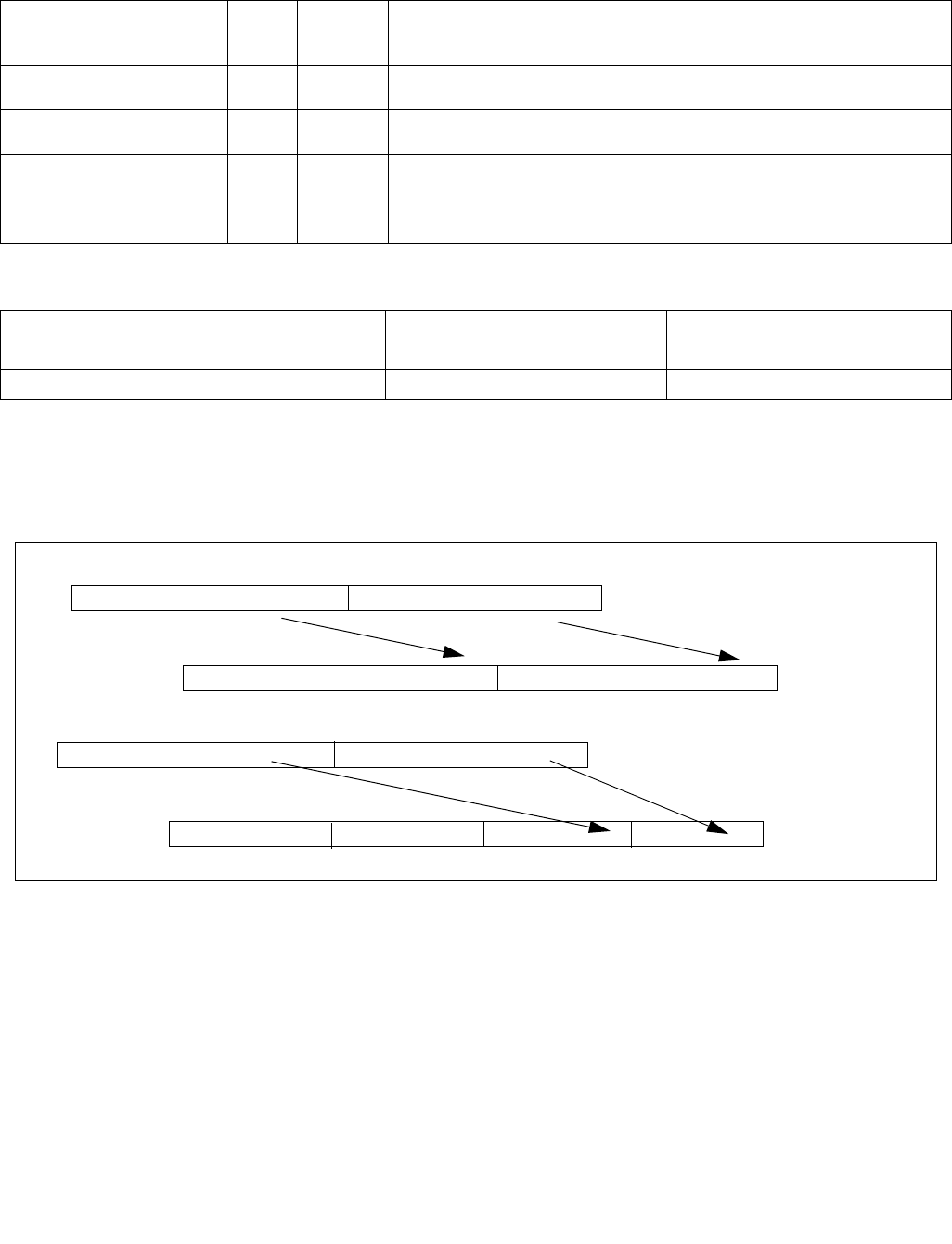
BNDMOV—Move Bounds
INSTRUCTION SET REFERENCE, A-L
3-100 Vol. 2A
BNDMOV—Move Bounds
Instruction Operand Encoding
Description
BNDMOV moves a pair of lower and upper bound values from the source operand (the second operand) to the
destination (the first operand). Each operation is 128-bit move. The exceptions are same as the MOV instruction.
The memory format for loading/store bounds in 64-bit mode is shown in Figure 3-5.
This instruction does not change flags.
Operation
BNDMOV register to register
DEST.LB SRC.LB;
DEST.UB SRC.UB;
Opcode/
Instruction
Op/En 64/32
bit Mode
Support
CPUID
Feature
Flag
Description
66 0F 1A /r
BNDMOV bnd1, bnd2/m64
RM NE/V MPX Move lower and upper bound from bnd2/m64 to bound register
bnd1.
66 0F 1A /r
BNDMOV bnd1, bnd2/m128
RM V/NE MPX Move lower and upper bound from bnd2/m128 to bound register
bnd1.
66 0F 1B /r
BNDMOV bnd1/m64, bnd2
MR NE/V MPX Move lower and upper bound from bnd2 to bnd1/m64.
66 0F 1B /r
BNDMOV bnd1/m128, bnd2
MR V/NE MPX Move lower and upper bound from bnd2 to bound register
bnd1/m128.
Op/En Operand 1 Operand 2 Operand 3
RM ModRM:reg (w) ModRM:r/m (r) NA
MR ModRM:r/m (w) ModRM:reg (r) NA
Figure 3-5. Memory Layout of BNDMOV to/from Memory
Upper Bound (UB) Lower Bound (LB)
80
16 Byte offset
BNDMOV to memory in 64-bit mode
Upper Bound (UB) Lower Bound (LB)
80
16 Byte offset
BNDMOV to memory in 32-bit mode
4

BNDMOV—Move Bounds
INSTRUCTION SET REFERENCE, A-L
Vol. 2A 3-101
BNDMOV from memory
IF 64-bit mode THEN
DEST.LB LOAD_QWORD(SRC);
DEST.UB LOAD_QWORD(SRC+8);
ELSE
DEST.LB LOAD_DWORD_ZERO_EXT(SRC);
DEST.UB LOAD_DWORD_ZERO_EXT(SRC+4);
FI;
BNDMOV to memory
IF 64-bit mode THEN
DEST[63:0] SRC.LB;
DEST[127:64] SRC.UB;
ELSE
DEST[31:0] SRC.LB;
DEST[63:32] SRC.UB;
FI;
Intel C/C++ Compiler Intrinsic Equivalent
BNDMOV void * _bnd_copy_ptr_bounds(const void *q, const void *r)
Flags Affected
None
Protected Mode Exceptions
#UD If the LOCK prefix is used but the destination is not a memory operand.
If ModRM.r/m encodes BND4-BND7 when Intel MPX is enabled.
If 67H prefix is not used and CS.D=0.
If 67H prefix is used and CS.D=1.
#SS(0) If the memory operand effective address is outside the SS segment limit.
#GP(0) If the memory operand effective address is outside the CS, DS, ES, FS, or GS segment limit.
If the destination operand points to a non-writable segment
If the DS, ES, FS, or GS segment register contains a NULL segment selector.
#AC(0) If alignment checking is enabled and an unaligned memory reference is made while CPL is 3.
#PF(fault code) If a page fault occurs.
Real-Address Mode Exceptions
#UD If the LOCK prefix is used but the destination is not a memory operand.
If ModRM.r/m encodes BND4-BND7 when Intel MPX is enabled.
If 16-bit addressing is used.
#GP(0) If the memory operand effective address is outside the CS, DS, ES, FS, or GS segment limit.
#SS If the memory operand effective address is outside the SS segment limit.

BNDMOV—Move Bounds
INSTRUCTION SET REFERENCE, A-L
3-102 Vol. 2A
Virtual-8086 Mode Exceptions
#UD If the LOCK prefix is used but the destination is not a memory operand.
If ModRM.r/m encodes BND4-BND7 when Intel MPX is enabled.
If 16-bit addressing is used.
#GP(0) If the memory operand effective address is outside the CS, DS, ES, FS, or GS segment limit.
#SS(0) If the memory operand effective address is outside the SS segment limit.
#AC(0) If alignment checking is enabled and an unaligned memory reference is made while CPL is 3.
#PF(fault code) If a page fault occurs.
Compatibility Mode Exceptions
Same exceptions as in protected mode.
64-Bit Mode Exceptions
#UD If the LOCK prefix is used but the destination is not a memory operand.
If ModRM.r/m and REX encodes BND4-BND15 when Intel MPX is enabled.
#SS(0) If the memory address referencing the SS segment is in a non-canonical form.
#GP(0) If the memory address is in a non-canonical form.
#AC(0) If alignment checking is enabled and an unaligned memory reference is made while CPL is 3.
#PF(fault code) If a page fault occurs.

BNDSTX—Store Extended Bounds Using Address Translation
INSTRUCTION SET REFERENCE, A-L
Vol. 2A 3-103
BNDSTX—Store Extended Bounds Using Address Translation
Instruction Operand Encoding
Description
BNDSTX uses the linear address constructed from the displacement and base register of the SIB-addressing form
of the memory operand (mib) to perform address translation to store to a bound table entry. The bounds in the
source operand bnd are written to the lower and upper bounds in the BTE. The content of the index register of mib
is written to the pointer value field in the BTE.
This instruction does not cause memory access to the linear address of mib nor the effective address referenced by
the base, and does not read or write any flags.
Segment overrides apply to the linear address computation with the base of mib, and are used during address
translation to generate the address of the bound table entry. By default, the address of the BTE is assumed to be
linear address. There are no segmentation checks performed on the base of mib.
The base of mib will not be checked for canonical address violation as it does not access memory.
Any encoding of this instruction that does not specify base or index register will treat those registers as zero
(constant). The reg-reg form of this instruction will remain a NOP.
The scale field of the SIB byte has no effect on these instructions and is ignored.
The bound register may be partially updated on memory faults. The order in which memory operands are loaded is
implementation specific.
Operation
base mib.SIB.base ? mib.SIB.base + Disp: 0;
ptr_value mib.SIB.index ? mib.SIB.index : 0;
Outside 64-bit mode
A_BDE[31:0] (Zero_extend32(base[31:12] « 2) + (BNDCFG[31:12] «12 );
A_BT[31:0] LoadFrom(A_BDE);
IF A_BT[0] equal 0 Then
BNDSTATUS A_BDE | 02H;
#BR;
FI;
A_DEST[31:0] (Zero_extend32(base[11:2] « 4) + (A_BT[31:2] « 2 ); // address of Bound table entry
A_DEST[8][31:0] ptr_value;
A_DEST[0][31:0] BND.LB;
A_DEST[4][31:0] BND.UB;
Opcode/
Instruction
Op/En 64/32
bit Mode
Support
CPUID
Feature
Flag
Description
0F 1B /r
BNDSTX mib, bnd
MR V/V MPX Store the bounds in bnd and the pointer value in the index regis-
ter of mib to a bound table entry (BTE) with address translation
using the base of mib.
Op/En Operand 1 Operand 2 Operand 3
MR SIB.base (r): Address of pointer
SIB.index(r) ModRM:reg (r) NA

BNDSTX—Store Extended Bounds Using Address Translation
INSTRUCTION SET REFERENCE, A-L
3-104 Vol. 2A
In 64-bit mode
A_BDE[63:0] (Zero_extend64(base[47+MAWA:20] « 3) + (BNDCFG[63:20] «12 );1
A_BT[63:0] LoadFrom(A_BDE);
IF A_BT[0] equal 0 Then
BNDSTATUS A_BDE | 02H;
#BR;
FI;
A_DEST[63:0] (Zero_extend64(base[19:3] « 5) + (A_BT[63:3] « 3 ); // address of Bound table entry
A_DEST[16][63:0] ptr_value;
A_DEST[0][63:0] BND.LB;
A_DEST[8][63:0] BND.UB;
Intel C/C++ Compiler Intrinsic Equivalent
BNDSTX: _bnd_store_ptr_bounds(const void **ptr_addr, const void *ptr_val);
Flags Affected
None
Protected Mode Exceptions
#BR If the bound directory entry is invalid.
#UD If the LOCK prefix is used.
If ModRM.r/m encodes BND4-BND7 when Intel MPX is enabled.
If 67H prefix is not used and CS.D=0.
If 67H prefix is used and CS.D=1.
#GP(0) If a destination effective address of the Bound Table entry is outside the DS segment limit.
If DS register contains a NULL segment selector.
If the destination operand points to a non-writable segment
#PF(fault code) If a page fault occurs.
Real-Address Mode Exceptions
#UD If the LOCK prefix is used.
If ModRM.r/m encodes BND4-BND7 when Intel MPX is enabled.
If 16-bit addressing is used.
#GP(0) If a destination effective address of the Bound Table entry is outside the DS segment limit.
Virtual-8086 Mode Exceptions
#UD If the LOCK prefix is used.
If ModRM.r/m encodes BND4-BND7 when Intel MPX is enabled.
If 16-bit addressing is used.
#GP(0) If a destination effective address of the Bound Table entry is outside the DS segment limit.
#PF(fault code) If a page fault occurs.
Compatibility Mode Exceptions
Same exceptions as in protected mode.
1. If CPL < 3, the supervisor MAWA (MAWAS) is used; this value is 0. If CPL = 3, the user MAWA (MAWAU) is used; this value is enumer-
ated in CPUID.(EAX=07H,ECX=0H):ECX.MAWAU[bits 21:17]. See Section 17.3.1 of Intel® 64 and IA-32 Architectures Software Devel-
oper’s Manual, Volume 1.

BNDSTX—Store Extended Bounds Using Address Translation
INSTRUCTION SET REFERENCE, A-L
Vol. 2A 3-105
64-Bit Mode Exceptions
#BR If the bound directory entry is invalid.
#UD If ModRM is RIP relative.
If the LOCK prefix is used.
If ModRM.r/m and REX encodes BND4-BND15 when Intel MPX is enabled.
#GP(0) If the memory address (A_BDE or A_BTE) is in a non-canonical form.
If the destination operand points to a non-writable segment
#PF(fault code) If a page fault occurs.

BOUND—Check Array Index Against Bounds
INSTRUCTION SET REFERENCE, A-L
3-106 Vol. 2A
BOUND—Check Array Index Against Bounds
Instruction Operand Encoding
Description
BOUND determines if the first operand (array index) is within the bounds of an array specified the second operand
(bounds operand). The array index is a signed integer located in a register. The bounds operand is a memory loca-
tion that contains a pair of signed doubleword-integers (when the operand-size attribute is 32) or a pair of signed
word-integers (when the operand-size attribute is 16). The first doubleword (or word) is the lower bound of the
array and the second doubleword (or word) is the upper bound of the array. The array index must be greater than
or equal to the lower bound and less than or equal to the upper bound plus the operand size in bytes. If the index
is not within bounds, a BOUND range exceeded exception (#BR) is signaled. When this exception is generated, the
saved return instruction pointer points to the BOUND instruction.
The bounds limit data structure (two words or doublewords containing the lower and upper limits of the array) is
usually placed just before the array itself, making the limits addressable via a constant offset from the beginning of
the array. Because the address of the array already will be present in a register, this practice avoids extra bus cycles
to obtain the effective address of the array bounds.
This instruction executes as described in compatibility mode and legacy mode. It is not valid in 64-bit mode.
Operation
IF 64bit Mode
THEN
#UD;
ELSE
IF (ArrayIndex < LowerBound OR ArrayIndex > UpperBound)
(* Below lower bound or above upper bound *)
THEN #BR; FI;
FI;
Flags Affected
None.
Protected Mode Exceptions
#BR If the bounds test fails.
#UD If second operand is not a memory location.
If the LOCK prefix is used.
#GP(0) If a memory operand effective address is outside the CS, DS, ES, FS, or GS segment limit.
If the DS, ES, FS, or GS register contains a NULL segment selector.
#SS(0) If a memory operand effective address is outside the SS segment limit.
#PF(fault-code) If a page fault occurs.
#AC(0) If alignment checking is enabled and an unaligned memory reference is made while the
current privilege level is 3.
Opcode Instruction Op/
En
64-bit
Mode
Compat/
Leg Mode
Description
62 /rBOUND r16, m16&16 RM Invalid Valid Check if r16 (array index) is within bounds
specified by m16&16.
62 /rBOUND r32, m32&32 RM Invalid Valid Check if r32 (array index) is within bounds
specified by m32&32.
Op/En Operand 1 Operand 2 Operand 3 Operand 4
RM ModRM:reg (r) ModRM:r/m (r) NA NA

BOUND—Check Array Index Against Bounds
INSTRUCTION SET REFERENCE, A-L
Vol. 2A 3-107
Real-Address Mode Exceptions
#BR If the bounds test fails.
#UD If second operand is not a memory location.
If the LOCK prefix is used.
#GP If a memory operand effective address is outside the CS, DS, ES, FS, or GS segment limit.
#SS If a memory operand effective address is outside the SS segment limit.
Virtual-8086 Mode Exceptions
#BR If the bounds test fails.
#UD If second operand is not a memory location.
If the LOCK prefix is used.
#GP(0) If a memory operand effective address is outside the CS, DS, ES, FS, or GS segment limit.
#SS(0) If a memory operand effective address is outside the SS segment limit.
#PF(fault-code) If a page fault occurs.
#AC(0) If alignment checking is enabled and an unaligned memory reference is made.
Compatibility Mode Exceptions
Same exceptions as in protected mode.
64-Bit Mode Exceptions
#UD If in 64-bit mode.

BSF—Bit Scan Forward
INSTRUCTION SET REFERENCE, A-L
3-108 Vol. 2A
BSF—Bit Scan Forward
Instruction Operand Encoding
Description
Searches the source operand (second operand) for the least significant set bit (1 bit). If a least significant 1 bit is
found, its bit index is stored in the destination operand (first operand). The source operand can be a register or a
memory location; the destination operand is a register. The bit index is an unsigned offset from bit 0 of the source
operand. If the content of the source operand is 0, the content of the destination operand is undefined.
In 64-bit mode, the instruction’s default operation size is 32 bits. Using a REX prefix in the form of REX.R permits
access to additional registers (R8-R15). Using a REX prefix in the form of REX.W promotes operation to 64 bits. See
the summary chart at the beginning of this section for encoding data and limits.
Operation
IF SRC = 0
THEN
ZF ← 1;
DEST is undefined;
ELSE
ZF ← 0;
temp ← 0;
WHILE Bit(SRC, temp) = 0
DO
temp ← temp + 1;
OD;
DEST ← temp;
FI;
Flags Affected
The ZF flag is set to 1 if all the source operand is 0; otherwise, the ZF flag is cleared. The CF, OF, SF, AF, and PF, flags
are undefined.
Protected Mode Exceptions
#GP(0) If a memory operand effective address is outside the CS, DS, ES, FS, or GS segment limit.
If the DS, ES, FS, or GS register contains a NULL segment selector.
#SS(0) If a memory operand effective address is outside the SS segment limit.
#PF(fault-code) If a page fault occurs.
#AC(0) If alignment checking is enabled and an unaligned memory reference is made while the
current privilege level is 3.
#UD If the LOCK prefix is used.
Opcode Instruction Op/
En
64-bit
Mode
Compat/
Leg Mode
Description
0F BC /r BSF r16, r/m16 RM Valid Valid Bit scan forward on r/m16.
0F BC /r BSF r32, r/m32 RM Valid Valid Bit scan forward on r/m32.
REX.W + 0F BC /r BSF r64, r/m64 RM Valid N.E. Bit scan forward on r/m64.
Op/En Operand 1 Operand 2 Operand 3 Operand 4
RM ModRM:reg (w) ModRM:r/m (r) NA NA

BSF—Bit Scan Forward
INSTRUCTION SET REFERENCE, A-L
Vol. 2A 3-109
Real-Address Mode Exceptions
#GP If a memory operand effective address is outside the CS, DS, ES, FS, or GS segment limit.
#SS If a memory operand effective address is outside the SS segment limit.
#UD If the LOCK prefix is used.
Virtual-8086 Mode Exceptions
#GP(0) If a memory operand effective address is outside the CS, DS, ES, FS, or GS segment limit.
#SS(0) If a memory operand effective address is outside the SS segment limit.
#PF(fault-code) If a page fault occurs.
#AC(0) If alignment checking is enabled and an unaligned memory reference is made.
#UD If the LOCK prefix is used.
Compatibility Mode Exceptions
Same exceptions as in protected mode.
64-Bit Mode Exceptions
#SS(0) If a memory address referencing the SS segment is in a non-canonical form.
#GP(0) If the memory address is in a non-canonical form.
#PF(fault-code) If a page fault occurs.
#AC(0) If alignment checking is enabled and an unaligned memory reference is made while the
current privilege level is 3.
#UD If the LOCK prefix is used.

BSR—Bit Scan Reverse
INSTRUCTION SET REFERENCE, A-L
3-110 Vol. 2A
BSR—Bit Scan Reverse
Instruction Operand Encoding
Description
Searches the source operand (second operand) for the most significant set bit (1 bit). If a most significant 1 bit is
found, its bit index is stored in the destination operand (first operand). The source operand can be a register or a
memory location; the destination operand is a register. The bit index is an unsigned offset from bit 0 of the source
operand. If the content source operand is 0, the content of the destination operand is undefined.
In 64-bit mode, the instruction’s default operation size is 32 bits. Using a REX prefix in the form of REX.R permits
access to additional registers (R8-R15). Using a REX prefix in the form of REX.W promotes operation to 64 bits. See
the summary chart at the beginning of this section for encoding data and limits.
Operation
IF SRC = 0
THEN
ZF ← 1;
DEST is undefined;
ELSE
ZF ← 0;
temp ← OperandSize – 1;
WHILE Bit(SRC, temp) = 0
DO
temp ← temp - 1;
OD;
DEST ← temp;
FI;
Flags Affected
The ZF flag is set to 1 if all the source operand is 0; otherwise, the ZF flag is cleared. The CF, OF, SF, AF, and PF, flags
are undefined.
Protected Mode Exceptions
#GP(0) If a memory operand effective address is outside the CS, DS, ES, FS, or GS segment limit.
If the DS, ES, FS, or GS register contains a NULL segment selector.
#SS(0) If a memory operand effective address is outside the SS segment limit.
#PF(fault-code) If a page fault occurs.
#AC(0) If alignment checking is enabled and an unaligned memory reference is made while the
current privilege level is 3.
#UD If the LOCK prefix is used.
Opcode Instruction Op/
En
64-bit
Mode
Compat/
Leg Mode
Description
0F BD /r BSR r16, r/m16 RM Valid Valid Bit scan reverse on r/m16.
0F BD /r BSR r32, r/m32 RM Valid Valid Bit scan reverse on r/m32.
REX.W + 0F BD /r BSR r64, r/m64 RM Valid N.E. Bit scan reverse on r/m64.
Op/En Operand 1 Operand 2 Operand 3 Operand 4
RM ModRM:reg (w) ModRM:r/m (r) NA NA

BSR—Bit Scan Reverse
INSTRUCTION SET REFERENCE, A-L
Vol. 2A 3-111
Real-Address Mode Exceptions
#GP If a memory operand effective address is outside the CS, DS, ES, FS, or GS segment limit.
#SS If a memory operand effective address is outside the SS segment limit.
#UD If the LOCK prefix is used.
Virtual-8086 Mode Exceptions
#GP(0) If a memory operand effective address is outside the CS, DS, ES, FS, or GS segment limit.
#SS(0) If a memory operand effective address is outside the SS segment limit.
#PF(fault-code) If a page fault occurs.
#AC(0) If alignment checking is enabled and an unaligned memory reference is made.
#UD If the LOCK prefix is used.
Compatibility Mode Exceptions
Same exceptions as in protected mode.
64-Bit Mode Exceptions
#SS(0) If a memory address referencing the SS segment is in a non-canonical form.
#GP(0) If the memory address is in a non-canonical form.
#PF(fault-code) If a page fault occurs.
#AC(0) If alignment checking is enabled and an unaligned memory reference is made while the
current privilege level is 3.
#UD If the LOCK prefix is used.

BSWAP—Byte Swap
INSTRUCTION SET REFERENCE, A-L
3-112 Vol. 2A
BSWAP—Byte Swap
Instruction Operand Encoding
Description
Reverses the byte order of a 32-bit or 64-bit (destination) register. This instruction is provided for converting little-
endian values to big-endian format and vice versa. To swap bytes in a word value (16-bit register), use the XCHG
instruction. When the BSWAP instruction references a 16-bit register, the result is undefined.
In 64-bit mode, the instruction’s default operation size is 32 bits. Using a REX prefix in the form of REX.R permits
access to additional registers (R8-R15). Using a REX prefix in the form of REX.W promotes operation to 64 bits. See
the summary chart at the beginning of this section for encoding data and limits.
IA-32 Architecture Legacy Compatibility
The BSWAP instruction is not supported on IA-32 processors earlier than the Intel486™ processor family. For
compatibility with this instruction, software should include functionally equivalent code for execution on Intel
processors earlier than the Intel486 processor family.
Operation
TEMP ← DEST
IF 64-bit mode AND OperandSize = 64
THEN
DEST[7:0] ← TEMP[63:56];
DEST[15:8] ← TEMP[55:48];
DEST[23:16] ← TEMP[47:40];
DEST[31:24] ← TEMP[39:32];
DEST[39:32] ← TEMP[31:24];
DEST[47:40] ← TEMP[23:16];
DEST[55:48] ← TEMP[15:8];
DEST[63:56] ← TEMP[7:0];
ELSE
DEST[7:0] ← TEMP[31:24];
DEST[15:8] ← TEMP[23:16];
DEST[23:16] ← TEMP[15:8];
DEST[31:24] ← TEMP[7:0];
FI;
Flags Affected
None.
Exceptions (All Operating Modes)
#UD If the LOCK prefix is used.
Opcode Instruction Op/
En
64-bit
Mode
Compat/
Leg Mode
Description
0F C8+rd BSWAP r32 O Valid* Valid Reverses the byte order of a 32-bit register.
REX.W + 0F C8+rd BSWAP r64 O Valid N.E. Reverses the byte order of a 64-bit register.
NOTES:
* See IA-32 Architecture Compatibility section below.
Op/En Operand 1 Operand 2 Operand 3 Operand 4
O opcode + rd (r, w) NA NA NA

BT—Bit Test
INSTRUCTION SET REFERENCE, A-L
Vol. 2A 3-113
BT—Bit Test
Instruction Operand Encoding
Description
Selects the bit in a bit string (specified with the first operand, called the bit base) at the bit-position designated by
the bit offset (specified by the second operand) and stores the value of the bit in the CF flag. The bit base operand
can be a register or a memory location; the bit offset operand can be a register or an immediate value:
•If the bit base operand specifies a register, the instruction takes the modulo 16, 32, or 64 of the bit offset
operand (modulo size depends on the mode and register size; 64-bit operands are available only in 64-bit
mode).
•If the bit base operand specifies a memory location, the operand represents the address of the byte in memory
that contains the bit base (bit 0 of the specified byte) of the bit string. The range of the bit position that can be
referenced by the offset operand depends on the operand size.
See also: Bit(BitBase, BitOffset) on page 3-11.
Some assemblers support immediate bit offsets larger than 31 by using the immediate bit offset field in combina-
tion with the displacement field of the memory operand. In this case, the low-order 3 or 5 bits (3 for 16-bit oper-
ands, 5 for 32-bit operands) of the immediate bit offset are stored in the immediate bit offset field, and the high-
order bits are shifted and combined with the byte displacement in the addressing mode by the assembler. The
processor will ignore the high order bits if they are not zero.
When accessing a bit in memory, the processor may access 4 bytes starting from the memory address for a 32-bit
operand size, using by the following relationship:
Effective Address + (4 ∗ (BitOffset DIV 32))
Or, it may access 2 bytes starting from the memory address for a 16-bit operand, using this relationship:
Effective Address + (2 ∗ (BitOffset DIV 16))
It may do so even when only a single byte needs to be accessed to reach the given bit. When using this bit
addressing mechanism, software should avoid referencing areas of memory close to address space holes. In partic-
ular, it should avoid references to memory-mapped I/O registers. Instead, software should use the MOV instruc-
tions to load from or store to these addresses, and use the register form of these instructions to manipulate the
data.
In 64-bit mode, the instruction’s default operation size is 32 bits. Using a REX prefix in the form of REX.R permits
access to additional registers (R8-R15). Using a REX prefix in the form of REX.W promotes operation to 64 bit oper-
ands. See the summary chart at the beginning of this section for encoding data and limits.
Operation
CF ← Bit(BitBase, BitOffset);
Opcode Instruction Op/
En
64-bit
Mode
Compat/
Leg Mode
Description
0F A3 /r BT r/m16, r16 MR Valid Valid Store selected bit in CF flag.
0F A3 /r BT r/m32, r32 MR Valid Valid Store selected bit in CF flag.
REX.W + 0F A3 /r BT r/m64, r64 MR Valid N.E. Store selected bit in CF flag.
0F BA /4 ib BT r/m16, imm8 MI Valid Valid Store selected bit in CF flag.
0F BA /4 ib BT r/m32, imm8 MI Valid Valid Store selected bit in CF flag.
REX.W + 0F BA /4 ib BT r/m64, imm8 MI Valid N.E. Store selected bit in CF flag.
Op/En Operand 1 Operand 2 Operand 3 Operand 4
MR ModRM:r/m (r) ModRM:reg (r) NA NA
MI ModRM:r/m (r) imm8 NA NA

BT—Bit Test
INSTRUCTION SET REFERENCE, A-L
3-114 Vol. 2A
Flags Affected
The CF flag contains the value of the selected bit. The ZF flag is unaffected. The OF, SF, AF, and PF flags are
undefined.
Protected Mode Exceptions
#GP(0) If a memory operand effective address is outside the CS, DS, ES, FS, or GS segment limit.
If the DS, ES, FS, or GS register contains a NULL segment selector.
#SS(0) If a memory operand effective address is outside the SS segment limit.
#PF(fault-code) If a page fault occurs.
#AC(0) If alignment checking is enabled and an unaligned memory reference is made while the
current privilege level is 3.
#UD If the LOCK prefix is used.
Real-Address Mode Exceptions
#GP If a memory operand effective address is outside the CS, DS, ES, FS, or GS segment limit.
#SS If a memory operand effective address is outside the SS segment limit.
#UD If the LOCK prefix is used.
Virtual-8086 Mode Exceptions
#GP(0) If a memory operand effective address is outside the CS, DS, ES, FS, or GS segment limit.
#SS(0) If a memory operand effective address is outside the SS segment limit.
#PF(fault-code) If a page fault occurs.
#AC(0) If alignment checking is enabled and an unaligned memory reference is made.
#UD If the LOCK prefix is used.
Compatibility Mode Exceptions
Same exceptions as in protected mode.
64-Bit Mode Exceptions
#SS(0) If a memory address referencing the SS segment is in a non-canonical form.
#GP(0) If the memory address is in a non-canonical form.
#PF(fault-code) If a page fault occurs.
#AC(0) If alignment checking is enabled and an unaligned memory reference is made while the
current privilege level is 3.
#UD If the LOCK prefix is used.

BTC—Bit Test and Complement
INSTRUCTION SET REFERENCE, A-L
Vol. 2A 3-115
BTC—Bit Test and Complement
Instruction Operand Encoding
Description
Selects the bit in a bit string (specified with the first operand, called the bit base) at the bit-position designated by
the bit offset operand (second operand), stores the value of the bit in the CF flag, and complements the selected
bit in the bit string. The bit base operand can be a register or a memory location; the bit offset operand can be a
register or an immediate value:
•If the bit base operand specifies a register, the instruction takes the modulo 16, 32, or 64 of the bit offset
operand (modulo size depends on the mode and register size; 64-bit operands are available only in 64-bit
mode). This allows any bit position to be selected.
•If the bit base operand specifies a memory location, the operand represents the address of the byte in memory
that contains the bit base (bit 0 of the specified byte) of the bit string. The range of the bit position that can be
referenced by the offset operand depends on the operand size.
See also: Bit(BitBase, BitOffset) on page 3-11.
Some assemblers support immediate bit offsets larger than 31 by using the immediate bit offset field in combina-
tion with the displacement field of the memory operand. See “BT—Bit Test” in this chapter for more information on
this addressing mechanism.
This instruction can be used with a LOCK prefix to allow the instruction to be executed atomically.
In 64-bit mode, the instruction’s default operation size is 32 bits. Using a REX prefix in the form of REX.R permits
access to additional registers (R8-R15). Using a REX prefix in the form of REX.W promotes operation to 64 bits. See
the summary chart at the beginning of this section for encoding data and limits.
Operation
CF ← Bit(BitBase, BitOffset);
Bit(BitBase, BitOffset) ← NOT Bit(BitBase, BitOffset);
Flags Affected
The CF flag contains the value of the selected bit before it is complemented. The ZF flag is unaffected. The OF, SF,
AF, and PF flags are undefined.
Opcode Instruction Op/
En
64-bit
Mode
Compat/
Leg Mode
Description
0F BB /r BTC r/m16, r16 MR Valid Valid Store selected bit in CF flag and complement.
0F BB /r BTC r/m32, r32 MR Valid Valid Store selected bit in CF flag and complement.
REX.W + 0F BB /r BTC r/m64, r64 MR Valid N.E. Store selected bit in CF flag and complement.
0F BA /7 ib BTC r/m16, imm8 MI Valid Valid Store selected bit in CF flag and complement.
0F BA /7 ib BTC r/m32, imm8 MI Valid Valid Store selected bit in CF flag and complement.
REX.W + 0F BA /7 ib BTC r/m64, imm8 MI Valid N.E. Store selected bit in CF flag and complement.
Op/En Operand 1 Operand 2 Operand 3 Operand 4
MR ModRM:r/m (r, w) ModRM:reg (r) NA NA
MI ModRM:r/m (r, w) imm8 NA NA

BTC—Bit Test and Complement
INSTRUCTION SET REFERENCE, A-L
3-116 Vol. 2A
Protected Mode Exceptions
#GP(0) If the destination operand points to a non-writable segment.
If a memory operand effective address is outside the CS, DS, ES, FS, or GS segment limit.
If the DS, ES, FS, or GS register contains a NULL segment selector.
#SS(0) If a memory operand effective address is outside the SS segment limit.
#PF(fault-code) If a page fault occurs.
#AC(0) If alignment checking is enabled and an unaligned memory reference is made while the
current privilege level is 3.
#UD If the LOCK prefix is used but the destination is not a memory operand.
Real-Address Mode Exceptions
#GP If a memory operand effective address is outside the CS, DS, ES, FS, or GS segment limit.
#SS If a memory operand effective address is outside the SS segment limit.
#UD If the LOCK prefix is used but the destination is not a memory operand.
Virtual-8086 Mode Exceptions
#GP(0) If a memory operand effective address is outside the CS, DS, ES, FS, or GS segment limit.
#SS(0) If a memory operand effective address is outside the SS segment limit.
#PF(fault-code) If a page fault occurs.
#AC(0) If alignment checking is enabled and an unaligned memory reference is made.
#UD If the LOCK prefix is used but the destination is not a memory operand.
Compatibility Mode Exceptions
Same exceptions as in protected mode.
64-Bit Mode Exceptions
#SS(0) If a memory address referencing the SS segment is in a non-canonical form.
#GP(0) If the memory address is in a non-canonical form.
#PF(fault-code) If a page fault occurs.
#AC(0) If alignment checking is enabled and an unaligned memory reference is made while the
current privilege level is 3.
#UD If the LOCK prefix is used but the destination is not a memory operand.

BTR—Bit Test and Reset
INSTRUCTION SET REFERENCE, A-L
Vol. 2A 3-117
BTR—Bit Test and Reset
Instruction Operand Encoding
Description
Selects the bit in a bit string (specified with the first operand, called the bit base) at the bit-position designated by
the bit offset operand (second operand), stores the value of the bit in the CF flag, and clears the selected bit in the
bit string to 0. The bit base operand can be a register or a memory location; the bit offset operand can be a register
or an immediate value:
•If the bit base operand specifies a register, the instruction takes the modulo 16, 32, or 64 of the bit offset
operand (modulo size depends on the mode and register size; 64-bit operands are available only in 64-bit
mode). This allows any bit position to be selected.
•If the bit base operand specifies a memory location, the operand represents the address of the byte in memory
that contains the bit base (bit 0 of the specified byte) of the bit string. The range of the bit position that can be
referenced by the offset operand depends on the operand size.
See also: Bit(BitBase, BitOffset) on page 3-11.
Some assemblers support immediate bit offsets larger than 31 by using the immediate bit offset field in combina-
tion with the displacement field of the memory operand. See “BT—Bit Test” in this chapter for more information on
this addressing mechanism.
This instruction can be used with a LOCK prefix to allow the instruction to be executed atomically.
In 64-bit mode, the instruction’s default operation size is 32 bits. Using a REX prefix in the form of REX.R permits
access to additional registers (R8-R15). Using a REX prefix in the form of REX.W promotes operation to 64 bits. See
the summary chart at the beginning of this section for encoding data and limits.
Operation
CF ← Bit(BitBase, BitOffset);
Bit(BitBase, BitOffset) ← 0;
Flags Affected
The CF flag contains the value of the selected bit before it is cleared. The ZF flag is unaffected. The OF, SF, AF, and
PF flags are undefined.
Opcode Instruction Op/
En
64-bit
Mode
Compat/
Leg Mode
Description
0F B3 /r BTR r/m16, r16 MR Valid Valid Store selected bit in CF flag and clear.
0F B3 /r BTR r/m32, r32 MR Valid Valid Store selected bit in CF flag and clear.
REX.W + 0F B3 /r BTR r/m64, r64 MR Valid N.E. Store selected bit in CF flag and clear.
0F BA /6 ib BTR r/m16, imm8 MI Valid Valid Store selected bit in CF flag and clear.
0F BA /6 ib BTR r/m32, imm8 MI Valid Valid Store selected bit in CF flag and clear.
REX.W + 0F BA /6 ib BTR r/m64, imm8 MI Valid N.E. Store selected bit in CF flag and clear.
Op/En Operand 1 Operand 2 Operand 3 Operand 4
MR ModRM:r/m (r, w) ModRM:reg (r) NA NA
MI ModRM:r/m (r, w) imm8 NA NA

BTR—Bit Test and Reset
INSTRUCTION SET REFERENCE, A-L
3-118 Vol. 2A
Protected Mode Exceptions
#GP(0) If the destination operand points to a non-writable segment.
If a memory operand effective address is outside the CS, DS, ES, FS, or GS segment limit.
If the DS, ES, FS, or GS register contains a NULL segment selector.
#SS(0) If a memory operand effective address is outside the SS segment limit.
#PF(fault-code) If a page fault occurs.
#AC(0) If alignment checking is enabled and an unaligned memory reference is made while the
current privilege level is 3.
#UD If the LOCK prefix is used but the destination is not a memory operand.
Real-Address Mode Exceptions
#GP If a memory operand effective address is outside the CS, DS, ES, FS, or GS segment limit.
#SS If a memory operand effective address is outside the SS segment limit.
#UD If the LOCK prefix is used but the destination is not a memory operand.
Virtual-8086 Mode Exceptions
#GP(0) If a memory operand effective address is outside the CS, DS, ES, FS, or GS segment limit.
#SS(0) If a memory operand effective address is outside the SS segment limit.
#PF(fault-code) If a page fault occurs.
#AC(0) If alignment checking is enabled and an unaligned memory reference is made.
#UD If the LOCK prefix is used but the destination is not a memory operand.
Compatibility Mode Exceptions
Same exceptions as in protected mode.
64-Bit Mode Exceptions
#SS(0) If a memory address referencing the SS segment is in a non-canonical form.
#GP(0) If the memory address is in a non-canonical form.
#PF(fault-code) If a page fault occurs.
#AC(0) If alignment checking is enabled and an unaligned memory reference is made while the
current privilege level is 3.
#UD If the LOCK prefix is used but the destination is not a memory operand.

BTS—Bit Test and Set
INSTRUCTION SET REFERENCE, A-L
Vol. 2A 3-119
BTS—Bit Test and Set
Instruction Operand Encoding
Description
Selects the bit in a bit string (specified with the first operand, called the bit base) at the bit-position designated by
the bit offset operand (second operand), stores the value of the bit in the CF flag, and sets the selected bit in the
bit string to 1. The bit base operand can be a register or a memory location; the bit offset operand can be a register
or an immediate value:
•If the bit base operand specifies a register, the instruction takes the modulo 16, 32, or 64 of the bit offset
operand (modulo size depends on the mode and register size; 64-bit operands are available only in 64-bit
mode). This allows any bit position to be selected.
•If the bit base operand specifies a memory location, the operand represents the address of the byte in memory
that contains the bit base (bit 0 of the specified byte) of the bit string. The range of the bit position that can be
referenced by the offset operand depends on the operand size.
See also: Bit(BitBase, BitOffset) on page 3-11.
Some assemblers support immediate bit offsets larger than 31 by using the immediate bit offset field in combina-
tion with the displacement field of the memory operand. See “BT—Bit Test” in this chapter for more information on
this addressing mechanism.
This instruction can be used with a LOCK prefix to allow the instruction to be executed atomically.
In 64-bit mode, the instruction’s default operation size is 32 bits. Using a REX prefix in the form of REX.R permits
access to additional registers (R8-R15). Using a REX prefix in the form of REX.W promotes operation to 64 bits. See
the summary chart at the beginning of this section for encoding data and limits.
Operation
CF ← Bit(BitBase, BitOffset);
Bit(BitBase, BitOffset) ← 1;
Flags Affected
The CF flag contains the value of the selected bit before it is set. The ZF flag is unaffected. The OF, SF, AF, and PF
flags are undefined.
Opcode Instruction Op/
En
64-bit
Mode
Compat/
Leg Mode
Description
0F AB /r BTS r/m16, r16 MR Valid Valid Store selected bit in CF flag and set.
0F AB /r BTS r/m32, r32 MR Valid Valid Store selected bit in CF flag and set.
REX.W + 0F AB /r BTS r/m64, r64 MR Valid N.E. Store selected bit in CF flag and set.
0F BA /5 ib BTS r/m16, imm8 MI Valid Valid Store selected bit in CF flag and set.
0F BA /5 ib BTS r/m32, imm8 MI Valid Valid Store selected bit in CF flag and set.
REX.W + 0F BA /5 ib BTS r/m64, imm8 MI Valid N.E. Store selected bit in CF flag and set.
Op/En Operand 1 Operand 2 Operand 3 Operand 4
MR ModRM:r/m (r, w) ModRM:reg (r) NA NA
MI ModRM:r/m (r, w) imm8 NA NA

BTS—Bit Test and Set
INSTRUCTION SET REFERENCE, A-L
3-120 Vol. 2A
Protected Mode Exceptions
#GP(0) If the destination operand points to a non-writable segment.
If a memory operand effective address is outside the CS, DS, ES, FS, or GS segment limit.
If the DS, ES, FS, or GS register contains a NULL segment selector.
#SS(0) If a memory operand effective address is outside the SS segment limit.
#PF(fault-code) If a page fault occurs.
#AC(0) If alignment checking is enabled and an unaligned memory reference is made while the
current privilege level is 3.
#UD If the LOCK prefix is used but the destination is not a memory operand.
Real-Address Mode Exceptions
#GP If a memory operand effective address is outside the CS, DS, ES, FS, or GS segment limit.
#SS If a memory operand effective address is outside the SS segment limit.
#UD If the LOCK prefix is used but the destination is not a memory operand.
Virtual-8086 Mode Exceptions
#GP If a memory operand effective address is outside the CS, DS, ES, FS, or GS segment limit.
#SS If a memory operand effective address is outside the SS segment limit.
#PF(fault-code) If a page fault occurs.
#AC(0) If alignment checking is enabled and an unaligned memory reference is made.
#UD If the LOCK prefix is used but the destination is not a memory operand.
Compatibility Mode Exceptions
Same exceptions as in protected mode.
64-Bit Mode Exceptions
#SS(0) If a memory address referencing the SS segment is in a non-canonical form.
#GP(0) If the memory address is in a non-canonical form.
#PF(fault-code) If a page fault occurs.
#AC(0) If alignment checking is enabled and an unaligned memory reference is made while the
current privilege level is 3.
#UD If the LOCK prefix is used but the destination is not a memory operand.

BZHI — Zero High Bits Starting with Specified Bit Position
INSTRUCTION SET REFERENCE, A-L
Vol. 2A 3-121
BZHI — Zero High Bits Starting with Specified Bit Position
Instruction Operand Encoding
Description
BZHI copies the bits of the first source operand (the second operand) into the destination operand (the first
operand) and clears the higher bits in the destination according to the INDEX value specified by the second source
operand (the third operand). The INDEX is specified by bits 7:0 of the second source operand. The INDEX value is
saturated at the value of OperandSize -1. CF is set, if the number contained in the 8 low bits of the third operand
is greater than OperandSize -1.
This instruction is not supported in real mode and virtual-8086 mode. The operand size is always 32 bits if not in
64-bit mode. In 64-bit mode operand size 64 requires VEX.W1. VEX.W1 is ignored in non-64-bit modes. An
attempt to execute this instruction with VEX.L not equal to 0 will cause #UD.
Operation
N ← SRC2[7:0]
DEST ← SRC1
IF (N < OperandSize)
DEST[OperandSize-1:N] ← 0
FI
IF (N > OperandSize - 1)
CF ← 1
ELSE
CF ← 0
FI
Flags Affected
ZF, CF and SF flags are updated based on the result. OF flag is cleared. AF and PF flags are undefined.
Intel C/C++ Compiler Intrinsic Equivalent
BZHI: unsigned __int32 _bzhi_u32(unsigned __int32 src, unsigned __int32 index);
BZHI: unsigned __int64 _bzhi_u64(unsigned __int64 src, unsigned __int32 index);
SIMD Floating-Point Exceptions
None
Other Exceptions
See Section 2.5.1, “Exception Conditions for VEX-Encoded GPR Instructions”, Table 2-29; additionally
#UD If VEX.W = 1.
Opcode/Instruction Op/
En
64/32
-bit
Mode
CPUID
Feature
Flag
Description
VEX.NDS.LZ.0F38.W0 F5 /r
BZHI r32a, r/m32, r32b
RMV V/V BMI2 Zero bits in r/m32 starting with the position in r32b, write result to
r32a.
VEX.NDS.LZ.0F38.W1 F5 /r
BZHI r64a, r/m64, r64b
RMV V/N.E. BMI2 Zero bits in r/m64 starting with the position in r64b, write result to
r64a.
Op/En Operand 1 Operand 2 Operand 3 Operand 4
RMV ModRM:reg (w) ModRM:r/m (r) VEX.vvvv (r) NA

CALL—Call Procedure
INSTRUCTION SET REFERENCE, A-L
3-122 Vol. 2A
CALL—Call Procedure
Instruction Operand Encoding
Description
Saves procedure linking information on the stack and branches to the called procedure specified using the target
operand. The target operand specifies the address of the first instruction in the called procedure. The operand can
be an immediate value, a general-purpose register, or a memory location.
This instruction can be used to execute four types of calls:
•Near Call — A call to a procedure in the current code segment (the segment currently pointed to by the CS
register), sometimes referred to as an intra-segment call.
•Far Call — A call to a procedure located in a different segment than the current code segment, sometimes
referred to as an inter-segment call.
•Inter-privilege-level far call — A far call to a procedure in a segment at a different privilege level than that
of the currently executing program or procedure.
•Task switch — A call to a procedure located in a different task.
The latter two call types (inter-privilege-level call and task switch) can only be executed in protected mode. See
“Calling Procedures Using Call and RET” in Chapter 6 of the Intel® 64 and IA-32 Architectures Software Devel-
oper’s Manual, Volume 1, for additional information on near, far, and inter-privilege-level calls. See Chapter 7,
“Task Management,” in the Intel® 64 and IA-32 Architectures Software Developer’s Manual, Volume 3A, for infor-
mation on performing task switches with the CALL instruction.
Opcode Instruction Op/
En
64-bit
Mode
Compat/
Leg Mode
Description
E8 cw CALL rel16 M N.S. Valid Call near, relative, displacement relative to next
instruction.
E8 cd CALL rel32 M Valid Valid Call near, relative, displacement relative to next
instruction. 32-bit displacement sign extended to
64-bits in 64-bit mode.
FF /2 CALL r/m16 M N.E. Valid Call near, absolute indirect, address given in r/m16.
FF /2 CALL r/m32 M N.E. Valid Call near, absolute indirect, address given in r/m32.
FF /2 CALL r/m64 M Valid N.E. Call near, absolute indirect, address given in r/m64.
9A cd CALL ptr16:16 D Invalid Valid Call far, absolute, address given in operand.
9A cp CALL ptr16:32 D Invalid Valid Call far, absolute, address given in operand.
FF /3 CALL m16:16 M Valid Valid Call far, absolute indirect address given in m16:16.
In 32-bit mode: if selector points to a gate, then RIP
= 32-bit zero extended displacement taken from
gate; else RIP = zero extended 16-bit offset from
far pointer referenced in the instruction.
FF /3 CALL m16:32 M Valid Valid In 64-bit mode: If selector points to a gate, then RIP
= 64-bit displacement taken from gate; else RIP =
zero extended 32-bit offset from far pointer
referenced in the instruction.
REX.W + FF /3 CALL m16:64 M Valid N.E. In 64-bit mode: If selector points to a gate, then RIP
= 64-bit displacement taken from gate; else RIP =
64-bit offset from far pointer referenced in the
instruction.
Op/En Operand 1 Operand 2 Operand 3 Operand 4
DOffset NA NA NA
MModRM:r/m (r) NA NA NA

CALL—Call Procedure
INSTRUCTION SET REFERENCE, A-L
Vol. 2A 3-123
Near Call. When executing a near call, the processor pushes the value of the EIP register (which contains the offset
of the instruction following the CALL instruction) on the stack (for use later as a return-instruction pointer). The
processor then branches to the address in the current code segment specified by the target operand. The target
operand specifies either an absolute offset in the code segment (an offset from the base of the code segment) or a
relative offset (a signed displacement relative to the current value of the instruction pointer in the EIP register; this
value points to the instruction following the CALL instruction). The CS register is not changed on near calls.
For a near call absolute, an absolute offset is specified indirectly in a general-purpose register or a memory location
(r/m16, r/m32, or r/m64). The operand-size attribute determines the size of the target operand (16, 32 or 64
bits). When in 64-bit mode, the operand size for near call (and all near branches) is forced to 64-bits. Absolute
offsets are loaded directly into the EIP(RIP) register. If the operand size attribute is 16, the upper two bytes of the
EIP register are cleared, resulting in a maximum instruction pointer size of 16 bits. When accessing an absolute
offset indirectly using the stack pointer [ESP] as the base register, the base value used is the value of the ESP
before the instruction executes.
A relative offset (rel16 or rel32) is generally specified as a label in assembly code. But at the machine code level, it
is encoded as a signed, 16- or 32-bit immediate value. This value is added to the value in the EIP(RIP) register. In
64-bit mode the relative offset is always a 32-bit immediate value which is sign extended to 64-bits before it is
added to the value in the RIP register for the target calculation. As with absolute offsets, the operand-size attribute
determines the size of the target operand (16, 32, or 64 bits). In 64-bit mode the target operand will always be 64-
bits because the operand size is forced to 64-bits for near branches.
Far Calls in Real-Address or Virtual-8086 Mode. When executing a far call in real- address or virtual-8086 mode, the
processor pushes the current value of both the CS and EIP registers on the stack for use as a return-instruction
pointer. The processor then performs a “far branch” to the code segment and offset specified with the target
operand for the called procedure. The target operand specifies an absolute far address either directly with a pointer
(ptr16:16 or ptr16:32) or indirectly with a memory location (m16:16 or m16:32). With the pointer method, the
segment and offset of the called procedure is encoded in the instruction using a 4-byte (16-bit operand size) or 6-
byte (32-bit operand size) far address immediate. With the indirect method, the target operand specifies a memory
location that contains a 4-byte (16-bit operand size) or 6-byte (32-bit operand size) far address. The operand-size
attribute determines the size of the offset (16 or 32 bits) in the far address. The far address is loaded directly into
the CS and EIP registers. If the operand-size attribute is 16, the upper two bytes of the EIP register are cleared.
Far Calls in Protected Mode. When the processor is operating in protected mode, the CALL instruction can be used to
perform the following types of far calls:
•Far call to the same privilege level
•Far call to a different privilege level (inter-privilege level call)
•Task switch (far call to another task)
In protected mode, the processor always uses the segment selector part of the far address to access the corre-
sponding descriptor in the GDT or LDT. The descriptor type (code segment, call gate, task gate, or TSS) and access
rights determine the type of call operation to be performed.
If the selected descriptor is for a code segment, a far call to a code segment at the same privilege level is
performed. (If the selected code segment is at a different privilege level and the code segment is non-conforming,
a general-protection exception is generated.) A far call to the same privilege level in protected mode is very similar
to one carried out in real-address or virtual-8086 mode. The target operand specifies an absolute far address either
directly with a pointer (ptr16:16 or ptr16:32) or indirectly with a memory location (m16:16 or m16:32). The
operand- size attribute determines the size of the offset (16 or 32 bits) in the far address. The new code segment
selector and its descriptor are loaded into CS register; the offset from the instruction is loaded into the EIP register.
A call gate (described in the next paragraph) can also be used to perform a far call to a code segment at the same
privilege level. Using this mechanism provides an extra level of indirection and is the preferred method of making
calls between 16-bit and 32-bit code segments.
When executing an inter-privilege-level far call, the code segment for the procedure being called must be accessed
through a call gate. The segment selector specified by the target operand identifies the call gate. The target
operand can specify the call gate segment selector either directly with a pointer (ptr16:16 or ptr16:32) or indirectly
with a memory location (m16:16 or m16:32). The processor obtains the segment selector for the new code
segment and the new instruction pointer (offset) from the call gate descriptor. (The offset from the target operand
is ignored when a call gate is used.)

CALL—Call Procedure
INSTRUCTION SET REFERENCE, A-L
3-124 Vol. 2A
On inter-privilege-level calls, the processor switches to the stack for the privilege level of the called procedure. The
segment selector for the new stack segment is specified in the TSS for the currently running task. The branch to
the new code segment occurs after the stack switch. (Note that when using a call gate to perform a far call to a
segment at the same privilege level, no stack switch occurs.) On the new stack, the processor pushes the segment
selector and stack pointer for the calling procedure’s stack, an optional set of parameters from the calling proce-
dures stack, and the segment selector and instruction pointer for the calling procedure’s code segment. (A value in
the call gate descriptor determines how many parameters to copy to the new stack.) Finally, the processor
branches to the address of the procedure being called within the new code segment.
Executing a task switch with the CALL instruction is similar to executing a call through a call gate. The target
operand specifies the segment selector of the task gate for the new task activated by the switch (the offset in the
target operand is ignored). The task gate in turn points to the TSS for the new task, which contains the segment
selectors for the task’s code and stack segments. Note that the TSS also contains the EIP value for the next instruc-
tion that was to be executed before the calling task was suspended. This instruction pointer value is loaded into the
EIP register to re-start the calling task.
The CALL instruction can also specify the segment selector of the TSS directly, which eliminates the indirection of
the task gate. See Chapter 7, “Task Management,” in the Intel® 64 and IA-32 Architectures Software Developer’s
Manual, Volume 3A, for information on the mechanics of a task switch.
When you execute at task switch with a CALL instruction, the nested task flag (NT) is set in t he EFLAGS registe r and
the new TSS’s previous task link field is loaded with the old task’s TSS selector. Code is expected to suspend this
nested task by executing an IRET instruction which, because the NT flag is set, automatically uses the previous
task link to return to the calling task. (See “Task Linking” in Chapter 7 of the Intel® 64 and IA-32 Architectures
Software Developer’s Manual, Volume 3A, for information on nested tasks.) Switching tasks with the CALL instruc-
tion differs in this regard from JMP instruction. JMP does not set the NT flag and therefore does not expect an IRET
instruction to suspend the task.
Mixing 16-Bit and 32-Bit Calls. When making far calls between 16-bit and 32-bit code segments, use a call gate. If
the far call is from a 32-bit code segment to a 16-bit code segment, the call should be made from the first 64
KBytes of the 32-bit code segment. This is because the operand-size attribute of the instruction is set to 16, so only
a 16-bit return address offset can be saved. Also, the call should be made using a 16-bit call gate so that 16-bit
values can be pushed on the stack. See Chapter 21, “Mixing 16-Bit and 32-Bit Code,” in the Intel® 64 and IA-32
Architectures Software Developer’s Manual, Volume 3B, for more information.
Far Calls in Compatibility Mode. When the processor is operating in compatibility mode, the CALL instruction can be
used to perform the following types of far calls:
•Far call to the same privilege level, remaining in compatibility mode
•Far call to the same privilege level, transitioning to 64-bit mode
•Far call to a different privilege level (inter-privilege level call), transitioning to 64-bit mode
Note that a CALL instruction can not be used to cause a task switch in compatibility mode since task switches are
not supported in IA-32e mode.
In compatibility mode, the processor always uses the segment selector part of the far address to access the corre-
sponding descriptor in the GDT or LDT. The descriptor type (code segment, call gate) and access rights determine
the type of call operation to be performed.
If the selected descriptor is for a code segment, a far call to a code segment at the same privilege level is
performed. (If the selected code segment is at a different privilege level and the code segment is non-conforming,
a general-protection exception is generated.) A far call to the same privilege level in compatibility mode is very
similar to one carried out in protected mode. The target operand specifies an absolute far address either directly
with a pointer (ptr16:16 or ptr16:32) or indirectly with a memory location (m16:16 or m16:32). The operand-size
attribute determines the size of the offset (16 or 32 bits) in the far address. The new code segment selector and its
descriptor are loaded into CS register and the offset from the instruction is loaded into the EIP register. The differ-
ence is that 64-bit mode may be entered. This specified by the L bit in the new code segment descriptor.
Note that a 64-bit call gate (described in the next paragraph) can also be used to perform a far call to a code
segment at the same privilege level. However, using this mechanism requires that the target code segment
descriptor have the L bit set, causing an entry to 64-bit mode.
When executing an inter-privilege-level far call, the code segment for the procedure being called must be accessed
through a 64-bit call gate. The segment selector specified by the target operand identifies the call gate. The target

CALL—Call Procedure
INSTRUCTION SET REFERENCE, A-L
Vol. 2A 3-125
operand can specify the call gate segment selector either directly with a pointer (ptr16:16 or ptr16:32) or indirectly
with a memory location (m16:16 or m16:32). The processor obtains the segment selector for the new code
segment and the new instruction pointer (offset) from the 16-byte call gate descriptor. (The offset from the target
operand is ignored when a call gate is used.)
On inter-privilege-level calls, the processor switches to the stack for the privilege level of the called procedure. The
segment selector for the new stack segment is set to NULL. The new stack pointer is specified in the TSS for the
currently running task. The branch to the new code segment occurs after the stack switch. (Note that when using
a call gate to perform a far call to a segment at the same privilege level, an implicit stack switch occurs as a result
of entering 64-bit mode. The SS selector is unchanged, but stack segment accesses use a segment base of 0x0,
the limit is ignored, and the default stack size is 64-bits. The full value of RSP is used for the offset, of which the
upper 32-bits are undefined.) On the new stack, the processor pushes the segment selector and stack pointer for
the calling procedure’s stack and the segment selector and instruction pointer for the calling procedure’s code
segment. (Parameter copy is not supported in IA-32e mode.) Finally, the processor branches to the address of the
procedure being called within the new code segment.
Near/(Far) Calls in 64-bit Mode. When the processor is operating in 64-bit mode, the CALL instruction can be used to
perform the following types of far calls:
•Far call to the same privilege level, transitioning to compatibility mode
•Far call to the same privilege level, remaining in 64-bit mode
•Far call to a different privilege level (inter-privilege level call), remaining in 64-bit mode
Note that in this mode the CALL instruction can not be used to cause a task switch in 64-bit mode since task
switches are not supported in IA-32e mode.
In 64-bit mode, the processor always uses the segment selector part of the far address to access the corresponding
descriptor in the GDT or LDT. The descriptor type (code segment, call gate) and access rights determine the type
of call operation to be performed.
If the selected descriptor is for a code segment, a far call to a code segment at the same privilege level is
performed. (If the selected code segment is at a different privilege level and the code segment is non-conforming,
a general-protection exception is generated.) A far call to the same privilege level in 64-bit mode is very similar to
one carried out in compatibility mode. The target operand specifies an absolute far address indirectly with a
memory location (m16:16, m16:32 or m16:64). The form of CALL with a direct specification of absolute far
address is not defined in 64-bit mode. The operand-size attribute determines the size of the offset (16, 32, or 64
bits) in the far address. The new code segment selector and its descriptor are loaded into the CS register; the offset
from the instruction is loaded into the EIP register. The new code segment may specify entry either into compati-
bility or 64-bit mode, based on the L bit value.
A 64-bit call gate (described in the next paragraph) can also be used to perform a far call to a code segment at the
same privilege level. However, using this mechanism requires that the target code segment descriptor have the L
bit set.
When executing an inter-privilege-level far call, the code segment for the procedure being called must be accessed
through a 64-bit call gate. The segment selector specified by the target operand identifies the call gate. The target
operand can only specify the call gate segment selector indirectly with a memory location (m16:16, m16:32 or
m16:64). The processor obtains the segment selector for the new code segment and the new instruction pointer
(offset) from the 16-byte call gate descriptor. (The offset from the target operand is ignored when a call gate is
used.)
On inter-privilege-level calls, the processor switches to the stack for the privilege level of the called procedure. The
segment selector for the new stack segment is set to NULL. The new stack pointer is specified in the TSS for the
currently running task. The branch to the new code segment occurs after the stack switch.
Note that when using a call gate to perform a far call to a segment at the same privilege level, an implicit stack
switch occurs as a result of entering 64-bit mode. The SS selector is unchanged, but stack segment accesses use
a segment base of 0x0, the limit is ignored, and the default stack size is 64-bits. (The full value of RSP is used for
the offset.) On the new stack, the processor pushes the segment selector and stack pointer for the calling proce-
dure’s stack and the segment selector and instruction pointer for the calling procedure’s code segment. (Parameter
copy is not supported in IA-32e mode.) Finally, the processor branches to the address of the procedure being called
within the new code segment.

CALL—Call Procedure
INSTRUCTION SET REFERENCE, A-L
3-126 Vol. 2A
Operation
IF near call
THEN IF near relative call
THEN
IF OperandSize = 64
THEN
tempDEST ← SignExtend(DEST); (* DEST is rel32 *)
tempRIP ← RIP + tempDEST;
IF stack not large enough for a 8-byte return address
THEN #SS(0); FI;
Push(RIP);
RIP ← tempRIP;
FI;
IF OperandSize = 32
THEN
tempEIP ← EIP + DEST; (* DEST is rel32 *)
IF tempEIP is not within code segment limit THEN #GP(0); FI;
IF stack not large enough for a 4-byte return address
THEN #SS(0); FI;
Push(EIP);
EIP ← tempEIP;
FI;
IF OperandSize = 16
THEN
tempEIP ← (EIP + DEST) AND 0000FFFFH; (* DEST is rel16 *)
IF tempEIP is not within code segment limit THEN #GP(0); FI;
IF stack not large enough for a 2-byte return address
THEN #SS(0); FI;
Push(IP);
EIP ← tempEIP;
FI;
ELSE (* Near absolute call *)
IF OperandSize = 64
THEN
tempRIP ← DEST; (* DEST is r/m64 *)
IF stack not large enough for a 8-byte return address
THEN #SS(0); FI;
Push(RIP);
RIP ← tempRIP;
FI;
IF OperandSize = 32
THEN
tempEIP ← DEST; (* DEST is r/m32 *)
IF tempEIP is not within code segment limit THEN #GP(0); FI;
IF stack not large enough for a 4-byte return address
THEN #SS(0); FI;
Push(EIP);
EIP ← tempEIP;
FI;
IF OperandSize = 16
THEN
tempEIP ← DEST AND 0000FFFFH; (* DEST is r/m16 *)
IF tempEIP is not within code segment limit THEN #GP(0); FI;

CALL—Call Procedure
INSTRUCTION SET REFERENCE, A-L
Vol. 2A 3-127
IF stack not large enough for a 2-byte return address
THEN #SS(0); FI;
Push(IP);
EIP ← tempEIP;
FI;
FI;rel/abs
FI; near
IF far call and (PE = 0 or (PE = 1 and VM = 1)) (* Real-address or virtual-8086 mode *)
THEN
IF OperandSize = 32
THEN
IF stack not large enough for a 6-byte return address
THEN #SS(0); FI;
IF DEST[31:16] is not zero THEN #GP(0); FI;
Push(CS); (* Padded with 16 high-order bits *)
Push(EIP);
CS ← DEST[47:32]; (* DEST is ptr16:32 or [m16:32] *)
EIP ← DEST[31:0]; (* DEST is ptr16:32 or [m16:32] *)
ELSE (* OperandSize = 16 *)
IF stack not large enough for a 4-byte return address
THEN #SS(0); FI;
Push(CS);
Push(IP);
CS ← DEST[31:16]; (* DEST is ptr16:16 or [m16:16] *)
EIP ← DEST[15:0]; (* DEST is ptr16:16 or [m16:16]; clear upper 16 bits *)
FI;
FI;
IF far call and (PE = 1 and VM = 0) (* Protected mode or IA-32e Mode, not virtual-8086 mode*)
THEN
IF segment selector in target operand NULL
THEN #GP(0); FI;
IF segment selector index not within descriptor table limits
THEN #GP(new code segment selector); FI;
Read type and access rights of selected segment descriptor;
IF IA32_EFER.LMA = 0
THEN
IF segment type is not a conforming or nonconforming code segment, call
gate, task gate, or TSS
THEN #GP(segment selector); FI;
ELSE
IF segment type is not a conforming or nonconforming code segment or
64-bit call gate,
THEN #GP(segment selector); FI;
FI;
Depending on type and access rights:
GO TO CONFORMING-CODE-SEGMENT;
GO TO NONCONFORMING-CODE-SEGMENT;
GO TO CALL-GATE;
GO TO TASK-GATE;
GO TO TASK-STATE-SEGMENT;
FI;

CALL—Call Procedure
INSTRUCTION SET REFERENCE, A-L
3-128 Vol. 2A
CONFORMING-CODE-SEGMENT:
IF L bit = 1 and D bit = 1 and IA32_EFER.LMA = 1
THEN GP(new code segment selector); FI;
IF DPL > CPL
THEN #GP(new code segment selector); FI;
IF segment not present
THEN #NP(new code segment selector); FI;
IF stack not large enough for return address
THEN #SS(0); FI;
tempEIP ← DEST(Offset);
IF OperandSize = 16
THEN
tempEIP ← tempEIP AND 0000FFFFH; FI; (* Clear upper 16 bits *)
IF (EFER.LMA = 0 or target mode = Compatibility mode) and (tempEIP outside new code
segment limit)
THEN #GP(0); FI;
IF tempEIP is non-canonical
THEN #GP(0); FI;
IF OperandSize = 32
THEN
Push(CS); (* Padded with 16 high-order bits *)
Push(EIP);
CS ← DEST(CodeSegmentSelector);
(* Segment descriptor information also loaded *)
CS(RPL) ← CPL;
EIP ← tempEIP;
ELSE
IF OperandSize = 16
THEN
Push(CS);
Push(IP);
CS ← DEST(CodeSegmentSelector);
(* Segment descriptor information also loaded *)
CS(RPL) ← CPL;
EIP ← tempEIP;
ELSE (* OperandSize = 64 *)
Push(CS); (* Padded with 48 high-order bits *)
Push(RIP);
CS ← DEST(CodeSegmentSelector);
(* Segment descriptor information also loaded *)
CS(RPL) ← CPL;
RIP ← tempEIP;
FI;
FI;
END;
NONCONFORMING-CODE-SEGMENT:
IF L-Bit = 1 and D-BIT = 1 and IA32_EFER.LMA = 1
THEN GP(new code segment selector); FI;
IF (RPL > CPL) or (DPL ≠ CPL)
THEN #GP(new code segment selector); FI;
IF segment not present
THEN #NP(new code segment selector); FI;
IF stack not large enough for return address

CALL—Call Procedure
INSTRUCTION SET REFERENCE, A-L
Vol. 2A 3-129
THEN #SS(0); FI;
tempEIP ← DEST(Offset);
IF OperandSize = 16
THEN tempEIP ← tempEIP AND 0000FFFFH; FI; (* Clear upper 16 bits *)
IF (EFER.LMA = 0 or target mode = Compatibility mode) and (tempEIP outside new code
segment limit)
THEN #GP(0); FI;
IF tempEIP is non-canonical
THEN #GP(0); FI;
IF OperandSize = 32
THEN
Push(CS); (* Padded with 16 high-order bits *)
Push(EIP);
CS ← DEST(CodeSegmentSelector);
(* Segment descriptor information also loaded *)
CS(RPL) ← CPL;
EIP ← tempEIP;
ELSE
IF OperandSize = 16
THEN
Push(CS);
Push(IP);
CS ← DEST(CodeSegmentSelector);
(* Segment descriptor information also loaded *)
CS(RPL) ← CPL;
EIP ← tempEIP;
ELSE (* OperandSize = 64 *)
Push(CS); (* Padded with 48 high-order bits *)
Push(RIP);
CS ← DEST(CodeSegmentSelector);
(* Segment descriptor information also loaded *)
CS(RPL) ← CPL;
RIP ← tempEIP;
FI;
FI;
END;
CALL-GATE:
IF call gate (DPL < CPL) or (RPL > DPL)
THEN #GP(call-gate selector); FI;
IF call gate not present
THEN #NP(call-gate selector); FI;
IF call-gate code-segment selector is NULL
THEN #GP(0); FI;
IF call-gate code-segment selector index is outside descriptor table limits
THEN #GP(call-gate code-segment selector); FI;
Read call-gate code-segment descriptor;
IF call-gate code-segment descriptor does not indicate a code segment
or call-gate code-segment descriptor DPL > CPL
THEN #GP(call-gate code-segment selector); FI;
IF IA32_EFER.LMA = 1 AND (call-gate code-segment descriptor is
not a 64-bit code segment or call-gate code-segment descriptor has both L-bit and D-bit set)
THEN #GP(call-gate code-segment selector); FI;
IF call-gate code segment not present

CALL—Call Procedure
INSTRUCTION SET REFERENCE, A-L
3-130 Vol. 2A
THEN #NP(call-gate code-segment selector); FI;
IF call-gate code segment is non-conforming and DPL < CPL
THEN go to MORE-PRIVILEGE;
ELSE go to SAME-PRIVILEGE;
FI;
END;
MORE-PRIVILEGE:
IF current TSS is 32-bit
THEN
TSSstackAddress ← (new code-segment DPL ∗ 8) + 4;
IF (TSSstackAddress + 5) > current TSS limit
THEN #TS(current TSS selector); FI;
NewSS ← 2 bytes loaded from (TSS base + TSSstackAddress + 4);
NewESP ← 4 bytes loaded from (TSS base + TSSstackAddress);
ELSE
IF current TSS is 16-bit
THEN
TSSstackAddress ← (new code-segment DPL ∗ 4) + 2
IF (TSSstackAddress + 3) > current TSS limit
THEN #TS(current TSS selector); FI;
NewSS ← 2 bytes loaded from (TSS base + TSSstackAddress + 2);
NewESP ← 2 bytes loaded from (TSS base + TSSstackAddress);
ELSE (* current TSS is 64-bit *)
TSSstackAddress ← (new code-segment DPL ∗ 8) + 4;
IF (TSSstackAddress + 7) > current TSS limit
THEN #TS(current TSS selector); FI;
NewSS ← new code-segment DPL; (* NULL selector with RPL = new CPL *)
NewRSP ← 8 bytes loaded from (current TSS base + TSSstackAddress);
FI;
FI;
IF IA32_EFER.LMA = 0 and NewSS is NULL
THEN #TS(NewSS); FI;
Read new code-segment descriptor and new stack-segment descriptor;
IF IA32_EFER.LMA = 0 and (NewSS RPL ≠ new code-segment DPL
or new stack-segment DPL ≠ new code-segment DPL or new stack segment is not a
writable data segment)
THEN #TS(NewSS); FI
IF IA32_EFER.LMA = 0 and new stack segment not present
THEN #SS(NewSS); FI;
IF CallGateSize = 32
THEN
IF new stack does not have room for parameters plus 16 bytes
THEN #SS(NewSS); FI;
IF CallGate(InstructionPointer) not within new code-segment limit
THEN #GP(0); FI;
SS ← newSS; (* Segment descriptor information also loaded *)
ESP ← newESP;
CS:EIP ← CallGate(CS:InstructionPointer);
(* Segment descriptor information also loaded *)
Push(oldSS:oldESP); (* From calling procedure *)
temp ← parameter count from call gate, masked to 5 bits;
Push(parameters from calling procedure’s stack, temp)
Push(oldCS:oldEIP); (* Return address to calling procedure *)

CALL—Call Procedure
INSTRUCTION SET REFERENCE, A-L
Vol. 2A 3-131
ELSE
IF CallGateSize = 16
THEN
IF new stack does not have room for parameters plus 8 bytes
THEN #SS(NewSS); FI;
IF (CallGate(InstructionPointer) AND FFFFH) not in new code-segment limit
THEN #GP(0); FI;
SS ← newSS; (* Segment descriptor information also loaded *)
ESP ← newESP;
CS:IP ← CallGate(CS:InstructionPointer);
(* Segment descriptor information also loaded *)
Push(oldSS:oldESP); (* From calling procedure *)
temp ← parameter count from call gate, masked to 5 bits;
Push(parameters from calling procedure’s stack, temp)
Push(oldCS:oldEIP); (* Return address to calling procedure *)
ELSE (* CallGateSize = 64 *)
IF pushing 32 bytes on the stack would use a non-canonical address
THEN #SS(NewSS); FI;
IF (CallGate(InstructionPointer) is non-canonical)
THEN #GP(0); FI;
SS ← NewSS; (* NewSS is NULL)
RSP ← NewESP;
CS:IP ← CallGate(CS:InstructionPointer);
(* Segment descriptor information also loaded *)
Push(oldSS:oldESP); (* From calling procedure *)
Push(oldCS:oldEIP); (* Return address to calling procedure *)
FI;
FI;
CPL ← CodeSegment(DPL)
CS(RPL) ← CPL
END;
SAME-PRIVILEGE:
IF CallGateSize = 32
THEN
IF stack does not have room for 8 bytes
THEN #SS(0); FI;
IF CallGate(InstructionPointer) not within code segment limit
THEN #GP(0); FI;
CS:EIP ← CallGate(CS:EIP) (* Segment descriptor information also loaded *)
Push(oldCS:oldEIP); (* Return address to calling procedure *)
ELSE
If CallGateSize = 16
THEN
IF stack does not have room for 4 bytes
THEN #SS(0); FI;
IF CallGate(InstructionPointer) not within code segment limit
THEN #GP(0); FI;
CS:IP ← CallGate(CS:instruction pointer);
(* Segment descriptor information also loaded *)
Push(oldCS:oldIP); (* Return address to calling procedure *)
ELSE (* CallGateSize = 64)
IF pushing 16 bytes on the stack touches non-canonical addresses
THEN #SS(0); FI;

CALL—Call Procedure
INSTRUCTION SET REFERENCE, A-L
3-132 Vol. 2A
IF RIP non-canonical
THEN #GP(0); FI;
CS:IP ← CallGate(CS:instruction pointer);
(* Segment descriptor information also loaded *)
Push(oldCS:oldIP); (* Return address to calling procedure *)
FI;
FI;
CS(RPL) ← CPL
END;
TASK-GATE:
IF task gate DPL < CPL or RPL
THEN #GP(task gate selector); FI;
IF task gate not present
THEN #NP(task gate selector); FI;
Read the TSS segment selector in the task-gate descriptor;
IF TSS segment selector local/global bit is set to local
or index not within GDT limits
THEN #GP(TSS selector); FI;
Access TSS descriptor in GDT;
IF TSS descriptor specifies that the TSS is busy (low-order 5 bits set to 00001)
THEN #GP(TSS selector); FI;
IF TSS not present
THEN #NP(TSS selector); FI;
SWITCH-TASKS (with nesting) to TSS;
IF EIP not within code segment limit
THEN #GP(0); FI;
END;
TASK-STATE-SEGMENT:
IF TSS DPL < CPL or RPL
or TSS descriptor indicates TSS not available
THEN #GP(TSS selector); FI;
IF TSS is not present
THEN #NP(TSS selector); FI;
SWITCH-TASKS (with nesting) to TSS;
IF EIP not within code segment limit
THEN #GP(0); FI;
END;
Flags Affected
All flags are affected if a task switch occurs; no flags are affected if a task switch does not occur.

CALL—Call Procedure
INSTRUCTION SET REFERENCE, A-L
Vol. 2A 3-133
Protected Mode Exceptions
#GP(0) If the target offset in destination operand is beyond the new code segment limit.
If the segment selector in the destination operand is NULL.
If the code segment selector in the gate is NULL.
If a memory operand effective address is outside the CS, DS, ES, FS, or GS segment limit.
If the DS, ES, FS, or GS register is used to access memory and it contains a NULL segment
selector.
#GP(selector) If a code segment or gate or TSS selector index is outside descriptor table limits.
If the segment descriptor pointed to by the segment selector in the destination operand is not
for a conforming-code segment, nonconforming-code segment, call gate, task gate, or task
state segment.
If the DPL for a nonconforming-code segment is not equal to the CPL or the RPL for the
segment’s segment selector is greater than the CPL.
If the DPL for a conforming-code segment is greater than the CPL.
If the DPL from a call-gate, task-gate, or TSS segment descriptor is less than the CPL or than
the RPL of the call-gate, task-gate, or TSS’s segment selector.
If the segment descriptor for a segment selector from a call gate does not indicate it is a code
segment.
If the segment selector from a call gate is beyond the descriptor table limits.
If the DPL for a code-segment obtained from a call gate is greater than the CPL.
If the segment selector for a TSS has its local/global bit set for local.
If a TSS segment descriptor specifies that the TSS is busy or not available.
#SS(0) If pushing the return address, parameters, or stack segment pointer onto the stack exceeds
the bounds of the stack segment, when no stack switch occurs.
If a memory operand effective address is outside the SS segment limit.
#SS(selector) If pushing the return address, parameters, or stack segment pointer onto the stack exceeds
the bounds of the stack segment, when a stack switch occurs.
If the SS register is being loaded as part of a stack switch and the segment pointed to is
marked not present.
If stack segment does not have room for the return address, parameters, or stack segment
pointer, when stack switch occurs.
#NP(selector) If a code segment, data segment, stack segment, call gate, task gate, or TSS is not present.
#TS(selector) If the new stack segment selector and ESP are beyond the end of the TSS.
If the new stack segment selector is NULL.
If the RPL of the new stack segment selector in the TSS is not equal to the DPL of the code
segment being accessed.
If DPL of the stack segment descriptor for the new stack segment is not equal to the DPL of the
code segment descriptor.
If the new stack segment is not a writable data segment.
If segment-selector index for stack segment is outside descriptor table limits.
#PF(fault-code) If a page fault occurs.
#AC(0) If alignment checking is enabled and an unaligned memory reference is made while the
current privilege level is 3.
#UD If the LOCK prefix is used.
Real-Address Mode Exceptions
#GP If a memory operand effective address is outside the CS, DS, ES, FS, or GS segment limit.
If the target offset is beyond the code segment limit.
#UD If the LOCK prefix is used.

CALL—Call Procedure
INSTRUCTION SET REFERENCE, A-L
3-134 Vol. 2A
Virtual-8086 Mode Exceptions
#GP(0) If a memory operand effective address is outside the CS, DS, ES, FS, or GS segment limit.
If the target offset is beyond the code segment limit.
#PF(fault-code) If a page fault occurs.
#AC(0) If alignment checking is enabled and an unaligned memory reference is made.
#UD If the LOCK prefix is used.
Compatibility Mode Exceptions
Same exceptions as in protected mode.
#GP(selector) If a memory address accessed by the selector is in non-canonical space.
#GP(0) If the target offset in the destination operand is non-canonical.
64-Bit Mode Exceptions
#GP(0) If a memory address is non-canonical.
If target offset in destination operand is non-canonical.
If the segment selector in the destination operand is NULL.
If the code segment selector in the 64-bit gate is NULL.
#GP(selector) If code segment or 64-bit call gate is outside descriptor table limits.
If code segment or 64-bit call gate overlaps non-canonical space.
If the segment descriptor pointed to by the segment selector in the destination operand is not
for a conforming-code segment, nonconforming-code segment, or 64-bit call gate.
If the segment descriptor pointed to by the segment selector in the destination operand is a
code segment and has both the D-bit and the L- bit set.
If the DPL for a nonconforming-code segment is not equal to the CPL, or the RPL for the
segment’s segment selector is greater than the CPL.
If the DPL for a conforming-code segment is greater than the CPL.
If the DPL from a 64-bit call-gate is less than the CPL or than the RPL of the 64-bit call-gate.
If the upper type field of a 64-bit call gate is not 0x0.
If the segment selector from a 64-bit call gate is beyond the descriptor table limits.
If the DPL for a code-segment obtained from a 64-bit call gate is greater than the CPL.
If the code segment descriptor pointed to by the selector in the 64-bit gate doesn't have the L-
bit set and the D-bit clear.
If the segment descriptor for a segment selector from the 64-bit call gate does not indicate it
is a code segment.
#SS(0) If pushing the return offset or CS selector onto the stack exceeds the bounds of the stack
segment when no stack switch occurs.
If a memory operand effective address is outside the SS segment limit.
If the stack address is in a non-canonical form.
#SS(selector) If pushing the old values of SS selector, stack pointer, EFLAGS, CS selector, offset, or error
code onto the stack violates the canonical boundary when a stack switch occurs.
#NP(selector) If a code segment or 64-bit call gate is not present.
#TS(selector) If the load of the new RSP exceeds the limit of the TSS.
#UD (64-bit mode only) If a far call is direct to an absolute address in memory.
If the LOCK prefix is used.
#PF(fault-code) If a page fault occurs.
#AC(0) If alignment checking is enabled and an unaligned memory reference is made while the
current privilege level is 3.

CBW/CWDE/CDQE—Convert Byte to Word/Convert Word to Doubleword/Convert Doubleword to Quadword
INSTRUCTION SET REFERENCE, A-L
Vol. 2A 3-135
CBW/CWDE/CDQE—Convert Byte to Word/Convert Word to Doubleword/Convert Doubleword to
Quadword
Instruction Operand Encoding
Description
Double the size of the source operand by means of sign extension. The CBW (convert byte to word) instruction
copies the sign (bit 7) in the source operand into every bit in the AH register. The CWDE (convert word to double-
word) instruction copies the sign (bit 15) of the word in the AX register into the high 16 bits of the EAX register.
CBW and CWDE reference the same opcode. The CBW instruction is intended for use when the operand-size attri-
bute is 16; CWDE is intended for use when the operand-size attribute is 32. Some assemblers may force the
operand size. Others may treat these two mnemonics as synonyms (CBW/CWDE) and use the setting of the
operand-size attribute to determine the size of values to be converted.
In 64-bit mode, the default operation size is the size of the destination register. Use of the REX.W prefix promotes
this instruction (CDQE when promoted) to operate on 64-bit operands. In which case, CDQE copies the sign (bit
31) of the doubleword in the EAX register into the high 32 bits of RAX.
Operation
IF OperandSize = 16 (* Instruction = CBW *)
THEN
AX ← SignExtend(AL);
ELSE IF (OperandSize = 32, Instruction = CWDE)
EAX ← SignExtend(AX); FI;
ELSE (* 64-Bit Mode, OperandSize = 64, Instruction = CDQE*)
RAX ← SignExtend(EAX);
FI;
Flags Affected
None.
Exceptions (All Operating Modes)
#UD If the LOCK prefix is used.
Opcode Instruction Op/
En
64-bit
Mode
Compat/
Leg Mode
Description
98 CBW NP Valid Valid AX ← sign-extend of AL.
98 CWDE NP Valid Valid EAX ← sign-extend of AX.
REX.W + 98 CDQE NP Valid N.E. RAX ← sign-extend of EAX.
Op/En Operand 1 Operand 2 Operand 3 Operand 4
NP NA NA NA NA

CLAC—Clear AC Flag in EFLAGS Register
INSTRUCTION SET REFERENCE, A-L
3-136 Vol. 2A
CLAC—Clear AC Flag in EFLAGS Register
Instruction Operand Encoding
Description
Clears the AC flag bit in EFLAGS register. This disables any alignment checking of user-mode data accesses. If the
SMAP bit is set in the CR4 register, this disallows explicit supervisor-mode data accesses to user-mode pages.
This instruction's operation is the same in non-64-bit modes and 64-bit mode. Attempts to execute CLAC when
CPL > 0 cause #UD.
Operation
EFLAGS.AC ← 0;
Flags Affected
AC cleared. Other flags are unaffected.
Protected Mode Exceptions
#UD If the LOCK prefix is used.
If the CPL > 0.
If CPUID.(EAX=07H, ECX=0H):EBX.SMAP[bit 20] = 0.
Real-Address Mode Exceptions
#UD If the LOCK prefix is used.
If CPUID.(EAX=07H, ECX=0H):EBX.SMAP[bit 20] = 0.
Virtual-8086 Mode Exceptions
#UD The CLAC instruction is not recognized in virtual-8086 mode.
Compatibility Mode Exceptions
#UD If the LOCK prefix is used.
If the CPL > 0.
If CPUID.(EAX=07H, ECX=0H):EBX.SMAP[bit 20] = 0.
64-Bit Mode Exceptions
#UD If the LOCK prefix is used.
If the CPL > 0.
If CPUID.(EAX=07H, ECX=0H):EBX.SMAP[bit 20] = 0.
Opcode/
Instruction
Op /
En
64/32 bit
Mode
Support
CPUID
Feature
Flag
Description
0F 01 CA
CLAC
NP V/V SMAP Clear the AC flag in the EFLAGS register.
Op/En Operand 1 Operand 2 Operand 3 Operand 4
NP NA NA NA NA

CLC—Clear Carry Flag
INSTRUCTION SET REFERENCE, A-L
Vol. 2A 3-137
CLC—Clear Carry Flag
Instruction Operand Encoding
Description
Clears the CF flag in the EFLAGS register. Operation is the same in all modes.
Operation
CF ← 0;
Flags Affected
The CF flag is set to 0. The OF, ZF, SF, AF, and PF flags are unaffected.
Exceptions (All Operating Modes)
#UD If the LOCK prefix is used.
Opcode Instruction Op/
En
64-bit
Mode
Compat/
Leg Mode
Description
F8 CLC NP Valid Valid Clear CF flag.
Op/En Operand 1 Operand 2 Operand 3 Operand 4
NP NA NA NA NA

CLD—Clear Direction Flag
INSTRUCTION SET REFERENCE, A-L
3-138 Vol. 2A
CLD—Clear Direction Flag
Instruction Operand Encoding
Description
Clears the DF flag in the EFLAGS register. When the DF flag is set to 0, string operations increment the index regis-
ters (ESI and/or EDI). Operation is the same in all modes.
Operation
DF ← 0;
Flags Affected
The DF flag is set to 0. The CF, OF, ZF, SF, AF, and PF flags are unaffected.
Exceptions (All Operating Modes)
#UD If the LOCK prefix is used.
Opcode Instruction Op/
En
64-bit
Mode
Compat/
Leg Mode
Description
FC CLD NP Valid Valid Clear DF flag.
Op/En Operand 1 Operand 2 Operand 3 Operand 4
NP NA NA NA NA

CLFLUSH—Flush Cache Line
INSTRUCTION SET REFERENCE, A-L
Vol. 2A 3-139
CLFLUSH—Flush Cache Line
Instruction Operand Encoding
Description
Invalidates from every level of the cache hierarchy in the cache coherence domain the cache line that contains the
linear address specified with the memory operand. If that cache line contains modified data at any level of the
cache hierarchy, that data is written back to memory. The source operand is a byte memory location.
The availability of CLFLUSH is indicated by the presence of the CPUID feature flag CLFSH
(CPUID.01H:EDX[bit 19]). The aligned cache line size affected is also indicated with the CPUID instruction (bits 8
through 15 of the EBX register when the initial value in the EAX register is 1).
The memory attribute of the page containing the affected line has no effect on the behavior of this instruction. It
should be noted that processors are free to speculatively fetch and cache data from system memory regions
assigned a memory-type allowing for speculative reads (such as, the WB, WC, and WT memory types). PREFETCHh
instructions can be used to provide the processor with hints for this speculative behavior. Because this speculative
fetching can occur at any time and is not tied to instruction execution, the CLFLUSH instruction is not ordered with
respect to PREFETCHh instructions or any of the speculative fetching mechanisms (that is, data can be specula-
tively loaded into a cache line just before, during, or after the execution of a CLFLUSH instruction that references
the cache line).
Executions of the CLFLUSH instruction are ordered with respect to each other and with respect to writes, locked
read-modify-write instructions, fence instructions, and executions of CLFLUSHOPT to the same cache line.1 They
are not ordered with respect to executions of CLFLUSHOPT to different cache lines.
The CLFLUSH instruction can be used at all privilege levels and is subject to all permission checking and faults asso-
ciated with a byte load (and in addition, a CLFLUSH instruction is allowed to flush a linear address in an execute-
only segment). Like a load, the CLFLUSH instruction sets the A bit but not the D bit in the page tables.
In some implementations, the CLFLUSH instruction may always cause transactional abort with Transactional
Synchronization Extensions (TSX). The CLFLUSH instruction is not expected to be commonly used inside typical
transactional regions. However, programmers must not rely on CLFLUSH instruction to force a transactional abort,
since whether they cause transactional abort is implementation dependent.
The CLFLUSH instruction was introduced with the SSE2 extensions; however, because it has its own CPUID feature
flag, it can be implemented in IA-32 processors that do not include the SSE2 extensions. Also, detecting the pres-
ence of the SSE2 extensions with the CPUID instruction does not guarantee that the CLFLUSH instruction is imple-
mented in the processor.
CLFLUSH operation is the same in non-64-bit modes and 64-bit mode.
Operation
Flush_Cache_Line(SRC);
Intel C/C++ Compiler Intrinsic Equivalents
CLFLUSH: void _mm_clflush(void const *p)
Opcode Instruction Op/
En
64-bit
Mode
Compat/
Leg Mode
Description
0F AE /7 CLFLUSH m8 M Valid Valid Flushes cache line containing m8.
Op/En Operand 1 Operand 2 Operand 3 Operand 4
M ModRM:r/m (w) NA NA NA
1. Earlier versions of this manual specified that executions of the CLFLUSH instruction were ordered only by the MFENCE instruction.
All processors implementing the CLFLUSH instruction also order it relative to the other operations enumerated above.

CLFLUSH—Flush Cache Line
INSTRUCTION SET REFERENCE, A-L
3-140 Vol. 2A
Protected Mode Exceptions
#GP(0) For an illegal memory operand effective address in the CS, DS, ES, FS or GS segments.
#SS(0) For an illegal address in the SS segment.
#PF(fault-code) For a page fault.
#UD If CPUID.01H:EDX.CLFSH[bit 19] = 0.
If the LOCK prefix is used.
If an instruction prefix F2H or F3H is used.
Real-Address Mode Exceptions
#GP If any part of the operand lies outside the effective address space from 0 to FFFFH.
#UD If CPUID.01H:EDX.CLFSH[bit 19] = 0.
If the LOCK prefix is used.
If an instruction prefix F2H or F3H is used.
Virtual-8086 Mode Exceptions
Same exceptions as in real address mode.
#PF(fault-code) For a page fault.
Compatibility Mode Exceptions
Same exceptions as in protected mode.
64-Bit Mode Exceptions
#SS(0) If a memory address referencing the SS segment is in a non-canonical form.
#GP(0) If the memory address is in a non-canonical form.
#PF(fault-code) For a page fault.
#UD If CPUID.01H:EDX.CLFSH[bit 19] = 0.
If the LOCK prefix is used.
If an instruction prefix F2H or F3H is used.

CLFLUSHOPT—Flush Cache Line Optimized
INSTRUCTION SET REFERENCE, A-L
Vol. 2A 3-141
CLFLUSHOPT—Flush Cache Line Optimized
Instruction Operand Encoding
Description
Invalidates from every level of the cache hierarchy in the cache coherence domain the cache line that contains the
linear address specified with the memory operand. If that cache line contains modified data at any level of the
cache hierarchy, that data is written back to memory. The source operand is a byte memory location.
The availability of CLFLUSHOPT is indicated by the presence of the CPUID feature flag CLFLUSHOPT
(CPUID.(EAX=7,ECX=0):EBX[bit 23]). The aligned cache line size affected is also indicated with the CPUID instruc-
tion (bits 8 through 15 of the EBX register when the initial value in the EAX register is 1).
The memory attribute of the page containing the affected line has no effect on the behavior of this instruction. It
should be noted that processors are free to speculatively fetch and cache data from system memory regions
assigned a memory-type allowing for speculative reads (such as, the WB, WC, and WT memory types). PREFETCHh
instructions can be used to provide the processor with hints for this speculative behavior. Because this speculative
fetching can occur at any time and is not tied to instruction execution, the CLFLUSH instruction is not ordered with
respect to PREFETCHh instructions or any of the speculative fetching mechanisms (that is, data can be specula-
tively loaded into a cache line just before, during, or after the execution of a CLFLUSH instruction that references
the cache line).
Executions of the CLFLUSHOPT instruction are ordered with respect to fence instructions and to locked read-
modify-write instructions; they are also ordered with respect to the following accesses to the cache line being
invalidated: writes, executions of CLFLUSH, and executions of CLFLUSHOPT. They are not ordered with respect to
writes, executions of CLFLUSH, or executions of CLFLUSHOPT that access other cache lines; to enforce ordering
with such an operation, software can insert an SFENCE instruction between CFLUSHOPT and that operation.
The CLFLUSHOPT instruction can be used at all privilege levels and is subject to all permission checking and faults
associated with a byte load (and in addition, a CLFLUSHOPT instruction is allowed to flush a linear address in an
execute-only segment). Like a load, the CLFLUSHOPT instruction sets the A bit but not the D bit in the page tables.
In some implementations, the CLFLUSHOPT instruction may always cause transactional abort with Transactional
Synchronization Extensions (TSX). The CLFLUSHOPT instruction is not expected to be commonly used inside
typical transactional regions. However, programmers must not rely on CLFLUSHOPT instruction to force a transac-
tional abort, since whether they cause transactional abort is implementation dependent.
CLFLUSHOPT operation is the same in non-64-bit modes and 64-bit mode.
Operation
Flush_Cache_Line_Optimized(SRC);
Intel C/C++ Compiler Intrinsic Equivalents
CLFLUSHOPT:void _mm_clflushopt(void const *p)
Opcode Instruction Op/
En
64-bit
Mode
Compat/
Leg Mode
Description
66 0F AE /7 CLFLUSHOPT m8 M Valid Valid Flushes cache line containing m8.
Op/En Operand 1 Operand 2 Operand 3 Operand 4
M ModRM:r/m (w) NA NA NA

CLFLUSHOPT—Flush Cache Line Optimized
INSTRUCTION SET REFERENCE, A-L
3-142 Vol. 2A
Protected Mode Exceptions
#GP(0) For an illegal memory operand effective address in the CS, DS, ES, FS or GS segments.
#SS(0) For an illegal address in the SS segment.
#PF(fault-code) For a page fault.
#UD If CPUID.(EAX=7,ECX=0):EBX.CLFLUSHOPT[bit 23] = 0.
If the LOCK prefix is used.
If an instruction prefix F2H or F3H is used.
Real-Address Mode Exceptions
#GP If any part of the operand lies outside the effective address space from 0 to FFFFH.
#UD If CPUID.(EAX=7,ECX=0):EBX.CLFLUSHOPT[bit 23] = 0.
If the LOCK prefix is used.
If an instruction prefix F2H or F3H is used.
Virtual-8086 Mode Exceptions
Same exceptions as in real address mode.
#PF(fault-code) For a page fault.
Compatibility Mode Exceptions
Same exceptions as in protected mode.
64-Bit Mode Exceptions
#SS(0) If a memory address referencing the SS segment is in a non-canonical form.
#GP(0) If the memory address is in a non-canonical form.
#PF(fault-code) For a page fault.
#UD If CPUID.(EAX=7,ECX=0):EBX.CLFLUSHOPT[bit 23] = 0.
If the LOCK prefix is used.
If an instruction prefix F2H or F3H is used.

CLI — Clear Interrupt Flag
INSTRUCTION SET REFERENCE, A-L
Vol. 2A 3-143
CLI — Clear Interrupt Flag
Instruction Operand Encoding
Description
If protected-mode virtual interrupts are not enabled, CLI clears the IF flag in the EFLAGS register. No other flags
are affected. Clearing the IF flag causes the processor to ignore maskable external interrupts. The IF flag and the
CLI and STI instruction have no affect on the generation of exceptions and NMI interrupts.
When protected-mode virtual interrupts are enabled, CPL is 3, and IOPL is less than 3; CLI clears the VIF flag in the
EFLAGS register, leaving IF unaffected. Table 3-7 indicates the action of the CLI instruction depending on the
processor operating mode and the CPL/IOPL of the running program or procedure.
Operation is the same in all modes.
Operation
IF PE = 0
THEN
IF ← 0; (* Reset Interrupt Flag *)
ELSE
IF VM = 0;
THEN
IF IOPL ≥ CPL
THEN
IF ← 0; (* Reset Interrupt Flag *)
ELSE
IF ((IOPL < CPL) and (CPL = 3) and (PVI = 1))
THEN
VIF ← 0; (* Reset Virtual Interrupt Flag *)
ELSE
#GP(0);
Opcode Instruction Op/
En
64-bit
Mode
Compat/
Leg Mode
Description
FA CLI NP Valid Valid Clear interrupt flag; interrupts disabled when
interrupt flag cleared.
Op/En Operand 1 Operand 2 Operand 3 Operand 4
NP NA NA NA NA
Table 3-7. Decision Table for CLI Results
PE VM IOPL CPL PVI VIP VME CLI Result
0XXXXXXIF = 0
10
≥ CPL X X X X IF = 0
10
< CPL 3 1 X X VIF = 0
10
< CPL < 3X X XGP Fault
10
< CPL X 0 X X GP Fault
113XXXXIF = 0
11
< 3X X X 1VIF = 0
11
< 3X X X 0GP Fault
NOTES:
* X = This setting has no impact.

CLI — Clear Interrupt Flag
INSTRUCTION SET REFERENCE, A-L
3-144 Vol. 2A
FI;
FI;
ELSE (* VM = 1 *)
IF IOPL = 3
THEN
IF ← 0; (* Reset Interrupt Flag *)
ELSE
IF (IOPL < 3) AND (VME = 1)
THEN
VIF ← 0; (* Reset Virtual Interrupt Flag *)
ELSE
#GP(0);
FI;
FI;
FI;
FI;
Flags Affected
If protected-mode virtual interrupts are not enabled, IF is set to 0 if the CPL is equal to or less than the IOPL; other-
wise, it is not affected. Other flags are unaffected.
When protected-mode virtual interrupts are enabled, CPL is 3, and IOPL is less than 3; CLI clears the VIF flag in the
EFLAGS register, leaving IF unaffected. Other flags are unaffected.
Protected Mode Exceptions
#GP(0) If the CPL is greater (has less privilege) than the IOPL of the current program or procedure.
#UD If the LOCK prefix is used.
Real-Address Mode Exceptions
#UD If the LOCK prefix is used.
Virtual-8086 Mode Exceptions
#GP(0) If the CPL is greater (has less privilege) than the IOPL of the current program or procedure.
#UD If the LOCK prefix is used.
Compatibility Mode Exceptions
Same exceptions as in protected mode.
64-Bit Mode Exceptions
#GP(0) If the CPL is greater (has less privilege) than the IOPL of the current program or procedure.
#UD If the LOCK prefix is used.

CLTS—Clear Task-Switched Flag in CR0
INSTRUCTION SET REFERENCE, A-L
Vol. 2A 3-145
CLTS—Clear Task-Switched Flag in CR0
Instruction Operand Encoding
Description
Clears the task-switched (TS) flag in the CR0 register. This instruction is intended for use in operating-system
procedures. It is a privileged instruction that can only be executed at a CPL of 0. It is allowed to be executed in real-
address mode to allow initialization for protected mode.
The processor sets the TS flag every time a task switch occurs. The flag is used to synchronize the saving of FPU
context in multitasking applications. See the description of the TS flag in the section titled “Control Registers” in
Chapter 2 of the Intel® 64 and IA-32 Architectures Software Developer’s Manual, Volume 3A, for more information
about this flag.
CLTS operation is the same in non-64-bit modes and 64-bit mode.
See Chapter 25, “VMX Non-Root Operation,” of the Intel® 64 and IA-32 Architectures Software Developer’s
Manual, Volume 3C, for more information about the behavior of this instruction in VMX non-root operation.
Operation
CR0.TS[bit 3] ← 0;
Flags Affected
The TS flag in CR0 register is cleared.
Protected Mode Exceptions
#GP(0) If the current privilege level is not 0.
#UD If the LOCK prefix is used.
Real-Address Mode Exceptions
#UD If the LOCK prefix is used.
Virtual-8086 Mode Exceptions
#GP(0) CLTS is not recognized in virtual-8086 mode.
#UD If the LOCK prefix is used.
Compatibility Mode Exceptions
Same exceptions as in protected mode.
64-Bit Mode Exceptions
#GP(0) If the CPL is greater than 0.
#UD If the LOCK prefix is used.
Opcode Instruction Op/
En
64-bit
Mode
Compat/
Leg Mode
Description
0F 06 CLTS NP Valid Valid Clears TS flag in CR0.
Op/En Operand 1 Operand 2 Operand 3 Operand 4
NP NA NA NA NA

CLWB—Cache Line Write Back
INSTRUCTION SET REFERENCE, A-L
3-146 Vol. 2A
CLWB—Cache Line Write Back
Instruction Operand Encoding1
Description
Writes back to memory the cache line (if modified) that contains the linear address specified with the memory
operand from any level of the cache hierarchy in the cache coherence domain. The line may be retained in the
cache hierarchy in non-modified state. Retaining the line in the cache hierarchy is a performance optimization
(treated as a hint by hardware) to reduce the possibility of cache miss on a subsequent access. Hardware may
choose to retain the line at any of the levels in the cache hierarchy, and in some cases, may invalidate the line from
the cache hierarchy. The source operand is a byte memory location.
The availability of CLWB instruction is indicated by the presence of the CPUID feature flag CLWB (bit 24 of the EBX
register, see “CPUID — CPU Identification” in this chapter). The aligned cache line size affected is also indicated
with the CPUID instruction (bits 8 through 15 of the EBX register when the initial value in the EAX register is 1).
The memory attribute of the page containing the affected line has no effect on the behavior of this instruction. It
should be noted that processors are free to speculatively fetch and cache data from system memory regions that
are assigned a memory-type allowing for speculative reads (such as, the WB, WC, and WT memory types).
PREFETCHh instructions can be used to provide the processor with hints for this speculative behavior. Because this
speculative fetching can occur at any time and is not tied to instruction execution, the CLWB instruction is not
ordered with respect to PREFETCHh instructions or any of the speculative fetching mechanisms (that is, data can
be speculatively loaded into a cache line just before, during, or after the execution of a CLWB instruction that refer-
ences the cache line).
CLWB instruction is ordered only by store-fencing operations. For example, software can use an SFENCE, MFENCE,
XCHG, or LOCK-prefixed instructions to ensure that previous stores are included in the write-back. CLWB instruc-
tion need not be ordered by another CLWB or CLFLUSHOPT instruction. CLWB is implicitly ordered with older stores
executed by the logical processor to the same address.
For usages that require only writing back modified data from cache lines to memory (do not require the line to be
invalidated), and expect to subsequently access the data, software is recommended to use CLWB (with appropriate
fencing) instead of CLFLUSH or CLFLUSHOPT for improved performance.
The CLWB instruction can be used at all privilege levels and is subject to all permission checking and faults associ-
ated with a byte load. Like a load, the CLWB instruction sets the accessed flag but not the dirty flag in the page
tables.
In some implementations, the CLWB instruction may always cause transactional abort with Transactional Synchro-
nization Extensions (TSX). CLWB instruction is not expected to be commonly used inside typical transactional
regions. However, programmers must not rely on CLWB instruction to force a transactional abort, since whether
they cause transactional abort is implementation dependent.
Operation
Cache_Line_Write_Back(m8);
Flags Affected
None.
Opcode/
Instruction
Op/
En
64/32 bit
Mode
Support
CPUID
Feature Flag
Description
66 0F AE /6
CLWB m8
MV/V CLWB Writes back modified cache line containing m8, and may
retain the line in cache hierarchy in non-modified state.
Op/En Operand 1 Operand 2 Operand 3 Operand 4
MModRM:r/m (w) NA NA NA
1. ModRM.MOD != 011B

CLWB—Cache Line Write Back
INSTRUCTION SET REFERENCE, A-L
Vol. 2A 3-147
C/C++ Compiler Intrinsic Equivalent
CLWB void _mm_clwb(void const *p);
Protected Mode Exceptions
#UD If the LOCK prefix is used.
If CPUID.(EAX=07H, ECX=0H):EBX.CLWB[bit 24] = 0.
#GP(0) For an illegal memory operand effective address in the CS, DS, ES, FS or GS segments.
#SS(0) For an illegal address in the SS segment.
#PF(fault-code) For a page fault.
Real-Address Mode Exceptions
#UD If the LOCK prefix is used.
If CPUID.(EAX=07H, ECX=0H):EBX.CLWB[bit 24] = 0.
#GP If any part of the operand lies outside the effective address space from 0 to FFFFH.
Virtual-8086 Mode Exceptions
Same exceptions as in real address mode.
#PF(fault-code) For a page fault.
Compatibility Mode Exceptions
Same exceptions as in protected mode.
64-Bit Mode Exceptions
#UD If the LOCK prefix is used.
If CPUID.(EAX=07H, ECX=0H):EBX.CLWB[bit 24] = 0.
#SS(0) If a memory address referencing the SS segment is in a non-canonical form.
#GP(0) If the memory address is in a non-canonical form.
#PF(fault-code) For a page fault.

CMC—Complement Carry Flag
INSTRUCTION SET REFERENCE, A-L
3-148 Vol. 2A
CMC—Complement Carry Flag
Instruction Operand Encoding
Description
Complements the CF flag in the EFLAGS register. CMC operation is the same in non-64-bit modes and 64-bit mode.
Operation
EFLAGS.CF[bit 0]← NOT EFLAGS.CF[bit 0];
Flags Affected
The CF flag contains the complement of its original value. The OF, ZF, SF, AF, and PF flags are unaffected.
Exceptions (All Operating Modes)
#UD If the LOCK prefix is used.
Opcode Instruction Op/
En
64-bit
Mode
Compat/
Leg Mode
Description
F5 CMC NP Valid Valid Complement CF flag.
Op/En Operand 1 Operand 2 Operand 3 Operand 4
NP NA NA NA NA

CMOVcc—Conditional Move
INSTRUCTION SET REFERENCE, A-L
Vol. 2A 3-149
CMOVcc—Conditional Move
Opcode Instruction Op/
En
64-Bit
Mode
Compat/
Leg Mode
Description
0F 47 /r CMOVA r16, r/m16 RM Valid Valid Move if above (CF=0 and ZF=0).
0F 47 /r CMOVA r32, r/m32 RM Valid Valid Move if above (CF=0 and ZF=0).
REX.W + 0F 47 /r CMOVA r64, r/m64 RM Valid N.E. Move if above (CF=0 and ZF=0).
0F 43 /r CMOVAE r16, r/m16 RM Valid Valid Move if above or equal (CF=0).
0F 43 /r CMOVAE r32, r/m32 RM Valid Valid Move if above or equal (CF=0).
REX.W + 0F 43 /r CMOVAE r64, r/m64 RM Valid N.E. Move if above or equal (CF=0).
0F 42 /r CMOVB r16, r/m16 RM Valid Valid Move if below (CF=1).
0F 42 /r CMOVB r32, r/m32 RM Valid Valid Move if below (CF=1).
REX.W + 0F 42 /r CMOVB r64, r/m64 RM Valid N.E. Move if below (CF=1).
0F 46 /r CMOVBE r16, r/m16 RM Valid Valid Move if below or equal (CF=1 or ZF=1).
0F 46 /r CMOVBE r32, r/m32 RM Valid Valid Move if below or equal (CF=1 or ZF=1).
REX.W + 0F 46 /r CMOVBE r64, r/m64 RM Valid N.E. Move if below or equal (CF=1 or ZF=1).
0F 42 /r CMOVC r16, r/m16 RM Valid Valid Move if carry (CF=1).
0F 42 /r CMOVC r32, r/m32 RM Valid Valid Move if carry (CF=1).
REX.W + 0F 42 /r CMOVC r64, r/m64 RM Valid N.E. Move if carry (CF=1).
0F 44 /r CMOVE r16, r/m16 RM Valid Valid Move if equal (ZF=1).
0F 44 /r CMOVE r32, r/m32 RM Valid Valid Move if equal (ZF=1).
REX.W + 0F 44 /r CMOVE r64, r/m64 RM Valid N.E. Move if equal (ZF=1).
0F 4F /r CMOVG r16, r/m16 RM Valid Valid Move if greater (ZF=0 and SF=OF).
0F 4F /r CMOVG r32, r/m32 RM Valid Valid Move if greater (ZF=0 and SF=OF).
REX.W + 0F 4F /r CMOVG r64, r/m64 RM V/N.E. NA Move if greater (ZF=0 and SF=OF).
0F 4D /r CMOVGE r16, r/m16 RM Valid Valid Move if greater or equal (SF=OF).
0F 4D /r CMOVGE r32, r/m32 RM Valid Valid Move if greater or equal (SF=OF).
REX.W + 0F 4D /r CMOVGE r64, r/m64 RM Valid N.E. Move if greater or equal (SF=OF).
0F 4C /r CMOVL r16, r/m16 RM Valid Valid Move if less (SF≠ OF).
0F 4C /r CMOVL r32, r/m32 RM Valid Valid Move if less (SF≠ OF).
REX.W + 0F 4C /r CMOVL r64, r/m64 RM Valid N.E. Move if less (SF≠ OF).
0F 4E /r CMOVLE r16, r/m16 RM Valid Valid Move if less or equal (ZF=1 or SF≠ OF).
0F 4E /r CMOVLE r32, r/m32 RM Valid Valid Move if less or equal (ZF=1 or SF≠ OF).
REX.W + 0F 4E /r CMOVLE r64, r/m64 RM Valid N.E. Move if less or equal (ZF=1 or SF≠ OF).
0F 46 /r CMOVNA r16, r/m16 RM Valid Valid Move if not above (CF=1 or ZF=1).
0F 46 /r CMOVNA r32, r/m32 RM Valid Valid Move if not above (CF=1 or ZF=1).
REX.W + 0F 46 /r CMOVNA r64, r/m64 RM Valid N.E. Move if not above (CF=1 or ZF=1).
0F 42 /r CMOVNAE r16, r/m16 RM Valid Valid Move if not above or equal (CF=1).
0F 42 /r CMOVNAE r32, r/m32 RM Valid Valid Move if not above or equal (CF=1).
REX.W + 0F 42 /r CMOVNAE r64, r/m64 RM Valid N.E. Move if not above or equal (CF=1).
0F 43 /r CMOVNB r16, r/m16 RM Valid Valid Move if not below (CF=0).
0F 43 /r CMOVNB r32, r/m32 RM Valid Valid Move if not below (CF=0).
REX.W + 0F 43 /r CMOVNB r64, r/m64 RM Valid N.E. Move if not below (CF=0).
0F 47 /r CMOVNBE r16, r/m16 RM Valid Valid Move if not below or equal (CF=0 and ZF=0).

CMOVcc—Conditional Move
INSTRUCTION SET REFERENCE, A-L
3-150 Vol. 2A
Opcode Instruction Op/
En
64-Bit
Mode
Compat/
Leg Mode
Description
0F 47 /r CMOVNBE r32, r/m32 RM Valid Valid Move if not below or equal (CF=0 and ZF=0).
REX.W + 0F 47 /r CMOVNBE r64, r/m64 RM Valid N.E. Move if not below or equal (CF=0 and ZF=0).
0F 43 /r CMOVNC r16, r/m16 RM Valid Valid Move if not carry (CF=0).
0F 43 /r CMOVNC r32, r/m32 RM Valid Valid Move if not carry (CF=0).
REX.W + 0F 43 /r CMOVNC r64, r/m64 RM Valid N.E. Move if not carry (CF=0).
0F 45 /r CMOVNE r16, r/m16 RM Valid Valid Move if not equal (ZF=0).
0F 45 /r CMOVNE r32, r/m32 RM Valid Valid Move if not equal (ZF=0).
REX.W + 0F 45 /r CMOVNE r64, r/m64 RM Valid N.E. Move if not equal (ZF=0).
0F 4E /r CMOVNG r16, r/m16 RM Valid Valid Move if not greater (ZF=1 or SF≠ OF).
0F 4E /r CMOVNG r32, r/m32 RM Valid Valid Move if not greater (ZF=1 or SF≠ OF).
REX.W + 0F 4E /r CMOVNG r64, r/m64 RM Valid N.E. Move if not greater (ZF=1 or SF≠ OF).
0F 4C /r CMOVNGE r16, r/m16 RM Valid Valid Move if not greater or equal (SF≠ OF).
0F 4C /r CMOVNGE r32, r/m32 RM Valid Valid Move if not greater or equal (SF≠ OF).
REX.W + 0F 4C /r CMOVNGE r64, r/m64 RM Valid N.E. Move if not greater or equal (SF≠ OF).
0F 4D /r CMOVNL r16, r/m16 RM Valid Valid Move if not less (SF=OF).
0F 4D /r CMOVNL r32, r/m32 RM Valid Valid Move if not less (SF=OF).
REX.W + 0F 4D /r CMOVNL r64, r/m64 RM Valid N.E. Move if not less (SF=OF).
0F 4F /r CMOVNLE r16, r/m16 RM Valid Valid Move if not less or equal (ZF=0 and SF=OF).
0F 4F /r CMOVNLE r32, r/m32 RM Valid Valid Move if not less or equal (ZF=0 and SF=OF).
REX.W + 0F 4F /r CMOVNLE r64, r/m64 RM Valid N.E. Move if not less or equal (ZF=0 and SF=OF).
0F 41 /r CMOVNO r16, r/m16 RM Valid Valid Move if not overflow (OF=0).
0F 41 /r CMOVNO r32, r/m32 RM Valid Valid Move if not overflow (OF=0).
REX.W + 0F 41 /r CMOVNO r64, r/m64 RM Valid N.E. Move if not overflow (OF=0).
0F 4B /r CMOVNP r16, r/m16 RM Valid Valid Move if not parity (PF=0).
0F 4B /r CMOVNP r32, r/m32 RM Valid Valid Move if not parity (PF=0).
REX.W + 0F 4B /r CMOVNP r64, r/m64 RM Valid N.E. Move if not parity (PF=0).
0F 49 /r CMOVNS r16, r/m16 RM Valid Valid Move if not sign (SF=0).
0F 49 /r CMOVNS r32, r/m32 RM Valid Valid Move if not sign (SF=0).
REX.W + 0F 49 /r CMOVNS r64, r/m64 RM Valid N.E. Move if not sign (SF=0).
0F 45 /r CMOVNZ r16, r/m16 RM Valid Valid Move if not zero (ZF=0).
0F 45 /r CMOVNZ r32, r/m32 RM Valid Valid Move if not zero (ZF=0).
REX.W + 0F 45 /r CMOVNZ r64, r/m64 RM Valid N.E. Move if not zero (ZF=0).
0F 40 /r CMOVO r16, r/m16 RM Valid Valid Move if overflow (OF=1).
0F 40 /r CMOVO r32, r/m32 RM Valid Valid Move if overflow (OF=1).
REX.W + 0F 40 /r CMOVO r64, r/m64 RM Valid N.E. Move if overflow (OF=1).
0F 4A /r CMOVP r16, r/m16 RM Valid Valid Move if parity (PF=1).
0F 4A /r CMOVP r32, r/m32 RM Valid Valid Move if parity (PF=1).
REX.W + 0F 4A /r CMOVP r64, r/m64 RM Valid N.E. Move if parity (PF=1).
0F 4A /r CMOVPE r16, r/m16 RM Valid Valid Move if parity even (PF=1).
0F 4A /r CMOVPE r32, r/m32 RM Valid Valid Move if parity even (PF=1).
REX.W + 0F 4A /r CMOVPE r64, r/m64 RM Valid N.E. Move if parity even (PF=1).

CMOVcc—Conditional Move
INSTRUCTION SET REFERENCE, A-L
Vol. 2A 3-151
Instruction Operand Encoding
Description
The CMOVcc instructions check the state of one or more of the status flags in the EFLAGS register (CF, OF, PF, SF,
and ZF) and perform a move operation if the flags are in a specified state (or condition). A condition code (cc) is
associated with each instruction to indicate the condition being tested for. If the condition is not satisfied, a move
is not performed and execution continues with the instruction following the CMOVcc instruction.
These instructions can move 16-bit, 32-bit or 64-bit values from memory to a general-purpose register or from one
general-purpose register to another. Conditional moves of 8-bit register operands are not supported.
The condition for each CMOVcc mnemonic is given in the description column of the above table. The terms “less”
and “greater” are used for comparisons of signed integers and the terms “above” and “below” are used for
unsigned integers.
Because a particular state of the status flags can sometimes be interpreted in two ways, two mnemonics are
defined for some opcodes. For example, the CMOVA (conditional move if above) instruction and the CMOVNBE
(conditional move if not below or equal) instruction are alternate mnemonics for the opcode 0F 47H.
The CMOVcc instructions were introduced in P6 family processors; however, these instructions may not be
supported by all IA-32 processors. Software can determine if the CMOVcc instructions are supported by checking
the processor’s feature information with the CPUID instruction (see “CPUID—CPU Identification” in this chapter).
In 64-bit mode, the instruction’s default operation size is 32 bits. Use of the REX.R prefix permits access to addi-
tional registers (R8-R15). Use of the REX.W prefix promotes operation to 64 bits. See the summary chart at the
beginning of this section for encoding data and limits.
Operation
temp ← SRC
IF condition TRUE
THEN
DEST ← temp;
FI;
ELSE
IF (OperandSize = 32 and IA-32e mode active)
THEN
DEST[63:32] ← 0;
FI;
FI;
Opcode Instruction Op/
En
64-Bit
Mode
Compat/
Leg Mode
Description
0F 4B /r CMOVPO r16, r/m16 RM Valid Valid Move if parity odd (PF=0).
0F 4B /r CMOVPO r32, r/m32 RM Valid Valid Move if parity odd (PF=0).
REX.W + 0F 4B /r CMOVPO r64, r/m64 RM Valid N.E. Move if parity odd (PF=0).
0F 48 /r CMOVS r16, r/m16 RM Valid Valid Move if sign (SF=1).
0F 48 /r CMOVS r32, r/m32 RM Valid Valid Move if sign (SF=1).
REX.W + 0F 48 /r CMOVS r64, r/m64 RM Valid N.E. Move if sign (SF=1).
0F 44 /r CMOVZ r16, r/m16 RM Valid Valid Move if zero (ZF=1).
0F 44 /r CMOVZ r32, r/m32 RM Valid Valid Move if zero (ZF=1).
REX.W + 0F 44 /r CMOVZ r64, r/m64 RM Valid N.E. Move if zero (ZF=1).
Op/En Operand 1 Operand 2 Operand 3 Operand 4
RM ModRM:reg (r, w) ModRM:r/m (r) NA NA

CMOVcc—Conditional Move
INSTRUCTION SET REFERENCE, A-L
3-152 Vol. 2A
Flags Affected
None.
Protected Mode Exceptions
#GP(0) If a memory operand effective address is outside the CS, DS, ES, FS, or GS segment limit.
If the DS, ES, FS, or GS register contains a NULL segment selector.
#SS(0) If a memory operand effective address is outside the SS segment limit.
#PF(fault-code) If a page fault occurs.
#AC(0) If alignment checking is enabled and an unaligned memory reference is made while the
current privilege level is 3.
#UD If the LOCK prefix is used.
Real-Address Mode Exceptions
#GP If a memory operand effective address is outside the CS, DS, ES, FS, or GS segment limit.
#SS If a memory operand effective address is outside the SS segment limit.
#UD If the LOCK prefix is used.
Virtual-8086 Mode Exceptions
#GP(0) If a memory operand effective address is outside the CS, DS, ES, FS, or GS segment limit.
#SS(0) If a memory operand effective address is outside the SS segment limit.
#PF(fault-code) If a page fault occurs.
#AC(0) If alignment checking is enabled and an unaligned memory reference is made.
#UD If the LOCK prefix is used.
Compatibility Mode Exceptions
Same exceptions as in protected mode.
64-Bit Mode Exceptions
#SS(0) If a memory address referencing the SS segment is in a non-canonical form.
#GP(0) If the memory address is in a non-canonical form.
#PF(fault-code) If a page fault occurs.
#AC(0) If alignment checking is enabled and an unaligned memory reference is made while the
current privilege level is 3.
#UD If the LOCK prefix is used.

CMP—Compare Two Operands
INSTRUCTION SET REFERENCE, A-L
Vol. 2A 3-153
CMP—Compare Two Operands
Instruction Operand Encoding
Description
Compares the first source operand with the second source operand and sets the status flags in the EFLAGS register
according to the results. The comparison is performed by subtracting the second operand from the first operand
and then setting the status flags in the same manner as the SUB instruction. When an immediate value is used as
an operand, it is sign-extended to the length of the first operand.
The condition codes used by the Jcc, CMOVcc, and SETcc instructions are based on the results of a CMP instruction.
Appendix B, “EFLAGS Condition Codes,” in the Intel® 64 and IA-32 Architectures Software Developer’s Manual,
Volume 1, shows the relationship of the status flags and the condition codes.
Opcode Instruction Op/
En
64-Bit
Mode
Compat/
Leg Mode
Description
3C ib CMP AL, imm8 IValid Valid Compare imm8 with AL.
3D iw CMP AX, imm16 IValid Valid Compare imm16 with AX.
3D id CMP EAX, imm32 IValid Valid Compare imm32 with EAX.
REX.W + 3D id CMP RAX, imm32 I Valid N.E. Compare imm32 sign-extended to 64-bits
with RAX.
80 /7 ib CMP r/m8, imm8 MI Valid Valid Compare imm8 with r/m8.
REX + 80 /7 ib CMP r/m8*, imm8 MI Valid N.E. Compare imm8 with r/m8.
81 /7 iw CMP r/m16, imm16 MI Valid Valid Compare imm16 with r/m16.
81 /7 id CMP r/m32, imm32 MI Valid Valid Compare imm32 with r/m32.
REX.W + 81 /7 id CMP r/m64, imm32 MI Valid N.E. Compare imm32 sign-extended to 64-bits
with r/m64.
83 /7 ib CMP r/m16, imm8 MI Valid Valid Compare imm8 with r/m16.
83 /7 ib CMP r/m32, imm8 MI Valid Valid Compare imm8 with r/m32.
REX.W + 83 /7 ib CMP r/m64, imm8 MI Valid N.E. Compare imm8 with r/m64.
38 /rCMP r/m8, r8 MR Valid Valid Compare r8 with r/m8.
REX + 38 /rCMP r/m8*, r8*MR Valid N.E. Compare r8 with r/m8.
39 /rCMP r/m16, r16 MR Valid Valid Compare r16 with r/m16.
39 /rCMP r/m32, r32 MR Valid Valid Compare r32 with r/m32.
REX.W + 39 /rCMP r/m64,r64 MR Valid N.E. Compare r64 with r/m64.
3A /rCMP r8, r/m8 RM Valid Valid Compare r/m8 with r8.
REX + 3A /rCMP r8*, r/m8*RM Valid N.E. Compare r/m8 with r8.
3B /rCMP r16, r/m16 RM Valid Valid Compare r/m16 with r16.
3B /rCMP r32, r/m32 RM Valid Valid Compare r/m32 with r32.
REX.W + 3B /rCMP r64, r/m64 RM Valid N.E. Compare r/m64 with r64.
NOTES:
* In 64-bit mode, r/m8 can not be encoded to access the following byte registers if a REX prefix is used: AH, BH, CH, DH.
Op/En Operand 1 Operand 2 Operand 3 Operand 4
RM ModRM:reg (r) ModRM:r/m (r) NA NA
MR ModRM:r/m (r) ModRM:reg (r) NA NA
MI ModRM:r/m (r) imm8 NA NA
I AL/AX/EAX/RAX (r) imm8 NA NA

CMP—Compare Two Operands
INSTRUCTION SET REFERENCE, A-L
3-154 Vol. 2A
In 64-bit mode, the instruction’s default operation size is 32 bits. Use of the REX.R prefix permits access to addi-
tional registers (R8-R15). Use of the REX.W prefix promotes operation to 64 bits. See the summary chart at the
beginning of this section for encoding data and limits.
Operation
temp ← SRC1 − SignExtend(SRC2);
ModifyStatusFlags; (* Modify status flags in the same manner as the SUB instruction*)
Flags Affected
The CF, OF, SF, ZF, AF, and PF flags are set according to the result.
Protected Mode Exceptions
#GP(0) If a memory operand effective address is outside the CS, DS, ES, FS, or GS segment limit.
If the DS, ES, FS, or GS register contains a NULL segment selector.
#SS(0) If a memory operand effective address is outside the SS segment limit.
#PF(fault-code) If a page fault occurs.
#AC(0) If alignment checking is enabled and an unaligned memory reference is made while the
current privilege level is 3.
#UD If the LOCK prefix is used.
Real-Address Mode Exceptions
#GP If a memory operand effective address is outside the CS, DS, ES, FS, or GS segment limit.
#SS If a memory operand effective address is outside the SS segment limit.
Virtual-8086 Mode Exceptions
#GP(0) If a memory operand effective address is outside the CS, DS, ES, FS, or GS segment limit.
#SS(0) If a memory operand effective address is outside the SS segment limit.
#PF(fault-code) If a page fault occurs.
#AC(0) If alignment checking is enabled and an unaligned memory reference is made.
#UD If the LOCK prefix is used.
Compatibility Mode Exceptions
Same exceptions as in protected mode.
64-Bit Mode Exceptions
#SS(0) If a memory address referencing the SS segment is in a non-canonical form.
#GP(0) If the memory address is in a non-canonical form.
#PF(fault-code) If a page fault occurs.
#AC(0) If alignment checking is enabled and an unaligned memory reference is made while the
current privilege level is 3.
#UD If the LOCK prefix is used.

CMPPD—Compare Packed Double-Precision Floating-Point Values
INSTRUCTION SET REFERENCE, A-L
Vol. 2A 3-155
CMPPD—Compare Packed Double-Precision Floating-Point Values
Instruction Operand Encoding
Description
Performs a SIMD compare of the packed double-precision floating-point values in the second source operand and
the first source operand and returns the results of the comparison to the destination operand. The comparison
predicate operand (immediate byte) specifies the type of comparison performed on each pair of packed values in
the two source operands.
EVEX encoded versions: The first source operand (second operand) is a ZMM/YMM/XMM register. The second
source operand can be a ZMM/YMM/XMM register, a 512/256/128-bit memory location or a 512/256/128-bit vector
broadcasted from a 64-bit memory location. The destination operand (first operand) is an opmask register.
Comparison results are written to the destination operand under the writemask k2. Each comparison result is a
single mask bit of 1 (comparison true) or 0 (comparison false).
VEX.256 encoded version: The first source operand (second operand) is a YMM register. The second source
operand (third operand) can be a YMM register or a 256-bit memory location. The destination operand (first
operand) is a YMM register. Four comparisons are performed with results written to the destination operand. The
result of each comparison is a quadword mask of all 1s (comparison true) or all 0s (comparison false).
128-bit Legacy SSE version: The first source and destination operand (first operand) is an XMM register. The
second source operand (second operand) can be an XMM register or 128-bit memory location. Bits (MAX_VL-
1:128) of the corresponding ZMM destination register remain unchanged. Two comparisons are performed with
results written to bits 127:0 of the destination operand. The result of each comparison is a quadword mask of all
1s (comparison true) or all 0s (comparison false).
Opcode/
Instruction
Op /
En
64/32
bit Mode
Support
CPUID
Feature
Flag
Description
66 0F C2 /r ib
CMPPD xmm1, xmm2/m128, imm8
RMI V/V SSE2 Compare packed double-precision floating-point values
in xmm2/m128 and xmm1 using bits 2:0 of imm8 as a
comparison predicate.
VEX.NDS.128.66.0F.WIG C2 /r ib
VCMPPD xmm1, xmm2, xmm3/m128,
imm8
RVMI V/V AVX Compare packed double-precision floating-point values
in xmm3/m128 and xmm2 using bits 4:0 of imm8 as a
comparison predicate.
VEX.NDS.256.66.0F.WIG C2 /r ib
VCMPPD ymm1, ymm2, ymm3/m256,
imm8
RVMI V/V AVX Compare packed double-precision floating-point values
in ymm3/m256 and ymm2 using bits 4:0 of imm8 as a
comparison predicate.
EVEX.NDS.128.66.0F.W1 C2 /r ib
VCMPPD k1 {k2}, xmm2,
xmm3/m128/m64bcst, imm8
FV V/V AVX512VL
AVX512F
Compare packed double-precision floating-point values
in xmm3/m128/m64bcst and xmm2 using bits 4:0 of
imm8 as a comparison predicate with writemask k2
and leave the result in mask register k1.
EVEX.NDS.256.66.0F.W1 C2 /r ib
VCMPPD k1 {k2}, ymm2,
ymm3/m256/m64bcst, imm8
FV V/V AVX512VL
AVX512F
Compare packed double-precision floating-point values
in ymm3/m256/m64bcst and ymm2 using bits 4:0 of
imm8 as a comparison predicate with writemask k2
and leave the result in mask register k1.
EVEX.NDS.512.66.0F.W1 C2 /r ib
VCMPPD k1 {k2}, zmm2,
zmm3/m512/m64bcst{sae}, imm8
FV V/V AVX512F Compare packed double-precision floating-point values
in zmm3/m512/m64bcst and zmm2 using bits 4:0 of
imm8 as a comparison predicate with writemask k2
and leave the result in mask register k1.
Op/En Operand 1 Operand 2 Operand 3 Operand 4
RMI ModRM:reg (r, w) ModRM:r/m (r) Imm8 NA
RVMI ModRM:reg (w) VEX.vvvv ModRM:r/m (r) Imm8
FV ModRM:reg (w) EVEX.vvvv ModRM:r/m (r) Imm8

CMPPD—Compare Packed Double-Precision Floating-Point Values
INSTRUCTION SET REFERENCE, A-L
3-156 Vol. 2A
VEX.128 encoded version: The first source operand (second operand) is an XMM register. The second source
operand (third operand) can be an XMM register or a 128-bit memory location. Bits (MAX_VL-1:128) of the desti-
nation ZMM register are zeroed. Two comparisons are performed with results written to bits 127:0 of the destina-
tion operand.
The comparison predicate operand is an 8-bit immediate:
•For instructions encoded using the VEX or EVEX prefix, bits 4:0 define the type of comparison to be performed
(see Table 3-1). Bits 5 through 7 of the immediate are reserved.
•For instruction encodings that do not use VEX prefix, bits 2:0 define the type of comparison to be made (see the
first 8 rows of Table 3-1). Bits 3 through 7 of the immediate are reserved.
Table 3-1. Comparison Predicate for CMPPD and CMPPS Instructions
Predicate imm8
Value
Description Result: A Is 1st Operand, B Is 2nd Operand Signals
#IA on
QNAN
A >B A < B A = B Unordered1
EQ_OQ (EQ) 0H Equal (ordered, non-signaling) False False True False No
LT_OS (LT) 1H Less-than (ordered, signaling) False True False False Yes
LE_OS (LE) 2H Less-than-or-equal (ordered, signaling) False True True False Yes
UNORD_Q (UNORD) 3H Unordered (non-signaling) False False False True No
NEQ_UQ (NEQ) 4H Not-equal (unordered, non-signaling) True True False True No
NLT_US (NLT) 5H Not-less-than (unordered, signaling) True False True True Yes
NLE_US (NLE) 6H Not-less-than-or-equal (unordered, signaling) True False False True Yes
ORD_Q (ORD) 7H Ordered (non-signaling) True True True False No
EQ_UQ 8H Equal (unordered, non-signaling) False False True True No
NGE_US (NGE) 9H Not-greater-than-or-equal (unordered,
signaling)
False True False True Yes
NGT_US (NGT) AH Not-greater-than (unordered, signaling) False True True True Yes
FALSE_OQ(FALSE) BH False (ordered, non-signaling) False False False False No
NEQ_OQ CH Not-equal (ordered, non-signaling) True True False False No
GE_OS (GE) DH Greater-than-or-equal (ordered, signaling) True False True False Yes
GT_OS (GT) EH Greater-than (ordered, signaling) True False False False Yes
TRUE_UQ(TRUE) FH True (unordered, non-signaling) True True True True No
EQ_OS 10H Equal (ordered, signaling) False False True False Yes
LT_OQ 11H Less-than (ordered, nonsignaling) False True False False No
LE_OQ 12H Less-than-or-equal (ordered, nonsignaling) False True True False No
UNORD_S 13H Unordered (signaling) False False False True Yes
NEQ_US 14H Not-equal (unordered, signaling) True True False True Yes
NLT_UQ 15H Not-less-than (unordered, nonsignaling) True False True True No
NLE_UQ 16H Not-less-than-or-equal (unordered, nonsig-
naling)
True False False True No
ORD_S 17H Ordered (signaling) True True True False Yes
EQ_US 18H Equal (unordered, signaling) False False True True Yes
NGE_UQ 19H Not-greater-than-or-equal (unordered, non-
signaling)
False True False True No

CMPPD—Compare Packed Double-Precision Floating-Point Values
INSTRUCTION SET REFERENCE, A-L
Vol. 2A 3-157
The unordered relationship is true when at least one of the two source operands being compared is a NaN; the
ordered relationship is true when neither source operand is a NaN.
A subsequent computational instruction that uses the mask result in the destination operand as an input operand
will not generate an exception, because a mask of all 0s corresponds to a floating-point value of +0.0 and a mask
of all 1s corresponds to a QNaN.
Note that processors with “CPUID.1H:ECX.AVX =0” do not implement the “greater-than”, “greater-than-or-equal”,
“not-greater than”, and “not-greater-than-or-equal relations” predicates. These comparisons can be made either
by using the inverse relationship (that is, use the “not-less-than-or-equal” to make a “greater-than” comparison)
or by using software emulation. When using software emulation, the program must swap the operands (copying
registers when necessary to protect the data that will now be in the destination), and then perform the compare
using a different predicate. The predicate to be used for these emulations is listed in the first 8 rows of Table 3-7
(Intel 64 and IA-32 Architectures Software Developer’s Manual Volume 2A) under the heading Emulation.
Compilers and assemblers may implement the following two-operand pseudo-ops in addition to the three-operand
CMPPD instruction, for processors with “CPUID.1H:ECX.AVX =0”. See Table 3-2. Compiler should treat reserved
Imm8 values as illegal syntax.
:
The greater-than relations that the processor does not implement require more than one instruction to emulate in
software and therefore should not be implemented as pseudo-ops. (For these, the programmer should reverse the
operands of the corresponding less than relations and use move instructions to ensure that the mask is moved to
the correct destination register and that the source operand is left intact.)
Processors with “CPUID.1H:ECX.AVX =1” implement the full complement of 32 predicates shown in Table 3-3, soft-
ware emulation is no longer needed. Compilers and assemblers may implement the following three-operand
pseudo-ops in addition to the four-operand VCMPPD instruction. See Table 3-3, where the notations of reg1 reg2,
and reg3 represent either XMM registers or YMM registers. Compiler should treat reserved Imm8 values as illegal
NGT_UQ 1AH Not-greater-than (unordered, nonsignaling) False True True True No
FALSE_OS 1BH False (ordered, signaling) False False False False Yes
NEQ_OS 1CH Not-equal (ordered, signaling) True True False False Yes
GE_OQ 1DH Greater-than-or-equal (ordered, nonsignal-
ing)
True False True False No
GT_OQ 1EH Greater-than (ordered, nonsignaling) True False False False No
TRUE_US 1FH True (unordered, signaling) True True True True Yes
NOTES:
1. If either operand A or B is a NAN.
Table 3-2. Pseudo-Op and CMPPD Implementation
Pseudo-Op CMPPD Implementation
CMPEQPD xmm1, xmm2 CMPPD xmm1, xmm2, 0
CMPLTPD xmm1, xmm2 CMPPD xmm1, xmm2, 1
CMPLEPD xmm1, xmm2 CMPPD xmm1, xmm2, 2
CMPUNORDPD xmm1, xmm2 CMPPD xmm1, xmm2, 3
CMPNEQPD xmm1, xmm2 CMPPD xmm1, xmm2, 4
CMPNLTPD xmm1, xmm2 CMPPD xmm1, xmm2, 5
CMPNLEPD xmm1, xmm2 CMPPD xmm1, xmm2, 6
CMPORDPD xmm1, xmm2 CMPPD xmm1, xmm2, 7
Table 3-1. Comparison Predicate for CMPPD and CMPPS Instructions (Contd.)
Predicate imm8
Value
Description Result: A Is 1st Operand, B Is 2nd Operand Signals
#IA on
QNAN
A >B A < B A = B Unordered1

CMPPD—Compare Packed Double-Precision Floating-Point Values
INSTRUCTION SET REFERENCE, A-L
3-158 Vol. 2A
syntax. Alternately, intrinsics can map the pseudo-ops to pre-defined constants to support a simpler intrinsic inter-
face. Compilers and assemblers may implement three-operand pseudo-ops for EVEX encoded VCMPPD instructions
in a similar fashion by extending the syntax listed in Table 3-3.
:Table 3-3. Pseudo-Op and VCMPPD Implementation
Pseudo-Op CMPPD Implementation
VCMPEQPD reg1, reg2, reg3 VCMPPD reg1, reg2, reg3, 0
VCMPLTPD reg1, reg2, reg3 VCMPPD reg1, reg2, reg3, 1
VCMPLEPD reg1, reg2, reg3 VCMPPD reg1, reg2, reg3, 2
VCMPUNORDPD reg1, reg2, reg3 VCMPPD reg1, reg2, reg3, 3
VCMPNEQPD reg1, reg2, reg3 VCMPPD reg1, reg2, reg3, 4
VCMPNLTPD reg1, reg2, reg3 VCMPPD reg1, reg2, reg3, 5
VCMPNLEPD reg1, reg2, reg3 VCMPPD reg1, reg2, reg3, 6
VCMPORDPD reg1, reg2, reg3 VCMPPD reg1, reg2, reg3, 7
VCMPEQ_UQPD reg1, reg2, reg3 VCMPPD reg1, reg2, reg3, 8
VCMPNGEPD reg1, reg2, reg3 VCMPPD reg1, reg2, reg3, 9
VCMPNGTPD reg1, reg2, reg3 VCMPPD reg1, reg2, reg3, 0AH
VCMPFALSEPD reg1, reg2, reg3 VCMPPD reg1, reg2, reg3, 0BH
VCMPNEQ_OQPD reg1, reg2, reg3 VCMPPD reg1, reg2, reg3, 0CH
VCMPGEPD reg1, reg2, reg3 VCMPPD reg1, reg2, reg3, 0DH
VCMPGTPD reg1, reg2, reg3 VCMPPD reg1, reg2, reg3, 0EH
VCMPTRUEPD reg1, reg2, reg3 VCMPPD reg1, reg2, reg3, 0FH
VCMPEQ_OSPD reg1, reg2, reg3 VCMPPD reg1, reg2, reg3, 10H
VCMPLT_OQPD reg1, reg2, reg3 VCMPPD reg1, reg2, reg3, 11H
VCMPLE_OQPD reg1, reg2, reg3 VCMPPD reg1, reg2, reg3, 12H
VCMPUNORD_SPD reg1, reg2, reg3 VCMPPD reg1, reg2, reg3, 13H
VCMPNEQ_USPD reg1, reg2, reg3 VCMPPD reg1, reg2, reg3, 14H
VCMPNLT_UQPD reg1, reg2, reg3 VCMPPD reg1, reg2, reg3, 15H
VCMPNLE_UQPD reg1, reg2, reg3 VCMPPD reg1, reg2, reg3, 16H
VCMPORD_SPD reg1, reg2, reg3 VCMPPD reg1, reg2, reg3, 17H
VCMPEQ_USPD reg1, reg2, reg3 VCMPPD reg1, reg2, reg3, 18H
VCMPNGE_UQPD reg1, reg2, reg3 VCMPPD reg1, reg2, reg3, 19H
VCMPNGT_UQPD reg1, reg2, reg3 VCMPPD reg1, reg2, reg3, 1AH
VCMPFALSE_OSPD reg1, reg2, reg3 VCMPPD reg1, reg2, reg3, 1BH
VCMPNEQ_OSPD reg1, reg2, reg3 VCMPPD reg1, reg2, reg3, 1CH
VCMPGE_OQPD reg1, reg2, reg3 VCMPPD reg1, reg2, reg3, 1DH
VCMPGT_OQPD reg1, reg2, reg3 VCMPPD reg1, reg2, reg3, 1EH
VCMPTRUE_USPD reg1, reg2, reg3 VCMPPD reg1, reg2, reg3, 1FH

CMPPD—Compare Packed Double-Precision Floating-Point Values
INSTRUCTION SET REFERENCE, A-L
Vol. 2A 3-159
Operation
CASE (COMPARISON PREDICATE) OF
0: OP3 EQ_OQ; OP5 EQ_OQ;
1: OP3 LT_OS; OP5 LT_OS;
2: OP3 LE_OS; OP5 LE_OS;
3: OP3 UNORD_Q; OP5 UNORD_Q;
4: OP3 NEQ_UQ; OP5 NEQ_UQ;
5: OP3 NLT_US; OP5 NLT_US;
6: OP3 NLE_US; OP5 NLE_US;
7: OP3 ORD_Q; OP5 ORD_Q;
8: OP5 EQ_UQ;
9: OP5 NGE_US;
10: OP5 NGT_US;
11: OP5 FALSE_OQ;
12: OP5 NEQ_OQ;
13: OP5 GE_OS;
14: OP5 GT_OS;
15: OP5 TRUE_UQ;
16: OP5 EQ_OS;
17: OP5 LT_OQ;
18: OP5 LE_OQ;
19: OP5 UNORD_S;
20: OP5 NEQ_US;
21: OP5 NLT_UQ;
22: OP5 NLE_UQ;
23: OP5 ORD_S;
24: OP5 EQ_US;
25: OP5 NGE_UQ;
26: OP5 NGT_UQ;
27: OP5 FALSE_OS;
28: OP5 NEQ_OS;
29: OP5 GE_OQ;
30: OP5 GT_OQ;
31: OP5 TRUE_US;
DEFAULT: Reserved;
ESAC;

CMPPD—Compare Packed Double-Precision Floating-Point Values
INSTRUCTION SET REFERENCE, A-L
3-160 Vol. 2A
VCMPPD (EVEX encoded versions)
(KL, VL) = (2, 128), (4, 256), (8, 512)
FOR j 0 TO KL-1
i j * 64
IF k2[j] OR *no writemask*
THEN
IF (EVEX.b = 1) AND (SRC2 *is memory*)
THEN
CMP SRC1[i+63:i] OP5 SRC2[63:0]
ELSE
CMP SRC1[i+63:i] OP5 SRC2[i+63:i]
FI;
IF CMP = TRUE
THEN DEST[j] 1;
ELSE DEST[j] 0; FI;
ELSE DEST[j] 0 ; zeroing-masking only
FI;
ENDFOR
DEST[MAX_KL-1:KL] 0
VCMPPD (VEX.256 encoded version)
CMP0 SRC1[63:0] OP5 SRC2[63:0];
CMP1 SRC1[127:64] OP5 SRC2[127:64];
CMP2 SRC1[191:128] OP5 SRC2[191:128];
CMP3 SRC1[255:192] OP5 SRC2[255:192];
IF CMP0 = TRUE
THEN DEST[63:0] FFFFFFFFFFFFFFFFH;
ELSE DEST[63:0] 0000000000000000H; FI;
IF CMP1 = TRUE
THEN DEST[127:64] FFFFFFFFFFFFFFFFH;
ELSE DEST[127:64] 0000000000000000H; FI;
IF CMP2 = TRUE
THEN DEST[191:128] FFFFFFFFFFFFFFFFH;
ELSE DEST[191:128] 0000000000000000H; FI;
IF CMP3 = TRUE
THEN DEST[255:192] FFFFFFFFFFFFFFFFH;
ELSE DEST[255:192] 0000000000000000H; FI;
DEST[MAX_VL-1:256] 0
VCMPPD (VEX.128 encoded version)
CMP0 SRC1[63:0] OP5 SRC2[63:0];
CMP1 SRC1[127:64] OP5 SRC2[127:64];
IF CMP0 = TRUE
THEN DEST[63:0] FFFFFFFFFFFFFFFFH;
ELSE DEST[63:0] 0000000000000000H; FI;
IF CMP1 = TRUE
THEN DEST[127:64] FFFFFFFFFFFFFFFFH;
ELSE DEST[127:64] 0000000000000000H; FI;
DEST[MAX_VL-1:128] 0

CMPPD—Compare Packed Double-Precision Floating-Point Values
INSTRUCTION SET REFERENCE, A-L
Vol. 2A 3-161
CMPPD (128-bit Legacy SSE version)
CMP0 SRC1[63:0] OP3 SRC2[63:0];
CMP1 SRC1[127:64] OP3 SRC2[127:64];
IF CMP0 = TRUE
THEN DEST[63:0] FFFFFFFFFFFFFFFFH;
ELSE DEST[63:0] 0000000000000000H; FI;
IF CMP1 = TRUE
THEN DEST[127:64] FFFFFFFFFFFFFFFFH;
ELSE DEST[127:64] 0000000000000000H; FI;
DEST[MAX_VL-1:128] (Unmodified)
Intel C/C++ Compiler Intrinsic Equivalent
VCMPPD __mmask8 _mm512_cmp_pd_mask( __m512d a, __m512d b, int imm);
VCMPPD __mmask8 _mm512_cmp_round_pd_mask( __m512d a, __m512d b, int imm, int sae);
VCMPPD __mmask8 _mm512_mask_cmp_pd_mask( __mmask8 k1, __m512d a, __m512d b, int imm);
VCMPPD __mmask8 _mm512_mask_cmp_round_pd_mask( __mmask8 k1, __m512d a, __m512d b, int imm, int sae);
VCMPPD __mmask8 _mm256_cmp_pd_mask( __m256d a, __m256d b, int imm);
VCMPPD __mmask8 _mm256_mask_cmp_pd_mask( __mmask8 k1, __m256d a, __m256d b, int imm);
VCMPPD __mmask8 _mm_cmp_pd_mask( __m128d a, __m128d b, int imm);
VCMPPD __mmask8 _mm_mask_cmp_pd_mask( __mmask8 k1, __m128d a, __m128d b, int imm);
VCMPPD __m256 _mm256_cmp_pd(__m256d a, __m256d b, int imm)
(V)CMPPD __m128 _mm_cmp_pd(__m128d a, __m128d b, int imm)
SIMD Floating-Point Exceptions
Invalid if SNaN operand and invalid if QNaN and predicate as listed in Table 3-1.
Denormal
Other Exceptions
VEX-encoded instructions, see Exceptions Type 2.
EVEX-encoded instructions, see Exceptions Type E2.

CMPPS—Compare Packed Single-Precision Floating-Point Values
INSTRUCTION SET REFERENCE, A-L
3-162 Vol. 2A
CMPPS—Compare Packed Single-Precision Floating-Point Values
Instruction Operand Encoding
Description
Performs a SIMD compare of the packed single-precision floating-point values in the second source operand and
the first source operand and returns the results of the comparison to the destination operand. The comparison
predicate operand (immediate byte) specifies the type of comparison performed on each of the pairs of packed
values.
EVEX encoded versions: The first source operand (second operand) is a ZMM/YMM/XMM register. The second
source operand can be a ZMM/YMM/XMM register, a 512/256/128-bit memory location or a 512/256/128-bit vector
broadcasted from a 32-bit memory location. The destination operand (first operand) is an opmask register.
Comparison results are written to the destination operand under the writemask k2. Each comparison result is a
single mask bit of 1 (comparison true) or 0 (comparison false).
VEX.256 encoded version: The first source operand (second operand) is a YMM register. The second source operand
(third operand) can be a YMM register or a 256-bit memory location. The destination operand (first operand) is a
YMM register. Eight comparisons are performed with results written to the destination operand. The result of each
comparison is a doubleword mask of all 1s (comparison true) or all 0s (comparison false).
128-bit Legacy SSE version: The first source and destination operand (first operand) is an XMM register. The
second source operand (second operand) can be an XMM register or 128-bit memory location. Bits (MAX_VL-
1:128) of the corresponding ZMM destination register remain unchanged. Four comparisons are performed with
results written to bits 127:0 of the destination operand. The result of each comparison is a doubleword mask of all
1s (comparison true) or all 0s (comparison false).
Opcode/
Instruction
Op /
En
64/32
bit Mode
Support
CPUID
Feature
Flag
Description
0F C2 /r ib
CMPPS xmm1, xmm2/m128,
imm8
RMI V/V SSE Compare packed single-precision floating-point values in
xmm2/m128 and xmm1 using bits 2:0 of imm8 as a
comparison predicate.
VEX.NDS.128.0F.WIG C2 /r ib
VCMPPS xmm1, xmm2,
xmm3/m128, imm8
RVMI V/V AVX Compare packed single-precision floating-point values in
xmm3/m128 and xmm2 using bits 4:0 of imm8 as a
comparison predicate.
VEX.NDS.256.0F.WIG C2 /r ib
VCMPPS ymm1, ymm2,
ymm3/m256, imm8
RVMI V/V AVX Compare packed single-precision floating-point values in
ymm3/m256 and ymm2 using bits 4:0 of imm8 as a
comparison predicate.
EVEX.NDS.128.0F.W0 C2 /r ib
VCMPPS k1 {k2}, xmm2,
xmm3/m128/m32bcst, imm8
FV V/V AVX512VL
AVX512F
Compare packed single-precision floating-point values in
xmm3/m128/m32bcst and xmm2 using bits 4:0 of imm8 as
a comparison predicate with writemask k2 and leave the
result in mask register k1.
EVEX.NDS.256.0F.W0 C2 /r ib
VCMPPS k1 {k2}, ymm2,
ymm3/m256/m32bcst, imm8
FV V/V AVX512VL
AVX512F
Compare packed single-precision floating-point values in
ymm3/m256/m32bcst and ymm2 using bits 4:0 of imm8 as
a comparison predicate with writemask k2 and leave the
result in mask register k1.
EVEX.NDS.512.0F.W0 C2 /r ib
VCMPPS k1 {k2}, zmm2,
zmm3/m512/m32bcst{sae}, imm8
FV V/V AVX512F Compare packed single-precision floating-point values in
zmm3/m512/m32bcst and zmm2 using bits 4:0 of imm8 as
a comparison predicate with writemask k2 and leave the
result in mask register k1.
Op/En Operand 1 Operand 2 Operand 3 Operand 4
RMI ModRM:reg (r, w) ModRM:r/m (r) Imm8 NA
RVMI ModRM:reg (w) VEX.vvvv ModRM:r/m (r) Imm8
FV ModRM:reg (w) EVEX.vvvv ModRM:r/m (r) Imm8

CMPPS—Compare Packed Single-Precision Floating-Point Values
INSTRUCTION SET REFERENCE, A-L
Vol. 2A 3-163
VEX.128 encoded version: The first source operand (second operand) is an XMM register. The second source
operand (third operand) can be an XMM register or a 128-bit memory location. Bits (MAX_VL-1:128) of the desti-
nation ZMM register are zeroed. Four comparisons are performed with results written to bits 127:0 of the destina-
tion operand.
The comparison predicate operand is an 8-bit immediate:
•For instructions encoded using the VEX prefix and EVEX prefix, bits 4:0 define the type of comparison to be
performed (see Table 3-1). Bits 5 through 7 of the immediate are reserved.
•For instruction encodings that do not use VEX prefix, bits 2:0 define the type of comparison to be made (see
the first 8 rows of Table 3-1). Bits 3 through 7 of the immediate are reserved.
The unordered relationship is true when at least one of the two source operands being compared is a NaN; the
ordered relationship is true when neither source operand is a NaN.
A subsequent computational instruction that uses the mask result in the destination operand as an input operand
will not generate an exception, because a mask of all 0s corresponds to a floating-point value of +0.0 and a mask
of all 1s corresponds to a QNaN.
Note that processors with “CPUID.1H:ECX.AVX =0” do not implement the “greater-than”, “greater-than-or-equal”,
“not-greater than”, and “not-greater-than-or-equal relations” predicates. These comparisons can be made either
by using the inverse relationship (that is, use the “not-less-than-or-equal” to make a “greater-than” comparison)
or by using software emulation. When using software emulation, the program must swap the operands (copying
registers when necessary to protect the data that will now be in the destination), and then perform the compare
using a different predicate. The predicate to be used for these emulations is listed in the first 8 rows of Table 3-7
(Intel 64 and IA-32 Architectures Software Developer’s Manual Volume 2A) under the heading Emulation.
Compilers and assemblers may implement the following two-operand pseudo-ops in addition to the three-operand
CMPPS instruction, for processors with “CPUID.1H:ECX.AVX =0”. See Table 3-4. Compiler should treat reserved
Imm8 values as illegal syntax.
:
The greater-than relations that the processor does not implement require more than one instruction to emulate in
software and therefore should not be implemented as pseudo-ops. (For these, the programmer should reverse the
operands of the corresponding less than relations and use move instructions to ensure that the mask is moved to
the correct destination register and that the source operand is left intact.)
Processors with “CPUID.1H:ECX.AVX =1” implement the full complement of 32 predicates shown in Table 3-5, soft-
ware emulation is no longer needed. Compilers and assemblers may implement the following three-operand
pseudo-ops in addition to the four-operand VCMPPS instruction. See Table 3-5, where the notation of reg1 and
reg2 represent either XMM registers or YMM registers. Compiler should treat reserved Imm8 values as illegal
syntax. Alternately, intrinsics can map the pseudo-ops to pre-defined constants to support a simpler intrinsic inter-
face. Compilers and assemblers may implement three-operand pseudo-ops for EVEX encoded VCMPPS instructions
in a similar fashion by extending the syntax listed in Table 3-5.
:
Table 3-4. Pseudo-Op and CMPPS Implementation
Pseudo-Op CMPPS Implementation
CMPEQPS xmm1, xmm2 CMPPS xmm1, xmm2, 0
CMPLTPS xmm1, xmm2 CMPPS xmm1, xmm2, 1
CMPLEPS xmm1, xmm2 CMPPS xmm1, xmm2, 2
CMPUNORDPS xmm1, xmm2 CMPPS xmm1, xmm2, 3
CMPNEQPS xmm1, xmm2 CMPPS xmm1, xmm2, 4
CMPNLTPS xmm1, xmm2 CMPPS xmm1, xmm2, 5
CMPNLEPS xmm1, xmm2 CMPPS xmm1, xmm2, 6
CMPORDPS xmm1, xmm2 CMPPS xmm1, xmm2, 7

CMPPS—Compare Packed Single-Precision Floating-Point Values
INSTRUCTION SET REFERENCE, A-L
3-164 Vol. 2A
Table 3-5. Pseudo-Op and VCMPPS Implementation
Pseudo-Op CMPPS Implementation
VCMPEQPS reg1, reg2, reg3 VCMPPS reg1, reg2, reg3, 0
VCMPLTPS reg1, reg2, reg3 VCMPPS reg1, reg2, reg3, 1
VCMPLEPS reg1, reg2, reg3 VCMPPS reg1, reg2, reg3, 2
VCMPUNORDPS reg1, reg2, reg3 VCMPPS reg1, reg2, reg3, 3
VCMPNEQPS reg1, reg2, reg3 VCMPPS reg1, reg2, reg3, 4
VCMPNLTPS reg1, reg2, reg3 VCMPPS reg1, reg2, reg3, 5
VCMPNLEPS reg1, reg2, reg3 VCMPPS reg1, reg2, reg3, 6
VCMPORDPS reg1, reg2, reg3 VCMPPS reg1, reg2, reg3, 7
VCMPEQ_UQPS reg1, reg2, reg3 VCMPPS reg1, reg2, reg3, 8
VCMPNGEPS reg1, reg2, reg3 VCMPPS reg1, reg2, reg3, 9
VCMPNGTPS reg1, reg2, reg3 VCMPPS reg1, reg2, reg3, 0AH
VCMPFALSEPS reg1, reg2, reg3 VCMPPS reg1, reg2, reg3, 0BH
VCMPNEQ_OQPS reg1, reg2, reg3 VCMPPS reg1, reg2, reg3, 0CH
VCMPGEPS reg1, reg2, reg3 VCMPPS reg1, reg2, reg3, 0DH
VCMPGTPS reg1, reg2, reg3 VCMPPS reg1, reg2, reg3, 0EH
VCMPTRUEPS reg1, reg2, reg3 VCMPPS reg1, reg2, reg3, 0FH
VCMPEQ_OSPS reg1, reg2, reg3 VCMPPS reg1, reg2, reg3, 10H
VCMPLT_OQPS reg1, reg2, reg3 VCMPPS reg1, reg2, reg3, 11H
VCMPLE_OQPS reg1, reg2, reg3 VCMPPS reg1, reg2, reg3, 12H
VCMPUNORD_SPS reg1, reg2, reg3 VCMPPS reg1, reg2, reg3, 13H
VCMPNEQ_USPS reg1, reg2, reg3 VCMPPS reg1, reg2, reg3, 14H
VCMPNLT_UQPS reg1, reg2, reg3 VCMPPS reg1, reg2, reg3, 15H
VCMPNLE_UQPS reg1, reg2, reg3 VCMPPS reg1, reg2, reg3, 16H
VCMPORD_SPS reg1, reg2, reg3 VCMPPS reg1, reg2, reg3, 17H
VCMPEQ_USPS reg1, reg2, reg3 VCMPPS reg1, reg2, reg3, 18H
VCMPNGE_UQPS reg1, reg2, reg3 VCMPPS reg1, reg2, reg3, 19H
VCMPNGT_UQPS reg1, reg2, reg3 VCMPPS reg1, reg2, reg3, 1AH
VCMPFALSE_OSPS reg1, reg2, reg3 VCMPPS reg1, reg2, reg3, 1BH
VCMPNEQ_OSPS reg1, reg2, reg3 VCMPPS reg1, reg2, reg3, 1CH
VCMPGE_OQPS reg1, reg2, reg3 VCMPPS reg1, reg2, reg3, 1DH
VCMPGT_OQPS reg1, reg2, reg3 VCMPPS reg1, reg2, reg3, 1EH
VCMPTRUE_USPS reg1, reg2, reg3 VCMPPS reg1, reg2, reg3, 1FH

CMPPS—Compare Packed Single-Precision Floating-Point Values
INSTRUCTION SET REFERENCE, A-L
Vol. 2A 3-165
Operation
CASE (COMPARISON PREDICATE) OF
0: OP3 EQ_OQ; OP5 EQ_OQ;
1: OP3 LT_OS; OP5 LT_OS;
2: OP3 LE_OS; OP5 LE_OS;
3: OP3 UNORD_Q; OP5 UNORD_Q;
4: OP3 NEQ_UQ; OP5 NEQ_UQ;
5: OP3 NLT_US; OP5 NLT_US;
6: OP3 NLE_US; OP5 NLE_US;
7: OP3 ORD_Q; OP5 ORD_Q;
8: OP5 EQ_UQ;
9: OP5 NGE_US;
10: OP5 NGT_US;
11: OP5 FALSE_OQ;
12: OP5 NEQ_OQ;
13: OP5 GE_OS;
14: OP5 GT_OS;
15: OP5 TRUE_UQ;
16: OP5 EQ_OS;
17: OP5 LT_OQ;
18: OP5 LE_OQ;
19: OP5 UNORD_S;
20: OP5 NEQ_US;
21: OP5 NLT_UQ;
22: OP5 NLE_UQ;
23: OP5 ORD_S;
24: OP5 EQ_US;
25: OP5 NGE_UQ;
26: OP5 NGT_UQ;
27: OP5 FALSE_OS;
28: OP5 NEQ_OS;
29: OP5 GE_OQ;
30: OP5 GT_OQ;
31: OP5 TRUE_US;
DEFAULT: Reserved
ESAC;

CMPPS—Compare Packed Single-Precision Floating-Point Values
INSTRUCTION SET REFERENCE, A-L
3-166 Vol. 2A
VCMPPS (EVEX encoded versions)
(KL, VL) = (4, 128), (8, 256), (16, 512)
FOR j 0 TO KL-1
i j * 32
IF k2[j] OR *no writemask*
THEN
IF (EVEX.b = 1) AND (SRC2 *is memory*)
THEN
CMP SRC1[i+31:i] OP5 SRC2[31:0]
ELSE
CMP SRC1[i+31:i] OP5 SRC2[i+31:i]
FI;
IF CMP = TRUE
THEN DEST[j] 1;
ELSE DEST[j] 0; FI;
ELSE DEST[j] 0 ; zeroing-masking onlyFI;
FI;
ENDFOR
DEST[MAX_KL-1:KL] 0
VCMPPS (VEX.256 encoded version)
CMP0 SRC1[31:0] OP5 SRC2[31:0];
CMP1 SRC1[63:32] OP5 SRC2[63:32];
CMP2 SRC1[95:64] OP5 SRC2[95:64];
CMP3 SRC1[127:96] OP5 SRC2[127:96];
CMP4 SRC1[159:128] OP5 SRC2[159:128];
CMP5 SRC1[191:160] OP5 SRC2[191:160];
CMP6 SRC1[223:192] OP5 SRC2[223:192];
CMP7 SRC1[255:224] OP5 SRC2[255:224];
IF CMP0 = TRUE
THEN DEST[31:0] FFFFFFFFH;
ELSE DEST[31:0] 000000000H; FI;
IF CMP1 = TRUE
THEN DEST[63:32] FFFFFFFFH;
ELSE DEST[63:32] 000000000H; FI;
IF CMP2 = TRUE
THEN DEST[95:64] FFFFFFFFH;
ELSE DEST[95:64] 000000000H; FI;
IF CMP3 = TRUE
THEN DEST[127:96] FFFFFFFFH;
ELSE DEST[127:96] 000000000H; FI;
IF CMP4 = TRUE
THEN DEST[159:128] FFFFFFFFH;
ELSE DEST[159:128] 000000000H; FI;
IF CMP5 = TRUE
THEN DEST[191:160] FFFFFFFFH;
ELSE DEST[191:160] 000000000H; FI;
IF CMP6 = TRUE
THEN DEST[223:192] FFFFFFFFH;
ELSE DEST[223:192] 000000000H; FI;
IF CMP7 = TRUE
THEN DEST[255:224] FFFFFFFFH;
ELSE DEST[255:224] 000000000H; FI;
DEST[MAX_VL-1:256] 0

CMPPS—Compare Packed Single-Precision Floating-Point Values
INSTRUCTION SET REFERENCE, A-L
Vol. 2A 3-167
VCMPPS (VEX.128 encoded version)
CMP0 SRC1[31:0] OP5 SRC2[31:0];
CMP1 SRC1[63:32] OP5 SRC2[63:32];
CMP2 SRC1[95:64] OP5 SRC2[95:64];
CMP3 SRC1[127:96] OP5 SRC2[127:96];
IF CMP0 = TRUE
THEN DEST[31:0] FFFFFFFFH;
ELSE DEST[31:0] 000000000H; FI;
IF CMP1 = TRUE
THEN DEST[63:32] FFFFFFFFH;
ELSE DEST[63:32] 000000000H; FI;
IF CMP2 = TRUE
THEN DEST[95:64] FFFFFFFFH;
ELSE DEST[95:64] 000000000H; FI;
IF CMP3 = TRUE
THEN DEST[127:96] FFFFFFFFH;
ELSE DEST[127:96] 000000000H; FI;
DEST[MAX_VL-1:128] 0
CMPPS (128-bit Legacy SSE version)
CMP0 SRC1[31:0] OP3 SRC2[31:0];
CMP1 SRC1[63:32] OP3 SRC2[63:32];
CMP2 SRC1[95:64] OP3 SRC2[95:64];
CMP3 SRC1[127:96] OP3 SRC2[127:96];
IF CMP0 = TRUE
THEN DEST[31:0] FFFFFFFFH;
ELSE DEST[31:0] 000000000H; FI;
IF CMP1 = TRUE
THEN DEST[63:32] FFFFFFFFH;
ELSE DEST[63:32] 000000000H; FI;
IF CMP2 = TRUE
THEN DEST[95:64] FFFFFFFFH;
ELSE DEST[95:64] 000000000H; FI;
IF CMP3 = TRUE
THEN DEST[127:96] FFFFFFFFH;
ELSE DEST[127:96] 000000000H; FI;
DEST[MAX_VL-1:128] (Unmodified)
Intel C/C++ Compiler Intrinsic Equivalent
VCMPPS __mmask16 _mm512_cmp_ps_mask( __m512 a, __m512 b, int imm);
VCMPPS __mmask16 _mm512_cmp_round_ps_mask( __m512 a, __m512 b, int imm, int sae);
VCMPPS __mmask16 _mm512_mask_cmp_ps_mask( __mmask16 k1, __m512 a, __m512 b, int imm);
VCMPPS __mmask16 _mm512_mask_cmp_round_ps_mask( __mmask16 k1, __m512 a, __m512 b, int imm, int sae);
VCMPPD __mmask8 _mm256_cmp_ps_mask( __m256 a, __m256 b, int imm);
VCMPPS __mmask8 _mm256_mask_cmp_ps_mask( __mmask8 k1, __m256 a, __m256 b, int imm);
VCMPPS __mmask8 _mm_cmp_ps_mask( __m128 a, __m128 b, int imm);
VCMPPS __mmask8 _mm_mask_cmp_ps_mask( __mmask8 k1, __m128 a, __m128 b, int imm);
VCMPPS __m256 _mm256_cmp_ps(__m256 a, __m256 b, int imm)
CMPPS __m128 _mm_cmp_ps(__m128 a, __m128 b, int imm)
SIMD Floating-Point Exceptions
Invalid if SNaN operand and invalid if QNaN and predicate as listed in Table 3-1.
Denormal

CMPPS—Compare Packed Single-Precision Floating-Point Values
INSTRUCTION SET REFERENCE, A-L
3-168 Vol. 2A
Other Exceptions
VEX-encoded instructions, see Exceptions Type 2.
EVEX-encoded instructions, see Exceptions Type E2.

CMPS/CMPSB/CMPSW/CMPSD/CMPSQ—Compare String Operands
INSTRUCTION SET REFERENCE, A-L
Vol. 2A 3-169
CMPS/CMPSB/CMPSW/CMPSD/CMPSQ—Compare String Operands
Instruction Operand Encoding
Description
Compares the byte, word, doubleword, or quadword specified with the first source operand with the byte, word,
doubleword, or quadword specified with the second source operand and sets the status flags in the EFLAGS register
according to the results.
Both source operands are located in memory. The address of the first source operand is read from DS:SI, DS:ESI
or RSI (depending on the address-size attribute of the instruction is 16, 32, or 64, respectively). The address of the
second source operand is read from ES:DI, ES:EDI or RDI (again depending on the address-size attribute of the
instruction is 16, 32, or 64). The DS segment may be overridden with a segment override prefix, but the ES
segment cannot be overridden.
At the assembly-code level, two forms of this instruction are allowed: the “explicit-operands” form and the “no-
operands” form. The explicit-operands form (specified with the CMPS mnemonic) allows the two source operands
to be specified explicitly. Here, the source operands should be symbols that indicate the size and location of the
source values. This explicit-operand form is provided to allow documentation. However, note that the documenta-
tion provided by this form can be misleading. That is, the source operand symbols must specify the correct type
(size) of the operands (bytes, words, or doublewords, quadwords), but they do not have to specify the correct loca-
Opcode Instruction Op/
En
64-Bit
Mode
Compat/
Leg Mode
Description
A6 CMPS m8, m8 NP Valid Valid For legacy mode, compare byte at address DS:(E)SI with
byte at address ES:(E)DI; For 64-bit mode compare byte
at address (R|E)SI to byte at address (R|E)DI. The status
flags are set accordingly.
A7 CMPS m16, m16 NP Valid Valid For legacy mode, compare word at address DS:(E)SI
with word at address ES:(E)DI; For 64-bit mode
compare word at address (R|E)SI with word at address
(R|E)DI. The status flags are set accordingly.
A7 CMPS m32, m32 NP Valid Valid For legacy mode, compare dword at address DS:(E)SI at
dword at address ES:(E)DI; For 64-bit mode compare
dword at address (R|E)SI at dword at address (R|E)DI.
The status flags are set accordingly.
REX.W + A7 CMPS m64, m64 NP Valid N.E. Compares quadword at address (R|E)SI with quadword
at address (R|E)DI and sets the status flags accordingly.
A6 CMPSB NP Valid Valid For legacy mode, compare byte at address DS:(E)SI with
byte at address ES:(E)DI; For 64-bit mode compare byte
at address (R|E)SI with byte at address (R|E)DI. The
status flags are set accordingly.
A7 CMPSW NP Valid Valid For legacy mode, compare word at address DS:(E)SI
with word at address ES:(E)DI; For 64-bit mode
compare word at address (R|E)SI with word at address
(R|E)DI. The status flags are set accordingly.
A7 CMPSD NP Valid Valid For legacy mode, compare dword at address DS:(E)SI
with dword at address ES:(E)DI; For 64-bit mode
compare dword at address (R|E)SI with dword at
address (R|E)DI. The status flags are set accordingly.
REX.W + A7 CMPSQ NP Valid N.E. Compares quadword at address (R|E)SI with quadword
at address (R|E)DI and sets the status flags accordingly.
Op/En Operand 1 Operand 2 Operand 3 Operand 4
NP NA NA NA NA

CMPS/CMPSB/CMPSW/CMPSD/CMPSQ—Compare String Operands
INSTRUCTION SET REFERENCE, A-L
3-170 Vol. 2A
tion. Locations of the source operands are always specified by the DS:(E)SI (or RSI) and ES:(E)DI (or RDI) regis-
ters, which must be loaded correctly before the compare string instruction is executed.
The no-operands form provides “short forms” of the byte, word, and doubleword versions of the CMPS instructions.
Here also the DS:(E)SI (or RSI) and ES:(E)DI (or RDI) registers are assumed by the processor to specify the loca-
tion of the source operands. The size of the source operands is selected with the mnemonic: CMPSB (byte compar-
ison), CMPSW (word comparison), CMPSD (doubleword comparison), or CMPSQ (quadword comparison using
REX.W).
After the comparison, the (E/R)SI and (E/R)DI registers increment or decrement automatically according to the
setting of the DF flag in the EFLAGS register. (If the DF flag is 0, the (E/R)SI and (E/R)DI register increment; if the
DF flag is 1, the registers decrement.) The registers increment or decrement by 1 for byte operations, by 2 for word
operations, 4 for doubleword operations. If operand size is 64, RSI and RDI registers increment by 8 for quadword
operations.
The CMPS, CMPSB, CMPSW, CMPSD, and CMPSQ instructions can be preceded by the REP prefix for block compar-
isons. More often, however, these instructions will be used in a LOOP construct that takes some action based on the
setting of the status flags before the next comparison is made. See “REP/REPE/REPZ /REPNE/REPNZ—Repeat
String Operation Prefix” in Chapter 4 of the Intel® 64 and IA-32 Architectures Software Developer’s Manual,
Volume 2B, for a description of the REP prefix.
In 64-bit mode, the instruction’s default address size is 64 bits, 32 bit address size is supported using the prefix
67H. Use of the REX.W prefix promotes doubleword operation to 64 bits (see CMPSQ). See the summary chart at
the beginning of this section for encoding data and limits.
Operation
temp ← SRC1 - SRC2;
SetStatusFlags(temp);
IF (64-Bit Mode)
THEN
IF (Byte comparison)
THEN IF DF = 0
THEN
(R|E)SI ← (R|E)SI + 1;
(R|E)DI ← (R|E)DI + 1;
ELSE
(R|E)SI ← (R|E)SI – 1;
(R|E)DI ← (R|E)DI – 1;
FI;
ELSE IF (Word comparison)
THEN IF DF = 0
THEN
(R|E)SI ← (R|E)SI + 2;
(R|E)DI ← (R|E)DI + 2;
ELSE
(R|E)SI ← (R|E)SI – 2;
(R|E)DI ← (R|E)DI – 2;
FI;
ELSE IF (Doubleword comparison)
THEN IF DF = 0
THEN
(R|E)SI ← (R|E)SI + 4;
(R|E)DI ← (R|E)DI + 4;
ELSE
(R|E)SI ← (R|E)SI – 4;
(R|E)DI ← (R|E)DI – 4;
FI;

CMPS/CMPSB/CMPSW/CMPSD/CMPSQ—Compare String Operands
INSTRUCTION SET REFERENCE, A-L
Vol. 2A 3-171
ELSE (* Quadword comparison *)
THEN IF DF = 0
(R|E)SI ← (R|E)SI + 8;
(R|E)DI ← (R|E)DI + 8;
ELSE
(R|E)SI ← (R|E)SI – 8;
(R|E)DI ← (R|E)DI – 8;
FI;
FI;
ELSE (* Non-64-bit Mode *)
IF (byte comparison)
THEN IF DF = 0
THEN
(E)SI ← (E)SI + 1;
(E)DI ← (E)DI + 1;
ELSE
(E)SI ← (E)SI – 1;
(E)DI ← (E)DI – 1;
FI;
ELSE IF (Word comparison)
THEN IF DF = 0
(E)SI ← (E)SI + 2;
(E)DI ← (E)DI + 2;
ELSE
(E)SI ← (E)SI – 2;
(E)DI ← (E)DI – 2;
FI;
ELSE (* Doubleword comparison *)
THEN IF DF = 0
(E)SI ← (E)SI + 4;
(E)DI ← (E)DI + 4;
ELSE
(E)SI ← (E)SI – 4;
(E)DI ← (E)DI – 4;
FI;
FI;
FI;
Flags Affected
The CF, OF, SF, ZF, AF, and PF flags are set according to the temporary result of the comparison.
Protected Mode Exceptions
#GP(0) If a memory operand effective address is outside the CS, DS, ES, FS, or GS segment limit.
If the DS, ES, FS, or GS register contains a NULL segment selector.
#SS(0) If a memory operand effective address is outside the SS segment limit.
#PF(fault-code) If a page fault occurs.
#AC(0) If alignment checking is enabled and an unaligned memory reference is made while the
current privilege level is 3.
#UD If the LOCK prefix is used.

CMPS/CMPSB/CMPSW/CMPSD/CMPSQ—Compare String Operands
INSTRUCTION SET REFERENCE, A-L
3-172 Vol. 2A
Real-Address Mode Exceptions
#GP If a memory operand effective address is outside the CS, DS, ES, FS, or GS segment limit.
#SS If a memory operand effective address is outside the SS segment limit.
#UD If the LOCK prefix is used.
Virtual-8086 Mode Exceptions
#GP(0) If a memory operand effective address is outside the CS, DS, ES, FS, or GS segment limit.
#SS(0) If a memory operand effective address is outside the SS segment limit.
#PF(fault-code) If a page fault occurs.
#AC(0) If alignment checking is enabled and an unaligned memory reference is made.
#UD If the LOCK prefix is used.
Compatibility Mode Exceptions
Same exceptions as in protected mode.
64-Bit Mode Exceptions
#SS(0) If a memory address referencing the SS segment is in a non-canonical form.
#GP(0) If the memory address is in a non-canonical form.
#PF(fault-code) If a page fault occurs.
#AC(0) If alignment checking is enabled and an unaligned memory reference is made while the
current privilege level is 3.
#UD If the LOCK prefix is used.

CMPSD—Compare Scalar Double-Precision Floating-Point Value
INSTRUCTION SET REFERENCE, A-L
Vol. 2A 3-173
CMPSD—Compare Scalar Double-Precision Floating-Point Value
Instruction Operand Encoding
Description
Compares the low double-precision floating-point values in the second source operand and the first source operand
and returns the results in of the comparison to the destination operand. The comparison predicate operand (imme-
diate operand) specifies the type of comparison performed.
128-bit Legacy SSE version: The first source and destination operand (first operand) is an XMM register. The
second source operand (second operand) can be an XMM register or 64-bit memory location. Bits (MAX_VL-1:64)
of the corresponding YMM destination register remain unchanged. The comparison result is a quadword mask of all
1s (comparison true) or all 0s (comparison false).
VEX.128 encoded version: The first source operand (second operand) is an XMM register. The second source
operand (third operand) can be an XMM register or a 64-bit memory location. The result is stored in the low quad-
word of the destination operand; the high quadword is filled with the contents of the high quadword of the first
source operand. Bits (MAX_VL-1:128) of the destination ZMM register are zeroed. The comparison result is a quad-
word mask of all 1s (comparison true) or all 0s (comparison false).
EVEX encoded version: The first source operand (second operand) is an XMM register. The second source operand
can be a XMM register or a 64-bit memory location. The destination operand (first operand) is an opmask register.
The comparison result is a single mask bit of 1 (comparison true) or 0 (comparison false), written to the destination
starting from the LSB according to the writemask k2. Bits (MAX_KL-1:128) of the destination register are cleared.
The comparison predicate operand is an 8-bit immediate:
•For instructions encoded using the VEX prefix, bits 4:0 define the type of comparison to be performed (see
Table 3-1). Bits 5 through 7 of the immediate are reserved.
•For instruction encodings that do not use VEX prefix, bits 2:0 define the type of comparison to be made (see
the first 8 rows of Table 3-1). Bits 3 through 7 of the immediate are reserved.
The unordered relationship is true when at least one of the two source operands being compared is a NaN; the
ordered relationship is true when neither source operand is a NaN.
A subsequent computational instruction that uses the mask result in the destination operand as an input operand
will not generate an exception, because a mask of all 0s corresponds to a floating-point value of +0.0 and a mask
of all 1s corresponds to a QNaN.
Note that processors with “CPUID.1H:ECX.AVX =0” do not implement the “greater-than”, “greater-than-or-equal”,
“not-greater than”, and “not-greater-than-or-equal relations” predicates. These comparisons can be made either
by using the inverse relationship (that is, use the “not-less-than-or-equal” to make a “greater-than” comparison)
Opcode/
Instruction
Op /
En
64/32
bit Mode
Support
CPUID
Feature
Flag
Description
F2 0F C2 /r ib
CMPSD xmm1, xmm2/m64, imm8
RMI V/V SSE2 Compare low double-precision floating-point value in
xmm2/m64 and xmm1 using bits 2:0 of imm8 as comparison
predicate.
VEX.NDS.128.F2.0F.WIG C2 /r ib
VCMPSD xmm1, xmm2,
xmm3/m64, imm8
RVMI V/V AVX Compare low double-precision floating-point value in
xmm3/m64 and xmm2 using bits 4:0 of imm8 as comparison
predicate.
EVEX.NDS.LIG.F2.0F.W1 C2 /r ib
VCMPSD k1 {k2}, xmm2,
xmm3/m64{sae}, imm8
T1S V/V AVX512F Compare low double-precision floating-point value in
xmm3/m64 and xmm2 using bits 4:0 of imm8 as comparison
predicate with writemask k2 and leave the result in mask
register k1.
Op/En Operand 1 Operand 2 Operand 3 Operand 4
RMI ModRM:reg (r, w) ModRM:r/m (r) Imm8 NA
RVMI ModRM:reg (w) VEX.vvvv ModRM:r/m (r) Imm8
T1S ModRM:reg (w) EVEX.vvvv ModRM:r/m (r) Imm8

CMPSD—Compare Scalar Double-Precision Floating-Point Value
INSTRUCTION SET REFERENCE, A-L
3-174 Vol. 2A
or by using software emulation. When using software emulation, the program must swap the operands (copying
registers when necessary to protect the data that will now be in the destination), and then perform the compare
using a different predicate. The predicate to be used for these emulations is listed in the first 8 rows of Table 3-7
(Intel 64 and IA-32 Architectures Software Developer’s Manual Volume 2A) under the heading Emulation.
Compilers and assemblers may implement the following two-operand pseudo-ops in addition to the three-operand
CMPSD instruction, for processors with “CPUID.1H:ECX.AVX =0”. See Table 3-6. Compiler should treat reserved
Imm8 values as illegal syntax.
:
The greater-than relations that the processor does not implement require more than one instruction to emulate in
software and therefore should not be implemented as pseudo-ops. (For these, the programmer should reverse the
operands of the corresponding less than relations and use move instructions to ensure that the mask is moved to
the correct destination register and that the source operand is left intact.)
Processors with “CPUID.1H:ECX.AVX =1” implement the full complement of 32 predicates shown in Table 3-7, soft-
ware emulation is no longer needed. Compilers and assemblers may implement the following three-operand
pseudo-ops in addition to the four-operand VCMPSD instruction. See Table 3-7, where the notations of reg1 reg2,
and reg3 represent either XMM registers or YMM registers. Compiler should treat reserved Imm8 values as illegal
syntax. Alternately, intrinsics can map the pseudo-ops to pre-defined constants to support a simpler intrinsic inter-
face. Compilers and assemblers may implement three-operand pseudo-ops for EVEX encoded VCMPSD instructions
in a similar fashion by extending the syntax listed in Table 3-7.
:
Table 3-6. Pseudo-Op and CMPSD Implementation
Pseudo-Op CMPSD Implementation
CMPEQSD xmm1, xmm2 CMPSD xmm1, xmm2, 0
CMPLTSD xmm1, xmm2 CMPSD xmm1, xmm2, 1
CMPLESD xmm1, xmm2 CMPSD xmm1, xmm2, 2
CMPUNORDSD xmm1, xmm2 CMPSD xmm1, xmm2, 3
CMPNEQSD xmm1, xmm2 CMPSD xmm1, xmm2, 4
CMPNLTSD xmm1, xmm2 CMPSD xmm1, xmm2, 5
CMPNLESD xmm1, xmm2 CMPSD xmm1, xmm2, 6
CMPORDSD xmm1, xmm2 CMPSD xmm1, xmm2, 7
Table 3-7. Pseudo-Op and VCMPSD Implementation
Pseudo-Op CMPSD Implementation
VCMPEQSD reg1, reg2, reg3 VCMPSD reg1, reg2, reg3, 0
VCMPLTSD reg1, reg2, reg3 VCMPSD reg1, reg2, reg3, 1
VCMPLESD reg1, reg2, reg3 VCMPSD reg1, reg2, reg3, 2
VCMPUNORDSD reg1, reg2, reg3 VCMPSD reg1, reg2, reg3, 3
VCMPNEQSD reg1, reg2, reg3 VCMPSD reg1, reg2, reg3, 4
VCMPNLTSD reg1, reg2, reg3 VCMPSD reg1, reg2, reg3, 5
VCMPNLESD reg1, reg2, reg3 VCMPSD reg1, reg2, reg3, 6
VCMPORDSD reg1, reg2, reg3 VCMPSD reg1, reg2, reg3, 7
VCMPEQ_UQSD reg1, reg2, reg3 VCMPSD reg1, reg2, reg3, 8
VCMPNGESD reg1, reg2, reg3 VCMPSD reg1, reg2, reg3, 9
VCMPNGTSD reg1, reg2, reg3 VCMPSD reg1, reg2, reg3, 0AH
VCMPFALSESD reg1, reg2, reg3 VCMPSD reg1, reg2, reg3, 0BH
VCMPNEQ_OQSD reg1, reg2, reg3 VCMPSD reg1, reg2, reg3, 0CH
VCMPGESD reg1, reg2, reg3 VCMPSD reg1, reg2, reg3, 0DH

CMPSD—Compare Scalar Double-Precision Floating-Point Value
INSTRUCTION SET REFERENCE, A-L
Vol. 2A 3-175
Software should ensure VCMPSD is encoded with VEX.L=0. Encoding VCMPSD with VEX.L=1 may encounter unpre-
dictable behavior across different processor generations.
Operation
CASE (COMPARISON PREDICATE) OF
0: OP3 EQ_OQ; OP5 EQ_OQ;
1: OP3 LT_OS; OP5 LT_OS;
2: OP3 LE_OS; OP5 LE_OS;
3: OP3 UNORD_Q; OP5 UNORD_Q;
4: OP3 NEQ_UQ; OP5 NEQ_UQ;
5: OP3 NLT_US; OP5 NLT_US;
6: OP3 NLE_US; OP5 NLE_US;
7: OP3 ORD_Q; OP5 ORD_Q;
8: OP5 EQ_UQ;
9: OP5 NGE_US;
10: OP5 NGT_US;
11: OP5 FALSE_OQ;
12: OP5 NEQ_OQ;
13: OP5 GE_OS;
14: OP5 GT_OS;
15: OP5 TRUE_UQ;
16: OP5 EQ_OS;
17: OP5 LT_OQ;
18: OP5 LE_OQ;
19: OP5 UNORD_S;
20: OP5 NEQ_US;
21: OP5 NLT_UQ;
VCMPGTSD reg1, reg2, reg3 VCMPSD reg1, reg2, reg3, 0EH
VCMPTRUESD reg1, reg2, reg3 VCMPSD reg1, reg2, reg3, 0FH
VCMPEQ_OSSD reg1, reg2, reg3 VCMPSD reg1, reg2, reg3, 10H
VCMPLT_OQSD reg1, reg2, reg3 VCMPSD reg1, reg2, reg3, 11H
VCMPLE_OQSD reg1, reg2, reg3 VCMPSD reg1, reg2, reg3, 12H
VCMPUNORD_SSD reg1, reg2, reg3 VCMPSD reg1, reg2, reg3, 13H
VCMPNEQ_USSD reg1, reg2, reg3 VCMPSD reg1, reg2, reg3, 14H
VCMPNLT_UQSD reg1, reg2, reg3 VCMPSD reg1, reg2, reg3, 15H
VCMPNLE_UQSD reg1, reg2, reg3 VCMPSD reg1, reg2, reg3, 16H
VCMPORD_SSD reg1, reg2, reg3 VCMPSD reg1, reg2, reg3, 17H
VCMPEQ_USSD reg1, reg2, reg3 VCMPSD reg1, reg2, reg3, 18H
VCMPNGE_UQSD reg1, reg2, reg3 VCMPSD reg1, reg2, reg3, 19H
VCMPNGT_UQSD reg1, reg2, reg3 VCMPSD reg1, reg2, reg3, 1AH
VCMPFALSE_OSSD reg1, reg2, reg3 VCMPSD reg1, reg2, reg3, 1BH
VCMPNEQ_OSSD reg1, reg2, reg3 VCMPSD reg1, reg2, reg3, 1CH
VCMPGE_OQSD reg1, reg2, reg3 VCMPSD reg1, reg2, reg3, 1DH
VCMPGT_OQSD reg1, reg2, reg3 VCMPSD reg1, reg2, reg3, 1EH
VCMPTRUE_USSD reg1, reg2, reg3 VCMPSD reg1, reg2, reg3, 1FH
Table 3-7. Pseudo-Op and VCMPSD Implementation
Pseudo-Op CMPSD Implementation

CMPSD—Compare Scalar Double-Precision Floating-Point Value
INSTRUCTION SET REFERENCE, A-L
3-176 Vol. 2A
22: OP5 NLE_UQ;
23: OP5 ORD_S;
24: OP5 EQ_US;
25: OP5 NGE_UQ;
26: OP5 NGT_UQ;
27: OP5 FALSE_OS;
28: OP5 NEQ_OS;
29: OP5 GE_OQ;
30: OP5 GT_OQ;
31: OP5 TRUE_US;
DEFAULT: Reserved
ESAC;
VCMPSD (EVEX encoded version)
CMP0 SRC1[63:0] OP5 SRC2[63:0];
IF k2[0] or *no writemask*
THEN IF CMP0 = TRUE
THEN DEST[0] 1;
ELSE DEST[0] 0; FI;
ELSE DEST[0] 0 ; zeroing-masking only
FI;
DEST[MAX_KL-1:1] 0
CMPSD (128-bit Legacy SSE version)
CMP0 DEST[63:0] OP3 SRC[63:0];
IF CMP0 = TRUE
THEN DEST[63:0] FFFFFFFFFFFFFFFFH;
ELSE DEST[63:0] 0000000000000000H; FI;
DEST[MAX_VL-1:64] (Unmodified)
VCMPSD (VEX.128 encoded version)
CMP0 SRC1[63:0] OP5 SRC2[63:0];
IF CMP0 = TRUE
THEN DEST[63:0] FFFFFFFFFFFFFFFFH;
ELSE DEST[63:0] 0000000000000000H; FI;
DEST[127:64] SRC1[127:64]
DEST[MAX_VL-1:128] 0
Intel C/C++ Compiler Intrinsic Equivalent
VCMPSD __mmask8 _mm_cmp_sd_mask( __m128d a, __m128d b, int imm);
VCMPSD __mmask8 _mm_cmp_round_sd_mask( __m128d a, __m128d b, int imm, int sae);
VCMPSD __mmask8 _mm_mask_cmp_sd_mask( __mmask8 k1, __m128d a, __m128d b, int imm);
VCMPSD __mmask8 _mm_mask_cmp_round_sd_mask( __mmask8 k1, __m128d a, __m128d b, int imm, int sae);
(V)CMPSD __m128d _mm_cmp_sd(__m128d a, __m128d b, const int imm)
SIMD Floating-Point Exceptions
Invalid if SNaN operand, Invalid if QNaN and predicate as listed in Table 3-1 Denormal.
Other Exceptions
VEX-encoded instructions, see Exceptions Type 3.
EVEX-encoded instructions, see Exceptions Type E3.

CMPSS—Compare Scalar Single-Precision Floating-Point Value
INSTRUCTION SET REFERENCE, A-L
Vol. 2A 3-177
CMPSS—Compare Scalar Single-Precision Floating-Point Value
Instruction Operand Encoding
Description
Compares the low single-precision floating-point values in the second source operand and the first source operand
and returns the results of the comparison to the destination operand. The comparison predicate operand (imme-
diate operand) specifies the type of comparison performed.
128-bit Legacy SSE version: The first source and destination operand (first operand) is an XMM register. The
second source operand (second operand) can be an XMM register or 32-bit memory location. Bits (MAX_VL-1:32)
of the corresponding YMM destination register remain unchanged. The comparison result is a doubleword mask of
all 1s (comparison true) or all 0s (comparison false).
VEX.128 encoded version: The first source operand (second operand) is an XMM register. The second source
operand (third operand) can be an XMM register or a 32-bit memory location. The result is stored in the low 32 bits
of the destination operand; bits 128:32 of the destination operand are copied from the first source operand. Bits
(MAX_VL-1:128) of the destination ZMM register are zeroed. The comparison result is a doubleword mask of all 1s
(comparison true) or all 0s (comparison false).
EVEX encoded version: The first source operand (second operand) is an XMM register. The second source operand
can be a XMM register or a 32-bit memory location. The destination operand (first operand) is an opmask register.
The comparison result is a single mask bit of 1 (comparison true) or 0 (comparison false), written to the destination
starting from the LSB according to the writemask k2. Bits (MAX_KL-1:128) of the destination register are cleared.
The comparison predicate operand is an 8-bit immediate:
•For instructions encoded using the VEX prefix, bits 4:0 define the type of comparison to be performed (see
Table 3-1). Bits 5 through 7 of the immediate are reserved.
•For instruction encodings that do not use VEX prefix, bits 2:0 define the type of comparison to be made (see
the first 8 rows of Table 3-1). Bits 3 through 7 of the immediate are reserved.
The unordered relationship is true when at least one of the two source operands being compared is a NaN; the
ordered relationship is true when neither source operand is a NaN.
A subsequent computational instruction that uses the mask result in the destination operand as an input operand
will not generate an exception, because a mask of all 0s corresponds to a floating-point value of +0.0 and a mask
of all 1s corresponds to a QNaN.
Note that processors with “CPUID.1H:ECX.AVX =0” do not implement the “greater-than”, “greater-than-or-equal”,
“not-greater than”, and “not-greater-than-or-equal relations” predicates. These comparisons can be made either
Opcode/
Instruction
Op /
En
64/32
bit Mode
Support
CPUID
Feature
Flag
Description
F3 0F C2 /r ib
CMPSS xmm1, xmm2/m32, imm8
RMI V/V SSE Compare low single-precision floating-point value in
xmm2/m32 and xmm1 using bits 2:0 of imm8 as
comparison predicate.
VEX.NDS.128.F3.0F.WIG C2 /r ib
VCMPSS xmm1, xmm2, xmm3/m32,
imm8
RVMI V/V AVX Compare low single-precision floating-point value in
xmm3/m32 and xmm2 using bits 4:0 of imm8 as
comparison predicate.
EVEX.NDS.LIG.F3.0F.W0 C2 /r ib
VCMPSS k1 {k2}, xmm2,
xmm3/m32{sae}, imm8
T1S V/V AVX512F Compare low single-precision floating-point value in
xmm3/m32 and xmm2 using bits 4:0 of imm8 as
comparison predicate with writemask k2 and leave the
result in mask register k1.
Op/En Operand 1 Operand 2 Operand 3 Operand 4
RMI ModRM:reg (r, w) ModRM:r/m (r) Imm8 NA
RVMI ModRM:reg (w) VEX.vvvv ModRM:r/m (r) Imm8
T1S ModRM:reg (w) EVEX.vvvv ModRM:r/m (r) Imm8

CMPSS—Compare Scalar Single-Precision Floating-Point Value
INSTRUCTION SET REFERENCE, A-L
3-178 Vol. 2A
by using the inverse relationship (that is, use the “not-less-than-or-equal” to make a “greater-than” comparison)
or by using software emulation. When using software emulation, the program must swap the operands (copying
registers when necessary to protect the data that will now be in the destination), and then perform the compare
using a different predicate. The predicate to be used for these emulations is listed in the first 8 rows of Table 3-7
(Intel 64 and IA-32 Architectures Software Developer’s Manual Volume 2A) under the heading Emulation.
Compilers and assemblers may implement the following two-operand pseudo-ops in addition to the three-operand
CMPSS instruction, for processors with “CPUID.1H:ECX.AVX =0”. See Table 3-8. Compiler should treat reserved
Imm8 values as illegal syntax.
:
The greater-than relations that the processor does not implement require more than one instruction to emulate in
software and therefore should not be implemented as pseudo-ops. (For these, the programmer should reverse the
operands of the corresponding less than relations and use move instructions to ensure that the mask is moved to
the correct destination register and that the source operand is left intact.)
Processors with “CPUID.1H:ECX.AVX =1” implement the full complement of 32 predicates shown in Table 3-7, soft-
ware emulation is no longer needed. Compilers and assemblers may implement the following three-operand
pseudo-ops in addition to the four-operand VCMPSS instruction. See Table 3-9, where the notations of reg1 reg2,
and reg3 represent either XMM registers or YMM registers. Compiler should treat reserved Imm8 values as illegal
syntax. Alternately, intrinsics can map the pseudo-ops to pre-defined constants to support a simpler intrinsic inter-
face. Compilers and assemblers may implement three-operand pseudo-ops for EVEX encoded VCMPSS instructions
in a similar fashion by extending the syntax listed in Table 3-9.
:
Table 3-8. Pseudo-Op and CMPSS Implementation
Pseudo-Op CMPSS Implementation
CMPEQSS xmm1, xmm2 CMPSS xmm1, xmm2, 0
CMPLTSS xmm1, xmm2 CMPSS xmm1, xmm2, 1
CMPLESS xmm1, xmm2 CMPSS xmm1, xmm2, 2
CMPUNORDSS xmm1, xmm2 CMPSS xmm1, xmm2, 3
CMPNEQSS xmm1, xmm2 CMPSS xmm1, xmm2, 4
CMPNLTSS xmm1, xmm2 CMPSS xmm1, xmm2, 5
CMPNLESS xmm1, xmm2 CMPSS xmm1, xmm2, 6
CMPORDSS xmm1, xmm2 CMPSS xmm1, xmm2, 7
Table 3-9. Pseudo-Op and VCMPSS Implementation
Pseudo-Op CMPSS Implementation
VCMPEQSS reg1, reg2, reg3 VCMPSS reg1, reg2, reg3, 0
VCMPLTSS reg1, reg2, reg3 VCMPSS reg1, reg2, reg3, 1
VCMPLESS reg1, reg2, reg3 VCMPSS reg1, reg2, reg3, 2
VCMPUNORDSS reg1, reg2, reg3 VCMPSS reg1, reg2, reg3, 3
VCMPNEQSS reg1, reg2, reg3 VCMPSS reg1, reg2, reg3, 4
VCMPNLTSS reg1, reg2, reg3 VCMPSS reg1, reg2, reg3, 5
VCMPNLESS reg1, reg2, reg3 VCMPSS reg1, reg2, reg3, 6
VCMPORDSS reg1, reg2, reg3 VCMPSS reg1, reg2, reg3, 7
VCMPEQ_UQSS reg1, reg2, reg3 VCMPSS reg1, reg2, reg3, 8
VCMPNGESS reg1, reg2, reg3 VCMPSS reg1, reg2, reg3, 9
VCMPNGTSS reg1, reg2, reg3 VCMPSS reg1, reg2, reg3, 0AH
VCMPFALSESS reg1, reg2, reg3 VCMPSS reg1, reg2, reg3, 0BH
VCMPNEQ_OQSS reg1, reg2, reg3 VCMPSS reg1, reg2, reg3, 0CH
VCMPGESS reg1, reg2, reg3 VCMPSS reg1, reg2, reg3, 0DH

CMPSS—Compare Scalar Single-Precision Floating-Point Value
INSTRUCTION SET REFERENCE, A-L
Vol. 2A 3-179
Software should ensure VCMPSS is encoded with VEX.L=0. Encoding VCMPSS with VEX.L=1 may encounter unpre-
dictable behavior across different processor generations.
Operation
CASE (COMPARISON PREDICATE) OF
0: OP3 EQ_OQ; OP5 EQ_OQ;
1: OP3 LT_OS; OP5 LT_OS;
2: OP3 LE_OS; OP5 LE_OS;
3: OP3 UNORD_Q; OP5 UNORD_Q;
4: OP3 NEQ_UQ; OP5 NEQ_UQ;
5: OP3 NLT_US; OP5 NLT_US;
6: OP3 NLE_US; OP5 NLE_US;
7: OP3 ORD_Q; OP5 ORD_Q;
8: OP5 EQ_UQ;
9: OP5 NGE_US;
10: OP5 NGT_US;
11: OP5 FALSE_OQ;
12: OP5 NEQ_OQ;
13: OP5 GE_OS;
14: OP5 GT_OS;
15: OP5 TRUE_UQ;
16: OP5 EQ_OS;
17: OP5 LT_OQ;
18: OP5 LE_OQ;
19: OP5 UNORD_S;
20: OP5 NEQ_US;
21: OP5 NLT_UQ;
VCMPGTSS reg1, reg2, reg3 VCMPSS reg1, reg2, reg3, 0EH
VCMPTRUESS reg1, reg2, reg3 VCMPSS reg1, reg2, reg3, 0FH
VCMPEQ_OSSS reg1, reg2, reg3 VCMPSS reg1, reg2, reg3, 10H
VCMPLT_OQSS reg1, reg2, reg3 VCMPSS reg1, reg2, reg3, 11H
VCMPLE_OQSS reg1, reg2, reg3 VCMPSS reg1, reg2, reg3, 12H
VCMPUNORD_SSS reg1, reg2, reg3 VCMPSS reg1, reg2, reg3, 13H
VCMPNEQ_USSS reg1, reg2, reg3 VCMPSS reg1, reg2, reg3, 14H
VCMPNLT_UQSS reg1, reg2, reg3 VCMPSS reg1, reg2, reg3, 15H
VCMPNLE_UQSS reg1, reg2, reg3 VCMPSS reg1, reg2, reg3, 16H
VCMPORD_SSS reg1, reg2, reg3 VCMPSS reg1, reg2, reg3, 17H
VCMPEQ_USSS reg1, reg2, reg3 VCMPSS reg1, reg2, reg3, 18H
VCMPNGE_UQSS reg1, reg2, reg3 VCMPSS reg1, reg2, reg3, 19H
VCMPNGT_UQSS reg1, reg2, reg3 VCMPSS reg1, reg2, reg3, 1AH
VCMPFALSE_OSSS reg1, reg2, reg3 VCMPSS reg1, reg2, reg3, 1BH
VCMPNEQ_OSSS reg1, reg2, reg3 VCMPSS reg1, reg2, reg3, 1CH
VCMPGE_OQSS reg1, reg2, reg3 VCMPSS reg1, reg2, reg3, 1DH
VCMPGT_OQSS reg1, reg2, reg3 VCMPSS reg1, reg2, reg3, 1EH
VCMPTRUE_USSS reg1, reg2, reg3 VCMPSS reg1, reg2, reg3, 1FH
Table 3-9. Pseudo-Op and VCMPSS Implementation
Pseudo-Op CMPSS Implementation

CMPSS—Compare Scalar Single-Precision Floating-Point Value
INSTRUCTION SET REFERENCE, A-L
3-180 Vol. 2A
22: OP5 NLE_UQ;
23: OP5 ORD_S;
24: OP5 EQ_US;
25: OP5 NGE_UQ;
26: OP5 NGT_UQ;
27: OP5 FALSE_OS;
28: OP5 NEQ_OS;
29: OP5 GE_OQ;
30: OP5 GT_OQ;
31: OP5 TRUE_US;
DEFAULT: Reserved
ESAC;
VCMPSS (EVEX encoded version)
CMP0 SRC1[31:0] OP5 SRC2[31:0];
IF k2[0] or *no writemask*
THEN IF CMP0 = TRUE
THEN DEST[0] 1;
ELSE DEST[0] 0; FI;
ELSE DEST[0] 0 ; zeroing-masking only
FI;
DEST[MAX_KL-1:1] 0
CMPSS (128-bit Legacy SSE version)
CMP0 DEST[31:0] OP3 SRC[31:0];
IF CMP0 = TRUE
THEN DEST[31:0] FFFFFFFFH;
ELSE DEST[31:0] 00000000H; FI;
DEST[MAX_VL-1:32] (Unmodified)
VCMPSS (VEX.128 encoded version)
CMP0 SRC1[31:0] OP5 SRC2[31:0];
IF CMP0 = TRUE
THEN DEST[31:0] FFFFFFFFH;
ELSE DEST[31:0] 00000000H; FI;
DEST[127:32] SRC1[127:32]
DEST[MAX_VL-1:128] 0
Intel C/C++ Compiler Intrinsic Equivalent
VCMPSS __mmask8 _mm_cmp_ss_mask( __m128 a, __m128 b, int imm);
VCMPSS __mmask8 _mm_cmp_round_ss_mask( __m128 a, __m128 b, int imm, int sae);
VCMPSS __mmask8 _mm_mask_cmp_ss_mask( __mmask8 k1, __m128 a, __m128 b, int imm);
VCMPSS __mmask8 _mm_mask_cmp_round_ss_mask( __mmask8 k1, __m128 a, __m128 b, int imm, int sae);
(V)CMPSS __m128 _mm_cmp_ss(__m128 a, __m128 b, const int imm)
SIMD Floating-Point Exceptions
Invalid if SNaN operand, Invalid if QNaN and predicate as listed in Table 3-1, Denormal.
Other Exceptions
VEX-encoded instructions, see Exceptions Type 3.
EVEX-encoded instructions, see Exceptions Type E3.

CMPXCHG—Compare and Exchange
INSTRUCTION SET REFERENCE, A-L
Vol. 2A 3-181
CMPXCHG—Compare and Exchange
Instruction Operand Encoding
Description
Compares the value in the AL, AX, EAX, or RAX register with the first operand (destination operand). If the two
values are equal, the second operand (source operand) is loaded into the destination operand. Otherwise, the
destination operand is loaded into the AL, AX, EAX or RAX register. RAX register is available only in 64-bit mode.
This instruction can be used with a LOCK prefix to allow the instruction to be executed atomically. To simplify the
interface to the processor’s bus, the destination operand receives a write cycle without regard to the result of the
comparison. The destination operand is written back if the comparison fails; otherwise, the source operand is
written into the destination. (The processor never produces a locked read without also producing a locked write.)
In 64-bit mode, the instruction’s default operation size is 32 bits. Use of the REX.R prefix permits access to addi-
tional registers (R8-R15). Use of the REX.W prefix promotes operation to 64 bits. See the summary chart at the
beginning of this section for encoding data and limits.
IA-32 Architecture Compatibility
This instruction is not supported on Intel processors earlier than the Intel486 processors.
Operation
(* Accumulator = AL, AX, EAX, or RAX depending on whether a byte, word, doubleword, or quadword comparison is being performed *)
TEMP ← DEST
IF accumulator = TEMP
THEN
ZF ← 1;
DEST ← SRC;
ELSE
ZF ← 0;
accumulator ← TEMP;
DEST ← TEMP;
FI;
Opcode/
Instruction
Op/
En
64-Bit
Mode
Compat/
Leg Mode
Description
0F B0/r
CMPXCHG r/m8, r8
MR Valid Valid* Compare AL with r/m8. If equal, ZF is set and r8 is loaded into
r/m8. Else, clear ZF and load r/m8 into AL.
REX + 0F B0/r
CMPXCHG r/m8**,r8
MR Valid N.E. Compare AL with r/m8. If equal, ZF is set and r8 is loaded into
r/m8. Else, clear ZF and load r/m8 into AL.
0F B1/r
CMPXCHG r/m16, r16
MR Valid Valid* Compare AX with r/m16. If equal, ZF is set and r16 is loaded
into r/m16. Else, clear ZF and load r/m16 into AX.
0F B1/r
CMPXCHG r/m32, r32
MR Valid Valid* Compare EAX with r/m32. If equal, ZF is set and r32 is loaded
into r/m32. Else, clear ZF and load r/m32 into EAX.
REX.W + 0F B1/r
CMPXCHG r/m64, r64
MR Valid N.E. Compare RAX with r/m64. If equal, ZF is set and r64 is loaded
into r/m64. Else, clear ZF and load r/m64 into RAX.
NOTES:
* See the IA-32 Architecture Compatibility section below.
** In 64-bit mode, r/m8 can not be encoded to access the following byte registers if a REX prefix is used: AH, BH, CH, DH.
Op/En Operand 1 Operand 2 Operand 3 Operand 4
MR ModRM:r/m (r, w) ModRM:reg (r) NA NA

CMPXCHG—Compare and Exchange
INSTRUCTION SET REFERENCE, A-L
3-182 Vol. 2A
Flags Affected
The ZF flag is set if the values in the destination operand and register AL, AX, or EAX are equal; otherwise it is
cleared. The CF, PF, AF, SF, and OF flags are set according to the results of the comparison operation.
Protected Mode Exceptions
#GP(0) If the destination is located in a non-writable segment.
If a memory operand effective address is outside the CS, DS, ES, FS, or GS segment limit.
If the DS, ES, FS, or GS register contains a NULL segment selector.
#SS(0) If a memory operand effective address is outside the SS segment limit.
#PF(fault-code) If a page fault occurs.
#AC(0) If alignment checking is enabled and an unaligned memory reference is made while the
current privilege level is 3.
#UD If the LOCK prefix is used but the destination is not a memory operand.
Real-Address Mode Exceptions
#GP If a memory operand effective address is outside the CS, DS, ES, FS, or GS segment limit.
#SS If a memory operand effective address is outside the SS segment limit.
#UD If the LOCK prefix is used but the destination is not a memory operand.
Virtual-8086 Mode Exceptions
#GP(0) If a memory operand effective address is outside the CS, DS, ES, FS, or GS segment limit.
#SS(0) If a memory operand effective address is outside the SS segment limit.
#PF(fault-code) If a page fault occurs.
#AC(0) If alignment checking is enabled and an unaligned memory reference is made.
#UD If the LOCK prefix is used but the destination is not a memory operand.
Compatibility Mode Exceptions
Same exceptions as in protected mode.
64-Bit Mode Exceptions
#SS(0) If a memory address referencing the SS segment is in a non-canonical form.
#GP(0) If the memory address is in a non-canonical form.
#PF(fault-code) If a page fault occurs.
#AC(0) If alignment checking is enabled and an unaligned memory reference is made while the
current privilege level is 3.
#UD If the LOCK prefix is used but the destination is not a memory operand.

CMPXCHG8B/CMPXCHG16B—Compare and Exchange Bytes
INSTRUCTION SET REFERENCE, A-L
Vol. 2A 3-183
CMPXCHG8B/CMPXCHG16B—Compare and Exchange Bytes
Instruction Operand Encoding
Description
Compares the 64-bit value in EDX:EAX (or 128-bit value in RDX:RAX if operand size is 128 bits) with the operand
(destination operand). If the values are equal, the 64-bit value in ECX:EBX (or 128-bit value in RCX:RBX) is stored
in the destination operand. Otherwise, the value in the destination operand is loaded into EDX:EAX (or RDX:RAX).
The destination operand is an 8-byte memory location (or 16-byte memory location if operand size is 128 bits). For
the EDX:EAX and ECX:EBX register pairs, EDX and ECX contain the high-order 32 bits and EAX and EBX contain the
low-order 32 bits of a 64-bit value. For the RDX:RAX and RCX:RBX register pairs, RDX and RCX contain the high-
order 64 bits and RAX and RBX contain the low-order 64bits of a 128-bit value.
This instruction can be used with a LOCK prefix to allow the instruction to be executed atomically. To simplify the
interface to the processor’s bus, the destination operand receives a write cycle without regard to the result of the
comparison. The destination operand is written back if the comparison fails; otherwise, the source operand is
written into the destination. (The processor never produces a locked read without also producing a locked write.)
In 64-bit mode, default operation size is 64 bits. Use of the REX.W prefix promotes operation to 128 bits. Note that
CMPXCHG16B requires that the destination (memory) operand be 16-byte aligned. See the summary chart at the
beginning of this section for encoding data and limits. For information on the CPUID flag that indicates
CMPXCHG16B, see page 3-206.
IA-32 Architecture Compatibility
This instruction encoding is not supported on Intel processors earlier than the Pentium processors.
Opcode/
Instruction
Op/
En
64-Bit
Mode
Compat/
Leg Mode
Description
0F C7 /1 m64
CMPXCHG8B m64
M Valid Valid* Compare EDX:EAX with m64. If equal, set ZF and load
ECX:EBX into m64. Else, clear ZF and load m64 into EDX:EAX.
REX.W + 0F C7 /1 m128
CMPXCHG16B m128
M Valid N.E. Compare RDX:RAX with m128. If equal, set ZF and load
RCX:RBX into m128. Else, clear ZF and load m128 into
RDX:RAX.
NOTES:
*See IA-32 Architecture Compatibility section below.
Op/En Operand 1 Operand 2 Operand 3 Operand 4
M ModRM:r/m (r, w) NA NA NA

CMPXCHG8B/CMPXCHG16B—Compare and Exchange Bytes
INSTRUCTION SET REFERENCE, A-L
3-184 Vol. 2A
Operation
IF (64-Bit Mode and OperandSize = 64)
THEN
TEMP128 ← DEST
IF (RDX:RAX = TEMP128)
THEN
ZF ← 1;
DEST ← RCX:RBX;
ELSE
ZF ← 0;
RDX:RAX ← TEMP128;
DEST ← TEMP128;
FI;
FI
ELSE
TEMP64 ← DEST;
IF (EDX:EAX = TEMP64)
THEN
ZF ← 1;
DEST ← ECX:EBX;
ELSE
ZF ← 0;
EDX:EAX ← TEMP64;
DEST ← TEMP64;
FI;
FI;
FI;
Flags Affected
The ZF flag is set if the destination operand and EDX:EAX are equal; otherwise it is cleared. The CF, PF, AF, SF, and
OF flags are unaffected.
Protected Mode Exceptions
#UD If the destination is not a memory operand.
#GP(0) If the destination is located in a non-writable segment.
If a memory operand effective address is outside the CS, DS, ES, FS, or GS segment limit.
If the DS, ES, FS, or GS register contains a NULL segment selector.
#SS(0) If a memory operand effective address is outside the SS segment limit.
#PF(fault-code) If a page fault occurs.
#AC(0) If alignment checking is enabled and an unaligned memory reference is made while the
current privilege level is 3.
Real-Address Mode Exceptions
#UD If the destination operand is not a memory location.
#GP If a memory operand effective address is outside the CS, DS, ES, FS, or GS segment limit.
#SS If a memory operand effective address is outside the SS segment limit.

CMPXCHG8B/CMPXCHG16B—Compare and Exchange Bytes
INSTRUCTION SET REFERENCE, A-L
Vol. 2A 3-185
Virtual-8086 Mode Exceptions
#UD If the destination operand is not a memory location.
#GP(0) If a memory operand effective address is outside the CS, DS, ES, FS, or GS segment limit.
#SS(0) If a memory operand effective address is outside the SS segment limit.
#PF(fault-code) If a page fault occurs.
#AC(0) If alignment checking is enabled and an unaligned memory reference is made.
Compatibility Mode Exceptions
Same exceptions as in protected mode.
64-Bit Mode Exceptions
#SS(0) If a memory address referencing the SS segment is in a non-canonical form.
#GP(0) If the memory address is in a non-canonical form.
If memory operand for CMPXCHG16B is not aligned on a 16-byte boundary.
If CPUID.01H:ECX.CMPXCHG16B[bit 13] = 0.
#UD If the destination operand is not a memory location.
#PF(fault-code) If a page fault occurs.
#AC(0) If alignment checking is enabled and an unaligned memory reference is made while the
current privilege level is 3.

COMISD—Compare Scalar Ordered Double-Precision Floating-Point Values and Set EFLAGS
INSTRUCTION SET REFERENCE, A-L
3-186 Vol. 2A
COMISD—Compare Scalar Ordered Double-Precision Floating-Point Values and Set EFLAGS
Instruction Operand Encoding
Description
Compares the double-precision floating-point values in the low quadwords of operand 1 (first operand) and
operand 2 (second operand), and sets the ZF, PF, and CF flags in the EFLAGS register according to the result (unor-
dered, greater than, less than, or equal). The OF, SF and AF flags in the EFLAGS register are set to 0. The unor-
dered result is returned if either source operand is a NaN (QNaN or SNaN).
Operand 1 is an XMM register; operand 2 can be an XMM register or a 64 bit memory
location. The COMISD instruction differs from the UCOMISD instruction in that it signals a SIMD floating-point
invalid operation exception (#I) when a source operand is either a QNaN or SNaN. The UCOMISD instruction signals
an invalid numeric exception only if a source operand is an SNaN.
The EFLAGS register is not updated if an unmasked SIMD floating-point exception is generated.
VEX.vvvv and EVEX.vvvv are reserved and must be 1111b, otherwise instructions will #UD.
Software should ensure VCOMISD is encoded with VEX.L=0. Encoding VCOMISD with VEX.L=1 may encounter
unpredictable behavior across different processor generations.
Operation
COMISD (all versions)
RESULT OrderedCompare(DEST[63:0] <> SRC[63:0]) {
(* Set EFLAGS *) CASE (RESULT) OF
UNORDERED: ZF,PF,CF 111;
GREATER_THAN: ZF,PF,CF 000;
LESS_THAN: ZF,PF,CF 001;
EQUAL: ZF,PF,CF 100;
ESAC;
OF, AF, SF 0; }
Opcode/
Instruction
Op /
En
64/32
bit Mode
Support
CPUID
Feature
Flag
Description
66 0F 2F /r
COMISD xmm1, xmm2/m64
RM V/V SSE2 Compare low double-precision floating-point values in
xmm1 and xmm2/mem64 and set the EFLAGS flags
accordingly.
VEX.128.66.0F.WIG 2F /r
VCOMISD xmm1, xmm2/m64
RM V/V AVX Compare low double-precision floating-point values in
xmm1 and xmm2/mem64 and set the EFLAGS flags
accordingly.
EVEX.LIG.66.0F.W1 2F /r
VCOMISD xmm1, xmm2/m64{sae}
T1S V/V AVX512F Compare low double-precision floating-point values in
xmm1 and xmm2/mem64 and set the EFLAGS flags
accordingly.
Op/En Operand 1 Operand 2 Operand 3 Operand 4
RM ModRM:reg (w) ModRM:r/m (r) NA NA
T1S ModRM:reg (w) ModRM:r/m (r) NA NA

COMISD—Compare Scalar Ordered Double-Precision Floating-Point Values and Set EFLAGS
INSTRUCTION SET REFERENCE, A-L
Vol. 2A 3-187
Intel C/C++ Compiler Intrinsic Equivalent
VCOMISD int _mm_comi_round_sd(__m128d a, __m128d b, int imm, int sae);
VCOMISD int _mm_comieq_sd (__m128d a, __m128d b)
VCOMISD int _mm_comilt_sd (__m128d a, __m128d b)
VCOMISD int _mm_comile_sd (__m128d a, __m128d b)
VCOMISD int _mm_comigt_sd (__m128d a, __m128d b)
VCOMISD int _mm_comige_sd (__m128d a, __m128d b)
VCOMISD int _mm_comineq_sd (__m128d a, __m128d b)
SIMD Floating-Point Exceptions
Invalid (if SNaN or QNaN operands), Denormal.
Other Exceptions
VEX-encoded instructions, see Exceptions Type 3;
EVEX-encoded instructions, see Exceptions Type E3NF.
#UD If VEX.vvvv != 1111B or EVEX.vvvv != 1111B.

COMISS—Compare Scalar Ordered Single-Precision Floating-Point Values and Set EFLAGS
INSTRUCTION SET REFERENCE, A-L
3-188 Vol. 2A
COMISS—Compare Scalar Ordered Single-Precision Floating-Point Values and Set EFLAGS
Instruction Operand Encoding
Description
Compares the single-precision floating-point values in the low quadwords of operand 1 (first operand) and operand
2 (second operand), and sets the ZF, PF, and CF flags in the EFLAGS register according to the result (unordered,
greater than, less than, or equal). The OF, SF and AF flags in the EFLAGS register are set to 0. The unordered result
is returned if either source operand is a NaN (QNaN or SNaN).
Operand 1 is an XMM register; operand 2 can be an XMM register or a 32 bit memory location.
The COMISS instruction differs from the UCOMISS instruction in that it signals a SIMD floating-point invalid opera-
tion exception (#I) when a source operand is either a QNaN or SNaN. The UCOMISS instruction signals an invalid
numeric exception only if a source operand is an SNaN.
The EFLAGS register is not updated if an unmasked SIMD floating-point exception is generated.
VEX.vvvv and EVEX.vvvv are reserved and must be 1111b, otherwise instructions will #UD.
Software should ensure VCOMISS is encoded with VEX.L=0. Encoding VCOMISS with VEX.L=1 may encounter
unpredictable behavior across different processor generations.
Operation
COMISS (all versions)
RESULT OrderedCompare(DEST[31:0] <> SRC[31:0]) {
(* Set EFLAGS *) CASE (RESULT) OF
UNORDERED: ZF,PF,CF 111;
GREATER_THAN: ZF,PF,CF 000;
LESS_THAN: ZF,PF,CF 001;
EQUAL: ZF,PF,CF 100;
ESAC;
OF, AF, SF 0; }
Opcode/
Instruction
Op /
En
64/32
bit Mode
Support
CPUID
Feature
Flag
Description
0F 2F /r
COMISS xmm1, xmm2/m32
RM V/V SSE Compare low single-precision floating-point values in
xmm1 and xmm2/mem32 and set the EFLAGS flags
accordingly.
VEX.128.0F.WIG 2F /r
VCOMISS xmm1, xmm2/m32
RM V/V AVX Compare low single-precision floating-point values in
xmm1 and xmm2/mem32 and set the EFLAGS flags
accordingly.
EVEX.LIG.0F.W0 2F /r
VCOMISS xmm1, xmm2/m32{sae}
T1S V/V AVX512F Compare low single-precision floating-point values in
xmm1 and xmm2/mem32 and set the EFLAGS flags
accordingly.
Op/En Operand 1 Operand 2 Operand 3 Operand 4
RM ModRM:reg (w) ModRM:r/m (r) NA NA
T1S ModRM:reg (w) ModRM:r/m (r) NA NA

COMISS—Compare Scalar Ordered Single-Precision Floating-Point Values and Set EFLAGS
INSTRUCTION SET REFERENCE, A-L
Vol. 2A 3-189
Intel C/C++ Compiler Intrinsic Equivalent
VCOMISS int _mm_comi_round_ss(__m128 a, __m128 b, int imm, int sae);
VCOMISS int _mm_comieq_ss (__m128 a, __m128 b)
VCOMISS int _mm_comilt_ss (__m128 a, __m128 b)
VCOMISS int _mm_comile_ss (__m128 a, __m128 b)
VCOMISS int _mm_comigt_ss (__m128 a, __m128 b)
VCOMISS int _mm_comige_ss (__m128 a, __m128 b)
VCOMISS int _mm_comineq_ss (__m128 a, __m128 b)
SIMD Floating-Point Exceptions
Invalid (if SNaN or QNaN operands), Denormal.
Other Exceptions
VEX-encoded instructions, see Exceptions Type 3;
EVEX-encoded instructions, see Exceptions Type E3NF.
#UD If VEX.vvvv != 1111B or EVEX.vvvv != 1111B.

CPUID—CPU Identification
INSTRUCTION SET REFERENCE, A-L
3-190 Vol. 2A
CPUID—CPU Identification
Instruction Operand Encoding
Description
The ID flag (bit 21) in the EFLAGS register indicates support for the CPUID instruction. If a software procedure can
set and clear this flag, the processor executing the procedure supports the CPUID instruction. This instruction oper-
ates the same in non-64-bit modes and 64-bit mode.
CPUID returns processor identification and feature information in the EAX, EBX, ECX, and EDX registers.1 The
instruction’s output is dependent on the contents of the EAX register upon execution (in some cases, ECX as well).
For example, the following pseudocode loads EAX with 00H and causes CPUID to return a Maximum Return Value
and the Vendor Identification String in the appropriate registers:
MOV EAX, 00H
CPUID
Table 3-8 shows information returned, depending on the initial value loaded into the EAX register.
Two types of information are returned: basic and extended function information. If a value entered for CPUID.EAX
is higher than the maximum input value for basic or extended function for that processor then the data for the
highest basic information leaf is returned. For example, using the Intel Core i7 processor, the following is true:
CPUID.EAX = 05H (* Returns MONITOR/MWAIT leaf. *)
CPUID.EAX = 0AH (* Returns Architectural Performance Monitoring leaf. *)
CPUID.EAX = 0BH (* Returns Extended Topology Enumeration leaf. *)
CPUID.EAX = 0CH (* INVALID: Returns the same information as CPUID.EAX = 0BH. *)
CPUID.EAX = 80000008H (* Returns linear/physical address size data. *)
CPUID.EAX = 8000000AH (* INVALID: Returns same information as CPUID.EAX = 0BH. *)
If a value entered for CPUID.EAX is less than or equal to the maximum input value and the leaf is not supported on
that processor then 0 is returned in all the registers.
When CPUID returns the highest basic leaf information as a result of an invalid input EAX value, any dependence
on input ECX value in the basic leaf is honored.
CPUID can be executed at any privilege level to serialize instruction execution. Serializing instruction execution
guarantees that any modifications to flags, registers, and memory for previous instructions are completed before
the next instruction is fetched and executed.
See also:
“Serializing Instructions” in Chapter 8, “Multiple-Processor Management,” in the Intel® 64 and IA-32 Architectures
Software Developer’s Manual, Volume 3A.
“Caching Translation Information” in Chapter 4, “Paging,” in the Intel® 64 and IA-32 Architectures Software Devel-
oper’s Manual, Volume 3A.
Opcode Instruction Op/
En
64-Bit
Mode
Compat/
Leg Mode
Description
0F A2 CPUID NP Valid Valid Returns processor identification and feature
information to the EAX, EBX, ECX, and EDX
registers, as determined by input entered in
EAX (in some cases, ECX as well).
Op/En Operand 1 Operand 2 Operand 3 Operand 4
NP NA NA NA NA
1. On Intel 64 processors, CPUID clears the high 32 bits of the RAX/RBX/RCX/RDX registers in all modes.

CPUID—CPU Identification
INSTRUCTION SET REFERENCE, A-L
Vol. 2A 3-191
Table 3-8. Information Returned by CPUID Instruction
Initial EAX
Value Information Provided about the Processor
Basic CPUID Information
0H EAX Maximum Input Value for Basic CPUID Information.
EBX “Genu”
ECX “ntel”
EDX “ineI”
01H EAX Version Information: Type, Family, Model, and Stepping ID (see Figure 3-6).
EBX Bits 07 - 00: Brand Index.
Bits 15 - 08: CLFLUSH line size (Value ∗ 8 = cache line size in bytes; used also by CLFLUSHOPT).
Bits 23 - 16: Maximum number of addressable IDs for logical processors in this physical package*.
Bits 31 - 24: Initial APIC ID.
ECX Feature Information (see Figure 3-7 and Table 3-10).
EDX Feature Information (see Figure 3-8 and Table 3-11).
NOTES:
* The nearest power-of-2 integer that is not smaller than EBX[23:16] is the number of unique initial APIC
IDs reserved for addressing different logical processors in a physical package. This field is only valid if
CPUID.1.EDX.HTT[bit 28]= 1.
02H EAX Cache and TLB Information (see Table 3-12).
EBX Cache and TLB Information.
ECX Cache and TLB Information.
EDX Cache and TLB Information.
03H EAX Reserved.
EBX Reserved.
ECX Bits 00 - 31 of 96 bit processor serial number. (Available in Pentium III processor only; otherwise, the
value in this register is reserved.)
EDX Bits 32 - 63 of 96 bit processor serial number. (Available in Pentium III processor only; otherwise, the
value in this register is reserved.)
NOTES:
Processor serial number (PSN) is not supported in the Pentium 4 processor or later. On all models, use
the PSN flag (returned using CPUID) to check for PSN support before accessing the feature.
CPUID leaves above 2 and below 80000000H are visible only when IA32_MISC_ENABLE[bit 22] has its default value of 0.
Deterministic Cache Parameters Leaf
04H NOTES:
Leaf 04H output depends on the initial value in ECX.*
See also: “INPUT EAX = 04H: Returns Deterministic Cache Parameters for Each Level” on page 214.
EAX Bits 04 - 00: Cache Type Field.
0 = Null - No more caches.
1 = Data Cache.
2 = Instruction Cache.
3 = Unified Cache.
4-31 = Reserved.

CPUID—CPU Identification
INSTRUCTION SET REFERENCE, A-L
3-192 Vol. 2A
Bits 07 - 05: Cache Level (starts at 1).
Bit 08: Self Initializing cache level (does not need SW initialization).
Bit 09: Fully Associative cache.
Bits 13 - 10: Reserved.
Bits 25 - 14: Maximum number of addressable IDs for logical processors sharing this cache**, ***.
Bits 31 - 26: Maximum number of addressable IDs for processor cores in the physical
package**, ****, *****.
EBX Bits 11 - 00: L = System Coherency Line Size**.
Bits 21 - 12: P = Physical Line partitions**.
Bits 31 - 22: W = Ways of associativity**.
ECX Bits 31-00: S = Number of Sets**.
EDX Bit 00: Write-Back Invalidate/Invalidate.
0 = WBINVD/INVD from threads sharing this cache acts upon lower level caches for threads sharing this
cache.
1 = WBINVD/INVD is not guaranteed to act upon lower level caches of non-originating threads sharing
this cache.
Bit 01: Cache Inclusiveness.
0 = Cache is not inclusive of lower cache levels.
1 = Cache is inclusive of lower cache levels.
Bit 02: Complex Cache Indexing.
0 = Direct mapped cache.
1=A complex function is used to index the cache, potentially using all address bits.
Bits 31 - 03: Reserved = 0.
NOTES:
* If ECX contains an invalid sub leaf index, EAX/EBX/ECX/EDX return 0. Sub-leaf index n+1 is invalid if sub-
leaf n returns EAX[4:0] as 0.
** Add one to the return value to get the result.
***The nearest power-of-2 integer that is not smaller than (1 + EAX[25:14]) is the number of unique ini-
tial APIC IDs reserved for addressing different logical processors sharing this cache.
**** The nearest power-of-2 integer that is not smaller than (1 + EAX[31:26]) is the number of unique
Core_IDs reserved for addressing different processor cores in a physical package. Core ID is a subset of
bits of the initial APIC ID.
***** The returned value is constant for valid initial values in ECX. Valid ECX values start from 0.
MONITOR/MWAIT Leaf
05H EAX Bits 15 - 00: Smallest monitor-line size in bytes (default is processor's monitor granularity).
Bits 31 - 16: Reserved = 0.
EBX Bits 15 - 00: Largest monitor-line size in bytes (default is processor's monitor granularity).
Bits 31 - 16: Reserved = 0.
ECX Bit 00: Enumeration of Monitor-Mwait extensions (beyond EAX and EBX registers) supported.
Bit 01: Supports treating interrupts as break-event for MWAIT, even when interrupts disabled.
Bits 31 - 02: Reserved.
Table 3-8. Information Returned by CPUID Instruction (Contd.)
Initial EAX
Value Information Provided about the Processor

CPUID—CPU Identification
INSTRUCTION SET REFERENCE, A-L
Vol. 2A 3-193
EDX Bits 03 - 00: Number of C0* sub C-states supported using MWAIT.
Bits 07 - 04: Number of C1* sub C-states supported using MWAIT.
Bits 11 - 08: Number of C2* sub C-states supported using MWAIT.
Bits 15 - 12: Number of C3* sub C-states supported using MWAIT.
Bits 19 - 16: Number of C4* sub C-states supported using MWAIT.
Bits 23 - 20: Number of C5* sub C-states supported using MWAIT.
Bits 27 - 24: Number of C6* sub C-states supported using MWAIT.
Bits 31 - 28: Number of C7* sub C-states supported using MWAIT.
NOTE:
* The definition of C0 through C7 states for MWAIT extension are processor-specific C-states, not ACPI C-
states.
Thermal and Power Management Leaf
06H EAX Bit 00: Digital temperature sensor is supported if set.
Bit 01: Intel Turbo Boost Technology Available (see description of IA32_MISC_ENABLE[38]).
Bit 02: ARAT. APIC-Timer-always-running feature is supported if set.
Bit 03: Reserved.
Bit 04: PLN. Power limit notification controls are supported if set.
Bit 05: ECMD. Clock modulation duty cycle extension is supported if set.
Bit 06: PTM. Package thermal management is supported if set.
Bit 07: HWP. HWP base registers (IA32_PM_ENABLE[bit 0], IA32_HWP_CAPABILITIES,
IA32_HWP_REQUEST, IA32_HWP_STATUS) are supported if set.
Bit 08: HWP_Notification. IA32_HWP_INTERRUPT MSR is supported if set.
Bit 09: HWP_Activity_Window. IA32_HWP_REQUEST[bits 41:32] is supported if set.
Bit 10: HWP_Energy_Performance_Preference. IA32_HWP_REQUEST[bits 31:24] is supported if set.
Bit 11: HWP_Package_Level_Request. IA32_HWP_REQUEST_PKG MSR is supported if set.
Bit 12: Reserved.
Bit 13: HDC. HDC base registers IA32_PKG_HDC_CTL, IA32_PM_CTL1, IA32_THREAD_STALL MSRs are
supported if set.
Bits 31 - 15: Reserved.
EBX Bits 03 - 00: Number of Interrupt Thresholds in Digital Thermal Sensor.
Bits 31 - 04: Reserved.
ECX Bit 00: Hardware Coordination Feedback Capability (Presence of IA32_MPERF and IA32_APERF). The
capability to provide a measure of delivered processor performance (since last reset of the counters), as
a percentage of the expected processor performance when running at the TSC frequency.
Bits 02 - 01: Reserved = 0.
Bit 03: The processor supports performance-energy bias preference if CPUID.06H:ECX.SETBH[bit 3] is set
and it also implies the presence of a new architectural MSR called IA32_ENERGY_PERF_BIAS (1B0H).
Bits 31 - 04: Reserved = 0.
EDX Reserved = 0.
Table 3-8. Information Returned by CPUID Instruction (Contd.)
Initial EAX
Value Information Provided about the Processor

CPUID—CPU Identification
INSTRUCTION SET REFERENCE, A-L
3-194 Vol. 2A
Structured Extended Feature Flags Enumeration Leaf (Output depends on ECX input value)
07H Sub-leaf 0 (Input ECX = 0). *
EAX Bits 31 - 00: Reports the maximum input value for supported leaf 7 sub-leaves.
EBX Bit 00: FSGSBASE. Supports RDFSBASE/RDGSBASE/WRFSBASE/WRGSBASE if 1.
Bit 01: IA32_TSC_ADJUST MSR is supported if 1.
Bit 02: SGX. Supports Intel® Software Guard Extensions (Intel® SGX Extensions) if 1.
Bit 03: BMI1.
Bit 04: HLE.
Bit 05: AVX2.
Bit 06: FDP_EXCPTN_ONLY. x87 FPU Data Pointer updated only on x87 exceptions if 1.
Bit 07: SMEP. Supports Supervisor-Mode Execution Prevention if 1.
Bit 08: BMI2.
Bit 09: Supports Enhanced REP MOVSB/STOSB if 1.
Bit 10: INVPCID. If 1, supports INVPCID instruction for system software that manages process-context
identifiers.
Bit 11: RTM.
Bit 12: RDT-M. Supports Intel® Resource Director Technology (Intel® RDT) Monitoring capability if 1.
Bit 13: Deprecates FPU CS and FPU DS values if 1.
Bit 14: MPX. Supports Intel® Memory Protection Extensions if 1.
Bit 15: RDT-A. Supports Intel® Resource Director Technology (Intel® RDT) Allocation capability if 1.
Bits 17:16: Reserved.
Bit 18: RDSEED.
Bit 19: ADX.
Bit 20: SMAP. Supports Supervisor-Mode Access Prevention (and the CLAC/STAC instructions) if 1.
Bits 22 - 21: Reserved.
Bit 23: CLFLUSHOPT.
Bit 24: CLWB.
Bit 25: Intel Processor Trace.
Bits 28 - 26: Reserved.
Bit 29: SHA. supports Intel® Secure Hash Algorithm Extensions (Intel® SHA Extensions) if 1.
Bits 31 - 30: Reserved.
ECX Bit 00: PREFETCHWT1.
Bit 01: Reserved.
Bit 02: UMIP. Supports user-mode instruction prevention if 1.
Bit 03: PKU. Supports protection keys for user-mode pages if 1.
Bit 04: OSPKE. If 1, OS has set CR4.PKE to enable protection keys (and the RDPKRU/WRPKRU instruc-
tions).
Bits 16 - 5: Reserved.
Bits 21 - 17: The value of MAWAU used by the BNDLDX and BNDSTX instructions in 64-bit mode.
Bit 22: RDPID. Supports Read Processor ID if 1.
Bits 29 - 23: Reserved.
Bit 30: SGX_LC. Supports SGX Launch Configuration if 1.
Bit 31: Reserved.
EDX Reserved.
NOTE:
* If ECX contains an invalid sub-leaf index, EAX/EBX/ECX/EDX return 0. Sub-leaf index n is invalid if n
exceeds the value that sub-leaf 0 returns in EAX.
Table 3-8. Information Returned by CPUID Instruction (Contd.)
Initial EAX
Value Information Provided about the Processor

CPUID—CPU Identification
INSTRUCTION SET REFERENCE, A-L
Vol. 2A 3-195
Direct Cache Access Information Leaf
09H EAX Value of bits [31:0] of IA32_PLATFORM_DCA_CAP MSR (address 1F8H).
EBX Reserved.
ECX Reserved.
EDX Reserved.
Architectural Performance Monitoring Leaf
0AH EAX Bits 07 - 00: Version ID of architectural performance monitoring.
Bits 15 - 08: Number of general-purpose performance monitoring counter per logical processor.
Bits 23 - 16: Bit width of general-purpose, performance monitoring counter.
Bits 31 - 24: Length of EBX bit vector to enumerate architectural performance monitoring events.
EBX Bit 00: Core cycle event not available if 1.
Bit 01: Instruction retired event not available if 1.
Bit 02: Reference cycles event not available if 1.
Bit 03: Last-level cache reference event not available if 1.
Bit 04: Last-level cache misses event not available if 1.
Bit 05: Branch instruction retired event not available if 1.
Bit 06: Branch mispredict retired event not available if 1.
Bits 31 - 07: Reserved = 0.
ECX Reserved = 0.
EDX Bits 04 - 00: Number of fixed-function performance counters (if Version ID > 1).
Bits 12 - 05: Bit width of fixed-function performance counters (if Version ID > 1).
Reserved = 0.
Extended Topology Enumeration Leaf
0BH NOTES:
Most of Leaf 0BH output depends on the initial value in ECX.
The EDX output of leaf 0BH is always valid and does not vary with input value in ECX.
Output value in ECX[7:0] always equals input value in ECX[7:0].
For sub-leaves that return an invalid level-type of 0 in ECX[15:8]; EAX and EBX will return 0.
If an input value n in ECX returns the invalid level-type of 0 in ECX[15:8], other input values with ECX >
n also return 0 in ECX[15:8].
EAX Bits 04 - 00: Number of bits to shift right on x2APIC ID to get a unique topology ID of the next level type*.
All logical processors with the same next level ID share current level.
Bits 31 - 05: Reserved.
EBX Bits 15 - 00: Number of logical processors at this level type. The number reflects configuration as shipped
by Intel**.
Bits 31- 16: Reserved.
ECX Bits 07 - 00: Level number. Same value in ECX input.
Bits 15 - 08: Level type***.
Bits 31 - 16: Reserved.
EDX Bits 31- 00: x2APIC ID the current logical processor.
NOTES:
* Software should use this field (EAX[4:0]) to enumerate processor topology of the system.
Table 3-8. Information Returned by CPUID Instruction (Contd.)
Initial EAX
Value Information Provided about the Processor

CPUID—CPU Identification
INSTRUCTION SET REFERENCE, A-L
3-196 Vol. 2A
** Software must not use EBX[15:0] to enumerate processor topology of the system. This value in this
field (EBX[15:0]) is only intended for display/diagnostic purposes. The actual number of logical processors
available to BIOS/OS/Applications may be different from the value of EBX[15:0], depending on software
and platform hardware configurations.
*** The value of the “level type” field is not related to level numbers in any way, higher “level type” val-
ues do not mean higher levels. Level type field has the following encoding:
0: Invalid.
1: SMT.
2: Core.
3-255: Reserved.
Processor Extended State Enumeration Main Leaf (EAX = 0DH, ECX = 0)
0DH NOTES:
Leaf 0DH main leaf (ECX = 0).
EAX Bits 31 - 00: Reports the supported bits of the lower 32 bits of XCR0. XCR0[n] can be set to 1 only if
EAX[n] is 1.
Bit 00: x87 state.
Bit 01: SSE state.
Bit 02: AVX state.
Bits 04 - 03: MPX state.
Bits 07 - 05: AVX-512 state.
Bit 08: Used for IA32_XSS.
Bit 09: PKRU state.
Bits 31 - 10: Reserved.
EBX Bits 31 - 00: Maximum size (bytes, from the beginning of the XSAVE/XRSTOR save area) required by
enabled features in XCR0. May be different than ECX if some features at the end of the XSAVE save area
are not enabled.
ECX Bit 31 - 00: Maximum size (bytes, from the beginning of the XSAVE/XRSTOR save area) of the
XSAVE/XRSTOR save area required by all supported features in the processor, i.e., all the valid bit fields in
XCR0.
EDX Bit 31 - 00: Reports the supported bits of the upper 32 bits of XCR0. XCR0[n+32] can be set to 1 only if
EDX[n] is 1.
Bits 31 - 00: Reserved.
Processor Extended State Enumeration Sub-leaf (EAX = 0DH, ECX = 1)
0DH EAX Bit 00: XSAVEOPT is available.
Bit 01: Supports XSAVEC and the compacted form of XRSTOR if set.
Bit 02: Supports XGETBV with ECX = 1 if set.
Bit 03: Supports XSAVES/XRSTORS and IA32_XSS if set.
Bits 31 - 04: Reserved.
EBX Bits 31 - 00: The size in bytes of the XSAVE area containing all states enabled by XCRO | IA32_XSS.
ECX Bits 31 - 00: Reports the supported bits of the lower 32 bits of the IA32_XSS MSR. IA32_XSS[n] can be
set to 1 only if ECX[n] is 1.
Bits 07 - 00: Used for XCR0.
Bit 08: PT state.
Bit 09: Used for XCR0.
Bits 31 - 10: Reserved.
EDX Bits 31 - 00: Reports the supported bits of the upper 32 bits of the IA32_XSS MSR. IA32_XSS[n+32] can
be set to 1 only if EDX[n] is 1.
Bits 31 - 00: Reserved.
Table 3-8. Information Returned by CPUID Instruction (Contd.)
Initial EAX
Value Information Provided about the Processor

CPUID—CPU Identification
INSTRUCTION SET REFERENCE, A-L
Vol. 2A 3-197
Processor Extended State Enumeration Sub-leaves (EAX = 0DH, ECX = n, n > 1)
0DH NOTES:
Leaf 0DH output depends on the initial value in ECX.
Each sub-leaf index (starting at position 2) is supported if it corresponds to a supported bit in either the
XCR0 register or the IA32_XSS MSR.
* If ECX contains an invalid sub-leaf index, EAX/EBX/ECX/EDX return 0. Sub-leaf n (0 ≤ n ≤ 31) is invalid
if sub-leaf 0 returns 0 in EAX[n] and sub-leaf 1 returns 0 in ECX[n]. Sub-leaf n (32 ≤ n ≤ 63) is invalid if
sub-leaf 0 returns 0 in EDX[n-32] and sub-leaf 1 returns 0 in EDX[n-32].
EAX Bits 31 - 0: The size in bytes (from the offset specified in EBX) of the save area for an extended state
feature associated with a valid sub-leaf index, n.
EBX Bits 31 - 0: The offset in bytes of this extended state component’s save area from the beginning of the
XSAVE/XRSTOR area.
This field reports 0 if the sub-leaf index, n, does not map to a valid bit in the XCR0 register*.
ECX Bit 00 is set if the bit n (corresponding to the sub-leaf index) is supported in the IA32_XSS MSR; it is clear
if bit n is instead supported in XCR0.
Bit 01 is set if, when the compacted format of an XSAVE area is used, this extended state component
located on the next 64-byte boundary following the preceding state component (otherwise, it is located
immediately following the preceding state component).
Bits 31 - 02 are reserved.
This field reports 0 if the sub-leaf index, n, is invalid*.
EDX This field reports 0 if the sub-leaf index, n, is invalid*; otherwise it is reserved.
Intel Resource Director Technology (Intel RDT) Monitoring Enumeration Sub-leaf (EAX = 0FH, ECX = 0)
0FH NOTES:
Leaf 0FH output depends on the initial value in ECX.
Sub-leaf index 0 reports valid resource type starting at bit position 1 of EDX.
EAX Reserved.
EBX Bits 31 - 00: Maximum range (zero-based) of RMID within this physical processor of all types.
ECX Reserved.
EDX Bit 00: Reserved.
Bit 01: Supports L3 Cache Intel RDT Monitoring if 1.
Bits 31 - 02: Reserved.
L3 Cache Intel RDT Monitoring Capability Enumeration Sub-leaf (EAX = 0FH, ECX = 1)
0FH NOTES:
Leaf 0FH output depends on the initial value in ECX.
EAX Reserved.
EBX Bits 31 - 00: Conversion factor from reported IA32_QM_CTR value to occupancy metric (bytes).
ECX Maximum range (zero-based) of RMID of this resource type.
EDX Bit 00: Supports L3 occupancy monitoring if 1.
Bit 01: Supports L3 Total Bandwidth monitoring if 1.
Bit 02: Supports L3 Local Bandwidth monitoring if 1.
Bits 31 - 03: Reserved.
Table 3-8. Information Returned by CPUID Instruction (Contd.)
Initial EAX
Value Information Provided about the Processor

CPUID—CPU Identification
INSTRUCTION SET REFERENCE, A-L
3-198 Vol. 2A
Intel Resource Director Technology (Intel RDT) Allocation Enumeration Sub-leaf (EAX = 10H, ECX = 0)
10H NOTES:
Leaf 10H output depends on the initial value in ECX.
Sub-leaf index 0 reports valid resource identification (ResID) starting at bit position 1 of EBX.
EAX Reserved.
EBX Bit 00: Reserved.
Bit 01: Supports L3 Cache Allocation Technology if 1.
Bit 02: Supports L2 Cache Allocation Technology if 1.
Bits 31 - 03: Reserved.
ECX Reserved.
EDX Reserved.
L3 Cache Allocation Technology Enumeration Sub-leaf (EAX = 10H, ECX = ResID =1)
10H NOTES:
Leaf 10H output depends on the initial value in ECX.
EAX Bits 4 - 00: Length of the capacity bit mask for the corresponding ResID using minus-one notation.
Bits 31 - 05: Reserved.
EBX Bits 31 - 00: Bit-granular map of isolation/contention of allocation units.
ECX Bit 00: Reserved.
Bit 01: Updates of COS should be infrequent if 1.
Bit 02: Code and Data Prioritization Technology supported if 1.
Bits 31 - 03: Reserved.
EDX Bits 15 - 00: Highest COS number supported for this ResID.
Bits 31 - 16: Reserved.
L2 Cache Allocation Technology Enumeration Sub-leaf (EAX = 10H, ECX = ResID =2)
10H NOTES:
Leaf 10H output depends on the initial value in ECX.
EAX Bits 4 - 00: Length of the capacity bit mask for the corresponding ResID using minus-one notation.
Bits 31 - 05: Reserved.
EBX Bits 31 - 00: Bit-granular map of isolation/contention of allocation units.
ECX Bits 31 - 00: Reserved.
EDX Bits 15 - 00: Highest COS number supported for this ResID.
Bits 31 - 16: Reserved.
Intel SGX Capability Enumeration Leaf, sub-leaf 0 (EAX = 12H, ECX = 0)
12H NOTES:
Leaf 12H sub-leaf 0 (ECX = 0) is supported if CPUID.(EAX=07H, ECX=0H):EBX[SGX] = 1.
EAX Bit 00: SGX1. If 1, Indicates Intel SGX supports the collection of SGX1 leaf functions.
Bit 01: SGX2. If 1, Indicates Intel SGX supports the collection of SGX2 leaf functions.
Bit 31 - 02: Reserved.
EBX Bit 31 - 00: MISCSELECT. Bit vector of supported extended SGX features.
ECX Bit 31 - 00: Reserved.
Table 3-8. Information Returned by CPUID Instruction (Contd.)
Initial EAX
Value Information Provided about the Processor

CPUID—CPU Identification
INSTRUCTION SET REFERENCE, A-L
Vol. 2A 3-199
EDX Bit 07 - 00: MaxEnclaveSize_Not64. The maximum supported enclave size in non-64-bit mode is
2^(EDX[7:0]).
Bit 15 - 08: MaxEnclaveSize_64. The maximum supported enclave size in 64-bit mode is 2^(EDX[15:8]).
Bits 31 - 16: Reserved.
Intel SGX Attributes Enumeration Leaf, sub-leaf 1 (EAX = 12H, ECX = 1)
12H NOTES:
Leaf 12H sub-leaf 1 (ECX = 1) is supported if CPUID.(EAX=07H, ECX=0H):EBX[SGX] = 1.
EAX Bit 31 - 00: Reports the valid bits of SECS.ATTRIBUTES[31:0] that software can set with ECREATE.
EBX Bit 31 - 00: Reports the valid bits of SECS.ATTRIBUTES[63:32] that software can set with ECREATE.
ECX Bit 31 - 00: Reports the valid bits of SECS.ATTRIBUTES[95:64] that software can set with ECREATE.
EDX Bit 31 - 00: Reports the valid bits of SECS.ATTRIBUTES[127:96] that software can set with ECREATE.
Intel SGX EPC Enumeration Leaf, sub-leaves (EAX = 12H, ECX = 2 or higher)
12H NOTES:
Leaf 12H sub-leaf 2 or higher (ECX >= 2) is supported if CPUID.(EAX=07H, ECX=0H):EBX[SGX] = 1.
For sub-leaves (ECX = 2 or higher), definition of EDX,ECX,EBX,EAX[31:4] depends on the sub-leaf type
listed below.
EAX Bit 03 - 00: Sub-leaf Type
0000b: Indicates this sub-leaf is invalid.
0001b: This sub-leaf enumerates an EPC section. EBX:EAX and EDX:ECX provide information on the
Enclave Page Cache (EPC) section.
All other type encodings are reserved.
Type 0000b. This sub-leaf is invalid.
EDX:ECX:EBX:EAX return 0.
Type 0001b. This sub-leaf enumerates an EPC sections with EDX:ECX, EBX:EAX defined as follows.
EAX[11:04]: Reserved (enumerate 0).
EAX[31:12]: Bits 31:12 of the physical address of the base of the EPC section.
EBX[19:00]: Bits 51:32 of the physical address of the base of the EPC section.
EBX[31:20]: Reserved.
ECX[03:00]: EPC section property encoding defined as follows:
If EAX[3:0] 0000b, then all bits of the EDX:ECX pair are enumerated as 0.
If EAX[3:0] 0001b, then this section has confidentiality and integrity protection.
All other encodings are reserved.
ECX[11:04]: Reserved (enumerate 0).
ECX[31:12]: Bits 31:12 of the size of the corresponding EPC section within the Processor Reserved
Memory.
EDX[19:00]: Bits 51:32 of the size of the corresponding EPC section within the Processor Reserved
Memory.
EDX[31:20]: Reserved.
Table 3-8. Information Returned by CPUID Instruction (Contd.)
Initial EAX
Value Information Provided about the Processor

CPUID—CPU Identification
INSTRUCTION SET REFERENCE, A-L
3-200 Vol. 2A
Intel Processor Trace Enumeration Main Leaf (EAX = 14H, ECX = 0)
14H NOTES:
Leaf 14H main leaf (ECX = 0).
EAX Bits 31 - 00: Reports the maximum sub-leaf supported in leaf 14H.
EBX Bit 00: If 1, indicates that IA32_RTIT_CTL.CR3Filter can be set to 1, and that IA32_RTIT_CR3_MATCH
MSR can be accessed.
Bit 01: If 1, indicates support of Configurable PSB and Cycle-Accurate Mode.
Bit 02: If 1, indicates support of IP Filtering, TraceStop filtering, and preservation of Intel PT MSRs across
warm reset.
Bit 03: If 1, indicates support of MTC timing packet and suppression of COFI-based packets.
Bit 04: If 1, indicates support of PTWRITE. Writes can set IA32_RTIT_CTL[12] (PTWEn) and
IA32_RTIT_CTL[5] (FUPonPTW), and PTWRITE can generate packets.
Bit 05: If 1, indicates support of Power Event Trace. Writes can set IA32_RTIT_CTL[4] (PwrEvtEn),
enabling Power Event Trace packet generation.
Bit 31 - 06: Reserved.
ECX Bit 00: If 1, Tracing can be enabled with IA32_RTIT_CTL.ToPA = 1, hence utilizing the ToPA output
scheme; IA32_RTIT_OUTPUT_BASE and IA32_RTIT_OUTPUT_MASK_PTRS MSRs can be accessed.
Bit 01: If 1, ToPA tables can hold any number of output entries, up to the maximum allowed by the Mas-
kOrTableOffset field of IA32_RTIT_OUTPUT_MASK_PTRS.
Bit 02: If 1, indicates support of Single-Range Output scheme.
Bit 03: If 1, indicates support of output to Trace Transport subsystem.
Bit 30 - 04: Reserved.
Bit 31: If 1, generated packets which contain IP payloads have LIP values, which include the CS base com-
ponent.
EDX Bits 31 - 00: Reserved.
Intel Processor Trace Enumeration Sub-leaf (EAX = 14H, ECX = 1)
14H EAX Bits 02 - 00: Number of configurable Address Ranges for filtering.
Bits 15 - 03: Reserved.
Bits 31 - 16: Bitmap of supported MTC period encodings.
EBX Bits 15 - 00: Bitmap of supported Cycle Threshold value encodings.
Bit 31 - 16: Bitmap of supported Configurable PSB frequency encodings.
ECX Bits 31 - 00: Reserved.
EDX Bits 31 - 00: Reserved.
Time Stamp Counter and Nominal Core Crystal Clock Information Leaf
15H NOTES:
If EBX[31:0] is 0, the TSC/”core crystal clock” ratio is not enumerated.
EBX[31:0]/EAX[31:0] indicates the ratio of the TSC frequency and the core crystal clock frequency.
If ECX is 0, the nominal core crystal clock frequency is not enumerated.
“TSC frequency” = “core crystal clock frequency” * EBX/EAX.
The core crystal clock may differ from the reference clock, bus clock, or core clock frequencies.
EAX Bits 31 - 00: An unsigned integer which is the denominator of the TSC/”core crystal clock” ratio.
EBX Bits 31 - 00: An unsigned integer which is the numerator of the TSC/”core crystal clock” ratio.
ECX Bits 31 - 00: An unsigned integer which is the nominal frequency of the core crystal clock in Hz.
EDX Bits 31 - 00: Reserved = 0.
Table 3-8. Information Returned by CPUID Instruction (Contd.)
Initial EAX
Value Information Provided about the Processor

CPUID—CPU Identification
INSTRUCTION SET REFERENCE, A-L
Vol. 2A 3-201
Processor Frequency Information Leaf
16H EAX Bits 15 - 00: Processor Base Frequency (in MHz).
Bits 31 - 16: Reserved =0.
EBX Bits 15 - 00: Maximum Frequency (in MHz).
Bits 31 - 16: Reserved = 0.
ECX Bits 15 - 00: Bus (Reference) Frequency (in MHz).
Bits 31 - 16: Reserved = 0.
EDX Reserved.
NOTES:
* Data is returned from this interface in accordance with the processor's specification and does not reflect
actual values. Suitable use of this data includes the display of processor information in like manner to the
processor brand string and for determining the appropriate range to use when displaying processor
information e.g. frequency history graphs. The returned information should not be used for any other
purpose as the returned information does not accurately correlate to information / counters returned by
other processor interfaces.
While a processor may support the Processor Frequency Information leaf, fields that return a value of
zero are not supported.
System-On-Chip Vendor Attribute Enumeration Main Leaf (EAX = 17H, ECX = 0)
17H NOTES:
Leaf 17H main leaf (ECX = 0).
Leaf 17H output depends on the initial value in ECX.
Leaf 17H sub-leaves 1 through 3 reports SOC Vendor Brand String.
Leaf 17H is valid if MaxSOCID_Index >= 3.
Leaf 17H sub-leaves 4 and above are reserved.
EAX Bits 31 - 00: MaxSOCID_Index. Reports the maximum input value of supported sub-leaf in leaf 17H.
EBX Bits 15 - 00: SOC Vendor ID.
Bit 16: IsVendorScheme. If 1, the SOC Vendor ID field is assigned via an industry standard enumeration
scheme. Otherwise, the SOC Vendor ID field is assigned by Intel.
Bits 31 - 17: Reserved = 0.
ECX Bits 31 - 00: Project ID. A unique number an SOC vendor assigns to its SOC projects.
EDX Bits 31 - 00: Stepping ID. A unique number within an SOC project that an SOC vendor assigns.
System-On-Chip Vendor Attribute Enumeration Sub-leaf (EAX = 17H, ECX = 1..3)
17H EAX Bit 31 - 00: SOC Vendor Brand String. UTF-8 encoded string.
EBX Bit 31 - 00: SOC Vendor Brand String. UTF-8 encoded string.
ECX Bit 31 - 00: SOC Vendor Brand String. UTF-8 encoded string.
EDX Bit 31 - 00: SOC Vendor Brand String. UTF-8 encoded string.
NOTES:
Leaf 17H output depends on the initial value in ECX.
SOC Vendor Brand String is a UTF-8 encoded string padded with trailing bytes of 00H.
The complete SOC Vendor Brand String is constructed by concatenating in ascending order of
EAX:EBX:ECX:EDX and from the sub-leaf 1 fragment towards sub-leaf 3.
Table 3-8. Information Returned by CPUID Instruction (Contd.)
Initial EAX
Value Information Provided about the Processor

CPUID—CPU Identification
INSTRUCTION SET REFERENCE, A-L
3-202 Vol. 2A
System-On-Chip Vendor Attribute Enumeration Sub-leaves (EAX = 17H, ECX > MaxSOCID_Index)
17H NOTES:
Leaf 17H output depends on the initial value in ECX.
EAX Bits 31 - 00: Reserved = 0.
EBX Bits 31 - 00: Reserved = 0.
ECX Bits 31 - 00: Reserved = 0.
EDX Bits 31 - 00: Reserved = 0.
Unimplemented CPUID Leaf Functions
40000000H
-
4FFFFFFFH
Invalid. No existing or future CPU will return processor identification or feature information if the initial
EAX value is in the range 40000000H to 4FFFFFFFH.
Extended Function CPUID Information
80000000H EAX Maximum Input Value for Extended Function CPUID Information.
EBX Reserved.
ECX Reserved.
EDX Reserved.
80000001H EAX Extended Processor Signature and Feature Bits.
EBX Reserved.
ECX Bit 00: LAHF/SAHF available in 64-bit mode.
Bits 04 - 01: Reserved.
Bit 05: LZCNT.
Bits 07 - 06: Reserved.
Bit 08: PREFETCHW.
Bits 31 - 09: Reserved.
EDX Bits 10 - 00: Reserved.
Bit 11: SYSCALL/SYSRET available in 64-bit mode.
Bits 19 - 12: Reserved = 0.
Bit 20: Execute Disable Bit available.
Bits 25 - 21: Reserved = 0.
Bit 26: 1-GByte pages are available if 1.
Bit 27: RDTSCP and IA32_TSC_AUX are available if 1.
Bit 28: Reserved = 0.
Bit 29: Intel® 64 Architecture available if 1.
Bits 31 - 30: Reserved = 0.
80000002H EAX
EBX
ECX
EDX
Processor Brand String.
Processor Brand String Continued.
Processor Brand String Continued.
Processor Brand String Continued.
80000003H EAX
EBX
ECX
EDX
Processor Brand String Continued.
Processor Brand String Continued.
Processor Brand String Continued.
Processor Brand String Continued.
Table 3-8. Information Returned by CPUID Instruction (Contd.)
Initial EAX
Value Information Provided about the Processor

CPUID—CPU Identification
INSTRUCTION SET REFERENCE, A-L
Vol. 2A 3-203
INPUT EAX = 0: Returns CPUID’s Highest Value for Basic Processor Information and the Vendor Identification String
When CPUID executes with EAX set to 0, the processor returns the highest value the CPUID recognizes for
returning basic processor information. The value is returned in the EAX register and is processor specific.
80000004H EAX
EBX
ECX
EDX
Processor Brand String Continued.
Processor Brand String Continued.
Processor Brand String Continued.
Processor Brand String Continued.
80000005H EAX
EBX
ECX
EDX
Reserved = 0.
Reserved = 0.
Reserved = 0.
Reserved = 0.
80000006H EAX
EBX
Reserved = 0.
Reserved = 0.
ECX
EDX
Bits 07 - 00: Cache Line size in bytes.
Bits 11 - 08: Reserved.
Bits 15 - 12: L2 Associativity field *.
Bits 31 - 16: Cache size in 1K units.
Reserved = 0.
NOTES:
* L2 associativity field encodings:
00H - Disabled.
01H - Direct mapped.
02H - 2-way.
04H - 4-way.
06H - 8-way.
08H - 16-way.
0FH - Fully associative.
80000007H EAX
EBX
ECX
EDX
Reserved = 0.
Reserved = 0.
Reserved = 0.
Bits 07 - 00: Reserved = 0.
Bit 08: Invariant TSC available if 1.
Bits 31 - 09: Reserved = 0.
80000008H EAX Linear/Physical Address size.
Bits 07 - 00: #Physical Address Bits*.
Bits 15 - 08: #Linear Address Bits.
Bits 31 - 16: Reserved = 0.
EBX
ECX
EDX
Reserved = 0.
Reserved = 0.
Reserved = 0.
NOTES:
* If CPUID.80000008H:EAX[7:0] is supported, the maximum physical address number supported should
come from this field.
Table 3-8. Information Returned by CPUID Instruction (Contd.)
Initial EAX
Value Information Provided about the Processor
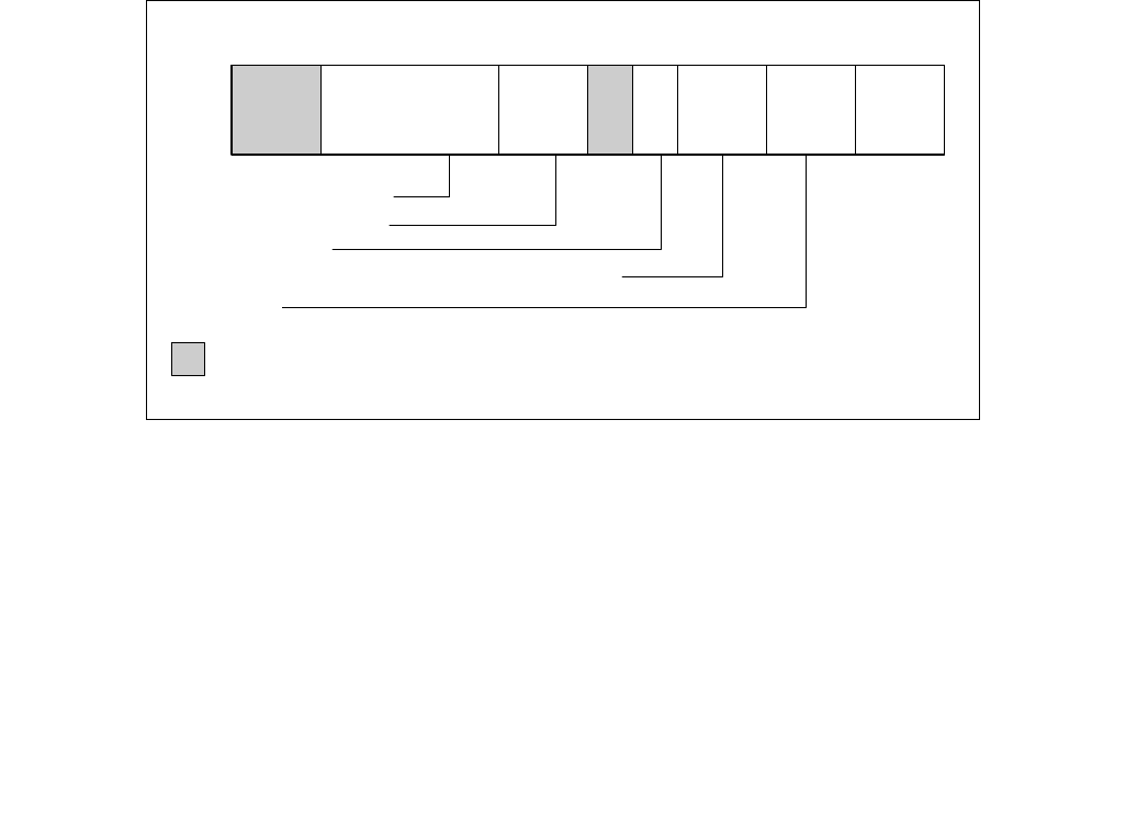
CPUID—CPU Identification
INSTRUCTION SET REFERENCE, A-L
3-204 Vol. 2A
A vendor identification string is also returned in EBX, EDX, and ECX. For Intel processors, the string is “Genuin-
eIntel” and is expressed:
EBX ← 756e6547h (* “Genu”, with G in the low eight bits of BL *)
EDX ← 49656e69h (* “ineI”, with i in the low eight bits of DL *)
ECX ← 6c65746eh (* “ntel”, with n in the low eight bits of CL *)
INPUT EAX = 80000000H: Returns CPUID’s Highest Value for Extended Processor Information
When CPUID executes with EAX set to 80000000H, the processor returns the highest value the processor recog-
nizes for returning extended processor information. The value is returned in the EAX register and is processor
specific.
IA32_BIOS_SIGN_ID Returns Microcode Update Signature
For processors that support the microcode update facility, the IA32_BIOS_SIGN_ID MSR is loaded with the update
signature whenever CPUID executes. The signature is returned in the upper DWORD. For details, see Chapter 9 in
the Intel® 64 and IA-32 Architectures Software Developer’s Manual, Volume 3A.
INPUT EAX = 01H: Returns Model, Family, Stepping Information
When CPUID executes with EAX set to 01H, version information is returned in EAX (see Figure 3-6). For example:
model, family, and processor type for the Intel Xeon processor 5100 series is as follows:
•Model — 1111B
•Family — 0101B
•Processor Type — 00B
See Table 3-9 for available processor type values. Stepping IDs are provided as needed.
Figure 3-6. Version Information Returned by CPUID in EAX
OM16525
Processor Type
034781112131415161920272831
EAX
Family (0FH for the Pentium 4 Processor Family)
Model
Extended
Family ID
Extended
Model ID
Family
ID Model Stepping
ID
Extended Family ID (0)
Extended Model ID (0)
Reserved

CPUID—CPU Identification
INSTRUCTION SET REFERENCE, A-L
Vol. 2A 3-205
NOTE
See Chapter 19 in the Intel® 64 and IA-32 Architectures Software Developer’s Manual, Volume 1,
for information on identifying earlier IA-32 processors.
The Extended Family ID needs to be examined only when the Family ID is 0FH. Integrate the fields into a display
using the following rule:
IF Family_ID ≠ 0FH
THEN DisplayFamily = Family_ID;
ELSE DisplayFamily = Extended_Family_ID + Family_ID;
(* Right justify and zero-extend 4-bit field. *)
FI;
(* Show DisplayFamily as HEX field. *)
The Extended Model ID needs to be examined only when the Family ID is 06H or 0FH. Integrate the field into a
display using the following rule:
IF (Family_ID = 06H or Family_ID = 0FH)
THEN DisplayModel = (Extended_Model_ID « 4) + Model_ID;
(* Right justify and zero-extend 4-bit field; display Model_ID as HEX field.*)
ELSE DisplayModel = Model_ID;
FI;
(* Show DisplayModel as HEX field. *)
INPUT EAX = 01H: Returns Additional Information in EBX
When CPUID executes with EAX set to 01H, additional information is returned to the EBX register:
•Brand index (low byte of EBX) — this number provides an entry into a brand string table that contains brand
strings for IA-32 processors. More information about this field is provided later in this section.
•CLFLUSH instruction cache line size (second byte of EBX) — this number indicates the size of the cache line
flushed by the CLFLUSH and CLFLUSHOPT instructions in 8-byte increments. This field was introduced in the
Pentium 4 processor.
•Local APIC ID (high byte of EBX) — this number is the 8-bit ID that is assigned to the local APIC on the
processor during power up. This field was introduced in the Pentium 4 processor.
INPUT EAX = 01H: Returns Feature Information in ECX and EDX
When CPUID executes with EAX set to 01H, feature information is returned in ECX and EDX.
•Figure 3-7 and Table 3-10 show encodings for ECX.
•Figure 3-8 and Table 3-11 show encodings for EDX.
For all feature flags, a 1 indicates that the feature is supported. Use Intel to properly interpret feature flags.
NOTE
Software must confirm that a processor feature is present using feature flags returned by CPUID
prior to using the feature. Software should not depend on future offerings retaining all features.
Table 3-9. Processor Type Field
Type Encoding
Original OEM Processor 00B
Intel OverDrive® Processor 01B
Dual processor (not applicable to Intel486 processors) 10B
Intel reserved 11B
CPUID—CPU Identification
INSTRUCTION SET REFERENCE, A-L
3-206 Vol. 2A
Figure 3-7. Feature Information Returned in the ECX Register
Table 3-10. Feature Information Returned in the ECX Register
Bit # Mnemonic Description
0 SSE3 Streaming SIMD Extensions 3 (SSE3). A value of 1 indicates the processor supports this
technology.
1PCLMULQDQPCLMULQDQ. A value of 1 indicates the processor supports the PCLMULQDQ instruction.
2DTES64 64-bit DS Area. A value of 1 indicates the processor supports DS area using 64-bit layout.
3 MONITOR MONITOR/MWAIT. A value of 1 indicates the processor supports this feature.
4 DS-CPL CPL Qualified Debug Store. A value of 1 indicates the processor supports the extensions to the
Debug Store feature to allow for branch message storage qualified by CPL.
5VMX Virtual Machine Extensions. A value of 1 indicates that the processor supports this technology.
6SMX Safer Mode Extensions. A value of 1 indicates that the processor supports this technology. See
Chapter 6, “Safer Mode Extensions Reference”.
7 EIST Enhanced Intel SpeedStep® technology. A value of 1 indicates that the processor supports this
technology.
8 TM2 Thermal Monitor 2. A value of 1 indicates whether the processor supports this technology.
9 SSSE3 A value of 1 indicates the presence of the Supplemental Streaming SIMD Extensions 3 (SSSE3). A
value of 0 indicates the instruction extensions are not present in the processor.
OM16524b
CNXT-ID — L1 Context ID
012345678910111213141516171819202122232425262728293031
ECX
TM2 — Thermal Monitor 2
EIST — Enhanced Intel SpeedStep® Technology
DS-CPL — CPL Qualified Debug Store
MONITOR — MONITOR/MWAIT
PCLMULQDQ — Carryless Multiplication
Reserved
CMPXCHG16B
SMX — Safer Mode Extensions
xTPR Update Control
SSSE3 — SSSE3 Extensions
PDCM — Perf/Debug Capability MSR
VMX — Virtual Machine Extensions
SSE4_1 — SSE4.1
OSXSAVE
SSE4_2 — SSE4.2
DCA — Direct Cache Access
x2APIC
POPCNT
XSAVE
AVX
AES
FMA — Fused Multiply Add
SSE3 — SSE3 Extensions
PCID — Process-context Identifiers
0
DTES64 — 64-bit DS Area
MOVBE
TSC-Deadline
F16C
RDRAND
SDBG

CPUID—CPU Identification
INSTRUCTION SET REFERENCE, A-L
Vol. 2A 3-207
10 CNXT-ID L1 Context ID. A value of 1 indicates the L1 data cache mode can be set to either adaptive mode
or shared mode. A value of 0 indicates this feature is not supported. See definition of the
IA32_MISC_ENABLE MSR Bit 24 (L1 Data Cache Context Mode) for details.
11 SDBG A value of 1 indicates the processor supports IA32_DEBUG_INTERFACE MSR for silicon debug.
12 FMA A value of 1 indicates the processor supports FMA extensions using YMM state.
13 CMPXCHG16B CMPXCHG16B Available. A value of 1 indicates that the feature is available. See the
“CMPXCHG8B/CMPXCHG16B—Compare and Exchange Bytes” section in this chapter for a
description.
14 xTPR Update
Control
xTPR Update Control. A value of 1 indicates that the processor supports changing
IA32_MISC_ENABLE[bit 23].
15 PDCM Perfmon and Debug Capability: A value of 1 indicates the processor supports the performance
and debug feature indication MSR IA32_PERF_CAPABILITIES.
16 Reserved Reserved
17 PCID Process-context identifiers. A value of 1 indicates that the processor supports PCIDs and that
software may set CR4.PCIDE to 1.
18 DCA A value of 1 indicates the processor supports the ability to prefetch data from a memory mapped
device.
19 SSE4.1 A value of 1 indicates that the processor supports SSE4.1.
20 SSE4.2 A value of 1 indicates that the processor supports SSE4.2.
21 x2APIC A value of 1 indicates that the processor supports x2APIC feature.
22 MOVBE A value of 1 indicates that the processor supports MOVBE instruction.
23 POPCNT A value of 1 indicates that the processor supports the POPCNT instruction.
24 TSC-Deadline A value of 1 indicates that the processor’s local APIC timer supports one-shot operation using a
TSC deadline value.
25 AESNI A value of 1 indicates that the processor supports the AESNI instruction extensions.
26 XSAVE A value of 1 indicates that the processor supports the XSAVE/XRSTOR processor extended states
feature, the XSETBV/XGETBV instructions, and XCR0.
27 OSXSAVE A value of 1 indicates that the OS has set CR4.OSXSAVE[bit 18] to enable XSETBV/XGETBV
instructions to access XCR0 and to support processor extended state management using
XSAVE/XRSTOR.
28 AVX A value of 1 indicates the processor supports the AVX instruction extensions.
29 F16C A value of 1 indicates that processor supports 16-bit floating-point conversion instructions.
30 RDRAND A value of 1 indicates that processor supports RDRAND instruction.
31 Not Used Always returns 0.
Table 3-10. Feature Information Returned in the ECX Register (Contd.)
Bit # Mnemonic Description
CPUID—CPU Identification
INSTRUCTION SET REFERENCE, A-L
3-208 Vol. 2A
Figure 3-8. Feature Information Returned in the EDX Register
OM16523
PBE–Pend. Brk. EN.
012345678910111213141516171819202122232425262728293031
EDX
TM–Therm. Monitor
HTT–Multi-threading
SS–Self Snoop
SSE2–SSE2 Extensions
SSE–SSE Extensions
FXSR–FXSAVE/FXRSTOR
MMX–MMX Technology
ACPI–Thermal Monitor and Clock Ctrl
DS–Debug Store
CLFSH–CLFLUSH instruction
PSN–Processor Serial Number
PSE-36 – Page Size Extension
PAT–Page Attribute Table
CMOV–Conditional Move/Compare Instruction
MCA–Machine Check Architecture
PGE–PTE Global Bit
MTRR–Memory Type Range Registers
SEP–SYSENTER and SYSEXIT
APIC–APIC on Chip
CX8–CMPXCHG8B Inst.
MCE–Machine Check Exception
PAE–Physical Address Extensions
MSR–RDMSR and WRMSR Support
TSC–Time Stamp Counter
PSE–Page Size Extensions
DE–Debugging Extensions
VME–Virtual-8086 Mode Enhancement
FPU–x87 FPU on Chip
Reserved

CPUID—CPU Identification
INSTRUCTION SET REFERENCE, A-L
Vol. 2A 3-209
Table 3-11. More on Feature Information Returned in the EDX Register
Bit # Mnemonic Description
0 FPU Floating Point Unit On-Chip. The processor contains an x87 FPU.
1 VME Virtual 8086 Mode Enhancements. Virtual 8086 mode enhancements, including CR4.VME for controlling the
feature, CR4.PVI for protected mode virtual interrupts, software interrupt indirection, expansion of the TSS
with the software indirection bitmap, and EFLAGS.VIF and EFLAGS.VIP flags.
2 DE Debugging Extensions. Support for I/O breakpoints, including CR4.DE for controlling the feature, and optional
trapping of accesses to DR4 and DR5.
3 PSE Page Size Extension. Large pages of size 4 MByte are supported, including CR4.PSE for controlling the
feature, the defined dirty bit in PDE (Page Directory Entries), optional reserved bit trapping in CR3, PDEs, and
PTEs.
4 TSC Time Stamp Counter. The RDTSC instruction is supported, including CR4.TSD for controlling privilege.
5 MSR Model Specific Registers RDMSR and WRMSR Instructions. The RDMSR and WRMSR instructions are
supported. Some of the MSRs are implementation dependent.
6 PAE Physical Address Extension. Physical addresses greater than 32 bits are supported: extended page table
entry formats, an extra level in the page translation tables is defined, 2-MByte pages are supported instead of
4 Mbyte pages if PAE bit is 1.
7 MCE Machine Check Exception. Exception 18 is defined for Machine Checks, including CR4.MCE for controlling the
feature. This feature does not define the model-specific implementations of machine-check error logging,
reporting, and processor shutdowns. Machine Check exception handlers may have to depend on processor
version to do model specific processing of the exception, or test for the presence of the Machine Check feature.
8 CX8 CMPXCHG8B Instruction. The compare-and-exchange 8 bytes (64 bits) instruction is supported (implicitly
locked and atomic).
9 APIC APIC On-Chip. The processor contains an Advanced Programmable Interrupt Controller (APIC), responding to
memory mapped commands in the physical address range FFFE0000H to FFFE0FFFH (by default - some
processors permit the APIC to be relocated).
10 Reserved Reserved
11 SEP SYSENTER and SYSEXIT Instructions. The SYSENTER and SYSEXIT and associated MSRs are supported.
12 MTRR Memory Type Range Registers. MTRRs are supported. The MTRRcap MSR contains feature bits that describe
what memory types are supported, how many variable MTRRs are supported, and whether fixed MTRRs are
supported.
13 PGE Page Global Bit. The global bit is supported in paging-structure entries that map a page, indicating TLB entries
that are common to different processes and need not be flushed. The CR4.PGE bit controls this feature.
14 MCA Machine Check Architecture. A value of 1 indicates the Machine Check Architecture of reporting machine
errors is supported. The MCG_CAP MSR contains feature bits describing how many banks of error reporting
MSRs are supported.
15 CMOV Conditional Move Instructions. The conditional move instruction CMOV is supported. In addition, if x87 FPU is
present as indicated by the CPUID.FPU feature bit, then the FCOMI and FCMOV instructions are supported
16 PAT Page Attribute Table. Page Attribute Table is supported. This feature augments the Memory Type Range
Registers (MTRRs), allowing an operating system to specify attributes of memory accessed through a linear
address on a 4KB granularity.
17 PSE-36 36-Bit Page Size Extension. 4-MByte pages addressing physical memory beyond 4 GBytes are supported with
32-bit paging. This feature indicates that upper bits of the physical address of a 4-MByte page are encoded in
bits 20:13 of the page-directory entry. Such physical addresses are limited by MAXPHYADDR and may be up to
40 bits in size.
18 PSN Processor Serial Number. The processor supports the 96-bit processor identification number feature and the
feature is enabled.
19 CLFSH CLFLUSH Instruction. CLFLUSH Instruction is supported.
20 Reserved Reserved

CPUID—CPU Identification
INSTRUCTION SET REFERENCE, A-L
3-210 Vol. 2A
INPUT EAX = 02H: TLB/Cache/Prefetch Information Returned in EAX, EBX, ECX, EDX
When CPUID executes with EAX set to 02H, the processor returns information about the processor’s internal TLBs,
cache and prefetch hardware in the EAX, EBX, ECX, and EDX registers. The information is reported in encoded form
and fall into the following categories:
•The least-significant byte in register EAX (register AL) will always return 01H. Software should ignore this value
and not interpret it as an informational descriptor.
•The most significant bit (bit 31) of each register indicates whether the register contains valid information (set
to 0) or is reserved (set to 1).
•If a register contains valid information, the information is contained in 1 byte descriptors. There are four types
of encoding values for the byte descriptor, the encoding type is noted in the second column of Table 3-12. Table
3-12 lists the encoding of these descriptors. Note that the order of descriptors in the EAX, EBX, ECX, and EDX
registers is not defined; that is, specific bytes are not designated to contain descriptors for specific cache,
prefetch, or TLB types. The descriptors may appear in any order. Note also a processor may report a general
descriptor type (FFH) and not report any byte descriptor of “cache type” via CPUID leaf 2.
21 DS Debug Store. The processor supports the ability to write debug information into a memory resident buffer.
This feature is used by the branch trace store (BTS) and precise event-based sampling (PEBS) facilities (see
Chapter 23, “Introduction to Virtual-Machine Extensions,” in the Intel® 64 and IA-32 Architectures Software
Developer’s Manual, Volume 3C).
22 ACPI Thermal Monitor and Software Controlled Clock Facilities. The processor implements internal MSRs that
allow processor temperature to be monitored and processor performance to be modulated in predefined duty
cycles under software control.
23 MMX Intel MMX Technology. The processor supports the Intel MMX technology.
24 FXSR FXSAVE and FXRSTOR Instructions. The FXSAVE and FXRSTOR instructions are supported for fast save and
restore of the floating point context. Presence of this bit also indicates that CR4.OSFXSR is available for an
operating system to indicate that it supports the FXSAVE and FXRSTOR instructions.
25 SSE SSE. The processor supports the SSE extensions.
26 SSE2 SSE2. The processor supports the SSE2 extensions.
27 SS Self Snoop. The processor supports the management of conflicting memory types by performing a snoop of its
own cache structure for transactions issued to the bus.
28 HTT Max APIC IDs reserved field is Valid. A value of 0 for HTT indicates there is only a single logical processor in
the package and software should assume only a single APIC ID is reserved. A value of 1 for HTT indicates the
value in CPUID.1.EBX[23:16] (the Maximum number of addressable IDs for logical processors in this package) is
valid for the package.
29 TM Thermal Monitor. The processor implements the thermal monitor automatic thermal control circuitry (TCC).
30 Reserved Reserved
31 PBE Pending Break Enable. The processor supports the use of the FERR#/PBE# pin when the processor is in the
stop-clock state (STPCLK# is asserted) to signal the processor that an interrupt is pending and that the
processor should return to normal operation to handle the interrupt. Bit 10 (PBE enable) in the
IA32_MISC_ENABLE MSR enables this capability.
Table 3-11. More on Feature Information Returned in the EDX Register (Contd.)
Bit # Mnemonic Description

CPUID—CPU Identification
INSTRUCTION SET REFERENCE, A-L
Vol. 2A 3-211
Table 3-12. Encoding of CPUID Leaf 2 Descriptors
Value Type Description
00H General Null descriptor, this byte contains no information
01H TLB Instruction TLB: 4 KByte pages, 4-way set associative, 32 entries
02H TLB Instruction TLB: 4 MByte pages, fully associative, 2 entries
03H TLB Data TLB: 4 KByte pages, 4-way set associative, 64 entries
04H TLB Data TLB: 4 MByte pages, 4-way set associative, 8 entries
05H TLB Data TLB1: 4 MByte pages, 4-way set associative, 32 entries
06H Cache 1st-level instruction cache: 8 KBytes, 4-way set associative, 32 byte line size
08H Cache 1st-level instruction cache: 16 KBytes, 4-way set associative, 32 byte line size
09H Cache 1st-level instruction cache: 32KBytes, 4-way set associative, 64 byte line size
0AH Cache 1st-level data cache: 8 KBytes, 2-way set associative, 32 byte line size
0BH TLB Instruction TLB: 4 MByte pages, 4-way set associative, 4 entries
0CH Cache 1st-level data cache: 16 KBytes, 4-way set associative, 32 byte line size
0DH Cache 1st-level data cache: 16 KBytes, 4-way set associative, 64 byte line size
0EH Cache 1st-level data cache: 24 KBytes, 6-way set associative, 64 byte line size
1DH Cache 2nd-level cache: 128 KBytes, 2-way set associative, 64 byte line size
21H Cache 2nd-level cache: 256 KBytes, 8-way set associative, 64 byte line size
22H Cache 3rd-level cache: 512 KBytes, 4-way set associative, 64 byte line size, 2 lines per sector
23H Cache 3rd-level cache: 1 MBytes, 8-way set associative, 64 byte line size, 2 lines per sector
24H Cache 2nd-level cache: 1 MBytes, 16-way set associative, 64 byte line size
25H Cache 3rd-level cache: 2 MBytes, 8-way set associative, 64 byte line size, 2 lines per sector
29H Cache 3rd-level cache: 4 MBytes, 8-way set associative, 64 byte line size, 2 lines per sector
2CH Cache 1st-level data cache: 32 KBytes, 8-way set associative, 64 byte line size
30H Cache 1st-level instruction cache: 32 KBytes, 8-way set associative, 64 byte line size
40H Cache No 2nd-level cache or, if processor contains a valid 2nd-level cache, no 3rd-level cache
41H Cache 2nd-level cache: 128 KBytes, 4-way set associative, 32 byte line size
42H Cache 2nd-level cache: 256 KBytes, 4-way set associative, 32 byte line size
43H Cache 2nd-level cache: 512 KBytes, 4-way set associative, 32 byte line size
44H Cache 2nd-level cache: 1 MByte, 4-way set associative, 32 byte line size
45H Cache 2nd-level cache: 2 MByte, 4-way set associative, 32 byte line size
46H Cache 3rd-level cache: 4 MByte, 4-way set associative, 64 byte line size
47H Cache 3rd-level cache: 8 MByte, 8-way set associative, 64 byte line size
48H Cache 2nd-level cache: 3MByte, 12-way set associative, 64 byte line size
49H Cache 3rd-level cache: 4MB, 16-way set associative, 64-byte line size (Intel Xeon processor MP, Family 0FH, Model
06H);
2nd-level cache: 4 MByte, 16-way set associative, 64 byte line size
4AH Cache 3rd-level cache: 6MByte, 12-way set associative, 64 byte line size
4BH Cache 3rd-level cache: 8MByte, 16-way set associative, 64 byte line size
4CH Cache 3rd-level cache: 12MByte, 12-way set associative, 64 byte line size
4DH Cache 3rd-level cache: 16MByte, 16-way set associative, 64 byte line size
4EH Cache 2nd-level cache: 6MByte, 24-way set associative, 64 byte line size
4FH TLB Instruction TLB: 4 KByte pages, 32 entries

CPUID—CPU Identification
INSTRUCTION SET REFERENCE, A-L
3-212 Vol. 2A
50H TLB Instruction TLB: 4 KByte and 2-MByte or 4-MByte pages, 64 entries
51H TLB Instruction TLB: 4 KByte and 2-MByte or 4-MByte pages, 128 entries
52H TLB Instruction TLB: 4 KByte and 2-MByte or 4-MByte pages, 256 entries
55H TLB Instruction TLB: 2-MByte or 4-MByte pages, fully associative, 7 entries
56H TLB Data TLB0: 4 MByte pages, 4-way set associative, 16 entries
57H TLB Data TLB0: 4 KByte pages, 4-way associative, 16 entries
59H TLB Data TLB0: 4 KByte pages, fully associative, 16 entries
5AH TLB Data TLB0: 2 MByte or 4 MByte pages, 4-way set associative, 32 entries
5BH TLB Data TLB: 4 KByte and 4 MByte pages, 64 entries
5CH TLB Data TLB: 4 KByte and 4 MByte pages,128 entries
5DH TLB Data TLB: 4 KByte and 4 MByte pages,256 entries
60H Cache 1st-level data cache: 16 KByte, 8-way set associative, 64 byte line size
61H TLB Instruction TLB: 4 KByte pages, fully associative, 48 entries
63H TLB Data TLB: 2 MByte or 4 MByte pages, 4-way set associative, 32 entries and a separate array with 1 GByte
pages, 4-way set associative, 4 entries
64H TLB Data TLB: 4 KByte pages, 4-way set associative, 512 entries
66H Cache 1st-level data cache: 8 KByte, 4-way set associative, 64 byte line size
67H Cache 1st-level data cache: 16 KByte, 4-way set associative, 64 byte line size
68H Cache 1st-level data cache: 32 KByte, 4-way set associative, 64 byte line size
6AH Cache uTLB: 4 KByte pages, 8-way set associative, 64 entries
6BH Cache DTLB: 4 KByte pages, 8-way set associative, 256 entries
6CH Cache DTLB: 2M/4M pages, 8-way set associative, 128 entries
6DH Cache DTLB: 1 GByte pages, fully associative, 16 entries
70H Cache Trace cache: 12 K-μop, 8-way set associative
71H Cache Trace cache: 16 K-μop, 8-way set associative
72H Cache Trace cache: 32 K-μop, 8-way set associative
76H TLB Instruction TLB: 2M/4M pages, fully associative, 8 entries
78H Cache 2nd-level cache: 1 MByte, 4-way set associative, 64byte line size
79H Cache 2nd-level cache: 128 KByte, 8-way set associative, 64 byte line size, 2 lines per sector
7AH Cache 2nd-level cache: 256 KByte, 8-way set associative, 64 byte line size, 2 lines per sector
7BH Cache 2nd-level cache: 512 KByte, 8-way set associative, 64 byte line size, 2 lines per sector
7CH Cache 2nd-level cache: 1 MByte, 8-way set associative, 64 byte line size, 2 lines per sector
7DH Cache 2nd-level cache: 2 MByte, 8-way set associative, 64byte line size
7FH Cache 2nd-level cache: 512 KByte, 2-way set associative, 64-byte line size
80H Cache 2nd-level cache: 512 KByte, 8-way set associative, 64-byte line size
82H Cache 2nd-level cache: 256 KByte, 8-way set associative, 32 byte line size
83H Cache 2nd-level cache: 512 KByte, 8-way set associative, 32 byte line size
84H Cache 2nd-level cache: 1 MByte, 8-way set associative, 32 byte line size
85H Cache 2nd-level cache: 2 MByte, 8-way set associative, 32 byte line size
86H Cache 2nd-level cache: 512 KByte, 4-way set associative, 64 byte line size
87H Cache 2nd-level cache: 1 MByte, 8-way set associative, 64 byte line size
Table 3-12. Encoding of CPUID Leaf 2 Descriptors (Contd.)
Value Type Description

CPUID—CPU Identification
INSTRUCTION SET REFERENCE, A-L
Vol. 2A 3-213
Example 3-1. Example of Cache and TLB Interpretation
The first member of the family of Pentium 4 processors returns the following information about caches and TLBs
when the CPUID executes with an input value of 2:
EAX 66 5B 50 01H
EBX 0H
ECX 0H
EDX 00 7A 70 00H
A0H DTLB DTLB: 4k pages, fully associative, 32 entries
B0H TLB Instruction TLB: 4 KByte pages, 4-way set associative, 128 entries
B1H TLB Instruction TLB: 2M pages, 4-way, 8 entries or 4M pages, 4-way, 4 entries
B2H TLB Instruction TLB: 4KByte pages, 4-way set associative, 64 entries
B3H TLB Data TLB: 4 KByte pages, 4-way set associative, 128 entries
B4H TLB Data TLB1: 4 KByte pages, 4-way associative, 256 entries
B5H TLB Instruction TLB: 4KByte pages, 8-way set associative, 64 entries
B6H TLB Instruction TLB: 4KByte pages, 8-way set associative, 128 entries
BAH TLB Data TLB1: 4 KByte pages, 4-way associative, 64 entries
C0H TLB Data TLB: 4 KByte and 4 MByte pages, 4-way associative, 8 entries
C1H STLB Shared 2nd-Level TLB: 4 KByte/2MByte pages, 8-way associative, 1024 entries
C2H DTLB DTLB: 4 KByte/2 MByte pages, 4-way associative, 16 entries
C3H STLB Shared 2nd-Level TLB: 4 KByte /2 MByte pages, 6-way associative, 1536 entries. Also 1GBbyte pages, 4-way,
16 entries.
C4H DTLB DTLB: 2M/4M Byte pages, 4-way associative, 32 entries
CAH STLB Shared 2nd-Level TLB: 4 KByte pages, 4-way associative, 512 entries
D0H Cache 3rd-level cache: 512 KByte, 4-way set associative, 64 byte line size
D1H Cache 3rd-level cache: 1 MByte, 4-way set associative, 64 byte line size
D2H Cache 3rd-level cache: 2 MByte, 4-way set associative, 64 byte line size
D6H Cache 3rd-level cache: 1 MByte, 8-way set associative, 64 byte line size
D7H Cache 3rd-level cache: 2 MByte, 8-way set associative, 64 byte line size
D8H Cache 3rd-level cache: 4 MByte, 8-way set associative, 64 byte line size
DCH Cache 3rd-level cache: 1.5 MByte, 12-way set associative, 64 byte line size
DDH Cache 3rd-level cache: 3 MByte, 12-way set associative, 64 byte line size
DEH Cache 3rd-level cache: 6 MByte, 12-way set associative, 64 byte line size
E2H Cache 3rd-level cache: 2 MByte, 16-way set associative, 64 byte line size
E3H Cache 3rd-level cache: 4 MByte, 16-way set associative, 64 byte line size
E4H Cache 3rd-level cache: 8 MByte, 16-way set associative, 64 byte line size
EAH Cache 3rd-level cache: 12MByte, 24-way set associative, 64 byte line size
EBH Cache 3rd-level cache: 18MByte, 24-way set associative, 64 byte line size
ECH Cache 3rd-level cache: 24MByte, 24-way set associative, 64 byte line size
F0H Prefetch 64-Byte prefetching
F1H Prefetch 128-Byte prefetching
FFH General CPUID leaf 2 does not report cache descriptor information, use CPUID leaf 4 to query cache parameters
Table 3-12. Encoding of CPUID Leaf 2 Descriptors (Contd.)
Value Type Description

CPUID—CPU Identification
INSTRUCTION SET REFERENCE, A-L
3-214 Vol. 2A
Which means:
•The least-significant byte (byte 0) of register EAX is set to 01H. This value should be ignored.
•The most-significant bit of all four registers (EAX, EBX, ECX, and EDX) is set to 0, indicating that each register
contains valid 1-byte descriptors.
•Bytes 1, 2, and 3 of register EAX indicate that the processor has:
— 50H - a 64-entry instruction TLB, for mapping 4-KByte and 2-MByte or 4-MByte pages.
— 5BH - a 64-entry data TLB, for mapping 4-KByte and 4-MByte pages.
— 66H - an 8-KByte 1st level data cache, 4-way set associative, with a 64-Byte cache line size.
•The descriptors in registers EBX and ECX are valid, but contain NULL descriptors.
•Bytes 0, 1, 2, and 3 of register EDX indicate that the processor has:
— 00H - NULL descriptor.
— 70H - Trace cache: 12 K-μop, 8-way set associative.
— 7AH - a 256-KByte 2nd level cache, 8-way set associative, with a sectored, 64-byte cache line size.
— 00H - NULL descriptor.
INPUT EAX = 04H: Returns Deterministic Cache Parameters for Each Level
When CPUID executes with EAX set to 04H and ECX contains an index value, the processor returns encoded data
that describe a set of deterministic cache parameters (for the cache level associated with the input in ECX). Valid
index values start from 0.
Software can enumerate the deterministic cache parameters for each level of the cache hierarchy starting with an
index value of 0, until the parameters report the value associated with the cache type field is 0. The architecturally
defined fields reported by deterministic cache parameters are documented in Table 3-8.
This Cache Size in Bytes
= (Ways + 1) * (Partitions + 1) * (Line_Size + 1) * (Sets + 1)
= (EBX[31:22] + 1) * (EBX[21:12] + 1) * (EBX[11:0] + 1) * (ECX + 1)
The CPUID leaf 04H also reports data that can be used to derive the topology of processor cores in a physical
package. This information is constant for all valid index values. Software can query the raw data reported by
executing CPUID with EAX=04H and ECX=0 and use it as part of the topology enumeration algorithm described in
Chapter 8, “Multiple-Processor Management,” in the Intel® 64 and IA-32 Architectures Software Developer’s
Manual, Volume 3A.
INPUT EAX = 05H: Returns MONITOR and MWAIT Features
When CPUID executes with EAX set to 05H, the processor returns information about features available to
MONITOR/MWAIT instructions. The MONITOR instruction is used for address-range monitoring in conjunction with
MWAIT instruction. The MWAIT instruction optionally provides additional extensions for advanced power manage-
ment. See Table 3-8.
INPUT EAX = 06H: Returns Thermal and Power Management Features
When CPUID executes with EAX set to 06H, the processor returns information about thermal and power manage-
ment features. See Table 3-8.
INPUT EAX = 07H: Returns Structured Extended Feature Enumeration Information
When CPUID executes with EAX set to 07H and ECX = 0, the processor returns information about the maximum
input value for sub-leaves that contain extended feature flags. See Table 3-8.
When CPUID executes with EAX set to 07H and the input value of ECX is invalid (see leaf 07H entry in Table 3-8),
the processor returns 0 in EAX/EBX/ECX/EDX. In subleaf 0, EAX returns the maximum input value of the highest
leaf 7 sub-leaf, and EBX, ECX & EDX contain information of extended feature flags.

CPUID—CPU Identification
INSTRUCTION SET REFERENCE, A-L
Vol. 2A 3-215
INPUT EAX = 09H: Returns Direct Cache Access Information
When CPUID executes with EAX set to 09H, the processor returns information about Direct Cache Access capabili-
ties. See Table 3-8.
INPUT EAX = 0AH: Returns Architectural Performance Monitoring Features
When CPUID executes with EAX set to 0AH, the processor returns information about support for architectural
performance monitoring capabilities. Architectural performance monitoring is supported if the version ID (see
Table 3-8) is greater than Pn 0. See Table 3-8.
For each version of architectural performance monitoring capability, software must enumerate this leaf to discover
the programming facilities and the architectural performance events available in the processor. The details are
described in Chapter 23, “Introduction to Virtual-Machine Extensions,” in the Intel® 64 and IA-32 Architectures
Software Developer’s Manual, Volume 3C.
INPUT EAX = 0BH: Returns Extended Topology Information
When CPUID executes with EAX set to 0BH, the processor returns information about extended topology enumera-
tion data. Software must detect the presence of CPUID leaf 0BH by verifying (a) the highest leaf index supported
by CPUID is >= 0BH, and (b) CPUID.0BH:EBX[15:0] reports a non-zero value. See Table 3-8.
INPUT EAX = 0DH: Returns Processor Extended States Enumeration Information
When CPUID executes with EAX set to 0DH and ECX = 0, the processor returns information about the bit-vector
representation of all processor state extensions that are supported in the processor and storage size requirements
of the XSAVE/XRSTOR area. See Table 3-8.
When CPUID executes with EAX set to 0DH and ECX = n (n > 1, and is a valid sub-leaf index), the processor returns
information about the size and offset of each processor extended state save area within the XSAVE/XRSTOR area.
See Table 3-8. Software can use the forward-extendable technique depicted below to query the valid sub-leaves
and obtain size and offset information for each processor extended state save area:
For i = 2 to 62 // sub-leaf 1 is reserved
IF (CPUID.(EAX=0DH, ECX=0):VECTOR[i] = 1 ) // VECTOR is the 64-bit value of EDX:EAX
Execute CPUID.(EAX=0DH, ECX = i) to examine size and offset for sub-leaf i;
FI;
INPUT EAX = 0FH: Returns Intel Resource Director Technology (Intel RDT) Monitoring Enumeration Information
When CPUID executes with EAX set to 0FH and ECX = 0, the processor returns information about the bit-vector
representation of QoS monitoring resource types that are supported in the processor and maximum range of RMID
values the processor can use to monitor of any supported resource types. Each bit, starting from bit 1, corresponds
to a specific resource type if the bit is set. The bit position corresponds to the sub-leaf index (or ResID) that soft-
ware must use to query QoS monitoring capability available for that type. See Table 3-8.
When CPUID executes with EAX set to 0FH and ECX = n (n >= 1, and is a valid ResID), the processor returns infor-
mation software can use to program IA32_PQR_ASSOC, IA32_QM_EVTSEL MSRs before reading QoS data from the
IA32_QM_CTR MSR.
INPUT EAX = 10H: Returns Intel Resource Director Technology (Intel RDT) Allocation Enumeration Information
When CPUID executes with EAX set to 10H and ECX = 0, the processor returns information about the bit-vector
representation of QoS Enforcement resource types that are supported in the processor. Each bit, starting from bit
1, corresponds to a specific resource type if the bit is set. The bit position corresponds to the sub-leaf index (or
ResID) that software must use to query QoS enforcement capability available for that type. See Table 3-8.
When CPUID executes with EAX set to 10H and ECX = n (n >= 1, and is a valid ResID), the processor returns infor-
mation about available classes of service and range of QoS mask MSRs that software can use to configure each
class of services using capability bit masks in the QoS Mask registers, IA32_resourceType_Mask_n.

CPUID—CPU Identification
INSTRUCTION SET REFERENCE, A-L
3-216 Vol. 2A
INPUT EAX = 12H: Returns Intel SGX Enumeration Information
When CPUID executes with EAX set to 12H and ECX = 0H, the processor returns information about Intel SGX capa-
bilities. See Table 3-8.
When CPUID executes with EAX set to 12H and ECX = 1H, the processor returns information about Intel SGX attri-
butes. See Table 3-8.
When CPUID executes with EAX set to 12H and ECX = n (n > 1), the processor returns information about Intel SGX
Enclave Page Cache. See Table 3-8.
INPUT EAX = 14H: Returns Intel Processor Trace Enumeration Information
When CPUID executes with EAX set to 14H and ECX = 0H, the processor returns information about Intel Processor
Trace extensions. See Table 3-8.
When CPUID executes with EAX set to 14H and ECX = n (n > 0 and less than the number of non-zero bits in
CPUID.(EAX=14H, ECX= 0H).EAX), the processor returns information about packet generation in Intel Processor
Trace. See Table 3-8.
INPUT EAX = 15H: Returns Time Stamp Counter and Nominal Core Crystal Clock Information
When CPUID executes with EAX set to 15H and ECX = 0H, the processor returns information about Time Stamp
Counter and Core Crystal Clock. See Table 3-8.
INPUT EAX = 16H: Returns Processor Frequency Information
When CPUID executes with EAX set to 16H, the processor returns information about Processor Frequency Informa-
tion. See Table 3-8.
INPUT EAX = 17H: Returns System-On-Chip Information
When CPUID executes with EAX set to 17H, the processor returns information about the System-On-Chip Vendor
Attribute Enumeration. See Table 3-8.
METHODS FOR RETURNING BRANDING INFORMATION
Use the following techniques to access branding information:
1. Processor brand string method.
2. Processor brand index; this method uses a software supplied brand string table.
These two methods are discussed in the following sections. For methods that are available in early processors, see
Section: “Identification of Earlier IA-32 Processors” in Chapter 19 of the Intel® 64 and IA-32 Architectures Soft-
ware Developer’s Manual, Volume 1.
The Processor Brand String Method
Figure 3-9 describes the algorithm used for detection of the brand string. Processor brand identification software
should execute this algorithm on all Intel 64 and IA-32 processors.
This method (introduced with Pentium 4 processors) returns an ASCII brand identification string and the Processor
Base frequency of the processor to the EAX, EBX, ECX, and EDX registers.

CPUID—CPU Identification
INSTRUCTION SET REFERENCE, A-L
Vol. 2A 3-217
How Brand Strings Work
To use the brand string method, execute CPUID with EAX input of 8000002H through 80000004H. For each input
value, CPUID returns 16 ASCII characters using EAX, EBX, ECX, and EDX. The returned string will be NULL-termi-
nated.
Figure 3-9. Determination of Support for the Processor Brand String
OM15194
IF (EAX & 0x80000000)
CPUID
IF (EAX Return Value
≥0x80000004)
CPUID
Function
Supported
True ≥
Extended
EAX Return Value =
Max. Extended CPUID
Function Index
Input: EAX=
0x80000000
Processor Brand
String Not
Supported
False
Processor Brand
String Supported
True
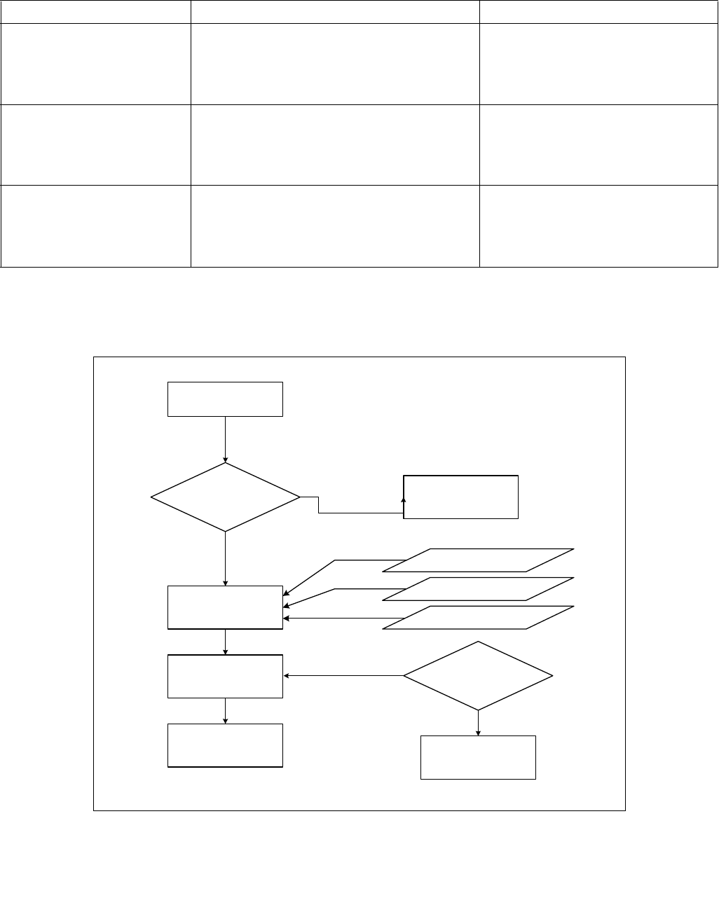
CPUID—CPU Identification
INSTRUCTION SET REFERENCE, A-L
3-218 Vol. 2A
Table 3-13 shows the brand string that is returned by the first processor in the Pentium 4 processor family.
Extracting the Processor Frequency from Brand Strings
Figure 3-10 provides an algorithm which software can use to extract the Processor Base frequency from the
processor brand string.
Table 3-13. Processor Brand String Returned with Pentium 4 Processor
EAX Input Value Return Values ASCII Equivalent
80000002H EAX = 20202020H
EBX = 20202020H
ECX = 20202020H
EDX = 6E492020H
“ ”
“”
“”
“nI ”
80000003H EAX = 286C6574H
EBX = 50202952H
ECX = 69746E65H
EDX = 52286D75H
“(let”
“P )R”
“itne”
“R(mu”
80000004H EAX = 20342029H
EBX = 20555043H
ECX = 30303531H
EDX = 007A484DH
“ 4 )”
“ UPC”
“0051”
“\0zHM”
Figure 3-10. Algorithm for Extracting Processor Frequency
OM15195
IF Substring Matched
"zHM", or
"zHG", or
"zHT"
Determine "Freq"
and "Multiplier" True
Determine "Multiplier"
Scan "Brand String" in
Reverse Byte Order
Report Error
False
Scan Digits
Until Blank
Match
Substring
Determine "Freq" Reverse Digits
To Decimal Value
Processor Base
Frequency =
"Freq" x "Multiplier" "Freq" = X.YZ if
Digits = "ZY.X"
In Reverse Order
If "zHM"
If "zHG"
If "zHT" Multiplier = 1 x 10¹²
Multiplier = 1 x 10⁹
Multiplier = 1 x 10⁶

CPUID—CPU Identification
INSTRUCTION SET REFERENCE, A-L
Vol. 2A 3-219
The Processor Brand Index Method
The brand index method (introduced with Pentium® III Xeon® processors) provides an entry point into a brand
identification table that is maintained in memory by system software and is accessible from system- and user-level
code. In this table, each brand index is associate with an ASCII brand identification string that identifies the official
Intel family and model number of a processor.
When CPUID executes with EAX set to 1, the processor returns a brand index to the low byte in EBX. Software can
then use this index to locate the brand identification string for the processor in the brand identification table. The
first entry (brand index 0) in this table is reserved, allowing for backward compatibility with processors that do not
support the brand identification feature. Starting with processor signature family ID = 0FH, model = 03H, brand
index method is no longer supported. Use brand string method instead.
Table 3-14 shows brand indices that have identification strings associated with them.
IA-32 Architecture Compatibility
CPUID is not supported in early models of the Intel486 processor or in any IA-32 processor earlier than the
Intel486 processor.
Table 3-14. Mapping of Brand Indices; and Intel 64 and IA-32 Processor Brand Strings
Brand Index Brand String
00H This processor does not support the brand identification feature
01H Intel(R) Celeron(R) processor1
02H Intel(R) Pentium(R) III processor1
03H Intel(R) Pentium(R) III Xeon(R) processor; If processor signature = 000006B1h, then Intel(R) Celeron(R)
processor
04H Intel(R) Pentium(R) III processor
06H Mobile Intel(R) Pentium(R) III processor-M
07H Mobile Intel(R) Celeron(R) processor1
08H Intel(R) Pentium(R) 4 processor
09H Intel(R) Pentium(R) 4 processor
0AH Intel(R) Celeron(R) processor1
0BH Intel(R) Xeon(R) processor; If processor signature = 00000F13h, then Intel(R) Xeon(R) processor MP
0CH Intel(R) Xeon(R) processor MP
0EH Mobile Intel(R) Pentium(R) 4 processor-M; If processor signature = 00000F13h, then Intel(R) Xeon(R) processor
0FH Mobile Intel(R) Celeron(R) processor1
11H Mobile Genuine Intel(R) processor
12H Intel(R) Celeron(R) M processor
13H Mobile Intel(R) Celeron(R) processor1
14H Intel(R) Celeron(R) processor
15H Mobile Genuine Intel(R) processor
16H Intel(R) Pentium(R) M processor
17H Mobile Intel(R) Celeron(R) processor1
18H – 0FFH RESERVED
NOTES:
1. Indicates versions of these processors that were introduced after the Pentium III

CPUID—CPU Identification
INSTRUCTION SET REFERENCE, A-L
3-220 Vol. 2A
Operation
IA32_BIOS_SIGN_ID MSR ← Update with installed microcode revision number;
CASE (EAX) OF
EAX = 0:
EAX ← Highest basic function input value understood by CPUID;
EBX ← Vendor identification string;
EDX ← Vendor identification string;
ECX ← Vendor identification string;
BREAK;
EAX = 1H:
EAX[3:0] ← Stepping ID;
EAX[7:4] ← Model;
EAX[11:8] ← Family;
EAX[13:12] ← Processor type;
EAX[15:14] ← Reserved;
EAX[19:16] ← Extended Model;
EAX[27:20] ← Extended Family;
EAX[31:28] ← Reserved;
EBX[7:0] ← Brand Index; (* Reserved if the value is zero. *)
EBX[15:8] ← CLFLUSH Line Size;
EBX[16:23] ← Reserved; (* Number of threads enabled = 2 if MT enable fuse set. *)
EBX[24:31] ← Initial APIC ID;
ECX ← Feature flags; (* See Figure 3-7. *)
EDX ← Feature flags; (* See Figure 3-8. *)
BREAK;
EAX = 2H:
EAX ← Cache and TLB information;
EBX
← Cache and TLB information;
ECX
← Cache and TLB information;
EDX ← Cache and TLB information;
BREAK;
EAX = 3H:
EAX ← Reserved;
EBX
← Reserved;
ECX
← ProcessorSerialNumber[31:0];
(* Pentium III processors only, otherwise reserved. *)
EDX ← ProcessorSerialNumber[63:32];
(* Pentium III processors only, otherwise reserved. *
BREAK
EAX = 4H:
EAX ← Deterministic Cache Parameters Leaf; (* See Table 3-8. *)
EBX ← Deterministic Cache Parameters Leaf;
ECX
← Deterministic Cache Parameters Leaf;
EDX ← Deterministic Cache Parameters Leaf;
BREAK;
EAX = 5H:
EAX ← MONITOR/MWAIT Leaf; (* See Table 3-8. *)
EBX
← MONITOR/MWAIT Leaf;
ECX
← MONITOR/MWAIT Leaf;
EDX ← MONITOR/MWAIT Leaf;
BREAK;

CPUID—CPU Identification
INSTRUCTION SET REFERENCE, A-L
Vol. 2A 3-221
EAX = 6H:
EAX ← Thermal and Power Management Leaf; (* See Table 3-8. *)
EBX
← Thermal and Power Management Leaf;
ECX
← Thermal and Power Management Leaf;
EDX ← Thermal and Power Management Leaf;
BREAK;
EAX = 7H:
EAX ← Structured Extended Feature Flags Enumeration Leaf; (* See Table 3-8. *)
EBX ← Structured Extended Feature Flags Enumeration Leaf;
ECX
← Structured Extended Feature Flags Enumeration Leaf;
EDX ← Structured Extended Feature Flags Enumeration Leaf;
BREAK;
EAX = 8H:
EAX ← Reserved = 0;
EBX
← Reserved = 0;
ECX
← Reserved = 0;
EDX ← Reserved = 0;
BREAK;
EAX = 9H:
EAX ← Direct Cache Access Information Leaf; (* See Table 3-8. *)
EBX
← Direct Cache Access Information Leaf;
ECX
← Direct Cache Access Information Leaf;
EDX ← Direct Cache Access Information Leaf;
BREAK;
EAX = AH:
EAX ← Architectural Performance Monitoring Leaf; (* See Table 3-8. *)
EBX
← Architectural Performance Monitoring Leaf;
ECX
← Architectural Performance Monitoring Leaf;
EDX ← Architectural Performance Monitoring Leaf;
BREAK
EAX = BH:
EAX ← Extended Topology Enumeration Leaf; (* See Table 3-8. *)
EBX ← Extended Topology Enumeration Leaf;
ECX
← Extended Topology Enumeration Leaf;
EDX ← Extended Topology Enumeration Leaf;
BREAK;
EAX = CH:
EAX ← Reserved = 0;
EBX
← Reserved = 0;
ECX
← Reserved = 0;
EDX ← Reserved = 0;
BREAK;
EAX = DH:
EAX ← Processor Extended State Enumeration Leaf; (* See Table 3-8. *)
EBX
← Processor Extended State Enumeration Leaf;
ECX
← Processor Extended State Enumeration Leaf;
EDX ← Processor Extended State Enumeration Leaf;
BREAK;
EAX = EH:
EAX ← Reserved = 0;
EBX
← Reserved = 0;
ECX
← Reserved = 0;
EDX ← Reserved = 0;
BREAK;

CPUID—CPU Identification
INSTRUCTION SET REFERENCE, A-L
3-222 Vol. 2A
EAX = FH:
EAX ← Intel Resource Director Technology Monitoring Enumeration Leaf; (* See Table 3-8. *)
EBX
← Intel Resource Director Technology Monitoring Enumeration Leaf;
ECX
← Intel Resource Director Technology Monitoring Enumeration Leaf;
EDX ← Intel Resource Director Technology Monitoring Enumeration Leaf;
BREAK;
EAX = 10H:
EAX ← Intel Resource Director Technology Allocation Enumeration Leaf; (* See Table 3-8. *)
EBX
← Intel Resource Director Technology Allocation Enumeration Leaf;
ECX
← Intel Resource Director Technology Allocation Enumeration Leaf;
EDX ← Intel Resource Director Technology Allocation Enumeration Leaf;
BREAK;
EAX = 12H:
EAX ← Intel SGX Enumeration Leaf; (* See Table 3-8. *)
EBX
← Intel SGX Enumeration Leaf;
ECX
← Intel SGX Enumeration Leaf;
EDX ← Intel SGX Enumeration Leaf;
BREAK;
EAX = 14H:
EAX ← Intel Processor Trace Enumeration Leaf; (* See Table 3-8. *)
EBX
← Intel Processor Trace Enumeration Leaf;
ECX
← Intel Processor Trace Enumeration Leaf;
EDX ← Intel Processor Trace Enumeration Leaf;
BREAK;
EAX = 15H:
EAX ← Time Stamp Counter and Nominal Core Crystal Clock Information Leaf; (* See Table 3-8. *)
EBX
← Time Stamp Counter and Nominal Core Crystal Clock Information Leaf;
ECX
← Time Stamp Counter and Nominal Core Crystal Clock Information Leaf;
EDX ← Time Stamp Counter and Nominal Core Crystal Clock Information Leaf;
BREAK;
EAX = 16H:
EAX ← Processor Frequency Information Enumeration Leaf; (* See Table 3-8. *)
EBX
← Processor Frequency Information Enumeration Leaf;
ECX
← Processor Frequency Information Enumeration Leaf;
EDX ← Processor Frequency Information Enumeration Leaf;
BREAK;
EAX = 17H:
EAX ← System-On-Chip Vendor Attribute Enumeration Leaf; (* See Table 3-8. *)
EBX
← System-On-Chip Vendor Attribute Enumeration Leaf;
ECX
← System-On-Chip Vendor Attribute Enumeration Leaf;
EDX ← System-On-Chip Vendor Attribute Enumeration Leaf;
BREAK;
EAX = 80000000H:
EAX ← Highest extended function input value understood by CPUID;
EBX ← Reserved;
ECX ← Reserved;
EDX ← Reserved;
BREAK;
EAX = 80000001H:
EAX ← Reserved;
EBX ← Reserved;
ECX ← Extended Feature Bits (* See Table 3-8.*);
EDX ← Extended Feature Bits (* See Table 3-8. *);
BREAK;

CPUID—CPU Identification
INSTRUCTION SET REFERENCE, A-L
Vol. 2A 3-223
EAX = 80000002H:
EAX ← Processor Brand String;
EBX ← Processor Brand String, continued;
ECX ← Processor Brand String, continued;
EDX ← Processor Brand String, continued;
BREAK;
EAX = 80000003H:
EAX ← Processor Brand String, continued;
EBX ← Processor Brand String, continued;
ECX ← Processor Brand String, continued;
EDX ← Processor Brand String, continued;
BREAK;
EAX = 80000004H:
EAX ← Processor Brand String, continued;
EBX ← Processor Brand String, continued;
ECX ← Processor Brand String, continued;
EDX ← Processor Brand String, continued;
BREAK;
EAX = 80000005H:
EAX ← Reserved = 0;
EBX ← Reserved = 0;
ECX ← Reserved = 0;
EDX ← Reserved = 0;
BREAK;
EAX = 80000006H:
EAX ← Reserved = 0;
EBX ← Reserved = 0;
ECX ← Cache information;
EDX ← Reserved = 0;
BREAK;
EAX = 80000007H:
EAX ← Reserved = 0;
EBX ← Reserved = 0;
ECX ← Reserved = 0;
EDX ← Reserved = Misc Feature Flags;
BREAK;
EAX = 80000008H:
EAX ← Reserved = Physical Address Size Information;
EBX ← Reserved = Virtual Address Size Information;
ECX ← Reserved = 0;
EDX ← Reserved = 0;
BREAK;
EAX >= 40000000H and EAX <= 4FFFFFFFH:
DEFAULT: (* EAX = Value outside of recognized range for CPUID. *)
(* If the highest basic information leaf data depend on ECX input value, ECX is honored.*)
EAX ← Reserved; (* Information returned for highest basic information leaf. *)
EBX ← Reserved; (* Information returned for highest basic information leaf. *)
ECX ← Reserved; (* Information returned for highest basic information leaf. *)
EDX ← Reserved; (* Information returned for highest basic information leaf. *)
BREAK;
ESAC;
Flags Affected
None.

CPUID—CPU Identification
INSTRUCTION SET REFERENCE, A-L
3-224 Vol. 2A
Exceptions (All Operating Modes)
#UD If the LOCK prefix is used.
In earlier IA-32 processors that do not support the CPUID instruction, execution of the instruc-
tion results in an invalid opcode (#UD) exception being generated.

CRC32 — Accumulate CRC32 Value
INSTRUCTION SET REFERENCE, A-L
Vol. 2A 3-225
CRC32 — Accumulate CRC32 Value
Instruction Operand Encoding
Description
Starting with an initial value in the first operand (destination operand), accumulates a CRC32 (polynomial
11EDC6F41H) value for the second operand (source operand) and stores the result in the destination operand. The
source operand can be a register or a memory location. The destination operand must be an r32 or r64 register. If
the destination is an r64 register, then the 32-bit result is stored in the least significant double word and
00000000H is stored in the most significant double word of the r64 register.
The initial value supplied in the destination operand is a double word integer stored in the r32 register or the least
significant double word of the r64 register. To incrementally accumulate a CRC32 value, software retains the result
of the previous CRC32 operation in the destination operand, then executes the CRC32 instruction again with new
input data in the source operand. Data contained in the source operand is processed in reflected bit order. This
means that the most significant bit of the source operand is treated as the least significant bit of the quotient, and
so on, for all the bits of the source operand. Likewise, the result of the CRC operation is stored in the destination
operand in reflected bit order. This means that the most significant bit of the resulting CRC (bit 31) is stored in the
least significant bit of the destination operand (bit 0), and so on, for all the bits of the CRC.
Operation
Notes:
BIT_REFLECT64: DST[63-0] = SRC[0-63]
BIT_REFLECT32: DST[31-0] = SRC[0-31]
BIT_REFLECT16: DST[15-0] = SRC[0-15]
BIT_REFLECT8: DST[7-0] = SRC[0-7]
MOD2: Remainder from Polynomial division modulus 2
Opcode/
Instruction
Op/
En
64-Bit
Mode
Compat/
Leg Mode
Description
F2 0F 38 F0 /r
CRC32 r32, r/m8
RM Valid Valid Accumulate CRC32 on r/m8.
F2 REX 0F 38 F0 /r
CRC32 r32, r/m8*
RM Valid N.E. Accumulate CRC32 on r/m8.
F2 0F 38 F1 /r
CRC32 r32, r/m16
RM Valid Valid Accumulate CRC32 on r/m16.
F2 0F 38 F1 /r
CRC32 r32, r/m32
RM Valid Valid Accumulate CRC32 on r/m32.
F2 REX.W 0F 38 F0 /r
CRC32 r64, r/m8
RM Valid N.E. Accumulate CRC32 on r/m8.
F2 REX.W 0F 38 F1 /r
CRC32 r64, r/m64
RM Valid N.E. Accumulate CRC32 on r/m64.
NOTES:
*In 64-bit mode, r/m8 can not be encoded to access the following byte registers if a REX prefix is used: AH, BH, CH, DH.
Op/En Operand 1 Operand 2 Operand 3 Operand 4
RM ModRM:reg (r, w) ModRM:r/m (r) NA NA

CRC32 — Accumulate CRC32 Value
INSTRUCTION SET REFERENCE, A-L
3-226 Vol. 2A
CRC32 instruction for 64-bit source operand and 64-bit destination operand:
TEMP1[63-0] BIT_REFLECT64 (SRC[63-0])
TEMP2[31-0] BIT_REFLECT32 (DEST[31-0])
TEMP3[95-0] TEMP1[63-0] « 32
TEMP4[95-0] TEMP2[31-0] « 64
TEMP5[95-0] TEMP3[95-0] XOR TEMP4[95-0]
TEMP6[31-0] TEMP5[95-0] MOD2 11EDC6F41H
DEST[31-0] BIT_REFLECT (TEMP6[31-0])
DEST[63-32] 00000000H
CRC32 instruction for 32-bit source operand and 32-bit destination operand:
TEMP1[31-0] BIT_REFLECT32 (SRC[31-0])
TEMP2[31-0] BIT_REFLECT32 (DEST[31-0])
TEMP3[63-0] TEMP1[31-0] « 32
TEMP4[63-0] TEMP2[31-0] « 32
TEMP5[63-0] TEMP3[63-0] XOR TEMP4[63-0]
TEMP6[31-0] TEMP5[63-0] MOD2 11EDC6F41H
DEST[31-0] BIT_REFLECT (TEMP6[31-0])
CRC32 instruction for 16-bit source operand and 32-bit destination operand:
TEMP1[15-0] BIT_REFLECT16 (SRC[15-0])
TEMP2[31-0] BIT_REFLECT32 (DEST[31-0])
TEMP3[47-0] TEMP1[15-0] « 32
TEMP4[47-0] TEMP2[31-0] « 16
TEMP5[47-0] TEMP3[47-0] XOR TEMP4[47-0]
TEMP6[31-0] TEMP5[47-0] MOD2 11EDC6F41H
DEST[31-0] BIT_REFLECT (TEMP6[31-0])
CRC32 instruction for 8-bit source operand and 64-bit destination operand:
TEMP1[7-0] BIT_REFLECT8(SRC[7-0])
TEMP2[31-0] BIT_REFLECT32 (DEST[31-0])
TEMP3[39-0] TEMP1[7-0] « 32
TEMP4[39-0] TEMP2[31-0] « 8
TEMP5[39-0] TEMP3[39-0] XOR TEMP4[39-0]
TEMP6[31-0] TEMP5[39-0] MOD2 11EDC6F41H
DEST[31-0] BIT_REFLECT (TEMP6[31-0])
DEST[63-32] 00000000H
CRC32 instruction for 8-bit source operand and 32-bit destination operand:
TEMP1[7-0] BIT_REFLECT8(SRC[7-0])
TEMP2[31-0] BIT_REFLECT32 (DEST[31-0])
TEMP3[39-0] TEMP1[7-0] « 32
TEMP4[39-0] TEMP2[31-0] « 8
TEMP5[39-0] TEMP3[39-0] XOR TEMP4[39-0]
TEMP6[31-0] TEMP5[39-0] MOD2 11EDC6F41H
DEST[31-0] BIT_REFLECT (TEMP6[31-0])
Flags Affected
None

CRC32 — Accumulate CRC32 Value
INSTRUCTION SET REFERENCE, A-L
Vol. 2A 3-227
Intel C/C++ Compiler Intrinsic Equivalent
unsigned int _mm_crc32_u8( unsigned int crc, unsigned char data )
unsigned int _mm_crc32_u16( unsigned int crc, unsigned short data )
unsigned int _mm_crc32_u32( unsigned int crc, unsigned int data )
unsinged __int64 _mm_crc32_u64( unsinged __int64 crc, unsigned __int64 data )
SIMD Floating Point Exceptions
None
Protected Mode Exceptions
#GP(0) If a memory operand effective address is outside the CS, DS, ES, FS or GS segments.
#SS(0) If a memory operand effective address is outside the SS segment limit.
#PF (fault-code) For a page fault.
#AC(0) If alignment checking is enabled and an unaligned memory reference is made while the
current privilege level is 3.
#UD If CPUID.01H:ECX.SSE4_2 [Bit 20] = 0.
If LOCK prefix is used.
Real-Address Mode Exceptions
#GP(0) If any part of the operand lies outside of the effective address space from 0 to 0FFFFH.
#SS(0) If a memory operand effective address is outside the SS segment limit.
#UD If CPUID.01H:ECX.SSE4_2 [Bit 20] = 0.
If LOCK prefix is used.
Virtual 8086 Mode Exceptions
#GP(0) If any part of the operand lies outside of the effective address space from 0 to 0FFFFH.
#SS(0) If a memory operand effective address is outside the SS segment limit.
#PF (fault-code) For a page fault.
#AC(0) If alignment checking is enabled and an unaligned memory reference is made.
#UD If CPUID.01H:ECX.SSE4_2 [Bit 20] = 0.
If LOCK prefix is used.
Compatibility Mode Exceptions
Same exceptions as in Protected Mode.
64-Bit Mode Exceptions
#GP(0) If the memory address is in a non-canonical form.
#SS(0) If a memory address referencing the SS segment is in a non-canonical form.
#PF (fault-code) For a page fault.
#AC(0) If alignment checking is enabled and an unaligned memory reference is made while the
current privilege level is 3.
#UD If CPUID.01H:ECX.SSE4_2 [Bit 20] = 0.
If LOCK prefix is used.

CVTDQ2PD—Convert Packed Doubleword Integers to Packed Double-Precision Floating-Point Values
INSTRUCTION SET REFERENCE, A-L
3-228 Vol. 2A
CVTDQ2PD—Convert Packed Doubleword Integers to Packed Double-Precision Floating-Point
Values
Instruction Operand Encoding
Description
Converts two, four or eight packed signed doubleword integers in the source operand (the second operand) to two,
four or eight packed double-precision floating-point values in the destination operand (the first operand).
EVEX encoded versions: The source operand can be a YMM/XMM/XMM (low 64 bits) register, a 256/128/64-bit
memory location or a 256/128/64-bit vector broadcasted from a 32-bit memory location. The destination operand
is a ZMM/YMM/XMM register conditionally updated with writemask k1. Attempt to encode this instruction with EVEX
embedded rounding is ignored.
VEX.256 encoded version: The source operand is an XMM register or 128- bit memory location. The destination
operand is a YMM register.
VEX.128 encoded version: The source operand is an XMM register or 64- bit memory location. The destination
operand is a XMM register. The upper Bits (MAX_VL-1:128) of the corresponding ZMM register destination are
zeroed.
128-bit Legacy SSE version: The source operand is an XMM register or 64- bit memory location. The destination
operand is an XMM register. The upper Bits (MAX_VL-1:128) of the corresponding ZMM register destination are
unmodified.
VEX.vvvv and EVEX.vvvv are reserved and must be 1111b, otherwise instructions will #UD.
Opcode/
Instruction
Op /
En
64/32
bit Mode
Support
CPUID
Feature
Flag
Description
F3 0F E6 /r
CVTDQ2PD xmm1, xmm2/m64
RM V/V SSE2 Convert two packed signed doubleword integers from
xmm2/mem to two packed double-precision floating-
point values in xmm1.
VEX.128.F3.0F.WIG E6 /r
VCVTDQ2PD xmm1, xmm2/m64
RM V/V AVX Convert two packed signed doubleword integers from
xmm2/mem to two packed double-precision floating-
point values in xmm1.
VEX.256.F3.0F.WIG E6 /r
VCVTDQ2PD ymm1, xmm2/m128
RM V/V AVX Convert four packed signed doubleword integers from
xmm2/mem to four packed double-precision floating-
point values in ymm1.
EVEX.128.F3.0F.W0 E6 /r
VCVTDQ2PD xmm1 {k1}{z},
xmm2/m128/m32bcst
HV V/V AVX512VL
AVX512F
Convert 2 packed signed doubleword integers from
xmm2/m128/m32bcst to eight packed double-precision
floating-point values in xmm1 with writemask k1.
EVEX.256.F3.0F.W0 E6 /r
VCVTDQ2PD ymm1 {k1}{z},
xmm2/m128/m32bcst
HV V/V AVX512VL
AVX512F
Convert 4 packed signed doubleword integers from
xmm2/m128/m32bcst to 4 packed double-precision
floating-point values in ymm1 with writemask k1.
EVEX.512.F3.0F.W0 E6 /r
VCVTDQ2PD zmm1 {k1}{z},
ymm2/m256/m32bcst
HV V/V AVX512F Convert eight packed signed doubleword integers from
ymm2/m256/m32bcst to eight packed double-precision
floating-point values in zmm1 with writemask k1.
Op/En Operand 1 Operand 2 Operand 3 Operand 4
RM ModRM:reg (w) ModRM:r/m (r) NA NA
HV ModRM:reg (w) ModRM:r/m (r) NA NA

CVTDQ2PD—Convert Packed Doubleword Integers to Packed Double-Precision Floating-Point Values
INSTRUCTION SET REFERENCE, A-L
Vol. 2A 3-229
Operation
VCVTDQ2PD (EVEX encoded versions) when src operand is a register
(KL, VL) = (2, 128), (4, 256), (8, 512)
FOR j 0 TO KL-1
i j * 64
k j * 32
IF k1[j] OR *no writemask*
THEN DEST[i+63:i]
Convert_Integer_To_Double_Precision_Floating_Point(SRC[k+31:k])
ELSE
IF *merging-masking* ; merging-masking
THEN *DEST[i+63:i] remains unchanged*
ELSE ; zeroing-masking
DEST[i+63:i] 0
FI
FI;
ENDFOR
DEST[MAX_VL-1:VL] 0
Figure 3-11. CVTDQ2PD (VEX.256 encoded version)
DEST
SRC X0X1X2X3
X3 X2
X1 X0

CVTDQ2PD—Convert Packed Doubleword Integers to Packed Double-Precision Floating-Point Values
INSTRUCTION SET REFERENCE, A-L
3-230 Vol. 2A
VCVTDQ2PD (EVEX encoded versions) when src operand is a memory source
(KL, VL) = (2, 128), (4, 256), (8, 512)
FOR j 0 TO KL-1
i j * 64
k j * 32
IF k1[j] OR *no writemask*
THEN
IF (EVEX.b = 1)
THEN
DEST[i+63:i]
Convert_Integer_To_Double_Precision_Floating_Point(SRC[31:0])
ELSE
DEST[i+63:i]
Convert_Integer_To_Double_Precision_Floating_Point(SRC[k+31:k])
FI;
ELSE
IF *merging-masking* ; merging-masking
THEN *DEST[i+63:i] remains unchanged*
ELSE ; zeroing-masking
DEST[i+63:i] 0
FI
FI;
ENDFOR
DEST[MAX_VL-1:VL] 0
VCVTDQ2PD (VEX.256 encoded version)
DEST[63:0] Convert_Integer_To_Double_Precision_Floating_Point(SRC[31:0])
DEST[127:64] Convert_Integer_To_Double_Precision_Floating_Point(SRC[63:32])
DEST[191:128] Convert_Integer_To_Double_Precision_Floating_Point(SRC[95:64])
DEST[255:192] Convert_Integer_To_Double_Precision_Floating_Point(SRC[127:96)
DEST[MAX_VL-1:256] 0
VCVTDQ2PD (VEX.128 encoded version)
DEST[63:0] Convert_Integer_To_Double_Precision_Floating_Point(SRC[31:0])
DEST[127:64] Convert_Integer_To_Double_Precision_Floating_Point(SRC[63:32])
DEST[MAX_VL-1:128] 0
CVTDQ2PD (128-bit Legacy SSE version)
DEST[63:0] Convert_Integer_To_Double_Precision_Floating_Point(SRC[31:0])
DEST[127:64] Convert_Integer_To_Double_Precision_Floating_Point(SRC[63:32])
DEST[MAX_VL-1:128] (unmodified)
Intel C/C++ Compiler Intrinsic Equivalent
VCVTDQ2PD __m512d _mm512_cvtepi32_pd( __m256i a);
VCVTDQ2PD __m512d _mm512_mask_cvtepi32_pd( __m512d s, __mmask8 k, __m256i a);
VCVTDQ2PD __m512d _mm512_maskz_cvtepi32_pd( __mmask8 k, __m256i a);
VCVTDQ2PD __m256d _mm256_mask_cvtepi32_pd( __m256d s, __mmask8 k, __m256i a);
VCVTDQ2PD __m256d _mm256_maskz_cvtepi32_pd( __mmask8 k, __m256i a);
VCVTDQ2PD __m128d _mm_mask_cvtepi32_pd( __m128d s, __mmask8 k, __m128i a);
VCVTDQ2PD __m128d _mm_maskz_cvtepi32_pd( __mmask8 k, __m128i a);
CVTDQ2PD __m256d _mm256_cvtepi32_pd (__m128i src)
CVTDQ2PD __m128d _mm_cvtepi32_pd (__m128i src)

CVTDQ2PD—Convert Packed Doubleword Integers to Packed Double-Precision Floating-Point Values
INSTRUCTION SET REFERENCE, A-L
Vol. 2A 3-231
Other Exceptions
VEX-encoded instructions, see Exceptions Type 5;
EVEX-encoded instructions, see Exceptions Type E5.
#UD If VEX.vvvv != 1111B or EVEX.vvvv != 1111B.

CVTDQ2PS—Convert Packed Doubleword Integers to Packed Single-Precision Floating-Point Values
INSTRUCTION SET REFERENCE, A-L
3-232 Vol. 2A
CVTDQ2PS—Convert Packed Doubleword Integers to Packed Single-Precision Floating-Point
Values
Instruction Operand Encoding
Description
Converts four, eight or sixteen packed signed doubleword integers in the source operand to four, eight or sixteen
packed single-precision floating-point values in the destination operand.
EVEX encoded versions: The source operand can be a ZMM/YMM/XMM register, a 512/256/128-bit memory loca-
tion or a 512/256/128-bit vector broadcasted from a 32-bit memory location. The destination operand is a
ZMM/YMM/XMM register conditionally updated with writemask k1.
VEX.256 encoded version: The source operand is a YMM register or 256- bit memory location. The destination
operand is a YMM register. Bits (MAX_VL-1:256) of the corresponding register destination are zeroed.
VEX.128 encoded version: The source operand is an XMM register or 128- bit memory location. The destination
operand is a XMM register. The upper bits (MAX_VL-1:128) of the corresponding register destination are zeroed.
128-bit Legacy SSE version: The source operand is an XMM register or 128- bit memory location. The destination
operand is an XMM register. The upper Bits (MAX_VL-1:128) of the corresponding register destination are unmod-
ified.
VEX.vvvv and EVEX.vvvv are reserved and must be 1111b, otherwise instructions will #UD.
Opcode
Instruction
Op /
En
64/32
bit Mode
Support
CPUID
Feature
Flag
Description
0F 5B /r
CVTDQ2PS xmm1, xmm2/m128
RM V/V SSE2 Convert four packed signed doubleword integers from
xmm2/mem to four packed single-precision floating-
point values in xmm1.
VEX.128.0F.WIG 5B /r
VCVTDQ2PS xmm1, xmm2/m128
RM V/V AVX Convert four packed signed doubleword integers from
xmm2/mem to four packed single-precision floating-
point values in xmm1.
VEX.256.0F.WIG 5B /r
VCVTDQ2PS ymm1, ymm2/m256
RM V/V AVX Convert eight packed signed doubleword integers from
ymm2/mem to eight packed single-precision floating-
point values in ymm1.
EVEX.128.0F.W0 5B /r
VCVTDQ2PS xmm1 {k1}{z},
xmm2/m128/m32bcst
FV V/V AVX512VL
AVX512F
Convert four packed signed doubleword integers from
xmm2/m128/m32bcst to four packed single-precision
floating-point values in xmm1with writemask k1.
EVEX.256.0F.W0 5B /r
VCVTDQ2PS ymm1 {k1}{z},
ymm2/m256/m32bcst
FV V/V AVX512VL
AVX512F
Convert eight packed signed doubleword integers from
ymm2/m256/m32bcst to eight packed single-precision
floating-point values in ymm1with writemask k1.
EVEX.512.0F.W0 5B /r
VCVTDQ2PS zmm1 {k1}{z},
zmm2/m512/m32bcst{er}
FV V/V AVX512F Convert sixteen packed signed doubleword integers
from zmm2/m512/m32bcst to sixteen packed single-
precision floating-point values in zmm1with writemask
k1.
Op/En Operand 1 Operand 2 Operand 3 Operand 4
RM ModRM:reg (w) ModRM:r/m (r) NA NA
FV ModRM:reg (w) ModRM:r/m (r) NA NA

CVTDQ2PS—Convert Packed Doubleword Integers to Packed Single-Precision Floating-Point Values
INSTRUCTION SET REFERENCE, A-L
Vol. 2A 3-233
Operation
VCVTDQ2PS (EVEX encoded versions) when SRC operand is a register
(KL, VL) = (4, 128), (8, 256), (16, 512)
IF (VL = 512) AND (EVEX.b = 1)
THEN
SET_RM(EVEX.RC); ; refer to Table 2-4 in the Intel® Architecture Instruction Set Extensions Programming Reference
ELSE
SET_RM(MXCSR.RM); ; refer to Table 2-4 in the Intel® Architecture Instruction Set Extensions Programming Reference
FI;
FOR j 0 TO KL-1
i j * 32
IF k1[j] OR *no writemask*
THEN DEST[i+31:i]
Convert_Integer_To_Single_Precision_Floating_Point(SRC[i+31:i])
ELSE
IF *merging-masking* ; merging-masking
THEN *DEST[i+31:i] remains unchanged*
ELSE ; zeroing-masking
DEST[i+31:i] 0
FI
FI;
ENDFOR
DEST[MAX_VL-1:VL] 0
VCVTDQ2PS (EVEX encoded versions) when SRC operand is a memory source
(KL, VL) = (4, 128), (8, 256), (16, 512)
FOR j 0 TO KL-1
i j * 32
IF k1[j] OR *no writemask*
THEN
IF (EVEX.b = 1)
THEN
DEST[i+31:i]
Convert_Integer_To_Single_Precision_Floating_Point(SRC[31:0])
ELSE
DEST[i+31:i]
Convert_Integer_To_Single_Precision_Floating_Point(SRC[i+31:i])
FI;
ELSE
IF *merging-masking* ; merging-masking
THEN *DEST[i+31:i] remains unchanged*
ELSE ; zeroing-masking
DEST[i+31:i] 0
FI
FI;
ENDFOR
DEST[MAX_VL-1:VL] 0

CVTDQ2PS—Convert Packed Doubleword Integers to Packed Single-Precision Floating-Point Values
INSTRUCTION SET REFERENCE, A-L
3-234 Vol. 2A
VCVTDQ2PS (VEX.256 encoded version)
DEST[31:0] Convert_Integer_To_Single_Precision_Floating_Point(SRC[31:0])
DEST[63:32] Convert_Integer_To_Single_Precision_Floating_Point(SRC[63:32])
DEST[95:64] Convert_Integer_To_Single_Precision_Floating_Point(SRC[95:64])
DEST[127:96] Convert_Integer_To_Single_Precision_Floating_Point(SRC[127:96)
DEST[159:128] Convert_Integer_To_Single_Precision_Floating_Point(SRC[159:128])
DEST[191:160] Convert_Integer_To_Single_Precision_Floating_Point(SRC[191:160])
DEST[223:192] Convert_Integer_To_Single_Precision_Floating_Point(SRC[223:192])
DEST[255:224] Convert_Integer_To_Single_Precision_Floating_Point(SRC[255:224)
DEST[MAX_VL-1:256] 0
VCVTDQ2PS (VEX.128 encoded version)
DEST[31:0] Convert_Integer_To_Single_Precision_Floating_Point(SRC[31:0])
DEST[63:32] Convert_Integer_To_Single_Precision_Floating_Point(SRC[63:32])
DEST[95:64] Convert_Integer_To_Single_Precision_Floating_Point(SRC[95:64])
DEST[127:96] Convert_Integer_To_Single_Precision_Floating_Point(SRC[127z:96)
DEST[MAX_VL-1:128] 0
CVTDQ2PS (128-bit Legacy SSE version)
DEST[31:0] Convert_Integer_To_Single_Precision_Floating_Point(SRC[31:0])
DEST[63:32] Convert_Integer_To_Single_Precision_Floating_Point(SRC[63:32])
DEST[95:64] Convert_Integer_To_Single_Precision_Floating_Point(SRC[95:64])
DEST[127:96] Convert_Integer_To_Single_Precision_Floating_Point(SRC[127z:96)
DEST[MAX_VL-1:128] (unmodified)
Intel C/C++ Compiler Intrinsic Equivalent
VCVTDQ2PS __m512 _mm512_cvtepi32_ps( __m512i a);
VCVTDQ2PS __m512 _mm512_mask_cvtepi32_ps( __m512 s, __mmask16 k, __m512i a);
VCVTDQ2PS __m512 _mm512_maskz_cvtepi32_ps( __mmask16 k, __m512i a);
VCVTDQ2PS __m512 _mm512_cvt_roundepi32_ps( __m512i a, int r);
VCVTDQ2PS __m512 _mm512_mask_cvt_roundepi_ps( __m512 s, __mmask16 k, __m512i a, int r);
VCVTDQ2PS __m512 _mm512_maskz_cvt_roundepi32_ps( __mmask16 k, __m512i a, int r);
VCVTDQ2PS __m256 _mm256_mask_cvtepi32_ps( __m256 s, __mmask8 k, __m256i a);
VCVTDQ2PS __m256 _mm256_maskz_cvtepi32_ps( __mmask8 k, __m256i a);
VCVTDQ2PS __m128 _mm_mask_cvtepi32_ps( __m128 s, __mmask8 k, __m128i a);
VCVTDQ2PS __m128 _mm_maskz_cvtepi32_ps( __mmask8 k, __m128i a);
CVTDQ2PS __m256 _mm256_cvtepi32_ps (__m256i src)
CVTDQ2PS __m128 _mm_cvtepi32_ps (__m128i src)
SIMD Floating-Point Exceptions
Precision
Other Exceptions
VEX-encoded instructions, see Exceptions Type 2;
EVEX-encoded instructions, see Exceptions Type E2.
#UD If VEX.vvvv != 1111B or EVEX.vvvv != 1111B.

CVTPD2DQ—Convert Packed Double-Precision Floating-Point Values to Packed Doubleword Integers
INSTRUCTION SET REFERENCE, A-L
Vol. 2A 3-235
CVTPD2DQ—Convert Packed Double-Precision Floating-Point Values to Packed Doubleword
Integers
Instruction Operand Encoding
Description
Converts packed double-precision floating-point values in the source operand (second operand) to packed signed
doubleword integers in the destination operand (first operand).
When a conversion is inexact, the value returned is rounded according to the rounding control bits in the MXCSR
register or the embedded rounding control bits. If a converted result cannot be represented in the destination
format, the floating-point invalid exception is raised, and if this exception is masked, the indefinite integer value
(2w-1, where w represents the number of bits in the destination format) is returned.
EVEX encoded versions: The source operand is a ZMM/YMM/XMM register, a 512-bit memory location, or a 512-bit
vector broadcasted from a 64-bit memory location. The destination operand is a ZMM/YMM/XMM register condi-
tionally updated with writemask k1. The upper bits (MAX_VL-1:256/128/64) of the corresponding destination are
zeroed.
VEX.256 encoded version: The source operand is a YMM register or 256- bit memory location. The destination
operand is an XMM register. The upper bits (MAX_VL-1:128) of the corresponding ZMM register destination are
zeroed.
VEX.128 encoded version: The source operand is an XMM register or 128- bit memory location. The destination
operand is a XMM register. The upper bits (MAX_VL-1:64) of the corresponding ZMM register destination are
zeroed.
128-bit Legacy SSE version: The source operand is an XMM register or 128- bit memory location. The destination
operand is an XMM register. Bits[127:64] of the destination XMM register are zeroed. However, the upper bits
(MAX_VL-1:128) of the corresponding ZMM register destination are unmodified.
VEX.vvvv and EVEX.vvvv are reserved and must be 1111b, otherwise instructions will #UD.
Opcode
Instruction
Op /
En
64/32
bit Mode
Support
CPUID
Feature
Flag
Description
F2 0F E6 /r
CVTPD2DQ xmm1, xmm2/m128
RM V/V SSE2 Convert two packed double-precision floating-point
values in xmm2/mem to two signed doubleword
integers in xmm1.
VEX.128.F2.0F.WIG E6 /r
VCVTPD2DQ xmm1, xmm2/m128
RM V/V AVX Convert two packed double-precision floating-point
values in xmm2/mem to two signed doubleword
integers in xmm1.
VEX.256.F2.0F.WIG E6 /r
VCVTPD2DQ xmm1, ymm2/m256
RM V/V AVX Convert four packed double-precision floating-point
values in ymm2/mem to four signed doubleword
integers in xmm1.
EVEX.128.F2.0F.W1 E6 /r
VCVTPD2DQ xmm1 {k1}{z},
xmm2/m128/m64bcst
FV V/V AVX512VL
AVX512F
Convert two packed double-precision floating-point
values in xmm2/m128/m64bcst to two signed
doubleword integers in xmm1 subject to writemask k1.
EVEX.256.F2.0F.W1 E6 /r
VCVTPD2DQ xmm1 {k1}{z},
ymm2/m256/m64bcst
FV V/V AVX512VL
AVX512F
Convert four packed double-precision floating-point
values in ymm2/m256/m64bcst to four signed
doubleword integers in xmm1 subject to writemask k1.
EVEX.512.F2.0F.W1 E6 /r
VCVTPD2DQ ymm1 {k1}{z},
zmm2/m512/m64bcst{er}
FV V/V AVX512F Convert eight packed double-precision floating-point
values in zmm2/m512/m64bcst to eight signed
doubleword integers in ymm1 subject to writemask k1.
Op/En Operand 1 Operand 2 Operand 3 Operand 4
RM ModRM:reg (w) ModRM:r/m (r) NA NA
FV ModRM:reg (w) ModRM:r/m (r) NA NA
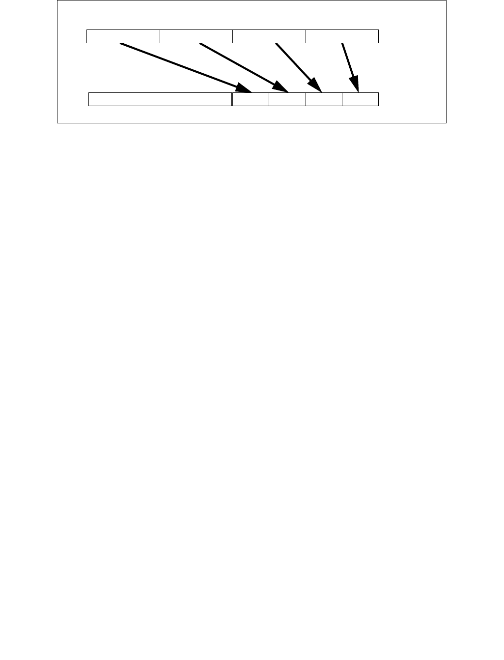
CVTPD2DQ—Convert Packed Double-Precision Floating-Point Values to Packed Doubleword Integers
INSTRUCTION SET REFERENCE, A-L
3-236 Vol. 2A
Operation
VCVTPD2DQ (EVEX encoded versions) when src operand is a register
(KL, VL) = (2, 128), (4, 256), (8, 512)
IF (VL = 512) AND (EVEX.b = 1)
THEN
SET_RM(EVEX.RC);
ELSE
SET_RM(MXCSR.RM);
FI;
FOR j 0 TO KL-1
i j * 32
k j * 64
IF k1[j] OR *no writemask*
THEN DEST[i+31:i]
Convert_Double_Precision_Floating_Point_To_Integer(SRC[k+63:k])
ELSE
IF *merging-masking* ; merging-masking
THEN *DEST[i+31:i] remains unchanged*
ELSE ; zeroing-masking
DEST[i+31:i] 0
FI
FI;
ENDFOR
DEST[MAX_VL-1:VL/2] 0
Figure 3-12. VCVTPD2DQ (VEX.256 encoded version)
DEST
SRC
X0X1X2X3
X3 X2
X1 X0
0

CVTPD2DQ—Convert Packed Double-Precision Floating-Point Values to Packed Doubleword Integers
INSTRUCTION SET REFERENCE, A-L
Vol. 2A 3-237
VCVTPD2DQ (EVEX encoded versions) when src operand is a memory source
(KL, VL) = (2, 128), (4, 256), (8, 512)
FOR j 0 TO KL-1
i j * 32
k j * 64
IF k1[j] OR *no writemask*
THEN
IF (EVEX.b = 1)
THEN
DEST[i+31:i]
Convert_Double_Precision_Floating_Point_To_Integer(SRC[63:0])
ELSE
DEST[i+31:i]
Convert_Double_Precision_Floating_Point_To_Integer(SRC[k+63:k])
FI;
ELSE
IF *merging-masking* ; merging-masking
THEN *DEST[i+31:i] remains unchanged*
ELSE ; zeroing-masking
DEST[i+31:i] 0
FI
FI;
ENDFOR
DEST[MAX_VL-1:VL/2] 0
VCVTPD2DQ (VEX.256 encoded version)
DEST[31:0] Convert_Double_Precision_Floating_Point_To_Integer(SRC[63:0])
DEST[63:32] Convert_Double_Precision_Floating_Point_To_Integer(SRC[127:64])
DEST[95:64] Convert_Double_Precision_Floating_Point_To_Integer(SRC[191:128])
DEST[127:96] Convert_Double_Precision_Floating_Point_To_Integer(SRC[255:192)
DEST[MAX_VL-1:128]0
VCVTPD2DQ (VEX.128 encoded version)
DEST[31:0] Convert_Double_Precision_Floating_Point_To_Integer(SRC[63:0])
DEST[63:32] Convert_Double_Precision_Floating_Point_To_Integer(SRC[127:64])
DEST[MAX_VL-1:64]0
CVTPD2DQ (128-bit Legacy SSE version)
DEST[31:0] Convert_Double_Precision_Floating_Point_To_Integer(SRC[63:0])
DEST[63:32] Convert_Double_Precision_Floating_Point_To_Integer(SRC[127:64])
DEST[127:64] 0
DEST[MAX_VL-1:128] (unmodified)

CVTPD2DQ—Convert Packed Double-Precision Floating-Point Values to Packed Doubleword Integers
INSTRUCTION SET REFERENCE, A-L
3-238 Vol. 2A
Intel C/C++ Compiler Intrinsic Equivalent
VCVTPD2DQ __m256i _mm512_cvtpd_epi32( __m512d a);
VCVTPD2DQ __m256i _mm512_mask_cvtpd_epi32( __m256i s, __mmask8 k, __m512d a);
VCVTPD2DQ __m256i _mm512_maskz_cvtpd_epi32( __mmask8 k, __m512d a);
VCVTPD2DQ __m256i _mm512_cvt_roundpd_epi32( __m512d a, int r);
VCVTPD2DQ __m256i _mm512_mask_cvt_roundpd_epi32( __m256i s, __mmask8 k, __m512d a, int r);
VCVTPD2DQ __m256i _mm512_maskz_cvt_roundpd_epi32( __mmask8 k, __m512d a, int r);
VCVTPD2DQ __m128i _mm256_mask_cvtpd_epi32( __m128i s, __mmask8 k, __m256d a);
VCVTPD2DQ __m128i _mm256_maskz_cvtpd_epi32( __mmask8 k, __m256d a);
VCVTPD2DQ __m128i _mm_mask_cvtpd_epi32( __m128i s, __mmask8 k, __m128d a);
VCVTPD2DQ __m128i _mm_maskz_cvtpd_epi32( __mmask8 k, __m128d a);
VCVTPD2DQ __m128i _mm256_cvtpd_epi32 (__m256d src)
CVTPD2DQ __m128i _mm_cvtpd_epi32 (__m128d src)
SIMD Floating-Point Exceptions
Invalid, Precision
Other Exceptions
See Exceptions Type 2; additionally
EVEX-encoded instructions, see Exceptions Type E2.
#UD If VEX.vvvv != 1111B or EVEX.vvvv != 1111B.

CVTPD2PI—Convert Packed Double-Precision FP Values to Packed Dword Integers
INSTRUCTION SET REFERENCE, A-L
Vol. 2A 3-239
CVTPD2PI—Convert Packed Double-Precision FP Values to Packed Dword Integers
Instruction Operand Encoding
Description
Converts two packed double-precision floating-point values in the source operand (second operand) to two packed
signed doubleword integers in the destination operand (first operand).
The source operand can be an XMM register or a 128-bit memory location. The destination operand is an MMX tech-
nology register.
When a conversion is inexact, the value returned is rounded according to the rounding control bits in the MXCSR
register. If a converted result is larger than the maximum signed doubleword integer, the floating-point invalid
exception is raised, and if this exception is masked, the indefinite integer value (80000000H) is returned.
This instruction causes a transition from x87 FPU to MMX technology operation (that is, the x87 FPU top-of-stack
pointer is set to 0 and the x87 FPU tag word is set to all 0s [valid]). If this instruction is executed while an x87 FPU
floating-point exception is pending, the exception is handled before the CVTPD2PI instruction is executed.
In 64-bit mode, use of the REX.R prefix permits this instruction to access additional registers (XMM8-XMM15).
Operation
DEST[31:0] ← Convert_Double_Precision_Floating_Point_To_Integer32(SRC[63:0]);
DEST[63:32] ← Convert_Double_Precision_Floating_Point_To_Integer32(SRC[127:64]);
Intel C/C++ Compiler Intrinsic Equivalent
CVTPD1PI: __m64 _mm_cvtpd_pi32(__m128d a)
SIMD Floating-Point Exceptions
Invalid, Precision.
Other Exceptions
See Table 22-4, “Exception Conditions for Legacy SIMD/MMX Instructions with FP Exception and 16-Byte Align-
ment,” in the Intel® 64 and IA-32 Architectures Software Developer’s Manual, Volume 3B.
Opcode/
Instruction
Op/
En
64-Bit
Mode
Compat/
Leg Mode
Description
66 0F 2D /r
CVTPD2PI mm, xmm/m128
RM Valid Valid Convert two packed double-precision floating-
point values from xmm/m128 to two packed
signed doubleword integers in mm.
Op/En Operand 1 Operand 2 Operand 3 Operand 4
RM ModRM:reg (w) ModRM:r/m (r) NA NA

CVTPD2PS—Convert Packed Double-Precision Floating-Point Values to Packed Single-Precision Floating-Point Values
INSTRUCTION SET REFERENCE, A-L
3-240 Vol. 2A
CVTPD2PS—Convert Packed Double-Precision Floating-Point Values to Packed Single-Precision
Floating-Point Values
Instruction Operand Encoding
Description
Converts two, four or eight packed double-precision floating-point values in the source operand (second operand)
to two, four or eight packed single-precision floating-point values in the destination operand (first operand).
When a conversion is inexact, the value returned is rounded according to the rounding control bits in the MXCSR
register or the embedded rounding control bits.
EVEX encoded versions: The source operand is a ZMM/YMM/XMM register, a 512/256/128-bit memory location, or
a 512/256/128-bit vector broadcasted from a 64-bit memory location. The destination operand is a
YMM/XMM/XMM (low 64-bits) register conditionally updated with writemask k1. The upper bits (MAX_VL-
1:256/128/64) of the corresponding destination are zeroed.
VEX.256 encoded version: The source operand is a YMM register or 256- bit memory location. The destination
operand is an XMM register. The upper bits (MAX_VL-1:128) of the corresponding ZMM register destination are
zeroed.
VEX.128 encoded version: The source operand is an XMM register or 128- bit memory location. The destination
operand is a XMM register. The upper bits (MAX_VL-1:64) of the corresponding ZMM register destination are
zeroed.
128-bit Legacy SSE version: The source operand is an XMM register or 128- bit memory location. The destination
operand is an XMM register. Bits[127:64] of the destination XMM register are zeroed. However, the upper Bits
(MAX_VL-1:128) of the corresponding ZMM register destination are unmodified.
VEX.vvvv and EVEX.vvvv are reserved and must be 1111b otherwise instructions will #UD.
Opcode/
Instruction
Op /
En
64/32
bit Mode
Support
CPUID
Feature
Flag
Description
66 0F 5A /r
CVTPD2PS xmm1, xmm2/m128
RM V/V SSE2 Convert two packed double-precision floating-point
values in xmm2/mem to two single-precision
floating-point values in xmm1.
VEX.128.66.0F.WIG 5A /r
VCVTPD2PS xmm1, xmm2/m128
RM V/V AVX Convert two packed double-precision floating-point
values in xmm2/mem to two single-precision
floating-point values in xmm1.
VEX.256.66.0F.WIG 5A /r
VCVTPD2PS xmm1, ymm2/m256
RM V/V AVX Convert four packed double-precision floating-point
values in ymm2/mem to four single-precision
floating-point values in xmm1.
EVEX.128.66.0F.W1 5A /r
VCVTPD2PS xmm1 {k1}{z},
xmm2/m128/m64bcst
FV V/V AVX512VL
AVX512F
Convert two packed double-precision floating-point
values in xmm2/m128/m64bcst to two single-
precision floating-point values in xmm1with
writemask k1.
EVEX.256.66.0F.W1 5A /r
VCVTPD2PS xmm1 {k1}{z},
ymm2/m256/m64bcst
FV V/V AVX512VL
AVX512F
Convert four packed double-precision floating-point
values in ymm2/m256/m64bcst to four single-
precision floating-point values in xmm1with
writemask k1.
EVEX.512.66.0F.W1 5A /r
VCVTPD2PS ymm1 {k1}{z},
zmm2/m512/m64bcst{er}
FV V/V AVX512F Convert eight packed double-precision floating-point
values in zmm2/m512/m64bcst to eight single-
precision floating-point values in ymm1with
writemask k1.
Op/En Operand 1 Operand 2 Operand 3 Operand 4
RM ModRM:reg (w) ModRM:r/m (r) NA NA
FV ModRM:reg (w) ModRM:r/m (r) NA NA

CVTPD2PS—Convert Packed Double-Precision Floating-Point Values to Packed Single-Precision Floating-Point Values
INSTRUCTION SET REFERENCE, A-L
Vol. 2A 3-241
Operation
VCVTPD2PS (EVEX encoded version) when src operand is a register
(KL, VL) = (2, 128), (4, 256), (8, 512)
IF (VL = 512) AND (EVEX.b = 1)
THEN
SET_RM(EVEX.RC);
ELSE
SET_RM(MXCSR.RM);
FI;
FOR j 0 TO KL-1
i j * 32
k j * 64
IF k1[j] OR *no writemask*
THEN
DEST[i+31:i] Convert_Double_Precision_Floating_Point_To_Single_Precision_Floating_Point(SRC[k+63:k])
ELSE
IF *merging-masking* ; merging-masking
THEN *DEST[i+31:i] remains unchanged*
ELSE ; zeroing-masking
DEST[i+31:i] 0
FI
FI;
ENDFOR
DEST[MAX_VL-1:VL/2] 0
Figure 3-13. VCVTPD2PS (VEX.256 encoded version)
DEST
SRC
X0X1X2X3
X3 X2
X1 X0
0

CVTPD2PS—Convert Packed Double-Precision Floating-Point Values to Packed Single-Precision Floating-Point Values
INSTRUCTION SET REFERENCE, A-L
3-242 Vol. 2A
VCVTPD2PS (EVEX encoded version) when src operand is a memory source
(KL, VL) = (2, 128), (4, 256), (8, 512)
FOR j 0 TO KL-1
i j * 32
k j * 64
IF k1[j] OR *no writemask*
THEN
IF (EVEX.b = 1)
THEN
DEST[i+31:i] Convert_Double_Precision_Floating_Point_To_Single_Precision_Floating_Point(SRC[63:0])
ELSE
DEST[i+31:i] Convert_Double_Precision_Floating_Point_To_Single_Precision_Floating_Point(SRC[k+63:k])
FI;
ELSE
IF *merging-masking* ; merging-masking
THEN *DEST[i+31:i] remains unchanged*
ELSE ; zeroing-masking
DEST[i+31:i] 0
FI
FI;
ENDFOR
DEST[MAX_VL-1:VL/2] 0
VCVTPD2PS (VEX.256 encoded version)
DEST[31:0] Convert_Double_Precision_To_Single_Precision_Floating_Point(SRC[63:0])
DEST[63:32] Convert_Double_Precision_To_Single_Precision_Floating_Point(SRC[127:64])
DEST[95:64] Convert_Double_Precision_To_Single_Precision_Floating_Point(SRC[191:128])
DEST[127:96] Convert_Double_Precision_To_Single_Precision_Floating_Point(SRC[255:192)
DEST[MAX_VL-1:128] 0
VCVTPD2PS (VEX.128 encoded version)
DEST[31:0] Convert_Double_Precision_To_Single_Precision_Floating_Point(SRC[63:0])
DEST[63:32] Convert_Double_Precision_To_Single_Precision_Floating_Point(SRC[127:64])
DEST[MAX_VL-1:64] 0
CVTPD2PS (128-bit Legacy SSE version)
DEST[31:0] Convert_Double_Precision_To_Single_Precision_Floating_Point(SRC[63:0])
DEST[63:32] Convert_Double_Precision_To_Single_Precision_Floating_Point(SRC[127:64])
DEST[127:64] 0
DEST[MAX_VL-1:128] (unmodified)

CVTPD2PS—Convert Packed Double-Precision Floating-Point Values to Packed Single-Precision Floating-Point Values
INSTRUCTION SET REFERENCE, A-L
Vol. 2A 3-243
Intel C/C++ Compiler Intrinsic Equivalent
VCVTPD2PS __m256 _mm512_cvtpd_ps( __m512d a);
VCVTPD2PS __m256 _mm512_mask_cvtpd_ps( __m256 s, __mmask8 k, __m512d a);
VCVTPD2PS __m256 _mm512_maskz_cvtpd_ps( __mmask8 k, __m512d a);
VCVTPD2PS __m256 _mm512_cvt_roundpd_ps( __m512d a, int r);
VCVTPD2PS __m256 _mm512_mask_cvt_roundpd_ps( __m256 s, __mmask8 k, __m512d a, int r);
VCVTPD2PS __m256 _mm512_maskz_cvt_roundpd_ps( __mmask8 k, __m512d a, int r);
VCVTPD2PS __m128 _mm256_mask_cvtpd_ps( __m128 s, __mmask8 k, __m256d a);
VCVTPD2PS __m128 _mm256_maskz_cvtpd_ps( __mmask8 k, __m256d a);
VCVTPD2PS __m128 _mm_mask_cvtpd_ps( __m128 s, __mmask8 k, __m128d a);
VCVTPD2PS __m128 _mm_maskz_cvtpd_ps( __mmask8 k, __m128d a);
VCVTPD2PS __m128 _mm256_cvtpd_ps (__m256d a)
CVTPD2PS __m128 _mm_cvtpd_ps (__m128d a)
SIMD Floating-Point Exceptions
Invalid, Precision, Underflow, Overflow, Denormal
Other Exceptions
VEX-encoded instructions, see Exceptions Type 2;
EVEX-encoded instructions, see Exceptions Type E2.
#UD If VEX.vvvv != 1111B or EVEX.vvvv != 1111B.

CVTPI2PD—Convert Packed Dword Integers to Packed Double-Precision FP Values
INSTRUCTION SET REFERENCE, A-L
3-244 Vol. 2A
CVTPI2PD—Convert Packed Dword Integers to Packed Double-Precision FP Values
Instruction Operand Encoding
Description
Converts two packed signed doubleword integers in the source operand (second operand) to two packed double-
precision floating-point values in the destination operand (first operand).
The source operand can be an MMX technology register or a 64-bit memory location. The destination operand is an
XMM register. In addition, depending on the operand configuration:
•For operands xmm, mm: the instruction causes a transition from x87 FPU to MMX technology operation (that
is, the x87 FPU top-of-stack pointer is set to 0 and the x87 FPU tag word is set to all 0s [valid]). If this
instruction is executed while an x87 FPU floating-point exception is pending, the exception is handled before
the CVTPI2PD instruction is executed.
•For operands xmm, m64: the instruction does not cause a transition to MMX technology and does not take
x87 FPU exceptions.
In 64-bit mode, use of the REX.R prefix permits this instruction to access additional registers (XMM8-XMM15).
Operation
DEST[63:0] ← Convert_Integer_To_Double_Precision_Floating_Point(SRC[31:0]);
DEST[127:64] ← Convert_Integer_To_Double_Precision_Floating_Point(SRC[63:32]);
Intel C/C++ Compiler Intrinsic Equivalent
CVTPI2PD: __m128d _mm_cvtpi32_pd(__m64 a)
SIMD Floating-Point Exceptions
None
Other Exceptions
See Table 22-6, “Exception Conditions for Legacy SIMD/MMX Instructions with XMM and without FP Exception,” in
the Intel® 64 and IA-32 Architectures Software Developer’s Manual, Volume 3B.
Opcode/
Instruction
Op/
En
64-Bit
Mode
Compat/
Leg Mode
Description
66 0F 2A /r
CVTPI2PD xmm, mm/m64*
RM Valid Valid Convert two packed signed doubleword
integers from mm/mem64 to two packed
double-precision floating-point values in xmm.
NOTES:
*Operation is different for different operand sets; see the Description section.
Op/En Operand 1 Operand 2 Operand 3 Operand 4
RM ModRM:reg (w) ModRM:r/m (r) NA NA

CVTPI2PS—Convert Packed Dword Integers to Packed Single-Precision FP Values
INSTRUCTION SET REFERENCE, A-L
Vol. 2A 3-245
CVTPI2PS—Convert Packed Dword Integers to Packed Single-Precision FP Values
Instruction Operand Encoding
Description
Converts two packed signed doubleword integers in the source operand (second operand) to two packed single-
precision floating-point values in the destination operand (first operand).
The source operand can be an MMX technology register or a 64-bit memory location. The destination operand is an
XMM register. The results are stored in the low quadword of the destination operand, and the high quadword
remains unchanged. When a conversion is inexact, the value returned is rounded according to the rounding control
bits in the MXCSR register.
This instruction causes a transition from x87 FPU to MMX technology operation (that is, the x87 FPU top-of-stack
pointer is set to 0 and the x87 FPU tag word is set to all 0s [valid]). If this instruction is executed while an x87 FPU
floating-point exception is pending, the exception is handled before the CVTPI2PS instruction is executed.
In 64-bit mode, use of the REX.R prefix permits this instruction to access additional registers (XMM8-XMM15).
Operation
DEST[31:0] ← Convert_Integer_To_Single_Precision_Floating_Point(SRC[31:0]);
DEST[63:32] ← Convert_Integer_To_Single_Precision_Floating_Point(SRC[63:32]);
(* High quadword of destination unchanged *)
Intel C/C++ Compiler Intrinsic Equivalent
CVTPI2PS: __m128 _mm_cvtpi32_ps(__m128 a, __m64 b)
SIMD Floating-Point Exceptions
Precision
Other Exceptions
See Table 22-5, “Exception Conditions for Legacy SIMD/MMX Instructions with XMM and FP Exception,” in the
Intel® 64 and IA-32 Architectures Software Developer’s Manual, Volume 3B.
Opcode/
Instruction
Op/
En
64-Bit
Mode
Compat/
Leg Mode
Description
0F 2A /r
CVTPI2PS xmm, mm/m64
RM Valid Valid Convert two signed doubleword integers
from mm/m64 to two single-precision
floating-point values in xmm.
Op/En Operand 1 Operand 2 Operand 3 Operand 4
RM ModRM:reg (w) ModRM:r/m (r) NA NA

CVTPS2DQ—Convert Packed Single-Precision Floating-Point Values to Packed Signed Doubleword Integer Values
INSTRUCTION SET REFERENCE, A-L
3-246 Vol. 2A
CVTPS2DQ—Convert Packed Single-Precision Floating-Point Values to Packed Signed
Doubleword Integer Values
Instruction Operand Encoding
Description
Converts four, eight or sixteen packed single-precision floating-point values in the source operand to four, eight or
sixteen signed doubleword integers in the destination operand.
When a conversion is inexact, the value returned is rounded according to the rounding control bits in the MXCSR
register or the embedded rounding control bits. If a converted result cannot be represented in the destination
format, the floating-point invalid exception is raised, and if this exception is masked, the indefinite integer value
(2w-1, where w represents the number of bits in the destination format) is returned.
EVEX encoded versions: The source operand is a ZMM register, a 512-bit memory location or a 512-bit vector
broadcasted from a 32-bit memory location. The destination operand is a ZMM register conditionally updated with
writemask k1.
VEX.256 encoded version: The source operand is a YMM register or 256- bit memory location. The destination
operand is a YMM register. The upper bits (MAX_VL-1:256) of the corresponding ZMM register destination are
zeroed.
VEX.128 encoded version: The source operand is an XMM register or 128- bit memory location. The destination
operand is a XMM register. The upper bits (MAX_VL-1:128) of the corresponding ZMM register destination are
zeroed.
128-bit Legacy SSE version: The source operand is an XMM register or 128- bit memory location. The destination
operand is an XMM register. The upper bits (MAX_VL-1:128) of the corresponding ZMM register destination are
unmodified.
VEX.vvvv and EVEX.vvvv are reserved and must be 1111b otherwise instructions will #UD.
Opcode/
Instruction
Op /
En
64/32
bit Mode
Support
CPUID
Feature
Flag
Description
66 0F 5B /r
CVTPS2DQ xmm1, xmm2/m128
RM V/V SSE2 Convert four packed single-precision floating-point values
from xmm2/mem to four packed signed doubleword
values in xmm1.
VEX.128.66.0F.WIG 5B /r
VCVTPS2DQ xmm1, xmm2/m128
RM V/V AVX Convert four packed single-precision floating-point values
from xmm2/mem to four packed signed doubleword
values in xmm1.
VEX.256.66.0F.WIG 5B /r
VCVTPS2DQ ymm1, ymm2/m256
RM V/V AVX Convert eight packed single-precision floating-point values
from ymm2/mem to eight packed signed doubleword
values in ymm1.
EVEX.128.66.0F.W0 5B /r
VCVTPS2DQ xmm1 {k1}{z},
xmm2/m128/m32bcst
FV V/V AVX512VL
AVX512F
Convert four packed single precision floating-point values
from xmm2/m128/m32bcst to four packed signed
doubleword values in xmm1 subject to writemask k1.
EVEX.256.66.0F.W0 5B /r
VCVTPS2DQ ymm1 {k1}{z},
ymm2/m256/m32bcst
FV V/V AVX512VL
AVX512F
Convert eight packed single precision floating-point values
from ymm2/m256/m32bcst to eight packed signed
doubleword values in ymm1 subject to writemask k1.
EVEX.512.66.0F.W0 5B /r
VCVTPS2DQ zmm1 {k1}{z},
zmm2/m512/m32bcst{er}
FV V/V AVX512F Convert sixteen packed single-precision floating-point
values from zmm2/m512/m32bcst to sixteen packed
signed doubleword values in zmm1 subject to writemask
k1.
Op/En Operand 1 Operand 2 Operand 3 Operand 4
RM ModRM:reg (w) ModRM:r/m (r) NA NA
FV ModRM:reg (w) ModRM:r/m (r) NA NA

CVTPS2DQ—Convert Packed Single-Precision Floating-Point Values to Packed Signed Doubleword Integer Values
INSTRUCTION SET REFERENCE, A-L
Vol. 2A 3-247
Operation
VCVTPS2DQ (encoded versions) when src operand is a register
(KL, VL) = (4, 128), (8, 256), (16, 512)
IF (VL = 512) AND (EVEX.b = 1)
THEN
SET_RM(EVEX.RC);
ELSE
SET_RM(MXCSR.RM);
FI;
FOR j 0 TO KL-1
i j * 32
IF k1[j] OR *no writemask*
THEN DEST[i+31:i]
Convert_Single_Precision_Floating_Point_To_Integer(SRC[i+31:i])
ELSE
IF *merging-masking* ; merging-masking
THEN *DEST[i+31:i] remains unchanged*
ELSE ; zeroing-masking
DEST[i+31:i] 0
FI
FI;
ENDFOR
DEST[MAX_VL-1:VL] 0
VCVTPS2DQ (EVEX encoded versions) when src operand is a memory source
(KL, VL) = (4, 128), (8, 256), (16, 512)
FOR j 0 TO 15
i j * 32
IF k1[j] OR *no writemask*
THEN
IF (EVEX.b = 1)
THEN
DEST[i+31:i]
Convert_Single_Precision_Floating_Point_To_Integer(SRC[31:0])
ELSE
DEST[i+31:i]
Convert_Single_Precision_Floating_Point_To_Integer(SRC[i+31:i])
FI;
ELSE
IF *merging-masking* ; merging-masking
THEN *DEST[i+31:i] remains unchanged*
ELSE ; zeroing-masking
DEST[i+31:i] 0
FI
FI;
ENDFOR
DEST[MAX_VL-1:VL] 0

CVTPS2DQ—Convert Packed Single-Precision Floating-Point Values to Packed Signed Doubleword Integer Values
INSTRUCTION SET REFERENCE, A-L
3-248 Vol. 2A
VCVTPS2DQ (VEX.256 encoded version)
DEST[31:0] Convert_Single_Precision_Floating_Point_To_Integer(SRC[31:0])
DEST[63:32] Convert_Single_Precision_Floating_Point_To_Integer(SRC[63:32])
DEST[95:64] Convert_Single_Precision_Floating_Point_To_Integer(SRC[95:64])
DEST[127:96] Convert_Single_Precision_Floating_Point_To_Integer(SRC[127:96)
DEST[159:128] Convert_Single_Precision_Floating_Point_To_Integer(SRC[159:128])
DEST[191:160] Convert_Single_Precision_Floating_Point_To_Integer(SRC[191:160])
DEST[223:192] Convert_Single_Precision_Floating_Point_To_Integer(SRC[223:192])
DEST[255:224] Convert_Single_Precision_Floating_Point_To_Integer(SRC[255:224])
VCVTPS2DQ (VEX.128 encoded version)
DEST[31:0] Convert_Single_Precision_Floating_Point_To_Integer(SRC[31:0])
DEST[63:32] Convert_Single_Precision_Floating_Point_To_Integer(SRC[63:32])
DEST[95:64] Convert_Single_Precision_Floating_Point_To_Integer(SRC[95:64])
DEST[127:96] Convert_Single_Precision_Floating_Point_To_Integer(SRC[127:96])
DEST[MAX_VL-1:128] 0
CVTPS2DQ (128-bit Legacy SSE version)
DEST[31:0] Convert_Single_Precision_Floating_Point_To_Integer(SRC[31:0])
DEST[63:32] Convert_Single_Precision_Floating_Point_To_Integer(SRC[63:32])
DEST[95:64] Convert_Single_Precision_Floating_Point_To_Integer(SRC[95:64])
DEST[127:96] Convert_Single_Precision_Floating_Point_To_Integer(SRC[127:96])
DEST[MAX_VL-1:128] (unmodified)
Intel C/C++ Compiler Intrinsic Equivalent
VCVTPS2DQ __m512i _mm512_cvtps_epi32( __m512 a);
VCVTPS2DQ __m512i _mm512_mask_cvtps_epi32( __m512i s, __mmask16 k, __m512 a);
VCVTPS2DQ __m512i _mm512_maskz_cvtps_epi32( __mmask16 k, __m512 a);
VCVTPS2DQ __m512i _mm512_cvt_roundps_epi32( __m512 a, int r);
VCVTPS2DQ __m512i _mm512_mask_cvt_roundps_epi32( __m512i s, __mmask16 k, __m512 a, int r);
VCVTPS2DQ __m512i _mm512_maskz_cvt_roundps_epi32( __mmask16 k, __m512 a, int r);
VCVTPS2DQ __m256i _mm256_mask_cvtps_epi32( __m256i s, __mmask8 k, __m256 a);
VCVTPS2DQ __m256i _mm256_maskz_cvtps_epi32( __mmask8 k, __m256 a);
VCVTPS2DQ __m128i _mm_mask_cvtps_epi32( __m128i s, __mmask8 k, __m128 a);
VCVTPS2DQ __m128i _mm_maskz_cvtps_epi32( __mmask8 k, __m128 a);
VCVTPS2DQ __ m256i _mm256_cvtps_epi32 (__m256 a)
CVTPS2DQ __m128i _mm_cvtps_epi32 (__m128 a)
SIMD Floating-Point Exceptions
Invalid, Precision
Other Exceptions
VEX-encoded instructions, see Exceptions Type 2;
EVEX-encoded instructions, see Exceptions Type E2.
#UD If VEX.vvvv != 1111B or EVEX.vvvv != 1111B.

CVTPS2PD—Convert Packed Single-Precision Floating-Point Values to Packed Double-Precision Floating-Point Values
INSTRUCTION SET REFERENCE, A-L
Vol. 2A 3-249
CVTPS2PD—Convert Packed Single-Precision Floating-Point Values to Packed Double-Precision
Floating-Point Values
Instruction Operand Encoding
Description
Converts two, four or eight packed single-precision floating-point values in the source operand (second operand)
to two, four or eight packed double-precision floating-point values in the destination operand (first operand).
EVEX encoded versions: The source operand is a YMM/XMM/XMM (low 64-bits) register, a 256/128/64-bit memory
location or a 256/128/64-bit vector broadcasted from a 32-bit memory location. The destination operand is a
ZMM/YMM/XMM register conditionally updated with writemask k1.
VEX.256 encoded version: The source operand is an XMM register or 128- bit memory location. The destination
operand is a YMM register. Bits (MAX_VL-1:256) of the corresponding destination ZMM register are zeroed.
VEX.128 encoded version: The source operand is an XMM register or 64- bit memory location. The destination
operand is a XMM register. The upper Bits (MAX_VL-1:128) of the corresponding ZMM register destination are
zeroed.
128-bit Legacy SSE version: The source operand is an XMM register or 64- bit memory location. The destination
operand is an XMM register. The upper Bits (MAX_VL-1:128) of the corresponding ZMM register destination are
unmodified.
Note: VEX.vvvv and EVEX.vvvv are reserved and must be 1111b otherwise instructions will #UD.
Opcode/
Instruction
Op /
En
64/32
bit Mode
Support
CPUID
Feature
Flag
Description
0F 5A /r
CVTPS2PD xmm1, xmm2/m64
RM V/V SSE2 Convert two packed single-precision floating-point values in
xmm2/m64 to two packed double-precision floating-point
values in xmm1.
VEX.128.0F.WIG 5A /r
VCVTPS2PD xmm1, xmm2/m64
RM V/V AVX Convert two packed single-precision floating-point values in
xmm2/m64 to two packed double-precision floating-point
values in xmm1.
VEX.256.0F.WIG 5A /r
VCVTPS2PD ymm1, xmm2/m128
RM V/V AVX Convert four packed single-precision floating-point values
in xmm2/m128 to four packed double-precision floating-
point values in ymm1.
EVEX.128.0F.W0 5A /r
VCVTPS2PD xmm1 {k1}{z},
xmm2/m64/m32bcst
HV V/V AVX512VL
AVX512F
Convert two packed single-precision floating-point values in
xmm2/m64/m32bcst to packed double-precision floating-
point values in xmm1 with writemask k1.
EVEX.256.0F.W0 5A /r
VCVTPS2PD ymm1 {k1}{z},
xmm2/m128/m32bcst
HV V/V AVX512VL Convert four packed single-precision floating-point values
in xmm2/m128/m32bcst to packed double-precision
floating-point values in ymm1 with writemask k1.
EVEX.512.0F.W0 5A /r
VCVTPS2PD zmm1 {k1}{z},
ymm2/m256/m32bcst{sae}
HV V/V AVX512F Convert eight packed single-precision floating-point values
in ymm2/m256/b32bcst to eight packed double-precision
floating-point values in zmm1 with writemask k1.
Op/En Operand 1 Operand 2 Operand 3 Operand 4
RM ModRM:reg (w) ModRM:r/m (r) NA NA
HV ModRM:reg (w) ModRM:r/m (r) NA NA
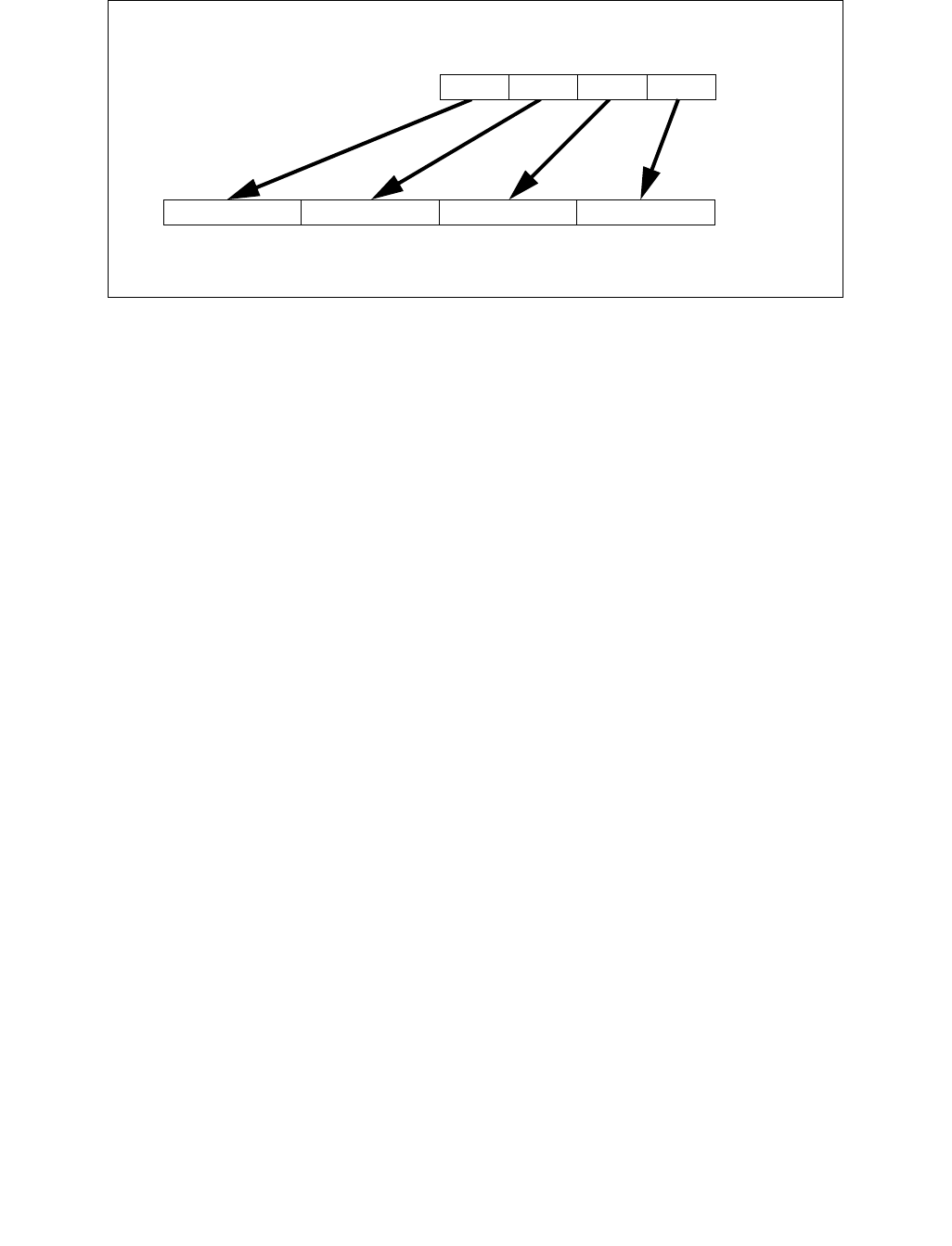
CVTPS2PD—Convert Packed Single-Precision Floating-Point Values to Packed Double-Precision Floating-Point Values
INSTRUCTION SET REFERENCE, A-L
3-250 Vol. 2A
Operation
VCVTPS2PD (EVEX encoded versions) when src operand is a register
(KL, VL) = (2, 128), (4, 256), (8, 512)
FOR j 0 TO KL-1
i j * 64
k j * 32
IF k1[j] OR *no writemask*
THEN DEST[i+63:i]
Convert_Single_Precision_To_Double_Precision_Floating_Point(SRC[k+31:k])
ELSE
IF *merging-masking* ; merging-masking
THEN *DEST[i+63:i] remains unchanged*
ELSE ; zeroing-masking
DEST[i+63:i] 0
FI
FI;
ENDFOR
DEST[MAX_VL-1:VL] 0
VCVTPS2PD (EVEX encoded versions) when src operand is a memory source
(KL, VL) = (2, 128), (4, 256), (8, 512)
FOR j 0 TO KL-1
i j * 64
k j * 32
IF k1[j] OR *no writemask*
THEN
IF (EVEX.b = 1)
THEN
DEST[i+63:i]
Convert_Single_Precision_To_Double_Precision_Floating_Point(SRC[31:0])
ELSE
DEST[i+63:i]
Convert_Single_Precision_To_Double_Precision_Floating_Point(SRC[k+31:k])
FI;
ELSE
Figure 3-14. CVTPS2PD (VEX.256 encoded version)
DEST
SRC X0X1X2X3
X3 X2
X1 X0

CVTPS2PD—Convert Packed Single-Precision Floating-Point Values to Packed Double-Precision Floating-Point Values
INSTRUCTION SET REFERENCE, A-L
Vol. 2A 3-251
IF *merging-masking* ; merging-masking
THEN *DEST[i+63:i] remains unchanged*
ELSE ; zeroing-masking
DEST[i+63:i] 0
FI
FI;
ENDFOR
DEST[MAX_VL-1:VL] 0
VCVTPS2PD (VEX.256 encoded version)
DEST[63:0] Convert_Single_Precision_To_Double_Precision_Floating_Point(SRC[31:0])
DEST[127:64] Convert_Single_Precision_To_Double_Precision_Floating_Point(SRC[63:32])
DEST[191:128] Convert_Single_Precision_To_Double_Precision_Floating_Point(SRC[95:64])
DEST[255:192] Convert_Single_Precision_To_Double_Precision_Floating_Point(SRC[127:96)
DEST[MAX_VL-1:256] 0
VCVTPS2PD (VEX.128 encoded version)
DEST[63:0] Convert_Single_Precision_To_Double_Precision_Floating_Point(SRC[31:0])
DEST[127:64] Convert_Single_Precision_To_Double_Precision_Floating_Point(SRC[63:32])
DEST[MAX_VL-1:128] 0
CVTPS2PD (128-bit Legacy SSE version)
DEST[63:0] Convert_Single_Precision_To_Double_Precision_Floating_Point(SRC[31:0])
DEST[127:64] Convert_Single_Precision_To_Double_Precision_Floating_Point(SRC[63:32])
DEST[MAX_VL-1:128] (unmodified)
Intel C/C++ Compiler Intrinsic Equivalent
VCVTPS2PD __m512d _mm512_cvtps_pd( __m256 a);
VCVTPS2PD __m512d _mm512_mask_cvtps_pd( __m512d s, __mmask8 k, __m256 a);
VCVTPS2PD __m512d _mm512_maskz_cvtps_pd( __mmask8 k, __m256 a);
VCVTPS2PD __m512d _mm512_cvt_roundps_pd( __m256 a, int sae);
VCVTPS2PD __m512d _mm512_mask_cvt_roundps_pd( __m512d s, __mmask8 k, __m256 a, int sae);
VCVTPS2PD __m512d _mm512_maskz_cvt_roundps_pd( __mmask8 k, __m256 a, int sae);
VCVTPS2PD __m256d _mm256_mask_cvtps_pd( __m256d s, __mmask8 k, __m128 a);
VCVTPS2PD __m256d _mm256_maskz_cvtps_pd( __mmask8 k, __m128a);
VCVTPS2PD __m128d _mm_mask_cvtps_pd( __m128d s, __mmask8 k, __m128 a);
VCVTPS2PD __m128d _mm_maskz_cvtps_pd( __mmask8 k, __m128 a);
VCVTPS2PD __m256d _mm256_cvtps_pd (__m128 a)
CVTPS2PD __m128d _mm_cvtps_pd (__m128 a)
SIMD Floating-Point Exceptions
Invalid, Denormal
Other Exceptions
VEX-encoded instructions, see Exceptions Type 3;
EVEX-encoded instructions, see Exceptions Type E3.
#UD If VEX.vvvv != 1111B or EVEX.vvvv != 1111B.

CVTPS2PI—Convert Packed Single-Precision FP Values to Packed Dword Integers
INSTRUCTION SET REFERENCE, A-L
3-252 Vol. 2A
CVTPS2PI—Convert Packed Single-Precision FP Values to Packed Dword Integers
Instruction Operand Encoding
Description
Converts two packed single-precision floating-point values in the source operand (second operand) to two packed
signed doubleword integers in the destination operand (first operand).
The source operand can be an XMM register or a 128-bit memory location. The destination operand is an MMX tech-
nology register. When the source operand is an XMM register, the two single-precision floating-point values are
contained in the low quadword of the register. When a conversion is inexact, the value returned is rounded
according to the rounding control bits in the MXCSR register. If a converted result is larger than the maximum
signed doubleword integer, the floating-point invalid exception is raised, and if this exception is masked, the indef-
inite integer value (80000000H) is returned.
CVTPS2PI causes a transition from x87 FPU to MMX technology operation (that is, the x87 FPU top-of-stack pointer
is set to 0 and the x87 FPU tag word is set to all 0s [valid]). If this instruction is executed while an x87 FPU floating-
point exception is pending, the exception is handled before the CVTPS2PI instruction is executed.
In 64-bit mode, use of the REX.R prefix permits this instruction to access additional registers (XMM8-XMM15).
Operation
DEST[31:0] ← Convert_Single_Precision_Floating_Point_To_Integer(SRC[31:0]);
DEST[63:32] ← Convert_Single_Precision_Floating_Point_To_Integer(SRC[63:32]);
Intel C/C++ Compiler Intrinsic Equivalent
CVTPS2PI: __m64 _mm_cvtps_pi32(__m128 a)
SIMD Floating-Point Exceptions
Invalid, Precision
Other Exceptions
See Table 22-5, “Exception Conditions for Legacy SIMD/MMX Instructions with XMM and FP Exception,” in the
Intel® 64 and IA-32 Architectures Software Developer’s Manual, Volume 3B.
Opcode/
Instruction
Op/
En
64-Bit
Mode
Compat/
Leg Mode
Description
0F 2D /r
CVTPS2PI mm, xmm/m64
RM Valid Valid Convert two packed single-precision floating-
point values from xmm/m64 to two packed
signed doubleword integers in mm.
Op/En Operand 1 Operand 2 Operand 3 Operand 4
RM ModRM:reg (w) ModRM:r/m (r) NA NA

CVTSD2SI—Convert Scalar Double-Precision Floating-Point Value to Doubleword Integer
INSTRUCTION SET REFERENCE, A-L
Vol. 2A 3-253
CVTSD2SI—Convert Scalar Double-Precision Floating-Point Value to Doubleword Integer
Instruction Operand Encoding
Description
Converts a double-precision floating-point value in the source operand (the second operand) to a signed double-
word integer in the destination operand (first operand). The source operand can be an XMM register or a 64-bit
memory location. The destination operand is a general-purpose register. When the source operand is an XMM
register, the double-precision floating-point value is contained in the low quadword of the register.
When a conversion is inexact, the value returned is rounded according to the rounding control bits in the MXCSR
register.
If a converted result exceeds the range limits of signed doubleword integer (in non-64-bit modes or 64-bit mode
with REX.W/VEX.W/EVEX.W=0), the floating-point invalid exception is raised, and if this exception is masked, the
indefinite integer value (80000000H) is returned.
If a converted result exceeds the range limits of signed quadword integer (in 64-bit mode and
REX.W/VEX.W/EVEX.W = 1), the floating-point invalid exception is raised, and if this exception is masked, the
indefinite integer value (80000000_00000000H) is returned.
Legacy SSE instruction: Use of the REX.W prefix promotes the instruction to produce 64-bit data in 64-bit mode.
See the summary chart at the beginning of this section for encoding data and limits.
Note: VEX.vvvv and EVEX.vvvv are reserved and must be 1111b, otherwise instructions will #UD.
Software should ensure VCVTSD2SI is encoded with VEX.L=0. Encoding VCVTSD2SI with VEX.L=1 may encounter
unpredictable behavior across different processor generations.
Opcode/
Instruction
Op /
En
64/32
bit Mode
Support
CPUID
Feature
Flag
Description
F2 0F 2D /r
CVTSD2SI r32, xmm1/m64
RM V/V SSE2 Convert one double-precision floating-point value from
xmm1/m64 to one signed doubleword integer r32.
F2 REX.W 0F 2D /r
CVTSD2SI r64, xmm1/m64
RM V/N.E. SSE2 Convert one double-precision floating-point value from
xmm1/m64 to one signed quadword integer sign-
extended into r64.
VEX.128.F2.0F.W0 2D /r
VCVTSD2SI r32, xmm1/m64
RM V/V AVX Convert one double-precision floating-point value from
xmm1/m64 to one signed doubleword integer r32.
VEX.128.F2.0F.W1 2D /r
VCVTSD2SI r64, xmm1/m64
RM V/N.E.1AVX Convert one double-precision floating-point value from
xmm1/m64 to one signed quadword integer sign-
extended into r64.
EVEX.LIG.F2.0F.W0 2D /r
VCVTSD2SI r32, xmm1/m64{er}
T1F V/V AVX512F Convert one double-precision floating-point value from
xmm1/m64 to one signed doubleword integer r32.
EVEX.LIG.F2.0F.W1 2D /r
VCVTSD2SI r64, xmm1/m64{er}
T1F V/N.E.1
NOTES:
1. VEX.W1/EVEX.W1 in non-64 bit is ignored; the instructions behaves as if the W0 version is used.
AVX512F Convert one double-precision floating-point value from
xmm1/m64 to one signed quadword integer sign-
extended into r64.
Op/En Operand 1 Operand 2 Operand 3 Operand 4
RM ModRM:reg (w) ModRM:r/m (r) NA NA
T1F ModRM:reg (w) ModRM:r/m (r) NA NA

CVTSD2SI—Convert Scalar Double-Precision Floating-Point Value to Doubleword Integer
INSTRUCTION SET REFERENCE, A-L
3-254 Vol. 2A
Operation
VCVTSD2SI (EVEX encoded version)
IF SRC *is register* AND (EVEX.b = 1)
THEN
SET_RM(EVEX.RC);
ELSE
SET_RM(MXCSR.RM);
FI;
IF 64-Bit Mode and OperandSize = 64
THEN DEST[63:0] Convert_Double_Precision_Floating_Point_To_Integer(SRC[63:0]);
ELSE DEST[31:0] Convert_Double_Precision_Floating_Point_To_Integer(SRC[63:0]);
FI
(V)CVTSD2SI
IF 64-Bit Mode and OperandSize = 64
THEN
DEST[63:0] Convert_Double_Precision_Floating_Point_To_Integer(SRC[63:0]);
ELSE
DEST[31:0] Convert_Double_Precision_Floating_Point_To_Integer(SRC[63:0]);
FI;
Intel C/C++ Compiler Intrinsic Equivalent
VCVTSD2SI int _mm_cvtsd_i32(__m128d);
VCVTSD2SI int _mm_cvt_roundsd_i32(__m128d, int r);
VCVTSD2SI __int64 _mm_cvtsd_i64(__m128d);
VCVTSD2SI __int64 _mm_cvt_roundsd_i64(__m128d, int r);
CVTSD2SI __int64 _mm_cvtsd_si64(__m128d);
CVTSD2SI int _mm_cvtsd_si32(__m128d a)
SIMD Floating-Point Exceptions
Invalid, Precision
Other Exceptions
VEX-encoded instructions, see Exceptions Type 3;
EVEX-encoded instructions, see Exceptions Type E3NF.
#UD If VEX.vvvv != 1111B or EVEX.vvvv != 1111B.

CVTSD2SS—Convert Scalar Double-Precision Floating-Point Value to Scalar Single-Precision Floating-Point Value
INSTRUCTION SET REFERENCE, A-L
Vol. 2A 3-255
CVTSD2SS—Convert Scalar Double-Precision Floating-Point Value to Scalar Single-Precision
Floating-Point Value
Instruction Operand Encoding
Description
Converts a double-precision floating-point value in the “convert-from” source operand (the second operand in
SSE2 version, otherwise the third operand) to a single-precision floating-point value in the destination operand.
When the “convert-from” operand is an XMM register, the double-precision floating-point value is contained in the
low quadword of the register. The result is stored in the low doubleword of the destination operand. When the
conversion is inexact, the value returned is rounded according to the rounding control bits in the MXCSR register.
128-bit Legacy SSE version: The “convert-from” source operand (the second operand) is an XMM register or
memory location. Bits (MAX_VL-1:32) of the corresponding destination register remain unchanged. The destina-
tion operand is an XMM register.
VEX.128 and EVEX encoded versions: The “convert-from” source operand (the third operand) can be an XMM
register or a 64-bit memory location. The first source and destination operands are XMM registers. Bits (127:32) of
the XMM register destination are copied from the corresponding bits in the first source operand. Bits (MAX_VL-
1:128) of the destination register are zeroed.
EVEX encoded version: the converted result in written to the low doubleword element of the destination under the
writemask.
Software should ensure VCVTSD2SS is encoded with VEX.L=0. Encoding VCVTSD2SS with VEX.L=1 may encounter
unpredictable behavior across different processor generations.
Opcode/
Instruction
Op /
En
64/32
bit Mode
Support
CPUID
Feature
Flag
Description
F2 0F 5A /r
CVTSD2SS xmm1, xmm2/m64
RM V/V SSE2 Convert one double-precision floating-point value in
xmm2/m64 to one single-precision floating-point value
in xmm1.
VEX.NDS.128.F2.0F.WIG 5A /r
VCVTSD2SS xmm1,xmm2,
xmm3/m64
RVM V/V AVX Convert one double-precision floating-point value in
xmm3/m64 to one single-precision floating-point value
and merge with high bits in xmm2.
EVEX.NDS.LIG.F2.0F.W1 5A /r
VCVTSD2SS xmm1 {k1}{z}, xmm2,
xmm3/m64{er}
T1S V/V AVX512F Convert one double-precision floating-point value in
xmm3/m64 to one single-precision floating-point value
and merge with high bits in xmm2 under writemask k1.
Op/En Operand 1 Operand 2 Operand 3 Operand 4
RM ModRM:reg (w) ModRM:r/m (r) NA NA
RVM ModRM:reg (w) VEX.vvvv ModRM:r/m (r) NA
T1S ModRM:reg (w) EVEX.vvvv ModRM:r/m (r) NA

CVTSD2SS—Convert Scalar Double-Precision Floating-Point Value to Scalar Single-Precision Floating-Point Value
INSTRUCTION SET REFERENCE, A-L
3-256 Vol. 2A
Operation
VCVTSD2SS (EVEX encoded version)
IF (SRC2 *is register*) AND (EVEX.b = 1)
THEN
SET_RM(EVEX.RC);
ELSE
SET_RM(MXCSR.RM);
FI;
IF k1[0] or *no writemask*
THEN DEST[31:0] Convert_Double_Precision_To_Single_Precision_Floating_Point(SRC2[63:0]);
ELSE
IF *merging-masking* ; merging-masking
THEN *DEST[31:0] remains unchanged*
ELSE ; zeroing-masking
THEN DEST[31:0] 0
FI;
FI;
DEST[127:32] SRC1[127:32]
DEST[MAX_VL-1:128] 0
VCVTSD2SS (VEX.128 encoded version)
DEST[31:0] Convert_Double_Precision_To_Single_Precision_Floating_Point(SRC2[63:0]);
DEST[127:32] SRC1[127:32]
DEST[MAX_VL-1:128] 0
CVTSD2SS (128-bit Legacy SSE version)
DEST[31:0] Convert_Double_Precision_To_Single_Precision_Floating_Point(SRC[63:0]);
(* DEST[MAX_VL-1:32] Unmodified *)
Intel C/C++ Compiler Intrinsic Equivalent
VCVTSD2SS __m128 _mm_mask_cvtsd_ss(__m128 s, __mmask8 k, __m128 a, __m128d b);
VCVTSD2SS __m128 _mm_maskz_cvtsd_ss( __mmask8 k, __m128 a,__m128d b);
VCVTSD2SS __m128 _mm_cvt_roundsd_ss(__m128 a, __m128d b, int r);
VCVTSD2SS __m128 _mm_mask_cvt_roundsd_ss(__m128 s, __mmask8 k, __m128 a, __m128d b, int r);
VCVTSD2SS __m128 _mm_maskz_cvt_roundsd_ss( __mmask8 k, __m128 a,__m128d b, int r);
CVTSD2SS __m128_mm_cvtsd_ss(__m128 a, __m128d b)
SIMD Floating-Point Exceptions
Overflow, Underflow, Invalid, Precision, Denormal
Other Exceptions
VEX-encoded instructions, see Exceptions Type 3.
EVEX-encoded instructions, see Exceptions Type E3.

CVTSI2SD—Convert Doubleword Integer to Scalar Double-Precision Floating-Point Value
INSTRUCTION SET REFERENCE, A-L
Vol. 2A 3-257
CVTSI2SD—Convert Doubleword Integer to Scalar Double-Precision Floating-Point Value
Instruction Operand Encoding
Description
Converts a signed doubleword integer (or signed quadword integer if operand size is 64 bits) in the “convert-from”
source operand to a double-precision floating-point value in the destination operand. The result is stored in the low
quadword of the destination operand, and the high quadword left unchanged. When conversion is inexact, the
value returned is rounded according to the rounding control bits in the MXCSR register.
The second source operand can be a general-purpose register or a 32/64-bit memory location. The first source and
destination operands are XMM registers.
128-bit Legacy SSE version: Use of the REX.W prefix promotes the instruction to 64-bit operands. The “convert-
from” source operand (the second operand) is a general-purpose register or memory location. The destination is
an XMM register Bits (MAX_VL-1:64) of the corresponding destination register remain unchanged.
VEX.128 and EVEX encoded versions: The “convert-from” source operand (the third operand) can be a general-
purpose register or a memory location. The first source and destination operands are XMM registers. Bits (127:64)
of the XMM register destination are copied from the corresponding bits in the first source operand. Bits (MAX_VL-
1:128) of the destination register are zeroed.
EVEX.W0 version: attempt to encode this instruction with EVEX embedded rounding is ignored.
VEX.W1 and EVEX.W1 versions: promotes the instruction to use 64-bit input value in 64-bit mode.
Software should ensure VCVTSI2SD is encoded with VEX.L=0. Encoding VCVTSI2SD with VEX.L=1 may encounter
unpredictable behavior across different processor generations.
Opcode/
Instruction
Op /
En
64/32
bit Mode
Support
CPUID
Feature
Flag
Description
F2 0F 2A /r
CVTSI2SD xmm1, r32/m32
RM V/V SSE2 Convert one signed doubleword integer from
r32/m32 to one double-precision floating-point
value in xmm1.
F2 REX.W 0F 2A /r
CVTSI2SD xmm1, r/m64
RM V/N.E. SSE2 Convert one signed quadword integer from r/m64
to one double-precision floating-point value in
xmm1.
VEX.NDS.128.F2.0F.W0 2A /r
VCVTSI2SD xmm1, xmm2, r/m32
RVM V/V AVX Convert one signed doubleword integer from
r/m32 to one double-precision floating-point
value in xmm1.
VEX.NDS.128.F2.0F.W1 2A /r
VCVTSI2SD xmm1, xmm2, r/m64
RVM V/N.E.1AVX Convert one signed quadword integer from r/m64
to one double-precision floating-point value in
xmm1.
EVEX.NDS.LIG.F2.0F.W0 2A /r
VCVTSI2SD xmm1, xmm2, r/m32
T1S V/V AVX512F Convert one signed doubleword integer from
r/m32 to one double-precision floating-point
value in xmm1.
EVEX.NDS.LIG.F2.0F.W1 2A /r
VCVTSI2SD xmm1, xmm2, r/m64{er}
T1S V/N.E.1
NOTES:
1. VEX.W1/EVEX.W1 in non-64 bit is ignored; the instructions behaves as if the W0 version is used.
AVX512F Convert one signed quadword integer from r/m64
to one double-precision floating-point value in
xmm1.
Op/En Operand 1 Operand 2 Operand 3 Operand 4
RM ModRM:reg (w) ModRM:r/m (r) NA NA
RVM ModRM:reg (w) VEX.vvvv ModRM:r/m (r) NA
T1S ModRM:reg (w) EVEX.vvvv ModRM:r/m (r) NA

CVTSI2SD—Convert Doubleword Integer to Scalar Double-Precision Floating-Point Value
INSTRUCTION SET REFERENCE, A-L
3-258 Vol. 2A
Operation
VCVTSI2SD (EVEX encoded version)
IF (SRC2 *is register*) AND (EVEX.b = 1)
THEN
SET_RM(EVEX.RC);
ELSE
SET_RM(MXCSR.RM);
FI;
IF 64-Bit Mode And OperandSize = 64
THEN
DEST[63:0] Convert_Integer_To_Double_Precision_Floating_Point(SRC2[63:0]);
ELSE
DEST[63:0] Convert_Integer_To_Double_Precision_Floating_Point(SRC2[31:0]);
FI;
DEST[127:64] SRC1[127:64]
DEST[MAX_VL-1:128] 0
VCVTSI2SD (VEX.128 encoded version)
IF 64-Bit Mode And OperandSize = 64
THEN
DEST[63:0] Convert_Integer_To_Double_Precision_Floating_Point(SRC2[63:0]);
ELSE
DEST[63:0] Convert_Integer_To_Double_Precision_Floating_Point(SRC2[31:0]);
FI;
DEST[127:64] SRC1[127:64]
DEST[MAX_VL-1:128] 0
CVTSI2SD
IF 64-Bit Mode And OperandSize = 64
THEN
DEST[63:0] Convert_Integer_To_Double_Precision_Floating_Point(SRC[63:0]);
ELSE
DEST[63:0] Convert_Integer_To_Double_Precision_Floating_Point(SRC[31:0]);
FI;
DEST[MAX_VL-1:64] (Unmodified)
Intel C/C++ Compiler Intrinsic Equivalent
VCVTSI2SD __m128d _mm_cvti32_sd(__m128d s, int a);
VCVTSI2SD __m128d _mm_cvt_roundi32_sd(__m128d s, int a, int r);
VCVTSI2SD __m128d _mm_cvti64_sd(__m128d s, __int64 a);
VCVTSI2SD __m128d _mm_cvt_roundi64_sd(__m128d s, __int64 a, int r);
CVTSI2SD __m128d _mm_cvtsi64_sd(__m128d s, __int64 a);
CVTSI2SD __m128d_mm_cvtsi32_sd(__m128d a, int b)
SIMD Floating-Point Exceptions
Precision
Other Exceptions
VEX-encoded instructions, see Exceptions Type 3 if W1, else Type 5.
EVEX-encoded instructions, see Exceptions Type E3NF if W1, else Type E10NF.

CVTSI2SS—Convert Doubleword Integer to Scalar Single-Precision Floating-Point Value
INSTRUCTION SET REFERENCE, A-L
Vol. 2A 3-259
CVTSI2SS—Convert Doubleword Integer to Scalar Single-Precision Floating-Point Value
Instruction Operand Encoding
Description
Converts a signed doubleword integer (or signed quadword integer if operand size is 64 bits) in the “convert-from”
source operand to a single-precision floating-point value in the destination operand (first operand). The “convert-
from” source operand can be a general-purpose register or a memory location. The destination operand is an XMM
register. The result is stored in the low doubleword of the destination operand, and the upper three doublewords
are left unchanged. When a conversion is inexact, the value returned is rounded according to the rounding control
bits in the MXCSR register or the embedded rounding control bits.
128-bit Legacy SSE version: In 64-bit mode, Use of the REX.W prefix promotes the instruction to use 64-bit input
value. The “convert-from” source operand (the second operand) is a general-purpose register or memory location.
Bits (MAX_VL-1:32) of the corresponding destination register remain unchanged.
VEX.128 and EVEX encoded versions: The “convert-from” source operand (the third operand) can be a general-
purpose register or a memory location. The first source and destination operands are XMM registers. Bits (127:32)
of the XMM register destination are copied from corresponding bits in the first source operand. Bits (MAX_VL-
1:128) of the destination register are zeroed.
EVEX encoded version: the converted result in written to the low doubleword element of the destination under the
writemask.
Software should ensure VCVTSI2SS is encoded with VEX.L=0. Encoding VCVTSI2SS with VEX.L=1 may encounter
unpredictable behavior across different processor generations.
Opcode/
Instruction
Op /
En
64/32
bit Mode
Support
CPUID
Feature
Flag
Description
F3 0F 2A /r
CVTSI2SS xmm1, r/m32
RM V/V SSE Convert one signed doubleword integer from r/m32
to one single-precision floating-point value in xmm1.
F3 REX.W 0F 2A /r
CVTSI2SS xmm1, r/m64
RM V/N.E. SSE Convert one signed quadword integer from r/m64
to one single-precision floating-point value in xmm1.
VEX.NDS.128.F3.0F.W0 2A /r
VCVTSI2SS xmm1, xmm2, r/m32
RVM V/V AVX Convert one signed doubleword integer from r/m32
to one single-precision floating-point value in xmm1.
VEX.NDS.128.F3.0F.W1 2A /r
VCVTSI2SS xmm1, xmm2, r/m64
RVM V/N.E.1AVX Convert one signed quadword integer from r/m64
to one single-precision floating-point value in xmm1.
EVEX.NDS.LIG.F3.0F.W0 2A /r
VCVTSI2SS xmm1, xmm2, r/m32{er}
T1S V/V AVX512F Convert one signed doubleword integer from r/m32
to one single-precision floating-point value in xmm1.
EVEX.NDS.LIG.F3.0F.W1 2A /r
VCVTSI2SS xmm1, xmm2, r/m64{er}
T1S V/N.E.1
NOTES:
1. VEX.W1/EVEX.W1 in non-64 bit is ignored; the instructions behaves as if the W0 version is used.
AVX512F Convert one signed quadword integer from r/m64
to one single-precision floating-point value in xmm1.
Op/En Operand 1 Operand 2 Operand 3 Operand 4
RM ModRM:reg (w) ModRM:r/m (r) NA NA
RVM ModRM:reg (w) VEX.vvvv ModRM:r/m (r) NA
T1S ModRM:reg (w) EVEX.vvvv ModRM:r/m (r) NA

CVTSI2SS—Convert Doubleword Integer to Scalar Single-Precision Floating-Point Value
INSTRUCTION SET REFERENCE, A-L
3-260 Vol. 2A
Operation
VCVTSI2SS (EVEX encoded version)
IF (SRC2 *is register*) AND (EVEX.b = 1)
THEN
SET_RM(EVEX.RC);
ELSE
SET_RM(MXCSR.RM);
FI;
IF 64-Bit Mode And OperandSize = 64
THEN
DEST[31:0] Convert_Integer_To_Single_Precision_Floating_Point(SRC[63:0]);
ELSE
DEST[31:0] Convert_Integer_To_Single_Precision_Floating_Point(SRC[31:0]);
FI;
DEST[127:32] SRC1[127:32]
DEST[MAX_VL-1:128] 0
VCVTSI2SS (VEX.128 encoded version)
IF 64-Bit Mode And OperandSize = 64
THEN
DEST[31:0] Convert_Integer_To_Single_Precision_Floating_Point(SRC[63:0]);
ELSE
DEST[31:0] Convert_Integer_To_Single_Precision_Floating_Point(SRC[31:0]);
FI;
DEST[127:32] SRC1[127:32]
DEST[MAX_VL-1:128] 0
CVTSI2SS (128-bit Legacy SSE version)
IF 64-Bit Mode And OperandSize = 64
THEN
DEST[31:0] Convert_Integer_To_Single_Precision_Floating_Point(SRC[63:0]);
ELSE
DEST[31:0] Convert_Integer_To_Single_Precision_Floating_Point(SRC[31:0]);
FI;
DEST[MAX_VL-1:32] (Unmodified)
Intel C/C++ Compiler Intrinsic Equivalent
VCVTSI2SS __m128 _mm_cvti32_ss(__m128 s, int a);
VCVTSI2SS __m128 _mm_cvt_roundi32_ss(__m128 s, int a, int r);
VCVTSI2SS __m128 _mm_cvti64_ss(__m128 s, __int64 a);
VCVTSI2SS __m128 _mm_cvt_roundi64_ss(__m128 s, __int64 a, int r);
CVTSI2SS __m128 _mm_cvtsi64_ss(__m128 s, __int64 a);
CVTSI2SS __m128 _mm_cvtsi32_ss(__m128 a, int b);
SIMD Floating-Point Exceptions
Precision
Other Exceptions
VEX-encoded instructions, see Exceptions Type 3.
EVEX-encoded instructions, see Exceptions Type E3NF.

CVTSS2SD—Convert Scalar Single-Precision Floating-Point Value to Scalar Double-Precision Floating-Point Value
INSTRUCTION SET REFERENCE, A-L
Vol. 2A 3-261
CVTSS2SD—Convert Scalar Single-Precision Floating-Point Value to Scalar Double-Precision
Floating-Point Value
Instruction Operand Encoding
Description
Converts a single-precision floating-point value in the “convert-from” source operand to a double-precision
floating-point value in the destination operand. When the “convert-from” source operand is an XMM register, the
single-precision floating-point value is contained in the low doubleword of the register. The result is stored in the
low quadword of the destination operand.
128-bit Legacy SSE version: The “convert-from” source operand (the second operand) is an XMM register or
memory location. Bits (MAX_VL-1:64) of the corresponding destination register remain unchanged. The destina-
tion operand is an XMM register.
VEX.128 and EVEX encoded versions: The “convert-from” source operand (the third operand) can be an XMM
register or a 32-bit memory location. The first source and destination operands are XMM registers. Bits (127:64) of
the XMM register destination are copied from the corresponding bits in the first source operand. Bits (MAX_VL-
1:128) of the destination register are zeroed.
Software should ensure VCVTSS2SD is encoded with VEX.L=0. Encoding VCVTSS2SD with VEX.L=1 may encounter
unpredictable behavior across different processor generations.
Operation
VCVTSS2SD (EVEX encoded version)
IF k1[0] or *no writemask*
THEN DEST[63:0] Convert_Single_Precision_To_Double_Precision_Floating_Point(SRC2[31:0]);
ELSE
IF *merging-masking* ; merging-masking
THEN *DEST[63:0] remains unchanged*
ELSE ; zeroing-masking
THEN DEST[63:0] = 0
FI;
FI;
DEST[127:64] SRC1[127:64]
DEST[MAX_VL-1:128] 0
Opcode/
Instruction
Op /
En
64/32
bit Mode
Support
CPUID
Feature
Flag
Description
F3 0F 5A /r
CVTSS2SD xmm1, xmm2/m32
RM V/V SSE2 Convert one single-precision floating-point value in
xmm2/m32 to one double-precision floating-point value
in xmm1.
VEX.NDS.128.F3.0F.WIG 5A /r
VCVTSS2SD xmm1, xmm2,
xmm3/m32
RVM V/V AVX Convert one single-precision floating-point value in
xmm3/m32 to one double-precision floating-point value
and merge with high bits of xmm2.
EVEX.NDS.LIG.F3.0F.W0 5A /r
VCVTSS2SD xmm1 {k1}{z}, xmm2,
xmm3/m32{sae}
T1S V/V AVX512F Convert one single-precision floating-point value in
xmm3/m32 to one double-precision floating-point value
and merge with high bits of xmm2 under writemask k1.
Op/En Operand 1 Operand 2 Operand 3 Operand 4
RM ModRM:reg (w) ModRM:r/m (r) NA NA
RVM ModRM:reg (w) VEX.vvvv ModRM:r/m (r) NA
T1S ModRM:reg (w) EVEX.vvvv ModRM:r/m (r) NA

CVTSS2SD—Convert Scalar Single-Precision Floating-Point Value to Scalar Double-Precision Floating-Point Value
INSTRUCTION SET REFERENCE, A-L
3-262 Vol. 2A
VCVTSS2SD (VEX.128 encoded version)
DEST[63:0] Convert_Single_Precision_To_Double_Precision_Floating_Point(SRC2[31:0])
DEST[127:64] SRC1[127:64]
DEST[MAX_VL-1:128] 0
CVTSS2SD (128-bit Legacy SSE version)
DEST[63:0] Convert_Single_Precision_To_Double_Precision_Floating_Point(SRC[31:0]);
DEST[MAX_VL-1:64] (Unmodified)
Intel C/C++ Compiler Intrinsic Equivalent
VCVTSS2SD __m128d _mm_cvt_roundss_sd(__m128d a, __m128 b, int r);
VCVTSS2SD __m128d _mm_mask_cvt_roundss_sd(__m128d s, __mmask8 m, __m128d a,__m128 b, int r);
VCVTSS2SD __m128d _mm_maskz_cvt_roundss_sd(__mmask8 k, __m128d a, __m128 a, int r);
VCVTSS2SD __m128d _mm_mask_cvtss_sd(__m128d s, __mmask8 m, __m128d a,__m128 b);
VCVTSS2SD __m128d _mm_maskz_cvtss_sd(__mmask8 m, __m128d a,__m128 b);
CVTSS2SD __m128d_mm_cvtss_sd(__m128d a, __m128 a);
SIMD Floating-Point Exceptions
Invalid, Denormal
Other Exceptions
VEX-encoded instructions, see Exceptions Type 3.
EVEX-encoded instructions, see Exceptions Type E3.

CVTSS2SI—Convert Scalar Single-Precision Floating-Point Value to Doubleword Integer
INSTRUCTION SET REFERENCE, A-L
Vol. 2A 3-263
CVTSS2SI—Convert Scalar Single-Precision Floating-Point Value to Doubleword Integer
Instruction Operand Encoding
Description
Converts a single-precision floating-point value in the source operand (the second operand) to a signed double-
word integer (or signed quadword integer if operand size is 64 bits) in the destination operand (the first operand).
The source operand can be an XMM register or a memory location. The destination operand is a general-purpose
register. When the source operand is an XMM register, the single-precision floating-point value is contained in the
low doubleword of the register.
When a conversion is inexact, the value returned is rounded according to the rounding control bits in the MXCSR
register or the embedded rounding control bits. If a converted result cannot be represented in the destination
format, the floating-point invalid exception is raised, and if this exception is masked, the indefinite integer value
(2w-1, where w represents the number of bits in the destination format) is returned.
Legacy SSE instructions: In 64-bit mode, Use of the REX.W prefix promotes the instruction to produce 64-bit data.
See the summary chart at the beginning of this section for encoding data and limits.
VEX.W1 and EVEX.W1 versions: promotes the instruction to produce 64-bit data in 64-bit mode.
Note: VEX.vvvv and EVEX.vvvv are reserved and must be 1111b, otherwise instructions will #UD.
Software should ensure VCVTSS2SI is encoded with VEX.L=0. Encoding VCVTSS2SI with VEX.L=1 may encounter
unpredictable behavior across different processor generations.
Opcode/
Instruction
Op /
En
64/32
bit Mode
Support
CPUID
Feature
Flag
Description
F3 0F 2D /r
CVTSS2SI r32, xmm1/m32
RM V/V SSE Convert one single-precision floating-point value from
xmm1/m32 to one signed doubleword integer in r32.
F3 REX.W 0F 2D /r
CVTSS2SI r64, xmm1/m32
RM V/N.E. SSE Convert one single-precision floating-point value from
xmm1/m32 to one signed quadword integer in r64.
VEX.128.F3.0F.W0 2D /r
VCVTSS2SI r32, xmm1/m32
RM V/V AVX Convert one single-precision floating-point value from
xmm1/m32 to one signed doubleword integer in r32.
VEX.128.F3.0F.W1 2D /r
VCVTSS2SI r64, xmm1/m32
RM V/N.E.1AVX Convert one single-precision floating-point value from
xmm1/m32 to one signed quadword integer in r64.
EVEX.LIG.F3.0F.W0 2D /r
VCVTSS2SI r32, xmm1/m32{er}
T1F V/V AVX512F Convert one single-precision floating-point value from
xmm1/m32 to one signed doubleword integer in r32.
EVEX.LIG.F3.0F.W1 2D /r
VCVTSS2SI r64, xmm1/m32{er}
T1F V/N.E.1
NOTES:
1. VEX.W1/EVEX.W1 in non-64 bit is ignored; the instructions behaves as if the W0 version is used.
AVX512F Convert one single-precision floating-point value from
xmm1/m32 to one signed quadword integer in r64.
Op/En Operand 1 Operand 2 Operand 3 Operand 4
RM ModRM:reg (w) ModRM:r/m (r) NA NA
T1F ModRM:reg (w) ModRM:r/m (r) NA NA

CVTSS2SI—Convert Scalar Single-Precision Floating-Point Value to Doubleword Integer
INSTRUCTION SET REFERENCE, A-L
3-264 Vol. 2A
Operation
VCVTSS2SI (EVEX encoded version)
IF (SRC *is register*) AND (EVEX.b = 1)
THEN
SET_RM(EVEX.RC);
ELSE
SET_RM(MXCSR.RM);
FI;
IF 64-bit Mode and OperandSize = 64
THEN
DEST[63:0] Convert_Single_Precision_Floating_Point_To_Integer(SRC[31:0]);
ELSE
DEST[31:0] Convert_Single_Precision_Floating_Point_To_Integer(SRC[31:0]);
FI;
(V)CVTSS2SI (Legacy and VEX.128 encoded version)
IF 64-bit Mode and OperandSize = 64
THEN
DEST[63:0] Convert_Single_Precision_Floating_Point_To_Integer(SRC[31:0]);
ELSE
DEST[31:0] Convert_Single_Precision_Floating_Point_To_Integer(SRC[31:0]);
FI;
Intel C/C++ Compiler Intrinsic Equivalent
VCVTSS2SI int _mm_cvtss_i32( __m128 a);
VCVTSS2SI int _mm_cvt_roundss_i32( __m128 a, int r);
VCVTSS2SI __int64 _mm_cvtss_i64( __m128 a);
VCVTSS2SI __int64 _mm_cvt_roundss_i64( __m128 a, int r);
SIMD Floating-Point Exceptions
Invalid, Precision
Other Exceptions
VEX-encoded instructions, see Exceptions Type 3; additionally
#UD If VEX.vvvv != 1111B.
EVEX-encoded instructions, see Exceptions Type E3NF.

CVTTPD2DQ—Convert with Truncation Packed Double-Precision Floating-Point Values to Packed Doubleword Integers
INSTRUCTION SET REFERENCE, A-L
Vol. 2A 3-265
CVTTPD2DQ—Convert with Truncation Packed Double-Precision Floating-Point Values to
Packed Doubleword Integers
Instruction Operand Encoding
Description
Converts two, four or eight packed double-precision floating-point values in the source operand (second operand)
to two, four or eight packed signed doubleword integers in the destination operand (first operand).
When a conversion is inexact, a truncated (round toward zero) value is returned. If a converted result is larger than
the maximum signed doubleword integer, the floating-point invalid exception is raised, and if this exception is
masked, the indefinite integer value (80000000H) is returned.
EVEX encoded versions: The source operand is a ZMM/YMM/XMM register, a 512/256/128-bit memory location, or
a 512/256/128-bit vector broadcasted from a 64-bit memory location. The destination operand is a
YMM/XMM/XMM (low 64 bits) register conditionally updated with writemask k1. The upper bits (MAX_VL-1:256) of
the corresponding destination are zeroed.
VEX.256 encoded version: The source operand is a YMM register or 256- bit memory location. The destination
operand is an XMM register. The upper bits (MAX_VL-1:128) of the corresponding ZMM register destination are
zeroed.
VEX.128 encoded version: The source operand is an XMM register or 128- bit memory location. The destination
operand is a XMM register. The upper bits (MAX_VL-1:64) of the corresponding ZMM register destination are
zeroed.
128-bit Legacy SSE version: The source operand is an XMM register or 128- bit memory location. The destination
operand is an XMM register. The upper bits (MAX_VL-1:128) of the corresponding ZMM register destination are
unmodified.
Note: VEX.vvvv and EVEX.vvvv are reserved and must be 1111b, otherwise instructions will #UD.
Opcode/
Instruction
Op /
En
64/32
bit Mode
Support
CPUID
Feature
Flag
Description
66 0F E6 /r
CVTTPD2DQ xmm1, xmm2/m128
RM V/V SSE2 Convert two packed double-precision floating-point
values in xmm2/mem to two signed doubleword
integers in xmm1 using truncation.
VEX.128.66.0F.WIG E6 /r
VCVTTPD2DQ xmm1, xmm2/m128
RM V/V AVX Convert two packed double-precision floating-point
values in xmm2/mem to two signed doubleword
integers in xmm1 using truncation.
VEX.256.66.0F.WIG E6 /r
VCVTTPD2DQ xmm1, ymm2/m256
RM V/V AVX Convert four packed double-precision floating-point
values in ymm2/mem to four signed doubleword
integers in xmm1 using truncation.
EVEX.128.66.0F.W1 E6 /r
VCVTTPD2DQ xmm1 {k1}{z},
xmm2/m128/m64bcst
FV V/V AVX512VL
AVX512F
Convert two packed double-precision floating-point
values in xmm2/m128/m64bcst to two signed
doubleword integers in xmm1 using truncation subject
to writemask k1.
EVEX.256.66.0F.W1 E6 /r
VCVTTPD2DQ xmm1 {k1}{z},
ymm2/m256/m64bcst
FV V/V AVX512VL
AVX512F
Convert four packed double-precision floating-point
values in ymm2/m256/m64bcst to four signed
doubleword integers in xmm1 using truncation subject
to writemask k1.
EVEX.512.66.0F.W1 E6 /r
VCVTTPD2DQ ymm1 {k1}{z},
zmm2/m512/m64bcst{sae}
FV V/V AVX512F Convert eight packed double-precision floating-point
values in zmm2/m512/m64bcst to eight signed
doubleword integers in ymm1 using truncation subject
to writemask k1.
Op/En Operand 1 Operand 2 Operand 3 Operand 4
RM ModRM:reg (w) ModRM:r/m (r) NA NA
FV ModRM:reg (w) ModRM:r/m (r) NA NA
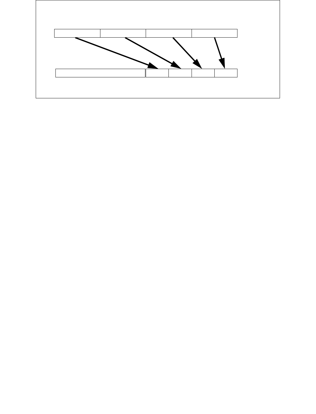
CVTTPD2DQ—Convert with Truncation Packed Double-Precision Floating-Point Values to Packed Doubleword Integers
INSTRUCTION SET REFERENCE, A-L
3-266 Vol. 2A
Operation
VCVTTPD2DQ (EVEX encoded versions) when src operand is a register
(KL, VL) = (2, 128), (4, 256), (8, 512)
FOR j 0 TO KL-1
i j * 32
k j * 64
IF k1[j] OR *no writemask*
THEN DEST[i+31:i]
Convert_Double_Precision_Floating_Point_To_Integer_Truncate(SRC[k+63:k])
ELSE
IF *merging-masking* ; merging-masking
THEN *DEST[i+31:i] remains unchanged*
ELSE ; zeroing-masking
DEST[i+31:i] 0
FI
FI;
ENDFOR
DEST[MAX_VL-1:VL/2] 0
Figure 3-15. VCVTTPD2DQ (VEX.256 encoded version)
DEST
SRC
X0X1X2X3
X3 X2
X1 X0
0

CVTTPD2DQ—Convert with Truncation Packed Double-Precision Floating-Point Values to Packed Doubleword Integers
INSTRUCTION SET REFERENCE, A-L
Vol. 2A 3-267
VCVTTPD2DQ (EVEX encoded versions) when src operand is a memory source
(KL, VL) = (2, 128), (4, 256), (8, 512)
FOR j 0 TO KL-1
i j * 32
k j * 64
IF k1[j] OR *no writemask*
THEN
IF (EVEX.b = 1)
THEN
DEST[i+31:i]
Convert_Double_Precision_Floating_Point_To_Integer_Truncate(SRC[63:0])
ELSE
DEST[i+31:i]
Convert_Double_Precision_Floating_Point_To_Integer_Truncate(SRC[k+63:k])
FI;
ELSE
IF *merging-masking* ; merging-masking
THEN *DEST[i+31:i] remains unchanged*
ELSE ; zeroing-masking
DEST[i+31:i] 0
FI
FI;
ENDFOR
DEST[MAX_VL-1:VL/2] 0
VCVTTPD2DQ (VEX.256 encoded version)
DEST[31:0] Convert_Double_Precision_Floating_Point_To_Integer_Truncate(SRC[63:0])
DEST[63:32] Convert_Double_Precision_Floating_Point_To_Integer_Truncate(SRC[127:64])
DEST[95:64] Convert_Double_Precision_Floating_Point_To_Integer_Truncate(SRC[191:128])
DEST[127:96] Convert_Double_Precision_Floating_Point_To_Integer_Truncate(SRC[255:192)
DEST[MAX_VL-1:128]0
VCVTTPD2DQ (VEX.128 encoded version)
DEST[31:0] Convert_Double_Precision_Floating_Point_To_Integer_Truncate(SRC[63:0])
DEST[63:32] Convert_Double_Precision_Floating_Point_To_Integer_Truncate(SRC[127:64])
DEST[MAX_VL-1:64]0
CVTTPD2DQ (128-bit Legacy SSE version)
DEST[31:0] Convert_Double_Precision_Floating_Point_To_Integer_Truncate(SRC[63:0])
DEST[63:32] Convert_Double_Precision_Floating_Point_To_Integer_Truncate(SRC[127:64])
DEST[127:64] 0
DEST[MAX_VL-1:128] (unmodified)

CVTTPD2DQ—Convert with Truncation Packed Double-Precision Floating-Point Values to Packed Doubleword Integers
INSTRUCTION SET REFERENCE, A-L
3-268 Vol. 2A
Intel C/C++ Compiler Intrinsic Equivalent
VCVTTPD2DQ __m256i _mm512_cvttpd_epi32( __m512d a);
VCVTTPD2DQ __m256i _mm512_mask_cvttpd_epi32( __m256i s, __mmask8 k, __m512d a);
VCVTTPD2DQ __m256i _mm512_maskz_cvttpd_epi32( __mmask8 k, __m512d a);
VCVTTPD2DQ __m256i _mm512_cvtt_roundpd_epi32( __m512d a, int sae);
VCVTTPD2DQ __m256i _mm512_mask_cvtt_roundpd_epi32( __m256i s, __mmask8 k, __m512d a, int sae);
VCVTTPD2DQ __m256i _mm512_maskz_cvtt_roundpd_epi32( __mmask8 k, __m512d a, int sae);
VCVTTPD2DQ __m128i _mm256_mask_cvttpd_epi32( __m128i s, __mmask8 k, __m256d a);
VCVTTPD2DQ __m128i _mm256_maskz_cvttpd_epi32( __mmask8 k, __m256d a);
VCVTTPD2DQ __m128i _mm_mask_cvttpd_epi32( __m128i s, __mmask8 k, __m128d a);
VCVTTPD2DQ __m128i _mm_maskz_cvttpd_epi32( __mmask8 k, __m128d a);
VCVTTPD2DQ __m128i _mm256_cvttpd_epi32 (__m256d src);
CVTTPD2DQ __m128i _mm_cvttpd_epi32 (__m128d src);
SIMD Floating-Point Exceptions
Invalid, Precision
Other Exceptions
VEX-encoded instructions, see Exceptions Type 2;
EVEX-encoded instructions, see Exceptions Type E2.
#UD If VEX.vvvv != 1111B or EVEX.vvvv != 1111B.

CVTTPD2PI—Convert with Truncation Packed Double-Precision FP Values to Packed Dword Integers
INSTRUCTION SET REFERENCE, A-L
Vol. 2A 3-269
CVTTPD2PI—Convert with Truncation Packed Double-Precision FP Values to Packed Dword
Integers
Instruction Operand Encoding
Description
Converts two packed double-precision floating-point values in the source operand (second operand) to two packed
signed doubleword integers in the destination operand (first operand). The source operand can be an XMM register
or a 128-bit memory location. The destination operand is an MMX technology register.
When a conversion is inexact, a truncated (round toward zero) result is returned. If a converted result is larger
than the maximum signed doubleword integer, the floating-point invalid exception is raised, and if this exception is
masked, the indefinite integer value (80000000H) is returned.
This instruction causes a transition from x87 FPU to MMX technology operation (that is, the x87 FPU top-of-stack
pointer is set to 0 and the x87 FPU tag word is set to all 0s [valid]). If this instruction is executed while an x87 FPU
floating-point exception is pending, the exception is handled before the CVTTPD2PI instruction is executed.
In 64-bit mode, use of the REX.R prefix permits this instruction to access additional registers (XMM8-XMM15).
Operation
DEST[31:0] ← Convert_Double_Precision_Floating_Point_To_Integer32_Truncate(SRC[63:0]);
DEST[63:32] ← Convert_Double_Precision_Floating_Point_To_Integer32_
Truncate(SRC[127:64]);
Intel C/C++ Compiler Intrinsic Equivalent
CVTTPD1PI: __m64 _mm_cvttpd_pi32(__m128d a)
SIMD Floating-Point Exceptions
Invalid, Precision
Other Mode Exceptions
See Table 22-4, “Exception Conditions for Legacy SIMD/MMX Instructions with FP Exception and 16-Byte Align-
ment,” in the Intel® 64 and IA-32 Architectures Software Developer’s Manual, Volume 3B.
Opcode/
Instruction
Op/
En
64-Bit
Mode
Compat/
Leg Mode
Description
66 0F 2C /r
CVTTPD2PI mm, xmm/m128
RM Valid Valid Convert two packer double-precision floating-
point values from xmm/m128 to two packed
signed doubleword integers in mm using
truncation.
Op/En Operand 1 Operand 2 Operand 3 Operand 4
RM ModRM:reg (w) ModRM:r/m (r) NA NA

CVTTPS2DQ—Convert with Truncation Packed Single-Precision Floating-Point Values to Packed Signed Doubleword Integer Values
INSTRUCTION SET REFERENCE, A-L
3-270 Vol. 2A
CVTTPS2DQ—Convert with Truncation Packed Single-Precision Floating-Point Values to Packed
Signed Doubleword Integer Values
Instruction Operand Encoding
Description
Converts four, eight or sixteen packed single-precision floating-point values in the source operand to four, eight or
sixteen signed doubleword integers in the destination operand.
When a conversion is inexact, a truncated (round toward zero) value is returned. If a converted result is larger than
the maximum signed doubleword integer, the floating-point invalid exception is raised, and if this exception is
masked, the indefinite integer value (80000000H) is returned.
EVEX encoded versions: The source operand is a ZMM/YMM/XMM register, a 512/256/128-bit memory location or
a 512/256/128-bit vector broadcasted from a 32-bit memory location. The destination operand is a
ZMM/YMM/XMM register conditionally updated with writemask k1.
VEX.256 encoded version: The source operand is a YMM register or 256- bit memory location. The destination
operand is a YMM register. The upper bits (MAX_VL-1:256) of the corresponding ZMM register destination are
zeroed.
VEX.128 encoded version: The source operand is an XMM register or 128- bit memory location. The destination
operand is a XMM register. The upper bits (MAX_VL-1:128) of the corresponding ZMM register destination are
zeroed.
128-bit Legacy SSE version: The source operand is an XMM register or 128- bit memory location. The destination
operand is an XMM register. The upper bits (MAX_VL-1:128) of the corresponding ZMM register destination are
unmodified.
Note: VEX.vvvv and EVEX.vvvv are reserved and must be 1111b otherwise instructions will #UD.
Opcode/
Instruction
Op /
En
64/32
bit Mode
Support
CPUID
Feature
Flag
Description
F3 0F 5B /r
CVTTPS2DQ xmm1, xmm2/m128
RM V/V SSE2 Convert four packed single-precision floating-point
values from xmm2/mem to four packed signed
doubleword values in xmm1 using truncation.
VEX.128.F3.0F.WIG 5B /r
VCVTTPS2DQ xmm1, xmm2/m128
RM V/V AVX Convert four packed single-precision floating-point
values from xmm2/mem to four packed signed
doubleword values in xmm1 using truncation.
VEX.256.F3.0F.WIG 5B /r
VCVTTPS2DQ ymm1, ymm2/m256
RM V/V AVX Convert eight packed single-precision floating-point
values from ymm2/mem to eight packed signed
doubleword values in ymm1 using truncation.
EVEX.128.F3.0F.W0 5B /r
VCVTTPS2DQ xmm1 {k1}{z},
xmm2/m128/m32bcst
FV V/V AVX512VL
AVX512F
Convert four packed single precision floating-point
values from xmm2/m128/m32bcst to four packed
signed doubleword values in xmm1 using truncation
subject to writemask k1.
EVEX.256.F3.0F.W0 5B /r
VCVTTPS2DQ ymm1 {k1}{z},
ymm2/m256/m32bcst
FV V/V AVX512VL
AVX512F
Convert eight packed single precision floating-point
values from ymm2/m256/m32bcst to eight packed
signed doubleword values in ymm1 using truncation
subject to writemask k1.
EVEX.512.F3.0F.W0 5B /r
VCVTTPS2DQ zmm1 {k1}{z},
zmm2/m512/m32bcst {sae}
FV V/V AVX512F Convert sixteen packed single-precision floating-point
values from zmm2/m512/m32bcst to sixteen packed
signed doubleword values in zmm1 using truncation
subject to writemask k1.
Op/En Operand 1 Operand 2 Operand 3 Operand 4
RM ModRM:reg (w) ModRM:r/m (r) NA NA
FV ModRM:reg (w) ModRM:r/m (r) NA NA

CVTTPS2DQ—Convert with Truncation Packed Single-Precision Floating-Point Values to Packed Signed Doubleword Integer Values
INSTRUCTION SET REFERENCE, A-L
Vol. 2A 3-271
Operation
VCVTTPS2DQ (EVEX encoded versions) when src operand is a register
(KL, VL) = (4, 128), (8, 256), (16, 512)
FOR j 0 TO KL-1
i j * 32
IF k1[j] OR *no writemask*
THEN DEST[i+31:i]
Convert_Single_Precision_Floating_Point_To_Integer_Truncate(SRC[i+31:i])
ELSE
IF *merging-masking* ; merging-masking
THEN *DEST[i+31:i] remains unchanged*
ELSE ; zeroing-masking
DEST[i+31:i] 0
FI
FI;
ENDFOR
DEST[MAX_VL-1:VL] 0
VCVTTPS2DQ (EVEX encoded versions) when src operand is a memory source
(KL, VL) = (4, 128), (8, 256), (16, 512)
FOR j 0 TO 15
i j * 32
IF k1[j] OR *no writemask*
THEN
IF (EVEX.b = 1)
THEN
DEST[i+31:i]
Convert_Single_Precision_Floating_Point_To_Integer_Truncate(SRC[31:0])
ELSE
DEST[i+31:i]
Convert_Single_Precision_Floating_Point_To_Integer_Truncate(SRC[i+31:i])
FI;
ELSE
IF *merging-masking* ; merging-masking
THEN *DEST[i+31:i] remains unchanged*
ELSE ; zeroing-masking
DEST[i+31:i] 0
FI
FI;
ENDFOR
DEST[MAX_VL-1:VL] 0
VCVTTPS2DQ (VEX.256 encoded version)
DEST[31:0] Convert_Single_Precision_Floating_Point_To_Integer_Truncate(SRC[31:0])
DEST[63:32] Convert_Single_Precision_Floating_Point_To_Integer_Truncate(SRC[63:32])
DEST[95:64] Convert_Single_Precision_Floating_Point_To_Integer_Truncate(SRC[95:64])
DEST[127:96] Convert_Single_Precision_Floating_Point_To_Integer_Truncate(SRC[127:96)
DEST[159:128] Convert_Single_Precision_Floating_Point_To_Integer_Truncate(SRC[159:128])
DEST[191:160] Convert_Single_Precision_Floating_Point_To_Integer_Truncate(SRC[191:160])
DEST[223:192] Convert_Single_Precision_Floating_Point_To_Integer_Truncate(SRC[223:192])
DEST[255:224] Convert_Single_Precision_Floating_Point_To_Integer_Truncate(SRC[255:224])

CVTTPS2DQ—Convert with Truncation Packed Single-Precision Floating-Point Values to Packed Signed Doubleword Integer Values
INSTRUCTION SET REFERENCE, A-L
3-272 Vol. 2A
VCVTTPS2DQ (VEX.128 encoded version)
DEST[31:0] Convert_Single_Precision_Floating_Point_To_Integer_Truncate(SRC[31:0])
DEST[63:32] Convert_Single_Precision_Floating_Point_To_Integer_Truncate(SRC[63:32])
DEST[95:64] Convert_Single_Precision_Floating_Point_To_Integer_Truncate(SRC[95:64])
DEST[127:96] Convert_Single_Precision_Floating_Point_To_Integer_Truncate(SRC[127:96])
DEST[MAX_VL-1:128] 0
CVTTPS2DQ (128-bit Legacy SSE version)
DEST[31:0] Convert_Single_Precision_Floating_Point_To_Integer_Truncate(SRC[31:0])
DEST[63:32] Convert_Single_Precision_Floating_Point_To_Integer_Truncate(SRC[63:32])
DEST[95:64] Convert_Single_Precision_Floating_Point_To_Integer_Truncate(SRC[95:64])
DEST[127:96] Convert_Single_Precision_Floating_Point_To_Integer_Truncate(SRC[127:96])
DEST[MAX_VL-1:128] (unmodified)
Intel C/C++ Compiler Intrinsic Equivalent
VCVTTPS2DQ __m512i _mm512_cvttps_epi32( __m512 a);
VCVTTPS2DQ __m512i _mm512_mask_cvttps_epi32( __m512i s, __mmask16 k, __m512 a);
VCVTTPS2DQ __m512i _mm512_maskz_cvttps_epi32( __mmask16 k, __m512 a);
VCVTTPS2DQ __m512i _mm512_cvtt_roundps_epi32( __m512 a, int sae);
VCVTTPS2DQ __m512i _mm512_mask_cvtt_roundps_epi32( __m512i s, __mmask16 k, __m512 a, int sae);
VCVTTPS2DQ __m512i _mm512_maskz_cvtt_roundps_epi32( __mmask16 k, __m512 a, int sae);
VCVTTPS2DQ __m256i _mm256_mask_cvttps_epi32( __m256i s, __mmask8 k, __m256 a);
VCVTTPS2DQ __m256i _mm256_maskz_cvttps_epi32( __mmask8 k, __m256 a);
VCVTTPS2DQ __m128i _mm_mask_cvttps_epi32( __m128i s, __mmask8 k, __m128 a);
VCVTTPS2DQ __m128i _mm_maskz_cvttps_epi32( __mmask8 k, __m128 a);
VCVTTPS2DQ __m256i _mm256_cvttps_epi32 (__m256 a)
CVTTPS2DQ __m128i _mm_cvttps_epi32 (__m128 a)
SIMD Floating-Point Exceptions
Invalid, Precision
Other Exceptions
VEX-encoded instructions, see Exceptions Type 2; additionally
EVEX-encoded instructions, see Exceptions Type E2.
#UD If VEX.vvvv != 1111B or EVEX.vvvv != 1111B.

CVTTPS2PI—Convert with Truncation Packed Single-Precision FP Values to Packed Dword Integers
INSTRUCTION SET REFERENCE, A-L
Vol. 2A 3-273
CVTTPS2PI—Convert with Truncation Packed Single-Precision FP Values to Packed Dword
Integers
Instruction Operand Encoding
Description
Converts two packed single-precision floating-point values in the source operand (second operand) to two packed
signed doubleword integers in the destination operand (first operand). The source operand can be an XMM register
or a 64-bit memory location. The destination operand is an MMX technology register. When the source operand is
an XMM register, the two single-precision floating-point values are contained in the low quadword of the register.
When a conversion is inexact, a truncated (round toward zero) result is returned. If a converted result is larger
than the maximum signed doubleword integer, the floating-point invalid exception is raised, and if this exception is
masked, the indefinite integer value (80000000H) is returned.
This instruction causes a transition from x87 FPU to MMX technology operation (that is, the x87 FPU top-of-stack
pointer is set to 0 and the x87 FPU tag word is set to all 0s [valid]). If this instruction is executed while an x87 FPU
floating-point exception is pending, the exception is handled before the CVTTPS2PI instruction is executed.
In 64-bit mode, use of the REX.R prefix permits this instruction to access additional registers (XMM8-XMM15).
Operation
DEST[31:0] ← Convert_Single_Precision_Floating_Point_To_Integer_Truncate(SRC[31:0]);
DEST[63:32] ← Convert_Single_Precision_Floating_Point_To_Integer_Truncate(SRC[63:32]);
Intel C/C++ Compiler Intrinsic Equivalent
CVTTPS2PI: __m64 _mm_cvttps_pi32(__m128 a)
SIMD Floating-Point Exceptions
Invalid, Precision
Other Exceptions
See Table 22-5, “Exception Conditions for Legacy SIMD/MMX Instructions with XMM and FP Exception,” in the
Intel® 64 and IA-32 Architectures Software Developer’s Manual, Volume 3B.
Opcode/
Instruction
Op/
En
64-Bit
Mode
Compat/
Leg Mode
Description
0F 2C /r
CVTTPS2PI mm, xmm/m64
RM Valid Valid Convert two single-precision floating-point
values from xmm/m64 to two signed
doubleword signed integers in mm using
truncation.
Op/En Operand 1 Operand 2 Operand 3 Operand 4
RM ModRM:reg (w) ModRM:r/m (r) NA NA

CVTTSD2SI—Convert with Truncation Scalar Double-Precision Floating-Point Value to Signed Integer
INSTRUCTION SET REFERENCE, A-L
3-274 Vol. 2A
CVTTSD2SI—Convert with Truncation Scalar Double-Precision Floating-Point Value to Signed
Integer
Instruction Operand Encoding
Description
Converts a double-precision floating-point value in the source operand (the second operand) to a signed double-
word integer (or signed quadword integer if operand size is 64 bits) in the destination operand (the first operand).
The source operand can be an XMM register or a 64-bit memory location. The destination operand is a general
purpose register. When the source operand is an XMM register, the double-precision floating-point value is
contained in the low quadword of the register.
When a conversion is inexact, the value returned is rounded according to the rounding control bits in the MXCSR
register.
If a converted result exceeds the range limits of signed doubleword integer (in non-64-bit modes or 64-bit mode
with REX.W/VEX.W/EVEX.W=0), the floating-point invalid exception is raised, and if this exception is masked, the
indefinite integer value (80000000H) is returned.
If a converted result exceeds the range limits of signed quadword integer (in 64-bit mode and
REX.W/VEX.W/EVEX.W = 1), the floating-point invalid exception is raised, and if this exception is masked, the
indefinite integer value (80000000_00000000H) is returned.
Legacy SSE instructions: In 64-bit mode, Use of the REX.W prefix promotes the instruction to 64-bit operation. See
the summary chart at the beginning of this section for encoding data and limits.
VEX.W1 and EVEX.W1 versions: promotes the instruction to produce 64-bit data in 64-bit mode.
Note: VEX.vvvv and EVEX.vvvv are reserved and must be 1111b, otherwise instructions will #UD.
Opcode/
Instruction
Op /
En
64/32
bit Mode
Support
CPUID
Feature
Flag
Description
F2 0F 2C /r
CVTTSD2SI r32, xmm1/m64
RM V/V SSE2 Convert one double-precision floating-point value from
xmm1/m64 to one signed doubleword integer in r32
using truncation.
F2 REX.W 0F 2C /r
CVTTSD2SI r64, xmm1/m64
RM V/N.E. SSE2 Convert one double-precision floating-point value from
xmm1/m64 to one signed quadword integer in r64
using truncation.
VEX.128.F2.0F.W0 2C /r
VCVTTSD2SI r32, xmm1/m64
RM V/V AVX Convert one double-precision floating-point value from
xmm1/m64 to one signed doubleword integer in r32
using truncation.
VEX.128.F2.0F.W1 2C /r
VCVTTSD2SI r64, xmm1/m64
T1F V/N.E.1AVX Convert one double-precision floating-point value from
xmm1/m64 to one signed quadword integer in r64
using truncation.
EVEX.LIG.F2.0F.W0 2C /r
VCVTTSD2SI r32, xmm1/m64{sae}
T1F V/V AVX512F Convert one double-precision floating-point value from
xmm1/m64 to one signed doubleword integer in r32
using truncation.
EVEX.LIG.F2.0F.W1 2C /r
VCVTTSD2SI r64, xmm1/m64{sae}
T1F V/N.E.1
NOTES:
1. For this specific instruction, VEX.W/EVEX.W in non-64 bit is ignored; the instructions behaves as if the W0 ver-
sion is used.
AVX512F Convert one double-precision floating-point value from
xmm1/m64 to one signed quadword integer in r64
using truncation.
Op/En Operand 1 Operand 2 Operand 3 Operand 4
RM ModRM:reg (w) ModRM:r/m (r) NA NA
T1F ModRM:reg (w) ModRM:r/m (r) NA NA

CVTTSD2SI—Convert with Truncation Scalar Double-Precision Floating-Point Value to Signed Integer
INSTRUCTION SET REFERENCE, A-L
Vol. 2A 3-275
Software should ensure VCVTTSD2SI is encoded with VEX.L=0. Encoding VCVTTSD2SI with VEX.L=1 may
encounter unpredictable behavior across different processor generations.
Operation
(V)CVTTSD2SI (All versions)
IF 64-Bit Mode and OperandSize = 64
THEN
DEST[63:0] Convert_Double_Precision_Floating_Point_To_Integer_Truncate(SRC[63:0]);
ELSE
DEST[31:0] Convert_Double_Precision_Floating_Point_To_Integer_Truncate(SRC[63:0]);
FI;
Intel C/C++ Compiler Intrinsic Equivalent
VCVTTSD2SI int _mm_cvttsd_i32( __m128d a);
VCVTTSD2SI int _mm_cvtt_roundsd_i32( __m128d a, int sae);
VCVTTSD2SI __int64 _mm_cvttsd_i64( __m128d a);
VCVTTSD2SI __int64 _mm_cvtt_roundsd_i64( __m128d a, int sae);
CVTTSD2SI int _mm_cvttsd_si32( __m128d a);
CVTTSD2SI __int64 _mm_cvttsd_si64( __m128d a);
SIMD Floating-Point Exceptions
Invalid, Precision
Other Exceptions
VEX-encoded instructions, see Exceptions Type 3; additionally
#UD If VEX.vvvv != 1111B.
EVEX-encoded instructions, see Exceptions Type E3NF.

CVTTSS2SI—Convert with Truncation Scalar Single-Precision Floating-Point Value to Integer
INSTRUCTION SET REFERENCE, A-L
3-276 Vol. 2A
CVTTSS2SI—Convert with Truncation Scalar Single-Precision Floating-Point Value to Integer
Instruction Operand Encoding
Description
Converts a single-precision floating-point value in the source operand (the second operand) to a signed doubleword
integer (or signed quadword integer if operand size is 64 bits) in the destination operand (the first operand). The
source operand can be an XMM register or a 32-bit memory location. The destination operand is a general purpose
register. When the source operand is an XMM register, the single-precision floating-point value is contained in the
low doubleword of the register.
When a conversion is inexact, a truncated (round toward zero) result is returned. If a converted result is larger than
the maximum signed doubleword integer, the floating-point invalid exception is raised. If this exception is masked,
the indefinite integer value (80000000H or 80000000_00000000H if operand size is 64 bits) is returned.
Legacy SSE instructions: In 64-bit mode, Use of the REX.W prefix promotes the instruction to 64-bit operation. See
the summary chart at the beginning of this section for encoding data and limits.
VEX.W1 and EVEX.W1 versions: promotes the instruction to produce 64-bit data in 64-bit mode.
Note: VEX.vvvv and EVEX.vvvv are reserved and must be 1111b, otherwise instructions will #UD.
Software should ensure VCVTTSS2SI is encoded with VEX.L=0. Encoding VCVTTSS2SI with VEX.L=1 may
encounter unpredictable behavior across different processor generations.
Opcode/
Instruction
Op /
En
64/32
bit Mode
Support
CPUID
Feature
Flag
Description
F3 0F 2C /r
CVTTSS2SI r32, xmm1/m32
RM V/V SSE Convert one single-precision floating-point value from
xmm1/m32 to one signed doubleword integer in r32
using truncation.
F3 REX.W 0F 2C /r
CVTTSS2SI r64, xmm1/m32
RM V/N.E. SSE Convert one single-precision floating-point value from
xmm1/m32 to one signed quadword integer in r64
using truncation.
VEX.128.F3.0F.W0 2C /r
VCVTTSS2SI r32, xmm1/m32
RM V/V AVX Convert one single-precision floating-point value from
xmm1/m32 to one signed doubleword integer in r32
using truncation.
VEX.128.F3.0F.W1 2C /r
VCVTTSS2SI r64, xmm1/m32
RM V/N.E.1AVX Convert one single-precision floating-point value from
xmm1/m32 to one signed quadword integer in r64
using truncation.
EVEX.LIG.F3.0F.W0 2C /r
VCVTTSS2SI r32, xmm1/m32{sae}
T1F V/V AVX512F Convert one single-precision floating-point value from
xmm1/m32 to one signed doubleword integer in r32
using truncation.
EVEX.LIG.F3.0F.W1 2C /r
VCVTTSS2SI r64, xmm1/m32{sae}
T1F V/N.E.1
NOTES:
1. For this specific instruction, VEX.W/EVEX.W in non-64 bit is ignored; the instructions behaves as if the W0 ver-
sion is used.
AVX512F Convert one single-precision floating-point value from
xmm1/m32 to one signed quadword integer in r64
using truncation.
Op/En Operand 1 Operand 2 Operand 3 Operand 4
RM ModRM:reg (w) ModRM:r/m (r) NA NA
T1F ModRM:reg (w) ModRM:r/m (r) NA NA

CVTTSS2SI—Convert with Truncation Scalar Single-Precision Floating-Point Value to Integer
INSTRUCTION SET REFERENCE, A-L
Vol. 2A 3-277
Operation
(V)CVTTSS2SI (All versions)
IF 64-Bit Mode and OperandSize = 64
THEN
DEST[63:0] Convert_Single_Precision_Floating_Point_To_Integer_Truncate(SRC[31:0]);
ELSE
DEST[31:0] Convert_Single_Precision_Floating_Point_To_Integer_Truncate(SRC[31:0]);
FI;
Intel C/C++ Compiler Intrinsic Equivalent
VCVTTSS2SI int _mm_cvttss_i32( __m128 a);
VCVTTSS2SI int _mm_cvtt_roundss_i32( __m128 a, int sae);
VCVTTSS2SI __int64 _mm_cvttss_i64( __m128 a);
VCVTTSS2SI __int64 _mm_cvtt_roundss_i64( __m128 a, int sae);
CVTTSS2SI int _mm_cvttss_si32( __m128 a);
CVTTSS2SI __int64 _mm_cvttss_si64( __m128 a);
SIMD Floating-Point Exceptions
Invalid, Precision
Other Exceptions
See Exceptions Type 3; additionally
#UD If VEX.vvvv != 1111B.
EVEX-encoded instructions, see Exceptions Type E3NF.

CWD/CDQ/CQO—Convert Word to Doubleword/Convert Doubleword to Quadword
INSTRUCTION SET REFERENCE, A-L
3-278 Vol. 2A
CWD/CDQ/CQO—Convert Word to Doubleword/Convert Doubleword to Quadword
Instruction Operand Encoding
Description
Doubles the size of the operand in register AX, EAX, or RAX (depending on the operand size) by means of sign
extension and stores the result in registers DX:AX, EDX:EAX, or RDX:RAX, respectively. The CWD instruction
copies the sign (bit 15) of the value in the AX register into every bit position in the DX register. The CDQ instruction
copies the sign (bit 31) of the value in the EAX register into every bit position in the EDX register. The CQO instruc-
tion (available in 64-bit mode only) copies the sign (bit 63) of the value in the RAX register into every bit position
in the RDX register.
The CWD instruction can be used to produce a doubleword dividend from a word before word division. The CDQ
instruction can be used to produce a quadword dividend from a doubleword before doubleword division. The CQO
instruction can be used to produce a double quadword dividend from a quadword before a quadword division.
The CWD and CDQ mnemonics reference the same opcode. The CWD instruction is intended for use when the
operand-size attribute is 16 and the CDQ instruction for when the operand-size attribute is 32. Some assemblers
may force the operand size to 16 when CWD is used and to 32 when CDQ is used. Others may treat these
mnemonics as synonyms (CWD/CDQ) and use the current setting of the operand-size attribute to determine the
size of values to be converted, regardless of the mnemonic used.
In 64-bit mode, use of the REX.W prefix promotes operation to 64 bits. The CQO mnemonics reference the same
opcode as CWD/CDQ. See the summary chart at the beginning of this section for encoding data and limits.
Operation
IF OperandSize = 16 (* CWD instruction *)
THEN
DX ← SignExtend(AX);
ELSE IF OperandSize = 32 (* CDQ instruction *)
EDX ← SignExtend(EAX); FI;
ELSE IF 64-Bit Mode and OperandSize = 64 (* CQO instruction*)
RDX ← SignExtend(RAX); FI;
FI;
Flags Affected
None
Exceptions (All Operating Modes)
#UD If the LOCK prefix is used.
Opcode Instruction Op/
En
64-Bit
Mode
Compat/
Leg Mode
Description
99 CWD NP Valid Valid DX:AX ← sign-extend of AX.
99 CDQ NP Valid Valid EDX:EAX ← sign-extend of EAX.
REX.W + 99 CQO NP Valid N.E. RDX:RAX← sign-extend of RAX.
Op/En Operand 1 Operand 2 Operand 3 Operand 4
NP NA NA NA NA

DAA—Decimal Adjust AL after Addition
INSTRUCTION SET REFERENCE, A-L
Vol. 2A 3-279
DAA—Decimal Adjust AL after Addition
Instruction Operand Encoding
Description
Adjusts the sum of two packed BCD values to create a packed BCD result. The AL register is the implied source and
destination operand. The DAA instruction is only useful when it follows an ADD instruction that adds (binary addi-
tion) two 2-digit, packed BCD values and stores a byte result in the AL register. The DAA instruction then adjusts
the contents of the AL register to contain the correct 2-digit, packed BCD result. If a decimal carry is detected, the
CF and AF flags are set accordingly.
This instruction executes as described above in compatibility mode and legacy mode. It is not valid in 64-bit mode.
Operation
IF 64-Bit Mode
THEN
#UD;
ELSE
old_AL ← AL;
old_CF ← CF;
CF ← 0;
IF (((AL AND 0FH) > 9) or AF = 1)
THEN
AL ← AL + 6;
CF ← old_CF or (Carry from AL ← AL + 6);
AF ← 1;
ELSE
AF ← 0;
FI;
IF ((old_AL > 99H) or (old_CF = 1))
THEN
AL ← AL + 60H;
CF ← 1;
ELSE
CF ← 0;
FI;
FI;
Example
ADD AL, BL Before: AL=79H BL=35H EFLAGS(OSZAPC)=XXXXXX
After: AL=AEH BL=35H EFLAGS(0SZAPC)=110000
DAA Before: AL=AEH BL=35H EFLAGS(OSZAPC)=110000
After: AL=14H BL=35H EFLAGS(0SZAPC)=X00111
DAA Before: AL=2EH BL=35H EFLAGS(OSZAPC)=110000
After: AL=34H BL=35H EFLAGS(0SZAPC)=X00101
Opcode Instruction Op/
En
64-Bit
Mode
Compat/
Leg Mode
Description
27 DAA NP Invalid Valid Decimal adjust AL after addition.
Op/En Operand 1 Operand 2 Operand 3 Operand 4
NP NA NA NA NA

DAA—Decimal Adjust AL after Addition
INSTRUCTION SET REFERENCE, A-L
3-280 Vol. 2A
Flags Affected
The CF and AF flags are set if the adjustment of the value results in a decimal carry in either digit of the result (see
the “Operation” section above). The SF, ZF, and PF flags are set according to the result. The OF flag is undefined.
Protected Mode Exceptions
#UD If the LOCK prefix is used.
Real-Address Mode Exceptions
#UD If the LOCK prefix is used.
Virtual-8086 Mode Exceptions
#UD If the LOCK prefix is used.
Compatibility Mode Exceptions
#UD If the LOCK prefix is used.
64-Bit Mode Exceptions
#UD If in 64-bit mode.

DAS—Decimal Adjust AL after Subtraction
INSTRUCTION SET REFERENCE, A-L
Vol. 2A 3-281
DAS—Decimal Adjust AL after Subtraction
Instruction Operand Encoding
Description
Adjusts the result of the subtraction of two packed BCD values to create a packed BCD result. The AL register is the
implied source and destination operand. The DAS instruction is only useful when it follows a SUB instruction that
subtracts (binary subtraction) one 2-digit, packed BCD value from another and stores a byte result in the AL
register. The DAS instruction then adjusts the contents of the AL register to contain the correct 2-digit, packed BCD
result. If a decimal borrow is detected, the CF and AF flags are set accordingly.
This instruction executes as described above in compatibility mode and legacy mode. It is not valid in 64-bit mode.
Operation
IF 64-Bit Mode
THEN
#UD;
ELSE
old_AL ← AL;
old_CF ← CF;
CF ← 0;
IF (((AL AND 0FH) > 9) or AF = 1)
THEN
AL ← AL - 6;
CF ← old_CF or (Borrow from AL ← AL − 6);
AF ← 1;
ELSE
AF ← 0;
FI;
IF ((old_AL > 99H) or (old_CF = 1))
THEN
AL ← AL − 60H;
CF ← 1;
FI;
FI;
Example
SUB AL, BL Before: AL = 35H, BL = 47H, EFLAGS(OSZAPC) = XXXXXX
After: AL = EEH, BL = 47H, EFLAGS(0SZAPC) = 010111
DAA Before: AL = EEH, BL = 47H, EFLAGS(OSZAPC) = 010111
After: AL = 88H, BL = 47H, EFLAGS(0SZAPC) = X10111
Flags Affected
The CF and AF flags are set if the adjustment of the value results in a decimal borrow in either digit of the result
(see the “Operation” section above). The SF, ZF, and PF flags are set according to the result. The OF flag is unde-
fined.
Opcode Instruction Op/
En
64-Bit
Mode
Compat/
Leg Mode
Description
2F DAS NP Invalid Valid Decimal adjust AL after subtraction.
Op/En Operand 1 Operand 2 Operand 3 Operand 4
NP NA NA NA NA

DAS—Decimal Adjust AL after Subtraction
INSTRUCTION SET REFERENCE, A-L
3-282 Vol. 2A
Protected Mode Exceptions
#UD If the LOCK prefix is used.
Real-Address Mode Exceptions
#UD If the LOCK prefix is used.
Virtual-8086 Mode Exceptions
#UD If the LOCK prefix is used.
Compatibility Mode Exceptions
#UD If the LOCK prefix is used.
64-Bit Mode Exceptions
#UD If in 64-bit mode.

DEC—Decrement by 1
INSTRUCTION SET REFERENCE, A-L
Vol. 2A 3-283
DEC—Decrement by 1
Instruction Operand Encoding
Description
Subtracts 1 from the destination operand, while preserving the state of the CF flag. The destination operand can be
a register or a memory location. This instruction allows a loop counter to be updated without disturbing the CF flag.
(To perform a decrement operation that updates the CF flag, use a SUB instruction with an immediate operand of
1.)
This instruction can be used with a LOCK prefix to allow the instruction to be executed atomically.
In 64-bit mode, DEC r16 and DEC r32 are not encodable (because opcodes 48H through 4FH are REX prefixes).
Otherwise, the instruction’s 64-bit mode default operation size is 32 bits. Use of the REX.R prefix permits access to
additional registers (R8-R15). Use of the REX.W prefix promotes operation to 64 bits.
See the summary chart at the beginning of this section for encoding data and limits.
Operation
DEST ← DEST – 1;
Flags Affected
The CF flag is not affected. The OF, SF, ZF, AF, and PF flags are set according to the result.
Protected Mode Exceptions
#GP(0) If the destination operand is located in a non-writable segment.
If a memory operand effective address is outside the CS, DS, ES, FS, or GS segment limit.
If the DS, ES, FS, or GS register contains a NULL segment selector.
#SS(0) If a memory operand effective address is outside the SS segment limit.
#PF(fault-code) If a page fault occurs.
#AC(0) If alignment checking is enabled and an unaligned memory reference is made while the
current privilege level is 3.
#UD If the LOCK prefix is used but the destination is not a memory operand.
Opcode Instruction Op/
En
64-Bit
Mode
Compat/
Leg Mode
Description
FE /1 DEC r/m8 MValid Valid Decrement r/m8 by 1.
REX + FE /1 DEC r/m8*M Valid N.E. Decrement r/m8 by 1.
FF /1 DEC r/m16 MValid Valid Decrement r/m16 by 1.
FF /1 DEC r/m32 MValid Valid Decrement r/m32 by 1.
REX.W + FF /1 DEC r/m64 M Valid N.E. Decrement r/m64 by 1.
48+rw DEC r16 O N.E. Valid Decrement r16 by 1.
48+rd DEC r32 O N.E. Valid Decrement r32 by 1.
NOTES:
* In 64-bit mode, r/m8 can not be encoded to access the following byte registers if a REX prefix is used: AH, BH, CH, DH.
Op/En Operand 1 Operand 2 Operand 3 Operand 4
M ModRM:r/m (r, w) NA NA NA
O opcode + rd (r, w) NA NA NA

DEC—Decrement by 1
INSTRUCTION SET REFERENCE, A-L
3-284 Vol. 2A
Real-Address Mode Exceptions
#GP If a memory operand effective address is outside the CS, DS, ES, FS, or GS segment limit.
#SS If a memory operand effective address is outside the SS segment limit.
#UD If the LOCK prefix is used but the destination is not a memory operand.
Virtual-8086 Mode Exceptions
#GP(0) If a memory operand effective address is outside the CS, DS, ES, FS, or GS segment limit.
#SS(0) If a memory operand effective address is outside the SS segment limit.
#PF(fault-code) If a page fault occurs.
#AC(0) If alignment checking is enabled and an unaligned memory reference is made.
#UD If the LOCK prefix is used but the destination is not a memory operand.
Compatibility Mode Exceptions
Same exceptions as in protected mode.
64-Bit Mode Exceptions
#SS(0) If a memory address referencing the SS segment is in a non-canonical form.
#GP(0) If the memory address is in a non-canonical form.
#PF(fault-code) If a page fault occurs.
#AC(0) If alignment checking is enabled and an unaligned memory reference is made while the
current privilege level is 3.
#UD If the LOCK prefix is used but the destination is not a memory operand.

DIV—Unsigned Divide
INSTRUCTION SET REFERENCE, A-L
Vol. 2A 3-285
DIV—Unsigned Divide
Instruction Operand Encoding
Description
Divides unsigned the value in the AX, DX:AX, EDX:EAX, or RDX:RAX registers (dividend) by the source operand
(divisor) and stores the result in the AX (AH:AL), DX:AX, EDX:EAX, or RDX:RAX registers. The source operand can
be a general-purpose register or a memory location. The action of this instruction depends on the operand size
(dividend/divisor). Division using 64-bit operand is available only in 64-bit mode.
Non-integral results are truncated (chopped) towards 0. The remainder is always less than the divisor in magni-
tude. Overflow is indicated with the #DE (divide error) exception rather than with the CF flag.
In 64-bit mode, the instruction’s default operation size is 32 bits. Use of the REX.R prefix permits access to addi-
tional registers (R8-R15). Use of the REX.W prefix promotes operation to 64 bits. In 64-bit mode when REX.W is
applied, the instruction divides the unsigned value in RDX:RAX by the source operand and stores the quotient in
RAX, the remainder in RDX.
See the summary chart at the beginning of this section for encoding data and limits. See Table 3-15.
Opcode Instruction Op/
En
64-Bit
Mode
Compat/
Leg Mode
Description
F6 /6 DIV r/m8 M Valid Valid Unsigned divide AX by r/m8, with result
stored in AL ← Quotient, AH ← Remainder.
REX + F6 /6 DIV r/m8*M Valid N.E. Unsigned divide AX by r/m8, with result
stored in AL ← Quotient, AH ← Remainder.
F7 /6 DIV r/m16 M Valid Valid Unsigned divide DX:AX by r/m16, with result
stored in AX ← Quotient, DX ← Remainder.
F7 /6 DIV r/m32 M Valid Valid Unsigned divide EDX:EAX by r/m32, with
result stored in EAX ← Quotient, EDX ←
Remainder.
REX.W + F7 /6 DIV r/m64 M Valid N.E. Unsigned divide RDX:RAX by r/m64, with
result stored in RAX ← Quotient, RDX ←
Remainder.
NOTES:
* In 64-bit mode, r/m8 can not be encoded to access the following byte registers if a REX prefix is used: AH, BH, CH, DH.
Op/En Operand 1 Operand 2 Operand 3 Operand 4
M ModRM:r/m (w) NA NA NA
Table 3-15. DIV Action
Operand Size Dividend Divisor Quotient Remainder
Maximum
Quotient
Word/byte AX r/m8 AL AH 255
Doubleword/word DX:AX r/m16 AX DX 65,535
Quadword/doubleword EDX:EAX r/m32 EAX EDX 232 − 1
Doublequadword/
quadword
RDX:RAX r/m64 RAX RDX 264 − 1

DIV—Unsigned Divide
INSTRUCTION SET REFERENCE, A-L
3-286 Vol. 2A
Operation
IF SRC = 0
THEN #DE; FI; (* Divide Error *)
IF OperandSize = 8 (* Word/Byte Operation *)
THEN
temp ← AX / SRC;
IF temp > FFH
THEN #DE; (* Divide error *)
ELSE
AL ← temp;
AH ← AX MOD SRC;
FI;
ELSE IF OperandSize = 16 (* Doubleword/word operation *)
THEN
temp ← DX:AX / SRC;
IF temp > FFFFH
THEN #DE; (* Divide error *)
ELSE
AX ← temp;
DX ← DX:AX MOD SRC;
FI;
FI;
ELSE IF Operandsize = 32 (* Quadword/doubleword operation *)
THEN
temp ← EDX:EAX / SRC;
IF temp > FFFFFFFFH
THEN #DE; (* Divide error *)
ELSE
EAX ← temp;
EDX ← EDX:EAX MOD SRC;
FI;
FI;
ELSE IF 64-Bit Mode and Operandsize = 64 (* Doublequadword/quadword operation *)
THEN
temp ← RDX:RAX / SRC;
IF temp > FFFFFFFFFFFFFFFFH
THEN #DE; (* Divide error *)
ELSE
RAX ← temp;
RDX ← RDX:RAX MOD SRC;
FI;
FI;
FI;
Flags Affected
The CF, OF, SF, ZF, AF, and PF flags are undefined.

DIV—Unsigned Divide
INSTRUCTION SET REFERENCE, A-L
Vol. 2A 3-287
Protected Mode Exceptions
#DE If the source operand (divisor) is 0
If the quotient is too large for the designated register.
#GP(0) If a memory operand effective address is outside the CS, DS, ES, FS, or GS segment limit.
If the DS, ES, FS, or GS register contains a NULL segment selector.
#SS(0) If a memory operand effective address is outside the SS segment limit.
#PF(fault-code) If a page fault occurs.
#AC(0) If alignment checking is enabled and an unaligned memory reference is made while the
current privilege level is 3.
#UD If the LOCK prefix is used.
Real-Address Mode Exceptions
#DE If the source operand (divisor) is 0.
If the quotient is too large for the designated register.
#GP If a memory operand effective address is outside the CS, DS, ES, FS, or GS segment limit.
If the DS, ES, FS, or GS register contains a NULL segment selector.
#SS(0) If a memory operand effective address is outside the SS segment limit.
#UD If the LOCK prefix is used.
Virtual-8086 Mode Exceptions
#DE If the source operand (divisor) is 0.
If the quotient is too large for the designated register.
#GP(0) If a memory operand effective address is outside the CS, DS, ES, FS, or GS segment limit.
#SS If a memory operand effective address is outside the SS segment limit.
#PF(fault-code) If a page fault occurs.
#AC(0) If alignment checking is enabled and an unaligned memory reference is made.
#UD If the LOCK prefix is used.
Compatibility Mode Exceptions
Same exceptions as in protected mode.
64-Bit Mode Exceptions
#SS(0) If a memory address referencing the SS segment is in a non-canonical form.
#GP(0) If the memory address is in a non-canonical form.
#DE If the source operand (divisor) is 0
If the quotient is too large for the designated register.
#PF(fault-code) If a page fault occurs.
#AC(0) If alignment checking is enabled and an unaligned memory reference is made while the
current privilege level is 3.
#UD If the LOCK prefix is used.

DIVPD—Divide Packed Double-Precision Floating-Point Values
INSTRUCTION SET REFERENCE, A-L
3-288 Vol. 2A
DIVPD—Divide Packed Double-Precision Floating-Point Values
Instruction Operand Encoding
Description
Performs a SIMD divide of the double-precision floating-point values in the first source operand by the floating-
point values in the second source operand (the third operand). Results are written to the destination operand (the
first operand).
EVEX encoded versions: The first source operand (the second operand) is a ZMM/YMM/XMM register. The second
source operand can be a ZMM/YMM/XMM register, a 512/256/128-bit memory location or a 512/256/128-bit vector
broadcasted from a 64-bit memory location. The destination operand is a ZMM/YMM/XMM register conditionally
updated with writemask k1.
VEX.256 encoded version: The first source operand (the second operand) is a YMM register. The second source
operand can be a YMM register or a 256-bit memory location. The destination operand is a YMM register. The upper
bits (MAX_VL-1:256) of the corresponding destination are zeroed.
VEX.128 encoded version: The first source operand (the second operand) is a XMM register. The second source
operand can be a XMM register or a 128-bit memory location. The destination operand is a XMM register. The upper
bits (MAX_VL-1:128) of the corresponding destination are zeroed.
128-bit Legacy SSE version: The second source operand (the second operand) can be an XMM register or an 128-
bit memory location. The destination is the same as the first source operand. The upper bits (MAX_VL-1:128) of the
corresponding destination are unmodified.
Opcode/
Instruction
Op /
En
64/32
bit Mode
Support
CPUID
Feature
Flag
Description
66 0F 5E /r
DIVPD xmm1, xmm2/m128
RM V/V SSE2 Divide packed double-precision floating-point values
in xmm1 by packed double-precision floating-point
values in xmm2/mem.
VEX.NDS.128.66.0F.WIG 5E /r
VDIVPD xmm1, xmm2, xmm3/m128
RVM V/V AVX Divide packed double-precision floating-point values
in xmm2 by packed double-precision floating-point
values in xmm3/mem.
VEX.NDS.256.66.0F.WIG 5E /r
VDIVPD ymm1, ymm2, ymm3/m256
RVM V/V AVX Divide packed double-precision floating-point values
in ymm2 by packed double-precision floating-point
values in ymm3/mem.
EVEX.NDS.128.66.0F.W1 5E /r
VDIVPD xmm1 {k1}{z}, xmm2,
xmm3/m128/m64bcst
FV V/V AVX512VL
AVX512F
Divide packed double-precision floating-point values
in xmm2 by packed double-precision floating-point
values in xmm3/m128/m64bcst and write results to
xmm1 subject to writemask k1.
EVEX.NDS.256.66.0F.W1 5E /r
VDIVPD ymm1 {k1}{z}, ymm2,
ymm3/m256/m64bcst
FV V/V AVX512VL
AVX512F
Divide packed double-precision floating-point values
in ymm2 by packed double-precision floating-point
values in ymm3/m256/m64bcst and write results to
ymm1 subject to writemask k1.
EVEX.NDS.512.66.0F.W1 5E /r
VDIVPD zmm1 {k1}{z}, zmm2,
zmm3/m512/m64bcst{er}
FV V/V AVX512F Divide packed double-precision floating-point values
in zmm2 by packed double-precision FP values in
zmm3/m512/m64bcst and write results to zmm1
subject to writemask k1.
Op/En Operand 1 Operand 2 Operand 3 Operand 4
RM ModRM:reg (r, w) ModRM:r/m (r) NA NA
RVM ModRM:reg (w) VEX.vvvv ModRM:r/m (r) NA
FV ModRM:reg (w) EVEX.vvvv ModRM:r/m (r) NA

DIVPD—Divide Packed Double-Precision Floating-Point Values
INSTRUCTION SET REFERENCE, A-L
Vol. 2A 3-289
Operation
VDIVPD (EVEX encoded versions)
(KL, VL) = (2, 128), (4, 256), (8, 512)
IF (VL = 512) AND (EVEX.b = 1) AND SRC2 *is a register*
THEN
SET_RM(EVEX.RC); ; refer to Table 2-4 in the Intel® Architecture Instruction Set Extensions Programming Reference
ELSE
SET_RM(MXCSR.RM);
FI;
FOR j 0 TO KL-1
i j * 64
IF k1[j] OR *no writemask*
THEN
IF (EVEX.b = 1) AND (SRC2 *is memory*)
THEN
DEST[i+63:i] SRC1[i+63:i] / SRC2[63:0]
ELSE
DEST[i+63:i] SRC1[i+63:i] / SRC2[i+63:i]
FI;
ELSE
IF *merging-masking* ; merging-masking
THEN *DEST[i+63:i] remains unchanged*
ELSE ; zeroing-masking
DEST[i+63:i] 0
FI
FI;
ENDFOR
DEST[MAX_VL-1:VL] 0
VDIVPD (VEX.256 encoded version)
DEST[63:0] SRC1[63:0] / SRC2[63:0]
DEST[127:64] SRC1[127:64] / SRC2[127:64]
DEST[191:128] SRC1[191:128] / SRC2[191:128]
DEST[255:192] SRC1[255:192] / SRC2[255:192]
DEST[MAX_VL-1:256] 0;
VDIVPD (VEX.128 encoded version)
DEST[63:0] SRC1[63:0] / SRC2[63:0]
DEST[127:64] SRC1[127:64] / SRC2[127:64]
DEST[MAX_VL-1:128] 0;
DIVPD (128-bit Legacy SSE version)
DEST[63:0] SRC1[63:0] / SRC2[63:0]
DEST[127:64] SRC1[127:64] / SRC2[127:64]
DEST[MAX_VL-1:128] (Unmodified)

DIVPD—Divide Packed Double-Precision Floating-Point Values
INSTRUCTION SET REFERENCE, A-L
3-290 Vol. 2A
Intel C/C++ Compiler Intrinsic Equivalent
VDIVPD __m512d _mm512_div_pd( __m512d a, __m512d b);
VDIVPD __m512d _mm512_mask_div_pd(__m512d s, __mmask8 k, __m512d a, __m512d b);
VDIVPD __m512d _mm512_maskz_div_pd( __mmask8 k, __m512d a, __m512d b);
VDIVPD __m256d _mm256_mask_div_pd(__m256d s, __mmask8 k, __m256d a, __m256d b);
VDIVPD __m256d _mm256_maskz_div_pd( __mmask8 k, __m256d a, __m256d b);
VDIVPD __m128d _mm_mask_div_pd(__m128d s, __mmask8 k, __m128d a, __m128d b);
VDIVPD __m128d _mm_maskz_div_pd( __mmask8 k, __m128d a, __m128d b);
VDIVPD __m512d _mm512_div_round_pd( __m512d a, __m512d b, int);
VDIVPD __m512d _mm512_mask_div_round_pd(__m512d s, __mmask8 k, __m512d a, __m512d b, int);
VDIVPD __m512d _mm512_maskz_div_round_pd( __mmask8 k, __m512d a, __m512d b, int);
VDIVPD __m256d _mm256_div_pd (__m256d a, __m256d b);
DIVPD __m128d _mm_div_pd (__m128d a, __m128d b);
SIMD Floating-Point Exceptions
Overflow, Underflow, Invalid, Divide-by-Zero, Precision, Denormal
Other Exceptions
VEX-encoded instructions, see Exceptions Type 2.
EVEX-encoded instructions, see Exceptions Type E2.

DIVPS—Divide Packed Single-Precision Floating-Point Values
INSTRUCTION SET REFERENCE, A-L
Vol. 2A 3-291
DIVPS—Divide Packed Single-Precision Floating-Point Values
Instruction Operand Encoding
Description
Performs a SIMD divide of the four, eight or sixteen packed single-precision floating-point values in the first source
operand (the second operand) by the four, eight or sixteen packed single-precision floating-point values in the
second source operand (the third operand). Results are written to the destination operand (the first operand).
EVEX encoded versions: The first source operand (the second operand) is a ZMM/YMM/XMM register. The second
source operand can be a ZMM/YMM/XMM register, a 512/256/128-bit memory location or a 512/256/128-bit vector
broadcasted from a 32-bit memory location. The destination operand is a ZMM/YMM/XMM register conditionally
updated with writemask k1.
VEX.256 encoded version: The first source operand is a YMM register. The second source operand can be a YMM
register or a 256-bit memory location. The destination operand is a YMM register.
VEX.128 encoded version: The first source operand is a XMM register. The second source operand can be a XMM
register or a 128-bit memory location. The destination operand is a XMM register. The upper bits (MAX_VL-1:128)
of the corresponding ZMM register destination are zeroed.
128-bit Legacy SSE version: The second source can be an XMM register or an 128-bit memory location. The desti-
nation is not distinct from the first source XMM register and the upper bits (MAX_VL-1:128) of the corresponding
ZMM register destination are unmodified.
Opcode/
Instruction
Op /
En
64/32
bit Mode
Support
CPUID
Feature
Flag
Description
0F 5E /r
DIVPS xmm1, xmm2/m128
RM V/V SSE Divide packed single-precision floating-point values
in xmm1 by packed single-precision floating-point
values in xmm2/mem.
VEX.NDS.128.0F.WIG 5E /r
VDIVPS xmm1, xmm2, xmm3/m128
RVM V/V AVX Divide packed single-precision floating-point values
in xmm2 by packed single-precision floating-point
values in xmm3/mem.
VEX.NDS.256.0F.WIG 5E /r
VDIVPS ymm1, ymm2, ymm3/m256
RVM V/V AVX Divide packed single-precision floating-point values
in ymm2 by packed single-precision floating-point
values in ymm3/mem.
EVEX.NDS.128.0F.W0 5E /r
VDIVPS xmm1 {k1}{z}, xmm2,
xmm3/m128/m32bcst
FV V/V AVX512VL
AVX512F
Divide packed single-precision floating-point values
in xmm2 by packed single-precision floating-point
values in xmm3/m128/m32bcst and write results to
xmm1 subject to writemask k1.
EVEX.NDS.256.0F.W0 5E /r
VDIVPS ymm1 {k1}{z}, ymm2,
ymm3/m256/m32bcst
FV V/V AVX512VL
AVX512F
Divide packed single-precision floating-point values
in ymm2 by packed single-precision floating-point
values in ymm3/m256/m32bcst and write results to
ymm1 subject to writemask k1.
EVEX.NDS.512.0F.W0 5E /r
VDIVPS zmm1 {k1}{z}, zmm2,
zmm3/m512/m32bcst{er}
FV V/V AVX512F Divide packed single-precision floating-point values
in zmm2 by packed single-precision floating-point
values in zmm3/m512/m32bcst and write results to
zmm1 subject to writemask k1.
Op/En Operand 1 Operand 2 Operand 3 Operand 4
RM ModRM:reg (r, w) ModRM:r/m (r) NA NA
RVM ModRM:reg (w) VEX.vvvv ModRM:r/m (r) NA
FV ModRM:reg (w) EVEX.vvvv ModRM:r/m (r) NA

DIVPS—Divide Packed Single-Precision Floating-Point Values
INSTRUCTION SET REFERENCE, A-L
3-292 Vol. 2A
Operation
VDIVPS (EVEX encoded versions)
(KL, VL) = (4, 128), (8, 256), (16, 512)
IF (VL = 512) AND (EVEX.b = 1) AND SRC2 *is a register*
THEN
SET_RM(EVEX.RC);
ELSE
SET_RM(MXCSR.RM);
FI;
FOR j 0 TO KL-1
i j * 32
IF k1[j] OR *no writemask*
THEN
IF (EVEX.b = 1) AND (SRC2 *is memory*)
THEN
DEST[i+31:i] SRC1[i+31:i] / SRC2[31:0]
ELSE
DEST[i+31:i] SRC1[i+31:i] / SRC2[i+31:i]
FI;
ELSE
IF *merging-masking* ; merging-masking
THEN *DEST[i+31:i] remains unchanged*
ELSE ; zeroing-masking
DEST[i+31:i] 0
FI
FI;
ENDFOR
DEST[MAX_VL-1:VL] 0
VDIVPS (VEX.256 encoded version)
DEST[31:0] SRC1[31:0] / SRC2[31:0]
DEST[63:32] SRC1[63:32] / SRC2[63:32]
DEST[95:64] SRC1[95:64] / SRC2[95:64]
DEST[127:96] SRC1[127:96] / SRC2[127:96]
DEST[159:128] SRC1[159:128] / SRC2[159:128]
DEST[191:160]SRC1[191:160] / SRC2[191:160]
DEST[223:192] SRC1[223:192] / SRC2[223:192]
DEST[255:224] SRC1[255:224] / SRC2[255:224].
DEST[MAX_VL-1:256] 0;
VDIVPS (VEX.128 encoded version)
DEST[31:0] SRC1[31:0] / SRC2[31:0]
DEST[63:32] SRC1[63:32] / SRC2[63:32]
DEST[95:64] SRC1[95:64] / SRC2[95:64]
DEST[127:96] SRC1[127:96] / SRC2[127:96]
DEST[MAX_VL-1:128] 0

DIVPS—Divide Packed Single-Precision Floating-Point Values
INSTRUCTION SET REFERENCE, A-L
Vol. 2A 3-293
DIVPS (128-bit Legacy SSE version)
DEST[31:0] SRC1[31:0] / SRC2[31:0]
DEST[63:32] SRC1[63:32] / SRC2[63:32]
DEST[95:64] SRC1[95:64] / SRC2[95:64]
DEST[127:96] SRC1[127:96] / SRC2[127:96]
DEST[MAX_VL-1:128] (Unmodified)
Intel C/C++ Compiler Intrinsic Equivalent
VDIVPS __m512 _mm512_div_ps( __m512 a, __m512 b);
VDIVPS __m512 _mm512_mask_div_ps(__m512 s, __mmask16 k, __m512 a, __m512 b);
VDIVPS __m512 _mm512_maskz_div_ps(__mmask16 k, __m512 a, __m512 b);
VDIVPD __m256d _mm256_mask_div_pd(__m256d s, __mmask8 k, __m256d a, __m256d b);
VDIVPD __m256d _mm256_maskz_div_pd( __mmask8 k, __m256d a, __m256d b);
VDIVPD __m128d _mm_mask_div_pd(__m128d s, __mmask8 k, __m128d a, __m128d b);
VDIVPD __m128d _mm_maskz_div_pd( __mmask8 k, __m128d a, __m128d b);
VDIVPS __m512 _mm512_div_round_ps( __m512 a, __m512 b, int);
VDIVPS __m512 _mm512_mask_div_round_ps(__m512 s, __mmask16 k, __m512 a, __m512 b, int);
VDIVPS __m512 _mm512_maskz_div_round_ps(__mmask16 k, __m512 a, __m512 b, int);
VDIVPS __m256 _mm256_div_ps (__m256 a, __m256 b);
DIVPS __m128 _mm_div_ps (__m128 a, __m128 b);
SIMD Floating-Point Exceptions
Overflow, Underflow, Invalid, Divide-by-Zero, Precision, Denormal
Other Exceptions
VEX-encoded instructions, see Exceptions Type 2.
EVEX-encoded instructions, see Exceptions Type E2.

DIVSD—Divide Scalar Double-Precision Floating-Point Value
INSTRUCTION SET REFERENCE, A-L
3-294 Vol. 2A
DIVSD—Divide Scalar Double-Precision Floating-Point Value
Instruction Operand Encoding
Description
Divides the low double-precision floating-point value in the first source operand by the low double-precision
floating-point value in the second source operand, and stores the double-precision floating-point result in the desti-
nation operand. The second source operand can be an XMM register or a 64-bit memory location. The first source
and destination are XMM registers.
128-bit Legacy SSE version: The first source operand and the destination operand are the same. Bits (MAX_VL-
1:64) of the corresponding ZMM destination register remain unchanged.
VEX.128 encoded version: The first source operand is an xmm register encoded by VEX.vvvv. The quadword at bits
127:64 of the destination operand is copied from the corresponding quadword of the first source operand. Bits
(MAX_VL-1:128) of the destination register are zeroed.
EVEX.128 encoded version: The first source operand is an xmm register encoded by EVEX.vvvv. The quadword
element of the destination operand at bits 127:64 are copied from the first source operand. Bits (MAX_VL-1:128)
of the destination register are zeroed.
EVEX version: The low quadword element of the destination is updated according to the writemask.
Software should ensure VDIVSD is encoded with VEX.L=0. Encoding VDIVSD with VEX.L=1 may encounter unpre-
dictable behavior across different processor generations.
Opcode/
Instruction
Op /
En
64/32
bit Mode
Support
CPUID
Feature
Flag
Description
F2 0F 5E /r
DIVSD xmm1, xmm2/m64
RM V/V SSE2 Divide low double-precision floating-point value in
xmm1 by low double-precision floating-point value
in xmm2/m64.
VEX.NDS.128.F2.0F.WIG 5E /r
VDIVSD xmm1, xmm2, xmm3/m64
RVM V/V AVX Divide low double-precision floating-point value in
xmm2 by low double-precision floating-point value
in xmm3/m64.
EVEX.NDS.LIG.F2.0F.W1 5E /r
VDIVSD xmm1 {k1}{z}, xmm2,
xmm3/m64{er}
T1S V/V AVX512F Divide low double-precision floating-point value in
xmm2 by low double-precision floating-point value
in xmm3/m64.
Op/En Operand 1 Operand 2 Operand 3 Operand 4
RM ModRM:reg (r, w) ModRM:r/m (r) NA NA
RVM ModRM:reg (w) VEX.vvvv ModRM:r/m (r) NA
T1S ModRM:reg (w) EVEX.vvvv ModRM:r/m (r) NA

DIVSD—Divide Scalar Double-Precision Floating-Point Value
INSTRUCTION SET REFERENCE, A-L
Vol. 2A 3-295
Operation
VDIVSD (EVEX encoded version)
IF (EVEX.b = 1) AND SRC2 *is a register*
THEN
SET_RM(EVEX.RC);
ELSE
SET_RM(MXCSR.RM);
FI;
IF k1[0] or *no writemask*
THEN DEST[63:0] SRC1[63:0] / SRC2[63:0]
ELSE
IF *merging-masking* ; merging-masking
THEN *DEST[63:0] remains unchanged*
ELSE ; zeroing-masking
THEN DEST[63:0] 0
FI;
FI;
DEST[127:64] SRC1[127:64]
DEST[MAX_VL-1:128] 0
VDIVSD (VEX.128 encoded version)
DEST[63:0] SRC1[63:0] / SRC2[63:0]
DEST[127:64] SRC1[127:64]
DEST[MAX_VL-1:128] 0
DIVSD (128-bit Legacy SSE version)
DEST[63:0] DEST[63:0] / SRC[63:0]
DEST[MAX_VL-1:64] (Unmodified)
Intel C/C++ Compiler Intrinsic Equivalent
VDIVSD __m128d _mm_mask_div_sd(__m128d s, __mmask8 k, __m128d a, __m128d b);
VDIVSD __m128d _mm_maskz_div_sd( __mmask8 k, __m128d a, __m128d b);
VDIVSD __m128d _mm_div_round_sd( __m128d a, __m128d b, int);
VDIVSD __m128d _mm_mask_div_round_sd(__m128d s, __mmask8 k, __m128d a, __m128d b, int);
VDIVSD __m128d _mm_maskz_div_round_sd( __mmask8 k, __m128d a, __m128d b, int);
DIVSD __m128d _mm_div_sd (__m128d a, __m128d b);
SIMD Floating-Point Exceptions
Overflow, Underflow, Invalid, Divide-by-Zero, Precision, Denormal
Other Exceptions
VEX-encoded instructions, see Exceptions Type 3.
EVEX-encoded instructions, see Exceptions Type E3.

DIVSS—Divide Scalar Single-Precision Floating-Point Values
INSTRUCTION SET REFERENCE, A-L
3-296 Vol. 2A
DIVSS—Divide Scalar Single-Precision Floating-Point Values
Instruction Operand Encoding
Description
Divides the low single-precision floating-point value in the first source operand by the low single-precision floating-
point value in the second source operand, and stores the single-precision floating-point result in the destination
operand. The second source operand can be an XMM register or a 32-bit memory location.
128-bit Legacy SSE version: The first source operand and the destination operand are the same. Bits (MAX_VL-
1:32) of the corresponding YMM destination register remain unchanged.
VEX.128 encoded version: The first source operand is an xmm register encoded by VEX.vvvv. The three high-order
doublewords of the destination operand are copied from the first source operand. Bits (MAX_VL-1:128) of the
destination register are zeroed.
EVEX.128 encoded version: The first source operand is an xmm register encoded by EVEX.vvvv. The doubleword
elements of the destination operand at bits 127:32 are copied from the first source operand. Bits (MAX_VL-1:128)
of the destination register are zeroed.
EVEX version: The low doubleword element of the destination is updated according to the writemask.
Software should ensure VDIVSS is encoded with VEX.L=0. Encoding VDIVSS with VEX.L=1 may encounter unpre-
dictable behavior across different processor generations.
Opcode/
Instruction
Op /
En
64/32
bit Mode
Support
CPUID
Feature
Flag
Description
F3 0F 5E /r
DIVSS xmm1, xmm2/m32
RM V/V SSE Divide low single-precision floating-point value in
xmm1 by low single-precision floating-point value in
xmm2/m32.
VEX.NDS.128.F3.0F.WIG 5E /r
VDIVSS xmm1, xmm2, xmm3/m32
RVM V/V AVX Divide low single-precision floating-point value in
xmm2 by low single-precision floating-point value in
xmm3/m32.
EVEX.NDS.LIG.F3.0F.W0 5E /r
VDIVSS xmm1 {k1}{z}, xmm2,
xmm3/m32{er}
T1S V/V AVX512F Divide low single-precision floating-point value in
xmm2 by low single-precision floating-point value in
xmm3/m32.
Op/En Operand 1 Operand 2 Operand 3 Operand 4
RM ModRM:reg (r, w) ModRM:r/m (r) NA NA
RVM ModRM:reg (w) VEX.vvvv ModRM:r/m (r) NA
T1S ModRM:reg (w) EVEX.vvvv ModRM:r/m (r) NA

DIVSS—Divide Scalar Single-Precision Floating-Point Values
INSTRUCTION SET REFERENCE, A-L
Vol. 2A 3-297
Operation
VDIVSS (EVEX encoded version)
IF (EVEX.b = 1) AND SRC2 *is a register*
THEN
SET_RM(EVEX.RC);
ELSE
SET_RM(MXCSR.RM);
FI;
IF k1[0] or *no writemask*
THEN DEST[31:0] SRC1[31:0] / SRC2[31:0]
ELSE
IF *merging-masking* ; merging-masking
THEN *DEST[31:0] remains unchanged*
ELSE ; zeroing-masking
THEN DEST[31:0] 0
FI;
FI;
DEST[127:32] SRC1[127:32]
DEST[MAX_VL-1:128] 0
VDIVSS (VEX.128 encoded version)
DEST[31:0] SRC1[31:0] / SRC2[31:0]
DEST[127:32] SRC1[127:32]
DEST[MAX_VL-1:128] 0
DIVSS (128-bit Legacy SSE version)
DEST[31:0] DEST[31:0] / SRC[31:0]
DEST[MAX_VL-1:32] (Unmodified)
Intel C/C++ Compiler Intrinsic Equivalent
VDIVSS __m128 _mm_mask_div_ss(__m128 s, __mmask8 k, __m128 a, __m128 b);
VDIVSS __m128 _mm_maskz_div_ss( __mmask8 k, __m128 a, __m128 b);
VDIVSS __m128 _mm_div_round_ss( __m128 a, __m128 b, int);
VDIVSS __m128 _mm_mask_div_round_ss(__m128 s, __mmask8 k, __m128 a, __m128 b, int);
VDIVSS __m128 _mm_maskz_div_round_ss( __mmask8 k, __m128 a, __m128 b, int);
DIVSS __m128 _mm_div_ss(__m128 a, __m128 b);
SIMD Floating-Point Exceptions
Overflow, Underflow, Invalid, Divide-by-Zero, Precision, Denormal
Other Exceptions
VEX-encoded instructions, see Exceptions Type 3.
EVEX-encoded instructions, see Exceptions Type E3.

DPPD — Dot Product of Packed Double Precision Floating-Point Values
INSTRUCTION SET REFERENCE, A-L
3-298 Vol. 2A
DPPD — Dot Product of Packed Double Precision Floating-Point Values
Instruction Operand Encoding
Description
Conditionally multiplies the packed double-precision floating-point values in the destination operand (first operand)
with the packed double-precision floating-point values in the source (second operand) depending on a mask
extracted from bits [5:4] of the immediate operand (third operand). If a condition mask bit is zero, the corre-
sponding multiplication is replaced by a value of 0.0 in the manner described by Section 12.8.4 of Intel® 64 and
IA-32 Architectures Software Developer’s Manual, Volume 1.
The two resulting double-precision values are summed into an intermediate result. The intermediate result is
conditionally broadcasted to the destination using a broadcast mask specified by bits [1:0] of the immediate byte.
If a broadcast mask bit is “1”, the intermediate result is copied to the corresponding qword element in the destina-
tion operand. If a broadcast mask bit is zero, the corresponding element in the destination is set to zero.
DPPD follows the NaN forwarding rules stated in the Software Developer’s Manual, vol. 1, table 4.7. These rules do
not cover horizontal prioritization of NaNs. Horizontal propagation of NaNs to the destination and the positioning of
those NaNs in the destination is implementation dependent. NaNs on the input sources or computationally gener-
ated NaNs will have at least one NaN propagated to the destination.
128-bit Legacy SSE version: The second source can be an XMM register or an 128-bit memory location. The desti-
nation is not distinct from the first source XMM register and the upper bits (VLMAX-1:128) of the corresponding
YMM register destination are unmodified.
VEX.128 encoded version: the first source operand is an XMM register or 128-bit memory location. The destination
operand is an XMM register. The upper bits (VLMAX-1:128) of the corresponding YMM register destination are
zeroed.
If VDPPD is encoded with VEX.L= 1, an attempt to execute the instruction encoded with VEX.L= 1 will cause an
#UD exception.
Opcode/
Instruction
Op/
En
64/32-bit
Mode
CPUID
Feature
Flag
Description
66 0F 3A 41 /r ib
DPPD xmm1, xmm2/m128, imm8
RMI V/V SSE4_1 Selectively multiply packed DP floating-point
values from xmm1 with packed DP floating-
point values from xmm2, add and selectively
store the packed DP floating-point values to
xmm1.
VEX.NDS.128.66.0F3A.WIG 41 /r ib
VDPPD xmm1,xmm2, xmm3/m128, imm8
RVMI V/V AVX Selectively multiply packed DP floating-point
values from xmm2 with packed DP floating-
point values from xmm3, add and selectively
store the packed DP floating-point values to
xmm1.
Op/En Operand 1 Operand 2 Operand 3 Operand 4
RMI ModRM:reg (r, w) ModRM:r/m (r) imm8 NA
RVMI ModRM:reg (w) VEX.vvvv (r) ModRM:r/m (r) imm8

DPPD — Dot Product of Packed Double Precision Floating-Point Values
INSTRUCTION SET REFERENCE, A-L
Vol. 2A 3-299
Operation
DP_primitive (SRC1, SRC2)
IF (imm8[4] = 1)
THEN Temp1[63:0] DEST[63:0] * SRC[63:0]; // update SIMD exception flags
ELSE Temp1[63:0] +0.0; FI;
IF (imm8[5] = 1)
THEN Temp1[127:64] DEST[127:64] * SRC[127:64]; // update SIMD exception flags
ELSE Temp1[127:64] +0.0; FI;
/* if unmasked exception reported, execute exception handler*/
Temp2[63:0] Temp1[63:0] + Temp1[127:64]; // update SIMD exception flags
/* if unmasked exception reported, execute exception handler*/
IF (imm8[0] = 1)
THEN DEST[63:0] Temp2[63:0];
ELSE DEST[63:0] +0.0; FI;
IF (imm8[1] = 1)
THEN DEST[127:64] Temp2[63:0];
ELSE DEST[127:64] +0.0; FI;
DPPD (128-bit Legacy SSE version)
DEST[127:0]DP_Primitive(SRC1[127:0], SRC2[127:0]);
DEST[VLMAX-1:128] (Unmodified)
VDPPD (VEX.128 encoded version)
DEST[127:0]DP_Primitive(SRC1[127:0], SRC2[127:0]);
DEST[VLMAX-1:128] 0
Flags Affected
None
Intel C/C++ Compiler Intrinsic Equivalent
DPPD: __m128d _mm_dp_pd ( __m128d a, __m128d b, const int mask);
SIMD Floating-Point Exceptions
Overflow, Underflow, Invalid, Precision, Denormal
Exceptions are determined separately for each add and multiply operation. Unmasked exceptions will leave the
destination untouched.
Other Exceptions
See Exceptions Type 2; additionally
#UD If VEX.L= 1.
DPPS — Dot Product of Packed Single Precision Floating-Point Values
INSTRUCTION SET REFERENCE, A-L
3-300 Vol. 2A
DPPS — Dot Product of Packed Single Precision Floating-Point Values
Instruction Operand Encoding
Description
Conditionally multiplies the packed single precision floating-point values in the destination operand (first operand)
with the packed single-precision floats in the source (second operand) depending on a mask extracted from the
high 4 bits of the immediate byte (third operand). If a condition mask bit in Imm8[7:4] is zero, the corresponding
multiplication is replaced by a value of 0.0 in the manner described by Section 12.8.4 of Intel® 64 and IA-32 Archi-
tectures Software Developer’s Manual, Volume 1.
The four resulting single-precision values are summed into an intermediate result. The intermediate result is condi-
tionally broadcasted to the destination using a broadcast mask specified by bits [3:0] of the immediate byte.
If a broadcast mask bit is “1”, the intermediate result is copied to the corresponding dword element in the destina-
tion operand. If a broadcast mask bit is zero, the corresponding element in the destination is set to zero.
DPPS follows the NaN forwarding rules stated in the Software Developer’s Manual, vol. 1, table 4.7. These rules do
not cover horizontal prioritization of NaNs. Horizontal propagation of NaNs to the destination and the positioning of
those NaNs in the destination is implementation dependent. NaNs on the input sources or computationally gener-
ated NaNs will have at least one NaN propagated to the destination.
128-bit Legacy SSE version: The second source can be an XMM register or an 128-bit memory location. The desti-
nation is not distinct from the first source XMM register and the upper bits (VLMAX-1:128) of the corresponding
YMM register destination are unmodified.
VEX.128 encoded version: the first source operand is an XMM register or 128-bit memory location. The destination
operand is an XMM register. The upper bits (VLMAX-1:128) of the corresponding YMM register destination are
zeroed.
VEX.256 encoded version: The first source operand is a YMM register. The second source operand can be a YMM
register or a 256-bit memory location. The destination operand is a YMM register.
Opcode/
Instruction
Op/
En
64/32-bit
Mode
CPUID
Feature
Flag
Description
66 0F 3A 40 /r ib
DPPS xmm1, xmm2/m128, imm8
RMI V/V SSE4_1 Selectively multiply packed SP floating-point
values from xmm1 with packed SP floating-
point values from xmm2, add and selectively
store the packed SP floating-point values or
zero values to xmm1.
VEX.NDS.128.66.0F3A.WIG 40 /r ib
VDPPS xmm1,xmm2, xmm3/m128, imm8
RVMI V/V AVX Multiply packed SP floating point values from
xmm1 with packed SP floating point values
from xmm2/mem selectively add and store to
xmm1.
VEX.NDS.256.66.0F3A.WIG 40 /r ib
VDPPS ymm1, ymm2, ymm3/m256, imm8
RVMI V/V AVX Multiply packed single-precision floating-point
values from ymm2 with packed SP floating
point values from ymm3/mem, selectively add
pairs of elements and store to ymm1.
Op/En Operand 1 Operand 2 Operand 3 Operand 4
RMI ModRM:reg (r, w) ModRM:r/m (r) imm8 NA
RVMI ModRM:reg (w) VEX.vvvv (r) ModRM:r/m (r) imm8

DPPS — Dot Product of Packed Single Precision Floating-Point Values
INSTRUCTION SET REFERENCE, A-L
Vol. 2A 3-301
Operation
DP_primitive (SRC1, SRC2)
IF (imm8[4] = 1)
THEN Temp1[31:0] DEST[31:0] * SRC[31:0]; // update SIMD exception flags
ELSE Temp1[31:0] +0.0; FI;
IF (imm8[5] = 1)
THEN Temp1[63:32] DEST[63:32] * SRC[63:32]; // update SIMD exception flags
ELSE Temp1[63:32] +0.0; FI;
IF (imm8[6] = 1)
THEN Temp1[95:64] DEST[95:64] * SRC[95:64]; // update SIMD exception flags
ELSE Temp1[95:64] +0.0; FI;
IF (imm8[7] = 1)
THEN Temp1[127:96] DEST[127:96] * SRC[127:96]; // update SIMD exception flags
ELSE Temp1[127:96] +0.0; FI;
Temp2[31:0] Temp1[31:0] + Temp1[63:32]; // update SIMD exception flags
/* if unmasked exception reported, execute exception handler*/
Temp3[31:0] Temp1[95:64] + Temp1[127:96]; // update SIMD exception flags
/* if unmasked exception reported, execute exception handler*/
Temp4[31:0] Temp2[31:0] + Temp3[31:0]; // update SIMD exception flags
/* if unmasked exception reported, execute exception handler*/
IF (imm8[0] = 1)
THEN DEST[31:0] Temp4[31:0];
ELSE DEST[31:0] +0.0; FI;
IF (imm8[1] = 1)
THEN DEST[63:32] Temp4[31:0];
ELSE DEST[63:32] +0.0; FI;
IF (imm8[2] = 1)
THEN DEST[95:64] Temp4[31:0];
ELSE DEST[95:64] +0.0; FI;
IF (imm8[3] = 1)
THEN DEST[127:96] Temp4[31:0];
ELSE DEST[127:96] +0.0; FI;
DPPS (128-bit Legacy SSE version)
DEST[127:0]DP_Primitive(SRC1[127:0], SRC2[127:0]);
DEST[VLMAX-1:128] (Unmodified)
VDPPS (VEX.128 encoded version)
DEST[127:0]DP_Primitive(SRC1[127:0], SRC2[127:0]);
DEST[VLMAX-1:128] 0
VDPPS (VEX.256 encoded version)
DEST[127:0]DP_Primitive(SRC1[127:0], SRC2[127:0]);
DEST[255:128]DP_Primitive(SRC1[255:128], SRC2[255:128]);
Flags Affected
None

DPPS — Dot Product of Packed Single Precision Floating-Point Values
INSTRUCTION SET REFERENCE, A-L
3-302 Vol. 2A
Intel C/C++ Compiler Intrinsic Equivalent
(V)DPPS: __m128 _mm_dp_ps ( __m128 a, __m128 b, const int mask);
VDPPS: __m256 _mm256_dp_ps ( __m256 a, __m256 b, const int mask);
SIMD Floating-Point Exceptions
Overflow, Underflow, Invalid, Precision, Denormal
Exceptions are determined separately for each add and multiply operation, in the order of their execution.
Unmasked exceptions will leave the destination operands unchanged.
Other Exceptions
See Exceptions Type 2.

EMMS—Empty MMX Technology State
INSTRUCTION SET REFERENCE, A-L
Vol. 2A 3-303
EMMS—Empty MMX Technology State
Instruction Operand Encoding
Description
Sets the values of all the tags in the x87 FPU tag word to empty (all 1s). This operation marks the x87 FPU data
registers (which are aliased to the MMX technology registers) as available for use by x87 FPU floating-point instruc-
tions. (See Figure 8-7 in the Intel® 64 and IA-32 Architectures Software Developer’s Manual, Volume 1, for the
format of the x87 FPU tag word.) All other MMX instructions (other than the EMMS instruction) set all the tags in
x87 FPU tag word to valid (all 0s).
The EMMS instruction must be used to clear the MMX technology state at the end of all MMX technology procedures
or subroutines and before calling other procedures or subroutines that may execute x87 floating-point instructions.
If a floating-point instruction loads one of the registers in the x87 FPU data register stack before the x87 FPU tag
word has been reset by the EMMS instruction, an x87 floating-point register stack overflow can occur that will
result in an x87 floating-point exception or incorrect result.
EMMS operation is the same in non-64-bit modes and 64-bit mode.
Operation
x87FPUTagWord ← FFFFH;
Intel C/C++ Compiler Intrinsic Equivalent
void _mm_empty()
Flags Affected
None
Protected Mode Exceptions
#UD If CR0.EM[bit 2] = 1.
#NM If CR0.TS[bit 3] = 1.
#MF If there is a pending FPU exception.
#UD If the LOCK prefix is used.
Real-Address Mode Exceptions
Same exceptions as in protected mode.
Virtual-8086 Mode Exceptions
Same exceptions as in protected mode.
Compatibility Mode Exceptions
Same exceptions as in protected mode.
64-Bit Mode Exceptions
Same exceptions as in protected mode.
Opcode Instruction Op/
En
64-Bit
Mode
Compat/
Leg Mode
Description
0F 77 EMMS NP Valid Valid Set the x87 FPU tag word to empty.
Op/En Operand 1 Operand 2 Operand 3 Operand 4
NP NA NA NA NA

ENTER—Make Stack Frame for Procedure Parameters
INSTRUCTION SET REFERENCE, A-L
3-304 Vol. 2A
ENTER—Make Stack Frame for Procedure Parameters
Instruction Operand Encoding
Description
Creates a stack frame (comprising of space for dynamic storage and 1-32 frame pointer storage) for a procedure.
The first operand (imm16) specifies the size of the dynamic storage in the stack frame (that is, the number of bytes
of dynamically allocated on the stack for the procedure). The second operand (imm8) gives the lexical nesting level
(0 to 31) of the procedure. The nesting level (imm8 mod 32) and the OperandSize attribute determine the size in
bytes of the storage space for frame pointers.
The nesting level determines the number of frame pointers that are copied into the “display area” of the new stack
frame from the preceding frame. The default size of the frame pointer is the StackAddrSize attribute, but can be
overridden using the 66H prefix. Thus, the OperandSize attribute determines the size of each frame pointer that
will be copied into the stack frame and the data being transferred from SP/ESP/RSP register into the BP/EBP/RBP
register.
The ENTER and companion LEAVE instructions are provided to support block structured languages. The ENTER
instruction (when used) is typically the first instruction in a procedure and is used to set up a new stack frame for
a procedure. The LEAVE instruction is then used at the end of the procedure (just before the RET instruction) to
release the stack frame.
If the nesting level is 0, the processor pushes the frame pointer from the BP/EBP/RBP register onto the stack,
copies the current stack pointer from the SP/ESP/RSP register into the BP/EBP/RBP register, and loads the
SP/ESP/RSP register with the current stack-pointer value minus the value in the size operand. For nesting levels of
1 or greater, the processor pushes additional frame pointers on the stack before adjusting the stack pointer. These
additional frame pointers provide the called procedure with access points to other nested frames on the stack. See
“Procedure Calls for Block-Structured Languages” in Chapter 6 of the Intel® 64 and IA-32 Architectures Software
Developer’s Manual, Volume 1, for more information about the actions of the ENTER instruction.
The ENTER instruction causes a page fault whenever a write using the final value of the stack pointer (within the
current stack segment) would do so.
In 64-bit mode, default operation size is 64 bits; 32-bit operation size cannot be encoded. Use of 66H prefix
changes frame pointer operand size to 16 bits.
When the 66H prefix is used and causing the OperandSize attribute to be less than the StackAddrSize, software is
responsible for the following:
•The companion LEAVE instruction must also use the 66H prefix,
•The value in the RBP/EBP register prior to executing “66H ENTER” must be within the same 16KByte region of
the current stack pointer (RSP/ESP), such that the value of RBP/EBP after “66H ENTER” remains a valid address
in the stack. This ensures “66H LEAVE” can restore 16-bits of data from the stack.
Opcode Instruction Op/
En
64-Bit
Mode
Compat/
Leg Mode
Description
C8 iw 00 ENTER imm16, 0 II Valid Valid Create a stack frame for a procedure.
C8 iw 01 ENTER imm16,1 II Valid Valid Create a stack frame with a nested pointer for
a procedure.
C8 iw ib ENTER imm16, imm8 II Valid Valid Create a stack frame with nested pointers for
a procedure.
Op/En Operand 1 Operand 2 Operand 3 Operand 4
II iw imm8 NA NA

ENTER—Make Stack Frame for Procedure Parameters
INSTRUCTION SET REFERENCE, A-L
Vol. 2A 3-305
Operation
AllocSize ← imm16;
NestingLevel ← imm8 MOD 32;
IF (OperandSize = 64)
THEN
Push(RBP); (* RSP decrements by 8 *)
FrameTemp ← RSP;
ELSE IF OperandSize = 32
THEN
Push(EBP); (* (E)SP decrements by 4 *)
FrameTemp ← ESP; FI;
ELSE (* OperandSize = 16 *)
Push(BP); (* RSP or (E)SP decrements by 2 *)
FrameTemp ← SP;
FI;
IF NestingLevel = 0
THEN GOTO CONTINUE;
FI;
IF (NestingLevel > 1)
THEN FOR i ← 1 to (NestingLevel - 1)
DO
IF (OperandSize = 64)
THEN
RBP ← RBP - 8;
Push([RBP]); (* Quadword push *)
ELSE IF OperandSize = 32
THEN
IF StackSize = 32
EBP ← EBP - 4;
Push([EBP]); (* Doubleword push *)
ELSE (* StackSize = 16 *)
BP ← BP - 4;
Push([BP]); (* Doubleword push *)
FI;
FI;
ELSE (* OperandSize = 16 *)
IF StackSize = 32
THEN
EBP ← EBP - 2;
Push([EBP]); (* Word push *)
ELSE (* StackSize = 16 *)
BP ← BP - 2;
Push([BP]); (* Word push *)
FI;
FI;
OD;
FI;
IF (OperandSize = 64) (* nestinglevel 1 *)
THEN
Push(FrameTemp); (* Quadword push and RSP decrements by 8 *)
ELSE IF OperandSize = 32

ENTER—Make Stack Frame for Procedure Parameters
INSTRUCTION SET REFERENCE, A-L
3-306 Vol. 2A
THEN
Push(FrameTemp); FI; (* Doubleword push and (E)SP decrements by 4 *)
ELSE (* OperandSize = 16 *)
Push(FrameTemp); (* Word push and RSP|ESP|SP decrements by 2 *)
FI;
CONTINUE:
IF 64-Bit Mode (StackSize = 64)
THEN
RBP ← FrameTemp;
RSP ← RSP − AllocSize;
ELSE IF OperandSize = 32
THEN
EBP ← FrameTemp;
ESP ← ESP − AllocSize; FI;
ELSE (* OperandSize = 16 *)
BP ← FrameTemp[15:1]; (* Bits 16 and above of applicable RBP/EBP are unmodified *)
SP ← SP − AllocSize;
FI;
END;
Flags Affected
None.
Protected Mode Exceptions
#SS(0) If the new value of the SP or ESP register is outside the stack segment limit.
#PF(fault-code) If a page fault occurs or if a write using the final value of the stack pointer (within the current
stack segment) would cause a page fault.
#UD If the LOCK prefix is used.
Real-Address Mode Exceptions
#SS If the new value of the SP or ESP register is outside the stack segment limit.
#UD If the LOCK prefix is used.
Virtual-8086 Mode Exceptions
#SS(0) If the new value of the SP or ESP register is outside the stack segment limit.
#PF(fault-code) If a page fault occurs or if a write using the final value of the stack pointer (within the current
stack segment) would cause a page fault.
#UD If the LOCK prefix is used.
Compatibility Mode Exceptions
Same exceptions as in protected mode.
64-Bit Mode Exceptions
#SS(0) If the stack address is in a non-canonical form.
#PF(fault-code) If a page fault occurs or if a write using the final value of the stack pointer (within the current
stack segment) would cause a page fault.
#UD If the LOCK prefix is used.

EXTRACTPS—Extract Packed Floating-Point Values
INSTRUCTION SET REFERENCE, A-L
Vol. 2A 3-307
EXTRACTPS—Extract Packed Floating-Point Values
Instruction Operand Encoding
Description
Extracts a single-precision floating-point value from the source operand (second operand) at the 32-bit offset spec-
ified from imm8. Immediate bits higher than the most significant offset for the vector length are ignored.
The extracted single-precision floating-point value is stored in the low 32-bits of the destination operand
In 64-bit mode, destination register operand has default operand size of 64 bits. The upper 32-bits of the register
are filled with zero. REX.W is ignored.
VEX.128 and EVEX encoded version: When VEX.W1 or EVEX.W1 form is used in 64-bit mode with a general
purpose register (GPR) as a destination operand, the packed single quantity is zero extended to 64 bits.
VEX.vvvv/EVEX.vvvv is reserved and must be 1111b otherwise instructions will #UD.
128-bit Legacy SSE version: When a REX.W prefix is used in 64-bit mode with a general purpose register (GPR) as
a destination operand, the packed single quantity is zero extended to 64 bits.
The source register is an XMM register. Imm8[1:0] determine the starting DWORD offset from which to extract the
32-bit floating-point value.
If VEXTRACTPS is encoded with VEX.L= 1, an attempt to execute the instruction encoded with VEX.L= 1 will cause
an #UD exception.
Operation
VEXTRACTPS (EVEX and VEX.128 encoded version)
SRC_OFFSET IMM8[1:0]
IF (64-Bit Mode and DEST is register)
DEST[31:0] (SRC[127:0] >> (SRC_OFFSET*32)) AND 0FFFFFFFFh
DEST[63:32] 0
ELSE
DEST[31:0] (SRC[127:0] >> (SRC_OFFSET*32)) AND 0FFFFFFFFh
FI
Opcode/
Instruction
Op /
En
64/32
bit Mode
Support
CPUID
Feature
Flag
Description
66 0F 3A 17 /r ib
EXTRACTPS reg/m32, xmm1, imm8
RMI VV SSE4_1 Extract one single-precision floating-point value
from xmm1 at the offset specified by imm8 and
store the result in reg or m32. Zero extend the
results in 64-bit register if applicable.
VEX.128.66.0F3A.WIG 17 /r ib
VEXTRACTPS reg/m32, xmm1, imm8
RMI V/V AVX Extract one single-precision floating-point value
from xmm1 at the offset specified by imm8 and
store the result in reg or m32. Zero extend the
results in 64-bit register if applicable.
EVEX.128.66.0F3A.WIG 17 /r ib
VEXTRACTPS reg/m32, xmm1, imm8
T1S V/V AVX512F Extract one single-precision floating-point value
from xmm1 at the offset specified by imm8 and
store the result in reg or m32. Zero extend the
results in 64-bit register if applicable.
Op/En Operand 1 Operand 2 Operand 3 Operand 4
RMI ModRM:r/m (w) ModRM:reg (r) Imm8 NA
T1S ModRM:r/m (w) ModRM:reg (r) Imm8 NA

EXTRACTPS—Extract Packed Floating-Point Values
INSTRUCTION SET REFERENCE, A-L
3-308 Vol. 2A
EXTRACTPS (128-bit Legacy SSE version)
SRC_OFFSET IMM8[1:0]
IF (64-Bit Mode and DEST is register)
DEST[31:0] (SRC[127:0] >> (SRC_OFFSET*32)) AND 0FFFFFFFFh
DEST[63:32] 0
ELSE
DEST[31:0] (SRC[127:0] >> (SRC_OFFSET*32)) AND 0FFFFFFFFh
FI
Intel C/C++ Compiler Intrinsic Equivalent
EXTRACTPS int _mm_extract_ps (__m128 a, const int nidx);
SIMD Floating-Point Exceptions
None
Other Exceptions
VEX-encoded instructions, see Exceptions Type 5; Additionally
EVEX-encoded instructions, see Exceptions Type E9NF.
#UD IF VEX.L = 0.
#UD If VEX.vvvv != 1111B or EVEX.vvvv != 1111B.

F2XM1—Compute 2x–1
INSTRUCTION SET REFERENCE, A-L
Vol. 2A 3-309
F2XM1—Compute 2x–1
Description
Computes the exponential value of 2 to the power of the source operand minus 1. The source operand is located in
register ST(0) and the result is also stored in ST(0). The value of the source operand must lie in the range –1.0 to
+1.0. If the source value is outside this range, the result is undefined.
The following table shows the results obtained when computing the exponential value of various classes of
numbers, assuming that neither overflow nor underflow occurs.
Values other than 2 can be exponentiated using the following formula:
xy ← 2(y ∗ log2x)
This instruction’s operation is the same in non-64-bit modes and 64-bit mode.
Operation
ST(0) ← (2ST(0) − 1);
FPU Flags Affected
C1 Set to 0 if stack underflow occurred.
Set if result was rounded up; cleared otherwise.
C0, C2, C3 Undefined.
Floating-Point Exceptions
#IS Stack underflow occurred.
#IA Source operand is an SNaN value or unsupported format.
#D Source is a denormal value.
#U Result is too small for destination format.
#P Value cannot be represented exactly in destination format.
Protected Mode Exceptions
#NM CR0.EM[bit 2] or CR0.TS[bit 3] = 1.
#UD If the LOCK prefix is used.
Real-Address Mode Exceptions
Same exceptions as in protected mode.
Virtual-8086 Mode Exceptions
Same exceptions as in protected mode.
Opcode Instruction 64-Bit
Mode
Compat/
Leg Mode
Description
D9 F0 F2XM1 Valid Valid Replace ST(0) with (2ST(0) – 1).
Table 3-16. Results Obtained from F2XM1
ST(0) SRC ST(0) DEST
− 1.0 to −0− 0.5 to − 0
− 0− 0
+ 0+ 0
+ 0 to +1.0 + 0 to 1.0

F2XM1—Compute 2x–1
INSTRUCTION SET REFERENCE, A-L
3-310 Vol. 2A
Compatibility Mode Exceptions
Same exceptions as in protected mode.
64-Bit Mode Exceptions
Same exceptions as in protected mode.

FABS—Absolute Value
INSTRUCTION SET REFERENCE, A-L
Vol. 2A 3-311
FABS—Absolute Value
Description
Clears the sign bit of ST(0) to create the absolute value of the operand. The following table shows the results
obtained when creating the absolute value of various classes of numbers.
This instruction’s operation is the same in non-64-bit modes and 64-bit mode.
Operation
ST(0) ← |ST(0)|;
FPU Flags Affected
C1 Set to 0.
C0, C2, C3 Undefined.
Floating-Point Exceptions
#IS Stack underflow occurred.
Protected Mode Exceptions
#NM CR0.EM[bit 2] or CR0.TS[bit 3] = 1.
#UD If the LOCK prefix is used.
Real-Address Mode Exceptions
Same exceptions as in protected mode.
Virtual-8086 Mode Exceptions
Same exceptions as in protected mode.
Compatibility Mode Exceptions
Same exceptions as in protected mode.
64-Bit Mode Exceptions
Same exceptions as in protected mode.
Opcode Instruction 64-Bit
Mode
Compat/
Leg Mode
Description
D9 E1 FABS Valid Valid Replace ST with its absolute value.
Table 3-17. Results Obtained from FABS
ST(0) SRC ST(0) DEST
− ∞+ ∞
− F+ F
− 0+ 0
+ 0+ 0
+ F+ F
+ ∞+ ∞
NaN NaN
NOTES:
F Means finite floating-point value.

FADD/FADDP/FIADD—Add
INSTRUCTION SET REFERENCE, A-L
3-312 Vol. 2A
FADD/FADDP/FIADD—Add
Description
Adds the destination and source operands and stores the sum in the destination location. The destination operand
is always an FPU register; the source operand can be a register or a memory location. Source operands in memory
can be in single-precision or double-precision floating-point format or in word or doubleword integer format.
The no-operand version of the instruction adds the contents of the ST(0) register to the ST(1) register. The one-
operand version adds the contents of a memory location (either a floating-point or an integer value) to the contents
of the ST(0) register. The two-operand version, adds the contents of the ST(0) register to the ST(i) register or vice
versa. The value in ST(0) can be doubled by coding:
FADD ST(0), ST(0);
The FADDP instructions perform the additional operation of popping the FPU register stack after storing the result.
To pop the register stack, the processor marks the ST(0) register as empty and increments the stack pointer (TOP)
by 1. (The no-operand version of the floating-point add instructions always results in the register stack being
popped. In some assemblers, the mnemonic for this instruction is FADD rather than FADDP.)
The FIADD instructions convert an integer source operand to double extended-precision floating-point format
before performing the addition.
The table on the following page shows the results obtained when adding various classes of numbers, assuming that
neither overflow nor underflow occurs.
When the sum of two operands with opposite signs is 0, the result is +0, except for the round toward −∞ mode, in
which case the result is −0. When the source operand is an integer 0, it is treated as a +0.
When both operand are infinities of the same sign, the result is ∞ of the expected sign. If both operands are infini-
ties of opposite signs, an invalid-operation exception is generated. See Table 3-18.
Opcode Instruction 64-Bit
Mode
Compat/
Leg Mode
Description
D8 /0 FADD m32fp Valid Valid Add m32fp to ST(0) and store result in ST(0).
DC /0 FADD m64fp Valid Valid Add m64fp to ST(0) and store result in ST(0).
D8 C0+i FADD ST(0), ST(i) Valid Valid Add ST(0) to ST(i) and store result in ST(0).
DC C0+i FADD ST(i), ST(0) Valid Valid Add ST(i) to ST(0) and store result in ST(i).
DE C0+i FADDP ST(i), ST(0) Valid Valid Add ST(0) to ST(i), store result in ST(i), and pop the
register stack.
DE C1 FADDP Valid Valid Add ST(0) to ST(1), store result in ST(1), and pop the
register stack.
DA /0 FIADD m32int Valid Valid Add m32int to ST(0) and store result in ST(0).
DE /0 FIADD m16int Valid Valid Add m16int to ST(0) and store result in ST(0).

FADD/FADDP/FIADD—Add
INSTRUCTION SET REFERENCE, A-L
Vol. 2A 3-313
This instruction’s operation is the same in non-64-bit modes and 64-bit mode.
Operation
IF Instruction = FIADD
THEN
DEST ← DEST + ConvertToDoubleExtendedPrecisionFP(SRC);
ELSE (* Source operand is floating-point value *)
DEST ← DEST + SRC;
FI;
IF Instruction = FADDP
THEN
PopRegisterStack;
FI;
FPU Flags Affected
C1 Set to 0 if stack underflow occurred.
Set if result was rounded up; cleared otherwise.
C0, C2, C3 Undefined.
Floating-Point Exceptions
#IS Stack underflow occurred.
#IA Operand is an SNaN value or unsupported format.
Operands are infinities of unlike sign.
#D Source operand is a denormal value.
#U Result is too small for destination format.
#O Result is too large for destination format.
#P Value cannot be represented exactly in destination format.
Table 3-18. FADD/FADDP/FIADD Results
DEST
− ∞− F− 0+ 0 + F+ ∞NaN
− ∞− ∞− ∞− ∞− ∞− ∞*NaN
− F or − I− ∞− FSRCSRC± F or ± 0+ ∞NaN
SRC −0− ∞DEST − 0± 0DEST+ ∞NaN
+ 0− ∞ DEST ± 0+ 0DEST+ ∞NaN
+ F or + I− ∞± F or ± 0SRC SRC + F + ∞NaN
+ ∞*+ ∞+ ∞+ ∞+ ∞+ ∞NaN
NaN NaN NaN NaN NaN NaN NaN NaN
NOTES:
F Means finite floating-point value.
IMeans integer.
* Indicates floating-point invalid-arithmetic-operand (#IA) exception.

FADD/FADDP/FIADD—Add
INSTRUCTION SET REFERENCE, A-L
3-314 Vol. 2A
Protected Mode Exceptions
#GP(0) If a memory operand effective address is outside the CS, DS, ES, FS, or GS segment limit.
If the DS, ES, FS, or GS register contains a NULL segment selector.
#SS(0) If a memory operand effective address is outside the SS segment limit.
#NM CR0.EM[bit 2] or CR0.TS[bit 3] = 1.
#PF(fault-code) If a page fault occurs.
#AC(0) If alignment checking is enabled and an unaligned memory reference is made while the
current privilege level is 3.
#UD If the LOCK prefix is used.
Real-Address Mode Exceptions
#GP If a memory operand effective address is outside the CS, DS, ES, FS, or GS segment limit.
#SS If a memory operand effective address is outside the SS segment limit.
#NM CR0.EM[bit 2] or CR0.TS[bit 3] = 1.
#UD If the LOCK prefix is used.
Virtual-8086 Mode Exceptions
#GP(0) If a memory operand effective address is outside the CS, DS, ES, FS, or GS segment limit.
#SS(0) If a memory operand effective address is outside the SS segment limit.
#NM CR0.EM[bit 2] or CR0.TS[bit 3] = 1.
#PF(fault-code) If a page fault occurs.
#AC(0) If alignment checking is enabled and an unaligned memory reference is made.
#UD If the LOCK prefix is used.
Compatibility Mode Exceptions
Same exceptions as in protected mode.
64-Bit Mode Exceptions
#SS(0) If a memory address referencing the SS segment is in a non-canonical form.
#GP(0) If the memory address is in a non-canonical form.
#NM CR0.EM[bit 2] or CR0.TS[bit 3] = 1.
#MF If there is a pending x87 FPU exception.
#PF(fault-code) If a page fault occurs.
#AC(0) If alignment checking is enabled and an unaligned memory reference is made while the
current privilege level is 3.
#UD If the LOCK prefix is used.

FBLD—Load Binary Coded Decimal
INSTRUCTION SET REFERENCE, A-L
Vol. 2A 3-315
FBLD—Load Binary Coded Decimal
Description
Converts the BCD source operand into double extended-precision floating-point format and pushes the value onto
the FPU stack. The source operand is loaded without rounding errors. The sign of the source operand is preserved,
including that of −0.
The packed BCD digits are assumed to be in the range 0 through 9; the instruction does not check for invalid digits
(AH through FH). Attempting to load an invalid encoding produces an undefined result.
This instruction’s operation is the same in non-64-bit modes and 64-bit mode.
Operation
TOP ← TOP − 1;
ST(0) ← ConvertToDoubleExtendedPrecisionFP(SRC);
FPU Flags Affected
C1 Set to 1 if stack overflow occurred; otherwise, set to 0.
C0, C2, C3 Undefined.
Floating-Point Exceptions
#IS Stack overflow occurred.
Protected Mode Exceptions
#GP(0) If a memory operand effective address is outside the CS, DS, ES, FS, or GS segment limit.
If the DS, ES, FS, or GS register contains a NULL segment selector.
#SS(0) If a memory operand effective address is outside the SS segment limit.
#NM CR0.EM[bit 2] or CR0.TS[bit 3] = 1.
#PF(fault-code) If a page fault occurs.
#AC(0) If alignment checking is enabled and an unaligned memory reference is made while the
current privilege level is 3.
#UD If the LOCK prefix is used.
Real-Address Mode Exceptions
#GP If a memory operand effective address is outside the CS, DS, ES, FS, or GS segment limit.
#SS If a memory operand effective address is outside the SS segment limit.
#NM CR0.EM[bit 2] or CR0.TS[bit 3] = 1.
#UD If the LOCK prefix is used.
Virtual-8086 Mode Exceptions
#GP(0) If a memory operand effective address is outside the CS, DS, ES, FS, or GS segment limit.
#SS(0) If a memory operand effective address is outside the SS segment limit.
#NM CR0.EM[bit 2] or CR0.TS[bit 3] = 1.
#PF(fault-code) If a page fault occurs.
#AC(0) If alignment checking is enabled and an unaligned memory reference is made.
#UD If the LOCK prefix is used.
Opcode Instruction 64-Bit
Mode
Compat/
Leg Mode
Description
DF /4 FBLD m80dec Valid Valid Convert BCD value to floating-point and push onto the
FPU stack.

FBLD—Load Binary Coded Decimal
INSTRUCTION SET REFERENCE, A-L
3-316 Vol. 2A
Compatibility Mode Exceptions
Same exceptions as in protected mode.
64-Bit Mode Exceptions
#SS(0) If a memory address referencing the SS segment is in a non-canonical form.
#GP(0) If the memory address is in a non-canonical form.
#NM CR0.EM[bit 2] or CR0.TS[bit 3] = 1.
#MF If there is a pending x87 FPU exception.
#PF(fault-code) If a page fault occurs.
#AC(0) If alignment checking is enabled and an unaligned memory reference is made while the
current privilege level is 3.
#UD If the LOCK prefix is used.

FBSTP—Store BCD Integer and Pop
INSTRUCTION SET REFERENCE, A-L
Vol. 2A 3-317
FBSTP—Store BCD Integer and Pop
Description
Converts the value in the ST(0) register to an 18-digit packed BCD integer, stores the result in the destination
operand, and pops the register stack. If the source value is a non-integral value, it is rounded to an integer value,
according to rounding mode specified by the RC field of the FPU control word. To pop the register stack, the
processor marks the ST(0) register as empty and increments the stack pointer (TOP) by 1.
The destination operand specifies the address where the first byte destination value is to be stored. The BCD value
(including its sign bit) requires 10 bytes of space in memory.
The following table shows the results obtained when storing various classes of numbers in packed BCD format.
If the converted value is too large for the destination format, or if the source operand is an ∞, SNaN, QNAN, or is in
an unsupported format, an invalid-arithmetic-operand condition is signaled. If the invalid-operation exception is
not masked, an invalid-arithmetic-operand exception (#IA) is generated and no value is stored in the destination
operand. If the invalid-operation exception is masked, the packed BCD indefinite value is stored in memory.
This instruction’s operation is the same in non-64-bit modes and 64-bit mode.
Operation
DEST ← BCD(ST(0));
PopRegisterStack;
FPU Flags Affected
C1 Set to 0 if stack underflow occurred.
Set if result was rounded up; cleared otherwise.
C0, C2, C3 Undefined.
Opcode Instruction 64-Bit
Mode
Compat/
Leg Mode
Description
DF /6 FBSTP m80bcd Valid Valid Store ST(0) in m80bcd and pop ST(0).
Table 3-19. FBSTP Results
ST(0) DEST
− ∞ or Value Too Large for DEST Format *
F ≤ − 1− D
−1 < F < -0**
− 0 − 0
+ 0+ 0
+ 0 < F < +1**
F ≥ +1+ D
+ ∞ or Value Too Large for DEST Format *
NaN *
NOTES:
F Means finite floating-point value.
D Means packed-BCD number.
* Indicates floating-point invalid-operation (#IA) exception.
** ±0 or ±1, depending on the rounding mode.

FBSTP—Store BCD Integer and Pop
INSTRUCTION SET REFERENCE, A-L
3-318 Vol. 2A
Floating-Point Exceptions
#IS Stack underflow occurred.
#IA Converted value that exceeds 18 BCD digits in length.
Source operand is an SNaN, QNaN, ±∞, or in an unsupported format.
#P Value cannot be represented exactly in destination format.
Protected Mode Exceptions
#GP(0) If a segment register is being loaded with a segment selector that points to a non-writable
segment.
If a memory operand effective address is outside the CS, DS, ES, FS, or GS segment limit.
If the DS, ES, FS, or GS register contains a NULL segment selector.
#SS(0) If a memory operand effective address is outside the SS segment limit.
#NM CR0.EM[bit 2] or CR0.TS[bit 3] = 1.
#PF(fault-code) If a page fault occurs.
#AC(0) If alignment checking is enabled and an unaligned memory reference is made while the
current privilege level is 3.
#UD If the LOCK prefix is used.
Real-Address Mode Exceptions
#GP If a memory operand effective address is outside the CS, DS, ES, FS, or GS segment limit.
#SS If a memory operand effective address is outside the SS segment limit.
#NM CR0.EM[bit 2] or CR0.TS[bit 3] = 1.
#UD If the LOCK prefix is used.
Virtual-8086 Mode Exceptions
#GP(0) If a memory operand effective address is outside the CS, DS, ES, FS, or GS segment limit.
#SS(0) If a memory operand effective address is outside the SS segment limit.
#NM CR0.EM[bit 2] or CR0.TS[bit 3] = 1.
#PF(fault-code) If a page fault occurs.
#AC(0) If alignment checking is enabled and an unaligned memory reference is made.
#UD If the LOCK prefix is used.
Compatibility Mode Exceptions
Same exceptions as in protected mode.
64-Bit Mode Exceptions
#SS(0) If a memory address referencing the SS segment is in a non-canonical form.
#GP(0) If the memory address is in a non-canonical form.
#NM CR0.EM[bit 2] or CR0.TS[bit 3] = 1.
#MF If there is a pending x87 FPU exception.
#PF(fault-code) If a page fault occurs.
#AC(0) If alignment checking is enabled and an unaligned memory reference is made while the
current privilege level is 3.
#UD If the LOCK prefix is used.

FCHS—Change Sign
INSTRUCTION SET REFERENCE, A-L
Vol. 2A 3-319
FCHS—Change Sign
Description
Complements the sign bit of ST(0). This operation changes a positive value into a negative value of equal magni-
tude or vice versa. The following table shows the results obtained when changing the sign of various classes of
numbers.
This instruction’s operation is the same in non-64-bit modes and 64-bit mode.
Operation
SignBit(ST(0)) ← NOT (SignBit(ST(0)));
FPU Flags Affected
C1 Set to 0.
C0, C2, C3 Undefined.
Floating-Point Exceptions
#IS Stack underflow occurred.
Protected Mode Exceptions
#NM CR0.EM[bit 2] or CR0.TS[bit 3] = 1.
#UD If the LOCK prefix is used.
Real-Address Mode Exceptions
Same exceptions as in protected mode.
Virtual-8086 Mode Exceptions
Same exceptions as in protected mode.
Compatibility Mode Exceptions
Same exceptions as in protected mode.
Opcode Instruction 64-Bit
Mode
Compat/
Leg Mode
Description
D9 E0 FCHS Valid Valid Complements sign of ST(0).
Table 3-20. FCHS Results
ST(0) SRC ST(0) DEST
− ∞+ ∞
− F+ F
− 0+ 0
+ 0− 0
+ F− F
+ ∞− ∞
NaN NaN
NOTES:
* F means finite floating-point value.

FCHS—Change Sign
INSTRUCTION SET REFERENCE, A-L
3-320 Vol. 2A
64-Bit Mode Exceptions
Same exceptions as in protected mode.

FCLEX/FNCLEX—Clear Exceptions
INSTRUCTION SET REFERENCE, A-L
Vol. 2A 3-321
FCLEX/FNCLEX—Clear Exceptions
Description
Clears the floating-point exception flags (PE, UE, OE, ZE, DE, and IE), the exception summary status flag (ES), the
stack fault flag (SF), and the busy flag (B) in the FPU status word. The FCLEX instruction checks for and handles
any pending unmasked floating-point exceptions before clearing the exception flags; the FNCLEX instruction does
not.
The assembler issues two instructions for the FCLEX instruction (an FWAIT instruction followed by an FNCLEX
instruction), and the processor executes each of these instructions separately. If an exception is generated for
either of these instructions, the save EIP points to the instruction that caused the exception.
IA-32 Architecture Compatibility
When operating a Pentium or Intel486 processor in MS-DOS* compatibility mode, it is possible (under unusual
circumstances) for an FNCLEX instruction to be interrupted prior to being executed to handle a pending FPU excep-
tion. See the section titled “No-Wait FPU Instructions Can Get FPU Interrupt in Window” in Appendix D of the Intel®
64 and IA-32 Architectures Software Developer’s Manual, Volume 1, for a description of these circumstances. An
FNCLEX instruction cannot be interrupted in this way on later Intel processors, except for the Intel QuarkTM X1000
processor.
This instruction affects only the x87 FPU floating-point exception flags. It does not affect the SIMD floating-point
exception flags in the MXCRS register.
This instruction’s operation is the same in non-64-bit modes and 64-bit mode.
Operation
FPUStatusWord[0:7] ← 0;
FPUStatusWord[15] ← 0;
FPU Flags Affected
The PE, UE, OE, ZE, DE, IE, ES, SF, and B flags in the FPU status word are cleared. The C0, C1, C2, and C3 flags are
undefined.
Floating-Point Exceptions
None
Protected Mode Exceptions
#NM CR0.EM[bit 2] or CR0.TS[bit 3] = 1.
#UD If the LOCK prefix is used.
Real-Address Mode Exceptions
Same exceptions as in protected mode.
Opcode* Instruction 64-Bit
Mode
Compat/
Leg Mode
Description
9B DB E2 FCLEX Valid Valid Clear floating-point exception flags after checking for
pending unmasked floating-point exceptions.
DB E2 FNCLEX*Valid Valid Clear floating-point exception flags without checking for
pending unmasked floating-point exceptions.
NOTES:
* See IA-32 Architecture Compatibility section below.

FCLEX/FNCLEX—Clear Exceptions
INSTRUCTION SET REFERENCE, A-L
3-322 Vol. 2A
Virtual-8086 Mode Exceptions
Same exceptions as in protected mode.
Compatibility Mode Exceptions
Same exceptions as in protected mode.
64-Bit Mode Exceptions
Same exceptions as in protected mode.

FCMOVcc—Floating-Point Conditional Move
INSTRUCTION SET REFERENCE, A-L
Vol. 2A 3-323
FCMOVcc—Floating-Point Conditional Move
Description
Tests the status flags in the EFLAGS register and moves the source operand (second operand) to the destination
operand (first operand) if the given test condition is true. The condition for each mnemonic os given in the Descrip-
tion column above and in Chapter 8 in the Intel® 64 and IA-32 Architectures Software Developer’s Manual, Volume
1. The source operand is always in the ST(i) register and the destination operand is always ST(0).
The FCMOVcc instructions are useful for optimizing small IF constructions. They also help eliminate branching
overhead for IF operations and the possibility of branch mispredictions by the processor.
A processor may not support the FCMOVcc instructions. Software can check if the FCMOVcc instructions are
supported by checking the processor’s feature information with the CPUID instruction (see “COMISS—Compare
Scalar Ordered Single-Precision Floating-Point Values and Set EFLAGS” in this chapter). If both the CMOV and FPU
feature bits are set, the FCMOVcc instructions are supported.
This instruction’s operation is the same in non-64-bit modes and 64-bit mode.
IA-32 Architecture Compatibility
The FCMOVcc instructions were introduced to the IA-32 Architecture in the P6 family processors and are not avail-
able in earlier IA-32 processors.
Operation
IF condition TRUE
THEN ST(0) ← ST(i);
FI;
FPU Flags Affected
C1 Set to 0 if stack underflow occurred.
C0, C2, C3 Undefined.
Floating-Point Exceptions
#IS Stack underflow occurred.
Integer Flags Affected
None.
Opcode* Instruction 64-Bit
Mode
Compat/
Leg Mode*
Description
DA C0+i FCMOVB ST(0), ST(i) Valid Valid Move if below (CF=1).
DA C8+i FCMOVE ST(0), ST(i) Valid Valid Move if equal (ZF=1).
DA D0+i FCMOVBE ST(0), ST(i) Valid Valid Move if below or equal (CF=1 or ZF=1).
DA D8+i FCMOVU ST(0), ST(i) Valid Valid Move if unordered (PF=1).
DB C0+i FCMOVNB ST(0), ST(i) Valid Valid Move if not below (CF=0).
DB C8+i FCMOVNE ST(0), ST(i) Valid Valid Move if not equal (ZF=0).
DB D0+i FCMOVNBE ST(0), ST(i) Valid Valid Move if not below or equal (CF=0 and ZF=0).
DB D8+i FCMOVNU ST(0), ST(i) Valid Valid Move if not unordered (PF=0).
NOTES:
* See IA-32 Architecture Compatibility section below.

FCMOVcc—Floating-Point Conditional Move
INSTRUCTION SET REFERENCE, A-L
3-324 Vol. 2A
Protected Mode Exceptions
#NM CR0.EM[bit 2] or CR0.TS[bit 3] = 1.
#UD If the LOCK prefix is used.
Real-Address Mode Exceptions
Same exceptions as in protected mode.
Virtual-8086 Mode Exceptions
Same exceptions as in protected mode.
Compatibility Mode Exceptions
Same exceptions as in protected mode.
64-Bit Mode Exceptions
Same exceptions as in protected mode.

FCOM/FCOMP/FCOMPP—Compare Floating Point Values
INSTRUCTION SET REFERENCE, A-L
Vol. 2A 3-325
FCOM/FCOMP/FCOMPP—Compare Floating Point Values
Description
Compares the contents of register ST(0) and source value and sets condition code flags C0, C2, and C3 in the FPU
status word according to the results (see the table below). The source operand can be a data register or a memory
location. If no source operand is given, the value in ST(0) is compared with the value in ST(1). The sign of zero is
ignored, so that –0.0 is equal to +0.0.
This instruction checks the class of the numbers being compared (see “FXAM—Examine Floating-Point” in this
chapter). If either operand is a NaN or is in an unsupported format, an invalid-arithmetic-operand exception (#IA)
is raised and, if the exception is masked, the condition flags are set to “unordered.” If the invalid-arithmetic-
operand exception is unmasked, the condition code flags are not set.
The FCOMP instruction pops the register stack following the comparison operation and the FCOMPP instruction
pops the register stack twice following the comparison operation. To pop the register stack, the processor marks
the ST(0) register as empty and increments the stack pointer (TOP) by 1.
The FCOM instructions perform the same operation as the FUCOM instructions. The only difference is how they
handle QNaN operands. The FCOM instructions raise an invalid-arithmetic-operand exception (#IA) when either or
both of the operands is a NaN value or is in an unsupported format. The FUCOM instructions perform the same
operation as the FCOM instructions, except that they do not generate an invalid-arithmetic-operand exception for
QNaNs.
This instruction’s operation is the same in non-64-bit modes and 64-bit mode.
Opcode Instruction 64-Bit
Mode
Compat/
Leg Mode
Description
D8 /2 FCOM m32fp Valid Valid Compare ST(0) with m32fp.
DC /2 FCOM m64fp Valid Valid Compare ST(0) with m64fp.
D8 D0+i FCOM ST(i) Valid Valid Compare ST(0) with ST(i).
D8 D1 FCOM Valid Valid Compare ST(0) with ST(1).
D8 /3 FCOMP m32fp Valid Valid Compare ST(0) with m32fp and pop register stack.
DC /3 FCOMP m64fp Valid Valid Compare ST(0) with m64fp and pop register stack.
D8 D8+i FCOMP ST(i) Valid Valid Compare ST(0) with ST(i) and pop register stack.
D8 D9 FCOMP Valid Valid Compare ST(0) with ST(1) and pop register stack.
DE D9 FCOMPP Valid Valid Compare ST(0) with ST(1) and pop register stack
twice.
Table 3-21. FCOM/FCOMP/FCOMPP Results
Condition C3 C2 C0
ST(0) > SRC 0 0 0
ST(0) < SRC 0 0 1
ST(0) = SRC 1 0 0
Unordered* 1 1 1
NOTES:
* Flags not set if unmasked invalid-arithmetic-operand (#IA) exception is generated.

FCOM/FCOMP/FCOMPP—Compare Floating Point Values
INSTRUCTION SET REFERENCE, A-L
3-326 Vol. 2A
Operation
CASE (relation of operands) OF
ST > SRC: C3, C2, C0 ← 000;
ST < SRC: C3, C2, C0 ← 001;
ST = SRC: C3, C2, C0 ← 100;
ESAC;
IF ST(0) or SRC = NaN or unsupported format
THEN
#IA
IF FPUControlWord.IM = 1
THEN
C3, C2, C0 ← 111;
FI;
FI;
IF Instruction = FCOMP
THEN
PopRegisterStack;
FI;
IF Instruction = FCOMPP
THEN
PopRegisterStack;
PopRegisterStack;
FI;
FPU Flags Affected
C1 Set to 0.
C0, C2, C3 See table on previous page.
Floating-Point Exceptions
#IS Stack underflow occurred.
#IA One or both operands are NaN values or have unsupported formats.
Register is marked empty.
#D One or both operands are denormal values.
Protected Mode Exceptions
#GP(0) If a memory operand effective address is outside the CS, DS, ES, FS, or GS segment limit.
If the DS, ES, FS, or GS register contains a NULL segment selector.
#SS(0) If a memory operand effective address is outside the SS segment limit.
#NM CR0.EM[bit 2] or CR0.TS[bit 3] = 1.
#PF(fault-code) If a page fault occurs.
#AC(0) If alignment checking is enabled and an unaligned memory reference is made while the
current privilege level is 3.
#UD If the LOCK prefix is used.
Real-Address Mode Exceptions
#GP If a memory operand effective address is outside the CS, DS, ES, FS, or GS segment limit.
#SS If a memory operand effective address is outside the SS segment limit.
#NM CR0.EM[bit 2] or CR0.TS[bit 3] = 1.
#UD If the LOCK prefix is used.

FCOM/FCOMP/FCOMPP—Compare Floating Point Values
INSTRUCTION SET REFERENCE, A-L
Vol. 2A 3-327
Virtual-8086 Mode Exceptions
#GP(0) If a memory operand effective address is outside the CS, DS, ES, FS, or GS segment limit.
#SS(0) If a memory operand effective address is outside the SS segment limit.
#NM CR0.EM[bit 2] or CR0.TS[bit 3] = 1.
#PF(fault-code) If a page fault occurs.
#AC(0) If alignment checking is enabled and an unaligned memory reference is made.
#UD If the LOCK prefix is used.
Compatibility Mode Exceptions
Same exceptions as in protected mode.
64-Bit Mode Exceptions
#SS(0) If a memory address referencing the SS segment is in a non-canonical form.
#GP(0) If the memory address is in a non-canonical form.
#NM CR0.EM[bit 2] or CR0.TS[bit 3] = 1.
#MF If there is a pending x87 FPU exception.
#PF(fault-code) If a page fault occurs.
#AC(0) If alignment checking is enabled and an unaligned memory reference is made while the
current privilege level is 3.
#UD If the LOCK prefix is used.

FCOMI/FCOMIP/ FUCOMI/FUCOMIP—Compare Floating Point Values and Set EFLAGS
INSTRUCTION SET REFERENCE, A-L
3-328 Vol. 2A
FCOMI/FCOMIP/ FUCOMI/FUCOMIP—Compare Floating Point Values and Set EFLAGS
Description
Performs an unordered comparison of the contents of registers ST(0) and ST(i) and sets the status flags ZF, PF, and
CF in the EFLAGS register according to the results (see the table below). The sign of zero is ignored for compari-
sons, so that –0.0 is equal to +0.0.
An unordered comparison checks the class of the numbers being compared (see “FXAM—Examine Floating-Point”
in this chapter). The FUCOMI/FUCOMIP instructions perform the same operations as the FCOMI/FCOMIP instruc-
tions. The only difference is that the FUCOMI/FUCOMIP instructions raise the invalid-arithmetic-operand exception
(#IA) only when either or both operands are an SNaN or are in an unsupported format; QNaNs cause the condition
code flags to be set to unordered, but do not cause an exception to be generated. The FCOMI/FCOMIP instructions
raise an invalid-operation exception when either or both of the operands are a NaN value of any kind or are in an
unsupported format.
If the operation results in an invalid-arithmetic-operand exception being raised, the status flags in the EFLAGS
register are set only if the exception is masked.
The FCOMI/FCOMIP and FUCOMI/FUCOMIP instructions set the OF, SF and AF flags to zero in the EFLAGS register
(regardless of whether an invalid-operation exception is detected).
The FCOMIP and FUCOMIP instructions also pop the register stack following the comparison operation. To pop the
register stack, the processor marks the ST(0) register as empty and increments the stack pointer (TOP) by 1.
This instruction’s operation is the same in non-64-bit modes and 64-bit mode.
IA-32 Architecture Compatibility
The FCOMI/FCOMIP/FUCOMI/FUCOMIP instructions were introduced to the IA-32 Architecture in the P6 family
processors and are not available in earlier IA-32 processors.
Opcode Instruction 64-Bit
Mode
Compat/
Leg Mode
Description
DB F0+i FCOMI ST, ST(i) Valid Valid Compare ST(0) with ST(i) and set status flags accordingly.
DF F0+i FCOMIP ST, ST(i) Valid Valid Compare ST(0) with ST(i), set status flags accordingly, and
pop register stack.
DB E8+i FUCOMI ST, ST(i) Valid Valid Compare ST(0) with ST(i), check for ordered values, and set
status flags accordingly.
DF E8+i FUCOMIP ST, ST(i) Valid Valid Compare ST(0) with ST(i), check for ordered values, set
status flags accordingly, and pop register stack.
Table 3-22. FCOMI/FCOMIP/ FUCOMI/FUCOMIP Results
Comparison Results* ZF PF CF
ST0 > ST(i) 0 0 0
ST0 < ST(i) 0 0 1
ST0 = ST(i) 1 0 0
Unordered** 1 1 1
NOTES:
* See the IA-32 Architecture Compatibility section below.
** Flags not set if unmasked invalid-arithmetic-operand (#IA) exception is generated.

FCOMI/FCOMIP/ FUCOMI/FUCOMIP—Compare Floating Point Values and Set EFLAGS
INSTRUCTION SET REFERENCE, A-L
Vol. 2A 3-329
Operation
CASE (relation of operands) OF
ST(0) > ST(i): ZF, PF, CF ← 000;
ST(0) < ST(i): ZF, PF, CF ← 001;
ST(0) = ST(i): ZF, PF, CF ← 100;
ESAC;
IF Instruction is FCOMI or FCOMIP
THEN
IF ST(0) or ST(i) = NaN or unsupported format
THEN
#IA
IF FPUControlWord.IM = 1
THEN
ZF, PF, CF ← 111;
FI;
FI;
FI;
IF Instruction is FUCOMI or FUCOMIP
THEN
IF ST(0) or ST(i) = QNaN, but not SNaN or unsupported format
THEN
ZF, PF, CF ← 111;
ELSE (* ST(0) or ST(i) is SNaN or unsupported format *)
#IA;
IF FPUControlWord.IM = 1
THEN
ZF, PF, CF ← 111;
FI;
FI;
FI;
IF Instruction is FCOMIP or FUCOMIP
THEN
PopRegisterStack;
FI;
FPU Flags Affected
C1 Set to 0.
C0, C2, C3 Not affected.
Floating-Point Exceptions
#IS Stack underflow occurred.
#IA (FCOMI or FCOMIP instruction) One or both operands are NaN values or have unsupported
formats.
(FUCOMI or FUCOMIP instruction) One or both operands are SNaN values (but not QNaNs) or
have undefined formats. Detection of a QNaN value does not raise an invalid-operand excep-
tion.

FCOMI/FCOMIP/ FUCOMI/FUCOMIP—Compare Floating Point Values and Set EFLAGS
INSTRUCTION SET REFERENCE, A-L
3-330 Vol. 2A
Protected Mode Exceptions
#NM CR0.EM[bit 2] or CR0.TS[bit 3] = 1.
#MF If there is a pending x87 FPU exception.
#UD If the LOCK prefix is used.
Real-Address Mode Exceptions
Same exceptions as in protected mode.
Virtual-8086 Mode Exceptions
Same exceptions as in protected mode.
Compatibility Mode Exceptions
Same exceptions as in protected mode.
64-Bit Mode Exceptions
Same exceptions as in protected mode.

FCOS— Cosine
INSTRUCTION SET REFERENCE, A-L
Vol. 2A 3-331
FCOS— Cosine
Description
Computes the approximate cosine of the source operand in register ST(0) and stores the result in ST(0). The
source operand must be given in radians and must be within the range −263 to +263. The following table shows the
results obtained when taking the cosine of various classes of numbers.
If the source operand is outside the acceptable range, the C2 flag in the FPU status word is set, and the value in
register ST(0) remains unchanged. The instruction does not raise an exception when the source operand is out of
range. It is up to the program to check the C2 flag for out-of-range conditions. Source values outside the range −
263 to +263 can be reduced to the range of the instruction by subtracting an appropriate integer multiple of 2π.
However, even within the range -263 to +263, inaccurate results can occur because the finite approximation of π
used internally for argument reduction is not sufficient in all cases. Therefore, for accurate results it is safe to apply
FCOS only to arguments reduced accurately in software, to a value smaller in absolute value than 3π/8. See the
sections titled “Approximation of Pi” and “Transcendental Instruction Accuracy” in Chapter 8 of the Intel® 64 and
IA-32 Architectures Software Developer’s Manual, Volume 1, for a discussion of the proper value to use for π in
performing such reductions.
This instruction’s operation is the same in non-64-bit modes and 64-bit mode.
Operation
IF |ST(0)| < 263
THEN
C2 ← 0;
ST(0) ← FCOS(ST(0)); // approximation of cosine
ELSE (* Source operand is out-of-range *)
C2 ← 1;
FI;
Opcode Instruction 64-Bit
Mode
Compat/
Leg Mode
Description
D9 FF FCOS Valid Valid Replace ST(0) with its approximate cosine.
Table 3-23. FCOS Results
ST(0) SRC ST(0) DEST
− ∞*
− F−1 to +1
− 0+ 1
+ 0+ 1
+ F− 1 to + 1
+ ∞*
NaN NaN
NOTES:
F Means finite floating-point value.
* Indicates floating-point invalid-arithmetic-operand (#IA) exception.

FCOS— Cosine
INSTRUCTION SET REFERENCE, A-L
3-332 Vol. 2A
FPU Flags Affected
C1 Set to 0 if stack underflow occurred.
Set if result was rounded up; cleared otherwise.
Undefined if C2 is 1.
C2 Set to 1 if outside range (−263 < source operand < +263); otherwise, set to 0.
C0, C3 Undefined.
Floating-Point Exceptions
#IS Stack underflow occurred.
#IA Source operand is an SNaN value, ∞, or unsupported format.
#D Source is a denormal value.
#P Value cannot be represented exactly in destination format.
Protected Mode Exceptions
#NM CR0.EM[bit 2] or CR0.TS[bit 3] = 1.
#MF If there is a pending x87 FPU exception.
#UD If the LOCK prefix is used.
Real-Address Mode Exceptions
Same exceptions as in protected mode.
Virtual-8086 Mode Exceptions
Same exceptions as in protected mode.
Compatibility Mode Exceptions
Same exceptions as in protected mode.
64-Bit Mode Exceptions
Same exceptions as in protected mode.

FDECSTP—Decrement Stack-Top Pointer
INSTRUCTION SET REFERENCE, A-L
Vol. 2A 3-333
FDECSTP—Decrement Stack-Top Pointer
Description
Subtracts one from the TOP field of the FPU status word (decrements the top-of-stack pointer). If the TOP field
contains a 0, it is set to 7. The effect of this instruction is to rotate the stack by one position. The contents of the
FPU data registers and tag register are not affected.
This instruction’s operation is the same in non-64-bit modes and 64-bit mode.
Operation
IF TOP = 0
THEN TOP ← 7;
ELSE TOP ← TOP – 1;
FI;
FPU Flags Affected
The C1 flag is set to 0. The C0, C2, and C3 flags are undefined.
Floating-Point Exceptions
None.
Protected Mode Exceptions
#NM CR0.EM[bit 2] or CR0.TS[bit 3] = 1.
#MF If there is a pending x87 FPU exception.
#UD If the LOCK prefix is used.
Real-Address Mode Exceptions
Same exceptions as in protected mode.
Virtual-8086 Mode Exceptions
Same exceptions as in protected mode.
Compatibility Mode Exceptions
Same exceptions as in protected mode.
64-Bit Mode Exceptions
Same exceptions as in protected mode.
Opcode Instruction 64-Bit
Mode
Compat/
Leg Mode
Description
D9 F6 FDECSTP Valid Valid Decrement TOP field in FPU status word.

FDIV/FDIVP/FIDIV—Divide
INSTRUCTION SET REFERENCE, A-L
3-334 Vol. 2A
FDIV/FDIVP/FIDIV—Divide
Description
Divides the destination operand by the source operand and stores the result in the destination location. The desti-
nation operand (dividend) is always in an FPU register; the source operand (divisor) can be a register or a memory
location. Source operands in memory can be in single-precision or double-precision floating-point format, word or
doubleword integer format.
The no-operand version of the instruction divides the contents of the ST(1) register by the contents of the ST(0)
register. The one-operand version divides the contents of the ST(0) register by the contents of a memory location
(either a floating-point or an integer value). The two-operand version, divides the contents of the ST(0) register by
the contents of the ST(i) register or vice versa.
The FDIVP instructions perform the additional operation of popping the FPU register stack after storing the result.
To pop the register stack, the processor marks the ST(0) register as empty and increments the stack pointer (TOP)
by 1. The no-operand version of the floating-point divide instructions always results in the register stack being
popped. In some assemblers, the mnemonic for this instruction is FDIV rather than FDIVP.
The FIDIV instructions convert an integer source operand to double extended-precision floating-point format
before performing the division. When the source operand is an integer 0, it is treated as a +0.
If an unmasked divide-by-zero exception (#Z) is generated, no result is stored; if the exception is masked, an ∞ of
the appropriate sign is stored in the destination operand.
The following table shows the results obtained when dividing various classes of numbers, assuming that neither
overflow nor underflow occurs.
Opcode Instruction 64-Bit
Mode
Compat/
Leg Mode
Description
D8 /6 FDIV m32fp Valid Valid Divide ST(0) by m32fp and store result in ST(0).
DC /6 FDIV m64fp Valid Valid Divide ST(0) by m64fp and store result in ST(0).
D8 F0+i FDIV ST(0), ST(i) Valid Valid Divide ST(0) by ST(i) and store result in ST(0).
DC F8+i FDIV ST(i), ST(0) Valid Valid Divide ST(i) by ST(0) and store result in ST(i).
DE F8+i FDIVP ST(i), ST(0) Valid Valid Divide ST(i) by ST(0), store result in ST(i), and pop the
register stack.
DE F9 FDIVP Valid Valid Divide ST(1) by ST(0), store result in ST(1), and pop
the register stack.
DA /6 FIDIV m32int Valid Valid Divide ST(0) by m32int and store result in ST(0).
DE /6 FIDIV m16int Valid Valid Divide ST(0) by m16int and store result in ST(0).

FDIV/FDIVP/FIDIV—Divide
INSTRUCTION SET REFERENCE, A-L
Vol. 2A 3-335
This instruction’s operation is the same in non-64-bit modes and 64-bit mode.
Operation
IF SRC = 0
THEN
#Z;
ELSE
IF Instruction is FIDIV
THEN
DEST ← DEST / ConvertToDoubleExtendedPrecisionFP(SRC);
ELSE (* Source operand is floating-point value *)
DEST ← DEST / SRC;
FI;
FI;
IF Instruction = FDIVP
THEN
PopRegisterStack;
FI;
FPU Flags Affected
C1 Set to 0 if stack underflow occurred.
Set if result was rounded up; cleared otherwise.
C0, C2, C3 Undefined.
Table 3-24. FDIV/FDIVP/FIDIV Results
DEST
− ∞− F− 0+ 0+ F+ ∞NaN
− ∞*+ 0+ 0− 0− 0* NaN
− F+ ∞+ F+ 0− 0− F− ∞NaN
− I+ ∞+ F+ 0− 0− F− ∞NaN
SRC − 0+ ∞** * * ** − ∞NaN
+ 0− ∞** * * ** + ∞NaN
+ I− ∞− F − 0+ 0+ F+ ∞NaN
+ F− ∞− F− 0+ 0+ F+ ∞NaN
+ ∞*− 0− 0+ 0+ 0* NaN
NaN NaN NaN NaN NaN NaN NaN NaN
NOTES:
F Means finite floating-point value.
IMeans integer.
* Indicates floating-point invalid-arithmetic-operand (#IA) exception.
** Indicates floating-point zero-divide (#Z) exception.

FDIV/FDIVP/FIDIV—Divide
INSTRUCTION SET REFERENCE, A-L
3-336 Vol. 2A
Floating-Point Exceptions
#IS Stack underflow occurred.
#IA Operand is an SNaN value or unsupported format.
±∞ / ±∞; ±0 / ±0
#D Source is a denormal value.
#Z DEST / ±0, where DEST is not equal to ±0.
#U Result is too small for destination format.
#O Result is too large for destination format.
#P Value cannot be represented exactly in destination format.
Protected Mode Exceptions
#GP(0) If a memory operand effective address is outside the CS, DS, ES, FS, or GS segment limit.
If the DS, ES, FS, or GS register contains a NULL segment selector.
#SS(0) If a memory operand effective address is outside the SS segment limit.
#NM CR0.EM[bit 2] or CR0.TS[bit 3] = 1.
#PF(fault-code) If a page fault occurs.
#AC(0) If alignment checking is enabled and an unaligned memory reference is made while the
current privilege level is 3.
#UD If the LOCK prefix is used.
Real-Address Mode Exceptions
#GP If a memory operand effective address is outside the CS, DS, ES, FS, or GS segment limit.
#SS If a memory operand effective address is outside the SS segment limit.
#NM CR0.EM[bit 2] or CR0.TS[bit 3] = 1.
#UD If the LOCK prefix is used.
Virtual-8086 Mode Exceptions
#GP(0) If a memory operand effective address is outside the CS, DS, ES, FS, or GS segment limit.
#SS(0) If a memory operand effective address is outside the SS segment limit.
#NM CR0.EM[bit 2] or CR0.TS[bit 3] = 1.
#PF(fault-code) If a page fault occurs.
#AC(0) If alignment checking is enabled and an unaligned memory reference is made.
#UD If the LOCK prefix is used.
Compatibility Mode Exceptions
Same exceptions as in protected mode.
64-Bit Mode Exceptions
#SS(0) If a memory address referencing the SS segment is in a non-canonical form.
#GP(0) If the memory address is in a non-canonical form.
#NM CR0.EM[bit 2] or CR0.TS[bit 3] = 1.
#MF If there is a pending x87 FPU exception.
#PF(fault-code) If a page fault occurs.
#AC(0) If alignment checking is enabled and an unaligned memory reference is made while the
current privilege level is 3.
#UD If the LOCK prefix is used.

FDIVR/FDIVRP/FIDIVR—Reverse Divide
INSTRUCTION SET REFERENCE, A-L
Vol. 2A 3-337
FDIVR/FDIVRP/FIDIVR—Reverse Divide
Description
Divides the source operand by the destination operand and stores the result in the destination location. The desti-
nation operand (divisor) is always in an FPU register; the source operand (dividend) can be a register or a memory
location. Source operands in memory can be in single-precision or double-precision floating-point format, word or
doubleword integer format.
These instructions perform the reverse operations of the FDIV, FDIVP, and FIDIV instructions. They are provided to
support more efficient coding.
The no-operand version of the instruction divides the contents of the ST(0) register by the contents of the ST(1)
register. The one-operand version divides the contents of a memory location (either a floating-point or an integer
value) by the contents of the ST(0) register. The two-operand version, divides the contents of the ST(i) register by
the contents of the ST(0) register or vice versa.
The FDIVRP instructions perform the additional operation of popping the FPU register stack after storing the result.
To pop the register stack, the processor marks the ST(0) register as empty and increments the stack pointer (TOP)
by 1. The no-operand version of the floating-point divide instructions always results in the register stack being
popped. In some assemblers, the mnemonic for this instruction is FDIVR rather than FDIVRP.
The FIDIVR instructions convert an integer source operand to double extended-precision floating-point format
before performing the division.
If an unmasked divide-by-zero exception (#Z) is generated, no result is stored; if the exception is masked, an ∞ of
the appropriate sign is stored in the destination operand.
The following table shows the results obtained when dividing various classes of numbers, assuming that neither
overflow nor underflow occurs.
Opcode Instruction 64-Bit
Mode
Compat/
Leg Mode
Description
D8 /7 FDIVR m32fp Valid Valid Divide m32fp by ST(0) and store result in ST(0).
DC /7 FDIVR m64fp Valid Valid Divide m64fp by ST(0) and store result in ST(0).
D8 F8+i FDIVR ST(0), ST(i) Valid Valid Divide ST(i) by ST(0) and store result in ST(0).
DC F0+i FDIVR ST(i), ST(0) Valid Valid Divide ST(0) by ST(i) and store result in ST(i).
DE F0+i FDIVRP ST(i), ST(0) Valid Valid Divide ST(0) by ST(i), store result in ST(i), and pop the
register stack.
DE F1 FDIVRP Valid Valid Divide ST(0) by ST(1), store result in ST(1), and pop the
register stack.
DA /7 FIDIVR m32int Valid Valid Divide m32int by ST(0) and store result in ST(0).
DE /7 FIDIVR m16int Valid Valid Divide m16int by ST(0) and store result in ST(0).

FDIVR/FDIVRP/FIDIVR—Reverse Divide
INSTRUCTION SET REFERENCE, A-L
3-338 Vol. 2A
When the source operand is an integer 0, it is treated as a +0. This instruction’s operation is the same in non-64-bit
modes and 64-bit mode.
Operation
IF DEST = 0
THEN
#Z;
ELSE
IF Instruction = FIDIVR
THEN
DEST ← ConvertToDoubleExtendedPrecisionFP(SRC) / DEST;
ELSE (* Source operand is floating-point value *)
DEST ← SRC / DEST;
FI;
FI;
IF Instruction = FDIVRP
THEN
PopRegisterStack;
FI;
FPU Flags Affected
C1 Set to 0 if stack underflow occurred.
Set if result was rounded up; cleared otherwise.
C0, C2, C3 Undefined.
Table 3-25. FDIVR/FDIVRP/FIDIVR Results
DEST
− ∞− F− 0+ 0+ F+ ∞NaN
− ∞*+ ∞+ ∞− ∞− ∞*NaN
SRC − F+ 0+ F****− F − 0NaN
− I+ 0+ F****− F − 0NaN
− 0+ 0+ 0* *− 0− 0NaN
+ 0− 0− 0* *+ 0+ 0NaN
+ I− 0− F****+ F + 0NaN
+ F− 0− F****+ F+ 0NaN
+ ∞*− ∞− ∞+ ∞+ ∞*NaN
NaN NaN NaN NaN NaN NaN NaN NaN
NOTES:
FMeans finite floating-point value.
IMeans integer.
* Indicates floating-point invalid-arithmetic-operand (#IA) exception.
** Indicates floating-point zero-divide (#Z) exception.

FDIVR/FDIVRP/FIDIVR—Reverse Divide
INSTRUCTION SET REFERENCE, A-L
Vol. 2A 3-339
Floating-Point Exceptions
#IS Stack underflow occurred.
#IA Operand is an SNaN value or unsupported format.
±∞ / ±∞; ±0 / ±0
#D Source is a denormal value.
#Z SRC / ±0, where SRC is not equal to ±0.
#U Result is too small for destination format.
#O Result is too large for destination format.
#P Value cannot be represented exactly in destination format.
Protected Mode Exceptions
#GP(0) If a memory operand effective address is outside the CS, DS, ES, FS, or GS segment limit.
If the DS, ES, FS, or GS register contains a NULL segment selector.
#SS(0) If a memory operand effective address is outside the SS segment limit.
#NM CR0.EM[bit 2] or CR0.TS[bit 3] = 1.
#PF(fault-code) If a page fault occurs.
#AC(0) If alignment checking is enabled and an unaligned memory reference is made while the
current privilege level is 3.
#UD If the LOCK prefix is used.
Real-Address Mode Exceptions
#GP If a memory operand effective address is outside the CS, DS, ES, FS, or GS segment limit.
#SS If a memory operand effective address is outside the SS segment limit.
#NM CR0.EM[bit 2] or CR0.TS[bit 3] = 1.
#UD If the LOCK prefix is used.
Virtual-8086 Mode Exceptions
#GP(0) If a memory operand effective address is outside the CS, DS, ES, FS, or GS segment limit.
#SS(0) If a memory operand effective address is outside the SS segment limit.
#NM CR0.EM[bit 2] or CR0.TS[bit 3] = 1.
#PF(fault-code) If a page fault occurs.
#AC(0) If alignment checking is enabled and an unaligned memory reference is made.
#UD If the LOCK prefix is used.
Compatibility Mode Exceptions
Same exceptions as in protected mode.
64-Bit Mode Exceptions
#SS(0) If a memory address referencing the SS segment is in a non-canonical form.
#GP(0) If the memory address is in a non-canonical form.
#NM CR0.EM[bit 2] or CR0.TS[bit 3] = 1.
#MF If there is a pending x87 FPU exception.
#PF(fault-code) If a page fault occurs.
#AC(0) If alignment checking is enabled and an unaligned memory reference is made while the
current privilege level is 3.
#UD If the LOCK prefix is used.

FFREE—Free Floating-Point Register
INSTRUCTION SET REFERENCE, A-L
3-340 Vol. 2A
FFREE—Free Floating-Point Register
Description
Sets the tag in the FPU tag register associated with register ST(i) to empty (11B). The contents of ST(i) and the FPU
stack-top pointer (TOP) are not affected.
This instruction’s operation is the same in non-64-bit modes and 64-bit mode.
Operation
TAG(i) ← 11B;
FPU Flags Affected
C0, C1, C2, C3 undefined.
Floating-Point Exceptions
None
Protected Mode Exceptions
#NM CR0.EM[bit 2] or CR0.TS[bit 3] = 1.
#MF If there is a pending x87 FPU exception.
#UD If the LOCK prefix is used.
Real-Address Mode Exceptions
Same exceptions as in protected mode.
Virtual-8086 Mode Exceptions
Same exceptions as in protected mode.
Compatibility Mode Exceptions
Same exceptions as in protected mode.
64-Bit Mode Exceptions
Same exceptions as in protected mode.
Opcode Instruction 64-Bit
Mode
Compat/
Leg Mode
Description
DD C0+i FFREE ST(i) Valid Valid Sets tag for ST(i) to empty.

FICOM/FICOMP—Compare Integer
INSTRUCTION SET REFERENCE, A-L
Vol. 2A 3-341
FICOM/FICOMP—Compare Integer
Description
Compares the value in ST(0) with an integer source operand and sets the condition code flags C0, C2, and C3 in
the FPU status word according to the results (see table below). The integer value is converted to double extended-
precision floating-point format before the comparison is made.
These instructions perform an “unordered comparison.” An unordered comparison also checks the class of the
numbers being compared (see “FXAM—Examine Floating-Point” in this chapter). If either operand is a NaN or is in
an undefined format, the condition flags are set to “unordered.”
The sign of zero is ignored, so that –0.0 ← +0.0.
The FICOMP instructions pop the register stack following the comparison. To pop the register stack, the processor
marks the ST(0) register empty and increments the stack pointer (TOP) by 1.
This instruction’s operation is the same in non-64-bit modes and 64-bit mode.
Operation
CASE (relation of operands) OF
ST(0) > SRC: C3, C2, C0 ← 000;
ST(0) < SRC: C3, C2, C0 ← 001;
ST(0) = SRC: C3, C2, C0 ← 100;
Unordered: C3, C2, C0 ← 111;
ESAC;
IF Instruction = FICOMP
THEN
PopRegisterStack;
FI;
FPU Flags Affected
C1 Set to 0.
C0, C2, C3 See table on previous page.
Floating-Point Exceptions
#IS Stack underflow occurred.
#IA One or both operands are NaN values or have unsupported formats.
#D One or both operands are denormal values.
Opcode Instruction 64-Bit
Mode
Compat/
Leg Mode
Description
DE /2 FICOM m16int Valid Valid Compare ST(0) with m16int.
DA /2 FICOM m32int Valid Valid Compare ST(0) with m32int.
DE /3 FICOMP m16int Valid Valid Compare ST(0) with m16int and pop stack register.
DA /3 FICOMP m32int Valid Valid Compare ST(0) with m32int and pop stack register.
Table 3-26. FICOM/FICOMP Results
Condition C3 C2 C0
ST(0) > SRC 0 0 0
ST(0) < SRC 0 0 1
ST(0) = SRC 1 0 0
Unordered 1 1 1

FICOM/FICOMP—Compare Integer
INSTRUCTION SET REFERENCE, A-L
3-342 Vol. 2A
Protected Mode Exceptions
#GP(0) If a memory operand effective address is outside the CS, DS, ES, FS, or GS segment limit.
If the DS, ES, FS, or GS register contains a NULL segment selector.
#SS(0) If a memory operand effective address is outside the SS segment limit.
#NM CR0.EM[bit 2] or CR0.TS[bit 3] = 1.
#PF(fault-code) If a page fault occurs.
#AC(0) If alignment checking is enabled and an unaligned memory reference is made while the
current privilege level is 3.
#UD If the LOCK prefix is used.
Real-Address Mode Exceptions
#GP If a memory operand effective address is outside the CS, DS, ES, FS, or GS segment limit.
#SS If a memory operand effective address is outside the SS segment limit.
#NM CR0.EM[bit 2] or CR0.TS[bit 3] = 1.
#UD If the LOCK prefix is used.
Virtual-8086 Mode Exceptions
#GP(0) If a memory operand effective address is outside the CS, DS, ES, FS, or GS segment limit.
#SS(0) If a memory operand effective address is outside the SS segment limit.
#NM CR0.EM[bit 2] or CR0.TS[bit 3] = 1.
#PF(fault-code) If a page fault occurs.
#AC(0) If alignment checking is enabled and an unaligned memory reference is made.
#UD If the LOCK prefix is used.
Compatibility Mode Exceptions
Same exceptions as in protected mode.
64-Bit Mode Exceptions
#SS(0) If a memory address referencing the SS segment is in a non-canonical form.
#GP(0) If the memory address is in a non-canonical form.
#NM CR0.EM[bit 2] or CR0.TS[bit 3] = 1.
#MF If there is a pending x87 FPU exception.
#PF(fault-code) If a page fault occurs.
#AC(0) If alignment checking is enabled and an unaligned memory reference is made while the
current privilege level is 3.
#UD If the LOCK prefix is used.

FILD—Load Integer
INSTRUCTION SET REFERENCE, A-L
Vol. 2A 3-343
FILD—Load Integer
Description
Converts the signed-integer source operand into double extended-precision floating-point format and pushes the
value onto the FPU register stack. The source operand can be a word, doubleword, or quadword integer. It is loaded
without rounding errors. The sign of the source operand is preserved.
This instruction’s operation is the same in non-64-bit modes and 64-bit mode.
Operation
TOP ← TOP − 1;
ST(0) ← ConvertToDoubleExtendedPrecisionFP(SRC);
FPU Flags Affected
C1 Set to 1 if stack overflow occurred; set to 0 otherwise.
C0, C2, C3 Undefined.
Floating-Point Exceptions
#IS Stack overflow occurred.
Protected Mode Exceptions
#GP(0) If a memory operand effective address is outside the CS, DS, ES, FS, or GS segment limit.
If the DS, ES, FS, or GS register contains a NULL segment selector.
#SS(0) If a memory operand effective address is outside the SS segment limit.
#NM CR0.EM[bit 2] or CR0.TS[bit 3] = 1.
#PF(fault-code) If a page fault occurs.
#AC(0) If alignment checking is enabled and an unaligned memory reference is made while the
current privilege level is 3.
#UD If the LOCK prefix is used.
Real-Address Mode Exceptions
#GP If a memory operand effective address is outside the CS, DS, ES, FS, or GS segment limit.
#SS If a memory operand effective address is outside the SS segment limit.
#NM CR0.EM[bit 2] or CR0.TS[bit 3] = 1.
#UD If the LOCK prefix is used.
Virtual-8086 Mode Exceptions
#GP(0) If a memory operand effective address is outside the CS, DS, ES, FS, or GS segment limit.
#SS(0) If a memory operand effective address is outside the SS segment limit.
#NM CR0.EM[bit 2] or CR0.TS[bit 3] = 1.
#PF(fault-code) If a page fault occurs.
#AC(0) If alignment checking is enabled and an unaligned memory reference is made.
#UD If the LOCK prefix is used.
Opcode Instruction 64-Bit
Mode
Compat/
Leg Mode
Description
DF /0 FILD m16int Valid Valid Push m16int onto the FPU register stack.
DB /0 FILD m32int Valid Valid Push m32int onto the FPU register stack.
DF /5 FILD m64int Valid Valid Push m64int onto the FPU register stack.

FILD—Load Integer
INSTRUCTION SET REFERENCE, A-L
3-344 Vol. 2A
Compatibility Mode Exceptions
Same exceptions as in protected mode.
64-Bit Mode Exceptions
#SS(0) If a memory address referencing the SS segment is in a non-canonical form.
#GP(0) If the memory address is in a non-canonical form.
#NM CR0.EM[bit 2] or CR0.TS[bit 3] = 1.
#MF If there is a pending x87 FPU exception.
#PF(fault-code) If a page fault occurs.
#AC(0) If alignment checking is enabled and an unaligned memory reference is made while the
current privilege level is 3.
#UD If the LOCK prefix is used.

FINCSTP—Increment Stack-Top Pointer
INSTRUCTION SET REFERENCE, A-L
Vol. 2A 3-345
FINCSTP—Increment Stack-Top Pointer
Description
Adds one to the TOP field of the FPU status word (increments the top-of-stack pointer). If the TOP field contains a
7, it is set to 0. The effect of this instruction is to rotate the stack by one position. The contents of the FPU data
registers and tag register are not affected. This operation is not equivalent to popping the stack, because the tag
for the previous top-of-stack register is not marked empty.
This instruction’s operation is the same in non-64-bit modes and 64-bit mode.
Operation
IF TOP = 7
THEN TOP ← 0;
ELSE TOP ← TOP + 1;
FI;
FPU Flags Affected
The C1 flag is set to 0. The C0, C2, and C3 flags are undefined.
Floating-Point Exceptions
None
Protected Mode Exceptions
#NM CR0.EM[bit 2] or CR0.TS[bit 3] = 1.
#MF If there is a pending x87 FPU exception.
#UD If the LOCK prefix is used.
Real-Address Mode Exceptions
Same exceptions as in protected mode.
Virtual-8086 Mode Exceptions
Same exceptions as in protected mode.
Compatibility Mode Exceptions
Same exceptions as in protected mode.
64-Bit Mode Exceptions
Same exceptions as in protected mode.
Opcode Instruction 64-Bit
Mode
Compat/
Leg Mode
Description
D9 F7 FINCSTP Valid Valid Increment the TOP field in the FPU status register.

FINIT/FNINIT—Initialize Floating-Point Unit
INSTRUCTION SET REFERENCE, A-L
3-346 Vol. 2A
FINIT/FNINIT—Initialize Floating-Point Unit
Description
Sets the FPU control, status, tag, instruction pointer, and data pointer registers to their default states. The FPU
control word is set to 037FH (round to nearest, all exceptions masked, 64-bit precision). The status word is cleared
(no exception flags set, TOP is set to 0). The data registers in the register stack are left unchanged, but they are all
tagged as empty (11B). Both the instruction and data pointers are cleared.
The FINIT instruction checks for and handles any pending unmasked floating-point exceptions before performing
the initialization; the FNINIT instruction does not.
The assembler issues two instructions for the FINIT instruction (an FWAIT instruction followed by an FNINIT
instruction), and the processor executes each of these instructions in separately. If an exception is generated for
either of these instructions, the save EIP points to the instruction that caused the exception.
This instruction’s operation is the same in non-64-bit modes and 64-bit mode.
IA-32 Architecture Compatibility
When operating a Pentium or Intel486 processor in MS-DOS compatibility mode, it is possible (under unusual
circumstances) for an FNINIT instruction to be interrupted prior to being executed to handle a pending FPU excep-
tion. See the section titled “No-Wait FPU Instructions Can Get FPU Interrupt in Window” in Appendix D of the Intel®
64 and IA-32 Architectures Software Developer’s Manual, Volume 1, for a description of these circumstances. An
FNINIT instruction cannot be interrupted in this way on later Intel processors, except for the Intel QuarkTM X1000
processor.
In the Intel387 math coprocessor, the FINIT/FNINIT instruction does not clear the instruction and data pointers.
This instruction affects only the x87 FPU. It does not affect the XMM and MXCSR registers.
Operation
FPUControlWord ← 037FH;
FPUStatusWord ← 0;
FPUTagWord ← FFFFH;
FPUDataPointer ← 0;
FPUInstructionPointer ← 0;
FPULastInstructionOpcode ← 0;
FPU Flags Affected
C0, C1, C2, C3 set to 0.
Floating-Point Exceptions
None
Opcode Instruction 64-Bit
Mode
Compat/
Leg Mode
Description
9B DB E3 FINIT Valid Valid Initialize FPU after checking for pending unmasked
floating-point exceptions.
DB E3 FNINIT*Valid Valid Initialize FPU without checking for pending unmasked
floating-point exceptions.
NOTES:
* See IA-32 Architecture Compatibility section below.

FINIT/FNINIT—Initialize Floating-Point Unit
INSTRUCTION SET REFERENCE, A-L
Vol. 2A 3-347
Protected Mode Exceptions
#NM CR0.EM[bit 2] or CR0.TS[bit 3] = 1.
#MF If there is a pending x87 FPU exception.
#UD If the LOCK prefix is used.
Real-Address Mode Exceptions
Same exceptions as in protected mode.
Virtual-8086 Mode Exceptions
Same exceptions as in protected mode.
Compatibility Mode Exceptions
Same exceptions as in protected mode.
64-Bit Mode Exceptions
Same exceptions as in protected mode.

FIST/FISTP—Store Integer
INSTRUCTION SET REFERENCE, A-L
3-348 Vol. 2A
FIST/FISTP—Store Integer
Description
The FIST instruction converts the value in the ST(0) register to a signed integer and stores the result in the desti-
nation operand. Values can be stored in word or doubleword integer format. The destination operand specifies the
address where the first byte of the destination value is to be stored.
The FISTP instruction performs the same operation as the FIST instruction and then pops the register stack. To pop
the register stack, the processor marks the ST(0) register as empty and increments the stack pointer (TOP) by 1.
The FISTP instruction also stores values in quadword integer format.
The following table shows the results obtained when storing various classes of numbers in integer format.
If the source value is a non-integral value, it is rounded to an integer value, according to the rounding mode spec-
ified by the RC field of the FPU control word.
If the converted value is too large for the destination format, or if the source operand is an ∞, SNaN, QNAN, or is in
an unsupported format, an invalid-arithmetic-operand condition is signaled. If the invalid-operation exception is
not masked, an invalid-arithmetic-operand exception (#IA) is generated and no value is stored in the destination
operand. If the invalid-operation exception is masked, the integer indefinite value is stored in memory.
This instruction’s operation is the same in non-64-bit modes and 64-bit mode.
Opcode Instruction 64-Bit
Mode
Compat/
Leg Mode
Description
DF /2 FIST m16int Valid Valid Store ST(0) in m16int.
DB /2 FIST m32int Valid Valid Store ST(0) in m32int.
DF /3 FISTP m16int Valid Valid Store ST(0) in m16int and pop register stack.
DB /3 FISTP m32int Valid Valid Store ST(0) in m32int and pop register stack.
DF /7 FISTP m64int Valid Valid Store ST(0) in m64int and pop register stack.
Table 3-27. FIST/FISTP Results
ST(0) DEST
− ∞ or Value Too Large for DEST Format *
F ≤ −1− I
−1 < F < −0**
− 00
+ 00
+ 0 < F < + 1**
F ≥ + 1 + I
+ ∞ or Value Too Large for DEST Format *
NaN *
NOTES:
F Means finite floating-point value.
IMeans integer.
* Indicates floating-point invalid-operation (#IA) exception.
** 0 or ±1, depending on the rounding mode.

FIST/FISTP—Store Integer
INSTRUCTION SET REFERENCE, A-L
Vol. 2A 3-349
Operation
DEST ← Integer(ST(0));
IF Instruction = FISTP
THEN
PopRegisterStack;
FI;
FPU Flags Affected
C1 Set to 0 if stack underflow occurred.
Indicates rounding direction of if the inexact exception (#P) is generated: 0 ← not roundup; 1
← roundup.
Set to 0 otherwise.
C0, C2, C3 Undefined.
Floating-Point Exceptions
#IS Stack underflow occurred.
#IA Converted value is too large for the destination format.
Source operand is an SNaN, QNaN, ±∞, or unsupported format.
#P Value cannot be represented exactly in destination format.
Protected Mode Exceptions
#GP(0) If the destination is located in a non-writable segment.
If a memory operand effective address is outside the CS, DS, ES, FS, or GS segment limit.
If the DS, ES, FS, or GS register is used to access memory and it contains a NULL segment
selector.
#SS(0) If a memory operand effective address is outside the SS segment limit.
#NM CR0.EM[bit 2] or CR0.TS[bit 3] = 1.
#PF(fault-code) If a page fault occurs.
#AC(0) If alignment checking is enabled and an unaligned memory reference is made while the
current privilege level is 3.
#UD If the LOCK prefix is used.
Real-Address Mode Exceptions
#GP If a memory operand effective address is outside the CS, DS, ES, FS, or GS segment limit.
#SS If a memory operand effective address is outside the SS segment limit.
#NM CR0.EM[bit 2] or CR0.TS[bit 3] = 1.
#UD If the LOCK prefix is used.
Virtual-8086 Mode Exceptions
#GP(0) If a memory operand effective address is outside the CS, DS, ES, FS, or GS segment limit.
#SS(0) If a memory operand effective address is outside the SS segment limit.
#NM CR0.EM[bit 2] or CR0.TS[bit 3] = 1.
#PF(fault-code) If a page fault occurs.
#AC(0) If alignment checking is enabled and an unaligned memory reference is made.
#UD If the LOCK prefix is used.
Compatibility Mode Exceptions
Same exceptions as in protected mode.

FIST/FISTP—Store Integer
INSTRUCTION SET REFERENCE, A-L
3-350 Vol. 2A
64-Bit Mode Exceptions
#SS(0) If a memory address referencing the SS segment is in a non-canonical form.
#GP(0) If the memory address is in a non-canonical form.
#NM CR0.EM[bit 2] or CR0.TS[bit 3] = 1.
#MF If there is a pending x87 FPU exception.
#PF(fault-code) If a page fault occurs.
#AC(0) If alignment checking is enabled and an unaligned memory reference is made while the
current privilege level is 3.
#UD If the LOCK prefix is used.

FISTTP—Store Integer with Truncation
INSTRUCTION SET REFERENCE, A-L
Vol. 2A 3-351
FISTTP—Store Integer with Truncation
Description
FISTTP converts the value in ST into a signed integer using truncation (chop) as rounding mode, transfers the
result to the destination, and pop ST. FISTTP accepts word, short integer, and long integer destinations.
The following table shows the results obtained when storing various classes of numbers in integer format.
This instruction’s operation is the same in non-64-bit modes and 64-bit mode.
Operation
DEST ← ST;
pop ST;
Flags Affected
C1 is cleared; C0, C2, C3 undefined.
Numeric Exceptions
Invalid, Stack Invalid (stack underflow), Precision.
Protected Mode Exceptions
#GP(0) If the destination is in a nonwritable segment.
For an illegal memory operand effective address in the CS, DS, ES, FS or GS segments.
#SS(0) For an illegal address in the SS segment.
#PF(fault-code) For a page fault.
#AC(0) If alignment checking is enabled and an unaligned memory reference is made while the
current privilege level is 3.
#NM If CR0.EM[bit 2] = 1.
If CR0.TS[bit 3] = 1.
#UD If CPUID.01H:ECX.SSE3[bit 0] = 0.
If the LOCK prefix is used.
Opcode Instruction 64-Bit Mode Compat/
Leg Mode
Description
DF /1 FISTTP m16int Valid Valid Store ST(0) in m16int with truncation.
DB /1 FISTTP m32int Valid Valid Store ST(0) in m32int with truncation.
DD /1 FISTTP m64int Valid Valid Store ST(0) in m64int with truncation.
Table 3-28. FISTTP Results
ST(0) DEST
− ∞ or Value Too Large for DEST Format *
F≤ − 1− I
− 1 <F<+ 1 0
FŠ+ 1+ I
+ ∞ or Value Too Large for DEST Format *
NaN *
NOTES:
F Means finite floating-point value.
ΙMeans integer.
∗Indicates floating-point invalid-operation (#IA) exception.

FISTTP—Store Integer with Truncation
INSTRUCTION SET REFERENCE, A-L
3-352 Vol. 2A
Real Address Mode Exceptions
GP(0) If any part of the operand would lie outside of the effective address space from 0 to 0FFFFH.
#NM If CR0.EM[bit 2] = 1.
If CR0.TS[bit 3] = 1.
#UD If CPUID.01H:ECX.SSE3[bit 0] = 0.
If the LOCK prefix is used.
Virtual 8086 Mode Exceptions
GP(0) If any part of the operand would lie outside of the effective address space from 0 to 0FFFFH.
#NM If CR0.EM[bit 2] = 1.
If CR0.TS[bit 3] = 1.
#UD If CPUID.01H:ECX.SSE3[bit 0] = 0.
If the LOCK prefix is used.
#PF(fault-code) For a page fault.
#AC(0) For unaligned memory reference if the current privilege is 3.
Compatibility Mode Exceptions
Same exceptions as in protected mode.
64-Bit Mode Exceptions
#SS(0) If a memory address referencing the SS segment is in a non-canonical form.
#GP(0) If the memory address is in a non-canonical form.
#NM CR0.EM[bit 2] or CR0.TS[bit 3] = 1.
#MF If there is a pending x87 FPU exception.
#PF(fault-code) If a page fault occurs.
#AC(0) If alignment checking is enabled and an unaligned memory reference is made while the
current privilege level is 3.
If the LOCK prefix is used.

FLD—Load Floating Point Value
INSTRUCTION SET REFERENCE, A-L
Vol. 2A 3-353
FLD—Load Floating Point Value
Description
Pushes the source operand onto the FPU register stack. The source operand can be in single-precision, double-
precision, or double extended-precision floating-point format. If the source operand is in single-precision or
double-precision floating-point format, it is automatically converted to the double extended-precision floating-
point format before being pushed on the stack.
The FLD instruction can also push the value in a selected FPU register [ST(i)] onto the stack. Here, pushing register
ST(0) duplicates the stack top.
This instruction’s operation is the same in non-64-bit modes and 64-bit mode.
Operation
IF SRC is ST(i)
THEN
temp ← ST(i);
FI;
TOP ← TOP − 1;
IF SRC is memory-operand
THEN
ST(0) ← ConvertToDoubleExtendedPrecisionFP(SRC);
ELSE (* SRC is ST(i) *)
ST(0) ← temp;
FI;
FPU Flags Affected
C1 Set to 1 if stack overflow occurred; otherwise, set to 0.
C0, C2, C3 Undefined.
Floating-Point Exceptions
#IS Stack underflow or overflow occurred.
#IA Source operand is an SNaN. Does not occur if the source operand is in double extended-preci-
sion floating-point format (FLD m80fp or FLD ST(i)).
#D Source operand is a denormal value. Does not occur if the source operand is in double
extended-precision floating-point format.
Opcode Instruction 64-Bit
Mode
Compat/
Leg Mode
Description
D9 /0 FLD m32fp Valid Valid Push m32fp onto the FPU register stack.
DD /0 FLD m64fp Valid Valid Push m64fp onto the FPU register stack.
DB /5 FLD m80fp Valid Valid Push m80fp onto the FPU register stack.
D9 C0+i FLD ST(i) Valid Valid Push ST(i) onto the FPU register stack.

FLD—Load Floating Point Value
INSTRUCTION SET REFERENCE, A-L
3-354 Vol. 2A
Protected Mode Exceptions
#GP(0) If destination is located in a non-writable segment.
If a memory operand effective address is outside the CS, DS, ES, FS, or GS segment limit.
If the DS, ES, FS, or GS register is used to access memory and it contains a NULL segment
selector.
#SS(0) If a memory operand effective address is outside the SS segment limit.
#NM CR0.EM[bit 2] or CR0.TS[bit 3] = 1.
#PF(fault-code) If a page fault occurs.
#AC(0) If alignment checking is enabled and an unaligned memory reference is made while the
current privilege level is 3.
#UD If the LOCK prefix is used.
Real-Address Mode Exceptions
#GP If a memory operand effective address is outside the CS, DS, ES, FS, or GS segment limit.
#SS If a memory operand effective address is outside the SS segment limit.
#NM CR0.EM[bit 2] or CR0.TS[bit 3] = 1.
#UD If the LOCK prefix is used.
Virtual-8086 Mode Exceptions
#GP(0) If a memory operand effective address is outside the CS, DS, ES, FS, or GS segment limit.
#SS(0) If a memory operand effective address is outside the SS segment limit.
#NM CR0.EM[bit 2] or CR0.TS[bit 3] = 1.
#PF(fault-code) If a page fault occurs.
#AC(0) If alignment checking is enabled and an unaligned memory reference is made.
#UD If the LOCK prefix is used.
Compatibility Mode Exceptions
Same exceptions as in protected mode.
64-Bit Mode Exceptions
#SS(0) If a memory address referencing the SS segment is in a non-canonical form.
#GP(0) If the memory address is in a non-canonical form.
#NM CR0.EM[bit 2] or CR0.TS[bit 3] = 1.
#MF If there is a pending x87 FPU exception.
#PF(fault-code) If a page fault occurs.
#AC(0) If alignment checking is enabled and an unaligned memory reference is made while the
current privilege level is 3.
#UD If the LOCK prefix is used.

FLD1/FLDL2T/FLDL2E/FLDPI/FLDLG2/FLDLN2/FLDZ—Load Constant
INSTRUCTION SET REFERENCE, A-L
Vol. 2A 3-355
FLD1/FLDL2T/FLDL2E/FLDPI/FLDLG2/FLDLN2/FLDZ—Load Constant
Description
Push one of seven commonly used constants (in double extended-precision floating-point format) onto the FPU
register stack. The constants that can be loaded with these instructions include +1.0, +0.0, log210, log2e, π, log102,
and loge2. For each constant, an internal 66-bit constant is rounded (as specified by the RC field in the FPU control
word) to double extended-precision floating-point format. The inexact-result exception (#P) is not generated as a
result of the rounding, nor is the C1 flag set in the x87 FPU status word if the value is rounded up.
See the section titled “Approximation of Pi” in Chapter 8 of the Intel® 64 and IA-32 Architectures Software Devel-
oper’s Manual, Volume 1, for a description of the π constant.
This instruction’s operation is the same in non-64-bit modes and 64-bit mode.
IA-32 Architecture Compatibility
When the RC field is set to round-to-nearest, the FPU produces the same constants that is produced by the Intel
8087 and Intel 287 math coprocessors.
Operation
TOP ← TOP − 1;
ST(0) ← CONSTANT;
FPU Flags Affected
C1 Set to 1 if stack overflow occurred; otherwise, set to 0.
C0, C2, C3 Undefined.
Floating-Point Exceptions
#IS Stack overflow occurred.
Protected Mode Exceptions
#NM CR0.EM[bit 2] or CR0.TS[bit 3] = 1.
#MF If there is a pending x87 FPU exception.
#UD If the LOCK prefix is used.
Real-Address Mode Exceptions
Same exceptions as in protected mode.
Virtual-8086 Mode Exceptions
Same exceptions as in protected mode.
Opcode* Instruction 64-Bit
Mode
Compat/
Leg Mode
Description
D9 E8 FLD1 Valid Valid Push +1.0 onto the FPU register stack.
D9 E9 FLDL2T Valid Valid Push log210 onto the FPU register stack.
D9 EA FLDL2E Valid Valid Push log2e onto the FPU register stack.
D9 EB FLDPI Valid Valid Push π onto the FPU register stack.
D9 EC FLDLG2 Valid Valid Push log102 onto the FPU register stack.
D9 ED FLDLN2 Valid Valid Push loge2 onto the FPU register stack.
D9 EE FLDZ Valid Valid Push +0.0 onto the FPU register stack.
NOTES:
* See IA-32 Architecture Compatibility section below.

FLD1/FLDL2T/FLDL2E/FLDPI/FLDLG2/FLDLN2/FLDZ—Load Constant
INSTRUCTION SET REFERENCE, A-L
3-356 Vol. 2A
Virtual-8086 Mode Exceptions
Same exceptions as in protected mode.
Compatibility Mode Exceptions
Same exceptions as in protected mode.
64-Bit Mode Exceptions
Same exceptions as in protected mode.

FLDCW—Load x87 FPU Control Word
INSTRUCTION SET REFERENCE, A-L
Vol. 2A 3-357
FLDCW—Load x87 FPU Control Word
Description
Loads the 16-bit source operand into the FPU control word. The source operand is a memory location. This instruc-
tion is typically used to establish or change the FPU’s mode of operation.
If one or more exception flags are set in the FPU status word prior to loading a new FPU control word and the new
control word unmasks one or more of those exceptions, a floating-point exception will be generated upon execution
of the next floating-point instruction (except for the no-wait floating-point instructions, see the section titled “Soft-
ware Exception Handling” in Chapter 8 of the Intel® 64 and IA-32 Architectures Software Developer’s Manual,
Volume 1). To avoid raising exceptions when changing FPU operating modes, clear any pending exceptions (using
the FCLEX or FNCLEX instruction) before loading the new control word.
This instruction’s operation is the same in non-64-bit modes and 64-bit mode.
Operation
FPUControlWord ← SRC;
FPU Flags Affected
C0, C1, C2, C3 undefined.
Floating-Point Exceptions
None; however, this operation might unmask a pending exception in the FPU status word. That exception is then
generated upon execution of the next “waiting” floating-point instruction.
Protected Mode Exceptions
#GP(0) If a memory operand effective address is outside the CS, DS, ES, FS, or GS segment limit.
If the DS, ES, FS, or GS register is used to access memory and it contains a NULL segment
selector.
#SS(0) If a memory operand effective address is outside the SS segment limit.
#NM CR0.EM[bit 2] or CR0.TS[bit 3] = 1.
#PF(fault-code) If a page fault occurs.
#AC(0) If alignment checking is enabled and an unaligned memory reference is made while the
current privilege level is 3.
#UD If the LOCK prefix is used.
Real-Address Mode Exceptions
#GP If a memory operand effective address is outside the CS, DS, ES, FS, or GS segment limit.
#SS If a memory operand effective address is outside the SS segment limit.
#NM CR0.EM[bit 2] or CR0.TS[bit 3] = 1.
#UD If the LOCK prefix is used.
Opcode Instruction 64-Bit
Mode
Compat/
Leg Mode
Description
D9 /5 FLDCW m2byte Valid Valid Load FPU control word from m2byte.

FLDCW—Load x87 FPU Control Word
INSTRUCTION SET REFERENCE, A-L
3-358 Vol. 2A
Virtual-8086 Mode Exceptions
#GP(0) If a memory operand effective address is outside the CS, DS, ES, FS, or GS segment limit.
#SS(0) If a memory operand effective address is outside the SS segment limit.
#NM CR0.EM[bit 2] or CR0.TS[bit 3] = 1.
#PF(fault-code) If a page fault occurs.
#AC(0) If alignment checking is enabled and an unaligned memory reference is made.
#UD If the LOCK prefix is used.
Compatibility Mode Exceptions
Same exceptions as in protected mode.
64-Bit Mode Exceptions
#SS(0) If a memory address referencing the SS segment is in a non-canonical form.
#GP(0) If the memory address is in a non-canonical form.
#NM CR0.EM[bit 2] or CR0.TS[bit 3] = 1.
#MF If there is a pending x87 FPU exception.
#PF(fault-code) If a page fault occurs.
#AC(0) If alignment checking is enabled and an unaligned memory reference is made while the
current privilege level is 3.
#UD If the LOCK prefix is used.

FLDENV—Load x87 FPU Environment
INSTRUCTION SET REFERENCE, A-L
Vol. 2A 3-359
FLDENV—Load x87 FPU Environment
Description
Loads the complete x87 FPU operating environment from memory into the FPU registers. The source operand spec-
ifies the first byte of the operating-environment data in memory. This data is typically written to the specified
memory location by a FSTENV or FNSTENV instruction.
The FPU operating environment consists of the FPU control word, status word, tag word, instruction pointer, data
pointer, and last opcode. Figures 8-9 through 8-12 in the Intel® 64 and IA-32 Architectures Software Developer’s
Manual, Volume 1, show the layout in memory of the loaded environment, depending on the operating mode of the
processor (protected or real) and the current operand-size attribute (16-bit or 32-bit). In virtual-8086 mode, the
real mode layouts are used.
The FLDENV instruction should be executed in the same operating mode as the corresponding FSTENV/FNSTENV
instruction.
If one or more unmasked exception flags are set in the new FPU status word, a floating-point exception will be
generated upon execution of the next floating-point instruction (except for the no-wait floating-point instructions,
see the section titled “Software Exception Handling” in Chapter 8 of the Intel® 64 and IA-32 Architectures Soft-
ware Developer’s Manual, Volume 1). To avoid generating exceptions when loading a new environment, clear all
the exception flags in the FPU status word that is being loaded.
If a page or limit fault occurs during the execution of this instruction, the state of the x87 FPU registers as seen by
the fault handler may be different than the state being loaded from memory. In such situations, the fault handler
should ignore the status of the x87 FPU registers, handle the fault, and return. The FLDENV instruction will then
complete the loading of the x87 FPU registers with no resulting context inconsistency.
This instruction’s operation is the same in non-64-bit modes and 64-bit mode.
Operation
FPUControlWord ← SRC[FPUControlWord];
FPUStatusWord ← SRC[FPUStatusWord];
FPUTagWord ← SRC[FPUTagWord];
FPUDataPointer ← SRC[FPUDataPointer];
FPUInstructionPointer ← SRC[FPUInstructionPointer];
FPULastInstructionOpcode ← SRC[FPULastInstructionOpcode];
FPU Flags Affected
The C0, C1, C2, C3 flags are loaded.
Floating-Point Exceptions
None; however, if an unmasked exception is loaded in the status word, it is generated upon execution of the next
“waiting” floating-point instruction.
Opcode Instruction 64-Bit
Mode
Compat/
Leg Mode
Description
D9 /4 FLDENV m14/28byte Valid Valid Load FPU environment from m14byte or m28byte.

FLDENV—Load x87 FPU Environment
INSTRUCTION SET REFERENCE, A-L
3-360 Vol. 2A
Protected Mode Exceptions
#GP(0) If a memory operand effective address is outside the CS, DS, ES, FS, or GS segment limit.
If the DS, ES, FS, or GS register is used to access memory and it contains a NULL segment
selector.
#SS(0) If a memory operand effective address is outside the SS segment limit.
#NM CR0.EM[bit 2] or CR0.TS[bit 3] = 1.
#PF(fault-code) If a page fault occurs.
#AC(0) If alignment checking is enabled and an unaligned memory reference is made while the
current privilege level is 3.
#UD If the LOCK prefix is used.
Real-Address Mode Exceptions
#GP If a memory operand effective address is outside the CS, DS, ES, FS, or GS segment limit.
#SS If a memory operand effective address is outside the SS segment limit.
#NM CR0.EM[bit 2] or CR0.TS[bit 3] = 1.
#UD If the LOCK prefix is used.
Virtual-8086 Mode Exceptions
#GP(0) If a memory operand effective address is outside the CS, DS, ES, FS, or GS segment limit.
#SS(0) If a memory operand effective address is outside the SS segment limit.
#NM CR0.EM[bit 2] or CR0.TS[bit 3] = 1.
#PF(fault-code) If a page fault occurs.
#AC(0) If alignment checking is enabled and an unaligned memory reference is made.
#UD If the LOCK prefix is used.
Compatibility Mode Exceptions
Same exceptions as in protected mode.
64-Bit Mode Exceptions
#SS(0) If a memory address referencing the SS segment is in a non-canonical form.
#GP(0) If the memory address is in a non-canonical form.
#NM CR0.EM[bit 2] or CR0.TS[bit 3] = 1.
#MF If there is a pending x87 FPU exception.
#PF(fault-code) If a page fault occurs.
#AC(0) If alignment checking is enabled and an unaligned memory reference is made while the
current privilege level is 3.
#UD If the LOCK prefix is used.

FMUL/FMULP/FIMUL—Multiply
INSTRUCTION SET REFERENCE, A-L
Vol. 2A 3-361
FMUL/FMULP/FIMUL—Multiply
Description
Multiplies the destination and source operands and stores the product in the destination location. The destination
operand is always an FPU data register; the source operand can be an FPU data register or a memory location.
Source operands in memory can be in single-precision or double-precision floating-point format or in word or
doubleword integer format.
The no-operand version of the instruction multiplies the contents of the ST(1) register by the contents of the ST(0)
register and stores the product in the ST(1) register. The one-operand version multiplies the contents of the ST(0)
register by the contents of a memory location (either a floating point or an integer value) and stores the product in
the ST(0) register. The two-operand version, multiplies the contents of the ST(0) register by the contents of the
ST(i) register, or vice versa, with the result being stored in the register specified with the first operand (the desti-
nation operand).
The FMULP instructions perform the additional operation of popping the FPU register stack after storing the
product. To pop the register stack, the processor marks the ST(0) register as empty and increments the stack
pointer (TOP) by 1. The no-operand version of the floating-point multiply instructions always results in the register
stack being popped. In some assemblers, the mnemonic for this instruction is FMUL rather than FMULP.
The FIMUL instructions convert an integer source operand to double extended-
precision floating-point format before performing the multiplication.
The sign of the result is always the exclusive-OR of the source signs, even if one or more of the values being multi-
plied is 0 or ∞. When the source operand is an integer 0, it is treated as a +0.
The following table shows the results obtained when multiplying various classes of numbers, assuming that neither
overflow nor underflow occurs.
Opcode Instruction 64-Bit
Mode
Compat/
Leg Mode
Description
D8 /1 FMUL m32fp Valid Valid Multiply ST(0) by m32fp and store result in ST(0).
DC /1 FMUL m64fp Valid Valid Multiply ST(0) by m64fp and store result in ST(0).
D8 C8+i FMUL ST(0), ST(i) Valid Valid Multiply ST(0) by ST(i) and store result in ST(0).
DC C8+i FMUL ST(i), ST(0) Valid Valid Multiply ST(i) by ST(0) and store result in ST(i).
DE C8+i FMULP ST(i), ST(0) Valid Valid Multiply ST(i) by ST(0), store result in ST(i), and pop the
register stack.
DE C9 FMULP Valid Valid Multiply ST(1) by ST(0), store result in ST(1), and pop
the register stack.
DA /1 FIMUL m32int Valid Valid Multiply ST(0) by m32int and store result in ST(0).
DE /1 FIMUL m16int Valid Valid Multiply ST(0) by m16int and store result in ST(0).

FMUL/FMULP/FIMUL—Multiply
INSTRUCTION SET REFERENCE, A-L
3-362 Vol. 2A
This instruction’s operation is the same in non-64-bit modes and 64-bit mode.
Operation
IF Instruction = FIMUL
THEN
DEST ← DEST ∗ ConvertToDoubleExtendedPrecisionFP(SRC);
ELSE (* Source operand is floating-point value *)
DEST ← DEST ∗ SRC;
FI;
IF Instruction = FMULP
THEN
PopRegisterStack;
FI;
FPU Flags Affected
C1 Set to 0 if stack underflow occurred.
Set if result was rounded up; cleared otherwise.
C0, C2, C3 Undefined.
Floating-Point Exceptions
#IS Stack underflow occurred.
#IA Operand is an SNaN value or unsupported format.
One operand is ±0 and the other is ±∞.
#D Source operand is a denormal value.
#U Result is too small for destination format.
#O Result is too large for destination format.
#P Value cannot be represented exactly in destination format.
Table 3-29. FMUL/FMULP/FIMUL Results
DEST
− ∞− F− 0+ 0+ F+ ∞NaN
− ∞+ ∞+ ∞**− ∞− ∞NaN
− F+ ∞+ F+ 0− 0− F− ∞NaN
− I+ ∞+ F+ 0− 0− F− ∞NaN
SRC − 0*+ 0+ 0− 0− 0*NaN
+ 0*− 0− 0+ 0+ 0*NaN
+ I− ∞− F− 0+ 0+ F+ ∞NaN
+ F− ∞− F− 0+ 0+ F+ ∞NaN
+ ∞− ∞− ∞**+ ∞+ ∞NaN
NaN NaN NaN NaN NaN NaN NaN NaN
NOTES:
FMeans finite floating-point value.
IMeans Integer.
* Indicates invalid-arithmetic-operand (#IA) exception.

FMUL/FMULP/FIMUL—Multiply
INSTRUCTION SET REFERENCE, A-L
Vol. 2A 3-363
Protected Mode Exceptions
#GP(0) If a memory operand effective address is outside the CS, DS, ES, FS, or GS segment limit.
If the DS, ES, FS, or GS register is used to access memory and it contains a NULL segment
selector.
#SS(0) If a memory operand effective address is outside the SS segment limit.
#NM CR0.EM[bit 2] or CR0.TS[bit 3] = 1.
#PF(fault-code) If a page fault occurs.
#AC(0) If alignment checking is enabled and an unaligned memory reference is made while the
current privilege level is 3.
#UD If the LOCK prefix is used.
Real-Address Mode Exceptions
#GP If a memory operand effective address is outside the CS, DS, ES, FS, or GS segment limit.
#SS If a memory operand effective address is outside the SS segment limit.
#NM CR0.EM[bit 2] or CR0.TS[bit 3] = 1.
#UD If the LOCK prefix is used.
Virtual-8086 Mode Exceptions
#GP(0) If a memory operand effective address is outside the CS, DS, ES, FS, or GS segment limit.
#SS(0) If a memory operand effective address is outside the SS segment limit.
#NM CR0.EM[bit 2] or CR0.TS[bit 3] = 1.
#PF(fault-code) If a page fault occurs.
#AC(0) If alignment checking is enabled and an unaligned memory reference is made.
#UD If the LOCK prefix is used.
Compatibility Mode Exceptions
Same exceptions as in protected mode.
64-Bit Mode Exceptions
#SS(0) If a memory address referencing the SS segment is in a non-canonical form.
#GP(0) If the memory address is in a non-canonical form.
#NM CR0.EM[bit 2] or CR0.TS[bit 3] = 1.
#MF If there is a pending x87 FPU exception.
#PF(fault-code) If a page fault occurs.
#AC(0) If alignment checking is enabled and an unaligned memory reference is made while the
current privilege level is 3.
#UD If the LOCK prefix is used.

FNOP—No Operation
INSTRUCTION SET REFERENCE, A-L
3-364 Vol. 2A
FNOP—No Operation
Description
Performs no FPU operation. This instruction takes up space in the instruction stream but does not affect the FPU or
machine context, except the EIP register and the FPU Instruction Pointer.
This instruction’s operation is the same in non-64-bit modes and 64-bit mode.
FPU Flags Affected
C0, C1, C2, C3 undefined.
Floating-Point Exceptions
None
Protected Mode Exceptions
#NM CR0.EM[bit 2] or CR0.TS[bit 3] = 1.
#MF If there is a pending x87 FPU exception.
#UD If the LOCK prefix is used.
Real-Address Mode Exceptions
Same exceptions as in protected mode.
Virtual-8086 Mode Exceptions
Same exceptions as in protected mode.
Compatibility Mode Exceptions
Same exceptions as in protected mode.
64-Bit Mode Exceptions
Same exceptions as in protected mode.
Opcode Instruction 64-Bit
Mode
Compat/
Leg Mode
Description
D9 D0 FNOP Valid Valid No operation is performed.

FPATAN—Partial Arctangent
INSTRUCTION SET REFERENCE, A-L
Vol. 2A 3-365
FPATAN—Partial Arctangent
Description
Computes the arctangent of the source operand in register ST(1) divided by the source operand in register ST(0),
stores the result in ST(1), and pops the FPU register stack. The result in register ST(0) has the same sign as the
source operand ST(1) and a magnitude less than +π.
The FPATAN instruction returns the angle between the X axis and the line from the origin to the point (X,Y), where
Y (the ordinate) is ST(1) and X (the abscissa) is ST(0). The angle depends on the sign of X and Y independently,
not just on the sign of the ratio Y/X. This is because a point (−X,Y) is in the second quadrant, resulting in an angle
between π/2 and π, while a point (X,−Y) is in the fourth quadrant, resulting in an angle between 0 and −π/2. A point
(−X,−Y) is in the third quadrant, giving an angle between −π/2 and −π.
The following table shows the results obtained when computing the arctangent of various classes of numbers,
assuming that underflow does not occur.
There is no restriction on the range of source operands that FPATAN can accept.
This instruction’s operation is the same in non-64-bit modes and 64-bit mode.
IA-32 Architecture Compatibility
The source operands for this instruction are restricted for the 80287 math coprocessor to the following range:
0 ≤ |ST(1)| < |ST(0)| < +∞
Opcode* Instruction 64-Bit
Mode
Compat/
Leg Mode
Description
D9 F3 FPATAN Valid Valid Replace ST(1) with arctan(ST(1)/ST(0)) and pop the register stack.
NOTES:
* See IA-32 Architecture Compatibility section below.
Table 3-30. FPATAN Results
ST(0)
− ∞ − F− 0+ 0+ F+ ∞NaN
− ∞ − 3π/4*− π/2 − π/2 − π/2 − π/2 − π/4*NaN
ST(1) − F-p −π to −π/2−π/2 −π/2 −π/2 to −0- 0 NaN
− 0-p -p -p
*− 0*− 0− 0NaN
+ 0+p + p + π*+ 0*+ 0+ 0NaN
+ F+p +π to +π/2+ π/2+π/2+π/2 to +0+ 0NaN
+ ∞ +3π/4*+π/2+π/2+π/2+ π/2+ π/4*NaN
NaN NaN NaN NaN NaN NaN NaN NaN
NOTES:
FMeans finite floating-point value.
* Table 8-10 in the Intel® 64 and IA-32 Architectures Software Developer’s Manual, Volume 1, specifies that the ratios 0/0 and ∞/∞
generate the floating-point invalid arithmetic-operation exception and, if this exception is masked, the floating-point QNaN indefi-
nite value is returned. With the FPATAN instruction, the 0/0 or ∞/∞ value is actually not calculated using division. Instead, the arc-
tangent of the two variables is derived from a standard mathematical formulation that is generalized to allow complex numbers as
arguments. In this complex variable formulation, arctangent(0,0) etc. has well defined values. These values are needed to develop
a library to compute transcendental functions with complex arguments, based on the FPU functions that only allow floating-point
values as arguments.

FPATAN—Partial Arctangent
INSTRUCTION SET REFERENCE, A-L
3-366 Vol. 2A
Operation
ST(1) ← arctan(ST(1) / ST(0));
PopRegisterStack;
FPU Flags Affected
C1 Set to 0 if stack underflow occurred.
Set if result was rounded up; cleared otherwise.
C0, C2, C3 Undefined.
Floating-Point Exceptions
#IS Stack underflow occurred.
#IA Source operand is an SNaN value or unsupported format.
#D Source operand is a denormal value.
#U Result is too small for destination format.
#P Value cannot be represented exactly in destination format.
Protected Mode Exceptions
#NM CR0.EM[bit 2] or CR0.TS[bit 3] = 1.
#MF If there is a pending x87 FPU exception.
#UD If the LOCK prefix is used.
Real-Address Mode Exceptions
Same exceptions as in protected mode.
Virtual-8086 Mode Exceptions
Same exceptions as in protected mode.
Compatibility Mode Exceptions
Same exceptions as in protected mode.
64-Bit Mode Exceptions
Same exceptions as in protected mode.

FPREM—Partial Remainder
INSTRUCTION SET REFERENCE, A-L
Vol. 2A 3-367
FPREM—Partial Remainder
Description
Computes the remainder obtained from dividing the value in the ST(0) register (the dividend) by the value in the
ST(1) register (the divisor or modulus), and stores the result in ST(0). The remainder represents the following
value:
Remainder ← ST(0) − (Q ∗ ST(1))
Here, Q is an integer value that is obtained by truncating the floating-point number quotient of [ST(0) / ST(1)]
toward zero. The sign of the remainder is the same as the sign of the dividend. The magnitude of the remainder is
less than that of the modulus, unless a partial remainder was computed (as described below).
This instruction produces an exact result; the inexact-result exception does not occur and the rounding control has
no effect. The following table shows the results obtained when computing the remainder of various classes of
numbers, assuming that underflow does not occur.
When the result is 0, its sign is the same as that of the dividend. When the modulus is ∞, the result is equal to the
value in ST(0).
The FPREM instruction does not compute the remainder specified in IEEE Std 754. The IEEE specified remainder
can be computed with the FPREM1 instruction. The FPREM instruction is provided for compatibility with the Intel
8087 and Intel287 math coprocessors.
The FPREM instruction gets its name “partial remainder” because of the way it computes the remainder. This
instruction arrives at a remainder through iterative subtraction. It can, however, reduce the exponent of ST(0) by
no more than 63 in one execution of the instruction. If the instruction succeeds in producing a remainder that is
less than the modulus, the operation is complete and the C2 flag in the FPU status word is cleared. Otherwise, C2
is set, and the result in ST(0) is called the partial remainder. The exponent of the partial remainder will be less
than the exponent of the original dividend by at least 32. Software can re-execute the instruction (using the partial
remainder in ST(0) as the dividend) until C2 is cleared. (Note that while executing such a remainder-computation
loop, a higher-priority interrupting routine that needs the FPU can force a context switch in-between the instruc-
tions in the loop.)
An important use of the FPREM instruction is to reduce the arguments of periodic functions. When reduction is
complete, the instruction stores the three least-significant bits of the quotient in the C3, C1, and C0 flags of the FPU
Opcode Instruction 64-Bit
Mode
Compat/
Leg Mode
Description
D9 F8 FPREM Valid Valid Replace ST(0) with the remainder obtained from dividing
ST(0) by ST(1).
Table 3-31. FPREM Results
ST(1)
-∞-F -0 +0 +F +∞NaN
-∞******NaN
ST(0) -F ST(0) -F or -0 ** ** -F or -0 ST(0) NaN
-0 -0 -0 * * -0 -0 NaN
+0 +0 +0 * * +0 +0 NaN
+F ST(0) +F or +0 ** ** +F or +0 ST(0) NaN
+∞******NaN
NaN NaN NaN NaN NaN NaN NaN NaN
NOTES:
FMeans finite floating-point value.
* Indicates floating-point invalid-arithmetic-operand (#IA) exception.
** Indicates floating-point zero-divide (#Z) exception.

FPREM—Partial Remainder
INSTRUCTION SET REFERENCE, A-L
3-368 Vol. 2A
status word. This information is important in argument reduction for the tangent function (using a modulus of π/4),
because it locates the original angle in the correct one of eight sectors of the unit circle.
This instruction’s operation is the same in non-64-bit modes and 64-bit mode.
Operation
D ← exponent(ST(0)) – exponent(ST(1));
IF D < 64
THEN
Q ← Integer(TruncateTowardZero(ST(0) / ST(1)));
ST(0) ← ST(0) – (ST(1) ∗ Q);
C2 ← 0;
C0, C3, C1 ← LeastSignificantBits(Q); (* Q2, Q1, Q0 *)
ELSE
C2 ← 1;
N ← An implementation-dependent number between 32 and 63;
QQ ← Integer(TruncateTowardZero((ST(0) / ST(1)) / 2(D − N)));
ST(0) ← ST(0) – (ST(1) ∗ QQ ∗ 2(D − N));
FI;
FPU Flags Affected
C0 Set to bit 2 (Q2) of the quotient.
C1 Set to 0 if stack underflow occurred; otherwise, set to least significant bit of quotient (Q0).
C2 Set to 0 if reduction complete; set to 1 if incomplete.
C3 Set to bit 1 (Q1) of the quotient.
Floating-Point Exceptions
#IS Stack underflow occurred.
#IA Source operand is an SNaN value, modulus is 0, dividend is ∞, or unsupported format.
#D Source operand is a denormal value.
#U Result is too small for destination format.
Protected Mode Exceptions
#NM CR0.EM[bit 2] or CR0.TS[bit 3] = 1.
#MF If there is a pending x87 FPU exception.
#UD If the LOCK prefix is used.
Real-Address Mode Exceptions
Same exceptions as in protected mode.
Virtual-8086 Mode Exceptions
Same exceptions as in protected mode.
Compatibility Mode Exceptions
Same exceptions as in protected mode.
64-Bit Mode Exceptions
Same exceptions as in protected mode.

FPREM1—Partial Remainder
INSTRUCTION SET REFERENCE, A-L
Vol. 2A 3-369
FPREM1—Partial Remainder
Description
Computes the IEEE remainder obtained from dividing the value in the ST(0) register (the dividend) by the value in
the ST(1) register (the divisor or modulus), and stores the result in ST(0). The remainder represents the following
value:
Remainder ← ST(0) − (Q ∗ ST(1))
Here, Q is an integer value that is obtained by rounding the floating-point number quotient of [ST(0) / ST(1)]
toward the nearest integer value. The magnitude of the remainder is less than or equal to half the magnitude of the
modulus, unless a partial remainder was computed (as described below).
This instruction produces an exact result; the precision (inexact) exception does not occur and the rounding control
has no effect. The following table shows the results obtained when computing the remainder of various classes of
numbers, assuming that underflow does not occur.
When the result is 0, its sign is the same as that of the dividend. When the modulus is ∞, the result is equal to the
value in ST(0).
The FPREM1 instruction computes the remainder specified in IEEE Standard 754. This instruction operates differ-
ently from the FPREM instruction in the way that it rounds the quotient of ST(0) divided by ST(1) to an integer (see
the “Operation” section below).
Like the FPREM instruction, FPREM1 computes the remainder through iterative subtraction, but can reduce the
exponent of ST(0) by no more than 63 in one execution of the instruction. If the instruction succeeds in producing
a remainder that is less than one half the modulus, the operation is complete and the C2 flag in the FPU status word
is cleared. Otherwise, C2 is set, and the result in ST(0) is called the partial remainder. The exponent of the partial
remainder will be less than the exponent of the original dividend by at least 32. Software can re-execute the
instruction (using the partial remainder in ST(0) as the dividend) until C2 is cleared. (Note that while executing
such a remainder-computation loop, a higher-priority interrupting routine that needs the FPU can force a context
switch in-between the instructions in the loop.)
An important use of the FPREM1 instruction is to reduce the arguments of periodic functions. When reduction is
complete, the instruction stores the three least-significant bits of the quotient in the C3, C1, and C0 flags of the FPU
Opcode Instruction 64-Bit
Mode
Compat/
Leg Mode
Description
D9 F5 FPREM1 Valid Valid Replace ST(0) with the IEEE remainder obtained from dividing
ST(0) by ST(1).
Table 3-32. FPREM1 Results
ST(1)
− ∞− F− 0+ 0+ F+ ∞ NaN
− ∞******NaN
ST(0) − FST(0)±F or −0** **± F or − 0ST(0) NaN
− 0− 0− 0* *− 0-0NaN
+ 0+ 0+ 0* *+ 0+0NaN
+ FST(0)± F or + 0** **± F or + 0ST(0) NaN
+ ∞ ******NaN
NaN NaN NaN NaN NaN NaN NaN NaN
NOTES:
F Means finite floating-point value.
* Indicates floating-point invalid-arithmetic-operand (#IA) exception.
** Indicates floating-point zero-divide (#Z) exception.

FPREM1—Partial Remainder
INSTRUCTION SET REFERENCE, A-L
3-370 Vol. 2A
status word. This information is important in argument reduction for the tangent function (using a modulus of π/4),
because it locates the original angle in the correct one of eight sectors of the unit circle.
This instruction’s operation is the same in non-64-bit modes and 64-bit mode.
Operation
D ← exponent(ST(0)) – exponent(ST(1));
IF D < 64
THEN
Q ← Integer(RoundTowardNearestInteger(ST(0) / ST(1)));
ST(0) ← ST(0) – (ST(1) ∗ Q);
C2 ← 0;
C0, C3, C1 ← LeastSignificantBits(Q); (* Q2, Q1, Q0 *)
ELSE
C2 ← 1;
N ← An implementation-dependent number between 32 and 63;
QQ ← Integer(TruncateTowardZero((ST(0) / ST(1)) / 2(D − N)));
ST(0) ← ST(0) – (ST(1) ∗ QQ ∗ 2(D − N));
FI;
FPU Flags Affected
C0 Set to bit 2 (Q2) of the quotient.
C1 Set to 0 if stack underflow occurred; otherwise, set to least significant bit of quotient (Q0).
C2 Set to 0 if reduction complete; set to 1 if incomplete.
C3 Set to bit 1 (Q1) of the quotient.
Floating-Point Exceptions
#IS Stack underflow occurred.
#IA Source operand is an SNaN value, modulus (divisor) is 0, dividend is ∞, or unsupported
format.
#D Source operand is a denormal value.
#U Result is too small for destination format.
Protected Mode Exceptions
#NM CR0.EM[bit 2] or CR0.TS[bit 3] = 1.
#MF If there is a pending x87 FPU exception.
#UD If the LOCK prefix is used.
Real-Address Mode Exceptions
Same exceptions as in protected mode.
Virtual-8086 Mode Exceptions
Same exceptions as in protected mode.
Compatibility Mode Exceptions
Same exceptions as in protected mode.
64-Bit Mode Exceptions
Same exceptions as in protected mode.

FPTAN—Partial Tangent
INSTRUCTION SET REFERENCE, A-L
Vol. 2A 3-371
FPTAN—Partial Tangent
Description
Computes the approximate tangent of the source operand in register ST(0), stores the result in ST(0), and pushes
a 1.0 onto the FPU register stack. The source operand must be given in radians and must be less than ±263. The
following table shows the unmasked results obtained when computing the partial tangent of various classes of
numbers, assuming that underflow does not occur.
If the source operand is outside the acceptable range, the C2 flag in the FPU status word is set, and the value in
register ST(0) remains unchanged. The instruction does not raise an exception when the source operand is out of
range. It is up to the program to check the C2 flag for out-of-range conditions. Source values outside the range −
263 to +263 can be reduced to the range of the instruction by subtracting an appropriate integer multiple of 2π.
However, even within the range -263 to +263, inaccurate results can occur because the finite approximation of π
used internally for argument reduction is not sufficient in all cases. Therefore, for accurate results it is safe to apply
FPTAN only to arguments reduced accurately in software, to a value smaller in absolute value than 3π/8. See the
sections titled “Approximation of Pi” and “Transcendental Instruction Accuracy” in Chapter 8 of the Intel® 64 and
IA-32 Architectures Software Developer’s Manual, Volume 1, for a discussion of the proper value to use for π in
performing such reductions.
The value 1.0 is pushed onto the register stack after the tangent has been computed to maintain compatibility with
the Intel 8087 and Intel287 math coprocessors. This operation also simplifies the calculation of other trigonometric
functions. For instance, the cotangent (which is the reciprocal of the tangent) can be computed by executing a
FDIVR instruction after the FPTAN instruction.
This instruction’s operation is the same in non-64-bit modes and 64-bit mode.
Opcode Instruction 64-Bit
Mode
Compat/
Leg Mode
Description
D9 F2 FPTAN Valid Valid Replace ST(0) with its approximate tangent and push 1
onto the FPU stack.
Table 3-33. FPTAN Results
ST(0) SRC ST(0) DEST
− ∞ *
− F− F to + F
− 0- 0
+ 0+ 0
+ F− F to + F
+ ∞ *
NaN NaN
NOTES:
FMeans finite floating-point value.
* Indicates floating-point invalid-arithmetic-operand (#IA) exception.

FPTAN—Partial Tangent
INSTRUCTION SET REFERENCE, A-L
3-372 Vol. 2A
Operation
IF ST(0) < 263
THEN
C2 ← 0;
ST(0) ← fptan(ST(0)); // approximation of tan
TOP ← TOP − 1;
ST(0) ← 1.0;
ELSE (* Source operand is out-of-range *)
C2 ← 1;
FI;
FPU Flags Affected
C1 Set to 0 if stack underflow occurred; set to 1 if stack overflow occurred.
Set if result was rounded up; cleared otherwise.
C2 Set to 1 if outside range (−263 < source operand < +263); otherwise, set to 0.
C0, C3 Undefined.
Floating-Point Exceptions
#IS Stack underflow or overflow occurred.
#IA Source operand is an SNaN value, ∞, or unsupported format.
#D Source operand is a denormal value.
#U Result is too small for destination format.
#P Value cannot be represented exactly in destination format.
Protected Mode Exceptions
#NM CR0.EM[bit 2] or CR0.TS[bit 3] = 1.
#MF If there is a pending x87 FPU exception.
#UD If the LOCK prefix is used.
Real-Address Mode Exceptions
Same exceptions as in protected mode.
Virtual-8086 Mode Exceptions
Same exceptions as in protected mode.
Compatibility Mode Exceptions
Same exceptions as in protected mode.
64-Bit Mode Exceptions
Same exceptions as in protected mode.

FRNDINT—Round to Integer
INSTRUCTION SET REFERENCE, A-L
Vol. 2A 3-373
FRNDINT—Round to Integer
Description
Rounds the source value in the ST(0) register to the nearest integral value, depending on the current rounding
mode (setting of the RC field of the FPU control word), and stores the result in ST(0).
If the source value is ∞, the value is not changed. If the source value is not an integral value, the floating-point
inexact-result exception (#P) is generated.
This instruction’s operation is the same in non-64-bit modes and 64-bit mode.
Operation
ST(0) ← RoundToIntegralValue(ST(0));
FPU Flags Affected
C1 Set to 0 if stack underflow occurred.
Set if result was rounded up; cleared otherwise.
C0, C2, C3 Undefined.
Floating-Point Exceptions
#IS Stack underflow occurred.
#IA Source operand is an SNaN value or unsupported format.
#D Source operand is a denormal value.
#P Source operand is not an integral value.
Protected Mode Exceptions
#NM CR0.EM[bit 2] or CR0.TS[bit 3] = 1.
#MF If there is a pending x87 FPU exception.
#UD If the LOCK prefix is used.
Real-Address Mode Exceptions
Same exceptions as in protected mode.
Virtual-8086 Mode Exceptions
Same exceptions as in protected mode.
Compatibility Mode Exceptions
Same exceptions as in protected mode.
64-Bit Mode Exceptions
Same exceptions as in protected mode.
Opcode Instruction 64-Bit
Mode
Compat/
Leg Mode
Description
D9 FC FRNDINT Valid Valid Round ST(0) to an integer.

FRSTOR—Restore x87 FPU State
INSTRUCTION SET REFERENCE, A-L
3-374 Vol. 2A
FRSTOR—Restore x87 FPU State
Description
Loads the FPU state (operating environment and register stack) from the memory area specified with the source
operand. This state data is typically written to the specified memory location by a previous FSAVE/FNSAVE instruc-
tion.
The FPU operating environment consists of the FPU control word, status word, tag word, instruction pointer, data
pointer, and last opcode. Figures 8-9 through 8-12 in the Intel® 64 and IA-32 Architectures Software Developer’s
Manual, Volume 1, show the layout in memory of the stored environment, depending on the operating mode of the
processor (protected or real) and the current operand-size attribute (16-bit or 32-bit). In virtual-8086 mode, the
real mode layouts are used. The contents of the FPU register stack are stored in the 80 bytes immediately following
the operating environment image.
The FRSTOR instruction should be executed in the same operating mode as the corresponding FSAVE/FNSAVE
instruction.
If one or more unmasked exception bits are set in the new FPU status word, a floating-point exception will be
generated. To avoid raising exceptions when loading a new operating environment, clear all the exception flags in
the FPU status word that is being loaded.
This instruction’s operation is the same in non-64-bit modes and 64-bit mode.
Operation
FPUControlWord ← SRC[FPUControlWord];
FPUStatusWord ← SRC[FPUStatusWord];
FPUTagWord ← SRC[FPUTagWord];
FPUDataPointer ← SRC[FPUDataPointer];
FPUInstructionPointer ← SRC[FPUInstructionPointer];
FPULastInstructionOpcode ← SRC[FPULastInstructionOpcode];
ST(0) ← SRC[ST(0)];
ST(1) ← SRC[ST(1)];
ST(2) ← SRC[ST(2)];
ST(3) ← SRC[ST(3)];
ST(4) ← SRC[ST(4)];
ST(5) ← SRC[ST(5)];
ST(6) ← SRC[ST(6)];
ST(7) ← SRC[ST(7)];
FPU Flags Affected
The C0, C1, C2, C3 flags are loaded.
Floating-Point Exceptions
None; however, this operation might unmask an existing exception that has been detected but not generated,
because it was masked. Here, the exception is generated at the completion of the instruction.
Opcode Instruction 64-Bit
Mode
Compat/
Leg Mode
Description
DD /4 FRSTOR m94/108byte Valid Valid Load FPU state from m94byte or m108byte.

FRSTOR—Restore x87 FPU State
INSTRUCTION SET REFERENCE, A-L
Vol. 2A 3-375
Protected Mode Exceptions
#GP(0) If a memory operand effective address is outside the CS, DS, ES, FS, or GS segment limit.
If the DS, ES, FS, or GS register is used to access memory and it contains a NULL segment
selector.
#SS(0) If a memory operand effective address is outside the SS segment limit.
#NM CR0.EM[bit 2] or CR0.TS[bit 3] = 1.
#PF(fault-code) If a page fault occurs.
#AC(0) If alignment checking is enabled and an unaligned memory reference is made while the
current privilege level is 3.
#UD If the LOCK prefix is used.
Real-Address Mode Exceptions
#GP If a memory operand effective address is outside the CS, DS, ES, FS, or GS segment limit.
#SS If a memory operand effective address is outside the SS segment limit.
#NM CR0.EM[bit 2] or CR0.TS[bit 3] = 1.
#UD If the LOCK prefix is used.
Virtual-8086 Mode Exceptions
#GP(0) If a memory operand effective address is outside the CS, DS, ES, FS, or GS segment limit.
#SS(0) If a memory operand effective address is outside the SS segment limit.
#NM CR0.EM[bit 2] or CR0.TS[bit 3] = 1.
#PF(fault-code) If a page fault occurs.
#AC(0) If alignment checking is enabled and an unaligned memory reference is made.
#UD If the LOCK prefix is used.
Compatibility Mode Exceptions
Same exceptions as in protected mode.
64-Bit Mode Exceptions
#SS(0) If a memory address referencing the SS segment is in a non-canonical form.
#GP(0) If the memory address is in a non-canonical form.
#NM CR0.EM[bit 2] or CR0.TS[bit 3] = 1.
#PF(fault-code) If a page fault occurs.
#AC(0) If alignment checking is enabled and an unaligned memory reference is made while the
current privilege level is 3.
#UD If the LOCK prefix is used.

FSAVE/FNSAVE—Store x87 FPU State
INSTRUCTION SET REFERENCE, A-L
3-376 Vol. 2A
FSAVE/FNSAVE—Store x87 FPU State
Description
Stores the current FPU state (operating environment and register stack) at the specified destination in memory,
and then re-initializes the FPU. The FSAVE instruction checks for and handles pending unmasked floating-point
exceptions before storing the FPU state; the FNSAVE instruction does not.
The FPU operating environment consists of the FPU control word, status word, tag word, instruction pointer, data
pointer, and last opcode. Figures 8-9 through 8-12 in the Intel® 64 and IA-32 Architectures Software Developer’s
Manual, Volume 1, show the layout in memory of the stored environment, depending on the operating mode of the
processor (protected or real) and the current operand-size attribute (16-bit or 32-bit). In virtual-8086 mode, the
real mode layouts are used. The contents of the FPU register stack are stored in the 80 bytes immediately follow
the operating environment image.
The saved image reflects the state of the FPU after all floating-point instructions preceding the FSAVE/FNSAVE
instruction in the instruction stream have been executed.
After the FPU state has been saved, the FPU is reset to the same default values it is set to with the FINIT/FNINIT
instructions (see “FINIT/FNINIT—Initialize Floating-Point Unit” in this chapter).
The FSAVE/FNSAVE instructions are typically used when the operating system needs to perform a context switch,
an exception handler needs to use the FPU, or an application program needs to pass a “clean” FPU to a procedure.
The assembler issues two instructions for the FSAVE instruction (an FWAIT instruction followed by an FNSAVE
instruction), and the processor executes each of these instructions separately. If an exception is generated for
either of these instructions, the save EIP points to the instruction that caused the exception.
This instruction’s operation is the same in non-64-bit modes and 64-bit mode.
IA-32 Architecture Compatibility
For Intel math coprocessors and FPUs prior to the Intel Pentium processor, an FWAIT instruction should be
executed before attempting to read from the memory image stored with a prior FSAVE/FNSAVE instruction. This
FWAIT instruction helps ensure that the storage operation has been completed.
When operating a Pentium or Intel486 processor in MS-DOS compatibility mode, it is possible (under unusual
circumstances) for an FNSAVE instruction to be interrupted prior to being executed to handle a pending FPU excep-
tion. See the section titled “No-Wait FPU Instructions Can Get FPU Interrupt in Window” in Appendix D of the Intel®
64 and IA-32 Architectures Software Developer’s Manual, Volume 1, for a description of these circumstances. An
FNSAVE instruction cannot be interrupted in this way on later Intel processors, except for the Intel QuarkTM X1000
processor.
Opcode Instruction 64-Bit
Mode
Compat/
Leg Mode
Description
9B DD /6 FSAVE m94/108byte Valid Valid Store FPU state to m94byte or m108byte after
checking for pending unmasked floating-point
exceptions. Then re-initialize the FPU.
DD /6 FNSAVE* m94/108byte Valid Valid Store FPU environment to m94byte or m108byte
without checking for pending unmasked floating-
point exceptions. Then re-initialize the FPU.
NOTES:
* See IA-32 Architecture Compatibility section below.

FSAVE/FNSAVE—Store x87 FPU State
INSTRUCTION SET REFERENCE, A-L
Vol. 2A 3-377
Operation
(* Save FPU State and Registers *)
DEST[FPUControlWord] ← FPUControlWord;
DEST[FPUStatusWord] ← FPUStatusWord;
DEST[FPUTagWord] ← FPUTagWord;
DEST[FPUDataPointer] ← FPUDataPointer;
DEST[FPUInstructionPointer] ← FPUInstructionPointer;
DEST[FPULastInstructionOpcode] ← FPULastInstructionOpcode;
DEST[ST(0)] ← ST(0);
DEST[ST(1)] ← ST(1);
DEST[ST(2)] ← ST(2);
DEST[ST(3)] ← ST(3);
DEST[ST(4)]← ST(4);
DEST[ST(5)] ← ST(5);
DEST[ST(6)] ← ST(6);
DEST[ST(7)] ← ST(7);
(* Initialize FPU *)
FPUControlWord ← 037FH;
FPUStatusWord ← 0;
FPUTagWord ← FFFFH;
FPUDataPointer ← 0;
FPUInstructionPointer ← 0;
FPULastInstructionOpcode ← 0;
FPU Flags Affected
The C0, C1, C2, and C3 flags are saved and then cleared.
Floating-Point Exceptions
None.
Protected Mode Exceptions
#GP(0) If destination is located in a non-writable segment.
If a memory operand effective address is outside the CS, DS, ES, FS, or GS segment limit.
If the DS, ES, FS, or GS register is used to access memory and it contains a NULL segment
selector.
#SS(0) If a memory operand effective address is outside the SS segment limit.
#NM CR0.EM[bit 2] or CR0.TS[bit 3] = 1.
#PF(fault-code) If a page fault occurs.
#AC(0) If alignment checking is enabled and an unaligned memory reference is made while the
current privilege level is 3.
#UD If the LOCK prefix is used.
Real-Address Mode Exceptions
#GP If a memory operand effective address is outside the CS, DS, ES, FS, or GS segment limit.
#SS If a memory operand effective address is outside the SS segment limit.
#NM CR0.EM[bit 2] or CR0.TS[bit 3] = 1.
#UD If the LOCK prefix is used.

FSAVE/FNSAVE—Store x87 FPU State
INSTRUCTION SET REFERENCE, A-L
3-378 Vol. 2A
Virtual-8086 Mode Exceptions
#GP(0) If a memory operand effective address is outside the CS, DS, ES, FS, or GS segment limit.
#SS(0) If a memory operand effective address is outside the SS segment limit.
#NM CR0.EM[bit 2] or CR0.TS[bit 3] = 1.
#PF(fault-code) If a page fault occurs.
#AC(0) If alignment checking is enabled and an unaligned memory reference is made.
#UD If the LOCK prefix is used.
Compatibility Mode Exceptions
Same exceptions as in protected mode.
64-Bit Mode Exceptions
#SS(0) If a memory address referencing the SS segment is in a non-canonical form.
#GP(0) If the memory address is in a non-canonical form.
#NM CR0.EM[bit 2] or CR0.TS[bit 3] = 1.
#MF If there is a pending x87 FPU exception.
#PF(fault-code) If a page fault occurs.
#AC(0) If alignment checking is enabled and an unaligned memory reference is made while the
current privilege level is 3.

FSCALE—Scale
INSTRUCTION SET REFERENCE, A-L
Vol. 2A 3-379
FSCALE—Scale
Description
Truncates the value in the source operand (toward 0) to an integral value and adds that value to the exponent of
the destination operand. The destination and source operands are floating-point values located in registers ST(0)
and ST(1), respectively. This instruction provides rapid multiplication or division by integral powers of 2. The
following table shows the results obtained when scaling various classes of numbers, assuming that neither over-
flow nor underflow occurs.
In most cases, only the exponent is changed and the mantissa (significand) remains unchanged. However, when
the value being scaled in ST(0) is a denormal value, the mantissa is also changed and the result may turn out to be
a normalized number. Similarly, if overflow or underflow results from a scale operation, the resulting mantissa will
differ from the source’s mantissa.
The FSCALE instruction can also be used to reverse the action of the FXTRACT instruction, as shown in the following
example:
FXTRACT;
FSCALE;
FSTP ST(1);
In this example, the FXTRACT instruction extracts the significand and exponent from the value in ST(0) and stores
them in ST(0) and ST(1) respectively. The FSCALE then scales the significand in ST(0) by the exponent in ST(1),
recreating the original value before the FXTRACT operation was performed. The FSTP ST(1) instruction overwrites
the exponent (extracted by the FXTRACT instruction) with the recreated value, which returns the stack to its orig-
inal state with only one register [ST(0)] occupied.
This instruction’s operation is the same in non-64-bit modes and 64-bit mode.
Operation
ST(0) ← ST(0) ∗ 2RoundTowardZero(ST(1));
FPU Flags Affected
C1 Set to 0 if stack underflow occurred.
Set if result was rounded up; cleared otherwise.
C0, C2, C3 Undefined.
Opcode Instruction 64-Bit
Mode
Compat/
Leg Mode
Description
D9 FD FSCALE Valid Valid Scale ST(0) by ST(1).
Table 3-34. FSCALE Results
ST(1)
− ∞ − F− 0+ 0+ F+ ∞ NaN
− ∞NaN − ∞ − ∞ − ∞ − ∞ − ∞ NaN
ST(0) − F− 0− F− F− F− F− ∞ NaN
− 0− 0 − 0 − 0− 0− 0 NaN NaN
+ 0+ 0+ 0+ 0 + 0+ 0NaN NaN
+ F+ 0 + F+ F+ F + F+ ∞ NaN
+ ∞ NaN + ∞ + ∞ + ∞ + ∞ + ∞ NaN
NaN NaN NaN NaN NaN NaN NaN NaN
NOTES:
F Means finite floating-point value.

FSCALE—Scale
INSTRUCTION SET REFERENCE, A-L
3-380 Vol. 2A
Floating-Point Exceptions
#IS Stack underflow occurred.
#IA Source operand is an SNaN value or unsupported format.
#D Source operand is a denormal value.
#U Result is too small for destination format.
#O Result is too large for destination format.
#P Value cannot be represented exactly in destination format.
Protected Mode Exceptions
#NM CR0.EM[bit 2] or CR0.TS[bit 3] = 1.
#MF If there is a pending x87 FPU exception.
#UD If the LOCK prefix is used.
Real-Address Mode Exceptions
Same exceptions as in protected mode.
Virtual-8086 Mode Exceptions
Same exceptions as in protected mode.
Compatibility Mode Exceptions
Same exceptions as in protected mode.
64-Bit Mode Exceptions
Same exceptions as in protected mode.

FSIN—Sine
INSTRUCTION SET REFERENCE, A-L
Vol. 2A 3-381
FSIN—Sine
Description
Computes an approximation of the sine of the source operand in register ST(0) and stores the result in ST(0). The
source operand must be given in radians and must be within the range −263 to +263. The following table shows the
results obtained when taking the sine of various classes of numbers, assuming that underflow does not occur.
If the source operand is outside the acceptable range, the C2 flag in the FPU status word is set, and the value in
register ST(0) remains unchanged. The instruction does not raise an exception when the source operand is out of
range. It is up to the program to check the C2 flag for out-of-range conditions. Source values outside the range −
263 to +263 can be reduced to the range of the instruction by subtracting an appropriate integer multiple of 2π.
However, even within the range -263 to +263, inaccurate results can occur because the finite approximation of π
used internally for argument reduction is not sufficient in all cases. Therefore, for accurate results it is safe to apply
FSIN only to arguments reduced accurately in software, to a value smaller in absolute value than 3π/4. See the
sections titled “Approximation of Pi” and “Transcendental Instruction Accuracy” in Chapter 8 of the Intel® 64 and
IA-32 Architectures Software Developer’s Manual, Volume 1, for a discussion of the proper value to use for π in
performing such reductions.
This instruction’s operation is the same in non-64-bit modes and 64-bit mode.
Operation
IF -263 < ST(0) < 263
THEN
C2 ← 0;
ST(0) ← fsin(ST(0)); // approximation of the mathematical sin function
ELSE (* Source operand out of range *)
C2 ← 1;
FI;
FPU Flags Affected
C1 Set to 0 if stack underflow occurred.
Set if result was rounded up; cleared otherwise.
C2 Set to 1 if outside range (−263 < source operand < +263); otherwise, set to 0.
C0, C3 Undefined.
Opcode Instruction 64-Bit
Mode
Compat/
Leg Mode
Description
D9 FE FSIN Valid Valid Replace ST(0) with the approximate of its sine.
Table 3-35. FSIN Results
SRC (ST(0)) DEST (ST(0))
− ∞*
− F− 1 to + 1
− 0−0
+ 0+ 0
+ F− 1 to +1
+ ∞*
NaN NaN
NOTES:
F Means finite floating-point value.
* Indicates floating-point invalid-arithmetic-operand (#IA) exception.

FSIN—Sine
INSTRUCTION SET REFERENCE, A-L
3-382 Vol. 2A
Floating-Point Exceptions
#IS Stack underflow occurred.
#IA Source operand is an SNaN value, ∞, or unsupported format.
#D Source operand is a denormal value.
#P Value cannot be represented exactly in destination format.
Protected Mode Exceptions
#NM CR0.EM[bit 2] or CR0.TS[bit 3] = 1.
#MF If there is a pending x87 FPU exception.
#UD If the LOCK prefix is used.
Real-Address Mode Exceptions
Same exceptions as in protected mode.
Virtual-8086 Mode Exceptions
Same exceptions as in protected mode.
Compatibility Mode Exceptions
Same exceptions as in protected mode.
64-Bit Mode Exceptions
Same exceptions as in protected mode.

FSINCOS—Sine and Cosine
INSTRUCTION SET REFERENCE, A-L
Vol. 2A 3-383
FSINCOS—Sine and Cosine
Description
Computes both the approximate sine and the cosine of the source operand in register ST(0), stores the sine in
ST(0), and pushes the cosine onto the top of the FPU register stack. (This instruction is faster than executing the
FSIN and FCOS instructions in succession.)
The source operand must be given in radians and must be within the range −263 to +263. The following table shows
the results obtained when taking the sine and cosine of various classes of numbers, assuming that underflow does
not occur.
If the source operand is outside the acceptable range, the C2 flag in the FPU status word is set, and the value in
register ST(0) remains unchanged. The instruction does not raise an exception when the source operand is out of
range. It is up to the program to check the C2 flag for out-of-range conditions. Source values outside the range −
263 to +263 can be reduced to the range of the instruction by subtracting an appropriate integer multiple of 2π.
However, even within the range -263 to +263, inaccurate results can occur because the finite approximation of π
used internally for argument reduction is not sufficient in all cases. Therefore, for accurate results it is safe to apply
FSINCOS only to arguments reduced accurately in software, to a value smaller in absolute value than 3π/8. See the
sections titled “Approximation of Pi” and “Transcendental Instruction Accuracy” in Chapter 8 of the Intel® 64 and
IA-32 Architectures Software Developer’s Manual, Volume 1, for a discussion of the proper value to use for π in
performing such reductions.
This instruction’s operation is the same in non-64-bit modes and 64-bit mode.
Opcode Instruction 64-Bit
Mode
Compat/
Leg Mode
Description
D9 FB FSINCOS Valid Valid Compute the sine and cosine of ST(0); replace ST(0) with the
approximate sine, and push the approximate cosine onto the
register stack.
Table 3-36. FSINCOS Results
SRC DEST
ST(0) ST(1) Cosine ST(0) Sine
− ∞**
− F− 1 to + 1− 1 to + 1
− 0+ 1− 0
+ 0+ 1+ 0
+ F− 1 to + 1− 1 to + 1
+ ∞ **
NaN NaN NaN
NOTES:
F Means finite floating-point value.
* Indicates floating-point invalid-arithmetic-operand (#IA) exception.

FSINCOS—Sine and Cosine
INSTRUCTION SET REFERENCE, A-L
3-384 Vol. 2A
Operation
IF ST(0) < 263
THEN
C2 ← 0;
TEMP ← fcos(ST(0)); // approximation of cosine
ST(0) ← fsin(ST(0)); // approximation of sine
TOP ← TOP − 1;
ST(0) ← TEMP;
ELSE (* Source operand out of range *)
C2 ← 1;
FI;
FPU Flags Affected
C1 Set to 0 if stack underflow occurred; set to 1 of stack overflow occurs.
Set if result was rounded up; cleared otherwise.
C2 Set to 1 if outside range (−263 < source operand < +263); otherwise, set to 0.
C0, C3 Undefined.
Floating-Point Exceptions
#IS Stack underflow or overflow occurred.
#IA Source operand is an SNaN value, ∞, or unsupported format.
#D Source operand is a denormal value.
#U Result is too small for destination format.
#P Value cannot be represented exactly in destination format.
Protected Mode Exceptions
#NM CR0.EM[bit 2] or CR0.TS[bit 3] = 1.
#MF If there is a pending x87 FPU exception.
#UD If the LOCK prefix is used.
Real-Address Mode Exceptions
Same exceptions as in protected mode.
Virtual-8086 Mode Exceptions
Same exceptions as in protected mode.
Compatibility Mode Exceptions
Same exceptions as in protected mode.
64-Bit Mode Exceptions
Same exceptions as in protected mode.

FSQRT—Square Root
INSTRUCTION SET REFERENCE, A-L
Vol. 2A 3-385
FSQRT—Square Root
Description
Computes the square root of the source value in the ST(0) register and stores the result in ST(0).
The following table shows the results obtained when taking the square root of various classes of numbers,
assuming that neither overflow nor underflow occurs.
This instruction’s operation is the same in non-64-bit modes and 64-bit mode.
Operation
ST(0) ← SquareRoot(ST(0));
FPU Flags Affected
C1 Set to 0 if stack underflow occurred.
Set if result was rounded up; cleared otherwise.
C0, C2, C3 Undefined.
Floating-Point Exceptions
#IS Stack underflow occurred.
#IA Source operand is an SNaN value or unsupported format.
Source operand is a negative value (except for −0).
#D Source operand is a denormal value.
#P Value cannot be represented exactly in destination format.
Protected Mode Exceptions
#NM CR0.EM[bit 2] or CR0.TS[bit 3] = 1.
#MF If there is a pending x87 FPU exception.
#UD If the LOCK prefix is used.
Real-Address Mode Exceptions
Same exceptions as in protected mode.
Opcode Instruction 64-Bit
Mode
Compat/
Leg Mode
Description
D9 FA FSQRT Valid Valid Computes square root of ST(0) and stores the result in ST(0).
Table 3-37. FSQRT Results
SRC (ST(0)) DEST (ST(0))
− ∞ *
− F*
− 0− 0
+ 0+ 0
+ F+ F
+ ∞ + ∞
NaN NaN
NOTES:
F Means finite floating-point value.
* Indicates floating-point invalid-arithmetic-operand (#IA) exception.

FSQRT—Square Root
INSTRUCTION SET REFERENCE, A-L
3-386 Vol. 2A
Virtual-8086 Mode Exceptions
Same exceptions as in protected mode.
Compatibility Mode Exceptions
Same exceptions as in protected mode.
64-Bit Mode Exceptions
Same exceptions as in protected mode.

FST/FSTP—Store Floating Point Value
INSTRUCTION SET REFERENCE, A-L
Vol. 2A 3-387
FST/FSTP—Store Floating Point Value
Description
The FST instruction copies the value in the ST(0) register to the destination operand, which can be a memory loca-
tion or another register in the FPU register stack. When storing the value in memory, the value is converted to
single-precision or double-precision floating-point format.
The FSTP instruction performs the same operation as the FST instruction and then pops the register stack. To pop
the register stack, the processor marks the ST(0) register as empty and increments the stack pointer (TOP) by 1.
The FSTP instruction can also store values in memory in double extended-precision floating-point format.
If the destination operand is a memory location, the operand specifies the address where the first byte of the desti-
nation value is to be stored. If the destination operand is a register, the operand specifies a register in the register
stack relative to the top of the stack.
If the destination size is single-precision or double-precision, the significand of the value being stored is rounded
to the width of the destination (according to the rounding mode specified by the RC field of the FPU control word),
and the exponent is converted to the width and bias of the destination format. If the value being stored is too large
for the destination format, a numeric overflow exception (#O) is generated and, if the exception is unmasked, no
value is stored in the destination operand. If the value being stored is a denormal value, the denormal exception
(#D) is not generated. This condition is simply signaled as a numeric underflow exception (#U) condition.
If the value being stored is ±0, ±∞, or a NaN, the least-significant bits of the significand and the exponent are trun-
cated to fit the destination format. This operation preserves the value’s identity as a 0, ∞, or NaN.
If the destination operand is a non-empty register, the invalid-operation exception is not generated.
This instruction’s operation is the same in non-64-bit modes and 64-bit mode.
Operation
DEST ← ST(0);
IF Instruction = FSTP
THEN
PopRegisterStack;
FI;
FPU Flags Affected
C1 Set to 0 if stack underflow occurred.
Indicates rounding direction of if the floating-point inexact exception (#P) is generated: 0 ←
not roundup; 1 ← roundup.
C0, C2, C3 Undefined.
Opcode Instruction 64-Bit
Mode
Compat/
Leg Mode
Description
D9 /2 FST m32fp Valid Valid Copy ST(0) to m32fp.
DD /2 FST m64fp Valid Valid Copy ST(0) to m64fp.
DD D0+i FST ST(i) Valid Valid Copy ST(0) to ST(i).
D9 /3 FSTP m32fp Valid Valid Copy ST(0) to m32fp and pop register stack.
DD /3 FSTP m64fp Valid Valid Copy ST(0) to m64fp and pop register stack.
DB /7 FSTP m80fp Valid Valid Copy ST(0) to m80fp and pop register stack.
DD D8+i FSTP ST(i) Valid Valid Copy ST(0) to ST(i) and pop register stack.

FST/FSTP—Store Floating Point Value
INSTRUCTION SET REFERENCE, A-L
3-388 Vol. 2A
Floating-Point Exceptions
#IS Stack underflow occurred.
#IA If destination result is an SNaN value or unsupported format, except when the destination
format is in double extended-precision floating-point format.
#U Result is too small for the destination format.
#O Result is too large for the destination format.
#P Value cannot be represented exactly in destination format.
Protected Mode Exceptions
#GP(0) If the destination is located in a non-writable segment.
If a memory operand effective address is outside the CS, DS, ES, FS, or GS segment limit.
If the DS, ES, FS, or GS register is used to access memory and it contains a NULL segment
selector.
#SS(0) If a memory operand effective address is outside the SS segment limit.
#NM CR0.EM[bit 2] or CR0.TS[bit 3] = 1.
#PF(fault-code) If a page fault occurs.
#AC(0) If alignment checking is enabled and an unaligned memory reference is made while the
current privilege level is 3.
#UD If the LOCK prefix is used.
Real-Address Mode Exceptions
#GP If a memory operand effective address is outside the CS, DS, ES, FS, or GS segment limit.
#SS If a memory operand effective address is outside the SS segment limit.
#NM CR0.EM[bit 2] or CR0.TS[bit 3] = 1.
#UD If the LOCK prefix is used.
Virtual-8086 Mode Exceptions
#GP(0) If a memory operand effective address is outside the CS, DS, ES, FS, or GS segment limit.
#SS(0) If a memory operand effective address is outside the SS segment limit.
#NM CR0.EM[bit 2] or CR0.TS[bit 3] = 1.
#PF(fault-code) If a page fault occurs.
#AC(0) If alignment checking is enabled and an unaligned memory reference is made.
#UD If the LOCK prefix is used.
Compatibility Mode Exceptions
Same exceptions as in protected mode.
64-Bit Mode Exceptions
#SS(0) If a memory address referencing the SS segment is in a non-canonical form.
#GP(0) If the memory address is in a non-canonical form.
#NM CR0.EM[bit 2] or CR0.TS[bit 3] = 1.
#MF If there is a pending x87 FPU exception.
#PF(fault-code) If a page fault occurs.
#AC(0) If alignment checking is enabled and an unaligned memory reference is made while the
current privilege level is 3.
#UD If the LOCK prefix is used.

FSTCW/FNSTCW—Store x87 FPU Control Word
INSTRUCTION SET REFERENCE, A-L
Vol. 2A 3-389
FSTCW/FNSTCW—Store x87 FPU Control Word
Description
Stores the current value of the FPU control word at the specified destination in memory. The FSTCW instruction
checks for and handles pending unmasked floating-point exceptions before storing the control word; the FNSTCW
instruction does not.
The assembler issues two instructions for the FSTCW instruction (an FWAIT instruction followed by an FNSTCW
instruction), and the processor executes each of these instructions in separately. If an exception is generated for
either of these instructions, the save EIP points to the instruction that caused the exception.
This instruction’s operation is the same in non-64-bit modes and 64-bit mode.
IA-32 Architecture Compatibility
When operating a Pentium or Intel486 processor in MS-DOS compatibility mode, it is possible (under unusual
circumstances) for an FNSTCW instruction to be interrupted prior to being executed to handle a pending FPU
exception. See the section titled “No-Wait FPU Instructions Can Get FPU Interrupt in Window” in Appendix D of the
Intel® 64 and IA-32 Architectures Software Developer’s Manual, Volume 1, for a description of these circum-
stances. An FNSTCW instruction cannot be interrupted in this way on later Intel processors, except for the Intel
QuarkTM X1000 processor.
Operation
DEST ← FPUControlWord;
FPU Flags Affected
The C0, C1, C2, and C3 flags are undefined.
Floating-Point Exceptions
None.
Protected Mode Exceptions
#GP(0) If the destination is located in a non-writable segment.
If a memory operand effective address is outside the CS, DS, ES, FS, or GS segment limit.
If the DS, ES, FS, or GS register is used to access memory and it contains a NULL segment
selector.
#SS(0) If a memory operand effective address is outside the SS segment limit.
#NM CR0.EM[bit 2] or CR0.TS[bit 3] = 1.
#PF(fault-code) If a page fault occurs.
#AC(0) If alignment checking is enabled and an unaligned memory reference is made while the
current privilege level is 3.
#UD If the LOCK prefix is used.
Opcode Instruction 64-Bit
Mode
Compat/
Leg Mode
Description
9B D9 /7 FSTCW m2byte Valid Valid Store FPU control word to m2byte after checking for
pending unmasked floating-point exceptions.
D9 /7 FNSTCW* m2byte Valid Valid Store FPU control word to m2byte without checking for
pending unmasked floating-point exceptions.
NOTES:
* See IA-32 Architecture Compatibility section below.

FSTCW/FNSTCW—Store x87 FPU Control Word
INSTRUCTION SET REFERENCE, A-L
3-390 Vol. 2A
Real-Address Mode Exceptions
#GP If a memory operand effective address is outside the CS, DS, ES, FS, or GS segment limit.
#SS If a memory operand effective address is outside the SS segment limit.
#NM CR0.EM[bit 2] or CR0.TS[bit 3] = 1.
#UD If the LOCK prefix is used.
Virtual-8086 Mode Exceptions
#GP(0) If a memory operand effective address is outside the CS, DS, ES, FS, or GS segment limit.
#SS(0) If a memory operand effective address is outside the SS segment limit.
#NM CR0.EM[bit 2] or CR0.TS[bit 3] = 1.
#PF(fault-code) If a page fault occurs.
#AC(0) If alignment checking is enabled and an unaligned memory reference is made.
#UD If the LOCK prefix is used.
Compatibility Mode Exceptions
Same exceptions as in protected mode.
64-Bit Mode Exceptions
#SS(0) If a memory address referencing the SS segment is in a non-canonical form.
#GP(0) If the memory address is in a non-canonical form.
#NM CR0.EM[bit 2] or CR0.TS[bit 3] = 1.
#MF If there is a pending x87 FPU exception.
#PF(fault-code) If a page fault occurs.
#AC(0) If alignment checking is enabled and an unaligned memory reference is made while the
current privilege level is 3.
#UD If the LOCK prefix is used.

FSTENV/FNSTENV—Store x87 FPU Environment
INSTRUCTION SET REFERENCE, A-L
Vol. 2A 3-391
FSTENV/FNSTENV—Store x87 FPU Environment
Description
Saves the current FPU operating environment at the memory location specified with the destination operand, and
then masks all floating-point exceptions. The FPU operating environment consists of the FPU control word, status
word, tag word, instruction pointer, data pointer, and last opcode. Figures 8-9 through 8-12 in the Intel® 64 and
IA-32 Architectures Software Developer’s Manual, Volume 1, show the layout in memory of the stored environ-
ment, depending on the operating mode of the processor (protected or real) and the current operand-size attribute
(16-bit or 32-bit). In virtual-8086 mode, the real mode layouts are used.
The FSTENV instruction checks for and handles any pending unmasked floating-point exceptions before storing
the FPU environment; the FNSTENV instruction does not. The saved image reflects the state of the FPU after all
floating-point instructions preceding the FSTENV/FNSTENV instruction in the instruction stream have been
executed.
These instructions are often used by exception handlers because they provide access to the FPU instruction and
data pointers. The environment is typically saved in the stack. Masking all exceptions after saving the environment
prevents floating-point exceptions from interrupting the exception handler.
The assembler issues two instructions for the FSTENV instruction (an FWAIT instruction followed by an FNSTENV
instruction), and the processor executes each of these instructions separately. If an exception is generated for
either of these instructions, the save EIP points to the instruction that caused the exception.
This instruction’s operation is the same in non-64-bit modes and 64-bit mode.
IA-32 Architecture Compatibility
When operating a Pentium or Intel486 processor in MS-DOS compatibility mode, it is possible (under unusual
circumstances) for an FNSTENV instruction to be interrupted prior to being executed to handle a pending FPU
exception. See the section titled “No-Wait FPU Instructions Can Get FPU Interrupt in Window” in Appendix D of the
Intel® 64 and IA-32 Architectures Software Developer’s Manual, Volume 1, for a description of these circum-
stances. An FNSTENV instruction cannot be interrupted in this way on later Intel processors, except for the Intel
QuarkTM X1000 processor.
Operation
DEST[FPUControlWord] ← FPUControlWord;
DEST[FPUStatusWord] ← FPUStatusWord;
DEST[FPUTagWord] ← FPUTagWord;
DEST[FPUDataPointer] ← FPUDataPointer;
DEST[FPUInstructionPointer] ← FPUInstructionPointer;
DEST[FPULastInstructionOpcode] ← FPULastInstructionOpcode;
FPU Flags Affected
The C0, C1, C2, and C3 are undefined.
Opcode Instruction 64-Bit
Mode
Compat/
Leg Mode
Description
9B D9 /6 FSTENV m14/28byte Valid Valid Store FPU environment to m14byte or m28byte
after checking for pending unmasked floating-point
exceptions. Then mask all floating-point exceptions.
D9 /6 FNSTENV* m14/28byte Valid Valid Store FPU environment to m14byte or m28byte
without checking for pending unmasked floating-
point exceptions. Then mask all floating-
point exceptions.
NOTES:
* See IA-32 Architecture Compatibility section below.

FSTENV/FNSTENV—Store x87 FPU Environment
INSTRUCTION SET REFERENCE, A-L
3-392 Vol. 2A
Floating-Point Exceptions
None
Protected Mode Exceptions
#GP(0) If the destination is located in a non-writable segment.
If a memory operand effective address is outside the CS, DS, ES, FS, or GS segment limit.
If the DS, ES, FS, or GS register is used to access memory and it contains a NULL segment
selector.
#SS(0) If a memory operand effective address is outside the SS segment limit.
#NM CR0.EM[bit 2] or CR0.TS[bit 3] = 1.
#PF(fault-code) If a page fault occurs.
#AC(0) If alignment checking is enabled and an unaligned memory reference is made while the
current privilege level is 3.
#UD If the LOCK prefix is used.
Real-Address Mode Exceptions
#GP If a memory operand effective address is outside the CS, DS, ES, FS, or GS segment limit.
#SS If a memory operand effective address is outside the SS segment limit.
#NM CR0.EM[bit 2] or CR0.TS[bit 3] = 1.
#UD If the LOCK prefix is used.
Virtual-8086 Mode Exceptions
#GP(0) If a memory operand effective address is outside the CS, DS, ES, FS, or GS segment limit.
#SS(0) If a memory operand effective address is outside the SS segment limit.
#NM CR0.EM[bit 2] or CR0.TS[bit 3] = 1.
#PF(fault-code) If a page fault occurs.
#AC(0) If alignment checking is enabled and an unaligned memory reference is made.
#UD If the LOCK prefix is used.
Compatibility Mode Exceptions
Same exceptions as in protected mode.
64-Bit Mode Exceptions
#SS(0) If a memory address referencing the SS segment is in a non-canonical form.
#GP(0) If the memory address is in a non-canonical form.
#NM CR0.EM[bit 2] or CR0.TS[bit 3] = 1.
#MF If there is a pending x87 FPU exception.
#PF(fault-code) If a page fault occurs.
#AC(0) If alignment checking is enabled and an unaligned memory reference is made while the
current privilege level is 3.
#UD If the LOCK prefix is used.

FSTSW/FNSTSW—Store x87 FPU Status Word
INSTRUCTION SET REFERENCE, A-L
Vol. 2A 3-393
FSTSW/FNSTSW—Store x87 FPU Status Word
Description
Stores the current value of the x87 FPU status word in the destination location. The destination operand can be
either a two-byte memory location or the AX register. The FSTSW instruction checks for and handles pending
unmasked floating-point exceptions before storing the status word; the FNSTSW instruction does not.
The FNSTSW AX form of the instruction is used primarily in conditional branching (for instance, after an FPU
comparison instruction or an FPREM, FPREM1, or FXAM instruction), where the direction of the branch depends on
the state of the FPU condition code flags. (See the section titled “Branching and Conditional Moves on FPU Condi-
tion Codes” in Chapter 8 of the Intel® 64 and IA-32 Architectures Software Developer’s Manual, Volume 1.) This
instruction can also be used to invoke exception handlers (by examining the exception flags) in environments that
do not use interrupts. When the FNSTSW AX instruction is executed, the AX register is updated before the
processor executes any further instructions. The status stored in the AX register is thus guaranteed to be from the
completion of the prior FPU instruction.
The assembler issues two instructions for the FSTSW instruction (an FWAIT instruction followed by an FNSTSW
instruction), and the processor executes each of these instructions separately. If an exception is generated for
either of these instructions, the save EIP points to the instruction that caused the exception.
This instruction’s operation is the same in non-64-bit modes and 64-bit mode.
IA-32 Architecture Compatibility
When operating a Pentium or Intel486 processor in MS-DOS compatibility mode, it is possible (under unusual
circumstances) for an FNSTSW instruction to be interrupted prior to being executed to handle a pending FPU
exception. See the section titled “No-Wait FPU Instructions Can Get FPU Interrupt in Window” in Appendix D of the
Intel® 64 and IA-32 Architectures Software Developer’s Manual, Volume 1, for a description of these circum-
stances. An FNSTSW instruction cannot be interrupted in this way on later Intel processors, except for the Intel
QuarkTM X1000 processor.
Operation
DEST ← FPUStatusWord;
FPU Flags Affected
The C0, C1, C2, and C3 are undefined.
Floating-Point Exceptions
None
Opcode Instruction 64-Bit
Mode
Compat/
Leg Mode
Description
9B DD /7 FSTSW m2byte Valid Valid Store FPU status word at m2byte after checking
for pending unmasked floating-point exceptions.
9B DF E0 FSTSW AX Valid Valid Store FPU status word in AX register after
checking for pending unmasked floating-point
exceptions.
DD /7 FNSTSW* m2byte Valid Valid Store FPU status word at m2byte without
checking for pending unmasked floating-point
exceptions.
DF E0 FNSTSW* AX Valid Valid Store FPU status word in AX register without
checking for pending unmasked floating-point
exceptions.
NOTES:
* See IA-32 Architecture Compatibility section below.

FSTSW/FNSTSW—Store x87 FPU Status Word
INSTRUCTION SET REFERENCE, A-L
3-394 Vol. 2A
Protected Mode Exceptions
#GP(0) If the destination is located in a non-writable segment.
If a memory operand effective address is outside the CS, DS, ES, FS, or GS segment limit.
If the DS, ES, FS, or GS register is used to access memory and it contains a NULL segment
selector.
#SS(0) If a memory operand effective address is outside the SS segment limit.
#NM CR0.EM[bit 2] or CR0.TS[bit 3] = 1.
#PF(fault-code) If a page fault occurs.
#AC(0) If alignment checking is enabled and an unaligned memory reference is made while the
current privilege level is 3.
#UD If the LOCK prefix is used.
Real-Address Mode Exceptions
#GP If a memory operand effective address is outside the CS, DS, ES, FS, or GS segment limit.
#SS If a memory operand effective address is outside the SS segment limit.
#NM CR0.EM[bit 2] or CR0.TS[bit 3] = 1.
Virtual-8086 Mode Exceptions
#GP(0) If a memory operand effective address is outside the CS, DS, ES, FS, or GS segment limit.
#SS(0) If a memory operand effective address is outside the SS segment limit.
#NM CR0.EM[bit 2] or CR0.TS[bit 3] = 1.
#PF(fault-code) If a page fault occurs.
#AC(0) If alignment checking is enabled and an unaligned memory reference is made.
#UD If the LOCK prefix is used.
Compatibility Mode Exceptions
Same exceptions as in protected mode.
64-Bit Mode Exceptions
#SS(0) If a memory address referencing the SS segment is in a non-canonical form.
#GP(0) If the memory address is in a non-canonical form.
#NM CR0.EM[bit 2] or CR0.TS[bit 3] = 1.
#MF If there is a pending x87 FPU exception.
#PF(fault-code) If a page fault occurs.
#AC(0) If alignment checking is enabled and an unaligned memory reference is made while the
current privilege level is 3.
#UD If the LOCK prefix is used.

FSUB/FSUBP/FISUB—Subtract
INSTRUCTION SET REFERENCE, A-L
Vol. 2A 3-395
FSUB/FSUBP/FISUB—Subtract
Description
Subtracts the source operand from the destination operand and stores the difference in the destination location.
The destination operand is always an FPU data register; the source operand can be a register or a memory location.
Source operands in memory can be in single-precision or double-precision floating-point format or in word or
doubleword integer format.
The no-operand version of the instruction subtracts the contents of the ST(0) register from the ST(1) register and
stores the result in ST(1). The one-operand version subtracts the contents of a memory location (either a floating-
point or an integer value) from the contents of the ST(0) register and stores the result in ST(0). The two-operand
version, subtracts the contents of the ST(0) register from the ST(i) register or vice versa.
The FSUBP instructions perform the additional operation of popping the FPU register stack following the subtrac-
tion. To pop the register stack, the processor marks the ST(0) register as empty and increments the stack pointer
(TOP) by 1. The no-operand version of the floating-point subtract instructions always results in the register stack
being popped. In some assemblers, the mnemonic for this instruction is FSUB rather than FSUBP.
The FISUB instructions convert an integer source operand to double extended-precision floating-point format
before performing the subtraction.
Table 3-38 shows the results obtained when subtracting various classes of numbers from one another, assuming
that neither overflow nor underflow occurs. Here, the SRC value is subtracted from the DEST value (DEST − SRC =
result).
When the difference between two operands of like sign is 0, the result is +0, except for the round toward −∞ mode,
in which case the result is −0. This instruction also guarantees that +0 − (−0) = +0, and that −0 − (+0) = −0. When the
source operand is an integer 0, it is treated as a +0.
When one operand is ∞, the result is ∞ of the expected sign. If both operands are ∞ of the same sign, an invalid-
operation exception is generated.
Opcode Instruction 64-Bit
Mode
Compat/
Leg Mode
Description
D8 /4 FSUB m32fp Valid Valid Subtract m32fp from ST(0) and store result in ST(0).
DC /4 FSUB m64fp Valid Valid Subtract m64fp from ST(0) and store result in ST(0).
D8 E0+i FSUB ST(0), ST(i) Valid Valid Subtract ST(i) from ST(0) and store result in ST(0).
DC E8+i FSUB ST(i), ST(0) Valid Valid Subtract ST(0) from ST(i) and store result in ST(i).
DE E8+i FSUBP ST(i), ST(0) Valid Valid Subtract ST(0) from ST(i), store result in ST(i), and
pop register stack.
DE E9 FSUBP Valid Valid Subtract ST(0) from ST(1), store result in ST(1), and
pop register stack.
DA /4 FISUB m32int Valid Valid Subtract m32int from ST(0) and store result in ST(0).
DE /4 FISUB m16int Valid Valid Subtract m16int from ST(0) and store result in ST(0).

FSUB/FSUBP/FISUB—Subtract
INSTRUCTION SET REFERENCE, A-L
3-396 Vol. 2A
This instruction’s operation is the same in non-64-bit modes and 64-bit mode.
Operation
IF Instruction = FISUB
THEN
DEST ← DEST − ConvertToDoubleExtendedPrecisionFP(SRC);
ELSE (* Source operand is floating-point value *)
DEST ← DEST − SRC;
FI;
IF Instruction = FSUBP
THEN
PopRegisterStack;
FI;
FPU Flags Affected
C1 Set to 0 if stack underflow occurred.
Set if result was rounded up; cleared otherwise.
C0, C2, C3 Undefined.
Floating-Point Exceptions
#IS Stack underflow occurred.
#IA Operand is an SNaN value or unsupported format.
Operands are infinities of like sign.
#D Source operand is a denormal value.
#U Result is too small for destination format.
#O Result is too large for destination format.
#P Value cannot be represented exactly in destination format.
Table 3-38. FSUB/FSUBP/FISUB Results
SRC
− ∞− F or − I− 0+ 0+ F or + I+ ∞ NaN
− ∞*− ∞ − ∞− ∞− ∞− ∞ NaN
− F+ ∞±F or ±0 DEST DEST − F− ∞NaN
DEST − 0+ ∞−SRC ±0− 0− SRC − ∞NaN
+ 0+ ∞−SRC + 0±0− SRC − ∞NaN
+ F+ ∞ + F DEST DEST ±F or ±0− ∞ NaN
+ ∞ + ∞ + ∞+ ∞+ ∞+ ∞ *NaN
NaN NaN NaN NaN NaN NaN NaN NaN
NOTES:
F Means finite floating-point value.
IMeans integer.
* Indicates floating-point invalid-arithmetic-operand (#IA) exception.

FSUB/FSUBP/FISUB—Subtract
INSTRUCTION SET REFERENCE, A-L
Vol. 2A 3-397
Protected Mode Exceptions
#GP(0) If a memory operand effective address is outside the CS, DS, ES, FS, or GS segment limit.
If the DS, ES, FS, or GS register is used to access memory and it contains a NULL segment
selector.
#SS(0) If a memory operand effective address is outside the SS segment limit.
#NM CR0.EM[bit 2] or CR0.TS[bit 3] = 1.
#PF(fault-code) If a page fault occurs.
#AC(0) If alignment checking is enabled and an unaligned memory reference is made while the
current privilege level is 3.
#UD If the LOCK prefix is used.
Real-Address Mode Exceptions
#GP If a memory operand effective address is outside the CS, DS, ES, FS, or GS segment limit.
#SS If a memory operand effective address is outside the SS segment limit.
#NM CR0.EM[bit 2] or CR0.TS[bit 3] = 1.
#UD If the LOCK prefix is used.
Virtual-8086 Mode Exceptions
#GP(0) If a memory operand effective address is outside the CS, DS, ES, FS, or GS segment limit.
#SS(0) If a memory operand effective address is outside the SS segment limit.
#NM CR0.EM[bit 2] or CR0.TS[bit 3] = 1.
#PF(fault-code) If a page fault occurs.
#AC(0) If alignment checking is enabled and an unaligned memory reference is made.
#UD If the LOCK prefix is used.
Compatibility Mode Exceptions
Same exceptions as in protected mode.
64-Bit Mode Exceptions
#SS(0) If a memory address referencing the SS segment is in a non-canonical form.
#GP(0) If the memory address is in a non-canonical form.
#NM CR0.EM[bit 2] or CR0.TS[bit 3] = 1.
#MF If there is a pending x87 FPU exception.
#PF(fault-code) If a page fault occurs.
#AC(0) If alignment checking is enabled and an unaligned memory reference is made while the
current privilege level is 3.
#UD If the LOCK prefix is used.

FSUBR/FSUBRP/FISUBR—Reverse Subtract
INSTRUCTION SET REFERENCE, A-L
3-398 Vol. 2A
FSUBR/FSUBRP/FISUBR—Reverse Subtract
Description
Subtracts the destination operand from the source operand and stores the difference in the destination location.
The destination operand is always an FPU register; the source operand can be a register or a memory location.
Source operands in memory can be in single-precision or double-precision floating-point format or in word or
doubleword integer format.
These instructions perform the reverse operations of the FSUB, FSUBP, and FISUB instructions. They are provided
to support more efficient coding.
The no-operand version of the instruction subtracts the contents of the ST(1) register from the ST(0) register and
stores the result in ST(1). The one-operand version subtracts the contents of the ST(0) register from the contents
of a memory location (either a floating-point or an integer value) and stores the result in ST(0). The two-operand
version, subtracts the contents of the ST(i) register from the ST(0) register or vice versa.
The FSUBRP instructions perform the additional operation of popping the FPU register stack following the subtrac-
tion. To pop the register stack, the processor marks the ST(0) register as empty and increments the stack pointer
(TOP) by 1. The no-operand version of the floating-point reverse subtract instructions always results in the register
stack being popped. In some assemblers, the mnemonic for this instruction is FSUBR rather than FSUBRP.
The FISUBR instructions convert an integer source operand to double extended-precision floating-point format
before performing the subtraction.
The following table shows the results obtained when subtracting various classes of numbers from one another,
assuming that neither overflow nor underflow occurs. Here, the DEST value is subtracted from the SRC value (SRC
− DEST = result).
When the difference between two operands of like sign is 0, the result is +0, except for the round toward −∞ mode,
in which case the result is −0. This instruction also guarantees that +0 − (−0) = +0, and that −0 − (+0) = −0. When the
source operand is an integer 0, it is treated as a +0.
When one operand is ∞, the result is ∞ of the expected sign. If both operands are ∞ of the same sign, an invalid-
operation exception is generated.
Opcode Instruction 64-Bit
Mode
Compat/
Leg Mode
Description
D8 /5 FSUBR m32fp Valid Valid Subtract ST(0) from m32fp and store result in ST(0).
DC /5 FSUBR m64fp Valid Valid Subtract ST(0) from m64fp and store result in ST(0).
D8 E8+i FSUBR ST(0), ST(i) Valid Valid Subtract ST(0) from ST(i) and store result in ST(0).
DC E0+i FSUBR ST(i), ST(0) Valid Valid Subtract ST(i) from ST(0) and store result in ST(i).
DE E0+i FSUBRP ST(i), ST(0) Valid Valid Subtract ST(i) from ST(0), store result in ST(i), and
pop register stack.
DE E1 FSUBRP Valid Valid Subtract ST(1) from ST(0), store result in ST(1), and
pop register stack.
DA /5 FISUBR m32int Valid Valid Subtract ST(0) from m32int and store result in ST(0).
DE /5 FISUBR m16int Valid Valid Subtract ST(0) from m16int and store result in ST(0).

FSUBR/FSUBRP/FISUBR—Reverse Subtract
INSTRUCTION SET REFERENCE, A-L
Vol. 2A 3-399
This instruction’s operation is the same in non-64-bit modes and 64-bit mode.
Operation
IF Instruction = FISUBR
THEN
DEST ← ConvertToDoubleExtendedPrecisionFP(SRC) − DEST;
ELSE (* Source operand is floating-point value *)
DEST ← SRC − DEST; FI;
IF Instruction = FSUBRP
THEN
PopRegisterStack; FI;
FPU Flags Affected
C1 Set to 0 if stack underflow occurred.
Set if result was rounded up; cleared otherwise.
C0, C2, C3 Undefined.
Floating-Point Exceptions
#IS Stack underflow occurred.
#IA Operand is an SNaN value or unsupported format.
Operands are infinities of like sign.
#D Source operand is a denormal value.
#U Result is too small for destination format.
#O Result is too large for destination format.
#P Value cannot be represented exactly in destination format.
Table 3-39. FSUBR/FSUBRP/FISUBR Results
SRC
− ∞ −F or −I−0+0+F or +I+ ∞ NaN
− ∞*+ ∞ + ∞ + ∞ + ∞ + ∞ NaN
− F− ∞ ±F or ±0−DEST −DEST + F+ ∞ NaN
DEST − 0− ∞ SRC ±0+ 0SRC+ ∞ NaN
+ 0− ∞ SRC − 0±0SRC+ ∞ NaN
+ F− ∞ − F−DEST −DEST ±F or ±0+ ∞ NaN
+ ∞ − ∞ − ∞ − ∞ − ∞ − ∞ *NaN
NaN NaN NaN NaN NaN NaN NaN NaN
NOTES:
F Means finite floating-point value.
IMeans integer.
* Indicates floating-point invalid-arithmetic-operand (#IA) exception.

FSUBR/FSUBRP/FISUBR—Reverse Subtract
INSTRUCTION SET REFERENCE, A-L
3-400 Vol. 2A
Protected Mode Exceptions
#GP(0) If a memory operand effective address is outside the CS, DS, ES, FS, or GS segment limit.
If the DS, ES, FS, or GS register is used to access memory and it contains a NULL segment
selector.
#SS(0) If a memory operand effective address is outside the SS segment limit.
#NM CR0.EM[bit 2] or CR0.TS[bit 3] = 1.
#PF(fault-code) If a page fault occurs.
#AC(0) If alignment checking is enabled and an unaligned memory reference is made while the
current privilege level is 3.
#UD If the LOCK prefix is used.
Real-Address Mode Exceptions
#GP If a memory operand effective address is outside the CS, DS, ES, FS, or GS segment limit.
#SS If a memory operand effective address is outside the SS segment limit.
#NM CR0.EM[bit 2] or CR0.TS[bit 3] = 1.
#UD If the LOCK prefix is used.
Virtual-8086 Mode Exceptions
#GP(0) If a memory operand effective address is outside the CS, DS, ES, FS, or GS segment limit.
#SS(0) If a memory operand effective address is outside the SS segment limit.
#NM CR0.EM[bit 2] or CR0.TS[bit 3] = 1.
#PF(fault-code) If a page fault occurs.
#AC(0) If alignment checking is enabled and an unaligned memory reference is made.
#UD If the LOCK prefix is used.
Compatibility Mode Exceptions
Same exceptions as in protected mode.
64-Bit Mode Exceptions
#SS(0) If a memory address referencing the SS segment is in a non-canonical form.
#GP(0) If the memory address is in a non-canonical form.
#NM CR0.EM[bit 2] or CR0.TS[bit 3] = 1.
#MF If there is a pending x87 FPU exception.
#PF(fault-code) If a page fault occurs.
#AC(0) If alignment checking is enabled and an unaligned memory reference is made while the
current privilege level is 3.
#UD If the LOCK prefix is used.

FTST—TEST
INSTRUCTION SET REFERENCE, A-L
Vol. 2A 3-401
FTST—TEST
Description
Compares the value in the ST(0) register with 0.0 and sets the condition code flags C0, C2, and C3 in the FPU
status word according to the results (see table below).
This instruction performs an “unordered comparison.” An unordered comparison also checks the class of the
numbers being compared (see “FXAM—Examine Floating-Point” in this chapter). If the value in register ST(0) is a
NaN or is in an undefined format, the condition flags are set to “unordered” and the invalid operation exception is
generated.
The sign of zero is ignored, so that (– 0.0 ← +0.0).
This instruction’s operation is the same in non-64-bit modes and 64-bit mode.
Operation
CASE (relation of operands) OF
Not comparable: C3, C2, C0 ← 111;
ST(0) > 0.0: C3, C2, C0 ← 000;
ST(0) < 0.0: C3, C2, C0 ← 001;
ST(0) = 0.0: C3, C2, C0 ← 100;
ESAC;
FPU Flags Affected
C1 Set to 0.
C0, C2, C3 See Table 3-40.
Floating-Point Exceptions
#IS Stack underflow occurred.
#IA The source operand is a NaN value or is in an unsupported format.
#D The source operand is a denormal value.
Protected Mode Exceptions
#NM CR0.EM[bit 2] or CR0.TS[bit 3] = 1.
#MF If there is a pending x87 FPU exception.
#UD If the LOCK prefix is used.
Real-Address Mode Exceptions
Same exceptions as in protected mode.
Opcode Instruction 64-Bit
Mode
Compat/
Leg Mode
Description
D9 E4 FTST Valid Valid Compare ST(0) with 0.0.
Table 3-40. FTST Results
Condition C3 C2 C0
ST(0) > 0.0 0 0 0
ST(0) < 0.0 0 0 1
ST(0) = 0.0 1 0 0
Unordered 1 1 1

FTST—TEST
INSTRUCTION SET REFERENCE, A-L
3-402 Vol. 2A
Virtual-8086 Mode Exceptions
Same exceptions as in protected mode.
Compatibility Mode Exceptions
Same exceptions as in protected mode.
64-Bit Mode Exceptions
Same exceptions as in protected mode.

FUCOM/FUCOMP/FUCOMPP—Unordered Compare Floating Point Values
INSTRUCTION SET REFERENCE, A-L
Vol. 2A 3-403
FUCOM/FUCOMP/FUCOMPP—Unordered Compare Floating Point Values
Description
Performs an unordered comparison of the contents of register ST(0) and ST(i) and sets condition code flags C0, C2,
and C3 in the FPU status word according to the results (see the table below). If no operand is specified, the
contents of registers ST(0) and ST(1) are compared. The sign of zero is ignored, so that –0.0 is equal to +0.0.
An unordered comparison checks the class of the numbers being compared (see “FXAM—Examine Floating-Point”
in this chapter). The FUCOM/FUCOMP/FUCOMPP instructions perform the same operations as the
FCOM/FCOMP/FCOMPP instructions. The only difference is that the FUCOM/FUCOMP/FUCOMPP instructions raise
the invalid-arithmetic-operand exception (#IA) only when either or both operands are an SNaN or are in an unsup-
ported format; QNaNs cause the condition code flags to be set to unordered, but do not cause an exception to be
generated. The FCOM/FCOMP/FCOMPP instructions raise an invalid-operation exception when either or both of the
operands are a NaN value of any kind or are in an unsupported format.
As with the FCOM/FCOMP/FCOMPP instructions, if the operation results in an invalid-arithmetic-operand exception
being raised, the condition code flags are set only if the exception is masked.
The FUCOMP instruction pops the register stack following the comparison operation and the FUCOMPP instruction
pops the register stack twice following the comparison operation. To pop the register stack, the processor marks
the ST(0) register as empty and increments the stack pointer (TOP) by 1.
This instruction’s operation is the same in non-64-bit modes and 64-bit mode.
Opcode Instruction 64-Bit
Mode
Compat/
Leg Mode
Description
DD E0+i FUCOM ST(i) Valid Valid Compare ST(0) with ST(i).
DD E1 FUCOM Valid Valid Compare ST(0) with ST(1).
DD E8+i FUCOMP ST(i) Valid Valid Compare ST(0) with ST(i) and pop register stack.
DD E9 FUCOMP Valid Valid Compare ST(0) with ST(1) and pop register stack.
DA E9 FUCOMPP Valid Valid Compare ST(0) with ST(1) and pop register stack twice.
Table 3-41. FUCOM/FUCOMP/FUCOMPP Results
Comparison Results* C3 C2 C0
ST0 > ST(i) 0 0 0
ST0 < ST(i) 0 0 1
ST0 = ST(i) 1 0 0
Unordered 1 1 1
NOTES:
* Flags not set if unmasked invalid-arithmetic-operand (#IA) exception is generated.

FUCOM/FUCOMP/FUCOMPP—Unordered Compare Floating Point Values
INSTRUCTION SET REFERENCE, A-L
3-404 Vol. 2A
Operation
CASE (relation of operands) OF
ST > SRC: C3, C2, C0 ← 000;
ST < SRC: C3, C2, C0 ← 001;
ST = SRC: C3, C2, C0 ← 100;
ESAC;
IF ST(0) or SRC = QNaN, but not SNaN or unsupported format
THEN
C3, C2, C0 ← 111;
ELSE (* ST(0) or SRC is SNaN or unsupported format *)
#IA;
IF FPUControlWord.IM = 1
THEN
C3, C2, C0 ← 111;
FI;
FI;
IF Instruction = FUCOMP
THEN
PopRegisterStack;
FI;
IF Instruction = FUCOMPP
THEN
PopRegisterStack;
FI;
FPU Flags Affected
C1 Set to 0 if stack underflow occurred.
C0, C2, C3 See Table 3-41.
Floating-Point Exceptions
#IS Stack underflow occurred.
#IA One or both operands are SNaN values or have unsupported formats. Detection of a QNaN
value in and of itself does not raise an invalid-operand exception.
#D One or both operands are denormal values.
Protected Mode Exceptions
#NM CR0.EM[bit 2] or CR0.TS[bit 3] = 1.
#MF If there is a pending x87 FPU exception.
#UD If the LOCK prefix is used.
Real-Address Mode Exceptions
Same exceptions as in protected mode.
Virtual-8086 Mode Exceptions
Same exceptions as in protected mode.
Compatibility Mode Exceptions
Same exceptions as in protected mode.

FUCOM/FUCOMP/FUCOMPP—Unordered Compare Floating Point Values
INSTRUCTION SET REFERENCE, A-L
Vol. 2A 3-405
64-Bit Mode Exceptions
Same exceptions as in protected mode.

FXAM—Examine Floating-Point
INSTRUCTION SET REFERENCE, A-L
3-406 Vol. 2A
FXAM—Examine Floating-Point
Description
Examines the contents of the ST(0) register and sets the condition code flags C0, C2, and C3 in the FPU status word
to indicate the class of value or number in the register (see the table below).
.
The C1 flag is set to the sign of the value in ST(0), regardless of whether the register is empty or full.
This instruction’s operation is the same in non-64-bit modes and 64-bit mode.
Operation
C1 ← sign bit of ST; (* 0 for positive, 1 for negative *)
CASE (class of value or number in ST(0)) OF
Unsupported:C3, C2, C0 ← 000;
NaN: C3, C2, C0 ← 001;
Normal: C3, C2, C0 ← 010;
Infinity: C3, C2, C0 ← 011;
Zero: C3, C2, C0 ← 100;
Empty: C3, C2, C0 ← 101;
Denormal: C3, C2, C0 ← 110;
ESAC;
FPU Flags Affected
C1 Sign of value in ST(0).
C0, C2, C3 See Table 3-42.
Floating-Point Exceptions
None
Protected Mode Exceptions
#NM CR0.EM[bit 2] or CR0.TS[bit 3] = 1.
#MF If there is a pending x87 FPU exception.
#UD If the LOCK prefix is used.
Real-Address Mode Exceptions
Same exceptions as in protected mode.
Opcode Instruction 64-Bit
Mode
Compat/
Leg Mode
Description
D9 E5 FXAM Valid Valid Classify value or number in ST(0).
Table 3-42. FXAM Results
Class C3 C2 C0
Unsupported 000
NaN 001
Normal finite number 010
Infinity 011
Zero 100
Empty 101
Denormal number 110

FXAM—Examine Floating-Point
INSTRUCTION SET REFERENCE, A-L
Vol. 2A 3-407
Virtual-8086 Mode Exceptions
Same exceptions as in protected mode.
Compatibility Mode Exceptions
Same exceptions as in protected mode.
64-Bit Mode Exceptions
Same exceptions as in protected mode.

FXCH—Exchange Register Contents
INSTRUCTION SET REFERENCE, A-L
3-408 Vol. 2A
FXCH—Exchange Register Contents
Description
Exchanges the contents of registers ST(0) and ST(i). If no source operand is specified, the contents of ST(0) and
ST(1) are exchanged.
This instruction provides a simple means of moving values in the FPU register stack to the top of the stack [ST(0)],
so that they can be operated on by those floating-point instructions that can only operate on values in ST(0). For
example, the following instruction sequence takes the square root of the third register from the top of the register
stack:
FXCH ST(3);
FSQRT;
FXCH ST(3);
This instruction’s operation is the same in non-64-bit modes and 64-bit mode.
Operation
IF (Number-of-operands) is 1
THEN
temp ← ST(0);
ST(0) ← SRC;
SRC ← temp;
ELSE
temp ← ST(0);
ST(0) ← ST(1);
ST(1) ← temp;
FI;
FPU Flags Affected
C1 Set to 0.
C0, C2, C3 Undefined.
Floating-Point Exceptions
#IS Stack underflow occurred.
Protected Mode Exceptions
#NM CR0.EM[bit 2] or CR0.TS[bit 3] = 1.
#MF If there is a pending x87 FPU exception.
#UD If the LOCK prefix is used.
Real-Address Mode Exceptions
Same exceptions as in protected mode.
Virtual-8086 Mode Exceptions
Same exceptions as in protected mode.
Opcode Instruction 64-Bit
Mode
Compat/
Leg Mode
Description
D9 C8+i FXCH ST(i) Valid Valid Exchange the contents of ST(0) and ST(i).
D9 C9 FXCH Valid Valid Exchange the contents of ST(0) and ST(1).

FXCH—Exchange Register Contents
INSTRUCTION SET REFERENCE, A-L
Vol. 2A 3-409
Compatibility Mode Exceptions
Same exceptions as in protected mode.
64-Bit Mode Exceptions
Same exceptions as in protected mode.

FXRSTOR—Restore x87 FPU, MMX, XMM, and MXCSR State
INSTRUCTION SET REFERENCE, A-L
3-410 Vol. 2A
FXRSTOR—Restore x87 FPU, MMX, XMM, and MXCSR State
Instruction Operand Encoding
Description
Reloads the x87 FPU, MMX technology, XMM, and MXCSR registers from the 512-byte memory image specified in
the source operand. This data should have been written to memory previously using the FXSAVE instruction, and
in the same format as required by the operating modes. The first byte of the data should be located on a 16-byte
boundary. There are three distinct layouts of the FXSAVE state map: one for legacy and compatibility mode, a
second format for 64-bit mode FXSAVE/FXRSTOR with REX.W=0, and the third format is for 64-bit mode with
FXSAVE64/FXRSTOR64. Table 3-43 shows the layout of the legacy/compatibility mode state information in memory
and describes the fields in the memory image for the FXRSTOR and FXSAVE instructions. Table 3-46 shows the
layout of the 64-bit mode state information when REX.W is set (FXSAVE64/FXRSTOR64). Table 3-47 shows the
layout of the 64-bit mode state information when REX.W is clear (FXSAVE/FXRSTOR).
The state image referenced with an FXRSTOR instruction must have been saved using an FXSAVE instruction or be
in the same format as required by Table 3-43, Table 3-46, or Table 3-47. Referencing a state image saved with an
FSAVE, FNSAVE instruction or incompatible field layout will result in an incorrect state restoration.
The FXRSTOR instruction does not flush pending x87 FPU exceptions. To check and raise exceptions when loading
x87 FPU state information with the FXRSTOR instruction, use an FWAIT instruction after the FXRSTOR instruction.
If the OSFXSR bit in control register CR4 is not set, the FXRSTOR instruction may not restore the states of the XMM
and MXCSR registers. This behavior is implementation dependent.
If the MXCSR state contains an unmasked exception with a corresponding status flag also set, loading the register
with the FXRSTOR instruction will not result in a SIMD floating-point error condition being generated. Only the next
occurrence of this unmasked exception will result in the exception being generated.
Bits 16 through 32 of the MXCSR register are defined as reserved and should be set to 0. Attempting to write a 1 in
any of these bits from the saved state image will result in a general protection exception (#GP) being generated.
Bytes 464:511 of an FXSAVE image are available for software use. FXRSTOR ignores the content of bytes 464:511
in an FXSAVE state image.
Operation
IF 64-Bit Mode
THEN
(x87 FPU, MMX, XMM15-XMM0, MXCSR) Load(SRC);
ELSE
(x87 FPU, MMX, XMM7-XMM0, MXCSR) ← Load(SRC);
FI;
x87 FPU and SIMD Floating-Point Exceptions
None.
Opcode/
Instruction
Op/
En
64-Bit
Mode
Compat/
Leg Mode
Description
0F AE /1
FXRSTOR m512byte
M Valid Valid Restore the x87 FPU, MMX, XMM, and MXCSR
register state from m512byte.
REX.W+ 0F AE /1
FXRSTOR64 m512byte
M Valid N.E. Restore the x87 FPU, MMX, XMM, and MXCSR
register state from m512byte.
Op/En Operand 1 Operand 2 Operand 3 Operand 4
M ModRM:r/m (r) NA NA NA

FXRSTOR—Restore x87 FPU, MMX, XMM, and MXCSR State
INSTRUCTION SET REFERENCE, A-L
Vol. 2A 3-411
Protected Mode Exceptions
#GP(0) For an illegal memory operand effective address in the CS, DS, ES, FS or GS segments.
If a memory operand is not aligned on a 16-byte boundary, regardless of segment. (See align-
ment check exception [#AC] below.)
For an attempt to set reserved bits in MXCSR.
#SS(0) For an illegal address in the SS segment.
#PF(fault-code) For a page fault.
#NM If CR0.TS[bit 3] = 1.
If CR0.EM[bit 2] = 1.
#UD If CPUID.01H:EDX.FXSR[bit 24] = 0.
If instruction is preceded by a LOCK prefix.
#AC If this exception is disabled a general protection exception (#GP) is signaled if the memory
operand is not aligned on a 16-byte boundary, as described above. If the alignment check
exception (#AC) is enabled (and the CPL is 3), signaling of #AC is not guaranteed and may
vary with implementation, as follows. In all implementations where #AC is not signaled, a
general protection exception is signaled in its place. In addition, the width of the alignment
check may also vary with implementation. For instance, for a given implementation, an align-
ment check exception might be signaled for a 2-byte misalignment, whereas a general protec-
tion exception might be signaled for all other misalignments (4-, 8-, or 16-byte
misalignments).
#UD If the LOCK prefix is used.
Real-Address Mode Exceptions
#GP If a memory operand is not aligned on a 16-byte boundary, regardless of segment.
If any part of the operand lies outside the effective address space from 0 to FFFFH.
For an attempt to set reserved bits in MXCSR.
#NM If CR0.TS[bit 3] = 1.
If CR0.EM[bit 2] = 1.
#UD If CPUID.01H:EDX.FXSR[bit 24] = 0.
If the LOCK prefix is used.
Virtual-8086 Mode Exceptions
Same exceptions as in real address mode.
#PF(fault-code) For a page fault.
#AC For unaligned memory reference.
#UD If the LOCK prefix is used.
Compatibility Mode Exceptions
Same exceptions as in protected mode.

FXRSTOR—Restore x87 FPU, MMX, XMM, and MXCSR State
INSTRUCTION SET REFERENCE, A-L
3-412 Vol. 2A
64-Bit Mode Exceptions
#SS(0) If a memory address referencing the SS segment is in a non-canonical form.
#GP(0) If the memory address is in a non-canonical form.
If memory operand is not aligned on a 16-byte boundary, regardless of segment.
For an attempt to set reserved bits in MXCSR.
#PF(fault-code) For a page fault.
#NM If CR0.TS[bit 3] = 1.
If CR0.EM[bit 2] = 1.
#UD If CPUID.01H:EDX.FXSR[bit 24] = 0.
If instruction is preceded by a LOCK prefix.
#AC If this exception is disabled a general protection exception (#GP) is signaled if the memory
operand is not aligned on a 16-byte boundary, as described above. If the alignment check
exception (#AC) is enabled (and the CPL is 3), signaling of #AC is not guaranteed and may
vary with implementation, as follows. In all implementations where #AC is not signaled, a
general protection exception is signaled in its place. In addition, the width of the alignment
check may also vary with implementation. For instance, for a given implementation, an align-
ment check exception might be signaled for a 2-byte misalignment, whereas a general protec-
tion exception might be signaled for all other misalignments (4-, 8-, or 16-byte
misalignments).
FXSAVE—Save x87 FPU, MMX Technology, and SSE State
INSTRUCTION SET REFERENCE, A-L
Vol. 2A 3-413
FXSAVE—Save x87 FPU, MMX Technology, and SSE State
Instruction Operand Encoding
Description
Saves the current state of the x87 FPU, MMX technology, XMM, and MXCSR registers to a 512-byte memory loca-
tion specified in the destination operand. The content layout of the 512 byte region depends on whether the
processor is operating in non-64-bit operating modes or 64-bit sub-mode of IA-32e mode.
Bytes 464:511 are available to software use. The processor does not write to bytes 464:511 of an FXSAVE area.
The operation of FXSAVE in non-64-bit modes is described first.
Non-64-Bit Mode Operation
Table 3-43 shows the layout of the state information in memory when the processor is operating in legacy modes.
Opcode/
Instruction
Op/
En
64-Bit
Mode
Compat/
Leg Mode
Description
0F AE /0
FXSAVE m512byte
M Valid Valid Save the x87 FPU, MMX, XMM, and MXCSR
register state to m512byte.
REX.W+ 0F AE /0
FXSAVE64 m512byte
M Valid N.E. Save the x87 FPU, MMX, XMM, and MXCSR
register state to m512byte.
Op/En Operand 1 Operand 2 Operand 3 Operand 4
MModRM:r/m (w) NA NA NA
Table 3-43. Non-64-bit-Mode Layout of FXSAVE and FXRSTOR
Memory Region
15 14 13 12 11 10 9 8 7 6 5 4 3 2 1 0
Rsvd FCS FIP[31:0] FOP Rsvd FTW FSW FCW 0
MXCSR_MASK MXCSR Rsrvd FDS FDP[31:0] 16
Reserved ST0/MM0 32
Reserved ST1/MM1 48
Reserved ST2/MM2 64
Reserved ST3/MM3 80
Reserved ST4/MM4 96
Reserved ST5/MM5 112
Reserved ST6/MM6 128
Reserved ST7/MM7 144
XMM0 160
XMM1 176
XMM2 192
XMM3 208
XMM4 224
XMM5 240
XMM6 256
XMM7 272
Reserved 288

FXSAVE—Save x87 FPU, MMX Technology, and SSE State
INSTRUCTION SET REFERENCE, A-L
3-414 Vol. 2A
The destination operand contains the first byte of the memory image, and it must be aligned on a 16-byte
boundary. A misaligned destination operand will result in a general-protection (#GP) exception being generated (or
in some cases, an alignment check exception [#AC]).
The FXSAVE instruction is used when an operating system needs to perform a context switch or when an exception
handler needs to save and examine the current state of the x87 FPU, MMX technology, and/or XMM and MXCSR
registers.
The fields in Table 3-43 are defined in Table 3-44.
Reserved 304
Reserved 320
Reserved 336
Reserved 352
Reserved 368
Reserved 384
Reserved 400
Reserved 416
Reserved 432
Reserved 448
Available 464
Available 480
Available 496
Table 3-44. Field Definitions
Field Definition
FCW x87 FPU Control Word (16 bits). See Figure 8-6 in the Intel® 64 and IA-32 Architectures Software
Developer’s Manual, Volume 1, for the layout of the x87 FPU control word.
FSW x87 FPU Status Word (16 bits). See Figure 8-4 in the Intel® 64 and IA-32 Architectures Software
Developer’s Manual, Volume 1, for the layout of the x87 FPU status word.
Abridged FTW x87 FPU Tag Word (8 bits). The tag information saved here is abridged, as described in the following
paragraphs.
FOP x87 FPU Opcode (16 bits). The lower 11 bits of this field contain the opcode, upper 5 bits are reserved.
See Figure 8-8 in the Intel® 64 and IA-32 Architectures Software Developer’s Manual, Volume 1, for
the layout of the x87 FPU opcode field.
FIP x87 FPU Instruction Pointer Offset (64 bits). The contents of this field differ depending on the current
addressing mode (32-bit, 16-bit, or 64-bit) of the processor when the FXSAVE instruction was
executed:
32-bit mode — 32-bit IP offset.
16-bit mode — low 16 bits are IP offset; high 16 bits are reserved.
64-bit mode with REX.W — 64-bit IP offset.
64-bit mode without REX.W — 32-bit IP offset.
See “x87 FPU Instruction and Operand (Data) Pointers” in Chapter 8 of the Intel® 64 and IA-32
Architectures Software Developer’s Manual, Volume 1, for a description of the x87 FPU instruction
pointer.
Table 3-43. Non-64-bit-Mode Layout of FXSAVE and FXRSTOR
Memory Region (Contd.)
15 14 13 12 11 10 9 8 7 6 5 4 3 2 1 0

FXSAVE—Save x87 FPU, MMX Technology, and SSE State
INSTRUCTION SET REFERENCE, A-L
Vol. 2A 3-415
The FXSAVE instruction saves an abridged version of the x87 FPU tag word in the FTW field (unlike the FSAVE
instruction, which saves the complete tag word). The tag information is saved in physical register order (R0
through R7), rather than in top-of-stack (TOS) order. With the FXSAVE instruction, however, only a single bit (1 for
valid or 0 for empty) is saved for each tag. For example, assume that the tag word is currently set as follows:
R7 R6 R5 R4 R3 R2 R1 R0
11 xx xx xx 11 11 11 11
Here, 11B indicates empty stack elements and “xx” indicates valid (00B), zero (01B), or special (10B).
For this example, the FXSAVE instruction saves only the following 8 bits of information:
R7 R6 R5 R4 R3 R2 R1 R0
01110000
Here, a 1 is saved for any valid, zero, or special tag, and a 0 is saved for any empty tag.
The operation of the FXSAVE instruction differs from that of the FSAVE instruction, the as follows:
•FXSAVE instruction does not check for pending unmasked floating-point exceptions. (The FXSAVE operation in
this regard is similar to the operation of the FNSAVE instruction).
•After the FXSAVE instruction has saved the state of the x87 FPU, MMX technology, XMM, and MXCSR registers,
the processor retains the contents of the registers. Because of this behavior, the FXSAVE instruction cannot be
FCS x87 FPU Instruction Pointer Selector (16 bits). If CPUID.(EAX=07H,ECX=0H):EBX[bit 13] = 1, the
processor deprecates FCS and FDS, and this field is saved as 0000H.
FDP x87 FPU Instruction Operand (Data) Pointer Offset (64 bits). The contents of this field differ
depending on the current addressing mode (32-bit, 16-bit, or 64-bit) of the processor when the
FXSAVE instruction was executed:
32-bit mode — 32-bit DP offset.
16-bit mode — low 16 bits are DP offset; high 16 bits are reserved.
64-bit mode with REX.W — 64-bit DP offset.
64-bit mode without REX.W — 32-bit DP offset.
See “x87 FPU Instruction and Operand (Data) Pointers” in Chapter 8 of the Intel® 64 and IA-32
Architectures Software Developer’s Manual, Volume 1, for a description of the x87 FPU operand
pointer.
FDS x87 FPU Instruction Operand (Data) Pointer Selector (16 bits). If CPUID.(EAX=07H,ECX=0H):EBX[bit
13] = 1, the processor deprecates FCS and FDS, and this field is saved as 0000H.
MXCSR MXCSR Register State (32 bits). See Figure 10-3 in the Intel® 64 and IA-32 Architectures Software
Developer’s Manual, Volume 1, for the layout of the MXCSR register. If the OSFXSR bit in control
register CR4 is not set, the FXSAVE instruction may not save this register. This behavior is
implementation dependent.
MXCSR_
MASK
MXCSR_MASK (32 bits). This mask can be used to adjust values written to the MXCSR register,
ensuring that reserved bits are set to 0. Set the mask bits and flags in MXCSR to the mode of
operation desired for SSE and SSE2 SIMD floating-point instructions. See “Guidelines for Writing to the
MXCSR Register” in Chapter 11 of the Intel® 64 and IA-32 Architectures Software Developer’s Manual,
Volume 1, for instructions for how to determine and use the MXCSR_MASK value.
ST0/MM0 through
ST7/MM7
x87 FPU or MMX technology registers. These 80-bit fields contain the x87 FPU data registers or the
MMX technology registers, depending on the state of the processor prior to the execution of the
FXSAVE instruction. If the processor had been executing x87 FPU instruction prior to the FXSAVE
instruction, the x87 FPU data registers are saved; if it had been executing MMX instructions (or SSE or
SSE2 instructions that operated on the MMX technology registers), the MMX technology registers are
saved. When the MMX technology registers are saved, the high 16 bits of the field are reserved.
XMM0 through XMM7 XMM registers (128 bits per field). If the OSFXSR bit in control register CR4 is not set, the FXSAVE
instruction may not save these registers. This behavior is implementation dependent.
Table 3-44. Field Definitions (Contd.)
Field Definition

FXSAVE—Save x87 FPU, MMX Technology, and SSE State
INSTRUCTION SET REFERENCE, A-L
3-416 Vol. 2A
used by an application program to pass a “clean” x87 FPU state to a procedure, since it retains the current
state. To clean the x87 FPU state, an application must explicitly execute an FINIT instruction after an FXSAVE
instruction to reinitialize the x87 FPU state.
•The format of the memory image saved with the FXSAVE instruction is the same regardless of the current
addressing mode (32-bit or 16-bit) and operating mode (protected, real address, or system management).
This behavior differs from the FSAVE instructions, where the memory image format is different depending on
the addressing mode and operating mode. Because of the different image formats, the memory image saved
with the FXSAVE instruction cannot be restored correctly with the FRSTOR instruction, and likewise the state
saved with the FSAVE instruction cannot be restored correctly with the FXRSTOR instruction.
The FSAVE format for FTW can be recreated from the FTW valid bits and the stored 80-bit FP data (assuming the
stored data was not the contents of MMX technology registers) using Table 3-45.
The J-bit is defined to be the 1-bit binary integer to the left of the decimal place in the significand. The M-bit is
defined to be the most significant bit of the fractional portion of the significand (i.e., the bit immediately to the right
of the decimal place).
When the M-bit is the most significant bit of the fractional portion of the significand, it must be 0 if the fraction is all
0’s.
IA-32e Mode Operation
In compatibility sub-mode of IA-32e mode, legacy SSE registers, XMM0 through XMM7, are saved according to the
legacy FXSAVE map. In 64-bit mode, all of the SSE registers, XMM0 through XMM15, are saved. Additionally, there
are two different layouts of the FXSAVE map in 64-bit mode, corresponding to FXSAVE64 (which requires
REX.W=1) and FXSAVE (REX.W=0). In the FXSAVE64 map (Table 3-46), the FPU IP and FPU DP pointers are 64-bit
wide. In the FXSAVE map for 64-bit mode (Table 3-47), the FPU IP and FPU DP pointers are 32-bits.
Table 3-45. Recreating FSAVE Format
Exponent
all 1’s
Exponent
all 0’s
Fraction
all 0’s
J and M
bits
FTW valid bit
x87 FTW
0000x1Special 10
0001x1
Valid 00
0 0 1001
Special 10
0 0 1101
Valid 00
0100x1
Special 10
0101x1
Special 10
0 1 1001
Zero 01
0 1 1101
Special 10
1001x1
Special 10
1001x1
Special 10
1 0 1001
Special 10
1 0 1101
Special 10
For all legal combinations above. 0Empty 11

FXSAVE—Save x87 FPU, MMX Technology, and SSE State
INSTRUCTION SET REFERENCE, A-L
Vol. 2A 3-417
Table 3-46. Layout of the 64-bit-mode FXSAVE64 Map
(requires REX.W = 1)
15 14 13 12 11 10 9 8 7 6 5 4 3 2 1 0
FIP FOP Reserved FTW FSW FCW 0
MXCSR_MASK MXCSR FDP 16
Reserved ST0/MM0 32
Reserved ST1/MM1 48
Reserved ST2/MM2 64
Reserved ST3/MM3 80
Reserved ST4/MM4 96
Reserved ST5/MM5 112
Reserved ST6/MM6 128
Reserved ST7/MM7 144
XMM0 160
XMM1 176
XMM2 192
XMM3 208
XMM4 224
XMM5 240
XMM6 256
XMM7 272
XMM8 288
XMM9 304
XMM10 320
XMM11 336
XMM12 352
XMM13 368
XMM14 384
XMM15 400
Reserved 416
Reserved 432
Reserved 448
Available 464
Available 480
Available 496

FXSAVE—Save x87 FPU, MMX Technology, and SSE State
INSTRUCTION SET REFERENCE, A-L
3-418 Vol. 2A
Table 3-47. Layout of the 64-bit-mode FXSAVE Map (REX.W = 0)
15 14 13 12 11 10 9 8 7 6 5 4 3 2 1 0
Reserved FCS FIP[31:0] FOP Reserved FTW FSW FCW 0
MXCSR_MASK MXCSR Reserved FDS FDP[31:0] 16
Reserved ST0/MM0 32
Reserved ST1/MM1 48
Reserved ST2/MM2 64
Reserved ST3/MM3 80
Reserved ST4/MM4 96
Reserved ST5/MM5 112
Reserved ST6/MM6 128
Reserved ST7/MM7 144
XMM0 160
XMM1 176
XMM2 192
XMM3 208
XMM4 224
XMM5 240
XMM6 256
XMM7 272
XMM8 288
XMM9 304
XMM10 320
XMM11 336
XMM12 352
XMM13 368
XMM14 384
XMM15 400
Reserved 416
Reserved 432
Reserved 448
Available 464
Available 480
Available 496

FXSAVE—Save x87 FPU, MMX Technology, and SSE State
INSTRUCTION SET REFERENCE, A-L
Vol. 2A 3-419
Operation
IF 64-Bit Mode
THEN
IF REX.W = 1
THEN
DEST ← Save64BitPromotedFxsave(x87 FPU, MMX, XMM15-XMM0,
MXCSR);
ELSE
DEST ← Save64BitDefaultFxsave(x87 FPU, MMX, XMM15-XMM0, MXCSR);
FI;
ELSE
DEST ← SaveLegacyFxsave(x87 FPU, MMX, XMM7-XMM0, MXCSR);
FI;
Protected Mode Exceptions
#GP(0) For an illegal memory operand effective address in the CS, DS, ES, FS or GS segments.
If a memory operand is not aligned on a 16-byte boundary, regardless of segment. (See the
description of the alignment check exception [#AC] below.)
#SS(0) For an illegal address in the SS segment.
#PF(fault-code) For a page fault.
#NM If CR0.TS[bit 3] = 1.
If CR0.EM[bit 2] = 1.
#UD If CPUID.01H:EDX.FXSR[bit 24] = 0.
#UD If the LOCK prefix is used.
#AC If this exception is disabled a general protection exception (#GP) is signaled if the memory
operand is not aligned on a 16-byte boundary, as described above. If the alignment check
exception (#AC) is enabled (and the CPL is 3), signaling of #AC is not guaranteed and may
vary with implementation, as follows. In all implementations where #AC is not signaled, a
general protection exception is signaled in its place. In addition, the width of the alignment
check may also vary with implementation. For instance, for a given implementation, an align-
ment check exception might be signaled for a 2-byte misalignment, whereas a general protec-
tion exception might be signaled for all other misalignments (4-, 8-, or 16-byte
misalignments).
Real-Address Mode Exceptions
#GP If a memory operand is not aligned on a 16-byte boundary, regardless of segment.
If any part of the operand lies outside the effective address space from 0 to FFFFH.
#NM If CR0.TS[bit 3] = 1.
If CR0.EM[bit 2] = 1.
#UD If CPUID.01H:EDX.FXSR[bit 24] = 0.
If the LOCK prefix is used.
Virtual-8086 Mode Exceptions
Same exceptions as in real address mode.
#PF(fault-code) For a page fault.
#AC For unaligned memory reference.
#UD If the LOCK prefix is used.
Compatibility Mode Exceptions
Same exceptions as in protected mode.

FXSAVE—Save x87 FPU, MMX Technology, and SSE State
INSTRUCTION SET REFERENCE, A-L
3-420 Vol. 2A
64-Bit Mode Exceptions
#SS(0) If a memory address referencing the SS segment is in a non-canonical form.
#GP(0) If the memory address is in a non-canonical form.
If memory operand is not aligned on a 16-byte boundary, regardless of segment.
#PF(fault-code) For a page fault.
#NM If CR0.TS[bit 3] = 1.
If CR0.EM[bit 2] = 1.
#UD If CPUID.01H:EDX.FXSR[bit 24] = 0.
If the LOCK prefix is used.
#AC If this exception is disabled a general protection exception (#GP) is signaled if the memory
operand is not aligned on a 16-byte boundary, as described above. If the alignment check
exception (#AC) is enabled (and the CPL is 3), signaling of #AC is not guaranteed and may
vary with implementation, as follows. In all implementations where #AC is not signaled, a
general protection exception is signaled in its place. In addition, the width of the alignment
check may also vary with implementation. For instance, for a given implementation, an align-
ment check exception might be signaled for a 2-byte misalignment, whereas a general protec-
tion exception might be signaled for all other misalignments (4-, 8-, or 16-byte
misalignments).
Implementation Note
The order in which the processor signals general-protection (#GP) and page-fault (#PF) exceptions when they both
occur on an instruction boundary is given in Table 5-2 in the Intel® 64 and IA-32 Architectures Software Devel-
oper’s Manual, Volume 3B. This order vary for FXSAVE for different processor implementations.

FXTRACT—Extract Exponent and Significand
INSTRUCTION SET REFERENCE, A-L
Vol. 2A 3-421
FXTRACT—Extract Exponent and Significand
Description
Separates the source value in the ST(0) register into its exponent and significand, stores the exponent in ST(0),
and pushes the significand onto the register stack. Following this operation, the new top-of-stack register ST(0)
contains the value of the original significand expressed as a floating-point value. The sign and significand of this
value are the same as those found in the source operand, and the exponent is 3FFFH (biased value for a true expo-
nent of zero). The ST(1) register contains the value of the original operand’s true (unbiased) exponent expressed
as a floating-point value. (The operation performed by this instruction is a superset of the IEEE-recommended
logb(x) function.)
This instruction and the F2XM1 instruction are useful for performing power and range scaling operations. The
FXTRACT instruction is also useful for converting numbers in double extended-precision floating-point format to
decimal representations (e.g., for printing or displaying).
If the floating-point zero-divide exception (#Z) is masked and the source operand is zero, an exponent value of –
∞ is stored in register ST(1) and 0 with the sign of the source operand is stored in register ST(0).
This instruction’s operation is the same in non-64-bit modes and 64-bit mode.
Operation
TEMP ← Significand(ST(0));
ST(0) ← Exponent(ST(0));
TOP← TOP − 1;
ST(0) ← TEMP;
FPU Flags Affected
C1 Set to 0 if stack underflow occurred; set to 1 if stack overflow occurred.
C0, C2, C3 Undefined.
Floating-Point Exceptions
#IS Stack underflow or overflow occurred.
#IA Source operand is an SNaN value or unsupported format.
#Z ST(0) operand is ±0.
#D Source operand is a denormal value.
Protected Mode Exceptions
#NM CR0.EM[bit 2] or CR0.TS[bit 3] = 1.
#MF If there is a pending x87 FPU exception.
#UD If the LOCK prefix is used.
Real-Address Mode Exceptions
Same exceptions as in protected mode.
Virtual-8086 Mode Exceptions
Same exceptions as in protected mode.
Opcode/
Instruction
64-Bit
Mode
Compat/
Leg Mode
Description
D9 F4
FXTRACT
Valid Valid Separate value in ST(0) into exponent and significand, store
exponent in ST(0), and push the significand onto the register
stack.

FXTRACT—Extract Exponent and Significand
INSTRUCTION SET REFERENCE, A-L
3-422 Vol. 2A
Compatibility Mode Exceptions
Same exceptions as in protected mode.
64-Bit Mode Exceptions
Same exceptions as in protected mode.

FYL2X—Compute y * log2x
INSTRUCTION SET REFERENCE, A-L
Vol. 2A 3-423
FYL2X—Compute y ∗ log2x
Description
Computes (ST(1) ∗ log2 (ST(0))), stores the result in resister ST(1), and pops the FPU register stack. The source
operand in ST(0) must be a non-zero positive number.
The following table shows the results obtained when taking the log of various classes of numbers, assuming that
neither overflow nor underflow occurs.
If the divide-by-zero exception is masked and register ST(0) contains ±0, the instruction returns ∞ with a sign that
is the opposite of the sign of the source operand in register ST(1).
The FYL2X instruction is designed with a built-in multiplication to optimize the calculation of logarithms with an
arbitrary positive base (b):
logbx ← (log2b)–1 ∗ log2x
This instruction’s operation is the same in non-64-bit modes and 64-bit mode.
Operation
ST(1) ← ST(1) ∗ log2ST(0);
PopRegisterStack;
FPU Flags Affected
C1 Set to 0 if stack underflow occurred.
Set if result was rounded up; cleared otherwise.
C0, C2, C3 Undefined.
Opcode Instruction 64-Bit
Mode
Compat/
Leg Mode
Description
D9 F1 FYL2X Valid Valid Replace ST(1) with (ST(1) ∗ log2ST(0)) and pop the
register stack.
Table 3-48. FYL2X Results
ST(0)
− ∞ − F±0 +0<+F<+1 + 1 + F > + 1+ ∞ NaN
− ∞ **+ ∞ + ∞ *− ∞− ∞ NaN
ST(1) − F**** + F− 0− F− ∞ NaN
− 0*** + 0− 0− 0*
NaN
+ 0 *** − 0+ 0+ 0*
NaN
+ F **** − F+ 0+ F+ ∞ NaN
+ ∞ **− ∞ − ∞ *+ ∞ + ∞ NaN
NaN NaN NaN NaN NaN NaN NaN NaN NaN
NOTES:
F Means finite floating-point value.
* Indicates floating-point invalid-operation (#IA) exception.
** Indicates floating-point zero-divide (#Z) exception.

FYL2X—Compute y * log2x
INSTRUCTION SET REFERENCE, A-L
3-424 Vol. 2A
Floating-Point Exceptions
#IS Stack underflow occurred.
#IA Either operand is an SNaN or unsupported format.
Source operand in register ST(0) is a negative finite value
(not -0).
#Z Source operand in register ST(0) is ±0.
#D Source operand is a denormal value.
#U Result is too small for destination format.
#O Result is too large for destination format.
#P Value cannot be represented exactly in destination format.
Protected Mode Exceptions
#NM CR0.EM[bit 2] or CR0.TS[bit 3] = 1.
#MF If there is a pending x87 FPU exception.
#UD If the LOCK prefix is used.
Real-Address Mode Exceptions
Same exceptions as in protected mode.
Virtual-8086 Mode Exceptions
Same exceptions as in protected mode.
Compatibility Mode Exceptions
Same exceptions as in protected mode.
64-Bit Mode Exceptions
Same exceptions as in protected mode.
FYL2XP1—Compute y * log2(x +1)
INSTRUCTION SET REFERENCE, A-L
Vol. 2A 3-425
FYL2XP1—Compute y ∗ log2(x +1)
Description
Computes (ST(1) ∗ log2(ST(0) + 1.0)), stores the result in register ST(1), and pops the FPU register stack. The
source operand in ST(0) must be in the range:
The source operand in ST(1) can range from −∞ to +∞. If the ST(0) operand is outside of its acceptable range, the
result is undefined and software should not rely on an exception being generated. Under some circumstances
exceptions may be generated when ST(0) is out of range, but this behavior is implementation specific and not
guaranteed.
The following table shows the results obtained when taking the log epsilon of various classes of numbers, assuming
that underflow does not occur.
This instruction provides optimal accuracy for values of epsilon [the value in register ST(0)] that are close to 0. For
small epsilon (ε) values, more significant digits can be retained by using the FYL2XP1 instruction than by using
(ε+1) as an argument to the FYL2X instruction. The (ε+1) expression is commonly found in compound interest and
annuity calculations. The result can be simply converted into a value in another logarithm base by including a scale
factor in the ST(1) source operand. The following equation is used to calculate the scale factor for a particular loga-
rithm base, where n is the logarithm base desired for the result of the FYL2XP1 instruction:
scale factor ← logn 2
This instruction’s operation is the same in non-64-bit modes and 64-bit mode.
Operation
ST(1) ← ST(1) ∗ log2(ST(0) + 1.0);
PopRegisterStack;
Opcode Instruction 64-Bit
Mode
Compat/
Leg Mode
Description
D9 F9 FYL2XP1 Valid Valid Replace ST(1) with ST(1) ∗ log2(ST(0) + 1.0) and pop the
register stack.
Table 3-49. FYL2XP1 Results
ST(0)
−(1 − ( )) to −0-0 +0 +0 to +(1 - ()) NaN
− ∞ +∞** − ∞ NaN
ST(1) − F+F+0-0 − F NaN
− 0+0+0-0 − 0 NaN
+0 − 0 − 0+0 +0 NaN
+F − F − 0+0 +F NaN
+∞− ∞ ** +∞NaN
NaN NaN NaN NaN NaN NaN
NOTES:
FMeans finite floating-point value.
* Indicates floating-point invalid-operation (#IA) exception.
122⁄–())to 1 2 2⁄–()–
22⁄
22⁄

FYL2XP1—Compute y * log2(x +1)
INSTRUCTION SET REFERENCE, A-L
3-426 Vol. 2A
FPU Flags Affected
C1 Set to 0 if stack underflow occurred.
Set if result was rounded up; cleared otherwise.
C0, C2, C3 Undefined.
Floating-Point Exceptions
#IS Stack underflow occurred.
#IA Either operand is an SNaN value or unsupported format.
#D Source operand is a denormal value.
#U Result is too small for destination format.
#O Result is too large for destination format.
#P Value cannot be represented exactly in destination format.
Protected Mode Exceptions
#NM CR0.EM[bit 2] or CR0.TS[bit 3] = 1.
#MF If there is a pending x87 FPU exception.
#UD If the LOCK prefix is used.
Real-Address Mode Exceptions
Same exceptions as in protected mode.
Virtual-8086 Mode Exceptions
Same exceptions as in protected mode.
Compatibility Mode Exceptions
Same exceptions as in protected mode.
64-Bit Mode Exceptions
Same exceptions as in protected mode.
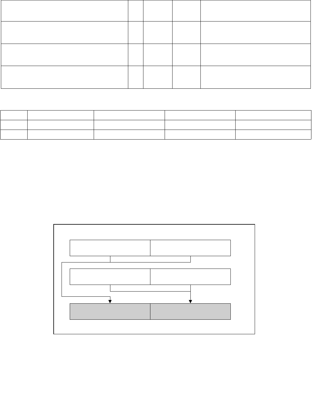
HADDPD—Packed Double-FP Horizontal Add
INSTRUCTION SET REFERENCE, A-L
Vol. 2A 3-427
HADDPD—Packed Double-FP Horizontal Add
Instruction Operand Encoding
Description
Adds the double-precision floating-point values in the high and low quadwords of the destination operand and
stores the result in the low quadword of the destination operand.
Adds the double-precision floating-point values in the high and low quadwords of the source operand and stores the
result in the high quadword of the destination operand.
In 64-bit mode, use of the REX.R prefix permits this instruction to access additional registers (XMM8-XMM15).
See Figure 3-16 for HADDPD; see Figure 3-17 for VHADDPD.
Opcode/
Instruction
Op/
En
64/32-bit
Mode
CPUID
Feature
Flag
Description
66 0F 7C /r
HADDPD xmm1, xmm2/m128
RM V/V SSE3 Horizontal add packed double-precision
floating-point values from xmm2/m128 to
xmm1.
VEX.NDS.128.66.0F.WIG 7C /r
VHADDPD xmm1,xmm2, xmm3/m128
RVM V/V AVX Horizontal add packed double-precision
floating-point values from xmm2 and
xmm3/mem.
VEX.NDS.256.66.0F.WIG 7C /r
VHADDPD ymm1, ymm2, ymm3/m256
RVM V/V AVX Horizontal add packed double-precision
floating-point values from ymm2 and
ymm3/mem.
Op/En Operand 1 Operand 2 Operand 3 Operand 4
RM ModRM:reg (r, w) ModRM:r/m (r) NA NA
RVM ModRM:reg (w) VEX.vvvv (r) ModRM:r/m (r) NA
Figure 3-16. HADDPD—Packed Double-FP Horizontal Add
OM15993
HADDPD xmm1, xmm2/m128
xmm1
xmm2
/m128
[63:0][127:64]
[127:64] [63:0]
[63:0][127:64]
Result:
xmm1
xmm2/m128[63:0] +
xmm2/m128[127:64] xmm1[63:0] + xmm1[127:64]
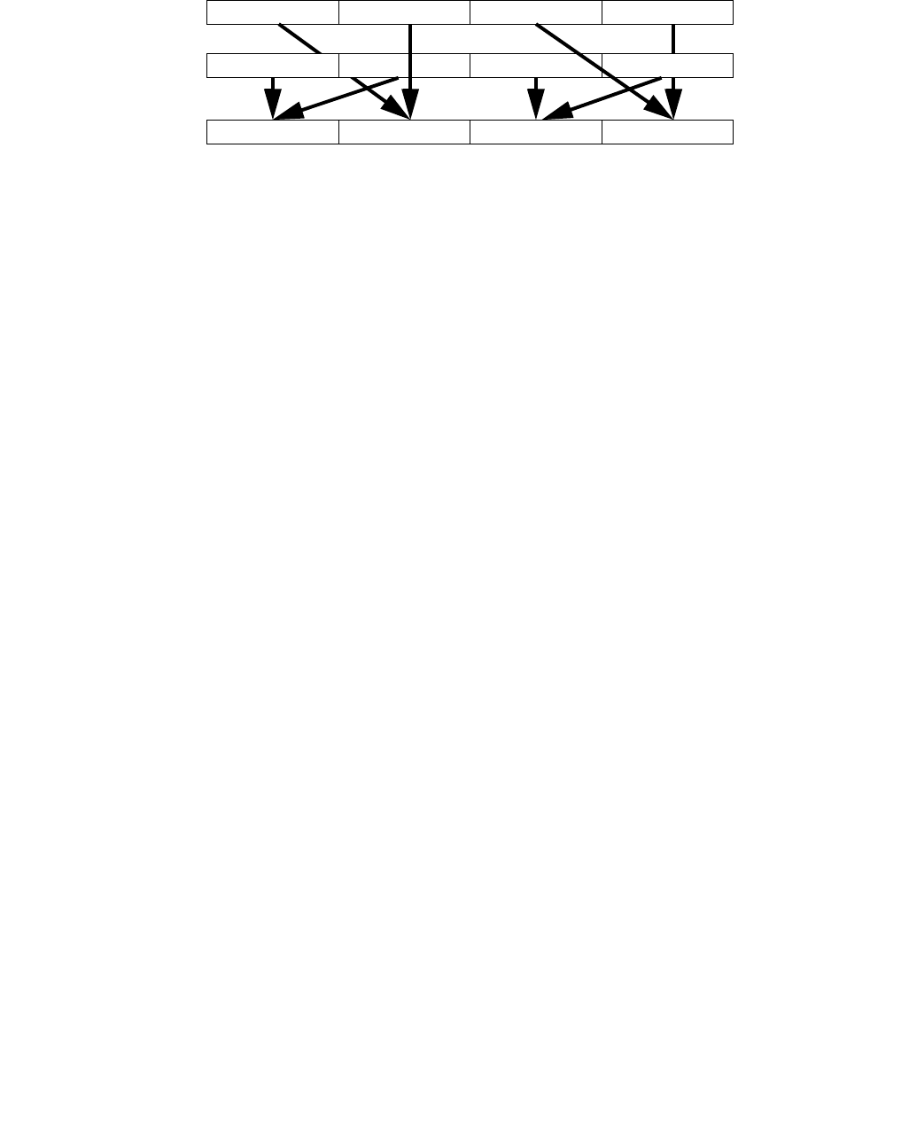
HADDPD—Packed Double-FP Horizontal Add
INSTRUCTION SET REFERENCE, A-L
3-428 Vol. 2A
Figure 3-17. VHADDPD operation
128-bit Legacy SSE version: The second source can be an XMM register or an 128-bit memory location. The desti-
nation is not distinct from the first source XMM register and the upper bits (VLMAX-1:128) of the corresponding
YMM register destination are unmodified.
VEX.128 encoded version: the first source operand is an XMM register or 128-bit memory location. The destination
operand is an XMM register. The upper bits (VLMAX-1:128) of the corresponding YMM register destination are
zeroed.
VEX.256 encoded version: The first source operand is a YMM register. The second source operand can be a YMM
register or a 256-bit memory location. The destination operand is a YMM register.
Operation
HADDPD (128-bit Legacy SSE version)
DEST[63:0] SRC1[127:64] + SRC1[63:0]
DEST[127:64] SRC2[127:64] + SRC2[63:0]
DEST[VLMAX-1:128] (Unmodified)
VHADDPD (VEX.128 encoded version)
DEST[63:0] SRC1[127:64] + SRC1[63:0]
DEST[127:64] SRC2[127:64] + SRC2[63:0]
DEST[VLMAX-1:128] 0
VHADDPD (VEX.256 encoded version)
DEST[63:0] SRC1[127:64] + SRC1[63:0]
DEST[127:64] SRC2[127:64] + SRC2[63:0]
DEST[191:128] SRC1[255:192] + SRC1[191:128]
DEST[255:192] SRC2[255:192] + SRC2[191:128]
Intel C/C++ Compiler Intrinsic Equivalent
VHADDPD: __m256d _mm256_hadd_pd (__m256d a, __m256d b);
HADDPD: __m128d _mm_hadd_pd (__m128d a, __m128d b);
Exceptions
When the source operand is a memory operand, the operand must be aligned on a 16-byte boundary or a general-
protection exception (#GP) will be generated.
Y2 + Y3 X2 + X3 Y0 + Y1 X0 + X1DEST
X3 X2
SRC1 X1 X0
Y3 Y2 Y1 Y0
SRC2

HADDPD—Packed Double-FP Horizontal Add
INSTRUCTION SET REFERENCE, A-L
Vol. 2A 3-429
Numeric Exceptions
Overflow, Underflow, Invalid, Precision, Denormal
Other Exceptions
See Exceptions Type 2.

HADDPS—Packed Single-FP Horizontal Add
INSTRUCTION SET REFERENCE, A-L
3-430 Vol. 2A
HADDPS—Packed Single-FP Horizontal Add
Instruction Operand Encoding
Description
Adds the single-precision floating-point values in the first and second dwords of the destination operand and stores
the result in the first dword of the destination operand.
Adds single-precision floating-point values in the third and fourth dword of the destination operand and stores the
result in the second dword of the destination operand.
Adds single-precision floating-point values in the first and second dword of the source operand and stores the
result in the third dword of the destination operand.
Adds single-precision floating-point values in the third and fourth dword of the source operand and stores the result
in the fourth dword of the destination operand.
In 64-bit mode, use of the REX.R prefix permits this instruction to access additional registers (XMM8-XMM15).
Opcode/
Instruction
Op/
En
64/32-bit
Mode
CPUID
Feature
Flag
Description
F2 0F 7C /r
HADDPS xmm1, xmm2/m128
RM V/V SSE3 Horizontal add packed single-precision
floating-point values from xmm2/m128 to
xmm1.
VEX.NDS.128.F2.0F.WIG 7C /r
VHADDPS xmm1, xmm2, xmm3/m128
RVM V/V AVX Horizontal add packed single-precision
floating-point values from xmm2 and
xmm3/mem.
VEX.NDS.256.F2.0F.WIG 7C /r
VHADDPS ymm1, ymm2, ymm3/m256
RVM V/V AVX Horizontal add packed single-precision
floating-point values from ymm2 and
ymm3/mem.
Op/En Operand 1 Operand 2 Operand 3 Operand 4
RM ModRM:reg (r, w) ModRM:r/m (r) NA NA
RVM ModRM:reg (w) VEX.vvvv (r) ModRM:r/m (r) NA
HADDPS—Packed Single-FP Horizontal Add
INSTRUCTION SET REFERENCE, A-L
Vol. 2A 3-431
See Figure 3-18 for HADDPS; see Figure 3-19 for VHADDPS.
Figure 3-19. VHADDPS operation
128-bit Legacy SSE version: The second source can be an XMM register or an 128-bit memory location. The desti-
nation is not distinct from the first source XMM register and the upper bits (VLMAX-1:128) of the corresponding
YMM register destination are unmodified.
VEX.128 encoded version: the first source operand is an XMM register or 128-bit memory location. The destination
operand is an XMM register. The upper bits (VLMAX-1:128) of the corresponding YMM register destination are
zeroed.
VEX.256 encoded version: The first source operand is a YMM register. The second source operand can be a YMM
register or a 256-bit memory location. The destination operand is a YMM register.
Figure 3-18. HADDPS—Packed Single-FP Horizontal Add
OM15994
HADDPS xmm1, xmm2/m128
RESULT:
xmm1
xmm2/
m128
xmm1[31:0] +
xmm1[63:32]
[31:0]
xmm1[95:64] +
xmm1[127:96]
[63:32]
[63:32] [31:0]
xmm1
[31:0][63:32]
xmm2/m128
[31:0] + xmm2/
m128[63:32]
[95:64]
xmm2/m128
[95:64] + xmm2/
m128[127:96]
[127:96]
[127:96] [95:64]
[95:64][127:96]
Y6+Y7 X6+X7
Y2+Y3
X2+X3
DEST
SRC1 X0
SRC2
X1X2X3X4X5X6X7
Y0Y1Y2Y3Y4Y5Y6Y7
X0+X1
Y4+Y5 X4+X5
Y0+Y1

HADDPS—Packed Single-FP Horizontal Add
INSTRUCTION SET REFERENCE, A-L
3-432 Vol. 2A
Operation
HADDPS (128-bit Legacy SSE version)
DEST[31:0] SRC1[63:32] + SRC1[31:0]
DEST[63:32] SRC1[127:96] + SRC1[95:64]
DEST[95:64] SRC2[63:32] + SRC2[31:0]
DEST[127:96] SRC2[127:96] + SRC2[95:64]
DEST[VLMAX-1:128] (Unmodified)
VHADDPS (VEX.128 encoded version)
DEST[31:0] SRC1[63:32] + SRC1[31:0]
DEST[63:32] SRC1[127:96] + SRC1[95:64]
DEST[95:64] SRC2[63:32] + SRC2[31:0]
DEST[127:96] SRC2[127:96] + SRC2[95:64]
DEST[VLMAX-1:128] 0
VHADDPS (VEX.256 encoded version)
DEST[31:0] SRC1[63:32] + SRC1[31:0]
DEST[63:32] SRC1[127:96] + SRC1[95:64]
DEST[95:64] SRC2[63:32] + SRC2[31:0]
DEST[127:96] SRC2[127:96] + SRC2[95:64]
DEST[159:128] SRC1[191:160] + SRC1[159:128]
DEST[191:160] SRC1[255:224] + SRC1[223:192]
DEST[223:192] SRC2[191:160] + SRC2[159:128]
DEST[255:224] SRC2[255:224] + SRC2[223:192]
Intel C/C++ Compiler Intrinsic Equivalent
HADDPS: __m128 _mm_hadd_ps (__m128 a, __m128 b);
VHADDPS: __m256 _mm256_hadd_ps (__m256 a, __m256 b);
Exceptions
When the source operand is a memory operand, the operand must be aligned on a 16-byte boundary or a general-
protection exception (#GP) will be generated.
Numeric Exceptions
Overflow, Underflow, Invalid, Precision, Denormal
Other Exceptions
See Exceptions Type 2.

HLT—Halt
INSTRUCTION SET REFERENCE, A-L
Vol. 2A 3-433
HLT—Halt
Instruction Operand Encoding
Description
Stops instruction execution and places the processor in a HALT state. An enabled interrupt (including NMI and
SMI), a debug exception, the BINIT# signal, the INIT# signal, or the RESET# signal will resume execution. If an
interrupt (including NMI) is used to resume execution after a HLT instruction, the saved instruction pointer
(CS:EIP) points to the instruction following the HLT instruction.
When a HLT instruction is executed on an Intel 64 or IA-32 processor supporting Intel Hyper-Threading Technology,
only the logical processor that executes the instruction is halted. The other logical processors in the physical
processor remain active, unless they are each individually halted by executing a HLT instruction.
The HLT instruction is a privileged instruction. When the processor is running in protected or virtual-8086 mode,
the privilege level of a program or procedure must be 0 to execute the HLT instruction.
This instruction’s operation is the same in non-64-bit modes and 64-bit mode.
Operation
Enter Halt state;
Flags Affected
None
Protected Mode Exceptions
#GP(0) If the current privilege level is not 0.
#UD If the LOCK prefix is used.
Real-Address Mode Exceptions
None.
Virtual-8086 Mode Exceptions
Same exceptions as in protected mode.
Compatibility Mode Exceptions
Same exceptions as in protected mode.
64-Bit Mode Exceptions
Same exceptions as in protected mode.
Opcode Instruction Op/
En
64-Bit
Mode
Compat/
Leg Mode
Description
F4 HLT NP Valid Valid Halt
Op/En Operand 1 Operand 2 Operand 3 Operand 4
NP NA NA NA NA
HSUBPD—Packed Double-FP Horizontal Subtract
INSTRUCTION SET REFERENCE, A-L
3-434 Vol. 2A
HSUBPD—Packed Double-FP Horizontal Subtract
Instruction Operand Encoding
Description
The HSUBPD instruction subtracts horizontally the packed DP FP numbers of both operands.
Subtracts the double-precision floating-point value in the high quadword of the destination operand from the low
quadword of the destination operand and stores the result in the low quadword of the destination operand.
Subtracts the double-precision floating-point value in the high quadword of the source operand from the low quad-
word of the source operand and stores the result in the high quadword of the destination operand.
In 64-bit mode, use of the REX.R prefix permits this instruction to access additional registers (XMM8-XMM15).
See Figure 3-20 for HSUBPD; see Figure 3-21 for VHSUBPD.
Opcode/
Instruction
Op/
En
64/32-bit
Mode
CPUID
Feature
Flag
Description
66 0F 7D /r
HSUBPD xmm1, xmm2/m128
RM V/V SSE3 Horizontal subtract packed double-precision
floating-point values from xmm2/m128 to
xmm1.
VEX.NDS.128.66.0F.WIG 7D /r
VHSUBPD xmm1,xmm2, xmm3/m128
RVM V/V AVX Horizontal subtract packed double-precision
floating-point values from xmm2 and
xmm3/mem.
VEX.NDS.256.66.0F.WIG 7D /r
VHSUBPD ymm1, ymm2, ymm3/m256
RVM V/V AVX Horizontal subtract packed double-precision
floating-point values from ymm2 and
ymm3/mem.
Op/En Operand 1 Operand 2 Operand 3 Operand 4
RM ModRM:reg (r, w) ModRM:r/m (r) NA NA
RVM ModRM:reg (w) VEX.vvvv (r) ModRM:r/m (r) NA
Figure 3-20. HSUBPD—Packed Double-FP Horizontal Subtract
OM15995
HSUBPD xmm1, xmm2/m128
xmm1
xmm2
/m128
[63:0][127:64]
[127:64] [63:0]
[63:0][127:64]
Result:
xmm1
xmm2/m128[63:0] -
xmm2/m128[127:64] xmm1[63:0] - xmm1[127:64]

HSUBPD—Packed Double-FP Horizontal Subtract
INSTRUCTION SET REFERENCE, A-L
Vol. 2A 3-435
Figure 3-21. VHSUBPD operation
128-bit Legacy SSE version: The second source can be an XMM register or an 128-bit memory location. The desti-
nation is not distinct from the first source XMM register and the upper bits (VLMAX-1:128) of the corresponding
YMM register destination are unmodified.
VEX.128 encoded version: the first source operand is an XMM register or 128-bit memory location. The destination
operand is an XMM register. The upper bits (VLMAX-1:128) of the corresponding YMM register destination are
zeroed.
VEX.256 encoded version: The first source operand is a YMM register. The second source operand can be a YMM
register or a 256-bit memory location. The destination operand is a YMM register.
Operation
HSUBPD (128-bit Legacy SSE version)
DEST[63:0] SRC1[63:0] - SRC1[127:64]
DEST[127:64] SRC2[63:0] - SRC2[127:64]
DEST[VLMAX-1:128] (Unmodified)
VHSUBPD (VEX.128 encoded version)
DEST[63:0] SRC1[63:0] - SRC1[127:64]
DEST[127:64] SRC2[63:0] - SRC2[127:64]
DEST[VLMAX-1:128] 0
VHSUBPD (VEX.256 encoded version)
DEST[63:0] SRC1[63:0] - SRC1[127:64]
DEST[127:64] SRC2[63:0] - SRC2[127:64]
DEST[191:128] SRC1[191:128] - SRC1[255:192]
DEST[255:192] SRC2[191:128] - SRC2[255:192]
Intel C/C++ Compiler Intrinsic Equivalent
HSUBPD: __m128d _mm_hsub_pd(__m128d a, __m128d b)
VHSUBPD: __m256d _mm256_hsub_pd (__m256d a, __m256d b);
Exceptions
When the source operand is a memory operand, the operand must be aligned on a 16-byte boundary or a general-
protection exception (#GP) will be generated.
Numeric Exceptions
Overflow, Underflow, Invalid, Precision, Denormal
Y2 - Y3 X2 - X3 Y0 - Y1 X0 - X1DEST
X3 X2
SRC1 X1 X0
Y3 Y2 Y1 Y0
SRC2

HSUBPD—Packed Double-FP Horizontal Subtract
INSTRUCTION SET REFERENCE, A-L
3-436 Vol. 2A
Other Exceptions
See Exceptions Type 2.

HSUBPS—Packed Single-FP Horizontal Subtract
INSTRUCTION SET REFERENCE, A-L
Vol. 2A 3-437
HSUBPS—Packed Single-FP Horizontal Subtract
Instruction Operand Encoding
Description
Subtracts the single-precision floating-point value in the second dword of the destination operand from the first
dword of the destination operand and stores the result in the first dword of the destination operand.
Subtracts the single-precision floating-point value in the fourth dword of the destination operand from the third
dword of the destination operand and stores the result in the second dword of the destination operand.
Subtracts the single-precision floating-point value in the second dword of the source operand from the first dword
of the source operand and stores the result in the third dword of the destination operand.
Subtracts the single-precision floating-point value in the fourth dword of the source operand from the third dword
of the source operand and stores the result in the fourth dword of the destination operand.
In 64-bit mode, use of the REX.R prefix permits this instruction to access additional registers (XMM8-XMM15).
See Figure 3-22 for HSUBPS; see Figure 3-23 for VHSUBPS.
Opcode/
Instruction
Op/
En
64/32-bit
Mode
CPUID
Feature
Flag
Description
F2 0F 7D /r
HSUBPS xmm1, xmm2/m128
RM V/V SSE3 Horizontal subtract packed single-precision
floating-point values from xmm2/m128 to
xmm1.
VEX.NDS.128.F2.0F.WIG 7D /r
VHSUBPS xmm1, xmm2, xmm3/m128
RVM V/V AVX Horizontal subtract packed single-precision
floating-point values from xmm2 and
xmm3/mem.
VEX.NDS.256.F2.0F.WIG 7D /r
VHSUBPS ymm1, ymm2, ymm3/m256
RVM V/V AVX Horizontal subtract packed single-precision
floating-point values from ymm2 and
ymm3/mem.
Op/En Operand 1 Operand 2 Operand 3 Operand 4
RM ModRM:reg (r, w) ModRM:r/m (r) NA NA
RVM ModRM:reg (w) VEX.vvvv (r) ModRM:r/m (r) NA
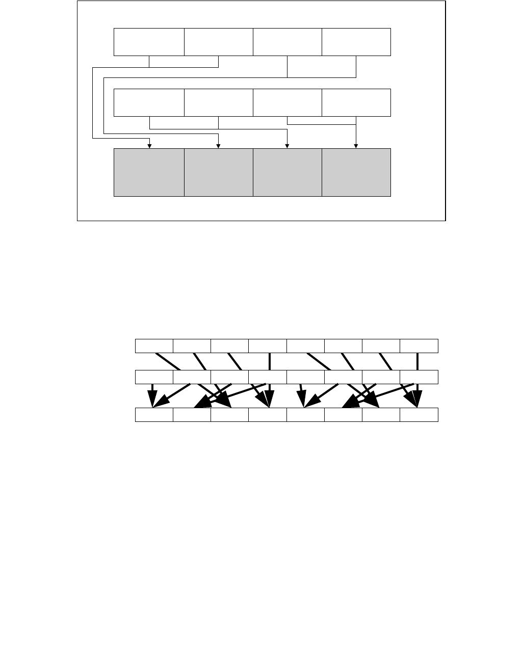
HSUBPS—Packed Single-FP Horizontal Subtract
INSTRUCTION SET REFERENCE, A-L
3-438 Vol. 2A
Figure 3-23. VHSUBPS operation
128-bit Legacy SSE version: The second source can be an XMM register or an 128-bit memory location. The desti-
nation is not distinct from the first source XMM register and the upper bits (VLMAX-1:128) of the corresponding
YMM register destination are unmodified.
VEX.128 encoded version: the first source operand is an XMM register or 128-bit memory location. The destination
operand is an XMM register. The upper bits (VLMAX-1:128) of the corresponding YMM register destination are
zeroed.
VEX.256 encoded version: The first source operand is a YMM register. The second source operand can be a YMM
register or a 256-bit memory location. The destination operand is a YMM register.
Figure 3-22. HSUBPS—Packed Single-FP Horizontal Subtract
OM15996
HSUBPS xmm1, xmm2/m128
RESULT:
xmm1
xmm2/
m128
xmm1[31:0] -
xmm1[63:32]
[31:0]
xmm1[95:64] -
xmm1[127:96]
[63:32]
[63:32] [31:0]
xmm1
[31:0][63:32]
xmm2/m128
[31:0] - xmm2/
m128[63:32]
[95:64]
xmm2/m128
[95:64] - xmm2/
m128[127:96]
[127:96]
[127:96] [95:64]
[95:64][127:96]
Y6-Y7 X6-X7
Y2-Y3
X2-X3
DEST
SRC1 X0
SRC2
X1X2X3X4X5X6X7
Y0Y1Y2Y3Y4Y5Y6Y7
X0-X1
Y4-Y5 X4-X5
Y0-Y1

HSUBPS—Packed Single-FP Horizontal Subtract
INSTRUCTION SET REFERENCE, A-L
Vol. 2A 3-439
Operation
HSUBPS (128-bit Legacy SSE version)
DEST[31:0] SRC1[31:0] - SRC1[63:32]
DEST[63:32] SRC1[95:64] - SRC1[127:96]
DEST[95:64] SRC2[31:0] - SRC2[63:32]
DEST[127:96] SRC2[95:64] - SRC2[127:96]
DEST[VLMAX-1:128] (Unmodified)
VHSUBPS (VEX.128 encoded version)
DEST[31:0] SRC1[31:0] - SRC1[63:32]
DEST[63:32] SRC1[95:64] - SRC1[127:96]
DEST[95:64] SRC2[31:0] - SRC2[63:32]
DEST[127:96] SRC2[95:64] - SRC2[127:96]
DEST[VLMAX-1:128] 0
VHSUBPS (VEX.256 encoded version)
DEST[31:0] SRC1[31:0] - SRC1[63:32]
DEST[63:32] SRC1[95:64] - SRC1[127:96]
DEST[95:64] SRC2[31:0] - SRC2[63:32]
DEST[127:96] SRC2[95:64] - SRC2[127:96]
DEST[159:128] SRC1[159:128] - SRC1[191:160]
DEST[191:160] SRC1[223:192] - SRC1[255:224]
DEST[223:192] SRC2[159:128] - SRC2[191:160]
DEST[255:224] SRC2[223:192] - SRC2[255:224]
Intel C/C++ Compiler Intrinsic Equivalent
HSUBPS: __m128 _mm_hsub_ps(__m128 a, __m128 b);
VHSUBPS: __m256 _mm256_hsub_ps (__m256 a, __m256 b);
Exceptions
When the source operand is a memory operand, the operand must be aligned on a 16-byte boundary or a general-
protection exception (#GP) will be generated.
Numeric Exceptions
Overflow, Underflow, Invalid, Precision, Denormal
Other Exceptions
See Exceptions Type 2.

IDIV—Signed Divide
INSTRUCTION SET REFERENCE, A-L
3-440 Vol. 2A
IDIV—Signed Divide
Instruction Operand Encoding
Description
Divides the (signed) value in the AX, DX:AX, or EDX:EAX (dividend) by the source operand (divisor) and stores the
result in the AX (AH:AL), DX:AX, or EDX:EAX registers. The source operand can be a general-purpose register or a
memory location. The action of this instruction depends on the operand size (dividend/divisor).
Non-integral results are truncated (chopped) towards 0. The remainder is always less than the divisor in magni-
tude. Overflow is indicated with the #DE (divide error) exception rather than with the CF flag.
In 64-bit mode, the instruction’s default operation size is 32 bits. Use of the REX.R prefix permits access to addi-
tional registers (R8-R15). Use of the REX.W prefix promotes operation to 64 bits. In 64-bit mode when REX.W is
applied, the instruction divides the signed value in RDX:RAX by the source operand. RAX contains a 64-bit
quotient; RDX contains a 64-bit remainder.
See the summary chart at the beginning of this section for encoding data and limits. See Table 3-50.
Opcode Instruction Op/
En
64-Bit
Mode
Compat/
Leg Mode
Description
F6 /7 IDIV r/m8 M Valid Valid Signed divide AX by r/m8, with result stored in:
AL ← Quotient, AH ← Remainder.
REX + F6 /7 IDIV r/m8* M Valid N.E. Signed divide AX by r/m8, with result stored in
AL ← Quotient, AH ← Remainder.
F7 /7 IDIV r/m16 M Valid Valid Signed divide DX:AX by r/m16, with result
stored in AX ← Quotient, DX ← Remainder.
F7 /7 IDIV r/m32 M Valid Valid Signed divide EDX:EAX by r/m32, with result
stored in EAX ← Quotient, EDX ← Remainder.
REX.W + F7 /7 IDIV r/m64 M Valid N.E. Signed divide RDX:RAX by r/m64, with result
stored in RAX ← Quotient, RDX ← Remainder.
NOTES:
* In 64-bit mode, r/m8 can not be encoded to access the following byte registers if a REX prefix is used: AH, BH, CH, DH.
Op/En Operand 1 Operand 2 Operand 3 Operand 4
M ModRM:r/m (r) NA NA NA
Table 3-50. IDIV Results
Operand Size Dividend Divisor Quotient Remainder Quotient Range
Word/byte AX r/m8 AL AH −128 to +127
Doubleword/word DX:AX r/m16 AX DX −32,768 to +32,767
Quadword/doubleword EDX:EAX r/m32 EAX EDX −231 to 231 − 1
Doublequadword/ quadword RDX:RAX r/m64 RAX RDX −263 to 263 − 1

IDIV—Signed Divide
INSTRUCTION SET REFERENCE, A-L
Vol. 2A 3-441
Operation
IF SRC = 0
THEN #DE; (* Divide error *)
FI;
IF OperandSize = 8 (* Word/byte operation *)
THEN
temp ← AX / SRC; (* Signed division *)
IF (temp > 7FH) or (temp < 80H)
(* If a positive result is greater than 7FH or a negative result is less than 80H *)
THEN #DE; (* Divide error *)
ELSE
AL ← temp;
AH ← AX SignedModulus SRC;
FI;
ELSE IF OperandSize = 16 (* Doubleword/word operation *)
THEN
temp ← DX:AX / SRC; (* Signed division *)
IF (temp > 7FFFH) or (temp < 8000H)
(* If a positive result is greater than 7FFFH
or a negative result is less than 8000H *)
THEN
#DE; (* Divide error *)
ELSE
AX ← temp;
DX ← DX:AX SignedModulus SRC;
FI;
FI;
ELSE IF OperandSize = 32 (* Quadword/doubleword operation *)
temp ← EDX:EAX / SRC; (* Signed division *)
IF (temp > 7FFFFFFFH) or (temp < 80000000H)
(* If a positive result is greater than 7FFFFFFFH
or a negative result is less than 80000000H *)
THEN
#DE; (* Divide error *)
ELSE
EAX ← temp;
EDX ← EDXE:AX SignedModulus SRC;
FI;
FI;
ELSE IF OperandSize = 64 (* Doublequadword/quadword operation *)
temp ← RDX:RAX / SRC; (* Signed division *)
IF (temp > 7FFFFFFFFFFFFFFFH) or (temp < 8000000000000000H)
(* If a positive result is greater than 7FFFFFFFFFFFFFFFH
or a negative result is less than 8000000000000000H *)
THEN
#DE; (* Divide error *)
ELSE
RAX ← temp;
RDX ← RDE:RAX SignedModulus SRC;
FI;
FI;
FI;

IDIV—Signed Divide
INSTRUCTION SET REFERENCE, A-L
3-442 Vol. 2A
Flags Affected
The CF, OF, SF, ZF, AF, and PF flags are undefined.
Protected Mode Exceptions
#DE If the source operand (divisor) is 0.
The signed result (quotient) is too large for the destination.
#GP(0) If a memory operand effective address is outside the CS, DS, ES, FS, or GS segment limit.
If the DS, ES, FS, or GS register is used to access memory and it contains a NULL segment
selector.
#SS(0) If a memory operand effective address is outside the SS segment limit.
#PF(fault-code) If a page fault occurs.
#AC(0) If alignment checking is enabled and an unaligned memory reference is made while the
current privilege level is 3.
#UD If the LOCK prefix is used.
Real-Address Mode Exceptions
#DE If the source operand (divisor) is 0.
The signed result (quotient) is too large for the destination.
#GP If a memory operand effective address is outside the CS, DS, ES, FS, or GS segment limit.
#SS If a memory operand effective address is outside the SS segment limit.
#UD If the LOCK prefix is used.
Virtual-8086 Mode Exceptions
#DE If the source operand (divisor) is 0.
The signed result (quotient) is too large for the destination.
#GP(0) If a memory operand effective address is outside the CS, DS, ES, FS, or GS segment limit.
#SS(0) If a memory operand effective address is outside the SS segment limit.
#PF(fault-code) If a page fault occurs.
#AC(0) If alignment checking is enabled and an unaligned memory reference is made.
#UD If the LOCK prefix is used.
Compatibility Mode Exceptions
Same exceptions as in protected mode.
64-Bit Mode Exceptions
#SS(0) If a memory address referencing the SS segment is in a non-canonical form.
#GP(0) If the memory address is in a non-canonical form.
#DE If the source operand (divisor) is 0
If the quotient is too large for the designated register.
#PF(fault-code) If a page fault occurs.
#AC(0) If alignment checking is enabled and an unaligned memory reference is made while the
current privilege level is 3.
#UD If the LOCK prefix is used.

IMUL—Signed Multiply
INSTRUCTION SET REFERENCE, A-L
Vol. 2A 3-443
IMUL—Signed Multiply
Instruction Operand Encoding
Description
Performs a signed multiplication of two operands. This instruction has three forms, depending on the number of
operands.
•One-operand form — This form is identical to that used by the MUL instruction. Here, the source operand (in
a general-purpose register or memory location) is multiplied by the value in the AL, AX, EAX, or RAX register
(depending on the operand size) and the product (twice the size of the input operand) is stored in the AX,
DX:AX, EDX:EAX, or RDX:RAX registers, respectively.
•Two-operand form — With this form the destination operand (the first operand) is multiplied by the source
operand (second operand). The destination operand is a general-purpose register and the source operand is an
immediate value, a general-purpose register, or a memory location. The intermediate product (twice the size of
the input operand) is truncated and stored in the destination operand location.
•Three-operand form — This form requires a destination operand (the first operand) and two source operands
(the second and the third operands). Here, the first source operand (which can be a general-purpose register
or a memory location) is multiplied by the second source operand (an immediate value). The intermediate
product (twice the size of the first source operand) is truncated and stored in the destination operand (a
general-purpose register).
Opcode Instruction Op/
En
64-Bit
Mode
Compat/
Leg Mode
Description
F6 /5 IMUL r/m8* MValid Valid AX← AL ∗ r/m byte.
F7 /5 IMUL r/m16 MValid Valid DX:AX ← AX ∗ r/m word.
F7 /5 IMUL r/m32 MValid Valid EDX:EAX ← EAX ∗ r/m32.
REX.W + F7 /5 IMUL r/m64 M Valid N.E. RDX:RAX ← RAX ∗ r/m64.
0F AF /rIMUL r16, r/m16 RM Valid Valid word register ← word register ∗ r/m16.
0F AF /rIMUL r32, r/m32 RM Valid Valid doubleword register ← doubleword register ∗
r/m32.
REX.W + 0F AF /rIMUL r64, r/m64 RM Valid N.E. Quadword register ← Quadword register ∗
r/m64.
6B /r ib IMUL r16, r/m16, imm8 RMI Valid Valid word register ← r/m16 ∗ sign-extended
immediate byte.
6B /r ib IMUL r32, r/m32, imm8 RMI Valid Valid doubleword register ← r/m32 ∗ sign-
extended immediate byte.
REX.W + 6B /r ib IMUL r64, r/m64, imm8 RMI Valid N.E. Quadword register ← r/m64 ∗ sign-extended
immediate byte.
69 /r iw IMUL r16, r/m16, imm16 RMI Valid Valid word register ← r/m16 ∗ immediate word.
69 /r id IMUL r32, r/m32, imm32 RMI Valid Valid doubleword register ← r/m32 ∗ immediate
doubleword.
REX.W + 69 /r id IMUL r64, r/m64, imm32 RMI Valid N.E. Quadword register ← r/m64 ∗ immediate
doubleword.
NOTES:
* In 64-bit mode, r/m8 can not be encoded to access the following byte registers if a REX prefix is used: AH, BH, CH, DH.
Op/En Operand 1 Operand 2 Operand 3 Operand 4
M ModRM:r/m (r, w) NA NA NA
RM ModRM:reg (r, w) ModRM:r/m (r) NA NA
RMI ModRM:reg (r, w) ModRM:r/m (r) imm8/16/32 NA

IMUL—Signed Multiply
INSTRUCTION SET REFERENCE, A-L
3-444 Vol. 2A
When an immediate value is used as an operand, it is sign-extended to the length of the destination operand
format.
The CF and OF flags are set when the signed integer value of the intermediate product differs from the sign
extended operand-size-truncated product, otherwise the CF and OF flags are cleared.
The three forms of the IMUL instruction are similar in that the length of the product is calculated to twice the length
of the operands. With the one-operand form, the product is stored exactly in the destination. With the two- and
three- operand forms, however, the result is truncated to the length of the destination before it is stored in the
destination register. Because of this truncation, the CF or OF flag should be tested to ensure that no significant bits
are lost.
The two- and three-operand forms may also be used with unsigned operands because the lower half of the product
is the same regardless if the operands are signed or unsigned. The CF and OF flags, however, cannot be used to
determine if the upper half of the result is non-zero.
In 64-bit mode, the instruction’s default operation size is 32 bits. Use of the REX.R prefix permits access to addi-
tional registers (R8-R15). Use of the REX.W prefix promotes operation to 64 bits. Use of REX.W modifies the three
forms of the instruction as follows.
•One-operand form —The source operand (in a 64-bit general-purpose register or memory location) is
multiplied by the value in the RAX register and the product is stored in the RDX:RAX registers.
•Two-operand form — The source operand is promoted to 64 bits if it is a register or a memory location. The
destination operand is promoted to 64 bits.
•Three-operand form — The first source operand (either a register or a memory location) and destination
operand are promoted to 64 bits. If the source operand is an immediate, it is sign extended to 64 bits.
Operation
IF (NumberOfOperands = 1)
THEN IF (OperandSize = 8)
THEN
TMP_XP ← AL ∗ SRC (* Signed multiplication; TMP_XP is a signed integer at twice the width of the SRC *);
AX ← TMP_XP[15:0];
IF SignExtend(TMP_XP[7:0]) = TMP_XP
THEN CF ← 0; OF ← 0;
ELSE CF ← 1; OF ← 1; FI;
ELSE IF OperandSize = 16
THEN
TMP_XP ← AX ∗ SRC (* Signed multiplication; TMP_XP is a signed integer at twice the width of the SRC *)
DX:AX ← TMP_XP[31:0];
IF SignExtend(TMP_XP[15:0]) = TMP_XP
THEN CF ← 0; OF ← 0;
ELSE CF ← 1; OF ← 1; FI;
ELSE IF OperandSize = 32
THEN
TMP_XP ← EAX ∗ SRC (* Signed multiplication; TMP_XP is a signed integer at twice the width of the SRC*)
EDX:EAX ← TMP_XP[63:0];
IF SignExtend(TMP_XP[31:0]) = TMP_XP
THEN CF ← 0; OF ← 0;
ELSE CF ← 1; OF ← 1; FI;
ELSE (* OperandSize = 64 *)
TMP_XP ← RAX ∗ SRC (* Signed multiplication; TMP_XP is a signed integer at twice the width of the SRC *)
EDX:EAX ← TMP_XP[127:0];
IF SignExtend(TMP_XP[63:0]) = TMP_XP
THEN CF ← 0; OF ← 0;
ELSE CF ← 1; OF ← 1; FI;
FI;

IMUL—Signed Multiply
INSTRUCTION SET REFERENCE, A-L
Vol. 2A 3-445
FI;
ELSE IF (NumberOfOperands = 2)
THEN
TMP_XP ← DEST ∗ SRC (* Signed multiplication; TMP_XP is a signed integer at twice the width of the SRC *)
DEST ← TruncateToOperandSize(TMP_XP);
IF SignExtend(DEST) ≠ TMP_XP
THEN CF ← 1; OF ← 1;
ELSE CF ← 0; OF ← 0; FI;
ELSE (* NumberOfOperands = 3 *)
TMP_XP ← SRC1 ∗ SRC2 (* Signed multiplication; TMP_XP is a signed integer at twice the width of the SRC1 *)
DEST ← TruncateToOperandSize(TMP_XP);
IF SignExtend(DEST) ≠ TMP_XP
THEN CF ← 1; OF ← 1;
ELSE CF ← 0; OF ← 0; FI;
FI;
FI;
Flags Affected
For the one operand form of the instruction, the CF and OF flags are set when significant bits are carried into the
upper half of the result and cleared when the result fits exactly in the lower half of the result. For the two- and
three-operand forms of the instruction, the CF and OF flags are set when the result must be truncated to fit in the
destination operand size and cleared when the result fits exactly in the destination operand size. The SF, ZF, AF, and
PF flags are undefined.
Protected Mode Exceptions
#GP(0) If a memory operand effective address is outside the CS, DS, ES, FS, or GS segment limit.
If the DS, ES, FS, or GS register is used to access memory and it contains a NULL NULL
segment selector.
#SS(0) If a memory operand effective address is outside the SS segment limit.
#PF(fault-code) If a page fault occurs.
#AC(0) If alignment checking is enabled and an unaligned memory reference is made while the
current privilege level is 3.
#UD If the LOCK prefix is used.
Real-Address Mode Exceptions
#GP If a memory operand effective address is outside the CS, DS, ES, FS, or GS segment limit.
#SS If a memory operand effective address is outside the SS segment limit.
#UD If the LOCK prefix is used.
Virtual-8086 Mode Exceptions
#GP(0) If a memory operand effective address is outside the CS, DS, ES, FS, or GS segment limit.
#SS(0) If a memory operand effective address is outside the SS segment limit.
#PF(fault-code) If a page fault occurs.
#AC(0) If alignment checking is enabled and an unaligned memory reference is made.
#UD If the LOCK prefix is used.
Compatibility Mode Exceptions
Same exceptions as in protected mode.

IMUL—Signed Multiply
INSTRUCTION SET REFERENCE, A-L
3-446 Vol. 2A
64-Bit Mode Exceptions
#SS(0) If a memory address referencing the SS segment is in a non-canonical form.
#GP(0) If the memory address is in a non-canonical form.
#PF(fault-code) If a page fault occurs.
#AC(0) If alignment checking is enabled and an unaligned memory reference is made while the
current privilege level is 3.
#UD If the LOCK prefix is used.

IN—Input from Port
INSTRUCTION SET REFERENCE, A-L
Vol. 2A 3-447
IN—Input from Port
Instruction Operand Encoding
Description
Copies the value from the I/O port specified with the second operand (source operand) to the destination operand
(first operand). The source operand can be a byte-immediate or the DX register; the destination operand can be
register AL, AX, or EAX, depending on the size of the port being accessed (8, 16, or 32 bits, respectively). Using the
DX register as a source operand allows I/O port addresses from 0 to 65,535 to be accessed; using a byte imme-
diate allows I/O port addresses 0 to 255 to be accessed.
When accessing an 8-bit I/O port, the opcode determines the port size; when accessing a 16- and 32-bit I/O port,
the operand-size attribute determines the port size. At the machine code level, I/O instructions are shorter when
accessing 8-bit I/O ports. Here, the upper eight bits of the port address will be 0.
This instruction is only useful for accessing I/O ports located in the processor’s I/O address space. See Chapter 18,
“Input/Output,” in the Intel® 64 and IA-32 Architectures Software Developer’s Manual, Volume 1, for more infor-
mation on accessing I/O ports in the I/O address space.
This instruction’s operation is the same in non-64-bit modes and 64-bit mode.
Operation
IF ((PE = 1) and ((CPL > IOPL) or (VM = 1)))
THEN (* Protected mode with CPL > IOPL or virtual-8086 mode *)
IF (Any I/O Permission Bit for I/O port being accessed = 1)
THEN (* I/O operation is not allowed *)
#GP(0);
ELSE ( * I/O operation is allowed *)
DEST ← SRC; (* Read from selected I/O port *)
FI;
ELSE (Real Mode or Protected Mode with CPL ≤ IOPL *)
DEST ← SRC; (* Read from selected I/O port *)
FI;
Flags Affected
None
Opcode Instruction Op/
En
64-Bit
Mode
Compat/
Leg Mode
Description
E4 ib IN AL, imm8 I Valid Valid Input byte from imm8 I/O port address into
AL.
E5 ib IN AX, imm8 I Valid Valid Input word from imm8 I/O port address into
AX.
E5 ib IN EAX, imm8 I Valid Valid Input dword from imm8 I/O port address into
EAX.
EC IN AL,DX NP Valid Valid Input byte from I/O port in DX into AL.
ED IN AX,DX NP Valid Valid Input word from I/O port in DX into AX.
ED IN EAX,DX NP Valid Valid Input doubleword from I/O port in DX into
EAX.
Op/En Operand 1 Operand 2 Operand 3 Operand 4
Iimm8 NA NA NA
NP NA NA NA NA

IN—Input from Port
INSTRUCTION SET REFERENCE, A-L
3-448 Vol. 2A
Protected Mode Exceptions
#GP(0) If the CPL is greater than (has less privilege) the I/O privilege level (IOPL) and any of the
corresponding I/O permission bits in TSS for the I/O port being accessed is 1.
#UD If the LOCK prefix is used.
Real-Address Mode Exceptions
#UD If the LOCK prefix is used.
Virtual-8086 Mode Exceptions
#GP(0) If any of the I/O permission bits in the TSS for the I/O port being accessed is 1.
#PF(fault-code) If a page fault occurs.
#UD If the LOCK prefix is used.
Compatibility Mode Exceptions
Same exceptions as in protected mode.
64-Bit Mode Exceptions
#GP(0) If the CPL is greater than (has less privilege) the I/O privilege level (IOPL) and any of the
corresponding I/O permission bits in TSS for the I/O port being accessed is 1.
#UD If the LOCK prefix is used.

INC—Increment by 1
INSTRUCTION SET REFERENCE, A-L
Vol. 2A 3-449
INC—Increment by 1
Instruction Operand Encoding
Description
Adds 1 to the destination operand, while preserving the state of the CF flag. The destination operand can be a
register or a memory location. This instruction allows a loop counter to be updated without disturbing the CF flag.
(Use a ADD instruction with an immediate operand of 1 to perform an increment operation that does updates the
CF flag.)
This instruction can be used with a LOCK prefix to allow the instruction to be executed atomically.
In 64-bit mode, INC r16 and INC r32 are not encodable (because opcodes 40H through 47H are REX prefixes).
Otherwise, the instruction’s 64-bit mode default operation size is 32 bits. Use of the REX.R prefix permits access to
additional registers (R8-R15). Use of the REX.W prefix promotes operation to 64 bits.
Operation
DEST ← DEST + 1;
AFlags Affected
The CF flag is not affected. The OF, SF, ZF, AF, and PF flags are set according to the result.
Protected Mode Exceptions
#GP(0) If the destination operand is located in a non-writable segment.
If a memory operand effective address is outside the CS, DS, ES, FS, or GS segment limit.
If the DS, ES, FS, or GS register is used to access memory and it contains a NULLsegment
selector.
#SS(0) If a memory operand effective address is outside the SS segment limit.
#PF(fault-code) If a page fault occurs.
#AC(0) If alignment checking is enabled and an unaligned memory reference is made while the
current privilege level is 3.
#UD If the LOCK prefix is used but the destination is not a memory operand.
Opcode Instruction Op/
En
64-Bit
Mode
Compat/
Leg Mode
Description
FE /0 INC r/m8 MValid Valid Increment r/m byte by 1.
REX + FE /0 INC r/m8*MValid N.E. Increment r/m byte by 1.
FF /0 INC r/m16 MValid Valid Increment r/m word by 1.
FF /0 INC r/m32 MValid Valid Increment r/m doubleword by 1.
REX.W + FF /0 INC r/m64 MValid N.E. Increment r/m quadword by 1.
40+ rw** INC r16 O N.E. Valid Increment word register by 1.
40+ rd INC r32 O N.E. Valid Increment doubleword register by 1.
NOTES:
* In 64-bit mode, r/m8 can not be encoded to access the following byte registers if a REX prefix is used: AH, BH, CH, DH.
** 40H through 47H are REX prefixes in 64-bit mode.
Op/En Operand 1 Operand 2 Operand 3 Operand 4
M ModRM:r/m (r, w) NA NA NA
O opcode + rd (r, w) NA NA NA

INC—Increment by 1
INSTRUCTION SET REFERENCE, A-L
3-450 Vol. 2A
Real-Address Mode Exceptions
#GP If a memory operand effective address is outside the CS, DS, ES, FS, or GS segment limit.
#SS If a memory operand effective address is outside the SS segment limit.
#UD If the LOCK prefix is used but the destination is not a memory operand.
Virtual-8086 Mode Exceptions
#GP(0) If a memory operand effective address is outside the CS, DS, ES, FS, or GS segment limit.
#SS(0) If a memory operand effective address is outside the SS segment limit.
#PF(fault-code) If a page fault occurs.
#AC(0) If alignment checking is enabled and an unaligned memory reference is made.
#UD If the LOCK prefix is used but the destination is not a memory operand.
Compatibility Mode Exceptions
Same exceptions as in protected mode.
64-Bit Mode Exceptions
#SS(0) If a memory address referencing the SS segment is in a non-canonical form.
#GP(0) If the memory address is in a non-canonical form.
#PF(fault-code) If a page fault occurs.
#AC(0) If alignment checking is enabled and an unaligned memory reference is made while the
current privilege level is 3.
#UD If the LOCK prefix is used but the destination is not a memory operand.

INS/INSB/INSW/INSD—Input from Port to String
INSTRUCTION SET REFERENCE, A-L
Vol. 2A 3-451
INS/INSB/INSW/INSD—Input from Port to String
Instruction Operand Encoding
Description
Copies the data from the I/O port specified with the source operand (second operand) to the destination operand
(first operand). The source operand is an I/O port address (from 0 to 65,535) that is read from the DX register. The
destination operand is a memory location, the address of which is read from either the ES:DI, ES:EDI or the RDI
registers (depending on the address-size attribute of the instruction, 16, 32 or 64, respectively). (The ES segment
cannot be overridden with a segment override prefix.) The size of the I/O port being accessed (that is, the size of
the source and destination operands) is determined by the opcode for an 8-bit I/O port or by the operand-size attri-
bute of the instruction for a 16- or 32-bit I/O port.
At the assembly-code level, two forms of this instruction are allowed: the “explicit-operands” form and the “no-
operands” form. The explicit-operands form (specified with the INS mnemonic) allows the source and destination
operands to be specified explicitly. Here, the source operand must be “DX,” and the destination operand should be
a symbol that indicates the size of the I/O port and the destination address. This explicit-operands form is provided
to allow documentation; however, note that the documentation provided by this form can be misleading. That is,
the destination operand symbol must specify the correct type (size) of the operand (byte, word, or doubleword),
but it does not have to specify the correct location. The location is always specified by the ES:(E)DI registers,
which must be loaded correctly before the INS instruction is executed.
The no-operands form provides “short forms” of the byte, word, and doubleword versions of the INS instructions.
Here also DX is assumed by the processor to be the source operand and ES:(E)DI is assumed to be the destination
operand. The size of the I/O port is specified with the choice of mnemonic: INSB (byte), INSW (word), or INSD
(doubleword).
After the byte, word, or doubleword is transfer from the I/O port to the memory location, the DI/EDI/RDI register
is incremented or decremented automatically according to the setting of the DF flag in the EFLAGS register. (If the
DF flag is 0, the (E)DI register is incremented; if the DF flag is 1, the (E)DI register is decremented.) The (E)DI
register is incremented or decremented by 1 for byte operations, by 2 for word operations, or by 4 for doubleword
operations.
Opcode Instruction Op/
En
64-Bit
Mode
Compat/
Leg Mode
Description
6C INS m8, DX NP Valid Valid Input byte from I/O port specified in DX into
memory location specified in ES:(E)DI or RDI.*
6D INS m16, DX NP Valid Valid Input word from I/O port specified in DX into
memory location specified in ES:(E)DI or RDI.1
6D INS m32, DX NP Valid Valid Input doubleword from I/O port specified in DX
into memory location specified in ES:(E)DI or
RDI.1
6C INSB NP Valid Valid Input byte from I/O port specified in DX into
memory location specified with ES:(E)DI or
RDI.1
6D INSW NP Valid Valid Input word from I/O port specified in DX into
memory location specified in ES:(E)DI or RDI.1
6D INSD NP Valid Valid Input doubleword from I/O port specified in DX
into memory location specified in ES:(E)DI or
RDI.1
NOTES:
* In 64-bit mode, only 64-bit (RDI) and 32-bit (EDI) address sizes are supported. In non-64-bit mode, only 32-bit (EDI) and 16-bit (DI)
address sizes are supported.
Op/En Operand 1 Operand 2 Operand 3 Operand 4
NP NA NA NA NA

INS/INSB/INSW/INSD—Input from Port to String
INSTRUCTION SET REFERENCE, A-L
3-452 Vol. 2A
The INS, INSB, INSW, and INSD instructions can be preceded by the REP prefix for block input of ECX bytes, words,
or doublewords. See “REP/REPE/REPZ /REPNE/REPNZ—Repeat String Operation Prefix” in Chapter 4 of the Intel®
64 and IA-32 Architectures Software Developer’s Manual, Volume 2B, for a description of the REP prefix.
These instructions are only useful for accessing I/O ports located in the processor’s I/O address space. See Chapter
18, “Input/Output,” in the Intel® 64 and IA-32 Architectures Software Developer’s Manual, Volume 1, for more
information on accessing I/O ports in the I/O address space.
In 64-bit mode, default address size is 64 bits, 32 bit address size is supported using the prefix 67H. The address
of the memory destination is specified by RDI or EDI. 16-bit address size is not supported in 64-bit mode. The
operand size is not promoted.
These instructions may read from the I/O port without writing to the memory location if an exception or VM exit
occurs due to the write (e.g. #PF). If this would be problematic, for example because the I/O port read has side-
effects, software should ensure the write to the memory location does not cause an exception or VM exit.
Operation
IF ((PE = 1) and ((CPL > IOPL) or (VM = 1)))
THEN (* Protected mode with CPL > IOPL or virtual-8086 mode *)
IF (Any I/O Permission Bit for I/O port being accessed = 1)
THEN (* I/O operation is not allowed *)
#GP(0);
ELSE (* I/O operation is allowed *)
DEST ← SRC; (* Read from I/O port *)
FI;
ELSE (Real Mode or Protected Mode with CPL IOPL *)
DEST ← SRC; (* Read from I/O port *)
FI;
Non-64-bit Mode:
IF (Byte transfer)
THEN IF DF = 0
THEN (E)DI ← (E)DI + 1;
ELSE (E)DI ← (E)DI – 1; FI;
ELSE IF (Word transfer)
THEN IF DF = 0
THEN (E)DI ← (E)DI + 2;
ELSE (E)DI ← (E)DI – 2; FI;
ELSE (* Doubleword transfer *)
THEN IF DF = 0
THEN (E)DI ← (E)DI + 4;
ELSE (E)DI ← (E)DI – 4; FI;
FI;
FI;
FI64-bit Mode:
IF (Byte transfer)
THEN IF DF = 0
THEN (E|R)DI ← (E|R)DI + 1;
ELSE (E|R)DI ← (E|R)DI – 1; FI;
ELSE IF (Word transfer)
THEN IF DF = 0
THEN (E)DI ← (E)DI + 2;
ELSE (E)DI ← (E)DI – 2; FI;
ELSE (* Doubleword transfer *)

INS/INSB/INSW/INSD—Input from Port to String
INSTRUCTION SET REFERENCE, A-L
Vol. 2A 3-453
THEN IF DF = 0
THEN (E|R)DI ← (E|R)DI + 4;
ELSE (E|R)DI ← (E|R)DI – 4; FI;
FI;
FI;
Flags Affected
None
Protected Mode Exceptions
#GP(0) If the CPL is greater than (has less privilege) the I/O privilege level (IOPL) and any of the
corresponding I/O permission bits in TSS for the I/O port being accessed is 1.
If the destination is located in a non-writable segment.
If an illegal memory operand effective address in the ES segments is given.
#PF(fault-code) If a page fault occurs.
#AC(0) If alignment checking is enabled and an unaligned memory reference is made while the
current privilege level is 3.
#UD If the LOCK prefix is used.
Real-Address Mode Exceptions
#GP If a memory operand effective address is outside the CS, DS, ES, FS, or GS segment limit.
#SS If a memory operand effective address is outside the SS segment limit.
#UD If the LOCK prefix is used.
Virtual-8086 Mode Exceptions
#GP(0) If any of the I/O permission bits in the TSS for the I/O port being accessed is 1.
#PF(fault-code) If a page fault occurs.
#AC(0) If alignment checking is enabled and an unaligned memory reference is made.
#UD If the LOCK prefix is used.
Compatibility Mode Exceptions
Same exceptions as in protected mode.
64-Bit Mode Exceptions
#SS(0) If a memory address referencing the SS segment is in a non-canonical form.
#GP(0) If the CPL is greater than (has less privilege) the I/O privilege level (IOPL) and any of the
corresponding I/O permission bits in TSS for the I/O port being accessed is 1.
If the memory address is in a non-canonical form.
#PF(fault-code) If a page fault occurs.
#AC(0) If alignment checking is enabled and an unaligned memory reference is made while the
current privilege level is 3.
#UD If the LOCK prefix is used.

INSERTPS—Insert Scalar Single-Precision Floating-Point Value
INSTRUCTION SET REFERENCE, A-L
3-454 Vol. 2A
INSERTPS—Insert Scalar Single-Precision Floating-Point Value
Instruction Operand Encoding
Description
(register source form)
Select a single-precision floating-point element from second source as indicated by Count_S bits of the immediate
operand and destination operand it into the first source at the location indicated by the Count_D bits of the imme-
diate operand. Store in the destination and zero out destination elements based on the ZMask bits of the immediate
operand.
(memory source form)
Load a floating-point element from a 32-bit memory location and destination operand it into the first source at the
location indicated by the Count_D bits of the immediate operand. Store in the destination and zero out destination
elements based on the ZMask bits of the immediate operand.
128-bit Legacy SSE version: The first source register is an XMM register. The second source operand is either an
XMM register or a 32-bit memory location. The destination is not distinct from the first source XMM register and the
upper bits (MAX_VL-1:128) of the corresponding register destination are unmodified.
VEX.128 and EVEX encoded version: The destination and first source register is an XMM register. The second
source operand is either an XMM register or a 32-bit memory location. The upper bits (MAX_VL-1:128) of the corre-
sponding register destination are zeroed.
If VINSERTPS is encoded with VEX.L= 1, an attempt to execute the instruction encoded with VEX.L= 1 will cause
an #UD exception.
Opcode/
Instruction
Op /
En
64/32
bit Mode
Support
CPUID
Feature
Flag
Description
66 0F 3A 21 /r ib
INSERTPS xmm1, xmm2/m32, imm8
RMI V/V SSE4_1 Insert a single-precision floating-point value selected
by imm8 from xmm2/m32 into xmm1 at the specified
destination element specified by imm8 and zero out
destination elements in xmm1 as indicated in imm8.
VEX.NDS.128.66.0F3A.WIG 21 /r ib
VINSERTPS xmm1, xmm2,
xmm3/m32, imm8
RVMI V/V AVX Insert a single-precision floating-point value selected
by imm8 from xmm3/m32 and merge with values in
xmm2 at the specified destination element specified
by imm8 and write out the result and zero out
destination elements in xmm1 as indicated in imm8.
EVEX.NDS.128.66.0F3A.W0 21 /r ib
VINSERTPS xmm1, xmm2,
xmm3/m32, imm8
T1S V/V AVX512F Insert a single-precision floating-point value selected
by imm8 from xmm3/m32 and merge with values in
xmm2 at the specified destination element specified
by imm8 and write out the result and zero out
destination elements in xmm1 as indicated in imm8.
Op/En Operand 1 Operand 2 Operand 3 Operand 4
RMI ModRM:reg (r, w) ModRM:r/m (r) Imm8 NA
RVMI ModRM:reg (w) VEX.vvvv ModRM:r/m (r) Imm8
T1S ModRM:reg (w) EVEX.vvvv ModRM:r/m (r) Imm8

INSERTPS—Insert Scalar Single-Precision Floating-Point Value
INSTRUCTION SET REFERENCE, A-L
Vol. 2A 3-455
Operation
VINSERTPS (VEX.128 and EVEX encoded version)
IF (SRC = REG) THEN COUNT_S imm8[7:6]
ELSE COUNT_S 0
COUNT_D imm8[5:4]
ZMASK imm8[3:0]
CASE (COUNT_S) OF
0: TMP SRC2[31:0]
1: TMP SRC2[63:32]
2: TMP SRC2[95:64]
3: TMP SRC2[127:96]
ESAC;
CASE (COUNT_D) OF
0: TMP2[31:0] TMP
TMP2[127:32] SRC1[127:32]
1: TMP2[63:32] TMP
TMP2[31:0] SRC1[31:0]
TMP2[127:64] SRC1[127:64]
2: TMP2[95:64] TMP
TMP2[63:0] SRC1[63:0]
TMP2[127:96] SRC1[127:96]
3: TMP2[127:96] TMP
TMP2[95:0] SRC1[95:0]
ESAC;
IF (ZMASK[0] = 1) THEN DEST[31:0] 00000000H
ELSE DEST[31:0] TMP2[31:0]
IF (ZMASK[1] = 1) THEN DEST[63:32] 00000000H
ELSE DEST[63:32] TMP2[63:32]
IF (ZMASK[2] = 1) THEN DEST[95:64] 00000000H
ELSE DEST[95:64] TMP2[95:64]
IF (ZMASK[3] = 1) THEN DEST[127:96] 00000000H
ELSE DEST[127:96] TMP2[127:96]
DEST[MAX_VL-1:128] 0
INSERTPS (128-bit Legacy SSE version)
IF (SRC = REG) THEN COUNT_S imm8[7:6]
ELSE COUNT_S 0
COUNT_D imm8[5:4]
ZMASK imm8[3:0]
CASE (COUNT_S) OF
0: TMP SRC[31:0]
1: TMP SRC[63:32]
2: TMP SRC[95:64]
3: TMP SRC[127:96]
ESAC;
CASE (COUNT_D) OF
0: TMP2[31:0] TMP
TMP2[127:32] DEST[127:32]
1: TMP2[63:32] TMP
TMP2[31:0] DEST[31:0]
TMP2[127:64] DEST[127:64]
2: TMP2[95:64] TMP

INSERTPS—Insert Scalar Single-Precision Floating-Point Value
INSTRUCTION SET REFERENCE, A-L
3-456 Vol. 2A
TMP2[63:0] DEST[63:0]
TMP2[127:96] DEST[127:96]
3: TMP2[127:96] TMP
TMP2[95:0] DEST[95:0]
ESAC;
IF (ZMASK[0] = 1) THEN DEST[31:0] 00000000H
ELSE DEST[31:0] TMP2[31:0]
IF (ZMASK[1] = 1) THEN DEST[63:32] 00000000H
ELSE DEST[63:32] TMP2[63:32]
IF (ZMASK[2] = 1) THEN DEST[95:64] 00000000H
ELSE DEST[95:64] TMP2[95:64]
IF (ZMASK[3] = 1) THEN DEST[127:96] 00000000H
ELSE DEST[127:96] TMP2[127:96]
DEST[MAX_VL-1:128] (Unmodified)
Intel C/C++ Compiler Intrinsic Equivalent
VINSERTPS __m128 _mm_insert_ps(__m128 dst, __m128 src, const int nidx);
INSETRTPS __m128 _mm_insert_ps(__m128 dst, __m128 src, const int nidx);
SIMD Floating-Point Exceptions
None
Other Exceptions
Non-EVEX-encoded instruction, see Exceptions Type 5; additionally
#UD If VEX.L = 0.
EVEX-encoded instruction, see Exceptions Type E9NF.

INT n/INTO/INT 3—Call to Interrupt Procedure
INSTRUCTION SET REFERENCE, A-L
Vol. 2A 3-457
INT n/INTO/INT 3—Call to Interrupt Procedure
Instruction Operand Encoding
Description
The INT n instruction generates a call to the interrupt or exception handler specified with the destination operand
(see the section titled “Interrupts and Exceptions” in Chapter 6 of the Intel® 64 and IA-32 Architectures Software
Developer’s Manual, Volume 1). The destination operand specifies a vector from 0 to 255, encoded as an 8-bit
unsigned intermediate value. Each vector provides an index to a gate descriptor in the IDT. The first 32 vectors are
reserved by Intel for system use. Some of these vectors are used for internally generated exceptions.
The INT n instruction is the general mnemonic for executing a software-generated call to an interrupt handler. The
INTO instruction is a special mnemonic for calling overflow exception (#OF), exception 4. The overflow interrupt
checks the OF flag in the EFLAGS register and calls the overflow interrupt handler if the OF flag is set to 1. (The
INTO instruction cannot be used in 64-bit mode.)
The INT 3 instruction generates a special one byte opcode (CC) that is intended for calling the debug exception
handler. (This one byte form is valuable because it can be used to replace the first byte of any instruction with a
breakpoint, including other one byte instructions, without over-writing other code). To further support its function
as a debug breakpoint, the interrupt generated with the CC opcode also differs from the regular software interrupts
as follows:
•Interrupt redirection does not happen when in VME mode; the interrupt is handled by a protected-mode
handler.
•The virtual-8086 mode IOPL checks do not occur. The interrupt is taken without faulting at any IOPL level.
Note that the “normal” 2-byte opcode for INT 3 (CD03) does not have these special features. Intel and Microsoft
assemblers will not generate the CD03 opcode from any mnemonic, but this opcode can be created by direct
numeric code definition or by self-modifying code.
The action of the INT n instruction (including the INTO and INT 3 instructions) is similar to that of a far call made
with the CALL instruction. The primary difference is that with the INT n instruction, the EFLAGS register is pushed
onto the stack before the return address. (The return address is a far address consisting of the current values of
the CS and EIP registers.) Returns from interrupt procedures are handled with the IRET instruction, which pops the
EFLAGS information and return address from the stack.
The vector specifies an interrupt descriptor in the interrupt descriptor table (IDT); that is, it provides index into the
IDT. The selected interrupt descriptor in turn contains a pointer to an interrupt or exception handler procedure.
In protected mode, the IDT contains an array of 8-byte descriptors, each of which is an interrupt gate, trap gate,
or task gate. In real-address mode, the IDT is an array of 4-byte far pointers (2-byte code segment selector and
a 2-byte instruction pointer), each of which point directly to a procedure in the selected segment. (Note that in
real-address mode, the IDT is called the interrupt vector table, and its pointers are called interrupt vectors.)
The following decision table indicates which action in the lower portion of the table is taken given the conditions in
the upper portion of the table. Each Y in the lower section of the decision table represents a procedure defined in
the “Operation” section for this instruction (except #GP).
Opcode Instruction Op/
En
64-Bit
Mode
Compat/
Leg Mode
Description
CC INT 3 NP Valid Valid Interrupt 3—trap to debugger.
CD ib INT imm8 I Valid Valid Interrupt vector specified by immediate byte.
CE INTO NP Invalid Valid Interrupt 4—if overflow flag is 1.
Op/En Operand 1 Operand 2 Operand 3 Operand 4
NP NA NA NA NA
Iimm8 NA NA NA

INT n/INTO/INT 3—Call to Interrupt Procedure
INSTRUCTION SET REFERENCE, A-L
3-458 Vol. 2A
When the processor is executing in virtual-8086 mode, the IOPL determines the action of the INT n instruction. If
the IOPL is less than 3, the processor generates a #GP(selector) exception; if the IOPL is 3, the processor executes
a protected mode interrupt to privilege level 0. The interrupt gate's DPL must be set to 3 and the target CPL of the
interrupt handler procedure must be 0 to execute the protected mode interrupt to privilege level 0.
The interrupt descriptor table register (IDTR) specifies the base linear address and limit of the IDT. The initial base
address value of the IDTR after the processor is powered up or reset is 0.
Operation
The following operational description applies not only to the INT n and INTO instructions, but also to external inter-
rupts, nonmaskable interrupts (NMIs), and exceptions. Some of these events push onto the stack an error code.
The operational description specifies numerous checks whose failure may result in delivery of a nested exception.
In these cases, the original event is not delivered.
The operational description specifies the error code delivered by any nested exception. In some cases, the error
code is specified with a pseudofunction error_code(num,idt,ext), where idt and ext are bit values. The pseudofunc-
tion produces an error code as follows: (1) if idt is 0, the error code is (num & FCH) | ext; (2) if idt is 1, the error
code is (num « 3) | 2 | ext.
In many cases, the pseudofunction error_code is invoked with a pseudovariable EXT. The value of EXT depends on
the nature of the event whose delivery encountered a nested exception: if that event is a software interrupt, EXT is
0; otherwise, EXT is 1.
Table 3-51. Decision Table
PE 01 1 1 1 1 1 1
VM –– – – – 0 1 1
IOPL –– – – – – <3 =3
DPL/CPL
RELATIONSHIP
–DPL<
CPL
–DPL>
CPL
DPL=
CPL or C
DPL<
CPL & NC
––
INTERRUPT TYPE –S/W – – – – – –
GATE TYPE –– TaskTrap or
Interrupt
Trap or
Interrupt
Trap or
Interrupt
Trap or
Interrupt
Trap or
Interrupt
REAL-ADDRESS-MODE Y
PROTECTED-MODE YYY Y Y Y Y
TRAP-OR-INTERRUPT-
GATE
YYYYY
INTER-PRIVILEGE-LEVEL-
INTERRUPT
Y
INTRA-PRIVILEGE-LEVEL-
INTERRUPT
Y
INTERRUPT-FROM-
VIRTUAL-8086-MODE
Y
TASK-GATE Y
#GP YY Y
NOTES:
−Don't Care.
Y Yes, action taken.
Blank Action not taken.

INT n/INTO/INT 3—Call to Interrupt Procedure
INSTRUCTION SET REFERENCE, A-L
Vol. 2A 3-459
IF PE = 0
THEN
GOTO REAL-ADDRESS-MODE;
ELSE (* PE = 1 *)
IF (VM = 1 and IOPL < 3 AND INT n)
THEN
#GP(0); (* Bit 0 of error code is 0 because INT n *)
ELSE (* Protected mode, IA-32e mode, or virtual-8086 mode interrupt *)
IF (IA32_EFER.LMA = 0)
THEN (* Protected mode, or virtual-8086 mode interrupt *)
GOTO PROTECTED-MODE;
ELSE (* IA-32e mode interrupt *)
GOTO IA-32e-MODE;
FI;
FI;
FI;
REAL-ADDRESS-MODE:
IF ((vector_number « 2) + 3) is not within IDT limit
THEN #GP; FI;
IF stack not large enough for a 6-byte return information
THEN #SS; FI;
Push (EFLAGS[15:0]);
IF ← 0; (* Clear interrupt flag *)
TF ← 0; (* Clear trap flag *)
AC ← 0; (* Clear AC flag *)
Push(CS);
Push(IP);
(* No error codes are pushed in real-address mode*)
CS ← IDT(Descriptor (vector_number « 2), selector));
EIP ← IDT(Descriptor (vector_number « 2), offset)); (* 16 bit offset AND 0000FFFFH *)
END;
PROTECTED-MODE:
IF ((vector_number « 3) + 7) is not within IDT limits
or selected IDT descriptor is not an interrupt-, trap-, or task-gate type
THEN #GP(error_code(vector_number,1,EXT)); FI;
(* idt operand to error_code set because vector is used *)
IF software interrupt (* Generated by INT n, INT3, or INTO *)
THEN
IF gate DPL < CPL (* PE = 1, DPL < CPL, software interrupt *)
THEN #GP(error_code(vector_number,1,0)); FI;
(* idt operand to error_code set because vector is used *)
(* ext operand to error_code is 0 because INT n, INT3, or INTO*)
FI;
IF gate not present
THEN #NP(error_code(vector_number,1,EXT)); FI;
(* idt operand to error_code set because vector is used *)
IF task gate (* Specified in the selected interrupt table descriptor *)
THEN GOTO TASK-GATE;
ELSE GOTO TRAP-OR-INTERRUPT-GATE; (* PE = 1, trap/interrupt gate *)
FI;
END;
IA-32e-MODE:
IF INTO and CS.L = 1 (64-bit mode)
THEN #UD;

INT n/INTO/INT 3—Call to Interrupt Procedure
INSTRUCTION SET REFERENCE, A-L
3-460 Vol. 2A
FI;
IF ((vector_number « 4) + 15) is not in IDT limits
or selected IDT descriptor is not an interrupt-, or trap-gate type
THEN #GP(error_code(vector_number,1,EXT));
(* idt operand to error_code set because vector is used *)
FI;
IF software interrupt (* Generated by INT n, INT 3, or INTO *)
THEN
IF gate DPL < CPL (* PE = 1, DPL < CPL, software interrupt *)
THEN #GP(error_code(vector_number,1,0));
(* idt operand to error_code set because vector is used *)
(* ext operand to error_code is 0 because INT n, INT3, or INTO*)
FI;
FI;
IF gate not present
THEN #NP(error_code(vector_number,1,EXT));
(* idt operand to error_code set because vector is used *)
FI;
GOTO TRAP-OR-INTERRUPT-GATE; (* Trap/interrupt gate *)
END;
TASK-GATE: (* PE = 1, task gate *)
Read TSS selector in task gate (IDT descriptor);
IF local/global bit is set to local or index not within GDT limits
THEN #GP(error_code(TSS selector,0,EXT)); FI;
(* idt operand to error_code is 0 because selector is used *)
Access TSS descriptor in GDT;
IF TSS descriptor specifies that the TSS is busy (low-order 5 bits set to 00001)
THEN #GP(TSS selector,0,EXT)); FI;
(* idt operand to error_code is 0 because selector is used *)
IF TSS not present
THEN #NP(TSS selector,0,EXT)); FI;
(* idt operand to error_code is 0 because selector is used *)
SWITCH-TASKS (with nesting) to TSS;
IF interrupt caused by fault with error code
THEN
IF stack limit does not allow push of error code
THEN #SS(EXT); FI;
Push(error code);
FI;
IF EIP not within code segment limit
THEN #GP(EXT); FI;
END;
TRAP-OR-INTERRUPT-GATE:
Read new code-segment selector for trap or interrupt gate (IDT descriptor);
IF new code-segment selector is NULL
THEN #GP(EXT); FI; (* Error code contains NULL selector *)
IF new code-segment selector is not within its descriptor table limits
THEN #GP(error_code(new code-segment selector,0,EXT)); FI;
(* idt operand to error_code is 0 because selector is used *)
Read descriptor referenced by new code-segment selector;
IF descriptor does not indicate a code segment or new code-segment DPL > CPL
THEN #GP(error_code(new code-segment selector,0,EXT)); FI;
(* idt operand to error_code is 0 because selector is used *)
IF new code-segment descriptor is not present,

INT n/INTO/INT 3—Call to Interrupt Procedure
INSTRUCTION SET REFERENCE, A-L
Vol. 2A 3-461
THEN #NP(error_code(new code-segment selector,0,EXT)); FI;
(* idt operand to error_code is 0 because selector is used *)
IF new code segment is non-conforming with DPL < CPL
THEN
IF VM = 0
THEN
GOTO INTER-PRIVILEGE-LEVEL-INTERRUPT;
(* PE = 1, VM = 0, interrupt or trap gate, nonconforming code segment,
DPL < CPL *)
ELSE (* VM = 1 *)
IF new code-segment DPL ≠ 0
THEN #GP(error_code(new code-segment selector,0,EXT));
(* idt operand to error_code is 0 because selector is used *)
GOTO INTERRUPT-FROM-VIRTUAL-8086-MODE; FI;
(* PE = 1, interrupt or trap gate, DPL < CPL, VM = 1 *)
FI;
ELSE (* PE = 1, interrupt or trap gate, DPL ≥ CPL *)
IF VM = 1
THEN #GP(error_code(new code-segment selector,0,EXT));
(* idt operand to error_code is 0 because selector is used *)
IF new code segment is conforming or new code-segment DPL = CPL
THEN
GOTO INTRA-PRIVILEGE-LEVEL-INTERRUPT;
ELSE (* PE = 1, interrupt or trap gate, nonconforming code segment, DPL > CPL *)
#GP(error_code(new code-segment selector,0,EXT));
(* idt operand to error_code is 0 because selector is used *)
FI;
FI;
END;
INTER-PRIVILEGE-LEVEL-INTERRUPT:
(* PE = 1, interrupt or trap gate, non-conforming code segment, DPL < CPL *)
IF (IA32_EFER.LMA = 0) (* Not IA-32e mode *)
THEN
(* Identify stack-segment selector for new privilege level in current TSS *)
IF current TSS is 32-bit
THEN
TSSstackAddress ← (new code-segment DPL « 3) + 4;
IF (TSSstackAddress + 5) > current TSS limit
THEN #TS(error_code(current TSS selector,0,EXT)); FI;
(* idt operand to error_code is 0 because selector is used *)
NewSS ← 2 bytes loaded from (TSS base + TSSstackAddress + 4);
NewESP ← 4 bytes loaded from (TSS base + TSSstackAddress);
ELSE (* current TSS is 16-bit *)
TSSstackAddress ← (new code-segment DPL « 2) + 2
IF (TSSstackAddress + 3) > current TSS limit
THEN #TS(error_code(current TSS selector,0,EXT)); FI;
(* idt operand to error_code is 0 because selector is used *)
NewSS ← 2 bytes loaded from (TSS base + TSSstackAddress + 2);
NewESP ← 2 bytes loaded from (TSS base + TSSstackAddress);
FI;
IF NewSS is NULL
THEN #TS(EXT); FI;
IF NewSS index is not within its descriptor-table limits
or NewSS RPL ≠ new code-segment DPL

INT n/INTO/INT 3—Call to Interrupt Procedure
INSTRUCTION SET REFERENCE, A-L
3-462 Vol. 2A
THEN #TS(error_code(NewSS,0,EXT)); FI;
(* idt operand to error_code is 0 because selector is used *)
Read new stack-segment descriptor for NewSS in GDT or LDT;
IF new stack-segment DPL ≠ new code-segment DPL
or new stack-segment Type does not indicate writable data segment
THEN #TS(error_code(NewSS,0,EXT)); FI;
(* idt operand to error_code is 0 because selector is used *)
IF NewSS is not present
THEN #SS(error_code(NewSS,0,EXT)); FI;
(* idt operand to error_code is 0 because selector is used *)
ELSE (* IA-32e mode *)
IF IDT-gate IST = 0
THEN TSSstackAddress ← (new code-segment DPL « 3) + 4;
ELSE TSSstackAddress ← (IDT gate IST « 3) + 28;
FI;
IF (TSSstackAddress + 7) > current TSS limit
THEN #TS(error_code(current TSS selector,0,EXT); FI;
(* idt operand to error_code is 0 because selector is used *)
NewRSP ← 8 bytes loaded from (current TSS base + TSSstackAddress);
NewSS ← new code-segment DPL; (* NULL selector with RPL = new CPL *)
FI;
IF IDT gate is 32-bit
THEN
IF new stack does not have room for 24 bytes (error code pushed)
or 20 bytes (no error code pushed)
THEN #SS(error_code(NewSS,0,EXT)); FI;
(* idt operand to error_code is 0 because selector is used *)
FI
ELSE
IF IDT gate is 16-bit
THEN
IF new stack does not have room for 12 bytes (error code pushed)
or 10 bytes (no error code pushed);
THEN #SS(error_code(NewSS,0,EXT)); FI;
(* idt operand to error_code is 0 because selector is used *)
ELSE (* 64-bit IDT gate*)
IF StackAddress is non-canonical
THEN #SS(EXT); FI; (* Error code contains NULL selector *)
FI;
FI;
IF (IA32_EFER.LMA = 0) (* Not IA-32e mode *)
THEN
IF instruction pointer from IDT gate is not within new code-segment limits
THEN #GP(EXT); FI; (* Error code contains NULL selector *)
ESP ← NewESP;
SS ← NewSS; (* Segment descriptor information also loaded *)
ELSE (* IA-32e mode *)
IF instruction pointer from IDT gate contains a non-canonical address
THEN #GP(EXT); FI; (* Error code contains NULL selector *)
RSP ← NewRSP & FFFFFFFFFFFFFFF0H;
SS ← NewSS;
FI;
IF IDT gate is 32-bit
THEN

INT n/INTO/INT 3—Call to Interrupt Procedure
INSTRUCTION SET REFERENCE, A-L
Vol. 2A 3-463
CS:EIP ← Gate(CS:EIP); (* Segment descriptor information also loaded *)
ELSE
IF IDT gate 16-bit
THEN
CS:IP ← Gate(CS:IP);
(* Segment descriptor information also loaded *)
ELSE (* 64-bit IDT gate *)
CS:RIP ← Gate(CS:RIP);
(* Segment descriptor information also loaded *)
FI;
FI;
IF IDT gate is 32-bit
THEN
Push(far pointer to old stack);
(* Old SS and ESP, 3 words padded to 4 *)
Push(EFLAGS);
Push(far pointer to return instruction);
(* Old CS and EIP, 3 words padded to 4 *)
Push(ErrorCode); (* If needed, 4 bytes *)
ELSE
IF IDT gate 16-bit
THEN
Push(far pointer to old stack);
(* Old SS and SP, 2 words *)
Push(EFLAGS(15-0]);
Push(far pointer to return instruction);
(* Old CS and IP, 2 words *)
Push(ErrorCode); (* If needed, 2 bytes *)
ELSE (* 64-bit IDT gate *)
Push(far pointer to old stack);
(* Old SS and SP, each an 8-byte push *)
Push(RFLAGS); (* 8-byte push *)
Push(far pointer to return instruction);
(* Old CS and RIP, each an 8-byte push *)
Push(ErrorCode); (* If needed, 8-bytes *)
FI;
FI;
CPL ← new code-segment DPL;
CS(RPL) ← CPL;
IF IDT gate is interrupt gate
THEN IF ← 0 (* Interrupt flag set to 0, interrupts disabled *); FI;
TF ← 0;
VM ← 0;
RF ← 0;
NT ← 0;
END;
INTERRUPT-FROM-VIRTUAL-8086-MODE:
(* Identify stack-segment selector for privilege level 0 in current TSS *)
IF current TSS is 32-bit
THEN
IF TSS limit < 9
THEN #TS(error_code(current TSS selector,0,EXT)); FI;
(* idt operand to error_code is 0 because selector is used *)
NewSS ← 2 bytes loaded from (current TSS base + 8);

INT n/INTO/INT 3—Call to Interrupt Procedure
INSTRUCTION SET REFERENCE, A-L
3-464 Vol. 2A
NewESP ← 4 bytes loaded from (current TSS base + 4);
ELSE (* current TSS is 16-bit *)
IF TSS limit < 5
THEN #TS(error_code(current TSS selector,0,EXT)); FI;
(* idt operand to error_code is 0 because selector is used *)
NewSS ← 2 bytes loaded from (current TSS base + 4);
NewESP ← 2 bytes loaded from (current TSS base + 2);
FI;
IF NewSS is NULL
THEN #TS(EXT); FI; (* Error code contains NULL selector *)
IF NewSS index is not within its descriptor table limits
or NewSS RPL ≠ 0
THEN #TS(error_code(NewSS,0,EXT)); FI;
(* idt operand to error_code is 0 because selector is used *)
Read new stack-segment descriptor for NewSS in GDT or LDT;
IF new stack-segment DPL ≠ 0 or stack segment does not indicate writable data segment
THEN #TS(error_code(NewSS,0,EXT)); FI;
(* idt operand to error_code is 0 because selector is used *)
IF new stack segment not present
THEN #SS(error_code(NewSS,0,EXT)); FI;
(* idt operand to error_code is 0 because selector is used *)
IF IDT gate is 32-bit
THEN
IF new stack does not have room for 40 bytes (error code pushed)
or 36 bytes (no error code pushed)
THEN #SS(error_code(NewSS,0,EXT)); FI;
(* idt operand to error_code is 0 because selector is used *)
ELSE (* IDT gate is 16-bit)
IF new stack does not have room for 20 bytes (error code pushed)
or 18 bytes (no error code pushed)
THEN #SS(error_code(NewSS,0,EXT)); FI;
(* idt operand to error_code is 0 because selector is used *)
FI;
IF instruction pointer from IDT gate is not within new code-segment limits
THEN #GP(EXT); FI; (* Error code contains NULL selector *)
tempEFLAGS ← EFLAGS;
VM ← 0;
TF ← 0;
RF ← 0;
NT ← 0;
IF service through interrupt gate
THEN IF = 0; FI;
TempSS ← SS;
TempESP ← ESP;
SS ← NewSS;
ESP ← NewESP;
(* Following pushes are 16 bits for 16-bit IDT gates and 32 bits for 32-bit IDT gates;
Segment selector pushes in 32-bit mode are padded to two words *)
Push(GS);
Push(FS);
Push(DS);
Push(ES);
Push(TempSS);
Push(TempESP);

INT n/INTO/INT 3—Call to Interrupt Procedure
INSTRUCTION SET REFERENCE, A-L
Vol. 2A 3-465
Push(TempEFlags);
Push(CS);
Push(EIP);
GS ← 0; (* Segment registers made NULL, invalid for use in protected mode *)
FS ← 0;
DS ← 0;
ES ← 0;
CS:IP ← Gate(CS); (* Segment descriptor information also loaded *)
IF OperandSize = 32
THEN
EIP ← Gate(instruction pointer);
ELSE (* OperandSize is 16 *)
EIP ← Gate(instruction pointer) AND 0000FFFFH;
FI;
(* Start execution of new routine in Protected Mode *)
END;
INTRA-PRIVILEGE-LEVEL-INTERRUPT:
(* PE = 1, DPL = CPL or conforming segment *)
IF IA32_EFER.LMA = 1 (* IA-32e mode *)
IF IDT-descriptor IST ≠ 0
THEN
TSSstackAddress ← (IDT-descriptor IST « 3) + 28;
IF (TSSstackAddress + 7) > TSS limit
THEN #TS(error_code(current TSS selector,0,EXT)); FI;
(* idt operand to error_code is 0 because selector is used *)
NewRSP ← 8 bytes loaded from (current TSS base + TSSstackAddress);
FI;
IF 32-bit gate (* implies IA32_EFER.LMA = 0 *)
THEN
IF current stack does not have room for 16 bytes (error code pushed)
or 12 bytes (no error code pushed)
THEN #SS(EXT); FI; (* Error code contains NULL selector *)
ELSE IF 16-bit gate (* implies IA32_EFER.LMA = 0 *)
IF current stack does not have room for 8 bytes (error code pushed)
or 6 bytes (no error code pushed)
THEN #SS(EXT); FI; (* Error code contains NULL selector *)
ELSE (* IA32_EFER.LMA = 1, 64-bit gate*)
IF NewRSP contains a non-canonical address
THEN #SS(EXT); (* Error code contains NULL selector *)
FI;
FI;
IF (IA32_EFER.LMA = 0) (* Not IA-32e mode *)
THEN
IF instruction pointer from IDT gate is not within new code-segment limit
THEN #GP(EXT); FI; (* Error code contains NULL selector *)
ELSE
IF instruction pointer from IDT gate contains a non-canonical address
THEN #GP(EXT); FI; (* Error code contains NULL selector *)
RSP ← NewRSP & FFFFFFFFFFFFFFF0H;
FI;
IF IDT gate is 32-bit (* implies IA32_EFER.LMA = 0 *)
THEN
Push (EFLAGS);
Push (far pointer to return instruction); (* 3 words padded to 4 *)

INT n/INTO/INT 3—Call to Interrupt Procedure
INSTRUCTION SET REFERENCE, A-L
3-466 Vol. 2A
CS:EIP ← Gate(CS:EIP); (* Segment descriptor information also loaded *)
Push (ErrorCode); (* If any *)
ELSE
IF IDT gate is 16-bit (* implies IA32_EFER.LMA = 0 *)
THEN
Push (FLAGS);
Push (far pointer to return location); (* 2 words *)
CS:IP ← Gate(CS:IP);
(* Segment descriptor information also loaded *)
Push (ErrorCode); (* If any *)
ELSE (* IA32_EFER.LMA = 1, 64-bit gate*)
Push(far pointer to old stack);
(* Old SS and SP, each an 8-byte push *)
Push(RFLAGS); (* 8-byte push *)
Push(far pointer to return instruction);
(* Old CS and RIP, each an 8-byte push *)
Push(ErrorCode); (* If needed, 8 bytes *)
CS:RIP ← GATE(CS:RIP);
(* Segment descriptor information also loaded *)
FI;
FI;
CS(RPL) ← CPL;
IF IDT gate is interrupt gate
THEN IF ← 0; FI; (* Interrupt flag set to 0; interrupts disabled *)
TF ← 0;
NT ← 0;
VM ← 0;
RF ← 0;
END;
Flags Affected
The EFLAGS register is pushed onto the stack. The IF, TF, NT, AC, RF, and VM flags may be cleared, depending on
the mode of operation of the processor when the INT instruction is executed (see the “Operation” section). If the
interrupt uses a task gate, any flags may be set or cleared, controlled by the EFLAGS image in the new task’s TSS.
Protected Mode Exceptions
#GP(error_code) If the instruction pointer in the IDT or in the interrupt-, trap-, or task gate is beyond the code
segment limits.
If the segment selector in the interrupt-, trap-, or task gate is NULL.
If an interrupt-, trap-, or task gate, code segment, or TSS segment selector index is outside its
descriptor table limits.
If the vector selects a descriptor outside the IDT limits.
If an IDT descriptor is not an interrupt-, trap-, or task-descriptor.
If an interrupt is generated by the INT n, INT 3, or INTO instruction and the DPL of an inter-
rupt-, trap-, or task-descriptor is less than the CPL.
If the segment selector in an interrupt- or trap-gate does not point to a segment descriptor for
a code segment.
If the segment selector for a TSS has its local/global bit set for local.
If a TSS segment descriptor specifies that the TSS is busy or not available.

INT n/INTO/INT 3—Call to Interrupt Procedure
INSTRUCTION SET REFERENCE, A-L
Vol. 2A 3-467
#SS(error_code) If pushing the return address, flags, or error code onto the stack exceeds the bounds of the
stack segment and no stack switch occurs.
If the SS register is being loaded and the segment pointed to is marked not present.
If pushing the return address, flags, error code, or stack segment pointer exceeds the bounds
of the new stack segment when a stack switch occurs.
#NP(error_code) If code segment, interrupt-, trap-, or task gate, or TSS is not present.
#TS(error_code) If the RPL of the stack segment selector in the TSS is not equal to the DPL of the code segment
being accessed by the interrupt or trap gate.
If DPL of the stack segment descriptor pointed to by the stack segment selector in the TSS is
not equal to the DPL of the code segment descriptor for the interrupt or trap gate.
If the stack segment selector in the TSS is NULL.
If the stack segment for the TSS is not a writable data segment.
If segment-selector index for stack segment is outside descriptor table limits.
#PF(fault-code) If a page fault occurs.
#UD If the LOCK prefix is used.
#AC(EXT) If alignment checking is enabled, the gate DPL is 3, and a stack push is unaligned.
Real-Address Mode Exceptions
#GP If a memory operand effective address is outside the CS, DS, ES, FS, or GS segment limit.
If the interrupt vector number is outside the IDT limits.
#SS If stack limit violation on push.
If pushing the return address, flags, or error code onto the stack exceeds the bounds of the
stack segment.
#UD If the LOCK prefix is used.
Virtual-8086 Mode Exceptions
#GP(error_code) (For INT n, INTO, or BOUND instruction) If the IOPL is less than 3 or the DPL of the interrupt-
, trap-, or task-gate descriptor is not equal to 3.
If the instruction pointer in the IDT or in the interrupt-, trap-, or task gate is beyond the code
segment limits.
If the segment selector in the interrupt-, trap-, or task gate is NULL.
If a interrupt-, trap-, or task gate, code segment, or TSS segment selector index is outside its
descriptor table limits.
If the vector selects a descriptor outside the IDT limits.
If an IDT descriptor is not an interrupt-, trap-, or task-descriptor.
If an interrupt is generated by the INT n instruction and the DPL of an interrupt-, trap-, or
task-descriptor is less than the CPL.
If the segment selector in an interrupt- or trap-gate does not point to a segment descriptor for
a code segment.
If the segment selector for a TSS has its local/global bit set for local.
#SS(error_code) If the SS register is being loaded and the segment pointed to is marked not present.
If pushing the return address, flags, error code, stack segment pointer, or data segments
exceeds the bounds of the stack segment.
#NP(error_code) If code segment, interrupt-, trap-, or task gate, or TSS is not present.

INT n/INTO/INT 3—Call to Interrupt Procedure
INSTRUCTION SET REFERENCE, A-L
3-468 Vol. 2A
#TS(error_code) If the RPL of the stack segment selector in the TSS is not equal to the DPL of the code segment
being accessed by the interrupt or trap gate.
If DPL of the stack segment descriptor for the TSS’s stack segment is not equal to the DPL of
the code segment descriptor for the interrupt or trap gate.
If the stack segment selector in the TSS is NULL.
If the stack segment for the TSS is not a writable data segment.
If segment-selector index for stack segment is outside descriptor table limits.
#PF(fault-code) If a page fault occurs.
#BP If the INT 3 instruction is executed.
#OF If the INTO instruction is executed and the OF flag is set.
#UD If the LOCK prefix is used.
#AC(EXT) If alignment checking is enabled, the gate DPL is 3, and a stack push is unaligned.
Compatibility Mode Exceptions
Same exceptions as in protected mode.
64-Bit Mode Exceptions
#GP(error_code) If the instruction pointer in the 64-bit interrupt gate or 64-bit trap gate is non-canonical.
If the segment selector in the 64-bit interrupt or trap gate is NULL.
If the vector selects a descriptor outside the IDT limits.
If the vector points to a gate which is in non-canonical space.
If the vector points to a descriptor which is not a 64-bit interrupt gate or 64-bit trap gate.
If the descriptor pointed to by the gate selector is outside the descriptor table limit.
If the descriptor pointed to by the gate selector is in non-canonical space.
If the descriptor pointed to by the gate selector is not a code segment.
If the descriptor pointed to by the gate selector doesn’t have the L-bit set, or has both the L-
bit and D-bit set.
If the descriptor pointed to by the gate selector has DPL > CPL.
#SS(error_code) If a push of the old EFLAGS, CS selector, EIP, or error code is in non-canonical space with no
stack switch.
If a push of the old SS selector, ESP, EFLAGS, CS selector, EIP, or error code is in non-canonical
space on a stack switch (either CPL change or no-CPL with IST).
#NP(error_code) If the 64-bit interrupt-gate, 64-bit trap-gate, or code segment is not present.
#TS(error_code) If an attempt to load RSP from the TSS causes an access to non-canonical space.
If the RSP from the TSS is outside descriptor table limits.
#PF(fault-code) If a page fault occurs.
#UD If the LOCK prefix is used.
#AC(EXT) If alignment checking is enabled, the gate DPL is 3, and a stack push is unaligned.

INVD—Invalidate Internal Caches
INSTRUCTION SET REFERENCE, A-L
Vol. 2A 3-469
INVD—Invalidate Internal Caches
Instruction Operand Encoding
Description
Invalidates (flushes) the processor’s internal caches and issues a special-function bus cycle that directs external
caches to also flush themselves. Data held in internal caches is not written back to main memory.
After executing this instruction, the processor does not wait for the external caches to complete their flushing oper-
ation before proceeding with instruction execution. It is the responsibility of hardware to respond to the cache flush
signal.
The INVD instruction is a privileged instruction. When the processor is running in protected mode, the CPL of a
program or procedure must be 0 to execute this instruction.
The INVD instruction may be used when the cache is used as temporary memory and the cache contents need to
be invalidated rather than written back to memory. When the cache is used as temporary memory, no external
device should be actively writing data to main memory.
Use this instruction with care. Data cached internally and not written back to main memory will be lost. Note that
any data from an external device to main memory (for example, via a PCIWrite) can be temporarily stored in the
caches; these data can be lost when an INVD instruction is executed. Unless there is a specific requirement or
benefit to flushing caches without writing back modified cache lines (for example, temporary memory, testing, or
fault recovery where cache coherency with main memory is not a concern), software should instead use the
WBINVD instruction.
This instruction’s operation is the same in non-64-bit modes and 64-bit mode.
IA-32 Architecture Compatibility
The INVD instruction is implementation dependent; it may be implemented differently on different families of Intel
64 or IA-32 processors. This instruction is not supported on IA-32 processors earlier than the Intel486 processor.
Operation
Flush(InternalCaches);
SignalFlush(ExternalCaches);
Continue (* Continue execution *)
Flags Affected
None
Protected Mode Exceptions
#GP(0) If the current privilege level is not 0.
#UD If the LOCK prefix is used.
Real-Address Mode Exceptions
#UD If the LOCK prefix is used.
Opcode Instruction Op/
En
64-Bit
Mode
Compat/
Leg Mode
Description
0F 08 INVD NP Valid Valid Flush internal caches; initiate flushing of
external caches.
NOTES:
* See the IA-32 Architecture Compatibility section below.
Op/En Operand 1 Operand 2 Operand 3 Operand 4
NP NA NA NA NA

INVD—Invalidate Internal Caches
INSTRUCTION SET REFERENCE, A-L
3-470 Vol. 2A
Virtual-8086 Mode Exceptions
#GP(0) The INVD instruction cannot be executed in virtual-8086 mode.
Compatibility Mode Exceptions
Same exceptions as in protected mode.
64-Bit Mode Exceptions
Same exceptions as in protected mode.

INVLPG—Invalidate TLB Entries
INSTRUCTION SET REFERENCE, A-L
Vol. 2A 3-471
INVLPG—Invalidate TLB Entries
Instruction Operand Encoding
Description
Invalidates any translation lookaside buffer (TLB) entries specified with the source operand. The source operand is
a memory address. The processor determines the page that contains that address and flushes all TLB entries for
that page.1
The INVLPG instruction is a privileged instruction. When the processor is running in protected mode, the CPL must
be 0 to execute this instruction.
The INVLPG instruction normally flushes TLB entries only for the specified page; however, in some cases, it may
flush more entries, even the entire TLB. The instruction is guaranteed to invalidates only TLB entries associated
with the current PCID. (If PCIDs are disabled — CR4.PCIDE = 0 — the current PCID is 000H.) The instruction also
invalidates any global TLB entries for the specified page, regardless of PCID.
For more details on operations that flush the TLB, see “MOV—Move to/from Control Registers” in the Intel® 64 and
IA-32 Architectures Software Developer’s Manual, Volume 2B and Section 4.10.4.1, “Operations that Invalidate
TLBs and Paging-Structure Caches,” in the Intel® 64 and IA-32 Architectures Software Developer’s Manual,
Volume 3A.
This instruction’s operation is the same in all non-64-bit modes. It also operates the same in 64-bit mode, except
if the memory address is in non-canonical form. In this case, INVLPG is the same as a NOP.
IA-32 Architecture Compatibility
The INVLPG instruction is implementation dependent, and its function may be implemented differently on different
families of Intel 64 or IA-32 processors. This instruction is not supported on IA-32 processors earlier than the
Intel486 processor.
Operation
Invalidate(RelevantTLBEntries);
Continue; (* Continue execution *)
Flags Affected
None.
Protected Mode Exceptions
#GP(0) If the current privilege level is not 0.
#UD Operand is a register.
If the LOCK prefix is used.
Opcode Instruction Op/
En
64-Bit
Mode
Compat/
Leg Mode
Description
0F 01/7 INVLPG mM Valid Valid Invalidate TLB entries for page containing m.
NOTES:
* See the IA-32 Architecture Compatibility section below.
Op/En Operand 1 Operand 2 Operand 3 Operand 4
MModRM:r/m (r) NA NA NA
1. If the paging structures map the linear address using a page larger than 4 KBytes and there are multiple TLB entries for that page
(see Section 4.10.2.3, “Details of TLB Use,” in the Intel® 64 and IA-32 Architectures Software Developer’s Manual, Volume 3A), the
instruction invalidates all of them.

INVLPG—Invalidate TLB Entries
INSTRUCTION SET REFERENCE, A-L
3-472 Vol. 2A
Real-Address Mode Exceptions
#UD Operand is a register.
If the LOCK prefix is used.
Virtual-8086 Mode Exceptions
#GP(0) The INVLPG instruction cannot be executed at the virtual-8086 mode.
64-Bit Mode Exceptions
#GP(0) If the current privilege level is not 0.
#UD Operand is a register.
If the LOCK prefix is used.

INVPCID—Invalidate Process-Context Identifier
INSTRUCTION SET REFERENCE, A-L
Vol. 2A 3-473
INVPCID—Invalidate Process-Context Identifier
Instruction Operand Encoding
Description
Invalidates mappings in the translation lookaside buffers (TLBs) and paging-structure caches based on process-
context identifier (PCID). (See Section 4.10, “Caching Translation Information,” in Intel 64 and IA-32 Architecture
Software Developer’s Manual, Volume 3A.) Invalidation is based on the INVPCID type specified in the register
operand and the INVPCID descriptor specified in the memory operand.
Outside 64-bit mode, the register operand is always 32 bits, regardless of the value of CS.D. In 64-bit mode the
register operand has 64 bits.
There are four INVPCID types currently defined:
•Individual-address invalidation: If the INVPCID type is 0, the logical processor invalidates mappings—except
global translations—for the linear address and PCID specified in the INVPCID descriptor.1 In some cases, the
instruction may invalidate global translations or mappings for other linear addresses (or other PCIDs) as well.
•Single-context invalidation: If the INVPCID type is 1, the logical processor invalidates all mappings—except
global translations—associated with the PCID specified in the INVPCID descriptor. In some cases, the
instruction may invalidate global translations or mappings for other PCIDs as well.
•All-context invalidation, including global translations: If the INVPCID type is 2, the logical processor invalidates
all mappings—including global translations—associated with any PCID.
•All-context invalidation: If the INVPCID type is 3, the logical processor invalidates all mappings—except global
translations—associated with any PCID. In some case, the instruction may invalidate global translations as
well.
The INVPCID descriptor comprises 128 bits and consists of a PCID and a linear address as shown in Figure 3-24.
For INVPCID type 0, the processor uses the full 64 bits of the linear address even outside 64-bit mode; the linear
address is not used for other INVPCID types.
Opcode/Instruction Op/
En
64/32-
bit
Mode
CPUID
Feature
Flag
Description
66 0F 38 82 /r
INVPCID r32, m128
RM NE/V INVPCID Invalidates entries in the TLBs and paging-structure
caches based on invalidation type in r32 and descrip-
tor in m128.
66 0F 38 82 /r
INVPCID r64, m128
RM V/NE INVPCID Invalidates entries in the TLBs and paging-structure
caches based on invalidation type in r64 and descrip-
tor in m128.
Op/En Operand 1 Operand 2 Operand 3 Operand 4
RM ModRM:reg (R) ModRM:r/m (R) NA NA
1. If the paging structures map the linear address using a page larger than 4 KBytes and there are multiple TLB entries for that page
(see Section 4.10.2.3, “Details of TLB Use,” in the Intel® 64 and IA-32 Architectures Software Developer’s Manual, Volume 3A), the
instruction invalidates all of them.
Figure 3-24. INVPCID Descriptor
127 64 63 01112
Reserved (must be zero)Linear Address PCID

INVPCID—Invalidate Process-Context Identifier
INSTRUCTION SET REFERENCE, A-L
3-474 Vol. 2A
If CR4.PCIDE = 0, a logical processor does not cache information for any PCID other than 000H. In this case,
executions with INVPCID types 0 and 1 are allowed only if the PCID specified in the INVPCID descriptor is 000H;
executions with INVPCID types 2 and 3 invalidate mappings only for PCID 000H. Note that CR4.PCIDE must be 0
outside 64-bit mode (see Chapter 4.10.1, “Process-Context Identifiers (PCIDs)‚” of the Intel® 64 and IA-32 Archi-
tectures Software Developer’s Manual, Volume 3A).
Operation
INVPCID_TYPE ← value of register operand; // must be in the range of 0–3
INVPCID_DESC ← value of memory operand;
CASE INVPCID_TYPE OF
0: // individual-address invalidation
PCID ← INVPCID_DESC[11:0];
L_ADDR ← INVPCID_DESC[127:64];
Invalidate mappings for L_ADDR associated with PCID except global translations;
BREAK;
1: // single PCID invalidation
PCID ← INVPCID_DESC[11:0];
Invalidate all mappings associated with PCID except global translations;
BREAK;
2: // all PCID invalidation including global translations
Invalidate all mappings for all PCIDs, including global translations;
BREAK;
3: // all PCID invalidation retaining global translations
Invalidate all mappings for all PCIDs except global translations;
BREAK;
ESAC;
Intel C/C++ Compiler Intrinsic Equivalent
INVPCID: void _invpcid(unsigned __int32 type, void * descriptor);
SIMD Floating-Point Exceptions
None
Protected Mode Exceptions
#GP(0) If the current privilege level is not 0.
If the memory operand effective address is outside the CS, DS, ES, FS, or GS segment limit.
If the DS, ES, FS, or GS register contains an unusable segment.
If the source operand is located in an execute-only code segment.
If an invalid type is specified in the register operand, i.e., INVPCID_TYPE > 3.
If bits 63:12 of INVPCID_DESC are not all zero.
If INVPCID_TYPE is either 0 or 1 and INVPCID_DESC[11:0] is not zero.
If INVPCID_TYPE is 0 and the linear address in INVPCID_DESC[127:64] is not canonical.
#PF(fault-code) If a page fault occurs in accessing the memory operand.
#SS(0) If the memory operand effective address is outside the SS segment limit.
If the SS register contains an unusable segment.
#UD If if CPUID.(EAX=07H, ECX=0H):EBX.INVPCID (bit 10) = 0.
If the LOCK prefix is used.

INVPCID—Invalidate Process-Context Identifier
INSTRUCTION SET REFERENCE, A-L
Vol. 2A 3-475
Real-Address Mode Exceptions
#GP If an invalid type is specified in the register operand, i.e., INVPCID_TYPE > 3.
If bits 63:12 of INVPCID_DESC are not all zero.
If INVPCID_TYPE is either 0 or 1 and INVPCID_DESC[11:0] is not zero.
If INVPCID_TYPE is 0 and the linear address in INVPCID_DESC[127:64] is not canonical.
#UD If CPUID.(EAX=07H, ECX=0H):EBX.INVPCID (bit 10) = 0.
If the LOCK prefix is used.
Virtual-8086 Mode Exceptions
#GP(0) The INVPCID instruction is not recognized in virtual-8086 mode.
Compatibility Mode Exceptions
Same exceptions as in protected mode.
64-Bit Mode Exceptions
#GP(0) If the current privilege level is not 0.
If the memory operand is in the CS, DS, ES, FS, or GS segments and the memory address is
in a non-canonical form.
If an invalid type is specified in the register operand, i.e., INVPCID_TYPE > 3.
If bits 63:12 of INVPCID_DESC are not all zero.
If CR4.PCIDE=0, INVPCID_TYPE is either 0 or 1, and INVPCID_DESC[11:0] is not zero.
If INVPCID_TYPE is 0 and the linear address in INVPCID_DESC[127:64] is not canonical.
#PF(fault-code) If a page fault occurs in accessing the memory operand.
#SS(0) If the memory destination operand is in the SS segment and the memory address is in a non-
canonical form.
#UD If the LOCK prefix is used.
If CPUID.(EAX=07H, ECX=0H):EBX.INVPCID (bit 10) = 0.

IRET/IRETD—Interrupt Return
INSTRUCTION SET REFERENCE, A-L
3-476 Vol. 2A
IRET/IRETD—Interrupt Return
Instruction Operand Encoding
Description
Returns program control from an exception or interrupt handler to a program or procedure that was interrupted by
an exception, an external interrupt, or a software-generated interrupt. These instructions are also used to perform
a return from a nested task. (A nested task is created when a CALL instruction is used to initiate a task switch or
when an interrupt or exception causes a task switch to an interrupt or exception handler.) See the section titled
“Task Linking” in Chapter 7 of the Intel® 64 and IA-32 Architectures Software Developer’s Manual, Volume 3A.
IRET and IRETD are mnemonics for the same opcode. The IRETD mnemonic (interrupt return double) is intended
for use when returning from an interrupt when using the 32-bit operand size; however, most assemblers use the
IRET mnemonic interchangeably for both operand sizes.
In Real-Address Mode, the IRET instruction preforms a far return to the interrupted program or procedure. During
this operation, the processor pops the return instruction pointer, return code segment selector, and EFLAGS image
from the stack to the EIP, CS, and EFLAGS registers, respectively, and then resumes execution of the interrupted
program or procedure.
In Protected Mode, the action of the IRET instruction depends on the settings of the NT (nested task) and VM flags
in the EFLAGS register and the VM flag in the EFLAGS image stored on the current stack. Depending on the setting
of these flags, the processor performs the following types of interrupt returns:
•Return from virtual-8086 mode.
•Return to virtual-8086 mode.
•Intra-privilege level return.
•Inter-privilege level return.
•Return from nested task (task switch).
If the NT flag (EFLAGS register) is cleared, the IRET instruction performs a far return from the interrupt procedure,
without a task switch. The code segment being returned to must be equally or less privileged than the interrupt
handler routine (as indicated by the RPL field of the code segment selector popped from the stack).
As with a real-address mode interrupt return, the IRET instruction pops the return instruction pointer, return code
segment selector, and EFLAGS image from the stack to the EIP, CS, and EFLAGS registers, respectively, and then
resumes execution of the interrupted program or procedure. If the return is to another privilege level, the IRET
instruction also pops the stack pointer and SS from the stack, before resuming program execution. If the return is
to virtual-8086 mode, the processor also pops the data segment registers from the stack.
If the NT flag is set, the IRET instruction performs a task switch (return) from a nested task (a task called with a
CALL instruction, an interrupt, or an exception) back to the calling or interrupted task. The updated state of the
task executing the IRET instruction is saved in its TSS. If the task is re-entered later, the code that follows the IRET
instruction is executed.
If the NT flag is set and the processor is in IA-32e mode, the IRET instruction causes a general protection excep-
tion.
If nonmaskable interrupts (NMIs) are blocked (see Section 6.7.1, “Handling Multiple NMIs” in the Intel® 64 and
IA-32 Architectures Software Developer’s Manual, Volume 3A), execution of the IRET instruction unblocks NMIs.
Opcode Instruction Op/
En
64-Bit
Mode
Compat/
Leg Mode
Description
CF IRET NP Valid Valid Interrupt return (16-bit operand size).
CF IRETD NP Valid Valid Interrupt return (32-bit operand size).
REX.W + CF IRETQ NP Valid N.E. Interrupt return (64-bit operand size).
Op/En Operand 1 Operand 2 Operand 3 Operand 4
NP NA NA NA NA

IRET/IRETD—Interrupt Return
INSTRUCTION SET REFERENCE, A-L
Vol. 2A 3-477
This unblocking occurs even if the instruction causes a fault. In such a case, NMIs are unmasked before the excep-
tion handler is invoked.
In 64-bit mode, the instruction’s default operation size is 32 bits. Use of the REX.W prefix promotes operation to 64
bits (IRETQ). See the summary chart at the beginning of this section for encoding data and limits.
See “Changes to Instruction Behavior in VMX Non-Root Operation” in Chapter 25 of the Intel® 64 and IA-32 Archi-
tectures Software Developer’s Manual, Volume 3C, for more information about the behavior of this instruction in
VMX non-root operation.
Operation
IF PE = 0
THEN GOTO REAL-ADDRESS-MODE;
ELSIF (IA32_EFER.LMA = 0)
THEN
IF (EFLAGS.VM = 1)
THEN GOTO RETURN-FROM-VIRTUAL-8086-MODE;
ELSE GOTO PROTECTED-MODE;
FI;
ELSE GOTO IA-32e-MODE;
FI;
REAL-ADDRESS-MODE;
IF OperandSize = 32
THEN
EIP ← Pop();
CS ← Pop(); (* 32-bit pop, high-order 16 bits discarded *)
tempEFLAGS ← Pop();
EFLAGS ← (tempEFLAGS AND 257FD5H) OR (EFLAGS AND 1A0000H);
ELSE (* OperandSize = 16 *)
EIP ← Pop(); (* 16-bit pop; clear upper 16 bits *)
CS ← Pop(); (* 16-bit pop *)
EFLAGS[15:0] ← Pop();
FI;
END;
RETURN-FROM-VIRTUAL-8086-MODE:
(* Processor is in virtual-8086 mode when IRET is executed and stays in virtual-8086 mode *)
IF IOPL = 3 (* Virtual mode: PE = 1, VM = 1, IOPL = 3 *)
THEN IF OperandSize = 32
THEN
EIP ← Pop();
CS ← Pop(); (* 32-bit pop, high-order 16 bits discarded *)
EFLAGS ← Pop();
(* VM, IOPL,VIP and VIF EFLAG bits not modified by pop *)
IF EIP not within CS limit
THEN #GP(0); FI;
ELSE (* OperandSize = 16 *)
EIP ← Pop(); (* 16-bit pop; clear upper 16 bits *)
CS ← Pop(); (* 16-bit pop *)
EFLAGS[15:0] ← Pop(); (* IOPL in EFLAGS not modified by pop *)
IF EIP not within CS limit
THEN #GP(0); FI;
FI;
ELSE

IRET/IRETD—Interrupt Return
INSTRUCTION SET REFERENCE, A-L
3-478 Vol. 2A
#GP(0); (* Trap to virtual-8086 monitor: PE = 1, VM = 1, IOPL < 3 *)
FI;
END;
PROTECTED-MODE:
IF NT = 1
THEN GOTO TASK-RETURN; (* PE = 1, VM = 0, NT = 1 *)
FI;
IF OperandSize = 32
THEN
EIP ← Pop();
CS ← Pop(); (* 32-bit pop, high-order 16 bits discarded *)
tempEFLAGS ← Pop();
ELSE (* OperandSize = 16 *)
EIP ← Pop(); (* 16-bit pop; clear upper bits *)
CS ← Pop(); (* 16-bit pop *)
tempEFLAGS ← Pop(); (* 16-bit pop; clear upper bits *)
FI;
IF tempEFLAGS(VM) = 1 and CPL = 0
THEN GOTO RETURN-TO-VIRTUAL-8086-MODE;
ELSE GOTO PROTECTED-MODE-RETURN;
FI;
TASK-RETURN: (* PE = 1, VM = 0, NT = 1 *)
SWITCH-TASKS (without nesting) to TSS specified in link field of current TSS;
Mark the task just abandoned as NOT BUSY;
IF EIP is not within CS limit
THEN #GP(0); FI;
END;
RETURN-TO-VIRTUAL-8086-MODE:
(* Interrupted procedure was in virtual-8086 mode: PE = 1, CPL=0, VM = 1 in flag image *)
IF EIP not within CS limit
THEN #GP(0); FI;
EFLAGS ← tempEFLAGS;
ESP ← Pop();
SS ← Pop(); (* Pop 2 words; throw away high-order word *)
ES ← Pop(); (* Pop 2 words; throw away high-order word *)
DS ← Pop(); (* Pop 2 words; throw away high-order word *)
FS ← Pop(); (* Pop 2 words; throw away high-order word *)
GS ← Pop(); (* Pop 2 words; throw away high-order word *)
CPL ← 3;
(* Resume execution in Virtual-8086 mode *)
END;
PROTECTED-MODE-RETURN: (* PE = 1 *)
IF CS(RPL) > CPL
THEN GOTO RETURN-TO-OUTER-PRIVILEGE-LEVEL;
ELSE GOTO RETURN-TO-SAME-PRIVILEGE-LEVEL; FI;
END;
RETURN-TO-OUTER-PRIVILEGE-LEVEL:
IF OperandSize = 32
THEN

IRET/IRETD—Interrupt Return
INSTRUCTION SET REFERENCE, A-L
Vol. 2A 3-479
ESP ← Pop();
SS ← Pop(); (* 32-bit pop, high-order 16 bits discarded *)
ELSE IF OperandSize = 16
THEN
ESP ← Pop(); (* 16-bit pop; clear upper bits *)
SS ← Pop(); (* 16-bit pop *)
ELSE (* OperandSize = 64 *)
RSP ← Pop();
SS ← Pop(); (* 64-bit pop, high-order 48 bits discarded *)
FI;
IF new mode ≠ 64-Bit Mode
THEN
IF EIP is not within CS limit
THEN #GP(0); FI;
ELSE (* new mode = 64-bit mode *)
IF RIP is non-canonical
THEN #GP(0); FI;
FI;
EFLAGS (CF, PF, AF, ZF, SF, TF, DF, OF, NT) ← tempEFLAGS;
IF OperandSize = 32
THEN EFLAGS(RF, AC, ID) ← tempEFLAGS; FI;
IF CPL ≤ IOPL
THEN EFLAGS(IF) ← tempEFLAGS; FI;
IF CPL = 0
THEN
EFLAGS(IOPL) ← tempEFLAGS;
IF OperandSize = 32
THEN EFLAGS(VM, VIF, VIP) ← tempEFLAGS; FI;
IF OperandSize = 64
THEN EFLAGS(VIF, VIP) ← tempEFLAGS; FI;
FI;
CPL ← CS(RPL);
FOR each SegReg in (ES, FS, GS, and DS)
DO
tempDesc ← descriptor cache for SegReg (* hidden part of segment register *)
IF tempDesc(DPL) < CPL AND tempDesc(Type) is data or non-conforming code
THEN (* Segment register invalid *)
SegReg ← NULL;
FI;
OD;
END;
RETURN-TO-SAME-PRIVILEGE-LEVEL: (* PE = 1, RPL = CPL *)
IF new mode ≠ 64-Bit Mode
THEN
IF EIP is not within CS limit
THEN #GP(0); FI;
ELSE (* new mode = 64-bit mode *)
IF RIP is non-canonical
THEN #GP(0); FI;
FI;
EFLAGS (CF, PF, AF, ZF, SF, TF, DF, OF, NT) ← tempEFLAGS;
IF OperandSize = 32 or OperandSize = 64
THEN EFLAGS(RF, AC, ID) ← tempEFLAGS; FI;

IRET/IRETD—Interrupt Return
INSTRUCTION SET REFERENCE, A-L
3-480 Vol. 2A
IF CPL ≤ IOPL
THEN EFLAGS(IF) ← tempEFLAGS; FI;
IF CPL = 0
THEN (* VM = 0 in flags image *)
EFLAGS(IOPL) ← tempEFLAGS;
IF OperandSize = 32 or OperandSize = 64
THEN EFLAGS(VIF, VIP) ← tempEFLAGS; FI;
FI;
END;
IA-32e-MODE:
IF NT = 1
THEN #GP(0);
ELSE IF OperandSize = 32
THEN
EIP ← Pop();
CS ← Pop();
tempEFLAGS ← Pop();
ELSE IF OperandSize = 16
THEN
EIP ← Pop(); (* 16-bit pop; clear upper bits *)
CS ← Pop(); (* 16-bit pop *)
tempEFLAGS ← Pop(); (* 16-bit pop; clear upper bits *)
FI;
ELSE (* OperandSize = 64 *)
THEN
RIP ← Pop();
CS ← Pop(); (* 64-bit pop, high-order 48 bits discarded *)
tempRFLAGS ← Pop();
FI;
IF tempCS.RPL > CPL
THEN GOTO RETURN-TO-OUTER-PRIVILEGE-LEVEL;
ELSE
IF instruction began in 64-Bit Mode
THEN
IF OperandSize = 32
THEN
ESP ← Pop();
SS ← Pop(); (* 32-bit pop, high-order 16 bits discarded *)
ELSE IF OperandSize = 16
THEN
ESP ← Pop(); (* 16-bit pop; clear upper bits *)
SS ← Pop(); (* 16-bit pop *)
ELSE (* OperandSize = 64 *)
RSP ← Pop();
SS ← Pop(); (* 64-bit pop, high-order 48 bits discarded *)
FI;
FI;
GOTO RETURN-TO-SAME-PRIVILEGE-LEVEL; FI;
END;

IRET/IRETD—Interrupt Return
INSTRUCTION SET REFERENCE, A-L
Vol. 2A 3-481
Flags Affected
All the flags and fields in the EFLAGS register are potentially modified, depending on the mode of operation of the
processor. If performing a return from a nested task to a previous task, the EFLAGS register will be modified
according to the EFLAGS image stored in the previous task’s TSS.
Protected Mode Exceptions
#GP(0) If the return code or stack segment selector is NULL.
If the return instruction pointer is not within the return code segment limit.
#GP(selector) If a segment selector index is outside its descriptor table limits.
If the return code segment selector RPL is less than the CPL.
If the DPL of a conforming-code segment is greater than the return code segment selector
RPL.
If the DPL for a nonconforming-code segment is not equal to the RPL of the code segment
selector.
If the stack segment descriptor DPL is not equal to the RPL of the return code segment
selector.
If the stack segment is not a writable data segment.
If the stack segment selector RPL is not equal to the RPL of the return code segment selector.
If the segment descriptor for a code segment does not indicate it is a code segment.
If the segment selector for a TSS has its local/global bit set for local.
If a TSS segment descriptor specifies that the TSS is not busy.
If a TSS segment descriptor specifies that the TSS is not available.
#SS(0) If the top bytes of stack are not within stack limits.
#NP(selector) If the return code or stack segment is not present.
#PF(fault-code) If a page fault occurs.
#AC(0) If an unaligned memory reference occurs when the CPL is 3 and alignment checking is
enabled.
#UD If the LOCK prefix is used.
Real-Address Mode Exceptions
#GP If the return instruction pointer is not within the return code segment limit.
#SS If the top bytes of stack are not within stack limits.
Virtual-8086 Mode Exceptions
#GP(0) If the return instruction pointer is not within the return code segment limit.
IF IOPL not equal to 3.
#PF(fault-code) If a page fault occurs.
#SS(0) If the top bytes of stack are not within stack limits.
#AC(0) If an unaligned memory reference occurs and alignment checking is enabled.
#UD If the LOCK prefix is used.
Compatibility Mode Exceptions
#GP(0) If EFLAGS.NT[bit 14] = 1.
Other exceptions same as in Protected Mode.

IRET/IRETD—Interrupt Return
INSTRUCTION SET REFERENCE, A-L
3-482 Vol. 2A
64-Bit Mode Exceptions
#GP(0) If EFLAGS.NT[bit 14] = 1.
If the return code segment selector is NULL.
If the stack segment selector is NULL going back to compatibility mode.
If the stack segment selector is NULL going back to CPL3 64-bit mode.
If a NULL stack segment selector RPL is not equal to CPL going back to non-CPL3 64-bit mode.
If the return instruction pointer is not within the return code segment limit.
If the return instruction pointer is non-canonical.
#GP(Selector) If a segment selector index is outside its descriptor table limits.
If a segment descriptor memory address is non-canonical.
If the segment descriptor for a code segment does not indicate it is a code segment.
If the proposed new code segment descriptor has both the D-bit and L-bit set.
If the DPL for a nonconforming-code segment is not equal to the RPL of the code segment
selector.
If CPL is greater than the RPL of the code segment selector.
If the DPL of a conforming-code segment is greater than the return code segment selector
RPL.
If the stack segment is not a writable data segment.
If the stack segment descriptor DPL is not equal to the RPL of the return code segment
selector.
If the stack segment selector RPL is not equal to the RPL of the return code segment selector.
#SS(0) If an attempt to pop a value off the stack violates the SS limit.
If an attempt to pop a value off the stack causes a non-canonical address to be referenced.
#NP(selector) If the return code or stack segment is not present.
#PF(fault-code) If a page fault occurs.
#AC(0) If an unaligned memory reference occurs when the CPL is 3 and alignment checking is
enabled.
#UD If the LOCK prefix is used.

Jcc—Jump if Condition Is Met
INSTRUCTION SET REFERENCE, A-L
Vol. 2A 3-483
Jcc—Jump if Condition Is Met
Opcode Instruction Op/
En
64-Bit
Mode
Compat/
Leg Mode
Description
77 cb JA rel8 D Valid Valid Jump short if above (CF=0 and ZF=0).
73 cb JAE rel8 D Valid Valid Jump short if above or equal (CF=0).
72 cb JB rel8 D Valid Valid Jump short if below (CF=1).
76 cb JBE rel8 D Valid Valid Jump short if below or equal (CF=1 or ZF=1).
72 cb JC rel8 D Valid Valid Jump short if carry (CF=1).
E3 cb JCXZ rel8 DN.E. Valid Jump short if CX register is 0.
E3 cb JECXZ rel8 D Valid Valid Jump short if ECX register is 0.
E3 cb JRCXZ rel8 D Valid N.E. Jump short if RCX register is 0.
74 cb JE rel8 D Valid Valid Jump short if equal (ZF=1).
7F cb JG rel8 D Valid Valid Jump short if greater (ZF=0 and SF=OF).
7D cb JGE rel8 D Valid Valid Jump short if greater or equal (SF=OF).
7C cb JL rel8 D Valid Valid Jump short if less (SF≠ OF).
7E cb JLE rel8 D Valid Valid Jump short if less or equal (ZF=1 or SF≠ OF).
76 cb JNA rel8 D Valid Valid Jump short if not above (CF=1 or ZF=1).
72 cb JNAE rel8 D Valid Valid Jump short if not above or equal (CF=1).
73 cb JNB rel8 D Valid Valid Jump short if not below (CF=0).
77 cb JNBE rel8 D Valid Valid Jump short if not below or equal (CF=0 and
ZF=0).
73 cb JNC rel8 D Valid Valid Jump short if not carry (CF=0).
75 cb JNE rel8 D Valid Valid Jump short if not equal (ZF=0).
7E cb JNG rel8 D Valid Valid Jump short if not greater (ZF=1 or SF≠ OF).
7C cb JNGE rel8 D Valid Valid Jump short if not greater or equal (SF≠ OF).
7D cb JNL rel8 D Valid Valid Jump short if not less (SF=OF).
7F cb JNLE rel8 D Valid Valid Jump short if not less or equal (ZF=0 and
SF=OF).
71 cb JNO rel8 D Valid Valid Jump short if not overflow (OF=0).
7B cb JNP rel8 D Valid Valid Jump short if not parity (PF=0).
79 cb JNS rel8 D Valid Valid Jump short if not sign (SF=0).
75 cb JNZ rel8 D Valid Valid Jump short if not zero (ZF=0).
70 cb JO rel8 D Valid Valid Jump short if overflow (OF=1).
7A cb JP rel8 D Valid Valid Jump short if parity (PF=1).
7A cb JPE rel8 D Valid Valid Jump short if parity even (PF=1).
7B cb JPO rel8 D Valid Valid Jump short if parity odd (PF=0).
78 cb JS rel8 D Valid Valid Jump short if sign (SF=1).
74 cb JZ rel8 D Valid Valid Jump short if zero (ZF = 1).
0F 87 cw JA rel16 D N.S. Valid Jump near if above (CF=0 and ZF=0). Not
supported in 64-bit mode.
0F 87 cd JA rel32 D Valid Valid Jump near if above (CF=0 and ZF=0).
0F 83 cw JAE rel16 D N.S. Valid Jump near if above or equal (CF=0). Not
supported in 64-bit mode.

Jcc—Jump if Condition Is Met
INSTRUCTION SET REFERENCE, A-L
3-484 Vol. 2A
0F 83 cd JAE rel32 D Valid Valid Jump near if above or equal (CF=0).
0F 82 cw JB rel16 D N.S. Valid Jump near if below (CF=1). Not supported in
64-bit mode.
0F 82 cd JB rel32 D Valid Valid Jump near if below (CF=1).
0F 86 cw JBE rel16 D N.S. Valid Jump near if below or equal (CF=1 or ZF=1).
Not supported in 64-bit mode.
0F 86 cd JBE rel32 D Valid Valid Jump near if below or equal (CF=1 or ZF=1).
0F 82 cw JC rel16 D N.S. Valid Jump near if carry (CF=1). Not supported in
64-bit mode.
0F 82 cd JC rel32 D Valid Valid Jump near if carry (CF=1).
0F 84 cw JE rel16 D N.S. Valid Jump near if equal (ZF=1). Not supported in
64-bit mode.
0F 84 cd JE rel32 D Valid Valid Jump near if equal (ZF=1).
0F 84 cw JZ rel16 D N.S. Valid Jump near if 0 (ZF=1). Not supported in 64-bit
mode.
0F 84 cd JZ rel32 D Valid Valid Jump near if 0 (ZF=1).
0F 8F cw JG rel16 D N.S. Valid Jump near if greater (ZF=0 and SF=OF). Not
supported in 64-bit mode.
0F 8F cd JG rel32 D Valid Valid Jump near if greater (ZF=0 and SF=OF).
0F 8D cw JGE rel16 D N.S. Valid Jump near if greater or equal (SF=OF). Not
supported in 64-bit mode.
0F 8D cd JGE rel32 D Valid Valid Jump near if greater or equal (SF=OF).
0F 8C cw JL rel16 D N.S. Valid Jump near if less (SF≠ OF). Not supported in
64-bit mode.
0F 8C cd JL rel32 D Valid Valid Jump near if less (SF≠ OF).
0F 8E cw JLE rel16 D N.S. Valid Jump near if less or equal (ZF=1 or SF≠ OF).
Not supported in 64-bit mode.
0F 8E cd JLE rel32 D Valid Valid Jump near if less or equal (ZF=1 or SF≠ OF).
0F 86 cw JNA rel16 D N.S. Valid Jump near if not above (CF=1 or ZF=1). Not
supported in 64-bit mode.
0F 86 cd JNA rel32 D Valid Valid Jump near if not above (CF=1 or ZF=1).
0F 82 cw JNAE rel16 D N.S. Valid Jump near if not above or equal (CF=1). Not
supported in 64-bit mode.
0F 82 cd JNAE rel32 D Valid Valid Jump near if not above or equal (CF=1).
0F 83 cw JNB rel16 D N.S. Valid Jump near if not below (CF=0). Not supported
in 64-bit mode.
0F 83 cd JNB rel32 D Valid Valid Jump near if not below (CF=0).
0F 87 cw JNBE rel16 D N.S. Valid Jump near if not below or equal (CF=0 and
ZF=0). Not supported in 64-bit mode.
0F 87 cd JNBE rel32 D Valid Valid Jump near if not below or equal (CF=0 and
ZF=0).
0F 83 cw JNC rel16 D N.S. Valid Jump near if not carry (CF=0). Not supported
in 64-bit mode.
0F 83 cd JNC rel32 D Valid Valid Jump near if not carry (CF=0).
Opcode Instruction Op/
En
64-Bit
Mode
Compat/
Leg Mode
Description

Jcc—Jump if Condition Is Met
INSTRUCTION SET REFERENCE, A-L
Vol. 2A 3-485
0F 85 cw JNE rel16 D N.S. Valid Jump near if not equal (ZF=0). Not supported
in 64-bit mode.
0F 85 cd JNE rel32 D Valid Valid Jump near if not equal (ZF=0).
0F 8E cw JNG rel16 D N.S. Valid Jump near if not greater (ZF=1 or SF≠ OF).
Not supported in 64-bit mode.
0F 8E cd JNG rel32 D Valid Valid Jump near if not greater (ZF=1 or SF≠ OF).
0F 8C cw JNGE rel16 D N.S. Valid Jump near if not greater or equal (SF≠ OF).
Not supported in 64-bit mode.
0F 8C cd JNGE rel32 D Valid Valid Jump near if not greater or equal (SF≠ OF).
0F 8D cw JNL rel16 D N.S. Valid Jump near if not less (SF=OF). Not supported
in 64-bit mode.
0F 8D cd JNL rel32 D Valid Valid Jump near if not less (SF=OF).
0F 8F cw JNLE rel16 D N.S. Valid Jump near if not less or equal (ZF=0 and
SF=OF). Not supported in 64-bit mode.
0F 8F cd JNLE rel32 D Valid Valid Jump near if not less or equal (ZF=0 and
SF=OF).
0F 81 cw JNO rel16 D N.S. Valid Jump near if not overflow (OF=0). Not
supported in 64-bit mode.
0F 81 cd JNO rel32 D Valid Valid Jump near if not overflow (OF=0).
0F 8B cw JNP rel16 D N.S. Valid Jump near if not parity (PF=0). Not supported
in 64-bit mode.
0F 8B cd JNP rel32 D Valid Valid Jump near if not parity (PF=0).
0F 89 cw JNS rel16 D N.S. Valid Jump near if not sign (SF=0). Not supported in
64-bit mode.
0F 89 cd JNS rel32 D Valid Valid Jump near if not sign (SF=0).
0F 85 cw JNZ rel16 D N.S. Valid Jump near if not zero (ZF=0). Not supported in
64-bit mode.
0F 85 cd JNZ rel32 D Valid Valid Jump near if not zero (ZF=0).
0F 80 cw JO rel16 D N.S. Valid Jump near if overflow (OF=1). Not supported
in 64-bit mode.
0F 80 cd JO rel32 D Valid Valid Jump near if overflow (OF=1).
0F 8A cw JP rel16 D N.S. Valid Jump near if parity (PF=1). Not supported in
64-bit mode.
0F 8A cd JP rel32 D Valid Valid Jump near if parity (PF=1).
0F 8A cw JPE rel16 D N.S. Valid Jump near if parity even (PF=1). Not
supported in 64-bit mode.
0F 8A cd JPE rel32 D Valid Valid Jump near if parity even (PF=1).
0F 8B cw JPO rel16 D N.S. Valid Jump near if parity odd (PF=0). Not supported
in 64-bit mode.
0F 8B cd JPO rel32 D Valid Valid Jump near if parity odd (PF=0).
0F 88 cw JS rel16 D N.S. Valid Jump near if sign (SF=1). Not supported in 64-
bit mode.
Opcode Instruction Op/
En
64-Bit
Mode
Compat/
Leg Mode
Description

Jcc—Jump if Condition Is Met
INSTRUCTION SET REFERENCE, A-L
3-486 Vol. 2A
Instruction Operand Encoding
Description
Checks the state of one or more of the status flags in the EFLAGS register (CF, OF, PF, SF, and ZF) and, if the flags
are in the specified state (condition), performs a jump to the target instruction specified by the destination
operand. A condition code (cc) is associated with each instruction to indicate the condition being tested for. If the
condition is not satisfied, the jump is not performed and execution continues with the instruction following the Jcc
instruction.
The target instruction is specified with a relative offset (a signed offset relative to the current value of the instruc-
tion pointer in the EIP register). A relative offset (rel8, rel16, or rel32) is generally specified as a label in assembly
code, but at the machine code level, it is encoded as a signed, 8-bit or 32-bit immediate value, which is added to
the instruction pointer. Instruction coding is most efficient for offsets of –128 to +127. If the operand-size attribute
is 16, the upper two bytes of the EIP register are cleared, resulting in a maximum instruction pointer size of 16 bits.
The conditions for each Jcc mnemonic are given in the “Description” column of the table on the preceding page. The
terms “less” and “greater” are used for comparisons of signed integers and the terms “above” and “below” are used
for unsigned integers.
Because a particular state of the status flags can sometimes be interpreted in two ways, two mnemonics are
defined for some opcodes. For example, the JA (jump if above) instruction and the JNBE (jump if not below or
equal) instruction are alternate mnemonics for the opcode 77H.
The Jcc instruction does not support far jumps (jumps to other code segments). When the target for the conditional
jump is in a different segment, use the opposite condition from the condition being tested for the Jcc instruction,
and then access the target with an unconditional far jump (JMP instruction) to the other segment. For example, the
following conditional far jump is illegal:
JZ FARLABEL;
To accomplish this far jump, use the following two instructions:
JNZ BEYOND;
JMP FARLABEL;
BEYOND:
The JRCXZ, JECXZ and JCXZ instructions differ from other Jcc instructions because they do not check status flags.
Instead, they check RCX, ECX or CX for 0. The register checked is determined by the address-size attribute. These
instructions are useful when used at the beginning of a loop that terminates with a conditional loop instruction
(such as LOOPNE). They can be used to prevent an instruction sequence from entering a loop when RCX, ECX or CX
is 0. This would cause the loop to execute 264, 232 or 64K times (not zero times).
All conditional jumps are converted to code fetches of one or two cache lines, regardless of jump address or cache-
ability.
In 64-bit mode, operand size is fixed at 64 bits. JMP Short is RIP = RIP + 8-bit offset sign extended to 64 bits. JMP
Near is RIP = RIP + 32-bit offset sign extended to 64-bits.
0F 88 cd JS rel32 D Valid Valid Jump near if sign (SF=1).
0F 84 cw JZ rel16 D N.S. Valid Jump near if 0 (ZF=1). Not supported in 64-bit
mode.
0F 84 cd JZ rel32 D Valid Valid Jump near if 0 (ZF=1).
Op/En Operand 1 Operand 2 Operand 3 Operand 4
DOffset NA NA NA
Opcode Instruction Op/
En
64-Bit
Mode
Compat/
Leg Mode
Description

Jcc—Jump if Condition Is Met
INSTRUCTION SET REFERENCE, A-L
Vol. 2A 3-487
Operation
IF condition
THEN
tempEIP ← EIP + SignExtend(DEST);
IF OperandSize = 16
THEN tempEIP ← tempEIP AND 0000FFFFH;
FI;
IF tempEIP is not within code segment limit
THEN #GP(0);
ELSE EIP ← tempEIP
FI;
FI;
Flags Affected
None
Protected Mode Exceptions
#GP(0) If the offset being jumped to is beyond the limits of the CS segment.
#UD If the LOCK prefix is used.
Real-Address Mode Exceptions
#GP If the offset being jumped to is beyond the limits of the CS segment or is outside of the effec-
tive address space from 0 to FFFFH. This condition can occur if a 32-bit address size override
prefix is used.
#UD If the LOCK prefix is used.
Virtual-8086 Mode Exceptions
Same exceptions as in real address mode.
Compatibility Mode Exceptions
Same exceptions as in protected mode.
64-Bit Mode Exceptions
#GP(0) If the memory address is in a non-canonical form.
#UD If the LOCK prefix is used.

JMP—Jump
INSTRUCTION SET REFERENCE, A-L
3-488 Vol. 2A
JMP—Jump
Instruction Operand Encoding
Description
Transfers program control to a different point in the instruction stream without recording return information. The
destination (target) operand specifies the address of the instruction being jumped to. This operand can be an
immediate value, a general-purpose register, or a memory location.
This instruction can be used to execute four different types of jumps:
•Near jump—A jump to an instruction within the current code segment (the segment currently pointed to by the
CS register), sometimes referred to as an intrasegment jump.
•Short jump—A near jump where the jump range is limited to –128 to +127 from the current EIP value.
•Far jump—A jump to an instruction located in a different segment than the current code segment but at the
same privilege level, sometimes referred to as an intersegment jump.
•Task switch—A jump to an instruction located in a different task.
A task switch can only be executed in protected mode (see Chapter 7, in the Intel® 64 and IA-32 Architectures
Software Developer’s Manual, Volume 3A, for information on performing task switches with the JMP instruction).
Near and Short Jumps. When executing a near jump, the processor jumps to the address (within the current code
segment) that is specified with the target operand. The target operand specifies either an absolute offset (that is
an offset from the base of the code segment) or a relative offset (a signed displacement relative to the current
Opcode Instruction Op/
En
64-Bit
Mode
Compat/
Leg Mode
Description
EB cb JMP rel8 D Valid Valid Jump short, RIP = RIP + 8-bit displacement sign
extended to 64-bits
E9 cw JMP rel16 D N.S. Valid Jump near, relative, displacement relative to
next instruction. Not supported in 64-bit
mode.
E9 cd JMP rel32 D Valid Valid Jump near, relative, RIP = RIP + 32-bit
displacement sign extended to 64-bits
FF /4 JMP r/m16 M N.S. Valid Jump near, absolute indirect, address = zero-
extended r/m16. Not supported in 64-bit
mode.
FF /4 JMP r/m32 M N.S. Valid Jump near, absolute indirect, address given in
r/m32. Not supported in 64-bit mode.
FF /4 JMP r/m64 M Valid N.E. Jump near, absolute indirect, RIP = 64-Bit
offset from register or memory
EA cd JMP ptr16:16 D Inv. Valid Jump far, absolute, address given in operand
EA cp JMP ptr16:32 D Inv. Valid Jump far, absolute, address given in operand
FF /5 JMP m16:16 D Valid Valid Jump far, absolute indirect, address given in
m16:16
FF /5 JMP m16:32 D Valid Valid Jump far, absolute indirect, address given in
m16:32.
REX.W + FF /5 JMP m16:64 D Valid N.E. Jump far, absolute indirect, address given in
m16:64.
Op/En Operand 1 Operand 2 Operand 3 Operand 4
DOffset NA NA NA
M ModRM:r/m (r) NA NA NA

JMP—Jump
INSTRUCTION SET REFERENCE, A-L
Vol. 2A 3-489
value of the instruction pointer in the EIP register). A near jump to a relative offset of 8-bits (rel8) is referred to as
a short jump. The CS register is not changed on near and short jumps.
An absolute offset is specified indirectly in a general-purpose register or a memory location (r/m16 or r/m32). The
operand-size attribute determines the size of the target operand (16 or 32 bits). Absolute offsets are loaded
directly into the EIP register. If the operand-size attribute is 16, the upper two bytes of the EIP register are cleared,
resulting in a maximum instruction pointer size of 16 bits.
A relative offset (rel8, rel16, or rel32) is generally specified as a label in assembly code, but at the machine code
level, it is encoded as a signed 8-, 16-, or 32-bit immediate value. This value is added to the value in the EIP
register. (Here, the EIP register contains the address of the instruction following the JMP instruction). When using
relative offsets, the opcode (for short vs. near jumps) and the operand-size attribute (for near relative jumps)
determines the size of the target operand (8, 16, or 32 bits).
Far Jumps in Real-Address or Virtual-8086 Mode. When executing a far jump in real-address or virtual-8086 mode,
the processor jumps to the code segment and offset specified with the target operand. Here the target operand
specifies an absolute far address either directly with a pointer (ptr16:16 or ptr16:32) or indirectly with a memory
location (m16:16 or m16:32). With the pointer method, the segment and address of the called procedure is
encoded in the instruction, using a 4-byte (16-bit operand size) or 6-byte (32-bit operand size) far address imme-
diate. With the indirect method, the target operand specifies a memory location that contains a 4-byte (16-bit
operand size) or 6-byte (32-bit operand size) far address. The far address is loaded directly into the CS and EIP
registers. If the operand-size attribute is 16, the upper two bytes of the EIP register are cleared.
Far Jumps in Protected Mode. When the processor is operating in protected mode, the JMP instruction can be used
to perform the following three types of far jumps:
•A far jump to a conforming or non-conforming code segment.
•A far jump through a call gate.
•A task switch.
(The JMP instruction cannot be used to perform inter-privilege-level far jumps.)
In protected mode, the processor always uses the segment selector part of the far address to access the corre-
sponding descriptor in the GDT or LDT. The descriptor type (code segment, call gate, task gate, or TSS) and access
rights determine the type of jump to be performed.
If the selected descriptor is for a code segment, a far jump to a code segment at the same privilege level is
performed. (If the selected code segment is at a different privilege level and the code segment is non-conforming,
a general-protection exception is generated.) A far jump to the same privilege level in protected mode is very
similar to one carried out in real-address or virtual-8086 mode. The target operand specifies an absolute far
address either directly with a pointer (ptr16:16 or ptr16:32) or indirectly with a memory location (m16:16 or
m16:32). The operand-size attribute determines the size of the offset (16 or 32 bits) in the far address. The new
code segment selector and its descriptor are loaded into CS register, and the offset from the instruction is loaded
into the EIP register. Note that a call gate (described in the next paragraph) can also be used to perform far call to
a code segment at the same privilege level. Using this mechanism provides an extra level of indirection and is the
preferred method of making jumps between 16-bit and 32-bit code segments.
When executing a far jump through a call gate, the segment selector specified by the target operand identifies the
call gate. (The offset part of the target operand is ignored.) The processor then jumps to the code segment speci-
fied in the call gate descriptor and begins executing the instruction at the offset specified in the call gate. No stack
switch occurs. Here again, the target operand can specify the far address of the call gate either directly with a
pointer (ptr16:16 or ptr16:32) or indirectly with a memory location (m16:16 or m16:32).
Executing a task switch with the JMP instruction is somewhat similar to executing a jump through a call gate. Here
the target operand specifies the segment selector of the task gate for the task being switched to (and the offset
part of the target operand is ignored). The task gate in turn points to the TSS for the task, which contains the
segment selectors for the task’s code and stack segments. The TSS also contains the EIP value for the next instruc-
tion that was to be executed before the task was suspended. This instruction pointer value is loaded into the EIP
register so that the task begins executing again at this next instruction.
The JMP instruction can also specify the segment selector of the TSS directly, which eliminates the indirection of the
task gate. See Chapter 7 in Intel® 64 and IA-32 Architectures Software Developer’s Manual, Volume 3A, for
detailed information on the mechanics of a task switch.

JMP—Jump
INSTRUCTION SET REFERENCE, A-L
3-490 Vol. 2A
Note that when you execute at task switch with a JMP instruction, the nested task flag (NT) is not set in the EFLAGS
register and the new TSS’s previous task link field is not loaded with the old task’s TSS selector. A return to the
previous task can thus not be carried out by executing the IRET instruction. Switching tasks with the JMP instruc-
tion differs in this regard from the CALL instruction which does set the NT flag and save the previous task link infor-
mation, allowing a return to the calling task with an IRET instruction.
In 64-Bit Mode — The instruction’s operation size is fixed at 64 bits. If a selector points to a gate, then RIP equals
the 64-bit displacement taken from gate; else RIP equals the zero-extended offset from the far pointer referenced
in the instruction.
See the summary chart at the beginning of this section for encoding data and limits.
Operation
IF near jump
IF 64-bit Mode
THEN
IF near relative jump
THEN
tempRIP ← RIP + DEST; (* RIP is instruction following JMP instruction*)
ELSE (* Near absolute jump *)
tempRIP ← DEST;
FI;
ELSE
IF near relative jump
THEN
tempEIP ← EIP + DEST; (* EIP is instruction following JMP instruction*)
ELSE (* Near absolute jump *)
tempEIP ← DEST;
FI;
FI;
IF (IA32_EFER.LMA = 0 or target mode = Compatibility mode)
and tempEIP outside code segment limit
THEN #GP(0); FI
IF 64-bit mode and tempRIP is not canonical
THEN #GP(0);
FI;
IF OperandSize = 32
THEN
EIP ← tempEIP;
ELSE
IF OperandSize = 16
THEN (* OperandSize = 16 *)
EIP ← tempEIP AND 0000FFFFH;
ELSE (* OperandSize = 64)
RIP ← tempRIP;
FI;
FI;
FI;
IF far jump and (PE = 0 or (PE = 1 AND VM = 1)) (* Real-address or virtual-8086 mode *)
THEN
tempEIP ← DEST(Offset); (* DEST is ptr16:32 or [m16:32] *)
IF tempEIP is beyond code segment limit
THEN #GP(0); FI;
CS ← DEST(segment selector); (* DEST is ptr16:32 or [m16:32] *)
IF OperandSize = 32

JMP—Jump
INSTRUCTION SET REFERENCE, A-L
Vol. 2A 3-491
THEN
EIP ← tempEIP; (* DEST is ptr16:32 or [m16:32] *)
ELSE (* OperandSize = 16 *)
EIP ← tempEIP AND 0000FFFFH; (* Clear upper 16 bits *)
FI;
FI;
IF far jump and (PE = 1 and VM = 0)
(* IA-32e mode or protected mode, not virtual-8086 mode *)
THEN
IF effective address in the CS, DS, ES, FS, GS, or SS segment is illegal
or segment selector in target operand NULL
THEN #GP(0); FI;
IF segment selector index not within descriptor table limits
THEN #GP(new selector); FI;
Read type and access rights of segment descriptor;
IF (EFER.LMA = 0)
THEN
IF segment type is not a conforming or nonconforming code
segment, call gate, task gate, or TSS
THEN #GP(segment selector); FI;
ELSE
IF segment type is not a conforming or nonconforming code segment
call gate
THEN #GP(segment selector); FI;
FI;
Depending on type and access rights:
GO TO CONFORMING-CODE-SEGMENT;
GO TO NONCONFORMING-CODE-SEGMENT;
GO TO CALL-GATE;
GO TO TASK-GATE;
GO TO TASK-STATE-SEGMENT;
ELSE
#GP(segment selector);
FI;
CONFORMING-CODE-SEGMENT:
IF L-Bit = 1 and D-BIT = 1 and IA32_EFER.LMA = 1
THEN GP(new code segment selector); FI;
IF DPL > CPL
THEN #GP(segment selector); FI;
IF segment not present
THEN #NP(segment selector); FI;
tempEIP ← DEST(Offset);
IF OperandSize = 16
THEN tempEIP ← tempEIP AND 0000FFFFH;
FI;
IF (IA32_EFER.LMA = 0 or target mode = Compatibility mode) and
tempEIP outside code segment limit
THEN #GP(0); FI
IF tempEIP is non-canonical
THEN #GP(0); FI;
CS ← DEST[segment selector]; (* Segment descriptor information also loaded *)
CS(RPL) ← CPL
EIP ← tempEIP;
END;

JMP—Jump
INSTRUCTION SET REFERENCE, A-L
3-492 Vol. 2A
NONCONFORMING-CODE-SEGMENT:
IF L-Bit = 1 and D-BIT = 1 and IA32_EFER.LMA = 1
THEN GP(new code segment selector); FI;
IF (RPL > CPL) OR (DPL ≠ CPL)
THEN #GP(code segment selector); FI;
IF segment not present
THEN #NP(segment selector); FI;
tempEIP ← DEST(Offset);
IF OperandSize = 16
THEN tempEIP ← tempEIP AND 0000FFFFH; FI;
IF (IA32_EFER.LMA = 0 OR target mode = Compatibility mode)
and tempEIP outside code segment limit
THEN #GP(0); FI
IF tempEIP is non-canonical THEN #GP(0); FI;
CS ← DEST[segment selector]; (* Segment descriptor information also loaded *)
CS(RPL) ← CPL;
EIP ← tempEIP;
END;
CALL-GATE:
IF call gate DPL < CPL
or call gate DPL < call gate segment-selector RPL
THEN #GP(call gate selector); FI;
IF call gate not present
THEN #NP(call gate selector); FI;
IF call gate code-segment selector is NULL
THEN #GP(0); FI;
IF call gate code-segment selector index outside descriptor table limits
THEN #GP(code segment selector); FI;
Read code segment descriptor;
IF code-segment segment descriptor does not indicate a code segment
or code-segment segment descriptor is conforming and DPL > CPL
or code-segment segment descriptor is non-conforming and DPL ≠ CPL
THEN #GP(code segment selector); FI;
IF IA32_EFER.LMA = 1 and (code-segment descriptor is not a 64-bit code segment
or code-segment segment descriptor has both L-Bit and D-bit set)
THEN #GP(code segment selector); FI;
IF code segment is not present
THEN #NP(code-segment selector); FI;
IF instruction pointer is not within code-segment limit
THEN #GP(0); FI;
tempEIP ← DEST(Offset);
IF GateSize = 16
THEN tempEIP ← tempEIP AND 0000FFFFH; FI;
IF (IA32_EFER.LMA = 0 OR target mode = Compatibility mode) AND tempEIP
outside code segment limit
THEN #GP(0); FI
CS ← DEST[SegmentSelector); (* Segment descriptor information also loaded *)
CS(RPL) ← CPL;
EIP ← tempEIP;
END;
TASK-GATE:
IF task gate DPL < CPL
or task gate DPL < task gate segment-selector RPL

JMP—Jump
INSTRUCTION SET REFERENCE, A-L
Vol. 2A 3-493
THEN #GP(task gate selector); FI;
IF task gate not present
THEN #NP(gate selector); FI;
Read the TSS segment selector in the task-gate descriptor;
IF TSS segment selector local/global bit is set to local
or index not within GDT limits
or TSS descriptor specifies that the TSS is busy
THEN #GP(TSS selector); FI;
IF TSS not present
THEN #NP(TSS selector); FI;
SWITCH-TASKS to TSS;
IF EIP not within code segment limit
THEN #GP(0); FI;
END;
TASK-STATE-SEGMENT:
IF TSS DPL < CPL
or TSS DPL < TSS segment-selector RPL
or TSS descriptor indicates TSS not available
THEN #GP(TSS selector); FI;
IF TSS is not present
THEN #NP(TSS selector); FI;
SWITCH-TASKS to TSS;
IF EIP not within code segment limit
THEN #GP(0); FI;
END;
Flags Affected
All flags are affected if a task switch occurs; no flags are affected if a task switch does not occur.
Protected Mode Exceptions
#GP(0) If offset in target operand, call gate, or TSS is beyond the code segment limits.
If the segment selector in the destination operand, call gate, task gate, or TSS is NULL.
If a memory operand effective address is outside the CS, DS, ES, FS, or GS segment limit.
If the DS, ES, FS, or GS register is used to access memory and it contains a NULL segment
selector.
#GP(selector) If the segment selector index is outside descriptor table limits.
If the segment descriptor pointed to by the segment selector in the destination operand is not
for a conforming-code segment, nonconforming-code segment, call gate, task gate, or task
state segment.
If the DPL for a nonconforming-code segment is not equal to the CPL
(When not using a call gate.) If the RPL for the segment’s segment selector is greater than the
CPL.
If the DPL for a conforming-code segment is greater than the CPL.
If the DPL from a call-gate, task-gate, or TSS segment descriptor is less than the CPL or than
the RPL of the call-gate, task-gate, or TSS’s segment selector.
If the segment descriptor for selector in a call gate does not indicate it is a code segment.
If the segment descriptor for the segment selector in a task gate does not indicate an available
TSS.
If the segment selector for a TSS has its local/global bit set for local.
If a TSS segment descriptor specifies that the TSS is busy or not available.
#SS(0) If a memory operand effective address is outside the SS segment limit.

JMP—Jump
INSTRUCTION SET REFERENCE, A-L
3-494 Vol. 2A
#NP (selector) If the code segment being accessed is not present.
If call gate, task gate, or TSS not present.
#PF(fault-code) If a page fault occurs.
#AC(0) If alignment checking is enabled and an unaligned memory reference is made while the
current privilege level is 3. (Only occurs when fetching target from memory.)
#UD If the LOCK prefix is used.
Real-Address Mode Exceptions
#GP If a memory operand effective address is outside the CS, DS, ES, FS, or GS segment limit.
If a memory operand effective address is outside the CS, DS, ES, FS, or GS segment limit.
#SS If a memory operand effective address is outside the SS segment limit.
#UD If the LOCK prefix is used.
Virtual-8086 Mode Exceptions
#GP(0) If the target operand is beyond the code segment limits.
If a memory operand effective address is outside the CS, DS, ES, FS, or GS segment limit.
#SS(0) If a memory operand effective address is outside the SS segment limit.
#PF(fault-code) If a page fault occurs.
#AC(0) If alignment checking is enabled and an unaligned memory reference is made. (Only occurs
when fetching target from memory.)
#UD If the LOCK prefix is used.
Compatibility Mode Exceptions
Same as 64-bit mode exceptions.
64-Bit Mode Exceptions
#GP(0) If a memory address is non-canonical.
If target offset in destination operand is non-canonical.
If target offset in destination operand is beyond the new code segment limit.
If the segment selector in the destination operand is NULL.
If the code segment selector in the 64-bit gate is NULL.
#GP(selector) If the code segment or 64-bit call gate is outside descriptor table limits.
If the code segment or 64-bit call gate overlaps non-canonical space.
If the segment descriptor from a 64-bit call gate is in non-canonical space.
If the segment descriptor pointed to by the segment selector in the destination operand is not
for a conforming-code segment, nonconforming-code segment, 64-bit call gate.
If the segment descriptor pointed to by the segment selector in the destination operand is a
code segment, and has both the D-bit and the L-bit set.
If the DPL for a nonconforming-code segment is not equal to the CPL, or the RPL for the
segment’s segment selector is greater than the CPL.
If the DPL for a conforming-code segment is greater than the CPL.
If the DPL from a 64-bit call-gate is less than the CPL or than the RPL of the 64-bit call-gate.
If the upper type field of a 64-bit call gate is not 0x0.
If the segment selector from a 64-bit call gate is beyond the descriptor table limits.
If the code segment descriptor pointed to by the selector in the 64-bit gate doesn't have the L-
bit set and the D-bit clear.
If the segment descriptor for a segment selector from the 64-bit call gate does not indicate it
is a code segment.
If the code segment is non-conforming and CPL ≠ DPL.

JMP—Jump
INSTRUCTION SET REFERENCE, A-L
Vol. 2A 3-495
If the code segment is confirming and CPL < DPL.
#NP(selector) If a code segment or 64-bit call gate is not present.
#UD (64-bit mode only) If a far jump is direct to an absolute address in memory.
If the LOCK prefix is used.
#PF(fault-code) If a page fault occurs.
#AC(0) If alignment checking is enabled and an unaligned memory reference is made while the
current privilege level is 3.

KADDW/KADDB/KADDQ/KADDD—ADD Two Masks
INSTRUCTION SET REFERENCE, A-L
3-496 Vol. 2A
KADDW/KADDB/KADDQ/KADDD—ADD Two Masks
Instruction Operand Encoding
Description
Adds the vector mask k2 and the vector mask k3, and writes the result into vector mask k1.
Operation
KADDW
DEST[15:0] SRC1[15:0] + SRC2[15:0]
DEST[MAX_KL-1:16] 0
KADDB
DEST[7:0] SRC1[7:0] + SRC2[7:0]
DEST[MAX_KL-1:8] 0
KADDQ
DEST[63:0] SRC1[63:0] + SRC2[63:0]
DEST[MAX_KL-1:64] 0
KADDD
DEST[31:0] SRC1[31:0] + SRC2[31:0]
DEST[MAX_KL-1:32] 0
Intel C/C++ Compiler Intrinsic Equivalent
SIMD Floating-Point Exceptions
None
Other Exceptions
See Exceptions Type K20.
Opcode/
Instruction
Op/En 64/32
bit Mode
Support
CPUID
Feature
Flag
Description
VEX.L1.0F.W0 4A /r
KADDW k1, k2, k3
RVR V/V AVX512DQ Add 16 bits masks in k2 and k3 and place result in k1.
VEX.L1.66.0F.W0 4A /r
KADDB k1, k2, k3
RVR V/V AVX512DQ Add 8 bits masks in k2 and k3 and place result in k1.
VEX.L1.0F.W1 4A /r
KADDQ k1, k2, k3
RVR V/V AVX512BW Add 64 bits masks in k2 and k3 and place result in k1.
VEX.L1.66.0F.W1 4A /r
KADDD k1, k2, k3
RVR V/V AVX512BW Add 32 bits masks in k2 and k3 and place result in k1.
Op/En Operand 1 Operand 2 Operand 3
RVR ModRM:reg (w) VEX.1vvv (r) ModRM:r/m (r, ModRM:[7:6] must be 11b)

KANDW/KANDB/KANDQ/KANDD—Bitwise Logical AND Masks
INSTRUCTION SET REFERENCE, A-L
Vol. 2A 3-497
KANDW/KANDB/KANDQ/KANDD—Bitwise Logical AND Masks
Instruction Operand Encoding
Description
Performs a bitwise AND between the vector mask k2 and the vector mask k3, and writes the result into vector mask
k1.
Operation
KANDW
DEST[15:0] SRC1[15:0] BITWISE AND SRC2[15:0]
DEST[MAX_KL-1:16] 0
KANDB
DEST[7:0] SRC1[7:0] BITWISE AND SRC2[7:0]
DEST[MAX_KL-1:8] 0
KANDQ
DEST[63:0] SRC1[63:0] BITWISE AND SRC2[63:0]
DEST[MAX_KL-1:64] 0
KANDD
DEST[31:0] SRC1[31:0] BITWISE AND SRC2[31:0]
DEST[MAX_KL-1:32] 0
Intel C/C++ Compiler Intrinsic Equivalent
KANDW __mmask16 _mm512_kand(__mmask16 a, __mmask16 b);
Flags Affected
None
SIMD Floating-Point Exceptions
None
Other Exceptions
See Exceptions Type K20.
Opcode/
Instruction
Op/En 64/32
bit Mode
Support
CPUID
Feature
Flag
Description
VEX.NDS.L1.0F.W0 41 /r
KANDW k1, k2, k3
RVR V/V AVX512F Bitwise AND 16 bits masks k2 and k3 and place result in k1.
VEX.L1.66.0F.W0 41 /r
KANDB k1, k2, k3
RVR V/V AVX512DQ Bitwise AND 8 bits masks k2 and k3 and place result in k1.
VEX.L1.0F.W1 41 /r
KANDQ k1, k2, k3
RVR V/V AVX512BW Bitwise AND 64 bits masks k2 and k3 and place result in k1.
VEX.L1.66.0F.W1 41 /r
KANDD k1, k2, k3
RVR V/V AVX512BW Bitwise AND 32 bits masks k2 and k3 and place result in k1.
Op/En Operand 1 Operand 2 Operand 3
RVR ModRM:reg (w) VEX.1vvv (r) ModRM:r/m (r, ModRM:[7:6] must be 11b)

KANDNW/KANDNB/KANDNQ/KANDND—Bitwise Logical AND NOT Masks
INSTRUCTION SET REFERENCE, A-L
3-498 Vol. 2A
KANDNW/KANDNB/KANDNQ/KANDND—Bitwise Logical AND NOT Masks
Instruction Operand Encoding
Description
Performs a bitwise AND NOT between the vector mask k2 and the vector mask k3, and writes the result into vector
mask k1.
Operation
KANDNW
DEST[15:0] (BITWISE NOT SRC1[15:0]) BITWISE AND SRC2[15:0]
DEST[MAX_KL-1:16] 0
KANDNB
DEST[7:0] (BITWISE NOT SRC1[7:0]) BITWISE AND SRC2[7:0]
DEST[MAX_KL-1:8] 0
KANDNQ
DEST[63:0] (BITWISE NOT SRC1[63:0]) BITWISE AND SRC2[63:0]
DEST[MAX_KL-1:64] 0
KANDND
DEST[31:0] (BITWISE NOT SRC1[31:0]) BITWISE AND SRC2[31:0]
DEST[MAX_KL-1:32] 0
Intel C/C++ Compiler Intrinsic Equivalent
KANDNW __mmask16 _mm512_kandn(__mmask16 a, __mmask16 b);
Flags Affected
None
SIMD Floating-Point Exceptions
None
Other Exceptions
See Exceptions Type K20.
Opcode/
Instruction
Op/En 64/32
bit Mode
Support
CPUID
Feature
Flag
Description
VEX.NDS.L1.0F.W0 42 /r
KANDNW k1, k2, k3
RVR V/V AVX512F Bitwise AND NOT 16 bits masks k2 and k3 and place result in
k1.
VEX.L1.66.0F.W0 42 /r
KANDNB k1, k2, k3
RVR V/V AVX512DQ Bitwise AND NOT 8 bits masks k1 and k2 and place result in k1.
VEX.L1.0F.W1 42 /r
KANDNQ k1, k2, k3
RVR V/V AVX512BW Bitwise AND NOT 64 bits masks k2 and k3 and place result in
k1.
VEX.L1.66.0F.W1 42 /r
KANDND k1, k2, k3
RVR V/V AVX512BW Bitwise AND NOT 32 bits masks k2 and k3 and place result in
k1.
Op/En Operand 1 Operand 2 Operand 3
RVR ModRM:reg (w) VEX.1vvv (r) ModRM:r/m (r, ModRM:[7:6] must be 11b)

KMOVW/KMOVB/KMOVQ/KMOVD—Move from and to Mask Registers
INSTRUCTION SET REFERENCE, A-L
Vol. 2A 3-499
KMOVW/KMOVB/KMOVQ/KMOVD—Move from and to Mask Registers
Instruction Operand Encoding
Description
Copies values from the source operand (second operand) to the destination operand (first operand). The source
and destination operands can be mask registers, memory location or general purpose. The instruction cannot be
used to transfer data between general purpose registers and or memory locations.
When moving to a mask register, the result is zero extended to MAX_KL size (i.e., 64 bits currently). When moving
to a general-purpose register (GPR), the result is zero-extended to the size of the destination. In 32-bit mode, the
default GPR destination’s size is 32 bits. In 64-bit mode, the default GPR destination’s size is 64 bits. Note that
REX.W cannot be used to modify the size of the general-purpose destination.
Opcode/
Instruction
Op/En 64/32
bit Mode
Support
CPUID
Feature
Flag
Description
VEX.L0.0F.W0 90 /r
KMOVW k1, k2/m16
RM V/V AVX512F Move 16 bits mask from k2/m16 and store the result in k1.
VEX.L0.66.0F.W0 90 /r
KMOVB k1, k2/m8
RM V/V AVX512DQ Move 8 bits mask from k2/m8 and store the result in k1.
VEX.L0.0F.W1 90 /r
KMOVQ k1, k2/m64
RM V/V AVX512BW Move 64 bits mask from k2/m64 and store the result in k1.
VEX.L0.66.0F.W1 90 /r
KMOVD k1, k2/m32
RM V/V AVX512BW Move 32 bits mask from k2/m32 and store the result in k1.
VEX.L0.0F.W0 91 /r
KMOVW m16, k1
MR V/V AVX512F Move 16 bits mask from k1 and store the result in m16.
VEX.L0.66.0F.W0 91 /r
KMOVB m8, k1
MR V/V AVX512DQ Move 8 bits mask from k1 and store the result in m8.
VEX.L0.0F.W1 91 /r
KMOVQ m64, k1
MR V/V AVX512BW Move 64 bits mask from k1 and store the result in m64.
VEX.L0.66.0F.W1 91 /r
KMOVD m32, k1
MR V/V AVX512BW Move 32 bits mask from k1 and store the result in m32.
VEX.L0.0F.W0 92 /r
KMOVW k1, r32
RR V/V AVX512F Move 16 bits mask from r32 to k1.
VEX.L0.66.0F.W0 92 /r
KMOVB k1, r32
RR V/V AVX512DQ Move 8 bits mask from r32 to k1.
VEX.L0.F2.0F.W1 92 /r
KMOVQ k1, r64
RR V/I AVX512BW Move 64 bits mask from r64 to k1.
VEX.L0.F2.0F.W0 92 /r
KMOVD k1, r32
RR V/V AVX512BW Move 32 bits mask from r32 to k1.
VEX.L0.0F.W0 93 /r
KMOVW r32, k1
RR V/V AVX512F Move 16 bits mask from k1 to r32.
VEX.L0.66.0F.W0 93 /r
KMOVB r32, k1
RR V/V AVX512DQ Move 8 bits mask from k1 to r32.
VEX.L0.F2.0F.W1 93 /r
KMOVQ r64, k1
RR V/I AVX512BW Move 64 bits mask from k1 to r64.
VEX.L0.F2.0F.W0 93 /r
KMOVD r32, k1
RR V/V AVX512BW Move 32 bits mask from k1 to r32.
Op/En Operand 1 Operand 2
RM ModRM:reg (w) ModRM:r/m (r)
MR ModRM:r/m (w, ModRM:[7:6] must not be 11b) ModRM:reg (r)
RR ModRM:reg (w) ModRM:r/m (r, ModRM:[7:6] must be 11b)

KMOVW/KMOVB/KMOVQ/KMOVD—Move from and to Mask Registers
INSTRUCTION SET REFERENCE, A-L
3-500 Vol. 2A
Operation
KMOVW
IF *destination is a memory location*
DEST[15:0] SRC[15:0]
IF *destination is a mask register or a GPR *
DEST ZeroExtension(SRC[15:0])
KMOVB
IF *destination is a memory location*
DEST[7:0] SRC[7:0]
IF *destination is a mask register or a GPR *
DEST ZeroExtension(SRC[7:0])
KMOVQ
IF *destination is a memory location or a GPR*
DEST[63:0] SRC[63:0]
IF *destination is a mask register*
DEST ZeroExtension(SRC[63:0])
KMOVD
IF *destination is a memory location*
DEST[31:0] SRC[31:0]
IF *destination is a mask register or a GPR *
DEST ZeroExtension(SRC[31:0])
Intel C/C++ Compiler Intrinsic Equivalent
KMOVW __mmask16 _mm512_kmov(__mmask16 a);
Flags Affected
None
SIMD Floating-Point Exceptions
None
Other Exceptions
Instructions with RR operand encoding See Exceptions Type K20.
Instructions with RM or MR operand encoding See Exceptions Type K21.

KNOTW/KNOTB/KNOTQ/KNOTD—NOT Mask Register
INSTRUCTION SET REFERENCE, A-L
Vol. 2A 3-501
KNOTW/KNOTB/KNOTQ/KNOTD—NOT Mask Register
Instruction Operand Encoding
Description
Performs a bitwise NOT of vector mask k2 and writes the result into vector mask k1.
Operation
KNOTW
DEST[15:0] BITWISE NOT SRC[15:0]
DEST[MAX_KL-1:16] 0
KNOTB
DEST[7:0] BITWISE NOT SRC[7:0]
DEST[MAX_KL-1:8] 0
KNOTQ
DEST[63:0] BITWISE NOT SRC[63:0]
DEST[MAX_KL-1:64] 0
KNOTD
DEST[31:0] BITWISE NOT SRC[31:0]
DEST[MAX_KL-1:32] 0
Intel C/C++ Compiler Intrinsic Equivalent
KNOTW __mmask16 _mm512_knot(__mmask16 a);
Flags Affected
None
SIMD Floating-Point Exceptions
None
Other Exceptions
See Exceptions Type K20.
Opcode/
Instruction
Op/En 64/32
bit Mode
Support
CPUID
Feature Flag
Description
VEX.L0.0F.W0 44 /r
KNOTW k1, k2
RR V/V AVX512F Bitwise NOT of 16 bits mask k2.
VEX.L0.66.0F.W0 44 /r
KNOTB k1, k2
RR V/V AVX512DQ Bitwise NOT of 8 bits mask k2.
VEX.L0.0F.W1 44 /r
KNOTQ k1, k2
RR V/V AVX512BW Bitwise NOT of 64 bits mask k2.
VEX.L0.66.0F.W1 44 /r
KNOTD k1, k2
RR V/V AVX512BW Bitwise NOT of 32 bits mask k2.
Op/En Operand 1 Operand 2
RR ModRM:reg (w) ModRM:r/m (r, ModRM:[7:6] must be 11b)

KORW/KORB/KORQ/KORD—Bitwise Logical OR Masks
INSTRUCTION SET REFERENCE, A-L
3-502 Vol. 2A
KORW/KORB/KORQ/KORD—Bitwise Logical OR Masks
Instruction Operand Encoding
Description
Performs a bitwise OR between the vector mask k2 and the vector mask k3, and writes the result into vector mask
k1 (three-operand form).
Operation
KORW
DEST[15:0] SRC1[15:0] BITWISE OR SRC2[15:0]
DEST[MAX_KL-1:16] 0
KORB
DEST[7:0] SRC1[7:0] BITWISE OR SRC2[7:0]
DEST[MAX_KL-1:8] 0
KORQ
DEST[63:0] SRC1[63:0] BITWISE OR SRC2[63:0]
DEST[MAX_KL-1:64] 0
KORD
DEST[31:0] SRC1[31:0] BITWISE OR SRC2[31:0]
DEST[MAX_KL-1:32] 0
Intel C/C++ Compiler Intrinsic Equivalent
KORW __mmask16 _mm512_kor(__mmask16 a, __mmask16 b);
Flags Affected
None
SIMD Floating-Point Exceptions
None
Other Exceptions
See Exceptions Type K20.
Opcode/
Instruction
Op/En 64/32
bit Mode
Support
CPUID
Feature
Flag
Description
VEX.NDS.L1.0F.W0 45 /r
KORW k1, k2, k3
RVR V/V AVX512F Bitwise OR 16 bits masks k2 and k3 and place result in k1.
VEX.L1.66.0F.W0 45 /r
KORB k1, k2, k3
RVR V/V AVX512DQ Bitwise OR 8 bits masks k2 and k3 and place result in k1.
VEX.L1.0F.W1 45 /r
KORQ k1, k2, k3
RVR V/V AVX512BW Bitwise OR 64 bits masks k2 and k3 and place result in k1.
VEX.L1.66.0F.W1 45 /r
KORD k1, k2, k3
RVR V/V AVX512BW Bitwise OR 32 bits masks k2 and k3 and place result in k1.
Op/En Operand 1 Operand 2 Operand 3
RVR ModRM:reg (w) VEX.1vvv (r) ModRM:r/m (r, ModRM:[7:6] must be 11b)

KORTESTW/KORTESTB/KORTESTQ/KORTESTD—OR Masks And Set Flags
INSTRUCTION SET REFERENCE, A-L
Vol. 2A 3-503
KORTESTW/KORTESTB/KORTESTQ/KORTESTD—OR Masks And Set Flags
Instruction Operand Encoding
Description
Performs a bitwise OR between the vector mask register k2, and the vector mask register k1, and sets CF and ZF
based on the operation result.
ZF flag is set if both sources are 0x0. CF is set if, after the OR operation is done, the operation result is all 1’s.
Operation
KORTESTW
TMP[15:0] DEST[15:0] BITWISE OR SRC[15:0]
IF(TMP[15:0]=0)
THEN ZF 1
ELSE ZF 0
FI;
IF(TMP[15:0]=FFFFh)
THEN CF 1
ELSE CF 0
FI;
KORTESTB
TMP[7:0] DEST[7:0] BITWISE OR SRC[7:0]
IF(TMP[7:0]=0)
THEN ZF 1
ELSE ZF 0
FI;
IF(TMP[7:0]==FFh)
THEN CF 1
ELSE CF 0
FI;
Opcode/
Instruction
Op/
En
64/32
bit Mode
Support
CPUID
Feature
Flag
Description
VEX.L0.0F.W0 98 /r
KORTESTW k1, k2
RR V/V AVX512F Bitwise OR 16 bits masks k1 and k2 and update ZF and CF accordingly.
VEX.L0.66.0F.W0 98 /r
KORTESTB k1, k2
RR V/V AVX512DQ Bitwise OR 8 bits masks k1 and k2 and update ZF and CF accordingly.
VEX.L0.0F.W1 98 /r
KORTESTQ k1, k2
RR V/V AVX512BW Bitwise OR 64 bits masks k1 and k2 and update ZF and CF accordingly.
VEX.L0.66.0F.W1 98 /r
KORTESTD k1, k2
RR V/V AVX512BW Bitwise OR 32 bits masks k1 and k2 and update ZF and CF accordingly.
Op/En Operand 1 Operand 2
RR ModRM:reg (w) ModRM:r/m (r, ModRM:[7:6] must be 11b)

KORTESTW/KORTESTB/KORTESTQ/KORTESTD—OR Masks And Set Flags
INSTRUCTION SET REFERENCE, A-L
3-504 Vol. 2A
KORTESTQ
TMP[63:0] DEST[63:0] BITWISE OR SRC[63:0]
IF(TMP[63:0]=0)
THEN ZF 1
ELSE ZF 0
FI;
IF(TMP[63:0]==FFFFFFFF_FFFFFFFFh)
THEN CF 1
ELSE CF 0
FI;
KORTESTD
TMP[31:0] DEST[31:0] BITWISE OR SRC[31:0]
IF(TMP[31:0]=0)
THEN ZF 1
ELSE ZF 0
FI;
IF(TMP[31:0]=FFFFFFFFh)
THEN CF 1
ELSE CF 0
FI;
Intel C/C++ Compiler Intrinsic Equivalent
KORTESTW __mmask16 _mm512_kortest[cz](__mmask16 a, __mmask16 b);
Flags Affected
The ZF flag is set if the result of OR-ing both sources is all 0s.
The CF flag is set if the result of OR-ing both sources is all 1s.
The OF, SF, AF, and PF flags are set to 0.
Other Exceptions
See Exceptions Type K20.

KSHIFTLW/KSHIFTLB/KSHIFTLQ/KSHIFTLD—Shift Left Mask Registers
INSTRUCTION SET REFERENCE, A-L
Vol. 2A 3-505
KSHIFTLW/KSHIFTLB/KSHIFTLQ/KSHIFTLD—Shift Left Mask Registers
Instruction Operand Encoding
Description
Shifts 8/16/32/64 bits in the second operand (source operand) left by the count specified in immediate byte and
place the least significant 8/16/32/64 bits of the result in the destination operand. The higher bits of the destina-
tion are zero-extended. The destination is set to zero if the count value is greater than 7 (for byte shift), 15 (for
word shift), 31 (for doubleword shift) or 63 (for quadword shift).
Operation
KSHIFTLW
COUNT imm8[7:0]
DEST[MAX_KL-1:0] 0
IF COUNT <=15
THEN DEST[15:0] SRC1[15:0] << COUNT;
FI;
KSHIFTLB
COUNT imm8[7:0]
DEST[MAX_KL-1:0] 0
IF COUNT <=7
THEN DEST[7:0] SRC1[7:0] << COUNT;
FI;
KSHIFTLQ
COUNT imm8[7:0]
DEST[MAX_KL-1:0] 0
IF COUNT <=63
THEN DEST[63:0] SRC1[63:0] << COUNT;
FI;
Opcode/
Instruction
Op/En 64/32
bit Mode
Support
CPUID
Feature
Flag
Description
VEX.L0.66.0F3A.W1 32 /r
KSHIFTLW k1, k2, imm8
RRI V/V AVX512F Shift left 16 bits in k2 by immediate and write result in k1.
VEX.L0.66.0F3A.W0 32 /r
KSHIFTLB k1, k2, imm8
RRI V/V AVX512DQ Shift left 8 bits in k2 by immediate and write result in k1.
VEX.L0.66.0F3A.W1 33 /r
KSHIFTLQ k1, k2, imm8
RRI V/V AVX512BW Shift left 64 bits in k2 by immediate and write result in k1.
VEX.L0.66.0F3A.W0 33 /r
KSHIFTLD k1, k2, imm8
RRI V/V AVX512BW Shift left 32 bits in k2 by immediate and write result in k1.
Op/En Operand 1 Operand 2 Operand 3
RRI ModRM:reg (w) ModRM:r/m (r, ModRM:[7:6] must be 11b) Imm8

KSHIFTLW/KSHIFTLB/KSHIFTLQ/KSHIFTLD—Shift Left Mask Registers
INSTRUCTION SET REFERENCE, A-L
3-506 Vol. 2A
KSHIFTLD
COUNT imm8[7:0]
DEST[MAX_KL-1:0] 0
IF COUNT <=31
THEN DEST[31:0] SRC1[31:0] << COUNT;
FI;
Intel C/C++ Compiler Intrinsic Equivalent
Compiler auto generates KSHIFTLW when needed.
Flags Affected
None
SIMD Floating-Point Exceptions
None
Other Exceptions
See Exceptions Type K20.

KSHIFTRW/KSHIFTRB/KSHIFTRQ/KSHIFTRD—Shift Right Mask Registers
INSTRUCTION SET REFERENCE, A-L
Vol. 2A 3-507
KSHIFTRW/KSHIFTRB/KSHIFTRQ/KSHIFTRD—Shift Right Mask Registers
Instruction Operand Encoding
Description
Shifts 8/16/32/64 bits in the second operand (source operand) right by the count specified in immediate and place
the least significant 8/16/32/64 bits of the result in the destination operand. The higher bits of the destination are
zero-extended. The destination is set to zero if the count value is greater than 7 (for byte shift), 15 (for word shift),
31 (for doubleword shift) or 63 (for quadword shift).
Operation
KSHIFTRW
COUNT imm8[7:0]
DEST[MAX_KL-1:0] 0
IF COUNT <=15
THEN DEST[15:0] SRC1[15:0] >> COUNT;
FI;
KSHIFTRB
COUNT imm8[7:0]
DEST[MAX_KL-1:0] 0
IF COUNT <=7
THEN DEST[7:0] SRC1[7:0] >> COUNT;
FI;
KSHIFTRQ
COUNT imm8[7:0]
DEST[MAX_KL-1:0] 0
IF COUNT <=63
THEN DEST[63:0] SRC1[63:0] >> COUNT;
FI;
Opcode/
Instruction
Op/En 64/32
bit Mode
Support
CPUID
Feature
Flag
Description
VEX.L0.66.0F3A.W1 30 /r
KSHIFTRW k1, k2, imm8
RRI V/V AVX512F Shift right 16 bits in k2 by immediate and write result in k1.
VEX.L0.66.0F3A.W0 30 /r
KSHIFTRB k1, k2, imm8
RRI V/V AVX512DQ Shift right 8 bits in k2 by immediate and write result in k1.
VEX.L0.66.0F3A.W1 31 /r
KSHIFTRQ k1, k2, imm8
RRI V/V AVX512BW Shift right 64 bits in k2 by immediate and write result in k1.
VEX.L0.66.0F3A.W0 31 /r
KSHIFTRD k1, k2, imm8
RRI V/V AVX512BW Shift right 32 bits in k2 by immediate and write result in k1.
Op/En Operand 1 Operand 2 Operand 3
RRI ModRM:reg (w) ModRM:r/m (r, ModRM:[7:6] must be 11b) Imm8

KSHIFTRW/KSHIFTRB/KSHIFTRQ/KSHIFTRD—Shift Right Mask Registers
INSTRUCTION SET REFERENCE, A-L
3-508 Vol. 2A
KSHIFTRD
COUNT imm8[7:0]
DEST[MAX_KL-1:0] 0
IF COUNT <=31
THEN DEST[31:0] SRC1[31:0] >> COUNT;
FI;
Intel C/C++ Compiler Intrinsic Equivalent
Compiler auto generates KSHIFTRW when needed.
Flags Affected
None
SIMD Floating-Point Exceptions
None
Other Exceptions
See Exceptions Type K20.

KTESTW/KTESTB/KTESTQ/KTESTD—Packed Bit Test Masks and Set Flags
INSTRUCTION SET REFERENCE, A-L
Vol. 2A 3-509
KTESTW/KTESTB/KTESTQ/KTESTD—Packed Bit Test Masks and Set Flags
Instruction Operand Encoding
Description
Performs a bitwise comparison of the bits of the first source operand and corresponding bits in the second source
operand. If the AND operation produces all zeros, the ZF is set else the ZF is clear. If the bitwise AND operation of
the inverted first source operand with the second source operand produces all zeros the CF is set else the CF is
clear. Only the EFLAGS register is updated.
Note: In VEX-encoded versions, VEX.vvvv is reserved and must be 1111b, otherwise instructions will #UD.
Operation
KTESTW
TEMP[15:0] SRC2[15:0] AND SRC1[15:0]
IF (TEMP[15:0] = = 0)
THEN ZF 1;
ELSE ZF 0;
FI;
TEMP[15:0] SRC2[15:0] AND NOT SRC1[15:0]
IF (TEMP[15:0] = = 0)
THEN CF 1;
ELSE CF 0;
FI;
AF OF PF SF 0;
KTESTB
TEMP[7:0] SRC2[7:0] AND SRC1[7:0]
IF (TEMP[7:0] = = 0)
THEN ZF 1;
ELSE ZF 0;
FI;
TEMP[7:0] SRC2[7:0] AND NOT SRC1[7:0]
IF (TEMP[7:0] = = 0)
THEN CF 1;
ELSE CF 0;
FI;
AF OF PF SF 0;
Opcode/
Instruction
Op
En
64/32
bit Mode
Support
CPUID
Feature
Flag
Description
VEX.L0.0F.W0 99 /r
KTESTW k1, k2
RR V/V AVX512DQ Set ZF and CF depending on sign bit AND and ANDN of 16 bits mask
register sources.
VEX.L0.66.0F.W0 99 /r
KTESTB k1, k2
RR V/V AVX512DQ Set ZF and CF depending on sign bit AND and ANDN of 8 bits mask
register sources.
VEX.L0.0F.W1 99 /r
KTESTQ k1, k2
RR V/V AVX512BW Set ZF and CF depending on sign bit AND and ANDN of 64 bits mask
register sources.
VEX.L0.66.0F.W1 99 /r
KTESTD k1, k2
RR V/V AVX512BW Set ZF and CF depending on sign bit AND and ANDN of 32 bits mask
register sources.
Op/En Operand 1 Operand2
RR ModRM:reg (r) ModRM:r/m (r, ModRM:[7:6] must be 11b)

KTESTW/KTESTB/KTESTQ/KTESTD—Packed Bit Test Masks and Set Flags
INSTRUCTION SET REFERENCE, A-L
3-510 Vol. 2A
KTESTQ
TEMP[63:0] SRC2[63:0] AND SRC1[63:0]
IF (TEMP[63:0] = = 0)
THEN ZF 1;
ELSE ZF 0;
FI;
TEMP[63:0] SRC2[63:0] AND NOT SRC1[63:0]
IF (TEMP[63:0] = = 0)
THEN CF 1;
ELSE CF 0;
FI;
AF OF PF SF 0;
KTESTD
TEMP[31:0] SRC2[31:0] AND SRC1[31:0]
IF (TEMP[31:0] = = 0)
THEN ZF 1;
ELSE ZF 0;
FI;
TEMP[31:0] SRC2[31:0] AND NOT SRC1[31:0]
IF (TEMP[31:0] = = 0)
THEN CF 1;
ELSE CF 0;
FI;
AF OF PF SF 0;
Intel C/C++ Compiler Intrinsic Equivalent
SIMD Floating-Point Exceptions
None
Other Exceptions
See Exceptions Type K20.

KUNPCKBW/KUNPCKWD/KUNPCKDQ—Unpack for Mask Registers
INSTRUCTION SET REFERENCE, A-L
Vol. 2A 3-511
KUNPCKBW/KUNPCKWD/KUNPCKDQ—Unpack for Mask Registers
Instruction Operand Encoding
Description
Unpacks the lower 8/16/32 bits of the second and third operands (source operands) into the low part of the first
operand (destination operand), starting from the low bytes. The result is zero-extended in the destination.
Operation
KUNPCKBW
DEST[7:0] SRC2[7:0]
DEST[15:8] SRC1[7:0]
DEST[MAX_KL-1:16] 0
KUNPCKWD
DEST[15:0] SRC2[15:0]
DEST[31:16] SRC1[15:0]
DEST[MAX_KL-1:32] 0
KUNPCKDQ
DEST[31:0] SRC2[31:0]
DEST[63:32] SRC1[31:0]
DEST[MAX_KL-1:64] 0
Intel C/C++ Compiler Intrinsic Equivalent
KUNPCKBW __mmask16 _mm512_kunpackb(__mmask16 a, __mmask16 b);
KUNPCKDQ __mmask64 _mm512_kunpackd(__mmask64 a, __mmask64 b);
KUNPCKWD __mmask32 _mm512_kunpackw(__mmask32 a, __mmask32 b);
Flags Affected
None
SIMD Floating-Point Exceptions
None
Other Exceptions
See Exceptions Type K20.
Opcode/
Instruction
Op/En 64/32
bit Mode
Support
CPUID
Feature
Flag
Description
VEX.NDS.L1.66.0F.W0 4B /r
KUNPCKBW k1, k2, k3
RVR V/V AVX512F Unpack and interleave 8 bits masks in k2 and k3 and write
word result in k1.
VEX.NDS.L1.0F.W0 4B /r
KUNPCKWD k1, k2, k3
RVR V/V AVX512BW Unpack and interleave 16 bits in k2 and k3 and write double-
word result in k1.
VEX.NDS.L1.0F.W1 4B /r
KUNPCKDQ k1, k2, k3
RVR V/V AVX512BW Unpack and interleave 32 bits masks in k2 and k3 and write
quadword result in k1.
Op/En Operand 1 Operand 2 Operand 3
RVR ModRM:reg (w) VEX.1vvv (r) ModRM:r/m (r, ModRM:[7:6] must be 11b)

KXNORW/KXNORB/KXNORQ/KXNORD—Bitwise Logical XNOR Masks
INSTRUCTION SET REFERENCE, A-L
3-512 Vol. 2A
KXNORW/KXNORB/KXNORQ/KXNORD—Bitwise Logical XNOR Masks
Instruction Operand Encoding
Description
Performs a bitwise XNOR between the vector mask k2 and the vector mask k3, and writes the result into vector
mask k1 (three-operand form).
Operation
KXNORW
DEST[15:0] NOT (SRC1[15:0] BITWISE XOR SRC2[15:0])
DEST[MAX_KL-1:16] 0
KXNORB
DEST[7:0] NOT (SRC1[7:0] BITWISE XOR SRC2[7:0])
DEST[MAX_KL-1:8] 0
KXNORQ
DEST[63:0] NOT (SRC1[63:0] BITWISE XOR SRC2[63:0])
DEST[MAX_KL-1:64] 0
KXNORD
DEST[31:0] NOT (SRC1[31:0] BITWISE XOR SRC2[31:0])
DEST[MAX_KL-1:32] 0
Intel C/C++ Compiler Intrinsic Equivalent
KXNORW __mmask16 _mm512_kxnor(__mmask16 a, __mmask16 b);
Flags Affected
None
SIMD Floating-Point Exceptions
None
Other Exceptions
See Exceptions Type K20.
Opcode/
Instruction
Op/En 64/32
bit Mode
Support
CPUID
Feature
Flag
Description
VEX.NDS.L1.0F.W0 46 /r
KXNORW k1, k2, k3
RVR V/V AVX512F Bitwise XNOR 16 bits masks k2 and k3 and place result in k1.
VEX.L1.66.0F.W0 46 /r
KXNORB k1, k2, k3
RVR V/V AVX512DQ Bitwise XNOR 8 bits masks k2 and k3 and place result in k1.
VEX.L1.0F.W1 46 /r
KXNORQ k1, k2, k3
RVR V/V AVX512BW Bitwise XNOR 64 bits masks k2 and k3 and place result in k1.
VEX.L1.66.0F.W1 46 /r
KXNORD k1, k2, k3
RVR V/V AVX512BW Bitwise XNOR 32 bits masks k2 and k3 and place result in k1.
Op/En Operand 1 Operand 2 Operand 3
RVR ModRM:reg (w) VEX.1vvv (r) ModRM:r/m (r, ModRM:[7:6] must be 11b)

KXORW/KXORB/KXORQ/KXORD—Bitwise Logical XOR Masks
INSTRUCTION SET REFERENCE, A-L
Vol. 2A 3-513
KXORW/KXORB/KXORQ/KXORD—Bitwise Logical XOR Masks
Instruction Operand Encoding
Description
Performs a bitwise XOR between the vector mask k2 and the vector mask k3, and writes the result into vector mask
k1 (three-operand form).
Operation
KXORW
DEST[15:0] SRC1[15:0] BITWISE XOR SRC2[15:0]
DEST[MAX_KL-1:16] 0
KXORB
DEST[7:0] SRC1[7:0] BITWISE XOR SRC2[7:0]
DEST[MAX_KL-1:8] 0
KXORQ
DEST[63:0] SRC1[63:0] BITWISE XOR SRC2[63:0]
DEST[MAX_KL-1:64] 0
KXORD
DEST[31:0] SRC1[31:0] BITWISE XOR SRC2[31:0]
DEST[MAX_KL-1:32] 0
Intel C/C++ Compiler Intrinsic Equivalent
KXORW __mmask16 _mm512_kxor(__mmask16 a, __mmask16 b);
Flags Affected
None
SIMD Floating-Point Exceptions
None
Other Exceptions
See Exceptions Type K20.
Opcode/
Instruction
Op/En 64/32
bit Mode
Support
CPUID
Feature
Flag
Description
VEX.NDS.L1.0F.W0 47 /r
KXORW k1, k2, k3
RVR V/V AVX512F Bitwise XOR 16 bits masks k2 and k3 and place result in k1.
VEX.L1.66.0F.W0 47 /r
KXORB k1, k2, k3
RVR V/V AVX512DQ Bitwise XOR 8 bits masks k2 and k3 and place result in k1.
VEX.L1.0F.W1 47 /r
KXORQ k1, k2, k3
RVR V/V AVX512BW Bitwise XOR 64 bits masks k2 and k3 and place result in k1.
VEX.L1.66.0F.W1 47 /r
KXORD k1, k2, k3
RVR V/V AVX512BW Bitwise XOR 32 bits masks k2 and k3 and place result in k1.
Op/En Operand 1 Operand 2 Operand 3
RVR ModRM:reg (w) VEX.1vvv (r) ModRM:r/m (r, ModRM:[7:6] must be 11b)

LAHF—Load Status Flags into AH Register
INSTRUCTION SET REFERENCE, A-L
3-514 Vol. 2A
LAHF—Load Status Flags into AH Register
Instruction Operand Encoding
Description
This instruction executes as described above in compatibility mode and legacy mode. It is valid in 64-bit mode only
if CPUID.80000001H:ECX.LAHF-SAHF[bit 0] = 1.
Operation
IF 64-Bit Mode
THEN
IF CPUID.80000001H:ECX.LAHF-SAHF[bit 0] = 1;
THEN AH ← RFLAGS(SF:ZF:0:AF:0:PF:1:CF);
ELSE #UD;
FI;
ELSE
AH ← EFLAGS(SF:ZF:0:AF:0:PF:1:CF);
FI;
Flags Affected
None. The state of the flags in the EFLAGS register is not affected.
Protected Mode Exceptions
#UD If the LOCK prefix is used.
Real-Address Mode Exceptions
Same exceptions as in protected mode.
Virtual-8086 Mode Exceptions
Same exceptions as in protected mode.
Compatibility Mode Exceptions
Same exceptions as in protected mode.
64-Bit Mode Exceptions
#UD If CPUID.80000001H:ECX.LAHF-SAHF[bit 0] = 0.
If the LOCK prefix is used.
Opcode Instruction Op/
En
64-Bit
Mode
Compat/
Leg Mode
Description
9F LAHF NP Invalid* Valid Load: AH ← EFLAGS(SF:ZF:0:AF:0:PF:1:CF).
NOTES:
*Valid in specific steppings. See Description section.
Op/En Operand 1 Operand 2 Operand 3 Operand 4
NP NA NA NA NA

LAR—Load Access Rights Byte
INSTRUCTION SET REFERENCE, A-L
Vol. 2A 3-515
LAR—Load Access Rights Byte
Instruction Operand Encoding
Description
Loads the access rights from the segment descriptor specified by the second operand (source operand) into the
first operand (destination operand) and sets the ZF flag in the flag register. The source operand (which can be a
register or a memory location) contains the segment selector for the segment descriptor being accessed. If the
source operand is a memory address, only 16 bits of data are accessed. The destination operand is a general-
purpose register.
The processor performs access checks as part of the loading process. Once loaded in the destination register, soft-
ware can perform additional checks on the access rights information.
The access rights for a segment descriptor include fields located in the second doubleword (bytes 4–7) of the
segment descriptor. The following fields are loaded by the LAR instruction:
•Bits 7:0 are returned as 0
•Bits 11:8 return the segment type.
•Bit 12 returns the S flag.
•Bits 14:13 return the DPL.
•Bit 15 returns the P flag.
•The following fields are returned only if the operand size is greater than 16 bits:
— Bits 19:16 are undefined.
— Bit 20 returns the software-available bit in the descriptor.
— Bit 21 returns the L flag.
— Bit 22 returns the D/B flag.
— Bit 23 returns the G flag.
— Bits 31:24 are returned as 0.
This instruction performs the following checks before it loads the access rights in the destination register:
•Checks that the segment selector is not NULL.
•Checks that the segment selector points to a descriptor that is within the limits of the GDT or LDT being
accessed
•Checks that the descriptor type is valid for this instruction. All code and data segment descriptors are valid for
(can be accessed with) the LAR instruction. The valid system segment and gate descriptor types are given in
Table 3-52.
•If the segment is not a conforming code segment, it checks that the specified segment descriptor is visible at
the CPL (that is, if the CPL and the RPL of the segment selector are less than or equal to the DPL of the segment
selector).
If the segment descriptor cannot be accessed or is an invalid type for the instruction, the ZF flag is cleared and no
access rights are loaded in the destination operand.
Opcode Instruction Op/
En
64-Bit
Mode
Compat/
Leg Mode
Description
0F 02 /rLAR r16, r16/m16 RM Valid Valid r16 ← access rights referenced by r16/m16
0F 02 /rLAR reg, r32/m161RM Valid Valid reg ← access rights referenced by r32/m16
NOTES:
1. For all loads (regardless of source or destination sizing) only bits 16-0 are used. Other bits are ignored.
Op/En Operand 1 Operand 2 Operand 3 Operand 4
RM ModRM:reg (w) ModRM:r/m (r) NA NA

LAR—Load Access Rights Byte
INSTRUCTION SET REFERENCE, A-L
3-516 Vol. 2A
The LAR instruction can only be executed in protected mode and IA-32e mode.
Operation
IF Offset(SRC) > descriptor table limit
THEN
ZF ← 0;
ELSE
SegmentDescriptor ← descriptor referenced by SRC;
IF SegmentDescriptor(Type) ≠ conforming code segment
and (CPL > DPL) or (RPL > DPL)
or SegmentDescriptor(Type) is not valid for instruction
THEN
ZF ← 0;
ELSE
DEST ← access rights from SegmentDescriptor as given in Description section;
ZF ← 1;
FI;
FI;
Flags Affected
The ZF flag is set to 1 if the access rights are loaded successfully; otherwise, it is cleared to 0.
Table 3-52. Segment and Gate Types
Type Protected Mode IA-32e Mode
Name Valid Name Valid
0Reserved No Reserved No
1Available 16-bit TSS Yes Reserved No
2LDT Yes LDT No
3Busy 16-bit TSS Yes Reserved No
416-bit call gate Yes Reserved No
516-bit/32-bit task gate Yes Reserved No
616-bit interrupt gate No Reserved No
716-bit trap gate No Reserved No
8Reserved No Reserved No
9Available 32-bit TSS Yes Available 64-bit TSS Yes
AReserved No Reserved No
BBusy 32-bit TSS Yes Busy 64-bit TSS Yes
C32-bit call gate Yes 64-bit call gate Yes
DReserved No Reserved No
E32-bit interrupt gate No 64-bit interrupt gate No
F32-bit trap gate No 64-bit trap gate No

LAR—Load Access Rights Byte
INSTRUCTION SET REFERENCE, A-L
Vol. 2A 3-517
Protected Mode Exceptions
#GP(0) If a memory operand effective address is outside the CS, DS, ES, FS, or GS segment limit.
If the DS, ES, FS, or GS register is used to access memory and it contains a NULL segment
selector.
#SS(0) If a memory operand effective address is outside the SS segment limit.
#PF(fault-code) If a page fault occurs.
#AC(0) If alignment checking is enabled and the memory operand effective address is unaligned while
the current privilege level is 3.
#UD If the LOCK prefix is used.
Real-Address Mode Exceptions
#UD The LAR instruction is not recognized in real-address mode.
Virtual-8086 Mode Exceptions
#UD The LAR instruction cannot be executed in virtual-8086 mode.
Compatibility Mode Exceptions
Same exceptions as in protected mode.
64-Bit Mode Exceptions
#SS(0) If the memory operand effective address referencing the SS segment is in a non-canonical
form.
#GP(0) If the memory operand effective address is in a non-canonical form.
#PF(fault-code) If a page fault occurs.
#AC(0) If alignment checking is enabled and the memory operand effective address is unaligned while
the current privilege level is 3.
#UD If the LOCK prefix is used.

LDDQU—Load Unaligned Integer 128 Bits
INSTRUCTION SET REFERENCE, A-L
3-518 Vol. 2A
LDDQU—Load Unaligned Integer 128 Bits
Instruction Operand Encoding
Description
The instruction is functionally similar to (V)MOVDQU ymm/xmm, m256/m128 for loading from memory. That is:
32/16 bytes of data starting at an address specified by the source memory operand (second operand) are fetched
from memory and placed in a destination register (first operand). The source operand need not be aligned on a
32/16-byte boundary. Up to 64/32 bytes may be loaded from memory; this is implementation dependent.
This instruction may improve performance relative to (V)MOVDQU if the source operand crosses a cache line
boundary. In situations that require the data loaded by (V)LDDQU be modified and stored to the same location, use
(V)MOVDQU or (V)MOVDQA instead of (V)LDDQU. To move a double quadword to or from memory locations that
are known to be aligned on 16-byte boundaries, use the (V)MOVDQA instruction.
Implementation Notes
•If the source is aligned to a 32/16-byte boundary, based on the implementation, the 32/16 bytes may be
loaded more than once. For that reason, the usage of (V)LDDQU should be avoided when using uncached or
write-combining (WC) memory regions. For uncached or WC memory regions, keep using (V)MOVDQU.
•This instruction is a replacement for (V)MOVDQU (load) in situations where cache line splits significantly affect
performance. It should not be used in situations where store-load forwarding is performance critical. If
performance of store-load forwarding is critical to the application, use (V)MOVDQA store-load pairs when data
is 256/128-bit aligned or (V)MOVDQU store-load pairs when data is 256/128-bit unaligned.
•If the memory address is not aligned on 32/16-byte boundary, some implementations may load up to 64/32
bytes and return 32/16 bytes in the destination. Some processor implementations may issue multiple loads to
access the appropriate 32/16 bytes. Developers of multi-threaded or multi-processor software should be aware
that on these processors the loads will be performed in a non-atomic way.
•If alignment checking is enabled (CR0.AM = 1, RFLAGS.AC = 1, and CPL = 3), an alignment-check exception
(#AC) may or may not be generated (depending on processor implementation) when the memory address is
not aligned on an 8-byte boundary.
In 64-bit mode, use of the REX.R prefix permits this instruction to access additional registers (XMM8-XMM15).
Note: In VEX-encoded versions, VEX.vvvv is reserved and must be 1111b otherwise instructions will #UD.
Operation
LDDQU (128-bit Legacy SSE version)
DEST[127:0] SRC[127:0]
DEST[VLMAX-1:128] (Unmodified)
Opcode/
Instruction
Op/
En
64/32-bit
Mode
CPUID
Feature
Flag
Description
F2 0F F0 /r
LDDQU xmm1, mem
RM V/V SSE3 Load unaligned data from mem and return
double quadword in xmm1.
VEX.128.F2.0F.WIG F0 /r
VLDDQU xmm1, m128
RM V/V AVX Load unaligned packed integer values from
mem to xmm1.
VEX.256.F2.0F.WIG F0 /r
VLDDQU ymm1, m256
RM V/V AVX Load unaligned packed integer values from
mem to ymm1.
Op/En Operand 1 Operand 2 Operand 3 Operand 4
RM ModRM:reg (w) ModRM:r/m (r) NA NA

LDDQU—Load Unaligned Integer 128 Bits
INSTRUCTION SET REFERENCE, A-L
Vol. 2A 3-519
VLDDQU (VEX.128 encoded version)
DEST[127:0] SRC[127:0]
DEST[VLMAX-1:128] 0
VLDDQU (VEX.256 encoded version)
DEST[255:0] SRC[255:0]
Intel C/C++ Compiler Intrinsic Equivalent
LDDQU: __m128i _mm_lddqu_si128 (__m128i * p);
VLDDQU: __m256i _mm256_lddqu_si256 (__m256i * p);
Numeric Exceptions
None
Other Exceptions
See Exceptions Type 4;
Note treatment of #AC varies.

LDMXCSR—Load MXCSR Register
INSTRUCTION SET REFERENCE, A-L
3-520 Vol. 2A
LDMXCSR—Load MXCSR Register
Instruction Operand Encoding
Description
Loads the source operand into the MXCSR control/status register. The source operand is a 32-bit memory location.
See “MXCSR Control and Status Register” in Chapter 10, of the Intel® 64 and IA-32 Architectures Software Devel-
oper’s Manual, Volume 1, for a description of the MXCSR register and its contents.
The LDMXCSR instruction is typically used in conjunction with the (V)STMXCSR instruction, which stores the
contents of the MXCSR register in memory.
The default MXCSR value at reset is 1F80H.
If a (V)LDMXCSR instruction clears a SIMD floating-point exception mask bit and sets the corresponding exception
flag bit, a SIMD floating-point exception will not be immediately generated. The exception will be generated only
upon the execution of the next instruction that meets both conditions below:
•the instruction must operate on an XMM or YMM register operand,
•the instruction causes that particular SIMD floating-point exception to be reported.
This instruction’s operation is the same in non-64-bit modes and 64-bit mode.
If VLDMXCSR is encoded with VEX.L= 1, an attempt to execute the instruction encoded with VEX.L= 1 will cause an
#UD exception.
Note: In VEX-encoded versions, VEX.vvvv is reserved and must be 1111b, otherwise instructions will #UD.
Operation
MXCSR ← m32;
C/C++ Compiler Intrinsic Equivalent
_mm_setcsr(unsigned int i)
Numeric Exceptions
None
Other Exceptions
See Exceptions Type 5; additionally
#GP For an attempt to set reserved bits in MXCSR.
#UD If VEX.vvvv ≠ 1111B.
Opcode/
Instruction
Op/
En
64/32-bit
Mode
CPUID
Feature
Flag
Description
0F AE /2
LDMXCSR m32
M V/V SSE Load MXCSR register from m32.
VEX.LZ.0F.WIG AE /2
VLDMXCSR m32
M V/V AVX Load MXCSR register from m32.
Op/En Operand 1 Operand 2 Operand 3 Operand 4
MModRM:r/m (r) NA NA NA

LDS/LES/LFS/LGS/LSS—Load Far Pointer
INSTRUCTION SET REFERENCE, A-L
Vol. 2A 3-521
LDS/LES/LFS/LGS/LSS—Load Far Pointer
Instruction Operand Encoding
Description
Loads a far pointer (segment selector and offset) from the second operand (source operand) into a segment
register and the first operand (destination operand). The source operand specifies a 48-bit or a 32-bit pointer in
memory depending on the current setting of the operand-size attribute (32 bits or 16 bits, respectively). The
instruction opcode and the destination operand specify a segment register/general-purpose register pair. The 16-
bit segment selector from the source operand is loaded into the segment register specified with the opcode (DS,
SS, ES, FS, or GS). The 32-bit or 16-bit offset is loaded into the register specified with the destination operand.
If one of these instructions is executed in protected mode, additional information from the segment descriptor
pointed to by the segment selector in the source operand is loaded in the hidden part of the selected segment
register.
Also in protected mode, a NULL selector (values 0000 through 0003) can be loaded into DS, ES, FS, or GS registers
without causing a protection exception. (Any subsequent reference to a segment whose corresponding segment
register is loaded with a NULL selector, causes a general-protection exception (#GP) and no memory reference to
the segment occurs.)
In 64-bit mode, the instruction’s default operation size is 32 bits. Using a REX prefix in the form of REX.W promotes
operation to specify a source operand referencing an 80-bit pointer (16-bit selector, 64-bit offset) in memory.
Using a REX prefix in the form of REX.R permits access to additional registers (R8-R15). See the summary chart at
the beginning of this section for encoding data and limits.
Operation
64-BIT_MODE
IF SS is loaded
THEN
IF SegmentSelector = NULL and ( (RPL = 3) or
(RPL ≠ 3 and RPL ≠ CPL) )
THEN #GP(0);
ELSE IF descriptor is in non-canonical space
Opcode Instruction Op/
En
64-Bit
Mode
Compat/
Leg Mode
Description
C5 /rLDS r16,m16:16 RM Invalid Valid Load DS:r16 with far pointer from memory.
C5 /rLDS r32,m16:32 RM Invalid Valid Load DS:r32 with far pointer from memory.
0F B2 /rLSS r16,m16:16 RM Valid Valid Load SS:r16 with far pointer from memory.
0F B2 /rLSS r32,m16:32 RM Valid Valid Load SS:r32 with far pointer from memory.
REX + 0F B2 /rLSS r64,m16:64 RM Valid N.E. Load SS:r64 with far pointer from memory.
C4 /rLES r16,m16:16 RM Invalid Valid Load ES:r16 with far pointer from memory.
C4 /rLES r32,m16:32 RM Invalid Valid Load ES:r32 with far pointer from memory.
0F B4 /rLFS r16,m16:16 RM Valid Valid Load FS:r16 with far pointer from memory.
0F B4 /rLFS r32,m16:32 RM Valid Valid Load FS:r32 with far pointer from memory.
REX + 0F B4 /rLFS r64,m16:64 RM Valid N.E. Load FS:r64 with far pointer from memory.
0F B5 /rLGS r16,m16:16 RM Valid Valid Load GS:r16 with far pointer from memory.
0F B5 /rLGS r32,m16:32 RM Valid Valid Load GS:r32 with far pointer from memory.
REX + 0F B5 /rLGS r64,m16:64 RM Valid N.E. Load GS:r64 with far pointer from memory.
Op/En Operand 1 Operand 2 Operand 3 Operand 4
RM ModRM:reg (w) ModRM:r/m (r) NA NA

LDS/LES/LFS/LGS/LSS—Load Far Pointer
INSTRUCTION SET REFERENCE, A-L
3-522 Vol. 2A
THEN #GP(0); FI;
ELSE IF Segment selector index is not within descriptor table limits
or segment selector RPL ≠ CPL
or access rights indicate nonwritable data segment
or DPL ≠ CPL
THEN #GP(selector); FI;
ELSE IF Segment marked not present
THEN #SS(selector); FI;
FI;
SS ← SegmentSelector(SRC);
SS ← SegmentDescriptor([SRC]);
ELSE IF attempt to load DS, or ES
THEN #UD;
ELSE IF FS, or GS is loaded with non-NULL segment selector
THEN IF Segment selector index is not within descriptor table limits
or access rights indicate segment neither data nor readable code segment
or segment is data or nonconforming-code segment
and ( RPL > DPL or CPL > DPL)
THEN #GP(selector); FI;
ELSE IF Segment marked not present
THEN #NP(selector); FI;
FI;
SegmentRegister ← SegmentSelector(SRC) ;
SegmentRegister ← SegmentDescriptor([SRC]);
FI;
ELSE IF FS, or GS is loaded with a NULL selector:
THEN
SegmentRegister ← NULLSelector;
SegmentRegister(DescriptorValidBit) ← 0; FI; (* Hidden flag;
not accessible by software *)
FI;
DEST ← Offset(SRC);
PREOTECTED MODE OR COMPATIBILITY MODE;
IF SS is loaded
THEN
IF SegementSelector = NULL
THEN #GP(0);
ELSE IF Segment selector index is not within descriptor table limits
or segment selector RPL ≠ CPL
or access rights indicate nonwritable data segment
or DPL ≠ CPL
THEN #GP(selector); FI;
ELSE IF Segment marked not present
THEN #SS(selector); FI;
FI;
SS ← SegmentSelector(SRC);
SS ← SegmentDescriptor([SRC]);
ELSE IF DS, ES, FS, or GS is loaded with non-NULL segment selector
THEN IF Segment selector index is not within descriptor table limits
or access rights indicate segment neither data nor readable code segment
or segment is data or nonconforming-code segment
and (RPL > DPL or CPL > DPL)
THEN #GP(selector); FI;

LDS/LES/LFS/LGS/LSS—Load Far Pointer
INSTRUCTION SET REFERENCE, A-L
Vol. 2A 3-523
ELSE IF Segment marked not present
THEN #NP(selector); FI;
FI;
SegmentRegister ← SegmentSelector(SRC) AND RPL;
SegmentRegister ← SegmentDescriptor([SRC]);
FI;
ELSE IF DS, ES, FS, or GS is loaded with a NULL selector:
THEN
SegmentRegister ← NULLSelector;
SegmentRegister(DescriptorValidBit) ← 0; FI; (* Hidden flag;
not accessible by software *)
FI;
DEST ← Offset(SRC);
Real-Address or Virtual-8086 Mode
SegmentRegister ← SegmentSelector(SRC); FI;
DEST ← Offset(SRC);
Flags Affected
None
Protected Mode Exceptions
#UD If source operand is not a memory location.
If the LOCK prefix is used.
#GP(0) If a NULL selector is loaded into the SS register.
If a memory operand effective address is outside the CS, DS, ES, FS, or GS segment limit.
If the DS, ES, FS, or GS register is used to access memory and it contains a NULL segment
selector.
#GP(selector) If the SS register is being loaded and any of the following is true: the segment selector index
is not within the descriptor table limits, the segment selector RPL is not equal to CPL, the
segment is a non-writable data segment, or DPL is not equal to CPL.
If the DS, ES, FS, or GS register is being loaded with a non-NULL segment selector and any of
the following is true: the segment selector index is not within descriptor table limits, the
segment is neither a data nor a readable code segment, or the segment is a data or noncon-
forming-code segment and both RPL and CPL are greater than DPL.
#SS(0) If a memory operand effective address is outside the SS segment limit.
#SS(selector) If the SS register is being loaded and the segment is marked not present.
#NP(selector) If DS, ES, FS, or GS register is being loaded with a non-NULL segment selector and the
segment is marked not present.
#PF(fault-code) If a page fault occurs.
#AC(0) If alignment checking is enabled and an unaligned memory reference is made while the
current privilege level is 3.
Real-Address Mode Exceptions
#GP If a memory operand effective address is outside the CS, DS, ES, FS, or GS segment limit.
#SS If a memory operand effective address is outside the SS segment limit.
#UD If source operand is not a memory location.
If the LOCK prefix is used.

LDS/LES/LFS/LGS/LSS—Load Far Pointer
INSTRUCTION SET REFERENCE, A-L
3-524 Vol. 2A
Virtual-8086 Mode Exceptions
#UD If source operand is not a memory location.
If the LOCK prefix is used.
#GP(0) If a memory operand effective address is outside the CS, DS, ES, FS, or GS segment limit.
#SS(0) If a memory operand effective address is outside the SS segment limit.
#PF(fault-code) If a page fault occurs.
#AC(0) If alignment checking is enabled and an unaligned memory reference is made.
Compatibility Mode Exceptions
Same exceptions as in protected mode.
64-Bit Mode Exceptions
#GP(0) If the memory address is in a non-canonical form.
If a NULL selector is attempted to be loaded into the SS register in compatibility mode.
If a NULL selector is attempted to be loaded into the SS register in CPL3 and 64-bit mode.
If a NULL selector is attempted to be loaded into the SS register in non-CPL3 and 64-bit mode
where its RPL is not equal to CPL.
#GP(Selector) If the FS, or GS register is being loaded with a non-NULL segment selector and any of the
following is true: the segment selector index is not within descriptor table limits, the memory
address of the descriptor is non-canonical, the segment is neither a data nor a readable code
segment, or the segment is a data or nonconforming-code segment and both RPL and CPL are
greater than DPL.
If the SS register is being loaded and any of the following is true: the segment selector index
is not within the descriptor table limits, the memory address of the descriptor is non-canonical,
the segment selector RPL is not equal to CPL, the segment is a nonwritable data segment, or
DPL is not equal to CPL.
#SS(0) If a memory operand effective address is non-canonical
#SS(Selector) If the SS register is being loaded and the segment is marked not present.
#NP(selector) If FS, or GS register is being loaded with a non-NULL segment selector and the segment is
marked not present.
#PF(fault-code) If a page fault occurs.
#AC(0) If alignment checking is enabled and an unaligned memory reference is made while the
current privilege level is 3.
#UD If source operand is not a memory location.
If the LOCK prefix is used.

LEA—Load Effective Address
INSTRUCTION SET REFERENCE, A-L
Vol. 2A 3-525
LEA—Load Effective Address
Instruction Operand Encoding
Description
Computes the effective address of the second operand (the source operand) and stores it in the first operand
(destination operand). The source operand is a memory address (offset part) specified with one of the processors
addressing modes; the destination operand is a general-purpose register. The address-size and operand-size attri-
butes affect the action performed by this instruction, as shown in the following table. The operand-size attribute of
the instruction is determined by the chosen register; the address-size attribute is determined by the attribute of
the code segment.
Different assemblers may use different algorithms based on the size attribute and symbolic reference of the source
operand.
In 64-bit mode, the instruction’s destination operand is governed by operand size attribute, the default operand
size is 32 bits. Address calculation is governed by address size attribute, the default address size is 64-bits. In 64-
bit mode, address size of 16 bits is not encodable. See Table 3-54.
Opcode Instruction Op/
En
64-Bit
Mode
Compat/
Leg Mode
Description
8D /rLEA r16,m RM Valid Valid Store effective address for m in register r16.
8D /rLEA r32,m RM Valid Valid Store effective address for m in register r32.
REX.W + 8D /rLEA r64,m RM Valid N.E. Store effective address for m in register r64.
Op/En Operand 1 Operand 2 Operand 3 Operand 4
RM ModRM:reg (w) ModRM:r/m (r) NA NA
Table 3-53. Non-64-bit Mode LEA Operation with Address and Operand Size Attributes
Operand Size Address Size Action Performed
16 16 16-bit effective address is calculated and stored in requested 16-bit register destination.
16 32 32-bit effective address is calculated. The lower 16 bits of the address are stored in the
requested 16-bit register destination.
32 16 16-bit effective address is calculated. The 16-bit address is zero-extended and stored in the
requested 32-bit register destination.
32 32 32-bit effective address is calculated and stored in the requested 32-bit register destination.
Table 3-54. 64-bit Mode LEA Operation with Address and Operand Size Attributes
Operand Size Address Size Action Performed
16 32 32-bit effective address is calculated (using 67H prefix). The lower 16 bits of the address are
stored in the requested 16-bit register destination (using 66H prefix).
16 64 64-bit effective address is calculated (default address size). The lower 16 bits of the address
are stored in the requested 16-bit register destination (using 66H prefix).
32 32 32-bit effective address is calculated (using 67H prefix) and stored in the requested 32-bit
register destination.
32 64 64-bit effective address is calculated (default address size) and the lower 32 bits of the
address are stored in the requested 32-bit register destination.
64 32 32-bit effective address is calculated (using 67H prefix), zero-extended to 64-bits, and stored
in the requested 64-bit register destination (using REX.W).
64 64 64-bit effective address is calculated (default address size) and all 64-bits of the address are
stored in the requested 64-bit register destination (using REX.W).

LEA—Load Effective Address
INSTRUCTION SET REFERENCE, A-L
3-526 Vol. 2A
Operation
IF OperandSize = 16 and AddressSize = 16
THEN
DEST ← EffectiveAddress(SRC); (* 16-bit address *)
ELSE IF OperandSize = 16 and AddressSize = 32
THEN
temp ← EffectiveAddress(SRC); (* 32-bit address *)
DEST ← temp[0:15]; (* 16-bit address *)
FI;
ELSE IF OperandSize = 32 and AddressSize = 16
THEN
temp ← EffectiveAddress(SRC); (* 16-bit address *)
DEST ← ZeroExtend(temp); (* 32-bit address *)
FI;
ELSE IF OperandSize = 32 and AddressSize = 32
THEN
DEST ← EffectiveAddress(SRC); (* 32-bit address *)
FI;
ELSE IF OperandSize = 16 and AddressSize = 64
THEN
temp ← EffectiveAddress(SRC); (* 64-bit address *)
DEST ← temp[0:15]; (* 16-bit address *)
FI;
ELSE IF OperandSize = 32 and AddressSize = 64
THEN
temp ← EffectiveAddress(SRC); (* 64-bit address *)
DEST ← temp[0:31]; (* 16-bit address *)
FI;
ELSE IF OperandSize = 64 and AddressSize = 64
THEN
DEST ← EffectiveAddress(SRC); (* 64-bit address *)
FI;
FI;
Flags Affected
None
Protected Mode Exceptions
#UD If source operand is not a memory location.
If the LOCK prefix is used.
Real-Address Mode Exceptions
Same exceptions as in protected mode.
Virtual-8086 Mode Exceptions
Same exceptions as in protected mode.
Compatibility Mode Exceptions
Same exceptions as in protected mode.
64-Bit Mode Exceptions
Same exceptions as in protected mode.

LEAVE—High Level Procedure Exit
INSTRUCTION SET REFERENCE, A-L
Vol. 2A 3-527
LEAVE—High Level Procedure Exit
Instruction Operand Encoding
Description
Releases the stack frame set up by an earlier ENTER instruction. The LEAVE instruction copies the frame pointer (in
the EBP register) into the stack pointer register (ESP), which releases the stack space allocated to the stack frame.
The old frame pointer (the frame pointer for the calling procedure that was saved by the ENTER instruction) is then
popped from the stack into the EBP register, restoring the calling procedure’s stack frame.
A RET instruction is commonly executed following a LEAVE instruction to return program control to the calling
procedure.
See “Procedure Calls for Block-Structured Languages” in Chapter 7 of the Intel® 64 and IA-32 Architectures Soft-
ware Developer’s Manual, Volume 1, for detailed information on the use of the ENTER and LEAVE instructions.
In 64-bit mode, the instruction’s default operation size is 64 bits; 32-bit operation cannot be encoded. See the
summary chart at the beginning of this section for encoding data and limits.
Operation
IF StackAddressSize = 32
THEN
ESP ← EBP;
ELSE IF StackAddressSize = 64
THEN RSP ← RBP; FI;
ELSE IF StackAddressSize = 16
THEN SP ← BP; FI;
FI;
IF OperandSize = 32
THEN EBP ← Pop();
ELSE IF OperandSize = 64
THEN RBP ← Pop(); FI;
ELSE IF OperandSize = 16
THEN BP ← Pop(); FI;
FI;
Flags Affected
None
Opcode Instruction Op/
En
64-Bit
Mode
Compat/
Leg Mode
Description
C9 LEAVE NP Valid Valid Set SP to BP, then pop BP.
C9 LEAVE NP N.E. Valid Set ESP to EBP, then pop EBP.
C9 LEAVE NP Valid N.E. Set RSP to RBP, then pop RBP.
Op/En Operand 1 Operand 2 Operand 3 Operand 4
NP NA NA NA NA

LEAVE—High Level Procedure Exit
INSTRUCTION SET REFERENCE, A-L
3-528 Vol. 2A
Protected Mode Exceptions
#SS(0) If the EBP register points to a location that is not within the limits of the current stack
segment.
#PF(fault-code) If a page fault occurs.
#AC(0) If alignment checking is enabled and an unaligned memory reference is made while the
current privilege level is 3.
#UD If the LOCK prefix is used.
Real-Address Mode Exceptions
#GP If the EBP register points to a location outside of the effective address space from 0 to FFFFH.
#UD If the LOCK prefix is used.
Virtual-8086 Mode Exceptions
#GP(0) If the EBP register points to a location outside of the effective address space from 0 to FFFFH.
#PF(fault-code) If a page fault occurs.
#AC(0) If alignment checking is enabled and an unaligned memory reference is made.
#UD If the LOCK prefix is used.
Compatibility Mode Exceptions
Same exceptions as in protected mode.
64-Bit Mode Exceptions
#SS(0) If the stack address is in a non-canonical form.
#AC(0) If alignment checking is enabled and an unaligned memory reference is made while the
current privilege level is 3.
#UD If the LOCK prefix is used.

LFENCE—Load Fence
INSTRUCTION SET REFERENCE, A-L
Vol. 2A 3-529
LFENCE—Load Fence
Instruction Operand Encoding
Description
Performs a serializing operation on all load-from-memory instructions that were issued prior the LFENCE instruc-
tion. Specifically, LFENCE does not execute until all prior instructions have completed locally, and no later instruc-
tion begins execution until LFENCE completes. In particular, an instruction that loads from memory and that
precedes an LFENCE receives data from memory prior to completion of the LFENCE. (An LFENCE that follows an
instruction that stores to memory might complete before the data being stored have become globally visible.)
Instructions following an LFENCE may be fetched from memory before the LFENCE, but they will not execute until
the LFENCE completes.
Weakly ordered memory types can be used to achieve higher processor performance through such techniques as
out-of-order issue and speculative reads. The degree to which a consumer of data recognizes or knows that the
data is weakly ordered varies among applications and may be unknown to the producer of this data. The LFENCE
instruction provides a performance-efficient way of ensuring load ordering between routines that produce weakly-
ordered results and routines that consume that data.
Processors are free to fetch and cache data speculatively from regions of system memory that use the WB, WC,
and WT memory types. This speculative fetching can occur at any time and is not tied to instruction execution.
Thus, it is not ordered with respect to executions of the LFENCE instruction; data can be brought into the caches
speculatively just before, during, or after the execution of an LFENCE instruction.
This instruction’s operation is the same in non-64-bit modes and 64-bit mode.
Specification of the instruction's opcode above indicates a ModR/M byte of E8. For this instruction, the processor
ignores the r/m field of the ModR/M byte. Thus, LFENCE is encoded by any opcode of the form 0F AE Ex, where x is
in the range 8-F.
Operation
Wait_On_Following_Instructions_Until(preceding_instructions_complete);
Intel C/C++ Compiler Intrinsic Equivalent
void _mm_lfence(void)
Exceptions (All Modes of Operation)
#UD If CPUID.01H:EDX.SSE2[bit 26] = 0.
If the LOCK prefix is used.
Opcode Instruction Op/
En
64-Bit
Mode
Compat/
Leg Mode
Description
0F AE E8 LFENCE NP Valid Valid Serializes load operations.
Op/En Operand 1 Operand 2 Operand 3 Operand 4
NP NA NA NA NA

LGDT/LIDT—Load Global/Interrupt Descriptor Table Register
INSTRUCTION SET REFERENCE, A-L
3-530 Vol. 2A
LGDT/LIDT—Load Global/Interrupt Descriptor Table Register
Instruction Operand Encoding
Description
Loads the values in the source operand into the global descriptor table register (GDTR) or the interrupt descriptor
table register (IDTR). The source operand specifies a 6-byte memory location that contains the base address (a
linear address) and the limit (size of table in bytes) of the global descriptor table (GDT) or the interrupt descriptor
table (IDT). If operand-size attribute is 32 bits, a 16-bit limit (lower 2 bytes of the 6-byte data operand) and a 32-
bit base address (upper 4 bytes of the data operand) are loaded into the register. If the operand-size attribute
is 16 bits, a 16-bit limit (lower 2 bytes) and a 24-bit base address (third, fourth, and fifth byte) are loaded. Here,
the high-order byte of the operand is not used and the high-order byte of the base address in the GDTR or IDTR is
filled with zeros.
The LGDT and LIDT instructions are used only in operating-system software; they are not used in application
programs. They are the only instructions that directly load a linear address (that is, not a segment-relative
address) and a limit in protected mode. They are commonly executed in real-address mode to allow processor
initialization prior to switching to protected mode.
In 64-bit mode, the instruction’s operand size is fixed at 8+2 bytes (an 8-byte base and a 2-byte limit). See the
summary chart at the beginning of this section for encoding data and limits.
See “SGDT—Store Global Descriptor Table Register” in Chapter 4, Intel® 64 and IA-32 Architectures Software
Developer’s Manual, Volume 2B, for information on storing the contents of the GDTR and IDTR.
Opcode Instruction Op/
En
64-Bit
Mode
Compat/
Leg Mode
Description
0F 01 /2 LGDT m16&32 M N.E. Valid Load m into GDTR.
0F 01 /3 LIDT m16&32 M N.E. Valid Load m into IDTR.
0F 01 /2 LGDT m16&64 MValid N.E. Load m into GDTR.
0F 01 /3 LIDT m16&64 MValid N.E. Load m into IDTR.
Op/En Operand 1 Operand 2 Operand 3 Operand 4
M ModRM:r/m (r) NA NA NA

LGDT/LIDT—Load Global/Interrupt Descriptor Table Register
INSTRUCTION SET REFERENCE, A-L
Vol. 2A 3-531
Operation
IF Instruction is LIDT
THEN
IF OperandSize = 16
THEN
IDTR(Limit) ← SRC[0:15];
IDTR(Base) ← SRC[16:47] AND 00FFFFFFH;
ELSE IF 32-bit Operand Size
THEN
IDTR(Limit) ← SRC[0:15];
IDTR(Base) ← SRC[16:47];
FI;
ELSE IF 64-bit Operand Size (* In 64-Bit Mode *)
THEN
IDTR(Limit) ← SRC[0:15];
IDTR(Base) ← SRC[16:79];
FI;
FI;
ELSE (* Instruction is LGDT *)
IF OperandSize = 16
THEN
GDTR(Limit) ← SRC[0:15];
GDTR(Base) ← SRC[16:47] AND 00FFFFFFH;
ELSE IF 32-bit Operand Size
THEN
GDTR(Limit) ← SRC[0:15];
GDTR(Base) ← SRC[16:47];
FI;
ELSE IF 64-bit Operand Size (* In 64-Bit Mode *)
THEN
GDTR(Limit) ← SRC[0:15];
GDTR(Base) ← SRC[16:79];
FI;
FI;
FI;
Flags Affected
None
Protected Mode Exceptions
#UD If source operand is not a memory location.
If the LOCK prefix is used.
#GP(0) If the current privilege level is not 0.
If a memory operand effective address is outside the CS, DS, ES, FS, or GS segment limit.
If the DS, ES, FS, or GS register is used to access memory and it contains a NULL segment
selector.
#SS(0) If a memory operand effective address is outside the SS segment limit.
#PF(fault-code) If a page fault occurs.

LGDT/LIDT—Load Global/Interrupt Descriptor Table Register
INSTRUCTION SET REFERENCE, A-L
3-532 Vol. 2A
Real-Address Mode Exceptions
#UD If source operand is not a memory location.
If the LOCK prefix is used.
#GP If a memory operand effective address is outside the CS, DS, ES, FS, or GS segment limit.
#SS If a memory operand effective address is outside the SS segment limit.
Virtual-8086 Mode Exceptions
#UD If source operand is not a memory location.
If the LOCK prefix is used.
#GP(0) The LGDT and LIDT instructions are not recognized in virtual-8086 mode.
#GP If the current privilege level is not 0.
Compatibility Mode Exceptions
Same exceptions as in protected mode.
64-Bit Mode Exceptions
#SS(0) If a memory address referencing the SS segment is in a non-canonical form.
#GP(0) If the current privilege level is not 0.
If the memory address is in a non-canonical form.
#UD If source operand is not a memory location.
If the LOCK prefix is used.
#PF(fault-code) If a page fault occurs.

LLDT—Load Local Descriptor Table Register
INSTRUCTION SET REFERENCE, A-L
Vol. 2A 3-533
LLDT—Load Local Descriptor Table Register
Instruction Operand Encoding
Description
Loads the source operand into the segment selector field of the local descriptor table register (LDTR). The source
operand (a general-purpose register or a memory location) contains a segment selector that points to a local
descriptor table (LDT). After the segment selector is loaded in the LDTR, the processor uses the segment selector
to locate the segment descriptor for the LDT in the global descriptor table (GDT). It then loads the segment limit
and base address for the LDT from the segment descriptor into the LDTR. The segment registers DS, ES, SS, FS,
GS, and CS are not affected by this instruction, nor is the LDTR field in the task state segment (TSS) for the current
task.
If bits 2-15 of the source operand are 0, LDTR is marked invalid and the LLDT instruction completes silently.
However, all subsequent references to descriptors in the LDT (except by the LAR, VERR, VERW or LSL instructions)
cause a general protection exception (#GP).
The operand-size attribute has no effect on this instruction.
The LLDT instruction is provided for use in operating-system software; it should not be used in application
programs. This instruction can only be executed in protected mode or 64-bit mode.
In 64-bit mode, the operand size is fixed at 16 bits.
Operation
IF SRC(Offset) > descriptor table limit
THEN #GP(segment selector); FI;
IF segment selector is valid
Read segment descriptor;
IF SegmentDescriptor(Type) ≠ LDT
THEN #GP(segment selector); FI;
IF segment descriptor is not present
THEN #NP(segment selector); FI;
LDTR(SegmentSelector) ← SRC;
LDTR(SegmentDescriptor) ← GDTSegmentDescriptor;
ELSE LDTR ← INVALID
FI;
Flags Affected
None
Opcode Instruction Op/
En
64-Bit
Mode
Compat/
Leg Mode
Description
0F 00 /2 LLDT r/m16 M Valid Valid Load segment selector r/m16 into LDTR.
Op/En Operand 1 Operand 2 Operand 3 Operand 4
M ModRM:r/m (r) NA NA NA

LLDT—Load Local Descriptor Table Register
INSTRUCTION SET REFERENCE, A-L
3-534 Vol. 2A
Protected Mode Exceptions
#GP(0) If the current privilege level is not 0.
If a memory operand effective address is outside the CS, DS, ES, FS, or GS segment limit.
If the DS, ES, FS, or GS register contains a NULL segment selector.
#GP(selector) If the selector operand does not point into the Global Descriptor Table or if the entry in the GDT
is not a Local Descriptor Table.
Segment selector is beyond GDT limit.
#SS(0) If a memory operand effective address is outside the SS segment limit.
#NP(selector) If the LDT descriptor is not present.
#PF(fault-code) If a page fault occurs.
#UD If the LOCK prefix is used.
Real-Address Mode Exceptions
#UD The LLDT instruction is not recognized in real-address mode.
Virtual-8086 Mode Exceptions
#UD The LLDT instruction is not recognized in virtual-8086 mode.
Compatibility Mode Exceptions
Same exceptions as in protected mode.
64-Bit Mode Exceptions
#SS(0) If a memory address referencing the SS segment is in a non-canonical form.
#GP(0) If the current privilege level is not 0.
If the memory address is in a non-canonical form.
#GP(selector) If the selector operand does not point into the Global Descriptor Table or if the entry in the GDT
is not a Local Descriptor Table.
Segment selector is beyond GDT limit.
#NP(selector) If the LDT descriptor is not present.
#PF(fault-code) If a page fault occurs.
#UD If the LOCK prefix is used.

LMSW—Load Machine Status Word
INSTRUCTION SET REFERENCE, A-L
Vol. 2A 3-535
LMSW—Load Machine Status Word
Instruction Operand Encoding
Description
Loads the source operand into the machine status word, bits 0 through 15 of register CR0. The source operand can
be a 16-bit general-purpose register or a memory location. Only the low-order 4 bits of the source operand (which
contains the PE, MP, EM, and TS flags) are loaded into CR0. The PG, CD, NW, AM, WP, NE, and ET flags of CR0 are
not affected. The operand-size attribute has no effect on this instruction.
If the PE flag of the source operand (bit 0) is set to 1, the instruction causes the processor to switch to protected
mode. While in protected mode, the LMSW instruction cannot be used to clear the PE flag and force a switch back
to real-address mode.
The LMSW instruction is provided for use in operating-system software; it should not be used in application
programs. In protected or virtual-8086 mode, it can only be executed at CPL 0.
This instruction is provided for compatibility with the Intel 286 processor; programs and procedures intended to
run on IA-32 and Intel 64 processors beginning with Intel386 processors should use the MOV (control registers)
instruction to load the whole CR0 register. The MOV CR0 instruction can be used to set and clear the PE flag in CR0,
allowing a procedure or program to switch between protected and real-address modes.
This instruction is a serializing instruction.
This instruction’s operation is the same in non-64-bit modes and 64-bit mode. Note that the operand size is fixed
at 16 bits.
See “Changes to Instruction Behavior in VMX Non-Root Operation” in Chapter 25 of the Intel® 64 and IA-32 Archi-
tectures Software Developer’s Manual, Volume 3C, for more information about the behavior of this instruction in
VMX non-root operation.
Operation
CR0[0:3] ← SRC[0:3];
Flags Affected
None
Protected Mode Exceptions
#GP(0) If the current privilege level is not 0.
If a memory operand effective address is outside the CS, DS, ES, FS, or GS segment limit.
If the DS, ES, FS, or GS register is used to access memory and it contains a NULL segment
selector.
#SS(0) If a memory operand effective address is outside the SS segment limit.
#PF(fault-code) If a page fault occurs.
#UD If the LOCK prefix is used.
Real-Address Mode Exceptions
#GP If a memory operand effective address is outside the CS, DS, ES, FS, or GS segment limit.
#UD If the LOCK prefix is used.
Opcode Instruction Op/
En
64-Bit
Mode
Compat/
Leg Mode
Description
0F 01 /6 LMSW r/m16 M Valid Valid Loads r/m16 in machine status word of CR0.
Op/En Operand 1 Operand 2 Operand 3 Operand 4
M ModRM:r/m (r) NA NA NA

LMSW—Load Machine Status Word
INSTRUCTION SET REFERENCE, A-L
3-536 Vol. 2A
Virtual-8086 Mode Exceptions
#GP(0) The LMSW instruction is not recognized in real-address mode.
Compatibility Mode Exceptions
Same exceptions as in protected mode.
64-Bit Mode Exceptions
#SS(0) If a memory address referencing the SS segment is in a non-canonical form.
#GP(0) If the current privilege level is not 0.
If the memory address is in a non-canonical form.
#PF(fault-code) If a page fault occurs.
#UD If the LOCK prefix is used.

LOCK—Assert LOCK# Signal Prefix
INSTRUCTION SET REFERENCE, A-L
Vol. 2A 3-537
LOCK—Assert LOCK# Signal Prefix
Instruction Operand Encoding
Description
Causes the processor’s LOCK# signal to be asserted during execution of the accompanying instruction (turns the
instruction into an atomic instruction). In a multiprocessor environment, the LOCK# signal ensures that the
processor has exclusive use of any shared memory while the signal is asserted.
In most IA-32 and all Intel 64 processors, locking may occur without the LOCK# signal being asserted. See the “IA-
32 Architecture Compatibility” section below for more details.
The LOCK prefix can be prepended only to the following instructions and only to those forms of the instructions
where the destination operand is a memory operand: ADD, ADC, AND, BTC, BTR, BTS, CMPXCHG, CMPXCH8B,
CMPXCHG16B, DEC, INC, NEG, NOT, OR, SBB, SUB, XOR, XADD, and XCHG. If the LOCK prefix is used with one of
these instructions and the source operand is a memory operand, an undefined opcode exception (#UD) may be
generated. An undefined opcode exception will also be generated if the LOCK prefix is used with any instruction not
in the above list. The XCHG instruction always asserts the LOCK# signal regardless of the presence or absence of
the LOCK prefix.
The LOCK prefix is typically used with the BTS instruction to perform a read-modify-write operation on a memory
location in shared memory environment.
The integrity of the LOCK prefix is not affected by the alignment of the memory field. Memory locking is observed
for arbitrarily misaligned fields.
This instruction’s operation is the same in non-64-bit modes and 64-bit mode.
IA-32 Architecture Compatibility
Beginning with the P6 family processors, when the LOCK prefix is prefixed to an instruction and the memory area
being accessed is cached internally in the processor, the LOCK# signal is generally not asserted. Instead, only the
processor’s cache is locked. Here, the processor’s cache coherency mechanism ensures that the operation is
carried out atomically with regards to memory. See “Effects of a Locked Operation on Internal Processor Caches”
in Chapter 8 of Intel® 64 and IA-32 Architectures Software Developer’s Manual, Volume 3A, the for more informa-
tion on locking of caches.
Operation
AssertLOCK#(DurationOfAccompaningInstruction);
Flags Affected
None
Protected Mode Exceptions
#UD If the LOCK prefix is used with an instruction not listed: ADD, ADC, AND, BTC, BTR, BTS,
CMPXCHG, CMPXCH8B, CMPXCHG16B, DEC, INC, NEG, NOT, OR, SBB, SUB, XOR, XADD,
XCHG.
Other exceptions can be generated by the instruction when the LOCK prefix is applied.
Opcode Instruction Op/
En
64-Bit
Mode
Compat/
Leg Mode
Description
F0 LOCK NP Valid Valid Asserts LOCK# signal for duration of the
accompanying instruction.
NOTES:
* See IA-32 Architecture Compatibility section below.
Op/En Operand 1 Operand 2 Operand 3 Operand 4
NP NA NA NA NA

LOCK—Assert LOCK# Signal Prefix
INSTRUCTION SET REFERENCE, A-L
3-538 Vol. 2A
Real-Address Mode Exceptions
Same exceptions as in protected mode.
Virtual-8086 Mode Exceptions
Same exceptions as in protected mode.
Compatibility Mode Exceptions
Same exceptions as in protected mode.
64-Bit Mode Exceptions
Same exceptions as in protected mode.

LODS/LODSB/LODSW/LODSD/LODSQ—Load String
INSTRUCTION SET REFERENCE, A-L
Vol. 2A 3-539
LODS/LODSB/LODSW/LODSD/LODSQ—Load String
Instruction Operand Encoding
Description
Loads a byte, word, or doubleword from the source operand into the AL, AX, or EAX register, respectively. The
source operand is a memory location, the address of which is read from the DS:ESI or the DS:SI registers
(depending on the address-size attribute of the instruction, 32 or 16, respectively). The DS segment may be over-
ridden with a segment override prefix.
At the assembly-code level, two forms of this instruction are allowed: the “explicit-operands” form and the “no-
operands” form. The explicit-operands form (specified with the LODS mnemonic) allows the source operand to be
specified explicitly. Here, the source operand should be a symbol that indicates the size and location of the source
value. The destination operand is then automatically selected to match the size of the source operand (the AL
register for byte operands, AX for word operands, and EAX for doubleword operands). This explicit-operands form
is provided to allow documentation; however, note that the documentation provided by this form can be
misleading. That is, the source operand symbol must specify the correct type (size) of the operand (byte, word, or
doubleword), but it does not have to specify the correct location. The location is always specified by the DS:(E)SI
registers, which must be loaded correctly before the load string instruction is executed.
The no-operands form provides “short forms” of the byte, word, and doubleword versions of the LODS instructions.
Here also DS:(E)SI is assumed to be the source operand and the AL, AX, or EAX register is assumed to be the desti-
nation operand. The size of the source and destination operands is selected with the mnemonic: LODSB (byte
loaded into register AL), LODSW (word loaded into AX), or LODSD (doubleword loaded into EAX).
After the byte, word, or doubleword is transferred from the memory location into the AL, AX, or EAX register, the
(E)SI register is incremented or decremented automatically according to the setting of the DF flag in the EFLAGS
register. (If the DF flag is 0, the (E)SI register is incremented; if the DF flag is 1, the ESI register is decremented.)
The (E)SI register is incremented or decremented by 1 for byte operations, by 2 for word operations, or by 4 for
doubleword operations.
Opcode Instruction Op/
En
64-Bit
Mode
Compat/
Leg Mode
Description
AC LODS m8 NP Valid Valid For legacy mode, Load byte at address DS:(E)SI
into AL. For 64-bit mode load byte at address
(R)SI into AL.
AD LODS m16 NP Valid Valid For legacy mode, Load word at address
DS:(E)SI into AX. For 64-bit mode load word at
address (R)SI into AX.
AD LODS m32 NP Valid Valid For legacy mode, Load dword at address
DS:(E)SI into EAX. For 64-bit mode load dword
at address (R)SI into EAX.
REX.W + AD LODS m64 NP Valid N.E. Load qword at address (R)SI into RAX.
AC LODSB NP Valid Valid For legacy mode, Load byte at address DS:(E)SI
into AL. For 64-bit mode load byte at address
(R)SI into AL.
AD LODSW NP Valid Valid For legacy mode, Load word at address
DS:(E)SI into AX. For 64-bit mode load word at
address (R)SI into AX.
AD LODSD NP Valid Valid For legacy mode, Load dword at address
DS:(E)SI into EAX. For 64-bit mode load dword
at address (R)SI into EAX.
REX.W + AD LODSQ NP Valid N.E. Load qword at address (R)SI into RAX.
Op/En Operand 1 Operand 2 Operand 3 Operand 4
NP NA NA NA NA

LODS/LODSB/LODSW/LODSD/LODSQ—Load String
INSTRUCTION SET REFERENCE, A-L
3-540 Vol. 2A
In 64-bit mode, use of the REX.W prefix promotes operation to 64 bits. LODS/LODSQ load the quadword at address
(R)SI into RAX. The (R)SI register is then incremented or decremented automatically according to the setting of
the DF flag in the EFLAGS register.
The LODS, LODSB, LODSW, and LODSD instructions can be preceded by the REP prefix for block loads of ECX bytes,
words, or doublewords. More often, however, these instructions are used within a LOOP construct because further
processing of the data moved into the register is usually necessary before the next transfer can be made. See
“REP/REPE/REPZ /REPNE/REPNZ—Repeat String Operation Prefix” in Chapter 4 of the Intel® 64 and IA-32 Archi-
tectures Software Developer’s Manual, Volume 2B, for a description of the REP prefix.
Operation
IF AL ← SRC; (* Byte load *)
THEN AL ← SRC; (* Byte load *)
IF DF = 0
THEN (E)SI ← (E)SI + 1;
ELSE (E)SI ← (E)SI – 1;
FI;
ELSE IF AX ← SRC; (* Word load *)
THEN IF DF = 0
THEN (E)SI ← (E)SI + 2;
ELSE (E)SI ← (E)SI – 2;
IF;
FI;
ELSE IF EAX ← SRC; (* Doubleword load *)
THEN IF DF = 0
THEN (E)SI ← (E)SI + 4;
ELSE (E)SI ← (E)SI – 4;
FI;
FI;
ELSE IF RAX ← SRC; (* Quadword load *)
THEN IF DF = 0
THEN (R)SI ← (R)SI + 8;
ELSE (R)SI ← (R)SI – 8;
FI;
FI;
FI;
Flags Affected
None
Protected Mode Exceptions
#GP(0) If a memory operand effective address is outside the CS, DS, ES, FS, or GS segment limit.
If the DS, ES, FS, or GS register contains a NULL segment selector.
#SS(0) If a memory operand effective address is outside the SS segment limit.
#PF(fault-code) If a page fault occurs.
#AC(0) If alignment checking is enabled and an unaligned memory reference is made while the
current privilege level is 3.
#UD If the LOCK prefix is used.
Real-Address Mode Exceptions
#GP If a memory operand effective address is outside the CS, DS, ES, FS, or GS segment limit.
#SS If a memory operand effective address is outside the SS segment limit.
#UD If the LOCK prefix is used.

LODS/LODSB/LODSW/LODSD/LODSQ—Load String
INSTRUCTION SET REFERENCE, A-L
Vol. 2A 3-541
Virtual-8086 Mode Exceptions
#GP(0) If a memory operand effective address is outside the CS, DS, ES, FS, or GS segment limit.
#SS(0) If a memory operand effective address is outside the SS segment limit.
#PF(fault-code) If a page fault occurs.
#AC(0) If alignment checking is enabled and an unaligned memory reference is made.
#UD If the LOCK prefix is used.
Compatibility Mode Exceptions
Same exceptions as in protected mode.
64-Bit Mode Exceptions
#SS(0) If a memory address referencing the SS segment is in a non-canonical form.
#GP(0) If the memory address is in a non-canonical form.
#PF(fault-code) If a page fault occurs.
#AC(0) If alignment checking is enabled and an unaligned memory reference is made while the
current privilege level is 3.
#UD If the LOCK prefix is used.

LOOP/LOOPcc—Loop According to ECX Counter
INSTRUCTION SET REFERENCE, A-L
3-542 Vol. 2A
LOOP/LOOPcc—Loop According to ECX Counter
Instruction Operand Encoding
Description
Performs a loop operation using the RCX, ECX or CX register as a counter (depending on whether address size is 64
bits, 32 bits, or 16 bits). Note that the LOOP instruction ignores REX.W; but 64-bit address size can be over-ridden
using a 67H prefix.
Each time the LOOP instruction is executed, the count register is decremented, then checked for 0. If the count is
0, the loop is terminated and program execution continues with the instruction following the LOOP instruction. If
the count is not zero, a near jump is performed to the destination (target) operand, which is presumably the
instruction at the beginning of the loop.
The target instruction is specified with a relative offset (a signed offset relative to the current value of the instruc-
tion pointer in the IP/EIP/RIP register). This offset is generally specified as a label in assembly code, but at the
machine code level, it is encoded as a signed, 8-bit immediate value, which is added to the instruction pointer.
Offsets of –128 to +127 are allowed with this instruction.
Some forms of the loop instruction (LOOPcc) also accept the ZF flag as a condition for terminating the loop before
the count reaches zero. With these forms of the instruction, a condition code (cc) is associated with each instruction
to indicate the condition being tested for. Here, the LOOPcc instruction itself does not affect the state of the ZF flag;
the ZF flag is changed by other instructions in the loop.
Operation
IF (AddressSize = 32)
THEN Count is ECX;
ELSE IF (AddressSize = 64)
Count is RCX;
ELSE Count is CX;
FI;
Count ← Count – 1;
IF Instruction is not LOOP
THEN
IF (Instruction ← LOOPE) or (Instruction ← LOOPZ)
THEN IF (ZF = 1) and (Count ≠ 0)
THEN BranchCond ← 1;
ELSE BranchCond ← 0;
FI;
ELSE (Instruction = LOOPNE) or (Instruction = LOOPNZ)
IF (ZF = 0 ) and (Count ≠ 0)
THEN BranchCond ← 1;
ELSE BranchCond ← 0;
Opcode Instruction Op/
En
64-Bit
Mode
Compat/
Leg Mode
Description
E2 cb LOOP rel8 D Valid Valid Decrement count; jump short if count ≠ 0.
E1 cb LOOPE rel8 D Valid Valid Decrement count; jump short if count ≠ 0 and
ZF = 1.
E0 cb LOOPNE rel8 D Valid Valid Decrement count; jump short if count ≠ 0 and
ZF = 0.
Op/En Operand 1 Operand 2 Operand 3 Operand 4
DOffset NA NA NA

LOOP/LOOPcc—Loop According to ECX Counter
INSTRUCTION SET REFERENCE, A-L
Vol. 2A 3-543
FI;
FI;
ELSE (* Instruction = LOOP *)
IF (Count ≠ 0)
THEN BranchCond ← 1;
ELSE BranchCond ← 0;
FI;
FI;
IF BranchCond = 1
THEN
IF OperandSize = 32
THEN EIP ← EIP + SignExtend(DEST);
ELSE IF OperandSize = 64
THEN RIP ← RIP + SignExtend(DEST);
FI;
ELSE IF OperandSize = 16
THEN EIP ← EIP AND 0000FFFFH;
FI;
FI;
IF OperandSize = (32 or 64)
THEN IF (R/E)IP < CS.Base or (R/E)IP > CS.Limit
#GP; FI;
FI;
FI;
ELSE
Terminate loop and continue program execution at (R/E)IP;
FI;
Flags Affected
None
Protected Mode Exceptions
#GP(0) If the offset being jumped to is beyond the limits of the CS segment.
#UD If the LOCK prefix is used.
Real-Address Mode Exceptions
#GP If the offset being jumped to is beyond the limits of the CS segment or is outside of the effec-
tive address space from 0 to FFFFH. This condition can occur if a 32-bit address size override
prefix is used.
#UD If the LOCK prefix is used.
Virtual-8086 Mode Exceptions
Same exceptions as in real address mode.
Compatibility Mode Exceptions
Same exceptions as in protected mode.
64-Bit Mode Exceptions
#GP(0) If the offset being jumped to is in a non-canonical form.
#UD If the LOCK prefix is used.

LSL—Load Segment Limit
INSTRUCTION SET REFERENCE, A-L
3-544 Vol. 2A
LSL—Load Segment Limit
Instruction Operand Encoding
Description
Loads the unscrambled segment limit from the segment descriptor specified with the second operand (source
operand) into the first operand (destination operand) and sets the ZF flag in the EFLAGS register. The source
operand (which can be a register or a memory location) contains the segment selector for the segment descriptor
being accessed. The destination operand is a general-purpose register.
The processor performs access checks as part of the loading process. Once loaded in the destination register, soft-
ware can compare the segment limit with the offset of a pointer.
The segment limit is a 20-bit value contained in bytes 0 and 1 and in the first 4 bits of byte 6 of the segment
descriptor. If the descriptor has a byte granular segment limit (the granularity flag is set to 0), the destination
operand is loaded with a byte granular value (byte limit). If the descriptor has a page granular segment limit (the
granularity flag is set to 1), the LSL instruction will translate the page granular limit (page limit) into a byte limit
before loading it into the destination operand. The translation is performed by shifting the 20-bit “raw” limit left 12
bits and filling the low-order 12 bits with 1s.
When the operand size is 32 bits, the 32-bit byte limit is stored in the destination operand. When the operand size
is 16 bits, a valid 32-bit limit is computed; however, the upper 16 bits are truncated and only the low-order 16 bits
are loaded into the destination operand.
This instruction performs the following checks before it loads the segment limit into the destination register:
•Checks that the segment selector is not NULL.
•Checks that the segment selector points to a descriptor that is within the limits of the GDT or LDT being
accessed
•Checks that the descriptor type is valid for this instruction. All code and data segment descriptors are valid for
(can be accessed with) the LSL instruction. The valid special segment and gate descriptor types are given in the
following table.
•If the segment is not a conforming code segment, the instruction checks that the specified segment descriptor
is visible at the CPL (that is, if the CPL and the RPL of the segment selector are less than or equal to the DPL of
the segment selector).
If the segment descriptor cannot be accessed or is an invalid type for the instruction, the ZF flag is cleared and no
value is loaded in the destination operand.
Opcode Instruction Op/
En
64-Bit
Mode
Compat/
Leg Mode
Description
0F 03 /rLSL r16, r16/m16 RM Valid Valid Load: r16 ← segment limit, selector r16/m16.
0F 03 /rLSL r32, r32/m16*RM Valid Valid Load: r32 ← segment limit, selector r32/m16.
REX.W + 0F 03 /rLSL r64, r32/m16*RM Valid Valid Load: r64 ← segment limit, selector r32/m16
NOTES:
* For all loads (regardless of destination sizing), only bits 16-0 are used. Other bits are ignored.
Op/En Operand 1 Operand 2 Operand 3 Operand 4
RM ModRM:reg (w) ModRM:r/m (r) NA NA

LSL—Load Segment Limit
INSTRUCTION SET REFERENCE, A-L
Vol. 2A 3-545
Operation
IF SRC(Offset) > descriptor table limit
THEN ZF ← 0; FI;
Read segment descriptor;
IF SegmentDescriptor(Type) ≠ conforming code segment
and (CPL > DPL) OR (RPL > DPL)
or Segment type is not valid for instruction
THEN
ZF ← 0;
ELSE
temp ← SegmentLimit([SRC]);
IF (G ← 1)
THEN temp ← ShiftLeft(12, temp) OR 00000FFFH;
ELSE IF OperandSize = 32
THEN DEST ← temp; FI;
ELSE IF OperandSize = 64 (* REX.W used *)
THEN DEST (* Zero-extended *) ← temp; FI;
ELSE (* OperandSize = 16 *)
DEST ← temp AND FFFFH;
FI;
FI;
Flags Affected
The ZF flag is set to 1 if the segment limit is loaded successfully; otherwise, it is set to 0.
Table 3-55. Segment and Gate Descriptor Types
Type Protected Mode IA-32e Mode
Name Valid Name Valid
0Reserved No Upper 8 byte of a 16-Byte
descriptor
Yes
1Available 16-bit TSS Yes Reserved No
2LDT Yes LDT Yes
3Busy 16-bit TSS Yes Reserved No
416-bit call gate No Reserved No
516-bit/32-bit task gate No Reserved No
616-bit interrupt gate No Reserved No
716-bit trap gate No Reserved No
8Reserved No Reserved No
9Available 32-bit TSS Yes 64-bit TSS Yes
AReserved No Reserved No
BBusy 32-bit TSS Yes Busy 64-bit TSS Yes
C32-bit call gate No 64-bit call gate No
DReserved No Reserved No
E32-bit interrupt gate No 64-bit interrupt gate No
F32-bit trap gate No 64-bit trap gate No

LSL—Load Segment Limit
INSTRUCTION SET REFERENCE, A-L
3-546 Vol. 2A
Protected Mode Exceptions
#GP(0) If a memory operand effective address is outside the CS, DS, ES, FS, or GS segment limit.
If the DS, ES, FS, or GS register is used to access memory and it contains a NULL segment
selector.
#SS(0) If a memory operand effective address is outside the SS segment limit.
#PF(fault-code) If a page fault occurs.
#AC(0) If alignment checking is enabled and the memory operand effective address is unaligned while
the current privilege level is 3.
#UD If the LOCK prefix is used.
Real-Address Mode Exceptions
#UD The LSL instruction cannot be executed in real-address mode.
Virtual-8086 Mode Exceptions
#UD The LSL instruction cannot be executed in virtual-8086 mode.
Compatibility Mode Exceptions
Same exceptions as in protected mode.
64-Bit Mode Exceptions
#SS(0) If the memory operand effective address referencing the SS segment is in a non-canonical
form.
#GP(0) If the memory operand effective address is in a non-canonical form.
#PF(fault-code) If a page fault occurs.
#AC(0) If alignment checking is enabled and the memory operand effective address is unaligned while
the current privilege level is 3.
#UD If the LOCK prefix is used.

LTR—Load Task Register
INSTRUCTION SET REFERENCE, A-L
Vol. 2A 3-547
LTR—Load Task Register
Instruction Operand Encoding
Description
Loads the source operand into the segment selector field of the task register. The source operand (a general-
purpose register or a memory location) contains a segment selector that points to a task state segment (TSS).
After the segment selector is loaded in the task register, the processor uses the segment selector to locate the
segment descriptor for the TSS in the global descriptor table (GDT). It then loads the segment limit and base
address for the TSS from the segment descriptor into the task register. The task pointed to by the task register is
marked busy, but a switch to the task does not occur.
The LTR instruction is provided for use in operating-system software; it should not be used in application programs.
It can only be executed in protected mode when the CPL is 0. It is commonly used in initialization code to establish
the first task to be executed.
The operand-size attribute has no effect on this instruction.
In 64-bit mode, the operand size is still fixed at 16 bits. The instruction references a 16-byte descriptor to load the
64-bit base.
Operation
IF SRC is a NULL selector
THEN #GP(0);
IF SRC(Offset) > descriptor table limit OR IF SRC(type) ≠ global
THEN #GP(segment selector); FI;
Read segment descriptor;
IF segment descriptor is not for an available TSS
THEN #GP(segment selector); FI;
IF segment descriptor is not present
THEN #NP(segment selector); FI;
TSSsegmentDescriptor(busy) ← 1;
(* Locked read-modify-write operation on the entire descriptor when setting busy flag *)
TaskRegister(SegmentSelector) ← SRC;
TaskRegister(SegmentDescriptor) ← TSSSegmentDescriptor;
Flags Affected
None
Opcode Instruction Op/
En
64-Bit
Mode
Compat/
Leg Mode
Description
0F 00 /3 LTR r/m16 M Valid Valid Load r/m16 into task register.
Op/En Operand 1 Operand 2 Operand 3 Operand 4
M ModRM:r/m (r) NA NA NA

LTR—Load Task Register
INSTRUCTION SET REFERENCE, A-L
3-548 Vol. 2A
Protected Mode Exceptions
#GP(0) If the current privilege level is not 0.
If a memory operand effective address is outside the CS, DS, ES, FS, or GS segment limit.
If the source operand contains a NULL segment selector.
If the DS, ES, FS, or GS register is used to access memory and it contains a NULL segment
selector.
#GP(selector) If the source selector points to a segment that is not a TSS or to one for a task that is already
busy.
If the selector points to LDT or is beyond the GDT limit.
#NP(selector) If the TSS is marked not present.
#SS(0) If a memory operand effective address is outside the SS segment limit.
#PF(fault-code) If a page fault occurs.
#UD If the LOCK prefix is used.
Real-Address Mode Exceptions
#UD The LTR instruction is not recognized in real-address mode.
Virtual-8086 Mode Exceptions
#UD The LTR instruction is not recognized in virtual-8086 mode.
Compatibility Mode Exceptions
Same exceptions as in protected mode.
64-Bit Mode Exceptions
#SS(0) If a memory address referencing the SS segment is in a non-canonical form.
#GP(0) If the current privilege level is not 0.
If the memory address is in a non-canonical form.
If the source operand contains a NULL segment selector.
#GP(selector) If the source selector points to a segment that is not a TSS or to one for a task that is already
busy.
If the selector points to LDT or is beyond the GDT limit.
If the descriptor type of the upper 8-byte of the 16-byte descriptor is non-zero.
#NP(selector) If the TSS is marked not present.
#PF(fault-code) If a page fault occurs.
#UD If the LOCK prefix is used.

LZCNT— Count the Number of Leading Zero Bits
INSTRUCTION SET REFERENCE, A-L
Vol. 2A 3-549
LZCNT— Count the Number of Leading Zero Bits
Instruction Operand Encoding
Description
Counts the number of leading most significant zero bits in a source operand (second operand) returning the result
into a destination (first operand).
LZCNT differs from BSR. For example, LZCNT will produce the operand size when the input operand is zero. It
should be noted that on processors that do not support LZCNT, the instruction byte encoding is executed as BSR.
In 64-bit mode 64-bit operand size requires REX.W=1.
Operation
temp ← OperandSize - 1
DEST ← 0
WHILE (temp >= 0) AND (Bit(SRC, temp) = 0)
DO
temp ← temp - 1
DEST ← DEST+ 1
OD
IF DEST = OperandSize
CF ← 1
ELSE
CF ← 0
FI
IF DEST = 0
ZF ← 1
ELSE
ZF ← 0
FI
Flags Affected
ZF flag is set to 1 in case of zero output (most significant bit of the source is set), and to 0 otherwise, CF flag is set
to 1 if input was zero and cleared otherwise. OF, SF, PF and AF flags are undefined.
Opcode/Instruction Op/
En
64/32
-bit
Mode
CPUID
Feature
Flag
Description
F3 0F BD /r RM V/V LZCNT Count the number of leading zero bits in r/m16, return result in r16.
LZCNT r16, r/m16
F3 0F BD /r RM V/V LZCNT Count the number of leading zero bits in r/m32, return result in r32.
LZCNT r32, r/m32
F3 REX.W 0F BD /r RM V/N.E. LZCNT Count the number of leading zero bits in r/m64, return result in r64.
LZCNT r64, r/m64
Op/En Operand 1 Operand 2 Operand 3 Operand 4
RM ModRM:reg (w) ModRM:r/m (r) NA NA

LZCNT— Count the Number of Leading Zero Bits
INSTRUCTION SET REFERENCE, A-L
3-550 Vol. 2A
Intel C/C++ Compiler Intrinsic Equivalent
LZCNT: unsigned __int32 _lzcnt_u32(unsigned __int32 src);
LZCNT: unsigned __int64 _lzcnt_u64(unsigned __int64 src);
Protected Mode Exceptions
#GP(0) For an illegal memory operand effective address in the CS, DS, ES, FS or GS segments.
If the DS, ES, FS, or GS register is used to access memory and it contains a null segment
selector.
#SS(0) For an illegal address in the SS segment.
#PF (fault-code) For a page fault.
#AC(0) If alignment checking is enabled and an unaligned memory reference is made while the
current privilege level is 3.
Real-Address Mode Exceptions
#GP(0) If any part of the operand lies outside of the effective address space from 0 to 0FFFFH.
#SS(0) For an illegal address in the SS segment.
Virtual 8086 Mode Exceptions
#GP(0) If any part of the operand lies outside of the effective address space from 0 to 0FFFFH.
#SS(0) For an illegal address in the SS segment.
#PF (fault-code) For a page fault.
#AC(0) If alignment checking is enabled and an unaligned memory reference is made while the
current privilege level is 3.
Compatibility Mode Exceptions
Same exceptions as in Protected Mode.
64-Bit Mode Exceptions
#GP(0) If the memory address is in a non-canonical form.
#SS(0) If a memory address referencing the SS segment is in a non-canonical form.
#PF (fault-code) For a page fault.
#AC(0) If alignment checking is enabled and an unaligned memory reference is made while the
current privilege level is 3.

MASKMOVDQU—Store Selected Bytes of Double Quadword
INSTRUCTION SET REFERENCE, M-U
4-8 Vol. 2B
MASKMOVDQU—Store Selected Bytes of Double Quadword
Instruction Operand Encoding1
Description
Stores selected bytes from the source operand (first operand) into an 128-bit memory location. The mask operand
(second operand) selects which bytes from the source operand are written to memory. The source and mask oper-
ands are XMM registers. The memory location specified by the effective address in the DI/EDI/RDI register (the
default segment register is DS, but this may be overridden with a segment-override prefix). The memory location
does not need to be aligned on a natural boundary. (The size of the store address depends on the address-size
attribute.)
The most significant bit in each byte of the mask operand determines whether the corresponding byte in the source
operand is written to the corresponding byte location in memory: 0 indicates no write and 1 indicates write.
The MASKMOVDQU instruction generates a non-temporal hint to the processor to minimize cache pollution. The
non-temporal hint is implemented by using a write combining (WC) memory type protocol (see “Caching of
Temporal vs. Non-Temporal Data” in Chapter 10, of the Intel® 64 and IA-32 Architectures Software Developer’s
Manual, Volume 1). Because the WC protocol uses a weakly-ordered memory consistency model, a fencing opera-
tion implemented with the SFENCE or MFENCE instruction should be used in conjunction with MASKMOVDQU
instructions if multiple processors might use different memory types to read/write the destination memory loca-
tions.
Behavior with a mask of all 0s is as follows:
•No data will be written to memory.
•Signaling of breakpoints (code or data) is not guaranteed; different processor implementations may signal or
not signal these breakpoints.
•Exceptions associated with addressing memory and page faults may still be signaled (implementation
dependent).
•If the destination memory region is mapped as UC or WP, enforcement of associated semantics for these
memory types is not guaranteed (that is, is reserved) and is implementation-specific.
The MASKMOVDQU instruction can be used to improve performance of algorithms that need to merge data on a
byte-by-byte basis. MASKMOVDQU should not cause a read for ownership; doing so generates unnecessary band-
width since data is to be written directly using the byte-mask without allocating old data prior to the store.
In 64-bit mode, use of the REX.R prefix permits this instruction to access additional registers (XMM8-XMM15).
Note: In VEX-encoded versions, VEX.vvvv is reserved and must be 1111b otherwise instructions will #UD.
If VMASKMOVDQU is encoded with VEX.L= 1, an attempt to execute the instruction encoded with VEX.L= 1 will
cause an #UD exception.
Opcode/
Instruction
Op/
En
64/32-bit
Mode
CPUID
Feature
Flag
Description
66 0F F7 /r
MASKMOVDQU xmm1, xmm2
RM V/V SSE2 Selectively write bytes from xmm1 to
memory location using the byte mask in
xmm2. The default memory location is
specified by DS:DI/EDI/RDI.
VEX.128.66.0F.WIG F7 /r
VMASKMOVDQU xmm1, xmm2
RM V/V AVX Selectively write bytes from xmm1 to
memory location using the byte mask in
xmm2. The default memory location is
specified by DS:DI/EDI/RDI.
Op/En Operand 1 Operand 2 Operand 3 Operand 4
RM ModRM:reg (r) ModRM:r/m (r) NA NA
1.ModRM.MOD = 011B required

MASKMOVDQU—Store Selected Bytes of Double Quadword
INSTRUCTION SET REFERENCE, M-U
Vol. 2B 4-9
Operation
IF (MASK[7] = 1)
THEN DEST[DI/EDI] ← SRC[7:0] ELSE (* Memory location unchanged *); FI;
IF (MASK[15] = 1)
THEN DEST[DI/EDI +1] ← SRC[15:8] ELSE (* Memory location unchanged *); FI;
(* Repeat operation for 3rd through 14th bytes in source operand *)
IF (MASK[127] = 1)
THEN DEST[DI/EDI +15] ← SRC[127:120] ELSE (* Memory location unchanged *); FI;
Intel C/C++ Compiler Intrinsic Equivalent
void _mm_maskmoveu_si128(__m128i d, __m128i n, char * p)
Other Exceptions
See Exceptions Type 4; additionally
#UD If VEX.L= 1
If VEX.vvvv ≠ 1111B.

MASKMOVQ—Store Selected Bytes of Quadword
INSTRUCTION SET REFERENCE, M-U
4-10 Vol. 2B
MASKMOVQ—Store Selected Bytes of Quadword
Instruction Operand Encoding
Description
Stores selected bytes from the source operand (first operand) into a 64-bit memory location. The mask operand
(second operand) selects which bytes from the source operand are written to memory. The source and mask oper-
ands are MMX technology registers. The memory location specified by the effective address in the DI/EDI/RDI
register (the default segment register is DS, but this may be overridden with a segment-override prefix). The
memory location does not need to be aligned on a natural boundary. (The size of the store address depends on the
address-size attribute.)
The most significant bit in each byte of the mask operand determines whether the corresponding byte in the source
operand is written to the corresponding byte location in memory: 0 indicates no write and 1 indicates write.
The MASKMOVQ instruction generates a non-temporal hint to the processor to minimize cache pollution. The non-
temporal hint is implemented by using a write combining (WC) memory type protocol (see “Caching of Temporal
vs. Non-Temporal Data” in Chapter 10, of the Intel® 64 and IA-32 Architectures Software Developer’s Manual,
Volume 1). Because the WC protocol uses a weakly-ordered memory consistency model, a fencing operation imple-
mented with the SFENCE or MFENCE instruction should be used in conjunction with MASKMOVQ instructions if
multiple processors might use different memory types to read/write the destination memory locations.
This instruction causes a transition from x87 FPU to MMX technology state (that is, the x87 FPU top-of-stack pointer
is set to 0 and the x87 FPU tag word is set to all 0s [valid]).
The behavior of the MASKMOVQ instruction with a mask of all 0s is as follows:
•No data will be written to memory.
•Transition from x87 FPU to MMX technology state will occur.
•Exceptions associated with addressing memory and page faults may still be signaled (implementation
dependent).
•Signaling of breakpoints (code or data) is not guaranteed (implementation dependent).
•If the destination memory region is mapped as UC or WP, enforcement of associated semantics for these
memory types is not guaranteed (that is, is reserved) and is implementation-specific.
The MASKMOVQ instruction can be used to improve performance for algorithms that need to merge data on a byte-
by-byte basis. It should not cause a read for ownership; doing so generates unnecessary bandwidth since data is
to be written directly using the byte-mask without allocating old data prior to the store.
In 64-bit mode, the memory address is specified by DS:RDI.
Opcode/
Instruction
Op/
En
64-Bit
Mode
Compat/
Leg Mode
Description
0F F7 /r
MASKMOVQ mm1, mm2
RM Valid Valid Selectively write bytes from mm1 to memory
location using the byte mask in mm2. The
default memory location is specified by
DS:DI/EDI/RDI.
Op/En Operand 1 Operand 2 Operand 3 Operand 4
RM ModRM:reg (r) ModRM:r/m (r) NA NA

MASKMOVQ—Store Selected Bytes of Quadword
INSTRUCTION SET REFERENCE, M-U
Vol. 2B 4-11
Operation
IF (MASK[7] = 1)
THEN DEST[DI/EDI] ← SRC[7:0] ELSE (* Memory location unchanged *); FI;
IF (MASK[15] = 1)
THEN DEST[DI/EDI +1] ← SRC[15:8] ELSE (* Memory location unchanged *); FI;
(* Repeat operation for 3rd through 6th bytes in source operand *)
IF (MASK[63] = 1)
THEN DEST[DI/EDI +15] ← SRC[63:56] ELSE (* Memory location unchanged *); FI;
Intel C/C++ Compiler Intrinsic Equivalent
void _mm_maskmove_si64(__m64d, __m64n, char * p)
Other Exceptions
See Table 22-8, “Exception Conditions for Legacy SIMD/MMX Instructions without FP Exception,” in the Intel® 64
and IA-32 Architectures Software Developer’s Manual, Volume 3A.

MAXPD—Maximum of Packed Double-Precision Floating-Point Values
INSTRUCTION SET REFERENCE, M-U
4-12 Vol. 2B
MAXPD—Maximum of Packed Double-Precision Floating-Point Values
Instruction Operand Encoding
Description
Performs a SIMD compare of the packed double-precision floating-point values in the first source operand and the
second source operand and returns the maximum value for each pair of values to the destination operand.
If the values being compared are both 0.0s (of either sign), the value in the second operand (source operand) is
returned. If a value in the second operand is an SNaN, then SNaN is forwarded unchanged to the destination (that
is, a QNaN version of the SNaN is not returned).
If only one value is a NaN (SNaN or QNaN) for this instruction, the second operand (source operand), either a NaN
or a valid floating-point value, is written to the result. If instead of this behavior, it is required that the NaN source
operand (from either the first or second operand) be returned, the action of MAXPD can be emulated using a
sequence of instructions, such as a comparison followed by AND, ANDN and OR.
EVEX encoded versions: The first source operand (the second operand) is a ZMM/YMM/XMM register. The second
source operand can be a ZMM/YMM/XMM register, a 512/256/128-bit memory location or a 512/256/128-bit vector
broadcasted from a 64-bit memory location. The destination operand is a ZMM/YMM/XMM register conditionally
updated with writemask k1.
VEX.256 encoded version: The first source operand is a YMM register. The second source operand can be a YMM
register or a 256-bit memory location. The destination operand is a YMM register. The upper bits (MAX_VL-1:256)
of the corresponding ZMM register destination are zeroed.
VEX.128 encoded version: The first source operand is a XMM register. The second source operand can be a XMM
register or a 128-bit memory location. The destination operand is a XMM register. The upper bits (MAX_VL-1:128)
of the corresponding ZMM register destination are zeroed.
Opcode/
Instruction
Op /
En
64/32
bit Mode
Support
CPUID
Feature
Flag
Description
66 0F 5F /r
MAXPD xmm1, xmm2/m128
RM V/V SSE2 Return the maximum double-precision floating-point
values between xmm1 and xmm2/m128.
VEX.NDS.128.66.0F.WIG 5F /r
VMAXPD xmm1, xmm2, xmm3/m128
RVM V/V AVX Return the maximum double-precision floating-point
values between xmm2 and xmm3/m128.
VEX.NDS.256.66.0F.WIG 5F /r
VMAXPD ymm1, ymm2, ymm3/m256
RVM V/V AVX Return the maximum packed double-precision
floating-point values between ymm2 and
ymm3/m256.
EVEX.NDS.128.66.0F.W1 5F /r
VMAXPD xmm1 {k1}{z}, xmm2,
xmm3/m128/m64bcst
FV V/V AVX512VL
AVX512F
Return the maximum packed double-precision
floating-point values between xmm2 and
xmm3/m128/m64bcst and store result in xmm1
subject to writemask k1.
EVEX.NDS.256.66.0F.W1 5F /r
VMAXPD ymm1 {k1}{z}, ymm2,
ymm3/m256/m64bcst
FV V/V AVX512VL
AVX512F
Return the maximum packed double-precision
floating-point values between ymm2 and
ymm3/m256/m64bcst and store result in ymm1
subject to writemask k1.
EVEX.NDS.512.66.0F.W1 5F /r
VMAXPD zmm1 {k1}{z}, zmm2,
zmm3/m512/m64bcst{sae}
FV V/V AVX512F Return the maximum packed double-precision
floating-point values between zmm2 and
zmm3/m512/m64bcst and store result in zmm1
subject to writemask k1.
Op/En Operand 1 Operand 2 Operand 3 Operand 4
RM ModRM:reg (r, w) ModRM:r/m (r) NA NA
RVM ModRM:reg (w) VEX.vvvv ModRM:r/m (r) NA
FV ModRM:reg (w) EVEX.vvvv ModRM:r/m (r) NA

MAXPD—Maximum of Packed Double-Precision Floating-Point Values
INSTRUCTION SET REFERENCE, M-U
Vol. 2B 4-13
128-bit Legacy SSE version: The second source can be an XMM register or an 128-bit memory location. The desti-
nation is not distinct from the first source XMM register and the upper bits (MAX_VL-1:128) of the corresponding
ZMM register destination are unmodified.
Operation
MAX(SRC1, SRC2)
{
IF ((SRC1 = 0.0) and (SRC2 = 0.0)) THEN DEST SRC2;
ELSE IF (SRC1 = SNaN) THEN DEST SRC2; FI;
ELSE IF (SRC2 = SNaN) THEN DEST SRC2; FI;
ELSE IF (SRC1 > SRC2) THEN DEST SRC1;
ELSE DEST SRC2;
FI;
}
VMAXPD (EVEX encoded versions)
(KL, VL) = (2, 128), (4, 256), (8, 512)
FOR j 0 TO KL-1
i j * 64
IF k1[j] OR *no writemask*
THEN
IF (EVEX.b = 1) AND (SRC2 *is memory*)
THEN
DEST[i+63:i] MAX(SRC1[i+63:i], SRC2[63:0])
ELSE
DEST[i+63:i] MAX(SRC1[i+63:i], SRC2[i+63:i])
FI;
ELSE
IF *merging-masking* ; merging-masking
THEN *DEST[i+63:i] remains unchanged*
ELSE DEST[i+63:i] 0 ; zeroing-masking
FI
FI;
ENDFOR
DEST[MAX_VL-1:VL] 0
VMAXPD (VEX.256 encoded version)
DEST[63:0] MAX(SRC1[63:0], SRC2[63:0])
DEST[127:64] MAX(SRC1[127:64], SRC2[127:64])
DEST[191:128] MAX(SRC1[191:128], SRC2[191:128])
DEST[255:192] MAX(SRC1[255:192], SRC2[255:192])
DEST[MAX_VL-1:256] 0
VMAXPD (VEX.128 encoded version)
DEST[63:0] MAX(SRC1[63:0], SRC2[63:0])
DEST[127:64] MAX(SRC1[127:64], SRC2[127:64])
DEST[MAX_VL-1:128] 0

MAXPD—Maximum of Packed Double-Precision Floating-Point Values
INSTRUCTION SET REFERENCE, M-U
4-14 Vol. 2B
MAXPD (128-bit Legacy SSE version)
DEST[63:0] MAX(DEST[63:0], SRC[63:0])
DEST[127:64] MAX(DEST[127:64], SRC[127:64])
DEST[MAX_VL-1:128] (Unmodified)
Intel C/C++ Compiler Intrinsic Equivalent
VMAXPD __m512d _mm512_max_pd( __m512d a, __m512d b);
VMAXPD __m512d _mm512_mask_max_pd(__m512d s, __mmask8 k, __m512d a, __m512d b,);
VMAXPD __m512d _mm512_maskz_max_pd( __mmask8 k, __m512d a, __m512d b);
VMAXPD __m512d _mm512_max_round_pd( __m512d a, __m512d b, int);
VMAXPD __m512d _mm512_mask_max_round_pd(__m512d s, __mmask8 k, __m512d a, __m512d b, int);
VMAXPD __m512d _mm512_maskz_max_round_pd( __mmask8 k, __m512d a, __m512d b, int);
VMAXPD __m256d _mm256_mask_max_pd(__m5256d s, __mmask8 k, __m256d a, __m256d b);
VMAXPD __m256d _mm256_maskz_max_pd( __mmask8 k, __m256d a, __m256d b);
VMAXPD __m128d _mm_mask_max_pd(__m128d s, __mmask8 k, __m128d a, __m128d b);
VMAXPD __m128d _mm_maskz_max_pd( __mmask8 k, __m128d a, __m128d b);
VMAXPD __m256d _mm256_max_pd (__m256d a, __m256d b);
(V)MAXPD __m128d _mm_max_pd (__m128d a, __m128d b);
SIMD Floating-Point Exceptions
Invalid (including QNaN Source Operand), Denormal
Other Exceptions
Non-EVEX-encoded instruction, see Exceptions Type 2.
EVEX-encoded instruction, see Exceptions Type E2.

MAXPS—Maximum of Packed Single-Precision Floating-Point Values
INSTRUCTION SET REFERENCE, M-U
Vol. 2B 4-15
MAXPS—Maximum of Packed Single-Precision Floating-Point Values
Instruction Operand Encoding
Description
Performs a SIMD compare of the packed single-precision floating-point values in the first source operand and the
second source operand and returns the maximum value for each pair of values to the destination operand.
If the values being compared are both 0.0s (of either sign), the value in the second operand (source operand) is
returned. If a value in the second operand is an SNaN, then SNaN is forwarded unchanged to the destination (that
is, a QNaN version of the SNaN is not returned).
If only one value is a NaN (SNaN or QNaN) for this instruction, the second operand (source operand), either a NaN
or a valid floating-point value, is written to the result. If instead of this behavior, it is required that the NaN source
operand (from either the first or second operand) be returned, the action of MAXPS can be emulated using a
sequence of instructions, such as, a comparison followed by AND, ANDN and OR.
EVEX encoded versions: The first source operand (the second operand) is a ZMM/YMM/XMM register. The second
source operand can be a ZMM/YMM/XMM register, a 512/256/128-bit memory location or a 512/256/128-bit vector
broadcasted from a 32-bit memory location. The destination operand is a ZMM/YMM/XMM register conditionally
updated with writemask k1.
VEX.256 encoded version: The first source operand is a YMM register. The second source operand can be a YMM
register or a 256-bit memory location. The destination operand is a YMM register. The upper bits (MAX_VL-1:256)
of the corresponding ZMM register destination are zeroed.
VEX.128 encoded version: The first source operand is a XMM register. The second source operand can be a XMM
register or a 128-bit memory location. The destination operand is a XMM register. The upper bits (MAX_VL-1:128)
of the corresponding ZMM register destination are zeroed.
128-bit Legacy SSE version: The second source can be an XMM register or an 128-bit memory location. The desti-
nation is not distinct from the first source XMM register and the upper bits (MAX_VL-1:128) of the corresponding
ZMM register destination are unmodified.
Opcode/
Instruction
Op /
En
64/32
bit Mode
Support
CPUID
Feature
Flag
Description
0F 5F /r
MAXPS xmm1, xmm2/m128
RM V/V SSE Return the maximum single-precision floating-point values
between xmm1 and xmm2/mem.
VEX.NDS.128.0F.WIG 5F /r
VMAXPS xmm1, xmm2,
xmm3/m128
RVM V/V AVX Return the maximum single-precision floating-point values
between xmm2 and xmm3/mem.
VEX.NDS.256.0F.WIG 5F /r
VMAXPS ymm1, ymm2,
ymm3/m256
RVM V/V AVX Return the maximum single-precision floating-point values
between ymm2 and ymm3/mem.
EVEX.NDS.128.0F.W0 5F /r
VMAXPS xmm1 {k1}{z}, xmm2,
xmm3/m128/m32bcst
FV V/V AVX512VL
AVX512F
Return the maximum packed single-precision floating-point
values between xmm2 and xmm3/m128/m32bcst and store
result in xmm1 subject to writemask k1.
EVEX.NDS.256.0F.W0 5F /r
VMAXPS ymm1 {k1}{z}, ymm2,
ymm3/m256/m32bcst
FV V/V AVX512VL
AVX512F
Return the maximum packed single-precision floating-point
values between ymm2 and ymm3/m256/m32bcst and store
result in ymm1 subject to writemask k1.
EVEX.NDS.512.0F.W0 5F /r
VMAXPS zmm1 {k1}{z}, zmm2,
zmm3/m512/m32bcst{sae}
FV V/V AVX512F Return the maximum packed single-precision floating-point
values between zmm2 and zmm3/m512/m32bcst and store
result in zmm1 subject to writemask k1.
Op/En Operand 1 Operand 2 Operand 3 Operand 4
RM ModRM:reg (r, w) ModRM:r/m (r) NA NA
RVM ModRM:reg (w) VEX.vvvv ModRM:r/m (r) NA
FV ModRM:reg (w) EVEX.vvvv ModRM:r/m (r) NA

MAXPS—Maximum of Packed Single-Precision Floating-Point Values
INSTRUCTION SET REFERENCE, M-U
4-16 Vol. 2B
Operation
MAX(SRC1, SRC2)
{
IF ((SRC1 = 0.0) and (SRC2 = 0.0)) THEN DEST SRC2;
ELSE IF (SRC1 = SNaN) THEN DEST SRC2; FI;
ELSE IF (SRC2 = SNaN) THEN DEST SRC2; FI;
ELSE IF (SRC1 > SRC2) THEN DEST SRC1;
ELSE DEST SRC2;
FI;
}
VMAXPS (EVEX encoded versions)
(KL, VL) = (4, 128), (8, 256), (16, 512)
FOR j 0 TO KL-1
i j * 32
IF k1[j] OR *no writemask*
THEN
IF (EVEX.b = 1) AND (SRC2 *is memory*)
THEN
DEST[i+31:i] MAX(SRC1[i+31:i], SRC2[31:0])
ELSE
DEST[i+31:i] MAX(SRC1[i+31:i], SRC2[i+31:i])
FI;
ELSE
IF *merging-masking* ; merging-masking
THEN *DEST[i+31:i] remains unchanged*
ELSE DEST[i+31:i] 0 ; zeroing-masking
FI
FI;
ENDFOR
DEST[MAX_VL-1:VL] 0
VMAXPS (VEX.256 encoded version)
DEST[31:0] MAX(SRC1[31:0], SRC2[31:0])
DEST[63:32] MAX(SRC1[63:32], SRC2[63:32])
DEST[95:64] MAX(SRC1[95:64], SRC2[95:64])
DEST[127:96] MAX(SRC1[127:96], SRC2[127:96])
DEST[159:128] MAX(SRC1[159:128], SRC2[159:128])
DEST[191:160] MAX(SRC1[191:160], SRC2[191:160])
DEST[223:192] MAX(SRC1[223:192], SRC2[223:192])
DEST[255:224] MAX(SRC1[255:224], SRC2[255:224])
DEST[MAX_VL-1:256] 0
VMAXPS (VEX.128 encoded version)
DEST[31:0] MAX(SRC1[31:0], SRC2[31:0])
DEST[63:32] MAX(SRC1[63:32], SRC2[63:32])
DEST[95:64] MAX(SRC1[95:64], SRC2[95:64])
DEST[127:96] MAX(SRC1[127:96], SRC2[127:96])
DEST[MAX_VL-1:128] 0

MAXPS—Maximum of Packed Single-Precision Floating-Point Values
INSTRUCTION SET REFERENCE, M-U
Vol. 2B 4-17
MAXPS (128-bit Legacy SSE version)
DEST[31:0] MAX(DEST[31:0], SRC[31:0])
DEST[63:32] MAX(DEST[63:32], SRC[63:32])
DEST[95:64] MAX(DEST[95:64], SRC[95:64])
DEST[127:96] MAX(DEST[127:96], SRC[127:96])
DEST[MAX_VL-1:128] (Unmodified)
Intel C/C++ Compiler Intrinsic Equivalent
VMAXPS __m512 _mm512_max_ps( __m512 a, __m512 b);
VMAXPS __m512 _mm512_mask_max_ps(__m512 s, __mmask16 k, __m512 a, __m512 b);
VMAXPS __m512 _mm512_maskz_max_ps( __mmask16 k, __m512 a, __m512 b);
VMAXPS __m512 _mm512_max_round_ps( __m512 a, __m512 b, int);
VMAXPS __m512 _mm512_mask_max_round_ps(__m512 s, __mmask16 k, __m512 a, __m512 b, int);
VMAXPS __m512 _mm512_maskz_max_round_ps( __mmask16 k, __m512 a, __m512 b, int);
VMAXPS __m256 _mm256_mask_max_ps(__m256 s, __mmask8 k, __m256 a, __m256 b);
VMAXPS __m256 _mm256_maskz_max_ps( __mmask8 k, __m256 a, __m256 b);
VMAXPS __m128 _mm_mask_max_ps(__m128 s, __mmask8 k, __m128 a, __m128 b);
VMAXPS __m128 _mm_maskz_max_ps( __mmask8 k, __m128 a, __m128 b);
VMAXPS __m256 _mm256_max_ps (__m256 a, __m256 b);
MAXPS __m128 _mm_max_ps (__m128 a, __m128 b);
SIMD Floating-Point Exceptions
Invalid (including QNaN Source Operand), Denormal
Other Exceptions
Non-EVEX-encoded instruction, see Exceptions Type 2.
EVEX-encoded instruction, see Exceptions Type E2.

MAXSD—Return Maximum Scalar Double-Precision Floating-Point Value
INSTRUCTION SET REFERENCE, M-U
4-18 Vol. 2B
MAXSD—Return Maximum Scalar Double-Precision Floating-Point Value
Instruction Operand Encoding
Description
Compares the low double-precision floating-point values in the first source operand and the second source
operand, and returns the maximum value to the low quadword of the destination operand. The second source
operand can be an XMM register or a 64-bit memory location. The first source and destination operands are XMM
registers. When the second source operand is a memory operand, only 64 bits are accessed.
If the values being compared are both 0.0s (of either sign), the value in the second source operand is returned. If
a value in the second source operand is an SNaN, that SNaN is returned unchanged to the destination (that is, a
QNaN version of the SNaN is not returned).
If only one value is a NaN (SNaN or QNaN) for this instruction, the second source operand, either a NaN or a valid
floating-point value, is written to the result. If instead of this behavior, it is required that the NaN of either source
operand be returned, the action of MAXSD can be emulated using a sequence of instructions, such as, a comparison
followed by AND, ANDN and OR.
128-bit Legacy SSE version: The destination and first source operand are the same. Bits (MAX_VL-1:64) of the
corresponding destination register remain unchanged.
VEX.128 and EVEX encoded version: Bits (127:64) of the XMM register destination are copied from corresponding
bits in the first source operand. Bits (MAX_VL-1:128) of the destination register are zeroed.
EVEX encoded version: The low quadword element of the destination operand is updated according to the
writemask.
Software should ensure VMAXSD is encoded with VEX.L=0. Encoding VMAXSD with VEX.L=1 may encounter unpre-
dictable behavior across different processor generations.
Opcode/
Instruction
Op /
En
64/32
bit Mode
Support
CPUID
Feature
Flag
Description
F2 0F 5F /r
MAXSD xmm1, xmm2/m64
RM V/V SSE2 Return the maximum scalar double-precision floating-point
value between xmm2/m64 and xmm1.
VEX.NDS.128.F2.0F.WIG 5F /r
VMAXSD xmm1, xmm2,
xmm3/m64
RVM V/V AVX Return the maximum scalar double-precision floating-point
value between xmm3/m64 and xmm2.
EVEX.NDS.LIG.F2.0F.W1 5F /r
VMAXSD xmm1 {k1}{z}, xmm2,
xmm3/m64{sae}
T1S V/V AVX512F Return the maximum scalar double-precision floating-point
value between xmm3/m64 and xmm2.
Op/En Operand 1 Operand 2 Operand 3 Operand 4
RM ModRM:reg (r, w) ModRM:r/m (r) NA NA
RVM ModRM:reg (w) VEX.vvvv ModRM:r/m (r) NA
T1S ModRM:reg (w) EVEX.vvvv ModRM:r/m (r) NA

MAXSD—Return Maximum Scalar Double-Precision Floating-Point Value
INSTRUCTION SET REFERENCE, M-U
Vol. 2B 4-19
Operation
MAX(SRC1, SRC2)
{
IF ((SRC1 = 0.0) and (SRC2 = 0.0)) THEN DEST SRC2;
ELSE IF (SRC1 = SNaN) THEN DEST SRC2; FI;
ELSE IF (SRC2 = SNaN) THEN DEST SRC2; FI;
ELSE IF (SRC1 > SRC2) THEN DEST SRC1;
ELSE DEST SRC2;
FI;
}
VMAXSD (EVEX encoded version)
IF k1[0] or *no writemask*
THEN DEST[63:0] MAX(SRC1[63:0], SRC2[63:0])
ELSE
IF *merging-masking* ; merging-masking
THEN *DEST[63:0] remains unchanged*
ELSE ; zeroing-masking
DEST[63:0] 0
FI;
FI;
DEST[127:64] SRC1[127:64]
DEST[MAX_VL-1:128] 0
VMAXSD (VEX.128 encoded version)
DEST[63:0] MAX(SRC1[63:0], SRC2[63:0])
DEST[127:64] SRC1[127:64]
DEST[MAX_VL-1:128] 0
MAXSD (128-bit Legacy SSE version)
DEST[63:0] MAX(DEST[63:0], SRC[63:0])
DEST[MAX_VL-1:64] (Unmodified)
Intel C/C++ Compiler Intrinsic Equivalent
VMAXSD __m128d _mm_max_round_sd( __m128d a, __m128d b, int);
VMAXSD __m128d _mm_mask_max_round_sd(__m128d s, __mmask8 k, __m128d a, __m128d b, int);
VMAXSD __m128d _mm_maskz_max_round_sd( __mmask8 k, __m128d a, __m128d b, int);
MAXSD __m128d _mm_max_sd(__m128d a, __m128d b)
SIMD Floating-Point Exceptions
Invalid (Including QNaN Source Operand), Denormal
Other Exceptions
Non-EVEX-encoded instruction, see Exceptions Type 3.
EVEX-encoded instruction, see Exceptions Type E3.

MAXSS—Return Maximum Scalar Single-Precision Floating-Point Value
INSTRUCTION SET REFERENCE, M-U
4-20 Vol. 2B
MAXSS—Return Maximum Scalar Single-Precision Floating-Point Value
Instruction Operand Encoding
Description
Compares the low single-precision floating-point values in the first source operand and the second source operand,
and returns the maximum value to the low doubleword of the destination operand.
If the values being compared are both 0.0s (of either sign), the value in the second source operand is returned. If
a value in the second source operand is an SNaN, that SNaN is returned unchanged to the destination (that is, a
QNaN version of the SNaN is not returned).
If only one value is a NaN (SNaN or QNaN) for this instruction, the second source operand, either a NaN or a valid
floating-point value, is written to the result. If instead of this behavior, it is required that the NaN from either source
operand be returned, the action of MAXSS can be emulated using a sequence of instructions, such as, a comparison
followed by AND, ANDN and OR.
The second source operand can be an XMM register or a 32-bit memory location. The first source and destination
operands are XMM registers.
128-bit Legacy SSE version: The destination and first source operand are the same. Bits (MAX_VL:32) of the corre-
sponding destination register remain unchanged.
VEX.128 and EVEX encoded version: The first source operand is an xmm register encoded by VEX.vvvv. Bits
(127:32) of the XMM register destination are copied from corresponding bits in the first source operand. Bits
(MAX_VL:128) of the destination register are zeroed.
EVEX encoded version: The low doubleword element of the destination operand is updated according to the
writemask.
Software should ensure VMAXSS is encoded with VEX.L=0. Encoding VMAXSS with VEX.L=1 may encounter unpre-
dictable behavior across different processor generations.
Opcode/
Instruction
Op /
En
64/32
bit Mode
Support
CPUID
Feature
Flag
Description
F3 0F 5F /r
MAXSS xmm1, xmm2/m32
RM V/V SSE Return the maximum scalar single-precision floating-point
value between xmm2/m32 and xmm1.
VEX.NDS.128.F3.0F.WIG 5F /r
VMAXSS xmm1, xmm2,
xmm3/m32
RVM V/V AVX Return the maximum scalar single-precision floating-point
value between xmm3/m32 and xmm2.
EVEX.NDS.LIG.F3.0F.W0 5F /r
VMAXSS xmm1 {k1}{z}, xmm2,
xmm3/m32{sae}
T1S V/V AVX512F Return the maximum scalar single-precision floating-point
value between xmm3/m32 and xmm2.
Op/En Operand 1 Operand 2 Operand 3 Operand 4
RM ModRM:reg (r, w) ModRM:r/m (r) NA NA
RVM ModRM:reg (w) VEX.vvvv ModRM:r/m (r) NA
T1S ModRM:reg (w) EVEX.vvvv ModRM:r/m (r) NA

MAXSS—Return Maximum Scalar Single-Precision Floating-Point Value
INSTRUCTION SET REFERENCE, M-U
Vol. 2B 4-21
Operation
MAX(SRC1, SRC2)
{
IF ((SRC1 = 0.0) and (SRC2 = 0.0)) THEN DEST SRC2;
ELSE IF (SRC1 = SNaN) THEN DEST SRC2; FI;
ELSE IF (SRC2 = SNaN) THEN DEST SRC2; FI;
ELSE IF (SRC1 > SRC2) THEN DEST SRC1;
ELSE DEST SRC2;
FI;
}
VMAXSS (EVEX encoded version)
IF k1[0] or *no writemask*
THEN DEST[31:0] MAX(SRC1[31:0], SRC2[31:0])
ELSE
IF *merging-masking* ; merging-masking
THEN *DEST[31:0] remains unchanged*
ELSE ; zeroing-masking
THEN DEST[31:0] 0
FI;
FI;
DEST[127:32] SRC1[127:32]
DEST[MAX_VL-1:128] 0
VMAXSS (VEX.128 encoded version)
DEST[31:0] MAX(SRC1[31:0], SRC2[31:0])
DEST[127:32] SRC1[127:32]
DEST[MAX_VL-1:128] 0
MAXSS (128-bit Legacy SSE version)
DEST[31:0] MAX(DEST[31:0], SRC[31:0])
DEST[MAX_VL-1:32] (Unmodified)
Intel C/C++ Compiler Intrinsic Equivalent
VMAXSS __m128 _mm_max_round_ss( __m128 a, __m128 b, int);
VMAXSS __m128 _mm_mask_max_round_ss(__m128 s, __mmask8 k, __m128 a, __m128 b, int);
VMAXSS __m128 _mm_maskz_max_round_ss( __mmask8 k, __m128 a, __m128 b, int);
MAXSS __m128 _mm_max_ss(__m128 a, __m128 b)
SIMD Floating-Point Exceptions
Invalid (Including QNaN Source Operand), Denormal
Other Exceptions
Non-EVEX-encoded instruction, see Exceptions Type 3.
EVEX-encoded instruction, see Exceptions Type E3.

MFENCE—Memory Fence
INSTRUCTION SET REFERENCE, M-U
4-22 Vol. 2B
MFENCE—Memory Fence
Instruction Operand Encoding
Description
Performs a serializing operation on all load-from-memory and store-to-memory instructions that were issued prior
the MFENCE instruction. This serializing operation guarantees that every load and store instruction that precedes
the MFENCE instruction in program order becomes globally visible before any load or store instruction that follows
the MFENCE instruction.1 The MFENCE instruction is ordered with respect to all load and store instructions, other
MFENCE instructions, any LFENCE and SFENCE instructions, and any serializing instructions (such as the CPUID
instruction). MFENCE does not serialize the instruction stream.
Weakly ordered memory types can be used to achieve higher processor performance through such techniques as
out-of-order issue, speculative reads, write-combining, and write-collapsing. The degree to which a consumer of
data recognizes or knows that the data is weakly ordered varies among applications and may be unknown to the
producer of this data. The MFENCE instruction provides a performance-efficient way of ensuring load and store
ordering between routines that produce weakly-ordered results and routines that consume that data.
Processors are free to fetch and cache data speculatively from regions of system memory that use the WB, WC, and
WT memory types. This speculative fetching can occur at any time and is not tied to instruction execution. Thus, it
is not ordered with respect to executions of the MFENCE instruction; data can be brought into the caches specula-
tively just before, during, or after the execution of an MFENCE instruction.
This instruction’s operation is the same in non-64-bit modes and 64-bit mode.
Specification of the instruction's opcode above indicates a ModR/M byte of F0. For this instruction, the processor
ignores the r/m field of the ModR/M byte. Thus, MFENCE is encoded by any opcode of the form 0F AE Fx, where x
is in the range 0-7.
Operation
Wait_On_Following_Loads_And_Stores_Until(preceding_loads_and_stores_globally_visible);
Intel C/C++ Compiler Intrinsic Equivalent
void _mm_mfence(void)
Exceptions (All Modes of Operation)
#UD If CPUID.01H:EDX.SSE2[bit 26] = 0.
If the LOCK prefix is used.
Opcode Instruction Op/
En
64-Bit
Mode
Compat/
Leg Mode
Description
0F AE F0 MFENCE NP Valid Valid Serializes load and store operations.
Op/En Operand 1 Operand 2 Operand 3 Operand 4
NP NA NA NA NA
1. A load instruction is considered to become globally visible when the value to be loaded into its destination register is determined.

MINPD—Minimum of Packed Double-Precision Floating-Point Values
INSTRUCTION SET REFERENCE, M-U
Vol. 2B 4-23
MINPD—Minimum of Packed Double-Precision Floating-Point Values
Instruction Operand Encoding
Description
Performs a SIMD compare of the packed double-precision floating-point values in the first source operand and the
second source operand and returns the minimum value for each pair of values to the destination operand.
If the values being compared are both 0.0s (of either sign), the value in the second operand (source operand) is
returned. If a value in the second operand is an SNaN, then SNaN is forwarded unchanged to the destination (that
is, a QNaN version of the SNaN is not returned).
If only one value is a NaN (SNaN or QNaN) for this instruction, the second operand (source operand), either a NaN
or a valid floating-point value, is written to the result. If instead of this behavior, it is required that the NaN source
operand (from either the first or second operand) be returned, the action of MINPD can be emulated using a
sequence of instructions, such as, a comparison followed by AND, ANDN and OR.
EVEX encoded versions: The first source operand (the second operand) is a ZMM/YMM/XMM register. The second
source operand can be a ZMM/YMM/XMM register, a 512/256/128-bit memory location or a 512/256/128-bit vector
broadcasted from a 64-bit memory location. The destination operand is a ZMM/YMM/XMM register conditionally
updated with writemask k1.
VEX.256 encoded version: The first source operand is a YMM register. The second source operand can be a YMM
register or a 256-bit memory location. The destination operand is a YMM register. The upper bits (MAX_VL-1:256)
of the corresponding ZMM register destination are zeroed.
VEX.128 encoded version: The first source operand is a XMM register. The second source operand can be a XMM
register or a 128-bit memory location. The destination operand is a XMM register. The upper bits (MAX_VL-1:128)
of the corresponding ZMM register destination are zeroed.
128-bit Legacy SSE version: The second source can be an XMM register or an 128-bit memory location. The desti-
nation is not distinct from the first source XMM register and the upper bits (MAX_VL-1:128) of the corresponding
ZMM register destination are unmodified.
Opcode/
Instruction
Op /
En
64/32
bit Mode
Support
CPUID
Feature
Flag
Description
66 0F 5D /r
MINPD xmm1, xmm2/m128
RM V/V SSE2 Return the minimum double-precision floating-point values
between xmm1 and xmm2/mem
VEX.NDS.128.66.0F.WIG 5D /r
VMINPD xmm1, xmm2,
xmm3/m128
RVM V/V AVX Return the minimum double-precision floating-point values
between xmm2 and xmm3/mem.
VEX.NDS.256.66.0F.WIG 5D /r
VMINPD ymm1, ymm2,
ymm3/m256
RVM V/V AVX Return the minimum packed double-precision floating-point
values between ymm2 and ymm3/mem.
EVEX.NDS.128.66.0F.W1 5D /r
VMINPD xmm1 {k1}{z}, xmm2,
xmm3/m128/m64bcst
FV V/V AVX512VL
AVX512F
Return the minimum packed double-precision floating-point
values between xmm2 and xmm3/m128/m64bcst and store
result in xmm1 subject to writemask k1.
EVEX.NDS.256.66.0F.W1 5D /r
VMINPD ymm1 {k1}{z}, ymm2,
ymm3/m256/m64bcst
FV V/V AVX512VL
AVX512F
Return the minimum packed double-precision floating-point
values between ymm2 and ymm3/m256/m64bcst and store
result in ymm1 subject to writemask k1.
EVEX.NDS.512.66.0F.W1 5D /r
VMINPD zmm1 {k1}{z}, zmm2,
zmm3/m512/m64bcst{sae}
FV V/V AVX512F Return the minimum packed double-precision floating-point
values between zmm2 and zmm3/m512/m64bcst and store
result in zmm1 subject to writemask k1.
Op/En Operand 1 Operand 2 Operand 3 Operand 4
RM ModRM:reg (r, w) ModRM:r/m (r) NA NA
RVM ModRM:reg (w) VEX.vvvv ModRM:r/m (r) NA
FV ModRM:reg (w) EVEX.vvvv ModRM:r/m (r) NA

MINPD—Minimum of Packed Double-Precision Floating-Point Values
INSTRUCTION SET REFERENCE, M-U
4-24 Vol. 2B
Operation
MIN(SRC1, SRC2)
{
IF ((SRC1 = 0.0) and (SRC2 = 0.0)) THEN DEST SRC2;
ELSE IF (SRC1 = SNaN) THEN DEST SRC2; FI;
ELSE IF (SRC2 = SNaN) THEN DEST SRC2; FI;
ELSE IF (SRC1 < SRC2) THEN DEST SRC1;
ELSE DEST SRC2;
FI;
}
VMINPD (EVEX encoded version)
(KL, VL) = (2, 128), (4, 256), (8, 512)
FOR j 0 TO KL-1
i j * 64
IF k1[j] OR *no writemask*
THEN
IF (EVEX.b = 1) AND (SRC2 *is memory*)
THEN
DEST[i+63:i] MIN(SRC1[i+63:i], SRC2[63:0])
ELSE
DEST[i+63:i] MIN(SRC1[i+63:i], SRC2[i+63:i])
FI;
ELSE
IF *merging-masking* ; merging-masking
THEN *DEST[i+63:i] remains unchanged*
ELSE DEST[i+63:i] 0 ; zeroing-masking
FI
FI;
ENDFOR
DEST[MAX_VL-1:VL] 0
VMINPD (VEX.256 encoded version)
DEST[63:0] MIN(SRC1[63:0], SRC2[63:0])
DEST[127:64] MIN(SRC1[127:64], SRC2[127:64])
DEST[191:128] MIN(SRC1[191:128], SRC2[191:128])
DEST[255:192] MIN(SRC1[255:192], SRC2[255:192])
VMINPD (VEX.128 encoded version)
DEST[63:0] MIN(SRC1[63:0], SRC2[63:0])
DEST[127:64] MIN(SRC1[127:64], SRC2[127:64])
DEST[MAX_VL-1:128] 0
MINPD (128-bit Legacy SSE version)
DEST[63:0] MIN(SRC1[63:0], SRC2[63:0])
DEST[127:64] MIN(SRC1[127:64], SRC2[127:64])
DEST[MAX_VL-1:128] (Unmodified)

MINPD—Minimum of Packed Double-Precision Floating-Point Values
INSTRUCTION SET REFERENCE, M-U
Vol. 2B 4-25
Intel C/C++ Compiler Intrinsic Equivalent
VMINPD __m512d _mm512_min_pd( __m512d a, __m512d b);
VMINPD __m512d _mm512_mask_min_pd(__m512d s, __mmask8 k, __m512d a, __m512d b);
VMINPD __m512d _mm512_maskz_min_pd( __mmask8 k, __m512d a, __m512d b);
VMINPD __m512d _mm512_min_round_pd( __m512d a, __m512d b, int);
VMINPD __m512d _mm512_mask_min_round_pd(__m512d s, __mmask8 k, __m512d a, __m512d b, int);
VMINPD __m512d _mm512_maskz_min_round_pd( __mmask8 k, __m512d a, __m512d b, int);
VMINPD __m256d _mm256_mask_min_pd(__m256d s, __mmask8 k, __m256d a, __m256d b);
VMINPD __m256d _mm256_maskz_min_pd( __mmask8 k, __m256d a, __m256d b);
VMINPD __m128d _mm_mask_min_pd(__m128d s, __mmask8 k, __m128d a, __m128d b);
VMINPD __m128d _mm_maskz_min_pd( __mmask8 k, __m128d a, __m128d b);
VMINPD __m256d _mm256_min_pd (__m256d a, __m256d b);
MINPD __m128d _mm_min_pd (__m128d a, __m128d b);
SIMD Floating-Point Exceptions
Invalid (including QNaN Source Operand), Denormal
Other Exceptions
Non-EVEX-encoded instruction, see Exceptions Type 2.
EVEX-encoded instruction, see Exceptions Type E2.

MINPS—Minimum of Packed Single-Precision Floating-Point Values
INSTRUCTION SET REFERENCE, M-U
4-26 Vol. 2B
MINPS—Minimum of Packed Single-Precision Floating-Point Values
Instruction Operand Encoding
Description
Performs a SIMD compare of the packed single-precision floating-point values in the first source operand and the
second source operand and returns the minimum value for each pair of values to the destination operand.
If the values being compared are both 0.0s (of either sign), the value in the second operand (source operand) is
returned. If a value in the second operand is an SNaN, then SNaN is forwarded unchanged to the destination (that
is, a QNaN version of the SNaN is not returned).
If only one value is a NaN (SNaN or QNaN) for this instruction, the second operand (source operand), either a NaN
or a valid floating-point value, is written to the result. If instead of this behavior, it is required that the NaN source
operand (from either the first or second operand) be returned, the action of MINPS can be emulated using a
sequence of instructions, such as, a comparison followed by AND, ANDN and OR.
EVEX encoded versions: The first source operand (the second operand) is a ZMM/YMM/XMM register. The second
source operand can be a ZMM/YMM/XMM register, a 512/256/128-bit memory location or a 512/256/128-bit vector
broadcasted from a 32-bit memory location. The destination operand is a ZMM/YMM/XMM register conditionally
updated with writemask k1.
VEX.256 encoded version: The first source operand is a YMM register. The second source operand can be a YMM
register or a 256-bit memory location. The destination operand is a YMM register. The upper bits (MAX_VL-1:256)
of the corresponding ZMM register destination are zeroed.
VEX.128 encoded version: The first source operand is a XMM register. The second source operand can be a XMM
register or a 128-bit memory location. The destination operand is a XMM register. The upper bits (MAX_VL-1:128)
of the corresponding ZMM register destination are zeroed.
128-bit Legacy SSE version: The second source can be an XMM register or an 128-bit memory location. The desti-
nation is not distinct from the first source XMM register and the upper bits (MAX_VL-1:128) of the corresponding
ZMM register destination are unmodified.
Opcode/
Instruction
Op /
En
64/32
bit Mode
Support
CPUID
Feature
Flag
Description
0F 5D /r
MINPS xmm1, xmm2/m128
RM V/V SSE Return the minimum single-precision floating-point values
between xmm1 and xmm2/mem.
VEX.NDS.128.0F.WIG 5D /r
VMINPS xmm1, xmm2,
xmm3/m128
RVM V/V AVX Return the minimum single-precision floating-point values
between xmm2 and xmm3/mem.
VEX.NDS.256.0F.WIG 5D /r
VMINPS ymm1, ymm2,
ymm3/m256
RVM V/V AVX Return the minimum single double-precision floating-point
values between ymm2 and ymm3/mem.
EVEX.NDS.128.0F.W0 5D /r
VMINPS xmm1 {k1}{z}, xmm2,
xmm3/m128/m32bcst
FV V/V AVX512VL
AVX512F
Return the minimum packed single-precision floating-point
values between xmm2 and xmm3/m128/m32bcst and store
result in xmm1 subject to writemask k1.
EVEX.NDS.256.0F.W0 5D /r
VMINPS ymm1 {k1}{z}, ymm2,
ymm3/m256/m32bcst
FV V/V AVX512VL
AVX512F
Return the minimum packed single-precision floating-point
values between ymm2 and ymm3/m256/m32bcst and store
result in ymm1 subject to writemask k1.
EVEX.NDS.512.0F.W0 5D /r
VMINPS zmm1 {k1}{z}, zmm2,
zmm3/m512/m32bcst{sae}
FV V/V AVX512F Return the minimum packed single-precision floating-point
values between zmm2 and zmm3/m512/m32bcst and store
result in zmm1 subject to writemask k1.
Op/En Operand 1 Operand 2 Operand 3 Operand 4
RM ModRM:reg (r, w) ModRM:r/m (r) NA NA
RVM ModRM:reg (w) VEX.vvvv ModRM:r/m (r) NA
FV ModRM:reg (w) EVEX.vvvv ModRM:r/m (r) NA

MINPS—Minimum of Packed Single-Precision Floating-Point Values
INSTRUCTION SET REFERENCE, M-U
Vol. 2B 4-27
Operation
MIN(SRC1, SRC2)
{
IF ((SRC1 = 0.0) and (SRC2 = 0.0)) THEN DEST SRC2;
ELSE IF (SRC1 = SNaN) THEN DEST SRC2; FI;
ELSE IF (SRC2 = SNaN) THEN DEST SRC2; FI;
ELSE IF (SRC1 < SRC2) THEN DEST SRC1;
ELSE DEST SRC2;
FI;
}
VMINPS (EVEX encoded version)
(KL, VL) = (4, 128), (8, 256), (16, 512)
FOR j 0 TO KL-1
i j * 32
IF k1[j] OR *no writemask*
THEN
IF (EVEX.b = 1) AND (SRC2 *is memory*)
THEN
DEST[i+31:i] MIN(SRC1[i+31:i], SRC2[31:0])
ELSE
DEST[i+31:i] MIN(SRC1[i+31:i], SRC2[i+31:i])
FI;
ELSE
IF *merging-masking* ; merging-masking
THEN *DEST[i+31:i] remains unchanged*
ELSE DEST[i+31:i] 0 ; zeroing-masking
FI
FI;
ENDFOR
DEST[MAX_VL-1:VL] 0
VMINPS (VEX.256 encoded version)
DEST[31:0] MIN(SRC1[31:0], SRC2[31:0])
DEST[63:32] MIN(SRC1[63:32], SRC2[63:32])
DEST[95:64] MIN(SRC1[95:64], SRC2[95:64])
DEST[127:96] MIN(SRC1[127:96], SRC2[127:96])
DEST[159:128] MIN(SRC1[159:128], SRC2[159:128])
DEST[191:160] MIN(SRC1[191:160], SRC2[191:160])
DEST[223:192] MIN(SRC1[223:192], SRC2[223:192])
DEST[255:224] MIN(SRC1[255:224], SRC2[255:224])
VMINPS (VEX.128 encoded version)
DEST[31:0] MIN(SRC1[31:0], SRC2[31:0])
DEST[63:32] MIN(SRC1[63:32], SRC2[63:32])
DEST[95:64] MIN(SRC1[95:64], SRC2[95:64])
DEST[127:96] MIN(SRC1[127:96], SRC2[127:96])
DEST[MAX_VL-1:128] 0

MINPS—Minimum of Packed Single-Precision Floating-Point Values
INSTRUCTION SET REFERENCE, M-U
4-28 Vol. 2B
MINPS (128-bit Legacy SSE version)
DEST[31:0] MIN(SRC1[31:0], SRC2[31:0])
DEST[63:32] MIN(SRC1[63:32], SRC2[63:32])
DEST[95:64] MIN(SRC1[95:64], SRC2[95:64])
DEST[127:96] MIN(SRC1[127:96], SRC2[127:96])
DEST[MAX_VL-1:128] (Unmodified)
Intel C/C++ Compiler Intrinsic Equivalent
VMINPS __m512 _mm512_min_ps( __m512 a, __m512 b);
VMINPS __m512 _mm512_mask_min_ps(__m512 s, __mmask16 k, __m512 a, __m512 b);
VMINPS __m512 _mm512_maskz_min_ps( __mmask16 k, __m512 a, __m512 b);
VMINPS __m512 _mm512_min_round_ps( __m512 a, __m512 b, int);
VMINPS __m512 _mm512_mask_min_round_ps(__m512 s, __mmask16 k, __m512 a, __m512 b, int);
VMINPS __m512 _mm512_maskz_min_round_ps( __mmask16 k, __m512 a, __m512 b, int);
VMINPS __m256 _mm256_mask_min_ps(__m256 s, __mmask8 k, __m256 a, __m256 b);
VMINPS __m256 _mm256_maskz_min_ps( __mmask8 k, __m256 a, __m25 b);
VMINPS __m128 _mm_mask_min_ps(__m128 s, __mmask8 k, __m128 a, __m128 b);
VMINPS __m128 _mm_maskz_min_ps( __mmask8 k, __m128 a, __m128 b);
VMINPS __m256 _mm256_min_ps (__m256 a, __m256 b);
MINPS __m128 _mm_min_ps (__m128 a, __m128 b);
SIMD Floating-Point Exceptions
Invalid (including QNaN Source Operand), Denormal
Other Exceptions
Non-EVEX-encoded instruction, see Exceptions Type 2.
EVEX-encoded instruction, see Exceptions Type E2.

MINSD—Return Minimum Scalar Double-Precision Floating-Point Value
INSTRUCTION SET REFERENCE, M-U
Vol. 2B 4-29
MINSD—Return Minimum Scalar Double-Precision Floating-Point Value
Instruction Operand Encoding
Description
Compares the low double-precision floating-point values in the first source operand and the second source
operand, and returns the minimum value to the low quadword of the destination operand. When the source
operand is a memory operand, only the 64 bits are accessed.
If the values being compared are both 0.0s (of either sign), the value in the second source operand is returned. If
a value in the second source operand is an SNaN, then SNaN is returned unchanged to the destination (that is, a
QNaN version of the SNaN is not returned).
If only one value is a NaN (SNaN or QNaN) for this instruction, the second source operand, either a NaN or a valid
floating-point value, is written to the result. If instead of this behavior, it is required that the NaN source operand
(from either the first or second source) be returned, the action of MINSD can be emulated using a sequence of
instructions, such as, a comparison followed by AND, ANDN and OR.
The second source operand can be an XMM register or a 64-bit memory location. The first source and destination
operands are XMM registers.
128-bit Legacy SSE version: The destination and first source operand are the same. Bits (MAX_VL-1:64) of the
corresponding destination register remain unchanged.
VEX.128 and EVEX encoded version: Bits (127:64) of the XMM register destination are copied from corresponding
bits in the first source operand. Bits (MAX_VL-1:128) of the destination register are zeroed.
EVEX encoded version: The low quadword element of the destination operand is updated according to the
writemask.
Software should ensure VMINSD is encoded with VEX.L=0. Encoding VMINSD with VEX.L=1 may encounter unpre-
dictable behavior across different processor generations.
Opcode/
Instruction
Op /
En
64/32
bit Mode
Support
CPUID
Feature
Flag
Description
F2 0F 5D /r
MINSD xmm1, xmm2/m64
RM V/V SSE2 Return the minimum scalar double-precision floating-
point value between xmm2/m64 and xmm1.
VEX.NDS.128.F2.0F.WIG 5D /r
VMINSD xmm1, xmm2, xmm3/m64
RVM V/V AVX Return the minimum scalar double-precision floating-
point value between xmm3/m64 and xmm2.
EVEX.NDS.LIG.F2.0F.W1 5D /r
VMINSD xmm1 {k1}{z}, xmm2,
xmm3/m64{sae}
T1S V/V AVX512F Return the minimum scalar double-precision floating-
point value between xmm3/m64 and xmm2.
Op/En Operand 1 Operand 2 Operand 3 Operand 4
RM ModRM:reg (r, w) ModRM:r/m (r) NA NA
RVM ModRM:reg (w) VEX.vvvv ModRM:r/m (r) NA
T1S ModRM:reg (w) EVEX.vvvv ModRM:r/m (r) NA

MINSD—Return Minimum Scalar Double-Precision Floating-Point Value
INSTRUCTION SET REFERENCE, M-U
4-30 Vol. 2B
Operation
MIN(SRC1, SRC2)
{
IF ((SRC1 = 0.0) and (SRC2 = 0.0)) THEN DEST SRC2;
ELSE IF (SRC1 = SNaN) THEN DEST SRC2; FI;
ELSE IF (SRC2 = SNaN) THEN DEST SRC2; FI;
ELSE IF (SRC1 < SRC2) THEN DEST SRC1;
ELSE DEST SRC2;
FI;
}
MINSD (EVEX encoded version)
IF k1[0] or *no writemask*
THEN DEST[63:0] MIN(SRC1[63:0], SRC2[63:0])
ELSE
IF *merging-masking* ; merging-masking
THEN *DEST[63:0] remains unchanged*
ELSE ; zeroing-masking
THEN DEST[63:0] 0
FI;
FI;
DEST[127:64] SRC1[127:64]
DEST[MAX_VL-1:128] 0
MINSD (VEX.128 encoded version)
DEST[63:0] MIN(SRC1[63:0], SRC2[63:0])
DEST[127:64] SRC1[127:64]
DEST[MAX_VL-1:128] 0
MINSD (128-bit Legacy SSE version)
DEST[63:0] MIN(SRC1[63:0], SRC2[63:0])
DEST[MAX_VL-1:64] (Unmodified)
Intel C/C++ Compiler Intrinsic Equivalent
VMINSD __m128d _mm_min_round_sd(__m128d a, __m128d b, int);
VMINSD __m128d _mm_mask_min_round_sd(__m128d s, __mmask8 k, __m128d a, __m128d b, int);
VMINSD __m128d _mm_maskz_min_round_sd( __mmask8 k, __m128d a, __m128d b, int);
MINSD __m128d _mm_min_sd(__m128d a, __m128d b)
SIMD Floating-Point Exceptions
Invalid (including QNaN Source Operand), Denormal
Other Exceptions
Non-EVEX-encoded instruction, see Exceptions Type 3.
EVEX-encoded instruction, see Exceptions Type E3.

MINSS—Return Minimum Scalar Single-Precision Floating-Point Value
INSTRUCTION SET REFERENCE, M-U
Vol. 2B 4-31
MINSS—Return Minimum Scalar Single-Precision Floating-Point Value
Instruction Operand Encoding
Description
Compares the low single-precision floating-point values in the first source operand and the second source operand
and returns the minimum value to the low doubleword of the destination operand.
If the values being compared are both 0.0s (of either sign), the value in the second source operand is returned. If
a value in the second operand is an SNaN, that SNaN is returned unchanged to the destination (that is, a QNaN
version of the SNaN is not returned).
If only one value is a NaN (SNaN or QNaN) for this instruction, the second source operand, either a NaN or a valid
floating-point value, is written to the result. If instead of this behavior, it is required that the NaN in either source
operand be returned, the action of MINSD can be emulated using a sequence of instructions, such as, a comparison
followed by AND, ANDN and OR.
The second source operand can be an XMM register or a 32-bit memory location. The first source and destination
operands are XMM registers.
128-bit Legacy SSE version: The destination and first source operand are the same. Bits (MAX_VL:32) of the corre-
sponding destination register remain unchanged.
VEX.128 and EVEX encoded version: The first source operand is an xmm register encoded by (E)VEX.vvvv. Bits
(127:32) of the XMM register destination are copied from corresponding bits in the first source operand. Bits
(MAX_VL-1:128) of the destination register are zeroed.
EVEX encoded version: The low doubleword element of the destination operand is updated according to the
writemask.
Software should ensure VMINSS is encoded with VEX.L=0. Encoding VMINSS with VEX.L=1 may encounter unpre-
dictable behavior across different processor generations.
Opcode/
Instruction
Op /
En
64/32
bit Mode
Support
CPUID
Feature
Flag
Description
F3 0F 5D /r
MINSS xmm1,xmm2/m32
RM V/V SSE Return the minimum scalar single-precision floating-
point value between xmm2/m32 and xmm1.
VEX.NDS.128.F3.0F.WIG 5D /r
VMINSS xmm1,xmm2, xmm3/m32
RVM V/V AVX Return the minimum scalar single-precision floating-
point value between xmm3/m32 and xmm2.
EVEX.NDS.LIG.F3.0F.W0 5D /r
VMINSS xmm1 {k1}{z}, xmm2,
xmm3/m32{sae}
T1S V/V AVX512F Return the minimum scalar single-precision floating-
point value between xmm3/m32 and xmm2.
Op/En Operand 1 Operand 2 Operand 3 Operand 4
RM ModRM:reg (r, w) ModRM:r/m (r) NA NA
RVM ModRM:reg (w) VEX.vvvv ModRM:r/m (r) NA
T1S ModRM:reg (w) EVEX.vvvv ModRM:r/m (r) NA

MINSS—Return Minimum Scalar Single-Precision Floating-Point Value
INSTRUCTION SET REFERENCE, M-U
4-32 Vol. 2B
Operation
MIN(SRC1, SRC2)
{
IF ((SRC1 = 0.0) and (SRC2 = 0.0)) THEN DEST SRC2;
ELSE IF (SRC1 = SNaN) THEN DEST SRC2; FI;
ELSE IF (SRC2 = SNaN) THEN DEST SRC2; FI;
ELSE IF (SRC1 < SRC2) THEN DEST SRC1;
ELSE DEST SRC2;
FI;
}
MINSS (EVEX encoded version)
IF k1[0] or *no writemask*
THEN DEST[31:0] MIN(SRC1[31:0], SRC2[31:0])
ELSE
IF *merging-masking* ; merging-masking
THEN *DEST[31:0] remains unchanged*
ELSE ; zeroing-masking
THEN DEST[31:0] 0
FI;
FI;
DEST[127:32] SRC1[127:32]
DEST[MAX_VL-1:128] 0
VMINSS (VEX.128 encoded version)
DEST[31:0] MIN(SRC1[31:0], SRC2[31:0])
DEST[127:32] SRC1[127:32]
DEST[MAX_VL-1:128] 0
MINSS (128-bit Legacy SSE version)
DEST[31:0] MIN(SRC1[31:0], SRC2[31:0])
DEST[MAX_VL-1:128] (Unmodified)
Intel C/C++ Compiler Intrinsic Equivalent
VMINSS __m128 _mm_min_round_ss( __m128 a, __m128 b, int);
VMINSS __m128 _mm_mask_min_round_ss(__m128 s, __mmask8 k, __m128 a, __m128 b, int);
VMINSS __m128 _mm_maskz_min_round_ss( __mmask8 k, __m128 a, __m128 b, int);
MINSS __m128 _mm_min_ss(__m128 a, __m128 b)
SIMD Floating-Point Exceptions
Invalid (Including QNaN Source Operand), Denormal
Other Exceptions
Non-EVEX-encoded instruction, see Exceptions Type 2.
EVEX-encoded instruction, see Exceptions Type E2.

MONITOR—Set Up Monitor Address
INSTRUCTION SET REFERENCE, M-U
Vol. 2B 4-33
MONITOR—Set Up Monitor Address
Instruction Operand Encoding
Description
The MONITOR instruction arms address monitoring hardware using an address specified in EAX (the address range
that the monitoring hardware checks for store operations can be determined by using CPUID). A store to an
address within the specified address range triggers the monitoring hardware. The state of monitor hardware is
used by MWAIT.
The content of EAX is an effective address (in 64-bit mode, RAX is used). By default, the DS segment is used to
create a linear address that is monitored. Segment overrides can be used.
ECX and EDX are also used. They communicate other information to MONITOR. ECX specifies optional extensions.
EDX specifies optional hints; it does not change the architectural behavior of the instruction. For the Pentium 4
processor (family 15, model 3), no extensions or hints are defined. Undefined hints in EDX are ignored by the
processor; undefined extensions in ECX raises a general protection fault.
The address range must use memory of the write-back type. Only write-back memory will correctly trigger the
monitoring hardware. Additional information on determining what address range to use in order to prevent false
wake-ups is described in Chapter 8, “Multiple-Processor Management” of the Intel® 64 and IA-32 Architectures
Software Developer’s Manual, Volume 3A.
The MONITOR instruction is ordered as a load operation with respect to other memory transactions. The instruction
is subject to the permission checking and faults associated with a byte load. Like a load, MONITOR sets the A-bit
but not the D-bit in page tables.
CPUID.01H:ECX.MONITOR[bit 3] indicates the availability of MONITOR and MWAIT in the processor. When set,
MONITOR may be executed only at privilege level 0 (use at any other privilege level results in an invalid-opcode
exception). The operating system or system BIOS may disable this instruction by using the IA32_MISC_ENABLE
MSR; disabling MONITOR clears the CPUID feature flag and causes execution to generate an invalid-opcode excep-
tion.
The instruction’s operation is the same in non-64-bit modes and 64-bit mode.
Operation
MONITOR sets up an address range for the monitor hardware using the content of EAX (RAX in 64-bit mode) as an
effective address and puts the monitor hardware in armed state. Always use memory of the write-back caching
type. A store to the specified address range will trigger the monitor hardware. The content of ECX and EDX are
used to communicate other information to the monitor hardware.
Intel C/C++ Compiler Intrinsic Equivalent
MONITOR: void _mm_monitor(void const *p, unsigned extensions,unsigned hints)
Numeric Exceptions
None
Opcode Instruction Op/
En
64-Bit
Mode
Compat/
Leg Mode
Description
0F 01 C8 MONITOR NP Valid Valid Sets up a linear address range to be
monitored by hardware and activates the
monitor. The address range should be a write-
back memory caching type. The address is
DS:EAX (DS:RAX in 64-bit mode).
Op/En Operand 1 Operand 2 Operand 3 Operand 4
NP NA NA NA NA

MONITOR—Set Up Monitor Address
INSTRUCTION SET REFERENCE, M-U
4-34 Vol. 2B
Protected Mode Exceptions
#GP(0) If the value in EAX is outside the CS, DS, ES, FS, or GS segment limit.
If the DS, ES, FS, or GS register is used to access memory and it contains a NULL segment
selector.
If ECX ≠ 0.
#SS(0) If the value in EAX is outside the SS segment limit.
#PF(fault-code) For a page fault.
#UD If CPUID.01H:ECX.MONITOR[bit 3] = 0.
If current privilege level is not 0.
Real Address Mode Exceptions
#GP If the CS, DS, ES, FS, or GS register is used to access memory and the value in EAX is outside
of the effective address space from 0 to FFFFH.
If ECX ≠ 0.
#SS If the SS register is used to access memory and the value in EAX is outside of the effective
address space from 0 to FFFFH.
#UD If CPUID.01H:ECX.MONITOR[bit 3] = 0.
Virtual 8086 Mode Exceptions
#UD The MONITOR instruction is not recognized in virtual-8086 mode (even if
CPUID.01H:ECX.MONITOR[bit 3] = 1).
Compatibility Mode Exceptions
Same exceptions as in protected mode.
64-Bit Mode Exceptions
#GP(0) If the linear address of the operand in the CS, DS, ES, FS, or GS segment is in a non-canonical
form.
If RCX ≠ 0.
#SS(0) If the SS register is used to access memory and the value in EAX is in a non-canonical form.
#PF(fault-code) For a page fault.
#UD If the current privilege level is not 0.
If CPUID.01H:ECX.MONITOR[bit 3] = 0.

MOV—Move
INSTRUCTION SET REFERENCE, M-U
Vol. 2B 4-35
MOV—Move
Opcode Instruction Op/
En
64-Bit
Mode
Compat/
Leg Mode
Description
88 /rMOV r/m8,r8 MR Valid Valid Move r8 to r/m8.
REX + 88 /rMOV r/m8***,r8*** MR Valid N.E. Move r8 to r/m8.
89 /rMOV r/m16,r16 MR Valid Valid Move r16 to r/m16.
89 /rMOV r/m32,r32 MR Valid Valid Move r32 to r/m32.
REX.W + 89 /rMOV r/m64,r64 MR Valid N.E. Move r64 to r/m64.
8A /rMOV r8,r/m8 RM Valid Valid Move r/m8 to r8.
REX + 8A /rMOV r8***,r/m8*** RM Valid N.E. Move r/m8 to r8.
8B /rMOV r16,r/m16 RM Valid Valid Move r/m16 to r16.
8B /rMOV r32,r/m32 RM Valid Valid Move r/m32 to r32.
REX.W + 8B /rMOV r64,r/m64 RM Valid N.E. Move r/m64 to r64.
8C /rMOV r/m16,Sreg** MR Valid Valid Move segment register to r/m16.
REX.W + 8C /rMOV r/m64,Sreg** MR Valid Valid Move zero extended 16-bit segment register
to r/m64.
8E /rMOV Sreg,r/m16** RM Valid Valid Move r/m16 to segment register.
REX.W + 8E /rMOV Sreg,r/m64** RM Valid Valid Move lower 16 bits of r/m64 to segment
register.
A0 MOV AL,moffs8* FD Valid Valid Move byte at (seg:offset) to AL.
REX.W + A0 MOV AL,moffs8*FD ValidN.E.Move byte at (offset) to AL.
A1 MOV AX,moffs16* FD Valid Valid Move word at (seg:offset) to AX.
A1 MOV EAX,moffs32* FD Valid Valid Move doubleword at (seg:offset) to EAX.
REX.W + A1 MOV RAX,moffs64* FD Valid N.E. Move quadword at (offset) to RAX.
A2 MOV moffs8,AL TD Valid Valid Move AL to (seg:offset).
REX.W + A2 MOV moffs8***,AL TD Valid N.E. Move AL to (offset).
A3 MOV moffs16*,AX TD Valid Valid Move AX to (seg:offset).
A3 MOV moffs32*,EAX TD Valid Valid Move EAX to (seg:offset).
REX.W + A3 MOV moffs64*,RAX TD Valid N.E. Move RAX to (offset).
B0+ rb ib MOV r8, imm8 OI Valid Valid Move imm8 to r8.
REX + B0+ rb ib MOV r8***, imm8 OI Valid N.E. Move imm8 to r8.
B8+ rw iw MOV r16, imm16 OI Valid Valid Move imm16 to r16.
B8+ rd id MOV r32, imm32 OI Valid Valid Move imm32 to r32.
REX.W + B8+ rd io MOV r64, imm64 OI Valid N.E. Move imm64 to r64.
C6 /0 ib MOV r/m8, imm8 MI Valid Valid Move imm8 to r/m8.
REX + C6 /0 ib MOV r/m8***, imm8 MI Valid N.E. Move imm8 to r/m8.
C7 /0 iw MOV r/m16, imm16 MI Valid Valid Move imm16 to r/m16.
C7 /0 id MOV r/m32, imm32 MI Valid Valid Move imm32 to r/m32.
REX.W + C7 /0 id MOV r/m64, imm32 MI Valid N.E. Move imm32 sign extended to 64-bits to
r/m64.

MOV—Move
INSTRUCTION SET REFERENCE, M-U
4-36 Vol. 2B
Instruction Operand Encoding
Description
Copies the second operand (source operand) to the first operand (destination operand). The source operand can be
an immediate value, general-purpose register, segment register, or memory location; the destination register can
be a general-purpose register, segment register, or memory location. Both operands must be the same size, which
can be a byte, a word, a doubleword, or a quadword.
The MOV instruction cannot be used to load the CS register. Attempting to do so results in an invalid opcode excep-
tion (#UD). To load the CS register, use the far JMP, CALL, or RET instruction.
If the destination operand is a segment register (DS, ES, FS, GS, or SS), the source operand must be a valid
segment selector. In protected mode, moving a segment selector into a segment register automatically causes the
segment descriptor information associated with that segment selector to be loaded into the hidden (shadow) part
of the segment register. While loading this information, the segment selector and segment descriptor information
is validated (see the “Operation” algorithm below). The segment descriptor data is obtained from the GDT or LDT
entry for the specified segment selector.
A NULL segment selector (values 0000-0003) can be loaded into the DS, ES, FS, and GS registers without causing
a protection exception. However, any subsequent attempt to reference a segment whose corresponding segment
register is loaded with a NULL value causes a general protection exception (#GP) and no memory reference occurs.
Loading the SS register with a MOV instruction inhibits all interrupts until after the execution of the next instruc-
tion. This operation allows a stack pointer to be loaded into the ESP register with the next instruction (MOV ESP,
stack-pointer value) before an interrupt occurs1. Be aware that the LSS instruction offers a more efficient
method of loading the SS and ESP registers.
When executing MOV Reg, Sreg, the processor copies the content of Sreg to the 16 least significant bits of the
general-purpose register. The upper bits of the destination register are zero for most IA-32 processors (Pentium
NOTES:
*The moffs8, moffs16, moffs32 and moffs64 operands specify a simple offset relative to the segment base, where 8, 16, 32 and 64
refer to the size of the data. The address-size attribute of the instruction determines the size of the offset, either 16, 32 or 64
bits.
** In 32-bit mode, the assembler may insert the 16-bit operand-size prefix with this instruction (see the following “Description” sec-
tion for further information).
***In 64-bit mode, r/m8 can not be encoded to access the following byte registers if a REX prefix is used: AH, BH, CH, DH.
Op/En Operand 1 Operand 2 Operand 3 Operand 4
MR ModRM:r/m (w) ModRM:reg (r) NA NA
RM ModRM:reg (w) ModRM:r/m (r) NA NA
FD AL/AX/EAX/RAX Moffs NA NA
TD Moffs (w) AL/AX/EAX/RAX NA NA
OI opcode + rd (w) imm8/16/32/64 NA NA
MI ModRM:r/m (w) imm8/16/32/64 NA NA
1. If a code instruction breakpoint (for debug) is placed on an instruction located immediately after a MOV SS instruction, the break-
point may not be triggered. However, in a sequence of instructions that load the SS register, only the first instruction in the
sequence is guaranteed to delay an interrupt.
In the following sequence, interrupts may be recognized before MOV ESP, EBP executes:
MOV SS, EDX
MOV SS, EAX
MOV ESP, EBP

MOV—Move
INSTRUCTION SET REFERENCE, M-U
Vol. 2B 4-37
Pro processors and later) and all Intel 64 processors, with the exception that bits 31:16 are undefined for Intel
Quark X1000 processors, Pentium and earlier processors.
In 64-bit mode, the instruction’s default operation size is 32 bits. Use of the REX.R prefix permits access to addi-
tional registers (R8-R15). Use of the REX.W prefix promotes operation to 64 bits. See the summary chart at the
beginning of this section for encoding data and limits.
Operation
DEST ← SRC;
Loading a segment register while in protected mode results in special checks and actions, as described in the
following listing. These checks are performed on the segment selector and the segment descriptor to which it
points.
IF SS is loaded
THEN
IF segment selector is NULL
THEN #GP(0); FI;
IF segment selector index is outside descriptor table limits
or segment selector's RPL ≠ CPL
or segment is not a writable data segment
or DPL ≠ CPL
THEN #GP(selector); FI;
IF segment not marked present
THEN #SS(selector);
ELSE
SS ← segment selector;
SS ← segment descriptor; FI;
FI;
IF DS, ES, FS, or GS is loaded with non-NULL selector
THEN
IF segment selector index is outside descriptor table limits
or segment is not a data or readable code segment
or ((segment is a data or nonconforming code segment)
or ((RPL > DPL) and (CPL > DPL))
THEN #GP(selector); FI;
IF segment not marked present
THEN #NP(selector);
ELSE
SegmentRegister ← segment selector;
SegmentRegister ← segment descriptor; FI;
FI;
IF DS, ES, FS, or GS is loaded with NULL selector
THEN
SegmentRegister ← segment selector;
SegmentRegister ← segment descriptor;
FI;
Flags Affected
None

MOV—Move
INSTRUCTION SET REFERENCE, M-U
4-38 Vol. 2B
Protected Mode Exceptions
#GP(0) If attempt is made to load SS register with NULL segment selector.
If the destination operand is in a non-writable segment.
If a memory operand effective address is outside the CS, DS, ES, FS, or GS segment limit.
If the DS, ES, FS, or GS register contains a NULL segment selector.
#GP(selector) If segment selector index is outside descriptor table limits.
If the SS register is being loaded and the segment selector's RPL and the segment descriptor’s
DPL are not equal to the CPL.
If the SS register is being loaded and the segment pointed to is a
non-writable data segment.
If the DS, ES, FS, or GS register is being loaded and the segment pointed to is not a data or
readable code segment.
If the DS, ES, FS, or GS register is being loaded and the segment pointed to is a data or
nonconforming code segment, but both the RPL and the CPL are greater than the DPL.
#SS(0) If a memory operand effective address is outside the SS segment limit.
#SS(selector) If the SS register is being loaded and the segment pointed to is marked not present.
#NP If the DS, ES, FS, or GS register is being loaded and the segment pointed to is marked not
present.
#PF(fault-code) If a page fault occurs.
#AC(0) If alignment checking is enabled and an unaligned memory reference is made while the
current privilege level is 3.
#UD If attempt is made to load the CS register.
If the LOCK prefix is used.
Real-Address Mode Exceptions
#GP If a memory operand effective address is outside the CS, DS, ES, FS, or GS segment limit.
#SS If a memory operand effective address is outside the SS segment limit.
#UD If attempt is made to load the CS register.
If the LOCK prefix is used.
Virtual-8086 Mode Exceptions
#GP(0) If a memory operand effective address is outside the CS, DS, ES, FS, or GS segment limit.
#SS(0) If a memory operand effective address is outside the SS segment limit.
#PF(fault-code) If a page fault occurs.
#AC(0) If alignment checking is enabled and an unaligned memory reference is made.
#UD If attempt is made to load the CS register.
If the LOCK prefix is used.
Compatibility Mode Exceptions
Same exceptions as in protected mode.

MOV—Move
INSTRUCTION SET REFERENCE, M-U
Vol. 2B 4-39
64-Bit Mode Exceptions
#GP(0) If the memory address is in a non-canonical form.
If an attempt is made to load SS register with NULL segment selector when CPL = 3.
If an attempt is made to load SS register with NULL segment selector when CPL < 3 and CPL
≠ RPL.
#GP(selector) If segment selector index is outside descriptor table limits.
If the memory access to the descriptor table is non-canonical.
If the SS register is being loaded and the segment selector's RPL and the segment descriptor’s
DPL are not equal to the CPL.
If the SS register is being loaded and the segment pointed to is a nonwritable data segment.
If the DS, ES, FS, or GS register is being loaded and the segment pointed to is not a data or
readable code segment.
If the DS, ES, FS, or GS register is being loaded and the segment pointed to is a data or
nonconforming code segment, but both the RPL and the CPL are greater than the DPL.
#SS(0) If the stack address is in a non-canonical form.
#SS(selector) If the SS register is being loaded and the segment pointed to is marked not present.
#PF(fault-code) If a page fault occurs.
#AC(0) If alignment checking is enabled and an unaligned memory reference is made while the
current privilege level is 3.
#UD If attempt is made to load the CS register.
If the LOCK prefix is used.
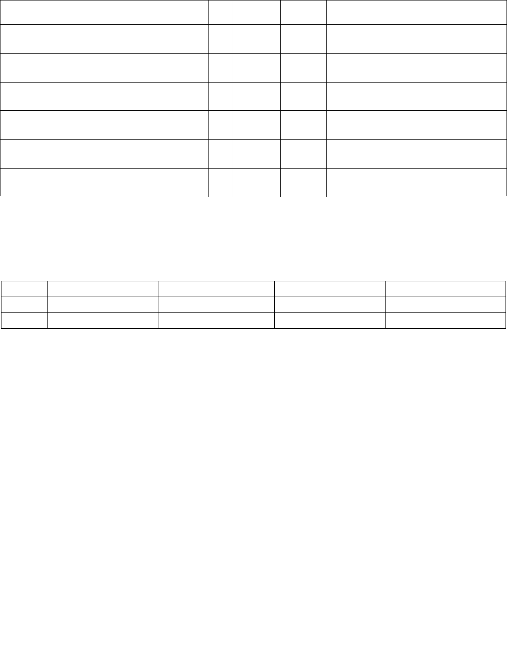
MOV—Move to/from Control Registers
INSTRUCTION SET REFERENCE, M-U
4-40 Vol. 2B
MOV—Move to/from Control Registers
Instruction Operand Encoding
Description
Moves the contents of a control register (CR0, CR2, CR3, CR4, or CR8) to a general-purpose register or the
contents of a general purpose register to a control register. The operand size for these instructions is always 32 bits
in non-64-bit modes, regardless of the operand-size attribute. (See “Control Registers” in Chapter 2 of the Intel®
64 and IA-32 Architectures Software Developer’s Manual, Volume 3A, for a detailed description of the flags and
fields in the control registers.) This instruction can be executed only when the current privilege level is 0.
At the opcode level, the reg field within the ModR/M byte specifies which of the control registers is loaded or read.
The 2 bits in the mod field are ignored. The r/m field specifies the general-purpose register loaded or read.
Attempts to reference CR1, CR5, CR6, CR7, and CR9–CR15 result in undefined opcode (#UD) exceptions.
When loading control registers, programs should not attempt to change the reserved bits; that is, always set
reserved bits to the value previously read. An attempt to change CR4's reserved bits will cause a general protection
fault. Reserved bits in CR0 and CR3 remain clear after any load of those registers; attempts to set them have no
impact. On Pentium 4, Intel Xeon and P6 family processors, CR0.ET remains set after any load of CR0; attempts to
clear this bit have no impact.
In certain cases, these instructions have the side effect of invalidating entries in the TLBs and the paging-structure
caches. See Section 4.10.4.1, “Operations that Invalidate TLBs and Paging-Structure Caches,” in the Intel® 64 and
IA-32 Architectures Software Developer’s Manual, Volume 3A for details.
The following side effects are implementation-specific for the Pentium 4, Intel Xeon, and P6 processor family: when
modifying PE or PG in register CR0, or PSE or PAE in register CR4, all TLB entries are flushed, including global
entries. Software should not depend on this functionality in all Intel 64 or IA-32 processors.
In 64-bit mode, the instruction’s default operation size is 64 bits. The REX.R prefix must be used to access CR8. Use
of REX.B permits access to additional registers (R8-R15). Use of the REX.W prefix or 66H prefix is ignored. Use of
Opcode/
Instruction
Op/
En
64-Bit
Mode
Compat/
Leg Mode
Description
0F 20/r
MOV r32, CR0–CR7
MR N.E. Valid Move control register to r32.
0F 20/r
MOV r64, CR0–CR7
MR Valid N.E. Move extended control register to r64.
REX.R + 0F 20 /0
MOV r64, CR8
MR Valid N.E. Move extended CR8 to r64.1
0F 22 /r
MOV CR0–CR7, r32
RM N.E. Valid Move r32 to control register.
0F 22 /r
MOV CR0–CR7, r64
RM Valid N.E. Move r64 to extended control register.
REX.R + 0F 22 /0
MOV CR8, r64
RM Valid N.E. Move r64 to extended CR8.1
NOTE:
1. MOV CR* instructions, except for MOV CR8, are serializing instructions. MOV CR8 is not
architecturally defined as a serializing instruction. For more information, see Chapter 8 in Intel® 64 and IA-32 Architectures Soft-
ware Developer’s Manual, Volume 3A.
Op/En Operand 1 Operand 2 Operand 3 Operand 4
MR ModRM:r/m (w) ModRM:reg (r) NA NA
RM ModRM:reg (w) ModRM:r/m (r) NA NA

MOV—Move to/from Control Registers
INSTRUCTION SET REFERENCE, M-U
Vol. 2B 4-41
the REX.R prefix to specify a register other than CR8 causes an invalid-opcode exception. See the summary chart
at the beginning of this section for encoding data and limits.
If CR4.PCIDE = 1, bit 63 of the source operand to MOV to CR3 determines whether the instruction invalidates
entries in the TLBs and the paging-structure caches (see Section 4.10.4.1, “Operations that Invalidate TLBs and
Paging-Structure Caches,” in the Intel® 64 and IA-32 Architectures Software Developer’s Manual, Volume 3A). The
instruction does not modify bit 63 of CR3, which is reserved and always 0.
See “Changes to Instruction Behavior in VMX Non-Root Operation” in Chapter 25 of the Intel® 64 and IA-32 Archi-
tectures Software Developer’s Manual, Volume 3C, for more information about the behavior of this instruction in
VMX non-root operation.
Operation
DEST ← SRC;
Flags Affected
The OF, SF, ZF, AF, PF, and CF flags are undefined.
Protected Mode Exceptions
#GP(0) If the current privilege level is not 0.
If an attempt is made to write invalid bit combinations in CR0 (such as setting the PG flag to 1
when the PE flag is set to 0, or setting the CD flag to 0 when the NW flag is set to 1).
If an attempt is made to write a 1 to any reserved bit in CR4.
If an attempt is made to write 1 to CR4.PCIDE.
If any of the reserved bits are set in the page-directory pointers table (PDPT) and the loading
of a control register causes the PDPT to be loaded into the processor.
#UD If the LOCK prefix is used.
If an attempt is made to access CR1, CR5, CR6, or CR7.
Real-Address Mode Exceptions
#GP If an attempt is made to write a 1 to any reserved bit in CR4.
If an attempt is made to write 1 to CR4.PCIDE.
If an attempt is made to write invalid bit combinations in CR0 (such as setting the PG flag to 1
when the PE flag is set to 0).
#UD If the LOCK prefix is used.
If an attempt is made to access CR1, CR5, CR6, or CR7.
Virtual-8086 Mode Exceptions
#GP(0) These instructions cannot be executed in virtual-8086 mode.
Compatibility Mode Exceptions
#GP(0) If the current privilege level is not 0.
If an attempt is made to write invalid bit combinations in CR0 (such as setting the PG flag to 1
when the PE flag is set to 0, or setting the CD flag to 0 when the NW flag is set to 1).
If an attempt is made to change CR4.PCIDE from 0 to 1 while CR3[11:0] ≠ 000H.
If an attempt is made to clear CR0.PG[bit 31] while CR4.PCIDE = 1.
If an attempt is made to write a 1 to any reserved bit in CR3.
If an attempt is made to leave IA-32e mode by clearing CR4.PAE[bit 5].
#UD If the LOCK prefix is used.
If an attempt is made to access CR1, CR5, CR6, or CR7.

MOV—Move to/from Control Registers
INSTRUCTION SET REFERENCE, M-U
4-42 Vol. 2B
64-Bit Mode Exceptions
#GP(0) If the current privilege level is not 0.
If an attempt is made to write invalid bit combinations in CR0 (such as setting the PG flag to 1
when the PE flag is set to 0, or setting the CD flag to 0 when the NW flag is set to 1).
If an attempt is made to change CR4.PCIDE from 0 to 1 while CR3[11:0] ≠ 000H.
If an attempt is made to clear CR0.PG[bit 31].
If an attempt is made to write a 1 to any reserved bit in CR4.
If an attempt is made to write a 1 to any reserved bit in CR8.
If an attempt is made to write a 1 to any reserved bit in CR3.
If an attempt is made to leave IA-32e mode by clearing CR4.PAE[bit 5].
#UD If the LOCK prefix is used.
If an attempt is made to access CR1, CR5, CR6, or CR7.
If the REX.R prefix is used to specify a register other than CR8.

MOV—Move to/from Debug Registers
INSTRUCTION SET REFERENCE, M-U
Vol. 2B 4-43
MOV—Move to/from Debug Registers
Instruction Operand Encoding
Description
Moves the contents of a debug register (DR0, DR1, DR2, DR3, DR4, DR5, DR6, or DR7) to a general-purpose
register or vice versa. The operand size for these instructions is always 32 bits in non-64-bit modes, regardless of
the operand-size attribute. (See Section 17.2, “Debug Registers”, of the Intel® 64 and IA-32 Architectures Soft-
ware Developer’s Manual, Volume 3A, for a detailed description of the flags and fields in the debug registers.)
The instructions must be executed at privilege level 0 or in real-address mode.
When the debug extension (DE) flag in register CR4 is clear, these instructions operate on debug registers in a
manner that is compatible with Intel386 and Intel486 processors. In this mode, references to DR4 and DR5 refer
to DR6 and DR7, respectively. When the DE flag in CR4 is set, attempts to reference DR4 and DR5 result in an
undefined opcode (#UD) exception. (The CR4 register was added to the IA-32 Architecture beginning with the
Pentium processor.)
At the opcode level, the reg field within the ModR/M byte specifies which of the debug registers is loaded or read.
The two bits in the mod field are ignored. The r/m field specifies the general-purpose register loaded or read.
In 64-bit mode, the instruction’s default operation size is 64 bits. Use of the REX.B prefix permits access to addi-
tional registers (R8–R15). Use of the REX.W or 66H prefix is ignored. Use of the REX.R prefix causes an invalid-
opcode exception. See the summary chart at the beginning of this section for encoding data and limits.
Operation
IF ((DE = 1) and (SRC or DEST = DR4 or DR5))
THEN
#UD;
ELSE
DEST ← SRC;
FI;
Flags Affected
The OF, SF, ZF, AF, PF, and CF flags are undefined.
Opcode/
Instruction
Op/
En
64-Bit
Mode
Compat/
Leg Mode
Description
0F 21/r
MOV r32, DR0–DR7
MR N.E. Valid Move debug register to r32.
0F 21/r
MOV r64, DR0–DR7
MR Valid N.E. Move extended debug register to r64.
0F 23 /r
MOV DR0–DR7, r32
RM N.E. Valid Move r32 to debug register.
0F 23 /r
MOV DR0–DR7, r64
RM Valid N.E. Move r64 to extended debug register.
Op/En Operand 1 Operand 2 Operand 3 Operand 4
MR ModRM:r/m (w) ModRM:reg (r) NA NA
RM ModRM:reg (w) ModRM:r/m (r) NA NA

MOV—Move to/from Debug Registers
INSTRUCTION SET REFERENCE, M-U
4-44 Vol. 2B
Protected Mode Exceptions
#GP(0) If the current privilege level is not 0.
#UD If CR4.DE[bit 3] = 1 (debug extensions) and a MOV instruction is executed involving DR4 or
DR5.
If the LOCK prefix is used.
#DB If any debug register is accessed while the DR7.GD[bit 13] = 1.
Real-Address Mode Exceptions
#UD If CR4.DE[bit 3] = 1 (debug extensions) and a MOV instruction is executed involving DR4 or
DR5.
If the LOCK prefix is used.
#DB If any debug register is accessed while the DR7.GD[bit 13] = 1.
Virtual-8086 Mode Exceptions
#GP(0) The debug registers cannot be loaded or read when in virtual-8086 mode.
Compatibility Mode Exceptions
Same exceptions as in protected mode.
64-Bit Mode Exceptions
#GP(0) If the current privilege level is not 0.
If an attempt is made to write a 1 to any of bits 63:32 in DR6.
If an attempt is made to write a 1 to any of bits 63:32 in DR7.
#UD If CR4.DE[bit 3] = 1 (debug extensions) and a MOV instruction is executed involving DR4 or
DR5.
If the LOCK prefix is used.
If the REX.R prefix is used.
#DB If any debug register is accessed while the DR7.GD[bit 13] = 1.

MOVAPD—Move Aligned Packed Double-Precision Floating-Point Values
INSTRUCTION SET REFERENCE, M-U
Vol. 2B 4-45
MOVAPD—Move Aligned Packed Double-Precision Floating-Point Values
Instruction Operand Encoding
Opcode/
Instruction
Op/En 64/32
bit Mode
Support
CPUID
Feature
Flag
Description
66 0F 28 /r
MOVAPD xmm1, xmm2/m128
RM V/V SSE2 Move aligned packed double-precision floating-
point values from xmm2/mem to xmm1.
66 0F 29 /r
MOVAPD xmm2/m128, xmm1
MR V/V SSE2 Move aligned packed double-precision floating-
point values from xmm1 to xmm2/mem.
VEX.128.66.0F.WIG 28 /r
VMOVAPD xmm1, xmm2/m128
RM V/V AVX Move aligned packed double-precision floating-
point values from xmm2/mem to xmm1.
VEX.128.66.0F.WIG 29 /r
VMOVAPD xmm2/m128, xmm1
MR V/V AVX Move aligned packed double-precision floating-
point values from xmm1 to xmm2/mem.
VEX.256.66.0F.WIG 28 /r
VMOVAPD ymm1, ymm2/m256
RM V/V AVX Move aligned packed double-precision floating-
point values from ymm2/mem to ymm1.
VEX.256.66.0F.WIG 29 /r
VMOVAPD ymm2/m256, ymm1
MR V/V AVX Move aligned packed double-precision floating-
point values from ymm1 to ymm2/mem.
EVEX.128.66.0F.W1 28 /r
VMOVAPD xmm1 {k1}{z}, xmm2/m128
FVM-RM V/V AVX512VL
AVX512F
Move aligned packed double-precision floating-
point values from xmm2/m128 to xmm1 using
writemask k1.
EVEX.256.66.0F.W1 28 /r
VMOVAPD ymm1 {k1}{z}, ymm2/m256
FVM-RM V/V AVX512VL
AVX512F
Move aligned packed double-precision floating-
point values from ymm2/m256 to ymm1 using
writemask k1.
EVEX.512.66.0F.W1 28 /r
VMOVAPD zmm1 {k1}{z}, zmm2/m512
FVM-RM V/V AVX512F Move aligned packed double-precision floating-
point values from zmm2/m512 to zmm1 using
writemask k1.
EVEX.128.66.0F.W1 29 /r
VMOVAPD xmm2/m128 {k1}{z}, xmm1
FVM-MR V/V AVX512VL
AVX512F
Move aligned packed double-precision floating-
point values from xmm1 to xmm2/m128 using
writemask k1.
EVEX.256.66.0F.W1 29 /r
VMOVAPD ymm2/m256 {k1}{z}, ymm1
FVM-MR V/V AVX512VL
AVX512F
Move aligned packed double-precision floating-
point values from ymm1 to ymm2/m256 using
writemask k1.
EVEX.512.66.0F.W1 29 /r
VMOVAPD zmm2/m512 {k1}{z}, zmm1
FVM-MR V/V AVX512F Move aligned packed double-precision floating-
point values from zmm1 to zmm2/m512 using
writemask k1.
Op/En Operand 1 Operand 2 Operand 3 Operand 4
RM ModRM:reg (w) ModRM:r/m (r) NA NA
MR ModRM:r/m (w) ModRM:reg (r) NA NA
FVM-RM ModRM:reg (w) ModRM:r/m (r) NA NA
FVM-MR ModRM:r/m (w) ModRM:reg (r) NA NA

MOVAPD—Move Aligned Packed Double-Precision Floating-Point Values
INSTRUCTION SET REFERENCE, M-U
4-46 Vol. 2B
Description
Moves 2, 4 or 8 double-precision floating-point values from the source operand (second operand) to the destination
operand (first operand). This instruction can be used to load an XMM, YMM or ZMM register from an 128-bit, 256-
bit or 512-bit memory location, to store the contents of an XMM, YMM or ZMM register into a 128-bit, 256-bit or
512-bit memory location, or to move data between two XMM, two YMM or two ZMM registers.
When the source or destination operand is a memory operand, the operand must be aligned on a 16-byte (128-bit
versions), 32-byte (256-bit version) or 64-byte (EVEX.512 encoded version) boundary or a general-protection
exception (#GP) will be generated. For EVEX encoded versions, the operand must be aligned to the size of the
memory operand. To move double-precision floating-point values to and from unaligned memory locations, use the
VMOVUPD instruction.
Note: VEX.vvvv and EVEX.vvvv are reserved and must be 1111b otherwise instructions will #UD.
EVEX.512 encoded version:
Moves 512 bits of packed double-precision floating-point values from the source operand (second operand) to the
destination operand (first operand). This instruction can be used to load a ZMM register from a 512-bit float64
memory location, to store the contents of a ZMM register into a 512-bit float64 memory location, or to move data
between two ZMM registers. When the source or destination operand is a memory operand, the operand must be
aligned on a 64-byte boundary or a general-protection exception (#GP) will be generated. To move single-precision
floating-point values to and from unaligned memory locations, use the VMOVUPD instruction.
VEX.256 and EVEX.256 encoded versions:
Moves 256 bits of packed double-precision floating-point values from the source operand (second operand) to the
destination operand (first operand). This instruction can be used to load a YMM register from a 256-bit memory
location, to store the contents of a YMM register into a 256-bit memory location, or to move data between two YMM
registers. When the source or destination operand is a memory operand, the operand must be aligned on a 32-byte
boundary or a general-protection exception (#GP) will be generated. To move double-precision floating-point
values to and from unaligned memory locations, use the VMOVUPD instruction.
128-bit versions:
Moves 128 bits of packed double-precision floating-point values from the source operand (second operand) to the
destination operand (first operand). This instruction can be used to load an XMM register from a 128-bit memory
location, to store the contents of an XMM register into a 128-bit memory location, or to move data between two
XMM registers. When the source or destination operand is a memory operand, the operand must be aligned on a
16-byte boundary or a general-protection exception (#GP) will be generated. To move single-precision floating-
point values to and from unaligned memory locations, use the VMOVUPD instruction.
128-bit Legacy SSE version: Bits (MAX_VL-1:128) of the corresponding ZMM destination register remain
unchanged.
(E)VEX.128 encoded version: Bits (MAX_VL-1:128) of the destination ZMM register destination are zeroed.
Operation
VMOVAPD (EVEX encoded versions, register-copy form)
(KL, VL) = (2, 128), (4, 256), (8, 512)
FOR j 0 TO KL-1
i j * 64
IF k1[j] OR *no writemask*
THEN DEST[i+63:i] SRC[i+63:i]
ELSE
IF *merging-masking* ; merging-masking
THEN *DEST[i+63:i] remains unchanged*
ELSE DEST[i+63:i] 0 ; zeroing-masking
FI
FI;
ENDFOR
DEST[MAX_VL-1:VL] 0

MOVAPD—Move Aligned Packed Double-Precision Floating-Point Values
INSTRUCTION SET REFERENCE, M-U
Vol. 2B 4-47
VMOVAPD (EVEX encoded versions, store-form)
(KL, VL) = (2, 128), (4, 256), (8, 512)
FOR j 0 TO KL-1
i j * 64
IF k1[j] OR *no writemask*
THEN DEST[i+63:i] SRC[i+63:i]
ELSE
ELSE *DEST[i+63:i] remains unchanged* ; merging-masking
FI;
ENDFOR;
VMOVAPD (EVEX encoded versions, load-form)
(KL, VL) = (2, 128), (4, 256), (8, 512)
FOR j 0 TO KL-1
i j * 64
IF k1[j] OR *no writemask*
THEN DEST[i+63:i] SRC[i+63:i]
ELSE
IF *merging-masking* ; merging-masking
THEN *DEST[i+63:i] remains unchanged*
ELSE DEST[i+63:i] 0 ; zeroing-masking
FI
FI;
ENDFOR
DEST[MAX_VL-1:VL] 0
VMOVAPD (VEX.256 encoded version, load - and register copy)
DEST[255:0] SRC[255:0]
DEST[MAX_VL-1:256] 0
VMOVAPD (VEX.256 encoded version, store-form)
DEST[255:0] SRC[255:0]
VMOVAPD (VEX.128 encoded version, load - and register copy)
DEST[127:0] SRC[127:0]
DEST[MAX_VL-1:128] 0
MOVAPD (128-bit load- and register-copy- form Legacy SSE version)
DEST[127:0] SRC[127:0]
DEST[MAX_VL-1:128] (Unmodified)
(V)MOVAPD (128-bit store-form version)
DEST[127:0] SRC[127:0]

MOVAPD—Move Aligned Packed Double-Precision Floating-Point Values
INSTRUCTION SET REFERENCE, M-U
4-48 Vol. 2B
Intel C/C++ Compiler Intrinsic Equivalent
VMOVAPD __m512d _mm512_load_pd( void * m);
VMOVAPD __m512d _mm512_mask_load_pd(__m512d s, __mmask8 k, void * m);
VMOVAPD __m512d _mm512_maskz_load_pd( __mmask8 k, void * m);
VMOVAPD void _mm512_store_pd( void * d, __m512d a);
VMOVAPD void _mm512_mask_store_pd( void * d, __mmask8 k, __m512d a);
VMOVAPD __m256d _mm256_mask_load_pd(__m256d s, __mmask8 k, void * m);
VMOVAPD __m256d _mm256_maskz_load_pd( __mmask8 k, void * m);
VMOVAPD void _mm256_mask_store_pd( void * d, __mmask8 k, __m256d a);
VMOVAPD __m128d _mm_mask_load_pd(__m128d s, __mmask8 k, void * m);
VMOVAPD __m128d _mm_maskz_load_pd( __mmask8 k, void * m);
VMOVAPD void _mm_mask_store_pd( void * d, __mmask8 k, __m128d a);
MOVAPD __m256d _mm256_load_pd (double * p);
MOVAPD void _mm256_store_pd(double * p, __m256d a);
MOVAPD __m128d _mm_load_pd (double * p);
MOVAPD void _mm_store_pd(double * p, __m128d a);
SIMD Floating-Point Exceptions
None
Other Exceptions
Non-EVEX-encoded instruction, see Exceptions Type1.SSE2;
EVEX-encoded instruction, see Exceptions Type E1.
#UD If EVEX.vvvv != 1111B or VEX.vvvv != 1111B.

MOVAPS—Move Aligned Packed Single-Precision Floating-Point Values
INSTRUCTION SET REFERENCE, M-U
Vol. 2B 4-49
MOVAPS—Move Aligned Packed Single-Precision Floating-Point Values
Instruction Operand Encoding
Description
Moves 4, 8 or 16 single-precision floating-point values from the source operand (second operand) to the destina-
tion operand (first operand). This instruction can be used to load an XMM, YMM or ZMM register from an 128-bit,
256-bit or 512-bit memory location, to store the contents of an XMM, YMM or ZMM register into a 128-bit, 256-bit
or 512-bit memory location, or to move data between two XMM, two YMM or two ZMM registers.
When the source or destination operand is a memory operand, the operand must be aligned on a 16-byte (128-bit
version), 32-byte (VEX.256 encoded version) or 64-byte (EVEX.512 encoded version) boundary or a general-
protection exception (#GP) will be generated. For EVEX.512 encoded versions, the operand must be aligned to the
size of the memory operand. To move single-precision floating-point values to and from unaligned memory loca-
tions, use the VMOVUPS instruction.
Opcode/
Instruction
Op/En 64/32
bit Mode
Support
CPUID
Feature
Flag
Description
0F 28 /r
MOVAPS xmm1, xmm2/m128
RM V/V SSE Move aligned packed single-precision floating-point
values from xmm2/mem to xmm1.
0F 29 /r
MOVAPS xmm2/m128, xmm1
MR V/V SSE Move aligned packed single-precision floating-point
values from xmm1 to xmm2/mem.
VEX.128.0F.WIG 28 /r
VMOVAPS xmm1, xmm2/m128
RM V/V AVX Move aligned packed single-precision floating-point
values from xmm2/mem to xmm1.
VEX.128.0F.WIG 29 /r
VMOVAPS xmm2/m128, xmm1
MR V/V AVX Move aligned packed single-precision floating-point
values from xmm1 to xmm2/mem.
VEX.256.0F.WIG 28 /r
VMOVAPS ymm1, ymm2/m256
RM V/V AVX Move aligned packed single-precision floating-point
values from ymm2/mem to ymm1.
VEX.256.0F.WIG 29 /r
VMOVAPS ymm2/m256, ymm1
MR V/V AVX Move aligned packed single-precision floating-point
values from ymm1 to ymm2/mem.
EVEX.128.0F.W0 28 /r
VMOVAPS xmm1 {k1}{z}, xmm2/m128
FVM-RM V/V AVX512VL
AVX512F
Move aligned packed single-precision floating-point
values from xmm2/m128 to xmm1 using
writemask k1.
EVEX.256.0F.W0 28 /r
VMOVAPS ymm1 {k1}{z}, ymm2/m256
FVM-RM V/V AVX512VL
AVX512F
Move aligned packed single-precision floating-point
values from ymm2/m256 to ymm1 using
writemask k1.
EVEX.512.0F.W0 28 /r
VMOVAPS zmm1 {k1}{z}, zmm2/m512
FVM-RM V/V AVX512F Move aligned packed single-precision floating-point
values from zmm2/m512 to zmm1 using
writemask k1.
EVEX.128.0F.W0 29 /r
VMOVAPS xmm2/m128 {k1}{z}, xmm1
FVM-MR V/V AVX512VL
AVX512F
Move aligned packed single-precision floating-point
values from xmm1 to xmm2/m128 using
writemask k1.
EVEX.256.0F.W0 29 /r
VMOVAPS ymm2/m256 {k1}{z}, ymm1
FVM-MR V/V AVX512VL
AVX512F
Move aligned packed single-precision floating-point
values from ymm1 to ymm2/m256 using
writemask k1.
EVEX.512.0F.W0 29 /r
VMOVAPS zmm2/m512 {k1}{z}, zmm1
FVM-MR V/V AVX512F Move aligned packed single-precision floating-point
values from zmm1 to zmm2/m512 using
writemask k1.
Op/En Operand 1 Operand 2 Operand 3 Operand 4
RM ModRM:reg (w) ModRM:r/m (r) NA NA
MR ModRM:r/m (w) ModRM:reg (r) NA NA
FVM-RM ModRM:reg (w) ModRM:r/m (r) NA NA
FVM-MR ModRM:r/m (w) ModRM:reg (r) NA NA

MOVAPS—Move Aligned Packed Single-Precision Floating-Point Values
INSTRUCTION SET REFERENCE, M-U
4-50 Vol. 2B
Note: VEX.vvvv and EVEX.vvvv are reserved and must be 1111b otherwise instructions will #UD.
EVEX.512 encoded version:
Moves 512 bits of packed single-precision floating-point values from the source operand (second operand) to the
destination operand (first operand). This instruction can be used to load a ZMM register from a 512-bit float32
memory location, to store the contents of a ZMM register into a float32 memory location, or to move data between
two ZMM registers. When the source or destination operand is a memory operand, the operand must be aligned on
a 64-byte boundary or a general-protection exception (#GP) will be generated. To move single-precision floating-
point values to and from unaligned memory locations, use the VMOVUPS instruction.
VEX.256 and EVEX.256 encoded version:
Moves 256 bits of packed single-precision floating-point values from the source operand (second operand) to the
destination operand (first operand). This instruction can be used to load a YMM register from a 256-bit memory
location, to store the contents of a YMM register into a 256-bit memory location, or to move data between two YMM
registers. When the source or destination operand is a memory operand, the operand must be aligned on a 32-byte
boundary or a general-protection exception (#GP) will be generated.
128-bit versions:
Moves 128 bits of packed single-precision floating-point values from the source operand (second operand) to the
destination operand (first operand). This instruction can be used to load an XMM register from a 128-bit memory
location, to store the contents of an XMM register into a 128-bit memory location, or to move data between two
XMM registers. When the source or destination operand is a memory operand, the operand must be aligned on a
16-byte boundary or a general-protection exception (#GP) will be generated. To move single-precision floating-
point values to and from unaligned memory locations, use the VMOVUPS instruction.
128-bit Legacy SSE version: Bits (MAX_VL-1:128) of the corresponding ZMM destination register remain
unchanged.
(E)VEX.128 encoded version: Bits (MAX_VL-1:128) of the destination ZMM register are zeroed.
Operation
VMOVAPS (EVEX encoded versions, register-copy form)
(KL, VL) = (4, 128), (8, 256), (16, 512)
FOR j 0 TO KL-1
i j * 32
IF k1[j] OR *no writemask*
THEN DEST[i+31:i] SRC[i+31:i]
ELSE
IF *merging-masking* ; merging-masking
THEN *DEST[i+31:i] remains unchanged*
ELSE DEST[i+31:i] 0 ; zeroing-masking
FI
FI;
ENDFOR
DEST[MAX_VL-1:VL] 0
VMOVAPS (EVEX encoded versions, store-form)
(KL, VL) = (4, 128), (8, 256), (16, 512)
FOR j 0 TO KL-1
i j * 32
IF k1[j] OR *no writemask*
THEN DEST[i+31:i]
SRC[i+31:i]
ELSE *DEST[i+31:i] remains unchanged* ; merging-masking
FI;
ENDFOR;

MOVAPS—Move Aligned Packed Single-Precision Floating-Point Values
INSTRUCTION SET REFERENCE, M-U
Vol. 2B 4-51
VMOVAPS (EVEX encoded versions, load-form)
(KL, VL) = (4, 128), (8, 256), (16, 512)
FOR j 0 TO KL-1
i j * 32
IF k1[j] OR *no writemask*
THEN DEST[i+31:i] SRC[i+31:i]
ELSE
IF *merging-masking* ; merging-masking
THEN *DEST[i+31:i] remains unchanged*
ELSE DEST[i+31:i] 0 ; zeroing-masking
FI
FI;
ENDFOR
DEST[MAX_VL-1:VL] 0
VMOVAPS (VEX.256 encoded version, load - and register copy)
DEST[255:0] SRC[255:0]
DEST[MAX_VL-1:256] 0
VMOVAPS (VEX.256 encoded version, store-form)
DEST[255:0] SRC[255:0]
VMOVAPS (VEX.128 encoded version, load - and register copy)
DEST[127:0] SRC[127:0]
DEST[MAX_VL-1:128] 0
MOVAPS (128-bit load- and register-copy- form Legacy SSE version)
DEST[127:0] SRC[127:0]
DEST[MAX_VL-1:128] (Unmodified)
(V)MOVAPS (128-bit store-form version)
DEST[127:0] SRC[127:0]
Intel C/C++ Compiler Intrinsic Equivalent
VMOVAPS __m512 _mm512_load_ps( void * m);
VMOVAPS __m512 _mm512_mask_load_ps(__m512 s, __mmask16 k, void * m);
VMOVAPS __m512 _mm512_maskz_load_ps( __mmask16 k, void * m);
VMOVAPS void _mm512_store_ps( void * d, __m512 a);
VMOVAPS void _mm512_mask_store_ps( void * d, __mmask16 k, __m512 a);
VMOVAPS __m256 _mm256_mask_load_ps(__m256 a, __mmask8 k, void * s);
VMOVAPS __m256 _mm256_maskz_load_ps( __mmask8 k, void * s);
VMOVAPS void _mm256_mask_store_ps( void * d, __mmask8 k, __m256 a);
VMOVAPS __m128 _mm_mask_load_ps(__m128 a, __mmask8 k, void * s);
VMOVAPS __m128 _mm_maskz_load_ps( __mmask8 k, void * s);
VMOVAPS void _mm_mask_store_ps( void * d, __mmask8 k, __m128 a);
MOVAPS __m256 _mm256_load_ps (float * p);
MOVAPS void _mm256_store_ps(float * p, __m256 a);
MOVAPS __m128 _mm_load_ps (float * p);
MOVAPS void _mm_store_ps(float * p, __m128 a);
SIMD Floating-Point Exceptions
None

MOVAPS—Move Aligned Packed Single-Precision Floating-Point Values
INSTRUCTION SET REFERENCE, M-U
4-52 Vol. 2B
Other Exceptions
Non-EVEX-encoded instruction, see Exceptions Type1.SSE; additionally
#UD If VEX.vvvv != 1111B.
EVEX-encoded instruction, see Exceptions Type E1.

MOVBE—Move Data After Swapping Bytes
INSTRUCTION SET REFERENCE, M-U
Vol. 2B 4-53
MOVBE—Move Data After Swapping Bytes
Instruction Operand Encoding
Description
Performs a byte swap operation on the data copied from the second operand (source operand) and store the result
in the first operand (destination operand). The source operand can be a general-purpose register, or memory loca-
tion; the destination register can be a general-purpose register, or a memory location; however, both operands can
not be registers, and only one operand can be a memory location. Both operands must be the same size, which can
be a word, a doubleword or quadword.
The MOVBE instruction is provided for swapping the bytes on a read from memory or on a write to memory; thus
providing support for converting little-endian values to big-endian format and vice versa.
In 64-bit mode, the instruction's default operation size is 32 bits. Use of the REX.R prefix permits access to addi-
tional registers (R8-R15). Use of the REX.W prefix promotes operation to 64 bits. See the summary chart at the
beginning of this section for encoding data and limits.
Operation
TEMP ← SRC
IF ( OperandSize = 16)
THEN
DEST[7:0] ← TEMP[15:8];
DEST[15:8] ← TEMP[7:0];
ELES IF ( OperandSize = 32)
DEST[7:0] ← TEMP[31:24];
DEST[15:8] ← TEMP[23:16];
DEST[23:16] ← TEMP[15:8];
DEST[31:23] ← TEMP[7:0];
ELSE IF ( OperandSize = 64)
DEST[7:0] ← TEMP[63:56];
DEST[15:8] ← TEMP[55:48];
DEST[23:16] ← TEMP[47:40];
DEST[31:24] ← TEMP[39:32];
DEST[39:32] ← TEMP[31:24];
DEST[47:40] ← TEMP[23:16];
DEST[55:48] ← TEMP[15:8];
DEST[63:56] ← TEMP[7:0];
FI;
Opcode Instruction Op/
En
64-Bit
Mode
Compat/
Leg Mode
Description
0F 38 F0 /rMOVBE r16, m16 RM Valid Valid Reverse byte order in m16 and move to r16.
0F 38 F0 /rMOVBE r32, m32 RM Valid Valid Reverse byte order in m32 and move to r32.
REX.W + 0F 38 F0 /rMOVBE r64, m64 RM Valid N.E. Reverse byte order in m64 and move to r64.
0F 38 F1 /rMOVBE m16, r16 MR Valid Valid Reverse byte order in r16 and move to m16.
0F 38 F1 /rMOVBE m32, r32 MR Valid Valid Reverse byte order in r32 and move to m32.
REX.W + 0F 38 F1 /rMOVBE m64, r64 MR Valid N.E. Reverse byte order in r64 and move to m64.
Op/En Operand 1 Operand 2 Operand 3 Operand 4
RM ModRM:reg (w) ModRM:r/m (r) NA NA
MR ModRM:r/m (w) ModRM:reg (r) NA NA

MOVBE—Move Data After Swapping Bytes
INSTRUCTION SET REFERENCE, M-U
4-54 Vol. 2B
Flags Affected
None
Protected Mode Exceptions
#GP(0) If the destination operand is in a non-writable segment.
If a memory operand effective address is outside the CS, DS, ES, FS, or GS segment limit.
If the DS, ES, FS, or GS register contains a NULL segment selector.
#SS(0) If a memory operand effective address is outside the SS segment limit.
#PF(fault-code) If a page fault occurs.
#AC(0) If alignment checking is enabled and an unaligned memory reference is made while the
current privilege level is 3.
#UD If CPUID.01H:ECX.MOVBE[bit 22] = 0.
If the LOCK prefix is used.
If REP (F3H) prefix is used.
Real-Address Mode Exceptions
#GP If a memory operand effective address is outside the CS, DS, ES, FS, or GS segment limit.
#SS If a memory operand effective address is outside the SS segment limit.
#UD If CPUID.01H:ECX.MOVBE[bit 22] = 0.
If the LOCK prefix is used.
If REP (F3H) prefix is used.
Virtual-8086 Mode Exceptions
#GP(0) If a memory operand effective address is outside the CS, DS, ES, FS, or GS segment limit.
#SS(0) If a memory operand effective address is outside the SS segment limit.
#PF(fault-code) If a page fault occurs.
#AC(0) If alignment checking is enabled and an unaligned memory reference is made while the
current privilege level is 3.
#UD If CPUID.01H:ECX.MOVBE[bit 22] = 0.
If the LOCK prefix is used.
If REP (F3H) prefix is used.
If REPNE (F2H) prefix is used and CPUID.01H:ECX.SSE4_2[bit 20] = 0.
Compatibility Mode Exceptions
Same exceptions as in protected mode.
64-Bit Mode Exceptions
#GP(0) If the memory address is in a non-canonical form.
#SS(0) If the stack address is in a non-canonical form.
#PF(fault-code) If a page fault occurs.
#AC(0) If alignment checking is enabled and an unaligned memory reference is made while the
current privilege level is 3.
#UD If CPUID.01H:ECX.MOVBE[bit 22] = 0.
If the LOCK prefix is used.
If REP (F3H) prefix is used.

MOVD/MOVQ—Move Doubleword/Move Quadword
INSTRUCTION SET REFERENCE, M-U
Vol. 2B 4-55
MOVD/MOVQ—Move Doubleword/Move Quadword
Opcode/
Instruction
Op/ En 64/32-bit
Mode
CPUID
Feature
Flag
Description
0F 6E /r
MOVD mm, r/m32
RM V/V MMX Move doubleword from r/m32 to mm.
REX.W + 0F 6E /r
MOVQ mm, r/m64
RM V/N.E. MMX Move quadword from r/m64 to mm.
0F 7E /r
MOVD r/m32, mm
MR V/V MMX Move doubleword from mm to r/m32.
REX.W + 0F 7E /r
MOVQ r/m64, mm
MR V/N.E. MMX Move quadword from mm to r/m64.
66 0F 6E /r
MOVD xmm, r/m32
RM V/V SSE2 Move doubleword from r/m32 to xmm.
66 REX.W 0F 6E /r
MOVQ xmm, r/m64
RM V/N.E. SSE2 Move quadword from r/m64 to xmm.
66 0F 7E /r
MOVD r/m32, xmm
MR V/V SSE2 Move doubleword from xmm register to r/m32.
66 REX.W 0F 7E /r
MOVQ r/m64, xmm
MR V/N.E. SSE2 Move quadword from xmm register to r/m64.
VEX.128.66.0F.W0 6E /
VMOVD xmm1, r32/m32
RM V/V AVX Move doubleword from r/m32 to xmm1.
VEX.128.66.0F.W1 6E /r
VMOVQ xmm1, r64/m64
RM V/N.E1.AVX Move quadword from r/m64 to xmm1.
VEX.128.66.0F.W0 7E /r
VMOVD r32/m32, xmm1
MR V/V AVX Move doubleword from xmm1 register to r/m32.
VEX.128.66.0F.W1 7E /r
VMOVQ r64/m64, xmm1
MR V/N.E1.AVX Move quadword from xmm1 register to r/m64.
EVEX.128.66.0F.W0 6E /r
VMOVD xmm1, r32/m32
T1S-RM V/V AVX512F Move doubleword from r/m32 to xmm1.
EVEX.128.66.0F.W1 6E /r
VMOVQ xmm1, r64/m64
T1S-RM V/N.E.1
NOTES:
1. For this specific instruction, VEX.W/EVEX.W in non-64 bit is ignored; the instructions behaves as if the W0 ver-
sion is used.
AVX512F Move quadword from r/m64 to xmm1.
EVEX.128.66.0F.W0 7E /r
VMOVD r32/m32, xmm1
T1S-MR V/V AVX512F Move doubleword from xmm1 register to r/m32.
EVEX.128.66.0F.W1 7E /r
VMOVQ r64/m64, xmm1
T1S-MR V/N.E.1AVX512F Move quadword from xmm1 register to r/m64.

MOVD/MOVQ—Move Doubleword/Move Quadword
INSTRUCTION SET REFERENCE, M-U
4-56 Vol. 2B
Instruction Operand Encoding
Description
Copies a doubleword from the source operand (second operand) to the destination operand (first operand). The
source and destination operands can be general-purpose registers, MMX technology registers, XMM registers, or
32-bit memory locations. This instruction can be used to move a doubleword to and from the low doubleword of an
MMX technology register and a general-purpose register or a 32-bit memory location, or to and from the low
doubleword of an XMM register and a general-purpose register or a 32-bit memory location. The instruction cannot
be used to transfer data between MMX technology registers, between XMM registers, between general-purpose
registers, or between memory locations.
When the destination operand is an MMX technology register, the source operand is written to the low doubleword
of the register, and the register is zero-extended to 64 bits. When the destination operand is an XMM register, the
source operand is written to the low doubleword of the register, and the register is zero-extended to 128 bits.
In 64-bit mode, the instruction’s default operation size is 32 bits. Use of the REX.R prefix permits access to addi-
tional registers (R8-R15). Use of the REX.W prefix promotes operation to 64 bits. See the summary chart at the
beginning of this section for encoding data and limits.
MOVD/Q with XMM destination:
Moves a dword/qword integer from the source operand and stores it in the low 32/64-bits of the destination XMM
register. The upper bits of the destination are zeroed. The source operand can be a 32/64-bit register or 32/64-bit
memory location.
128-bit Legacy SSE version: Bits (MAX_VL-1:128) of the corresponding YMM destination register remain
unchanged. Qword operation requires the use of REX.W=1.
VEX.128 encoded version: Bits (MAX_VL-1:128) of the destination register are zeroed. Qword operation requires
the use of VEX.W=1.
EVEX.128 encoded version: Bits (MAX_VL-1:128) of the destination register are zeroed. Qword operation requires
the use of EVEX.W=1.
MOVD/Q with 32/64 reg/mem destination:
Stores the low dword/qword of the source XMM register to 32/64-bit memory location or general-purpose register.
Qword operation requires the use of REX.W=1, VEX.W=1, or EVEX.W=1.
Note: VEX.vvvv and EVEX.vvvv are reserved and must be 1111b otherwise instructions will #UD.
If VMOVD or VMOVQ is encoded with VEX.L= 1, an attempt to execute the instruction encoded with VEX.L= 1 will
cause an #UD exception.
Operation
MOVD (when destination operand is MMX technology register)
DEST[31:0] ← SRC;
DEST[63:32] ← 00000000H;
MOVD (when destination operand is XMM register)
DEST[31:0] ← SRC;
DEST[127:32] ← 000000000000000000000000H;
DEST[VLMAX-1:128] (Unmodified)
Op/En Operand 1 Operand 2 Operand 3 Operand 4
RM ModRM:reg (w) ModRM:r/m (r) NA NA
MR ModRM:r/m (w) ModRM:reg (r) NA NA
T1S-RM ModRM:reg (w) ModRM:r/m (r) NA NA
T1S-MR ModRM:r/m (w) ModRM:reg (r) NA NA

MOVD/MOVQ—Move Doubleword/Move Quadword
INSTRUCTION SET REFERENCE, M-U
Vol. 2B 4-57
MOVD (when source operand is MMX technology or XMM register)
DEST ← SRC[31:0];
VMOVD (VEX-encoded version when destination is an XMM register)
DEST[31:0] SRC[31:0]
DEST[VLMAX-1:32] 0
MOVQ (when destination operand is XMM register)
DEST[63:0] ← SRC[63:0];
DEST[127:64] ← 0000000000000000H;
DEST[VLMAX-1:128] (Unmodified)
MOVQ (when destination operand is r/m64)
DEST[63:0] ← SRC[63:0];
MOVQ (when source operand is XMM register or r/m64)
DEST ← SRC[63:0];
VMOVQ (VEX-encoded version when destination is an XMM register)
DEST[63:0] SRC[63:0]
DEST[VLMAX-1:64] 0
VMOVD (EVEX-encoded version when destination is an XMM register)
DEST[31:0] SRC[31:0]
DEST[511:32] 0H
VMOVQ (EVEX-encoded version when destination is an XMM register)
DEST[63:0] SRC[63:0]
DEST[511:64] 0H
Intel C/C++ Compiler Intrinsic Equivalent
MOVD: __m64 _mm_cvtsi32_si64 (int i )
MOVD: int _mm_cvtsi64_si32 ( __m64m )
MOVD: __m128i _mm_cvtsi32_si128 (int a)
MOVD: int _mm_cvtsi128_si32 ( __m128i a)
MOVQ: __int64 _mm_cvtsi128_si64(__m128i);
MOVQ: __m128i _mm_cvtsi64_si128(__int64);
VMOVD __m128i _mm_cvtsi32_si128( int);
VMOVD int _mm_cvtsi128_si32( __m128i );
VMOVQ __m128i _mm_cvtsi64_si128 (__int64);
VMOVQ __int64 _mm_cvtsi128_si64(__m128i );
VMOVQ __m128i _mm_loadl_epi64( __m128i * s);
VMOVQ void _mm_storel_epi64( __m128i * d, __m128i s);
Flags Affected
None
SIMD Floating-Point Exceptions
None

MOVD/MOVQ—Move Doubleword/Move Quadword
INSTRUCTION SET REFERENCE, M-U
4-58 Vol. 2B
Other Exceptions
Non-EVEX-encoded instruction, see Exceptions Type 5.
EVEX-encoded instruction, see Exceptions Type E9NF.
#UD If VEX.L = 1.
If VEX.vvvv != 1111B or EVEX.vvvv != 1111B.

MOVDDUP—Replicate Double FP Values
INSTRUCTION SET REFERENCE, M-U
Vol. 2B 4-59
MOVDDUP—Replicate Double FP Values
Instruction Operand Encoding
Description
For 256-bit or higher versions: Duplicates even-indexed double-precision floating-point values from the source
operand (the second operand) and into adjacent pair and store to the destination operand (the first operand).
For 128-bit versions: Duplicates the low double-precision floating-point value from the source operand (the second
operand) and store to the destination operand (the first operand).
128-bit Legacy SSE version: Bits (MAX_VL-1:128) of the corresponding destination register are unchanged. The
source operand is XMM register or a 64-bit memory location.
VEX.128 and EVEX.128 encoded version: Bits (MAX_VL-1:128) of the destination register are zeroed. The source
operand is XMM register or a 64-bit memory location. The destination is updated conditionally under the writemask
for EVEX version.
VEX.256 and EVEX.256 encoded version: Bits (MAX_VL-1:256) of the destination register are zeroed. The source
operand is YMM register or a 256-bit memory location. The destination is updated conditionally under the
writemask for EVEX version.
EVEX.512 encoded version: The destination is updated according to the writemask. The source operand is ZMM
register or a 512-bit memory location.
Note: VEX.vvvv and EVEX.vvvv are reserved and must be 1111b otherwise instructions will #UD.
Opcode/
Instruction
Op / En 64/32
bit Mode
Support
CPUID
Feature
Flag
Description
F2 0F 12 /r
MOVDDUP xmm1, xmm2/m64
RM V/V SSE3 Move double-precision floating-point value from
xmm2/m64 and duplicate into xmm1.
VEX.128.F2.0F.WIG 12 /r
VMOVDDUP xmm1, xmm2/m64
RM V/V AVX Move double-precision floating-point value from
xmm2/m64 and duplicate into xmm1.
VEX.256.F2.0F.WIG 12 /r
VMOVDDUP ymm1, ymm2/m256
RM V/V AVX Move even index double-precision floating-point
values from ymm2/mem and duplicate each element
into ymm1.
EVEX.128.F2.0F.W1 12 /r
VMOVDDUP xmm1 {k1}{z},
xmm2/m64
DUP-RM V/V AVX512VL
AVX512F
Move double-precision floating-point value from
xmm2/m64 and duplicate each element into xmm1
subject to writemask k1.
EVEX.256.F2.0F.W1 12 /r
VMOVDDUP ymm1 {k1}{z},
ymm2/m256
DUP-RM V/V AVX512VL
AVX512F
Move even index double-precision floating-point
values from ymm2/m256 and duplicate each element
into ymm1 subject to writemask k1.
EVEX.512.F2.0F.W1 12 /r
VMOVDDUP zmm1 {k1}{z},
zmm2/m512
DUP-RM V/V AVX512F Move even index double-precision floating-point
values from zmm2/m512 and duplicate each element
into zmm1 subject to writemask k1.
Op/En Operand 1 Operand 2 Operand 3 Operand 4
RM ModRM:reg (w) ModRM:r/m (r) NA NA
DUP-RM ModRM:reg (w) ModRM:r/m (r) NA NA
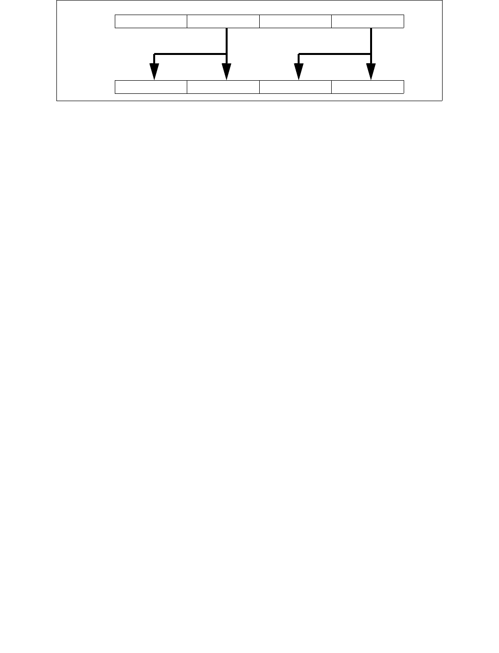
MOVDDUP—Replicate Double FP Values
INSTRUCTION SET REFERENCE, M-U
4-60 Vol. 2B
Operation
VMOVDDUP (EVEX encoded versions)
(KL, VL) = (2, 128), (4, 256), (8, 512)
TMP_SRC[63:0] SRC[63:0]
TMP_SRC[127:64] SRC[63:0]
IF VL >= 256
TMP_SRC[191:128] SRC[191:128]
TMP_SRC[255:192] SRC[191:128]
FI;
IF VL >= 512
TMP_SRC[319:256] SRC[319:256]
TMP_SRC[383:320] SRC[319:256]
TMP_SRC[477:384] SRC[477:384]
TMP_SRC[511:484] SRC[477:384]
FI;
FOR j 0 TO KL-1
i j * 64
IF k1[j] OR *no writemask*
THEN DEST[i+63:i] TMP_SRC[i+63:i]
ELSE
IF *merging-masking* ; merging-masking
THEN *DEST[i+63:i] remains unchanged*
ELSE ; zeroing-masking
DEST[i+63:i] 0 ; zeroing-masking
FI
FI;
ENDFOR
DEST[MAX_VL-1:VL] 0
VMOVDDUP (VEX.256 encoded version)
DEST[63:0] SRC[63:0]
DEST[127:64] SRC[63:0]
DEST[191:128] SRC[191:128]
DEST[255:192] SRC[191:128]
DEST[MAX_VL-1:256] 0
VMOVDDUP (VEX.128 encoded version)
DEST[63:0] SRC[63:0]
DEST[127:64] SRC[63:0]
DEST[MAX_VL-1:128] 0
Figure 4-2. VMOVDDUP Operation
X2 X2 X0 X0DEST
X3 X2
SRC X1 X0

MOVDDUP—Replicate Double FP Values
INSTRUCTION SET REFERENCE, M-U
Vol. 2B 4-61
MOVDDUP (128-bit Legacy SSE version)
DEST[63:0] SRC[63:0]
DEST[127:64] SRC[63:0]
DEST[MAX_VL-1:128] (Unmodified)
Intel C/C++ Compiler Intrinsic Equivalent
VMOVDDUP __m512d _mm512_movedup_pd( __m512d a);
VMOVDDUP __m512d _mm512_mask_movedup_pd(__m512d s, __mmask8 k, __m512d a);
VMOVDDUP __m512d _mm512_maskz_movedup_pd( __mmask8 k, __m512d a);
VMOVDDUP __m256d _mm256_mask_movedup_pd(__m256d s, __mmask8 k, __m256d a);
VMOVDDUP __m256d _mm256_maskz_movedup_pd( __mmask8 k, __m256d a);
VMOVDDUP __m128d _mm_mask_movedup_pd(__m128d s, __mmask8 k, __m128d a);
VMOVDDUP __m128d _mm_maskz_movedup_pd( __mmask8 k, __m128d a);
MOVDDUP __m256d _mm256_movedup_pd (__m256d a);
MOVDDUP __m128d _mm_movedup_pd (__m128d a);
SIMD Floating-Point Exceptions
None
Other Exceptions
Non-EVEX-encoded instruction, see Exceptions Type 5;
EVEX-encoded instruction, see Exceptions Type E5NF.
#UD If EVEX.vvvv != 1111B or VEX.vvvv != 1111B.

MOVDQA,VMOVDQA32/64—Move Aligned Packed Integer Values
INSTRUCTION SET REFERENCE, M-U
4-62 Vol. 2B
MOVDQA,VMOVDQA32/64—Move Aligned Packed Integer Values
Opcode/
Instruction
Op/En 64/32
bit Mode
Support
CPUID
Feature
Flag
Description
66 0F 6F /r
MOVDQA xmm1, xmm2/m128
RM V/V SSE2 Move aligned packed integer values from
xmm2/mem to xmm1.
66 0F 7F /r
MOVDQA xmm2/m128, xmm1
MR V/V SSE2 Move aligned packed integer values from xmm1
to xmm2/mem.
VEX.128.66.0F.WIG 6F /r
VMOVDQA xmm1, xmm2/m128
RM V/V AVX Move aligned packed integer values from
xmm2/mem to xmm1.
VEX.128.66.0F.WIG 7F /r
VMOVDQA xmm2/m128, xmm1
MR V/V AVX Move aligned packed integer values from xmm1
to xmm2/mem.
VEX.256.66.0F.WIG 6F /r
VMOVDQA ymm1, ymm2/m256
RM V/V AVX Move aligned packed integer values from
ymm2/mem to ymm1.
VEX.256.66.0F.WIG 7F /r
VMOVDQA ymm2/m256, ymm1
MR V/V AVX Move aligned packed integer values from ymm1
to ymm2/mem.
EVEX.128.66.0F.W0 6F /r
VMOVDQA32 xmm1 {k1}{z},
xmm2/m128
FVM-RM V/V AVX512VL
AVX512F
Move aligned packed doubleword integer values
from xmm2/m128 to xmm1 using writemask
k1.
EVEX.256.66.0F.W0 6F /r
VMOVDQA32 ymm1 {k1}{z},
ymm2/m256
FVM-RM V/V AVX512VL
AVX512F
Move aligned packed doubleword integer values
from ymm2/m256 to ymm1 using writemask
k1.
EVEX.512.66.0F.W0 6F /r
VMOVDQA32 zmm1 {k1}{z},
zmm2/m512
FVM-RM V/V AVX512F Move aligned packed doubleword integer values
from zmm2/m512 to zmm1 using writemask k1.
EVEX.128.66.0F.W0 7F /r
VMOVDQA32 xmm2/m128 {k1}{z},
xmm1
FVM-MR V/V AVX512VL
AVX512F
Move aligned packed doubleword integer values
from xmm1 to xmm2/m128 using writemask
k1.
EVEX.256.66.0F.W0 7F /r
VMOVDQA32 ymm2/m256 {k1}{z},
ymm1
FVM-MR V/V AVX512VL
AVX512F
Move aligned packed doubleword integer values
from ymm1 to ymm2/m256 using writemask
k1.
EVEX.512.66.0F.W0 7F /r
VMOVDQA32 zmm2/m512 {k1}{z},
zmm1
FVM-MR V/V AVX512F Move aligned packed doubleword integer values
from zmm1 to zmm2/m512 using writemask k1.
EVEX.128.66.0F.W1 6F /r
VMOVDQA64 xmm1 {k1}{z},
xmm2/m128
FVM-RM V/V AVX512VL
AVX512F
Move aligned quadword integer values from
xmm2/m128 to xmm1 using writemask k1.
EVEX.256.66.0F.W1 6F /r
VMOVDQA64 ymm1 {k1}{z},
ymm2/m256
FVM-RM V/V AVX512VL
AVX512F
Move aligned quadword integer values from
ymm2/m256 to ymm1 using writemask k1.
EVEX.512.66.0F.W1 6F /r
VMOVDQA64 zmm1 {k1}{z},
zmm2/m512
FVM-RM V/V AVX512F Move aligned packed quadword integer values
from zmm2/m512 to zmm1 using writemask k1.
EVEX.128.66.0F.W1 7F /r
VMOVDQA64 xmm2/m128 {k1}{z},
xmm1
FVM-MR V/V AVX512VL
AVX512F
Move aligned packed quadword integer values
from xmm1 to xmm2/m128 using writemask
k1.
EVEX.256.66.0F.W1 7F /r
VMOVDQA64 ymm2/m256 {k1}{z},
ymm1
FVM-MR V/V AVX512VL
AVX512F
Move aligned packed quadword integer values
from ymm1 to ymm2/m256 using writemask
k1.
EVEX.512.66.0F.W1 7F /r
VMOVDQA64 zmm2/m512 {k1}{z},
zmm1
FVM-MR V/V AVX512F Move aligned packed quadword integer values
from zmm1 to zmm2/m512 using writemask k1.

MOVDQA,VMOVDQA32/64—Move Aligned Packed Integer Values
INSTRUCTION SET REFERENCE, M-U
Vol. 2B 4-63
Instruction Operand Encoding
Description
Note: VEX.vvvv and EVEX.vvvv are reserved and must be 1111b otherwise instructions will #UD.
EVEX encoded versions:
Moves 128, 256 or 512 bits of packed doubleword/quadword integer values from the source operand (the second
operand) to the destination operand (the first operand). This instruction can be used to load a vector register from
an int32/int64 memory location, to store the contents of a vector register into an int32/int64 memory location, or
to move data between two ZMM registers. When the source or destination operand is a memory operand, the
operand must be aligned on a 16 (EVEX.128)/32(EVEX.256)/64(EVEX.512)-byte boundary or a general-protection
exception (#GP) will be generated. To move integer data to and from unaligned memory locations, use the
VMOVDQU instruction.
The destination operand is updated at 32-bit (VMOVDQA32) or 64-bit (VMOVDQA64) granularity according to the
writemask.
VEX.256 encoded version:
Moves 256 bits of packed integer values from the source operand (second operand) to the destination operand
(first operand). This instruction can be used to load a YMM register from a 256-bit memory location, to store the
contents of a YMM register into a 256-bit memory location, or to move data between two YMM registers.
When the source or destination operand is a memory operand, the operand must be aligned on a 32-byte boundary
or a general-protection exception (#GP) will be generated. To move integer data to and from unaligned memory
locations, use the VMOVDQU instruction. Bits (MAX_VL-1:256) of the destination register are zeroed.
128-bit versions:
Moves 128 bits of packed integer values from the source operand (second operand) to the destination operand
(first operand). This instruction can be used to load an XMM register from a 128-bit memory location, to store the
contents of an XMM register into a 128-bit memory location, or to move data between two XMM registers.
When the source or destination operand is a memory operand, the operand must be aligned on a 16-byte boundary
or a general-protection exception (#GP) will be generated. To move integer data to and from unaligned memory
locations, use the VMOVDQU instruction.
128-bit Legacy SSE version: Bits (MAX_VL-1:128) of the corresponding ZMM destination register remain
unchanged.
VEX.128 encoded version: Bits (MAX_VL-1:128) of the destination register are zeroed.
Op/En Operand 1 Operand 2 Operand 3 Operand 4
RM ModRM:reg (w) ModRM:r/m (r) NA NA
MR ModRM:r/m (w) ModRM:reg (r) NA NA
FVM-RM ModRM:reg (w) ModRM:r/m (r) NA NA
FVM-MR ModRM:r/m (w) ModRM:reg (r) NA NA

MOVDQA,VMOVDQA32/64—Move Aligned Packed Integer Values
INSTRUCTION SET REFERENCE, M-U
4-64 Vol. 2B
Operation
VMOVDQA32 (EVEX encoded versions, register-copy form)
(KL, VL) = (4, 128), (8, 256), (16, 512)
FOR j 0 TO KL-1
i j * 32
IF k1[j] OR *no writemask*
THEN DEST[i+31:i] SRC[i+31:i]
ELSE
IF *merging-masking* ; merging-masking
THEN *DEST[i+31:i] remains unchanged*
ELSE DEST[i+31:i] 0 ; zeroing-masking
FI
FI;
ENDFOR
DEST[MAX_VL-1:VL] 0
VMOVDQA32 (EVEX encoded versions, store-form)
(KL, VL) = (4, 128), (8, 256), (16, 512)
FOR j 0 TO KL-1
i j * 32
IF k1[j] OR *no writemask*
THEN DEST[i+31:i] SRC[i+31:i]
ELSE *DEST[i+31:i] remains unchanged* ; merging-masking
FI;
ENDFOR;
VMOVDQA32 (EVEX encoded versions, load-form)
(KL, VL) = (4, 128), (8, 256), (16, 512)
FOR j 0 TO KL-1
i j * 32
IF k1[j] OR *no writemask*
THEN DEST[i+31:i] SRC[i+31:i]
ELSE
IF *merging-masking* ; merging-masking
THEN *DEST[i+31:i] remains unchanged*
ELSE DEST[i+31:i] 0 ; zeroing-masking
FI
FI;
ENDFOR
DEST[MAX_VL-1:VL] 0

MOVDQA,VMOVDQA32/64—Move Aligned Packed Integer Values
INSTRUCTION SET REFERENCE, M-U
Vol. 2B 4-65
VMOVDQA64 (EVEX encoded versions, register-copy form)
(KL, VL) = (2, 128), (4, 256), (8, 512)
FOR j 0 TO KL-1
i j * 64
IF k1[j] OR *no writemask*
THEN DEST[i+63:i] SRC[i+63:i]
ELSE
IF *merging-masking* ; merging-masking
THEN *DEST[i+63:i] remains unchanged*
ELSE DEST[i+63:i] 0 ; zeroing-masking
FI
FI;
ENDFOR
DEST[MAX_VL-1:VL] 0
VMOVDQA64 (EVEX encoded versions, store-form)
(KL, VL) = (2, 128), (4, 256), (8, 512)
FOR j 0 TO KL-1
i j * 64
IF k1[j] OR *no writemask*
THEN DEST[i+63:i] SRC[i+63:i]
ELSE *DEST[i+63:i] remains unchanged* ; merging-masking
FI;
ENDFOR;
VMOVDQA64 (EVEX encoded versions, load-form)
(KL, VL) = (2, 128), (4, 256), (8, 512)
FOR j 0 TO KL-1
i j * 64
IF k1[j] OR *no writemask*
THEN DEST[i+63:i] SRC[i+63:i]
ELSE
IF *merging-masking* ; merging-masking
THEN *DEST[i+63:i] remains unchanged*
ELSE DEST[i+63:i] 0 ; zeroing-masking
FI
FI;
ENDFOR
DEST[MAX_VL-1:VL] 0
VMOVDQA (VEX.256 encoded version, load - and register copy)
DEST[255:0] SRC[255:0]
DEST[MAX_VL-1:256] 0
VMOVDQA (VEX.256 encoded version, store-form)
DEST[255:0] SRC[255:0]
VMOVDQA (VEX.128 encoded version)
DEST[127:0] SRC[127:0]
DEST[MAX_VL-1:128] 0
VMOVDQA (128-bit load- and register-copy- form Legacy SSE version)
DEST[127:0] SRC[127:0]
DEST[MAX_VL-1:128] (Unmodified)

MOVDQA,VMOVDQA32/64—Move Aligned Packed Integer Values
INSTRUCTION SET REFERENCE, M-U
4-66 Vol. 2B
(V)MOVDQA (128-bit store-form version)
DEST[127:0] SRC[127:0]
Intel C/C++ Compiler Intrinsic Equivalent
VMOVDQA32 __m512i _mm512_load_epi32( void * sa);
VMOVDQA32 __m512i _mm512_mask_load_epi32(__m512i s, __mmask16 k, void * sa);
VMOVDQA32 __m512i _mm512_maskz_load_epi32( __mmask16 k, void * sa);
VMOVDQA32 void _mm512_store_epi32(void * d, __m512i a);
VMOVDQA32 void _mm512_mask_store_epi32(void * d, __mmask16 k, __m512i a);
VMOVDQA32 __m256i _mm256_mask_load_epi32(__m256i s, __mmask8 k, void * sa);
VMOVDQA32 __m256i _mm256_maskz_load_epi32( __mmask8 k, void * sa);
VMOVDQA32 void _mm256_store_epi32(void * d, __m256i a);
VMOVDQA32 void _mm256_mask_store_epi32(void * d, __mmask8 k, __m256i a);
VMOVDQA32 __m128i _mm_mask_load_epi32(__m128i s, __mmask8 k, void * sa);
VMOVDQA32 __m128i _mm_maskz_load_epi32( __mmask8 k, void * sa);
VMOVDQA32 void _mm_store_epi32(void * d, __m128i a);
VMOVDQA32 void _mm_mask_store_epi32(void * d, __mmask8 k, __m128i a);
VMOVDQA64 __m512i _mm512_load_epi64( void * sa);
VMOVDQA64 __m512i _mm512_mask_load_epi64(__m512i s, __mmask8 k, void * sa);
VMOVDQA64 __m512i _mm512_maskz_load_epi64( __mmask8 k, void * sa);
VMOVDQA64 void _mm512_store_epi64(void * d, __m512i a);
VMOVDQA64 void _mm512_mask_store_epi64(void * d, __mmask8 k, __m512i a);
VMOVDQA64 __m256i _mm256_mask_load_epi64(__m256i s, __mmask8 k, void * sa);
VMOVDQA64 __m256i _mm256_maskz_load_epi64( __mmask8 k, void * sa);
VMOVDQA64 void _mm256_store_epi64(void * d, __m256i a);
VMOVDQA64 void _mm256_mask_store_epi64(void * d, __mmask8 k, __m256i a);
VMOVDQA64 __m128i _mm_mask_load_epi64(__m128i s, __mmask8 k, void * sa);
VMOVDQA64 __m128i _mm_maskz_load_epi64( __mmask8 k, void * sa);
VMOVDQA64 void _mm_store_epi64(void * d, __m128i a);
VMOVDQA64 void _mm_mask_store_epi64(void * d, __mmask8 k, __m128i a);
MOVDQA void __m256i _mm256_load_si256 (__m256i * p);
MOVDQA _mm256_store_si256(_m256i *p, __m256i a);
MOVDQA __m128i _mm_load_si128 (__m128i * p);
MOVDQA void _mm_store_si128(__m128i *p, __m128i a);
SIMD Floating-Point Exceptions
None
Other Exceptions
Non-EVEX-encoded instruction, see Exceptions Type1.SSE2;
EVEX-encoded instruction, see Exceptions Type E1.
#UD If EVEX.vvvv != 1111B or VEX.vvvv != 1111B.

MOVDQU,VMOVDQU8/16/32/64—Move Unaligned Packed Integer Values
INSTRUCTION SET REFERENCE, M-U
Vol. 2B 4-67
MOVDQU,VMOVDQU8/16/32/64—Move Unaligned Packed Integer Values
Opcode/
Instruction
Op/En 64/32
bit Mode
Support
CPUID
Feature
Flag
Description
F3 0F 6F /r
MOVDQU xmm1, xmm2/m128
RM V/V SSE2 Move unaligned packed integer values from
xmm2/m128 to xmm1.
F3 0F 7F /r
MOVDQU xmm2/m128, xmm1
MR V/V SSE2 Move unaligned packed integer values from
xmm1 to xmm2/m128.
VEX.128.F3.0F.WIG 6F /r
VMOVDQU xmm1, xmm2/m128
RM V/V AVX Move unaligned packed integer values from
xmm2/m128 to xmm1.
VEX.128.F3.0F.WIG 7F /r
VMOVDQU xmm2/m128, xmm1
MR V/V AVX Move unaligned packed integer values from
xmm1 to xmm2/m128.
VEX.256.F3.0F.WIG 6F /r
VMOVDQU ymm1, ymm2/m256
RM V/V AVX Move unaligned packed integer values from
ymm2/m256 to ymm1.
VEX.256.F3.0F.WIG 7F /r
VMOVDQU ymm2/m256, ymm1
MR V/V AVX Move unaligned packed integer values from
ymm1 to ymm2/m256.
EVEX.128.F2.0F.W0 6F /r
VMOVDQU8 xmm1 {k1}{z}, xmm2/m128
FVM-RM V/V AVX512VL
AVX512BW
Move unaligned packed byte integer values
from xmm2/m128 to xmm1 using writemask
k1.
EVEX.256.F2.0F.W0 6F /r
VMOVDQU8 ymm1 {k1}{z}, ymm2/m256
FVM-RM V/V AVX512VL
AVX512BW
Move unaligned packed byte integer values
from ymm2/m256 to ymm1 using writemask
k1.
EVEX.512.F2.0F.W0 6F /r
VMOVDQU8 zmm1 {k1}{z}, zmm2/m512
FVM-RM V/V AVX512BW Move unaligned packed byte integer values
from zmm2/m512 to zmm1 using writemask
k1.
EVEX.128.F2.0F.W0 7F /r
VMOVDQU8 xmm2/m128 {k1}{z}, xmm1
FVM-MR V/V AVX512VL
AVX512BW
Move unaligned packed byte integer values
from xmm1 to xmm2/m128 using writemask
k1.
EVEX.256.F2.0F.W0 7F /r
VMOVDQU8 ymm2/m256 {k1}{z}, ymm1
FVM-MR V/V AVX512VL
AVX512BW
Move unaligned packed byte integer values
from ymm1 to ymm2/m256 using writemask
k1.
EVEX.512.F2.0F.W0 7F /r
VMOVDQU8 zmm2/m512 {k1}{z}, zmm1
FVM-MR V/V AVX512BW Move unaligned packed byte integer values
from zmm1 to zmm2/m512 using writemask
k1.
EVEX.128.F2.0F.W1 6F /r
VMOVDQU16 xmm1 {k1}{z}, xmm2/m128
FVM-RM V/V AVX512VL
AVX512BW
Move unaligned packed word integer values
from xmm2/m128 to xmm1 using writemask
k1.
EVEX.256.F2.0F.W1 6F /r
VMOVDQU16 ymm1 {k1}{z}, ymm2/m256
FVM-RM V/V AVX512VL
AVX512BW
Move unaligned packed word integer values
from ymm2/m256 to ymm1 using writemask
k1.
EVEX.512.F2.0F.W1 6F /r
VMOVDQU16 zmm1 {k1}{z}, zmm2/m512
FVM-RM V/V AVX512BW Move unaligned packed word integer values
from zmm2/m512 to zmm1 using writemask
k1.
EVEX.128.F2.0F.W1 7F /r
VMOVDQU16 xmm2/m128 {k1}{z}, xmm1
FVM-MR V/V AVX512VL
AVX512BW
Move unaligned packed word integer values
from xmm1 to xmm2/m128 using writemask
k1.
EVEX.256.F2.0F.W1 7F /r
VMOVDQU16 ymm2/m256 {k1}{z}, ymm1
FVM-MR V/V AVX512VL
AVX512BW
Move unaligned packed word integer values
from ymm1 to ymm2/m256 using writemask
k1.
EVEX.512.F2.0F.W1 7F /r
VMOVDQU16 zmm2/m512 {k1}{z}, zmm1
FVM-MR V/V AVX512BW Move unaligned packed word integer values
from zmm1 to zmm2/m512 using writemask
k1.
EVEX.128.F3.0F.W0 6F /r
VMOVDQU32 xmm1 {k1}{z},
xmm2/mm128
FVM-RM V/V AVX512VL
AVX512F
Move unaligned packed doubleword integer
values from xmm2/m128 to xmm1 using
writemask k1.

MOVDQU,VMOVDQU8/16/32/64—Move Unaligned Packed Integer Values
INSTRUCTION SET REFERENCE, M-U
4-68 Vol. 2B
Instruction Operand Encoding
Description
Note: VEX.vvvv and EVEX.vvvv are reserved and must be 1111b otherwise instructions will #UD.
EVEX encoded versions:
Moves 128, 256 or 512 bits of packed byte/word/doubleword/quadword integer values from the source operand
(the second operand) to the destination operand (first operand). This instruction can be used to load a vector
register from a memory location, to store the contents of a vector register into a memory location, or to move data
between two vector registers.
EVEX.256.F3.0F.W0 6F /r
VMOVDQU32 ymm1 {k1}{z}, ymm2/m256
FVM-RM V/V AVX512VL
AVX512F
Move unaligned packed doubleword integer
values from ymm2/m256 to ymm1 using
writemask k1.
EVEX.512.F3.0F.W0 6F /r
VMOVDQU32 zmm1 {k1}{z}, zmm2/m512
FVM-RM V/V AVX512F Move unaligned packed doubleword integer
values from zmm2/m512 to zmm1 using
writemask k1.
EVEX.128.F3.0F.W0 7F /r
VMOVDQU32 xmm2/m128 {k1}{z}, xmm1
FVM-MR V/V AVX512VL
AVX512F
Move unaligned packed doubleword integer
values from xmm1 to xmm2/m128 using
writemask k1.
EVEX.256.F3.0F.W0 7F /r
VMOVDQU32 ymm2/m256 {k1}{z}, ymm1
FVM-MR V/V AVX512VL
AVX512F
Move unaligned packed doubleword integer
values from ymm1 to ymm2/m256 using
writemask k1.
EVEX.512.F3.0F.W0 7F /r
VMOVDQU32 zmm2/m512 {k1}{z}, zmm1
FVM-MR V/V AVX512F Move unaligned packed doubleword integer
values from zmm1 to zmm2/m512 using
writemask k1.
EVEX.128.F3.0F.W1 6F /r
VMOVDQU64 xmm1 {k1}{z}, xmm2/m128
FVM-RM V/V AVX512VL
AVX512F
Move unaligned packed quadword integer
values from xmm2/m128 to xmm1 using
writemask k1.
EVEX.256.F3.0F.W1 6F /r
VMOVDQU64 ymm1 {k1}{z}, ymm2/m256
FVM-RM V/V AVX512VL
AVX512F
Move unaligned packed quadword integer
values from ymm2/m256 to ymm1 using
writemask k1.
EVEX.512.F3.0F.W1 6F /r
VMOVDQU64 zmm1 {k1}{z}, zmm2/m512
FVM-RM V/V AVX512F Move unaligned packed quadword integer
values from zmm2/m512 to zmm1 using
writemask k1.
EVEX.128.F3.0F.W1 7F /r
VMOVDQU64 xmm2/m128 {k1}{z}, xmm1
FVM-MR V/V AVX512VL
AVX512F
Move unaligned packed quadword integer
values from xmm1 to xmm2/m128 using
writemask k1.
EVEX.256.F3.0F.W1 7F /r
VMOVDQU64 ymm2/m256 {k1}{z}, ymm1
FVM-MR V/V AVX512VL
AVX512F
Move unaligned packed quadword integer
values from ymm1 to ymm2/m256 using
writemask k1.
EVEX.512.F3.0F.W1 7F /r
VMOVDQU64 zmm2/m512 {k1}{z}, zmm1
FVM-MR V/V AVX512F Move unaligned packed quadword integer
values from zmm1 to zmm2/m512 using
writemask k1.
Op/En Operand 1 Operand 2 Operand 3 Operand 4
RM ModRM:reg (w) ModRM:r/m (r) NA NA
MR ModRM:r/m (w) ModRM:reg (r) NA NA
FVM-RM ModRM:reg (w) ModRM:r/m (r) NA NA
FVM-MR ModRM:r/m (w) ModRM:reg (r) NA NA
Opcode/
Instruction
Op/En 64/32
bit Mode
Support
CPUID
Feature
Flag
Description

MOVDQU,VMOVDQU8/16/32/64—Move Unaligned Packed Integer Values
INSTRUCTION SET REFERENCE, M-U
Vol. 2B 4-69
The destination operand is updated at 8-bit (VMOVDQU8), 16-bit (VMOVDQU16), 32-bit (VMOVDQU32), or 64-bit
(VMOVDQU64) granularity according to the writemask.
VEX.256 encoded version:
Moves 256 bits of packed integer values from the source operand (second operand) to the destination operand
(first operand). This instruction can be used to load a YMM register from a 256-bit memory location, to store the
contents of a YMM register into a 256-bit memory location, or to move data between two YMM registers.
Bits (MAX_VL-1:256) of the destination register are zeroed.
128-bit versions:
Moves 128 bits of packed integer values from the source operand (second operand) to the destination operand
(first operand). This instruction can be used to load an XMM register from a 128-bit memory location, to store the
contents of an XMM register into a 128-bit memory location, or to move data between two XMM registers.
128-bit Legacy SSE version: Bits (MAX_VL-1:128) of the corresponding destination register remain unchanged.
When the source or destination operand is a memory operand, the operand may be unaligned to any alignment
without causing a general-protection exception (#GP) to be generated
VEX.128 encoded version: Bits (MAX_VL-1:128) of the destination register are zeroed.
Operation
VMOVDQU8 (EVEX encoded versions, register-copy form)
(KL, VL) = (16, 128), (32, 256), (64, 512)
FOR j 0 TO KL-1
i j * 8
IF k1[j] OR *no writemask*
THEN DEST[i+7:i] SRC[i+7:i]
ELSE
IF *merging-masking* ; merging-masking
THEN *DEST[i+7:i] remains unchanged*
ELSE DEST[i+7:i] 0 ; zeroing-masking
FI
FI;
ENDFOR
DEST[MAX_VL-1:VL] 0
VMOVDQU8 (EVEX encoded versions, store-form)
(KL, VL) = (16, 128), (32, 256), (64, 512)
FOR j 0 TO KL-1
i j * 8
IF k1[j] OR *no writemask*
THEN DEST[i+7:i]
SRC[i+7:i]
ELSE *DEST[i+7:i] remains unchanged* ; merging-masking
FI;
ENDFOR;

MOVDQU,VMOVDQU8/16/32/64—Move Unaligned Packed Integer Values
INSTRUCTION SET REFERENCE, M-U
4-70 Vol. 2B
VMOVDQU8 (EVEX encoded versions, load-form)
(KL, VL) = (16, 128), (32, 256), (64, 512)
FOR j 0 TO KL-1
i j * 8
IF k1[j] OR *no writemask*
THEN DEST[i+7:i] SRC[i+7:i]
ELSE
IF *merging-masking* ; merging-masking
THEN *DEST[i+7:i] remains unchanged*
ELSE DEST[i+7:i] 0 ; zeroing-masking
FI
FI;
ENDFOR
DEST[MAX_VL-1:VL] 0
VMOVDQU16 (EVEX encoded versions, register-copy form)
(KL, VL) = (8, 128), (16, 256), (32, 512)
FOR j 0 TO KL-1
i j * 16
IF k1[j] OR *no writemask*
THEN DEST[i+15:i] SRC[i+15:i]
ELSE
IF *merging-masking* ; merging-masking
THEN *DEST[i+15:i] remains unchanged*
ELSE DEST[i+15:i] 0 ; zeroing-masking
FI
FI;
ENDFOR
DEST[MAX_VL-1:VL] 0
VMOVDQU16 (EVEX encoded versions, store-form)
(KL, VL) = (8, 128), (16, 256), (32, 512)
FOR j 0 TO KL-1
i j * 16
IF k1[j] OR *no writemask*
THEN DEST[i+15:i]
SRC[i+15:i]
ELSE *DEST[i+15:i] remains unchanged* ; merging-masking
FI;
ENDFOR;

MOVDQU,VMOVDQU8/16/32/64—Move Unaligned Packed Integer Values
INSTRUCTION SET REFERENCE, M-U
Vol. 2B 4-71
VMOVDQU16 (EVEX encoded versions, load-form)
(KL, VL) = (8, 128), (16, 256), (32, 512)
FOR j 0 TO KL-1
i j * 16
IF k1[j] OR *no writemask*
THEN DEST[i+15:i] SRC[i+15:i]
ELSE
IF *merging-masking* ; merging-masking
THEN *DEST[i+15:i] remains unchanged*
ELSE DEST[i+15:i] 0 ; zeroing-masking
FI
FI;
ENDFOR
DEST[MAX_VL-1:VL] 0
VMOVDQU32 (EVEX encoded versions, register-copy form)
(KL, VL) = (4, 128), (8, 256), (16, 512)
FOR j 0 TO KL-1
i j * 32
IF k1[j] OR *no writemask*
THEN DEST[i+31:i] SRC[i+31:i]
ELSE
IF *merging-masking* ; merging-masking
THEN *DEST[i+31:i] remains unchanged*
ELSE DEST[i+31:i] 0 ; zeroing-masking
FI
FI;
ENDFOR
DEST[MAX_VL-1:VL] 0
VMOVDQU32 (EVEX encoded versions, store-form)
(KL, VL) = (4, 128), (8, 256), (16, 512)
FOR j 0 TO KL-1
i j * 32
IF k1[j] OR *no writemask*
THEN DEST[i+31:i]
SRC[i+31:i]
ELSE *DEST[i+31:i] remains unchanged* ; merging-masking
FI;
ENDFOR;

MOVDQU,VMOVDQU8/16/32/64—Move Unaligned Packed Integer Values
INSTRUCTION SET REFERENCE, M-U
4-72 Vol. 2B
VMOVDQU32 (EVEX encoded versions, load-form)
(KL, VL) = (4, 128), (8, 256), (16, 512)
FOR j 0 TO KL-1
i j * 32
IF k1[j] OR *no writemask*
THEN DEST[i+31:i] SRC[i+31:i]
ELSE
IF *merging-masking* ; merging-masking
THEN *DEST[i+31:i] remains unchanged*
ELSE DEST[i+31:i] 0 ; zeroing-masking
FI
FI;
ENDFOR
DEST[MAX_VL-1:VL] 0
VMOVDQU64 (EVEX encoded versions, register-copy form)
(KL, VL) = (2, 128), (4, 256), (8, 512)
FOR j 0 TO KL-1
i j * 64
IF k1[j] OR *no writemask*
THEN DEST[i+63:i] SRC[i+63:i]
ELSE
IF *merging-masking* ; merging-masking
THEN *DEST[i+63:i] remains unchanged*
ELSE DEST[i+63:i] 0 ; zeroing-masking
FI
FI;
ENDFOR
DEST[MAX_VL-1:VL] 0
VMOVDQU64 (EVEX encoded versions, store-form)
(KL, VL) = (2, 128), (4, 256), (8, 512)
FOR j 0 TO KL-1
i j * 64
IF k1[j] OR *no writemask*
THEN DEST[i+63:i] SRC[i+63:i]
ELSE *DEST[i+63:i] remains unchanged* ; merging-masking
FI;
ENDFOR;

MOVDQU,VMOVDQU8/16/32/64—Move Unaligned Packed Integer Values
INSTRUCTION SET REFERENCE, M-U
Vol. 2B 4-73
VMOVDQU64 (EVEX encoded versions, load-form)
(KL, VL) = (2, 128), (4, 256), (8, 512)
FOR j 0 TO KL-1
i j * 64
IF k1[j] OR *no writemask*
THEN DEST[i+63:i] SRC[i+63:i]
ELSE
IF *merging-masking* ; merging-masking
THEN *DEST[i+63:i] remains unchanged*
ELSE DEST[i+63:i] 0 ; zeroing-masking
FI
FI;
ENDFOR
DEST[MAX_VL-1:VL] 0
VMOVDQU (VEX.256 encoded version, load - and register copy)
DEST[255:0] SRC[255:0]
DEST[MAX_VL-1:256] 0
VMOVDQU (VEX.256 encoded version, store-form)
DEST[255:0] SRC[255:0]
VMOVDQU (VEX.128 encoded version)
DEST[127:0] SRC[127:0]
DEST[MAX_VL-1:128] 0
VMOVDQU (128-bit load- and register-copy- form Legacy SSE version)
DEST[127:0] SRC[127:0]
DEST[MAX_VL-1:128] (Unmodified)
(V)MOVDQU (128-bit store-form version)
DEST[127:0] SRC[127:0]
Intel C/C++ Compiler Intrinsic Equivalent
VMOVDQU16 __m512i _mm512_mask_loadu_epi16(__m512i s, __mmask32 k, void * sa);
VMOVDQU16 __m512i _mm512_maskz_loadu_epi16( __mmask32 k, void * sa);
VMOVDQU16 void _mm512_mask_storeu_epi16(void * d, __mmask32 k, __m512i a);
VMOVDQU16 __m256i _mm256_mask_loadu_epi16(__m256i s, __mmask16 k, void * sa);
VMOVDQU16 __m256i _mm256_maskz_loadu_epi16( __mmask16 k, void * sa);
VMOVDQU16 void _mm256_mask_storeu_epi16(void * d, __mmask16 k, __m256i a);
VMOVDQU16 void _mm256_maskz_storeu_epi16(void * d, __mmask16 k);
VMOVDQU16 __m128i _mm_mask_loadu_epi16(__m128i s, __mmask8 k, void * sa);
VMOVDQU16 __m128i _mm_maskz_loadu_epi16( __mmask8 k, void * sa);
VMOVDQU16 void _mm_mask_storeu_epi16(void * d, __mmask8 k, __m128i a);
VMOVDQU32 __m512i _mm512_loadu_epi32( void * sa);
VMOVDQU32 __m512i _mm512_mask_loadu_epi32(__m512i s, __mmask16 k, void * sa);
VMOVDQU32 __m512i _mm512_maskz_loadu_epi32( __mmask16 k, void * sa);
VMOVDQU32 void _mm512_storeu_epi32(void * d, __m512i a);
VMOVDQU32 void _mm512_mask_storeu_epi32(void * d, __mmask16 k, __m512i a);
VMOVDQU32 __m256i _mm256_mask_loadu_epi32(__m256i s, __mmask8 k, void * sa);
VMOVDQU32 __m256i _mm256_maskz_loadu_epi32( __mmask8 k, void * sa);
VMOVDQU32 void _mm256_storeu_epi32(void * d, __m256i a);
VMOVDQU32 void _mm256_mask_storeu_epi32(void * d, __mmask8 k, __m256i a);
VMOVDQU32 __m128i _mm_mask_loadu_epi32(__m128i s, __mmask8 k, void * sa);

MOVDQU,VMOVDQU8/16/32/64—Move Unaligned Packed Integer Values
INSTRUCTION SET REFERENCE, M-U
4-74 Vol. 2B
VMOVDQU32 __m128i _mm_maskz_loadu_epi32( __mmask8 k, void * sa);
VMOVDQU32 void _mm_storeu_epi32(void * d, __m128i a);
VMOVDQU32 void _mm_mask_storeu_epi32(void * d, __mmask8 k, __m128i a);
VMOVDQU64 __m512i _mm512_loadu_epi64( void * sa);
VMOVDQU64 __m512i _mm512_mask_loadu_epi64(__m512i s, __mmask8 k, void * sa);
VMOVDQU64 __m512i _mm512_maskz_loadu_epi64( __mmask8 k, void * sa);
VMOVDQU64 void _mm512_storeu_epi64(void * d, __m512i a);
VMOVDQU64 void _mm512_mask_storeu_epi64(void * d, __mmask8 k, __m512i a);
VMOVDQU64 __m256i _mm256_mask_loadu_epi64(__m256i s, __mmask8 k, void * sa);
VMOVDQU64 __m256i _mm256_maskz_loadu_epi64( __mmask8 k, void * sa);
VMOVDQU64 void _mm256_storeu_epi64(void * d, __m256i a);
VMOVDQU64 void _mm256_mask_storeu_epi64(void * d, __mmask8 k, __m256i a);
VMOVDQU64 __m128i _mm_mask_loadu_epi64(__m128i s, __mmask8 k, void * sa);
VMOVDQU64 __m128i _mm_maskz_loadu_epi64( __mmask8 k, void * sa);
VMOVDQU64 void _mm_storeu_epi64(void * d, __m128i a);
VMOVDQU64 void _mm_mask_storeu_epi64(void * d, __mmask8 k, __m128i a);
VMOVDQU8 __m512i _mm512_mask_loadu_epi8(__m512i s, __mmask64 k, void * sa);
VMOVDQU8 __m512i _mm512_maskz_loadu_epi8( __mmask64 k, void * sa);
VMOVDQU8 void _mm512_mask_storeu_epi8(void * d, __mmask64 k, __m512i a);
VMOVDQU8 __m256i _mm256_mask_loadu_epi8(__m256i s, __mmask32 k, void * sa);
VMOVDQU8 __m256i _mm256_maskz_loadu_epi8( __mmask32 k, void * sa);
VMOVDQU8 void _mm256_mask_storeu_epi8(void * d, __mmask32 k, __m256i a);
VMOVDQU8 void _mm256_maskz_storeu_epi8(void * d, __mmask32 k);
VMOVDQU8 __m128i _mm_mask_loadu_epi8(__m128i s, __mmask16 k, void * sa);
VMOVDQU8 __m128i _mm_maskz_loadu_epi8( __mmask16 k, void * sa);
VMOVDQU8 void _mm_mask_storeu_epi8(void * d, __mmask16 k, __m128i a);
MOVDQU __m256i _mm256_loadu_si256 (__m256i * p);
MOVDQU _mm256_storeu_si256(_m256i *p, __m256i a);
MOVDQU __m128i _mm_loadu_si128 (__m128i * p);
MOVDQU _mm_storeu_si128(__m128i *p, __m128i a);
SIMD Floating-Point Exceptions
None
Other Exceptions
Non-EVEX-encoded instruction, see Exceptions Type 4;
EVEX-encoded instruction, see Exceptions Type E4.nb.
#UD If EVEX.vvvv != 1111B or VEX.vvvv != 1111B.

MOVDQ2Q—Move Quadword from XMM to MMX Technology Register
INSTRUCTION SET REFERENCE, M-U
Vol. 2B 4-75
MOVDQ2Q—Move Quadword from XMM to MMX Technology Register
Instruction Operand Encoding
Description
Moves the low quadword from the source operand (second operand) to the destination operand (first operand).
The source operand is an XMM register and the destination operand is an MMX technology register.
This instruction causes a transition from x87 FPU to MMX technology operation (that is, the x87 FPU top-of-stack
pointer is set to 0 and the x87 FPU tag word is set to all 0s [valid]). If this instruction is executed while an x87 FPU
floating-point exception is pending, the exception is handled before the MOVDQ2Q instruction is executed.
In 64-bit mode, use of the REX.R prefix permits this instruction to access additional registers (XMM8-XMM15).
Operation
DEST ← SRC[63:0];
Intel C/C++ Compiler Intrinsic Equivalent
MOVDQ2Q: __m64 _mm_movepi64_pi64 ( __m128i a)
SIMD Floating-Point Exceptions
None.
Protected Mode Exceptions
#NM If CR0.TS[bit 3] = 1.
#UD If CR0.EM[bit 2] = 1.
If CR4.OSFXSR[bit 9] = 0.
If CPUID.01H:EDX.SSE2[bit 26] = 0.
If the LOCK prefix is used.
#MF If there is a pending x87 FPU exception.
Real-Address Mode Exceptions
Same exceptions as in protected mode.
Virtual-8086 Mode Exceptions
Same exceptions as in protected mode.
Compatibility Mode Exceptions
Same exceptions as in protected mode.
64-Bit Mode Exceptions
Same exceptions as in protected mode.
Opcode Instruction Op/
En
64-Bit
Mode
Compat/
Leg Mode
Description
F2 0F D6 /r MOVDQ2Q mm, xmm RM Valid Valid Move low quadword from xmm to mmx
register.
Op/En Operand 1 Operand 2 Operand 3 Operand 4
RM ModRM:reg (w) ModRM:r/m (r) NA NA

MOVHLPS—Move Packed Single-Precision Floating-Point Values High to Low
INSTRUCTION SET REFERENCE, M-U
4-76 Vol. 2B
MOVHLPS—Move Packed Single-Precision Floating-Point Values High to Low
Instruction Operand Encoding1
Description
This instruction cannot be used for memory to register moves.
128-bit two-argument form:
Moves two packed single-precision floating-point values from the high quadword of the second XMM argument
(second operand) to the low quadword of the first XMM register (first argument). The quadword at bits 127:64 of
the destination operand is left unchanged. Bits (MAX_VL-1:128) of the corresponding destination register remain
unchanged.
128-bit and EVEX three-argument form
Moves two packed single-precision floating-point values from the high quadword of the third XMM argument (third
operand) to the low quadword of the destination (first operand). Copies the high quadword from the second XMM
argument (second operand) to the high quadword of the destination (first operand). Bits (MAX_VL-1:128) of the
corresponding destination register are zeroed.
If VMOVHLPS is encoded with VEX.L or EVEX.L’L= 1, an attempt to execute the instruction encoded with VEX.L or
EVEX.L’L= 1 will cause an #UD exception.
Operation
MOVHLPS (128-bit two-argument form)
DEST[63:0] SRC[127:64]
DEST[MAX_VL-1:64] (Unmodified)
VMOVHLPS (128-bit three-argument form - VEX & EVEX)
DEST[63:0] SRC2[127:64]
DEST[127:64] SRC1[127:64]
DEST[MAX_VL-1:128] 0
Intel C/C++ Compiler Intrinsic Equivalent
MOVHLPS __m128 _mm_movehl_ps(__m128 a, __m128 b)
SIMD Floating-Point Exceptions
None
Opcode/
Instruction
Op /
En
64/32
bit Mode
Support
CPUID
Feature
Flag
Description
0F 12 /r
MOVHLPS xmm1, xmm2
RM V/V SSE Move two packed single-precision floating-point values
from high quadword of xmm2 to low quadword of xmm1.
VEX.NDS.128.0F.WIG 12 /r
VMOVHLPS xmm1, xmm2, xmm3
RVM V/V AVX Merge two packed single-precision floating-point values
from high quadword of xmm3 and low quadword of xmm2.
EVEX.NDS.128.0F.W0 12 /r
VMOVHLPS xmm1, xmm2, xmm3
RVM V/V AVX512F Merge two packed single-precision floating-point values
from high quadword of xmm3 and low quadword of xmm2.
Op/En Operand 1 Operand 2 Operand 3 Operand 4
RM ModRM:reg (w) ModRM:r/m (r) NA NA
RVM ModRM:reg (w) vvvv (r) ModRM:r/m (r) NA
1. ModRM.MOD = 011B required

MOVHLPS—Move Packed Single-Precision Floating-Point Values High to Low
INSTRUCTION SET REFERENCE, M-U
Vol. 2B 4-77
Other Exceptions
Non-EVEX-encoded instruction, see Exceptions Type 7; additionally
#UD If VEX.L = 1.
EVEX-encoded instruction, see Exceptions Type E7NM.128.

MOVHPD—Move High Packed Double-Precision Floating-Point Value
INSTRUCTION SET REFERENCE, M-U
4-78 Vol. 2B
MOVHPD—Move High Packed Double-Precision Floating-Point Value
Instruction Operand Encoding
Description
This instruction cannot be used for register to register or memory to memory moves.
128-bit Legacy SSE load:
Moves a double-precision floating-point value from the source 64-bit memory operand and stores it in the high 64-
bits of the destination XMM register. The lower 64bits of the XMM register are preserved. Bits (MAX_VL-1:128) of
the corresponding destination register are preserved.
VEX.128 & EVEX encoded load:
Loads a double-precision floating-point value from the source 64-bit memory operand (the third operand) and
stores it in the upper 64-bits of the destination XMM register (first operand). The low 64-bits from the first source
operand (second operand) are copied to the low 64-bits of the destination. Bits (MAX_VL-1:128) of the corre-
sponding destination register are zeroed.
128-bit store:
Stores a double-precision floating-point value from the high 64-bits of the XMM register source (second operand)
to the 64-bit memory location (first operand).
Note: VMOVHPD (store) (VEX.128.66.0F 17 /r) is legal and has the same behavior as the existing 66 0F 17 store.
For VMOVHPD (store) VEX.vvvv and EVEX.vvvv are reserved and must be 1111b otherwise instruction will #UD.
If VMOVHPD is encoded with VEX.L or EVEX.L’L= 1, an attempt to execute the instruction encoded with VEX.L or
EVEX.L’L= 1 will cause an #UD exception.
Opcode/
Instruction
Op / En 64/32
bit Mode
Support
CPUID
Feature
Flag
Description
66 0F 16 /r
MOVHPD xmm1, m64
RM V/V SSE2 Move double-precision floating-point value from m64
to high quadword of xmm1.
VEX.NDS.128.66.0F.WIG 16 /r
VMOVHPD xmm2, xmm1, m64
RVM V/V AVX Merge double-precision floating-point value from m64
and the low quadword of xmm1.
EVEX.NDS.128.66.0F.W1 16 /r
VMOVHPD xmm2, xmm1, m64
T1S V/V AVX512F Merge double-precision floating-point value from m64
and the low quadword of xmm1.
66 0F 17 /r
MOVHPD m64, xmm1
MR V/V SSE2 Move double-precision floating-point value from high
quadword of xmm1 to m64.
VEX.128.66.0F.WIG 17 /r
VMOVHPD m64, xmm1
MR V/V AVX Move double-precision floating-point value from high
quadword of xmm1 to m64.
EVEX.128.66.0F.W1 17 /r
VMOVHPD m64, xmm1
T1S-MR V/V AVX512F Move double-precision floating-point value from high
quadword of xmm1 to m64.
Op/En Operand 1 Operand 2 Operand 3 Operand 4
RM ModRM:reg (r, w) ModRM:r/m (r) NA NA
RVM ModRM:reg (w) VEX.vvvv ModRM:r/m (r) NA
MR ModRM:r/m (w) ModRM:reg (r) NA NA
T1S ModRM:reg (w) EVEX.vvvv ModRM:r/m (r) NA
T1S-MR ModRM:r/m (w) ModRM:reg (r) NA NA

MOVHPD—Move High Packed Double-Precision Floating-Point Value
INSTRUCTION SET REFERENCE, M-U
Vol. 2B 4-79
Operation
MOVHPD (128-bit Legacy SSE load)
DEST[63:0] (Unmodified)
DEST[127:64] SRC[63:0]
DEST[MAX_VL-1:128] (Unmodified)
VMOVHPD (VEX.128 & EVEX encoded load)
DEST[63:0] SRC1[63:0]
DEST[127:64] SRC2[63:0]
DEST[MAX_VL-1:128] 0
VMOVHPD (store)
DEST[63:0] SRC[127:64]
Intel C/C++ Compiler Intrinsic Equivalent
MOVHPD __m128d _mm_loadh_pd ( __m128d a, double *p)
MOVHPD void _mm_storeh_pd (double *p, __m128d a)
SIMD Floating-Point Exceptions
None
Other Exceptions
Non-EVEX-encoded instruction, see Exceptions Type 5; additionally
#UD If VEX.L = 1.
EVEX-encoded instruction, see Exceptions Type E9NF.

MOVHPS—Move High Packed Single-Precision Floating-Point Values
INSTRUCTION SET REFERENCE, M-U
4-80 Vol. 2B
MOVHPS—Move High Packed Single-Precision Floating-Point Values
Instruction Operand Encoding
Description
This instruction cannot be used for register to register or memory to memory moves.
128-bit Legacy SSE load:
Moves two packed single-precision floating-point values from the source 64-bit memory operand and stores them
in the high 64-bits of the destination XMM register. The lower 64bits of the XMM register are preserved. Bits
(MAX_VL-1:128) of the corresponding destination register are preserved.
VEX.128 & EVEX encoded load:
Loads two single-precision floating-point values from the source 64-bit memory operand (the third operand) and
stores it in the upper 64-bits of the destination XMM register (first operand). The low 64-bits from the first source
operand (the second operand) are copied to the lower 64-bits of the destination. Bits (MAX_VL-1:128) of the corre-
sponding destination register are zeroed.
128-bit store:
Stores two packed single-precision floating-point values from the high 64-bits of the XMM register source (second
operand) to the 64-bit memory location (first operand).
Note: VMOVHPS (store) (VEX.NDS.128.0F 17 /r) is legal and has the same behavior as the existing 0F 17 store.
For VMOVHPS (store) VEX.vvvv and EVEX.vvvv are reserved and must be 1111b otherwise instruction will #UD.
If VMOVHPS is encoded with VEX.L or EVEX.L’L= 1, an attempt to execute the instruction encoded with VEX.L or
EVEX.L’L= 1 will cause an #UD exception.
Opcode/
Instruction
Op / En 64/32
bit Mode
Support
CPUID
Feature
Flag
Description
0F 16 /r
MOVHPS xmm1, m64
RM V/V SSE Move two packed single-precision floating-point values
from m64 to high quadword of xmm1.
VEX.NDS.128.0F.WIG 16 /r
VMOVHPS xmm2, xmm1, m64
RVM V/V AVX Merge two packed single-precision floating-point values
from m64 and the low quadword of xmm1.
EVEX.NDS.128.0F.W0 16 /r
VMOVHPS xmm2, xmm1, m64
T2 V/V AVX512F Merge two packed single-precision floating-point values
from m64 and the low quadword of xmm1.
0F 17 /r
MOVHPS m64, xmm1
MR V/V SSE Move two packed single-precision floating-point values
from high quadword of xmm1 to m64.
VEX.128.0F.WIG 17 /r
VMOVHPS m64, xmm1
MR V/V AVX Move two packed single-precision floating-point values
from high quadword of xmm1 to m64.
EVEX.128.0F.W0 17 /r
VMOVHPS m64, xmm1
T2-MR V/V AVX512F Move two packed single-precision floating-point values
from high quadword of xmm1 to m64.
Op/En Operand 1 Operand 2 Operand 3 Operand 4
RM ModRM:reg (r, w) ModRM:r/m (r) NA NA
RVM ModRM:reg (w) VEX.vvvv ModRM:r/m (r) NA
MR ModRM:r/m (w) ModRM:reg (r) NA NA
T2 ModRM:reg (w) EVEX.vvvv ModRM:r/m (r) NA
T2-MR ModRM:r/m (w) ModRM:reg (r) NA NA

MOVHPS—Move High Packed Single-Precision Floating-Point Values
INSTRUCTION SET REFERENCE, M-U
Vol. 2B 4-81
Operation
MOVHPS (128-bit Legacy SSE load)
DEST[63:0] (Unmodified)
DEST[127:64] SRC[63:0]
DEST[MAX_VL-1:128] (Unmodified)
VMOVHPS (VEX.128 and EVEX encoded load)
DEST[63:0] SRC1[63:0]
DEST[127:64] SRC2[63:0]
DEST[MAX_VL-1:128] 0
VMOVHPS (store)
DEST[63:0] SRC[127:64]
Intel C/C++ Compiler Intrinsic Equivalent
MOVHPS __m128 _mm_loadh_pi ( __m128 a, __m64 *p)
MOVHPS void _mm_storeh_pi (__m64 *p, __m128 a)
SIMD Floating-Point Exceptions
None
Other Exceptions
Non-EVEX-encoded instruction, see Exceptions Type 5; additionally
#UD If VEX.L = 1.
EVEX-encoded instruction, see Exceptions Type E9NF.

MOVLHPS—Move Packed Single-Precision Floating-Point Values Low to High
INSTRUCTION SET REFERENCE, M-U
4-82 Vol. 2B
MOVLHPS—Move Packed Single-Precision Floating-Point Values Low to High
Instruction Operand Encoding1
Description
This instruction cannot be used for memory to register moves.
128-bit two-argument form:
Moves two packed single-precision floating-point values from the low quadword of the second XMM argument
(second operand) to the high quadword of the first XMM register (first argument). The low quadword of the desti-
nation operand is left unchanged. Bits (MAX_VL-1:128) of the corresponding destination register are unmodified.
128-bit three-argument forms:
Moves two packed single-precision floating-point values from the low quadword of the third XMM argument (third
operand) to the high quadword of the destination (first operand). Copies the low quadword from the second XMM
argument (second operand) to the low quadword of the destination (first operand). Bits (MAX_VL-1:128) of the
corresponding destination register are zeroed.
If VMOVLHPS is encoded with VEX.L or EVEX.L’L= 1, an attempt to execute the instruction encoded with VEX.L or
EVEX.L’L= 1 will cause an #UD exception.
Operation
MOVLHPS (128-bit two-argument form)
DEST[63:0] (Unmodified)
DEST[127:64] SRC[63:0]
DEST[MAX_VL-1:128] (Unmodified)
VMOVLHPS (128-bit three-argument form - VEX & EVEX)
DEST[63:0] SRC1[63:0]
DEST[127:64] SRC2[63:0]
DEST[MAX_VL-1:128] 0
Intel C/C++ Compiler Intrinsic Equivalent
MOVLHPS __m128 _mm_movelh_ps(__m128 a, __m128 b)
SIMD Floating-Point Exceptions
None
Opcode/
Instruction
Op /
En
64/32
bit Mode
Support
CPUID
Feature
Flag
Description
0F 16 /r
MOVLHPS xmm1, xmm2
RM V/V SSE Move two packed single-precision floating-point values from
low quadword of xmm2 to high quadword of xmm1.
VEX.NDS.128.0F.WIG 16 /r
VMOVLHPS xmm1, xmm2, xmm3
RVM V/V AVX Merge two packed single-precision floating-point values
from low quadword of xmm3 and low quadword of xmm2.
EVEX.NDS.128.0F.W0 16 /r
VMOVLHPS xmm1, xmm2, xmm3
RVM V/V AVX512F Merge two packed single-precision floating-point values
from low quadword of xmm3 and low quadword of xmm2.
Op/En Operand 1 Operand 2 Operand 3 Operand 4
RM ModRM:reg (w) ModRM:r/m (r) NA NA
RVM ModRM:reg (w) vvvv (r) ModRM:r/m (r) NA
1. ModRM.MOD = 011B required

MOVLHPS—Move Packed Single-Precision Floating-Point Values Low to High
INSTRUCTION SET REFERENCE, M-U
Vol. 2B 4-83
Other Exceptions
Non-EVEX-encoded instruction, see Exceptions Type 7; additionally
#UD If VEX.L = 1.
EVEX-encoded instruction, see Exceptions Type E7NM.128.

MOVLPD—Move Low Packed Double-Precision Floating-Point Value
INSTRUCTION SET REFERENCE, M-U
4-84 Vol. 2B
MOVLPD—Move Low Packed Double-Precision Floating-Point Value
Instruction Operand Encoding
Description
This instruction cannot be used for register to register or memory to memory moves.
128-bit Legacy SSE load:
Moves a double-precision floating-point value from the source 64-bit memory operand and stores it in the low 64-
bits of the destination XMM register. The upper 64bits of the XMM register are preserved. Bits (MAX_VL-1:128) of
the corresponding destination register are preserved.
VEX.128 & EVEX encoded load:
Loads a double-precision floating-point value from the source 64-bit memory operand (third operand), merges it
with the upper 64-bits of the first source XMM register (second operand), and stores it in the low 128-bits of the
destination XMM register (first operand). Bits (MAX_VL-1:128) of the corresponding destination register are
zeroed.
128-bit store:
Stores a double-precision floating-point value from the low 64-bits of the XMM register source (second operand) to
the 64-bit memory location (first operand).
Note: VMOVLPD (store) (VEX.128.66.0F 13 /r) is legal and has the same behavior as the existing 66 0F 13 store.
For VMOVLPD (store) VEX.vvvv and EVEX.vvvv are reserved and must be 1111b otherwise instruction will #UD.
If VMOVLPD is encoded with VEX.L or EVEX.L’L= 1, an attempt to execute the instruction encoded with VEX.L or
EVEX.L’L= 1 will cause an #UD exception.
Operation
MOVLPD (128-bit Legacy SSE load)
DEST[63:0] SRC[63:0]
DEST[MAX_VL-1:64] (Unmodified)
VMOVLPD (VEX.128 & EVEX encoded load)
Opcode/
Instruction
Op / En 64/32
bit Mode
Support
CPUID
Feature
Flag
Description
66 0F 12 /r
MOVLPD xmm1, m64
RM V/V SSE2 Move double-precision floating-point value from m64 to
low quadword of xmm1.
VEX.NDS.128.66.0F.WIG 12 /r
VMOVLPD xmm2, xmm1, m64
RVM V/V AVX Merge double-precision floating-point value from m64
and the high quadword of xmm1.
EVEX.NDS.128.66.0F.W1 12 /r
VMOVLPD xmm2, xmm1, m64
T1S V/V AVX512F Merge double-precision floating-point value from m64
and the high quadword of xmm1.
66 0F 13/r
MOVLPD m64, xmm1
MR V/V SSE2 Move double-precision floating-point value from low
quadword of xmm1 to m64.
VEX.128.66.0F.WIG 13/r
VMOVLPD m64, xmm1
MR V/V AVX Move double-precision floating-point value from low
quadword of xmm1 to m64.
EVEX.128.66.0F.W1 13/r
VMOVLPD m64, xmm1
T1S-MR V/V AVX512F Move double-precision floating-point value from low
quadword of xmm1 to m64.
Op/En Operand 1 Operand 2 Operand 3 Operand 4
RM ModRM:reg (r, w) ModRM:r/m (r) NA NA
RVM ModRM:r/m (r) VEX.vvvv ModRM:r/m (r) NA
MR ModRM:r/m (w) ModRM:reg (r) NA NA
T1S ModRM:reg (w) EVEX.vvvv ModRM:r/m (r) NA
T1S-MR ModRM:r/m (w) ModRM:reg (r) NA NA

MOVLPD—Move Low Packed Double-Precision Floating-Point Value
INSTRUCTION SET REFERENCE, M-U
Vol. 2B 4-85
DEST[63:0] SRC2[63:0]
DEST[127:64] SRC1[127:64]
DEST[MAX_VL-1:128] 0
VMOVLPD (store)
DEST[63:0] SRC[63:0]
Intel C/C++ Compiler Intrinsic Equivalent
MOVLPD __m128d _mm_loadl_pd ( __m128d a, double *p)
MOVLPD void _mm_storel_pd (double *p, __m128d a)
SIMD Floating-Point Exceptions
None
Other Exceptions
Non-EVEX-encoded instruction, see Exceptions Type 5; additionally
#UD If VEX.L = 1.
EVEX-encoded instruction, see Exceptions Type E9NF.

MOVLPS—Move Low Packed Single-Precision Floating-Point Values
INSTRUCTION SET REFERENCE, M-U
4-86 Vol. 2B
MOVLPS—Move Low Packed Single-Precision Floating-Point Values
Instruction Operand Encoding
Description
This instruction cannot be used for register to register or memory to memory moves.
128-bit Legacy SSE load:
Moves two packed single-precision floating-point values from the source 64-bit memory operand and stores them
in the low 64-bits of the destination XMM register. The upper 64bits of the XMM register are preserved. Bits
(MAX_VL-1:128) of the corresponding destination register are preserved.
VEX.128 & EVEX encoded load:
Loads two packed single-precision floating-point values from the source 64-bit memory operand (the third
operand), merges them with the upper 64-bits of the first source operand (the second operand), and stores them
in the low 128-bits of the destination register (the first operand). Bits (MAX_VL-1:128) of the corresponding desti-
nation register are zeroed.
128-bit store:
Loads two packed single-precision floating-point values from the low 64-bits of the XMM register source (second
operand) to the 64-bit memory location (first operand).
Note: VMOVLPS (store) (VEX.128.0F 13 /r) is legal and has the same behavior as the existing 0F 13 store. For
VMOVLPS (store) VEX.vvvv and EVEX.vvvv are reserved and must be 1111b otherwise instruction will #UD.
If VMOVLPS is encoded with VEX.L or EVEX.L’L= 1, an attempt to execute the instruction encoded with VEX.L or
EVEX.L’L= 1 will cause an #UD exception.
Opcode/
Instruction
Op / En 64/32
bit Mode
Support
CPUID
Feature
Flag
Description
0F 12 /r
MOVLPS xmm1, m64
RM V/V SSE Move two packed single-precision floating-point values
from m64 to low quadword of xmm1.
VEX.NDS.128.0F.WIG 12 /r
VMOVLPS xmm2, xmm1, m64
RVM V/V AVX Merge two packed single-precision floating-point values
from m64 and the high quadword of xmm1.
EVEX.NDS.128.0F.W0 12 /r
VMOVLPS xmm2, xmm1, m64
T2 V/V AVX512F Merge two packed single-precision floating-point values
from m64 and the high quadword of xmm1.
0F 13/r
MOVLPS m64, xmm1
MR V/V SSE Move two packed single-precision floating-point values
from low quadword of xmm1 to m64.
VEX.128.0F.WIG 13/r
VMOVLPS m64, xmm1
MR V/V AVX Move two packed single-precision floating-point values
from low quadword of xmm1 to m64.
EVEX.128.0F.W0 13/r
VMOVLPS m64, xmm1
T2-MR V/V AVX512F Move two packed single-precision floating-point values
from low quadword of xmm1 to m64.
Op/En Operand 1 Operand 2 Operand 3 Operand 4
RM ModRM:reg (r, w) ModRM:r/m (r) NA NA
RVM ModRM:reg (w) VEX.vvvv ModRM:r/m (r) NA
MR ModRM:r/m (w) ModRM:reg (r) NA NA
T2 ModRM:reg (w) EVEX.vvvv ModRM:r/m (r) NA
T2-MR ModRM:r/m (w) ModRM:reg (r) NA NA

MOVLPS—Move Low Packed Single-Precision Floating-Point Values
INSTRUCTION SET REFERENCE, M-U
Vol. 2B 4-87
Operation
MOVLPS (128-bit Legacy SSE load)
DEST[63:0] SRC[63:0]
DEST[MAX_VL-1:64] (Unmodified)
VMOVLPS (VEX.128 & EVEX encoded load)
DEST[63:0] SRC2[63:0]
DEST[127:64] SRC1[127:64]
DEST[MAX_VL-1:128] 0
VMOVLPS (store)
DEST[63:0] SRC[63:0]
Intel C/C++ Compiler Intrinsic Equivalent
MOVLPS __m128 _mm_loadl_pi ( __m128 a, __m64 *p)
MOVLPS void _mm_storel_pi (__m64 *p, __m128 a)
SIMD Floating-Point Exceptions
None
Other Exceptions
Non-EVEX-encoded instruction, see Exceptions Type 5; additionally
#UD If VEX.L = 1.
EVEX-encoded instruction, see Exceptions Type E9NF.

MOVMSKPD—Extract Packed Double-Precision Floating-Point Sign Mask
INSTRUCTION SET REFERENCE, M-U
4-88 Vol. 2B
MOVMSKPD—Extract Packed Double-Precision Floating-Point Sign Mask
Instruction Operand Encoding
Description
Extracts the sign bits from the packed double-precision floating-point values in the source operand (second
operand), formats them into a 2-bit mask, and stores the mask in the destination operand (first operand). The
source operand is an XMM register, and the destination operand is a general-purpose register. The mask is stored
in the 2 low-order bits of the destination operand. Zero-extend the upper bits of the destination.
In 64-bit mode, the instruction can access additional registers (XMM8-XMM15, R8-R15) when used with a REX.R
prefix. The default operand size is 64-bit in 64-bit mode.
128-bit versions: The source operand is a YMM register. The destination operand is a general purpose register.
VEX.256 encoded version: The source operand is a YMM register. The destination operand is a general purpose
register.
Note: In VEX-encoded versions, VEX.vvvv is reserved and must be 1111b, otherwise instructions will #UD.
Operation
(V)MOVMSKPD (128-bit versions)
DEST[0] SRC[63]
DEST[1] SRC[127]
IF DEST = r32
THEN DEST[31:2] 0;
ELSE DEST[63:2] 0;
FI
VMOVMSKPD (VEX.256 encoded version)
DEST[0] SRC[63]
DEST[1] SRC[127]
DEST[2] SRC[191]
DEST[3] SRC[255]
IF DEST = r32
THEN DEST[31:4] 0;
ELSE DEST[63:4] 0;
FI
Opcode/
Instruction
Op/
En
64/32-bit
Mode
CPUID
Feature
Flag
Description
66 0F 50 /r
MOVMSKPD reg, xmm
RM V/V SSE2 Extract 2-bit sign mask from xmm and store in reg. The
upper bits of r32 or r64 are filled with zeros.
VEX.128.66.0F.WIG 50 /r
VMOVMSKPD reg, xmm2
RM V/V AVX Extract 2-bit sign mask from xmm2 and store in reg.
The upper bits of r32 or r64 are zeroed.
VEX.256.66.0F.WIG 50 /r
VMOVMSKPD reg, ymm2
RM V/V AVX Extract 4-bit sign mask from ymm2 and store in reg.
The upper bits of r32 or r64 are zeroed.
Op/En Operand 1 Operand 2 Operand 3 Operand 4
RM ModRM:reg (w) ModRM:r/m (r) NA NA

MOVMSKPD—Extract Packed Double-Precision Floating-Point Sign Mask
INSTRUCTION SET REFERENCE, M-U
Vol. 2B 4-89
Intel C/C++ Compiler Intrinsic Equivalent
MOVMSKPD: int _mm_movemask_pd ( __m128d a)
VMOVMSKPD: _mm256_movemask_pd(__m256d a)
SIMD Floating-Point Exceptions
None
Other Exceptions
See Exceptions Type 7; additionally
#UD If VEX.vvvv ≠ 1111B.

MOVMSKPS—Extract Packed Single-Precision Floating-Point Sign Mask
INSTRUCTION SET REFERENCE, M-U
4-90 Vol. 2B
MOVMSKPS—Extract Packed Single-Precision Floating-Point Sign Mask
Instruction Operand Encoding1
Description
Extracts the sign bits from the packed single-precision floating-point values in the source operand (second
operand), formats them into a 4- or 8-bit mask, and stores the mask in the destination operand (first operand).
The source operand is an XMM or YMM register, and the destination operand is a general-purpose register. The
mask is stored in the 4 or 8 low-order bits of the destination operand. The upper bits of the destination operand
beyond the mask are filled with zeros.
In 64-bit mode, the instruction can access additional registers (XMM8-XMM15, R8-R15) when used with a REX.R
prefix. The default operand size is 64-bit in 64-bit mode.
128-bit versions: The source operand is a YMM register. The destination operand is a general purpose register.
VEX.256 encoded version: The source operand is a YMM register. The destination operand is a general purpose
register.
Note: In VEX-encoded versions, VEX.vvvv is reserved and must be 1111b, otherwise instructions will #UD.
Operation
DEST[0] ← SRC[31];
DEST[1] ← SRC[63];
DEST[2] ← SRC[95];
DEST[3] ← SRC[127];
IF DEST = r32
THEN DEST[31:4] ← ZeroExtend;
ELSE DEST[63:4] ← ZeroExtend;
FI;
Opcode/
Instruction
Op/
En
64/32-bit
Mode
CPUID
Feature
Flag
Description
0F 50 /r
MOVMSKPS reg, xmm
RM V/V SSE Extract 4-bit sign mask from xmm and store in reg.
The upper bits of r32 or r64 are filled with zeros.
VEX.128.0F.WIG 50 /r
VMOVMSKPS reg, xmm2
RM V/V AVX Extract 4-bit sign mask from xmm2 and store in reg.
The upper bits of r32 or r64 are zeroed.
VEX.256.0F.WIG 50 /r
VMOVMSKPS reg, ymm2
RM V/V AVX Extract 8-bit sign mask from ymm2 and store in reg.
The upper bits of r32 or r64 are zeroed.
Op/En Operand 1 Operand 2 Operand 3 Operand 4
RM ModRM:reg (w) ModRM:r/m (r) NA NA
1. ModRM.MOD = 011B required

MOVMSKPS—Extract Packed Single-Precision Floating-Point Sign Mask
INSTRUCTION SET REFERENCE, M-U
Vol. 2B 4-91
(V)MOVMSKPS (128-bit version)
DEST[0] SRC[31]
DEST[1] SRC[63]
DEST[2] SRC[95]
DEST[3] SRC[127]
IF DEST = r32
THEN DEST[31:4] 0;
ELSE DEST[63:4] 0;
FI
VMOVMSKPS (VEX.256 encoded version)
DEST[0] SRC[31]
DEST[1] SRC[63]
DEST[2] SRC[95]
DEST[3] SRC[127]
DEST[4] SRC[159]
DEST[5] SRC[191]
DEST[6] SRC[223]
DEST[7] SRC[255]
IF DEST = r32
THEN DEST[31:8] 0;
ELSE DEST[63:8] 0;
FI
Intel C/C++ Compiler Intrinsic Equivalent
int _mm_movemask_ps(__m128 a)
int _mm256_movemask_ps(__m256 a)
SIMD Floating-Point Exceptions
None.
Other Exceptions
See Exceptions Type 7; additionally
#UD If VEX.vvvv ≠ 1111B.

MOVNTDQA—Load Double Quadword Non-Temporal Aligned Hint
INSTRUCTION SET REFERENCE, M-U
4-92 Vol. 2B
MOVNTDQA—Load Double Quadword Non-Temporal Aligned Hint
Instruction Operand Encoding1
Description
MOVNTDQA loads a double quadword from the source operand (second operand) to the destination operand (first
operand) using a non-temporal hint if the memory source is WC (write combining) memory type. For WC memory
type, the nontemporal hint may be implemented by loading a temporary internal buffer with the equivalent of an
aligned cache line without filling this data to the cache. Any memory-type aliased lines in the cache will be snooped
and flushed. Subsequent MOVNTDQA reads to unread portions of the WC cache line will receive data from the
temporary internal buffer if data is available. The temporary internal buffer may be flushed by the processor at any
time for any reason, for example:
• A load operation other than a MOVNTDQA which references memory already resident in a temporary internal
buffer.
• A non-WC reference to memory already resident in a temporary internal buffer.
• Interleaving of reads and writes to a single temporary internal buffer.
• Repeated (V)MOVNTDQA loads of a particular 16-byte item in a streaming line.
• Certain micro-architectural conditions including resource shortages, detection of
a mis-speculation condition, and various fault conditions
The non-temporal hint is implemented by using a write combining (WC) memory type protocol when reading the
data from memory. Using this protocol, the processor
does not read the data into the cache hierarchy, nor does it fetch the corresponding cache line from memory into
the cache hierarchy. The memory type of the region being read can override the non-temporal hint, if the memory
address specified for the non-temporal read is not a WC memory region. Information on non-temporal reads and
writes can be found in “Caching of Temporal vs. Non-Temporal Data” in Chapter 10 in the Intel® 64 and IA-32
Architecture Software Developer’s Manual, Volume 3A.
Because the WC protocol uses a weakly-ordered memory consistency model, a fencing operation implemented with
a MFENCE instruction should be used in conjunction with MOVNTDQA instructions if multiple processors might use
different memory types for the referenced memory locations or to synchronize reads of a processor with writes by
other agents in the system. A processor’s implementation of the streaming load hint does not override the effective
memory type, but the implementation of the hint is processor dependent. For example, a processor implementa-
Opcode/
Instruction
Op /
En
64/32
bit Mode
Support
CPUID
Feature Flag
Description
66 0F 38 2A /r
MOVNTDQA xmm1, m128
RM V/V SSE4_1 Move double quadword from m128 to xmm1 using non-
temporal hint if WC memory type.
VEX.128.66.0F38.WIG 2A /r
VMOVNTDQA xmm1, m128
RM V/V AVX Move double quadword from m128 to xmm using non-
temporal hint if WC memory type.
VEX.256.66.0F38.WIG 2A /r
VMOVNTDQA ymm1, m256
RM V/V AVX2 Move 256-bit data from m256 to ymm using non-temporal
hint if WC memory type.
EVEX.128.66.0F38.W0 2A /r
VMOVNTDQA xmm1, m128
FVM V/V AVX512VL
AVX512F
Move 128-bit data from m128 to xmm using non-temporal
hint if WC memory type.
EVEX.256.66.0F38.W0 2A /r
VMOVNTDQA ymm1, m256
FVM V/V AVX512VL
AVX512F
Move 256-bit data from m256 to ymm using non-temporal
hint if WC memory type.
EVEX.512.66.0F38.W0 2A /r
VMOVNTDQA zmm1, m512
FVM V/V AVX512F Move 512-bit data from m512 to zmm using non-temporal
hint if WC memory type.
Op/En Operand 1 Operand 2 Operand 3 Operand 4
RM ModRM:reg (w) ModRM:r/m (r) NA NA
FVM ModRM:reg (w) ModRM:r/m (r) NA NA
1. ModRM.MOD = 011B required

MOVNTDQA—Load Double Quadword Non-Temporal Aligned Hint
INSTRUCTION SET REFERENCE, M-U
Vol. 2B 4-93
tion may choose to ignore the hint and process the instruction as a normal MOVDQA for any memory type. Alter-
natively, another implementation may optimize cache reads generated by MOVNTDQA on WB memory type to
reduce cache evictions.
The 128-bit (V)MOVNTDQA addresses must be 16-byte aligned or the instruction will cause a #GP.
The 256-bit VMOVNTDQA addresses must be 32-byte aligned or the instruction will cause a #GP.
The 512-bit VMOVNTDQA addresses must be 64-byte aligned or the instruction will cause a #GP.
Operation
MOVNTDQA (128bit- Legacy SSE form)
DEST SRC
DEST[MAX_VL-1:128] (Unmodified)
VMOVNTDQA (VEX.128 and EVEX.128 encoded form)
DEST SRC
DEST[MAX_VL-1:128] 0
VMOVNTDQA (VEX.256 and EVEX.256 encoded forms)
DEST[255:0] SRC[255:0]
DEST[MAX_VL-1:256] 0
VMOVNTDQA (EVEX.512 encoded form)
DEST[511:0] SRC[511:0]
Intel C/C++ Compiler Intrinsic Equivalent
VMOVNTDQA __m512i _mm512_stream_load_si512(void * p);
MOVNTDQA __m128i _mm_stream_load_si128 (__m128i *p);
VMOVNTDQA __m256i _mm_stream_load_si256 (__m256i *p);
SIMD Floating-Point Exceptions
None
Other Exceptions
Non-EVEX-encoded instruction, see Exceptions Type1;
EVEX-encoded instruction, see Exceptions Type E1NF.
#UD If VEX.vvvv != 1111B or EVEX.vvvv != 1111B.

MOVNTDQ—Store Packed Integers Using Non-Temporal Hint
INSTRUCTION SET REFERENCE, M-U
4-94 Vol. 2B
MOVNTDQ—Store Packed Integers Using Non-Temporal Hint
Instruction Operand Encoding1
Description
Moves the packed integers in the source operand (second operand) to the destination operand (first operand) using
a non-temporal hint to prevent caching of the data during the write to memory. The source operand is an XMM
register, YMM register or ZMM register, which is assumed to contain integer data (packed bytes, words, double-
words, or quadwords). The destination operand is a 128-bit, 256-bit or 512-bit memory location. The memory
operand must be aligned on a 16-byte (128-bit version), 32-byte (VEX.256 encoded version) or 64-byte (512-bit
version) boundary otherwise a general-protection exception (#GP) will be generated.
The non-temporal hint is implemented by using a write combining (WC) memory type protocol when writing the
data to memory. Using this protocol, the processor does not write the data into the cache hierarchy, nor does it
fetch the corresponding cache line from memory into the cache hierarchy. The memory type of the region being
written to can override the non-temporal hint, if the memory address specified for the non-temporal store is in an
uncacheable (UC) or write protected (WP) memory region. For more information on non-temporal stores, see
“Caching of Temporal vs. Non-Temporal Data” in Chapter 10 in the IA-32 Intel Architecture Software Developer’s
Manual, Volume 1.
Because the WC protocol uses a weakly-ordered memory consistency model, a fencing operation implemented with
the SFENCE or MFENCE instruction should be used in conjunction with VMOVNTDQ instructions if multiple proces-
sors might use different memory types to read/write the destination memory locations.
Note: VEX.vvvv and EVEX.vvvv are reserved and must be 1111b, VEX.L must be 0; otherwise instructions will
#UD.
Operation
VMOVNTDQ(EVEX encoded versions)
VL = 128, 256, 512
DEST[VL-1:0] SRC[VL-1:0]
DEST[MAX_VL-1:VL] 0
Opcode/
Instruction
Op /
En
64/32
bit Mode
Support
CPUID
Feature Flag
Description
66 0F E7 /r
MOVNTDQ m128, xmm1
MR V/V SSE2 Move packed integer values in xmm1 to m128 using non-
temporal hint.
VEX.128.66.0F.WIG E7 /r
VMOVNTDQ m128, xmm1
MR V/V AVX Move packed integer values in xmm1 to m128 using non-
temporal hint.
VEX.256.66.0F.WIG E7 /r
VMOVNTDQ m256, ymm1
MR V/V AVX Move packed integer values in ymm1 to m256 using non-
temporal hint.
EVEX.128.66.0F.W0 E7 /r
VMOVNTDQ m128, xmm1
FVM V/V AVX512VL
AVX512F
Move packed integer values in xmm1 to m128 using non-
temporal hint.
EVEX.256.66.0F.W0 E7 /r
VMOVNTDQ m256, ymm1
FVM V/V AVX512VL
AVX512F
Move packed integer values in zmm1 to m256 using non-
temporal hint.
EVEX.512.66.0F.W0 E7 /r
VMOVNTDQ m512, zmm1
FVM V/V AVX512F Move packed integer values in zmm1 to m512 using non-
temporal hint.
Op/En Operand 1 Operand 2 Operand 3 Operand 4
MR ModRM:r/m (w) ModRM:reg (r) NA NA
FVM ModRM:r/m (w) ModRM:reg (r) NA NA
1. ModRM.MOD = 011B required

MOVNTDQ—Store Packed Integers Using Non-Temporal Hint
INSTRUCTION SET REFERENCE, M-U
Vol. 2B 4-95
MOVNTDQ (Legacy and VEX versions)
DEST SRC
Intel C/C++ Compiler Intrinsic Equivalent
VMOVNTDQ void _mm512_stream_si512(void * p, __m512i a);
VMOVNTDQ void _mm256_stream_si256 (__m256i * p, __m256i a);
MOVNTDQ void _mm_stream_si128 (__m128i * p, __m128i a);
SIMD Floating-Point Exceptions
None
Other Exceptions
Non-EVEX-encoded instruction, see Exceptions Type1.SSE2;
EVEX-encoded instruction, see Exceptions Type E1NF.
#UD If VEX.vvvv != 1111B or EVEX.vvvv != 1111B.

MOVNTI—Store Doubleword Using Non-Temporal Hint
INSTRUCTION SET REFERENCE, M-U
4-96 Vol. 2B
MOVNTI—Store Doubleword Using Non-Temporal Hint
Instruction Operand Encoding
Description
Moves the doubleword integer in the source operand (second operand) to the destination operand (first operand)
using a non-temporal hint to minimize cache pollution during the write to memory. The source operand is a
general-purpose register. The destination operand is a 32-bit memory location.
The non-temporal hint is implemented by using a write combining (WC) memory type protocol when writing the
data to memory. Using this protocol, the processor does not write the data into the cache hierarchy, nor does it
fetch the corresponding cache line from memory into the cache hierarchy. The memory type of the region being
written to can override the non-temporal hint, if the memory address specified for the non-temporal store is in an
uncacheable (UC) or write protected (WP) memory region. For more information on non-temporal stores, see
“Caching of Temporal vs. Non-Temporal Data” in Chapter 10 in the Intel® 64 and IA-32 Architectures Software
Developer’s Manual, Volume 1.
Because the WC protocol uses a weakly-ordered memory consistency model, a fencing operation implemented with
the SFENCE or MFENCE instruction should be used in conjunction with MOVNTI instructions if multiple processors
might use different memory types to read/write the destination memory locations.
In 64-bit mode, the instruction’s default operation size is 32 bits. Use of the REX.R prefix permits access to addi-
tional registers (R8-R15). Use of the REX.W prefix promotes operation to 64 bits. See the summary chart at the
beginning of this section for encoding data and limits.
Operation
DEST ← SRC;
Intel C/C++ Compiler Intrinsic Equivalent
MOVNTI: void _mm_stream_si32 (int *p, int a)
MOVNTI: void _mm_stream_si64(__int64 *p, __int64 a)
SIMD Floating-Point Exceptions
None.
Protected Mode Exceptions
#GP(0) For an illegal memory operand effective address in the CS, DS, ES, FS or GS segments.
#SS(0) For an illegal address in the SS segment.
#PF(fault-code) For a page fault.
#UD If CPUID.01H:EDX.SSE2[bit 26] = 0.
If the LOCK prefix is used.
Opcode Instruction Op/
En
64-Bit
Mode
Compat/
Leg Mode
Description
0F C3 /rMOVNTI m32, r32 MR Valid Valid Move doubleword from r32 to m32 using non-
temporal hint.
REX.W + 0F C3 /rMOVNTI m64, r64 MR Valid N.E. Move quadword from r64 to m64 using non-
temporal hint.
Op/En Operand 1 Operand 2 Operand 3 Operand 4
MR ModRM:r/m (w) ModRM:reg (r) NA NA

MOVNTI—Store Doubleword Using Non-Temporal Hint
INSTRUCTION SET REFERENCE, M-U
Vol. 2B 4-97
Real-Address Mode Exceptions
#GP If any part of the operand lies outside the effective address space from 0 to FFFFH.
#UD If CPUID.01H:EDX.SSE2[bit 26] = 0.
If the LOCK prefix is used.
Virtual-8086 Mode Exceptions
Same exceptions as in real address mode.
#PF(fault-code) For a page fault.
Compatibility Mode Exceptions
Same exceptions as in protected mode.
64-Bit Mode Exceptions
#SS(0) If a memory address referencing the SS segment is in a non-canonical form.
#GP(0) If the memory address is in a non-canonical form.
#PF(fault-code) For a page fault.
#UD If CPUID.01H:EDX.SSE2[bit 26] = 0.
If the LOCK prefix is used.
#AC(0) If alignment checking is enabled and an unaligned memory reference is made while the
current privilege level is 3.

MOVNTPD—Store Packed Double-Precision Floating-Point Values Using Non-Temporal Hint
INSTRUCTION SET REFERENCE, M-U
4-98 Vol. 2B
MOVNTPD—Store Packed Double-Precision Floating-Point Values Using Non-Temporal Hint
Instruction Operand Encoding1
Description
Moves the packed double-precision floating-point values in the source operand (second operand) to the destination
operand (first operand) using a non-temporal hint to prevent caching of the data during the write to memory. The
source operand is an XMM register, YMM register or ZMM register, which is assumed to contain packed double-
precision, floating-pointing data. The destination operand is a 128-bit, 256-bit or 512-bit memory location. The
memory operand must be aligned on a 16-byte (128-bit version), 32-byte (VEX.256 encoded version) or 64-byte
(EVEX.512 encoded version) boundary otherwise a general-protection exception (#GP) will be generated.
The non-temporal hint is implemented by using a write combining (WC) memory type protocol when writing the
data to memory. Using this protocol, the processor does not write the data into the cache hierarchy, nor does it
fetch the corresponding cache line from memory into the cache hierarchy. The memory type of the region being
written to can override the non-temporal hint, if the memory address specified for the non-temporal store is in an
uncacheable (UC) or write protected (WP) memory region. For more information on non-temporal stores, see
“Caching of Temporal vs. Non-Temporal Data” in Chapter 10 in the IA-32 Intel Architecture Software Developer’s
Manual, Volume 1.
Because the WC protocol uses a weakly-ordered memory consistency model, a fencing operation implemented with
the SFENCE or MFENCE instruction should be used in conjunction with MOVNTPD instructions if multiple processors
might use different memory types to read/write the destination memory locations.
Note: VEX.vvvv and EVEX.vvvv are reserved and must be 1111b, VEX.L must be 0; otherwise instructions will
#UD.
Operation
VMOVNTPD (EVEX encoded versions)
VL = 128, 256, 512
DEST[VL-1:0] SRC[VL-1:0]
DEST[MAX_VL-1:VL] 0
Opcode/
Instruction
Op /
En
64/32
bit Mode
Support
CPUID
Feature
Flag
Description
66 0F 2B /r
MOVNTPD m128, xmm1
MR V/V SSE2 Move packed double-precision values in xmm1 to m128 using
non-temporal hint.
VEX.128.66.0F.WIG 2B /r
VMOVNTPD m128, xmm1
MR V/V AVX Move packed double-precision values in xmm1 to m128 using
non-temporal hint.
VEX.256.66.0F.WIG 2B /r
VMOVNTPD m256, ymm1
MR V/V AVX Move packed double-precision values in ymm1 to m256 using
non-temporal hint.
EVEX.128.66.0F.W1 2B /r
VMOVNTPD m128, xmm1
FVM V/V AVX512VL
AVX512F
Move packed double-precision values in xmm1 to m128 using
non-temporal hint.
EVEX.256.66.0F.W1 2B /r
VMOVNTPD m256, ymm1
FVM V/V AVX512VL
AVX512F
Move packed double-precision values in ymm1 to m256 using
non-temporal hint.
EVEX.512.66.0F.W1 2B /r
VMOVNTPD m512, zmm1
FVM V/V AVX512F Move packed double-precision values in zmm1 to m512 using
non-temporal hint.
Op/En Operand 1 Operand 2 Operand 3 Operand 4
MR ModRM:r/m (w) ModRM:reg (r) NA NA
FVM ModRM:r/m (w) ModRM:reg (r) NA NA
1. ModRM.MOD = 011B required

MOVNTPD—Store Packed Double-Precision Floating-Point Values Using Non-Temporal Hint
INSTRUCTION SET REFERENCE, M-U
Vol. 2B 4-99
MOVNTPD (Legacy and VEX versions)
DEST SRC
Intel C/C++ Compiler Intrinsic Equivalent
VMOVNTPD void _mm512_stream_pd(double * p, __m512d a);
VMOVNTPD void _mm256_stream_pd (double * p, __m256d a);
MOVNTPD void _mm_stream_pd (double * p, __m128d a);
SIMD Floating-Point Exceptions
None
Other Exceptions
Non-EVEX-encoded instruction, see Exceptions Type1.SSE2;
EVEX-encoded instruction, see Exceptions Type E1NF.
#UD If VEX.vvvv != 1111B or EVEX.vvvv != 1111B.

MOVNTPS—Store Packed Single-Precision Floating-Point Values Using Non-Temporal Hint
INSTRUCTION SET REFERENCE, M-U
4-100 Vol. 2B
MOVNTPS—Store Packed Single-Precision Floating-Point Values Using Non-Temporal Hint
Instruction Operand Encoding1
Description
Moves the packed single-precision floating-point values in the source operand (second operand) to the destination
operand (first operand) using a non-temporal hint to prevent caching of the data during the write to memory. The
source operand is an XMM register, YMM register or ZMM register, which is assumed to contain packed single-preci-
sion, floating-pointing. The destination operand is a 128-bit, 256-bit or 512-bit memory location. The memory
operand must be aligned on a 16-byte (128-bit version), 32-byte (VEX.256 encoded version) or 64-byte (EVEX.512
encoded version) boundary otherwise a general-protection exception (#GP) will be generated.
The non-temporal hint is implemented by using a write combining (WC) memory type protocol when writing the
data to memory. Using this protocol, the processor does not write the data into the cache hierarchy, nor does it
fetch the corresponding cache line from memory into the cache hierarchy. The memory type of the region being
written to can override the non-temporal hint, if the memory address specified for the non-temporal store is in an
uncacheable (UC) or write protected (WP) memory region. For more information on non-temporal stores, see
“Caching of Temporal vs. Non-Temporal Data” in Chapter 10 in the IA-32 Intel Architecture Software Developer’s
Manual, Volume 1.
Because the WC protocol uses a weakly-ordered memory consistency model, a fencing operation implemented with
the SFENCE or MFENCE instruction should be used in conjunction with MOVNTPS instructions if multiple processors
might use different memory types to read/write the destination memory locations.
Note: VEX.vvvv and EVEX.vvvv are reserved and must be 1111b otherwise instructions will #UD.
Operation
VMOVNTPS (EVEX encoded versions)
VL = 128, 256, 512
DEST[VL-1:0] SRC[VL-1:0]
DEST[MAX_VL-1:VL] 0
Opcode/
Instruction
Op /
En
64/32
bit Mode
Support
CPUID
Feature
Flag
Description
0F 2B /r
MOVNTPS m128, xmm1
MR V/V SSE Move packed single-precision values xmm1 to mem using
non-temporal hint.
VEX.128.0F.WIG 2B /r
VMOVNTPS m128, xmm1
MR V/V AVX Move packed single-precision values xmm1 to mem using
non-temporal hint.
VEX.256.0F.WIG 2B /r
VMOVNTPS m256, ymm1
MR V/V AVX Move packed single-precision values ymm1 to mem using
non-temporal hint.
EVEX.128.0F.W0 2B /r
VMOVNTPS m128, xmm1
FVM V/V AVX512VL
AVX512F
Move packed single-precision values in xmm1 to m128
using non-temporal hint.
EVEX.256.0F.W0 2B /r
VMOVNTPS m256, ymm1
FVM V/V AVX512VL
AVX512F
Move packed single-precision values in ymm1 to m256
using non-temporal hint.
EVEX.512.0F.W0 2B /r
VMOVNTPS m512, zmm1
FVM V/V AVX512F Move packed single-precision values in zmm1 to m512
using non-temporal hint.
Op/En Operand 1 Operand 2 Operand 3 Operand 4
MR ModRM:r/m (w) ModRM:reg (r) NA NA
FVM ModRM:r/m (w) ModRM:reg (r) NA NA
1. ModRM.MOD = 011B required

MOVNTPS—Store Packed Single-Precision Floating-Point Values Using Non-Temporal Hint
INSTRUCTION SET REFERENCE, M-U
Vol. 2B 4-101
MOVNTPS
DEST SRC
Intel C/C++ Compiler Intrinsic Equivalent
VMOVNTPS void _mm512_stream_ps(float * p, __m512d a);
MOVNTPS void _mm_stream_ps (float * p, __m128d a);
VMOVNTPS void _mm256_stream_ps (float * p, __m256 a);
SIMD Floating-Point Exceptions
None
Other Exceptions
Non-EVEX-encoded instruction, see Exceptions Type1.SSE; additionally
EVEX-encoded instruction, see Exceptions Type E1NF.
#UD If VEX.vvvv != 1111B or EVEX.vvvv != 1111B.

MOVNTQ—Store of Quadword Using Non-Temporal Hint
INSTRUCTION SET REFERENCE, M-U
4-102 Vol. 2B
MOVNTQ—Store of Quadword Using Non-Temporal Hint
Instruction Operand Encoding
Description
Moves the quadword in the source operand (second operand) to the destination operand (first operand) using a
non-temporal hint to minimize cache pollution during the write to memory. The source operand is an MMX tech-
nology register, which is assumed to contain packed integer data (packed bytes, words, or doublewords). The
destination operand is a 64-bit memory location.
The non-temporal hint is implemented by using a write combining (WC) memory type protocol when writing the
data to memory. Using this protocol, the processor does not write the data into the cache hierarchy, nor does it
fetch the corresponding cache line from memory into the cache hierarchy. The memory type of the region being
written to can override the non-temporal hint, if the memory address specified for the non-temporal store is in an
uncacheable (UC) or write protected (WP) memory region. For more information on non-temporal stores, see
“Caching of Temporal vs. Non-Temporal Data” in Chapter 10 in the Intel® 64 and IA-32 Architectures Software
Developer’s Manual, Volume 1.
Because the WC protocol uses a weakly-ordered memory consistency model, a fencing operation implemented with
the SFENCE or MFENCE instruction should be used in conjunction with MOVNTQ instructions if multiple processors
might use different memory types to read/write the destination memory locations.
This instruction’s operation is the same in non-64-bit modes and 64-bit mode.
Operation
DEST ← SRC;
Intel C/C++ Compiler Intrinsic Equivalent
MOVNTQ: void _mm_stream_pi(__m64 * p, __m64 a)
SIMD Floating-Point Exceptions
None.
Other Exceptions
See Table 22-8, “Exception Conditions for Legacy SIMD/MMX Instructions without FP Exception,” in the Intel® 64
and IA-32 Architectures Software Developer’s Manual, Volume 3A.
Opcode Instruction Op/
En
64-Bit
Mode
Compat/
Leg Mode
Description
0F E7 /rMOVNTQ m64, mm MR Valid Valid Move quadword from mm to m64 using non-
temporal hint.
Op/En Operand 1 Operand 2 Operand 3 Operand 4
MR ModRM:r/m (w) ModRM:reg (r) NA NA

MOVQ—Move Quadword
INSTRUCTION SET REFERENCE, M-U
Vol. 2B 4-103
MOVQ—Move Quadword
Instruction Operand Encoding
Description
Copies a quadword from the source operand (second operand) to the destination operand (first operand). The
source and destination operands can be MMX technology registers, XMM registers, or 64-bit memory locations.
This instruction can be used to move a quadword between two MMX technology registers or between an MMX tech-
nology register and a 64-bit memory location, or to move data between two XMM registers or between an XMM
register and a 64-bit memory location. The instruction cannot be used to transfer data between memory locations.
When the source operand is an XMM register, the low quadword is moved; when the destination operand is an XMM
register, the quadword is stored to the low quadword of the register, and the high quadword is cleared to all 0s.
In 64-bit mode and if not encoded using VEX/EVEX, use of the REX prefix in the form of REX.R permits this instruc-
tion to access additional registers (XMM8-XMM15).
Note: VEX.vvvv and EVEX.vvvv are reserved and must be 1111b, otherwise instructions will #UD.
If VMOVQ is encoded with VEX.L= 1, an attempt to execute the instruction encoded with VEX.L= 1 will cause an
#UD exception.
Opcode/
Instruction
Op/ En 64/32-bit
Mode
CPUID
Feature
Flag
Description
0F 6F /r
MOVQ mm, mm/m64
RM V/V MMX Move quadword from mm/m64 to mm.
0F 7F /r
MOVQ mm/m64, mm
MR V/V MMX Move quadword from mm to mm/m64.
F3 0F 7E /r
MOVQ xmm1, xmm2/m64
RM V/V SSE2 Move quadword from xmm2/mem64 to xmm1.
VEX.128.F3.0F.WIG 7E /r
VMOVQ xmm1, xmm2/m64
RM V/V AVX Move quadword from xmm2 to xmm1.
EVEX.128.F3.0F.W1 7E /r
VMOVQ xmm1, xmm2/m64
T1S-RM V/V AVX512F Move quadword from xmm2/m64 to xmm1.
66 0F D6 /r
MOVQ xmm2/m64, xmm1
MR V/V SSE2 Move quadword from xmm1 to xmm2/mem64.
VEX.128.66.0F.WIG D6 /r
VMOVQ xmm1/m64, xmm2
MR V/V AVX Move quadword from xmm2 register to xmm1/m64.
EVEX.128.66.0F.W1 D6 /r
VMOVQ xmm1/m64, xmm2
T1S-MR V/V AVX512F Move quadword from xmm2 register to xmm1/m64.
Op/En Operand 1 Operand 2 Operand 3 Operand 4
RM ModRM:reg (w) ModRM:r/m (r) NA NA
MR ModRM:r/m (w) ModRM:reg (r) NA NA
T1S-RM ModRM:reg (w) ModRM:r/m (r) NA NA
T1S-MR ModRM:r/m (w) ModRM:reg (r) NA NA

MOVQ—Move Quadword
INSTRUCTION SET REFERENCE, M-U
4-104 Vol. 2B
Operation
MOVQ instruction when operating on MMX technology registers and memory locations:
DEST ← SRC;
MOVQ instruction when source and destination operands are XMM registers:
DEST[63:0] ← SRC[63:0];
DEST[127:64] ← 0000000000000000H;
MOVQ instruction when source operand is XMM register and destination
operand is memory location:
DEST ← SRC[63:0];
MOVQ instruction when source operand is memory location and destination
operand is XMM register:
DEST[63:0] ← SRC;
DEST[127:64] ← 0000000000000000H;
VMOVQ (VEX.NDS.128.F3.0F 7E) with XMM register source and destination:
DEST[63:0] ← SRC[63:0]
DEST[VLMAX-1:64] ← 0
VMOVQ (VEX.128.66.0F D6) with XMM register source and destination:
DEST[63:0] ← SRC[63:0]
DEST[VLMAX-1:64] ← 0
VMOVQ (7E - EVEX encoded version) with XMM register source and destination:
DEST[63:0] SRC[63:0]
DEST[MAX_VL-1:64] 0
VMOVQ (D6 - EVEX encoded version) with XMM register source and destination:
DEST[63:0] SRC[63:0]
DEST[MAX_VL-1:64] 0
VMOVQ (7E) with memory source:
DEST[63:0] ← SRC[63:0]
DEST[VLMAX-1:64] ← 0
VMOVQ (7E - EVEX encoded version) with memory source:
DEST[63:0] SRC[63:0]
DEST[:MAX_VL-1:64] 0
VMOVQ (D6) with memory dest:
DEST[63:0] ← SRC2[63:0]
Flags Affected
None.
Intel C/C++ Compiler Intrinsic Equivalent
VMOVQ __m128i _mm_loadu_si64( void * s);
VMOVQ void _mm_storeu_si64( void * d, __m128i s);
MOVQ m128i _mm_mov_epi64(__m128i a)

MOVQ—Move Quadword
INSTRUCTION SET REFERENCE, M-U
Vol. 2B 4-105
SIMD Floating-Point Exceptions
None
Other Exceptions
See Table 22-8, “Exception Conditions for Legacy SIMD/MMX Instructions without FP Exception,” in the Intel® 64
and IA-32 Architectures Software Developer’s Manual, Volume 3B.

MOVQ2DQ—Move Quadword from MMX Technology to XMM Register
INSTRUCTION SET REFERENCE, M-U
4-106 Vol. 2B
MOVQ2DQ—Move Quadword from MMX Technology to XMM Register
Instruction Operand Encoding
Description
Moves the quadword from the source operand (second operand) to the low quadword of the destination operand
(first operand). The source operand is an MMX technology register and the destination operand is an XMM register.
This instruction causes a transition from x87 FPU to MMX technology operation (that is, the x87 FPU top-of-stack
pointer is set to 0 and the x87 FPU tag word is set to all 0s [valid]). If this instruction is executed while an x87 FPU
floating-point exception is pending, the exception is handled before the MOVQ2DQ instruction is executed.
In 64-bit mode, use of the REX.R prefix permits this instruction to access additional registers (XMM8-XMM15).
Operation
DEST[63:0] ← SRC[63:0];
DEST[127:64] ← 00000000000000000H;
Intel C/C++ Compiler Intrinsic Equivalent
MOVQ2DQ: __128i _mm_movpi64_pi64 ( __m64 a)
SIMD Floating-Point Exceptions
None.
Protected Mode Exceptions
#NM If CR0.TS[bit 3] = 1.
#UD If CR0.EM[bit 2] = 1.
If CR4.OSFXSR[bit 9] = 0.
If CPUID.01H:EDX.SSE2[bit 26] = 0.
If the LOCK prefix is used.
#MF If there is a pending x87 FPU exception.
Real-Address Mode Exceptions
Same exceptions as in protected mode.
Virtual-8086 Mode Exceptions
Same exceptions as in protected mode.
Compatibility Mode Exceptions
Same exceptions as in protected mode.
64-Bit Mode Exceptions
Same exceptions as in protected mode.
Opcode Instruction Op/
En
64-Bit
Mode
Compat/
Leg Mode
Description
F3 0F D6 /r MOVQ2DQ xmm, mm RM Valid Valid Move quadword from mmx to low quadword
of xmm.
Op/En Operand 1 Operand 2 Operand 3 Operand 4
RM ModRM:reg (w) ModRM:r/m (r) NA NA

MOVS/MOVSB/MOVSW/MOVSD/MOVSQ—Move Data from String to String
INSTRUCTION SET REFERENCE, M-U
Vol. 2B 4-107
MOVS/MOVSB/MOVSW/MOVSD/MOVSQ—Move Data from String to String
\
Instruction Operand Encoding
Description
Moves the byte, word, or doubleword specified with the second operand (source operand) to the location specified
with the first operand (destination operand). Both the source and destination operands are located in memory. The
address of the source operand is read from the DS:ESI or the DS:SI registers (depending on the address-size attri-
bute of the instruction, 32 or 16, respectively). The address of the destination operand is read from the ES:EDI or
the ES:DI registers (again depending on the address-size attribute of the instruction). The DS segment may be
overridden with a segment override prefix, but the ES segment cannot be overridden.
At the assembly-code level, two forms of this instruction are allowed: the “explicit-operands” form and the “no-
operands” form. The explicit-operands form (specified with the MOVS mnemonic) allows the source and destination
operands to be specified explicitly. Here, the source and destination operands should be symbols that indicate the
size and location of the source value and the destination, respectively. This explicit-operands form is provided to
allow documentation; however, note that the documentation provided by this form can be misleading. That is, the
source and destination operand symbols must specify the correct type (size) of the operands (bytes, words, or
doublewords), but they do not have to specify the correct location. The locations of the source and destination
operands are always specified by the DS:(E)SI and ES:(E)DI registers, which must be loaded correctly before the
move string instruction is executed.
The no-operands form provides “short forms” of the byte, word, and doubleword versions of the MOVS instruc-
tions. Here also DS:(E)SI and ES:(E)DI are assumed to be the source and destination operands, respectively. The
size of the source and destination operands is selected with the mnemonic: MOVSB (byte move), MOVSW (word
move), or MOVSD (doubleword move).
After the move operation, the (E)SI and (E)DI registers are incremented or decremented automatically according
to the setting of the DF flag in the EFLAGS register. (If the DF flag is 0, the (E)SI and (E)DI register are incre-
Opcode Instruction Op/
En
64-Bit
Mode
Compat/
Leg Mode
Description
A4 MOVS m8, m8 NP Valid Valid For legacy mode, Move byte from address
DS:(E)SI to ES:(E)DI. For 64-bit mode move
byte from address (R|E)SI to (R|E)DI.
A5 MOVS m16, m16 NP Valid Valid For legacy mode, move word from address
DS:(E)SI to ES:(E)DI. For 64-bit mode move
word at address (R|E)SI to (R|E)DI.
A5 MOVS m32, m32 NP Valid Valid For legacy mode, move dword from address
DS:(E)SI to ES:(E)DI. For 64-bit mode move
dword from address (R|E)SI to (R|E)DI.
REX.W + A5 MOVS m64, m64 NP Valid N.E. Move qword from address (R|E)SI to (R|E)DI.
A4 MOVSB NP Valid Valid For legacy mode, Move byte from address
DS:(E)SI to ES:(E)DI. For 64-bit mode move
byte from address (R|E)SI to (R|E)DI.
A5 MOVSW NP Valid Valid For legacy mode, move word from address
DS:(E)SI to ES:(E)DI. For 64-bit mode move
word at address (R|E)SI to (R|E)DI.
A5 MOVSD NP Valid Valid For legacy mode, move dword from address
DS:(E)SI to ES:(E)DI. For 64-bit mode move
dword from address (R|E)SI to (R|E)DI.
REX.W + A5 MOVSQ NP Valid N.E. Move qword from address (R|E)SI to (R|E)DI.
Op/En Operand 1 Operand 2 Operand 3 Operand 4
NP NA NA NA NA

MOVS/MOVSB/MOVSW/MOVSD/MOVSQ—Move Data from String to String
INSTRUCTION SET REFERENCE, M-U
4-108 Vol. 2B
mented; if the DF flag is 1, the (E)SI and (E)DI registers are decremented.) The registers are incremented or
decremented by 1 for byte operations, by 2 for word operations, or by 4 for doubleword operations.
NOTE
To improve performance, more recent processors support modifications to the processor’s
operation during the string store operations initiated with MOVS and MOVSB. See Section 7.3.9.3
in the Intel® 64 and IA-32 Architectures Software Developer’s Manual, Volume 1 for additional
information on fast-string operation.
The MOVS, MOVSB, MOVSW, and MOVSD instructions can be preceded by the REP prefix (see “REP/REPE/REPZ
/REPNE/REPNZ—Repeat String Operation Prefix” for a description of the REP prefix) for block moves of ECX bytes,
words, or doublewords.
In 64-bit mode, the instruction’s default address size is 64 bits, 32-bit address size is supported using the prefix
67H. The 64-bit addresses are specified by RSI and RDI; 32-bit address are specified by ESI and EDI. Use of the
REX.W prefix promotes doubleword operation to 64 bits. See the summary chart at the beginning of this section for
encoding data and limits.
Operation
DEST ← SRC;
Non-64-bit Mode:
IF (Byte move)
THEN IF DF = 0
THEN
(E)SI ← (E)SI + 1;
(E)DI ← (E)DI + 1;
ELSE
(E)SI ← (E)SI – 1;
(E)DI ← (E)DI – 1;
FI;
ELSE IF (Word move)
THEN IF DF = 0
(E)SI ← (E)SI + 2;
(E)DI ← (E)DI + 2;
FI;
ELSE
(E)SI ← (E)SI – 2;
(E)DI ← (E)DI – 2;
FI;
ELSE IF (Doubleword move)
THEN IF DF = 0
(E)SI ← (E)SI + 4;
(E)DI ← (E)DI + 4;
FI;
ELSE
(E)SI ← (E)SI – 4;
(E)DI ← (E)DI – 4;
FI;
FI;
64-bit Mode:
IF (Byte move)
THEN IF DF = 0
THEN

MOVS/MOVSB/MOVSW/MOVSD/MOVSQ—Move Data from String to String
INSTRUCTION SET REFERENCE, M-U
Vol. 2B 4-109
(R|E)SI ← (R|E)SI + 1;
(R|E)DI ← (R|E)DI + 1;
ELSE
(R|E)SI ← (R|E)SI – 1;
(R|E)DI ← (R|E)DI – 1;
FI;
ELSE IF (Word move)
THEN IF DF = 0
(R|E)SI ← (R|E)SI + 2;
(R|E)DI ← (R|E)DI + 2;
FI;
ELSE
(R|E)SI ← (R|E)SI – 2;
(R|E)DI ← (R|E)DI – 2;
FI;
ELSE IF (Doubleword move)
THEN IF DF = 0
(R|E)SI ← (R|E)SI + 4;
(R|E)DI ← (R|E)DI + 4;
FI;
ELSE
(R|E)SI ← (R|E)SI – 4;
(R|E)DI ← (R|E)DI – 4;
FI;
ELSE IF (Quadword move)
THEN IF DF = 0
(R|E)SI ← (R|E)SI + 8;
(R|E)DI ← (R|E)DI + 8;
FI;
ELSE
(R|E)SI ← (R|E)SI – 8;
(R|E)DI ← (R|E)DI – 8;
FI;
FI;
Flags Affected
None
Protected Mode Exceptions
#GP(0) If the destination is located in a non-writable segment.
If a memory operand effective address is outside the CS, DS, ES, FS, or GS segment limit.
If the DS, ES, FS, or GS register contains a NULL segment selector.
#SS(0) If a memory operand effective address is outside the SS segment limit.
#PF(fault-code) If a page fault occurs.
#AC(0) If alignment checking is enabled and an unaligned memory reference is made while the
current privilege level is 3.
#UD If the LOCK prefix is used.
Real-Address Mode Exceptions
#GP If a memory operand effective address is outside the CS, DS, ES, FS, or GS segment limit.
#SS If a memory operand effective address is outside the SS segment limit.
#UD If the LOCK prefix is used.

MOVS/MOVSB/MOVSW/MOVSD/MOVSQ—Move Data from String to String
INSTRUCTION SET REFERENCE, M-U
4-110 Vol. 2B
Virtual-8086 Mode Exceptions
#GP(0) If a memory operand effective address is outside the CS, DS, ES, FS, or GS segment limit.
#SS(0) If a memory operand effective address is outside the SS segment limit.
#PF(fault-code) If a page fault occurs.
#AC(0) If alignment checking is enabled and an unaligned memory reference is made.
#UD If the LOCK prefix is used.
Compatibility Mode Exceptions
Same exceptions as in protected mode.
64-Bit Mode Exceptions
#SS(0) If a memory address referencing the SS segment is in a non-canonical form.
#GP(0) If the memory address is in a non-canonical form.
#PF(fault-code) If a page fault occurs.
#AC(0) If alignment checking is enabled and an unaligned memory reference is made while the
current privilege level is 3.
#UD If the LOCK prefix is used.

MOVSD—Move or Merge Scalar Double-Precision Floating-Point Value
INSTRUCTION SET REFERENCE, M-U
Vol. 2B 4-111
MOVSD—Move or Merge Scalar Double-Precision Floating-Point Value
Instruction Operand Encoding
Opcode/
Instruction
Op / En 64/32
bit Mode
Support
CPUID
Feature
Flag
Description
F2 0F 10 /r
MOVSD xmm1, xmm2
RM V/V SSE2 Move scalar double-precision floating-point value
from xmm2 to xmm1 register.
F2 0F 10 /r
MOVSD xmm1, m64
RM V/V SSE2 Load scalar double-precision floating-point value
from m64 to xmm1 register.
F2 0F 11 /r
MOVSD xmm1/m64, xmm2
MR V/V SSE2 Move scalar double-precision floating-point value
from xmm2 register to xmm1/m64.
VEX.NDS.LIG.F2.0F.WIG 10 /r
VMOVSD xmm1, xmm2, xmm3
RVM V/V AVX Merge scalar double-precision floating-point value
from xmm2 and xmm3 to xmm1 register.
VEX.LIG.F2.0F.WIG 10 /r
VMOVSD xmm1, m64
XM V/V AVX Load scalar double-precision floating-point value
from m64 to xmm1 register.
VEX.NDS.LIG.F2.0F.WIG 11 /r
VMOVSD xmm1, xmm2, xmm3
MVR V/V AVX Merge scalar double-precision floating-point value
from xmm2 and xmm3 registers to xmm1.
VEX.LIG.F2.0F.WIG 11 /r
VMOVSD m64, xmm1
MR V/V AVX Store scalar double-precision floating-point value
from xmm1 register to m64.
EVEX.NDS.LIG.F2.0F.W1 10 /r
VMOVSD xmm1 {k1}{z}, xmm2, xmm3
RVM V/V AVX512F Merge scalar double-precision floating-point value
from xmm2 and xmm3 registers to xmm1 under
writemask k1.
EVEX.LIG.F2.0F.W1 10 /r
VMOVSD xmm1 {k1}{z}, m64
T1S-RM V/V AVX512F Load scalar double-precision floating-point value
from m64 to xmm1 register under writemask k1.
EVEX.NDS.LIG.F2.0F.W1 11 /r
VMOVSD xmm1 {k1}{z}, xmm2, xmm3
MVR V/V AVX512F Merge scalar double-precision floating-point value
from xmm2 and xmm3 registers to xmm1 under
writemask k1.
EVEX.LIG.F2.0F.W1 11 /r
VMOVSD m64 {k1}, xmm1
T1S-MR V/V AVX512F Store scalar double-precision floating-point value
from xmm1 register to m64 under writemask k1.
Op/En Operand 1 Operand 2 Operand 3 Operand 4
RM ModRM:reg (r, w) ModRM:r/m (r) NA NA
RVM ModRM:reg (w) VEX.vvvv (r) ModRM:r/m (r) NA
MR ModRM:r/m (w) ModRM:reg (r) NA NA
XM ModRM:reg (w) ModRM:r/m (r) NA NA
MVR ModRM:r/m (w) vvvv (r) ModRM:reg (r) NA
T1S-RM ModRM:reg (r, w) ModRM:r/m (r) NA NA
T1S-MR ModRM:r/m (w) ModRM:reg (r) NA NA

MOVSD—Move or Merge Scalar Double-Precision Floating-Point Value
INSTRUCTION SET REFERENCE, M-U
4-112 Vol. 2B
Description
Moves a scalar double-precision floating-point value from the source operand (second operand) to the destination
operand (first operand). The source and destination operands can be XMM registers or 64-bit memory locations.
This instruction can be used to move a double-precision floating-point value to and from the low quadword of an
XMM register and a 64-bit memory location, or to move a double-precision floating-point value between the low
quadwords of two XMM registers. The instruction cannot be used to transfer data between memory locations.
Legacy version: When the source and destination operands are XMM registers, bits MAX_VL:64 of the destination
operand remains unchanged. When the source operand is a memory location and destination operand is an XMM
registers, the quadword at bits 127:64 of the destination operand is cleared to all 0s, bits MAX_VL:128 of the desti-
nation operand remains unchanged.
VEX and EVEX encoded register-register syntax: Moves a scalar double-precision floating-point value from the
second source operand (the third operand) to the low quadword element of the destination operand (the first
operand). Bits 127:64 of the destination operand are copied from the first source operand (the second operand).
Bits (MAX_VL-1:128) of the corresponding destination register are zeroed.
VEX and EVEX encoded memory store syntax: When the source operand is a memory location and destination
operand is an XMM registers, bits MAX_VL:64 of the destination operand is cleared to all 0s.
EVEX encoded versions: The low quadword of the destination is updated according to the writemask.
Note: For VMOVSD (memory store and load forms), VEX.vvvv and EVEX.vvvv are reserved and must be 1111b,
otherwise instruction will #UD.
Operation
VMOVSD (EVEX.NDS.LIG.F2.0F 10 /r: VMOVSD xmm1, m64 with support for 32 registers)
IF k1[0] or *no writemask*
THEN DEST[63:0] SRC[63:0]
ELSE
IF *merging-masking* ; merging-masking
THEN *DEST[63:0] remains unchanged*
ELSE ; zeroing-masking
THEN DEST[63:0] 0
FI;
FI;
DEST[511:64] 0
VMOVSD (EVEX.NDS.LIG.F2.0F 11 /r: VMOVSD m64, xmm1 with support for 32 registers)
IF k1[0] or *no writemask*
THEN DEST[63:0] SRC[63:0]
ELSE *DEST[63:0] remains unchanged* ; merging-masking
FI;
VMOVSD (EVEX.NDS.LIG.F2.0F 11 /r: VMOVSD xmm1, xmm2, xmm3)
IF k1[0] or *no writemask*
THEN DEST[63:0] SRC2[63:0]
ELSE
IF *merging-masking* ; merging-masking
THEN *DEST[63:0] remains unchanged*
ELSE ; zeroing-masking
THEN DEST[63:0] 0
FI;
FI;
DEST[127:64] SRC1[127:64]
DEST[MAX_VL-1:128] 0

MOVSD—Move or Merge Scalar Double-Precision Floating-Point Value
INSTRUCTION SET REFERENCE, M-U
Vol. 2B 4-113
MOVSD (128-bit Legacy SSE version: MOVSD XMM1, XMM2)
DEST[63:0] SRC[63:0]
DEST[MAX_VL-1:64] (Unmodified)
VMOVSD (VEX.NDS.128.F2.0F 11 /r: VMOVSD xmm1, xmm2, xmm3)
DEST[63:0] SRC2[63:0]
DEST[127:64] SRC1[127:64]
DEST[MAX_VL-1:128] 0
VMOVSD (VEX.NDS.128.F2.0F 10 /r: VMOVSD xmm1, xmm2, xmm3)
DEST[63:0] SRC2[63:0]
DEST[127:64] SRC1[127:64]
DEST[MAX_VL-1:128] 0
VMOVSD (VEX.NDS.128.F2.0F 10 /r: VMOVSD xmm1, m64)
DEST[63:0] SRC[63:0]
DEST[MAX_VL-1:64] 0
MOVSD/VMOVSD (128-bit versions: MOVSD m64, xmm1 or VMOVSD m64, xmm1)
DEST[63:0] SRC[63:0]
MOVSD (128-bit Legacy SSE version: MOVSD XMM1, m64)
DEST[63:0] SRC[63:0]
DEST[127:64] 0
DEST[MAX_VL-1:128] (Unmodified)
Intel C/C++ Compiler Intrinsic Equivalent
VMOVSD __m128d _mm_mask_load_sd(__m128d s, __mmask8 k, double * p);
VMOVSD __m128d _mm_maskz_load_sd( __mmask8 k, double * p);
VMOVSD __m128d _mm_mask_move_sd(__m128d sh, __mmask8 k, __m128d sl, __m128d a);
VMOVSD __m128d _mm_maskz_move_sd( __mmask8 k, __m128d s, __m128d a);
VMOVSD void _mm_mask_store_sd(double * p, __mmask8 k, __m128d s);
MOVSD __m128d _mm_load_sd (double *p)
MOVSD void _mm_store_sd (double *p, __m128d a)
MOVSD __m128d _mm_move_sd ( __m128d a, __m128d b)
SIMD Floating-Point Exceptions
None
Other Exceptions
Non-EVEX-encoded instruction, see Exceptions Type 5; additionally
#UD If VEX.vvvv != 1111B.
EVEX-encoded instruction, see Exceptions Type E10.
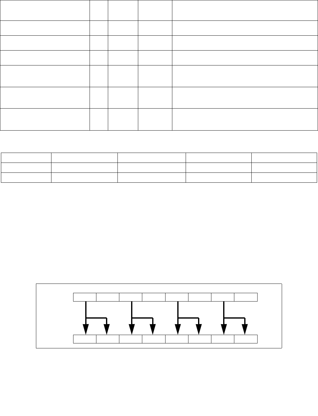
MOVSHDUP—Replicate Single FP Values
INSTRUCTION SET REFERENCE, M-U
4-114 Vol. 2B
MOVSHDUP—Replicate Single FP Values
Instruction Operand Encoding
Description
Duplicates odd-indexed single-precision floating-point values from the source operand (the second operand) to
adjacent element pair in the destination operand (the first operand). See Figure 4-3. The source operand is an
XMM, YMM or ZMM register or 128, 256 or 512-bit memory location and the destination operand is an XMM, YMM
or ZMM register.
128-bit Legacy SSE version: Bits (MAX_VL-1:128) of the corresponding destination register remain unchanged.
VEX.128 encoded version: Bits (MAX_VL-1:128) of the destination register are zeroed.
VEX.256 encoded version: Bits (MAX_VL-1:256) of the destination register are zeroed.
EVEX encoded version: The destination operand is updated at 32-bit granularity according to the writemask.
Note: VEX.vvvv and EVEX.vvvv are reserved and must be 1111b otherwise instructions will #UD.
Operation
VMOVSHDUP (EVEX encoded versions)
Opcode/
Instruction
Op /
En
64/32
bit Mode
Support
CPUID
Feature
Flag
Description
F3 0F 16 /r
MOVSHDUP xmm1, xmm2/m128
RM V/V SSE3 Move odd index single-precision floating-point values from
xmm2/mem and duplicate each element into xmm1.
VEX.128.F3.0F.WIG 16 /r
VMOVSHDUP xmm1, xmm2/m128
RM V/V AVX Move odd index single-precision floating-point values from
xmm2/mem and duplicate each element into xmm1.
VEX.256.F3.0F.WIG 16 /r
VMOVSHDUP ymm1, ymm2/m256
RM V/V AVX Move odd index single-precision floating-point values from
ymm2/mem and duplicate each element into ymm1.
EVEX.128.F3.0F.W0 16 /r
VMOVSHDUP xmm1 {k1}{z},
xmm2/m128
FVM V/V AVX512VL
AVX512F
Move odd index single-precision floating-point values from
xmm2/m128 and duplicate each element into xmm1 under
writemask.
EVEX.256.F3.0F.W0 16 /r
VMOVSHDUP ymm1 {k1}{z},
ymm2/m256
FVM V/V AVX512VL
AVX512F
Move odd index single-precision floating-point values from
ymm2/m256 and duplicate each element into ymm1 under
writemask.
EVEX.512.F3.0F.W0 16 /r
VMOVSHDUP zmm1 {k1}{z},
zmm2/m512
FVM V/V AVX512F Move odd index single-precision floating-point values from
zmm2/m512 and duplicate each element into zmm1 under
writemask.
Op/En Operand 1 Operand 2 Operand 3 Operand 4
RM ModRM:reg (w) ModRM:r/m (r) NA NA
FVM ModRM:reg (w) ModRM:r/m (r) NA NA
Figure 4-3. MOVSHDUP Operation
DEST
SRC X4X5X6X7
X1X1X3X3X5X5X7X7
X0X1X2X3

MOVSHDUP—Replicate Single FP Values
INSTRUCTION SET REFERENCE, M-U
Vol. 2B 4-115
(KL, VL) = (4, 128), (8, 256), (16, 512)
TMP_SRC[31:0] SRC[63:32]
TMP_SRC[63:32] SRC[63:32]
TMP_SRC[95:64] SRC[127:96]
TMP_SRC[127:96] SRC[127:96]
IF VL >= 256
TMP_SRC[159:128] SRC[191:160]
TMP_SRC[191:160] SRC[191:160]
TMP_SRC[223:192] SRC[255:224]
TMP_SRC[255:224] SRC[255:224]
FI;
IF VL >= 512
TMP_SRC[287:256] SRC[319:288]
TMP_SRC[319:288] SRC[319:288]
TMP_SRC[351:320] SRC[383:352]
TMP_SRC[383:352] SRC[383:352]
TMP_SRC[415:384] SRC[447:416]
TMP_SRC[447:416] SRC[447:416]
TMP_SRC[479:448] SRC[511:480]
TMP_SRC[511:480] SRC[511:480]
FI;
FOR j 0 TO KL-1
i j * 32
IF k1[j] OR *no writemask*
THEN DEST[i+31:i] TMP_SRC[i+31:i]
ELSE
IF *merging-masking* ; merging-masking
THEN *DEST[i+31:i] remains unchanged*
ELSE ; zeroing-masking
DEST[i+31:i] 0
FI
FI;
ENDFOR
DEST[MAX_VL-1:VL] 0
VMOVSHDUP (VEX.256 encoded version)
DEST[31:0] SRC[63:32]
DEST[63:32] SRC[63:32]
DEST[95:64] SRC[127:96]
DEST[127:96] SRC[127:96]
DEST[159:128] SRC[191:160]
DEST[191:160] SRC[191:160]
DEST[223:192] SRC[255:224]
DEST[255:224] SRC[255:224]
DEST[MAX_VL-1:256] 0
VMOVSHDUP (VEX.128 encoded version)
DEST[31:0] SRC[63:32]
DEST[63:32] SRC[63:32]
DEST[95:64] SRC[127:96]
DEST[127:96] SRC[127:96]
DEST[MAX_VL-1:128] 0
MOVSHDUP (128-bit Legacy SSE version)
DEST[31:0] SRC[63:32]

MOVSHDUP—Replicate Single FP Values
INSTRUCTION SET REFERENCE, M-U
4-116 Vol. 2B
DEST[63:32] SRC[63:32]
DEST[95:64] SRC[127:96]
DEST[127:96] SRC[127:96]
DEST[MAX_VL-1:128] (Unmodified)
Intel C/C++ Compiler Intrinsic Equivalent
VMOVSHDUP __m512 _mm512_movehdup_ps( __m512 a);
VMOVSHDUP __m512 _mm512_mask_movehdup_ps(__m512 s, __mmask16 k, __m512 a);
VMOVSHDUP __m512 _mm512_maskz_movehdup_ps( __mmask16 k, __m512 a);
VMOVSHDUP __m256 _mm256_mask_movehdup_ps(__m256 s, __mmask8 k, __m256 a);
VMOVSHDUP __m256 _mm256_maskz_movehdup_ps( __mmask8 k, __m256 a);
VMOVSHDUP __m128 _mm_mask_movehdup_ps(__m128 s, __mmask8 k, __m128 a);
VMOVSHDUP __m128 _mm_maskz_movehdup_ps( __mmask8 k, __m128 a);
VMOVSHDUP __m256 _mm256_movehdup_ps (__m256 a);
VMOVSHDUP __m128 _mm_movehdup_ps (__m128 a);
SIMD Floating-Point Exceptions
None
Other Exceptions
Non-EVEX-encoded instruction, see Exceptions Type 4;
EVEX-encoded instruction, see Exceptions Type E4NF.nb.
#UD If EVEX.vvvv != 1111B or VEX.vvvv != 1111B.
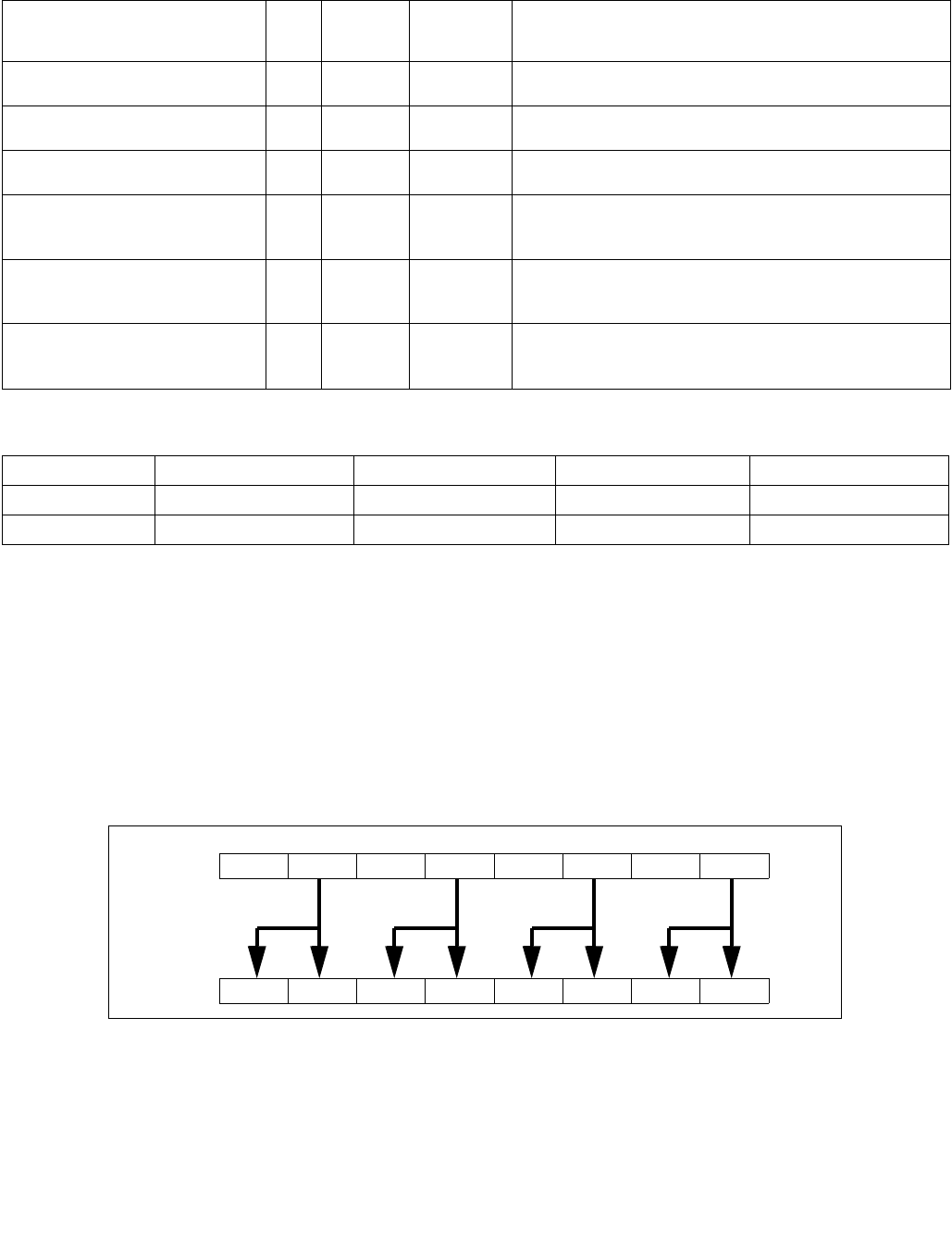
MOVSLDUP—Replicate Single FP Values
INSTRUCTION SET REFERENCE, M-U
Vol. 2B 4-117
MOVSLDUP—Replicate Single FP Values
Instruction Operand Encoding
Description
Duplicates even-indexed single-precision floating-point values from the source operand (the second operand). See
Figure 4-4. The source operand is an XMM, YMM or ZMM register or 128, 256 or 512-bit memory location and the
destination operand is an XMM, YMM or ZMM register.
128-bit Legacy SSE version: Bits (MAX_VL-1:128) of the corresponding destination register remain unchanged.
VEX.128 encoded version: Bits (MAX_VL-1:128) of the destination register are zeroed.
VEX.256 encoded version: Bits (MAX_VL-1:256) of the destination register are zeroed.
EVEX encoded version: The destination operand is updated at 32-bit granularity according to the writemask.
Note: VEX.vvvv and EVEX.vvvv are reserved and must be 1111b otherwise instructions will #UD.
Opcode/
Instruction
Op /
En
64/32
bit Mode
Support
CPUID
Feature
Flag
Description
F3 0F 12 /r
MOVSLDUP xmm1, xmm2/m128
A V/V SSE3 Move even index single-precision floating-point values from
xmm2/mem and duplicate each element into xmm1.
VEX.128.F3.0F.WIG 12 /r
VMOVSLDUP xmm1, xmm2/m128
RM V/V AVX Move even index single-precision floating-point values from
xmm2/mem and duplicate each element into xmm1.
VEX.256.F3.0F.WIG 12 /r
VMOVSLDUP ymm1, ymm2/m256
RM V/V AVX Move even index single-precision floating-point values from
ymm2/mem and duplicate each element into ymm1.
EVEX.128.F3.0F.W0 12 /r
VMOVSLDUP xmm1 {k1}{z},
xmm2/m128
FVM V/V AVX512VL
AVX512F
Move even index single-precision floating-point values from
xmm2/m128 and duplicate each element into xmm1 under
writemask.
EVEX.256.F3.0F.W0 12 /r
VMOVSLDUP ymm1 {k1}{z},
ymm2/m256
FVM V/V AVX512VL
AVX512F
Move even index single-precision floating-point values from
ymm2/m256 and duplicate each element into ymm1 under
writemask.
EVEX.512.F3.0F.W0 12 /r
VMOVSLDUP zmm1 {k1}{z},
zmm2/m512
FVM V/V AVX512F Move even index single-precision floating-point values from
zmm2/m512 and duplicate each element into zmm1 under
writemask.
Op/En Operand 1 Operand 2 Operand 3 Operand 4
RM ModRM:reg (w) ModRM:r/m (r) NA NA
FVM ModRM:reg (w) ModRM:r/m (r) NA NA
Figure 4-4. MOVSLDUP Operation
DEST
SRC X4X5X6X7
X0X0X2X2X4X4X6X6
X0X1X2X3

MOVSLDUP—Replicate Single FP Values
INSTRUCTION SET REFERENCE, M-U
4-118 Vol. 2B
Operation
VMOVSLDUP (EVEX encoded versions)
(KL, VL) = (4, 128), (8, 256), (16, 512)
TMP_SRC[31:0] SRC[31:0]
TMP_SRC[63:32] SRC[31:0]
TMP_SRC[95:64] SRC[95:64]
TMP_SRC[127:96] SRC[95:64]
IF VL >= 256
TMP_SRC[159:128] SRC[159:128]
TMP_SRC[191:160] SRC[159:128]
TMP_SRC[223:192] SRC[223:192]
TMP_SRC[255:224] SRC[223:192]
FI;
IF VL >= 512
TMP_SRC[287:256] SRC[287:256]
TMP_SRC[319:288] SRC[287:256]
TMP_SRC[351:320] SRC[351:320]
TMP_SRC[383:352] SRC[351:320]
TMP_SRC[415:384] SRC[415:384]
TMP_SRC[447:416] SRC[415:384]
TMP_SRC[479:448] SRC[479:448]
TMP_SRC[511:480] SRC[479:448]
FI;
FOR j 0 TO KL-1
i j * 32
IF k1[j] OR *no writemask*
THEN DEST[i+31:i] TMP_SRC[i+31:i]
ELSE
IF *merging-masking* ; merging-masking
THEN *DEST[i+31:i] remains unchanged*
ELSE ; zeroing-masking
DEST[i+31:i] 0
FI
FI;
ENDFOR
DEST[MAX_VL-1:VL] 0
VMOVSLDUP (VEX.256 encoded version)
DEST[31:0] SRC[31:0]
DEST[63:32] SRC[31:0]
DEST[95:64] SRC[95:64]
DEST[127:96] SRC[95:64]
DEST[159:128] SRC[159:128]
DEST[191:160] SRC[159:128]
DEST[223:192] SRC[223:192]
DEST[255:224] SRC[223:192]
DEST[MAX_VL-1:256] 0
VMOVSLDUP (VEX.128 encoded version)
DEST[31:0] SRC[31:0]
DEST[63:32] SRC[31:0]
DEST[95:64] SRC[95:64]
DEST[127:96] SRC[95:64]
DEST[MAX_VL-1:128] 0

MOVSLDUP—Replicate Single FP Values
INSTRUCTION SET REFERENCE, M-U
Vol. 2B 4-119
MOVSLDUP (128-bit Legacy SSE version)
DEST[31:0] SRC[31:0]
DEST[63:32] SRC[31:0]
DEST[95:64] SRC[95:64]
DEST[127:96] SRC[95:64]
DEST[MAX_VL-1:128] (Unmodified)
Intel C/C++ Compiler Intrinsic Equivalent
VMOVSLDUP __m512 _mm512_moveldup_ps( __m512 a);
VMOVSLDUP __m512 _mm512_mask_moveldup_ps(__m512 s, __mmask16 k, __m512 a);
VMOVSLDUP __m512 _mm512_maskz_moveldup_ps( __mmask16 k, __m512 a);
VMOVSLDUP __m256 _mm256_mask_moveldup_ps(__m256 s, __mmask8 k, __m256 a);
VMOVSLDUP __m256 _mm256_maskz_moveldup_ps( __mmask8 k, __m256 a);
VMOVSLDUP __m128 _mm_mask_moveldup_ps(__m128 s, __mmask8 k, __m128 a);
VMOVSLDUP __m128 _mm_maskz_moveldup_ps( __mmask8 k, __m128 a);
VMOVSLDUP __m256 _mm256_moveldup_ps (__m256 a);
VMOVSLDUP __m128 _mm_moveldup_ps (__m128 a);
SIMD Floating-Point Exceptions
None
Other Exceptions
Non-EVEX-encoded instruction, see Exceptions Type 4;
EVEX-encoded instruction, see Exceptions Type E4NF.nb.
#UD If EVEX.vvvv != 1111B or VEX.vvvv != 1111B.

MOVSS—Move or Merge Scalar Single-Precision Floating-Point Value
INSTRUCTION SET REFERENCE, M-U
4-120 Vol. 2B
MOVSS—Move or Merge Scalar Single-Precision Floating-Point Value
Instruction Operand Encoding
Opcode/
Instruction
Op / En 64/32
bit Mode
Support
CPUID
Feature
Flag
Description
F3 0F 10 /r
MOVSS xmm1, xmm2
RM V/V SSE Merge scalar single-precision floating-point value
from xmm2 to xmm1 register.
F3 0F 10 /r
MOVSS xmm1, m32
RM V/V SSE Load scalar single-precision floating-point value from
m32 to xmm1 register.
VEX.NDS.LIG.F3.0F.WIG 10 /r
VMOVSS xmm1, xmm2, xmm3
RVM V/V AVX Merge scalar single-precision floating-point value
from xmm2 and xmm3 to xmm1 register
VEX.LIG.F3.0F.WIG 10 /r
VMOVSS xmm1, m32
XM V/V AVX Load scalar single-precision floating-point value from
m32 to xmm1 register.
F3 0F 11 /r
MOVSS xmm2/m32, xmm1
MR V/V SSE Move scalar single-precision floating-point value
from xmm1 register to xmm2/m32.
VEX.NDS.LIG.F3.0F.WIG 11 /r
VMOVSS xmm1, xmm2, xmm3
MVR V/V AVX Move scalar single-precision floating-point value
from xmm2 and xmm3 to xmm1 register.
VEX.LIG.F3.0F.WIG 11 /r
VMOVSS m32, xmm1
MR V/V AVX Move scalar single-precision floating-point value
from xmm1 register to m32.
EVEX.NDS.LIG.F3.0F.W0 10 /r
VMOVSS xmm1 {k1}{z}, xmm2, xmm3
RVM V/V AVX512F Move scalar single-precision floating-point value
from xmm2 and xmm3 to xmm1 register under
writemask k1.
EVEX.LIG.F3.0F.W0 10 /r
VMOVSS xmm1 {k1}{z}, m32
T1S-RM V/V AVX512F Move scalar single-precision floating-point values
from m32 to xmm1 under writemask k1.
EVEX.NDS.LIG.F3.0F.W0 11 /r
VMOVSS xmm1 {k1}{z}, xmm2, xmm3
MVR V/V AVX512F Move scalar single-precision floating-point value
from xmm2 and xmm3 to xmm1 register under
writemask k1.
EVEX.LIG.F3.0F.W0 11 /r
VMOVSS m32 {k1}, xmm1
T1S-MR V/V AVX512F Move scalar single-precision floating-point values
from xmm1 to m32 under writemask k1.
Op/En Operand 1 Operand 2 Operand 3 Operand 4
RM ModRM:reg (r, w) ModRM:r/m (r) NA NA
RVM ModRM:reg (w) VEX.vvvv (r) ModRM:r/m (r) NA
MR ModRM:r/m (w) ModRM:reg (r) NA NA
XM ModRM:reg (w) ModRM:r/m (r) NA NA
MVR ModRM:r/m (w) vvvv (r) ModRM:reg (r) NA
T1S-RM ModRM:reg (r, w) ModRM:r/m (r) NA NA
T1S-MR ModRM:r/m (w) ModRM:reg (r) NA NA

MOVSS—Move or Merge Scalar Single-Precision Floating-Point Value
INSTRUCTION SET REFERENCE, M-U
Vol. 2B 4-121
Description
Moves a scalar single-precision floating-point value from the source operand (second operand) to the destination
operand (first operand). The source and destination operands can be XMM registers or 32-bit memory locations.
This instruction can be used to move a single-precision floating-point value to and from the low doubleword of an
XMM register and a 32-bit memory location, or to move a single-precision floating-point value between the low
doublewords of two XMM registers. The instruction cannot be used to transfer data between memory locations.
Legacy version: When the source and destination operands are XMM registers, bits (MAX_VL-1:32) of the corre-
sponding destination register are unmodified. When the source operand is a memory location and destination
operand is an XMM registers, Bits (127:32) of the destination operand is cleared to all 0s, bits MAX_VL:128 of the
destination operand remains unchanged.
VEX and EVEX encoded register-register syntax: Moves a scalar single-precision floating-point value from the
second source operand (the third operand) to the low doubleword element of the destination operand (the first
operand). Bits 127:32 of the destination operand are copied from the first source operand (the second operand).
Bits (MAX_VL-1:128) of the corresponding destination register are zeroed.
VEX and EVEX encoded memory load syntax: When the source operand is a memory location and destination
operand is an XMM registers, bits MAX_VL:32 of the destination operand is cleared to all 0s.
EVEX encoded versions: The low doubleword of the destination is updated according to the writemask.
Note: For memory store form instruction “VMOVSS m32, xmm1”, VEX.vvvv is reserved and must be 1111b other-
wise instruction will #UD. For memory store form instruction “VMOVSS mv {k1}, xmm1”, EVEX.vvvv is reserved
and must be 1111b otherwise instruction will #UD.
Software should ensure VMOVSS is encoded with VEX.L=0. Encoding VMOVSS with VEX.L=1 may encounter
unpredictable behavior across different processor generations.
Operation
VMOVSS (EVEX.NDS.LIG.F3.0F.W0 11 /r when the source operand is memory and the destination is an XMM register)
IF k1[0] or *no writemask*
THEN DEST[31:0] SRC[31:0]
ELSE
IF *merging-masking* ; merging-masking
THEN *DEST[31:0] remains unchanged*
ELSE ; zeroing-masking
THEN DEST[31:0] 0
FI;
FI;
DEST[511:32] 0
VMOVSS (EVEX.NDS.LIG.F3.0F.W0 10 /r when the source operand is an XMM register and the destination is memory)
IF k1[0] or *no writemask*
THEN DEST[31:0] SRC[31:0]
ELSE *DEST[31:0] remains unchanged* ; merging-masking
FI;

MOVSS—Move or Merge Scalar Single-Precision Floating-Point Value
INSTRUCTION SET REFERENCE, M-U
4-122 Vol. 2B
VMOVSS (EVEX.NDS.LIG.F3.0F.W0 10/11 /r where the source and destination are XMM registers)
IF k1[0] or *no writemask*
THEN DEST[31:0] SRC2[31:0]
ELSE
IF *merging-masking* ; merging-masking
THEN *DEST[31:0] remains unchanged*
ELSE ; zeroing-masking
THEN DEST[31:0] 0
FI;
FI;
DEST[127:32] SRC1[127:32]
DEST[MAX_VL-1:128] 0
MOVSS (Legacy SSE version when the source and destination operands are both XMM registers)
DEST[31:0] SRC[31:0]
DEST[MAX_VL-1:32] (Unmodified)
VMOVSS (VEX.NDS.128.F3.0F 11 /r where the destination is an XMM register)
DEST[31:0] SRC2[31:0]
DEST[127:32] SRC1[127:32]
DEST[MAX_VL-1:128] 0
VMOVSS (VEX.NDS.128.F3.0F 10 /r where the source and destination are XMM registers)
DEST[31:0] SRC2[31:0]
DEST[127:32] SRC1[127:32]
DEST[MAX_VL-1:128] 0
VMOVSS (VEX.NDS.128.F3.0F 10 /r when the source operand is memory and the destination is an XMM register)
DEST[31:0] SRC[31:0]
DEST[MAX_VL-1:32] 0
MOVSS/VMOVSS (when the source operand is an XMM register and the destination is memory)
DEST[31:0] SRC[31:0]
MOVSS (Legacy SSE version when the source operand is memory and the destination is an XMM register)
DEST[31:0] SRC[31:0]
DEST[127:32] 0
DEST[MAX_VL-1:128] (Unmodified)
Intel C/C++ Compiler Intrinsic Equivalent
VMOVSS __m128 _mm_mask_load_ss(__m128 s, __mmask8 k, float * p);
VMOVSS __m128 _mm_maskz_load_ss( __mmask8 k, float * p);
VMOVSS __m128 _mm_mask_move_ss(__m128 sh, __mmask8 k, __m128 sl, __m128 a);
VMOVSS __m128 _mm_maskz_move_ss( __mmask8 k, __m128 s, __m128 a);
VMOVSS void _mm_mask_store_ss(float * p, __mmask8 k, __m128 a);
MOVSS __m128 _mm_load_ss(float * p)
MOVSS void_mm_store_ss(float * p, __m128 a)
MOVSS __m128 _mm_move_ss(__m128 a, __m128 b)
SIMD Floating-Point Exceptions
None

MOVSS—Move or Merge Scalar Single-Precision Floating-Point Value
INSTRUCTION SET REFERENCE, M-U
Vol. 2B 4-123
Other Exceptions
Non-EVEX-encoded instruction, see Exceptions Type 5; additionally
#UD If VEX.vvvv != 1111B.
EVEX-encoded instruction, see Exceptions Type E10.

MOVSX/MOVSXD—Move with Sign-Extension
INSTRUCTION SET REFERENCE, M-U
4-124 Vol. 2B
MOVSX/MOVSXD—Move with Sign-Extension
Instruction Operand Encoding
Description
Copies the contents of the source operand (register or memory location) to the destination operand (register) and
sign extends the value to 16 or 32 bits (see Figure 7-6 in the Intel® 64 and IA-32 Architectures Software Devel-
oper’s Manual, Volume 1). The size of the converted value depends on the operand-size attribute.
In 64-bit mode, the instruction’s default operation size is 32 bits. Use of the REX.R prefix permits access to addi-
tional registers (R8-R15). Use of the REX.W prefix promotes operation to 64 bits. See the summary chart at the
beginning of this section for encoding data and limits.
Operation
DEST ← SignExtend(SRC);
Flags Affected
None.
Protected Mode Exceptions
#GP(0) If a memory operand effective address is outside the CS, DS, ES, FS, or GS segment limit.
If the DS, ES, FS, or GS register contains a NULL segment selector.
#SS(0) If a memory operand effective address is outside the SS segment limit.
#PF(fault-code) If a page fault occurs.
#AC(0) If alignment checking is enabled and an unaligned memory reference is made while the
current privilege level is 3.
#UD If the LOCK prefix is used.
Opcode Instruction Op/
En
64-Bit
Mode
Compat/
Leg Mode
Description
0F BE /rMOVSX r16, r/m8 RM Valid Valid Move byte to word with sign-extension.
0F BE /rMOVSX r32, r/m8 RM Valid Valid Move byte to doubleword with sign-
extension.
REX + 0F BE /rMOVSX r64, r/m8* RM Valid N.E. Move byte to quadword with sign-extension.
0F BF /rMOVSX r32, r/m16 RM Valid Valid Move word to doubleword, with sign-
extension.
REX.W + 0F BF /rMOVSX r64, r/m16 RM Valid N.E. Move word to quadword with sign-extension.
REX.W** + 63 /rMOVSXD r64, r/m32 RM Valid N.E. Move doubleword to quadword with sign-
extension.
NOTES:
* In 64-bit mode, r/m8 can not be encoded to access the following byte registers if a REX prefix is used: AH, BH, CH, DH.
** The use of MOVSXD without REX.W in 64-bit mode is discouraged, Regular MOV should be used instead of using MOVSXD without
REX.W.
Op/En Operand 1 Operand 2 Operand 3 Operand 4
RM ModRM:reg (w) ModRM:r/m (r) NA NA

MOVSX/MOVSXD—Move with Sign-Extension
INSTRUCTION SET REFERENCE, M-U
Vol. 2B 4-125
Real-Address Mode Exceptions
#GP If a memory operand effective address is outside the CS, DS, ES, FS, or GS segment limit.
#SS If a memory operand effective address is outside the SS segment limit.
#UD If the LOCK prefix is used.
Virtual-8086 Mode Exceptions
#GP(0) If a memory operand effective address is outside the CS, DS, ES, FS, or GS segment limit.
#SS(0) If a memory operand effective address is outside the SS segment limit.
#PF(fault-code) If a page fault occurs.
#UD If the LOCK prefix is used.
Compatibility Mode Exceptions
Same exceptions as in protected mode.
64-Bit Mode Exceptions
#SS(0) If a memory address referencing the SS segment is in a non-canonical form.
#GP(0) If the memory address is in a non-canonical form.
#PF(fault-code) If a page fault occurs.
#AC(0) If alignment checking is enabled and an unaligned memory reference is made while the
current privilege level is 3.
#UD If the LOCK prefix is used.

MOVUPD—Move Unaligned Packed Double-Precision Floating-Point Values
INSTRUCTION SET REFERENCE, M-U
4-126 Vol. 2B
MOVUPD—Move Unaligned Packed Double-Precision Floating-Point Values
Instruction Operand Encoding
Description
Note: VEX.vvvv and EVEX.vvvv is reserved and must be 1111b otherwise instructions will #UD.
EVEX.512 encoded version:
Moves 512 bits of packed double-precision floating-point values from the source operand (second operand) to the
destination operand (first operand). This instruction can be used to load a ZMM register from a float64 memory
location, to store the contents of a ZMM register into a memory. The destination operand is updated according to
the writemask.
Opcode/
Instruction
Op / En 64/32
bit Mode
Support
CPUID
Feature
Flag
Description
66 0F 10 /r
MOVUPD xmm1, xmm2/m128
RM V/V SSE2 Move unaligned packed double-precision floating-
point from xmm2/mem to xmm1.
66 0F 11 /r
MOVUPD xmm2/m128, xmm1
MR V/V SSE2 Move unaligned packed double-precision floating-
point from xmm1 to xmm2/mem.
VEX.128.66.0F.WIG 10 /r
VMOVUPD xmm1, xmm2/m128
RM V/V AVX Move unaligned packed double-precision floating-
point from xmm2/mem to xmm1.
VEX.128.66.0F.WIG 11 /r
VMOVUPD xmm2/m128, xmm1
MR V/V AVX Move unaligned packed double-precision floating-
point from xmm1 to xmm2/mem.
VEX.256.66.0F.WIG 10 /r
VMOVUPD ymm1, ymm2/m256
RM V/V AVX Move unaligned packed double-precision floating-
point from ymm2/mem to ymm1.
VEX.256.66.0F.WIG 11 /r
VMOVUPD ymm2/m256, ymm1
MR V/V AVX Move unaligned packed double-precision floating-
point from ymm1 to ymm2/mem.
EVEX.128.66.0F.W1 10 /r
VMOVUPD xmm1 {k1}{z}, xmm2/m128
FVM-RM V/V AVX512VL
AVX512F
Move unaligned packed double-precision floating-
point from xmm2/m128 to xmm1 using
writemask k1.
EVEX.128.66.0F.W1 11 /r
VMOVUPD xmm2/m128 {k1}{z}, xmm1
FVM-MR V/V AVX512VL
AVX512F
Move unaligned packed double-precision floating-
point from xmm1 to xmm2/m128 using
writemask k1.
EVEX.256.66.0F.W1 10 /r
VMOVUPD ymm1 {k1}{z}, ymm2/m256
FVM-RM V/V AVX512VL
AVX512F
Move unaligned packed double-precision floating-
point from ymm2/m256 to ymm1 using
writemask k1.
EVEX.256.66.0F.W1 11 /r
VMOVUPD ymm2/m256 {k1}{z}, ymm1
FVM-MR V/V AVX512VL
AVX512F
Move unaligned packed double-precision floating-
point from ymm1 to ymm2/m256 using
writemask k1.
EVEX.512.66.0F.W1 10 /r
VMOVUPD zmm1 {k1}{z}, zmm2/m512
FVM-RM V/V AVX512F Move unaligned packed double-precision floating-
point values from zmm2/m512 to zmm1 using
writemask k1.
EVEX.512.66.0F.W1 11 /r
VMOVUPD zmm2/m512 {k1}{z}, zmm1
FVM-MR V/V AVX512F Move unaligned packed double-precision floating-
point values from zmm1 to zmm2/m512 using
writemask k1.
Op/En Operand 1 Operand 2 Operand 3 Operand 4
RM ModRM:reg (w) ModRM:r/m (r) NA NA
MR ModRM:r/m (w) ModRM:reg (r) NA NA
FVM-RM ModRM:reg (w) ModRM:r/m (r) NA NA
RVM-MR ModRM:r/m (w) ModRM:reg (r) NA NA

MOVUPD—Move Unaligned Packed Double-Precision Floating-Point Values
INSTRUCTION SET REFERENCE, M-U
Vol. 2B 4-127
VEX.256 encoded version:
Moves 256 bits of packed double-precision floating-point values from the source operand (second operand) to the
destination operand (first operand). This instruction can be used to load a YMM register from a 256-bit memory
location, to store the contents of a YMM register into a 256-bit memory location, or to move data between two YMM
registers. Bits (MAX_VL-1:256) of the destination register are zeroed.
128-bit versions:
Moves 128 bits of packed double-precision floating-point values from the source operand (second operand) to the
destination operand (first operand). This instruction can be used to load an XMM register from a 128-bit memory
location, to store the contents of an XMM register into a 128-bit memory location, or to move data between two
XMM registers.
128-bit Legacy SSE version: Bits (MAX_VL-1:128) of the corresponding destination register remain unchanged.
When the source or destination operand is a memory operand, the operand may be unaligned on a 16-byte
boundary without causing a general-protection exception (#GP) to be generated
VEX.128 and EVEX.128 encoded versions: Bits (MAX_VL-1:128) of the destination register are zeroed.
Operation
VMOVUPD (EVEX encoded versions, register-copy form)
(KL, VL) = (2, 128), (4, 256), (8, 512)
FOR j 0 TO KL-1
i j * 64
IF k1[j] OR *no writemask*
THEN DEST[i+63:i] SRC[i+63:i]
ELSE
IF *merging-masking* ; merging-masking
THEN *DEST[i+63:i] remains unchanged*
ELSE DEST[i+63:i] 0 ; zeroing-masking
FI
FI;
ENDFOR
DEST[MAX_VL-1:VL] 0
VMOVUPD (EVEX encoded versions, store-form)
(KL, VL) = (2, 128), (4, 256), (8, 512)
FOR j 0 TO KL-1
i j * 64
IF k1[j] OR *no writemask*
THEN DEST[i+63:i] SRC[i+63:i]
ELSE *DEST[i+63:i] remains unchanged* ; merging-masking
FI;
ENDFOR;

MOVUPD—Move Unaligned Packed Double-Precision Floating-Point Values
INSTRUCTION SET REFERENCE, M-U
4-128 Vol. 2B
VMOVUPD (EVEX encoded versions, load-form)
(KL, VL) = (2, 128), (4, 256), (8, 512)
FOR j 0 TO KL-1
i j * 64
IF k1[j] OR *no writemask*
THEN DEST[i+63:i] SRC[i+63:i]
ELSE
IF *merging-masking* ; merging-masking
THEN *DEST[i+63:i] remains unchanged*
ELSE DEST[i+63:i] 0 ; zeroing-masking
FI
FI;
ENDFOR
DEST[MAX_VL-1:VL] 0
VMOVUPD (VEX.256 encoded version, load - and register copy)
DEST[255:0] SRC[255:0]
DEST[MAX_VL-1:256] 0
VMOVUPD (VEX.256 encoded version, store-form)
DEST[255:0] SRC[255:0]
VMOVUPD (VEX.128 encoded version)
DEST[127:0] SRC[127:0]
DEST[MAX_VL-1:128] 0
MOVUPD (128-bit load- and register-copy- form Legacy SSE version)
DEST[127:0] SRC[127:0]
DEST[MAX_VL-1:128] (Unmodified)
(V)MOVUPD (128-bit store-form version)
DEST[127:0] SRC[127:0]
Intel C/C++ Compiler Intrinsic Equivalent
VMOVUPD __m512d _mm512_loadu_pd( void * s);
VMOVUPD __m512d _mm512_mask_loadu_pd(__m512d a, __mmask8 k, void * s);
VMOVUPD __m512d _mm512_maskz_loadu_pd( __mmask8 k, void * s);
VMOVUPD void _mm512_storeu_pd( void * d, __m512d a);
VMOVUPD void _mm512_mask_storeu_pd( void * d, __mmask8 k, __m512d a);
VMOVUPD __m256d _mm256_mask_loadu_pd(__m256d s, __mmask8 k, void * m);
VMOVUPD __m256d _mm256_maskz_loadu_pd( __mmask8 k, void * m);
VMOVUPD void _mm256_mask_storeu_pd( void * d, __mmask8 k, __m256d a);
VMOVUPD __m128d _mm_mask_loadu_pd(__m128d s, __mmask8 k, void * m);
VMOVUPD __m128d _mm_maskz_loadu_pd( __mmask8 k, void * m);
VMOVUPD void _mm_mask_storeu_pd( void * d, __mmask8 k, __m128d a);
MOVUPD __m256d _mm256_loadu_pd (double * p);
MOVUPD void _mm256_storeu_pd( double *p, __m256d a);
MOVUPD __m128d _mm_loadu_pd (double * p);
MOVUPD void _mm_storeu_pd( double *p, __m128d a);
SIMD Floating-Point Exceptions
None

MOVUPD—Move Unaligned Packed Double-Precision Floating-Point Values
INSTRUCTION SET REFERENCE, M-U
Vol. 2B 4-129
Other Exceptions
Non-EVEX-encoded instruction, see Exceptions Type 4.
Note treatment of #AC varies; additionally
#UD If VEX.vvvv != 1111B.
EVEX-encoded instruction, see Exceptions Type E4.nb.

MOVUPS—Move Unaligned Packed Single-Precision Floating-Point Values
INSTRUCTION SET REFERENCE, M-U
4-130 Vol. 2B
MOVUPS—Move Unaligned Packed Single-Precision Floating-Point Values
Instruction Operand Encoding
Description
Note: VEX.vvvv and EVEX.vvvv is reserved and must be 1111b otherwise instructions will #UD.
EVEX.512 encoded version:
Moves 512 bits of packed single-precision floating-point values from the source operand (second operand) to the
destination operand (first operand). This instruction can be used to load a ZMM register from a 512-bit float32
memory location, to store the contents of a ZMM register into memory. The destination operand is updated
according to the writemask.
Opcode/
Instruction
Op / En 64/32
bit Mode
Support
CPUID
Feature
Flag
Description
0F 10 /r
MOVUPS xmm1, xmm2/m128
RM V/V SSE Move unaligned packed single-precision
floating-point from xmm2/mem to xmm1.
0F 11 /r
MOVUPS xmm2/m128, xmm1
MR V/V SSE Move unaligned packed single-precision
floating-point from xmm1 to xmm2/mem.
VEX.128.0F.WIG 10 /r
VMOVUPS xmm1, xmm2/m128
RM V/V AVX Move unaligned packed single-precision
floating-point from xmm2/mem to xmm1.
VEX.128.0F 11.WIG /r
VMOVUPS xmm2/m128, xmm1
MR V/V AVX Move unaligned packed single-precision
floating-point from xmm1 to xmm2/mem.
VEX.256.0F 10.WIG /r
VMOVUPS ymm1, ymm2/m256
RM V/V AVX Move unaligned packed single-precision
floating-point from ymm2/mem to ymm1.
VEX.256.0F 11.WIG /r
VMOVUPS ymm2/m256, ymm1
MR V/V AVX Move unaligned packed single-precision
floating-point from ymm1 to ymm2/mem.
EVEX.128.0F.W0 10 /r
VMOVUPS xmm1 {k1}{z}, xmm2/m128
FVM-RM V/V AVX512VL
AVX512F
Move unaligned packed single-precision
floating-point values from xmm2/m128 to
xmm1 using writemask k1.
EVEX.256.0F.W0 10 /r
VMOVUPS ymm1 {k1}{z}, ymm2/m256
FVM-RM V/V AVX512VL
AVX512F
Move unaligned packed single-precision
floating-point values from ymm2/m256 to
ymm1 using writemask k1.
EVEX.512.0F.W0 10 /r
VMOVUPS zmm1 {k1}{z}, zmm2/m512
FVM-RM V/V AVX512F Move unaligned packed single-precision
floating-point values from zmm2/m512 to
zmm1 using writemask k1.
EVEX.128.0F.W0 11 /r
VMOVUPS xmm2/m128 {k1}{z}, xmm1
FVM-MR V/V AVX512VL
AVX512F
Move unaligned packed single-precision
floating-point values from xmm1 to
xmm2/m128 using writemask k1.
EVEX.256.0F.W0 11 /r
VMOVUPS ymm2/m256 {k1}{z}, ymm1
FVM-MR V/V AVX512VL
AVX512F
Move unaligned packed single-precision
floating-point values from ymm1 to
ymm2/m256 using writemask k1.
EVEX.512.0F.W0 11 /r
VMOVUPS zmm2/m512 {k1}{z}, zmm1
FVM-MR V/V AVX512F Move unaligned packed single-precision
floating-point values from zmm1 to
zmm2/m512 using writemask k1.
Op/En Operand 1 Operand 2 Operand 3 Operand 4
RM ModRM:reg (w) ModRM:r/m (r) NA NA
MR ModRM:r/m (w) ModRM:reg (r) NA NA
FVM-RM ModRM:reg (w) ModRM:r/m (r) NA NA
RVM-MR ModRM:r/m (w) ModRM:reg (r) NA NA

MOVUPS—Move Unaligned Packed Single-Precision Floating-Point Values
INSTRUCTION SET REFERENCE, M-U
Vol. 2B 4-131
VEX.256 and EVEX.256 encoded versions:
Moves 256 bits of packed single-precision floating-point values from the source operand (second operand) to the
destination operand (first operand). This instruction can be used to load a YMM register from a 256-bit memory
location, to store the contents of a YMM register into a 256-bit memory location, or to move data between two YMM
registers. Bits (MAX_VL-1:256) of the destination register are zeroed.
128-bit versions:
Moves 128 bits of packed single-precision floating-point values from the source operand (second operand) to the
destination operand (first operand). This instruction can be used to load an XMM register from a 128-bit memory
location, to store the contents of an XMM register into a 128-bit memory location, or to move data between two
XMM registers.
128-bit Legacy SSE version: Bits (MAX_VL-1:128) of the corresponding destination register remain unchanged.
When the source or destination operand is a memory operand, the operand may be unaligned without causing a
general-protection exception (#GP) to be generated.
VEX.128 and EVEX.128 encoded versions: Bits (MAX_VL-1:128) of the destination register are zeroed.
Operation
VMOVUPS (EVEX encoded versions, register-copy form)
(KL, VL) = (4, 128), (8, 256), (16, 512)
FOR j 0 TO KL-1
i j * 32
IF k1[j] OR *no writemask*
THEN DEST[i+31:i] SRC[i+31:i]
ELSE
IF *merging-masking* ; merging-masking
THEN *DEST[i+31:i] remains unchanged*
ELSE DEST[i+31:i] 0 ; zeroing-masking
FI
FI;
ENDFOR
DEST[MAX_VL-1:VL] 0
VMOVUPS (EVEX encoded versions, store-form)
(KL, VL) = (4, 128), (8, 256), (16, 512)
FOR j 0 TO KL-1
i j * 32
IF k1[j] OR *no writemask*
THEN DEST[i+31:i] SRC[i+31:i]
ELSE *DEST[i+31:i] remains unchanged* ; merging-masking
FI;
ENDFOR;

MOVUPS—Move Unaligned Packed Single-Precision Floating-Point Values
INSTRUCTION SET REFERENCE, M-U
4-132 Vol. 2B
VMOVUPS (EVEX encoded versions, load-form)
(KL, VL) = (4, 128), (8, 256), (16, 512)
FOR j 0 TO KL-1
i j * 32
IF k1[j] OR *no writemask*
THEN DEST[i+31:i] SRC[i+31:i]
ELSE
IF *merging-masking* ; merging-masking
THEN *DEST[i+31:i] remains unchanged*
ELSE DEST[i+31:i] 0 ; zeroing-masking
FI
FI;
ENDFOR
DEST[MAX_VL-1:VL] 0
VMOVUPS (VEX.256 encoded version, load - and register copy)
DEST[255:0] SRC[255:0]
DEST[MAX_VL-1:256] 0
VMOVUPS (VEX.256 encoded version, store-form)
DEST[255:0] SRC[255:0]
VMOVUPS (VEX.128 encoded version)
DEST[127:0] SRC[127:0]
DEST[MAX_VL-1:128] 0
MOVUPS (128-bit load- and register-copy- form Legacy SSE version)
DEST[127:0] SRC[127:0]
DEST[MAX_VL-1:128] (Unmodified)
(V)MOVUPS (128-bit store-form version)
DEST[127:0] SRC[127:0]
Intel C/C++ Compiler Intrinsic Equivalent
VMOVUPS __m512 _mm512_loadu_ps( void * s);
VMOVUPS __m512 _mm512_mask_loadu_ps(__m512 a, __mmask16 k, void * s);
VMOVUPS __m512 _mm512_maskz_loadu_ps( __mmask16 k, void * s);
VMOVUPS void _mm512_storeu_ps( void * d, __m512 a);
VMOVUPS void _mm512_mask_storeu_ps( void * d, __mmask8 k, __m512 a);
VMOVUPS __m256 _mm256_mask_loadu_ps(__m256 a, __mmask8 k, void * s);
VMOVUPS __m256 _mm256_maskz_loadu_ps( __mmask8 k, void * s);
VMOVUPS void _mm256_mask_storeu_ps( void * d, __mmask8 k, __m256 a);
VMOVUPS __m128 _mm_mask_loadu_ps(__m128 a, __mmask8 k, void * s);
VMOVUPS __m128 _mm_maskz_loadu_ps( __mmask8 k, void * s);
VMOVUPS void _mm_mask_storeu_ps( void * d, __mmask8 k, __m128 a);
MOVUPS __m256 _mm256_loadu_ps ( float * p);
MOVUPS void _mm256 _storeu_ps( float *p, __m256 a);
MOVUPS __m128 _mm_loadu_ps ( float * p);
MOVUPS void _mm_storeu_ps( float *p, __m128 a);
SIMD Floating-Point Exceptions
None

MOVUPS—Move Unaligned Packed Single-Precision Floating-Point Values
INSTRUCTION SET REFERENCE, M-U
Vol. 2B 4-133
Other Exceptions
Non-EVEX-encoded instruction, see Exceptions Type 4.
Note treatment of #AC varies;
EVEX-encoded instruction, see Exceptions Type E4.nb.
#UD If EVEX.vvvv != 1111B or VEX.vvvv != 1111B.

MOVZX—Move with Zero-Extend
INSTRUCTION SET REFERENCE, M-U
4-134 Vol. 2B
MOVZX—Move with Zero-Extend
Instruction Operand Encoding
Description
Copies the contents of the source operand (register or memory location) to the destination operand (register) and
zero extends the value. The size of the converted value depends on the operand-size attribute.
In 64-bit mode, the instruction’s default operation size is 32 bits. Use of the REX.R prefix permits access to addi-
tional registers (R8-R15). Use of the REX.W prefix promotes operation to 64 bit operands. See the summary chart
at the beginning of this section for encoding data and limits.
Operation
DEST ← ZeroExtend(SRC);
Flags Affected
None.
Protected Mode Exceptions
#GP(0) If a memory operand effective address is outside the CS, DS, ES, FS, or GS segment limit.
If the DS, ES, FS, or GS register contains a NULL segment selector.
#SS(0) If a memory operand effective address is outside the SS segment limit.
#PF(fault-code) If a page fault occurs.
#AC(0) If alignment checking is enabled and an unaligned memory reference is made while the
current privilege level is 3.
#UD If the LOCK prefix is used.
Real-Address Mode Exceptions
#GP If a memory operand effective address is outside the CS, DS, ES, FS, or GS segment limit.
#SS If a memory operand effective address is outside the SS segment limit.
#UD If the LOCK prefix is used.
Opcode Instruction Op/
En
64-Bit
Mode
Compat/
Leg Mode
Description
0F B6 /rMOVZX r16, r/m8 RM Valid Valid Move byte to word with zero-extension.
0F B6 /rMOVZX r32, r/m8 RM Valid Valid Move byte to doubleword, zero-extension.
REX.W + 0F B6 /rMOVZX r64, r/m8* RM Valid N.E. Move byte to quadword, zero-extension.
0F B7 /rMOVZX r32, r/m16 RM Valid Valid Move word to doubleword, zero-extension.
REX.W + 0F B7 /rMOVZX r64, r/m16 RM Valid N.E. Move word to quadword, zero-extension.
NOTES:
* In 64-bit mode, r/m8 can not be encoded to access the following byte registers if the REX prefix is used: AH, BH, CH, DH.
Op/En Operand 1 Operand 2 Operand 3 Operand 4
RM ModRM:reg (w) ModRM:r/m (r) NA NA

MOVZX—Move with Zero-Extend
INSTRUCTION SET REFERENCE, M-U
Vol. 2B 4-135
Virtual-8086 Mode Exceptions
#GP(0) If a memory operand effective address is outside the CS, DS, ES, FS, or GS segment limit.
#SS(0) If a memory operand effective address is outside the SS segment limit.
#PF(fault-code) If a page fault occurs.
#AC(0) If alignment checking is enabled and an unaligned memory reference is made.
#UD If the LOCK prefix is used.
Compatibility Mode Exceptions
Same exceptions as in protected mode.
64-Bit Mode Exceptions
#SS(0) If a memory address referencing the SS segment is in a non-canonical form.
#GP(0) If the memory address is in a non-canonical form.
#PF(fault-code) If a page fault occurs.
#AC(0) If alignment checking is enabled and an unaligned memory reference is made while the
current privilege level is 3.
#UD If the LOCK prefix is used.
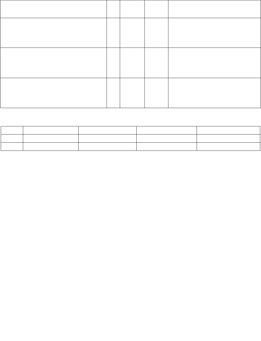
MPSADBW — Compute Multiple Packed Sums of Absolute Difference
INSTRUCTION SET REFERENCE, M-U
4-136 Vol. 2B
MPSADBW — Compute Multiple Packed Sums of Absolute Difference
Instruction Operand Encoding
Description
(V)MPSADBW calculates packed word results of sum-absolute-difference (SAD) of unsigned bytes from two blocks
of 32-bit dword elements, using two select fields in the immediate byte to select the offsets of the two blocks within
the first source operand and the second operand. Packed SAD word results are calculated within each 128-bit lane.
Each SAD word result is calculated between a stationary block_2 (whose offset within the second source operand
is selected by a two bit select control, multiplied by 32 bits) and a sliding block_1 at consecutive byte-granular
position within the first source operand. The offset of the first 32-bit block of block_1 is selectable using a one bit
select control, multiplied by 32 bits.
128-bit Legacy SSE version: Imm8[1:0]*32 specifies the bit offset of block_2 within the second source operand.
Imm[2]*32 specifies the initial bit offset of the block_1 within the first source operand. The first source operand
and destination operand are the same. The first source and destination operands are XMM registers. The second
source operand is either an XMM register or a 128-bit memory location. Bits (VLMAX-1:128) of the corresponding
YMM destination register remain unchanged. Bits 7:3 of the immediate byte are ignored.
VEX.128 encoded version: Imm8[1:0]*32 specifies the bit offset of block_2 within the second source operand.
Imm[2]*32 specifies the initial bit offset of the block_1 within the first source operand. The first source and desti-
nation operands are XMM registers. The second source operand is either an XMM register or a 128-bit memory
location. Bits (127:128) of the corresponding YMM register are zeroed. Bits 7:3 of the immediate byte are ignored.
VEX.256 encoded version: The sum-absolute-difference (SAD) operation is repeated 8 times for MPSADW between
the same block_2 (fixed offset within the second source operand) and a variable block_1 (offset is shifted by 8 bits
for each SAD operation) in the first source operand. Each 16-bit result of eight SAD operations between block_2
and block_1 is written to the respective word in the lower 128 bits of the destination operand.
Additionally, VMPSADBW performs another eight SAD operations on block_4 of the second source operand and
block_3 of the first source operand. (Imm8[4:3]*32 + 128) specifies the bit offset of block_4 within the second
source operand. (Imm[5]*32+128) specifies the initial bit offset of the block_3 within the first source operand.
Each 16-bit result of eight SAD operations between block_4 and block_3 is written to the respective word in the
upper 128 bits of the destination operand.
Opcode/
Instruction
Op/
En
64/32-bit
Mode
CPUID
Feature
Flag
Description
66 0F 3A 42 /r ib
MPSADBW xmm1, xmm2/m128, imm8
RMI V/V SSE4_1 Sums absolute 8-bit integer difference of
adjacent groups of 4 byte integers in xmm1
and xmm2/m128 and writes the results in
xmm1. Starting offsets within xmm1 and
xmm2/m128 are determined by imm8.
VEX.NDS.128.66.0F3A.WIG 42 /r ib
VMPSADBW xmm1, xmm2, xmm3/m128, imm8
RVMI V/V AVX Sums absolute 8-bit integer difference of
adjacent groups of 4 byte integers in xmm2
and xmm3/m128 and writes the results in
xmm1. Starting offsets within xmm2 and
xmm3/m128 are determined by imm8.
VEX.NDS.256.66.0F3A.WIG 42 /r ib
VMPSADBW ymm1, ymm2, ymm3/m256, imm8
RVMI V/V AVX2 Sums absolute 8-bit integer difference of
adjacent groups of 4 byte integers in xmm2
and ymm3/m128 and writes the results in
ymm1. Starting offsets within ymm2 and
xmm3/m128 are determined by imm8.
Op/En Operand 1 Operand 2 Operand 3 Operand 4
RMI ModRM:reg (r, w) ModRM:r/m (r) imm8 NA
RVMI ModRM:reg (w) VEX.vvvv (r) ModRM:r/m (r) imm8
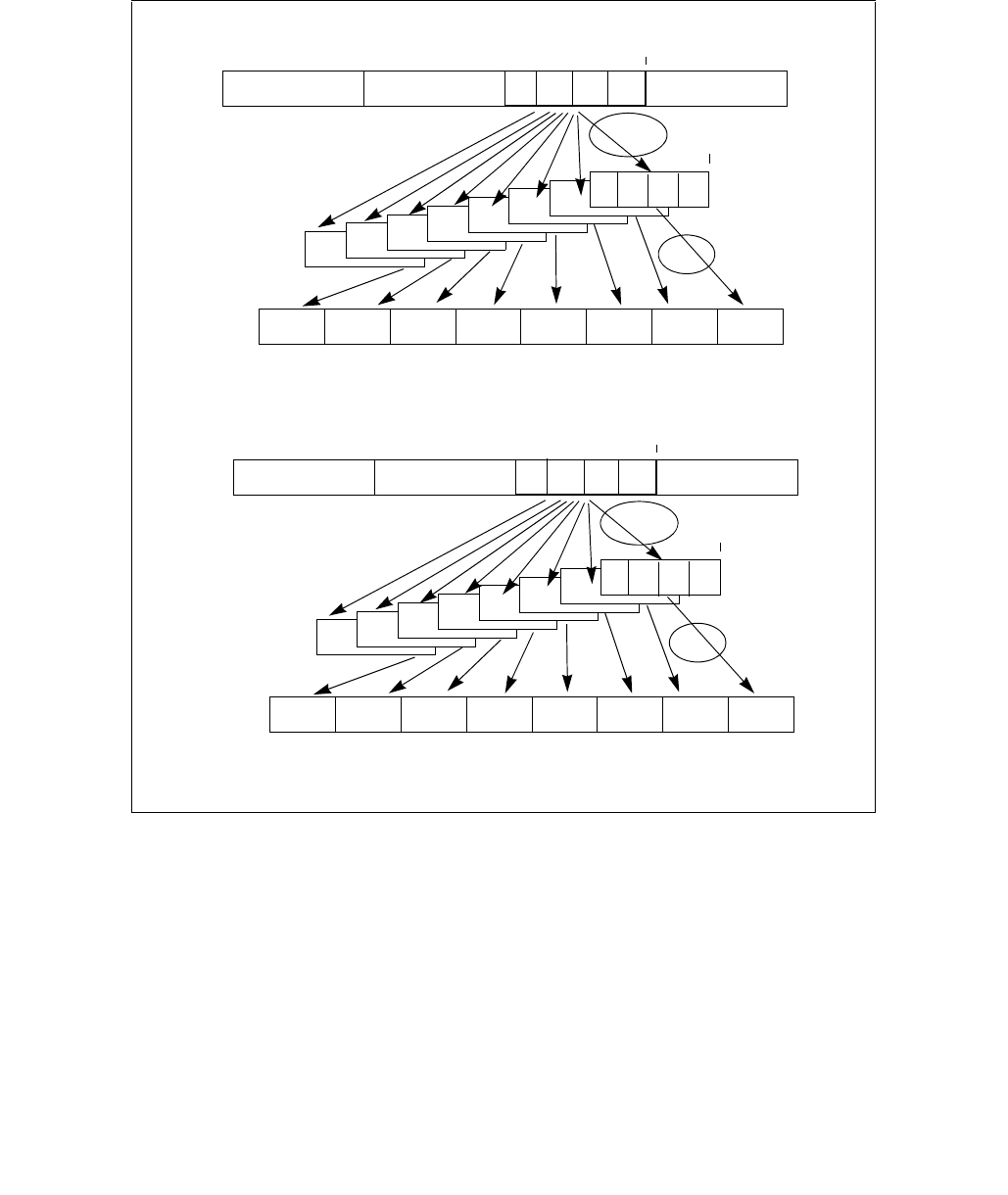
MPSADBW — Compute Multiple Packed Sums of Absolute Difference
INSTRUCTION SET REFERENCE, M-U
Vol. 2B 4-137
The first source operand is a YMM register. The second source register can be a YMM register or a 256-bit memory
location. The destination operand is a YMM register. Bits 7:6 of the immediate byte are ignored.
Note: If VMPSADBW is encoded with VEX.L= 1, an attempt to execute the instruction encoded with VEX.L= 1 will
cause an #UD exception.
Figure 4-5. 256-bit VMPSADBW Operation
Abs. Diff.
Sum
Imm[4:3]*32+128
Imm[5]*32+128
Src2
Src1
128
255 144
128
255 224 192
Abs. Diff.
Sum
Imm[1:0]*32
Imm[2]*32
Src2
Destination
0
127 16
0
127 96 64
Destination
Src1

MPSADBW — Compute Multiple Packed Sums of Absolute Difference
INSTRUCTION SET REFERENCE, M-U
4-138 Vol. 2B
Operation
VMPSADBW (VEX.256 encoded version)
BLK2_OFFSET imm8[1:0]*32
BLK1_OFFSET imm8[2]*32
SRC1_BYTE0 SRC1[BLK1_OFFSET+7:BLK1_OFFSET]
SRC1_BYTE1 SRC1[BLK1_OFFSET+15:BLK1_OFFSET+8]
SRC1_BYTE2 SRC1[BLK1_OFFSET+23:BLK1_OFFSET+16]
SRC1_BYTE3 SRC1[BLK1_OFFSET+31:BLK1_OFFSET+24]
SRC1_BYTE4 SRC1[BLK1_OFFSET+39:BLK1_OFFSET+32]
SRC1_BYTE5 SRC1[BLK1_OFFSET+47:BLK1_OFFSET+40]
SRC1_BYTE6 SRC1[BLK1_OFFSET+55:BLK1_OFFSET+48]
SRC1_BYTE7 SRC1[BLK1_OFFSET+63:BLK1_OFFSET+56]
SRC1_BYTE8 SRC1[BLK1_OFFSET+71:BLK1_OFFSET+64]
SRC1_BYTE9 SRC1[BLK1_OFFSET+79:BLK1_OFFSET+72]
SRC1_BYTE10 SRC1[BLK1_OFFSET+87:BLK1_OFFSET+80]
SRC2_BYTE0 SRC2[BLK2_OFFSET+7:BLK2_OFFSET]
SRC2_BYTE1 SRC2[BLK2_OFFSET+15:BLK2_OFFSET+8]
SRC2_BYTE2 SRC2[BLK2_OFFSET+23:BLK2_OFFSET+16]
SRC2_BYTE3 SRC2[BLK2_OFFSET+31:BLK2_OFFSET+24]
TEMP0 ABS(SRC1_BYTE0 - SRC2_BYTE0)
TEMP1 ABS(SRC1_BYTE1 - SRC2_BYTE1)
TEMP2 ABS(SRC1_BYTE2 - SRC2_BYTE2)
TEMP3 ABS(SRC1_BYTE3 - SRC2_BYTE3)
DEST[15:0] TEMP0 + TEMP1 + TEMP2 + TEMP3
TEMP0 ABS(SRC1_BYTE1 - SRC2_BYTE0)
TEMP1 ABS(SRC1_BYTE2 - SRC2_BYTE1)
TEMP2 ABS(SRC1_BYTE3 - SRC2_BYTE2)
TEMP3 ABS(SRC1_BYTE4 - SRC2_BYTE3)
DEST[31:16] TEMP0 + TEMP1 + TEMP2 + TEMP3
TEMP0 ABS(SRC1_BYTE2 - SRC2_BYTE0)
TEMP1 ABS(SRC1_BYTE3 - SRC2_BYTE1)
TEMP2 ABS(SRC1_BYTE4 - SRC2_BYTE2)
TEMP3 ABS(SRC1_BYTE5 - SRC2_BYTE3)
DEST[47:32] TEMP0 + TEMP1 + TEMP2 + TEMP3
TEMP0 ABS(SRC1_BYTE3 - SRC2_BYTE0)
TEMP1 ABS(SRC1_BYTE4 - SRC2_BYTE1)
TEMP2 ABS(SRC1_BYTE5 - SRC2_BYTE2)
TEMP3 ABS(SRC1_BYTE6 - SRC2_BYTE3)
DEST[63:48] TEMP0 + TEMP1 + TEMP2 + TEMP3
TEMP0 ABS(SRC1_BYTE4 - SRC2_BYTE0)
TEMP1 ABS(SRC1_BYTE5 - SRC2_BYTE1)
TEMP2 ABS(SRC1_BYTE6 - SRC2_BYTE2)
TEMP3 ABS(SRC1_BYTE7 - SRC2_BYTE3)
DEST[79:64] TEMP0 + TEMP1 + TEMP2 + TEMP3

MPSADBW — Compute Multiple Packed Sums of Absolute Difference
INSTRUCTION SET REFERENCE, M-U
Vol. 2B 4-139
TEMP0 ABS(SRC1_BYTE5 - SRC2_BYTE0)
TEMP1 ABS(SRC1_BYTE6 - SRC2_BYTE1)
TEMP2 ABS(SRC1_BYTE7 - SRC2_BYTE2)
TEMP3 ABS(SRC1_BYTE8 - SRC2_BYTE3)
DEST[95:80] TEMP0 + TEMP1 + TEMP2 + TEMP3
TEMP0 ABS(SRC1_BYTE6 - SRC2_BYTE0)
TEMP1 ABS(SRC1_BYTE7 - SRC2_BYTE1)
TEMP2 ABS(SRC1_BYTE8 - SRC2_BYTE2)
TEMP3 ABS(SRC1_BYTE9 - SRC2_BYTE3)
DEST[111:96] TEMP0 + TEMP1 + TEMP2 + TEMP3
TEMP0 ABS(SRC1_BYTE7 - SRC2_BYTE0)
TEMP1 ABS(SRC1_BYTE8 - SRC2_BYTE1)
TEMP2 ABS(SRC1_BYTE9 - SRC2_BYTE2)
TEMP3 ABS(SRC1_BYTE10 - SRC2_BYTE3)
DEST[127:112] TEMP0 + TEMP1 + TEMP2 + TEMP3
BLK2_OFFSET imm8[4:3]*32 + 128
BLK1_OFFSET imm8[5]*32 + 128
SRC1_BYTE0 SRC1[BLK1_OFFSET+7:BLK1_OFFSET]
SRC1_BYTE1 SRC1[BLK1_OFFSET+15:BLK1_OFFSET+8]
SRC1_BYTE2 SRC1[BLK1_OFFSET+23:BLK1_OFFSET+16]
SRC1_BYTE3 SRC1[BLK1_OFFSET+31:BLK1_OFFSET+24]
SRC1_BYTE4 SRC1[BLK1_OFFSET+39:BLK1_OFFSET+32]
SRC1_BYTE5 SRC1[BLK1_OFFSET+47:BLK1_OFFSET+40]
SRC1_BYTE6 SRC1[BLK1_OFFSET+55:BLK1_OFFSET+48]
SRC1_BYTE7 SRC1[BLK1_OFFSET+63:BLK1_OFFSET+56]
SRC1_BYTE8 SRC1[BLK1_OFFSET+71:BLK1_OFFSET+64]
SRC1_BYTE9 SRC1[BLK1_OFFSET+79:BLK1_OFFSET+72]
SRC1_BYTE10 SRC1[BLK1_OFFSET+87:BLK1_OFFSET+80]
SRC2_BYTE0 SRC2[BLK2_OFFSET+7:BLK2_OFFSET]
SRC2_BYTE1 SRC2[BLK2_OFFSET+15:BLK2_OFFSET+8]
SRC2_BYTE2 SRC2[BLK2_OFFSET+23:BLK2_OFFSET+16]
SRC2_BYTE3 SRC2[BLK2_OFFSET+31:BLK2_OFFSET+24]
TEMP0 ABS(SRC1_BYTE0 - SRC2_BYTE0)
TEMP1 ABS(SRC1_BYTE1 - SRC2_BYTE1)
TEMP2 ABS(SRC1_BYTE2 - SRC2_BYTE2)
TEMP3 ABS(SRC1_BYTE3 - SRC2_BYTE3)
DEST[143:128] TEMP0 + TEMP1 + TEMP2 + TEMP3
TEMP0 ABS(SRC1_BYTE1 - SRC2_BYTE0)
TEMP1 ABS(SRC1_BYTE2 - SRC2_BYTE1)
TEMP2 ABS(SRC1_BYTE3 - SRC2_BYTE2)
TEMP3 ABS(SRC1_BYTE4 - SRC2_BYTE3)
DEST[159:144] TEMP0 + TEMP1 + TEMP2 + TEMP3
TEMP0 ABS(SRC1_BYTE2 - SRC2_BYTE0)
TEMP1 ABS(SRC1_BYTE3 - SRC2_BYTE1)
TEMP2 ABS(SRC1_BYTE4 - SRC2_BYTE2)
TEMP3 ABS(SRC1_BYTE5 - SRC2_BYTE3)
DEST[175:160] TEMP0 + TEMP1 + TEMP2 + TEMP3

MPSADBW — Compute Multiple Packed Sums of Absolute Difference
INSTRUCTION SET REFERENCE, M-U
4-140 Vol. 2B
TEMP0 ABS(SRC1_BYTE3 - SRC2_BYTE0)
TEMP1 ABS(SRC1_BYTE4 - SRC2_BYTE1)
TEMP2 ABS(SRC1_BYTE5 - SRC2_BYTE2)
TEMP3 ABS(SRC1_BYTE6 - SRC2_BYTE3)
DEST[191:176] TEMP0 + TEMP1 + TEMP2 + TEMP3
TEMP0 ABS(SRC1_BYTE4 - SRC2_BYTE0)
TEMP1 ABS(SRC1_BYTE5 - SRC2_BYTE1)
TEMP2 ABS(SRC1_BYTE6 - SRC2_BYTE2)
TEMP3 ABS(SRC1_BYTE7 - SRC2_BYTE3)
DEST[207:192] TEMP0 + TEMP1 + TEMP2 + TEMP3
TEMP0 ABS(SRC1_BYTE5 - SRC2_BYTE0)
TEMP1 ABS(SRC1_BYTE6 - SRC2_BYTE1)
TEMP2 ABS(SRC1_BYTE7 - SRC2_BYTE2)
TEMP3 ABS(SRC1_BYTE8 - SRC2_BYTE3)
DEST[223:208] TEMP0 + TEMP1 + TEMP2 + TEMP3
TEMP0 ABS(SRC1_BYTE6 - SRC2_BYTE0)
TEMP1 ABS(SRC1_BYTE7 - SRC2_BYTE1)
TEMP2 ABS(SRC1_BYTE8 - SRC2_BYTE2)
TEMP3 ABS(SRC1_BYTE9 - SRC2_BYTE3)
DEST[239:224] TEMP0 + TEMP1 + TEMP2 + TEMP3
TEMP0 ABS(SRC1_BYTE7 - SRC2_BYTE0)
TEMP1 ABS(SRC1_BYTE8 - SRC2_BYTE1)
TEMP2 ABS(SRC1_BYTE9 - SRC2_BYTE2)
TEMP3 ABS(SRC1_BYTE10 - SRC2_BYTE3)
DEST[255:240] TEMP0 + TEMP1 + TEMP2 + TEMP3
VMPSADBW (VEX.128 encoded version)
BLK2_OFFSET imm8[1:0]*32
BLK1_OFFSET imm8[2]*32
SRC1_BYTE0 SRC1[BLK1_OFFSET+7:BLK1_OFFSET]
SRC1_BYTE1 SRC1[BLK1_OFFSET+15:BLK1_OFFSET+8]
SRC1_BYTE2 SRC1[BLK1_OFFSET+23:BLK1_OFFSET+16]
SRC1_BYTE3 SRC1[BLK1_OFFSET+31:BLK1_OFFSET+24]
SRC1_BYTE4 SRC1[BLK1_OFFSET+39:BLK1_OFFSET+32]
SRC1_BYTE5 SRC1[BLK1_OFFSET+47:BLK1_OFFSET+40]
SRC1_BYTE6 SRC1[BLK1_OFFSET+55:BLK1_OFFSET+48]
SRC1_BYTE7 SRC1[BLK1_OFFSET+63:BLK1_OFFSET+56]
SRC1_BYTE8 SRC1[BLK1_OFFSET+71:BLK1_OFFSET+64]
SRC1_BYTE9 SRC1[BLK1_OFFSET+79:BLK1_OFFSET+72]
SRC1_BYTE10 SRC1[BLK1_OFFSET+87:BLK1_OFFSET+80]
SRC2_BYTE0 SRC2[BLK2_OFFSET+7:BLK2_OFFSET]
SRC2_BYTE1 SRC2[BLK2_OFFSET+15:BLK2_OFFSET+8]
SRC2_BYTE2 SRC2[BLK2_OFFSET+23:BLK2_OFFSET+16]
SRC2_BYTE3 SRC2[BLK2_OFFSET+31:BLK2_OFFSET+24]

MPSADBW — Compute Multiple Packed Sums of Absolute Difference
INSTRUCTION SET REFERENCE, M-U
Vol. 2B 4-141
TEMP0 ABS(SRC1_BYTE0 - SRC2_BYTE0)
TEMP1 ABS(SRC1_BYTE1 - SRC2_BYTE1)
TEMP2 ABS(SRC1_BYTE2 - SRC2_BYTE2)
TEMP3 ABS(SRC1_BYTE3 - SRC2_BYTE3)
DEST[15:0] TEMP0 + TEMP1 + TEMP2 + TEMP3
TEMP0 ABS(SRC1_BYTE1 - SRC2_BYTE0)
TEMP1 ABS(SRC1_BYTE2 - SRC2_BYTE1)
TEMP2 ABS(SRC1_BYTE3 - SRC2_BYTE2)
TEMP3 ABS(SRC1_BYTE4 - SRC2_BYTE3)
DEST[31:16] TEMP0 + TEMP1 + TEMP2 + TEMP3
TEMP0 ABS(SRC1_BYTE2 - SRC2_BYTE0)
TEMP1 ABS(SRC1_BYTE3 - SRC2_BYTE1)
TEMP2 ABS(SRC1_BYTE4 - SRC2_BYTE2)
TEMP3 ABS(SRC1_BYTE5 - SRC2_BYTE3)
DEST[47:32] TEMP0 + TEMP1 + TEMP2 + TEMP3
TEMP0 ABS(SRC1_BYTE3 - SRC2_BYTE0)
TEMP1 ABS(SRC1_BYTE4 - SRC2_BYTE1)
TEMP2 ABS(SRC1_BYTE5 - SRC2_BYTE2)
TEMP3 ABS(SRC1_BYTE6 - SRC2_BYTE3)
DEST[63:48] TEMP0 + TEMP1 + TEMP2 + TEMP3
TEMP0 ABS(SRC1_BYTE4 - SRC2_BYTE0)
TEMP1 ABS(SRC1_BYTE5 - SRC2_BYTE1)
TEMP2 ABS(SRC1_BYTE6 - SRC2_BYTE2)
TEMP3 ABS(SRC1_BYTE7 - SRC2_BYTE3)
DEST[79:64] TEMP0 + TEMP1 + TEMP2 + TEMP3
TEMP0 ABS(SRC1_BYTE5 - SRC2_BYTE0)
TEMP1 ABS(SRC1_BYTE6 - SRC2_BYTE1)
TEMP2 ABS(SRC1_BYTE7 - SRC2_BYTE2)
TEMP3 ABS(SRC1_BYTE8 - SRC2_BYTE3)
DEST[95:80] TEMP0 + TEMP1 + TEMP2 + TEMP3
TEMP0 ABS(SRC1_BYTE6 - SRC2_BYTE0)
TEMP1 ABS(SRC1_BYTE7 - SRC2_BYTE1)
TEMP2 ABS(SRC1_BYTE8 - SRC2_BYTE2)
TEMP3 ABS(SRC1_BYTE9 - SRC2_BYTE3)
DEST[111:96] TEMP0 + TEMP1 + TEMP2 + TEMP3
TEMP0 ABS(SRC1_BYTE7 - SRC2_BYTE0)
TEMP1 ABS(SRC1_BYTE8 - SRC2_BYTE1)
TEMP2 ABS(SRC1_BYTE9 - SRC2_BYTE2)
TEMP3 ABS(SRC1_BYTE10 - SRC2_BYTE3)
DEST[127:112] TEMP0 + TEMP1 + TEMP2 + TEMP3
DEST[VLMAX-1:128] 0

MPSADBW — Compute Multiple Packed Sums of Absolute Difference
INSTRUCTION SET REFERENCE, M-U
4-142 Vol. 2B
MPSADBW (128-bit Legacy SSE version)
SRC_OFFSET imm8[1:0]*32
DEST_OFFSET imm8[2]*32
DEST_BYTE0 DEST[DEST_OFFSET+7:DEST_OFFSET]
DEST_BYTE1 DEST[DEST_OFFSET+15:DEST_OFFSET+8]
DEST_BYTE2 DEST[DEST_OFFSET+23:DEST_OFFSET+16]
DEST_BYTE3 DEST[DEST_OFFSET+31:DEST_OFFSET+24]
DEST_BYTE4 DEST[DEST_OFFSET+39:DEST_OFFSET+32]
DEST_BYTE5 DEST[DEST_OFFSET+47:DEST_OFFSET+40]
DEST_BYTE6 DEST[DEST_OFFSET+55:DEST_OFFSET+48]
DEST_BYTE7 DEST[DEST_OFFSET+63:DEST_OFFSET+56]
DEST_BYTE8 DEST[DEST_OFFSET+71:DEST_OFFSET+64]
DEST_BYTE9 DEST[DEST_OFFSET+79:DEST_OFFSET+72]
DEST_BYTE10 DEST[DEST_OFFSET+87:DEST_OFFSET+80]
SRC_BYTE0 SRC[SRC_OFFSET+7:SRC_OFFSET]
SRC_BYTE1 SRC[SRC_OFFSET+15:SRC_OFFSET+8]
SRC_BYTE2 SRC[SRC_OFFSET+23:SRC_OFFSET+16]
SRC_BYTE3 SRC[SRC_OFFSET+31:SRC_OFFSET+24]
TEMP0 ABS( DEST_BYTE0 - SRC_BYTE0)
TEMP1 ABS( DEST_BYTE1 - SRC_BYTE1)
TEMP2 ABS( DEST_BYTE2 - SRC_BYTE2)
TEMP3 ABS( DEST_BYTE3 - SRC_BYTE3)
DEST[15:0] TEMP0 + TEMP1 + TEMP2 + TEMP3
TEMP0 ABS( DEST_BYTE1 - SRC_BYTE0)
TEMP1 ABS( DEST_BYTE2 - SRC_BYTE1)
TEMP2 ABS( DEST_BYTE3 - SRC_BYTE2)
TEMP3 ABS( DEST_BYTE4 - SRC_BYTE3)
DEST[31:16] TEMP0 + TEMP1 + TEMP2 + TEMP3
TEMP0 ABS( DEST_BYTE2 - SRC_BYTE0)
TEMP1 ABS( DEST_BYTE3 - SRC_BYTE1)
TEMP2 ABS( DEST_BYTE4 - SRC_BYTE2)
TEMP3 ABS( DEST_BYTE5 - SRC_BYTE3)
DEST[47:32] TEMP0 + TEMP1 + TEMP2 + TEMP3
TEMP0 ABS( DEST_BYTE3 - SRC_BYTE0)
TEMP1 ABS( DEST_BYTE4 - SRC_BYTE1)
TEMP2 ABS( DEST_BYTE5 - SRC_BYTE2)
TEMP3 ABS( DEST_BYTE6 - SRC_BYTE3)
DEST[63:48] TEMP0 + TEMP1 + TEMP2 + TEMP3
TEMP0 ABS( DEST_BYTE4 - SRC_BYTE0)
TEMP1 ABS( DEST_BYTE5 - SRC_BYTE1)
TEMP2 ABS( DEST_BYTE6 - SRC_BYTE2)
TEMP3 ABS( DEST_BYTE7 - SRC_BYTE3)
DEST[79:64] TEMP0 + TEMP1 + TEMP2 + TEMP3

MPSADBW — Compute Multiple Packed Sums of Absolute Difference
INSTRUCTION SET REFERENCE, M-U
Vol. 2B 4-143
TEMP0 ABS( DEST_BYTE5 - SRC_BYTE0)
TEMP1 ABS( DEST_BYTE6 - SRC_BYTE1)
TEMP2 ABS( DEST_BYTE7 - SRC_BYTE2)
TEMP3 ABS( DEST_BYTE8 - SRC_BYTE3)
DEST[95:80] TEMP0 + TEMP1 + TEMP2 + TEMP3
TEMP0 ABS( DEST_BYTE6 - SRC_BYTE0)
TEMP1 ABS( DEST_BYTE7 - SRC_BYTE1)
TEMP2 ABS( DEST_BYTE8 - SRC_BYTE2)
TEMP3 ABS( DEST_BYTE9 - SRC_BYTE3)
DEST[111:96] TEMP0 + TEMP1 + TEMP2 + TEMP3
TEMP0 ABS( DEST_BYTE7 - SRC_BYTE0)
TEMP1 ABS( DEST_BYTE8 - SRC_BYTE1)
TEMP2 ABS( DEST_BYTE9 - SRC_BYTE2)
TEMP3 ABS( DEST_BYTE10 - SRC_BYTE3)
DEST[127:112] TEMP0 + TEMP1 + TEMP2 + TEMP3
DEST[VLMAX-1:128] (Unmodified)
Intel C/C++ Compiler Intrinsic Equivalent
(V)MPSADBW: __m128i _mm_mpsadbw_epu8 (__m128i s1, __m128i s2, const int mask);
VMPSADBW: __m256i _mm256_mpsadbw_epu8 (__m256i s1, __m256i s2, const int mask);
Flags Affected
None
Other Exceptions
See Exceptions Type 4; additionally
#UD If VEX.L = 1.

MUL—Unsigned Multiply
INSTRUCTION SET REFERENCE, M-U
4-144 Vol. 2B
MUL—Unsigned Multiply
Instruction Operand Encoding
Description
Performs an unsigned multiplication of the first operand (destination operand) and the second operand (source
operand) and stores the result in the destination operand. The destination operand is an implied operand located in
register AL, AX or EAX (depending on the size of the operand); the source operand is located in a general-purpose
register or a memory location. The action of this instruction and the location of the result depends on the opcode
and the operand size as shown in Table 4-9.
The result is stored in register AX, register pair DX:AX, or register pair EDX:EAX (depending on the operand size),
with the high-order bits of the product contained in register AH, DX, or EDX, respectively. If the high-order bits of
the product are 0, the CF and OF flags are cleared; otherwise, the flags are set.
In 64-bit mode, the instruction’s default operation size is 32 bits. Use of the REX.R prefix permits access to addi-
tional registers (R8-R15). Use of the REX.W prefix promotes operation to 64 bits.
See the summary chart at the beginning of this section for encoding data and limits.
Opcode Instruction Op/
En
64-Bit
Mode
Compat/
Leg Mode
Description
F6 /4 MUL r/m8 M Valid Valid Unsigned multiply (AX ← AL ∗ r/m8).
REX + F6 /4 MUL r/m8*M Valid N.E. Unsigned multiply (AX ← AL ∗ r/m8).
F7 /4 MUL r/m16 M Valid Valid Unsigned multiply (DX:AX ← AX ∗ r/m16).
F7 /4 MUL r/m32 MValid Valid Unsigned multiply (EDX:EAX ← EAX ∗ r/m32).
REX.W + F7 /4 MUL r/m64 MValid N.E. Unsigned multiply (RDX:RAX ← RAX ∗ r/m64).
NOTES:
* In 64-bit mode, r/m8 can not be encoded to access the following byte registers if a REX prefix is used: AH, BH, CH, DH.
Op/En Operand 1 Operand 2 Operand 3 Operand 4
M ModRM:r/m (r) NA NA NA
Table 4-9. MUL Results
Operand Size Source 1 Source 2 Destination
Byte AL r/m8 AX
Word AX r/m16 DX:AX
Doubleword EAX r/m32 EDX:EAX
Quadword RAX r/m64 RDX:RAX

MUL—Unsigned Multiply
INSTRUCTION SET REFERENCE, M-U
Vol. 2B 4-145
Operation
IF (Byte operation)
THEN
AX ← AL ∗ SRC;
ELSE (* Word or doubleword operation *)
IF OperandSize = 16
THEN
DX:AX ← AX ∗ SRC;
ELSE IF OperandSize = 32
THEN EDX:EAX ← EAX ∗ SRC; FI;
ELSE (* OperandSize = 64 *)
RDX:RAX ← RAX ∗ SRC;
FI;
FI;
Flags Affected
The OF and CF flags are set to 0 if the upper half of the result is 0; otherwise, they are set to 1. The SF, ZF, AF, and
PF flags are undefined.
Protected Mode Exceptions
#GP(0) If a memory operand effective address is outside the CS, DS, ES, FS, or GS segment limit.
If the DS, ES, FS, or GS register contains a NULL segment selector.
#SS(0) If a memory operand effective address is outside the SS segment limit.
#PF(fault-code) If a page fault occurs.
#AC(0) If alignment checking is enabled and an unaligned memory reference is made while the
current privilege level is 3.
#UD If the LOCK prefix is used.
Real-Address Mode Exceptions
#GP If a memory operand effective address is outside the CS, DS, ES, FS, or GS segment limit.
#SS If a memory operand effective address is outside the SS segment limit.
#UD If the LOCK prefix is used.
Virtual-8086 Mode Exceptions
#GP(0) If a memory operand effective address is outside the CS, DS, ES, FS, or GS segment limit.
#SS(0) If a memory operand effective address is outside the SS segment limit.
#PF(fault-code) If a page fault occurs.
#AC(0) If alignment checking is enabled and an unaligned memory reference is made.
#UD If the LOCK prefix is used.
Compatibility Mode Exceptions
Same exceptions as in protected mode.
64-Bit Mode Exceptions
#SS(0) If a memory address referencing the SS segment is in a non-canonical form.
#GP(0) If the memory address is in a non-canonical form.
#PF(fault-code) If a page fault occurs.
#AC(0) If alignment checking is enabled and an unaligned memory reference is made while the
current privilege level is 3.

MULPD—Multiply Packed Double-Precision Floating-Point Values
INSTRUCTION SET REFERENCE, M-U
4-146 Vol. 2B
MULPD—Multiply Packed Double-Precision Floating-Point Values
Instruction Operand Encoding
Description
Multiply packed double-precision floating-point values from the first source operand with corresponding values in
the second source operand, and stores the packed double-precision floating-point results in the destination
operand.
EVEX encoded versions: The first source operand (the second operand) is a ZMM/YMM/XMM register. The second
source operand can be a ZMM/YMM/XMM register, a 512/256/128-bit memory location or a 512/256/128-bit vector
broadcasted from a 64-bit memory location. The destination operand is a ZMM/YMM/XMM register conditionally
updated with writemask k1.
VEX.256 encoded version: The first source operand is a YMM register. The second source operand can be a YMM
register or a 256-bit memory location. The destination operand is a YMM register. Bits (MAX_VL-1:256) of the
corresponding destination ZMM register are zeroed.
VEX.128 encoded version: The first source operand is a XMM register. The second source operand can be a XMM
register or a 128-bit memory location. The destination operand is a XMM register. The upper bits (MAX_VL-1:128)
of the destination YMM register destination are zeroed.
128-bit Legacy SSE version: The second source can be an XMM register or an 128-bit memory location. The desti-
nation is not distinct from the first source XMM register and the upper bits (MAX_VL-1:128) of the corresponding
ZMM register destination are unmodified.
Opcode/
Instruction
Op /
En
64/32
bit Mode
Support
CPUID
Feature
Flag
Description
66 0F 59 /r
MULPD xmm1, xmm2/m128
RM V/V SSE2 Multiply packed double-precision floating-point values
in xmm2/m128 with xmm1 and store result in xmm1.
VEX.NDS.128.66.0F.WIG 59 /r
VMULPD xmm1,xmm2, xmm3/m128
RVM V/V AVX Multiply packed double-precision floating-point values
in xmm3/m128 with xmm2 and store result in xmm1.
VEX.NDS.256.66.0F.WIG 59 /r
VMULPD ymm1, ymm2, ymm3/m256
RVM V/V AVX Multiply packed double-precision floating-point values
in ymm3/m256 with ymm2 and store result in ymm1.
EVEX.NDS.128.66.0F.W1 59 /r
VMULPD xmm1 {k1}{z}, xmm2,
xmm3/m128/m64bcst
FV V/V AVX512VL
AVX512F
Multiply packed double-precision floating-point values
from xmm3/m128/m64bcst to xmm2 and store result
in xmm1.
EVEX.NDS.256.66.0F.W1 59 /r
VMULPD ymm1 {k1}{z}, ymm2,
ymm3/m256/m64bcst
FV V/V AVX512VL
AVX512F
Multiply packed double-precision floating-point values
from ymm3/m256/m64bcst to ymm2 and store result
in ymm1.
EVEX.NDS.512.66.0F.W1 59 /r
VMULPD zmm1 {k1}{z}, zmm2,
zmm3/m512/m64bcst{er}
FV V/V AVX512F Multiply packed double-precision floating-point values
in zmm3/m512/m64bcst with zmm2 and store result
in zmm1.
Op/En Operand 1 Operand 2 Operand 3 Operand 4
RM ModRM:reg (r, w) ModRM:r/m (r) NA NA
RVM ModRM:reg (w) VEX.vvvv (r) ModRM:r/m (r) NA
FV ModRM:reg (w) EVEX.vvvv (r) ModRM:r/m (r) NA

MULPD—Multiply Packed Double-Precision Floating-Point Values
INSTRUCTION SET REFERENCE, M-U
Vol. 2B 4-147
Operation
VMULPD (EVEX encoded versions)
(KL, VL) = (2, 128), (4, 256), (8, 512)
IF (VL = 512) AND (EVEX.b = 1) AND SRC2 *is a register*
THEN
SET_RM(EVEX.RC);
ELSE
SET_RM(MXCSR.RM);
FI;
FOR j 0 TO KL-1
i j * 64
IF k1[j] OR *no writemask*
THEN
IF (EVEX.b = 1) AND (SRC2 *is memory*)
THEN
DEST[i+63:i] SRC1[i+63:i] * SRC2[63:0]
ELSE
DEST[i+63:i] SRC1[i+63:i] * SRC2[i+63:i]
FI;
ELSE
IF *merging-masking* ; merging-masking
THEN *DEST[i+63:i] remains unchanged*
ELSE ; zeroing-masking
DEST[i+63:i] 0
FI
FI;
ENDFOR
DEST[MAX_VL-1:VL] 0
VMULPD (VEX.256 encoded version)
DEST[63:0] SRC1[63:0] * SRC2[63:0]
DEST[127:64] SRC1[127:64] * SRC2[127:64]
DEST[191:128] SRC1[191:128] * SRC2[191:128]
DEST[255:192] SRC1[255:192] * SRC2[255:192]
DEST[MAX_VL-1:256] 0;
.
VMULPD (VEX.128 encoded version)
DEST[63:0] SRC1[63:0] * SRC2[63:0]
DEST[127:64] SRC1[127:64] * SRC2[127:64]
DEST[MAX_VL-1:128] 0
MULPD (128-bit Legacy SSE version)
DEST[63:0] DEST[63:0] * SRC[63:0]
DEST[127:64] DEST[127:64] * SRC[127:64]
DEST[MAX_VL-1:128] (Unmodified)

MULPD—Multiply Packed Double-Precision Floating-Point Values
INSTRUCTION SET REFERENCE, M-U
4-148 Vol. 2B
Intel C/C++ Compiler Intrinsic Equivalent
VMULPD __m512d _mm512_mul_pd( __m512d a, __m512d b);
VMULPD __m512d _mm512_mask_mul_pd(__m512d s, __mmask8 k, __m512d a, __m512d b);
VMULPD __m512d _mm512_maskz_mul_pd( __mmask8 k, __m512d a, __m512d b);
VMULPD __m512d _mm512_mul_round_pd( __m512d a, __m512d b, int);
VMULPD __m512d _mm512_mask_mul_round_pd(__m512d s, __mmask8 k, __m512d a, __m512d b, int);
VMULPD __m512d _mm512_maskz_mul_round_pd( __mmask8 k, __m512d a, __m512d b, int);
VMULPD __m256d _mm256_mul_pd (__m256d a, __m256d b);
MULPD __m128d _mm_mul_pd (__m128d a, __m128d b);
SIMD Floating-Point Exceptions
Overflow, Underflow, Invalid, Precision, Denormal
Other Exceptions
Non-EVEX-encoded instruction, see Exceptions Type 2.
EVEX-encoded instruction, see Exceptions Type E2.

MULPS—Multiply Packed Single-Precision Floating-Point Values
INSTRUCTION SET REFERENCE, M-U
Vol. 2B 4-149
MULPS—Multiply Packed Single-Precision Floating-Point Values
Instruction Operand Encoding
Description
Multiply the packed single-precision floating-point values from the first source operand with the corresponding
values in the second source operand, and stores the packed double-precision floating-point results in the destina-
tion operand.
EVEX encoded versions: The first source operand (the second operand) is a ZMM/YMM/XMM register. The second
source operand can be a ZMM/YMM/XMM register, a 512/256/128-bit memory location or a 512/256/128-bit vector
broadcasted from a 32-bit memory location. The destination operand is a ZMM/YMM/XMM register conditionally
updated with writemask k1.
VEX.256 encoded version: The first source operand is a YMM register. The second source operand can be a YMM
register or a 256-bit memory location. The destination operand is a YMM register. Bits (MAX_VL-1:256) of the
corresponding destination ZMM register are zeroed.
VEX.128 encoded version: The first source operand is a XMM register. The second source operand can be a XMM
register or a 128-bit memory location. The destination operand is a XMM register. The upper bits (MAX_VL-1:128)
of the destination YMM register destination are zeroed.
128-bit Legacy SSE version: The second source can be an XMM register or an 128-bit memory location. The desti-
nation is not distinct from the first source XMM register and the upper bits (MAX_VL-1:128) of the corresponding
ZMM register destination are unmodified.
Opcode/
Instruction
Op /
En
64/32
bit Mode
Support
CPUID
Feature
Flag
Description
0F 59 /r
MULPS xmm1, xmm2/m128
RM V/V SSE Multiply packed single-precision floating-point values in
xmm2/m128 with xmm1 and store result in xmm1.
VEX.NDS.128.0F.WIG 59 /r
VMULPS xmm1,xmm2, xmm3/m128
RVM V/V AVX Multiply packed single-precision floating-point values in
xmm3/m128 with xmm2 and store result in xmm1.
VEX.NDS.256.0F.WIG 59 /r
VMULPS ymm1, ymm2, ymm3/m256
RVM V/V AVX Multiply packed single-precision floating-point values in
ymm3/m256 with ymm2 and store result in ymm1.
EVEX.NDS.128.0F.W0 59 /r
VMULPS xmm1 {k1}{z}, xmm2,
xmm3/m128/m32bcst
FV V/V AVX512VL
AVX512F
Multiply packed single-precision floating-point values
from xmm3/m128/m32bcst to xmm2 and store result in
xmm1.
EVEX.NDS.256.0F.W0 59 /r
VMULPS ymm1 {k1}{z}, ymm2,
ymm3/m256/m32bcst
FV V/V AVX512VL
AVX512F
Multiply packed single-precision floating-point values
from ymm3/m256/m32bcst to ymm2 and store result in
ymm1.
EVEX.NDS.512.0F.W0 59 /r
VMULPS zmm1 {k1}{z}, zmm2,
zmm3/m512/m32bcst {er}
FV V/V AVX512F Multiply packed single-precision floating-point values in
zmm3/m512/m32bcst with zmm2 and store result in
zmm1.
Op/En Operand 1 Operand 2 Operand 3 Operand 4
RM ModRM:reg (r, w) ModRM:r/m (r) NA NA
RVM ModRM:reg (w) VEX.vvvv (r) ModRM:r/m (r) NA
FV ModRM:reg (w) EVEX.vvvv (r) ModRM:r/m (r) NA

MULPS—Multiply Packed Single-Precision Floating-Point Values
INSTRUCTION SET REFERENCE, M-U
4-150 Vol. 2B
Operation
VMULPS (EVEX encoded version)
(KL, VL) = (4, 128), (8, 256), (16, 512)
IF (VL = 512) AND (EVEX.b = 1) AND SRC2 *is a register*
THEN
SET_RM(EVEX.RC);
ELSE
SET_RM(MXCSR.RM);
FI;
FOR j 0 TO KL-1
i j * 32
IF k1[j] OR *no writemask*
THEN
IF (EVEX.b = 1) AND (SRC2 *is memory*)
THEN
DEST[i+31:i] SRC1[i+31:i] * SRC2[31:0]
ELSE
DEST[i+31:i] SRC1[i+31:i] * SRC2[i+31:i]
FI;
ELSE
IF *merging-masking* ; merging-masking
THEN *DEST[i+31:i] remains unchanged*
ELSE ; zeroing-masking
DEST[i+31:i] 0
FI
FI;
ENDFOR
DEST[MAX_VL-1:VL] 0
VMULPS (VEX.256 encoded version)
DEST[31:0] SRC1[31:0] * SRC2[31:0]
DEST[63:32] SRC1[63:32] * SRC2[63:32]
DEST[95:64] SRC1[95:64] * SRC2[95:64]
DEST[127:96] SRC1[127:96] * SRC2[127:96]
DEST[159:128] SRC1[159:128] * SRC2[159:128]
DEST[191:160]SRC1[191:160] * SRC2[191:160]
DEST[223:192] SRC1[223:192] * SRC2[223:192]
DEST[255:224] SRC1[255:224] * SRC2[255:224].
DEST[MAX_VL-1:256] 0;
VMULPS (VEX.128 encoded version)
DEST[31:0] SRC1[31:0] * SRC2[31:0]
DEST[63:32] SRC1[63:32] * SRC2[63:32]
DEST[95:64] SRC1[95:64] * SRC2[95:64]
DEST[127:96] SRC1[127:96] * SRC2[127:96]
DEST[MAX_VL-1:128] 0
MULPS (128-bit Legacy SSE version)
DEST[31:0] SRC1[31:0] * SRC2[31:0]
DEST[63:32] SRC1[63:32] * SRC2[63:32]
DEST[95:64] SRC1[95:64] * SRC2[95:64]
DEST[127:96] SRC1[127:96] * SRC2[127:96]
DEST[MAX_VL-1:128] (Unmodified)

MULPS—Multiply Packed Single-Precision Floating-Point Values
INSTRUCTION SET REFERENCE, M-U
Vol. 2B 4-151
Intel C/C++ Compiler Intrinsic Equivalent
VMULPS __m512 _mm512_mul_ps( __m512 a, __m512 b);
VMULPS __m512 _mm512_mask_mul_ps(__m512 s, __mmask16 k, __m512 a, __m512 b);
VMULPS __m512 _mm512_maskz_mul_ps(__mmask16 k, __m512 a, __m512 b);
VMULPS __m512 _mm512_mul_round_ps( __m512 a, __m512 b, int);
VMULPS __m512 _mm512_mask_mul_round_ps(__m512 s, __mmask16 k, __m512 a, __m512 b, int);
VMULPS __m512 _mm512_maskz_mul_round_ps(__mmask16 k, __m512 a, __m512 b, int);
VMULPS __m256 _mm256_mask_mul_ps(__m256 s, __mmask8 k, __m256 a, __m256 b);
VMULPS __m256 _mm256_maskz_mul_ps(__mmask8 k, __m256 a, __m256 b);
VMULPS __m128 _mm_mask_mul_ps(__m128 s, __mmask8 k, __m128 a, __m128 b);
VMULPS __m128 _mm_maskz_mul_ps(__mmask8 k, __m128 a, __m128 b);
VMULPS __m256 _mm256_mul_ps (__m256 a, __m256 b);
MULPS __m128 _mm_mul_ps (__m128 a, __m128 b);
SIMD Floating-Point Exceptions
Overflow, Underflow, Invalid, Precision, Denormal
Other Exceptions
Non-EVEX-encoded instruction, see Exceptions Type 2.
EVEX-encoded instruction, see Exceptions Type E2.

MULSD—Multiply Scalar Double-Precision Floating-Point Value
INSTRUCTION SET REFERENCE, M-U
4-152 Vol. 2B
MULSD—Multiply Scalar Double-Precision Floating-Point Value
Instruction Operand Encoding
Description
Multiplies the low double-precision floating-point value in the second source operand by the low double-precision
floating-point value in the first source operand, and stores the double-precision floating-point result in the destina-
tion operand. The second source operand can be an XMM register or a 64-bit memory location. The first source
operand and the destination operands are XMM registers.
128-bit Legacy SSE version: The first source operand and the destination operand are the same. Bits (MAX_VL-
1:64) of the corresponding destination register remain unchanged.
VEX.128 and EVEX encoded version: The quadword at bits 127:64 of the destination operand is copied from the
same bits of the first source operand. Bits (MAX_VL-1:128) of the destination register are zeroed.
EVEX encoded version: The low quadword element of the destination operand is updated according to the
writemask.
Software should ensure VMULSD is encoded with VEX.L=0. Encoding VMULSD with VEX.L=1 may encounter unpre-
dictable behavior across different processor generations.
Opcode/
Instruction
Op /
En
64/32
bit Mode
Support
CPUID
Feature
Flag
Description
F2 0F 59 /r
MULSD xmm1,xmm2/m64
RM V/V SSE2 Multiply the low double-precision floating-point value in
xmm2/m64 by low double-precision floating-point
value in xmm1.
VEX.NDS.128.F2.0F.WIG 59 /r
VMULSD xmm1,xmm2, xmm3/m64
RVM V/V AVX Multiply the low double-precision floating-point value in
xmm3/m64 by low double-precision floating-point
value in xmm2.
EVEX.NDS.LIG.F2.0F.W1 59 /r
VMULSD xmm1 {k1}{z}, xmm2,
xmm3/m64 {er}
T1S V/V AVX512F Multiply the low double-precision floating-point value in
xmm3/m64 by low double-precision floating-point
value in xmm2.
Op/En Operand 1 Operand 2 Operand 3 Operand 4
RM ModRM:reg (r, w) ModRM:r/m (r) NA NA
RVM ModRM:reg (w) VEX.vvvv (r) ModRM:r/m (r) NA
T1S ModRM:reg (w) EVEX.vvvv (r) ModRM:r/m (r) NA

MULSD—Multiply Scalar Double-Precision Floating-Point Value
INSTRUCTION SET REFERENCE, M-U
Vol. 2B 4-153
Operation
VMULSD (EVEX encoded version)
IF (EVEX.b = 1) AND SRC2 *is a register*
THEN
SET_RM(EVEX.RC);
ELSE
SET_RM(MXCSR.RM);
FI;
IF k1[0] or *no writemask*
THEN DEST[63:0] SRC1[63:0] * SRC2[63:0]
ELSE
IF *merging-masking* ; merging-masking
THEN *DEST[63:0] remains unchanged*
ELSE ; zeroing-masking
THEN DEST[63:0] 0
FI
FI;
ENDFOR
DEST[127:64] SRC1[127:64]
DEST[MAX_VL-1:128] 0
VMULSD (VEX.128 encoded version)
DEST[63:0] SRC1[63:0] * SRC2[63:0]
DEST[127:64] SRC1[127:64]
DEST[MAX_VL-1:128] 0
MULSD (128-bit Legacy SSE version)
DEST[63:0] DEST[63:0] * SRC[63:0]
DEST[MAX_VL-1:64] (Unmodified)
Intel C/C++ Compiler Intrinsic Equivalent
VMULSD __m128d _mm_mask_mul_sd(__m128d s, __mmask8 k, __m128d a, __m128d b);
VMULSD __m128d _mm_maskz_mul_sd( __mmask8 k, __m128d a, __m128d b);
VMULSD __m128d _mm_mul_round_sd( __m128d a, __m128d b, int);
VMULSD __m128d _mm_mask_mul_round_sd(__m128d s, __mmask8 k, __m128d a, __m128d b, int);
VMULSD __m128d _mm_maskz_mul_round_sd( __mmask8 k, __m128d a, __m128d b, int);
MULSD __m128d _mm_mul_sd (__m128d a, __m128d b)
SIMD Floating-Point Exceptions
Overflow, Underflow, Invalid, Precision, Denormal
Other Exceptions
Non-EVEX-encoded instruction, see Exceptions Type 3.
EVEX-encoded instruction, see Exceptions Type E3.

MULSS—Multiply Scalar Single-Precision Floating-Point Values
INSTRUCTION SET REFERENCE, M-U
4-154 Vol. 2B
MULSS—Multiply Scalar Single-Precision Floating-Point Values
Instruction Operand Encoding
Description
Multiplies the low single-precision floating-point value from the second source operand by the low single-precision
floating-point value in the first source operand, and stores the single-precision floating-point result in the destina-
tion operand. The second source operand can be an XMM register or a 32-bit memory location. The first source
operand and the destination operands are XMM registers.
128-bit Legacy SSE version: The first source operand and the destination operand are the same. Bits (MAX_VL-
1:32) of the corresponding YMM destination register remain unchanged.
VEX.128 and EVEX encoded version: The first source operand is an xmm register encoded by VEX.vvvv. The three
high-order doublewords of the destination operand are copied from the first source operand. Bits (MAX_VL-1:128)
of the destination register are zeroed.
EVEX encoded version: The low doubleword element of the destination operand is updated according to the
writemask.
Software should ensure VMULSS is encoded with VEX.L=0. Encoding VMULSS with VEX.L=1 may encounter unpre-
dictable behavior across different processor generations.
Opcode/
Instruction
Op /
En
64/32
bit Mode
Support
CPUID
Feature
Flag
Description
F3 0F 59 /r
MULSS xmm1,xmm2/m32
RM V/V SSE Multiply the low single-precision floating-point value in
xmm2/m32 by the low single-precision floating-point
value in xmm1.
VEX.NDS.128.F3.0F.WIG 59 /r
VMULSS xmm1,xmm2, xmm3/m32
RVM V/V AVX Multiply the low single-precision floating-point value in
xmm3/m32 by the low single-precision floating-point
value in xmm2.
EVEX.NDS.LIG.F3.0F.W0 59 /r
VMULSS xmm1 {k1}{z}, xmm2,
xmm3/m32 {er}
T1S V/V AVX512F Multiply the low single-precision floating-point value in
xmm3/m32 by the low single-precision floating-point
value in xmm2.
Op/En Operand 1 Operand 2 Operand 3 Operand 4
RM ModRM:reg (r, w) ModRM:r/m (r) NA NA
RVM ModRM:reg (w) VEX.vvvv (r) ModRM:r/m (r) NA
T1S ModRM:reg (w) EVEX.vvvv (r) ModRM:r/m (r) NA

MULSS—Multiply Scalar Single-Precision Floating-Point Values
INSTRUCTION SET REFERENCE, M-U
Vol. 2B 4-155
Operation
VMULSS (EVEX encoded version)
IF (EVEX.b = 1) AND SRC2 *is a register*
THEN
SET_RM(EVEX.RC);
ELSE
SET_RM(MXCSR.RM);
FI;
IF k1[0] or *no writemask*
THEN DEST[31:0] SRC1[31:0] * SRC2[31:0]
ELSE
IF *merging-masking* ; merging-masking
THEN *DEST[31:0] remains unchanged*
ELSE ; zeroing-masking
THEN DEST[31:0] 0
FI
FI;
ENDFOR
DEST[127:32] SRC1[127:32]
DEST[MAX_VL-1:128] 0
VMULSS (VEX.128 encoded version)
DEST[31:0] SRC1[31:0] * SRC2[31:0]
DEST[127:32] SRC1[127:32]
DEST[MAX_VL-1:128] 0
MULSS (128-bit Legacy SSE version)
DEST[31:0] DEST[31:0] * SRC[31:0]
DEST[MAX_VL-1:32] (Unmodified)
Intel C/C++ Compiler Intrinsic Equivalent
VMULSS __m128 _mm_mask_mul_ss(__m128 s, __mmask8 k, __m128 a, __m128 b);
VMULSS __m128 _mm_maskz_mul_ss( __mmask8 k, __m128 a, __m128 b);
VMULSS __m128 _mm_mul_round_ss( __m128 a, __m128 b, int);
VMULSS __m128 _mm_mask_mul_round_ss(__m128 s, __mmask8 k, __m128 a, __m128 b, int);
VMULSS __m128 _mm_maskz_mul_round_ss( __mmask8 k, __m128 a, __m128 b, int);
MULSS __m128 _mm_mul_ss(__m128 a, __m128 b)
SIMD Floating-Point Exceptions
Underflow, Overflow, Invalid, Precision, Denormal
Other Exceptions
Non-EVEX-encoded instruction, see Exceptions Type 3.
EVEX-encoded instruction, see Exceptions Type E3.

MULX — Unsigned Multiply Without Affecting Flags
INSTRUCTION SET REFERENCE, M-U
4-156 Vol. 2B
MULX — Unsigned Multiply Without Affecting Flags
Instruction Operand Encoding
Description
Performs an unsigned multiplication of the implicit source operand (EDX/RDX) and the specified source operand
(the third operand) and stores the low half of the result in the second destination (second operand), the high half
of the result in the first destination operand (first operand), without reading or writing the arithmetic flags. This
enables efficient programming where the software can interleave add with carry operations and multiplications.
If the first and second operand are identical, it will contain the high half of the multiplication result.
This instruction is not supported in real mode and virtual-8086 mode. The operand size is always 32 bits if not in
64-bit mode. In 64-bit mode operand size 64 requires VEX.W1. VEX.W1 is ignored in non-64-bit modes. An
attempt to execute this instruction with VEX.L not equal to 0 will cause #UD.
Operation
// DEST1: ModRM:reg
// DEST2: VEX.vvvv
IF (OperandSize = 32)
SRC1 ← EDX;
DEST2 ← (SRC1*SRC2)[31:0];
DEST1 ← (SRC1*SRC2)[63:32];
ELSE IF (OperandSize = 64)
SRC1 ← RDX;
DEST2 ← (SRC1*SRC2)[63:0];
DEST1 ← (SRC1*SRC2)[127:64];
FI
Flags Affected
None
Intel C/C++ Compiler Intrinsic Equivalent
Auto-generated from high-level language when possible.
unsigned int mulx_u32(unsigned int a, unsigned int b, unsigned int * hi);
unsigned __int64 mulx_u64(unsigned __int64 a, unsigned __int64 b, unsigned __int64 * hi);
SIMD Floating-Point Exceptions
None
Opcode/
Instruction
Op/
En
64/32
-bit
Mode
CPUID
Feature
Flag
Description
VEX.NDD.LZ.F2.0F38.W0 F6 /r
MULX r32a, r32b, r/m32
RVM V/V BMI2 Unsigned multiply of r/m32 with EDX without affecting arithmetic
flags.
VEX.NDD.LZ.F2.0F38.W1 F6 /r
MULX r64a, r64b, r/m64
RVM V/N.E. BMI2 Unsigned multiply of r/m64 with RDX without affecting arithmetic
flags.
Op/En Operand 1 Operand 2 Operand 3 Operand 4
RVM ModRM:reg (w) VEX.vvvv (w) ModRM:r/m (r) RDX/EDX is implied 64/32 bits
source

MULX — Unsigned Multiply Without Affecting Flags
INSTRUCTION SET REFERENCE, M-U
Vol. 2B 4-157
Other Exceptions
See Section 2.5.1, “Exception Conditions for VEX-Encoded GPR Instructions”, Table 2-29; additionally
#UD If VEX.W = 1.

MWAIT—Monitor Wait
INSTRUCTION SET REFERENCE, M-U
4-158 Vol. 2B
MWAIT—Monitor Wait
Instruction Operand Encoding
Description
MWAIT instruction provides hints to allow the processor to enter an implementation-dependent optimized state.
There are two principal targeted usages: address-range monitor and advanced power management. Both usages
of MWAIT require the use of the MONITOR instruction.
CPUID.01H:ECX.MONITOR[bit 3] indicates the availability of MONITOR and MWAIT in the processor. When set,
MWAIT may be executed only at privilege level 0 (use at any other privilege level results in an invalid-opcode
exception). The operating system or system BIOS may disable this instruction by using the IA32_MISC_ENABLE
MSR; disabling MWAIT clears the CPUID feature flag and causes execution to generate an invalid-opcode excep-
tion.
This instruction’s operation is the same in non-64-bit modes and 64-bit mode.
ECX specifies optional extensions for the MWAIT instruction. EAX may contain hints such as the preferred optimized
state the processor should enter. The first processors to implement MWAIT supported only the zero value for EAX
and ECX. Later processors allowed setting ECX[0] to enable masked interrupts as break events for MWAIT (see
below). Software can use the CPUID instruction to determine the extensions and hints supported by the processor.
MWAIT for Address Range Monitoring
For address-range monitoring, the MWAIT instruction operates with the MONITOR instruction. The two instructions
allow the definition of an address at which to wait (MONITOR) and a implementation-dependent-optimized opera-
tion to commence at the wait address (MWAIT). The execution of MWAIT is a hint to the processor that it can enter
an implementation-dependent-optimized state while waiting for an event or a store operation to the address range
armed by MONITOR.
The following cause the processor to exit the implementation-dependent-optimized state: a store to the address
range armed by the MONITOR instruction, an NMI or SMI, a debug exception, a machine check exception, the
BINIT# signal, the INIT# signal, and the RESET# signal. Other implementation-dependent events may also cause
the processor to exit the implementation-dependent-optimized state.
In addition, an external interrupt causes the processor to exit the implementation-dependent-optimized state
either (1) if the interrupt would be delivered to software (e.g., as it would be if HLT had been executed instead of
MWAIT); or (2) if ECX[0] = 1. Software can execute MWAIT with ECX[0] = 1 only if CPUID.05H:ECX[bit 1] = 1.
(Implementation-specific conditions may result in an interrupt causing the processor to exit the implementation-
dependent-optimized state even if interrupts are masked and ECX[0] = 0.)
Following exit from the implementation-dependent-optimized state, control passes to the instruction following the
MWAIT instruction. A pending interrupt that is not masked (including an NMI or an SMI) may be delivered before
execution of that instruction. Unlike the HLT instruction, the MWAIT instruction does not support a restart at the
MWAIT instruction following the handling of an SMI.
If the preceding MONITOR instruction did not successfully arm an address range or if the MONITOR instruction has
not been executed prior to executing MWAIT, then the processor will not enter the implementation-dependent-opti-
mized state. Execution will resume at the instruction following the MWAIT.
Opcode Instruction Op/
En
64-Bit
Mode
Compat/
Leg Mode
Description
0F 01 C9 MWAIT NP Valid Valid A hint that allow the processor to stop
instruction execution and enter an
implementation-dependent optimized state
until occurrence of a class of events.
Op/En Operand 1 Operand 2 Operand 3 Operand 4
NP NA NA NA NA

MWAIT—Monitor Wait
INSTRUCTION SET REFERENCE, M-U
Vol. 2B 4-159
MWAIT for Power Management
MWAIT accepts a hint and optional extension to the processor that it can enter a specified target C state while
waiting for an event or a store operation to the address range armed by MONITOR. Support for MWAIT extensions
for power management is indicated by CPUID.05H:ECX[bit 0] reporting 1.
EAX and ECX are used to communicate the additional information to the MWAIT instruction, such as the kind of
optimized state the processor should enter. ECX specifies optional extensions for the MWAIT instruction. EAX may
contain hints such as the preferred optimized state the processor should enter. Implementation-specific conditions
may cause a processor to ignore the hint and enter a different optimized state. Future processor implementations
may implement several optimized “waiting” states and will select among those states based on the hint argument.
Table 4-10 describes the meaning of ECX and EAX registers for MWAIT extensions.
Note that if MWAIT is used to enter any of the C-states that are numerically higher than C1, a store to the address
range armed by the MONITOR instruction will cause the processor to exit MWAIT only if the store was originated by
other processor agents. A store from non-processor agent might not cause the processor to exit MWAIT in such
cases.
For additional details of MWAIT extensions, see Chapter 14, “Power and Thermal Management,” of Intel® 64 and
IA-32 Architectures Software Developer’s Manual, Volume 3A.
Operation
(* MWAIT takes the argument in EAX as a hint extension and is architected to take the argument in ECX as an instruction extension
MWAIT EAX, ECX *)
{
WHILE ( (“Monitor Hardware is in armed state”)) {
implementation_dependent_optimized_state(EAX, ECX); }
Set the state of Monitor Hardware as triggered;
}
Intel C/C++ Compiler Intrinsic Equivalent
MWAIT: void _mm_mwait(unsigned extensions, unsigned hints)
Table 4-10. MWAIT Extension Register (ECX)
Bits Description
0Treat interrupts as break events even if masked (e.g., even if EFLAGS.IF=0). May be set only if
CPUID.05H:ECX[bit 1] = 1.
31: 1 Reserved
Table 4-11. MWAIT Hints Register (EAX)
Bits Description
3 : 0 Sub C-state within a C-state, indicated by bits [7:4]
7 : 4 Target C-state*
Value of 0 means C1; 1 means C2 and so on
Value of 01111B means C0
Note: Target C states for MWAIT extensions are processor-specific C-states, not ACPI C-states
31: 8 Reserved

MWAIT—Monitor Wait
INSTRUCTION SET REFERENCE, M-U
4-160 Vol. 2B
Example
MONITOR/MWAIT instruction pair must be coded in the same loop because execution of the MWAIT instruction will
trigger the monitor hardware. It is not a proper usage to execute MONITOR once and then execute MWAIT in a
loop. Setting up MONITOR without executing MWAIT has no adverse effects.
Typically the MONITOR/MWAIT pair is used in a sequence, such as:
EAX = Logical Address(Trigger)
ECX = 0 (*Hints *)
EDX = 0 (* Hints *)
IF ( !trigger_store_happened) {
MONITOR EAX, ECX, EDX
IF ( !trigger_store_happened ) {
MWAIT EAX, ECX
}
}
The above code sequence makes sure that a triggering store does not happen between the first check of the trigger
and the execution of the monitor instruction. Without the second check that triggering store would go un-noticed.
Typical usage of MONITOR and MWAIT would have the above code sequence within a loop.
Numeric Exceptions
None
Protected Mode Exceptions
#GP(0) If ECX[31:1] ≠ 0.
If ECX[0] = 1 and CPUID.05H:ECX[bit 1] = 0.
#UD If CPUID.01H:ECX.MONITOR[bit 3] = 0.
If current privilege level is not 0.
Real Address Mode Exceptions
#GP If ECX[31:1] ≠ 0.
If ECX[0] = 1 and CPUID.05H:ECX[bit 1] = 0.
#UD If CPUID.01H:ECX.MONITOR[bit 3] = 0.
Virtual 8086 Mode Exceptions
#UD The MWAIT instruction is not recognized in virtual-8086 mode (even if
CPUID.01H:ECX.MONITOR[bit 3] = 1).
Compatibility Mode Exceptions
Same exceptions as in protected mode.
64-Bit Mode Exceptions
#GP(0) If RCX[63:1] ≠ 0.
If RCX[0] = 1 and CPUID.05H:ECX[bit 1] = 0.
#UD If the current privilege level is not 0.
If CPUID.01H:ECX.MONITOR[bit 3] = 0.

NEG—Two's Complement Negation
INSTRUCTION SET REFERENCE, M-U
Vol. 2B 4-161
NEG—Two's Complement Negation
Instruction Operand Encoding
Description
Replaces the value of operand (the destination operand) with its two's complement. (This operation is equivalent
to subtracting the operand from 0.) The destination operand is located in a general-purpose register or a memory
location.
This instruction can be used with a LOCK prefix to allow the instruction to be executed atomically.
In 64-bit mode, the instruction’s default operation size is 32 bits. Using a REX prefix in the form of REX.R permits
access to additional registers (R8-R15). Using a REX prefix in the form of REX.W promotes operation to 64 bits. See
the summary chart at the beginning of this section for encoding data and limits.
Operation
IF DEST = 0
THEN CF ← 0;
ELSE CF ← 1;
FI;
DEST ← [– (DEST)]
Flags Affected
The CF flag set to 0 if the source operand is 0; otherwise it is set to 1. The OF, SF, ZF, AF, and PF flags are set
according to the result.
Protected Mode Exceptions
#GP(0) If the destination is located in a non-writable segment.
If a memory operand effective address is outside the CS, DS, ES, FS, or GS segment limit.
If the DS, ES, FS, or GS register contains a NULL segment selector.
#SS(0) If a memory operand effective address is outside the SS segment limit.
#PF(fault-code) If a page fault occurs.
#AC(0) If alignment checking is enabled and an unaligned memory reference is made while the
current privilege level is 3.
#UD If the LOCK prefix is used but the destination is not a memory operand.
Opcode Instruction Op/
En
64-Bit
Mode
Compat/
Leg Mode
Description
F6 /3 NEG r/m8 M Valid Valid Two's complement negate r/m8.
REX + F6 /3 NEG r/m8* M Valid N.E. Two's complement negate r/m8.
F7 /3 NEG r/m16 M Valid Valid Two's complement negate r/m16.
F7 /3 NEG r/m32 M Valid Valid Two's complement negate r/m32.
REX.W + F7 /3 NEG r/m64 M Valid N.E. Two's complement negate r/m64.
NOTES:
* In 64-bit mode, r/m8 can not be encoded to access the following byte registers if a REX prefix is used: AH, BH, CH, DH.
Op/En Operand 1 Operand 2 Operand 3 Operand 4
M ModRM:r/m (r, w) NA NA NA

NEG—Two's Complement Negation
INSTRUCTION SET REFERENCE, M-U
4-162 Vol. 2B
Real-Address Mode Exceptions
#GP If a memory operand effective address is outside the CS, DS, ES, FS, or GS segment limit.
#SS If a memory operand effective address is outside the SS segment limit.
#UD If the LOCK prefix is used but the destination is not a memory operand.
Virtual-8086 Mode Exceptions
#GP(0) If a memory operand effective address is outside the CS, DS, ES, FS, or GS segment limit.
#SS(0) If a memory operand effective address is outside the SS segment limit.
#PF(fault-code) If a page fault occurs.
#AC(0) If alignment checking is enabled and an unaligned memory reference is made.
#UD If the LOCK prefix is used but the destination is not a memory operand.
Compatibility Mode Exceptions
Same as for protected mode exceptions.
64-Bit Mode Exceptions
#SS(0) If a memory address referencing the SS segment is in a non-canonical form.
#GP(0) If the memory address is in a non-canonical form.
#PF(fault-code) For a page fault.
#AC(0) If alignment checking is enabled and an unaligned memory reference is made while the
current privilege level is 3.
#UD If the LOCK prefix is used but the destination is not a memory operand.

NOP—No Operation
INSTRUCTION SET REFERENCE, M-U
Vol. 2B 4-163
NOP—No Operation
Instruction Operand Encoding
Description
This instruction performs no operation. It is a one-byte or multi-byte NOP that takes up space in the instruction
stream but does not impact machine context, except for the EIP register.
The multi-byte form of NOP is available on processors with model encoding:
•CPUID.01H.EAX[Bytes 11:8] = 0110B or 1111B
The multi-byte NOP instruction does not alter the content of a register and will not issue a memory operation. The
instruction’s operation is the same in non-64-bit modes and 64-bit mode.
Operation
The one-byte NOP instruction is an alias mnemonic for the XCHG (E)AX, (E)AX instruction.
The multi-byte NOP instruction performs no operation on supported processors and generates undefined opcode
exception on processors that do not support the multi-byte NOP instruction.
The memory operand form of the instruction allows software to create a byte sequence of “no operation” as one
instruction. For situations where multiple-byte NOPs are needed, the recommended operations (32-bit mode and
64-bit mode) are:
Flags Affected
None
Exceptions (All Operating Modes)
#UD If the LOCK prefix is used.
Opcode Instruction Op/
En
64-Bit
Mode
Compat/
Leg Mode
Description
90 NOP NP Valid Valid One byte no-operation instruction.
0F 1F /0 NOP r/m16 M Valid Valid Multi-byte no-operation instruction.
0F 1F /0 NOP r/m32 M Valid Valid Multi-byte no-operation instruction.
Op/En Operand 1 Operand 2 Operand 3 Operand 4
NP NA NA NA NA
M ModRM:r/m (r) NA NA NA
Table 4-12. Recommended Multi-Byte Sequence of NOP Instruction
Length Assembly Byte Sequence
2 bytes 66 NOP 66 90H
3 bytes NOP DWORD ptr [EAX] 0F 1F 00H
4 bytes NOP DWORD ptr [EAX + 00H] 0F 1F 40 00H
5 bytes NOP DWORD ptr [EAX + EAX*1 + 00H] 0F 1F 44 00 00H
6 bytes 66 NOP DWORD ptr [EAX + EAX*1 + 00H] 66 0F 1F 44 00 00H
7 bytes NOP DWORD ptr [EAX + 00000000H] 0F 1F 80 00 00 00 00H
8 bytes NOP DWORD ptr [EAX + EAX*1 + 00000000H] 0F 1F 84 00 00 00 00 00H
9 bytes 66 NOP DWORD ptr [EAX + EAX*1 + 00000000H] 66 0F 1F 84 00 00 00 00 00H

NOT—One's Complement Negation
INSTRUCTION SET REFERENCE, M-U
4-164 Vol. 2B
NOT—One's Complement Negation
Instruction Operand Encoding
Description
Performs a bitwise NOT operation (each 1 is set to 0, and each 0 is set to 1) on the destination operand and stores
the result in the destination operand location. The destination operand can be a register or a memory location.
This instruction can be used with a LOCK prefix to allow the instruction to be executed atomically.
In 64-bit mode, the instruction’s default operation size is 32 bits. Using a REX prefix in the form of REX.R permits
access to additional registers (R8-R15). Using a REX prefix in the form of REX.W promotes operation to 64 bits. See
the summary chart at the beginning of this section for encoding data and limits.
Operation
DEST ← NOT DEST;
Flags Affected
None
Protected Mode Exceptions
#GP(0) If the destination operand points to a non-writable segment.
If a memory operand effective address is outside the CS, DS, ES, FS, or GS segment limit.
If the DS, ES, FS, or GS register contains a NULL segment selector.
#SS(0) If a memory operand effective address is outside the SS segment limit.
#PF(fault-code) If a page fault occurs.
#AC(0) If alignment checking is enabled and an unaligned memory reference is made while the
current privilege level is 3.
#UD If the LOCK prefix is used but the destination is not a memory operand.
Real-Address Mode Exceptions
#GP If a memory operand effective address is outside the CS, DS, ES, FS, or GS segment limit.
#SS If a memory operand effective address is outside the SS segment limit.
#UD If the LOCK prefix is used but the destination is not a memory operand.
Opcode Instruction Op/
En
64-Bit
Mode
Compat/
Leg Mode
Description
F6 /2 NOT r/m8 MValid Valid Reverse each bit of r/m8.
REX + F6 /2 NOT r/m8* MValid N.E. Reverse each bit of r/m8.
F7 /2 NOT r/m16 MValid Valid Reverse each bit of r/m16.
F7 /2 NOT r/m32 MValid Valid Reverse each bit of r/m32.
REX.W + F7 /2 NOT r/m64 MValid N.E. Reverse each bit of r/m64.
NOTES:
* In 64-bit mode, r/m8 can not be encoded to access the following byte registers if a REX prefix is used: AH, BH, CH, DH.
Op/En Operand 1 Operand 2 Operand 3 Operand 4
M ModRM:r/m (r, w) NA NA NA

NOT—One's Complement Negation
INSTRUCTION SET REFERENCE, M-U
Vol. 2B 4-165
Virtual-8086 Mode Exceptions
#GP(0) If a memory operand effective address is outside the CS, DS, ES, FS, or GS segment limit.
#SS(0) If a memory operand effective address is outside the SS segment limit.
#PF(fault-code) If a page fault occurs.
#AC(0) If alignment checking is enabled and an unaligned memory reference is made.
#UD If the LOCK prefix is used but the destination is not a memory operand.
Compatibility Mode Exceptions
Same as for protected mode exceptions.
64-Bit Mode Exceptions
#SS(0) If a memory address referencing the SS segment is in a non-canonical form.
#GP(0) If the memory address is in a non-canonical form.
#PF(fault-code) If a page fault occurs.
#AC(0) If alignment checking is enabled and an unaligned memory reference is made while the
current privilege level is 3.
#UD If the LOCK prefix is used but the destination is not a memory operand.

OR—Logical Inclusive OR
INSTRUCTION SET REFERENCE, M-U
4-166 Vol. 2B
OR—Logical Inclusive OR
Instruction Operand Encoding
Description
Performs a bitwise inclusive OR operation between the destination (first) and source (second) operands and stores
the result in the destination operand location. The source operand can be an immediate, a register, or a memory
location; the destination operand can be a register or a memory location. (However, two memory operands cannot
be used in one instruction.) Each bit of the result of the OR instruction is set to 0 if both corresponding bits of the
first and second operands are 0; otherwise, each bit is set to 1.
This instruction can be used with a LOCK prefix to allow the instruction to be executed atomically.
Opcode Instruction Op/
En
64-Bit
Mode
Compat/
Leg Mode
Description
0C ib OR AL, imm8 IValid Valid AL OR imm8.
0D iw OR AX, imm16 IValid Valid AX OR imm16.
0D id OR EAX, imm32 IValid Valid EAX OR imm32.
REX.W + 0D id OR RAX, imm32 IValid N.E. RAX OR imm32 (sign-extended).
80 /1 ib OR r/m8, imm8 MI Valid Valid r/m8 OR imm8.
REX + 80 /1 ib OR r/m8*, imm8 MI Valid N.E. r/m8 OR imm8.
81 /1 iw OR r/m16, imm16 MI Valid Valid r/m16 OR imm16.
81 /1 id OR r/m32, imm32 MI Valid Valid r/m32 OR imm32.
REX.W + 81 /1 id OR r/m64, imm32 MI Valid N.E. r/m64 OR imm32 (sign-extended).
83 /1 ib OR r/m16, imm8 MI Valid Valid r/m16 OR imm8 (sign-extended).
83 /1 ib OR r/m32, imm8 MI Valid Valid r/m32 OR imm8 (sign-extended).
REX.W + 83 /1 ib OR r/m64, imm8 MI Valid N.E. r/m64 OR imm8 (sign-extended).
08 /rOR r/m8, r8 MR Valid Valid r/m8 OR r8.
REX + 08 /rOR r/m8*, r8* MR Valid N.E. r/m8 OR r8.
09 /rOR r/m16, r16 MR Valid Valid r/m16 OR r16.
09 /rOR r/m32, r32 MR Valid Valid r/m32 OR r32.
REX.W + 09 /rOR r/m64, r64 MR Valid N.E. r/m64 OR r64.
0A /rOR r8, r/m8 RM Valid Valid r8 OR r/m8.
REX + 0A /rOR r8*, r/m8* RM Valid N.E. r8 OR r/m8.
0B /rOR r16, r/m16 RM Valid Valid r16 OR r/m16.
0B /rOR r32, r/m32 RM Valid Valid r32 OR r/m32.
REX.W + 0B /rOR r64, r/m64 RM Valid N.E. r64 OR r/m64.
NOTES:
* In 64-bit mode, r/m8 can not be encoded to access the following byte registers if a REX prefix is used: AH, BH, CH, DH.
Op/En Operand 1 Operand 2 Operand 3 Operand 4
I AL/AX/EAX/RAX imm8/16/32 NA NA
MI ModRM:r/m (r, w) imm8/16/32 NA NA
MR ModRM:r/m (r, w) ModRM:reg (r) NA NA
RM ModRM:reg (r, w) ModRM:r/m (r) NA NA

OR—Logical Inclusive OR
INSTRUCTION SET REFERENCE, M-U
Vol. 2B 4-167
In 64-bit mode, the instruction’s default operation size is 32 bits. Using a REX prefix in the form of REX.R permits
access to additional registers (R8-R15). Using a REX prefix in the form of REX.W promotes operation to 64 bits. See
the summary chart at the beginning of this section for encoding data and limits.
Operation
DEST ← DEST OR SRC;
Flags Affected
The OF and CF flags are cleared; the SF, ZF, and PF flags are set according to the result. The state of the AF flag is
undefined.
Protected Mode Exceptions
#GP(0) If the destination operand points to a non-writable segment.
If a memory operand effective address is outside the CS, DS, ES, FS, or GS segment limit.
If the DS, ES, FS, or GS register contains a NULL segment selector.
#SS(0) If a memory operand effective address is outside the SS segment limit.
#PF(fault-code) If a page fault occurs.
#AC(0) If alignment checking is enabled and an unaligned memory reference is made while the
current privilege level is 3.
#UD If the LOCK prefix is used but the destination is not a memory operand.
Real-Address Mode Exceptions
#GP If a memory operand effective address is outside the CS, DS, ES, FS, or GS segment limit.
#SS If a memory operand effective address is outside the SS segment limit.
#UD If the LOCK prefix is used but the destination is not a memory operand.
Virtual-8086 Mode Exceptions
#GP(0) If a memory operand effective address is outside the CS, DS, ES, FS, or GS segment limit.
#SS(0) If a memory operand effective address is outside the SS segment limit.
#PF(fault-code) If a page fault occurs.
#AC(0) If alignment checking is enabled and an unaligned memory reference is made.
#UD If the LOCK prefix is used but the destination is not a memory operand.
Compatibility Mode Exceptions
Same as for protected mode exceptions.
64-Bit Mode Exceptions
#SS(0) If a memory address referencing the SS segment is in a non-canonical form.
#GP(0) If the memory address is in a non-canonical form.
#PF(fault-code) If a page fault occurs.
#AC(0) If alignment checking is enabled and an unaligned memory reference is made while the
current privilege level is 3.
#UD If the LOCK prefix is used but the destination is not a memory operand.

ORPD—Bitwise Logical OR of Packed Double Precision Floating-Point Values
INSTRUCTION SET REFERENCE, M-U
4-168 Vol. 2B
ORPD—Bitwise Logical OR of Packed Double Precision Floating-Point Values
Instruction Operand Encoding
Description
Performs a bitwise logical OR of the two, four or eight packed double-precision floating-point values from the first
source operand and the second source operand, and stores the result in the destination operand.
EVEX encoded versions: The first source operand is a ZMM/YMM/XMM register. The second source operand can be
a ZMM/YMM/XMM register, a 512/256/128-bit memory location, or a 512/256/128-bit vector broadcasted from a
32-bit memory location. The destination operand is a ZMM/YMM/XMM register conditionally updated with
writemask k1.
VEX.256 encoded version: The first source operand is a YMM register. The second source operand is a YMM register
or a 256-bit memory location. The destination operand is a YMM register. The upper bits (MAX_VL-1:256) of the
corresponding ZMM register destination are zeroed.
VEX.128 encoded version: The first source operand is an XMM register. The second source operand is an XMM
register or 128-bit memory location. The destination operand is an XMM register. The upper bits (MAX_VL-1:128)
of the corresponding ZMM register destination are zeroed.
128-bit Legacy SSE version: The second source can be an XMM register or an 128-bit memory location. The desti-
nation is not distinct from the first source XMM register and the upper bits (MAX_VL-1:128) of the corresponding
register destination are unmodified.
Opcode/
Instruction
Op /
En
64/32
bit Mode
Support
CPUID
Feature
Flag
Description
66 0F 56/r
ORPD xmm1, xmm2/m128
RM V/V SSE2 Return the bitwise logical OR of packed double-precision
floating-point values in xmm1 and xmm2/mem.
VEX.NDS.128.66.0F 56 /r
VORPD xmm1,xmm2, xmm3/m128
RVM V/V AVX Return the bitwise logical OR of packed double-precision
floating-point values in xmm2 and xmm3/mem.
VEX.NDS.256.66.0F 56 /r
VORPD ymm1, ymm2, ymm3/m256
RVM V/V AVX Return the bitwise logical OR of packed double-precision
floating-point values in ymm2 and ymm3/mem.
EVEX.NDS.128.66.0F.W1 56 /r
VORPD xmm1 {k1}{z}, xmm2,
xmm3/m128/m64bcst
FV V/V AVX512VL
AVX512DQ
Return the bitwise logical OR of packed double-precision
floating-point values in xmm2 and xmm3/m128/m64bcst
subject to writemask k1.
EVEX.NDS.256.66.0F.W1 56 /r
VORPD ymm1 {k1}{z}, ymm2,
ymm3/m256/m64bcst
FV V/V AVX512VL
AVX512DQ
Return the bitwise logical OR of packed double-precision
floating-point values in ymm2 and ymm3/m256/m64bcst
subject to writemask k1.
EVEX.NDS.512.66.0F.W1 56 /r
VORPD zmm1 {k1}{z}, zmm2,
zmm3/m512/m64bcst
FV V/V AVX512DQ Return the bitwise logical OR of packed double-precision
floating-point values in zmm2 and zmm3/m512/m64bcst
subject to writemask k1.
Op/En Operand 1 Operand 2 Operand 3 Operand 4
RM ModRM:reg (r, w) ModRM:r/m (r) NA NA
RVM ModRM:reg (w) VEX.vvvv (r) ModRM:r/m (r) NA
FV ModRM:reg (w) EVEX.vvvv (r) ModRM:r/m (r) NA

ORPD—Bitwise Logical OR of Packed Double Precision Floating-Point Values
INSTRUCTION SET REFERENCE, M-U
Vol. 2B 4-169
Operation
VORPD (EVEX encoded versions)
(KL, VL) = (2, 128), (4, 256), (8, 512)
FOR j 0 TO KL-1
i j * 64
IF k1[j] OR *no writemask*
THEN
IF (EVEX.b == 1) AND (SRC2 *is memory*)
THEN
DEST[i+63:i] SRC1[i+63:i] BITWISE OR SRC2[63:0]
ELSE
DEST[i+63:i] SRC1[i+63:i] BITWISE OR SRC2[i+63:i]
FI;
ELSE
IF *merging-masking* ; merging-masking
THEN *DEST[i+63:i] remains unchanged*
ELSE *zeroing-masking* ; zeroing-masking
DEST[i+63:i] 0
FI
FI;
ENDFOR
DEST[MAX_VL-1:VL] 0
VORPD (VEX.256 encoded version)
DEST[63:0] SRC1[63:0] BITWISE OR SRC2[63:0]
DEST[127:64] SRC1[127:64] BITWISE OR SRC2[127:64]
DEST[191:128] SRC1[191:128] BITWISE OR SRC2[191:128]
DEST[255:192] SRC1[255:192] BITWISE OR SRC2[255:192]
DEST[MAX_VL-1:256] 0
VORPD (VEX.128 encoded version)
DEST[63:0] SRC1[63:0] BITWISE OR SRC2[63:0]
DEST[127:64] SRC1[127:64] BITWISE OR SRC2[127:64]
DEST[MAX_VL-1:128] 0
ORPD (128-bit Legacy SSE version)
DEST[63:0] DEST[63:0] BITWISE OR SRC[63:0]
DEST[127:64] DEST[127:64] BITWISE OR SRC[127:64]
DEST[MAX_VL-1:128] (Unmodified)
Intel C/C++ Compiler Intrinsic Equivalent
VORPD __m512d _mm512_or_pd ( __m512d a, __m512d b);
VORPD __m512d _mm512_mask_or_pd ( __m512d s, __mmask8 k, __m512d a, __m512d b);
VORPD __m512d _mm512_maskz_or_pd (__mmask8 k, __m512d a, __m512d b);
VORPD __m256d _mm256_mask_or_pd (__m256d s, ___mmask8 k, __m256d a, __m256d b);
VORPD __m256d _mm256_maskz_or_pd (__mmask8 k, __m256d a, __m256d b);
VORPD __m128d _mm_mask_or_pd ( __m128d s, __mmask8 k, __m128d a, __m128d b);
VORPD __m128d _mm_maskz_or_pd (__mmask8 k, __m128d a, __m128d b);
VORPD __m256d _mm256_or_pd (__m256d a, __m256d b);
ORPD __m128d _mm_or_pd (__m128d a, __m128d b);

ORPD—Bitwise Logical OR of Packed Double Precision Floating-Point Values
INSTRUCTION SET REFERENCE, M-U
4-170 Vol. 2B
SIMD Floating-Point Exceptions
None
Other Exceptions
Non-EVEX-encoded instruction, see Exceptions Type 4.
EVEX-encoded instruction, see Exceptions Type E4.

ORPS—Bitwise Logical OR of Packed Single Precision Floating-Point Values
INSTRUCTION SET REFERENCE, M-U
Vol. 2B 4-171
ORPS—Bitwise Logical OR of Packed Single Precision Floating-Point Values
Instruction Operand Encoding
Description
Performs a bitwise logical OR of the four, eight or sixteen packed single-precision floating-point values from the
first source operand and the second source operand, and stores the result in the destination operand
EVEX encoded versions: The first source operand is a ZMM/YMM/XMM register. The second source operand can be
a ZMM/YMM/XMM register, a 512/256/128-bit memory location, or a 512/256/128-bit vector broadcasted from a
32-bit memory location. The destination operand is a ZMM/YMM/XMM register conditionally updated with
writemask k1.
VEX.256 encoded version: The first source operand is a YMM register. The second source operand is a YMM register
or a 256-bit memory location. The destination operand is a YMM register. The upper bits (MAX_VL-1:256) of the
corresponding ZMM register destination are zeroed.
VEX.128 encoded version: The first source operand is an XMM register. The second source operand is an XMM
register or 128-bit memory location. The destination operand is an XMM register. The upper bits (MAX_VL-1:128)
of the corresponding ZMM register destination are zeroed.
128-bit Legacy SSE version: The second source can be an XMM register or an 128-bit memory location. The desti-
nation is not distinct from the first source XMM register and the upper bits (MAX_VL-1:128) of the corresponding
register destination are unmodified.
Opcode/
Instruction
Op /
En
64/32
bit Mode
Support
CPUID
Feature
Flag
Description
0F 56 /r
ORPS xmm1, xmm2/m128
RM V/V SSE Return the bitwise logical OR of packed single-precision
floating-point values in xmm1 and xmm2/mem.
VEX.NDS.128.0F 56 /r
VORPS xmm1,xmm2, xmm3/m128
RVM V/V AVX Return the bitwise logical OR of packed single-precision
floating-point values in xmm2 and xmm3/mem.
VEX.NDS.256.0F 56 /r
VORPS ymm1, ymm2, ymm3/m256
RVM V/V AVX Return the bitwise logical OR of packed single-precision
floating-point values in ymm2 and ymm3/mem.
EVEX.NDS.128.0F.W0 56 /r
VORPS xmm1 {k1}{z}, xmm2,
xmm3/m128/m32bcst
FV V/V AVX512VL
AVX512DQ
Return the bitwise logical OR of packed single-precision
floating-point values in xmm2 and xmm3/m128/m32bcst
subject to writemask k1.
EVEX.NDS.256.0F.W0 56 /r
VORPS ymm1 {k1}{z}, ymm2,
ymm3/m256/m32bcst
FV V/V AVX512VL
AVX512DQ
Return the bitwise logical OR of packed single-precision
floating-point values in ymm2 and ymm3/m256/m32bcst
subject to writemask k1.
EVEX.NDS.512.0F.W0 56 /r
VORPS zmm1 {k1}{z}, zmm2,
zmm3/m512/m32bcst
FV V/V AVX512DQ Return the bitwise logical OR of packed single-precision
floating-point values in zmm2 and zmm3/m512/m32bcst
subject to writemask k1.
Op/En Operand 1 Operand 2 Operand 3 Operand 4
RM ModRM:reg (r, w) ModRM:r/m (r) NA NA
RVM ModRM:reg (w) VEX.vvvv (r) ModRM:r/m (r) NA
FV ModRM:reg (w) EVEX.vvvv (r) ModRM:r/m (r) NA

ORPS—Bitwise Logical OR of Packed Single Precision Floating-Point Values
INSTRUCTION SET REFERENCE, M-U
4-172 Vol. 2B
Operation
VORPS (EVEX encoded versions)
(KL, VL) = (4, 128), (8, 256), (16, 512)
FOR j 0 TO KL-1
i j * 32
IF k1[j] OR *no writemask*
THEN
IF (EVEX.b == 1) AND (SRC2 *is memory*)
THEN
DEST[i+31:i] SRC1[i+31:i] BITWISE OR SRC2[31:0]
ELSE
DEST[i+31:i] SRC1[i+31:i] BITWISE OR SRC2[i+31:i]
FI;
ELSE
IF *merging-masking* ; merging-masking
THEN *DEST[i+31:i] remains unchanged*
ELSE *zeroing-masking* ; zeroing-masking
DEST[i+31:i] 0
FI
FI;
ENDFOR
DEST[MAX_VL-1:VL] 0
VORPS (VEX.256 encoded version)
DEST[31:0] SRC1[31:0] BITWISE OR SRC2[31:0]
DEST[63:32] SRC1[63:32] BITWISE OR SRC2[63:32]
DEST[95:64] SRC1[95:64] BITWISE OR SRC2[95:64]
DEST[127:96] SRC1[127:96] BITWISE OR SRC2[127:96]
DEST[159:128] SRC1[159:128] BITWISE OR SRC2[159:128]
DEST[191:160] SRC1[191:160] BITWISE OR SRC2[191:160]
DEST[223:192] SRC1[223:192] BITWISE OR SRC2[223:192]
DEST[255:224] SRC1[255:224] BITWISE OR SRC2[255:224].
DEST[MAX_VL-1:256] 0
VORPS (VEX.128 encoded version)
DEST[31:0] SRC1[31:0] BITWISE OR SRC2[31:0]
DEST[63:32] SRC1[63:32] BITWISE OR SRC2[63:32]
DEST[95:64] SRC1[95:64] BITWISE OR SRC2[95:64]
DEST[127:96] SRC1[127:96] BITWISE OR SRC2[127:96]
DEST[MAX_VL-1:128] 0
ORPS (128-bit Legacy SSE version)
DEST[31:0] SRC1[31:0] BITWISE OR SRC2[31:0]
DEST[63:32] SRC1[63:32] BITWISE OR SRC2[63:32]
DEST[95:64] SRC1[95:64] BITWISE OR SRC2[95:64]
DEST[127:96] SRC1[127:96] BITWISE OR SRC2[127:96]
DEST[MAX_VL-1:128] (Unmodified)

ORPS—Bitwise Logical OR of Packed Single Precision Floating-Point Values
INSTRUCTION SET REFERENCE, M-U
Vol. 2B 4-173
Intel C/C++ Compiler Intrinsic Equivalent
VORPS __m512 _mm512_or_ps ( __m512 a, __m512 b);
VORPS __m512 _mm512_mask_or_ps ( __m512 s, __mmask16 k, __m512 a, __m512 b);
VORPS __m512 _mm512_maskz_or_ps (__mmask16 k, __m512 a, __m512 b);
VORPS __m256 _mm256_mask_or_ps (__m256 s, ___mmask8 k, __m256 a, __m256 b);
VORPS __m256 _mm256_maskz_or_ps (__mmask8 k, __m256 a, __m256 b);
VORPS __m128 _mm_mask_or_ps ( __m128 s, __mmask8 k, __m128 a, __m128 b);
VORPS __m128 _mm_maskz_or_ps (__mmask8 k, __m128 a, __m128 b);
VORPS __m256 _mm256_or_ps (__m256 a, __m256 b);
ORPS __m128 _mm_or_ps (__m128 a, __m128 b);
SIMD Floating-Point Exceptions
None
Other Exceptions
Non-EVEX-encoded instruction, see Exceptions Type 4.
EVEX-encoded instruction, see Exceptions Type E4.

OUT—Output to Port
INSTRUCTION SET REFERENCE, M-U
4-174 Vol. 2B
OUT—Output to Port
Instruction Operand Encoding
Description
Copies the value from the second operand (source operand) to the I/O port specified with the destination operand
(first operand). The source operand can be register AL, AX, or EAX, depending on the size of the port being
accessed (8, 16, or 32 bits, respectively); the destination operand can be a byte-immediate or the DX register.
Using a byte immediate allows I/O port addresses 0 to 255 to be accessed; using the DX register as a source
operand allows I/O ports from 0 to 65,535 to be accessed.
The size of the I/O port being accessed is determined by the opcode for an 8-bit I/O port or by the operand-size
attribute of the instruction for a 16- or 32-bit I/O port.
At the machine code level, I/O instructions are shorter when accessing 8-bit I/O ports. Here, the upper eight bits
of the port address will be 0.
This instruction is only useful for accessing I/O ports located in the processor’s I/O address space. See Chapter 18,
“Input/Output,” in the Intel® 64 and IA-32 Architectures Software Developer’s Manual, Volume 1, for more infor-
mation on accessing I/O ports in the I/O address space.
This instruction’s operation is the same in non-64-bit modes and 64-bit mode.
IA-32 Architecture Compatibility
After executing an OUT instruction, the Pentium® processor ensures that the EWBE# pin has been sampled active
before it begins to execute the next instruction. (Note that the instruction can be prefetched if EWBE# is not active,
but it will not be executed until the EWBE# pin is sampled active.) Only the Pentium processor family has the
EWBE# pin.
Opcode* Instruction Op/
En
64-Bit
Mode
Compat/
Leg Mode
Description
E6 ib OUT imm8, AL I Valid Valid Output byte in AL to I/O port address imm8.
E7 ib OUT imm8, AX I Valid Valid Output word in AX to I/O port address imm8.
E7 ib OUT imm8, EAX I Valid Valid Output doubleword in EAX to I/O port address
imm8.
EE OUT DX, AL NP Valid Valid Output byte in AL to I/O port address in DX.
EF OUT DX, AX NP Valid Valid Output word in AX to I/O port address in DX.
EF OUT DX, EAX NP Valid Valid Output doubleword in EAX to I/O port address
in DX.
NOTES:
* See IA-32 Architecture Compatibility section below.
Op/En Operand 1 Operand 2 Operand 3 Operand 4
Iimm8 NA NA NA
NP NA NA NA NA

OUT—Output to Port
INSTRUCTION SET REFERENCE, M-U
Vol. 2B 4-175
Operation
IF ((PE = 1) and ((CPL > IOPL) or (VM = 1)))
THEN (* Protected mode with CPL > IOPL or virtual-8086 mode *)
IF (Any I/O Permission Bit for I/O port being accessed = 1)
THEN (* I/O operation is not allowed *)
#GP(0);
ELSE ( * I/O operation is allowed *)
DEST ← SRC; (* Writes to selected I/O port *)
FI;
ELSE (Real Mode or Protected Mode with CPL ≤ IOPL *)
DEST ← SRC; (* Writes to selected I/O port *)
FI;
Flags Affected
None
Protected Mode Exceptions
#GP(0) If the CPL is greater than (has less privilege) the I/O privilege level (IOPL) and any of the
corresponding I/O permission bits in TSS for the I/O port being accessed is 1.
#UD If the LOCK prefix is used.
Real-Address Mode Exceptions
#UD If the LOCK prefix is used.
Virtual-8086 Mode Exceptions
#GP(0) If any of the I/O permission bits in the TSS for the I/O port being accessed is 1.
#PF(fault-code) If a page fault occurs.
#UD If the LOCK prefix is used.
Compatibility Mode Exceptions
Same as protected mode exceptions.
64-Bit Mode Exceptions
Same as protected mode exceptions.

OUTS/OUTSB/OUTSW/OUTSD—Output String to Port
INSTRUCTION SET REFERENCE, M-U
4-176 Vol. 2B
OUTS/OUTSB/OUTSW/OUTSD—Output String to Port
Instruction Operand Encoding
Description
Copies data from the source operand (second operand) to the I/O port specified with the destination operand (first
operand). The source operand is a memory location, the address of which is read from either the DS:SI, DS:ESI or
the RSI registers (depending on the address-size attribute of the instruction, 16, 32 or 64, respectively). (The DS
segment may be overridden with a segment override prefix.) The destination operand is an I/O port address (from
0 to 65,535) that is read from the DX register. The size of the I/O port being accessed (that is, the size of the source
and destination operands) is determined by the opcode for an 8-bit I/O port or by the operand-size attribute of the
instruction for a 16- or 32-bit I/O port.
At the assembly-code level, two forms of this instruction are allowed: the “explicit-operands” form and the “no-
operands” form. The explicit-operands form (specified with the OUTS mnemonic) allows the source and destination
operands to be specified explicitly. Here, the source operand should be a symbol that indicates the size of the I/O
port and the source address, and the destination operand must be DX. This explicit-operands form is provided to
allow documentation; however, note that the documentation provided by this form can be misleading. That is, the
source operand symbol must specify the correct type (size) of the operand (byte, word, or doubleword), but it does
not have to specify the correct location. The location is always specified by the DS:(E)SI or RSI registers, which
must be loaded correctly before the OUTS instruction is executed.
The no-operands form provides “short forms” of the byte, word, and doubleword versions of the OUTS instructions.
Here also DS:(E)SI is assumed to be the source operand and DX is assumed to be the destination operand. The size
of the I/O port is specified with the choice of mnemonic: OUTSB (byte), OUTSW (word), or OUTSD (doubleword).
After the byte, word, or doubleword is transferred from the memory location to the I/O port, the SI/ESI/RSI
register is incremented or decremented automatically according to the setting of the DF flag in the EFLAGS register.
(If the DF flag is 0, the (E)SI register is incremented; if the DF flag is 1, the SI/ESI/RSI register is decremented.)
The SI/ESI/RSI register is incremented or decremented by 1 for byte operations, by 2 for word operations, and by
4 for doubleword operations.
Opcode* Instruction Op/
En
64-Bit
Mode
Compat/
Leg Mode
Description
6E OUTS DX, m8 NP Valid Valid Output byte from memory location specified
in DS:(E)SI or RSI to I/O port specified in DX**.
6F OUTS DX, m16 NP Valid Valid Output word from memory location specified
in DS:(E)SI or RSI to I/O port specified in DX**.
6F OUTS DX, m32 NP Valid Valid Output doubleword from memory location
specified in DS:(E)SI or RSI to I/O port specified
in DX**.
6E OUTSB NP Valid Valid Output byte from memory location specified
in DS:(E)SI or RSI to I/O port specified in DX**.
6F OUTSW NP Valid Valid Output word from memory location specified
in DS:(E)SI or RSI to I/O port specified in DX**.
6F OUTSD NP Valid Valid Output doubleword from memory location
specified in DS:(E)SI or RSI to I/O port specified
in DX**.
NOTES:
* See IA-32 Architecture Compatibility section below.
** In 64-bit mode, only 64-bit (RSI) and 32-bit (ESI) address sizes are supported. In non-64-bit mode, only 32-bit (ESI) and 16-bit (SI)
address sizes are supported.
Op/En Operand 1 Operand 2 Operand 3 Operand 4
NP NA NA NA NA

OUTS/OUTSB/OUTSW/OUTSD—Output String to Port
INSTRUCTION SET REFERENCE, M-U
Vol. 2B 4-177
The OUTS, OUTSB, OUTSW, and OUTSD instructions can be preceded by the REP prefix for block input of ECX
bytes, words, or doublewords. See “REP/REPE/REPZ /REPNE/REPNZ—Repeat String Operation Prefix” in this
chapter for a description of the REP prefix. This instruction is only useful for accessing I/O ports located in the
processor’s I/O address space. See Chapter 18, “Input/Output,” in the Intel® 64 and IA-32 Architectures Software
Developer’s Manual, Volume 1, for more information on accessing I/O ports in the I/O address space.
In 64-bit mode, the default operand size is 32 bits; operand size is not promoted by the use of REX.W. In 64-bit
mode, the default address size is 64 bits, and 64-bit address is specified using RSI by default. 32-bit address using
ESI is support using the prefix 67H, but 16-bit address is not supported in 64-bit mode.
IA-32 Architecture Compatibility
After executing an OUTS, OUTSB, OUTSW, or OUTSD instruction, the Pentium processor ensures that the EWBE#
pin has been sampled active before it begins to execute the next instruction. (Note that the instruction can be
prefetched if EWBE# is not active, but it will not be executed until the EWBE# pin is sampled active.) Only the
Pentium processor family has the EWBE# pin.
For the Pentium 4, Intel® Xeon®, and P6 processor family, upon execution of an OUTS, OUTSB, OUTSW, or OUTSD
instruction, the processor will not execute the next instruction until the data phase of the transaction is complete.
Operation
IF ((PE = 1) and ((CPL > IOPL) or (VM = 1)))
THEN (* Protected mode with CPL > IOPL or virtual-8086 mode *)
IF (Any I/O Permission Bit for I/O port being accessed = 1)
THEN (* I/O operation is not allowed *)
#GP(0);
ELSE (* I/O operation is allowed *)
DEST ← SRC; (* Writes to I/O port *)
FI;
ELSE (Real Mode or Protected Mode or 64-Bit Mode with CPL ≤ IOPL *)
DEST ← SRC; (* Writes to I/O port *)
FI;
Byte transfer:
IF 64-bit mode
Then
IF 64-Bit Address Size
THEN
IF DF = 0
THEN RSI ← RSI RSI + 1;
ELSE RSI ← RSI or – 1;
FI;
ELSE (* 32-Bit Address Size *)
IF DF = 0
THEN ESI ← ESI + 1;
ELSE ESI ← ESI – 1;
FI;
FI;
ELSE
IF DF = 0
THEN (E)SI ← (E)SI + 1;
ELSE (E)SI ← (E)SI – 1;
FI;
FI;
Word transfer:
IF 64-bit mode

OUTS/OUTSB/OUTSW/OUTSD—Output String to Port
INSTRUCTION SET REFERENCE, M-U
4-178 Vol. 2B
Then
IF 64-Bit Address Size
THEN
IF DF = 0
THEN RSI ← RSI RSI + 2;
ELSE RSI ← RSI or – 2;
FI;
ELSE (* 32-Bit Address Size *)
IF DF = 0
THEN ESI ← ESI + 2;
ELSE ESI ← ESI – 2;
FI;
FI;
ELSE
IF DF = 0
THEN (E)SI ← (E)SI + 2;
ELSE (E)SI ← (E)SI – 2;
FI;
FI;
Doubleword transfer:
IF 64-bit mode
Then
IF 64-Bit Address Size
THEN
IF DF = 0
THEN RSI ← RSI RSI + 4;
ELSE RSI ← RSI or – 4;
FI;
ELSE (* 32-Bit Address Size *)
IF DF = 0
THEN ESI ← ESI + 4;
ELSE ESI ← ESI – 4;
FI;
FI;
ELSE
IF DF = 0
THEN (E)SI ← (E)SI + 4;
ELSE (E)SI ← (E)SI – 4;
FI;
FI;
Flags Affected
None

OUTS/OUTSB/OUTSW/OUTSD—Output String to Port
INSTRUCTION SET REFERENCE, M-U
Vol. 2B 4-179
Protected Mode Exceptions
#GP(0) If the CPL is greater than (has less privilege) the I/O privilege level (IOPL) and any of the
corresponding I/O permission bits in TSS for the I/O port being accessed is 1.
If a memory operand effective address is outside the limit of the CS, DS, ES, FS, or GS
segment.
If the segment register contains a NULL segment selector.
#PF(fault-code) If a page fault occurs.
#AC(0) If alignment checking is enabled and an unaligned memory reference is made while the
current privilege level is 3.
#UD If the LOCK prefix is used.
Real-Address Mode Exceptions
#GP If a memory operand effective address is outside the CS, DS, ES, FS, or GS segment limit.
#SS If a memory operand effective address is outside the SS segment limit.
#UD If the LOCK prefix is used.
Virtual-8086 Mode Exceptions
#GP(0) If any of the I/O permission bits in the TSS for the I/O port being accessed is 1.
#PF(fault-code) If a page fault occurs.
#AC(0) If alignment checking is enabled and an unaligned memory reference is made.
#UD If the LOCK prefix is used.
Compatibility Mode Exceptions
Same as for protected mode exceptions.
64-Bit Mode Exceptions
#SS(0) If a memory address referencing the SS segment is in a non-canonical form.
#GP(0) If the CPL is greater than (has less privilege) the I/O privilege level (IOPL) and any of the
corresponding I/O permission bits in TSS for the I/O port being accessed is 1.
If the memory address is in a non-canonical form.
#PF(fault-code) If a page fault occurs.
#AC(0) If alignment checking is enabled and an unaligned memory reference is made while the
current privilege level is 3.
#UD If the LOCK prefix is used.

PABSB/PABSW/PABSD/PABSQ — Packed Absolute Value
INSTRUCTION SET REFERENCE, M-U
4-180 Vol. 2B
PABSB/PABSW/PABSD/PABSQ — Packed Absolute Value
Opcode/
Instruction
Op/
En
64/32 bit
Mode
Support
CPUID
Feature
Flag
Description
0F 38 1C /r1
PABSB mm1, mm2/m64
RM V/V SSSE3 Compute the absolute value of bytes in
mm2/m64 and store UNSIGNED result in mm1.
66 0F 38 1C /r
PABSB xmm1, xmm2/m128
RM V/V SSSE3 Compute the absolute value of bytes in
xmm2/m128 and store UNSIGNED result in
xmm1.
0F 38 1D /r1
PABSW mm1, mm2/m64
RM V/V SSSE3 Compute the absolute value of 16-bit integers
in mm2/m64 and store UNSIGNED result in
mm1.
66 0F 38 1D /r
PABSW xmm1, xmm2/m128
RM V/V SSSE3 Compute the absolute value of 16-bit integers
in xmm2/m128 and store UNSIGNED result in
xmm1.
0F 38 1E /r1
PABSD mm1, mm2/m64
RM V/V SSSE3 Compute the absolute value of 32-bit integers
in mm2/m64 and store UNSIGNED result in
mm1.
66 0F 38 1E /r
PABSD xmm1, xmm2/m128
RM V/V SSSE3 Compute the absolute value of 32-bit integers
in xmm2/m128 and store UNSIGNED result in
xmm1.
VEX.128.66.0F38.WIG 1C /r
VPABSB xmm1, xmm2/m128
RM V/V AVX Compute the absolute value of bytes in
xmm2/m128 and store UNSIGNED result in
xmm1.
VEX.128.66.0F38.WIG 1D /r
VPABSW xmm1, xmm2/m128
RM V/V AVX Compute the absolute value of 16- bit
integers in xmm2/m128 and store UNSIGNED
result in xmm1.
VEX.128.66.0F38.WIG 1E /r
VPABSD xmm1, xmm2/m128
RM V/V AVX Compute the absolute value of 32- bit
integers in xmm2/m128 and store UNSIGNED
result in xmm1.
VEX.256.66.0F38.WIG 1C /r
VPABSB ymm1, ymm2/m256
RM V/V AVX2 Compute the absolute value of bytes in
ymm2/m256 and store UNSIGNED result in
ymm1.
VEX.256.66.0F38.WIG 1D /r
VPABSW ymm1, ymm2/m256
RM V/V AVX2 Compute the absolute value of 16-bit integers
in ymm2/m256 and store UNSIGNED result in
ymm1.
VEX.256.66.0F38.WIG 1E /r
VPABSD ymm1, ymm2/m256
RM V/V AVX2 Compute the absolute value of 32-bit integers
in ymm2/m256 and store UNSIGNED result in
ymm1.
EVEX.128.66.0F38.WIG 1C /r
VPABSB xmm1 {k1}{z}, xmm2/m128
FVM V/V AVX512VL
AVX512BW
Compute the absolute value of bytes in
xmm2/m128 and store UNSIGNED result in
xmm1 using writemask k1.
EVEX.256.66.0F38.WIG 1C /r
VPABSB ymm1 {k1}{z}, ymm2/m256
FVM V/V AVX512VL
AVX512BW
Compute the absolute value of bytes in
ymm2/m256 and store UNSIGNED result in
ymm1 using writemask k1.
EVEX.512.66.0F38.WIG 1C /r
VPABSB zmm1 {k1}{z}, zmm2/m512
FVM V/V AVX512BW Compute the absolute value of bytes in
zmm2/m512 and store UNSIGNED result in
zmm1 using writemask k1.
EVEX.128.66.0F38.WIG 1D /r
VPABSW xmm1 {k1}{z}, xmm2/m128
FVM V/V AVX512VL
AVX512BW
Compute the absolute value of 16-bit integers
in xmm2/m128 and store UNSIGNED result in
xmm1 using writemask k1.

PABSB/PABSW/PABSD/PABSQ — Packed Absolute Value
INSTRUCTION SET REFERENCE, M-U
Vol. 2B 4-181
Instruction Operand Encoding
Description
PABSB/W/D computes the absolute value of each data element of the source operand (the second operand) and
stores the UNSIGNED results in the destination operand (the first operand). PABSB operates on signed bytes,
PABSW operates on signed 16-bit words, and PABSD operates on signed 32-bit integers.
EVEX encoded VPABSD/Q: The source operand is a ZMM/YMM/XMM register, a 512/256/128-bit memory location,
or a 512/256/128-bit vector broadcasted from a 32/64-bit memory location. The destination operand is a
ZMM/YMM/XMM register updated according to the writemask.
EVEX encoded VPABSB/W: The source operand is a ZMM/YMM/XMM register, or a 512/256/128-bit memory loca-
tion. The destination operand is a ZMM/YMM/XMM register updated according to the writemask.
VEX.256 encoded versions: The source operand is a YMM register or a 256-bit memory location. The destination
operand is a YMM register. The upper bits (MAX_VL-1:256) of the corresponding register destination are zeroed.
VEX.128 encoded versions: The source operand is an XMM register or 128-bit memory location. The destination
operand is an XMM register. The upper bits (MAX_VL-1:128) of the corresponding register destination are zeroed.
EVEX.256.66.0F38.WIG 1D /r
VPABSW ymm1 {k1}{z}, ymm2/m256
FVM V/V AVX512VL
AVX512BW
Compute the absolute value of 16-bit integers
in ymm2/m256 and store UNSIGNED result in
ymm1 using writemask k1.
EVEX.512.66.0F38.WIG 1D /r
VPABSW zmm1 {k1}{z}, zmm2/m512
FVM V/V AVX512BW Compute the absolute value of 16-bit integers
in zmm2/m512 and store UNSIGNED result in
zmm1 using writemask k1.
EVEX.128.66.0F38.W0 1E /r
VPABSD xmm1 {k1}{z}, xmm2/m128/m32bcst
FV V/V AVX512VL
AVX512F
Compute the absolute value of 32-bit integers
in xmm2/m128/m32bcst and store UNSIGNED
result in xmm1 using writemask k1.
EVEX.256.66.0F38.W0 1E /r
VPABSD ymm1 {k1}{z}, ymm2/m256/m32bcst
FV V/V AVX512VL
AVX512F
Compute the absolute value of 32-bit integers
in ymm2/m256/m32bcst and store UNSIGNED
result in ymm1 using writemask k1.
VPABSD zmm1 {k1}{z}, zmm2/m512/m32bcst FV V/V AVX512F Compute the absolute value of 32-bit integers
in zmm2/m512/m32bcst and store UNSIGNED
result in zmm1 using writemask k1.
EVEX.128.66.0F38.W1 1F /r
VPABSQ xmm1 {k1}{z}, xmm2/m128/m64bcst
FV V/V AVX512VL
AVX512F
Compute the absolute value of 64-bit integers
in xmm2/m128/m64bcst and store UNSIGNED
result in xmm1 using writemask k1.
EVEX.256.66.0F38.W1 1F /r
VPABSQ ymm1 {k1}{z}, ymm2/m256/m64bcst
FV V/V AVX512VL
AVX512F
Compute the absolute value of 64-bit integers
in ymm2/m256/m64bcst and store UNSIGNED
result in ymm1 using writemask k1.
EVEX.512.66.0F38.W1 1F /r
VPABSQ zmm1 {k1}{z}, zmm2/m512/m64bcst
FV V/V AVX512F Compute the absolute value of 64-bit integers
in zmm2/m512/m64bcst and store UNSIGNED
result in zmm1 using writemask k1.
NOTES:
1. See note in Section 2.4, “AVX and SSE Instruction Exception Specification” in the Intel® 64 and IA-32 Architectures Software
Developer’s Manual, Volume 2A and Section 22.25.3, “Exception Conditions of Legacy SIMD Instructions Operating on MMX Registers”
in the Intel® 64 and IA-32 Architectures Software Developer’s Manual, Volume 3A.
Op/En Operand 1 Operand 2 Operand 3 Operand 4
RM ModRM:reg (w) ModRM:r/m (r) NA NA
FVM ModRM:reg (w) ModRM:r/m (r) NA NA
FV ModRM:reg (w) ModRM:r/m (r) NA NA

PABSB/PABSW/PABSD/PABSQ — Packed Absolute Value
INSTRUCTION SET REFERENCE, M-U
4-182 Vol. 2B
128-bit Legacy SSE version: The source operand can be an XMM register or an 128-bit memory location. The desti-
nation is an XMM register. The upper bits (VL_MAX-1:128) of the corresponding register destination are unmodi-
fied.
VEX.vvvv and EVEX.vvvv are reserved and must be 1111b otherwise instructions will #UD.
Operation
PABSB with 128 bit operands:
Unsigned DEST[7:0] ABS(SRC[7: 0])
Repeat operation for 2nd through 15th bytes
Unsigned DEST[127:120] ABS(SRC[127:120])
VPABSB with 128 bit operands:
Unsigned DEST[7:0] ABS(SRC[7: 0])
Repeat operation for 2nd through 15th bytes
Unsigned DEST[127:120]ABS(SRC[127:120])
VPABSB with 256 bit operands:
Unsigned DEST[7:0]ABS(SRC[7: 0])
Repeat operation for 2nd through 31st bytes
Unsigned DEST[255:248]ABS(SRC[255:248])
VPABSB (EVEX encoded versions)
(KL, VL) = (16, 128), (32, 256), (64, 512)
FOR j 0 TO KL-1
i j * 8
IF k1[j] OR *no writemask*
THEN
Unsigned DEST[i+7:i] ABS(SRC[i+7:i])
ELSE
IF *merging-masking* ; merging-masking
THEN *DEST[i+7:i] remains unchanged*
ELSE *zeroing-masking* ; zeroing-masking
DEST[i+7:i] 0
FI
FI;
ENDFOR;
DEST[MAX_VL-1:VL] 0
PABSW with 128 bit operands:
Unsigned DEST[15:0]ABS(SRC[15:0])
Repeat operation for 2nd through 7th 16-bit words
Unsigned DEST[127:112]ABS(SRC[127:112])
VPABSW with 128 bit operands:
Unsigned DEST[15:0] ABS(SRC[15:0])
Repeat operation for 2nd through 7th 16-bit words
Unsigned DEST[127:112]ABS(SRC[127:112])
VPABSW with 256 bit operands:
Unsigned DEST[15:0]ABS(SRC[15:0])
Repeat operation for 2nd through 15th 16-bit words
Unsigned DEST[255:240] ABS(SRC[255:240])

PABSB/PABSW/PABSD/PABSQ — Packed Absolute Value
INSTRUCTION SET REFERENCE, M-U
Vol. 2B 4-183
VPABSW (EVEX encoded versions)
(KL, VL) = (8, 128), (16, 256), (32, 512)
FOR j 0 TO KL-1
i j * 16
IF k1[j] OR *no writemask*
THEN
Unsigned DEST[i+15:i] ABS(SRC[i+15:i])
ELSE
IF *merging-masking* ; merging-masking
THEN *DEST[i+15:i] remains unchanged*
ELSE *zeroing-masking* ; zeroing-masking
DEST[i+15:i] 0
FI
FI;
ENDFOR;
DEST[MAX_VL-1:VL] 0
PABSD with 128 bit operands:
Unsigned DEST[31:0]ABS(SRC[31:0])
Repeat operation for 2nd through 3rd 32-bit double words
Unsigned DEST[127:96]ABS(SRC[127:96])
VPABSD with 128 bit operands:
Unsigned DEST[31:0]ABS(SRC[31:0])
Repeat operation for 2nd through 3rd 32-bit double words
Unsigned DEST[127:96]ABS(SRC[127:96])
VPABSD with 256 bit operands:
Unsigned DEST[31:0] ABS(SRC[31:0])
Repeat operation for 2nd through 7th 32-bit double words
Unsigned DEST[255:224] ABS(SRC[255:224])
VPABSD (EVEX encoded versions)
(KL, VL) = (4, 128), (8, 256), (16, 512)
FOR j 0 TO KL-1
i j * 32
IF k1[j] OR *no writemask*
THEN
IF (EVEX.b = 1) AND (SRC *is memory*)
THEN
Unsigned DEST[i+31:i] ABS(SRC[31:0])
ELSE
Unsigned DEST[i+31:i] ABS(SRC[i+31:i])
FI;
ELSE
IF *merging-masking* ; merging-masking
THEN *DEST[i+31:i] remains unchanged*
ELSE *zeroing-masking* ; zeroing-masking
DEST[i+31:i] 0
FI
FI;
ENDFOR;
DEST[MAX_VL-1:VL] 0

PABSB/PABSW/PABSD/PABSQ — Packed Absolute Value
INSTRUCTION SET REFERENCE, M-U
4-184 Vol. 2B
VPABSQ (EVEX encoded versions)
(KL, VL) = (2, 128), (4, 256), (8, 512)
FOR j 0 TO KL-1
i j * 64
IF k1[j] OR *no writemask*
THEN
IF (EVEX.b = 1) AND (SRC *is memory*)
THEN
Unsigned DEST[i+63:i] ABS(SRC[63:0])
ELSE
Unsigned DEST[i+63:i] ABS(SRC[i+63:i])
FI;
ELSE
IF *merging-masking* ; merging-masking
THEN *DEST[i+63:i] remains unchanged*
ELSE *zeroing-masking* ; zeroing-masking
DEST[i+63:i] 0
FI
FI;
ENDFOR;
DEST[MAX_VL-1:VL] 0
Intel C/C++ Compiler Intrinsic Equivalents
VPABSB__m512i _mm512_abs_epi8 ( __m512i a)
VPABSW__m512i _mm512_abs_epi16 ( __m512i a)
VPABSB__m512i _mm512_mask_abs_epi8 ( __m512i s, __mmask64 m, __m512i a)
VPABSW__m512i _mm512_mask_abs_epi16 ( __m512i s, __mmask32 m, __m512i a)
VPABSB__m512i _mm512_maskz_abs_epi8 (__mmask64 m, __m512i a)
VPABSW__m512i _mm512_maskz_abs_epi16 (__mmask32 m, __m512i a)
VPABSB__m256i _mm256_mask_abs_epi8 (__m256i s, __mmask32 m, __m256i a)
VPABSW__m256i _mm256_mask_abs_epi16 (__m256i s, __mmask16 m, __m256i a)
VPABSB__m256i _mm256_maskz_abs_epi8 (__mmask32 m, __m256i a)
VPABSW__m256i _mm256_maskz_abs_epi16 (__mmask16 m, __m256i a)
VPABSB__m128i _mm_mask_abs_epi8 (__m128i s, __mmask16 m, __m128i a)
VPABSW__m128i _mm_mask_abs_epi16 (__m128i s, __mmask8 m, __m128i a)
VPABSB__m128i _mm_maskz_abs_epi8 (__mmask16 m, __m128i a)
VPABSW__m128i _mm_maskz_abs_epi16 (__mmask8 m, __m128i a)
VPABSD __m256i _mm256_mask_abs_epi32(__m256i s, __mmask8 k, __m256i a);
VPABSD __m256i _mm256_maskz_abs_epi32( __mmask8 k, __m256i a);
VPABSD __m128i _mm_mask_abs_epi32(__m128i s, __mmask8 k, __m128i a);
VPABSD __m128i _mm_maskz_abs_epi32( __mmask8 k, __m128i a);
VPABSD __m512i _mm512_abs_epi32( __m512i a);
VPABSD __m512i _mm512_mask_abs_epi32(__m512i s, __mmask16 k, __m512i a);
VPABSD __m512i _mm512_maskz_abs_epi32( __mmask16 k, __m512i a);
VPABSQ __m512i _mm512_abs_epi64( __m512i a);
VPABSQ __m512i _mm512_mask_abs_epi64(__m512i s, __mmask8 k, __m512i a);
VPABSQ __m512i _mm512_maskz_abs_epi64( __mmask8 k, __m512i a);
VPABSQ __m256i _mm256_mask_abs_epi64(__m256i s, __mmask8 k, __m256i a);
VPABSQ __m256i _mm256_maskz_abs_epi64( __mmask8 k, __m256i a);
VPABSQ __m128i _mm_mask_abs_epi64(__m128i s, __mmask8 k, __m128i a);
VPABSQ __m128i _mm_maskz_abs_epi64( __mmask8 k, __m128i a);
PABSB __m128i _mm_abs_epi8 (__m128i a)
VPABSB __m128i _mm_abs_epi8 (__m128i a)

PABSB/PABSW/PABSD/PABSQ — Packed Absolute Value
INSTRUCTION SET REFERENCE, M-U
Vol. 2B 4-185
VPABSB __m256i _mm256_abs_epi8 (__m256i a)
PABSW __m128i _mm_abs_epi16 (__m128i a)
VPABSW __m128i _mm_abs_epi16 (__m128i a)
VPABSW __m256i _mm256_abs_epi16 (__m256i a)
PABSD __m128i _mm_abs_epi32 (__m128i a)
VPABSD __m128i _mm_abs_epi32 (__m128i a)
VPABSD __m256i _mm256_abs_epi32 (__m256i a)
SIMD Floating-Point Exceptions
None
Other Exceptions
Non-EVEX-encoded instruction, see Exceptions Type 4.
EVEX-encoded VPABSD/Q, see Exceptions Type E4.
EVEX-encoded VPABSB/W, see Exceptions Type E4.nb.

PACKSSWB/PACKSSDW—Pack with Signed Saturation
INSTRUCTION SET REFERENCE, M-U
4-186 Vol. 2B
PACKSSWB/PACKSSDW—Pack with Signed Saturation
Opcode/
Instruction
Op/
En
64/32 bit
Mode
Support
CPUID
Feature Flag
Description
0F 63 /r1
PACKSSWB mm1, mm2/m64
RM V/V MMX Converts 4 packed signed word integers from
mm1 and from mm2/m64 into 8 packed
signed byte integers in mm1 using signed
saturation.
66 0F 63 /r
PACKSSWB xmm1, xmm2/m128
RM V/V SSE2 Converts 8 packed signed word integers from
xmm1 and from xxm2/m128 into 16 packed
signed byte integers in xxm1 using signed
saturation.
0F 6B /r1
PACKSSDW mm1, mm2/m64
RM V/V MMX Converts 2 packed signed doubleword
integers from mm1 and from mm2/m64 into 4
packed signed word integers in mm1 using
signed saturation.
66 0F 6B /r
PACKSSDW xmm1, xmm2/m128
RM V/V SSE2 Converts 4 packed signed doubleword
integers from xmm1 and from xxm2/m128
into 8 packed signed word integers in xxm1
using signed saturation.
VEX.NDS.128.66.0F.WIG 63 /r
VPACKSSWB xmm1,xmm2, xmm3/m128
RVM V/V AVX Converts 8 packed signed word integers from
xmm2 and from xmm3/m128 into 16 packed
signed byte integers in xmm1 using signed
saturation.
VEX.NDS.128.66.0F.WIG 6B /r
VPACKSSDW xmm1,xmm2, xmm3/m128
RVM V/V AVX Converts 4 packed signed doubleword
integers from xmm2 and from xmm3/m128
into 8 packed signed word integers in xmm1
using signed saturation.
VEX.NDS.256.66.0F.WIG 63 /r
VPACKSSWB ymm1, ymm2, ymm3/m256
RVM V/V AVX2 Converts 16 packed signed word integers
from ymm2 and from ymm3/m256 into 32
packed signed byte integers in ymm1 using
signed saturation.
VEX.NDS.256.66.0F.WIG 6B /r
VPACKSSDW ymm1, ymm2, ymm3/m256
RVM V/V AVX2 Converts 8 packed signed doubleword
integers from ymm2 and from ymm3/m256
into 16 packed signed word integers in
ymm1using signed saturation.
EVEX.NDS.128.66.0F.WIG 63 /r
VPACKSSWB xmm1 {k1}{z}, xmm2, xmm3/m128
FVM V/V AVX512VL
AVX512BW
Converts packed signed word integers from
xmm2 and from xmm3/m128 into packed
signed byte integers in xmm1 using signed
saturation under writemask k1.
EVEX.NDS.256.66.0F.WIG 63 /r
VPACKSSWB ymm1 {k1}{z}, ymm2, ymm3/m256
FVM V/V AVX512VL
AVX512BW
Converts packed signed word integers from
ymm2 and from ymm3/m256 into packed
signed byte integers in ymm1 using signed
saturation under writemask k1.
EVEX.NDS.512.66.0F.WIG 63 /r
VPACKSSWB zmm1 {k1}{z}, zmm2, zmm3/m512
FVM V/V AVX512BW Converts packed signed word integers from
zmm2 and from zmm3/m512 into packed
signed byte integers in zmm1 using signed
saturation under writemask k1.
EVEX.NDS.128.66.0F.W0 6B /r
VPACKSSDW xmm1 {k1}{z}, xmm2,
xmm3/m128/m32bcst
FV V/V AVX512VL
AVX512BW
Converts packed signed doubleword integers
from xmm2 and from xmm3/m128/m32bcst
into packed signed word integers in xmm1
using signed saturation under writemask k1.
PACKSSWB/PACKSSDW—Pack with Signed Saturation
INSTRUCTION SET REFERENCE, M-U
Vol. 2B 4-187
Instruction Operand Encoding
Description
Converts packed signed word integers into packed signed byte integers (PACKSSWB) or converts packed signed
doubleword integers into packed signed word integers (PACKSSDW), using saturation to handle overflow condi-
tions. See Figure 4-6 for an example of the packing operation.
PACKSSWB converts packed signed word integers in the first and second source operands into packed signed byte
integers using signed saturation to handle overflow conditions beyond the range of signed byte integers. If the
signed doubleword value is beyond the range of an unsigned word (i.e. greater than 7FH or less than 80H), the
saturated signed byte integer value of 7FH or 80H, respectively, is stored in the destination. PACKSSDW converts
packed signed doubleword integers in the first and second source operands into packed signed word integers using
signed saturation to handle overflow conditions beyond 7FFFH and 8000H.
EVEX encoded PACKSSWB: The first source operand is a ZMM/YMM/XMM register. The second source operand is a
ZMM/YMM/XMM register or a 512/256/128-bit memory location. The destination operand is a ZMM/YMM/XMM
register, updated conditional under the writemask k1.
EVEX encoded PACKSSDW: The first source operand is a ZMM/YMM/XMM register. The second source operand is a
ZMM/YMM/XMM register, a 512/256/128-bit memory location, or a 512/256/128-bit vector broadcasted from a 32-
bit memory location. The destination operand is a ZMM/YMM/XMM register, updated conditional under the
writemask k1.
EVEX.NDS.256.66.0F.W0 6B /r
VPACKSSDW ymm1 {k1}{z}, ymm2,
ymm3/m256/m32bcst
FV V/V AVX512VL
AVX512BW
Converts packed signed doubleword integers
from ymm2 and from ymm3/m256/m32bcst
into packed signed word integers in ymm1
using signed saturation under writemask k1.
EVEX.NDS.512.66.0F.W0 6B /r
VPACKSSDW zmm1 {k1}{z}, zmm2,
zmm3/m512/m32bcst
FV V/V AVX512BW Converts packed signed doubleword integers
from zmm2 and from zmm3/m512/m32bcst
into packed signed word integers in zmm1
using signed saturation under writemask k1.
NOTES:
1. See note in Section 2.4, “AVX and SSE Instruction Exception Specification” in the Intel® 64 and IA-32 Architectures Software
Developer’s Manual, Volume 2A and Section 22.25.3, “Exception Conditions of Legacy SIMD Instructions Operating on MMX Registers”
in the Intel® 64 and IA-32 Architectures Software Developer’s Manual, Volume 3A.
Op/En Operand 1 Operand 2 Operand 3 Operand 4
RM ModRM:reg (r, w) ModRM:r/m (r) NA NA
RVM ModRM:reg (w) VEX.vvvv (r) ModRM:r/m (r) NA
FVM ModRM:reg (w) EVEX.vvvv (r) ModRM:r/m (r) NA
FV ModRM:reg (w) EVEX.vvvv (r) ModRM:r/m (r) NA
Figure 4-6. Operation of the PACKSSDW Instruction Using 64-bit Operands
DC
64-Bit SRC
64-Bit DEST
D’ C’ B’ A’
64-Bit DEST
BA

PACKSSWB/PACKSSDW—Pack with Signed Saturation
INSTRUCTION SET REFERENCE, M-U
4-188 Vol. 2B
VEX.256 encoded version: The first source operand is a YMM register. The second source operand is a YMM register
or a 256-bit memory location. The destination operand is a YMM register. The upper bits (MAX_VL-1:256) of the
corresponding ZMM register destination are zeroed.
VEX.128 encoded version: The first source operand is an XMM register. The second source operand is an XMM
register or 128-bit memory location. The destination operand is an XMM register. The upper bits (MAX_VL-1:128)
of the corresponding ZMM register destination are zeroed.
128-bit Legacy SSE version: The first source operand is an XMM register. The second operand can be an XMM
register or an 128-bit memory location. The destination is not distinct from the first source XMM register and the
upper bits (MAX_VL-1:128) of the corresponding ZMM destination register destination are unmodified.
Operation
PACKSSWB instruction (128-bit Legacy SSE version)
DEST[7:0] SaturateSignedWordToSignedByte (DEST[15:0]);
DEST[15:8] SaturateSignedWordToSignedByte (DEST[31:16]);
DEST[23:16] SaturateSignedWordToSignedByte (DEST[47:32]);
DEST[31:24] SaturateSignedWordToSignedByte (DEST[63:48]);
DEST[39:32] SaturateSignedWordToSignedByte (DEST[79:64]);
DEST[47:40] SaturateSignedWordToSignedByte (DEST[95:80]);
DEST[55:48] SaturateSignedWordToSignedByte (DEST[111:96]);
DEST[63:56] SaturateSignedWordToSignedByte (DEST[127:112]);
DEST[71:64] SaturateSignedWordToSignedByte (SRC[15:0]);
DEST[79:72] SaturateSignedWordToSignedByte (SRC[31:16]);
DEST[87:80] SaturateSignedWordToSignedByte (SRC[47:32]);
DEST[95:88] SaturateSignedWordToSignedByte (SRC[63:48]);
DEST[103:96] SaturateSignedWordToSignedByte (SRC[79:64]);
DEST[111:104] SaturateSignedWordToSignedByte (SRC[95:80]);
DEST[119:112] SaturateSignedWordToSignedByte (SRC[111:96]);
DEST[127:120] SaturateSignedWordToSignedByte (SRC[127:112]);
DEST[MAX_VL-1:128] (Unmodified)
PACKSSDW instruction (128-bit Legacy SSE version)
DEST[15:0] SaturateSignedDwordToSignedWord (DEST[31:0]);
DEST[31:16] SaturateSignedDwordToSignedWord (DEST[63:32]);
DEST[47:32] SaturateSignedDwordToSignedWord (DEST[95:64]);
DEST[63:48] SaturateSignedDwordToSignedWord (DEST[127:96]);
DEST[79:64] SaturateSignedDwordToSignedWord (SRC[31:0]);
DEST[95:80] SaturateSignedDwordToSignedWord (SRC[63:32]);
DEST[111:96] SaturateSignedDwordToSignedWord (SRC[95:64]);
DEST[127:112] SaturateSignedDwordToSignedWord (SRC[127:96]);
DEST[MAX_VL-1:128] (Unmodified)

PACKSSWB/PACKSSDW—Pack with Signed Saturation
INSTRUCTION SET REFERENCE, M-U
Vol. 2B 4-189
VPACKSSWB instruction (VEX.128 encoded version)
DEST[7:0] SaturateSignedWordToSignedByte (SRC1[15:0]);
DEST[15:8] SaturateSignedWordToSignedByte (SRC1[31:16]);
DEST[23:16] SaturateSignedWordToSignedByte (SRC1[47:32]);
DEST[31:24] SaturateSignedWordToSignedByte (SRC1[63:48]);
DEST[39:32] SaturateSignedWordToSignedByte (SRC1[79:64]);
DEST[47:40] SaturateSignedWordToSignedByte (SRC1[95:80]);
DEST[55:48] SaturateSignedWordToSignedByte (SRC1[111:96]);
DEST[63:56] SaturateSignedWordToSignedByte (SRC1[127:112]);
DEST[71:64] SaturateSignedWordToSignedByte (SRC2[15:0]);
DEST[79:72] SaturateSignedWordToSignedByte (SRC2[31:16]);
DEST[87:80] SaturateSignedWordToSignedByte (SRC2[47:32]);
DEST[95:88] SaturateSignedWordToSignedByte (SRC2[63:48]);
DEST[103:96] SaturateSignedWordToSignedByte (SRC2[79:64]);
DEST[111:104] SaturateSignedWordToSignedByte (SRC2[95:80]);
DEST[119:112] SaturateSignedWordToSignedByte (SRC2[111:96]);
DEST[127:120] SaturateSignedWordToSignedByte (SRC2[127:112]);
DEST[MAX_VL-1:128] 0;
VPACKSSDW instruction (VEX.128 encoded version)
DEST[15:0] SaturateSignedDwordToSignedWord (SRC1[31:0]);
DEST[31:16] SaturateSignedDwordToSignedWord (SRC1[63:32]);
DEST[47:32] SaturateSignedDwordToSignedWord (SRC1[95:64]);
DEST[63:48] SaturateSignedDwordToSignedWord (SRC1[127:96]);
DEST[79:64] SaturateSignedDwordToSignedWord (SRC2[31:0]);
DEST[95:80] SaturateSignedDwordToSignedWord (SRC2[63:32]);
DEST[111:96] SaturateSignedDwordToSignedWord (SRC2[95:64]);
DEST[127:112] SaturateSignedDwordToSignedWord (SRC2[127:96]);
DEST[MAX_VL-1:128] 0;
VPACKSSWB instruction (VEX.256 encoded version)
DEST[7:0] SaturateSignedWordToSignedByte (SRC1[15:0]);
DEST[15:8] SaturateSignedWordToSignedByte (SRC1[31:16]);
DEST[23:16] SaturateSignedWordToSignedByte (SRC1[47:32]);
DEST[31:24] SaturateSignedWordToSignedByte (SRC1[63:48]);
DEST[39:32] SaturateSignedWordToSignedByte (SRC1[79:64]);
DEST[47:40] SaturateSignedWordToSignedByte (SRC1[95:80]);
DEST[55:48] SaturateSignedWordToSignedByte (SRC1[111:96]);
DEST[63:56] SaturateSignedWordToSignedByte (SRC1[127:112]);
DEST[71:64] SaturateSignedWordToSignedByte (SRC2[15:0]);
DEST[79:72] SaturateSignedWordToSignedByte (SRC2[31:16]);
DEST[87:80] SaturateSignedWordToSignedByte (SRC2[47:32]);
DEST[95:88] SaturateSignedWordToSignedByte (SRC2[63:48]);
DEST[103:96] SaturateSignedWordToSignedByte (SRC2[79:64]);
DEST[111:104] SaturateSignedWordToSignedByte (SRC2[95:80]);
DEST[119:112] SaturateSignedWordToSignedByte (SRC2[111:96]);
DEST[127:120] SaturateSignedWordToSignedByte (SRC2[127:112]);
DEST[135:128] SaturateSignedWordToSignedByte (SRC1[143:128]);
DEST[143:136] SaturateSignedWordToSignedByte (SRC1[159:144]);
DEST[151:144] SaturateSignedWordToSignedByte (SRC1[175:160]);
DEST[159:152] SaturateSignedWordToSignedByte (SRC1[191:176]);
DEST[167:160] SaturateSignedWordToSignedByte (SRC1[207:192]);
DEST[175:168] SaturateSignedWordToSignedByte (SRC1[223:208]);
DEST[183:176] SaturateSignedWordToSignedByte (SRC1[239:224]);

PACKSSWB/PACKSSDW—Pack with Signed Saturation
INSTRUCTION SET REFERENCE, M-U
4-190 Vol. 2B
DEST[191:184] SaturateSignedWordToSignedByte (SRC1[255:240]);
DEST[199:192] SaturateSignedWordToSignedByte (SRC2[143:128]);
DEST[207:200] SaturateSignedWordToSignedByte (SRC2[159:144]);
DEST[215:208] SaturateSignedWordToSignedByte (SRC2[175:160]);
DEST[223:216] SaturateSignedWordToSignedByte (SRC2[191:176]);
DEST[231:224] SaturateSignedWordToSignedByte (SRC2[207:192]);
DEST[239:232] SaturateSignedWordToSignedByte (SRC2[223:208]);
DEST[247:240] SaturateSignedWordToSignedByte (SRC2[239:224]);
DEST[255:248] SaturateSignedWordToSignedByte (SRC2[255:240]);
DEST[MAX_VL-1:256] 0;
VPACKSSDW instruction (VEX.256 encoded version)
DEST[15:0] SaturateSignedDwordToSignedWord (SRC1[31:0]);
DEST[31:16] SaturateSignedDwordToSignedWord (SRC1[63:32]);
DEST[47:32] SaturateSignedDwordToSignedWord (SRC1[95:64]);
DEST[63:48] SaturateSignedDwordToSignedWord (SRC1[127:96]);
DEST[79:64] SaturateSignedDwordToSignedWord (SRC2[31:0]);
DEST[95:80] SaturateSignedDwordToSignedWord (SRC2[63:32]);
DEST[111:96] SaturateSignedDwordToSignedWord (SRC2[95:64]);
DEST[127:112] SaturateSignedDwordToSignedWord (SRC2[127:96]);
DEST[143:128] SaturateSignedDwordToSignedWord (SRC1[159:128]);
DEST[159:144] SaturateSignedDwordToSignedWord (SRC1[191:160]);
DEST[175:160] SaturateSignedDwordToSignedWord (SRC1[223:192]);
DEST[191:176] SaturateSignedDwordToSignedWord (SRC1[255:224]);
DEST[207:192] SaturateSignedDwordToSignedWord (SRC2[159:128]);
DEST[223:208] SaturateSignedDwordToSignedWord (SRC2[191:160]);
DEST[239:224] SaturateSignedDwordToSignedWord (SRC2[223:192]);
DEST[255:240] SaturateSignedDwordToSignedWord (SRC2[255:224]);
DEST[MAX_VL-1:256] 0;
VPACKSSWB (EVEX encoded versions)
(KL, VL) = (16, 128), (32, 256), (64, 512)
TMP_DEST[7:0] SaturateSignedWordToSignedByte (SRC1[15:0]);
TMP_DEST[15:8] SaturateSignedWordToSignedByte (SRC1[31:16]);
TMP_DEST[23:16] SaturateSignedWordToSignedByte (SRC1[47:32]);
TMP_DEST[31:24] SaturateSignedWordToSignedByte (SRC1[63:48]);
TMP_DEST[39:32] SaturateSignedWordToSignedByte (SRC1[79:64]);
TMP_DEST[47:40] SaturateSignedWordToSignedByte (SRC1[95:80]);
TMP_DEST[55:48] SaturateSignedWordToSignedByte (SRC1[111:96]);
TMP_DEST[63:56] SaturateSignedWordToSignedByte (SRC1[127:112]);
TMP_DEST[71:64] SaturateSignedWordToSignedByte (SRC2[15:0]);
TMP_DEST[79:72] SaturateSignedWordToSignedByte (SRC2[31:16]);
TMP_DEST[87:80] SaturateSignedWordToSignedByte (SRC2[47:32]);
TMP_DEST[95:88] SaturateSignedWordToSignedByte (SRC2[63:48]);
TMP_DEST[103:96] SaturateSignedWordToSignedByte (SRC2[79:64]);
TMP_DEST[111:104] SaturateSignedWordToSignedByte (SRC2[95:80]);
TMP_DEST[119:112] SaturateSignedWordToSignedByte (SRC2[111:96]);
TMP_DEST[127:120] SaturateSignedWordToSignedByte (SRC2[127:112]);
IF VL >= 256
TMP_DEST[135:128] SaturateSignedWordToSignedByte (SRC1[143:128]);
TMP_DEST[143:136] SaturateSignedWordToSignedByte (SRC1[159:144]);
TMP_DEST[151:144] SaturateSignedWordToSignedByte (SRC1[175:160]);
TMP_DEST[159:152] SaturateSignedWordToSignedByte (SRC1[191:176]);
TMP_DEST[167:160] SaturateSignedWordToSignedByte (SRC1[207:192]);

PACKSSWB/PACKSSDW—Pack with Signed Saturation
INSTRUCTION SET REFERENCE, M-U
Vol. 2B 4-191
TMP_DEST[175:168] SaturateSignedWordToSignedByte (SRC1[223:208]);
TMP_DEST[183:176] SaturateSignedWordToSignedByte (SRC1[239:224]);
TMP_DEST[191:184] SaturateSignedWordToSignedByte (SRC1[255:240]);
TMP_DEST[199:192] SaturateSignedWordToSignedByte (SRC2[143:128]);
TMP_DEST[207:200] SaturateSignedWordToSignedByte (SRC2[159:144]);
TMP_DEST[215:208] SaturateSignedWordToSignedByte (SRC2[175:160]);
TMP_DEST[223:216] SaturateSignedWordToSignedByte (SRC2[191:176]);
TMP_DEST[231:224] SaturateSignedWordToSignedByte (SRC2[207:192]);
TMP_DEST[239:232] SaturateSignedWordToSignedByte (SRC2[223:208]);
TMP_DEST[247:240] SaturateSignedWordToSignedByte (SRC2[239:224]);
TMP_DEST[255:248] SaturateSignedWordToSignedByte (SRC2[255:240]);
FI;
IF VL >= 512
TMP_DEST[263:256] SaturateSignedWordToSignedByte (SRC1[271:256]);
TMP_DEST[271:264] SaturateSignedWordToSignedByte (SRC1[287:272]);
TMP_DEST[279:272] SaturateSignedWordToSignedByte (SRC1[303:288]);
TMP_DEST[287:280] SaturateSignedWordToSignedByte (SRC1[319:304]);
TMP_DEST[295:288] SaturateSignedWordToSignedByte (SRC1[335:320]);
TMP_DEST[303:296] SaturateSignedWordToSignedByte (SRC1[351:336]);
TMP_DEST[311:304] SaturateSignedWordToSignedByte (SRC1[367:352]);
TMP_DEST[319:312] SaturateSignedWordToSignedByte (SRC1[383:368]);
TMP_DEST[327:320] SaturateSignedWordToSignedByte (SRC2[271:256]);
TMP_DEST[335:328] SaturateSignedWordToSignedByte (SRC2[287:272]);
TMP_DEST[343:336] SaturateSignedWordToSignedByte (SRC2[303:288]);
TMP_DEST[351:344] SaturateSignedWordToSignedByte (SRC2[319:304]);
TMP_DEST[359:352] SaturateSignedWordToSignedByte (SRC2[335:320]);
TMP_DEST[367:360] SaturateSignedWordToSignedByte (SRC2[351:336]);
TMP_DEST[375:368] SaturateSignedWordToSignedByte (SRC2[367:352]);
TMP_DEST[383:376] SaturateSignedWordToSignedByte (SRC2[383:368]);
TMP_DEST[391:384] SaturateSignedWordToSignedByte (SRC1[399:384]);
TMP_DEST[399:392] SaturateSignedWordToSignedByte (SRC1[415:400]);
TMP_DEST[407:400] SaturateSignedWordToSignedByte (SRC1[431:416]);
TMP_DEST[415:408] SaturateSignedWordToSignedByte (SRC1[447:432]);
TMP_DEST[423:416] SaturateSignedWordToSignedByte (SRC1[463:448]);
TMP_DEST[431:424] SaturateSignedWordToSignedByte (SRC1[479:464]);
TMP_DEST[439:432] SaturateSignedWordToSignedByte (SRC1[495:480]);
TMP_DEST[447:440] SaturateSignedWordToSignedByte (SRC1[511:496]);
TMP_DEST[455:448] SaturateSignedWordToSignedByte (SRC2[399:384]);
TMP_DEST[463:456] SaturateSignedWordToSignedByte (SRC2[415:400]);
TMP_DEST[471:464] SaturateSignedWordToSignedByte (SRC2[431:416]);
TMP_DEST[479:472] SaturateSignedWordToSignedByte (SRC2[447:432]);
TMP_DEST[487:480] SaturateSignedWordToSignedByte (SRC2[463:448]);
TMP_DEST[495:488] SaturateSignedWordToSignedByte (SRC2[479:464]);
TMP_DEST[503:496] SaturateSignedWordToSignedByte (SRC2[495:480]);
TMP_DEST[511:504] SaturateSignedWordToSignedByte (SRC2[511:496]);
FI;
FOR j 0 TO KL-1
i j * 8
IF k1[j] OR *no writemask*
THEN
DEST[i+7:i] TMP_DEST[i+7:i]

PACKSSWB/PACKSSDW—Pack with Signed Saturation
INSTRUCTION SET REFERENCE, M-U
4-192 Vol. 2B
ELSE
IF *merging-masking* ; merging-masking
THEN *DEST[i+7:i] remains unchanged*
ELSE *zeroing-masking* ; zeroing-masking
DEST[i+7:i] 0
FI
FI;
ENDFOR;
DEST[MAX_VL-1:VL] 0
VPACKSSDW (EVEX encoded versions)
(KL, VL) = (8, 128), (16, 256), (32, 512)
FOR j 0 TO ((KL/2) - 1)
i j * 32
IF (EVEX.b == 1) AND (SRC2 *is memory*)
THEN
TMP_SRC2[i+31:i] SRC2[31:0]
ELSE
TMP_SRC2[i+31:i] SRC2[i+31:i]
FI;
ENDFOR;
TMP_DEST[15:0] SaturateSignedDwordToSignedWord (SRC1[31:0]);
TMP_DEST[31:16] SaturateSignedDwordToSignedWord (SRC1[63:32]);
TMP_DEST[47:32] SaturateSignedDwordToSignedWord (SRC1[95:64]);
TMP_DEST[63:48] SaturateSignedDwordToSignedWord (SRC1[127:96]);
TMP_DEST[79:64] SaturateSignedDwordToSignedWord (TMP_SRC2[31:0]);
TMP_DEST[95:80] SaturateSignedDwordToSignedWord (TMP_SRC2[63:32]);
TMP_DEST[111:96] SaturateSignedDwordToSignedWord (TMP_SRC2[95:64]);
TMP_DEST[127:112] SaturateSignedDwordToSignedWord (TMP_SRC2[127:96]);
IF VL >= 256
TMP_DEST[143:128] SaturateSignedDwordToSignedWord (SRC1[159:128]);
TMP_DEST[159:144] SaturateSignedDwordToSignedWord (SRC1[191:160]);
TMP_DEST[175:160] SaturateSignedDwordToSignedWord (SRC1[223:192]);
TMP_DEST[191:176] SaturateSignedDwordToSignedWord (SRC1[255:224]);
TMP_DEST[207:192] SaturateSignedDwordToSignedWord (TMP_SRC2[159:128]);
TMP_DEST[223:208] SaturateSignedDwordToSignedWord (TMP_SRC2[191:160]);
TMP_DEST[239:224] SaturateSignedDwordToSignedWord (TMP_SRC2[223:192]);
TMP_DEST[255:240] SaturateSignedDwordToSignedWord (TMP_SRC2[255:224]);
FI;
IF VL >= 512
TMP_DEST[271:256] SaturateSignedDwordToSignedWord (SRC1[287:256]);
TMP_DEST[287:272] SaturateSignedDwordToSignedWord (SRC1[319:288]);
TMP_DEST[303:288] SaturateSignedDwordToSignedWord (SRC1[351:320]);
TMP_DEST[319:304] SaturateSignedDwordToSignedWord (SRC1[383:352]);
TMP_DEST[335:320] SaturateSignedDwordToSignedWord (TMP_SRC2[287:256]);
TMP_DEST[351:336] SaturateSignedDwordToSignedWord (TMP_SRC2[319:288]);
TMP_DEST[367:352] SaturateSignedDwordToSignedWord (TMP_SRC2[351:320]);
TMP_DEST[383:368] SaturateSignedDwordToSignedWord (TMP_SRC2[383:352]);
TMP_DEST[399:384] SaturateSignedDwordToSignedWord (SRC1[415:384]);
TMP_DEST[415:400] SaturateSignedDwordToSignedWord (SRC1[447:416]);
TMP_DEST[431:416] SaturateSignedDwordToSignedWord (SRC1[479:448]);

PACKSSWB/PACKSSDW—Pack with Signed Saturation
INSTRUCTION SET REFERENCE, M-U
Vol. 2B 4-193
TMP_DEST[447:432] SaturateSignedDwordToSignedWord (SRC1[511:480]);
TMP_DEST[463:448] SaturateSignedDwordToSignedWord (TMP_SRC2[415:384]);
TMP_DEST[479:464] SaturateSignedDwordToSignedWord (TMP_SRC2[447:416]);
TMP_DEST[495:480] SaturateSignedDwordToSignedWord (TMP_SRC2[479:448]);
TMP_DEST[511:496] SaturateSignedDwordToSignedWord (TMP_SRC2[511:480]);
FI;
FOR j 0 TO KL-1
i j * 16
IF k1[j] OR *no writemask*
THEN DEST[i+15:i] TMP_DEST[i+15:i]
ELSE
IF *merging-masking* ; merging-masking
THEN *DEST[i+15:i] remains unchanged*
ELSE *zeroing-masking* ; zeroing-masking
DEST[i+15:i] 0
FI
FI;
ENDFOR;
DEST[MAX_VL-1:VL] 0
Intel C/C++ Compiler Intrinsic Equivalents
VPACKSSDW__m512i _mm512_packs_epi32(__m512i m1, __m512i m2);
VPACKSSDW__m512i _mm512_mask_packs_epi32(__m512i s, __mmask32 k, __m512i m1, __m512i m2);
VPACKSSDW__m512i _mm512_maskz_packs_epi32( __mmask32 k, __m512i m1, __m512i m2);
VPACKSSDW__m256i _mm256_mask_packs_epi32( __m256i s, __mmask16 k, __m256i m1, __m256i m2);
VPACKSSDW__m256i _mm256_maskz_packs_epi32( __mmask16 k, __m256i m1, __m256i m2);
VPACKSSDW__m128i _mm_mask_packs_epi32( __m128i s, __mmask8 k, __m128i m1, __m128i m2);
VPACKSSDW__m128i _mm_maskz_packs_epi32( __mmask8 k, __m128i m1, __m128i m2);
VPACKSSWB__m512i _mm512_packs_epi16(__m512i m1, __m512i m2);
VPACKSSWB__m512i _mm512_mask_packs_epi16(__m512i s, __mmask32 k, __m512i m1, __m512i m2);
VPACKSSWB__m512i _mm512_maskz_packs_epi16( __mmask32 k, __m512i m1, __m512i m2);
VPACKSSWB__m256i _mm256_mask_packs_epi16( __m256i s, __mmask16 k, __m256i m1, __m256i m2);
VPACKSSWB__m256i _mm256_maskz_packs_epi16( __mmask16 k, __m256i m1, __m256i m2);
VPACKSSWB__m128i _mm_mask_packs_epi16( __m128i s, __mmask8 k, __m128i m1, __m128i m2);
VPACKSSWB__m128i _mm_maskz_packs_epi16( __mmask8 k, __m128i m1, __m128i m2);
PACKSSWB __m128i _mm_packs_epi16(__m128i m1, __m128i m2)
PACKSSDW __m128i _mm_packs_epi32(__m128i m1, __m128i m2)
VPACKSSWB __m256i _mm256_packs_epi16(__m256i m1, __m256i m2)
VPACKSSDW __m256i _mm256_packs_epi32(__m256i m1, __m256i m2)
SIMD Floating-Point Exceptions
None
Other Exceptions
Non-EVEX-encoded instruction, see Exceptions Type 4.
EVEX-encoded VPACKSSDW, see Exceptions Type E4NF.
EVEX-encoded VPACKSSWB, see Exceptions Type E4NF.nb.

PACKUSDW—Pack with Unsigned Saturation
INSTRUCTION SET REFERENCE, M-U
4-194 Vol. 2B
PACKUSDW—Pack with Unsigned Saturation
Instruction Operand Encoding
Description
Converts packed signed doubleword integers in the first and second source operands into packed unsigned word
integers using unsigned saturation to handle overflow conditions. If the signed doubleword value is beyond the
range of an unsigned word (that is, greater than FFFFH or less than 0000H), the saturated unsigned word integer
value of FFFFH or 0000H, respectively, is stored in the destination.
EVEX encoded versions: The first source operand is a ZMM/YMM/XMM register. The second source operand is a
ZMM/YMM/XMM register, a 512/256/128-bit memory location, or a 512/256/128-bit vector broadcasted from a 32-
bit memory location. The destination operand is a ZMM register, updated conditionally under the writemask k1.
VEX.256 encoded version: The first source operand is a YMM register. The second source operand is a YMM register
or a 256-bit memory location. The destination operand is a YMM register. The upper bits (MAX_VL-1:256) of the
corresponding ZMM register destination are zeroed.
VEX.128 encoded version: The first source operand is an XMM register. The second source operand is an XMM
register or 128-bit memory location. The destination operand is an XMM register. The upper bits (MAX_VL-1:128)
of the corresponding ZMM register destination are zeroed.
128-bit Legacy SSE version: The first source operand is an XMM register. The second operand can be an XMM
register or an 128-bit memory location. The destination is not distinct from the first source XMM register and the
upper bits (MAX_VL-1:128) of the corresponding destination register destination are unmodified.
Opcode/
Instruction
Op /
En
64/32
bit Mode
Support
CPUID
Feature
Flag
Description
66 0F 38 2B /r
PACKUSDW xmm1, xmm2/m128
RM V/V SSE4_1 Convert 4 packed signed doubleword integers from xmm1
and 4 packed signed doubleword integers from
xmm2/m128 into 8 packed unsigned word integers in
xmm1 using unsigned saturation.
VEX.NDS.128.66.0F38 2B /r
VPACKUSDW xmm1,xmm2,
xmm3/m128
RVM V/V AVX Convert 4 packed signed doubleword integers from xmm2
and 4 packed signed doubleword integers from
xmm3/m128 into 8 packed unsigned word integers in
xmm1 using unsigned saturation.
VEX.NDS.256.66.0F38 2B /r
VPACKUSDW ymm1, ymm2,
ymm3/m256
RVM V/V AVX2 Convert 8 packed signed doubleword integers from ymm2
and 8 packed signed doubleword integers from
ymm3/m256 into 16 packed unsigned word integers in
ymm1 using unsigned saturation.
EVEX.NDS.128.66.0F38.W0 2B /r
VPACKUSDW xmm1{k1}{z},
xmm2, xmm3/m128/m32bcst
FV V/V AVX512VL
AVX512BW
Convert packed signed doubleword integers from xmm2
and packed signed doubleword integers from
xmm3/m128/m32bcst into packed unsigned word integers
in xmm1 using unsigned saturation under writemask k1.
EVEX.NDS.256.66.0F38.W0 2B /r FV V/V AVX512VL
AVX512BW
Convert packed signed doubleword integers from ymm2
and packed signed doubleword integers from
ymm3/m256/m32bcst into packed unsigned word integers
in ymm1 using unsigned saturation under writemask k1.
EVEX.NDS.512.66.0F38.W0 2B /r
VPACKUSDW zmm1{k1}{z},
zmm2, zmm3/m512/m32bcst
FV V/V AVX512BW Convert packed signed doubleword integers from zmm2
and packed signed doubleword integers from
zmm3/m512/m32bcst into packed unsigned word integers
in zmm1 using unsigned saturation under writemask k1.
Op/En Operand 1 Operand 2 Operand 3 Operand 4
RM ModRM:reg (r, w) ModRM:r/m (r) NA NA
RVM ModRM:reg (w) VEX.vvvv (r) ModRM:r/m (r) NA
FV ModRM:reg (w) EVEX.vvvv (r) ModRM:r/m (r) NA

PACKUSDW—Pack with Unsigned Saturation
INSTRUCTION SET REFERENCE, M-U
Vol. 2B 4-195
Operation
PACKUSDW (Legacy SSE instruction)
TMP[15:0] (DEST[31:0] < 0) ? 0 : DEST[15:0];
DEST[15:0] (DEST[31:0] > FFFFH) ? FFFFH : TMP[15:0] ;
TMP[31:16] (DEST[63:32] < 0) ? 0 : DEST[47:32];
DEST[31:16] (DEST[63:32] > FFFFH) ? FFFFH : TMP[31:16] ;
TMP[47:32] (DEST[95:64] < 0) ? 0 : DEST[79:64];
DEST[47:32] (DEST[95:64] > FFFFH) ? FFFFH : TMP[47:32] ;
TMP[63:48] (DEST[127:96] < 0) ? 0 : DEST[111:96];
DEST[63:48] (DEST[127:96] > FFFFH) ? FFFFH : TMP[63:48] ;
TMP[79:64] (SRC[31:0] < 0) ? 0 : SRC[15:0];
DEST[79:64] (SRC[31:0] > FFFFH) ? FFFFH : TMP[79:64] ;
TMP[95:80] (SRC[63:32] < 0) ? 0 : SRC[47:32];
DEST[95:80] (SRC[63:32] > FFFFH) ? FFFFH : TMP[95:80] ;
TMP[111:96] (SRC[95:64] < 0) ? 0 : SRC[79:64];
DEST[111:96] (SRC[95:64] > FFFFH) ? FFFFH : TMP[111:96] ;
TMP[127:112] (SRC[127:96] < 0) ? 0 : SRC[111:96];
DEST[127:112] (SRC[127:96] > FFFFH) ? FFFFH : TMP[127:112] ;
DEST[MAX_VL-1:128] (Unmodified)
PACKUSDW (VEX.128 encoded version)
TMP[15:0] (SRC1[31:0] < 0) ? 0 : SRC1[15:0];
DEST[15:0] (SRC1[31:0] > FFFFH) ? FFFFH : TMP[15:0] ;
TMP[31:16] (SRC1[63:32] < 0) ? 0 : SRC1[47:32];
DEST[31:16] (SRC1[63:32] > FFFFH) ? FFFFH : TMP[31:16] ;
TMP[47:32] (SRC1[95:64] < 0) ? 0 : SRC1[79:64];
DEST[47:32] (SRC1[95:64] > FFFFH) ? FFFFH : TMP[47:32] ;
TMP[63:48] (SRC1[127:96] < 0) ? 0 : SRC1[111:96];
DEST[63:48] (SRC1[127:96] > FFFFH) ? FFFFH : TMP[63:48] ;
TMP[79:64] (SRC2[31:0] < 0) ? 0 : SRC2[15:0];
DEST[79:64] (SRC2[31:0] > FFFFH) ? FFFFH : TMP[79:64] ;
TMP[95:80] (SRC2[63:32] < 0) ? 0 : SRC2[47:32];
DEST[95:80] (SRC2[63:32] > FFFFH) ? FFFFH : TMP[95:80] ;
TMP[111:96] (SRC2[95:64] < 0) ? 0 : SRC2[79:64];
DEST[111:96] (SRC2[95:64] > FFFFH) ? FFFFH : TMP[111:96] ;
TMP[127:112] (SRC2[127:96] < 0) ? 0 : SRC2[111:96];
DEST[127:112] (SRC2[127:96] > FFFFH) ? FFFFH : TMP[127:112];
DEST[MAX_VL-1:128] 0;
VPACKUSDW (VEX.256 encoded version)
TMP[15:0] (SRC1[31:0] < 0) ? 0 : SRC1[15:0];
DEST[15:0] (SRC1[31:0] > FFFFH) ? FFFFH : TMP[15:0] ;
TMP[31:16] (SRC1[63:32] < 0) ? 0 : SRC1[47:32];
DEST[31:16] (SRC1[63:32] > FFFFH) ? FFFFH : TMP[31:16] ;
TMP[47:32] (SRC1[95:64] < 0) ? 0 : SRC1[79:64];
DEST[47:32] (SRC1[95:64] > FFFFH) ? FFFFH : TMP[47:32] ;
TMP[63:48] (SRC1[127:96] < 0) ? 0 : SRC1[111:96];
DEST[63:48] (SRC1[127:96] > FFFFH) ? FFFFH : TMP[63:48] ;
TMP[79:64] (SRC2[31:0] < 0) ? 0 : SRC2[15:0];
DEST[79:64] (SRC2[31:0] > FFFFH) ? FFFFH : TMP[79:64] ;
TMP[95:80] (SRC2[63:32] < 0) ? 0 : SRC2[47:32];
DEST[95:80] (SRC2[63:32] > FFFFH) ? FFFFH : TMP[95:80] ;
TMP[111:96] (SRC2[95:64] < 0) ? 0 : SRC2[79:64];
DEST[111:96] (SRC2[95:64] > FFFFH) ? FFFFH : TMP[111:96] ;

PACKUSDW—Pack with Unsigned Saturation
INSTRUCTION SET REFERENCE, M-U
4-196 Vol. 2B
TMP[127:112] (SRC2[127:96] < 0) ? 0 : SRC2[111:96];
DEST[127:112] (SRC2[127:96] > FFFFH) ? FFFFH : TMP[127:112] ;
TMP[143:128] (SRC1[159:128] < 0) ? 0 : SRC1[143:128];
DEST[143:128] (SRC1[159:128] > FFFFH) ? FFFFH : TMP[143:128] ;
TMP[159:144] (SRC1[191:160] < 0) ? 0 : SRC1[175:160];
DEST[159:144] (SRC1[191:160] > FFFFH) ? FFFFH : TMP[159:144] ;
TMP[175:160] (SRC1[223:192] < 0) ? 0 : SRC1[207:192];
DEST[175:160] (SRC1[223:192] > FFFFH) ? FFFFH : TMP[175:160] ;
TMP[191:176] (SRC1[255:224] < 0) ? 0 : SRC1[239:224];
DEST[191:176] (SRC1[255:224] > FFFFH) ? FFFFH : TMP[191:176] ;
TMP[207:192] (SRC2[159:128] < 0) ? 0 : SRC2[143:128];
DEST[207:192] (SRC2[159:128] > FFFFH) ? FFFFH : TMP[207:192] ;
TMP[223:208] (SRC2[191:160] < 0) ? 0 : SRC2[175:160];
DEST[223:208] (SRC2[191:160] > FFFFH) ? FFFFH : TMP[223:208] ;
TMP[239:224] (SRC2[223:192] < 0) ? 0 : SRC2[207:192];
DEST[239:224] (SRC2[223:192] > FFFFH) ? FFFFH : TMP[239:224] ;
TMP[255:240] (SRC2[255:224] < 0) ? 0 : SRC2[239:224];
DEST[255:240] (SRC2[255:224] > FFFFH) ? FFFFH : TMP[255:240] ;
DEST[MAX_VL-1:256] 0;
VPACKUSDW (EVEX encoded versions)
(KL, VL) = (8, 128), (16, 256), (32, 512)
FOR j 0 TO ((KL/2) - 1)
i j * 32
IF (EVEX.b == 1) AND (SRC2 *is memory*)
THEN
TMP_SRC2[i+31:i] SRC2[31:0]
ELSE
TMP_SRC2[i+31:i] SRC2[i+31:i]
FI;
ENDFOR;
TMP[15:0] (SRC1[31:0] < 0) ? 0 : SRC1[15:0];
DEST[15:0] (SRC1[31:0] > FFFFH) ? FFFFH : TMP[15:0] ;
TMP[31:16] (SRC1[63:32] < 0) ? 0 : SRC1[47:32];
DEST[31:16] (SRC1[63:32] > FFFFH) ? FFFFH : TMP[31:16] ;
TMP[47:32] (SRC1[95:64] < 0) ? 0 : SRC1[79:64];
DEST[47:32] (SRC1[95:64] > FFFFH) ? FFFFH : TMP[47:32] ;
TMP[63:48] (SRC1[127:96] < 0) ? 0 : SRC1[111:96];
DEST[63:48] (SRC1[127:96] > FFFFH) ? FFFFH : TMP[63:48] ;
TMP[79:64] (TMP_SRC2[31:0] < 0) ? 0 : TMP_SRC2[15:0];
DEST[79:64] (TMP_SRC2[31:0] > FFFFH) ? FFFFH : TMP[79:64] ;
TMP[95:80] (TMP_SRC2[63:32] < 0) ? 0 : TMP_SRC2[47:32];
DEST[95:80] (TMP_SRC2[63:32] > FFFFH) ? FFFFH : TMP[95:80] ;
TMP[111:96] (TMP_SRC2[95:64] < 0) ? 0 : TMP_SRC2[79:64];
DEST[111:96] (TMP_SRC2[95:64] > FFFFH) ? FFFFH : TMP[111:96] ;
TMP[127:112] (TMP_SRC2[127:96] < 0) ? 0 : TMP_SRC2[111:96];
DEST[127:112] (TMP_SRC2[127:96] > FFFFH) ? FFFFH : TMP[127:112] ;
IF VL >= 256
TMP[143:128] (SRC1[159:128] < 0) ? 0 : SRC1[143:128];
DEST[143:128] (SRC1[159:128] > FFFFH) ? FFFFH : TMP[143:128] ;
TMP[159:144] (SRC1[191:160] < 0) ? 0 : SRC1[175:160];
DEST[159:144] (SRC1[191:160] > FFFFH) ? FFFFH : TMP[159:144] ;

PACKUSDW—Pack with Unsigned Saturation
INSTRUCTION SET REFERENCE, M-U
Vol. 2B 4-197
TMP[175:160] (SRC1[223:192] < 0) ? 0 : SRC1[207:192];
DEST[175:160] (SRC1[223:192] > FFFFH) ? FFFFH : TMP[175:160] ;
TMP[191:176] (SRC1[255:224] < 0) ? 0 : SRC1[239:224];
DEST[191:176] (SRC1[255:224] > FFFFH) ? FFFFH : TMP[191:176] ;
TMP[207:192] (TMP_SRC2[159:128] < 0) ? 0 : TMP_SRC2[143:128];
DEST[207:192] (TMP_SRC2[159:128] > FFFFH) ? FFFFH : TMP[207:192] ;
TMP[223:208] (TMP_SRC2[191:160] < 0) ? 0 : TMP_SRC2[175:160];
DEST[223:208] (TMP_SRC2[191:160] > FFFFH) ? FFFFH : TMP[223:208] ;
TMP[239:224] (TMP_SRC2[223:192] < 0) ? 0 : TMP_SRC2[207:192];
DEST[239:224] (TMP_SRC2[223:192] > FFFFH) ? FFFFH : TMP[239:224] ;
TMP[255:240] (TMP_SRC2[255:224] < 0) ? 0 : TMP_SRC2[239:224];
DEST[255:240] (TMP_SRC2[255:224] > FFFFH) ? FFFFH : TMP[255:240] ;
FI;
IF VL >= 512
TMP[271:256] (SRC1[287:256] < 0) ? 0 : SRC1[271:256];
DEST[271:256] (SRC1[287:256] > FFFFH) ? FFFFH : TMP[271:256] ;
TMP[287:272] (SRC1[319:288] < 0) ? 0 : SRC1[303:288];
DEST[287:272] (SRC1[319:288] > FFFFH) ? FFFFH : TMP[287:272] ;
TMP[303:288] (SRC1[351:320] < 0) ? 0 : SRC1[335:320];
DEST[303:288] (SRC1[351:320] > FFFFH) ? FFFFH : TMP[303:288] ;
TMP[319:304] (SRC1[383:352] < 0) ? 0 : SRC1[367:352];
DEST[319:304] (SRC1[383:352] > FFFFH) ? FFFFH : TMP[319:304] ;
TMP[335:320] (TMP_SRC2[287:256] < 0) ? 0 : TMP_SRC2[271:256];
DEST[335:304] (TMP_SRC2[287:256] > FFFFH) ? FFFFH : TMP[79:64] ;
TMP[351:336] (TMP_SRC2[319:288] < 0) ? 0 : TMP_SRC2[303:288];
DEST[351:336] (TMP_SRC2[319:288] > FFFFH) ? FFFFH : TMP[351:336] ;
TMP[367:352] (TMP_SRC2[351:320] < 0) ? 0 : TMP_SRC2[315:320];
DEST[367:352] (TMP_SRC2[351:320] > FFFFH) ? FFFFH : TMP[367:352] ;
TMP[383:368] (TMP_SRC2[383:352] < 0) ? 0 : TMP_SRC2[367:352];
DEST[383:368] (TMP_SRC2[383:352] > FFFFH) ? FFFFH : TMP[383:368] ;
TMP[399:384] (SRC1[415:384] < 0) ? 0 : SRC1[399:384];
DEST[399:384] (SRC1[415:384] > FFFFH) ? FFFFH : TMP[399:384] ;
TMP[415:400] (SRC1[447:416] < 0) ? 0 : SRC1[431:416];
DEST[415:400] (SRC1[447:416] > FFFFH) ? FFFFH : TMP[415:400] ;
TMP[431:416] (SRC1[479:448] < 0) ? 0 : SRC1[463:448];
DEST[431:416] (SRC1[479:448] > FFFFH) ? FFFFH : TMP[431:416] ;
TMP[447:432] (SRC1[511:480] < 0) ? 0 : SRC1[495:480];
DEST[447:432] (SRC1[511:480] > FFFFH) ? FFFFH : TMP[447:432] ;
TMP[463:448] (TMP_SRC2[415:384] < 0) ? 0 : TMP_SRC2[399:384];
DEST[463:448] (TMP_SRC2[415:384] > FFFFH) ? FFFFH : TMP[463:448] ;
TMP[475:464] (TMP_SRC2[447:416] < 0) ? 0 : TMP_SRC2[431:416];
DEST[475:464] (TMP_SRC2[447:416] > FFFFH) ? FFFFH : TMP[475:464] ;
TMP[491:476] (TMP_SRC2[479:448] < 0) ? 0 : TMP_SRC2[463:448];
DEST[491:476] (TMP_SRC2[479:448] > FFFFH) ? FFFFH : TMP[491:476] ;
TMP[511:492] (TMP_SRC2[511:480] < 0) ? 0 : TMP_SRC2[495:480];
DEST[511:492] (TMP_SRC2[511:480] > FFFFH) ? FFFFH : TMP[511:492] ;
FI;
FOR j 0 TO KL-1
i j * 16
IF k1[j] OR *no writemask*
THEN
DEST[i+15:i] TMP_DEST[i+15:i]
ELSE
IF *merging-masking* ; merging-masking

PACKUSDW—Pack with Unsigned Saturation
INSTRUCTION SET REFERENCE, M-U
4-198 Vol. 2B
THEN *DEST[i+15:i] remains unchanged*
ELSE *zeroing-masking* ; zeroing-masking
DEST[i+15:i] 0
FI
FI;
ENDFOR;
DEST[MAX_VL-1:VL] 0
Intel C/C++ Compiler Intrinsic Equivalents
VPACKUSDW__m512i _mm512_packus_epi32(__m512i m1, __m512i m2);
VPACKUSDW__m512i _mm512_mask_packus_epi32(__m512i s, __mmask32 k, __m512i m1, __m512i m2);
VPACKUSDW__m512i _mm512_maskz_packus_epi32( __mmask32 k, __m512i m1, __m512i m2);
VPACKUSDW__m256i _mm256_mask_packus_epi32( __m256i s, __mmask16 k, __m256i m1, __m256i m2);
VPACKUSDW__m256i _mm256_maskz_packus_epi32( __mmask16 k, __m256i m1, __m256i m2);
VPACKUSDW__m128i _mm_mask_packus_epi32( __m128i s, __mmask8 k, __m128i m1, __m128i m2);
VPACKUSDW__m128i _mm_maskz_packus_epi32( __mmask8 k, __m128i m1, __m128i m2);
PACKUSDW__m128i _mm_packus_epi32(__m128i m1, __m128i m2);
VPACKUSDW__m256i _mm256_packus_epi32(__m256i m1, __m256i m2);
SIMD Floating-Point Exceptions
None
Other Exceptions
Non-EVEX-encoded instruction, see Exceptions Type 4.
EVEX-encoded instruction, see Exceptions Type E4NF.

PACKUSWB—Pack with Unsigned Saturation
INSTRUCTION SET REFERENCE, M-U
Vol. 2B 4-199
PACKUSWB—Pack with Unsigned Saturation
Instruction Operand Encoding
Description
Converts 4, 8, 16 or 32 signed word integers from the destination operand (first operand) and 4, 8, 16 or 32 signed
word integers from the source operand (second operand) into 8, 16, 32 or 64 unsigned byte integers and stores the
result in the destination operand. (See Figure 4-6 for an example of the packing operation.) If a signed word
integer value is beyond the range of an unsigned byte integer (that is, greater than FFH or less than 00H), the satu-
rated unsigned byte integer value of FFH or 00H, respectively, is stored in the destination.
EVEX.512 encoded version: The first source operand is a ZMM register. The second source operand is a ZMM
register or a 512-bit memory location. The destination operand is a ZMM register.
Opcode/
Instruction
Op/
En
64/32 bit
Mode
Support
CPUID
Feature Flag
Description
0F 67 /r1
PACKUSWB mm, mm/m64
RM V/V MMX Converts 4 signed word integers from mm and
4 signed word integers from mm/m64 into 8
unsigned byte integers in mm using unsigned
saturation.
66 0F 67 /r
PACKUSWB xmm1, xmm2/m128
RM V/V SSE2 Converts 8 signed word integers from xmm1
and 8 signed word integers from xmm2/m128
into 16 unsigned byte integers in xmm1 using
unsigned saturation.
VEX.NDS.128.66.0F.WIG 67 /r
VPACKUSWB xmm1, xmm2, xmm3/m128
RVM V/V AVX Converts 8 signed word integers from xmm2
and 8 signed word integers from xmm3/m128
into 16 unsigned byte integers in xmm1 using
unsigned saturation.
VEX.NDS.256.66.0F.WIG 67 /r
VPACKUSWB ymm1, ymm2, ymm3/m256
RVM V/V AVX2 Converts 16 signed word integers from ymm2
and 16signed word integers from
ymm3/m256 into 32 unsigned byte integers
in ymm1 using unsigned saturation.
EVEX.NDS.128.66.0F.WIG 67 /r
VPACKUSWB xmm1{k1}{z}, xmm2, xmm3/m128
FVM V/V AVX512VL
AVX512BW
Converts signed word integers from xmm2
and signed word integers from xmm3/m128
into unsigned byte integers in xmm1 using
unsigned saturation under writemask k1.
EVEX.NDS.256.66.0F.WIG 67 /r
VPACKUSWB ymm1{k1}{z}, ymm2, ymm3/m256
FVM V/V AVX512VL
AVX512BW
Converts signed word integers from ymm2
and signed word integers from ymm3/m256
into unsigned byte integers in ymm1 using
unsigned saturation under writemask k1.
EVEX.NDS.512.66.0F.WIG 67 /r
VPACKUSWB zmm1{k1}{z}, zmm2, zmm3/m512
FVM V/V AVX512BW Converts signed word integers from zmm2
and signed word integers from zmm3/m512
into unsigned byte integers in zmm1 using
unsigned saturation under writemask k1.
NOTES:
1. See note in Section 2.4, “AVX and SSE Instruction Exception Specification” in the Intel® 64 and IA-32 Architectures Software
Developer’s Manual, Volume 2A and Section 22.25.3, “Exception Conditions of Legacy SIMD Instructions Operating on MMX Registers” in
the Intel® 64 and IA-32 Architectures Software Developer’s Manual, Volume 3A.
Op/En Operand 1 Operand 2 Operand 3 Operand 4
RM ModRM:reg (r, w) ModRM:r/m (r) NA NA
RVM ModRM:reg (w) VEX.vvvv (r) ModRM:r/m (r) NA
FVM ModRM:reg (w) EVEX.vvvv (r) ModRM:r/m (r) NA

PACKUSWB—Pack with Unsigned Saturation
INSTRUCTION SET REFERENCE, M-U
4-200 Vol. 2B
VEX.256 and EVEX.256 encoded versions: The first source operand is a YMM register. The second source operand
is a YMM register or a 256-bit memory location. The destination operand is a YMM register. The upper bits
(MAX_VL-1:256) of the corresponding ZMM register destination are zeroed.
VEX.128 and EVEX.128 encoded versions: The first source operand is an XMM register. The second source operand
is an XMM register or 128-bit memory location. The destination operand is an XMM register. The upper bits
(MAX_VL-1:128) of the corresponding register destination are zeroed.
128-bit Legacy SSE version: The first source operand is an XMM register. The second operand can be an XMM
register or an 128-bit memory location. The destination is not distinct from the first source XMM register and the
upper bits (MAX_VL-1:128) of the corresponding register destination are unmodified.
Operation
PACKUSWB (with 64-bit operands)
DEST[7:0] ← SaturateSignedWordToUnsignedByte DEST[15:0];
DEST[15:8] ← SaturateSignedWordToUnsignedByte DEST[31:16];
DEST[23:16] ← SaturateSignedWordToUnsignedByte DEST[47:32];
DEST[31:24] ← SaturateSignedWordToUnsignedByte DEST[63:48];
DEST[39:32] ← SaturateSignedWordToUnsignedByte SRC[15:0];
DEST[47:40] ← SaturateSignedWordToUnsignedByte SRC[31:16];
DEST[55:48] ← SaturateSignedWordToUnsignedByte SRC[47:32];
DEST[63:56] ← SaturateSignedWordToUnsignedByte SRC[63:48];
PACKUSWB (Legacy SSE instruction)
DEST[7:0]SaturateSignedWordToUnsignedByte (DEST[15:0]);
DEST[15:8] SaturateSignedWordToUnsignedByte (DEST[31:16]);
DEST[23:16] SaturateSignedWordToUnsignedByte (DEST[47:32]);
DEST[31:24] SaturateSignedWordToUnsignedByte (DEST[63:48]);
DEST[39:32] SaturateSignedWordToUnsignedByte (DEST[79:64]);
DEST[47:40] SaturateSignedWordToUnsignedByte (DEST[95:80]);
DEST[55:48] SaturateSignedWordToUnsignedByte (DEST[111:96]);
DEST[63:56] SaturateSignedWordToUnsignedByte (DEST[127:112]);
DEST[71:64] SaturateSignedWordToUnsignedByte (SRC[15:0]);
DEST[79:72] SaturateSignedWordToUnsignedByte (SRC[31:16]);
DEST[87:80] SaturateSignedWordToUnsignedByte (SRC[47:32]);
DEST[95:88] SaturateSignedWordToUnsignedByte (SRC[63:48]);
DEST[103:96] SaturateSignedWordToUnsignedByte (SRC[79:64]);
DEST[111:104] SaturateSignedWordToUnsignedByte (SRC[95:80]);
DEST[119:112] SaturateSignedWordToUnsignedByte (SRC[111:96]);
DEST[127:120] SaturateSignedWordToUnsignedByte (SRC[127:112]);
PACKUSWB (VEX.128 encoded version)
DEST[7:0] SaturateSignedWordToUnsignedByte (SRC1[15:0]);
DEST[15:8] SaturateSignedWordToUnsignedByte (SRC1[31:16]);
DEST[23:16] SaturateSignedWordToUnsignedByte (SRC1[47:32]);
DEST[31:24] SaturateSignedWordToUnsignedByte (SRC1[63:48]);
DEST[39:32] SaturateSignedWordToUnsignedByte (SRC1[79:64]);
DEST[47:40] SaturateSignedWordToUnsignedByte (SRC1[95:80]);
DEST[55:48] SaturateSignedWordToUnsignedByte (SRC1[111:96]);
DEST[63:56] SaturateSignedWordToUnsignedByte (SRC1[127:112]);
DEST[71:64] SaturateSignedWordToUnsignedByte (SRC2[15:0]);
DEST[79:72] SaturateSignedWordToUnsignedByte (SRC2[31:16]);
DEST[87:80] SaturateSignedWordToUnsignedByte (SRC2[47:32]);
DEST[95:88] SaturateSignedWordToUnsignedByte (SRC2[63:48]);
DEST[103:96] SaturateSignedWordToUnsignedByte (SRC2[79:64]);
DEST[111:104] SaturateSignedWordToUnsignedByte (SRC2[95:80]);

PACKUSWB—Pack with Unsigned Saturation
INSTRUCTION SET REFERENCE, M-U
Vol. 2B 4-201
DEST[119:112] SaturateSignedWordToUnsignedByte (SRC2[111:96]);
DEST[127:120] SaturateSignedWordToUnsignedByte (SRC2[127:112]);
DEST[VLMAX-1:128] 0;
VPACKUSWB (VEX.256 encoded version)
DEST[7:0] SaturateSignedWordToUnsignedByte (SRC1[15:0]);
DEST[15:8] SaturateSignedWordToUnsignedByte (SRC1[31:16]);
DEST[23:16] SaturateSignedWordToUnsignedByte (SRC1[47:32]);
DEST[31:24] SaturateSignedWordToUnsignedByte (SRC1[63:48]);
DEST[39:32] SaturateSignedWordToUnsignedByte (SRC1[79:64]);
DEST[47:40] SaturateSignedWordToUnsignedByte (SRC1[95:80]);
DEST[55:48] SaturateSignedWordToUnsignedByte (SRC1[111:96]);
DEST[63:56] SaturateSignedWordToUnsignedByte (SRC1[127:112]);
DEST[71:64] SaturateSignedWordToUnsignedByte (SRC2[15:0]);
DEST[79:72] SaturateSignedWordToUnsignedByte (SRC2[31:16]);
DEST[87:80] SaturateSignedWordToUnsignedByte (SRC2[47:32]);
DEST[95:88] SaturateSignedWordToUnsignedByte (SRC2[63:48]);
DEST[103:96] SaturateSignedWordToUnsignedByte (SRC2[79:64]);
DEST[111:104] SaturateSignedWordToUnsignedByte (SRC2[95:80]);
DEST[119:112] SaturateSignedWordToUnsignedByte (SRC2[111:96]);
DEST[127:120] SaturateSignedWordToUnsignedByte (SRC2[127:112]);
DEST[135:128] SaturateSignedWordToUnsignedByte (SRC1[143:128]);
DEST[143:136] SaturateSignedWordToUnsignedByte (SRC1[159:144]);
DEST[151:144] SaturateSignedWordToUnsignedByte (SRC1[175:160]);
DEST[159:152] SaturateSignedWordToUnsignedByte (SRC1[191:176]);
DEST[167:160] SaturateSignedWordToUnsignedByte (SRC1[207:192]);
DEST[175:168] SaturateSignedWordToUnsignedByte (SRC1[223:208]);
DEST[183:176] SaturateSignedWordToUnsignedByte (SRC1[239:224]);
DEST[191:184] SaturateSignedWordToUnsignedByte (SRC1[255:240]);
DEST[199:192] SaturateSignedWordToUnsignedByte (SRC2[143:128]);
DEST[207:200] SaturateSignedWordToUnsignedByte (SRC2[159:144]);
DEST[215:208] SaturateSignedWordToUnsignedByte (SRC2[175:160]);
DEST[223:216] SaturateSignedWordToUnsignedByte (SRC2[191:176]);
DEST[231:224] SaturateSignedWordToUnsignedByte (SRC2[207:192]);
DEST[239:232] SaturateSignedWordToUnsignedByte (SRC2[223:208]);
DEST[247:240] SaturateSignedWordToUnsignedByte (SRC2[239:224]);
DEST[255:248] SaturateSignedWordToUnsignedByte (SRC2[255:240]);
VPACKUSWB (EVEX encoded versions)
(KL, VL) = (16, 128), (32, 256), (64, 512)
TMP_DEST[7:0] SaturateSignedWordToUnsignedByte (SRC1[15:0]);
TMP_DEST[15:8] SaturateSignedWordToUnsignedByte (SRC1[31:16]);
TMP_DEST[23:16] SaturateSignedWordToUnsignedByte (SRC1[47:32]);
TMP_DEST[31:24] SaturateSignedWordToUnsignedByte (SRC1[63:48]);
TMP_DEST[39:32] SaturateSignedWordToUnsignedByte (SRC1[79:64]);
TMP_DEST[47:40] SaturateSignedWordToUnsignedByte (SRC1[95:80]);
TMP_DEST[55:48] SaturateSignedWordToUnsignedByte (SRC1[111:96]);
TMP_DEST[63:56] SaturateSignedWordToUnsignedByte (SRC1[127:112]);
TMP_DEST[71:64] SaturateSignedWordToUnsignedByte (SRC2[15:0]);
TMP_DEST[79:72] SaturateSignedWordToUnsignedByte (SRC2[31:16]);
TMP_DEST[87:80] SaturateSignedWordToUnsignedByte (SRC2[47:32]);
TMP_DEST[95:88] SaturateSignedWordToUnsignedByte (SRC2[63:48]);
TMP_DEST[103:96] SaturateSignedWordToUnsignedByte (SRC2[79:64]);
TMP_DEST[111:104] SaturateSignedWordToUnsignedByte (SRC2[95:80]);

PACKUSWB—Pack with Unsigned Saturation
INSTRUCTION SET REFERENCE, M-U
4-202 Vol. 2B
TMP_DEST[119:112] SaturateSignedWordToUnsignedByte (SRC2[111:96]);
TMP_DEST[127:120] SaturateSignedWordToUnsignedByte (SRC2[127:112]);
IF VL >= 256
TMP_DEST[135:128] SaturateSignedWordToUnsignedByte (SRC1[143:128]);
TMP_DEST[143:136] SaturateSignedWordToUnsignedByte (SRC1[159:144]);
TMP_DEST[151:144] SaturateSignedWordToUnsignedByte (SRC1[175:160]);
TMP_DEST[159:152] SaturateSignedWordToUnsignedByte (SRC1[191:176]);
TMP_DEST[167:160] SaturateSignedWordToUnsignedByte (SRC1[207:192]);
TMP_DEST[175:168] SaturateSignedWordToUnsignedByte (SRC1[223:208]);
TMP_DEST[183:176] SaturateSignedWordToUnsignedByte (SRC1[239:224]);
TMP_DEST[191:184] SaturateSignedWordToUnsignedByte (SRC1[255:240]);
TMP_DEST[199:192] SaturateSignedWordToUnsignedByte (SRC2[143:128]);
TMP_DEST[207:200] SaturateSignedWordToUnsignedByte (SRC2[159:144]);
TMP_DEST[215:208] SaturateSignedWordToUnsignedByte (SRC2[175:160]);
TMP_DEST[223:216] SaturateSignedWordToUnsignedByte (SRC2[191:176]);
TMP_DEST[231:224] SaturateSignedWordToUnsignedByte (SRC2[207:192]);
TMP_DEST[239:232] SaturateSignedWordToUnsignedByte (SRC2[223:208]);
TMP_DEST[247:240] SaturateSignedWordToUnsignedByte (SRC2[239:224]);
TMP_DEST[255:248] SaturateSignedWordToUnsignedByte (SRC2[255:240]);
FI;
IF VL >= 512
TMP_DEST[263:256] SaturateSignedWordToUnsignedByte (SRC1[271:256]);
TMP_DEST[271:264] SaturateSignedWordToUnsignedByte (SRC1[287:272]);
TMP_DEST[279:272] SaturateSignedWordToUnsignedByte (SRC1[303:288]);
TMP_DEST[287:280] SaturateSignedWordToUnsignedByte (SRC1[319:304]);
TMP_DEST[295:288] SaturateSignedWordToUnsignedByte (SRC1[335:320]);
TMP_DEST[303:296] SaturateSignedWordToUnsignedByte (SRC1[351:336]);
TMP_DEST[311:304] SaturateSignedWordToUnsignedByte (SRC1[367:352]);
TMP_DEST[319:312] SaturateSignedWordToUnsignedByte (SRC1[383:368]);
TMP_DEST[327:320] SaturateSignedWordToUnsignedByte (SRC2[271:256]);
TMP_DEST[335:328] SaturateSignedWordToUnsignedByte (SRC2[287:272]);
TMP_DEST[343:336] SaturateSignedWordToUnsignedByte (SRC2[303:288]);
TMP_DEST[351:344] SaturateSignedWordToUnsignedByte (SRC2[319:304]);
TMP_DEST[359:352] SaturateSignedWordToUnsignedByte (SRC2[335:320]);
TMP_DEST[367:360] SaturateSignedWordToUnsignedByte (SRC2[351:336]);
TMP_DEST[375:368] SaturateSignedWordToUnsignedByte (SRC2[367:352]);
TMP_DEST[383:376] SaturateSignedWordToUnsignedByte (SRC2[383:368]);
TMP_DEST[391:384] SaturateSignedWordToUnsignedByte (SRC1[399:384]);
TMP_DEST[399:392] SaturateSignedWordToUnsignedByte (SRC1[415:400]);
TMP_DEST[407:400] SaturateSignedWordToUnsignedByte (SRC1[431:416]);
TMP_DEST[415:408] SaturateSignedWordToUnsignedByte (SRC1[447:432]);
TMP_DEST[423:416] SaturateSignedWordToUnsignedByte (SRC1[463:448]);
TMP_DEST[431:424] SaturateSignedWordToUnsignedByte (SRC1[479:464]);
TMP_DEST[439:432] SaturateSignedWordToUnsignedByte (SRC1[495:480]);
TMP_DEST[447:440] SaturateSignedWordToUnsignedByte (SRC1[511:496]);
TMP_DEST[455:448] SaturateSignedWordToUnsignedByte (SRC2[399:384]);
TMP_DEST[463:456] SaturateSignedWordToUnsignedByte (SRC2[415:400]);
TMP_DEST[471:464] SaturateSignedWordToUnsignedByte (SRC2[431:416]);
TMP_DEST[479:472] SaturateSignedWordToUnsignedByte (SRC2[447:432]);
TMP_DEST[487:480] SaturateSignedWordToUnsignedByte (SRC2[463:448]);
TMP_DEST[495:488] SaturateSignedWordToUnsignedByte (SRC2[479:464]);

PACKUSWB—Pack with Unsigned Saturation
INSTRUCTION SET REFERENCE, M-U
Vol. 2B 4-203
TMP_DEST[503:496] SaturateSignedWordToUnsignedByte (SRC2[495:480]);
TMP_DEST[511:504] SaturateSignedWordToUnsignedByte (SRC2[511:496]);
FI;
FOR j 0 TO KL-1
i j * 8
IF k1[j] OR *no writemask*
THEN
DEST[i+7:i] TMP_DEST[i+7:i]
ELSE
IF *merging-masking* ; merging-masking
THEN *DEST[i+7:i] remains unchanged*
ELSE *zeroing-masking* ; zeroing-masking
DEST[i+7:i] 0
FI
FI;
ENDFOR;
DEST[MAX_VL-1:VL] 0
Intel C/C++ Compiler Intrinsic Equivalents
VPACKUSWB__m512i _mm512_packus_epi16(__m512i m1, __m512i m2);
VPACKUSWB__m512i _mm512_mask_packus_epi16(__m512i s, __mmask64 k, __m512i m1, __m512i m2);
VPACKUSWB__m512i _mm512_maskz_packus_epi16(__mmask64 k, __m512i m1, __m512i m2);
VPACKUSWB__m256i _mm256_mask_packus_epi16(__m256i s, __mmask32 k, __m256i m1, __m256i m2);
VPACKUSWB__m256i _mm256_maskz_packus_epi16(__mmask32 k, __m256i m1, __m256i m2);
VPACKUSWB__m128i _mm_mask_packus_epi16(__m128i s, __mmask16 k, __m128i m1, __m128i m2);
VPACKUSWB__m128i _mm_maskz_packus_epi16(__mmask16 k, __m128i m1, __m128i m2);
PACKUSWB: __m64 _mm_packs_pu16(__m64 m1, __m64 m2)
(V)PACKUSWB: __m128i _mm_packus_epi16(__m128i m1, __m128i m2)
VPACKUSWB: __m256i _mm256_packus_epi16(__m256i m1, __m256i m2);
Flags Affected
None
SIMD Floating-Point Exceptions
None
Other Exceptions
Non-EVEX-encoded instruction, see Exceptions Type 4.
EVEX-encoded instruction, see Exceptions Type E4NF.nb.

PADDB/PADDW/PADDD/PADDQ—Add Packed Integers
INSTRUCTION SET REFERENCE, M-U
4-204 Vol. 2B
PADDB/PADDW/PADDD/PADDQ—Add Packed Integers
Opcode/
Instruction
Op /
En
64/32
bit Mode
Support
CPUID
Feature
Flag
Description
0F FC /r1
PADDB mm, mm/m64
RM V/V MMX Add packed byte integers from mm/m64 and mm.
0F FD /r1
PADDW mm, mm/m64
RM V/V MMX Add packed word integers from mm/m64 and mm.
66 0F FC /r
PADDB xmm1, xmm2/m128
RM V/V SSE2 Add packed byte integers from xmm2/m128 and
xmm1.
66 0F FD /r
PADDW xmm1, xmm2/m128
RM V/V SSE2 Add packed word integers from xmm2/m128 and
xmm1.
66 0F FE /r
PADDD xmm1, xmm2/m128
RM V/V SSE2 Add packed doubleword integers from xmm2/m128
and xmm1.
66 0F D4 /r
PADDQ xmm1, xmm2/m128
RM V/V SSE2 Add packed quadword integers from xmm2/m128
and xmm1.
VEX.NDS.128.66.0F.WIG FC /r
VPADDB xmm1, xmm2, xmm3/m128
RVM V/V AVX Add packed byte integers from xmm2, and
xmm3/m128 and store in xmm1.
VEX.NDS.128.66.0F.WIG FD /r
VPADDW xmm1, xmm2, xmm3/m128
RVM V/V AVX Add packed word integers from xmm2, xmm3/m128
and store in xmm1.
VEX.NDS.128.66.0F.WIG FE /r
VPADDD xmm1, xmm2, xmm3/m128
RVM V/V AVX Add packed doubleword integers from xmm2,
xmm3/m128 and store in xmm1.
VEX.NDS.128.66.0F.WIG D4 /r
VPADDQ xmm1, xmm2, xmm3/m128
RVM V/V AVX Add packed quadword integers from xmm2,
xmm3/m128 and store in xmm1.
VEX.NDS.256.66.0F.WIG FC /r
VPADDB ymm1, ymm2, ymm3/m256
RVM V/V AVX2 Add packed byte integers from ymm2, and
ymm3/m256 and store in ymm1.
VEX.NDS.256.66.0F.WIG FD /r
VPADDW ymm1, ymm2, ymm3/m256
RVM V/V AVX2 Add packed word integers from ymm2, ymm3/m256
and store in ymm1.
VEX.NDS.256.66.0F.WIG FE /r
VPADDD ymm1, ymm2, ymm3/m256
RVM V/V AVX2 Add packed doubleword integers from ymm2,
ymm3/m256 and store in ymm1.
VEX.NDS.256.66.0F.WIG D4 /r
VPADDQ ymm1, ymm2, ymm3/m256
RVM V/V AVX2 Add packed quadword integers from ymm2,
ymm3/m256 and store in ymm1.
EVEX.NDS.128.66.0F.WIG FC /r
VPADDB xmm1 {k1}{z}, xmm2,
xmm3/m128
FVM V/V AVX512VL
AVX512BW
Add packed byte integers from xmm2, and
xmm3/m128 and store in xmm1 using writemask k1.
EVEX.NDS.128.66.0F.WIG FD /r
VPADDW xmm1 {k1}{z}, xmm2,
xmm3/m128
FVM V/V AVX512VL
AVX512BW
Add packed word integers from xmm2, and
xmm3/m128 and store in xmm1 using writemask k1.
EVEX.NDS.128.66.0F.W0 FE /r
VPADDD xmm1 {k1}{z}, xmm2,
xmm3/m128/m32bcst
FV V/V AVX512VL
AVX512F
Add packed doubleword integers from xmm2, and
xmm3/m128/m32bcst and store in xmm1 using
writemask k1.
EVEX.NDS.128.66.0F.W1 D4 /r
VPADDQ xmm1 {k1}{z}, xmm2,
xmm3/m128/m64bcst
FV V/V AVX512VL
AVX512F
Add packed quadword integers from xmm2, and
xmm3/m128/m64bcst and store in xmm1 using
writemask k1.
EVEX.NDS.256.66.0F.WIG FC /r
VPADDB ymm1 {k1}{z}, ymm2,
ymm3/m256
FVM V/V AVX512VL
AVX512BW
Add packed byte integers from ymm2, and
ymm3/m256 and store in ymm1 using writemask k1.
EVEX.NDS.256.66.0F.WIG FD /r
VPADDW ymm1 {k1}{z}, ymm2,
ymm3/m256
FVM V/V AVX512VL
AVX512BW
Add packed word integers from ymm2, and
ymm3/m256 and store in ymm1 using writemask k1.
EVEX.NDS.256.66.0F.W0 FE /r
VPADDD ymm1 {k1}{z}, ymm2,
ymm3/m256/m32bcst
FV V/V AVX512VL
AVX512F
Add packed doubleword integers from ymm2,
ymm3/m256/m32bcst and store in ymm1 using
writemask k1.

PADDB/PADDW/PADDD/PADDQ—Add Packed Integers
INSTRUCTION SET REFERENCE, M-U
Vol. 2B 4-205
Instruction Operand Encoding
Description
Performs a SIMD add of the packed integers from the source operand (second operand) and the destination
operand (first operand), and stores the packed integer results in the destination operand. See Figure 9-4 in the
Intel® 64 and IA-32 Architectures Software Developer’s Manual, Volume 1, for an illustration of a SIMD operation.
Overflow is handled with wraparound, as described in the following paragraphs.
The PADDB and VPADDB instructions add packed byte integers from the first source operand and second source
operand and store the packed integer results in the destination operand. When an individual result is too large to
be represented in 8 bits (overflow), the result is wrapped around and the low 8 bits are written to the destination
operand (that is, the carry is ignored).
The PADDW and VPADDW instructions add packed word integers from the first source operand and second source
operand and store the packed integer results in the destination operand. When an individual result is too large to
be represented in 16 bits (overflow), the result is wrapped around and the low 16 bits are written to the destination
operand (that is, the carry is ignored).
The PADDD and VPADDD instructions add packed doubleword integers from the first source operand and second
source operand and store the packed integer results in the destination operand. When an individual result is too
large to be represented in 32 bits (overflow), the result is wrapped around and the low 32 bits are written to the
destination operand (that is, the carry is ignored).
The PADDQ and VPADDQ instructions add packed quadword integers from the first source operand and second
source operand and store the packed integer results in the destination operand. When a quadword result is too
large to be represented in 64 bits (overflow), the result is wrapped around and the low 64 bits are written to the
destination operand (that is, the carry is ignored).
EVEX.NDS.256.66.0F.W1 D4 /r
VPADDQ ymm1 {k1}{z}, ymm2,
ymm3/m256/m64bcst
FV V/V AVX512VL
AVX512F
Add packed quadword integers from ymm2,
ymm3/m256/m64bcst and store in ymm1 using
writemask k1.
EVEX.NDS.512.66.0F.WIG FC /r
VPADDB zmm1 {k1}{z}, zmm2,
zmm3/m512
FVM V/V AVX512BW Add packed byte integers from zmm2, and
zmm3/m512 and store in zmm1 using writemask k1.
EVEX.NDS.512.66.0F.WIG FD /r
VPADDW zmm1 {k1}{z}, zmm2,
zmm3/m512
FVM V/V AVX512BW Add packed word integers from zmm2, and
zmm3/m512 and store in zmm1 using writemask k1.
EVEX.NDS.512.66.0F.W0 FE /r
VPADDD zmm1 {k1}{z}, zmm2,
zmm3/m512/m32bcst
FV V/V AVX512F Add packed doubleword integers from zmm2,
zmm3/m512/m32bcst and store in zmm1 using
writemask k1.
EVEX.NDS.512.66.0F.W1 D4 /r
VPADDQ zmm1 {k1}{z}, zmm2,
zmm3/m512/m64bcst
FV V/V AVX512F Add packed quadword integers from zmm2,
zmm3/m512/m64bcst and store in zmm1 using
writemask k1.
NOTES:
1. See note in Section 2.4, “AVX and SSE Instruction Exception Specification” in the Intel® 64 and IA-32 Architectures Software
Developer’s Manual, Volume 2A and Section 22.25.3, “Exception Conditions of Legacy SIMD Instructions Operating on MMX
Registers” in the Intel® 64 and IA-32 Architectures Software Developer’s Manual, Volume 3A.
Op/En Operand 1 Operand 2 Operand 3 Operand 4
RM ModRM:reg (r, w) ModRM:r/m (r) NA NA
RVM ModRM:reg (w) VEX.vvvv (r) ModRM:r/m (r) NA
FVM ModRM:reg (w) EVEX.vvvv (r) ModRM:r/m (r) NA
FV ModRM:reg (w) EVEX.vvvv (r) ModRM:r/m (r) NA
Opcode/
Instruction
Op /
En
64/32
bit Mode
Support
CPUID
Feature
Flag
Description

PADDB/PADDW/PADDD/PADDQ—Add Packed Integers
INSTRUCTION SET REFERENCE, M-U
4-206 Vol. 2B
Note that the (V)PADDB, (V)PADDW, (V)PADDD and (V)PADDQ instructions can operate on either unsigned or
signed (two's complement notation) packed integers; however, it does not set bits in the EFLAGS register to indi-
cate overflow and/or a carry. To prevent undetected overflow conditions, software must control the ranges of
values operated on.
EVEX encoded VPADDD/Q: The first source operand is a ZMM/YMM/XMM register. The second source operand is a
ZMM/YMM/XMM register, a 512/256/128-bit memory location or a 512/256/128-bit vector broadcasted from a
32/64-bit memory location. The destination operand is a ZMM/YMM/XMM register updated according to the
writemask.
EVEX encoded VPADDB/W: The first source operand is a ZMM/YMM/XMM register. The second source operand is a
ZMM/YMM/XMM register, a 512/256/128-bit memory location. The destination operand is a ZMM/YMM/XMM
register updated according to the writemask.
VEX.256 encoded version: The first source operand is a YMM register. The second source operand is a YMM register
or a 256-bit memory location. The destination operand is a YMM register. the upper bits (MAX_VL-1:256) of the
destination are cleared.
VEX.128 encoded version: The first source operand is an XMM register. The second source operand is an XMM
register or 128-bit memory location. The destination operand is an XMM register. The upper bits (MAX_VL-1:128)
of the corresponding ZMM register destination are zeroed.
128-bit Legacy SSE version: The first source operand is an XMM register. The second operand can be an XMM
register or an 128-bit memory location. The destination is not distinct from the first source XMM register and the
upper bits (MAX_VL-1:128) of the corresponding ZMM register destination are unmodified.
Operation
PADDB (with 64-bit operands)
DEST[7:0] ← DEST[7:0] + SRC[7:0];
(* Repeat add operation for 2nd through 7th byte *)
DEST[63:56] ← DEST[63:56] + SRC[63:56];
PADDW (with 64-bit operands)
DEST[15:0] ← DEST[15:0] + SRC[15:0];
(* Repeat add operation for 2nd and 3th word *)
DEST[63:48] ← DEST[63:48] + SRC[63:48];
PADDD (with 64-bit operands)
DEST[31:0] ← DEST[31:0] + SRC[31:0];
DEST[63:32] ← DEST[63:32] + SRC[63:32];
PADDQ (with 64-Bit operands)
DEST[63:0] ← DEST[63:0] + SRC[63:0];
PADDB (Legacy SSE instruction)
DEST[7:0]← DEST[7:0] + SRC[7:0];
(* Repeat add operation for 2nd through 15th byte *)
DEST[127:120]← DEST[127:120] + SRC[127:120];
DEST[MAX_VL-1:128] (Unmodified)
PADDW (Legacy SSE instruction)
DEST[15:0] ← DEST[15:0] + SRC[15:0];
(* Repeat add operation for 2nd through 7th word *)
DEST[127:112]← DEST[127:112] + SRC[127:112];
DEST[MAX_VL-1:128] (Unmodified)
PADDD (Legacy SSE instruction)
DEST[31:0]← DEST[31:0] + SRC[31:0];
(* Repeat add operation for 2nd and 3th doubleword *)
DEST[127:96]← DEST[127:96] + SRC[127:96];

PADDB/PADDW/PADDD/PADDQ—Add Packed Integers
INSTRUCTION SET REFERENCE, M-U
Vol. 2B 4-207
DEST[MAX_VL-1:128] (Unmodified)
PADDQ (Legacy SSE instruction)
DEST[63:0]← DEST[63:0] + SRC[63:0];
DEST[127:64]← DEST[127:64] + SRC[127:64];
DEST[MAX_VL-1:128] (Unmodified)
VPADDB (VEX.128 encoded instruction)
DEST[7:0]← SRC1[7:0] + SRC2[7:0];
(* Repeat add operation for 2nd through 15th byte *)
DEST[127:120]← SRC1[127:120] + SRC2[127:120];
DEST[MAX_VL-1:128] ← 0;
VPADDW (VEX.128 encoded instruction)
DEST[15:0] ← SRC1[15:0] + SRC2[15:0];
(* Repeat add operation for 2nd through 7th word *)
DEST[127:112]← SRC1[127:112] + SRC2[127:112];
DEST[MAX_VL-1:128] ← 0;
VPADDD (VEX.128 encoded instruction)
DEST[31:0]← SRC1[31:0] + SRC2[31:0];
(* Repeat add operation for 2nd and 3th doubleword *)
DEST[127:96] ← SRC1[127:96] + SRC2[127:96];
DEST[MAX_VL-1:128] ← 0;
VPADDQ (VEX.128 encoded instruction)
DEST[63:0]← SRC1[63:0] + SRC2[63:0];
DEST[127:64] ← SRC1[127:64] + SRC2[127:64];
DEST[MAX_VL-1:128] ← 0;
VPADDB (VEX.256 encoded instruction)
DEST[7:0]← SRC1[7:0] + SRC2[7:0];
(* Repeat add operation for 2nd through 31th byte *)
DEST[255:248]← SRC1[255:248] + SRC2[255:248];
VPADDW (VEX.256 encoded instruction)
DEST[15:0] ← SRC1[15:0] + SRC2[15:0];
(* Repeat add operation for 2nd through 15th word *)
DEST[255:240]← SRC1[255:240] + SRC2[255:240];
VPADDD (VEX.256 encoded instruction)
DEST[31:0]← SRC1[31:0] + SRC2[31:0];
(* Repeat add operation for 2nd and 7th doubleword *)
DEST[255:224] ← SRC1[255:224] + SRC2[255:224];
VPADDQ (VEX.256 encoded instruction)
DEST[63:0]← SRC1[63:0] + SRC2[63:0];
DEST[127:64] ← SRC1[127:64] + SRC2[127:64];
DEST[191:128]← SRC1[191:128] + SRC2[191:128];
DEST[255:192] ← SRC1[255:192] + SRC2[255:192];
VPADDB (EVEX encoded versions)
(KL, VL) = (16, 128), (32, 256), (64, 512)

PADDB/PADDW/PADDD/PADDQ—Add Packed Integers
INSTRUCTION SET REFERENCE, M-U
4-208 Vol. 2B
FOR j 0 TO KL-1
i j * 8
IF k1[j] OR *no writemask*
THEN DEST[i+7:i] SRC1[i+7:i] + SRC2[i+7:i]
ELSE
IF *merging-masking* ; merging-masking
THEN *DEST[i+7:i] remains unchanged*
ELSE *zeroing-masking* ; zeroing-masking
DEST[i+7:i] = 0
FI
FI;
ENDFOR;
DEST[MAX_VL-1:VL] 0
VPADDW (EVEX encoded versions)
(KL, VL) = (8, 128), (16, 256), (32, 512)
FOR j 0 TO KL-1
i j * 16
IF k1[j] OR *no writemask*
THEN DEST[i+15:i] SRC1[i+15:i] + SRC2[i+15:i]
ELSE
IF *merging-masking* ; merging-masking
THEN *DEST[i+15:i] remains unchanged*
ELSE *zeroing-masking* ; zeroing-masking
DEST[i+15:i] = 0
FI
FI;
ENDFOR;
DEST[MAX_VL-1:VL] 0
VPADDD (EVEX encoded versions)
(KL, VL) = (4, 128), (8, 256), (16, 512)
FOR j 0 TO KL-1
i j * 32
IF k1[j] OR *no writemask*
THEN
IF (EVEX.b = 1) AND (SRC2 *is memory*)
THEN DEST[i+31:i] SRC1[i+31:i] + SRC2[31:0]
ELSE DEST[i+31:i] SRC1[i+31:i] + SRC2[i+31:i]
FI;
ELSE
IF *merging-masking* ; merging-masking
THEN *DEST[i+31:i] remains unchanged*
ELSE *zeroing-masking* ; zeroing-masking
DEST[i+31:i] 0
FI
FI;
ENDFOR;
DEST[MAX_VL-1:VL] 0
VPADDQ (EVEX encoded versions)
(KL, VL) = (2, 128), (4, 256), (8, 512)
FOR j 0 TO KL-1

PADDB/PADDW/PADDD/PADDQ—Add Packed Integers
INSTRUCTION SET REFERENCE, M-U
Vol. 2B 4-209
i j * 64
IF k1[j] OR *no writemask*
THEN
IF (EVEX.b = 1) AND (SRC2 *is memory*)
THEN DEST[i+63:i] SRC1[i+63:i] + SRC2[63:0]
ELSE DEST[i+63:i] SRC1[i+63:i] + SRC2[i+63:i]
FI;
ELSE
IF *merging-masking* ; merging-masking
THEN *DEST[i+63:i] remains unchanged*
ELSE *zeroing-masking* ; zeroing-masking
DEST[i+63:i] 0
FI
FI;
ENDFOR;
DEST[MAX_VL-1:VL] 0
Intel C/C++ Compiler Intrinsic Equivalents
VPADDB__m512i _mm512_add_epi8 ( __m512i a, __m512i b)
VPADDW__m512i _mm512_add_epi16 ( __m512i a, __m512i b)
VPADDB__m512i _mm512_mask_add_epi8 ( __m512i s, __mmask64 m, __m512i a, __m512i b)
VPADDW__m512i _mm512_mask_add_epi16 ( __m512i s, __mmask32 m, __m512i a, __m512i b)
VPADDB__m512i _mm512_maskz_add_epi8 (__mmask64 m, __m512i a, __m512i b)
VPADDW__m512i _mm512_maskz_add_epi16 (__mmask32 m, __m512i a, __m512i b)
VPADDB__m256i _mm256_mask_add_epi8 (__m256i s, __mmask32 m, __m256i a, __m256i b)
VPADDW__m256i _mm256_mask_add_epi16 (__m256i s, __mmask16 m, __m256i a, __m256i b)
VPADDB__m256i _mm256_maskz_add_epi8 (__mmask32 m, __m256i a, __m256i b)
VPADDW__m256i _mm256_maskz_add_epi16 (__mmask16 m, __m256i a, __m256i b)
VPADDB__m128i _mm_mask_add_epi8 (__m128i s, __mmask16 m, __m128i a, __m128i b)
VPADDW__m128i _mm_mask_add_epi16 (__m128i s, __mmask8 m, __m128i a, __m128i b)
VPADDB__m128i _mm_maskz_add_epi8 (__mmask16 m, __m128i a, __m128i b)
VPADDW__m128i _mm_maskz_add_epi16 (__mmask8 m, __m128i a, __m128i b)
VPADDD __m512i _mm512_add_epi32( __m512i a, __m512i b);
VPADDD __m512i _mm512_mask_add_epi32(__m512i s, __mmask16 k, __m512i a, __m512i b);
VPADDD __m512i _mm512_maskz_add_epi32( __mmask16 k, __m512i a, __m512i b);
VPADDD __m256i _mm256_mask_add_epi32(__m256i s, __mmask8 k, __m256i a, __m256i b);
VPADDD __m256i _mm256_maskz_add_epi32( __mmask8 k, __m256i a, __m256i b);
VPADDD __m128i _mm_mask_add_epi32(__m128i s, __mmask8 k, __m128i a, __m128i b);
VPADDD __m128i _mm_maskz_add_epi32( __mmask8 k, __m128i a, __m128i b);
VPADDQ __m512i _mm512_add_epi64( __m512i a, __m512i b);
VPADDQ __m512i _mm512_mask_add_epi64(__m512i s, __mmask8 k, __m512i a, __m512i b);
VPADDQ __m512i _mm512_maskz_add_epi64( __mmask8 k, __m512i a, __m512i b);
VPADDQ __m256i _mm256_mask_add_epi64(__m256i s, __mmask8 k, __m256i a, __m256i b);
VPADDQ __m256i _mm256_maskz_add_epi64( __mmask8 k, __m256i a, __m256i b);
VPADDQ __m128i _mm_mask_add_epi64(__m128i s, __mmask8 k, __m128i a, __m128i b);
VPADDQ __m128i _mm_maskz_add_epi64( __mmask8 k, __m128i a, __m128i b);
PADDB __m128i _mm_add_epi8 (__m128i a,__m128i b );
PADDW __m128i _mm_add_epi16 ( __m128i a, __m128i b);
PADDD __m128i _mm_add_epi32 ( __m128i a, __m128i b);
PADDQ __m128i _mm_add_epi64 ( __m128i a, __m128i b);
VPADDB __m256i _mm256_add_epi8 (__m256ia,__m256i b );
VPADDW __m256i _mm256_add_epi16 ( __m256i a, __m256i b);
VPADDD __m256i _mm256_add_epi32 ( __m256i a, __m256i b);
VPADDQ __m256i _mm256_add_epi64 ( __m256i a, __m256i b);

PADDB/PADDW/PADDD/PADDQ—Add Packed Integers
INSTRUCTION SET REFERENCE, M-U
4-210 Vol. 2B
PADDB __m64 _mm_add_pi8(__m64 m1, __m64 m2)
PADDW __m64 _mm_add_pi16(__m64 m1, __m64 m2)
PADDD __m64 _mm_add_pi32(__m64 m1, __m64 m2)
PADDQ __m64 _mm_add_pi64(__m64 m1, __m64 m2)
SIMD Floating-Point Exceptions
None
Other Exceptions
Non-EVEX-encoded instruction, see Exceptions Type 4.
EVEX-encoded VPADDD/Q, see Exceptions Type E4.
EVEX-encoded VPADDB/W, see Exceptions Type E4.nb.

PADDSB/PADDSW—Add Packed Signed Integers with Signed Saturation
INSTRUCTION SET REFERENCE, M-U
Vol. 2B 4-211
PADDSB/PADDSW—Add Packed Signed Integers with Signed Saturation
Opcode/
Instruction
Op/
En
64/32 bit
Mode
Support
CPUID
Feature
Flag
Description
0F EC /r1
PADDSB mm, mm/m64
RM V/V MMX Add packed signed byte integers from
mm/m64 and mm and saturate the results.
66 0F EC /r
PADDSB xmm1, xmm2/m128
RM V/V SSE2 Add packed signed byte integers from
xmm2/m128 and xmm1 saturate the results.
0F ED /r1
PADDSW mm, mm/m64
RM V/V MMX Add packed signed word integers from
mm/m64 and mm and saturate the results.
66 0F ED /r
PADDSW xmm1, xmm2/m128
RM V/V SSE2 Add packed signed word integers from
xmm2/m128 and xmm1 and saturate the
results.
VEX.NDS.128.66.0F.WIG EC /r
VPADDSB xmm1, xmm2, xmm3/m128
RVM V/V AVX Add packed signed byte integers from
xmm3/m128 and xmm2 saturate the results.
VEX.NDS.128.66.0F.WIG ED /r
VPADDSW xmm1, xmm2, xmm3/m128
RVM V/V AVX Add packed signed word integers from
xmm3/m128 and xmm2 and saturate the
results.
VEX.NDS.256.66.0F.WIG EC /r
VPADDSB ymm1, ymm2, ymm3/m256
RVM V/V AVX2 Add packed signed byte integers from ymm2,
and ymm3/m256 and store the saturated
results in ymm1.
VEX.NDS.256.66.0F.WIG ED /r
VPADDSW ymm1, ymm2, ymm3/m256
RVM V/V AVX2 Add packed signed word integers from ymm2,
and ymm3/m256 and store the saturated
results in ymm1.
EVEX.NDS.128.66.0F.WIG EC /r
VPADDSB xmm1 {k1}{z}, xmm2, xmm3/m128
FVM V/V AVX512VL
AVX512BW
Add packed signed byte integers from xmm2,
and xmm3/m128 and store the saturated
results in xmm1 under writemask k1.
EVEX.NDS.256.66.0F.WIG EC /r
VPADDSB ymm1 {k1}{z}, ymm2, ymm3/m256
FVM V/V AVX512VL
AVX512BW
Add packed signed byte integers from ymm2,
and ymm3/m256 and store the saturated
results in ymm1 under writemask k1.
EVEX.NDS.512.66.0F.WIG EC /r
VPADDSB zmm1 {k1}{z}, zmm2, zmm3/m512
FVM V/V AVX512BW Add packed signed byte integers from zmm2,
and zmm3/m512 and store the saturated
results in zmm1 under writemask k1.
EVEX.NDS.128.66.0F.WIG ED /r
VPADDSW xmm1 {k1}{z}, xmm2, xmm3/m128
FVM V/V AVX512VL
AVX512BW
Add packed signed word integers from xmm2,
and xmm3/m128 and store the saturated
results in xmm1 under writemask k1.
EVEX.NDS.256.66.0F.WIG ED /r
VPADDSW ymm1 {k1}{z}, ymm2, ymm3/m256
FVM V/V AVX512VL
AVX512BW
Add packed signed word integers from ymm2,
and ymm3/m256 and store the saturated
results in ymm1 under writemask k1.
EVEX.NDS.512.66.0F.WIG ED /r
VPADDSW zmm1 {k1}{z}, zmm2, zmm3/m512
FVM V/V AVX512BW Add packed signed word integers from zmm2,
and zmm3/m512 and store the saturated
results in zmm1 under writemask k1.
NOTES:
1. See note in Section 2.4, “AVX and SSE Instruction Exception Specification” in the Intel® 64 and IA-32 Architectures Software
Developer’s Manual, Volume 2A and Section 22.25.3, “Exception Conditions of Legacy SIMD Instructions Operating on MMX Registers”
in the Intel® 64 and IA-32 Architectures Software Developer’s Manual, Volume 3A.

PADDSB/PADDSW—Add Packed Signed Integers with Signed Saturation
INSTRUCTION SET REFERENCE, M-U
4-212 Vol. 2B
Instruction Operand Encoding
Description
Performs a SIMD add of the packed signed integers from the source operand (second operand) and the destination
operand (first operand), and stores the packed integer results in the destination operand. See Figure 9-4 in the
Intel® 64 and IA-32 Architectures Software Developer’s Manual, Volume 1, for an illustration of a SIMD operation.
Overflow is handled with signed saturation, as described in the following paragraphs.
(V)PADDSB performs a SIMD add of the packed signed integers with saturation from the first source operand and
second source operand and stores the packed integer results in the destination operand. When an individual byte
result is beyond the range of a signed byte integer (that is, greater than 7FH or less than 80H), the saturated value
of 7FH or 80H, respectively, is written to the destination operand.
(V)PADDSW performs a SIMD add of the packed signed word integers with saturation from the first source operand
and second source operand and stores the packed integer results in the destination operand. When an individual
word result is beyond the range of a signed word integer (that is, greater than 7FFFH or less than 8000H), the satu-
rated value of 7FFFH or 8000H, respectively, is written to the destination operand.
EVEX encoded versions: The first source operand is an ZMM/YMM/XMM register. The second source operand is an
ZMM/YMM/XMM register or a memory location. The destination operand is an ZMM/YMM/XMM register.
VEX.256 encoded version: The first source operand is a YMM register. The second source operand is a YMM register
or a 256-bit memory location. The destination operand is a YMM register.
VEX.128 encoded version: The first source operand is an XMM register. The second source operand is an XMM
register or 128-bit memory location. The destination operand is an XMM register. The upper bits (MAX_VL-1:128) of
the corresponding register destination are zeroed.
128-bit Legacy SSE version: The first source operand is an XMM register. The second operand can be an XMM
register or an 128-bit memory location. The destination is not distinct from the first source XMM register and the
upper bits (MAX_VL-1:128) of the corresponding register destination are unmodified.
Operation
PADDSB (with 64-bit operands)
DEST[7:0] ← SaturateToSignedByte(DEST[7:0] + SRC (7:0]);
(* Repeat add operation for 2nd through 7th bytes *)
DEST[63:56] ← SaturateToSignedByte(DEST[63:56] + SRC[63:56] );
PADDSB (with 128-bit operands)
DEST[7:0] ←SaturateToSignedByte (DEST[7:0] + SRC[7:0]);
(* Repeat add operation for 2nd through 14th bytes *)
DEST[127:120] ← SaturateToSignedByte (DEST[111:120] + SRC[127:120]);
VPADDSB (VEX.128 encoded version)
DEST[7:0] SaturateToSignedByte (SRC1[7:0] + SRC2[7:0]);
(* Repeat subtract operation for 2nd through 14th bytes *)
DEST[127:120] SaturateToSignedByte (SRC1[111:120] + SRC2[127:120]);
DEST[VLMAX-1:128] 0
VPADDSB (VEX.256 encoded version)
DEST[7:0] SaturateToSignedByte (SRC1[7:0] + SRC2[7:0]);
(* Repeat add operation for 2nd through 31st bytes *)
DEST[255:248] SaturateToSignedByte (SRC1[255:248] + SRC2[255:248]);
Op/En Operand 1 Operand 2 Operand 3 Operand 4
RM ModRM:reg (r, w) ModRM:r/m (r) NA NA
RVM ModRM:reg (w) VEX.vvvv (r) ModRM:r/m (r) NA
FVM ModRM:reg (w) EVEX.vvvv (r) ModRM:r/m (r) NA

PADDSB/PADDSW—Add Packed Signed Integers with Signed Saturation
INSTRUCTION SET REFERENCE, M-U
Vol. 2B 4-213
VPADDSB (EVEX encoded versions)
(KL, VL) = (16, 128), (32, 256), (64, 512)
FOR j 0 TO KL-1
i j * 8
IF k1[j] OR *no writemask*
THEN DEST[i+7:i] SaturateToSignedByte (SRC1[i+7:i] + SRC2[i+7:i])
ELSE
IF *merging-masking* ; merging-masking
THEN *DEST[i+7:i] remains unchanged*
ELSE *zeroing-masking* ; zeroing-masking
DEST[i+7:i] = 0
FI
FI;
ENDFOR;
DEST[MAX_VL-1:VL] 0
PADDSW (with 64-bit operands)
DEST[15:0] ← SaturateToSignedWord(DEST[15:0] + SRC[15:0] );
(* Repeat add operation for 2nd and 7th words *)
DEST[63:48] ← SaturateToSignedWord(DEST[63:48] + SRC[63:48] );
PADDSW (with 128-bit operands)
DEST[15:0] ← SaturateToSignedWord (DEST[15:0] + SRC[15:0]);
(* Repeat add operation for 2nd through 7th words *)
DEST[127:112] ← SaturateToSignedWord (DEST[127:112] + SRC[127:112]);
VPADDSW (VEX.128 encoded version)
DEST[15:0] SaturateToSignedWord (SRC1[15:0] + SRC2[15:0]);
(* Repeat subtract operation for 2nd through 7th words *)
DEST[127:112] SaturateToSignedWord (SRC1[127:112] + SRC2[127:112]);
DEST[VLMAX-1:128] 0
VPADDSW (VEX.256 encoded version)
DEST[15:0] SaturateToSignedWord (SRC1[15:0] + SRC2[15:0]);
(* Repeat add operation for 2nd through 15th words *)
DEST[255:240] SaturateToSignedWord (SRC1[255:240] + SRC2[255:240])
VPADDSW (EVEX encoded versions)
(KL, VL) = (8, 128), (16, 256), (32, 512)
FOR j 0 TO KL-1
i j * 16
IF k1[j] OR *no writemask*
THEN DEST[i+15:i] SaturateToSignedWord (SRC1[i+15:i] + SRC2[i+15:i])
ELSE
IF *merging-masking* ; merging-masking
THEN *DEST[i+15:i] remains unchanged*
ELSE *zeroing-masking* ; zeroing-masking
DEST[i+15:i] = 0
FI
FI;
ENDFOR;
DEST[MAX_VL-1:VL] 0

PADDSB/PADDSW—Add Packed Signed Integers with Signed Saturation
INSTRUCTION SET REFERENCE, M-U
4-214 Vol. 2B
Intel C/C++ Compiler Intrinsic Equivalents
PADDSB: __m64 _mm_adds_pi8(__m64 m1, __m64 m2)
(V)PADDSB: __m128i _mm_adds_epi8 ( __m128i a, __m128i b)
VPADDSB: __m256i _mm256_adds_epi8 ( __m256i a, __m256i b)
PADDSW: __m64 _mm_adds_pi16(__m64 m1, __m64 m2)
(V)PADDSW: __m128i _mm_adds_epi16 ( __m128i a, __m128i b)
VPADDSW: __m256i _mm256_adds_epi16 ( __m256i a, __m256i b)
VPADDSB__m512i _mm512_adds_epi8 ( __m512i a, __m512i b)
VPADDSW__m512i _mm512_adds_epi16 ( __m512i a, __m512i b)
VPADDSB__m512i _mm512_mask_adds_epi8 ( __m512i s, __mmask64 m, __m512i a, __m512i b)
VPADDSW__m512i _mm512_mask_adds_epi16 ( __m512i s, __mmask32 m, __m512i a, __m512i b)
VPADDSB__m512i _mm512_maskz_adds_epi8 (__mmask64 m, __m512i a, __m512i b)
VPADDSW__m512i _mm512_maskz_adds_epi16 (__mmask32 m, __m512i a, __m512i b)
VPADDSB__m256i _mm256_mask_adds_epi8 (__m256i s, __mmask32 m, __m256i a, __m256i b)
VPADDSW__m256i _mm256_mask_adds_epi16 (__m256i s, __mmask16 m, __m256i a, __m256i b)
VPADDSB__m256i _mm256_maskz_adds_epi8 (__mmask32 m, __m256i a, __m256i b)
VPADDSW__m256i _mm256_maskz_adds_epi16 (__mmask16 m, __m256i a, __m256i b)
VPADDSB__m128i _mm_mask_adds_epi8 (__m128i s, __mmask16 m, __m128i a, __m128i b)
VPADDSW__m128i _mm_mask_adds_epi16 (__m128i s, __mmask8 m, __m128i a, __m128i b)
VPADDSB__m128i _mm_maskz_adds_epi8 (__mmask16 m, __m128i a, __m128i b)
VPADDSW__m128i _mm_maskz_adds_epi16 (__mmask8 m, __m128i a, __m128i b)
Flags Affected
None.
SIMD Floating-Point Exceptions
None.
Other Exceptions
Non-EVEX-encoded instruction, see Exceptions Type 4.
EVEX-encoded instruction, see Exceptions Type E4.nb.

PADDUSB/PADDUSW—Add Packed Unsigned Integers with Unsigned Saturation
INSTRUCTION SET REFERENCE, M-U
Vol. 2B 4-215
PADDUSB/PADDUSW—Add Packed Unsigned Integers with Unsigned Saturation
Opcode/
Instruction
Op/
En
64/32 bit
Mode
Support
CPUID
Feature Flag
Description
0F DC /r1
PADDUSB mm, mm/m64
RM V/V MMX Add packed unsigned byte integers from
mm/m64 and mm and saturate the results.
66 0F DC /r
PADDUSB xmm1, xmm2/m128
RM V/V SSE2 Add packed unsigned byte integers from
xmm2/m128 and xmm1 saturate the results.
0F DD /r1
PADDUSW mm, mm/m64
RM V/V MMX Add packed unsigned word integers from
mm/m64 and mm and saturate the results.
66 0F DD /r
PADDUSW xmm1, xmm2/m128
RM V/V SSE2 Add packed unsigned word integers from
xmm2/m128 to xmm1 and saturate the
results.
VEX.NDS.128.660F.WIG DC /r
VPADDUSB xmm1, xmm2, xmm3/m128
RVM V/V AVX Add packed unsigned byte integers from
xmm3/m128 to xmm2 and saturate the
results.
VEX.NDS.128.66.0F.WIG DD /r
VPADDUSW xmm1, xmm2, xmm3/m128
RVM V/V AVX Add packed unsigned word integers from
xmm3/m128 to xmm2 and saturate the
results.
VEX.NDS.256.66.0F.WIG DC /r
VPADDUSB ymm1, ymm2, ymm3/m256
RVM V/V AVX2 Add packed unsigned byte integers from
ymm2, and ymm3/m256 and store the
saturated results in ymm1.
VEX.NDS.256.66.0F.WIG DD /r
VPADDUSW ymm1, ymm2, ymm3/m256
RVM V/V AVX2 Add packed unsigned word integers from
ymm2, and ymm3/m256 and store the
saturated results in ymm1.
EVEX.NDS.128.66.0F.WIG DC /r
VPADDUSB xmm1 {k1}{z}, xmm2, xmm3/m128
FVM V/V AVX512VL
AVX512BW
Add packed unsigned byte integers from
xmm2, and xmm3/m128 and store the
saturated results in xmm1 under writemask
k1.
EVEX.NDS.256.66.0F.WIG DC /r
VPADDUSB ymm1 {k1}{z}, ymm2, ymm3/m256
FVM V/V AVX512VL
AVX512BW
Add packed unsigned byte integers from
ymm2, and ymm3/m256 and store the
saturated results in ymm1 under writemask
k1.
EVEX.NDS.512.66.0F.WIG DC /r
VPADDUSB zmm1 {k1}{z}, zmm2, zmm3/m512
FVM V/V AVX512BW Add packed unsigned byte integers from
zmm2, and zmm3/m512 and store the
saturated results in zmm1 under writemask
k1.
EVEX.NDS.128.66.0F.WIG DD /r
VPADDUSW xmm1 {k1}{z}, xmm2, xmm3/m128
FVM V/V AVX512VL
AVX512BW
Add packed unsigned word integers from
xmm2, and xmm3/m128 and store the
saturated results in xmm1 under writemask
k1.
EVEX.NDS.256.66.0F.WIG DD /r
VPADDUSW ymm1 {k1}{z}, ymm2, ymm3/m256
FVM V/V AVX512VL
AVX512BW
Add packed unsigned word integers from
ymm2, and ymm3/m256 and store the
saturated results in ymm1 under writemask
k1.

PADDUSB/PADDUSW—Add Packed Unsigned Integers with Unsigned Saturation
INSTRUCTION SET REFERENCE, M-U
4-216 Vol. 2B
Instruction Operand Encoding
Description
Performs a SIMD add of the packed unsigned integers from the source operand (second operand) and the destina-
tion operand (first operand), and stores the packed integer results in the destination operand. See Figure 9-4 in the
Intel® 64 and IA-32 Architectures Software Developer’s Manual, Volume 1, for an illustration of a SIMD operation.
Overflow is handled with unsigned saturation, as described in the following paragraphs.
(V)PADDUSB performs a SIMD add of the packed unsigned integers with saturation from the first source operand
and second source operand and stores the packed integer results in the destination operand. When an individual
byte result is beyond the range of an unsigned byte integer (that is, greater than FFH), the saturated value of FFH
is written to the destination operand.
(V)PADDUSW performs a SIMD add of the packed unsigned word integers with saturation from the first source
operand and second source operand and stores the packed integer results in the destination operand. When an
individual word result is beyond the range of an unsigned word integer (that is, greater than FFFFH), the saturated
value of FFFFH is written to the destination operand.
EVEX encoded versions: The first source operand is an ZMM/YMM/XMM register. The second source operand is an
ZMM/YMM/XMM register or a 512/256/128-bit memory location. The destination is an ZMM/YMM/XMM register.
VEX.256 encoded version: The first source operand is a YMM register. The second source operand is a YMM register
or a 256-bit memory location. The destination operand is a YMM register.
VEX.128 encoded version: The first source operand is an XMM register. The second source operand is an XMM
register or 128-bit memory location. The destination operand is an XMM register. The upper bits (MAX_VL-1:128)
of the corresponding destination register destination are zeroed.
128-bit Legacy SSE version: The first source operand is an XMM register. The second operand can be an XMM
register or an 128-bit memory location. The destination is not distinct from the first source XMM register and the
upper bits (MAX_VL-1:128) of the corresponding register destination are unmodified.
Operation
PADDUSB (with 64-bit operands)
DEST[7:0] ← SaturateToUnsignedByte(DEST[7:0] + SRC (7:0] );
(* Repeat add operation for 2nd through 7th bytes *)
DEST[63:56] ← SaturateToUnsignedByte(DEST[63:56] + SRC[63:56]
PADDUSB (with 128-bit operands)
DEST[7:0] ← SaturateToUnsignedByte (DEST[7:0] + SRC[7:0]);
(* Repeat add operation for 2nd through 14th bytes *)
DEST[127:120] ← SaturateToUnSignedByte (DEST[127:120] + SRC[127:120]);
EVEX.NDS.512.66.0F.WIG DD /r
VPADDUSW zmm1 {k1}{z}, zmm2, zmm3/m512
FVM V/V AVX512BW Add packed unsigned word integers from
zmm2, and zmm3/m512 and store the
saturated results in zmm1 under writemask
k1.
NOTES:
1. See note in Section 2.4, “AVX and SSE Instruction Exception Specification” in the Intel® 64 and IA-32 Architectures Software
Developer’s Manual, Volume 2A and Section 22.25.3, “Exception Conditions of Legacy SIMD Instructions Operating on MMX Registers”
in the Intel® 64 and IA-32 Architectures Software Developer’s Manual, Volume 3A.
Op/En Operand 1 Operand 2 Operand 3 Operand 4
RM ModRM:reg (r, w) ModRM:r/m (r) NA NA
RVM ModRM:reg (w) VEX.vvvv (r) ModRM:r/m (r) NA
FVM ModRM:reg (w) EVEX.vvvv (r) ModRM:r/m (r) NA

PADDUSB/PADDUSW—Add Packed Unsigned Integers with Unsigned Saturation
INSTRUCTION SET REFERENCE, M-U
Vol. 2B 4-217
VPADDUSB (VEX.128 encoded version)
DEST[7:0] SaturateToUnsignedByte (SRC1[7:0] + SRC2[7:0]);
(* Repeat subtract operation for 2nd through 14th bytes *)
DEST[127:120] SaturateToUnsignedByte (SRC1[111:120] + SRC2[127:120]);
DEST[VLMAX-1:128] 0
VPADDUSB (VEX.256 encoded version)
DEST[7:0] SaturateToUnsignedByte (SRC1[7:0] + SRC2[7:0]);
(* Repeat add operation for 2nd through 31st bytes *)
DEST[255:248] SaturateToUnsignedByte (SRC1[255:248] + SRC2[255:248]);
PADDUSW (with 64-bit operands)
DEST[15:0] ← SaturateToUnsignedWord(DEST[15:0] + SRC[15:0] );
(* Repeat add operation for 2nd and 3rd words *)
DEST[63:48] ← SaturateToUnsignedWord(DEST[63:48] + SRC[63:48] );
PADDUSW (with 128-bit operands)
DEST[15:0] ← SaturateToUnsignedWord (DEST[15:0] + SRC[15:0]);
(* Repeat add operation for 2nd through 7th words *)
DEST[127:112] ← SaturateToUnSignedWord (DEST[127:112] + SRC[127:112]);
VPADDUSW (VEX.128 encoded version)
DEST[15:0] SaturateToUnsignedWord (SRC1[15:0] + SRC2[15:0]);
(* Repeat subtract operation for 2nd through 7th words *)
DEST[127:112] SaturateToUnsignedWord (SRC1[127:112] + SRC2[127:112]);
DEST[VLMAX-1:128] 0
VPADDUSW (VEX.256 encoded version)
DEST[15:0] SaturateToUnsignedWord (SRC1[15:0] + SRC2[15:0]);
(* Repeat add operation for 2nd through 15th words *)
DEST[255:240] SaturateToUnsignedWord (SRC1[255:240] + SRC2[255:240])
VPADDUSB (EVEX encoded versions)
(KL, VL) = (16, 128), (32, 256), (64, 512)
FOR j 0 TO KL-1
i j * 8
IF k1[j] OR *no writemask*
THEN DEST[i+7:i] SaturateToUnsignedByte (SRC1[i+7:i] + SRC2[i+7:i])
ELSE
IF *merging-masking* ; merging-masking
THEN *DEST[i+7:i] remains unchanged*
ELSE *zeroing-masking* ; zeroing-masking
DEST[i+7:i] = 0
FI
FI;
ENDFOR;
DEST[MAX_VL-1:VL] 0
VPADDUSW (EVEX encoded versions)
(KL, VL) = (8, 128), (16, 256), (32, 512)
FOR j 0 TO KL-1
i j * 16
IF k1[j] OR *no writemask*

PADDUSB/PADDUSW—Add Packed Unsigned Integers with Unsigned Saturation
INSTRUCTION SET REFERENCE, M-U
4-218 Vol. 2B
THEN DEST[i+15:i] SaturateToUnsignedWord (SRC1[i+15:i] + SRC2[i+15:i])
ELSE
IF *merging-masking* ; merging-masking
THEN *DEST[i+15:i] remains unchanged*
ELSE *zeroing-masking* ; zeroing-masking
DEST[i+15:i] = 0
FI
FI;
ENDFOR;
DEST[MAX_VL-1:VL] 0
Intel C/C++ Compiler Intrinsic Equivalents
PADDUSB: __m64 _mm_adds_pu8(__m64 m1, __m64 m2)
PADDUSW: __m64 _mm_adds_pu16(__m64 m1, __m64 m2)
(V)PADDUSB: __m128i _mm_adds_epu8 ( __m128i a, __m128i b)
(V)PADDUSW: __m128i _mm_adds_epu16 ( __m128i a, __m128i b)
VPADDUSB: __m256i _mm256_adds_epu8 ( __m256i a, __m256i b)
VPADDUSW: __m256i _mm256_adds_epu16 ( __m256i a, __m256i b)
VPADDUSB__m512i _mm512_adds_epu8 ( __m512i a, __m512i b)
VPADDUSW__m512i _mm512_adds_epu16 ( __m512i a, __m512i b)
VPADDUSB__m512i _mm512_mask_adds_epu8 ( __m512i s, __mmask64 m, __m512i a, __m512i b)
VPADDUSW__m512i _mm512_mask_adds_epu16 ( __m512i s, __mmask32 m, __m512i a, __m512i b)
VPADDUSB__m512i _mm512_maskz_adds_epu8 (__mmask64 m, __m512i a, __m512i b)
VPADDUSW__m512i _mm512_maskz_adds_epu16 (__mmask32 m, __m512i a, __m512i b)
VPADDUSB__m256i _mm256_mask_adds_epu8 (__m256i s, __mmask32 m, __m256i a, __m256i b)
VPADDUSW__m256i _mm256_mask_adds_epu16 (__m256i s, __mmask16 m, __m256i a, __m256i b)
VPADDUSB__m256i _mm256_maskz_adds_epu8 (__mmask32 m, __m256i a, __m256i b)
VPADDUSW__m256i _mm256_maskz_adds_epu16 (__mmask16 m, __m256i a, __m256i b)
VPADDUSB__m128i _mm_mask_adds_epu8 (__m128i s, __mmask16 m, __m128i a, __m128i b)
VPADDUSW__m128i _mm_mask_adds_epu16 (__m128i s, __mmask8 m, __m128i a, __m128i b)
VPADDUSB__m128i _mm_maskz_adds_epu8 (__mmask16 m, __m128i a, __m128i b)
VPADDUSW__m128i _mm_maskz_adds_epu16 (__mmask8 m, __m128i a, __m128i b)
Flags Affected
None.
Numeric Exceptions
None.
Other Exceptions
Non-EVEX-encoded instruction, see Exceptions Type 4.
EVEX-encoded instruction, see Exceptions Type E4.nb.

PALIGNR — Packed Align Right
INSTRUCTION SET REFERENCE, M-U
Vol. 2B 4-219
PALIGNR — Packed Align Right
Instruction Operand Encoding
Description
(V)PALIGNR concatenates the destination operand (the first operand) and the source operand (the second
operand) into an intermediate composite, shifts the composite at byte granularity to the right by a constant imme-
diate, and extracts the right-aligned result into the destination. The first and the second operands can be an MMX,
Opcode/
Instruction
Op/
En
64/32 bit
Mode
Support
CPUID
Feature
Flag
Description
0F 3A 0F /r ib1
PALIGNR mm1, mm2/m64, imm8
RMI V/V SSSE3 Concatenate destination and source operands,
extract byte-aligned result shifted to the right by
constant value in imm8 into mm1.
66 0F 3A 0F /r ib
PALIGNR xmm1, xmm2/m128, imm8
RMI V/V SSSE3 Concatenate destination and source operands,
extract byte-aligned result shifted to the right by
constant value in imm8 into xmm1.
VEX.NDS.128.66.0F3A.WIG 0F /r ib
VPALIGNR xmm1, xmm2, xmm3/m128, imm8
RVMI V/V AVX Concatenate xmm2 and xmm3/m128, extract
byte aligned result shifted to the right by
constant value in imm8 and result is stored in
xmm1.
VEX.NDS.256.66.0F3A.WIG 0F /r ib
VPALIGNR ymm1, ymm2, ymm3/m256, imm8
RVMI V/V AVX2 Concatenate pairs of 16 bytes in ymm2 and
ymm3/m256 into 32-byte intermediate result,
extract byte-aligned, 16-byte result shifted to
the right by constant values in imm8 from each
intermediate result, and two 16-byte results are
stored in ymm1.
EVEX.NDS.128.66.0F3A.WIG 0F /r ib
VPALIGNR xmm1 {k1}{z}, xmm2, xmm3/m128,
imm8
FVM V/V AVX512VL
AVX512BW
Concatenate xmm2 and xmm3/m128 into a 32-
byte intermediate result, extract byte aligned
result shifted to the right by constant value in
imm8 and result is stored in xmm1.
EVEX.NDS.256.66.0F3A.WIG 0F /r ib
VPALIGNR ymm1 {k1}{z}, ymm2, ymm3/m256,
imm8
FVM V/V AVX512VL
AVX512BW
Concatenate pairs of 16 bytes in ymm2 and
ymm3/m256 into 32-byte intermediate result,
extract byte-aligned, 16-byte result shifted to
the right by constant values in imm8 from each
intermediate result, and two 16-byte results are
stored in ymm1.
EVEX.NDS.512.66.0F3A.WIG 0F /r ib
VPALIGNR zmm1 {k1}{z}, zmm2, zmm3/m512,
imm8
FVM V/V AVX512BW Concatenate pairs of 16 bytes in zmm2 and
zmm3/m512 into 32-byte intermediate result,
extract byte-aligned, 16-byte result shifted to
the right by constant values in imm8 from each
intermediate result, and four 16-byte results are
stored in zmm1.
NOTES:
1. See note in Section 2.4, “AVX and SSE Instruction Exception Specification” in the Intel® 64 and IA-32 Architectures Software
Developer’s Manual, Volume 2A and Section 22.25.3, “Exception Conditions of Legacy SIMD Instructions Operating on MMX Registers”
in the Intel® 64 and IA-32 Architectures Software Developer’s Manual, Volume 3A.
Op/En Operand 1 Operand 2 Operand 3 Operand 4
RMI ModRM:reg (r, w) ModRM:r/m (r) imm8 NA
RVMI ModRM:reg (w) VEX.vvvv (r) ModRM:r/m (r) imm8
FVM ModRM:reg (w) EVEX.vvvv (r) ModRM:r/m (r) NA
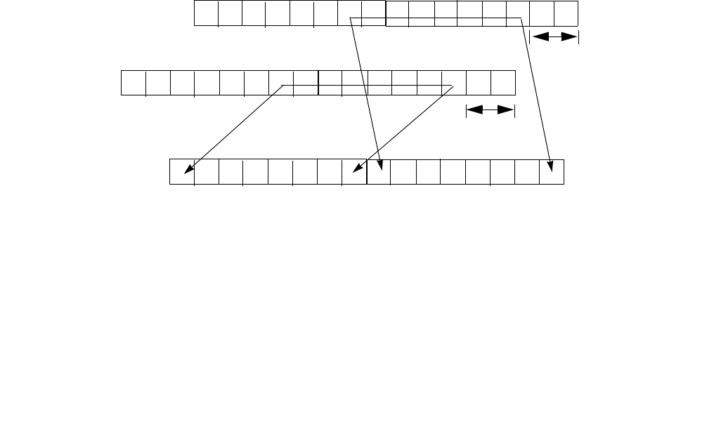
PALIGNR — Packed Align Right
INSTRUCTION SET REFERENCE, M-U
4-220 Vol. 2B
XMM or a YMM register. The immediate value is considered unsigned. Immediate shift counts larger than the 2L
(i.e. 32 for 128-bit operands, or 16 for 64-bit operands) produce a zero result. Both operands can be MMX regis-
ters, XMM registers or YMM registers. When the source operand is a 128-bit memory operand, the operand must
be aligned on a 16-byte boundary or a general-protection exception (#GP) will be generated.
In 64-bit mode and not encoded by VEX/EVEX prefix, use the REX prefix to access additional registers.
128-bit Legacy SSE version: Bits (VLMAX-1:128) of the corresponding YMM destination register remain
unchanged.
EVEX.512 encoded version: The first source operand is a ZMM register and contains four 16-byte blocks. The
second source operand is a ZMM register or a 512-bit memory location containing four 16-byte block. The destina-
tion operand is a ZMM register and contain four 16-byte results. The imm8[7:0] is the common shift count
used for each of the four successive 16-byte block sources. The low 16-byte block of the two source operands
produce the low 16-byte result of the destination operand, the high 16-byte block of the two source operands
produce the high 16-byte result of the destination operand and so on for the blocks in the middle.
VEX.256 and EVEX.256 encoded versions: The first source operand is a YMM register and contains two 16-byte
blocks. The second source operand is a YMM register or a 256-bit memory location containing two 16-byte block.
The destination operand is a YMM register and contain two 16-byte results. The imm8[7:0] is the common shift
count used for the two lower 16-byte block sources and the two upper 16-byte block sources. The low 16-byte
block of the two source operands produce the low 16-byte result of the destination operand, the high 16-byte block
of the two source operands produce the high 16-byte result of the destination operand. The upper bits (MAX_VL-
1:256) of the corresponding ZMM register destination are zeroed.
VEX.128 and EVEX.128 encoded versions: The first source operand is an XMM register. The second source operand
is an XMM register or 128-bit memory location. The destination operand is an XMM register. The upper bits
(MAX_VL-1:128) of the corresponding ZMM register destination are zeroed.
Concatenation is done with 128-bit data in the first and second source operand for both 128-bit and 256-bit
instructions. The high 128-bits of the intermediate composite 256-bit result came from the 128-bit data from the
first source operand; the low 128-bits of the intermediate result came from the 128-bit data of the second source
operand.
Note: VEX.L must be 0, otherwise the instruction will #UD.
Figure 4-7. 256-bit VPALIGN Instruction Operation
Operation
PALIGNR (with 64-bit operands)
temp1[127:0] = CONCATENATE(DEST,SRC)>>(imm8*8)
DEST[63:0] = temp1[63:0]
127 0
SRC1
Imm8[7:0]*8
Imm8[7:0]*8
127 0
SRC2
255 128
SRC1
255 128
SRC2
255 128
DEST
127 0
DEST

PALIGNR — Packed Align Right
INSTRUCTION SET REFERENCE, M-U
Vol. 2B 4-221
PALIGNR (with 128-bit operands)
temp1[255:0] ((DEST[127:0] << 128) OR SRC[127:0])>>(imm8*8);
DEST[127:0] temp1[127:0]
DEST[VLMAX-1:128] (Unmodified)
VPALIGNR (VEX.128 encoded version)
temp1[255:0] ((SRC1[127:0] << 128) OR SRC2[127:0])>>(imm8*8);
DEST[127:0] temp1[127:0]
DEST[VLMAX-1:128] 0
VPALIGNR (VEX.256 encoded version)
temp1[255:0] ((SRC1[127:0] << 128) OR SRC2[127:0])>>(imm8[7:0]*8);
DEST[127:0] temp1[127:0]
temp1[255:0] ((SRC1[255:128] << 128) OR SRC2[255:128])>>(imm8[7:0]*8);
DEST[MAX_VL-1:128] temp1[127:0]
VPALIGNR (EVEX encoded versions)
(KL, VL) = (16, 128), (32, 256), (64, 512)
FOR l 0 TO VL-1 with increments of 128
temp1[255:0] ← ((SRC1[l+127:l] << 128) OR SRC2[l+127:l])>>(imm8[7:0]*8);
TMP_DEST[l+127:l] ← temp1[127:0]
ENDFOR;
FOR j 0 TO KL-1
i j * 8
IF k1[j] OR *no writemask*
THEN DEST[i+7:i] TMP_DEST[i+7:i]
ELSE
IF *merging-masking* ; merging-masking
THEN *DEST[i+7:i] remains unchanged*
ELSE *zeroing-masking* ; zeroing-masking
DEST[i+7:i] = 0
FI
FI;
ENDFOR;
DEST[MAX_VL-1:VL] 0
Intel C/C++ Compiler Intrinsic Equivalents
PALIGNR: __m64 _mm_alignr_pi8 (__m64 a, __m64 b, int n)
(V)PALIGNR: __m128i _mm_alignr_epi8 (__m128i a, __m128i b, int n)
VPALIGNR: __m256i _mm256_alignr_epi8 (__m256i a, __m256i b, const int n)
VPALIGNR __m512i _mm512_alignr_epi8 (__m512i a, __m512i b, const int n)
VPALIGNR __m512i _mm512_mask_alignr_epi8 (__m512i s, __mmask64 m, __m512i a, __m512i b, const int n)
VPALIGNR __m512i _mm512_maskz_alignr_epi8 ( __mmask64 m, __m512i a, __m512i b, const int n)
VPALIGNR __m256i _mm256_mask_alignr_epi8 (__m256i s, __mmask32 m, __m256i a, __m256i b, const int n)
VPALIGNR __m256i _mm256_maskz_alignr_epi8 (__mmask32 m, __m256i a, __m256i b, const int n)
VPALIGNR __m128i _mm_mask_alignr_epi8 (__m128i s, __mmask16 m, __m128i a, __m128i b, const int n)
VPALIGNR __m128i _mm_maskz_alignr_epi8 (__mmask16 m, __m128i a, __m128i b, const int n)
SIMD Floating-Point Exceptions
None.

PALIGNR — Packed Align Right
INSTRUCTION SET REFERENCE, M-U
4-222 Vol. 2B
Other Exceptions
Non-EVEX-encoded instruction, see Exceptions Type 4.
EVEX-encoded instruction, see Exceptions Type E4NF.nb.

PAND—Logical AND
INSTRUCTION SET REFERENCE, M-U
Vol. 2B 4-223
PAND—Logical AND
Instruction Operand Encoding
Description
Performs a bitwise logical AND operation on the first source operand and second source operand and stores the
result in the destination operand. Each bit of the result is set to 1 if the corresponding bits of the first and second
operands are 1, otherwise it is set to 0.
In 64-bit mode and not encoded with VEX/EVEX, using a REX prefix in the form of REX.R permits this instruction to
access additional registers (XMM8-XMM15).
Opcode/
Instruction
Op/
En
64/32 bit
Mode
Support
CPUID
Feature Flag
Description
0F DB /r1
PAND mm, mm/m64
RM V/V MMX Bitwise AND mm/m64 and mm.
66 0F DB /r
PAND xmm1, xmm2/m128
RM V/V SSE2 Bitwise AND of xmm2/m128 and xmm1.
VEX.NDS.128.66.0F.WIG DB /r
VPAND xmm1, xmm2, xmm3/m128
RVM V/V AVX Bitwise AND of xmm3/m128 and xmm.
VEX.NDS.256.66.0F.WIG DB /r
VPAND ymm1, ymm2, ymm3/.m256
RVM V/V AVX2 Bitwise AND of ymm2, and ymm3/m256 and
store result in ymm1.
EVEX.NDS.128.66.0F.W0 DB /r
VPANDD xmm1 {k1}{z}, xmm2,
xmm3/m128/m32bcst
FV V/V AVX512VL
AVX512F
Bitwise AND of packed doubleword integers in
xmm2 and xmm3/m128/m32bcst and store
result in xmm1 using writemask k1.
EVEX.NDS.256.66.0F.W0 DB /r
VPANDD ymm1 {k1}{z}, ymm2,
ymm3/m256/m32bcst
FV V/V AVX512VL
AVX512F
Bitwise AND of packed doubleword integers in
ymm2 and ymm3/m256/m32bcst and store
result in ymm1 using writemask k1.
EVEX.NDS.512.66.0F.W0 DB /r
VPANDD zmm1 {k1}{z}, zmm2,
zmm3/m512/m32bcst
FV V/V AVX512F Bitwise AND of packed doubleword integers in
zmm2 and zmm3/m512/m32bcst and store
result in zmm1 using writemask k1.
EVEX.NDS.128.66.0F.W1 DB /r
VPANDQ xmm1 {k1}{z}, xmm2,
xmm3/m128/m64bcst
FV V/V AVX512VL
AVX512F
Bitwise AND of packed quadword integers in
xmm2 and xmm3/m128/m64bcst and store
result in xmm1 using writemask k1.
EVEX.NDS.256.66.0F.W1 DB /r
VPANDQ ymm1 {k1}{z}, ymm2,
ymm3/m256/m64bcst
FV V/V AVX512VL
AVX512F
Bitwise AND of packed quadword integers in
ymm2 and ymm3/m256/m64bcst and store
result in ymm1 using writemask k1.
EVEX.NDS.512.66.0F.W1 DB /r
VPANDQ zmm1 {k1}{z}, zmm2,
zmm3/m512/m64bcst
FV V/V AVX512F Bitwise AND of packed quadword integers in
zmm2 and zmm3/m512/m64bcst and store
result in zmm1 using writemask k1.
NOTES:
1. See note in Section 2.4, “AVX and SSE Instruction Exception Specification” in the Intel® 64 and IA-32 Architectures Software
Developer’s Manual, Volume 2A and Section 22.25.3, “Exception Conditions of Legacy SIMD Instructions Operating on MMX Registers”
in the Intel® 64 and IA-32 Architectures Software Developer’s Manual, Volume 3A.
Op/En Operand 1 Operand 2 Operand 3 Operand 4
RM ModRM:reg (r, w) ModRM:r/m (r) NA NA
RVM ModRM:reg (w) VEX.vvvv (r) ModRM:r/m (r) NA
FV ModRM:reg (w) EVEX.vvvv (r) ModRM:r/m (r) NA

PAND—Logical AND
INSTRUCTION SET REFERENCE, M-U
4-224 Vol. 2B
Legacy SSE instructions: The source operand can be an MMX technology register or a 64-bit memory location. The
destination operand can be an MMX technology register.
128-bit Legacy SSE version: The first source operand is an XMM register. The second operand can be an XMM
register or an 128-bit memory location. The destination is not distinct from the first source XMM register and the
upper bits (MAX_VL-1:128) of the corresponding ZMM register destination are unmodified.
EVEX encoded versions: The first source operand is a ZMM/YMM/XMM register. The second source operand can be
a ZMM/YMM/XMM register, a 512/256/128-bit memory location or a 512/256/128-bit vector broadcasted from a
32/64-bit memory location. The destination operand is a ZMM/YMM/XMM register conditionally updated with
writemask k1 at 32/64-bit granularity.
VEX.256 encoded versions: The first source operand is a YMM register. The second source operand is a YMM
register or a 256-bit memory location. The destination operand is a YMM register. The upper bits (MAX_VL-1:256)
of the corresponding ZMM register destination are zeroed.
VEX.128 encoded versions: The first source operand is an XMM register. The second source operand is an XMM
register or 128-bit memory location. The destination operand is an XMM register. The upper bits (MAX_VL-1:128)
of the corresponding ZMM register destination are zeroed.
Operation
PAND (64-bit operand)
DEST DEST AND SRC
PAND (128-bit Legacy SSE version)
DEST DEST AND SRC
DEST[VLMAX-1:128] (Unmodified)
VPAND (VEX.128 encoded version)
DEST SRC1 AND SRC2
DEST[VLMAX-1:128] 0
VPAND (VEX.256 encoded instruction)
DEST[255:0] (SRC1[255:0] AND SRC2[255:0])
DEST[VLMAX-1:256] 0
VPANDD (EVEX encoded versions)
(KL, VL) = (4, 128), (8, 256), (16, 512)
FOR j 0 TO KL-1
i j * 32
IF k1[j] OR *no writemask*
THEN
IF (EVEX.b = 1) AND (SRC2 *is memory*)
THEN DEST[i+31:i] SRC1[i+31:i] BITWISE AND SRC2[31:0]
ELSE DEST[i+31:i] SRC1[i+31:i] BITWISE AND SRC2[i+31:i]
FI;
ELSE
IF *merging-masking* ; merging-masking
THEN *DEST[i+31:i] remains unchanged*
ELSE ; zeroing-masking
DEST[i+31:i] 0
FI
FI;
ENDFOR
DEST[MAX_VL-1:VL] 0
VPANDQ (EVEX encoded versions)

PAND—Logical AND
INSTRUCTION SET REFERENCE, M-U
Vol. 2B 4-225
(KL, VL) = (2, 128), (4, 256), (8, 512)
FOR j 0 TO KL-1
i j * 64
IF k1[j] OR *no writemask*
THEN
IF (EVEX.b = 1) AND (SRC2 *is memory*)
THEN DEST[i+63:i] SRC1[i+63:i] BITWISE AND SRC2[63:0]
ELSE DEST[i+63:i] SRC1[i+63:i] BITWISE AND SRC2[i+63:i]
FI;
ELSE
IF *merging-masking* ; merging-masking
THEN *DEST[i+63:i] remains unchanged*
ELSE ; zeroing-masking
DEST[i+63:i] 0
FI
FI;
ENDFOR
DEST[MAX_VL-1:VL] 0
Intel C/C++ Compiler Intrinsic Equivalents
VPANDD __m512i _mm512_and_epi32( __m512i a, __m512i b);
VPANDD __m512i _mm512_mask_and_epi32(__m512i s, __mmask16 k, __m512i a, __m512i b);
VPANDD __m512i _mm512_maskz_and_epi32( __mmask16 k, __m512i a, __m512i b);
VPANDQ __m512i _mm512_and_epi64( __m512i a, __m512i b);
VPANDQ __m512i _mm512_mask_and_epi64(__m512i s, __mmask8 k, __m512i a, __m512i b);
VPANDQ __m512i _mm512_maskz_and_epi64( __mmask8 k, __m512i a, __m512i b);
VPANDND __m256i _mm256_mask_and_epi32(__m256i s, __mmask8 k, __m256i a, __m256i b);
VPANDND __m256i _mm256_maskz_and_epi32( __mmask8 k, __m256i a, __m256i b);
VPANDND __m128i _mm_mask_and_epi32(__m128i s, __mmask8 k, __m128i a, __m128i b);
VPANDND __m128i _mm_maskz_and_epi32( __mmask8 k, __m128i a, __m128i b);
VPANDNQ __m256i _mm256_mask_and_epi64(__m256i s, __mmask8 k, __m256i a, __m256i b);
VPANDNQ __m256i _mm256_maskz_and_epi64( __mmask8 k, __m256i a, __m256i b);
VPANDNQ __m128i _mm_mask_and_epi64(__m128i s, __mmask8 k, __m128i a, __m128i b);
VPANDNQ __m128i _mm_maskz_and_epi64( __mmask8 k, __m128i a, __m128i b);
PAND: __m64 _mm_and_si64 (__m64 m1, __m64 m2)
(V)PAND:__m128i _mm_and_si128 ( __m128i a, __m128i b)
VPAND: __m256i _mm256_and_si256 ( __m256i a, __m256i b)
Flags Affected
None.
Numeric Exceptions
None.
Other Exceptions
Non-EVEX-encoded instruction, see Exceptions Type 4.
EVEX-encoded instruction, see Exceptions Type E4.

PANDN—Logical AND NOT
INSTRUCTION SET REFERENCE, M-U
4-226 Vol. 2B
PANDN—Logical AND NOT
Instruction Operand Encoding
Description
Performs a bitwise logical NOT operation on the first source operand, then performs bitwise AND with second
source operand and stores the result in the destination operand. Each bit of the result is set to 1 if the corre-
sponding bit in the first operand is 0 and the corresponding bit in the second operand is 1, otherwise it is set to 0.
In 64-bit mode and not encoded with VEX/EVEX, using a REX prefix in the form of REX.R permits this instruction to
access additional registers (XMM8-XMM15).
Opcode/
Instruction
Op/
En
64/32 bit
Mode
Support
CPUID
Feature
Flag
Description
0F DF /r1
PANDN mm, mm/m64
RM V/V MMX Bitwise AND NOT of mm/m64 and mm.
66 0F DF /r
PANDN xmm1, xmm2/m128
RM V/V SSE2 Bitwise AND NOT of xmm2/m128 and xmm1.
VEX.NDS.128.66.0F.WIG DF /r
VPANDN xmm1, xmm2, xmm3/m128
RVM V/V AVX Bitwise AND NOT of xmm3/m128 and xmm2.
VEX.NDS.256.66.0F.WIG DF /r
VPANDN ymm1, ymm2, ymm3/m256
RVM V/V AVX2 Bitwise AND NOT of ymm2, and ymm3/m256
and store result in ymm1.
EVEX.NDS.128.66.0F.W0 DF /r
VPANDND xmm1 {k1}{z}, xmm2,
xmm3/m128/m32bcst
FV V/V AVX512VL
AVX512F
Bitwise AND NOT of packed doubleword
integers in xmm2 and xmm3/m128/m32bcst
and store result in xmm1 using writemask k1.
EVEX.NDS.256.66.0F.W0 DF /r
VPANDND ymm1 {k1}{z}, ymm2,
ymm3/m256/m32bcst
FV V/V AVX512VL
AVX512F
Bitwise AND NOT of packed doubleword
integers in ymm2 and ymm3/m256/m32bcst
and store result in ymm1 using writemask k1.
EVEX.NDS.512.66.0F.W0 DF /r
VPANDND zmm1 {k1}{z}, zmm2,
zmm3/m512/m32bcst
FV V/V AVX512F Bitwise AND NOT of packed doubleword
integers in zmm2 and zmm3/m512/m32bcst
and store result in zmm1 using writemask k1.
EVEX.NDS.128.66.0F.W1 DF /r
VPANDNQ xmm1 {k1}{z}, xmm2,
xmm3/m128/m64bcst
FV V/V AVX512VL
AVX512F
Bitwise AND NOT of packed quadword
integers in xmm2 and xmm3/m128/m64bcst
and store result in xmm1 using writemask k1.
EVEX.NDS.256.66.0F.W1 DF /r
VPANDNQ ymm1 {k1}{z}, ymm2,
ymm3/m256/m64bcst
FV V/V AVX512VL
AVX512F
Bitwise AND NOT of packed quadword
integers in ymm2 and ymm3/m256/m64bcst
and store result in ymm1 using writemask k1.
EVEX.NDS.512.66.0F.W1 DF /r
VPANDNQ zmm1 {k1}{z}, zmm2,
zmm3/m512/m64bcst
FV V/V AVX512F Bitwise AND NOT of packed quadword
integers in zmm2 and zmm3/m512/m64bcst
and store result in zmm1 using writemask k1.
NOTES:
1. See note in Section 2.4, “AVX and SSE Instruction Exception Specification” in the Intel® 64 and IA-32 Architectures Software
Developer’s Manual, Volume 2A and Section 22.25.3, “Exception Conditions of Legacy SIMD Instructions Operating on MMX Registers”
in the Intel® 64 and IA-32 Architectures Software Developer’s Manual, Volume 3A.
Op/En Operand 1 Operand 2 Operand 3 Operand 4
RM ModRM:reg (r, w) ModRM:r/m (r) NA NA
RVM ModRM:reg (w) VEX.vvvv (r) ModRM:r/m (r) NA
FV ModRM:reg (w) EVEX.vvvv (r) ModRM:r/m (r) NA

PANDN—Logical AND NOT
INSTRUCTION SET REFERENCE, M-U
Vol. 2B 4-227
Legacy SSE instructions: The source operand can be an MMX technology register or a 64-bit memory location. The
destination operand can be an MMX technology register.
128-bit Legacy SSE version: The first source operand is an XMM register. The second operand can be an XMM
register or an 128-bit memory location. The destination is not distinct from the first source XMM register and the
upper bits (MAX_VL-1:128) of the corresponding ZMM register destination are unmodified.
EVEX encoded versions: The first source operand is a ZMM/YMM/XMM register. The second source operand can be
a ZMM/YMM/XMM register, a 512/256/128-bit memory location or a 512/256/128-bit vector broadcasted from a
32/64-bit memory location. The destination operand is a ZMM/YMM/XMM register conditionally updated with
writemask k1 at 32/64-bit granularity.
VEX.256 encoded versions: The first source operand is a YMM register. The second source operand is a YMM
register or a 256-bit memory location. The destination operand is a YMM register. The upper bits (MAX_VL-1:256)
of the corresponding ZMM register destination are zeroed.
VEX.128 encoded versions: The first source operand is an XMM register. The second source operand is an XMM
register or 128-bit memory location. The destination operand is an XMM register. The upper bits (MAX_VL-1:128)
of the corresponding ZMM register destination are zeroed.
Operation
PANDN (64-bit operand)
DEST NOT(DEST) AND SRC
PANDN (128-bit Legacy SSE version)
DEST NOT(DEST) AND SRC
DEST[VLMAX-1:128] (Unmodified)
VPANDN (VEX.128 encoded version)
DEST NOT(SRC1) AND SRC2
DEST[VLMAX-1:128] 0
VPANDN (VEX.256 encoded instruction)
DEST[255:0] ((NOT SRC1[255:0]) AND SRC2[255:0])
DEST[VLMAX-1:256] 0
VPANDND (EVEX encoded versions)
(KL, VL) = (4, 128), (8, 256), (16, 512)
FOR j 0 TO KL-1
i j * 32
IF k1[j] OR *no writemask*
THEN
IF (EVEX.b = 1) AND (SRC2 *is memory*)
THEN DEST[i+31:i] ((NOT SRC1[i+31:i]) AND SRC2[31:0])
ELSE DEST[i+31:i] ((NOT SRC1[i+31:i]) AND SRC2[i+31:i])
FI;
ELSE
IF *merging-masking* ; merging-masking
THEN *DEST[i+31:i] remains unchanged*
ELSE ; zeroing-masking
DEST[i+31:i] 0
FI
FI;
ENDFOR
DEST[MAX_VL-1:VL] 0
VPANDNQ (EVEX encoded versions)

PANDN—Logical AND NOT
INSTRUCTION SET REFERENCE, M-U
4-228 Vol. 2B
(KL, VL) = (2, 128), (4, 256), (8, 512)
FOR j 0 TO KL-1
i j * 64
IF k1[j] OR *no writemask*
THEN
IF (EVEX.b = 1) AND (SRC2 *is memory*)
THEN DEST[i+63:i] ((NOT SRC1[i+63:i]) AND SRC2[63:0])
ELSE DEST[i+63:i] ((NOT SRC1[i+63:i]) AND SRC2[i+63:i])
FI;
ELSE
IF *merging-masking* ; merging-masking
THEN *DEST[i+63:i] remains unchanged*
ELSE ; zeroing-masking
DEST[i+63:i] 0
FI
FI;
ENDFOR
DEST[MAX_VL-1:VL] 0
Intel C/C++ Compiler Intrinsic Equivalents
VPANDND __m512i _mm512_andnot_epi32( __m512i a, __m512i b);
VPANDND __m512i _mm512_mask_andnot_epi32(__m512i s, __mmask16 k, __m512i a, __m512i b);
VPANDND __m512i _mm512_maskz_andnot_epi32( __mmask16 k, __m512i a, __m512i b);
VPANDND __m256i _mm256_mask_andnot_epi32(__m256i s, __mmask8 k, __m256i a, __m256i b);
VPANDND __m256i _mm256_maskz_andnot_epi32( __mmask8 k, __m256i a, __m256i b);
VPANDND __m128i _mm_mask_andnot_epi32(__m128i s, __mmask8 k, __m128i a, __m128i b);
VPANDND __m128i _mm_maskz_andnot_epi32( __mmask8 k, __m128i a, __m128i b);
VPANDNQ __m512i _mm512_andnot_epi64( __m512i a, __m512i b);
VPANDNQ __m512i _mm512_mask_andnot_epi64(__m512i s, __mmask8 k, __m512i a, __m512i b);
VPANDNQ __m512i _mm512_maskz_andnot_epi64( __mmask8 k, __m512i a, __m512i b);
VPANDNQ __m256i _mm256_mask_andnot_epi64(__m256i s, __mmask8 k, __m256i a, __m256i b);
VPANDNQ __m256i _mm256_maskz_andnot_epi64( __mmask8 k, __m256i a, __m256i b);
VPANDNQ __m128i _mm_mask_andnot_epi64(__m128i s, __mmask8 k, __m128i a, __m128i b);
VPANDNQ __m128i _mm_maskz_andnot_epi64( __mmask8 k, __m128i a, __m128i b);
PANDN: __m64 _mm_andnot_si64 (__m64 m1, __m64 m2)
(V)PANDN:__m128i _mm_andnot_si128 ( __m128i a, __m128i b)
VPANDN: __m256i _mm256_andnot_si256 ( __m256i a, __m256i b)
Flags Affected
None.
Numeric Exceptions
None.
Other Exceptions
Non-EVEX-encoded instruction, see Exceptions Type 4.
EVEX-encoded instruction, see Exceptions Type E4.

PAUSE—Spin Loop Hint
INSTRUCTION SET REFERENCE, M-U
Vol. 2B 4-229
PAUSE—Spin Loop Hint
Instruction Operand Encoding
Description
Improves the performance of spin-wait loops. When executing a “spin-wait loop,” processors will suffer a severe
performance penalty when exiting the loop because it detects a possible memory order violation. The PAUSE
instruction provides a hint to the processor that the code sequence is a spin-wait loop. The processor uses this hint
to avoid the memory order violation in most situations, which greatly improves processor performance. For this
reason, it is recommended that a PAUSE instruction be placed in all spin-wait loops.
An additional function of the PAUSE instruction is to reduce the power consumed by a processor while executing a
spin loop. A processor can execute a spin-wait loop extremely quickly, causing the processor to consume a lot of
power while it waits for the resource it is spinning on to become available. Inserting a pause instruction in a spin-
wait loop greatly reduces the processor’s power consumption.
This instruction was introduced in the Pentium 4 processors, but is backward compatible with all IA-32 processors.
In earlier IA-32 processors, the PAUSE instruction operates like a NOP instruction. The Pentium 4 and Intel Xeon
processors implement the PAUSE instruction as a delay. The delay is finite and can be zero for some processors.
This instruction does not change the architectural state of the processor (that is, it performs essentially a delaying
no-op operation).
This instruction’s operation is the same in non-64-bit modes and 64-bit mode.
Operation
Execute_Next_Instruction(DELAY);
Numeric Exceptions
None.
Exceptions (All Operating Modes)
#UD If the LOCK prefix is used.
Opcode Instruction Op/
En
64-Bit
Mode
Compat/
Leg Mode
Description
F3 90 PAUSE NP Valid Valid Gives hint to processor that improves
performance of spin-wait loops.
Op/En Operand 1 Operand 2 Operand 3 Operand 4
NP NA NA NA NA

PAVGB/PAVGW—Average Packed Integers
INSTRUCTION SET REFERENCE, M-U
4-230 Vol. 2B
PAVGB/PAVGW—Average Packed Integers
Instruction Operand Encoding
Opcode/
Instruction
Op/
En
64/32 bit
Mode
Support
CPUID
Feature
Flag
Description
0F E0 /r1
PAVGB mm1, mm2/m64
RM V/V SSE Average packed unsigned byte integers from
mm2/m64 and mm1 with rounding.
66 0F E0, /r
PAVGB xmm1, xmm2/m128
RM V/V SSE2 Average packed unsigned byte integers from
xmm2/m128 and xmm1 with rounding.
0F E3 /r1
PAVGW mm1, mm2/m64
RM V/V SSE Average packed unsigned word integers from
mm2/m64 and mm1 with rounding.
66 0F E3 /r
PAVGW xmm1, xmm2/m128
RM V/V SSE2 Average packed unsigned word integers from
xmm2/m128 and xmm1 with rounding.
VEX.NDS.128.66.0F.WIG E0 /r
VPAVGB xmm1, xmm2, xmm3/m128
RVM V/V AVX Average packed unsigned byte integers from
xmm3/m128 and xmm2 with rounding.
VEX.NDS.128.66.0F.WIG E3 /r
VPAVGW xmm1, xmm2, xmm3/m128
RVM V/V AVX Average packed unsigned word integers from
xmm3/m128 and xmm2 with rounding.
VEX.NDS.256.66.0F.WIG E0 /r
VPAVGB ymm1, ymm2, ymm3/m256
RVM V/V AVX2 Average packed unsigned byte integers from
ymm2, and ymm3/m256 with rounding and
store to ymm1.
VEX.NDS.256.66.0F.WIG E3 /r
VPAVGW ymm1, ymm2, ymm3/m256
RVM V/V AVX2 Average packed unsigned word integers from
ymm2, ymm3/m256 with rounding to ymm1.
EVEX.NDS.128.66.0F.WIG E0 /r
VPAVGB xmm1 {k1}{z}, xmm2, xmm3/m128
FVM V/V AVX512VL
AVX512BW
Average packed unsigned byte integers from
xmm2, and xmm3/m128 with rounding and
store to xmm1 under writemask k1.
EVEX.NDS.256.66.0F.WIG E0 /r
VPAVGB ymm1 {k1}{z}, ymm2, ymm3/m256
FVM V/V AVX512VL
AVX512BW
Average packed unsigned byte integers from
ymm2, and ymm3/m256 with rounding and
store to ymm1 under writemask k1.
EVEX.NDS.512.66.0F.WIG E0 /r
VPAVGB zmm1 {k1}{z}, zmm2, zmm3/m512
FVM V/V AVX512BW Average packed unsigned byte integers from
zmm2, and zmm3/m512 with rounding and
store to zmm1 under writemask k1.
EVEX.NDS.128.66.0F.WIG E3 /r
VPAVGW xmm1 {k1}{z}, xmm2, xmm3/m128
FVM V/V AVX512VL
AVX512BW
Average packed unsigned word integers from
xmm2, xmm3/m128 with rounding to xmm1
under writemask k1.
EVEX.NDS.256.66.0F.WIG E3 /r
VPAVGW ymm1 {k1}{z}, ymm2, ymm3/m256
FVM V/V AVX512VL
AVX512BW
Average packed unsigned word integers from
ymm2, ymm3/m256 with rounding to ymm1
under writemask k1.
EVEX.NDS.512.66.0F.WIG E3 /r
VPAVGW zmm1 {k1}{z}, zmm2, zmm3/m512
FVM V/V AVX512BW Average packed unsigned word integers from
zmm2, zmm3/m512 with rounding to zmm1
under writemask k1.
NOTES:
1. See note in Section 2.4, “AVX and SSE Instruction Exception Specification” in the Intel® 64 and IA-32 Architectures Software
Developer’s Manual, Volume 2A and Section 22.25.3, “Exception Conditions of Legacy SIMD Instructions Operating on MMX Registers”
in the Intel® 64 and IA-32 Architectures Software Developer’s Manual, Volume 3A.
Op/En Operand 1 Operand 2 Operand 3 Operand 4
RM ModRM:reg (r, w) ModRM:r/m (r) NA NA

PAVGB/PAVGW—Average Packed Integers
INSTRUCTION SET REFERENCE, M-U
Vol. 2B 4-231
Description
Performs a SIMD average of the packed unsigned integers from the source operand (second operand) and the
destination operand (first operand), and stores the results in the destination operand. For each corresponding pair
of data elements in the first and second operands, the elements are added together, a 1 is added to the temporary
sum, and that result is shifted right one bit position.
The (V)PAVGB instruction operates on packed unsigned bytes and the (V)PAVGW instruction operates on packed
unsigned words.
In 64-bit mode and not encoded with VEX/EVEX, using a REX prefix in the form of REX.R permits this instruction to
access additional registers (XMM8-XMM15).
Legacy SSE instructions: The source operand can be an MMX technology register or a 64-bit memory location. The
destination operand can be an MMX technology register.
128-bit Legacy SSE version: The first source operand is an XMM register. The second operand can be an XMM
register or an 128-bit memory location. The destination is not distinct from the first source XMM register and the
upper bits (MAX_VL-1:128) of the corresponding register destination are unmodified.
EVEX.512 encoded version: The first source operand is a ZMM register. The second source operand is a ZMM
register or a 512-bit memory location. The destination operand is a ZMM register.
VEX.256 and EVEX.256 encoded versions: The first source operand is a YMM register. The second source operand
is a YMM register or a 256-bit memory location. The destination operand is a YMM register.
VEX.128 and EVEX.128 encoded versions: The first source operand is an XMM register. The second source operand
is an XMM register or 128-bit memory location. The destination operand is an XMM register. The upper bits
(MAX_VL-1:128) of the corresponding register destination are zeroed.
Operation
PAVGB (with 64-bit operands)
DEST[7:0] ← (SRC[7:0] + DEST[7:0] + 1) >> 1; (* Temp sum before shifting is 9 bits *)
(* Repeat operation performed for bytes 2 through 6 *)
DEST[63:56] ← (SRC[63:56] + DEST[63:56] + 1) >> 1;
PAVGW (with 64-bit operands)
DEST[15:0] ← (SRC[15:0] + DEST[15:0] + 1) >> 1; (* Temp sum before shifting is 17 bits *)
(* Repeat operation performed for words 2 and 3 *)
DEST[63:48] ← (SRC[63:48] + DEST[63:48] + 1) >> 1;
PAVGB (with 128-bit operands)
DEST[7:0] ← (SRC[7:0] + DEST[7:0] + 1) >> 1; (* Temp sum before shifting is 9 bits *)
(* Repeat operation performed for bytes 2 through 14 *)
DEST[127:120] ← (SRC[127:120] + DEST[127:120] + 1) >> 1;
PAVGW (with 128-bit operands)
DEST[15:0] ← (SRC[15:0] + DEST[15:0] + 1) >> 1; (* Temp sum before shifting is 17 bits *)
(* Repeat operation performed for words 2 through 6 *)
DEST[127:112] ← (SRC[127:112] + DEST[127:112] + 1) >> 1;
RVM ModRM:reg (w) VEX.vvvv (r) ModRM:r/m (r) NA
FVM ModRM:reg (w) EVEX.vvvv (r) ModRM:r/m (r) NA
Op/En Operand 1 Operand 2 Operand 3 Operand 4

PAVGB/PAVGW—Average Packed Integers
INSTRUCTION SET REFERENCE, M-U
4-232 Vol. 2B
VPAVGB (VEX.128 encoded version)
DEST[7:0] (SRC1[7:0] + SRC2[7:0] + 1) >> 1;
(* Repeat operation performed for bytes 2 through 15 *)
DEST[127:120] (SRC1[127:120] + SRC2[127:120] + 1) >> 1
DEST[VLMAX-1:128] 0
VPAVGW (VEX.128 encoded version)
DEST[15:0] (SRC1[15:0] + SRC2[15:0] + 1) >> 1;
(* Repeat operation performed for 16-bit words 2 through 7 *)
DEST[127:112] (SRC1[127:112] + SRC2[127:112] + 1) >> 1
DEST[VLMAX-1:128] 0
VPAVGB (VEX.256 encoded instruction)
DEST[7:0] (SRC1[7:0] + SRC2[7:0] + 1) >> 1; (* Temp sum before shifting is 9 bits *)
(* Repeat operation performed for bytes 2 through 31)
DEST[255:248] (SRC1[255:248] + SRC2[255:248] + 1) >> 1;
VPAVGW (VEX.256 encoded instruction)
DEST[15:0] (SRC1[15:0] + SRC2[15:0] + 1) >> 1; (* Temp sum before shifting is 17 bits *)
(* Repeat operation performed for words 2 through 15)
DEST[255:14]) (SRC1[255:240] + SRC2[255:240] + 1) >> 1;
VPAVGB (EVEX encoded versions)
(KL, VL) = (16, 128), (32, 256), (64, 512)
FOR j 0 TO KL-1
i j * 8
IF k1[j] OR *no writemask*
THEN DEST[i+7:i] (SRC1[i+7:i] + SRC2[i+7:i] + 1) >> 1; (* Temp sum before shifting is 9 bits *)
ELSE
IF *merging-masking* ; merging-masking
THEN *DEST[i+7:i] remains unchanged*
ELSE *zeroing-masking* ; zeroing-masking
DEST[i+7:i] = 0
FI
FI;
ENDFOR;
DEST[MAX_VL-1:VL] 0
VPAVGW (EVEX encoded versions)
(KL, VL) = (8, 128), (16, 256), (32, 512)
FOR j 0 TO KL-1
i j * 16
IF k1[j] OR *no writemask*
THEN DEST[i+15:i] (SRC1[i+15:i] + SRC2[i+15:i] + 1) >> 1
; (* Temp sum before shifting is 17 bits *)
ELSE
IF *merging-masking* ; merging-masking
THEN *DEST[i+15:i] remains unchanged*
ELSE *zeroing-masking* ; zeroing-masking
DEST[i+15:i] = 0
FI
FI;
ENDFOR;
DEST[MAX_VL-1:VL] 0

PAVGB/PAVGW—Average Packed Integers
INSTRUCTION SET REFERENCE, M-U
Vol. 2B 4-233
Intel C/C++ Compiler Intrinsic Equivalents
VPAVGB __m512i _mm512_avg_epu8( __m512i a, __m512i b);
VPAVGW __m512i _mm512_avg_epu16( __m512i a, __m512i b);
VPAVGB __m512i _mm512_mask_avg_epu8(__m512i s, __mmask64 m, __m512i a, __m512i b);
VPAVGW __m512i _mm512_mask_avg_epu16(__m512i s, __mmask32 m, __m512i a, __m512i b);
VPAVGB __m512i _mm512_maskz_avg_epu8( __mmask64 m, __m512i a, __m512i b);
VPAVGW __m512i _mm512_maskz_avg_epu16( __mmask32 m, __m512i a, __m512i b);
VPAVGB __m256i _mm256_mask_avg_epu8(__m256i s, __mmask32 m, __m256i a, __m256i b);
VPAVGW __m256i _mm256_mask_avg_epu16(__m256i s, __mmask16 m, __m256i a, __m256i b);
VPAVGB __m256i _mm256_maskz_avg_epu8( __mmask32 m, __m256i a, __m256i b);
VPAVGW __m256i _mm256_maskz_avg_epu16( __mmask16 m, __m256i a, __m256i b);
VPAVGB __m128i _mm_mask_avg_epu8(__m128i s, __mmask16 m, __m128i a, __m128i b);
VPAVGW __m128i _mm_mask_avg_epu16(__m128i s, __mmask8 m, __m128i a, __m128i b);
VPAVGB __m128i _mm_maskz_avg_epu8( __mmask16 m, __m128i a, __m128i b);
VPAVGW __m128i _mm_maskz_avg_epu16( __mmask8 m, __m128i a, __m128i b);
PAVGB: __m64 _mm_avg_pu8 (__m64 a, __m64 b)
PAVGW: __m64 _mm_avg_pu16 (__m64 a, __m64 b)
(V)PAVGB: __m128i _mm_avg_epu8 ( __m128i a, __m128i b)
(V)PAVGW: __m128i _mm_avg_epu16 ( __m128i a, __m128i b)
VPAVGB: __m256i _mm256_avg_epu8 ( __m256i a, __m256i b)
VPAVGW: __m256i _mm256_avg_epu16 ( __m256i a, __m256i b)
Flags Affected
None.
Numeric Exceptions
None.
Other Exceptions
Non-EVEX-encoded instruction, see Exceptions Type 4.
EVEX-encoded instruction, see Exceptions Type E4.nb.

PBLENDVB — Variable Blend Packed Bytes
INSTRUCTION SET REFERENCE, M-U
4-234 Vol. 2B
PBLENDVB — Variable Blend Packed Bytes
Instruction Operand Encoding
Description
Conditionally copies byte elements from the source operand (second operand) to the destination operand (first
operand) depending on mask bits defined in the implicit third register argument, XMM0. The mask bits are the most
significant bit in each byte element of the XMM0 register.
If a mask bit is “1", then the corresponding byte element in the source operand is copied to the destination, else
the byte element in the destination operand is left unchanged.
The register assignment of the implicit third operand is defined to be the architectural register XMM0.
128-bit Legacy SSE version: The first source operand and the destination operand is the same. Bits (VLMAX-1:128)
of the corresponding YMM destination register remain unchanged. The mask register operand is implicitly defined
to be the architectural register XMM0. An attempt to execute PBLENDVB with a VEX prefix will cause #UD.
VEX.128 encoded version: The first source operand and the destination operand are XMM registers. The second
source operand is an XMM register or 128-bit memory location. The mask operand is the third source register, and
encoded in bits[7:4] of the immediate byte(imm8). The bits[3:0] of imm8 are ignored. In 32-bit mode, imm8[7] is
ignored. The upper bits (VLMAX-1:128) of the corresponding YMM register (destination register) are zeroed. VEX.L
must be 0, otherwise the instruction will #UD. VEX.W must be 0, otherwise, the instruction will #UD.
VEX.256 encoded version: The first source operand and the destination operand are YMM registers. The second
source operand is an YMM register or 256-bit memory location. The third source register is an YMM register and
encoded in bits[7:4] of the immediate byte(imm8). The bits[3:0] of imm8 are ignored. In 32-bit mode, imm8[7] is
ignored.
VPBLENDVB permits the mask to be any XMM or YMM register. In contrast, PBLENDVB treats XMM0 implicitly as the
mask and do not support non-destructive destination operation. An attempt to execute PBLENDVB encoded with a
VEX prefix will cause a #UD exception.
Operation
PBLENDVB (128-bit Legacy SSE version)
MASK XMM0
IF (MASK[7] = 1) THEN DEST[7:0] SRC[7:0];
ELSE DEST[7:0] DEST[7:0];
IF (MASK[15] = 1) THEN DEST[15:8] SRC[15:8];
Opcode/
Instruction
Op/
En
64/32 bit
Mode
Support
CPUID
Feature
Flag
Description
66 0F 38 10 /r
PBLENDVB xmm1, xmm2/m128, <XMM0>
RM V/V SSE4_1 Select byte values from xmm1 and
xmm2/m128 from mask specified in the high
bit of each byte in XMM0 and store the
values into xmm1.
VEX.NDS.128.66.0F3A.W0 4C /r /is4
VPBLENDVB xmm1, xmm2, xmm3/m128, xmm4
RVMR V/V AVX Select byte values from xmm2 and
xmm3/m128 using mask bits in the specified
mask register, xmm4, and store the values
into xmm1.
VEX.NDS.256.66.0F3A.W0 4C /r /is4
VPBLENDVB ymm1, ymm2, ymm3/m256, ymm4
RVMR V/V AVX2 Select byte values from ymm2 and
ymm3/m256 from mask specified in the high
bit of each byte in ymm4 and store the
values into ymm1.
Op/En Operand 1 Operand 2 Operand 3 Operand 4
RM ModRM:reg (r, w) ModRM:r/m (r) <XMM0> NA
RVMR ModRM:reg (w) VEX.vvvv (r) ModRM:r/m (r) imm8[7:4]

PBLENDVB — Variable Blend Packed Bytes
INSTRUCTION SET REFERENCE, M-U
Vol. 2B 4-235
ELSE DEST[15:8] DEST[15:8];
IF (MASK[23] = 1) THEN DEST[23:16] SRC[23:16]
ELSE DEST[23:16] DEST[23:16];
IF (MASK[31] = 1) THEN DEST[31:24] SRC[31:24]
ELSE DEST[31:24] DEST[31:24];
IF (MASK[39] = 1) THEN DEST[39:32] SRC[39:32]
ELSE DEST[39:32] DEST[39:32];
IF (MASK[47] = 1) THEN DEST[47:40] SRC[47:40]
ELSE DEST[47:40] DEST[47:40];
IF (MASK[55] = 1) THEN DEST[55:48] SRC[55:48]
ELSE DEST[55:48] DEST[55:48];
IF (MASK[63] = 1) THEN DEST[63:56] SRC[63:56]
ELSE DEST[63:56] DEST[63:56];
IF (MASK[71] = 1) THEN DEST[71:64] SRC[71:64]
ELSE DEST[71:64] DEST[71:64];
IF (MASK[79] = 1) THEN DEST[79:72] SRC[79:72]
ELSE DEST[79:72] DEST[79:72];
IF (MASK[87] = 1) THEN DEST[87:80] SRC[87:80]
ELSE DEST[87:80] DEST[87:80];
IF (MASK[95] = 1) THEN DEST[95:88] SRC[95:88]
ELSE DEST[95:88] DEST[95:88];
IF (MASK[103] = 1) THEN DEST[103:96] SRC[103:96]
ELSE DEST[103:96] DEST[103:96];
IF (MASK[111] = 1) THEN DEST[111:104] SRC[111:104]
ELSE DEST[111:104] DEST[111:104];
IF (MASK[119] = 1) THEN DEST[119:112] SRC[119:112]
ELSE DEST[119:112] DEST[119:112];
IF (MASK[127] = 1) THEN DEST[127:120] SRC[127:120]
ELSE DEST[127:120] DEST[127:120])
DEST[VLMAX-1:128] (Unmodified)
VPBLENDVB (VEX.128 encoded version)
MASK SRC3
IF (MASK[7] = 1) THEN DEST[7:0] SRC2[7:0];
ELSE DEST[7:0] SRC1[7:0];
IF (MASK[15] = 1) THEN DEST[15:8] SRC2[15:8];
ELSE DEST[15:8] SRC1[15:8];
IF (MASK[23] = 1) THEN DEST[23:16] SRC2[23:16]
ELSE DEST[23:16] SRC1[23:16];
IF (MASK[31] = 1) THEN DEST[31:24] SRC2[31:24]
ELSE DEST[31:24] SRC1[31:24];
IF (MASK[39] = 1) THEN DEST[39:32] SRC2[39:32]
ELSE DEST[39:32] SRC1[39:32];
IF (MASK[47] = 1) THEN DEST[47:40] SRC2[47:40]
ELSE DEST[47:40] SRC1[47:40];
IF (MASK[55] = 1) THEN DEST[55:48] SRC2[55:48]
ELSE DEST[55:48] SRC1[55:48];
IF (MASK[63] = 1) THEN DEST[63:56] SRC2[63:56]
ELSE DEST[63:56] SRC1[63:56];
IF (MASK[71] = 1) THEN DEST[71:64] SRC2[71:64]
ELSE DEST[71:64] SRC1[71:64];
IF (MASK[79] = 1) THEN DEST[79:72] SRC2[79:72]
ELSE DEST[79:72] SRC1[79:72];
IF (MASK[87] = 1) THEN DEST[87:80] SRC2[87:80]

PBLENDVB — Variable Blend Packed Bytes
INSTRUCTION SET REFERENCE, M-U
4-236 Vol. 2B
ELSE DEST[87:80] SRC1[87:80];
IF (MASK[95] = 1) THEN DEST[95:88] SRC2[95:88]
ELSE DEST[95:88] SRC1[95:88];
IF (MASK[103] = 1) THEN DEST[103:96] SRC2[103:96]
ELSE DEST[103:96] SRC1[103:96];
IF (MASK[111] = 1) THEN DEST[111:104] SRC2[111:104]
ELSE DEST[111:104] SRC1[111:104];
IF (MASK[119] = 1) THEN DEST[119:112] SRC2[119:112]
ELSE DEST[119:112] SRC1[119:112];
IF (MASK[127] = 1) THEN DEST[127:120] SRC2[127:120]
ELSE DEST[127:120] SRC1[127:120])
DEST[VLMAX-1:128] 0
VPBLENDVB (VEX.256 encoded version)
MASK SRC3
IF (MASK[7] == 1) THEN DEST[7:0] SRC2[7:0];
ELSE DEST[7:0] SRC1[7:0];
IF (MASK[15] == 1) THEN DEST[15:8] SRC2[15:8];
ELSE DEST[15:8] SRC1[15:8];
IF (MASK[23] == 1) THEN DEST[23:16] SRC2[23:16]
ELSE DEST[23:16] SRC1[23:16];
IF (MASK[31] == 1) THEN DEST[31:24] SRC2[31:24]
ELSE DEST[31:24] SRC1[31:24];
IF (MASK[39] == 1) THEN DEST[39:32] SRC2[39:32]
ELSE DEST[39:32] SRC1[39:32];
IF (MASK[47] == 1) THEN DEST[47:40] SRC2[47:40]
ELSE DEST[47:40] SRC1[47:40];
IF (MASK[55] == 1) THEN DEST[55:48] SRC2[55:48]
ELSE DEST[55:48] SRC1[55:48];
IF (MASK[63] == 1) THEN DEST[63:56] SRC2[63:56]
ELSE DEST[63:56] SRC1[63:56];
IF (MASK[71] == 1) THEN DEST[71:64] SRC2[71:64]
ELSE DEST[71:64] SRC1[71:64];
IF (MASK[79] == 1) THEN DEST[79:72] SRC2[79:72]
ELSE DEST[79:72] SRC1[79:72];
IF (MASK[87] == 1) THEN DEST[87:80] SRC2[87:80]
ELSE DEST[87:80] SRC1[87:80];
IF (MASK[95] == 1) THEN DEST[95:88] SRC2[95:88]
ELSE DEST[95:88] SRC1[95:88];
IF (MASK[103] == 1) THEN DEST[103:96] SRC2[103:96]
ELSE DEST[103:96] SRC1[103:96];
IF (MASK[111] == 1) THEN DEST[111:104] SRC2[111:104]
ELSE DEST[111:104] SRC1[111:104];
IF (MASK[119] == 1) THEN DEST[119:112] SRC2[119:112]
ELSE DEST[119:112] SRC1[119:112];
IF (MASK[127] == 1) THEN DEST[127:120] SRC2[127:120]
ELSE DEST[127:120] SRC1[127:120])
IF (MASK[135] == 1) THEN DEST[135:128] SRC2[135:128];
ELSE DEST[135:128] SRC1[135:128];
IF (MASK[143] == 1) THEN DEST[143:136] SRC2[143:136];
ELSE DEST[[143:136] SRC1[143:136];
IF (MASK[151] == 1) THEN DEST[151:144] SRC2[151:144]
ELSE DEST[151:144] SRC1[151:144];
IF (MASK[159] == 1) THEN DEST[159:152] SRC2[159:152]

PBLENDVB — Variable Blend Packed Bytes
INSTRUCTION SET REFERENCE, M-U
Vol. 2B 4-237
ELSE DEST[159:152] SRC1[159:152];
IF (MASK[167] == 1) THEN DEST[167:160] SRC2[167:160]
ELSE DEST[167:160] SRC1[167:160];
IF (MASK[175] == 1) THEN DEST[175:168] SRC2[175:168]
ELSE DEST[175:168] SRC1[175:168];
IF (MASK[183] == 1) THEN DEST[183:176] SRC2[183:176]
ELSE DEST[183:176] SRC1[183:176];
IF (MASK[191] == 1) THEN DEST[191:184] SRC2[191:184]
ELSE DEST[191:184] SRC1[191:184];
IF (MASK[199] == 1) THEN DEST[199:192] SRC2[199:192]
ELSE DEST[199:192] SRC1[199:192];
IF (MASK[207] == 1) THEN DEST[207:200] SRC2[207:200]
ELSE DEST[207:200] SRC1[207:200]
IF (MASK[215] == 1) THEN DEST[215:208] SRC2[215:208]
ELSE DEST[215:208] SRC1[215:208];
IF (MASK[223] == 1) THEN DEST[223:216] SRC2[223:216]
ELSE DEST[223:216] SRC1[223:216];
IF (MASK[231] == 1) THEN DEST[231:224] SRC2[231:224]
ELSE DEST[231:224] SRC1[231:224];
IF (MASK[239] == 1) THEN DEST[239:232] SRC2[239:232]
ELSE DEST[239:232] SRC1[239:232];
IF (MASK[247] == 1) THEN DEST[247:240] SRC2[247:240]
ELSE DEST[247:240] SRC1[247:240];
IF (MASK[255] == 1) THEN DEST[255:248] SRC2[255:248]
ELSE DEST[255:248] SRC1[255:248]
Intel C/C++ Compiler Intrinsic Equivalent
(V)PBLENDVB: __m128i _mm_blendv_epi8 (__m128i v1, __m128i v2, __m128i mask);
VPBLENDVB: __m256i _mm256_blendv_epi8 (__m256i v1, __m256i v2, __m256i mask);
Flags Affected
None.
SIMD Floating-Point Exceptions
None.
Other Exceptions
See Exceptions Type 4; additionally
#UD If VEX.W = 1.

PBLENDW — Blend Packed Words
INSTRUCTION SET REFERENCE, M-U
4-238 Vol. 2B
PBLENDW — Blend Packed Words
Instruction Operand Encoding
Description
Words from the source operand (second operand) are conditionally written to the destination operand (first
operand) depending on bits in the immediate operand (third operand). The immediate bits (bits 7:0) form a mask
that determines whether the corresponding word in the destination is copied from the source. If a bit in the mask,
corresponding to a word, is “1", then the word is copied, else the word element in the destination operand is
unchanged.
128-bit Legacy SSE version: The second source operand can be an XMM register or a 128-bit memory location. The
first source and destination operands are XMM registers. Bits (VLMAX-1:128) of the corresponding YMM destination
register remain unchanged.
VEX.128 encoded version: The second source operand can be an XMM register or a 128-bit memory location. The
first source and destination operands are XMM registers. Bits (VLMAX-1:128) of the corresponding YMM register
are zeroed.
VEX.256 encoded version: The first source operand is a YMM register. The second source operand is a YMM register
or a 256-bit memory location. The destination operand is a YMM register.
Operation
PBLENDW (128-bit Legacy SSE version)
IF (imm8[0] = 1) THEN DEST[15:0] SRC[15:0]
ELSE DEST[15:0] DEST[15:0]
IF (imm8[1] = 1) THEN DEST[31:16] SRC[31:16]
ELSE DEST[31:16] DEST[31:16]
IF (imm8[2] = 1) THEN DEST[47:32] SRC[47:32]
ELSE DEST[47:32] DEST[47:32]
IF (imm8[3] = 1) THEN DEST[63:48] SRC[63:48]
ELSE DEST[63:48] DEST[63:48]
IF (imm8[4] = 1) THEN DEST[79:64] SRC[79:64]
ELSE DEST[79:64] DEST[79:64]
IF (imm8[5] = 1) THEN DEST[95:80] SRC[95:80]
ELSE DEST[95:80] DEST[95:80]
IF (imm8[6] = 1) THEN DEST[111:96] SRC[111:96]
ELSE DEST[111:96] DEST[111:96]
IF (imm8[7] = 1) THEN DEST[127:112] SRC[127:112]
Opcode/
Instruction
Op/
En
64/32 bit
Mode
Support
CPUID
Feature
Flag
Description
66 0F 3A 0E /r ib
PBLENDW xmm1, xmm2/m128, imm8
RMI V/V SSE4_1 Select words from xmm1 and xmm2/m128
from mask specified in imm8 and store the
values into xmm1.
VEX.NDS.128.66.0F3A.WIG 0E /r ib
VPBLENDW xmm1, xmm2, xmm3/m128, imm8
RVMI V/V AVX Select words from xmm2 and xmm3/m128
from mask specified in imm8 and store the
values into xmm1.
VEX.NDS.256.66.0F3A.WIG 0E /r ib
VPBLENDW ymm1, ymm2, ymm3/m256, imm8
RVMI V/V AVX2 Select words from ymm2 and ymm3/m256
from mask specified in imm8 and store the
values into ymm1.
Op/En Operand 1 Operand 2 Operand 3 Operand 4
RMI ModRM:reg (r, w) ModRM:r/m (r) imm8 NA
RVMI ModRM:reg (w) VEX.vvvv (r) ModRM:r/m (r) imm8

PBLENDW — Blend Packed Words
INSTRUCTION SET REFERENCE, M-U
Vol. 2B 4-239
ELSE DEST[127:112] DEST[127:112]
VPBLENDW (VEX.128 encoded version)
IF (imm8[0] = 1) THEN DEST[15:0] SRC2[15:0]
ELSE DEST[15:0] SRC1[15:0]
IF (imm8[1] = 1) THEN DEST[31:16] SRC2[31:16]
ELSE DEST[31:16] SRC1[31:16]
IF (imm8[2] = 1) THEN DEST[47:32] SRC2[47:32]
ELSE DEST[47:32] SRC1[47:32]
IF (imm8[3] = 1) THEN DEST[63:48] SRC2[63:48]
ELSE DEST[63:48] SRC1[63:48]
IF (imm8[4] = 1) THEN DEST[79:64] SRC2[79:64]
ELSE DEST[79:64] SRC1[79:64]
IF (imm8[5] = 1) THEN DEST[95:80] SRC2[95:80]
ELSE DEST[95:80] SRC1[95:80]
IF (imm8[6] = 1) THEN DEST[111:96] SRC2[111:96]
ELSE DEST[111:96] SRC1[111:96]
IF (imm8[7] = 1) THEN DEST[127:112] SRC2[127:112]
ELSE DEST[127:112] SRC1[127:112]
DEST[VLMAX-1:128] 0
VPBLENDW (VEX.256 encoded version)
IF (imm8[0] == 1) THEN DEST[15:0] SRC2[15:0]
ELSE DEST[15:0] SRC1[15:0]
IF (imm8[1] == 1) THEN DEST[31:16] SRC2[31:16]
ELSE DEST[31:16] SRC1[31:16]
IF (imm8[2] == 1) THEN DEST[47:32] SRC2[47:32]
ELSE DEST[47:32] SRC1[47:32]
IF (imm8[3] == 1) THEN DEST[63:48] SRC2[63:48]
ELSE DEST[63:48] SRC1[63:48]
IF (imm8[4] == 1) THEN DEST[79:64] SRC2[79:64]
ELSE DEST[79:64] SRC1[79:64]
IF (imm8[5] == 1) THEN DEST[95:80] SRC2[95:80]
ELSE DEST[95:80] SRC1[95:80]
IF (imm8[6] == 1) THEN DEST[111:96] SRC2[111:96]
ELSE DEST[111:96] SRC1[111:96]
IF (imm8[7] == 1) THEN DEST[127:112] SRC2[127:112]
ELSE DEST[127:112] SRC1[127:112]
IF (imm8[0] == 1) THEN DEST[143:128] SRC2[143:128]
ELSE DEST[143:128] SRC1[143:128]
IF (imm8[1] == 1) THEN DEST[159:144] SRC2[159:144]
ELSE DEST[159:144] SRC1[159:144]
IF (imm8[2] == 1) THEN DEST[175:160] SRC2[175:160]
ELSE DEST[175:160] SRC1[175:160]
IF (imm8[3] == 1) THEN DEST[191:176] SRC2[191:176]
ELSE DEST[191:176] SRC1[191:176]
IF (imm8[4] == 1) THEN DEST[207:192] SRC2[207:192]
ELSE DEST[207:192] SRC1[207:192]
IF (imm8[5] == 1) THEN DEST[223:208] SRC2[223:208]
ELSE DEST[223:208] SRC1[223:208]
IF (imm8[6] == 1) THEN DEST[239:224] SRC2[239:224]
ELSE DEST[239:224] SRC1[239:224]
IF (imm8[7] == 1) THEN DEST[255:240] SRC2[255:240]
ELSE DEST[255:240] SRC1[255:240]

PBLENDW — Blend Packed Words
INSTRUCTION SET REFERENCE, M-U
4-240 Vol. 2B
Intel C/C++ Compiler Intrinsic Equivalent
(V)PBLENDW: __m128i _mm_blend_epi16 (__m128i v1, __m128i v2, const int mask);
VPBLENDW: __m256i _mm256_blend_epi16 (__m256i v1, __m256i v2, const int mask)
Flags Affected
None.
SIMD Floating-Point Exceptions
None.
Other Exceptions
See Exceptions Type 4; additionally
#UD If VEX.L = 1 and AVX2 = 0.
PCLMULQDQ - Carry-Less Multiplication Quadword
INSTRUCTION SET REFERENCE, M-U
Vol. 2B 4-241
PCLMULQDQ - Carry-Less Multiplication Quadword
Instruction Operand Encoding
Description
Performs a carry-less multiplication of two quadwords, selected from the first source and second source operand
according to the value of the immediate byte. Bits 4 and 0 are used to select which 64-bit half of each operand to
use according to Table 4-13, other bits of the immediate byte are ignored.
The first source operand and the destination operand are the same and must be an XMM register. The second
source operand can be an XMM register or a 128-bit memory location. Bits (VLMAX-1:128) of the corresponding
YMM destination register remain unchanged.
Compilers and assemblers may implement the following pseudo-op syntax to simply programming and emit the
required encoding for Imm8.
Opcode/
Instruction
Op/
En
64/32 bit
Mode
Support
CPUID
Feature
Flag
Description
66 0F 3A 44 /r ib
PCLMULQDQ xmm1, xmm2/m128, imm8
RMI V/V PCLMUL-
QDQ
Carry-less multiplication of one quadword of
xmm1 by one quadword of xmm2/m128,
stores the 128-bit result in xmm1. The imme-
diate is used to determine which quadwords
of xmm1 and xmm2/m128 should be used.
VEX.NDS.128.66.0F3A.WIG 44 /r ib
VPCLMULQDQ xmm1, xmm2, xmm3/m128, imm8
RVMI V/V Both PCL-
MULQDQ
and AVX
flags
Carry-less multiplication of one quadword of
xmm2 by one quadword of xmm3/m128,
stores the 128-bit result in xmm1. The imme-
diate is used to determine which quadwords
of xmm2 and xmm3/m128 should be used.
Op/En Operand 1 Operand2 Operand3 Operand4
RMI ModRM:reg (r, w) ModRM:r/m (r) imm8 NA
RVMI ModRM:reg (w) VEX.vvvv (r) ModRM:r/m (r) imm8
Table 4-13. PCLMULQDQ Quadword Selection of Immediate Byte
Imm[4] Imm[0] PCLMULQDQ Operation
00CL_MUL( SRC2
1[63:0], SRC1[63:0] )
NOTES:
1. SRC2 denotes the second source operand, which can be a register or memory; SRC1 denotes the first source and destination oper-
and.
0 1 CL_MUL( SRC2[63:0], SRC1[127:64] )
1 0 CL_MUL( SRC2[127:64], SRC1[63:0] )
1 1 CL_MUL( SRC2[127:64], SRC1[127:64] )
Table 4-14. Pseudo-Op and PCLMULQDQ Implementation
Pseudo-Op Imm8 Encoding
PCLMULLQLQDQ xmm1, xmm2 0000_0000B
PCLMULHQLQDQ xmm1, xmm2 0000_0001B
PCLMULLQHQDQ xmm1, xmm2 0001_0000B
PCLMULHQHQDQ xmm1, xmm2 0001_0001B

PCLMULQDQ - Carry-Less Multiplication Quadword
INSTRUCTION SET REFERENCE, M-U
4-242 Vol. 2B
Operation
PCLMULQDQ
IF (Imm8[0] = 0 )
THEN
TEMP1 SRC1 [63:0];
ELSE
TEMP1 SRC1 [127:64];
FI
IF (Imm8[4] = 0 )
THEN
TEMP2 SRC2 [63:0];
ELSE
TEMP2 SRC2 [127:64];
FI
For i = 0 to 63 {
TmpB [ i ] (TEMP1[ 0 ] and TEMP2[ i ]);
For j = 1 to i {
TmpB [ i ] TmpB [ i ] xor (TEMP1[ j ] and TEMP2[ i - j ])
}
DEST[ i ] TmpB[ i ];
}
For i = 64 to 126 {
TmpB [ i ] 0;
For j = i - 63 to 63 {
TmpB [ i ] TmpB [ i ] xor (TEMP1[ j ] and TEMP2[ i - j ])
}
DEST[ i ] TmpB[ i ];
}
DEST[127] 0;
DEST[VLMAX-1:128] (Unmodified)
VPCLMULQDQ
IF (Imm8[0] = 0 )
THEN
TEMP1 SRC1 [63:0];
ELSE
TEMP1 SRC1 [127:64];
FI
IF (Imm8[4] = 0 )
THEN
TEMP2 SRC2 [63:0];
ELSE
TEMP2 SRC2 [127:64];
FI
For i = 0 to 63 {
TmpB [ i ] (TEMP1[ 0 ] and TEMP2[ i ]);
For j = 1 to i {
TmpB [i] TmpB [i] xor (TEMP1[ j ] and TEMP2[ i - j ])
}
DEST[i] TmpB[i];
}
For i = 64 to 126 {
TmpB [ i ] 0;
For j = i - 63 to 63 {

PCLMULQDQ - Carry-Less Multiplication Quadword
INSTRUCTION SET REFERENCE, M-U
Vol. 2B 4-243
TmpB [i] TmpB [i] xor (TEMP1[ j ] and TEMP2[ i - j ])
}
DEST[i] TmpB[i];
}
DEST[VLMAX-1:127] 0;
Intel C/C++ Compiler Intrinsic Equivalent
(V)PCLMULQDQ: __m128i _mm_clmulepi64_si128 (__m128i, __m128i, const int)
SIMD Floating-Point Exceptions
None.
Other Exceptions
See Exceptions Type 4, additionally
#UD If VEX.L = 1.

PCMPEQB/PCMPEQW/PCMPEQD— Compare Packed Data for Equal
INSTRUCTION SET REFERENCE, M-U
4-244 Vol. 2B
PCMPEQB/PCMPEQW/PCMPEQD— Compare Packed Data for Equal
Opcode/
Instruction
Op/
En
64/32 bit
Mode
Support
CPUID
Feature
Flag
Description
0F 74 /r1
PCMPEQB mm, mm/m64
RM V/V MMX Compare packed bytes in mm/m64 and mm
for equality.
66 0F 74 /r
PCMPEQB xmm1, xmm2/m128
RM V/V SSE2 Compare packed bytes in xmm2/m128 and
xmm1 for equality.
0F 75 /r1
PCMPEQW mm, mm/m64
RM V/V MMX Compare packed words in mm/m64 and mm
for equality.
66 0F 75 /r
PCMPEQW xmm1, xmm2/m128
RM V/V SSE2 Compare packed words in xmm2/m128 and
xmm1 for equality.
0F 76 /r1
PCMPEQD mm, mm/m64
RM V/V MMX Compare packed doublewords in mm/m64 and
mm for equality.
66 0F 76 /r
PCMPEQD xmm1, xmm2/m128
RM V/V SSE2 Compare packed doublewords in xmm2/m128
and xmm1 for equality.
VEX.NDS.128.66.0F.WIG 74 /r
VPCMPEQB xmm1, xmm2, xmm3/m128
RVM V/V AVX Compare packed bytes in xmm3/m128 and
xmm2 for equality.
VEX.NDS.128.66.0F.WIG 75 /r
VPCMPEQW xmm1, xmm2, xmm3/m128
RVM V/V AVX Compare packed words in xmm3/m128 and
xmm2 for equality.
VEX.NDS.128.66.0F.WIG 76 /r
VPCMPEQD xmm1, xmm2, xmm3/m128
RVM V/V AVX Compare packed doublewords in xmm3/m128
and xmm2 for equality.
VEX.NDS.256.66.0F.WIG 74 /r
VPCMPEQB ymm1, ymm2, ymm3 /m256
RVM V/V AVX2 Compare packed bytes in ymm3/m256 and
ymm2 for equality.
VEX.NDS.256.66.0F.WIG 75 /r
VPCMPEQW ymm1, ymm2, ymm3 /m256
RVM V/V AVX2 Compare packed words in ymm3/m256 and
ymm2 for equality.
VEX.NDS.256.66.0F.WIG 76 /r
VPCMPEQD ymm1, ymm2, ymm3 /m256
RVM V/V AVX2 Compare packed doublewords in ymm3/m256
and ymm2 for equality.
EVEX.NDS.128.66.0F.W0 76 /r
VPCMPEQD k1 {k2}, xmm2, xmm3/m128/m32bcst
FV V/V AVX512V
L
AVX512F
Compare Equal between int32 vector xmm2
and int32 vector xmm3/m128/m32bcst, and
set vector mask k1 to reflect the
zero/nonzero status of each element of the
result, under writemask.
EVEX.NDS.256.66.0F.W0 76 /r
VPCMPEQD k1 {k2}, ymm2, ymm3/m256/m32bcst
FV V/V AVX512V
L
AVX512F
Compare Equal between int32 vector ymm2
and int32 vector ymm3/m256/m32bcst, and
set vector mask k1 to reflect the
zero/nonzero status of each element of the
result, under writemask.
EVEX.NDS.512.66.0F.W0 76 /r
VPCMPEQD k1 {k2}, zmm2, zmm3/m512/m32bcst
FV V/V AVX512F Compare Equal between int32 vectors in
zmm2 and zmm3/m512/m32bcst, and set
destination k1 according to the comparison
results under writemask k2.
EVEX.NDS.128.66.0F.WIG 74 /r
VPCMPEQB k1 {k2}, xmm2, xmm3 /m128
FVM V/V AVX512V
L
AVX512B
W
Compare packed bytes in xmm3/m128 and
xmm2 for equality and set vector mask k1 to
reflect the zero/nonzero status of each
element of the result, under writemask.

PCMPEQB/PCMPEQW/PCMPEQD— Compare Packed Data for Equal
INSTRUCTION SET REFERENCE, M-U
Vol. 2B 4-245
Instruction Operand Encoding
Description
Performs a SIMD compare for equality of the packed bytes, words, or doublewords in the destination operand (first
operand) and the source operand (second operand). If a pair of data elements is equal, the corresponding data
element in the destination operand is set to all 1s; otherwise, it is set to all 0s.
The (V)PCMPEQB instruction compares the corresponding bytes in the destination and source operands; the
(V)PCMPEQW instruction compares the corresponding words in the destination and source operands; and the
(V)PCMPEQD instruction compares the corresponding doublewords in the destination and source operands.
In 64-bit mode and not encoded with VEX/EVEX, using a REX prefix in the form of REX.R permits this instruction to
access additional registers (XMM8-XMM15).
Legacy SSE instructions: The source operand can be an MMX technology register or a 64-bit memory location. The
destination operand can be an MMX technology register.
128-bit Legacy SSE version: The second source operand can be an XMM register or a 128-bit memory location. The
first source and destination operands are XMM registers. Bits (VLMAX-1:128) of the corresponding YMM destination
register remain unchanged.
VEX.128 encoded version: The second source operand can be an XMM register or a 128-bit memory location. The
first source and destination operands are XMM registers. Bits (VLMAX-1:128) of the corresponding YMM register
are zeroed.
EVEX.NDS.256.66.0F.WIG 74 /r
VPCMPEQB k1 {k2}, ymm2, ymm3 /m256
FVM V/V AVX512V
L
AVX512B
W
Compare packed bytes in ymm3/m256 and
ymm2 for equality and set vector mask k1 to
reflect the zero/nonzero status of each
element of the result, under writemask.
EVEX.NDS.512.66.0F.WIG 74 /r
VPCMPEQB k1 {k2}, zmm2, zmm3 /m512
FVM V/V AVX512B
W
Compare packed bytes in zmm3/m512 and
zmm2 for equality and set vector mask k1 to
reflect the zero/nonzero status of each
element of the result, under writemask.
EVEX.NDS.128.66.0F.WIG 75 /r
VPCMPEQW k1 {k2}, xmm2, xmm3 /m128
FVM V/V AVX512V
L
AVX512B
W
Compare packed words in xmm3/m128 and
xmm2 for equality and set vector mask k1 to
reflect the zero/nonzero status of each
element of the result, under writemask.
EVEX.NDS.256.66.0F.WIG 75 /r
VPCMPEQW k1 {k2}, ymm2, ymm3 /m256
FVM V/V AVX512V
L
AVX512B
W
Compare packed words in ymm3/m256 and
ymm2 for equality and set vector mask k1 to
reflect the zero/nonzero status of each
element of the result, under writemask.
EVEX.NDS.512.66.0F.WIG 75 /r
VPCMPEQW k1 {k2}, zmm2, zmm3 /m512
FVM V/V AVX512B
W
Compare packed words in zmm3/m512 and
zmm2 for equality and set vector mask k1 to
reflect the zero/nonzero status of each
element of the result, under writemask.
NOTES:
1. See note in Section 2.4, “AVX and SSE Instruction Exception Specification” in the Intel® 64 and IA-32 Architectures Software
Developer’s Manual, Volume 2A and Section 22.25.3, “Exception Conditions of Legacy SIMD Instructions Operating on MMX Registers”
in the Intel® 64 and IA-32 Architectures Software Developer’s Manual, Volume 3A.
Op/En Operand 1 Operand 2 Operand 3 Operand 4
RM ModRM:reg (r, w) ModRM:r/m (r) NA NA
RVM ModRM:reg (w) VEX.vvvv (r) ModRM:r/m (r) NA
FV ModRM:reg (w) EVEX.vvvv (r) ModRM:r/m (r) NA
FVM ModRM:reg (w) EVEX.vvvv (r) ModRM:r/m (r) NA

PCMPEQB/PCMPEQW/PCMPEQD— Compare Packed Data for Equal
INSTRUCTION SET REFERENCE, M-U
4-246 Vol. 2B
VEX.256 encoded version: The first source operand is a YMM register. The second source operand is a YMM register
or a 256-bit memory location. The destination operand is a YMM register.
EVEX encoded VPCMPEQD: The first source operand (second operand) is a ZMM/YMM/XMM register. The second
source operand can be a ZMM/YMM/XMM register, a 512/256/128-bit memory location or a 512/256/128-bit vector
broadcasted from a 32-bit memory location. The destination operand (first operand) is a mask register updated
according to the writemask k2.
EVEX encoded VPCMPEQB/W: The first source operand (second operand) is a ZMM/YMM/XMM register. The second
source operand can be a ZMM/YMM/XMM register, a 512/256/128-bit memory location. The destination operand
(first operand) is a mask register updated according to the writemask k2.
Operation
PCMPEQB (with 64-bit operands)
IF DEST[7:0] = SRC[7:0]
THEN DEST[7:0) ← FFH;
ELSE DEST[7:0] ← 0; FI;
(* Continue comparison of 2nd through 7th bytes in DEST and SRC *)
IF DEST[63:56] = SRC[63:56]
THEN DEST[63:56] ← FFH;
ELSE DEST[63:56] ← 0; FI;
COMPARE_BYTES_EQUAL (SRC1, SRC2)
IF SRC1[7:0] = SRC2[7:0]
THEN DEST[7:0] FFH;
ELSE DEST[7:0] 0; FI;
(* Continue comparison of 2nd through 15th bytes in SRC1 and SRC2 *)
IF SRC1[127:120] = SRC2[127:120]
THEN DEST[127:120] FFH;
ELSE DEST[127:120] 0; FI;
COMPARE_WORDS_EQUAL (SRC1, SRC2)
IF SRC1[15:0] = SRC2[15:0]
THEN DEST[15:0] FFFFH;
ELSE DEST[15:0] 0; FI;
(* Continue comparison of 2nd through 7th 16-bit words in SRC1 and SRC2 *)
IF SRC1[127:112] = SRC2[127:112]
THEN DEST[127:112] FFFFH;
ELSE DEST[127:112] 0; FI;
COMPARE_DWORDS_EQUAL (SRC1, SRC2)
IF SRC1[31:0] = SRC2[31:0]
THEN DEST[31:0] FFFFFFFFH;
ELSE DEST[31:0] 0; FI;
(* Continue comparison of 2nd through 3rd 32-bit dwords in SRC1 and SRC2 *)
IF SRC1[127:96] = SRC2[127:96]
THEN DEST[127:96] FFFFFFFFH;
ELSE DEST[127:96] 0; FI;
PCMPEQB (with 128-bit operands)
DEST[127:0] COMPARE_BYTES_EQUAL(DEST[127:0],SRC[127:0])
DEST[MAX_VL-1:128] (Unmodified)
VPCMPEQB (VEX.128 encoded version)
DEST[127:0] COMPARE_BYTES_EQUAL(SRC1[127:0],SRC2[127:0])

PCMPEQB/PCMPEQW/PCMPEQD— Compare Packed Data for Equal
INSTRUCTION SET REFERENCE, M-U
Vol. 2B 4-247
DEST[VLMAX-1:128] 0
VPCMPEQB (VEX.256 encoded version)
DEST[127:0] COMPARE_BYTES_EQUAL(SRC1[127:0],SRC2[127:0])
DEST[255:128] COMPARE_BYTES_EQUAL(SRC1[255:128],SRC2[255:128])
DEST[VLMAX-1:256] 0
VPCMPEQB (EVEX encoded versions)
(KL, VL) = (16, 128), (32, 256), (64, 512)
FOR j 0 TO KL-1
i j * 8
IF k2[j] OR *no writemask*
THEN
/* signed comparison */
CMP SRC1[i+7:i] == SRC2[i+7:i];
IF CMP = TRUE
THEN DEST[j] 1;
ELSE DEST[j] 0; FI;
ELSE DEST[j] 0 ; zeroing-masking onlyFI;
FI;
ENDFOR
DEST[MAX_KL-1:KL] 0
PCMPEQW (with 64-bit operands)
IF DEST[15:0] = SRC[15:0]
THEN DEST[15:0] ← FFFFH;
ELSE DEST[15:0] ← 0; FI;
(* Continue comparison of 2nd and 3rd words in DEST and SRC *)
IF DEST[63:48] = SRC[63:48]
THEN DEST[63:48] ← FFFFH;
ELSE DEST[63:48] ← 0; FI;
PCMPEQW (with 128-bit operands)
DEST[127:0] COMPARE_WORDS_EQUAL(DEST[127:0],SRC[127:0])
DEST[MAX_VL-1:128] (Unmodified)
VPCMPEQW (VEX.128 encoded version)
DEST[127:0] COMPARE_WORDS_EQUAL(SRC1[127:0],SRC2[127:0])
DEST[VLMAX-1:128] 0
VPCMPEQW (VEX.256 encoded version)
DEST[127:0] COMPARE_WORDS_EQUAL(SRC1[127:0],SRC2[127:0])
DEST[255:128] COMPARE_WORDS_EQUAL(SRC1[255:128],SRC2[255:128])
DEST[VLMAX-1:256] 0
VPCMPEQW (EVEX encoded versions)
(KL, VL) = (8, 128), (16, 256), (32, 512)
FOR j 0 TO KL-1
i j * 16
IF k2[j] OR *no writemask*
THEN
/* signed comparison */
CMP SRC1[i+15:i] == SRC2[i+15:i];
IF CMP = TRUE

PCMPEQB/PCMPEQW/PCMPEQD— Compare Packed Data for Equal
INSTRUCTION SET REFERENCE, M-U
4-248 Vol. 2B
THEN DEST[j] 1;
ELSE DEST[j] 0; FI;
ELSE DEST[j] 0 ; zeroing-masking onlyFI;
FI;
ENDFOR
DEST[MAX_KL-1:KL] 0
PCMPEQD (with 64-bit operands)
IF DEST[31:0] = SRC[31:0]
THEN DEST[31:0] ← FFFFFFFFH;
ELSE DEST[31:0] ← 0; FI;
IF DEST[63:32] = SRC[63:32]
THEN DEST[63:32] ← FFFFFFFFH;
ELSE DEST[63:32] ← 0; FI;
PCMPEQD (with 128-bit operands)
DEST[127:0] COMPARE_DWORDS_EQUAL(DEST[127:0],SRC[127:0])
DEST[MAX_VL-1:128] (Unmodified)
VPCMPEQD (VEX.128 encoded version)
DEST[127:0] COMPARE_DWORDS_EQUAL(SRC1[127:0],SRC2[127:0])
DEST[VLMAX-1:128] 0
VPCMPEQD (VEX.256 encoded version)
DEST[127:0] COMPARE_DWORDS_EQUAL(SRC1[127:0],SRC2[127:0])
DEST[255:128] COMPARE_DWORDS_EQUAL(SRC1[255:128],SRC2[255:128])
DEST[VLMAX-1:256] 0
VPCMPEQD (EVEX encoded versions)
(KL, VL) = (4, 128), (8, 256), (16, 512)
FOR j 0 TO KL-1
i j * 32
IF k2[j] OR *no writemask*
THEN
/* signed comparison */
IF (EVEX.b = 1) AND (SRC2 *is memory*)
THEN CMP SRC1[i+31:i] = SRC2[31:0];
ELSE CMP SRC1[i+31:i] = SRC2[i+31:i];
FI;
IF CMP = TRUE
THEN DEST[j] 1;
ELSE DEST[j] 0; FI;
ELSE DEST[j] 0 ; zeroing-masking only
FI;
ENDFOR
DEST[MAX_KL-1:KL] 0
Intel C/C++ Compiler Intrinsic Equivalents
VPCMPEQB __mmask64 _mm512_cmpeq_epi8_mask(__m512i a, __m512i b);
VPCMPEQB __mmask64 _mm512_mask_cmpeq_epi8_mask(__mmask64 k, __m512i a, __m512i b);
VPCMPEQB __mmask32 _mm256_cmpeq_epi8_mask(__m256i a, __m256i b);
VPCMPEQB __mmask32 _mm256_mask_cmpeq_epi8_mask(__mmask32 k, __m256i a, __m256i b);
VPCMPEQB __mmask16 _mm_cmpeq_epi8_mask(__m128i a, __m128i b);
VPCMPEQB __mmask16 _mm_mask_cmpeq_epi8_mask(__mmask16 k, __m128i a, __m128i b);

PCMPEQB/PCMPEQW/PCMPEQD— Compare Packed Data for Equal
INSTRUCTION SET REFERENCE, M-U
Vol. 2B 4-249
VPCMPEQW __mmask32 _mm512_cmpeq_epi16_mask(__m512i a, __m512i b);
VPCMPEQW __mmask32 _mm512_mask_cmpeq_epi16_mask(__mmask32 k, __m512i a, __m512i b);
VPCMPEQW __mmask16 _mm256_cmpeq_epi16_mask(__m256i a, __m256i b);
VPCMPEQW __mmask16 _mm256_mask_cmpeq_epi16_mask(__mmask16 k, __m256i a, __m256i b);
VPCMPEQW __mmask8 _mm_cmpeq_epi16_mask(__m128i a, __m128i b);
VPCMPEQW __mmask8 _mm_mask_cmpeq_epi16_mask(__mmask8 k, __m128i a, __m128i b);
VPCMPEQD __mmask16 _mm512_cmpeq_epi32_mask( __m512i a, __m512i b);
VPCMPEQD __mmask16 _mm512_mask_cmpeq_epi32_mask(__mmask16 k, __m512i a, __m512i b);
VPCMPEQD __mmask8 _mm256_cmpeq_epi32_mask(__m256i a, __m256i b);
VPCMPEQD __mmask8 _mm256_mask_cmpeq_epi32_mask(__mmask8 k, __m256i a, __m256i b);
VPCMPEQD __mmask8 _mm_cmpeq_epi32_mask(__m128i a, __m128i b);
VPCMPEQD __mmask8 _mm_mask_cmpeq_epi32_mask(__mmask8 k, __m128i a, __m128i b);
PCMPEQB: __m64 _mm_cmpeq_pi8 (__m64 m1, __m64 m2)
PCMPEQW: __m64 _mm_cmpeq_pi16 (__m64 m1, __m64 m2)
PCMPEQD: __m64 _mm_cmpeq_pi32 (__m64 m1, __m64 m2)
(V)PCMPEQB: __m128i _mm_cmpeq_epi8 ( __m128i a, __m128i b)
(V)PCMPEQW: __m128i _mm_cmpeq_epi16 ( __m128i a, __m128i b)
(V)PCMPEQD: __m128i _mm_cmpeq_epi32 ( __m128i a, __m128i b)
VPCMPEQB: __m256i _mm256_cmpeq_epi8 ( __m256i a, __m256i b)
VPCMPEQW: __m256i _mm256_cmpeq_epi16 ( __m256i a, __m256i b)
VPCMPEQD: __m256i _mm256_cmpeq_epi32 ( __m256i a, __m256i b)
Flags Affected
None.
SIMD Floating-Point Exceptions
None.
Other Exceptions
Non-EVEX-encoded instruction, see Exceptions Type 4.
EVEX-encoded VPCMPEQD, see Exceptions Type E4.
EVEX-encoded VPCMPEQB/W, see Exceptions Type E4.nb.

PCMPEQQ — Compare Packed Qword Data for Equal
INSTRUCTION SET REFERENCE, M-U
4-250 Vol. 2B
PCMPEQQ — Compare Packed Qword Data for Equal
Instruction Operand Encoding
Description
Performs an SIMD compare for equality of the packed quadwords in the destination operand (first operand) and the
source operand (second operand). If a pair of data elements is equal, the corresponding data element in the desti-
nation is set to all 1s; otherwise, it is set to 0s.
128-bit Legacy SSE version: The second source operand can be an XMM register or a 128-bit memory location. The
first source and destination operands are XMM registers. Bits (VLMAX-1:128) of the corresponding YMM destination
register remain unchanged.
VEX.128 encoded version: The second source operand can be an XMM register or a 128-bit memory location. The
first source and destination operands are XMM registers. Bits (VLMAX-1:128) of the corresponding YMM register
are zeroed.
VEX.256 encoded version: The first source operand is a YMM register. The second source operand is a YMM register
or a 256-bit memory location. The destination operand is a YMM register.
EVEX encoded VPCMPEQQ: The first source operand (second operand) is a ZMM/YMM/XMM register. The second
source operand can be a ZMM/YMM/XMM register, a 512/256/128-bit memory location or a 512/256/128-bit vector
broadcasted from a 64-bit memory location. The destination operand (first operand) is a mask register updated
according to the writemask k2.
Opcode/
Instruction
Op/
En
64/32 bit
Mode
Support
CPUID
Feature
Flag
Description
66 0F 38 29 /r
PCMPEQQ xmm1, xmm2/m128
RM V/V SSE4_1 Compare packed qwords in xmm2/m128 and
xmm1 for equality.
VEX.NDS.128.66.0F38.WIG 29 /r
VPCMPEQQ xmm1, xmm2, xmm3/m128
RVM V/V AVX Compare packed quadwords in xmm3/m128
and xmm2 for equality.
VEX.NDS.256.66.0F38.WIG 29 /r
VPCMPEQQ ymm1, ymm2, ymm3 /m256
RVM V/V AVX2 Compare packed quadwords in ymm3/m256
and ymm2 for equality.
EVEX.NDS.128.66.0F38.W1 29 /r
VPCMPEQQ k1 {k2}, xmm2, xmm3/m128/m64bcst
FV V/V AVX512VL
AVX512F
Compare Equal between int64 vector xmm2
and int64 vector xmm3/m128/m64bcst, and
set vector mask k1 to reflect the zero/nonzero
status of each element of the result, under
writemask.
EVEX.NDS.256.66.0F38.W1 29 /r
VPCMPEQQ k1 {k2}, ymm2, ymm3/m256/m64bcst
FV V/V AVX512VL
AVX512F
Compare Equal between int64 vector ymm2
and int64 vector ymm3/m256/m64bcst, and
set vector mask k1 to reflect the zero/nonzero
status of each element of the result, under
writemask.
EVEX.NDS.512.66.0F38.W1 29 /r
VPCMPEQQ k1 {k2}, zmm2, zmm3/m512/m64bcst
FV V/V AVX512F Compare Equal between int64 vector zmm2
and int64 vector zmm3/m512/m64bcst, and
set vector mask k1 to reflect the zero/nonzero
status of each element of the result, under
writemask.
Op/En Operand 1 Operand 2 Operand 3 Operand 4
RM ModRM:reg (r, w) ModRM:r/m (r) NA NA
RVM ModRM:reg (w) VEX.vvvv (r) ModRM:r/m (r) NA
FV ModRM:reg (w) EVEX.vvvv (r) ModRM:r/m (r) NA

PCMPEQQ — Compare Packed Qword Data for Equal
INSTRUCTION SET REFERENCE, M-U
Vol. 2B 4-251
Operation
PCMPEQQ (with 128-bit operands)
IF (DEST[63:0] = SRC[63:0])
THEN DEST[63:0] FFFFFFFFFFFFFFFFH;
ELSE DEST[63:0] 0; FI;
IF (DEST[127:64] = SRC[127:64])
THEN DEST[127:64] FFFFFFFFFFFFFFFFH;
ELSE DEST[127:64] 0; FI;
DEST[MAX_VL-1:128] (Unmodified)
COMPARE_QWORDS_EQUAL (SRC1, SRC2)
IF SRC1[63:0] = SRC2[63:0]
THEN DEST[63:0] FFFFFFFFFFFFFFFFH;
ELSE DEST[63:0] 0; FI;
IF SRC1[127:64] = SRC2[127:64]
THEN DEST[127:64] FFFFFFFFFFFFFFFFH;
ELSE DEST[127:64] 0; FI;
VPCMPEQQ (VEX.128 encoded version)
DEST[127:0] COMPARE_QWORDS_EQUAL(SRC1,SRC2)
DEST[VLMAX-1:128] 0
VPCMPEQQ (VEX.256 encoded version)
DEST[127:0] COMPARE_QWORDS_EQUAL(SRC1[127:0],SRC2[127:0])
DEST[255:128] COMPARE_QWORDS_EQUAL(SRC1[255:128],SRC2[255:128])
DEST[VLMAX-1:256] 0
VPCMPEQQ (EVEX encoded versions)
(KL, VL) = (2, 128), (4, 256), (8, 512)
FOR j 0 TO KL-1
i j * 64
IF k2[j] OR *no writemask*
THEN
IF (EVEX.b = 1) AND (SRC2 *is memory*)
THEN CMP SRC1[i+63:i] = SRC2[63:0];
ELSE CMP SRC1[i+63:i] = SRC2[i+63:i];
FI;
IF CMP = TRUE
THEN DEST[j] 1;
ELSE DEST[j] 0; FI;
ELSE DEST[j] 0 ; zeroing-masking only
FI;
ENDFOR
DEST[MAX_KL-1:KL] 0
Intel C/C++ Compiler Intrinsic Equivalent
VPCMPEQQ __mmask8 _mm512_cmpeq_epi64_mask( __m512i a, __m512i b);
VPCMPEQQ __mmask8 _mm512_mask_cmpeq_epi64_mask(__mmask8 k, __m512i a, __m512i b);
VPCMPEQQ __mmask8 _mm256_cmpeq_epi64_mask( __m256i a, __m256i b);
VPCMPEQQ __mmask8 _mm256_mask_cmpeq_epi64_mask(__mmask8 k, __m256i a, __m256i b);
VPCMPEQQ __mmask8 _mm_cmpeq_epi64_mask( __m128i a, __m128i b);
VPCMPEQQ __mmask8 _mm_mask_cmpeq_epi64_mask(__mmask8 k, __m128i a, __m128i b);
(V)PCMPEQQ: __m128i _mm_cmpeq_epi64(__m128i a, __m128i b);

PCMPEQQ — Compare Packed Qword Data for Equal
INSTRUCTION SET REFERENCE, M-U
4-252 Vol. 2B
VPCMPEQQ: __m256i _mm256_cmpeq_epi64( __m256i a, __m256i b);
Flags Affected
None.
SIMD Floating-Point Exceptions
None.
Other Exceptions
Non-EVEX-encoded instruction, see Exceptions Type 4.
EVEX-encoded VPCMPEQQ, see Exceptions Type E4.

PCMPESTRI — Packed Compare Explicit Length Strings, Return Index
INSTRUCTION SET REFERENCE, M-U
Vol. 2B 4-253
PCMPESTRI — Packed Compare Explicit Length Strings, Return Index
Instruction Operand Encoding
Description
The instruction compares and processes data from two string fragments based on the encoded value in the Imm8
Control Byte (see Section 4.1, “Imm8 Control Byte Operation for PCMPESTRI / PCMPESTRM / PCMPISTRI / PCMP-
ISTRM”), and generates an index stored to the count register (ECX).
Each string fragment is represented by two values. The first value is an xmm (or possibly m128 for the second
operand) which contains the data elements of the string (byte or word data). The second value is stored in an input
length register. The input length register is EAX/RAX (for xmm1) or EDX/RDX (for xmm2/m128). The length repre-
sents the number of bytes/words which are valid for the respective xmm/m128 data.
The length of each input is interpreted as being the absolute-value of the value in the length register. The absolute-
value computation saturates to 16 (for bytes) and 8 (for words), based on the value of imm8[bit3] when the value
in the length register is greater than 16 (8) or less than -16 (-8).
The comparison and aggregation operations are performed according to the encoded value of Imm8 bit fields (see
Section 4.1). The index of the first (or last, according to imm8[6]) set bit of IntRes2 (see Section 4.1.4) is returned
in ECX. If no bits are set in IntRes2, ECX is set to 16 (8).
Note that the Arithmetic Flags are written in a non-standard manner in order to supply the most relevant informa-
tion:
CFlag – Reset if IntRes2 is equal to zero, set otherwise
ZFlag – Set if absolute-value of EDX is < 16 (8), reset otherwise
SFlag – Set if absolute-value of EAX is < 16 (8), reset otherwise
OFlag – IntRes2[0]
AFlag – Reset
PFlag – Reset
Effective Operand Size
Intel C/C++ Compiler Intrinsic Equivalent For Returning Index
int _mm_cmpestri (__m128i a, int la, __m128i b, int lb, const int mode);
Opcode/
Instruction
Op/
En
64/32 bit
Mode
Support
CPUID
Feature
Flag
Description
66 0F 3A 61 /r imm8
PCMPESTRI xmm1, xmm2/m128, imm8
RMI V/V SSE4_2 Perform a packed comparison of string data
with explicit lengths, generating an index, and
storing the result in ECX.
VEX.128.66.0F3A 61 /r ib
VPCMPESTRI xmm1, xmm2/m128, imm8
RMI V/V AVX Perform a packed comparison of string data
with explicit lengths, generating an index, and
storing the result in ECX.
Op/En Operand 1 Operand 2 Operand 3 Operand 4
RMI ModRM:reg (r) ModRM:r/m (r) imm8 NA
Operating mode/size Operand 1 Operand 2 Length 1 Length 2 Result
16 bit xmm xmm/m128 EAX EDX ECX
32 bit xmm xmm/m128 EAX EDX ECX
64 bit xmm xmm/m128 EAX EDX ECX
64 bit + REX.W xmm xmm/m128 RAX RDX ECX

PCMPESTRI — Packed Compare Explicit Length Strings, Return Index
INSTRUCTION SET REFERENCE, M-U
4-254 Vol. 2B
Intel C/C++ Compiler Intrinsics For Reading EFlag Results
int _mm_cmpestra (__m128i a, int la, __m128i b, int lb, const int mode);
int _mm_cmpestrc (__m128i a, int la, __m128i b, int lb, const int mode);
int _mm_cmpestro (__m128i a, int la, __m128i b, int lb, const int mode);
int _mm_cmpestrs (__m128i a, int la, __m128i b, int lb, const int mode);
int _mm_cmpestrz (__m128i a, int la, __m128i b, int lb, const int mode);
SIMD Floating-Point Exceptions
None.
Other Exceptions
See Exceptions Type 4; additionally, this instruction does not cause #GP if the memory operand is not aligned to 16
Byte boundary, and
#UD If VEX.L = 1.
If VEX.vvvv ≠ 1111B.

PCMPESTRM — Packed Compare Explicit Length Strings, Return Mask
INSTRUCTION SET REFERENCE, M-U
Vol. 2B 4-255
PCMPESTRM — Packed Compare Explicit Length Strings, Return Mask
Instruction Operand Encoding
Description
The instruction compares data from two string fragments based on the encoded value in the imm8 contol byte (see
Section 4.1, “Imm8 Control Byte Operation for PCMPESTRI / PCMPESTRM / PCMPISTRI / PCMPISTRM”), and gener-
ates a mask stored to XMM0.
Each string fragment is represented by two values. The first value is an xmm (or possibly m128 for the second
operand) which contains the data elements of the string (byte or word data). The second value is stored in an input
length register. The input length register is EAX/RAX (for xmm1) or EDX/RDX (for xmm2/m128). The length repre-
sents the number of bytes/words which are valid for the respective xmm/m128 data.
The length of each input is interpreted as being the absolute-value of the value in the length register. The absolute-
value computation saturates to 16 (for bytes) and 8 (for words), based on the value of imm8[bit3] when the value
in the length register is greater than 16 (8) or less than -16 (-8).
The comparison and aggregation operations are performed according to the encoded value of Imm8 bit fields (see
Section 4.1). As defined by imm8[6], IntRes2 is then either stored to the least significant bits of XMM0 (zero
extended to 128 bits) or expanded into a byte/word-mask and then stored to XMM0.
Note that the Arithmetic Flags are written in a non-standard manner in order to supply the most relevant informa-
tion:
CFlag – Reset if IntRes2 is equal to zero, set otherwise
ZFlag – Set if absolute-value of EDX is < 16 (8), reset otherwise
SFlag – Set if absolute-value of EAX is < 16 (8), reset otherwise
OFlag –IntRes2[0]
AFlag – Reset
PFlag – Reset
Note: In VEX.128 encoded versions, bits (VLMAX-1:128) of XMM0 are zeroed. VEX.vvvv is reserved and must be
1111b, VEX.L must be 0, otherwise the instruction will #UD.
Opcode/
Instruction
Op/
En
64/32 bit
Mode
Support
CPUID
Feature
Flag
Description
66 0F 3A 60 /r imm8
PCMPESTRM xmm1, xmm2/m128, imm8
RMI V/V SSE4_2 Perform a packed comparison of string data
with explicit lengths, generating a mask, and
storing the result in XMM0.
VEX.128.66.0F3A 60 /r ib
VPCMPESTRM xmm1, xmm2/m128, imm8
RMI V/V AVX Perform a packed comparison of string data
with explicit lengths, generating a mask, and
storing the result in XMM0.
Op/En Operand 1 Operand 2 Operand 3 Operand 4
RMI ModRM:reg (r) ModRM:r/m (r) imm8 NA

PCMPESTRM — Packed Compare Explicit Length Strings, Return Mask
INSTRUCTION SET REFERENCE, M-U
4-256 Vol. 2B
Effective Operand Size
Intel C/C++ Compiler Intrinsic Equivalent For Returning Mask
__m128i _mm_cmpestrm (__m128i a, int la, __m128i b, int lb, const int mode);
Intel C/C++ Compiler Intrinsics For Reading EFlag Results
int _mm_cmpestra (__m128i a, int la, __m128i b, int lb, const int mode);
int _mm_cmpestrc (__m128i a, int la, __m128i b, int lb, const int mode);
int _mm_cmpestro (__m128i a, int la, __m128i b, int lb, const int mode);
int _mm_cmpestrs (__m128i a, int la, __m128i b, int lb, const int mode);
int _mm_cmpestrz (__m128i a, int la, __m128i b, int lb, const int mode);
SIMD Floating-Point Exceptions
None.
Other Exceptions
See Exceptions Type 4; additionally, this instruction does not cause #GP if the memory operand is not aligned to 16
Byte boundary, and
#UD If VEX.L = 1.
If VEX.vvvv ≠ 1111B.
Operating mode/size Operand1 Operand 2 Length1 Length2 Result
16 bit xmm xmm/m128 EAX EDX XMM0
32 bit xmm xmm/m128 EAX EDX XMM0
64 bit xmm xmm/m128 EAX EDX XMM0
64 bit + REX.W xmm xmm/m128 RAX RDX XMM0

PCMPGTB/PCMPGTW/PCMPGTD—Compare Packed Signed Integers for Greater Than
INSTRUCTION SET REFERENCE, M-U
Vol. 2B 4-257
PCMPGTB/PCMPGTW/PCMPGTD—Compare Packed Signed Integers for Greater Than
Opcode/
Instruction
Op/
En
64/32 bit
Mode
Support
CPUID
Feature
Flag
Description
0F 64 /r1
PCMPGTB mm, mm/m64
RM V/V MMX Compare packed signed byte integers in mm and
mm/m64 for greater than.
66 0F 64 /r
PCMPGTB xmm1, xmm2/m128
RM V/V SSE2 Compare packed signed byte integers in xmm1
and xmm2/m128 for greater than.
0F 65 /r1
PCMPGTW mm, mm/m64
RM V/V MMX Compare packed signed word integers in mm and
mm/m64 for greater than.
66 0F 65 /r
PCMPGTW xmm1, xmm2/m128
RM V/V SSE2 Compare packed signed word integers in xmm1
and xmm2/m128 for greater than.
0F 66 /r1
PCMPGTD mm, mm/m64
RM V/V MMX Compare packed signed doubleword integers in
mm and mm/m64 for greater than.
66 0F 66 /r
PCMPGTD xmm1, xmm2/m128
RM V/V SSE2 Compare packed signed doubleword integers in
xmm1 and xmm2/m128 for greater than.
VEX.NDS.128.66.0F.WIG 64 /r
VPCMPGTB xmm1, xmm2, xmm3/m128
RVM V/V AVX Compare packed signed byte integers in xmm2
and xmm3/m128 for greater than.
VEX.NDS.128.66.0F.WIG 65 /r
VPCMPGTW xmm1, xmm2, xmm3/m128
RVM V/V AVX Compare packed signed word integers in xmm2
and xmm3/m128 for greater than.
VEX.NDS.128.66.0F.WIG 66 /r
VPCMPGTD xmm1, xmm2, xmm3/m128
RVM V/V AVX Compare packed signed doubleword integers in
xmm2 and xmm3/m128 for greater than.
VEX.NDS.256.66.0F.WIG 64 /r
VPCMPGTB ymm1, ymm2, ymm3/m256
RVM V/V AVX2 Compare packed signed byte integers in ymm2
and ymm3/m256 for greater than.
VEX.NDS.256.66.0F.WIG 65 /r
VPCMPGTW ymm1, ymm2, ymm3/m256
RVM V/V AVX2 Compare packed signed word integers in ymm2
and ymm3/m256 for greater than.
VEX.NDS.256.66.0F.WIG 66 /r
VPCMPGTD ymm1, ymm2, ymm3/m256
RVM V/V AVX2 Compare packed signed doubleword integers in
ymm2 and ymm3/m256 for greater than.
EVEX.NDS.128.66.0F.W0 66 /r
VPCMPGTD k1 {k2}, xmm2,
xmm3/m128/m32bcst
FV V/V AVX512VL
AVX512F
Compare Greater between int32 vector xmm2 and
int32 vector xmm3/m128/m32bcst, and set
vector mask k1 to reflect the zero/nonzero status
of each element of the result, under writemask.
EVEX.NDS.256.66.0F.W0 66 /r
VPCMPGTD k1 {k2}, ymm2,
ymm3/m256/m32bcst
FV V/V AVX512VL
AVX512F
Compare Greater between int32 vector ymm2 and
int32 vector ymm3/m256/m32bcst, and set
vector mask k1 to reflect the zero/nonzero status
of each element of the result, under writemask.
EVEX.NDS.512.66.0F.W0 66 /r
VPCMPGTD k1 {k2}, zmm2,
zmm3/m512/m32bcst
FV V/V AVX512F Compare Greater between int32 elements in
zmm2 and zmm3/m512/m32bcst, and set
destination k1 according to the comparison results
under writemask. k2.
EVEX.NDS.128.66.0F.WIG 64 /r
VPCMPGTB k1 {k2}, xmm2, xmm3/m128
FVM V/V AVX512VL
AVX512BW
Compare packed signed byte integers in xmm2
and xmm3/m128 for greater than, and set vector
mask k1 to reflect the zero/nonzero status of each
element of the result, under writemask.
EVEX.NDS.256.66.0F.WIG 64 /r
VPCMPGTB k1 {k2}, ymm2, ymm3/m256
FVM V/V AVX512VL
AVX512BW
Compare packed signed byte integers in ymm2
and ymm3/m256 for greater than, and set vector
mask k1 to reflect the zero/nonzero status of each
element of the result, under writemask.
PCMPGTB/PCMPGTW/PCMPGTD—Compare Packed Signed Integers for Greater Than
INSTRUCTION SET REFERENCE, M-U
4-258 Vol. 2B
Instruction Operand Encoding
Description
Performs an SIMD signed compare for the greater value of the packed byte, word, or doubleword integers in the
destination operand (first operand) and the source operand (second operand). If a data element in the destination
operand is greater than the corresponding date element in the source operand, the corresponding data element in
the destination operand is set to all 1s; otherwise, it is set to all 0s.
The PCMPGTB instruction compares the corresponding signed byte integers in the destination and source oper-
ands; the PCMPGTW instruction compares the corresponding signed word integers in the destination and source
operands; and the PCMPGTD instruction compares the corresponding signed doubleword integers in the destina-
tion and source operands.
In 64-bit mode and not encoded with VEX/EVEX, using a REX prefix in the form of REX.R permits this instruction to
access additional registers (XMM8-XMM15).
Legacy SSE instructions: The source operand can be an MMX technology register or a 64-bit memory location. The
destination operand can be an MMX technology register.
128-bit Legacy SSE version: The second source operand can be an XMM register or a 128-bit memory location. The
first source operand and destination operand are XMM registers. Bits (VLMAX-1:128) of the corresponding YMM
destination register remain unchanged.
VEX.128 encoded version: The second source operand can be an XMM register or a 128-bit memory location. The
first source operand and destination operand are XMM registers. Bits (VLMAX-1:128) of the corresponding YMM
register are zeroed.
VEX.256 encoded version: The first source operand is a YMM register. The second source operand is a YMM register
or a 256-bit memory location. The destination operand is a YMM register.
EVEX.NDS.512.66.0F.WIG 64 /r
VPCMPGTB k1 {k2}, zmm2, zmm3/m512
FVM V/V AVX512BW Compare packed signed byte integers in zmm2 and
zmm3/m512 for greater than, and set vector
mask k1 to reflect the zero/nonzero status of each
element of the result, under writemask.
EVEX.NDS.128.66.0F.WIG 65 /r
VPCMPGTW k1 {k2}, xmm2, xmm3/m128
FVM V/V AVX512VL
AVX512BW
Compare packed signed word integers in xmm2
and xmm3/m128 for greater than, and set vector
mask k1 to reflect the zero/nonzero status of each
element of the result, under writemask.
EVEX.NDS.256.66.0F.WIG 65 /r
VPCMPGTW k1 {k2}, ymm2, ymm3/m256
FVM V/V AVX512VL
AVX512BW
Compare packed signed word integers in ymm2
and ymm3/m256 for greater than, and set vector
mask k1 to reflect the zero/nonzero status of each
element of the result, under writemask.
EVEX.NDS.512.66.0F.WIG 65 /r
VPCMPGTW k1 {k2}, zmm2, zmm3/m512
FVM V/V AVX512BW Compare packed signed word integers in zmm2
and zmm3/m512 for greater than, and set vector
mask k1 to reflect the zero/nonzero status of each
element of the result, under writemask.
NOTES:
1. See note in Section 2.4, “AVX and SSE Instruction Exception Specification” in the Intel® 64 and IA-32 Architectures Software
Developer’s Manual, Volume 2A and Section 22.25.3, “Exception Conditions of Legacy SIMD Instructions Operating on MMX Registers”
in the Intel® 64 and IA-32 Architectures Software Developer’s Manual, Volume 3A.
Op/En Operand 1 Operand 2 Operand 3 Operand 4
RM ModRM:reg (r, w) ModRM:r/m (r) NA NA
RVM ModRM:reg (w) VEX.vvvv (r) ModRM:r/m (r) NA
FV ModRM:reg (w) EVEX.vvvv (r) ModRM:r/m (r) NA
FVM ModRM:reg (w) EVEX.vvvv (r) ModRM:r/m (r) NA

PCMPGTB/PCMPGTW/PCMPGTD—Compare Packed Signed Integers for Greater Than
INSTRUCTION SET REFERENCE, M-U
Vol. 2B 4-259
EVEX encoded VPCMPGTD: The first source operand (second operand) is a ZMM/YMM/XMM register. The second
source operand can be a ZMM/YMM/XMM register, a 512/256/128-bit memory location or a 512/256/128-bit vector
broadcasted from a 32-bit memory location. The destination operand (first operand) is a mask register updated
according to the writemask k2.
EVEX encoded VPCMPGTB/W: The first source operand (second operand) is a ZMM/YMM/XMM register. The second
source operand can be a ZMM/YMM/XMM register, a 512/256/128-bit memory location. The destination operand
(first operand) is a mask register updated according to the writemask k2.
Operation
PCMPGTB (with 64-bit operands)
IF DEST[7:0] > SRC[7:0]
THEN DEST[7:0) ← FFH;
ELSE DEST[7:0] ← 0; FI;
(* Continue comparison of 2nd through 7th bytes in DEST and SRC *)
IF DEST[63:56] > SRC[63:56]
THEN DEST[63:56] ← FFH;
ELSE DEST[63:56] ← 0; FI;
COMPARE_BYTES_GREATER (SRC1, SRC2)
IF SRC1[7:0] > SRC2[7:0]
THEN DEST[7:0] FFH;
ELSE DEST[7:0] 0; FI;
(* Continue comparison of 2nd through 15th bytes in SRC1 and SRC2 *)
IF SRC1[127:120] > SRC2[127:120]
THEN DEST[127:120] FFH;
ELSE DEST[127:120] 0; FI;
COMPARE_WORDS_GREATER (SRC1, SRC2)
IF SRC1[15:0] > SRC2[15:0]
THEN DEST[15:0] FFFFH;
ELSE DEST[15:0] 0; FI;
(* Continue comparison of 2nd through 7th 16-bit words in SRC1 and SRC2 *)
IF SRC1[127:112] > SRC2[127:112]
THEN DEST[127:112] FFFFH;
ELSE DEST[127:112] 0; FI;
COMPARE_DWORDS_GREATER (SRC1, SRC2)
IF SRC1[31:0] > SRC2[31:0]
THEN DEST[31:0] FFFFFFFFH;
ELSE DEST[31:0] 0; FI;
(* Continue comparison of 2nd through 3rd 32-bit dwords in SRC1 and SRC2 *)
IF SRC1[127:96] > SRC2[127:96]
THEN DEST[127:96] FFFFFFFFH;
ELSE DEST[127:96] 0; FI;
PCMPGTB (with 128-bit operands)
DEST[127:0] COMPARE_BYTES_GREATER(DEST[127:0],SRC[127:0])
DEST[MAX_VL-1:128] (Unmodified)
VPCMPGTB (VEX.128 encoded version)
DEST[127:0] COMPARE_BYTES_GREATER(SRC1,SRC2)
DEST[VLMAX-1:128] 0

PCMPGTB/PCMPGTW/PCMPGTD—Compare Packed Signed Integers for Greater Than
INSTRUCTION SET REFERENCE, M-U
4-260 Vol. 2B
VPCMPGTB (VEX.256 encoded version)
DEST[127:0] COMPARE_BYTES_GREATER(SRC1[127:0],SRC2[127:0])
DEST[255:128] COMPARE_BYTES_GREATER(SRC1[255:128],SRC2[255:128])
DEST[VLMAX-1:256] 0
VPCMPGTB (EVEX encoded versions)
(KL, VL) = (16, 128), (32, 256), (64, 512)
FOR j 0 TO KL-1
i j * 8
IF k2[j] OR *no writemask*
THEN
/* signed comparison */
CMP SRC1[i+7:i] > SRC2[i+7:i];
IF CMP = TRUE
THEN DEST[j] 1;
ELSE DEST[j] 0; FI;
ELSE DEST[j] 0 ; zeroing-masking onlyFI;
FI;
ENDFOR
DEST[MAX_KL-1:KL] 0
PCMPGTW (with 64-bit operands)
IF DEST[15:0] > SRC[15:0]
THEN DEST[15:0] ← FFFFH;
ELSE DEST[15:0] ← 0; FI;
(* Continue comparison of 2nd and 3rd words in DEST and SRC *)
IF DEST[63:48] > SRC[63:48]
THEN DEST[63:48] ← FFFFH;
ELSE DEST[63:48] ← 0; FI;
PCMPGTW (with 128-bit operands)
DEST[127:0] COMPARE_WORDS_GREATER(DEST[127:0],SRC[127:0])
DEST[MAX_VL-1:128] (Unmodified)
VPCMPGTW (VEX.128 encoded version)
DEST[127:0] COMPARE_WORDS_GREATER(SRC1,SRC2)
DEST[VLMAX-1:128] 0
VPCMPGTW (VEX.256 encoded version)
DEST[127:0] COMPARE_WORDS_GREATER(SRC1[127:0],SRC2[127:0])
DEST[255:128] COMPARE_WORDS_GREATER(SRC1[255:128],SRC2[255:128])
DEST[VLMAX-1:256] 0
VPCMPGTW (EVEX encoded versions)
(KL, VL) = (8, 128), (16, 256), (32, 512)
FOR j 0 TO KL-1
i j * 16
IF k2[j] OR *no writemask*
THEN
/* signed comparison */
CMP SRC1[i+15:i] > SRC2[i+15:i];
IF CMP = TRUE
THEN DEST[j] 1;
ELSE DEST[j] 0; FI;

PCMPGTB/PCMPGTW/PCMPGTD—Compare Packed Signed Integers for Greater Than
INSTRUCTION SET REFERENCE, M-U
Vol. 2B 4-261
ELSE DEST[j] 0 ; zeroing-masking onlyFI;
FI;
ENDFOR
DEST[MAX_KL-1:KL] 0
PCMPGTD (with 64-bit operands)
IF DEST[31:0] > SRC[31:0]
THEN DEST[31:0] ← FFFFFFFFH;
ELSE DEST[31:0] ← 0; FI;
IF DEST[63:32] > SRC[63:32]
THEN DEST[63:32] ← FFFFFFFFH;
ELSE DEST[63:32] ← 0; FI;
PCMPGTD (with 128-bit operands)
DEST[127:0] COMPARE_DWORDS_GREATER(DEST[127:0],SRC[127:0])
DEST[MAX_VL-1:128] (Unmodified)
VPCMPGTD (VEX.128 encoded version)
DEST[127:0] COMPARE_DWORDS_GREATER(SRC1,SRC2)
DEST[VLMAX-1:128] 0
VPCMPGTD (VEX.256 encoded version)
DEST[127:0] COMPARE_DWORDS_GREATER(SRC1[127:0],SRC2[127:0])
DEST[255:128] COMPARE_DWORDS_GREATER(SRC1[255:128],SRC2[255:128])
DEST[VLMAX-1:256] 0
VPCMPGTD (EVEX encoded versions)
(KL, VL) = (4, 128), (8, 256), (8, 512)
FOR j 0 TO KL-1
i j * 32
IF k2[j] OR *no writemask*
THEN
/* signed comparison */
IF (EVEX.b = 1) AND (SRC2 *is memory*)
THEN CMP SRC1[i+31:i] > SRC2[31:0];
ELSE CMP SRC1[i+31:i] > SRC2[i+31:i];
FI;
IF CMP = TRUE
THEN DEST[j] 1;
ELSE DEST[j] 0; FI;
ELSE DEST[j] 0 ; zeroing-masking only
FI;
ENDFOR
DEST[MAX_KL-1:KL] 0
Intel C/C++ Compiler Intrinsic Equivalents
VPCMPGTB __mmask64 _mm512_cmpgt_epi8_mask(__m512i a, __m512i b);
VPCMPGTB __mmask64 _mm512_mask_cmpgt_epi8_mask(__mmask64 k, __m512i a, __m512i b);
VPCMPGTB __mmask32 _mm256_cmpgt_epi8_mask(__m256i a, __m256i b);
VPCMPGTB __mmask32 _mm256_mask_cmpgt_epi8_mask(__mmask32 k, __m256i a, __m256i b);
VPCMPGTB __mmask16 _mm_cmpgt_epi8_mask(__m128i a, __m128i b);
VPCMPGTB __mmask16 _mm_mask_cmpgt_epi8_mask(__mmask16 k, __m128i a, __m128i b);
VPCMPGTD __mmask16 _mm512_cmpgt_epi32_mask(__m512i a, __m512i b);

PCMPGTB/PCMPGTW/PCMPGTD—Compare Packed Signed Integers for Greater Than
INSTRUCTION SET REFERENCE, M-U
4-262 Vol. 2B
VPCMPGTD __mmask16 _mm512_mask_cmpgt_epi32_mask(__mmask16 k, __m512i a, __m512i b);
VPCMPGTD __mmask8 _mm256_cmpgt_epi32_mask(__m256i a, __m256i b);
VPCMPGTD __mmask8 _mm256_mask_cmpgt_epi32_mask(__mmask8 k, __m256i a, __m256i b);
VPCMPGTD __mmask8 _mm_cmpgt_epi32_mask(__m128i a, __m128i b);
VPCMPGTD __mmask8 _mm_mask_cmpgt_epi32_mask(__mmask8 k, __m128i a, __m128i b);
VPCMPGTW __mmask32 _mm512_cmpgt_epi16_mask(__m512i a, __m512i b);
VPCMPGTW __mmask32 _mm512_mask_cmpgt_epi16_mask(__mmask32 k, __m512i a, __m512i b);
VPCMPGTW __mmask16 _mm256_cmpgt_epi16_mask(__m256i a, __m256i b);
VPCMPGTW __mmask16 _mm256_mask_cmpgt_epi16_mask(__mmask16 k, __m256i a, __m256i b);
VPCMPGTW __mmask8 _mm_cmpgt_epi16_mask(__m128i a, __m128i b);
VPCMPGTW __mmask8 _mm_mask_cmpgt_epi16_mask(__mmask8 k, __m128i a, __m128i b);
PCMPGTB:__m64 _mm_cmpgt_pi8 (__m64 m1, __m64 m2)
PCMPGTW:__m64 _mm_pcmpgt_pi16 (__m64 m1, __m64 m2)
PCMPGTD:__m64 _mm_pcmpgt_pi32 (__m64 m1, __m64 m2)
(V)PCMPGTB:__m128i _mm_cmpgt_epi8 ( __m128i a, __m128i b)
(V)PCMPGTW:__m128i _mm_cmpgt_epi16 ( __m128i a, __m128i b)
(V)DCMPGTD:__m128i _mm_cmpgt_epi32 ( __m128i a, __m128i b)
VPCMPGTB: __m256i _mm256_cmpgt_epi8 ( __m256i a, __m256i b)
VPCMPGTW: __m256i _mm256_cmpgt_epi16 ( __m256i a, __m256i b)
VPCMPGTD: __m256i _mm256_cmpgt_epi32 ( __m256i a, __m256i b)
Flags Affected
None.
Numeric Exceptions
None.
Other Exceptions
Non-EVEX-encoded instruction, see Exceptions Type 4.
EVEX-encoded VPCMPGTD, see Exceptions Type E4.
EVEX-encoded VPCMPGTB/W, see Exceptions Type E4.nb.

PCMPGTQ — Compare Packed Data for Greater Than
INSTRUCTION SET REFERENCE, M-U
Vol. 2B 4-263
PCMPGTQ — Compare Packed Data for Greater Than
Instruction Operand Encoding
Description
Performs an SIMD signed compare for the packed quadwords in the destination operand (first operand) and the
source operand (second operand). If the data element in the first (destination) operand is greater than the
corresponding element in the second (source) operand, the corresponding data element in the destination is set
to all 1s; otherwise, it is set to 0s.
128-bit Legacy SSE version: The second source operand can be an XMM register or a 128-bit memory location. The
first source operand and destination operand are XMM registers. Bits (VLMAX-1:128) of the corresponding YMM
destination register remain unchanged.
VEX.128 encoded version: The second source operand can be an XMM register or a 128-bit memory location. The
first source operand and destination operand are XMM registers. Bits (VLMAX-1:128) of the corresponding YMM
register are zeroed.
VEX.256 encoded version: The first source operand is a YMM register. The second source operand is a YMM register
or a 256-bit memory location. The destination operand is a YMM register.
EVEX encoded VPCMPGTD/Q: The first source operand (second operand) is a ZMM/YMM/XMM register. The second
source operand can be a ZMM/YMM/XMM register, a 512/256/128-bit memory location or a 512/256/128-bit vector
broadcasted from a 64-bit memory location. The destination operand (first operand) is a mask register updated
according to the writemask k2.
Opcode/
Instruction
Op/
En
64/32 bit
Mode
Support
CPUID
Feature
Flag
Description
66 0F 38 37 /r
PCMPGTQ xmm1,xmm2/m128
RM V/V SSE4_2 Compare packed signed qwords in xmm2/m128
and xmm1 for greater than.
VEX.NDS.128.66.0F38.WIG 37 /r
VPCMPGTQ xmm1, xmm2, xmm3/m128
RVM V/V AVX Compare packed signed qwords in xmm2 and
xmm3/m128 for greater than.
VEX.NDS.256.66.0F38.WIG 37 /r
VPCMPGTQ ymm1, ymm2, ymm3/m256
RVM V/V AVX2 Compare packed signed qwords in ymm2 and
ymm3/m256 for greater than.
EVEX.NDS.128.66.0F38.W1 37 /r
VPCMPGTQ k1 {k2}, xmm2,
xmm3/m128/m64bcst
FV V/V AVX512VL
AVX512F
Compare Greater between int64 vector xmm2 and
int64 vector xmm3/m128/m64bcst, and set
vector mask k1 to reflect the zero/nonzero status
of each element of the result, under writemask.
EVEX.NDS.256.66.0F38.W1 37 /r
VPCMPGTQ k1 {k2}, ymm2,
ymm3/m256/m64bcst
FV V/V AVX512VL
AVX512F
Compare Greater between int64 vector ymm2 and
int64 vector ymm3/m256/m64bcst, and set
vector mask k1 to reflect the zero/nonzero status
of each element of the result, under writemask.
EVEX.NDS.512.66.0F38.W1 37 /r
VPCMPGTQ k1 {k2}, zmm2, zmm3/m512/m64bcst
FV V/V AVX512F Compare Greater between int64 vector zmm2 and
int64 vector zmm3/m512/m64bcst, and set
vector mask k1 to reflect the zero/nonzero status
of each element of the result, under writemask.
Op/En Operand 1 Operand 2 Operand 3 Operand 4
RM ModRM:reg (r, w) ModRM:r/m (r) NA NA
RVM ModRM:reg (w) VEX.vvvv (r) ModRM:r/m (r) NA
FV ModRM:reg (w) EVEX.vvvv (r) ModRM:r/m (r) NA

PCMPGTQ — Compare Packed Data for Greater Than
INSTRUCTION SET REFERENCE, M-U
4-264 Vol. 2B
Operation
COMPARE_QWORDS_GREATER (SRC1, SRC2)
IF SRC1[63:0] > SRC2[63:0]
THEN DEST[63:0] FFFFFFFFFFFFFFFFH;
ELSE DEST[63:0] 0; FI;
IF SRC1[127:64] > SRC2[127:64]
THEN DEST[127:64] FFFFFFFFFFFFFFFFH;
ELSE DEST[127:64] 0; FI;
VPCMPGTQ (VEX.128 encoded version)
DEST[127:0] COMPARE_QWORDS_GREATER(SRC1,SRC2)
DEST[VLMAX-1:128] 0
VPCMPGTQ (VEX.256 encoded version)
DEST[127:0] COMPARE_QWORDS_GREATER(SRC1[127:0],SRC2[127:0])
DEST[255:128] COMPARE_QWORDS_GREATER(SRC1[255:128],SRC2[255:128])
DEST[VLMAX-1:256] 0
VPCMPGTQ (EVEX encoded versions)
(KL, VL) = (2, 128), (4, 256), (8, 512)
FOR j 0 TO KL-1
i j * 64
IF k2[j] OR *no writemask*
THEN
/* signed comparison */
IF (EVEX.b = 1) AND (SRC2 *is memory*)
THEN CMP SRC1[i+63:i] > SRC2[63:0];
ELSE CMP SRC1[i+63:i] > SRC2[i+63:i];
FI;
IF CMP = TRUE
THEN DEST[j] 1;
ELSE DEST[j] 0; FI;
ELSE DEST[j] 0 ; zeroing-masking only
FI;
ENDFOR
DEST[MAX_KL-1:KL] 0
Intel C/C++ Compiler Intrinsic Equivalent
VPCMPGTQ __mmask8 _mm512_cmpgt_epi64_mask( __m512i a, __m512i b);
VPCMPGTQ __mmask8 _mm512_mask_cmpgt_epi64_mask(__mmask8 k, __m512i a, __m512i b);
VPCMPGTQ __mmask8 _mm256_cmpgt_epi64_mask( __m256i a, __m256i b);
VPCMPGTQ __mmask8 _mm256_mask_cmpgt_epi64_mask(__mmask8 k, __m256i a, __m256i b);
VPCMPGTQ __mmask8 _mm_cmpgt_epi64_mask( __m128i a, __m128i b);
VPCMPGTQ __mmask8 _mm_mask_cmpgt_epi64_mask(__mmask8 k, __m128i a, __m128i b);
(V)PCMPGTQ: __m128i _mm_cmpgt_epi64(__m128i a, __m128i b)
VPCMPGTQ: __m256i _mm256_cmpgt_epi64( __m256i a, __m256i b);
Flags Affected
None.
SIMD Floating-Point Exceptions
None.

PCMPGTQ — Compare Packed Data for Greater Than
INSTRUCTION SET REFERENCE, M-U
Vol. 2B 4-265
Other Exceptions
Non-EVEX-encoded instruction, see Exceptions Type 4.
EVEX-encoded VPCMPGTQ, see Exceptions Type E4.

PCMPISTRI — Packed Compare Implicit Length Strings, Return Index
INSTRUCTION SET REFERENCE, M-U
4-266 Vol. 2B
PCMPISTRI — Packed Compare Implicit Length Strings, Return Index
Instruction Operand Encoding
Description
The instruction compares data from two strings based on the encoded value in the Imm8 Control Byte (see Section
4.1, “Imm8 Control Byte Operation for PCMPESTRI / PCMPESTRM / PCMPISTRI / PCMPISTRM”), and generates an
index stored to ECX.
Each string is represented by a single value. The value is an xmm (or possibly m128 for the second operand) which
contains the data elements of the string (byte or word data). Each input byte/word is augmented with a
valid/invalid tag. A byte/word is considered valid only if it has a lower index than the least significant null
byte/word. (The least significant null byte/word is also considered invalid.)
The comparison and aggregation operations are performed according to the encoded value of Imm8 bit fields (see
Section 4.1). The index of the first (or last, according to imm8[6]) set bit of IntRes2 is returned in ECX. If no bits
are set in IntRes2, ECX is set to 16 (8).
Note that the Arithmetic Flags are written in a non-standard manner in order to supply the most relevant informa-
tion:
CFlag – Reset if IntRes2 is equal to zero, set otherwise
ZFlag – Set if any byte/word of xmm2/mem128 is null, reset otherwise
SFlag – Set if any byte/word of xmm1 is null, reset otherwise
OFlag –IntRes2[0]
AFlag – Reset
PFlag – Reset
Note: In VEX.128 encoded version, VEX.vvvv is reserved and must be 1111b, VEX.L must be 0, otherwise the
instruction will #UD.
Effective Operand Size
Intel C/C++ Compiler Intrinsic Equivalent For Returning Index
int _mm_cmpistri (__m128i a, __m128i b, const int mode);
Opcode/
Instruction
Op/
En
64/32 bit
Mode
Support
CPUID
Feature
Flag
Description
66 0F 3A 63 /r imm8
PCMPISTRI xmm1, xmm2/m128, imm8
RM V/V SSE4_2 Perform a packed comparison of string data
with implicit lengths, generating an index, and
storing the result in ECX.
VEX.128.66.0F3A.WIG 63 /r ib
VPCMPISTRI xmm1, xmm2/m128, imm8
RM V/V AVX Perform a packed comparison of string data
with implicit lengths, generating an index, and
storing the result in ECX.
Op/En Operand 1 Operand 2 Operand 3 Operand 4
RM ModRM:reg (r) ModRM:r/m (r) imm8 NA
Operating mode/size Operand1 Operand 2 Result
16 bit xmm xmm/m128 ECX
32 bit xmm xmm/m128 ECX
64 bit xmm xmm/m128 ECX

PCMPISTRI — Packed Compare Implicit Length Strings, Return Index
INSTRUCTION SET REFERENCE, M-U
Vol. 2B 4-267
Intel C/C++ Compiler Intrinsics For Reading EFlag Results
int _mm_cmpistra (__m128i a, __m128i b, const int mode);
int _mm_cmpistrc (__m128i a, __m128i b, const int mode);
int _mm_cmpistro (__m128i a, __m128i b, const int mode);
int _mm_cmpistrs (__m128i a, __m128i b, const int mode);
int _mm_cmpistrz (__m128i a, __m128i b, const int mode);
SIMD Floating-Point Exceptions
None.
Other Exceptions
See Exceptions Type 4; additionally, this instruction does not cause #GP if the memory operand is not aligned to
16 Byte boundary, and
#UD If VEX.L = 1.
If VEX.vvvv ≠ 1111B.
PCMPISTRM — Packed Compare Implicit Length Strings, Return Mask
INSTRUCTION SET REFERENCE, M-U
4-268 Vol. 2B
PCMPISTRM — Packed Compare Implicit Length Strings, Return Mask
Instruction Operand Encoding
Description
The instruction compares data from two strings based on the encoded value in the imm8 byte (see Section 4.1,
“Imm8 Control Byte Operation for PCMPESTRI / PCMPESTRM / PCMPISTRI / PCMPISTRM”) generating a mask
stored to XMM0.
Each string is represented by a single value. The value is an xmm (or possibly m128 for the second operand) which
contains the data elements of the string (byte or word data). Each input byte/word is augmented with a
valid/invalid tag. A byte/word is considered valid only if it has a lower index than the least significant null
byte/word. (The least significant null byte/word is also considered invalid.)
The comparison and aggregation operation are performed according to the encoded value of Imm8 bit fields (see
Section 4.1). As defined by imm8[6], IntRes2 is then either stored to the least significant bits of XMM0 (zero
extended to 128 bits) or expanded into a byte/word-mask and then stored to XMM0.
Note that the Arithmetic Flags are written in a non-standard manner in order to supply the most relevant informa-
tion:
CFlag – Reset if IntRes2 is equal to zero, set otherwise
ZFlag – Set if any byte/word of xmm2/mem128 is null, reset otherwise
SFlag – Set if any byte/word of xmm1 is null, reset otherwise
OFlag – IntRes2[0]
AFlag – Reset
PFlag – Reset
Note: In VEX.128 encoded versions, bits (VLMAX-1:128) of XMM0 are zeroed. VEX.vvvv is reserved and must be
1111b, VEX.L must be 0, otherwise the instruction will #UD.
Effective Operand Size
Intel C/C++ Compiler Intrinsic Equivalent For Returning Mask
__m128i _mm_cmpistrm (__m128i a, __m128i b, const int mode);
Opcode/
Instruction
Op/
En
64/32 bit
Mode
Support
CPUID
Feature
Flag
Description
66 0F 3A 62 /r imm8
PCMPISTRM xmm1, xmm2/m128, imm8
RM V/V SSE4_2 Perform a packed comparison of string data
with implicit lengths, generating a mask, and
storing the result in XMM0.
VEX.128.66.0F3A.WIG 62 /r ib
VPCMPISTRM xmm1, xmm2/m128, imm8
RM V/V AVX Perform a packed comparison of string data
with implicit lengths, generating a Mask, and
storing the result in XMM0.
Op/En Operand 1 Operand 2 Operand 3 Operand 4
RM ModRM:reg (r) ModRM:r/m (r) imm8 NA
Operating mode/size Operand1 Operand 2 Result
16 bit xmm xmm/m128 XMM0
32 bit xmm xmm/m128 XMM0
64 bit xmm xmm/m128 XMM0

PCMPISTRM — Packed Compare Implicit Length Strings, Return Mask
INSTRUCTION SET REFERENCE, M-U
Vol. 2B 4-269
Intel C/C++ Compiler Intrinsics For Reading EFlag Results
int _mm_cmpistra (__m128i a, __m128i b, const int mode);
int _mm_cmpistrc (__m128i a, __m128i b, const int mode);
int _mm_cmpistro (__m128i a, __m128i b, const int mode);
int _mm_cmpistrs (__m128i a, __m128i b, const int mode);
int _mm_cmpistrz (__m128i a, __m128i b, const int mode);
SIMD Floating-Point Exceptions
None.
Other Exceptions
See Exceptions Type 4; additionally, this instruction does not cause #GP if the memory operand is not aligned to
16 Byte boundary, and
#UD If VEX.L = 1.
If VEX.vvvv ≠ 1111B.
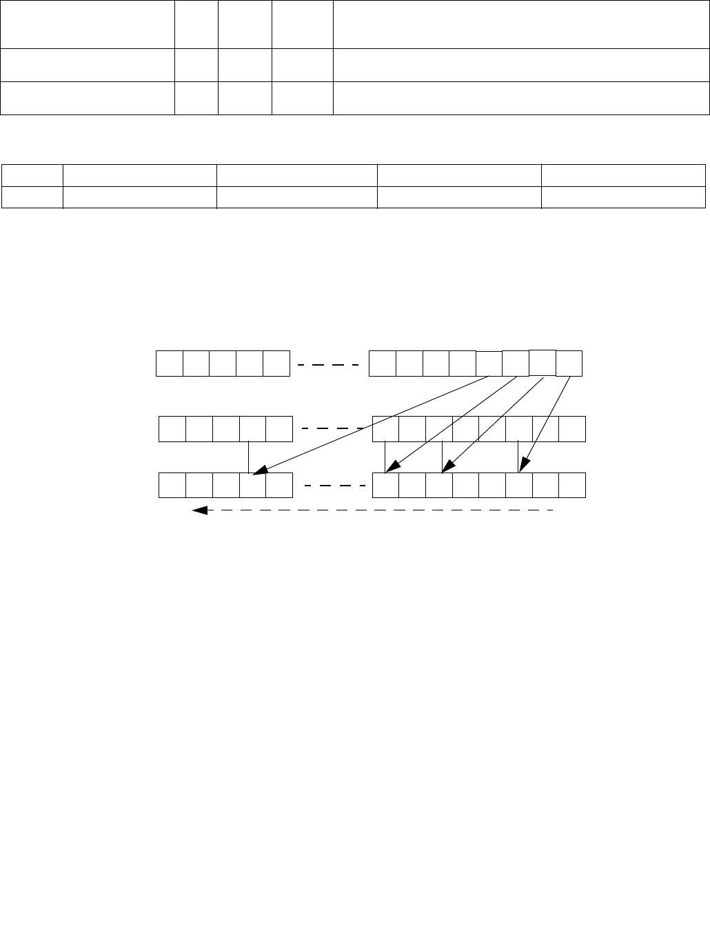
PDEP — Parallel Bits Deposit
INSTRUCTION SET REFERENCE, M-U
4-270 Vol. 2B
PDEP — Parallel Bits Deposit
Instruction Operand Encoding
Description
PDEP uses a mask in the second source operand (the third operand) to transfer/scatter contiguous low order bits
in the first source operand (the second operand) into the destination (the first operand). PDEP takes the low bits
from the first source operand and deposit them in the destination operand at the corresponding bit locations that
are set in the second source operand (mask). All other bits (bits not set in mask) in destination are set to zero.
Figure 4-8. PDEP Example
This instruction is not supported in real mode and virtual-8086 mode. The operand size is always 32 bits if not in
64-bit mode. In 64-bit mode operand size 64 requires VEX.W1. VEX.W1 is ignored in non-64-bit modes. An
attempt to execute this instruction with VEX.L not equal to 0 will cause #UD.
Operation
TEMP ← SRC1;
MASK ← SRC2;
DEST ← 0 ;
m← 0, k← 0;
DO WHILE m< OperandSize
IF MASK[ m] = 1 THEN
DEST[ m] ← TEMP[ k];
k ← k+ 1;
FI
m ← m+ 1;
OD
Opcode/
Instruction
Op/
En
64/32
-bit
Mode
CPUID
Feature
Flag
Description
VEX.NDS.LZ.F2.0F38.W0 F5 /r
PDEP r32a, r32b, r/m32
RVM V/V BMI2 Parallel deposit of bits from r32b using mask in r/m32, result is writ-
ten to r32a.
VEX.NDS.LZ.F2.0F38.W1 F5 /r
PDEP r64a, r64b, r/m64
RVM V/N.E. BMI2 Parallel deposit of bits from r64b using mask in r/m64, result is writ-
ten to r64a.
Op/En Operand 1 Operand 2 Operand 3 Operand 4
RVM ModRM:reg (w) VEX.vvvv (r) ModRM:r/m (r) NA
0010010101000
000000000
DEST
SRC1
SRC2
(mask)
S31 S30 S29 S28 S27 S7S6S5S3
S4S2S1S0
S0
S1
S2
S3
bit 0
bit 31

PDEP — Parallel Bits Deposit
INSTRUCTION SET REFERENCE, M-U
Vol. 2B 4-271
Flags Affected
None.
Intel C/C++ Compiler Intrinsic Equivalent
PDEP: unsigned __int32 _pdep_u32(unsigned __int32 src, unsigned __int32 mask);
PDEP: unsigned __int64 _pdep_u64(unsigned __int64 src, unsigned __int32 mask);
SIMD Floating-Point Exceptions
None
Other Exceptions
See Section 2.5.1, “Exception Conditions for VEX-Encoded GPR Instructions”, Table 2-29; additionally
#UD If VEX.W = 1.
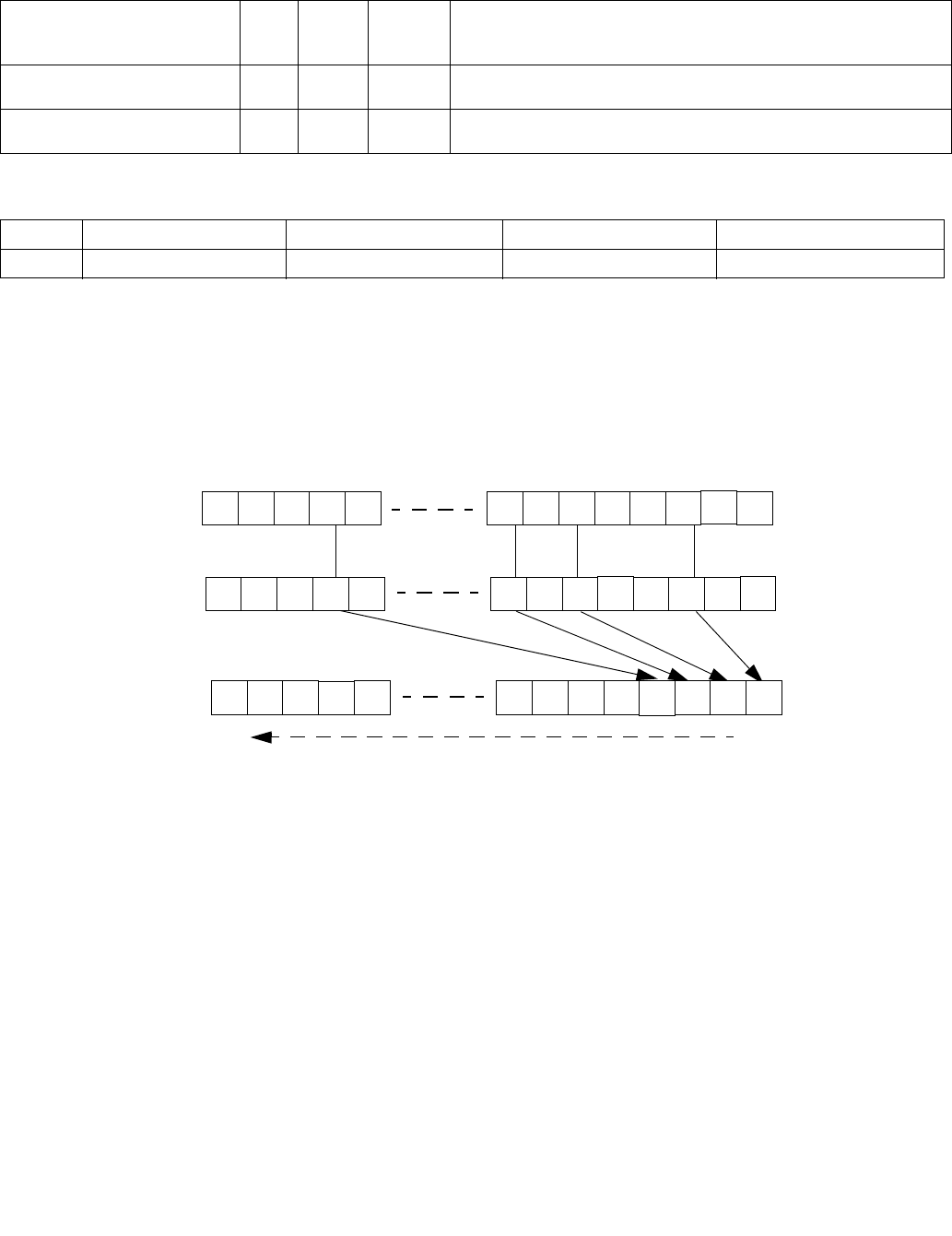
PEXT — Parallel Bits Extract
INSTRUCTION SET REFERENCE, M-U
4-272 Vol. 2B
PEXT — Parallel Bits Extract
Instruction Operand Encoding
Description
PEXT uses a mask in the second source operand (the third operand) to transfer either contiguous or non-contig-
uous bits in the first source operand (the second operand) to contiguous low order bit positions in the destination
(the first operand). For each bit set in the MASK, PEXT extracts the corresponding bits from the first source operand
and writes them into contiguous lower bits of destination operand. The remaining upper bits of destination are
zeroed.
Figure 4-9. PEXT Example
This instruction is not supported in real mode and virtual-8086 mode. The operand size is always 32 bits if not in
64-bit mode. In 64-bit mode operand size 64 requires VEX.W1. VEX.W1 is ignored in non-64-bit modes. An
attempt to execute this instruction with VEX.L not equal to 0 will cause #UD.
Operation
TEMP ← SRC1;
MASK ← SRC2;
DEST ← 0 ;
m← 0, k← 0;
DO WHILE m< OperandSize
IF MASK[ m] = 1 THEN
DEST[ k] ← TEMP[ m];
k ← k+ 1;
FI
Opcode/
Instruction
Op/
En
64/32
-bit
Mode
CPUID
Feature
Flag
Description
VEX.NDS.LZ.F3.0F38.W0 F5 /r
PEXT r32a, r32b, r/m32
RVM V/V BMI2 Parallel extract of bits from r32b using mask in r/m32, result is writ-
ten to r32a.
VEX.NDS.LZ.F3.0F38.W1 F5 /r
PEXT r64a, r64b, r/m64
RVM V/N.E. BMI2 Parallel extract of bits from r64b using mask in r/m64, result is writ-
ten to r64a.
Op/En Operand 1 Operand 2 Operand 3 Operand 4
RVM ModRM:reg (w) VEX.vvvv (r) ModRM:r/m (r) NA
DEST
SRC1
SRC2
(mask)
S31 S30 S29 S28 S27 S7S6S5S3
S4S2S1S0
001010101000
S2
S5
S7
000000000
0
S28
bit 0
bit 31

PEXT — Parallel Bits Extract
INSTRUCTION SET REFERENCE, M-U
Vol. 2B 4-273
m ← m+ 1;
OD
Flags Affected
None.
Intel C/C++ Compiler Intrinsic Equivalent
PEXT: unsigned __int32 _pext_u32(unsigned __int32 src, unsigned __int32 mask);
PEXT: unsigned __int64 _pext_u64(unsigned __int64 src, unsigned __int32 mask);
SIMD Floating-Point Exceptions
None
Other Exceptions
See Section 2.5.1, “Exception Conditions for VEX-Encoded GPR Instructions”, Table 2-29; additionally
#UD If VEX.W = 1.

PEXTRB/PEXTRD/PEXTRQ — Extract Byte/Dword/Qword
INSTRUCTION SET REFERENCE, M-U
4-274 Vol. 2B
PEXTRB/PEXTRD/PEXTRQ — Extract Byte/Dword/Qword
Instruction Operand Encoding
Description
Extract a byte/dword/qword integer value from the source XMM register at a byte/dword/qword offset determined
from imm8[3:0]. The destination can be a register or byte/dword/qword memory location. If the destination is a
register, the upper bits of the register are zero extended.
In legacy non-VEX encoded version and if the destination operand is a register, the default operand size in 64-bit
mode for PEXTRB/PEXTRD is 64 bits, the bits above the least significant byte/dword data are filled with zeros.
PEXTRQ is not encodable in non-64-bit modes and requires REX.W in 64-bit mode.
Opcode/
Instruction
Op/ En 64/32 bit
Mode
Support
CPUID
Feature
Flag
Description
66 0F 3A 14
/r ib
PEXTRB reg/m8, xmm2, imm8
MRI V/V SSE4_1 Extract a byte integer value from xmm2 at the
source byte offset specified by imm8 into reg or
m8. The upper bits of r32 or r64 are zeroed.
66 0F 3A 16
/r ib
PEXTRD r/m32, xmm2, imm8
MRI V/V SSE4_1 Extract a dword integer value from xmm2 at the
source dword offset specified by imm8 into r/m32.
66 REX.W 0F 3A 16
/r ib
PEXTRQ r/m64, xmm2, imm8
MRI V/N.E. SSE4_1 Extract a qword integer value from xmm2 at the
source qword offset specified by imm8 into r/m64.
VEX.128.66.0F3A.W0 14 /r ib
VPEXTRB reg/m8, xmm2, imm8
MRI V1/V AVX Extract a byte integer value from xmm2 at the
source byte offset specified by imm8 into reg or
m8. The upper bits of r64/r32 is filled with zeros.
VEX.128.66.0F3A.W0 16 /r ib
VPEXTRD r32/m32, xmm2, imm8
MRI V/V AVX Extract a dword integer value from xmm2 at the
source dword offset specified by imm8 into
r32/m32.
VEX.128.66.0F3A.W1 16 /r ib
VPEXTRQ r64/m64, xmm2, imm8
MRI V/i AVX Extract a qword integer value from xmm2 at the
source dword offset specified by imm8 into
r64/m64.
EVEX.128.66.0F3A.WIG 14 /r ib
VPEXTRB reg/m8, xmm2, imm8
T1S-MRI V/V AVX512BW Extract a byte integer value from xmm2 at the
source byte offset specified by imm8 into reg or
m8. The upper bits of r64/r32 is filled with zeros.
EVEX.128.66.0F3A.W0 16 /r ib
VPEXTRD r32/m32, xmm2, imm8
T1S-MRI V/V AVX512DQ Extract a dword integer value from xmm2 at the
source dword offset specified by imm8 into
r32/m32.
EVEX.128.66.0F3A.W1 16 /r ib
VPEXTRQ r64/m64, xmm2, imm8
T1S-MRI V/N.E.1
NOTES:
1. In 64-bit mode, VEX.W1 is ignored for VPEXTRB (similar to legacy REX.W=1 prefix in PEXTRB).
2. VEX.W/EVEX.W in non-64 bit is ignored; the instructions behaves as if the W0 version is used.
AVX512DQ Extract a qword integer value from xmm2 at the
source dword offset specified by imm8 into
r64/m64.
Op/En Operand 1 Operand 2 Operand 3 Operand 4
MRI ModRM:r/m (w) ModRM:reg (r) imm8 NA

PEXTRB/PEXTRD/PEXTRQ — Extract Byte/Dword/Qword
INSTRUCTION SET REFERENCE, M-U
Vol. 2B 4-275
Note: In VEX.128 encoded versions, VEX.vvvv is reserved and must be 1111b, VEX.L must be 0, otherwise the
instruction will #UD. In EVEX.128 encoded versions, EVEX.vvvv is reserved and must be 1111b, EVEX.L”L must be
0, otherwise the instruction will #UD. If the destination operand is a register, the default operand size in 64-bit
mode for VPEXTRB/VPEXTRD is 64 bits, the bits above the least significant byte/word/dword data are filled with
zeros. Attempt to execute VPEXTRQ in non-64-bit mode will cause #UD.
Operation
CASE of
PEXTRB: SEL COUNT[3:0];
TEMP (Src >> SEL*8) AND FFH;
IF (DEST = Mem8)
THEN
Mem8 TEMP[7:0];
ELSE IF (64-Bit Mode and 64-bit register selected)
THEN
R64[7:0] TEMP[7:0];
r64[63:8] ← ZERO_FILL; };
ELSE
R32[7:0] TEMP[7:0];
r32[31:8] ← ZERO_FILL; };
FI;
PEXTRD:SEL COUNT[1:0];
TEMP (Src >> SEL*32) AND FFFF_FFFFH;
DEST TEMP;
PEXTRQ: SEL COUNT[0];
TEMP (Src >> SEL*64);
DEST TEMP;
EASC:
VPEXTRTD/VPEXTRQ
IF (64-Bit Mode and 64-bit dest operand)
THEN
Src_Offset Imm8[0]
r64/m64 (Src >> Src_Offset * 64)
ELSE
Src_Offset Imm8[1:0]
r32/m32 ((Src >> Src_Offset *32) AND 0FFFFFFFFh);
FI
VPEXTRB ( dest=m8)
SRC_Offset Imm8[3:0]
Mem8 (Src >> Src_Offset*8)
VPEXTRB ( dest=reg)
IF (64-Bit Mode )
THEN
SRC_Offset Imm8[3:0]
DEST[7:0] ((Src >> Src_Offset*8) AND 0FFh)
DEST[63:8] ZERO_FILL;
ELSE
SRC_Offset . Imm8[3:0];
DEST[7:0] ((Src >> Src_Offset*8) AND 0FFh);
DEST[31:8] ZERO_FILL;
FI

PEXTRB/PEXTRD/PEXTRQ — Extract Byte/Dword/Qword
INSTRUCTION SET REFERENCE, M-U
4-276 Vol. 2B
Intel C/C++ Compiler Intrinsic Equivalent
PEXTRB: int _mm_extract_epi8 (__m128i src, const int ndx);
PEXTRD: int _mm_extract_epi32 (__m128i src, const int ndx);
PEXTRQ: __int64 _mm_extract_epi64 (__m128i src, const int ndx);
Flags Affected
None.
SIMD Floating-Point Exceptions
None.
Other Exceptions
Non-EVEX-encoded instruction, see Exceptions Type 5;
EVEX-encoded instruction, see Exceptions Type E9NF.
#UD If VEX.L = 1 or EVEX.L’L > 0.
If VEX.vvvv != 1111B or EVEX.vvvv != 1111B.
If VPEXTRQ in non-64-bit mode, VEX.W=1.

PEXTRW—Extract Word
INSTRUCTION SET REFERENCE, M-U
Vol. 2B 4-277
PEXTRW—Extract Word
Instruction Operand Encoding
Description
Copies the word in the source operand (second operand) specified by the count operand (third operand) to the
destination operand (first operand). The source operand can be an MMX technology register or an XMM register.
The destination operand can be the low word of a general-purpose register or a 16-bit memory address. The count
operand is an 8-bit immediate. When specifying a word location in an MMX technology register, the 2 least-signifi-
cant bits of the count operand specify the location; for an XMM register, the 3 least-significant bits specify the loca-
tion. The content of the destination register above bit 16 is cleared (set to all 0s).
In 64-bit mode, using a REX prefix in the form of REX.R permits this instruction to access additional registers
(XMM8-XMM15, R8-15). If the destination operand is a general-purpose register, the default operand size is 64-bits
in 64-bit mode.
Opcode/
Instruction
Op/
En
64/32 bit
Mode
Support
CPUID
Feature
Flag
Description
0F C5 /r ib1
PEXTRW reg, mm, imm8
RMI V/V SSE Extract the word specified by imm8 from mm
and move it to reg, bits 15-0. The upper bits of
r32 or r64 is zeroed.
66 0F C5 /r ib
PEXTRW reg, xmm, imm8
RMI V/V SSE2 Extract the word specified by imm8 from xmm
and move it to reg, bits 15-0. The upper bits of
r32 or r64 is zeroed.
66 0F 3A 15
/r ib
PEXTRW reg/m16, xmm, imm8
MRI V/V SSE4_1 Extract the word specified by imm8 from xmm
and copy it to lowest 16 bits of reg or m16.
Zero-extend the result in the destination, r32
or r64.
VEX.128.66.0F.W0 C5 /r ib
VPEXTRW reg, xmm1, imm8
RMI V2/V AVX Extract the word specified by imm8 from
xmm1 and move it to reg, bits 15:0. Zero-
extend the result. The upper bits of r64/r32 is
filled with zeros.
VEX.128.66.0F3A.W0 15 /r ib
VPEXTRW reg/m16, xmm2, imm8
MRI V/V AVX Extract a word integer value from xmm2 at
the source word offset specified by imm8 into
reg or m16. The upper bits of r64/r32 is filled
with zeros.
EVEX.128.66.0F.WIG C5 /r ib
VPEXTRW reg, xmm1, imm8
RMI V/V AVX512B
W
Extract the word specified by imm8 from
xmm1 and move it to reg, bits 15:0. Zero-
extend the result. The upper bits of r64/r32 is
filled with zeros.
EVEX.128.66.0F3A.WIG 15 /r ib
VPEXTRW reg/m16, xmm2, imm8
T1S-
MRI
V/V AVX512B
W
Extract a word integer value from xmm2 at
the source word offset specified by imm8 into
reg or m16. The upper bits of r64/r32 is filled
with zeros.
NOTES:
1. See note in Section 2.4, “AVX and SSE Instruction Exception Specification” in the Intel® 64 and IA-32 Architectures Software
Developer’s Manual, Volume 2A and Section 22.25.3, “Exception Conditions of Legacy SIMD Instructions Operating on MMX Registers”
in the Intel® 64 and IA-32 Architectures Software Developer’s Manual, Volume 3A.
2. In 64-bit mode, VEX.W1 is ignored for VPEXTRW (similar to legacy REX.W=1 prefix in PEXTRW).
Op/En Operand 1 Operand 2 Operand 3 Operand 4
RMI ModRM:reg (w) ModRM:r/m (r) imm8 NA
MRI ModRM:r/m (w) ModRM:reg (r) imm8 NA

PEXTRW—Extract Word
INSTRUCTION SET REFERENCE, M-U
4-278 Vol. 2B
Note: In VEX.128 encoded versions, VEX.vvvv is reserved and must be 1111b, VEX.L must be 0, otherwise the
instruction will #UD. In EVEX.128 encoded versions, EVEX.vvvv is reserved and must be 1111b, EVEX.L must be 0,
otherwise the instruction will #UD. If the destination operand is a register, the default operand size in 64-bit mode
for VPEXTRW is 64 bits, the bits above the least significant byte/word/dword data are filled with zeros.
Operation
IF (DEST = Mem16)
THEN
SEL COUNT[2:0];
TEMP (Src >> SEL*16) AND FFFFH;
Mem16 TEMP[15:0];
ELSE IF (64-Bit Mode and destination is a general-purpose register)
THEN
FOR (PEXTRW instruction with 64-bit source operand)
{SEL ← COUNT[1:0];
TEMP ← (SRC >> (SEL ∗ 16)) AND FFFFH;
r64[15:0] ← TEMP[15:0];
r64[63:16] ← ZERO_FILL; };
FOR (PEXTRW instruction with 128-bit source operand)
{SEL ← COUNT[2:0];
TEMP ← (SRC >> (SEL ∗ 16)) AND FFFFH;
r64[15:0] ← TEMP[15:0];
r64[63:16] ← ZERO_FILL; }
ELSE
FOR (PEXTRW instruction with 64-bit source operand)
{SEL ← COUNT[1:0];
TEMP ← (SRC >> (SEL ∗ 16)) AND FFFFH;
r32[15:0] ← TEMP[15:0];
r32[31:16] ← ZERO_FILL; };
FOR (PEXTRW instruction with 128-bit source operand)
{SEL ← COUNT[2:0];
TEMP ← (SRC >> (SEL ∗ 16)) AND FFFFH;
r32[15:0] ← TEMP[15:0];
r32[31:16] ← ZERO_FILL; };
FI;
FI;
VPEXTRW ( dest=m16)
SRC_Offset Imm8[2:0]
Mem16 (Src >> Src_Offset*16)
VPEXTRW ( dest=reg)
IF (64-Bit Mode )
THEN
SRC_Offset Imm8[2:0]
DEST[15:0] ((Src >> Src_Offset*16) AND 0FFFFh)
DEST[63:16] ZERO_FILL;
ELSE
SRC_Offset Imm8[2:0]
DEST[15:0] ((Src >> Src_Offset*16) AND 0FFFFh)
DEST[31:16] ZERO_FILL;
FI

PEXTRW—Extract Word
INSTRUCTION SET REFERENCE, M-U
Vol. 2B 4-279
Intel C/C++ Compiler Intrinsic Equivalent
PEXTRW: int _mm_extract_pi16 (__m64 a, int n)
PEXTRW: int _mm_extract_epi16 ( __m128i a, int imm)
Flags Affected
None.
Numeric Exceptions
None.
Other Exceptions
Non-EVEX-encoded instruction, see Exceptions Type 5;
EVEX-encoded instruction, see Exceptions Type E9NF.
#UD If VEX.L = 1 or EVEX.L’L > 0.
If VEX.vvvv != 1111B or EVEX.vvvv != 1111B.

PHADDW/PHADDD — Packed Horizontal Add
INSTRUCTION SET REFERENCE, M-U
4-280 Vol. 2B
PHADDW/PHADDD — Packed Horizontal Add
Instruction Operand Encoding
Description
(V)PHADDW adds two adjacent 16-bit signed integers horizontally from the source and destination operands and
packs the 16-bit signed results to the destination operand (first operand). (V)PHADDD adds two adjacent 32-bit
signed integers horizontally from the source and destination operands and packs the 32-bit signed results to the
destination operand (first operand). When the source operand is a 128-bit memory operand, the operand must be
aligned on a 16-byte boundary or a general-protection exception (#GP) will be generated.
Note that these instructions can operate on either unsigned or signed (two’s complement notation) integers;
however, it does not set bits in the EFLAGS register to indicate overflow and/or a carry. To prevent undetected over-
flow conditions, software must control the ranges of the values operated on.
Legacy SSE instructions: Both operands can be MMX registers. The second source operand can be an MMX register
or a 64-bit memory location.
128-bit Legacy SSE version: The first source and destination operands are XMM registers. The second source
operand can be an XMM register or a 128-bit memory location. Bits (VLMAX-1:128) of the corresponding YMM
destination register remain unchanged.
In 64-bit mode, use the REX prefix to access additional registers.
Opcode/
Instruction
Op/
En
64/32 bit
Mode
Support
CPUID
Feature
Flag
Description
0F 38 01 /r1
PHADDW mm1, mm2/m64
RM V/V SSSE3 Add 16-bit integers horizontally, pack to mm1.
66 0F 38 01 /r
PHADDW xmm1, xmm2/m128
RM V/V SSSE3 Add 16-bit integers horizontally, pack to
xmm1.
0F 38 02 /r
PHADDD mm1, mm2/m64
RM V/V SSSE3 Add 32-bit integers horizontally, pack to mm1.
66 0F 38 02 /r
PHADDD xmm1, xmm2/m128
RM V/V SSSE3 Add 32-bit integers horizontally, pack to
xmm1.
VEX.NDS.128.66.0F38.WIG 01 /r
VPHADDW xmm1, xmm2, xmm3/m128
RVM V/V AVX Add 16-bit integers horizontally, pack to
xmm1.
VEX.NDS.128.66.0F38.WIG 02 /r
VPHADDD xmm1, xmm2, xmm3/m128
RVM V/V AVX Add 32-bit integers horizontally, pack to
xmm1.
VEX.NDS.256.66.0F38.WIG 01 /r
VPHADDW ymm1, ymm2, ymm3/m256
RVM V/V AVX2 Add 16-bit signed integers horizontally, pack
to ymm1.
VEX.NDS.256.66.0F38.WIG 02 /r
VPHADDD ymm1, ymm2, ymm3/m256
RVM V/V AVX2 Add 32-bit signed integers horizontally, pack
to ymm1.
NOTES:
1. See note in Section 2.4, “AVX and SSE Instruction Exception Specification” in the Intel® 64 and IA-32 Architectures Software
Developer’s Manual, Volume 2A and Section 22.25.3, “Exception Conditions of Legacy SIMD Instructions Operating on MMX Registers”
in the Intel® 64 and IA-32 Architectures Software Developer’s Manual, Volume 3A.
Op/En Operand 1 Operand 2 Operand 3 Operand 4
RM ModRM:reg (r, w) ModRM:r/m (r) NA NA
RVM ModRM:reg (w) VEX.vvvv (r) ModRM:r/m (r) NA
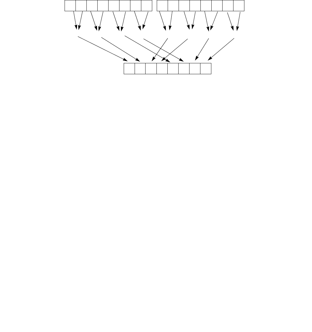
PHADDW/PHADDD — Packed Horizontal Add
INSTRUCTION SET REFERENCE, M-U
Vol. 2B 4-281
VEX.128 encoded version: The first source and destination operands are XMM registers. The second source
operand can be an XMM register or a 128-bit memory location. Bits (VLMAX-1:128) of the corresponding YMM
register are zeroed.
VEX.256 encoded version: Horizontal addition of two adjacent data elements of the low 16-bytes of the first and
second source operands are packed into the low 16-bytes of the destination operand. Horizontal addition of two
adjacent data elements of the high 16-bytes of the first and second source operands are packed into the high 16-
bytes of the destination operand. The first source and destination operands are YMM registers. The second source
operand can be an YMM register or a 256-bit memory location.
Note: VEX.L must be 0, otherwise the instruction will #UD.
Figure 4-10. 256-bit VPHADDD Instruction Operation
Operation
PHADDW (with 64-bit operands)
mm1[15-0] = mm1[31-16] + mm1[15-0];
mm1[31-16] = mm1[63-48] + mm1[47-32];
mm1[47-32] = mm2/m64[31-16] + mm2/m64[15-0];
mm1[63-48] = mm2/m64[63-48] + mm2/m64[47-32];
PHADDW (with 128-bit operands)
xmm1[15-0] = xmm1[31-16] + xmm1[15-0];
xmm1[31-16] = xmm1[63-48] + xmm1[47-32];
xmm1[47-32] = xmm1[95-80] + xmm1[79-64];
xmm1[63-48] = xmm1[127-112] + xmm1[111-96];
xmm1[79-64] = xmm2/m128[31-16] + xmm2/m128[15-0];
xmm1[95-80] = xmm2/m128[63-48] + xmm2/m128[47-32];
xmm1[111-96] = xmm2/m128[95-80] + xmm2/m128[79-64];
xmm1[127-112] = xmm2/m128[127-112] + xmm2/m128[111-96];
VPHADDW (VEX.128 encoded version)
DEST[15:0] SRC1[31:16] + SRC1[15:0]
DEST[31:16] SRC1[63:48] + SRC1[47:32]
DEST[47:32] SRC1[95:80] + SRC1[79:64]
DEST[63:48] SRC1[127:112] + SRC1[111:96]
DEST[79:64] SRC2[31:16] + SRC2[15:0]
DEST[95:80] SRC2[63:48] + SRC2[47:32]
DEST[111:96] SRC2[95:80] + SRC2[79:64]
DEST[127:112] SRC2[127:112] + SRC2[111:96]
DEST[VLMAX-1:128] 0
X0X3 X2 X1
Y0Y3 Y2 Y1 X4X7 X6 X5
Y4Y7 Y6 Y5
SRC2
S0
Dest
S3S4
0
255
SRC1
S7 S2 S1S3 S3

PHADDW/PHADDD — Packed Horizontal Add
INSTRUCTION SET REFERENCE, M-U
4-282 Vol. 2B
VPHADDW (VEX.256 encoded version)
DEST[15:0] SRC1[31:16] + SRC1[15:0]
DEST[31:16] SRC1[63:48] + SRC1[47:32]
DEST[47:32] SRC1[95:80] + SRC1[79:64]
DEST[63:48] SRC1[127:112] + SRC1[111:96]
DEST[79:64] SRC2[31:16] + SRC2[15:0]
DEST[95:80] SRC2[63:48] + SRC2[47:32]
DEST[111:96] SRC2[95:80] + SRC2[79:64]
DEST[127:112] SRC2[127:112] + SRC2[111:96]
DEST[143:128] SRC1[159:144] + SRC1[143:128]
DEST[159:144] SRC1[191:176] + SRC1[175:160]
DEST[175:160] SRC1[223:208] + SRC1[207:192]
DEST[191:176] SRC1[255:240] + SRC1[239:224]
DEST[207:192] SRC2[127:112] + SRC2[143:128]
DEST[223:208] SRC2[159:144] + SRC2[175:160]
DEST[239:224] SRC2[191:176] + SRC2[207:192]
DEST[255:240] SRC2[223:208] + SRC2[239:224]
PHADDD (with 64-bit operands)
mm1[31-0] = mm1[63-32] + mm1[31-0];
mm1[63-32] = mm2/m64[63-32] + mm2/m64[31-0];
PHADDD (with 128-bit operands)
xmm1[31-0] = xmm1[63-32] + xmm1[31-0];
xmm1[63-32] = xmm1[127-96] + xmm1[95-64];
xmm1[95-64] = xmm2/m128[63-32] + xmm2/m128[31-0];
xmm1[127-96] = xmm2/m128[127-96] + xmm2/m128[95-64];
VPHADDD (VEX.128 encoded version)
DEST[31-0] SRC1[63-32] + SRC1[31-0]
DEST[63-32] SRC1[127-96] + SRC1[95-64]
DEST[95-64] SRC2[63-32] + SRC2[31-0]
DEST[127-96] SRC2[127-96] + SRC2[95-64]
DEST[VLMAX-1:128] 0
VPHADDD (VEX.256 encoded version)
DEST[31-0] SRC1[63-32] + SRC1[31-0]
DEST[63-32] SRC1[127-96] + SRC1[95-64]
DEST[95-64] SRC2[63-32] + SRC2[31-0]
DEST[127-96] SRC2[127-96] + SRC2[95-64]
DEST[159-128] SRC1[191-160] + SRC1[159-128]
DEST[191-160] SRC1[255-224] + SRC1[223-192]
DEST[223-192] SRC2[191-160] + SRC2[159-128]
DEST[255-224] SRC2[255-224] + SRC2[223-192]
Intel C/C++ Compiler Intrinsic Equivalents
PHADDW: __m64 _mm_hadd_pi16 (__m64 a, __m64 b)
PHADDD: __m64 _mm_hadd_pi32 (__m64 a, __m64 b)
(V)PHADDW: __m128i _mm_hadd_epi16 (__m128i a, __m128i b)
(V)PHADDD: __m128i _mm_hadd_epi32 (__m128i a, __m128i b)
VPHADDW: __m256i _mm256_hadd_epi16 (__m256i a, __m256i b)
VPHADDD: __m256i _mm256_hadd_epi32 (__m256i a, __m256i b)

PHADDW/PHADDD — Packed Horizontal Add
INSTRUCTION SET REFERENCE, M-U
Vol. 2B 4-283
SIMD Floating-Point Exceptions
None.
Other Exceptions
See Exceptions Type 4; additionally
#UD If VEX.L = 1.

PHADDSW — Packed Horizontal Add and Saturate
INSTRUCTION SET REFERENCE, M-U
4-284 Vol. 2B
PHADDSW — Packed Horizontal Add and Saturate
Instruction Operand Encoding
Description
(V)PHADDSW adds two adjacent signed 16-bit integers horizontally from the source and destination operands and
saturates the signed results; packs the signed, saturated 16-bit results to the destination operand (first operand)
When the source operand is a 128-bit memory operand, the operand must be aligned on a 16-byte boundary or a
general-protection exception (#GP) will be generated.
Legacy SSE version: Both operands can be MMX registers. The second source operand can be an MMX register or a
64-bit memory location.
128-bit Legacy SSE version: The first source and destination operands are XMM registers. The second source
operand is an XMM register or a 128-bit memory location. Bits (VLMAX-1:128) of the corresponding YMM destina-
tion register remain unchanged.
In 64-bit mode, use the REX prefix to access additional registers.
VEX.128 encoded version: The first source and destination operands are XMM registers. The second source
operand is an XMM register or a 128-bit memory location. Bits (VLMAX-1:128) of the destination YMM register are
zeroed.
VEX.256 encoded version: The first source and destination operands are YMM registers. The second source
operand can be an YMM register or a 256-bit memory location.
Note: VEX.L must be 0, otherwise the instruction will #UD.
Operation
PHADDSW (with 64-bit operands)
mm1[15-0] = SaturateToSignedWord((mm1[31-16] + mm1[15-0]);
mm1[31-16] = SaturateToSignedWord(mm1[63-48] + mm1[47-32]);
mm1[47-32] = SaturateToSignedWord(mm2/m64[31-16] + mm2/m64[15-0]);
mm1[63-48] = SaturateToSignedWord(mm2/m64[63-48] + mm2/m64[47-32]);
Opcode/
Instruction
Op/
En
64/32 bit
Mode
Support
CPUID
Feature
Flag
Description
0F 38 03 /r1
PHADDSW mm1, mm2/m64
RM V/V SSSE3 Add 16-bit signed integers horizontally, pack
saturated integers to mm1.
66 0F 38 03 /r
PHADDSW xmm1, xmm2/m128
RM V/V SSSE3 Add 16-bit signed integers horizontally, pack
saturated integers to xmm1.
VEX.NDS.128.66.0F38.WIG 03 /r
VPHADDSW xmm1, xmm2, xmm3/m128
RVM V/V AVX Add 16-bit signed integers horizontally, pack
saturated integers to xmm1.
VEX.NDS.256.66.0F38.WIG 03 /r
VPHADDSW ymm1, ymm2, ymm3/m256
RVM V/V AVX2 Add 16-bit signed integers horizontally, pack
saturated integers to ymm1.
NOTES:
1. See note in Section 2.4, “AVX and SSE Instruction Exception Specification” in the Intel® 64 and IA-32 Architectures Software
Developer’s Manual, Volume 2A and Section 22.25.3, “Exception Conditions of Legacy SIMD Instructions Operating on MMX Registers”
in the Intel® 64 and IA-32 Architectures Software Developer’s Manual, Volume 3A.
Op/En Operand 1 Operand 2 Operand 3 Operand 4
RM ModRM:reg (r, w) ModRM:r/m (r) NA NA
RVM ModRM:reg (w) VEX.vvvv (r) ModRM:r/m (r) NA

PHADDSW — Packed Horizontal Add and Saturate
INSTRUCTION SET REFERENCE, M-U
Vol. 2B 4-285
PHADDSW (with 128-bit operands)
xmm1[15-0]= SaturateToSignedWord(xmm1[31-16] + xmm1[15-0]);
xmm1[31-16] = SaturateToSignedWord(xmm1[63-48] + xmm1[47-32]);
xmm1[47-32] = SaturateToSignedWord(xmm1[95-80] + xmm1[79-64]);
xmm1[63-48] = SaturateToSignedWord(xmm1[127-112] + xmm1[111-96]);
xmm1[79-64] = SaturateToSignedWord(xmm2/m128[31-16] + xmm2/m128[15-0]);
xmm1[95-80] = SaturateToSignedWord(xmm2/m128[63-48] + xmm2/m128[47-32]);
xmm1[111-96] = SaturateToSignedWord(xmm2/m128[95-80] + xmm2/m128[79-64]);
xmm1[127-112] = SaturateToSignedWord(xmm2/m128[127-112] + xmm2/m128[111-96]);
VPHADDSW (VEX.128 encoded version)
DEST[15:0]= SaturateToSignedWord(SRC1[31:16] + SRC1[15:0])
DEST[31:16] = SaturateToSignedWord(SRC1[63:48] + SRC1[47:32])
DEST[47:32] = SaturateToSignedWord(SRC1[95:80] + SRC1[79:64])
DEST[63:48] = SaturateToSignedWord(SRC1[127:112] + SRC1[111:96])
DEST[79:64] = SaturateToSignedWord(SRC2[31:16] + SRC2[15:0])
DEST[95:80] = SaturateToSignedWord(SRC2[63:48] + SRC2[47:32])
DEST[111:96] = SaturateToSignedWord(SRC2[95:80] + SRC2[79:64])
DEST[127:112] = SaturateToSignedWord(SRC2[127:112] + SRC2[111:96])
DEST[VLMAX-1:128] 0
VPHADDSW (VEX.256 encoded version)
DEST[15:0]= SaturateToSignedWord(SRC1[31:16] + SRC1[15:0])
DEST[31:16] = SaturateToSignedWord(SRC1[63:48] + SRC1[47:32])
DEST[47:32] = SaturateToSignedWord(SRC1[95:80] + SRC1[79:64])
DEST[63:48] = SaturateToSignedWord(SRC1[127:112] + SRC1[111:96])
DEST[79:64] = SaturateToSignedWord(SRC2[31:16] + SRC2[15:0])
DEST[95:80] = SaturateToSignedWord(SRC2[63:48] + SRC2[47:32])
DEST[111:96] = SaturateToSignedWord(SRC2[95:80] + SRC2[79:64])
DEST[127:112] = SaturateToSignedWord(SRC2[127:112] + SRC2[111:96])
DEST[143:128]= SaturateToSignedWord(SRC1[159:144] + SRC1[143:128])
DEST[159:144] = SaturateToSignedWord(SRC1[191:176] + SRC1[175:160])
DEST[175:160] = SaturateToSignedWord( SRC1[223:208] + SRC1[207:192])
DEST[191:176] = SaturateToSignedWord(SRC1[255:240] + SRC1[239:224])
DEST[207:192] = SaturateToSignedWord(SRC2[127:112] + SRC2[143:128])
DEST[223:208] = SaturateToSignedWord(SRC2[159:144] + SRC2[175:160])
DEST[239:224] = SaturateToSignedWord(SRC2[191-160] + SRC2[159-128])
DEST[255:240] = SaturateToSignedWord(SRC2[255:240] + SRC2[239:224])
Intel C/C++ Compiler Intrinsic Equivalent
PHADDSW: __m64 _mm_hadds_pi16 (__m64 a, __m64 b)
(V)PHADDSW: __m128i _mm_hadds_epi16 (__m128i a, __m128i b)
VPHADDSW: __m256i _mm256_hadds_epi16 (__m256i a, __m256i b)
SIMD Floating-Point Exceptions
None.
Other Exceptions
See Exceptions Type 4; additionally
#UD If VEX.L = 1.

PHMINPOSUW — Packed Horizontal Word Minimum
INSTRUCTION SET REFERENCE, M-U
4-286 Vol. 2B
PHMINPOSUW — Packed Horizontal Word Minimum
Instruction Operand Encoding
Description
Determine the minimum unsigned word value in the source operand (second operand) and place the unsigned
word in the low word (bits 0-15) of the destination operand (first operand). The word index of the minimum value
is stored in bits 16-18 of the destination operand. The remaining upper bits of the destination are set to zero.
128-bit Legacy SSE version: Bits (VLMAX-1:128) of the corresponding YMM destination register remain
unchanged.
VEX.128 encoded version: Bits (VLMAX-1:128) of the destination YMM register are zeroed. VEX.vvvv is reserved
and must be 1111b, VEX.L must be 0, otherwise the instruction will #UD.
Operation
PHMINPOSUW (128-bit Legacy SSE version)
INDEX 0;
MIN SRC[15:0]
IF (SRC[31:16] < MIN)
THEN INDEX 1; MIN SRC[31:16]; FI;
IF (SRC[47:32] < MIN)
THEN INDEX 2; MIN SRC[47:32]; FI;
* Repeat operation for words 3 through 6
IF (SRC[127:112] < MIN)
THEN INDEX 7; MIN SRC[127:112]; FI;
DEST[15:0] MIN;
DEST[18:16] INDEX;
DEST[127:19] 0000000000000000000000000000H;
Opcode/
Instruction
Op/
En
64/32 bit
Mode
Support
CPUID
Feature
Flag
Description
66 0F 38 41 /r
PHMINPOSUW xmm1, xmm2/m128
RM V/V SSE4_1 Find the minimum unsigned word in
xmm2/m128 and place its value in the low
word of xmm1 and its index in the second-
lowest word of xmm1.
VEX.128.66.0F38.WIG 41 /r
VPHMINPOSUW xmm1, xmm2/m128
RM V/V AVX Find the minimum unsigned word in
xmm2/m128 and place its value in the low
word of xmm1 and its index in the second-
lowest word of xmm1.
Op/En Operand 1 Operand 2 Operand 3 Operand 4
RM ModRM:reg (w) ModRM:r/m (r) NA NA

PHMINPOSUW — Packed Horizontal Word Minimum
INSTRUCTION SET REFERENCE, M-U
Vol. 2B 4-287
VPHMINPOSUW (VEX.128 encoded version)
INDEX 0
MIN SRC[15:0]
IF (SRC[31:16] < MIN) THEN INDEX 1; MIN SRC[31:16]
IF (SRC[47:32] < MIN) THEN INDEX 2; MIN SRC[47:32]
* Repeat operation for words 3 through 6
IF (SRC[127:112] < MIN) THEN INDEX 7; MIN SRC[127:112]
DEST[15:0] MIN
DEST[18:16] INDEX
DEST[127:19] 0000000000000000000000000000H
DEST[VLMAX-1:128] 0
Intel C/C++ Compiler Intrinsic Equivalent
PHMINPOSUW: __m128i _mm_minpos_epu16( __m128i packed_words);
Flags Affected
None.
SIMD Floating-Point Exceptions
None.
Other Exceptions
See Exceptions Type 4; additionally
#UD If VEX.L = 1.
If VEX.vvvv ≠ 1111B.

PHSUBW/PHSUBD — Packed Horizontal Subtract
INSTRUCTION SET REFERENCE, M-U
4-288 Vol. 2B
PHSUBW/PHSUBD — Packed Horizontal Subtract
Instruction Operand Encoding
Description
(V)PHSUBW performs horizontal subtraction on each adjacent pair of 16-bit signed integers by subtracting the
most significant word from the least significant word of each pair in the source and destination operands, and packs
the signed 16-bit results to the destination operand (first operand). (V)PHSUBD performs horizontal subtraction on
each adjacent pair of 32-bit signed integers by subtracting the most significant doubleword from the least signifi-
cant doubleword of each pair, and packs the signed 32-bit result to the destination operand. When the source
operand is a 128-bit memory operand, the operand must be aligned on a 16-byte boundary or a general-protection
exception (#GP) will be generated.
Legacy SSE version: Both operands can be MMX registers. The second source operand can be an MMX register or a
64-bit memory location.
128-bit Legacy SSE version: The first source and destination operands are XMM registers. The second source
operand is an XMM register or a 128-bit memory location. Bits (VLMAX-1:128) of the corresponding YMM destina-
tion register remain unchanged.
In 64-bit mode, use the REX prefix to access additional registers.
VEX.128 encoded version: The first source and destination operands are XMM registers. The second source
operand is an XMM register or a 128-bit memory location. Bits (VLMAX-1:128) of the destination YMM register are
zeroed.
Opcode/
Instruction
Op/
En
64/32 bit
Mode
Support
CPUID
Feature
Flag
Description
0F 38 05 /r1
PHSUBW mm1, mm2/m64
RM V/V SSSE3 Subtract 16-bit signed integers horizontally,
pack to mm1.
66 0F 38 05 /r
PHSUBW xmm1, xmm2/m128
RM V/V SSSE3 Subtract 16-bit signed integers horizontally,
pack to xmm1.
0F 38 06 /r
PHSUBD mm1, mm2/m64
RM V/V SSSE3 Subtract 32-bit signed integers horizontally,
pack to mm1.
66 0F 38 06 /r
PHSUBD xmm1, xmm2/m128
RM V/V SSSE3 Subtract 32-bit signed integers horizontally,
pack to xmm1.
VEX.NDS.128.66.0F38.WIG 05 /r
VPHSUBW xmm1, xmm2, xmm3/m128
RVM V/V AVX Subtract 16-bit signed integers horizontally,
pack to xmm1.
VEX.NDS.128.66.0F38.WIG 06 /r
VPHSUBD xmm1, xmm2, xmm3/m128
RVM V/V AVX Subtract 32-bit signed integers horizontally,
pack to xmm1.
VEX.NDS.256.66.0F38.WIG 05 /r
VPHSUBW ymm1, ymm2, ymm3/m256
RVM V/V AVX2 Subtract 16-bit signed integers horizontally,
pack to ymm1.
VEX.NDS.256.66.0F38.WIG 06 /r
VPHSUBD ymm1, ymm2, ymm3/m256
RVM V/V AVX2 Subtract 32-bit signed integers horizontally,
pack to ymm1.
NOTES:
1. See note in Section 2.4, “AVX and SSE Instruction Exception Specification” in the Intel® 64 and IA-32 Architectures Software
Developer’s Manual, Volume 2A and Section 22.25.3, “Exception Conditions of Legacy SIMD Instructions Operating on MMX Registers”
in the Intel® 64 and IA-32 Architectures Software Developer’s Manual, Volume 3A.
Op/En Operand 1 Operand 2 Operand 3 Operand 4
RM ModRM:reg (r, w) ModRM:r/m (r) NA NA
RVM ModRM:reg (r, w) VEX.vvvv (r) ModRM:r/m (r) NA

PHSUBW/PHSUBD — Packed Horizontal Subtract
INSTRUCTION SET REFERENCE, M-U
Vol. 2B 4-289
VEX.256 encoded version: The first source and destination operands are YMM registers. The second source
operand can be an YMM register or a 256-bit memory location.
Note: VEX.L must be 0, otherwise the instruction will #UD.
Operation
PHSUBW (with 64-bit operands)
mm1[15-0] = mm1[15-0] - mm1[31-16];
mm1[31-16] = mm1[47-32] - mm1[63-48];
mm1[47-32] = mm2/m64[15-0] - mm2/m64[31-16];
mm1[63-48] = mm2/m64[47-32] - mm2/m64[63-48];
PHSUBW (with 128-bit operands)
xmm1[15-0] = xmm1[15-0] - xmm1[31-16];
xmm1[31-16] = xmm1[47-32] - xmm1[63-48];
xmm1[47-32] = xmm1[79-64] - xmm1[95-80];
xmm1[63-48] = xmm1[111-96] - xmm1[127-112];
xmm1[79-64] = xmm2/m128[15-0] - xmm2/m128[31-16];
xmm1[95-80] = xmm2/m128[47-32] - xmm2/m128[63-48];
xmm1[111-96] = xmm2/m128[79-64] - xmm2/m128[95-80];
xmm1[127-112] = xmm2/m128[111-96] - xmm2/m128[127-112];
VPHSUBW (VEX.128 encoded version)
DEST[15:0] SRC1[15:0] - SRC1[31:16]
DEST[31:16] SRC1[47:32] - SRC1[63:48]
DEST[47:32] SRC1[79:64] - SRC1[95:80]
DEST[63:48] SRC1[111:96] - SRC1[127:112]
DEST[79:64] SRC2[15:0] - SRC2[31:16]
DEST[95:80] SRC2[47:32] - SRC2[63:48]
DEST[111:96] SRC2[79:64] - SRC2[95:80]
DEST[127:112] SRC2[111:96] - SRC2[127:112]
DEST[VLMAX-1:128] 0
VPHSUBW (VEX.256 encoded version)
DEST[15:0] SRC1[15:0] - SRC1[31:16]
DEST[31:16] SRC1[47:32] - SRC1[63:48]
DEST[47:32] SRC1[79:64] - SRC1[95:80]
DEST[63:48] SRC1[111:96] - SRC1[127:112]
DEST[79:64] SRC2[15:0] - SRC2[31:16]
DEST[95:80] SRC2[47:32] - SRC2[63:48]
DEST[111:96] SRC2[79:64] - SRC2[95:80]
DEST[127:112] SRC2[111:96] - SRC2[127:112]
DEST[143:128] SRC1[143:128] - SRC1[159:144]
DEST[159:144] SRC1[175:160] - SRC1[191:176]
DEST[175:160] SRC1[207:192] - SRC1[223:208]
DEST[191:176] SRC1[239:224] - SRC1[255:240]
DEST[207:192] SRC2[143:128] - SRC2[159:144]
DEST[223:208] SRC2[175:160] - SRC2[191:176]
DEST[239:224] SRC2[207:192] - SRC2[223:208]
DEST[255:240] SRC2[239:224] - SRC2[255:240]
PHSUBD (with 64-bit operands)
mm1[31-0] = mm1[31-0] - mm1[63-32];
mm1[63-32] = mm2/m64[31-0] - mm2/m64[63-32];

PHSUBW/PHSUBD — Packed Horizontal Subtract
INSTRUCTION SET REFERENCE, M-U
4-290 Vol. 2B
PHSUBD (with 128-bit operands)
xmm1[31-0] = xmm1[31-0] - xmm1[63-32];
xmm1[63-32] = xmm1[95-64] - xmm1[127-96];
xmm1[95-64] = xmm2/m128[31-0] - xmm2/m128[63-32];
xmm1[127-96] = xmm2/m128[95-64] - xmm2/m128[127-96];
VPHSUBD (VEX.128 encoded version)
DEST[31-0] SRC1[31-0] - SRC1[63-32]
DEST[63-32] SRC1[95-64] - SRC1[127-96]
DEST[95-64] SRC2[31-0] - SRC2[63-32]
DEST[127-96] SRC2[95-64] - SRC2[127-96]
DEST[VLMAX-1:128] 0
VPHSUBD (VEX.256 encoded version)
DEST[31:0] SRC1[31:0] - SRC1[63:32]
DEST[63:32] SRC1[95:64] - SRC1[127:96]
DEST[95:64] SRC2[31:0] - SRC2[63:32]
DEST[127:96] SRC2[95:64] - SRC2[127:96]
DEST[159:128] SRC1[159:128] - SRC1[191:160]
DEST[191:160] SRC1[223:192] - SRC1[255:224]
DEST[223:192] SRC2[159:128] - SRC2[191:160]
DEST[255:224] SRC2[223:192] - SRC2[255:224]
Intel C/C++ Compiler Intrinsic Equivalents
PHSUBW: __m64 _mm_hsub_pi16 (__m64 a, __m64 b)
PHSUBD: __m64 _mm_hsub_pi32 (__m64 a, __m64 b)
(V)PHSUBW: __m128i _mm_hsub_epi16 (__m128i a, __m128i b)
(V)PHSUBD: __m128i _mm_hsub_epi32 (__m128i a, __m128i b)
VPHSUBW: __m256i _mm256_hsub_epi16 (__m256i a, __m256i b)
VPHSUBD: __m256i _mm256_hsub_epi32 (__m256i a, __m256i b)
SIMD Floating-Point Exceptions
None.
Other Exceptions
See Exceptions Type 4; additionally
#UD If VEX.L = 1.

PHSUBSW — Packed Horizontal Subtract and Saturate
INSTRUCTION SET REFERENCE, M-U
Vol. 2B 4-291
PHSUBSW — Packed Horizontal Subtract and Saturate
Instruction Operand Encoding
Description
(V)PHSUBSW performs horizontal subtraction on each adjacent pair of 16-bit signed integers by subtracting the
most significant word from the least significant word of each pair in the source and destination operands. The
signed, saturated 16-bit results are packed to the destination operand (first operand). When the source operand is
a 128-bit memory operand, the operand must be aligned on a 16-byte boundary or a general-protection exception
(#GP) will be generated.
Legacy SSE version: Both operands can be MMX registers. The second source operand can be an MMX register or
a 64-bit memory location.
128-bit Legacy SSE version: The first source and destination operands are XMM registers. The second source
operand is an XMM register or a 128-bit memory location. Bits (VLMAX-1:128) of the corresponding YMM destina-
tion register remain unchanged.
In 64-bit mode, use the REX prefix to access additional registers.
VEX.128 encoded version: The first source and destination operands are XMM registers. The second source
operand is an XMM register or a 128-bit memory location. Bits (VLMAX-1:128) of the destination YMM register are
zeroed.
VEX.256 encoded version: The first source and destination operands are YMM registers. The second source
operand can be an YMM register or a 256-bit memory location.
Note: VEX.L must be 0, otherwise the instruction will #UD.
Operation
PHSUBSW (with 64-bit operands)
mm1[15-0] = SaturateToSignedWord(mm1[15-0] - mm1[31-16]);
mm1[31-16] = SaturateToSignedWord(mm1[47-32] - mm1[63-48]);
mm1[47-32] = SaturateToSignedWord(mm2/m64[15-0] - mm2/m64[31-16]);
mm1[63-48] = SaturateToSignedWord(mm2/m64[47-32] - mm2/m64[63-48]);
Opcode/
Instruction
Op/
En
64/32 bit
Mode
Support
CPUID
Feature
Flag
Description
0F 38 07 /r1
PHSUBSW mm1, mm2/m64
RM V/V SSSE3 Subtract 16-bit signed integer horizontally,
pack saturated integers to mm1.
66 0F 38 07 /r
PHSUBSW xmm1, xmm2/m128
RM V/V SSSE3 Subtract 16-bit signed integer horizontally,
pack saturated integers to xmm1.
VEX.NDS.128.66.0F38.WIG 07 /r
VPHSUBSW xmm1, xmm2, xmm3/m128
RVM V/V AVX Subtract 16-bit signed integer horizontally,
pack saturated integers to xmm1.
VEX.NDS.256.66.0F38.WIG 07 /r
VPHSUBSW ymm1, ymm2, ymm3/m256
RVM V/V AVX2 Subtract 16-bit signed integer horizontally,
pack saturated integers to ymm1.
NOTES:
1. See note in Section 2.4, “AVX and SSE Instruction Exception Specification” in the Intel® 64 and IA-32 Architectures Software
Developer’s Manual, Volume 2A and Section 22.25.3, “Exception Conditions of Legacy SIMD Instructions Operating on MMX Registers”
in the Intel® 64 and IA-32 Architectures Software Developer’s Manual, Volume 3A.
Op/En Operand 1 Operand 2 Operand 3 Operand 4
RM ModRM:reg (r, w) ModRM:r/m (r) NA NA
RVM ModRM:reg (r, w) VEX.vvvv (r) ModRM:r/m (r) NA

PHSUBSW — Packed Horizontal Subtract and Saturate
INSTRUCTION SET REFERENCE, M-U
4-292 Vol. 2B
PHSUBSW (with 128-bit operands)
xmm1[15-0] = SaturateToSignedWord(xmm1[15-0] - xmm1[31-16]);
xmm1[31-16] = SaturateToSignedWord(xmm1[47-32] - xmm1[63-48]);
xmm1[47-32] = SaturateToSignedWord(xmm1[79-64] - xmm1[95-80]);
xmm1[63-48] = SaturateToSignedWord(xmm1[111-96] - xmm1[127-112]);
xmm1[79-64] = SaturateToSignedWord(xmm2/m128[15-0] - xmm2/m128[31-16]);
xmm1[95-80] =SaturateToSignedWord(xmm2/m128[47-32] - xmm2/m128[63-48]);
xmm1[111-96] =SaturateToSignedWord(xmm2/m128[79-64] - xmm2/m128[95-80]);
xmm1[127-112]= SaturateToSignedWord(xmm2/m128[111-96] - xmm2/m128[127-112]);
VPHSUBSW (VEX.128 encoded version)
DEST[15:0]= SaturateToSignedWord(SRC1[15:0] - SRC1[31:16])
DEST[31:16] = SaturateToSignedWord(SRC1[47:32] - SRC1[63:48])
DEST[47:32] = SaturateToSignedWord(SRC1[79:64] - SRC1[95:80])
DEST[63:48] = SaturateToSignedWord(SRC1[111:96] - SRC1[127:112])
DEST[79:64] = SaturateToSignedWord(SRC2[15:0] - SRC2[31:16])
DEST[95:80] = SaturateToSignedWord(SRC2[47:32] - SRC2[63:48])
DEST[111:96] = SaturateToSignedWord(SRC2[79:64] - SRC2[95:80])
DEST[127:112] = SaturateToSignedWord(SRC2[111:96] - SRC2[127:112])
DEST[VLMAX-1:128] 0
VPHSUBSW (VEX.256 encoded version)
DEST[15:0]= SaturateToSignedWord(SRC1[15:0] - SRC1[31:16])
DEST[31:16] = SaturateToSignedWord(SRC1[47:32] - SRC1[63:48])
DEST[47:32] = SaturateToSignedWord(SRC1[79:64] - SRC1[95:80])
DEST[63:48] = SaturateToSignedWord(SRC1[111:96] - SRC1[127:112])
DEST[79:64] = SaturateToSignedWord(SRC2[15:0] - SRC2[31:16])
DEST[95:80] = SaturateToSignedWord(SRC2[47:32] - SRC2[63:48])
DEST[111:96] = SaturateToSignedWord(SRC2[79:64] - SRC2[95:80])
DEST[127:112] = SaturateToSignedWord(SRC2[111:96] - SRC2[127:112])
DEST[143:128]= SaturateToSignedWord(SRC1[143:128] - SRC1[159:144])
DEST[159:144] = SaturateToSignedWord(SRC1[175:160] - SRC1[191:176])
DEST[175:160] = SaturateToSignedWord(SRC1[207:192] - SRC1[223:208])
DEST[191:176] = SaturateToSignedWord(SRC1[239:224] - SRC1[255:240])
DEST[207:192] = SaturateToSignedWord(SRC2[143:128] - SRC2[159:144])
DEST[223:208] = SaturateToSignedWord(SRC2[175:160] - SRC2[191:176])
DEST[239:224] = SaturateToSignedWord(SRC2[207:192] - SRC2[223:208])
DEST[255:240] = SaturateToSignedWord(SRC2[239:224] - SRC2[255:240])
Intel C/C++ Compiler Intrinsic Equivalent
PHSUBSW: __m64 _mm_hsubs_pi16 (__m64 a, __m64 b)
(V)PHSUBSW: __m128i _mm_hsubs_epi16 (__m128i a, __m128i b)
VPHSUBSW: __m256i _mm256_hsubs_epi16 (__m256i a, __m256i b)
SIMD Floating-Point Exceptions
None.
Other Exceptions
See Exceptions Type 4; additionally
#UD If VEX.L = 1.

PINSRB/PINSRD/PINSRQ — Insert Byte/Dword/Qword
INSTRUCTION SET REFERENCE, M-U
Vol. 2B 4-293
PINSRB/PINSRD/PINSRQ — Insert Byte/Dword/Qword
Instruction Operand Encoding
Description
Copies a byte/dword/qword from the source operand (second operand) and inserts it in the destination operand
(first operand) at the location specified with the count operand (third operand). (The other elements in the desti-
nation register are left untouched.) The source operand can be a general-purpose register or a memory location.
(When the source operand is a general-purpose register, PINSRB copies the low byte of the register.) The destina-
tion operand is an XMM register. The count operand is an 8-bit immediate. When specifying a qword[dword, byte]
location in an XMM register, the [2, 4] least-significant bit(s) of the count operand specify the location.
In 64-bit mode and not encoded with VEX/EVEX, using a REX prefix in the form of REX.R permits this instruction to
access additional registers (XMM8-XMM15, R8-15). Use of REX.W permits the use of 64 bit general purpose regis-
ters.
Opcode/
Instruction
Op/ En 64/32 bit
Mode
Support
CPUID
Feature
Flag
Description
66 0F 3A 20 /r ib
PINSRB xmm1, r32/m8, imm8
RMI V/V SSE4_1 Insert a byte integer value from r32/m8 into
xmm1 at the destination element in xmm1
specified by imm8.
66 0F 3A 22 /r ib
PINSRD xmm1, r/m32, imm8
RMI V/V SSE4_1 Insert a dword integer value from r/m32 into
the xmm1 at the destination element
specified by imm8.
66 REX.W 0F 3A 22 /r ib
PINSRQ xmm1, r/m64, imm8
RMI V/N. E. SSE4_1 Insert a qword integer value from r/m64 into
the xmm1 at the destination element
specified by imm8.
VEX.NDS.128.66.0F3A.W0 20 /r ib
VPINSRB xmm1, xmm2, r32/m8, imm8
RVMI V1/V AVX Merge a byte integer value from r32/m8 and
rest from xmm2 into xmm1 at the byte offset
in imm8.
VEX.NDS.128.66.0F3A.W0 22 /r ib
VPINSRD xmm1, xmm2, r/m32, imm8
RVMI V/V AVX Insert a dword integer value from r32/m32
and rest from xmm2 into xmm1 at the dword
offset in imm8.
VEX.NDS.128.66.0F3A.W1 22 /r ib
VPINSRQ xmm1, xmm2, r/m64, imm8
RVMI V/I AVX Insert a qword integer value from r64/m64
and rest from xmm2 into xmm1 at the qword
offset in imm8.
EVEX.NDS.128.66.0F3A.WIG 20 /r ib
VPINSRB xmm1, xmm2, r32/m8, imm8
T1S-
RVMI
V/V AVX512BW Merge a byte integer value from r32/m8 and
rest from xmm2 into xmm1 at the byte offset
in imm8.
EVEX.NDS.128.66.0F3A.W0 22 /r ib
VPINSRD xmm1, xmm2, r32/m32, imm8
T1S-
RVMI
V/V AVX512DQ Insert a dword integer value from r32/m32
and rest from xmm2 into xmm1 at the dword
offset in imm8.
EVEX.NDS.128.66.0F3A.W1 22 /r ib
VPINSRQ xmm1, xmm2, r64/m64, imm8
T1S-
RVMI
V/N.E.1AVX512DQ Insert a qword integer value from r64/m64
and rest from xmm2 into xmm1 at the qword
offset in imm8.
NOTES:
1. In 64-bit mode, VEX.W1 is ignored for VPINSRB (similar to legacy REX.W=1 prefix with PINSRB).
Op/En Operand 1 Operand 2 Operand 3 Operand 4
RMI ModRM:reg (w) ModRM:r/m (r) imm8 NA
RVMI ModRM:reg (w) VEX.vvvv (r) ModRM:r/m (r) imm8
T1S-RVMI ModRM:reg (w) EVEX.vvvv (r) ModRM:r/m (r) Imm8

PINSRB/PINSRD/PINSRQ — Insert Byte/Dword/Qword
INSTRUCTION SET REFERENCE, M-U
4-294 Vol. 2B
128-bit Legacy SSE version: Bits (VLMAX-1:128) of the corresponding YMM destination register remain
unchanged.
VEX.128 encoded version: Bits (VLMAX-1:128) of the destination register are zeroed. VEX.L must be 0, otherwise
the instruction will #UD. Attempt to execute VPINSRQ in non-64-bit mode will cause #UD.
EVEX.128 encoded version: Bits (VLMAX-1:128) of the destination register are zeroed. EVEX.L’L must be 0, other-
wise the instruction will #UD.
Operation
CASE OF
PINSRB: SEL COUNT[3:0];
MASK (0FFH << (SEL * 8));
TEMP (((SRC[7:0] << (SEL *8)) AND MASK);
PINSRD: SEL COUNT[1:0];
MASK (0FFFFFFFFH << (SEL * 32));
TEMP (((SRC << (SEL *32)) AND MASK) ;
PINSRQ: SEL COUNT[0]
MASK (0FFFFFFFFFFFFFFFFH << (SEL * 64));
TEMP (((SRC << (SEL *64)) AND MASK) ;
ESAC;
DEST ((DEST AND NOT MASK) OR TEMP);
VPINSRB (VEX/EVEX encoded version)
SEL imm8[3:0]
DEST[127:0] write_b_element(SEL, SRC2, SRC1)
DEST[VLMAX-1:128] 0
VPINSRD (VEX/EVEX encoded version)
SEL imm8[1:0]
DEST[127:0] write_d_element(SEL, SRC2, SRC1)
DEST[VLMAX-1:128] 0
VPINSRQ (VEX/EVEX encoded version)
SEL imm8[0]
DEST[127:0] write_q_element(SEL, SRC2, SRC1)
DEST[VLMAX-1:128] 0
Intel C/C++ Compiler Intrinsic Equivalent
PINSRB: __m128i _mm_insert_epi8 (__m128i s1, int s2, const int ndx);
PINSRD: __m128i _mm_insert_epi32 (__m128i s2, int s, const int ndx);
PINSRQ: __m128i _mm_insert_epi64(__m128i s2, __int64 s, const int ndx);
Flags Affected
None.
SIMD Floating-Point Exceptions
None.
Other Exceptions
EVEX-encoded instruction, see Exceptions Type 5;
EVEX-encoded instruction, see Exceptions Type E9NF.

PINSRB/PINSRD/PINSRQ — Insert Byte/Dword/Qword
INSTRUCTION SET REFERENCE, M-U
Vol. 2B 4-295
#UD If VEX.L = 1 or EVEX.L’L > 0.
If VPINSRQ in non-64-bit mode with VEX.W=1.

PINSRW—Insert Word
INSTRUCTION SET REFERENCE, M-U
4-296 Vol. 2B
PINSRW—Insert Word
Instruction Operand Encoding
Description
Copies a word from the source operand (second operand) and inserts it in the destination operand (first operand)
at the location specified with the count operand (third operand). (The other words in the destination register are
left untouched.) The source operand can be a general-purpose register or a 16-bit memory location. (When the
source operand is a general-purpose register, the low word of the register is copied.) The destination operand can
be an MMX technology register or an XMM register. The count operand is an 8-bit immediate. When specifying a
word location in an MMX technology register, the 2 least-significant bits of the count operand specify the location;
for an XMM register, the 3 least-significant bits specify the location.
In 64-bit mode and not encoded with VEX/EVEX, using a REX prefix in the form of REX.R permits this instruction to
access additional registers (XMM8-XMM15, R8-15).
128-bit Legacy SSE version: Bits (VLMAX-1:128) of the corresponding YMM destination register remain
unchanged.
VEX.128 encoded version: Bits (VLMAX-1:128) of the destination YMM register are zeroed. VEX.L must be 0, other-
wise the instruction will #UD.
EVEX.128 encoded version: Bits (VLMAX-1:128) of the destination register are zeroed. EVEX.L’L must be 0, other-
wise the instruction will #UD.
Operation
PINSRW (with 64-bit source operand)
SEL ← COUNT AND 3H;
CASE (Determine word position) OF
SEL ← 0: MASK ← 000000000000FFFFH;
Opcode/
Instruction
Op/ En 64/32 bit
Mode
Support
CPUID
Feature
Flag
Description
0F C4 /r ib1
PINSRW mm, r32/m16, imm8
RMI V/V SSE Insert the low word from r32 or from m16
into mm at the word position specified by
imm8.
66 0F C4 /r ib
PINSRW xmm, r32/m16, imm8
RMI V/V SSE2 Move the low word of r32 or from m16 into
xmm at the word position specified by imm8.
VEX.NDS.128.66.0F.W0 C4 /r ib
VPINSRW xmm1, xmm2, r32/m16, imm8
RVMI V2/V AVX Insert a word integer value from r32/m16
and rest from xmm2 into xmm1 at the word
offset in imm8.
EVEX.NDS.128.66.0F.WIG C4 /r ib
VPINSRW xmm1, xmm2, r32/m16, imm8
T1S-
RVMI
V/V AVX512BW Insert a word integer value from r32/m16 and
rest from xmm2 into xmm1 at the word
offset in imm8.
NOTES:
1. See note in Section 2.4, “AVX and SSE Instruction Exception Specification” in the Intel® 64 and IA-32 Architectures Software
Developer’s Manual, Volume 2A and Section 22.25.3, “Exception Conditions of Legacy SIMD Instructions Operating on MMX Registers”
in the Intel® 64 and IA-32 Architectures Software Developer’s Manual, Volume 3A.
2. In 64-bit mode, VEX.W1 is ignored for VPINSRW (similar to legacy REX.W=1 prefix in PINSRW).
Op/En Operand 1 Operand 2 Operand 3 Operand 4
RMI ModRM:reg (w) ModRM:r/m (r) imm8 NA
RVMI ModRM:reg (w) VEX.vvvv (r) ModRM:r/m (r) imm8
T1S-RVMI ModRM:reg (w) EVEX.vvvv (r) ModRM:r/m (r) Imm8

PINSRW—Insert Word
INSTRUCTION SET REFERENCE, M-U
Vol. 2B 4-297
SEL ← 1: MASK ← 00000000FFFF0000H;
SEL ← 2: MASK ← 0000FFFF00000000H;
SEL ← 3: MASK ← FFFF000000000000H;
DEST ← (DEST AND NOT MASK) OR (((SRC << (SEL ∗ 16)) AND MASK);
PINSRW (with 128-bit source operand)
SEL ← COUNT AND 7H;
CASE (Determine word position) OF
SEL ← 0: MASK ← 0000000000000000000000000000FFFFH;
SEL ← 1: MASK ← 000000000000000000000000FFFF0000H;
SEL ← 2: MASK ← 00000000000000000000FFFF00000000H;
SEL ← 3: MASK ← 0000000000000000FFFF000000000000H;
SEL ← 4: MASK ← 000000000000FFFF0000000000000000H;
SEL ← 5: MASK ← 00000000FFFF00000000000000000000H;
SEL ← 6: MASK ← 0000FFFF000000000000000000000000H;
SEL ← 7: MASK ← FFFF0000000000000000000000000000H;
DEST ← (DEST AND NOT MASK) OR (((SRC << (SEL ∗ 16)) AND MASK);
VPINSRW (VEX/EVEX encoded version)
SEL imm8[2:0]
DEST[127:0] write_w_element(SEL, SRC2, SRC1)
DEST[VLMAX-1:128] 0
Intel C/C++ Compiler Intrinsic Equivalent
PINSRW: __m64 _mm_insert_pi16 (__m64 a, int d, int n)
PINSRW: __m128i _mm_insert_epi16 ( __m128i a, int b, int imm)
Flags Affected
None.
Numeric Exceptions
None.
Other Exceptions
EVEX-encoded instruction, see Exceptions Type 5;
EVEX-encoded instruction, see Exceptions Type E9NF.
#UD If VEX.L = 1 or EVEX.L’L > 0.

PMADDUBSW — Multiply and Add Packed Signed and Unsigned Bytes
INSTRUCTION SET REFERENCE, M-U
4-298 Vol. 2B
PMADDUBSW — Multiply and Add Packed Signed and Unsigned Bytes
Instruction Operand Encoding
Description
(V)PMADDUBSW multiplies vertically each unsigned byte of the destination operand (first operand) with the corre-
sponding signed byte of the source operand (second operand), producing intermediate signed 16-bit integers. Each
adjacent pair of signed words is added and the saturated result is packed to the destination operand. For example,
the lowest-order bytes (bits 7-0) in the source and destination operands are multiplied and the intermediate signed
word result is added with the corresponding intermediate result from the 2nd lowest-order bytes (bits 15-8) of the
operands; the sign-saturated result is stored in the lowest word of the destination register (15-0). The same oper-
ation is performed on the other pairs of adjacent bytes. Both operands can be MMX register or XMM registers. When
the source operand is a 128-bit memory operand, the operand must be aligned on a 16-byte boundary or a
general-protection exception (#GP) will be generated.
In 64-bit mode and not encoded with VEX/EVEX, use the REX prefix to access XMM8-XMM15.
Opcode/
Instruction
Op/
En
64/32 bit
Mode
Support
CPUID
Feature
Flag
Description
0F 38 04 /r1
PMADDUBSW mm1, mm2/m64
RM V/V SSSE3 Multiply signed and unsigned bytes, add
horizontal pair of signed words, pack
saturated signed-words to mm1.
66 0F 38 04 /r
PMADDUBSW xmm1, xmm2/m128
RM V/V SSSE3 Multiply signed and unsigned bytes, add
horizontal pair of signed words, pack
saturated signed-words to xmm1.
VEX.NDS.128.66.0F38.WIG 04 /r
VPMADDUBSW xmm1, xmm2, xmm3/m128
RVM V/V AVX Multiply signed and unsigned bytes, add
horizontal pair of signed words, pack
saturated signed-words to xmm1.
VEX.NDS.256.66.0F38.WIG 04 /r
VPMADDUBSW ymm1, ymm2, ymm3/m256
RVM V/V AVX2 Multiply signed and unsigned bytes, add
horizontal pair of signed words, pack
saturated signed-words to ymm1.
EVEX.NDS.128.66.0F38.WIG 04 /r
VPMADDUBSW xmm1 {k1}{z}, xmm2, xmm3/m128
FVM V/V AVX512VL
AVX512BW
Multiply signed and unsigned bytes, add
horizontal pair of signed words, pack
saturated signed-words to xmm1 under
writemask k1.
EVEX.NDS.256.66.0F38.WIG 04 /r
VPMADDUBSW ymm1 {k1}{z}, ymm2, ymm3/m256
FVM V/V AVX512VL
AVX512BW
Multiply signed and unsigned bytes, add
horizontal pair of signed words, pack
saturated signed-words to ymm1 under
writemask k1.
EVEX.NDS.512.66.0F38.WIG 04 /r
VPMADDUBSW zmm1 {k1}{z}, zmm2, zmm3/m512
FVM V/V AVX512BW Multiply signed and unsigned bytes, add
horizontal pair of signed words, pack
saturated signed-words to zmm1 under
writemask k1.
NOTES:
1. See note in Section 2.4, “AVX and SSE Instruction Exception Specification” in the Intel® 64 and IA-32 Architectures Software
Developer’s Manual, Volume 2A and Section 22.25.3, “Exception Conditions of Legacy SIMD Instructions Operating on MMX Registers”
in the Intel® 64 and IA-32 Architectures Software Developer’s Manual, Volume 3A.
Op/En Operand 1 Operand 2 Operand 3 Operand 4
RM ModRM:reg (r, w) ModRM:r/m (r) NA NA
RVM ModRM:reg (w) VEX.vvvv (r) ModRM:r/m (r) NA
FVM ModRM:reg (w) EVEX.vvvv (r) ModRM:r/m (r) NA

PMADDUBSW — Multiply and Add Packed Signed and Unsigned Bytes
INSTRUCTION SET REFERENCE, M-U
Vol. 2B 4-299
128-bit Legacy SSE version: The first source and destination operands are XMM registers. The second source
operand is an XMM register or a 128-bit memory location. Bits (MAX_VL-1:128) of the corresponding destination
register remain unchanged.
VEX.128 and EVEX.128 encoded versions: The first source and destination operands are XMM registers. The
second source operand is an XMM register or a 128-bit memory location. Bits (MAX_VL-1:128) of the corre-
sponding destination register are zeroed.
VEX.256 and EVEX.256 encoded versions: The second source operand can be an YMM register or a 256-bit memory
location. The first source and destination operands are YMM registers. Bits (MAX_VL-1:256) of the corresponding
ZMM register are zeroed.
EVEX.512 encoded version: The second source operand can be an ZMM register or a 512-bit memory location. The
first source and destination operands are ZMM registers.
Operation
PMADDUBSW (with 64 bit operands)
DEST[15-0] = SaturateToSignedWord(SRC[15-8]*DEST[15-8]+SRC[7-0]*DEST[7-0]);
DEST[31-16] = SaturateToSignedWord(SRC[31-24]*DEST[31-24]+SRC[23-16]*DEST[23-16]);
DEST[47-32] = SaturateToSignedWord(SRC[47-40]*DEST[47-40]+SRC[39-32]*DEST[39-32]);
DEST[63-48] = SaturateToSignedWord(SRC[63-56]*DEST[63-56]+SRC[55-48]*DEST[55-48]);
PMADDUBSW (with 128 bit operands)
DEST[15-0] = SaturateToSignedWord(SRC[15-8]* DEST[15-8]+SRC[7-0]*DEST[7-0]);
// Repeat operation for 2nd through 7th word
SRC1/DEST[127-112] = SaturateToSignedWord(SRC[127-120]*DEST[127-120]+ SRC[119-112]* DEST[119-112]);
VPMADDUBSW (VEX.128 encoded version)
DEST[15:0] SaturateToSignedWord(SRC2[15:8]* SRC1[15:8]+SRC2[7:0]*SRC1[7:0])
// Repeat operation for 2nd through 7th word
DEST[127:112] SaturateToSignedWord(SRC2[127:120]*SRC1[127:120]+ SRC2[119:112]* SRC1[119:112])
DEST[VLMAX-1:128] 0
VPMADDUBSW (VEX.256 encoded version)
DEST[15:0] SaturateToSignedWord(SRC2[15:8]* SRC1[15:8]+SRC2[7:0]*SRC1[7:0])
// Repeat operation for 2nd through 15th word
DEST[255:240] SaturateToSignedWord(SRC2[255:248]*SRC1[255:248]+ SRC2[247:240]* SRC1[247:240])
DEST[VLMAX-1:256] 0
VPMADDUBSW (EVEX encoded versions)
(KL, VL) = (8, 128), (16, 256), (32, 512)
FOR j 0 TO KL-1
i j * 16
IF k1[j] OR *no writemask*
THEN DEST[i+15:i] SaturateToSignedWord(SRC2[i+15:i+8]* SRC1[i+15:i+8] + SRC2[i+7:i]*SRC1[i+7:i])
ELSE
IF *merging-masking* ; merging-masking
THEN *DEST[i+15:i] remains unchanged*
ELSE *zeroing-masking* ; zeroing-masking
DEST[i+15:i] = 0
FI
FI;
ENDFOR;
DEST[MAX_VL-1:VL] 0

PMADDUBSW — Multiply and Add Packed Signed and Unsigned Bytes
INSTRUCTION SET REFERENCE, M-U
4-300 Vol. 2B
Intel C/C++ Compiler Intrinsic Equivalents
VPMADDUBSW __m512i _mm512_mddubs_epi16( __m512i a, __m512i b);
VPMADDUBSW __m512i _mm512_mask_mddubs_epi16(__m512i s, __mmask32 k, __m512i a, __m512i b);
VPMADDUBSW __m512i _mm512_maskz_mddubs_epi16( __mmask32 k, __m512i a, __m512i b);
VPMADDUBSW __m256i _mm256_mask_mddubs_epi16(__m256i s, __mmask16 k, __m256i a, __m256i b);
VPMADDUBSW __m256i _mm256_maskz_mddubs_epi16( __mmask16 k, __m256i a, __m256i b);
VPMADDUBSW __m128i _mm_mask_mddubs_epi16(__m128i s, __mmask8 k, __m128i a, __m128i b);
VPMADDUBSW __m128i _mm_maskz_maddubs_epi16( __mmask8 k, __m128i a, __m128i b);
PMADDUBSW: __m64 _mm_maddubs_pi16 (__m64 a, __m64 b)
(V)PMADDUBSW: __m128i _mm_maddubs_epi16 (__m128i a, __m128i b)
VPMADDUBSW: __m256i _mm256_maddubs_epi16 (__m256i a, __m256i b)
SIMD Floating-Point Exceptions
None.
Other Exceptions
Non-EVEX-encoded instruction, see Exceptions Type 4.
EVEX-encoded instruction, see Exceptions Type E4NF.nb.

PMADDWD—Multiply and Add Packed Integers
INSTRUCTION SET REFERENCE, M-U
Vol. 2B 4-301
PMADDWD—Multiply and Add Packed Integers
Instruction Operand Encoding
Description
Multiplies the individual signed words of the destination operand (first operand) by the corresponding signed words
of the source operand (second operand), producing temporary signed, doubleword results. The adjacent double-
word results are then summed and stored in the destination operand. For example, the corresponding low-order
words (15-0) and (31-16) in the source and destination operands are multiplied by one another and the double-
word results are added together and stored in the low doubleword of the destination register (31-0). The same
operation is performed on the other pairs of adjacent words. (Figure 4-11 shows this operation when using 64-bit
operands).
Opcode/
Instruction
Op/
En
64/32 bit
Mode
Support
CPUID
Feature
Flag
Description
0F F5 /r1
PMADDWD mm, mm/m64
RM V/V MMX Multiply the packed words in mm by the packed
words in mm/m64, add adjacent doubleword
results, and store in mm.
66 0F F5 /r
PMADDWD xmm1, xmm2/m128
RM V/V SSE2 Multiply the packed word integers in xmm1 by
the packed word integers in xmm2/m128, add
adjacent doubleword results, and store in
xmm1.
VEX.NDS.128.66.0F.WIG F5 /r
VPMADDWD xmm1, xmm2, xmm3/m128
RVM V/V AVX Multiply the packed word integers in xmm2 by
the packed word integers in xmm3/m128, add
adjacent doubleword results, and store in
xmm1.
VEX.NDS.256.66.0F.WIG F5 /r
VPMADDWD ymm1, ymm2, ymm3/m256
RVM V/V AVX2 Multiply the packed word integers in ymm2 by
the packed word integers in ymm3/m256, add
adjacent doubleword results, and store in
ymm1.
EVEX.NDS.128.66.0F.WIG F5 /r
VPMADDWD xmm1 {k1}{z}, xmm2, xmm3/m128
FVM V/V AVX512VL
AVX512BW
Multiply the packed word integers in xmm2 by
the packed word integers in xmm3/m128, add
adjacent doubleword results, and store in
xmm1 under writemask k1.
EVEX.NDS.256.66.0F.WIG F5 /r
VPMADDWD ymm1 {k1}{z}, ymm2, ymm3/m256
FVM V/V AVX512VL
AVX512BW
Multiply the packed word integers in ymm2 by
the packed word integers in ymm3/m256, add
adjacent doubleword results, and store in
ymm1 under writemask k1.
EVEX.NDS.512.66.0F.WIG F5 /r
VPMADDWD zmm1 {k1}{z}, zmm2, zmm3/m512
FVM V/V AVX512BW Multiply the packed word integers in zmm2 by
the packed word integers in zmm3/m512, add
adjacent doubleword results, and store in
zmm1 under writemask k1.
NOTES:
1. See note in Section 2.4, “AVX and SSE Instruction Exception Specification” in the Intel® 64 and IA-32 Architectures Software
Developer’s Manual, Volume 2A and Section 22.25.3, “Exception Conditions of Legacy SIMD Instructions Operating on MMX Registers”
in the Intel® 64 and IA-32 Architectures Software Developer’s Manual, Volume 3A.
Op/En Operand 1 Operand 2 Operand 3 Operand 4
RM ModRM:reg (r, w) ModRM:r/m (r) NA NA
RVM ModRM:reg (w) VEX.vvvv (r) ModRM:r/m (r) NA
FVM ModRM:reg (w) EVEX.vvvv (r) ModRM:r/m (r) NA
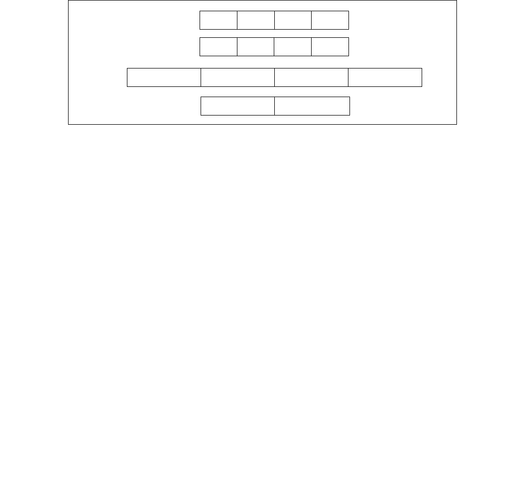
PMADDWD—Multiply and Add Packed Integers
INSTRUCTION SET REFERENCE, M-U
4-302 Vol. 2B
The (V)PMADDWD instruction wraps around only in one situation: when the 2 pairs of words being operated on in
a group are all 8000H. In this case, the result wraps around to 80000000H.
In 64-bit mode and not encoded with VEX/EVEX, using a REX prefix in the form of REX.R permits this instruction to
access additional registers (XMM8-XMM15).
Legacy SSE version: The first source and destination operands are MMX registers. The second source operand is an
MMX register or a 64-bit memory location.
128-bit Legacy SSE version: The first source and destination operands are XMM registers. The second source
operand is an XMM register or a 128-bit memory location. Bits (VLMAX-1:128) of the corresponding YMM destina-
tion register remain unchanged.
VEX.128 encoded version: The first source and destination operands are XMM registers. The second source
operand is an XMM register or a 128-bit memory location. Bits (VLMAX-1:128) of the destination YMM register are
zeroed.
VEX.256 encoded version: The second source operand can be an YMM register or a 256-bit memory location. The
first source and destination operands are YMM registers.
EVEX.512 encoded version: The second source operand can be an ZMM register or a 512-bit memory location. The
first source and destination operands are ZMM registers.
Operation
PMADDWD (with 64-bit operands)
DEST[31:0] ← (DEST[15:0] ∗ SRC[15:0]) + (DEST[31:16] ∗ SRC[31:16]);
DEST[63:32] ← (DEST[47:32] ∗ SRC[47:32]) + (DEST[63:48] ∗ SRC[63:48]);
PMADDWD (with 128-bit operands)
DEST[31:0] ← (DEST[15:0] ∗ SRC[15:0]) + (DEST[31:16] ∗ SRC[31:16]);
DEST[63:32] ← (DEST[47:32] ∗ SRC[47:32]) + (DEST[63:48] ∗ SRC[63:48]);
DEST[95:64] ← (DEST[79:64] ∗ SRC[79:64]) + (DEST[95:80] ∗ SRC[95:80]);
DEST[127:96] ← (DEST[111:96] ∗ SRC[111:96]) + (DEST[127:112] ∗ SRC[127:112]);
VPMADDWD (VEX.128 encoded version)
DEST[31:0] (SRC1[15:0] * SRC2[15:0]) + (SRC1[31:16] * SRC2[31:16])
DEST[63:32] (SRC1[47:32] * SRC2[47:32]) + (SRC1[63:48] * SRC2[63:48])
DEST[95:64] (SRC1[79:64] * SRC2[79:64]) + (SRC1[95:80] * SRC2[95:80])
DEST[127:96] (SRC1[111:96] * SRC2[111:96]) + (SRC1[127:112] * SRC2[127:112])
DEST[VLMAX-1:128] 0
VPMADDWD (VEX.256 encoded version)
DEST[31:0] (SRC1[15:0] * SRC2[15:0]) + (SRC1[31:16] * SRC2[31:16])
DEST[63:32] (SRC1[47:32] * SRC2[47:32]) + (SRC1[63:48] * SRC2[63:48])
DEST[95:64] (SRC1[79:64] * SRC2[79:64]) + (SRC1[95:80] * SRC2[95:80])
DEST[127:96] (SRC1[111:96] * SRC2[111:96]) + (SRC1[127:112] * SRC2[127:112])
Figure 4-11. PMADDWD Execution Model Using 64-bit Operands
X3 X2 X1 X0
X3 ∗ Y3 X2 ∗ Y2 X1 ∗ Y1 X0 ∗ Y0
SRC
DEST
DEST
Y3 Y2 Y1 Y0
(X1∗Y1) + (X0∗Y0)
(X3∗Y3) + (X2∗Y2)
TEMP

PMADDWD—Multiply and Add Packed Integers
INSTRUCTION SET REFERENCE, M-U
Vol. 2B 4-303
DEST[159:128] (SRC1[143:128] * SRC2[143:128]) + (SRC1[159:144] * SRC2[159:144])
DEST[191:160] (SRC1[175:160] * SRC2[175:160]) + (SRC1[191:176] * SRC2[191:176])
DEST[223:192] (SRC1[207:192] * SRC2[207:192]) + (SRC1[223:208] * SRC2[223:208])
DEST[255:224] (SRC1[239:224] * SRC2[239:224]) + (SRC1[255:240] * SRC2[255:240])
DEST[VLMAX-1:256] 0
VPMADDWD (EVEX encoded versions)
(KL, VL) = (4, 128), (8, 256), (16, 512)
FOR j 0 TO KL-1
i j * 32
IF k1[j] OR *no writemask*
THEN DEST[i+31:i] (SRC2[i+31:i+16]* SRC1[i+31:i+16]) + (SRC2[i+15:i]*SRC1[i+15:i])
ELSE
IF *merging-masking* ; merging-masking
THEN *DEST[i+31:i] remains unchanged*
ELSE *zeroing-masking* ; zeroing-masking
DEST[i+31:i] = 0
FI
FI;
ENDFOR;
DEST[MAX_VL-1:VL] 0
Intel C/C++ Compiler Intrinsic Equivalent
VPMADDWD __m512i _mm512_mdd_epi16( __m512i a, __m512i b);
VPMADDWD __m512i _mm512_mask_mdd_epi16(__m512i s, __mmask16 k, __m512i a, __m512i b);
VPMADDWD __m512i _mm512_maskz_mdd_epi16( __mmask16 k, __m512i a, __m512i b);
VPMADDWD __m256i _mm256_mask_mdd_epi16(__m256i s, __mmask8 k, __m256i a, __m256i b);
VPMADDWD __m256i _mm256_maskz_mdd_epi16( __mmask8 k, __m256i a, __m256i b);
VPMADDWD __m128i _mm_mask_mdd_epi16(__m128i s, __mmask8 k, __m128i a, __m128i b);
VPMADDWD __m128i _mm_maskz_madd_epi16( __mmask8 k, __m128i a, __m128i b);
PMADDWD:__m64 _mm_madd_pi16(__m64 m1, __m64 m2)
(V)PMADDWD:__m128i _mm_madd_epi16 ( __m128i a, __m128i b)
VPMADDWD:__m256i _mm256_madd_epi16 ( __m256i a, __m256i b)
Flags Affected
None.
Numeric Exceptions
None.
Other Exceptions
Non-EVEX-encoded instruction, see Exceptions Type 4.
EVEX-encoded instruction, see Exceptions Type E4NF.nb.

PMAXSB/PMAXSW/PMAXSD/PMAXSQ—Maximum of Packed Signed Integers
INSTRUCTION SET REFERENCE, M-U
4-304 Vol. 2B
PMAXSB/PMAXSW/PMAXSD/PMAXSQ—Maximum of Packed Signed Integers
Opcode/
Instruction
Op /
En
64/32
bit Mode
Support
CPUID
Feature
Flag
Description
0F EE /r1
PMAXSW mm1, mm2/m64
RM V/V SSE Compare signed word integers in mm2/m64 and
mm1 and return maximum values.
66 0F 38 3C /r
PMAXSB xmm1, xmm2/m128
RM V/V SSE4_1 Compare packed signed byte integers in xmm1 and
xmm2/m128 and store packed maximum values in
xmm1.
66 0F EE /r
PMAXSW xmm1, xmm2/m128
RM V/V SSE2 Compare packed signed word integers in
xmm2/m128 and xmm1 and stores maximum
packed values in xmm1.
66 0F 38 3D /r
PMAXSD xmm1, xmm2/m128
RM V/V SSE4_1 Compare packed signed dword integers in xmm1
and xmm2/m128 and store packed maximum values
in xmm1.
VEX.NDS.128.66.0F38.WIG 3C /r
VPMAXSB xmm1, xmm2, xmm3/m128
RVM V/V AVX Compare packed signed byte integers in xmm2 and
xmm3/m128 and store packed maximum values in
xmm1.
VEX.NDS.128.66.0F.WIG EE /r
VPMAXSW xmm1, xmm2, xmm3/m128
RVM V/V AVX Compare packed signed word integers in
xmm3/m128 and xmm2 and store packed maximum
values in xmm1.
VEX.NDS.128.66.0F38.WIG 3D /r
VPMAXSD xmm1, xmm2, xmm3/m128
RVM V/V AVX Compare packed signed dword integers in xmm2
and xmm3/m128 and store packed maximum values
in xmm1.
VEX.NDS.256.66.0F38.WIG 3C /r
VPMAXSB ymm1, ymm2, ymm3/m256
RVM V/V AVX2 Compare packed signed byte integers in ymm2 and
ymm3/m256 and store packed maximum values in
ymm1.
VEX.NDS.256.66.0F.WIG EE /r
VPMAXSW ymm1, ymm2, ymm3/m256
RVM V/V AVX2 Compare packed signed word integers in
ymm3/m256 and ymm2 and store packed maximum
values in ymm1.
VEX.NDS.256.66.0F38.WIG 3D /r
VPMAXSD ymm1, ymm2, ymm3/m256
RVM V/V AVX2 Compare packed signed dword integers in ymm2
and ymm3/m256 and store packed maximum values
in ymm1.
EVEX.NDS.128.66.0F38.WIG 3C /r
VPMAXSB xmm1{k1}{z}, xmm2,
xmm3/m128
FVM V/V AVX512VL
AVX512BW
Compare packed signed byte integers in xmm2 and
xmm3/m128 and store packed maximum values in
xmm1 under writemask k1.
EVEX.NDS.256.66.0F38.WIG 3C /r
VPMAXSB ymm1{k1}{z}, ymm2,
ymm3/m256
FVM V/V AVX512VL
AVX512BW
Compare packed signed byte integers in ymm2 and
ymm3/m256 and store packed maximum values in
ymm1 under writemask k1.
EVEX.NDS.512.66.0F38.WIG 3C /r
VPMAXSB zmm1{k1}{z}, zmm2,
zmm3/m512
FVM V/V AVX512BW Compare packed signed byte integers in zmm2 and
zmm3/m512 and store packed maximum values in
zmm1 under writemask k1.
EVEX.NDS.128.66.0F.WIG EE /r
VPMAXSW xmm1{k1}{z}, xmm2,
xmm3/m128
FVM V/V AVX512VL
AVX512BW
Compare packed signed word integers in xmm2 and
xmm3/m128 and store packed maximum values in
xmm1 under writemask k1.
EVEX.NDS.256.66.0F.WIG EE /r
VPMAXSW ymm1{k1}{z}, ymm2,
ymm3/m256
FVM V/V AVX512VL
AVX512BW
Compare packed signed word integers in ymm2 and
ymm3/m256 and store packed maximum values in
ymm1 under writemask k1.
EVEX.NDS.512.66.0F.WIG EE /r
VPMAXSW zmm1{k1}{z}, zmm2,
zmm3/m512
FVM V/V AVX512BW Compare packed signed word integers in zmm2 and
zmm3/m512 and store packed maximum values in
zmm1 under writemask k1.
EVEX.NDS.128.66.0F38.W0 3D /r
VPMAXSD xmm1 {k1}{z}, xmm2,
xmm3/m128/m32bcst
FV V/V AVX512VL
AVX512F
Compare packed signed dword integers in xmm2
and xmm3/m128/m32bcst and store packed
maximum values in xmm1 using writemask k1.

PMAXSB/PMAXSW/PMAXSD/PMAXSQ—Maximum of Packed Signed Integers
INSTRUCTION SET REFERENCE, M-U
Vol. 2B 4-305
Instruction Operand Encoding
Description
Performs a SIMD compare of the packed signed byte, word, dword or qword integers in the second source operand
and the first source operand and returns the maximum value for each pair of integers to the destination operand.
Legacy SSE version PMAXSW: The source operand can be an MMX technology register or a 64-bit memory location.
The destination operand can be an MMX technology register.
128-bit Legacy SSE version: The first source and destination operands are XMM registers. The second source
operand is an XMM register or a 128-bit memory location. Bits (MAX_VL-1:128) of the corresponding YMM destina-
tion register remain unchanged.
VEX.128 encoded version: The first source and destination operands are XMM registers. The second source
operand is an XMM register or a 128-bit memory location. Bits (MAX_VL-1:128) of the corresponding destination
register are zeroed.
VEX.256 encoded version: The second source operand can be an YMM register or a 256-bit memory location. The
first source and destination operands are YMM registers. Bits (MAX_VL-1:256) of the corresponding destination
register are zeroed.
EVEX encoded VPMAXSD/Q: The first source operand is a ZMM/YMM/XMM register; The second source operand is
a ZMM/YMM/XMM register, a 512/256/128-bit memory location or a 512/256/128-bit vector broadcasted from a
32/64-bit memory location. The destination operand is conditionally updated based on writemask k1.
EVEX encoded VPMAXSB/W: The first source operand is a ZMM/YMM/XMM register; The second source operand is
a ZMM/YMM/XMM register, a 512/256/128-bit memory location. The destination operand is conditionally updated
based on writemask k1.
Operation
PMAXSW (64-bit operands)
IF DEST[15:0] > SRC[15:0]) THEN
DEST[15:0] ← DEST[15:0];
EVEX.NDS.256.66.0F38.W0 3D /r
VPMAXSD ymm1 {k1}{z}, ymm2,
ymm3/m256/m32bcst
FV V/V AVX512VL
AVX512F
Compare packed signed dword integers in ymm2
and ymm3/m256/m32bcst and store packed
maximum values in ymm1 using writemask k1.
EVEX.NDS.512.66.0F38.W0 3D /r
VPMAXSD zmm1 {k1}{z}, zmm2,
zmm3/m512/m32bcst
FV V/V AVX512F Compare packed signed dword integers in zmm2 and
zmm3/m512/m32bcst and store packed maximum
values in zmm1 using writemask k1.
EVEX.NDS.128.66.0F38.W1 3D /r
VPMAXSQ xmm1 {k1}{z}, xmm2,
xmm3/m128/m64bcst
FV V/V AVX512VL
AVX512F
Compare packed signed qword integers in xmm2
and xmm3/m128/m64bcst and store packed
maximum values in xmm1 using writemask k1.
EVEX.NDS.256.66.0F38.W1 3D /r
VPMAXSQ ymm1 {k1}{z}, ymm2,
ymm3/m256/m64bcst
FV V/V AVX512VL
AVX512F
Compare packed signed qword integers in ymm2
and ymm3/m256/m64bcst and store packed
maximum values in ymm1 using writemask k1.
EVEX.NDS.512.66.0F38.W1 3D /r
VPMAXSQ zmm1 {k1}{z}, zmm2,
zmm3/m512/m64bcst
FV V/V AVX512F Compare packed signed qword integers in zmm2 and
zmm3/m512/m64bcst and store packed maximum
values in zmm1 using writemask k1.
Op/En Operand 1 Operand 2 Operand 3 Operand 4
RM ModRM:reg (r, w) ModRM:r/m (r) NA NA
RVM ModRM:reg (w) VEX.vvvv (r) ModRM:r/m (r) NA
FVM ModRM:reg (w) EVEX.vvvv (r) ModRM:r/m (r) NA
FV ModRM:reg (w) EVEX.vvvv (r) ModRM:r/m (r) NA
Opcode/
Instruction
Op /
En
64/32
bit Mode
Support
CPUID
Feature
Flag
Description

PMAXSB/PMAXSW/PMAXSD/PMAXSQ—Maximum of Packed Signed Integers
INSTRUCTION SET REFERENCE, M-U
4-306 Vol. 2B
ELSE
DEST[15:0] ← SRC[15:0]; FI;
(* Repeat operation for 2nd and 3rd words in source and destination operands *)
IF DEST[63:48] > SRC[63:48]) THEN
DEST[63:48] ← DEST[63:48];
ELSE
DEST[63:48] ← SRC[63:48]; FI;
PMAXSB (128-bit Legacy SSE version)
IF DEST[7:0] >SRC[7:0] THEN
DEST[7:0] DEST[7:0];
ELSE
DEST[7:0] SRC[7:0]; FI;
(* Repeat operation for 2nd through 15th bytes in source and destination operands *)
IF DEST[127:120] >SRC[127:120] THEN
DEST[127:120] DEST[127:120];
ELSE
DEST[127:120] SRC[127:120]; FI;
DEST[MAX_VL-1:128] (Unmodified)
VPMAXSB (VEX.128 encoded version)
IF SRC1[7:0] >SRC2[7:0] THEN
DEST[7:0] SRC1[7:0];
ELSE
DEST[7:0] SRC2[7:0]; FI;
(* Repeat operation for 2nd through 15th bytes in source and destination operands *)
IF SRC1[127:120] >SRC2[127:120] THEN
DEST[127:120] SRC1[127:120];
ELSE
DEST[127:120] SRC2[127:120]; FI;
DEST[MAX_VL-1:128] 0
VPMAXSB (VEX.256 encoded version)
IF SRC1[7:0] >SRC2[7:0] THEN
DEST[7:0] SRC1[7:0];
ELSE
DEST[7:0] SRC2[7:0]; FI;
(* Repeat operation for 2nd through 31st bytes in source and destination operands *)
IF SRC1[255:248] >SRC2[255:248] THEN
DEST[255:248] SRC1[255:248];
ELSE
DEST[255:248] SRC2[255:248]; FI;
DEST[MAX_VL-1:256] 0
VPMAXSB (EVEX encoded versions)
(KL, VL) = (16, 128), (32, 256), (64, 512)
FOR j 0 TO KL-1
i j * 8
IF k1[j] OR *no writemask* THEN
IF SRC1[i+7:i] > SRC2[i+7:i]
THEN DEST[i+7:i] SRC1[i+7:i];
ELSE DEST[i+7:i] SRC2[i+7:i];
FI;
ELSE

PMAXSB/PMAXSW/PMAXSD/PMAXSQ—Maximum of Packed Signed Integers
INSTRUCTION SET REFERENCE, M-U
Vol. 2B 4-307
IF *merging-masking* ; merging-masking
THEN *DEST[i+7:i] remains unchanged*
ELSE ; zeroing-masking
DEST[i+7:i] 0
FI
FI;
ENDFOR;
DEST[MAX_VL-1:VL] 0
PMAXSW (128-bit Legacy SSE version)
IF DEST[15:0] >SRC[15:0] THEN
DEST[15:0] DEST[15:0];
ELSE
DEST[15:0] SRC[15:0]; FI;
(* Repeat operation for 2nd through 7th words in source and destination operands *)
IF DEST[127:112] >SRC[127:112] THEN
DEST[127:112] DEST[127:112];
ELSE
DEST[127:112] SRC[127:112]; FI;
DEST[MAX_VL-1:128] (Unmodified)
VPMAXSW (VEX.128 encoded version)
IF SRC1[15:0] > SRC2[15:0] THEN
DEST[15:0] SRC1[15:0];
ELSE
DEST[15:0] SRC2[15:0]; FI;
(* Repeat operation for 2nd through 7th words in source and destination operands *)
IF SRC1[127:112] >SRC2[127:112] THEN
DEST[127:112] SRC1[127:112];
ELSE
DEST[127:112] SRC2[127:112]; FI;
DEST[MAX_VL-1:128] 0
VPMAXSW (VEX.256 encoded version)
IF SRC1[15:0] > SRC2[15:0] THEN
DEST[15:0] SRC1[15:0];
ELSE
DEST[15:0] SRC2[15:0]; FI;
(* Repeat operation for 2nd through 15th words in source and destination operands *)
IF SRC1[255:240] >SRC2[255:240] THEN
DEST[255:240] SRC1[255:240];
ELSE
DEST[255:240] SRC2[255:240]; FI;
DEST[MAX_VL-1:256] 0
VPMAXSW (EVEX encoded versions)
(KL, VL) = (8, 128), (16, 256), (32, 512)
FOR j 0 TO KL-1
i j * 16
IF k1[j] OR *no writemask* THEN
IF SRC1[i+15:i] > SRC2[i+15:i]
THEN DEST[i+15:i] SRC1[i+15:i];
ELSE DEST[i+15:i] SRC2[i+15:i];
FI;
ELSE

PMAXSB/PMAXSW/PMAXSD/PMAXSQ—Maximum of Packed Signed Integers
INSTRUCTION SET REFERENCE, M-U
4-308 Vol. 2B
IF *merging-masking* ; merging-masking
THEN *DEST[i+15:i] remains unchanged*
ELSE ; zeroing-masking
DEST[i+15:i] 0
FI
FI;
ENDFOR;
DEST[MAX_VL-1:VL] 0
PMAXSD (128-bit Legacy SSE version)
IF DEST[31:0] >SRC[31:0] THEN
DEST[31:0] DEST[31:0];
ELSE
DEST[31:0] SRC[31:0]; FI;
(* Repeat operation for 2nd through 7th words in source and destination operands *)
IF DEST[127:96] >SRC[127:96] THEN
DEST[127:96] DEST[127:96];
ELSE
DEST[127:96] SRC[127:96]; FI;
DEST[MAX_VL-1:128] (Unmodified)
VPMAXSD (VEX.128 encoded version)
IF SRC1[31:0] > SRC2[31:0] THEN
DEST[31:0] SRC1[31:0];
ELSE
DEST[31:0] SRC2[31:0]; FI;
(* Repeat operation for 2nd through 3rd dwords in source and destination operands *)
IF SRC1[127:96] > SRC2[127:96] THEN
DEST[127:96] SRC1[127:96];
ELSE
DEST[127:96] SRC2[127:96]; FI;
DEST[MAX_VL-1:128] 0
VPMAXSD (VEX.256 encoded version)
IF SRC1[31:0] > SRC2[31:0] THEN
DEST[31:0] SRC1[31:0];
ELSE
DEST[31:0] SRC2[31:0]; FI;
(* Repeat operation for 2nd through 7th dwords in source and destination operands *)
IF SRC1[255:224] > SRC2[255:224] THEN
DEST[255:224] SRC1[255:224];
ELSE
DEST[255:224] SRC2[255:224]; FI;
DEST[MAX_VL-1:256] 0
VPMAXSD (EVEX encoded versions)
(KL, VL) = (4, 128), (8, 256), (16, 512)
FOR j 0 TO KL-1
i j * 32
IF k1[j] OR *no writemask*THEN
IF (EVEX.b = 1) AND (SRC2 *is memory*)
THEN
IF SRC1[i+31:i] > SRC2[31:0]
THEN DEST[i+31:i] SRC1[i+31:i];

PMAXSB/PMAXSW/PMAXSD/PMAXSQ—Maximum of Packed Signed Integers
INSTRUCTION SET REFERENCE, M-U
Vol. 2B 4-309
ELSE DEST[i+31:i] SRC2[31:0];
FI;
ELSE
IF SRC1[i+31:i] > SRC2[i+31:i]
THEN DEST[i+31:i] SRC1[i+31:i];
ELSE DEST[i+31:i] SRC2[i+31:i];
FI;
FI;
ELSE
IF *merging-masking* ; merging-masking
THEN *DEST[i+31:i] remains unchanged*
ELSE DEST[i+31:i] 0 ; zeroing-masking
FI
FI;
ENDFOR
DEST[MAX_VL-1:VL] 0
VPMAXSQ (EVEX encoded versions)
(KL, VL) = (2, 128), (4, 256), (8, 512)
FOR j 0 TO KL-1
i j * 64
IF k1[j] OR *no writemask* THEN
IF (EVEX.b = 1) AND (SRC2 *is memory*)
THEN
IF SRC1[i+63:i] > SRC2[63:0]
THEN DEST[i+63:i] SRC1[i+63:i];
ELSE DEST[i+63:i] SRC2[63:0];
FI;
ELSE
IF SRC1[i+63:i] > SRC2[i+63:i]
THEN DEST[i+63:i] SRC1[i+63:i];
ELSE DEST[i+63:i] SRC2[i+63:i];
FI;
FI;
ELSE
IF *merging-masking* ; merging-masking
THEN *DEST[i+63:i] remains unchanged*
ELSE ; zeroing-masking
THEN DEST[i+63:i] 0
FI
FI;
ENDFOR;
DEST[MAX_VL-1:VL] 0
Intel C/C++ Compiler Intrinsic Equivalent
VPMAXSB __m512i _mm512_max_epi8( __m512i a, __m512i b);
VPMAXSB __m512i _mm512_mask_max_epi8(__m512i s, __mmask64 k, __m512i a, __m512i b);
VPMAXSB __m512i _mm512_maskz_max_epi8( __mmask64 k, __m512i a, __m512i b);
VPMAXSW __m512i _mm512_max_epi16( __m512i a, __m512i b);
VPMAXSW __m512i _mm512_mask_max_epi16(__m512i s, __mmask32 k, __m512i a, __m512i b);
VPMAXSW __m512i _mm512_maskz_max_epi16( __mmask32 k, __m512i a, __m512i b);
VPMAXSB __m256i _mm256_mask_max_epi8(__m256i s, __mmask32 k, __m256i a, __m256i b);
VPMAXSB __m256i _mm256_maskz_max_epi8( __mmask32 k, __m256i a, __m256i b);
VPMAXSW __m256i _mm256_mask_max_epi16(__m256i s, __mmask16 k, __m256i a, __m256i b);

PMAXSB/PMAXSW/PMAXSD/PMAXSQ—Maximum of Packed Signed Integers
INSTRUCTION SET REFERENCE, M-U
4-310 Vol. 2B
VPMAXSW __m256i _mm256_maskz_max_epi16( __mmask16 k, __m256i a, __m256i b);
VPMAXSB __m128i _mm_mask_max_epi8(__m128i s, __mmask16 k, __m128i a, __m128i b);
VPMAXSB __m128i _mm_maskz_max_epi8( __mmask16 k, __m128i a, __m128i b);
VPMAXSW __m128i _mm_mask_max_epi16(__m128i s, __mmask8 k, __m128i a, __m128i b);
VPMAXSW __m128i _mm_maskz_max_epi16( __mmask8 k, __m128i a, __m128i b);
VPMAXSD __m256i _mm256_mask_max_epi32(__m256i s, __mmask16 k, __m256i a, __m256i b);
VPMAXSD __m256i _mm256_maskz_max_epi32( __mmask16 k, __m256i a, __m256i b);
VPMAXSQ __m256i _mm256_mask_max_epi64(__m256i s, __mmask8 k, __m256i a, __m256i b);
VPMAXSQ __m256i _mm256_maskz_max_epi64( __mmask8 k, __m256i a, __m256i b);
VPMAXSD __m128i _mm_mask_max_epi32(__m128i s, __mmask8 k, __m128i a, __m128i b);
VPMAXSD __m128i _mm_maskz_max_epi32( __mmask8 k, __m128i a, __m128i b);
VPMAXSQ __m128i _mm_mask_max_epi64(__m128i s, __mmask8 k, __m128i a, __m128i b);
VPMAXSQ __m128i _mm_maskz_max_epu64( __mmask8 k, __m128i a, __m128i b);
VPMAXSD __m512i _mm512_max_epi32( __m512i a, __m512i b);
VPMAXSD __m512i _mm512_mask_max_epi32(__m512i s, __mmask16 k, __m512i a, __m512i b);
VPMAXSD __m512i _mm512_maskz_max_epi32( __mmask16 k, __m512i a, __m512i b);
VPMAXSQ __m512i _mm512_max_epi64( __m512i a, __m512i b);
VPMAXSQ __m512i _mm512_mask_max_epi64(__m512i s, __mmask8 k, __m512i a, __m512i b);
VPMAXSQ __m512i _mm512_maskz_max_epi64( __mmask8 k, __m512i a, __m512i b);
(V)PMAXSB __m128i _mm_max_epi8 ( __m128i a, __m128i b);
(V)PMAXSW __m128i _mm_max_epi16 ( __m128i a, __m128i b)
(V)PMAXSD __m128i _mm_max_epi32 ( __m128i a, __m128i b);
VPMAXSB __m256i _mm256_max_epi8 ( __m256i a, __m256i b);
VPMAXSW __m256i _mm256_max_epi16 ( __m256i a, __m256i b)
VPMAXSD __m256i _mm256_max_epi32 ( __m256i a, __m256i b);
PMAXSW:__m64 _mm_max_pi16(__m64 a, __m64 b)
SIMD Floating-Point Exceptions
None
Other Exceptions
Non-EVEX-encoded instruction, see Exceptions Type 4.
EVEX-encoded VPMAXSD/Q, see Exceptions Type E4.
EVEX-encoded VPMAXSB/W, see Exceptions Type E4.nb.

PMAXUB/PMAXUW—Maximum of Packed Unsigned Integers
INSTRUCTION SET REFERENCE, M-U
Vol. 2B 4-311
PMAXUB/PMAXUW—Maximum of Packed Unsigned Integers
Instruction Operand Encoding
Opcode/
Instruction
Op /
En
64/32
bit Mode
Support
CPUID
Feature
Flag
Description
0F DE /r1
PMAXUB mm1, mm2/m64
RM V/V SSE Compare unsigned byte integers in mm2/m64 and
mm1 and returns maximum values.
66 0F DE /r
PMAXUB xmm1, xmm2/m128
RM V/V SSE2 Compare packed unsigned byte integers in xmm1
and xmm2/m128 and store packed maximum
values in xmm1.
66 0F 38 3E/r
PMAXUW xmm1, xmm2/m128
RM V/V SSE4_1 Compare packed unsigned word integers in
xmm2/m128 and xmm1 and stores maximum
packed values in xmm1.
VEX.NDS.128.66.0F DE /r
VPMAXUB xmm1, xmm2, xmm3/m128
RVM V/V AVX Compare packed unsigned byte integers in xmm2
and xmm3/m128 and store packed maximum
values in xmm1.
VEX.NDS.128.66.0F38 3E/r
VPMAXUW xmm1, xmm2, xmm3/m128
RVM V/V AVX Compare packed unsigned word integers in
xmm3/m128 and xmm2 and store maximum
packed values in xmm1.
VEX.NDS.256.66.0F DE /r
VPMAXUB ymm1, ymm2, ymm3/m256
RVM V/V AVX2 Compare packed unsigned byte integers in ymm2
and ymm3/m256 and store packed maximum
values in ymm1.
VEX.NDS.256.66.0F38 3E/r
VPMAXUW ymm1, ymm2, ymm3/m256
RVM V/V AVX2 Compare packed unsigned word integers in
ymm3/m256 and ymm2 and store maximum
packed values in ymm1.
EVEX.NDS.128.66.0F.WIG DE /r
VPMAXUB xmm1{k1}{z}, xmm2,
xmm3/m128
FVM V/V AVX512VL
AVX512BW
Compare packed unsigned byte integers in xmm2
and xmm3/m128 and store packed maximum
values in xmm1 under writemask k1.
EVEX.NDS.256.66.0F.WIG DE /r
VPMAXUB ymm1{k1}{z}, ymm2,
ymm3/m256
FVM V/V AVX512VL
AVX512BW
Compare packed unsigned byte integers in ymm2
and ymm3/m256 and store packed maximum
values in ymm1 under writemask k1.
EVEX.NDS.512.66.0F.WIG DE /r
VPMAXUB zmm1{k1}{z}, zmm2,
zmm3/m512
FVM V/V AVX512BW Compare packed unsigned byte integers in zmm2
and zmm3/m512 and store packed maximum
values in zmm1 under writemask k1.
EVEX.NDS.128.66.0F38.WIG 3E /r
VPMAXUW xmm1{k1}{z}, xmm2,
xmm3/m128
FVM V/V AVX512VL
AVX512BW
Compare packed unsigned word integers in xmm2
and xmm3/m128 and store packed maximum
values in xmm1 under writemask k1.
EVEX.NDS.256.66.0F38.WIG 3E /r
VPMAXUW ymm1{k1}{z}, ymm2,
ymm3/m256
FVM V/V AVX512VL
AVX512BW
Compare packed unsigned word integers in ymm2
and ymm3/m256 and store packed maximum
values in ymm1 under writemask k1.
EVEX.NDS.512.66.0F38.WIG 3E /r
VPMAXUW zmm1{k1}{z}, zmm2,
zmm3/m512
FVM V/V AVX512BW Compare packed unsigned word integers in zmm2
and zmm3/m512 and store packed maximum
values in zmm1 under writemask k1.
NOTES:
1. See note in Section 2.4, “AVX and SSE Instruction Exception Specification” in the Intel® 64 and IA-32 Architectures Software
Developer’s Manual, Volume 2A and Section 22.25.3, “Exception Conditions of Legacy SIMD Instructions Operating on MMX
Registers” in the Intel® 64 and IA-32 Architectures Software Developer’s Manual, Volume 3A.
Op/En Operand 1 Operand 2 Operand 3 Operand 4
RM ModRM:reg (r, w) ModRM:r/m (r) NA NA
RVM ModRM:reg (w) VEX.vvvv (r) ModRM:r/m (r) NA
FVM ModRM:reg (w) EVEX.vvvv (r) ModRM:r/m (r) NA

PMAXUB/PMAXUW—Maximum of Packed Unsigned Integers
INSTRUCTION SET REFERENCE, M-U
4-312 Vol. 2B
Description
Performs a SIMD compare of the packed unsigned byte, word integers in the second source operand and the first
source operand and returns the maximum value for each pair of integers to the destination operand.
Legacy SSE version PMAXUB: The source operand can be an MMX technology register or a 64-bit memory location.
The destination operand can be an MMX technology register.
128-bit Legacy SSE version: The first source and destination operands are XMM registers. The second source
operand is an XMM register or a 128-bit memory location. Bits (MAX_VL-1:128) of the corresponding destination
register remain unchanged.
VEX.128 encoded version: The first source and destination operands are XMM registers. The second source
operand is an XMM register or a 128-bit memory location. Bits (MAX_VL-1:128) of the corresponding destination
register are zeroed.
VEX.256 encoded version: The second source operand can be an YMM register or a 256-bit memory location. The
first source and destination operands are YMM registers.
EVEX encoded versions: The first source operand is a ZMM/YMM/XMM register; The second source operand is a
ZMM/YMM/XMM register or a 512/256/128-bit memory location. The destination operand is conditionally updated
based on writemask k1.
Operation
PMAXUB (64-bit operands)
IF DEST[7:0] > SRC[17:0]) THEN
DEST[7:0] ← DEST[7:0];
ELSE
DEST[7:0] ← SRC[7:0]; FI;
(* Repeat operation for 2nd through 7th bytes in source and destination operands *)
IF DEST[63:56] > SRC[63:56]) THEN
DEST[63:56] ← DEST[63:56];
ELSE
DEST[63:56] ← SRC[63:56]; FI;
PMAXUB (128-bit Legacy SSE version)
IF DEST[7:0] >SRC[7:0] THEN
DEST[7:0] DEST[7:0];
ELSE
DEST[15:0] SRC[7:0]; FI;
(* Repeat operation for 2nd through 15th bytes in source and destination operands *)
IF DEST[127:120] >SRC[127:120] THEN
DEST[127:120] DEST[127:120];
ELSE
DEST[127:120] SRC[127:120]; FI;
DEST[MAX_VL-1:128] (Unmodified)
VPMAXUB (VEX.128 encoded version)
IF SRC1[7:0] >SRC2[7:0] THEN
DEST[7:0] SRC1[7:0];
ELSE
DEST[7:0] SRC2[7:0]; FI;
(* Repeat operation for 2nd through 15th bytes in source and destination operands *)
IF SRC1[127:120] >SRC2[127:120] THEN
DEST[127:120] SRC1[127:120];
ELSE
DEST[127:120] SRC2[127:120]; FI;
DEST[MAX_VL-1:128] 0

PMAXUB/PMAXUW—Maximum of Packed Unsigned Integers
INSTRUCTION SET REFERENCE, M-U
Vol. 2B 4-313
VPMAXUB (VEX.256 encoded version)
IF SRC1[7:0] >SRC2[7:0] THEN
DEST[7:0] SRC1[7:0];
ELSE
DEST[15:0] SRC2[7:0]; FI;
(* Repeat operation for 2nd through 31st bytes in source and destination operands *)
IF SRC1[255:248] >SRC2[255:248] THEN
DEST[255:248] SRC1[255:248];
ELSE
DEST[255:248] SRC2[255:248]; FI;
DEST[MAX_VL-1:128] 0
VPMAXUB (EVEX encoded versions)
(KL, VL) = (16, 128), (32, 256), (64, 512)
FOR j 0 TO KL-1
i j * 8
IF k1[j] OR *no writemask* THEN
IF SRC1[i+7:i] > SRC2[i+7:i]
THEN DEST[i+7:i] SRC1[i+7:i];
ELSE DEST[i+7:i] SRC2[i+7:i];
FI;
ELSE
IF *merging-masking* ; merging-masking
THEN *DEST[i+7:i] remains unchanged*
ELSE ; zeroing-masking
DEST[i+7:i] 0
FI
FI;
ENDFOR;
DEST[MAX_VL-1:VL] 0
PMAXUW (128-bit Legacy SSE version)
IF DEST[15:0] >SRC[15:0] THEN
DEST[15:0] DEST[15:0];
ELSE
DEST[15:0] SRC[15:0]; FI;
(* Repeat operation for 2nd through 7th words in source and destination operands *)
IF DEST[127:112] >SRC[127:112] THEN
DEST[127:112] DEST[127:112];
ELSE
DEST[127:112] SRC[127:112]; FI;
DEST[MAX_VL-1:128] (Unmodified)
VPMAXUW (VEX.128 encoded version)
IF SRC1[15:0] > SRC2[15:0] THEN
DEST[15:0] SRC1[15:0];
ELSE
DEST[15:0] SRC2[15:0]; FI;
(* Repeat operation for 2nd through 7th words in source and destination operands *)
IF SRC1[127:112] >SRC2[127:112] THEN
DEST[127:112] SRC1[127:112];
ELSE
DEST[127:112] SRC2[127:112]; FI;
DEST[MAX_VL-1:128] 0

PMAXUB/PMAXUW—Maximum of Packed Unsigned Integers
INSTRUCTION SET REFERENCE, M-U
4-314 Vol. 2B
VPMAXUW (VEX.256 encoded version)
IF SRC1[15:0] > SRC2[15:0] THEN
DEST[15:0] SRC1[15:0];
ELSE
DEST[15:0] SRC2[15:0]; FI;
(* Repeat operation for 2nd through 15th words in source and destination operands *)
IF SRC1[255:240] >SRC2[255:240] THEN
DEST[255:240] SRC1[255:240];
ELSE
DEST[255:240] SRC2[255:240]; FI;
DEST[MAX_VL-1:128] 0
VPMAXUW (EVEX encoded versions)
(KL, VL) = (8, 128), (16, 256), (32, 512)
FOR j 0 TO KL-1
i j * 16
IF k1[j] OR *no writemask* THEN
IF SRC1[i+15:i] > SRC2[i+15:i]
THEN DEST[i+15:i] SRC1[i+15:i];
ELSE DEST[i+15:i] SRC2[i+15:i];
FI;
ELSE
IF *merging-masking* ; merging-masking
THEN *DEST[i+15:i] remains unchanged*
ELSE ; zeroing-masking
DEST[i+15:i] 0
FI
FI;
ENDFOR;
DEST[MAX_VL-1:VL] 0
Intel C/C++ Compiler Intrinsic Equivalent
VPMAXUB __m512i _mm512_max_epu8( __m512i a, __m512i b);
VPMAXUB __m512i _mm512_mask_max_epu8(__m512i s, __mmask64 k, __m512i a, __m512i b);
VPMAXUB __m512i _mm512_maskz_max_epu8( __mmask64 k, __m512i a, __m512i b);
VPMAXUW __m512i _mm512_max_epu16( __m512i a, __m512i b);
VPMAXUW __m512i _mm512_mask_max_epu16(__m512i s, __mmask32 k, __m512i a, __m512i b);
VPMAXUW __m512i _mm512_maskz_max_epu16( __mmask32 k, __m512i a, __m512i b);
VPMAXUB __m256i _mm256_mask_max_epu8(__m256i s, __mmask32 k, __m256i a, __m256i b);
VPMAXUB __m256i _mm256_maskz_max_epu8( __mmask32 k, __m256i a, __m256i b);
VPMAXUW __m256i _mm256_mask_max_epu16(__m256i s, __mmask16 k, __m256i a, __m256i b);
VPMAXUW __m256i _mm256_maskz_max_epu16( __mmask16 k, __m256i a, __m256i b);
VPMAXUB __m128i _mm_mask_max_epu8(__m128i s, __mmask16 k, __m128i a, __m128i b);
VPMAXUB __m128i _mm_maskz_max_epu8( __mmask16 k, __m128i a, __m128i b);
VPMAXUW __m128i _mm_mask_max_epu16(__m128i s, __mmask8 k, __m128i a, __m128i b);
VPMAXUW __m128i _mm_maskz_max_epu16( __mmask8 k, __m128i a, __m128i b);
(V)PMAXUB __m128i _mm_max_epu8 ( __m128i a, __m128i b);
(V)PMAXUW __m128i _mm_max_epu16 ( __m128i a, __m128i b)
VPMAXUB __m256i _mm256_max_epu8 ( __m256i a, __m256i b);
VPMAXUW __m256i _mm256_max_epu16 ( __m256i a, __m256i b);
PMAXUB: __m64 _mm_max_pu8(__m64 a, __m64 b);

PMAXUB/PMAXUW—Maximum of Packed Unsigned Integers
INSTRUCTION SET REFERENCE, M-U
Vol. 2B 4-315
SIMD Floating-Point Exceptions
None
Other Exceptions
Non-EVEX-encoded instruction, see Exceptions Type 4.
EVEX-encoded instruction, see Exceptions Type E4.nb.

PMAXUD/PMAXUQ—Maximum of Packed Unsigned Integers
INSTRUCTION SET REFERENCE, M-U
4-316 Vol. 2B
PMAXUD/PMAXUQ—Maximum of Packed Unsigned Integers
Instruction Operand Encoding
Description
Performs a SIMD compare of the packed unsigned dword or qword integers in the second source operand and the
first source operand and returns the maximum value for each pair of integers to the destination operand.
128-bit Legacy SSE version: The first source and destination operands are XMM registers. The second source
operand is an XMM register or a 128-bit memory location. Bits (MAX_VL-1:128) of the corresponding destination
register remain unchanged.
VEX.128 encoded version: The first source and destination operands are XMM registers. The second source
operand is an XMM register or a 128-bit memory location. Bits (MAX_VL-1:128) of the corresponding destination
register are zeroed.
VEX.256 encoded version: The first source operand is a YMM register; The second source operand is a YMM register
or 256-bit memory location. Bits (MAX_VL-1:256) of the corresponding destination register are zeroed.
EVEX encoded versions: The first source operand is a ZMM/YMM/XMM register; The second source operand is a
ZMM/YMM/XMM register, a 512/256/128-bit memory location or a 512/256/128-bit vector broadcasted from a
32/64-bit memory location. The destination operand is conditionally updated based on writemask k1.
Opcode/
Instruction
Op/
En
64/32
bit Mode
Support
CPUID
Feature
Flag
Description
66 0F 38 3F /r
PMAXUD xmm1, xmm2/m128
RM V/V SSE4_1 Compare packed unsigned dword integers in xmm1
and xmm2/m128 and store packed maximum values in
xmm1.
VEX.NDS.128.66.0F38.WIG 3F /r
VPMAXUD xmm1, xmm2, xmm3/m128
RVM V/V AVX Compare packed unsigned dword integers in xmm2
and xmm3/m128 and store packed maximum values in
xmm1.
VEX.NDS.256.66.0F38.WIG 3F /r
VPMAXUD ymm1, ymm2, ymm3/m256
RVM V/V AVX2 Compare packed unsigned dword integers in ymm2
and ymm3/m256 and store packed maximum values in
ymm1.
EVEX.NDS.128.66.0F38.W0 3F /r
VPMAXUD xmm1 {k1}{z}, xmm2,
xmm3/m128/m32bcst
FV V/V AVX512VL
AVX512F
Compare packed unsigned dword integers in xmm2
and xmm3/m128/m32bcst and store packed
maximum values in xmm1 under writemask k1.
EVEX.NDS.256.66.0F38.W0 3F /r
VPMAXUD ymm1 {k1}{z}, ymm2,
ymm3/m256/m32bcst
FV V/V AVX512VL
AVX512F
Compare packed unsigned dword integers in ymm2
and ymm3/m256/m32bcst and store packed
maximum values in ymm1 under writemask k1.
EVEX.NDS.512.66.0F38.W0 3F /r
VPMAXUD zmm1 {k1}{z}, zmm2,
zmm3/m512/m32bcst
FV V/V AVX512F Compare packed unsigned dword integers in zmm2
and zmm3/m512/m32bcst and store packed maximum
values in zmm1 under writemask k1.
EVEX.NDS.128.66.0F38.W1 3F /r
VPMAXUQ xmm1 {k1}{z}, xmm2,
xmm3/m128/m64bcst
FV V/V AVX512VL
AVX512F
Compare packed unsigned qword integers in xmm2
and xmm3/m128/m64bcst and store packed
maximum values in xmm1 under writemask k1.
EVEX.NDS.256.66.0F38.W1 3F /r
VPMAXUQ ymm1 {k1}{z}, ymm2,
ymm3/m256/m64bcst
FV V/V AVX512VL
AVX512F
Compare packed unsigned qword integers in ymm2
and ymm3/m256/m64bcst and store packed
maximum values in ymm1 under writemask k1.
EVEX.NDS.512.66.0F38.W1 3F /r
VPMAXUQ zmm1 {k1}{z}, zmm2,
zmm3/m512/m64bcst
FV V/V AVX512F Compare packed unsigned qword integers in zmm2
and zmm3/m512/m64bcst and store packed maximum
values in zmm1 under writemask k1.
Op/En Operand 1 Operand 2 Operand 3 Operand 4
RM ModRM:reg (r, w) ModRM:r/m (r) NA NA
RVM ModRM:reg (w) VEX.vvvv ModRM:r/m (r) NA
FV ModRM:reg (w) EVEX.vvvv ModRM:r/m (r) NA

PMAXUD/PMAXUQ—Maximum of Packed Unsigned Integers
INSTRUCTION SET REFERENCE, M-U
Vol. 2B 4-317
Operation
PMAXUD (128-bit Legacy SSE version)
IF DEST[31:0] >SRC[31:0] THEN
DEST[31:0] DEST[31:0];
ELSE
DEST[31:0] SRC[31:0]; FI;
(* Repeat operation for 2nd through 7th words in source and destination operands *)
IF DEST[127:96] >SRC[127:96] THEN
DEST[127:96] DEST[127:96];
ELSE
DEST[127:96] SRC[127:96]; FI;
DEST[MAX_VL-1:128] (Unmodified)
VPMAXUD (VEX.128 encoded version)
IF SRC1[31:0] > SRC2[31:0] THEN
DEST[31:0] SRC1[31:0];
ELSE
DEST[31:0] SRC2[31:0]; FI;
(* Repeat operation for 2nd through 3rd dwords in source and destination operands *)
IF SRC1[127:96] > SRC2[127:96] THEN
DEST[127:96] SRC1[127:96];
ELSE
DEST[127:96] SRC2[127:96]; FI;
DEST[MAX_VL-1:128] 0
VPMAXUD (VEX.256 encoded version)
IF SRC1[31:0] > SRC2[31:0] THEN
DEST[31:0] SRC1[31:0];
ELSE
DEST[31:0] SRC2[31:0]; FI;
(* Repeat operation for 2nd through 7th dwords in source and destination operands *)
IF SRC1[255:224] > SRC2[255:224] THEN
DEST[255:224] SRC1[255:224];
ELSE
DEST[255:224] SRC2[255:224]; FI;
DEST[MAX_VL-1:256] 0

PMAXUD/PMAXUQ—Maximum of Packed Unsigned Integers
INSTRUCTION SET REFERENCE, M-U
4-318 Vol. 2B
VPMAXUD (EVEX encoded versions)
(KL, VL) = (4, 128), (8, 256), (16, 512)
FOR j 0 TO KL-1
i j * 32
IF k1[j] OR *no writemask* THEN
IF (EVEX.b = 1) AND (SRC2 *is memory*)
THEN
IF SRC1[i+31:i] > SRC2[31:0]
THEN DEST[i+31:i] SRC1[i+31:i];
ELSE DEST[i+31:i] SRC2[31:0];
FI;
ELSE
IF SRC1[i+31:i] > SRC2[i+31:i]
THEN DEST[i+31:i] SRC1[i+31:i];
ELSE DEST[i+31:i] SRC2[i+31:i];
FI;
FI;
ELSE
IF *merging-masking* ; merging-masking
THEN *DEST[i+31:i] remains unchanged*
ELSE ; zeroing-masking
THEN DEST[i+31:i] 0
FI
FI;
ENDFOR;
DEST[MAX_VL-1:VL] 0
VPMAXUQ (EVEX encoded versions)
(KL, VL) = (2, 128), (4, 256), (8, 512)
FOR j 0 TO KL-1
i j * 64
IF k1[j] OR *no writemask* THEN
IF (EVEX.b = 1) AND (SRC2 *is memory*)
THEN
IF SRC1[i+63:i] > SRC2[63:0]
THEN DEST[i+63:i] SRC1[i+63:i];
ELSE DEST[i+63:i] SRC2[63:0];
FI;
ELSE
IF SRC1[i+31:i] > SRC2[i+31:i]
THEN DEST[i+63:i] SRC1[i+63:i];
ELSE DEST[i+63:i] SRC2[i+63:i];
FI;
FI;
ELSE
IF *merging-masking* ; merging-masking
THEN *DEST[i+63:i] remains unchanged*
ELSE ; zeroing-masking
THEN DEST[i+63:i] 0
FI
FI;
ENDFOR;
DEST[MAX_VL-1:VL] 0

PMAXUD/PMAXUQ—Maximum of Packed Unsigned Integers
INSTRUCTION SET REFERENCE, M-U
Vol. 2B 4-319
Intel C/C++ Compiler Intrinsic Equivalent
VPMAXUD __m512i _mm512_max_epu32( __m512i a, __m512i b);
VPMAXUD __m512i _mm512_mask_max_epu32(__m512i s, __mmask16 k, __m512i a, __m512i b);
VPMAXUD __m512i _mm512_maskz_max_epu32( __mmask16 k, __m512i a, __m512i b);
VPMAXUQ __m512i _mm512_max_epu64( __m512i a, __m512i b);
VPMAXUQ __m512i _mm512_mask_max_epu64(__m512i s, __mmask8 k, __m512i a, __m512i b);
VPMAXUQ __m512i _mm512_maskz_max_epu64( __mmask8 k, __m512i a, __m512i b);
VPMAXUD __m256i _mm256_mask_max_epu32(__m256i s, __mmask16 k, __m256i a, __m256i b);
VPMAXUD __m256i _mm256_maskz_max_epu32( __mmask16 k, __m256i a, __m256i b);
VPMAXUQ __m256i _mm256_mask_max_epu64(__m256i s, __mmask8 k, __m256i a, __m256i b);
VPMAXUQ __m256i _mm256_maskz_max_epu64( __mmask8 k, __m256i a, __m256i b);
VPMAXUD __m128i _mm_mask_max_epu32(__m128i s, __mmask8 k, __m128i a, __m128i b);
VPMAXUD __m128i _mm_maskz_max_epu32( __mmask8 k, __m128i a, __m128i b);
VPMAXUQ __m128i _mm_mask_max_epu64(__m128i s, __mmask8 k, __m128i a, __m128i b);
VPMAXUQ __m128i _mm_maskz_max_epu64( __mmask8 k, __m128i a, __m128i b);
(V)PMAXUD __m128i _mm_max_epu32 ( __m128i a, __m128i b);
VPMAXUD __m256i _mm256_max_epu32 ( __m256i a, __m256i b);
SIMD Floating-Point Exceptions
None
Other Exceptions
Non-EVEX-encoded instruction, see Exceptions Type 4.
EVEX-encoded instruction, see Exceptions Type E4.

PMINSB/PMINSW—Minimum of Packed Signed Integers
INSTRUCTION SET REFERENCE, M-U
4-320 Vol. 2B
PMINSB/PMINSW—Minimum of Packed Signed Integers
Instruction Operand Encoding
Opcode/
Instruction
Op /
En
64/32
bit Mode
Support
CPUID
Feature
Flag
Description
0F EA /r1
PMINSW mm1, mm2/m64
RM V/V SSE Compare signed word integers in mm2/m64 and mm1
and return minimum values.
66 0F 38 38 /r
PMINSB xmm1, xmm2/m128
RM V/V SSE4_1 Compare packed signed byte integers in xmm1 and
xmm2/m128 and store packed minimum values in
xmm1.
66 0F EA /r
PMINSW xmm1, xmm2/m128
RM V/V SSE2 Compare packed signed word integers in xmm2/m128
and xmm1 and store packed minimum values in xmm1.
VEX.NDS.128.66.0F38 38 /r
VPMINSB xmm1, xmm2, xmm3/m128
RVM V/V AVX Compare packed signed byte integers in xmm2 and
xmm3/m128 and store packed minimum values in
xmm1.
VEX.NDS.128.66.0F EA /r
VPMINSW xmm1, xmm2, xmm3/m128
RVM V/V AVX Compare packed signed word integers in xmm3/m128
and xmm2 and return packed minimum values in
xmm1.
VEX.NDS.256.66.0F38 38 /r
VPMINSB ymm1, ymm2, ymm3/m256
RVM V/V AVX2 Compare packed signed byte integers in ymm2 and
ymm3/m256 and store packed minimum values in
ymm1.
VEX.NDS.256.66.0F EA /r
VPMINSW ymm1, ymm2, ymm3/m256
RVM V/V AVX2 Compare packed signed word integers in ymm3/m256
and ymm2 and return packed minimum values in
ymm1.
EVEX.NDS.128.66.0F38.WIG 38 /r
VPMINSB xmm1{k1}{z}, xmm2,
xmm3/m128
FVM V/V AVX512VL
AVX512BW
Compare packed signed byte integers in xmm2 and
xmm3/m128 and store packed minimum values in
xmm1 under writemask k1.
EVEX.NDS.256.66.0F38.WIG 38 /r
VPMINSB ymm1{k1}{z}, ymm2,
ymm3/m256
FVM V/V AVX512VL
AVX512BW
Compare packed signed byte integers in ymm2 and
ymm3/m256 and store packed minimum values in
ymm1 under writemask k1.
EVEX.NDS.512.66.0F38.WIG 38 /r
VPMINSB zmm1{k1}{z}, zmm2,
zmm3/m512
FVM V/V AVX512BW Compare packed signed byte integers in zmm2 and
zmm3/m512 and store packed minimum values in
zmm1 under writemask k1.
EVEX.NDS.128.66.0F.WIG EA /r
VPMINSW xmm1{k1}{z}, xmm2,
xmm3/m128
FVM V/V AVX512VL
AVX512BW
Compare packed signed word integers in xmm2 and
xmm3/m128 and store packed minimum values in
xmm1 under writemask k1.
EVEX.NDS.256.66.0F.WIG EA /r
VPMINSW ymm1{k1}{z}, ymm2,
ymm3/m256
FVM V/V AVX512VL
AVX512BW
Compare packed signed word integers in ymm2 and
ymm3/m256 and store packed minimum values in
ymm1 under writemask k1.
EVEX.NDS.512.66.0F.WIG EA /r
VPMINSW zmm1{k1}{z}, zmm2,
zmm3/m512
FVM V/V AVX512BW Compare packed signed word integers in zmm2 and
zmm3/m512 and store packed minimum values in
zmm1 under writemask k1.
NOTES:
1. See note in Section 2.4, “AVX and SSE Instruction Exception Specification” in the Intel® 64 and IA-32 Architectures Software
Developer’s Manual, Volume 2A and Section 22.25.3, “Exception Conditions of Legacy SIMD Instructions Operating on MMX
Registers” in the Intel® 64 and IA-32 Architectures Software Developer’s Manual, Volume 3A.
Op/En Operand 1 Operand 2 Operand 3 Operand 4
RM ModRM:reg (r, w) ModRM:r/m (r) NA NA
RVM ModRM:reg (w) VEX.vvvv (r) ModRM:r/m (r) NA
FVM ModRM:reg (w) EVEX.vvvv (r) ModRM:r/m (r) NA

PMINSB/PMINSW—Minimum of Packed Signed Integers
INSTRUCTION SET REFERENCE, M-U
Vol. 2B 4-321
Description
Performs a SIMD compare of the packed signed byte, word, or dword integers in the second source operand and
the first source operand and returns the minimum value for each pair of integers to the destination operand.
Legacy SSE version PMINSW: The source operand can be an MMX technology register or a 64-bit memory location.
The destination operand can be an MMX technology register.
128-bit Legacy SSE version: The first source and destination operands are XMM registers. The second source
operand is an XMM register or a 128-bit memory location. Bits (MAX_VL-1:128) of the corresponding destination
register remain unchanged.
VEX.128 encoded version: The first source and destination operands are XMM registers. The second source
operand is an XMM register or a 128-bit memory location. Bits (MAX_VL-1:128) of the corresponding destination
register are zeroed.
VEX.256 encoded version: The second source operand can be an YMM register or a 256-bit memory location. The
first source and destination operands are YMM registers.
EVEX encoded versions: The first source operand is a ZMM/YMM/XMM register; The second source operand is a
ZMM/YMM/XMM register or a 512/256/128-bit memory location. The destination operand is conditionally updated
based on writemask k1.
Operation
PMINSW (64-bit operands)
IF DEST[15:0] < SRC[15:0] THEN
DEST[15:0] ← DEST[15:0];
ELSE
DEST[15:0] ← SRC[15:0]; FI;
(* Repeat operation for 2nd and 3rd words in source and destination operands *)
IF DEST[63:48] < SRC[63:48] THEN
DEST[63:48] ← DEST[63:48];
ELSE
DEST[63:48] ← SRC[63:48]; FI;
PMINSB (128-bit Legacy SSE version)
IF DEST[7:0] < SRC[7:0] THEN
DEST[7:0] DEST[7:0];
ELSE
DEST[15:0] SRC[7:0]; FI;
(* Repeat operation for 2nd through 15th bytes in source and destination operands *)
IF DEST[127:120] < SRC[127:120] THEN
DEST[127:120] DEST[127:120];
ELSE
DEST[127:120] SRC[127:120]; FI;
DEST[MAX_VL-1:128] (Unmodified)
VPMINSB (VEX.128 encoded version)
IF SRC1[7:0] < SRC2[7:0] THEN
DEST[7:0] SRC1[7:0];
ELSE
DEST[7:0] SRC2[7:0]; FI;
(* Repeat operation for 2nd through 15th bytes in source and destination operands *)
IF SRC1[127:120] < SRC2[127:120] THEN
DEST[127:120] SRC1[127:120];
ELSE
DEST[127:120] SRC2[127:120]; FI;
DEST[MAX_VL-1:128] 0

PMINSB/PMINSW—Minimum of Packed Signed Integers
INSTRUCTION SET REFERENCE, M-U
4-322 Vol. 2B
VPMINSB (VEX.256 encoded version)
IF SRC1[7:0] < SRC2[7:0] THEN
DEST[7:0] SRC1[7:0];
ELSE
DEST[15:0] SRC2[7:0]; FI;
(* Repeat operation for 2nd through 31st bytes in source and destination operands *)
IF SRC1[255:248] < SRC2[255:248] THEN
DEST[255:248] SRC1[255:248];
ELSE
DEST[255:248] SRC2[255:248]; FI;
DEST[MAX_VL-1:256] 0
VPMINSB (EVEX encoded versions)
(KL, VL) = (16, 128), (32, 256), (64, 512)
FOR j 0 TO KL-1
i j * 8
IF k1[j] OR *no writemask* THEN
IF SRC1[i+7:i] < SRC2[i+7:i]
THEN DEST[i+7:i] SRC1[i+7:i];
ELSE DEST[i+7:i] SRC2[i+7:i];
FI;
ELSE
IF *merging-masking* ; merging-masking
THEN *DEST[i+7:i] remains unchanged*
ELSE ; zeroing-masking
DEST[i+7:i] 0
FI
FI;
ENDFOR;
DEST[MAX_VL-1:VL] 0
PMINSW (128-bit Legacy SSE version)
IF DEST[15:0] < SRC[15:0] THEN
DEST[15:0] DEST[15:0];
ELSE
DEST[15:0] SRC[15:0]; FI;
(* Repeat operation for 2nd through 7th words in source and destination operands *)
IF DEST[127:112] < SRC[127:112] THEN
DEST[127:112] DEST[127:112];
ELSE
DEST[127:112] SRC[127:112]; FI;
DEST[MAX_VL-1:128] (Unmodified)
VPMINSW (VEX.128 encoded version)
IF SRC1[15:0] < SRC2[15:0] THEN
DEST[15:0] SRC1[15:0];
ELSE
DEST[15:0] SRC2[15:0]; FI;
(* Repeat operation for 2nd through 7th words in source and destination operands *)
IF SRC1[127:112] < SRC2[127:112] THEN
DEST[127:112] SRC1[127:112];
ELSE
DEST[127:112] SRC2[127:112]; FI;
DEST[MAX_VL-1:128] 0

PMINSB/PMINSW—Minimum of Packed Signed Integers
INSTRUCTION SET REFERENCE, M-U
Vol. 2B 4-323
VPMINSW (VEX.256 encoded version)
IF SRC1[15:0] < SRC2[15:0] THEN
DEST[15:0] SRC1[15:0];
ELSE
DEST[15:0] SRC2[15:0]; FI;
(* Repeat operation for 2nd through 15th words in source and destination operands *)
IF SRC1[255:240] < SRC2[255:240] THEN
DEST[255:240] SRC1[255:240];
ELSE
DEST[255:240] SRC2[255:240]; FI;
DEST[MAX_VL-1:256] 0
VPMINSW (EVEX encoded versions)
(KL, VL) = (8, 128), (16, 256), (32, 512)
FOR j 0 TO KL-1
i j * 16
IF k1[j] OR *no writemask* THEN
IF SRC1[i+15:i] < SRC2[i+15:i]
THEN DEST[i+15:i] SRC1[i+15:i];
ELSE DEST[i+15:i] SRC2[i+15:i];
FI;
ELSE
IF *merging-masking* ; merging-masking
THEN *DEST[i+15:i] remains unchanged*
ELSE ; zeroing-masking
DEST[i+15:i] 0
FI
FI;
ENDFOR;
DEST[MAX_VL-1:VL] 0
Intel C/C++ Compiler Intrinsic Equivalent
VPMINSB __m512i _mm512_min_epi8( __m512i a, __m512i b);
VPMINSB __m512i _mm512_mask_min_epi8(__m512i s, __mmask64 k, __m512i a, __m512i b);
VPMINSB __m512i _mm512_maskz_min_epi8( __mmask64 k, __m512i a, __m512i b);
VPMINSW __m512i _mm512_min_epi16( __m512i a, __m512i b);
VPMINSW __m512i _mm512_mask_min_epi16(__m512i s, __mmask32 k, __m512i a, __m512i b);
VPMINSW __m512i _mm512_maskz_min_epi16( __mmask32 k, __m512i a, __m512i b);
VPMINSB __m256i _mm256_mask_min_epi8(__m256i s, __mmask32 k, __m256i a, __m256i b);
VPMINSB __m256i _mm256_maskz_min_epi8( __mmask32 k, __m256i a, __m256i b);
VPMINSW __m256i _mm256_mask_min_epi16(__m256i s, __mmask16 k, __m256i a, __m256i b);
VPMINSW __m256i _mm256_maskz_min_epi16( __mmask16 k, __m256i a, __m256i b);
VPMINSB __m128i _mm_mask_min_epi8(__m128i s, __mmask16 k, __m128i a, __m128i b);
VPMINSB __m128i _mm_maskz_min_epi8( __mmask16 k, __m128i a, __m128i b);
VPMINSW __m128i _mm_mask_min_epi16(__m128i s, __mmask8 k, __m128i a, __m128i b);
VPMINSW __m128i _mm_maskz_min_epi16( __mmask8 k, __m128i a, __m128i b);
(V)PMINSB __m128i _mm_min_epi8 ( __m128i a, __m128i b);
(V)PMINSW __m128i _mm_min_epi16 ( __m128i a, __m128i b)
VPMINSB __m256i _mm256_min_epi8 ( __m256i a, __m256i b);
VPMINSW __m256i _mm256_min_epi16 ( __m256i a, __m256i b)
PMINSW:__m64 _mm_min_pi16 (__m64 a, __m64 b)

PMINSB/PMINSW—Minimum of Packed Signed Integers
INSTRUCTION SET REFERENCE, M-U
4-324 Vol. 2B
SIMD Floating-Point Exceptions
None
Other Exceptions
Non-EVEX-encoded instruction, see Exceptions Type 4.
EVEX-encoded instruction, see Exceptions Type E4.nb.
#MF (64-bit operations only) If there is a pending x87 FPU exception.

PMINSD/PMINSQ—Minimum of Packed Signed Integers
INSTRUCTION SET REFERENCE, M-U
Vol. 2B 4-325
PMINSD/PMINSQ—Minimum of Packed Signed Integers
Instruction Operand Encoding
Description
Performs a SIMD compare of the packed signed dword or qword integers in the second source operand and the first
source operand and returns the minimum value for each pair of integers to the destination operand.
128-bit Legacy SSE version: The first source and destination operands are XMM registers. The second source
operand is an XMM register or a 128-bit memory location. Bits (MAX_VL-1:128) of the corresponding destination
register remain unchanged.
VEX.128 encoded version: The first source and destination operands are XMM registers. The second source
operand is an XMM register or a 128-bit memory location. Bits (MAX_VL-1:128) of the corresponding destination
register are zeroed.
VEX.256 encoded version: The second source operand can be an YMM register or a 256-bit memory location. The
first source and destination operands are YMM registers. Bits (MAX_VL-1:256) of the corresponding destination
register are zeroed.
Opcode/
Instruction
Op/
En
64/32
bit Mode
Support
CPUID
Feature
Flag
Description
66 0F 38 39 /r
PMINSD xmm1, xmm2/m128
RM V/V SSE4_1 Compare packed signed dword integers in xmm1 and
xmm2/m128 and store packed minimum values in
xmm1.
VEX.NDS.128.66.0F38.WIG 39 /r
VPMINSD xmm1, xmm2, xmm3/m128
RVM V/V AVX Compare packed signed dword integers in xmm2 and
xmm3/m128 and store packed minimum values in
xmm1.
VEX.NDS.256.66.0F38.WIG 39 /r
VPMINSD ymm1, ymm2, ymm3/m256
RVM V/V AVX2 Compare packed signed dword integers in ymm2 and
ymm3/m128 and store packed minimum values in
ymm1.
EVEX.NDS.128.66.0F38.W0 39 /r
VPMINSD xmm1 {k1}{z}, xmm2,
xmm3/m128/m32bcst
FV V/V AVX512VL
AVX512F
Compare packed signed dword integers in xmm2 and
xmm3/m128 and store packed minimum values in
xmm1 under writemask k1.
EVEX.NDS.256.66.0F38.W0 39 /r
VPMINSD ymm1 {k1}{z}, ymm2,
ymm3/m256/m32bcst
FV V/V AVX512VL
AVX512F
Compare packed signed dword integers in ymm2 and
ymm3/m256 and store packed minimum values in
ymm1 under writemask k1.
EVEX.NDS.512.66.0F38.W0 39 /r
VPMINSD zmm1 {k1}{z}, zmm2,
zmm3/m512/m32bcst
FV V/V AVX512F Compare packed signed dword integers in zmm2 and
zmm3/m512/m32bcst and store packed minimum
values in zmm1 under writemask k1.
EVEX.NDS.128.66.0F38.W1 39 /r
VPMINSQ xmm1 {k1}{z}, xmm2,
xmm3/m128/m64bcst
FV V/V AVX512VL
AVX512F
Compare packed signed qword integers in xmm2 and
xmm3/m128 and store packed minimum values in
xmm1 under writemask k1.
EVEX.NDS.256.66.0F38.W1 39 /r
VPMINSQ ymm1 {k1}{z}, ymm2,
ymm3/m256/m64bcst
FV V/V AVX512VL
AVX512F
Compare packed signed qword integers in ymm2 and
ymm3/m256 and store packed minimum values in
ymm1 under writemask k1.
EVEX.NDS.512.66.0F38.W1 39 /r
VPMINSQ zmm1 {k1}{z}, zmm2,
zmm3/m512/m64bcst
FV V/V AVX512F Compare packed signed qword integers in zmm2 and
zmm3/m512/m64bcst and store packed minimum
values in zmm1 under writemask k1.
Op/En Operand 1 Operand 2 Operand 3 Operand 4
RM ModRM:reg (r, w) ModRM:r/m (r) NA NA
RVM ModRM:reg (w) VEX.vvvv (r) ModRM:r/m (r) NA
FV ModRM:reg (w) EVEX.vvvv (r) ModRM:r/m (r) NA

PMINSD/PMINSQ—Minimum of Packed Signed Integers
INSTRUCTION SET REFERENCE, M-U
4-326 Vol. 2B
EVEX encoded versions: The first source operand is a ZMM/YMM/XMM register; The second source operand is a
ZMM/YMM/XMM register, a 512/256/128-bit memory location or a 512/256/128-bit vector broadcasted from a
32/64-bit memory location. The destination operand is conditionally updated based on writemask k1.
Operation
PMINSD (128-bit Legacy SSE version)
IF DEST[31:0] < SRC[31:0] THEN
DEST[31:0] DEST[31:0];
ELSE
DEST[31:0] SRC[31:0]; FI;
(* Repeat operation for 2nd through 7th words in source and destination operands *)
IF DEST[127:96] < SRC[127:96] THEN
DEST[127:96] DEST[127:96];
ELSE
DEST[127:96] SRC[127:96]; FI;
DEST[MAX_VL-1:128] (Unmodified)
VPMINSD (VEX.128 encoded version)
IF SRC1[31:0] < SRC2[31:0] THEN
DEST[31:0] SRC1[31:0];
ELSE
DEST[31:0] SRC2[31:0]; FI;
(* Repeat operation for 2nd through 3rd dwords in source and destination operands *)
IF SRC1[127:96] < SRC2[127:96] THEN
DEST[127:96] SRC1[127:96];
ELSE
DEST[127:96] SRC2[127:96]; FI;
DEST[MAX_VL-1:128] 0
VPMINSD (VEX.256 encoded version)
IF SRC1[31:0] < SRC2[31:0] THEN
DEST[31:0] SRC1[31:0];
ELSE
DEST[31:0] SRC2[31:0]; FI;
(* Repeat operation for 2nd through 7th dwords in source and destination operands *)
IF SRC1[255:224] < SRC2[255:224] THEN
DEST[255:224] SRC1[255:224];
ELSE
DEST[255:224] SRC2[255:224]; FI;
DEST[MAX_VL-1:256] 0

PMINSD/PMINSQ—Minimum of Packed Signed Integers
INSTRUCTION SET REFERENCE, M-U
Vol. 2B 4-327
VPMINSD (EVEX encoded versions)
(KL, VL) = (4, 128), (8, 256), (16, 512)
FOR j 0 TO KL-1
i j * 32
IF k1[j] OR *no writemask* THEN
IF (EVEX.b = 1) AND (SRC2 *is memory*)
THEN
IF SRC1[i+31:i] < SRC2[31:0]
THEN DEST[i+31:i] SRC1[i+31:i];
ELSE DEST[i+31:i] SRC2[31:0];
FI;
ELSE
IF SRC1[i+31:i] < SRC2[i+31:i]
THEN DEST[i+31:i] SRC1[i+31:i];
ELSE DEST[i+31:i] SRC2[i+31:i];
FI;
FI;
ELSE
IF *merging-masking* ; merging-masking
THEN *DEST[i+31:i] remains unchanged*
ELSE ; zeroing-masking
DEST[i+31:i] 0
FI
FI;
ENDFOR;
DEST[MAX_VL-1:VL] 0
VPMINSQ (EVEX encoded versions)
(KL, VL) = (2, 128), (4, 256), (8, 512)
FOR j 0 TO KL-1
i j * 64
IF k1[j] OR *no writemask* THEN
IF (EVEX.b = 1) AND (SRC2 *is memory*)
THEN
IF SRC1[i+63:i] < SRC2[63:0]
THEN DEST[i+63:i] SRC1[i+63:i];
ELSE DEST[i+63:i] SRC2[63:0];
FI;
ELSE
IF SRC1[i+63:i] < SRC2[i+63:i]
THEN DEST[i+63:i] SRC1[i+63:i];
ELSE DEST[i+63:i] SRC2[i+63:i];
FI;
FI;
ELSE
IF *merging-masking* ; merging-masking
THEN *DEST[i+63:i] remains unchanged*
ELSE ; zeroing-masking
DEST[i+63:i] 0
FI
FI;
ENDFOR;
DEST[MAX_VL-1:VL] 0

PMINSD/PMINSQ—Minimum of Packed Signed Integers
INSTRUCTION SET REFERENCE, M-U
4-328 Vol. 2B
Intel C/C++ Compiler Intrinsic Equivalent
VPMINSD __m512i _mm512_min_epi32( __m512i a, __m512i b);
VPMINSD __m512i _mm512_mask_min_epi32(__m512i s, __mmask16 k, __m512i a, __m512i b);
VPMINSD __m512i _mm512_maskz_min_epi32( __mmask16 k, __m512i a, __m512i b);
VPMINSQ __m512i _mm512_min_epi64( __m512i a, __m512i b);
VPMINSQ __m512i _mm512_mask_min_epi64(__m512i s, __mmask8 k, __m512i a, __m512i b);
VPMINSQ __m512i _mm512_maskz_min_epi64( __mmask8 k, __m512i a, __m512i b);
VPMINSD __m256i _mm256_mask_min_epi32(__m256i s, __mmask16 k, __m256i a, __m256i b);
VPMINSD __m256i _mm256_maskz_min_epi32( __mmask16 k, __m256i a, __m256i b);
VPMINSQ __m256i _mm256_mask_min_epi64(__m256i s, __mmask8 k, __m256i a, __m256i b);
VPMINSQ __m256i _mm256_maskz_min_epi64( __mmask8 k, __m256i a, __m256i b);
VPMINSD __m128i _mm_mask_min_epi32(__m128i s, __mmask8 k, __m128i a, __m128i b);
VPMINSD __m128i _mm_maskz_min_epi32( __mmask8 k, __m128i a, __m128i b);
VPMINSQ __m128i _mm_mask_min_epi64(__m128i s, __mmask8 k, __m128i a, __m128i b);
VPMINSQ __m128i _mm_maskz_min_epu64( __mmask8 k, __m128i a, __m128i b);
(V)PMINSD __m128i _mm_min_epi32 ( __m128i a, __m128i b);
VPMINSD __m256i _mm256_min_epi32 (__m256i a, __m256i b);
SIMD Floating-Point Exceptions
None
Other Exceptions
Non-EVEX-encoded instruction, see Exceptions Type 4.
EVEX-encoded instruction, see Exceptions Type E4.

PMINUB/PMINUW—Minimum of Packed Unsigned Integers
INSTRUCTION SET REFERENCE, M-U
Vol. 2B 4-329
PMINUB/PMINUW—Minimum of Packed Unsigned Integers
Instruction Operand Encoding
Opcode/
Instruction
Op /
En
64/32
bit Mode
Support
CPUID
Feature
Flag
Description
0F DA /r1
PMINUB mm1, mm2/m64
RM V/V SSE Compare unsigned byte integers in mm2/m64 and
mm1 and returns minimum values.
66 0F DA /r
PMINUB xmm1, xmm2/m128
RM V/V SSE2 Compare packed unsigned byte integers in xmm1
and xmm2/m128 and store packed minimum values
in xmm1.
66 0F 38 3A/r
PMINUW xmm1, xmm2/m128
RM V/V SSE4_1 Compare packed unsigned word integers in
xmm2/m128 and xmm1 and store packed minimum
values in xmm1.
VEX.NDS.128.66.0F DA /r
VPMINUB xmm1, xmm2, xmm3/m128
RVM V/V AVX Compare packed unsigned byte integers in xmm2
and xmm3/m128 and store packed minimum values
in xmm1.
VEX.NDS.128.66.0F38 3A/r
VPMINUW xmm1, xmm2, xmm3/m128
RVM V/V AVX Compare packed unsigned word integers in
xmm3/m128 and xmm2 and return packed
minimum values in xmm1.
VEX.NDS.256.66.0F DA /r
VPMINUB ymm1, ymm2, ymm3/m256
RVM V/V AVX2 Compare packed unsigned byte integers in ymm2
and ymm3/m256 and store packed minimum values
in ymm1.
VEX.NDS.256.66.0F38 3A/r
VPMINUW ymm1, ymm2, ymm3/m256
RVM V/V AVX2 Compare packed unsigned word integers in
ymm3/m256 and ymm2 and return packed
minimum values in ymm1.
EVEX.NDS.128.66.0F DA /r
VPMINUB xmm1 {k1}{z}, xmm2,
xmm3/m128
FVM V/V AVX512VL
AVX512BW
Compare packed unsigned byte integers in xmm2
and xmm3/m128 and store packed minimum values
in xmm1 under writemask k1.
EVEX.NDS.256.66.0F DA /r
VPMINUB ymm1 {k1}{z}, ymm2,
ymm3/m256
FVM V/V AVX512VL
AVX512BW
Compare packed unsigned byte integers in ymm2
and ymm3/m256 and store packed minimum values
in ymm1 under writemask k1.
EVEX.NDS.512.66.0F DA /r
VPMINUB zmm1 {k1}{z}, zmm2,
zmm3/m512
FVM V/V AVX512BW Compare packed unsigned byte integers in zmm2
and zmm3/m512 and store packed minimum values
in zmm1 under writemask k1.
EVEX.NDS.128.66.0F38 3A/r
VPMINUW xmm1{k1}{z}, xmm2,
xmm3/m128
FVM V/V AVX512VL
AVX512BW
Compare packed unsigned word integers in
xmm3/m128 and xmm2 and return packed
minimum values in xmm1 under writemask k1.
EVEX.NDS.256.66.0F38 3A/r
VPMINUW ymm1{k1}{z}, ymm2,
ymm3/m256
FVM V/V AVX512VL
AVX512BW
Compare packed unsigned word integers in
ymm3/m256 and ymm2 and return packed
minimum values in ymm1 under writemask k1.
EVEX.NDS.512.66.0F38 3A/r
VPMINUW zmm1{k1}{z}, zmm2,
zmm3/m512
FVM V/V AVX512BW Compare packed unsigned word integers in
zmm3/m512 and zmm2 and return packed
minimum values in zmm1 under writemask k1.
NOTES:
1. See note in Section 2.4, “AVX and SSE Instruction Exception Specification” in the Intel® 64 and IA-32 Architectures Software
Developer’s Manual, Volume 2A and Section 22.25.3, “Exception Conditions of Legacy SIMD Instructions Operating on MMX
Registers” in the Intel® 64 and IA-32 Architectures Software Developer’s Manual, Volume 3A.
Op/En Operand 1 Operand 2 Operand 3 Operand 4
RM ModRM:reg (r, w) ModRM:r/m (r) NA NA
RVM ModRM:reg (w) VEX.vvvv (r) ModRM:r/m (r) NA
FVM ModRM:reg (w) EVEX.vvvv (r) ModRM:r/m (r) NA

PMINUB/PMINUW—Minimum of Packed Unsigned Integers
INSTRUCTION SET REFERENCE, M-U
4-330 Vol. 2B
Description
Performs a SIMD compare of the packed unsigned byte or word integers in the second source operand and the first
source operand and returns the minimum value for each pair of integers to the destination operand.
Legacy SSE version PMINUB: The source operand can be an MMX technology register or a 64-bit memory location.
The destination operand can be an MMX technology register.
128-bit Legacy SSE version: The first source and destination operands are XMM registers. The second source
operand is an XMM register or a 128-bit memory location. Bits (MAX_VL-1:128) of the corresponding destination
register remain unchanged.
VEX.128 encoded version: The first source and destination operands are XMM registers. The second source
operand is an XMM register or a 128-bit memory location. Bits (MAX_VL-1:128) of the corresponding destination
register are zeroed.
VEX.256 encoded version: The second source operand can be an YMM register or a 256-bit memory location. The
first source and destination operands are YMM registers.
EVEX encoded versions: The first source operand is a ZMM/YMM/XMM register; The second source operand is a
ZMM/YMM/XMM register or a 512/256/128-bit memory location. The destination operand is conditionally updated
based on writemask k1.
Operation
PMINUB (for 64-bit operands)
IF DEST[7:0] < SRC[17:0] THEN
DEST[7:0] ← DEST[7:0];
ELSE
DEST[7:0] ← SRC[7:0]; FI;
(* Repeat operation for 2nd through 7th bytes in source and destination operands *)
IF DEST[63:56] < SRC[63:56] THEN
DEST[63:56] ← DEST[63:56];
ELSE
DEST[63:56] ← SRC[63:56]; FI;
PMINUB instruction for 128-bit operands:
IF DEST[7:0] < SRC[7:0] THEN
DEST[7:0] DEST[7:0];
ELSE
DEST[15:0] SRC[7:0]; FI;
(* Repeat operation for 2nd through 15th bytes in source and destination operands *)
IF DEST[127:120] < SRC[127:120] THEN
DEST[127:120] DEST[127:120];
ELSE
DEST[127:120] SRC[127:120]; FI;
DEST[MAX_VL-1:128] (Unmodified)
VPMINUB (VEX.128 encoded version)
IF SRC1[7:0] < SRC2[7:0] THEN
DEST[7:0] SRC1[7:0];
ELSE
DEST[7:0] SRC2[7:0]; FI;
(* Repeat operation for 2nd through 15th bytes in source and destination operands *)
IF SRC1[127:120] < SRC2[127:120] THEN
DEST[127:120] SRC1[127:120];
ELSE
DEST[127:120] SRC2[127:120]; FI;
DEST[MAX_VL-1:128] 0

PMINUB/PMINUW—Minimum of Packed Unsigned Integers
INSTRUCTION SET REFERENCE, M-U
Vol. 2B 4-331
VPMINUB (VEX.256 encoded version)
IF SRC1[7:0] < SRC2[7:0] THEN
DEST[7:0] SRC1[7:0];
ELSE
DEST[15:0] SRC2[7:0]; FI;
(* Repeat operation for 2nd through 31st bytes in source and destination operands *)
IF SRC1[255:248] < SRC2[255:248] THEN
DEST[255:248] SRC1[255:248];
ELSE
DEST[255:248] SRC2[255:248]; FI;
DEST[MAX_VL-1:256] 0
VPMINUB (EVEX encoded versions)
(KL, VL) = (16, 128), (32, 256), (64, 512)
FOR j 0 TO KL-1
i j * 8
IF k1[j] OR *no writemask* THEN
IF SRC1[i+7:i] < SRC2[i+7:i]
THEN DEST[i+7:i] SRC1[i+7:i];
ELSE DEST[i+7:i] SRC2[i+7:i];
FI;
ELSE
IF *merging-masking* ; merging-masking
THEN *DEST[i+7:i] remains unchanged*
ELSE ; zeroing-masking
DEST[i+7:i] 0
FI
FI;
ENDFOR;
DEST[MAX_VL-1:VL] 0
PMINUW instruction for 128-bit operands:
IF DEST[15:0] < SRC[15:0] THEN
DEST[15:0] DEST[15:0];
ELSE
DEST[15:0] SRC[15:0]; FI;
(* Repeat operation for 2nd through 7th words in source and destination operands *)
IF DEST[127:112] < SRC[127:112] THEN
DEST[127:112] DEST[127:112];
ELSE
DEST[127:112] SRC[127:112]; FI;
DEST[MAX_VL-1:128] (Unmodified)
VPMINUW (VEX.128 encoded version)
IF SRC1[15:0] < SRC2[15:0] THEN
DEST[15:0] SRC1[15:0];
ELSE
DEST[15:0] SRC2[15:0]; FI;
(* Repeat operation for 2nd through 7th words in source and destination operands *)
IF SRC1[127:112] < SRC2[127:112] THEN
DEST[127:112] SRC1[127:112];
ELSE
DEST[127:112] SRC2[127:112]; FI;
DEST[MAX_VL-1:128] 0

PMINUB/PMINUW—Minimum of Packed Unsigned Integers
INSTRUCTION SET REFERENCE, M-U
4-332 Vol. 2B
VPMINUW (VEX.256 encoded version)
IF SRC1[15:0] < SRC2[15:0] THEN
DEST[15:0] SRC1[15:0];
ELSE
DEST[15:0] SRC2[15:0]; FI;
(* Repeat operation for 2nd through 15th words in source and destination operands *)
IF SRC1[255:240] < SRC2[255:240] THEN
DEST[255:240] SRC1[255:240];
ELSE
DEST[255:240] SRC2[255:240]; FI;
DEST[MAX_VL-1:256] 0
VPMINUW (EVEX encoded versions)
(KL, VL) = (8, 128), (16, 256), (32, 512)
FOR j 0 TO KL-1
i j * 16
IF k1[j] OR *no writemask* THEN
IF SRC1[i+15:i] < SRC2[i+15:i]
THEN DEST[i+15:i] SRC1[i+15:i];
ELSE DEST[i+15:i] SRC2[i+15:i];
FI;
ELSE
IF *merging-masking* ; merging-masking
THEN *DEST[i+15:i] remains unchanged*
ELSE ; zeroing-masking
DEST[i+15:i] 0
FI
FI;
ENDFOR;
DEST[MAX_VL-1:VL] 0
Intel C/C++ Compiler Intrinsic Equivalent
VPMINUB __m512i _mm512_min_epu8( __m512i a, __m512i b);
VPMINUB __m512i _mm512_mask_min_epu8(__m512i s, __mmask64 k, __m512i a, __m512i b);
VPMINUB __m512i _mm512_maskz_min_epu8( __mmask64 k, __m512i a, __m512i b);
VPMINUW __m512i _mm512_min_epu16( __m512i a, __m512i b);
VPMINUW __m512i _mm512_mask_min_epu16(__m512i s, __mmask32 k, __m512i a, __m512i b);
VPMINUW __m512i _mm512_maskz_min_epu16( __mmask32 k, __m512i a, __m512i b);
VPMINUB __m256i _mm256_mask_min_epu8(__m256i s, __mmask32 k, __m256i a, __m256i b);
VPMINUB __m256i _mm256_maskz_min_epu8( __mmask32 k, __m256i a, __m256i b);
VPMINUW __m256i _mm256_mask_min_epu16(__m256i s, __mmask16 k, __m256i a, __m256i b);
VPMINUW __m256i _mm256_maskz_min_epu16( __mmask16 k, __m256i a, __m256i b);
VPMINUB __m128i _mm_mask_min_epu8(__m128i s, __mmask16 k, __m128i a, __m128i b);
VPMINUB __m128i _mm_maskz_min_epu8( __mmask16 k, __m128i a, __m128i b);
VPMINUW __m128i _mm_mask_min_epu16(__m128i s, __mmask8 k, __m128i a, __m128i b);
VPMINUW __m128i _mm_maskz_min_epu16( __mmask8 k, __m128i a, __m128i b);
(V)PMINUB __m128i _mm_min_epu8 ( __m128i a, __m128i b)
(V)PMINUW __m128i _mm_min_epu16 ( __m128i a, __m128i b);
VPMINUB __m256i _mm256_min_epu8 ( __m256i a, __m256i b)
VPMINUW __m256i _mm256_min_epu16 ( __m256i a, __m256i b);
PMINUB: __m64 _m_min_pu8 (__m64 a, __m64 b)

PMINUB/PMINUW—Minimum of Packed Unsigned Integers
INSTRUCTION SET REFERENCE, M-U
Vol. 2B 4-333
SIMD Floating-Point Exceptions
None
Other Exceptions
Non-EVEX-encoded instruction, see Exceptions Type 4.
EVEX-encoded instruction, see Exceptions Type E4.nb.

PMINUD/PMINUQ—Minimum of Packed Unsigned Integers
INSTRUCTION SET REFERENCE, M-U
4-334 Vol. 2B
PMINUD/PMINUQ—Minimum of Packed Unsigned Integers
Instruction Operand Encoding
Description
Performs a SIMD compare of the packed unsigned dword/qword integers in the second source operand and the first
source operand and returns the minimum value for each pair of integers to the destination operand.
128-bit Legacy SSE version: The first source and destination operands are XMM registers. The second source
operand is an XMM register or a 128-bit memory location. Bits (MAX_VL-1:128) of the corresponding destination
register remain unchanged.
VEX.128 encoded version: The first source and destination operands are XMM registers. The second source
operand is an XMM register or a 128-bit memory location. Bits (MAX_VL-1:128) of the corresponding destination
register are zeroed.
VEX.256 encoded version: The second source operand can be an YMM register or a 256-bit memory location. The
first source and destination operands are YMM registers. Bits (MAX_VL-1:256) of the corresponding destination
register are zeroed.
EVEX encoded versions: The first source operand is a ZMM/YMM/XMM register; The second source operand is a
ZMM/YMM/XMM register, a 512/256/128-bit memory location or a 512/256/128-bit vector broadcasted from a
32/64-bit memory location. The destination operand is conditionally updated based on writemask k1.
Opcode/
Instruction
Op/
En
64/32
bit Mode
Support
CPUID
Feature
Flag
Description
66 0F 38 3B /r
PMINUD xmm1, xmm2/m128
RM V/V SSE4_1 Compare packed unsigned dword integers in xmm1 and
xmm2/m128 and store packed minimum values in xmm1.
VEX.NDS.128.66.0F38.WIG 3B /r
VPMINUD xmm1, xmm2,
xmm3/m128
RVM V/V AVX Compare packed unsigned dword integers in xmm2 and
xmm3/m128 and store packed minimum values in xmm1.
VEX.NDS.256.66.0F38.WIG 3B /r
VPMINUD ymm1, ymm2,
ymm3/m256
RVM V/V AVX2 Compare packed unsigned dword integers in ymm2 and
ymm3/m256 and store packed minimum values in ymm1.
EVEX.NDS.128.66.0F38.W0 3B /r
VPMINUD xmm1 {k1}{z}, xmm2,
xmm3/m128/m32bcst
FV V/V AVX512VL
AVX512F
Compare packed unsigned dword integers in xmm2 and
xmm3/m128/m32bcst and store packed minimum values
in xmm1 under writemask k1.
EVEX.NDS.256.66.0F38.W0 3B /r
VPMINUD ymm1 {k1}{z}, ymm2,
ymm3/m256/m32bcst
FV V/V AVX512VL
AVX512F
Compare packed unsigned dword integers in ymm2 and
ymm3/m256/m32bcst and store packed minimum values
in ymm1 under writemask k1.
EVEX.NDS.512.66.0F38.W0 3B /r
VPMINUD zmm1 {k1}{z}, zmm2,
zmm3/m512/m32bcst
FV V/V AVX512F Compare packed unsigned dword integers in zmm2 and
zmm3/m512/m32bcst and store packed minimum values
in zmm1 under writemask k1.
EVEX.NDS.128.66.0F38.W1 3B /r
VPMINUQ xmm1 {k1}{z}, xmm2,
xmm3/m128/m64bcst
FV V/V AVX512VL
AVX512F
Compare packed unsigned qword integers in xmm2 and
xmm3/m128/m64bcst and store packed minimum values
in xmm1 under writemask k1.
EVEX.NDS.256.66.0F38.W1 3B /r
VPMINUQ ymm1 {k1}{z}, ymm2,
ymm3/m256/m64bcst
FV V/V AVX512VL
AVX512F
Compare packed unsigned qword integers in ymm2 and
ymm3/m256/m64bcst and store packed minimum values
in ymm1 under writemask k1.
EVEX.NDS.512.66.0F38.W1 3B /r
VPMINUQ zmm1 {k1}{z}, zmm2,
zmm3/m512/m64bcst
FV V/V AVX512F Compare packed unsigned qword integers in zmm2 and
zmm3/m512/m64bcst and store packed minimum values
in zmm1 under writemask k1.
Op/En Operand 1 Operand 2 Operand 3 Operand 4
RM ModRM:reg (r, w) ModRM:r/m (r) NA NA
RVM ModRM:reg (w) VEX.vvvv (r) ModRM:r/m (r) NA
FV ModRM:reg (w) EVEX.vvvv (r) ModRM:r/m (r) NA

PMINUD/PMINUQ—Minimum of Packed Unsigned Integers
INSTRUCTION SET REFERENCE, M-U
Vol. 2B 4-335
Operation
PMINUD (128-bit Legacy SSE version)
PMINUD instruction for 128-bit operands:
IF DEST[31:0] < SRC[31:0] THEN
DEST[31:0] DEST[31:0];
ELSE
DEST[31:0] SRC[31:0]; FI;
(* Repeat operation for 2nd through 7th words in source and destination operands *)
IF DEST[127:96] < SRC[127:96] THEN
DEST[127:96] DEST[127:96];
ELSE
DEST[127:96] SRC[127:96]; FI;
DEST[MAX_VL-1:128] (Unmodified)
VPMINUD (VEX.128 encoded version)
VPMINUD instruction for 128-bit operands:
IF SRC1[31:0] < SRC2[31:0] THEN
DEST[31:0] SRC1[31:0];
ELSE
DEST[31:0] SRC2[31:0]; FI;
(* Repeat operation for 2nd through 3rd dwords in source and destination operands *)
IF SRC1[127:96] < SRC2[127:96] THEN
DEST[127:96] SRC1[127:96];
ELSE
DEST[127:96] SRC2[127:96]; FI;
DEST[MAX_VL-1:128] 0
VPMINUD (VEX.256 encoded version)
VPMINUD instruction for 128-bit operands:
IF SRC1[31:0] < SRC2[31:0] THEN
DEST[31:0] SRC1[31:0];
ELSE
DEST[31:0] SRC2[31:0]; FI;
(* Repeat operation for 2nd through 7th dwords in source and destination operands *)
IF SRC1[255:224] < SRC2[255:224] THEN
DEST[255:224] SRC1[255:224];
ELSE
DEST[255:224] SRC2[255:224]; FI;
DEST[MAX_VL-1:256] 0

PMINUD/PMINUQ—Minimum of Packed Unsigned Integers
INSTRUCTION SET REFERENCE, M-U
4-336 Vol. 2B
VPMINUD (EVEX encoded versions)
(KL, VL) = (4, 128), (8, 256), (16, 512)
FOR j 0 TO KL-1
i j * 32
IF k1[j] OR *no writemask* THEN
IF (EVEX.b = 1) AND (SRC2 *is memory*)
THEN
IF SRC1[i+31:i] < SRC2[31:0]
THEN DEST[i+31:i] SRC1[i+31:i];
ELSE DEST[i+31:i] SRC2[31:0];
FI;
ELSE
IF SRC1[i+31:i] < SRC2[i+31:i]
THEN DEST[i+31:i] SRC1[i+31:i];
ELSE DEST[i+31:i] SRC2[i+31:i];
FI;
FI;
ELSE
IF *merging-masking* ; merging-masking
THEN *DEST[i+31:i] remains unchanged*
ELSE ; zeroing-masking
DEST[i+31:i] 0
FI
FI;
ENDFOR;
DEST[MAX_VL-1:VL] 0
VPMINUQ (EVEX encoded versions)
(KL, VL) = (2, 128), (4, 256), (8, 512)
FOR j 0 TO KL-1
i j * 64
IF k1[j] OR *no writemask* THEN
IF (EVEX.b = 1) AND (SRC2 *is memory*)
THEN
IF SRC1[i+63:i] < SRC2[63:0]
THEN DEST[i+63:i] SRC1[i+63:i];
ELSE DEST[i+63:i] SRC2[63:0];
FI;
ELSE
IF SRC1[i+63:i] < SRC2[i+63:i]
THEN DEST[i+63:i] SRC1[i+63:i];
ELSE DEST[i+63:i] SRC2[i+63:i];
FI;
FI;
ELSE
IF *merging-masking* ; merging-masking
THEN *DEST[i+63:i] remains unchanged*
ELSE ; zeroing-masking
DEST[i+63:i] 0
FI
FI;
ENDFOR;
DEST[MAX_VL-1:VL] 0

PMINUD/PMINUQ—Minimum of Packed Unsigned Integers
INSTRUCTION SET REFERENCE, M-U
Vol. 2B 4-337
Intel C/C++ Compiler Intrinsic Equivalent
VPMINUD __m512i _mm512_min_epu32( __m512i a, __m512i b);
VPMINUD __m512i _mm512_mask_min_epu32(__m512i s, __mmask16 k, __m512i a, __m512i b);
VPMINUD __m512i _mm512_maskz_min_epu32( __mmask16 k, __m512i a, __m512i b);
VPMINUQ __m512i _mm512_min_epu64( __m512i a, __m512i b);
VPMINUQ __m512i _mm512_mask_min_epu64(__m512i s, __mmask8 k, __m512i a, __m512i b);
VPMINUQ __m512i _mm512_maskz_min_epu64( __mmask8 k, __m512i a, __m512i b);
VPMINUD __m256i _mm256_mask_min_epu32(__m256i s, __mmask16 k, __m256i a, __m256i b);
VPMINUD __m256i _mm256_maskz_min_epu32( __mmask16 k, __m256i a, __m256i b);
VPMINUQ __m256i _mm256_mask_min_epu64(__m256i s, __mmask8 k, __m256i a, __m256i b);
VPMINUQ __m256i _mm256_maskz_min_epu64( __mmask8 k, __m256i a, __m256i b);
VPMINUD __m128i _mm_mask_min_epu32(__m128i s, __mmask8 k, __m128i a, __m128i b);
VPMINUD __m128i _mm_maskz_min_epu32( __mmask8 k, __m128i a, __m128i b);
VPMINUQ __m128i _mm_mask_min_epu64(__m128i s, __mmask8 k, __m128i a, __m128i b);
VPMINUQ __m128i _mm_maskz_min_epu64( __mmask8 k, __m128i a, __m128i b);
(V)PMINUD __m128i _mm_min_epu32 ( __m128i a, __m128i b);
VPMINUD __m256i _mm256_min_epu32 ( __m256i a, __m256i b);
SIMD Floating-Point Exceptions
None
Other Exceptions
Non-EVEX-encoded instruction, see Exceptions Type 4.
EVEX-encoded instruction, see Exceptions Type E4.

PMOVMSKB—Move Byte Mask
INSTRUCTION SET REFERENCE, M-U
4-338 Vol. 2B
PMOVMSKB—Move Byte Mask
Instruction Operand Encoding
Description
Creates a mask made up of the most significant bit of each byte of the source operand (second operand) and stores
the result in the low byte or word of the destination operand (first operand).
The byte mask is 8 bits for 64-bit source operand, 16 bits for 128-bit source operand and 32 bits for 256-bit source
operand. The destination operand is a general-purpose register.
In 64-bit mode, the instruction can access additional registers (XMM8-XMM15, R8-R15) when used with a REX.R
prefix. The default operand size is 64-bit in 64-bit mode.
Legacy SSE version: The source operand is an MMX technology register.
128-bit Legacy SSE version: The source operand is an XMM register.
VEX.128 encoded version: The source operand is an XMM register.
VEX.256 encoded version: The source operand is a YMM register.
Note: VEX.vvvv is reserved and must be 1111b.
Operation
PMOVMSKB (with 64-bit source operand and r32)
r32[0] ← SRC[7];
r32[1] ← SRC[15];
(* Repeat operation for bytes 2 through 6 *)
r32[7] ← SRC[63];
r32[31:8] ← ZERO_FILL;
(V)PMOVMSKB (with 128-bit source operand and r32)
r32[0] ← SRC[7];
r32[1] ← SRC[15];
(* Repeat operation for bytes 2 through 14 *)
r32[15] ← SRC[127];
r32[31:16] ← ZERO_FILL;
Opcode/
Instruction
Op/
En
64/32 bit
Mode
Support
CPUID
Feature
Flag
Description
0F D7 /r1
PMOVMSKB reg, mm
RM V/V SSE Move a byte mask of mm to reg. The upper
bits of r32 or r64 are zeroed
66 0F D7 /r
PMOVMSKB reg, xmm
RM V/V SSE2 Move a byte mask of xmm to reg. The upper
bits of r32 or r64 are zeroed
VEX.128.66.0F.WIG D7 /r
VPMOVMSKB reg, xmm1
RM V/V AVX Move a byte mask of xmm1 to reg. The upper
bits of r32 or r64 are filled with zeros.
VEX.256.66.0F.WIG D7 /r
VPMOVMSKB reg, ymm1
RM V/V AVX2 Move a 32-bit mask of ymm1 to reg. The
upper bits of r64 are filled with zeros.
NOTES:
1. See note in Section 2.4, “AVX and SSE Instruction Exception Specification” in the Intel® 64 and IA-32 Architectures Software
Developer’s Manual, Volume 2A and Section 22.25.3, “Exception Conditions of Legacy SIMD Instructions Operating on MMX Registers”
in the Intel® 64 and IA-32 Architectures Software Developer’s Manual, Volume 3A.
Op/En Operand 1 Operand 2 Operand 3 Operand 4
RM ModRM:reg (w) ModRM:r/m (r) NA NA

PMOVMSKB—Move Byte Mask
INSTRUCTION SET REFERENCE, M-U
Vol. 2B 4-339
VPMOVMSKB (with 256-bit source operand and r32)
r32[0] SRC[7];
r32[1] SRC[15];
(* Repeat operation for bytes 3rd through 31*)
r32[31] SRC[255];
PMOVMSKB (with 64-bit source operand and r64)
r64[0] ← SRC[7];
r64[1] ← SRC[15];
(* Repeat operation for bytes 2 through 6 *)
r64[7] ← SRC[63];
r64[63:8] ← ZERO_FILL;
(V)PMOVMSKB (with 128-bit source operand and r64)
r64[0] ← SRC[7];
r64[1] ← SRC[15];
(* Repeat operation for bytes 2 through 14 *)
r64[15] ← SRC[127];
r64[63:16] ← ZERO_FILL;
VPMOVMSKB (with 256-bit source operand and r64)
r64[0] SRC[7];
r64[1] SRC[15];
(* Repeat operation for bytes 2 through 31*)
r64[31] SRC[255];
r64[63:32] ZERO_FILL;
Intel C/C++ Compiler Intrinsic Equivalent
PMOVMSKB: int _mm_movemask_pi8(__m64 a)
(V)PMOVMSKB: int _mm_movemask_epi8 ( __m128i a)
VPMOVMSKB: int _mm256_movemask_epi8 ( __m256i a)
Flags Affected
None.
Numeric Exceptions
None.
Other Exceptions
See Exceptions Type 7; additionally
#UD If VEX.vvvv ≠ 1111B.

PMOVSX—Packed Move with Sign Extend
INSTRUCTION SET REFERENCE, M-U
4-340 Vol. 2B
PMOVSX—Packed Move with Sign Extend
Opcode/
Instruction
Op /
En
64/32
bit Mode
Support
CPUID
Feature
Flag
Description
66 0f 38 20 /r
PMOVSXBW xmm1, xmm2/m64
RM V/V SSE4_1 Sign extend 8 packed 8-bit integers in the low 8 bytes
of xmm2/m64 to 8 packed 16-bit integers in xmm1.
66 0f 38 21 /r
PMOVSXBD xmm1, xmm2/m32
RM V/V SSE4_1 Sign extend 4 packed 8-bit integers in the low 4 bytes
of xmm2/m32 to 4 packed 32-bit integers in xmm1.
66 0f 38 22 /r
PMOVSXBQ xmm1, xmm2/m16
RM V/V SSE4_1 Sign extend 2 packed 8-bit integers in the low 2 bytes
of xmm2/m16 to 2 packed 64-bit integers in xmm1.
66 0f 38 23/r
PMOVSXWD xmm1, xmm2/m64
RM V/V SSE4_1 Sign extend 4 packed 16-bit integers in the low 8 bytes
of xmm2/m64 to 4 packed 32-bit integers in xmm1.
66 0f 38 24 /r
PMOVSXWQ xmm1, xmm2/m32
RM V/V SSE4_1 Sign extend 2 packed 16-bit integers in the low 4 bytes
of xmm2/m32 to 2 packed 64-bit integers in xmm1.
66 0f 38 25 /r
PMOVSXDQ xmm1, xmm2/m64
RM V/V SSE4_1 Sign extend 2 packed 32-bit integers in the low 8 bytes
of xmm2/m64 to 2 packed 64-bit integers in xmm1.
VEX.128.66.0F38.WIG 20 /r
VPMOVSXBW xmm1, xmm2/m64
RM V/V AVX Sign extend 8 packed 8-bit integers in the low 8 bytes
of xmm2/m64 to 8 packed 16-bit integers in xmm1.
VEX.128.66.0F38.WIG 21 /r
VPMOVSXBD xmm1, xmm2/m32
RM V/V AVX Sign extend 4 packed 8-bit integers in the low 4 bytes
of xmm2/m32 to 4 packed 32-bit integers in xmm1.
VEX.128.66.0F38.WIG 22 /r
VPMOVSXBQ xmm1, xmm2/m16
RM V/V AVX Sign extend 2 packed 8-bit integers in the low 2 bytes
of xmm2/m16 to 2 packed 64-bit integers in xmm1.
VEX.128.66.0F38.WIG 23 /r
VPMOVSXWD xmm1, xmm2/m64
RM V/V AVX Sign extend 4 packed 16-bit integers in the low 8 bytes
of xmm2/m64 to 4 packed 32-bit integers in xmm1.
VEX.128.66.0F38.WIG 24 /r
VPMOVSXWQ xmm1, xmm2/m32
RM V/V AVX Sign extend 2 packed 16-bit integers in the low 4 bytes
of xmm2/m32 to 2 packed 64-bit integers in xmm1.
VEX.128.66.0F38.WIG 25 /r
VPMOVSXDQ xmm1, xmm2/m64
RM V/V AVX Sign extend 2 packed 32-bit integers in the low 8 bytes
of xmm2/m64 to 2 packed 64-bit integers in xmm1.
VEX.256.66.0F38.WIG 20 /r
VPMOVSXBW ymm1, xmm2/m128
RM V/V AVX2 Sign extend 16 packed 8-bit integers in xmm2/m128 to
16 packed 16-bit integers in ymm1.
VEX.256.66.0F38.WIG 21 /r
VPMOVSXBD ymm1, xmm2/m64
RM V/V AVX2 Sign extend 8 packed 8-bit integers in the low 8 bytes
of xmm2/m64 to 8 packed 32-bit integers in ymm1.
VEX.256.66.0F38.WIG 22 /r
VPMOVSXBQ ymm1, xmm2/m32
RM V/V AVX2 Sign extend 4 packed 8-bit integers in the low 4 bytes
of xmm2/m32 to 4 packed 64-bit integers in ymm1.
VEX.256.66.0F38.WIG 23 /r
VPMOVSXWD ymm1, xmm2/m128
RM V/V AVX2 Sign extend 8 packed 16-bit integers in the low 16
bytes of xmm2/m128 to 8 packed 32-bit integers in
ymm1.
VEX.256.66.0F38.WIG 24 /r
VPMOVSXWQ ymm1, xmm2/m64
RM V/V AVX2 Sign extend 4 packed 16-bit integers in the low 8 bytes
of xmm2/m64 to 4 packed 64-bit integers in ymm1.
VEX.256.66.0F38.WIG 25 /r
VPMOVSXDQ ymm1, xmm2/m128
RM V/V AVX2 Sign extend 4 packed 32-bit integers in the low 16
bytes of xmm2/m128 to 4 packed 64-bit integers in
ymm1.
EVEX.128.66.0F38.WIG 20 /r
VPMOVSXBW xmm1 {k1}{z},
xmm2/m64
HVM V/V AVX512VL
AVX512BW
Sign extend 8 packed 8-bit integers in xmm2/m64 to 8
packed 16-bit integers in zmm1.
EVEX.256.66.0F38.WIG 20 /r
VPMOVSXBW ymm1 {k1}{z},
xmm2/m128
HVM V/V AVX512VL
AVX512BW
Sign extend 16 packed 8-bit integers in xmm2/m128 to
16 packed 16-bit integers in ymm1.
EVEX.512.66.0F38.WIG 20 /r
VPMOVSXBW zmm1 {k1}{z},
ymm2/m256
HVM V/V AVX512BW Sign extend 32 packed 8-bit integers in ymm2/m256 to
32 packed 16-bit integers in zmm1.
EVEX.128.66.0F38.WIG 21 /r
VPMOVSXBD xmm1 {k1}{z},
xmm2/m32
QVM V/V AVX512VL
AVX512F
Sign extend 4 packed 8-bit integers in the low 4 bytes
of xmm2/m32 to 4 packed 32-bit integers in xmm1
subject to writemask k1.

PMOVSX—Packed Move with Sign Extend
INSTRUCTION SET REFERENCE, M-U
Vol. 2B 4-341
EVEX.256.66.0F38.WIG 21 /r
VPMOVSXBD ymm1 {k1}{z},
xmm2/m64
QVM V/V AVX512VL
AVX512F
Sign extend 8 packed 8-bit integers in the low 8 bytes
of xmm2/m64 to 8 packed 32-bit integers in ymm1
subject to writemask k1.
EVEX.512.66.0F38.WIG 21 /r
VPMOVSXBD zmm1 {k1}{z},
xmm2/m128
QVM V/V AVX512F Sign extend 16 packed 8-bit integers in the low 16
bytes of xmm2/m128 to 16 packed 32-bit integers in
zmm1 subject to writemask k1.
EVEX.128.66.0F38.WIG 22 /r
VPMOVSXBQ xmm1 {k1}{z},
xmm2/m16
OVM V/V AVX512VL
AVX512F
Sign extend 2 packed 8-bit integers in the low 2 bytes
of xmm2/m16 to 2 packed 64-bit integers in xmm1
subject to writemask k1.
EVEX.256.66.0F38.WIG 22 /r
VPMOVSXBQ ymm1 {k1}{z},
xmm2/m32
OVM V/V AVX512VL
AVX512F
Sign extend 4 packed 8-bit integers in the low 4 bytes
of xmm2/m32 to 4 packed 64-bit integers in ymm1
subject to writemask k1.
EVEX.512.66.0F38.WIG 22 /r
VPMOVSXBQ zmm1 {k1}{z},
xmm2/m64
OVM V/V AVX512F Sign extend 8 packed 8-bit integers in the low 8 bytes
of xmm2/m64 to 8 packed 64-bit integers in zmm1
subject to writemask k1.
EVEX.128.66.0F38.WIG 23 /r
VPMOVSXWD xmm1 {k1}{z},
xmm2/m64
HVM V/V AVX512VL
AVX512F
Sign extend 4 packed 16-bit integers in the low 8 bytes
of ymm2/mem to 4 packed 32-bit integers in xmm1
subject to writemask k1.
EVEX.256.66.0F38.WIG 23 /r
VPMOVSXWD ymm1 {k1}{z},
xmm2/m128
HVM V/V AVX512VL
AVX512F
Sign extend 8 packed 16-bit integers in the low 16
bytes of ymm2/m128 to 8 packed 32-bit integers in
ymm1 subject to writemask k1.
EVEX.512.66.0F38.WIG 23 /r
VPMOVSXWD zmm1 {k1}{z},
ymm2/m256
HVM V/V AVX512F Sign extend 16 packed 16-bit integers in the low 32
bytes of ymm2/m256 to 16 packed 32-bit integers in
zmm1 subject to writemask k1.
EVEX.128.66.0F38.WIG 24 /r
VPMOVSXWQ xmm1 {k1}{z},
xmm2/m32
QVM V/V AVX512VL
AVX512F
Sign extend 2 packed 16-bit integers in the low 4 bytes
of xmm2/m32 to 2 packed 64-bit integers in xmm1
subject to writemask k1.
EVEX.256.66.0F38.WIG 24 /r
VPMOVSXWQ ymm1 {k1}{z},
xmm2/m64
QVM V/V AVX512VL
AVX512F
Sign extend 4 packed 16-bit integers in the low 8 bytes
of xmm2/m64 to 4 packed 64-bit integers in ymm1
subject to writemask k1.
EVEX.512.66.0F38.WIG 24 /r
VPMOVSXWQ zmm1 {k1}{z},
xmm2/m128
QVM V/V AVX512F Sign extend 8 packed 16-bit integers in the low 16
bytes of xmm2/m128 to 8 packed 64-bit integers in
zmm1 subject to writemask k1.
EVEX.128.66.0F38.W0 25 /r
VPMOVSXDQ xmm1 {k1}{z},
xmm2/m64
HVM V/V AVX512VL
AVX512F
Sign extend 2 packed 32-bit integers in the low 8 bytes
of xmm2/m64 to 2 packed 64-bit integers in zmm1
using writemask k1.
EVEX.256.66.0F38.W0 25 /r
VPMOVSXDQ ymm1 {k1}{z},
xmm2/m128
HVM V/V AVX512VL
AVX512F
Sign extend 4 packed 32-bit integers in the low 16
bytes of xmm2/m128 to 4 packed 64-bit integers in
zmm1 using writemask k1.
EVEX.512.66.0F38.W0 25 /r
VPMOVSXDQ zmm1 {k1}{z},
ymm2/m256
HVM V/V AVX512F Sign extend 8 packed 32-bit integers in the low 32
bytes of ymm2/m256 to 8 packed 64-bit integers in
zmm1 using writemask k1.
Opcode/
Instruction
Op /
En
64/32
bit Mode
Support
CPUID
Feature
Flag
Description

PMOVSX—Packed Move with Sign Extend
INSTRUCTION SET REFERENCE, M-U
4-342 Vol. 2B
Instruction Operand Encoding
Description
Legacy and VEX encoded versions: Packed byte, word, or dword integers in the low bytes of the source operand
(second operand) are sign extended to word, dword, or quadword integers and stored in packed signed bytes the
destination operand.
128-bit Legacy SSE version: Bits (MAX_VL-1:128) of the corresponding destination register remain unchanged.
VEX.128 and EVEX.128 encoded versions: Bits (MAX_VL-1:128) of the corresponding destination register are
zeroed.
VEX.256 and EVEX.256 encoded versions: Bits (MAX_VL-1:256) of the corresponding destination register are
zeroed.
EVEX encoded versions: Packed byte, word or dword integers starting from the low bytes of the source operand
(second operand) are sign extended to word, dword or quadword integers and stored to the destination operand
under the writemask. The destination register is XMM, YMM or ZMM Register.
Note: VEX.vvvv and EVEX.vvvv are reserved and must be 1111b otherwise instructions will #UD.
Op/En Operand 1 Operand 2 Operand 3 Operand 4
RM ModRM:reg (w) ModRM:r/m (r) NA NA
HVM, QVM, OVM ModRM:reg (w) ModRM:r/m (r) NA NA

PMOVSX—Packed Move with Sign Extend
INSTRUCTION SET REFERENCE, M-U
Vol. 2B 4-343
Operation
Packed_Sign_Extend_BYTE_to_WORD(DEST, SRC)
DEST[15:0] SignExtend(SRC[7:0]);
DEST[31:16] SignExtend(SRC[15:8]);
DEST[47:32] SignExtend(SRC[23:16]);
DEST[63:48] SignExtend(SRC[31:24]);
DEST[79:64] SignExtend(SRC[39:32]);
DEST[95:80] SignExtend(SRC[47:40]);
DEST[111:96] SignExtend(SRC[55:48]);
DEST[127:112] SignExtend(SRC[63:56]);
Packed_Sign_Extend_BYTE_to_DWORD(DEST, SRC)
DEST[31:0] SignExtend(SRC[7:0]);
DEST[63:32] SignExtend(SRC[15:8]);
DEST[95:64] SignExtend(SRC[23:16]);
DEST[127:96] SignExtend(SRC[31:24]);
Packed_Sign_Extend_BYTE_to_QWORD(DEST, SRC)
DEST[63:0] SignExtend(SRC[7:0]);
DEST[127:64] SignExtend(SRC[15:8]);
Packed_Sign_Extend_WORD_to_DWORD(DEST, SRC)
DEST[31:0] SignExtend(SRC[15:0]);
DEST[63:32] SignExtend(SRC[31:16]);
DEST[95:64] SignExtend(SRC[47:32]);
DEST[127:96] SignExtend(SRC[63:48]);
Packed_Sign_Extend_WORD_to_QWORD(DEST, SRC)
DEST[63:0] SignExtend(SRC[15:0]);
DEST[127:64] SignExtend(SRC[31:16]);
Packed_Sign_Extend_DWORD_to_QWORD(DEST, SRC)
DEST[63:0] SignExtend(SRC[31:0]);
DEST[127:64] SignExtend(SRC[63:32]);
VPMOVSXBW (EVEX encoded versions)
(KL, VL) = (8, 128), (16, 256), (32, 512)
Packed_Sign_Extend_BYTE_to_WORD(TMP_DEST[127:0], SRC[63:0])
IF VL >= 256
Packed_Sign_Extend_BYTE_to_WORD(TMP_DEST[255:128], SRC[127:64])
FI;
IF VL >= 512
Packed_Sign_Extend_BYTE_to_WORD(TMP_DEST[383:256], SRC[191:128])
Packed_Sign_Extend_BYTE_to_WORD(TMP_DEST[511:384], SRC[255:192])
FI;
FOR j 0 TO KL-1
i j * 16
IF k1[j] OR *no writemask*
THEN DEST[i+15:i] TEMP_DEST[i+15:i]
ELSE
IF *merging-masking* ; merging-masking
THEN *DEST[i+15:i] remains unchanged*
ELSE *zeroing-masking* ; zeroing-masking
DEST[i+15:i] 0

PMOVSX—Packed Move with Sign Extend
INSTRUCTION SET REFERENCE, M-U
4-344 Vol. 2B
FI
FI;
ENDFOR
DEST[MAX_VL-1:VL] 0
VPMOVSXBD (EVEX encoded versions)
(KL, VL) = (4, 128), (8, 256), (16, 512)
Packed_Sign_Extend_BYTE_to_DWORD(TMP_DEST[127:0], SRC[31:0])
IF VL >= 256
Packed_Sign_Extend_BYTE_to_DWORD(TMP_DEST[255:128], SRC[63:32])
FI;
IF VL >= 512
Packed_Sign_Extend_BYTE_to_DWORD(TMP_DEST[383:256], SRC[95:64])
Packed_Sign_Extend_BYTE_to_DWORD(TMP_DEST[511:384], SRC[127:96])
FI;
FOR j 0 TO KL-1
i j * 32
IF k1[j] OR *no writemask*
THEN DEST[i+31:i] TEMP_DEST[i+31:i]
ELSE
IF *merging-masking* ; merging-masking
THEN *DEST[i+31:i] remains unchanged*
ELSE *zeroing-masking* ; zeroing-masking
DEST[i+31:i] 0
FI
FI;
ENDFOR
DEST[MAX_VL-1:VL] 0
VPMOVSXBQ (EVEX encoded versions)
(KL, VL) = (2, 128), (4, 256), (8, 512)
Packed_Sign_Extend_BYTE_to_QWORD(TMP_DEST[127:0], SRC[15:0])
IF VL >= 256
Packed_Sign_Extend_BYTE_to_QWORD(TMP_DEST[255:128], SRC[31:16])
FI;
IF VL >= 512
Packed_Sign_Extend_BYTE_to_QWORD(TMP_DEST[383:256], SRC[47:32])
Packed_Sign_Extend_BYTE_to_QWORD(TMP_DEST[511:384], SRC[63:48])
FI;
FOR j 0 TO KL-1
i j * 64
IF k1[j] OR *no writemask*
THEN DEST[i+63:i] TEMP_DEST[i+63:i]
ELSE
IF *merging-masking* ; merging-masking
THEN *DEST[i+63:i] remains unchanged*
ELSE *zeroing-masking* ; zeroing-masking
DEST[i+63:i] 0
FI
FI;
ENDFOR
DEST[MAX_VL-1:VL] 0

PMOVSX—Packed Move with Sign Extend
INSTRUCTION SET REFERENCE, M-U
Vol. 2B 4-345
VPMOVSXWD (EVEX encoded versions)
(KL, VL) = (4, 128), (8, 256), (16, 512)
Packed_Sign_Extend_WORD_to_DWORD(TMP_DEST[127:0], SRC[63:0])
IF VL >= 256
Packed_Sign_Extend_WORD_to_DWORD(TMP_DEST[255:128], SRC[127:64])
FI;
IF VL >= 512
Packed_Sign_Extend_WORD_to_DWORD(TMP_DEST[383:256], SRC[191:128])
Packed_Sign_Extend_WORD_to_DWORD(TMP_DEST[511:384], SRC[256:192])
FI;
FOR j 0 TO KL-1
i j * 32
IF k1[j] OR *no writemask*
THEN DEST[i+31:i] TEMP_DEST[i+31:i]
ELSE
IF *merging-masking* ; merging-masking
THEN *DEST[i+31:i] remains unchanged*
ELSE *zeroing-masking* ; zeroing-masking
DEST[i+31:i] 0
FI
FI;
ENDFOR
DEST[MAX_VL-1:VL] 0
VPMOVSXWQ (EVEX encoded versions)
(KL, VL) = (2, 128), (4, 256), (8, 512)
Packed_Sign_Extend_WORD_to_QWORD(TMP_DEST[127:0], SRC[31:0])
IF VL >= 256
Packed_Sign_Extend_WORD_to_QWORD(TMP_DEST[255:128], SRC[63:32])
FI;
IF VL >= 512
Packed_Sign_Extend_WORD_to_QWORD(TMP_DEST[383:256], SRC[95:64])
Packed_Sign_Extend_WORD_to_QWORD(TMP_DEST[511:384], SRC[127:96])
FI;
FOR j 0 TO KL-1
i j * 64
IF k1[j] OR *no writemask*
THEN DEST[i+63:i] TEMP_DEST[i+63:i]
ELSE
IF *merging-masking* ; merging-masking
THEN *DEST[i+63:i] remains unchanged*
ELSE *zeroing-masking* ; zeroing-masking
DEST[i+63:i] 0
FI
FI;
ENDFOR
DEST[MAX_VL-1:VL] 0

PMOVSX—Packed Move with Sign Extend
INSTRUCTION SET REFERENCE, M-U
4-346 Vol. 2B
VPMOVSXDQ (EVEX encoded versions)
(KL, VL) = (2, 128), (4, 256), (8, 512)
Packed_Sign_Extend_DWORD_to_QWORD(TEMP_DEST[127:0], SRC[63:0])
IF VL >= 256
Packed_Sign_Extend_DWORD_to_QWORD(TEMP_DEST[255:128], SRC[127:64])
FI;
IF VL >= 512
Packed_Sign_Extend_DWORD_to_QWORD(TEMP_DEST[383:256], SRC[191:128])
Packed_Sign_Extend_DWORD_to_QWORD(TEMP_DEST[511:384], SRC[255:192])
FI;
FOR j 0 TO KL-1
i j * 64
IF k1[j] OR *no writemask*
THEN DEST[i+63:i] TEMP_DEST[i+63:i]
ELSE
IF *merging-masking* ; merging-masking
THEN *DEST[i+63:i] remains unchanged*
ELSE *zeroing-masking* ; zeroing-masking
DEST[i+63:i] 0
FI
FI;
ENDFOR
DEST[MAX_VL-1:VL] 0
VPMOVSXBW (VEX.256 encoded version)
Packed_Sign_Extend_BYTE_to_WORD(DEST[127:0], SRC[63:0])
Packed_Sign_Extend_BYTE_to_WORD(DEST[255:128], SRC[127:64])
DEST[MAX_VL-1:256] 0
VPMOVSXBD (VEX.256 encoded version)
Packed_Sign_Extend_BYTE_to_DWORD(DEST[127:0], SRC[31:0])
Packed_Sign_Extend_BYTE_to_DWORD(DEST[255:128], SRC[63:32])
DEST[MAX_VL-1:256] 0
VPMOVSXBQ (VEX.256 encoded version)
Packed_Sign_Extend_BYTE_to_QWORD(DEST[127:0], SRC[15:0])
Packed_Sign_Extend_BYTE_to_QWORD(DEST[255:128], SRC[31:16])
DEST[MAX_VL-1:256] 0
VPMOVSXWD (VEX.256 encoded version)
Packed_Sign_Extend_WORD_to_DWORD(DEST[127:0], SRC[63:0])
Packed_Sign_Extend_WORD_to_DWORD(DEST[255:128], SRC[127:64])
DEST[MAX_VL-1:256] 0
VPMOVSXWQ (VEX.256 encoded version)
Packed_Sign_Extend_WORD_to_QWORD(DEST[127:0], SRC[31:0])
Packed_Sign_Extend_WORD_to_QWORD(DEST[255:128], SRC[63:32])
DEST[MAX_VL-1:256] 0
VPMOVSXDQ (VEX.256 encoded version)
Packed_Sign_Extend_DWORD_to_QWORD(DEST[127:0], SRC[63:0])
Packed_Sign_Extend_DWORD_to_QWORD(DEST[255:128], SRC[127:64])
DEST[MAX_VL-1:256] 0

PMOVSX—Packed Move with Sign Extend
INSTRUCTION SET REFERENCE, M-U
Vol. 2B 4-347
VPMOVSXBW (VEX.128 encoded version)
Packed_Sign_Extend_BYTE_to_WORDDEST[127:0], SRC[127:0]()
DEST[MAX_VL-1:128] 0
VPMOVSXBD (VEX.128 encoded version)
Packed_Sign_Extend_BYTE_to_DWORD(DEST[127:0], SRC[127:0])
DEST[MAX_VL-1:128] 0
VPMOVSXBQ (VEX.128 encoded version)
Packed_Sign_Extend_BYTE_to_QWORD(DEST[127:0], SRC[127:0])
DEST[MAX_VL-1:128] 0
VPMOVSXWD (VEX.128 encoded version)
Packed_Sign_Extend_WORD_to_DWORD(DEST[127:0], SRC[127:0])
DEST[MAX_VL-1:128] 0
VPMOVSXWQ (VEX.128 encoded version)
Packed_Sign_Extend_WORD_to_QWORD(DEST[127:0], SRC[127:0])
DEST[MAX_VL-1:128] 0
VPMOVSXDQ (VEX.128 encoded version)
Packed_Sign_Extend_DWORD_to_QWORD(DEST[127:0], SRC[127:0])
DEST[MAX_VL-1:128] 0
PMOVSXBW
Packed_Sign_Extend_BYTE_to_WORD(DEST[127:0], SRC[127:0])
DEST[MAX_VL-1:128] (Unmodified)
PMOVSXBD
Packed_Sign_Extend_BYTE_to_DWORD(DEST[127:0], SRC[127:0])
DEST[MAX_VL-1:128] (Unmodified)
PMOVSXBQ
Packed_Sign_Extend_BYTE_to_QWORD(DEST[127:0], SRC[127:0])
DEST[MAX_VL-1:128] (Unmodified)
PMOVSXWD
Packed_Sign_Extend_WORD_to_DWORD(DEST[127:0], SRC[127:0])
DEST[MAX_VL-1:128] (Unmodified)
PMOVSXWQ
Packed_Sign_Extend_WORD_to_QWORD(DEST[127:0], SRC[127:0])
DEST[MAX_VL-1:128] (Unmodified)
PMOVSXDQ
Packed_Sign_Extend_DWORD_to_QWORD(DEST[127:0], SRC[127:0])
DEST[MAX_VL-1:128] (Unmodified)
Intel C/C++ Compiler Intrinsic Equivalent
VPMOVSXBW __m512i _mm512_cvtepi8_epi16(__m512i a);
VPMOVSXBW __m512i _mm512_mask_cvtepi8_epi16(__m512i a, __mmask32 k, __m512i b);
VPMOVSXBW __m512i _mm512_maskz_cvtepi8_epi16( __mmask32 k, __m512i b);
VPMOVSXBD __m512i _mm512_cvtepi8_epi32(__m512i a);
VPMOVSXBD __m512i _mm512_mask_cvtepi8_epi32(__m512i a, __mmask16 k, __m512i b);

PMOVSX—Packed Move with Sign Extend
INSTRUCTION SET REFERENCE, M-U
4-348 Vol. 2B
VPMOVSXBD __m512i _mm512_maskz_cvtepi8_epi32( __mmask16 k, __m512i b);
VPMOVSXBQ __m512i _mm512_cvtepi8_epi64(__m512i a);
VPMOVSXBQ __m512i _mm512_mask_cvtepi8_epi64(__m512i a, __mmask8 k, __m512i b);
VPMOVSXBQ __m512i _mm512_maskz_cvtepi8_epi64( __mmask8 k, __m512i a);
VPMOVSXDQ __m512i _mm512_cvtepi32_epi64(__m512i a);
VPMOVSXDQ __m512i _mm512_mask_cvtepi32_epi64(__m512i a, __mmask8 k, __m512i b);
VPMOVSXDQ __m512i _mm512_maskz_cvtepi32_epi64( __mmask8 k, __m512i a);
VPMOVSXWD __m512i _mm512_cvtepi16_epi32(__m512i a);
VPMOVSXWD __m512i _mm512_mask_cvtepi16_epi32(__m512i a, __mmask16 k, __m512i b);
VPMOVSXWD __m512i _mm512_maskz_cvtepi16_epi32(__mmask16 k, __m512i a);
VPMOVSXWQ __m512i _mm512_cvtepi16_epi64(__m512i a);
VPMOVSXWQ __m512i _mm512_mask_cvtepi16_epi64(__m512i a, __mmask8 k, __m512i b);
VPMOVSXWQ __m512i _mm512_maskz_cvtepi16_epi64( __mmask8 k, __m512i a);
VPMOVSXBW __m256i _mm256_cvtepi8_epi16(__m256i a);
VPMOVSXBW __m256i _mm256_mask_cvtepi8_epi16(__m256i a, __mmask16 k, __m256i b);
VPMOVSXBW __m256i _mm256_maskz_cvtepi8_epi16( __mmask16 k, __m256i b);
VPMOVSXBD __m256i _mm256_cvtepi8_epi32(__m256i a);
VPMOVSXBD __m256i _mm256_mask_cvtepi8_epi32(__m256i a, __mmask8 k, __m256i b);
VPMOVSXBD __m256i _mm256_maskz_cvtepi8_epi32( __mmask8 k, __m256i b);
VPMOVSXBQ __m256i _mm256_cvtepi8_epi64(__m256i a);
VPMOVSXBQ __m256i _mm256_mask_cvtepi8_epi64(__m256i a, __mmask8 k, __m256i b);
VPMOVSXBQ __m256i _mm256_maskz_cvtepi8_epi64( __mmask8 k, __m256i a);
VPMOVSXDQ __m256i _mm256_cvtepi32_epi64(__m256i a);
VPMOVSXDQ __m256i _mm256_mask_cvtepi32_epi64(__m256i a, __mmask8 k, __m256i b);
VPMOVSXDQ __m256i _mm256_maskz_cvtepi32_epi64( __mmask8 k, __m256i a);
VPMOVSXWD __m256i _mm256_cvtepi16_epi32(__m256i a);
VPMOVSXWD __m256i _mm256_mask_cvtepi16_epi32(__m256i a, __mmask16 k, __m256i b);
VPMOVSXWD __m256i _mm256_maskz_cvtepi16_epi32(__mmask16 k, __m256i a);
VPMOVSXWQ __m256i _mm256_cvtepi16_epi64(__m256i a);
VPMOVSXWQ __m256i _mm256_mask_cvtepi16_epi64(__m256i a, __mmask8 k, __m256i b);
VPMOVSXWQ __m256i _mm256_maskz_cvtepi16_epi64( __mmask8 k, __m256i a);
VPMOVSXBW __m128i _mm_mask_cvtepi8_epi16(__m128i a, __mmask8 k, __m128i b);
VPMOVSXBW __m128i _mm_maskz_cvtepi8_epi16( __mmask8 k, __m128i b);
VPMOVSXBD __m128i _mm_mask_cvtepi8_epi32(__m128i a, __mmask8 k, __m128i b);
VPMOVSXBD __m128i _mm_maskz_cvtepi8_epi32( __mmask8 k, __m128i b);
VPMOVSXBQ __m128i _mm_mask_cvtepi8_epi64(__m128i a, __mmask8 k, __m128i b);
VPMOVSXBQ __m128i _mm_maskz_cvtepi8_epi64( __mmask8 k, __m128i a);
VPMOVSXDQ __m128i _mm_mask_cvtepi32_epi64(__m128i a, __mmask8 k, __m128i b);
VPMOVSXDQ __m128i _mm_maskz_cvtepi32_epi64( __mmask8 k, __m128i a);
VPMOVSXWD __m128i _mm_mask_cvtepi16_epi32(__m128i a, __mmask16 k, __m128i b);
VPMOVSXWD __m128i _mm_maskz_cvtepi16_epi32(__mmask16 k, __m128i a);
VPMOVSXWQ __m128i _mm_mask_cvtepi16_epi64(__m128i a, __mmask8 k, __m128i b);
VPMOVSXWQ __m128i _mm_maskz_cvtepi16_epi64( __mmask8 k, __m128i a);
PMOVSXBW __m128i _mm_ cvtepi8_epi16 ( __m128i a);
PMOVSXBD __m128i _mm_ cvtepi8_epi32 ( __m128i a);
PMOVSXBQ __m128i _mm_ cvtepi8_epi64 ( __m128i a);
PMOVSXWD __m128i _mm_ cvtepi16_epi32 ( __m128i a);
PMOVSXWQ __m128i _mm_ cvtepi16_epi64 ( __m128i a);
PMOVSXDQ __m128i _mm_ cvtepi32_epi64 ( __m128i a);
SIMD Floating-Point Exceptions
None

PMOVSX—Packed Move with Sign Extend
INSTRUCTION SET REFERENCE, M-U
Vol. 2B 4-349
Other Exceptions
Non-EVEX-encoded instruction, see Exceptions Type 5.
EVEX-encoded instruction, see Exceptions Type E5.
#UD If VEX.vvvv != 1111B, or EVEX.vvvv != 1111B.

PMOVZX—Packed Move with Zero Extend
INSTRUCTION SET REFERENCE, M-U
4-350 Vol. 2B
PMOVZX—Packed Move with Zero Extend
Opcode/
Instruction
Op /
En
64/32
bit Mode
Support
CPUID
Feature
Flag
Description
66 0f 38 30 /r
PMOVZXBW xmm1, xmm2/m64
RM V/V SSE4_1 Zero extend 8 packed 8-bit integers in the low 8
bytes of xmm2/m64 to 8 packed 16-bit integers in
xmm1.
66 0f 38 31 /r
PMOVZXBD xmm1, xmm2/m32
RM V/V SSE4_1 Zero extend 4 packed 8-bit integers in the low 4
bytes of xmm2/m32 to 4 packed 32-bit integers in
xmm1.
66 0f 38 32 /r
PMOVZXBQ xmm1, xmm2/m16
RM V/V SSE4_1 Zero extend 2 packed 8-bit integers in the low 2
bytes of xmm2/m16 to 2 packed 64-bit integers in
xmm1.
66 0f 38 33 /r
PMOVZXWD xmm1, xmm2/m64
RM V/V SSE4_1 Zero extend 4 packed 16-bit integers in the low 8
bytes of xmm2/m64 to 4 packed 32-bit integers in
xmm1.
66 0f 38 34 /r
PMOVZXWQ xmm1, xmm2/m32
RM V/V SSE4_1 Zero extend 2 packed 16-bit integers in the low 4
bytes of xmm2/m32 to 2 packed 64-bit integers in
xmm1.
66 0f 38 35 /r
PMOVZXDQ xmm1, xmm2/m64
RM V/V SSE4_1 Zero extend 2 packed 32-bit integers in the low 8
bytes of xmm2/m64 to 2 packed 64-bit integers in
xmm1.
VEX.128.66.0F38.WIG 30 /r
VPMOVZXBW xmm1, xmm2/m64
RM V/V AVX Zero extend 8 packed 8-bit integers in the low 8
bytes of xmm2/m64 to 8 packed 16-bit integers in
xmm1.
VEX.128.66.0F38.WIG 31 /r
VPMOVZXBD xmm1, xmm2/m32
RM V/V AVX Zero extend 4 packed 8-bit integers in the low 4
bytes of xmm2/m32 to 4 packed 32-bit integers in
xmm1.
VEX.128.66.0F38.WIG 32 /r
VPMOVZXBQ xmm1, xmm2/m16
RM V/V AVX Zero extend 2 packed 8-bit integers in the low 2
bytes of xmm2/m16 to 2 packed 64-bit integers in
xmm1.
VEX.128.66.0F38.WIG 33 /r
VPMOVZXWD xmm1, xmm2/m64
RM V/V AVX Zero extend 4 packed 16-bit integers in the low 8
bytes of xmm2/m64 to 4 packed 32-bit integers in
xmm1.
VEX.128.66.0F38.WIG 34 /r
VPMOVZXWQ xmm1, xmm2/m32
RM V/V AVX Zero extend 2 packed 16-bit integers in the low 4
bytes of xmm2/m32 to 2 packed 64-bit integers in
xmm1.
VEX.128.66.0F 38.WIG 35 /r
VPMOVZXDQ xmm1, xmm2/m64
RM V/V AVX Zero extend 2 packed 32-bit integers in the low 8
bytes of xmm2/m64 to 2 packed 64-bit integers in
xmm1.
VEX.256.66.0F38.WIG 30 /r
VPMOVZXBW ymm1, xmm2/m128
RM V/V AVX2 Zero extend 16 packed 8-bit integers in
xmm2/m128 to 16 packed 16-bit integers in ymm1.
VEX.256.66.0F38.WIG 31 /r
VPMOVZXBD ymm1, xmm2/m64
RM V/V AVX2 Zero extend 8 packed 8-bit integers in the low 8
bytes of xmm2/m64 to 8 packed 32-bit integers in
ymm1.
VEX.256.66.0F38.WIG 32 /r
VPMOVZXBQ ymm1, xmm2/m32
RM V/V AVX2 Zero extend 4 packed 8-bit integers in the low 4
bytes of xmm2/m32 to 4 packed 64-bit integers in
ymm1.
VEX.256.66.0F38.WIG 33 /r
VPMOVZXWD ymm1, xmm2/m128
RM V/V AVX2 Zero extend 8 packed 16-bit integers xmm2/m128
to 8 packed 32-bit integers in ymm1.
VEX.256.66.0F38.WIG 34 /r
VPMOVZXWQ ymm1, xmm2/m64
RM V/V AVX2 Zero extend 4 packed 16-bit integers in the low 8
bytes of xmm2/m64 to 4 packed 64-bit integers in
xmm1.
VEX.256.66.0F38.WIG 35 /r
VPMOVZXDQ ymm1, xmm2/m128
RM V/V AVX2 Zero extend 4 packed 32-bit integers in
xmm2/m128 to 4 packed 64-bit integers in ymm1.

PMOVZX—Packed Move with Zero Extend
INSTRUCTION SET REFERENCE, M-U
Vol. 2B 4-351
EVEX.128.66.0F38 30.WIG /r
VPMOVZXBW xmm1 {k1}{z}, xmm2/m64
HVM V/V AVX512VL
AVX512BW
Zero extend 8 packed 8-bit integers in the low 8
bytes of xmm2/m64 to 8 packed 16-bit integers in
xmm1.
EVEX.256.66.0F38.WIG 30 /r
VPMOVZXBW ymm1 {k1}{z},
xmm2/m128
HVM V/V AVX512VL
AVX512BW
Zero extend 16 packed 8-bit integers in
xmm2/m128 to 16 packed 16-bit integers in ymm1.
EVEX.512.66.0F38.WIG 30 /r
VPMOVZXBW zmm1 {k1}{z},
ymm2/m256
HVM V/V AVX512BW Zero extend 32 packed 8-bit integers in
ymm2/m256 to 32 packed 16-bit integers in zmm1.
EVEX.128.66.0F38.WIG 31 /r
VPMOVZXBD xmm1 {k1}{z}, xmm2/m32
QVM V/V AVX512VL
AVX512F
Zero extend 4 packed 8-bit integers in the low 4
bytes of xmm2/m32 to 4 packed 32-bit integers in
xmm1 subject to writemask k1.
EVEX.256.66.0F38.WIG 31 /r
VPMOVZXBD ymm1 {k1}{z}, xmm2/m64
QVM V/V AVX512VL
AVX512F
Zero extend 8 packed 8-bit integers in the low 8
bytes of xmm2/m64 to 8 packed 32-bit integers in
ymm1 subject to writemask k1.
EVEX.512.66.0F38.WIG 31 /r
VPMOVZXBD zmm1 {k1}{z},
xmm2/m128
QVM V/V AVX512F Zero extend 16 packed 8-bit integers in
xmm2/m128 to 16 packed 32-bit integers in zmm1
subject to writemask k1.
EVEX.128.66.0F38.WIG 32 /r
VPMOVZXBQ xmm1 {k1}{z}, xmm2/m16
OVM V/V AVX512VL
AVX512F
Zero extend 2 packed 8-bit integers in the low 2
bytes of xmm2/m16 to 2 packed 64-bit integers in
xmm1 subject to writemask k1.
EVEX.256.66.0F38.WIG 32 /r
VPMOVZXBQ ymm1 {k1}{z}, xmm2/m32
OVM V/V AVX512VL
AVX512F
Zero extend 4 packed 8-bit integers in the low 4
bytes of xmm2/m32 to 4 packed 64-bit integers in
ymm1 subject to writemask k1.
EVEX.512.66.0F38.WIG 32 /r
VPMOVZXBQ zmm1 {k1}{z}, xmm2/m64
OVM V/V AVX512F Zero extend 8 packed 8-bit integers in the low 8
bytes of xmm2/m64 to 8 packed 64-bit integers in
zmm1 subject to writemask k1.
EVEX.128.66.0F38.WIG 33 /r
VPMOVZXWD xmm1 {k1}{z}, xmm2/m64
HVM V/V AVX512VL
AVX512F
Zero extend 4 packed 16-bit integers in the low 8
bytes of xmm2/m64 to 4 packed 32-bit integers in
xmm1 subject to writemask k1.
EVEX.256.66.0F38.WIG 33 /r
VPMOVZXWD ymm1 {k1}{z},
xmm2/m128
HVM V/V AVX512VL
AVX512F
Zero extend 8 packed 16-bit integers in
xmm2/m128 to 8 packed 32-bit integers in zmm1
subject to writemask k1.
EVEX.512.66.0F38.WIG 33 /r
VPMOVZXWD zmm1 {k1}{z},
ymm2/m256
HVM V/V AVX512F Zero extend 16 packed 16-bit integers in
ymm2/m256 to 16 packed 32-bit integers in zmm1
subject to writemask k1.
EVEX.128.66.0F38.WIG 34 /r
VPMOVZXWQ xmm1 {k1}{z}, xmm2/m32
QVM V/V AVX512VL
AVX512F
Zero extend 2 packed 16-bit integers in the low 4
bytes of xmm2/m32 to 2 packed 64-bit integers in
xmm1 subject to writemask k1.
EVEX.256.66.0F38.WIG 34 /r
VPMOVZXWQ ymm1 {k1}{z}, xmm2/m64
QVM V/V AVX512VL
AVX512F
Zero extend 4 packed 16-bit integers in the low 8
bytes of xmm2/m64 to 4 packed 64-bit integers in
ymm1 subject to writemask k1.
EVEX.512.66.0F38.WIG 34 /r
VPMOVZXWQ zmm1 {k1}{z},
xmm2/m128
QVM V/V AVX512F Zero extend 8 packed 16-bit integers in
xmm2/m128 to 8 packed 64-bit integers in zmm1
subject to writemask k1.
Opcode/
Instruction
Op /
En
64/32
bit Mode
Support
CPUID
Feature
Flag
Description

PMOVZX—Packed Move with Zero Extend
INSTRUCTION SET REFERENCE, M-U
4-352 Vol. 2B
Instruction Operand Encoding
Description
Legacy, VEX and EVEX encoded versions: Packed byte, word, or dword integers starting from the low bytes of the
source operand (second operand) are zero extended to word, dword, or quadword integers and stored in packed
signed bytes the destination operand.
128-bit Legacy SSE version: Bits (MAX_VL-1:128) of the corresponding destination register remain unchanged.
VEX.128 encoded version: Bits (MAX_VL-1:128) of the corresponding destination register are zeroed.
VEX.256 encoded version: Bits (MAX_VL-1:256) of the corresponding destination register are zeroed.
EVEX encoded versions: Packed dword integers starting from the low bytes of the source operand (second
operand) are zero extended to quadword integers and stored to the destination operand under the writemask.The
destination register is XMM, YMM or ZMM Register.
Note: VEX.vvvv and EVEX.vvvv are reserved and must be 1111b otherwise instructions will #UD.
Operation
Packed_Zero_Extend_BYTE_to_WORD(DEST, SRC)
DEST[15:0] ZeroExtend(SRC[7:0]);
DEST[31:16] ZeroExtend(SRC[15:8]);
DEST[47:32] ZeroExtend(SRC[23:16]);
DEST[63:48] ZeroExtend(SRC[31:24]);
DEST[79:64] ZeroExtend(SRC[39:32]);
DEST[95:80] ZeroExtend(SRC[47:40]);
DEST[111:96] ZeroExtend(SRC[55:48]);
DEST[127:112] ZeroExtend(SRC[63:56]);
Packed_Zero_Extend_BYTE_to_DWORD(DEST, SRC)
DEST[31:0] ZeroExtend(SRC[7:0]);
DEST[63:32] ZeroExtend(SRC[15:8]);
DEST[95:64] ZeroExtend(SRC[23:16]);
DEST[127:96] ZeroExtend(SRC[31:24]);
Packed_Zero_Extend_BYTE_to_QWORD(DEST, SRC)
DEST[63:0] ZeroExtend(SRC[7:0]);
DEST[127:64] ZeroExtend(SRC[15:8]);
EVEX.128.66.0F38.W0 35 /r
VPMOVZXDQ xmm1 {k1}{z}, xmm2/m64
HVM V/V AVX512VL
AVX512F
Zero extend 2 packed 32-bit integers in the low 8
bytes of xmm2/m64 to 2 packed 64-bit integers in
zmm1 using writemask k1.
EVEX.256.66.0F38.W0 35 /r
VPMOVZXDQ ymm1 {k1}{z},
xmm2/m128
HVM V/V AVX512VL
AVX512F
Zero extend 4 packed 32-bit integers in
xmm2/m128 to 4 packed 64-bit integers in zmm1
using writemask k1.
EVEX.512.66.0F38.W0 35 /r
VPMOVZXDQ zmm1 {k1}{z},
ymm2/m256
HVM V/V AVX512F Zero extend 8 packed 32-bit integers in
ymm2/m256 to 8 packed 64-bit integers in zmm1
using writemask k1.
Op/En Operand 1 Operand 2 Operand 3 Operand 4
RM ModRM:reg (w) ModRM:r/m (r) NA NA
HVM, QVM, OVM ModRM:reg (w) ModRM:r/m (r) NA NA
Opcode/
Instruction
Op /
En
64/32
bit Mode
Support
CPUID
Feature
Flag
Description

PMOVZX—Packed Move with Zero Extend
INSTRUCTION SET REFERENCE, M-U
Vol. 2B 4-353
Packed_Zero_Extend_WORD_to_DWORD(DEST, SRC)
DEST[31:0] ZeroExtend(SRC[15:0]);
DEST[63:32] ZeroExtend(SRC[31:16]);
DEST[95:64] ZeroExtend(SRC[47:32]);
DEST[127:96] ZeroExtend(SRC[63:48]);
Packed_Zero_Extend_WORD_to_QWORD(DEST, SRC)
DEST[63:0] ZeroExtend(SRC[15:0]);
DEST[127:64] ZeroExtend(SRC[31:16]);
Packed_Zero_Extend_DWORD_to_QWORD(DEST, SRC)
DEST[63:0] ZeroExtend(SRC[31:0]);
DEST[127:64] ZeroExtend(SRC[63:32]);
VPMOVZXBW (EVEX encoded versions)
(KL, VL) = (8, 128), (16, 256), (32, 512)
Packed_Zero_Extend_BYTE_to_WORD(TMP_DEST[127:0], SRC[63:0])
IF VL >= 256
Packed_Zero_Extend_BYTE_to_WORD(TMP_DEST[255:128], SRC[127:64])
FI;
IF VL >= 512
Packed_Zero_Extend_BYTE_to_WORD(TMP_DEST[383:256], SRC[191:128])
Packed_Zero_Extend_BYTE_to_WORD(TMP_DEST[511:384], SRC[255:192])
FI;
FOR j 0 TO KL-1
i j * 16
IF k1[j] OR *no writemask*
THEN DEST[i+15:i] TEMP_DEST[i+15:i]
ELSE
IF *merging-masking* ; merging-masking
THEN *DEST[i+15:i] remains unchanged*
ELSE *zeroing-masking* ; zeroing-masking
DEST[i+15:i] 0
FI
FI;
ENDFOR
DEST[MAX_VL-1:VL] 0
VPMOVZXBD (EVEX encoded versions)
(KL, VL) = (4, 128), (8, 256), (16, 512)
Packed_Zero_Extend_BYTE_to_DWORD(TMP_DEST[127:0], SRC[31:0])
IF VL >= 256
Packed_Zero_Extend_BYTE_to_DWORD(TMP_DEST[255:128], SRC[63:32])
FI;
IF VL >= 512
Packed_Zero_Extend_BYTE_to_DWORD(TMP_DEST[383:256], SRC[95:64])
Packed_Zero_Extend_BYTE_to_DWORD(TMP_DEST[511:384], SRC[127:96])
FI;
FOR j 0 TO KL-1
i j * 32
IF k1[j] OR *no writemask*
THEN DEST[i+31:i] TEMP_DEST[i+31:i]
ELSE
IF *merging-masking* ; merging-masking

PMOVZX—Packed Move with Zero Extend
INSTRUCTION SET REFERENCE, M-U
4-354 Vol. 2B
THEN *DEST[i+31:i] remains unchanged*
ELSE *zeroing-masking* ; zeroing-masking
DEST[i+31:i] 0
FI
FI;
ENDFOR
DEST[MAX_VL-1:VL] 0
VPMOVZXBQ (EVEX encoded versions)
(KL, VL) = (2, 128), (4, 256), (8, 512)
Packed_Zero_Extend_BYTE_to_QWORD(TMP_DEST[127:0], SRC[15:0])
IF VL >= 256
Packed_Zero_Extend_BYTE_to_QWORD(TMP_DEST[255:128], SRC[31:16])
FI;
IF VL >= 512
Packed_Zero_Extend_BYTE_to_QWORD(TMP_DEST[383:256], SRC[47:32])
Packed_Zero_Extend_BYTE_to_QWORD(TMP_DEST[511:384], SRC[63:48])
FI;
FOR j 0 TO KL-1
i j * 64
IF k1[j] OR *no writemask*
THEN DEST[i+63:i] TEMP_DEST[i+63:i]
ELSE
IF *merging-masking* ; merging-masking
THEN *DEST[i+63:i] remains unchanged*
ELSE *zeroing-masking* ; zeroing-masking
DEST[i+63:i] 0
FI
FI;
ENDFOR
DEST[MAX_VL-1:VL] 0
VPMOVZXWD (EVEX encoded versions)
(KL, VL) = (4, 128), (8, 256), (16, 512)
Packed_Zero_Extend_WORD_to_DWORD(TMP_DEST[127:0], SRC[63:0])
IF VL >= 256
Packed_Zero_Extend_WORD_to_DWORD(TMP_DEST[255:128], SRC[127:64])
FI;
IF VL >= 512
Packed_Zero_Extend_WORD_to_DWORD(TMP_DEST[383:256], SRC[191:128])
Packed_Zero_Extend_WORD_to_DWORD(TMP_DEST[511:384], SRC[256:192])
FI;
FOR j 0 TO KL-1
i j * 32
IF k1[j] OR *no writemask*
THEN DEST[i+31:i] TEMP_DEST[i+31:i]
ELSE
IF *merging-masking* ; merging-masking
THEN *DEST[i+31:i] remains unchanged*
ELSE *zeroing-masking* ; zeroing-masking
DEST[i+31:i] 0
FI
FI;
ENDFOR

PMOVZX—Packed Move with Zero Extend
INSTRUCTION SET REFERENCE, M-U
Vol. 2B 4-355
DEST[MAX_VL-1:VL] 0
VPMOVZXWQ (EVEX encoded versions)
(KL, VL) = (2, 128), (4, 256), (8, 512)
Packed_Zero_Extend_WORD_to_QWORD(TMP_DEST[127:0], SRC[31:0])
IF VL >= 256
Packed_Zero_Extend_WORD_to_QWORD(TMP_DEST[255:128], SRC[63:32])
FI;
IF VL >= 512
Packed_Zero_Extend_WORD_to_QWORD(TMP_DEST[383:256], SRC[95:64])
Packed_Zero_Extend_WORD_to_QWORD(TMP_DEST[511:384], SRC[127:96])
FI;
FOR j 0 TO KL-1
i j * 64
IF k1[j] OR *no writemask*
THEN DEST[i+63:i] TEMP_DEST[i+63:i]
ELSE
IF *merging-masking* ; merging-masking
THEN *DEST[i+63:i] remains unchanged*
ELSE *zeroing-masking* ; zeroing-masking
DEST[i+63:i] 0
FI
FI;
ENDFOR
DEST[MAX_VL-1:VL] 0
VPMOVZXDQ (EVEX encoded versions)
(KL, VL) = (2, 128), (4, 256), (8, 512)
Packed_Zero_Extend_DWORD_to_QWORD(TEMP_DEST[127:0], SRC[63:0])
IF VL >= 256
Packed_Zero_Extend_DWORD_to_QWORD(TEMP_DEST[255:128], SRC[127:64])
FI;
IF VL >= 512
Packed_Zero_Extend_DWORD_to_QWORD(TEMP_DEST[383:256], SRC[191:128])
Packed_Zero_Extend_DWORD_to_QWORD(TEMP_DEST[511:384], SRC[255:192])
FI;
FOR j 0 TO KL-1
i j * 64
IF k1[j] OR *no writemask*
THEN DEST[i+63:i] TEMP_DEST[i+63:i]
ELSE
IF *merging-masking* ; merging-masking
THEN *DEST[i+63:i] remains unchanged*
ELSE *zeroing-masking* ; zeroing-masking
DEST[i+63:i] 0
FI
FI;
ENDFOR
DEST[MAX_VL-1:VL] 0
VPMOVZXBW (VEX.256 encoded version)
Packed_Zero_Extend_BYTE_to_WORD(DEST[127:0], SRC[63:0])
Packed_Zero_Extend_BYTE_to_WORD(DEST[255:128], SRC[127:64])
DEST[MAX_VL-1:256] 0

PMOVZX—Packed Move with Zero Extend
INSTRUCTION SET REFERENCE, M-U
4-356 Vol. 2B
VPMOVZXBD (VEX.256 encoded version)
Packed_Zero_Extend_BYTE_to_DWORD(DEST[127:0], SRC[31:0])
Packed_Zero_Extend_BYTE_to_DWORD(DEST[255:128], SRC[63:32])
DEST[MAX_VL-1:256] 0
VPMOVZXBQ (VEX.256 encoded version)
Packed_Zero_Extend_BYTE_to_QWORD(DEST[127:0], SRC[15:0])
Packed_Zero_Extend_BYTE_to_QWORD(DEST[255:128], SRC[31:16])
DEST[MAX_VL-1:256] 0
VPMOVZXWD (VEX.256 encoded version)
Packed_Zero_Extend_WORD_to_DWORD(DEST[127:0], SRC[63:0])
Packed_Zero_Extend_WORD_to_DWORD(DEST[255:128], SRC[127:64])
DEST[MAX_VL-1:256] 0
VPMOVZXWQ (VEX.256 encoded version)
Packed_Zero_Extend_WORD_to_QWORD(DEST[127:0], SRC[31:0])
Packed_Zero_Extend_WORD_to_QWORD(DEST[255:128], SRC[63:32])
DEST[MAX_VL-1:256] 0
VPMOVZXDQ (VEX.256 encoded version)
Packed_Zero_Extend_DWORD_to_QWORD(DEST[127:0], SRC[63:0])
Packed_Zero_Extend_DWORD_to_QWORD(DEST[255:128], SRC[127:64])
DEST[MAX_VL-1:256] 0
VPMOVZXBW (VEX.128 encoded version)
Packed_Zero_Extend_BYTE_to_WORD()
DEST[MAX_VL-1:128] 0
VPMOVZXBD (VEX.128 encoded version)
Packed_Zero_Extend_BYTE_to_DWORD()
DEST[MAX_VL-1:128] 0
VPMOVZXBQ (VEX.128 encoded version)
Packed_Zero_Extend_BYTE_to_QWORD()
DEST[MAX_VL-1:128] 0
VPMOVZXWD (VEX.128 encoded version)
Packed_Zero_Extend_WORD_to_DWORD()
DEST[MAX_VL-1:128] 0
VPMOVZXWQ (VEX.128 encoded version)
Packed_Zero_Extend_WORD_to_QWORD()
DEST[MAX_VL-1:128] 0
VPMOVZXDQ (VEX.128 encoded version)
Packed_Zero_Extend_DWORD_to_QWORD()
DEST[MAX_VL-1:128] 0
PMOVZXBW
Packed_Zero_Extend_BYTE_to_WORD()
DEST[MAX_VL-1:128] (Unmodified)

PMOVZX—Packed Move with Zero Extend
INSTRUCTION SET REFERENCE, M-U
Vol. 2B 4-357
PMOVZXBD
Packed_Zero_Extend_BYTE_to_DWORD()
DEST[MAX_VL-1:128] (Unmodified)
PMOVZXBQ
Packed_Zero_Extend_BYTE_to_QWORD()
DEST[MAX_VL-1:128] (Unmodified)
PMOVZXWD
Packed_Zero_Extend_WORD_to_DWORD()
DEST[MAX_VL-1:128] (Unmodified)
PMOVZXWQ
Packed_Zero_Extend_WORD_to_QWORD()
DEST[MAX_VL-1:128] (Unmodified)
PMOVZXDQ
Packed_Zero_Extend_DWORD_to_QWORD()
DEST[MAX_VL-1:128] (Unmodified)
Intel C/C++ Compiler Intrinsic Equivalent
VPMOVZXBW __m512i _mm512_cvtepu8_epi16(__m256i a);
VPMOVZXBW __m512i _mm512_mask_cvtepu8_epi16(__m512i a, __mmask32 k, __m256i b);
VPMOVZXBW __m512i _mm512_maskz_cvtepu8_epi16( __mmask32 k, __m256i b);
VPMOVZXBD __m512i _mm512_cvtepu8_epi32(__m128i a);
VPMOVZXBD __m512i _mm512_mask_cvtepu8_epi32(__m512i a, __mmask16 k, __m128i b);
VPMOVZXBD __m512i _mm512_maskz_cvtepu8_epi32( __mmask16 k, __m128i b);
VPMOVZXBQ __m512i _mm512_cvtepu8_epi64(__m128i a);
VPMOVZXBQ __m512i _mm512_mask_cvtepu8_epi64(__m512i a, __mmask8 k, __m128i b);
VPMOVZXBQ __m512i _mm512_maskz_cvtepu8_epi64( __mmask8 k, __m128i a);
VPMOVZXDQ __m512i _mm512_cvtepu32_epi64(__m256i a);
VPMOVZXDQ __m512i _mm512_mask_cvtepu32_epi64(__m512i a, __mmask8 k, __m256i b);
VPMOVZXDQ __m512i _mm512_maskz_cvtepu32_epi64( __mmask8 k, __m256i a);
VPMOVZXWD __m512i _mm512_cvtepu16_epi32(__m128i a);
VPMOVZXWD __m512i _mm512_mask_cvtepu16_epi32(__m512i a, __mmask16 k, __m128i b);
VPMOVZXWD __m512i _mm512_maskz_cvtepu16_epi32(__mmask16 k, __m128i a);
VPMOVZXWQ __m512i _mm512_cvtepu16_epi64(__m256i a);
VPMOVZXWQ __m512i _mm512_mask_cvtepu16_epi64(__m512i a, __mmask8 k, __m256i b);
VPMOVZXWQ __m512i _mm512_maskz_cvtepu16_epi64( __mmask8 k, __m256i a);
VPMOVZXBW __m256i _mm256_cvtepu8_epi16(__m256i a);
VPMOVZXBW __m256i _mm256_mask_cvtepu8_epi16(__m256i a, __mmask16 k, __m128i b);
VPMOVZXBW __m256i _mm256_maskz_cvtepu8_epi16( __mmask16 k, __m128i b);
VPMOVZXBD __m256i _mm256_cvtepu8_epi32(__m128i a);
VPMOVZXBD __m256i _mm256_mask_cvtepu8_epi32(__m256i a, __mmask8 k, __m128i b);
VPMOVZXBD __m256i _mm256_maskz_cvtepu8_epi32( __mmask8 k, __m128i b);
VPMOVZXBQ __m256i _mm256_cvtepu8_epi64(__m128i a);
VPMOVZXBQ __m256i _mm256_mask_cvtepu8_epi64(__m256i a, __mmask8 k, __m128i b);
VPMOVZXBQ __m256i _mm256_maskz_cvtepu8_epi64( __mmask8 k, __m128i a);
VPMOVZXDQ __m256i _mm256_cvtepu32_epi64(__m128i a);
VPMOVZXDQ __m256i _mm256_mask_cvtepu32_epi64(__m256i a, __mmask8 k, __m128i b);
VPMOVZXDQ __m256i _mm256_maskz_cvtepu32_epi64( __mmask8 k, __m128i a);
VPMOVZXWD __m256i _mm256_cvtepu16_epi32(__m128i a);
VPMOVZXWD __m256i _mm256_mask_cvtepu16_epi32(__m256i a, __mmask16 k, __m128i b);
VPMOVZXWD __m256i _mm256_maskz_cvtepu16_epi32(__mmask16 k, __m128i a);

PMOVZX—Packed Move with Zero Extend
INSTRUCTION SET REFERENCE, M-U
4-358 Vol. 2B
VPMOVZXWQ __m256i _mm256_cvtepu16_epi64(__m128i a);
VPMOVZXWQ __m256i _mm256_mask_cvtepu16_epi64(__m256i a, __mmask8 k, __m128i b);
VPMOVZXWQ __m256i _mm256_maskz_cvtepu16_epi64( __mmask8 k, __m128i a);
VPMOVZXBW __m128i _mm_mask_cvtepu8_epi16(__m128i a, __mmask8 k, __m128i b);
VPMOVZXBW __m128i _mm_maskz_cvtepu8_epi16( __mmask8 k, __m128i b);
VPMOVZXBD __m128i _mm_mask_cvtepu8_epi32(__m128i a, __mmask8 k, __m128i b);
VPMOVZXBD __m128i _mm_maskz_cvtepu8_epi32( __mmask8 k, __m128i b);
VPMOVZXBQ __m128i _mm_mask_cvtepu8_epi64(__m128i a, __mmask8 k, __m128i b);
VPMOVZXBQ __m128i _mm_maskz_cvtepu8_epi64( __mmask8 k, __m128i a);
VPMOVZXDQ __m128i _mm_mask_cvtepu32_epi64(__m128i a, __mmask8 k, __m128i b);
VPMOVZXDQ __m128i _mm_maskz_cvtepu32_epi64( __mmask8 k, __m128i a);
VPMOVZXWD __m128i _mm_mask_cvtepu16_epi32(__m128i a, __mmask16 k, __m128i b);
VPMOVZXWD __m128i _mm_maskz_cvtepu16_epi32(__mmask8 k, __m128i a);
VPMOVZXWQ __m128i _mm_mask_cvtepu16_epi64(__m128i a, __mmask8 k, __m128i b);
VPMOVZXWQ __m128i _mm_maskz_cvtepu16_epi64( __mmask8 k, __m128i a);
PMOVZXBW __m128i _mm_ cvtepu8_epi16 ( __m128i a);
PMOVZXBD __m128i _mm_ cvtepu8_epi32 ( __m128i a);
PMOVZXBQ __m128i _mm_ cvtepu8_epi64 ( __m128i a);
PMOVZXWD __m128i _mm_ cvtepu16_epi32 ( __m128i a);
PMOVZXWQ __m128i _mm_ cvtepu16_epi64 ( __m128i a);
PMOVZXDQ __m128i _mm_ cvtepu32_epi64 ( __m128i a);
SIMD Floating-Point Exceptions
None
Other Exceptions
Non-EVEX-encoded instruction, see Exceptions Type 5.
EVEX-encoded instruction, see Exceptions Type E5.
#UD If VEX.vvvv != 1111B, or EVEX.vvvv != 1111B.

PMULDQ—Multiply Packed Doubleword Integers
INSTRUCTION SET REFERENCE, M-U
Vol. 2B 4-359
PMULDQ—Multiply Packed Doubleword Integers
Instruction Operand Encoding
Description
Multiplies packed signed doubleword integers in the even-numbered (zero-based reference) elements of the first
source operand with the packed signed doubleword integers in the corresponding elements of the second source
operand and stores packed signed quadword results in the destination operand.
128-bit Legacy SSE version: The input signed doubleword integers are taken from the even-numbered elements of
the source operands, i.e. the first (low) and third doubleword element. For 128-bit memory operands, 128 bits are
fetched from memory, but only the first and third doublewords are used in the computation. The first source
operand and the destination XMM operand is the same. The second source operand can be an XMM register or 128-
bit memory location. Bits (MAX_VL-1:128) of the corresponding destination register remain unchanged.
VEX.128 encoded version: The input signed doubleword integers are taken from the even-numbered elements of
the source operands, i.e., the first (low) and third doubleword element. For 128-bit memory operands, 128 bits are
fetched from memory, but only the first and third doublewords are used in the computation.The first source
operand and the destination operand are XMM registers. The second source operand can be an XMM register or
128-bit memory location. Bits (MAX_VL-1:128) of the corresponding destination register are zeroed.
VEX.256 encoded version: The input signed doubleword integers are taken from the even-numbered elements of
the source operands, i.e. the first, 3rd, 5th, 7th doubleword element. For 256-bit memory operands, 256 bits are
fetched from memory, but only the four even-numbered doublewords are used in the computation. The first source
operand and the destination operand are YMM registers. The second source operand can be a YMM register or 256-
bit memory location. Bits (MAX_VL-1:256) of the corresponding destination ZMM register are zeroed.
Opcode/
Instruction
Op /
En
64/32
bit Mode
Support
CPUID
Feature
Flag
Description
66 0F 38 28 /r
PMULDQ xmm1, xmm2/m128
RM V/V SSE4_1 Multiply packed signed doubleword integers in xmm1 by
packed signed doubleword integers in xmm2/m128, and
store the quadword results in xmm1.
VEX.NDS.128.66.0F38.WIG 28 /r
VPMULDQ xmm1, xmm2,
xmm3/m128
RVM V/V AVX Multiply packed signed doubleword integers in xmm2 by
packed signed doubleword integers in xmm3/m128, and
store the quadword results in xmm1.
VEX.NDS.256.66.0F38.WIG 28 /r
VPMULDQ ymm1, ymm2,
ymm3/m256
RVM V/V AVX2 Multiply packed signed doubleword integers in ymm2 by
packed signed doubleword integers in ymm3/m256, and
store the quadword results in ymm1.
EVEX.NDS.128.66.0F38.W1 28 /r
VPMULDQ xmm1 {k1}{z}, xmm2,
xmm3/m128/m64bcst
FV V/V AVX512VL
AVX512F
Multiply packed signed doubleword integers in xmm2 by
packed signed doubleword integers in
xmm3/m128/m64bcst, and store the quadword results in
xmm1 using writemask k1.
EVEX.NDS.256.66.0F38.W1 28 /r
VPMULDQ ymm1 {k1}{z}, ymm2,
ymm3/m256/m64bcst
FV V/V AVX512VL
AVX512F
Multiply packed signed doubleword integers in ymm2 by
packed signed doubleword integers in
ymm3/m256/m64bcst, and store the quadword results in
ymm1 using writemask k1.
EVEX.NDS.512.66.0F38.W1 28 /r
VPMULDQ zmm1 {k1}{z}, zmm2,
zmm3/m512/m64bcst
FV V/V AVX512F Multiply packed signed doubleword integers in zmm2 by
packed signed doubleword integers in
zmm3/m512/m64bcst, and store the quadword results in
zmm1 using writemask k1.
Op/En Operand 1 Operand 2 Operand 3 Operand 4
RM ModRM:reg (r, w) ModRM:r/m (r) NA NA
RVM ModRM:reg (w) VEX.vvvv (r) ModRM:r/m (r) NA
FV ModRM:reg (w) EVEX.vvvv (r) ModRM:r/m (r) NA

PMULDQ—Multiply Packed Doubleword Integers
INSTRUCTION SET REFERENCE, M-U
4-360 Vol. 2B
EVEX encoded version: The input signed doubleword integers are taken from the even-numbered elements of the
source operands. The first source operand is a ZMM/YMM/XMM registers. The second source operand can be an
ZMM/YMM/XMM register, a 512/256/128-bit memory location or a 512/256/128-bit vector broadcasted from a 64-
bit memory location. The destination is a ZMM/YMM/XMM register, and updated according to the writemask at 64-
bit granularity.
Operation
VPMULDQ (EVEX encoded versions)
(KL, VL) = (2, 128), (4, 256), (8, 512)
FOR j 0 TO KL-1
i j * 64
IF k1[j] OR *no writemask*
THEN
IF (EVEX.b = 1) AND (SRC2 *is memory*)
THEN DEST[i+63:i] SignExtend64( SRC1[i+31:i]) * SignExtend64( SRC2[31:0])
ELSE DEST[i+63:i] SignExtend64( SRC1[i+31:i]) * SignExtend64( SRC2[i+31:i])
FI;
ELSE
IF *merging-masking* ; merging-masking
THEN *DEST[i+63:i] remains unchanged*
ELSE *zeroing-masking* ; zeroing-masking
DEST[i+63:i] 0
FI
FI;
ENDFOR
DEST[MAX_VL-1:VL] 0
VPMULDQ (VEX.256 encoded version)
DEST[63:0] SignExtend64( SRC1[31:0]) * SignExtend64( SRC2[31:0])
DEST[127:64] SignExtend64( SRC1[95:64]) * SignExtend64( SRC2[95:64])
DEST[191:128] SignExtend64( SRC1[159:128]) * SignExtend64( SRC2[159:128])
DEST[255:192] SignExtend64( SRC1[223:192]) * SignExtend64( SRC2[223:192])
DEST[MAX_VL-1:256] 0
VPMULDQ (VEX.128 encoded version)
DEST[63:0] SignExtend64( SRC1[31:0]) * SignExtend64( SRC2[31:0])
DEST[127:64] SignExtend64( SRC1[95:64]) * SignExtend64( SRC2[95:64])
DEST[MAX_VL-1:128] 0
PMULDQ (128-bit Legacy SSE version)
DEST[63:0] SignExtend64( DEST[31:0]) * SignExtend64( SRC[31:0])
DEST[127:64] SignExtend64( DEST[95:64]) * SignExtend64( SRC[95:64])
DEST[MAX_VL-1:128] (Unmodified)
Intel C/C++ Compiler Intrinsic Equivalent
VPMULDQ __m512i _mm512_mul_epi32(__m512i a, __m512i b);
VPMULDQ __m512i _mm512_mask_mul_epi32(__m512i s, __mmask8 k, __m512i a, __m512i b);
VPMULDQ __m512i _mm512_maskz_mul_epi32( __mmask8 k, __m512i a, __m512i b);
VPMULDQ __m256i _mm256_mask_mul_epi32(__m256i s, __mmask8 k, __m256i a, __m256i b);
VPMULDQ __m256i _mm256_mask_mul_epi32( __mmask8 k, __m256i a, __m256i b);
VPMULDQ __m128i _mm_mask_mul_epi32(__m128i s, __mmask8 k, __m128i a, __m128i b);
VPMULDQ __m128i _mm_mask_mul_epi32( __mmask8 k, __m128i a, __m128i b);
(V)PMULDQ __m128i _mm_mul_epi32( __m128i a, __m128i b);
VPMULDQ __m256i _mm256_mul_epi32( __m256i a, __m256i b);

PMULDQ—Multiply Packed Doubleword Integers
INSTRUCTION SET REFERENCE, M-U
Vol. 2B 4-361
SIMD Floating-Point Exceptions
None
Other Exceptions
Non-EVEX-encoded instruction, see Exceptions Type 4.
EVEX-encoded instruction, see Exceptions Type E4.

PMULHRSW — Packed Multiply High with Round and Scale
INSTRUCTION SET REFERENCE, M-U
4-362 Vol. 2B
PMULHRSW — Packed Multiply High with Round and Scale
Instruction Operand Encoding
Description
PMULHRSW multiplies vertically each signed 16-bit integer from the destination operand (first operand) with the
corresponding signed 16-bit integer of the source operand (second operand), producing intermediate, signed 32-
bit integers. Each intermediate 32-bit integer is truncated to the 18 most significant bits. Rounding is always
performed by adding 1 to the least significant bit of the 18-bit intermediate result. The final result is obtained by
selecting the 16 bits immediately to the right of the most significant bit of each 18-bit intermediate result and
packed to the destination operand.
When the source operand is a 128-bit memory operand, the operand must be aligned on a 16-byte boundary or a
general-protection exception (#GP) will be generated.
In 64-bit mode and not encoded with VEX/EVEX, use the REX prefix to access XMM8-XMM15 registers.
Legacy SSE version 64-bit operand: Both operands can be MMX registers. The second source operand is an MMX
register or a 64-bit memory location.
Opcode/
Instruction
Op/
En
64/32 bit
Mode
Support
CPUID
Feature
Flag
Description
0F 38 0B /r1
PMULHRSW mm1, mm2/m64
RM V/V SSSE3 Multiply 16-bit signed words, scale and round
signed doublewords, pack high 16 bits to
mm1.
66 0F 38 0B /r
PMULHRSW xmm1, xmm2/m128
RM V/V SSSE3 Multiply 16-bit signed words, scale and round
signed doublewords, pack high 16 bits to
xmm1.
VEX.NDS.128.66.0F38.WIG 0B /r
VPMULHRSW xmm1, xmm2, xmm3/m128
RVM V/V AVX Multiply 16-bit signed words, scale and round
signed doublewords, pack high 16 bits to
xmm1.
VEX.NDS.256.66.0F38.WIG 0B /r
VPMULHRSW ymm1, ymm2, ymm3/m256
RVM V/V AVX2 Multiply 16-bit signed words, scale and round
signed doublewords, pack high 16 bits to
ymm1.
EVEX.NDS.128.66.0F38.WIG 0B /r
VPMULHRSW xmm1 {k1}{z}, xmm2, xmm3/m128
FVM V/V AVX512VL
AVX512BW
Multiply 16-bit signed words, scale and round
signed doublewords, pack high 16 bits to
xmm1 under writemask k1.
EVEX.NDS.256.66.0F38.WIG 0B /r
VPMULHRSW ymm1 {k1}{z}, ymm2, ymm3/m256
FVM V/V AVX512VL
AVX512BW
Multiply 16-bit signed words, scale and round
signed doublewords, pack high 16 bits to
ymm1 under writemask k1.
EVEX.NDS.512.66.0F38.WIG 0B /r
VPMULHRSW zmm1 {k1}{z}, zmm2, zmm3/m512
FVM V/V AVX512BW Multiply 16-bit signed words, scale and round
signed doublewords, pack high 16 bits to
zmm1 under writemask k1.
NOTES:
1. See note in Section 2.4, “AVX and SSE Instruction Exception Specification” in the Intel® 64 and IA-32 Architectures Software
Developer’s Manual, Volume 2A and Section 22.25.3, “Exception Conditions of Legacy SIMD Instructions Operating on MMX Registers”
in the Intel® 64 and IA-32 Architectures Software Developer’s Manual, Volume 3A.
Op/En Operand 1 Operand 2 Operand 3 Operand 4
RM ModRM:reg (r, w) ModRM:r/m (r) NA NA
RVM ModRM:reg (w) VEX.vvvv (r) ModRM:r/m (r) NA
FVM ModRM:reg (w) EVEX.vvvv (r) ModRM:r/m (r) NA

PMULHRSW — Packed Multiply High with Round and Scale
INSTRUCTION SET REFERENCE, M-U
Vol. 2B 4-363
128-bit Legacy SSE version: The first source and destination operands are XMM registers. The second source
operand is an XMM register or a 128-bit memory location. Bits (VLMAX-1:128) of the corresponding YMM destina-
tion register remain unchanged.
VEX.128 encoded version: The first source and destination operands are XMM registers. The second source
operand is an XMM register or a 128-bit memory location. Bits (VLMAX-1:128) of the destination YMM register are
zeroed.
VEX.256 encoded version: The second source operand can be an YMM register or a 256-bit memory location. The
first source and destination operands are YMM registers.
EVEX encoded versions: The first source operand is a ZMM/YMM/XMM register. The second source operand can be
a ZMM/YMM/XMM register, a 512/256/128-bit memory location. The destination operand is a ZMM/YMM/XMM
register conditionally updated with writemask k1.
Operation
PMULHRSW (with 64-bit operands)
temp0[31:0] = INT32 ((DEST[15:0] * SRC[15:0]) >>14) + 1;
temp1[31:0] = INT32 ((DEST[31:16] * SRC[31:16]) >>14) + 1;
temp2[31:0] = INT32 ((DEST[47:32] * SRC[47:32]) >> 14) + 1;
temp3[31:0] = INT32 ((DEST[63:48] * SRc[63:48]) >> 14) + 1;
DEST[15:0] = temp0[16:1];
DEST[31:16] = temp1[16:1];
DEST[47:32] = temp2[16:1];
DEST[63:48] = temp3[16:1];
PMULHRSW (with 128-bit operand)
temp0[31:0] = INT32 ((DEST[15:0] * SRC[15:0]) >>14) + 1;
temp1[31:0] = INT32 ((DEST[31:16] * SRC[31:16]) >>14) + 1;
temp2[31:0] = INT32 ((DEST[47:32] * SRC[47:32]) >>14) + 1;
temp3[31:0] = INT32 ((DEST[63:48] * SRC[63:48]) >>14) + 1;
temp4[31:0] = INT32 ((DEST[79:64] * SRC[79:64]) >>14) + 1;
temp5[31:0] = INT32 ((DEST[95:80] * SRC[95:80]) >>14) + 1;
temp6[31:0] = INT32 ((DEST[111:96] * SRC[111:96]) >>14) + 1;
temp7[31:0] = INT32 ((DEST[127:112] * SRC[127:112) >>14) + 1;
DEST[15:0] = temp0[16:1];
DEST[31:16] = temp1[16:1];
DEST[47:32] = temp2[16:1];
DEST[63:48] = temp3[16:1];
DEST[79:64] = temp4[16:1];
DEST[95:80] = temp5[16:1];
DEST[111:96] = temp6[16:1];
DEST[127:112] = temp7[16:1];
VPMULHRSW (VEX.128 encoded version)
temp0[31:0] INT32 ((SRC1[15:0] * SRC2[15:0]) >>14) + 1
temp1[31:0] INT32 ((SRC1[31:16] * SRC2[31:16]) >>14) + 1
temp2[31:0] INT32 ((SRC1[47:32] * SRC2[47:32]) >>14) + 1
temp3[31:0] INT32 ((SRC1[63:48] * SRC2[63:48]) >>14) + 1
temp4[31:0] INT32 ((SRC1[79:64] * SRC2[79:64]) >>14) + 1
temp5[31:0] INT32 ((SRC1[95:80] * SRC2[95:80]) >>14) + 1
temp6[31:0] INT32 ((SRC1[111:96] * SRC2[111:96]) >>14) + 1
temp7[31:0] INT32 ((SRC1[127:112] * SRC2[127:112) >>14) + 1
DEST[15:0] temp0[16:1]
DEST[31:16] temp1[16:1]
DEST[47:32] temp2[16:1]

PMULHRSW — Packed Multiply High with Round and Scale
INSTRUCTION SET REFERENCE, M-U
4-364 Vol. 2B
DEST[63:48] temp3[16:1]
DEST[79:64] temp4[16:1]
DEST[95:80] temp5[16:1]
DEST[111:96] temp6[16:1]
DEST[127:112] temp7[16:1]
DEST[VLMAX-1:128] 0
VPMULHRSW (VEX.256 encoded version)
temp0[31:0] INT32 ((SRC1[15:0] * SRC2[15:0]) >>14) + 1
temp1[31:0] INT32 ((SRC1[31:16] * SRC2[31:16]) >>14) + 1
temp2[31:0] INT32 ((SRC1[47:32] * SRC2[47:32]) >>14) + 1
temp3[31:0] INT32 ((SRC1[63:48] * SRC2[63:48]) >>14) + 1
temp4[31:0] INT32 ((SRC1[79:64] * SRC2[79:64]) >>14) + 1
temp5[31:0] INT32 ((SRC1[95:80] * SRC2[95:80]) >>14) + 1
temp6[31:0] INT32 ((SRC1[111:96] * SRC2[111:96]) >>14) + 1
temp7[31:0] INT32 ((SRC1[127:112] * SRC2[127:112) >>14) + 1
temp8[31:0] INT32 ((SRC1[143:128] * SRC2[143:128]) >>14) + 1
temp9[31:0] INT32 ((SRC1[159:144] * SRC2[159:144]) >>14) + 1
temp10[31:0] INT32 ((SRC1[75:160] * SRC2[175:160]) >>14) + 1
temp11[31:0] INT32 ((SRC1[191:176] * SRC2[191:176]) >>14) + 1
temp12[31:0] INT32 ((SRC1[207:192] * SRC2[207:192]) >>14) + 1
temp13[31:0] INT32 ((SRC1[223:208] * SRC2[223:208]) >>14) + 1
temp14[31:0] INT32 ((SRC1[239:224] * SRC2[239:224]) >>14) + 1
temp15[31:0] INT32 ((SRC1[255:240] * SRC2[255:240) >>14) + 1
DEST[15:0] temp0[16:1]
DEST[31:16] temp1[16:1]
DEST[47:32] temp2[16:1]
DEST[63:48] temp3[16:1]
DEST[79:64] temp4[16:1]
DEST[95:80] temp5[16:1]
DEST[111:96] temp6[16:1]
DEST[127:112] temp7[16:1]
DEST[143:128] temp8[16:1]
DEST[159:144] temp9[16:1]
DEST[175:160] temp10[16:1]
DEST[191:176] temp11[16:1]
DEST[207:192] temp12[16:1]
DEST[223:208] temp13[16:1]
DEST[239:224] temp14[16:1]
DEST[255:240] temp15[16:1]
DEST[MAX_VL-1:256] 0
VPMULHRSW (EVEX encoded version)
(KL, VL) = (8, 128), (16, 256), (32, 512)
FOR j 0 TO KL-1
i j * 16
IF k1[j] OR *no writemask*
THEN
temp[31:0] ((SRC1[i+15:i] * SRC2[i+15:i]) >>14) + 1
DEST[i+15:i] tmp[16:1]
ELSE
IF *merging-masking* ; merging-masking
THEN *DEST[i+15:i] remains unchanged*

PMULHRSW — Packed Multiply High with Round and Scale
INSTRUCTION SET REFERENCE, M-U
Vol. 2B 4-365
ELSE *zeroing-masking* ; zeroing-masking
DEST[i+15:i] 0
FI
FI;
ENDFOR
DEST[MAX_VL-1:VL] 0
Intel C/C++ Compiler Intrinsic Equivalents
VPMULHRSW __m512i _mm512_mulhrs_epi16(__m512i a, __m512i b);
VPMULHRSW __m512i _mm512_mask_mulhrs_epi16(__m512i s, __mmask32 k, __m512i a, __m512i b);
VPMULHRSW __m512i _mm512_maskz_mulhrs_epi16( __mmask32 k, __m512i a, __m512i b);
VPMULHRSW __m256i _mm256_mask_mulhrs_epi16(__m256i s, __mmask16 k, __m256i a, __m256i b);
VPMULHRSW __m256i _mm256_maskz_mulhrs_epi16( __mmask16 k, __m256i a, __m256i b);
VPMULHRSW __m128i _mm_mask_mulhrs_epi16(__m128i s, __mmask8 k, __m128i a, __m128i b);
VPMULHRSW __m128i _mm_maskz_mulhrs_epi16( __mmask8 k, __m128i a, __m128i b);
PMULHRSW: __m64 _mm_mulhrs_pi16 (__m64 a, __m64 b)
(V)PMULHRSW: __m128i _mm_mulhrs_epi16 (__m128i a, __m128i b)
VPMULHRSW:__m256i _mm256_mulhrs_epi16 (__m256i a, __m256i b)
SIMD Floating-Point Exceptions
None.
Other Exceptions
Non-EVEX-encoded instruction, see Exceptions Type 4.
EVEX-encoded instruction, see Exceptions Type E4.nb.

PMULHUW—Multiply Packed Unsigned Integers and Store High Result
INSTRUCTION SET REFERENCE, M-U
4-366 Vol. 2B
PMULHUW—Multiply Packed Unsigned Integers and Store High Result
Instruction Operand Encoding
Description
Performs a SIMD unsigned multiply of the packed unsigned word integers in the destination operand (first operand)
and the source operand (second operand), and stores the high 16 bits of each 32-bit intermediate results in the
destination operand. (Figure 4-12 shows this operation when using 64-bit operands.)
In 64-bit mode and not encoded with VEX/EVEX, using a REX prefix in the form of REX.R permits this instruction to
access additional registers (XMM8-XMM15).
Legacy SSE version 64-bit operand: The source operand can be an MMX technology register or a 64-bit memory
location. The destination operand is an MMX technology register.
128-bit Legacy SSE version: The first source and destination operands are XMM registers. The second source
operand is an XMM register or a 128-bit memory location. Bits (VLMAX-1:128) of the corresponding YMM destina-
tion register remain unchanged.
Opcode/
Instruction
Op/
En
64/32 bit
Mode
Support
CPUID
Feature
Flag
Description
0F E4 /r1
PMULHUW mm1, mm2/m64
RM V/V SSE Multiply the packed unsigned word integers in
mm1 register and mm2/m64, and store the
high 16 bits of the results in mm1.
66 0F E4 /r
PMULHUW xmm1, xmm2/m128
RM V/V SSE2 Multiply the packed unsigned word integers in
xmm1 and xmm2/m128, and store the high
16 bits of the results in xmm1.
VEX.NDS.128.66.0F.WIG E4 /r
VPMULHUW xmm1, xmm2, xmm3/m128
RVM V/V AVX Multiply the packed unsigned word integers in
xmm2 and xmm3/m128, and store the high
16 bits of the results in xmm1.
VEX.NDS.256.66.0F.WIG E4 /r
VPMULHUW ymm1, ymm2, ymm3/m256
RVM V/V AVX2 Multiply the packed unsigned word integers in
ymm2 and ymm3/m256, and store the high
16 bits of the results in ymm1.
EVEX.NDS.128.66.0F.WIG E4 /r
VPMULHUW xmm1 {k1}{z}, xmm2, xmm3/m128
FVM V/V AVX512VL
AVX512BW
Multiply the packed unsigned word integers in
xmm2 and xmm3/m128, and store the high
16 bits of the results in xmm1 under
writemask k1.
EVEX.NDS.256.66.0F.WIG E4 /r
VPMULHUW ymm1 {k1}{z}, ymm2, ymm3/m256
FVM V/V AVX512VL
AVX512BW
Multiply the packed unsigned word integers in
ymm2 and ymm3/m256, and store the high
16 bits of the results in ymm1 under
writemask k1.
EVEX.NDS.512.66.0F.WIG E4 /r
VPMULHUW zmm1 {k1}{z}, zmm2, zmm3/m512
FVM V/V AVX512BW Multiply the packed unsigned word integers in
zmm2 and zmm3/m512, and store the high 16
bits of the results in zmm1 under writemask
k1.
NOTES:
1. See note in Section 2.4, “AVX and SSE Instruction Exception Specification” in the Intel® 64 and IA-32 Architectures Software
Developer’s Manual, Volume 2A and Section 22.25.3, “Exception Conditions of Legacy SIMD Instructions Operating on MMX Registers”
in the Intel® 64 and IA-32 Architectures Software Developer’s Manual, Volume 3A.
Op/En Operand 1 Operand 2 Operand 3 Operand 4
RM ModRM:reg (r, w) ModRM:r/m (r) NA NA
RVM ModRM:reg (w) VEX.vvvv (r) ModRM:r/m (r) NA
FVM ModRM:reg (w) EVEX.vvvv (r) ModRM:r/m (r) NA
PMULHUW—Multiply Packed Unsigned Integers and Store High Result
INSTRUCTION SET REFERENCE, M-U
Vol. 2B 4-367
VEX.128 encoded version: The first source and destination operands are XMM registers. The second source
operand is an XMM register or a 128-bit memory location. Bits (VLMAX-1:128) of the destination YMM register are
zeroed. VEX.L must be 0, otherwise the instruction will #UD.
VEX.256 encoded version: The second source operand can be an YMM register or a 256-bit memory location. The
first source and destination operands are YMM registers.
EVEX encoded versions: The first source operand is a ZMM/YMM/XMM register. The second source operand can be
a ZMM/YMM/XMM register, a 512/256/128-bit memory location. The destination operand is a ZMM/YMM/XMM
register conditionally updated with writemask k1.
Operation
PMULHUW (with 64-bit operands)
TEMP0[31:0] ←DEST[15:0] ∗ SRC[15:0]; (* Unsigned multiplication *)
TEMP1[31:0] ←DEST[31:16] ∗ SRC[31:16];
TEMP2[31:0] ← DEST[47:32]
∗ SRC[47:32];
TEMP3[31:0] ←DEST[63:48] ∗ SRC[63:48];
DEST[15:0] ← TEMP0[31:16];
DEST[31:16] ← TEMP1[31:16];
DEST[47:32] ← TEMP2[31:16];
DEST[63:48] ← TEMP3[31:16];
PMULHUW (with 128-bit operands)
TEMP0[31:0] ← DEST[15:0]
∗ SRC[15:0]; (* Unsigned multiplication *)
TEMP1[31:0] ←DEST[31:16] ∗ SRC[31:16];
TEMP2[31:0] ← DEST[47:32]
∗ SRC[47:32];
TEMP3[31:0] ←DEST[63:48] ∗ SRC[63:48];
TEMP4[31:0] ←DEST[79:64] ∗ SRC[79:64];
TEMP5[31:0] ← DEST[95:80]
∗ SRC[95:80];
TEMP6[31:0] ← DEST[111:96]
∗ SRC[111:96];
TEMP7[31:0] ←DEST[127:112] ∗ SRC[127:112];
DEST[15:0] ← TEMP0[31:16];
DEST[31:16] ← TEMP1[31:16];
DEST[47:32] ← TEMP2[31:16];
DEST[63:48] ← TEMP3[31:16];
DEST[79:64] ← TEMP4[31:16];
DEST[95:80] ← TEMP5[31:16];
DEST[111:96] ← TEMP6[31:16];
DEST[127:112] ← TEMP7[31:16];
VPMULHUW (VEX.128 encoded version)
TEMP0[31:0] SRC1[15:0] * SRC2[15:0]
Figure 4-12. PMULHUW and PMULHW Instruction Operation Using 64-bit Operands
X3 X2 X1 X0
Z3 = X3 ∗ Y3 Z2 = X2 ∗ Y2 Z1 = X1 ∗ Y1 Z0 = X0 ∗ Y0
SRC
DEST
DEST
Y3 Y2 Y1 Y0
TEMP
Z3[31:16] Z2[31:16] Z1[31:16] Z0[31:16]

PMULHUW—Multiply Packed Unsigned Integers and Store High Result
INSTRUCTION SET REFERENCE, M-U
4-368 Vol. 2B
TEMP1[31:0] SRC1[31:16] * SRC2[31:16]
TEMP2[31:0] SRC1[47:32] * SRC2[47:32]
TEMP3[31:0] SRC1[63:48] * SRC2[63:48]
TEMP4[31:0] SRC1[79:64] * SRC2[79:64]
TEMP5[31:0] SRC1[95:80] * SRC2[95:80]
TEMP6[31:0] SRC1[111:96] * SRC2[111:96]
TEMP7[31:0] SRC1[127:112] * SRC2[127:112]
DEST[15:0] TEMP0[31:16]
DEST[31:16] TEMP1[31:16]
DEST[47:32] TEMP2[31:16]
DEST[63:48] TEMP3[31:16]
DEST[79:64] TEMP4[31:16]
DEST[95:80] TEMP5[31:16]
DEST[111:96] TEMP6[31:16]
DEST[127:112] TEMP7[31:16]
DEST[VLMAX-1:128] 0
PMULHUW (VEX.256 encoded version)
TEMP0[31:0] SRC1[15:0] * SRC2[15:0]
TEMP1[31:0] SRC1[31:16] * SRC2[31:16]
TEMP2[31:0] SRC1[47:32] * SRC2[47:32]
TEMP3[31:0] SRC1[63:48] * SRC2[63:48]
TEMP4[31:0] SRC1[79:64] * SRC2[79:64]
TEMP5[31:0] SRC1[95:80] * SRC2[95:80]
TEMP6[31:0] SRC1[111:96] * SRC2[111:96]
TEMP7[31:0] SRC1[127:112] * SRC2[127:112]
TEMP8[31:0] SRC1[143:128] * SRC2[143:128]
TEMP9[31:0] SRC1[159:144] * SRC2[159:144]
TEMP10[31:0] SRC1[175:160] * SRC2[175:160]
TEMP11[31:0] SRC1[191:176] * SRC2[191:176]
TEMP12[31:0] SRC1[207:192] * SRC2[207:192]
TEMP13[31:0] SRC1[223:208] * SRC2[223:208]
TEMP14[31:0] SRC1[239:224] * SRC2[239:224]
TEMP15[31:0] SRC1[255:240] * SRC2[255:240]
DEST[15:0] TEMP0[31:16]
DEST[31:16] TEMP1[31:16]
DEST[47:32] TEMP2[31:16]
DEST[63:48] TEMP3[31:16]
DEST[79:64] TEMP4[31:16]
DEST[95:80] TEMP5[31:16]
DEST[111:96] TEMP6[31:16]
DEST[127:112] TEMP7[31:16]
DEST[143:128] TEMP8[31:16]
DEST[159:144] TEMP9[31:16]
DEST[175:160] TEMP10[31:16]
DEST[191:176] TEMP11[31:16]
DEST[207:192] TEMP12[31:16]
DEST[223:208] TEMP13[31:16]
DEST[239:224] TEMP14[31:16]
DEST[255:240] TEMP15[31:16]
DEST[MAX_VL-1:256] 0
PMULHUW (EVEX encoded versions)
(KL, VL) = (8, 128), (16, 256), (32, 512)

PMULHUW—Multiply Packed Unsigned Integers and Store High Result
INSTRUCTION SET REFERENCE, M-U
Vol. 2B 4-369
FOR j 0 TO KL-1
i j * 16
IF k1[j] OR *no writemask*
THEN
temp[31:0] SRC1[i+15:i] * SRC2[i+15:i]
DEST[i+15:i] tmp[31:16]
ELSE
IF *merging-masking* ; merging-masking
THEN *DEST[i+15:i] remains unchanged*
ELSE *zeroing-masking* ; zeroing-masking
DEST[i+15:i] 0
FI
FI;
ENDFOR
DEST[MAX_VL-1:VL] 0
Intel C/C++ Compiler Intrinsic Equivalent
VPMULHUW __m512i _mm512_mulhi_epu16(__m512i a, __m512i b);
VPMULHUW __m512i _mm512_mask_mulhi_epu16(__m512i s, __mmask32 k, __m512i a, __m512i b);
VPMULHUW __m512i _mm512_maskz_mulhi_epu16( __mmask32 k, __m512i a, __m512i b);
VPMULHUW __m256i _mm256_mask_mulhi_epu16(__m256i s, __mmask16 k, __m256i a, __m256i b);
VPMULHUW __m256i _mm256_maskz_mulhi_epu16( __mmask16 k, __m256i a, __m256i b);
VPMULHUW __m128i _mm_mask_mulhi_epu16(__m128i s, __mmask8 k, __m128i a, __m128i b);
VPMULHUW __m128i _mm_maskz_mulhi_epu16( __mmask8 k, __m128i a, __m128i b);
PMULHUW:__m64 _mm_mulhi_pu16(__m64 a, __m64 b)
(V)PMULHUW:__m128i _mm_mulhi_epu16 ( __m128i a, __m128i b)
VPMULHUW:__m256i _mm256_mulhi_epu16 ( __m256i a, __m256i b)
Flags Affected
None.
Numeric Exceptions
None.
Other Exceptions
Non-EVEX-encoded instruction, see Exceptions Type 4.
EVEX-encoded instruction, see Exceptions Type E4.nb.

PMULHW—Multiply Packed Signed Integers and Store High Result
INSTRUCTION SET REFERENCE, M-U
4-370 Vol. 2B
PMULHW—Multiply Packed Signed Integers and Store High Result
Instruction Operand Encoding
Description
Performs a SIMD signed multiply of the packed signed word integers in the destination operand (first operand) and
the source operand (second operand), and stores the high 16 bits of each intermediate 32-bit result in the destina-
tion operand. (Figure 4-12 shows this operation when using 64-bit operands.)
n 64-bit mode and not encoded with VEX/EVEX, using a REX prefix in the form of REX.R permits this instruction to
access additional registers (XMM8-XMM15).
Legacy SSE version 64-bit operand: The source operand can be an MMX technology register or a 64-bit memory
location. The destination operand is an MMX technology register.
128-bit Legacy SSE version: The first source and destination operands are XMM registers. The second source
operand is an XMM register or a 128-bit memory location. Bits (VLMAX-1:128) of the corresponding YMM destina-
tion register remain unchanged.
VEX.128 encoded version: The first source and destination operands are XMM registers. The second source
operand is an XMM register or a 128-bit memory location. Bits (VLMAX-1:128) of the destination YMM register are
zeroed. VEX.L must be 0, otherwise the instruction will #UD.
Opcode/
Instruction
Op/
En
64/32 bit
Mode
Support
CPUID
Feature
Flag
Description
0F E5 /r1
PMULHW mm, mm/m64
RM V/V MMX Multiply the packed signed word integers in mm1
register and mm2/m64, and store the high 16
bits of the results in mm1.
66 0F E5 /r
PMULHW xmm1, xmm2/m128
RM V/V SSE2 Multiply the packed signed word integers in
xmm1 and xmm2/m128, and store the high 16
bits of the results in xmm1.
VEX.NDS.128.66.0F.WIG E5 /r
VPMULHW xmm1, xmm2, xmm3/m128
RVM V/V AVX Multiply the packed signed word integers in
xmm2 and xmm3/m128, and store the high 16
bits of the results in xmm1.
VEX.NDS.256.66.0F.WIG E5 /r
VPMULHW ymm1, ymm2, ymm3/m256
RVM V/V AVX2 Multiply the packed signed word integers in
ymm2 and ymm3/m256, and store the high 16
bits of the results in ymm1.
EVEX.NDS.128.66.0F.WIG E5 /r
VPMULHW xmm1 {k1}{z}, xmm2, xmm3/m128
FVM V/V AVX512VL
AVX512BW
Multiply the packed signed word integers in
xmm2 and xmm3/m128, and store the high 16
bits of the results in xmm1 under writemask k1.
EVEX.NDS.256.66.0F.WIG E5 /r
VPMULHW ymm1 {k1}{z}, ymm2, ymm3/m256
FVM V/V AVX512VL
AVX512BW
Multiply the packed signed word integers in
ymm2 and ymm3/m256, and store the high 16
bits of the results in ymm1 under writemask k1.
EVEX.NDS.512.66.0F.WIG E5 /r
VPMULHW zmm1 {k1}{z}, zmm2, zmm3/m512
FVM V/V AVX512BW Multiply the packed signed word integers in
zmm2 and zmm3/m512, and store the high 16
bits of the results in zmm1 under writemask k1.
NOTES:
1. See note in Section 2.4, “AVX and SSE Instruction Exception Specification” in the Intel® 64 and IA-32 Architectures Software
Developer’s Manual, Volume 2A and Section 22.25.3, “Exception Conditions of Legacy SIMD Instructions Operating on MMX Registers”
in the Intel® 64 and IA-32 Architectures Software Developer’s Manual, Volume 3A.
Op/En Operand 1 Operand 2 Operand 3 Operand 4
RM ModRM:reg (r, w) ModRM:r/m (r) NA NA
RVM ModRM:reg (w) VEX.vvvv (r) ModRM:r/m (r) NA
FVM ModRM:reg (w) EVEX.vvvv (r) ModRM:r/m (r) NA

PMULHW—Multiply Packed Signed Integers and Store High Result
INSTRUCTION SET REFERENCE, M-U
Vol. 2B 4-371
VEX.256 encoded version: The second source operand can be an YMM register or a 256-bit memory location. The
first source and destination operands are YMM registers.
EVEX encoded versions: The first source operand is a ZMM/YMM/XMM register. The second source operand can be
a ZMM/YMM/XMM register, a 512/256/128-bit memory location. The destination operand is a ZMM/YMM/XMM
register conditionally updated with writemask k1.
Operation
PMULHW (with 64-bit operands)
TEMP0[31:0] ← DEST[15:0]
∗ SRC[15:0]; (* Signed multiplication *)
TEMP1[31:0] ← DEST[31:16]
∗ SRC[31:16];
TEMP2[31:0] ← DEST[47:32]
∗ SRC[47:32];
TEMP3[31:0] ←DEST[63:48] ∗ SRC[63:48];
DEST[15:0] ← TEMP0[31:16];
DEST[31:16] ← TEMP1[31:16];
DEST[47:32] ← TEMP2[31:16];
DEST[63:48] ← TEMP3[31:16];
PMULHW (with 128-bit operands)
TEMP0[31:0] ← DEST[15:0]
∗ SRC[15:0]; (* Signed multiplication *)
TEMP1[31:0] ←DEST[31:16] ∗ SRC[31:16];
TEMP2[31:0] ← DEST[47:32]
∗ SRC[47:32];
TEMP3[31:0] ←DEST[63:48] ∗ SRC[63:48];
TEMP4[31:0] ←DEST[79:64] ∗ SRC[79:64];
TEMP5[31:0] ← DEST[95:80]
∗ SRC[95:80];
TEMP6[31:0] ← DEST[111:96]
∗ SRC[111:96];
TEMP7[31:0] ←DEST[127:112] ∗ SRC[127:112];
DEST[15:0] ← TEMP0[31:16];
DEST[31:16] ← TEMP1[31:16];
DEST[47:32] ← TEMP2[31:16];
DEST[63:48] ← TEMP3[31:16];
DEST[79:64] ← TEMP4[31:16];
DEST[95:80] ← TEMP5[31:16];
DEST[111:96] ← TEMP6[31:16];
DEST[127:112] ← TEMP7[31:16];
VPMULHW (VEX.128 encoded version)
TEMP0[31:0] SRC1[15:0] * SRC2[15:0] (*Signed Multiplication*)
TEMP1[31:0] SRC1[31:16] * SRC2[31:16]
TEMP2[31:0] SRC1[47:32] * SRC2[47:32]
TEMP3[31:0] SRC1[63:48] * SRC2[63:48]
TEMP4[31:0] SRC1[79:64] * SRC2[79:64]
TEMP5[31:0] SRC1[95:80] * SRC2[95:80]
TEMP6[31:0] SRC1[111:96] * SRC2[111:96]
TEMP7[31:0] SRC1[127:112] * SRC2[127:112]
DEST[15:0] TEMP0[31:16]
DEST[31:16] TEMP1[31:16]
DEST[47:32] TEMP2[31:16]
DEST[63:48] TEMP3[31:16]
DEST[79:64] TEMP4[31:16]
DEST[95:80] TEMP5[31:16]
DEST[111:96] TEMP6[31:16]
DEST[127:112] TEMP7[31:16]
DEST[VLMAX-1:128] 0

PMULHW—Multiply Packed Signed Integers and Store High Result
INSTRUCTION SET REFERENCE, M-U
4-372 Vol. 2B
PMULHW (VEX.256 encoded version)
TEMP0[31:0] SRC1[15:0] * SRC2[15:0] (*Signed Multiplication*)
TEMP1[31:0] SRC1[31:16] * SRC2[31:16]
TEMP2[31:0] SRC1[47:32] * SRC2[47:32]
TEMP3[31:0] SRC1[63:48] * SRC2[63:48]
TEMP4[31:0] SRC1[79:64] * SRC2[79:64]
TEMP5[31:0] SRC1[95:80] * SRC2[95:80]
TEMP6[31:0] SRC1[111:96] * SRC2[111:96]
TEMP7[31:0] SRC1[127:112] * SRC2[127:112]
TEMP8[31:0] SRC1[143:128] * SRC2[143:128]
TEMP9[31:0] SRC1[159:144] * SRC2[159:144]
TEMP10[31:0] SRC1[175:160] * SRC2[175:160]
TEMP11[31:0] SRC1[191:176] * SRC2[191:176]
TEMP12[31:0] SRC1[207:192] * SRC2[207:192]
TEMP13[31:0] SRC1[223:208] * SRC2[223:208]
TEMP14[31:0] SRC1[239:224] * SRC2[239:224]
TEMP15[31:0] SRC1[255:240] * SRC2[255:240]
DEST[15:0] TEMP0[31:16]
DEST[31:16] TEMP1[31:16]
DEST[47:32] TEMP2[31:16]
DEST[63:48] TEMP3[31:16]
DEST[79:64] TEMP4[31:16]
DEST[95:80] TEMP5[31:16]
DEST[111:96] TEMP6[31:16]
DEST[127:112] TEMP7[31:16]
DEST[143:128] TEMP8[31:16]
DEST[159:144] TEMP9[31:16]
DEST[175:160] TEMP10[31:16]
DEST[191:176] TEMP11[31:16]
DEST[207:192] TEMP12[31:16]
DEST[223:208] TEMP13[31:16]
DEST[239:224] TEMP14[31:16]
DEST[255:240] TEMP15[31:16]
DEST[VLMAX-1:256] 0
PMULHW (EVEX encoded versions)
(KL, VL) = (8, 128), (16, 256), (32, 512)
FOR j 0 TO KL-1
i j * 16
IF k1[j] OR *no writemask*
THEN
temp[31:0] SRC1[i+15:i] * SRC2[i+15:i]
DEST[i+15:i] tmp[31:16]
ELSE
IF *merging-masking* ; merging-masking
THEN *DEST[i+15:i] remains unchanged*
ELSE *zeroing-masking* ; zeroing-masking
DEST[i+15:i] 0
FI
FI;
ENDFOR
DEST[MAX_VL-1:VL] 0

PMULHW—Multiply Packed Signed Integers and Store High Result
INSTRUCTION SET REFERENCE, M-U
Vol. 2B 4-373
Intel C/C++ Compiler Intrinsic Equivalent
VPMULHW __m512i _mm512_mulhi_epi16(__m512i a, __m512i b);
VPMULHW __m512i _mm512_mask_mulhi_epi16(__m512i s, __mmask32 k, __m512i a, __m512i b);
VPMULHW __m512i _mm512_maskz_mulhi_epi16( __mmask32 k, __m512i a, __m512i b);
VPMULHW __m256i _mm256_mask_mulhi_epi16(__m256i s, __mmask16 k, __m256i a, __m256i b);
VPMULHW __m256i _mm256_maskz_mulhi_epi16( __mmask16 k, __m256i a, __m256i b);
VPMULHW __m128i _mm_mask_mulhi_epi16(__m128i s, __mmask8 k, __m128i a, __m128i b);
VPMULHW __m128i _mm_maskz_mulhi_epi16( __mmask8 k, __m128i a, __m128i b);
PMULHW:__m64 _mm_mulhi_pi16 (__m64 m1, __m64 m2)
(V)PMULHW:__m128i _mm_mulhi_epi16 ( __m128i a, __m128i b)
VPMULHW:__m256i _mm256_mulhi_epi16 ( __m256i a, __m256i b)
Flags Affected
None.
SIMD Floating-Point Exceptions
None.
Other Exceptions
Non-EVEX-encoded instruction, see Exceptions Type 4.
EVEX-encoded instruction, see Exceptions Type E4.nb.

PMULLD/PMULLQ—Multiply Packed Integers and Store Low Result
INSTRUCTION SET REFERENCE, M-U
4-374 Vol. 2B
PMULLD/PMULLQ—Multiply Packed Integers and Store Low Result
Instruction Operand Encoding
Description
Performs a SIMD signed multiply of the packed signed dword/qword integers from each element of the first source
operand with the corresponding element in the second source operand. The low 32/64 bits of each 64/128-bit
intermediate results are stored to the destination operand.
128-bit Legacy SSE version: The first source and destination operands are XMM registers. The second source
operand is an XMM register or a 128-bit memory location. Bits (MAX_VL-1:128) of the corresponding ZMM destina-
tion register remain unchanged.
VEX.128 encoded version: The first source and destination operands are XMM registers. The second source
operand is an XMM register or a 128-bit memory location. Bits (MAX_VL-1:128) of the corresponding ZMM register
are zeroed.
VEX.256 encoded version: The first source operand is a YMM register; The second source operand is a YMM register
or 256-bit memory location. Bits (MAX_VL-1:256) of the corresponding destination ZMM register are zeroed.
Opcode/
Instruction
Op/
En
64/32
bit Mode
Support
CPUID
Feature
Flag
Description
66 0F 38 40 /r
PMULLD xmm1, xmm2/m128
RM V/V SSE4_1 Multiply the packed dword signed integers in xmm1 and
xmm2/m128 and store the low 32 bits of each product in
xmm1.
VEX.NDS.128.66.0F38.WIG 40 /r
VPMULLD xmm1, xmm2,
xmm3/m128
RVM V/V AVX Multiply the packed dword signed integers in xmm2 and
xmm3/m128 and store the low 32 bits of each product in
xmm1.
VEX.NDS.256.66.0F38.WIG 40 /r
VPMULLD ymm1, ymm2,
ymm3/m256
RVM V/V AVX2 Multiply the packed dword signed integers in ymm2 and
ymm3/m256 and store the low 32 bits of each product in
ymm1.
EVEX.NDS.128.66.0F38.W0 40 /r
VPMULLD xmm1 {k1}{z}, xmm2,
xmm3/m128/m32bcst
FV V/V AVX512VL
AVX512F
Multiply the packed dword signed integers in xmm2 and
xmm3/m128/m32bcst and store the low 32 bits of each
product in xmm1 under writemask k1.
EVEX.NDS.256.66.0F38.W0 40 /r
VPMULLD ymm1 {k1}{z}, ymm2,
ymm3/m256/m32bcst
FV V/V AVX512VL
AVX512F
Multiply the packed dword signed integers in ymm2 and
ymm3/m256/m32bcst and store the low 32 bits of each
product in ymm1 under writemask k1.
EVEX.NDS.512.66.0F38.W0 40 /r
VPMULLD zmm1 {k1}{z}, zmm2,
zmm3/m512/m32bcst
FV V/V AVX512F Multiply the packed dword signed integers in zmm2 and
zmm3/m512/m32bcst and store the low 32 bits of each
product in zmm1 under writemask k1.
EVEX.NDS.128.66.0F38.W1 40 /r
VPMULLQ xmm1 {k1}{z}, xmm2,
xmm3/m128/m64bcst
FV V/V AVX512VL
AVX512DQ
Multiply the packed qword signed integers in xmm2 and
xmm3/m128/m64bcst and store the low 64 bits of each
product in xmm1 under writemask k1.
EVEX.NDS.256.66.0F38.W1 40 /r
VPMULLQ ymm1 {k1}{z}, ymm2,
ymm3/m256/m64bcst
FV V/V AVX512VL
AVX512DQ
Multiply the packed qword signed integers in ymm2 and
ymm3/m256/m64bcst and store the low 64 bits of each
product in ymm1 under writemask k1.
EVEX.NDS.512.66.0F38.W1 40 /r
VPMULLQ zmm1 {k1}{z}, zmm2,
zmm3/m512/m64bcst
FV V/V AVX512DQ Multiply the packed qword signed integers in zmm2 and
zmm3/m512/m64bcst and store the low 64 bits of each
product in zmm1 under writemask k1.
Op/En Operand 1 Operand 2 Operand 3 Operand 4
RM ModRM:reg (r, w) ModRM:r/m (r) NA NA
RVM ModRM:reg (w) VEX.vvvv (r) ModRM:r/m (r) NA
FV ModRM:reg (w) EVEX.vvvv (r) ModRM:r/m (r) NA

PMULLD/PMULLQ—Multiply Packed Integers and Store Low Result
INSTRUCTION SET REFERENCE, M-U
Vol. 2B 4-375
EVEX encoded versions: The first source operand is a ZMM/YMM/XMM register. The second source operand is a
ZMM/YMM/XMM register, a 512/256/128-bit memory location or a 512/256/128-bit vector broadcasted from a
32/64-bit memory location. The destination operand is conditionally updated based on writemask k1.
Operation
VPMULLQ (EVEX encoded versions)
(KL, VL) = (2, 128), (4, 256), (8, 512)
FOR j 0 TO KL-1
i j * 64
IF k1[j] OR *no writemask* THEN
IF (EVEX.b == 1) AND (SRC2 *is memory*)
THEN Temp[127:0] SRC1[i+63:i] * SRC2[63:0]
ELSE Temp[127:0] SRC1[i+63:i] * SRC2[i+63:i]
FI;
DEST[i+63:i] Temp[63:0]
ELSE
IF *merging-masking* ; merging-masking
THEN *DEST[i+63:i] remains unchanged*
ELSE ; zeroing-masking
DEST[i+63:i] 0
FI
FI;
ENDFOR
DEST[MAX_VL-1:VL] 0
VPMULLD (EVEX encoded versions)
(KL, VL) = (4, 128), (8, 256), (16, 512)
FOR j 0 TO KL-1
i j * 32
IF k1[j] OR *no writemask* THEN
IF (EVEX.b = 1) AND (SRC2 *is memory*)
THEN Temp[63:0] SRC1[i+31:i] * SRC2[31:0]
ELSE Temp[63:0] SRC1[i+31:i] * SRC2[i+31:i]
FI;
DEST[i+31:i] Temp[31:0]
ELSE
IF *merging-masking* ; merging-masking
*DEST[i+31:i] remains unchanged*
ELSE ; zeroing-masking
DEST[i+31:i] 0
FI
FI;
ENDFOR
DEST[MAX_VL-1:VL] 0

PMULLD/PMULLQ—Multiply Packed Integers and Store Low Result
INSTRUCTION SET REFERENCE, M-U
4-376 Vol. 2B
VPMULLD (VEX.256 encoded version)
Temp0[63:0] SRC1[31:0] * SRC2[31:0]
Temp1[63:0] SRC1[63:32] * SRC2[63:32]
Temp2[63:0] SRC1[95:64] * SRC2[95:64]
Temp3[63:0] SRC1[127:96] * SRC2[127:96]
Temp4[63:0] SRC1[159:128] * SRC2[159:128]
Temp5[63:0] SRC1[191:160] * SRC2[191:160]
Temp6[63:0] SRC1[223:192] * SRC2[223:192]
Temp7[63:0] SRC1[255:224] * SRC2[255:224]
DEST[31:0] Temp0[31:0]
DEST[63:32] Temp1[31:0]
DEST[95:64] Temp2[31:0]
DEST[127:96] Temp3[31:0]
DEST[159:128] Temp4[31:0]
DEST[191:160] Temp5[31:0]
DEST[223:192] Temp6[31:0]
DEST[255:224] Temp7[31:0]
DEST[MAX_VL-1:256] 0
VPMULLD (VEX.128 encoded version)
Temp0[63:0] SRC1[31:0] * SRC2[31:0]
Temp1[63:0] SRC1[63:32] * SRC2[63:32]
Temp2[63:0] SRC1[95:64] * SRC2[95:64]
Temp3[63:0] SRC1[127:96] * SRC2[127:96]
DEST[31:0] Temp0[31:0]
DEST[63:32] Temp1[31:0]
DEST[95:64] Temp2[31:0]
DEST[127:96] Temp3[31:0]
DEST[MAX_VL-1:128] 0
PMULLD (128-bit Legacy SSE version)
Temp0[63:0] DEST[31:0] * SRC[31:0]
Temp1[63:0] DEST[63:32] * SRC[63:32]
Temp2[63:0] DEST[95:64] * SRC[95:64]
Temp3[63:0] DEST[127:96] * SRC[127:96]
DEST[31:0] Temp0[31:0]
DEST[63:32] Temp1[31:0]
DEST[95:64] Temp2[31:0]
DEST[127:96] Temp3[31:0]
DEST[MAX_VL-1:128] (Unmodified)
Intel C/C++ Compiler Intrinsic Equivalent
VPMULLD __m512i _mm512_mullo_epi32(__m512i a, __m512i b);
VPMULLD __m512i _mm512_mask_mullo_epi32(__m512i s, __mmask16 k, __m512i a, __m512i b);
VPMULLD __m512i _mm512_maskz_mullo_epi32( __mmask16 k, __m512i a, __m512i b);
VPMULLD __m256i _mm256_mask_mullo_epi32(__m256i s, __mmask8 k, __m256i a, __m256i b);
VPMULLD __m256i _mm256_maskz_mullo_epi32( __mmask8 k, __m256i a, __m256i b);
VPMULLD __m128i _mm_mask_mullo_epi32(__m128i s, __mmask8 k, __m128i a, __m128i b);
VPMULLD __m128i _mm_maskz_mullo_epi32( __mmask8 k, __m128i a, __m128i b);
VPMULLD __m256i _mm256_mullo_epi32(__m256i a, __m256i b);
PMULLD __m128i _mm_mullo_epi32(__m128i a, __m128i b);
VPMULLQ __m512i _mm512_mullo_epi64(__m512i a, __m512i b);
VPMULLQ __m512i _mm512_mask_mullo_epi64(__m512i s, __mmask8 k, __m512i a, __m512i b);

PMULLD/PMULLQ—Multiply Packed Integers and Store Low Result
INSTRUCTION SET REFERENCE, M-U
Vol. 2B 4-377
VPMULLQ __m512i _mm512_maskz_mullo_epi64( __mmask8 k, __m512i a, __m512i b);
VPMULLQ __m256i _mm256_mullo_epi64(__m256i a, __m256i b);
VPMULLQ __m256i _mm256_mask_mullo_epi64(__m256i s, __mmask8 k, __m256i a, __m256i b);
VPMULLQ __m256i _mm256_maskz_mullo_epi64( __mmask8 k, __m256i a, __m256i b);
VPMULLQ __m128i _mm_mullo_epi64(__m128i a, __m128i b);
VPMULLQ __m128i _mm_mask_mullo_epi64(__m128i s, __mmask8 k, __m128i a, __m128i b);
VPMULLQ __m128i _mm_maskz_mullo_epi64( __mmask8 k, __m128i a, __m128i b);
SIMD Floating-Point Exceptions
None
Other Exceptions
Non-EVEX-encoded instruction, see Exceptions Type 4.
EVEX-encoded instruction, see Exceptions Type E4.
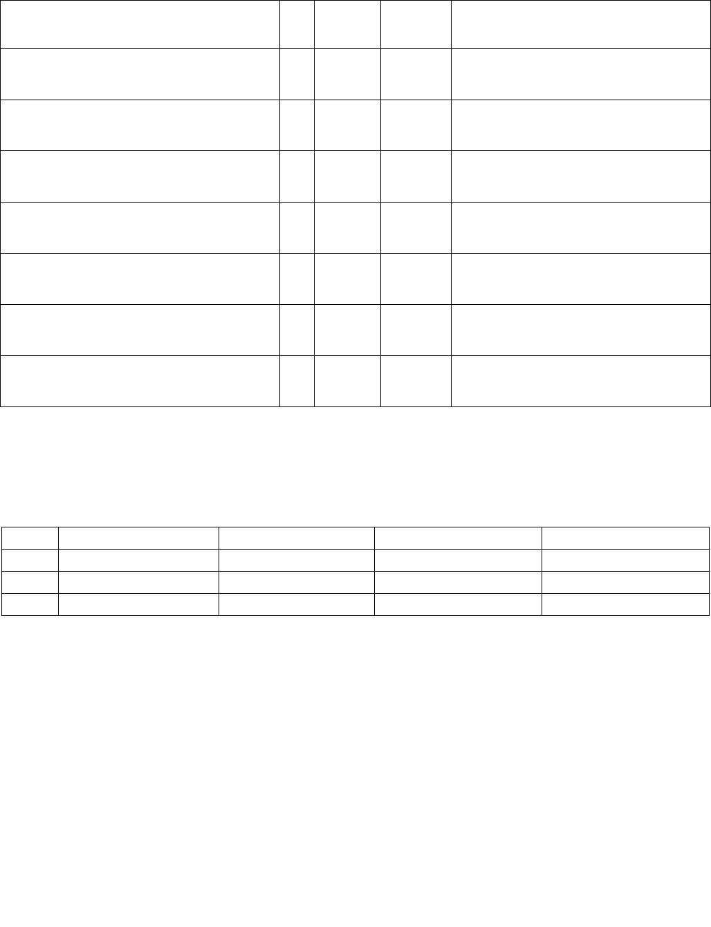
PMULLW—Multiply Packed Signed Integers and Store Low Result
INSTRUCTION SET REFERENCE, M-U
4-378 Vol. 2B
PMULLW—Multiply Packed Signed Integers and Store Low Result
Instruction Operand Encoding
Description
Performs a SIMD signed multiply of the packed signed word integers in the destination operand (first operand) and
the source operand (second operand), and stores the low 16 bits of each intermediate 32-bit result in the destina-
tion operand. (Figure 4-12 shows this operation when using 64-bit operands.)
In 64-bit mode and not encoded with VEX/EVEX, using a REX prefix in the form of REX.R permits this instruction to
access additional registers (XMM8-XMM15).
Legacy SSE version 64-bit operand: The source operand can be an MMX technology register or a 64-bit memory
location. The destination operand is an MMX technology register.
128-bit Legacy SSE version: The first source and destination operands are XMM registers. The second source
operand is an XMM register or a 128-bit memory location. Bits (VLMAX-1:128) of the corresponding YMM destina-
tion register remain unchanged.
VEX.128 encoded version: The first source and destination operands are XMM registers. The second source
operand is an XMM register or a 128-bit memory location. Bits (VLMAX-1:128) of the destination YMM register are
zeroed. VEX.L must be 0, otherwise the instruction will #UD.
Opcode/
Instruction
Op/
En
64/32 bit
Mode
Support
CPUID
Feature
Flag
Description
0F D5 /r1
PMULLW mm, mm/m64
RM V/V MMX Multiply the packed signed word integers in
mm1 register and mm2/m64, and store the low
16 bits of the results in mm1.
66 0F D5 /r
PMULLW xmm1, xmm2/m128
RM V/V SSE2 Multiply the packed signed word integers in
xmm1 and xmm2/m128, and store the low 16
bits of the results in xmm1.
VEX.NDS.128.66.0F.WIG D5 /r
VPMULLW xmm1, xmm2, xmm3/m128
RVM V/V AVX Multiply the packed dword signed integers in
xmm2 and xmm3/m128 and store the low 32
bits of each product in xmm1.
VEX.NDS.256.66.0F.WIG D5 /r
VPMULLW ymm1, ymm2, ymm3/m256
RVM V/V AVX2 Multiply the packed signed word integers in
ymm2 and ymm3/m256, and store the low 16
bits of the results in ymm1.
EVEX.NDS.128.66.0F.WIG D5 /r
VPMULLW xmm1 {k1}{z}, xmm2, xmm3/m128
FVM V/V AVX512VL
AVX512BW
Multiply the packed signed word integers in
xmm2 and xmm3/m128, and store the low 16
bits of the results in xmm1 under writemask k1.
EVEX.NDS.256.66.0F.WIG D5 /r
VPMULLW ymm1 {k1}{z}, ymm2, ymm3/m256
FVM V/V AVX512VL
AVX512BW
Multiply the packed signed word integers in
ymm2 and ymm3/m256, and store the low 16
bits of the results in ymm1 under writemask k1.
EVEX.NDS.512.66.0F.WIG D5 /r
VPMULLW zmm1 {k1}{z}, zmm2, zmm3/m512
FVM V/V AVX512BW Multiply the packed signed word integers in
zmm2 and zmm3/m512, and store the low 16
bits of the results in zmm1 under writemask k1.
NOTES:
1. See note in Section 2.4, “AVX and SSE Instruction Exception Specification” in the Intel® 64 and IA-32 Architectures Software
Developer’s Manual, Volume 2A and Section 22.25.3, “Exception Conditions of Legacy SIMD Instructions Operating on MMX Registers”
in the Intel® 64 and IA-32 Architectures Software Developer’s Manual, Volume 3A.
Op/En Operand 1 Operand 2 Operand 3 Operand 4
RM ModRM:reg (r, w) ModRM:r/m (r) NA NA
RVM ModRM:reg (w) VEX.vvvv (r) ModRM:r/m (r) NA
FVM ModRM:reg (w) EVEX.vvvv (r) ModRM:r/m (r) NA
PMULLW—Multiply Packed Signed Integers and Store Low Result
INSTRUCTION SET REFERENCE, M-U
Vol. 2B 4-379
VEX.256 encoded version: The second source operand can be an YMM register or a 256-bit memory location. The
first source and destination operands are YMM registers.
EVEX encoded versions: The first source operand is a ZMM/YMM/XMM register. The second source operand is a
ZMM/YMM/XMM register, a 512/256/128-bit memory location. The destination operand is conditionally updated
based on writemask k1.
Operation
PMULLW (with 64-bit operands)
TEMP0[31:0] ← DEST[15:0]
∗ SRC[15:0]; (* Signed multiplication *)
TEMP1[31:0] ← DEST[31:16]
∗ SRC[31:16];
TEMP2[31:0] ← DEST[47:32]
∗ SRC[47:32];
TEMP3[31:0] ←DEST[63:48] ∗ SRC[63:48];
DEST[15:0] ← TEMP0[15:0];
DEST[31:16] ← TEMP1[15:0];
DEST[47:32] ← TEMP2[15:0];
DEST[63:48] ← TEMP3[15:0];
PMULLW (with 128-bit operands)
TEMP0[31:0] ← DEST[15:0]
∗ SRC[15:0]; (* Signed multiplication *)
TEMP1[31:0] ←DEST[31:16] ∗ SRC[31:16];
TEMP2[31:0] ← DEST[47:32]
∗ SRC[47:32];
TEMP3[31:0] ←DEST[63:48] ∗ SRC[63:48];
TEMP4[31:0] ←DEST[79:64] ∗ SRC[79:64];
TEMP5[31:0] ← DEST[95:80]
∗ SRC[95:80];
TEMP6[31:0] ← DEST[111:96]
∗ SRC[111:96];
TEMP7[31:0] ←DEST[127:112] ∗ SRC[127:112];
DEST[15:0] ← TEMP0[15:0];
DEST[31:16] ← TEMP1[15:0];
DEST[47:32] ← TEMP2[15:0];
DEST[63:48] ← TEMP3[15:0];
DEST[79:64] ← TEMP4[15:0];
DEST[95:80] ← TEMP5[15:0];
DEST[111:96] ← TEMP6[15:0];
DEST[127:112] ← TEMP7[15:0];
DEST[VLMAX-1:256] 0
Figure 4-13. PMULLU Instruction Operation Using 64-bit Operands
X3 X2 X1 X0
Z3 = X3 ∗ Y3 Z2 = X2 ∗ Y2 Z1 = X1 ∗ Y1 Z0 = X0 ∗ Y0
SRC
DEST
DEST
Y3 Y2 Y1 Y0
TEMP
Z3[15:0] Z2[15:0] Z1[15:0] Z0[15:0]

PMULLW—Multiply Packed Signed Integers and Store Low Result
INSTRUCTION SET REFERENCE, M-U
4-380 Vol. 2B
VPMULLW (VEX.128 encoded version)
Temp0[31:0] SRC1[15:0] * SRC2[15:0]
Temp1[31:0] SRC1[31:16] * SRC2[31:16]
Temp2[31:0] SRC1[47:32] * SRC2[47:32]
Temp3[31:0] SRC1[63:48] * SRC2[63:48]
Temp4[31:0] SRC1[79:64] * SRC2[79:64]
Temp5[31:0] SRC1[95:80] * SRC2[95:80]
Temp6[31:0] SRC1[111:96] * SRC2[111:96]
Temp7[31:0] SRC1[127:112] * SRC2[127:112]
DEST[15:0] Temp0[15:0]
DEST[31:16] Temp1[15:0]
DEST[47:32] Temp2[15:0]
DEST[63:48] Temp3[15:0]
DEST[79:64] Temp4[15:0]
DEST[95:80] Temp5[15:0]
DEST[111:96] Temp6[15:0]
DEST[127:112] Temp7[15:0]
DEST[VLMAX-1:128] 0
PMULLW (EVEX encoded versions)
(KL, VL) = (8, 128), (16, 256), (32, 512)
FOR j 0 TO KL-1
i j * 16
IF k1[j] OR *no writemask*
THEN
temp[31:0] SRC1[i+15:i] * SRC2[i+15:i]
DEST[i+15:i] temp[15:0]
ELSE
IF *merging-masking* ; merging-masking
THEN *DEST[i+15:i] remains unchanged*
ELSE *zeroing-masking* ; zeroing-masking
DEST[i+15:i] 0
FI
FI;
ENDFOR
DEST[MAX_VL-1:VL] 0
Intel C/C++ Compiler Intrinsic Equivalent
VPMULLW __m512i _mm512_mullo_epi16(__m512i a, __m512i b);
VPMULLW __m512i _mm512_mask_mullo_epi16(__m512i s, __mmask32 k, __m512i a, __m512i b);
VPMULLW __m512i _mm512_maskz_mullo_epi16( __mmask32 k, __m512i a, __m512i b);
VPMULLW __m256i _mm256_mask_mullo_epi16(__m256i s, __mmask16 k, __m256i a, __m256i b);
VPMULLW __m256i _mm256_maskz_mullo_epi16( __mmask16 k, __m256i a, __m256i b);
VPMULLW __m128i _mm_mask_mullo_epi16(__m128i s, __mmask8 k, __m128i a, __m128i b);
VPMULLW __m128i _mm_maskz_mullo_epi16( __mmask8 k, __m128i a, __m128i b);
PMULLW: __m64 _mm_mullo_pi16(__m64 m1, __m64 m2)
(V)PMULLW: __m128i _mm_mullo_epi16 ( __m128i a, __m128i b)
VPMULLW:__m256i _mm256_mullo_epi16 ( __m256i a, __m256i b);
Flags Affected
None.

PMULLW—Multiply Packed Signed Integers and Store Low Result
INSTRUCTION SET REFERENCE, M-U
Vol. 2B 4-381
SIMD Floating-Point Exceptions
None.
Other Exceptions
Non-EVEX-encoded instruction, see Exceptions Type 4.
EVEX-encoded instruction, see Exceptions Type E4.nb.

PMULUDQ—Multiply Packed Unsigned Doubleword Integers
INSTRUCTION SET REFERENCE, M-U
4-382 Vol. 2B
PMULUDQ—Multiply Packed Unsigned Doubleword Integers
Instruction Operand Encoding
Description
Multiplies the first operand (destination operand) by the second operand (source operand) and stores the result in
the destination operand.
In 64-bit mode and not encoded with VEX/EVEX, using a REX prefix in the form of REX.R permits this instruction to
access additional registers (XMM8-XMM15).
Legacy SSE version 64-bit operand: The source operand can be an unsigned doubleword integer stored in the low
doubleword of an MMX technology register or a 64-bit memory location. The destination operand can be an
unsigned doubleword integer stored in the low doubleword an MMX technology register. The result is an unsigned
Opcode/
Instruction
Op/
En
64/32 bit
Mode
Support
CPUID
Feature
Flag
Description
0F F4 /r1
PMULUDQ mm1, mm2/m64
RM V/V SSE2 Multiply unsigned doubleword integer in mm1 by
unsigned doubleword integer in mm2/m64, and
store the quadword result in mm1.
66 0F F4 /r
PMULUDQ xmm1, xmm2/m128
RM V/V SSE2 Multiply packed unsigned doubleword integers in
xmm1 by packed unsigned doubleword integers
in xmm2/m128, and store the quadword results
in xmm1.
VEX.NDS.128.66.0F.WIG F4 /r
VPMULUDQ xmm1, xmm2, xmm3/m128
RVM V/V AVX Multiply packed unsigned doubleword integers in
xmm2 by packed unsigned doubleword integers
in xmm3/m128, and store the quadword results
in xmm1.
VEX.NDS.256.66.0F.WIG F4 /r
VPMULUDQ ymm1, ymm2, ymm3/m256
RVM V/V AVX2 Multiply packed unsigned doubleword integers in
ymm2 by packed unsigned doubleword integers
in ymm3/m256, and store the quadword results
in ymm1.
EVEX.NDS.128.66.0F.W1 F4 /r
VPMULUDQ xmm1 {k1}{z}, xmm2,
xmm3/m128/m64bcst
FV V/V AVX512VL
AVX512F
Multiply packed unsigned doubleword integers in
xmm2 by packed unsigned doubleword integers
in xmm3/m128/m64bcst, and store the
quadword results in xmm1 under writemask k1.
EVEX.NDS.256.66.0F.W1 F4 /r
VPMULUDQ ymm1 {k1}{z}, ymm2,
ymm3/m256/m64bcst
FV V/V AVX512VL
AVX512F
Multiply packed unsigned doubleword integers in
ymm2 by packed unsigned doubleword integers
in ymm3/m256/m64bcst, and store the
quadword results in ymm1 under writemask k1.
EVEX.NDS.512.66.0F.W1 F4 /r
VPMULUDQ zmm1 {k1}{z}, zmm2,
zmm3/m512/m64bcst
FV V/V AVX512F Multiply packed unsigned doubleword integers in
zmm2 by packed unsigned doubleword integers
in zmm3/m512/m64bcst, and store the
quadword results in zmm1 under writemask k1.
NOTES:
1. See note in Section 2.4, “AVX and SSE Instruction Exception Specification” in the Intel® 64 and IA-32 Architectures Software
Developer’s Manual, Volume 2A and Section 22.25.3, “Exception Conditions of Legacy SIMD Instructions Operating on MMX Registers”
in the Intel® 64 and IA-32 Architectures Software Developer’s Manual, Volume 3A.
Op/En Operand 1 Operand 2 Operand 3 Operand 4
RM ModRM:reg (r, w) ModRM:r/m (r) NA NA
RVM ModRM:reg (w) VEX.vvvv (r) ModRM:r/m (r) NA
FV ModRM:reg (w) EVEX.vvvv (r) ModRM:r/m (r) NA

PMULUDQ—Multiply Packed Unsigned Doubleword Integers
INSTRUCTION SET REFERENCE, M-U
Vol. 2B 4-383
quadword integer stored in the destination an MMX technology register. When a quadword result is too large to be
represented in 64 bits (overflow), the result is wrapped around and the low 64 bits are written to the destination
element (that is, the carry is ignored).
For 64-bit memory operands, 64 bits are fetched from memory, but only the low doubleword is used in the compu-
tation.
128-bit Legacy SSE version: The second source operand is two packed unsigned doubleword integers stored in the
first (low) and third doublewords of an XMM register or a 128-bit memory location. For 128-bit memory operands,
128 bits are fetched from memory, but only the first and third doublewords are used in the computation. The first
source operand is two packed unsigned doubleword integers stored in the first and third doublewords of an XMM
register. The destination contains two packed unsigned quadword integers stored in an XMM register. Bits (VLMAX-
1:128) of the corresponding YMM destination register remain unchanged.
VEX.128 encoded version: The second source operand is two packed unsigned doubleword integers stored in the
first (low) and third doublewords of an XMM register or a 128-bit memory location. For 128-bit memory operands,
128 bits are fetched from memory, but only the first and third doublewords are used in the computation. The first
source operand is two packed unsigned doubleword integers stored in the first and third doublewords of an XMM
register. The destination contains two packed unsigned quadword integers stored in an XMM register. Bits (VLMAX-
1:128) of the destination YMM register are zeroed.
VEX.256 encoded version: The second source operand is four packed unsigned doubleword integers stored in the
first (low), third, fifth and seventh doublewords of a YMM register or a 256-bit memory location. For 256-bit
memory operands, 256 bits are fetched from memory, but only the first, third, fifth and seventh doublewords are
used in the computation. The first source operand is four packed unsigned doubleword integers stored in the first,
third, fifth and seventh doublewords of an YMM register. The destination contains four packed unaligned quadword
integers stored in an YMM register.
EVEX encoded version: The input unsigned doubleword integers are taken from the even-numbered elements of
the source operands. The first source operand is a ZMM/YMM/XMM registers. The second source operand can be an
ZMM/YMM/XMM register, a 512/256/128-bit memory location or a 512/256/128-bit vector broadcasted from a 64-
bit memory location. The destination is a ZMM/YMM/XMM register, and updated according to the writemask at 64-
bit granularity.
Operation
PMULUDQ (with 64-Bit operands)
DEST[63:0] ← DEST[31:0] ∗ SRC[31:0];
PMULUDQ (with 128-Bit operands)
DEST[63:0] ← DEST[31:0] ∗ SRC[31:0];
DEST[127:64] ← DEST[95:64] ∗ SRC[95:64];
VPMULUDQ (VEX.128 encoded version)
DEST[63:0] SRC1[31:0] * SRC2[31:0]
DEST[127:64] SRC1[95:64] * SRC2[95:64]
DEST[VLMAX-1:128] 0
VPMULUDQ (VEX.256 encoded version)
DEST[63:0] SRC1[31:0] * SRC2[31:0]
DEST[127:64] SRC1[95:64] * SRC2[95:64
DEST[191:128] SRC1[159:128] * SRC2[159:128]
DEST[255:192] SRC1[223:192] * SRC2[223:192]
DEST[VLMAX-1:256] 0
VPMULUDQ (EVEX encoded versions)
(KL, VL) = (2, 128), (4, 256), (8, 512)
FOR j 0 TO KL-1
i j * 64
IF k1[j] OR *no writemask* THEN
IF (EVEX.b = 1) AND (SRC2 *is memory*)

PMULUDQ—Multiply Packed Unsigned Doubleword Integers
INSTRUCTION SET REFERENCE, M-U
4-384 Vol. 2B
THEN DEST[i+63:i] ZeroExtend64( SRC1[i+31:i]) * ZeroExtend64( SRC2[31:0] )
ELSE DEST[i+63:i] ZeroExtend64( SRC1[i+31:i]) * ZeroExtend64( SRC2[i+31:i] )
FI;
ELSE
IF *merging-masking* ; merging-masking
THEN *DEST[i+63:i] remains unchanged*
ELSE *zeroing-masking* ; zeroing-masking
DEST[i+63:i] 0
FI
FI;
ENDFOR
DEST[MAX_VL-1:VL] 0
Intel C/C++ Compiler Intrinsic Equivalent
VPMULUDQ __m512i _mm512_mul_epu32(__m512i a, __m512i b);
VPMULUDQ __m512i _mm512_mask_mul_epu32(__m512i s, __mmask8 k, __m512i a, __m512i b);
VPMULUDQ __m512i _mm512_maskz_mul_epu32( __mmask8 k, __m512i a, __m512i b);
VPMULUDQ __m256i _mm256_mask_mul_epu32(__m256i s, __mmask8 k, __m256i a, __m256i b);
VPMULUDQ __m256i _mm256_maskz_mul_epu32( __mmask8 k, __m256i a, __m256i b);
VPMULUDQ __m128i _mm_mask_mul_epu32(__m128i s, __mmask8 k, __m128i a, __m128i b);
VPMULUDQ __m128i _mm_maskz_mul_epu32( __mmask8 k, __m128i a, __m128i b);
PMULUDQ:__m64 _mm_mul_su32 (__m64 a, __m64 b)
(V)PMULUDQ:__m128i _mm_mul_epu32 ( __m128i a, __m128i b)
VPMULUDQ:__m256i _mm256_mul_epu32( __m256i a, __m256i b);
Flags Affected
None.
SIMD Floating-Point Exceptions
None.
Other Exceptions
Non-EVEX-encoded instruction, see Exceptions Type 4.
EVEX-encoded instruction, see Exceptions Type E4.

POP—Pop a Value from the Stack
INSTRUCTION SET REFERENCE, M-U
Vol. 2B 4-385
POP—Pop a Value from the Stack
Instruction Operand Encoding
Description
Loads the value from the top of the stack to the location specified with the destination operand (or explicit opcode)
and then increments the stack pointer. The destination operand can be a general-purpose register, memory loca-
tion, or segment register.
Address and operand sizes are determined and used as follows:
•Address size. The D flag in the current code-segment descriptor determines the default address size; it may be
overridden by an instruction prefix (67H).
Opcode Instruction Op/
En
64-Bit
Mode
Compat/
Leg Mode
Description
8F /0 POP r/m16 M Valid Valid Pop top of stack into m16; increment stack
pointer.
8F /0 POP r/m32 M N.E. Valid Pop top of stack into m32; increment stack
pointer.
8F /0 POP r/m64 M Valid N.E. Pop top of stack into m64; increment stack
pointer. Cannot encode 32-bit operand size.
58+ rw POP r16 O Valid Valid Pop top of stack into r16; increment stack
pointer.
58+ rd POP r32 O N.E. Valid Pop top of stack into r32; increment stack
pointer.
58+ rd POP r64 O Valid N.E. Pop top of stack into r64; increment stack
pointer. Cannot encode 32-bit operand size.
1F POP DS NP Invalid Valid Pop top of stack into DS; increment stack
pointer.
07 POP ES NP Invalid Valid Pop top of stack into ES; increment stack
pointer.
17 POP SS NP Invalid Valid Pop top of stack into SS; increment stack
pointer.
0F A1 POP FS NP Valid Valid Pop top of stack into FS; increment stack
pointer by 16 bits.
0F A1 POP FS NP N.E. Valid Pop top of stack into FS; increment stack
pointer by 32 bits.
0F A1 POP FS NP Valid N.E. Pop top of stack into FS; increment stack
pointer by 64 bits.
0F A9 POP GS NP Valid Valid Pop top of stack into GS; increment stack
pointer by 16 bits.
0F A9 POP GS NP N.E. Valid Pop top of stack into GS; increment stack
pointer by 32 bits.
0F A9 POP GS NP Valid N.E. Pop top of stack into GS; increment stack
pointer by 64 bits.
Op/En Operand 1 Operand 2 Operand 3 Operand 4
MModRM:r/m (w) NA NA NA
Oopcode + rd (w) NA NA NA
NP NA NA NA NA

POP—Pop a Value from the Stack
INSTRUCTION SET REFERENCE, M-U
4-386 Vol. 2B
The address size is used only when writing to a destination operand in memory.
•Operand size. The D flag in the current code-segment descriptor determines the default operand size; it may
be overridden by instruction prefixes (66H or REX.W).
The operand size (16, 32, or 64 bits) determines the amount by which the stack pointer is incremented (2, 4
or 8).
•Stack-address size. Outside of 64-bit mode, the B flag in the current stack-segment descriptor determines the
size of the stack pointer (16 or 32 bits); in 64-bit mode, the size of the stack pointer is always 64 bits.
The stack-address size determines the width of the stack pointer when reading from the stack in memory and
when incrementing the stack pointer. (As stated above, the amount by which the stack pointer is incremented
is determined by the operand size.)
If the destination operand is one of the segment registers DS, ES, FS, GS, or SS, the value loaded into the register
must be a valid segment selector. In protected mode, popping a segment selector into a segment register automat-
ically causes the descriptor information associated with that segment selector to be loaded into the hidden
(shadow) part of the segment register and causes the selector and the descriptor information to be validated (see
the “Operation” section below).
A NULL value (0000-0003) may be popped into the DS, ES, FS, or GS register without causing a general protection
fault. However, any subsequent attempt to reference a segment whose corresponding segment register is loaded
with a NULL value causes a general protection exception (#GP). In this situation, no memory reference occurs and
the saved value of the segment register is NULL.
The POP instruction cannot pop a value into the CS register. To load the CS register from the stack, use the RET
instruction.
If the ESP register is used as a base register for addressing a destination operand in memory, the POP instruction
computes the effective address of the operand after it increments the ESP register. For the case of a 16-bit stack
where ESP wraps to 0H as a result of the POP instruction, the resulting location of the memory write is processor-
family-specific.
The POP ESP instruction increments the stack pointer (ESP) before data at the old top of stack is written into the
destination.
A POP SS instruction inhibits all interrupts, including the NMI interrupt, until after execution of the next instruction.
This action allows sequential execution of POP SS and MOV ESP, EBP instructions without the danger of having an
invalid stack during an interrupt1. However, use of the LSS instruction is the preferred method of loading the SS
and ESP registers.
In 64-bit mode, using a REX prefix in the form of REX.R permits access to additional registers (R8-R15). When in
64-bit mode, POPs using 32-bit operands are not encodable and POPs to DS, ES, SS are not valid. See the summary
chart at the beginning of this section for encoding data and limits.
Operation
IF StackAddrSize = 32
THEN
IF OperandSize = 32
THEN
DEST ← SS:ESP; (* Copy a doubleword *)
ESP ← ESP + 4;
ELSE (* OperandSize = 16*)
DEST ← SS:ESP; (* Copy a word *)
1. If a code instruction breakpoint (for debug) is placed on an instruction located immediately after a POP SS instruction, the breakpoint
may not be triggered. However, in a sequence of instructions that POP the SS register, only the first instruction in the sequence is
guaranteed to delay an interrupt.
In the following sequence, interrupts may be recognized before POP ESP executes:
POP SS
POP SS
POP ESP

POP—Pop a Value from the Stack
INSTRUCTION SET REFERENCE, M-U
Vol. 2B 4-387
ESP ← ESP + 2;
FI;
ELSE IF StackAddrSize = 64
THEN
IF OperandSize = 64
THEN
DEST ← SS:RSP; (* Copy quadword *)
RSP ← RSP + 8;
ELSE (* OperandSize = 16*)
DEST ← SS:RSP; (* Copy a word *)
RSP ← RSP + 2;
FI;
FI;
ELSE StackAddrSize = 16
THEN
IF OperandSize = 16
THEN
DEST ← SS:SP; (* Copy a word *)
SP ← SP + 2;
ELSE (* OperandSize = 32 *)
DEST ← SS:SP; (* Copy a doubleword *)
SP ← SP + 4;
FI;
FI;
Loading a segment register while in protected mode results in special actions, as described in the following listing.
These checks are performed on the segment selector and the segment descriptor it points to.
64-BIT_MODE
IF FS, or GS is loaded with non-NULL selector;
THEN
IF segment selector index is outside descriptor table limits
OR segment is not a data or readable code segment
OR ((segment is a data or nonconforming code segment)
AND (both RPL and CPL > DPL))
THEN #GP(selector);
IF segment not marked present
THEN #NP(selector);
ELSE
SegmentRegister ← segment selector;
SegmentRegister ← segment descriptor;
FI;
FI;
IF FS, or GS is loaded with a NULL selector;
THEN
SegmentRegister ← segment selector;
SegmentRegister ← segment descriptor;
FI;
PREOTECTED MODE OR COMPATIBILITY MODE;
IF SS is loaded;

POP—Pop a Value from the Stack
INSTRUCTION SET REFERENCE, M-U
4-388 Vol. 2B
THEN
IF segment selector is NULL
THEN #GP(0);
FI;
IF segment selector index is outside descriptor table limits
or segment selector's RPL ≠ CPL
or segment is not a writable data segment
or DPL ≠ CPL
THEN #GP(selector);
FI;
IF segment not marked present
THEN #SS(selector);
ELSE
SS ← segment selector;
SS ← segment descriptor;
FI;
FI;
IF DS, ES, FS, or GS is loaded with non-NULL selector;
THEN
IF segment selector index is outside descriptor table limits
or segment is not a data or readable code segment
or ((segment is a data or nonconforming code segment)
and (both RPL and CPL > DPL))
THEN #GP(selector);
FI;
IF segment not marked present
THEN #NP(selector);
ELSE
SegmentRegister ← segment selector;
SegmentRegister ← segment descriptor;
FI;
FI;
IF DS, ES, FS, or GS is loaded with a NULL selector
THEN
SegmentRegister ← segment selector;
SegmentRegister ← segment descriptor;
FI;
Flags Affected
None.
Protected Mode Exceptions
#GP(0) If attempt is made to load SS register with NULL segment selector.
If the destination operand is in a non-writable segment.
If a memory operand effective address is outside the CS, DS, ES, FS, or GS segment limit.
If the DS, ES, FS, or GS register is used to access memory and it contains a NULL segment
selector.
#GP(selector) If segment selector index is outside descriptor table limits.
If the SS register is being loaded and the segment selector's RPL and the segment descriptor’s
DPL are not equal to the CPL.

POP—Pop a Value from the Stack
INSTRUCTION SET REFERENCE, M-U
Vol. 2B 4-389
If the SS register is being loaded and the segment pointed to is a
non-writable data segment.
If the DS, ES, FS, or GS register is being loaded and the segment pointed to is not a data or
readable code segment.
If the DS, ES, FS, or GS register is being loaded and the segment pointed to is a data or
nonconforming code segment, but both the RPL and the CPL are greater than the DPL.
#SS(0) If the current top of stack is not within the stack segment.
If a memory operand effective address is outside the SS segment limit.
#SS(selector) If the SS register is being loaded and the segment pointed to is marked not present.
#NP If the DS, ES, FS, or GS register is being loaded and the segment pointed to is marked not
present.
#PF(fault-code) If a page fault occurs.
#AC(0) If an unaligned memory reference is made while the current privilege level is 3 and alignment
checking is enabled.
#UD If the LOCK prefix is used.
Real-Address Mode Exceptions
#GP If a memory operand effective address is outside the CS, DS, ES, FS, or GS segment limit.
#UD If the LOCK prefix is used.
Virtual-8086 Mode Exceptions
#GP(0) If a memory operand effective address is outside the CS, DS, ES, FS, or GS segment limit.
#PF(fault-code) If a page fault occurs.
#AC(0) If an unaligned memory reference is made while alignment checking is enabled.
#UD If the LOCK prefix is used.
Compatibility Mode Exceptions
Same as for protected mode exceptions.
64-Bit Mode Exceptions
#GP(0) If the memory address is in a non-canonical form.
#SS(0) If the stack address is in a non-canonical form.
#GP(selector) If the descriptor is outside the descriptor table limit.
If the FS or GS register is being loaded and the segment pointed to is not a data or readable
code segment.
If the FS or GS register is being loaded and the segment pointed to is a data or nonconforming
code segment, but both the RPL and the CPL are greater than the DPL.
#AC(0) If an unaligned memory reference is made while alignment checking is enabled.
#PF(fault-code) If a page fault occurs.
#NP If the FS or GS register is being loaded and the segment pointed to is marked not present.
#UD If the LOCK prefix is used.

POPA/POPAD—Pop All General-Purpose Registers
INSTRUCTION SET REFERENCE, M-U
4-390 Vol. 2B
POPA/POPAD—Pop All General-Purpose Registers
Instruction Operand Encoding
Description
Pops doublewords (POPAD) or words (POPA) from the stack into the general-purpose registers. The registers are
loaded in the following order: EDI, ESI, EBP, EBX, EDX, ECX, and EAX (if the operand-size attribute is 32) and DI,
SI, BP, BX, DX, CX, and AX (if the operand-size attribute is 16). (These instructions reverse the operation of the
PUSHA/PUSHAD instructions.) The value on the stack for the ESP or SP register is ignored. Instead, the ESP or SP
register is incremented after each register is loaded.
The POPA (pop all) and POPAD (pop all double) mnemonics reference the same opcode. The POPA instruction is
intended for use when the operand-size attribute is 16 and the POPAD instruction for when the operand-size attri-
bute is 32. Some assemblers may force the operand size to 16 when POPA is used and to 32 when POPAD is used
(using the operand-size override prefix [66H] if necessary). Others may treat these mnemonics as synonyms
(POPA/POPAD) and use the current setting of the operand-size attribute to determine the size of values to be
popped from the stack, regardless of the mnemonic used. (The D flag in the current code segment’s segment
descriptor determines the operand-size attribute.)
This instruction executes as described in non-64-bit modes. It is not valid in 64-bit mode.
Operation
IF 64-Bit Mode
THEN
#UD;
ELSE
IF OperandSize = 32 (* Instruction = POPAD *)
THEN
EDI ← Pop();
ESI ← Pop();
EBP ← Pop();
Increment ESP by 4; (* Skip next 4 bytes of stack *)
EBX ← Pop();
EDX ← Pop();
ECX ← Pop();
EAX ← Pop();
ELSE (* OperandSize = 16, instruction = POPA *)
DI ← Pop();
SI ← Pop();
BP ← Pop();
Increment ESP by 2; (* Skip next 2 bytes of stack *)
BX ← Pop();
DX ← Pop();
CX ← Pop();
AX ← Pop();
FI;
FI;
Opcode Instruction Op/
En
64-Bit
Mode
Compat/
Leg Mode
Description
61 POPA NP Invalid Valid Pop DI, SI, BP, BX, DX, CX, and AX.
61 POPAD NP Invalid Valid Pop EDI, ESI, EBP, EBX, EDX, ECX, and EAX.
Op/En Operand 1 Operand 2 Operand 3 Operand 4
NP NA NA NA NA

POPA/POPAD—Pop All General-Purpose Registers
INSTRUCTION SET REFERENCE, M-U
Vol. 2B 4-391
Flags Affected
None.
Protected Mode Exceptions
#SS(0) If the starting or ending stack address is not within the stack segment.
#PF(fault-code) If a page fault occurs.
#AC(0) If an unaligned memory reference is made while the current privilege level is 3 and alignment
checking is enabled.
#UD If the LOCK prefix is used.
Real-Address Mode Exceptions
#SS If the starting or ending stack address is not within the stack segment.
#UD If the LOCK prefix is used.
Virtual-8086 Mode Exceptions
#SS(0) If the starting or ending stack address is not within the stack segment.
#PF(fault-code) If a page fault occurs.
#AC(0) If an unaligned memory reference is made while alignment checking is enabled.
#UD If the LOCK prefix is used.
Compatibility Mode Exceptions
Same as for protected mode exceptions.
64-Bit Mode Exceptions
#UD If in 64-bit mode.

POPCNT — Return the Count of Number of Bits Set to 1
INSTRUCTION SET REFERENCE, M-U
4-392 Vol. 2B
POPCNT — Return the Count of Number of Bits Set to 1
Instruction Operand Encoding
Description
This instruction calculates the number of bits set to 1 in the second operand (source) and returns the count in the
first operand (a destination register).
Operation
Count = 0;
For (i=0; i < OperandSize; i++)
{ IF (SRC[ i] = 1) // i’th bit
THEN Count++; FI;
}
DEST Count;
Flags Affected
OF, SF, ZF, AF, CF, PF are all cleared. ZF is set if SRC = 0, otherwise ZF is cleared.
Intel C/C++ Compiler Intrinsic Equivalent
POPCNT: int _mm_popcnt_u32(unsigned int a);
POPCNT: int64_t _mm_popcnt_u64(unsigned __int64 a);
Protected Mode Exceptions
#GP(0) If a memory operand effective address is outside the CS, DS, ES, FS or GS segments.
#SS(0) If a memory operand effective address is outside the SS segment limit.
#PF (fault-code) For a page fault.
#AC(0) If an unaligned memory reference is made while the current privilege level is 3 and alignment
checking is enabled.
#UD If CPUID.01H:ECX.POPCNT [Bit 23] = 0.
If LOCK prefix is used.
Real-Address Mode Exceptions
#GP(0) If any part of the operand lies outside of the effective address space from 0 to 0FFFFH.
#SS(0) If a memory operand effective address is outside the SS segment limit.
#UD If CPUID.01H:ECX.POPCNT [Bit 23] = 0.
If LOCK prefix is used.
Opcode Instruction Op/
En
64-Bit
Mode
Compat/
Leg Mode
Description
F3 0F B8 /r POPCNT r16, r/m16 RM Valid Valid POPCNT on r/m16
F3 0F B8 /r POPCNT r32, r/m32 RM Valid Valid POPCNT on r/m32
F3 REX.W 0F B8 /r POPCNT r64, r/m64 RM Valid N.E. POPCNT on r/m64
Op/En Operand 1 Operand 2 Operand 3 Operand 4
RM ModRM:reg (w) ModRM:r/m (r) NA NA

POPCNT — Return the Count of Number of Bits Set to 1
INSTRUCTION SET REFERENCE, M-U
Vol. 2B 4-393
Virtual 8086 Mode Exceptions
#GP(0) If any part of the operand lies outside of the effective address space from 0 to 0FFFFH.
#SS(0) If a memory operand effective address is outside the SS segment limit.
#PF (fault-code) For a page fault.
#AC(0) If an unaligned memory reference is made while alignment checking is enabled.
#UD If CPUID.01H:ECX.POPCNT [Bit 23] = 0.
If LOCK prefix is used.
Compatibility Mode Exceptions
Same exceptions as in Protected Mode.
64-Bit Mode Exceptions
#GP(0) If the memory address is in a non-canonical form.
#SS(0) If a memory address referencing the SS segment is in a non-canonical form.
#PF (fault-code) For a page fault.
#AC(0) If alignment checking is enabled and an unaligned memory reference is made while the
current privilege level is 3.
#UD If CPUID.01H:ECX.POPCNT [Bit 23] = 0.
If LOCK prefix is used.

POPF/POPFD/POPFQ—Pop Stack into EFLAGS Register
INSTRUCTION SET REFERENCE, M-U
4-394 Vol. 2B
POPF/POPFD/POPFQ—Pop Stack into EFLAGS Register
Instruction Operand Encoding
Description
Pops a doubleword (POPFD) from the top of the stack (if the current operand-size attribute is 32) and stores the
value in the EFLAGS register, or pops a word from the top of the stack (if the operand-size attribute is 16) and
stores it in the lower 16 bits of the EFLAGS register (that is, the FLAGS register). These instructions reverse the
operation of the PUSHF/PUSHFD instructions.
The POPF (pop flags) and POPFD (pop flags double) mnemonics reference the same opcode. The POPF instruction
is intended for use when the operand-size attribute is 16; the POPFD instruction is intended for use when the
operand-size attribute is 32. Some assemblers may force the operand size to 16 for POPF and to 32 for POPFD.
Others may treat the mnemonics as synonyms (POPF/POPFD) and use the setting of the operand-size attribute to
determine the size of values to pop from the stack.
The effect of POPF/POPFD on the EFLAGS register changes, depending on the mode of operation. See the Table
4-15 and key below for details.
When operating in protected, compatibility, or 64-bit mode at privilege level 0 (or in real-address mode, the equiv-
alent to privilege level 0), all non-reserved flags in the EFLAGS register except RF1, VIP, VIF, and VM may be modi-
fied. VIP, VIF and VM remain unaffected.
When operating in protected, compatibility, or 64-bit mode with a privilege level greater than 0, but less than or
equal to IOPL, all flags can be modified except the IOPL field and RF1, IF, VIP, VIF, and VM; these remain unaffected.
The AC and ID flags can only be modified if the operand-size attribute is 32. The interrupt flag (IF) is altered only
when executing at a level at least as privileged as the IOPL. If a POPF/POPFD instruction is executed with insuffi-
cient privilege, an exception does not occur but privileged bits do not change.
When operating in virtual-8086 mode (EFLAGS.VM = 1) without the virtual-8086 mode extensions (CR4.VME = 0),
the POPF/POPFD instructions can be used only if IOPL = 3; otherwise, a general-protection exception (#GP) occurs.
If the virtual-8086 mode extensions are enabled (CR4.VME = 1), POPF (but not POPFD) can be executed in virtual-
8086 mode with IOPL < 3.
In 64-bit mode, the mnemonic assigned is POPFQ (note that the 32-bit operand is not encodable). POPFQ pops 64
bits from the stack. Reserved bits of RFLAGS (including the upper 32 bits of RFLAGS) are not affected.
See Chapter 3 of the Intel® 64 and IA-32 Architectures Software Developer’s Manual, Volume 1, for more informa-
tion about the EFLAGS registers.
Opcode Instruction Op/
En
64-Bit
Mode
Compat/
Leg Mode
Description
9D POPF NP Valid Valid Pop top of stack into lower 16 bits of EFLAGS.
9D POPFD NP N.E. Valid Pop top of stack into EFLAGS.
9D POPFQ NP Valid N.E. Pop top of stack and zero-extend into RFLAGS.
Op/En Operand 1 Operand 2 Operand 3 Operand 4
NP NA NA NA NA
1. RF is always zero after the execution of POPF. This is because POPF, like all instructions, clears RF as it begins to execute.
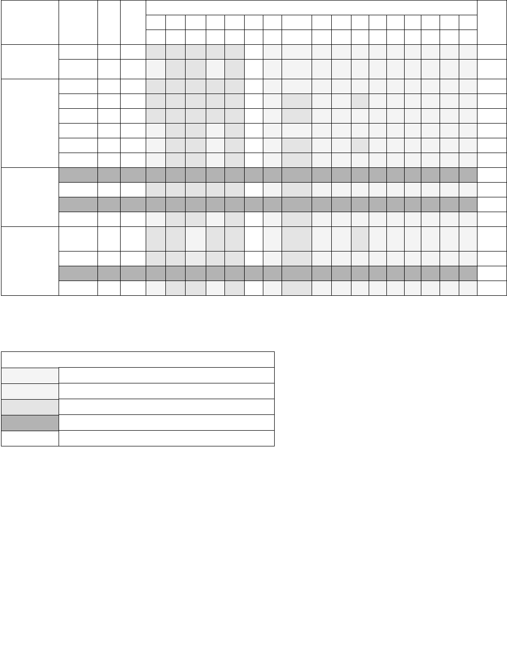
POPF/POPFD/POPFQ—Pop Stack into EFLAGS Register
INSTRUCTION SET REFERENCE, M-U
Vol. 2B 4-395
Operation
IF VM = 0 (* Not in Virtual-8086 Mode *)
THEN IF CPL = 0
THEN
IF OperandSize = 32;
THEN
EFLAGS ← Pop(); (* 32-bit pop *)
(* All non-reserved flags except RF, VIP, VIF, and VM can be modified;
VIP, VIF, VM, and all reserved bits are unaffected. RF is cleared. *)
ELSE IF (Operandsize = 64)
RFLAGS = Pop(); (* 64-bit pop *)
(* All non-reserved flags except RF, VIP, VIF, and VM can be modified;
VIP, VIF, VM, and all reserved bits are unaffected. RF is cleared. *)
ELSE (* OperandSize = 16 *)
Table 4-15. Effect of POPF/POPFD on the EFLAGS Register
Mode Operand
Size
CPL IOPL
Flags
Notes
21 20 19 18 17 16 14 13:12 11 10 9 8 7 6 4 2 0
ID VIP VIF AC VM RF NT IOPL OF DF IF TF SF ZF AF PF CF
Real-Address
Mode (CR0.PE
= 0)
16 0 0-3 N N N N N0S S S S S S S S S S S
32 0 0-3 S N N S N0S S S S S S S S S S S
Protected,
Compatibility,
and 64-Bit
Modes
(CR0.PE = 1,
EFLAGS.VM =
0)
16 0 0-3 N N N N N0S S S S S S S S S S S
16 1-3 <CPL N N N N N0S N S S N S S S S S S
16 1-3 ≥CPL N N N N N0S N S S S S S S S S S
32, 64 0 0-3 S N N S N0S S S S S S S S S S S
32, 64 1-3 <CPL S N N S N0S N S S N S S S S S S
32, 64 1-3 ≥CPL S N N S N0S N S S S S S S S S S
Virtual-8086
(CR0.PE = 1,
EFLAGS.VM =
1,
CR4.VME = 0)
16 30-2 X X X X X X X X X X X X X X X X X 1
16 3 3 N N N N N0S N S S S S S S S S S
32 30-2 X X X X X X X X X X X X X X X X X 1
32 3 3 S N N S N0S N S S S S S S S S S
VME
(CR0.PE = 1,
EFLAGS.VM =
1,
CR4.VME = 1)
16 3 0-2 N/
X
N/
X
SV/
X
N/
X
N/
X
0/
X
S/
X
N/X S/
X
S/
X
N/
X
S/
X
S/
X
S/
X
S/
X
S/
X
S/
X
2
16 3 3 N N N N N0S N S S S S S S S S S
32 30-2 X X X X X X X X X X X X X X X X X 1
32 3 3 S N N S N0S N S S S S S S S S S
NOTES:
1. #GP fault - no flag update
2. #GP fault with no flag update if VIP=1 in EFLAGS register and IF=1 in FLAGS value on stack
Key
SUpdated from stack
SV Updated from IF (bit 9) in FLAGS value on stack
NNo change in value
XNo EFLAGS update
0Value is cleared

POPF/POPFD/POPFQ—Pop Stack into EFLAGS Register
INSTRUCTION SET REFERENCE, M-U
4-396 Vol. 2B
EFLAGS[15:0] ← Pop(); (* 16-bit pop *)
(* All non-reserved flags can be modified. *)
FI;
ELSE (* CPL > 0 *)
IF OperandSize = 32
THEN
IF CPL > IOPL
THEN
EFLAGS ← Pop(); (* 32-bit pop *)
(* All non-reserved bits except IF, IOPL, VIP, VIF, VM and RF can be modified;
IF, IOPL, VIP, VIF, VM and all reserved bits are unaffected; RF is cleared. *)
ELSE
EFLAGS ← Pop(); (* 32-bit pop *)
(* All non-reserved bits except IOPL, VIP, VIF, VM and RF can be modified;
IOPL, VIP, VIF, VM and all reserved bits are unaffected; RF is cleared. *)
FI;
ELSE IF (Operandsize = 64)
IF CPL > IOPL
THEN
RFLAGS ← Pop(); (* 64-bit pop *)
(* All non-reserved bits except IF, IOPL, VIP, VIF, VM and RF can be modified;
IF, IOPL, VIP, VIF, VM and all reserved bits are unaffected; RF is cleared. *)
ELSE
RFLAGS ← Pop(); (* 64-bit pop *)
(* All non-reserved bits except IOPL, VIP, VIF, VM and RF can be modified;
IOPL, VIP, VIF, VM and all reserved bits are unaffected; RF is cleared. *)
FI;
ELSE (* OperandSize = 16 *)
EFLAGS[15:0] ← Pop(); (* 16-bit pop *)
(* All non-reserved bits except IOPL can be modified; IOPL and all
reserved bits are unaffected. *)
FI;
FI;
ELSE IF CR4.VME = 1 (* In Virtual-8086 Mode with VME Enabled *)
IF IOPL = 3
THEN IF OperandSize = 32
THEN
EFLAGS ← Pop();
(* All non-reserved bits except IOPL, VIP, VIF, VM, and RF can be modified;
VIP, VIF, VM, IOPL and all reserved bits are unaffected. RF is cleared. *)
ELSE
EFLAGS[15:0] ← Pop(); FI;
(* All non-reserved bits except IOPL can be modified;
IOPL and all reserved bits are unaffected. *)
FI;
ELSE (* IOPL < 3 *)
IF (Operandsize = 32)
THEN
#GP(0); (* Trap to virtual-8086 monitor. *)
ELSE (* Operandsize = 16 *)
tempFLAGS ← Pop();
IF EFLAGS.VIP = 1 AND tempFLAGS[9] = 1
THEN #GP(0);
ELSE

POPF/POPFD/POPFQ—Pop Stack into EFLAGS Register
INSTRUCTION SET REFERENCE, M-U
Vol. 2B 4-397
EFLAGS.VIF ← tempFLAGS[9];
EFLAGS[15:0] ← tempFLAGS;
(* All non-reserved bits except IOPL and IF can be modified;
IOPL, IF, and all reserved bits are unaffected. *)
FI;
FI;
FI;
ELSE (* In Virtual-8086 Mode *)
IF IOPL = 3
THEN IF OperandSize = 32
THEN
EFLAGS ← Pop();
(* All non-reserved bits except IOPL, VIP, VIF, VM, and RF can be modified;
VIP, VIF, VM, IOPL and all reserved bits are unaffected. RF is cleared. *)
ELSE
EFLAGS[15:0] ← Pop(); FI;
(* All non-reserved bits except IOPL can be modified;
IOPL and all reserved bits are unaffected. *)
ELSE (* IOPL < 3 *)
#GP(0); (* Trap to virtual-8086 monitor. *)
FI;
FI;
FI;
Flags Affected
All flags may be affected; see the Operation section for details.
Protected Mode Exceptions
#SS(0) If the top of stack is not within the stack segment.
#PF(fault-code) If a page fault occurs.
#AC(0) If an unaligned memory reference is made while the current privilege level is 3 and alignment
checking is enabled.
#UD If the LOCK prefix is used.
Real-Address Mode Exceptions
#SS If the top of stack is not within the stack segment.
#UD If the LOCK prefix is used.
Virtual-8086 Mode Exceptions
#GP(0) If the I/O privilege level is less than 3.
If an attempt is made to execute the POPF/POPFD instruction with an operand-size override
prefix.
#SS(0) If the top of stack is not within the stack segment.
#PF(fault-code) If a page fault occurs.
#AC(0) If an unaligned memory reference is made while alignment checking is enabled.
#UD If the LOCK prefix is used.
Compatibility Mode Exceptions
Same as for protected mode exceptions.

POPF/POPFD/POPFQ—Pop Stack into EFLAGS Register
INSTRUCTION SET REFERENCE, M-U
4-398 Vol. 2B
64-Bit Mode Exceptions
#GP(0) If the memory address is in a non-canonical form.
#SS(0) If the stack address is in a non-canonical form.
#PF(fault-code) If a page fault occurs.
#AC(0) If alignment checking is enabled and an unaligned memory reference is made while the
current privilege level is 3.
#UD If the LOCK prefix is used.

POR—Bitwise Logical OR
INSTRUCTION SET REFERENCE, M-U
Vol. 2B 4-399
POR—Bitwise Logical OR
Instruction Operand Encoding
Description
Performs a bitwise logical OR operation on the source operand (second operand) and the destination operand (first
operand) and stores the result in the destination operand. Each bit of the result is set to 1 if either or both of the
corresponding bits of the first and second operands are 1; otherwise, it is set to 0.
In 64-bit mode and not encoded with VEX/EVEX, using a REX prefix in the form of REX.R permits this instruction to
access additional registers (XMM8-XMM15).
Opcode/
Instruction
Op/
En
64/32 bit
Mode
Support
CPUID
Feature
Flag
Description
0F EB /r1
POR mm, mm/m64
RM V/V MMX Bitwise OR of mm/m64 and mm.
66 0F EB /r
POR xmm1, xmm2/m128
RM V/V SSE2 Bitwise OR of xmm2/m128 and xmm1.
VEX.NDS.128.66.0F.WIG EB /r
VPOR xmm1, xmm2, xmm3/m128
RVM V/V AVX Bitwise OR of xmm2/m128 and xmm3.
VEX.NDS.256.66.0F.WIG EB /r
VPOR ymm1, ymm2, ymm3/m256
RVM V/V AVX2 Bitwise OR of ymm2/m256 and ymm3.
EVEX.NDS.128.66.0F.W0 EB /r
VPORD xmm1 {k1}{z}, xmm2, xmm3/m128/m32bcst
FV V/V AVX512VL
AVX512F
Bitwise OR of packed doubleword integers in
xmm2 and xmm3/m128/m32bcst using
writemask k1.
EVEX.NDS.256.66.0F.W0 EB /r
VPORD ymm1 {k1}{z}, ymm2, ymm3/m256/m32bcst
FV V/V AVX512VL
AVX512F
Bitwise OR of packed doubleword integers in
ymm2 and ymm3/m256/m32bcst using
writemask k1.
EVEX.NDS.512.66.0F.W0 EB /r
VPORD zmm1 {k1}{z}, zmm2, zmm3/m512/m32bcst
FV V/V AVX512F Bitwise OR of packed doubleword integers in
zmm2 and zmm3/m512/m32bcst using
writemask k1.
EVEX.NDS.128.66.0F.W1 EB /r
VPORQ xmm1 {k1}{z}, xmm2, xmm3/m128/m64bcst
FV V/V AVX512VL
AVX512F
Bitwise OR of packed quadword integers in
xmm2 and xmm3/m128/m64bcst using
writemask k1.
EVEX.NDS.256.66.0F.W1 EB /r
VPORQ ymm1 {k1}{z}, ymm2, ymm3/m256/m64bcst
FV V/V AVX512VL
AVX512F
Bitwise OR of packed quadword integers in
ymm2 and ymm3/m256/m64bcst using
writemask k1.
EVEX.NDS.512.66.0F.W1 EB /r
VPORQ zmm1 {k1}{z}, zmm2, zmm3/m512/m64bcst
FV V/V AVX512F Bitwise OR of packed quadword integers in
zmm2 and zmm3/m512/m64bcst using
writemask k1.
NOTES:
1. See note in Section 2.4, “AVX and SSE Instruction Exception Specification” in the Intel® 64 and IA-32 Architectures Software
Developer’s Manual, Volume 2A and Section 22.25.3, “Exception Conditions of Legacy SIMD Instructions Operating on MMX Registers”
in the Intel® 64 and IA-32 Architectures Software Developer’s Manual, Volume 3A.
Op/En Operand 1 Operand 2 Operand 3 Operand 4
RM ModRM:reg (r, w) ModRM:r/m (r) NA NA
RVM ModRM:reg (w) VEX.vvvv (r) ModRM:r/m (r) NA
FV ModRM:reg (w) EVEX.vvvv (r) ModRM:r/m (r) NA

POR—Bitwise Logical OR
INSTRUCTION SET REFERENCE, M-U
4-400 Vol. 2B
Legacy SSE version: The source operand can be an MMX technology register or a 64-bit memory location. The
destination operand is an MMX technology register.
128-bit Legacy SSE version: The second source operand is an XMM register or a 128-bit memory location. The first
source and destination operands can be XMM registers. Bits (VLMAX-1:128) of the corresponding YMM destination
register remain unchanged.
VEX.128 encoded version: The second source operand is an XMM register or a 128-bit memory location. The first
source and destination operands can be XMM registers. Bits (VLMAX-1:128) of the destination YMM register are
zeroed.
VEX.256 encoded version: The second source operand is an YMM register or a 256-bit memory location. The first
source and destination operands can be YMM registers.
EVEX encoded version: The first source operand is a ZMM/YMM/XMM register. The second source operand can be a
ZMM/YMM/XMM register, a 512/256/128-bit memory location or a 512/256/128-bit vector broadcasted from a
32/64-bit memory location. The destination operand is a ZMM/YMM/XMM register conditionally updated with
writemask k1 at 32/64-bit granularity.
Operation
POR (64-bit operand)
DEST DEST OR SRC
POR (128-bit Legacy SSE version)
DEST DEST OR SRC
DEST[VLMAX-1:128] (Unmodified)
VPOR (VEX.128 encoded version)
DEST SRC1 OR SRC2
DEST[VLMAX-1:128] 0
VPOR (VEX.256 encoded version)
DEST SRC1 OR SRC2
DEST[VLMAX-1:256] 0
VPORD (EVEX encoded versions)
(KL, VL) = (4, 128), (8, 256), (16, 512)
FOR j 0 TO KL-1
i j * 32
IF k1[j] OR *no writemask* THEN
IF (EVEX.b = 1) AND (SRC2 *is memory*)
THEN DEST[i+31:i] SRC1[i+31:i] BITWISE OR SRC2[31:0]
ELSE DEST[i+31:i] SRC1[i+31:i] BITWISE OR SRC2[i+31:i]
FI;
ELSE
IF *merging-masking* ; merging-masking
*DEST[i+31:i] remains unchanged*
ELSE ; zeroing-masking
DEST[i+31:i] 0
FI;
FI;
ENDFOR;
DEST[MAX_VL-1:VL] 0

POR—Bitwise Logical OR
INSTRUCTION SET REFERENCE, M-U
Vol. 2B 4-401
Intel C/C++ Compiler Intrinsic Equivalent
VPORD __m512i _mm512_or_epi32(__m512i a, __m512i b);
VPORD __m512i _mm512_mask_or_epi32(__m512i s, __mmask16 k, __m512i a, __m512i b);
VPORD __m512i _mm512_maskz_or_epi32( __mmask16 k, __m512i a, __m512i b);
VPORD __m256i _mm256_or_epi32(__m256i a, __m256i b);
VPORD __m256i _mm256_mask_or_epi32(__m256i s, __mmask8 k, __m256i a, __m256i b,);
VPORD __m256i _mm256_maskz_or_epi32( __mmask8 k, __m256i a, __m256i b);
VPORD __m128i _mm_or_epi32(__m128i a, __m128i b);
VPORD __m128i _mm_mask_or_epi32(__m128i s, __mmask8 k, __m128i a, __m128i b);
VPORD __m128i _mm_maskz_or_epi32( __mmask8 k, __m128i a, __m128i b);
VPORQ __m512i _mm512_or_epi64(__m512i a, __m512i b);
VPORQ __m512i _mm512_mask_or_epi64(__m512i s, __mmask8 k, __m512i a, __m512i b);
VPORQ __m512i _mm512_maskz_or_epi64(__mmask8 k, __m512i a, __m512i b);
VPORQ __m256i _mm256_or_epi64(__m256i a, int imm);
VPORQ __m256i _mm256_mask_or_epi64(__m256i s, __mmask8 k, __m256i a, __m256i b);
VPORQ __m256i _mm256_maskz_or_epi64( __mmask8 k, __m256i a, __m256i b);
VPORQ __m128i _mm_or_epi64(__m128i a, __m128i b);
VPORQ __m128i _mm_mask_or_epi64(__m128i s, __mmask8 k, __m128i a, __m128i b);
VPORQ __m128i _mm_maskz_or_epi64( __mmask8 k, __m128i a, __m128i b);
POR __m64 _mm_or_si64(__m64 m1, __m64 m2)
(V)POR: __m128i _mm_or_si128(__m128i m1, __m128i m2)
VPOR: __m256i _mm256_or_si256 ( __m256i a, __m256i b)
Flags Affected
None.
SIMD Floating-Point Exceptions
None.
Other Exceptions
Non-EVEX-encoded instruction, see Exceptions Type 4.
EVEX-encoded instruction, see Exceptions Type E4.

PREFETCHh—Prefetch Data Into Caches
INSTRUCTION SET REFERENCE, M-U
4-402 Vol. 2B
PREFETCHh—Prefetch Data Into Caches
Instruction Operand Encoding
Description
Fetches the line of data from memory that contains the byte specified with the source operand to a location in the
cache hierarchy specified by a locality hint:
•T0 (temporal data)—prefetch data into all levels of the cache hierarchy.
•T1 (temporal data with respect to first level cache misses)—prefetch data into level 2 cache and higher.
•T2 (temporal data with respect to second level cache misses)—prefetch data into level 3 cache and higher, or
an implementation-specific choice.
•NTA (non-temporal data with respect to all cache levels)—prefetch data into non-temporal cache structure and
into a location close to the processor, minimizing cache pollution.
The source operand is a byte memory location. (The locality hints are encoded into the machine level instruction
using bits 3 through 5 of the ModR/M byte.)
If the line selected is already present in the cache hierarchy at a level closer to the processor, no data movement
occurs. Prefetches from uncacheable or WC memory are ignored.
The PREFETCHh instruction is merely a hint and does not affect program behavior. If executed, this instruction
moves data closer to the processor in anticipation of future use.
The implementation of prefetch locality hints is implementation-dependent, and can be overloaded or ignored by a
processor implementation. The amount of data prefetched is also processor implementation-dependent. It will,
however, be a minimum of 32 bytes. Additional details of the implementation-dependent locality hints are
described in Section 7.4 of Intel® 64 and IA-32 Architectures Optimization Reference Manual.
It should be noted that processors are free to speculatively fetch and cache data from system memory regions that
are assigned a memory-type that permits speculative reads (that is, the WB, WC, and WT memory types). A
PREFETCHh instruction is considered a hint to this speculative behavior. Because this speculative fetching can occur
at any time and is not tied to instruction execution, a PREFETCHh instruction is not ordered with respect to the
fence instructions (MFENCE, SFENCE, and LFENCE) or locked memory references. A PREFETCHh instruction is also
unordered with respect to CLFLUSH and CLFLUSHOPT instructions, other PREFETCHh instructions, or any other
general instruction. It is ordered with respect to serializing instructions such as CPUID, WRMSR, OUT, and MOV CR.
This instruction’s operation is the same in non-64-bit modes and 64-bit mode.
Operation
FETCH (m8);
Opcode Instruction Op/
En
64-Bit
Mode
Compat/
Leg Mode
Description
0F 18 /1 PREFETCHT0 m8 MValid Valid Move data from m8 closer to the processor
using T0 hint.
0F 18 /2 PREFETCHT1 m8 MValid Valid Move data from m8 closer to the processor
using T1 hint.
0F 18 /3 PREFETCHT2 m8 MValid Valid Move data from m8 closer to the processor
using T2 hint.
0F 18 /0 PREFETCHNTA m8 MValid Valid Move data from m8 closer to the processor
using NTA hint.
Op/En Operand 1 Operand 2 Operand 3 Operand 4
M ModRM:r/m (r) NA NA NA

PREFETCHh—Prefetch Data Into Caches
INSTRUCTION SET REFERENCE, M-U
Vol. 2B 4-403
Intel C/C++ Compiler Intrinsic Equivalent
void _mm_prefetch(char *p, int i)
The argument “*p” gives the address of the byte (and corresponding cache line) to be prefetched. The value “i”
gives a constant (_MM_HINT_T0, _MM_HINT_T1, _MM_HINT_T2, or _MM_HINT_NTA) that specifies the type of
prefetch operation to be performed.
Numeric Exceptions
None.
Exceptions (All Operating Modes)
#UD If the LOCK prefix is used.

PREFETCHW—Prefetch Data into Caches in Anticipation of a Write
INSTRUCTION SET REFERENCE, M-U
4-404 Vol. 2B
PREFETCHW—Prefetch Data into Caches in Anticipation of a Write
Instruction Operand Encoding
Description
Fetches the cache line of data from memory that contains the byte specified with the source operand to a location
in the 1st or 2nd level cache and invalidates other cached instances of the line.
The source operand is a byte memory location. If the line selected is already present in the lowest level cache and
is already in an exclusively owned state, no data movement occurs. Prefetches from non-writeback memory are
ignored.
The PREFETCHW instruction is merely a hint and does not affect program behavior. If executed, this instruction
moves data closer to the processor and invalidates other cached copies in anticipation of the line being written to
in the future.
The characteristic of prefetch locality hints is implementation-dependent, and can be overloaded or ignored by a
processor implementation. The amount of data prefetched is also processor implementation-dependent. It will,
however, be a minimum of 32 bytes. Additional details of the implementation-dependent locality hints are
described in Section 7.4 of Intel® 64 and IA-32 Architectures Optimization Reference Manual.
It should be noted that processors are free to speculatively fetch and cache data with exclusive ownership from
system memory regions that permit such accesses (that is, the WB memory type). A PREFETCHW instruction is
considered a hint to this speculative behavior. Because this speculative fetching can occur at any time and is not
tied to instruction execution, a PREFETCHW instruction is not ordered with respect to the fence instructions
(MFENCE, SFENCE, and LFENCE) or locked memory references. A PREFETCHW instruction is also unordered with
respect to CLFLUSH and CLFLUSHOPT instructions, other PREFETCHW instructions, or any other general instruction
It is ordered with respect to serializing instructions such as CPUID, WRMSR, OUT, and MOV CR.
This instruction's operation is the same in non-64-bit modes and 64-bit mode.
Operation
FETCH_WITH_EXCLUSIVE_OWNERSHIP (m8);
Flags Affected
All flags are affected
C/C++ Compiler Intrinsic Equivalent
void _m_prefetchw( void * );
Protected Mode Exceptions
#UD If the LOCK prefix is used.
Real-Address Mode Exceptions
#UD If the LOCK prefix is used.
Opcode/
Instruction
Op/
En
64/32 bit
Mode
Support
CPUID
Feature
Flag
Description
0F 0D /1
PREFETCHW m8
A V/V PRFCHW Move data from m8 closer to the processor in anticipation of a
write.
Op/En Operand 1 Operand 2 Operand 3 Operand 4
M ModRM:r/m (r) NA NA NA

PREFETCHW—Prefetch Data into Caches in Anticipation of a Write
INSTRUCTION SET REFERENCE, M-U
Vol. 2B 4-405
Virtual-8086 Mode Exceptions
#UD If the LOCK prefix is used.
Compatibility Mode Exceptions
#UD If the LOCK prefix is used.
64-Bit Mode Exceptions
#UD If the LOCK prefix is used.

PREFETCHWT1—Prefetch Vector Data Into Caches with Intent to Write and T1 Hint
INSTRUCTION SET REFERENCE, M-U
4-406 Vol. 2B
PREFETCHWT1—Prefetch Vector Data Into Caches with Intent to Write and T1 Hint
Instruction Operand Encoding
Description
Fetches the line of data from memory that contains the byte specified with the source operand to a location in the
cache hierarchy specified by an intent to write hint (so that data is brought into ‘Exclusive’ state via a request for
ownership) and a locality hint:
• T1 (temporal data with respect to first level cache)—prefetch data into the second level cache.
The source operand is a byte memory location. (The locality hints are encoded into the machine level instruction
using bits 3 through 5 of the ModR/M byte. Use of any ModR/M value other than the specified ones will lead to
unpredictable behavior.)
If the line selected is already present in the cache hierarchy at a level closer to the processor, no data movement
occurs. Prefetches from uncacheable or WC memory are ignored.
The PREFETCHh instruction is merely a hint and does not affect program behavior. If executed, this instruction
moves data closer to the processor in anticipation of future use.
The implementation of prefetch locality hints is implementation-dependent, and can be overloaded or ignored by a
processor implementation. The amount of data prefetched is also processor implementation-dependent. It will,
however, be a minimum of 32 bytes.
It should be noted that processors are free to speculatively fetch and cache data from system memory regions that
are assigned a memory-type that permits speculative reads (that is, the WB, WC, and WT memory types). A
PREFETCHh instruction is considered a hint to this speculative behavior. Because this speculative fetching can occur
at any time and is not tied to instruction execution, a PREFETCHh instruction is not ordered with respect to the
fence instructions (MFENCE, SFENCE, and LFENCE) or locked memory references. A PREFETCHh instruction is also
unordered with respect to CLFLUSH and CLFLUSHOPT instructions, other PREFETCHh instructions, or any other
general instruction. It is ordered with respect to serializing instructions such as CPUID, WRMSR, OUT, and MOV CR.
This instruction’s operation is the same in non-64-bit modes and 64-bit mode.
Operation
PREFETCH(mem, Level, State) Prefetches a byte memory location pointed by ‘mem’ into the cache level specified by ‘Level’; a request
for exclusive/ownership is done if ‘State’ is 1. Note that the memory location ignore cache line splits. This operation is considered a
hint for the processor and may be skipped depending on implementation.
Prefetch (m8, Level = 1, EXCLUSIVE=1);
Flags Affected
All flags are affected
C/C++ Compiler Intrinsic Equivalent
void _mm_prefetch( char const *, int hint= _MM_HINT_ET1);
Protected Mode Exceptions
#UD If the LOCK prefix is used.
Opcode/
Instruction
Op/
En
64/32 bit
Mode
Support
CPUID Feature
Flag
Description
0F 0D /2
PREFETCHWT1 m8
M V/V PREFETCHWT1 Move data from m8 closer to the processor using T1 hint
with intent to write.
Op/En Operand 1 Operand 2 Operand 3 Operand 4
MModRM:r/m (r) NA NA NA

PREFETCHWT1—Prefetch Vector Data Into Caches with Intent to Write and T1 Hint
INSTRUCTION SET REFERENCE, M-U
Vol. 2B 4-407
Real-Address Mode Exceptions
#UD If the LOCK prefix is used.
Virtual-8086 Mode Exceptions
#UD If the LOCK prefix is used.
Compatibility Mode Exceptions
#UD If the LOCK prefix is used.
64-Bit Mode Exceptions
#UD If the LOCK prefix is used.

PSADBW—Compute Sum of Absolute Differences
INSTRUCTION SET REFERENCE, M-U
4-408 Vol. 2B
PSADBW—Compute Sum of Absolute Differences
Instruction Operand Encoding
Description
Computes the absolute value of the difference of 8 unsigned byte integers from the source operand (second
Opcode/
Instruction
Op/
En
64/32 bit
Mode
Support
CPUID Feature
Flag
Description
0F F6 /r1
PSADBW mm1, mm2/m64
RM V/V SSE Computes the absolute differences of the
packed unsigned byte integers from mm2
/m64 and mm1; differences are then summed
to produce an unsigned word integer result.
66 0F F6 /r
PSADBW xmm1, xmm2/m128
RM V/V SSE2 Computes the absolute differences of the
packed unsigned byte integers from xmm2
/m128 and xmm1; the 8 low differences and 8
high differences are then summed separately
to produce two unsigned word integer results.
VEX.NDS.128.66.0F.WIG F6 /r
VPSADBW xmm1, xmm2, xmm3/m128
RVM V/V AVX Computes the absolute differences of the
packed unsigned byte integers from xmm3
/m128 and xmm2; the 8 low differences and 8
high differences are then summed separately
to produce two unsigned word integer results.
VEX.NDS.256.66.0F.WIG F6 /r
VPSADBW ymm1, ymm2, ymm3/m256
RVM V/V AVX2 Computes the absolute differences of the
packed unsigned byte integers from ymm3
/m256 and ymm2; then each consecutive 8
differences are summed separately to produce
four unsigned word integer results.
EVEX.NDS.128.66.0F.WIG F6 /r
VPSADBW xmm1, xmm2, xmm3/m128
FVM V/V AVX512VL
AVX512BW
Computes the absolute differences of the
packed unsigned byte integers from xmm3
/m128 and xmm2; then each consecutive 8
differences are summed separately to produce
four unsigned word integer results.
EVEX.NDS.256.66.0F.WIG F6 /r
VPSADBW ymm1, ymm2, ymm3/m256
FVM V/V AVX512VL
AVX512BW
Computes the absolute differences of the
packed unsigned byte integers from ymm3
/m256 and ymm2; then each consecutive 8
differences are summed separately to produce
four unsigned word integer results.
EVEX.NDS.512.66.0F.WIG F6 /r
VPSADBW zmm1, zmm2, zmm3/m512
FVM V/V AVX512BW Computes the absolute differences of the
packed unsigned byte integers from zmm3
/m512 and zmm2; then each consecutive 8
differences are summed separately to produce
four unsigned word integer results.
NOTES:
1. See note in Section 2.4, “AVX and SSE Instruction Exception Specification” in the Intel® 64 and IA-32 Architectures Software
Developer’s Manual, Volume 2A and Section 22.25.3, “Exception Conditions of Legacy SIMD Instructions Operating on MMX Registers”
in the Intel® 64 and IA-32 Architectures Software Developer’s Manual, Volume 3A.
Op/En Operand 1 Operand 2 Operand 3 Operand 4
RM ModRM:reg (r, w) ModRM:r/m (r) NA NA
RVM ModRM:reg (w) VEX.vvvv (r) ModRM:r/m (r) NA
FVM ModRM:reg (w) EVEX.vvvv ModRM:r/m (r) NA

PSADBW—Compute Sum of Absolute Differences
INSTRUCTION SET REFERENCE, M-U
Vol. 2B 4-409
operand) and from the destination operand (first operand). These 8 differences are then summed to produce an
unsigned word integer result that is stored in the destination operand. Figure 4-14 shows the operation of the
PSADBW instruction when using 64-bit operands.
When operating on 64-bit operands, the word integer result is stored in the low word of the destination operand,
and the remaining bytes in the destination operand are cleared to all 0s.
When operating on 128-bit operands, two packed results are computed. Here, the 8 low-order bytes of the source
and destination operands are operated on to produce a word result that is stored in the low word of the destination
operand, and the 8 high-order bytes are operated on to produce a word result that is stored in bits 64 through 79
of the destination operand. The remaining bytes of the destination operand are cleared.
For 256-bit version, the third group of 8 differences are summed to produce an unsigned word in bits[143:128] of
the destination register and the fourth group of 8 differences are summed to produce an unsigned word in
bits[207:192] of the destination register. The remaining words of the destination are set to 0.
For 512-bit version, the fifth group result is stored in bits [271:256] of the destination. The result from the sixth
group is stored in bits [335:320]. The results for the seventh and eighth group are stored respectively in bits
[399:384] and bits [463:447], respectively. The remaining bits in the destination are set to 0.
In 64-bit mode and not encoded by VEX/EVEX prefix, using a REX prefix in the form of REX.R permits this instruc-
tion to access additional registers (XMM8-XMM15).
Legacy SSE version: The source operand can be an MMX technology register or a 64-bit memory location. The
destination operand is an MMX technology register.
128-bit Legacy SSE version: The first source operand and destination register are XMM registers. The second
source operand is an XMM register or a 128-bit memory location. Bits (MAX_VL-1:128) of the corresponding ZMM
destination register remain unchanged.
VEX.128 and EVEX.128 encoded versions: The first source operand and destination register are XMM registers. The
second source operand is an XMM register or a 128-bit memory location. Bits (MAX_VL-1:128) of the corre-
sponding ZMM register are zeroed.
VEX.256 and EVEX.256 encoded versions: The first source operand and destination register are YMM registers. The
second source operand is an YMM register or a 256-bit memory location. Bits (MAX_VL-1:256) of the corre-
sponding ZMM register are zeroed.
EVEX.512 encoded version: The first source operand and destination register are ZMM registers. The second
source operand is a ZMM register or a 512-bit memory location.
Operation
VPSADBW (EVEX encoded versions)
VL = 128, 256, 512
TEMP0 ABS(SRC1[7:0] - SRC2[7:0])
(* Repeat operation for bytes 1 through 15 *)
TEMP15 ABS(SRC1[127:120] - SRC2[127:120])
DEST[15:0] SUM(TEMP0:TEMP7)
DEST[63:16] 000000000000H
Figure 4-14. PSADBW Instruction Operation Using 64-bit Operands
X3 X2 X1 X0
SRC
DEST
TEMP
X4X5X6X7
Y3 Y2 Y1 Y0Y4Y5Y6Y7
ABS(X0:Y0)ABS(X7:Y7) ABS(X6:Y6) ABS(X5:Y5) ABS(X4:Y4) ABS(X3:Y3) ABS(X2:Y2) ABS(X1:Y1)
DEST 00H 00H00H00H00H00H SUM(TEMP7...TEMP0)

PSADBW—Compute Sum of Absolute Differences
INSTRUCTION SET REFERENCE, M-U
4-410 Vol. 2B
DEST[79:64] SUM(TEMP8:TEMP15)
DEST[127:80] 00000000000H
IF VL >= 256
(* Repeat operation for bytes 16 through 31*)
TEMP31 ABS(SRC1[255:248] - SRC2[255:248])
DEST[143:128] SUM(TEMP16:TEMP23)
DEST[191:144] 000000000000H
DEST[207:192] SUM(TEMP24:TEMP31)
DEST[223:208] 00000000000H
FI;
IF VL >= 512
(* Repeat operation for bytes 32 through 63*)
TEMP63 ABS(SRC1[511:504] - SRC2[511:504])
DEST[271:256] SUM(TEMP0:TEMP7)
DEST[319:272] 000000000000H
DEST[335:320] SUM(TEMP8:TEMP15)
DEST[383:336] 00000000000H
DEST[399:384] SUM(TEMP16:TEMP23)
DEST[447:400] 000000000000H
DEST[463:448] SUM(TEMP24:TEMP31)
DEST[511:464] 00000000000H
FI;
DEST[MAX_VL-1:VL] 0
VPSADBW (VEX.256 encoded version)
TEMP0 ABS(SRC1[7:0] - SRC2[7:0])
(* Repeat operation for bytes 2 through 30*)
TEMP31 ABS(SRC1[255:248] - SRC2[255:248])
DEST[15:0] SUM(TEMP0:TEMP7)
DEST[63:16] 000000000000H
DEST[79:64] SUM(TEMP8:TEMP15)
DEST[127:80] 00000000000H
DEST[143:128] SUM(TEMP16:TEMP23)
DEST[191:144] 000000000000H
DEST[207:192] SUM(TEMP24:TEMP31)
DEST[223:208] 00000000000H
DEST[MAX_VL-1:256] 0

PSADBW—Compute Sum of Absolute Differences
INSTRUCTION SET REFERENCE, M-U
Vol. 2B 4-411
VPSADBW (VEX.128 encoded version)
TEMP0 ABS(SRC1[7:0] - SRC2[7:0])
(* Repeat operation for bytes 2 through 14 *)
TEMP15 ABS(SRC1[127:120] - SRC2[127:120])
DEST[15:0] SUM(TEMP0:TEMP7)
DEST[63:16] 000000000000H
DEST[79:64] SUM(TEMP8:TEMP15)
DEST[127:80] 00000000000H
DEST[MAX_VL-1:128] 0
PSADBW (128-bit Legacy SSE version)
TEMP0 ABS(DEST[7:0] - SRC[7:0])
(* Repeat operation for bytes 2 through 14 *)
TEMP15 ABS(DEST[127:120] - SRC[127:120])
DEST[15:0] SUM(TEMP0:TEMP7)
DEST[63:16] 000000000000H
DEST[79:64] SUM(TEMP8:TEMP15)
DEST[127:80] 00000000000
DEST[MAX_VL-1:128] (Unmodified)
PSADBW (64-bit operand)
TEMP0 ABS(DEST[7:0] - SRC[7:0])
(* Repeat operation for bytes 2 through 6 *)
TEMP7 ABS(DEST[63:56] - SRC[63:56])
DEST[15:0] SUM(TEMP0:TEMP7)
DEST[63:16] 000000000000H
Intel C/C++ Compiler Intrinsic Equivalent
VPSADBW __m512i _mm512_sad_epu8( __m512i a, __m512i b)
PSADBW:__m64 _mm_sad_pu8(__m64 a,__m64 b)
(V)PSADBW:__m128i _mm_sad_epu8(__m128i a, __m128i b)
VPSADBW:__m256i _mm256_sad_epu8( __m256i a, __m256i b)
Flags Affected
None.
SIMD Floating-Point Exceptions
None.
Other Exceptions
Non-EVEX-encoded instruction, see Exceptions Type 4.
EVEX-encoded instruction, see Exceptions Type E4NF.nb.

PSHUFB — Packed Shuffle Bytes
INSTRUCTION SET REFERENCE, M-U
4-412 Vol. 2B
PSHUFB — Packed Shuffle Bytes
Instruction Operand Encoding
Description
PSHUFB performs in-place shuffles of bytes in the destination operand (the first operand) according to the shuffle
control mask in the source operand (the second operand). The instruction permutes the data in the destination
operand, leaving the shuffle mask unaffected. If the most significant bit (bit[7]) of each byte of the shuffle control
mask is set, then constant zero is written in the result byte. Each byte in the shuffle control mask forms an index
to permute the corresponding byte in the destination operand. The value of each index is the least significant 4 bits
(128-bit operation) or 3 bits (64-bit operation) of the shuffle control byte. When the source operand is a 128-bit
memory operand, the operand must be aligned on a 16-byte boundary or a general-protection exception (#GP) will
be generated.
In 64-bit mode and not encoded with VEX/EVEX, use the REX prefix to access XMM8-XMM15 registers.
Legacy SSE version 64-bit operand: Both operands can be MMX registers.
128-bit Legacy SSE version: The first source operand and the destination operand are the same. Bits (VLMAX-
1:128) of the corresponding YMM destination register remain unchanged.
VEX.128 encoded version: The destination operand is the first operand, the first source operand is the second
operand, the second source operand is the third operand. Bits (VLMAX-1:128) of the destination YMM register are
zeroed.
VEX.256 encoded version: Bits (255:128) of the destination YMM register stores the 16-byte shuffle result of the
upper 16 bytes of the first source operand, using the upper 16-bytes of the second source operand as control mask.
Opcode/
Instruction
Op/
En
64/32 bit
Mode
Support
CPUID
Feature
Flag
Description
0F 38 00 /r1
PSHUFB mm1, mm2/m64
RM V/V SSSE3 Shuffle bytes in mm1 according to contents of
mm2/m64.
66 0F 38 00 /r
PSHUFB xmm1, xmm2/m128
RM V/V SSSE3 Shuffle bytes in xmm1 according to contents of
xmm2/m128.
VEX.NDS.128.66.0F38.WIG 00 /r
VPSHUFB xmm1, xmm2, xmm3/m128
RVM V/V AVX Shuffle bytes in xmm2 according to contents of
xmm3/m128.
VEX.NDS.256.66.0F38.WIG 00 /r
VPSHUFB ymm1, ymm2, ymm3/m256
RVM V/V AVX2 Shuffle bytes in ymm2 according to contents of
ymm3/m256.
EVEX.NDS.128.66.0F38.WIG 00 /r
VPSHUFB xmm1 {k1}{z}, xmm2, xmm3/m128
FVM V/V AVX512VL
AVX512BW
Shuffle bytes in xmm2 according to contents of
xmm3/m128 under write mask k1.
EVEX.NDS.256.66.0F38.WIG 00 /r
VPSHUFB ymm1 {k1}{z}, ymm2, ymm3/m256
FVM V/V AVX512VL
AVX512BW
Shuffle bytes in ymm2 according to contents of
ymm3/m256 under write mask k1.
EVEX.NDS.512.66.0F38.WIG 00 /r
VPSHUFB zmm1 {k1}{z}, zmm2, zmm3/m512
FVM V/V AVX512BW Shuffle bytes in zmm2 according to contents of
zmm3/m512 under write mask k1.
NOTES:
1. See note in Section 2.4, “AVX and SSE Instruction Exception Specification” in the Intel® 64 and IA-32 Architectures Software
Developer’s Manual, Volume 2A and Section 22.25.3, “Exception Conditions of Legacy SIMD Instructions Operating on MMX Registers”
in the Intel® 64 and IA-32 Architectures Software Developer’s Manual, Volume 3A.
Op/En Operand 1 Operand 2 Operand 3 Operand 4
RM ModRM:reg (r, w) ModRM:r/m (r) NA NA
RVM ModRM:reg (w) VEX.vvvv (r) ModRM:r/m (r) NA
FVM ModRM:reg (w) EVEX.vvvv (r) ModRM:r/m (r) NA

PSHUFB — Packed Shuffle Bytes
INSTRUCTION SET REFERENCE, M-U
Vol. 2B 4-413
The value of each index is for the high 128-bit lane is the least significant 4 bits of the respective shuffle control
byte. The index value selects a source data element within each 128-bit lane.
EVEX encoded version: The second source operand is an ZMM/YMM/XMM register or an 512/256/128-bit memory
location. The first source operand and destination operands are ZMM/YMM/XMM registers. The destination is condi-
tionally updated with writemask k1.
EVEX and VEX encoded version: Four/two in-lane 128-bit shuffles.
Operation
PSHUFB (with 64 bit operands)
TEMP ← DEST
for i = 0 to 7 {
if (SRC[(i * 8)+7] = 1 ) then
DEST[(i*8)+7...(i*8)+0] ← 0;
else
index[2..0] ← SRC[(i*8)+2 .. (i*8)+0];
DEST[(i*8)+7...(i*8)+0] ← TEMP[(index*8+7)..(index*8+0)];
endif;
}
PSHUFB (with 128 bit operands)
TEMP ← DEST
for i = 0 to 15 {
if (SRC[(i * 8)+7] = 1 ) then
DEST[(i*8)+7..(i*8)+0] ← 0;
else
index[3..0] ← SRC[(i*8)+3 .. (i*8)+0];
DEST[(i*8)+7..(i*8)+0] ← TEMP[(index*8+7)..(index*8+0)];
endif
}
VPSHUFB (VEX.128 encoded version)
for i = 0 to 15 {
if (SRC2[(i * 8)+7] = 1) then
DEST[(i*8)+7..(i*8)+0] 0;
else
index[3..0] SRC2[(i*8)+3 .. (i*8)+0];
DEST[(i*8)+7..(i*8)+0] SRC1[(index*8+7)..(index*8+0)];
endif
}
DEST[VLMAX-1:128] 0
VPSHUFB (VEX.256 encoded version)
for i = 0 to 15 {
if (SRC2[(i * 8)+7] == 1 ) then
DEST[(i*8)+7..(i*8)+0] 0;
else
index[3..0] SRC2[(i*8)+3 .. (i*8)+0];
DEST[(i*8)+7..(i*8)+0] SRC1[(index*8+7)..(index*8+0)];
endif
if (SRC2[128 + (i * 8)+7] == 1 ) then
DEST[128 + (i*8)+7..(i*8)+0] 0;
else
index[3..0] SRC2[128 + (i*8)+3 .. (i*8)+0];
DEST[128 + (i*8)+7..(i*8)+0] SRC1[128 + (index*8+7)..(index*8+0)];
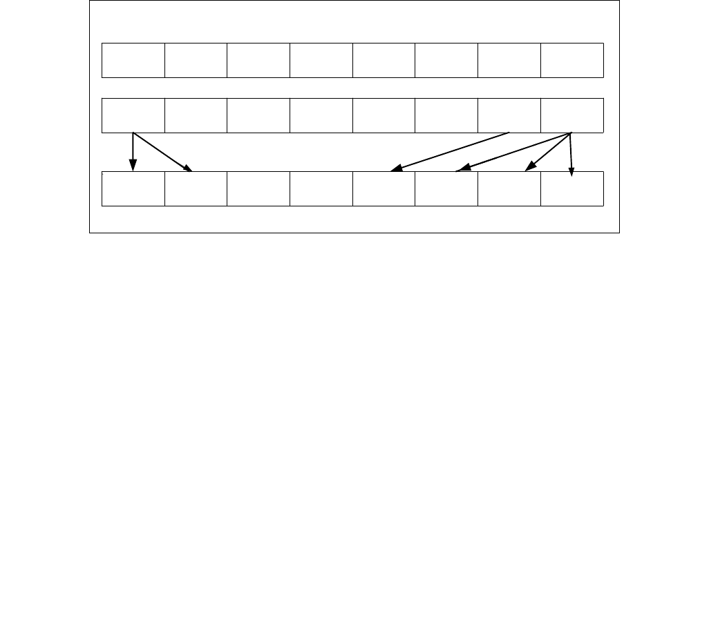
PSHUFB — Packed Shuffle Bytes
INSTRUCTION SET REFERENCE, M-U
4-414 Vol. 2B
endif
}
VPSHUFB (EVEX encoded versions)
(KL, VL) = (16, 128), (32, 256), (64, 512)
jmask (KL-1) & ~0xF // 0x00, 0x10, 0x30 depending on the VL
FOR j = 0 TO KL-1 // dest
IF kl[ i ] or no_masking
index src.byte[ j ];
IF index & 0x80
Dest.byte[ j ] 0;
ELSE
index (index & 0xF) + (j & jmask); // 16-element in-lane lookup
Dest.byte[ j ] src.byte[ index ];
ELSE if zeroing
Dest.byte[ j ] 0;
DEST[MAX_VL-1:VL] 0;
Intel C/C++ Compiler Intrinsic Equivalent
VPSHUFB __m512i _mm512_shuffle_epi8(__m512i a, __m512i b);
VPSHUFB __m512i _mm512_mask_shuffle_epi8(__m512i s, __mmask64 k, __m512i a, __m512i b);
VPSHUFB __m512i _mm512_maskz_shuffle_epi8( __mmask64 k, __m512i a, __m512i b);
VPSHUFB __m256i _mm256_mask_shuffle_epi8(__m256i s, __mmask32 k, __m256i a, __m256i b);
VPSHUFB __m256i _mm256_maskz_shuffle_epi8( __mmask32 k, __m256i a, __m256i b);
VPSHUFB __m128i _mm_mask_shuffle_epi8(__m128i s, __mmask16 k, __m128i a, __m128i b);
VPSHUFB __m128i _mm_maskz_shuffle_epi8( __mmask16 k, __m128i a, __m128i b);
PSHUFB: __m64 _mm_shuffle_pi8 (__m64 a, __m64 b)
(V)PSHUFB: __m128i _mm_shuffle_epi8 (__m128i a, __m128i b)
VPSHUFB:__m256i _mm256_shuffle_epi8(__m256i a, __m256i b)
SIMD Floating-Point Exceptions
None.
Figure 4-15. PSHUFB with 64-Bit Operands
07H 07H FFH 80H 01H 00H 00H 00H
04H 01H 07H 03H 02H 02H FFH 01H
04H 04H 00H 00H FFH 01H 01H 01H
MM2
MM1
MM1

PSHUFB — Packed Shuffle Bytes
INSTRUCTION SET REFERENCE, M-U
Vol. 2B 4-415
Other Exceptions
Non-EVEX-encoded instruction, see Exceptions Type 4.
EVEX-encoded instruction, see Exceptions Type E4NF.nb.

PSHUFD—Shuffle Packed Doublewords
INSTRUCTION SET REFERENCE, M-U
4-416 Vol. 2B
PSHUFD—Shuffle Packed Doublewords
Instruction Operand Encoding
Description
Copies doublewords from source operand (second operand) and inserts them in the destination operand (first
operand) at the locations selected with the order operand (third operand). Figure 4-16 shows the operation of the
256-bit VPSHUFD instruction and the encoding of the order operand. Each 2-bit field in the order operand selects
the contents of one doubleword location within a 128-bit lane and copy to the target element in the destination
operand. For example, bits 0 and 1 of the order operand targets the first doubleword element in the low and high
128-bit lane of the destination operand for 256-bit VPSHUFD. The encoded value of bits 1:0 of the order operand
(see the field encoding in Figure 4-16) determines which doubleword element (from the respective 128-bit lane) of
the source operand will be copied to doubleword 0 of the destination operand.
For 128-bit operation, only the low 128-bit lane are operative. The source operand can be an XMM register or a
128-bit memory location. The destination operand is an XMM register. The order operand is an 8-bit immediate.
Note that this instruction permits a doubleword in the source operand to be copied to more than one doubleword
location in the destination operand.
Opcode/
Instruction
Op/
En
64/32 bit
Mode
Support
CPUID
Feature
Flag
Description
66 0F 70 /r ib
PSHUFD xmm1, xmm2/m128, imm8
RMI V/V SSE2 Shuffle the doublewords in xmm2/m128 based on
the encoding in imm8 and store the result in xmm1.
VEX.128.66.0F.WIG 70 /r ib
VPSHUFD xmm1, xmm2/m128, imm8
RMI V/V AVX Shuffle the doublewords in xmm2/m128 based on
the encoding in imm8 and store the result in xmm1.
VEX.256.66.0F.WIG 70 /r ib
VPSHUFD ymm1, ymm2/m256, imm8
RMI V/V AVX2 Shuffle the doublewords in ymm2/m256 based on
the encoding in imm8 and store the result in ymm1.
EVEX.128.66.0F.W0 70 /r ib
VPSHUFD xmm1 {k1}{z}, xmm2/m128/m32bcst,
imm8
FV V/V AVX512VL
AVX512F
Shuffle the doublewords in xmm2/m128/m32bcst
based on the encoding in imm8 and store the result
in xmm1 using writemask k1.
EVEX.256.66.0F.W0 70 /r ib
VPSHUFD ymm1 {k1}{z}, ymm2/m256/m32bcst,
imm8
FV V/V AVX512VL
AVX512F
Shuffle the doublewords in ymm2/m256/m32bcst
based on the encoding in imm8 and store the result
in ymm1 using writemask k1.
EVEX.512.66.0F.W0 70 /r ib
VPSHUFD zmm1 {k1}{z}, zmm2/m512/m32bcst,
imm8
FV V/V AVX512F Shuffle the doublewords in zmm2/m512/m32bcst
based on the encoding in imm8 and store the result
in zmm1 using writemask k1.
Op/En Operand 1 Operand 2 Operand 3 Operand 4
RMI ModRM:reg (w) ModRM:r/m (r) imm8 NA
FV ModRM:reg (w) ModRM:r/m (r) Imm8 NA
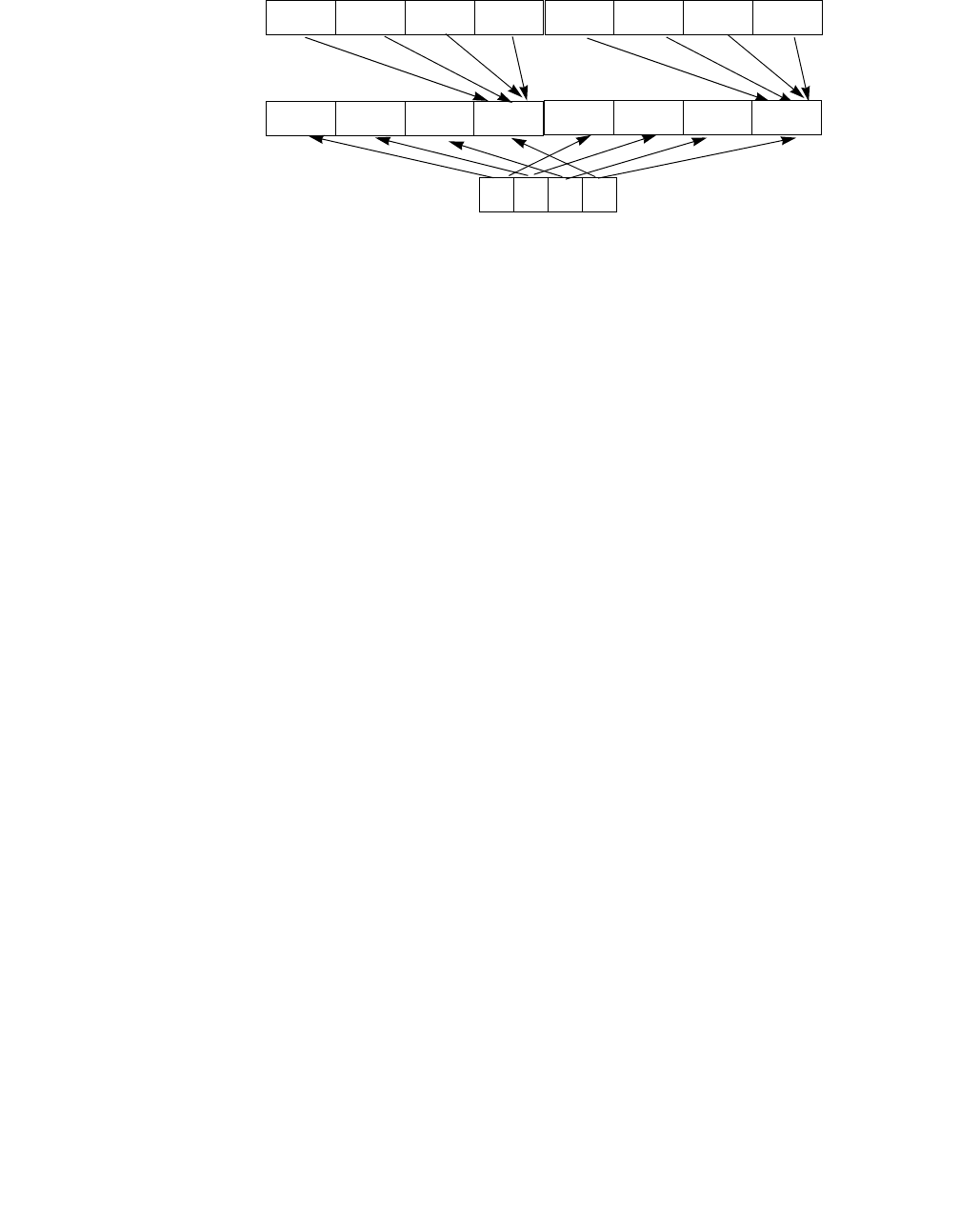
PSHUFD—Shuffle Packed Doublewords
INSTRUCTION SET REFERENCE, M-U
Vol. 2B 4-417
Figure 4-16. 256-bit VPSHUFD Instruction Operation
The source operand can be an XMM register or a 128-bit memory location. The destination operand is an XMM
register. The order operand is an 8-bit immediate. Note that this instruction permits a doubleword in the source
operand to be copied to more than one doubleword location in the destination operand.
In 64-bit mode and not encoded in VEX/EVEX, using REX.R permits this instruction to access XMM8-XMM15.
128-bit Legacy SSE version: Bits (VLMAX-1:128) of the corresponding YMM destination register remain
unchanged.
VEX.128 encoded version: The source operand can be an XMM register or a 128-bit memory location. The destina-
tion operand is an XMM register. Bits (MAX_VL-1:128) of the corresponding ZMM register are zeroed.
VEX.256 encoded version: The source operand can be an YMM register or a 256-bit memory location. The destina-
tion operand is an YMM register. Bits (MAX_VL-1:256) of the corresponding ZMM register are zeroed. Bits (255-
1:128) of the destination stores the shuffled results of the upper 16 bytes of the source operand using the imme-
diate byte as the order operand.
EVEX encoded version: The source operand can be an ZMM/YMM/XMM register, a 512/256/128-bit memory loca-
tion, or a 512/256/128-bit vector broadcasted from a 32-bit memory location. The destination operand is a
ZMM/YMM/XMM register updated according to the writemask.
Each 128-bit lane of the destination stores the shuffled results of the respective lane of the source operand using
the immediate byte as the order operand.
Note: EVEX.vvvv and VEX.vvvv are reserved and must be 1111b otherwise instructions will #UD.
Operation
PSHUFD (128-bit Legacy SSE version)
DEST[31:0] (SRC >> (ORDER[1:0] * 32))[31:0];
DEST[63:32] (SRC >> (ORDER[3:2] * 32))[31:0];
DEST[95:64] (SRC >> (ORDER[5:4] * 32))[31:0];
DEST[127:96] (SRC >> (ORDER[7:6] * 32))[31:0];
DEST[VLMAX-1:128] (Unmodified)
VPSHUFD (VEX.128 encoded version)
DEST[31:0] (SRC >> (ORDER[1:0] * 32))[31:0];
DEST[63:32] (SRC >> (ORDER[3:2] * 32))[31:0];
DEST[95:64] (SRC >> (ORDER[5:4] * 32))[31:0];
DEST[127:96] (SRC >> (ORDER[7:6] * 32))[31:0];
DEST[VLMAX-1:128] 0
X7 X6 X5 X4
SRC
DEST Y7 Y6 Y5 Y4
ORDER 00B - X0
01B - X1
10B - X2
11B - X3
Encoding
of Fields in
ORDER
01234567 Operand
Y3 Y2 Y1 Y0
X3 X2 X1 X0
00B - X4
01B - X5
10B - X6
11B - X7
Encoding
of Fields in
ORDER
Operand

PSHUFD—Shuffle Packed Doublewords
INSTRUCTION SET REFERENCE, M-U
4-418 Vol. 2B
VPSHUFD (VEX.256 encoded version)
DEST[31:0] (SRC[127:0] >> (ORDER[1:0] * 32))[31:0];
DEST[63:32] (SRC[127:0] >> (ORDER[3:2] * 32))[31:0];
DEST[95:64] (SRC[127:0] >> (ORDER[5:4] * 32))[31:0];
DEST[127:96] (SRC[127:0] >> (ORDER[7:6] * 32))[31:0];
DEST[159:128] (SRC[255:128] >> (ORDER[1:0] * 32))[31:0];
DEST[191:160] (SRC[255:128] >> (ORDER[3:2] * 32))[31:0];
DEST[223:192] (SRC[255:128] >> (ORDER[5:4] * 32))[31:0];
DEST[255:224] (SRC[255:128] >> (ORDER[7:6] * 32))[31:0];
DEST[VLMAX-1:256] 0
VPSHUFD (EVEX encoded versions)
(KL, VL) = (4, 128), (8, 256), (16, 512)
FOR j 0 TO KL-1
i j * 32
IF (EVEX.b = 1) AND (SRC *is memory*)
THEN TMP_SRC[i+31:i] SRC[31:0]
ELSE TMP_SRC[i+31:i] SRC[i+31:i]
FI;
ENDFOR;
IF VL >= 128
TMP_DEST[31:0] (TMP_SRC[127:0] >> (ORDER[1:0] * 32))[31:0];
TMP_DEST[63:32] (TMP_SRC[127:0] >> (ORDER[3:2] * 32))[31:0];
TMP_DEST[95:64] (TMP_SRC[127:0] >> (ORDER[5:4] * 32))[31:0];
TMP_DEST[127:96] (TMP_SRC[127:0] >> (ORDER[7:6] * 32))[31:0];
FI;
IF VL >= 256
TMP_DEST[159:128] (TMP_SRC[255:128] >> (ORDER[1:0] * 32))[31:0];
TMP_DEST[191:160] (TMP_SRC[255:128] >> (ORDER[3:2] * 32))[31:0];
TMP_DEST[223:192] (TMP_SRC[255:128] >> (ORDER[5:4] * 32))[31:0];
TMP_DEST[255:224] (TMP_SRC[255:128] >> (ORDER[7:6] * 32))[31:0];
FI;
IF VL >= 512
TMP_DEST[287:256] (TMP_SRC[383:256] >> (ORDER[1:0] * 32))[31:0];
TMP_DEST[319:288] (TMP_SRC[383:256] >> (ORDER[3:2] * 32))[31:0];
TMP_DEST[351:320] (TMP_SRC[383:256] >> (ORDER[5:4] * 32))[31:0];
TMP_DEST[383:352] (TMP_SRC[383:256] >> (ORDER[7:6] * 32))[31:0];
TMP_DEST[415:384] (TMP_SRC[511:384] >> (ORDER[1:0] * 32))[31:0];
TMP_DEST[447:416] (TMP_SRC[511:384] >> (ORDER[3:2] * 32))[31:0];
TMP_DEST[479:448] (TMP_SRC[511:384] >> (ORDER[5:4] * 32))[31:0];
TMP_DEST[511:480] (TMP_SRC[511:384] >> (ORDER[7:6] * 32))[31:0];
FI;
FOR j 0 TO KL-1
i j * 32
IF k1[j] OR *no writemask*
THEN DEST[i+31:i] TMP_DEST[i+31:i]
ELSE
IF *merging-masking* ; merging-masking
THEN *DEST[i+31:i] remains unchanged*
ELSE *zeroing-masking* ; zeroing-masking
DEST[i+31:i] 0
FI
FI;
ENDFOR

PSHUFD—Shuffle Packed Doublewords
INSTRUCTION SET REFERENCE, M-U
Vol. 2B 4-419
DEST[MAX_VL-1:VL] 0
Intel C/C++ Compiler Intrinsic Equivalent
VPSHUFD __m512i _mm512_shuffle_epi32(__m512i a, int n );
VPSHUFD __m512i _mm512_mask_shuffle_epi32(__m512i s, __mmask16 k, __m512i a, int n );
VPSHUFD __m512i _mm512_maskz_shuffle_epi32( __mmask16 k, __m512i a, int n );
VPSHUFD __m256i _mm256_mask_shuffle_epi32(__m256i s, __mmask8 k, __m256i a, int n );
VPSHUFD __m256i _mm256_maskz_shuffle_epi32( __mmask8 k, __m256i a, int n );
VPSHUFD __m128i _mm_mask_shuffle_epi32(__m128i s, __mmask8 k, __m128i a, int n );
VPSHUFD __m128i _mm_maskz_shuffle_epi32( __mmask8 k, __m128i a, int n );
(V)PSHUFD:__m128i _mm_shuffle_epi32(__m128i a, int n)
VPSHUFD:__m256i _mm256_shuffle_epi32(__m256i a, const int n)
Flags Affected
None.
SIMD Floating-Point Exceptions
None.
Other Exceptions
Non-EVEX-encoded instruction, see Exceptions Type 4.
EVEX-encoded instruction, see Exceptions Type E4NF.
#UD If VEX.vvvv ≠ 1111B or EVEX.vvvv ≠ 1111B.

PSHUFHW—Shuffle Packed High Words
INSTRUCTION SET REFERENCE, M-U
4-420 Vol. 2B
PSHUFHW—Shuffle Packed High Words
Instruction Operand Encoding
Description
Copies words from the high quadword of a 128-bit lane of the source operand and inserts them in the high quad-
word of the destination operand at word locations (of the respective lane) selected with the immediate operand.
This 256-bit operation is similar to the in-lane operation used by the 256-bit VPSHUFD instruction, which is illus-
trated in Figure 4-16. For 128-bit operation, only the low 128-bit lane is operative. Each 2-bit field in the immediate
operand selects the contents of one word location in the high quadword of the destination operand. The binary
encodings of the immediate operand fields select words (0, 1, 2 or 3, 4) from the high quadword of the source
operand to be copied to the destination operand. The low quadword of the source operand is copied to the low
quadword of the destination operand, for each 128-bit lane.
Note that this instruction permits a word in the high quadword of the source operand to be copied to more than one
word location in the high quadword of the destination operand.
In 64-bit mode and not encoded with VEX/EVEX, using a REX prefix in the form of REX.R permits this instruction to
access additional registers (XMM8-XMM15).
128-bit Legacy SSE version: The destination operand is an XMM register. The source operand can be an XMM
register or a 128-bit memory location. Bits (VLMAX-1:128) of the corresponding YMM destination register remain
unchanged.
VEX.128 encoded version: The destination operand is an XMM register. The source operand can be an XMM register
or a 128-bit memory location. Bits (VLMAX-1:128) of the destination YMM register are zeroed. VEX.vvvv is
reserved and must be 1111b, VEX.L must be 0, otherwise the instruction will #UD.
VEX.256 encoded version: The destination operand is an YMM register. The source operand can be an YMM register
or a 256-bit memory location.
Opcode/
Instruction
Op/
En
64/32 bit
Mode
Support
CPUID
Feature
Flag
Description
F3 0F 70 /r ib
PSHUFHW xmm1, xmm2/m128, imm8
RMI V/V SSE2 Shuffle the high words in xmm2/m128 based
on the encoding in imm8 and store the result in
xmm1.
VEX.128.F3.0F.WIG 70 /r ib
VPSHUFHW xmm1, xmm2/m128, imm8
RMI V/V AVX Shuffle the high words in xmm2/m128 based
on the encoding in imm8 and store the result in
xmm1.
VEX.256.F3.0F.WIG 70 /r ib
VPSHUFHW ymm1, ymm2/m256, imm8
RMI V/V AVX2 Shuffle the high words in ymm2/m256 based
on the encoding in imm8 and store the result in
ymm1.
EVEX.128.F3.0F.WIG 70 /r ib
VPSHUFHW xmm1 {k1}{z}, xmm2/m128, imm8
FVM V/V AVX512VL
AVX512BW
Shuffle the high words in xmm2/m128 based
on the encoding in imm8 and store the result in
xmm1 under write mask k1.
EVEX.256.F3.0F.WIG 70 /r ib
VPSHUFHW ymm1 {k1}{z}, ymm2/m256, imm8
FVM V/V AVX512VL
AVX512BW
Shuffle the high words in ymm2/m256 based
on the encoding in imm8 and store the result in
ymm1 under write mask k1.
EVEX.512.F3.0F.WIG 70 /r ib
VPSHUFHW zmm1 {k1}{z}, zmm2/m512, imm8
FVM V/V AVX512BW Shuffle the high words in zmm2/m512 based
on the encoding in imm8 and store the result in
zmm1 under write mask k1.
Op/En Operand 1 Operand 2 Operand 3 Operand 4
RMI ModRM:reg (w) ModRM:r/m (r) imm8 NA
FVM ModRM:reg (w) ModRM:r/m (r) Imm8 NA

PSHUFHW—Shuffle Packed High Words
INSTRUCTION SET REFERENCE, M-U
Vol. 2B 4-421
EVEX encoded version: The destination operand is a ZMM/YMM/XMM registers. The source operand can be a
ZMM/YMM/XMM register, a 512/256/128-bit memory location. The destination is updated according to the
writemask.
Note: In VEX encoded versions, VEX.vvvv is reserved and must be 1111b otherwise instructions will #UD.
Operation
PSHUFHW (128-bit Legacy SSE version)
DEST[63:0] SRC[63:0]
DEST[79:64] (SRC >> (imm[1:0] *16))[79:64]
DEST[95:80] (SRC >> (imm[3:2] * 16))[79:64]
DEST[111:96] (SRC >> (imm[5:4] * 16))[79:64]
DEST[127:112] (SRC >> (imm[7:6] * 16))[79:64]
DEST[VLMAX-1:128] (Unmodified)
VPSHUFHW (VEX.128 encoded version)
DEST[63:0] SRC1[63:0]
DEST[79:64] (SRC1 >> (imm[1:0] *16))[79:64]
DEST[95:80] (SRC1 >> (imm[3:2] * 16))[79:64]
DEST[111:96] (SRC1 >> (imm[5:4] * 16))[79:64]
DEST[127:112] (SRC1 >> (imm[7:6] * 16))[79:64]
DEST[VLMAX-1:128] 0
VPSHUFHW (VEX.256 encoded version)
DEST[63:0] SRC1[63:0]
DEST[79:64] (SRC1 >> (imm[1:0] *16))[79:64]
DEST[95:80] (SRC1 >> (imm[3:2] * 16))[79:64]
DEST[111:96] (SRC1 >> (imm[5:4] * 16))[79:64]
DEST[127:112] (SRC1 >> (imm[7:6] * 16))[79:64]
DEST[191:128] SRC1[191:128]
DEST[207192] (SRC1 >> (imm[1:0] *16))[207:192]
DEST[223:208] (SRC1 >> (imm[3:2] * 16))[207:192]
DEST[239:224] (SRC1 >> (imm[5:4] * 16))[207:192]
DEST[255:240] (SRC1 >> (imm[7:6] * 16))[207:192]
DEST[VLMAX-1:256] 0
VPSHUFHW (EVEX encoded versions)
(KL, VL) = (8, 128), (16, 256), (32, 512)
IF VL >= 128
TMP_DEST[63:0] SRC1[63:0]
TMP_DEST[79:64] (SRC1 >> (imm[1:0] *16))[79:64]
TMP_DEST[95:80] (SRC1 >> (imm[3:2] * 16))[79:64]
TMP_DEST[111:96] (SRC1 >> (imm[5:4] * 16))[79:64]
TMP_DEST[127:112] (SRC1 >> (imm[7:6] * 16))[79:64]
FI;
IF VL >= 256
TMP_DEST[191:128] SRC1[191:128]
TMP_DEST[207:192] (SRC1 >> (imm[1:0] *16))[207:192]
TMP_DEST[223:208] (SRC1 >> (imm[3:2] * 16))[207:192]
TMP_DEST[239:224] (SRC1 >> (imm[5:4] * 16))[207:192]
TMP_DEST[255:240] (SRC1 >> (imm[7:6] * 16))[207:192]
FI;
IF VL >= 512
TMP_DEST[319:256] SRC1[319:256]
TMP_DEST[335:320] (SRC1 >> (imm[1:0] *16))[335:320]

PSHUFHW—Shuffle Packed High Words
INSTRUCTION SET REFERENCE, M-U
4-422 Vol. 2B
TMP_DEST[351:336] (SRC1 >> (imm[3:2] * 16))[335:320]
TMP_DEST[367:352] (SRC1 >> (imm[5:4] * 16))[335:320]
TMP_DEST[383:368] (SRC1 >> (imm[7:6] * 16))[335:320]
TMP_DEST[447:384] SRC1[447:384]
TMP_DEST[463:448] (SRC1 >> (imm[1:0] *16))[463:448]
TMP_DEST[479:464] (SRC1 >> (imm[3:2] * 16))[463:448]
TMP_DEST[495:480] (SRC1 >> (imm[5:4] * 16))[463:448]
TMP_DEST[511:496] (SRC1 >> (imm[7:6] * 16))[463:448]
FI;
FOR j 0 TO KL-1
i j * 16
IF k1[j] OR *no writemask*
THEN DEST[i+15:i] TMP_DEST[i+15:i];
ELSE
IF *merging-masking* ; merging-masking
THEN *DEST[i+15:i] remains unchanged*
ELSE *zeroing-masking* ; zeroing-masking
DEST[i+15:i] 0
FI
FI;
ENDFOR
DEST[MAX_VL-1:VL] 0
Intel C/C++ Compiler Intrinsic Equivalent
VPSHUFHW __m512i _mm512_shufflehi_epi16(__m512i a, int n);
VPSHUFHW __m512i _mm512_mask_shufflehi_epi16(__m512i s, __mmask16 k, __m512i a, int n );
VPSHUFHW __m512i _mm512_maskz_shufflehi_epi16( __mmask16 k, __m512i a, int n );
VPSHUFHW __m256i _mm256_mask_shufflehi_epi16(__m256i s, __mmask8 k, __m256i a, int n );
VPSHUFHW __m256i _mm256_maskz_shufflehi_epi16( __mmask8 k, __m256i a, int n );
VPSHUFHW __m128i _mm_mask_shufflehi_epi16(__m128i s, __mmask8 k, __m128i a, int n );
VPSHUFHW __m128i _mm_maskz_shufflehi_epi16( __mmask8 k, __m128i a, int n );
(V)PSHUFHW:__m128i _mm_shufflehi_epi16(__m128i a, int n)
VPSHUFHW:__m256i _mm256_shufflehi_epi16(__m256i a, const int n)
Flags Affected
None.
SIMD Floating-Point Exceptions
None.
Other Exceptions
Non-EVEX-encoded instruction, see Exceptions Type 4;
EVEX-encoded instruction, see Exceptions Type E4NF.nb
#UD If VEX.vvvv != 1111B, or EVEX.vvvv != 1111B.

PSHUFLW—Shuffle Packed Low Words
INSTRUCTION SET REFERENCE, M-U
Vol. 2B 4-423
PSHUFLW—Shuffle Packed Low Words
Instruction Operand Encoding
Description
Copies words from the low quadword of a 128-bit lane of the source operand and inserts them in the low quadword
of the destination operand at word locations (of the respective lane) selected with the immediate operand. The
256-bit operation is similar to the in-lane operation used by the 256-bit VPSHUFD instruction, which is illustrated
in Figure 4-16. For 128-bit operation, only the low 128-bit lane is operative. Each 2-bit field in the immediate
operand selects the contents of one word location in the low quadword of the destination operand. The binary
encodings of the immediate operand fields select words (0, 1, 2 or 3) from the low quadword of the source operand
to be copied to the destination operand. The high quadword of the source operand is copied to the high quadword
of the destination operand, for each 128-bit lane.
Note that this instruction permits a word in the low quadword of the source operand to be copied to more than one
word location in the low quadword of the destination operand.
In 64-bit mode and not encoded with VEX/EVEX, using a REX prefix in the form of REX.R permits this instruction to
access additional registers (XMM8-XMM15).
128-bit Legacy SSE version: The destination operand is an XMM register. The source operand can be an XMM
register or a 128-bit memory location. Bits (VLMAX-1:128) of the corresponding YMM destination register remain
unchanged.
VEX.128 encoded version: The destination operand is an XMM register. The source operand can be an XMM register
or a 128-bit memory location. Bits (VLMAX-1:128) of the destination YMM register are zeroed.
VEX.256 encoded version: The destination operand is an YMM register. The source operand can be an YMM register
or a 256-bit memory location.
EVEX encoded version: The destination operand is a ZMM/YMM/XMM registers. The source operand can be a
ZMM/YMM/XMM register, a 512/256/128-bit memory location. The destination is updated according to the
writemask.
Opcode/
Instruction
Op/
En
64/32 bit
Mode
Support
CPUID
Feature
Flag
Description
F2 0F 70 /r ib
PSHUFLW xmm1, xmm2/m128, imm8
RMI V/V SSE2 Shuffle the low words in xmm2/m128 based on
the encoding in imm8 and store the result in
xmm1.
VEX.128.F2.0F.WIG 70 /r ib
VPSHUFLW xmm1, xmm2/m128, imm8
RMI V/V AVX Shuffle the low words in xmm2/m128 based on
the encoding in imm8 and store the result in
xmm1.
VEX.256.F2.0F.WIG 70 /r ib
VPSHUFLW ymm1, ymm2/m256, imm8
RMI V/V AVX2 Shuffle the low words in ymm2/m256 based on
the encoding in imm8 and store the result in
ymm1.
EVEX.128.F2.0F.WIG 70 /r ib
VPSHUFLW xmm1 {k1}{z}, xmm2/m128, imm8
FVM V/V AVX512VL
AVX512BW
Shuffle the low words in xmm2/m128 based on
the encoding in imm8 and store the result in
xmm1 under write mask k1.
EVEX.256.F2.0F.WIG 70 /r ib
VPSHUFLW ymm1 {k1}{z}, ymm2/m256, imm8
FVM V/V AVX512VL
AVX512BW
Shuffle the low words in ymm2/m256 based on
the encoding in imm8 and store the result in
ymm1 under write mask k1.
EVEX.512.F2.0F.WIG 70 /r ib
VPSHUFLW zmm1 {k1}{z}, zmm2/m512, imm8
FVM V/V AVX512BW Shuffle the low words in zmm2/m512 based on
the encoding in imm8 and store the result in
zmm1 under write mask k1.
Op/En Operand 1 Operand 2 Operand 3 Operand 4
RMI ModRM:reg (w) ModRM:r/m (r) imm8 NA
FVM ModRM:reg (w) ModRM:r/m (r) Imm8 NA

PSHUFLW—Shuffle Packed Low Words
INSTRUCTION SET REFERENCE, M-U
4-424 Vol. 2B
Note: In VEX encoded versions, VEX.vvvv is reserved and must be 1111b otherwise instructions will #UD.
Operation
PSHUFLW (128-bit Legacy SSE version)
DEST[15:0] (SRC >> (imm[1:0] *16))[15:0]
DEST[31:16] (SRC >> (imm[3:2] * 16))[15:0]
DEST[47:32] (SRC >> (imm[5:4] * 16))[15:0]
DEST[63:48] (SRC >> (imm[7:6] * 16))[15:0]
DEST[127:64] SRC[127:64]
DEST[VLMAX-1:128] (Unmodified)
VPSHUFLW (VEX.128 encoded version)
DEST[15:0] (SRC1 >> (imm[1:0] *16))[15:0]
DEST[31:16] (SRC1 >> (imm[3:2] * 16))[15:0]
DEST[47:32] (SRC1 >> (imm[5:4] * 16))[15:0]
DEST[63:48] (SRC1 >> (imm[7:6] * 16))[15:0]
DEST[127:64] SRC[127:64]
DEST[VLMAX-1:128] 0
VPSHUFLW (VEX.256 encoded version)
DEST[15:0] (SRC1 >> (imm[1:0] *16))[15:0]
DEST[31:16] (SRC1 >> (imm[3:2] * 16))[15:0]
DEST[47:32] (SRC1 >> (imm[5:4] * 16))[15:0]
DEST[63:48] (SRC1 >> (imm[7:6] * 16))[15:0]
DEST[127:64] SRC1[127:64]
DEST[143:128] (SRC1 >> (imm[1:0] *16))[143:128]
DEST[159:144] (SRC1 >> (imm[3:2] * 16))[143:128]
DEST[175:160] (SRC1 >> (imm[5:4] * 16))[143:128]
DEST[191:176] (SRC1 >> (imm[7:6] * 16))[143:128]
DEST[255:192] SRC1[255:192]
DEST[VLMAX-1:256] 0
VPSHUFLW (EVEX.U1.512 encoded version)
(KL, VL) = (8, 128), (16, 256), (32, 512)
IF VL >= 128
TMP_DEST[15:0] (SRC1 >> (imm[1:0] *16))[15:0]
TMP_DEST[31:16] (SRC1 >> (imm[3:2] * 16))[15:0]
TMP_DEST[47:32] (SRC1 >> (imm[5:4] * 16))[15:0]
TMP_DEST[63:48] (SRC1 >> (imm[7:6] * 16))[15:0]
TMP_DEST[127:64] SRC1[127:64]
FI;
IF VL >= 256
TMP_DEST[143:128] (SRC1 >> (imm[1:0] *16))[143:128]
TMP_DEST[159:144] (SRC1 >> (imm[3:2] * 16))[143:128]
TMP_DEST[175:160] (SRC1 >> (imm[5:4] * 16))[143:128]
TMP_DEST[191:176] (SRC1 >> (imm[7:6] * 16))[143:128]
TMP_DEST[255:192] SRC1[255:192]
FI;
IF VL >= 512
TMP_DEST[271:256] (SRC1 >> (imm[1:0] *16))[271:256]
TMP_DEST[287:272] (SRC1 >> (imm[3:2] * 16))[271:256]
TMP_DEST[303:288] (SRC1 >> (imm[5:4] * 16))[271:256]
TMP_DEST[319:304] (SRC1 >> (imm[7:6] * 16))[271:256]
TMP_DEST[383:320] SRC1[383:320]

PSHUFLW—Shuffle Packed Low Words
INSTRUCTION SET REFERENCE, M-U
Vol. 2B 4-425
TMP_DEST[399:384] (SRC1 >> (imm[1:0] *16))[399:384]
TMP_DEST[415:400] (SRC1 >> (imm[3:2] * 16))[399:384]
TMP_DEST[431:416] (SRC1 >> (imm[5:4] * 16))[399:384]
TMP_DEST[447:432] (SRC1 >> (imm[7:6] * 16))[399:384]
TMP_DEST[511:448] SRC1[511:448]
FI;
FOR j 0 TO KL-1
i j * 16
IF k1[j] OR *no writemask*
THEN DEST[i+15:i] TMP_DEST[i+15:i];
ELSE
IF *merging-masking* ; merging-masking
THEN *DEST[i+15:i] remains unchanged*
ELSE *zeroing-masking* ; zeroing-masking
DEST[i+15:i] 0
FI
FI;
ENDFOR
DEST[MAX_VL-1:VL] 0
Intel C/C++ Compiler Intrinsic Equivalent
VPSHUFLW __m512i _mm512_shufflelo_epi16(__m512i a, int n);
VPSHUFLW __m512i _mm512_mask_shufflelo_epi16(__m512i s, __mmask16 k, __m512i a, int n );
VPSHUFLW __m512i _mm512_maskz_shufflelo_epi16( __mmask16 k, __m512i a, int n );
VPSHUFLW __m256i _mm256_mask_shufflelo_epi16(__m256i s, __mmask8 k, __m256i a, int n );
VPSHUFLW __m256i _mm256_maskz_shufflelo_epi16( __mmask8 k, __m256i a, int n );
VPSHUFLW __m128i _mm_mask_shufflelo_epi16(__m128i s, __mmask8 k, __m128i a, int n );
VPSHUFLW __m128i _mm_maskz_shufflelo_epi16( __mmask8 k, __m128i a, int n );
(V)PSHUFLW:__m128i _mm_shufflelo_epi16(__m128i a, int n)
VPSHUFLW:__m256i _mm256_shufflelo_epi16(__m256i a, const int n)
Flags Affected
None.
SIMD Floating-Point Exceptions
None.
Other Exceptions
Non-EVEX-encoded instruction, see Exceptions Type 4;
EVEX-encoded instruction, see Exceptions Type E4NF.nb
#UD If VEX.vvvv != 1111B, or EVEX.vvvv != 1111B.

PSHUFW—Shuffle Packed Words
INSTRUCTION SET REFERENCE, M-U
4-426 Vol. 2B
PSHUFW—Shuffle Packed Words
Instruction Operand Encoding
Description
Copies words from the source operand (second operand) and inserts them in the destination operand (first
operand) at word locations selected with the order operand (third operand). This operation is similar to the opera-
tion used by the PSHUFD instruction, which is illustrated in Figure 4-16. For the PSHUFW instruction, each 2-bit
field in the order operand selects the contents of one word location in the destination operand. The encodings of the
order operand fields select words from the source operand to be copied to the destination operand.
The source operand can be an MMX technology register or a 64-bit memory location. The destination operand is an
MMX technology register. The order operand is an 8-bit immediate. Note that this instruction permits a word in the
source operand to be copied to more than one word location in the destination operand.
In 64-bit mode, using a REX prefix in the form of REX.R permits this instruction to access additional registers
(XMM8-XMM15).
Operation
DEST[15:0] ← (SRC >> (ORDER[1:0] * 16))[15:0];
DEST[31:16] ← (SRC >> (ORDER[3:2] * 16))[15:0];
DEST[47:32] ← (SRC >> (ORDER[5:4] * 16))[15:0];
DEST[63:48] ← (SRC >> (ORDER[7:6] * 16))[15:0];
Intel C/C++ Compiler Intrinsic Equivalent
PSHUFW: __m64 _mm_shuffle_pi16(__m64 a, int n)
Flags Affected
None.
Numeric Exceptions
None.
Other Exceptions
See Table 22-7, “Exception Conditions for SIMD/MMX Instructions with Memory Reference,” in the Intel® 64 and
IA-32 Architectures Software Developer’s Manual, Volume 3A.
Opcode/
Instruction
Op/
En
64-Bit
Mode
Compat/
Leg Mode
Description
0F 70 /r ib
PSHUFW mm1, mm2/m64, imm8
RMI Valid Valid Shuffle the words in mm2/m64 based on the
encoding in imm8 and store the result in mm1.
Op/En Operand 1 Operand 2 Operand 3 Operand 4
RMI ModRM:reg (w) ModRM:r/m (r) imm8 NA

PSIGNB/PSIGNW/PSIGND — Packed SIGN
INSTRUCTION SET REFERENCE, M-U
Vol. 2B 4-427
PSIGNB/PSIGNW/PSIGND — Packed SIGN
Instruction Operand Encoding
Opcode/
Instruction
Op/
En
64/32 bit
Mode
Support
CPUID
Feature
Flag
Description
0F 38 08 /r1
PSIGNB mm1, mm2/m64
RM V/V SSSE3 Negate/zero/preserve packed byte integers in
mm1 depending on the corresponding sign in
mm2/m64.
66 0F 38 08 /r
PSIGNB xmm1, xmm2/m128
RM V/V SSSE3 Negate/zero/preserve packed byte integers in
xmm1 depending on the corresponding sign in
xmm2/m128.
0F 38 09 /r1
PSIGNW mm1, mm2/m64
RM V/V SSSE3 Negate/zero/preserve packed word integers
in mm1 depending on the corresponding sign
in mm2/m128.
66 0F 38 09 /r
PSIGNW xmm1, xmm2/m128
RM V/V SSSE3 Negate/zero/preserve packed word integers
in xmm1 depending on the corresponding sign
in xmm2/m128.
0F 38 0A /r1
PSIGND mm1, mm2/m64
RM V/V SSSE3 Negate/zero/preserve packed doubleword
integers in mm1 depending on the
corresponding sign in mm2/m128.
66 0F 38 0A /r
PSIGND xmm1, xmm2/m128
RM V/V SSSE3 Negate/zero/preserve packed doubleword
integers in xmm1 depending on the
corresponding sign in xmm2/m128.
VEX.NDS.128.66.0F38.WIG 08 /r
VPSIGNB xmm1, xmm2, xmm3/m128
RVM V/V AVX Negate/zero/preserve packed byte integers in
xmm2 depending on the corresponding sign in
xmm3/m128.
VEX.NDS.128.66.0F38.WIG 09 /r
VPSIGNW xmm1, xmm2, xmm3/m128
RVM V/V AVX Negate/zero/preserve packed word integers
in xmm2 depending on the corresponding sign
in xmm3/m128.
VEX.NDS.128.66.0F38.WIG 0A /r
VPSIGND xmm1, xmm2, xmm3/m128
RVM V/V AVX Negate/zero/preserve packed doubleword
integers in xmm2 depending on the
corresponding sign in xmm3/m128.
VEX.NDS.256.66.0F38.WIG 08 /r
VPSIGNB ymm1, ymm2, ymm3/m256
RVM V/V AVX2 Negate packed byte integers in ymm2 if the
corresponding sign in ymm3/m256 is less
than zero.
VEX.NDS.256.66.0F38.WIG 09 /r
VPSIGNW ymm1, ymm2, ymm3/m256
RVM V/V AVX2 Negate packed 16-bit integers in ymm2 if the
corresponding sign in ymm3/m256 is less
than zero.
VEX.NDS.256.66.0F38.WIG 0A /r
VPSIGND ymm1, ymm2, ymm3/m256
RVM V/V AVX2 Negate packed doubleword integers in ymm2
if the corresponding sign in ymm3/m256 is
less than zero.
NOTES:
1. See note in Section 2.4, “AVX and SSE Instruction Exception Specification” in the Intel® 64 and IA-32 Architectures Software
Developer’s Manual, Volume 2A and Section 22.25.3, “Exception Conditions of Legacy SIMD Instructions Operating on MMX Registers”
in the Intel® 64 and IA-32 Architectures Software Developer’s Manual, Volume 3A.
Op/En Operand 1 Operand 2 Operand 3 Operand 4
RM ModRM:reg (r, w) ModRM:r/m (r) NA NA
RVM ModRM:reg (w) VEX.vvvv (r) ModRM:r/m (r) NA

PSIGNB/PSIGNW/PSIGND — Packed SIGN
INSTRUCTION SET REFERENCE, M-U
4-428 Vol. 2B
Description
(V)PSIGNB/(V)PSIGNW/(V)PSIGND negates each data element of the destination operand (the first operand) if the
signed integer value of the corresponding data element in the source operand (the second operand) is less than
zero. If the signed integer value of a data element in the source operand is positive, the corresponding data
element in the destination operand is unchanged. If a data element in the source operand is zero, the corre-
sponding data element in the destination operand is set to zero.
(V)PSIGNB operates on signed bytes. (V)PSIGNW operates on 16-bit signed words. (V)PSIGND operates on signed
32-bit integers. When the source operand is a 128bit memory operand, the operand must be aligned on a 16-byte
boundary or a general-protection exception (#GP) will be generated.
Legacy SSE instructions: Both operands can be MMX registers. In 64-bit mode, use the REX prefix to access addi-
tional registers.
128-bit Legacy SSE version: The first source and destination operands are XMM registers. The second source
operand is an XMM register or a 128-bit memory location. Bits (VLMAX-1:128) of the corresponding YMM destina-
tion register remain unchanged.
VEX.128 encoded version: The first source and destination operands are XMM registers. The second source
operand is an XMM register or a 128-bit memory location. Bits (VLMAX-1:128) of the destination YMM register are
zeroed. VEX.L must be 0, otherwise instructions will #UD.
VEX.256 encoded version: The first source and destination operands are YMM registers. The second source
operand is an YMM register or a 256-bit memory location.
Operation
PSIGNB (with 64 bit operands)
IF (SRC[7:0] < 0 )
DEST[7:0] ← Neg(DEST[7:0])
ELSEIF (SRC[7:0] = 0 )
DEST[7:0] ← 0
ELSEIF (SRC[7:0] > 0 )
DEST[7:0] ← DEST[7:0]
Repeat operation for 2nd through 7th bytes
IF (SRC[63:56] < 0 )
DEST[63:56] ← Neg(DEST[63:56])
ELSEIF (SRC[63:56] = 0 )
DEST[63:56] ← 0
ELSEIF (SRC[63:56] > 0 )
DEST[63:56] ← DEST[63:56]
PSIGNB (with 128 bit operands)
IF (SRC[7:0] < 0 )
DEST[7:0] ← Neg(DEST[7:0])
ELSEIF (SRC[7:0] = 0 )
DEST[7:0] ← 0
ELSEIF (SRC[7:0] > 0 )
DEST[7:0] ← DEST[7:0]
Repeat operation for 2nd through 15th bytes
IF (SRC[127:120] < 0 )
DEST[127:120] ← Neg(DEST[127:120])
ELSEIF (SRC[127:120] = 0 )
DEST[127:120] ← 0
ELSEIF (SRC[127:120] > 0 )
DEST[127:120] ← DEST[127:120]

PSIGNB/PSIGNW/PSIGND — Packed SIGN
INSTRUCTION SET REFERENCE, M-U
Vol. 2B 4-429
VPSIGNB (VEX.128 encoded version)
DEST[127:0] BYTE_SIGN(SRC1, SRC2)
DEST[VLMAX-1:128] 0
VPSIGNB (VEX.256 encoded version)
DEST[255:0] BYTE_SIGN_256b(SRC1, SRC2)
PSIGNW (with 64 bit operands)
IF (SRC[15:0] < 0 )
DEST[15:0] ← Neg(DEST[15:0])
ELSEIF (SRC[15:0] = 0 )
DEST[15:0] ← 0
ELSEIF (SRC[15:0] > 0 )
DEST[15:0] ← DEST[15:0]
Repeat operation for 2nd through 3rd words
IF (SRC[63:48] < 0 )
DEST[63:48] ← Neg(DEST[63:48])
ELSEIF (SRC[63:48] = 0 )
DEST[63:48] ← 0
ELSEIF (SRC[63:48] > 0 )
DEST[63:48] ← DEST[63:48]
PSIGNW (with 128 bit operands)
IF (SRC[15:0] < 0 )
DEST[15:0] ← Neg(DEST[15:0])
ELSEIF (SRC[15:0] = 0 )
DEST[15:0] ← 0
ELSEIF (SRC[15:0] > 0 )
DEST[15:0] ← DEST[15:0]
Repeat operation for 2nd through 7th words
IF (SRC[127:112] < 0 )
DEST[127:112] ← Neg(DEST[127:112])
ELSEIF (SRC[127:112] = 0 )
DEST[127:112] ← 0
ELSEIF (SRC[127:112] > 0 )
DEST[127:112] ← DEST[127:112]
VPSIGNW (VEX.128 encoded version)
DEST[127:0] WORD_SIGN(SRC1, SRC2)
DEST[VLMAX-1:128] 0
VPSIGNW (VEX.256 encoded version)
DEST[255:0] WORD_SIGN(SRC1, SRC2)
PSIGND (with 64 bit operands)
IF (SRC[31:0] < 0 )
DEST[31:0] ← Neg(DEST[31:0])
ELSEIF (SRC[31:0] = 0 )
DEST[31:0] ← 0
ELSEIF (SRC[31:0] > 0 )
DEST[31:0] ← DEST[31:0]
IF (SRC[63:32] < 0 )
DEST[63:32] ← Neg(DEST[63:32])
ELSEIF (SRC[63:32] = 0 )
DEST[63:32] ← 0

PSIGNB/PSIGNW/PSIGND — Packed SIGN
INSTRUCTION SET REFERENCE, M-U
4-430 Vol. 2B
ELSEIF (SRC[63:32] > 0 )
DEST[63:32] ← DEST[63:32]
PSIGND (with 128 bit operands)
IF (SRC[31:0] < 0 )
DEST[31:0] ← Neg(DEST[31:0])
ELSEIF (SRC[31:0] = 0 )
DEST[31:0] ← 0
ELSEIF (SRC[31:0] > 0 )
DEST[31:0] ← DEST[31:0]
Repeat operation for 2nd through 3rd double words
IF (SRC[127:96] < 0 )
DEST[127:96] ← Neg(DEST[127:96])
ELSEIF (SRC[127:96] = 0 )
DEST[127:96] ← 0
ELSEIF (SRC[127:96] > 0 )
DEST[127:96] ← DEST[127:96]
VPSIGND (VEX.128 encoded version)
DEST[127:0] DWORD_SIGN(SRC1, SRC2)
DEST[VLMAX-1:128] 0
VPSIGND (VEX.256 encoded version)
DEST[255:0] DWORD_SIGN(SRC1, SRC2)
Intel C/C++ Compiler Intrinsic Equivalent
PSIGNB: __m64 _mm_sign_pi8 (__m64 a, __m64 b)
(V)PSIGNB: __m128i _mm_sign_epi8 (__m128i a, __m128i b)
VPSIGNB: __m256i _mm256_sign_epi8 (__m256i a, __m256i b)
PSIGNW: __m64 _mm_sign_pi16 (__m64 a, __m64 b)
(V)PSIGNW: __m128i _mm_sign_epi16 (__m128i a, __m128i b)
VPSIGNW: __m256i _mm256_sign_epi16 (__m256i a, __m256i b)
PSIGND: __m64 _mm_sign_pi32 (__m64 a, __m64 b)
(V)PSIGND: __m128i _mm_sign_epi32 (__m128i a, __m128i b)
VPSIGND: __m256i _mm256_sign_epi32 (__m256i a, __m256i b)
SIMD Floating-Point Exceptions
None.
Other Exceptions
See Exceptions Type 4; additionally
#UD If VEX.L = 1.

PSLLDQ—Shift Double Quadword Left Logical
INSTRUCTION SET REFERENCE, M-U
Vol. 2B 4-431
PSLLDQ—Shift Double Quadword Left Logical
Instruction Operand Encoding
Description
Shifts the destination operand (first operand) to the left by the number of bytes specified in the count operand
(second operand). The empty low-order bytes are cleared (set to all 0s). If the value specified by the count
operand is greater than 15, the destination operand is set to all 0s. The count operand is an 8-bit immediate.
128-bit Legacy SSE version: The source and destination operands are the same. Bits (VLMAX-1:128) of the corre-
sponding YMM destination register remain unchanged.
VEX.128 encoded version: The source and destination operands are XMM registers. Bits (VLMAX-1:128) of the
destination YMM register are zeroed.
VEX.256 encoded version: The source operand is YMM register. The destination operand is an YMM register. Bits
(MAX_VL-1:256) of the corresponding ZMM register are zeroed. The count operand applies to both the low and
high 128-bit lanes.
EVEX encoded versions: The source operand is a ZMM/YMM/XMM register or a 512/256/128-bit memory location.
The destination operand is a ZMM/YMM/XMM register. The count operand applies to each 128-bit lanes.
Operation
VPSLLDQ (EVEX.U1.512 encoded version)
TEMP COUNT
IF (TEMP > 15) THEN TEMP 16; FI
DEST[127:0] SRC[127:0] << (TEMP * 8)
DEST[255:128] SRC[255:128] << (TEMP * 8)
DEST[383:256] SRC[383:256] << (TEMP * 8)
DEST[511:384] SRC[511:384] << (TEMP * 8)
DEST[MAX_VL-1:512] 0
Opcode/
Instruction
Op/
En
64/32 bit
Mode
Support
CPUID
Feature
Flag
Description
66 0F 73 /7 ib
PSLLDQ xmm1, imm8
MI V/V SSE2 Shift xmm1 left by imm8 bytes while shifting
in 0s.
VEX.NDD.128.66.0F.WIG 73 /7 ib
VPSLLDQ xmm1, xmm2, imm8
VMI V/V AVX Shift xmm2 left by imm8 bytes while shifting
in 0s and store result in xmm1.
VEX.NDD.256.66.0F.WIG 73 /7 ib
VPSLLDQ ymm1, ymm2, imm8
VMI V/V AVX2 Shift ymm2 left by imm8 bytes while shifting
in 0s and store result in ymm1.
EVEX.NDD.128.66.0F.WIG 73 /7 ib
VPSLLDQ xmm1,xmm2/ m128, imm8
FVMI V/V AVX512VL
AVX512BW
Shift xmm2/m128 left by imm8 bytes while
shifting in 0s and store result in xmm1.
EVEX.NDD.256.66.0F.WIG 73 /7 ib
VPSLLDQ ymm1, ymm2/m256, imm8
FVMI V/V AVX512VL
AVX512BW
Shift ymm2/m256 left by imm8 bytes while
shifting in 0s and store result in ymm1.
EVEX.NDD.512.66.0F.WIG 73 /7 ib
VPSLLDQ zmm1, zmm2/m512, imm8
FVMI V/V AVX512BW Shift zmm2/m512 left by imm8 bytes while
shifting in 0s and store result in zmm1.
Op/En Operand 1 Operand 2 Operand 3 Operand 4
MI ModRM:r/m (r, w) imm8 NA NA
VMI VEX.vvvv (w) ModRM:r/m (r) imm8 NA
FVMI EVEX.vvvv (w) ModRM:r/m (R) Imm8 NA

PSLLDQ—Shift Double Quadword Left Logical
INSTRUCTION SET REFERENCE, M-U
4-432 Vol. 2B
VPSLLDQ (VEX.256 and EVEX.256 encoded version)
TEMP COUNT
IF (TEMP > 15) THEN TEMP 16; FI
DEST[127:0] SRC[127:0] << (TEMP * 8)
DEST[255:128] SRC[255:128] << (TEMP * 8)
DEST[MAX_VL-1:256] 0
VPSLLDQ (VEX.128 and EVEX.128 encoded version)
TEMP COUNT
IF (TEMP > 15) THEN TEMP 16; FI
DEST SRC << (TEMP * 8)
DEST[MAX_VL-1:128] 0
PSLLDQ(128-bit Legacy SSE version)
TEMP COUNT
IF (TEMP > 15) THEN TEMP 16; FI
DEST DEST << (TEMP * 8)
DEST[VLMAX-1:128] (Unmodified)
Intel C/C++ Compiler Intrinsic Equivalent
(V)PSLLDQ:__m128i _mm_slli_si128 ( __m128i a, int imm)
VPSLLDQ:__m256i _mm256_slli_si256 ( __m256i a, const int imm)
VPSLLDQ __m512i _mm512_bslli_epi128 ( __m512i a, const int imm)
Flags Affected
None.
Numeric Exceptions
None.
Other Exceptions
Non-EVEX-encoded instruction, see Exceptions Type 7.
EVEX-encoded instruction, see Exceptions Type E4NF.nb.

PSLLW/PSLLD/PSLLQ—Shift Packed Data Left Logical
INSTRUCTION SET REFERENCE, M-U
Vol. 2B 4-433
PSLLW/PSLLD/PSLLQ—Shift Packed Data Left Logical
Opcode/
Instruction
Op/
En
64/32 bit
Mode
Support
CPUID
Feature
Flag
Description
0F F1 /r1
PSLLW mm, mm/m64
RM V/V MMX Shift words in mm left mm/m64 while shifting in
0s.
66 0F F1 /r
PSLLW xmm1, xmm2/m128
RM V/V SSE2 Shift words in xmm1 left by xmm2/m128 while
shifting in 0s.
0F 71 /6 ib
PSLLW mm1, imm8
MI V/V MMX Shift words in mm left by imm8 while shifting in
0s.
66 0F 71 /6 ib
PSLLW xmm1, imm8
MI V/V SSE2 Shift words in xmm1 left by imm8 while shifting
in 0s.
0F F2 /r1
PSLLD mm, mm/m64
RM V/V MMX Shift doublewords in mm left by mm/m64 while
shifting in 0s.
66 0F F2 /r
PSLLD xmm1, xmm2/m128
RM V/V SSE2 Shift doublewords in xmm1 left by xmm2/m128
while shifting in 0s.
0F 72 /6 ib1
PSLLD mm, imm8
MI V/V MMX Shift doublewords in mm left by imm8 while
shifting in 0s.
66 0F 72 /6 ib
PSLLD xmm1, imm8
MI V/V SSE2 Shift doublewords in xmm1 left by imm8 while
shifting in 0s.
0F F3 /r1
PSLLQ mm, mm/m64
RM V/V MMX Shift quadword in mm left by mm/m64 while
shifting in 0s.
66 0F F3 /r
PSLLQ xmm1, xmm2/m128
RM V/V SSE2 Shift quadwords in xmm1 left by xmm2/m128
while shifting in 0s.
0F 73 /6 ib1
PSLLQ mm, imm8
MI V/V MMX Shift quadword in mm left by imm8 while
shifting in 0s.
66 0F 73 /6 ib
PSLLQ xmm1, imm8
MI V/V SSE2 Shift quadwords in xmm1 left by imm8 while
shifting in 0s.
VEX.NDS.128.66.0F.WIG F1 /r
VPSLLW xmm1, xmm2, xmm3/m128
RVM V/V AVX Shift words in xmm2 left by amount specified in
xmm3/m128 while shifting in 0s.
VEX.NDD.128.66.0F.WIG 71 /6 ib
VPSLLW xmm1, xmm2, imm8
VMI V/V AVX Shift words in xmm2 left by imm8 while shifting
in 0s.
VEX.NDS.128.66.0F.WIG F2 /r
VPSLLD xmm1, xmm2, xmm3/m128
RVM V/V AVX Shift doublewords in xmm2 left by amount
specified in xmm3/m128 while shifting in 0s.
VEX.NDD.128.66.0F.WIG 72 /6 ib
VPSLLD xmm1, xmm2, imm8
VMI V/V AVX Shift doublewords in xmm2 left by imm8 while
shifting in 0s.
VEX.NDS.128.66.0F.WIG F3 /r
VPSLLQ xmm1, xmm2, xmm3/m128
RVM V/V AVX Shift quadwords in xmm2 left by amount
specified in xmm3/m128 while shifting in 0s.
VEX.NDD.128.66.0F.WIG 73 /6 ib
VPSLLQ xmm1, xmm2, imm8
VMI V/V AVX Shift quadwords in xmm2 left by imm8 while
shifting in 0s.
VEX.NDS.256.66.0F.WIG F1 /r
VPSLLW ymm1, ymm2, xmm3/m128
RVM V/V AVX2 Shift words in ymm2 left by amount specified in
xmm3/m128 while shifting in 0s.
VEX.NDD.256.66.0F.WIG 71 /6 ib
VPSLLW ymm1, ymm2, imm8
VMI V/V AVX2 Shift words in ymm2 left by imm8 while shifting
in 0s.

PSLLW/PSLLD/PSLLQ—Shift Packed Data Left Logical
INSTRUCTION SET REFERENCE, M-U
4-434 Vol. 2B
VEX.NDS.256.66.0F.WIG F2 /r
VPSLLD ymm1, ymm2, xmm3/m128
RVM V/V AVX2 Shift doublewords in ymm2 left by amount
specified in xmm3/m128 while shifting in 0s.
VEX.NDD.256.66.0F.WIG 72 /6 ib
VPSLLD ymm1, ymm2, imm8
VMI V/V AVX2 Shift doublewords in ymm2 left by imm8 while
shifting in 0s.
VEX.NDS.256.66.0F.WIG F3 /r
VPSLLQ ymm1, ymm2, xmm3/m128
RVM V/V AVX2 Shift quadwords in ymm2 left by amount
specified in xmm3/m128 while shifting in 0s.
VEX.NDD.256.66.0F.WIG 73 /6 ib
VPSLLQ ymm1, ymm2, imm8
VMI V/V AVX2 Shift quadwords in ymm2 left by imm8 while
shifting in 0s.
EVEX.NDS.128.66.0F.WIG F1 /r
VPSLLW xmm1 {k1}{z}, xmm2, xmm3/m128
M128 V/V AVX512VL
AVX512BW
Shift words in xmm2 left by amount specified in
xmm3/m128 while shifting in 0s using
writemask k1.
EVEX.NDS.256.66.0F.WIG F1 /r
VPSLLW ymm1 {k1}{z}, ymm2, xmm3/m128
M128 V/V AVX512VL
AVX512BW
Shift words in ymm2 left by amount specified in
xmm3/m128 while shifting in 0s using
writemask k1.
EVEX.NDS.512.66.0F.WIG F1 /r
VPSLLW zmm1 {k1}{z}, zmm2, xmm3/m128
M128 V/V AVX512BW Shift words in zmm2 left by amount specified in
xmm3/m128 while shifting in 0s using
writemask k1.
EVEX.NDD.128.66.0F.WIG 71 /6 ib
VPSLLW xmm1 {k1}{z}, xmm2/m128, imm8
FVMI V/V AVX512VL
AVX512BW
Shift words in xmm2/m128 left by imm8 while
shifting in 0s using writemask k1.
EVEX.NDD.256.66.0F.WIG 71 /6 ib
VPSLLW ymm1 {k1}{z}, ymm2/m256, imm8
FVMI V/V AVX512VL
AVX512BW
Shift words in ymm2/m256 left by imm8 while
shifting in 0s using writemask k1.
EVEX.NDD.512.66.0F.WIG 71 /6 ib
VPSLLW zmm1 {k1}{z}, zmm2/m512, imm8
FVMI V/V AVX512BW Shift words in zmm2/m512 left by imm8 while
shifting in 0 using writemask k1.
EVEX.NDS.128.66.0F.W0 F2 /r
VPSLLD xmm1 {k1}{z}, xmm2, xmm3/m128
M128 V/V AVX512VL
AVX512F
Shift doublewords in xmm2 left by amount
specified in xmm3/m128 while shifting in 0s
under writemask k1.
EVEX.NDS.256.66.0F.W0 F2 /r
VPSLLD ymm1 {k1}{z}, ymm2, xmm3/m128
M128 V/V AVX512VL
AVX512F
Shift doublewords in ymm2 left by amount
specified in xmm3/m128 while shifting in 0s
under writemask k1.
EVEX.NDS.512.66.0F.W0 F2 /r
VPSLLD zmm1 {k1}{z}, zmm2, xmm3/m128
M128 V/V AVX512F Shift doublewords in zmm2 left by amount
specified in xmm3/m128 while shifting in 0s
under writemask k1.
EVEX.NDD.128.66.0F.W0 72 /6 ib
VPSLLD xmm1 {k1}{z}, xmm2/m128/m32bcst,
imm8
FVI V/V AVX512VL
AVX512F
Shift doublewords in xmm2/m128/m32bcst left
by imm8 while shifting in 0s using writemask k1.
EVEX.NDD.256.66.0F.W0 72 /6 ib
VPSLLD ymm1 {k1}{z}, ymm2/m256/m32bcst,
imm8
FVI V/V AVX512VL
AVX512F
Shift doublewords in ymm2/m256/m32bcst left
by imm8 while shifting in 0s using writemask k1.
EVEX.NDD.512.66.0F.W0 72 /6 ib
VPSLLD zmm1 {k1}{z}, zmm2/m512/m32bcst,
imm8
FVI V/V AVX512F Shift doublewords in zmm2/m512/m32bcst left
by imm8 while shifting in 0s using writemask k1.
EVEX.NDS.128.66.0F.W1 F3 /r
VPSLLQ xmm1 {k1}{z}, xmm2, xmm3/m128
M128 V/V AVX512VL
AVX512F
Shift quadwords in xmm2 left by amount
specified in xmm3/m128 while shifting in 0s
using writemask k1.
EVEX.NDS.256.66.0F.W1 F3 /r
VPSLLQ ymm1 {k1}{z}, ymm2, xmm3/m128
M128 V/V AVX512VL
AVX512F
Shift quadwords in ymm2 left by amount
specified in xmm3/m128 while shifting in 0s
using writemask k1.
EVEX.NDS.512.66.0F.W1 F3 /r
VPSLLQ zmm1 {k1}{z}, zmm2, xmm3/m128
M128 V/V AVX512F Shift quadwords in zmm2 left by amount
specified in xmm3/m128 while shifting in 0s
using writemask k1.
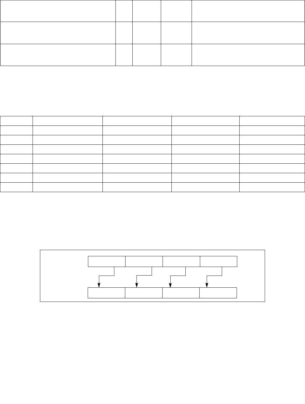
PSLLW/PSLLD/PSLLQ—Shift Packed Data Left Logical
INSTRUCTION SET REFERENCE, M-U
Vol. 2B 4-435
Instruction Operand Encoding
Description
Shifts the bits in the individual data elements (words, doublewords, or quadword) in the destination operand (first
operand) to the left by the number of bits specified in the count operand (second operand). As the bits in the data
elements are shifted left, the empty low-order bits are cleared (set to 0). If the value specified by the count
operand is greater than 15 (for words), 31 (for doublewords), or 63 (for a quadword), then the destination operand
is set to all 0s. Figure 4-17 gives an example of shifting words in a 64-bit operand.
The (V)PSLLW instruction shifts each of the words in the destination operand to the left by the number of bits spec-
ified in the count operand; the (V)PSLLD instruction shifts each of the doublewords in the destination operand; and
the (V)PSLLQ instruction shifts the quadword (or quadwords) in the destination operand.
In 64-bit mode and not encoded with VEX/EVEX, using a REX prefix in the form of REX.R permits this instruction to
access additional registers (XMM8-XMM15).
Legacy SSE instructions 64-bit operand: The destination operand is an MMX technology register; the count
operand can be either an MMX technology register or an 64-bit memory location.
EVEX.NDD.128.66.0F.W1 73 /6 ib
VPSLLQ xmm1 {k1}{z}, xmm2/m128/m64bcst,
imm8
FVI V/V AVX512VL
AVX512F
Shift quadwords in xmm2/m128/m64bcst left
by imm8 while shifting in 0s using writemask k1.
EVEX.NDD.256.66.0F.W1 73 /6 ib
VPSLLQ ymm1 {k1}{z}, ymm2/m256/m64bcst,
imm8
FVI V/V AVX512VL
AVX512F
Shift quadwords in ymm2/m256/m64bcst left
by imm8 while shifting in 0s using writemask k1.
EVEX.NDD.512.66.0F.W1 73 /6 ib
VPSLLQ zmm1 {k1}{z}, zmm2/m512/m64bcst,
imm8
FVI V/V AVX512F Shift quadwords in zmm2/m512/m64bcst left
by imm8 while shifting in 0s using writemask k1.
NOTES:
1. See note in Section 2.4, “AVX and SSE Instruction Exception Specification” in the Intel® 64 and IA-32 Architectures Software
Developer’s Manual, Volume 2A and Section 22.25.3, “Exception Conditions of Legacy SIMD Instructions Operating on MMX Registers”
in the Intel® 64 and IA-32 Architectures Software Developer’s Manual, Volume 3A.
Op/En Operand 1 Operand 2 Operand 3 Operand 4
RM ModRM:reg (r, w) ModRM:r/m (r) NA NA
MI ModRM:r/m (r, w) imm8 NA NA
RVM ModRM:reg (w) VEX.vvvv (r) ModRM:r/m (r) NA
VMI VEX.vvvv (w) ModRM:r/m (r) imm8 NA
FVMI EVEX.vvvv (w) ModRM:r/m (R) Imm8 NA
FVI EVEX.vvvv (w) ModRM:r/m (R) Imm8 NA
M128 ModRM:reg (w) VEX.vvvv (r) ModRM:r/m (r) NA
Figure 4-17. PSLLW, PSLLD, and PSLLQ Instruction Operation Using 64-bit Operand
DEST
DEST
Pre-Shift
Post-Shift
Shift Left
X0
X0 << COUNT
X3 X2 X1
X1 << COUNTX2 << COUNTX3 << COUNT
with Zero
Extension

PSLLW/PSLLD/PSLLQ—Shift Packed Data Left Logical
INSTRUCTION SET REFERENCE, M-U
4-436 Vol. 2B
128-bit Legacy SSE version: The destination and first source operands are XMM registers. Bits (VLMAX-1:128) of
the corresponding YMM destination register remain unchanged. The count operand can be either an XMM register
or a 128-bit memory location or an 8-bit immediate. If the count operand is a memory address, 128 bits are loaded
but the upper 64 bits are ignored.
VEX.128 encoded version: The destination and first source operands are XMM registers. Bits (VLMAX-1:128) of the
destination YMM register are zeroed. The count operand can be either an XMM register or a 128-bit memory loca-
tion or an 8-bit immediate. If the count operand is a memory address, 128 bits are loaded but the upper 64 bits are
ignored.
VEX.256 encoded version: The destination operand is a YMM register. The source operand is a YMM register or a
memory location. The count operand can come either from an XMM register or a memory location or an 8-bit imme-
diate. Bits (MAX_VL-1:256) of the corresponding ZMM register are zeroed.
EVEX encoded versions: The destination operand is a ZMM register updated according to the writemask. The count
operand is either an 8-bit immediate (the immediate count version) or an 8-bit value from an XMM register or a
memory location (the variable count version). For the immediate count version, the source operand (the second
operand) can be a ZMM register, a 512-bit memory location or a 512-bit vector broadcasted from a 32/64-bit
memory location. For the variable count version, the first source operand (the second operand) is a ZMM register,
the second source operand (the third operand, 8-bit variable count) can be an XMM register or a memory location.
Note: In VEX/EVEX encoded versions of shifts with an immediate count, vvvv of VEX/EVEX encode the destination
register, and VEX.B/EVEX.B + ModRM.r/m encodes the source register.
Note: For shifts with an immediate count (VEX.128.66.0F 71-73 /6, or EVEX.128.66.0F 71-73 /6),
VEX.vvvv/EVEX.vvvv encodes the destination register.
Operation
PSLLW (with 64-bit operand)
IF (COUNT > 15)
THEN
DEST[64:0] ← 0000000000000000H;
ELSE
DEST[15:0] ← ZeroExtend(DEST[15:0] << COUNT);
(* Repeat shift operation for 2nd and 3rd words *)
DEST[63:48] ← ZeroExtend(DEST[63:48] << COUNT);
FI;
PSLLD (with 64-bit operand)
IF (COUNT > 31)
THEN
DEST[64:0] ← 0000000000000000H;
ELSE
DEST[31:0] ← ZeroExtend(DEST[31:0] << COUNT);
DEST[63:32] ← ZeroExtend(DEST[63:32] << COUNT);
FI;
PSLLQ (with 64-bit operand)
IF (COUNT > 63)
THEN
DEST[64:0] ← 0000000000000000H;
ELSE
DEST ← ZeroExtend(DEST << COUNT);
FI;
LOGICAL_LEFT_SHIFT_WORDS(SRC, COUNT_SRC)
COUNT COUNT_SRC[63:0];
IF (COUNT > 15)
THEN

PSLLW/PSLLD/PSLLQ—Shift Packed Data Left Logical
INSTRUCTION SET REFERENCE, M-U
Vol. 2B 4-437
DEST[127:0] 00000000000000000000000000000000H
ELSE
DEST[15:0] ZeroExtend(SRC[15:0] << COUNT);
(* Repeat shift operation for 2nd through 7th words *)
DEST[127:112] ZeroExtend(SRC[127:112] << COUNT);
FI;
LOGICAL_LEFT_SHIFT_DWORDS1(SRC, COUNT_SRC)
COUNT COUNT_SRC[63:0];
IF (COUNT > 31)
THEN
DEST[31:0] 0
ELSE
DEST[31:0] ZeroExtend(SRC[31:0] << COUNT);
FI;
LOGICAL_LEFT_SHIFT_DWORDS(SRC, COUNT_SRC)
COUNT COUNT_SRC[63:0];
IF (COUNT > 31)
THEN
DEST[127:0] 00000000000000000000000000000000H
ELSE
DEST[31:0] ZeroExtend(SRC[31:0] << COUNT);
(* Repeat shift operation for 2nd through 3rd words *)
DEST[127:96] ZeroExtend(SRC[127:96] << COUNT);
FI;
LOGICAL_LEFT_SHIFT_QWORDS1(SRC, COUNT_SRC)
COUNT COUNT_SRC[63:0];
IF (COUNT > 63)
THEN
DEST[63:0] 0
ELSE
DEST[63:0] ZeroExtend(SRC[63:0] << COUNT);
FI;
LOGICAL_LEFT_SHIFT_QWORDS(SRC, COUNT_SRC)
COUNT COUNT_SRC[63:0];
IF (COUNT > 63)
THEN
DEST[127:0] 00000000000000000000000000000000H
ELSE
DEST[63:0] ZeroExtend(SRC[63:0] << COUNT);
DEST[127:64] ZeroExtend(SRC[127:64] << COUNT);
FI;
LOGICAL_LEFT_SHIFT_WORDS_256b(SRC, COUNT_SRC)
COUNT COUNT_SRC[63:0];
IF (COUNT > 15)
THEN
DEST[127:0] 00000000000000000000000000000000H
DEST[255:128] 00000000000000000000000000000000H
ELSE
DEST[15:0] ZeroExtend(SRC[15:0] << COUNT);
(* Repeat shift operation for 2nd through 15th words *)

PSLLW/PSLLD/PSLLQ—Shift Packed Data Left Logical
INSTRUCTION SET REFERENCE, M-U
4-438 Vol. 2B
DEST[255:240] ZeroExtend(SRC[255:240] << COUNT);
FI;
LOGICAL_LEFT_SHIFT_DWORDS_256b(SRC, COUNT_SRC)
COUNT COUNT_SRC[63:0];
IF (COUNT > 31)
THEN
DEST[127:0] 00000000000000000000000000000000H
DEST[255:128] 00000000000000000000000000000000H
ELSE
DEST[31:0] ZeroExtend(SRC[31:0] << COUNT);
(* Repeat shift operation for 2nd through 7th words *)
DEST[255:224] ZeroExtend(SRC[255:224] << COUNT);
FI;
LOGICAL_LEFT_SHIFT_QWORDS_256b(SRC, COUNT_SRC)
COUNT COUNT_SRC[63:0];
IF (COUNT > 63)
THEN
DEST[127:0] 00000000000000000000000000000000H
DEST[255:128] 00000000000000000000000000000000H
ELSE
DEST[63:0] ZeroExtend(SRC[63:0] << COUNT);
DEST[127:64] ZeroExtend(SRC[127:64] << COUNT)
DEST[191:128] ZeroExtend(SRC[191:128] << COUNT);
DEST[255:192] ZeroExtend(SRC[255:192] << COUNT);
FI;
VPSLLW (EVEX versions, xmm/m128)
(KL, VL) = (8, 128), (16, 256), (32, 512)
IF VL = 128
TMP_DEST[127:0] LOGICAL_LEFT_SHIFT_WORDS_128b(SRC1[127:0], SRC2)
FI;
IF VL = 256
TMP_DEST[255:0] LOGICAL_LEFT_SHIFT_WORDS_256b(SRC1[255:0], SRC2)
FI;
IF VL = 512
TMP_DEST[255:0] LOGICAL_LEFT_SHIFT_WORDS_256b(SRC1[255:0], SRC2)
TMP_DEST[511:256] LOGICAL_LEFT_SHIFT_WORDS_256b(SRC1[511:256], SRC2)
FI;
FOR j 0 TO KL-1
i j * 16
IF k1[j] OR *no writemask*
THEN DEST[i+15:i] TMP_DEST[i+15:i]
ELSE
IF *merging-masking* ; merging-masking
THEN *DEST[i+15:i] remains unchanged*
ELSE *zeroing-masking* ; zeroing-masking
DEST[i+15:i] = 0
FI
FI;
ENDFOR
DEST[MAX_VL-1:VL] 0

PSLLW/PSLLD/PSLLQ—Shift Packed Data Left Logical
INSTRUCTION SET REFERENCE, M-U
Vol. 2B 4-439
VPSLLW (EVEX versions, imm8)
(KL, VL) = (8, 128), (16, 256), (32, 512)
IF VL = 128
TMP_DEST[127:0] LOGICAL_LEFT_SHIFT_WORDS_128b(SRC1[127:0], imm8)
FI;
IF VL = 256
TMP_DEST[255:0] LOGICAL_RIGHT_SHIFT_WORDS_256b(SRC1[255:0], imm8)
FI;
IF VL = 512
TMP_DEST[255:0] LOGICAL_LEFT_SHIFT_WORDS_256b(SRC1[255:0], imm8)
TMP_DEST[511:256] LOGICAL_LEFT_SHIFT_WORDS_256b(SRC1[511:256], imm8)
FI;
FOR j 0 TO KL-1
i j * 16
IF k1[j] OR *no writemask*
THEN DEST[i+15:i] TMP_DEST[i+15:i]
ELSE
IF *merging-masking* ; merging-masking
THEN *DEST[i+15:i] remains unchanged*
ELSE *zeroing-masking* ; zeroing-masking
DEST[i+15:i] = 0
FI
FI;
ENDFOR
DEST[MAX_VL-1:VL] 0
VPSLLW (ymm, ymm, xmm/m128) - VEX.256 encoding
DEST[255:0] LOGICAL_LEFT_SHIFT_WORDS_256b(SRC1, SRC2)
DEST[MAX_VL-1:256] 0;
VPSLLW (ymm, imm8) - VEX.256 encoding
DEST[255:0] LOGICAL_LEFT_SHIFT_WORD_256b(SRC1, imm8)
DEST[MAX_VL-1:256] 0;
VPSLLW (xmm, xmm, xmm/m128) - VEX.128 encoding
DEST[127:0] LOGICAL_LEFT_SHIFT_WORDS(SRC1, SRC2)
DEST[MAX_VL-1:128] 0
VPSLLW (xmm, imm8) - VEX.128 encoding
DEST[127:0] LOGICAL_LEFT_SHIFT_WORDS(SRC1, imm8)
DEST[MAX_VL-1:128] 0

PSLLW/PSLLD/PSLLQ—Shift Packed Data Left Logical
INSTRUCTION SET REFERENCE, M-U
4-440 Vol. 2B
PSLLW (xmm, xmm, xmm/m128)
DEST[127:0] LOGICAL_LEFT_SHIFT_WORDS(DEST, SRC)
DEST[MAX_VL-1:128] (Unmodified)
PSLLW (xmm, imm8)
DEST[127:0] LOGICAL_LEFT_SHIFT_WORDS(DEST, imm8)
DEST[MAX_VL-1:128] (Unmodified)
VPSLLD (EVEX versions, imm8)
(KL, VL) = (4, 128), (8, 256), (16, 512)
FOR j 0 TO KL-1
i j * 32
IF k1[j] OR *no writemask* THEN
IF (EVEX.b = 1) AND (SRC1 *is memory*)
THEN DEST[i+31:i] LOGICAL_LEFT_SHIFT_DWORDS1(SRC1[31:0], imm8)
ELSE DEST[i+31:i] LOGICAL_LEFT_SHIFT_DWORDS1(SRC1[i+31:i], imm8)
FI;
ELSE
IF *merging-masking* ; merging-masking
THEN *DEST[i+31:i] remains unchanged*
ELSE *zeroing-masking* ; zeroing-masking
DEST[i+31:i] 0
FI
FI;
ENDFOR
DEST[MAX_VL-1:VL] 0
VPSLLD (EVEX versions, xmm/m128)
(KL, VL) = (4, 128), (8, 256), (16, 512)
IF VL = 128
TMP_DEST[127:0] LOGICAL_LEFT_SHIFT_DWORDS_128b(SRC1[127:0], SRC2)
FI;
IF VL = 256
TMP_DEST[255:0] LOGICAL_LEFT_SHIFT_DWORDS_256b(SRC1[255:0], SRC2)
FI;
IF VL = 512
TMP_DEST[255:0] LOGICAL_LEFT_SHIFT_DWORDS_256b(SRC1[255:0], SRC2)
TMP_DEST[511:256] LOGICAL_LEFT_SHIFT_DWORDS_256b(SRC1[511:256], SRC2)
FI;
FOR j 0 TO KL-1
i j * 32
IF k1[j] OR *no writemask*
THEN DEST[i+31:i] TMP_DEST[i+31:i]
ELSE
IF *merging-masking* ; merging-masking
THEN *DEST[i+31:i] remains unchanged*
ELSE *zeroing-masking* ; zeroing-masking
DEST[i+31:i] 0
FI
FI;
ENDFOR
DEST[MAX_VL-1:VL] 0

PSLLW/PSLLD/PSLLQ—Shift Packed Data Left Logical
INSTRUCTION SET REFERENCE, M-U
Vol. 2B 4-441
VPSLLD (ymm, ymm, xmm/m128) - VEX.256 encoding
DEST[255:0] LOGICAL_LEFT_SHIFT_DWORDS_256b(SRC1, SRC2)
DEST[MAX_VL-1:256] 0;
VPSLLD (ymm, imm8) - VEX.256 encoding
DEST[255:0] LOGICAL_LEFT_SHIFT_DWORDS_256b(SRC1, imm8)
DEST[MAX_VL-1:256] 0;
VPSLLD (xmm, xmm, xmm/m128) - VEX.128 encoding
DEST[127:0] LOGICAL_LEFT_SHIFT_DWORDS(SRC1, SRC2)
DEST[MAX_VL-1:128] 0
VPSLLD (xmm, imm8) - VEX.128 encoding
DEST[127:0] LOGICAL_LEFT_SHIFT_DWORDS(SRC1, imm8)
DEST[MAX_VL-1:128] 0
PSLLD (xmm, xmm, xmm/m128)
DEST[127:0] LOGICAL_LEFT_SHIFT_DWORDS(DEST, SRC)
DEST[MAX_VL-1:128] (Unmodified)
PSLLD (xmm, imm8)
DEST[127:0] LOGICAL_LEFT_SHIFT_DWORDS(DEST, imm8)
DEST[MAX_VL-1:128] (Unmodified)
VPSLLQ (EVEX versions, imm8)
(KL, VL) = (2, 128), (4, 256), (8, 512)
FOR j 0 TO KL-1
i j * 64
IF k1[j] OR *no writemask* THEN
IF (EVEX.b = 1) AND (SRC1 *is memory*)
THEN DEST[i+63:i] LOGICAL_LEFT_SHIFT_QWORDS1(SRC1[63:0], imm8)
ELSE DEST[i+63:i] LOGICAL_LEFT_SHIFT_QWORDS1(SRC1[i+63:i], imm8)
FI;
ELSE
IF *merging-masking* ; merging-masking
THEN *DEST[i+63:i] remains unchanged*
ELSE *zeroing-masking* ; zeroing-masking
DEST[i+63:i] 0
FI
FI;
ENDFOR
VPSLLQ (EVEX versions, xmm/m128)
(KL, VL) = (2, 128), (4, 256), (8, 512)
IF VL = 128
TMP_DEST[127:0] LOGICAL_LEFT_SHIFT_QWORDS_128b(SRC1[127:0], SRC2)
FI;
IF VL = 256
TMP_DEST[255:0] LOGICAL_LEFT_SHIFT_QWORDS_256b(SRC1[255:0], SRC2)
FI;
IF VL = 512
TMP_DEST[255:0] LOGICAL_LEFT_SHIFT_QWORDS_256b(SRC1[255:0], SRC2)
TMP_DEST[511:256] LOGICAL_LEFT_SHIFT_QWORDS_256b(SRC1[511:256], SRC2)
FI;

PSLLW/PSLLD/PSLLQ—Shift Packed Data Left Logical
INSTRUCTION SET REFERENCE, M-U
4-442 Vol. 2B
FOR j 0 TO KL-1
i j * 64
IF k1[j] OR *no writemask*
THEN DEST[i+63:i] TMP_DEST[i+63:i]
ELSE
IF *merging-masking* ; merging-masking
THEN *DEST[i+63:i] remains unchanged*
ELSE *zeroing-masking* ; zeroing-masking
DEST[i+63:i] 0
FI
FI;
ENDFOR
DEST[MAX_VL-1:VL] 0
VPSLLQ (ymm, ymm, xmm/m128) - VEX.256 encoding
DEST[255:0] LOGICAL_LEFT_SHIFT_QWORDS_256b(SRC1, SRC2)
DEST[MAX_VL-1:256] 0;
VPSLLQ (ymm, imm8) - VEX.256 encoding
DEST[255:0] LOGICAL_LEFT_SHIFT_QWORDS_256b(SRC1, imm8)
DEST[MAX_VL-1:256] 0;
VPSLLQ (xmm, xmm, xmm/m128) - VEX.128 encoding
DEST[127:0] LOGICAL_LEFT_SHIFT_QWORDS(SRC1, SRC2)
DEST[MAX_VL-1:128] 0
VPSLLQ (xmm, imm8) - VEX.128 encoding
DEST[127:0] LOGICAL_LEFT_SHIFT_QWORDS(SRC1, imm8)
DEST[MAX_VL-1:128] 0
PSLLQ (xmm, xmm, xmm/m128)
DEST[127:0] LOGICAL_LEFT_SHIFT_QWORDS(DEST, SRC)
DEST[MAX_VL-1:128] (Unmodified)
PSLLQ (xmm, imm8)
DEST[127:0] LOGICAL_LEFT_SHIFT_QWORDS(DEST, imm8)
DEST[MAX_VL-1:128] (Unmodified)
Intel C/C++ Compiler Intrinsic Equivalents
VPSLLD __m512i _mm512_slli_epi32(__m512i a, unsigned int imm);
VPSLLD __m512i _mm512_mask_slli_epi32(__m512i s, __mmask16 k, __m512i a, unsigned int imm);
VPSLLD __m512i _mm512_maskz_slli_epi32( __mmask16 k, __m512i a, unsigned int imm);
VPSLLD __m256i _mm256_mask_slli_epi32(__m256i s, __mmask8 k, __m256i a, unsigned int imm);
VPSLLD __m256i _mm256_maskz_slli_epi32( __mmask8 k, __m256i a, unsigned int imm);
VPSLLD __m128i _mm_mask_slli_epi32(__m128i s, __mmask8 k, __m128i a, unsigned int imm);
VPSLLD __m128i _mm_maskz_slli_epi32( __mmask8 k, __m128i a, unsigned int imm);
VPSLLD __m512i _mm512_sll_epi32(__m512i a, __m128i cnt);
VPSLLD __m512i _mm512_mask_sll_epi32(__m512i s, __mmask16 k, __m512i a, __m128i cnt);
VPSLLD __m512i _mm512_maskz_sll_epi32( __mmask16 k, __m512i a, __m128i cnt);
VPSLLD __m256i _mm256_mask_sll_epi32(__m256i s, __mmask8 k, __m256i a, __m128i cnt);
VPSLLD __m256i _mm256_maskz_sll_epi32( __mmask8 k, __m256i a, __m128i cnt);
VPSLLD __m128i _mm_mask_sll_epi32(__m128i s, __mmask8 k, __m128i a, __m128i cnt);
VPSLLD __m128i _mm_maskz_sll_epi32( __mmask8 k, __m128i a, __m128i cnt);

PSLLW/PSLLD/PSLLQ—Shift Packed Data Left Logical
INSTRUCTION SET REFERENCE, M-U
Vol. 2B 4-443
VPSLLQ __m512i _mm512_mask_slli_epi64(__m512i a, unsigned int imm);
VPSLLQ __m512i _mm512_mask_slli_epi64(__m512i s, __mmask8 k, __m512i a, unsigned int imm);
VPSLLQ __m512i _mm512_maskz_slli_epi64( __mmask8 k, __m512i a, unsigned int imm);
VPSLLQ __m256i _mm256_mask_slli_epi64(__m256i s, __mmask8 k, __m256i a, unsigned int imm);
VPSLLQ __m256i _mm256_maskz_slli_epi64( __mmask8 k, __m256i a, unsigned int imm);
VPSLLQ __m128i _mm_mask_slli_epi64(__m128i s, __mmask8 k, __m128i a, unsigned int imm);
VPSLLQ __m128i _mm_maskz_slli_epi64( __mmask8 k, __m128i a, unsigned int imm);
VPSLLQ __m512i _mm512_mask_sll_epi64(__m512i a, __m128i cnt);
VPSLLQ __m512i _mm512_mask_sll_epi64(__m512i s, __mmask8 k, __m512i a, __m128i cnt);
VPSLLQ __m512i _mm512_maskz_sll_epi64( __mmask8 k, __m512i a, __m128i cnt);
VPSLLQ __m256i _mm256_mask_sll_epi64(__m256i s, __mmask8 k, __m256i a, __m128i cnt);
VPSLLQ __m256i _mm256_maskz_sll_epi64( __mmask8 k, __m256i a, __m128i cnt);
VPSLLQ __m128i _mm_mask_sll_epi64(__m128i s, __mmask8 k, __m128i a, __m128i cnt);
VPSLLQ __m128i _mm_maskz_sll_epi64( __mmask8 k, __m128i a, __m128i cnt);
VPSLLW __m512i _mm512_slli_epi16(__m512i a, unsigned int imm);
VPSLLW __m512i _mm512_mask_slli_epi16(__m512i s, __mmask32 k, __m512i a, unsigned int imm);
VPSLLW __m512i _mm512_maskz_slli_epi16( __mmask32 k, __m512i a, unsigned int imm);
VPSLLW __m256i _mm256_mask_sllii_epi16(__m256i s, __mmask16 k, __m256i a, unsigned int imm);
VPSLLW __m256i _mm256_maskz_slli_epi16( __mmask16 k, __m256i a, unsigned int imm);
VPSLLW __m128i _mm_mask_slli_epi16(__m128i s, __mmask8 k, __m128i a, unsigned int imm);
VPSLLW __m128i _mm_maskz_slli_epi16( __mmask8 k, __m128i a, unsigned int imm);
VPSLLW __m512i _mm512_sll_epi16(__m512i a, __m128i cnt);
VPSLLW __m512i _mm512_mask_sll_epi16(__m512i s, __mmask32 k, __m512i a, __m128i cnt);
VPSLLW __m512i _mm512_maskz_sll_epi16( __mmask32 k, __m512i a, __m128i cnt);
VPSLLW __m256i _mm256_mask_sll_epi16(__m256i s, __mmask16 k, __m256i a, __m128i cnt);
VPSLLW __m256i _mm256_maskz_sll_epi16( __mmask16 k, __m256i a, __m128i cnt);
VPSLLW __m128i _mm_mask_sll_epi16(__m128i s, __mmask8 k, __m128i a, __m128i cnt);
VPSLLW __m128i _mm_maskz_sll_epi16( __mmask8 k, __m128i a, __m128i cnt);
PSLLW:__m64 _mm_slli_pi16 (__m64 m, int count)
PSLLW:__m64 _mm_sll_pi16(__m64 m, __m64 count)
(V)PSLLW:__m128i _mm_slli_pi16(__m64 m, int count)
(V)PSLLW:__m128i _mm_slli_pi16(__m128i m, __m128i count)
VPSLLW:__m256i _mm256_slli_epi16 (__m256i m, int count)
VPSLLW:__m256i _mm256_sll_epi16 (__m256i m, __m128i count)
PSLLD:__m64 _mm_slli_pi32(__m64 m, int count)
PSLLD:__m64 _mm_sll_pi32(__m64 m, __m64 count)
(V)PSLLD:__m128i _mm_slli_epi32(__m128i m, int count)
(V)PSLLD:__m128i _mm_sll_epi32(__m128i m, __m128i count)
VPSLLD:__m256i _mm256_slli_epi32 (__m256i m, int count)
VPSLLD:__m256i _mm256_sll_epi32 (__m256i m, __m128i count)
PSLLQ:__m64 _mm_slli_si64(__m64 m, int count)
PSLLQ:__m64 _mm_sll_si64(__m64 m, __m64 count)
(V)PSLLQ:__m128i _mm_slli_epi64(__m128i m, int count)
(V)PSLLQ:__m128i _mm_sll_epi64(__m128i m, __m128i count)
VPSLLQ:__m256i _mm256_slli_epi64 (__m256i m, int count)
VPSLLQ:__m256i _mm256_sll_epi64 (__m256i m, __m128i count)
Flags Affected
None.
Numeric Exceptions
None.

PSLLW/PSLLD/PSLLQ—Shift Packed Data Left Logical
INSTRUCTION SET REFERENCE, M-U
4-444 Vol. 2B
Other Exceptions
VEX-encoded instructions:
Syntax with RM/RVM operand encoding, see Exceptions Type 4.
Syntax with MI/VMI operand encoding, see Exceptions Type 7.
EVEX-encoded VPSLLW, see Exceptions Type E4NF.nb.
EVEX-encoded VPSLLD/Q:
Syntax with M128 operand encoding, see Exceptions Type E4NF.nb.
Syntax with FVI operand encoding, see Exceptions Type E4.

PSRAW/PSRAD/PSRAQ—Shift Packed Data Right Arithmetic
INSTRUCTION SET REFERENCE, M-U
Vol. 2B 4-445
PSRAW/PSRAD/PSRAQ—Shift Packed Data Right Arithmetic
Opcode/
Instruction
Op/
En
64/32 bit
Mode
Support
CPUID
Feature
Flag
Description
0F E1 /r1
PSRAW mm, mm/m64
RM V/V MMX Shift words in mm right by mm/m64 while shifting
in sign bits.
66 0F E1 /r
PSRAW xmm1, xmm2/m128
RM V/V SSE2 Shift words in xmm1 right by xmm2/m128 while
shifting in sign bits.
0F 71 /4 ib1
PSRAW mm, imm8
MI V/V MMX Shift words in mm right by imm8 while shifting in
sign bits
66 0F 71 /4 ib
PSRAW xmm1, imm8
MI V/V SSE2 Shift words in xmm1 right by imm8 while shifting
in sign bits
0F E2 /r1
PSRAD mm, mm/m64
RM V/V MMX Shift doublewords in mm right by mm/m64 while
shifting in sign bits.
66 0F E2 /r
PSRAD xmm1, xmm2/m128
RM V/V SSE2 Shift doubleword in xmm1 right by xmm2 /m128
while shifting in sign bits.
0F 72 /4 ib1
PSRAD mm, imm8
MI V/V MMX Shift doublewords in mm right by imm8 while
shifting in sign bits.
66 0F 72 /4 ib
PSRAD xmm1, imm8
MI V/V SSE2 Shift doublewords in xmm1 right by imm8 while
shifting in sign bits.
VEX.NDS.128.66.0F.WIG E1 /r
VPSRAW xmm1, xmm2, xmm3/m128
RVM V/V AVX Shift words in xmm2 right by amount specified in
xmm3/m128 while shifting in sign bits.
VEX.NDD.128.66.0F.WIG 71 /4 ib
VPSRAW xmm1, xmm2, imm8
VMI V/V AVX Shift words in xmm2 right by imm8 while shifting
in sign bits.
VEX.NDS.128.66.0F.WIG E2 /r
VPSRAD xmm1, xmm2, xmm3/m128
RVM V/V AVX Shift doublewords in xmm2 right by amount
specified in xmm3/m128 while shifting in sign
bits.
VEX.NDD.128.66.0F.WIG 72 /4 ib
VPSRAD xmm1, xmm2, imm8
VMI V/V AVX Shift doublewords in xmm2 right by imm8 while
shifting in sign bits.
VEX.NDS.256.66.0F.WIG E1 /r
VPSRAW ymm1, ymm2, xmm3/m128
RVM V/V AVX2 Shift words in ymm2 right by amount specified in
xmm3/m128 while shifting in sign bits.
VEX.NDD.256.66.0F.WIG 71 /4 ib
VPSRAW ymm1, ymm2, imm8
VMI V/V AVX2 Shift words in ymm2 right by imm8 while shifting
in sign bits.
VEX.NDS.256.66.0F.WIG E2 /r
VPSRAD ymm1, ymm2, xmm3/m128
RVM V/V AVX2 Shift doublewords in ymm2 right by amount
specified in xmm3/m128 while shifting in sign
bits.
VEX.NDD.256.66.0F.WIG 72 /4 ib
VPSRAD ymm1, ymm2, imm8
VMI V/V AVX2 Shift doublewords in ymm2 right by imm8 while
shifting in sign bits.
EVEX.NDS.128.66.0F.WIG E1 /r
VPSRAW xmm1 {k1}{z}, xmm2, xmm3/m128
M128 V/V AVX512VL
AVX512BW
Shift words in xmm2 right by amount specified in
xmm3/m128 while shifting in sign bits using
writemask k1.
EVEX.NDS.256.66.0F.WIG E1 /r
VPSRAW ymm1 {k1}{z}, ymm2, xmm3/m128
M128 V/V AVX512VL
AVX512BW
Shift words in ymm2 right by amount specified in
xmm3/m128 while shifting in sign bits using
writemask k1.
EVEX.NDS.512.66.0F.WIG E1 /r
VPSRAW zmm1 {k1}{z}, zmm2, xmm3/m128
M128 V/V AVX512BW Shift words in zmm2 right by amount specified in
xmm3/m128 while shifting in sign bits using
writemask k1.

PSRAW/PSRAD/PSRAQ—Shift Packed Data Right Arithmetic
INSTRUCTION SET REFERENCE, M-U
4-446 Vol. 2B
EVEX.NDD.128.66.0F.WIG 71 /4 ib
VPSRAW xmm1 {k1}{z}, xmm2/m128, imm8
FVMI V/V AVX512VL
AVX512BW
Shift words in xmm2/m128 right by imm8 while
shifting in sign bits using writemask k1.
EVEX.NDD.256.66.0F.WIG 71 /4 ib
VPSRAW ymm1 {k1}{z}, ymm2/m256, imm8
FVMI V/V AVX512VL
AVX512BW
Shift words in ymm2/m256 right by imm8 while
shifting in sign bits using writemask k1.
EVEX.NDD.512.66.0F.WIG 71 /4 ib
VPSRAW zmm1 {k1}{z}, zmm2/m512, imm8
FVMI V/V AVX512BW Shift words in zmm2/m512 right by imm8 while
shifting in sign bits using writemask k1.
EVEX.NDS.128.66.0F.W0 E2 /r
VPSRAD xmm1 {k1}{z}, xmm2, xmm3/m128
M128 V/V AVX512VL
AVX512F
Shift doublewords in xmm2 right by amount
specified in xmm3/m128 while shifting in sign bits
using writemask k1.
EVEX.NDS.256.66.0F.W0 E2 /r
VPSRAD ymm1 {k1}{z}, ymm2, xmm3/m128
M128 V/V AVX512VL
AVX512F
Shift doublewords in ymm2 right by amount
specified in xmm3/m128 while shifting in sign bits
using writemask k1.
EVEX.NDS.512.66.0F.W0 E2 /r
VPSRAD zmm1 {k1}{z}, zmm2, xmm3/m128
M128 V/V AVX512F Shift doublewords in zmm2 right by amount
specified in xmm3/m128 while shifting in sign bits
using writemask k1.
EVEX.NDD.128.66.0F.W0 72 /4 ib
VPSRAD xmm1 {k1}{z}, xmm2/m128/m32bcst,
imm8
FVI V/V AVX512VL
AVX512F
Shift doublewords in xmm2/m128/m32bcst right
by imm8 while shifting in sign bits using
writemask k1.
EVEX.NDD.256.66.0F.W0 72 /4 ib
VPSRAD ymm1 {k1}{z}, ymm2/m256/m32bcst,
imm8
FVI V/V AVX512VL
AVX512F
Shift doublewords in ymm2/m256/m32bcst right
by imm8 while shifting in sign bits using
writemask k1.
EVEX.NDD.512.66.0F.W0 72 /4 ib
VPSRAD zmm1 {k1}{z}, zmm2/m512/m32bcst,
imm8
FVI V/V AVX512F Shift doublewords in zmm2/m512/m32bcst right
by imm8 while shifting in sign bits using
writemask k1.
EVEX.NDS.128.66.0F.W1 E2 /r
VPSRAQ xmm1 {k1}{z}, xmm2, xmm3/m128
M128 V/V AVX512VL
AVX512F
Shift quadwords in xmm2 right by amount
specified in xmm3/m128 while shifting in sign bits
using writemask k1.
EVEX.NDS.256.66.0F.W1 E2 /r
VPSRAQ ymm1 {k1}{z}, ymm2, xmm3/m128
M128 V/V AVX512VL
AVX512F
Shift quadwords in ymm2 right by amount
specified in xmm3/m128 while shifting in sign bits
using writemask k1.
EVEX.NDS.512.66.0F.W1 E2 /r
VPSRAQ zmm1 {k1}{z}, zmm2, xmm3/m128
M128 V/V AVX512F Shift quadwords in zmm2 right by amount
specified in xmm3/m128 while shifting in sign bits
using writemask k1.
EVEX.NDD.128.66.0F.W1 72 /4 ib
VPSRAQ xmm1 {k1}{z}, xmm2/m128/m64bcst,
imm8
FVI V/V AVX512VL
AVX512F
Shift quadwords in xmm2/m128/m64bcst right by
imm8 while shifting in sign bits using writemask
k1.
EVEX.NDD.256.66.0F.W1 72 /4 ib
VPSRAQ ymm1 {k1}{z}, ymm2/m256/m64bcst,
imm8
FVI V/V AVX512VL
AVX512F
Shift quadwords in ymm2/m256/m64bcst right by
imm8 while shifting in sign bits using writemask
k1.
EVEX.NDD.512.66.0F.W1 72 /4 ib
VPSRAQ zmm1 {k1}{z}, zmm2/m512/m64bcst,
imm8
FVI V/V AVX512F Shift quadwords in zmm2/m512/m64bcst right by
imm8 while shifting in sign bits using writemask
k1.
NOTES:
1. See note in Section 2.4, “AVX and SSE Instruction Exception Specification” in the Intel® 64 and IA-32 Architectures Software
Developer’s Manual, Volume 2A and Section 22.25.3, “Exception Conditions of Legacy SIMD Instructions Operating on MMX Registers” in
the Intel® 64 and IA-32 Architectures Software Developer’s Manual, Volume 3A.
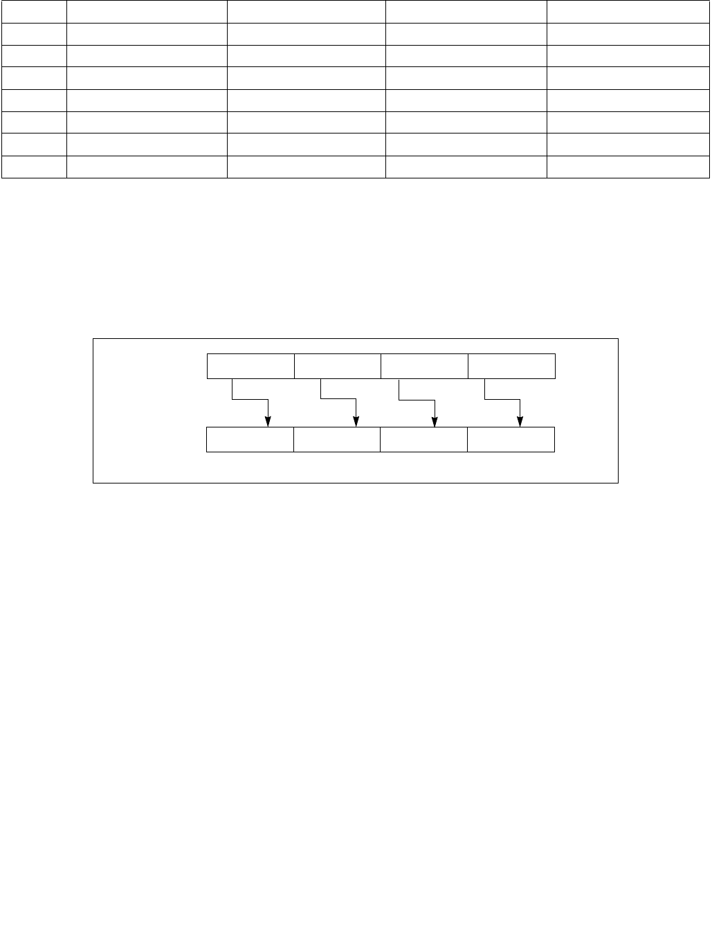
PSRAW/PSRAD/PSRAQ—Shift Packed Data Right Arithmetic
INSTRUCTION SET REFERENCE, M-U
Vol. 2B 4-447
Instruction Operand Encoding
Description
Shifts the bits in the individual data elements (words, doublewords or quadwords) in the destination operand (first
operand) to the right by the number of bits specified in the count operand (second operand). As the bits in the data
elements are shifted right, the empty high-order bits are filled with the initial value of the sign bit of the data
element. If the value specified by the count operand is greater than 15 (for words), 31 (for doublewords), or 63 (for
quadwords), each destination data element is filled with the initial value of the sign bit of the element. (Figure 4-18
gives an example of shifting words in a 64-bit operand.)
Note that only the first 64-bits of a 128-bit count operand are checked to compute the count. If the second source
operand is a memory address, 128 bits are loaded.
The (V)PSRAW instruction shifts each of the words in the destination operand to the right by the number of bits
specified in the count operand, and the (V)PSRAD instruction shifts each of the doublewords in the destination
operand.
In 64-bit mode and not encoded with VEX/EVEX, using a REX prefix in the form of REX.R permits this instruction to
access additional registers (XMM8-XMM15).
Legacy SSE instructions 64-bit operand: The destination operand is an MMX technology register; the count
operand can be either an MMX technology register or an 64-bit memory location.
128-bit Legacy SSE version: The destination and first source operands are XMM registers. Bits (VLMAX-1:128) of
the corresponding YMM destination register remain unchanged. The count operand can be either an XMM register
or a 128-bit memory location or an 8-bit immediate. If the count operand is a memory address, 128 bits are loaded
but the upper 64 bits are ignored.
VEX.128 encoded version: The destination and first source operands are XMM registers. Bits (VLMAX-1:128) of the
destination YMM register are zeroed. The count operand can be either an XMM register or a 128-bit memory loca-
tion or an 8-bit immediate. If the count operand is a memory address, 128 bits are loaded but the upper 64 bits are
ignored.
VEX.256 encoded version: The destination operand is a YMM register. The source operand is a YMM register or a
memory location. The count operand can come either from an XMM register or a memory location or an 8-bit
immediate. Bits (MAX_VL-1:256) of the corresponding ZMM register are zeroed.
Op/En Operand 1 Operand 2 Operand 3 Operand 4
RM ModRM:reg (r, w) ModRM:r/m (r) NA NA
MI ModRM:r/m (r, w) imm8 NA NA
RVM ModRM:reg (w) VEX.vvvv (r) ModRM:r/m (r) NA
VMI VEX.vvvv (w) ModRM:r/m (r) imm8 NA
FVMI EVEX.vvvv (w) ModRM:r/m (R) Imm8 NA
FVI EVEX.vvvv (w) ModRM:r/m (R) Imm8 NA
M128 ModRM:reg (w) EVEX.vvvv (r) ModRM:r/m (r) NA
Figure 4-18. PSRAW and PSRAD Instruction Operation Using a 64-bit Operand
DEST
DEST
Pre-Shift
Post-Shift
Shift Right
X0
X0 >> COUNT
X3 X2 X1
X1 >> COUNTX2 >> COUNTX3 >> COUNT
with Sign
Extension

PSRAW/PSRAD/PSRAQ—Shift Packed Data Right Arithmetic
INSTRUCTION SET REFERENCE, M-U
4-448 Vol. 2B
EVEX encoded versions: The destination operand is a ZMM register updated according to the writemask. The count
operand is either an 8-bit immediate (the immediate count version) or an 8-bit value from an XMM register or a
memory location (the variable count version). For the immediate count version, the source operand (the second
operand) can be a ZMM register, a 512-bit memory location or a 512-bit vector broadcasted from a 32/64-bit
memory location. For the variable count version, the first source operand (the second operand) is a ZMM register,
the second source operand (the third operand, 8-bit variable count) can be an XMM register or a memory location.
Note: In VEX/EVEX encoded versions of shifts with an immediate count, vvvv of VEX/EVEX encode the destination
register, and VEX.B/EVEX.B + ModRM.r/m encodes the source register.
Note: For shifts with an immediate count (VEX.128.66.0F 71-73 /4, EVEX.128.66.0F 71-73 /4),
VEX.vvvv/EVEX.vvvv encodes the destination register.
Operation
PSRAW (with 64-bit operand)
IF (COUNT > 15)
THEN COUNT ← 16;
FI;
DEST[15:0] ← SignExtend(DEST[15:0] >> COUNT);
(* Repeat shift operation for 2nd and 3rd words *)
DEST[63:48] ← SignExtend(DEST[63:48] >> COUNT);
PSRAD (with 64-bit operand)
IF (COUNT > 31)
THEN COUNT ← 32;
FI;
DEST[31:0] ← SignExtend(DEST[31:0] >> COUNT);
DEST[63:32] ← SignExtend(DEST[63:32] >> COUNT);
ARITHMETIC_RIGHT_SHIFT_DWORDS1(SRC, COUNT_SRC)
COUNT COUNT_SRC[63:0];
IF (COUNT > 31)
THEN
DEST[31:0] SignBit
ELSE
DEST[31:0] SignExtend(SRC[31:0] >> COUNT);
FI;
ARITHMETIC_RIGHT_SHIFT_QWORDS1(SRC, COUNT_SRC)
COUNT COUNT_SRC[63:0];
IF (COUNT > 63)
THEN
DEST[63:0] SignBit
ELSE
DEST[63:0] SignExtend(SRC[63:0] >> COUNT);
FI;
ARITHMETIC_RIGHT_SHIFT_WORDS_256b(SRC, COUNT_SRC)
COUNT COUNT_SRC[63:0];
IF (COUNT > 15)
THEN COUNT 16;
FI;
DEST[15:0] SignExtend(SRC[15:0] >> COUNT);
(* Repeat shift operation for 2nd through 15th words *)
DEST[255:240] SignExtend(SRC[255:240] >> COUNT);

PSRAW/PSRAD/PSRAQ—Shift Packed Data Right Arithmetic
INSTRUCTION SET REFERENCE, M-U
Vol. 2B 4-449
ARITHMETIC_RIGHT_SHIFT_DWORDS_256b(SRC, COUNT_SRC)
COUNT COUNT_SRC[63:0];
IF (COUNT > 31)
THEN COUNT 32;
FI;
DEST[31:0] SignExtend(SRC[31:0] >> COUNT);
(* Repeat shift operation for 2nd through 7th words *)
DEST[255:224] SignExtend(SRC[255:224] >> COUNT);
ARITHMETIC_RIGHT_SHIFT_QWORDS(SRC, COUNT_SRC, VL) ; VL: 128b, 256b or 512b
COUNT COUNT_SRC[63:0];
IF (COUNT > 63)
THEN COUNT 64;
FI;
DEST[63:0] SignExtend(SRC[63:0] >> COUNT);
(* Repeat shift operation for 2nd through 7th words *)
DEST[VL-1:VL-64] SignExtend(SRC[VL-1:VL-64] >> COUNT);
ARITHMETIC_RIGHT_SHIFT_WORDS(SRC, COUNT_SRC)
COUNT COUNT_SRC[63:0];
IF (COUNT > 15)
THEN COUNT 16;
FI;
DEST[15:0] SignExtend(SRC[15:0] >> COUNT);
(* Repeat shift operation for 2nd through 7th words *)
DEST[127:112] SignExtend(SRC[127:112] >> COUNT);
ARITHMETIC_RIGHT_SHIFT_DWORDS(SRC, COUNT_SRC)
COUNT COUNT_SRC[63:0];
IF (COUNT > 31)
THEN COUNT 32;
FI;
DEST[31:0] SignExtend(SRC[31:0] >> COUNT);
(* Repeat shift operation for 2nd through 3rd words *)
DEST[127:96] SignExtend(SRC[127:96] >> COUNT);

PSRAW/PSRAD/PSRAQ—Shift Packed Data Right Arithmetic
INSTRUCTION SET REFERENCE, M-U
4-450 Vol. 2B
VPSRAW (EVEX versions, xmm/m128)
(KL, VL) = (8, 128), (16, 256), (32, 512)
IF VL = 128
TMP_DEST[127:0] ARITHMETIC_RIGHT_SHIFT_WORDS_128b(SRC1[127:0], SRC2)
FI;
IF VL = 256
TMP_DEST[255:0] ARITHMETIC_RIGHT_SHIFT_WORDS_256b(SRC1[255:0], SRC2)
FI;
IF VL = 512
TMP_DEST[255:0] ARITHMETIC_RIGHT_SHIFT_WORDS_256b(SRC1[255:0], SRC2)
TMP_DEST[511:256] ARITHMETIC_RIGHT_SHIFT_WORDS_256b(SRC1[511:256], SRC2)
FI;
FOR j 0 TO KL-1
i j * 16
IF k1[j] OR *no writemask*
THEN DEST[i+15:i] TMP_DEST[i+15:i]
ELSE
IF *merging-masking* ; merging-masking
THEN *DEST[i+15:i] remains unchanged*
ELSE *zeroing-masking* ; zeroing-masking
DEST[i+15:i] = 0
FI
FI;
ENDFOR
DEST[MAX_VL-1:VL] 0
VPSRAW (EVEX versions, imm8)
(KL, VL) = (8, 128), (16, 256), (32, 512)
IF VL = 128
TMP_DEST[127:0] ARITHMETIC_RIGHT_SHIFT_WORDS_128b(SRC1[127:0], imm8)
FI;
IF VL = 256
TMP_DEST[255:0] ARITHMETIC_RIGHT_SHIFT_WORDS_256b(SRC1[255:0], imm8)
FI;
IF VL = 512
TMP_DEST[255:0] ARITHMETIC_RIGHT_SHIFT_WORDS_256b(SRC1[255:0], imm8)
TMP_DEST[511:256] ARITHMETIC_RIGHT_SHIFT_WORDS_256b(SRC1[511:256], imm8)
FI;
FOR j 0 TO KL-1
i j * 16
IF k1[j] OR *no writemask*
THEN DEST[i+15:i] TMP_DEST[i+15:i]
ELSE
IF *merging-masking* ; merging-masking
THEN *DEST[i+15:i] remains unchanged*
ELSE *zeroing-masking* ; zeroing-masking
DEST[i+15:i] = 0
FI
FI;
ENDFOR
DEST[MAX_VL-1:VL] 0

PSRAW/PSRAD/PSRAQ—Shift Packed Data Right Arithmetic
INSTRUCTION SET REFERENCE, M-U
Vol. 2B 4-451
VPSRAW (ymm, ymm, xmm/m128) - VEX
DEST[255:0] ARITHMETIC_RIGHT_SHIFT_WORDS_256b(SRC1, SRC2)
DEST[MAX_VL-1:256] 0
VPSRAW (ymm, imm8) - VEX
DEST[255:0] ARITHMETIC_RIGHT_SHIFT_WORDS_256b(SRC1, imm8)
DEST[MAX_VL-1:256] 0
VPSRAW (xmm, xmm, xmm/m128) - VEX
DEST[127:0] ARITHMETIC_RIGHT_SHIFT_WORDS(SRC1, SRC2)
DEST[MAX_VL-1:128] 0
VPSRAW (xmm, imm8) - VEX
DEST[127:0] ARITHMETIC_RIGHT_SHIFT_WORDS(SRC1, imm8)
DEST[MAX_VL-1:128] 0
PSRAW (xmm, xmm, xmm/m128)
DEST[127:0] ARITHMETIC_RIGHT_SHIFT_WORDS(DEST, SRC)
DEST[MAX_VL-1:128] (Unmodified)
PSRAW (xmm, imm8)
DEST[127:0] ARITHMETIC_RIGHT_SHIFT_WORDS(DEST, imm8)
DEST[MAX_VL-1:128] (Unmodified)
VPSRAD (EVEX versions, imm8)
(KL, VL) = (4, 128), (8, 256), (16, 512)
FOR j 0 TO KL-1
i j * 32
IF k1[j] OR *no writemask* THEN
IF (EVEX.b = 1) AND (SRC1 *is memory*)
THEN DEST[i+31:i] ARITHMETIC_RIGHT_SHIFT_DWORDS1(SRC1[31:0], imm8)
ELSE DEST[i+31:i] ARITHMETIC_RIGHT_SHIFT_DWORDS1(SRC1[i+31:i], imm8)
FI;
ELSE
IF *merging-masking* ; merging-masking
THEN *DEST[i+31:i] remains unchanged*
ELSE *zeroing-masking* ; zeroing-masking
DEST[i+31:i] 0
FI
FI;
ENDFOR
DEST[MAX_VL-1:VL] 0
VPSRAD (EVEX versions, xmm/m128)
(KL, VL) = (4, 128), (8, 256), (16, 512)
IF VL = 128
TMP_DEST[127:0] ARITHMETIC_RIGHT_SHIFT_DWORDS_128b(SRC1[127:0], SRC2)
FI;
IF VL = 256
TMP_DEST[255:0] ARITHMETIC_RIGHT_SHIFT_DWORDS_256b(SRC1[255:0], SRC2)
FI;
IF VL = 512
TMP_DEST[255:0] ARITHMETIC_RIGHT_SHIFT_DWORDS_256b(SRC1[255:0], SRC2)
TMP_DEST[511:256] ARITHMETIC_RIGHT_SHIFT_DWORDS_256b(SRC1[511:256], SRC2)

PSRAW/PSRAD/PSRAQ—Shift Packed Data Right Arithmetic
INSTRUCTION SET REFERENCE, M-U
4-452 Vol. 2B
FI;
FOR j 0 TO KL-1
i j * 32
IF k1[j] OR *no writemask*
THEN DEST[i+31:i] TMP_DEST[i+31:i]
ELSE
IF *merging-masking* ; merging-masking
THEN *DEST[i+31:i] remains unchanged*
ELSE *zeroing-masking* ; zeroing-masking
DEST[i+31:i] 0
FI
FI;
ENDFOR
DEST[MAX_VL-1:VL] 0
VPSRAD (ymm, ymm, xmm/m128) - VEX
DEST[255:0] ARITHMETIC_RIGHT_SHIFT_DWORDS_256b(SRC1, SRC2)
DEST[MAX_VL-1:256] 0
VPSRAD (ymm, imm8) - VEX
DEST[255:0] ARITHMETIC_RIGHT_SHIFT_DWORDS_256b(SRC1, imm8)
DEST[MAX_VL-1:256] 0
VPSRAD (xmm, xmm, xmm/m128) - VEX
DEST[127:0] ARITHMETIC_RIGHT_SHIFT_DWORDS(SRC1, SRC2)
DEST[MAX_VL-1:128] 0
VPSRAD (xmm, imm8) - VEX
DEST[127:0] ARITHMETIC_RIGHT_SHIFT_DWORDS(SRC1, imm8)
DEST[MAX_VL-1:128] 0
PSRAD (xmm, xmm, xmm/m128)
DEST[127:0] ARITHMETIC_RIGHT_SHIFT_DWORDS(DEST, SRC)
DEST[MAX_VL-1:128] (Unmodified)
PSRAD (xmm, imm8)
DEST[127:0] ARITHMETIC_RIGHT_SHIFT_DWORDS(DEST, imm8)
DEST[MAX_VL-1:128] (Unmodified)
VPSRAQ (EVEX versions, imm8)
(KL, VL) = (2, 128), (4, 256), (8, 512)
FOR j 0 TO KL-1
i j * 64
IF k1[j] OR *no writemask* THEN
IF (EVEX.b = 1) AND (SRC1 *is memory*)
THEN DEST[i+63:i] ARITHMETIC_RIGHT_SHIFT_QWORDS1(SRC1[63:0], imm8)
ELSE DEST[i+63:i] ARITHMETIC_RIGHT_SHIFT_QWORDS1(SRC1[i+63:i], imm8)
FI;
ELSE
IF *merging-masking* ; merging-masking
THEN *DEST[i+63:i] remains unchanged*
ELSE *zeroing-masking* ; zeroing-masking
DEST[i+63:i] 0

PSRAW/PSRAD/PSRAQ—Shift Packed Data Right Arithmetic
INSTRUCTION SET REFERENCE, M-U
Vol. 2B 4-453
FI
FI;
ENDFOR
DEST[MAX_VL-1:VL] 0
VPSRAQ (EVEX versions, xmm/m128)
(KL, VL) = (2, 128), (4, 256), (8, 512)
TMP_DEST[VL-1:0] ARITHMETIC_RIGHT_SHIFT_QWORDS(SRC1[VL-1:0], SRC2, VL)
FOR j 0 TO 7
i j * 64
IF k1[j] OR *no writemask*
THEN DEST[i+63:i] TMP_DEST[i+63:i]
ELSE
IF *merging-masking* ; merging-masking
THEN *DEST[i+63:i] remains unchanged*
ELSE *zeroing-masking* ; zeroing-masking
DEST[i+63:i] 0
FI
FI;
ENDFOR
DEST[MAX_VL-1:VL] 0
Intel C/C++ Compiler Intrinsic Equivalents
VPSRAD __m512i _mm512_srai_epi32(__m512i a, unsigned int imm);
VPSRAD __m512i _mm512_mask_srai_epi32(__m512i s, __mmask16 k, __m512i a, unsigned int imm);
VPSRAD __m512i _mm512_maskz_srai_epi32( __mmask16 k, __m512i a, unsigned int imm);
VPSRAD __m256i _mm256_mask_srai_epi32(__m256i s, __mmask8 k, __m256i a, unsigned int imm);
VPSRAD __m256i _mm256_maskz_srai_epi32( __mmask8 k, __m256i a, unsigned int imm);
VPSRAD __m128i _mm_mask_srai_epi32(__m128i s, __mmask8 k, __m128i a, unsigned int imm);
VPSRAD __m128i _mm_maskz_srai_epi32( __mmask8 k, __m128i a, unsigned int imm);
VPSRAD __m512i _mm512_sra_epi32(__m512i a, __m128i cnt);
VPSRAD __m512i _mm512_mask_sra_epi32(__m512i s, __mmask16 k, __m512i a, __m128i cnt);
VPSRAD __m512i _mm512_maskz_sra_epi32( __mmask16 k, __m512i a, __m128i cnt);
VPSRAD __m256i _mm256_mask_sra_epi32(__m256i s, __mmask8 k, __m256i a, __m128i cnt);
VPSRAD __m256i _mm256_maskz_sra_epi32( __mmask8 k, __m256i a, __m128i cnt);
VPSRAD __m128i _mm_mask_sra_epi32(__m128i s, __mmask8 k, __m128i a, __m128i cnt);
VPSRAD __m128i _mm_maskz_sra_epi32( __mmask8 k, __m128i a, __m128i cnt);
VPSRAQ __m512i _mm512_srai_epi64(__m512i a, unsigned int imm);
VPSRAQ __m512i _mm512_mask_srai_epi64(__m512i s, __mmask8 k, __m512i a, unsigned int imm)
VPSRAQ __m512i _mm512_maskz_srai_epi64( __mmask8 k, __m512i a, unsigned int imm)
VPSRAQ __m256i _mm256_mask_srai_epi64(__m256i s, __mmask8 k, __m256i a, unsigned int imm);
VPSRAQ __m256i _mm256_maskz_srai_epi64( __mmask8 k, __m256i a, unsigned int imm);
VPSRAQ __m128i _mm_mask_srai_epi64(__m128i s, __mmask8 k, __m128i a, unsigned int imm);
VPSRAQ __m128i _mm_maskz_srai_epi64( __mmask8 k, __m128i a, unsigned int imm);
VPSRAQ __m512i _mm512_sra_epi64(__m512i a, __m128i cnt);
VPSRAQ __m512i _mm512_mask_sra_epi64(__m512i s, __mmask8 k, __m512i a, __m128i cnt)
VPSRAQ __m512i _mm512_maskz_sra_epi64( __mmask8 k, __m512i a, __m128i cnt)
VPSRAQ __m256i _mm256_mask_sra_epi64(__m256i s, __mmask8 k, __m256i a, __m128i cnt);
VPSRAQ __m256i _mm256_maskz_sra_epi64( __mmask8 k, __m256i a, __m128i cnt);
VPSRAQ __m128i _mm_mask_sra_epi64(__m128i s, __mmask8 k, __m128i a, __m128i cnt);
VPSRAQ __m128i _mm_maskz_sra_epi64( __mmask8 k, __m128i a, __m128i cnt);
VPSRAW __m512i _mm512_srai_epi16(__m512i a, unsigned int imm);
VPSRAW __m512i _mm512_mask_srai_epi16(__m512i s, __mmask32 k, __m512i a, unsigned int imm);

PSRAW/PSRAD/PSRAQ—Shift Packed Data Right Arithmetic
INSTRUCTION SET REFERENCE, M-U
4-454 Vol. 2B
VPSRAW __m512i _mm512_maskz_srai_epi16( __mmask32 k, __m512i a, unsigned int imm);
VPSRAW __m256i _mm256_mask_srai_epi16(__m256i s, __mmask16 k, __m256i a, unsigned int imm);
VPSRAW __m256i _mm256_maskz_srai_epi16( __mmask16 k, __m256i a, unsigned int imm);
VPSRAW __m128i _mm_mask_srai_epi16(__m128i s, __mmask8 k, __m128i a, unsigned int imm);
VPSRAW __m128i _mm_maskz_srai_epi16( __mmask8 k, __m128i a, unsigned int imm);
VPSRAW __m512i _mm512_sra_epi16(__m512i a, __m128i cnt);
VPSRAW __m512i _mm512_mask_sra_epi16(__m512i s, __mmask16 k, __m512i a, __m128i cnt);
VPSRAW __m512i _mm512_maskz_sra_epi16( __mmask16 k, __m512i a, __m128i cnt);
VPSRAW __m256i _mm256_mask_sra_epi16(__m256i s, __mmask8 k, __m256i a, __m128i cnt);
VPSRAW __m256i _mm256_maskz_sra_epi16( __mmask8 k, __m256i a, __m128i cnt);
VPSRAW __m128i _mm_mask_sra_epi16(__m128i s, __mmask8 k, __m128i a, __m128i cnt);
VPSRAW __m128i _mm_maskz_sra_epi16( __mmask8 k, __m128i a, __m128i cnt);
PSRAW:__m64 _mm_srai_pi16 (__m64 m, int count)
PSRAW:__m64 _mm_sra_pi16 (__m64 m, __m64 count)
(V)PSRAW:__m128i _mm_srai_epi16(__m128i m, int count)
(V)PSRAW:__m128i _mm_sra_epi16(__m128i m, __m128i count)
VPSRAW:__m256i _mm256_srai_epi16 (__m256i m, int count)
VPSRAW:__m256i _mm256_sra_epi16 (__m256i m, __m128i count)
PSRAD:__m64 _mm_srai_pi32 (__m64 m, int count)
PSRAD:__m64 _mm_sra_pi32 (__m64 m, __m64 count)
(V)PSRAD:__m128i _mm_srai_epi32 (__m128i m, int count)
(V)PSRAD:__m128i _mm_sra_epi32 (__m128i m, __m128i count)
VPSRAD:__m256i _mm256_srai_epi32 (__m256i m, int count)
VPSRAD:__m256i _mm256_sra_epi32 (__m256i m, __m128i count)
Flags Affected
None.
Numeric Exceptions
None.
Other Exceptions
VEX-encoded instructions:
Syntax with RM/RVM operand encoding, see Exceptions Type 4.
Syntax with MI/VMI operand encoding, see Exceptions Type 7.
EVEX-encoded VPSRAW, see Exceptions Type E4NF.nb.
EVEX-encoded VPSRAD/Q:
Syntax with M128 operand encoding, see Exceptions Type E4NF.nb.
Syntax with FVI operand encoding, see Exceptions Type E4.

PSRLDQ—Shift Double Quadword Right Logical
INSTRUCTION SET REFERENCE, M-U
Vol. 2B 4-455
PSRLDQ—Shift Double Quadword Right Logical
Instruction Operand Encoding
Description
Shifts the destination operand (first operand) to the right by the number of bytes specified in the count operand
(second operand). The empty high-order bytes are cleared (set to all 0s). If the value specified by the count
operand is greater than 15, the destination operand is set to all 0s. The count operand is an 8-bit immediate.
In 64-bit mode and not encoded with VEX/EVEX, using a REX prefix in the form of REX.R permits this instruction to
access additional registers (XMM8-XMM15).
128-bit Legacy SSE version: The source and destination operands are the same. Bits (VLMAX-1:128) of the corre-
sponding YMM destination register remain unchanged.
VEX.128 encoded version: The source and destination operands are XMM registers. Bits (VLMAX-1:128) of the
destination YMM register are zeroed.
VEX.256 encoded version: The source operand is a YMM register. The destination operand is a YMM register. The
count operand applies to both the low and high 128-bit lanes.
VEX.256 encoded version: The source operand is YMM register. The destination operand is an YMM register. Bits
(MAX_VL-1:256) of the corresponding ZMM register are zeroed. The count operand applies to both the low and
high 128-bit lanes.
EVEX encoded versions: The source operand is a ZMM/YMM/XMM register or a 512/256/128-bit memory location.
The destination operand is a ZMM/YMM/XMM register. The count operand applies to each 128-bit lanes.
Note: VEX.vvvv/EVEX.vvvv encodes the destination register.
Opcode/
Instruction
Op/
En
64/32 bit
Mode
Support
CPUID
Feature
Flag
Description
66 0F 73 /3 ib
PSRLDQ xmm1, imm8
MI V/V SSE2 Shift xmm1 right by imm8 while shifting in 0s.
VEX.NDD.128.66.0F.WIG 73 /3 ib
VPSRLDQ xmm1, xmm2, imm8
VMI V/V AVX Shift xmm2 right by imm8 bytes while shifting in
0s.
VEX.NDD.256.66.0F.WIG 73 /3 ib
VPSRLDQ ymm1, ymm2, imm8
VMI V/V AVX2 Shift ymm1 right by imm8 bytes while shifting in
0s.
EVEX.NDD.128.66.0F.WIG 73 /3 ib
VPSRLDQ xmm1, xmm2/m128, imm8
FVM V/V AVX512VL
AVX512BW
Shift xmm2/m128 right by imm8 bytes while
shifting in 0s and store result in xmm1.
EVEX.NDD.256.66.0F.WIG 73 /3 ib
VPSRLDQ ymm1, ymm2/m256, imm8
FVM V/V AVX512VL
AVX512BW
Shift ymm2/m256 right by imm8 bytes while
shifting in 0s and store result in ymm1.
EVEX.NDD.512.66.0F.WIG 73 /3 ib
VPSRLDQ zmm1, zmm2/m512, imm8
FVM V/V AVX512BW Shift zmm2/m512 right by imm8 bytes while
shifting in 0s and store result in zmm1.
Op/En Operand 1 Operand 2 Operand 3 Operand 4
MI ModRM:r/m (r, w) imm8 NA NA
VMI VEX.vvvv (w) ModRM:r/m (r) imm8 NA
FVM EVEX.vvvv (w) ModRM:r/m (R) Imm8 NA

PSRLDQ—Shift Double Quadword Right Logical
INSTRUCTION SET REFERENCE, M-U
4-456 Vol. 2B
Operation
VPSRLDQ (EVEX.512 encoded version)
TEMP COUNT
IF (TEMP > 15) THEN TEMP 16; FI
DEST[127:0] SRC[127:0] >> (TEMP * 8)
DEST[255:128] SRC[255:128] >> (TEMP * 8)
DEST[383:256] SRC[383:256] >> (TEMP * 8)
DEST[511:384] SRC[511:384] >> (TEMP * 8)
DEST[MAX_VL-1:512] 0;
VPSRLDQ (VEX.256 and EVEX.256 encoded version)
TEMP COUNT
IF (TEMP > 15) THEN TEMP 16; FI
DEST[127:0] SRC[127:0] >> (TEMP * 8)
DEST[255:128] SRC[255:128] >> (TEMP * 8)
DEST[MAX_VL-1:256] 0;
VPSRLDQ (VEX.128 and EVEX.128 encoded version)
TEMP COUNT
IF (TEMP > 15) THEN TEMP 16; FI
DEST SRC >> (TEMP * 8)
DEST[MAX_VL-1:128] 0;
PSRLDQ(128-bit Legacy SSE version)
TEMP COUNT
IF (TEMP > 15) THEN TEMP 16; FI
DEST DEST >> (TEMP * 8)
DEST[MAX_VL-1:128] (Unmodified)
Intel C/C++ Compiler Intrinsic Equivalents
(V)PSRLDQ __m128i _mm_srli_si128 ( __m128i a, int imm)
VPSRLDQ __m256i _mm256_bsrli_epi128 ( __m256i, const int)
VPSRLDQ __m512i _mm512_bsrli_epi128 ( __m512i, int)
Flags Affected
None.
Numeric Exceptions
None.
Other Exceptions
Non-EVEX-encoded instruction, see Exceptions Type 7.
EVEX-encoded instruction, see Exceptions Type E4NF.nb.

PSRLW/PSRLD/PSRLQ—Shift Packed Data Right Logical
INSTRUCTION SET REFERENCE, M-U
Vol. 2B 4-457
PSRLW/PSRLD/PSRLQ—Shift Packed Data Right Logical
Opcode/
Instruction
Op/
En
64/32 bit
Mode
Support
CPUID
Feature
Flag
Description
0F D1 /r1
PSRLW mm, mm/m64
RM V/V MMX Shift words in mm right by amount specified in
mm/m64 while shifting in 0s.
66 0F D1 /r
PSRLW xmm1, xmm2/m128
RM V/V SSE2 Shift words in xmm1 right by amount
specified in xmm2/m128 while shifting in 0s.
0F 71 /2 ib1
PSRLW mm, imm8
MI V/V MMX Shift words in mm right by imm8 while shifting
in 0s.
66 0F 71 /2 ib
PSRLW xmm1, imm8
MI V/V SSE2 Shift words in xmm1 right by imm8 while
shifting in 0s.
0F D2 /r1
PSRLD mm, mm/m64
RM V/V MMX Shift doublewords in mm right by amount
specified in mm/m64 while shifting in 0s.
66 0F D2 /r
PSRLD xmm1, xmm2/m128
RM V/V SSE2 Shift doublewords in xmm1 right by amount
specified in xmm2 /m128 while shifting in 0s.
0F 72 /2 ib1
PSRLD mm, imm8
MI V/V MMX Shift doublewords in mm right by imm8 while
shifting in 0s.
66 0F 72 /2 ib
PSRLD xmm1, imm8
MI V/V SSE2 Shift doublewords in xmm1 right by imm8
while shifting in 0s.
0F D3 /r1
PSRLQ mm, mm/m64
RM V/V MMX Shift mm right by amount specified in
mm/m64 while shifting in 0s.
66 0F D3 /r
PSRLQ xmm1, xmm2/m128
RM V/V SSE2 Shift quadwords in xmm1 right by amount
specified in xmm2/m128 while shifting in 0s.
0F 73 /2 ib1
PSRLQ mm, imm8
MI V/V MMX Shift mm right by imm8 while shifting in 0s.
66 0F 73 /2 ib
PSRLQ xmm1, imm8
MI V/V SSE2 Shift quadwords in xmm1 right by imm8 while
shifting in 0s.
VEX.NDS.128.66.0F.WIG D1 /r
VPSRLW xmm1, xmm2, xmm3/m128
RVM V/V AVX Shift words in xmm2 right by amount
specified in xmm3/m128 while shifting in 0s.
VEX.NDD.128.66.0F.WIG 71 /2 ib
VPSRLW xmm1, xmm2, imm8
VMI V/V AVX Shift words in xmm2 right by imm8 while
shifting in 0s.
VEX.NDS.128.66.0F.WIG D2 /r
VPSRLD xmm1, xmm2, xmm3/m128
RVM V/V AVX Shift doublewords in xmm2 right by amount
specified in xmm3/m128 while shifting in 0s.
VEX.NDD.128.66.0F.WIG 72 /2 ib
VPSRLD xmm1, xmm2, imm8
VMI V/V AVX Shift doublewords in xmm2 right by imm8
while shifting in 0s.
VEX.NDS.128.66.0F.WIG D3 /r
VPSRLQ xmm1, xmm2, xmm3/m128
RVM V/V AVX Shift quadwords in xmm2 right by amount
specified in xmm3/m128 while shifting in 0s.
VEX.NDD.128.66.0F.WIG 73 /2 ib
VPSRLQ xmm1, xmm2, imm8
VMI V/V AVX Shift quadwords in xmm2 right by imm8 while
shifting in 0s.
VEX.NDS.256.66.0F.WIG D1 /r
VPSRLW ymm1, ymm2, xmm3/m128
RVM V/V AVX2 Shift words in ymm2 right by amount specified
in xmm3/m128 while shifting in 0s.
VEX.NDD.256.66.0F.WIG 71 /2 ib
VPSRLW ymm1, ymm2, imm8
VMI V/V AVX2 Shift words in ymm2 right by imm8 while
shifting in 0s.

PSRLW/PSRLD/PSRLQ—Shift Packed Data Right Logical
INSTRUCTION SET REFERENCE, M-U
4-458 Vol. 2B
VEX.NDS.256.66.0F.WIG D2 /r
VPSRLD ymm1, ymm2, xmm3/m128
RVM V/V AVX2 Shift doublewords in ymm2 right by amount
specified in xmm3/m128 while shifting in 0s.
VEX.NDD.256.66.0F.WIG 72 /2 ib
VPSRLD ymm1, ymm2, imm8
VMI V/V AVX2 Shift doublewords in ymm2 right by imm8
while shifting in 0s.
VEX.NDS.256.66.0F.WIG D3 /r
VPSRLQ ymm1, ymm2, xmm3/m128
RVM V/V AVX2 Shift quadwords in ymm2 right by amount
specified in xmm3/m128 while shifting in 0s.
VEX.NDD.256.66.0F.WIG 73 /2 ib
VPSRLQ ymm1, ymm2, imm8
VMI V/V AVX2 Shift quadwords in ymm2 right by imm8 while
shifting in 0s.
EVEX.NDS.128.66.0F.WIG D1 /r
VPSRLW xmm1 {k1}{z}, xmm2, xmm3/m128
M128 V/V AVX512VL
AVX512BW
Shift words in xmm2 right by amount specified
in xmm3/m128 while shifting in 0s using
writemask k1.
EVEX.NDS.256.66.0F.WIG D1 /r
VPSRLW ymm1 {k1}{z}, ymm2, xmm3/m128
M128 V/V AVX512VL
AVX512BW
Shift words in ymm2 right by amount specified
in xmm3/m128 while shifting in 0s using
writemask k1.
EVEX.NDS.512.66.0F.WIG D1 /r
VPSRLW zmm1 {k1}{z}, zmm2, xmm3/m128
M128 V/V AVX512BW Shift words in zmm2 right by amount specified
in xmm3/m128 while shifting in 0s using
writemask k1.
EVEX.NDD.128.66.0F.WIG 71 /2 ib
VPSRLW xmm1 {k1}{z}, xmm2/m128, imm8
FVM V/V AVX512VL
AVX512BW
Shift words in xmm2/m128 right by imm8
while shifting in 0s using writemask k1.
EVEX.NDD.256.66.0F.WIG 71 /2 ib
VPSRLW ymm1 {k1}{z}, ymm2/m256, imm8
FVM V/V AVX512VL
AVX512BW
Shift words in ymm2/m256 right by imm8
while shifting in 0s using writemask k1.
EVEX.NDD.512.66.0F.WIG 71 /2 ib
VPSRLW zmm1 {k1}{z}, zmm2/m512, imm8
FVM V/V AVX512BW Shift words in zmm2/m512 right by imm8
while shifting in 0s using writemask k1.
EVEX.NDS.128.66.0F.W0 D2 /r
VPSRLD xmm1 {k1}{z}, xmm2, xmm3/m128
M128 V/V AVX512VL
AVX512F
Shift doublewords in xmm2 right by amount
specified in xmm3/m128 while shifting in 0s
using writemask k1.
EVEX.NDS.256.66.0F.W0 D2 /r
VPSRLD ymm1 {k1}{z}, ymm2, xmm3/m128
M128 V/V AVX512VL
AVX512F
Shift doublewords in ymm2 right by amount
specified in xmm3/m128 while shifting in 0s
using writemask k1.
EVEX.NDS.512.66.0F.W0 D2 /r
VPSRLD zmm1 {k1}{z}, zmm2, xmm3/m128
M128 V/V AVX512F Shift doublewords in zmm2 right by amount
specified in xmm3/m128 while shifting in 0s
using writemask k1.
EVEX.NDD.128.66.0F.W0 72 /2 ib
VPSRLD xmm1 {k1}{z}, xmm2/m128/m32bcst,
imm8
FV V/V AVX512VL
AVX512F
Shift doublewords in xmm2/m128/m32bcst
right by imm8 while shifting in 0s using
writemask k1.
EVEX.NDD.256.66.0F.W0 72 /2 ib
VPSRLD ymm1 {k1}{z}, ymm2/m256/m32bcst,
imm8
FV V/V AVX512VL
AVX512F
Shift doublewords in ymm2/m256/m32bcst
right by imm8 while shifting in 0s using
writemask k1.
EVEX.NDD.512.66.0F.W0 72 /2 ib
VPSRLD zmm1 {k1}{z}, zmm2/m512/m32bcst,
imm8
FVI V/V AVX512F Shift doublewords in zmm2/m512/m32bcst
right by imm8 while shifting in 0s using
writemask k1.
EVEX.NDS.128.66.0F.W1 D3 /r
VPSRLQ xmm1 {k1}{z}, xmm2, xmm3/m128
M128 V/V AVX512VL
AVX512F
Shift quadwords in xmm2 right by amount
specified in xmm3/m128 while shifting in 0s
using writemask k1.
EVEX.NDS.256.66.0F.W1 D3 /r
VPSRLQ ymm1 {k1}{z}, ymm2, xmm3/m128
M128 V/V AVX512VL
AVX512F
Shift quadwords in ymm2 right by amount
specified in xmm3/m128 while shifting in 0s
using writemask k1.
EVEX.NDS.512.66.0F.W1 D3 /r
VPSRLQ zmm1 {k1}{z}, zmm2, xmm3/m128
M128 V/V AVX512F Shift quadwords in zmm2 right by amount
specified in xmm3/m128 while shifting in 0s
using writemask k1.
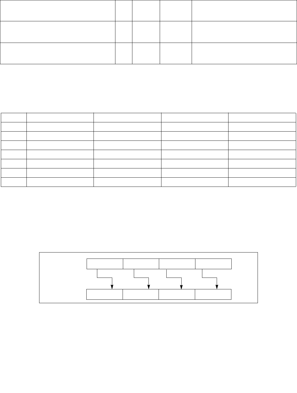
PSRLW/PSRLD/PSRLQ—Shift Packed Data Right Logical
INSTRUCTION SET REFERENCE, M-U
Vol. 2B 4-459
Instruction Operand Encoding
Description
Shifts the bits in the individual data elements (words, doublewords, or quadword) in the destination operand (first
operand) to the right by the number of bits specified in the count operand (second operand). As the bits in the data
elements are shifted right, the empty high-order bits are cleared (set to 0). If the value specified by the count
operand is greater than 15 (for words), 31 (for doublewords), or 63 (for a quadword), then the destination operand
is set to all 0s. Figure 4-19 gives an example of shifting words in a 64-bit operand.
Note that only the low 64-bits of a 128-bit count operand are checked to compute the count.
The (V)PSRLW instruction shifts each of the words in the destination operand to the right by the number of bits
specified in the count operand; the (V)PSRLD instruction shifts each of the doublewords in the destination operand;
and the PSRLQ instruction shifts the quadword (or quadwords) in the destination operand.
In 64-bit mode and not encoded with VEX/EVEX, using a REX prefix in the form of REX.R permits this instruction to
access additional registers (XMM8-XMM15).
Legacy SSE instruction 64-bit operand: The destination operand is an MMX technology register; the count operand
can be either an MMX technology register or an 64-bit memory location.
EVEX.NDD.128.66.0F.W1 73 /2 ib
VPSRLQ xmm1 {k1}{z}, xmm2/m128/m64bcst,
imm8
FV V/V AVX512VL
AVX512F
Shift quadwords in xmm2/m128/m64bcst
right by imm8 while shifting in 0s using
writemask k1.
EVEX.NDD.256.66.0F.W1 73 /2 ib
VPSRLQ ymm1 {k1}{z}, ymm2/m256/m64bcst,
imm8
FV V/V AVX512VL
AVX512F
Shift quadwords in ymm2/m256/m64bcst
right by imm8 while shifting in 0s using
writemask k1.
EVEX.NDD.512.66.0F.W1 73 /2 ib
VPSRLQ zmm1 {k1}{z}, zmm2/m512/m64bcst,
imm8
FVI V/V AVX512F Shift quadwords in zmm2/m512/m64bcst
right by imm8 while shifting in 0s using
writemask k1.
NOTES:
1. See note in Section 2.4, “AVX and SSE Instruction Exception Specification” in the Intel® 64 and IA-32 Architectures Software
Developer’s Manual, Volume 2A and Section 22.25.3, “Exception Conditions of Legacy SIMD Instructions Operating on MMX Registers”
in the Intel® 64 and IA-32 Architectures Software Developer’s Manual, Volume 3A.
Op/En Operand 1 Operand 2 Operand 3 Operand 4
RM ModRM:reg (r, w) ModRM:r/m (r) NA NA
MI ModRM:r/m (r, w) imm8 NA NA
RVM ModRM:reg (w) VEX.vvvv (r) ModRM:r/m (r) NA
VMI VEX.vvvv (w) ModRM:r/m (r) imm8 NA
FVM EVEX.vvvv (w) ModRM:r/m (R) Imm8 NA
FVI EVEX.vvvv (w) ModRM:r/m (R) Imm8 NA
M128 ModRM:reg (w) VEX.vvvv (r) ModRM:r/m (r) NA
Figure 4-19. PSRLW, PSRLD, and PSRLQ Instruction Operation Using 64-bit Operand
DEST
DEST
Pre-Shift
Post-Shift
Shift Right
X0
X0 >> COUNT
X3 X2 X1
X1 >> COUNTX2 >> COUNTX3 >> COUNT
with Zero
Extension

PSRLW/PSRLD/PSRLQ—Shift Packed Data Right Logical
INSTRUCTION SET REFERENCE, M-U
4-460 Vol. 2B
128-bit Legacy SSE version: The destination operand is an XMM register; the count operand can be either an XMM
register or a 128-bit memory location, or an 8-bit immediate. If the count operand is a memory address, 128 bits
are loaded but the upper 64 bits are ignored. Bits (VLMAX-1:128) of the corresponding YMM destination register
remain unchanged.
VEX.128 encoded version: The destination operand is an XMM register; the count operand can be either an XMM
register or a 128-bit memory location, or an 8-bit immediate. If the count operand is a memory address, 128 bits
are loaded but the upper 64 bits are ignored. Bits (VLMAX-1:128) of the destination YMM register are zeroed.
VEX.256 encoded version: The destination operand is a YMM register. The source operand is a YMM register or a
memory location. The count operand can come either from an XMM register or a memory location or an 8-bit imme-
diate. Bits (MAX_VL-1:256) of the corresponding ZMM register are zeroed.
EVEX encoded versions: The destination operand is a ZMM register updated according to the writemask. The count
operand is either an 8-bit immediate (the immediate count version) or an 8-bit value from an XMM register or a
memory location (the variable count version). For the immediate count version, the source operand (the second
operand) can be a ZMM register, a 512-bit memory location or a 512-bit vector broadcasted from a 32/64-bit
memory location. For the variable count version, the first source operand (the second operand) is a ZMM register,
the second source operand (the third operand, 8-bit variable count) can be an XMM register or a memory location.
Note: In VEX/EVEX encoded versions of shifts with an immediate count, vvvv of VEX/EVEX encode the destination
register, and VEX.B/EVEX.B + ModRM.r/m encodes the source register.
Note: For shifts with an immediate count (VEX.128.66.0F 71-73 /2, or EVEX.128.66.0F 71-73 /2),
VEX.vvvv/EVEX.vvvv encodes the destination register.
Operation
PSRLW (with 64-bit operand)
IF (COUNT > 15)
THEN
DEST[64:0] ← 0000000000000000H
ELSE
DEST[15:0] ← ZeroExtend(DEST[15:0] >> COUNT);
(* Repeat shift operation for 2nd and 3rd words *)
DEST[63:48] ← ZeroExtend(DEST[63:48] >> COUNT);
FI;
PSRLD (with 64-bit operand)
IF (COUNT > 31)
THEN
DEST[64:0] ← 0000000000000000H
ELSE
DEST[31:0] ← ZeroExtend(DEST[31:0] >> COUNT);
DEST[63:32] ← ZeroExtend(DEST[63:32] >> COUNT);
FI;
PSRLQ (with 64-bit operand)
IF (COUNT > 63)
THEN
DEST[64:0] ← 0000000000000000H
ELSE
DEST ← ZeroExtend(DEST >> COUNT);
FI;
LOGICAL_RIGHT_SHIFT_DWORDS1(SRC, COUNT_SRC)
COUNT COUNT_SRC[63:0];
IF (COUNT > 31)
THEN
DEST[31:0] 0
ELSE

PSRLW/PSRLD/PSRLQ—Shift Packed Data Right Logical
INSTRUCTION SET REFERENCE, M-U
Vol. 2B 4-461
DEST[31:0] ZeroExtend(SRC[31:0] >> COUNT);
FI;
LOGICAL_RIGHT_SHIFT_QWORDS1(SRC, COUNT_SRC)
COUNT COUNT_SRC[63:0];
IF (COUNT > 63)
THEN
DEST[63:0] 0
ELSE
DEST[63:0] ZeroExtend(SRC[63:0] >> COUNT);
FI;
LOGICAL_RIGHT_SHIFT_WORDS_256b(SRC, COUNT_SRC)
COUNT COUNT_SRC[63:0];
IF (COUNT > 15)
THEN
DEST[255:0] 0
ELSE
DEST[15:0] ZeroExtend(SRC[15:0] >> COUNT);
(* Repeat shift operation for 2nd through 15th words *)
DEST[255:240] ZeroExtend(SRC[255:240] >> COUNT);
FI;
LOGICAL_RIGHT_SHIFT_WORDS(SRC, COUNT_SRC)
COUNT COUNT_SRC[63:0];
IF (COUNT > 15)
THEN
DEST[127:0] 00000000000000000000000000000000H
ELSE
DEST[15:0] ZeroExtend(SRC[15:0] >> COUNT);
(* Repeat shift operation for 2nd through 7th words *)
DEST[127:112] ZeroExtend(SRC[127:112] >> COUNT);
FI;
LOGICAL_RIGHT_SHIFT_DWORDS_256b(SRC, COUNT_SRC)
COUNT COUNT_SRC[63:0];
IF (COUNT > 31)
THEN
DEST[255:0] 0
ELSE
DEST[31:0] ZeroExtend(SRC[31:0] >> COUNT);
(* Repeat shift operation for 2nd through 3rd words *)
DEST[255:224] ZeroExtend(SRC[255:224] >> COUNT);
FI;
LOGICAL_RIGHT_SHIFT_DWORDS(SRC, COUNT_SRC)
COUNT COUNT_SRC[63:0];
IF (COUNT > 31)
THEN
DEST[127:0] 00000000000000000000000000000000H
ELSE
DEST[31:0] ZeroExtend(SRC[31:0] >> COUNT);
(* Repeat shift operation for 2nd through 3rd words *)
DEST[127:96] ZeroExtend(SRC[127:96] >> COUNT);
FI;

PSRLW/PSRLD/PSRLQ—Shift Packed Data Right Logical
INSTRUCTION SET REFERENCE, M-U
4-462 Vol. 2B
LOGICAL_RIGHT_SHIFT_QWORDS_256b(SRC, COUNT_SRC)
COUNT COUNT_SRC[63:0];
IF (COUNT > 63)
THEN
DEST[255:0] 0
ELSE
DEST[63:0] ZeroExtend(SRC[63:0] >> COUNT);
DEST[127:64] ZeroExtend(SRC[127:64] >> COUNT);
DEST[191:128] ZeroExtend(SRC[191:128] >> COUNT);
DEST[255:192] ZeroExtend(SRC[255:192] >> COUNT);
FI;
LOGICAL_RIGHT_SHIFT_QWORDS(SRC, COUNT_SRC)
COUNT COUNT_SRC[63:0];
IF (COUNT > 63)
THEN
DEST[127:0] 00000000000000000000000000000000H
ELSE
DEST[63:0] ZeroExtend(SRC[63:0] >> COUNT);
DEST[127:64] ZeroExtend(SRC[127:64] >> COUNT);
FI;

PSRLW/PSRLD/PSRLQ—Shift Packed Data Right Logical
INSTRUCTION SET REFERENCE, M-U
Vol. 2B 4-463
VPSRLW (EVEX versions, xmm/m128)
(KL, VL) = (8, 128), (16, 256), (32, 512)
IF VL = 128
TMP_DEST[127:0] LOGICAL_RIGHT_SHIFT_WORDS_128b(SRC1[127:0], SRC2)
FI;
IF VL = 256
TMP_DEST[255:0] LOGICAL_RIGHT_SHIFT_WORDS_256b(SRC1[255:0], SRC2)
FI;
IF VL = 512
TMP_DEST[255:0] LOGICAL_RIGHT_SHIFT_WORDS_256b(SRC1[255:0], SRC2)
TMP_DEST[511:256] LOGICAL_RIGHT_SHIFT_WORDS_256b(SRC1[511:256], SRC2)
FI;
FOR j 0 TO KL-1
i j * 16
IF k1[j] OR *no writemask*
THEN DEST[i+15:i] TMP_DEST[i+15:i]
ELSE
IF *merging-masking* ; merging-masking
THEN *DEST[i+15:i] remains unchanged*
ELSE *zeroing-masking* ; zeroing-masking
DEST[i+15:i] = 0
FI
FI;
ENDFOR
DEST[MAX_VL-1:VL] 0
VPSRLW (EVEX versions, imm8)
(KL, VL) = (8, 128), (16, 256), (32, 512)
IF VL = 128
TMP_DEST[127:0] LOGICAL_RIGHT_SHIFT_WORDS_128b(SRC1[127:0], imm8)
FI;
IF VL = 256
TMP_DEST[255:0] LOGICAL_RIGHT_SHIFT_WORDS_256b(SRC1[255:0], imm8)
FI;
IF VL = 512
TMP_DEST[255:0] LOGICAL_RIGHT_SHIFT_WORDS_256b(SRC1[255:0], imm8)
TMP_DEST[511:256] LOGICAL_RIGHT_SHIFT_WORDS_256b(SRC1[511:256], imm8)
FI;
FOR j 0 TO KL-1
i j * 16
IF k1[j] OR *no writemask*
THEN DEST[i+15:i] TMP_DEST[i+15:i]
ELSE
IF *merging-masking* ; merging-masking
THEN *DEST[i+15:i] remains unchanged*
ELSE *zeroing-masking* ; zeroing-masking
DEST[i+15:i] = 0
FI
FI;
ENDFOR
DEST[MAX_VL-1:VL] 0

PSRLW/PSRLD/PSRLQ—Shift Packed Data Right Logical
INSTRUCTION SET REFERENCE, M-U
4-464 Vol. 2B
VPSRLW (ymm, ymm, xmm/m128) - VEX.256 encoding
DEST[255:0] LOGICAL_RIGHT_SHIFT_WORDS_256b(SRC1, SRC2)
DEST[MAX_VL-1:256] 0;
VPSRLW (ymm, imm8) - VEX.256 encoding
DEST[255:0] LOGICAL_RIGHT_SHIFT_WORDS_256b(SRC1, imm8)
DEST[MAX_VL-1:256] 0;
VPSRLW (xmm, xmm, xmm/m128) - VEX.128 encoding
DEST[127:0] LOGICAL_RIGHT_SHIFT_WORDS(SRC1, SRC2)
DEST[MAX_VL-1:128] 0
VPSRLW (xmm, imm8) - VEX.128 encoding
DEST[127:0] LOGICAL_RIGHT_SHIFT_WORDS(SRC1, imm8)
DEST[MAX_VL-1:128] 0
PSRLW (xmm, xmm, xmm/m128)
DEST[127:0] LOGICAL_RIGHT_SHIFT_WORDS(DEST, SRC)
DEST[MAX_VL-1:128] (Unmodified)
PSRLW (xmm, imm8)
DEST[127:0] LOGICAL_RIGHT_SHIFT_WORDS(DEST, imm8)
DEST[MAX_VL-1:128] (Unmodified)
VPSRLD (EVEX versions, xmm/m128)
(KL, VL) = (4, 128), (8, 256), (16, 512)
IF VL = 128
TMP_DEST[127:0] LOGICAL_RIGHT_SHIFT_DWORDS_128b(SRC1[127:0], SRC2)
FI;
IF VL = 256
TMP_DEST[255:0] LOGICAL_RIGHT_SHIFT_DWORDS_256b(SRC1[255:0], SRC2)
FI;
IF VL = 512
TMP_DEST[255:0] LOGICAL_RIGHT_SHIFT_DWORDS_256b(SRC1[255:0], SRC2)
TMP_DEST[511:256] LOGICAL_RIGHT_SHIFT_DWORDS_256b(SRC1[511:256], SRC2)
FI;
FOR j 0 TO KL-1
i j * 32
IF k1[j] OR *no writemask*
THEN DEST[i+31:i] TMP_DEST[i+31:i]
ELSE
IF *merging-masking* ; merging-masking
THEN *DEST[i+31:i] remains unchanged*
ELSE *zeroing-masking* ; zeroing-masking
DEST[i+31:i] 0
FI
FI;
ENDFOR
DEST[MAX_VL-1:VL] 0

PSRLW/PSRLD/PSRLQ—Shift Packed Data Right Logical
INSTRUCTION SET REFERENCE, M-U
Vol. 2B 4-465
VPSRLD (EVEX versions, imm8)
(KL, VL) = (4, 128), (8, 256), (16, 512)
FOR j 0 TO KL-1
i j * 32
IF k1[j] OR *no writemask* THEN
IF (EVEX.b = 1) AND (SRC1 *is memory*)
THEN DEST[i+31:i] LOGICAL_RIGHT_SHIFT_DWORDS1(SRC1[31:0], imm8)
ELSE DEST[i+31:i] LOGICAL_RIGHT_SHIFT_DWORDS1(SRC1[i+31:i], imm8)
FI;
ELSE
IF *merging-masking* ; merging-masking
THEN *DEST[i+31:i] remains unchanged*
ELSE *zeroing-masking* ; zeroing-masking
DEST[i+31:i] 0
FI
FI;
ENDFOR
DEST[MAX_VL-1:VL] 0
VPSRLD (ymm, ymm, xmm/m128) - VEX.256 encoding
DEST[255:0] LOGICAL_RIGHT_SHIFT_DWORDS_256b(SRC1, SRC2)
DEST[MAX_VL-1:256] 0;
VPSRLD (ymm, imm8) - VEX.256 encoding
DEST[255:0] LOGICAL_RIGHT_SHIFT_DWORDS_256b(SRC1, imm8)
DEST[MAX_VL-1:256] 0;
VPSRLD (xmm, xmm, xmm/m128) - VEX.128 encoding
DEST[127:0] LOGICAL_RIGHT_SHIFT_DWORDS(SRC1, SRC2)
DEST[MAX_VL-1:128] 0
VPSRLD (xmm, imm8) - VEX.128 encoding
DEST[127:0] LOGICAL_RIGHT_SHIFT_DWORDS(SRC1, imm8)
DEST[MAX_VL-1:128] 0
PSRLD (xmm, xmm, xmm/m128)
DEST[127:0] LOGICAL_RIGHT_SHIFT_DWORDS(DEST, SRC)
DEST[MAX_VL-1:128] (Unmodified)
PSRLD (xmm, imm8)
DEST[127:0] LOGICAL_RIGHT_SHIFT_DWORDS(DEST, imm8)
DEST[MAX_VL-1:128] (Unmodified)

PSRLW/PSRLD/PSRLQ—Shift Packed Data Right Logical
INSTRUCTION SET REFERENCE, M-U
4-466 Vol. 2B
VPSRLQ (EVEX versions, xmm/m128)
(KL, VL) = (2, 128), (4, 256), (8, 512)
TMP_DEST[255:0] LOGICAL_RIGHT_SHIFT_QWORDS_256b(SRC1[255:0], SRC2)
TMP_DEST[511:256] LOGICAL_RIGHT_SHIFT_QWORDS_256b(SRC1[511:256], SRC2)
IF VL = 128
TMP_DEST[127:0] LOGICAL_RIGHT_SHIFT_QWORDS_128b(SRC1[127:0], SRC2)
FI;
IF VL = 256
TMP_DEST[255:0] LOGICAL_RIGHT_SHIFT_QWORDS_256b(SRC1[255:0], SRC2)
FI;
IF VL = 512
TMP_DEST[255:0] LOGICAL_RIGHT_SHIFT_QWORDS_256b(SRC1[255:0], SRC2)
TMP_DEST[511:256] LOGICAL_RIGHT_SHIFT_QWORDS_256b(SRC1[511:256], SRC2)
FI;
FOR j 0 TO KL-1
i j * 64
IF k1[j] OR *no writemask*
THEN DEST[i+63:i] TMP_DEST[i+63:i]
ELSE
IF *merging-masking* ; merging-masking
THEN *DEST[i+63:i] remains unchanged*
ELSE *zeroing-masking* ; zeroing-masking
DEST[i+63:i] 0
FI
FI;
ENDFOR
DEST[MAX_VL-1:VL] 0
VPSRLQ (EVEX versions, imm8)
(KL, VL) = (2, 128), (4, 256), (8, 512)
FOR j 0 TO KL-1
i j * 64
IF k1[j] OR *no writemask* THEN
IF (EVEX.b = 1) AND (SRC1 *is memory*)
THEN DEST[i+63:i] LOGICAL_RIGHT_SHIFT_QWORDS1(SRC1[63:0], imm8)
ELSE DEST[i+63:i] LOGICAL_RIGHT_SHIFT_QWORDS1(SRC1[i+63:i], imm8)
FI;
ELSE
IF *merging-masking* ; merging-masking
THEN *DEST[i+63:i] remains unchanged*
ELSE *zeroing-masking* ; zeroing-masking
DEST[i+63:i] 0
FI
FI;
ENDFOR
DEST[MAX_VL-1:VL] 0
VPSRLQ (ymm, ymm, xmm/m128) - VEX.256 encoding
DEST[255:0] LOGICAL_RIGHT_SHIFT_QWORDS_256b(SRC1, SRC2)
DEST[MAX_VL-1:256] 0;
VPSRLQ (ymm, imm8) - VEX.256 encoding
DEST[255:0] LOGICAL_RIGHT_SHIFT_QWORDS_256b(SRC1, imm8)
DEST[MAX_VL-1:256] 0;

PSRLW/PSRLD/PSRLQ—Shift Packed Data Right Logical
INSTRUCTION SET REFERENCE, M-U
Vol. 2B 4-467
VPSRLQ (xmm, xmm, xmm/m128) - VEX.128 encoding
DEST[127:0] LOGICAL_RIGHT_SHIFT_QWORDS(SRC1, SRC2)
DEST[MAX_VL-1:128] 0
VPSRLQ (xmm, imm8) - VEX.128 encoding
DEST[127:0] LOGICAL_RIGHT_SHIFT_QWORDS(SRC1, imm8)
DEST[MAX_VL-1:128] 0
PSRLQ (xmm, xmm, xmm/m128)
DEST[127:0] LOGICAL_RIGHT_SHIFT_QWORDS(DEST, SRC)
DEST[MAX_VL-1:128] (Unmodified)
PSRLQ (xmm, imm8)
DEST[127:0] LOGICAL_RIGHT_SHIFT_QWORDS(DEST, imm8)
DEST[MAX_VL-1:128] (Unmodified)
Intel C/C++ Compiler Intrinsic Equivalents
VPSRLD __m512i _mm512_srli_epi32(__m512i a, unsigned int imm);
VPSRLD __m512i _mm512_mask_srli_epi32(__m512i s, __mmask16 k, __m512i a, unsigned int imm);
VPSRLD __m512i _mm512_maskz_srli_epi32( __mmask16 k, __m512i a, unsigned int imm);
VPSRLD __m256i _mm256_mask_srli_epi32(__m256i s, __mmask8 k, __m256i a, unsigned int imm);
VPSRLD __m256i _mm256_maskz_srli_epi32( __mmask8 k, __m256i a, unsigned int imm);
VPSRLD __m128i _mm_mask_srli_epi32(__m128i s, __mmask8 k, __m128i a, unsigned int imm);
VPSRLD __m128i _mm_maskz_srli_epi32( __mmask8 k, __m128i a, unsigned int imm);
VPSRLD __m512i _mm512_srl_epi32(__m512i a, __m128i cnt);
VPSRLD __m512i _mm512_mask_srl_epi32(__m512i s, __mmask16 k, __m512i a, __m128i cnt);
VPSRLD __m512i _mm512_maskz_srl_epi32( __mmask16 k, __m512i a, __m128i cnt);
VPSRLD __m256i _mm256_mask_srl_epi32(__m256i s, __mmask8 k, __m256i a, __m128i cnt);
VPSRLD __m256i _mm256_maskz_srl_epi32( __mmask8 k, __m256i a, __m128i cnt);
VPSRLD __m128i _mm_mask_srl_epi32(__m128i s, __mmask8 k, __m128i a, __m128i cnt);
VPSRLD __m128i _mm_maskz_srl_epi32( __mmask8 k, __m128i a, __m128i cnt);
VPSRLQ __m512i _mm512_srli_epi64(__m512i a, unsigned int imm);
VPSRLQ __m512i _mm512_mask_srli_epi64(__m512i s, __mmask8 k, __m512i a, unsigned int imm);
VPSRLQ __m512i _mm512_mask_srli_epi64( __mmask8 k, __m512i a, unsigned int imm);
VPSRLQ __m256i _mm256_mask_srli_epi64(__m256i s, __mmask8 k, __m256i a, unsigned int imm);
VPSRLQ __m256i _mm256_maskz_srli_epi64( __mmask8 k, __m256i a, unsigned int imm);
VPSRLQ __m128i _mm_mask_srli_epi64(__m128i s, __mmask8 k, __m128i a, unsigned int imm);
VPSRLQ __m128i _mm_maskz_srli_epi64( __mmask8 k, __m128i a, unsigned int imm);
VPSRLQ __m512i _mm512_srl_epi64(__m512i a, __m128i cnt);
VPSRLQ __m512i _mm512_mask_srl_epi64(__m512i s, __mmask8 k, __m512i a, __m128i cnt);
VPSRLQ __m512i _mm512_mask_srl_epi64( __mmask8 k, __m512i a, __m128i cnt);
VPSRLQ __m256i _mm256_mask_srl_epi64(__m256i s, __mmask8 k, __m256i a, __m128i cnt);
VPSRLQ __m256i _mm256_maskz_srl_epi64( __mmask8 k, __m256i a, __m128i cnt);
VPSRLQ __m128i _mm_mask_srl_epi64(__m128i s, __mmask8 k, __m128i a, __m128i cnt);
VPSRLQ __m128i _mm_maskz_srl_epi64( __mmask8 k, __m128i a, __m128i cnt);
VPSRLW __m512i _mm512_srli_epi16(__m512i a, unsigned int imm);
VPSRLW __m512i _mm512_mask_srli_epi16(__m512i s, __mmask32 k, __m512i a, unsigned int imm);
VPSRLW __m512i _mm512_maskz_srli_epi16( __mmask32 k, __m512i a, unsigned int imm);
VPSRLW __m256i _mm256_mask_srlii_epi16(__m256i s, __mmask16 k, __m256i a, unsigned int imm);
VPSRLW __m256i _mm256_maskz_srli_epi16( __mmask16 k, __m256i a, unsigned int imm);
VPSRLW __m128i _mm_mask_srli_epi16(__m128i s, __mmask8 k, __m128i a, unsigned int imm);
VPSRLW __m128i _mm_maskz_srli_epi16( __mmask8 k, __m128i a, unsigned int imm);
VPSRLW __m512i _mm512_srl_epi16(__m512i a, __m128i cnt);
VPSRLW __m512i _mm512_mask_srl_epi16(__m512i s, __mmask32 k, __m512i a, __m128i cnt);

PSRLW/PSRLD/PSRLQ—Shift Packed Data Right Logical
INSTRUCTION SET REFERENCE, M-U
4-468 Vol. 2B
VPSRLW __m512i _mm512_maskz_srl_epi16( __mmask32 k, __m512i a, __m128i cnt);
VPSRLW __m256i _mm256_mask_srl_epi16(__m256i s, __mmask16 k, __m256i a, __m128i cnt);
VPSRLW __m256i _mm256_maskz_srl_epi16( __mmask8 k, __mmask16 a, __m128i cnt);
VPSRLW __m128i _mm_mask_srl_epi16(__m128i s, __mmask8 k, __m128i a, __m128i cnt);
VPSRLW __m128i _mm_maskz_srl_epi16( __mmask8 k, __m128i a, __m128i cnt);
PSRLW:__m64 _mm_srli_pi16(__m64 m, int count)
PSRLW:__m64 _mm_srl_pi16 (__m64 m, __m64 count)
(V)PSRLW:__m128i _mm_srli_epi16 (__m128i m, int count)
(V)PSRLW:__m128i _mm_srl_epi16 (__m128i m, __m128i count)
VPSRLW:__m256i _mm256_srli_epi16 (__m256i m, int count)
VPSRLW:__m256i _mm256_srl_epi16 (__m256i m, __m128i count)
PSRLD:__m64 _mm_srli_pi32 (__m64 m, int count)
PSRLD:__m64 _mm_srl_pi32 (__m64 m, __m64 count)
(V)PSRLD:__m128i _mm_srli_epi32 (__m128i m, int count)
(V)PSRLD:__m128i _mm_srl_epi32 (__m128i m, __m128i count)
VPSRLD:__m256i _mm256_srli_epi32 (__m256i m, int count)
VPSRLD:__m256i _mm256_srl_epi32 (__m256i m, __m128i count)
PSRLQ:__m64 _mm_srli_si64 (__m64 m, int count)
PSRLQ:__m64 _mm_srl_si64 (__m64 m, __m64 count)
(V)PSRLQ:__m128i _mm_srli_epi64 (__m128i m, int count)
(V)PSRLQ:__m128i _mm_srl_epi64 (__m128i m, __m128i count)
VPSRLQ:__m256i _mm256_srli_epi64 (__m256i m, int count)
VPSRLQ:__m256i _mm256_srl_epi64 (__m256i m, __m128i count)
Flags Affected
None.
Numeric Exceptions
None.
Other Exceptions
VEX-encoded instructions:
Syntax with RM/RVM operand encoding, see Exceptions Type 4.
Syntax with MI/VMI operand encoding, see Exceptions Type 7.
EVEX-encoded VPSRLW, see Exceptions Type E4NF.nb.
EVEX-encoded VPSRLD/Q:
Syntax with M128 operand encoding, see Exceptions Type E4NF.nb.
Syntax with FVI operand encoding, see Exceptions Type E4.

PSUBB/PSUBW/PSUBD—Subtract Packed Integers
INSTRUCTION SET REFERENCE, M-U
Vol. 2B 4-469
PSUBB/PSUBW/PSUBD—Subtract Packed Integers
Opcode/
Instruction
Op/
En
64/32 bit
Mode
Support
CPUID
Feature
Flag
Description
0F F8 /r1
PSUBB mm, mm/m64
RM V/V MMX Subtract packed byte integers in mm/m64
from packed byte integers in mm.
66 0F F8 /r
PSUBB xmm1, xmm2/m128
RM V/V SSE2 Subtract packed byte integers in xmm2/m128
from packed byte integers in xmm1.
0F F9 /r1
PSUBW mm, mm/m64
RM V/V MMX Subtract packed word integers in mm/m64
from packed word integers in mm.
66 0F F9 /r
PSUBW xmm1, xmm2/m128
RM V/V SSE2 Subtract packed word integers in
xmm2/m128 from packed word integers in
xmm1.
0F FA /r1
PSUBD mm, mm/m64
RM V/V MMX Subtract packed doubleword integers in
mm/m64 from packed doubleword integers in
mm.
66 0F FA /r
PSUBD xmm1, xmm2/m128
RM V/V SSE2 Subtract packed doubleword integers in
xmm2/mem128 from packed doubleword
integers in xmm1.
VEX.NDS.128.66.0F.WIG F8 /r
VPSUBB xmm1, xmm2, xmm3/m128
RVM V/V AVX Subtract packed byte integers in xmm3/m128
from xmm2.
VEX.NDS.128.66.0F.WIG F9 /r
VPSUBW xmm1, xmm2, xmm3/m128
RVM V/V AVX Subtract packed word integers in
xmm3/m128 from xmm2.
VEX.NDS.128.66.0F.WIG FA /r
VPSUBD xmm1, xmm2, xmm3/m128
RVM V/V AVX Subtract packed doubleword integers in
xmm3/m128 from xmm2.
VEX.NDS.256.66.0F.WIG F8 /r
VPSUBB ymm1, ymm2, ymm3/m256
RVM V/V AVX2 Subtract packed byte integers in ymm3/m256
from ymm2.
VEX.NDS.256.66.0F.WIG F9 /r
VPSUBW ymm1, ymm2, ymm3/m256
RVM V/V AVX2 Subtract packed word integers in
ymm3/m256 from ymm2.
VEX.NDS.256.66.0F.WIG FA /r
VPSUBD ymm1, ymm2, ymm3/m256
RVM V/V AVX2 Subtract packed doubleword integers in
ymm3/m256 from ymm2.
EVEX.NDS.128.66.0F.WIG F8 /r
VPSUBB xmm1 {k1}{z}, xmm2, xmm3/m128
FVM V/V AVX512VL
AVX512BW
Subtract packed byte integers in xmm3/m128
from xmm2 and store in xmm1 using
writemask k1.
EVEX.NDS.256.66.0F.WIG F8 /r
VPSUBB ymm1 {k1}{z}, ymm2, ymm3/m256
FVM V/V AVX512VL
AVX512BW
Subtract packed byte integers in ymm3/m256
from ymm2 and store in ymm1 using
writemask k1.
EVEX.NDS.512.66.0F.WIG F8 /r
VPSUBB zmm1 {k1}{z}, zmm2, zmm3/m512
FVM V/V AVX512BW Subtract packed byte integers in zmm3/m512
from zmm2 and store in zmm1 using
writemask k1.
EVEX.NDS.128.66.0F.WIG F9 /r
VPSUBW xmm1 {k1}{z}, xmm2, xmm3/m128
FVM V/V AVX512VL
AVX512BW
Subtract packed word integers in
xmm3/m128 from xmm2 and store in xmm1
using writemask k1.
EVEX.NDS.256.66.0F.WIG F9 /r
VPSUBW ymm1 {k1}{z}, ymm2, ymm3/m256
FVM V/V AVX512VL
AVX512BW
Subtract packed word integers in
ymm3/m256 from ymm2 and store in ymm1
using writemask k1.
EVEX.NDS.512.66.0F.WIG F9 /r
VPSUBW zmm1 {k1}{z}, zmm2, zmm3/m512
FVM V/V AVX512BW Subtract packed word integers in
zmm3/m512 from zmm2 and store in zmm1
using writemask k1.

PSUBB/PSUBW/PSUBD—Subtract Packed Integers
INSTRUCTION SET REFERENCE, M-U
4-470 Vol. 2B
Instruction Operand Encoding
Description
Performs a SIMD subtract of the packed integers of the source operand (second operand) from the packed integers
of the destination operand (first operand), and stores the packed integer results in the destination operand. See
Figure 9-4 in the Intel® 64 and IA-32 Architectures Software Developer’s Manual, Volume 1, for an illustration of
a SIMD operation. Overflow is handled with wraparound, as described in the following paragraphs.
The (V)PSUBB instruction subtracts packed byte integers. When an individual result is too large or too small to be
represented in a byte, the result is wrapped around and the low 8 bits are written to the destination element.
The (V)PSUBW instruction subtracts packed word integers. When an individual result is too large or too small to be
represented in a word, the result is wrapped around and the low 16 bits are written to the destination element.
The (V)PSUBD instruction subtracts packed doubleword integers. When an individual result is too large or too small
to be represented in a doubleword, the result is wrapped around and the low 32 bits are written to the destination
element.
Note that the (V)PSUBB, (V)PSUBW, and (V)PSUBD instructions can operate on either unsigned or signed (two's
complement notation) packed integers; however, it does not set bits in the EFLAGS register to indicate overflow
and/or a carry. To prevent undetected overflow conditions, software must control the ranges of values upon which
it operates.
In 64-bit mode and not encoded with VEX/EVEX, using a REX prefix in the form of REX.R permits this instruction to
access additional registers (XMM8-XMM15).
Legacy SSE version 64-bit operand: The destination operand must be an MMX technology register and the source
operand can be either an MMX technology register or a 64-bit memory location.
128-bit Legacy SSE version: The second source operand is an XMM register or a 128-bit memory location. The first
source operand and destination operands are XMM registers. Bits (VLMAX-1:128) of the corresponding YMM desti-
nation register remain unchanged.
VEX.128 encoded version: The second source operand is an XMM register or a 128-bit memory location. The first
source operand and destination operands are XMM registers. Bits (VLMAX-1:128) of the destination YMM register
are zeroed.
EVEX.NDS.128.66.0F.W0 FA /r
VPSUBD xmm1 {k1}{z}, xmm2, xmm3/m128/m32bcst
FV V/V AVX512VL
AVX512F
Subtract packed doubleword integers in
xmm3/m128/m32bcst from xmm2 and store
in xmm1 using writemask k1.
EVEX.NDS.256.66.0F.W0 FA /r
VPSUBD ymm1 {k1}{z}, ymm2, ymm3/m256/m32bcst
FV V/V AVX512VL
AVX512F
Subtract packed doubleword integers in
ymm3/m256/m32bcst from ymm2 and store
in ymm1 using writemask k1.
EVEX.NDS.512.66.0F.W0 FA /r
VPSUBD zmm1 {k1}{z}, zmm2, zmm3/m512/m32bcst
FV V/V AVX512F Subtract packed doubleword integers in
zmm3/m512/m32bcst from zmm2 and store
in zmm1 using writemask k1
NOTES:
1. See note in Section 2.4, “AVX and SSE Instruction Exception Specification” in the Intel® 64 and IA-32 Architectures Software
Developer’s Manual, Volume 2A and Section 22.25.3, “Exception Conditions of Legacy SIMD Instructions Operating on MMX Registers” in
the Intel® 64 and IA-32 Architectures Software Developer’s Manual, Volume 3A.
Op/En Operand 1 Operand 2 Operand 3 Operand 4
RM ModRM:reg (r, w) ModRM:r/m (r) NA NA
RVM ModRM:reg (w) VEX.vvvv (r) ModRM:r/m (r) NA
FVM ModRM:reg (w) EVEX.vvvv (r) ModRM:r/m (r) NA
FV ModRM:reg (w) EVEX.vvvv (r) ModRM:r/m (r) NA

PSUBB/PSUBW/PSUBD—Subtract Packed Integers
INSTRUCTION SET REFERENCE, M-U
Vol. 2B 4-471
VEX.256 encoded versions: The second source operand is an YMM register or an 256-bit memory location. The first
source operand and destination operands are YMM registers. Bits (MAX_VL-1:256) of the corresponding ZMM
register are zeroed.
EVEX encoded VPSUBD: The second source operand is a ZMM/YMM/XMM register, a 512/256/128-bit memory loca-
tion or a 512/256/128-bit vector broadcasted from a 32/64-bit memory location. The first source operand and
destination operands are ZMM/YMM/XMM registers. The destination is conditionally updated with writemask k1.
EVEX encoded VPSUBB/W: The second source operand is a ZMM/YMM/XMM register, a 512/256/128-bit memory
location. The first source operand and destination operands are ZMM/YMM/XMM registers. The destination is condi-
tionally updated with writemask k1.
Operation
PSUBB (with 64-bit operands)
DEST[7:0] ← DEST[7:0] − SRC[7:0];
(* Repeat subtract operation for 2nd through 7th byte *)
DEST[63:56] ← DEST[63:56] − SRC[63:56];
PSUBW (with 64-bit operands)
DEST[15:0] ← DEST[15:0] − SRC[15:0];
(* Repeat subtract operation for 2nd and 3rd word *)
DEST[63:48] ← DEST[63:48] − SRC[63:48];
PSUBD (with 64-bit operands)
DEST[31:0] ← DEST[31:0] − SRC[31:0];
DEST[63:32] ← DEST[63:32] − SRC[63:32];
PSUBD (with 128-bit operands)
DEST[31:0] ← DEST[31:0] − SRC[31:0];
(* Repeat subtract operation for 2nd and 3rd doubleword *)
DEST[127:96] ← DEST[127:96] − SRC[127:96];
VPSUBB (EVEX encoded versions)
(KL, VL) = (16, 128), (32, 256), (64, 512)
FOR j 0 TO KL-1
i j * 8
IF k1[j] OR *no writemask*
THEN DEST[i+7:i] SRC1[i+7:i] - SRC2[i+7:i]
ELSE
IF *merging-masking* ; merging-masking
THEN *DEST[i+7:i] remains unchanged*
ELSE *zeroing-masking* ; zeroing-masking
DEST[i+7:i] = 0
FI
FI;
ENDFOR;
DEST[MAX_VL-1:VL] 0
VPSUBW (EVEX encoded versions)
(KL, VL) = (8, 128), (16, 256), (32, 512)
FOR j 0 TO KL-1
i j * 16
IF k1[j] OR *no writemask*
THEN DEST[i+15:i] SRC1[i+15:i] - SRC2[i+15:i]
ELSE
IF *merging-masking* ; merging-masking

PSUBB/PSUBW/PSUBD—Subtract Packed Integers
INSTRUCTION SET REFERENCE, M-U
4-472 Vol. 2B
THEN *DEST[i+15:i] remains unchanged*
ELSE *zeroing-masking* ; zeroing-masking
DEST[i+15:i] = 0
FI
FI;
ENDFOR;
DEST[MAX_VL-1:VL] 0
VPSUBD (EVEX encoded versions)
(KL, VL) = (4, 128), (8, 256), (16, 512)
FOR j 0 TO KL-1
i j * 32
IF k1[j] OR *no writemask* THEN
IF (EVEX.b = 1) AND (SRC2 *is memory*)
THEN DEST[i+31:i] SRC1[i+31:i] - SRC2[31:0]
ELSE DEST[i+31:i] SRC1[i+31:i] - SRC2[i+31:i]
FI;
ELSE
IF *merging-masking* ; merging-masking
THEN *DEST[i+31:i] remains unchanged*
ELSE *zeroing-masking* ; zeroing-masking
DEST[i+31:i] 0
FI
FI;
ENDFOR;
DEST[MAX_VL-1:VL] 0
VPSUBB (VEX.256 encoded version)
DEST[7:0] SRC1[7:0]-SRC2[7:0]
DEST[15:8] SRC1[15:8]-SRC2[15:8]
DEST[23:16] SRC1[23:16]-SRC2[23:16]
DEST[31:24] SRC1[31:24]-SRC2[31:24]
DEST[39:32] SRC1[39:32]-SRC2[39:32]
DEST[47:40] SRC1[47:40]-SRC2[47:40]
DEST[55:48] SRC1[55:48]-SRC2[55:48]
DEST[63:56] SRC1[63:56]-SRC2[63:56]
DEST[71:64] SRC1[71:64]-SRC2[71:64]
DEST[79:72] SRC1[79:72]-SRC2[79:72]
DEST[87:80] SRC1[87:80]-SRC2[87:80]
DEST[95:88] SRC1[95:88]-SRC2[95:88]
DEST[103:96] SRC1[103:96]-SRC2[103:96]
DEST[111:104] SRC1[111:104]-SRC2[111:104]
DEST[119:112] SRC1[119:112]-SRC2[119:112]
DEST[127:120] SRC1[127:120]-SRC2[127:120]
DEST[135:128] SRC1[135:128]-SRC2[135:128]
DEST[143:136] SRC1[143:136]-SRC2[143:136]
DEST[151:144] SRC1[151:144]-SRC2[151:144]
DEST[159:152] SRC1[159:152]-SRC2[159:152]
DEST[167:160] SRC1[167:160]-SRC2[167:160]
DEST[175:168] SRC1[175:168]-SRC2[175:168]
DEST[183:176] SRC1[183:176]-SRC2[183:176]
DEST[191:184] SRC1[191:184]-SRC2[191:184]
DEST[199:192] SRC1[199:192]-SRC2[199:192]
DEST[207:200] SRC1[207:200]-SRC2[207:200]

PSUBB/PSUBW/PSUBD—Subtract Packed Integers
INSTRUCTION SET REFERENCE, M-U
Vol. 2B 4-473
DEST[215:208] SRC1[215:208]-SRC2[215:208]
DEST[223:216] SRC1[223:216]-SRC2[223:216]
DEST[231:224] SRC1[231:224]-SRC2[231:224]
DEST[239:232] SRC1[239:232]-SRC2[239:232]
DEST[247:240] SRC1[247:240]-SRC2[247:240]
DEST[255:248] SRC1[255:248]-SRC2[255:248]
DEST[MAX_VL-1:256] 0
VPSUBB (VEX.128 encoded version)
DEST[7:0] SRC1[7:0]-SRC2[7:0]
DEST[15:8] SRC1[15:8]-SRC2[15:8]
DEST[23:16] SRC1[23:16]-SRC2[23:16]
DEST[31:24] SRC1[31:24]-SRC2[31:24]
DEST[39:32] SRC1[39:32]-SRC2[39:32]
DEST[47:40] SRC1[47:40]-SRC2[47:40]
DEST[55:48] SRC1[55:48]-SRC2[55:48]
DEST[63:56] SRC1[63:56]-SRC2[63:56]
DEST[71:64] SRC1[71:64]-SRC2[71:64]
DEST[79:72] SRC1[79:72]-SRC2[79:72]
DEST[87:80] SRC1[87:80]-SRC2[87:80]
DEST[95:88] SRC1[95:88]-SRC2[95:88]
DEST[103:96] SRC1[103:96]-SRC2[103:96]
DEST[111:104] SRC1[111:104]-SRC2[111:104]
DEST[119:112] SRC1[119:112]-SRC2[119:112]
DEST[127:120] SRC1[127:120]-SRC2[127:120]
DEST[MAX_VL-1:128] 0
PSUBB (128-bit Legacy SSE version)
DEST[7:0] DEST[7:0]-SRC[7:0]
DEST[15:8] DEST[15:8]-SRC[15:8]
DEST[23:16] DEST[23:16]-SRC[23:16]
DEST[31:24] DEST[31:24]-SRC[31:24]
DEST[39:32] DEST[39:32]-SRC[39:32]
DEST[47:40] DEST[47:40]-SRC[47:40]
DEST[55:48] DEST[55:48]-SRC[55:48]
DEST[63:56] DEST[63:56]-SRC[63:56]
DEST[71:64] DEST[71:64]-SRC[71:64]
DEST[79:72] DEST[79:72]-SRC[79:72]
DEST[87:80] DEST[87:80]-SRC[87:80]
DEST[95:88] DEST[95:88]-SRC[95:88]
DEST[103:96] DEST[103:96]-SRC[103:96]
DEST[111:104] DEST[111:104]-SRC[111:104]
DEST[119:112] DEST[119:112]-SRC[119:112]
DEST[127:120] DEST[127:120]-SRC[127:120]
DEST[MAX_VL-1:128] (Unmodified)
VPSUBW (VEX.256 encoded version)
DEST[15:0] SRC1[15:0]-SRC2[15:0]
DEST[31:16] SRC1[31:16]-SRC2[31:16]
DEST[47:32] SRC1[47:32]-SRC2[47:32]
DEST[63:48] SRC1[63:48]-SRC2[63:48]
DEST[79:64] SRC1[79:64]-SRC2[79:64]
DEST[95:80] SRC1[95:80]-SRC2[95:80]
DEST[111:96] SRC1[111:96]-SRC2[111:96]

PSUBB/PSUBW/PSUBD—Subtract Packed Integers
INSTRUCTION SET REFERENCE, M-U
4-474 Vol. 2B
DEST[127:112] SRC1[127:112]-SRC2[127:112]
DEST[143:128] SRC1[143:128]-SRC2[143:128]
DEST[159:144] SRC1[159:144]-SRC2[159:144]
DEST[175:160] SRC1[175:160]-SRC2[175:160]
DEST[191:176] SRC1[191:176]-SRC2[191:176]
DEST[207:192] SRC1207:192]-SRC2[207:192]
DEST[223:208] SRC1[223:208]-SRC2[223:208]
DEST[239:224] SRC1[239:224]-SRC2[239:224]
DEST[255:240] SRC1[255:240]-SRC2[255:240]
DEST[MAX_VL-1:256] 0
VPSUBW (VEX.128 encoded version)
DEST[15:0] SRC1[15:0]-SRC2[15:0]
DEST[31:16] SRC1[31:16]-SRC2[31:16]
DEST[47:32] SRC1[47:32]-SRC2[47:32]
DEST[63:48] SRC1[63:48]-SRC2[63:48]
DEST[79:64] SRC1[79:64]-SRC2[79:64]
DEST[95:80] SRC1[95:80]-SRC2[95:80]
DEST[111:96] SRC1[111:96]-SRC2[111:96]
DEST[127:112] SRC1[127:112]-SRC2[127:112]
DEST[MAX_VL-1:128] 0
PSUBW (128-bit Legacy SSE version)
DEST[15:0] DEST[15:0]-SRC[15:0]
DEST[31:16] DEST[31:16]-SRC[31:16]
DEST[47:32] DEST[47:32]-SRC[47:32]
DEST[63:48] DEST[63:48]-SRC[63:48]
DEST[79:64] DEST[79:64]-SRC[79:64]
DEST[95:80] DEST[95:80]-SRC[95:80]
DEST[111:96] DEST[111:96]-SRC[111:96]
DEST[127:112] DEST[127:112]-SRC[127:112]
DEST[MAX_VL-1:128] (Unmodified)
VPSUBD (VEX.256 encoded version)
DEST[31:0] SRC1[31:0]-SRC2[31:0]
DEST[63:32] SRC1[63:32]-SRC2[63:32]
DEST[95:64] SRC1[95:64]-SRC2[95:64]
DEST[127:96] SRC1[127:96]-SRC2[127:96]
DEST[159:128] SRC1[159:128]-SRC2[159:128]
DEST[191:160] SRC1[191:160]-SRC2[191:160]
DEST[223:192] SRC1[223:192]-SRC2[223:192]
DEST[255:224] SRC1[255:224]-SRC2[255:224]
DEST[MAX_VL-1:256] 0
VPSUBD (VEX.128 encoded version)
DEST[31:0] SRC1[31:0]-SRC2[31:0]
DEST[63:32] SRC1[63:32]-SRC2[63:32]
DEST[95:64] SRC1[95:64]-SRC2[95:64]
DEST[127:96] SRC1[127:96]-SRC2[127:96]
DEST[MAX_VL-1:128] 0
PSUBD (128-bit Legacy SSE version)
DEST[31:0] DEST[31:0]-SRC[31:0]
DEST[63:32] DEST[63:32]-SRC[63:32]

PSUBB/PSUBW/PSUBD—Subtract Packed Integers
INSTRUCTION SET REFERENCE, M-U
Vol. 2B 4-475
DEST[95:64] DEST[95:64]-SRC[95:64]
DEST[127:96] DEST[127:96]-SRC[127:96]
DEST[MAX_VL-1:128] (Unmodified)
Intel C/C++ Compiler Intrinsic Equivalents
VPSUBB __m512i _mm512_sub_epi8(__m512i a, __m512i b);
VPSUBB __m512i _mm512_mask_sub_epi8(__m512i s, __mmask64 k, __m512i a, __m512i b);
VPSUBB __m512i _mm512_maskz_sub_epi8( __mmask64 k, __m512i a, __m512i b);
VPSUBB __m256i _mm256_mask_sub_epi8(__m256i s, __mmask32 k, __m256i a, __m256i b);
VPSUBB __m256i _mm256_maskz_sub_epi8( __mmask32 k, __m256i a, __m256i b);
VPSUBB __m128i _mm_mask_sub_epi8(__m128i s, __mmask16 k, __m128i a, __m128i b);
VPSUBB __m128i _mm_maskz_sub_epi8( __mmask16 k, __m128i a, __m128i b);
VPSUBW __m512i _mm512_sub_epi16(__m512i a, __m512i b);
VPSUBW __m512i _mm512_mask_sub_epi16(__m512i s, __mmask32 k, __m512i a, __m512i b);
VPSUBW __m512i _mm512_maskz_sub_epi16( __mmask32 k, __m512i a, __m512i b);
VPSUBW __m256i _mm256_mask_sub_epi16(__m256i s, __mmask16 k, __m256i a, __m256i b);
VPSUBW __m256i _mm256_maskz_sub_epi16( __mmask16 k, __m256i a, __m256i b);
VPSUBW __m128i _mm_mask_sub_epi16(__m128i s, __mmask8 k, __m128i a, __m128i b);
VPSUBW __m128i _mm_maskz_sub_epi16( __mmask8 k, __m128i a, __m128i b);
VPSUBD __m512i _mm512_sub_epi32(__m512i a, __m512i b);
VPSUBD __m512i _mm512_mask_sub_epi32(__m512i s, __mmask16 k, __m512i a, __m512i b);
VPSUBD __m512i _mm512_maskz_sub_epi32( __mmask16 k, __m512i a, __m512i b);
VPSUBD __m256i _mm256_mask_sub_epi32(__m256i s, __mmask8 k, __m256i a, __m256i b);
VPSUBD __m256i _mm256_maskz_sub_epi32( __mmask8 k, __m256i a, __m256i b);
VPSUBD __m128i _mm_mask_sub_epi32(__m128i s, __mmask8 k, __m128i a, __m128i b);
VPSUBD __m128i _mm_maskz_sub_epi32( __mmask8 k, __m128i a, __m128i b);
PSUBB:__m64 _mm_sub_pi8(__m64 m1, __m64 m2)
(V)PSUBB:__m128i _mm_sub_epi8 ( __m128i a, __m128i b)
VPSUBB:__m256i _mm256_sub_epi8 ( __m256i a, __m256i b)
PSUBW:__m64 _mm_sub_pi16(__m64 m1, __m64 m2)
(V)PSUBW:__m128i _mm_sub_epi16 ( __m128i a, __m128i b)
VPSUBW:__m256i _mm256_sub_epi16 ( __m256i a, __m256i b)
PSUBD:__m64 _mm_sub_pi32(__m64 m1, __m64 m2)
(V)PSUBD:__m128i _mm_sub_epi32 ( __m128i a, __m128i b)
VPSUBD:__m256i _mm256_sub_epi32 ( __m256i a, __m256i b)
Flags Affected
None.
Numeric Exceptions
None.
Other Exceptions
Non-EVEX-encoded instruction, see Exceptions Type 4.
EVEX-encoded VPSUBD, see Exceptions Type E4.
EVEX-encoded VPSUBB/W, see Exceptions Type E4.nb.

PSUBQ—Subtract Packed Quadword Integers
INSTRUCTION SET REFERENCE, M-U
4-476 Vol. 2B
PSUBQ—Subtract Packed Quadword Integers
Instruction Operand Encoding
Description
Subtracts the second operand (source operand) from the first operand (destination operand) and stores the result
in the destination operand. When packed quadword operands are used, a SIMD subtract is performed. When a
quadword result is too large to be represented in 64 bits (overflow), the result is wrapped around and the low 64
bits are written to the destination element (that is, the carry is ignored).
Note that the (V)PSUBQ instruction can operate on either unsigned or signed (two’s complement notation) inte-
gers; however, it does not set bits in the EFLAGS register to indicate overflow and/or a carry. To prevent undetected
overflow conditions, software must control the ranges of the values upon which it operates.
In 64-bit mode and not encoded with VEX/EVEX, using a REX prefix in the form of REX.R permits this instruction to
access additional registers (XMM8-XMM15).
Legacy SSE version 64-bit operand: The source operand can be a quadword integer stored in an MMX technology
register or a 64-bit memory location.
128-bit Legacy SSE version: The second source operand is an XMM register or a 128-bit memory location. The first
source operand and destination operands are XMM registers. Bits (VLMAX-1:128) of the corresponding YMM desti-
nation register remain unchanged.
Opcode/
Instruction
Op/
En
64/32 bit
Mode
Support
CPUID
Feature
Flag
Description
0F FB /r1
PSUBQ mm1, mm2/m64
RM V/V SSE2 Subtract quadword integer in mm1 from mm2
/m64.
66 0F FB /r
PSUBQ xmm1, xmm2/m128
RM V/V SSE2 Subtract packed quadword integers in xmm1
from xmm2 /m128.
VEX.NDS.128.66.0F.WIG FB/r
VPSUBQ xmm1, xmm2, xmm3/m128
RVM V/V AVX Subtract packed quadword integers in
xmm3/m128 from xmm2.
VEX.NDS.256.66.0F.WIG FB /r
VPSUBQ ymm1, ymm2, ymm3/m256
RVM V/V AVX2 Subtract packed quadword integers in
ymm3/m256 from ymm2.
EVEX.NDS.128.66.0F.W1 FB /r
VPSUBQ xmm1 {k1}{z}, xmm2, xmm3/m128/m64bcst
FV V/V AVX512VL
AVX512F
Subtract packed quadword integers in
xmm3/m128/m64bcst from xmm2 and store
in xmm1 using writemask k1.
EVEX.NDS.256.66.0F.W1 FB /r
VPSUBQ ymm1 {k1}{z}, ymm2, ymm3/m256/m64bcst
FV V/V AVX512VL
AVX512F
Subtract packed quadword integers in
ymm3/m256/m64bcst from ymm2 and store
in ymm1 using writemask k1.
EVEX.NDS.512.66.0F.W1 FB/r
VPSUBQ zmm1 {k1}{z}, zmm2, zmm3/m512/m64bcst
FV V/V AVX512F Subtract packed quadword integers in
zmm3/m512/m64bcst from zmm2 and store
in zmm1 using writemask k1.
NOTES:
1. See note in Section 2.4, “AVX and SSE Instruction Exception Specification” in the Intel® 64 and IA-32 Architectures Software
Developer’s Manual, Volume 2A and Section 22.25.3, “Exception Conditions of Legacy SIMD Instructions Operating on MMX Registers”
in the Intel® 64 and IA-32 Architectures Software Developer’s Manual, Volume 3A.
Op/En Operand 1 Operand 2 Operand 3 Operand 4
RM ModRM:reg (r, w) ModRM:r/m (r) NA NA
RVM ModRM:reg (w) VEX.vvvv (r) ModRM:r/m (r) NA
FV ModRM:reg (w) EVEX.vvvv (r) ModRM:r/m (r) NA

PSUBQ—Subtract Packed Quadword Integers
INSTRUCTION SET REFERENCE, M-U
Vol. 2B 4-477
VEX.128 encoded version: The second source operand is an XMM register or a 128-bit memory location. The first
source operand and destination operands are XMM registers. Bits (VLMAX-1:128) of the destination YMM register
are zeroed.
VEX.256 encoded versions: The second source operand is an YMM register or an 256-bit memory location. The first
source operand and destination operands are YMM registers. Bits (MAX_VL-1:256) of the corresponding ZMM
register are zeroed.
EVEX encoded VPSUBQ: The second source operand is a ZMM/YMM/XMM register, a 512/256/128-bit memory loca-
tion or a 512/256/128-bit vector broadcasted from a 32/64-bit memory location. The first source operand and
destination operands are ZMM/YMM/XMM registers. The destination is conditionally updated with writemask k1.
Operation
PSUBQ (with 64-Bit operands)
DEST[63:0] ← DEST[63:0] − SRC[63:0];
PSUBQ (with 128-Bit operands)
DEST[63:0] ← DEST[63:0] − SRC[63:0];
DEST[127:64] ← DEST[127:64] − SRC[127:64];
VPSUBQ (VEX.128 encoded version)
DEST[63:0] SRC1[63:0]-SRC2[63:0]
DEST[127:64] SRC1[127:64]-SRC2[127:64]
DEST[VLMAX-1:128] 0
VPSUBQ (VEX.256 encoded version)
DEST[63:0] SRC1[63:0]-SRC2[63:0]
DEST[127:64] SRC1[127:64]-SRC2[127:64]
DEST[191:128] SRC1[191:128]-SRC2[191:128]
DEST[255:192] SRC1[255:192]-SRC2[255:192]
DEST[VLMAX-1:256] 0
VPSUBQ (EVEX encoded versions)
(KL, VL) = (2, 128), (4, 256), (8, 512)
FOR j 0 TO KL-1
i j * 64
IF k1[j] OR *no writemask* THEN
IF (EVEX.b = 1) AND (SRC2 *is memory*)
THEN DEST[i+63:i] SRC1[i+63:i] - SRC2[63:0]
ELSE DEST[i+63:i] SRC1[i+63:i] - SRC2[i+63:i]
FI;
ELSE
IF *merging-masking* ; merging-masking
THEN *DEST[i+63:i] remains unchanged*
ELSE *zeroing-masking* ; zeroing-masking
DEST[i+63:i] 0
FI
FI;
ENDFOR;
DEST[MAX_VL-1:VL] 0
Intel C/C++ Compiler Intrinsic Equivalents
VPSUBQ __m512i _mm512_sub_epi64(__m512i a, __m512i b);
VPSUBQ __m512i _mm512_mask_sub_epi64(__m512i s, __mmask8 k, __m512i a, __m512i b);
VPSUBQ __m512i _mm512_maskz_sub_epi64( __mmask8 k, __m512i a, __m512i b);
VPSUBQ __m256i _mm256_mask_sub_epi64(__m256i s, __mmask8 k, __m256i a, __m256i b);

PSUBQ—Subtract Packed Quadword Integers
INSTRUCTION SET REFERENCE, M-U
4-478 Vol. 2B
VPSUBQ __m256i _mm256_maskz_sub_epi64( __mmask8 k, __m256i a, __m256i b);
VPSUBQ __m128i _mm_mask_sub_epi64(__m128i s, __mmask8 k, __m128i a, __m128i b);
VPSUBQ __m128i _mm_maskz_sub_epi64( __mmask8 k, __m128i a, __m128i b);
PSUBQ:__m64 _mm_sub_si64(__m64 m1, __m64 m2)
(V)PSUBQ:__m128i _mm_sub_epi64(__m128i m1, __m128i m2)
VPSUBQ:__m256i _mm256_sub_epi64(__m256i m1, __m256i m2)
Flags Affected
None.
Numeric Exceptions
None.
Other Exceptions
Non-EVEX-encoded instruction, see Exceptions Type 4.
EVEX-encoded VPSUBQ, see Exceptions Type E4.

PSUBSB/PSUBSW—Subtract Packed Signed Integers with Signed Saturation
INSTRUCTION SET REFERENCE, M-U
Vol. 2B 4-479
PSUBSB/PSUBSW—Subtract Packed Signed Integers with Signed Saturation
Opcode/
Instruction
Op/
En
64/32 bit
Mode
Support
CPUID
Feature
Flag
Description
0F E8 /r1
PSUBSB mm, mm/m64
RM V/V MMX Subtract signed packed bytes in mm/m64 from
signed packed bytes in mm and saturate results.
66 0F E8 /r
PSUBSB xmm1, xmm2/m128
RM V/V SSE2 Subtract packed signed byte integers in
xmm2/m128 from packed signed byte integers
in xmm1 and saturate results.
0F E9 /r1
PSUBSW mm, mm/m64
RM V/V MMX Subtract signed packed words in mm/m64 from
signed packed words in mm and saturate
results.
66 0F E9 /r
PSUBSW xmm1, xmm2/m128
RM V/V SSE2 Subtract packed signed word integers in
xmm2/m128 from packed signed word integers
in xmm1 and saturate results.
VEX.NDS.128.66.0F.WIG E8 /r
VPSUBSB xmm1, xmm2, xmm3/m128
RVM V/V AVX Subtract packed signed byte integers in
xmm3/m128 from packed signed byte integers
in xmm2 and saturate results.
VEX.NDS.128.66.0F.WIG E9 /r
VPSUBSW xmm1, xmm2, xmm3/m128
RVM V/V AVX Subtract packed signed word integers in
xmm3/m128 from packed signed word integers
in xmm2 and saturate results.
VEX.NDS.256.66.0F.WIG E8 /r
VPSUBSB ymm1, ymm2, ymm3/m256
RVM V/V AVX2 Subtract packed signed byte integers in
ymm3/m256 from packed signed byte integers
in ymm2 and saturate results.
VEX.NDS.256.66.0F.WIG E9 /r
VPSUBSW ymm1, ymm2, ymm3/m256
RVM V/V AVX2 Subtract packed signed word integers in
ymm3/m256 from packed signed word integers
in ymm2 and saturate results.
EVEX.NDS.128.66.0F.WIG E8 /r
VPSUBSB xmm1 {k1}{z}, xmm2, xmm3/m128
FVM V/V AVX512VL
AVX512BW
Subtract packed signed byte integers in
xmm3/m128 from packed signed byte integers
in xmm2 and saturate results and store in
xmm1 using writemask k1.
EVEX.NDS.256.66.0F.WIG E8 /r
VPSUBSB ymm1 {k1}{z}, ymm2, ymm3/m256
FVM V/V AVX512VL
AVX512BW
Subtract packed signed byte integers in
ymm3/m256 from packed signed byte integers
in ymm2 and saturate results and store in
ymm1 using writemask k1.
EVEX.NDS.512.66.0F.WIG E8 /r
VPSUBSB zmm1 {k1}{z}, zmm2, zmm3/m512
FVM V/V AVX512BW Subtract packed signed byte integers in
zmm3/m512 from packed signed byte integers
in zmm2 and saturate results and store in zmm1
using writemask k1.
EVEX.NDS.128.66.0F.WIG E9 /r
VPSUBSW xmm1 {k1}{z}, xmm2, xmm3/m128
FVM V/V AVX512VL
AVX512BW
Subtract packed signed word integers in
xmm3/m128 from packed signed word integers
in xmm2 and saturate results and store in
xmm1 using writemask k1.
EVEX.NDS.256.66.0F.WIG E9 /r
VPSUBSW ymm1 {k1}{z}, ymm2, ymm3/m256
FVM V/V AVX512VL
AVX512BW
Subtract packed signed word integers in
ymm3/m256 from packed signed word integers
in ymm2 and saturate results and store in
ymm1 using writemask k1.

PSUBSB/PSUBSW—Subtract Packed Signed Integers with Signed Saturation
INSTRUCTION SET REFERENCE, M-U
4-480 Vol. 2B
Instruction Operand Encoding
Description
Performs a SIMD subtract of the packed signed integers of the source operand (second operand) from the packed
signed integers of the destination operand (first operand), and stores the packed integer results in the destination
operand. See Figure 9-4 in the Intel® 64 and IA-32 Architectures Software Developer’s Manual, Volume 1, for an
illustration of a SIMD operation. Overflow is handled with signed saturation, as described in the following para-
graphs.
The (V)PSUBSB instruction subtracts packed signed byte integers. When an individual byte result is beyond the
range of a signed byte integer (that is, greater than 7FH or less than 80H), the saturated value of 7FH or 80H,
respectively, is written to the destination operand.
The (V)PSUBSW instruction subtracts packed signed word integers. When an individual word result is beyond the
range of a signed word integer (that is, greater than 7FFFH or less than 8000H), the saturated value of 7FFFH or
8000H, respectively, is written to the destination operand.
In 64-bit mode and not encoded with VEX/EVEX, using a REX prefix in the form of REX.R permits this instruction to
access additional registers (XMM8-XMM15).
Legacy SSE version 64-bit operand: The destination operand must be an MMX technology register and the source
operand can be either an MMX technology register or a 64-bit memory location.
128-bit Legacy SSE version: The second source operand is an XMM register or a 128-bit memory location. The first
source operand and destination operands are XMM registers. Bits (VLMAX-1:128) of the corresponding YMM desti-
nation register remain unchanged.
VEX.128 encoded version: The second source operand is an XMM register or a 128-bit memory location. The first
source operand and destination operands are XMM registers. Bits (VLMAX-1:128) of the destination YMM register
are zeroed.
VEX.256 encoded versions: The second source operand is an YMM register or an 256-bit memory location. The first
source operand and destination operands are YMM registers. Bits (MAX_VL-1:256) of the corresponding ZMM
register are zeroed.
EVEX encoded version: The second source operand is an ZMM/YMM/XMM register or an 512/256/128-bit memory
location. The first source operand and destination operands are ZMM/YMM/XMM registers. The destination is condi-
tionally updated with writemask k1.
Operation
PSUBSB (with 64-bit operands)
DEST[7:0] ← SaturateToSignedByte (DEST[7:0] − SRC (7:0]);
(* Repeat subtract operation for 2nd through 7th bytes *)
DEST[63:56] ← SaturateToSignedByte (DEST[63:56] − SRC[63:56] );
EVEX.NDS.512.66.0F.WIG E9 /r
VPSUBSW zmm1 {k1}{z}, zmm2, zmm3/m512
FVM V/V AVX512BW Subtract packed signed word integers in
zmm3/m512 from packed signed word integers
in zmm2 and saturate results and store in zmm1
using writemask k1.
NOTES:
1. See note in Section 2.4, “AVX and SSE Instruction Exception Specification” in the Intel® 64 and IA-32 Architectures Software
Developer’s Manual, Volume 2A and Section 22.25.3, “Exception Conditions of Legacy SIMD Instructions Operating on MMX Registers”
in the Intel® 64 and IA-32 Architectures Software Developer’s Manual, Volume 3A.
Op/En Operand 1 Operand 2 Operand 3 Operand 4
RM ModRM:reg (r, w) ModRM:r/m (r) NA NA
RVM ModRM:reg (w) VEX.vvvv (r) ModRM:r/m (r) NA
FVM ModRM:reg (w) EVEX.vvvv (r) ModRM:r/m (r) NA

PSUBSB/PSUBSW—Subtract Packed Signed Integers with Signed Saturation
INSTRUCTION SET REFERENCE, M-U
Vol. 2B 4-481
PSUBSW (with 64-bit operands)
DEST[15:0] ← SaturateToSignedWord (DEST[15:0] − SRC[15:0] );
(* Repeat subtract operation for 2nd and 7th words *)
DEST[63:48] ← SaturateToSignedWord (DEST[63:48] − SRC[63:48] );
VPSUBSB (EVEX encoded versions)
(KL, VL) = (16, 128), (32, 256), (64, 512)
FOR j 0 TO KL-1
i j * 8;
IF k1[j] OR *no writemask*
THEN DEST[i+7:i] SaturateToSignedByte (SRC1[i+7:i] - SRC2[i+7:i])
ELSE
IF *merging-masking* ; merging-masking
THEN *DEST[i+7:i] remains unchanged*
ELSE *zeroing-masking* ; zeroing-masking
DEST[i+7:i] 0;
FI
FI;
ENDFOR;
DEST[MAX_VL-1:VL] 0
VPSUBSW (EVEX encoded versions)
(KL, VL) = (8, 128), (16, 256), (32, 512)
FOR j 0 TO KL-1
i j * 16
IF k1[j] OR *no writemask*
THEN DEST[i+15:i] SaturateToSignedWord (SRC1[i+15:i] - SRC2[i+15:i])
ELSE
IF *merging-masking* ; merging-masking
THEN *DEST[i+15:i] remains unchanged*
ELSE *zeroing-masking* ; zeroing-masking
DEST[i+15:i] 0;
FI
FI;
ENDFOR;
DEST[MAX_VL-1:VL] 0;
VPSUBSB (VEX.256 encoded version)
DEST[7:0] SaturateToSignedByte (SRC1[7:0] - SRC2[7:0]);
(* Repeat subtract operation for 2nd through 31th bytes *)
DEST[255:248] SaturateToSignedByte (SRC1[255:248] - SRC2[255:248]);
DEST[MAX_VL-1:256] 0;
VPSUBSB (VEX.128 encoded version)
DEST[7:0] SaturateToSignedByte (SRC1[7:0] - SRC2[7:0]);
(* Repeat subtract operation for 2nd through 14th bytes *)
DEST[127:120] SaturateToSignedByte (SRC1[127:120] - SRC2[127:120]);
DEST[MAX_VL-1:128] 0;
PSUBSB (128-bit Legacy SSE Version)
DEST[7:0] SaturateToSignedByte (DEST[7:0] - SRC[7:0]);
(* Repeat subtract operation for 2nd through 14th bytes *)
DEST[127:120] SaturateToSignedByte (DEST[127:120] - SRC[127:120]);
DEST[MAX_VL-1:128] (Unmodified);

PSUBSB/PSUBSW—Subtract Packed Signed Integers with Signed Saturation
INSTRUCTION SET REFERENCE, M-U
4-482 Vol. 2B
VPSUBSW (VEX.256 encoded version)
DEST[15:0] SaturateToSignedWord (SRC1[15:0] - SRC2[15:0]);
(* Repeat subtract operation for 2nd through 15th words *)
DEST[255:240] SaturateToSignedWord (SRC1[255:240] - SRC2[255:240]);
DEST[MAX_VL-1:256] 0;
VPSUBSW (VEX.128 encoded version)
DEST[15:0] SaturateToSignedWord (SRC1[15:0] - SRC2[15:0]);
(* Repeat subtract operation for 2nd through 7th words *)
DEST[127:112] SaturateToSignedWord (SRC1[127:112] - SRC2[127:112]);
DEST[MAX_VL-1:128] 0;
PSUBSW (128-bit Legacy SSE Version)
DEST[15:0] SaturateToSignedWord (DEST[15:0] - SRC[15:0]);
(* Repeat subtract operation for 2nd through 7th words *)
DEST[127:112] SaturateToSignedWord (DEST[127:112] - SRC[127:112]);
DEST[MAX_VL-1:128] (Unmodified);
Intel C/C++ Compiler Intrinsic Equivalents
VPSUBSB __m512i _mm512_subs_epi8(__m512i a, __m512i b);
VPSUBSB __m512i _mm512_mask_subs_epi8(__m512i s, __mmask64 k, __m512i a, __m512i b);
VPSUBSB __m512i _mm512_maskz_subs_epi8( __mmask64 k, __m512i a, __m512i b);
VPSUBSB __m256i _mm256_mask_subs_epi8(__m256i s, __mmask32 k, __m256i a, __m256i b);
VPSUBSB __m256i _mm256_maskz_subs_epi8( __mmask32 k, __m256i a, __m256i b);
VPSUBSB __m128i _mm_mask_subs_epi8(__m128i s, __mmask16 k, __m128i a, __m128i b);
VPSUBSB __m128i _mm_maskz_subs_epi8( __mmask16 k, __m128i a, __m128i b);
VPSUBSW __m512i _mm512_subs_epi16(__m512i a, __m512i b);
VPSUBSW __m512i _mm512_mask_subs_epi16(__m512i s, __mmask32 k, __m512i a, __m512i b);
VPSUBSW __m512i _mm512_maskz_subs_epi16( __mmask32 k, __m512i a, __m512i b);
VPSUBSW __m256i _mm256_mask_subs_epi16(__m256i s, __mmask16 k, __m256i a, __m256i b);
VPSUBSW __m256i _mm256_maskz_subs_epi16( __mmask16 k, __m256i a, __m256i b);
VPSUBSW __m128i _mm_mask_subs_epi16(__m128i s, __mmask8 k, __m128i a, __m128i b);
VPSUBSW __m128i _mm_maskz_subs_epi16( __mmask8 k, __m128i a, __m128i b);
PSUBSB:__m64 _mm_subs_pi8(__m64 m1, __m64 m2)
(V)PSUBSB:__m128i _mm_subs_epi8(__m128i m1, __m128i m2)
VPSUBSB:__m256i _mm256_subs_epi8(__m256i m1, __m256i m2)
PSUBSW:__m64 _mm_subs_pi16(__m64 m1, __m64 m2)
(V)PSUBSW:__m128i _mm_subs_epi16(__m128i m1, __m128i m2)
VPSUBSW:__m256i _mm256_subs_epi16(__m256i m1, __m256i m2)
Flags Affected
None.
Numeric Exceptions
None.
Other Exceptions
Non-EVEX-encoded instruction, see Exceptions Type 4.
EVEX-encoded instruction, see Exceptions Type E4.nb.

PSUBUSB/PSUBUSW—Subtract Packed Unsigned Integers with Unsigned Saturation
INSTRUCTION SET REFERENCE, M-U
Vol. 2B 4-483
PSUBUSB/PSUBUSW—Subtract Packed Unsigned Integers with Unsigned Saturation
Opcode/
Instruction
Op/
En
64/32 bit
Mode
Support
CPUID
Feature
Flag
Description
0F D8 /r1
PSUBUSB mm, mm/m64
RM V/V MMX Subtract unsigned packed bytes in mm/m64
from unsigned packed bytes in mm and
saturate result.
66 0F D8 /r
PSUBUSB xmm1, xmm2/m128
RM V/V SSE2 Subtract packed unsigned byte integers in
xmm2/m128 from packed unsigned byte
integers in xmm1 and saturate result.
0F D9 /r1
PSUBUSW mm, mm/m64
RM V/V MMX Subtract unsigned packed words in mm/m64
from unsigned packed words in mm and
saturate result.
66 0F D9 /r
PSUBUSW xmm1, xmm2/m128
RM V/V SSE2 Subtract packed unsigned word integers in
xmm2/m128 from packed unsigned word
integers in xmm1 and saturate result.
VEX.NDS.128.66.0F.WIG D8 /r
VPSUBUSB xmm1, xmm2, xmm3/m128
RVM V/V AVX Subtract packed unsigned byte integers in
xmm3/m128 from packed unsigned byte
integers in xmm2 and saturate result.
VEX.NDS.128.66.0F.WIG D9 /r
VPSUBUSW xmm1, xmm2, xmm3/m128
RVM V/V AVX Subtract packed unsigned word integers in
xmm3/m128 from packed unsigned word
integers in xmm2 and saturate result.
VEX.NDS.256.66.0F.WIG D8 /r
VPSUBUSB ymm1, ymm2, ymm3/m256
RVM V/V AVX2 Subtract packed unsigned byte integers in
ymm3/m256 from packed unsigned byte
integers in ymm2 and saturate result.
VEX.NDS.256.66.0F.WIG D9 /r
VPSUBUSW ymm1, ymm2, ymm3/m256
RVM V/V AVX2 Subtract packed unsigned word integers in
ymm3/m256 from packed unsigned word
integers in ymm2 and saturate result.
EVEX.NDS.128.66.0F.WIG D8 /r
VPSUBUSB xmm1 {k1}{z}, xmm2, xmm3/m128
FVM V/V AVX512VL
AVX512BW
Subtract packed unsigned byte integers in
xmm3/m128 from packed unsigned byte
integers in xmm2, saturate results and store
in xmm1 using writemask k1.
EVEX.NDS.256.66.0F.WIG D8 /r
VPSUBUSB ymm1 {k1}{z}, ymm2, ymm3/m256
FVM V/V AVX512VL
AVX512BW
Subtract packed unsigned byte integers in
ymm3/m256 from packed unsigned byte
integers in ymm2, saturate results and store
in ymm1 using writemask k1.
EVEX.NDS.512.66.0F.WIG D8 /r
VPSUBUSB zmm1 {k1}{z}, zmm2, zmm3/m512
FVM V/V AVX512BW Subtract packed unsigned byte integers in
zmm3/m512 from packed unsigned byte
integers in zmm2, saturate results and store
in zmm1 using writemask k1.
EVEX.NDS.128.66.0F.WIG D9 /r
VPSUBUSW xmm1 {k1}{z}, xmm2, xmm3/m128
FVM V/V AVX512VL
AVX512BW
Subtract packed unsigned word integers in
xmm3/m128 from packed unsigned word
integers in xmm2 and saturate results and
store in xmm1 using writemask k1.
EVEX.NDS.256.66.0F.WIG D9 /r
VPSUBUSW ymm1 {k1}{z}, ymm2, ymm3/m256
FVM V/V AVX512VL
AVX512BW
Subtract packed unsigned word integers in
ymm3/m256 from packed unsigned word
integers in ymm2, saturate results and store
in ymm1 using writemask k1.

PSUBUSB/PSUBUSW—Subtract Packed Unsigned Integers with Unsigned Saturation
INSTRUCTION SET REFERENCE, M-U
4-484 Vol. 2B
Instruction Operand Encoding
Description
Performs a SIMD subtract of the packed unsigned integers of the source operand (second operand) from the
packed unsigned integers of the destination operand (first operand), and stores the packed unsigned integer
results in the destination operand. See Figure 9-4 in the Intel® 64 and IA-32 Architectures Software Developer’s
Manual, Volume 1, for an illustration of a SIMD operation. Overflow is handled with unsigned saturation, as
described in the following paragraphs.
These instructions can operate on either 64-bit or 128-bit operands.
The (V)PSUBUSB instruction subtracts packed unsigned byte integers. When an individual byte result is less than
zero, the saturated value of 00H is written to the destination operand.
The (V)PSUBUSW instruction subtracts packed unsigned word integers. When an individual word result is less than
zero, the saturated value of 0000H is written to the destination operand.
In 64-bit mode and not encoded with VEX/EVEX, using a REX prefix in the form of REX.R permits this instruction to
access additional registers (XMM8-XMM15).
Legacy SSE version 64-bit operand: The destination operand must be an MMX technology register and the source
operand can be either an MMX technology register or a 64-bit memory location.
128-bit Legacy SSE version: The second source operand is an XMM register or a 128-bit memory location. The first
source operand and destination operands are XMM registers. Bits (VLMAX-1:128) of the corresponding YMM desti-
nation register remain unchanged.
VEX.128 encoded version: The second source operand is an XMM register or a 128-bit memory location. The first
source operand and destination operands are XMM registers. Bits (VLMAX-1:128) of the destination YMM register
are zeroed.
VEX.256 encoded versions: The second source operand is an YMM register or an 256-bit memory location. The first
source operand and destination operands are YMM registers. Bits (MAX_VL-1:256) of the corresponding ZMM
register are zeroed.
EVEX encoded version: The second source operand is an ZMM/YMM/XMM register or an 512/256/128-bit memory
location. The first source operand and destination operands are ZMM/YMM/XMM registers. The destination is condi-
tionally updated with writemask k1.
Operation
PSUBUSB (with 64-bit operands)
DEST[7:0] ← SaturateToUnsignedByte (DEST[7:0] − SRC (7:0] );
(* Repeat add operation for 2nd through 7th bytes *)
DEST[63:56] ← SaturateToUnsignedByte (DEST[63:56] − SRC[63:56];
EVEX.NDS.512.66.0F.WIG D9 /r
VPSUBUSW zmm1 {k1}{z}, zmm2, zmm3/m512
FVM V/V AVX512BW Subtract packed unsigned word integers in
zmm3/m512 from packed unsigned word
integers in zmm2, saturate results and store
in zmm1 using writemask k1.
NOTES:
1. See note in Section 2.4, “AVX and SSE Instruction Exception Specification” in the Intel® 64 and IA-32 Architectures Software
Developer’s Manual, Volume 2A and Section 22.25.3, “Exception Conditions of Legacy SIMD Instructions Operating on MMX Registers”
in the Intel® 64 and IA-32 Architectures Software Developer’s Manual, Volume 3A.
Op/En Operand 1 Operand 2 Operand 3 Operand 4
RM ModRM:reg (r, w) ModRM:r/m (r) NA NA
RVM ModRM:reg (w) VEX.vvvv (r) ModRM:r/m (r) NA
FVM ModRM:reg (w) EVEX.vvvv (r) ModRM:r/m (r) NA

PSUBUSB/PSUBUSW—Subtract Packed Unsigned Integers with Unsigned Saturation
INSTRUCTION SET REFERENCE, M-U
Vol. 2B 4-485
PSUBUSW (with 64-bit operands)
DEST[15:0] ← SaturateToUnsignedWord (DEST[15:0] − SRC[15:0] );
(* Repeat add operation for 2nd and 3rd words *)
DEST[63:48] ← SaturateToUnsignedWord (DEST[63:48] − SRC[63:48] );
VPSUBUSB (EVEX encoded versions)
(KL, VL) = (16, 128), (32, 256), (64, 512)
FOR j 0 TO KL-1
i j * 8;
IF k1[j] OR *no writemask*
THEN DEST[i+7:i] SaturateToUnsignedByte (SRC1[i+7:i] - SRC2[i+7:i])
ELSE
IF *merging-masking* ; merging-masking
THEN *DEST[i+7:i] remains unchanged*
ELSE *zeroing-masking* ; zeroing-masking
DEST[i+7:i] 0;
FI
FI;
ENDFOR;
DEST[MAX_VL-1:VL] 0;
VPSUBUSW (EVEX encoded versions)
(KL, VL) = (8, 128), (16, 256), (32, 512)
FOR j 0 TO KL-1
i j * 16;
IF k1[j] OR *no writemask*
THEN DEST[i+15:i] SaturateToUnsignedWord (SRC1[i+15:i] - SRC2[i+15:i])
ELSE
IF *merging-masking* ; merging-masking
THEN *DEST[i+15:i] remains unchanged*
ELSE *zeroing-masking* ; zeroing-masking
DEST[i+15:i] 0;
FI
FI;
ENDFOR;
DEST[MAX_VL-1:VL] 0;
VPSUBUSB (VEX.256 encoded version)
DEST[7:0] SaturateToUnsignedByte (SRC1[7:0] - SRC2[7:0]);
(* Repeat subtract operation for 2nd through 31st bytes *)
DEST[255:148] SaturateToUnsignedByte (SRC1[255:248] - SRC2[255:248]);
DEST[MAX_VL-1:256] 0;
VPSUBUSB (VEX.128 encoded version)
DEST[7:0] SaturateToUnsignedByte (SRC1[7:0] - SRC2[7:0]);
(* Repeat subtract operation for 2nd through 14th bytes *)
DEST[127:120] SaturateToUnsignedByte (SRC1[127:120] - SRC2[127:120]);
DEST[MAX_VL-1:128] 0
PSUBUSB (128-bit Legacy SSE Version)
DEST[7:0] SaturateToUnsignedByte (DEST[7:0] - SRC[7:0]);
(* Repeat subtract operation for 2nd through 14th bytes *)
DEST[127:120] SaturateToUnsignedByte (DEST[127:120] - SRC[127:120]);
DEST[MAX_VL-1:128] (Unmodified)

PSUBUSB/PSUBUSW—Subtract Packed Unsigned Integers with Unsigned Saturation
INSTRUCTION SET REFERENCE, M-U
4-486 Vol. 2B
VPSUBUSW (VEX.256 encoded version)
DEST[15:0] SaturateToUnsignedWord (SRC1[15:0] - SRC2[15:0]);
(* Repeat subtract operation for 2nd through 15th words *)
DEST[255:240] SaturateToUnsignedWord (SRC1[255:240] - SRC2[255:240]);
DEST[MAX_VL-1:256] 0;
VPSUBUSW (VEX.128 encoded version)
DEST[15:0] SaturateToUnsignedWord (SRC1[15:0] - SRC2[15:0]);
(* Repeat subtract operation for 2nd through 7th words *)
DEST[127:112] SaturateToUnsignedWord (SRC1[127:112] - SRC2[127:112]);
DEST[MAX_VL-1:128] 0
PSUBUSW (128-bit Legacy SSE Version)
DEST[15:0] SaturateToUnsignedWord (DEST[15:0] - SRC[15:0]);
(* Repeat subtract operation for 2nd through 7th words *)
DEST[127:112] SaturateToUnsignedWord (DEST[127:112] - SRC[127:112]);
DEST[MAX_VL-1:128] (Unmodified)
Intel C/C++ Compiler Intrinsic Equivalents
VPSUBUSB __m512i _mm512_subs_epu8(__m512i a, __m512i b);
VPSUBUSB __m512i _mm512_mask_subs_epu8(__m512i s, __mmask64 k, __m512i a, __m512i b);
VPSUBUSB __m512i _mm512_maskz_subs_epu8( __mmask64 k, __m512i a, __m512i b);
VPSUBUSB __m256i _mm256_mask_subs_epu8(__m256i s, __mmask32 k, __m256i a, __m256i b);
VPSUBUSB __m256i _mm256_maskz_subs_epu8( __mmask32 k, __m256i a, __m256i b);
VPSUBUSB __m128i _mm_mask_subs_epu8(__m128i s, __mmask16 k, __m128i a, __m128i b);
VPSUBUSB __m128i _mm_maskz_subs_epu8( __mmask16 k, __m128i a, __m128i b);
VPSUBUSW __m512i _mm512_subs_epu16(__m512i a, __m512i b);
VPSUBUSW __m512i _mm512_mask_subs_epu16(__m512i s, __mmask32 k, __m512i a, __m512i b);
VPSUBUSW __m512i _mm512_maskz_subs_epu16( __mmask32 k, __m512i a, __m512i b);
VPSUBUSW __m256i _mm256_mask_subs_epu16(__m256i s, __mmask16 k, __m256i a, __m256i b);
VPSUBUSW __m256i _mm256_maskz_subs_epu16( __mmask16 k, __m256i a, __m256i b);
VPSUBUSW __m128i _mm_mask_subs_epu16(__m128i s, __mmask8 k, __m128i a, __m128i b);
VPSUBUSW __m128i _mm_maskz_subs_epu16( __mmask8 k, __m128i a, __m128i b);
PSUBUSB:__m64 _mm_subs_pu8(__m64 m1, __m64 m2)
(V)PSUBUSB:__m128i _mm_subs_epu8(__m128i m1, __m128i m2)
VPSUBUSB:__m256i _mm256_subs_epu8(__m256i m1, __m256i m2)
PSUBUSW:__m64 _mm_subs_pu16(__m64 m1, __m64 m2)
(V)PSUBUSW:__m128i _mm_subs_epu16(__m128i m1, __m128i m2)
VPSUBUSW:__m256i _mm256_subs_epu16(__m256i m1, __m256i m2)
Flags Affected
None.
Numeric Exceptions
None.
Other Exceptions
Non-EVEX-encoded instruction, see Exceptions Type 4.
EVEX-encoded instruction, see Exceptions Type E4.

PTEST- Logical Compare
INSTRUCTION SET REFERENCE, M-U
Vol. 2B 4-487
PTEST- Logical Compare
Instruction Operand Encoding
Description
PTEST and VPTEST set the ZF flag if all bits in the result are 0 of the bitwise AND of the first source operand (first
operand) and the second source operand (second operand). VPTEST sets the CF flag if all bits in the result are 0 of
the bitwise AND of the second source operand (second operand) and the logical NOT of the destination operand.
The first source register is specified by the ModR/M reg field.
128-bit versions: The first source register is an XMM register. The second source register can be an XMM register
or a 128-bit memory location. The destination register is not modified.
VEX.256 encoded version: The first source register is a YMM register. The second source register can be a YMM
register or a 256-bit memory location. The destination register is not modified.
Note: In VEX-encoded versions, VEX.vvvv is reserved and must be 1111b, otherwise instructions will #UD.
Operation
(V)PTEST (128-bit version)
IF (SRC[127:0] BITWISE AND DEST[127:0] = 0)
THEN ZF 1;
ELSE ZF 0;
IF (SRC[127:0] BITWISE AND NOT DEST[127:0] = 0)
THEN CF 1;
ELSE CF 0;
DEST (unmodified)
AF OF PF SF 0;
VPTEST (VEX.256 encoded version)
IF (SRC[255:0] BITWISE AND DEST[255:0] = 0) THEN ZF 1;
ELSE ZF 0;
IF (SRC[255:0] BITWISE AND NOT DEST[255:0] = 0) THEN CF 1;
ELSE CF 0;
DEST (unmodified)
AF OF PF SF 0;
Opcode/
Instruction
Op/
En
64/32 bit
Mode
Support
CPUID
Feature
Flag
Description
66 0F 38 17 /r
PTEST xmm1, xmm2/m128
RM V/V SSE4_1 Set ZF if xmm2/m128 AND xmm1 result is all
0s. Set CF if xmm2/m128 AND NOT xmm1
result is all 0s.
VEX.128.66.0F38.WIG 17 /r
VPTEST xmm1, xmm2/m128
RM V/V AVX Set ZF and CF depending on bitwise AND and
ANDN of sources.
VEX.256.66.0F38.WIG 17 /r
VPTEST ymm1, ymm2/m256
RM V/V AVX Set ZF and CF depending on bitwise AND and
ANDN of sources.
Op/En Operand 1 Operand 2 Operand 3 Operand 4
RM ModRM:reg (r) ModRM:r/m (r) NA NA

PTEST- Logical Compare
INSTRUCTION SET REFERENCE, M-U
4-488 Vol. 2B
Intel C/C++ Compiler Intrinsic Equivalent
PTEST
int _mm_testz_si128 (__m128i s1, __m128i s2);
int _mm_testc_si128 (__m128i s1, __m128i s2);
int _mm_testnzc_si128 (__m128i s1, __m128i s2);
VPTEST
int _mm256_testz_si256 (__m256i s1, __m256i s2);
int _mm256_testc_si256 (__m256i s1, __m256i s2);
int _mm256_testnzc_si256 (__m256i s1, __m256i s2);
int _mm_testz_si128 (__m128i s1, __m128i s2);
int _mm_testc_si128 (__m128i s1, __m128i s2);
int _mm_testnzc_si128 (__m128i s1, __m128i s2);
Flags Affected
The 0F, AF, PF, SF flags are cleared and the ZF, CF flags are set according to the operation.
SIMD Floating-Point Exceptions
None.
Other Exceptions
See Exceptions Type 4; additionally
#UD If VEX.vvvv ≠ 1111B.

PTWRITE - Write Data to a Processor Trace Packet
INSTRUCTION SET REFERENCE, M-U
Vol. 2B 4-489
PTWRITE - Write Data to a Processor Trace Packet
Instruction Operand Encoding
Description
This instruction reads data in the source operand and sends it to the Intel Processor Trace hardware to be encoded
in a PTW packet if TriggerEn, ContextEn, FilterEn, and PTWEn are all set to 1. For more details on these values, see
Intel® 64 and IA-32 Architectures Software Developer’s Manual, Volume 3C, Section 36.2.3, “Power Event
Tracing”. The size of data is 64-bit if using REX.W in 64-bit mode, otherwise 32-bits of data are copied from the
source operand.
Note: The instruction will #UD if prefix 66H is used.
Operation
IF (IA32_RTIT_STATUS.TriggerEn & IA32_RTIT_STATUS.ContextEn & IA32_RTIT_STATUS.FilterEn & IA32_RTIT_CTL.PTWEn) = 1
PTW.PayloadBytes ← Encoded payload size;
PTW.IP ← IA32_RTIT_CTL.FUPonPTW
IF IA32_RTIT_CTL.FUPonPTW = 1
Insert FUP packet with IP of PTWRITE;
FI;
FI;
Flags Affected
None.
Other Exceptions
#GP(0) If a memory operand effective address is outside the CS, DS, ES, FS or GS segments.
#SS(0) If a memory operand effective address is outside the SS segment limit.
#PF (fault-code) For a page fault.
#AC(0) If an unaligned memory reference is made while the current privilege level is 3 and alignment
checking is enabled.
#UD If CPUID.(EAX=14H, ECX=0):EBX.PTWRITE [Bit 4] = 0.
If LOCK prefix is used.
If 66H prefix is used.
Opcode/
Instruction
Op/
En
64/32 bit
Mode
Support
CPUID
Feature
Flag
Description
F3 REX.W 0F AE /4
PTWRITE r64/m64
RM V/N.E Reads the data from r64/m64 to encod into a
PTW packet if dependencies are met (see
details below).
F3 0F AE /4
PTWRITE r32/m32
RM V/V Reads the data from r32/m32 to encode into a
PTW packet if dependencies are met (see
details below).
Op/En Operand 1 Operand 2 Operand 3 Operand 4
RM ModRM:rm (r) NA NA NA

PTWRITE - Write Data to a Processor Trace Packet
INSTRUCTION SET REFERENCE, M-U
4-490 Vol. 2B
Real-Address Mode Exceptions
#GP(0) If any part of the operand lies outside of the effective address space from 0 to 0FFFFH.
#SS(0) If a memory operand effective address is outside the SS segment limit.
#UD If CPUID.(EAX=14H, ECX=0):EBX.PTWRITE [Bit 4] = 0.
If LOCK prefix is used.
If 66H prefix is used.
Virtual 8086 Mode Exceptions
#GP(0) If any part of the operand lies outside of the effective address space from 0 to 0FFFFH.
#SS(0) If a memory operand effective address is outside the SS segment limit.
#PF (fault-code) For a page fault.
#AC(0) If an unaligned memory reference is made while alignment checking is enabled.
#UD If CPUID.(EAX=14H, ECX=0):EBX.PTWRITE [Bit 4] = 0.
If LOCK prefix is used.
If 66H prefix is used.
Compatibility Mode Exceptions
Same exceptions as in Protected Mode.
64-Bit Mode Exceptions
#GP(0) If the memory address is in a non-canonical form.
#SS(0) If a memory address referencing the SS segment is in a non-canonical form.
#PF (fault-code) For a page fault.
#AC(0) If alignment checking is enabled and an unaligned memory reference is made while the
current privilege level is 3.
#UD If CPUID.(EAX=14H, ECX=0):EBX.PTWRITE [Bit 4] = 0.
If LOCK prefix is used.
If 66H prefix is used.

PUNPCKHBW/PUNPCKHWD/PUNPCKHDQ/PUNPCKHQDQ— Unpack High Data
INSTRUCTION SET REFERENCE, M-U
Vol. 2B 4-491
PUNPCKHBW/PUNPCKHWD/PUNPCKHDQ/PUNPCKHQDQ— Unpack High Data
Opcode/
Instruction
Op/
En
64/32 bit
Mode
Support
CPUID
Feature
Flag
Description
0F 68 /r1
PUNPCKHBW mm, mm/m64
RM V/V MMX Unpack and interleave high-order bytes from
mm and mm/m64 into mm.
66 0F 68 /r
PUNPCKHBW xmm1, xmm2/m128
RM V/V SSE2 Unpack and interleave high-order bytes from
xmm1 and xmm2/m128 into xmm1.
0F 69 /r1
PUNPCKHWD mm, mm/m64
RM V/V MMX Unpack and interleave high-order words from
mm and mm/m64 into mm.
66 0F 69 /r
PUNPCKHWD xmm1, xmm2/m128
RM V/V SSE2 Unpack and interleave high-order words from
xmm1 and xmm2/m128 into xmm1.
0F 6A /r1
PUNPCKHDQ mm, mm/m64
RM V/V MMX Unpack and interleave high-order
doublewords from mm and mm/m64 into mm.
66 0F 6A /r
PUNPCKHDQ xmm1, xmm2/m128
RM V/V SSE2 Unpack and interleave high-order
doublewords from xmm1 and xmm2/m128
into xmm1.
66 0F 6D /r
PUNPCKHQDQ xmm1, xmm2/m128
RM V/V SSE2 Unpack and interleave high-order quadwords
from xmm1 and xmm2/m128 into xmm1.
VEX.NDS.128.66.0F.WIG 68/r
VPUNPCKHBW xmm1,xmm2, xmm3/m128
RVM V/V AVX Interleave high-order bytes from xmm2 and
xmm3/m128 into xmm1.
VEX.NDS.128.66.0F.WIG 69/r
VPUNPCKHWD xmm1,xmm2, xmm3/m128
RVM V/V AVX Interleave high-order words from xmm2 and
xmm3/m128 into xmm1.
VEX.NDS.128.66.0F.WIG 6A/r
VPUNPCKHDQ xmm1, xmm2, xmm3/m128
RVM V/V AVX Interleave high-order doublewords from
xmm2 and xmm3/m128 into xmm1.
VEX.NDS.128.66.0F.WIG 6D/r
VPUNPCKHQDQ xmm1, xmm2, xmm3/m128
RVM V/V AVX Interleave high-order quadword from xmm2
and xmm3/m128 into xmm1 register.
VEX.NDS.256.66.0F.WIG 68 /r
VPUNPCKHBW ymm1, ymm2, ymm3/m256
RVM V/V AVX2 Interleave high-order bytes from ymm2 and
ymm3/m256 into ymm1 register.
VEX.NDS.256.66.0F.WIG 69 /r
VPUNPCKHWD ymm1, ymm2, ymm3/m256
RVM V/V AVX2 Interleave high-order words from ymm2 and
ymm3/m256 into ymm1 register.
VEX.NDS.256.66.0F.WIG 6A /r
VPUNPCKHDQ ymm1, ymm2, ymm3/m256
RVM V/V AVX2 Interleave high-order doublewords from
ymm2 and ymm3/m256 into ymm1 register.
VEX.NDS.256.66.0F.WIG 6D /r
VPUNPCKHQDQ ymm1, ymm2, ymm3/m256
RVM V/V AVX2 Interleave high-order quadword from ymm2
and ymm3/m256 into ymm1 register.
EVEX.NDS.128.66.0F.WIG 68 /r
VPUNPCKHBW xmm1 {k1}{z}, xmm2, xmm3/m128
FVM V/V AVX512VL
AVX512BW
Interleave high-order bytes from xmm2 and
xmm3/m128 into xmm1 register using k1
write mask.
EVEX.NDS.128.66.0F.WIG 69 /r
VPUNPCKHWD xmm1 {k1}{z}, xmm2, xmm3/m128
FVM V/V AVX512VL
AVX512BW
Interleave high-order words from xmm2 and
xmm3/m128 into xmm1 register using k1
write mask.
EVEX.NDS.128.66.0F.W0 6A /r
VPUNPCKHDQ xmm1 {k1}{z}, xmm2,
xmm3/m128/m32bcst
FV V/V AVX512VL
AVX512F
Interleave high-order doublewords from
xmm2 and xmm3/m128/m32bcst into xmm1
register using k1 write mask.
EVEX.NDS.128.66.0F.W1 6D /r
VPUNPCKHQDQ xmm1 {k1}{z}, xmm2,
xmm3/m128/m64bcst
FV V/V AVX512VL
AVX512F
Interleave high-order quadword from xmm2
and xmm3/m128/m64bcst into xmm1
register using k1 write mask.

PUNPCKHBW/PUNPCKHWD/PUNPCKHDQ/PUNPCKHQDQ— Unpack High Data
INSTRUCTION SET REFERENCE, M-U
4-492 Vol. 2B
Instruction Operand Encoding
Description
Unpacks and interleaves the high-order data elements (bytes, words, doublewords, or quadwords) of the destina-
tion operand (first operand) and source operand (second operand) into the destination operand. Figure 4-20 shows
the unpack operation for bytes in 64-bit operands. The low-order data elements are ignored.
EVEX.NDS.256.66.0F.WIG 68 /r
VPUNPCKHBW ymm1 {k1}{z}, ymm2, ymm3/m256
FVM V/V AVX512VL
AVX512BW
Interleave high-order bytes from ymm2 and
ymm3/m256 into ymm1 register using k1
write mask.
EVEX.NDS.256.66.0F.WIG 69 /r
VPUNPCKHWD ymm1 {k1}{z}, ymm2, ymm3/m256
FVM V/V AVX512VL
AVX512BW
Interleave high-order words from ymm2 and
ymm3/m256 into ymm1 register using k1
write mask.
EVEX.NDS.256.66.0F.W0 6A /r
VPUNPCKHDQ ymm1 {k1}{z}, ymm2,
ymm3/m256/m32bcst
FV V/V AVX512VL
AVX512F
Interleave high-order doublewords from
ymm2 and ymm3/m256/m32bcst into ymm1
register using k1 write mask.
EVEX.NDS.256.66.0F.W1 6D /r
VPUNPCKHQDQ ymm1 {k1}{z}, ymm2,
ymm3/m256/m64bcst
FV V/V AVX512VL
AVX512F
Interleave high-order quadword from ymm2
and ymm3/m256/m64bcst into ymm1
register using k1 write mask.
EVEX.NDS.512.66.0F.WIG 68/r
VPUNPCKHBW zmm1 {k1}{z}, zmm2, zmm3/m512
FVM V/V AVX512BW Interleave high-order bytes from zmm2 and
zmm3/m512 into zmm1 register.
EVEX.NDS.512.66.0F.WIG 69/r
VPUNPCKHWD zmm1 {k1}{z}, zmm2, zmm3/m512
FVM V/V AVX512BW Interleave high-order words from zmm2 and
zmm3/m512 into zmm1 register.
EVEX.NDS.512.66.0F.W0 6A /r
VPUNPCKHDQ zmm1 {k1}{z}, zmm2,
zmm3/m512/m32bcst
FV V/V AVX512F Interleave high-order doublewords from
zmm2 and zmm3/m512/m32bcst into zmm1
register using k1 write mask.
EVEX.NDS.512.66.0F.W1 6D /r
VPUNPCKHQDQ zmm1 {k1}{z}, zmm2,
zmm3/m512/m64bcst
FV V/V AVX512F Interleave high-order quadword from zmm2
and zmm3/m512/m64bcst into zmm1 register
using k1 write mask.
NOTES:
1. See note in Section 2.4, “AVX and SSE Instruction Exception Specification” in the Intel® 64 and IA-32 Architectures Software
Developer’s Manual, Volume 2A and Section 22.25.3, “Exception Conditions of Legacy SIMD Instructions Operating on MMX Registers”
in the Intel® 64 and IA-32 Architectures Software Developer’s Manual, Volume 3A.
Op/En Operand 1 Operand 2 Operand 3 Operand 4
RM ModRM:reg (r, w) ModRM:r/m (r) NA NA
RVM ModRM:reg (w) VEX.vvvv (r) ModRM:r/m (r) NA
FVM ModRM:reg (w) EVEX.vvvv (r) ModRM:r/m (r) NA
FV ModRM:reg (w) EVEX.vvvv (r) ModRM:r/m (r) NA
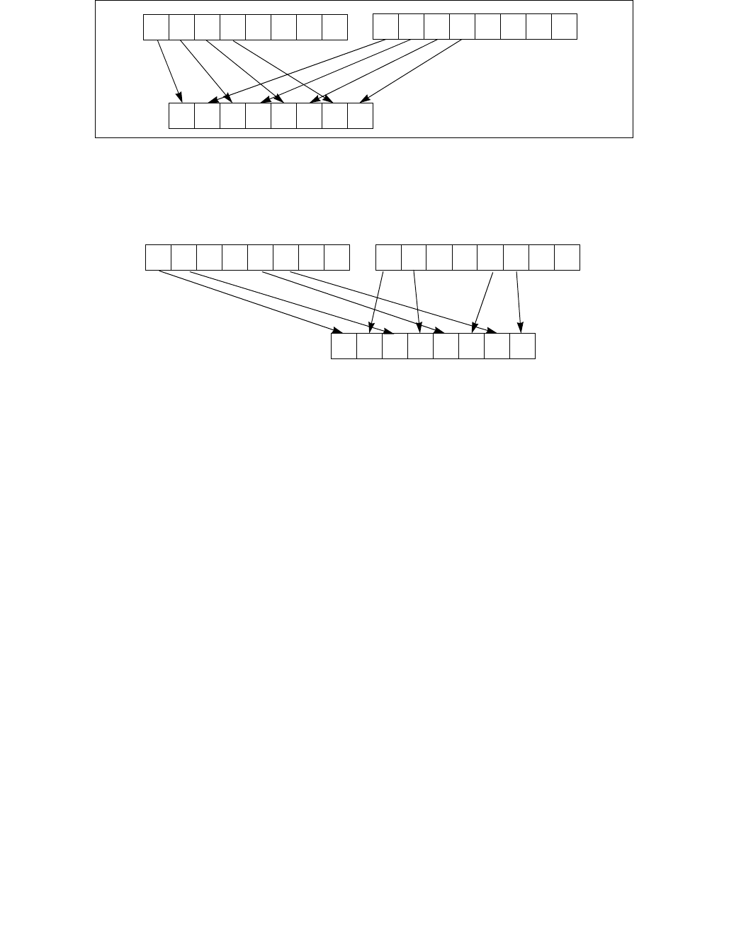
PUNPCKHBW/PUNPCKHWD/PUNPCKHDQ/PUNPCKHQDQ— Unpack High Data
INSTRUCTION SET REFERENCE, M-U
Vol. 2B 4-493
Figure 4-21. 256-bit VPUNPCKHDQ Instruction Operation
When the source data comes from a 64-bit memory operand, the full 64-bit operand is accessed from memory, but
the instruction uses only the high-order 32 bits. When the source data comes from a 128-bit memory operand, an
implementation may fetch only the appropriate 64 bits; however, alignment to a 16-byte boundary and normal
segment checking will still be enforced.
The (V)PUNPCKHBW instruction interleaves the high-order bytes of the source and destination operands, the
(V)PUNPCKHWD instruction interleaves the high-order words of the source and destination operands, the
(V)PUNPCKHDQ instruction interleaves the high-order doubleword (or doublewords) of the source and destination
operands, and the (V)PUNPCKHQDQ instruction interleaves the high-order quadwords of the source and destina-
tion operands.
These instructions can be used to convert bytes to words, words to doublewords, doublewords to quadwords, and
quadwords to double quadwords, respectively, by placing all 0s in the source operand. Here, if the source operand
contains all 0s, the result (stored in the destination operand) contains zero extensions of the high-order data
elements from the original value in the destination operand. For example, with the (V)PUNPCKHBW instruction the
high-order bytes are zero extended (that is, unpacked into unsigned word integers), and with the (V)PUNPCKHWD
instruction, the high-order words are zero extended (unpacked into unsigned doubleword integers).
In 64-bit mode and not encoded with VEX/EVEX, using a REX prefix in the form of REX.R permits this instruction to
access additional registers (XMM8-XMM15).
Legacy SSE versions 64-bit operand: The source operand can be an MMX technology register or a 64-bit memory
location. The destination operand is an MMX technology register.
128-bit Legacy SSE versions: The second source operand is an XMM register or a 128-bit memory location. The
first source operand and destination operands are XMM registers. Bits (VLMAX-1:128) of the corresponding YMM
destination register remain unchanged.
VEX.128 encoded versions: The second source operand is an XMM register or a 128-bit memory location. The first
source operand and destination operands are XMM registers. Bits (VLMAX-1:128) of the destination YMM register
are zeroed.
VEX.256 encoded version: The second source operand is an YMM register or an 256-bit memory location. The first
source operand and destination operands are YMM registers.
Figure 4-20. PUNPCKHBW Instruction Operation Using 64-bit Operands
X4X7 X6 X5 Y4Y7 Y6 Y5
X0X3 X2 X1
Y0Y3 Y2 Y1 X4X7 X6 X5
Y4Y7 Y6 Y5
SRC DEST
DEST
X2X7 X6 X3 Y2Y7 Y6 Y3
X0X3 X2 X1
Y0Y3 Y2 Y1 X4X7 X6 X5
Y4Y7 Y6 Y5
SRC
DEST
0
255 31
0
0
255
255
31

PUNPCKHBW/PUNPCKHWD/PUNPCKHDQ/PUNPCKHQDQ— Unpack High Data
INSTRUCTION SET REFERENCE, M-U
4-494 Vol. 2B
EVEX encoded VPUNPCKHDQ/QDQ: The second source operand is a ZMM/YMM/XMM register, a 512/256/128-bit
memory location or a 512/256/128-bit vector broadcasted from a 32/64-bit memory location. The first source
operand and destination operands are ZMM/YMM/XMM registers. The destination is conditionally updated with
writemask k1.
EVEX encoded VPUNPCKHWD/BW: The second source operand is a ZMM/YMM/XMM register, a 512/256/128-bit
memory location. The first source operand and destination operands are ZMM/YMM/XMM registers. The destination
is conditionally updated with writemask k1.
Operation
PUNPCKHBW instruction with 64-bit operands:
DEST[7:0] ← DEST[39:32];
DEST[15:8] ← SRC[39:32];
DEST[23:16] ← DEST[47:40];
DEST[31:24] ← SRC[47:40];
DEST[39:32] ← DEST[55:48];
DEST[47:40] ← SRC[55:48];
DEST[55:48] ← DEST[63:56];
DEST[63:56] ← SRC[63:56];
PUNPCKHW instruction with 64-bit operands:
DEST[15:0] ← DEST[47:32];
DEST[31:16] ← SRC[47:32];
DEST[47:32] ← DEST[63:48];
DEST[63:48] ← SRC[63:48];
PUNPCKHDQ instruction with 64-bit operands:
DEST[31:0] ← DEST[63:32];
DEST[63:32] ← SRC[63:32];
INTERLEAVE_HIGH_BYTES_512b (SRC1, SRC2)
TMP_DEST[255:0] INTERLEAVE_HIGH_BYTES_256b(SRC1[255:0], SRC[255:0])
TMP_DEST[511:256] INTERLEAVE_HIGH_BYTES_256b(SRC1[511:256], SRC[511:256])
INTERLEAVE_HIGH_BYTES_256b (SRC1, SRC2)
DEST[7:0] SRC1[71:64]
DEST[15:8] SRC2[71:64]
DEST[23:16] SRC1[79:72]
DEST[31:24] SRC2[79:72]
DEST[39:32] SRC1[87:80]
DEST[47:40] SRC2[87:80]
DEST[55:48] SRC1[95:88]
DEST[63:56] SRC2[95:88]
DEST[71:64] SRC1[103:96]
DEST[79:72] SRC2[103:96]
DEST[87:80] SRC1[111:104]
DEST[95:88] SRC2[111:104]
DEST[103:96] SRC1[119:112]
DEST[111:104] SRC2[119:112]
DEST[119:112] SRC1[127:120]
DEST[127:120] SRC2[127:120]
DEST[135:128] SRC1[199:192]
DEST[143:136] SRC2[199:192]
DEST[151:144] SRC1[207:200]
DEST[159:152] SRC2[207:200]

PUNPCKHBW/PUNPCKHWD/PUNPCKHDQ/PUNPCKHQDQ— Unpack High Data
INSTRUCTION SET REFERENCE, M-U
Vol. 2B 4-495
DEST[167:160] SRC1[215:208]
DEST[175:168] SRC2[215:208]
DEST[183:176] SRC1[223:216]
DEST[191:184] SRC2[223:216]
DEST[199:192] SRC1[231:224]
DEST[207:200] SRC2[231:224]
DEST[215:208] SRC1[239:232]
DEST[223:216] SRC2[239:232]
DEST[231:224] SRC1[247:240]
DEST[239:232] SRC2[247:240]
DEST[247:240] SRC1[255:248]
DEST[255:248] SRC2[255:248]
INTERLEAVE_HIGH_BYTES (SRC1, SRC2)
DEST[7:0] SRC1[71:64]
DEST[15:8] SRC2[71:64]
DEST[23:16] SRC1[79:72]
DEST[31:24] SRC2[79:72]
DEST[39:32] SRC1[87:80]
DEST[47:40] SRC2[87:80]
DEST[55:48] SRC1[95:88]
DEST[63:56] SRC2[95:88]
DEST[71:64] SRC1[103:96]
DEST[79:72] SRC2[103:96]
DEST[87:80] SRC1[111:104]
DEST[95:88] SRC2[111:104]
DEST[103:96] SRC1[119:112]
DEST[111:104] SRC2[119:112]
DEST[119:112] SRC1[127:120]
DEST[127:120] SRC2[127:120]
INTERLEAVE_HIGH_WORDS_512b (SRC1, SRC2)
TMP_DEST[255:0] INTERLEAVE_HIGH_WORDS_256b(SRC1[255:0], SRC[255:0])
TMP_DEST[511:256] INTERLEAVE_HIGH_WORDS_256b(SRC1[511:256], SRC[511:256])
INTERLEAVE_HIGH_WORDS_256b(SRC1, SRC2)
DEST[15:0] SRC1[79:64]
DEST[31:16] SRC2[79:64]
DEST[47:32] SRC1[95:80]
DEST[63:48] SRC2[95:80]
DEST[79:64] SRC1[111:96]
DEST[95:80] SRC2[111:96]
DEST[111:96] SRC1[127:112]
DEST[127:112] SRC2[127:112]
DEST[143:128] SRC1[207:192]
DEST[159:144] SRC2[207:192]
DEST[175:160] SRC1[223:208]
DEST[191:176] SRC2[223:208]
DEST[207:192] SRC1[239:224]
DEST[223:208] SRC2[239:224]
DEST[239:224] SRC1[255:240]
DEST[255:240] SRC2[255:240]
INTERLEAVE_HIGH_WORDS (SRC1, SRC2)

PUNPCKHBW/PUNPCKHWD/PUNPCKHDQ/PUNPCKHQDQ— Unpack High Data
INSTRUCTION SET REFERENCE, M-U
4-496 Vol. 2B
DEST[15:0] SRC1[79:64]
DEST[31:16] SRC2[79:64]
DEST[47:32] SRC1[95:80]
DEST[63:48] SRC2[95:80]
DEST[79:64] SRC1[111:96]
DEST[95:80] SRC2[111:96]
DEST[111:96] SRC1[127:112]
DEST[127:112] SRC2[127:112]
INTERLEAVE_HIGH_DWORDS_512b (SRC1, SRC2)
TMP_DEST[255:0] INTERLEAVE_HIGH_DWORDS_256b(SRC1[255:0], SRC2[255:0])
TMP_DEST[511:256] INTERLEAVE_HIGH_DWORDS_256b(SRC1[511:256], SRC2[511:256])
INTERLEAVE_HIGH_DWORDS_256b(SRC1, SRC2)
DEST[31:0] SRC1[95:64]
DEST[63:32] SRC2[95:64]
DEST[95:64] SRC1[127:96]
DEST[127:96] SRC2[127:96]
DEST[159:128] SRC1[223:192]
DEST[191:160] SRC2[223:192]
DEST[223:192] SRC1[255:224]
DEST[255:224] SRC2[255:224]
INTERLEAVE_HIGH_DWORDS(SRC1, SRC2)
DEST[31:0] SRC1[95:64]
DEST[63:32] SRC2[95:64]
DEST[95:64] SRC1[127:96]
DEST[127:96] SRC2[127:96]
INTERLEAVE_HIGH_QWORDS_512b (SRC1, SRC2)
TMP_DEST[255:0] INTERLEAVE_HIGH_QWORDS_256b(SRC1[255:0], SRC2[255:0])
TMP_DEST[511:256] INTERLEAVE_HIGH_QWORDS_256b(SRC1[511:256], SRC2[511:256])
INTERLEAVE_HIGH_QWORDS_256b(SRC1, SRC2)
DEST[63:0] SRC1[127:64]
DEST[127:64] SRC2[127:64]
DEST[191:128] SRC1[255:192]
DEST[255:192] SRC2[255:192]
INTERLEAVE_HIGH_QWORDS(SRC1, SRC2)
DEST[63:0] SRC1[127:64]
DEST[127:64] SRC2[127:64]
PUNPCKHBW (128-bit Legacy SSE Version)
DEST[127:0] INTERLEAVE_HIGH_BYTES(DEST, SRC)
DEST[255:127] (Unmodified)
VPUNPCKHBW (VEX.128 encoded version)
DEST[127:0] INTERLEAVE_HIGH_BYTES(SRC1, SRC2)
DEST[511:127] 0
VPUNPCKHBW (VEX.256 encoded version)
DEST[255:0] INTERLEAVE_HIGH_BYTES_256b(SRC1, SRC2)
DEST[MAX_VL-1:256] 0

PUNPCKHBW/PUNPCKHWD/PUNPCKHDQ/PUNPCKHQDQ— Unpack High Data
INSTRUCTION SET REFERENCE, M-U
Vol. 2B 4-497
VPUNPCKHBW (EVEX encoded versions)
(KL, VL) = (16, 128), (32, 256), (64, 512)
IF VL = 128
TMP_DEST[VL-1:0] INTERLEAVE_HIGH_BYTES(SRC1[VL-1:0], SRC2[VL-1:0])
FI;
IF VL = 256
TMP_DEST[VL-1:0] INTERLEAVE_HIGH_BYTES_256b(SRC1[VL-1:0], SRC2[VL-1:0])
FI;
IF VL = 512
TMP_DEST[VL-1:0] INTERLEAVE_HIGH_BYTES_512b(SRC1[VL-1:0], SRC2[VL-1:0])
FI;
FOR j 0 TO KL-1
i j * 8
IF k1[j] OR *no writemask*
THEN DEST[i+7:i] TMP_DEST[i+7:i]
ELSE
IF *merging-masking* ; merging-masking
THEN *DEST[i+7:i] remains unchanged*
ELSE *zeroing-masking* ; zeroing-masking
DEST[i+7:i] 0
FI
FI;
ENDFOR
DEST[MAX_VL-1:VL] 0
PUNPCKHWD (128-bit Legacy SSE Version)
DEST[127:0] INTERLEAVE_HIGH_WORDS(DEST, SRC)
DEST[255:127] (Unmodified)
VPUNPCKHWD (VEX.128 encoded version)
DEST[127:0] INTERLEAVE_HIGH_WORDS(SRC1, SRC2)
DEST[511:127] 0
VPUNPCKHWD (VEX.256 encoded version)
DEST[255:0] INTERLEAVE_HIGH_WORDS_256b(SRC1, SRC2)
DEST[MAX_VL-1:256] 0
VPUNPCKHWD (EVEX encoded versions)
(KL, VL) = (8, 128), (16, 256), (32, 512)
IF VL = 128
TMP_DEST[VL-1:0] INTERLEAVE_HIGH_WORDS(SRC1[VL-1:0], SRC2[VL-1:0])
FI;
IF VL = 256
TMP_DEST[VL-1:0] INTERLEAVE_HIGH_WORDS_256b(SRC1[VL-1:0], SRC2[VL-1:0])
FI;
IF VL = 512
TMP_DEST[VL-1:0] INTERLEAVE_HIGH_WORDS_512b(SRC1[VL-1:0], SRC2[VL-1:0])
FI;
FOR j 0 TO KL-1
i j * 16
IF k1[j] OR *no writemask*
THEN DEST[i+15:i] TMP_DEST[i+15:i]

PUNPCKHBW/PUNPCKHWD/PUNPCKHDQ/PUNPCKHQDQ— Unpack High Data
INSTRUCTION SET REFERENCE, M-U
4-498 Vol. 2B
ELSE
IF *merging-masking* ; merging-masking
THEN *DEST[i+15:i] remains unchanged*
ELSE *zeroing-masking* ; zeroing-masking
DEST[i+15:i] 0
FI
FI;
ENDFOR
DEST[MAX_VL-1:VL] 0
PUNPCKHDQ (128-bit Legacy SSE Version)
DEST[127:0] INTERLEAVE_HIGH_DWORDS(DEST, SRC)
DEST[255:127] (Unmodified)
VPUNPCKHDQ (VEX.128 encoded version)
DEST[127:0] INTERLEAVE_HIGH_DWORDS(SRC1, SRC2)
DEST[511:127] 0
VPUNPCKHDQ (VEX.256 encoded version)
DEST[255:0] INTERLEAVE_HIGH_DWORDS_256b(SRC1, SRC2)
DEST[MAX_VL-1:256] 0
VPUNPCKHDQ (EVEX.512 encoded version)
(KL, VL) = (4, 128), (8, 256), (16, 512)
FOR j 0 TO KL-1
i j * 32
IF (EVEX.b = 1) AND (SRC2 *is memory*)
THEN TMP_SRC2[i+31:i] SRC2[31:0]
ELSE TMP_SRC2[i+31:i] SRC2[i+31:i]
FI;
ENDFOR;
IF VL = 128
TMP_DEST[VL-1:0] INTERLEAVE_HIGH_DWORDS(SRC1[VL-1:0], TMP_SRC2[VL-1:0])
FI;
IF VL = 256
TMP_DEST[VL-1:0] INTERLEAVE_HIGH_DWORDS_256b(SRC1[VL-1:0], TMP_SRC2[VL-1:0])
FI;
IF VL = 512
TMP_DEST[VL-1:0] INTERLEAVE_HIGH_DWORDS_512b(SRC1[VL-1:0], TMP_SRC2[VL-1:0])
FI;
FOR j 0 TO KL-1
i j * 32
IF k1[j] OR *no writemask*
THEN DEST[i+31:i] TMP_DEST[i+31:i]
ELSE
IF *merging-masking* ; merging-masking
THEN *DEST[i+31:i] remains unchanged*
ELSE *zeroing-masking* ; zeroing-masking
DEST[i+31:i] 0
FI
FI;
ENDFOR
DEST[MAX_VL-1:VL] 0

PUNPCKHBW/PUNPCKHWD/PUNPCKHDQ/PUNPCKHQDQ— Unpack High Data
INSTRUCTION SET REFERENCE, M-U
Vol. 2B 4-499
PUNPCKHQDQ (128-bit Legacy SSE Version)
DEST[127:0] INTERLEAVE_HIGH_QWORDS(DEST, SRC)
DEST[MAX_VL-1:128] (Unmodified)
VPUNPCKHQDQ (VEX.128 encoded version)
DEST[127:0] INTERLEAVE_HIGH_QWORDS(SRC1, SRC2)
DEST[MAX_VL-1:128] 0
VPUNPCKHQDQ (VEX.256 encoded version)
DEST[255:0] INTERLEAVE_HIGH_QWORDS_256b(SRC1, SRC2)
DEST[MAX_VL-1:256] 0
VPUNPCKHQDQ (EVEX encoded versions)
(KL, VL) = (2, 128), (4, 256), (8, 512)
FOR j 0 TO KL-1
i j * 64
IF (EVEX.b = 1) AND (SRC2 *is memory*)
THEN TMP_SRC2[i+63:i] SRC2[63:0]
ELSE TMP_SRC2[i+63:i] SRC2[i+63:i]
FI;
ENDFOR;
IF VL = 128
TMP_DEST[VL-1:0] INTERLEAVE_HIGH_QWORDS(SRC1[VL-1:0], TMP_SRC2[VL-1:0])
FI;
IF VL = 256
TMP_DEST[VL-1:0] INTERLEAVE_HIGH_QWORDS_256b(SRC1[VL-1:0], TMP_SRC2[VL-1:0])
FI;
IF VL = 512
TMP_DEST[VL-1:0] INTERLEAVE_HIGH_QWORDS_512b(SRC1[VL-1:0], TMP_SRC2[VL-1:0])
FI;
FOR j 0 TO KL-1
i j * 64
IF k1[j] OR *no writemask*
THEN DEST[i+63:i] TMP_DEST[i+63:i]
ELSE
IF *merging-masking* ; merging-masking
THEN *DEST[i+63:i] remains unchanged*
ELSE *zeroing-masking* ; zeroing-masking
DEST[i+63:i] 0
FI
FI;
ENDFOR
DEST[MAX_VL-1:VL] 0
Intel C/C++ Compiler Intrinsic Equivalents
VPUNPCKHBW __m512i _mm512_unpackhi_epi8(__m512i a, __m512i b);
VPUNPCKHBW __m512i _mm512_mask_unpackhi_epi8(__m512i s, __mmask64 k, __m512i a, __m512i b);
VPUNPCKHBW __m512i _mm512_maskz_unpackhi_epi8( __mmask64 k, __m512i a, __m512i b);
VPUNPCKHBW __m256i _mm256_mask_unpackhi_epi8(__m256i s, __mmask32 k, __m256i a, __m256i b);
VPUNPCKHBW __m256i _mm256_maskz_unpackhi_epi8( __mmask32 k, __m256i a, __m256i b);
VPUNPCKHBW __m128i _mm_mask_unpackhi_epi8(v s, __mmask16 k, __m128i a, __m128i b);
VPUNPCKHBW __m128i _mm_maskz_unpackhi_epi8( __mmask16 k, __m128i a, __m128i b);

PUNPCKHBW/PUNPCKHWD/PUNPCKHDQ/PUNPCKHQDQ— Unpack High Data
INSTRUCTION SET REFERENCE, M-U
4-500 Vol. 2B
VPUNPCKHWD __m512i _mm512_unpackhi_epi16(__m512i a, __m512i b);
VPUNPCKHWD __m512i _mm512_mask_unpackhi_epi16(__m512i s, __mmask32 k, __m512i a, __m512i b);
VPUNPCKHWD __m512i _mm512_maskz_unpackhi_epi16( __mmask32 k, __m512i a, __m512i b);
VPUNPCKHWD __m256i _mm256_mask_unpackhi_epi16(__m256i s, __mmask16 k, __m256i a, __m256i b);
VPUNPCKHWD __m256i _mm256_maskz_unpackhi_epi16( __mmask16 k, __m256i a, __m256i b);
VPUNPCKHWD __m128i _mm_mask_unpackhi_epi16(v s, __mmask8 k, __m128i a, __m128i b);
VPUNPCKHWD __m128i _mm_maskz_unpackhi_epi16( __mmask8 k, __m128i a, __m128i b);
VPUNPCKHDQ __m512i _mm512_unpackhi_epi32(__m512i a, __m512i b);
VPUNPCKHDQ __m512i _mm512_mask_unpackhi_epi32(__m512i s, __mmask16 k, __m512i a, __m512i b);
VPUNPCKHDQ __m512i _mm512_maskz_unpackhi_epi32( __mmask16 k, __m512i a, __m512i b);
VPUNPCKHDQ __m256i _mm256_mask_unpackhi_epi32(__m512i s, __mmask8 k, __m512i a, __m512i b);
VPUNPCKHDQ __m256i _mm256_maskz_unpackhi_epi32( __mmask8 k, __m512i a, __m512i b);
VPUNPCKHDQ __m128i _mm_mask_unpackhi_epi32(__m512i s, __mmask8 k, __m512i a, __m512i b);
VPUNPCKHDQ __m128i _mm_maskz_unpackhi_epi32( __mmask8 k, __m512i a, __m512i b);
VPUNPCKHQDQ __m512i _mm512_unpackhi_epi64(__m512i a, __m512i b);
VPUNPCKHQDQ __m512i _mm512_mask_unpackhi_epi64(__m512i s, __mmask8 k, __m512i a, __m512i b);
VPUNPCKHQDQ __m512i _mm512_maskz_unpackhi_epi64( __mmask8 k, __m512i a, __m512i b);
VPUNPCKHQDQ __m256i _mm256_mask_unpackhi_epi64(__m512i s, __mmask8 k, __m512i a, __m512i b);
VPUNPCKHQDQ __m256i _mm256_maskz_unpackhi_epi64( __mmask8 k, __m512i a, __m512i b);
VPUNPCKHQDQ __m128i _mm_mask_unpackhi_epi64(__m512i s, __mmask8 k, __m512i a, __m512i b);
VPUNPCKHQDQ __m128i _mm_maskz_unpackhi_epi64( __mmask8 k, __m512i a, __m512i b);
PUNPCKHBW:__m64 _mm_unpackhi_pi8(__m64 m1, __m64 m2)
(V)PUNPCKHBW:__m128i _mm_unpackhi_epi8(__m128i m1, __m128i m2)
VPUNPCKHBW:__m256i _mm256_unpackhi_epi8(__m256i m1, __m256i m2)
PUNPCKHWD:__m64 _mm_unpackhi_pi16(__m64 m1,__m64 m2)
(V)PUNPCKHWD:__m128i _mm_unpackhi_epi16(__m128i m1,__m128i m2)
VPUNPCKHWD:__m256i _mm256_unpackhi_epi16(__m256i m1,__m256i m2)
PUNPCKHDQ:__m64 _mm_unpackhi_pi32(__m64 m1, __m64 m2)
(V)PUNPCKHDQ:__m128i _mm_unpackhi_epi32(__m128i m1, __m128i m2)
VPUNPCKHDQ:__m256i _mm256_unpackhi_epi32(__m256i m1, __m256i m2)
(V)PUNPCKHQDQ:__m128i _mm_unpackhi_epi64 ( __m128i a, __m128i b)
VPUNPCKHQDQ:__m256i _mm256_unpackhi_epi64 ( __m256i a, __m256i b)
Flags Affected
None.
Numeric Exceptions
None.
Other Exceptions
Non-EVEX-encoded instruction, see Exceptions Type 4.
EVEX-encoded VPUNPCKHQDQ/QDQ, see Exceptions Type E4NF.
EVEX-encoded VPUNPCKHBW/WD, see Exceptions Type E4NF.nb.

PUNPCKLBW/PUNPCKLWD/PUNPCKLDQ/PUNPCKLQDQ—Unpack Low Data
INSTRUCTION SET REFERENCE, M-U
Vol. 2B 4-501
PUNPCKLBW/PUNPCKLWD/PUNPCKLDQ/PUNPCKLQDQ—Unpack Low Data
Opcode/
Instruction
Op/
En
64/32 bit
Mode
Support
CPUID
Feature
Flag
Description
0F 60 /r1
PUNPCKLBW mm, mm/m32
RM V/V MMX Interleave low-order bytes from mm and
mm/m32 into mm.
66 0F 60 /r
PUNPCKLBW xmm1, xmm2/m128
RM V/V SSE2 Interleave low-order bytes from xmm1 and
xmm2/m128 into xmm1.
0F 61 /r1
PUNPCKLWD mm, mm/m32
RM V/V MMX Interleave low-order words from mm and
mm/m32 into mm.
66 0F 61 /r
PUNPCKLWD xmm1, xmm2/m128
RM V/V SSE2 Interleave low-order words from xmm1 and
xmm2/m128 into xmm1.
0F 62 /r1
PUNPCKLDQ mm, mm/m32
RM V/V MMX Interleave low-order doublewords from mm
and mm/m32 into mm.
66 0F 62 /r
PUNPCKLDQ xmm1, xmm2/m128
RM V/V SSE2 Interleave low-order doublewords from xmm1
and xmm2/m128 into xmm1.
66 0F 6C /r
PUNPCKLQDQ xmm1, xmm2/m128
RM V/V SSE2 Interleave low-order quadword from xmm1
and xmm2/m128 into xmm1 register.
VEX.NDS.128.66.0F.WIG 60/r
VPUNPCKLBW xmm1,xmm2, xmm3/m128
RVM V/V AVX Interleave low-order bytes from xmm2 and
xmm3/m128 into xmm1.
VEX.NDS.128.66.0F.WIG 61/r
VPUNPCKLWD xmm1,xmm2, xmm3/m128
RVM V/V AVX Interleave low-order words from xmm2 and
xmm3/m128 into xmm1.
VEX.NDS.128.66.0F.WIG 62/r
VPUNPCKLDQ xmm1, xmm2, xmm3/m128
RVM V/V AVX Interleave low-order doublewords from xmm2
and xmm3/m128 into xmm1.
VEX.NDS.128.66.0F.WIG 6C/r
VPUNPCKLQDQ xmm1, xmm2, xmm3/m128
RVM V/V AVX Interleave low-order quadword from xmm2
and xmm3/m128 into xmm1 register.
VEX.NDS.256.66.0F.WIG 60 /r
VPUNPCKLBW ymm1, ymm2, ymm3/m256
RVM V/V AVX2 Interleave low-order bytes from ymm2 and
ymm3/m256 into ymm1 register.
VEX.NDS.256.66.0F.WIG 61 /r
VPUNPCKLWD ymm1, ymm2, ymm3/m256
RVM V/V AVX2 Interleave low-order words from ymm2 and
ymm3/m256 into ymm1 register.
VEX.NDS.256.66.0F.WIG 62 /r
VPUNPCKLDQ ymm1, ymm2, ymm3/m256
RVM V/V AVX2 Interleave low-order doublewords from ymm2
and ymm3/m256 into ymm1 register.
VEX.NDS.256.66.0F.WIG 6C /r
VPUNPCKLQDQ ymm1, ymm2, ymm3/m256
RVM V/V AVX2 Interleave low-order quadword from ymm2
and ymm3/m256 into ymm1 register.
EVEX.NDS.128.66.0F.WIG 60 /r
VPUNPCKLBW xmm1 {k1}{z}, xmm2, xmm3/m128
FVM V/V AVX512VL
AVX512BW
Interleave low-order bytes from xmm2 and
xmm3/m128 into xmm1 register subject to
write mask k1.
EVEX.NDS.128.66.0F.WIG 61 /r
VPUNPCKLWD xmm1 {k1}{z}, xmm2, xmm3/m128
FVM V/V AVX512VL
AVX512BW
Interleave low-order words from xmm2 and
xmm3/m128 into xmm1 register subject to
write mask k1.
EVEX.NDS.128.66.0F.W0 62 /r
VPUNPCKLDQ xmm1 {k1}{z}, xmm2,
xmm3/m128/m32bcst
FV V/V AVX512VL
AVX512F
Interleave low-order doublewords from xmm2
and xmm3/m128/m32bcst into xmm1
register subject to write mask k1.
EVEX.NDS.128.66.0F.W1 6C /r
VPUNPCKLQDQ xmm1 {k1}{z}, xmm2,
xmm3/m128/m64bcst
FV V/V AVX512VL
AVX512F
Interleave low-order quadword from zmm2
and zmm3/m512/m64bcst into zmm1
register subject to write mask k1.

PUNPCKLBW/PUNPCKLWD/PUNPCKLDQ/PUNPCKLQDQ—Unpack Low Data
INSTRUCTION SET REFERENCE, M-U
4-502 Vol. 2B
Instruction Operand Encoding
Description
Unpacks and interleaves the low-order data elements (bytes, words, doublewords, and quadwords) of the destina-
tion operand (first operand) and source operand (second operand) into the destination operand. (Figure 4-22
shows the unpack operation for bytes in 64-bit operands.). The high-order data elements are ignored.
EVEX.NDS.256.66.0F.WIG 60 /r
VPUNPCKLBW ymm1 {k1}{z}, ymm2, ymm3/m256
FVM V/V AVX512VL
AVX512BW
Interleave low-order bytes from ymm2 and
ymm3/m256 into ymm1 register subject to
write mask k1.
EVEX.NDS.256.66.0F.WIG 61 /r
VPUNPCKLWD ymm1 {k1}{z}, ymm2, ymm3/m256
FVM V/V AVX512VL
AVX512BW
Interleave low-order words from ymm2 and
ymm3/m256 into ymm1 register subject to
write mask k1.
EVEX.NDS.256.66.0F.W0 62 /r
VPUNPCKLDQ ymm1 {k1}{z}, ymm2,
ymm3/m256/m32bcst
FV V/V AVX512VL
AVX512F
Interleave low-order doublewords from ymm2
and ymm3/m256/m32bcst into ymm1
register subject to write mask k1.
EVEX.NDS.256.66.0F.W1 6C /r
VPUNPCKLQDQ ymm1 {k1}{z}, ymm2,
ymm3/m256/m64bcst
FV V/V AVX512VL
AVX512F
Interleave low-order quadword from ymm2
and ymm3/m256/m64bcst into ymm1
register subject to write mask k1.
EVEX.NDS.512.66.0F.WIG 60/r
VPUNPCKLBW zmm1 {k1}{z}, zmm2, zmm3/m512
FVM V/V AVX512BW Interleave low-order bytes from zmm2 and
zmm3/m512 into zmm1 register subject to
write mask k1.
EVEX.NDS.512.66.0F.WIG 61/r
VPUNPCKLWD zmm1 {k1}{z}, zmm2, zmm3/m512
FVM V/V AVX512BW Interleave low-order words from zmm2 and
zmm3/m512 into zmm1 register subject to
write mask k1.
EVEX.NDS.512.66.0F.W0 62 /r
VPUNPCKLDQ zmm1 {k1}{z}, zmm2,
zmm3/m512/m32bcst
FV V/V AVX512F Interleave low-order doublewords from zmm2
and zmm3/m512/m32bcst into zmm1
register subject to write mask k1.
EVEX.NDS.512.66.0F.W1 6C /r
VPUNPCKLQDQ zmm1 {k1}{z}, zmm2,
zmm3/m512/m64bcst
FV V/V AVX512F Interleave low-order quadword from zmm2
and zmm3/m512/m64bcst into zmm1
register subject to write mask k1.
NOTES:
1. See note in Section 2.4, “AVX and SSE Instruction Exception Specification” in the Intel® 64 and IA-32 Architectures Software
Developer’s Manual, Volume 2A and Section 22.25.3, “Exception Conditions of Legacy SIMD Instructions Operating on MMX Registers”
in the Intel® 64 and IA-32 Architectures Software Developer’s Manual, Volume 3A.
Op/En Operand 1 Operand 2 Operand 3 Operand 4
RM ModRM:reg (r, w) ModRM:r/m (r) NA NA
RVM ModRM:reg (w) VEX.vvvv (r) ModRM:r/m (r) NA
FVM ModRM:reg (w) EVEX.vvvv (r) ModRM:r/m (r) NA
FV ModRM:reg (w) EVEX.vvvv (r) ModRM:r/m (r) NA
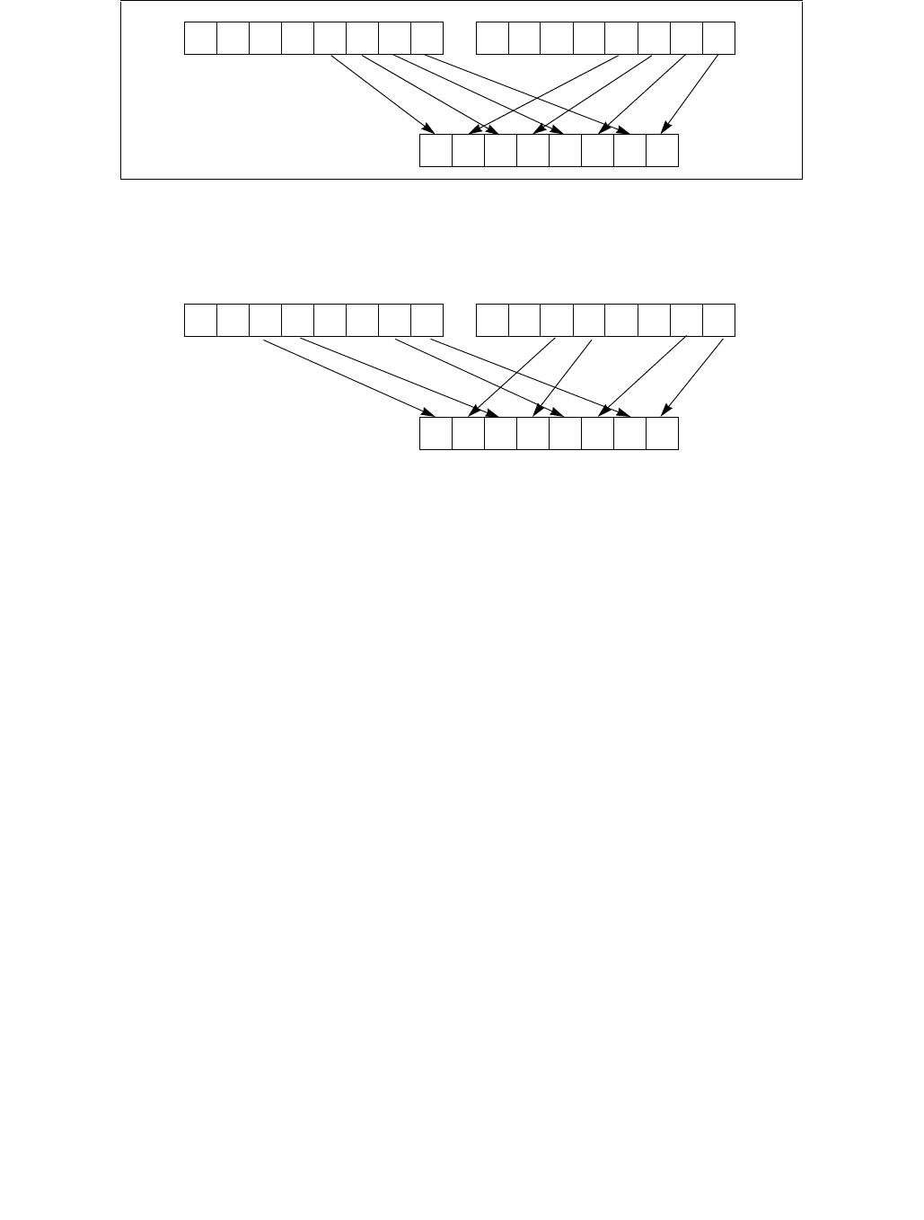
PUNPCKLBW/PUNPCKLWD/PUNPCKLDQ/PUNPCKLQDQ—Unpack Low Data
INSTRUCTION SET REFERENCE, M-U
Vol. 2B 4-503
Figure 4-23. 256-bit VPUNPCKLDQ Instruction Operation
When the source data comes from a 128-bit memory operand, an implementation may fetch only the appropriate
64 bits; however, alignment to a 16-byte boundary and normal segment checking will still be enforced.
The (V)PUNPCKLBW instruction interleaves the low-order bytes of the source and destination operands, the
(V)PUNPCKLWD instruction interleaves the low-order words of the source and destination operands, the
(V)PUNPCKLDQ instruction interleaves the low-order doubleword (or doublewords) of the source and destination
operands, and the (V)PUNPCKLQDQ instruction interleaves the low-order quadwords of the source and destination
operands.
These instructions can be used to convert bytes to words, words to doublewords, doublewords to quadwords, and
quadwords to double quadwords, respectively, by placing all 0s in the source operand. Here, if the source operand
contains all 0s, the result (stored in the destination operand) contains zero extensions of the high-order data
elements from the original value in the destination operand. For example, with the (V)PUNPCKLBW instruction the
high-order bytes are zero extended (that is, unpacked into unsigned word integers), and with the (V)PUNPCKLWD
instruction, the high-order words are zero extended (unpacked into unsigned doubleword integers).
In 64-bit mode and not encoded with VEX/EVEX, using a REX prefix in the form of REX.R permits this instruction to
access additional registers (XMM8-XMM15).
Legacy SSE versions 64-bit operand: The source operand can be an MMX technology register or a 32-bit memory
location. The destination operand is an MMX technology register.
128-bit Legacy SSE versions: The second source operand is an XMM register or a 128-bit memory location. The
first source operand and destination operands are XMM registers. Bits (VLMAX-1:128) of the corresponding YMM
destination register remain unchanged.
VEX.128 encoded versions: The second source operand is an XMM register or a 128-bit memory location. The first
source operand and destination operands are XMM registers. Bits (VLMAX-1:128) of the destination YMM register
are zeroed.
VEX.256 encoded version: The second source operand is an YMM register or an 256-bit memory location. The first
source operand and destination operands are YMM registers. Bits (MAX_VL-1:256) of the corresponding ZMM
register are zeroed.
Figure 4-22. PUNPCKLBW Instruction Operation Using 64-bit Operands
X0X3 X2 X1 Y0Y3 Y2 Y1
X0X3 X2 X1
Y0Y3 Y2 Y1 X4X7 X6 X5
Y4Y7 Y6 Y5
SRC DEST
DEST
X0X5 X4 X1 Y0Y5 Y4 Y1
X0X3 X2 X1
Y0Y3 Y2 Y1 X4X7 X6 X5
Y4Y7 Y6 Y5
SRC
DEST
0
255 31
0
0
255
255
31

PUNPCKLBW/PUNPCKLWD/PUNPCKLDQ/PUNPCKLQDQ—Unpack Low Data
INSTRUCTION SET REFERENCE, M-U
4-504 Vol. 2B
EVEX encoded VPUNPCKLDQ/QDQ: The second source operand is a ZMM/YMM/XMM register, a 512/256/128-bit
memory location or a 512/256/128-bit vector broadcasted from a 32/64-bit memory location. The first source
operand and destination operands are ZMM/YMM/XMM registers. The destination is conditionally updated with
writemask k1.
EVEX encoded VPUNPCKLWD/BW: The second source operand is a ZMM/YMM/XMM register, a 512/256/128-bit
memory location. The first source operand and destination operands are ZMM/YMM/XMM registers. The destination
is conditionally updated with writemask k1.
Operation
PUNPCKLBW instruction with 64-bit operands:
DEST[63:56] ← SRC[31:24];
DEST[55:48] ← DEST[31:24];
DEST[47:40] ← SRC[23:16];
DEST[39:32] ← DEST[23:16];
DEST[31:24] ← SRC[15:8];
DEST[23:16] ← DEST[15:8];
DEST[15:8] ← SRC[7:0];
DEST[7:0] ← DEST[7:0];
PUNPCKLWD instruction with 64-bit operands:
DEST[63:48] ← SRC[31:16];
DEST[47:32] ← DEST[31:16];
DEST[31:16] ← SRC[15:0];
DEST[15:0] ← DEST[15:0];
PUNPCKLDQ instruction with 64-bit operands:
DEST[63:32] ← SRC[31:0];
DEST[31:0] ← DEST[31:0];
INTERLEAVE_BYTES_512b (SRC1, SRC2)
TMP_DEST[255:0] INTERLEAVE_BYTES_256b(SRC1[255:0], SRC[255:0])
TMP_DEST[511:256] INTERLEAVE_BYTES_256b(SRC1[511:256], SRC[511:256])
INTERLEAVE_BYTES_256b (SRC1, SRC2)
DEST[7:0] SRC1[7:0]
DEST[15:8] SRC2[7:0]
DEST[23:16] SRC1[15:8]
DEST[31:24] SRC2[15:8]
DEST[39:32] SRC1[23:16]
DEST[47:40] SRC2[23:16]
DEST[55:48] SRC1[31:24]
DEST[63:56] SRC2[31:24]
DEST[71:64] SRC1[39:32]
DEST[79:72] SRC2[39:32]
DEST[87:80] SRC1[47:40]
DEST[95:88] SRC2[47:40]
DEST[103:96] SRC1[55:48]
DEST[111:104] SRC2[55:48]
DEST[119:112] SRC1[63:56]
DEST[127:120] SRC2[63:56]
DEST[135:128] SRC1[135:128]
DEST[143:136] SRC2[135:128]
DEST[151:144] SRC1[143:136]
DEST[159:152] SRC2[143:136]
DEST[167:160] SRC1[151:144]

PUNPCKLBW/PUNPCKLWD/PUNPCKLDQ/PUNPCKLQDQ—Unpack Low Data
INSTRUCTION SET REFERENCE, M-U
Vol. 2B 4-505
DEST[175:168] SRC2[151:144]
DEST[183:176] SRC1[159:152]
DEST[191:184] SRC2[159:152]
DEST[199:192] SRC1[167:160]
DEST[207:200] SRC2[167:160]
DEST[215:208] SRC1[175:168]
DEST[223:216] SRC2[175:168]
DEST[231:224] SRC1[183:176]
DEST[239:232] SRC2[183:176]
DEST[247:240] SRC1[191:184]
DEST[255:248] SRC2[191:184]
INTERLEAVE_BYTES (SRC1, SRC2)
DEST[7:0] SRC1[7:0]
DEST[15:8] SRC2[7:0]
DEST[23:16] SRC2[15:8]
DEST[31:24] SRC2[15:8]
DEST[39:32] SRC1[23:16]
DEST[47:40] SRC2[23:16]
DEST[55:48] SRC1[31:24]
DEST[63:56] SRC2[31:24]
DEST[71:64] SRC1[39:32]
DEST[79:72] SRC2[39:32]
DEST[87:80] SRC1[47:40]
DEST[95:88] SRC2[47:40]
DEST[103:96] SRC1[55:48]
DEST[111:104] SRC2[55:48]
DEST[119:112] SRC1[63:56]
DEST[127:120] SRC2[63:56]
INTERLEAVE_WORDS_512b (SRC1, SRC2)
TMP_DEST[255:0] INTERLEAVE_WORDS_256b(SRC1[255:0], SRC[255:0])
TMP_DEST[511:256] INTERLEAVE_WORDS_256b(SRC1[511:256], SRC[511:256])
INTERLEAVE_WORDS_256b(SRC1, SRC2)
DEST[15:0] SRC1[15:0]
DEST[31:16] SRC2[15:0]
DEST[47:32] SRC1[31:16]
DEST[63:48] SRC2[31:16]
DEST[79:64] SRC1[47:32]
DEST[95:80] SRC2[47:32]
DEST[111:96] SRC1[63:48]
DEST[127:112] SRC2[63:48]
DEST[143:128] SRC1[143:128]
DEST[159:144] SRC2[143:128]
DEST[175:160] SRC1[159:144]
DEST[191:176] SRC2[159:144]
DEST[207:192] SRC1[175:160]
DEST[223:208] SRC2[175:160]
DEST[239:224] SRC1[191:176]
DEST[255:240] SRC2[191:176]
INTERLEAVE_WORDS (SRC1, SRC2)
DEST[15:0] SRC1[15:0]

PUNPCKLBW/PUNPCKLWD/PUNPCKLDQ/PUNPCKLQDQ—Unpack Low Data
INSTRUCTION SET REFERENCE, M-U
4-506 Vol. 2B
DEST[31:16] SRC2[15:0]
DEST[47:32] SRC1[31:16]
DEST[63:48] SRC2[31:16]
DEST[79:64] SRC1[47:32]
DEST[95:80] SRC2[47:32]
DEST[111:96] SRC1[63:48]
DEST[127:112] SRC2[63:48]
INTERLEAVE_DWORDS_512b (SRC1, SRC2)
TMP_DEST[255:0] INTERLEAVE_DWORDS_256b(SRC1[255:0], SRC2[255:0])
TMP_DEST[511:256] INTERLEAVE_DWORDS_256b(SRC1[511:256], SRC2[511:256])
INTERLEAVE_DWORDS_256b(SRC1, SRC2)
DEST[31:0] SRC1[31:0]
DEST[63:32] SRC2[31:0]
DEST[95:64] SRC1[63:32]
DEST[127:96] SRC2[63:32]
DEST[159:128] SRC1[159:128]
DEST[191:160] SRC2[159:128]
DEST[223:192] SRC1[191:160]
DEST[255:224] SRC2[191:160]
INTERLEAVE_DWORDS(SRC1, SRC2)
DEST[31:0] SRC1[31:0]
DEST[63:32] SRC2[31:0]
DEST[95:64] SRC1[63:32]
DEST[127:96] SRC2[63:32]
INTERLEAVE_QWORDS_512b (SRC1, SRC2)
TMP_DEST[255:0] INTERLEAVE_QWORDS_256b(SRC1[255:0], SRC2[255:0])
TMP_DEST[511:256] INTERLEAVE_QWORDS_256b(SRC1[511:256], SRC2[511:256])
INTERLEAVE_QWORDS_256b(SRC1, SRC2)
DEST[63:0] SRC1[63:0]
DEST[127:64] SRC2[63:0]
DEST[191:128] SRC1[191:128]
DEST[255:192] SRC2[191:128]
INTERLEAVE_QWORDS(SRC1, SRC2)
DEST[63:0] SRC1[63:0]
DEST[127:64] SRC2[63:0]
PUNPCKLBW
DEST[127:0] INTERLEAVE_BYTES(DEST, SRC)
DEST[255:127] (Unmodified)
VPUNPCKLBW (VEX.128 encoded instruction)
DEST[127:0] INTERLEAVE_BYTES(SRC1, SRC2)
DEST[511:127] 0
VPUNPCKLBW (VEX.256 encoded instruction)
DEST[255:0] INTERLEAVE_BYTES_256b(SRC1, SRC2)
DEST[MAX_VL-1:256] 0

PUNPCKLBW/PUNPCKLWD/PUNPCKLDQ/PUNPCKLQDQ—Unpack Low Data
INSTRUCTION SET REFERENCE, M-U
Vol. 2B 4-507
VPUNPCKLBW (EVEX.512 encoded instruction)
(KL, VL) = (16, 128), (32, 256), (64, 512)
IF VL = 128
TMP_DEST[VL-1:0] INTERLEAVE_BYTES(SRC1[VL-1:0], SRC2[VL-1:0])
FI;
IF VL = 256
TMP_DEST[VL-1:0] INTERLEAVE_BYTES_256b(SRC1[VL-1:0], SRC2[VL-1:0])
FI;
IF VL = 512
TMP_DEST[VL-1:0] INTERLEAVE_BYTES_512b(SRC1[VL-1:0], SRC2[VL-1:0])
FI;
FOR j 0 TO KL-1
i j * 8
IF k1[j] OR *no writemask*
THEN DEST[i+7:i] TMP_DEST[i+7:i]
ELSE
IF *merging-masking* ; merging-masking
THEN *DEST[i+7:i] remains unchanged*
ELSE *zeroing-masking* ; zeroing-masking
DEST[i+7:i] 0
FI
FI;
ENDFOR
DEST[MAX_VL-1:VL] 0
DEST[511:0] INTERLEAVE_BYTES_512b(SRC1, SRC2)
PUNPCKLWD
DEST[127:0] INTERLEAVE_WORDS(DEST, SRC)
DEST[255:127] (Unmodified)
VPUNPCKLWD (VEX.128 encoded instruction)
DEST[127:0] INTERLEAVE_WORDS(SRC1, SRC2)
DEST[511:127] 0
VPUNPCKLWD (VEX.256 encoded instruction)
DEST[255:0] INTERLEAVE_WORDS_256b(SRC1, SRC2)
DEST[MAX_VL-1:256] 0
VPUNPCKLWD (EVEX.512 encoded instruction)
(KL, VL) = (8, 128), (16, 256), (32, 512)
IF VL = 128
TMP_DEST[VL-1:0] INTERLEAVE_WORDS(SRC1[VL-1:0], SRC2[VL-1:0])
FI;
IF VL = 256
TMP_DEST[VL-1:0] INTERLEAVE_WORDS_256b(SRC1[VL-1:0], SRC2[VL-1:0])
FI;
IF VL = 512
TMP_DEST[VL-1:0] INTERLEAVE_WORDS_512b(SRC1[VL-1:0], SRC2[VL-1:0])
FI;
FOR j 0 TO KL-1
i j * 16
IF k1[j] OR *no writemask*

PUNPCKLBW/PUNPCKLWD/PUNPCKLDQ/PUNPCKLQDQ—Unpack Low Data
INSTRUCTION SET REFERENCE, M-U
4-508 Vol. 2B
THEN DEST[i+15:i] TMP_DEST[i+15:i]
ELSE
IF *merging-masking* ; merging-masking
THEN *DEST[i+15:i] remains unchanged*
ELSE *zeroing-masking* ; zeroing-masking
DEST[i+15:i] 0
FI
FI;
ENDFOR
DEST[MAX_VL-1:VL] 0
DEST[511:0] INTERLEAVE_WORDS_512b(SRC1, SRC2)
PUNPCKLDQ
DEST[127:0] INTERLEAVE_DWORDS(DEST, SRC)
DEST[MAX_VL-1:128] (Unmodified)
VPUNPCKLDQ (VEX.128 encoded instruction)
DEST[127:0] INTERLEAVE_DWORDS(SRC1, SRC2)
DEST[MAX_VL-1:128] 0
VPUNPCKLDQ (VEX.256 encoded instruction)
DEST[255:0] INTERLEAVE_DWORDS_256b(SRC1, SRC2)
DEST[MAX_VL-1:256] 0
VPUNPCKLDQ (EVEX encoded instructions)
(KL, VL) = (4, 128), (8, 256), (16, 512)
FOR j 0 TO KL-1
i j * 32
IF (EVEX.b = 1) AND (SRC2 *is memory*)
THEN TMP_SRC2[i+31:i] SRC2[31:0]
ELSE TMP_SRC2[i+31:i] SRC2[i+31:i]
FI;
ENDFOR;
IF VL = 128
TMP_DEST[VL-1:0] INTERLEAVE_DWORDS(SRC1[VL-1:0], TMP_SRC2[VL-1:0])
FI;
IF VL = 256
TMP_DEST[VL-1:0] INTERLEAVE_DWORDS_256b(SRC1[VL-1:0], TMP_SRC2[VL-1:0])
FI;
IF VL = 512
TMP_DEST[VL-1:0] INTERLEAVE_DWORDS_512b(SRC1[VL-1:0], TMP_SRC2[VL-1:0])
FI;
FOR j 0 TO KL-1
i j * 32
IF k1[j] OR *no writemask*
THEN DEST[i+31:i] TMP_DEST[i+31:i]
ELSE
IF *merging-masking* ; merging-masking
THEN *DEST[i+31:i] remains unchanged*
ELSE *zeroing-masking* ; zeroing-masking
DEST[i+31:i] 0
FI
FI;

PUNPCKLBW/PUNPCKLWD/PUNPCKLDQ/PUNPCKLQDQ—Unpack Low Data
INSTRUCTION SET REFERENCE, M-U
Vol. 2B 4-509
ENDFOR
DEST511:0] INTERLEAVE_DWORDS_512b(SRC1, SRC2)
DEST[MAX_VL-1:VL] 0
PUNPCKLQDQ
DEST[127:0] INTERLEAVE_QWORDS(DEST, SRC)
DEST[MAX_VL-1:128] (Unmodified)
VPUNPCKLQDQ (VEX.128 encoded instruction)
DEST[127:0] INTERLEAVE_QWORDS(SRC1, SRC2)
DEST[MAX_VL-1:128] 0
VPUNPCKLQDQ (VEX.256 encoded instruction)
DEST[255:0] INTERLEAVE_QWORDS_256b(SRC1, SRC2)
DEST[MAX_VL-1:256] 0
VPUNPCKLQDQ (EVEX encoded instructions)
(KL, VL) = (2, 128), (4, 256), (8, 512)
FOR j 0 TO KL-1
i j * 64
IF (EVEX.b = 1) AND (SRC2 *is memory*)
THEN TMP_SRC2[i+63:i] SRC2[63:0]
ELSE TMP_SRC2[i+63:i] SRC2[i+63:i]
FI;
ENDFOR;
IF VL = 128
TMP_DEST[VL-1:0] INTERLEAVE_QWORDS(SRC1[VL-1:0], TMP_SRC2[VL-1:0])
FI;
IF VL = 256
TMP_DEST[VL-1:0] INTERLEAVE_QWORDS_256b(SRC1[VL-1:0], TMP_SRC2[VL-1:0])
FI;
IF VL = 512
TMP_DEST[VL-1:0] INTERLEAVE_QWORDS_512b(SRC1[VL-1:0], TMP_SRC2[VL-1:0])
FI;
FOR j 0 TO KL-1
i j * 64
IF k1[j] OR *no writemask*
THEN DEST[i+63:i] TMP_DEST[i+63:i]
ELSE
IF *merging-masking* ; merging-masking
THEN *DEST[i+63:i] remains unchanged*
ELSE *zeroing-masking* ; zeroing-masking
DEST[i+63:i] 0
FI
FI;
ENDFOR
DEST[MAX_VL-1:VL] 0
Intel C/C++ Compiler Intrinsic Equivalents
VPUNPCKLBW __m512i _mm512_unpacklo_epi8(__m512i a, __m512i b);
VPUNPCKLBW __m512i _mm512_mask_unpacklo_epi8(__m512i s, __mmask64 k, __m512i a, __m512i b);
VPUNPCKLBW __m512i _mm512_maskz_unpacklo_epi8( __mmask64 k, __m512i a, __m512i b);
VPUNPCKLBW __m256i _mm256_mask_unpacklo_epi8(__m256i s, __mmask32 k, __m256i a, __m256i b);

PUNPCKLBW/PUNPCKLWD/PUNPCKLDQ/PUNPCKLQDQ—Unpack Low Data
INSTRUCTION SET REFERENCE, M-U
4-510 Vol. 2B
VPUNPCKLBW __m256i _mm256_maskz_unpacklo_epi8( __mmask32 k, __m256i a, __m256i b);
VPUNPCKLBW __m128i _mm_mask_unpacklo_epi8(v s, __mmask16 k, __m128i a, __m128i b);
VPUNPCKLBW __m128i _mm_maskz_unpacklo_epi8( __mmask16 k, __m128i a, __m128i b);
VPUNPCKLWD __m512i _mm512_unpacklo_epi16(__m512i a, __m512i b);
VPUNPCKLWD __m512i _mm512_mask_unpacklo_epi16(__m512i s, __mmask32 k, __m512i a, __m512i b);
VPUNPCKLWD __m512i _mm512_maskz_unpacklo_epi16( __mmask32 k, __m512i a, __m512i b);
VPUNPCKLWD __m256i _mm256_mask_unpacklo_epi16(__m256i s, __mmask16 k, __m256i a, __m256i b);
VPUNPCKLWD __m256i _mm256_maskz_unpacklo_epi16( __mmask16 k, __m256i a, __m256i b);
VPUNPCKLWD __m128i _mm_mask_unpacklo_epi16(v s, __mmask8 k, __m128i a, __m128i b);
VPUNPCKLWD __m128i _mm_maskz_unpacklo_epi16( __mmask8 k, __m128i a, __m128i b);
VPUNPCKLDQ __m512i _mm512_unpacklo_epi32(__m512i a, __m512i b);
VPUNPCKLDQ __m512i _mm512_mask_unpacklo_epi32(__m512i s, __mmask16 k, __m512i a, __m512i b);
VPUNPCKLDQ __m512i _mm512_maskz_unpacklo_epi32( __mmask16 k, __m512i a, __m512i b);
VPUNPCKLDQ __m256i _mm256_mask_unpacklo_epi32(__m256i s, __mmask8 k, __m256i a, __m256i b);
VPUNPCKLDQ __m256i _mm256_maskz_unpacklo_epi32( __mmask8 k, __m256i a, __m256i b);
VPUNPCKLDQ __m128i _mm_mask_unpacklo_epi32(v s, __mmask8 k, __m128i a, __m128i b);
VPUNPCKLDQ __m128i _mm_maskz_unpacklo_epi32( __mmask8 k, __m128i a, __m128i b);
VPUNPCKLQDQ __m512i _mm512_unpacklo_epi64(__m512i a, __m512i b);
VPUNPCKLQDQ __m512i _mm512_mask_unpacklo_epi64(__m512i s, __mmask8 k, __m512i a, __m512i b);
VPUNPCKLQDQ __m512i _mm512_maskz_unpacklo_epi64( __mmask8 k, __m512i a, __m512i b);
VPUNPCKLQDQ __m256i _mm256_mask_unpacklo_epi64(__m256i s, __mmask8 k, __m256i a, __m256i b);
VPUNPCKLQDQ __m256i _mm256_maskz_unpacklo_epi64( __mmask8 k, __m256i a, __m256i b);
VPUNPCKLQDQ __m128i _mm_mask_unpacklo_epi64(__m128i s, __mmask8 k, __m128i a, __m128i b);
VPUNPCKLQDQ __m128i _mm_maskz_unpacklo_epi64( __mmask8 k, __m128i a, __m128i b);
PUNPCKLBW:__m64 _mm_unpacklo_pi8 (__m64 m1, __m64 m2)
(V)PUNPCKLBW:__m128i _mm_unpacklo_epi8 (__m128i m1, __m128i m2)
VPUNPCKLBW:__m256i _mm256_unpacklo_epi8 (__m256i m1, __m256i m2)
PUNPCKLWD:__m64 _mm_unpacklo_pi16 (__m64 m1, __m64 m2)
(V)PUNPCKLWD:__m128i _mm_unpacklo_epi16 (__m128i m1, __m128i m2)
VPUNPCKLWD:__m256i _mm256_unpacklo_epi16 (__m256i m1, __m256i m2)
PUNPCKLDQ:__m64 _mm_unpacklo_pi32 (__m64 m1, __m64 m2)
(V)PUNPCKLDQ:__m128i _mm_unpacklo_epi32 (__m128i m1, __m128i m2)
VPUNPCKLDQ:__m256i _mm256_unpacklo_epi32 (__m256i m1, __m256i m2)
(V)PUNPCKLQDQ:__m128i _mm_unpacklo_epi64 (__m128i m1, __m128i m2)
VPUNPCKLQDQ:__m256i _mm256_unpacklo_epi64 (__m256i m1, __m256i m2)
Flags Affected
None.
Numeric Exceptions
None.
Other Exceptions
Non-EVEX-encoded instruction, see Exceptions Type 4.
EVEX-encoded VPUNPCKLDQ/QDQ, see Exceptions Type E4NF.
EVEX-encoded VPUNPCKLBW/WD, see Exceptions Type E4NF.nb.

PUSH—Push Word, Doubleword or Quadword Onto the Stack
INSTRUCTION SET REFERENCE, M-U
Vol. 2B 4-511
PUSH—Push Word, Doubleword or Quadword Onto the Stack
Instruction Operand Encoding
Description
Decrements the stack pointer and then stores the source operand on the top of the stack. Address and operand
sizes are determined and used as follows:
•Address size. The D flag in the current code-segment descriptor determines the default address size; it may be
overridden by an instruction prefix (67H).
The address size is used only when referencing a source operand in memory.
•Operand size. The D flag in the current code-segment descriptor determines the default operand size; it may
be overridden by instruction prefixes (66H or REX.W).
The operand size (16, 32, or 64 bits) determines the amount by which the stack pointer is decremented (2, 4
or 8).
If the source operand is an immediate of size less than the operand size, a sign-extended value is pushed on
the stack. If the source operand is a segment register (16 bits) and the operand size is 64-bits, a zero-
extended value is pushed on the stack; if the operand size is 32-bits, either a zero-extended value is pushed
on the stack or the segment selector is written on the stack using a 16-bit move. For the last case, all recent
Core and Atom processors perform a 16-bit move, leaving the upper portion of the stack location unmodified.
•Stack-address size. Outside of 64-bit mode, the B flag in the current stack-segment descriptor determines the
size of the stack pointer (16 or 32 bits); in 64-bit mode, the size of the stack pointer is always 64 bits.
Opcode* Instruction Op/
En
64-Bit
Mode
Compat/
Leg Mode
Description
FF /6 PUSH r/m16 MValid Valid Push r/m16.
FF /6 PUSH r/m32 MN.E. Valid Push r/m32.
FF /6 PUSH r/m64 MValid N.E. Push r/m64.
50+rw PUSH r16 OValid Valid Push r16.
50+rd PUSH r32 ON.E. Valid Push r32.
50+rd PUSH r64 OValid N.E. Push r64.
6A ib PUSH imm8 IValid Valid Push imm8.
68 iw PUSH imm16 IValid Valid Push imm16.
68 id PUSH imm32 IValid Valid Push imm32.
0E PUSH CS NP Invalid Valid Push CS.
16 PUSH SS NP Invalid Valid Push SS.
1E PUSH DS NP Invalid Valid Push DS.
06 PUSH ES NP Invalid Valid Push ES.
0F A0 PUSH FS NP Valid Valid Push FS.
0F A8 PUSH GS NP Valid Valid Push GS.
NOTES:
* See IA-32 Architecture Compatibility section below.
Op/En Operand 1 Operand 2 Operand 3 Operand 4
M ModRM:r/m (r) NA NA NA
Oopcode + rd (r) NA NA NA
Iimm8/16/32 NA NA NA
NP NA NA NA NA

PUSH—Push Word, Doubleword or Quadword Onto the Stack
INSTRUCTION SET REFERENCE, M-U
4-512 Vol. 2B
The stack-address size determines the width of the stack pointer when writing to the stack in memory and
when decrementing the stack pointer. (As stated above, the amount by which the stack pointer is
decremented is determined by the operand size.)
If the operand size is less than the stack-address size, the PUSH instruction may result in a misaligned stack
pointer (a stack pointer that is not aligned on a doubleword or quadword boundary).
The PUSH ESP instruction pushes the value of the ESP register as it existed before the instruction was executed. If
a PUSH instruction uses a memory operand in which the ESP register is used for computing the operand address,
the address of the operand is computed before the ESP register is decremented.
If the ESP or SP register is 1 when the PUSH instruction is executed in real-address mode, a stack-fault exception
(#SS) is generated (because the limit of the stack segment is violated). Its delivery encounters a second stack-
fault exception (for the same reason), causing generation of a double-fault exception (#DF). Delivery of the
double-fault exception encounters a third stack-fault exception, and the logical processor enters shutdown mode.
See the discussion of the double-fault exception in Chapter 6 of the Intel® 64 and IA-32 Architectures Software
Developer’s Manual, Volume 3A.
IA-32 Architecture Compatibility
For IA-32 processors from the Intel 286 on, the PUSH ESP instruction pushes the value of the ESP register as it
existed before the instruction was executed. (This is also true for Intel 64 architecture, real-address and virtual-
8086 modes of IA-32 architecture.) For the Intel® 8086 processor, the PUSH SP instruction pushes the new value
of the SP register (that is the value after it has been decremented by 2).
Operation
(* See Description section for possible sign-extension or zero-extension of source operand and for *)
(* a case in which the size of the memory store may be smaller than the instruction’s operand size *)
IF StackAddrSize = 64
THEN
IF OperandSize = 64
THEN
RSP ← RSP – 8;
Memory[SS:RSP] ← SRC; (* push quadword *)
ELSE IF OperandSize = 32
THEN
RSP ← RSP – 4;
Memory[SS:RSP] ← SRC; (* push dword *)
ELSE (* OperandSize = 16 *)
RSP ← RSP – 2;
Memory[SS:RSP] ← SRC; (* push word *)
FI;
ELSE IF StackAddrSize = 32
THEN
IF OperandSize = 64
THEN
ESP ← ESP – 8;
Memory[SS:ESP] ← SRC; (* push quadword *)
ELSE IF OperandSize = 32
THEN
ESP ← ESP – 4;
Memory[SS:ESP] ← SRC; (* push dword *)
ELSE (* OperandSize = 16 *)
ESP ← ESP – 2;
Memory[SS:ESP] ← SRC; (* push word *)
FI;
ELSE (* StackAddrSize = 16 *)

PUSH—Push Word, Doubleword or Quadword Onto the Stack
INSTRUCTION SET REFERENCE, M-U
Vol. 2B 4-513
IF OperandSize = 32
THEN
SP ← SP – 4;
Memory[SS:SP] ← SRC; (* push dword *)
ELSE (* OperandSize = 16 *)
SP ← SP – 2;
Memory[SS:SP] ← SRC; (* push word *)
FI;
FI;
Flags Affected
None.
Protected Mode Exceptions
#GP(0) If a memory operand effective address is outside the CS, DS, ES, FS, or GS segment limit.
If the DS, ES, FS, or GS register is used to access memory and it contains a NULL segment
selector.
#SS(0) If a memory operand effective address is outside the SS segment limit.
#PF(fault-code) If a page fault occurs.
#AC(0) If alignment checking is enabled and an unaligned memory reference is made while the
current privilege level is 3.
#UD If the LOCK prefix is used.
Real-Address Mode Exceptions
#GP If a memory operand effective address is outside the CS, DS, ES, FS, or GS segment limit.
#SS If a memory operand effective address is outside the SS segment limit.
If the new value of the SP or ESP register is outside the stack segment limit.
#UD If the LOCK prefix is used.
Virtual-8086 Mode Exceptions
#GP(0) If a memory operand effective address is outside the CS, DS, ES, FS, or GS segment limit.
#SS(0) If a memory operand effective address is outside the SS segment limit.
#PF(fault-code) If a page fault occurs.
#AC(0) If alignment checking is enabled and an unaligned memory reference is made.
#UD If the LOCK prefix is used.
Compatibility Mode Exceptions
Same exceptions as in protected mode.
64-Bit Mode Exceptions
#GP(0) If the memory address is in a non-canonical form.
#SS(0) If the stack address is in a non-canonical form.
#PF(fault-code) If a page fault occurs.
#AC(0) If alignment checking is enabled and an unaligned memory reference is made while the
current privilege level is 3.
#UD If the LOCK prefix is used.
If the PUSH is of CS, SS, DS, or ES.

PUSHA/PUSHAD—Push All General-Purpose Registers
INSTRUCTION SET REFERENCE, M-U
4-514 Vol. 2B
PUSHA/PUSHAD—Push All General-Purpose Registers
Instruction Operand Encoding
Description
Pushes the contents of the general-purpose registers onto the stack. The registers are stored on the stack in the
following order: EAX, ECX, EDX, EBX, ESP (original value), EBP, ESI, and EDI (if the current operand-size attribute
is 32) and AX, CX, DX, BX, SP (original value), BP, SI, and DI (if the operand-size attribute is 16). These instruc-
tions perform the reverse operation of the POPA/POPAD instructions. The value pushed for the ESP or SP register
is its value before prior to pushing the first register (see the “Operation” section below).
The PUSHA (push all) and PUSHAD (push all double) mnemonics reference the same opcode. The PUSHA instruc-
tion is intended for use when the operand-size attribute is 16 and the PUSHAD instruction for when the operand-
size attribute is 32. Some assemblers may force the operand size to 16 when PUSHA is used and to 32 when
PUSHAD is used. Others may treat these mnemonics as synonyms (PUSHA/PUSHAD) and use the current setting
of the operand-size attribute to determine the size of values to be pushed from the stack, regardless of the
mnemonic used.
In the real-address mode, if the ESP or SP register is 1, 3, or 5 when PUSHA/PUSHAD executes: an #SS exception
is generated but not delivered (the stack error reported prevents #SS delivery). Next, the processor generates a
#DF exception and enters a shutdown state as described in the #DF discussion in Chapter 6 of the Intel® 64 and
IA-32 Architectures Software Developer’s Manual, Volume 3A.
This instruction executes as described in compatibility mode and legacy mode. It is not valid in 64-bit mode.
Operation
IF 64-bit Mode
THEN #UD
FI;
IF OperandSize = 32 (* PUSHAD instruction *)
THEN
Temp ← (ESP);
Push(EAX);
Push(ECX);
Push(EDX);
Push(EBX);
Push(Temp);
Push(EBP);
Push(ESI);
Push(EDI);
ELSE (* OperandSize = 16, PUSHA instruction *)
Temp ← (SP);
Push(AX);
Push(CX);
Push(DX);
Opcode Instruction Op/
En
64-Bit
Mode
Compat/
Leg Mode
Description
60 PUSHA NP Invalid Valid Push AX, CX, DX, BX, original SP, BP, SI, and DI.
60 PUSHAD NP Invalid Valid Push EAX, ECX, EDX, EBX, original ESP, EBP,
ESI, and EDI.
Op/En Operand 1 Operand 2 Operand 3 Operand 4
NP NA NA NA NA

PUSHA/PUSHAD—Push All General-Purpose Registers
INSTRUCTION SET REFERENCE, M-U
Vol. 2B 4-515
Push(BX);
Push(Temp);
Push(BP);
Push(SI);
Push(DI);
FI;
Flags Affected
None.
Protected Mode Exceptions
#SS(0) If the starting or ending stack address is outside the stack segment limit.
#PF(fault-code) If a page fault occurs.
#AC(0) If an unaligned memory reference is made while the current privilege level is 3 and alignment
checking is enabled.
#UD If the LOCK prefix is used.
Real-Address Mode Exceptions
#GP If the ESP or SP register contains 7, 9, 11, 13, or 15.
#UD If the LOCK prefix is used.
Virtual-8086 Mode Exceptions
#GP(0) If the ESP or SP register contains 7, 9, 11, 13, or 15.
#PF(fault-code) If a page fault occurs.
#AC(0) If an unaligned memory reference is made while alignment checking is enabled.
#UD If the LOCK prefix is used.
Compatibility Mode Exceptions
Same exceptions as in protected mode.
64-Bit Mode Exceptions
#UD If in 64-bit mode.

PUSHF/PUSHFD—Push EFLAGS Register onto the Stack
INSTRUCTION SET REFERENCE, M-U
4-516 Vol. 2B
PUSHF/PUSHFD—Push EFLAGS Register onto the Stack
Instruction Operand Encoding
Description
Decrements the stack pointer by 4 (if the current operand-size attribute is 32) and pushes the entire contents of
the EFLAGS register onto the stack, or decrements the stack pointer by 2 (if the operand-size attribute is 16) and
pushes the lower 16 bits of the EFLAGS register (that is, the FLAGS register) onto the stack. These instructions
reverse the operation of the POPF/POPFD instructions.
When copying the entire EFLAGS register to the stack, the VM and RF flags (bits 16 and 17) are not copied; instead,
the values for these flags are cleared in the EFLAGS image stored on the stack. See Chapter 3 of the Intel® 64 and
IA-32 Architectures Software Developer’s Manual, Volume 1, for more information about the EFLAGS register.
The PUSHF (push flags) and PUSHFD (push flags double) mnemonics reference the same opcode. The PUSHF
instruction is intended for use when the operand-size attribute is 16 and the PUSHFD instruction for when the
operand-size attribute is 32. Some assemblers may force the operand size to 16 when PUSHF is used and to 32
when PUSHFD is used. Others may treat these mnemonics as synonyms (PUSHF/PUSHFD) and use the current
setting of the operand-size attribute to determine the size of values to be pushed from the stack, regardless of the
mnemonic used.
In 64-bit mode, the instruction’s default operation is to decrement the stack pointer (RSP) by 8 and pushes RFLAGS
on the stack. 16-bit operation is supported using the operand size override prefix 66H. 32-bit operand size cannot
be encoded in this mode. When copying RFLAGS to the stack, the VM and RF flags (bits 16 and 17) are not copied;
instead, values for these flags are cleared in the RFLAGS image stored on the stack.
When in virtual-8086 mode and the I/O privilege level (IOPL) is less than 3, the PUSHF/PUSHFD instruction causes
a general protection exception (#GP).
In the real-address mode, if the ESP or SP register is 1 when PUSHF/PUSHFD instruction executes: an #SS excep-
tion is generated but not delivered (the stack error reported prevents #SS delivery). Next, the processor generates
a #DF exception and enters a shutdown state as described in the #DF discussion in Chapter 6 of the Intel® 64 and
IA-32 Architectures Software Developer’s Manual, Volume 3A.
Operation
IF (PE = 0) or (PE = 1 and ((VM = 0) or (VM = 1 and IOPL = 3)))
(* Real-Address Mode, Protected mode, or Virtual-8086 mode with IOPL equal to 3 *)
THEN
IF OperandSize = 32
THEN
push (EFLAGS AND 00FCFFFFH);
(* VM and RF EFLAG bits are cleared in image stored on the stack *)
ELSE
push (EFLAGS); (* Lower 16 bits only *)
FI;
ELSE IF 64-bit MODE (* In 64-bit Mode *)
IF OperandSize = 64
Opcode* Instruction Op/
En
64-Bit
Mode
Compat/
Leg Mode
Description
9C PUSHF NP Valid Valid Push lower 16 bits of EFLAGS.
9C PUSHFD NP N.E. Valid Push EFLAGS.
9C PUSHFQ NP Valid N.E. Push RFLAGS.
Op/En Operand 1 Operand 2 Operand 3 Operand 4
NP NA NA NA NA

PUSHF/PUSHFD—Push EFLAGS Register onto the Stack
INSTRUCTION SET REFERENCE, M-U
Vol. 2B 4-517
THEN
push (RFLAGS AND 00000000_00FCFFFFH);
(* VM and RF RFLAG bits are cleared in image stored on the stack; *)
ELSE
push (EFLAGS); (* Lower 16 bits only *)
FI;
ELSE (* In Virtual-8086 Mode with IOPL less than 3 *)
#GP(0); (* Trap to virtual-8086 monitor *)
FI;
Flags Affected
None.
Protected Mode Exceptions
#SS(0) If the new value of the ESP register is outside the stack segment boundary.
#PF(fault-code) If a page fault occurs.
#AC(0) If an unaligned memory reference is made while the current privilege level is 3 and alignment
checking is enabled.
#UD If the LOCK prefix is used.
Real-Address Mode Exceptions
#UD If the LOCK prefix is used.
Virtual-8086 Mode Exceptions
#GP(0) If the I/O privilege level is less than 3.
#PF(fault-code) If a page fault occurs.
#AC(0) If an unaligned memory reference is made while alignment checking is enabled.
#UD If the LOCK prefix is used.
Compatibility Mode Exceptions
Same exceptions as in protected mode.
64-Bit Mode Exceptions
#GP(0) If the memory address is in a non-canonical form.
#SS(0) If the stack address is in a non-canonical form.
#PF(fault-code) If a page fault occurs.
#AC(0) If an unaligned memory reference is made while the current privilege level is 3 and alignment
checking is enabled.
#UD If the LOCK prefix is used.

PXOR—Logical Exclusive OR
INSTRUCTION SET REFERENCE, M-U
4-518 Vol. 2B
PXOR—Logical Exclusive OR
Instruction Operand Encoding
Description
Performs a bitwise logical exclusive-OR (XOR) operation on the source operand (second operand) and the destina-
tion operand (first operand) and stores the result in the destination operand. Each bit of the result is 1 if the corre-
sponding bits of the two operands are different; each bit is 0 if the corresponding bits of the operands are the same.
In 64-bit mode and not encoded with VEX/EVEX, using a REX prefix in the form of REX.R permits this instruction to
access additional registers (XMM8-XMM15).
Legacy SSE instructions 64-bit operand: The source operand can be an MMX technology register or a 64-bit
memory location. The destination operand is an MMX technology register.
Opcode*/
Instruction
Op/
En
64/32 bit
Mode
Support
CPUID
Feature
Flag
Description
0F EF /r1
PXOR mm, mm/m64
RM V/V MMX Bitwise XOR of mm/m64 and mm.
66 0F EF /r
PXOR xmm1, xmm2/m128
RM V/V SSE2 Bitwise XOR of xmm2/m128 and xmm1.
VEX.NDS.128.66.0F.WIG EF /r
VPXOR xmm1, xmm2, xmm3/m128
RVM V/V AVX Bitwise XOR of xmm3/m128 and xmm2.
VEX.NDS.256.66.0F.WIG EF /r
VPXOR ymm1, ymm2, ymm3/m256
RVM V/V AVX2 Bitwise XOR of ymm3/m256 and ymm2.
EVEX.NDS.128.66.0F.W0 EF /r
VPXORD xmm1 {k1}{z}, xmm2, xmm3/m128/m32bcst
FV V/V AVX512VL
AVX512F
Bitwise XOR of packed doubleword integers in
xmm2 and xmm3/m128 using writemask k1.
EVEX.NDS.256.66.0F.W0 EF /r
VPXORD ymm1 {k1}{z}, ymm2, ymm3/m256/m32bcst
FV V/V AVX512VL
AVX512F
Bitwise XOR of packed doubleword integers in
ymm2 and ymm3/m256 using writemask k1.
EVEX.NDS.512.66.0F.W0 EF /r
VPXORD zmm1 {k1}{z}, zmm2, zmm3/m512/m32bcst
FV V/V AVX512F Bitwise XOR of packed doubleword integers in
zmm2 and zmm3/m512/m32bcst using
writemask k1.
EVEX.NDS.128.66.0F.W1 EF /r
VPXORQ xmm1 {k1}{z}, xmm2,
xmm3/m128/m64bcst
FV V/V AVX512VL
AVX512F
Bitwise XOR of packed quadword integers in
xmm2 and xmm3/m128 using writemask k1.
EVEX.NDS.256.66.0F.W1 EF /r
VPXORQ ymm1 {k1}{z}, ymm2, ymm3/m256/m64bcst
FV V/V AVX512VL
AVX512F
Bitwise XOR of packed quadword integers in
ymm2 and ymm3/m256 using writemask k1.
EVEX.NDS.512.66.0F.W1 EF /r
VPXORQ zmm1 {k1}{z}, zmm2, zmm3/m512/m64bcst
FV V/V AVX512F Bitwise XOR of packed quadword integers in
zmm2 and zmm3/m512/m64bcst using
writemask k1.
NOTES:
1. See note in Section 2.4, “AVX and SSE Instruction Exception Specification” in the Intel® 64 and IA-32 Architectures Software
Developer’s Manual, Volume 2A and Section 22.25.3, “Exception Conditions of Legacy SIMD Instructions Operating on MMX Registers”
in the Intel® 64 and IA-32 Architectures Software Developer’s Manual, Volume 3A.
Op/En Operand 1 Operand 2 Operand 3 Operand 4
RM ModRM:reg (r, w) ModRM:r/m (r) NA NA
RVM ModRM:reg (w) VEX.vvvv (r) ModRM:r/m (r) NA
FV ModRM:reg (w) EVEX.vvvv (r) ModRM:r/m (r) NA

PXOR—Logical Exclusive OR
INSTRUCTION SET REFERENCE, M-U
Vol. 2B 4-519
128-bit Legacy SSE version: The second source operand is an XMM register or a 128-bit memory location. The first
source operand and destination operands are XMM registers. Bits (VLMAX-1:128) of the corresponding YMM desti-
nation register remain unchanged.
VEX.128 encoded version: The second source operand is an XMM register or a 128-bit memory location. The first
source operand and destination operands are XMM registers. Bits (VLMAX-1:128) of the destination YMM register
are zeroed.
VEX.256 encoded version: The first source operand is a YMM register. The second source operand is a YMM register
or a 256-bit memory location. The destination operand is a YMM register. The upper bits (MAX_VL-1:256) of the
corresponding register destination are zeroed.
EVEX encoded versions: The first source operand is a ZMM/YMM/XMM register. The second source operand can be
a ZMM/YMM/XMM register, a 512/256/128-bit memory location or a 512/256/128-bit vector broadcasted from a
32/64-bit memory location. The destination operand is a ZMM/YMM/XMM register conditionally updated with
writemask k1.
Operation
PXOR (64-bit operand)
DEST DEST XOR SRC
PXOR (128-bit Legacy SSE version)
DEST DEST XOR SRC
DEST[VLMAX-1:128] (Unmodified)
VPXOR (VEX.128 encoded version)
DEST SRC1 XOR SRC2
DEST[VLMAX-1:128] 0
VPXOR (VEX.256 encoded version)
DEST SRC1 XOR SRC2
DEST[VLMAX-1:256] 0
VPXORD (EVEX encoded versions)
(KL, VL) = (4, 128), (8, 256), (16, 512)
FOR j 0 TO KL-1
i j * 32
IF k1[j] OR *no writemask* THEN
IF (EVEX.b = 1) AND (SRC2 *is memory*)
THEN DEST[i+31:i] SRC1[i+31:i] BITWISE XOR SRC2[31:0]
ELSE DEST[i+31:i] SRC1[i+31:i] BITWISE XOR SRC2[i+31:i]
FI;
ELSE
IF *merging-masking* ; merging-masking
THEN *DEST[31:0] remains unchanged*
ELSE ; zeroing-masking
DEST[31:0] 0
FI;
FI;
ENDFOR;
DEST[MAX_VL-1:VL] 0

PXOR—Logical Exclusive OR
INSTRUCTION SET REFERENCE, M-U
4-520 Vol. 2B
VPXORQ (EVEX encoded versions)
(KL, VL) = (2, 128), (4, 256), (8, 512)
FOR j 0 TO KL-1
i j * 64
IF k1[j] OR *no writemask* THEN
IF (EVEX.b = 1) AND (SRC2 *is memory*)
THEN DEST[i+63:i] SRC1[i+63:i] BITWISE XOR SRC2[63:0]
ELSE DEST[i+63:i] SRC1[i+63:i] BITWISE XOR SRC2[i+63:i]
FI;
ELSE
IF *merging-masking* ; merging-masking
THEN *DEST[63:0] remains unchanged*
ELSE ; zeroing-masking
DEST[63:0] 0
FI;
FI;
ENDFOR;
DEST[MAX_VL-1:VL] 0
Intel C/C++ Compiler Intrinsic Equivalent
VPXORD __m512i _mm512_xor_epi32(__m512i a, __m512i b)
VPXORD __m512i _mm512_mask_xor_epi32(__m512i s, __mmask16 m, __m512i a, __m512i b)
VPXORD __m512i _mm512_maskz_xor_epi32( __mmask16 m, __m512i a, __m512i b)
VPXORD __m256i _mm256_xor_epi32(__m256i a, __m256i b)
VPXORD __m256i _mm256_mask_xor_epi32(__m256i s, __mmask8 m, __m256i a, __m256i b)
VPXORD __m256i _mm256_maskz_xor_epi32( __mmask8 m, __m256i a, __m256i b)
VPXORD __m128i _mm_xor_epi32(__m128i a, __m128i b)
VPXORD __m128i _mm_mask_xor_epi32(__m128i s, __mmask8 m, __m128i a, __m128i b)
VPXORD __m128i _mm_maskz_xor_epi32( __mmask16 m, __m128i a, __m128i b)
VPXORQ __m512i _mm512_xor_epi64( __m512i a, __m512i b);
VPXORQ __m512i _mm512_mask_xor_epi64(__m512i s, __mmask8 m, __m512i a, __m512i b);
VPXORQ __m512i _mm512_maskz_xor_epi64(__mmask8 m, __m512i a, __m512i b);
VPXORQ __m256i _mm256_xor_epi64( __m256i a, __m256i b);
VPXORQ __m256i _mm256_mask_xor_epi64(__m256i s, __mmask8 m, __m256i a, __m256i b);
VPXORQ __m256i _mm256_maskz_xor_epi64(__mmask8 m, __m256i a, __m256i b);
VPXORQ __m128i _mm_xor_epi64( __m128i a, __m128i b);
VPXORQ __m128i _mm_mask_xor_epi64(__m128i s, __mmask8 m, __m128i a, __m128i b);
VPXORQ __m128i _mm_maskz_xor_epi64(__mmask8 m, __m128i a, __m128i b);
PXOR:__m64 _mm_xor_si64 (__m64 m1, __m64 m2)
(V)PXOR:__m128i _mm_xor_si128 ( __m128i a, __m128i b)
VPXOR:__m256i _mm256_xor_si256 ( __m256i a, __m256i b)
Flags Affected
None.
Numeric Exceptions
None.
Other Exceptions
Non-EVEX-encoded instruction, see Exceptions Type 4.
EVEX-encoded instruction, see Exceptions Type E4.

RCL/RCR/ROL/ROR—Rotate
INSTRUCTION SET REFERENCE, M-U
Vol. 2B 4-521
RCL/RCR/ROL/ROR—Rotate
Opcode** Instruction Op/
En
64-Bit
Mode
Compat/
Leg Mode
Description
D0 /2 RCL r/m8, 1 M1 Valid Valid Rotate 9 bits (CF, r/m8) left once.
REX + D0 /2 RCL r/m8*, 1 M1 Valid N.E. Rotate 9 bits (CF, r/m8) left once.
D2 /2 RCL r/m8, CL MC Valid Valid Rotate 9 bits (CF, r/m8) left CL times.
REX + D2 /2 RCL r/m8*, CL MC Valid N.E. Rotate 9 bits (CF, r/m8) left CL times.
C0 /2 ib RCL r/m8, imm8 MI Valid Valid Rotate 9 bits (CF, r/m8) left imm8 times.
REX + C0 /2 ib RCL r/m8*, imm8 MI Valid N.E. Rotate 9 bits (CF, r/m8) left imm8 times.
D1 /2 RCL r/m16, 1 M1 Valid Valid Rotate 17 bits (CF, r/m16) left once.
D3 /2 RCL r/m16, CL MC Valid Valid Rotate 17 bits (CF, r/m16) left CL times.
C1 /2 ib RCL r/m16, imm8 MI Valid Valid Rotate 17 bits (CF, r/m16) left imm8 times.
D1 /2 RCL r/m32, 1 M1 Valid Valid Rotate 33 bits (CF, r/m32) left once.
REX.W + D1 /2 RCL r/m64, 1 M1 Valid N.E. Rotate 65 bits (CF, r/m64) left once. Uses a 6
bit count.
D3 /2 RCL r/m32, CL MC Valid Valid Rotate 33 bits (CF, r/m32) left CL times.
REX.W + D3 /2 RCL r/m64, CL MC Valid N.E. Rotate 65 bits (CF, r/m64) left CL times. Uses a
6 bit count.
C1 /2 ib RCL r/m32, imm8 MI Valid Valid Rotate 33 bits (CF, r/m32) left imm8 times.
REX.W + C1 /2 ib RCL r/m64, imm8 MI Valid N.E. Rotate 65 bits (CF, r/m64) left imm8 times.
Uses a 6 bit count.
D0 /3 RCR r/m8, 1 M1 Valid Valid Rotate 9 bits (CF, r/m8) right once.
REX + D0 /3 RCR r/m8*, 1 M1 Valid N.E. Rotate 9 bits (CF, r/m8) right once.
D2 /3 RCR r/m8, CL MC Valid Valid Rotate 9 bits (CF, r/m8) right CL times.
REX + D2 /3 RCR r/m8*, CL MC Valid N.E. Rotate 9 bits (CF, r/m8) right CL times.
C0 /3 ib RCR r/m8, imm8 MI Valid Valid Rotate 9 bits (CF, r/m8) right imm8 times.
REX + C0 /3 ib RCR r/m8*, imm8 MI Valid N.E. Rotate 9 bits (CF, r/m8) right imm8 times.
D1 /3 RCR r/m16, 1 M1 Valid Valid Rotate 17 bits (CF, r/m16) right once.
D3 /3 RCR r/m16, CL MC Valid Valid Rotate 17 bits (CF, r/m16) right CL times.
C1 /3 ib RCR r/m16, imm8 MI Valid Valid Rotate 17 bits (CF, r/m16) right imm8 times.
D1 /3 RCR r/m32, 1 M1 Valid Valid Rotate 33 bits (CF, r/m32) right once. Uses a 6
bit count.
REX.W + D1 /3 RCR r/m64, 1 M1 Valid N.E. Rotate 65 bits (CF, r/m64) right once. Uses a 6
bit count.
D3 /3 RCR r/m32, CL MC Valid Valid Rotate 33 bits (CF, r/m32) right CL times.
REX.W + D3 /3 RCR r/m64, CL MC Valid N.E. Rotate 65 bits (CF, r/m64) right CL times. Uses
a 6 bit count.
C1 /3 ib RCR r/m32, imm8 MI Valid Valid Rotate 33 bits (CF, r/m32) right imm8 times.
REX.W + C1 /3 ib RCR r/m64, imm8 MI Valid N.E. Rotate 65 bits (CF, r/m64) right imm8 times.
Uses a 6 bit count.
D0 /0 ROL r/m8, 1 M1 Valid Valid Rotate 8 bits r/m8 left once.
REX + D0 /0 ROL r/m8*, 1 M1 Valid N.E. Rotate 8 bits r/m8 left once
D2 /0 ROL r/m8, CL MC Valid Valid Rotate 8 bits r/m8 left CL times.
REX + D2 /0 ROL r/m8*, CL MC Valid N.E. Rotate 8 bits r/m8 left CL times.
C0 /0 ib ROL r/m8, imm8 MI Valid Valid Rotate 8 bits r/m8 left imm8 times.

RCL/RCR/ROL/ROR—Rotate
INSTRUCTION SET REFERENCE, M-U
4-522 Vol. 2B
Instruction Operand Encoding
Opcode** Instruction Op/
En
64-Bit
Mode
Compat/
Leg Mode
Description
REX + C0 /0 ib ROL r/m8*, imm8 MI Valid N.E. Rotate 8 bits r/m8 left imm8 times.
D1 /0 ROL r/m16, 1 M1 Valid Valid Rotate 16 bits r/m16 left once.
D3 /0 ROL r/m16, CL MC Valid Valid Rotate 16 bits r/m16 left CL times.
C1 /0 ib ROL r/m16, imm8 MI Valid Valid Rotate 16 bits r/m16 left imm8 times.
D1 /0 ROL r/m32, 1 M1 Valid Valid Rotate 32 bits r/m32 left once.
REX.W + D1 /0 ROL r/m64, 1 M1 Valid N.E. Rotate 64 bits r/m64 left once. Uses a 6 bit
count.
D3 /0 ROL r/m32, CL MC Valid Valid Rotate 32 bits r/m32 left CL times.
REX.W + D3 /0 ROL r/m64, CL MC Valid N.E. Rotate 64 bits r/m64 left CL times. Uses a 6
bit count.
C1 /0 ib ROL r/m32, imm8 MI Valid Valid Rotate 32 bits r/m32 left imm8 times.
REX.W + C1 /0 ib ROL r/m64, imm8 MI Valid N.E. Rotate 64 bits r/m64 left imm8 times. Uses a
6 bit count.
D0 /1 ROR r/m8, 1 M1 Valid Valid Rotate 8 bits r/m8 right once.
REX + D0 /1 ROR r/m8*, 1 M1 Valid N.E. Rotate 8 bits r/m8 right once.
D2 /1 ROR r/m8, CL MC Valid Valid Rotate 8 bits r/m8 right CL times.
REX + D2 /1 ROR r/m8*, CL MC Valid N.E. Rotate 8 bits r/m8 right CL times.
C0 /1 ib ROR r/m8, imm8 MI Valid Valid Rotate 8 bits r/m16 right imm8 times.
REX + C0 /1 ib ROR r/m8*, imm8 MI Valid N.E. Rotate 8 bits r/m16 right imm8 times.
D1 /1 ROR r/m16, 1 M1 Valid Valid Rotate 16 bits r/m16 right once.
D3 /1 ROR r/m16, CL MC Valid Valid Rotate 16 bits r/m16 right CL times.
C1 /1 ib ROR r/m16, imm8 MI Valid Valid Rotate 16 bits r/m16 right imm8 times.
D1 /1 ROR r/m32, 1 M1 Valid Valid Rotate 32 bits r/m32 right once.
REX.W + D1 /1 ROR r/m64, 1 M1 Valid N.E. Rotate 64 bits r/m64 right once. Uses a 6 bit
count.
D3 /1 ROR r/m32, CL MC Valid Valid Rotate 32 bits r/m32 right CL times.
REX.W + D3 /1 ROR r/m64, CL MC Valid N.E. Rotate 64 bits r/m64 right CL times. Uses a 6
bit count.
C1 /1 ib ROR r/m32, imm8 MI Valid Valid Rotate 32 bits r/m32 right imm8 times.
REX.W + C1 /1 ib ROR r/m64, imm8 MI Valid N.E. Rotate 64 bits r/m64 right imm8 times. Uses a
6 bit count.
NOTES:
* In 64-bit mode, r/m8 can not be encoded to access the following byte registers if a REX prefix is used: AH, BH, CH, DH.
** See IA-32 Architecture Compatibility section below.
Op/En Operand 1 Operand 2 Operand 3 Operand 4
M1 ModRM:r/m (w) 1 NA NA
MC ModRM:r/m (w) CL NA NA
MI ModRM:r/m (w) imm8 NA NA

RCL/RCR/ROL/ROR—Rotate
INSTRUCTION SET REFERENCE, M-U
Vol. 2B 4-523
Description
Shifts (rotates) the bits of the first operand (destination operand) the number of bit positions specified in the
second operand (count operand) and stores the result in the destination operand. The destination operand can be
a register or a memory location; the count operand is an unsigned integer that can be an immediate or a value in
the CL register. The count is masked to 5 bits (or 6 bits if in 64-bit mode and REX.W = 1).
The rotate left (ROL) and rotate through carry left (RCL) instructions shift all the bits toward more-significant bit
positions, except for the most-significant bit, which is rotated to the least-significant bit location. The rotate right
(ROR) and rotate through carry right (RCR) instructions shift all the bits toward less significant bit positions, except
for the least-significant bit, which is rotated to the most-significant bit location.
The RCL and RCR instructions include the CF flag in the rotation. The RCL instruction shifts the CF flag into the
least-significant bit and shifts the most-significant bit into the CF flag. The RCR instruction shifts the CF flag into
the most-significant bit and shifts the least-significant bit into the CF flag. For the ROL and ROR instructions, the
original value of the CF flag is not a part of the result, but the CF flag receives a copy of the bit that was shifted from
one end to the other.
The OF flag is defined only for the 1-bit rotates; it is undefined in all other cases (except RCL and RCR instructions
only: a zero-bit rotate does nothing, that is affects no flags). For left rotates, the OF flag is set to the exclusive OR
of the CF bit (after the rotate) and the most-significant bit of the result. For right rotates, the OF flag is set to the
exclusive OR of the two most-significant bits of the result.
In 64-bit mode, using a REX prefix in the form of REX.R permits access to additional registers (R8-R15). Use of
REX.W promotes the first operand to 64 bits and causes the count operand to become a 6-bit counter.
IA-32 Architecture Compatibility
The 8086 does not mask the rotation count. However, all other IA-32 processors (starting with the Intel 286
processor) do mask the rotation count to 5 bits, resulting in a maximum count of 31. This masking is done in all
operating modes (including the virtual-8086 mode) to reduce the maximum execution time of the instructions.
Operation
(* RCL and RCR instructions *)
SIZE ← OperandSize;
CASE (determine count) OF
SIZE ← 8: tempCOUNT ← (COUNT AND 1FH) MOD 9;
SIZE ← 16: tempCOUNT ← (COUNT AND 1FH) MOD 17;
SIZE ← 32: tempCOUNT ← COUNT AND 1FH;
SIZE ← 64: tempCOUNT ← COUNT AND 3FH;
ESAC;
(* RCL instruction operation *)
WHILE (tempCOUNT ≠ 0)
DO
tempCF ← MSB(DEST);
DEST ← (DEST ∗ 2) + CF;
CF ← tempCF;
tempCOUNT ← tempCOUNT – 1;
OD;
ELIHW;
IF (COUNT & COUNTMASK) = 1
THEN OF ← MSB(DEST) XOR CF;
ELSE OF is undefined;
FI;

RCL/RCR/ROL/ROR—Rotate
INSTRUCTION SET REFERENCE, M-U
4-524 Vol. 2B
(* RCR instruction operation *)
IF (COUNT & COUNTMASK) = 1
THEN OF ← MSB(DEST) XOR CF;
ELSE OF is undefined;
FI;
WHILE (tempCOUNT ≠ 0)
DO
tempCF ← LSB(SRC);
DEST ← (DEST / 2) + (CF * 2SIZE);
CF ← tempCF;
tempCOUNT ← tempCOUNT – 1;
OD;
(* ROL and ROR instructions *)
IF OperandSize = 64
THEN COUNTMASK = 3FH;
ELSE COUNTMASK = 1FH;
FI;
(* ROL instruction operation *)
tempCOUNT ← (COUNT & COUNTMASK) MOD SIZE
WHILE (tempCOUNT ≠ 0)
DO
tempCF ← MSB(DEST);
DEST ← (DEST ∗ 2) + tempCF;
tempCOUNT ← tempCOUNT – 1;
OD;
ELIHW;
IF (COUNT & COUNTMASK) ≠ 0
THEN CF ← LSB(DEST);
FI;
IF (COUNT & COUNTMASK) = 1
THEN OF ← MSB(DEST) XOR CF;
ELSE OF is undefined;
FI;
(* ROR instruction operation *)
tempCOUNT ← (COUNT & COUNTMASK) MOD SIZE
WHILE (tempCOUNT ≠ 0)
DO
tempCF ← LSB(SRC);
DEST ← (DEST / 2) + (tempCF ∗ 2SIZE);
tempCOUNT ← tempCOUNT – 1;
OD;
ELIHW;
IF (COUNT & COUNTMASK) ≠ 0
THEN CF ← MSB(DEST);
FI;
IF (COUNT & COUNTMASK) = 1
THEN OF ← MSB(DEST) XOR MSB − 1(DEST);
ELSE OF is undefined;
FI;

RCL/RCR/ROL/ROR—Rotate
INSTRUCTION SET REFERENCE, M-U
Vol. 2B 4-525
Flags Affected
If the masked count is 0, the flags are not affected. If the masked count is 1, then the OF flag is affected, otherwise
(masked count is greater than 1) the OF flag is undefined. The CF flag is affected when the masked count is non-
zero. The SF, ZF, AF, and PF flags are always unaffected.
Protected Mode Exceptions
#GP(0) If the source operand is located in a non-writable segment.
If a memory operand effective address is outside the CS, DS, ES, FS, or GS segment limit.
If the DS, ES, FS, or GS register contains a NULL segment selector.
#SS(0) If a memory operand effective address is outside the SS segment limit.
#PF(fault-code) If a page fault occurs.
#AC(0) If alignment checking is enabled and an unaligned memory reference is made while the
current privilege level is 3.
#UD If the LOCK prefix is used.
Real-Address Mode Exceptions
#GP If a memory operand effective address is outside the CS, DS, ES, FS, or GS segment limit.
#SS If a memory operand effective address is outside the SS segment limit.
#UD If the LOCK prefix is used.
Virtual-8086 Mode Exceptions
#GP(0) If a memory operand effective address is outside the CS, DS, ES, FS, or GS segment limit.
#SS(0) If a memory operand effective address is outside the SS segment limit.
#PF(fault-code) If a page fault occurs.
#AC(0) If alignment checking is enabled and an unaligned memory reference is made.
#UD If the LOCK prefix is used.
Compatibility Mode Exceptions
Same exceptions as in protected mode.
64-Bit Mode Exceptions
#SS(0) If a memory address referencing the SS segment is in a non-canonical form.
#GP(0) If the source operand is located in a nonwritable segment.
If the memory address is in a non-canonical form.
#PF(fault-code) If a page fault occurs.
#AC(0) If alignment checking is enabled and an unaligned memory reference is made while the
current privilege level is 3.
#UD If the LOCK prefix is used.

RCPPS—Compute Reciprocals of Packed Single-Precision Floating-Point Values
INSTRUCTION SET REFERENCE, M-U
4-526 Vol. 2B
RCPPS—Compute Reciprocals of Packed Single-Precision Floating-Point Values
Instruction Operand Encoding
Description
Performs a SIMD computation of the approximate reciprocals of the four packed single-precision floating-point
values in the source operand (second operand) stores the packed single-precision floating-point results in the
destination operand. The source operand can be an XMM register or a 128-bit memory location. The destination
operand is an XMM register. See Figure 10-5 in the Intel® 64 and IA-32 Architectures Software Developer’s
Manual, Volume 1, for an illustration of a SIMD single-precision floating-point operation.
The relative error for this approximation is:
|Relative Error| ≤ 1.5 ∗ 2−12
The RCPPS instruction is not affected by the rounding control bits in the MXCSR register. When a source value is a
0.0, an ∞ of the sign of the source value is returned. A denormal source value is treated as a 0.0 (of the same sign).
Tiny results (see Section 4.9.1.5, “Numeric Underflow Exception (#U)” in Intel® 64 and IA-32 Architectures Soft-
ware Developer’s Manual, Volume 1) are always flushed to 0.0, with the sign of the operand. (Input values greater
than or equal to |1.11111111110100000000000B∗2125| are guaranteed to not produce tiny results; input values
less than or equal to |1.00000000000110000000001B*2126| are guaranteed to produce tiny results, which are in
turn flushed to 0.0; and input values in between this range may or may not produce tiny results, depending on the
implementation.) When a source value is an SNaN or QNaN, the SNaN is converted to a QNaN or the source QNaN
is returned.
In 64-bit mode, using a REX prefix in the form of REX.R permits this instruction to access additional registers
(XMM8-XMM15).
128-bit Legacy SSE version: The second source can be an XMM register or an 128-bit memory location. The desti-
nation is not distinct from the first source XMM register and the upper bits (VLMAX-1:128) of the corresponding
YMM register destination are unmodified.
VEX.128 encoded version: the first source operand is an XMM register or 128-bit memory location. The destination
operand is an XMM register. The upper bits (VLMAX-1:128) of the corresponding YMM register destination are
zeroed.
VEX.256 encoded version: The first source operand is a YMM register. The second source operand can be a YMM
register or a 256-bit memory location. The destination operand is a YMM register.
Note: In VEX-encoded versions, VEX.vvvv is reserved and must be 1111b, otherwise instructions will #UD.
Opcode*/
Instruction
Op/
En
64/32 bit
Mode
Support
CPUID
Feature
Flag
Description
0F 53 /r
RCPPS xmm1, xmm2/m128
RM V/V SSE Computes the approximate reciprocals of the
packed single-precision floating-point values
in xmm2/m128 and stores the results in
xmm1.
VEX.128.0F.WIG 53 /r
VRCPPS xmm1, xmm2/m128
RM V/V AVX Computes the approximate reciprocals of
packed single-precision values in xmm2/mem
and stores the results in xmm1.
VEX.256.0F.WIG 53 /r
VRCPPS ymm1, ymm2/m256
RM V/V AVX Computes the approximate reciprocals of
packed single-precision values in ymm2/mem
and stores the results in ymm1.
Op/En Operand 1 Operand 2 Operand 3 Operand 4
RM ModRM:reg (w) ModRM:r/m (r) NA NA

RCPPS—Compute Reciprocals of Packed Single-Precision Floating-Point Values
INSTRUCTION SET REFERENCE, M-U
Vol. 2B 4-527
Operation
RCPPS (128-bit Legacy SSE version)
DEST[31:0] APPROXIMATE(1/SRC[31:0])
DEST[63:32] APPROXIMATE(1/SRC[63:32])
DEST[95:64] APPROXIMATE(1/SRC[95:64])
DEST[127:96] APPROXIMATE(1/SRC[127:96])
DEST[VLMAX-1:128] (Unmodified)
VRCPPS (VEX.128 encoded version)
DEST[31:0] APPROXIMATE(1/SRC[31:0])
DEST[63:32] APPROXIMATE(1/SRC[63:32])
DEST[95:64] APPROXIMATE(1/SRC[95:64])
DEST[127:96] APPROXIMATE(1/SRC[127:96])
DEST[VLMAX-1:128] 0
VRCPPS (VEX.256 encoded version)
DEST[31:0] APPROXIMATE(1/SRC[31:0])
DEST[63:32] APPROXIMATE(1/SRC[63:32])
DEST[95:64] APPROXIMATE(1/SRC[95:64])
DEST[127:96] APPROXIMATE(1/SRC[127:96])
DEST[159:128] APPROXIMATE(1/SRC[159:128])
DEST[191:160] APPROXIMATE(1/SRC[191:160])
DEST[223:192] APPROXIMATE(1/SRC[223:192])
DEST[255:224] APPROXIMATE(1/SRC[255:224])
Intel C/C++ Compiler Intrinsic Equivalent
RCCPS: __m128 _mm_rcp_ps(__m128 a)
RCPPS: __m256 _mm256_rcp_ps (__m256 a);
SIMD Floating-Point Exceptions
None.
Other Exceptions
See Exceptions Type 4; additionally
#UD If VEX.vvvv ≠ 1111B.

RCPSS—Compute Reciprocal of Scalar Single-Precision Floating-Point Values
INSTRUCTION SET REFERENCE, M-U
4-528 Vol. 2B
RCPSS—Compute Reciprocal of Scalar Single-Precision Floating-Point Values
Instruction Operand Encoding
Description
Computes of an approximate reciprocal of the low single-precision floating-point value in the source operand
(second operand) and stores the single-precision floating-point result in the destination operand. The source
operand can be an XMM register or a 32-bit memory location. The destination operand is an XMM register. The
three high-order doublewords of the destination operand remain unchanged. See Figure 10-6 in the Intel® 64 and
IA-32 Architectures Software Developer’s Manual, Volume 1, for an illustration of a scalar single-precision floating-
point operation.
The relative error for this approximation is:
|Relative Error| ≤ 1.5 ∗ 2−12
The RCPSS instruction is not affected by the rounding control bits in the MXCSR register. When a source value is a
0.0, an ∞ of the sign of the source value is returned. A denormal source value is treated as a 0.0 (of the same sign).
Tiny results (see Section 4.9.1.5, “Numeric Underflow Exception (#U)” in Intel® 64 and IA-32 Architectures Soft-
ware Developer’s Manual, Volume 1) are always flushed to 0.0, with the sign of the operand. (Input values greater
than or equal to |1.11111111110100000000000B∗2125| are guaranteed to not produce tiny results; input values
less than or equal to |1.00000000000110000000001B*2126| are guaranteed to produce tiny results, which are in
turn flushed to 0.0; and input values in between this range may or may not produce tiny results, depending on the
implementation.) When a source value is an SNaN or QNaN, the SNaN is converted to a QNaN or the source QNaN
is returned.
In 64-bit mode, using a REX prefix in the form of REX.R permits this instruction to access additional registers
(XMM8-XMM15).
128-bit Legacy SSE version: The first source operand and the destination operand are the same. Bits (VLMAX-
1:32) of the corresponding YMM destination register remain unchanged.
VEX.128 encoded version: Bits (VLMAX-1:128) of the destination YMM register are zeroed.
Operation
RCPSS (128-bit Legacy SSE version)
DEST[31:0] APPROXIMATE(1/SRC[31:0])
DEST[VLMAX-1:32] (Unmodified)
Opcode*/
Instruction
Op/
En
64/32 bit
Mode
Support
CPUID
Feature
Flag
Description
F3 0F 53 /r
RCPSS xmm1, xmm2/m32
RM V/V SSE Computes the approximate reciprocal of the
scalar single-precision floating-point value in
xmm2/m32 and stores the result in xmm1.
VEX.NDS.LIG.F3.0F.WIG 53 /r
VRCPSS xmm1, xmm2, xmm3/m32
RVM V/V AVX Computes the approximate reciprocal of the
scalar single-precision floating-point value in
xmm3/m32 and stores the result in xmm1.
Also, upper single precision floating-point
values (bits[127:32]) from xmm2 are copied to
xmm1[127:32].
Op/En Operand 1 Operand 2 Operand 3 Operand 4
RM ModRM:reg (w) ModRM:r/m (r) NA NA
RVM ModRM:reg (w) VEX.vvvv (r) ModRM:r/m (r) NA

RCPSS—Compute Reciprocal of Scalar Single-Precision Floating-Point Values
INSTRUCTION SET REFERENCE, M-U
Vol. 2B 4-529
VRCPSS (VEX.128 encoded version)
DEST[31:0] APPROXIMATE(1/SRC2[31:0])
DEST[127:32] SRC1[127:32]
DEST[VLMAX-1:128] 0
Intel C/C++ Compiler Intrinsic Equivalent
RCPSS: __m128 _mm_rcp_ss(__m128 a)
SIMD Floating-Point Exceptions
None.
Other Exceptions
See Exceptions Type 5.

RDFSBASE/RDGSBASE—Read FS/GS Segment Base
INSTRUCTION SET REFERENCE, M-U
4-530 Vol. 2B
RDFSBASE/RDGSBASE—Read FS/GS Segment Base
Instruction Operand Encoding
Description
Loads the general-purpose register indicated by the modR/M:r/m field with the FS or GS segment base address.
The destination operand may be either a 32-bit or a 64-bit general-purpose register. The REX.W prefix indicates the
operand size is 64 bits. If no REX.W prefix is used, the operand size is 32 bits; the upper 32 bits of the source base
address (for FS or GS) are ignored and upper 32 bits of the destination register are cleared.
This instruction is supported only in 64-bit mode.
Operation
DEST ← FS/GS segment base address;
Flags Affected
None
C/C++ Compiler Intrinsic Equivalent
RDFSBASE: unsigned int _readfsbase_u32(void );
RDFSBASE: unsigned __int64 _readfsbase_u64(void );
RDGSBASE: unsigned int _readgsbase_u32(void );
RDGSBASE: unsigned __int64 _readgsbase_u64(void );
Protected Mode Exceptions
#UD The RDFSBASE and RDGSBASE instructions are not recognized in protected mode.
Real-Address Mode Exceptions
#UD The RDFSBASE and RDGSBASE instructions are not recognized in real-address mode.
Virtual-8086 Mode Exceptions
#UD The RDFSBASE and RDGSBASE instructions are not recognized in virtual-8086 mode.
Compatibility Mode Exceptions
#UD The RDFSBASE and RDGSBASE instructions are not recognized in compatibility mode.
Opcode/
Instruction
Op/
En
64/32-
bit
Mode
CPUID Fea-
ture Flag
Description
F3 0F AE /0
RDFSBASE r32
M V/I FSGSBASE Load the 32-bit destination register with the FS
base address.
F3 REX.W 0F AE /0
RDFSBASE r64
M V/I FSGSBASE Load the 64-bit destination register with the FS
base address.
F3 0F AE /1
RDGSBASE r32
M V/I FSGSBASE Load the 32-bit destination register with the GS
base address.
F3 REX.W 0F AE /1
RDGSBASE r64
M V/I FSGSBASE Load the 64-bit destination register with the GS
base address.
Op/En Operand 1 Operand 2 Operand 3 Operand 4
M ModRM:r/m (w) NA NA NA

RDFSBASE/RDGSBASE—Read FS/GS Segment Base
INSTRUCTION SET REFERENCE, M-U
Vol. 2B 4-531
64-Bit Mode Exceptions
#UD If the LOCK prefix is used.
If CR4.FSGSBASE[bit 16] = 0.
If CPUID.07H.0H:EBX.FSGSBASE[bit 0] = 0.

RDMSR—Read from Model Specific Register
INSTRUCTION SET REFERENCE, M-U
4-532 Vol. 2B
RDMSR—Read from Model Specific Register
Instruction Operand Encoding
Description
Reads the contents of a 64-bit model specific register (MSR) specified in the ECX register into registers EDX:EAX.
(On processors that support the Intel 64 architecture, the high-order 32 bits of RCX are ignored.) The EDX register
is loaded with the high-order 32 bits of the MSR and the EAX register is loaded with the low-order 32 bits. (On
processors that support the Intel 64 architecture, the high-order 32 bits of each of RAX and RDX are cleared.) If
fewer than 64 bits are implemented in the MSR being read, the values returned to EDX:EAX in unimplemented bit
locations are undefined.
This instruction must be executed at privilege level 0 or in real-address mode; otherwise, a general protection
exception #GP(0) will be generated. Specifying a reserved or unimplemented MSR address in ECX will also cause a
general protection exception.
The MSRs control functions for testability, execution tracing, performance-monitoring, and machine check errors.
Chapter 35, “Model-Specific Registers (MSRs),” in the Intel® 64 and IA-32 Architectures Software Developer’s
Manual, Volume 3C, lists all the MSRs that can be read with this instruction and their addresses. Note that each
processor family has its own set of MSRs.
The CPUID instruction should be used to determine whether MSRs are supported (CPUID.01H:EDX[5] = 1) before
using this instruction.
IA-32 Architecture Compatibility
The MSRs and the ability to read them with the RDMSR instruction were introduced into the IA-32 Architecture with
the Pentium processor. Execution of this instruction by an IA-32 processor earlier than the Pentium processor
results in an invalid opcode exception #UD.
See “Changes to Instruction Behavior in VMX Non-Root Operation” in Chapter 25 of the Intel® 64 and IA-32 Archi-
tectures Software Developer’s Manual, Volume 3C, for more information about the behavior of this instruction in
VMX non-root operation.
Operation
EDX:EAX ← MSR[ECX];
Flags Affected
None.
Protected Mode Exceptions
#GP(0) If the current privilege level is not 0.
If the value in ECX specifies a reserved or unimplemented MSR address.
#UD If the LOCK prefix is used.
Opcode* Instruction Op/
En
64-Bit
Mode
Compat/
Leg Mode
Description
0F 32 RDMSR NP Valid Valid Read MSR specified by ECX into EDX:EAX.
NOTES:
* See IA-32 Architecture Compatibility section below.
Op/En Operand 1 Operand 2 Operand 3 Operand 4
NP NA NA NA NA

RDMSR—Read from Model Specific Register
INSTRUCTION SET REFERENCE, M-U
Vol. 2B 4-533
Real-Address Mode Exceptions
#GP If the value in ECX specifies a reserved or unimplemented MSR address.
#UD If the LOCK prefix is used.
Virtual-8086 Mode Exceptions
#GP(0) The RDMSR instruction is not recognized in virtual-8086 mode.
Compatibility Mode Exceptions
Same exceptions as in protected mode.
64-Bit Mode Exceptions
Same exceptions as in protected mode.

RDPID—Read Processor ID
INSTRUCTION SET REFERENCE, M-U
4-534 Vol. 2B
RDPID—Read Processor ID
Instruction Operand Encoding
Description
Reads the value of the IA32_TSC_AUX MSR (address C0000103H) into the destination register. The value of CS.D
and operand-size prefixes (66H and REX.W) do not affect the behavior of the RDPID instruction.
Operation
DEST ← IA32_TSC_AUX
Flags Affected
None.
Protected Mode Exceptions
#UD If the LOCK prefix is used.
If the F2 prefix is used.
If CPUID.7H.0:ECX.RDPID[bit 22] = 0.
Real-Address Mode Exceptions
Same exceptions as in protected mode.
Virtual-8086 Mode Exceptions
Same exceptions as in protected mode.
Compatibility Mode Exceptions
Same exceptions as in protected mode.
64-Bit Mode Exceptions
Same exceptions as in protected mode.
Opcode/
Instruction
Op/
En
64/32-
bit
Mode
CPUID
Feature Flag
Description
F3 0F C7 /7
RDPID r32
M N.E./V RDPID Read IA32_TSC_AUX into r32.
F3 0F C7 /7
RDPID r64
M V/N.E. RDPID Read IA32_TSC_AUX into r64.
Op/En Operand 1 Operand 2 Operand 3 Operand 4
M ModRM:r/m (w) NA NA NA

RDPKRU—Read Protection Key Rights for User Pages
INSTRUCTION SET REFERENCE, M-U
Vol. 2B 4-535
RDPKRU—Read Protection Key Rights for User Pages
Instruction Operand Encoding
Description
Reads the value of PKRU into EAX and clears EDX. ECX must be 0 when RDPKRU is executed; otherwise, a general-
protection exception (#GP) occurs.
RDPKRU can be executed only if CR4.PKE = 1; otherwise, an invalid-opcode exception (#UD) occurs. Software can
discover the value of CR4.PKE by examining CPUID.(EAX=07H,ECX=0H):ECX.OSPKE [bit 4].
On processors that support the Intel 64 Architecture, the high-order 32-bits of RCX are ignored and the high-order
32-bits of RDX and RAX are cleared.
Operation
IF (ECX = 0)
THEN
EAX ← PKRU;
EDX ← 0;
ELSE #GP(0);
FI;
Flags Affected
None.
C/C++ Compiler Intrinsic Equivalent
RDPKRU: uint32_t _rdpkru_u32(void);
Protected Mode Exceptions
#GP(0) If ECX ≠ 0
#UD If the LOCK prefix is used.
If CR4.PKE = 0.
Real-Address Mode Exceptions
Same exceptions as in protected mode.
Virtual-8086 Mode Exceptions
Same exceptions as in protected mode.
Compatibility Mode Exceptions
Same exceptions as in protected mode.
Opcode* Instruction Op/
En
64/32bit
Mode
Support
CPUID
Feature
Flag
Description
0F 01 EE RDPKRU NP V/V OSPKE Reads PKRU into EAX.
Op/En Operand 1 Operand 2 Operand 3 Operand 4
NP NA NA NA NA

RDPKRU—Read Protection Key Rights for User Pages
INSTRUCTION SET REFERENCE, M-U
4-536 Vol. 2B
64-Bit Mode Exceptions
Same exceptions as in protected mode.

RDPMC—Read Performance-Monitoring Counters
INSTRUCTION SET REFERENCE, M-U
Vol. 2B 4-537
RDPMC—Read Performance-Monitoring Counters
Instruction Operand Encoding
Description
The EAX register is loaded with the low-order 32 bits. The EDX register is loaded with the supported high-order bits
of the counter. The number of high-order bits loaded into EDX is implementation specific on processors that do no
support architectural performance monitoring. The width of fixed-function and general-purpose performance coun-
ters on processors supporting architectural performance monitoring are reported by CPUID 0AH leaf. See below for
the treatment of the EDX register for “fast” reads.
The ECX register specifies the counter type (if the processor supports architectural performance monitoring) and
counter index. Counter type is specified in ECX[30] to select one of two type of performance counters. If the
processor does not support architectural performance monitoring, ECX[30:0] specifies the counter index; other-
wise ECX[29:0] specifies the index relative to the base of each counter type. ECX[31] selects “fast” read mode if
supported. The two counter types are:
•General-purpose or special-purpose performance counters are specified with ECX[30] = 0: The number of
general-purpose performance counters on processor supporting architectural performance monitoring are
reported by CPUID 0AH leaf. The number of general-purpose counters is model specific if the processor does
not support architectural performance monitoring, see Chapter 18, “Performance Monitoring” of Intel® 64 and
IA-32 Architectures Software Developer’s Manual, Volume 3B. Special-purpose counters are available only in
selected processor members, see Table 4-16.
•Fixed-function performance counter are specified with ECX[30] = 1. The number fixed-function performance
counters is enumerated by CPUID 0AH leaf. See Chapter 30 of Intel® 64 and IA-32 Architectures Software
Developer’s Manual, Volume 3B. This counter type is selected if ECX[30] is set.
The width of fixed-function performance counters and general-purpose performance counters on processor
supporting architectural performance monitoring are reported by CPUID 0AH leaf. The width of general-purpose
performance counters are 40-bits for processors that do not support architectural performance monitoring coun-
ters. The width of special-purpose performance counters are implementation specific.
Table 4-16 lists valid indices of the general-purpose and special-purpose performance counters according to the
DisplayFamily_DisplayModel values of CPUID encoding for each processor family (see CPUID instruction in Chapter
3, “Instruction Set Reference, A-L” in the Intel® 64 and IA-32 Architectures Software Developer’s Manual, Volume
2A).
Opcode* Instruction Op/
En
64-Bit
Mode
Compat/
Leg Mode
Description
0F 33 RDPMC NP Valid Valid Read performance-monitoring counter
specified by ECX into EDX:EAX.
Op/En Operand 1 Operand 2 Operand 3 Operand 4
NP NA NA NA NA
Table 4-16. Valid General and Special Purpose Performance Counter Index Range for RDPMC
Processor Family DisplayFamily_DisplayModel/
Other Signatures
Valid PMC Index
Range
General-purpose
Counters
P6 06H_01H, 06H_03H, 06H_05H,
06H_06H, 06H_07H, 06H_08H,
06H_0AH, 06H_0BH
0, 1 0, 1
Processors Based on Intel NetBurst
microarchitecture (No L3)
0FH_00H, 0FH_01H, 0FH_02H,
0FH_03H, 0FH_04H, 0FH_06H
≥ 0 and ≤ 17 ≥ 0 and ≤ 17
Pentium M processors 06H_09H, 06H_0DH 0, 1 0, 1
Processors Based on Intel NetBurst
microarchitecture (No L3)
0FH_03H, 0FH_04H) and (L3 is
present)
≥ 0 and ≤ 25 ≥ 0 and ≤ 17

RDPMC—Read Performance-Monitoring Counters
INSTRUCTION SET REFERENCE, M-U
4-538 Vol. 2B
Processors based on Intel NetBurst microarchitecture support “fast” (32-bit) and “slow” (40-bit) reads on the first
18 performance counters. Selected this option using ECX[31]. If bit 31 is set, RDPMC reads only the low 32 bits of
the selected performance counter. If bit 31 is clear, all 40 bits are read. A 32-bit result is returned in EAX and EDX
is set to 0. A 32-bit read executes faster on these processors than a full 40-bit read.
On processors based on Intel NetBurst microarchitecture with L3, performance counters with indices 18-25 are 32-
bit counters. EDX is cleared after executing RDPMC for these counters.
In Intel Core 2 processor family, Intel Xeon processor 3000, 5100, 5300 and 7400 series, the fixed-function perfor-
mance counters are 40-bits wide; they can be accessed by RDMPC with ECX between from 4000_0000H and
4000_0002H.
On Intel Xeon processor 7400 series, there are eight 32-bit special-purpose counters addressable with indices 2-9,
ECX[30]=0.
When in protected or virtual 8086 mode, the performance-monitoring counters enabled (PCE) flag in register CR4
restricts the use of the RDPMC instruction as follows. When the PCE flag is set, the RDPMC instruction can be
executed at any privilege level; when the flag is clear, the instruction can only be executed at privilege level 0.
(When in real-address mode, the RDPMC instruction is always enabled.)
The performance-monitoring counters can also be read with the RDMSR instruction, when executing at privilege
level 0.
The performance-monitoring counters are event counters that can be programmed to count events such as the
number of instructions decoded, number of interrupts received, or number of cache loads. Chapter 19, “Perfor-
mance Monitoring Events,” in the Intel® 64 and IA-32 Architectures Software Developer’s Manual, Volume 3B, lists
the events that can be counted for various processors in the Intel 64 and IA-32 architecture families.
The RDPMC instruction is not a serializing instruction; that is, it does not imply that all the events caused by the
preceding instructions have been completed or that events caused by subsequent instructions have not begun. If
Intel® Core™ Solo and Intel® Core™ Duo
processors, Dual-core Intel® Xeon®
processor LV
06H_0EH 0, 1 0, 1
Intel® Core™2 Duo processor, Intel Xeon
processor 3000, 5100, 5300, 7300 Series -
general-purpose PMC
06H_0FH 0, 1 0, 1
Intel® Core™2 Duo processor family, Intel
Xeon processor 3100, 3300, 5200, 5400
series - general-purpose PMC
06H_17H 0, 1 0, 1
Intel Xeon processors 7400 series (06H_1DH) ≥ 0 and ≤ 9 0, 1
45 nm and 32 nm Intel® Atom™ processors 06H_1CH, 06_26H, 06_27H,
06_35H, 06_36H
0, 1 0, 1
Intel® Atom™ processors based on
Silvermont or Airmont microarchitectures
06H_37H, 06_4AH, 06_4DH,
06_5AH, 06_5DH, 06_4CH
0, 1 0, 1
Next Generation Intel® Atom™ processors
based on Goldmont microarchitecture
06H_5CH, 06_5FH 0-3 0-3
Intel® processors based on the Nehalem,
Westmere microarchitectures
06H_1AH, 06H_1EH, 06H_1FH,
06_25H, 06_2CH, 06H_2EH,
06_2FH
0-3 0-3
Intel® processors based on the Sandy
Bridge, Ivy Bridge microarchitecture
06H_2AH, 06H_2DH, 06H_3AH,
06H_3EH
0-3 (0-7 if
HyperThreading is off)
0-3 (0-7 if
HyperThreading is off)
Intel® processors based on the Haswell,
Broadwell, SkyLake microarchitectures
06H_3CH, 06H_45H, 06H_46H,
06H_3FH, 06_3DH, 06_47H,
4FH, 06_56H, 06_4EH, 06_5EH
0-3 (0-7 if
HyperThreading is off)
0-3 (0-7 if
HyperThreading is off)
Table 4-16. Valid General and Special Purpose Performance Counter Index Range for RDPMC (Contd.)
Processor Family DisplayFamily_DisplayModel/
Other Signatures
Valid PMC Index
Range
General-purpose
Counters

RDPMC—Read Performance-Monitoring Counters
INSTRUCTION SET REFERENCE, M-U
Vol. 2B 4-539
an exact event count is desired, software must insert a serializing instruction (such as the CPUID instruction)
before and/or after the RDPMC instruction.
Performing back-to-back fast reads are not guaranteed to be monotonic. To guarantee monotonicity on back-to-
back reads, a serializing instruction must be placed between the two RDPMC instructions.
The RDPMC instruction can execute in 16-bit addressing mode or virtual-8086 mode; however, the full contents of
the ECX register are used to select the counter, and the event count is stored in the full EAX and EDX registers. The
RDPMC instruction was introduced into the IA-32 Architecture in the Pentium Pro processor and the Pentium
processor with MMX technology. The earlier Pentium processors have performance-monitoring counters, but they
must be read with the RDMSR instruction.
Operation
(* Intel processors that support architectural performance monitoring *)
Most significant counter bit (MSCB) = 47
IF ((CR4.PCE = 1) or (CPL = 0) or (CR0.PE = 0))
THEN IF (ECX[30] = 1 and ECX[29:0] in valid fixed-counter range)
EAX ← IA32_FIXED_CTR(ECX)[30:0];
EDX ← IA32_FIXED_CTR(ECX)[MSCB:32];
ELSE IF (ECX[30] = 0 and ECX[29:0] in valid general-purpose counter range)
EAX ← PMC(ECX[30:0])[31:0];
EDX ← PMC(ECX[30:0])[MSCB:32];
ELSE (* ECX is not valid or CR4.PCE is 0 and CPL is 1, 2, or 3 and CR0.PE is 1 *)
#GP(0);
FI;
(* Intel Core 2 Duo processor family and Intel Xeon processor 3000, 5100, 5300, 7400 series*)
Most significant counter bit (MSCB) = 39
IF ((CR4.PCE = 1) or (CPL = 0) or (CR0.PE = 0))
THEN IF (ECX[30] = 1 and ECX[29:0] in valid fixed-counter range)
EAX ← IA32_FIXED_CTR(ECX)[30:0];
EDX ← IA32_FIXED_CTR(ECX)[MSCB:32];
ELSE IF (ECX[30] = 0 and ECX[29:0] in valid general-purpose counter range)
EAX ← PMC(ECX[30:0])[31:0];
EDX ← PMC(ECX[30:0])[MSCB:32];
ELSE IF (ECX[30] = 0 and ECX[29:0] in valid special-purpose counter range)
EAX ← PMC(ECX[30:0])[31:0]; (* 32-bit read *)
ELSE (* ECX is not valid or CR4.PCE is 0 and CPL is 1, 2, or 3 and CR0.PE is 1 *)
#GP(0);
FI;
(* P6 family processors and Pentium processor with MMX technology *)
IF (ECX = 0 or 1) and ((CR4.PCE = 1) or (CPL = 0) or (CR0.PE = 0))
THEN
EAX ← PMC(ECX)[31:0];
EDX ← PMC(ECX)[39:32];
ELSE (* ECX is not 0 or 1 or CR4.PCE is 0 and CPL is 1, 2, or 3 and CR0.PE is 1 *)
#GP(0);
FI;
(* Processors based on Intel NetBurst microarchitecture *)
IF ((CR4.PCE = 1) or (CPL = 0) or (CR0.PE = 0))
THEN IF (ECX[30:0] = 0:17)
THEN IF ECX[31] = 0

RDPMC—Read Performance-Monitoring Counters
INSTRUCTION SET REFERENCE, M-U
4-540 Vol. 2B
THEN
EAX ← PMC(ECX[30:0])[31:0]; (* 40-bit read *)
EDX ← PMC(ECX[30:0])[39:32];
ELSE (* ECX[31] = 1*)
THEN
EAX ← PMC(ECX[30:0])[31:0]; (* 32-bit read *)
EDX ← 0;
FI;
ELSE IF (*64-bit Intel processor based on Intel NetBurst microarchitecture with L3 *)
THEN IF (ECX[30:0] = 18:25 )
EAX ← PMC(ECX[30:0])[31:0]; (* 32-bit read *)
EDX ← 0;
FI;
ELSE (* Invalid PMC index in ECX[30:0], see Table 4-19. *)
GP(0);
FI;
ELSE (* CR4.PCE = 0 and (CPL = 1, 2, or 3) and CR0.PE = 1 *)
#GP(0);
FI;
Flags Affected
None.
Protected Mode Exceptions
#GP(0) If the current privilege level is not 0 and the PCE flag in the CR4 register is clear.
If an invalid performance counter index is specified (see Table 4-16).
#UD If the LOCK prefix is used.
Real-Address Mode Exceptions
#GP If an invalid performance counter index is specified (see Table 4-16).
#UD If the LOCK prefix is used.
Virtual-8086 Mode Exceptions
#GP(0) If the PCE flag in the CR4 register is clear.
If an invalid performance counter index is specified (see Table 4-16).
#UD If the LOCK prefix is used.
Compatibility Mode Exceptions
Same exceptions as in protected mode.
64-Bit Mode Exceptions
#GP(0) If the current privilege level is not 0 and the PCE flag in the CR4 register is clear.
If an invalid performance counter index is specified (see Table 4-16).
#UD If the LOCK prefix is used.

RDRAND—Read Random Number
INSTRUCTION SET REFERENCE, M-U
Vol. 2B 4-541
RDRAND—Read Random Number
Instruction Operand Encoding
Description
Loads a hardware generated random value and store it in the destination register. The size of the random value is
determined by the destination register size and operating mode. The Carry Flag indicates whether a random value
is available at the time the instruction is executed. CF=1 indicates that the data in the destination is valid. Other-
wise CF=0 and the data in the destination operand will be returned as zeros for the specified width. All other flags
are forced to 0 in either situation. Software must check the state of CF=1 for determining if a valid random value
has been returned, otherwise it is expected to loop and retry execution of RDRAND (see Intel® 64 and IA-32 Archi-
tectures Software Developer’s Manual, Volume 1, Section 7.3.17, “Random Number Generator Instructions”).
This instruction is available at all privilege levels.
In 64-bit mode, the instruction's default operation size is 32 bits. Using a REX prefix in the form of REX.B permits
access to additional registers (R8-R15). Using a REX prefix in the form of REX.W promotes operation to 64 bit oper-
ands. See the summary chart at the beginning of this section for encoding data and limits.
Operation
IF HW_RND_GEN.ready = 1
THEN
CASE of
osize is 64: DEST[63:0] ← HW_RND_GEN.data;
osize is 32: DEST[31:0] ← HW_RND_GEN.data;
osize is 16: DEST[15:0] ← HW_RND_GEN.data;
ESAC
CF ← 1;
ELSE
CASE of
osize is 64: DEST[63:0] ← 0;
osize is 32: DEST[31:0] ← 0;
osize is 16: DEST[15:0] ← 0;
ESAC
CF ← 0;
FI
OF, SF, ZF, AF, PF ← 0;
Flags Affected
The CF flag is set according to the result (see the “Operation” section above). The OF, SF, ZF, AF, and PF flags are
set to 0.
Opcode*/
Instruction
Op/
En
64/32 bit
Mode
Support
CPUID
Feature
Flag
Description
0F C7 /6
RDRAND r16
M V/V RDRAND Read a 16-bit random number and store in the
destination register.
0F C7 /6
RDRAND r32
M V/V RDRAND Read a 32-bit random number and store in the
destination register.
REX.W + 0F C7 /6
RDRAND r64
M V/I RDRAND Read a 64-bit random number and store in the
destination register.
Op/En Operand 1 Operand 2 Operand 3 Operand 4
M ModRM:r/m (w) NA NA NA

RDRAND—Read Random Number
INSTRUCTION SET REFERENCE, M-U
4-542 Vol. 2B
Intel C/C++ Compiler Intrinsic Equivalent
RDRAND: int _rdrand16_step( unsigned short * );
RDRAND: int _rdrand32_step( unsigned int * );
RDRAND: int _rdrand64_step( unsigned __int64 *);
Protected Mode Exceptions
#UD If the LOCK prefix is used.
If the F2H or F3H prefix is used.
If CPUID.01H:ECX.RDRAND[bit 30] = 0.
Real-Address Mode Exceptions
Same exceptions as in protected mode.
Virtual-8086 Mode Exceptions
Same exceptions as in protected mode.
Compatibility Mode Exceptions
Same exceptions as in protected mode.
64-Bit Mode Exceptions
Same exceptions as in protected mode.

RDSEED—Read Random SEED
INSTRUCTION SET REFERENCE, M-U
Vol. 2B 4-543
RDSEED—Read Random SEED
Instruction Operand Encoding
Description
Loads a hardware generated random value and store it in the destination register. The random value is generated
from an Enhanced NRBG (Non Deterministic Random Bit Generator) that is compliant to NIST SP800-90B and NIST
SP800-90C in the XOR construction mode. The size of the random value is determined by the destination register
size and operating mode. The Carry Flag indicates whether a random value is available at the time the instruction
is executed. CF=1 indicates that the data in the destination is valid. Otherwise CF=0 and the data in the destination
operand will be returned as zeros for the specified width. All other flags are forced to 0 in either situation. Software
must check the state of CF=1 for determining if a valid random seed value has been returned, otherwise it is
expected to loop and retry execution of RDSEED (see Section 1.2).
The RDSEED instruction is available at all privilege levels. The RDSEED instruction executes normally either inside
or outside a transaction region.
In 64-bit mode, the instruction's default operation size is 32 bits. Using a REX prefix in the form of REX.B permits
access to additional registers (R8-R15). Using a REX prefix in the form of REX.W promotes operation to 64 bit oper-
ands. See the summary chart at the beginning of this section for encoding data and limits.
Operation
IF HW_NRND_GEN.ready = 1
THEN
CASE of
osize is 64: DEST[63:0] ← HW_NRND_GEN.data;
osize is 32: DEST[31:0] ← HW_NRND_GEN.data;
osize is 16: DEST[15:0] ← HW_NRND_GEN.data;
ESAC;
CF ← 1;
ELSE
CASE of
osize is 64: DEST[63:0] ← 0;
osize is 32: DEST[31:0] ← 0;
osize is 16: DEST[15:0] ← 0;
ESAC;
CF ← 0;
FI;
OF, SF, ZF, AF, PF ← 0;
Opcode/
Instruction
Op/
En
64/32
bit Mode
Support
CPUID
Feature
Flag
Description
0F C7 /7
RDSEED r16
M V/V RDSEED Read a 16-bit NIST SP800-90B & C compliant random value and
store in the destination register.
0F C7 /7
RDSEED r32
M V/V RDSEED Read a 32-bit NIST SP800-90B & C compliant random value and
store in the destination register.
REX.W + 0F C7 /7
RDSEED r64
M V/I RDSEED Read a 64-bit NIST SP800-90B & C compliant random value and
store in the destination register.
Op/En Operand 1 Operand 2 Operand 3 Operand 4
MModRM:r/m (w) NA NA NA

RDSEED—Read Random SEED
INSTRUCTION SET REFERENCE, M-U
4-544 Vol. 2B
Flags Affected
The CF flag is set according to the result (see the "Operation" section above). The OF, SF, ZF, AF, and PF flags
are set to 0.
C/C++ Compiler Intrinsic Equivalent
RDSEED int _rdseed16_step( unsigned short * );
RDSEED int _rdseed32_step( unsigned int * );
RDSEED int _rdseed64_step( unsigned __int64 *);
Protected Mode Exceptions
#UD If the LOCK prefix is used.
If the F2H or F3H prefix is used.
If CPUID.(EAX=07H, ECX=0H):EBX.RDSEED[bit 18] = 0.
Real-Address Mode Exceptions
#UD If the LOCK prefix is used.
If the F2H or F3H prefix is used.
If CPUID.(EAX=07H, ECX=0H):EBX.RDSEED[bit 18] = 0.
Virtual-8086 Mode Exceptions
#UD If the LOCK prefix is used.
If the F2H or F3H prefix is used.
If CPUID.(EAX=07H, ECX=0H):EBX.RDSEED[bit 18] = 0.
Compatibility Mode Exceptions
#UD If the LOCK prefix is used.
If the F2H or F3H prefix is used.
If CPUID.(EAX=07H, ECX=0H):EBX.RDSEED[bit 18] = 0.
64-Bit Mode Exceptions
#UD If the LOCK prefix is used.
If the F2H or F3H prefix is used.
If CPUID.(EAX=07H, ECX=0H):EBX.RDSEED[bit 18] = 0.

RDTSC—Read Time-Stamp Counter
INSTRUCTION SET REFERENCE, M-U
Vol. 2B 4-545
RDTSC—Read Time-Stamp Counter
Instruction Operand Encoding
Description
Reads the current value of the processor’s time-stamp counter (a 64-bit MSR) into the EDX:EAX registers. The EDX
register is loaded with the high-order 32 bits of the MSR and the EAX register is loaded with the low-order 32 bits.
(On processors that support the Intel 64 architecture, the high-order 32 bits of each of RAX and RDX are cleared.)
The processor monotonically increments the time-stamp counter MSR every clock cycle and resets it to 0 whenever
the processor is reset. See “Time Stamp Counter” in Chapter 17 of the Intel® 64 and IA-32 Architectures Software
Developer’s Manual, Volume 3B, for specific details of the time stamp counter behavior.
The time stamp disable (TSD) flag in register CR4 restricts the use of the RDTSC instruction as follows. When the
flag is clear, the RDTSC instruction can be executed at any privilege level; when the flag is set, the instruction can
only be executed at privilege level 0.
The time-stamp counter can also be read with the RDMSR instruction, when executing at privilege level 0.
The RDTSC instruction is not a serializing instruction. It does not necessarily wait until all previous instructions
have been executed before reading the counter. Similarly, subsequent instructions may begin execution before the
read operation is performed. If software requires RDTSC to be executed only after all previous instructions have
completed locally, it can either use RDTSCP (if the processor supports that instruction) or execute the sequence
LFENCE;RDTSC.
This instruction was introduced by the Pentium processor.
See “Changes to Instruction Behavior in VMX Non-Root Operation” in Chapter 25 of the Intel® 64 and IA-32 Archi-
tectures Software Developer’s Manual, Volume 3C, for more information about the behavior of this instruction in
VMX non-root operation.
Operation
IF (CR4.TSD = 0) or (CPL = 0) or (CR0.PE = 0)
THEN EDX:EAX ← TimeStampCounter;
ELSE (* CR4.TSD = 1 and (CPL = 1, 2, or 3) and CR0.PE = 1 *)
#GP(0);
FI;
Flags Affected
None.
Protected Mode Exceptions
#GP(0) If the TSD flag in register CR4 is set and the CPL is greater than 0.
#UD If the LOCK prefix is used.
Real-Address Mode Exceptions
#UD If the LOCK prefix is used.
Opcode* Instruction Op/
En
64-Bit
Mode
Compat/
Leg Mode
Description
0F 31 RDTSC NP Valid Valid Read time-stamp counter into EDX:EAX.
Op/En Operand 1 Operand 2 Operand 3 Operand 4
NP NA NA NA NA

RDTSC—Read Time-Stamp Counter
INSTRUCTION SET REFERENCE, M-U
4-546 Vol. 2B
Virtual-8086 Mode Exceptions
#GP(0) If the TSD flag in register CR4 is set.
#UD If the LOCK prefix is used.
Compatibility Mode Exceptions
Same exceptions as in protected mode.
64-Bit Mode Exceptions
Same exceptions as in protected mode.

RDTSCP—Read Time-Stamp Counter and Processor ID
INSTRUCTION SET REFERENCE, M-U
Vol. 2B 4-547
RDTSCP—Read Time-Stamp Counter and Processor ID
Instruction Operand Encoding
Description
Reads the current value of the processor’s time-stamp counter (a 64-bit MSR) into the EDX:EAX registers and also
reads the value of the IA32_TSC_AUX MSR (address C0000103H) into the ECX register. The EDX register is loaded
with the high-order 32 bits of the IA32_TSC MSR; the EAX register is loaded with the low-order 32 bits of the
IA32_TSC MSR; and the ECX register is loaded with the low-order 32-bits of IA32_TSC_AUX MSR. On processors
that support the Intel 64 architecture, the high-order 32 bits of each of RAX, RDX, and RCX are cleared.
The processor monotonically increments the time-stamp counter MSR every clock cycle and resets it to 0 whenever
the processor is reset. See “Time Stamp Counter” in Chapter 17 of the Intel® 64 and IA-32 Architectures Software
Developer’s Manual, Volume 3B, for specific details of the time stamp counter behavior.
The time stamp disable (TSD) flag in register CR4 restricts the use of the RDTSCP instruction as follows. When the
flag is clear, the RDTSCP instruction can be executed at any privilege level; when the flag is set, the instruction can
only be executed at privilege level 0.
The RDTSCP instruction waits until all previous instructions have been executed before reading the counter.
However, subsequent instructions may begin execution before the read operation is performed.
See “Changes to Instruction Behavior in VMX Non-Root Operation” in Chapter 25 of the Intel® 64 and IA-32 Archi-
tectures Software Developer’s Manual, Volume 3C, for more information about the behavior of this instruction in
VMX non-root operation.
Operation
IF (CR4.TSD = 0) or (CPL = 0) or (CR0.PE = 0)
THEN
EDX:EAX ← TimeStampCounter;
ECX ← IA32_TSC_AUX[31:0];
ELSE (* CR4.TSD = 1 and (CPL = 1, 2, or 3) and CR0.PE = 1 *)
#GP(0);
FI;
Flags Affected
None.
Protected Mode Exceptions
#GP(0) If the TSD flag in register CR4 is set and the CPL is greater than 0.
#UD If the LOCK prefix is used.
If CPUID.80000001H:EDX.RDTSCP[bit 27] = 0.
Real-Address Mode Exceptions
#UD If the LOCK prefix is used.
If CPUID.80000001H:EDX.RDTSCP[bit 27] = 0.
Opcode* Instruction Op/
En
64-Bit
Mode
Compat/
Leg Mode
Description
0F 01 F9 RDTSCP NP Valid Valid Read 64-bit time-stamp counter and
IA32_TSC_AUX value into EDX:EAX and ECX.
Op/En Operand 1 Operand 2 Operand 3 Operand 4
NP NA NA NA NA

RDTSCP—Read Time-Stamp Counter and Processor ID
INSTRUCTION SET REFERENCE, M-U
4-548 Vol. 2B
Virtual-8086 Mode Exceptions
#GP(0) If the TSD flag in register CR4 is set.
#UD If the LOCK prefix is used.
If CPUID.80000001H:EDX.RDTSCP[bit 27] = 0.
Compatibility Mode Exceptions
Same exceptions as in protected mode.
64-Bit Mode Exceptions
Same exceptions as in protected mode.

REP/REPE/REPZ/REPNE/REPNZ—Repeat String Operation Prefix
INSTRUCTION SET REFERENCE, M-U
Vol. 2B 4-549
REP/REPE/REPZ/REPNE/REPNZ—Repeat String Operation Prefix
Opcode Instruction Op/
En
64-Bit
Mode
Compat/
Leg Mode
Description
F3 6C REP INS m8, DX NP Valid Valid Input (E)CX bytes from port DX into ES:[(E)DI].
F3 6C REP INS m8, DX NP Valid N.E. Input RCX bytes from port DX into [RDI].
F3 6D REP INS m16, DX NP Valid Valid Input (E)CX words from port DX into ES:[(E)DI.]
F3 6D REP INS m32, DX NP Valid Valid Input (E)CX doublewords from port DX into
ES:[(E)DI].
F3 6D REP INS r/m32, DX NP Valid N.E. Input RCX default size from port DX into [RDI].
F3 A4 REP MOVS m8, m8 NP Valid Valid Move (E)CX bytes from DS:[(E)SI] to ES:[(E)DI].
F3 REX.W A4 REP MOVS m8, m8 NP Valid N.E. Move RCX bytes from [RSI] to [RDI].
F3 A5 REP MOVS m16, m16 NP Valid Valid Move (E)CX words from DS:[(E)SI] to ES:[(E)DI].
F3 A5 REP MOVS m32, m32 NP Valid Valid Move (E)CX doublewords from DS:[(E)SI] to
ES:[(E)DI].
F3 REX.W A5 REP MOVS m64, m64 NP Valid N.E. Move RCX quadwords from [RSI] to [RDI].
F3 6E REP OUTS DX, r/m8 NP Valid Valid Output (E)CX bytes from DS:[(E)SI] to port DX.
F3 REX.W 6E REP OUTS DX, r/m8* NP Valid N.E. Output RCX bytes from [RSI] to port DX.
F3 6F REP OUTS DX, r/m16 NP Valid Valid Output (E)CX words from DS:[(E)SI] to port DX.
F3 6F REP OUTS DX, r/m32 NP Valid Valid Output (E)CX doublewords from DS:[(E)SI] to
port DX.
F3 REX.W 6F REP OUTS DX, r/m32 NP Valid N.E. Output RCX default size from [RSI] to port DX.
F3 AC REP LODS AL NP Valid Valid Load (E)CX bytes from DS:[(E)SI] to AL.
F3 REX.W AC REP LODS AL NP Valid N.E. Load RCX bytes from [RSI] to AL.
F3 AD REP LODS AX NP Valid Valid Load (E)CX words from DS:[(E)SI] to AX.
F3 AD REP LODS EAX NP Valid Valid Load (E)CX doublewords from DS:[(E)SI] to
EAX.
F3 REX.W AD REP LODS RAX NP Valid N.E. Load RCX quadwords from [RSI] to RAX.
F3 AA REP STOS m8 NP Valid Valid Fill (E)CX bytes at ES:[(E)DI] with AL.
F3 REX.W AA REP STOS m8 NP Valid N.E. Fill RCX bytes at [RDI] with AL.
F3 AB REP STOS m16 NP Valid Valid Fill (E)CX words at ES:[(E)DI] with AX.
F3 AB REP STOS m32 NP Valid Valid Fill (E)CX doublewords at ES:[(E)DI] with EAX.
F3 REX.W AB REP STOS m64 NP Valid N.E. Fill RCX quadwords at [RDI] with RAX.
F3 A6 REPE CMPS m8, m8 NP Valid Valid Find nonmatching bytes in ES:[(E)DI] and
DS:[(E)SI].
F3 REX.W A6 REPE CMPS m8, m8 NP Valid N.E. Find non-matching bytes in [RDI] and [RSI].
F3 A7 REPE CMPS m16, m16 NP Valid Valid Find nonmatching words in ES:[(E)DI] and
DS:[(E)SI].
F3 A7 REPE CMPS m32, m32 NP Valid Valid Find nonmatching doublewords in ES:[(E)DI]
and DS:[(E)SI].
F3 REX.W A7 REPE CMPS m64, m64 NP Valid N.E. Find non-matching quadwords in [RDI] and
[RSI].
F3 AE REPE SCAS m8 NP Valid Valid Find non-AL byte starting at ES:[(E)DI].
F3 REX.W AE REPE SCAS m8 NP Valid N.E. Find non-AL byte starting at [RDI].
F3 AF REPE SCAS m16 NP Valid Valid Find non-AX word starting at ES:[(E)DI].
F3 AF REPE SCAS m32 NP Valid Valid Find non-EAX doubleword starting at
ES:[(E)DI].

REP/REPE/REPZ/REPNE/REPNZ—Repeat String Operation Prefix
INSTRUCTION SET REFERENCE, M-U
4-550 Vol. 2B
Instruction Operand Encoding
Description
Repeats a string instruction the number of times specified in the count register or until the indicated condition of
the ZF flag is no longer met. The REP (repeat), REPE (repeat while equal), REPNE (repeat while not equal), REPZ
(repeat while zero), and REPNZ (repeat while not zero) mnemonics are prefixes that can be added to one of the
string instructions. The REP prefix can be added to the INS, OUTS, MOVS, LODS, and STOS instructions, and the
REPE, REPNE, REPZ, and REPNZ prefixes can be added to the CMPS and SCAS instructions. (The REPZ and REPNZ
prefixes are synonymous forms of the REPE and REPNE prefixes, respectively.) The F3H prefix is defined for the
following instructions and undefined for the rest:
•F3H as REP/REPE/REPZ for string and input/output instruction.
•F3H is a mandatory prefix for POPCNT, LZCNT, and ADOX.
The REP prefixes apply only to one string instruction at a time. To repeat a block of instructions, use the LOOP
instruction or another looping construct. All of these repeat prefixes cause the associated instruction to be repeated
until the count in register is decremented to 0. See Table 4-17.
F3 REX.W AF REPE SCAS m64 NP Valid N.E. Find non-RAX quadword starting at [RDI].
F2 A6 REPNE CMPS m8, m8 NP Valid Valid Find matching bytes in ES:[(E)DI] and DS:[(E)SI].
F2 REX.W A6 REPNE CMPS m8, m8 NP Valid N.E. Find matching bytes in [RDI] and [RSI].
F2 A7 REPNE CMPS m16, m16 NP Valid Valid Find matching words in ES:[(E)DI] and
DS:[(E)SI].
F2 A7 REPNE CMPS m32, m32 NP Valid Valid Find matching doublewords in ES:[(E)DI] and
DS:[(E)SI].
F2 REX.W A7 REPNE CMPS m64, m64 NP Valid N.E. Find matching doublewords in [RDI] and [RSI].
F2 AE REPNE SCAS m8 NP Valid Valid Find AL, starting at ES:[(E)DI].
F2 REX.W AE REPNE SCAS m8 NP Valid N.E. Find AL, starting at [RDI].
F2 AF REPNE SCAS m16 NP Valid Valid Find AX, starting at ES:[(E)DI].
F2 AF REPNE SCAS m32 NP Valid Valid Find EAX, starting at ES:[(E)DI].
F2 REX.W AF REPNE SCAS m64 NP Valid N.E. Find RAX, starting at [RDI].
NOTES:
* In 64-bit mode, r/m8 can not be encoded to access the following byte registers if a REX prefix is used: AH, BH, CH, DH.
Op/En Operand 1 Operand 2 Operand 3 Operand 4
NP NA NA NA NA
Table 4-17. Repeat Prefixes
Repeat Prefix Termination Condition 1* Termination Condition 2
REP RCX or (E)CX = 0 None
REPE/REPZ RCX or (E)CX = 0ZF = 0
REPNE/REPNZ RCX or (E)CX = 0 ZF = 1
NOTES:
* Count register is CX, ECX or RCX by default, depending on attributes of the operating modes.
Opcode Instruction Op/
En
64-Bit
Mode
Compat/
Leg Mode
Description

REP/REPE/REPZ/REPNE/REPNZ—Repeat String Operation Prefix
INSTRUCTION SET REFERENCE, M-U
Vol. 2B 4-551
The REPE, REPNE, REPZ, and REPNZ prefixes also check the state of the ZF flag after each iteration and terminate
the repeat loop if the ZF flag is not in the specified state. When both termination conditions are tested, the cause
of a repeat termination can be determined either by testing the count register with a JECXZ instruction or by
testing the ZF flag (with a JZ, JNZ, or JNE instruction).
When the REPE/REPZ and REPNE/REPNZ prefixes are used, the ZF flag does not require initialization because both
the CMPS and SCAS instructions affect the ZF flag according to the results of the comparisons they make.
A repeating string operation can be suspended by an exception or interrupt. When this happens, the state of the
registers is preserved to allow the string operation to be resumed upon a return from the exception or interrupt
handler. The source and destination registers point to the next string elements to be operated on, the EIP register
points to the string instruction, and the ECX register has the value it held following the last successful iteration of
the instruction. This mechanism allows long string operations to proceed without affecting the interrupt response
time of the system.
When a fault occurs during the execution of a CMPS or SCAS instruction that is prefixed with REPE or REPNE, the
EFLAGS value is restored to the state prior to the execution of the instruction. Since the SCAS and CMPS instruc-
tions do not use EFLAGS as an input, the processor can resume the instruction after the page fault handler.
Use the REP INS and REP OUTS instructions with caution. Not all I/O ports can handle the rate at which these
instructions execute. Note that a REP STOS instruction is the fastest way to initialize a large block of memory.
In 64-bit mode, the operand size of the count register is associated with the address size attribute. Thus the default
count register is RCX; REX.W has no effect on the address size and the count register. In 64-bit mode, if 67H is
used to override address size attribute, the count register is ECX and any implicit source/destination operand will
use the corresponding 32-bit index register. See the summary chart at the beginning of this section for encoding
data and limits.
REP INS may read from the I/O port without writing to the memory location if an exception or VM exit occurs due
to the write (e.g. #PF). If this would be problematic, for example because the I/O port read has side-effects, soft-
ware should ensure the write to the memory location does not cause an exception or VM exit.
Operation
IF AddressSize = 16
THEN
Use CX for CountReg;
Implicit Source/Dest operand for memory use of SI/DI;
ELSE IF AddressSize = 64
THEN Use RCX for CountReg;
Implicit Source/Dest operand for memory use of RSI/RDI;
ELSE
Use ECX for CountReg;
Implicit Source/Dest operand for memory use of ESI/EDI;
FI;
WHILE CountReg ≠ 0
DO
Service pending interrupts (if any);
Execute associated string instruction;
CountReg ← (CountReg – 1);
IF CountReg = 0
THEN exit WHILE loop; FI;
IF (Repeat prefix is REPZ or REPE) and (ZF = 0)
or (Repeat prefix is REPNZ or REPNE) and (ZF = 1)
THEN exit WHILE loop; FI;
OD;
Flags Affected
None; however, the CMPS and SCAS instructions do set the status flags in the EFLAGS register.

REP/REPE/REPZ/REPNE/REPNZ—Repeat String Operation Prefix
INSTRUCTION SET REFERENCE, M-U
4-552 Vol. 2B
Exceptions (All Operating Modes)
Exceptions may be generated by an instruction associated with the prefix.
64-Bit Mode Exceptions
#GP(0) If the memory address is in a non-canonical form.

RET—Return from Procedure
INSTRUCTION SET REFERENCE, M-U
Vol. 2B 4-553
RET—Return from Procedure
Instruction Operand Encoding
Description
Transfers program control to a return address located on the top of the stack. The address is usually placed on the
stack by a CALL instruction, and the return is made to the instruction that follows the CALL instruction.
The optional source operand specifies the number of stack bytes to be released after the return address is popped;
the default is none. This operand can be used to release parameters from the stack that were passed to the called
procedure and are no longer needed. It must be used when the CALL instruction used to switch to a new procedure
uses a call gate with a non-zero word count to access the new procedure. Here, the source operand for the RET
instruction must specify the same number of bytes as is specified in the word count field of the call gate.
The RET instruction can be used to execute three different types of returns:
•Near return — A return to a calling procedure within the current code segment (the segment currently pointed
to by the CS register), sometimes referred to as an intrasegment return.
•Far return — A return to a calling procedure located in a different segment than the current code segment,
sometimes referred to as an intersegment return.
•Inter-privilege-level far return — A far return to a different privilege level than that of the currently
executing program or procedure.
The inter-privilege-level return type can only be executed in protected mode. See the section titled “Calling Proce-
dures Using Call and RET” in Chapter 6 of the Intel® 64 and IA-32 Architectures Software Developer’s Manual,
Volume 1, for detailed information on near, far, and inter-privilege-level returns.
When executing a near return, the processor pops the return instruction pointer (offset) from the top of the stack
into the EIP register and begins program execution at the new instruction pointer. The CS register is unchanged.
When executing a far return, the processor pops the return instruction pointer from the top of the stack into the EIP
register, then pops the segment selector from the top of the stack into the CS register. The processor then begins
program execution in the new code segment at the new instruction pointer.
The mechanics of an inter-privilege-level far return are similar to an intersegment return, except that the
processor examines the privilege levels and access rights of the code and stack segments being returned to deter-
mine if the control transfer is allowed to be made. The DS, ES, FS, and GS segment registers are cleared by the RET
instruction during an inter-privilege-level return if they refer to segments that are not allowed to be accessed at the
new privilege level. Since a stack switch also occurs on an inter-privilege level return, the ESP and SS registers are
loaded from the stack.
If parameters are passed to the called procedure during an inter-privilege level call, the optional source operand
must be used with the RET instruction to release the parameters on the return. Here, the parameters are released
both from the called procedure’s stack and the calling procedure’s stack (that is, the stack being returned to).
In 64-bit mode, the default operation size of this instruction is the stack-address size, i.e. 64 bits. This applies to
near returns, not far returns; the default operation size of far returns is 32 bits.
Opcode* Instruction Op/
En
64-Bit
Mode
Compat/
Leg Mode
Description
C3 RET NP Valid Valid Near return to calling procedure.
CB RET NP Valid Valid Far return to calling procedure.
C2 iw RET imm16 I Valid Valid Near return to calling procedure and pop
imm16 bytes from stack.
CA iw RET imm16 IValid Valid Far return to calling procedure and pop imm16
bytes from stack.
Op/En Operand 1 Operand 2 Operand 3 Operand 4
NP NA NA NA NA
I imm16 NA NA NA

RET—Return from Procedure
INSTRUCTION SET REFERENCE, M-U
4-554 Vol. 2B
Operation
(* Near return *)
IF instruction = near return
THEN;
IF OperandSize = 32
THEN
IF top 4 bytes of stack not within stack limits
THEN #SS(0); FI;
EIP ← Pop();
ELSE
IF OperandSize = 64
THEN
IF top 8 bytes of stack not within stack limits
THEN #SS(0); FI;
RIP ← Pop();
ELSE (* OperandSize = 16 *)
IF top 2 bytes of stack not within stack limits
THEN #SS(0); FI;
tempEIP ← Pop();
tempEIP ← tempEIP AND 0000FFFFH;
IF tempEIP not within code segment limits
THEN #GP(0); FI;
EIP ← tempEIP;
FI;
FI;
IF instruction has immediate operand
THEN (* Release parameters from stack *)
IF StackAddressSize = 32
THEN
ESP ← ESP + SRC;
ELSE
IF StackAddressSize = 64
THEN
RSP ← RSP + SRC;
ELSE (* StackAddressSize = 16 *)
SP ← SP + SRC;
FI;
FI;
FI;
FI;
(* Real-address mode or virtual-8086 mode *)
IF ((PE = 0) or (PE = 1 AND VM = 1)) and instruction = far return
THEN
IF OperandSize = 32
THEN
IF top 8 bytes of stack not within stack limits
THEN #SS(0); FI;
EIP ← Pop();
CS ← Pop(); (* 32-bit pop, high-order 16 bits discarded *)
ELSE (* OperandSize = 16 *)
IF top 4 bytes of stack not within stack limits
THEN #SS(0); FI;

RET—Return from Procedure
INSTRUCTION SET REFERENCE, M-U
Vol. 2B 4-555
tempEIP ← Pop();
tempEIP ← tempEIP AND 0000FFFFH;
IF tempEIP not within code segment limits
THEN #GP(0); FI;
EIP ← tempEIP;
CS ← Pop(); (* 16-bit pop *)
FI;
IF instruction has immediate operand
THEN (* Release parameters from stack *)
SP ← SP + (SRC AND FFFFH);
FI;
FI;
(* Protected mode, not virtual-8086 mode *)
IF (PE = 1 and VM = 0 and IA32_EFER.LMA = 0) and instruction = far return
THEN
IF OperandSize = 32
THEN
IF second doubleword on stack is not within stack limits
THEN #SS(0); FI;
ELSE (* OperandSize = 16 *)
IF second word on stack is not within stack limits
THEN #SS(0); FI;
FI;
IF return code segment selector is NULL
THEN #GP(0); FI;
IF return code segment selector addresses descriptor beyond descriptor table limit
THEN #GP(selector); FI;
Obtain descriptor to which return code segment selector points from descriptor table;
IF return code segment descriptor is not a code segment
THEN #GP(selector); FI;
IF return code segment selector RPL < CPL
THEN #GP(selector); FI;
IF return code segment descriptor is conforming
and return code segment DPL > return code segment selector RPL
THEN #GP(selector); FI;
IF return code segment descriptor is non-conforming and return code
segment DPL ≠ return code segment selector RPL
THEN #GP(selector); FI;
IF return code segment descriptor is not present
THEN #NP(selector); FI:
IF return code segment selector RPL > CPL
THEN GOTO RETURN-TO-OUTER-PRIVILEGE-LEVEL;
ELSE GOTO RETURN-TO-SAME-PRIVILEGE-LEVEL;
FI;
FI;
RETURN-SAME-PRIVILEGE-LEVEL:
IF the return instruction pointer is not within the return code segment limit
THEN #GP(0); FI;
IF OperandSize = 32
THEN
EIP ← Pop();
CS ← Pop(); (* 32-bit pop, high-order 16 bits discarded *)

RET—Return from Procedure
INSTRUCTION SET REFERENCE, M-U
4-556 Vol. 2B
ELSE (* OperandSize = 16 *)
EIP ← Pop();
EIP ← EIP AND 0000FFFFH;
CS ← Pop(); (* 16-bit pop *)
FI;
IF instruction has immediate operand
THEN (* Release parameters from stack *)
IF StackAddressSize = 32
THEN
ESP ← ESP + SRC;
ELSE (* StackAddressSize = 16 *)
SP ← SP + SRC;
FI;
FI;
RETURN-TO-OUTER-PRIVILEGE-LEVEL:
IF top (16 + SRC) bytes of stack are not within stack limits (OperandSize = 32)
or top (8 + SRC) bytes of stack are not within stack limits (OperandSize = 16)
THEN #SS(0); FI;
Read return segment selector;
IF stack segment selector is NULL
THEN #GP(0); FI;
IF return stack segment selector index is not within its descriptor table limits
THEN #GP(selector); FI;
Read segment descriptor pointed to by return segment selector;
IF stack segment selector RPL ≠ RPL of the return code segment selector
or stack segment is not a writable data segment
or stack segment descriptor DPL ≠ RPL of the return code segment selector
THEN #GP(selector); FI;
IF stack segment not present
THEN #SS(StackSegmentSelector); FI;
IF the return instruction pointer is not within the return code segment limit
THEN #GP(0); FI;
CPL ← ReturnCodeSegmentSelector(RPL);
IF OperandSize = 32
THEN
EIP ← Pop();
CS ← Pop(); (* 32-bit pop, high-order 16 bits discarded; segment descriptor loaded *)
CS(RPL) ← CPL;
IF instruction has immediate operand
THEN (* Release parameters from called procedure’s stack *)
IF StackAddressSize = 32
THEN
ESP ← ESP + SRC;
ELSE (* StackAddressSize = 16 *)
SP ← SP + SRC;
FI;
FI;
tempESP ← Pop();
tempSS ← Pop(); (* 32-bit pop, high-order 16 bits discarded; seg. descriptor loaded *)
ESP ← tempESP;
SS ← tempSS;
ELSE (* OperandSize = 16 *)
EIP ← Pop();

RET—Return from Procedure
INSTRUCTION SET REFERENCE, M-U
Vol. 2B 4-557
EIP ← EIP AND 0000FFFFH;
CS ← Pop(); (* 16-bit pop; segment descriptor loaded *)
CS(RPL) ← CPL;
IF instruction has immediate operand
THEN (* Release parameters from called procedure’s stack *)
IF StackAddressSize = 32
THEN
ESP ← ESP + SRC;
ELSE (* StackAddressSize = 16 *)
SP ← SP + SRC;
FI;
FI;
tempESP ← Pop();
tempSS ← Pop(); (* 16-bit pop; segment descriptor loaded *)
ESP ← tempESP;
SS ← tempSS;
FI;
FOR each of segment register (ES, FS, GS, and DS)
DO
IF segment register points to data or non-conforming code segment
and CPL > segment descriptor DPL (* DPL in hidden part of segment register *)
THEN SegmentSelector ← 0; (* Segment selector invalid *)
FI;
OD;
IF instruction has immediate operand
THEN (* Release parameters from calling procedure’s stack *)
IF StackAddressSize = 32
THEN
ESP ← ESP + SRC;
ELSE (* StackAddressSize = 16 *)
SP ← SP + SRC;
FI;
FI;
(* IA-32e Mode *)
IF (PE = 1 and VM = 0 and IA32_EFER.LMA = 1) and instruction = far return
THEN
IF OperandSize = 32
THEN
IF second doubleword on stack is not within stack limits
THEN #SS(0); FI;
IF first or second doubleword on stack is not in canonical space
THEN #SS(0); FI;
ELSE
IF OperandSize = 16
THEN
IF second word on stack is not within stack limits
THEN #SS(0); FI;
IF first or second word on stack is not in canonical space
THEN #SS(0); FI;
ELSE (* OperandSize = 64 *)
IF first or second quadword on stack is not in canonical space

RET—Return from Procedure
INSTRUCTION SET REFERENCE, M-U
4-558 Vol. 2B
THEN #SS(0); FI;
FI
FI;
IF return code segment selector is NULL
THEN GP(0); FI;
IF return code segment selector addresses descriptor beyond descriptor table limit
THEN GP(selector); FI;
IF return code segment selector addresses descriptor in non-canonical space
THEN GP(selector); FI;
Obtain descriptor to which return code segment selector points from descriptor table;
IF return code segment descriptor is not a code segment
THEN #GP(selector); FI;
IF return code segment descriptor has L-bit = 1 and D-bit = 1
THEN #GP(selector); FI;
IF return code segment selector RPL < CPL
THEN #GP(selector); FI;
IF return code segment descriptor is conforming
and return code segment DPL > return code segment selector RPL
THEN #GP(selector); FI;
IF return code segment descriptor is non-conforming
and return code segment DPL ≠ return code segment selector RPL
THEN #GP(selector); FI;
IF return code segment descriptor is not present
THEN #NP(selector); FI:
IF return code segment selector RPL > CPL
THEN GOTO IA-32E-MODE-RETURN-TO-OUTER-PRIVILEGE-LEVEL;
ELSE GOTO IA-32E-MODE-RETURN-SAME-PRIVILEGE-LEVEL;
FI;
FI;
IA-32E-MODE-RETURN-SAME-PRIVILEGE-LEVEL:
IF the return instruction pointer is not within the return code segment limit
THEN #GP(0); FI;
IF the return instruction pointer is not within canonical address space
THEN #GP(0); FI;
IF OperandSize = 32
THEN
EIP ← Pop();
CS ← Pop(); (* 32-bit pop, high-order 16 bits discarded *)
ELSE
IF OperandSize = 16
THEN
EIP ← Pop();
EIP ← EIP AND 0000FFFFH;
CS ← Pop(); (* 16-bit pop *)
ELSE (* OperandSize = 64 *)
RIP ← Pop();
CS ← Pop(); (* 64-bit pop, high-order 48 bits discarded *)
FI;
FI;
IF instruction has immediate operand
THEN (* Release parameters from stack *)
IF StackAddressSize = 32
THEN

RET—Return from Procedure
INSTRUCTION SET REFERENCE, M-U
Vol. 2B 4-559
ESP ← ESP + SRC;
ELSE
IF StackAddressSize = 16
THEN
SP ← SP + SRC;
ELSE (* StackAddressSize = 64 *)
RSP ← RSP + SRC;
FI;
FI;
FI;
IA-32E-MODE-RETURN-TO-OUTER-PRIVILEGE-LEVEL:
IF top (16 + SRC) bytes of stack are not within stack limits (OperandSize = 32)
or top (8 + SRC) bytes of stack are not within stack limits (OperandSize = 16)
THEN #SS(0); FI;
IF top (16 + SRC) bytes of stack are not in canonical address space (OperandSize = 32)
or top (8 + SRC) bytes of stack are not in canonical address space (OperandSize = 16)
or top (32 + SRC) bytes of stack are not in canonical address space (OperandSize = 64)
THEN #SS(0); FI;
Read return stack segment selector;
IF stack segment selector is NULL
THEN
IF new CS descriptor L-bit = 0
THEN #GP(selector);
IF stack segment selector RPL = 3
THEN #GP(selector);
FI;
IF return stack segment descriptor is not within descriptor table limits
THEN #GP(selector); FI;
IF return stack segment descriptor is in non-canonical address space
THEN #GP(selector); FI;
Read segment descriptor pointed to by return segment selector;
IF stack segment selector RPL ≠ RPL of the return code segment selector
or stack segment is not a writable data segment
or stack segment descriptor DPL ≠ RPL of the return code segment selector
THEN #GP(selector); FI;
IF stack segment not present
THEN #SS(StackSegmentSelector); FI;
IF the return instruction pointer is not within the return code segment limit
THEN #GP(0); FI:
IF the return instruction pointer is not within canonical address space
THEN #GP(0); FI;
CPL ← ReturnCodeSegmentSelector(RPL);
IF OperandSize = 32
THEN
EIP ← Pop();
CS ← Pop(); (* 32-bit pop, high-order 16 bits discarded, segment descriptor loaded *)
CS(RPL) ← CPL;
IF instruction has immediate operand
THEN (* Release parameters from called procedure’s stack *)
IF StackAddressSize = 32
THEN
ESP ← ESP + SRC;
ELSE

RET—Return from Procedure
INSTRUCTION SET REFERENCE, M-U
4-560 Vol. 2B
IF StackAddressSize = 16
THEN
SP ← SP + SRC;
ELSE (* StackAddressSize = 64 *)
RSP ← RSP + SRC;
FI;
FI;
FI;
tempESP ← Pop();
tempSS ← Pop(); (* 32-bit pop, high-order 16 bits discarded, segment descriptor loaded *)
ESP ← tempESP;
SS ← tempSS;
ELSE
IF OperandSize = 16
THEN
EIP ← Pop();
EIP ← EIP AND 0000FFFFH;
CS ← Pop(); (* 16-bit pop; segment descriptor loaded *)
CS(RPL) ← CPL;
IF instruction has immediate operand
THEN (* Release parameters from called procedure’s stack *)
IF StackAddressSize = 32
THEN
ESP ← ESP + SRC;
ELSE
IF StackAddressSize = 16
THEN
SP ← SP + SRC;
ELSE (* StackAddressSize = 64 *)
RSP ← RSP + SRC;
FI;
FI;
FI;
tempESP ← Pop();
tempSS ← Pop(); (* 16-bit pop; segment descriptor loaded *)
ESP ← tempESP;
SS ← tempSS;
ELSE (* OperandSize = 64 *)
RIP ← Pop();
CS ← Pop(); (* 64-bit pop; high-order 48 bits discarded; seg. descriptor loaded *)
CS(RPL) ← CPL;
IF instruction has immediate operand
THEN (* Release parameters from called procedure’s stack *)
RSP ← RSP + SRC;
FI;
tempESP ← Pop();
tempSS ← Pop(); (* 64-bit pop; high-order 48 bits discarded; seg. desc. loaded *)
ESP ← tempESP;
SS ← tempSS;
FI;
FI;
FOR each of segment register (ES, FS, GS, and DS)
DO

RET—Return from Procedure
INSTRUCTION SET REFERENCE, M-U
Vol. 2B 4-561
IF segment register points to data or non-conforming code segment
and CPL > segment descriptor DPL; (* DPL in hidden part of segment register *)
THEN SegmentSelector ← 0; (* SegmentSelector invalid *)
FI;
OD;
IF instruction has immediate operand
THEN (* Release parameters from calling procedure’s stack *)
IF StackAddressSize = 32
THEN
ESP ← ESP + SRC;
ELSE
IF StackAddressSize = 16
THEN
SP ← SP + SRC;
ELSE (* StackAddressSize = 64 *)
RSP ← RSP + SRC;
FI;
FI;
FI;
Flags Affected
None.
Protected Mode Exceptions
#GP(0) If the return code or stack segment selector NULL.
If the return instruction pointer is not within the return code segment limit
#GP(selector) If the RPL of the return code segment selector is less then the CPL.
If the return code or stack segment selector index is not within its descriptor table limits.
If the return code segment descriptor does not indicate a code segment.
If the return code segment is non-conforming and the segment selector’s DPL is not equal to
the RPL of the code segment’s segment selector
If the return code segment is conforming and the segment selector’s DPL greater than the RPL
of the code segment’s segment selector
If the stack segment is not a writable data segment.
If the stack segment selector RPL is not equal to the RPL of the return code segment selector.
If the stack segment descriptor DPL is not equal to the RPL of the return code segment
selector.
#SS(0) If the top bytes of stack are not within stack limits.
If the return stack segment is not present.
#NP(selector) If the return code segment is not present.
#PF(fault-code) If a page fault occurs.
#AC(0) If an unaligned memory access occurs when the CPL is 3 and alignment checking is enabled.
Real-Address Mode Exceptions
#GP If the return instruction pointer is not within the return code segment limit
#SS If the top bytes of stack are not within stack limits.
Virtual-8086 Mode Exceptions
#GP(0) If the return instruction pointer is not within the return code segment limit

RET—Return from Procedure
INSTRUCTION SET REFERENCE, M-U
4-562 Vol. 2B
#SS(0) If the top bytes of stack are not within stack limits.
#PF(fault-code) If a page fault occurs.
#AC(0) If an unaligned memory access occurs when alignment checking is enabled.
Compatibility Mode Exceptions
Same as 64-bit mode exceptions.
64-Bit Mode Exceptions
#GP(0) If the return instruction pointer is non-canonical.
If the return instruction pointer is not within the return code segment limit.
If the stack segment selector is NULL going back to compatibility mode.
If the stack segment selector is NULL going back to CPL3 64-bit mode.
If a NULL stack segment selector RPL is not equal to CPL going back to non-CPL3 64-bit mode.
If the return code segment selector is NULL.
#GP(selector) If the proposed segment descriptor for a code segment does not indicate it is a code segment.
If the proposed new code segment descriptor has both the D-bit and L-bit set.
If the DPL for a nonconforming-code segment is not equal to the RPL of the code segment
selector.
If CPL is greater than the RPL of the code segment selector.
If the DPL of a conforming-code segment is greater than the return code segment selector
RPL.
If a segment selector index is outside its descriptor table limits.
If a segment descriptor memory address is non-canonical.
If the stack segment is not a writable data segment.
If the stack segment descriptor DPL is not equal to the RPL of the return code segment
selector.
If the stack segment selector RPL is not equal to the RPL of the return code segment selector.
#SS(0) If an attempt to pop a value off the stack violates the SS limit.
If an attempt to pop a value off the stack causes a non-canonical address to be referenced.
#NP(selector) If the return code or stack segment is not present.
#PF(fault-code) If a page fault occurs.
#AC(0) If alignment checking is enabled and an unaligned memory reference is made while the
current privilege level is 3.

RORX — Rotate Right Logical Without Affecting Flags
INSTRUCTION SET REFERENCE, M-U
Vol. 2B 4-563
RORX — Rotate Right Logical Without Affecting Flags
Instruction Operand Encoding
Description
Rotates the bits of second operand right by the count value specified in imm8 without affecting arithmetic flags.
The RORX instruction does not read or write the arithmetic flags.
This instruction is not supported in real mode and virtual-8086 mode. The operand size is always 32 bits if not in
64-bit mode. In 64-bit mode operand size 64 requires VEX.W1. VEX.W1 is ignored in non-64-bit modes. An
attempt to execute this instruction with VEX.L not equal to 0 will cause #UD.
Operation
IF (OperandSize = 32)
y ← imm8 AND 1FH;
DEST ← (SRC >> y) | (SRC << (32-y));
ELSEIF (OperandSize = 64 )
y ← imm8 AND 3FH;
DEST ← (SRC >> y) | (SRC << (64-y));
ENDIF
Flags Affected
None
Intel C/C++ Compiler Intrinsic Equivalent
Auto-generated from high-level language.
SIMD Floating-Point Exceptions
None
Other Exceptions
See Section 2.5.1, “Exception Conditions for VEX-Encoded GPR Instructions”, Table 2-29; additionally
#UD If VEX.W = 1.
Opcode/
Instruction
Op/
En
64/32
-bit
Mode
CPUID
Feature
Flag
Description
VEX.LZ.F2.0F3A.W0 F0 /r ib
RORX r32, r/m32, imm8
RMI V/V BMI2 Rotate 32-bit r/m32 right imm8 times without affecting arithmetic
flags.
VEX.LZ.F2.0F3A.W1 F0 /r ib
RORX r64, r/m64, imm8
RMI V/N.E. BMI2 Rotate 64-bit r/m64 right imm8 times without affecting arithmetic
flags.
Op/En Operand 1 Operand 2 Operand 3 Operand 4
RMI ModRM:reg (w) ModRM:r/m (r) Imm8 NA

ROUNDPD — Round Packed Double Precision Floating-Point Values
INSTRUCTION SET REFERENCE, M-U
4-564 Vol. 2B
ROUNDPD — Round Packed Double Precision Floating-Point Values
Instruction Operand Encoding
Description
Round the 2 double-precision floating-point values in the source operand (second operand) using the rounding
mode specified in the immediate operand (third operand) and place the results in the destination operand (first
operand). The rounding process rounds each input floating-point value to an integer value and returns the integer
result as a double-precision floating-point value.
The immediate operand specifies control fields for the rounding operation, three bit fields are defined and shown in
Figure 4-24. Bit 3 of the immediate byte controls processor behavior for a precision exception, bit 2 selects the
source of rounding mode control. Bits 1:0 specify a non-sticky rounding-mode value (Table 4-18 lists the encoded
values for rounding-mode field).
The Precision Floating-Point Exception is signaled according to the immediate operand. If any source operand is an
SNaN then it will be converted to a QNaN. If DAZ is set to ‘1 then denormals will be converted to zero before
rounding.
128-bit Legacy SSE version: The second source can be an XMM register or 128-bit memory location. The destina-
tion is not distinct from the first source XMM register and the upper bits (VLMAX-1:128) of the corresponding YMM
register destination are unmodified.
VEX.128 encoded version: the source operand second source operand or a 128-bit memory location. The destina-
tion operand is an XMM register. The upper bits (VLMAX-1:128) of the corresponding YMM register destination are
zeroed.
VEX.256 encoded version: The source operand is a YMM register or a 256-bit memory location. The destination
operand is a YMM register.
Note: In VEX-encoded versions, VEX.vvvv is reserved and must be 1111b, otherwise instructions will #UD.
Opcode*/
Instruction
Op/
En
64/32 bit
Mode
Support
CPUID
Feature
Flag
Description
66 0F 3A 09 /r ib
ROUNDPD xmm1, xmm2/m128, imm8
RMI V/V SSE4_1 Round packed double precision floating-point
values in xmm2/m128 and place the result in
xmm1. The rounding mode is determined by
imm8.
VEX.128.66.0F3A.WIG 09 /r ib
VROUNDPD xmm1, xmm2/m128, imm8
RMI V/V AVX Round packed double-precision floating-point
values in xmm2/m128 and place the result in
xmm1. The rounding mode is determined by
imm8.
VEX.256.66.0F3A.WIG 09 /r ib
VROUNDPD ymm1, ymm2/m256, imm8
RMI V/V AVX Round packed double-precision floating-point
values in ymm2/m256 and place the result in
ymm1. The rounding mode is determined by
imm8.
Op/En Operand 1 Operand 2 Operand 3 Operand 4
RMI ModRM:reg (w) ModRM:r/m (r) imm8 NA

ROUNDPD — Round Packed Double Precision Floating-Point Values
INSTRUCTION SET REFERENCE, M-U
Vol. 2B 4-565
Operation
IF (imm[2] = ‘1)
THEN // rounding mode is determined by MXCSR.RC
DEST[63:0] ConvertDPFPToInteger_M(SRC[63:0]);
DEST[127:64] ConvertDPFPToInteger_M(SRC[127:64]);
ELSE // rounding mode is determined by IMM8.RC
DEST[63:0] ConvertDPFPToInteger_Imm(SRC[63:0]);
DEST[127:64] ConvertDPFPToInteger_Imm(SRC[127:64]);
FI
ROUNDPD (128-bit Legacy SSE version)
DEST[63:0] RoundToInteger(SRC[63:0]], ROUND_CONTROL)
DEST[127:64] RoundToInteger(SRC[127:64]], ROUND_CONTROL)
DEST[VLMAX-1:128] (Unmodified)
VROUNDPD (VEX.128 encoded version)
DEST[63:0] RoundToInteger(SRC[63:0]], ROUND_CONTROL)
DEST[127:64] RoundToInteger(SRC[127:64]], ROUND_CONTROL)
DEST[VLMAX-1:128] 0
VROUNDPD (VEX.256 encoded version)
DEST[63:0] RoundToInteger(SRC[63:0], ROUND_CONTROL)
DEST[127:64] RoundToInteger(SRC[127:64]], ROUND_CONTROL)
DEST[191:128] RoundToInteger(SRC[191:128]], ROUND_CONTROL)
DEST[255:192] RoundToInteger(SRC[255:192] ], ROUND_CONTROL)
Figure 4-24. Bit Control Fields of Immediate Byte for ROUNDxx Instruction
Table 4-18. Rounding Modes and Encoding of Rounding Control (RC) Field
Rounding
Mode
RC Field
Setting
Description
Round to
nearest (even)
00B Rounded result is the closest to the infinitely precise result. If two values are equally close, the result is
the even value (i.e., the integer value with the least-significant bit of zero).
Round down
(toward −∞)
01B Rounded result is closest to but no greater than the infinitely precise result.
Round up
(toward +∞)
10B Rounded result is closest to but no less than the infinitely precise result.
Round toward
zero (Truncate)
11B Rounded result is closest to but no greater in absolute value than the infinitely precise result.
8
RS — Rounding select; 1: MXCSR.RC, 0: Imm8.RC
RC — Rounding mode
3210
P — Precision Mask; 0: normal, 1: inexact
Reserved

ROUNDPD — Round Packed Double Precision Floating-Point Values
INSTRUCTION SET REFERENCE, M-U
4-566 Vol. 2B
Intel C/C++ Compiler Intrinsic Equivalent
__m128 _mm_round_pd(__m128d s1, int iRoundMode);
__m128 _mm_floor_pd(__m128d s1);
__m128 _mm_ceil_pd(__m128d s1)
__m256 _mm256_round_pd(__m256d s1, int iRoundMode);
__m256 _mm256_floor_pd(__m256d s1);
__m256 _mm256_ceil_pd(__m256d s1)
SIMD Floating-Point Exceptions
Invalid (signaled only if SRC = SNaN)
Precision (signaled only if imm[3] = ‘0; if imm[3] = ‘1, then the Precision Mask in the MXSCSR is ignored and preci-
sion exception is not signaled.)
Note that Denormal is not signaled by ROUNDPD.
Other Exceptions
See Exceptions Type 2; additionally
#UD If VEX.vvvv ≠ 1111B.

ROUNDPS — Round Packed Single Precision Floating-Point Values
INSTRUCTION SET REFERENCE, M-U
Vol. 2B 4-567
ROUNDPS — Round Packed Single Precision Floating-Point Values
Instruction Operand Encoding
Description
Round the 4 single-precision floating-point values in the source operand (second operand) using the rounding
mode specified in the immediate operand (third operand) and place the results in the destination operand (first
operand). The rounding process rounds each input floating-point value to an integer value and returns the integer
result as a single-precision floating-point value.
The immediate operand specifies control fields for the rounding operation, three bit fields are defined and shown in
Figure 4-24. Bit 3 of the immediate byte controls processor behavior for a precision exception, bit 2 selects the
source of rounding mode control. Bits 1:0 specify a non-sticky rounding-mode value (Table 4-18 lists the encoded
values for rounding-mode field).
The Precision Floating-Point Exception is signaled according to the immediate operand. If any source operand is an
SNaN then it will be converted to a QNaN. If DAZ is set to ‘1 then denormals will be converted to zero before
rounding.
128-bit Legacy SSE version: The second source can be an XMM register or 128-bit memory location. The destina-
tion is not distinct from the first source XMM register and the upper bits (VLMAX-1:128) of the corresponding YMM
register destination are unmodified.
VEX.128 encoded version: the source operand second source operand or a 128-bit memory location. The destina-
tion operand is an XMM register. The upper bits (VLMAX-1:128) of the corresponding YMM register destination are
zeroed.
VEX.256 encoded version: The source operand is a YMM register or a 256-bit memory location. The destination
operand is a YMM register.
Note: In VEX-encoded versions, VEX.vvvv is reserved and must be 1111b otherwise instructions will #UD.
Opcode*/
Instruction
Op/
En
64/32 bit
Mode
Support
CPUID
Feature
Flag
Description
66 0F 3A 08
/r ib
ROUNDPS xmm1, xmm2/m128, imm8
RMI V/V SSE4_1 Round packed single precision floating-point
values in xmm2/m128 and place the result in
xmm1. The rounding mode is determined by
imm8.
VEX.128.66.0F3A.WIG 08 /r ib
VROUNDPS xmm1, xmm2/m128, imm8
RMI V/V AVX Round packed single-precision floating-point
values in xmm2/m128 and place the result in
xmm1. The rounding mode is determined by
imm8.
VEX.256.66.0F3A.WIG 08 /r ib
VROUNDPS ymm1, ymm2/m256, imm8
RMI V/V AVX Round packed single-precision floating-point
values in ymm2/m256 and place the result in
ymm1. The rounding mode is determined by
imm8.
Op/En Operand 1 Operand 2 Operand 3 Operand 4
RMI ModRM:reg (w) ModRM:r/m (r) imm8 NA

ROUNDPS — Round Packed Single Precision Floating-Point Values
INSTRUCTION SET REFERENCE, M-U
4-568 Vol. 2B
Operation
IF (imm[2] = ‘1)
THEN // rounding mode is determined by MXCSR.RC
DEST[31:0] ConvertSPFPToInteger_M(SRC[31:0]);
DEST[63:32] ConvertSPFPToInteger_M(SRC[63:32]);
DEST[95:64] ConvertSPFPToInteger_M(SRC[95:64]);
DEST[127:96] ConvertSPFPToInteger_M(SRC[127:96]);
ELSE // rounding mode is determined by IMM8.RC
DEST[31:0] ConvertSPFPToInteger_Imm(SRC[31:0]);
DEST[63:32] ConvertSPFPToInteger_Imm(SRC[63:32]);
DEST[95:64] ConvertSPFPToInteger_Imm(SRC[95:64]);
DEST[127:96] ConvertSPFPToInteger_Imm(SRC[127:96]);
FI;
ROUNDPS(128-bit Legacy SSE version)
DEST[31:0] RoundToInteger(SRC[31:0], ROUND_CONTROL)
DEST[63:32] RoundToInteger(SRC[63:32], ROUND_CONTROL)
DEST[95:64] RoundToInteger(SRC[95:64]], ROUND_CONTROL)
DEST[127:96] RoundToInteger(SRC[127:96]], ROUND_CONTROL)
DEST[VLMAX-1:128] (Unmodified)
VROUNDPS (VEX.128 encoded version)
DEST[31:0] RoundToInteger(SRC[31:0], ROUND_CONTROL)
DEST[63:32] RoundToInteger(SRC[63:32], ROUND_CONTROL)
DEST[95:64] RoundToInteger(SRC[95:64]], ROUND_CONTROL)
DEST[127:96] RoundToInteger(SRC[127:96]], ROUND_CONTROL)
DEST[VLMAX-1:128] 0
VROUNDPS (VEX.256 encoded version)
DEST[31:0] RoundToInteger(SRC[31:0], ROUND_CONTROL)
DEST[63:32] RoundToInteger(SRC[63:32], ROUND_CONTROL)
DEST[95:64] RoundToInteger(SRC[95:64]], ROUND_CONTROL)
DEST[127:96] RoundToInteger(SRC[127:96]], ROUND_CONTROL)
DEST[159:128] RoundToInteger(SRC[159:128]], ROUND_CONTROL)
DEST[191:160] RoundToInteger(SRC[191:160]], ROUND_CONTROL)
DEST[223:192] RoundToInteger(SRC[223:192] ], ROUND_CONTROL)
DEST[255:224] RoundToInteger(SRC[255:224] ], ROUND_CONTROL)
Intel C/C++ Compiler Intrinsic Equivalent
__m128 _mm_round_ps(__m128 s1, int iRoundMode);
__m128 _mm_floor_ps(__m128 s1);
__m128 _mm_ceil_ps(__m128 s1)
__m256 _mm256_round_ps(__m256 s1, int iRoundMode);
__m256 _mm256_floor_ps(__m256 s1);
__m256 _mm256_ceil_ps(__m256 s1)

ROUNDPS — Round Packed Single Precision Floating-Point Values
INSTRUCTION SET REFERENCE, M-U
Vol. 2B 4-569
SIMD Floating-Point Exceptions
Invalid (signaled only if SRC = SNaN)
Precision (signaled only if imm[3] = ‘0; if imm[3] = ‘1, then the Precision Mask in the MXSCSR is ignored and preci-
sion exception is not signaled.)
Note that Denormal is not signaled by ROUNDPS.
Other Exceptions
See Exceptions Type 2; additionally
#UD If VEX.vvvv ≠ 1111B.

ROUNDSD — Round Scalar Double Precision Floating-Point Values
INSTRUCTION SET REFERENCE, M-U
4-570 Vol. 2B
ROUNDSD — Round Scalar Double Precision Floating-Point Values
Instruction Operand Encoding
Description
Round the DP FP value in the lower qword of the source operand (second operand) using the rounding mode spec-
ified in the immediate operand (third operand) and place the result in the destination operand (first operand). The
rounding process rounds a double-precision floating-point input to an integer value and returns the integer result
as a double precision floating-point value in the lowest position. The upper double precision floating-point value in
the destination is retained.
The immediate operand specifies control fields for the rounding operation, three bit fields are defined and shown in
Figure 4-24. Bit 3 of the immediate byte controls processor behavior for a precision exception, bit 2 selects the
source of rounding mode control. Bits 1:0 specify a non-sticky rounding-mode value (Table 4-18 lists the encoded
values for rounding-mode field).
The Precision Floating-Point Exception is signaled according to the immediate operand. If any source operand is an
SNaN then it will be converted to a QNaN. If DAZ is set to ‘1 then denormals will be converted to zero before
rounding.
128-bit Legacy SSE version: The first source operand and the destination operand are the same. Bits (VLMAX-
1:64) of the corresponding YMM destination register remain unchanged.
VEX.128 encoded version: Bits (VLMAX-1:128) of the destination YMM register are zeroed.
Operation
IF (imm[2] = ‘1)
THEN // rounding mode is determined by MXCSR.RC
DEST[63:0] ConvertDPFPToInteger_M(SRC[63:0]);
ELSE // rounding mode is determined by IMM8.RC
DEST[63:0] ConvertDPFPToInteger_Imm(SRC[63:0]);
FI;
DEST[127:63] remains unchanged ;
ROUNDSD (128-bit Legacy SSE version)
DEST[63:0] RoundToInteger(SRC[63:0], ROUND_CONTROL)
DEST[VLMAX-1:64] (Unmodified)
Opcode*/
Instruction
Op/
En
64/32 bit
Mode
Support
CPUID
Feature
Flag
Description
66 0F 3A 0B /r ib
ROUNDSD xmm1, xmm2/m64, imm8
RMI V/V SSE4_1 Round the low packed double precision
floating-point value in xmm2/m64 and place
the result in xmm1. The rounding mode is
determined by imm8.
VEX.NDS.LIG.66.0F3A.WIG 0B /r ib
VROUNDSD xmm1, xmm2, xmm3/m64, imm8
RVMI V/V AVX Round the low packed double precision
floating-point value in xmm3/m64 and place
the result in xmm1. The rounding mode is
determined by imm8. Upper packed double
precision floating-point value (bits[127:64])
from xmm2 is copied to xmm1[127:64].
Op/En Operand 1 Operand 2 Operand 3 Operand 4
RMI ModRM:reg (w) ModRM:r/m (r) imm8 NA
RVMI ModRM:reg (w) VEX.vvvv (r) ModRM:r/m (r) imm8

ROUNDSD — Round Scalar Double Precision Floating-Point Values
INSTRUCTION SET REFERENCE, M-U
Vol. 2B 4-571
VROUNDSD (VEX.128 encoded version)
DEST[63:0] RoundToInteger(SRC2[63:0], ROUND_CONTROL)
DEST[127:64] SRC1[127:64]
DEST[VLMAX-1:128] 0
Intel C/C++ Compiler Intrinsic Equivalent
ROUNDSD: __m128d mm_round_sd(__m128d dst, __m128d s1, int iRoundMode);
__m128d mm_floor_sd(__m128d dst, __m128d s1);
__m128d mm_ceil_sd(__m128d dst, __m128d s1);
SIMD Floating-Point Exceptions
Invalid (signaled only if SRC = SNaN)
Precision (signaled only if imm[3] = ‘0; if imm[3] = ‘1, then the Precision Mask in the MXSCSR is ignored and preci-
sion exception is not signaled.)
Note that Denormal is not signaled by ROUNDSD.
Other Exceptions
See Exceptions Type 3.

ROUNDSS — Round Scalar Single Precision Floating-Point Values
INSTRUCTION SET REFERENCE, M-U
4-572 Vol. 2B
ROUNDSS — Round Scalar Single Precision Floating-Point Values
Instruction Operand Encoding
Description
Round the single-precision floating-point value in the lowest dword of the source operand (second operand) using
the rounding mode specified in the immediate operand (third operand) and place the result in the destination
operand (first operand). The rounding process rounds a single-precision floating-point input to an integer value and
returns the result as a single-precision floating-point value in the lowest position. The upper three single-precision
floating-point values in the destination are retained.
The immediate operand specifies control fields for the rounding operation, three bit fields are defined and shown in
Figure 4-24. Bit 3 of the immediate byte controls processor behavior for a precision exception, bit 2 selects the
source of rounding mode control. Bits 1:0 specify a non-sticky rounding-mode value (Table 4-18 lists the encoded
values for rounding-mode field).
The Precision Floating-Point Exception is signaled according to the immediate operand. If any source operand is an
SNaN then it will be converted to a QNaN. If DAZ is set to ‘1 then denormals will be converted to zero before
rounding.
128-bit Legacy SSE version: The first source operand and the destination operand are the same. Bits (VLMAX-
1:32) of the corresponding YMM destination register remain unchanged.
VEX.128 encoded version: Bits (VLMAX-1:128) of the destination YMM register are zeroed.
Operation
IF (imm[2] = ‘1)
THEN // rounding mode is determined by MXCSR.RC
DEST[31:0] ConvertSPFPToInteger_M(SRC[31:0]);
ELSE // rounding mode is determined by IMM8.RC
DEST[31:0] ConvertSPFPToInteger_Imm(SRC[31:0]);
FI;
DEST[127:32] remains unchanged ;
ROUNDSS (128-bit Legacy SSE version)
DEST[31:0] RoundToInteger(SRC[31:0], ROUND_CONTROL)
DEST[VLMAX-1:32] (Unmodified)
Opcode*/
Instruction
Op/
En
64/32 bit
Mode
Support
CPUID
Feature
Flag
Description
66 0F 3A 0A /r ib
ROUNDSS xmm1, xmm2/m32, imm8
RMI V/V SSE4_1 Round the low packed single precision
floating-point value in xmm2/m32 and place
the result in xmm1. The rounding mode is
determined by imm8.
VEX.NDS.LIG.66.0F3A.WIG 0A /r ib
VROUNDSS xmm1, xmm2, xmm3/m32, imm8
RVMI V/V AVX Round the low packed single precision
floating-point value in xmm3/m32 and place
the result in xmm1. The rounding mode is
determined by imm8. Also, upper packed
single precision floating-point values
(bits[127:32]) from xmm2 are copied to
xmm1[127:32].
Op/En Operand 1 Operand 2 Operand 3 Operand 4
RMI ModRM:reg (w) ModRM:r/m (r) imm8 NA
RVMI ModRM:reg (w) VEX.vvvv (r) ModRM:r/m (r) imm8

ROUNDSS — Round Scalar Single Precision Floating-Point Values
INSTRUCTION SET REFERENCE, M-U
Vol. 2B 4-573
VROUNDSS (VEX.128 encoded version)
DEST[31:0] RoundToInteger(SRC2[31:0], ROUND_CONTROL)
DEST[127:32] SRC1[127:32]
DEST[VLMAX-1:128] 0
Intel C/C++ Compiler Intrinsic Equivalent
ROUNDSS: __m128 mm_round_ss(__m128 dst, __m128 s1, int iRoundMode);
__m128 mm_floor_ss(__m128 dst, __m128 s1);
__m128 mm_ceil_ss(__m128 dst, __m128 s1);
SIMD Floating-Point Exceptions
Invalid (signaled only if SRC = SNaN)
Precision (signaled only if imm[3] = ‘0; if imm[3] = ‘1, then the Precision Mask in the MXSCSR is ignored and preci-
sion exception is not signaled.)
Note that Denormal is not signaled by ROUNDSS.
Other Exceptions
See Exceptions Type 3.

RSM—Resume from System Management Mode
INSTRUCTION SET REFERENCE, M-U
4-574 Vol. 2B
RSM—Resume from System Management Mode
Instruction Operand Encoding
Description
Returns program control from system management mode (SMM) to the application program or operating-system
procedure that was interrupted when the processor received an SMM interrupt. The processor’s state is restored
from the dump created upon entering SMM. If the processor detects invalid state information during state restora-
tion, it enters the shutdown state. The following invalid information can cause a shutdown:
•Any reserved bit of CR4 is set to 1.
•Any illegal combination of bits in CR0, such as (PG=1 and PE=0) or (NW=1 and CD=0).
•(Intel Pentium and Intel486™ processors only.) The value stored in the state dump base field is not a 32-KByte
aligned address.
The contents of the model-specific registers are not affected by a return from SMM.
The SMM state map used by RSM supports resuming processor context for non-64-bit modes and 64-bit mode.
See Chapter 34, “System Management Mode,” in the Intel® 64 and IA-32 Architectures Software Developer’s
Manual, Volume 3C, for more information about SMM and the behavior of the RSM instruction.
Operation
ReturnFromSMM;
IF (IA-32e mode supported) or (CPUID DisplayFamily_DisplayModel = 06H_0CH )
THEN
ProcessorState ← Restore(SMMDump(IA-32e SMM STATE MAP));
Else
ProcessorState ← Restore(SMMDump(Non-32-Bit-Mode SMM STATE MAP));
FI
Flags Affected
All.
Protected Mode Exceptions
#UD If an attempt is made to execute this instruction when the processor is not in SMM.
If the LOCK prefix is used.
Real-Address Mode Exceptions
Same exceptions as in protected mode.
Virtual-8086 Mode Exceptions
Same exceptions as in protected mode.
Compatibility Mode Exceptions
Same exceptions as in protected mode.
Opcode* Instruction Op/
En
64-Bit
Mode
Compat/
Leg Mode
Description
0F AA RSM NP Valid Valid Resume operation of interrupted program.
Op/En Operand 1 Operand 2 Operand 3 Operand 4
NP NA NA NA NA

RSM—Resume from System Management Mode
INSTRUCTION SET REFERENCE, M-U
Vol. 2B 4-575
64-Bit Mode Exceptions
Same exceptions as in protected mode.

RSQRTPS—Compute Reciprocals of Square Roots of Packed Single-Precision Floating-Point Values
INSTRUCTION SET REFERENCE, M-U
4-576 Vol. 2B
RSQRTPS—Compute Reciprocals of Square Roots of Packed Single-Precision Floating-Point
Values
Instruction Operand Encoding
Description
Performs a SIMD computation of the approximate reciprocals of the square roots of the four packed single-preci-
sion floating-point values in the source operand (second operand) and stores the packed single-precision floating-
point results in the destination operand. The source operand can be an XMM register or a 128-bit memory location.
The destination operand is an XMM register. See Figure 10-5 in the Intel® 64 and IA-32 Architectures Software
Developer’s Manual, Volume 1, for an illustration of a SIMD single-precision floating-point operation.
The relative error for this approximation is:
|Relative Error| ≤ 1.5 ∗ 2−12
The RSQRTPS instruction is not affected by the rounding control bits in the MXCSR register. When a source value is
a 0.0, an ∞ of the sign of the source value is returned. A denormal source value is treated as a 0.0 (of the same
sign). When a source value is a negative value (other than −0.0), a floating-point indefinite is returned. When a
source value is an SNaN or QNaN, the SNaN is converted to a QNaN or the source QNaN is returned.
In 64-bit mode, using a REX prefix in the form of REX.R permits this instruction to access additional registers
(XMM8-XMM15).
128-bit Legacy SSE version: The second source can be an XMM register or an 128-bit memory location. The desti-
nation is not distinct from the first source XMM register and the upper bits (VLMAX-1:128) of the corresponding
YMM register destination are unmodified.
VEX.128 encoded version: the first source operand is an XMM register or 128-bit memory location. The destination
operand is an XMM register. The upper bits (VLMAX-1:128) of the corresponding YMM register destination are
zeroed.
VEX.256 encoded version: The first source operand is a YMM register. The second source operand can be a YMM
register or a 256-bit memory location. The destination operand is a YMM register.
Note: In VEX-encoded versions, VEX.vvvv is reserved and must be 1111b, otherwise instructions will #UD.
Opcode*/
Instruction
Op/
En
64/32 bit
Mode
Support
CPUID
Feature
Flag
Description
0F 52 /r
RSQRTPS xmm1, xmm2/m128
RM V/V SSE Computes the approximate reciprocals of the
square roots of the packed single-precision
floating-point values in xmm2/m128 and
stores the results in xmm1.
VEX.128.0F.WIG 52 /r
VRSQRTPS xmm1, xmm2/m128
RM V/V AVX Computes the approximate reciprocals of the
square roots of packed single-precision values
in xmm2/mem and stores the results in xmm1.
VEX.256.0F.WIG 52 /r
VRSQRTPS ymm1, ymm2/m256
RM V/V AVX Computes the approximate reciprocals of the
square roots of packed single-precision values
in ymm2/mem and stores the results in ymm1.
Op/En Operand 1 Operand 2 Operand 3 Operand 4
RM ModRM:reg (w) ModRM:r/m (r) NA NA

RSQRTPS—Compute Reciprocals of Square Roots of Packed Single-Precision Floating-Point Values
INSTRUCTION SET REFERENCE, M-U
Vol. 2B 4-577
Operation
RSQRTPS (128-bit Legacy SSE version)
DEST[31:0] APPROXIMATE(1/SQRT(SRC[31:0]))
DEST[63:32] APPROXIMATE(1/SQRT(SRC1[63:32]))
DEST[95:64] APPROXIMATE(1/SQRT(SRC1[95:64]))
DEST[127:96] APPROXIMATE(1/SQRT(SRC2[127:96]))
DEST[VLMAX-1:128] (Unmodified)
VRSQRTPS (VEX.128 encoded version)
DEST[31:0] APPROXIMATE(1/SQRT(SRC[31:0]))
DEST[63:32] APPROXIMATE(1/SQRT(SRC1[63:32]))
DEST[95:64] APPROXIMATE(1/SQRT(SRC1[95:64]))
DEST[127:96] APPROXIMATE(1/SQRT(SRC2[127:96]))
DEST[VLMAX-1:128] 0
VRSQRTPS (VEX.256 encoded version)
DEST[31:0] APPROXIMATE(1/SQRT(SRC[31:0]))
DEST[63:32] APPROXIMATE(1/SQRT(SRC1[63:32]))
DEST[95:64] APPROXIMATE(1/SQRT(SRC1[95:64]))
DEST[127:96] APPROXIMATE(1/SQRT(SRC2[127:96]))
DEST[159:128] APPROXIMATE(1/SQRT(SRC2[159:128]))
DEST[191:160] APPROXIMATE(1/SQRT(SRC2[191:160]))
DEST[223:192] APPROXIMATE(1/SQRT(SRC2[223:192]))
DEST[255:224] APPROXIMATE(1/SQRT(SRC2[255:224]))
Intel C/C++ Compiler Intrinsic Equivalent
RSQRTPS: __m128 _mm_rsqrt_ps(__m128 a)
RSQRTPS: __m256 _mm256_rsqrt_ps (__m256 a);
SIMD Floating-Point Exceptions
None.
Other Exceptions
See Exceptions Type 4; additionally
#UD If VEX.vvvv ≠ 1111B.

RSQRTSS—Compute Reciprocal of Square Root of Scalar Single-Precision Floating-Point Value
INSTRUCTION SET REFERENCE, M-U
4-578 Vol. 2B
RSQRTSS—Compute Reciprocal of Square Root of Scalar Single-Precision Floating-Point Value
Instruction Operand Encoding
Description
Computes an approximate reciprocal of the square root of the low single-precision floating-point value in the
source operand (second operand) stores the single-precision floating-point result in the destination operand. The
source operand can be an XMM register or a 32-bit memory location. The destination operand is an XMM register.
The three high-order doublewords of the destination operand remain unchanged. See Figure 10-6 in the Intel® 64
and IA-32 Architectures Software Developer’s Manual, Volume 1, for an illustration of a scalar single-precision
floating-point operation.
The relative error for this approximation is:
|Relative Error| ≤ 1.5 ∗ 2−12
The RSQRTSS instruction is not affected by the rounding control bits in the MXCSR register. When a source value is
a 0.0, an ∞ of the sign of the source value is returned. A denormal source value is treated as a 0.0 (of the same
sign). When a source value is a negative value (other than −0.0), a floating-point indefinite is returned. When a
source value is an SNaN or QNaN, the SNaN is converted to a QNaN or the source QNaN is returned.
In 64-bit mode, using a REX prefix in the form of REX.R permits this instruction to access additional registers
(XMM8-XMM15).
128-bit Legacy SSE version: The first source operand and the destination operand are the same. Bits (VLMAX-
1:32) of the corresponding YMM destination register remain unchanged.
VEX.128 encoded version: Bits (VLMAX-1:128) of the destination YMM register are zeroed.
Operation
RSQRTSS (128-bit Legacy SSE version)
DEST[31:0] APPROXIMATE(1/SQRT(SRC2[31:0]))
DEST[VLMAX-1:32] (Unmodified)
VRSQRTSS (VEX.128 encoded version)
DEST[31:0] APPROXIMATE(1/SQRT(SRC2[31:0]))
DEST[127:32] SRC1[127:32]
DEST[VLMAX-1:128] 0
Opcode*/
Instruction
Op/
En
64/32 bit
Mode
Support
CPUID
Feature
Flag
Description
F3 0F 52 /r
RSQRTSS xmm1, xmm2/m32
RM V/V SSE Computes the approximate reciprocal of the
square root of the low single-precision
floating-point value in xmm2/m32 and stores
the results in xmm1.
VEX.NDS.LIG.F3.0F.WIG 52 /r
VRSQRTSS xmm1, xmm2, xmm3/m32
RVM V/V AVX Computes the approximate reciprocal of the
square root of the low single precision
floating-point value in xmm3/m32 and stores
the results in xmm1. Also, upper single
precision floating-point values (bits[127:32])
from xmm2 are copied to xmm1[127:32].
Op/En Operand 1 Operand 2 Operand 3 Operand 4
RM ModRM:reg (w) ModRM:r/m (r) NA NA
RVM ModRM:reg (w) VEX.vvvv (r) ModRM:r/m (r) NA

RSQRTSS—Compute Reciprocal of Square Root of Scalar Single-Precision Floating-Point Value
INSTRUCTION SET REFERENCE, M-U
Vol. 2B 4-579
Intel C/C++ Compiler Intrinsic Equivalent
RSQRTSS: __m128 _mm_rsqrt_ss(__m128 a)
SIMD Floating-Point Exceptions
None.
Other Exceptions
See Exceptions Type 5.

SAHF—Store AH into Flags
INSTRUCTION SET REFERENCE, M-U
4-580 Vol. 2B
SAHF—Store AH into Flags
Instruction Operand Encoding
Description
Loads the SF, ZF, AF, PF, and CF flags of the EFLAGS register with values from the corresponding bits in the AH
register (bits 7, 6, 4, 2, and 0, respectively). Bits 1, 3, and 5 of register AH are ignored; the corresponding reserved
bits (1, 3, and 5) in the EFLAGS register remain as shown in the “Operation” section below.
This instruction executes as described above in compatibility mode and legacy mode. It is valid in 64-bit mode only
if CPUID.80000001H:ECX.LAHF-SAHF[bit 0] = 1.
Operation
IF IA-64 Mode
THEN
IF CPUID.80000001H.ECX[0] = 1;
THEN
RFLAGS(SF:ZF:0:AF:0:PF:1:CF) ← AH;
ELSE
#UD;
FI
ELSE
EFLAGS(SF:ZF:0:AF:0:PF:1:CF) ← AH;
FI;
Flags Affected
The SF, ZF, AF, PF, and CF flags are loaded with values from the AH register. Bits 1, 3, and 5 of the EFLAGS register
are unaffected, with the values remaining 1, 0, and 0, respectively.
Protected Mode Exceptions
None.
Real-Address Mode Exceptions
None.
Virtual-8086 Mode Exceptions
None.
Compatibility Mode Exceptions
None.
Opcode* Instruction Op/
En
64-Bit
Mode
Compat/
Leg Mode
Description
9E SAHF NP Invalid* Valid Loads SF, ZF, AF, PF, and CF from AH into
EFLAGS register.
NOTES:
* Valid in specific steppings. See Description section.
Op/En Operand 1 Operand 2 Operand 3 Operand 4
NP NA NA NA NA

SAHF—Store AH into Flags
INSTRUCTION SET REFERENCE, M-U
Vol. 2B 4-581
64-Bit Mode Exceptions
#UD If CPUID.80000001H.ECX[0] = 0.
If the LOCK prefix is used.

SAL/SAR/SHL/SHR—Shift
INSTRUCTION SET REFERENCE, M-U
4-582 Vol. 2B
SAL/SAR/SHL/SHR—Shift
Opcode*** Instruction Op/
En
64-Bit
Mode
Compat/
Leg Mode
Description
D0 /4 SAL r/m8, 1 M1 Valid Valid Multiply r/m8 by 2, once.
REX + D0 /4 SAL r/m8**, 1 M1 Valid N.E. Multiply r/m8 by 2, once.
D2 /4 SAL r/m8, CL MC Valid Valid Multiply r/m8 by 2, CL times.
REX + D2 /4 SAL r/m8**, CL MC Valid N.E. Multiply r/m8 by 2, CL times.
C0 /4 ib SAL r/m8, imm8 MI Valid Valid Multiply r/m8 by 2, imm8 times.
REX + C0 /4 ib SAL r/m8**, imm8 MI Valid N.E. Multiply r/m8 by 2, imm8 times.
D1 /4 SAL r/m16, 1 M1 Valid Valid Multiply r/m16 by 2, once.
D3 /4 SAL r/m16, CL MC Valid Valid Multiply r/m16 by 2, CL times.
C1 /4 ib SAL r/m16, imm8 MI Valid Valid Multiply r/m16 by 2, imm8 times.
D1 /4 SAL r/m32, 1 M1 Valid Valid Multiply r/m32 by 2, once.
REX.W + D1 /4 SAL r/m64, 1 M1 Valid N.E. Multiply r/m64 by 2, once.
D3 /4 SAL r/m32, CL MC Valid Valid Multiply r/m32 by 2, CL times.
REX.W + D3 /4 SAL r/m64, CL MC Valid N.E. Multiply r/m64 by 2, CL times.
C1 /4 ib SAL r/m32, imm8 MI Valid Valid Multiply r/m32 by 2, imm8 times.
REX.W + C1 /4 ib SAL r/m64, imm8 MI Valid N.E. Multiply r/m64 by 2, imm8 times.
D0 /7 SAR r/m8, 1 M1 Valid Valid Signed divide* r/m8 by 2, once.
REX + D0 /7 SAR r/m8**, 1 M1 Valid N.E. Signed divide* r/m8 by 2, once.
D2 /7 SAR r/m8, CL MC Valid Valid Signed divide* r/m8 by 2, CL times.
REX + D2 /7 SAR r/m8**, CL MC Valid N.E. Signed divide* r/m8 by 2, CL times.
C0 /7 ib SAR r/m8, imm8 MI Valid Valid Signed divide* r/m8 by 2, imm8 time.
REX + C0 /7 ib SAR r/m8**, imm8 MI Valid N.E. Signed divide* r/m8 by 2, imm8 times.
D1 /7 SAR r/m16,1 M1 Valid Valid Signed divide* r/m16 by 2, once.
D3 /7 SAR r/m16, CL MC Valid Valid Signed divide* r/m16 by 2, CL times.
C1 /7 ib SAR r/m16, imm8 MI Valid Valid Signed divide* r/m16 by 2, imm8 times.
D1 /7 SAR r/m32, 1 M1 Valid Valid Signed divide* r/m32 by 2, once.
REX.W + D1 /7 SAR r/m64, 1 M1 Valid N.E. Signed divide* r/m64 by 2, once.
D3 /7 SAR r/m32, CL MC Valid Valid Signed divide* r/m32 by 2, CL times.
REX.W + D3 /7 SAR r/m64, CL MC Valid N.E. Signed divide* r/m64 by 2, CL times.
C1 /7 ib SAR r/m32, imm8 MI Valid Valid Signed divide* r/m32 by 2, imm8 times.
REX.W + C1 /7 ib SAR r/m64, imm8 MI Valid N.E. Signed divide* r/m64 by 2, imm8 times
D0 /4 SHL r/m8, 1 M1 Valid Valid Multiply r/m8 by 2, once.
REX + D0 /4 SHL r/m8**, 1 M1 Valid N.E. Multiply r/m8 by 2, once.
D2 /4 SHL r/m8, CL MC Valid Valid Multiply r/m8 by 2, CL times.
REX + D2 /4 SHL r/m8**, CL MC Valid N.E. Multiply r/m8 by 2, CL times.
C0 /4 ib SHL r/m8, imm8 MI Valid Valid Multiply r/m8 by 2, imm8 times.
REX + C0 /4 ib SHL r/m8**, imm8 MI Valid N.E. Multiply r/m8 by 2, imm8 times.
D1 /4 SHL r/m16,1 M1 Valid Valid Multiply r/m16 by 2, once.
D3 /4 SHL r/m16, CL MC Valid Valid Multiply r/m16 by 2, CL times.
C1 /4 ib SHL r/m16, imm8 MI Valid Valid Multiply r/m16 by 2, imm8 times.
D1 /4 SHL r/m32,1 M1 Valid Valid Multiply r/m32 by 2, once.

SAL/SAR/SHL/SHR—Shift
INSTRUCTION SET REFERENCE, M-U
Vol. 2B 4-583
Instruction Operand Encoding
Description
Shifts the bits in the first operand (destination operand) to the left or right by the number of bits specified in the
second operand (count operand). Bits shifted beyond the destination operand boundary are first shifted into the CF
flag, then discarded. At the end of the shift operation, the CF flag contains the last bit shifted out of the destination
operand.
The destination operand can be a register or a memory location. The count operand can be an immediate value or
the CL register. The count is masked to 5 bits (or 6 bits if in 64-bit mode and REX.W is used). The count range is
limited to 0 to 31 (or 63 if 64-bit mode and REX.W is used). A special opcode encoding is provided for a count of 1.
The shift arithmetic left (SAL) and shift logical left (SHL) instructions perform the same operation; they shift the
bits in the destination operand to the left (toward more significant bit locations). For each shift count, the most
significant bit of the destination operand is shifted into the CF flag, and the least significant bit is cleared (see
Figure 7-7 in the Intel® 64 and IA-32 Architectures Software Developer’s Manual, Volume 1).
Opcode Instruction Op/
En
64-Bit
Mode
Compat/
Leg Mode
Description
REX.W + D1 /4 SHL r/m64,1 M1 Valid N.E. Multiply r/m64 by 2, once.
D3 /4 SHL r/m32, CL MC Valid Valid Multiply r/m32 by 2, CL times.
REX.W + D3 /4 SHL r/m64, CL MC Valid N.E. Multiply r/m64 by 2, CL times.
C1 /4 ib SHL r/m32, imm8 MI Valid Valid Multiply r/m32 by 2, imm8 times.
REX.W + C1 /4 ib SHL r/m64, imm8 MI Valid N.E. Multiply r/m64 by 2, imm8 times.
D0 /5 SHR r/m8,1 M1 Valid Valid Unsigned divide r/m8 by 2, once.
REX + D0 /5 SHR r/m8**, 1 M1 Valid N.E. Unsigned divide r/m8 by 2, once.
D2 /5 SHR r/m8, CL MC Valid Valid Unsigned divide r/m8 by 2, CL times.
REX + D2 /5 SHR r/m8**, CL MC Valid N.E. Unsigned divide r/m8 by 2, CL times.
C0 /5 ib SHR r/m8, imm8 MI Valid Valid Unsigned divide r/m8 by 2, imm8 times.
REX + C0 /5 ib SHR r/m8**, imm8 MI Valid N.E. Unsigned divide r/m8 by 2, imm8 times.
D1 /5 SHR r/m16, 1 M1 Valid Valid Unsigned divide r/m16 by 2, once.
D3 /5 SHR r/m16, CL MC Valid Valid Unsigned divide r/m16 by 2, CL times
C1 /5 ib SHR r/m16, imm8 MI Valid Valid Unsigned divide r/m16 by 2, imm8 times.
D1 /5 SHR r/m32, 1 M1 Valid Valid Unsigned divide r/m32 by 2, once.
REX.W + D1 /5 SHR r/m64, 1 M1 Valid N.E. Unsigned divide r/m64 by 2, once.
D3 /5 SHR r/m32, CL MC Valid Valid Unsigned divide r/m32 by 2, CL times.
REX.W + D3 /5 SHR r/m64, CL MC Valid N.E. Unsigned divide r/m64 by 2, CL times.
C1 /5 ib SHR r/m32, imm8 MI Valid Valid Unsigned divide r/m32 by 2, imm8 times.
REX.W + C1 /5 ib SHR r/m64, imm8 MI Valid N.E. Unsigned divide r/m64 by 2, imm8 times.
NOTES:
* Not the same form of division as IDIV; rounding is toward negative infinity.
** In 64-bit mode, r/m8 can not be encoded to access the following byte registers if a REX prefix is used: AH, BH, CH, DH.
***See IA-32 Architecture Compatibility section below.
Op/En Operand 1 Operand 2 Operand 3 Operand 4
M1 ModRM:r/m (r, w) 1 NA NA
MC ModRM:r/m (r, w) CL NA NA
MI ModRM:r/m (r, w) imm8 NA NA

SAL/SAR/SHL/SHR—Shift
INSTRUCTION SET REFERENCE, M-U
4-584 Vol. 2B
The shift arithmetic right (SAR) and shift logical right (SHR) instructions shift the bits of the destination operand to
the right (toward less significant bit locations). For each shift count, the least significant bit of the destination
operand is shifted into the CF flag, and the most significant bit is either set or cleared depending on the instruction
type. The SHR instruction clears the most significant bit (see Figure 7-8 in the Intel® 64 and IA-32 Architectures
Software Developer’s Manual, Volume 1); the SAR instruction sets or clears the most significant bit to correspond
to the sign (most significant bit) of the original value in the destination operand. In effect, the SAR instruction fills
the empty bit position’s shifted value with the sign of the unshifted value (see Figure 7-9 in the Intel® 64 and IA-32
Architectures Software Developer’s Manual, Volume 1).
The SAR and SHR instructions can be used to perform signed or unsigned division, respectively, of the destination
operand by powers of 2. For example, using the SAR instruction to shift a signed integer 1 bit to the right divides
the value by 2.
Using the SAR instruction to perform a division operation does not produce the same result as the IDIV instruction.
The quotient from the IDIV instruction is rounded toward zero, whereas the “quotient” of the SAR instruction is
rounded toward negative infinity. This difference is apparent only for negative numbers. For example, when the
IDIV instruction is used to divide -9 by 4, the result is -2 with a remainder of -1. If the SAR instruction is used to
shift -9 right by two bits, the result is -3 and the “remainder” is +3; however, the SAR instruction stores only the
most significant bit of the remainder (in the CF flag).
The OF flag is affected only on 1-bit shifts. For left shifts, the OF flag is set to 0 if the most-significant bit of the
result is the same as the CF flag (that is, the top two bits of the original operand were the same); otherwise, it is
set to 1. For the SAR instruction, the OF flag is cleared for all 1-bit shifts. For the SHR instruction, the OF flag is set
to the most-significant bit of the original operand.
In 64-bit mode, the instruction’s default operation size is 32 bits and the mask width for CL is 5 bits. Using a REX
prefix in the form of REX.R permits access to additional registers (R8-R15). Using a REX prefix in the form of REX.W
promotes operation to 64-bits and sets the mask width for CL to 6 bits. See the summary chart at the beginning of
this section for encoding data and limits.
IA-32 Architecture Compatibility
The 8086 does not mask the shift count. However, all other IA-32 processors (starting with the Intel 286 processor)
do mask the shift count to 5 bits, resulting in a maximum count of 31. This masking is done in all operating modes
(including the virtual-8086 mode) to reduce the maximum execution time of the instructions.
Operation
IF 64-Bit Mode and using REX.W
THEN
countMASK ← 3FH;
ELSE
countMASK ← 1FH;
FI
tempCOUNT ← (COUNT AND countMASK);
tempDEST ← DEST;
WHILE (tempCOUNT ≠ 0)
DO
IF instruction is SAL or SHL
THEN
CF ← MSB(DEST);
ELSE (* Instruction is SAR or SHR *)
CF ← LSB(DEST);
FI;
IF instruction is SAL or SHL
THEN
DEST ← DEST ∗ 2;
ELSE
IF instruction is SAR

SAL/SAR/SHL/SHR—Shift
INSTRUCTION SET REFERENCE, M-U
Vol. 2B 4-585
THEN
DEST ← DEST / 2; (* Signed divide, rounding toward negative infinity *)
ELSE (* Instruction is SHR *)
DEST ← DEST / 2 ; (* Unsigned divide *)
FI;
FI;
tempCOUNT ← tempCOUNT – 1;
OD;
(* Determine overflow for the various instructions *)
IF (COUNT and countMASK) = 1
THEN
IF instruction is SAL or SHL
THEN
OF ← MSB(DEST) XOR CF;
ELSE
IF instruction is SAR
THEN
OF ← 0;
ELSE (* Instruction is SHR *)
OF ← MSB(tempDEST);
FI;
FI;
ELSE IF (COUNT AND countMASK) = 0
THEN
All flags unchanged;
ELSE (* COUNT not 1 or 0 *)
OF ← undefined;
FI;
FI;
Flags Affected
The CF flag contains the value of the last bit shifted out of the destination operand; it is undefined for SHL and SHR
instructions where the count is greater than or equal to the size (in bits) of the destination operand. The OF flag is
affected only for 1-bit shifts (see “Description” above); otherwise, it is undefined. The SF, ZF, and PF flags are set
according to the result. If the count is 0, the flags are not affected. For a non-zero count, the AF flag is undefined.
Protected Mode Exceptions
#GP(0) If the destination is located in a non-writable segment.
If a memory operand effective address is outside the CS, DS, ES, FS, or GS segment limit.
If the DS, ES, FS, or GS register contains a NULL segment selector.
#SS(0) If a memory operand effective address is outside the SS segment limit.
#PF(fault-code) If a page fault occurs.
#AC(0) If alignment checking is enabled and an unaligned memory reference is made while the
current privilege level is 3.
#UD If the LOCK prefix is used.
Real-Address Mode Exceptions
#GP If a memory operand effective address is outside the CS, DS, ES, FS, or GS segment limit.
#SS If a memory operand effective address is outside the SS segment limit.
#UD If the LOCK prefix is used.

SAL/SAR/SHL/SHR—Shift
INSTRUCTION SET REFERENCE, M-U
4-586 Vol. 2B
Virtual-8086 Mode Exceptions
#GP(0) If a memory operand effective address is outside the CS, DS, ES, FS, or GS segment limit.
#SS(0) If a memory operand effective address is outside the SS segment limit.
#PF(fault-code) If a page fault occurs.
#AC(0) If alignment checking is enabled and an unaligned memory reference is made.
#UD If the LOCK prefix is used.
Compatibility Mode Exceptions
Same exceptions as in protected mode.
64-Bit Mode Exceptions
#SS(0) If a memory address referencing the SS segment is in a non-canonical form.
#GP(0) If the memory address is in a non-canonical form.
#PF(fault-code) If a page fault occurs.
#AC(0) If alignment checking is enabled and an unaligned memory reference is made while the
current privilege level is 3.
#UD If the LOCK prefix is used.

SARX/SHLX/SHRX — Shift Without Affecting Flags
INSTRUCTION SET REFERENCE, M-U
Vol. 2B 4-587
SARX/SHLX/SHRX — Shift Without Affecting Flags
Instruction Operand Encoding
Description
Shifts the bits of the first source operand (the second operand) to the left or right by a COUNT value specified in
the second source operand (the third operand). The result is written to the destination operand (the first operand).
The shift arithmetic right (SARX) and shift logical right (SHRX) instructions shift the bits of the destination operand
to the right (toward less significant bit locations), SARX keeps and propagates the most significant bit (sign bit)
while shifting.
The logical shift left (SHLX) shifts the bits of the destination operand to the left (toward more significant bit loca-
tions).
This instruction is not supported in real mode and virtual-8086 mode. The operand size is always 32 bits if not in
64-bit mode. In 64-bit mode operand size 64 requires VEX.W1. VEX.W1 is ignored in non-64-bit modes. An
attempt to execute this instruction with VEX.L not equal to 0 will cause #UD.
If the value specified in the first source operand exceeds OperandSize -1, the COUNT value is masked.
SARX,SHRX, and SHLX instructions do not update flags.
Operation
TEMP ← SRC1;
IF VEX.W1 and CS.L = 1
THEN
countMASK ←3FH;
ELSE
countMASK ←1FH;
FI
COUNT ← (SRC2 AND countMASK)
DEST[OperandSize -1] = TEMP[OperandSize -1];
DO WHILE (COUNT ≠ 0)
IF instruction is SHLX
THEN
DEST[] ← DEST *2;
Opcode/
Instruction
Op/
En
64/32
-bit
Mode
CPUID
Feature
Flag
Description
VEX.NDS.LZ.F3.0F38.W0 F7 /r
SARX r32a, r/m32, r32b
RMV V/V BMI2 Shift r/m32 arithmetically right with count specified in r32b.
VEX.NDS.LZ.66.0F38.W0 F7 /r
SHLX r32a, r/m32, r32b
RMV V/V BMI2 Shift r/m32 logically left with count specified in r32b.
VEX.NDS.LZ.F2.0F38.W0 F7 /r
SHRX r32a, r/m32, r32b
RMV V/V BMI2 Shift r/m32 logically right with count specified in r32b.
VEX.NDS.LZ.F3.0F38.W1 F7 /r
SARX r64a, r/m64, r64b
RMV V/N.E. BMI2 Shift r/m64 arithmetically right with count specified in r64b.
VEX.NDS.LZ.66.0F38.W1 F7 /r
SHLX r64a, r/m64, r64b
RMV V/N.E. BMI2 Shift r/m64 logically left with count specified in r64b.
VEX.NDS.LZ.F2.0F38.W1 F7 /r
SHRX r64a, r/m64, r64b
RMV V/N.E. BMI2 Shift r/m64 logically right with count specified in r64b.
Op/En Operand 1 Operand 2 Operand 3 Operand 4
RMV ModRM:reg (w) ModRM:r/m (r) VEX.vvvv (r) NA

SARX/SHLX/SHRX — Shift Without Affecting Flags
INSTRUCTION SET REFERENCE, M-U
4-588 Vol. 2B
ELSE IF instruction is SHRX
THEN
DEST[] ← DEST /2; //unsigned divide
ELSE // SARX
DEST[] ← DEST /2; // signed divide, round toward negative infinity
FI;
COUNT ← COUNT - 1;
OD
Flags Affected
None.
Intel C/C++ Compiler Intrinsic Equivalent
Auto-generated from high-level language.
SIMD Floating-Point Exceptions
None
Other Exceptions
See Section 2.5.1, “Exception Conditions for VEX-Encoded GPR Instructions”, Table 2-29; additionally
#UD If VEX.W = 1.

SBB—Integer Subtraction with Borrow
INSTRUCTION SET REFERENCE, M-U
Vol. 2B 4-589
SBB—Integer Subtraction with Borrow
Instruction Operand Encoding
Opcode Instruction Op/
En
64-Bit
Mode
Compat/
Leg Mode
Description
1C ib SBB AL, imm8 I Valid Valid Subtract with borrow imm8 from AL.
1D iw SBB AX, imm16 I Valid Valid Subtract with borrow imm16 from AX.
1D id SBB EAX, imm32 I Valid Valid Subtract with borrow imm32 from EAX.
REX.W + 1D id SBB RAX, imm32 I Valid N.E. Subtract with borrow sign-extended imm.32
to 64-bits from RAX.
80 /3 ib SBB r/m8, imm8 MI Valid Valid Subtract with borrow imm8 from r/m8.
REX + 80 /3 ib SBB r/m8*, imm8 MI Valid N.E. Subtract with borrow imm8 from r/m8.
81 /3 iw SBB r/m16, imm16 MI Valid Valid Subtract with borrow imm16 from r/m16.
81 /3 id SBB r/m32, imm32 MI Valid Valid Subtract with borrow imm32 from r/m32.
REX.W + 81 /3 id SBB r/m64, imm32 MI Valid N.E. Subtract with borrow sign-extended imm32 to
64-bits from r/m64.
83 /3 ib SBB r/m16, imm8 MI Valid Valid Subtract with borrow sign-extended imm8
from r/m16.
83 /3 ib SBB r/m32, imm8 MI Valid Valid Subtract with borrow sign-extended imm8
from r/m32.
REX.W + 83 /3 ib SBB r/m64, imm8 MI Valid N.E. Subtract with borrow sign-extended imm8
from r/m64.
18 /rSBB r/m8, r8 MR Valid Valid Subtract with borrow r8 from r/m8.
REX + 18 /rSBB r/m8*, r8 MR Valid N.E. Subtract with borrow r8 from r/m8.
19 /rSBB r/m16, r16 MR Valid Valid Subtract with borrow r16 from r/m16.
19 /rSBB r/m32, r32 MR Valid Valid Subtract with borrow r32 from r/m32.
REX.W + 19 /rSBB r/m64, r64 MR Valid N.E. Subtract with borrow r64 from r/m64.
1A /rSBB r8, r/m8 RM Valid Valid Subtract with borrow r/m8 from r8.
REX + 1A /rSBB r8*, r/m8* RM Valid N.E. Subtract with borrow r/m8 from r8.
1B /rSBB r16, r/m16 RM Valid Valid Subtract with borrow r/m16 from r16.
1B /rSBB r32, r/m32 RM Valid Valid Subtract with borrow r/m32 from r32.
REX.W + 1B /rSBB r64, r/m64 RM Valid N.E. Subtract with borrow r/m64 from r64.
NOTES:
* In 64-bit mode, r/m8 can not be encoded to access the following byte registers if a REX prefix is used: AH, BH, CH, DH.
Op/En Operand 1 Operand 2 Operand 3 Operand 4
I AL/AX/EAX/RAX imm8/16/32 NA NA
MI ModRM:r/m (w) imm8/16/32 NA NA
MR ModRM:r/m (w) ModRM:reg (r) NA NA
RM ModRM:reg (w) ModRM:r/m (r) NA NA

SBB—Integer Subtraction with Borrow
INSTRUCTION SET REFERENCE, M-U
4-590 Vol. 2B
Description
Adds the source operand (second operand) and the carry (CF) flag, and subtracts the result from the destination
operand (first operand). The result of the subtraction is stored in the destination operand. The destination operand
can be a register or a memory location; the source operand can be an immediate, a register, or a memory location.
(However, two memory operands cannot be used in one instruction.) The state of the CF flag represents a borrow
from a previous subtraction.
When an immediate value is used as an operand, it is sign-extended to the length of the destination operand
format.
The SBB instruction does not distinguish between signed or unsigned operands. Instead, the processor evaluates
the result for both data types and sets the OF and CF flags to indicate a borrow in the signed or unsigned result,
respectively. The SF flag indicates the sign of the signed result.
The SBB instruction is usually executed as part of a multibyte or multiword subtraction in which a SUB instruction
is followed by a SBB instruction.
This instruction can be used with a LOCK prefix to allow the instruction to be executed atomically.
In 64-bit mode, the instruction’s default operation size is 32 bits. Using a REX prefix in the form of REX.R permits
access to additional registers (R8-R15). Using a REX prefix in the form of REX.W promotes operation to 64 bits. See
the summary chart at the beginning of this section for encoding data and limits.
Operation
DEST ← (DEST – (SRC + CF));
Intel C/C++ Compiler Intrinsic Equivalent
SBB: extern unsigned char _subborrow_u8(unsigned char c_in, unsigned char src1, unsigned char src2, unsigned char *diff_out);
SBB: extern unsigned char _subborrow_u16(unsigned char c_in, unsigned short src1, unsigned short src2, unsigned short
*diff_out);
SBB: extern unsigned char _subborrow_u32(unsigned char c_in, unsigned int src1, unsigned char int, unsigned int *diff_out);
SBB: extern unsigned char _subborrow_u64(unsigned char c_in, unsigned __int64 src1, unsigned __int64 src2, unsigned
__int64 *diff_out);
Flags Affected
The OF, SF, ZF, AF, PF, and CF flags are set according to the result.
Protected Mode Exceptions
#GP(0) If the destination is located in a non-writable segment.
If a memory operand effective address is outside the CS, DS, ES, FS, or GS segment limit.
If the DS, ES, FS, or GS register contains a NULL segment selector.
#SS(0) If a memory operand effective address is outside the SS segment limit.
#PF(fault-code) If a page fault occurs.
#AC(0) If alignment checking is enabled and an unaligned memory reference is made while the
current privilege level is 3.
#UD If the LOCK prefix is used but the destination is not a memory operand.
Real-Address Mode Exceptions
#GP If a memory operand effective address is outside the CS, DS, ES, FS, or GS segment limit.
#SS If a memory operand effective address is outside the SS segment limit.
#UD If the LOCK prefix is used but the destination is not a memory operand.

SBB—Integer Subtraction with Borrow
INSTRUCTION SET REFERENCE, M-U
Vol. 2B 4-591
Virtual-8086 Mode Exceptions
#GP(0) If a memory operand effective address is outside the CS, DS, ES, FS, or GS segment limit.
#SS(0) If a memory operand effective address is outside the SS segment limit.
#PF(fault-code) If a page fault occurs.
#AC(0) If alignment checking is enabled and an unaligned memory reference is made.
#UD If the LOCK prefix is used but the destination is not a memory operand.
Compatibility Mode Exceptions
Same exceptions as in protected mode.
64-Bit Mode Exceptions
#SS(0) If a memory address referencing the SS segment is in a non-canonical form.
#GP(0) If the memory address is in a non-canonical form.
#PF(fault-code) If a page fault occurs.
#AC(0) If alignment checking is enabled and an unaligned memory reference is made while the
current privilege level is 3.
#UD If the LOCK prefix is used but the destination is not a memory operand.

SCAS/SCASB/SCASW/SCASD—Scan String
INSTRUCTION SET REFERENCE, M-U
4-592 Vol. 2B
SCAS/SCASB/SCASW/SCASD—Scan String
Instruction Operand Encoding
Description
In non-64-bit modes and in default 64-bit mode: this instruction compares a byte, word, doubleword or quadword
specified using a memory operand with the value in AL, AX, or EAX. It then sets status flags in EFLAGS recording
the results. The memory operand address is read from ES:(E)DI register (depending on the address-size attribute
of the instruction and the current operational mode). Note that ES cannot be overridden with a segment override
prefix.
At the assembly-code level, two forms of this instruction are allowed. The explicit-operand form and the no-oper-
ands form. The explicit-operand form (specified using the SCAS mnemonic) allows a memory operand to be speci-
fied explicitly. The memory operand must be a symbol that indicates the size and location of the operand value. The
register operand is then automatically selected to match the size of the memory operand (AL register for byte
comparisons, AX for word comparisons, EAX for doubleword comparisons). The explicit-operand form is provided
to allow documentation. Note that the documentation provided by this form can be misleading. That is, the
memory operand symbol must specify the correct type (size) of the operand (byte, word, or doubleword) but it
does not have to specify the correct location. The location is always specified by ES:(E)DI.
The no-operands form of the instruction uses a short form of SCAS. Again, ES:(E)DI is assumed to be the memory
operand and AL, AX, or EAX is assumed to be the register operand. The size of operands is selected by the
mnemonic: SCASB (byte comparison), SCASW (word comparison), or SCASD (doubleword comparison).
After the comparison, the (E)DI register is incremented or decremented automatically according to the setting of
the DF flag in the EFLAGS register. If the DF flag is 0, the (E)DI register is incremented; if the DF flag is 1, the (E)DI
register is decremented. The register is incremented or decremented by 1 for byte operations, by 2 for word oper-
ations, and by 4 for doubleword operations.
SCAS, SCASB, SCASW, SCASD, and SCASQ can be preceded by the REP prefix for block comparisons of ECX bytes,
words, doublewords, or quadwords. Often, however, these instructions will be used in a LOOP construct that takes
Opcode Instruction Op/
En
64-Bit
Mode
Compat/
Leg Mode
Description
AE SCAS m8 NP Valid Valid Compare AL with byte at ES:(E)DI or RDI, then
set status flags.*
AF SCAS m16 NP Valid Valid Compare AX with word at ES:(E)DI or RDI, then
set status flags.*
AF SCAS m32 NP Valid Valid Compare EAX with doubleword at ES(E)DI or
RDI then set status flags.*
REX.W + AF SCAS m64 NP Valid N.E. Compare RAX with quadword at RDI or EDI
then set status flags.
AE SCASB NP Valid Valid Compare AL with byte at ES:(E)DI or RDI then
set status flags.*
AF SCASW NP Valid Valid Compare AX with word at ES:(E)DI or RDI then
set status flags.*
AF SCASD NP Valid Valid Compare EAX with doubleword at ES:(E)DI or
RDI then set status flags.*
REX.W + AF SCASQ NP Valid N.E. Compare RAX with quadword at RDI or EDI
then set status flags.
NOTES:
* In 64-bit mode, only 64-bit (RDI) and 32-bit (EDI) address sizes are supported. In non-64-bit mode, only 32-bit (EDI) and 16-bit (DI)
address sizes are supported.
Op/En Operand 1 Operand 2 Operand 3 Operand 4
NP NA NA NA NA

SCAS/SCASB/SCASW/SCASD—Scan String
INSTRUCTION SET REFERENCE, M-U
Vol. 2B 4-593
some action based on the setting of status flags. See “REP/REPE/REPZ /REPNE/REPNZ—Repeat String Operation
Prefix” in this chapter for a description of the REP prefix.
In 64-bit mode, the instruction’s default address size is 64-bits, 32-bit address size is supported using the prefix
67H. Using a REX prefix in the form of REX.W promotes operation on doubleword operand to 64 bits. The 64-bit no-
operand mnemonic is SCASQ. Address of the memory operand is specified in either RDI or EDI, and
AL/AX/EAX/RAX may be used as the register operand. After a comparison, the destination register is incremented
or decremented by the current operand size (depending on the value of the DF flag). See the summary chart at the
beginning of this section for encoding data and limits.
Operation
Non-64-bit Mode:
IF (Byte comparison)
THEN
temp ← AL − SRC;
SetStatusFlags(temp);
THEN IF DF = 0
THEN (E)DI ← (E)DI + 1;
ELSE (E)DI ← (E)DI – 1; FI;
ELSE IF (Word comparison)
THEN
temp ← AX − SRC;
SetStatusFlags(temp);
IF DF = 0
THEN (E)DI ← (E)DI + 2;
ELSE (E)DI ← (E)DI – 2; FI;
FI;
ELSE IF (Doubleword comparison)
THEN
temp ← EAX – SRC;
SetStatusFlags(temp);
IF DF = 0
THEN (E)DI ← (E)DI + 4;
ELSE (E)DI ← (E)DI – 4; FI;
FI;
FI;
64-bit Mode:
IF (Byte cmparison)
THEN
temp ← AL − SRC;
SetStatusFlags(temp);
THEN IF DF = 0
THEN (R|E)DI ← (R|E)DI + 1;
ELSE (R|E)DI ← (R|E)DI – 1; FI;
ELSE IF (Word comparison)
THEN
temp ← AX − SRC;
SetStatusFlags(temp);
IF DF = 0
THEN (R|E)DI ← (R|E)DI + 2;
ELSE (R|E)DI ← (R|E)DI – 2; FI;
FI;

SCAS/SCASB/SCASW/SCASD—Scan String
INSTRUCTION SET REFERENCE, M-U
4-594 Vol. 2B
ELSE IF (Doubleword comparison)
THEN
temp ← EAX – SRC;
SetStatusFlags(temp);
IF DF = 0
THEN (R|E)DI ← (R|E)DI + 4;
ELSE (R|E)DI ← (R|E)DI – 4; FI;
FI;
ELSE IF (Quadword comparison using REX.W )
THEN
temp ← RAX − SRC;
SetStatusFlags(temp);
IF DF = 0
THEN (R|E)DI ← (R|E)DI + 8;
ELSE (R|E)DI ← (R|E)DI – 8;
FI;
FI;
F
Flags Affected
The OF, SF, ZF, AF, PF, and CF flags are set according to the temporary result of the comparison.
Protected Mode Exceptions
#GP(0) If a memory operand effective address is outside the limit of the ES segment.
If the ES register contains a NULL segment selector.
If an illegal memory operand effective address in the ES segment is given.
#PF(fault-code) If a page fault occurs.
#AC(0) If alignment checking is enabled and an unaligned memory reference is made while the
current privilege level is 3.
#UD If the LOCK prefix is used.
Real-Address Mode Exceptions
#GP If a memory operand effective address is outside the CS, DS, ES, FS, or GS segment limit.
#SS If a memory operand effective address is outside the SS segment limit.
#UD If the LOCK prefix is used.
Virtual-8086 Mode Exceptions
#GP(0) If a memory operand effective address is outside the CS, DS, ES, FS, or GS segment limit.
#SS(0) If a memory operand effective address is outside the SS segment limit.
#PF(fault-code) If a page fault occurs.
#AC(0) If alignment checking is enabled and an unaligned memory reference is made.
#UD If the LOCK prefix is used.
Compatibility Mode Exceptions
Same exceptions as in protected mode.

SCAS/SCASB/SCASW/SCASD—Scan String
INSTRUCTION SET REFERENCE, M-U
Vol. 2B 4-595
64-Bit Mode Exceptions
#GP(0) If the memory address is in a non-canonical form.
#PF(fault-code) If a page fault occurs.
#AC(0) If alignment checking is enabled and an unaligned memory reference is made while the
current privilege level is 3.
#UD If the LOCK prefix is used.

SETcc—Set Byte on Condition
INSTRUCTION SET REFERENCE, M-U
4-596 Vol. 2B
SETcc—Set Byte on Condition
Opcode Instruction Op/
En
64-Bit
Mode
Compat/
Leg Mode
Description
0F 97 SETA r/m8 M Valid Valid Set byte if above (CF=0 and ZF=0).
REX + 0F 97 SETA r/m8* M Valid N.E. Set byte if above (CF=0 and ZF=0).
0F 93 SETAE r/m8 M Valid Valid Set byte if above or equal (CF=0).
REX + 0F 93 SETAE r/m8* M Valid N.E. Set byte if above or equal (CF=0).
0F 92 SETB r/m8 M Valid Valid Set byte if below (CF=1).
REX + 0F 92 SETB r/m8* M Valid N.E. Set byte if below (CF=1).
0F 96 SETBE r/m8 M Valid Valid Set byte if below or equal (CF=1 or ZF=1).
REX + 0F 96 SETBE r/m8* M Valid N.E. Set byte if below or equal (CF=1 or ZF=1).
0F 92 SETC r/m8 M Valid Valid Set byte if carry (CF=1).
REX + 0F 92 SETC r/m8* M Valid N.E. Set byte if carry (CF=1).
0F 94 SETE r/m8 M Valid Valid Set byte if equal (ZF=1).
REX + 0F 94 SETE r/m8* M Valid N.E. Set byte if equal (ZF=1).
0F 9F SETG r/m8 M Valid Valid Set byte if greater (ZF=0 and SF=OF).
REX + 0F 9F SETG r/m8* M Valid N.E. Set byte if greater (ZF=0 and SF=OF).
0F 9D SETGE r/m8 M Valid Valid Set byte if greater or equal (SF=OF).
REX + 0F 9D SETGE r/m8* M Valid N.E. Set byte if greater or equal (SF=OF).
0F 9C SETL r/m8 M Valid Valid Set byte if less (SF≠ OF).
REX + 0F 9C SETL r/m8* M Valid N.E. Set byte if less (SF≠ OF).
0F 9E SETLE r/m8 M Valid Valid Set byte if less or equal (ZF=1 or SF≠ OF).
REX + 0F 9E SETLE r/m8* M Valid N.E. Set byte if less or equal (ZF=1 or SF≠ OF).
0F 96 SETNA r/m8 M Valid Valid Set byte if not above (CF=1 or ZF=1).
REX + 0F 96 SETNA r/m8* M Valid N.E. Set byte if not above (CF=1 or ZF=1).
0F 92 SETNAE r/m8 M Valid Valid Set byte if not above or equal (CF=1).
REX + 0F 92 SETNAE r/m8* M Valid N.E. Set byte if not above or equal (CF=1).
0F 93 SETNB r/m8 M Valid Valid Set byte if not below (CF=0).
REX + 0F 93 SETNB r/m8* M Valid N.E. Set byte if not below (CF=0).
0F 97 SETNBE r/m8 M Valid Valid Set byte if not below or equal (CF=0 and
ZF=0).
REX + 0F 97 SETNBE r/m8* M Valid N.E. Set byte if not below or equal (CF=0 and
ZF=0).
0F 93 SETNC r/m8 M Valid Valid Set byte if not carry (CF=0).
REX + 0F 93 SETNC r/m8* M Valid N.E. Set byte if not carry (CF=0).
0F 95 SETNE r/m8 M Valid Valid Set byte if not equal (ZF=0).
REX + 0F 95 SETNE r/m8* M Valid N.E. Set byte if not equal (ZF=0).
0F 9E SETNG r/m8 M Valid Valid Set byte if not greater (ZF=1 or SF≠ OF)
REX + 0F 9E SETNG r/m8* M Valid N.E. Set byte if not greater (ZF=1 or SF≠ OF).
0F 9C SETNGE r/m8 M Valid Valid Set byte if not greater or equal (SF≠ OF).
REX + 0F 9C SETNGE r/m8* M Valid N.E. Set byte if not greater or equal (SF≠ OF).
0F 9D SETNL r/m8 M Valid Valid Set byte if not less (SF=OF).
REX + 0F 9D SETNL r/m8* M Valid N.E. Set byte if not less (SF=OF).
0F 9F SETNLE r/m8 M Valid Valid Set byte if not less or equal (ZF=0 and SF=OF).

SETcc—Set Byte on Condition
INSTRUCTION SET REFERENCE, M-U
Vol. 2B 4-597
Instruction Operand Encoding
Description
Sets the destination operand to 0 or 1 depending on the settings of the status flags (CF, SF, OF, ZF, and PF) in the
EFLAGS register. The destination operand points to a byte register or a byte in memory. The condition code suffix
(cc) indicates the condition being tested for.
The terms “above” and “below” are associated with the CF flag and refer to the relationship between two unsigned
integer values. The terms “greater” and “less” are associated with the SF and OF flags and refer to the relationship
between two signed integer values.
Many of the SETcc instruction opcodes have alternate mnemonics. For example, SETG (set byte if greater) and
SETNLE (set if not less or equal) have the same opcode and test for the same condition: ZF equals 0 and SF equals
OF. These alternate mnemonics are provided to make code more intelligible. Appendix B, “EFLAGS Condition
Codes,” in the Intel® 64 and IA-32 Architectures Software Developer’s Manual, Volume 1, shows the alternate
mnemonics for various test conditions.
Some languages represent a logical one as an integer with all bits set. This representation can be obtained by
choosing the logically opposite condition for the SETcc instruction, then decrementing the result. For example, to
test for overflow, use the SETNO instruction, then decrement the result.
REX + 0F 9F SETNLE r/m8* M Valid N.E. Set byte if not less or equal (ZF=0 and SF=OF).
0F 91 SETNO r/m8 M Valid Valid Set byte if not overflow (OF=0).
REX + 0F 91 SETNO r/m8* M Valid N.E. Set byte if not overflow (OF=0).
0F 9B SETNP r/m8 M Valid Valid Set byte if not parity (PF=0).
REX + 0F 9B SETNP r/m8* M Valid N.E. Set byte if not parity (PF=0).
0F 99 SETNS r/m8 M Valid Valid Set byte if not sign (SF=0).
REX + 0F 99 SETNS r/m8* M Valid N.E. Set byte if not sign (SF=0).
0F 95 SETNZ r/m8 M Valid Valid Set byte if not zero (ZF=0).
REX + 0F 95 SETNZ r/m8* M Valid N.E. Set byte if not zero (ZF=0).
0F 90 SETO r/m8 M Valid Valid Set byte if overflow (OF=1)
REX + 0F 90 SETO r/m8* M Valid N.E. Set byte if overflow (OF=1).
0F 9A SETP r/m8 M Valid Valid Set byte if parity (PF=1).
REX + 0F 9A SETP r/m8* M Valid N.E. Set byte if parity (PF=1).
0F 9A SETPE r/m8 M Valid Valid Set byte if parity even (PF=1).
REX + 0F 9A SETPE r/m8* M Valid N.E. Set byte if parity even (PF=1).
0F 9B SETPO r/m8 M Valid Valid Set byte if parity odd (PF=0).
REX + 0F 9B SETPO r/m8* M Valid N.E. Set byte if parity odd (PF=0).
0F 98 SETS r/m8 M Valid Valid Set byte if sign (SF=1).
REX + 0F 98 SETS r/m8* M Valid N.E. Set byte if sign (SF=1).
0F 94 SETZ r/m8 M Valid Valid Set byte if zero (ZF=1).
REX + 0F 94 SETZ r/m8* M Valid N.E. Set byte if zero (ZF=1).
NOTES:
* In 64-bit mode, r/m8 can not be encoded to access the following byte registers if a REX prefix is used: AH, BH, CH, DH.
Op/En Operand 1 Operand 2 Operand 3 Operand 4
M ModRM:r/m (r) NA NA NA
Opcode Instruction Op/
En
64-Bit
Mode
Compat/
Leg Mode
Description

SETcc—Set Byte on Condition
INSTRUCTION SET REFERENCE, M-U
4-598 Vol. 2B
In IA-64 mode, the operand size is fixed at 8 bits. Use of REX prefix enable uniform addressing to additional byte
registers. Otherwise, this instruction’s operation is the same as in legacy mode and compatibility mode.
Operation
IF condition
THEN DEST ← 1;
ELSE DEST ← 0;
FI;
Flags Affected
None.
Protected Mode Exceptions
#GP(0) If the destination is located in a non-writable segment.
If a memory operand effective address is outside the CS, DS, ES, FS, or GS segment limit.
If the DS, ES, FS, or GS register contains a NULL segment selector.
#SS(0) If a memory operand effective address is outside the SS segment limit.
#PF(fault-code) If a page fault occurs.
#UD If the LOCK prefix is used.
Real-Address Mode Exceptions
#GP If a memory operand effective address is outside the CS, DS, ES, FS, or GS segment limit.
#SS If a memory operand effective address is outside the SS segment limit.
#UD If the LOCK prefix is used.
Virtual-8086 Mode Exceptions
#GP(0) If a memory operand effective address is outside the CS, DS, ES, FS, or GS segment limit.
#SS(0) If a memory operand effective address is outside the SS segment limit.
#PF(fault-code) If a page fault occurs.
#UD If the LOCK prefix is used.
Compatibility Mode Exceptions
Same exceptions as in protected mode.
64-Bit Mode Exceptions
#SS(0) If a memory address referencing the SS segment is in a non-canonical form.
#GP(0) If the memory address is in a non-canonical form.
#PF(fault-code) If a page fault occurs.
#UD If the LOCK prefix is used.

SFENCE—Store Fence
INSTRUCTION SET REFERENCE, M-U
Vol. 2B 4-599
SFENCE—Store Fence
Instruction Operand Encoding
Description
Performs a serializing operation on all store-to-memory instructions that were issued prior the SFENCE instruction.
This serializing operation guarantees that every store instruction that precedes the SFENCE instruction in program
order becomes globally visible before any store instruction that follows the SFENCE instruction. The SFENCE
instruction is ordered with respect to store instructions, other SFENCE instructions, any LFENCE and MFENCE
instructions, and any serializing instructions (such as the CPUID instruction). It is not ordered with respect to load
instructions.
Weakly ordered memory types can be used to achieve higher processor performance through such techniques as
out-of-order issue, write-combining, and write-collapsing. The degree to which a consumer of data recognizes or
knows that the data is weakly ordered varies among applications and may be unknown to the producer of this data.
The SFENCE instruction provides a performance-efficient way of ensuring store ordering between routines that
produce weakly-ordered results and routines that consume this data.
This instruction’s operation is the same in non-64-bit modes and 64-bit mode.
Specification of the instruction's opcode above indicates a ModR/M byte of F8. For this instruction, the processor
ignores the r/m field of the ModR/M byte. Thus, SFENCE is encoded by any opcode of the form 0F AE Fx, where x
is in the range 8-F.
Operation
Wait_On_Following_Stores_Until(preceding_stores_globally_visible);
Intel C/C++ Compiler Intrinsic Equivalent
void _mm_sfence(void)
Exceptions (All Operating Modes)
#UD If CPUID.01H:EDX.SSE[bit 25] = 0.
If the LOCK prefix is used.
Opcode* Instruction Op/
En
64-Bit
Mode
Compat/
Leg Mode
Description
0F AE F8 SFENCE NP Valid Valid Serializes store operations.
Op/En Operand 1 Operand 2 Operand 3 Operand 4
NP NA NA NA NA

SGDT—Store Global Descriptor Table Register
INSTRUCTION SET REFERENCE, M-U
4-600 Vol. 2B
SGDT—Store Global Descriptor Table Register
Instruction Operand Encoding
Description
Stores the content of the global descriptor table register (GDTR) in the destination operand. The destination
operand specifies a memory location.
In legacy or compatibility mode, the destination operand is a 6-byte memory location. If the operand-size attribute
is 16 bits, the limit is stored in the low 2 bytes and the 24-bit base address is stored in bytes 3-5, and byte 6 is zero-
filled. If the operand-size attribute is 32 bits, the 16-bit limit field of the register is stored in the low 2 bytes of the
memory location and the 32-bit base address is stored in the high 4 bytes.
In IA-32e mode, the operand size is fixed at 8+2 bytes. The instruction stores an 8-byte base and a 2-byte limit.
SGDT is useful only by operating-system software. However, it can be used in application programs without causing
an exception to be generated if CR4.UMIP = 0. See “LGDT/LIDT—Load Global/Interrupt Descriptor Table Register”
in Chapter 3, Intel® 64 and IA-32 Architectures Software Developer’s Manual, Volume 2A, for information on
loading the GDTR and IDTR.
IA-32 Architecture Compatibility
The 16-bit form of the SGDT is compatible with the Intel 286 processor if the upper 8 bits are not referenced. The
Intel 286 processor fills these bits with 1s; processor generations later than the Intel 286 processor fill these bits
with 0s.
Operation
IF instruction is SGDT
IF OperandSize = 16
THEN
DEST[0:15] ← GDTR(Limit);
DEST[16:39] ← GDTR(Base); (* 24 bits of base address stored *)
DEST[40:47] ← 0;
ELSE IF (32-bit Operand Size)
DEST[0:15] ← GDTR(Limit);
DEST[16:47] ← GDTR(Base); (* Full 32-bit base address stored *)
FI;
ELSE (* 64-bit Operand Size *)
DEST[0:15] ← GDTR(Limit);
DEST[16:79] ← GDTR(Base); (* Full 64-bit base address stored *)
FI;
FI;
Flags Affected
None.
Opcode* Instruction Op/
En
64-Bit
Mode
Compat/
Leg Mode
Description
0F 01 /0 SGDT mM Valid Valid Store GDTR to m.
NOTES:
* See IA-32 Architecture Compatibility section below.
Op/En Operand 1 Operand 2 Operand 3 Operand 4
M ModRM:r/m (w) NA NA NA

SGDT—Store Global Descriptor Table Register
INSTRUCTION SET REFERENCE, M-U
Vol. 2B 4-601
Protected Mode Exceptions
#UD If the destination operand is a register.
If the LOCK prefix is used.
#GP(0) If the destination is located in a non-writable segment.
If a memory operand effective address is outside the CS, DS, ES, FS, or GS segment limit.
If the DS, ES, FS, or GS register is used to access memory and it contains a NULL segment
selector.
If CR4.UMIP = 1 and CPL > 0.
#SS(0) If a memory operand effective address is outside the SS segment limit.
#PF(fault-code) If a page fault occurs.
#AC(0) If alignment checking is enabled and an unaligned memory reference is made while CPL = 3.
Real-Address Mode Exceptions
#UD If the destination operand is a register.
If the LOCK prefix is used.
#GP If a memory operand effective address is outside the CS, DS, ES, FS, or GS segment limit.
#SS If a memory operand effective address is outside the SS segment limit.
Virtual-8086 Mode Exceptions
#UD If the destination operand is a register.
If the LOCK prefix is used.
#GP(0) If a memory operand effective address is outside the CS, DS, ES, FS, or GS segment limit.
If CR4.UMIP = 1.
#SS(0) If a memory operand effective address is outside the SS segment limit.
#PF(fault-code) If a page fault occurs.
#AC(0) If alignment checking is enabled and an unaligned memory reference is made.
Compatibility Mode Exceptions
Same exceptions as in protected mode.
64-Bit Mode Exceptions
#SS(0) If a memory address referencing the SS segment is in a non-canonical form.
#UD If the destination operand is a register.
If the LOCK prefix is used.
#GP(0) If the memory address is in a non-canonical form.
If CR4.UMIP = 1 and CPL > 0.
#PF(fault-code) If a page fault occurs.
#AC(0) If alignment checking is enabled and an unaligned memory reference is made while CPL = 3.

SHA1RNDS4—Perform Four Rounds of SHA1 Operation
INSTRUCTION SET REFERENCE, M-U
4-602 Vol. 2B
SHA1RNDS4—Perform Four Rounds of SHA1 Operation
Instruction Operand Encoding
Description
The SHA1RNDS4 instruction performs four rounds of SHA1 operation using an initial SHA1 state (A,B,C,D) from the
first operand (which is a source operand and the destination operand) and some pre-computed sum of the next 4
round message dwords, and state variable E from the second operand (a source operand). The updated SHA1 state
(A,B,C,D) after four rounds of processing is stored in the destination operand.
Operation
SHA1RNDS4
The function f() and Constant K are dependent on the value of the immediate.
IF ( imm8[1:0] = 0 )
THEN f() f0(), K K0;
ELSE IF ( imm8[1:0] = 1 )
THEN f() f1(), K K1;
ELSE IF ( imm8[1:0] = 2 )
THEN f() f2(), K K2;
ELSE IF ( imm8[1:0] = 3 )
THEN f() f3(), K K3;
FI;
A SRC1[127:96];
B SRC1[95:64];
C SRC1[63:32];
D SRC1[31:0];
W0E SRC2[127:96];
W1 SRC2[95:64];
W2 SRC2[63:32];
W3 SRC2[31:0];
Round i = 0 operation:
A_1 f (B, C, D) + (A ROL 5) +W0E +K;
B_1 A;
C_1 B ROL 30;
D_1 C;
E_1 D;
FOR i = 1 to 3
A_(i +1) f (B_i, C_i, D_i) + (A_i ROL 5) +Wi+ E_i +K;
B_(i +1) A_i;
Opcode/
Instruction
Op/En 64/32
bit Mode
Support
CPUID
Feature
Flag
Description
0F 3A CC /r ib
SHA1RNDS4 xmm1,
xmm2/m128, imm8
RMI V/V SHA Performs four rounds of SHA1 operation operating on SHA1 state
(A,B,C,D) from xmm1, with a pre-computed sum of the next 4
round message dwords and state variable E from xmm2/m128.
The immediate byte controls logic functions and round constants.
Op/En Operand 1 Operand 2 Operand 3
RMI ModRM:reg (r, w) ModRM:r/m (r) Imm8

SHA1RNDS4—Perform Four Rounds of SHA1 Operation
INSTRUCTION SET REFERENCE, M-U
Vol. 2B 4-603
C_(i +1) B_i ROL 30;
D_(i +1) C_i;
E_(i +1) D_i;
ENDFOR
DEST[127:96] A_4;
DEST[95:64] B_4;
DEST[63:32] C_4;
DEST[31:0] D_4;
Intel C/C++ Compiler Intrinsic Equivalent
SHA1RNDS4: __m128i _mm_sha1rnds4_epu32(__m128i, __m128i, const int);
Flags Affected
None
SIMD Floating-Point Exceptions
None
Other Exceptions
See Exceptions Type 4.

SHA1NEXTE—Calculate SHA1 State Variable E after Four Rounds
INSTRUCTION SET REFERENCE, M-U
4-604 Vol. 2B
SHA1NEXTE—Calculate SHA1 State Variable E after Four Rounds
Instruction Operand Encoding
Description
The SHA1NEXTE calculates the SHA1 state variable E after four rounds of operation from the current SHA1 state
variable A in the destination operand. The calculated value of the SHA1 state variable E is added to the source
operand, which contains the scheduled dwords.
Operation
SHA1NEXTE
TMP (SRC1[127:96] ROL 30);
DEST[127:96] SRC2[127:96] + TMP;
DEST[95:64] SRC2[95:64];
DEST[63:32] SRC2[63:32];
DEST[31:0] SRC2[31:0];
Intel C/C++ Compiler Intrinsic Equivalent
SHA1NEXTE: __m128i _mm_sha1nexte_epu32(__m128i, __m128i);
Flags Affected
None
SIMD Floating-Point Exceptions
None
Other Exceptions
See Exceptions Type 4.
Opcode/
Instruction
Op/En 64/32
bit Mode
Support
CPUID
Feature
Flag
Description
0F 38 C8 /r
SHA1NEXTE xmm1,
xmm2/m128
RM V/V SHA Calculates SHA1 state variable E after four rounds of operation
from the current SHA1 state variable A in xmm1. The calculated
value of the SHA1 state variable E is added to the scheduled
dwords in xmm2/m128, and stored with some of the scheduled
dwords in xmm1.
Op/En Operand 1 Operand 2 Operand 3
RM ModRM:reg (r, w) ModRM:r/m (r) NA

SHA1MSG1—Perform an Intermediate Calculation for the Next Four SHA1 Message Dwords
INSTRUCTION SET REFERENCE, M-U
Vol. 2B 4-605
SHA1MSG1—Perform an Intermediate Calculation for the Next Four SHA1 Message Dwords
Instruction Operand Encoding
Description
The SHA1MSG1 instruction is one of two SHA1 message scheduling instructions. The instruction performs an inter-
mediate calculation for the next four SHA1 message dwords.
Operation
SHA1MSG1
W0 SRC1[127:96] ;
W1 SRC1[95:64] ;
W2 SRC1[63: 32] ;
W3 SRC1[31: 0] ;
W4 SRC2[127:96] ;
W5 SRC2[95:64] ;
DEST[127:96] W2 XOR W0;
DEST[95:64] W3 XOR W1;
DEST[63:32] W4 XOR W2;
DEST[31:0] W5 XOR W3;
Intel C/C++ Compiler Intrinsic Equivalent
SHA1MSG1: __m128i _mm_sha1msg1_epu32(__m128i, __m128i);
Flags Affected
None
SIMD Floating-Point Exceptions
None
Other Exceptions
See Exceptions Type 4.
Opcode/
Instruction
Op/En 64/32
bit Mode
Support
CPUID
Feature
Flag
Description
0F 38 C9 /r
SHA1MSG1 xmm1,
xmm2/m128
RM V/V SHA Performs an intermediate calculation for the next four SHA1
message dwords using previous message dwords from xmm1 and
xmm2/m128, storing the result in xmm1.
Op/En Operand 1 Operand 2 Operand 3
RM ModRM:reg (r, w) ModRM:r/m (r) NA

SHA1MSG2—Perform a Final Calculation for the Next Four SHA1 Message Dwords
INSTRUCTION SET REFERENCE, M-U
4-606 Vol. 2B
SHA1MSG2—Perform a Final Calculation for the Next Four SHA1 Message Dwords
Instruction Operand Encoding
Description
The SHA1MSG2 instruction is one of two SHA1 message scheduling instructions. The instruction performs the final
calculation to derive the next four SHA1 message dwords.
Operation
SHA1MSG2
W13 SRC2[95:64] ;
W14 SRC2[63: 32] ;
W15 SRC2[31: 0] ;
W16 (SRC1[127:96] XOR W13 ) ROL 1;
W17 (SRC1[95:64] XOR W14) ROL 1;
W18 (SRC1[63: 32] XOR W15) ROL 1;
W19 (SRC1[31: 0] XOR W16) ROL 1;
DEST[127:96] W16;
DEST[95:64] W17;
DEST[63:32] W18;
DEST[31:0] W19;
Intel C/C++ Compiler Intrinsic Equivalent
SHA1MSG2: __m128i _mm_sha1msg2_epu32(__m128i, __m128i);
Flags Affected
None
SIMD Floating-Point Exceptions
None
Other Exceptions
See Exceptions Type 4.
Opcode/
Instruction
Op/En 64/32
bit Mode
Support
CPUID
Feature
Flag
Description
0F 38 CA /r
SHA1MSG2 xmm1,
xmm2/m128
RM V/V SHA Performs the final calculation for the next four SHA1 message
dwords using intermediate results from xmm1 and the previous
message dwords from xmm2/m128, storing the result in xmm1.
Op/En Operand 1 Operand 2 Operand 3
RM ModRM:reg (r, w) ModRM:r/m (r) NA

SHA256RNDS2—Perform Two Rounds of SHA256 Operation
INSTRUCTION SET REFERENCE, M-U
Vol. 2B 4-607
SHA256RNDS2—Perform Two Rounds of SHA256 Operation
Instruction Operand Encoding
Description
The SHA256RNDS2 instruction performs 2 rounds of SHA256 operation using an initial SHA256 state (C,D,G,H)
from the first operand, an initial SHA256 state (A,B,E,F) from the second operand, and a pre-computed sum of the
next 2 round message dwords and the corresponding round constants from the implicit operand xmm0. Note that
only the two lower dwords of XMM0 are used by the instruction.
The updated SHA256 state (A,B,E,F) is written to the first operand, and the second operand can be used as the
updated state (C,D,G,H) in later rounds.
Operation
SHA256RNDS2
A_0 SRC2[127:96];
B_0 SRC2[95:64];
C_0 SRC1[127:96];
D_0 SRC1[95:64];
E_0 SRC2[63:32];
F_0 SRC2[31:0];
G_0 SRC1[63:32];
H_0 SRC1[31:0];
WK0 XMM0[31: 0];
WK1 XMM0[63: 32];
FOR i = 0 to 1
A_(i +1) Ch (E_i, F_i, G_i) +Σ1( E_i) +WKi+ H_i + Maj(A_i , B_i, C_i) +Σ0( A_i);
B_(i +1) A_i;
C_(i +1) B_i ;
D_(i +1) C_i;
E_(i +1) Ch (E_i, F_i, G_i) +Σ1( E_i) +WKi+ H_i + D_i;
F_(i +1) E_i ;
G_(i +1) F_i;
H_(i +1) G_i;
ENDFOR
DEST[127:96] A_2;
DEST[95:64] B_2;
DEST[63:32] E_2;
DEST[31:0] F_2;
Opcode/
Instruction
Op/En 64/32
bit Mode
Support
CPUID
Feature
Flag
Description
0F 38 CB /r
SHA256RNDS2 xmm1,
xmm2/m128, <XMM0>
RM0 V/V SHA Perform 2 rounds of SHA256 operation using an initial SHA256
state (C,D,G,H) from xmm1, an initial SHA256 state (A,B,E,F) from
xmm2/m128, and a pre-computed sum of the next 2 round mes-
sage dwords and the corresponding round constants from the
implicit operand XMM0, storing the updated SHA256 state
(A,B,E,F) result in xmm1.
Op/En Operand 1 Operand 2 Operand 3
RMI ModRM:reg (r, w) ModRM:r/m (r) Implicit XMM0 (r)

SHA256RNDS2—Perform Two Rounds of SHA256 Operation
INSTRUCTION SET REFERENCE, M-U
4-608 Vol. 2B
Intel C/C++ Compiler Intrinsic Equivalent
SHA256RNDS2: __m128i _mm_sha256rnds2_epu32(__m128i, __m128i, __m128i);
Flags Affected
None
SIMD Floating-Point Exceptions
None
Other Exceptions
See Exceptions Type 4.

SHA256MSG1—Perform an Intermediate Calculation for the Next Four SHA256 Message Dwords
INSTRUCTION SET REFERENCE, M-U
Vol. 2B 4-609
SHA256MSG1—Perform an Intermediate Calculation for the Next Four SHA256 Message
Dwords
Instruction Operand Encoding
Description
The SHA256MSG1 instruction is one of two SHA256 message scheduling instructions. The instruction performs an
intermediate calculation for the next four SHA256 message dwords.
Operation
SHA256MSG1
W4 SRC2[31: 0] ;
W3 SRC1[127:96] ;
W2 SRC1[95:64] ;
W1 SRC1[63: 32] ;
W0 SRC1[31: 0] ;
DEST[127:96] W3 + σ0( W4);
DEST[95:64] W2 + σ0( W3);
DEST[63:32] W1 + σ0( W2);
DEST[31:0] W0 + σ0( W1);
Intel C/C++ Compiler Intrinsic Equivalent
SHA256MSG1: __m128i _mm_sha256msg1_epu32(__m128i, __m128i);
Flags Affected
None
SIMD Floating-Point Exceptions
None
Other Exceptions
See Exceptions Type 4.
Opcode/
Instruction
Op/En 64/32
bit Mode
Support
CPUID
Feature
Flag
Description
0F 38 CC /r
SHA256MSG1 xmm1,
xmm2/m128
RM V/V SHA Performs an intermediate calculation for the next four SHA256
message dwords using previous message dwords from xmm1 and
xmm2/m128, storing the result in xmm1.
Op/En Operand 1 Operand 2 Operand 3
RM ModRM:reg (r, w) ModRM:r/m (r) NA

SHA256MSG2—Perform a Final Calculation for the Next Four SHA256 Message Dwords
INSTRUCTION SET REFERENCE, M-U
4-610 Vol. 2B
SHA256MSG2—Perform a Final Calculation for the Next Four SHA256 Message Dwords
Instruction Operand Encoding
Description
The SHA256MSG2 instruction is one of two SHA2 message scheduling instructions. The instruction performs the
final calculation for the next four SHA256 message dwords.
Operation
SHA256MSG2
W14 SRC2[95:64] ;
W15 SRC2[127:96] ;
W16 SRC1[31: 0] + σ1( W14) ;
W17 SRC1[63: 32] + σ1( W15) ;
W18 SRC1[95: 64] + σ1( W16) ;
W19 SRC1[127: 96] + σ1( W17) ;
DEST[127:96] W19 ;
DEST[95:64] W18 ;
DEST[63:32] W17 ;
DEST[31:0] W16;
Intel C/C++ Compiler Intrinsic Equivalent
SHA256MSG2 : __m128i _mm_sha256msg2_epu32(__m128i, __m128i);
Flags Affected
None
SIMD Floating-Point Exceptions
None
Other Exceptions
See Exceptions Type 4.
Opcode/
Instruction
Op/En 64/32
bit Mode
Support
CPUID
Feature
Flag
Description
0F 38 CD /r
SHA256MSG2 xmm1,
xmm2/m128
RM V/V SHA Performs the final calculation for the next four SHA256 message
dwords using previous message dwords from xmm1 and
xmm2/m128, storing the result in xmm1.
Op/En Operand 1 Operand 2 Operand 3
RM ModRM:reg (r, w) ModRM:r/m (r) NA

SHLD—Double Precision Shift Left
INSTRUCTION SET REFERENCE, M-U
Vol. 2B 4-611
SHLD—Double Precision Shift Left
Instruction Operand Encoding
Description
The SHLD instruction is used for multi-precision shifts of 64 bits or more.
The instruction shifts the first operand (destination operand) to the left the number of bits specified by the third
operand (count operand). The second operand (source operand) provides bits to shift in from the right (starting
with bit 0 of the destination operand).
The destination operand can be a register or a memory location; the source operand is a register. The count
operand is an unsigned integer that can be stored in an immediate byte or in the CL register. If the count operand
is CL, the shift count is the logical AND of CL and a count mask. In non-64-bit modes and default 64-bit mode; only
bits 0 through 4 of the count are used. This masks the count to a value between 0 and 31. If a count is greater than
the operand size, the result is undefined.
If the count is 1 or greater, the CF flag is filled with the last bit shifted out of the destination operand. For a 1-bit
shift, the OF flag is set if a sign change occurred; otherwise, it is cleared. If the count operand is 0, flags are not
affected.
In 64-bit mode, the instruction’s default operation size is 32 bits. Using a REX prefix in the form of REX.R permits
access to additional registers (R8-R15). Using a REX prefix in the form of REX.W promotes operation to 64 bits
(upgrading the count mask to 6 bits). See the summary chart at the beginning of this section for encoding data and
limits.
Operation
IF (In 64-Bit Mode and REX.W = 1)
THEN COUNT ← COUNT MOD 64;
ELSE COUNT ← COUNT MOD 32;
FI
SIZE ← OperandSize;
IF COUNT = 0
THEN
No operation;
ELSE
Opcode* Instruction Op/
En
64-Bit
Mode
Compat/
Leg Mode
Description
0F A4 /r ib SHLD r/m16, r16, imm8 MRI Valid Valid Shift r/m16 to left imm8 places while shifting
bits from r16 in from the right.
0F A5 /r SHLD r/m16, r16, CL MRC Valid Valid Shift r/m16 to left CL places while shifting bits
from r16 in from the right.
0F A4 /r ib SHLD r/m32, r32, imm8 MRI Valid Valid Shift r/m32 to left imm8 places while shifting
bits from r32 in from the right.
REX.W + 0F A4 /r ib SHLD r/m64, r64, imm8 MRI Valid N.E. Shift r/m64 to left imm8 places while shifting
bits from r64 in from the right.
0F A5 /r SHLD r/m32, r32, CL MRC Valid Valid Shift r/m32 to left CL places while shifting bits
from r32 in from the right.
REX.W + 0F A5 /r SHLD r/m64, r64, CL MRC Valid N.E. Shift r/m64 to left CL places while shifting
bits from r64 in from the right.
Op/En Operand 1 Operand 2 Operand 3 Operand 4
MRI ModRM:r/m (w) ModRM:reg (r) imm8 NA
MRC ModRM:r/m (w) ModRM:reg (r) CL NA

SHLD—Double Precision Shift Left
INSTRUCTION SET REFERENCE, M-U
4-612 Vol. 2B
IF COUNT > SIZE
THEN (* Bad parameters *)
DEST is undefined;
CF, OF, SF, ZF, AF, PF are undefined;
ELSE (* Perform the shift *)
CF ← BIT[DEST, SIZE – COUNT];
(* Last bit shifted out on exit *)
FOR i ← SIZE – 1 DOWN TO COUNT
DO
Bit(DEST, i) ← Bit(DEST, i – COUNT);
OD;
FOR i ← COUNT – 1 DOWN TO 0
DO
BIT[DEST, i] ← BIT[SRC, i – COUNT + SIZE];
OD;
FI;
FI;
Flags Affected
If the count is 1 or greater, the CF flag is filled with the last bit shifted out of the destination operand and the SF, ZF,
and PF flags are set according to the value of the result. For a 1-bit shift, the OF flag is set if a sign change occurred;
otherwise, it is cleared. For shifts greater than 1 bit, the OF flag is undefined. If a shift occurs, the AF flag is unde-
fined. If the count operand is 0, the flags are not affected. If the count is greater than the operand size, the flags
are undefined.
Protected Mode Exceptions
#GP(0) If the destination is located in a non-writable segment.
If a memory operand effective address is outside the CS, DS, ES, FS, or GS segment limit.
If the DS, ES, FS, or GS register contains a NULL segment selector.
#SS(0) If a memory operand effective address is outside the SS segment limit.
#PF(fault-code) If a page fault occurs.
#AC(0) If alignment checking is enabled and an unaligned memory reference is made while the
current privilege level is 3.
#UD If the LOCK prefix is used.
Real-Address Mode Exceptions
#GP If a memory operand effective address is outside the CS, DS, ES, FS, or GS segment limit.
#SS If a memory operand effective address is outside the SS segment limit.
#UD If the LOCK prefix is used.
Virtual-8086 Mode Exceptions
#GP(0) If a memory operand effective address is outside the CS, DS, ES, FS, or GS segment limit.
#SS(0) If a memory operand effective address is outside the SS segment limit.
#PF(fault-code) If a page fault occurs.
#AC(0) If alignment checking is enabled and an unaligned memory reference is made.
#UD If the LOCK prefix is used.
Compatibility Mode Exceptions
Same exceptions as in protected mode.

SHLD—Double Precision Shift Left
INSTRUCTION SET REFERENCE, M-U
Vol. 2B 4-613
64-Bit Mode Exceptions
#SS(0) If a memory address referencing the SS segment is in a non-canonical form.
#GP(0) If the memory address is in a non-canonical form.
#PF(fault-code) If a page fault occurs.
#AC(0) If alignment checking is enabled and an unaligned memory reference is made while the
current privilege level is 3.
#UD If the LOCK prefix is used.

SHRD—Double Precision Shift Right
INSTRUCTION SET REFERENCE, M-U
4-614 Vol. 2B
SHRD—Double Precision Shift Right
Instruction Operand Encoding
Description
The SHRD instruction is useful for multi-precision shifts of 64 bits or more.
The instruction shifts the first operand (destination operand) to the right the number of bits specified by the third
operand (count operand). The second operand (source operand) provides bits to shift in from the left (starting with
the most significant bit of the destination operand).
The destination operand can be a register or a memory location; the source operand is a register. The count
operand is an unsigned integer that can be stored in an immediate byte or the CL register. If the count operand is
CL, the shift count is the logical AND of CL and a count mask. In non-64-bit modes and default 64-bit mode, the
width of the count mask is 5 bits. Only bits 0 through 4 of the count register are used (masking the count to a value
between 0 and 31). If the count is greater than the operand size, the result is undefined.
If the count is 1 or greater, the CF flag is filled with the last bit shifted out of the destination operand. For a 1-bit
shift, the OF flag is set if a sign change occurred; otherwise, it is cleared. If the count operand is 0, flags are not
affected.
In 64-bit mode, the instruction’s default operation size is 32 bits. Using a REX prefix in the form of REX.R permits
access to additional registers (R8-R15). Using a REX prefix in the form of REX.W promotes operation to 64 bits
(upgrading the count mask to 6 bits). See the summary chart at the beginning of this section for encoding data and
limits.
Operation
IF (In 64-Bit Mode and REX.W = 1)
THEN COUNT ← COUNT MOD 64;
ELSE COUNT ← COUNT MOD 32;
FI
SIZE ← OperandSize;
IF COUNT = 0
THEN
No operation;
ELSE
Opcode* Instruction Op/
En
64-Bit
Mode
Compat/
Leg Mode
Description
0F AC /r ib SHRD r/m16, r16, imm8 MRI Valid Valid Shift r/m16 to right imm8 places while
shifting bits from r16 in from the left.
0F AD /r SHRD r/m16, r16, CL MRC Valid Valid Shift r/m16 to right CL places while shifting
bits from r16 in from the left.
0F AC /r ib SHRD r/m32, r32, imm8 MRI Valid Valid Shift r/m32 to right imm8 places while
shifting bits from r32 in from the left.
REX.W + 0F AC /r ib SHRD r/m64, r64, imm8 MRI Valid N.E. Shift r/m64 to right imm8 places while
shifting bits from r64 in from the left.
0F AD /r SHRD r/m32, r32, CL MRC Valid Valid Shift r/m32 to right CL places while shifting
bits from r32 in from the left.
REX.W + 0F AD /r SHRD r/m64, r64, CL MRC Valid N.E. Shift r/m64 to right CL places while shifting
bits from r64 in from the left.
Op/En Operand 1 Operand 2 Operand 3 Operand 4
MRI ModRM:r/m (w) ModRM:reg (r) imm8 NA
MRC ModRM:r/m (w) ModRM:reg (r) CL NA

SHRD—Double Precision Shift Right
INSTRUCTION SET REFERENCE, M-U
Vol. 2B 4-615
IF COUNT > SIZE
THEN (* Bad parameters *)
DEST is undefined;
CF, OF, SF, ZF, AF, PF are undefined;
ELSE (* Perform the shift *)
CF ← BIT[DEST, COUNT – 1]; (* Last bit shifted out on exit *)
FOR i ← 0 TO SIZE – 1 – COUNT
DO
BIT[DEST, i] ← BIT[DEST, i + COUNT];
OD;
FOR i ← SIZE – COUNT TO SIZE – 1
DO
BIT[DEST,i] ← BIT[SRC, i + COUNT – SIZE];
OD;
FI;
FI;
Flags Affected
If the count is 1 or greater, the CF flag is filled with the last bit shifted out of the destination operand and the SF,
ZF, and PF flags are set according to the value of the result. For a 1-bit shift, the OF flag is set if a sign change
occurred; otherwise, it is cleared. For shifts greater than 1 bit, the OF flag is undefined. If a shift occurs, the AF flag
is undefined. If the count operand is 0, the flags are not affected. If the count is greater than the operand size, the
flags are undefined.
Protected Mode Exceptions
#GP(0) If the destination is located in a non-writable segment.
If a memory operand effective address is outside the CS, DS, ES, FS, or GS segment limit.
If the DS, ES, FS, or GS register contains a NULL segment selector.
#SS(0) If a memory operand effective address is outside the SS segment limit.
#PF(fault-code) If a page fault occurs.
#AC(0) If alignment checking is enabled and an unaligned memory reference is made while the
current privilege level is 3.
#UD If the LOCK prefix is used.
Real-Address Mode Exceptions
#GP If a memory operand effective address is outside the CS, DS, ES, FS, or GS segment limit.
#SS If a memory operand effective address is outside the SS segment limit.
#UD If the LOCK prefix is used.
Virtual-8086 Mode Exceptions
#GP(0) If a memory operand effective address is outside the CS, DS, ES, FS, or GS segment limit.
#SS(0) If a memory operand effective address is outside the SS segment limit.
#PF(fault-code) If a page fault occurs.
#AC(0) If alignment checking is enabled and an unaligned memory reference is made.
#UD If the LOCK prefix is used.
Compatibility Mode Exceptions
Same exceptions as in protected mode.

SHRD—Double Precision Shift Right
INSTRUCTION SET REFERENCE, M-U
4-616 Vol. 2B
64-Bit Mode Exceptions
#SS(0) If a memory address referencing the SS segment is in a non-canonical form.
#GP(0) If the memory address is in a non-canonical form.
#PF(fault-code) If a page fault occurs.
#AC(0) If alignment checking is enabled and an unaligned memory reference is made while the
current privilege level is 3.
#UD If the LOCK prefix is used.

SHUFPD—Packed Interleave Shuffle of Pairs of Double-Precision Floating-Point Values
INSTRUCTION SET REFERENCE, M-U
Vol. 2B 4-617
SHUFPD—Packed Interleave Shuffle of Pairs of Double-Precision Floating-Point Values
Instruction Operand Encoding
Description
Selects a double-precision floating-point value of an input pair using a bit control and move to a designated
element of the destination operand. The low-to-high order of double-precision element of the destination operand
is interleaved between the first source operand and the second source operand at the granularity of input pair of
128 bits. Each bit in the imm8 byte, starting from bit 0, is the select control of the corresponding element of the
destination to received the shuffled result of an input pair.
EVEX encoded versions: The first source operand is a ZMM/YMM/XMM register. The second source operand can be
a ZMM/YMM/XMM register, a 512/256/128-bit memory location or a 512/256/128-bit vector broadcasted from a
64-bit memory location The destination operand is a ZMM/YMM/XMM register updated according to the writemask.
The select controls are the lower 8/4/2 bits of the imm8 byte.
VEX.256 encoded version: The first source operand is a YMM register. The second source operand can be a YMM
register or a 256-bit memory location. The destination operand is a YMM register. The select controls are the bit 3:0
of the imm8 byte, imm8[7:4) are ignored.
VEX.128 encoded version: The first source operand is a XMM register. The second source operand can be a XMM
register or a 128-bit memory location. The destination operand is a XMM register. The upper bits (MAX_VL-1:128)
of the corresponding ZMM register destination are zeroed. The select controls are the bit 1:0 of the imm8 byte,
imm8[7:2) are ignored.
Opcode/
Instruction
Op /
En
64/32
bit Mode
Support
CPUID
Feature
Flag
Description
66 0F C6 /r ib
SHUFPD xmm1, xmm2/m128, imm8
RMI V/V SSE2 Shuffle two pairs of double-precision floating-point
values from xmm1 and xmm2/m128 using imm8 to
select from each pair, interleaved result is stored in
xmm1.
VEX.NDS.128.66.0F.WIG C6 /r ib
VSHUFPD xmm1, xmm2, xmm3/m128,
imm8
RVMI V/V AVX Shuffle two pairs of double-precision floating-point
values from xmm2 and xmm3/m128 using imm8 to
select from each pair, interleaved result is stored in
xmm1.
VEX.NDS.256.66.0F.WIG C6 /r ib
VSHUFPD ymm1, ymm2, ymm3/m256,
imm8
RVMI V/V AVX Shuffle four pairs of double-precision floating-point
values from ymm2 and ymm3/m256 using imm8 to
select from each pair, interleaved result is stored in
xmm1.
EVEX.NDS.128.66.0F.W1 C6 /r ib
VSHUFPD xmm1{k1}{z}, xmm2,
xmm3/m128/m64bcst, imm8
FV V/V AVX512VL
AVX512F
Shuffle two paris of double-precision floating-point
values from xmm2 and xmm3/m128/m64bcst using
imm8 to select from each pair. store interleaved
results in xmm1 subject to writemask k1.
EVEX.NDS.256.66.0F.W1 C6 /r ib
VSHUFPD ymm1{k1}{z}, ymm2,
ymm3/m256/m64bcst, imm8
FV V/V AVX512VL
AVX512F
Shuffle four paris of double-precision floating-point
values from ymm2 and ymm3/m256/m64bcst using
imm8 to select from each pair. store interleaved
results in ymm1 subject to writemask k1.
EVEX.NDS.512.66.0F.W1 C6 /r ib
VSHUFPD zmm1{k1}{z}, zmm2,
zmm3/m512/m64bcst, imm8
FV V/V AVX512F Shuffle eight paris of double-precision floating-point
values from zmm2 and zmm3/m512/m64bcst using
imm8 to select from each pair. store interleaved
results in zmm1 subject to writemask k1.
Op/En Operand 1 Operand 2 Operand 3 Operand 4
RMI ModRM:reg (r, w) ModRM:r/m (r) Imm8 NA
RVMI ModRM:reg (w) VEX.vvvv (r) ModRM:r/m (r) Imm8
FV ModRM:reg (w) EVEX.vvvv (r) ModRM:r/m (r) Imm8
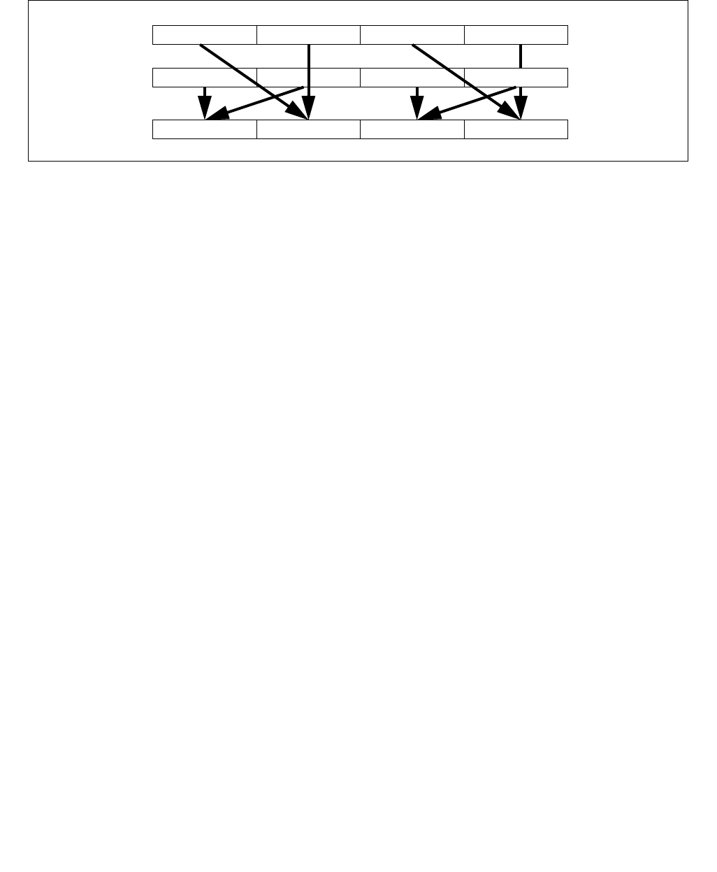
SHUFPD—Packed Interleave Shuffle of Pairs of Double-Precision Floating-Point Values
INSTRUCTION SET REFERENCE, M-U
4-618 Vol. 2B
128-bit Legacy SSE version: The second source can be an XMM register or an 128-bit memory location. The desti-
nation operand and the first source operand is the same and is an XMM register. The upper bits (MAX_VL-1:128) of
the corresponding ZMM register destination are unmodified. The select controls are the bit 1:0 of the imm8 byte,
imm8[7:2) are ignored.
Operation
VSHUFPD (EVEX encoded versions when SRC2 is a vector register)
(KL, VL) = (2, 128), (4, 256), (8, 512)
IF IMM0[0] = 0
THEN TMP_DEST[63:0] SRC1[63:0]
ELSE TMP_DEST[63:0] SRC1[127:64] FI;
IF IMM0[1] = 0
THEN TMP_DEST[127:64] SRC2[63:0]
ELSE TMP_DEST[127:64] SRC2[127:64] FI;
IF VL >= 256
IF IMM0[2] = 0
THEN TMP_DEST[191:128] SRC1[191:128]
ELSE TMP_DEST[191:128] SRC1[255:192] FI;
IF IMM0[3] = 0
THEN TMP_DEST[255:192] SRC2[191:128]
ELSE TMP_DEST[255:192] SRC2[255:192] FI;
FI;
IF VL >= 512
IF IMM0[4] = 0
THEN TMP_DEST[319:256] SRC1[319:256]
ELSE TMP_DEST[319:256] SRC1[383:320] FI;
IF IMM0[5] = 0
THEN TMP_DEST[383:320] SRC2[319:256]
ELSE TMP_DEST[383:320] SRC2[383:320] FI;
IF IMM0[6] = 0
THEN TMP_DEST[447:384] SRC1[447:384]
ELSE TMP_DEST[447:384] SRC1[511:448] FI;
IF IMM0[7] = 0
THEN TMP_DEST[511:448] SRC2[447:384]
ELSE TMP_DEST[511:448] SRC2[511:448] FI;
FI;
FOR j 0 TO KL-1
i j * 64
IF k1[j] OR *no writemask*
THEN DEST[i+63:i] TMP_DEST[i+63:i]
ELSE
Figure 4-25. 256-bit VSHUFPD Operation of Four Pairs of DP FP Values
Y2 or Y3 X2 or X3 Y0 or Y1 X0 or X1DEST
X3 X2
SRC1 X1 X0
Y3 Y2 Y1 Y0
SRC2

SHUFPD—Packed Interleave Shuffle of Pairs of Double-Precision Floating-Point Values
INSTRUCTION SET REFERENCE, M-U
Vol. 2B 4-619
IF *merging-masking* ; merging-masking
THEN *DEST[i+63:i] remains unchanged*
ELSE *zeroing-masking* ; zeroing-masking
DEST[i+63:i] 0
FI
FI;
ENDFOR
DEST[MAX_VL-1:VL] 0
VSHUFPD (EVEX encoded versions when SRC2 is memory)
(KL, VL) = (2, 128), (4, 256), (8, 512)
FOR j 0 TO KL-1
i j * 64
IF (EVEX.b = 1)
THEN TMP_SRC2[i+63:i] SRC2[63:0]
ELSE TMP_SRC2[i+63:i] SRC2[i+63:i]
FI;
ENDFOR;
IF IMM0[0] = 0
THEN TMP_DEST[63:0] SRC1[63:0]
ELSE TMP_DEST[63:0] SRC1[127:64] FI;
IF IMM0[1] = 0
THEN TMP_DEST[127:64] TMP_SRC2[63:0]
ELSE TMP_DEST[127:64] TMP_SRC2[127:64] FI;
IF VL >= 256
IF IMM0[2] = 0
THEN TMP_DEST[191:128] SRC1[191:128]
ELSE TMP_DEST[191:128] SRC1[255:192] FI;
IF IMM0[3] = 0
THEN TMP_DEST[255:192] TMP_SRC2[191:128]
ELSE TMP_DEST[255:192] TMP_SRC2[255:192] FI;
FI;
IF VL >= 512
IF IMM0[4] = 0
THEN TMP_DEST[319:256] SRC1[319:256]
ELSE TMP_DEST[319:256] SRC1[383:320] FI;
IF IMM0[5] = 0
THEN TMP_DEST[383:320] TMP_SRC2[319:256]
ELSE TMP_DEST[383:320] TMP_SRC2[383:320] FI;
IF IMM0[6] = 0
THEN TMP_DEST[447:384] SRC1[447:384]
ELSE TMP_DEST[447:384] SRC1[511:448] FI;
IF IMM0[7] = 0
THEN TMP_DEST[511:448] TMP_SRC2[447:384]
ELSE TMP_DEST[511:448] TMP_SRC2[511:448] FI;
FI;
FOR j 0 TO KL-1
i j * 64
IF k1[j] OR *no writemask*
THEN DEST[i+63:i] TMP_DEST[i+63:i]
ELSE
IF *merging-masking* ; merging-masking
THEN *DEST[i+63:i] remains unchanged*

SHUFPD—Packed Interleave Shuffle of Pairs of Double-Precision Floating-Point Values
INSTRUCTION SET REFERENCE, M-U
4-620 Vol. 2B
ELSE *zeroing-masking* ; zeroing-masking
DEST[i+63:i] 0
FI
FI;
ENDFOR
DEST[MAX_VL-1:VL] 0
VSHUFPD (VEX.256 encoded version)
IF IMM0[0] = 0
THEN DEST[63:0] SRC1[63:0]
ELSE DEST[63:0] SRC1[127:64] FI;
IF IMM0[1] = 0
THEN DEST[127:64] SRC2[63:0]
ELSE DEST[127:64] SRC2[127:64] FI;
IF IMM0[2] = 0
THEN DEST[191:128] SRC1[191:128]
ELSE DEST[191:128] SRC1[255:192] FI;
IF IMM0[3] = 0
THEN DEST[255:192] SRC2[191:128]
ELSE DEST[255:192] SRC2[255:192] FI;
DEST[MAX_VL-1:256] (Unmodified)
VSHUFPD (VEX.128 encoded version)
IF IMM0[0] = 0
THEN DEST[63:0] SRC1[63:0]
ELSE DEST[63:0] SRC1[127:64] FI;
IF IMM0[1] = 0
THEN DEST[127:64] SRC2[63:0]
ELSE DEST[127:64] SRC2[127:64] FI;
DEST[MAX_VL-1:128] 0
VSHUFPD (128-bit Legacy SSE version)
IF IMM0[0] = 0
THEN DEST[63:0] SRC1[63:0]
ELSE DEST[63:0] SRC1[127:64] FI;
IF IMM0[1] = 0
THEN DEST[127:64] SRC2[63:0]
ELSE DEST[127:64] SRC2[127:64] FI;
DEST[MAX_VL-1:128] (Unmodified)
Intel C/C++ Compiler Intrinsic Equivalent
VSHUFPD __m512d _mm512_shuffle_pd(__m512d a, __m512d b, int imm);
VSHUFPD __m512d _mm512_mask_shuffle_pd(__m512d s, __mmask8 k, __m512d a, __m512d b, int imm);
VSHUFPD __m512d _mm512_maskz_shuffle_pd( __mmask8 k, __m512d a, __m512d b, int imm);
VSHUFPD __m256d _mm256_shuffle_pd (__m256d a, __m256d b, const int select);
VSHUFPD __m256d _mm256_mask_shuffle_pd(__m256d s, __mmask8 k, __m256d a, __m256d b, int imm);
VSHUFPD __m256d _mm256_maskz_shuffle_pd( __mmask8 k, __m256d a, __m256d b, int imm);
SHUFPD __m128d _mm_shuffle_pd (__m128d a, __m128d b, const int select);
VSHUFPD __m128d _mm_mask_shuffle_pd(__m128d s, __mmask8 k, __m128d a, __m128d b, int imm);
VSHUFPD __m128d _mm_maskz_shuffle_pd( __mmask8 k, __m128d a, __m128d b, int imm);

SHUFPD—Packed Interleave Shuffle of Pairs of Double-Precision Floating-Point Values
INSTRUCTION SET REFERENCE, M-U
Vol. 2B 4-621
SIMD Floating-Point Exceptions
None
Other Exceptions
Non-EVEX-encoded instruction, see Exceptions Type 4.
EVEX-encoded instruction, see Exceptions Type E4NF.

SHUFPS—Packed Interleave Shuffle of Quadruplets of Single-Precision Floating-Point Values
INSTRUCTION SET REFERENCE, M-U
4-622 Vol. 2B
SHUFPS—Packed Interleave Shuffle of Quadruplets of Single-Precision Floating-Point Values
Instruction Operand Encoding
Description
Selects a single-precision floating-point value of an input quadruplet using a two-bit control and move to a desig-
nated element of the destination operand. Each 64-bit element-pair of a 128-bit lane of the destination operand is
interleaved between the corresponding lane of the first source operand and the second source operand at the gran-
ularity 128 bits. Each two bits in the imm8 byte, starting from bit 0, is the select control of the corresponding
element of a 128-bit lane of the destination to received the shuffled result of an input quadruplet. The two lower
elements of a 128-bit lane in the destination receives shuffle results from the quadruple of the first source operand.
The next two elements of the destination receives shuffle results from the quadruple of the second source operand.
EVEX encoded versions: The first source operand is a ZMM/YMM/XMM register. The second source operand can be
a ZMM/YMM/XMM register, a 512/256/128-bit memory location or a 512/256/128-bit vector broadcasted from a
32-bit memory location. The destination operand is a ZMM/YMM/XMM register updated according to the writemask.
Imm8[7:0] provides 4 select controls for each applicable 128-bit lane of the destination.
VEX.256 encoded version: The first source operand is a YMM register. The second source operand can be a YMM
register or a 256-bit memory location. The destination operand is a YMM register. Imm8[7:0] provides 4 select
controls for the high and low 128-bit of the destination.
VEX.128 encoded version: The first source operand is a XMM register. The second source operand can be a XMM
register or a 128-bit memory location. The destination operand is a XMM register. The upper bits (MAX_VL-1:128)
of the corresponding ZMM register destination are zeroed. Imm8[7:0] provides 4 select controls for each element
of the destination.
Opcode/
Instruction
Op /
En
64/32
bit Mode
Support
CPUID
Feature
Flag
Description
0F C6 /r ib
SHUFPS xmm1, xmm3/m128, imm8
RMI V/V SSE Select from quadruplet of single-precision floating-
point values in xmm1 and xmm2/m128 using imm8,
interleaved result pairs are stored in xmm1.
VEX.NDS.128.0F.WIG C6 /r ib
VSHUFPS xmm1, xmm2,
xmm3/m128, imm8
RVMI V/V AVX Select from quadruplet of single-precision floating-
point values in xmm1 and xmm2/m128 using imm8,
interleaved result pairs are stored in xmm1.
VEX.NDS.256.0F.WIG C6 /r ib
VSHUFPS ymm1, ymm2,
ymm3/m256, imm8
RVMI V/V AVX Select from quadruplet of single-precision floating-
point values in ymm2 and ymm3/m256 using imm8,
interleaved result pairs are stored in ymm1.
EVEX.NDS.128.0F.W0 C6 /r ib
VSHUFPS xmm1{k1}{z}, xmm2,
xmm3/m128/m32bcst, imm8
FV V/V AVX512VL
AVX512F
Select from quadruplet of single-precision floating-
point values in xmm1 and xmm2/m128 using imm8,
interleaved result pairs are stored in xmm1, subject to
writemask k1.
EVEX.NDS.256.0F.W0 C6 /r ib
VSHUFPS ymm1{k1}{z}, ymm2,
ymm3/m256/m32bcst, imm8
FV V/V AVX512VL
AVX512F
Select from quadruplet of single-precision floating-
point values in ymm2 and ymm3/m256 using imm8,
interleaved result pairs are stored in ymm1, subject to
writemask k1.
EVEX.NDS.512.0F.W0 C6 /r ib
VSHUFPS zmm1{k1}{z}, zmm2,
zmm3/m512/m32bcst, imm8
FV V/V AVX512F Select from quadruplet of single-precision floating-
point values in zmm2 and zmm3/m512 using imm8,
interleaved result pairs are stored in zmm1, subject to
writemask k1.
Op/En Operand 1 Operand 2 Operand 3 Operand 4
RMI ModRM:reg (r, w) ModRM:r/m (r) Imm8 NA
RVMI ModRM:reg (w) VEX.vvvv (r) ModRM:r/m (r) Imm8
FV ModRM:reg (w) EVEX.vvvv (r) ModRM:r/m (r) Imm8
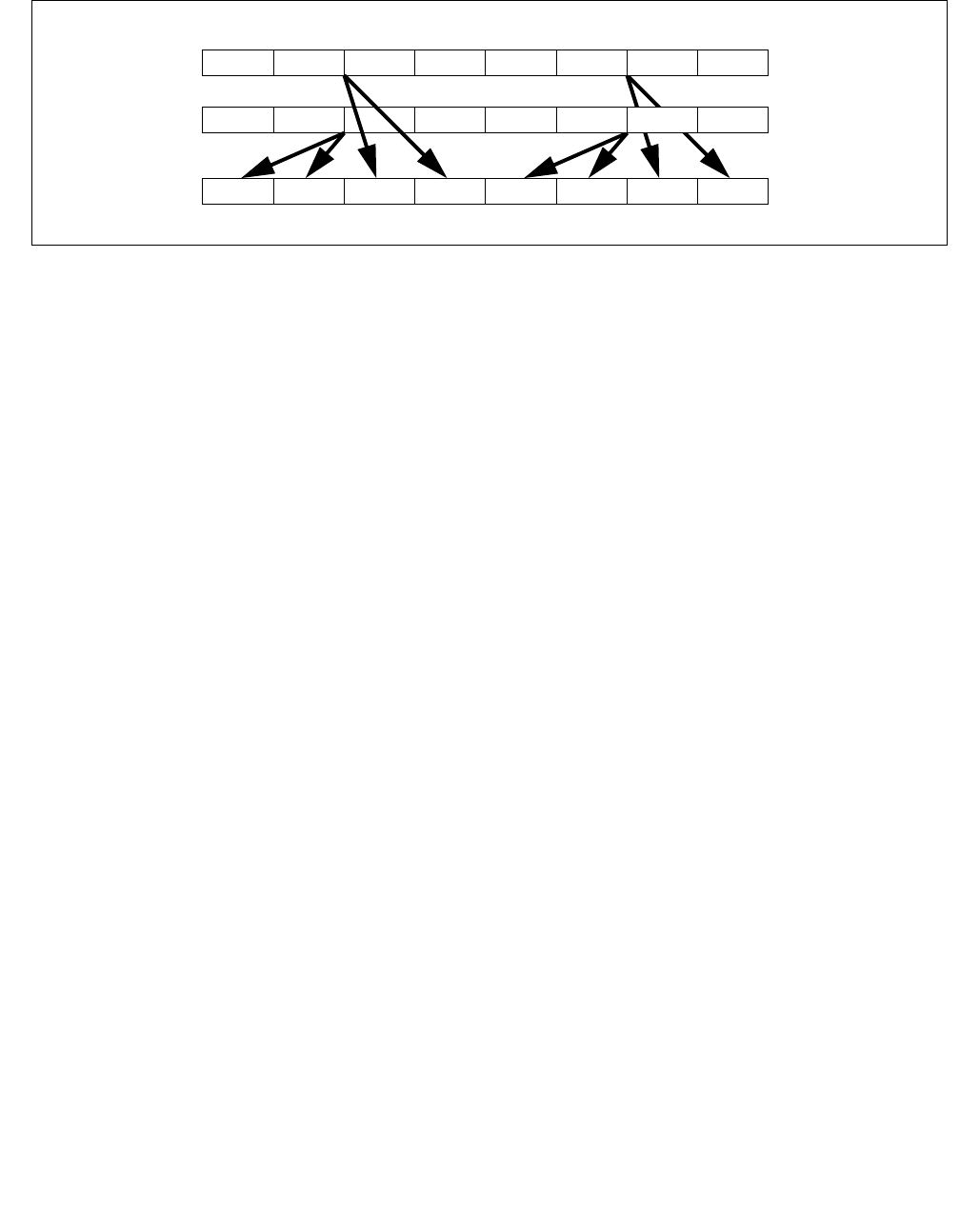
SHUFPS—Packed Interleave Shuffle of Quadruplets of Single-Precision Floating-Point Values
INSTRUCTION SET REFERENCE, M-U
Vol. 2B 4-623
128-bit Legacy SSE version: The source can be an XMM register or an 128-bit memory location. The destination is
not distinct from the first source XMM register and the upper bits (MAX_VL-1:128) of the corresponding ZMM
register destination are unmodified. Imm8[7:0] provides 4 select controls for each element of the destination.
Operation
Select4(SRC, control) {
CASE (control[1:0]) OF
0: TMP SRC[31:0];
1: TMP SRC[63:32];
2: TMP SRC[95:64];
3: TMP SRC[127:96];
ESAC;
RETURN TMP
}
VPSHUFPS (EVEX encoded versions when SRC2 is a vector register)
(KL, VL) = (4, 128), (8, 256), (16, 512)
TMP_DEST[31:0] Select4(SRC1[127:0], imm8[1:0]);
TMP_DEST[63:32] Select4(SRC1[127:0], imm8[3:2]);
TMP_DEST[95:64] Select4(SRC2[127:0], imm8[5:4]);
TMP_DEST[127:96] Select4(SRC2[127:0], imm8[7:6]);
IF VL >= 256
TMP_DEST[159:128] Select4(SRC1[255:128], imm8[1:0]);
TMP_DEST[191:160] Select4(SRC1[255:128], imm8[3:2]);
TMP_DEST[223:192] Select4(SRC2[255:128], imm8[5:4]);
TMP_DEST[255:224] Select4(SRC2[255:128], imm8[7:6]);
FI;
IF VL >= 512
TMP_DEST[287:256] Select4(SRC1[383:256], imm8[1:0]);
TMP_DEST[319:288] Select4(SRC1[383:256], imm8[3:2]);
TMP_DEST[351:320] Select4(SRC2[383:256], imm8[5:4]);
TMP_DEST[383:352] Select4(SRC2[383:256], imm8[7:6]);
TMP_DEST[415:384] Select4(SRC1[511:384], imm8[1:0]);
TMP_DEST[447:416] Select4(SRC1[511:384], imm8[3:2]);
TMP_DEST[479:448] Select4(SRC2[511:384], imm8[5:4]);
TMP_DEST[511:480] Select4(SRC2[511:384], imm8[7:6]);
FI;
FOR j 0 TO KL-1
Figure 4-26. 256-bit VSHUFPS Operation of Selection from Input Quadruplet and Pair-wise Interleaved Result
Y7 .. Y4 X7 .. X4
Y3 ..Y0
X3 .. X0
DEST
SRC1 X0
SRC2
X1X2X3X4X5X6X7
Y0Y1Y2Y3Y4Y5Y6Y7
X3 .. X0
Y7 .. Y4 X7 .. X4
Y3 ..Y0

SHUFPS—Packed Interleave Shuffle of Quadruplets of Single-Precision Floating-Point Values
INSTRUCTION SET REFERENCE, M-U
4-624 Vol. 2B
i j * 32
IF k1[j] OR *no writemask*
THEN DEST[i+31:i] TMP_DEST[i+31:i]
ELSE
IF *merging-masking* ; merging-masking
THEN *DEST[i+31:i] remains unchanged*
ELSE *zeroing-masking* ; zeroing-masking
DEST[i+31:i] 0
FI
FI;
ENDFOR
DEST[MAX_VL-1:VL] 0
VPSHUFPS (EVEX encoded versions when SRC2 is memory)
(KL, VL) = (4, 128), (8, 256), (16, 512)
FOR j 0 TO KL-1
i j * 32
IF (EVEX.b = 1)
THEN TMP_SRC2[i+31:i] SRC2[31:0]
ELSE TMP_SRC2[i+31:i] SRC2[i+31:i]
FI;
ENDFOR;
TMP_DEST[31:0] Select4(SRC1[127:0], imm8[1:0]);
TMP_DEST[63:32] Select4(SRC1[127:0], imm8[3:2]);
TMP_DEST[95:64] Select4(TMP_SRC2[127:0], imm8[5:4]);
TMP_DEST[127:96] Select4(TMP_SRC2[127:0], imm8[7:6]);
IF VL >= 256
TMP_DEST[159:128] Select4(SRC1[255:128], imm8[1:0]);
TMP_DEST[191:160] Select4(SRC1[255:128], imm8[3:2]);
TMP_DEST[223:192] Select4(TMP_SRC2[255:128], imm8[5:4]);
TMP_DEST[255:224] Select4(TMP_SRC2[255:128], imm8[7:6]);
FI;
IF VL >= 512
TMP_DEST[287:256] Select4(SRC1[383:256], imm8[1:0]);
TMP_DEST[319:288] Select4(SRC1[383:256], imm8[3:2]);
TMP_DEST[351:320] Select4(TMP_SRC2[383:256], imm8[5:4]);
TMP_DEST[383:352] Select4(TMP_SRC2[383:256], imm8[7:6]);
TMP_DEST[415:384] Select4(SRC1[511:384], imm8[1:0]);
TMP_DEST[447:416] Select4(SRC1[511:384], imm8[3:2]);
TMP_DEST[479:448] Select4(TMP_SRC2[511:384], imm8[5:4]);
TMP_DEST[511:480] Select4(TMP_SRC2[511:384], imm8[7:6]);
FI;
FOR j 0 TO KL-1
i j * 32
IF k1[j] OR *no writemask*
THEN DEST[i+31:i] TMP_DEST[i+31:i]
ELSE
IF *merging-masking* ; merging-masking
THEN *DEST[i+31:i] remains unchanged*
ELSE *zeroing-masking* ; zeroing-masking
DEST[i+31:i] 0
FI
FI;
ENDFOR

SHUFPS—Packed Interleave Shuffle of Quadruplets of Single-Precision Floating-Point Values
INSTRUCTION SET REFERENCE, M-U
Vol. 2B 4-625
DEST[MAX_VL-1:VL] 0
VSHUFPS (VEX.256 encoded version)
DEST[31:0] Select4(SRC1[127:0], imm8[1:0]);
DEST[63:32] Select4(SRC1[127:0], imm8[3:2]);
DEST[95:64] Select4(SRC2[127:0], imm8[5:4]);
DEST[127:96] Select4(SRC2[127:0], imm8[7:6]);
DEST[159:128] Select4(SRC1[255:128], imm8[1:0]);
DEST[191:160] Select4(SRC1[255:128], imm8[3:2]);
DEST[223:192] Select4(SRC2[255:128], imm8[5:4]);
DEST[255:224] Select4(SRC2[255:128], imm8[7:6]);
DEST[MAX_VL-1:256] 0
VSHUFPS (VEX.128 encoded version)
DEST[31:0] Select4(SRC1[127:0], imm8[1:0]);
DEST[63:32] Select4(SRC1[127:0], imm8[3:2]);
DEST[95:64] Select4(SRC2[127:0], imm8[5:4]);
DEST[127:96] Select4(SRC2[127:0], imm8[7:6]);
DEST[MAX_VL-1:128] 0
SHUFPS (128-bit Legacy SSE version)
DEST[31:0] Select4(SRC1[127:0], imm8[1:0]);
DEST[63:32] Select4(SRC1[127:0], imm8[3:2]);
DEST[95:64] Select4(SRC2[127:0], imm8[5:4]);
DEST[127:96] Select4(SRC2[127:0], imm8[7:6]);
DEST[MAX_VL-1:128] (Unmodified)
Intel C/C++ Compiler Intrinsic Equivalent
VSHUFPS __m512 _mm512_shuffle_ps(__m512 a, __m512 b, int imm);
VSHUFPS __m512 _mm512_mask_shuffle_ps(__m512 s, __mmask16 k, __m512 a, __m512 b, int imm);
VSHUFPS __m512 _mm512_maskz_shuffle_ps(__mmask16 k, __m512 a, __m512 b, int imm);
VSHUFPS __m256 _mm256_shuffle_ps (__m256 a, __m256 b, const int select);
VSHUFPS __m256 _mm256_mask_shuffle_ps(__m256 s, __mmask8 k, __m256 a, __m256 b, int imm);
VSHUFPS __m256 _mm256_maskz_shuffle_ps(__mmask8 k, __m256 a, __m256 b, int imm);
SHUFPS __m128 _mm_shuffle_ps (__m128 a, __m128 b, const int select);
VSHUFPS __m128 _mm_mask_shuffle_ps(__m128 s, __mmask8 k, __m128 a, __m128 b, int imm);
VSHUFPS __m128 _mm_maskz_shuffle_ps(__mmask8 k, __m128 a, __m128 b, int imm);
SIMD Floating-Point Exceptions
None
Other Exceptions
Non-EVEX-encoded instruction, see Exceptions Type 4.
EVEX-encoded instruction, see Exceptions Type E4NF.

SIDT—Store Interrupt Descriptor Table Register
INSTRUCTION SET REFERENCE, M-U
4-626 Vol. 2B
SIDT—Store Interrupt Descriptor Table Register
Instruction Operand Encoding
Description
Stores the content the interrupt descriptor table register (IDTR) in the destination operand. The destination
operand specifies a 6-byte memory location.
In non-64-bit modes, if the operand-size attribute is 32 bits, the 16-bit limit field of the register is stored in the low
2 bytes of the memory location and the 32-bit base address is stored in the high 4 bytes. If the operand-size attri-
bute is 16 bits, the limit is stored in the low 2 bytes and the 24-bit base address is stored in the third, fourth, and
fifth byte, with the sixth byte filled with 0s.
In 64-bit mode, the operand size fixed at 8+2 bytes. The instruction stores 8-byte base and 2-byte limit values.
SIDT is only useful in operating-system software; however, it can be used in application programs without causing
an exception to be generated if CR4.UMIP = 0. See “LGDT/LIDT—Load Global/Interrupt Descriptor Table Register”
in Chapter 3, Intel® 64 and IA-32 Architectures Software Developer’s Manual, Volume 2A, for information on
loading the GDTR and IDTR.
IA-32 Architecture Compatibility
The 16-bit form of SIDT is compatible with the Intel 286 processor if the upper 8 bits are not referenced. The Intel
286 processor fills these bits with 1s; processor generations later than the Intel 286 processor fill these bits with
0s.
Operation
IF instruction is SIDT
THEN
IF OperandSize = 16
THEN
DEST[0:15] ← IDTR(Limit);
DEST[16:39] ← IDTR(Base); (* 24 bits of base address stored; *)
DEST[40:47] ← 0;
ELSE IF (32-bit Operand Size)
DEST[0:15] ← IDTR(Limit);
DEST[16:47] ← IDTR(Base); FI; (* Full 32-bit base address stored *)
ELSE (* 64-bit Operand Size *)
DEST[0:15] ← IDTR(Limit);
DEST[16:79] ← IDTR(Base); (* Full 64-bit base address stored *)
FI;
FI;
Flags Affected
None.
Opcode* Instruction Op/
En
64-Bit
Mode
Compat/
Leg Mode
Description
0F 01 /1 SIDT mM Valid Valid Store IDTR to m.
Op/En Operand 1 Operand 2 Operand 3 Operand 4
MModRM:r/m (w) NA NA NA

SIDT—Store Interrupt Descriptor Table Register
INSTRUCTION SET REFERENCE, M-U
Vol. 2B 4-627
Protected Mode Exceptions
#GP(0) If the destination is located in a non-writable segment.
If a memory operand effective address is outside the CS, DS, ES, FS, or GS segment limit.
If the DS, ES, FS, or GS register is used to access memory and it contains a NULL segment
selector.
If CR4.UMIP = 1 and CPL > 0.
#SS(0) If a memory operand effective address is outside the SS segment limit.
#PF(fault-code) If a page fault occurs.
#AC(0) If alignment checking is enabled and an unaligned memory reference is made while CPL = 3.
#UD If the LOCK prefix is used.
Real-Address Mode Exceptions
#GP If a memory operand effective address is outside the CS, DS, ES, FS, or GS segment limit.
#SS If a memory operand effective address is outside the SS segment limit.
#UD If the LOCK prefix is used.
Virtual-8086 Mode Exceptions
#GP(0) If a memory operand effective address is outside the CS, DS, ES, FS, or GS segment limit.
If CR4.UMIP = 1.
#SS(0) If a memory operand effective address is outside the SS segment limit.
#PF(fault-code) If a page fault occurs.
#AC(0) If alignment checking is enabled and an unaligned memory reference is made.
#UD If the LOCK prefix is used.
Compatibility Mode Exceptions
Same exceptions as in protected mode.
64-Bit Mode Exceptions
#SS(0) If a memory address referencing the SS segment is in a non-canonical form.
#UD If the destination operand is a register.
If the LOCK prefix is used.
#GP(0) If the memory address is in a non-canonical form.
If CR4.UMIP = 1 and CPL > 0.
#PF(fault-code) If a page fault occurs.
#AC(0) If alignment checking is enabled and an unaligned memory reference is made while CPL = 3.

SLDT—Store Local Descriptor Table Register
INSTRUCTION SET REFERENCE, M-U
4-628 Vol. 2B
SLDT—Store Local Descriptor Table Register
Instruction Operand Encoding
Description
Stores the segment selector from the local descriptor table register (LDTR) in the destination operand. The desti-
nation operand can be a general-purpose register or a memory location. The segment selector stored with this
instruction points to the segment descriptor (located in the GDT) for the current LDT. This instruction can only be
executed in protected mode.
Outside IA-32e mode, when the destination operand is a 32-bit register, the 16-bit segment selector is copied into
the low-order 16 bits of the register. The high-order 16 bits of the register are cleared for the Pentium 4, Intel Xeon,
and P6 family processors. They are undefined for Pentium, Intel486, and Intel386 processors. When the destina-
tion operand is a memory location, the segment selector is written to memory as a 16-bit quantity, regardless of
the operand size.
In compatibility mode, when the destination operand is a 32-bit register, the 16-bit segment selector is copied into
the low-order 16 bits of the register. The high-order 16 bits of the register are cleared. When the destination
operand is a memory location, the segment selector is written to memory as a 16-bit quantity, regardless of the
operand size.
In 64-bit mode, using a REX prefix in the form of REX.R permits access to additional registers (R8-R15). The
behavior of SLDT with a 64-bit register is to zero-extend the 16-bit selector and store it in the register. If the desti-
nation is memory and operand size is 64, SLDT will write the 16-bit selector to memory as a 16-bit quantity,
regardless of the operand size.
Operation
DEST ← LDTR(SegmentSelector);
Flags Affected
None.
Protected Mode Exceptions
#GP(0) If the destination is located in a non-writable segment.
If a memory operand effective address is outside the CS, DS, ES, FS, or GS segment limit.
If the DS, ES, FS, or GS register is used to access memory and it contains a NULL segment
selector.
If CR4.UMIP = 1 and CPL > 0.
#SS(0) If a memory operand effective address is outside the SS segment limit.
#PF(fault-code) If a page fault occurs.
#AC(0) If alignment checking is enabled and an unaligned memory reference is made while CPL = 3.
#UD If the LOCK prefix is used.
Opcode* Instruction Op/
En
64-Bit
Mode
Compat/
Leg Mode
Description
0F 00 /0 SLDT r/m16 M Valid Valid Stores segment selector from LDTR in r/m16.
REX.W + 0F 00 /0 SLDT r64/m16 M Valid Valid Stores segment selector from LDTR in
r64/m16.
Op/En Operand 1 Operand 2 Operand 3 Operand 4
MModRM:r/m (w) NA NA NA

SLDT—Store Local Descriptor Table Register
INSTRUCTION SET REFERENCE, M-U
Vol. 2B 4-629
Real-Address Mode Exceptions
#UD The SLDT instruction is not recognized in real-address mode.
Virtual-8086 Mode Exceptions
#UD The SLDT instruction is not recognized in virtual-8086 mode.
Compatibility Mode Exceptions
Same exceptions as in protected mode.
64-Bit Mode Exceptions
#SS(0) If a memory address referencing the SS segment is in a non-canonical form.
#GP(0) If the memory address is in a non-canonical form.
If CR4.UMIP = 1 and CPL > 0.
#PF(fault-code) If a page fault occurs.
#AC(0) If alignment checking is enabled and an unaligned memory reference is made while CPL = 3.
#UD If the LOCK prefix is used.

SMSW—Store Machine Status Word
INSTRUCTION SET REFERENCE, M-U
4-630 Vol. 2B
SMSW—Store Machine Status Word
Instruction Operand Encoding
Description
Stores the machine status word (bits 0 through 15 of control register CR0) into the destination operand. The desti-
nation operand can be a general-purpose register or a memory location.
In non-64-bit modes, when the destination operand is a 32-bit register, the low-order 16 bits of register CR0 are
copied into the low-order 16 bits of the register and the high-order 16 bits are undefined. When the destination
operand is a memory location, the low-order 16 bits of register CR0 are written to memory as a 16-bit quantity,
regardless of the operand size.
In 64-bit mode, the behavior of the SMSW instruction is defined by the following examples:
•SMSW r16 operand size 16, store CR0[15:0] in r16
•SMSW r32 operand size 32, zero-extend CR0[31:0], and store in r32
•SMSW r64 operand size 64, zero-extend CR0[63:0], and store in r64
•SMSW m16 operand size 16, store CR0[15:0] in m16
•SMSW m16 operand size 32, store CR0[15:0] in m16 (not m32)
•SMSW m16 operands size 64, store CR0[15:0] in m16 (not m64)
SMSW is only useful in operating-system software. However, it is not a privileged instruction and can be used in
application programs if CR4.UMIP = 0. It is provided for compatibility with the Intel 286 processor. Programs and
procedures intended to run on IA-32 and Intel 64 processors beginning with the Intel386 processors should use the
MOV CR instruction to load the machine status word.
See “Changes to Instruction Behavior in VMX Non-Root Operation” in Chapter 25 of the Intel® 64 and IA-32 Archi-
tectures Software Developer’s Manual, Volume 3C, for more information about the behavior of this instruction in
VMX non-root operation.
Operation
DEST ← CR0[15:0];
(* Machine status word *)
Flags Affected
None.
Opcode* Instruction Op/
En
64-Bit
Mode
Compat/
Leg Mode
Description
0F 01 /4 SMSW r/m16 M Valid Valid Store machine status word to r/m16.
0F 01 /4 SMSW r32/m16 M Valid Valid Store machine status word in low-order 16
bits of r32/m16; high-order 16 bits of r32 are
undefined.
REX.W + 0F 01 /4 SMSW r64/m16 M Valid Valid Store machine status word in low-order 16
bits of r64/m16; high-order 16 bits of r32 are
undefined.
Op/En Operand 1 Operand 2 Operand 3 Operand 4
MModRM:r/m (w) NA NA NA

SMSW—Store Machine Status Word
INSTRUCTION SET REFERENCE, M-U
Vol. 2B 4-631
Protected Mode Exceptions
#GP(0) If the destination is located in a non-writable segment.
If a memory operand effective address is outside the CS, DS, ES, FS, or GS segment limit.
If the DS, ES, FS, or GS register is used to access memory and it contains a NULL segment
selector.
If CR4.UMIP = 1 and CPL > 0.
#SS(0) If a memory operand effective address is outside the SS segment limit.
#PF(fault-code) If a page fault occurs.
#AC(0) If alignment checking is enabled and an unaligned memory reference is made while CPL = 3.
#UD If the LOCK prefix is used.
Real-Address Mode Exceptions
#GP If a memory operand effective address is outside the CS, DS, ES, FS, or GS segment limit.
#SS(0) If a memory operand effective address is outside the SS segment limit.
#UD If the LOCK prefix is used.
Virtual-8086 Mode Exceptions
#GP(0) If a memory operand effective address is outside the CS, DS, ES, FS, or GS segment limit.
If CR4.UMIP = 1.
#SS(0) If a memory operand effective address is outside the SS segment limit.
#PF(fault-code) If a page fault occurs.
#AC(0) If alignment checking is enabled and an unaligned memory reference is made.
#UD If the LOCK prefix is used.
Compatibility Mode Exceptions
Same exceptions as in protected mode.
64-Bit Mode Exceptions
#SS(0) If a memory address referencing the SS segment is in a non-canonical form.
#GP(0) If the memory address is in a non-canonical form.
If CR4.UMIP = 1 and CPL > 0.
#PF(fault-code) If a page fault occurs.
#AC(0) If alignment checking is enabled and an unaligned memory reference is made while CPL = 3.
#UD If the LOCK prefix is used.

SQRTPD—Square Root of Double-Precision Floating-Point Values
INSTRUCTION SET REFERENCE, M-U
4-632 Vol. 2B
SQRTPD—Square Root of Double-Precision Floating-Point Values
Instruction Operand Encoding
Description
Performs a SIMD computation of the square roots of the two, four or eight packed double-precision floating-point
values in the source operand (the second operand) stores the packed double-precision floating-point results in the
destination operand (the first operand).
EVEX encoded versions: The source operand is a ZMM/YMM/XMM register, a 512/256/128-bit memory location, or
a 512/256/128-bit vector broadcasted from a 64-bit memory location. The destination operand is a
ZMM/YMM/XMM register updated according to the writemask.
VEX.256 encoded version: The source operand is a YMM register or a 256-bit memory location. The destination
operand is a YMM register. The upper bits (MAX_VL-1:256) of the corresponding ZMM register destination are
zeroed.
VEX.128 encoded version: the source operand second source operand or a 128-bit memory location. The destina-
tion operand is an XMM register. The upper bits (MAX_VL-1:128) of the corresponding ZMM register destination are
zeroed.
128-bit Legacy SSE version: The second source can be an XMM register or 128-bit memory location. The destina-
tion is not distinct from the first source XMM register and the upper bits (MAX_VL-1:128) of the corresponding ZMM
register destination are unmodified.
Note: VEX.vvvv and EVEX.vvvv are reserved and must be 1111b otherwise instructions will #UD.
Opcode/
Instruction
Op /
En
64/32
bit Mode
Support
CPUID
Feature
Flag
Description
66 0F 51 /r
SQRTPD xmm1, xmm2/m128
RM V/V SSE2 Computes Square Roots of the packed double-precision
floating-point values in xmm2/m128 and stores the result
in xmm1.
VEX.128.66.0F.WIG 51 /r
VSQRTPD xmm1, xmm2/m128
RM V/V AVX Computes Square Roots of the packed double-precision
floating-point values in xmm2/m128 and stores the result
in xmm1.
VEX.256.66.0F.WIG 51 /r
VSQRTPD ymm1, ymm2/m256
RM V/V AVX Computes Square Roots of the packed double-precision
floating-point values in ymm2/m256 and stores the result
in ymm1.
EVEX.128.66.0F.W1 51 /r
VSQRTPD xmm1 {k1}{z},
xmm2/m128/m32bcst
FV V/V AVX512VL
AVX512F
Computes Square Roots of the packed double-precision
floating-point values in xmm2/m128/m64bcst and stores
the result in xmm1 subject to writemask k1.
EVEX.256.66.0F.W1 51 /r
VSQRTPD ymm1 {k1}{z},
ymm2/m256/m32bcst
FV V/V AVX512VL
AVX512F
Computes Square Roots of the packed double-precision
floating-point values in ymm2/m256/m64bcst and stores
the result in ymm1 subject to writemask k1.
EVEX.512.66.0F.W1 51 /r
VSQRTPD zmm1 {k1}{z},
zmm2/m512/m64bcst{er}
FV V/V AVX512F Computes Square Roots of the packed double-precision
floating-point values in zmm2/m512/m64bcst and stores
the result in zmm1 subject to writemask k1.
Op/En Operand 1 Operand 2 Operand 3 Operand 4
RM ModRM:reg (w) ModRM:r/m (r) NA NA
FV ModRM:reg (w) ModRM:r/m (r) NA NA

SQRTPD—Square Root of Double-Precision Floating-Point Values
INSTRUCTION SET REFERENCE, M-U
Vol. 2B 4-633
Operation
VSQRTPD (EVEX encoded versions)
(KL, VL) = (2, 128), (4, 256), (8, 512)
IF (VL = 512) AND (EVEX.b = 1) AND (SRC *is register*)
THEN
SET_RM(EVEX.RC);
ELSE
SET_RM(MXCSR.RM);
FI;
FOR j 0 TO KL-1
i j * 64
IF k1[j] OR *no writemask* THEN
IF (EVEX.b = 1) AND (SRC *is memory*)
THEN DEST[i+63:i] SQRT(SRC[63:0])
ELSE DEST[i+63:i] SQRT(SRC[i+63:i])
FI;
ELSE
IF *merging-masking* ; merging-masking
THEN *DEST[i+63:i] remains unchanged*
ELSE ; zeroing-masking
DEST[i+63:i] 0
FI
FI;
ENDFOR
DEST[MAX_VL-1:VL] 0
VSQRTPD (VEX.256 encoded version)
DEST[63:0] SQRT(SRC[63:0])
DEST[127:64] SQRT(SRC[127:64])
DEST[191:128] SQRT(SRC[191:128])
DEST[255:192] SQRT(SRC[255:192])
DEST[MAX_VL-1:256] 0
.
VSQRTPD (VEX.128 encoded version)
DEST[63:0] SQRT(SRC[63:0])
DEST[127:64] SQRT(SRC[127:64])
DEST[MAX_VL-1:128] 0
SQRTPD (128-bit Legacy SSE version)
DEST[63:0] SQRT(SRC[63:0])
DEST[127:64] SQRT(SRC[127:64])
DEST[MAX_VL-1:128] (Unmodified)
Intel C/C++ Compiler Intrinsic Equivalent
VSQRTPD __m512d _mm512_sqrt_round_pd(__m512d a, int r);
VSQRTPD __m512d _mm512_mask_sqrt_round_pd(__m512d s, __mmask8 k, __m512d a, int r);
VSQRTPD __m512d _mm512_maskz_sqrt_round_pd( __mmask8 k, __m512d a, int r);
VSQRTPD __m256d _mm256_sqrt_pd (__m256d a);
VSQRTPD __m256d _mm256_mask_sqrt_pd(__m256d s, __mmask8 k, __m256d a, int r);
VSQRTPD __m256d _mm256_maskz_sqrt_pd( __mmask8 k, __m256d a, int r);
SQRTPD __m128d _mm_sqrt_pd (__m128d a);
VSQRTPD __m128d _mm_mask_sqrt_pd(__m128d s, __mmask8 k, __m128d a, int r);
VSQRTPD __m128d _mm_maskz_sqrt_pd( __mmask8 k, __m128d a, int r);

SQRTPD—Square Root of Double-Precision Floating-Point Values
INSTRUCTION SET REFERENCE, M-U
4-634 Vol. 2B
SIMD Floating-Point Exceptions
Invalid, Precision, Denormal
Other Exceptions
Non-EVEX-encoded instruction, see Exceptions Type 2; additionally
#UD If VEX.vvvv != 1111B.
EVEX-encoded instruction, see Exceptions Type E2.
#UD If EVEX.vvvv != 1111B.

SQRTPS—Square Root of Single-Precision Floating-Point Values
INSTRUCTION SET REFERENCE, M-U
Vol. 2B 4-635
SQRTPS—Square Root of Single-Precision Floating-Point Values
Instruction Operand Encoding
Description
Performs a SIMD computation of the square roots of the four, eight or sixteen packed single-precision floating-point
values in the source operand (second operand) stores the packed single-precision floating-point results in the
destination operand.
EVEX.512 encoded versions: The source operand is a ZMM/YMM/XMM register, a 512/256/128-bit memory location
or a 512/256/128-bit vector broadcasted from a 32-bit memory location. The destination operand is a
ZMM/YMM/XMM register updated according to the writemask.
VEX.256 encoded version: The source operand is a YMM register or a 256-bit memory location. The destination
operand is a YMM register. The upper bits (MAX_VL-1:256) of the corresponding ZMM register destination are
zeroed.
VEX.128 encoded version: the source operand second source operand or a 128-bit memory location. The destina-
tion operand is an XMM register. The upper bits (MAX_VL-1:128) of the corresponding ZMM register destination are
zeroed.
128-bit Legacy SSE version: The second source can be an XMM register or 128-bit memory location. The destina-
tion is not distinct from the first source XMM register and the upper bits (MAX_VL-1:128) of the corresponding ZMM
register destination are unmodified.
Note: VEX.vvvv and EVEX.vvvv are reserved and must be 1111b otherwise instructions will #UD.
Opcode/
Instruction
Op /
En
64/32
bit Mode
Support
CPUID
Feature
Flag
Description
0F 51 /r
SQRTPS xmm1, xmm2/m128
RM V/V SSE Computes Square Roots of the packed single-precision
floating-point values in xmm2/m128 and stores the result in
xmm1.
VEX.128.0F.WIG 51 /r
VSQRTPS xmm1, xmm2/m128
RM V/V AVX Computes Square Roots of the packed single-precision
floating-point values in xmm2/m128 and stores the result in
xmm1.
VEX.256.0F.WIG 51/r
VSQRTPS ymm1, ymm2/m256
RM V/V AVX Computes Square Roots of the packed single-precision
floating-point values in ymm2/m256 and stores the result in
ymm1.
EVEX.128.0F.W0 51 /r
VSQRTPS xmm1 {k1}{z},
xmm2/m128/m32bcst
FV V/V AVX512VL
AVX512F
Computes Square Roots of the packed single-precision
floating-point values in xmm2/m128/m32bcst and stores
the result in xmm1 subject to writemask k1.
EVEX.256.0F.W0 51 /r
VSQRTPS ymm1 {k1}{z},
ymm2/m256/m32bcst
FV V/V AVX512VL
AVX512F
Computes Square Roots of the packed single-precision
floating-point values in ymm2/m256/m32bcst and stores
the result in ymm1 subject to writemask k1.
EVEX.512.0F.W0 51/r
VSQRTPS zmm1 {k1}{z},
zmm2/m512/m32bcst{er}
FV V/V AVX512F Computes Square Roots of the packed single-precision
floating-point values in zmm2/m512/m32bcst and stores
the result in zmm1 subject to writemask k1.
Op/En Operand 1 Operand 2 Operand 3 Operand 4
RM ModRM:reg (w) ModRM:r/m (r) NA NA
FV ModRM:reg (w) ModRM:r/m (r) NA NA

SQRTPS—Square Root of Single-Precision Floating-Point Values
INSTRUCTION SET REFERENCE, M-U
4-636 Vol. 2B
Operation
VSQRTPS (EVEX encoded versions)
(KL, VL) = (4, 128), (8, 256), (16, 512)
IF (VL = 512) AND (EVEX.b = 1) AND (SRC *is register*)
THEN
SET_RM(EVEX.RC);
ELSE
SET_RM(MXCSR.RM);
FI;
FOR j 0 TO KL-1
i j * 32
IF k1[j] OR *no writemask* THEN
IF (EVEX.b = 1) AND (SRC *is memory*)
THEN DEST[i+31:i] SQRT(SRC[31:0])
ELSE DEST[i+31:i] SQRT(SRC[i+31:i])
FI;
ELSE
IF *merging-masking* ; merging-masking
THEN *DEST[i+31:i] remains unchanged*
ELSE ; zeroing-masking
DEST[i+31:i] 0
FI
FI;
ENDFOR
DEST[MAX_VL-1:VL] 0
VSQRTPS (VEX.256 encoded version)
DEST[31:0] SQRT(SRC[31:0])
DEST[63:32] SQRT(SRC[63:32])
DEST[95:64] SQRT(SRC[95:64])
DEST[127:96] SQRT(SRC[127:96])
DEST[159:128] SQRT(SRC[159:128])
DEST[191:160] SQRT(SRC[191:160])
DEST[223:192] SQRT(SRC[223:192])
DEST[255:224] SQRT(SRC[255:224])
VSQRTPS (VEX.128 encoded version)
DEST[31:0] SQRT(SRC[31:0])
DEST[63:32] SQRT(SRC[63:32])
DEST[95:64] SQRT(SRC[95:64])
DEST[127:96] SQRT(SRC[127:96])
DEST[MAX_VL-1:128] 0
SQRTPS (128-bit Legacy SSE version)
DEST[31:0] SQRT(SRC[31:0])
DEST[63:32] SQRT(SRC[63:32])
DEST[95:64] SQRT(SRC[95:64])
DEST[127:96] SQRT(SRC[127:96])
DEST[MAX_VL-1:128] (Unmodified)

SQRTPS—Square Root of Single-Precision Floating-Point Values
INSTRUCTION SET REFERENCE, M-U
Vol. 2B 4-637
Intel C/C++ Compiler Intrinsic Equivalent
VSQRTPS __m512 _mm512_sqrt_round_ps(__m512 a, int r);
VSQRTPS __m512 _mm512_mask_sqrt_round_ps(__m512 s, __mmask16 k, __m512 a, int r);
VSQRTPS __m512 _mm512_maskz_sqrt_round_ps( __mmask16 k, __m512 a, int r);
VSQRTPS __m256 _mm256_sqrt_ps (__m256 a);
VSQRTPS __m256 _mm256_mask_sqrt_ps(__m256 s, __mmask8 k, __m256 a, int r);
VSQRTPS __m256 _mm256_maskz_sqrt_ps( __mmask8 k, __m256 a, int r);
SQRTPS __m128 _mm_sqrt_ps (__m128 a);
VSQRTPS __m128 _mm_mask_sqrt_ps(__m128 s, __mmask8 k, __m128 a, int r);
VSQRTPS __m128 _mm_maskz_sqrt_ps( __mmask8 k, __m128 a, int r);
SIMD Floating-Point Exceptions
Invalid, Precision, Denormal
Other Exceptions
Non-EVEX-encoded instruction, see Exceptions Type 2; additionally
#UD If VEX.vvvv != 1111B.
EVEX-encoded instruction, see Exceptions Type E2.
#UD If EVEX.vvvv != 1111B.

SQRTSD—Compute Square Root of Scalar Double-Precision Floating-Point Value
INSTRUCTION SET REFERENCE, M-U
4-638 Vol. 2B
SQRTSD—Compute Square Root of Scalar Double-Precision Floating-Point Value
Instruction Operand Encoding
Description
Computes the square root of the low double-precision floating-point value in the second source operand and stores
the double-precision floating-point result in the destination operand. The second source operand can be an XMM
register or a 64-bit memory location. The first source and destination operands are XMM registers.
128-bit Legacy SSE version: The first source operand and the destination operand are the same. The quadword at
bits 127:64 of the destination operand remains unchanged. Bits (MAX_VL-1:64) of the corresponding destination
register remain unchanged.
VEX.128 and EVEX encoded versions: Bits 127:64 of the destination operand are copied from the corresponding
bits of the first source operand. Bits (MAX_VL-1:128) of the destination register are zeroed.
EVEX encoded version: The low quadword element of the destination operand is updated according to the
writemask.
Software should ensure VSQRTSD is encoded with VEX.L=0. Encoding VSQRTSD with VEX.L=1 may encounter
unpredictable behavior across different processor generations.
Opcode/
Instruction
Op /
En
64/32
bit Mode
Support
CPUID
Feature
Flag
Description
F2 0F 51/r
SQRTSD xmm1,xmm2/m64
RM V/V SSE2 Computes square root of the low double-precision floating-
point value in xmm2/m64 and stores the results in xmm1.
VEX.NDS.128.F2.0F.WIG 51/r
VSQRTSD xmm1,xmm2,
xmm3/m64
RVM V/V AVX Computes square root of the low double-precision floating-
point value in xmm3/m64 and stores the results in xmm1.
Also, upper double-precision floating-point value
(bits[127:64]) from xmm2 is copied to xmm1[127:64].
EVEX.NDS.LIG.F2.0F.W1 51/r
VSQRTSD xmm1 {k1}{z}, xmm2,
xmm3/m64{er}
T1S V/V AVX512F Computes square root of the low double-precision floating-
point value in xmm3/m64 and stores the results in xmm1
under writemask k1. Also, upper double-precision floating-
point value (bits[127:64]) from xmm2 is copied to
xmm1[127:64].
Op/En Operand 1 Operand 2 Operand 3 Operand 4
RM ModRM:reg (w) ModRM:r/m (r) NA NA
RVM ModRM:reg (w) VEX.vvvv (r) ModRM:r/m (r) NA
T1S ModRM:reg (w) EVEX.vvvv (r) ModRM:r/m (r) NA

SQRTSD—Compute Square Root of Scalar Double-Precision Floating-Point Value
INSTRUCTION SET REFERENCE, M-U
Vol. 2B 4-639
Operation
VSQRTSD (EVEX encoded version)
IF (EVEX.b = 1) AND (SRC2 *is register*)
THEN
SET_RM(EVEX.RC);
ELSE
SET_RM(MXCSR.RM);
FI;
IF k1[0] or *no writemask*
THEN DEST[63:0] SQRT(SRC2[63:0])
ELSE
IF *merging-masking* ; merging-masking
THEN *DEST[63:0] remains unchanged*
ELSE ; zeroing-masking
THEN DEST[63:0] 0
FI;
FI;
DEST[127:64] SRC1[127:64]
DEST[MAX_VL-1:128] 0
VSQRTSD (VEX.128 encoded version)
DEST[63:0] SQRT(SRC2[63:0])
DEST[127:64] SRC1[127:64]
DEST[MAX_VL-1:128] 0
SQRTSD (128-bit Legacy SSE version)
DEST[63:0] SQRT(SRC[63:0])
DEST[MAX_VL-1:64] (Unmodified)
Intel C/C++ Compiler Intrinsic Equivalent
VSQRTSD __m128d _mm_sqrt_round_sd(__m128d a, __m128d b, int r);
VSQRTSD __m128d _mm_mask_sqrt_round_sd(__m128d s, __mmask8 k, __m128d a, __m128d b, int r);
VSQRTSD __m128d _mm_maskz_sqrt_round_sd(__mmask8 k, __m128d a, __m128d b, int r);
SQRTSD __m128d _mm_sqrt_sd (__m128d a, __m128d b)
SIMD Floating-Point Exceptions
Invalid, Precision, Denormal
Other Exceptions
Non-EVEX-encoded instruction, see Exceptions Type 3.
EVEX-encoded instruction, see Exceptions Type E3.

SQRTSS—Compute Square Root of Scalar Single-Precision Value
INSTRUCTION SET REFERENCE, M-U
4-640 Vol. 2B
SQRTSS—Compute Square Root of Scalar Single-Precision Value
Instruction Operand Encoding
Description
Computes the square root of the low single-precision floating-point value in the second source operand and stores
the single-precision floating-point result in the destination operand. The second source operand can be an XMM
register or a 32-bit memory location. The first source and destination operands is an XMM register.
128-bit Legacy SSE version: The first source operand and the destination operand are the same. Bits (MAX_VL-
1:32) of the corresponding YMM destination register remain unchanged.
VEX.128 and EVEX encoded versions: Bits 127:32 of the destination operand are copied from the corresponding
bits of the first source operand. Bits (MAX_VL-1:128) of the destination ZMM register are zeroed.
EVEX encoded version: The low doubleword element of the destination operand is updated according to the
writemask.
Software should ensure VSQRTSS is encoded with VEX.L=0. Encoding VSQRTSS with VEX.L=1 may encounter
unpredictable behavior across different processor generations.
Opcode/
Instruction
Op /
En
64/32
bit Mode
Support
CPUID
Feature
Flag
Description
F3 0F 51 /r
SQRTSS xmm1, xmm2/m32
RM V/V SSE Computes square root of the low single-precision floating-point
value in xmm2/m32 and stores the results in xmm1.
VEX.NDS.128.F3.0F.WIG 51 /r
VSQRTSS xmm1, xmm2,
xmm3/m32
RVM V/V AVX Computes square root of the low single-precision floating-point
value in xmm3/m32 and stores the results in xmm1. Also,
upper single-precision floating-point values (bits[127:32]) from
xmm2 are copied to xmm1[127:32].
EVEX.NDS.LIG.F3.0F.W0 51 /r
VSQRTSS xmm1 {k1}{z}, xmm2,
xmm3/m32{er}
T1S V/V AVX512F Computes square root of the low single-precision floating-point
value in xmm3/m32 and stores the results in xmm1 under
writemask k1. Also, upper single-precision floating-point values
(bits[127:32]) from xmm2 are copied to xmm1[127:32].
Op/En Operand 1 Operand 2 Operand 3 Operand 4
RM ModRM:reg (w) ModRM:r/m (r) NA NA
RVM ModRM:reg (w) VEX.vvvv (r) ModRM:r/m (r) NA
T1S ModRM:reg (w) EVEX.vvvv (r) ModRM:r/m (r) NA

SQRTSS—Compute Square Root of Scalar Single-Precision Value
INSTRUCTION SET REFERENCE, M-U
Vol. 2B 4-641
Operation
VSQRTSS (EVEX encoded version)
IF (EVEX.b = 1) AND (SRC2 *is register*)
THEN
SET_RM(EVEX.RC);
ELSE
SET_RM(MXCSR.RM);
FI;
IF k1[0] or *no writemask*
THEN DEST[31:0] SQRT(SRC2[31:0])
ELSE
IF *merging-masking* ; merging-masking
THEN *DEST[31:0] remains unchanged*
ELSE ; zeroing-masking
DEST[31:0] 0
FI;
FI;
DEST[127:31] SRC1[127:31]
DEST[MAX_VL-1:128] 0
VSQRTSS (VEX.128 encoded version)
DEST[31:0] SQRT(SRC2[31:0])
DEST[127:32] SRC1[127:32]
DEST[MAX_VL-1:128] 0
SQRTSS (128-bit Legacy SSE version)
DEST[31:0] SQRT(SRC2[31:0])
DEST[MAX_VL-1:32] (Unmodified)
Intel C/C++ Compiler Intrinsic Equivalent
VSQRTSS __m128 _mm_sqrt_round_ss(__m128 a, __m128 b, int r);
VSQRTSS __m128 _mm_mask_sqrt_round_ss(__m128 s, __mmask8 k, __m128 a, __m128 b, int r);
VSQRTSS __m128 _mm_maskz_sqrt_round_ss( __mmask8 k, __m128 a, __m128 b, int r);
SQRTSS __m128 _mm_sqrt_ss(__m128 a)
SIMD Floating-Point Exceptions
Invalid, Precision, Denormal
Other Exceptions
Non-EVEX-encoded instruction, see Exceptions Type 3.
EVEX-encoded instruction, see Exceptions Type E3.

STAC—Set AC Flag in EFLAGS Register
INSTRUCTION SET REFERENCE, M-U
4-642 Vol. 2B
STAC—Set AC Flag in EFLAGS Register
Instruction Operand Encoding
Description
Sets the AC flag bit in EFLAGS register. This may enable alignment checking of user-mode data accesses. This
allows explicit supervisor-mode data accesses to user-mode pages even if the SMAP bit is set in the CR4 register.
This instruction's operation is the same in non-64-bit modes and 64-bit mode. Attempts to execute STAC when
CPL > 0 cause #UD.
Operation
EFLAGS.AC ← 1;
Flags Affected
AC set. Other flags are unaffected.
Protected Mode Exceptions
#UD If the LOCK prefix is used.
If the CPL > 0.
If CPUID.(EAX=07H, ECX=0H):EBX.SMAP[bit 20] = 0.
Real-Address Mode Exceptions
#UD If the LOCK prefix is used.
If CPUID.(EAX=07H, ECX=0H):EBX.SMAP[bit 20] = 0.
Virtual-8086 Mode Exceptions
#UD The STAC instruction is not recognized in virtual-8086 mode.
Compatibility Mode Exceptions
#UD If the LOCK prefix is used.
If the CPL > 0.
If CPUID.(EAX=07H, ECX=0H):EBX.SMAP[bit 20] = 0.
64-Bit Mode Exceptions
#UD If the LOCK prefix is used.
If the CPL > 0.
If CPUID.(EAX=07H, ECX=0H):EBX.SMAP[bit 20] = 0.
Opcode/
Instruction
Op /
En
64/32 bit
Mode
Support
CPUID
Feature
Flag
Description
0F 01 CB
STAC
NP V/V SMAP Set the AC flag in the EFLAGS register.
Op/En Operand 1 Operand 2 Operand 3 Operand 4
NP NA NA NA NA

STC—Set Carry Flag
INSTRUCTION SET REFERENCE, M-U
Vol. 2B 4-643
STC—Set Carry Flag
Instruction Operand Encoding
Description
Sets the CF flag in the EFLAGS register. Operation is the same in all modes.
Operation
CF ← 1;
Flags Affected
The CF flag is set. The OF, ZF, SF, AF, and PF flags are unaffected.
Exceptions (All Operating Modes)
#UD If the LOCK prefix is used.
Opcode Instruction Op/
En
64-Bit
Mode
Compat/
Leg Mode
Description
F9 STC NP Valid Valid Set CF flag.
Op/En Operand 1 Operand 2 Operand 3 Operand 4
NP NA NA NA NA

STD—Set Direction Flag
INSTRUCTION SET REFERENCE, M-U
4-644 Vol. 2B
STD—Set Direction Flag
Instruction Operand Encoding
Description
Sets the DF flag in the EFLAGS register. When the DF flag is set to 1, string operations decrement the index regis-
ters (ESI and/or EDI). Operation is the same in all modes.
Operation
DF ← 1;
Flags Affected
The DF flag is set. The CF, OF, ZF, SF, AF, and PF flags are unaffected.
Exceptions (All Operating Modes)
#UD If the LOCK prefix is used.
Opcode Instruction Op/
En
64-bit
Mode
Compat/
Leg Mode
Description
FD STD NP Valid Valid Set DF flag.
Op/En Operand 1 Operand 2 Operand 3 Operand 4
NP NA NA NA NA

STI—Set Interrupt Flag
INSTRUCTION SET REFERENCE, M-U
Vol. 2B 4-645
STI—Set Interrupt Flag
Instruction Operand Encoding
Description
If protected-mode virtual interrupts are not enabled, STI sets the interrupt flag (IF) in the EFLAGS register. After
the IF flag is set, the processor begins responding to external, maskable interrupts after the next instruction is
executed. The delayed effect of this instruction is provided to allow interrupts to be enabled just before returning
from a procedure (or subroutine). For instance, if an STI instruction is followed by an RET instruction, the RET
instruction is allowed to execute before external interrupts are recognized1. If the STI instruction is followed by a
CLI instruction (which clears the IF flag), the effect of the STI instruction is negated.
The IF flag and the STI and CLI instructions do not prohibit the generation of exceptions and NMI interrupts. NMI
interrupts (and SMIs) may be blocked for one macroinstruction following an STI.
When protected-mode virtual interrupts are enabled, CPL is 3, and IOPL is less than 3; STI sets the VIF flag in the
EFLAGS register, leaving IF unaffected.
Table 4-19 indicates the action of the STI instruction depending on the processor’s mode of operation and the
CPL/IOPL settings of the running program or procedure.
Operation is the same in all modes.
Opcode Instruction Op/
En
64-Bit
Mode
Compat/
Leg Mode
Description
FB STI NP Valid Valid Set interrupt flag; external, maskable
interrupts enabled at the end of the next
instruction.
Op/En Operand 1 Operand 2 Operand 3 Operand 4
NP NA NA NA NA
1. The STI instruction delays recognition of interrupts only if it is executed with EFLAGS.IF = 0. In a sequence of STI instructions, only
the first instruction in the sequence is guaranteed to delay interrupts.
In the following instruction sequence, interrupts may be recognized before RET executes:
STI
STI
RET
Table 4-19. Decision Table for STI Results
CR0.PE EFLAGS.VM EFLAGS.IOPL CS.CPL CR4.PVI EFLAGS.VIP CR4.VME STI Result
0XXXXXX IF = 1
10
≥ CPLXXXX IF = 1
10
< CPL 3 1 X X VIF = 1
10
< CPL < 3XXX GP Fault
10
< CPL X 0 X X GP Fault
10
< CPL X X 1 X GP Fault
113XXXX IF = 1
11
< 3X X 0 1 VIF = 1
11
< 3X X 1 X GP Fault
11
< 3X X X 0 GP Fault
NOTES:
X = This setting has no impact.

STI—Set Interrupt Flag
INSTRUCTION SET REFERENCE, M-U
4-646 Vol. 2B
Operation
IF PE = 0 (* Executing in real-address mode *)
THEN
IF ← 1; (* Set Interrupt Flag *)
ELSE (* Executing in protected mode or virtual-8086 mode *)
IF VM = 0 (* Executing in protected mode*)
THEN
IF IOPL ≥ CPL
THEN
IF ← 1; (* Set Interrupt Flag *)
ELSE
IF (IOPL < CPL) and (CPL = 3) and (PVI = 1)
THEN
VIF ← 1; (* Set Virtual Interrupt Flag *)
ELSE
#GP(0);
FI;
FI;
ELSE (* Executing in Virtual-8086 mode *)
IF IOPL = 3
THEN
IF ← 1; (* Set Interrupt Flag *)
ELSE
IF ((IOPL < 3) and (VIP = 0) and (VME = 1))
THEN
VIF ← 1; (* Set Virtual Interrupt Flag *)
ELSE
#GP(0); (* Trap to virtual-8086 monitor *)
FI;)
FI;
FI;
FI;
Flags Affected
The IF flag is set to 1; or the VIF flag is set to 1. Other flags are unaffected.
Protected Mode Exceptions
#GP(0) If the CPL is greater (has less privilege) than the IOPL of the current program or procedure.
#UD If the LOCK prefix is used.
Real-Address Mode Exceptions
#UD If the LOCK prefix is used.
Virtual-8086 Mode Exceptions
Same exceptions as in protected mode.
Compatibility Mode Exceptions
Same exceptions as in protected mode.
64-Bit Mode Exceptions
Same exceptions as in protected mode.

STMXCSR—Store MXCSR Register State
INSTRUCTION SET REFERENCE, M-U
Vol. 2B 4-647
STMXCSR—Store MXCSR Register State
Instruction Operand Encoding
Description
Stores the contents of the MXCSR control and status register to the destination operand. The destination operand
is a 32-bit memory location. The reserved bits in the MXCSR register are stored as 0s.
This instruction’s operation is the same in non-64-bit modes and 64-bit mode.
VEX.L must be 0, otherwise instructions will #UD.
Note: In VEX-encoded versions, VEX.vvvv is reserved and must be 1111b, otherwise instructions will #UD.
Operation
m32 ← MXCSR;
Intel C/C++ Compiler Intrinsic Equivalent
_mm_getcsr(void)
SIMD Floating-Point Exceptions
None.
Other Exceptions
See Exceptions Type 5; additionally
#UD If VEX.L= 1,
If VEX.vvvv ≠ 1111B.
Opcode*/
Instruction
Op/
En
64/32 bit
Mode
Support
CPUID
Feature
Flag
Description
0F AE /3
STMXCSR m32
M V/V SSE Store contents of MXCSR register to m32.
VEX.LZ.0F.WIG AE /3
VSTMXCSR m32
M V/V AVX Store contents of MXCSR register to m32.
Op/En Operand 1 Operand 2 Operand 3 Operand 4
M ModRM:r/m (w) NA NA NA

STOS/STOSB/STOSW/STOSD/STOSQ—Store String
INSTRUCTION SET REFERENCE, M-U
4-648 Vol. 2B
STOS/STOSB/STOSW/STOSD/STOSQ—Store String
Instruction Operand Encoding
Description
In non-64-bit and default 64-bit mode; stores a byte, word, or doubleword from the AL, AX, or EAX register
(respectively) into the destination operand. The destination operand is a memory location, the address of which is
read from either the ES:EDI or ES:DI register (depending on the address-size attribute of the instruction and the
mode of operation). The ES segment cannot be overridden with a segment override prefix.
At the assembly-code level, two forms of the instruction are allowed: the “explicit-operands” form and the “no-
operands” form. The explicit-operands form (specified with the STOS mnemonic) allows the destination operand to
be specified explicitly. Here, the destination operand should be a symbol that indicates the size and location of the
destination value. The source operand is then automatically selected to match the size of the destination operand
(the AL register for byte operands, AX for word operands, EAX for doubleword operands). The explicit-operands
form is provided to allow documentation; however, note that the documentation provided by this form can be
misleading. That is, the destination operand symbol must specify the correct type (size) of the operand (byte,
word, or doubleword), but it does not have to specify the correct location. The location is always specified by the
ES:(E)DI register. These must be loaded correctly before the store string instruction is executed.
The no-operands form provides “short forms” of the byte, word, doubleword, and quadword versions of the STOS
instructions. Here also ES:(E)DI is assumed to be the destination operand and AL, AX, or EAX is assumed to be the
source operand. The size of the destination and source operands is selected by the mnemonic: STOSB (byte read
from register AL), STOSW (word from AX), STOSD (doubleword from EAX).
After the byte, word, or doubleword is transferred from the register to the memory location, the (E)DI register is
incremented or decremented according to the setting of the DF flag in the EFLAGS register. If the DF flag is 0, the
register is incremented; if the DF flag is 1, the register is decremented (the register is incremented or decremented
by 1 for byte operations, by 2 for word operations, by 4 for doubleword operations).
Opcode Instruction Op/
En
64-Bit
Mode
Compat/
Leg Mode
Description
AA STOS m8 NA Valid Valid For legacy mode, store AL at address ES:(E)DI;
For 64-bit mode store AL at address RDI or
EDI.
AB STOS m16 NA Valid Valid For legacy mode, store AX at address ES:(E)DI;
For 64-bit mode store AX at address RDI or
EDI.
AB STOS m32 NA Valid Valid For legacy mode, store EAX at address
ES:(E)DI; For 64-bit mode store EAX at address
RDI or EDI.
REX.W + AB STOS m64 NA Valid N.E. Store RAX at address RDI or EDI.
AA STOSB NA Valid Valid For legacy mode, store AL at address ES:(E)DI;
For 64-bit mode store AL at address RDI or
EDI.
AB STOSW NA Valid Valid For legacy mode, store AX at address ES:(E)DI;
For 64-bit mode store AX at address RDI or
EDI.
AB STOSD NA Valid Valid For legacy mode, store EAX at address
ES:(E)DI; For 64-bit mode store EAX at address
RDI or EDI.
REX.W + AB STOSQ NA Valid N.E. Store RAX at address RDI or EDI.
Op/En Operand 1 Operand 2 Operand 3 Operand 4
NA NA NA NA NA

STOS/STOSB/STOSW/STOSD/STOSQ—Store String
INSTRUCTION SET REFERENCE, M-U
Vol. 2B 4-649
NOTE: To improve performance, more recent processors support modifications to the processor’s operation during
the string store operations initiated with STOS and STOSB. See Section 7.3.9.3 in the Intel® 64 and IA-32 Archi-
tectures Software Developer’s Manual, Volume 1 for additional information on fast-string operation.
In 64-bit mode, the default address size is 64 bits, 32-bit address size is supported using the prefix 67H. Using a
REX prefix in the form of REX.W promotes operation on doubleword operand to 64 bits. The promoted no-operand
mnemonic is STOSQ. STOSQ (and its explicit operands variant) store a quadword from the RAX register into the
destination addressed by RDI or EDI. See the summary chart at the beginning of this section for encoding data and
limits.
The STOS, STOSB, STOSW, STOSD, STOSQ instructions can be preceded by the REP prefix for block loads of ECX
bytes, words, or doublewords. More often, however, these instructions are used within a LOOP construct because
data needs to be moved into the AL, AX, or EAX register before it can be stored. See “REP/REPE/REPZ
/REPNE/REPNZ—Repeat String Operation Prefix” in this chapter for a description of the REP prefix.
Operation
Non-64-bit Mode:
IF (Byte store)
THEN
DEST ← AL;
THEN IF DF = 0
THEN (E)DI ← (E)DI + 1;
ELSE (E)DI ← (E)DI – 1;
FI;
ELSE IF (Word store)
THEN
DEST ← AX;
THEN IF DF = 0
THEN (E)DI ← (E)DI + 2;
ELSE (E)DI ← (E)DI – 2;
FI;
FI;
ELSE IF (Doubleword store)
THEN
DEST ← EAX;
THEN IF DF = 0
THEN (E)DI ← (E)DI + 4;
ELSE (E)DI ← (E)DI – 4;
FI;
FI;
FI;
64-bit Mode:
IF (Byte store)
THEN
DEST ← AL;
THEN IF DF = 0
THEN (R|E)DI ← (R|E)DI + 1;
ELSE (R|E)DI ← (R|E)DI – 1;
FI;
ELSE IF (Word store)
THEN
DEST ← AX;

STOS/STOSB/STOSW/STOSD/STOSQ—Store String
INSTRUCTION SET REFERENCE, M-U
4-650 Vol. 2B
THEN IF DF = 0
THEN (R|E)DI ← (R|E)DI + 2;
ELSE (R|E)DI ← (R|E)DI – 2;
FI;
FI;
ELSE IF (Doubleword store)
THEN
DEST ← EAX;
THEN IF DF = 0
THEN (R|E)DI ← (R|E)DI + 4;
ELSE (R|E)DI ← (R|E)DI – 4;
FI;
FI;
ELSE IF (Quadword store using REX.W )
THEN
DEST ← RAX;
THEN IF DF = 0
THEN (R|E)DI ← (R|E)DI + 8;
ELSE (R|E)DI ← (R|E)DI – 8;
FI;
FI;
FI;
Flags Affected
None.
Protected Mode Exceptions
#GP(0) If the destination is located in a non-writable segment.
If a memory operand effective address is outside the limit of the ES segment.
If the ES register contains a NULL segment selector.
#PF(fault-code) If a page fault occurs.
#AC(0) If alignment checking is enabled and an unaligned memory reference is made while the
current privilege level is 3.
#UD If the LOCK prefix is used.
Real-Address Mode Exceptions
#GP If a memory operand effective address is outside the ES segment limit.
#UD If the LOCK prefix is used.
Virtual-8086 Mode Exceptions
#GP(0) If a memory operand effective address is outside the ES segment limit.
#PF(fault-code) If a page fault occurs.
#AC(0) If alignment checking is enabled and an unaligned memory reference is made.
#UD If the LOCK prefix is used.
Compatibility Mode Exceptions
Same exceptions as in protected mode.
64-Bit Mode Exceptions
#GP(0) If the memory address is in a non-canonical form.

STOS/STOSB/STOSW/STOSD/STOSQ—Store String
INSTRUCTION SET REFERENCE, M-U
Vol. 2B 4-651
#PF(fault-code) If a page fault occurs.
#AC(0) If alignment checking is enabled and an unaligned memory reference is made while the
current privilege level is 3.
#UD If the LOCK prefix is used.

STR—Store Task Register
INSTRUCTION SET REFERENCE, M-U
4-652 Vol. 2B
STR—Store Task Register
Instruction Operand Encoding
Description
Stores the segment selector from the task register (TR) in the destination operand. The destination operand can be
a general-purpose register or a memory location. The segment selector stored with this instruction points to the
task state segment (TSS) for the currently running task.
When the destination operand is a 32-bit register, the 16-bit segment selector is copied into the lower 16 bits of the
register and the upper 16 bits of the register are cleared. When the destination operand is a memory location, the
segment selector is written to memory as a 16-bit quantity, regardless of operand size.
In 64-bit mode, operation is the same. The size of the memory operand is fixed at 16 bits. In register stores, the 2-
byte TR is zero extended if stored to a 64-bit register.
The STR instruction is useful only in operating-system software. It can only be executed in protected mode.
Operation
DEST ← TR(SegmentSelector);
Flags Affected
None.
Protected Mode Exceptions
#GP(0) If the destination is a memory operand that is located in a non-writable segment or if the
effective address is outside the CS, DS, ES, FS, or GS segment limit.
If the DS, ES, FS, or GS register is used to access memory and it contains a NULL segment
selector.
If CR4.UMIP = 1 and CPL > 0.
#SS(0) If a memory operand effective address is outside the SS segment limit.
#PF(fault-code) If a page fault occurs.
#AC(0) If alignment checking is enabled and an unaligned memory reference is made while the
current privilege level is 3.
#UD If the LOCK prefix is used.
Real-Address Mode Exceptions
#UD The STR instruction is not recognized in real-address mode.
Virtual-8086 Mode Exceptions
#UD The STR instruction is not recognized in virtual-8086 mode.
Compatibility Mode Exceptions
Same exceptions as in protected mode.
Opcode Instruction Op/
En
64-Bit
Mode
Compat/
Leg Mode
Description
0F 00 /1 STR r/m16 M Valid Valid Stores segment selector from TR in r/m16.
Op/En Operand 1 Operand 2 Operand 3 Operand 4
MModRM:r/m (w) NA NA NA

STR—Store Task Register
INSTRUCTION SET REFERENCE, M-U
Vol. 2B 4-653
64-Bit Mode Exceptions
#GP(0) If the memory address is in a non-canonical form.
If CR4.UMIP = 1 and CPL > 0.
#SS(0) If the stack address is in a non-canonical form.
#PF(fault-code) If a page fault occurs.
#AC(0) If alignment checking is enabled and an unaligned memory reference is made while the
current privilege level is 3.
#UD If the LOCK prefix is used.

SUB—Subtract
INSTRUCTION SET REFERENCE, M-U
4-654 Vol. 2B
SUB—Subtract
Instruction Operand Encoding
Description
Subtracts the second operand (source operand) from the first operand (destination operand) and stores the result
in the destination operand. The destination operand can be a register or a memory location; the source operand
can be an immediate, register, or memory location. (However, two memory operands cannot be used in one
instruction.) When an immediate value is used as an operand, it is sign-extended to the length of the destination
operand format.
Opcode Instruction Op/
En
64-Bit
Mode
Compat/
Leg Mode
Description
2C ib SUB AL, imm8 IValid Valid Subtract imm8 from AL.
2D iw SUB AX, imm16 IValid Valid Subtract imm16 from AX.
2D id SUB EAX, imm32 IValid Valid Subtract imm32 from EAX.
REX.W + 2D id SUB RAX, imm32 IValid N.E. Subtract imm32 sign-extended to 64-bits
from RAX.
80 /5 ib SUB r/m8, imm8 MI Valid Valid Subtract imm8 from r/m8.
REX + 80 /5 ib SUB r/m8*, imm8 MI Valid N.E. Subtract imm8 from r/m8.
81 /5 iw SUB r/m16, imm16 MI Valid Valid Subtract imm16 from r/m16.
81 /5 id SUB r/m32, imm32 MI Valid Valid Subtract imm32 from r/m32.
REX.W + 81 /5 id SUB r/m64, imm32 MI Valid N.E. Subtract imm32 sign-extended to 64-bits
from r/m64.
83 /5 ib SUB r/m16, imm8 MI Valid Valid Subtract sign-extended imm8 from r/m16.
83 /5 ib SUB r/m32, imm8 MI Valid Valid Subtract sign-extended imm8 from r/m32.
REX.W + 83 /5 ib SUB r/m64, imm8 MI Valid N.E. Subtract sign-extended imm8 from r/m64.
28 /rSUB r/m8, r8 MR Valid Valid Subtract r8 from r/m8.
REX + 28 /rSUB r/m8*, r8* MR Valid N.E. Subtract r8 from r/m8.
29 /rSUB r/m16, r16 MR Valid Valid Subtract r16 from r/m16.
29 /rSUB r/m32, r32 MR Valid Valid Subtract r32 from r/m32.
REX.W + 29 /rSUB r/m64, r64 MR Valid N.E. Subtract r64 from r/m64.
2A /rSUB r8, r/m8 RM Valid Valid Subtract r/m8 from r8.
REX + 2A /rSUB r8*, r/m8* RM Valid N.E. Subtract r/m8 from r8.
2B /rSUB r16, r/m16 RM Valid Valid Subtract r/m16 from r16.
2B /rSUB r32, r/m32 RM Valid Valid Subtract r/m32 from r32.
REX.W + 2B /rSUB r64, r/m64 RM Valid N.E. Subtract r/m64 from r64.
NOTES:
* In 64-bit mode, r/m8 can not be encoded to access the following byte registers if a REX prefix is used: AH, BH, CH, DH.
Op/En Operand 1 Operand 2 Operand 3 Operand 4
I AL/AX/EAX/RAX imm8/26/32 NA NA
MI ModRM:r/m (r, w) imm8/26/32 NA NA
MR ModRM:r/m (r, w) ModRM:reg (r) NA NA
RM ModRM:reg (r, w) ModRM:r/m (r) NA NA

SUB—Subtract
INSTRUCTION SET REFERENCE, M-U
Vol. 2B 4-655
The SUB instruction performs integer subtraction. It evaluates the result for both signed and unsigned integer
operands and sets the OF and CF flags to indicate an overflow in the signed or unsigned result, respectively. The SF
flag indicates the sign of the signed result.
In 64-bit mode, the instruction’s default operation size is 32 bits. Using a REX prefix in the form of REX.R permits
access to additional registers (R8-R15). Using a REX prefix in the form of REX.W promotes operation to 64 bits. See
the summary chart at the beginning of this section for encoding data and limits.
This instruction can be used with a LOCK prefix to allow the instruction to be executed atomically.
Operation
DEST ← (DEST – SRC);
Flags Affected
The OF, SF, ZF, AF, PF, and CF flags are set according to the result.
Protected Mode Exceptions
#GP(0) If the destination is located in a non-writable segment.
If a memory operand effective address is outside the CS, DS, ES, FS, or GS segment limit.
If the DS, ES, FS, or GS register contains a NULL segment selector.
#SS(0) If a memory operand effective address is outside the SS segment limit.
#PF(fault-code) If a page fault occurs.
#AC(0) If alignment checking is enabled and an unaligned memory reference is made while the
current privilege level is 3.
#UD If the LOCK prefix is used but the destination is not a memory operand.
Real-Address Mode Exceptions
#GP If a memory operand effective address is outside the CS, DS, ES, FS, or GS segment limit.
#SS If a memory operand effective address is outside the SS segment limit.
#UD If the LOCK prefix is used but the destination is not a memory operand.
Virtual-8086 Mode Exceptions
#GP(0) If a memory operand effective address is outside the CS, DS, ES, FS, or GS segment limit.
#SS(0) If a memory operand effective address is outside the SS segment limit.
#PF(fault-code) If a page fault occurs.
#AC(0) If alignment checking is enabled and an unaligned memory reference is made.
#UD If the LOCK prefix is used but the destination is not a memory operand.
Compatibility Mode Exceptions
Same exceptions as in protected mode.
64-Bit Mode Exceptions
#SS(0) If a memory address referencing the SS segment is in a non-canonical form.
#GP(0) If the memory address is in a non-canonical form.
#PF(fault-code) If a page fault occurs.
#AC(0) If alignment checking is enabled and an unaligned memory reference is made while the
current privilege level is 3.
#UD If the LOCK prefix is used but the destination is not a memory operand.

SUBPD—Subtract Packed Double-Precision Floating-Point Values
INSTRUCTION SET REFERENCE, M-U
4-656 Vol. 2B
SUBPD—Subtract Packed Double-Precision Floating-Point Values
Instruction Operand Encoding
Description
Performs a SIMD subtract of the two, four or eight packed double-precision floating-point values of the second
Source operand from the first Source operand, and stores the packed double-precision floating-point results in the
destination operand.
VEX.128 and EVEX.128 encoded versions: The second source operand is an XMM register or an 128-bit memory
location. The first source operand and destination operands are XMM registers. Bits (MAX_VL-1:128) of the corre-
sponding destination register are zeroed.
VEX.256 and EVEX.256 encoded versions: The second source operand is an YMM register or an 256-bit memory
location. The first source operand and destination operands are YMM registers. Bits (MAX_VL-1:256) of the corre-
sponding destination register are zeroed.
EVEX.512 encoded version: The second source operand is a ZMM register, a 512-bit memory location or a 512-bit
vector broadcasted from a 64-bit memory location. The first source operand and destination operands are ZMM
registers. The destination operand is conditionally updated according to the writemask.
128-bit Legacy SSE version: The second source can be an XMM register or an 128-bit memory location. The desti-
nation is not distinct from the first source XMM register and the upper Bits (MAX_VL-1:128) of the corresponding
register destination are unmodified.
Opcode/
Instruction
Op/
En
64/32
bit Mode
Support
CPUID
Feature
Flag
Description
66 0F 5C /r
SUBPD xmm1, xmm2/m128
RM V/V SSE2 Subtract packed double-precision floating-point values
in xmm2/mem from xmm1 and store result in xmm1.
VEX.NDS.128.66.0F.WIG 5C /r
VSUBPD xmm1,xmm2, xmm3/m128
RVM V/V AVX Subtract packed double-precision floating-point values
in xmm3/mem from xmm2 and store result in xmm1.
VEX.NDS.256.66.0F.WIG 5C /r
VSUBPD ymm1, ymm2, ymm3/m256
RVM V/V AVX Subtract packed double-precision floating-point values
in ymm3/mem from ymm2 and store result in ymm1.
EVEX.NDS.128.66.0F.W1 5C /r
VSUBPD xmm1 {k1}{z}, xmm2,
xmm3/m128/m64bcst
FV V/V AVX512VL
AVX512F
Subtract packed double-precision floating-point values
from xmm3/m128/m64bcst to xmm2 and store result
in xmm1 with writemask k1.
EVEX.NDS.256.66.0F.W1 5C /r
VSUBPD ymm1 {k1}{z}, ymm2,
ymm3/m256/m64bcst
FV V/V AVX512VL
AVX512F
Subtract packed double-precision floating-point values
from ymm3/m256/m64bcst to ymm2 and store result
in ymm1 with writemask k1.
EVEX.NDS.512.66.0F.W1 5C /r
VSUBPD zmm1 {k1}{z}, zmm2,
zmm3/m512/m64bcst{er}
FV V/V AVX512F Subtract packed double-precision floating-point values
from zmm3/m512/m64bcst to zmm2 and store result in
zmm1 with writemask k1.
Op/En Operand 1 Operand 2 Operand 3 Operand 4
RM ModRM:reg (r, w) ModRM:r/m (r) NA NA
RVM ModRM:reg (w) VEX.vvvv (r) ModRM:r/m (r) NA
FV ModRM:reg (w) EVEX.vvvv (r) ModRM:r/m (r) NA

SUBPD—Subtract Packed Double-Precision Floating-Point Values
INSTRUCTION SET REFERENCE, M-U
Vol. 2B 4-657
Operation
VSUBPD (EVEX encoded versions) when src2 operand is a vector register
(KL, VL) = (2, 128), (4, 256), (8, 512)
IF (VL = 512) AND (EVEX.b = 1)
THEN
SET_RM(EVEX.RC);
ELSE
SET_RM(MXCSR.RM);
FI;
FOR j 0 TO KL-1
i j * 64
IF k1[j] OR *no writemask*
THEN DEST[i+63:i] SRC1[i+63:i] - SRC2[i+63:i]
ELSE
IF *merging-masking* ; merging-masking
THEN *DEST[63:0] remains unchanged*
ELSE ; zeroing-masking
DEST[63:0] 0
FI;
FI;
ENDFOR
DEST[MAX_VL-1:VL] 0
VSUBPD (EVEX encoded versions) when src2 operand is a memory source
(KL, VL) = (2, 128), (4, 256), (8, 512)
FOR j 0 TO KL-1
i j * 64
IF k1[j] OR *no writemask* THEN
IF (EVEX.b = 1)
THEN DEST[i+63:i] SRC1[i+63:i] - SRC2[63:0];
ELSE EST[i+63:i] SRC1[i+63:i] - SRC2[i+63:i];
FI;
ELSE
IF *merging-masking* ; merging-masking
THEN *DEST[63:0] remains unchanged*
ELSE ; zeroing-masking
DEST[63:0] 0
FI;
FI;
ENDFOR
DEST[MAX_VL-1:VL] 0
VSUBPD (VEX.256 encoded version)
DEST[63:0] SRC1[63:0] - SRC2[63:0]
DEST[127:64] SRC1[127:64] - SRC2[127:64]
DEST[191:128] SRC1[191:128] - SRC2[191:128]
DEST[255:192] SRC1[255:192] - SRC2[255:192]
DEST[MAX_VL-1:256] 0

SUBPD—Subtract Packed Double-Precision Floating-Point Values
INSTRUCTION SET REFERENCE, M-U
4-658 Vol. 2B
VSUBPD (VEX.128 encoded version)
DEST[63:0] SRC1[63:0] - SRC2[63:0]
DEST[127:64] SRC1[127:64] - SRC2[127:64]
DEST[MAX_VL-1:128] 0
SUBPD (128-bit Legacy SSE version)
DEST[63:0] DEST[63:0] - SRC[63:0]
DEST[127:64] DEST[127:64] - SRC[127:64]
DEST[MAX_VL-1:128] (Unmodified)
Intel C/C++ Compiler Intrinsic Equivalent
VSUBPD __m512d _mm512_sub_pd (__m512d a, __m512d b);
VSUBPD __m512d _mm512_mask_sub_pd (__m512d s, __mmask8 k, __m512d a, __m512d b);
VSUBPD __m512d _mm512_maskz_sub_pd (__mmask8 k, __m512d a, __m512d b);
VSUBPD __m512d _mm512_sub_round_pd (__m512d a, __m512d b, int);
VSUBPD __m512d _mm512_mask_sub_round_pd (__m512d s, __mmask8 k, __m512d a, __m512d b, int);
VSUBPD __m512d _mm512_maskz_sub_round_pd (__mmask8 k, __m512d a, __m512d b, int);
VSUBPD __m256d _mm256_sub_pd (__m256d a, __m256d b);
VSUBPD __m256d _mm256_mask_sub_pd (__m256d s, __mmask8 k, __m256d a, __m256d b);
VSUBPD __m256d _mm256_maskz_sub_pd (__mmask8 k, __m256d a, __m256d b);
SUBPD __m128d _mm_sub_pd (__m128d a, __m128d b);
VSUBPD __m128d _mm_mask_sub_pd (__m128d s, __mmask8 k, __m128d a, __m128d b);
VSUBPD __m128d _mm_maskz_sub_pd (__mmask8 k, __m128d a, __m128d b);
SIMD Floating-Point Exceptions
Overflow, Underflow, Invalid, Precision, Denormal
Other Exceptions
VEX-encoded instructions, see Exceptions Type 2.
EVEX-encoded instructions, see Exceptions Type E2.

SUBPS—Subtract Packed Single-Precision Floating-Point Values
INSTRUCTION SET REFERENCE, M-U
Vol. 2B 4-659
SUBPS—Subtract Packed Single-Precision Floating-Point Values
Instruction Operand Encoding
Description
Performs a SIMD subtract of the packed single-precision floating-point values in the second Source operand from
the First Source operand, and stores the packed single-precision floating-point results in the destination operand.
VEX.128 and EVEX.128 encoded versions: The second source operand is an XMM register or an 128-bit memory
location. The first source operand and destination operands are XMM registers. Bits (MAX_VL-1:128) of the corre-
sponding destination register are zeroed.
VEX.256 and EVEX.256 encoded versions: The second source operand is an YMM register or an 256-bit memory
location. The first source operand and destination operands are YMM registers. Bits (MAX_VL-1:256) of the corre-
sponding destination register are zeroed.
EVEX.512 encoded version: The second source operand is a ZMM register, a 512-bit memory location or a 512-bit
vector broadcasted from a 32-bit memory location. The first source operand and destination operands are ZMM
registers. The destination operand is conditionally updated according to the writemask.
128-bit Legacy SSE version: The second source can be an XMM register or an 128-bit memory location. The desti-
nation is not distinct from the first source XMM register and the upper Bits (MAX_VL-1:128) of the corresponding
register destination are unmodified.
Opcode/
Instruction
Op/
En
64/32
bit Mode
Support
CPUID
Feature
Flag
Description
0F 5C /r
SUBPS xmm1, xmm2/m128
RM V/V SSE Subtract packed single-precision floating-point values
in xmm2/mem from xmm1 and store result in xmm1.
VEX.NDS.128.0F.WIG 5C /r
VSUBPS xmm1,xmm2, xmm3/m128
RVM V/V AVX Subtract packed single-precision floating-point values
in xmm3/mem from xmm2 and stores result in xmm1.
VEX.NDS.256.0F.WIG 5C /r
VSUBPS ymm1, ymm2, ymm3/m256
RVM V/V AVX Subtract packed single-precision floating-point values
in ymm3/mem from ymm2 and stores result in ymm1.
EVEX.NDS.128.0F.W0 5C /r
VSUBPS xmm1 {k1}{z}, xmm2,
xmm3/m128/m32bcst
FV V/V AVX512VL
AVX512F
Subtract packed single-precision floating-point values
from xmm3/m128/m32bcst to xmm2 and stores
result in xmm1 with writemask k1.
EVEX.NDS.256.0F.W0 5C /r
VSUBPS ymm1 {k1}{z}, ymm2,
ymm3/m256/m32bcst
FV V/V AVX512VL
AVX512F
Subtract packed single-precision floating-point values
from ymm3/m256/m32bcst to ymm2 and stores
result in ymm1 with writemask k1.
EVEX.NDS.512.0F.W0 5C /r
VSUBPS zmm1 {k1}{z}, zmm2,
zmm3/m512/m32bcst{er}
FV V/V AVX512F Subtract packed single-precision floating-point values
in zmm3/m512/m32bcst from zmm2 and stores result
in zmm1 with writemask k1.
Op/En Operand 1 Operand 2 Operand 3 Operand 4
RM ModRM:reg (r, w) ModRM:r/m (r) NA NA
RVM ModRM:reg (w) VEX.vvvv (r) ModRM:r/m (r) NA
FV ModRM:reg (w) EVEX.vvvv (r) ModRM:r/m (r) NA

SUBPS—Subtract Packed Single-Precision Floating-Point Values
INSTRUCTION SET REFERENCE, M-U
4-660 Vol. 2B
Operation
VSUBPS (EVEX encoded versions) when src2 operand is a vector register
(KL, VL) = (4, 128), (8, 256), (16, 512)
IF (VL = 512) AND (EVEX.b = 1)
THEN
SET_RM(EVEX.RC);
ELSE
SET_RM(MXCSR.RM);
FI;
FOR j 0 TO KL-1
i j * 32
IF k1[j] OR *no writemask*
THEN DEST[i+31:i] SRC1[i+31:i] - SRC2[i+31:i]
ELSE
IF *merging-masking* ; merging-masking
THEN *DEST[31:0] remains unchanged*
ELSE ; zeroing-masking
DEST[31:0] 0
FI;
FI;
ENDFOR;
DEST[MAX_VL-1:VL] 0
VSUBPS (EVEX encoded versions) when src2 operand is a memory source
(KL, VL) = (4, 128), (8, 256),(16, 512)
FOR j 0 TO KL-1
i j * 32
IF k1[j] OR *no writemask* THEN
IF (EVEX.b = 1)
THEN DEST[i+31:i] SRC1[i+31:i] - SRC2[31:0];
ELSE DEST[i+31:i] SRC1[i+31:i] - SRC2[i+31:i];
FI;
ELSE
IF *merging-masking* ; merging-masking
THEN *DEST[31:0] remains unchanged*
ELSE ; zeroing-masking
DEST[31:0] 0
FI;
FI;
ENDFOR;
DEST[MAX_VL-1:VL] 0
VSUBPS (VEX.256 encoded version)
DEST[31:0] SRC1[31:0] - SRC2[31:0]
DEST[63:32] SRC1[63:32] - SRC2[63:32]
DEST[95:64] SRC1[95:64] - SRC2[95:64]
DEST[127:96] SRC1[127:96] - SRC2[127:96]
DEST[159:128] SRC1[159:128] - SRC2[159:128]
DEST[191:160] SRC1[191:160] - SRC2[191:160]
DEST[223:192] SRC1[223:192] - SRC2[223:192]
DEST[255:224] SRC1[255:224] - SRC2[255:224].
DEST[MAX_VL-1:256] 0

SUBPS—Subtract Packed Single-Precision Floating-Point Values
INSTRUCTION SET REFERENCE, M-U
Vol. 2B 4-661
VSUBPS (VEX.128 encoded version)
DEST[31:0] SRC1[31:0] - SRC2[31:0]
DEST[63:32] SRC1[63:32] - SRC2[63:32]
DEST[95:64] SRC1[95:64] - SRC2[95:64]
DEST[127:96] SRC1[127:96] - SRC2[127:96]
DEST[MAX_VL-1:128] 0
SUBPS (128-bit Legacy SSE version)
DEST[31:0] SRC1[31:0] - SRC2[31:0]
DEST[63:32] SRC1[63:32] - SRC2[63:32]
DEST[95:64] SRC1[95:64] - SRC2[95:64]
DEST[127:96] SRC1[127:96] - SRC2[127:96]
DEST[MAX_VL-1:128] (Unmodified)
Intel C/C++ Compiler Intrinsic Equivalent
VSUBPS __m512 _mm512_sub_ps (__m512 a, __m512 b);
VSUBPS __m512 _mm512_mask_sub_ps (__m512 s, __mmask16 k, __m512 a, __m512 b);
VSUBPS __m512 _mm512_maskz_sub_ps (__mmask16 k, __m512 a, __m512 b);
VSUBPS __m512 _mm512_sub_round_ps (__m512 a, __m512 b, int);
VSUBPS __m512 _mm512_mask_sub_round_ps (__m512 s, __mmask16 k, __m512 a, __m512 b, int);
VSUBPS __m512 _mm512_maskz_sub_round_ps (__mmask16 k, __m512 a, __m512 b, int);
VSUBPS __m256 _mm256_sub_ps (__m256 a, __m256 b);
VSUBPS __m256 _mm256_mask_sub_ps (__m256 s, __mmask8 k, __m256 a, __m256 b);
VSUBPS __m256 _mm256_maskz_sub_ps (__mmask16 k, __m256 a, __m256 b);
SUBPS __m128 _mm_sub_ps (__m128 a, __m128 b);
VSUBPS __m128 _mm_mask_sub_ps (__m128 s, __mmask8 k, __m128 a, __m128 b);
VSUBPS __m128 _mm_maskz_sub_ps (__mmask16 k, __m128 a, __m128 b);
SIMD Floating-Point Exceptions
Overflow, Underflow, Invalid, Precision, Denormal
Other Exceptions
VEX-encoded instructions, see Exceptions Type 2.
EVEX-encoded instructions, see Exceptions Type E2.

SUBSD—Subtract Scalar Double-Precision Floating-Point Value
INSTRUCTION SET REFERENCE, M-U
4-662 Vol. 2B
SUBSD—Subtract Scalar Double-Precision Floating-Point Value
Instruction Operand Encoding
Description
Subtract the low double-precision floating-point value in the second source operand from the first source operand
and stores the double-precision floating-point result in the low quadword of the destination operand.
The second source operand can be an XMM register or a 64-bit memory location. The first source and destination
operands are XMM registers.
128-bit Legacy SSE version: The destination and first source operand are the same. Bits (MAX_VL-1:64) of the
corresponding destination register remain unchanged.
VEX.128 and EVEX encoded versions: Bits (127:64) of the XMM register destination are copied from corresponding
bits in the first source operand. Bits (MAX_VL-1:128) of the destination register are zeroed.
EVEX encoded version: The low quadword element of the destination operand is updated according to the
writemask.
Software should ensure VSUBSD is encoded with VEX.L=0. Encoding VSUBSD with VEX.L=1 may encounter unpre-
dictable behavior across different processor generations.
Opcode/
Instruction
Op /
En
64/32
bit Mode
Support
CPUID
Feature
Flag
Description
F2 0F 5C /r
SUBSD xmm1, xmm2/m64
RM V/V SSE2 Subtract the low double-precision floating-point value in
xmm2/m64 from xmm1 and store the result in xmm1.
VEX.NDS.128.F2.0F.WIG 5C /r
VSUBSD xmm1,xmm2, xmm3/m64
RVM V/V AVX Subtract the low double-precision floating-point value in
xmm3/m64 from xmm2 and store the result in xmm1.
EVEX.NDS.LIG.F2.0F.W1 5C /r
VSUBSD xmm1 {k1}{z}, xmm2,
xmm3/m64{er}
T1S V/V AVX512F Subtract the low double-precision floating-point value in
xmm3/m64 from xmm2 and store the result in xmm1
under writemask k1.
Op/En Operand 1 Operand 2 Operand 3 Operand 4
RM ModRM:reg (r, w) ModRM:r/m (r) NA NA
RVM ModRM:reg (w) VEX.vvvv (r) ModRM:r/m (r) NA
T1S ModRM:reg (w) EVEX.vvvv (r) ModRM:r/m (r) NA

SUBSD—Subtract Scalar Double-Precision Floating-Point Value
INSTRUCTION SET REFERENCE, M-U
Vol. 2B 4-663
Operation
VSUBSD (EVEX encoded version)
IF (SRC2 *is register*) AND (EVEX.b = 1)
THEN
SET_RM(EVEX.RC);
ELSE
SET_RM(MXCSR.RM);
FI;
IF k1[0] or *no writemask*
THEN DEST[63:0] SRC1[63:0] - SRC2[63:0]
ELSE
IF *merging-masking* ; merging-masking
THEN *DEST[63:0] remains unchanged*
ELSE ; zeroing-masking
THEN DEST[63:0] 0
FI;
FI;
DEST[127:64] SRC1[127:64]
DEST[MAX_VL-1:128] 0
VSUBSD (VEX.128 encoded version)
DEST[63:0] SRC1[63:0] - SRC2[63:0]
DEST[127:64] SRC1[127:64]
DEST[MAX_VL-1:128] 0
SUBSD (128-bit Legacy SSE version)
DEST[63:0] DEST[63:0] - SRC[63:0]
DEST[MAX_VL-1:64] (Unmodified)
Intel C/C++ Compiler Intrinsic Equivalent
VSUBSD __m128d _mm_mask_sub_sd (__m128d s, __mmask8 k, __m128d a, __m128d b);
VSUBSD __m128d _mm_maskz_sub_sd (__mmask8 k, __m128d a, __m128d b);
VSUBSD __m128d _mm_sub_round_sd (__m128d a, __m128d b, int);
VSUBSD __m128d _mm_mask_sub_round_sd (__m128d s, __mmask8 k, __m128d a, __m128d b, int);
VSUBSD __m128d _mm_maskz_sub_round_sd (__mmask8 k, __m128d a, __m128d b, int);
SUBSD __m128d _mm_sub_sd (__m128d a, __m128d b);
SIMD Floating-Point Exceptions
Overflow, Underflow, Invalid, Precision, Denormal
Other Exceptions
VEX-encoded instructions, see Exceptions Type 3.
EVEX-encoded instructions, see Exceptions Type E3.

SUBSS—Subtract Scalar Single-Precision Floating-Point Value
INSTRUCTION SET REFERENCE, M-U
4-664 Vol. 2B
SUBSS—Subtract Scalar Single-Precision Floating-Point Value
Instruction Operand Encoding
Description
Subtract the low single-precision floating-point value from the second source operand and the first source operand
and store the double-precision floating-point result in the low doubleword of the destination operand.
The second source operand can be an XMM register or a 32-bit memory location. The first source and destination
operands are XMM registers.
128-bit Legacy SSE version: The destination and first source operand are the same. Bits (MAX_VL-1:32) of the
corresponding destination register remain unchanged.
VEX.128 and EVEX encoded versions: Bits (127:32) of the XMM register destination are copied from corresponding
bits in the first source operand. Bits (MAX_VL-1:128) of the destination register are zeroed.
EVEX encoded version: The low doubleword element of the destination operand is updated according to the
writemask.
Software should ensure VSUBSS is encoded with VEX.L=0. Encoding VSUBSD with VEX.L=1 may encounter unpre-
dictable behavior across different processor generations.
Opcode/
Instruction
Op /
En
64/32
bit Mode
Support
CPUID
Feature
Flag
Description
F3 0F 5C /r
SUBSS xmm1, xmm2/m32
RM V/V SSE Subtract the low single-precision floating-point value in
xmm2/m32 from xmm1 and store the result in xmm1.
VEX.NDS.128.F3.0F.WIG 5C /r
VSUBSS xmm1,xmm2, xmm3/m32
RVM V/V AVX Subtract the low single-precision floating-point value in
xmm3/m32 from xmm2 and store the result in xmm1.
EVEX.NDS.LIG.F3.0F.W0 5C /r
VSUBSS xmm1 {k1}{z}, xmm2,
xmm3/m32{er}
T1S V/V AVX512F Subtract the low single-precision floating-point value in
xmm3/m32 from xmm2 and store the result in xmm1
under writemask k1.
Op/En Operand 1 Operand 2 Operand 3 Operand 4
RM ModRM:reg (r, w) ModRM:r/m (r) NA NA
RVM ModRM:reg (w) VEX.vvvv (r) ModRM:r/m (r) NA
T1S ModRM:reg (w) EVEX.vvvv (r) ModRM:r/m (r) NA

SUBSS—Subtract Scalar Single-Precision Floating-Point Value
INSTRUCTION SET REFERENCE, M-U
Vol. 2B 4-665
Operation
VSUBSS (EVEX encoded version)
IF (SRC2 *is register*) AND (EVEX.b = 1)
THEN
SET_RM(EVEX.RC);
ELSE
SET_RM(MXCSR.RM);
FI;
IF k1[0] or *no writemask*
THEN DEST[31:0] SRC1[31:0] - SRC2[31:0]
ELSE
IF *merging-masking* ; merging-masking
THEN *DEST[31:0] remains unchanged*
ELSE ; zeroing-masking
THEN DEST[31:0] 0
FI;
FI;
DEST[127:32] SRC1[127:32]
DEST[MAX_VL-1:128] 0
VSUBSS (VEX.128 encoded version)
DEST[31:0] SRC1[31:0] - SRC2[31:0]
DEST[127:32] SRC1[127:32]
DEST[MAX_VL-1:128] 0
SUBSS (128-bit Legacy SSE version)
DEST[31:0] DEST[31:0] - SRC[31:0]
DEST[MAX_VL-1:32] (Unmodified)
Intel C/C++ Compiler Intrinsic Equivalent
VSUBSS __m128 _mm_mask_sub_ss (__m128 s, __mmask8 k, __m128 a, __m128 b);
VSUBSS __m128 _mm_maskz_sub_ss (__mmask8 k, __m128 a, __m128 b);
VSUBSS __m128 _mm_sub_round_ss (__m128 a, __m128 b, int);
VSUBSS __m128 _mm_mask_sub_round_ss (__m128 s, __mmask8 k, __m128 a, __m128 b, int);
VSUBSS __m128 _mm_maskz_sub_round_ss (__mmask8 k, __m128 a, __m128 b, int);
SUBSS __m128 _mm_sub_ss (__m128 a, __m128 b);
SIMD Floating-Point Exceptions
Overflow, Underflow, Invalid, Precision, Denormal
Other Exceptions
VEX-encoded instructions, see Exceptions Type 3.
EVEX-encoded instructions, see Exceptions Type E3.

SWAPGS—Swap GS Base Register
INSTRUCTION SET REFERENCE, M-U
4-666 Vol. 2B
SWAPGS—Swap GS Base Register
Instruction Operand Encoding
Description
SWAPGS exchanges the current GS base register value with the value contained in MSR address C0000102H
(IA32_KERNEL_GS_BASE). The SWAPGS instruction is a privileged instruction intended for use by system soft-
ware.
When using SYSCALL to implement system calls, there is no kernel stack at the OS entry point. Neither is there a
straightforward method to obtain a pointer to kernel structures from which the kernel stack pointer could be read.
Thus, the kernel cannot save general purpose registers or reference memory.
By design, SWAPGS does not require any general purpose registers or memory operands. No registers need to be
saved before using the instruction. SWAPGS exchanges the CPL 0 data pointer from the IA32_KERNEL_GS_BASE
MSR with the GS base register. The kernel can then use the GS prefix on normal memory references to access
kernel data structures. Similarly, when the OS kernel is entered using an interrupt or exception (where the kernel
stack is already set up), SWAPGS can be used to quickly get a pointer to the kernel data structures.
The IA32_KERNEL_GS_BASE MSR itself is only accessible using RDMSR/WRMSR instructions. Those instructions
are only accessible at privilege level 0. The WRMSR instruction ensures that the IA32_KERNEL_GS_BASE MSR
contains a canonical address.
Operation
IF CS.L ≠ 1 (* Not in 64-Bit Mode *)
THEN
#UD; FI;
IF CPL ≠ 0
THEN #GP(0); FI;
tmp ← GS.base;
GS.base ← IA32_KERNEL_GS_BASE;
IA32_KERNEL_GS_BASE ← tmp;
Flags Affected
None
Protected Mode Exceptions
#UD If Mode ≠ 64-Bit.
Real-Address Mode Exceptions
#UD If Mode ≠ 64-Bit.
Virtual-8086 Mode Exceptions
#UD If Mode ≠ 64-Bit.
Opcode Instruction Op/
En
64-Bit
Mode
Compat/
Leg Mode
Description
0F 01 F8 SWAPGS NP Valid Invalid Exchanges the current GS base register value
with the value contained in MSR address
C0000102H.
Op/En Operand 1 Operand 2 Operand 3 Operand 4
NP NA NA NA NA

SWAPGS—Swap GS Base Register
INSTRUCTION SET REFERENCE, M-U
Vol. 2B 4-667
Compatibility Mode Exceptions
#UD If Mode ≠ 64-Bit.
64-Bit Mode Exceptions
#GP(0) If CPL ≠ 0.
If the LOCK prefix is used.

SYSCALL—Fast System Call
INSTRUCTION SET REFERENCE, M-U
4-668 Vol. 2B
SYSCALL—Fast System Call
Instruction Operand Encoding
Description
SYSCALL invokes an OS system-call handler at privilege level 0. It does so by loading RIP from the IA32_LSTAR
MSR (after saving the address of the instruction following SYSCALL into RCX). (The WRMSR instruction ensures
that the IA32_LSTAR MSR always contain a canonical address.)
SYSCALL also saves RFLAGS into R11 and then masks RFLAGS using the IA32_FMASK MSR (MSR address
C0000084H); specifically, the processor clears in RFLAGS every bit corresponding to a bit that is set in the
IA32_FMASK MSR.
SYSCALL loads the CS and SS selectors with values derived from bits 47:32 of the IA32_STAR MSR. However, the
CS and SS descriptor caches are not loaded from the descriptors (in GDT or LDT) referenced by those selectors.
Instead, the descriptor caches are loaded with fixed values. See the Operation section for details. It is the respon-
sibility of OS software to ensure that the descriptors (in GDT or LDT) referenced by those selector values corre-
spond to the fixed values loaded into the descriptor caches; the SYSCALL instruction does not ensure this
correspondence.
The SYSCALL instruction does not save the stack pointer (RSP). If the OS system-call handler will change the stack
pointer, it is the responsibility of software to save the previous value of the stack pointer. This might be done prior
to executing SYSCALL, with software restoring the stack pointer with the instruction following SYSCALL (which will
be executed after SYSRET). Alternatively, the OS system-call handler may save the stack pointer and restore it
before executing SYSRET.
Operation
IF (CS.L ≠ 1 ) or (IA32_EFER.LMA ≠ 1) or (IA32_EFER.SCE ≠ 1)
(* Not in 64-Bit Mode or SYSCALL/SYSRET not enabled in IA32_EFER *)
THEN #UD;
FI;
RCX ← RIP; (* Will contain address of next instruction *)
RIP ← IA32_LSTAR;
R11 ← RFLAGS;
RFLAGS ← RFLAGS AND NOT(IA32_FMASK);
CS.Selector ← IA32_STAR[47:32] AND FFFCH (* Operating system provides CS; RPL forced to 0 *)
(* Set rest of CS to a fixed value *)
CS.Base ← 0; (* Flat segment *)
CS.Limit ← FFFFFH; (* With 4-KByte granularity, implies a 4-GByte limit *)
CS.Type ← 11; (* Execute/read code, accessed *)
CS.S ← 1;
CS.DPL ← 0;
CS.P ← 1;
CS.L ← 1; (* Entry is to 64-bit mode *)
CS.D ← 0; (* Required if CS.L = 1 *)
CS.G ← 1; (* 4-KByte granularity *)
CPL ← 0;
Opcode Instruction Op/
En
64-Bit
Mode
Compat/
Leg Mode
Description
0F 05 SYSCALL NP Valid Invalid Fast call to privilege level 0 system
procedures.
Op/En Operand 1 Operand 2 Operand 3 Operand 4
NP NA NA NA NA

SYSCALL—Fast System Call
INSTRUCTION SET REFERENCE, M-U
Vol. 2B 4-669
SS.Selector ← IA32_STAR[47:32] + 8; (* SS just above CS *)
(* Set rest of SS to a fixed value *)
SS.Base ← 0; (* Flat segment *)
SS.Limit ← FFFFFH; (* With 4-KByte granularity, implies a 4-GByte limit *)
SS.Type ← 3; (* Read/write data, accessed *)
SS.S ← 1;
SS.DPL ← 0;
SS.P ← 1;
SS.B ← 1; (* 32-bit stack segment *)
SS.G ← 1; (* 4-KByte granularity *)
Flags Affected
All.
Protected Mode Exceptions
#UD The SYSCALL instruction is not recognized in protected mode.
Real-Address Mode Exceptions
#UD The SYSCALL instruction is not recognized in real-address mode.
Virtual-8086 Mode Exceptions
#UD The SYSCALL instruction is not recognized in virtual-8086 mode.
Compatibility Mode Exceptions
#UD The SYSCALL instruction is not recognized in compatibility mode.
64-Bit Mode Exceptions
#UD If IA32_EFER.SCE = 0.
If the LOCK prefix is used.

SYSENTER—Fast System Call
INSTRUCTION SET REFERENCE, M-U
4-670 Vol. 2B
SYSENTER—Fast System Call
Instruction Operand Encoding
Description
Executes a fast call to a level 0 system procedure or routine. SYSENTER is a companion instruction to SYSEXIT. The
instruction is optimized to provide the maximum performance for system calls from user code running at privilege
level 3 to operating system or executive procedures running at privilege level 0.
When executed in IA-32e mode, the SYSENTER instruction transitions the logical processor to 64-bit mode; other-
wise, the logical processor remains in protected mode.
Prior to executing the SYSENTER instruction, software must specify the privilege level 0 code segment and code
entry point, and the privilege level 0 stack segment and stack pointer by writing values to the following MSRs:
•IA32_SYSENTER_CS (MSR address 174H) — The lower 16 bits of this MSR are the segment selector for the
privilege level 0 code segment. This value is also used to determine the segment selector of the privilege level
0 stack segment (see the Operation section). This value cannot indicate a null selector.
•IA32_SYSENTER_EIP (MSR address 176H) — The value of this MSR is loaded into RIP (thus, this value
references the first instruction of the selected operating procedure or routine). In protected mode, only
bits 31:0 are loaded.
•IA32_SYSENTER_ESP (MSR address 175H) — The value of this MSR is loaded into RSP (thus, this value
contains the stack pointer for the privilege level 0 stack). This value cannot represent a non-canonical address.
In protected mode, only bits 31:0 are loaded.
These MSRs can be read from and written to using RDMSR/WRMSR. The WRMSR instruction ensures that the
IA32_SYSENTER_EIP and IA32_SYSENTER_ESP MSRs always contain canonical addresses.
While SYSENTER loads the CS and SS selectors with values derived from the IA32_SYSENTER_CS MSR, the CS and
SS descriptor caches are not loaded from the descriptors (in GDT or LDT) referenced by those selectors. Instead,
the descriptor caches are loaded with fixed values. See the Operation section for details. It is the responsibility of
OS software to ensure that the descriptors (in GDT or LDT) referenced by those selector values correspond to the
fixed values loaded into the descriptor caches; the SYSENTER instruction does not ensure this correspondence.
The SYSENTER instruction can be invoked from all operating modes except real-address mode.
The SYSENTER and SYSEXIT instructions are companion instructions, but they do not constitute a call/return pair.
When executing a SYSENTER instruction, the processor does not save state information for the user code (e.g., the
instruction pointer), and neither the SYSENTER nor the SYSEXIT instruction supports passing parameters on the
stack.
To use the SYSENTER and SYSEXIT instructions as companion instructions for transitions between privilege level 3
code and privilege level 0 operating system procedures, the following conventions must be followed:
•The segment descriptors for the privilege level 0 code and stack segments and for the privilege level 3 code and
stack segments must be contiguous in a descriptor table. This convention allows the processor to compute the
segment selectors from the value entered in the SYSENTER_CS_MSR MSR.
•The fast system call “stub” routines executed by user code (typically in shared libraries or DLLs) must save the
required return IP and processor state information if a return to the calling procedure is required. Likewise, the
operating system or executive procedures called with SYSENTER instructions must have access to and use this
saved return and state information when returning to the user code.
Opcode Instruction Op/
En
64-Bit
Mode
Compat/
Leg Mode
Description
0F 34 SYSENTER NP Valid Valid Fast call to privilege level 0 system
procedures.
Op/En Operand 1 Operand 2 Operand 3 Operand 4
NP NA NA NA NA

SYSENTER—Fast System Call
INSTRUCTION SET REFERENCE, M-U
Vol. 2B 4-671
The SYSENTER and SYSEXIT instructions were introduced into the IA-32 architecture in the Pentium II processor.
The availability of these instructions on a processor is indicated with the SYSENTER/SYSEXIT present (SEP) feature
flag returned to the EDX register by the CPUID instruction. An operating system that qualifies the SEP flag must
also qualify the processor family and model to ensure that the SYSENTER/SYSEXIT instructions are actually
present. For example:
IF CPUID SEP bit is set
THEN IF (Family = 6) and (Model < 3) and (Stepping < 3)
THEN
SYSENTER/SYSEXIT_Not_Supported; FI;
ELSE
SYSENTER/SYSEXIT_Supported; FI;
FI;
When the CPUID instruction is executed on the Pentium Pro processor (model 1), the processor returns a the SEP
flag as set, but does not support the SYSENTER/SYSEXIT instructions.
Operation
IF CR0.PE = 0 OR IA32_SYSENTER_CS[15:2] = 0 THEN #GP(0); FI;
RFLAGS.VM ← 0; (* Ensures protected mode execution *)
RFLAGS.IF ← 0; (* Mask interrupts *)
IF in IA-32e mode
THEN
RSP ← IA32_SYSENTER_ESP;
RIP ← IA32_SYSENTER_EIP;
ELSE
ESP ← IA32_SYSENTER_ESP[31:0];
EIP ← IA32_SYSENTER_EIP[31:0];
FI;
CS.Selector ← IA32_SYSENTER_CS[15:0] AND FFFCH;
(* Operating system provides CS; RPL forced to 0 *)
(* Set rest of CS to a fixed value *)
CS.Base ← 0; (* Flat segment *)
CS.Limit ← FFFFFH; (* With 4-KByte granularity, implies a 4-GByte limit *)
CS.Type ← 11; (* Execute/read code, accessed *)
CS.S ← 1;
CS.DPL ← 0;
CS.P ← 1;
IF in IA-32e mode
THEN
CS.L ← 1; (* Entry is to 64-bit mode *)
CS.D ← 0; (* Required if CS.L = 1 *)
ELSE
CS.L ← 0;
CS.D ← 1; (* 32-bit code segment*)
FI;
CS.G ← 1; (* 4-KByte granularity *)
CPL ← 0;
SS.Selector ← CS.Selector + 8; (* SS just above CS *)
(* Set rest of SS to a fixed value *)
SS.Base ← 0; (* Flat segment *)
SS.Limit ← FFFFFH; (* With 4-KByte granularity, implies a 4-GByte limit *)
SS.Type ← 3; (* Read/write data, accessed *)

SYSENTER—Fast System Call
INSTRUCTION SET REFERENCE, M-U
4-672 Vol. 2B
SS.S ← 1;
SS.DPL ← 0;
SS.P ← 1;
SS.B ← 1; (* 32-bit stack segment*)
SS.G ← 1; (* 4-KByte granularity *)
Flags Affected
VM, IF (see Operation above)
Protected Mode Exceptions
#GP(0) If IA32_SYSENTER_CS[15:2] = 0.
#UD If the LOCK prefix is used.
Real-Address Mode Exceptions
#GP The SYSENTER instruction is not recognized in real-address mode.
#UD If the LOCK prefix is used.
Virtual-8086 Mode Exceptions
Same exceptions as in protected mode.
Compatibility Mode Exceptions
Same exceptions as in protected mode.
64-Bit Mode Exceptions
Same exceptions as in protected mode.

SYSEXIT—Fast Return from Fast System Call
INSTRUCTION SET REFERENCE, M-U
Vol. 2B 4-673
SYSEXIT—Fast Return from Fast System Call
Instruction Operand Encoding
Description
Executes a fast return to privilege level 3 user code. SYSEXIT is a companion instruction to the SYSENTER instruc-
tion. The instruction is optimized to provide the maximum performance for returns from system procedures
executing at protections levels 0 to user procedures executing at protection level 3. It must be executed from code
executing at privilege level 0.
With a 64-bit operand size, SYSEXIT remains in 64-bit mode; otherwise, it either enters compatibility mode (if the
logical processor is in IA-32e mode) or remains in protected mode (if it is not).
Prior to executing SYSEXIT, software must specify the privilege level 3 code segment and code entry point, and the
privilege level 3 stack segment and stack pointer by writing values into the following MSR and general-purpose
registers:
•IA32_SYSENTER_CS (MSR address 174H) — Contains a 32-bit value that is used to determine the segment
selectors for the privilege level 3 code and stack segments (see the Operation section)
•RDX — The canonical address in this register is loaded into RIP (thus, this value references the first instruction
to be executed in the user code). If the return is not to 64-bit mode, only bits 31:0 are loaded.
•ECX — The canonical address in this register is loaded into RSP (thus, this value contains the stack pointer for
the privilege level 3 stack). If the return is not to 64-bit mode, only bits 31:0 are loaded.
The IA32_SYSENTER_CS MSR can be read from and written to using RDMSR and WRMSR.
While SYSEXIT loads the CS and SS selectors with values derived from the IA32_SYSENTER_CS MSR, the CS and
SS descriptor caches are not loaded from the descriptors (in GDT or LDT) referenced by those selectors. Instead,
the descriptor caches are loaded with fixed values. See the Operation section for details. It is the responsibility of
OS software to ensure that the descriptors (in GDT or LDT) referenced by those selector values correspond to the
fixed values loaded into the descriptor caches; the SYSEXIT instruction does not ensure this correspondence.
The SYSEXIT instruction can be invoked from all operating modes except real-address mode and virtual-8086
mode.
The SYSENTER and SYSEXIT instructions were introduced into the IA-32 architecture in the Pentium II processor.
The availability of these instructions on a processor is indicated with the SYSENTER/SYSEXIT present (SEP) feature
flag returned to the EDX register by the CPUID instruction. An operating system that qualifies the SEP flag must
also qualify the processor family and model to ensure that the SYSENTER/SYSEXIT instructions are actually
present. For example:
IF CPUID SEP bit is set
THEN IF (Family = 6) and (Model < 3) and (Stepping < 3)
THEN
SYSENTER/SYSEXIT_Not_Supported; FI;
ELSE
SYSENTER/SYSEXIT_Supported; FI;
FI;
When the CPUID instruction is executed on the Pentium Pro processor (model 1), the processor returns a the SEP
flag as set, but does not support the SYSENTER/SYSEXIT instructions.
Opcode Instruction Op/
En
64-Bit
Mode
Compat/
Leg Mode
Description
0F 35 SYSEXIT NP Valid Valid Fast return to privilege level 3 user code.
REX.W + 0F 35 SYSEXIT NP Valid Valid Fast return to 64-bit mode privilege level 3
user code.
Op/En Operand 1 Operand 2 Operand 3 Operand 4
NP NA NA NA NA

SYSEXIT—Fast Return from Fast System Call
INSTRUCTION SET REFERENCE, M-U
4-674 Vol. 2B
Operation
IF IA32_SYSENTER_CS[15:2] = 0 OR CR0.PE = 0 OR CPL ≠ 0 THEN #GP(0); FI;
IF operand size is 64-bit
THEN (* Return to 64-bit mode *)
RSP ← RCX;
RIP ← RDX;
ELSE (* Return to protected mode or compatibility mode *)
RSP ← ECX;
RIP ← EDX;
FI;
IF operand size is 64-bit (* Operating system provides CS; RPL forced to 3 *)
THEN CS.Selector ← IA32_SYSENTER_CS[15:0] + 32;
ELSE CS.Selector ← IA32_SYSENTER_CS[15:0] + 16;
FI;
CS.Selector ← CS.Selector OR 3; (* RPL forced to 3 *)
(* Set rest of CS to a fixed value *)
CS.Base ← 0; (* Flat segment *)
CS.Limit ← FFFFFH; (* With 4-KByte granularity, implies a 4-GByte limit *)
CS.Type ← 11; (* Execute/read code, accessed *)
CS.S ← 1;
CS.DPL ← 3;
CS.P ← 1;
IF operand size is 64-bit
THEN (* return to 64-bit mode *)
CS.L ← 1; (* 64-bit code segment *)
CS.D ← 0; (* Required if CS.L = 1 *)
ELSE (* return to protected mode or compatibility mode *)
CS.L ← 0;
CS.D ← 1; (* 32-bit code segment*)
FI;
CS.G ← 1; (* 4-KByte granularity *)
CPL ← 3;
SS.Selector ← CS.Selector + 8; (* SS just above CS *)
(* Set rest of SS to a fixed value *)
SS.Base ← 0; (* Flat segment *)
SS.Limit ← FFFFFH; (* With 4-KByte granularity, implies a 4-GByte limit *)
SS.Type ← 3; (* Read/write data, accessed *)
SS.S ← 1;
SS.DPL ← 3;
SS.P ← 1;
SS.B ← 1; (* 32-bit stack segment*)
SS.G ← 1; (* 4-KByte granularity *)
Flags Affected
None.
Protected Mode Exceptions
#GP(0) If IA32_SYSENTER_CS[15:2] = 0.
If CPL ≠ 0.
#UD If the LOCK prefix is used.

SYSEXIT—Fast Return from Fast System Call
INSTRUCTION SET REFERENCE, M-U
Vol. 2B 4-675
Real-Address Mode Exceptions
#GP The SYSEXIT instruction is not recognized in real-address mode.
#UD If the LOCK prefix is used.
Virtual-8086 Mode Exceptions
#GP(0) The SYSEXIT instruction is not recognized in virtual-8086 mode.
Compatibility Mode Exceptions
Same exceptions as in protected mode.
64-Bit Mode Exceptions
#GP(0) If IA32_SYSENTER_CS = 0.
If CPL ≠ 0.
If RCX or RDX contains a non-canonical address.
#UD If the LOCK prefix is used.

SYSRET—Return From Fast System Call
INSTRUCTION SET REFERENCE, M-U
4-676 Vol. 2B
SYSRET—Return From Fast System Call
Instruction Operand Encoding
Description
SYSRET is a companion instruction to the SYSCALL instruction. It returns from an OS system-call handler to user
code at privilege level 3. It does so by loading RIP from RCX and loading RFLAGS from R11.1 With a 64-bit operand
size, SYSRET remains in 64-bit mode; otherwise, it enters compatibility mode and only the low 32 bits of the regis-
ters are loaded.
SYSRET loads the CS and SS selectors with values derived from bits 63:48 of the IA32_STAR MSR. However, the
CS and SS descriptor caches are not loaded from the descriptors (in GDT or LDT) referenced by those selectors.
Instead, the descriptor caches are loaded with fixed values. See the Operation section for details. It is the respon-
sibility of OS software to ensure that the descriptors (in GDT or LDT) referenced by those selector values corre-
spond to the fixed values loaded into the descriptor caches; the SYSRET instruction does not ensure this
correspondence.
The SYSRET instruction does not modify the stack pointer (ESP or RSP). For that reason, it is necessary for software
to switch to the user stack. The OS may load the user stack pointer (if it was saved after SYSCALL) before executing
SYSRET; alternatively, user code may load the stack pointer (if it was saved before SYSCALL) after receiving control
from SYSRET.
If the OS loads the stack pointer before executing SYSRET, it must ensure that the handler of any interrupt or
exception delivered between restoring the stack pointer and successful execution of SYSRET is not invoked with the
user stack. It can do so using approaches such as the following:
•External interrupts. The OS can prevent an external interrupt from being delivered by clearing EFLAGS.IF
before loading the user stack pointer.
•Nonmaskable interrupts (NMIs). The OS can ensure that the NMI handler is invoked with the correct stack by
using the interrupt stack table (IST) mechanism for gate 2 (NMI) in the IDT (see Section 6.14.5, “Interrupt
Stack Table,” in Intel® 64 and IA-32 Architectures Software Developer’s Manual, Volume 3A).
•General-protection exceptions (#GP). The SYSRET instruction generates #GP(0) if the value of RCX is not
canonical. The OS can address this possibility using one or more of the following approaches:
— Confirming that the value of RCX is canonical before executing SYSRET.
— Using paging to ensure that the SYSCALL instruction will never save a non-canonical value into RCX.
— Using the IST mechanism for gate 13 (#GP) in the IDT.
Operation
IF (CS.L ≠ 1 ) or (IA32_EFER.LMA ≠ 1) or (IA32_EFER.SCE ≠ 1)
(* Not in 64-Bit Mode or SYSCALL/SYSRET not enabled in IA32_EFER *)
THEN #UD; FI;
IF (CPL ≠ 0) OR (RCX is not canonical) THEN #GP(0); FI;
Opcode Instruction Op/
En
64-Bit
Mode
Compat/
Leg Mode
Description
0F 07 SYSRET NP Valid Invalid Return to compatibility mode from fast
system call
REX.W + 0F 07 SYSRET NP Valid Invalid Return to 64-bit mode from fast system call
Op/En Operand 1 Operand 2 Operand 3 Operand 4
NP NA NA NA NA
1. Regardless of the value of R11, the RF and VM flags are always 0 in RFLAGS after execution of SYSRET. In addition, all reserved bits
in RFLAGS retain the fixed values.

SYSRET—Return From Fast System Call
INSTRUCTION SET REFERENCE, M-U
Vol. 2B 4-677
IF (operand size is 64-bit)
THEN (* Return to 64-Bit Mode *)
RIP ← RCX;
ELSE (* Return to Compatibility Mode *)
RIP ← ECX;
FI;
RFLAGS ← (R11 & 3C7FD7H) | 2; (* Clear RF, VM, reserved bits; set bit 2 *)
IF (operand size is 64-bit)
THEN CS.Selector ← IA32_STAR[63:48]+16;
ELSE CS.Selector ← IA32_STAR[63:48];
FI;
CS.Selector ← CS.Selector OR 3; (* RPL forced to 3 *)
(* Set rest of CS to a fixed value *)
CS.Base ← 0; (* Flat segment *)
CS.Limit ← FFFFFH; (* With 4-KByte granularity, implies a 4-GByte limit *)
CS.Type ← 11; (* Execute/read code, accessed *)
CS.S ← 1;
CS.DPL ← 3;
CS.P ← 1;
IF (operand size is 64-bit)
THEN (* Return to 64-Bit Mode *)
CS.L ← 1; (* 64-bit code segment *)
CS.D ← 0; (* Required if CS.L = 1 *)
ELSE (* Return to Compatibility Mode *)
CS.L ← 0; (* Compatibility mode *)
CS.D ← 1; (* 32-bit code segment *)
FI;
CS.G ← 1; (* 4-KByte granularity *)
CPL ← 3;
SS.Selector ← (IA32_STAR[63:48]+8) OR 3; (* RPL forced to 3 *)
(* Set rest of SS to a fixed value *)
SS.Base ← 0; (* Flat segment *)
SS.Limit ← FFFFFH; (* With 4-KByte granularity, implies a 4-GByte limit *)
SS.Type ← 3; (* Read/write data, accessed *)
SS.S ← 1;
SS.DPL ← 3;
SS.P ← 1;
SS.B ← 1; (* 32-bit stack segment*)
SS.G ← 1; (* 4-KByte granularity *)
Flags Affected
All.
Protected Mode Exceptions
#UD The SYSRET instruction is not recognized in protected mode.
Real-Address Mode Exceptions
#UD The SYSRET instruction is not recognized in real-address mode.
Virtual-8086 Mode Exceptions
#UD The SYSRET instruction is not recognized in virtual-8086 mode.

SYSRET—Return From Fast System Call
INSTRUCTION SET REFERENCE, M-U
4-678 Vol. 2B
Compatibility Mode Exceptions
#UD The SYSRET instruction is not recognized in compatibility mode.
64-Bit Mode Exceptions
#UD If IA32_EFER.SCE = 0.
If the LOCK prefix is used.
#GP(0) If CPL ≠ 0.
If RCX contains a non-canonical address.

TEST—Logical Compare
INSTRUCTION SET REFERENCE, M-U
Vol. 2B 4-679
TEST—Logical Compare
Instruction Operand Encoding
Description
Computes the bit-wise logical AND of first operand (source 1 operand) and the second operand (source 2 operand)
and sets the SF, ZF, and PF status flags according to the result. The result is then discarded.
In 64-bit mode, using a REX prefix in the form of REX.R permits access to additional registers (R8-R15). Using a
REX prefix in the form of REX.W promotes operation to 64 bits. See the summary chart at the beginning of this
section for encoding data and limits.
Opcode Instruction Op/
En
64-Bit
Mode
Compat/
Leg Mode
Description
A8 ib TEST AL, imm8 IValid Valid AND imm8 with AL; set SF, ZF, PF according to
result.
A9 iw TEST AX, imm16 IValid Valid AND imm16 with AX; set SF, ZF, PF according
to result.
A9 id TEST EAX, imm32 IValid Valid AND imm32 with EAX; set SF, ZF, PF according
to result.
REX.W + A9 id TEST RAX, imm32 IValid N.E. AND imm32 sign-extended to 64-bits with
RAX; set SF, ZF, PF according to result.
F6 /0 ib TEST r/m8, imm8 MI Valid Valid AND imm8 with r/m8; set SF, ZF, PF according
to result.
REX + F6 /0 ib TEST r/m8*, imm8 MI Valid N.E. AND imm8 with r/m8; set SF, ZF, PF according
to result.
F7 /0 iw TEST r/m16, imm16 MI Valid Valid AND imm16 with r/m16; set SF, ZF, PF
according to result.
F7 /0 id TEST r/m32, imm32 MI Valid Valid AND imm32 with r/m32; set SF, ZF, PF
according to result.
REX.W + F7 /0 id TEST r/m64, imm32 MI Valid N.E. AND imm32 sign-extended to 64-bits with
r/m64; set SF, ZF, PF according to result.
84 /rTEST r/m8, r8 MR Valid Valid AND
r8 with r/m8; set SF, ZF, PF according to
result.
REX + 84 /rTEST r/m8*, r8* MR Valid N.E. AND r8 with r/m8; set SF, ZF, PF according to
result.
85 /rTEST r/m16, r16 MR Valid Valid AND r16 with r/m16; set SF, ZF, PF according
to result.
85 /rTEST r/m32, r32 MR Valid Valid AND r32 with r/m32; set SF, ZF, PF according
to result.
REX.W + 85 /rTEST r/m64, r64 MR Valid N.E. AND r64 with r/m64; set SF, ZF, PF according
to result.
NOTES:
* In 64-bit mode, r/m8 can not be encoded to access the following byte registers if a REX prefix is used: AH, BH, CH, DH.
Op/En Operand 1 Operand 2 Operand 3 Operand 4
I AL/AX/EAX/RAX imm8/16/32 NA NA
MI ModRM:r/m (r) imm8/16/32 NA NA
MR ModRM:r/m (r) ModRM:reg (r) NA NA

TEST—Logical Compare
INSTRUCTION SET REFERENCE, M-U
4-680 Vol. 2B
Operation
TEMP ← SRC1 AND SRC2;
SF ← MSB(TEMP);
IF TEMP = 0
THEN ZF ← 1;
ELSE ZF ← 0;
FI:
PF ← BitwiseXNOR(TEMP[0:7]);
CF ← 0;
OF ← 0;
(* AF is undefined *)
Flags Affected
The OF and CF flags are set to 0. The SF, ZF, and PF flags are set according to the result (see the “Operation” section
above). The state of the AF flag is undefined.
Protected Mode Exceptions
#GP(0) If a memory operand effective address is outside the CS, DS, ES, FS, or GS segment limit.
If the DS, ES, FS, or GS register contains a NULL segment selector.
#SS(0) If a memory operand effective address is outside the SS segment limit.
#PF(fault-code) If a page fault occurs.
#AC(0) If alignment checking is enabled and an unaligned memory reference is made while the
current privilege level is 3.
#UD If the LOCK prefix is used.
Real-Address Mode Exceptions
#GP If a memory operand effective address is outside the CS, DS, ES, FS, or GS segment limit.
#SS If a memory operand effective address is outside the SS segment limit.
#UD If the LOCK prefix is used.
Virtual-8086 Mode Exceptions
#GP(0) If a memory operand effective address is outside the CS, DS, ES, FS, or GS segment limit.
#SS(0) If a memory operand effective address is outside the SS segment limit.
#PF(fault-code) If a page fault occurs.
#AC(0) If alignment checking is enabled and an unaligned memory reference is made.
#UD If the LOCK prefix is used.
Compatibility Mode Exceptions
Same exceptions as in protected mode.
64-Bit Mode Exceptions
#SS(0) If a memory address referencing the SS segment is in a non-canonical form.
#GP(0) If the memory address is in a non-canonical form.
#PF(fault-code) If a page fault occurs.
#AC(0) If alignment checking is enabled and an unaligned memory reference is made while the
current privilege level is 3.
#UD If the LOCK prefix is used.

TZCNT — Count the Number of Trailing Zero Bits
INSTRUCTION SET REFERENCE, M-U
Vol. 2B 4-681
TZCNT — Count the Number of Trailing Zero Bits
Instruction Operand Encoding
Description
TZCNT counts the number of trailing least significant zero bits in source operand (second operand) and returns the
result in destination operand (first operand). TZCNT is an extension of the BSF instruction. The key difference
between TZCNT and BSF instruction is that TZCNT provides operand size as output when source operand is zero
while in the case of BSF instruction, if source operand is zero, the content of destination operand are undefined. On
processors that do not support TZCNT, the instruction byte encoding is executed as BSF.
Operation
temp ← 0
DEST ← 0
DO WHILE ( (temp < OperandSize) and (SRC[ temp] = 0) )
temp ← temp +1
DEST ← DEST+ 1
OD
IF DEST = OperandSize
CF ← 1
ELSE
CF ← 0
FI
IF DEST = 0
ZF ← 1
ELSE
ZF ← 0
FI
Flags Affected
ZF is set to 1 in case of zero output (least significant bit of the source is set), and to 0 otherwise, CF is set to 1 if
the input was zero and cleared otherwise. OF, SF, PF and AF flags are undefined.
Intel C/C++ Compiler Intrinsic Equivalent
TZCNT: unsigned __int32 _tzcnt_u32(unsigned __int32 src);
TZCNT: unsigned __int64 _tzcnt_u64(unsigned __int64 src);
Opcode/
Instruction
Op/
En
64/32
-bit
Mode
CPUID
Feature
Flag
Description
F3 0F BC /r
TZCNT r16, r/m16
RM V/V BMI1 Count the number of trailing zero bits in r/m16, return result in r16.
F3 0F BC /r
TZCNT r32, r/m32
RM V/V BMI1 Count the number of trailing zero bits in r/m32, return result in r32.
F3 REX.W 0F BC /r
TZCNT r64, r/m64
RM V/N.E. BMI1 Count the number of trailing zero bits in r/m64, return result in r64.
Op/En Operand 1 Operand 2 Operand 3 Operand 4
A ModRM:reg (w) ModRM:r/m (r) NA NA

TZCNT — Count the Number of Trailing Zero Bits
INSTRUCTION SET REFERENCE, M-U
4-682 Vol. 2B
Protected Mode Exceptions
#GP(0) For an illegal memory operand effective address in the CS, DS, ES, FS or GS segments.
If the DS, ES, FS, or GS register is used to access memory and it contains a null segment
selector.
#SS(0) For an illegal address in the SS segment.
#PF (fault-code) For a page fault.
#AC(0) If alignment checking is enabled and an unaligned memory reference is made while the
current privilege level is 3.
Real-Address Mode Exceptions
#GP(0) If any part of the operand lies outside of the effective address space from 0 to 0FFFFH.
#SS(0) For an illegal address in the SS segment.
Virtual 8086 Mode Exceptions
#GP(0) If any part of the operand lies outside of the effective address space from 0 to 0FFFFH.
#SS(0) For an illegal address in the SS segment.
#PF (fault-code) For a page fault.
#AC(0) If alignment checking is enabled and an unaligned memory reference is made while the
current privilege level is 3.
Compatibility Mode Exceptions
Same exceptions as in Protected Mode.
64-Bit Mode Exceptions
#GP(0) If the memory address is in a non-canonical form.
#SS(0) If a memory address referencing the SS segment is in a non-canonical form.
#PF (fault-code) For a page fault.
#AC(0) If alignment checking is enabled and an unaligned memory reference is made while the
current privilege level is 3.

UCOMISD—Unordered Compare Scalar Double-Precision Floating-Point Values and Set EFLAGS
INSTRUCTION SET REFERENCE, M-U
Vol. 2B 4-683
UCOMISD—Unordered Compare Scalar Double-Precision Floating-Point Values and Set EFLAGS
Instruction Operand Encoding
Description
Performs an unordered compare of the double-precision floating-point values in the low quadwords of operand 1
(first operand) and operand 2 (second operand), and sets the ZF, PF, and CF flags in the EFLAGS register according
to the result (unordered, greater than, less than, or equal). The OF, SF and AF flags in the EFLAGS register are set
to 0. The unordered result is returned if either source operand is a NaN (QNaN or SNaN).
Operand 1 is an XMM register; operand 2 can be an XMM register or a 64 bit memory
location.
The UCOMISD instruction differs from the COMISD instruction in that it signals a SIMD floating-point invalid oper-
ation exception (#I) only when a source operand is an SNaN. The COMISD instruction signals an invalid numeric
exception only if a source operand is either an SNaN or a QNaN.
The EFLAGS register is not updated if an unmasked SIMD floating-point exception is generated.
Note: VEX.vvvv and EVEX.vvvv are reserved and must be 1111b, otherwise instructions will #UD.
Software should ensure VCOMISD is encoded with VEX.L=0. Encoding VCOMISD with VEX.L=1 may encounter
unpredictable behavior across different processor generations.
Operation
(V)UCOMISD (all versions)
RESULT UnorderedCompare(DEST[63:0] <> SRC[63:0]) {
(* Set EFLAGS *) CASE (RESULT) OF
UNORDERED: ZF,PF,CF 111;
GREATER_THAN: ZF,PF,CF 000;
LESS_THAN: ZF,PF,CF 001;
EQUAL: ZF,PF,CF 100;
ESAC;
OF, AF, SF 0; }
Opcode/
Instruction
Op /
En
64/32
bit Mode
Support
CPUID
Feature
Flag
Description
66 0F 2E /r
UCOMISD xmm1, xmm2/m64
RM V/V SSE2 Compare low double-precision floating-point values in
xmm1 and xmm2/mem64 and set the EFLAGS flags
accordingly.
VEX.128.66.0F.WIG 2E /r
VUCOMISD xmm1, xmm2/m64
RM V/V AVX Compare low double-precision floating-point values in
xmm1 and xmm2/mem64 and set the EFLAGS flags
accordingly.
EVEX.LIG.66.0F.W1 2E /r
VUCOMISD xmm1, xmm2/m64{sae}
T1S V/V AVX512F Compare low double-precision floating-point values in
xmm1 and xmm2/m64 and set the EFLAGS flags
accordingly.
Op/En Operand 1 Operand 2 Operand 3 Operand 4
RM ModRM:reg (r) ModRM:r/m (r) NA NA
T1S ModRM:reg (w) ModRM:r/m (r) NA NA

UCOMISD—Unordered Compare Scalar Double-Precision Floating-Point Values and Set EFLAGS
INSTRUCTION SET REFERENCE, M-U
4-684 Vol. 2B
Intel C/C++ Compiler Intrinsic Equivalent
VUCOMISD int _mm_comi_round_sd(__m128d a, __m128d b, int imm, int sae);
UCOMISD int _mm_ucomieq_sd(__m128d a, __m128d b)
UCOMISD int _mm_ucomilt_sd(__m128d a, __m128d b)
UCOMISD int _mm_ucomile_sd(__m128d a, __m128d b)
UCOMISD int _mm_ucomigt_sd(__m128d a, __m128d b)
UCOMISD int _mm_ucomige_sd(__m128d a, __m128d b)
UCOMISD int _mm_ucomineq_sd(__m128d a, __m128d b)
SIMD Floating-Point Exceptions
Invalid (if SNaN operands), Denormal
Other Exceptions
VEX-encoded instructions, see Exceptions Type 3; additionally
#UD If VEX.vvvv != 1111B.
EVEX-encoded instructions, see Exceptions Type E3NF.

UCOMISS—Unordered Compare Scalar Single-Precision Floating-Point Values and Set EFLAGS
INSTRUCTION SET REFERENCE, M-U
Vol. 2B 4-685
UCOMISS—Unordered Compare Scalar Single-Precision Floating-Point Values and Set EFLAGS
Instruction Operand Encoding
Description
Compares the single-precision floating-point values in the low doublewords of operand 1 (first operand) and
operand 2 (second operand), and sets the ZF, PF, and CF flags in the EFLAGS register according to the result (unor-
dered, greater than, less than, or equal). The OF, SF and AF flags in the EFLAGS register are set to 0. The unor-
dered result is returned if either source operand is a NaN (QNaN or SNaN).
Operand 1 is an XMM register; operand 2 can be an XMM register or a 32 bit memory location.
The UCOMISS instruction differs from the COMISS instruction in that it signals a SIMD floating-point invalid opera-
tion exception (#I) only if a source operand is an SNaN. The COMISS instruction signals an invalid numeric excep-
tion when a source operand is either a QNaN or SNaN.
The EFLAGS register is not updated if an unmasked SIMD floating-point exception is generated.
Note: VEX.vvvv and EVEX.vvvv are reserved and must be 1111b, otherwise instructions will #UD.
Software should ensure VCOMISS is encoded with VEX.L=0. Encoding VCOMISS with VEX.L=1 may encounter
unpredictable behavior across different processor generations.
Operation
(V)UCOMISS (all versions)
RESULT UnorderedCompare(DEST[31:0] <> SRC[31:0]) {
(* Set EFLAGS *) CASE (RESULT) OF
UNORDERED: ZF,PF,CF 111;
GREATER_THAN: ZF,PF,CF 000;
LESS_THAN: ZF,PF,CF 001;
EQUAL: ZF,PF,CF 100;
ESAC;
OF, AF, SF 0; }
Opcode/
Instruction
Op /
En
64/32
bit Mode
Support
CPUID
Feature
Flag
Description
0F 2E /r
UCOMISS xmm1, xmm2/m32
RM V/V SSE Compare low single-precision floating-point values in
xmm1 and xmm2/mem32 and set the EFLAGS flags
accordingly.
VEX.128.0F.WIG 2E /r
VUCOMISS xmm1, xmm2/m32
RM V/V AVX Compare low single-precision floating-point values in
xmm1 and xmm2/mem32 and set the EFLAGS flags
accordingly.
EVEX.LIG.0F.W0 2E /r
VUCOMISS xmm1, xmm2/m32{sae}
T1S V/V AVX512F Compare low single-precision floating-point values in
xmm1 and xmm2/mem32 and set the EFLAGS flags
accordingly.
Op/En Operand 1 Operand 2 Operand 3 Operand 4
RM ModRM:reg (r) ModRM:r/m (r) NA NA
T1S ModRM:reg (w) ModRM:r/m (r) NA NA

UCOMISS—Unordered Compare Scalar Single-Precision Floating-Point Values and Set EFLAGS
INSTRUCTION SET REFERENCE, M-U
4-686 Vol. 2B
Intel C/C++ Compiler Intrinsic Equivalent
VUCOMISS int _mm_comi_round_ss(__m128 a, __m128 b, int imm, int sae);
UCOMISS int _mm_ucomieq_ss(__m128 a, __m128 b);
UCOMISS int _mm_ucomilt_ss(__m128 a, __m128 b);
UCOMISS int _mm_ucomile_ss(__m128 a, __m128 b);
UCOMISS int _mm_ucomigt_ss(__m128 a, __m128 b);
UCOMISS int _mm_ucomige_ss(__m128 a, __m128 b);
UCOMISS int _mm_ucomineq_ss(__m128 a, __m128 b);
SIMD Floating-Point Exceptions
Invalid (if SNaN Operands), Denormal
Other Exceptions
VEX-encoded instructions, see Exceptions Type 3; additionally
#UD If VEX.vvvv != 1111B.
EVEX-encoded instructions, see Exceptions Type E3NF.

UD2—Undefined Instruction
INSTRUCTION SET REFERENCE, M-U
Vol. 2B 4-687
UD2—Undefined Instruction
Instruction Operand Encoding
Description
Generates an invalid opcode exception. This instruction is provided for software testing to explicitly generate an
invalid opcode exception. The opcode for this instruction is reserved for this purpose.
Other than raising the invalid opcode exception, this instruction has no effect on processor state or memory.
Even though it is the execution of the UD2 instruction that causes the invalid opcode exception, the instruction
pointer saved by delivery of the exception references the UD2 instruction (and not the following instruction).
This instruction’s operation is the same in non-64-bit modes and 64-bit mode.
Operation
#UD (* Generates invalid opcode exception *);
Flags Affected
None.
Exceptions (All Operating Modes)
#UD Raises an invalid opcode exception in all operating modes.
Opcode Instruction Op/
En
64-Bit
Mode
Compat/
Leg Mode
Description
0F 0B UD2 NP Valid Valid Raise invalid opcode exception.
Op/En Operand 1 Operand 2 Operand 3 Operand 4
NP NA NA NA NA

UNPCKHPD—Unpack and Interleave High Packed Double-Precision Floating-Point Values
INSTRUCTION SET REFERENCE, M-U
4-688 Vol. 2B
UNPCKHPD—Unpack and Interleave High Packed Double-Precision Floating-Point Values
Instruction Operand Encoding
Description
Performs an interleaved unpack of the high double-precision floating-point values from the first source operand and
the second source operand. See Figure 4-15 in the Intel® 64 and IA-32 Architectures Software Developer’s
Manual, Volume 2B.
128-bit Legacy SSE version: The second source can be an XMM register or an 128-bit memory location. The desti-
nation is not distinct from the first source XMM register and the upper bits (MAX_VL-1:128) of the corresponding
ZMM register destination are unmodified. When unpacking from a memory operand, an implementation may fetch
only the appropriate 64 bits; however, alignment to 16-byte boundary and normal segment checking will still be
enforced.
VEX.128 encoded version: The first source operand is a XMM register. The second source operand can be a XMM
register or a 128-bit memory location. The destination operand is a XMM register. The upper bits (MAX_VL-1:128)
of the corresponding ZMM register destination are zeroed.
VEX.256 encoded version: The first source operand is a YMM register. The second source operand can be a YMM
register or a 256-bit memory location. The destination operand is a YMM register.
EVEX.512 encoded version: The first source operand is a ZMM register. The second source operand is a ZMM
register, a 512-bit memory location, or a 512-bit vector broadcasted from a 64-bit memory location. The destina-
tion operand is a ZMM register, conditionally updated using writemask k1.
EVEX.256 encoded version: The first source operand is a YMM register. The second source operand is a YMM
register, a 256-bit memory location, or a 256-bit vector broadcasted from a 64-bit memory location. The destina-
tion operand is a YMM register, conditionally updated using writemask k1.
EVEX.128 encoded version: The first source operand is a XMM register. The second source operand is a XMM
register, a 128-bit memory location, or a 128-bit vector broadcasted from a 64-bit memory location. The destina-
tion operand is a XMM register, conditionally updated using writemask k1.
Opcode/
Instruction
Op /
En
64/32
bit Mode
Support
CPUID
Feature
Flag
Description
66 0F 15 /r
UNPCKHPD xmm1, xmm2/m128 RM
V/V SSE2 Unpacks and Interleaves double-precision floating-point
values from high quadwords of xmm1 and
xmm2/m128.
VEX.NDS.128.66.0F.WIG 15 /r
VUNPCKHPD xmm1,xmm2,
xmm3/m128
RVM
V/V AVX Unpacks and Interleaves double-precision floating-point
values from high quadwords of xmm2 and
xmm3/m128.
VEX.NDS.256.66.0F.WIG 15 /r
VUNPCKHPD ymm1,ymm2,
ymm3/m256
RVM V/V AVX Unpacks and Interleaves double-precision floating-point
values from high quadwords of ymm2 and
ymm3/m256.
EVEX.NDS.128.66.0F.W1 15 /r
VUNPCKHPD xmm1 {k1}{z}, xmm2,
xmm3/m128/m64bcst
FV V/V AVX512VL
AVX512F
Unpacks and Interleaves double precision floating-point
values from high quadwords of xmm2 and
xmm3/m128/m64bcst subject to writemask k1.
EVEX.NDS.256.66.0F.W1 15 /r
VUNPCKHPD ymm1 {k1}{z}, ymm2,
ymm3/m256/m64bcst
FV V/V AVX512VL
AVX512F
Unpacks and Interleaves double precision floating-point
values from high quadwords of ymm2 and
ymm3/m256/m64bcst subject to writemask k1.
EVEX.NDS.512.66.0F.W1 15 /r
VUNPCKHPD zmm1 {k1}{z}, zmm2,
zmm3/m512/m64bcst
FV V/V AVX512F Unpacks and Interleaves double-precision floating-point
values from high quadwords of zmm2 and
zmm3/m512/m64bcst subject to writemask k1.
Op/En Operand 1 Operand 2 Operand 3 Operand 4
RM ModRM:reg (r, w) ModRM:r/m (r) NA NA
RVM ModRM:reg (w) VEX.vvvv (r) ModRM:r/m (r) NA
FV ModRM:reg (w) EVEX.vvvv (r) ModRM:r/m (r) NA

UNPCKHPD—Unpack and Interleave High Packed Double-Precision Floating-Point Values
INSTRUCTION SET REFERENCE, M-U
Vol. 2B 4-689
Operation
VUNPCKHPD (EVEX encoded versions when SRC2 is a register)
(KL, VL) = (2, 128), (4, 256), (8, 512)
IF VL >= 128
TMP_DEST[63:0] SRC1[127:64]
TMP_DEST[127:64] SRC2[127:64]
FI;
IF VL >= 256
TMP_DEST[191:128] SRC1[255:192]
TMP_DEST[255:192] SRC2[255:192]
FI;
IF VL >= 512
TMP_DEST[319:256] SRC1[383:320]
TMP_DEST[383:320] SRC2[383:320]
TMP_DEST[447:384] SRC1[511:448]
TMP_DEST[511:448] SRC2[511:448]
FI;
FOR j 0 TO KL-1
i j * 64
IF k1[j] OR *no writemask*
THEN DEST[i+63:i] TMP_DEST[i+63:i]
ELSE
IF *merging-masking* ; merging-masking
THEN *DEST[i+63:i] remains unchanged*
ELSE *zeroing-masking* ; zeroing-masking
DEST[i+63:i] 0
FI
FI;
ENDFOR
DEST[MAX_VL-1:VL] 0

UNPCKHPD—Unpack and Interleave High Packed Double-Precision Floating-Point Values
INSTRUCTION SET REFERENCE, M-U
4-690 Vol. 2B
VUNPCKHPD (EVEX encoded version when SRC2 is memory)
(KL, VL) = (2, 128), (4, 256), (8, 512)
FOR j 0 TO KL-1
i j * 64
IF (EVEX.b = 1)
THEN TMP_SRC2[i+63:i] SRC2[63:0]
ELSE TMP_SRC2[i+63:i] SRC2[i+63:i]
FI;
ENDFOR;
IF VL >= 128
TMP_DEST[63:0] SRC1[127:64]
TMP_DEST[127:64] TMP_SRC2[127:64]
FI;
IF VL >= 256
TMP_DEST[191:128] SRC1[255:192]
TMP_DEST[255:192] TMP_SRC2[255:192]
FI;
IF VL >= 512
TMP_DEST[319:256] SRC1[383:320]
TMP_DEST[383:320] TMP_SRC2[383:320]
TMP_DEST[447:384] SRC1[511:448]
TMP_DEST[511:448] TMP_SRC2[511:448]
FI;
FOR j 0 TO KL-1
i j * 64
IF k1[j] OR *no writemask*
THEN DEST[i+63:i] TMP_DEST[i+63:i]
ELSE
IF *merging-masking* ; merging-masking
THEN *DEST[i+63:i] remains unchanged*
ELSE *zeroing-masking* ; zeroing-masking
DEST[i+63:i] 0
FI
FI;
ENDFOR
DEST[MAX_VL-1:VL] 0
VUNPCKHPD (VEX.256 encoded version)
DEST[63:0] SRC1[127:64]
DEST[127:64] SRC2[127:64]
DEST[191:128]SRC1[255:192]
DEST[255:192]SRC2[255:192]
DEST[MAX_VL-1:256] 0
VUNPCKHPD (VEX.128 encoded version)
DEST[63:0] SRC1[127:64]
DEST[127:64] SRC2[127:64]
DEST[MAX_VL-1:128] 0
UNPCKHPD (128-bit Legacy SSE version)
DEST[63:0] SRC1[127:64]
DEST[127:64] SRC2[127:64]
DEST[MAX_VL-1:128] (Unmodified)

UNPCKHPD—Unpack and Interleave High Packed Double-Precision Floating-Point Values
INSTRUCTION SET REFERENCE, M-U
Vol. 2B 4-691
Intel C/C++ Compiler Intrinsic Equivalent
VUNPCKHPD __m512d _mm512_unpackhi_pd( __m512d a, __m512d b);
VUNPCKHPD __m512d _mm512_mask_unpackhi_pd(__m512d s, __mmask8 k, __m512d a, __m512d b);
VUNPCKHPD __m512d _mm512_maskz_unpackhi_pd(__mmask8 k, __m512d a, __m512d b);
VUNPCKHPD __m256d _mm256_unpackhi_pd(__m256d a, __m256d b)
VUNPCKHPD __m256d _mm256_mask_unpackhi_pd(__m256d s, __mmask8 k, __m256d a, __m256d b);
VUNPCKHPD __m256d _mm256_maskz_unpackhi_pd(__mmask8 k, __m256d a, __m256d b);
UNPCKHPD __m128d _mm_unpackhi_pd(__m128d a, __m128d b)
VUNPCKHPD __m128d _mm_mask_unpackhi_pd(__m128d s, __mmask8 k, __m128d a, __m128d b);
VUNPCKHPD __m128d _mm_maskz_unpackhi_pd(__mmask8 k, __m128d a, __m128d b);
SIMD Floating-Point Exceptions
None
Other Exceptions
Non-EVEX-encoded instructions, see Exceptions Type 4.
EVEX-encoded instructions, see Exceptions Type E4NF.

UNPCKHPS—Unpack and Interleave High Packed Single-Precision Floating-Point Values
INSTRUCTION SET REFERENCE, M-U
4-692 Vol. 2B
UNPCKHPS—Unpack and Interleave High Packed Single-Precision Floating-Point Values
Instruction Operand Encoding
Description
Performs an interleaved unpack of the high single-precision floating-point values from the first source operand and
the second source operand.
128-bit Legacy SSE version: The second source can be an XMM register or an 128-bit memory location. The desti-
nation is not distinct from the first source XMM register and the upper bits (MAX_VL-1:128) of the corresponding
ZMM register destination are unmodified. When unpacking from a memory operand, an implementation may fetch
only the appropriate 64 bits; however, alignment to 16-byte boundary and normal segment checking will still be
enforced.
VEX.128 encoded version: The first source operand is a XMM register. The second source operand can be a XMM
register or a 128-bit memory location. The destination operand is a XMM register. The upper bits (MAX_VL-1:128)
of the corresponding ZMM register destination are zeroed.
VEX.256 encoded version: The second source operand is an YMM register or an 256-bit memory location. The first
source operand and destination operands are YMM registers.
Opcode/
Instruction
Op /
En
64/32
bit Mode
Support
CPUID
Feature
Flag
Description
0F 15 /r
UNPCKHPS xmm1, xmm2/m128 RM V/V SSE Unpacks and Interleaves single-precision floating-point
values from high quadwords of xmm1 and xmm2/m128.
VEX.NDS.128.0F.WIG 15 /r
VUNPCKHPS xmm1, xmm2,
xmm3/m128
RVM
V/V AVX Unpacks and Interleaves single-precision floating-point
values from high quadwords of xmm2 and xmm3/m128.
VEX.NDS.256.0F.WIG 15 /r
VUNPCKHPS ymm1, ymm2,
ymm3/m256
RVM V/V AVX Unpacks and Interleaves single-precision floating-point
values from high quadwords of ymm2 and ymm3/m256.
EVEX.NDS.128.0F.W0 15 /r
VUNPCKHPS xmm1 {k1}{z}, xmm2,
xmm3/m128/m32bcst
FV V/V AVX512VL
AVX512F
Unpacks and Interleaves single-precision floating-point
values from high quadwords of xmm2 and
xmm3/m128/m32bcst and write result to xmm1 subject to
writemask k1.
EVEX.NDS.256.0F.W0 15 /r
VUNPCKHPS ymm1 {k1}{z}, ymm2,
ymm3/m256/m32bcst
FV V/V AVX512VL
AVX512F
Unpacks and Interleaves single-precision floating-point
values from high quadwords of ymm2 and
ymm3/m256/m32bcst and write result to ymm1 subject to
writemask k1.
EVEX.NDS.512.0F.W0 15 /r
VUNPCKHPS zmm1 {k1}{z}, zmm2,
zmm3/m512/m32bcst
FV V/V AVX512F Unpacks and Interleaves single-precision floating-point
values from high quadwords of zmm2 and
zmm3/m512/m32bcst and write result to zmm1 subject to
writemask k1.
Op/En Operand 1 Operand 2 Operand 3 Operand 4
RM ModRM:reg (r, w) ModRM:r/m (r) NA NA
RVM ModRM:reg (w) VEX.vvvv (r) ModRM:r/m (r) NA
FV ModRM:reg (w) EVEX.vvvv (r) ModRM:r/m (r) NA
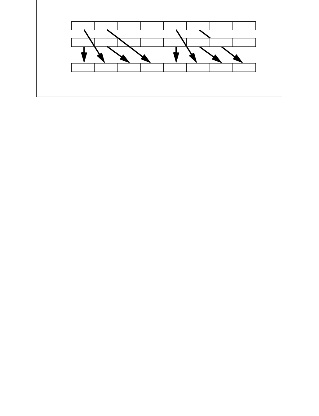
UNPCKHPS—Unpack and Interleave High Packed Single-Precision Floating-Point Values
INSTRUCTION SET REFERENCE, M-U
Vol. 2B 4-693
EVEX.512 encoded version: The first source operand is a ZMM register. The second source operand is a ZMM
register, a 512-bit memory location, or a 512-bit vector broadcasted from a 32-bit memory location. The destina-
tion operand is a ZMM register, conditionally updated using writemask k1.
EVEX.256 encoded version: The first source operand is a YMM register. The second source operand is a YMM
register, a 256-bit memory location, or a 256-bit vector broadcasted from a 32-bit memory location. The destina-
tion operand is a YMM register, conditionally updated using writemask k1.
EVEX.128 encoded version: The first source operand is a XMM register. The second source operand is a XMM
register, a 128-bit memory location, or a 128-bit vector broadcasted from a 32-bit memory location. The destina-
tion operand is a XMM register, conditionally updated using writemask k1.
Operation
VUNPCKHPS (EVEX encoded version when SRC2 is a register)
(KL, VL) = (4, 128), (8, 256), (16, 512)
IF VL >= 128
TMP_DEST[31:0] SRC1[95:64]
TMP_DEST[63:32] SRC2[95:64]
TMP_DEST[95:64] SRC1[127:96]
TMP_DEST[127:96] SRC2[127:96]
FI;
IF VL >= 256
TMP_DEST[159:128] SRC1[223:192]
TMP_DEST[191:160] SRC2[223:192]
TMP_DEST[223:192] SRC1[255:224]
TMP_DEST[255:224] SRC2[255:224]
FI;
IF VL >= 512
TMP_DEST[287:256] SRC1[351:320]
TMP_DEST[319:288] SRC2[351:320]
TMP_DEST[351:320] SRC1[383:352]
TMP_DEST[383:352] SRC2[383:352]
TMP_DEST[415:384] SRC1[479:448]
TMP_DEST[447:416] SRC2[479:448]
TMP_DEST[479:448] SRC1[511:480]
TMP_DEST[511:480] SRC2[511:480]
FI;
Figure 4-27. VUNPCKHPS Operation
DEST
SRC1
SRC2
X0X1X2X3
Y0Y1Y2Y3
X2Y2X3Y3X6Y6X7Y7
X4X5X6X7
Y4Y5Y6Y7

UNPCKHPS—Unpack and Interleave High Packed Single-Precision Floating-Point Values
INSTRUCTION SET REFERENCE, M-U
4-694 Vol. 2B
FOR j 0 TO KL-1
i j * 32
IF k1[j] OR *no writemask*
THEN DEST[i+31:i] TMP_DEST[i+31:i]
ELSE
IF *merging-masking* ; merging-masking
THEN *DEST[i+31:i] remains unchanged*
ELSE *zeroing-masking* ; zeroing-masking
DEST[i+31:i] 0
FI
FI;
ENDFOR
DEST[MAX_VL-1:VL] 0
VUNPCKHPS (EVEX encoded version when SRC2 is memory)
(KL, VL) = (4, 128), (8, 256), (16, 512)
FOR j 0 TO KL-1
i j * 32
IF (EVEX.b = 1)
THEN TMP_SRC2[i+31:i] SRC2[31:0]
ELSE TMP_SRC2[i+31:i] SRC2[i+31:i]
FI;
ENDFOR;
IF VL >= 128
TMP_DEST[31:0] SRC1[95:64]
TMP_DEST[63:32] TMP_SRC2[95:64]
TMP_DEST[95:64] SRC1[127:96]
TMP_DEST[127:96] TMP_SRC2[127:96]
FI;
IF VL >= 256
TMP_DEST[159:128] SRC1[223:192]
TMP_DEST[191:160] TMP_SRC2[223:192]
TMP_DEST[223:192] SRC1[255:224]
TMP_DEST[255:224] TMP_SRC2[255:224]
FI;
IF VL >= 512
TMP_DEST[287:256] SRC1[351:320]
TMP_DEST[319:288] TMP_SRC2[351:320]
TMP_DEST[351:320] SRC1[383:352]
TMP_DEST[383:352] TMP_SRC2[383:352]
TMP_DEST[415:384] SRC1[479:448]
TMP_DEST[447:416] TMP_SRC2[479:448]
TMP_DEST[479:448] SRC1[511:480]
TMP_DEST[511:480] TMP_SRC2[511:480]
FI;
FOR j 0 TO KL-1
i j * 32
IF k1[j] OR *no writemask*
THEN DEST[i+31:i] TMP_DEST[i+31:i]
ELSE
IF *merging-masking* ; merging-masking
THEN *DEST[i+31:i] remains unchanged*
ELSE *zeroing-masking* ; zeroing-masking
DEST[i+31:i] 0

UNPCKHPS—Unpack and Interleave High Packed Single-Precision Floating-Point Values
INSTRUCTION SET REFERENCE, M-U
Vol. 2B 4-695
FI
FI;
ENDFOR
DEST[MAX_VL-1:VL] 0
VUNPCKHPS (VEX.256 encoded version)
DEST[31:0] SRC1[95:64]
DEST[63:32] SRC2[95:64]
DEST[95:64] SRC1[127:96]
DEST[127:96] SRC2[127:96]
DEST[159:128] SRC1[223:192]
DEST[191:160] SRC2[223:192]
DEST[223:192] SRC1[255:224]
DEST[255:224] SRC2[255:224]
DEST[MAX_VL-1:256] 0
VUNPCKHPS (VEX.128 encoded version)
DEST[31:0] SRC1[95:64]
DEST[63:32] SRC2[95:64]
DEST[95:64] SRC1[127:96]
DEST[127:96] SRC2[127:96]
DEST[MAX_VL-1:128] 0
UNPCKHPS (128-bit Legacy SSE version)
DEST[31:0] SRC1[95:64]
DEST[63:32] SRC2[95:64]
DEST[95:64] SRC1[127:96]
DEST[127:96] SRC2[127:96]
DEST[MAX_VL-1:128] (Unmodified)
Intel C/C++ Compiler Intrinsic Equivalent
VUNPCKHPS __m512 _mm512_unpackhi_ps( __m512 a, __m512 b);
VUNPCKHPS __m512 _mm512_mask_unpackhi_ps(__m512 s, __mmask16 k, __m512 a, __m512 b);
VUNPCKHPS __m512 _mm512_maskz_unpackhi_ps(__mmask16 k, __m512 a, __m512 b);
VUNPCKHPS __m256 _mm256_unpackhi_ps (__m256 a, __m256 b);
VUNPCKHPS __m256 _mm256_mask_unpackhi_ps(__m256 s, __mmask8 k, __m256 a, __m256 b);
VUNPCKHPS __m256 _mm256_maskz_unpackhi_ps(__mmask8 k, __m256 a, __m256 b);
UNPCKHPS __m128 _mm_unpackhi_ps (__m128 a, __m128 b);
VUNPCKHPS __m128 _mm_mask_unpackhi_ps(__m128 s, __mmask8 k, __m128 a, __m128 b);
VUNPCKHPS __m128 _mm_maskz_unpackhi_ps(__mmask8 k, __m128 a, __m128 b);
SIMD Floating-Point Exceptions
None
Other Exceptions
Non-EVEX-encoded instructions, see Exceptions Type 4.
EVEX-encoded instructions, see Exceptions Type E4NF.

UNPCKLPD—Unpack and Interleave Low Packed Double-Precision Floating-Point Values
INSTRUCTION SET REFERENCE, M-U
4-696 Vol. 2B
UNPCKLPD—Unpack and Interleave Low Packed Double-Precision Floating-Point Values
Instruction Operand Encoding
Description
Performs an interleaved unpack of the low double-precision floating-point values from the first source operand and
the second source operand.
128-bit Legacy SSE version: The second source can be an XMM register or an 128-bit memory location. The desti-
nation is not distinct from the first source XMM register and the upper bits (MAX_VL-1:128) of the corresponding
ZMM register destination are unmodified. When unpacking from a memory operand, an implementation may fetch
only the appropriate 64 bits; however, alignment to 16-byte boundary and normal segment checking will still be
enforced.
VEX.128 encoded version: The first source operand is a XMM register. The second source operand can be a XMM
register or a 128-bit memory location. The destination operand is a XMM register. The upper bits (MAX_VL-1:128)
of the corresponding ZMM register destination are zeroed.
VEX.256 encoded version: The first source operand is a YMM register. The second source operand can be a YMM
register or a 256-bit memory location. The destination operand is a YMM register.
EVEX.512 encoded version: The first source operand is a ZMM register. The second source operand is a ZMM
register, a 512-bit memory location, or a 512-bit vector broadcasted from a 64-bit memory location. The destina-
tion operand is a ZMM register, conditionally updated using writemask k1.
EVEX.256 encoded version: The first source operand is a YMM register. The second source operand is a YMM
register, a 256-bit memory location, or a 256-bit vector broadcasted from a 64-bit memory location. The destina-
tion operand is a YMM register, conditionally updated using writemask k1.
EVEX.128 encoded version: The first source operand is an XMM register. The second source operand is a XMM
register, a 128-bit memory location, or a 128-bit vector broadcasted from a 64-bit memory location. The destina-
tion operand is a XMM register, conditionally updated using writemask k1.
Opcode/
Instruction
Op /
En
64/32
bit Mode
Support
CPUID
Feature
Flag
Description
66 0F 14 /r
UNPCKLPD xmm1, xmm2/m128 RM V/V SSE2 Unpacks and Interleaves double-precision floating-point
values from low quadwords of xmm1 and xmm2/m128.
VEX.NDS.128.66.0F.WIG 14 /r
VUNPCKLPD xmm1,xmm2,
xmm3/m128
RVM
V/V AVX Unpacks and Interleaves double-precision floating-point
values from low quadwords of xmm2 and xmm3/m128.
VEX.NDS.256.66.0F.WIG 14 /r
VUNPCKLPD ymm1,ymm2,
ymm3/m256
RVM V/V AVX Unpacks and Interleaves double-precision floating-point
values from low quadwords of ymm2 and ymm3/m256.
EVEX.NDS.128.66.0F.W1 14 /r
VUNPCKLPD xmm1 {k1}{z}, xmm2,
xmm3/m128/m64bcst
FV V/V AVX512VL
AVX512F
Unpacks and Interleaves double precision floating-point
values from low quadwords of xmm2 and
xmm3/m128/m64bcst subject to write mask k1.
EVEX.NDS.256.66.0F.W1 14 /r
VUNPCKLPD ymm1 {k1}{z}, ymm2,
ymm3/m256/m64bcst
FV V/V AVX512VL
AVX512F
Unpacks and Interleaves double precision floating-point
values from low quadwords of ymm2 and
ymm3/m256/m64bcst subject to write mask k1.
EVEX.NDS.512.66.0F.W1 14 /r
VUNPCKLPD zmm1 {k1}{z}, zmm2,
zmm3/m512/m64bcst
FV V/V AVX512F Unpacks and Interleaves double-precision floating-point
values from low quadwords of zmm2 and
zmm3/m512/m64bcst subject to write mask k1.
Op/En Operand 1 Operand 2 Operand 3 Operand 4
RM ModRM:reg (r, w) ModRM:r/m (r) NA NA
RVM ModRM:reg (w) VEX.vvvv (r) ModRM:r/m (r) NA
FV ModRM:reg (w) EVEX.vvvv (r) ModRM:r/m (r) NA

UNPCKLPD—Unpack and Interleave Low Packed Double-Precision Floating-Point Values
INSTRUCTION SET REFERENCE, M-U
Vol. 2B 4-697
Operation
VUNPCKLPD (EVEX encoded versions when SRC2 is a register)
(KL, VL) = (2, 128), (4, 256), (8, 512)
IF VL >= 128
TMP_DEST[63:0] SRC1[63:0]
TMP_DEST[127:64] SRC2[63:0]
FI;
IF VL >= 256
TMP_DEST[191:128] SRC1[191:128]
TMP_DEST[255:192] SRC2[191:128]
FI;
IF VL >= 512
TMP_DEST[319:256] SRC1[319:256]
TMP_DEST[383:320] SRC2[319:256]
TMP_DEST[447:384] SRC1[447:384]
TMP_DEST[511:448] SRC2[447:384]
FI;
FOR j 0 TO KL-1
i j * 64
IF k1[j] OR *no writemask*
THEN DEST[i+63:i] TMP_DEST[i+63:i]
ELSE
IF *merging-masking* ; merging-masking
THEN *DEST[i+63:i] remains unchanged*
ELSE *zeroing-masking* ; zeroing-masking
DEST[i+63:i] 0
FI
FI;
ENDFOR
DEST[MAX_VL-1:VL] 0

UNPCKLPD—Unpack and Interleave Low Packed Double-Precision Floating-Point Values
INSTRUCTION SET REFERENCE, M-U
4-698 Vol. 2B
VUNPCKLPD (EVEX encoded version when SRC2 is memory)
(KL, VL) = (2, 128), (4, 256), (8, 512)
FOR j 0 TO KL-1
i j * 64
IF (EVEX.b = 1)
THEN TMP_SRC2[i+63:i] SRC2[63:0]
ELSE TMP_SRC2[i+63:i] SRC2[i+63:i]
FI;
ENDFOR;
IF VL >= 128
TMP_DEST[63:0] SRC1[63:0]
TMP_DEST[127:64] TMP_SRC2[63:0]
FI;
IF VL >= 256
TMP_DEST[191:128] SRC1[191:128]
TMP_DEST[255:192] TMP_SRC2[191:128]
FI;
IF VL >= 512
TMP_DEST[319:256] SRC1[319:256]
TMP_DEST[383:320] TMP_SRC2[319:256]
TMP_DEST[447:384] SRC1[447:384]
TMP_DEST[511:448] TMP_SRC2[447:384]
FI;
FOR j 0 TO KL-1
i j * 64
IF k1[j] OR *no writemask*
THEN DEST[i+63:i] TMP_DEST[i+63:i]
ELSE
IF *merging-masking* ; merging-masking
THEN *DEST[i+63:i] remains unchanged*
ELSE *zeroing-masking* ; zeroing-masking
DEST[i+63:i] 0
FI
FI;
ENDFOR
DEST[MAX_VL-1:VL] 0
VUNPCKLPD (VEX.256 encoded version)
DEST[63:0] SRC1[63:0]
DEST[127:64] SRC2[63:0]
DEST[191:128] SRC1[191:128]
DEST[255:192] SRC2[191:128]
DEST[MAX_VL-1:256] 0
VUNPCKLPD (VEX.128 encoded version)
DEST[63:0] SRC1[63:0]
DEST[127:64] SRC2[63:0]
DEST[MAX_VL-1:128] 0
UNPCKLPD (128-bit Legacy SSE version)
DEST[63:0] SRC1[63:0]
DEST[127:64] SRC2[63:0]
DEST[MAX_VL-1:128] (Unmodified)

UNPCKLPD—Unpack and Interleave Low Packed Double-Precision Floating-Point Values
INSTRUCTION SET REFERENCE, M-U
Vol. 2B 4-699
Intel C/C++ Compiler Intrinsic Equivalent
VUNPCKLPD __m512d _mm512_unpacklo_pd( __m512d a, __m512d b);
VUNPCKLPD __m512d _mm512_mask_unpacklo_pd(__m512d s, __mmask8 k, __m512d a, __m512d b);
VUNPCKLPD __m512d _mm512_maskz_unpacklo_pd(__mmask8 k, __m512d a, __m512d b);
VUNPCKLPD __m256d _mm256_unpacklo_pd(__m256d a, __m256d b)
VUNPCKLPD __m256d _mm256_mask_unpacklo_pd(__m256d s, __mmask8 k, __m256d a, __m256d b);
VUNPCKLPD __m256d _mm256_maskz_unpacklo_pd(__mmask8 k, __m256d a, __m256d b);
UNPCKLPD __m128d _mm_unpacklo_pd(__m128d a, __m128d b)
VUNPCKLPD __m128d _mm_mask_unpacklo_pd(__m128d s, __mmask8 k, __m128d a, __m128d b);
VUNPCKLPD __m128d _mm_maskz_unpacklo_pd(__mmask8 k, __m128d a, __m128d b);
SIMD Floating-Point Exceptions
None
Other Exceptions
Non-EVEX-encoded instructions, see Exceptions Type 4.
EVEX-encoded instructions, see Exceptions Type E4NF.

UNPCKLPS—Unpack and Interleave Low Packed Single-Precision Floating-Point Values
INSTRUCTION SET REFERENCE, M-U
4-700 Vol. 2B
UNPCKLPS—Unpack and Interleave Low Packed Single-Precision Floating-Point Values
Instruction Operand Encoding
Description
Performs an interleaved unpack of the low single-precision floating-point values from the first source operand and
the second source operand.
128-bit Legacy SSE version: The second source can be an XMM register or an 128-bit memory location. The desti-
nation is not distinct from the first source XMM register and the upper bits (MAX_VL-1:128) of the corresponding
ZMM register destination are unmodified. When unpacking from a memory operand, an implementation may fetch
only the appropriate 64 bits; however, alignment to 16-byte boundary and normal segment checking will still be
enforced.
VEX.128 encoded version: The first source operand is a XMM register. The second source operand can be a XMM
register or a 128-bit memory location. The destination operand is a XMM register. The upper bits (MAX_VL-1:128)
of the corresponding ZMM register destination are zeroed.
VEX.256 encoded version: The first source operand is a YMM register. The second source operand can be a YMM
register or a 256-bit memory location. The destination operand is a YMM register.
Opcode/
Instruction
Op /
En
64/32
bit Mode
Support
CPUID
Feature
Flag
Description
0F 14 /r
UNPCKLPS xmm1, xmm2/m128 RM V/V SSE Unpacks and Interleaves single-precision floating-point
values from low quadwords of xmm1 and xmm2/m128.
VEX.NDS.128.0F.WIG 14 /r
VUNPCKLPS xmm1,xmm2,
xmm3/m128
RVM
V/V AVX Unpacks and Interleaves single-precision floating-point
values from low quadwords of xmm2 and xmm3/m128.
VEX.NDS.256.0F.WIG 14 /r
VUNPCKLPS
ymm1,ymm2,ymm3/m256
RVM V/V AVX Unpacks and Interleaves single-precision floating-point
values from low quadwords of ymm2 and ymm3/m256.
EVEX.NDS.128.0F.W0 14 /r
VUNPCKLPS xmm1 {k1}{z}, xmm2,
xmm3/m128/m32bcst
FV V/V AVX512VL
AVX512F
Unpacks and Interleaves single-precision floating-point
values from low quadwords of xmm2 and xmm3/mem and
write result to xmm1 subject to write mask k1.
EVEX.NDS.256.0F.W0 14 /r
VUNPCKLPS ymm1 {k1}{z}, ymm2,
ymm3/m256/m32bcst
FV V/V AVX512VL
AVX512F
Unpacks and Interleaves single-precision floating-point
values from low quadwords of ymm2 and ymm3/mem and
write result to ymm1 subject to write mask k1.
EVEX.NDS.512.0F.W0 14 /r
VUNPCKLPS zmm1 {k1}{z}, zmm2,
zmm3/m512/m32bcst
FV V/V AVX512F Unpacks and Interleaves single-precision floating-point
values from low quadwords of zmm2 and
zmm3/m512/m32bcst and write result to zmm1 subject
to write mask k1.
Op/En Operand 1 Operand 2 Operand 3 Operand 4
RM ModRM:reg (r, w) ModRM:r/m (r) NA NA
RVM ModRM:reg (w) VEX.vvvv (r) ModRM:r/m (r) NA
FV ModRM:reg (w) EVEX.vvvv (r) ModRM:r/m (r) NA

UNPCKLPS—Unpack and Interleave Low Packed Single-Precision Floating-Point Values
INSTRUCTION SET REFERENCE, M-U
Vol. 2B 4-701
EVEX.512 encoded version: The first source operand is a ZMM register. The second source operand is a ZMM
register, a 512-bit memory location, or a 512-bit vector broadcasted from a 32-bit memory location. The destina-
tion operand is a ZMM register, conditionally updated using writemask k1.
EVEX.256 encoded version: The first source operand is a YMM register. The second source operand is a YMM
register, a 256-bit memory location, or a 256-bit vector broadcasted from a 32-bit memory location. The destina-
tion operand is a YMM register, conditionally updated using writemask k1.
EVEX.128 encoded version: The first source operand is an XMM register. The second source operand is a XMM
register, a 128-bit memory location, or a 128-bit vector broadcasted from a 32-bit memory location. The destina-
tion operand is a XMM register, conditionally updated using writemask k1.
Operation
VUNPCKLPS (EVEX encoded version when SRC2 is a ZMM register)
(KL, VL) = (4, 128), (8, 256), (16, 512)
IF VL >= 128
TMP_DEST[31:0] SRC1[31:0]
TMP_DEST[63:32] SRC2[31:0]
TMP_DEST[95:64] SRC1[63:32]
TMP_DEST[127:96] SRC2[63:32]
FI;
IF VL >= 256
TMP_DEST[159:128] SRC1[159:128]
TMP_DEST[191:160] SRC2[159:128]
TMP_DEST[223:192] SRC1[191:160]
TMP_DEST[255:224] SRC2[191:160]
FI;
IF VL >= 512
TMP_DEST[287:256] SRC1[287:256]
TMP_DEST[319:288] SRC2[287:256]
TMP_DEST[351:320] SRC1[319:288]
TMP_DEST[383:352] SRC2[319:288]
TMP_DEST[415:384] SRC1[415:384]
TMP_DEST[447:416] SRC2[415:384]
TMP_DEST[479:448] SRC1[447:416]
TMP_DEST[511:480] SRC2[447:416]
FI;
FOR j 0 TO KL-1
i j * 32
Figure 4-28. VUNPCKLPS Operation
DEST
SRC1
SRC2
X0X1X2X3
Y0Y1Y2Y3
X0Y0X1Y1X4Y4X5Y5
X4X5X6X7
Y4Y5Y6Y7

UNPCKLPS—Unpack and Interleave Low Packed Single-Precision Floating-Point Values
INSTRUCTION SET REFERENCE, M-U
4-702 Vol. 2B
IF k1[j] OR *no writemask*
THEN DEST[i+31:i] TMP_DEST[i+31:i]
ELSE
IF *merging-masking* ; merging-masking
THEN *DEST[i+31:i] remains unchanged*
ELSE *zeroing-masking* ; zeroing-masking
DEST[i+31:i] 0
FI
FI;
ENDFOR
DEST[MAX_VL-1:VL] 0
VUNPCKLPS (EVEX encoded version when SRC2 is memory)
(KL, VL) = (4, 128), (8, 256), (16, 512)
FOR j 0 TO KL-1
i j * 31
IF (EVEX.b = 1)
THEN TMP_SRC2[i+31:i] SRC2[31:0]
ELSE TMP_SRC2[i+31:i] SRC2[i+31:i]
FI;
ENDFOR;
IF VL >= 128
TMP_DEST[31:0] SRC1[31:0]
TMP_DEST[63:32] TMP_SRC2[31:0]
TMP_DEST[95:64] SRC1[63:32]
TMP_DEST[127:96] TMP_SRC2[63:32]
FI;
IF VL >= 256
TMP_DEST[159:128] SRC1[159:128]
TMP_DEST[191:160] TMP_SRC2[159:128]
TMP_DEST[223:192] SRC1[191:160]
TMP_DEST[255:224] TMP_SRC2[191:160]
FI;
IF VL >= 512
TMP_DEST[287:256] SRC1[287:256]
TMP_DEST[319:288] TMP_SRC2[287:256]
TMP_DEST[351:320] SRC1[319:288]
TMP_DEST[383:352] TMP_SRC2[319:288]
TMP_DEST[415:384] SRC1[415:384]
TMP_DEST[447:416] TMP_SRC2[415:384]
TMP_DEST[479:448] SRC1[447:416]
TMP_DEST[511:480] TMP_SRC2[447:416]
FI;
FOR j 0 TO KL-1
i j * 32
IF k1[j] OR *no writemask*
THEN DEST[i+31:i] TMP_DEST[i+31:i]
ELSE
IF *merging-masking* ; merging-masking
THEN *DEST[i+31:i] remains unchanged*
ELSE *zeroing-masking* ; zeroing-masking
DEST[i+31:i] 0
FI
FI;

UNPCKLPS—Unpack and Interleave Low Packed Single-Precision Floating-Point Values
INSTRUCTION SET REFERENCE, M-U
Vol. 2B 4-703
ENDFOR
DEST[MAX_VL-1:VL] 0
UNPCKLPS (VEX.256 encoded version)
DEST[31:0] SRC1[31:0]
DEST[63:32] SRC2[31:0]
DEST[95:64] SRC1[63:32]
DEST[127:96] SRC2[63:32]
DEST[159:128] SRC1[159:128]
DEST[191:160] SRC2[159:128]
DEST[223:192] SRC1[191:160]
DEST[255:224] SRC2[191:160]
DEST[MAX_VL-1:256] 0
VUNPCKLPS (VEX.128 encoded version)
DEST[31:0] SRC1[31:0]
DEST[63:32] SRC2[31:0]
DEST[95:64] SRC1[63:32]
DEST[127:96] SRC2[63:32]
DEST[MAX_VL-1:128] 0
UNPCKLPS (128-bit Legacy SSE version)
DEST[31:0] SRC1[31:0]
DEST[63:32] SRC2[31:0]
DEST[95:64] SRC1[63:32]
DEST[127:96] SRC2[63:32]
DEST[MAX_VL-1:128] (Unmodified)
Intel C/C++ Compiler Intrinsic Equivalent
VUNPCKLPS __m512 _mm512_unpacklo_ps(__m512 a, __m512 b);
VUNPCKLPS __m512 _mm512_mask_unpacklo_ps(__m512 s, __mmask16 k, __m512 a, __m512 b);
VUNPCKLPS __m512 _mm512_maskz_unpacklo_ps(__mmask16 k, __m512 a, __m512 b);
VUNPCKLPS __m256 _mm256_unpacklo_ps (__m256 a, __m256 b);
VUNPCKLPS __m256 _mm256_mask_unpacklo_ps(__m256 s, __mmask8 k, __m256 a, __m256 b);
VUNPCKLPS __m256 _mm256_maskz_unpacklo_ps(__mmask8 k, __m256 a, __m256 b);
UNPCKLPS __m128 _mm_unpacklo_ps (__m128 a, __m128 b);
VUNPCKLPS __m128 _mm_mask_unpacklo_ps(__m128 s, __mmask8 k, __m128 a, __m128 b);
VUNPCKLPS __m128 _mm_maskz_unpacklo_ps(__mmask8 k, __m128 a, __m128 b);
SIMD Floating-Point Exceptions
None
Other Exceptions
Non-EVEX-encoded instructions, see Exceptions Type 4.
EVEX-encoded instructions, see Exceptions Type E4NF.

VALIGND/VALIGNQ—Align Doubleword/Quadword Vectors
INSTRUCTION SET REFERENCE, V-Z
Vol. 2C 5-5
VALIGND/VALIGNQ—Align Doubleword/Quadword Vectors
Instruction Operand Encoding
Description
Concatenates and shifts right doubleword/quadword elements of the first source operand (the second operand)
and the second source operand (the third operand) into a 1024/512/256-bit intermediate vector. The low
512/256/128-bit of the intermediate vector is written to the destination operand (the first operand) using the
writemask k1. The destination and first source operands are ZMM/YMM/XMM registers. The second source operand
can be a ZMM/YMM/XMM register, a 512/256/128-bit memory location or a 512/256/128-bit vector broadcasted
from a 32/64-bit memory location.
This instruction is writemasked, so only those elements with the corresponding bit set in vector mask register k1
are computed and stored into zmm1. Elements in zmm1 with the corresponding bit clear in k1 retain their previous
values (merging-masking) or are set to 0 (zeroing-masking).
Opcode/
Instruction
Op /
En
64/32
bit Mode
Support
CPUID
Feature
Flag
Description
EVEX.NDS.128.66.0F3A.W0 03 /r ib
VALIGND xmm1 {k1}{z}, xmm2,
xmm3/m128/m32bcst, imm8
FV V/V AVX512VL
AVX512F
Shift right and merge vectors xmm2 and
xmm3/m128/m32bcst with double-word granularity
using imm8 as number of elements to shift, and store the
final result in xmm1, under writemask.
EVEX.NDS.128.66.0F3A.W1 03 /r ib
VALIGNQ xmm1 {k1}{z}, xmm2,
xmm3/m128/m64bcst, imm8
FV V/V AVX512VL
AVX512F
Shift right and merge vectors xmm2 and
xmm3/m128/m64bcst with quad-word granularity using
imm8 as number of elements to shift, and store the final
result in xmm1, under writemask.
EVEX.NDS.256.66.0F3A.W0 03 /r ib
VALIGND ymm1 {k1}{z}, ymm2,
ymm3/m256/m32bcst, imm8
FV V/V AVX512VL
AVX512F
Shift right and merge vectors ymm2 and
ymm3/m256/m32bcst with double-word granularity
using imm8 as number of elements to shift, and store the
final result in ymm1, under writemask.
EVEX.NDS.256.66.0F3A.W1 03 /r ib
VALIGNQ ymm1 {k1}{z}, ymm2,
ymm3/m256/m64bcst, imm8
FV V/V AVX512VL
AVX512F
Shift right and merge vectors ymm2 and
ymm3/m256/m64bcst with quad-word granularity using
imm8 as number of elements to shift, and store the final
result in ymm1, under writemask.
EVEX.NDS.512.66.0F3A.W0 03 /r ib
VALIGND zmm1 {k1}{z}, zmm2,
zmm3/m512/m32bcst, imm8
FV V/V AVX512F Shift right and merge vectors zmm2 and
zmm3/m512/m32bcst with double-word granularity
using imm8 as number of elements to shift, and store the
final result in zmm1, under writemask.
EVEX.NDS.512.66.0F3A.W1 03 /r ib
VALIGNQ zmm1 {k1}{z}, zmm2,
zmm3/m512/m64bcst, imm8
FV V/V AVX512F Shift right and merge vectors zmm2 and
zmm3/m512/m64bcst with quad-word granularity using
imm8 as number of elements to shift, and store the final
result in zmm1, under writemask.
Op/En Operand 1 Operand 2 Operand 3 Operand 4
FV ModRM:reg (w) EVEX.vvvv ModRM:r/m (r) NA

VALIGND/VALIGNQ—Align Doubleword/Quadword Vectors
INSTRUCTION SET REFERENCE, V-Z
5-6 Vol. 2C
Operation
VALIGND (EVEX encoded versions)
(KL, VL) = (4, 128), (8, 256), (16, 512)
IF (SRC2 *is memory*) (AND EVEX.b = 1)
THEN
FOR j 0 TO KL-1
i j * 32
src[i+31:i] SRC2[31:0]
ENDFOR;
ELSE src SRC2
FI
; Concatenate sources
tmp[VL-1:0] src[VL-1:0]
tmp[2VL-1:VL] SRC1[VL-1:0]
; Shift right doubleword elements
IF VL = 128
THEN SHIFT = imm8[1:0]
ELSE
IF VL = 256
THEN SHIFT = imm8[2:0]
ELSE SHIFT = imm8[3:0]
FI
FI;
tmp[2VL-1:0] tmp[2VL-1:0] >> (32*SHIFT)
; Apply writemask
FOR j 0 TO KL-1
i j * 32
IF k1[j] OR *no writemask*
THEN DEST[i+31:i] tmp[i+31:i]
ELSE
IF *merging-masking* ; merging-masking
THEN *DEST[i+31:i] remains unchanged*
ELSE ; zeroing-masking
DEST[i+31:i] 0
FI
FI;
ENDFOR;
DEST[MAX_VL-1:VL] 0

VALIGND/VALIGNQ—Align Doubleword/Quadword Vectors
INSTRUCTION SET REFERENCE, V-Z
Vol. 2C 5-7
VALIGNQ (EVEX encoded versions)
(KL, VL) = (2, 128), (4, 256),(8, 512)
IF (SRC2 *is memory*) (AND EVEX.b = 1)
THEN
FOR j 0 TO KL-1
i j * 64
src[i+63:i] SRC2[63:0]
ENDFOR;
ELSE src SRC2
FI
; Concatenate sources
tmp[VL-1:0] src[VL-1:0]
tmp[2VL-1:VL] SRC1[VL-1:0]
; Shift right quadword elements
IF VL = 128
THEN SHIFT = imm8[0]
ELSE
IF VL = 256
THEN SHIFT = imm8[1:0]
ELSE SHIFT = imm8[2:0]
FI
FI;
tmp[2VL-1:0] tmp[2VL-1:0] >> (64*SHIFT)
; Apply writemask
FOR j 0 TO KL-1
i j * 64
IF k1[j] OR *no writemask*
THEN DEST[i+63:i] tmp[i+63:i]
ELSE
IF *merging-masking* ; merging-masking
THEN *DEST[i+63:i] remains unchanged*
ELSE ; zeroing-masking
DEST[i+63:i] 0
FI
FI;
ENDFOR;
DEST[MAX_VL-1:VL] 0

VALIGND/VALIGNQ—Align Doubleword/Quadword Vectors
INSTRUCTION SET REFERENCE, V-Z
5-8 Vol. 2C
Intel C/C++ Compiler Intrinsic Equivalent
VALIGND __m512i _mm512_alignr_epi32( __m512i a, __m512i b, int cnt);
VALIGND __m512i _mm512_mask_alignr_epi32(__m512i s, __mmask16 k, __m512i a, __m512i b, int cnt);
VALIGND __m512i _mm512_maskz_alignr_epi32( __mmask16 k, __m512i a, __m512i b, int cnt);
VALIGND __m256i _mm256_mask_alignr_epi32(__m256i s, __mmask8 k, __m256i a, __m256i b, int cnt);
VALIGND __m256i _mm256_maskz_alignr_epi32( __mmask8 k, __m256i a, __m256i b, int cnt);
VALIGND __m128i _mm_mask_alignr_epi32(__m128i s, __mmask8 k, __m128i a, __m128i b, int cnt);
VALIGND __m128i _mm_maskz_alignr_epi32( __mmask8 k, __m128i a, __m128i b, int cnt);
VALIGNQ __m512i _mm512_alignr_epi64( __m512i a, __m512i b, int cnt);
VALIGNQ __m512i _mm512_mask_alignr_epi64(__m512i s, __mmask8 k, __m512i a, __m512i b, int cnt);
VALIGNQ __m512i _mm512_maskz_alignr_epi64( __mmask8 k, __m512i a, __m512i b, int cnt);
VALIGNQ __m256i _mm256_mask_alignr_epi64(__m256i s, __mmask8 k, __m256i a, __m256i b, int cnt);
VALIGNQ __m256i _mm256_maskz_alignr_epi64( __mmask8 k, __m256i a, __m256i b, int cnt);
VALIGNQ __m128i _mm_mask_alignr_epi64(__m128i s, __mmask8 k, __m128i a, __m128i b, int cnt);
VALIGNQ __m128i _mm_maskz_alignr_epi64( __mmask8 k, __m128i a, __m128i b, int cnt);
Exceptions
See Exceptions Type E4NF.

VBLENDMPD/VBLENDMPS—Blend Float64/Float32 Vectors Using an OpMask Control
INSTRUCTION SET REFERENCE, V-Z
Vol. 2C 5-9
VBLENDMPD/VBLENDMPS—Blend Float64/Float32 Vectors Using an OpMask Control
Instruction Operand Encoding
Description
Performs an element-by-element blending between float64/float32 elements in the first source operand (the
second operand) with the elements in the second source operand (the third operand) using an opmask register as
select control. The blended result is written to the destination register.
The destination and first source operands are ZMM/YMM/XMM registers. The second source operand can be a
ZMM/YMM/XMM register, a 512/256/128-bit memory location or a 512/256/128-bit vector broadcasted from a 64-
bit memory location.
The opmask register is not used as a writemask for this instruction. Instead, the mask is used as an element
selector: every element of the destination is conditionally selected between first source or second source using the
value of the related mask bit (0 for first source operand, 1 for second source operand).
If EVEX.z is set, the elements with corresponding mask bit value of 0 in the destination operand are zeroed.
Opcode/
Instruction
Op /
En
64/32
bit Mode
Support
CPUID
Feature
Flag
Description
EVEX.NDS.128.66.0F38.W1 65 /r
VBLENDMPD xmm1 {k1}{z},
xmm2, xmm3/m128/m64bcst
FV V/V AVX512VL
AVX512F
Blend double-precision vector xmm2 and double-precision
vector xmm3/m128/m64bcst and store the result in xmm1,
under control mask.
EVEX.NDS.256.66.0F38.W1 65 /r
VBLENDMPD ymm1 {k1}{z},
ymm2, ymm3/m256/m64bcst
FV V/V AVX512VL
AVX512F
Blend double-precision vector ymm2 and double-precision
vector ymm3/m256/m64bcst and store the result in ymm1,
under control mask.
EVEX.NDS.512.66.0F38.W1 65 /r
VBLENDMPD zmm1 {k1}{z},
zmm2, zmm3/m512/m64bcst
FV V/V AVX512F Blend double-precision vector zmm2 and double-precision
vector zmm3/m512/m64bcst and store the result in zmm1,
under control mask.
EVEX.NDS.128.66.0F38.W0 65 /r
VBLENDMPS xmm1 {k1}{z},
xmm2, xmm3/m128/m32bcst
FV V/V AVX512VL
AVX512F
Blend single-precision vector xmm2 and single-precision
vector xmm3/m128/m32bcst and store the result in xmm1,
under control mask.
EVEX.NDS.256.66.0F38.W0 65 /r
VBLENDMPS ymm1 {k1}{z},
ymm2, ymm3/m256/m32bcst
FV V/V AVX512VL
AVX512F
Blend single-precision vector ymm2 and single-precision
vector ymm3/m256/m32bcst and store the result in ymm1,
under control mask.
EVEX.NDS.512.66.0F38.W0 65 /r
VBLENDMPS zmm1 {k1}{z},
zmm2, zmm3/m512/m32bcst
FV V/V AVX512F Blend single-precision vector zmm2 and single-precision
vector zmm3/m512/m32bcst using k1 as select control and
store the result in zmm1.
Op/En Operand 1 Operand 2 Operand 3 Operand 4
FV ModRM:reg (w) EVEX.vvvv ModRM:r/m (r) NA

VBLENDMPD/VBLENDMPS—Blend Float64/Float32 Vectors Using an OpMask Control
INSTRUCTION SET REFERENCE, V-Z
5-10 Vol. 2C
Operation
VBLENDMPD (EVEX encoded versions)
(KL, VL) = (2, 128), (4, 256), (8, 512)
FOR j 0 TO KL-1
i j * 64
IF k1[j] OR *no controlmask*
THEN
IF (EVEX.b = 1) AND (SRC2 *is memory*)
THEN
DEST[i+63:i] SRC2[63:0]
ELSE
DEST[i+63:i] SRC2[i+63:i]
FI;
ELSE
IF *merging-masking* ; merging-masking
THEN DEST[i+63:i] SRC1[i+63:i]
ELSE ; zeroing-masking
DEST[i+63:i] 0
FI;
FI;
ENDFOR
DEST[MAX_VL-1:VL] 0
VBLENDMPS (EVEX encoded versions)
(KL, VL) = (4, 128), (8, 256), (16, 512)
FOR j 0 TO KL-1
i j * 32
IF k1[j] OR *no controlmask*
THEN
IF (EVEX.b = 1) AND (SRC2 *is memory*)
THEN
DEST[i+31:i] SRC2[31:0]
ELSE
DEST[i+31:i] SRC2[i+31:i]
FI;
ELSE
IF *merging-masking* ; merging-masking
THEN DEST[i+31:i] SRC1[i+31:i]
ELSE ; zeroing-masking
DEST[i+31:i] 0
FI;
FI;
ENDFOR
DEST[MAX_VL-1:VL] 0

VBLENDMPD/VBLENDMPS—Blend Float64/Float32 Vectors Using an OpMask Control
INSTRUCTION SET REFERENCE, V-Z
Vol. 2C 5-11
Intel C/C++ Compiler Intrinsic Equivalent
VBLENDMPD __m512d _mm512_mask_blend_pd(__mmask8 k, __m512d a, __m512d b);
VBLENDMPD __m256d _mm256_mask_blend_pd(__mmask8 k, __m256d a, __m256d b);
VBLENDMPD __m128d _mm_mask_blend_pd(__mmask8 k, __m128d a, __m128d b);
VBLENDMPS __m512 _mm512_mask_blend_ps(__mmask16 k, __m512 a, __m512 b);
VBLENDMPS __m256 _mm256_mask_blend_ps(__mmask8 k, __m256 a, __m256 b);
VBLENDMPS __m128 _mm_mask_blend_ps(__mmask8 k, __m128 a, __m128 b);
SIMD Floating-Point Exceptions
None
Other Exceptions
See Exceptions Type E4.

VBROADCAST—Load with Broadcast Floating-Point Data
INSTRUCTION SET REFERENCE, V-Z
5-12 Vol. 2C
VBROADCAST—Load with Broadcast Floating-Point Data
Opcode/
Instruction
Op /
En
64/32
bit
Mode
Support
CPUID
Feature
Flag
Description
VEX.128.66.0F38.W0 18 /r
VBROADCASTSS xmm1, m32
RM V/V AVX Broadcast single-precision floating-point element in
mem to four locations in xmm1.
VEX.256.66.0F38.W0 18 /r
VBROADCASTSS ymm1, m32
RM V/V AVX Broadcast single-precision floating-point element in
mem to eight locations in ymm1.
VEX.256.66.0F38.W0 19 /r
VBROADCASTSD ymm1, m64
RM V/V AVX Broadcast double-precision floating-point element in
mem to four locations in ymm1.
VEX.256.66.0F38.W0 1A /r
VBROADCASTF128 ymm1, m128
RM V/V AVX Broadcast 128 bits of floating-point data in mem to
low and high 128-bits in ymm1.
EVEX.256.66.0F38.W1 19 /r
VBROADCASTSD ymm1 {k1}{z},
xmm2/m64
T1S V/V AVX512VL
AVX512F
Broadcast low double-precision floating-point element
in xmm2/m64 to four locations in ymm1 using
writemask k1.
EVEX.512.66.0F38.W1 19 /r
VBROADCASTSD zmm1 {k1}{z},
xmm2/m64
T1S V/V AVX512F Broadcast low double-precision floating-point element
in xmm2/m64 to eight locations in zmm1 using
writemask k1.
EVEX.256.66.0F38.W0 19 /r
VBROADCASTF32X2 ymm1 {k1}{z},
xmm2/m64
T2 V/V AVX512VL
AVX512DQ
Broadcast two single-precision floating-point elements
in xmm2/m64 to locations in ymm1 using writemask
k1.
EVEX.512.66.0F38.W0 19 /r
VBROADCASTF32X2 zmm1 {k1}{z},
xmm2/m64
T2 V/V AVX512DQ Broadcast two single-precision floating-point elements
in xmm2/m64 to locations in zmm1 using writemask
k1.
EVEX.128.66.0F38.W0 18 /r
VBROADCASTSS xmm1 {k1}{z},
xmm2/m32
T1S V/V AVX512VL
AVX512F
Broadcast low single-precision floating-point element
in xmm2/m32 to all locations in xmm1 using
writemask k1.
EVEX.256.66.0F38.W0 18 /r
VBROADCASTSS ymm1 {k1}{z},
xmm2/m32
T1S V/V AVX512VL
AVX512F
Broadcast low single-precision floating-point element
in xmm2/m32 to all locations in ymm1 using
writemask k1.
EVEX.512.66.0F38.W0 18 /r
VBROADCASTSS zmm1 {k1}{z},
xmm2/m32
T1S V/V AVX512F Broadcast low single-precision floating-point element
in xmm2/m32 to all locations in zmm1 using
writemask k1.
EVEX.256.66.0F38.W0 1A /r
VBROADCASTF32X4 ymm1 {k1}{z},
m128
T4 V/V AVX512VL
AVX512F
Broadcast 128 bits of 4 single-precision floating-point
data in mem to locations in ymm1 using writemask k1.
EVEX.512.66.0F38.W0 1A /r
VBROADCASTF32X4 zmm1 {k1}{z},
m128
T4 V/V AVX512F Broadcast 128 bits of 4 single-precision floating-point
data in mem to locations in zmm1 using writemask k1.
EVEX.256.66.0F38.W1 1A /r
VBROADCASTF64X2 ymm1 {k1}{z},
m128
T2 V/V AVX512VL
AVX512DQ
Broadcast 128 bits of 2 double-precision floating-point
data in mem to locations in ymm1 using writemask k1.
EVEX.512.66.0F38.W1 1A /r
VBROADCASTF64X2 zmm1 {k1}{z},
m128
T2 V/V AVX512DQ Broadcast 128 bits of 2 double-precision floating-point
data in mem to locations in zmm1 using writemask k1.
EVEX.512.66.0F38.W0 1B /r
VBROADCASTF32X8 zmm1 {k1}{z},
m256
T8 V/V AVX512DQ Broadcast 256 bits of 8 single-precision floating-point
data in mem to locations in zmm1 using writemask k1.
EVEX.512.66.0F38.W1 1B /r
VBROADCASTF64X4 zmm1 {k1}{z},
m256
T4 V/V AVX512F Broadcast 256 bits of 4 double-precision floating-point
data in mem to locations in zmm1 using writemask k1.
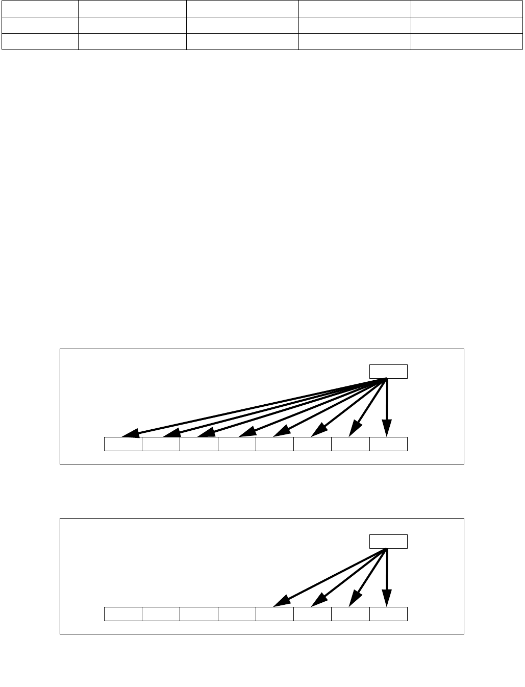
VBROADCAST—Load with Broadcast Floating-Point Data
INSTRUCTION SET REFERENCE, V-Z
Vol. 2C 5-13
Instruction Operand Encoding
Description
VBROADCASTSD/VBROADCASTSS/VBROADCASTF128 load floating-point values as one tuple from the source
operand (second operand) in memory and broadcast to all elements of the destination operand (first operand).
VEX256-encoded versions: The destination operand is a YMM register. The source operand is either a 32-bit,
64-bit, or 128-bit memory location. Register source encodings are reserved and will #UD. Bits (MAX_VL-
1:256) of the destination register are zeroed.
EVEX-encoded versions: The destination operand is a ZMM/YMM/XMM register and updated according to the
writemask k1. The source operand is either a 32-bit, 64-bit memory location or the low
doubleword/quadword element of an XMM register.
VBROADCASTF32X2/VBROADCASTF32X4/VBROADCASTF64X2/VBROADCASTF32X8/VBROADCASTF64X4 load
floating-point values as tuples from the source operand (the second operand) in memory or register and broadcast
to all elements of the destination operand (the first operand). The destination operand is a YMM/ZMM register
updated according to the writemask k1. The source operand is either a register or 64-bit/128-bit/256-bit memory
location.
VBROADCASTSD and VBROADCASTF128,F32x4 and F64x2 are only supported as 256-bit and 512-bit wide
versions and up. VBROADCASTSS is supported in 128-bit, 256-bit and 512-bit wide versions. F32x8 and F64x4 are
only supported as 512-bit wide versions.
VBROADCASTF32X2/VBROADCASTF32X4/VBROADCASTF32X8 have 32-bit granularity. VBROADCASTF64X2 and
VBROADCASTF64X4 have 64-bit granularity.
Note: VEX.vvvv and EVEX.vvvv are reserved and must be 1111b otherwise instructions will #UD.
If VBROADCASTSD or VBROADCASTF128 is encoded with VEX.L= 0, an attempt to execute the instruction encoded
with VEX.L= 0 will cause an #UD exception.
Op/En Operand 1 Operand 2 Operand 3 Operand 4
RM ModRM:reg (w) ModRM:r/m (r) NA NA
T1S, T2, T4, T8 ModRM:reg (w) ModRM:r/m (r) NA NA
Figure 5-1. VBROADCASTSS Operation (VEX.256 encoded version)
Figure 5-2. VBROADCASTSS Operation (VEX.128-bit version)
DEST
m32 X0
X0X0 X0X0 X0X0 X0X0
DEST
m32 X0
X0X0 X00X00 00
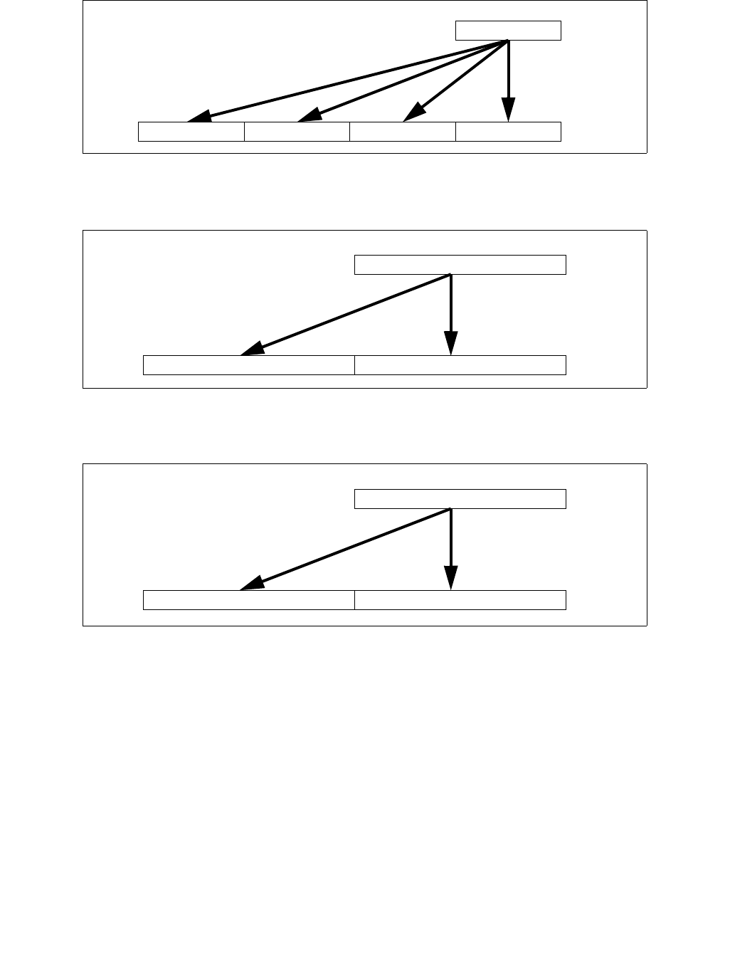
VBROADCAST—Load with Broadcast Floating-Point Data
INSTRUCTION SET REFERENCE, V-Z
5-14 Vol. 2C
Operation
VBROADCASTSS (128 bit version VEX and legacy)
temp SRC[31:0]
DEST[31:0] temp
DEST[63:32] temp
DEST[95:64] temp
DEST[127:96] temp
DEST[MAX_VL-1:128] 0
Figure 5-3. VBROADCASTSD Operation (VEX.256-bit version)
Figure 5-4. VBROADCASTF128 Operation (VEX.256-bit version)
Figure 5-5. VBROADCASTF64X4 Operation (512-bit version with writemask all 1s)
DEST
m64 X0
X0X0X0X0
DEST
m128 X0
X0X0
DEST
m256 X0
X0X0

VBROADCAST—Load with Broadcast Floating-Point Data
INSTRUCTION SET REFERENCE, V-Z
Vol. 2C 5-15
VBROADCASTSS (VEX.256 encoded version)
temp SRC[31:0]
DEST[31:0] temp
DEST[63:32] temp
DEST[95:64] temp
DEST[127:96] temp
DEST[159:128] temp
DEST[191:160] temp
DEST[223:192] temp
DEST[255:224] temp
DEST[MAX_VL-1:256] 0
VBROADCASTSS (EVEX encoded versions)
(KL, VL) (4, 128), (8, 256),= (16, 512)
FOR j 0 TO KL-1
i j * 32
IF k1[j] OR *no writemask*
THEN DEST[i+31:i] SRC[31:0]
ELSE
IF *merging-masking* ; merging-masking
THEN *DEST[i+31:i] remains unchanged*
ELSE ; zeroing-masking
DEST[i+31:i] 0
FI
FI;
ENDFOR
DEST[MAX_VL-1:VL] 0
VBROADCASTSD (VEX.256 encoded version)
temp SRC[63:0]
DEST[63:0] temp
DEST[127:64] temp
DEST[191:128] temp
DEST[255:192] temp
DEST[MAX_VL-1:256] 0
VBROADCASTSD (EVEX encoded versions)
(KL, VL) = (4, 256), (8, 512)
FOR j 0 TO KL-1
i j * 64
IF k1[j] OR *no writemask*
THEN DEST[i+63:i] SRC[63:0]
ELSE
IF *merging-masking* ; merging-masking
THEN *DEST[i+63:i] remains unchanged*
ELSE ; zeroing-masking
DEST[i+63:i] 0
FI
FI;
ENDFOR
DEST[MAX_VL-1:VL] 0

VBROADCAST—Load with Broadcast Floating-Point Data
INSTRUCTION SET REFERENCE, V-Z
5-16 Vol. 2C
VBROADCASTF32x2 (EVEX encoded versions)
(KL, VL) = (8, 256), (16, 512)
FOR j 0 TO KL-1
i j * 32
n (j mod 2) * 32
IF k1[j] OR *no writemask*
THEN DEST[i+31:i] SRC[n+31:n]
ELSE
IF *merging-masking* ; merging-masking
THEN *DEST[i+31:i] remains unchanged*
ELSE ; zeroing-masking
DEST[i+31:i] 0
FI
FI;
ENDFOR
DEST[MAX_VL-1:VL] 0
VBROADCASTF128 (VEX.256 encoded version)
temp SRC[127:0]
DEST[127:0] temp
DEST[255:128] temp
DEST[MAX_VL-1:256] 0
VBROADCASTF32X4 (EVEX encoded versions)
(KL, VL) = (8, 256), (16, 512)
FOR j 0 TO KL-1
i j* 32
n (j modulo 4) * 32
IF k1[j] OR *no writemask*
THEN DEST[i+31:i] SRC[n+31:n]
ELSE
IF *merging-masking* ; merging-masking
THEN *DEST[i+31:i] remains unchanged*
ELSE ; zeroing-masking
DEST[i+31:i] 0
FI
FI;
ENDFOR
DEST[MAX_VL-1:VL] 0

VBROADCAST—Load with Broadcast Floating-Point Data
INSTRUCTION SET REFERENCE, V-Z
Vol. 2C 5-17
VBROADCASTF64X2 (EVEX encoded versions)
(KL, VL) = (4, 256), (8, 512)
FOR j 0 TO KL-1
i j * 64
n (j modulo 2) * 64
IF k1[j] OR *no writemask*
THEN DEST[i+63:i] SRC[n+63:n]
ELSE
IF *merging-masking* ; merging-masking
THEN *DEST[i+63:i] remains unchanged*
ELSE ; zeroing-masking
DEST[i+63:i] = 0
FI
FI;
ENDFOR;
VBROADCASTF32X8 (EVEX.U1.512 encoded version)
FOR j 0 TO 15
i j * 32
n (j modulo 8) * 32
IF k1[j] OR *no writemask*
THEN DEST[i+31:i] SRC[n+31:n]
ELSE
IF *merging-masking* ; merging-masking
THEN *DEST[i+31:i] remains unchanged*
ELSE ; zeroing-masking
DEST[i+31:i] 0
FI
FI;
ENDFOR
DEST[MAX_VL-1:VL] 0
VBROADCASTF64X4 (EVEX.512 encoded version)
FOR j 0 TO 7
i j * 64
n (j modulo 4) * 64
IF k1[j] OR *no writemask*
THEN DEST[i+63:i] SRC[n+63:n]
ELSE
IF *merging-masking* ; merging-masking
THEN *DEST[i+63:i] remains unchanged*
ELSE ; zeroing-masking
DEST[i+63:i] 0
FI
FI;
ENDFOR
DEST[MAX_VL-1:VL] 0

VBROADCAST—Load with Broadcast Floating-Point Data
INSTRUCTION SET REFERENCE, V-Z
5-18 Vol. 2C
Intel C/C++ Compiler Intrinsic Equivalent
VBROADCASTF32x2 __m512 _mm512_broadcast_f32x2( __m128 a);
VBROADCASTF32x2 __m512 _mm512_mask_broadcast_f32x2(__m512 s, __mmask16 k, __m128 a);
VBROADCASTF32x2 __m512 _mm512_maskz_broadcast_f32x2( __mmask16 k, __m128 a);
VBROADCASTF32x2 __m256 _mm256_broadcast_f32x2( __m128 a);
VBROADCASTF32x2 __m256 _mm256_mask_broadcast_f32x2(__m256 s, __mmask8 k, __m128 a);
VBROADCASTF32x2 __m256 _mm256_maskz_broadcast_f32x2( __mmask8 k, __m128 a);
VBROADCASTF32x4 __m512 _mm512_broadcast_f32x4( __m128 a);
VBROADCASTF32x4 __m512 _mm512_mask_broadcast_f32x4(__m512 s, __mmask16 k, __m128 a);
VBROADCASTF32x4 __m512 _mm512_maskz_broadcast_f32x4( __mmask16 k, __m128 a);
VBROADCASTF32x4 __m256 _mm256_broadcast_f32x4( __m128 a);
VBROADCASTF32x4 __m256 _mm256_mask_broadcast_f32x4(__m256 s, __mmask8 k, __m128 a);
VBROADCASTF32x4 __m256 _mm256_maskz_broadcast_f32x4( __mmask8 k, __m128 a);
VBROADCASTF32x8 __m512 _mm512_broadcast_f32x8( __m256 a);
VBROADCASTF32x8 __m512 _mm512_mask_broadcast_f32x8(__m512 s, __mmask16 k, __m256 a);
VBROADCASTF32x8 __m512 _mm512_maskz_broadcast_f32x8( __mmask16 k, __m256 a);
VBROADCASTF64x2 __m512d _mm512_broadcast_f64x2( __m128d a);
VBROADCASTF64x2 __m512d _mm512_mask_broadcast_f64x2(__m512d s, __mmask8 k, __m128d a);
VBROADCASTF64x2 __m512d _mm512_maskz_broadcast_f64x2( __mmask8 k, __m128d a);
VBROADCASTF64x2 __m256d _mm256_broadcast_f64x2( __m128d a);
VBROADCASTF64x2 __m256d _mm256_mask_broadcast_f64x2(__m256d s, __mmask8 k, __m128d a);
VBROADCASTF64x2 __m256d _mm256_maskz_broadcast_f64x2( __mmask8 k, __m128d a);
VBROADCASTF64x4 __m512d _mm512_broadcast_f64x4( __m256d a);
VBROADCASTF64x4 __m512d _mm512_mask_broadcast_f64x4(__m512d s, __mmask8 k, __m256d a);
VBROADCASTF64x4 __m512d _mm512_maskz_broadcast_f64x4( __mmask8 k, __m256d a);
VBROADCASTSD __m512d _mm512_broadcastsd_pd( __m128d a);
VBROADCASTSD __m512d _mm512_mask_broadcastsd_pd(__m512d s, __mmask8 k, __m128d a);
VBROADCASTSD __m512d _mm512_maskz_broadcastsd_pd(__mmask8 k, __m128d a);
VBROADCASTSD __m256d _mm256_broadcastsd_pd(__m128d a);
VBROADCASTSD __m256d _mm256_mask_broadcastsd_pd(__m256d s, __mmask8 k, __m128d a);
VBROADCASTSD __m256d _mm256_maskz_broadcastsd_pd( __mmask8 k, __m128d a);
VBROADCASTSD __m256d _mm256_broadcast_sd(double *a);
VBROADCASTSS __m512 _mm512_broadcastss_ps( __m128 a);
VBROADCASTSS __m512 _mm512_mask_broadcastss_ps(__m512 s, __mmask16 k, __m128 a);
VBROADCASTSS __m512 _mm512_maskz_broadcastss_ps( __mmask16 k, __m128 a);
VBROADCASTSS __m256 _mm256_broadcastss_ps(__m128 a);
VBROADCASTSS __m256 _mm256_mask_broadcast_ss(__m256 s, __mmask8 k, __m128 a);
VBROADCASTSS __m256 _mm256_maskz_broadcast_ss( __mmask8 k, __m128 a);
VBROADCASTSS __m128 _mm_broadcastss_ps(__m128 a);
VBROADCASTSS __m128 _mm_mask_broadcast_ss(__m128 s, __mmask8 k, __m128 a);
VBROADCASTSS __m128 _mm_maskz_broadcast_ss( __mmask8 k, __m128 a);
VBROADCASTSS __m128 _mm_broadcast_ss(float *a);
VBROADCASTSS __m256 _mm256_broadcast_ss(float *a);
VBROADCASTF128 __m256 _mm256_broadcast_ps(__m128 * a);
VBROADCASTF128 __m256d _mm256_broadcast_pd(__m128d * a);
Exceptions
VEX-encoded instructions, see Exceptions Type 6;
EVEX-encoded instructions, see Exceptions Type E6.
#UD If VEX.L = 0 for VBROADCASTSD or VBROADCASTF128.
If EVEX.L’L = 0 for VBROADCASTSD/VBROADCASTF32X2/VBROADCASTF32X4/VBROADCASTF64X2.
If EVEX.L’L < 10b for VBROADCASTF32X8/VBROADCASTF64X4.

VPBROADCASTM—Broadcast Mask to Vector Register
INSTRUCTION SET REFERENCE, V-Z
Vol. 2C 5-19
VPBROADCASTM—Broadcast Mask to Vector Register
Instruction Operand Encoding
Description
Broadcasts the zero-extended 64/32 bit value of the low byte/word of the source operand (the second operand) to
each 64/32 bit element of the destination operand (the first operand). The source operand is an opmask register.
The destination operand is a ZMM register (EVEX.512), YMM register (EVEX.256), or XMM register (EVEX.128).
EVEX.vvvv is reserved and must be 1111b otherwise instructions will #UD.
Operation
VPBROADCASTMB2Q
(KL, VL) = (2, 128), (4, 256), (8, 512)
FOR j 0 TO KL-1
i j*64
DEST[i+63:i] ZeroExtend(SRC[7:0])
ENDFOR
DEST[MAX_VL-1:VL] 0
VPBROADCASTMW2D
(KL, VL) = (4, 128), (8, 256),(16, 512)
FOR j 0 TO KL-1
i j*32
DEST[i+31:i] ZeroExtend(SRC[15:0])
ENDFOR
DEST[MAX_VL-1:VL] 0
Opcode/
Instruction
Op/
En
64/32
bit Mode
Support
CPUID
Feature
Flag
Description
EVEX.128.F3.0F38.W1 2A /r
VPBROADCASTMB2Q xmm1, k1
RM V/V AVX512VL
AVX512CD
Broadcast low byte value in k1 to two locations in xmm1.
EVEX.256.F3.0F38.W1 2A /r
VPBROADCASTMB2Q ymm1, k1
RM V/V AVX512VL
AVX512CD
Broadcast low byte value in k1 to four locations in ymm1.
EVEX.512.F3.0F38.W1 2A /r
VPBROADCASTMB2Q zmm1, k1
RM V/V AVX512CD Broadcast low byte value in k1 to eight locations in zmm1.
EVEX.128.F3.0F38.W0 3A /r
VPBROADCASTMW2D xmm1, k1
RM V/V AVX512VL
AVX512CD
Broadcast low word value in k1 to four locations in xmm1.
EVEX.256.F3.0F38.W0 3A /r
VPBROADCASTMW2D ymm1, k1
RM V/V AVX512VL
AVX512CD
Broadcast low word value in k1 to eight locations in ymm1.
EVEX.512.F3.0F38.W0 3A /r
VPBROADCASTMW2D zmm1, k1
RM V/V AVX512CD Broadcast low word value in k1 to sixteen locations in
zmm1.
Op/En Operand 1 Operand 2 Operand 3 Operand 4
RM ModRM:reg (w) ModRM:r/m (r) NA NA

VPBROADCASTM—Broadcast Mask to Vector Register
INSTRUCTION SET REFERENCE, V-Z
5-20 Vol. 2C
Intel C/C++ Compiler Intrinsic Equivalent
VPBROADCASTMB2Q __m512i _mm512_broadcastmb_epi64( __mmask8);
VPBROADCASTMW2D __m512i _mm512_broadcastmw_epi32( __mmask16);
VPBROADCASTMB2Q __m256i _mm256_broadcastmb_epi64( __mmask8);
VPBROADCASTMW2D __m256i _mm256_broadcastmw_epi32( __mmask8);
VPBROADCASTMB2Q __m128i _mm_broadcastmb_epi64( __mmask8);
VPBROADCASTMW2D __m128i _mm_broadcastmw_epi32( __mmask8);
SIMD Floating-Point Exceptions
None
Other Exceptions
EVEX-encoded instruction, see Exceptions Type E6NF.

VCOMPRESSPD—Store Sparse Packed Double-Precision Floating-Point Values into Dense Memory
INSTRUCTION SET REFERENCE, V-Z
Vol. 2C 5-21
VCOMPRESSPD—Store Sparse Packed Double-Precision Floating-Point Values into Dense
Memory
Instruction Operand Encoding
Description
Compress (store) up to 8 double-precision floating-point values from the source operand (the second operand) as
a contiguous vector to the destination operand (the first operand) The source operand is a ZMM/YMM/XMM register,
the destination operand can be a ZMM/YMM/XMM register or a 512/256/128-bit memory location.
The opmask register k1 selects the active elements (partial vector or possibly non-contiguous if less than 8 active
elements) from the source operand to compress into a contiguous vector. The contiguous vector is written to the
destination starting from the low element of the destination operand.
Memory destination version: Only the contiguous vector is written to the destination memory location. EVEX.z
must be zero.
Register destination version: If the vector length of the contiguous vector is less than that of the input vector in the
source operand, the upper bits of the destination register are unmodified if EVEX.z is not set, otherwise the upper
bits are zeroed.
EVEX.vvvv is reserved and must be 1111b otherwise instructions will #UD.
Note that the compressed displacement assumes a pre-scaling (N) corresponding to the size of one single element
instead of the size of the full vector.
Operation
VCOMPRESSPD (EVEX encoded versions) store form
(KL, VL) = (2, 128), (4, 256), (8, 512)
SIZE 64
k 0
FOR j 0 TO KL-1
i j * 64
IF k1[j] OR *no writemask*
THEN
DEST[k+SIZE-1:k] SRC[i+63:i]
k k + SIZE
FI;
ENDFOR
Opcode/
Instruction
Op /
En
64/32
bit Mode
Support
CPUID
Feature
Flag
Description
EVEX.128.66.0F38.W1 8A /r
VCOMPRESSPD xmm1/m128 {k1}{z},
xmm2
T1S V/V AVX512VL
AVX512F
Compress packed double-precision floating-point
values from xmm2 to xmm1/m128 using writemask
k1.
EVEX.256.66.0F38.W1 8A /r
VCOMPRESSPD ymm1/m256 {k1}{z},
ymm2
T1S V/V AVX512VL
AVX512F
Compress packed double-precision floating-point
values from ymm2 to ymm1/m256 using writemask
k1.
EVEX.512.66.0F38.W1 8A /r
VCOMPRESSPD zmm1/m512 {k1}{z},
zmm2
T1S V/V AVX512F Compress packed double-precision floating-point
values from zmm2 using control mask k1 to
zmm1/m512.
Op/En Operand 1 Operand 2 Operand 3 Operand 4
T1S ModRM:r/m (w) ModRM:reg (r) NA NA

VCOMPRESSPD—Store Sparse Packed Double-Precision Floating-Point Values into Dense Memory
INSTRUCTION SET REFERENCE, V-Z
5-22 Vol. 2C
VCOMPRESSPD (EVEX encoded versions) reg-reg form
(KL, VL) = (2, 128), (4, 256), (8, 512)
SIZE 64
k 0
FOR j 0 TO KL-1
i j * 64
IF k1[j] OR *no writemask*
THEN
DEST[k+SIZE-1:k] SRC[i+63:i]
k k + SIZE
FI;
ENDFOR
IF *merging-masking*
THEN *DEST[VL-1:k] remains unchanged*
ELSE DEST[VL-1:k] ← 0
FI
DEST[MAX_VL-1:VL] 0
Intel C/C++ Compiler Intrinsic Equivalent
VCOMPRESSPD __m512d _mm512_mask_compress_pd( __m512d s, __mmask8 k, __m512d a);
VCOMPRESSPD __m512d _mm512_maskz_compress_pd( __mmask8 k, __m512d a);
VCOMPRESSPD void _mm512_mask_compressstoreu_pd( void * d, __mmask8 k, __m512d a);
VCOMPRESSPD __m256d _mm256_mask_compress_pd( __m256d s, __mmask8 k, __m256d a);
VCOMPRESSPD __m256d _mm256_maskz_compress_pd( __mmask8 k, __m256d a);
VCOMPRESSPD void _mm256_mask_compressstoreu_pd( void * d, __mmask8 k, __m256d a);
VCOMPRESSPD __m128d _mm_mask_compress_pd( __m128d s, __mmask8 k, __m128d a);
VCOMPRESSPD __m128d _mm_maskz_compress_pd( __mmask8 k, __m128d a);
VCOMPRESSPD void _mm_mask_compressstoreu_pd( void * d, __mmask8 k, __m128d a);
SIMD Floating-Point Exceptions
None
Other Exceptions
EVEX-encoded instructions, see Exceptions Type E4.nb.
#UD If EVEX.vvvv != 1111B.

VCOMPRESSPS—Store Sparse Packed Single-Precision Floating-Point Values into Dense Memory
INSTRUCTION SET REFERENCE, V-Z
Vol. 2C 5-23
VCOMPRESSPS—Store Sparse Packed Single-Precision Floating-Point Values into Dense Memory
Instruction Operand Encoding
Description
Compress (stores) up to 16 single-precision floating-point values from the source operand (the second operand) to
the destination operand (the first operand). The source operand is a ZMM/YMM/XMM register, the destination
operand can be a ZMM/YMM/XMM register or a 512/256/128-bit memory location.
The opmask register k1 selects the active elements (a partial vector or possibly non-contiguous if less than 16
active elements) from the source operand to compress into a contiguous vector. The contiguous vector is written to
the destination starting from the low element of the destination operand.
Memory destination version: Only the contiguous vector is written to the destination memory location. EVEX.z
must be zero.
Register destination version: If the vector length of the contiguous vector is less than that of the input vector in the
source operand, the upper bits of the destination register are unmodified if EVEX.z is not set, otherwise the upper
bits are zeroed.
EVEX.vvvv is reserved and must be 1111b otherwise instructions will #UD.
Note that the compressed displacement assumes a pre-scaling (N) corresponding to the size of one single element
instead of the size of the full vector.
Operation
VCOMPRESSPS (EVEX encoded versions) store form
(KL, VL) = (4, 128), (8, 256), (16, 512)
SIZE 32
k 0
FOR j 0 TO KL-1
i j * 32
IF k1[j] OR *no writemask*
THEN
DEST[k+SIZE-1:k] SRC[i+31:i]
k k + SIZE
FI;
ENDFOR;
Opcode/
Instruction
Op /
En
64/32
bit Mode
Support
CPUID
Feature
Flag
Description
EVEX.128.66.0F38.W0 8A /r
VCOMPRESSPS xmm1/m128 {k1}{z},
xmm2
T1S V/V AVX512VL
AVX512F
Compress packed single-precision floating-point
values from xmm2 to xmm1/m128 using writemask
k1.
EVEX.256.66.0F38.W0 8A /r
VCOMPRESSPS ymm1/m256 {k1}{z},
ymm2
T1S V/V AVX512VL
AVX512F
Compress packed single-precision floating-point
values from ymm2 to ymm1/m256 using writemask
k1.
EVEX.512.66.0F38.W0 8A /r
VCOMPRESSPS zmm1/m512 {k1}{z},
zmm2
T1S V/V AVX512F Compress packed single-precision floating-point
values from zmm2 using control mask k1 to
zmm1/m512.
Op/En Operand 1 Operand 2 Operand 3 Operand 4
T1S ModRM:r/m (w) ModRM:reg (r) NA NA

VCOMPRESSPS—Store Sparse Packed Single-Precision Floating-Point Values into Dense Memory
INSTRUCTION SET REFERENCE, V-Z
5-24 Vol. 2C
VCOMPRESSPS (EVEX encoded versions) reg-reg form
(KL, VL) = (4, 128), (8, 256), (16, 512)
SIZE 32
k 0
FOR j 0 TO KL-1
i j * 32
IF k1[j] OR *no writemask*
THEN
DEST[k+SIZE-1:k] SRC[i+31:i]
k k + SIZE
FI;
ENDFOR
IF *merging-masking*
THEN *DEST[VL-1:k] remains unchanged*
ELSE DEST[VL-1:k] 0
FI
DEST[MAX_VL-1:VL] 0
Intel C/C++ Compiler Intrinsic Equivalent
VCOMPRESSPS __m512 _mm512_mask_compress_ps( __m512 s, __mmask16 k, __m512 a);
VCOMPRESSPS __m512 _mm512_maskz_compress_ps( __mmask16 k, __m512 a);
VCOMPRESSPS void _mm512_mask_compressstoreu_ps( void * d, __mmask16 k, __m512 a);
VCOMPRESSPS __m256 _mm256_mask_compress_ps( __m256 s, __mmask8 k, __m256 a);
VCOMPRESSPS __m256 _mm256_maskz_compress_ps( __mmask8 k, __m256 a);
VCOMPRESSPS void _mm256_mask_compressstoreu_ps( void * d, __mmask8 k, __m256 a);
VCOMPRESSPS __m128 _mm_mask_compress_ps( __m128 s, __mmask8 k, __m128 a);
VCOMPRESSPS __m128 _mm_maskz_compress_ps( __mmask8 k, __m128 a);
VCOMPRESSPS void _mm_mask_compressstoreu_ps( void * d, __mmask8 k, __m128 a);
SIMD Floating-Point Exceptions
None
Other Exceptions
EVEX-encoded instructions, see Exceptions Type E4.nb.
#UD If EVEX.vvvv != 1111B.

VCVTPD2QQ—Convert Packed Double-Precision Floating-Point Values to Packed Quadword Integers
INSTRUCTION SET REFERENCE, V-Z
Vol. 2C 5-25
VCVTPD2QQ—Convert Packed Double-Precision Floating-Point Values to Packed Quadword
Integers
Instruction Operand Encoding
Description
Converts packed double-precision floating-point values in the source operand (second operand) to packed quad-
word integers in the destination operand (first operand).
EVEX encoded versions: The source operand is a ZMM/YMM/XMM register or a 512/256/128-bit memory location.
The destination operation is a ZMM/YMM/XMM register conditionally updated with writemask k1.
When a conversion is inexact, the value returned is rounded according to the rounding control bits in the MXCSR
register or the embedded rounding control bits. If a converted result cannot be represented in the destination
format, the floating-point invalid exception is raised, and if this exception is masked, the indefinite integer value
(2w-1, where w represents the number of bits in the destination format) is returned.
EVEX.vvvv is reserved and must be 1111b otherwise instructions will #UD.
Opcode/
Instruction
Op /
En
64/32
bit Mode
Support
CPUID
Feature
Flag
Description
EVEX.128.66.0F.W1 7B /r
VCVTPD2QQ xmm1 {k1}{z},
xmm2/m128/m64bcst
FV V/V AVX512VL
AVX512DQ
Convert two packed double-precision floating-point values from
xmm2/m128/m64bcst to two packed quadword integers in
xmm1 with writemask k1.
EVEX.256.66.0F.W1 7B /r
VCVTPD2QQ ymm1 {k1}{z},
ymm2/m256/m64bcst
FV V/V AVX512VL
AVX512DQ
Convert four packed double-precision floating-point values from
ymm2/m256/m64bcst to four packed quadword integers in
ymm1 with writemask k1.
EVEX.512.66.0F.W1 7B /r
VCVTPD2QQ zmm1 {k1}{z},
zmm2/m512/m64bcst{er}
FV V/V AVX512DQ Convert eight packed double-precision floating-point values
from zmm2/m512/m64bcst to eight packed quadword integers
in zmm1 with writemask k1.
Op/En Operand 1 Operand 2 Operand 3 Operand 4
FV ModRM:reg (w) ModRM:r/m (r) NA NA

VCVTPD2QQ—Convert Packed Double-Precision Floating-Point Values to Packed Quadword Integers
INSTRUCTION SET REFERENCE, V-Z
5-26 Vol. 2C
Operation
VCVTPD2QQ (EVEX encoded version) when src operand is a register
(KL, VL) = (2, 128), (4, 256), (8, 512)
IF (VL == 512) AND (EVEX.b == 1)
THEN
SET_RM(EVEX.RC);
ELSE
SET_RM(MXCSR.RM);
FI;
FOR j 0 TO KL-1
i j * 64
IF k1[j] OR *no writemask*
THEN DEST[i+63:i]
Convert_Double_Precision_Floating_Point_To_QuadInteger(SRC[i+63:i])
ELSE
IF *merging-masking* ; merging-masking
THEN *DEST[i+63:i] remains unchanged*
ELSE ; zeroing-masking
DEST[i+63:i] 0
FI
FI;
ENDFOR
DEST[MAX_VL-1:VL] 0
VCVTPD2QQ (EVEX encoded version) when src operand is a memory source
(KL, VL) = (2, 128), (4, 256), (8, 512)
FOR j 0 TO KL-1
i j * 64
IF k1[j] OR *no writemask*
THEN
IF (EVEX.b == 1)
THEN
DEST[i+63:i] Convert_Double_Precision_Floating_Point_To_QuadInteger(SRC[63:0])
ELSE
DEST[i+63:i] Convert_Double_Precision_Floating_Point_To_QuadInteger(SRC[i+63:i])
FI;
ELSE
IF *merging-masking* ; merging-masking
THEN *DEST[i+63:i] remains unchanged*
ELSE ; zeroing-masking
DEST[i+63:i] 0
FI
FI;
ENDFOR
DEST[MAX_VL-1:VL] 0

VCVTPD2QQ—Convert Packed Double-Precision Floating-Point Values to Packed Quadword Integers
INSTRUCTION SET REFERENCE, V-Z
Vol. 2C 5-27
Intel C/C++ Compiler Intrinsic Equivalent
VCVTPD2QQ __m512i _mm512_cvtpd_epi64( __m512d a);
VCVTPD2QQ __m512i _mm512_mask_cvtpd_epi64( __m512i s, __mmask8 k, __m512d a);
VCVTPD2QQ __m512i _mm512_maskz_cvtpd_epi64( __mmask8 k, __m512d a);
VCVTPD2QQ __m512i _mm512_cvt_roundpd_epi64( __m512d a, int r);
VCVTPD2QQ __m512i _mm512_mask_cvt_roundpd_epi64( __m512i s, __mmask8 k, __m512d a, int r);
VCVTPD2QQ __m512i _mm512_maskz_cvt_roundpd_epi64( __mmask8 k, __m512d a, int r);
VCVTPD2QQ __m256i _mm256_mask_cvtpd_epi64( __m256i s, __mmask8 k, __m256d a);
VCVTPD2QQ __m256i _mm256_maskz_cvtpd_epi64( __mmask8 k, __m256d a);
VCVTPD2QQ __m128i _mm_mask_cvtpd_epi64( __m128i s, __mmask8 k, __m128d a);
VCVTPD2QQ __m128i _mm_maskz_cvtpd_epi64( __mmask8 k, __m128d a);
VCVTPD2QQ __m256i _mm256_cvtpd_epi64 (__m256d src)
VCVTPD2QQ __m128i _mm_cvtpd_epi64 (__m128d src)
SIMD Floating-Point Exceptions
Invalid, Precision
Other Exceptions
EVEX-encoded instructions, see Exceptions Type E2
#UD If EVEX.vvvv != 1111B.

VCVTPD2UDQ—Convert Packed Double-Precision Floating-Point Values to Packed Unsigned Doubleword Integers
INSTRUCTION SET REFERENCE, V-Z
5-28 Vol. 2C
VCVTPD2UDQ—Convert Packed Double-Precision Floating-Point Values to Packed Unsigned
Doubleword Integers
Instruction Operand Encoding
Description
Converts packed double-precision floating-point values in the source operand (the second operand) to packed
unsigned doubleword integers in the destination operand (the first operand).
When a conversion is inexact, the value returned is rounded according to the rounding control bits in the MXCSR
register or the embedded rounding control bits. If a converted result cannot be represented in the destination
format, the floating-point invalid exception is raised, and if this exception is masked, the integer value 2w – 1 is
returned, where w represents the number of bits in the destination format.
The source operand is a ZMM/YMM/XMM register, a 512/256/128-bit memory location, or a 512/256/128-bit vector
broadcasted from a 64-bit memory location. The destination operand is a ZMM/YMM/XMM register conditionally
updated with writemask k1. The upper bits (MAX_VL-1:256) of the corresponding destination are zeroed.
EVEX.vvvv is reserved and must be 1111b otherwise instructions will #UD.
Opcode
Instruction
Op /
En
64/32
bit Mode
Support
CPUID
Feature
Flag
Description
EVEX.128.0F.W1 79 /r
VCVTPD2UDQ xmm1 {k1}{z},
xmm2/m128/m64bcst
FV V/V AVX512VL
AVX512F
Convert two packed double-precision floating-point
values in xmm2/m128/m64bcst to two unsigned
doubleword integers in xmm1 subject to writemask k1.
EVEX.256.0F.W1 79 /r
VCVTPD2UDQ xmm1 {k1}{z},
ymm2/m256/m64bcst
FV V/V AVX512VL
AVX512F
Convert four packed double-precision floating-point
values in ymm2/m256/m64bcst to four unsigned
doubleword integers in xmm1 subject to writemask k1.
EVEX.512.0F.W1 79 /r
VCVTPD2UDQ ymm1 {k1}{z},
zmm2/m512/m64bcst{er}
FV V/V AVX512F Convert eight packed double-precision floating-point
values in zmm2/m512/m64bcst to eight unsigned
doubleword integers in ymm1 subject to writemask k1.
Op/En Operand 1 Operand 2 Operand 3 Operand 4
FV ModRM:reg (w) ModRM:r/m (r) NA NA

VCVTPD2UDQ—Convert Packed Double-Precision Floating-Point Values to Packed Unsigned Doubleword Integers
INSTRUCTION SET REFERENCE, V-Z
Vol. 2C 5-29
Operation
VCVTPD2UDQ (EVEX encoded versions) when src2 operand is a register
(KL, VL) = (2, 128), (4, 256), (8, 512)
IF (VL = 512) AND (EVEX.b = 1)
THEN
SET_RM(EVEX.RC);
ELSE
SET_RM(MXCSR.RM);
FI;
FOR j 0 TO KL-1
i j * 32
k j * 64
IF k1[j] OR *no writemask*
THEN
DEST[i+31:i]
Convert_Double_Precision_Floating_Point_To_UInteger(SRC[k+63:k])
ELSE
IF *merging-masking* ; merging-masking
THEN *DEST[i+31:i] remains unchanged*
ELSE ; zeroing-masking
DEST[i+31:i] 0
FI
FI;
ENDFOR
DEST[MAX_VL-1:VL/2] 0
VCVTPD2UDQ (EVEX encoded versions) when src operand is a memory source
(KL, VL) = (2, 128), (4, 256), (8, 512)
FOR j 0 TO KL-1
i j * 32
k j * 64
IF k1[j] OR *no writemask*
THEN
IF (EVEX.b = 1)
THEN
DEST[i+31:i]
Convert_Double_Precision_Floating_Point_To_UInteger(SRC[63:0])
ELSE
DEST[i+31:i]
Convert_Double_Precision_Floating_Point_To_UInteger(SRC[k+63:k])
FI;
ELSE
IF *merging-masking* ; merging-masking
THEN *DEST[i+31:i] remains unchanged*
ELSE ; zeroing-masking
DEST[i+31:i] 0
FI
FI;
ENDFOR
DEST[MAX_VL-1:VL/2] 0

VCVTPD2UDQ—Convert Packed Double-Precision Floating-Point Values to Packed Unsigned Doubleword Integers
INSTRUCTION SET REFERENCE, V-Z
5-30 Vol. 2C
Intel C/C++ Compiler Intrinsic Equivalent
VCVTPD2UDQ __m256i _mm512_cvtpd_epu32( __m512d a);
VCVTPD2UDQ __m256i _mm512_mask_cvtpd_epu32( __m256i s, __mmask8 k, __m512d a);
VCVTPD2UDQ __m256i _mm512_maskz_cvtpd_epu32( __mmask8 k, __m512d a);
VCVTPD2UDQ __m256i _mm512_cvt_roundpd_epu32( __m512d a, int r);
VCVTPD2UDQ __m256i _mm512_mask_cvt_roundpd_epu32( __m256i s, __mmask8 k, __m512d a, int r);
VCVTPD2UDQ __m256i _mm512_maskz_cvt_roundpd_epu32( __mmask8 k, __m512d a, int r);
VCVTPD2UDQ __m128i _mm256_mask_cvtpd_epu32( __m128i s, __mmask8 k, __m256d a);
VCVTPD2UDQ __m128i _mm256_maskz_cvtpd_epu32( __mmask8 k, __m256d a);
VCVTPD2UDQ __m128i _mm_mask_cvtpd_epu32( __m128i s, __mmask8 k, __m128d a);
VCVTPD2UDQ __m128i _mm_maskz_cvtpd_epu32( __mmask8 k, __m128d a);
SIMD Floating-Point Exceptions
Invalid, Precision
Other Exceptions
EVEX-encoded instructions, see Exceptions Type E2.
#UD If EVEX.vvvv != 1111B.

VCVTPD2UQQ—Convert Packed Double-Precision Floating-Point Values to Packed Unsigned Quadword Integers
INSTRUCTION SET REFERENCE, V-Z
Vol. 2C 5-31
VCVTPD2UQQ—Convert Packed Double-Precision Floating-Point Values to Packed Unsigned
Quadword Integers
Instruction Operand Encoding
Description
Converts packed double-precision floating-point values in the source operand (second operand) to packed
unsigned quadword integers in the destination operand (first operand).
When a conversion is inexact, the value returned is rounded according to the rounding control bits in the MXCSR
register or the embedded rounding control bits. If a converted result cannot be represented in the destination
format, the floating-point invalid exception is raised, and if this exception is masked, the integer value 2w – 1 is
returned, where w represents the number of bits in the destination format.
The source operand is a ZMM/YMM/XMM register or a 512/256/128-bit memory location. The destination operation
is a ZMM/YMM/XMM register conditionally updated with writemask k1.
EVEX.vvvv is reserved and must be 1111b otherwise instructions will #UD.
Opcode/
Instruction
Op /
En
64/32
bit Mode
Support
CPUID
Feature
Flag
Description
EVEX.128.66.0F.W1 79 /r
VCVTPD2UQQ xmm1 {k1}{z},
xmm2/m128/m64bcst
FV V/V AVX512VL
AVX512DQ
Convert two packed double-precision floating-point values from
xmm2/mem to two packed unsigned quadword integers in
xmm1 with writemask k1.
EVEX.256.66.0F.W1 79 /r
VCVTPD2UQQ ymm1 {k1}{z},
ymm2/m256/m64bcst
FV V/V AVX512VL
AVX512DQ
Convert fourth packed double-precision floating-point values
from ymm2/mem to four packed unsigned quadword integers
in ymm1 with writemask k1.
EVEX.512.66.0F.W1 79 /r
VCVTPD2UQQ zmm1 {k1}{z},
zmm2/m512/m64bcst{er}
FV V/V AVX512DQ Convert eight packed double-precision floating-point values
from zmm2/mem to eight packed unsigned quadword integers
in zmm1 with writemask k1.
Op/En Operand 1 Operand 2 Operand 3 Operand 4
FV ModRM:reg (w) ModRM:r/m (r) NA NA

VCVTPD2UQQ—Convert Packed Double-Precision Floating-Point Values to Packed Unsigned Quadword Integers
INSTRUCTION SET REFERENCE, V-Z
5-32 Vol. 2C
Operation
VCVTPD2UQQ (EVEX encoded versions) when src operand is a register
(KL, VL) = (2, 128), (4, 256), (8, 512)
IF (VL == 512) AND (EVEX.b == 1)
THEN
SET_RM(EVEX.RC);
ELSE
SET_RM(MXCSR.RM);
FI;
FOR j 0 TO KL-1
i j * 64
IF k1[j] OR *no writemask*
THEN DEST[i+63:i]
Convert_Double_Precision_Floating_Point_To_UQuadInteger(SRC[i+63:i])
ELSE
IF *merging-masking* ; merging-masking
THEN *DEST[i+63:i] remains unchanged*
ELSE ; zeroing-masking
DEST[i+63:i] 0
FI
FI;
ENDFOR
DEST[MAX_VL-1:VL] 0
VCVTPD2UQQ (EVEX encoded versions) when src operand is a memory source
(KL, VL) = (2, 128), (4, 256), (8, 512)
FOR j 0 TO KL-1
i j * 64
IF k1[j] OR *no writemask*
THEN
IF (EVEX.b == 1)
THEN
DEST[i+63:i]
Convert_Double_Precision_Floating_Point_To_UQuadInteger(SRC[63:0])
ELSE
DEST[i+63:i]
Convert_Double_Precision_Floating_Point_To_UQuadInteger(SRC[i+63:i])
FI;
ELSE
IF *merging-masking* ; merging-masking
THEN *DEST[i+63:i] remains unchanged*
ELSE ; zeroing-masking
DEST[i+63:i] 0
FI
FI;
ENDFOR
DEST[MAX_VL-1:VL] 0

VCVTPD2UQQ—Convert Packed Double-Precision Floating-Point Values to Packed Unsigned Quadword Integers
INSTRUCTION SET REFERENCE, V-Z
Vol. 2C 5-33
Intel C/C++ Compiler Intrinsic Equivalent
VCVTPD2UQQ __m512i _mm512_cvtpd_epu64( __m512d a);
VCVTPD2UQQ __m512i _mm512_mask_cvtpd_epu64( __m512i s, __mmask8 k, __m512d a);
VCVTPD2UQQ __m512i _mm512_maskz_cvtpd_epu64( __mmask8 k, __m512d a);
VCVTPD2UQQ __m512i _mm512_cvt_roundpd_epu64( __m512d a, int r);
VCVTPD2UQQ __m512i _mm512_mask_cvt_roundpd_epu64( __m512i s, __mmask8 k, __m512d a, int r);
VCVTPD2UQQ __m512i _mm512_maskz_cvt_roundpd_epu64( __mmask8 k, __m512d a, int r);
VCVTPD2UQQ __m256i _mm256_mask_cvtpd_epu64( __m256i s, __mmask8 k, __m256d a);
VCVTPD2UQQ __m256i _mm256_maskz_cvtpd_epu64( __mmask8 k, __m256d a);
VCVTPD2UQQ __m128i _mm_mask_cvtpd_epu64( __m128i s, __mmask8 k, __m128d a);
VCVTPD2UQQ __m128i _mm_maskz_cvtpd_epu64( __mmask8 k, __m128d a);
VCVTPD2UQQ __m256i _mm256_cvtpd_epu64 (__m256d src)
VCVTPD2UQQ __m128i _mm_cvtpd_epu64 (__m128d src)
SIMD Floating-Point Exceptions
Invalid, Precision
Other Exceptions
EVEX-encoded instructions, see Exceptions Type E2
#UD If EVEX.vvvv != 1111B.

VCVTPH2PS—Convert 16-bit FP values to Single-Precision FP values
INSTRUCTION SET REFERENCE, V-Z
5-34 Vol. 2C
VCVTPH2PS—Convert 16-bit FP values to Single-Precision FP values
Instruction Operand Encoding
Description
Converts packed half precision (16-bits) floating-point values in the low-order bits of the source operand (the
second operand) to packed single-precision floating-point values and writes the converted values into the destina-
tion operand (the first operand).
If case of a denormal operand, the correct normal result is returned. MXCSR.DAZ is ignored and is treated as if it
0. No denormal exception is reported on MXCSR.
VEX.128 version: The source operand is a XMM register or 64-bit memory location. The destination operand is a
XMM register. The upper bits (MAX_VL-1:128) of the corresponding destination register are zeroed.
VEX.256 version: The source operand is a XMM register or 128-bit memory location. The destination operand is a
YMM register. Bits (MAX_VL-1:256) of the corresponding destination register are zeroed.
EVEX encoded versions: The source operand is a YMM/XMM/XMM (low 64-bits) register or a 256/128/64-bit
memory location. The destination operand is a ZMM/YMM/XMM register conditionally updated with writemask k1.
The diagram below illustrates how data is converted from four packed half precision (in 64 bits) to four single preci-
sion (in 128 bits) FP values.
Note: VEX.vvvv and EVEX.vvvv are reserved (must be 1111b).
Opcode/
Instruction
Op /
En
64/32
bit Mode
Support
CPUID
Feature
Flag
Description
VEX.128.66.0F38.W0 13 /r
VCVTPH2PS xmm1, xmm2/m64
RM V/V F16C Convert four packed half precision (16-bit) floating-
point values in xmm2/m64 to packed single-precision
floating-point value in xmm1.
VEX.256.66.0F38.W0 13 /r
VCVTPH2PS ymm1, xmm2/m128
RM V/V F16C Convert eight packed half precision (16-bit) floating-
point values in xmm2/m128 to packed single-
precision floating-point value in ymm1.
EVEX.128.66.0F38.W0 13 /r
VCVTPH2PS xmm1 {k1}{z}, xmm2/m64
HVM V/V AVX512VL
AVX512F
Convert four packed half precision (16-bit) floating-
point values in xmm2/m64 to packed single-precision
floating-point values in xmm1.
EVEX.256.66.0F38.W0 13 /r
VCVTPH2PS ymm1 {k1}{z},
xmm2/m128
HVM V/V AVX512VL
AVX512F
Convert eight packed half precision (16-bit) floating-
point values in xmm2/m128 to packed single-
precision floating-point values in ymm1.
EVEX.512.66.0F38.W0 13 /r
VCVTPH2PS zmm1 {k1}{z},
ymm2/m256 {sae}
HVM V/V AVX512F Convert sixteen packed half precision (16-bit)
floating-point values in ymm2/m256 to packed
single-precision floating-point values in zmm1.
Op/En Operand 1 Operand 2 Operand 3 Operand 4
RM ModRM:reg (w) ModRM:r/m (r) NA NA
HVM ModRM:reg (w) ModRM:r/m (r) NA NA

VCVTPH2PS—Convert 16-bit FP values to Single-Precision FP values
INSTRUCTION SET REFERENCE, V-Z
Vol. 2C 5-35
Operation
vCvt_h2s(SRC1[15:0])
{
RETURN Cvt_Half_Precision_To_Single_Precision(SRC1[15:0]);
}
VCVTPH2PS (EVEX encoded versions)
(KL, VL) = (4, 128), (8, 256), (16, 512)
FOR j 0 TO KL-1
i j * 32
k j * 16
IF k1[j] OR *no writemask*
THEN DEST[i+31:i]
vCvt_h2s(SRC[k+15:k])
ELSE
IF *merging-masking* ; merging-masking
THEN *DEST[i+31:i] remains unchanged*
ELSE ; zeroing-masking
DEST[i+31:i] 0
FI
FI;
ENDFOR
DEST[MAX_VL-1:VL] 0
VCVTPH2PS (VEX.256 encoded version)
DEST[31:0] vCvt_h2s(SRC1[15:0]);
DEST[63:32] vCvt_h2s(SRC1[31:16]);
DEST[95:64] vCvt_h2s(SRC1[47:32]);
DEST[127:96] vCvt_h2s(SRC1[63:48]);
DEST[159:128] vCvt_h2s(SRC1[79:64]);
DEST[191:160] vCvt_h2s(SRC1[95:80]);
DEST[223:192] vCvt_h2s(SRC1[111:96]);
DEST[255:224] vCvt_h2s(SRC1[127:112]);
DEST[MAX_VL-1:256] 0
Figure 5-6. VCVTPH2PS (128-bit Version)
VH0VH1VH2VH3
15 031 1647 3263 4895 64127 96
VS0VS1VS2VS3
31 063 3295 64127 96
convert convert
convertconvert
xmm2/mem64
xmm1
VCVTPH2PS xmm1, xmm2/mem64, imm8

VCVTPH2PS—Convert 16-bit FP values to Single-Precision FP values
INSTRUCTION SET REFERENCE, V-Z
5-36 Vol. 2C
VCVTPH2PS (VEX.128 encoded version)
DEST[31:0] vCvt_h2s(SRC1[15:0]);
DEST[63:32] vCvt_h2s(SRC1[31:16]);
DEST[95:64] vCvt_h2s(SRC1[47:32]);
DEST[127:96] vCvt_h2s(SRC1[63:48]);
DEST[MAX_VL-1:128] 0
Flags Affected
None
Intel C/C++ Compiler Intrinsic Equivalent
VCVTPH2PS __m512 _mm512_cvtph_ps( __m256i a);
VCVTPH2PS __m512 _mm512_mask_cvtph_ps(__m512 s, __mmask16 k, __m256i a);
VCVTPH2PS __m512 _mm512_maskz_cvtph_ps(__mmask16 k, __m256i a);
VCVTPH2PS __m512 _mm512_cvt_roundph_ps( __m256i a, int sae);
VCVTPH2PS __m512 _mm512_mask_cvt_roundph_ps(__m512 s, __mmask16 k, __m256i a, int sae);
VCVTPH2PS __m512 _mm512_maskz_cvt_roundph_ps( __mmask16 k, __m256i a, int sae);
VCVTPH2PS __m256 _mm256_mask_cvtph_ps(__m256 s, __mmask8 k, __m128i a);
VCVTPH2PS __m256 _mm256_maskz_cvtph_ps(__mmask8 k, __m128i a);
VCVTPH2PS __m128 _mm_mask_cvtph_ps(__m128 s, __mmask8 k, __m128i a);
VCVTPH2PS __m128 _mm_maskz_cvtph_ps(__mmask8 k, __m128i a);
VCVTPH2PS __m128 _mm_cvtph_ps ( __m128i m1);
VCVTPH2PS __m256 _mm256_cvtph_ps ( __m128i m1)
SIMD Floating-Point Exceptions
Invalid
Other Exceptions
VEX-encoded instructions, see Exceptions Type 11 (do not report #AC);
EVEX-encoded instructions, see Exceptions Type E11.
#UD If VEX.W=1.
#UD If VEX.vvvv != 1111B or EVEX.vvvv != 1111B.
VCVTPS2PH—Convert Single-Precision FP value to 16-bit FP value
INSTRUCTION SET REFERENCE, V-Z
Vol. 2C 5-37
VCVTPS2PH—Convert Single-Precision FP value to 16-bit FP value
Instruction Operand Encoding
Description
Convert packed single-precision floating values in the source operand to half-precision (16-bit) floating-point
values and store to the destination operand. The rounding mode is specified using the immediate field (imm8).
Underflow results (i.e., tiny results) are converted to denormals. MXCSR.FTZ is ignored. If a source element is
denormal relative to the input format with DM masked and at least one of PM or UM unmasked; a SIMD exception
will be raised with DE, UE and PE set.
The immediate byte defines several bit fields that control rounding operation. The effect and encoding of the RC
field are listed in Table 5-3.
Opcode/
Instruction
Op /
En
64/32
bit Mode
Support
CPUID
Feature
Flag
Description
VEX.128.66.0F3A.W0 1D /r ib
VCVTPS2PH xmm1/m64, xmm2,
imm8
MRI V/V F16C Convert four packed single-precision floating-point values
in xmm2 to packed half-precision (16-bit) floating-point
values in xmm1/m64. Imm8 provides rounding controls.
VEX.256.66.0F3A.W0 1D /r ib
VCVTPS2PH xmm1/m128, ymm2,
imm8
MRI V/V F16C Convert eight packed single-precision floating-point values
in ymm2 to packed half-precision (16-bit) floating-point
values in xmm1/m128. Imm8 provides rounding controls.
EVEX.128.66.0F3A.W0 1D /r ib
VCVTPS2PH xmm1/m64 {k1}{z},
xmm2, imm8
HVM V/V AVX512VL
AVX512F
Convert four packed single-precision floating-point values
in xmm2 to packed half-precision (16-bit) floating-point
values in xmm1/m64. Imm8 provides rounding controls.
EVEX.256.66.0F3A.W0 1D /r ib
VCVTPS2PH xmm1/m128 {k1}{z},
ymm2, imm8
HVM V/V AVX512VL
AVX512F
Convert eight packed single-precision floating-point values
in ymm2 to packed half-precision (16-bit) floating-point
values in xmm1/m128. Imm8 provides rounding controls.
EVEX.512.66.0F3A.W0 1D /r ib
VCVTPS2PH ymm1/m256 {k1}{z},
zmm2{sae}, imm8
HVM V/V AVX512F Convert sixteen packed single-precision floating-point
values in zmm2 to packed half-precision (16-bit) floating-
point values in ymm1/m256. Imm8 provides rounding
controls.
Op/En Operand 1 Operand 2 Operand 3 Operand 4
MRI ModRM:r/m (w) ModRM:reg (r) Imm8 NA
HVM ModRM:r/m (w) ModRM:reg (r) Imm8 NA
Figure 5-7. VCVTPS2PH (128-bit Version)
VH0VH1VH2VH3
15 031 1647 3263 4895 64127 96
VS0VS1VS2VS3
31 063 3295 64127 96
xmm1/mem64
xmm2
VCVTPS2PH xmm1/mem64, xmm2, imm8
convert
convert convert
convert

VCVTPS2PH—Convert Single-Precision FP value to 16-bit FP value
INSTRUCTION SET REFERENCE, V-Z
5-38 Vol. 2C
VEX.128 version: The source operand is a XMM register. The destination operand is a XMM register or 64-bit
memory location. If the destination operand is a register then the upper bits (MAX_VL-1:64) of corresponding
register are zeroed.
VEX.256 version: The source operand is a YMM register. The destination operand is a XMM register or 128-bit
memory location. If the destination operand is a register, the upper bits (MAX_VL-1:128) of the corresponding
destination register are zeroed.
Note: VEX.vvvv and EVEX.vvvv are reserved (must be 1111b).
EVEX encoded versions: The source operand is a ZMM/YMM/XMM register. The destination operand is a
YMM/XMM/XMM (low 64-bits) register or a 256/128/64-bit memory location, conditionally updated with writemask
k1. Bits (MAX_VL-1:256/128/64) of the corresponding destination register are zeroed.
Operation
vCvt_s2h(SRC1[31:0])
{
IF Imm[2] = 0
THEN ; using Imm[1:0] for rounding control, see Table 5-3
RETURN Cvt_Single_Precision_To_Half_Precision_FP_Imm(SRC1[31:0]);
ELSE ; using MXCSR.RC for rounding control
RETURN Cvt_Single_Precision_To_Half_Precision_FP_Mxcsr(SRC1[31:0]);
FI;
}
VCVTPS2PH (EVEX encoded versions) when dest is a register
(KL, VL) = (4, 128), (8, 256), (16, 512)
FOR j 0 TO KL-1
i j * 16
k j * 32
IF k1[j] OR *no writemask*
THEN DEST[i+15:i]
vCvt_s2h(SRC[k+31:k])
ELSE
IF *merging-masking* ; merging-masking
THEN *DEST[i+15:i] remains unchanged*
ELSE ; zeroing-masking
DEST[i+15:i] 0
FI
FI;
ENDFOR
DEST[MAX_VL-1:VL/2] 0
Table 5-3. Immediate Byte Encoding for 16-bit Floating-Point Conversion Instructions
Bits Field Name/value Description Comment
Imm[1:0] RC=00B Round to nearest even If Imm[2] = 0
RC=01B Round down
RC=10B Round up
RC=11B Truncate
Imm[2] MS1=0 Use imm[1:0] for rounding Ignore MXCSR.RC
MS1=1 Use MXCSR.RC for rounding
Imm[7:3] Ignored Ignored by processor

VCVTPS2PH—Convert Single-Precision FP value to 16-bit FP value
INSTRUCTION SET REFERENCE, V-Z
Vol. 2C 5-39
VCVTPS2PH (EVEX encoded versions) when dest is memory
(KL, VL) = (4, 128), (8, 256), (16, 512)
FOR j 0 TO KL-1
i j * 16
k j * 32
IF k1[j] OR *no writemask*
THEN DEST[i+15:i]
vCvt_s2h(SRC[k+31:k])
ELSE
*DEST[i+15:i] remains unchanged* ; merging-masking
FI;
ENDFOR
VCVTPS2PH (VEX.256 encoded version)
DEST[15:0] vCvt_s2h(SRC1[31:0]);
DEST[31:16] vCvt_s2h(SRC1[63:32]);
DEST[47:32] vCvt_s2h(SRC1[95:64]);
DEST[63:48] vCvt_s2h(SRC1[127:96]);
DEST[79:64] vCvt_s2h(SRC1[159:128]);
DEST[95:80] vCvt_s2h(SRC1[191:160]);
DEST[111:96] vCvt_s2h(SRC1[223:192]);
DEST[127:112] vCvt_s2h(SRC1[255:224]);
DEST[MAX_VL-1:128] 0
VCVTPS2PH (VEX.128 encoded version)
DEST[15:0] vCvt_s2h(SRC1[31:0]);
DEST[31:16] vCvt_s2h(SRC1[63:32]);
DEST[47:32] vCvt_s2h(SRC1[95:64]);
DEST[63:48] vCvt_s2h(SRC1[127:96]);
DEST[MAX_VL-1:64] 0
Flags Affected
None
Intel C/C++ Compiler Intrinsic Equivalent
VCVTPS2PH __m256i _mm512_cvtps_ph(__m512 a);
VCVTPS2PH __m256i _mm512_mask_cvtps_ph(__m256i s, __mmask16 k,__m512 a);
VCVTPS2PH __m256i _mm512_maskz_cvtps_ph(__mmask16 k,__m512 a);
VCVTPS2PH __m256i _mm512_cvt_roundps_ph(__m512 a, const int imm);
VCVTPS2PH __m256i _mm512_mask_cvt_roundps_ph(__m256i s, __mmask16 k,__m512 a, const int imm);
VCVTPS2PH __m256i _mm512_maskz_cvt_roundps_ph(__mmask16 k,__m512 a, const int imm);
VCVTPS2PH __m128i _mm256_mask_cvtps_ph(__m128i s, __mmask8 k,__m256 a);
VCVTPS2PH __m128i _mm256_maskz_cvtps_ph(__mmask8 k,__m256 a);
VCVTPS2PH __m128i _mm_mask_cvtps_ph(__m128i s, __mmask8 k,__m128 a);
VCVTPS2PH __m128i _mm_maskz_cvtps_ph(__mmask8 k,__m128 a);
VCVTPS2PH __m128i _mm_cvtps_ph ( __m128 m1, const int imm);
VCVTPS2PH __m128i _mm256_cvtps_ph(__m256 m1, const int imm);
SIMD Floating-Point Exceptions
Invalid, Underflow, Overflow, Precision, Denormal (if MXCSR.DAZ=0);

VCVTPS2PH—Convert Single-Precision FP value to 16-bit FP value
INSTRUCTION SET REFERENCE, V-Z
5-40 Vol. 2C
Other Exceptions
VEX-encoded instructions, see Exceptions Type 11 (do not report #AC);
EVEX-encoded instructions, see Exceptions Type E11.
#UD If VEX.W=1.
#UD If VEX.vvvv != 1111B or EVEX.vvvv != 1111B.

VCVTPS2UDQ—Convert Packed Single-Precision Floating-Point Values to Packed Unsigned Doubleword Integer Values
INSTRUCTION SET REFERENCE, V-Z
Vol. 2C 5-41
VCVTPS2UDQ—Convert Packed Single-Precision Floating-Point Values to Packed Unsigned
Doubleword Integer Values
Instruction Operand Encoding
Description
Converts sixteen packed single-precision floating-point values in the source operand to sixteen unsigned double-
word integers in the destination operand.
When a conversion is inexact, the value returned is rounded according to the rounding control bits in the MXCSR
register or the embedded rounding control bits. If a converted result cannot be represented in the destination
format, the floating-point invalid exception is raised, and if this exception is masked, the integer value 2w – 1 is
returned, where w represents the number of bits in the destination format.
The source operand is a ZMM/YMM/XMM register, a 512/256/128-bit memory location, or a 512/256/128-bit vector
broadcasted from a 32-bit memory location. The destination operand is a ZMM/YMM/XMM register conditionally
updated with writemask k1.
Note: EVEX.vvvv is reserved and must be 1111b otherwise instructions will #UD.
Opcode/
Instruction
Op /
En
64/32
bit Mode
Support
CPUID
Feature
Flag
Description
EVEX.128.0F.W0 79 /r
VCVTPS2UDQ xmm1 {k1}{z},
xmm2/m128/m32bcst
FV V/V AVX512VL
AVX512F
Convert four packed single precision floating-point
values from xmm2/m128/m32bcst to four packed
unsigned doubleword values in xmm1 subject to
writemask k1.
EVEX.256.0F.W0 79 /r
VCVTPS2UDQ ymm1 {k1}{z},
ymm2/m256/m32bcst
FV V/V AVX512VL
AVX512F
Convert eight packed single precision floating-point
values from ymm2/m256/m32bcst to eight packed
unsigned doubleword values in ymm1 subject to
writemask k1.
EVEX.512.0F.W0 79 /r
VCVTPS2UDQ zmm1 {k1}{z},
zmm2/m512/m32bcst{er}
FV V/V AVX512F Convert sixteen packed single-precision floating-point
values from zmm2/m512/m32bcst to sixteen packed
unsigned doubleword values in zmm1 subject to
writemask k1.
Op/En Operand 1 Operand 2 Operand 3 Operand 4
FV ModRM:reg (w) ModRM:r/m (r) NA NA

VCVTPS2UDQ—Convert Packed Single-Precision Floating-Point Values to Packed Unsigned Doubleword Integer Values
INSTRUCTION SET REFERENCE, V-Z
5-42 Vol. 2C
Operation
VCVTPS2UDQ (EVEX encoded versions) when src operand is a register
(KL, VL) = (4, 128), (8, 256), (16, 512)
IF (VL = 512) AND (EVEX.b = 1)
THEN
SET_RM(EVEX.RC);
ELSE
SET_RM(MXCSR.RM);
FI;
FOR j 0 TO KL-1
i j * 32
IF k1[j] OR *no writemask*
THEN DEST[i+31:i]
Convert_Single_Precision_Floating_Point_To_UInteger(SRC[i+31:i])
ELSE
IF *merging-masking* ; merging-masking
THEN *DEST[i+31:i] remains unchanged*
ELSE ; zeroing-masking
DEST[i+31:i] 0
FI
FI;
ENDFOR
DEST[MAX_VL-1:VL] 0
VCVTPS2UDQ (EVEX encoded versions) when src operand is a memory source
(KL, VL) = (4, 128), (8, 256), (16, 512)
FOR j 0 TO KL-1
i j * 32
IF k1[j] OR *no writemask*
THEN
IF (EVEX.b = 1)
THEN
DEST[i+31:i]
Convert_Single_Precision_Floating_Point_To_UInteger(SRC[31:0])
ELSE
DEST[i+31:i]
Convert_Single_Precision_Floating_Point_To_UInteger(SRC[i+31:i])
FI;
ELSE
IF *merging-masking* ; merging-masking
THEN *DEST[i+31:i] remains unchanged*
ELSE ; zeroing-masking
DEST[i+31:i] 0
FI
FI;
ENDFOR
DEST[MAX_VL-1:VL] 0

VCVTPS2UDQ—Convert Packed Single-Precision Floating-Point Values to Packed Unsigned Doubleword Integer Values
INSTRUCTION SET REFERENCE, V-Z
Vol. 2C 5-43
Intel C/C++ Compiler Intrinsic Equivalent
VCVTPS2UDQ __m512i _mm512_cvtps_epu32( __m512 a);
VCVTPS2UDQ __m512i _mm512_mask_cvtps_epu32( __m512i s, __mmask16 k, __m512 a);
VCVTPS2UDQ __m512i _mm512_maskz_cvtps_epu32( __mmask16 k, __m512 a);
VCVTPS2UDQ __m512i _mm512_cvt_roundps_epu32( __m512 a, int r);
VCVTPS2UDQ __m512i _mm512_mask_cvt_roundps_epu32( __m512i s, __mmask16 k, __m512 a, int r);
VCVTPS2UDQ __m512i _mm512_maskz_cvt_roundps_epu32( __mmask16 k, __m512 a, int r);
VCVTPS2UDQ __m256i _mm256_cvtps_epu32( __m256d a);
VCVTPS2UDQ __m256i _mm256_mask_cvtps_epu32( __m256i s, __mmask8 k, __m256 a);
VCVTPS2UDQ __m256i _mm256_maskz_cvtps_epu32( __mmask8 k, __m256 a);
VCVTPS2UDQ __m128i _mm_cvtps_epu32( __m128 a);
VCVTPS2UDQ __m128i _mm_mask_cvtps_epu32( __m128i s, __mmask8 k, __m128 a);
VCVTPS2UDQ __m128i _mm_maskz_cvtps_epu32( __mmask8 k, __m128 a);
SIMD Floating-Point Exceptions
Invalid, Precision
Other Exceptions
EVEX-encoded instructions, see Exceptions Type E2.
#UD If EVEX.vvvv != 1111B.

VCVTPS2QQ—Convert Packed Single Precision Floating-Point Values to Packed Singed Quadword Integer Values
INSTRUCTION SET REFERENCE, V-Z
5-44 Vol. 2C
VCVTPS2QQ—Convert Packed Single Precision Floating-Point Values to Packed Singed
Quadword Integer Values
Instruction Operand Encoding
Description
Converts eight packed single-precision floating-point values in the source operand to eight signed quadword inte-
gers in the destination operand.
When a conversion is inexact, the value returned is rounded according to the rounding control bits in the MXCSR
register or the embedded rounding control bits. If a converted result cannot be represented in the destination
format, the floating-point invalid exception is raised, and if this exception is masked, the indefinite integer value
(2w-1, where w represents the number of bits in the destination format) is returned.
The source operand is a YMM/XMM/XMM (low 64- bits) register or a 256/128/64-bit memory location. The destina-
tion operation is a ZMM/YMM/XMM register conditionally updated with writemask k1.
Note: EVEX.vvvv is reserved and must be 1111b otherwise instructions will #UD.
Opcode/
Instruction
Op /
En
64/32
bit Mode
Support
CPUID
Feature
Flag
Description
EVEX.128.66.0F.W0 7B /r
VCVTPS2QQ xmm1 {k1}{z},
xmm2/m64/m32bcst
HV V/V AVX512VL
AVX512DQ
Convert two packed single precision floating-point values from
xmm2/m64/m32bcst to two packed signed quadword values in
xmm1 subject to writemask k1.
EVEX.256.66.0F.W0 7B /r
VCVTPS2QQ ymm1 {k1}{z},
xmm2/m128/m32bcst
HV V/V AVX512VL
AVX512DQ
Convert four packed single precision floating-point values from
xmm2/m128/m32bcst to four packed signed quadword values
in ymm1 subject to writemask k1.
EVEX.512.66.0F.W0 7B /r
VCVTPS2QQ zmm1 {k1}{z},
ymm2/m256/m32bcst{er}
HV V/V AVX512DQ Convert eight packed single precision floating-point values from
ymm2/m256/m32bcst to eight packed signed quadword values
in zmm1 subject to writemask k1.
Op/En Operand 1 Operand 2 Operand 3 Operand 4
HV ModRM:reg (w) ModRM:r/m (r) NA NA

VCVTPS2QQ—Convert Packed Single Precision Floating-Point Values to Packed Singed Quadword Integer Values
INSTRUCTION SET REFERENCE, V-Z
Vol. 2C 5-45
Operation
VCVTPS2QQ (EVEX encoded versions) when src operand is a register
(KL, VL) = (2, 128), (4, 256), (8, 512)
IF (VL == 512) AND (EVEX.b == 1)
THEN
SET_RM(EVEX.RC);
ELSE
SET_RM(MXCSR.RM);
FI;
FOR j 0 TO KL-1
i j * 64
k j * 32
IF k1[j] OR *no writemask*
THEN DEST[i+63:i]
Convert_Single_Precision_To_QuadInteger(SRC[k+31:k])
ELSE
IF *merging-masking* ; merging-masking
THEN *DEST[i+63:i] remains unchanged*
ELSE ; zeroing-masking
DEST[i+63:i] 0
FI
FI;
ENDFOR
DEST[MAX_VL-1:VL] 0
VCVTPS2QQ (EVEX encoded versions) when src operand is a memory source
(KL, VL) = (2, 128), (4, 256), (8, 512)
FOR j 0 TO KL-1
i j * 64
k j * 32
IF k1[j] OR *no writemask*
THEN
IF (EVEX.b == 1)
THEN
DEST[i+63:i]
Convert_Single_Precision_To_QuadInteger(SRC[31:0])
ELSE
DEST[i+63:i]
Convert_Single_Precision_To_QuadInteger(SRC[k+31:k])
FI;
ELSE
IF *merging-masking* ; merging-masking
THEN *DEST[i+63:i] remains unchanged*
ELSE ; zeroing-masking
DEST[i+63:i] 0
FI
FI;
ENDFOR
DEST[MAX_VL-1:VL] 0

VCVTPS2QQ—Convert Packed Single Precision Floating-Point Values to Packed Singed Quadword Integer Values
INSTRUCTION SET REFERENCE, V-Z
5-46 Vol. 2C
Intel C/C++ Compiler Intrinsic Equivalent
VCVTPS2QQ __m512i _mm512_cvtps_epi64( __m512 a);
VCVTPS2QQ __m512i _mm512_mask_cvtps_epi64( __m512i s, __mmask16 k, __m512 a);
VCVTPS2QQ __m512i _mm512_maskz_cvtps_epi64( __mmask16 k, __m512 a);
VCVTPS2QQ __m512i _mm512_cvt_roundps_epi64( __m512 a, int r);
VCVTPS2QQ __m512i _mm512_mask_cvt_roundps_epi64( __m512i s, __mmask16 k, __m512 a, int r);
VCVTPS2QQ __m512i _mm512_maskz_cvt_roundps_epi64( __mmask16 k, __m512 a, int r);
VCVTPS2QQ __m256i _mm256_cvtps_epi64( __m256 a);
VCVTPS2QQ __m256i _mm256_mask_cvtps_epi64( __m256i s, __mmask8 k, __m256 a);
VCVTPS2QQ __m256i _mm256_maskz_cvtps_epi64( __mmask8 k, __m256 a);
VCVTPS2QQ __m128i _mm_cvtps_epi64( __m128 a);
VCVTPS2QQ __m128i _mm_mask_cvtps_epi64( __m128i s, __mmask8 k, __m128 a);
VCVTPS2QQ __m128i _mm_maskz_cvtps_epi64( __mmask8 k, __m128 a);
SIMD Floating-Point Exceptions
Invalid, Precision
Other Exceptions
EVEX-encoded instructions, see Exceptions Type E3
#UD If EVEX.vvvv != 1111B.

VCVTPS2UQQ—Convert Packed Single Precision Floating-Point Values to Packed Unsigned Quadword Integer Values
INSTRUCTION SET REFERENCE, V-Z
Vol. 2C 5-47
VCVTPS2UQQ—Convert Packed Single Precision Floating-Point Values to Packed Unsigned
Quadword Integer Values
Instruction Operand Encoding
Description
Converts up to eight packed single-precision floating-point values in the source operand to unsigned quadword
integers in the destination operand.
When a conversion is inexact, the value returned is rounded according to the rounding control bits in the MXCSR
register or the embedded rounding control bits. If a converted result cannot be represented in the destination
format, the floating-point invalid exception is raised, and if this exception is masked, the integer value 2w – 1 is
returned, where w represents the number of bits in the destination format.
The source operand is a YMM/XMM/XMM (low 64- bits) register or a 256/128/64-bit memory location. The destina-
tion operation is a ZMM/YMM/XMM register conditionally updated with writemask k1.
EVEX.vvvv is reserved and must be 1111b otherwise instructions will #UD.
Opcode/
Instruction
Op /
En
64/32
bit Mode
Support
CPUID
Feature
Flag
Description
EVEX.128.66.0F.W0 79 /r
VCVTPS2UQQ xmm1 {k1}{z},
xmm2/m64/m32bcst
HV V/V AVX512VL
AVX512DQ
Convert two packed single precision floating-point values from
zmm2/m64/m32bcst to two packed unsigned quadword values
in zmm1 subject to writemask k1.
EVEX.256.66.0F.W0 79 /r
VCVTPS2UQQ ymm1 {k1}{z},
xmm2/m128/m32bcst
HV V/V AVX512VL
AVX512DQ
Convert four packed single precision floating-point values from
xmm2/m128/m32bcst to four packed unsigned quadword
values in ymm1 subject to writemask k1.
EVEX.512.66.0F.W0 79 /r
VCVTPS2UQQ zmm1 {k1}{z},
ymm2/m256/m32bcst{er}
HV V/V AVX512DQ Convert eight packed single precision floating-point values from
ymm2/m256/m32bcst to eight packed unsigned quadword
values in zmm1 subject to writemask k1.
Op/En Operand 1 Operand 2 Operand 3 Operand 4
HV ModRM:reg (w) ModRM:r/m (r) NA NA

VCVTPS2UQQ—Convert Packed Single Precision Floating-Point Values to Packed Unsigned Quadword Integer Values
INSTRUCTION SET REFERENCE, V-Z
5-48 Vol. 2C
Operation
VCVTPS2UQQ (EVEX encoded versions) when src operand is a register
(KL, VL) = (2, 128), (4, 256), (8, 512)
IF (VL == 512) AND (EVEX.b == 1)
THEN
SET_RM(EVEX.RC);
ELSE
SET_RM(MXCSR.RM);
FI;
FOR j 0 TO KL-1
i j * 64
k j * 32
IF k1[j] OR *no writemask*
THEN DEST[i+63:i]
Convert_Single_Precision_To_UQuadInteger(SRC[k+31:k])
ELSE
IF *merging-masking* ; merging-masking
THEN *DEST[i+63:i] remains unchanged*
ELSE ; zeroing-masking
DEST[i+63:i] 0
FI
FI;
ENDFOR
DEST[MAX_VL-1:VL] 0
VCVTPS2UQQ (EVEX encoded versions) when src operand is a memory source
(KL, VL) = (2, 128), (4, 256), (8, 512)
FOR j 0 TO KL-1
i j * 64
k j * 32
IF k1[j] OR *no writemask*
THEN
IF (EVEX.b == 1)
THEN
DEST[i+63:i]
Convert_Single_Precision_To_UQuadInteger(SRC[31:0])
ELSE
DEST[i+63:i]
Convert_Single_Precision_To_UQuadInteger(SRC[k+31:k])
FI;
ELSE
IF *merging-masking* ; merging-masking
THEN *DEST[i+63:i] remains unchanged*
ELSE ; zeroing-masking
DEST[i+63:i] 0
FI
FI;
ENDFOR
DEST[MAX_VL-1:VL] 0

VCVTPS2UQQ—Convert Packed Single Precision Floating-Point Values to Packed Unsigned Quadword Integer Values
INSTRUCTION SET REFERENCE, V-Z
Vol. 2C 5-49
Intel C/C++ Compiler Intrinsic Equivalent
VCVTPS2UQQ __m512i _mm512_cvtps_epu64( __m512 a);
VCVTPS2UQQ __m512i _mm512_mask_cvtps_epu64( __m512i s, __mmask16 k, __m512 a);
VCVTPS2UQQ __m512i _mm512_maskz_cvtps_epu64( __mmask16 k, __m512 a);
VCVTPS2UQQ __m512i _mm512_cvt_roundps_epu64( __m512 a, int r);
VCVTPS2UQQ __m512i _mm512_mask_cvt_roundps_epu64( __m512i s, __mmask16 k, __m512 a, int r);
VCVTPS2UQQ __m512i _mm512_maskz_cvt_roundps_epu64( __mmask16 k, __m512 a, int r);
VCVTPS2UQQ __m256i _mm256_cvtps_epu64( __m256 a);
VCVTPS2UQQ __m256i _mm256_mask_cvtps_epu64( __m256i s, __mmask8 k, __m256 a);
VCVTPS2UQQ __m256i _mm256_maskz_cvtps_epu64( __mmask8 k, __m256 a);
VCVTPS2UQQ __m128i _mm_cvtps_epu64( __m128 a);
VCVTPS2UQQ __m128i _mm_mask_cvtps_epu64( __m128i s, __mmask8 k, __m128 a);
VCVTPS2UQQ __m128i _mm_maskz_cvtps_epu64( __mmask8 k, __m128 a);
SIMD Floating-Point Exceptions
Invalid, Precision
Other Exceptions
EVEX-encoded instructions, see Exceptions Type E3
#UD If EVEX.vvvv != 1111B.

VCVTQQ2PD—Convert Packed Quadword Integers to Packed Double-Precision Floating-Point Values
INSTRUCTION SET REFERENCE, V-Z
5-50 Vol. 2C
VCVTQQ2PD—Convert Packed Quadword Integers to Packed Double-Precision Floating-Point
Values
Instruction Operand Encoding
Description
Converts packed quadword integers in the source operand (second operand) to packed double-precision floating-
point values in the destination operand (first operand).
The source operand is a ZMM/YMM/XMM register or a 512/256/128-bit memory location. The destination operation
is a ZMM/YMM/XMM register conditionally updated with writemask k1.
EVEX.vvvv is reserved and must be 1111b otherwise instructions will #UD.
Operation
VCVTQQ2PD (EVEX2 encoded versions) when src operand is a register
(KL, VL) = (2, 128), (4, 256), (8, 512)
IF (VL == 512) AND (EVEX.b == 1)
THEN
SET_RM(EVEX.RC);
ELSE
SET_RM(MXCSR.RM);
FI;
FOR j 0 TO KL-1
i j * 64
IF k1[j] OR *no writemask*
THEN DEST[i+63:i]
Convert_QuadInteger_To_Double_Precision_Floating_Point(SRC[i+63:i])
ELSE
IF *merging-masking* ; merging-masking
THEN *DEST[i+63:i] remains unchanged*
ELSE ; zeroing-masking
DEST[i+63:i] 0
FI
FI;
ENDFOR
DEST[MAX_VL-1:VL] 0
Opcode/
Instruction
Op /
En
64/32
bit Mode
Support
CPUID
Feature
Flag
Description
EVEX.128.F3.0F.W1 E6 /r
VCVTQQ2PD xmm1 {k1}{z},
xmm2/m128/m64bcst
FV V/V AVX512VL
AVX512DQ
Convert two packed quadword integers from
xmm2/m128/m64bcst to packed double-precision floating-
point values in xmm1 with writemask k1.
EVEX.256.F3.0F.W1 E6 /r
VCVTQQ2PD ymm1 {k1}{z},
ymm2/m256/m64bcst
FV V/V AVX512VL
AVX512DQ
Convert four packed quadword integers from
ymm2/m256/m64bcst to packed double-precision floating-
point values in ymm1 with writemask k1.
EVEX.512.F3.0F.W1 E6 /r
VCVTQQ2PD zmm1 {k1}{z},
zmm2/m512/m64bcst{er}
FV V/V AVX512DQ Convert eight packed quadword integers from
zmm2/m512/m64bcst to eight packed double-precision
floating-point values in zmm1 with writemask k1.
Op/En Operand 1 Operand 2 Operand 3 Operand 4
FV ModRM:reg (w) ModRM:r/m (r) NA NA

VCVTQQ2PD—Convert Packed Quadword Integers to Packed Double-Precision Floating-Point Values
INSTRUCTION SET REFERENCE, V-Z
Vol. 2C 5-51
VCVTQQ2PD (EVEX encoded versions) when src operand is a memory source
(KL, VL) = (2, 128), (4, 256), (8, 512)
FOR j 0 TO KL-1
i j * 64
IF k1[j] OR *no writemask*
THEN
IF (EVEX.b == 1)
THEN
DEST[i+63:i]
Convert_QuadInteger_To_Double_Precision_Floating_Point(SRC[63:0])
ELSE
DEST[i+63:i]
Convert_QuadInteger_To_Double_Precision_Floating_Point(SRC[i+63:i])
FI;
ELSE
IF *merging-masking* ; merging-masking
THEN *DEST[i+63:i] remains unchanged*
ELSE ; zeroing-masking
DEST[i+63:i] 0
FI
FI;
ENDFOR
DEST[MAX_VL-1:VL] 0
Intel C/C++ Compiler Intrinsic Equivalent
VCVTQQ2PD __m512d _mm512_cvtepi64_pd( __m512i a);
VCVTQQ2PD __m512d _mm512_mask_cvtepi64_pd( __m512d s, __mmask16 k, __m512i a);
VCVTQQ2PD __m512d _mm512_maskz_cvtepi64_pd( __mmask16 k, __m512i a);
VCVTQQ2PD __m512d _mm512_cvt_roundepi64_pd( __m512i a, int r);
VCVTQQ2PD __m512d _mm512_mask_cvt_roundepi_ps( __m512d s, __mmask8 k, __m512i a, int r);
VCVTQQ2PD __m512d _mm512_maskz_cvt_roundepi64_pd( __mmask8 k, __m512i a, int r);
VCVTQQ2PD __m256d _mm256_mask_cvtepi64_pd( __m256d s, __mmask8 k, __m256i a);
VCVTQQ2PD __m256d _mm256_maskz_cvtepi64_pd( __mmask8 k, __m256i a);
VCVTQQ2PD __m128d _mm_mask_cvtepi64_pd( __m128d s, __mmask8 k, __m128i a);
VCVTQQ2PD __m128d _mm_maskz_cvtepi64_pd( __mmask8 k, __m128i a);
SIMD Floating-Point Exceptions
Precision
Other Exceptions
EVEX-encoded instructions, see Exceptions Type E2
#UD If EVEX.vvvv != 1111B.

VCVTQQ2PS—Convert Packed Quadword Integers to Packed Single-Precision Floating-Point Values
INSTRUCTION SET REFERENCE, V-Z
5-52 Vol. 2C
VCVTQQ2PS—Convert Packed Quadword Integers to Packed Single-Precision Floating-Point
Values
Instruction Operand Encoding
Description
Converts packed quadword integers in the source operand (second operand) to packed single-precision floating-
point values in the destination operand (first operand).
The source operand is a ZMM/YMM/XMM register or a 512/256/128-bit memory location. The destination operation
is a YMM/XMM/XMM (lower 64 bits) register conditionally updated with writemask k1.
EVEX.vvvv is reserved and must be 1111b otherwise instructions will #UD.
Operation
VCVTQQ2PS (EVEX encoded versions) when src operand is a register
(KL, VL) = (2, 128), (4, 256), (8, 512)
FOR j 0 TO KL-1
i j * 64
k j * 32
IF k1[j] OR *no writemask*
THEN DEST[k+31:k]
Convert_QuadInteger_To_Single_Precision_Floating_Point(SRC[i+63:i])
ELSE
IF *merging-masking* ; merging-masking
THEN *DEST[k+31:k] remains unchanged*
ELSE ; zeroing-masking
DEST[k+31:k] 0
FI
FI;
ENDFOR
DEST[MAX_VL-1:VL/2] 0
Opcode/
Instruction
Op /
En
64/32
bit Mode
Support
CPUID
Feature
Flag
Description
EVEX.128.0F.W1 5B /r
VCVTQQ2PS xmm1 {k1}{z},
xmm2/m128/m64bcst
FV V/V AVX512VL
AVX512DQ
Convert two packed quadword integers from xmm2/mem to
packed single-precision floating-point values in xmm1 with
writemask k1.
EVEX.256.0F.W1 5B /r
VCVTQQ2PS xmm1 {k1}{z},
ymm2/m256/m64bcst
FV V/V AVX512VL
AVX512DQ
Convert four packed quadword integers from ymm2/mem to
packed single-precision floating-point values in xmm1 with
writemask k1.
EVEX.512.0F.W1 5B /r
VCVTQQ2PS ymm1 {k1}{z},
zmm2/m512/m64bcst{er}
FV V/V AVX512DQ Convert eight packed quadword integers from zmm2/mem to
eight packed single-precision floating-point values in ymm1 with
writemask k1.
Op/En Operand 1 Operand 2 Operand 3 Operand 4
FV ModRM:reg (w) ModRM:r/m (r) NA NA

VCVTQQ2PS—Convert Packed Quadword Integers to Packed Single-Precision Floating-Point Values
INSTRUCTION SET REFERENCE, V-Z
Vol. 2C 5-53
VCVTQQ2PS (EVEX encoded versions) when src operand is a memory source
(KL, VL) = (2, 128), (4, 256), (8, 512)
FOR j 0 TO KL-1
i j * 64
k j * 32
IF k1[j] OR *no writemask*
THEN
IF (EVEX.b == 1)
THEN
DEST[k+31:k]
Convert_QuadInteger_To_Single_Precision_Floating_Point(SRC[63:0])
ELSE
DEST[k+31:k]
Convert_QuadInteger_To_Single_Precision_Floating_Point(SRC[i+63:i])
FI;
ELSE
IF *merging-masking* ; merging-masking
THEN *DEST[k+31:k] remains unchanged*
ELSE ; zeroing-masking
DEST[k+31:k] 0
FI
FI;
ENDFOR
DEST[MAX_VL-1:VL/2] 0
Intel C/C++ Compiler Intrinsic Equivalent
VCVTQQ2PS __m256 _mm512_cvtepi64_ps( __m512i a);
VCVTQQ2PS __m256 _mm512_mask_cvtepi64_ps( __m256 s, __mmask16 k, __m512i a);
VCVTQQ2PS __m256 _mm512_maskz_cvtepi64_ps( __mmask16 k, __m512i a);
VCVTQQ2PS __m256 _mm512_cvt_roundepi64_ps( __m512i a, int r);
VCVTQQ2PS __m256 _mm512_mask_cvt_roundepi_ps( __m256 s, __mmask8 k, __m512i a, int r);
VCVTQQ2PS __m256 _mm512_maskz_cvt_roundepi64_ps( __mmask8 k, __m512i a, int r);
VCVTQQ2PS __m128 _mm256_cvtepi64_ps( __m256i a);
VCVTQQ2PS __m128 _mm256_mask_cvtepi64_ps( __m128 s, __mmask8 k, __m256i a);
VCVTQQ2PS __m128 _mm256_maskz_cvtepi64_ps( __mmask8 k, __m256i a);
VCVTQQ2PS __m128 _mm_cvtepi64_ps( __m128i a);
VCVTQQ2PS __m128 _mm_mask_cvtepi64_ps( __m128 s, __mmask8 k, __m128i a);
VCVTQQ2PS __m128 _mm_maskz_cvtepi64_ps( __mmask8 k, __m128i a);
SIMD Floating-Point Exceptions
Precision
Other Exceptions
EVEX-encoded instructions, see Exceptions Type E2
#UD If EVEX.vvvv != 1111B.

VCVTSD2USI—Convert Scalar Double-Precision Floating-Point Value to Unsigned Doubleword Integer
INSTRUCTION SET REFERENCE, V-Z
5-54 Vol. 2C
VCVTSD2USI—Convert Scalar Double-Precision Floating-Point Value to Unsigned Doubleword
Integer
Instruction Operand Encoding
Description
Converts a double-precision floating-point value in the source operand (the second operand) to an unsigned
doubleword integer in the destination operand (the first operand). The source operand can be an XMM register or
a 64-bit memory location. The destination operand is a general-purpose register. When the source operand is an
XMM register, the double-precision floating-point value is contained in the low quadword of the register.
When a conversion is inexact, the value returned is rounded according to the rounding control bits in the MXCSR
register or the embedded rounding control bits. If a converted result cannot be represented in the destination
format, the floating-point invalid exception is raised, and if this exception is masked, the integer value 2w – 1 is
returned, where w represents the number of bits in the destination format.
Operation
VCVTSD2USI (EVEX encoded version)
IF (SRC *is register*) AND (EVEX.b = 1)
THEN
SET_RM(EVEX.RC);
ELSE
SET_RM(MXCSR.RM);
FI;
IF 64-Bit Mode and OperandSize = 64
THEN DEST[63:0] Convert_Double_Precision_Floating_Point_To_UInteger(SRC[63:0]);
ELSE DEST[31:0] Convert_Double_Precision_Floating_Point_To_UInteger(SRC[63:0]);
FI
Intel C/C++ Compiler Intrinsic Equivalent
VCVTSD2USI unsigned int _mm_cvtsd_u32(__m128d);
VCVTSD2USI unsigned int _mm_cvt_roundsd_u32(__m128d, int r);
VCVTSD2USI unsigned __int64 _mm_cvtsd_u64(__m128d);
VCVTSD2USI unsigned __int64 _mm_cvt_roundsd_u64(__m128d, int r);
SIMD Floating-Point Exceptions
Invalid, Precision
Other Exceptions
EVEX-encoded instructions, see Exceptions Type E3NF.
Opcode/
Instruction
Op /
En
64/32
bit Mode
Support
CPUID
Feature
Flag
Description
EVEX.LIG.F2.0F.W0 79 /r
VCVTSD2USI r32, xmm1/m64{er}
T1F V/V AVX512F Convert one double-precision floating-point value from
xmm1/m64 to one unsigned doubleword integer r32.
EVEX.LIG.F2.0F.W1 79 /r
VCVTSD2USI r64, xmm1/m64{er}
T1F V/N.E.1
NOTES:
1. EVEX.W1 in non-64 bit is ignored; the instructions behaves as if the W0 version is used.
AVX512F Convert one double-precision floating-point value from
xmm1/m64 to one unsigned quadword integer zero-
extended into r64.
Op/En Operand 1 Operand 2 Operand 3 Operand 4
T1F ModRM:reg (w) ModRM:r/m (r) NA NA

VCVTSS2USI—Convert Scalar Single-Precision Floating-Point Value to Unsigned Doubleword Integer
INSTRUCTION SET REFERENCE, V-Z
Vol. 2C 5-55
VCVTSS2USI—Convert Scalar Single-Precision Floating-Point Value to Unsigned Doubleword
Integer
Instruction Operand Encoding
Description
Converts a single-precision floating-point value in the source operand (the second operand) to an unsigned double-
word integer (or unsigned quadword integer if operand size is 64 bits) in the destination operand (the first
operand). The source operand can be an XMM register or a memory location. The destination operand is a general-
purpose register. When the source operand is an XMM register, the single-precision floating-point value is
contained in the low doubleword of the register.
When a conversion is inexact, the value returned is rounded according to the rounding control bits in the MXCSR
register or the embedded rounding control bits. If a converted result cannot be represented in the destination
format, the floating-point invalid exception is raised, and if this exception is masked, the integer value 2w – 1 is
returned, where w represents the number of bits in the destination format.
VEX.W1 and EVEX.W1 versions: promotes the instruction to produce 64-bit data in 64-bit mode.
Note: EVEX.vvvv is reserved and must be 1111b, otherwise instructions will #UD.
Operation
VCVTSS2USI (EVEX encoded version)
IF (SRC *is register*) AND (EVEX.b = 1)
THEN
SET_RM(EVEX.RC);
ELSE
SET_RM(MXCSR.RM);
FI;
IF 64-bit Mode and OperandSize = 64
THEN
DEST[63:0] Convert_Single_Precision_Floating_Point_To_UInteger(SRC[31:0]);
ELSE
DEST[31:0] Convert_Single_Precision_Floating_Point_To_UInteger(SRC[31:0]);
FI;
Intel C/C++ Compiler Intrinsic Equivalent
VCVTSS2USI unsigned _mm_cvtss_u32( __m128 a);
VCVTSS2USI unsigned _mm_cvt_roundss_u32( __m128 a, int r);
VCVTSS2USI unsigned __int64 _mm_cvtss_u64( __m128 a);
VCVTSS2USI unsigned __int64 _mm_cvt_roundss_u64( __m128 a, int r);
Opcode/
Instruction
Op /
En
64/32
bit Mode
Support
CPUID
Feature
Flag
Description
EVEX.LIG.F3.0F.W0 79 /r
VCVTSS2USI r32, xmm1/m32{er}
T1F V/V AVX512F Convert one single-precision floating-point value from
xmm1/m32 to one unsigned doubleword integer in r32.
EVEX.LIG.F3.0F.W1 79 /r
VCVTSS2USI r64, xmm1/m32{er}
T1F V/N.E.1
NOTES:
1. EVEX.W1 in non-64 bit is ignored; the instructions behaves as if the W0 version is used.
AVX512F Convert one single-precision floating-point value from
xmm1/m32 to one unsigned quadword integer in r64.
Op/En Operand 1 Operand 2 Operand 3 Operand 4
T1F ModRM:reg (w) ModRM:r/m (r) NA NA

VCVTSS2USI—Convert Scalar Single-Precision Floating-Point Value to Unsigned Doubleword Integer
INSTRUCTION SET REFERENCE, V-Z
5-56 Vol. 2C
SIMD Floating-Point Exceptions
Invalid, Precision
Other Exceptions
EVEX-encoded instructions, see Exceptions Type E3NF.

VCVTTPD2QQ—Convert with Truncation Packed Double-Precision Floating-Point Values to Packed Quadword Integers
INSTRUCTION SET REFERENCE, V-Z
Vol. 2C 5-57
VCVTTPD2QQ—Convert with Truncation Packed Double-Precision Floating-Point Values to
Packed Quadword Integers
Instruction Operand Encoding
Description
Converts with truncation packed double-precision floating-point values in the source operand (second operand) to
packed quadword integers in the destination operand (first operand).
EVEX encoded versions: The source operand is a ZMM/YMM/XMM register or a 512/256/128-bit memory location.
The destination operand is a ZMM/YMM/XMM register conditionally updated with writemask k1.
When a conversion is inexact, the value returned is rounded according to the rounding control bits in the MXCSR
register. If a converted result cannot be represented in the destination format, the floating-point invalid exception
is raised, and if this exception is masked, the indefinite integer value (2w-1, where w represents the number of bits
in the destination format) is returned.
Note: EVEX.vvvv is reserved and must be 1111b, otherwise instructions will #UD.
Operation
VCVTTPD2QQ (EVEX encoded version) when src operand is a register
(KL, VL) = (2, 128), (4, 256), (8, 512)
FOR j 0 TO KL-1
i j * 64
IF k1[j] OR *no writemask*
THEN DEST[i+63:i]
Convert_Double_Precision_Floating_Point_To_QuadInteger_Truncate(SRC[i+63:i])
ELSE
IF *merging-masking* ; merging-masking
THEN *DEST[i+63:i] remains unchanged*
ELSE ; zeroing-masking
DEST[i+63:i] 0
FI
FI;
ENDFOR
DEST[MAX_VL-1:VL] 0
Opcode/
Instruction
Op /
En
64/32
bit Mode
Support
CPUID
Feature
Flag
Description
EVEX.128.66.0F.W1 7A /r
VCVTTPD2QQ xmm1 {k1}{z},
xmm2/m128/m64bcst
FV V/V AVX512VL
AVX512DQ
Convert two packed double-precision floating-point values from
zmm2/m128/m64bcst to two packed quadword integers in
zmm1 using truncation with writemask k1.
EVEX.256.66.0F.W1 7A /r
VCVTTPD2QQ ymm1 {k1}{z},
ymm2/m256/m64bcst
FV V/V AVX512VL
AVX512DQ
Convert four packed double-precision floating-point values
from ymm2/m256/m64bcst to four packed quadword integers
in ymm1 using truncation with writemask k1.
EVEX.512.66.0F.W1 7A /r
VCVTTPD2QQ zmm1 {k1}{z},
zmm2/m512/m64bcst{sae}
FV V/V AVX512DQ Convert eight packed double-precision floating-point values
from zmm2/m512 to eight packed quadword integers in zmm1
using truncation with writemask k1.
Op/En Operand 1 Operand 2 Operand 3 Operand 4
FV ModRM:reg (w) ModRM:r/m (r) NA NA

VCVTTPD2QQ—Convert with Truncation Packed Double-Precision Floating-Point Values to Packed Quadword Integers
INSTRUCTION SET REFERENCE, V-Z
5-58 Vol. 2C
VCVTTPD2QQ (EVEX encoded version) when src operand is a memory source
(KL, VL) = (2, 128), (4, 256), (8, 512)
FOR j 0 TO KL-1
i j * 64
IF k1[j] OR *no writemask*
THEN
IF (EVEX.b == 1)
THEN
DEST[i+63:i] Convert_Double_Precision_Floating_Point_To_QuadInteger_Truncate(SRC[63:0])
ELSE
DEST[i+63:i] Convert_Double_Precision_Floating_Point_To_QuadInteger_Truncate(SRC[i+63:i])
FI;
ELSE
IF *merging-masking* ; merging-masking
THEN *DEST[i+63:i] remains unchanged*
ELSE ; zeroing-masking
DEST[i+63:i] 0
FI
FI;
ENDFOR
DEST[MAX_VL-1:VL] 0
Intel C/C++ Compiler Intrinsic Equivalent
VCVTTPD2QQ __m512i _mm512_cvttpd_epi64( __m512d a);
VCVTTPD2QQ __m512i _mm512_mask_cvttpd_epi64( __m512i s, __mmask8 k, __m512d a);
VCVTTPD2QQ __m512i _mm512_maskz_cvttpd_epi64( __mmask8 k, __m512d a);
VCVTTPD2QQ __m512i _mm512_cvtt_roundpd_epi64( __m512d a, int sae);
VCVTTPD2QQ __m512i _mm512_mask_cvtt_roundpd_epi64( __m512i s, __mmask8 k, __m512d a, int sae);
VCVTTPD2QQ __m512i _mm512_maskz_cvtt_roundpd_epi64( __mmask8 k, __m512d a, int sae);
VCVTTPD2QQ __m256i _mm256_mask_cvttpd_epi64( __m256i s, __mmask8 k, __m256d a);
VCVTTPD2QQ __m256i _mm256_maskz_cvttpd_epi64( __mmask8 k, __m256d a);
VCVTTPD2QQ __m128i _mm_mask_cvttpd_epi64( __m128i s, __mmask8 k, __m128d a);
VCVTTPD2QQ __m128i _mm_maskz_cvttpd_epi64( __mmask8 k, __m128d a);
SIMD Floating-Point Exceptions
Invalid, Precision
Other Exceptions
EVEX-encoded instructions, see Exceptions Type E2.
#UD If EVEX.vvvv != 1111B.

VCVTTPD2UDQ—Convert with Truncation Packed Double-Precision Floating-Point Values to Packed Unsigned Doubleword Integers
INSTRUCTION SET REFERENCE, V-Z
Vol. 2C 5-59
VCVTTPD2UDQ—Convert with Truncation Packed Double-Precision Floating-Point Values to
Packed Unsigned Doubleword Integers
Instruction Operand Encoding
Description
Converts with truncation packed double-precision floating-point values in the source operand (the second operand)
to packed unsigned doubleword integers in the destination operand (the first operand).
When a conversion is inexact, the value returned is rounded according to the rounding control bits in the MXCSR
register. If a converted result cannot be represented in the destination format, the floating-point invalid exception
is raised, and if this exception is masked, the integer value 2w – 1 is returned, where w represents the number of
bits in the destination format.
The source operand is a ZMM/YMM/XMM register, a 512/256/128-bit memory location, or a 512/256/128-bit vector
broadcasted from a 64-bit memory location. The destination operand is a YMM/XMM/XMM (low 64 bits) register
conditionally updated with writemask k1. The upper bits (MAX_VL-1:256) of the corresponding destination are
zeroed.
Note: EVEX.vvvv is reserved and must be 1111b, otherwise instructions will #UD.
Opcode
Instruction
Op /
En
64/32
bit Mode
Support
CPUID
Feature
Flag
Description
EVEX.128.0F.W1 78 /r
VCVTTPD2UDQ xmm1 {k1}{z},
xmm2/m128/m64bcst
FV V/V AVX512VL
AVX512F
Convert two packed double-precision floating-point values
in xmm2/m128/m64bcst to two unsigned doubleword
integers in xmm1 using truncation subject to writemask
k1.
EVEX.256.0F.W1 78 02 /r
VCVTTPD2UDQ xmm1 {k1}{z},
ymm2/m256/m64bcst
FV V/V AVX512VL
AVX512F
Convert four packed double-precision floating-point
values in ymm2/m256/m64bcst to four unsigned
doubleword integers in xmm1 using truncation subject to
writemask k1.
EVEX.512.0F.W1 78 /r
VCVTTPD2UDQ ymm1 {k1}{z},
zmm2/m512/m64bcst{sae}
FV V/V AVX512F Convert eight packed double-precision floating-point
values in zmm2/m512/m64bcst to eight unsigned
doubleword integers in ymm1 using truncation subject to
writemask k1.
Op/En Operand 1 Operand 2 Operand 3 Operand 4
FV ModRM:reg (w) ModRM:r/m (r) NA NA

VCVTTPD2UDQ—Convert with Truncation Packed Double-Precision Floating-Point Values to Packed Unsigned Doubleword Integers
INSTRUCTION SET REFERENCE, V-Z
5-60 Vol. 2C
Operation
VCVTTPD2UDQ (EVEX encoded versions) when src2 operand is a register
(KL, VL) = (2, 128), (4, 256),(8, 512)
FOR j 0 TO KL-1
i j * 32
k j * 64
IF k1[j] OR *no writemask*
THEN
DEST[i+31:i]
Convert_Double_Precision_Floating_Point_To_UInteger_Truncate(SRC[k+63:k])
ELSE
IF *merging-masking* ; merging-masking
THEN *DEST[i+31:i] remains unchanged*
ELSE ; zeroing-masking
DEST[i+31:i] 0
FI
FI;
ENDFOR
DEST[MAX_VL-1:VL/2] 0
VCVTTPD2UDQ (EVEX encoded versions) when src operand is a memory source
(KL, VL) = (2, 128), (4, 256),(8, 512)
FOR j 0 TO KL-1
i j * 32
k j * 64
IF k1[j] OR *no writemask*
THEN
IF (EVEX.b = 1)
THEN
DEST[i+31:i]
Convert_Double_Precision_Floating_Point_To_UInteger_Truncate(SRC[63:0])
ELSE
DEST[i+31:i]
Convert_Double_Precision_Floating_Point_To_UInteger_Truncate(SRC[k+63:k])
FI;
ELSE
IF *merging-masking* ; merging-masking
THEN *DEST[i+31:i] remains unchanged*
ELSE ; zeroing-masking
DEST[i+31:i] 0
FI
FI;
ENDFOR
DEST[MAX_VL-1:VL/2] 0

VCVTTPD2UDQ—Convert with Truncation Packed Double-Precision Floating-Point Values to Packed Unsigned Doubleword Integers
INSTRUCTION SET REFERENCE, V-Z
Vol. 2C 5-61
Intel C/C++ Compiler Intrinsic Equivalent
VCVTTPD2UDQ __m256i _mm512_cvttpd_epu32( __m512d a);
VCVTTPD2UDQ __m256i _mm512_mask_cvttpd_epu32( __m256i s, __mmask8 k, __m512d a);
VCVTTPD2UDQ __m256i _mm512_maskz_cvttpd_epu32( __mmask8 k, __m512d a);
VCVTTPD2UDQ __m256i _mm512_cvtt_roundpd_epu32( __m512d a, int sae);
VCVTTPD2UDQ __m256i _mm512_mask_cvtt_roundpd_epu32( __m256i s, __mmask8 k, __m512d a, int sae);
VCVTTPD2UDQ __m256i _mm512_maskz_cvtt_roundpd_epu32( __mmask8 k, __m512d a, int sae);
VCVTTPD2UDQ __m128i _mm256_mask_cvttpd_epu32( __m128i s, __mmask8 k, __m256d a);
VCVTTPD2UDQ __m128i _mm256_maskz_cvttpd_epu32( __mmask8 k, __m256d a);
VCVTTPD2UDQ __m128i _mm_mask_cvttpd_epu32( __m128i s, __mmask8 k, __m128d a);
VCVTTPD2UDQ __m128i _mm_maskz_cvttpd_epu32( __mmask8 k, __m128d a);
SIMD Floating-Point Exceptions
Invalid, Precision
Other Exceptions
EVEX-encoded instructions, see Exceptions Type E2.
#UD If EVEX.vvvv != 1111B.

VCVTTPD2UQQ—Convert with Truncation Packed Double-Precision Floating-Point Values to Packed Unsigned Quadword Integers
INSTRUCTION SET REFERENCE, V-Z
5-62 Vol. 2C
VCVTTPD2UQQ—Convert with Truncation Packed Double-Precision Floating-Point Values to
Packed Unsigned Quadword Integers
Instruction Operand Encoding
Description
Converts with truncation packed double-precision floating-point values in the source operand (second operand) to
packed unsigned quadword integers in the destination operand (first operand).
When a conversion is inexact, the value returned is rounded according to the rounding control bits in the MXCSR
register. If a converted result cannot be represented in the destination format, the floating-point invalid exception
is raised, and if this exception is masked, the integer value 2w – 1 is returned, where w represents the number of
bits in the destination format.
EVEX encoded versions: The source operand is a ZMM/YMM/XMM register or a 512/256/128-bit memory location.
The destination operation is a ZMM/YMM/XMM register conditionally updated with writemask k1.
Note: EVEX.vvvv is reserved and must be 1111b, otherwise instructions will #UD.
Operation
VCVTTPD2UQQ (EVEX encoded versions) when src operand is a register
(KL, VL) = (2, 128), (4, 256), (8, 512)
FOR j 0 TO KL-1
i j * 64
IF k1[j] OR *no writemask*
THEN DEST[i+63:i]
Convert_Double_Precision_Floating_Point_To_UQuadInteger_Truncate(SRC[i+63:i])
ELSE
IF *merging-masking* ; merging-masking
THEN *DEST[i+63:i] remains unchanged*
ELSE ; zeroing-masking
DEST[i+63:i] 0
FI
FI;
ENDFOR
DEST[MAX_VL-1:VL] 0
Opcode/
Instruction
Op /
En
64/32
bit Mode
Support
CPUID
Feature
Flag
Description
EVEX.128.66.0F.W1 78 /r
VCVTTPD2UQQ xmm1 {k1}{z},
xmm2/m128/m64bcst
FV V/V AVX512VL
AVX512DQ
Convert two packed double-precision floating-point values
from xmm2/m128/m64bcst to two packed unsigned
quadword integers in xmm1 using truncation with
writemask k1.
EVEX.256.66.0F.W1 78 /r
VCVTTPD2UQQ ymm1 {k1}{z},
ymm2/m256/m64bcst
FV V/V AVX512VL
AVX512DQ
Convert four packed double-precision floating-point values
from ymm2/m256/m64bcst to four packed unsigned
quadword integers in ymm1 using truncation with
writemask k1.
EVEX.512.66.0F.W1 78 /r
VCVTTPD2UQQ zmm1 {k1}{z},
zmm2/m512/m64bcst{sae}
FV V/V AVX512DQ Convert eight packed double-precision floating-point values
from zmm2/mem to eight packed unsigned quadword
integers in zmm1 using truncation with writemask k1.
Op/En Operand 1 Operand 2 Operand 3 Operand 4
FV ModRM:reg (w) ModRM:r/m (r) NA NA

VCVTTPD2UQQ—Convert with Truncation Packed Double-Precision Floating-Point Values to Packed Unsigned Quadword Integers
INSTRUCTION SET REFERENCE, V-Z
Vol. 2C 5-63
VCVTTPD2UQQ (EVEX encoded versions) when src operand is a memory source
(KL, VL) = (2, 128), (4, 256), (8, 512)
FOR j 0 TO KL-1
i j * 64
IF k1[j] OR *no writemask*
THEN
IF (EVEX.b == 1)
THEN
DEST[i+63:i]
Convert_Double_Precision_Floating_Point_To_UQuadInteger_Truncate(SRC[63:0])
ELSE
DEST[i+63:i]
Convert_Double_Precision_Floating_Point_To_UQuadInteger_Truncate(SRC[i+63:i])
FI;
ELSE
IF *merging-masking* ; merging-masking
THEN *DEST[i+63:i] remains unchanged*
ELSE ; zeroing-masking
DEST[i+63:i] 0
FI
FI;
ENDFOR
DEST[MAX_VL-1:VL] 0
Intel C/C++ Compiler Intrinsic Equivalent
VCVTTPD2UQQ _mm<size>[_mask[z]]_cvtt[_round]pd_epu64
VCVTTPD2UQQ __m512i _mm512_cvttpd_epu64( __m512d a);
VCVTTPD2UQQ __m512i _mm512_mask_cvttpd_epu64( __m512i s, __mmask8 k, __m512d a);
VCVTTPD2UQQ __m512i _mm512_maskz_cvttpd_epu64( __mmask8 k, __m512d a);
VCVTTPD2UQQ __m512i _mm512_cvtt_roundpd_epu64( __m512d a, int sae);
VCVTTPD2UQQ __m512i _mm512_mask_cvtt_roundpd_epu64( __m512i s, __mmask8 k, __m512d a, int sae);
VCVTTPD2UQQ __m512i _mm512_maskz_cvtt_roundpd_epu64( __mmask8 k, __m512d a, int sae);
VCVTTPD2UQQ __m256i _mm256_mask_cvttpd_epu64( __m256i s, __mmask8 k, __m256d a);
VCVTTPD2UQQ __m256i _mm256_maskz_cvttpd_epu64( __mmask8 k, __m256d a);
VCVTTPD2UQQ __m128i _mm_mask_cvttpd_epu64( __m128i s, __mmask8 k, __m128d a);
VCVTTPD2UQQ __m128i _mm_maskz_cvttpd_epu64( __mmask8 k, __m128d a);
SIMD Floating-Point Exceptions
Invalid, Precision
Other Exceptions
EVEX-encoded instructions, see Exceptions Type E2.
#UD If EVEX.vvvv != 1111B.

VCVTTPS2UDQ—Convert with Truncation Packed Single-Precision Floating-Point Values to Packed Unsigned Doubleword Integer Val-
INSTRUCTION SET REFERENCE, V-Z
5-64 Vol. 2C
VCVTTPS2UDQ—Convert with Truncation Packed Single-Precision Floating-Point Values to
Packed Unsigned Doubleword Integer Values
Instruction Operand Encoding
Description
Converts with truncation packed single-precision floating-point values in the source operand to sixteen unsigned
doubleword integers in the destination operand.
When a conversion is inexact, the value returned is rounded according to the rounding control bits in the MXCSR.
If a converted result cannot be represented in the destination format, the floating-point invalid exception is raised,
and if this exception is masked, the integer value 2w – 1 is returned, where w represents the number of bits in the
destination format.
EVEX encoded versions: The source operand is a ZMM/YMM/XMM register, a 512/256/128-bit memory location or
a 512/256/128-bit vector broadcasted from a 32-bit memory location. The destination operand is a
ZMM/YMM/XMM register conditionally updated with writemask k1.
Note: EVEX.vvvv is reserved and must be 1111b otherwise instructions will #UD.
Operation
VCVTTPS2UDQ (EVEX encoded versions) when src operand is a register
(KL, VL) = (4, 128), (8, 256), (16, 512)
FOR j 0 TO KL-1
i j * 32
IF k1[j] OR *no writemask*
THEN DEST[i+31:i]
Convert_Single_Precision_Floating_Point_To_UInteger_Truncate(SRC[i+31:i])
ELSE
IF *merging-masking* ; merging-masking
THEN *DEST[i+31:i] remains unchanged*
ELSE ; zeroing-masking
DEST[i+31:i] 0
FI
FI;
ENDFOR
DEST[MAX_VL-1:VL] 0
Opcode/
Instruction
Op /
En
64/32
bit Mode
Support
CPUID
Feature
Flag
Description
EVEX.128.0F.W0 78 /r
VCVTTPS2UDQ xmm1 {k1}{z},
xmm2/m128/m32bcst
FV V/V AVX512VL
AVX512F
Convert four packed single precision floating-point
values from xmm2/m128/m32bcst to four packed
unsigned doubleword values in xmm1 using
truncation subject to writemask k1.
EVEX.256.0F.W0 78 /r
VCVTTPS2UDQ ymm1 {k1}{z},
ymm2/m256/m32bcst
FV V/V AVX512VL
AVX512F
Convert eight packed single precision floating-point
values from ymm2/m256/m32bcst to eight packed
unsigned doubleword values in ymm1 using
truncation subject to writemask k1.
EVEX.512.0F.W0 78 /r
VCVTTPS2UDQ zmm1 {k1}{z},
zmm2/m512/m32bcst{sae}
FV V/V AVX512F Convert sixteen packed single-precision floating-
point values from zmm2/m512/m32bcst to sixteen
packed unsigned doubleword values in zmm1 using
truncation subject to writemask k1.
Op/En Operand 1 Operand 2 Operand 3 Operand 4
FV ModRM:reg (w) ModRM:r/m (r) NA NA

VCVTTPS2UDQ—Convert with Truncation Packed Single-Precision Floating-Point Values to Packed Unsigned Doubleword Integer Val-
INSTRUCTION SET REFERENCE, V-Z
Vol. 2C 5-65
VCVTTPS2UDQ (EVEX encoded versions) when src operand is a memory source
(KL, VL) = (4, 128), (8, 256), (16, 512)
FOR j 0 TO KL-1
i j * 32
IF k1[j] OR *no writemask*
THEN
IF (EVEX.b = 1)
THEN
DEST[i+31:i]
Convert_Single_Precision_Floating_Point_To_UInteger_Truncate(SRC[31:0])
ELSE
DEST[i+31:i]
Convert_Single_Precision_Floating_Point_To_UInteger_Truncate(SRC[i+31:i])
FI;
ELSE
IF *merging-masking* ; merging-masking
THEN *DEST[i+31:i] remains unchanged*
ELSE ; zeroing-masking
DEST[i+31:i] 0
FI
FI;
ENDFOR
DEST[MAX_VL-1:VL] 0
Intel C/C++ Compiler Intrinsic Equivalent
VCVTTPS2UDQ __m512i _mm512_cvttps_epu32( __m512 a);
VCVTTPS2UDQ __m512i _mm512_mask_cvttps_epu32( __m512i s, __mmask16 k, __m512 a);
VCVTTPS2UDQ __m512i _mm512_maskz_cvttps_epu32( __mmask16 k, __m512 a);
VCVTTPS2UDQ __m512i _mm512_cvtt_roundps_epu32( __m512 a, int sae);
VCVTTPS2UDQ __m512i _mm512_mask_cvtt_roundps_epu32( __m512i s, __mmask16 k, __m512 a, int sae);
VCVTTPS2UDQ __m512i _mm512_maskz_cvtt_roundps_epu32( __mmask16 k, __m512 a, int sae);
VCVTTPS2UDQ __m256i _mm256_mask_cvttps_epu32( __m256i s, __mmask8 k, __m256 a);
VCVTTPS2UDQ __m256i _mm256_maskz_cvttps_epu32( __mmask8 k, __m256 a);
VCVTTPS2UDQ __m128i _mm_mask_cvttps_epu32( __m128i s, __mmask8 k, __m128 a);
VCVTTPS2UDQ __m128i _mm_maskz_cvttps_epu32( __mmask8 k, __m128 a);
SIMD Floating-Point Exceptions
Invalid, Precision
Other Exceptions
EVEX-encoded instructions, see Exceptions Type E2.
#UD If EVEX.vvvv != 1111B.

VCVTTPS2QQ—Convert with Truncation Packed Single Precision Floating-Point Values to Packed Singed Quadword Integer Values
INSTRUCTION SET REFERENCE, V-Z
5-66 Vol. 2C
VCVTTPS2QQ—Convert with Truncation Packed Single Precision Floating-Point Values to
Packed Singed Quadword Integer Values
Instruction Operand Encoding
Description
Converts with truncation packed single-precision floating-point values in the source operand to eight signed quad-
word integers in the destination operand.
When a conversion is inexact, the value returned is rounded according to the rounding control bits in the MXCSR
register. If a converted result cannot be represented in the destination format, the floating-point invalid exception
is raised, and if this exception is masked, the indefinite integer value (2w-1, where w represents the number of bits
in the destination format) is returned.
EVEX encoded versions: The source operand is a YMM/XMM/XMM (low 64 bits) register or a 256/128/64-bit
memory location. The destination operation is a vector register conditionally updated with writemask k1.
Note: EVEX.vvvv is reserved and must be 1111b otherwise instructions will #UD.
Operation
VCVTTPS2QQ (EVEX encoded versions) when src operand is a register
(KL, VL) = (2, 128), (4, 256), (8, 512)
FOR j 0 TO KL-1
i j * 64
k j * 32
IF k1[j] OR *no writemask*
THEN DEST[i+63:i]
Convert_Single_Precision_To_QuadInteger_Truncate(SRC[k+31:k])
ELSE
IF *merging-masking* ; merging-masking
THEN *DEST[i+63:i] remains unchanged*
ELSE ; zeroing-masking
DEST[i+63:i] 0
FI
FI;
ENDFOR
DEST[MAX_VL-1:VL] 0
Opcode/
Instruction
Op /
En
64/32
bit Mode
Support
CPUID
Feature
Flag
Description
EVEX.128.66.0F.W0 7A /r
VCVTTPS2QQ xmm1 {k1}{z},
xmm2/m64/m32bcst
HV V/V AVX512VL
AVX512DQ
Convert two packed single precision floating-point values from
xmm2/m64/m32bcst to two packed signed quadword values in
xmm1 using truncation subject to writemask k1.
EVEX.256.66.0F.W0 7A /r
VCVTTPS2QQ ymm1 {k1}{z},
xmm2/m128/m32bcst
HV V/V AVX512VL
AVX512DQ
Convert four packed single precision floating-point values from
xmm2/m128/m32bcst to four packed signed quadword values
in ymm1 using truncation subject to writemask k1.
EVEX.512.66.0F.W0 7A /r
VCVTTPS2QQ zmm1 {k1}{z},
ymm2/m256/m32bcst{sae}
HV V/V AVX512DQ Convert eight packed single precision floating-point values from
ymm2/m256/m32bcst to eight packed signed quadword values
in zmm1 using truncation subject to writemask k1.
Op/En Operand 1 Operand 2 Operand 3 Operand 4
HV ModRM:reg (w) ModRM:r/m (r) NA NA

VCVTTPS2QQ—Convert with Truncation Packed Single Precision Floating-Point Values to Packed Singed Quadword Integer Values
INSTRUCTION SET REFERENCE, V-Z
Vol. 2C 5-67
VCVTTPS2QQ (EVEX encoded versions) when src operand is a memory source
(KL, VL) = (2, 128), (4, 256), (8, 512)
FOR j 0 TO KL-1
i j * 64
k j * 32
IF k1[j] OR *no writemask*
THEN
IF (EVEX.b == 1)
THEN
DEST[i+63:i]
Convert_Single_Precision_To_QuadInteger_Truncate(SRC[31:0])
ELSE
DEST[i+63:i]
Convert_Single_Precision_To_QuadInteger_Truncate(SRC[k+31:k])
FI;
ELSE
IF *merging-masking* ; merging-masking
THEN *DEST[i+63:i] remains unchanged*
ELSE ; zeroing-masking
DEST[i+63:i] 0
FI
FI;
ENDFOR
DEST[MAX_VL-1:VL] 0
Intel C/C++ Compiler Intrinsic Equivalent
VCVTTPS2QQ __m512i _mm512_cvttps_epi64( __m256 a);
VCVTTPS2QQ __m512i _mm512_mask_cvttps_epi64( __m512i s, __mmask16 k, __m256 a);
VCVTTPS2QQ __m512i _mm512_maskz_cvttps_epi64( __mmask16 k, __m256 a);
VCVTTPS2QQ __m512i _mm512_cvtt_roundps_epi64( __m256 a, int sae);
VCVTTPS2QQ __m512i _mm512_mask_cvtt_roundps_epi64( __m512i s, __mmask16 k, __m256 a, int sae);
VCVTTPS2QQ __m512i _mm512_maskz_cvtt_roundps_epi64( __mmask16 k, __m256 a, int sae);
VCVTTPS2QQ __m256i _mm256_mask_cvttps_epi64( __m256i s, __mmask8 k, __m128 a);
VCVTTPS2QQ __m256i _mm256_maskz_cvttps_epi64( __mmask8 k, __m128 a);
VCVTTPS2QQ __m128i _mm_mask_cvttps_epi64( __m128i s, __mmask8 k, __m128 a);
VCVTTPS2QQ __m128i _mm_maskz_cvttps_epi64( __mmask8 k, __m128 a);
SIMD Floating-Point Exceptions
Invalid, Precision
Other Exceptions
EVEX-encoded instructions, see Exceptions Type E3.
#UD If EVEX.vvvv != 1111B.

VCVTTPS2UQQ—Convert with Truncation Packed Single Precision Floating-Point Values to Packed Unsigned Quadword Integer Values
INSTRUCTION SET REFERENCE, V-Z
5-68 Vol. 2C
VCVTTPS2UQQ—Convert with Truncation Packed Single Precision Floating-Point Values to
Packed Unsigned Quadword Integer Values
Instruction Operand Encoding
Description
Converts with truncation up to eight packed single-precision floating-point values in the source operand to
unsigned quadword integers in the destination operand.
When a conversion is inexact, the value returned is rounded according to the rounding control bits in the MXCSR
register. If a converted result cannot be represented in the destination format, the floating-point invalid exception
is raised, and if this exception is masked, the integer value 2w – 1 is returned, where w represents the number of
bits in the destination format.
EVEX encoded versions: The source operand is a YMM/XMM/XMM (low 64 bits) register or a 256/128/64-bit
memory location. The destination operation is a vector register conditionally updated with writemask k1.
Note: EVEX.vvvv is reserved and must be 1111b otherwise instructions will #UD.
Operation
VCVTTPS2UQQ (EVEX encoded versions) when src operand is a register
(KL, VL) = (2, 128), (4, 256), (8, 512)
FOR j 0 TO KL-1
i j * 64
k j * 32
IF k1[j] OR *no writemask*
THEN DEST[i+63:i]
Convert_Single_Precision_To_UQuadInteger_Truncate(SRC[k+31:k])
ELSE
IF *merging-masking* ; merging-masking
THEN *DEST[i+63:i] remains unchanged*
ELSE ; zeroing-masking
DEST[i+63:i] 0
FI
FI;
ENDFOR
DEST[MAX_VL-1:VL] 0
Opcode/
Instruction
Op /
En
64/32
bit Mode
Support
CPUID
Feature
Flag
Description
EVEX.128.66.0F.W0 78 /r
VCVTTPS2UQQ xmm1 {k1}{z},
xmm2/m64/m32bcst
HV V/V AVX512VL
AVX512DQ
Convert two packed single precision floating-point values
from xmm2/m64/m32bcst to two packed unsigned quadword
values in xmm1 using truncation subject to writemask k1.
EVEX.256.66.0F.W0 78 /r
VCVTTPS2UQQ ymm1 {k1}{z},
xmm2/m128/m32bcst
HV V/V AVX512VL
AVX512DQ
Convert four packed single precision floating-point values
from xmm2/m128/m32bcst to four packed unsigned
quadword values in ymm1 using truncation subject to
writemask k1.
EVEX.512.66.0F.W0 78 /r
VCVTTPS2UQQ zmm1 {k1}{z},
ymm2/m256/m32bcst{sae}
HV V/V AVX512DQ Convert eight packed single precision floating-point values
from ymm2/m256/m32bcst to eight packed unsigned
quadword values in zmm1 using truncation subject to
writemask k1.
Op/En Operand 1 Operand 2 Operand 3 Operand 4
HV ModRM:reg (w) ModRM:r/m (r) NA NA

VCVTTPS2UQQ—Convert with Truncation Packed Single Precision Floating-Point Values to Packed Unsigned Quadword Integer Values
INSTRUCTION SET REFERENCE, V-Z
Vol. 2C 5-69
VCVTTPS2UQQ (EVEX encoded versions) when src operand is a memory source
(KL, VL) = (2, 128), (4, 256), (8, 512)
FOR j 0 TO KL-1
i j * 64
k j * 32
IF k1[j] OR *no writemask*
THEN
IF (EVEX.b == 1)
THEN
DEST[i+63:i]
Convert_Single_Precision_To_UQuadInteger_Truncate(SRC[31:0])
ELSE
DEST[i+63:i]
Convert_Single_Precision_To_UQuadInteger_Truncate(SRC[k+31:k])
FI;
ELSE
IF *merging-masking* ; merging-masking
THEN *DEST[i+63:i] remains unchanged*
ELSE ; zeroing-masking
DEST[i+63:i] 0
FI
FI;
ENDFOR
DEST[MAX_VL-1:VL] 0
Intel C/C++ Compiler Intrinsic Equivalent
VCVTTPS2UQQ _mm<size>[_mask[z]]_cvtt[_round]ps_epu64
VCVTTPS2UQQ __m512i _mm512_cvttps_epu64( __m256 a);
VCVTTPS2UQQ __m512i _mm512_mask_cvttps_epu64( __m512i s, __mmask16 k, __m256 a);
VCVTTPS2UQQ __m512i _mm512_maskz_cvttps_epu64( __mmask16 k, __m256 a);
VCVTTPS2UQQ __m512i _mm512_cvtt_roundps_epu64( __m256 a, int sae);
VCVTTPS2UQQ __m512i _mm512_mask_cvtt_roundps_epu64( __m512i s, __mmask16 k, __m256 a, int sae);
VCVTTPS2UQQ __m512i _mm512_maskz_cvtt_roundps_epu64( __mmask16 k, __m256 a, int sae);
VCVTTPS2UQQ __m256i _mm256_mask_cvttps_epu64( __m256i s, __mmask8 k, __m128 a);
VCVTTPS2UQQ __m256i _mm256_maskz_cvttps_epu64( __mmask8 k, __m128 a);
VCVTTPS2UQQ __m128i _mm_mask_cvttps_epu64( __m128i s, __mmask8 k, __m128 a);
VCVTTPS2UQQ __m128i _mm_maskz_cvttps_epu64( __mmask8 k, __m128 a);
SIMD Floating-Point Exceptions
Invalid, Precision
Other Exceptions
EVEX-encoded instructions, see Exceptions Type E3.
#UD If EVEX.vvvv != 1111B.

VCVTTSD2USI—Convert with Truncation Scalar Double-Precision Floating-Point Value to Unsigned Integer
INSTRUCTION SET REFERENCE, V-Z
5-70 Vol. 2C
VCVTTSD2USI—Convert with Truncation Scalar Double-Precision Floating-Point Value to
Unsigned Integer
Instruction Operand Encoding
Description
Converts with truncation a double-precision floating-point value in the source operand (the second operand) to an
unsigned doubleword integer (or unsigned quadword integer if operand size is 64 bits) in the destination operand
(the first operand). The source operand can be an XMM register or a 64-bit memory location. The destination
operand is a general-purpose register. When the source operand is an XMM register, the double-precision floating-
point value is contained in the low quadword of the register.
When a conversion is inexact, the value returned is rounded according to the rounding control bits in the MXCSR
register. If a converted result cannot be represented in the destination format, the floating-point invalid exception
is raised, and if this exception is masked, the integer value 2w – 1 is returned, where w represents the number of
bits in the destination format.
EVEX.W1 version: promotes the instruction to produce 64-bit data in 64-bit mode.
Operation
VCVTTSD2USI (EVEX encoded version)
IF 64-Bit Mode and OperandSize = 64
THEN DEST[63:0] Convert_Double_Precision_Floating_Point_To_UInteger_Truncate(SRC[63:0]);
ELSE DEST[31:0] Convert_Double_Precision_Floating_Point_To_UInteger_Truncate(SRC[63:0]);
FI
Intel C/C++ Compiler Intrinsic Equivalent
VCVTTSD2USI unsigned int _mm_cvttsd_u32(__m128d);
VCVTTSD2USI unsigned int _mm_cvtt_roundsd_u32(__m128d, int sae);
VCVTTSD2USI unsigned __int64 _mm_cvttsd_u64(__m128d);
VCVTTSD2USI unsigned __int64 _mm_cvtt_roundsd_u64(__m128d, int sae);
SIMD Floating-Point Exceptions
Invalid, Precision
Other Exceptions
EVEX-encoded instructions, see Exceptions Type E3NF.
Opcode/
Instruction
Op /
En
64/32
bit Mode
Support
CPUID
Feature
Flag
Description
EVEX.LIG.F2.0F.W0 78 /r
VCVTTSD2USI r32, xmm1/m64{sae}
T1F V/V AVX512F Convert one double-precision floating-point value from
xmm1/m64 to one unsigned doubleword integer r32
using truncation.
EVEX.LIG.F2.0F.W1 78 /r
VCVTTSD2USI r64, xmm1/m64{sae}
T1F V/N.E.1
NOTES:
1. For this specific instruction, EVEX.W in non-64 bit is ignored; the instructions behaves as if the W0 version is
used.
AVX512F Convert one double-precision floating-point value from
xmm1/m64 to one unsigned quadword integer zero-
extended into r64 using truncation.
Op/En Operand 1 Operand 2 Operand 3 Operand 4
T1F ModRM:reg (w) ModRM:r/m (r) NA NA

VCVTTSS2USI—Convert with Truncation Scalar Single-Precision Floating-Point Value to Unsigned Integer
INSTRUCTION SET REFERENCE, V-Z
Vol. 2C 5-71
VCVTTSS2USI—Convert with Truncation Scalar Single-Precision Floating-Point Value to
Unsigned Integer
Instruction Operand Encoding
Description
Converts with truncation a single-precision floating-point value in the source operand (the second operand) to an
unsigned doubleword integer (or unsigned quadword integer if operand size is 64 bits) in the destination operand
(the first operand). The source operand can be an XMM register or a memory location. The destination operand is
a general-purpose register. When the source operand is an XMM register, the single-precision floating-point value
is contained in the low doubleword of the register.
When a conversion is inexact, the value returned is rounded according to the rounding control bits in the MXCSR
register. If a converted result cannot be represented in the destination format, the floating-point invalid exception
is raised, and if this exception is masked, the integer value 2w – 1 is returned, where w represents the number of
bits in the destination format.
EVEX.W1 version: promotes the instruction to produce 64-bit data in 64-bit mode.
Note: EVEX.vvvv is reserved and must be 1111b, otherwise instructions will #UD.
Opcode/
Instruction
Op /
En
64/32
bit Mode
Support
CPUID
Feature
Flag
Description
EVEX.LIG.F3.0F.W0 78 /r
VCVTTSS2USI r32, xmm1/m32{sae}
T1F V/V AVX512F Convert one single-precision floating-point value from
xmm1/m32 to one unsigned doubleword integer in
r32 using truncation.
EVEX.LIG.F3.0F.W1 78 /r
VCVTTSS2USI r64, xmm1/m32{sae}
T1F V/N.E.1
NOTES:
1. For this specific instruction, EVEX.W in non-64 bit is ignored; the instructions behaves as if the W0 version is
used.
AVX512F Convert one single-precision floating-point value from
xmm1/m32 to one unsigned quadword integer in r64
using truncation.
Op/En Operand 1 Operand 2 Operand 3 Operand 4
T1F ModRM:reg (w) ModRM:r/m (r) NA NA

VCVTTSS2USI—Convert with Truncation Scalar Single-Precision Floating-Point Value to Unsigned Integer
INSTRUCTION SET REFERENCE, V-Z
5-72 Vol. 2C
Operation
VCVTTSS2USI (EVEX encoded version)
IF 64-bit Mode and OperandSize = 64
THEN
DEST[63:0] Convert_Single_Precision_Floating_Point_To_UInteger_Truncate(SRC[31:0]);
ELSE
DEST[31:0] Convert_Single_Precision_Floating_Point_To_UInteger_Truncate(SRC[31:0]);
FI;
Intel C/C++ Compiler Intrinsic Equivalent
VCVTTSS2USI unsigned int _mm_cvttss_u32( __m128 a);
VCVTTSS2USI unsigned int _mm_cvtt_roundss_u32( __m128 a, int sae);
VCVTTSS2USI unsigned __int64 _mm_cvttss_u64( __m128 a);
VCVTTSS2USI unsigned __int64 _mm_cvtt_roundss_u64( __m128 a, int sae);
SIMD Floating-Point Exceptions
Invalid, Precision
Other Exceptions
EVEX-encoded instructions, see Exceptions Type E3NF.

VCVTUDQ2PD—Convert Packed Unsigned Doubleword Integers to Packed Double-Precision Floating-Point Values
INSTRUCTION SET REFERENCE, V-Z
Vol. 2C 5-73
VCVTUDQ2PD—Convert Packed Unsigned Doubleword Integers to Packed Double-Precision
Floating-Point Values
Instruction Operand Encoding
Description
Converts packed unsigned doubleword integers in the source operand (second operand) to packed double-preci-
sion floating-point values in the destination operand (first operand).
The source operand is a YMM/XMM/XMM (low 64 bits) register, a 256/128/64-bit memory location or a
256/128/64-bit vector broadcasted from a 32-bit memory location. The destination operand is a ZMM/YMM/XMM
register conditionally updated with writemask k1.
Attempt to encode this instruction with EVEX embedded rounding is ignored.
Note: EVEX.vvvv is reserved and must be 1111b, otherwise instructions will #UD.
Operation
VCVTUDQ2PD (EVEX encoded versions) when src operand is a register
(KL, VL) = (2, 128), (4, 256), (8, 512)
FOR j 0 TO KL-1
i j * 64
k j * 32
IF k1[j] OR *no writemask*
THEN DEST[i+63:i]
Convert_UInteger_To_Double_Precision_Floating_Point(SRC[k+31:k])
ELSE
IF *merging-masking* ; merging-masking
THEN *DEST[i+63:i] remains unchanged*
ELSE ; zeroing-masking
DEST[i+63:i] 0
FI
FI;
ENDFOR
DEST[MAX_VL-1:VL] 0
Opcode/
Instruction
Op /
En
64/32
bit Mode
Support
CPUID
Feature
Flag
Description
EVEX.128.F3.0F.W0 7A /r
VCVTUDQ2PD xmm1 {k1}{z},
xmm2/m64/m32bcst
HV V/V AVX512VL
AVX512F
Convert two packed unsigned doubleword integers
from ymm2/m64/m32bcst to packed double-precision
floating-point values in zmm1 with writemask k1.
EVEX.256.F3.0F.W0 7A /r
VCVTUDQ2PD ymm1 {k1}{z},
xmm2/m128/m32bcst
HV V/V AVX512VL
AVX512F
Convert four packed unsigned doubleword integers
from xmm2/m128/m32bcst to packed double-
precision floating-point values in zmm1 with
writemask k1.
EVEX.512.F3.0F.W0 7A /r
VCVTUDQ2PD zmm1 {k1}{z},
ymm2/m256/m32bcst
HV V/V AVX512F Convert eight packed unsigned doubleword integers
from ymm2/m256/m32bcst to eight packed double-
precision floating-point values in zmm1 with
writemask k1.
Op/En Operand 1 Operand 2 Operand 3 Operand 4
HV ModRM:reg (w) ModRM:r/m (r) NA NA

VCVTUDQ2PD—Convert Packed Unsigned Doubleword Integers to Packed Double-Precision Floating-Point Values
INSTRUCTION SET REFERENCE, V-Z
5-74 Vol. 2C
VCVTUDQ2PD (EVEX encoded versions) when src operand is a memory source
(KL, VL) = (2, 128), (4, 256), (8, 512)
FOR j 0 TO KL-1
i j * 64
k j * 32
IF k1[j] OR *no writemask*
THEN
IF (EVEX.b = 1)
THEN
DEST[i+63:i]
Convert_UInteger_To_Double_Precision_Floating_Point(SRC[31:0])
ELSE
DEST[i+63:i]
Convert_UInteger_To_Double_Precision_Floating_Point(SRC[k+31:k])
FI;
ELSE
IF *merging-masking* ; merging-masking
THEN *DEST[i+63:i] remains unchanged*
ELSE ; zeroing-masking
DEST[i+63:i] 0
FI
FI;
ENDFOR
DEST[MAX_VL-1:VL] 0
Intel C/C++ Compiler Intrinsic Equivalent
VCVTUDQ2PD __m512d _mm512_cvtepu32_pd( __m256i a);
VCVTUDQ2PD __m512d _mm512_mask_cvtepu32_pd( __m512d s, __mmask8 k, __m256i a);
VCVTUDQ2PD __m512d _mm512_maskz_cvtepu32_pd( __mmask8 k, __m256i a);
VCVTUDQ2PD __m256d _mm256_cvtepu32_pd( __m128i a);
VCVTUDQ2PD __m256d _mm256_mask_cvtepu32_pd( __m256d s, __mmask8 k, __m128i a);
VCVTUDQ2PD __m256d _mm256_maskz_cvtepu32_pd( __mmask8 k, __m128i a);
VCVTUDQ2PD __m128d _mm_cvtepu32_pd( __m128i a);
VCVTUDQ2PD __m128d _mm_mask_cvtepu32_pd( __m128d s, __mmask8 k, __m128i a);
VCVTUDQ2PD __m128d _mm_maskz_cvtepu32_pd( __mmask8 k, __m128i a);
SIMD Floating-Point Exceptions
None
Other Exceptions
EVEX-encoded instructions, see Exceptions Type E5.
#UD If EVEX.vvvv != 1111B.

VCVTUDQ2PS—Convert Packed Unsigned Doubleword Integers to Packed Single-Precision Floating-Point Values
INSTRUCTION SET REFERENCE, V-Z
Vol. 2C 5-75
VCVTUDQ2PS—Convert Packed Unsigned Doubleword Integers to Packed Single-Precision
Floating-Point Values
Instruction Operand Encoding
Description
Converts packed unsigned doubleword integers in the source operand (second operand) to single-precision
floating-point values in the destination operand (first operand).
The source operand is a ZMM/YMM/XMM register, a 512/256/128-bit memory location or a 512/256/128-bit vector
broadcasted from a 32-bit memory location. The destination operand is a ZMM/YMM/XMM register conditionally
updated with writemask k1.
Note: EVEX.vvvv is reserved and must be 1111b, otherwise instructions will #UD.
Operation
VCVTUDQ2PS (EVEX encoded version) when src operand is a register
(KL, VL) = (4, 128), (8, 256), (16, 512)
IF (VL = 512) AND (EVEX.b = 1)
THEN
SET_RM(EVEX.RC);
ELSE
SET_RM(MXCSR.RM);
FI;
FOR j 0 TO KL-1
i j * 32
IF k1[j] OR *no writemask*
THEN DEST[i+31:i]
Convert_UInteger_To_Single_Precision_Floating_Point(SRC[i+31:i])
ELSE
IF *merging-masking* ; merging-masking
THEN *DEST[i+31:i] remains unchanged*
ELSE ; zeroing-masking
DEST[i+31:i] 0
FI
FI;
ENDFOR
DEST[MAX_VL-1:VL] 0
Opcode/
Instruction
Op /
En
64/32
bit Mode
Support
CPUID
Feature
Flag
Description
EVEX.128.F2.0F.W0 7A /r
VCVTUDQ2PS xmm1 {k1}{z},
xmm2/m128/m32bcst
FV V/V AVX512VL
AVX512F
Convert four packed unsigned doubleword integers from
xmm2/m128/m32bcst to packed single-precision
floating-point values in xmm1 with writemask k1.
EVEX.256.F2.0F.W0 7A /r
VCVTUDQ2PS ymm1 {k1}{z},
ymm2/m256/m32bcst
FV V/V AVX512VL
AVX512F
Convert eight packed unsigned doubleword integers
from ymm2/m256/m32bcst to packed single-precision
floating-point values in zmm1 with writemask k1.
EVEX.512.F2.0F.W0 7A /r
VCVTUDQ2PS zmm1 {k1}{z},
zmm2/m512/m32bcst{er}
FV V/V AVX512F Convert sixteen packed unsigned doubleword integers
from zmm2/m512/m32bcst to sixteen packed single-
precision floating-point values in zmm1 with writemask
k1.
Op/En Operand 1 Operand 2 Operand 3 Operand 4
FV ModRM:reg (w) ModRM:r/m (r) NA NA

VCVTUDQ2PS—Convert Packed Unsigned Doubleword Integers to Packed Single-Precision Floating-Point Values
INSTRUCTION SET REFERENCE, V-Z
5-76 Vol. 2C
VCVTUDQ2PS (EVEX encoded version) when src operand is a memory source
(KL, VL) = (4, 128), (8, 256), (16, 512)
FOR j 0 TO KL-1
i j * 32
IF k1[j] OR *no writemask*
THEN
IF (EVEX.b = 1)
THEN
DEST[i+31:i]
Convert_UInteger_To_Single_Precision_Floating_Point(SRC[31:0])
ELSE
DEST[i+31:i]
Convert_UInteger_To_Single_Precision_Floating_Point(SRC[i+31:i])
FI;
ELSE
IF *merging-masking* ; merging-masking
THEN *DEST[i+31:i] remains unchanged*
ELSE ; zeroing-masking
DEST[i+31:i] 0
FI
FI;
ENDFOR
DEST[MAX_VL-1:VL] 0
Intel C/C++ Compiler Intrinsic Equivalent
VCVTUDQ2PS __m512 _mm512_cvtepu32_ps( __m512i a);
VCVTUDQ2PS __m512 _mm512_mask_cvtepu32_ps( __m512 s, __mmask16 k, __m512i a);
VCVTUDQ2PS __m512 _mm512_maskz_cvtepu32_ps( __mmask16 k, __m512i a);
VCVTUDQ2PS __m512 _mm512_cvt_roundepu32_ps( __m512i a, int r);
VCVTUDQ2PS __m512 _mm512_mask_cvt_roundepu32_ps( __m512 s, __mmask16 k, __m512i a, int r);
VCVTUDQ2PS __m512 _mm512_maskz_cvt_roundepu32_ps( __mmask16 k, __m512i a, int r);
VCVTUDQ2PS __m256 _mm256_cvtepu32_ps( __m256i a);
VCVTUDQ2PS __m256 _mm256_mask_cvtepu32_ps( __m256 s, __mmask8 k, __m256i a);
VCVTUDQ2PS __m256 _mm256_maskz_cvtepu32_ps( __mmask8 k, __m256i a);
VCVTUDQ2PS __m128 _mm_cvtepu32_ps( __m128i a);
VCVTUDQ2PS __m128 _mm_mask_cvtepu32_ps( __m128 s, __mmask8 k, __m128i a);
VCVTUDQ2PS __m128 _mm_maskz_cvtepu32_ps( __mmask8 k, __m128i a);
SIMD Floating-Point Exceptions
Precision
Other Exceptions
EVEX-encoded instructions, see Exceptions Type E2.
#UD If EVEX.vvvv != 1111B.

VCVTUQQ2PD—Convert Packed Unsigned Quadword Integers to Packed Double-Precision Floating-Point Values
INSTRUCTION SET REFERENCE, V-Z
Vol. 2C 5-77
VCVTUQQ2PD—Convert Packed Unsigned Quadword Integers to Packed Double-Precision
Floating-Point Values
Instruction Operand Encoding
Description
Converts packed unsigned quadword integers in the source operand (second operand) to packed double-precision
floating-point values in the destination operand (first operand).
The source operand is a ZMM/YMM/XMM register, a 512/256/128-bit memory location or a 512/256/128-bit vector
broadcasted from a 64-bit memory location. The destination operand is a ZMM/YMM/XMM register conditionally
updated with writemask k1.
Note: EVEX.vvvv is reserved and must be 1111b, otherwise instructions will #UD.
Operation
VCVTUQQ2PD (EVEX encoded version) when src operand is a register
(KL, VL) = (2, 128), (4, 256), (8, 512)
IF (VL == 512) AND (EVEX.b == 1)
THEN
SET_RM(EVEX.RC);
ELSE
SET_RM(MXCSR.RM);
FI;
FOR j 0 TO KL-1
i j * 64
IF k1[j] OR *no writemask*
THEN DEST[i+63:i]
Convert_UQuadInteger_To_Double_Precision_Floating_Point(SRC[i+63:i])
ELSE
IF *merging-masking* ; merging-masking
THEN *DEST[i+63:i] remains unchanged*
ELSE ; zeroing-masking
DEST[i+63:i] 0
FI
FI;
ENDFOR
DEST[MAX_VL-1:VL] 0
Opcode/
Instruction
Op /
En
64/32
bit Mode
Support
CPUID
Feature
Flag
Description
EVEX.128.F3.0F.W1 7A /r
VCVTUQQ2PD xmm1 {k1}{z},
xmm2/m128/m64bcst
FV V/V AVX512VL
AVX512DQ
Convert two packed unsigned quadword integers from
xmm2/m128/m64bcst to two packed double-precision
floating-point values in xmm1 with writemask k1.
EVEX.256.F3.0F.W1 7A /r
VCVTUQQ2PD ymm1 {k1}{z},
ymm2/m256/m64bcst
FV V/V AVX512VL
AVX512DQ
Convert four packed unsigned quadword integers from
ymm2/m256/m64bcst to packed double-precision floating-
point values in ymm1 with writemask k1.
EVEX.512.F3.0F.W1 7A /r
VCVTUQQ2PD zmm1 {k1}{z},
zmm2/m512/m64bcst{er}
FV V/V AVX512DQ Convert eight packed unsigned quadword integers from
zmm2/m512/m64bcst to eight packed double-precision
floating-point values in zmm1 with writemask k1.
Op/En Operand 1 Operand 2 Operand 3 Operand 4
FV ModRM:reg (w) ModRM:r/m (r) NA NA

VCVTUQQ2PD—Convert Packed Unsigned Quadword Integers to Packed Double-Precision Floating-Point Values
INSTRUCTION SET REFERENCE, V-Z
5-78 Vol. 2C
VCVTUQQ2PD (EVEX encoded version) when src operand is a memory source
(KL, VL) = (2, 128), (4, 256), (8, 512)
FOR j 0 TO KL-1
i j * 64
IF k1[j] OR *no writemask*
THEN
IF (EVEX.b == 1)
THEN
DEST[i+63:i]
Convert_UQuadInteger_To_Double_Precision_Floating_Point(SRC[63:0])
ELSE
DEST[i+63:i]
Convert_UQuadInteger_To_Double_Precision_Floating_Point(SRC[i+63:i])
FI;
ELSE
IF *merging-masking* ; merging-masking
THEN *DEST[i+63:i] remains unchanged*
ELSE ; zeroing-masking
DEST[i+63:i] 0
FI
FI;
ENDFOR
DEST[MAX_VL-1:VL] 0
Intel C/C++ Compiler Intrinsic Equivalent
VCVTUQQ2PD __m512d _mm512_cvtepu64_ps( __m512i a);
VCVTUQQ2PD __m512d _mm512_mask_cvtepu64_ps( __m512d s, __mmask8 k, __m512i a);
VCVTUQQ2PD __m512d _mm512_maskz_cvtepu64_ps( __mmask8 k, __m512i a);
VCVTUQQ2PD __m512d _mm512_cvt_roundepu64_ps( __m512i a, int r);
VCVTUQQ2PD __m512d _mm512_mask_cvt_roundepu64_ps( __m512d s, __mmask8 k, __m512i a, int r);
VCVTUQQ2PD __m512d _mm512_maskz_cvt_roundepu64_ps( __mmask8 k, __m512i a, int r);
VCVTUQQ2PD __m256d _mm256_cvtepu64_ps( __m256i a);
VCVTUQQ2PD __m256d _mm256_mask_cvtepu64_ps( __m256d s, __mmask8 k, __m256i a);
VCVTUQQ2PD __m256d _mm256_maskz_cvtepu64_ps( __mmask8 k, __m256i a);
VCVTUQQ2PD __m128d _mm_cvtepu64_ps( __m128i a);
VCVTUQQ2PD __m128d _mm_mask_cvtepu64_ps( __m128d s, __mmask8 k, __m128i a);
VCVTUQQ2PD __m128d _mm_maskz_cvtepu64_ps( __mmask8 k, __m128i a);
SIMD Floating-Point Exceptions
Precision
Other Exceptions
EVEX-encoded instructions, see Exceptions Type E2.
#UD If EVEX.vvvv != 1111B.

VCVTUQQ2PS—Convert Packed Unsigned Quadword Integers to Packed Single-Precision Floating-Point Values
INSTRUCTION SET REFERENCE, V-Z
Vol. 2C 5-79
VCVTUQQ2PS—Convert Packed Unsigned Quadword Integers to Packed Single-Precision
Floating-Point Values
Instruction Operand Encoding
Description
Converts packed unsigned quadword integers in the source operand (second operand) to single-precision floating-
point values in the destination operand (first operand).
EVEX encoded versions: The source operand is a ZMM/YMM/XMM register or a 512/256/128-bit memory location.
The destination operand is a YMM/XMM/XMM (low 64 bits) register conditionally updated with writemask k1.
Note: EVEX.vvvv is reserved and must be 1111b, otherwise instructions will #UD.
Operation
VCVTUQQ2PS (EVEX encoded version) when src operand is a register
(KL, VL) = (2, 128), (4, 256), (8, 512)
IF (VL = 512) AND (EVEX.b = 1)
THEN
SET_RM(EVEX.RC);
ELSE
SET_RM(MXCSR.RM);
FI;
FOR j 0 TO KL-1
i j * 32
k j * 64
IF k1[j] OR *no writemask*
THEN DEST[i+31:i]
Convert_UQuadInteger_To_Single_Precision_Floating_Point(SRC[k+63:k])
ELSE
IF *merging-masking* ; merging-masking
THEN *DEST[i+31:i] remains unchanged*
ELSE ; zeroing-masking
DEST[i+31:i] 0
FI
FI;
ENDFOR
DEST[MAX_VL-1:VL/2] 0
Opcode/
Instruction
Op /
En
64/32
bit Mode
Support
CPUID
Feature
Flag
Description
EVEX.128.F2.0F.W1 7A /r
VCVTUQQ2PS xmm1 {k1}{z},
xmm2/m128/m64bcst
FV V/V AVX512VL
AVX512DQ
Convert two packed unsigned quadword integers from
xmm2/m128/m64bcst to packed single-precision floating-
point values in zmm1 with writemask k1.
EVEX.256.F2.0F.W1 7A /r
VCVTUQQ2PS xmm1 {k1}{z},
ymm2/m256/m64bcst
FV V/V AVX512VL
AVX512DQ
Convert four packed unsigned quadword integers from
ymm2/m256/m64bcst to packed single-precision floating-
point values in xmm1 with writemask k1.
EVEX.512.F2.0F.W1 7A /r
VCVTUQQ2PS ymm1 {k1}{z},
zmm2/m512/m64bcst{er}
FV V/V AVX512DQ Convert eight packed unsigned quadword integers from
zmm2/m512/m64bcst to eight packed single-precision
floating-point values in zmm1 with writemask k1.
Op/En Operand 1 Operand 2 Operand 3 Operand 4
FV ModRM:reg (w) ModRM:r/m (r) NA NA

VCVTUQQ2PS—Convert Packed Unsigned Quadword Integers to Packed Single-Precision Floating-Point Values
INSTRUCTION SET REFERENCE, V-Z
5-80 Vol. 2C
VCVTUQQ2PS (EVEX encoded version) when src operand is a memory source
(KL, VL) = (2, 128), (4, 256), (8, 512)
FOR j 0 TO KL-1
i j * 32
k j * 64
IF k1[j] OR *no writemask*
THEN
IF (EVEX.b = 1)
THEN
DEST[i+31:i]
Convert_UQuadInteger_To_Single_Precision_Floating_Point(SRC[63:0])
ELSE
DEST[i+31:i]
Convert_UQuadInteger_To_Single_Precision_Floating_Point(SRC[k+63:k])
FI;
ELSE
IF *merging-masking* ; merging-masking
THEN *DEST[i+31:i] remains unchanged*
ELSE ; zeroing-masking
DEST[i+31:i] 0
FI
FI;
ENDFOR
DEST[MAX_VL-1:VL/2] 0
Intel C/C++ Compiler Intrinsic Equivalent
VCVTUQQ2PS __m256 _mm512_cvtepu64_ps( __m512i a);
VCVTUQQ2PS __m256 _mm512_mask_cvtepu64_ps( __m256 s, __mmask8 k, __m512i a);
VCVTUQQ2PS __m256 _mm512_maskz_cvtepu64_ps( __mmask8 k, __m512i a);
VCVTUQQ2PS __m256 _mm512_cvt_roundepu64_ps( __m512i a, int r);
VCVTUQQ2PS __m256 _mm512_mask_cvt_roundepu64_ps( __m256 s, __mmask8 k, __m512i a, int r);
VCVTUQQ2PS __m256 _mm512_maskz_cvt_roundepu64_ps( __mmask8 k, __m512i a, int r);
VCVTUQQ2PS __m128 _mm256_cvtepu64_ps( __m256i a);
VCVTUQQ2PS __m128 _mm256_mask_cvtepu64_ps( __m128 s, __mmask8 k, __m256i a);
VCVTUQQ2PS __m128 _mm256_maskz_cvtepu64_ps( __mmask8 k, __m256i a);
VCVTUQQ2PS __m128 _mm_cvtepu64_ps( __m128i a);
VCVTUQQ2PS __m128 _mm_mask_cvtepu64_ps( __m128 s, __mmask8 k, __m128i a);
VCVTUQQ2PS __m128 _mm_maskz_cvtepu64_ps( __mmask8 k, __m128i a);
SIMD Floating-Point Exceptions
Precision
Other Exceptions
EVEX-encoded instructions, see Exceptions Type E2.
#UD If EVEX.vvvv != 1111B.

VCVTUSI2SD—Convert Unsigned Integer to Scalar Double-Precision Floating-Point Value
INSTRUCTION SET REFERENCE, V-Z
Vol. 2C 5-81
VCVTUSI2SD—Convert Unsigned Integer to Scalar Double-Precision Floating-Point Value
Instruction Operand Encoding
Description
Converts an unsigned doubleword integer (or unsigned quadword integer if operand size is 64 bits) in the second
source operand to a double-precision floating-point value in the destination operand. The result is stored in the low
quadword of the destination operand. When conversion is inexact, the value returned is rounded according to the
rounding control bits in the MXCSR register.
The second source operand can be a general-purpose register or a 32/64-bit memory location. The first source and
destination operands are XMM registers. Bits (127:64) of the XMM register destination are copied from corre-
sponding bits in the first source operand. Bits (MAX_VL-1:128) of the destination register are zeroed.
EVEX.W1 version: promotes the instruction to use 64-bit input value in 64-bit mode.
EVEX.W0 version: attempt to encode this instruction with EVEX embedded rounding is ignored.
Operation
VCVTUSI2SD (EVEX encoded version)
IF (SRC2 *is register*) AND (EVEX.b = 1)
THEN
SET_RM(EVEX.RC);
ELSE
SET_RM(MXCSR.RM);
FI;
IF 64-Bit Mode And OperandSize = 64
THEN
DEST[63:0] Convert_UInteger_To_Double_Precision_Floating_Point(SRC2[63:0]);
ELSE
DEST[63:0] Convert_UInteger_To_Double_Precision_Floating_Point(SRC2[31:0]);
FI;
DEST[127:64] SRC1[127:64]
DEST[MAX_VL-1:128] 0
Opcode/
Instruction
Op /
En
64/32
bit Mode
Support
CPUID
Feature
Flag
Description
EVEX.NDS.LIG.F2.0F.W0 7B /r
VCVTUSI2SD xmm1, xmm2, r/m32
T1S V/V AVX512F Convert one unsigned doubleword integer from
r/m32 to one double-precision floating-point value in
xmm1.
EVEX.NDS.LIG.F2.0F.W1 7B /r
VCVTUSI2SD xmm1, xmm2, r/m64{er}
T1S V/N.E.1
NOTES:
1. For this specific instruction, EVEX.W in non-64 bit is ignored; the instructions behaves as if the W0 version is
used.
AVX512F Convert one unsigned quadword integer from r/m64
to one double-precision floating-point value in xmm1.
Op/En Operand 1 Operand 2 Operand 3 Operand 4
T1S ModRM:reg (w) EVEX.vvvv ModRM:r/m (r) NA

VCVTUSI2SD—Convert Unsigned Integer to Scalar Double-Precision Floating-Point Value
INSTRUCTION SET REFERENCE, V-Z
5-82 Vol. 2C
Intel C/C++ Compiler Intrinsic Equivalent
VCVTUSI2SD __m128d _mm_cvtu32_sd( __m128d s, unsigned a);
VCVTUSI2SD __m128d _mm_cvtu64_sd( __m128d s, unsigned __int64 a);
VCVTUSI2SD __m128d _mm_cvt_roundu64_sd( __m128d s, unsigned __int64 a, int r);
SIMD Floating-Point Exceptions
Precision
Other Exceptions
See Exceptions Type E3NF if W1, else type E10NF.

VCVTUSI2SS—Convert Unsigned Integer to Scalar Single-Precision Floating-Point Value
INSTRUCTION SET REFERENCE, V-Z
Vol. 2C 5-83
VCVTUSI2SS—Convert Unsigned Integer to Scalar Single-Precision Floating-Point Value
Instruction Operand Encoding
Description
Converts a unsigned doubleword integer (or unsigned quadword integer if operand size is 64 bits) in the source
operand (second operand) to a single-precision floating-point value in the destination operand (first operand). The
source operand can be a general-purpose register or a memory location. The destination operand is an XMM
register. The result is stored in the low doubleword of the destination operand. When a conversion is inexact, the
value returned is rounded according to the rounding control bits in the MXCSR register or the embedded rounding
control bits.
The second source operand can be a general-purpose register or a 32/64-bit memory location. The first source and
destination operands are XMM registers. Bits (127:32) of the XMM register destination are copied from corre-
sponding bits in the first source operand. Bits (MAX_VL-1:128) of the destination register are zeroed.
EVEX.W1 version: promotes the instruction to use 64-bit input value in 64-bit mode.
Opcode/
Instruction
Op /
En
64/32
bit Mode
Support
CPUID
Feature
Flag
Description
EVEX.NDS.LIG.F3.0F.W0 7B /r
VCVTUSI2SS xmm1, xmm2, r/m32{er}
T1S V/V AVX512F Convert one signed doubleword integer from r/m32 to
one single-precision floating-point value in xmm1.
EVEX.NDS.LIG.F3.0F.W1 7B /r
VCVTUSI2SS xmm1, xmm2, r/m64{er}
T1S V/N.E.1
NOTES:
1. For this specific instruction, EVEX.W in non-64 bit is ignored; the instructions behaves as if the W0 version is
used.
AVX512F Convert one signed quadword integer from r/m64 to
one single-precision floating-point value in xmm1.
Op/En Operand 1 Operand 2 Operand 3 Operand 4
T1S ModRM:reg (w) VEX.vvvv ModRM:r/m (r) NA

VCVTUSI2SS—Convert Unsigned Integer to Scalar Single-Precision Floating-Point Value
INSTRUCTION SET REFERENCE, V-Z
5-84 Vol. 2C
Operation
VCVTUSI2SS (EVEX encoded version)
IF (SRC2 *is register*) AND (EVEX.b = 1)
THEN
SET_RM(EVEX.RC);
ELSE
SET_RM(MXCSR.RM);
FI;
IF 64-Bit Mode And OperandSize = 64
THEN
DEST[31:0] Convert_UInteger_To_Single_Precision_Floating_Point(SRC[63:0]);
ELSE
DEST[31:0] Convert_UInteger_To_Single_Precision_Floating_Point(SRC[31:0]);
FI;
DEST[127:32] SRC1[127:32]
DEST[MAX_VL-1:128] 0
Intel C/C++ Compiler Intrinsic Equivalent
VCVTUSI2SS __m128 _mm_cvtu32_ss( __m128 s, unsigned a);
VCVTUSI2SS __m128 _mm_cvt_roundu32_ss( __m128 s, unsigned a, int r);
VCVTUSI2SS __m128 _mm_cvtu64_ss( __m128 s, unsigned __int64 a);
VCVTUSI2SS __m128 _mm_cvt_roundu64_ss( __m128 s, unsigned __int64 a, int r);
SIMD Floating-Point Exceptions
Precision
Other Exceptions
See Exceptions Type E3NF.

VDBPSADBW—Double Block Packed Sum-Absolute-Differences (SAD) on Unsigned Bytes
INSTRUCTION SET REFERENCE, V-Z
Vol. 2C 5-85
VDBPSADBW—Double Block Packed Sum-Absolute-Differences (SAD) on Unsigned Bytes
Instruction Operand Encoding
Description
Compute packed SAD (sum of absolute differences) word results of unsigned bytes from two 32-bit dword
elements. Packed SAD word results are calculated in multiples of qword superblocks, producing 4 SAD word results
in each 64-bit superblock of the destination register.
Within each super block of packed word results, the SAD results from two 32-bit dword elements are calculated as
follows:
•The lower two word results are calculated each from the SAD operation between a sliding dword element within
a qword superblock from an intermediate vector with a stationary dword element in the corresponding qword
superblock of the first source operand. The intermediate vector, see “Tmp1” in Figure 5-8, is constructed from
the second source operand the imm8 byte as shuffle control to select dword elements within a 128-bit lane of
the second source operand. The two sliding dword elements in a qword superblock of Tmp1 are located at byte
offset 0 and 1 within the superblock, respectively. The stationary dword element in the qword superblock from
the first source operand is located at byte offset 0.
•The next two word results are calculated each from the SAD operation between a sliding dword element within
a qword superblock from the intermediate vector Tmp1 with a second stationary dword element in the corre-
sponding qword superblock of the first source operand. The two sliding dword elements in a qword superblock
of Tmp1 are located at byte offset 2and 3 within the superblock, respectively. The stationary dword element in
the qword superblock from the first source operand is located at byte offset 4.
•The intermediate vector is constructed in 128-bits lanes. Within each 128-bit lane, each dword element of the
intermediate vector is selected by a two-bit field within the imm8 byte on the corresponding 128-bits of the
second source operand. The imm8 byte serves as dword shuffle control within each 128-bit lanes of the inter-
mediate vector and the second source operand, similarly to PSHUFD.
The first source operand is a ZMM/YMM/XMM register. The second source operand is a ZMM/YMM/XMM register, or
a 512/256/128-bit memory location. The destination operand is conditionally updated based on writemask k1 at
16-bit word granularity.
Opcode/
Instruction
Op /
En
64/32
bit Mode
Support
CPUID
Feature
Flag
Description
EVEX.NDS.128.66.0F3A.W0 42 /r ib
VDBPSADBW xmm1 {k1}{z}, xmm2,
xmm3/m128, imm8
FVM V/V AVX512VL
AVX512BW
Compute packed SAD word results of unsigned bytes in
dword block from xmm2 with unsigned bytes of dword
blocks transformed from xmm3/m128 using the shuffle
controls in imm8. Results are written to xmm1 under the
writemask k1.
EVEX.NDS.256.66.0F3A.W0 42 /r ib
VDBPSADBW ymm1 {k1}{z}, ymm2,
ymm3/m256, imm8
FVM V/V AVX512VL
AVX512BW
Compute packed SAD word results of unsigned bytes in
dword block from ymm2 with unsigned bytes of dword
blocks transformed from ymm3/m256 using the shuffle
controls in imm8. Results are written to ymm1 under the
writemask k1.
EVEX.NDS.512.66.0F3A.W0 42 /r ib
VDBPSADBW zmm1 {k1}{z}, zmm2,
zmm3/m512, imm8
FVM V/V AVX512BW Compute packed SAD word results of unsigned bytes in
dword block from zmm2 with unsigned bytes of dword
blocks transformed from zmm3/m512 using the shuffle
controls in imm8. Results are written to zmm1 under the
writemask k1.
Op/En Operand 1 Operand 2 Operand 3 Operand 4
FVM ModRM:reg (w) EVEX.vvvv ModRM:r/m (r) Imm8
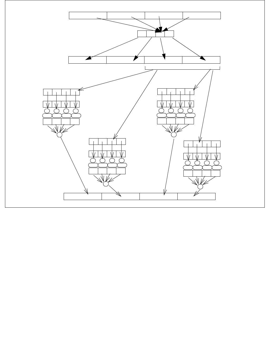
VDBPSADBW—Double Block Packed Sum-Absolute-Differences (SAD) on Unsigned Bytes
INSTRUCTION SET REFERENCE, V-Z
5-86 Vol. 2C
Figure 5-8. 64-bit Super Block of SAD Operation in VDBPSADBW
63 0153147
Src1 stationary dword 0
Tmp1 sliding dword
+
_
abs
_
abs
_
abs
_
abs
+
01531
Src1 stationary dword 0
Tmp1 sliding dword
_
abs
_
abs
_
abs
_
abs
Src1 stationary dword 1
Tmp1 sliding dword
_
abs
_
abs
_
abs
_
abs
Src1 stationary dword 1
Tmp1 sliding dword
_
abs
_
abs
_
abs
_
abs
+
+
Destination qword superblock
723
01531 723
82339 1531
01531 723
324763 3955
243955 3147
324763 3955
163147 2339
127+128*n 128*n31+128*n63+128*n95+128*n
128-bit Lane of Src2
03715
00B: DW0
01B: DW1
10B: DW2
11B: DW3
DW3 DW2 DW1 DW0
127+128*n 128*n31+128*n63+128*n95+128*n
128-bit Lane of Tmp1
imm8 shuffle control
Tmp1 qword superblock

VDBPSADBW—Double Block Packed Sum-Absolute-Differences (SAD) on Unsigned Bytes
INSTRUCTION SET REFERENCE, V-Z
Vol. 2C 5-87
Operation
VDBPSADBW (EVEX encoded versions)
(KL, VL) = (8, 128), (16, 256), (32, 512)
Selection of quadruplets:
FOR I = 0 to VL step 128
TMP1[I+31:I] select (SRC2[I+127: I], imm8[1:0])
TMP1[I+63: I+32] select (SRC2[I+127: I], imm8[3:2])
TMP1[I+95: I+64] select (SRC2[I+127: I], imm8[5:4])
TMP1[I+127: I+96] select (SRC2[I+127: I], imm8[7:6])
END FOR
SAD of quadruplets:
FOR I =0 to VL step 64
TMP_DEST[I+15:I] ABS(SRC1[I+7: I] - TMP1[I+7: I]) +
ABS(SRC1[I+15: I+8]- TMP1[I+15: I+8]) +
ABS(SRC1[I+23: I+16]- TMP1[I+23: I+16]) +
ABS(SRC1[I+31: I+24]- TMP1[I+31: I+24])
TMP_DEST[I+31: I+16] ABS(SRC1[I+7: I] - TMP1[I+15: I+8]) +
ABS(SRC1[I+15: I+8]- TMP1[I+23: I+16]) +
ABS(SRC1[I+23: I+16]- TMP1[I+31: I+24]) +
ABS(SRC1[I+31: I+24]- TMP1[I+39: I+32])
TMP_DEST[I+47: I+32] ABS(SRC1[I+39: I+32] - TMP1[I+23: I+16]) +
ABS(SRC1[I+47: I+40]- TMP1[I+31: I+24]) +
ABS(SRC1[I+55: I+48]- TMP1[I+39: I+32]) +
ABS(SRC1[I+63: I+56]- TMP1[I+47: I+40])
TMP_DEST[I+63: I+48] ABS(SRC1[I+39: I+32] - TMP1[I+31: I+24]) +
ABS(SRC1[I+47: I+40] - TMP1[I+39: I+32]) +
ABS(SRC1[I+55: I+48] - TMP1[I+47: I+40]) +
ABS(SRC1[I+63: I+56] - TMP1[I+55: I+48])
ENDFOR
FOR j 0 TO KL-1
i j * 16
IF k1[j] OR *no writemask*
THEN DEST[i+15:i] TMP_DEST[i+15:i]
ELSE
IF *merging-masking* ; merging-masking
THEN *DEST[i+15:i] remains unchanged*
ELSE ; zeroing-masking
DEST[i+15:i] 0
FI
FI;
ENDFOR
DEST[MAX_VL-1:VL] 0

VDBPSADBW—Double Block Packed Sum-Absolute-Differences (SAD) on Unsigned Bytes
INSTRUCTION SET REFERENCE, V-Z
5-88 Vol. 2C
Intel C/C++ Compiler Intrinsic Equivalent
VDBPSADBW __m512i _mm512_dbsad_epu8(__m512i a, __m512i b);
VDBPSADBW __m512i _mm512_mask_dbsad_epu8(__m512i s, __mmask32 m, __m512i a, __m512i b);
VDBPSADBW __m512i _mm512_maskz_dbsad_epu8(__mmask32 m, __m512i a, __m512i b);
VDBPSADBW __m256i _mm256_dbsad_epu8(__m256i a, __m256i b);
VDBPSADBW __m256i _mm256_mask_dbsad_epu8(__m256i s, __mmask16 m, __m256i a, __m256i b);
VDBPSADBW __m256i _mm256_maskz_dbsad_epu8(__mmask16 m, __m256i a, __m256i b);
VDBPSADBW __m128i _mm_dbsad_epu8(__m128i a, __m128i b);
VDBPSADBW __m128i _mm_mask_dbsad_epu8(__m128i s, __mmask8 m, __m128i a, __m128i b);
VDBPSADBW __m128i _mm_maskz_dbsad_epu8(__mmask8 m, __m128i a, __m128i b);
SIMD Floating-Point Exceptions
None
Other Exceptions
See Exceptions Type E4NF.nb.

VEXPANDPD—Load Sparse Packed Double-Precision Floating-Point Values from Dense Memory
INSTRUCTION SET REFERENCE, V-Z
Vol. 2C 5-89
VEXPANDPD—Load Sparse Packed Double-Precision Floating-Point Values from Dense Memory
Instruction Operand Encoding
Description
Expand (load) up to 8/4/2, contiguous, double-precision floating-point values of the input vector in the source
operand (the second operand) to sparse elements in the destination operand (the first operand) selected by the
writemask k1.
The destination operand is a ZMM/YMM/XMM register, the source operand can be a ZMM/YMM/XMM register or a
512/256/128-bit memory location.
The input vector starts from the lowest element in the source operand. The writemask register k1 selects the desti-
nation elements (a partial vector or sparse elements if less than 8 elements) to be replaced by the ascending
elements in the input vector. Destination elements not selected by the writemask k1 are either unmodified or
zeroed, depending on EVEX.z.
EVEX.vvvv is reserved and must be 1111b otherwise instructions will #UD.
Note that the compressed displacement assumes a pre-scaling (N) corresponding to the size of one single element
instead of the size of the full vector.
Operation
VEXPANDPD (EVEX encoded versions)
(KL, VL) = (2, 128), (4, 256), (8, 512)
k 0
FOR j 0 TO KL-1
i j * 64
IF k1[j] OR *no writemask*
THEN
DEST[i+63:i] SRC[k+63:k];
k k + 64
ELSE
IF *merging-masking* ; merging-masking
THEN *DEST[i+63:i] remains unchanged*
ELSE ; zeroing-masking
THEN DEST[i+63:i] 0
FI
FI;
ENDFOR
DEST[MAX_VL-1:VL] 0
Opcode/
Instruction
Op /
En
64/32
bit Mode
Support
CPUID
Feature
Flag
Description
EVEX.128.66.0F38.W1 88 /r
VEXPANDPD xmm1 {k1}{z},
xmm2/m128
T1S V/V AVX512VL
AVX512F
Expand packed double-precision floating-point values
from xmm2/m128 to xmm1 using writemask k1.
EVEX.256.66.0F38.W1 88 /r
VEXPANDPD ymm1 {k1}{z}, ymm2/m256
T1S V/V AVX512VL
AVX512F
Expand packed double-precision floating-point values
from ymm2/m256 to ymm1 using writemask k1.
EVEX.512.66.0F38.W1 88 /r
VEXPANDPD zmm1 {k1}{z}, zmm2/m512
T1S V/V AVX512F Expand packed double-precision floating-point values
from zmm2/m512 to zmm1 using writemask k1.
Op/En Operand 1 Operand 2 Operand 3 Operand 4
T1S ModRM:reg (w) ModRM:r/m (r) NA NA

VEXPANDPD—Load Sparse Packed Double-Precision Floating-Point Values from Dense Memory
INSTRUCTION SET REFERENCE, V-Z
5-90 Vol. 2C
Intel C/C++ Compiler Intrinsic Equivalent
VEXPANDPD __m512d _mm512_mask_expand_pd( __m512d s, __mmask8 k, __m512d a);
VEXPANDPD __m512d _mm512_maskz_expand_pd( __mmask8 k, __m512d a);
VEXPANDPD __m512d _mm512_mask_expandloadu_pd( __m512d s, __mmask8 k, void * a);
VEXPANDPD __m512d _mm512_maskz_expandloadu_pd( __mmask8 k, void * a);
VEXPANDPD __m256d _mm256_mask_expand_pd( __m256d s, __mmask8 k, __m256d a);
VEXPANDPD __m256d _mm256_maskz_expand_pd( __mmask8 k, __m256d a);
VEXPANDPD __m256d _mm256_mask_expandloadu_pd( __m256d s, __mmask8 k, void * a);
VEXPANDPD __m256d _mm256_maskz_expandloadu_pd( __mmask8 k, void * a);
VEXPANDPD __m128d _mm_mask_expand_pd( __m128d s, __mmask8 k, __m128d a);
VEXPANDPD __m128d _mm_maskz_expand_pd( __mmask8 k, __m128d a);
VEXPANDPD __m128d _mm_mask_expandloadu_pd( __m128d s, __mmask8 k, void * a);
VEXPANDPD __m128d _mm_maskz_expandloadu_pd( __mmask8 k, void * a);
SIMD Floating-Point Exceptions
None
Other Exceptions
See Exceptions Type E4.nb.
#UD If EVEX.vvvv != 1111B.

VEXPANDPS—Load Sparse Packed Single-Precision Floating-Point Values from Dense Memory
INSTRUCTION SET REFERENCE, V-Z
Vol. 2C 5-91
VEXPANDPS—Load Sparse Packed Single-Precision Floating-Point Values from Dense Memory
Instruction Operand Encoding
Description
Expand (load) up to 16/8/4, contiguous, single-precision floating-point values of the input vector in the source
operand (the second operand) to sparse elements of the destination operand (the first operand) selected by the
writemask k1.
The destination operand is a ZMM/YMM/XMM register, the source operand can be a ZMM/YMM/XMM register or a
512/256/128-bit memory location.
The input vector starts from the lowest element in the source operand. The writemask k1 selects the destination
elements (a partial vector or sparse elements if less than 16 elements) to be replaced by the ascending elements
in the input vector. Destination elements not selected by the writemask k1 are either unmodified or zeroed,
depending on EVEX.z.
EVEX.vvvv is reserved and must be 1111b otherwise instructions will #UD.
Note that the compressed displacement assumes a pre-scaling (N) corresponding to the size of one single element
instead of the size of the full vector.
Operation
VEXPANDPS (EVEX encoded versions)
(KL, VL) = (4, 128), (8, 256), (16, 512)
k 0
FOR j 0 TO KL-1
i j * 32
IF k1[j] OR *no writemask*
THEN
DEST[i+31:i] SRC[k+31:k];
k k + 32
ELSE
IF *merging-masking* ; merging-masking
THEN *DEST[i+31:i] remains unchanged*
ELSE ; zeroing-masking
DEST[i+31:i] 0
FI
FI;
ENDFOR
DEST[MAX_VL-1:VL] 0
Opcode/
Instruction
Op /
En
64/32
bit Mode
Support
CPUID
Feature
Flag
Description
EVEX.128.66.0F38.W0 88 /r
VEXPANDPS xmm1 {k1}{z}, xmm2/m128
T1S V/V AVX512VL
AVX512F
Expand packed single-precision floating-point values
from xmm2/m128 to xmm1 using writemask k1.
EVEX.256.66.0F38.W0 88 /r
VEXPANDPS ymm1 {k1}{z}, ymm2/m256
T1S V/V AVX512VL
AVX512F
Expand packed single-precision floating-point values
from ymm2/m256 to ymm1 using writemask k1.
EVEX.512.66.0F38.W0 88 /r
VEXPANDPS zmm1 {k1}{z}, zmm2/m512
T1S V/V AVX512F Expand packed single-precision floating-point values
from zmm2/m512 to zmm1 using writemask k1.
Op/En Operand 1 Operand 2 Operand 3 Operand 4
T1S ModRM:reg (w) ModRM:r/m (r) NA NA

VEXPANDPS—Load Sparse Packed Single-Precision Floating-Point Values from Dense Memory
INSTRUCTION SET REFERENCE, V-Z
5-92 Vol. 2C
Intel C/C++ Compiler Intrinsic Equivalent
VEXPANDPS __m512 _mm512_mask_expand_ps( __m512 s, __mmask16 k, __m512 a);
VEXPANDPS __m512 _mm512_maskz_expand_ps( __mmask16 k, __m512 a);
VEXPANDPS __m512 _mm512_mask_expandloadu_ps( __m512 s, __mmask16 k, void * a);
VEXPANDPS __m512 _mm512_maskz_expandloadu_ps( __mmask16 k, void * a);
VEXPANDPD __m256 _mm256_mask_expand_ps( __m256 s, __mmask8 k, __m256 a);
VEXPANDPD __m256 _mm256_maskz_expand_ps( __mmask8 k, __m256 a);
VEXPANDPD __m256 _mm256_mask_expandloadu_ps( __m256 s, __mmask8 k, void * a);
VEXPANDPD __m256 _mm256_maskz_expandloadu_ps( __mmask8 k, void * a);
VEXPANDPD __m128 _mm_mask_expand_ps( __m128 s, __mmask8 k, __m128 a);
VEXPANDPD __m128 _mm_maskz_expand_ps( __mmask8 k, __m128 a);
VEXPANDPD __m128 _mm_mask_expandloadu_ps( __m128 s, __mmask8 k, void * a);
VEXPANDPD __m128 _mm_maskz_expandloadu_ps( __mmask8 k, void * a);
SIMD Floating-Point Exceptions
None
Other Exceptions
See Exceptions Type E4.nb.
#UD If EVEX.vvvv != 1111B.

VERR/VERW—Verify a Segment for Reading or Writing
INSTRUCTION SET REFERENCE, V-Z
Vol. 2C 5-93
VERR/VERW—Verify a Segment for Reading or Writing
Instruction Operand Encoding
Description
Verifies whether the code or data segment specified with the source operand is readable (VERR) or writable
(VERW) from the current privilege level (CPL). The source operand is a 16-bit register or a memory location that
contains the segment selector for the segment to be verified. If the segment is accessible and readable (VERR) or
writable (VERW), the ZF flag is set; otherwise, the ZF flag is cleared. Code segments are never verified as writable.
This check cannot be performed on system segments.
To set the ZF flag, the following conditions must be met:
•The segment selector is not NULL.
•The selector must denote a descriptor within the bounds of the descriptor table (GDT or LDT).
•The selector must denote the descriptor of a code or data segment (not that of a system segment or gate).
•For the VERR instruction, the segment must be readable.
•For the VERW instruction, the segment must be a writable data segment.
•If the segment is not a conforming code segment, the segment’s DPL must be greater than or equal to (have
less or the same privilege as) both the CPL and the segment selector's RPL.
The validation performed is the same as is performed when a segment selector is loaded into the DS, ES, FS, or GS
register, and the indicated access (read or write) is performed. The segment selector's value cannot result in a
protection exception, enabling the software to anticipate possible segment access problems.
This instruction’s operation is the same in non-64-bit modes and 64-bit mode. The operand size is fixed at 16 bits.
Operation
IF SRC(Offset) > (GDTR(Limit) or (LDTR(Limit))
THEN ZF ← 0; FI;
Read segment descriptor;
IF SegmentDescriptor(DescriptorType) = 0 (* System segment *)
or (SegmentDescriptor(Type) ≠ conforming code segment)
and (CPL > DPL) or (RPL > DPL)
THEN
ZF ← 0;
ELSE
IF ((Instruction = VERR) and (Segment readable))
or ((Instruction = VERW) and (Segment writable))
THEN
ZF ← 1;
FI;
FI;
Opcode Instruction Op/
En
64-Bit
Mode
Compat/
Leg Mode
Description
0F 00 /4 VERR r/m16 M Valid Valid Set ZF=1 if segment specified with r/m16 can
be read.
0F 00 /5 VERW r/m16 M Valid Valid Set ZF=1 if segment specified with r/m16 can
be written.
Op/En Operand 1 Operand 2 Operand 3 Operand 4
M ModRM:r/m (r) NA NA NA

VERR/VERW—Verify a Segment for Reading or Writing
INSTRUCTION SET REFERENCE, V-Z
5-94 Vol. 2C
Flags Affected
The ZF flag is set to 1 if the segment is accessible and readable (VERR) or writable (VERW); otherwise, it is set to 0.
Protected Mode Exceptions
The only exceptions generated for these instructions are those related to illegal addressing of the source operand.
#GP(0) If a memory operand effective address is outside the CS, DS, ES, FS, or GS segment limit.
If the DS, ES, FS, or GS register is used to access memory and it contains a NULL segment
selector.
#SS(0) If a memory operand effective address is outside the SS segment limit.
#PF(fault-code) If a page fault occurs.
#AC(0) If alignment checking is enabled and an unaligned memory reference is made while the
current privilege level is 3.
#UD If the LOCK prefix is used.
Real-Address Mode Exceptions
#UD The VERR and VERW instructions are not recognized in real-address mode.
If the LOCK prefix is used.
Virtual-8086 Mode Exceptions
#UD The VERR and VERW instructions are not recognized in virtual-8086 mode.
If the LOCK prefix is used.
Compatibility Mode Exceptions
Same exceptions as in protected mode.
64-Bit Mode Exceptions
#SS(0) If a memory address referencing the SS segment is in a non-canonical form.
#GP(0) If the memory address is in a non-canonical form.
#PF(fault-code) If a page fault occurs.
#AC(0) If alignment checking is enabled and an unaligned memory reference is made while the
current privilege level is 3.
#UD If the LOCK prefix is used.

VEXP2PD—Approximation to the Exponential 2^x of Packed Double-Precision Floating-Point Values with Less Than 2^-23 Relative
INSTRUCTION SET REFERENCE, V-Z
Vol. 2C 5-95
VEXP2PD—Approximation to the Exponential 2^x of Packed Double-Precision Floating-Point
Values with Less Than 2^-23 Relative Error
Instruction Operand Encoding
Description
Computes the approximate base-2 exponential evaluation of the double-precision floating-point values in the
source operand (the second operand) and stores the results to the destination operand (the first operand) using
the writemask k1. The approximate base-2 exponential is evaluated with less than 2^-23 of relative error.
Denormal input values are treated as zeros and do not signal #DE, irrespective of MXCSR.DAZ. Denormal results
are flushed to zeros and do not signal #UE, irrespective of MXCSR.FZ.
The source operand is a ZMM register, a 512-bit memory location or a 512-bit vector broadcasted from a 64-bit
memory location. The destination operand is a ZMM register, conditionally updated using writemask k1.
EVEX.vvvv is reserved and must be 1111b otherwise instructions will #UD.
A numerically exact implementation of VEXP2xx can be found at https://software.intel.com/en-us/articles/refer-
ence-implementations-for-IA-approximation-instructions-vrcp14-vrsqrt14-vrcp28-vrsqrt28-vexp2.
Operation
VEXP2PD
(KL, VL) = (8, 512)
FOR j 0 TO KL-1
i j * 64
IF k1[j] OR *no writemask* THEN
IF (EVEX.b = 1) AND (SRC *is memory*)
THEN DEST[i+63:i] EXP2_23_DP(SRC[63:0])
ELSE DEST[i+63:i] EXP2_23_DP(SRC[i+63:i])
FI;
ELSE
IF *merging-masking* ; merging-masking
THEN *DEST[i+63:i] remains unchanged*
ELSE ; zeroing-masking
DEST[i+63:i] 0
FI;
FI;
ENDFOR;
Opcode/
Instruction
Op /
En
64/32
bit Mode
Support
CPUID
Feature
Flag
Description
EVEX.512.66.0F38.W1 C8 /r
VEXP2PD zmm1 {k1}{z},
zmm2/m512/m64bcst {sae}
FV V/V AVX512ER Computes approximations to the exponential 2^x (with less
than 2^-23 of maximum relative error) of the packed double-
precision floating-point values from zmm2/m512/m64bcst and
stores the floating-point result in zmm1with writemask k1.
Op/En Operand 1 Operand 2 Operand 3 Operand 4
FV ModRM:reg (r, w) ModRM:r/m (r) NA NA

VEXP2PD—Approximation to the Exponential 2^x of Packed Double-Precision Floating-Point Values with Less Than 2^-23 Relative Er-
INSTRUCTION SET REFERENCE, V-Z
5-96 Vol. 2C
Intel C/C++ Compiler Intrinsic Equivalent
VEXP2PD __m512d _mm512_exp2a23_round_pd (__m512d a, int sae);
VEXP2PD __m512d _mm512_mask_exp2a23_round_pd (__m512d a, __mmask8 m, __m512d b, int sae);
VEXP2PD __m512d _mm512_maskz_exp2a23_round_pd ( __mmask8 m, __m512d b, int sae);
SIMD Floating-Point Exceptions
Invalid (if SNaN input), Overflow
Other Exceptions
See Exceptions Type E2.
Table 5-4. Special Values Behavior
Source Input Result Comments
NaN QNaN(src) If (SRC = SNaN) then #I
+∞+∞
+/-0 1.0f Exact result
-∞+0.0f
Integral value N 2^ (N) Exact result

VEXP2PS—Approximation to the Exponential 2^x of Packed Single-Precision Floating-Point Values with Less Than 2^-23 Relative Er-
INSTRUCTION SET REFERENCE, V-Z
Vol. 2C 5-97
VEXP2PS—Approximation to the Exponential 2^x of Packed Single-Precision Floating-Point
Values with Less Than 2^-23 Relative Error
Instruction Operand Encoding
Description
Computes the approximate base-2 exponential evaluation of the single-precision floating-point values in the
source operand (the second operand) and store the results in the destination operand (the first operand) using the
writemask k1. The approximate base-2 exponential is evaluated with less than 2^-23 of relative error.
Denormal input values are treated as zeros and do not signal #DE, irrespective of MXCSR.DAZ. Denormal results
are flushed to zeros and do not signal #UE, irrespective of MXCSR.FZ.
The source operand is a ZMM register, a 512-bit memory location, or a 512-bit vector broadcasted from a 32-bit
memory location. The destination operand is a ZMM register, conditionally updated using writemask k1.
EVEX.vvvv is reserved and must be 1111b otherwise instructions will #UD.
A numerically exact implementation of VEXP2xx can be found at https://software.intel.com/en-us/articles/refer-
ence-implementations-for-IA-approximation-instructions-vrcp14-vrsqrt14-vrcp28-vrsqrt28-vexp2.
Operation
VEXP2PS
(KL, VL) = (16, 512)
FOR j 0 TO KL-1
i j * 32
IF k1[j] OR *no writemask* THEN
IF (EVEX.b = 1) AND (SRC *is memory*)
THEN DEST[i+31:i] EXP2_23_SP(SRC[31:0])
ELSE DEST[i+31:i] EXP2_23_SP(SRC[i+31:i])
FI;
ELSE
IF *merging-masking* ; merging-masking
THEN *DEST[i+31:i] remains unchanged*
ELSE ; zeroing-masking
DEST[i+31:i] 0
FI;
FI;
ENDFOR;
Opcode/
Instruction
Op /
En
64/32
bit Mode
Support
CPUID
Feature
Flag
Description
EVEX.512.66.0F38.W0 C8 /r
VEXP2PS zmm1 {k1}{z},
zmm2/m512/m32bcst {sae}
FV V/V AVX512ER Computes approximations to the exponential 2^x (with less
than 2^-23 of maximum relative error) of the packed single-
precision floating-point values from zmm2/m512/m32bcst and
stores the floating-point result in zmm1with writemask k1.
Op/En Operand 1 Operand 2 Operand 3 Operand 4
FV ModRM:reg (r, w) ModRM:r/m (r) NA NA

VEXP2PS—Approximation to the Exponential 2^x of Packed Single-Precision Floating-Point Values with Less Than 2^-23 Relative Er-
INSTRUCTION SET REFERENCE, V-Z
5-98 Vol. 2C
Intel C/C++ Compiler Intrinsic Equivalent
VEXP2PS __m512 _mm512_exp2a23_round_ps (__m512 a, int sae);
VEXP2PS __m512 _mm512_mask_exp2a23_round_ps (__m512 a, __mmask16 m, __m512 b, int sae);
VEXP2PS __m512 _mm512_maskz_exp2a23_round_ps (__mmask16 m, __m512 b, int sae);
SIMD Floating-Point Exceptions
Invalid (if SNaN input), Overflow
Other Exceptions
See Exceptions Type E2.
Table 5-5. Special Values Behavior
Source Input Result Comments
NaN QNaN(src) If (SRC = SNaN) then #I
+∞+∞
+/-0 1.0f Exact result
-∞+0.0f
Integral value N 2^ (N) Exact result

VEXTRACTF128/VEXTRACTF32x4/VEXTRACTF64x2/VEXTRACTF32x8/VEXTRACTF64x4—Extract Packed Floating-Point Values
INSTRUCTION SET REFERENCE, V-Z
Vol. 2C 5-99
VEXTRACTF128/VEXTRACTF32x4/VEXTRACTF64x2/VEXTRACTF32x8/VEXTRACTF64x4—Extr
act Packed Floating-Point Values
Instruction Operand Encoding
Description
VEXTRACTF128/VEXTRACTF32x4 and VEXTRACTF64x2 extract 128-bits of single-precision floating-point values
from the source operand (the second operand) and store to the low 128-bit of the destination operand (the first
operand). The 128-bit data extraction occurs at an 128-bit granular offset specified by imm8[0] (256-bit) or
imm8[1:0] as the multiply factor. The destination may be either a vector register or an 128-bit memory location.
VEXTRACTF32x4: The low 128-bit of the destination operand is updated at 32-bit granularity according to the
writemask.
VEXTRACTF32x8 and VEXTRACTF64x4 extract 256-bits of double-precision floating-point values from the source
operand (second operand) and store to the low 256-bit of the destination operand (the first operand). The 256-bit
data extraction occurs at an 256-bit granular offset specified by imm8[0] (256-bit) or imm8[0] as the multiply
factor The destination may be either a vector register or a 256-bit memory location.
VEXTRACTF64x4: The low 256-bit of the destination operand is updated at 64-bit granularity according to the
writemask.
VEX.vvvv and EVEX.vvvv are reserved and must be 1111b otherwise instructions will #UD.
The high 6 bits of the immediate are ignored.
If VEXTRACTF128 is encoded with VEX.L= 0, an attempt to execute the instruction encoded with VEX.L= 0 will
cause an #UD exception.
Opcode/
Instruction
Op /
En
64/32
bit Mode
Support
CPUID
Feature
Flag
Description
VEX.256.66.0F3A.W0 19 /r ib
VEXTRACTF128 xmm1/m128, ymm2,
imm8
RMI V/V AVX Extract 128 bits of packed floating-point values
from ymm2 and store results in xmm1/m128.
EVEX.256.66.0F3A.W0 19 /r ib
VEXTRACTF32X4 xmm1/m128 {k1}{z},
ymm2, imm8
T4 V/V AVX512VL
AVX512F
Extract 128 bits of packed single-precision floating-
point values from ymm2 and store results in
xmm1/m128 subject to writemask k1.
EVEX.512.66.0F3A.W0 19 /r ib
VEXTRACTF32x4 xmm1/m128 {k1}{z},
zmm2, imm8
T4 V/V AVX512F Extract 128 bits of packed single-precision floating-
point values from zmm2 and store results in
xmm1/m128 subject to writemask k1.
EVEX.256.66.0F3A.W1 19 /r ib
VEXTRACTF64X2 xmm1/m128 {k1}{z},
ymm2, imm8
T2 V/V AVX512VL
AVX512DQ
Extract 128 bits of packed double-precision
floating-point values from ymm2 and store results
in xmm1/m128 subject to writemask k1.
EVEX.512.66.0F3A.W1 19 /r ib
VEXTRACTF64X2 xmm1/m128 {k1}{z},
zmm2, imm8
T2 V/V AVX512DQ Extract 128 bits of packed double-precision
floating-point values from zmm2 and store results
in xmm1/m128 subject to writemask k1.
EVEX.512.66.0F3A.W0 1B /r ib
VEXTRACTF32X8 ymm1/m256 {k1}{z},
zmm2, imm8
T8 V/V AVX512DQ Extract 256 bits of packed single-precision floating-
point values from zmm2 and store results in
ymm1/m256 subject to writemask k1.
EVEX.512.66.0F3A.W1 1B /r ib
VEXTRACTF64x4 ymm1/m256 {k1}{z},
zmm2, imm8
T4 V/V AVX512F Extract 256 bits of packed double-precision
floating-point values from zmm2 and store results
in ymm1/m256 subject to writemask k1.
Op/En Operand 1 Operand 2 Operand 3 Operand 4
RMI ModRM:r/m (w) ModRM:reg (r) Imm8 NA
T2, T4, T8 ModRM:r/m (w) ModRM:reg (r) Imm8 NA

VEXTRACTF128/VEXTRACTF32x4/VEXTRACTF64x2/VEXTRACTF32x8/VEXTRACTF64x4—Extract Packed Floating-Point Values
INSTRUCTION SET REFERENCE, V-Z
5-100 Vol. 2C
Operation
VEXTRACTF32x4 (EVEX encoded versions) when destination is a register
VL = 256, 512
IF VL = 256
CASE (imm8[0]) OF
0: TMP_DEST[127:0] SRC1[127:0]
1: TMP_DEST[127:0] SRC1[255:128]
ESAC.
FI;
IF VL = 512
CASE (imm8[1:0]) OF
00: TMP_DEST[127:0] SRC1[127:0]
01: TMP_DEST[127:0] SRC1[255:128]
10: TMP_DEST[127:0] SRC1[383:256]
11: TMP_DEST[127:0] SRC1[511:384]
ESAC.
FI;
FOR j 0 TO 3
i j * 32
IF k1[j] OR *no writemask*
THEN DEST[i+31:i] TMP_DEST[i+31:i]
ELSE
IF *merging-masking* ; merging-masking
THEN *DEST[i+31:i] remains unchanged*
ELSE *zeroing-masking* ; zeroing-masking
DEST[i+31:i] 0
FI
FI;
ENDFOR
DEST[MAX_VL-1:128] 0

VEXTRACTF128/VEXTRACTF32x4/VEXTRACTF64x2/VEXTRACTF32x8/VEXTRACTF64x4—Extract Packed Floating-Point Values
INSTRUCTION SET REFERENCE, V-Z
Vol. 2C 5-101
VEXTRACTF32x4 (EVEX encoded versions) when destination is memory
VL = 256, 512
IF VL = 256
CASE (imm8[0]) OF
0: TMP_DEST[127:0] SRC1[127:0]
1: TMP_DEST[127:0] SRC1[255:128]
ESAC.
FI;
IF VL = 512
CASE (imm8[1:0]) OF
00: TMP_DEST[127:0] SRC1[127:0]
01: TMP_DEST[127:0] SRC1[255:128]
10: TMP_DEST[127:0] SRC1[383:256]
11: TMP_DEST[127:0] SRC1[511:384]
ESAC.
FI;
FOR j 0 TO 3
i j * 32
IF k1[j] OR *no writemask*
THEN DEST[i+31:i] TMP_DEST[i+31:i]
ELSE *DEST[i+31:i] remains unchanged* ; merging-masking
FI;
ENDFOR

VEXTRACTF128/VEXTRACTF32x4/VEXTRACTF64x2/VEXTRACTF32x8/VEXTRACTF64x4—Extract Packed Floating-Point Values
INSTRUCTION SET REFERENCE, V-Z
5-102 Vol. 2C
VEXTRACTF64x2 (EVEX encoded versions) when destination is a register
VL = 256, 512
IF VL = 256
CASE (imm8[0]) OF
0: TMP_DEST[127:0] SRC1[127:0]
1: TMP_DEST[127:0] SRC1[255:128]
ESAC.
FI;
IF VL = 512
CASE (imm8[1:0]) OF
00: TMP_DEST[127:0] SRC1[127:0]
01: TMP_DEST[127:0] SRC1[255:128]
10: TMP_DEST[127:0] SRC1[383:256]
11: TMP_DEST[127:0] SRC1[511:384]
ESAC.
FI;
FOR j 0 TO 1
i j * 64
IF k1[j] OR *no writemask*
THEN DEST[i+63:i] TMP_DEST[i+63:i]
ELSE
IF *merging-masking* ; merging-masking
THEN *DEST[i+63:i] remains unchanged*
ELSE *zeroing-masking* ; zeroing-masking
DEST[i+63:i] 0
FI
FI;
ENDFOR
DEST[MAX_VL-1:128] 0

VEXTRACTF128/VEXTRACTF32x4/VEXTRACTF64x2/VEXTRACTF32x8/VEXTRACTF64x4—Extract Packed Floating-Point Values
INSTRUCTION SET REFERENCE, V-Z
Vol. 2C 5-103
VEXTRACTF64x2 (EVEX encoded versions) when destination is memory
VL = 256, 512
IF VL = 256
CASE (imm8[0]) OF
0: TMP_DEST[127:0] SRC1[127:0]
1: TMP_DEST[127:0] SRC1[255:128]
ESAC.
FI;
IF VL = 512
CASE (imm8[1:0]) OF
00: TMP_DEST[127:0] SRC1[127:0]
01: TMP_DEST[127:0] SRC1[255:128]
10: TMP_DEST[127:0] SRC1[383:256]
11: TMP_DEST[127:0] SRC1[511:384]
ESAC.
FI;
FOR j 0 TO 1
i j * 64
IF k1[j] OR *no writemask*
THEN DEST[i+63:i] TMP_DEST[i+63:i]
ELSE *DEST[i+63:i] remains unchanged* ; merging-masking
FI;
ENDFOR
VEXTRACTF32x8 (EVEX.U1.512 encoded version) when destination is a register
VL = 512
CASE (imm8[0]) OF
0: TMP_DEST[255:0] SRC1[255:0]
1: TMP_DEST[255:0] SRC1[511:256]
ESAC.
FOR j 0 TO 7
i j * 32
IF k1[j] OR *no writemask*
THEN DEST[i+31:i] TMP_DEST[i+31:i]
ELSE
IF *merging-masking* ; merging-masking
THEN *DEST[i+31:i] remains unchanged*
ELSE *zeroing-masking* ; zeroing-masking
DEST[i+31:i] 0
FI
FI;
ENDFOR
DEST[MAX_VL-1:256] 0

VEXTRACTF128/VEXTRACTF32x4/VEXTRACTF64x2/VEXTRACTF32x8/VEXTRACTF64x4—Extract Packed Floating-Point Values
INSTRUCTION SET REFERENCE, V-Z
5-104 Vol. 2C
VEXTRACTF32x8 (EVEX.U1.512 encoded version) when destination is memory
CASE (imm8[0]) OF
0: TMP_DEST[255:0] SRC1[255:0]
1: TMP_DEST[255:0] SRC1[511:256]
ESAC.
FOR j 0 TO 7
i j * 32
IF k1[j] OR *no writemask*
THEN DEST[i+31:i] TMP_DEST[i+31:i]
ELSE *DEST[i+31:i] remains unchanged* ; merging-masking
FI;
ENDFOR
VEXTRACTF64x4 (EVEX.512 encoded version) when destination is a register
VL = 512
CASE (imm8[0]) OF
0: TMP_DEST[255:0] SRC1[255:0]
1: TMP_DEST[255:0] SRC1[511:256]
ESAC.
FOR j 0 TO 3
i j * 64
IF k1[j] OR *no writemask*
THEN DEST[i+63:i] TMP_DEST[i+63:i]
ELSE
IF *merging-masking* ; merging-masking
THEN *DEST[i+63:i] remains unchanged*
ELSE *zeroing-masking* ; zeroing-masking
DEST[i+63:i] 0
FI
FI;
ENDFOR
DEST[MAX_VL-1:256] 0
VEXTRACTF64x4 (EVEX.512 encoded version) when destination is memory
CASE (imm8[0]) OF
0: TMP_DEST[255:0] SRC1[255:0]
1: TMP_DEST[255:0] SRC1[511:256]
ESAC.
FOR j 0 TO 3
i j * 64
IF k1[j] OR *no writemask*
THEN DEST[i+63:i] TMP_DEST[i+63:i]
ELSE ; merging-masking
*DEST[i+63:i] remains unchanged*
FI;
ENDFOR

VEXTRACTF128/VEXTRACTF32x4/VEXTRACTF64x2/VEXTRACTF32x8/VEXTRACTF64x4—Extract Packed Floating-Point Values
INSTRUCTION SET REFERENCE, V-Z
Vol. 2C 5-105
VEXTRACTF128 (memory destination form)
CASE (imm8[0]) OF
0: DEST[127:0] SRC1[127:0]
1: DEST[127:0] SRC1[255:128]
ESAC.
VEXTRACTF128 (register destination form)
CASE (imm8[0]) OF
0: DEST[127:0] SRC1[127:0]
1: DEST[127:0] SRC1[255:128]
ESAC.
DEST[MAX_VL-1:128] 0
Intel C/C++ Compiler Intrinsic Equivalent
VEXTRACTF32x4 __m128 _mm512_extractf32x4_ps(__m512 a, const int nidx);
VEXTRACTF32x4 __m128 _mm512_mask_extractf32x4_ps(__m128 s, __mmask8 k, __m512 a, const int nidx);
VEXTRACTF32x4 __m128 _mm512_maskz_extractf32x4_ps( __mmask8 k, __m512 a, const int nidx);
VEXTRACTF32x4 __m128 _mm256_extractf32x4_ps(__m256 a, const int nidx);
VEXTRACTF32x4 __m128 _mm256_mask_extractf32x4_ps(__m128 s, __mmask8 k, __m256 a, const int nidx);
VEXTRACTF32x4 __m128 _mm256_maskz_extractf32x4_ps( __mmask8 k, __m256 a, const int nidx);
VEXTRACTF32x8 __m256 _mm512_extractf32x8_ps(__m512 a, const int nidx);
VEXTRACTF32x8 __m256 _mm512_mask_extractf32x8_ps(__m256 s, __mmask8 k, __m512 a, const int nidx);
VEXTRACTF32x8 __m256 _mm512_maskz_extractf32x8_ps( __mmask8 k, __m512 a, const int nidx);
VEXTRACTF64x2 __m128d _mm512_extractf64x2_pd(__m512d a, const int nidx);
VEXTRACTF64x2 __m128d _mm512_mask_extractf64x2_pd(__m128d s, __mmask8 k, __m512d a, const int nidx);
VEXTRACTF64x2 __m128d _mm512_maskz_extractf64x2_pd( __mmask8 k, __m512d a, const int nidx);
VEXTRACTF64x2 __m128d _mm256_extractf64x2_pd(__m256d a, const int nidx);
VEXTRACTF64x2 __m128d _mm256_mask_extractf64x2_pd(__m128d s, __mmask8 k, __m256d a, const int nidx);
VEXTRACTF64x2 __m128d _mm256_maskz_extractf64x2_pd( __mmask8 k, __m256d a, const int nidx);
VEXTRACTF64x4 __m256d _mm512_extractf64x4_pd( __m512d a, const int nidx);
VEXTRACTF64x4 __m256d _mm512_mask_extractf64x4_pd(__m256d s, __mmask8 k, __m512d a, const int nidx);
VEXTRACTF64x4 __m256d _mm512_maskz_extractf64x4_pd( __mmask8 k, __m512d a, const int nidx);
VEXTRACTF128 __m128 _mm256_extractf128_ps (__m256 a, int offset);
VEXTRACTF128 __m128d _mm256_extractf128_pd (__m256d a, int offset);
VEXTRACTF128 __m128i_mm256_extractf128_si256(__m256i a, int offset);
SIMD Floating-Point Exceptions
None
Other Exceptions
VEX-encoded instructions, see Exceptions Type 6;
EVEX-encoded instructions, see Exceptions Type E6NF.
#UD IF VEX.L = 0.
#UD If VEX.vvvv != 1111B or EVEX.vvvv != 1111B.

VEXTRACTI128/VEXTRACTI32x4/VEXTRACTI64x2/VEXTRACTI32x8/VEXTRACTI64x4—Extract packed Integer Values
INSTRUCTION SET REFERENCE, V-Z
5-106 Vol. 2C
VEXTRACTI128/VEXTRACTI32x4/VEXTRACTI64x2/VEXTRACTI32x8/VEXTRACTI64x4—Extract
packed Integer Values
Instruction Operand Encoding
Description
VEXTRACTI128/VEXTRACTI32x4 and VEXTRACTI64x2 extract 128-bits of doubleword integer values from the
source operand (the second operand) and store to the low 128-bit of the destination operand (the first operand).
The 128-bit data extraction occurs at an 128-bit granular offset specified by imm8[0] (256-bit) or imm8[1:0] as
the multiply factor. The destination may be either a vector register or an 128-bit memory location.
VEXTRACTI32x4: The low 128-bit of the destination operand is updated at 32-bit granularity according to the
writemask.
VEXTRACTI64x2: The low 128-bit of the destination operand is updated at 64-bit granularity according to the
writemask.
VEXTRACTI32x8 and VEXTRACTI64x4 extract 256-bits of quadword integer values from the source operand (the
second operand) and store to the low 256-bit of the destination operand (the first operand). The 256-bit data
extraction occurs at an 256-bit granular offset specified by imm8[0] (256-bit) or imm8[0] as the multiply factor
The destination may be either a vector register or a 256-bit memory location.
VEXTRACTI32x8: The low 256-bit of the destination operand is updated at 32-bit granularity according to the
writemask.
Opcode/
Instruction
Op /
En
64/32
bit Mode
Support
CPUID
Feature
Flag
Description
VEX.256.66.0F3A.W0 39 /r ib
VEXTRACTI128 xmm1/m128, ymm2,
imm8
RMI V/V AVX2 Extract 128 bits of integer data from ymm2 and
store results in xmm1/m128.
EVEX.256.66.0F3A.W0 39 /r ib
VEXTRACTI32X4 xmm1/m128 {k1}{z},
ymm2, imm8
T4 V/V AVX512VL
AVX512F
Extract 128 bits of double-word integer values
from ymm2 and store results in xmm1/m128
subject to writemask k1.
EVEX.512.66.0F3A.W0 39 /r ib
VEXTRACTI32x4 xmm1/m128 {k1}{z},
zmm2, imm8
T4 V/V AVX512F Extract 128 bits of double-word integer values
from zmm2 and store results in xmm1/m128
subject to writemask k1.
EVEX.256.66.0F3A.W1 39 /r ib
VEXTRACTI64X2 xmm1/m128 {k1}{z},
ymm2, imm8
T2 V/V AVX512VL
AVX512DQ
Extract 128 bits of quad-word integer values from
ymm2 and store results in xmm1/m128 subject to
writemask k1.
EVEX.512.66.0F3A.W1 39 /r ib
VEXTRACTI64X2 xmm1/m128 {k1}{z},
zmm2, imm8
T2 V/V AVX512DQ Extract 128 bits of quad-word integer values from
zmm2 and store results in xmm1/m128 subject to
writemask k1.
EVEX.512.66.0F3A.W0 3B /r ib
VEXTRACTI32X8 ymm1/m256 {k1}{z},
zmm2, imm8
T8 V/V AVX512DQ Extract 256 bits of double-word integer values
from zmm2 and store results in ymm1/m256
subject to writemask k1.
EVEX.512.66.0F3A.W1 3B /r ib
VEXTRACTI64x4 ymm1/m256 {k1}{z},
zmm2, imm8
T4 V/V AVX512F Extract 256 bits of quad-word integer values from
zmm2 and store results in ymm1/m256 subject to
writemask k1.
Op/En Operand 1 Operand 2 Operand 3 Operand 4
RMI ModRM:r/m (w) ModRM:reg (r) Imm8 NA
T2, T4, T8 ModRM:r/m (w) ModRM:reg (r) Imm8 NA

VEXTRACTI128/VEXTRACTI32x4/VEXTRACTI64x2/VEXTRACTI32x8/VEXTRACTI64x4—Extract packed Integer Values
INSTRUCTION SET REFERENCE, V-Z
Vol. 2C 5-107
VEXTRACTI64x4: The low 256-bit of the destination operand is updated at 64-bit granularity according to the
writemask.
VEX.vvvv and EVEX.vvvv are reserved and must be 1111b otherwise instructions will #UD.
The high 7 bits (6 bits in EVEX.512) of the immediate are ignored.
If VEXTRACTI128 is encoded with VEX.L= 0, an attempt to execute the instruction encoded with VEX.L= 0 will
cause an #UD exception.
Operation
VEXTRACTI32x4 (EVEX encoded versions) when destination is a register
VL = 256, 512
IF VL = 256
CASE (imm8[0]) OF
0: TMP_DEST[127:0] SRC1[127:0]
1: TMP_DEST[127:0] SRC1[255:128]
ESAC.
FI;
IF VL = 512
CASE (imm8[1:0]) OF
00: TMP_DEST[127:0] SRC1[127:0]
01: TMP_DEST[127:0] SRC1[255:128]
10: TMP_DEST[127:0] SRC1[383:256]
11: TMP_DEST[127:0] SRC1[511:384]
ESAC.
FI;
FOR j 0 TO 3
i j * 32
IF k1[j] OR *no writemask*
THEN DEST[i+31:i] TMP_DEST[i+31:i]
ELSE
IF *merging-masking* ; merging-masking
THEN *DEST[i+31:i] remains unchanged*
ELSE *zeroing-masking* ; zeroing-masking
DEST[i+31:i] 0
FI
FI;
ENDFOR
DEST[MAX_VL-1:128] 0
VEXTRACTI32x4 (EVEX encoded versions) when destination is memory
VL = 256, 512
IF VL = 256
CASE (imm8[0]) OF
0: TMP_DEST[127:0] SRC1[127:0]
1: TMP_DEST[127:0] SRC1[255:128]
ESAC.
FI;
IF VL = 512
CASE (imm8[1:0]) OF
00: TMP_DEST[127:0] SRC1[127:0]
01: TMP_DEST[127:0] SRC1[255:128]
10: TMP_DEST[127:0] SRC1[383:256]
11: TMP_DEST[127:0] SRC1[511:384]
ESAC.

VEXTRACTI128/VEXTRACTI32x4/VEXTRACTI64x2/VEXTRACTI32x8/VEXTRACTI64x4—Extract packed Integer Values
INSTRUCTION SET REFERENCE, V-Z
5-108 Vol. 2C
FI;
FOR j 0 TO 3
i j * 32
IF k1[j] OR *no writemask*
THEN DEST[i+31:i] TMP_DEST[i+31:i]
ELSE *DEST[i+31:i] remains unchanged* ; merging-masking
FI;
ENDFOR
VEXTRACTI64x2 (EVEX encoded versions) when destination is a register
VL = 256, 512
IF VL = 256
CASE (imm8[0]) OF
0: TMP_DEST[127:0] SRC1[127:0]
1: TMP_DEST[127:0] SRC1[255:128]
ESAC.
FI;
IF VL = 512
CASE (imm8[1:0]) OF
00: TMP_DEST[127:0] SRC1[127:0]
01: TMP_DEST[127:0] SRC1[255:128]
10: TMP_DEST[127:0] SRC1[383:256]
11: TMP_DEST[127:0] SRC1[511:384]
ESAC.
FI;
FOR j 0 TO 1
i j * 64
IF k1[j] OR *no writemask*
THEN DEST[i+63:i] TMP_DEST[i+63:i]
ELSE
IF *merging-masking* ; merging-masking
THEN *DEST[i+63:i] remains unchanged*
ELSE *zeroing-masking* ; zeroing-masking
DEST[i+63:i] 0
FI
FI;
ENDFOR
DEST[MAX_VL-1:128] 0

VEXTRACTI128/VEXTRACTI32x4/VEXTRACTI64x2/VEXTRACTI32x8/VEXTRACTI64x4—Extract packed Integer Values
INSTRUCTION SET REFERENCE, V-Z
Vol. 2C 5-109
VEXTRACTI64x2 (EVEX encoded versions) when destination is memory
VL = 256, 512
IF VL = 256
CASE (imm8[0]) OF
0: TMP_DEST[127:0] SRC1[127:0]
1: TMP_DEST[127:0] SRC1[255:128]
ESAC.
FI;
IF VL = 512
CASE (imm8[1:0]) OF
00: TMP_DEST[127:0] SRC1[127:0]
01: TMP_DEST[127:0] SRC1[255:128]
10: TMP_DEST[127:0] SRC1[383:256]
11: TMP_DEST[127:0] SRC1[511:384]
ESAC.
FI;
FOR j 0 TO 1
i j * 64
IF k1[j] OR *no writemask*
THEN DEST[i+63:i] TMP_DEST[i+63:i]
ELSE *DEST[i+63:i] remains unchanged* ; merging-masking
FI;
ENDFOR
VEXTRACTI32x8 (EVEX.U1.512 encoded version) when destination is a register
VL = 512
CASE (imm8[0]) OF
0: TMP_DEST[255:0] SRC1[255:0]
1: TMP_DEST[255:0] SRC1[511:256]
ESAC.
FOR j 0 TO 7
i j * 32
IF k1[j] OR *no writemask*
THEN DEST[i+31:i] TMP_DEST[i+31:i]
ELSE
IF *merging-masking* ; merging-masking
THEN *DEST[i+31:i] remains unchanged*
ELSE *zeroing-masking* ; zeroing-masking
DEST[i+31:i] 0
FI
FI;
ENDFOR
DEST[MAX_VL-1:256] 0

VEXTRACTI128/VEXTRACTI32x4/VEXTRACTI64x2/VEXTRACTI32x8/VEXTRACTI64x4—Extract packed Integer Values
INSTRUCTION SET REFERENCE, V-Z
5-110 Vol. 2C
VEXTRACTI32x8 (EVEX.U1.512 encoded version) when destination is memory
CASE (imm8[0]) OF
0: TMP_DEST[255:0] SRC1[255:0]
1: TMP_DEST[255:0] SRC1[511:256]
ESAC.
FOR j 0 TO 7
i j * 32
IF k1[j] OR *no writemask*
THEN DEST[i+31:i] TMP_DEST[i+31:i]
ELSE *DEST[i+31:i] remains unchanged* ; merging-masking
FI;
ENDFOR
VEXTRACTI64x4 (EVEX.512 encoded version) when destination is a register
VL = 512
CASE (imm8[0]) OF
0: TMP_DEST[255:0] SRC1[255:0]
1: TMP_DEST[255:0] SRC1[511:256]
ESAC.
FOR j 0 TO 3
i j * 64
IF k1[j] OR *no writemask*
THEN DEST[i+63:i] TMP_DEST[i+63:i]
ELSE
IF *merging-masking* ; merging-masking
THEN *DEST[i+63:i] remains unchanged*
ELSE *zeroing-masking* ; zeroing-masking
DEST[i+63:i] 0
FI
FI;
ENDFOR
DEST[MAX_VL-1:256] 0
VEXTRACTI64x4 (EVEX.512 encoded version) when destination is memory
CASE (imm8[0]) OF
0: TMP_DEST[255:0] SRC1[255:0]
1: TMP_DEST[255:0] SRC1[511:256]
ESAC.
FOR j 0 TO 3
i j * 64
IF k1[j] OR *no writemask*
THEN DEST[i+63:i] TMP_DEST[i+63:i]
ELSE *DEST[i+63:i] remains unchanged* ; merging-masking
FI;
ENDFOR

VEXTRACTI128/VEXTRACTI32x4/VEXTRACTI64x2/VEXTRACTI32x8/VEXTRACTI64x4—Extract packed Integer Values
INSTRUCTION SET REFERENCE, V-Z
Vol. 2C 5-111
VEXTRACTI128 (memory destination form)
CASE (imm8[0]) OF
0: DEST[127:0] SRC1[127:0]
1: DEST[127:0] SRC1[255:128]
ESAC.
VEXTRACTI128 (register destination form)
CASE (imm8[0]) OF
0: DEST[127:0] SRC1[127:0]
1: DEST[127:0] SRC1[255:128]
ESAC.
DEST[MAX_VL-1:128] 0
Intel C/C++ Compiler Intrinsic Equivalent
VEXTRACTI32x4 __m128i _mm512_extracti32x4_epi32(__m512i a, const int nidx);
VEXTRACTI32x4 __m128i _mm512_mask_extracti32x4_epi32(__m128i s, __mmask8 k, __m512i a, const int nidx);
VEXTRACTI32x4 __m128i _mm512_maskz_extracti32x4_epi32( __mmask8 k, __m512i a, const int nidx);
VEXTRACTI32x4 __m128i _mm256_extracti32x4_epi32(__m256i a, const int nidx);
VEXTRACTI32x4 __m128i _mm256_mask_extracti32x4_epi32(__m128i s, __mmask8 k, __m256i a, const int nidx);
VEXTRACTI32x4 __m128i _mm256_maskz_extracti32x4_epi32( __mmask8 k, __m256i a, const int nidx);
VEXTRACTI32x8 __m256i _mm512_extracti32x8_epi32(__m512i a, const int nidx);
VEXTRACTI32x8 __m256i _mm512_mask_extracti32x8_epi32(__m256i s, __mmask8 k, __m512i a, const int nidx);
VEXTRACTI32x8 __m256i _mm512_maskz_extracti32x8_epi32( __mmask8 k, __m512i a, const int nidx);
VEXTRACTI64x2 __m128i _mm512_extracti64x2_epi64(__m512i a, const int nidx);
VEXTRACTI64x2 __m128i _mm512_mask_extracti64x2_epi64(__m128i s, __mmask8 k, __m512i a, const int nidx);
VEXTRACTI64x2 __m128i _mm512_maskz_extracti64x2_epi64( __mmask8 k, __m512i a, const int nidx);
VEXTRACTI64x2 __m128i _mm256_extracti64x2_epi64(__m256i a, const int nidx);
VEXTRACTI64x2 __m128i _mm256_mask_extracti64x2_epi64(__m128i s, __mmask8 k, __m256i a, const int nidx);
VEXTRACTI64x2 __m128i _mm256_maskz_extracti64x2_epi64( __mmask8 k, __m256i a, const int nidx);
VEXTRACTI64x4 __m256i _mm512_extracti64x4_epi64(__m512i a, const int nidx);
VEXTRACTI64x4 __m256i _mm512_mask_extracti64x4_epi64(__m256i s, __mmask8 k, __m512i a, const int nidx);
VEXTRACTI64x4 __m256i _mm512_maskz_extracti64x4_epi64( __mmask8 k, __m512i a, const int nidx);
VEXTRACTI128 __m128i _mm256_extracti128_si256(__m256i a, int offset);
SIMD Floating-Point Exceptions
None
Other Exceptions
VEX-encoded instructions, see Exceptions Type 6;
EVEX-encoded instructions, see Exceptions Type E6NF.
#UD IF VEX.L = 0.
#UD If VEX.vvvv != 1111B or EVEX.vvvv != 1111B.

VFIXUPIMMPD—Fix Up Special Packed Float64 Values
INSTRUCTION SET REFERENCE, V-Z
5-112 Vol. 2C
VFIXUPIMMPD—Fix Up Special Packed Float64 Values
Instruction Operand Encoding
Description
Perform fix-up of quad-word elements encoded in double-precision floating-point format in the first source operand
(the second operand) using a 32-bit, two-level look-up table specified in the corresponding quadword element of
the second source operand (the third operand) with exception reporting specifier imm8. The elements that are
fixed-up are selected by mask bits of 1 specified in the opmask k1. Mask bits of 0 in the opmask k1 or table
response action of 0000b preserves the corresponding element of the first operand. The fixed-up elements from
the first source operand and the preserved element in the first operand are combined as the final results in the
destination operand (the first operand).
The destination and the first source operands are ZMM/YMM/XMM registers. The second source operand can be a
ZMM/YMM/XMM register, a 512/256/128-bit memory location or a 512/256/128-bit vector broadcasted from a 64-
bit memory location.
The two-level look-up table perform a fix-up of each DP FP input data in the first source operand by decoding the
input data encoding into 8 token types. A response table is defined for each token type that converts the input
encoding in the first source operand with one of 16 response actions.
This instruction is specifically intended for use in fixing up the results of arithmetic calculations involving one source
so that they match the spec, although it is generally useful for fixing up the results of multiple-instruction
sequences to reflect special-number inputs. For example, consider rcp(0). Input 0 to rcp, and you should get INF
according to the DX10 spec. However, evaluating rcp via Newton-Raphson, where x=approx(1/0), yields an incor-
rect result. To deal with this, VFIXUPIMMPD can be used after the N-R reciprocal sequence to set the result to the
correct value (i.e. INF when the input is 0).
If MXCSR.DAZ is not set, denormal input elements in the first source operand are considered as normal inputs and
do not trigger any fixup nor fault reporting.
Imm8 is used to set the required flags reporting. It supports #ZE and #IE fault reporting (see details below).
MXCSR mask bits are ignored and are treated as if all mask bits are set to masked response). If any of the imm8
bits is set and the condition met for fault reporting, MXCSR.IE or MXCSR.ZE might be updated.
This instruction is writemasked, so only those elements with the corresponding bit set in vector mask register k1
are computed and stored into zmm1. Elements in the destination with the corresponding bit clear in k1 retain their
previous values or are set to 0.
Opcode/
Instruction
Op /
En
64/32
bit Mode
Support
CPUID
Feature
Flag
Description
EVEX.NDS.128.66.0F3A.W1 54 /r ib
VFIXUPIMMPD xmm1 {k1}{z}, xmm2,
xmm3/m128/m64bcst, imm8
FV V/V AVX512VL
AVX512F
Fix up special numbers in float64 vector xmm1, float64
vector xmm2 and int64 vector xmm3/m128/m64bcst
and store the result in xmm1, under writemask.
EVEX.NDS.256.66.0F3A.W1 54 /r ib
VFIXUPIMMPD ymm1 {k1}{z}, ymm2,
ymm3/m256/m64bcst, imm8
FV V/V AVX512VL
AVX512F
Fix up special numbers in float64 vector ymm1, float64
vector ymm2 and int64 vector ymm3/m256/m64bcst
and store the result in ymm1, under writemask.
EVEX.NDS.512.66.0F3A.W1 54 /r ib
VFIXUPIMMPD zmm1 {k1}{z}, zmm2,
zmm3/m512/m64bcst{sae}, imm8
FV V/V AVX512F Fix up elements of float64 vector in zmm2 using int64
vector table in zmm3/m512/m64bcst, combine with
preserved elements from zmm1, and store the result in
zmm1.
Op/En Operand 1 Operand 2 Operand 3 Operand 4
FV ModRM:reg (r, w) EVEX.vvvv ModRM:r/m (r) Imm8

VFIXUPIMMPD—Fix Up Special Packed Float64 Values
INSTRUCTION SET REFERENCE, V-Z
Vol. 2C 5-113
Operation
enum TOKEN_TYPE
{
QNAN_TOKEN 0,
SNAN_TOKEN 1,
ZERO_VALUE_TOKEN 2,
POS_ONE_VALUE_TOKEN 3,
NEG_INF_TOKEN 4,
POS_INF_TOKEN 5,
NEG_VALUE_TOKEN 6,
POS_VALUE_TOKEN 7
}
FIXUPIMM_DP (dest[63:0], src1[63:0],tbl3[63:0], imm8 [7:0]){
tsrc[63:0] ((src1[62:52] = 0) AND (MXCSR.DAZ =1)) ? 0.0 : src1[63:0]
CASE(tsrc[63:0] of TOKEN_TYPE) {
QNAN_TOKEN: j 0;
SNAN_TOKEN: j 1;
ZERO_VALUE_TOKEN: j 2;
POS_ONE_VALUE_TOKEN: j 3;
NEG_INF_TOKEN: j 4;
POS_INF_TOKEN: j 5;
NEG_VALUE_TOKEN: j 6;
POS_VALUE_TOKEN: j 7;
} ; end source special CASE(tsrc…)
; The required response from src3 table is extracted
token_response[3:0] = tbl3[3+4*j:4*j];
CASE(token_response[3:0]) {
0000: dest[63:0] dest[63:0] ; ; preserve content of DEST
0001: dest[63:0] tsrc[63:0]; ; pass through src1 normal input value, denormal as zero
0010: dest[63:0] QNaN(tsrc[63:0]);
0011: dest[63:0] QNAN_Indefinite;
0100: dest[63:0] -INF;
0101: dest[63:0] +INF;
0110: dest[63:0] tsrc.sign? –INF : +INF;
0111: dest[63:0] -0;
1000: dest[63:0] +0;
1001: dest[63:0] -1;
1010: dest[63:0] +1;
1011: dest[63:0] ½;
1100: dest[63:0] 90.0;
1101: dest[63:0] PI/2;
1110: dest[63:0] MAX_FLOAT;
1111: dest[63:0] -MAX_FLOAT;
} ; end of token_response CASE

VFIXUPIMMPD—Fix Up Special Packed Float64 Values
INSTRUCTION SET REFERENCE, V-Z
5-114 Vol. 2C
; The required fault reporting from imm8 is extracted
; TOKENs are mutually exclusive and TOKENs priority defines the order.
; Multiple faults related to a single token can occur simultaneously.
IF (tsrc[63:0] of TOKEN_TYPE: ZERO_VALUE_TOKEN) AND imm8[0] then set #ZE;
IF (tsrc[63:0] of TOKEN_TYPE: ZERO_VALUE_TOKEN) AND imm8[1] then set #IE;
IF (tsrc[63:0] of TOKEN_TYPE: ONE_VALUE_TOKEN) AND imm8[2] then set #ZE;
IF (tsrc[63:0] of TOKEN_TYPE: ONE_VALUE_TOKEN) AND imm8[3] then set #IE;
IF (tsrc[63:0] of TOKEN_TYPE: SNAN_TOKEN) AND imm8[4] then set #IE;
IF (tsrc[63:0] of TOKEN_TYPE: NEG_INF_TOKEN) AND imm8[5] then set #IE;
IF (tsrc[63:0] of TOKEN_TYPE: NEG_VALUE_TOKEN) AND imm8[6] then set #IE;
IF (tsrc[63:0] of TOKEN_TYPE: POS_INF_TOKEN) AND imm8[7] then set #IE;
; end fault reporting
return dest[63:0];
} ; end of FIXUPIMM_DP()
VFIXUPIMMPD
(KL, VL) = (2, 128), (4, 256), (8, 512)
FOR j 0 TO KL-1
i j * 64
IF k1[j] OR *no writemask*
THEN
IF (EVEX.b = 1) AND (SRC2 *is memory*)
THEN
DEST[i+63:i] FIXUPIMM_DP(DEST[i+63:i], SRC1[i+63:i], SRC2[63:0], imm8 [7:0])
ELSE
DEST[i+63:i] FIXUPIMM_DP(DEST[i+63:i], SRC1[i+63:i], SRC2[i+63:i], imm8 [7:0])
FI;
ELSE
IF *merging-masking* ; merging-masking
THEN *DEST[i+63:i] remains unchanged*
ELSE DEST[i+63:i] 0 ; zeroing-masking
FI
FI;
ENDFOR
DEST[MAX_VL-1:VL] 0

VFIXUPIMMPD—Fix Up Special Packed Float64 Values
INSTRUCTION SET REFERENCE, V-Z
Vol. 2C 5-115
Immediate Control Description:
Intel C/C++ Compiler Intrinsic Equivalent
VFIXUPIMMPD __m512d _mm512_fixupimm_pd( __m512d a, __m512i tbl, int imm);
VFIXUPIMMPD __m512d _mm512_mask_fixupimm_pd(__m512d s, __mmask8 k, __m512d a, __m512i tbl, int imm);
VFIXUPIMMPD __m512d _mm512_maskz_fixupimm_pd( __mmask8 k, __m512d a, __m512i tbl, int imm);
VFIXUPIMMPD __m512d _mm512_fixupimm_round_pd( __m512d a, __m512i tbl, int imm, int sae);
VFIXUPIMMPD __m512d _mm512_mask_fixupimm_round_pd(__m512d s, __mmask8 k, __m512d a, __m512i tbl, int imm, int sae);
VFIXUPIMMPD __m512d _mm512_maskz_fixupimm_round_pd( __mmask8 k, __m512d a, __m512i tbl, int imm, int sae);
VFIXUPIMMPD __m256d _mm256_fixupimm_pd( __m256d a, __m256i tbl, int imm);
VFIXUPIMMPD __m256d _mm256_mask_fixupimm_pd(__m256d s, __mmask8 k, __m256d a, __m256i tbl, int imm);
VFIXUPIMMPD __m256d _mm256_maskz_fixupimm_pd( __mmask8 k, __m256d a, __m256i tbl, int imm);
VFIXUPIMMPD __m128d _mm_fixupimm_pd( __m128d a, __m128i tbl, int imm);
VFIXUPIMMPD __m128d _mm_mask_fixupimm_pd(__m128d s, __mmask8 k, __m128d a, __m128i tbl, int imm);
VFIXUPIMMPD __m128d _mm_maskz_fixupimm_pd( __mmask8 k, __m128d a, __m128i tbl, int imm);
SIMD Floating-Point Exceptions
Zero, Invalid
Other Exceptions
See Exceptions Type E2.
Figure 5-9. VFIXUPIMMPD Immediate Control Description
76543210
+ INF #IE
- INF #IE
SNaN #IE
- VE #IE
ONE
#IE
ONE #ZE
ZERO #IE
ZERO #ZE

VFIXUPIMMPS—Fix Up Special Packed Float32 Values
INSTRUCTION SET REFERENCE, V-Z
5-116 Vol. 2C
VFIXUPIMMPS—Fix Up Special Packed Float32 Values
Instruction Operand Encoding
Description
Perform fix-up of doubleword elements encoded in single-precision floating-point format in the first source operand
(the second operand) using a 32-bit, two-level look-up table specified in the corresponding doubleword element of
the second source operand (the third operand) with exception reporting specifier imm8. The elements that are
fixed-up are selected by mask bits of 1 specified in the opmask k1. Mask bits of 0 in the opmask k1 or table
response action of 0000b preserves the corresponding element of the first operand. The fixed-up elements from
the first source operand and the preserved element in the first operand are combined as the final results in the
destination operand (the first operand).
The destination and the first source operands are ZMM/YMM/XMM registers. The second source operand can be a
ZMM/YMM/XMM register, a 512/256/128-bit memory location or a 512/256/128-bit vector broadcasted from a 64-
bit memory location.
The two-level look-up table perform a fix-up of each SP FP input data in the first source operand by decoding the
input data encoding into 8 token types. A response table is defined for each token type that converts the input
encoding in the first source operand with one of 16 response actions.
This instruction is specifically intended for use in fixing up the results of arithmetic calculations involving one source
so that they match the spec, although it is generally useful for fixing up the results of multiple-instruction
sequences to reflect special-number inputs. For example, consider rcp(0). Input 0 to rcp, and you should get INF
according to the DX10 spec. However, evaluating rcp via Newton-Raphson, where x=approx(1/0), yields an incor-
rect result. To deal with this, VFIXUPIMMPS can be used after the N-R reciprocal sequence to set the result to the
correct value (i.e. INF when the input is 0).
If MXCSR.DAZ is not set, denormal input elements in the first source operand are considered as normal inputs and
do not trigger any fixup nor fault reporting.
Imm8 is used to set the required flags reporting. It supports #ZE and #IE fault reporting (see details below).
MXCSR.DAZ is used and refer to zmm2 only (i.e. zmm1 is not considered as zero in case MXCSR.DAZ is set).
MXCSR mask bits are ignored and are treated as if all mask bits are set to masked response). If any of the imm8
bits is set and the condition met for fault reporting, MXCSR.IE or MXCSR.ZE might be updated.
Opcode/
Instruction
Op /
En
64/32
bit Mode
Support
CPUID
Feature
Flag
Description
EVEX.NDS.128.66.0F3A.W0 54 /r
VFIXUPIMMPS xmm1 {k1}{z}, xmm2,
xmm3/m128/m32bcst, imm8
FV V/V AVX512VL
AVX512F
Fix up special numbers in float32 vector xmm1, float32
vector xmm2 and int32 vector xmm3/m128/m32bcst
and store the result in xmm1, under writemask.
EVEX.NDS.256.66.0F3A.W0 54 /r
VFIXUPIMMPS ymm1 {k1}{z}, ymm2,
ymm3/m256/m32bcst, imm8
FV V/V AVX512VL
AVX512F
Fix up special numbers in float32 vector ymm1, float32
vector ymm2 and int32 vector ymm3/m256/m32bcst
and store the result in ymm1, under writemask.
EVEX.NDS.512.66.0F3A.W0 54 /r ib
VFIXUPIMMPS zmm1 {k1}{z}, zmm2,
zmm3/m512/m32bcst{sae}, imm8
FV V/V AVX512F Fix up elements of float32 vector in zmm2 using int32
vector table in zmm3/m512/m32bcst, combine with
preserved elements from zmm1, and store the result in
zmm1.
Op/En Operand 1 Operand 2 Operand 3 Operand 4
FV ModRM:reg (r, w) EVEX.vvvv ModRM:r/m (r) Imm8

VFIXUPIMMPS—Fix Up Special Packed Float32 Values
INSTRUCTION SET REFERENCE, V-Z
Vol. 2C 5-117
Operation
enum TOKEN_TYPE
{
QNAN_TOKEN 0,
SNAN_TOKEN 1,
ZERO_VALUE_TOKEN 2,
POS_ONE_VALUE_TOKEN 3,
NEG_INF_TOKEN 4,
POS_INF_TOKEN 5,
NEG_VALUE_TOKEN 6,
POS_VALUE_TOKEN 7
}
FIXUPIMM_SP ( dest[31:0], src1[31:0],tbl3[31:0], imm8 [7:0]){
tsrc[31:0] ((src1[30:23] = 0) AND (MXCSR.DAZ =1)) ? 0.0 : src1[31:0]
CASE(tsrc[63:0] of TOKEN_TYPE) {
QNAN_TOKEN: j 0;
SNAN_TOKEN: j 1;
ZERO_VALUE_TOKEN: j 2;
POS_ONE_VALUE_TOKEN: j 3;
NEG_INF_TOKEN: j 4;
POS_INF_TOKEN: j 5;
NEG_VALUE_TOKEN: j 6;
POS_VALUE_TOKEN: j 7;
} ; end source special CASE(tsrc…)
; The required response from src3 table is extracted
token_response[3:0] = tbl3[3+4*j:4*j];
CASE(token_response[3:0]) {
0000: dest[31:0] dest[31:0]; ; preserve content of DEST
0001: dest[31:0] tsrc[31:0]; ; pass through src1 normal input value, denormal as zero
0010: dest[31:0] QNaN(tsrc[31:0]);
0011: dest[31:0] QNAN_Indefinite;
0100: dest[31:0] -INF;
0101: dest[31:0] +INF;
0110: dest[31:0] tsrc.sign? –INF : +INF;
0111: dest[31:0] -0;
1000: dest[31:0] +0;
1001: dest[31:0] -1;
1010: dest[31:0] +1;
1011: dest[31:0] ½;
1100: dest[31:0] 90.0;
1101: dest[31:0] PI/2;
1110: dest[31:0] MAX_FLOAT;
1111: dest[31:0] -MAX_FLOAT;
} ; end of token_response CASE

VFIXUPIMMPS—Fix Up Special Packed Float32 Values
INSTRUCTION SET REFERENCE, V-Z
5-118 Vol. 2C
; The required fault reporting from imm8 is extracted
; TOKENs are mutually exclusive and TOKENs priority defines the order.
; Multiple faults related to a single token can occur simultaneously.
IF (tsrc[31:0] of TOKEN_TYPE: ZERO_VALUE_TOKEN) AND imm8[0] then set #ZE;
IF (tsrc[31:0] of TOKEN_TYPE: ZERO_VALUE_TOKEN) AND imm8[1] then set #IE;
IF (tsrc[31:0] of TOKEN_TYPE: ONE_VALUE_TOKEN) AND imm8[2] then set #ZE;
IF (tsrc[31:0] of TOKEN_TYPE: ONE_VALUE_TOKEN) AND imm8[3] then set #IE;
IF (tsrc[31:0] of TOKEN_TYPE: SNAN_TOKEN) AND imm8[4] then set #IE;
IF (tsrc[31:0] of TOKEN_TYPE: NEG_INF_TOKEN) AND imm8[5] then set #IE;
IF (tsrc[31:0] of TOKEN_TYPE: NEG_VALUE_TOKEN) AND imm8[6] then set #IE;
IF (tsrc[31:0] of TOKEN_TYPE: POS_INF_TOKEN) AND imm8[7] then set #IE;
; end fault reporting
return dest[31:0];
} ; end of FIXUPIMM_SP()
VFIXUPIMMPS (EVEX)
(KL, VL) = (4, 128), (8, 256), (16, 512)
FOR j 0 TO KL-1
i j * 32
IF k1[j] OR *no writemask*
THEN
IF (EVEX.b = 1) AND (SRC2 *is memory*)
THEN
DEST[i+31:i] FIXUPIMM_SP(DEST[i+31:i], SRC1[i+31:i], SRC2[31:0], imm8 [7:0])
ELSE
DEST[i+31:i] FIXUPIMM_SP(DEST[i+31:i], SRC1[i+31:i], SRC2[i+31:i], imm8 [7:0])
FI;
ELSE
IF *merging-masking* ; merging-masking
THEN *DEST[i+31:i] remains unchanged*
ELSE DEST[i+31:i] 0 ; zeroing-masking
FI
FI;
ENDFOR
DEST[MAX_VL-1:VL] 0
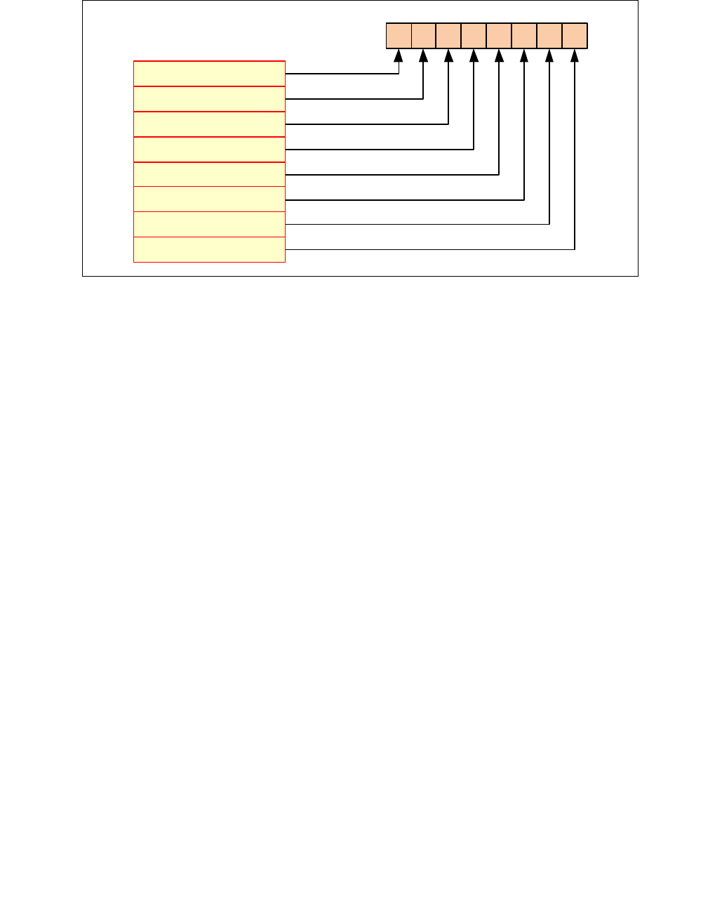
VFIXUPIMMPS—Fix Up Special Packed Float32 Values
INSTRUCTION SET REFERENCE, V-Z
Vol. 2C 5-119
Immediate Control Description:
Intel C/C++ Compiler Intrinsic Equivalent
VFIXUPIMMPS __m512 _mm512_fixupimm_ps( __m512 a, __m512i tbl, int imm);
VFIXUPIMMPS __m512 _mm512_mask_fixupimm_ps(__m512 s, __mmask16 k, __m512 a, __m512i tbl, int imm);
VFIXUPIMMPS __m512 _mm512_maskz_fixupimm_ps( __mmask16 k, __m512 a, __m512i tbl, int imm);
VFIXUPIMMPS __m512 _mm512_fixupimm_round_ps( __m512 a, __m512i tbl, int imm, int sae);
VFIXUPIMMPS __m512 _mm512_mask_fixupimm_round_ps(__m512 s, __mmask16 k, __m512 a, __m512i tbl, int imm, int sae);
VFIXUPIMMPS __m512 _mm512_maskz_fixupimm_round_ps( __mmask16 k, __m512 a, __m512i tbl, int imm, int sae);
VFIXUPIMMPS __m256 _mm256_fixupimm_ps( __m256 a, __m256i tbl, int imm);
VFIXUPIMMPS __m256 _mm256_mask_fixupimm_ps(__m256 s, __mmask8 k, __m256 a, __m256i tbl, int imm);
VFIXUPIMMPS __m256 _mm256_maskz_fixupimm_ps( __mmask8 k, __m256 a, __m256i tbl, int imm);
VFIXUPIMMPS __m128 _mm_fixupimm_ps( __m128 a, __m128i tbl, int imm);
VFIXUPIMMPS __m128 _mm_mask_fixupimm_ps(__m128 s, __mmask8 k, __m128 a, __m128i tbl, int imm);
VFIXUPIMMPS __m128 _mm_maskz_fixupimm_ps( __mmask8 k, __m128 a, __m128i tbl, int imm);
SIMD Floating-Point Exceptions
Zero, Invalid
Other Exceptions
See Exceptions Type E2.
Figure 5-10. VFIXUPIMMPS Immediate Control Description
76543210
+ INF #IE
- INF #IE
SNaN #IE
- VE #IE
ONE
#IE
ONE #ZE
ZERO #IE
ZERO #ZE

VFIXUPIMMSD—Fix Up Special Scalar Float64 Value
INSTRUCTION SET REFERENCE, V-Z
5-120 Vol. 2C
VFIXUPIMMSD—Fix Up Special Scalar Float64 Value
Instruction Operand Encoding
Description
Perform a fix-up of the low quadword element encoded in double-precision floating-point format in the first source
operand (the second operand) using a 32-bit, two-level look-up table specified in the low quadword element of the
second source operand (the third operand) with exception reporting specifier imm8. The element that is fixed-up is
selected by mask bit of 1 specified in the opmask k1. Mask bit of 0 in the opmask k1 or table response action of
0000b preserves the corresponding element of the first operand. The fixed-up element from the first source
operand or the preserved element in the first operand becomes the low quadword element of the destination
operand (the first operand). Bits 127:64 of the destination operand is copied from the corresponding bits of the first
source operand. The destination and first source operands are XMM registers. The second source operand can be a
XMM register or a 64- bit memory location.
The two-level look-up table perform a fix-up of each DP FP input data in the first source operand by decoding the
input data encoding into 8 token types. A response table is defined for each token type that converts the input
encoding in the first source operand with one of 16 response actions.
This instruction is specifically intended for use in fixing up the results of arithmetic calculations involving one source
so that they match the spec, although it is generally useful for fixing up the results of multiple-instruction
sequences to reflect special-number inputs. For example, consider rcp(0). Input 0 to rcp, and you should get INF
according to the DX10 spec. However, evaluating rcp via Newton-Raphson, where x=approx(1/0), yields an incor-
rect result. To deal with this, VFIXUPIMMPD can be used after the N-R reciprocal sequence to set the result to the
correct value (i.e. INF when the input is 0).
If MXCSR.DAZ is not set, denormal input elements in the first source operand are considered as normal inputs and
do not trigger any fixup nor fault reporting.
Imm8 is used to set the required flags reporting. It supports #ZE and #IE fault reporting (see details below).
MXCSR.DAZ is used and refer to zmm2 only (i.e. zmm1 is not considered as zero in case MXCSR.DAZ is set).
MXCSR mask bits are ignored and are treated as if all mask bits are set to masked response). If any of the imm8
bits is set and the condition met for fault reporting, MXCSR.IE or MXCSR.ZE might be updated.
Operation
enum TOKEN_TYPE
{
QNAN_TOKEN 0,
SNAN_TOKEN 1,
ZERO_VALUE_TOKEN 2,
POS_ONE_VALUE_TOKEN 3,
NEG_INF_TOKEN 4,
POS_INF_TOKEN 5,
NEG_VALUE_TOKEN 6,
POS_VALUE_TOKEN 7
}
Opcode/
Instruction
Op /
En
64/32
bit Mode
Support
CPUID
Feature
Flag
Description
EVEX.NDS.LIG.66.0F3A.W1 55 /r ib
VFIXUPIMMSD xmm1 {k1}{z},
xmm2, xmm3/m64{sae}, imm8
T1S V/V AVX512F Fix up a float64 number in the low quadword element of
xmm2 using scalar int32 table in xmm3/m64 and store the
result in xmm1.
Op/En Operand 1 Operand 2 Operand 3 Operand 4
T1S ModRM:reg (r, w) EVEX.vvvv ModRM:r/m (r) Imm8

VFIXUPIMMSD—Fix Up Special Scalar Float64 Value
INSTRUCTION SET REFERENCE, V-Z
Vol. 2C 5-121
FIXUPIMM_DP (dest[63:0], src1[63:0],tbl3[63:0], imm8 [7:0]){
tsrc[63:0] ((src1[62:52] = 0) AND (MXCSR.DAZ =1)) ? 0.0 : src1[63:0]
CASE(tsrc[63:0] of TOKEN_TYPE) {
QNAN_TOKEN: j 0;
SNAN_TOKEN: j 1;
ZERO_VALUE_TOKEN: j 2;
POS_ONE_VALUE_TOKEN: j 3;
NEG_INF_TOKEN: j 4;
POS_INF_TOKEN: j 5;
NEG_VALUE_TOKEN: j 6;
POS_VALUE_TOKEN: j 7;
} ; end source special CASE(tsrc…)
; The required response from src3 table is extracted
token_response[3:0] = tbl3[3+4*j:4*j];
CASE(token_response[3:0]) {
0000: dest[63:0] dest[63:0] ; preserve content of DEST
0001: dest[63:0] tsrc[63:0]; ; pass through src1 normal input value, denormal as zero
0010: dest[63:0] QNaN(tsrc[63:0]);
0011: dest[63:0] QNAN_Indefinite;
0100:dest[63:0] -INF;
0101: dest[63:0] +INF;
0110: dest[63:0] tsrc.sign? –INF : +INF;
0111: dest[63:0] -0;
1000: dest[63:0] +0;
1001: dest[63:0] -1;
1010: dest[63:0] +1;
1011: dest[63:0] ½;
1100: dest[63:0] 90.0;
1101: dest[63:0] PI/2;
1110: dest[63:0] MAX_FLOAT;
1111: dest[63:0] -MAX_FLOAT;
} ; end of token_response CASE
; The required fault reporting from imm8 is extracted
; TOKENs are mutually exclusive and TOKENs priority defines the order.
; Multiple faults related to a single token can occur simultaneously.
IF (tsrc[63:0] of TOKEN_TYPE: ZERO_VALUE_TOKEN) AND imm8[0] then set #ZE;
IF (tsrc[63:0] of TOKEN_TYPE: ZERO_VALUE_TOKEN) AND imm8[1] then set #IE;
IF (tsrc[63:0] of TOKEN_TYPE: ONE_VALUE_TOKEN) AND imm8[2] then set #ZE;
IF (tsrc[63:0] of TOKEN_TYPE: ONE_VALUE_TOKEN) AND imm8[3] then set #IE;
IF (tsrc[63:0] of TOKEN_TYPE: SNAN_TOKEN) AND imm8[4] then set #IE;
IF (tsrc[63:0] of TOKEN_TYPE: NEG_INF_TOKEN) AND imm8[5] then set #IE;
IF (tsrc[63:0] of TOKEN_TYPE: NEG_VALUE_TOKEN) AND imm8[6] then set #IE;
IF (tsrc[63:0] of TOKEN_TYPE: POS_INF_TOKEN) AND imm8[7] then set #IE;
; end fault reporting
return dest[63:0];
} ; end of FIXUPIMM_DP()
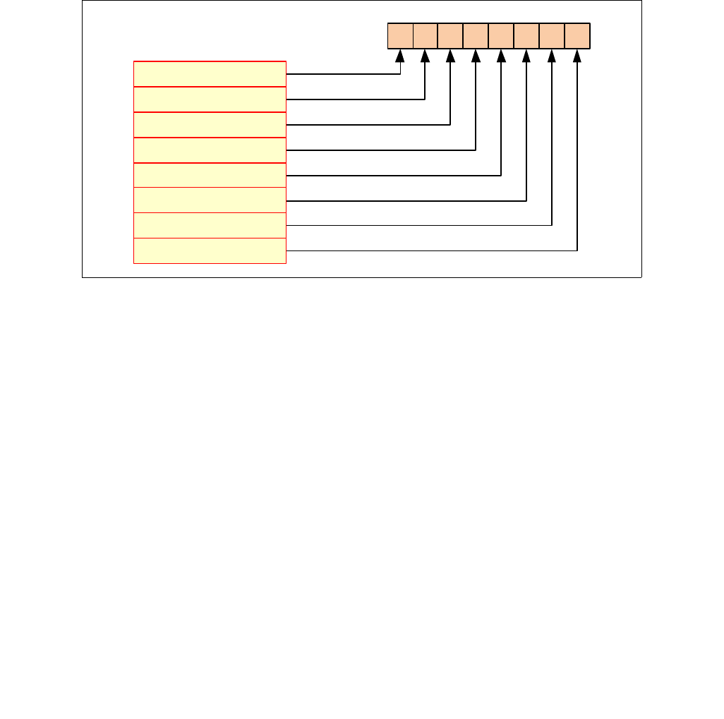
VFIXUPIMMSD—Fix Up Special Scalar Float64 Value
INSTRUCTION SET REFERENCE, V-Z
5-122 Vol. 2C
VFIXUPIMMSD (EVEX encoded version)
IF k1[0] OR *no writemask*
THEN DEST[63:0] FIXUPIMM_DP(DEST[63:0], SRC1[63:0], SRC2[63:0], imm8 [7:0])
ELSE
IF *merging-masking* ; merging-masking
THEN *DEST[63:0] remains unchanged*
ELSE DEST[63:0] 0 ; zeroing-masking
FI
FI;
DEST[127:64] SRC1[127:64]
DEST[MAX_VL-1:128] 0
Immediate Control Description:
Intel C/C++ Compiler Intrinsic Equivalent
VFIXUPIMMSD __m128d _mm_fixupimm_sd( __m128d a, __m128i tbl, int imm);
VFIXUPIMMSD __m128d _mm_mask_fixupimm_sd(__m128d s, __mmask8 k, __m128d a, __m128i tbl, int imm);
VFIXUPIMMSD __m128d _mm_maskz_fixupimm_sd( __mmask8 k, __m128d a, __m128i tbl, int imm);
VFIXUPIMMSD __m128d _mm_fixupimm_round_sd( __m128d a, __m128i tbl, int imm, int sae);
VFIXUPIMMSD __m128d _mm_mask_fixupimm_round_sd(__m128d s, __mmask8 k, __m128d a, __m128i tbl, int imm, int sae);
VFIXUPIMMSD __m128d _mm_maskz_fixupimm_round_sd( __mmask8 k, __m128d a, __m128i tbl, int imm, int sae);
SIMD Floating-Point Exceptions
Zero, Invalid
Other Exceptions
See Exceptions Type E3.
Figure 5-11. VFIXUPIMMSD Immediate Control Description
76543210
+INF #IE
-INF #IE
SNaN #IE
- VE #IE
ONE
#IE
ONE #ZE
ZERO #IE
ZERO #ZE

VFIXUPIMMSS—Fix Up Special Scalar Float32 Value
INSTRUCTION SET REFERENCE, V-Z
Vol. 2C 5-123
VFIXUPIMMSS—Fix Up Special Scalar Float32 Value
Instruction Operand Encoding
Description
Perform a fix-up of the low doubleword element encoded in single-precision floating-point format in the first source
operand (the second operand) using a 32-bit, two-level look-up table specified in the low doubleword element of
the second source operand (the third operand) with exception reporting specifier imm8. The element that is fixed-
up is selected by mask bit of 1 specified in the opmask k1. Mask bit of 0 in the opmask k1 or table response action
of 0000b preserves the corresponding element of the first operand. The fixed-up element from the first source
operand or the preserved element in the first operand becomes the low doubleword element of the destination
operand (the first operand) Bits 127:32 of the destination operand is copied from the corresponding bits of the first
source operand. The destination and first source operands are XMM registers. The second source operand can be a
XMM register or a 32-bit memory location.
The two-level look-up table perform a fix-up of each SP FP input data in the first source operand by decoding the
input data encoding into 8 token types. A response table is defined for each token type that converts the input
encoding in the first source operand with one of 16 response actions.
This instruction is specifically intended for use in fixing up the results of arithmetic calculations involving one
source so that they match the spec, although it is generally useful for fixing up the results of multiple-instruction
sequences to reflect special-number inputs. For example, consider rcp(0). Input 0 to rcp, and you should get INF
according to the DX10 spec. However, evaluating rcp via Newton-Raphson, where x=approx(1/0), yields an incor-
rect result. To deal with this, VFIXUPIMMPD can be used after the N-R reciprocal sequence to set the result to the
correct value (i.e. INF when the input is 0).
If MXCSR.DAZ is not set, denormal input elements in the first source operand are considered as normal inputs and
do not trigger any fixup nor fault reporting.
Imm8 is used to set the required flags reporting. It supports #ZE and #IE fault reporting (see details below).
MXCSR.DAZ is used and refer to zmm2 only (i.e. zmm1 is not considered as zero in case MXCSR.DAZ is set).
MXCSR mask bits are ignored and are treated as if all mask bits are set to masked response). If any of the imm8
bits is set and the condition met for fault reporting, MXCSR.IE or MXCSR.ZE might be updated.
Operation
enum TOKEN_TYPE
{
QNAN_TOKEN 0,
SNAN_TOKEN 1,
ZERO_VALUE_TOKEN 2,
POS_ONE_VALUE_TOKEN 3,
NEG_INF_TOKEN 4,
POS_INF_TOKEN 5,
NEG_VALUE_TOKEN 6,
POS_VALUE_TOKEN 7
}
Opcode/
Instruction
Op /
En
64/32
bit Mode
Support
CPUID
Feature
Flag
Description
EVEX.NDS.LIG.66.0F3A.W0 55 /r ib
VFIXUPIMMSS xmm1 {k1}{z}, xmm2,
xmm3/m32{sae}, imm8
T1S V/V AVX512F Fix up a float32 number in the low doubleword element
in xmm2 using scalar int32 table in xmm3/m32 and store
the result in xmm1.
Op/En Operand 1 Operand 2 Operand 3 Operand 4
T1S ModRM:reg (r, w) EVEX.vvvv ModRM:r/m (r) Imm8

VFIXUPIMMSS—Fix Up Special Scalar Float32 Value
INSTRUCTION SET REFERENCE, V-Z
5-124 Vol. 2C
FIXUPIMM_SP (dest[31:0], src1[31:0],tbl3[31:0], imm8 [7:0]){
tsrc[31:0] ((src1[30:23] = 0) AND (MXCSR.DAZ =1)) ? 0.0 : src1[31:0]
CASE(tsrc[63:0] of TOKEN_TYPE) {
QNAN_TOKEN: j 0;
SNAN_TOKEN: j 1;
ZERO_VALUE_TOKEN: j 2;
POS_ONE_VALUE_TOKEN: j 3;
NEG_INF_TOKEN: j 4;
POS_INF_TOKEN: j 5;
NEG_VALUE_TOKEN: j 6;
POS_VALUE_TOKEN: j = 7;
} ; end source special CASE(tsrc…)
; The required response from src3 table is extracted
token_response[3:0] = tbl3[3+4*j:4*j];
CASE(token_response[3:0]) {
0000: dest[31:0] dest[31:0]; ; preserve content of DEST
0001: dest[31:0] tsrc[31:0]; ; pass through src1 normal input value, denormal as zero
0010: dest[31:0] QNaN(tsrc[31:0]);
0011: dest[31:0] QNAN_Indefinite;
0100: dest[31:0] -INF;
0101: dest[31:0] +INF;
0110: dest[31:0] tsrc.sign? –INF : +INF;
0111: dest[31:0] -0;
1000: dest[31:0] +0;
1001: dest[31:0] -1;
1010: dest[31:0] +1;
1011: dest[31:0] ½;
1100: dest[31:0] 90.0;
1101: dest[31:0] PI/2;
1110: dest[31:0] MAX_FLOAT;
1111: dest[31:0] -MAX_FLOAT;
} ; end of token_response CASE
; The required fault reporting from imm8 is extracted
; TOKENs are mutually exclusive and TOKENs priority defines the order.
; Multiple faults related to a single token can occur simultaneously.
IF (tsrc[31:0] of TOKEN_TYPE: ZERO_VALUE_TOKEN) AND imm8[0] then set #ZE;
IF (tsrc[31:0] of TOKEN_TYPE: ZERO_VALUE_TOKEN) AND imm8[1] then set #IE;
IF (tsrc[31:0] of TOKEN_TYPE: ONE_VALUE_TOKEN) AND imm8[2] then set #ZE;
IF (tsrc[31:0] of TOKEN_TYPE: ONE_VALUE_TOKEN) AND imm8[3] then set #IE;
IF (tsrc[31:0] of TOKEN_TYPE: SNAN_TOKEN) AND imm8[4] then set #IE;
IF (tsrc[31:0] of TOKEN_TYPE: NEG_INF_TOKEN) AND imm8[5] then set #IE;
IF (tsrc[31:0] of TOKEN_TYPE: NEG_VALUE_TOKEN) AND imm8[6] then set #IE;
IF (tsrc[31:0] of TOKEN_TYPE: POS_INF_TOKEN) AND imm8[7] then set #IE;
; end fault reporting
return dest[31:0];
} ; end of FIXUPIMM_SP()
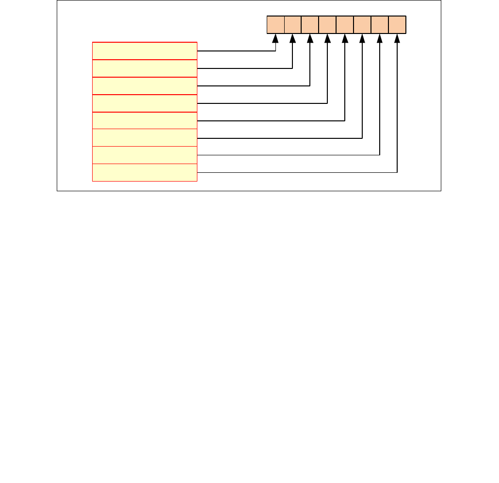
VFIXUPIMMSS—Fix Up Special Scalar Float32 Value
INSTRUCTION SET REFERENCE, V-Z
Vol. 2C 5-125
VFIXUPIMMSS (EVEX encoded version)
IF k1[0] OR *no writemask*
THEN DEST[31:0] FIXUPIMM_SP(DEST[31:0], SRC1[31:0], SRC2[31:0], imm8 [7:0])
ELSE
IF *merging-masking* ; merging-masking
THEN *DEST[31:0] remains unchanged*
ELSE DEST[31:0] 0 ; zeroing-masking
FI
FI;
DEST[127:32] SRC1[127:32]
DEST[MAX_VL-1:128] 0
Immediate Control Description:
Intel C/C++ Compiler Intrinsic Equivalent
VFIXUPIMMSS __m128 _mm_fixupimm_ss( __m128 a, __m128i tbl, int imm);
VFIXUPIMMSS __m128 _mm_mask_fixupimm_ss(__m128 s, __mmask8 k, __m128 a, __m128i tbl, int imm);
VFIXUPIMMSS __m128 _mm_maskz_fixupimm_ss( __mmask8 k, __m128 a, __m128i tbl, int imm);
VFIXUPIMMSS __m128 _mm_fixupimm_round_ss( __m128 a, __m128i tbl, int imm, int sae);
VFIXUPIMMSS __m128 _mm_mask_fixupimm_round_ss(__m128 s, __mmask8 k, __m128 a, __m128i tbl, int imm, int sae);
VFIXUPIMMSS __m128 _mm_maskz_fixupimm_round_ss( __mmask8 k, __m128 a, __m128i tbl, int imm, int sae);
SIMD Floating-Point Exceptions
Zero, Invalid
Other Exceptions
See Exceptions Type E3.
Figure 5-12. VFIXUPIMMSS Immediate Control Description
76543210
+ INF #IE
- INF #IE
SNaN #IE
-VE #IE
ONE
#IE
ONE #ZE
ZERO #IE
ZERO #ZE

VFMADD132PD/VFMADD213PD/VFMADD231PD—Fused Multiply-Add of Packed Double-Precision Floating-Point Values
INSTRUCTION SET REFERENCE, V-Z
5-126 Vol. 2C
VFMADD132PD/VFMADD213PD/VFMADD231PD—Fused Multiply-Add of Packed Double-
Precision Floating-Point Values
Opcode/
Instruction
Op/
En
64/32
bit Mode
Support
CPUID
Feature
Flag
Description
VEX.NDS.128.66.0F38.W1 98 /r
VFMADD132PD xmm1, xmm2,
xmm3/m128
RVM V/V FMA Multiply packed double-precision floating-point
values from xmm1 and xmm3/mem, add to xmm2
and put result in xmm1.
VEX.NDS.128.66.0F38.W1 A8 /r
VFMADD213PD xmm1, xmm2,
xmm3/m128
RVM V/V FMA Multiply packed double-precision floating-point
values from xmm1 and xmm2, add to xmm3/mem
and put result in xmm1.
VEX.NDS.128.66.0F38.W1 B8 /r
VFMADD231PD xmm1, xmm2,
xmm3/m128
RVM V/V FMA Multiply packed double-precision floating-point
values from xmm2 and xmm3/mem, add to xmm1
and put result in xmm1.
VEX.NDS.256.66.0F38.W1 98 /r
VFMADD132PD ymm1, ymm2,
ymm3/m256
RVM V/V FMA Multiply packed double-precision floating-point
values from ymm1 and ymm3/mem, add to ymm2
and put result in ymm1.
VEX.NDS.256.66.0F38.W1 A8 /r
VFMADD213PD ymm1, ymm2,
ymm3/m256
RVM V/V FMA Multiply packed double-precision floating-point
values from ymm1 and ymm2, add to ymm3/mem
and put result in ymm1.
VEX.NDS.256.66.0F38.W1 B8 /r
VFMADD231PD ymm1, ymm2,
ymm3/m256
RVM V/V FMA Multiply packed double-precision floating-point
values from ymm2 and ymm3/mem, add to ymm1
and put result in ymm1.
EVEX.NDS.128.66.0F38.W1 98 /r
VFMADD132PD xmm1 {k1}{z}, xmm2,
xmm3/m128/m64bcst
RVM V/V AVX512VL
AVX512F
Multiply packed double-precision floating-point
values from xmm1 and xmm3/m128/m64bcst, add
to xmm2 and put result in xmm1.
EVEX.NDS.128.66.0F38.W1 A8 /r
VFMADD213PD xmm1 {k1}{z}, xmm2,
xmm3/m128/m64bcst
FV V/V AVX512VL
AVX512F
Multiply packed double-precision floating-point
values from xmm1 and xmm2, add to
xmm3/m128/m64bcst and put result in xmm1.
EVEX.NDS.128.66.0F38.W1 B8 /r
VFMADD231PD xmm1 {k1}{z}, xmm2,
xmm3/m128/m64bcst
FV V/V AVX512VL
AVX512F
Multiply packed double-precision floating-point
values from xmm2 and xmm3/m128/m64bcst, add
to xmm1 and put result in xmm1.
EVEX.NDS.256.66.0F38.W1 98 /r
VFMADD132PD ymm1 {k1}{z}, ymm2,
ymm3/m256/m64bcst
FV V/V AVX512VL
AVX512F
Multiply packed double-precision floating-point
values from ymm1 and ymm3/m256/m64bcst, add
to ymm2 and put result in ymm1.
EVEX.NDS.256.66.0F38.W1 A8 /r
VFMADD213PD ymm1 {k1}{z}, ymm2,
ymm3/m256/m64bcst
FV V/V AVX512VL
AVX512F
Multiply packed double-precision floating-point
values from ymm1 and ymm2, add to
ymm3/m256/m64bcst and put result in ymm1.
EVEX.NDS.256.66.0F38.W1 B8 /r
VFMADD231PD ymm1 {k1}{z}, ymm2,
ymm3/m256/m64bcst
FV V/V AVX512VL
AVX512F
Multiply packed double-precision floating-point
values from ymm2 and ymm3/m256/m64bcst, add
to ymm1 and put result in ymm1.
EVEX.NDS.512.66.0F38.W1 98 /r
VFMADD132PD zmm1 {k1}{z}, zmm2,
zmm3/m512/m64bcst{er}
FV V/V AVX512F Multiply packed double-precision floating-point
values from zmm1 and zmm3/m512/m64bcst, add
to zmm2 and put result in zmm1.
EVEX.NDS.512.66.0F38.W1 A8 /r
VFMADD213PD zmm1 {k1}{z}, zmm2,
zmm3/m512/m64bcst{er}
FV V/V AVX512F Multiply packed double-precision floating-point
values from zmm1 and zmm2, add to
zmm3/m512/m64bcst and put result in zmm1.
EVEX.NDS.512.66.0F38.W1 B8 /r
VFMADD231PD zmm1 {k1}{z}, zmm2,
zmm3/m512/m64bcst{er}
FV V/V AVX512F Multiply packed double-precision floating-point
values from zmm2 and zmm3/m512/m64bcst, add
to zmm1 and put result in zmm1.

VFMADD132PD/VFMADD213PD/VFMADD231PD—Fused Multiply-Add of Packed Double-Precision Floating-Point Values
INSTRUCTION SET REFERENCE, V-Z
Vol. 2C 5-127
Instruction Operand Encoding
Description
Performs a set of SIMD multiply-add computation on packed double-precision floating-point values using three
source operands and writes the multiply-add results in the destination operand. The destination operand is also the
first source operand. The second operand must be a SIMD register. The third source operand can be a SIMD
register or a memory location.
VFMADD132PD: Multiplies the two, four or eight packed double-precision floating-point values from the first source
operand to the two, four or eight packed double-precision floating-point values in the third source operand, adds
the infinite precision intermediate result to the two, four or eight packed double-precision floating-point values in
the second source operand, performs rounding and stores the resulting two, four or eight packed double-precision
floating-point values to the destination operand (first source operand).
VFMADD213PD: Multiplies the two, four or eight packed double-precision floating-point values from the second
source operand to the two, four or eight packed double-precision floating-point values in the first source operand,
adds the infinite precision intermediate result to the two, four or eight packed double-precision floating-point
values in the third source operand, performs rounding and stores the resulting two, four or eight packed double-
precision floating-point values to the destination operand (first source operand).
VFMADD231PD: Multiplies the two, four or eight packed double-precision floating-point values from the second
source to the two, four or eight packed double-precision floating-point values in the third source operand, adds the
infinite precision intermediate result to the two, four or eight packed double-precision floating-point values in the
first source operand, performs rounding and stores the resulting two, four or eight packed double-precision
floating-point values to the destination operand (first source operand).
EVEX encoded versions: The destination operand (also first source operand) is a ZMM register and encoded in
reg_field. The second source operand is a ZMM register and encoded in EVEX.vvvv. The third source operand is a
ZMM register, a 512-bit memory location, or a 512-bit vector broadcasted from a 64-bit memory location. The
destination operand is conditionally updated with write mask k1.
VEX.256 encoded version: The destination operand (also first source operand) is a YMM register and encoded in
reg_field. The second source operand is a YMM register and encoded in VEX.vvvv. The third source operand is a
YMM register or a 256-bit memory location and encoded in rm_field.
VEX.128 encoded version: The destination operand (also first source operand) is a XMM register and encoded in
reg_field. The second source operand is a XMM register and encoded in VEX.vvvv. The third source operand is a
XMM register or a 128-bit memory location and encoded in rm_field. The upper 128 bits of the YMM destination
register are zeroed.
Op/En Operand 1 Operand 2 Operand 3 Operand 4
RVM ModRM:reg (r, w) VEX.vvvv (r) ModRM:r/m (r) NA
FV ModRM:reg (r, w) EVEX.vvvv (r) ModRM:r/m (r) NA

VFMADD132PD/VFMADD213PD/VFMADD231PD—Fused Multiply-Add of Packed Double-Precision Floating-Point Values
INSTRUCTION SET REFERENCE, V-Z
5-128 Vol. 2C
Operation
In the operations below, “*” and “+” symbols represent multiplication and addition with infinite precision inputs and outputs (no
rounding).
VFMADD132PD DEST, SRC2, SRC3 (VEX encoded version)
IF (VEX.128) THEN
MAXNUM 2
ELSEIF (VEX.256)
MAXNUM 4
FI
For i = 0 to MAXNUM-1 {
n 64*i;
DEST[n+63:n] RoundFPControl_MXCSR(DEST[n+63:n]*SRC3[n+63:n] + SRC2[n+63:n])
}
IF (VEX.128) THEN
DEST[MAX_VL-1:128] 0
ELSEIF (VEX.256)
DEST[MAX_VL-1:256] 0
FI
VFMADD213PD DEST, SRC2, SRC3 (VEX encoded version)
IF (VEX.128) THEN
MAXNUM 2
ELSEIF (VEX.256)
MAXNUM 4
FI
For i = 0 to MAXNUM-1 {
n 64*i;
DEST[n+63:n] RoundFPControl_MXCSR(SRC2[n+63:n]*DEST[n+63:n] + SRC3[n+63:n])
}
IF (VEX.128) THEN
DEST[MAX_VL-1:128] 0
ELSEIF (VEX.256)
DEST[MAX_VL-1:256] 0
FI
VFMADD231PD DEST, SRC2, SRC3 (VEX encoded version)
IF (VEX.128) THEN
MAXNUM 2
ELSEIF (VEX.256)
MAXNUM 4
FI
For i = 0 to MAXNUM-1 {
n 64*i;
DEST[n+63:n] RoundFPControl_MXCSR(SRC2[n+63:n]*SRC3[n+63:n] + DEST[n+63:n])
}
IF (VEX.128) THEN
DEST[MAX_VL-1:128] 0
ELSEIF (VEX.256)
DEST[MAX_VL-1:256] 0
FI

VFMADD132PD/VFMADD213PD/VFMADD231PD—Fused Multiply-Add of Packed Double-Precision Floating-Point Values
INSTRUCTION SET REFERENCE, V-Z
Vol. 2C 5-129
VFMADD132PD DEST, SRC2, SRC3 (EVEX encoded version, when src3 operand is a register)
(KL, VL) = (2, 128), (4, 256), (8, 512)
IF (VL = 512) AND (EVEX.b = 1)
THEN
SET_RM(EVEX.RC);
ELSE
SET_RM(MXCSR.RM);
FI;
FOR j 0 TO KL-1
i j * 64
IF k1[j] OR *no writemask*
THEN DEST[i+63:i]
RoundFPControl(DEST[i+63:i]*SRC3[i+63:i] + SRC2[i+63:i])
ELSE
IF *merging-masking* ; merging-masking
THEN *DEST[i+63:i] remains unchanged*
ELSE ; zeroing-masking
DEST[i+63:i] 0
FI
FI;
ENDFOR
DEST[MAX_VL-1:VL] 0
VFMADD132PD DEST, SRC2, SRC3 (EVEX encoded version, when src3 operand is a memory source)
(KL, VL) = (2, 128), (4, 256), (8, 512)
FOR j 0 TO KL-1
i j * 64
IF k1[j] OR *no writemask*
THEN
IF (EVEX.b = 1)
THEN
DEST[i+63:i]
RoundFPControl_MXCSR(DEST[i+63:i]*SRC3[63:0] + SRC2[i+63:i])
ELSE
DEST[i+63:i]
RoundFPControl_MXCSR(DEST[i+63:i]*SRC3[i+63:i] + SRC2[i+63:i])
FI;
ELSE
IF *merging-masking* ; merging-masking
THEN *DEST[i+63:i] remains unchanged*
ELSE ; zeroing-masking
DEST[i+63:i] 0
FI
FI;
ENDFOR
DEST[MAX_VL-1:VL] 0

VFMADD132PD/VFMADD213PD/VFMADD231PD—Fused Multiply-Add of Packed Double-Precision Floating-Point Values
INSTRUCTION SET REFERENCE, V-Z
5-130 Vol. 2C
VFMADD213PD DEST, SRC2, SRC3 (EVEX encoded version, when src3 operand is a is a register)
(KL, VL) = (2, 128), (4, 256), (8, 512)
IF (VL = 512) AND (EVEX.b = 1)
THEN
SET_RM(EVEX.RC);
ELSE
SET_RM(MXCSR.RM);
FI;
FOR j 0 TO KL-1
i j * 64
IF k1[j] OR *no writemask*
THEN DEST[i+63:i]
RoundFPControl(SRC2[i+63:i]*DEST[i+63:i] + SRC3[i+63:i])
ELSE
IF *merging-masking* ; merging-masking
THEN *DEST[i+63:i] remains unchanged*
ELSE ; zeroing-masking
DEST[i+63:i] 0
FI
FI;
ENDFOR
DEST[MAX_VL-1:VL] 0

VFMADD132PD/VFMADD213PD/VFMADD231PD—Fused Multiply-Add of Packed Double-Precision Floating-Point Values
INSTRUCTION SET REFERENCE, V-Z
Vol. 2C 5-131
VFMADD213PD DEST, SRC2, SRC3 (EVEX encoded version, when src3 operand is a memory source)
(KL, VL) = (2, 128), (4, 256), (8, 512)
FOR j 0 TO KL-1
i j * 64
IF k1[j] OR *no writemask*
THEN
IF (EVEX.b = 1)
THEN
DEST[i+63:i]
RoundFPControl_MXCSR(SRC2[i+63:i]*DEST[i+63:i] + SRC3[63:0])
ELSE
DEST[i+63:i]
RoundFPControl_MXCSR(SRC2[i+63:i]*DEST[i+63:i] + SRC3[i+63:i])
FI;
ELSE
IF *merging-masking* ; merging-masking
THEN *DEST[i+63:i] remains unchanged*
ELSE ; zeroing-masking
DEST[i+63:i] 0
FI
FI;
ENDFOR
DEST[MAX_VL-1:VL] 0
VFMADD231PD DEST, SRC2, SRC3 (EVEX encoded version, when src3 operand is a register)
(KL, VL) = (2, 128), (4, 256), (8, 512)
IF (VL = 512) AND (EVEX.b = 1)
THEN
SET_RM(EVEX.RC);
ELSE
SET_RM(MXCSR.RM);
FI;
FOR j 0 TO KL-1
i j * 64
IF k1[j] OR *no writemask*
THEN DEST[i+63:i]
RoundFPControl(SRC2[i+63:i]*SRC3[i+63:i] + DEST[i+63:i])
ELSE
IF *merging-masking* ; merging-masking
THEN *DEST[i+63:i] remains unchanged*
ELSE ; zeroing-masking
DEST[i+63:i] 0
FI
FI;
ENDFOR
DEST[MAX_VL-1:VL] 0

VFMADD132PD/VFMADD213PD/VFMADD231PD—Fused Multiply-Add of Packed Double-Precision Floating-Point Values
INSTRUCTION SET REFERENCE, V-Z
5-132 Vol. 2C
VFMADD231PD DEST, SRC2, SRC3 (EVEX encoded version, when src3 operand is a memory source)
(KL, VL) = (2, 128), (4, 256), (8, 512)
FOR j 0 TO KL-1
i j * 64
IF k1[j] OR *no writemask*
THEN
IF (EVEX.b = 1)
THEN
DEST[i+63:i]
RoundFPControl_MXCSR(SRC2[i+63:i]*SRC3[63:0] + DEST[i+63:i])
ELSE
DEST[i+63:i]
RoundFPControl_MXCSR(SRC2[i+63:i]*SRC3[i+63:i] + DEST[i+63:i])
FI;
ELSE
IF *merging-masking* ; merging-masking
THEN *DEST[i+63:i] remains unchanged*
ELSE ; zeroing-masking
DEST[i+63:i] 0
FI
FI;
ENDFOR
DEST[MAX_VL-1:VL] 0
Intel C/C++ Compiler Intrinsic Equivalent
VFMADDxxxPD __m512d _mm512_fmadd_pd(__m512d a, __m512d b, __m512d c);
VFMADDxxxPD __m512d _mm512_fmadd_round_pd(__m512d a, __m512d b, __m512d c, int r);
VFMADDxxxPD __m512d _mm512_mask_fmadd_pd(__m512d a, __mmask8 k, __m512d b, __m512d c);
VFMADDxxxPD __m512d _mm512_maskz_fmadd_pd(__mmask8 k, __m512d a, __m512d b, __m512d c);
VFMADDxxxPD __m512d _mm512_mask3_fmadd_pd(__m512d a, __m512d b, __m512d c, __mmask8 k);
VFMADDxxxPD __m512d _mm512_mask_fmadd_round_pd(__m512d a, __mmask8 k, __m512d b, __m512d c, int r);
VFMADDxxxPD __m512d _mm512_maskz_fmadd_round_pd(__mmask8 k, __m512d a, __m512d b, __m512d c, int r);
VFMADDxxxPD __m512d _mm512_mask3_fmadd_round_pd(__m512d a, __m512d b, __m512d c, __mmask8 k, int r);
VFMADDxxxPD __m256d _mm256_mask_fmadd_pd(__m256d a, __mmask8 k, __m256d b, __m256d c);
VFMADDxxxPD __m256d _mm256_maskz_fmadd_pd(__mmask8 k, __m256d a, __m256d b, __m256d c);
VFMADDxxxPD __m256d _mm256_mask3_fmadd_pd(__m256d a, __m256d b, __m256d c, __mmask8 k);
VFMADDxxxPD __m128d _mm_mask_fmadd_pd(__m128d a, __mmask8 k, __m128d b, __m128d c);
VFMADDxxxPD __m128d _mm_maskz_fmadd_pd(__mmask8 k, __m128d a, __m128d b, __m128d c);
VFMADDxxxPD __m128d _mm_mask3_fmadd_pd(__m128d a, __m128d b, __m128d c, __mmask8 k);
VFMADDxxxPD __m128d _mm_fmadd_pd (__m128d a, __m128d b, __m128d c);
VFMADDxxxPD __m256d _mm256_fmadd_pd (__m256d a, __m256d b, __m256d c);
SIMD Floating-Point Exceptions
Overflow, Underflow, Invalid, Precision, Denormal
Other Exceptions
VEX-encoded instructions, see Exceptions Type 2.
EVEX-encoded instructions, see Exceptions Type E2.

VFMADD132PS/VFMADD213PS/VFMADD231PS—Fused Multiply-Add of Packed Single-Precision Floating-Point Values
INSTRUCTION SET REFERENCE, V-Z
Vol. 2C 5-133
VFMADD132PS/VFMADD213PS/VFMADD231PS—Fused Multiply-Add of Packed Single-
Precision Floating-Point Values
Opcode/
Instruction
Op/
En
64/32
bit Mode
Support
CPUID
Feature
Flag
Description
VEX.NDS.128.66.0F38.W0 98 /r
VFMADD132PS xmm1, xmm2,
xmm3/m128
RVM V/V FMA Multiply packed single-precision floating-point values
from xmm1 and xmm3/mem, add to xmm2 and put
result in xmm1.
VEX.NDS.128.66.0F38.W0 A8 /r
VFMADD213PS xmm1, xmm2,
xmm3/m128
RVM V/V FMA Multiply packed single-precision floating-point values
from xmm1 and xmm2, add to xmm3/mem and put
result in xmm1.
VEX.NDS.128.66.0F38.W0 B8 /r
VFMADD231PS xmm1, xmm2,
xmm3/m128
RVM V/V FMA Multiply packed single-precision floating-point values
from xmm2 and xmm3/mem, add to xmm1 and put
result in xmm1.
VEX.NDS.256.66.0F38.W0 98 /r
VFMADD132PS ymm1, ymm2,
ymm3/m256
RVM V/V FMA Multiply packed single-precision floating-point values
from ymm1 and ymm3/mem, add to ymm2 and put
result in ymm1.
VEX.NDS.256.66.0F38.W0 A8 /r
VFMADD213PS ymm1, ymm2,
ymm3/m256
RVM V/V FMA Multiply packed single-precision floating-point values
from ymm1 and ymm2, add to ymm3/mem and put
result in ymm1.
VEX.NDS.256.66.0F38.0 B8 /r
VFMADD231PS ymm1, ymm2,
ymm3/m256
RVM V/V FMA Multiply packed single-precision floating-point values
from ymm2 and ymm3/mem, add to ymm1 and put
result in ymm1.
EVEX.NDS.128.66.0F38.W0 98 /r
VFMADD132PS xmm1 {k1}{z}, xmm2,
xmm3/m128/m32bcst
FV V/V AVX512VL
AVX512F
Multiply packed single-precision floating-point values
from xmm1 and xmm3/m128/m32bcst, add to
xmm2 and put result in xmm1.
EVEX.NDS.128.66.0F38.W0 A8 /r
VFMADD213PS xmm1 {k1}{z}, xmm2,
xmm3/m128/m32bcst
FV V/V AVX512VL
AVX512F
Multiply packed single-precision floating-point values
from xmm1 and xmm2, add to
xmm3/m128/m32bcst and put result in xmm1.
EVEX.NDS.128.66.0F38.W0 B8 /r
VFMADD231PS xmm1 {k1}{z}, xmm2,
xmm3/m128/m32bcst
FV V/V AVX512VL
AVX512F
Multiply packed single-precision floating-point values
from xmm2 and xmm3/m128/m32bcst, add to
xmm1 and put result in xmm1.
EVEX.NDS.256.66.0F38.W0 98 /r
VFMADD132PS ymm1 {k1}{z}, ymm2,
ymm3/m256/m32bcst
FV V/V AVX512VL
AVX512F
Multiply packed single-precision floating-point values
from ymm1 and ymm3/m256/m32bcst, add to
ymm2 and put result in ymm1.
EVEX.NDS.256.66.0F38.W0 A8 /r
VFMADD213PS ymm1 {k1}{z}, ymm2,
ymm3/m256/m32bcst
FV V/V AVX512VL
AVX512F
Multiply packed single-precision floating-point values
from ymm1 and ymm2, add to
ymm3/m256/m32bcst and put result in ymm1.
EVEX.NDS.256.66.0F38.W0 B8 /r
VFMADD231PS ymm1 {k1}{z}, ymm2,
ymm3/m256/m32bcst
FV V/V AVX512VL
AVX512F
Multiply packed single-precision floating-point values
from ymm2 and ymm3/m256/m32bcst, add to
ymm1 and put result in ymm1.
EVEX.NDS.512.66.0F38.W0 98 /r
VFMADD132PS zmm1 {k1}{z}, zmm2,
zmm3/m512/m32bcst{er}
FV V/V AVX512F Multiply packed single-precision floating-point values
from zmm1 and zmm3/m512/m32bcst, add to
zmm2 and put result in zmm1.
EVEX.NDS.512.66.0F38.W0 A8 /r
VFMADD213PS zmm1 {k1}{z}, zmm2,
zmm3/m512/m32bcst{er}
FV V/V AVX512F Multiply packed single-precision floating-point values
from zmm1 and zmm2, add to
zmm3/m512/m32bcst and put result in zmm1.
EVEX.NDS.512.66.0F38.W0 B8 /r
VFMADD231PS zmm1 {k1}{z}, zmm2,
zmm3/m512/m32bcst{er}
FV V/V AVX512F Multiply packed single-precision floating-point values
from zmm2 and zmm3/m512/m32bcst, add to
zmm1 and put result in zmm1.

VFMADD132PS/VFMADD213PS/VFMADD231PS—Fused Multiply-Add of Packed Single-Precision Floating-Point Values
INSTRUCTION SET REFERENCE, V-Z
5-134 Vol. 2C
Instruction Operand Encoding
Description
Performs a set of SIMD multiply-add computation on packed single-precision floating-point values using three
source operands and writes the multiply-add results in the destination operand. The destination operand is also the
first source operand. The second operand must be a SIMD register. The third source operand can be a SIMD
register or a memory location.
VFMADD132PS: Multiplies the four, eight or sixteen packed single-precision floating-point values from the first
source operand to the four, eight or sixteen packed single-precision floating-point values in the third source
operand, adds the infinite precision intermediate result to the four, eight or sixteen packed single-precision
floating-point values in the second source operand, performs rounding and stores the resulting four, eight or
sixteen packed single-precision floating-point values to the destination operand (first source operand).
VFMADD213PS: Multiplies the four, eight or sixteen packed single-precision floating-point values from the second
source operand to the four, eight or sixteen packed single-precision floating-point values in the first source
operand, adds the infinite precision intermediate result to the four, eight or sixteen packed single-precision
floating-point values in the third source operand, performs rounding and stores the resulting the four, eight or
sixteen packed single-precision floating-point values to the destination operand (first source operand).
VFMADD231PS: Multiplies the four, eight or sixteen packed single-precision floating-point values from the second
source operand to the four, eight or sixteen packed single-precision floating-point values in the third source
operand, adds the infinite precision intermediate result to the four, eight or sixteen packed single-precision
floating-point values in the first source operand, performs rounding and stores the resulting four, eight or sixteen
packed single-precision floating-point values to the destination operand (first source operand).
EVEX encoded versions: The destination operand (also first source operand) is a ZMM register and encoded in
reg_field. The second source operand is a ZMM register and encoded in EVEX.vvvv. The third source operand is a
ZMM register, a 512-bit memory location, or a 512-bit vector broadcasted from a 32-bit memory location. The
destination operand is conditionally updated with write mask k1.
VEX.256 encoded version: The destination operand (also first source operand) is a YMM register and encoded in
reg_field. The second source operand is a YMM register and encoded in VEX.vvvv. The third source operand is a
YMM register or a 256-bit memory location and encoded in rm_field.
VEX.128 encoded version: The destination operand (also first source operand) is a XMM register and encoded in
reg_field. The second source operand is a XMM register and encoded in VEX.vvvv. The third source operand is a
XMM register or a 128-bit memory location and encoded in rm_field. The upper 128 bits of the YMM destination
register are zeroed.
Op/En Operand 1 Operand 2 Operand 3 Operand 4
RVM ModRM:reg (r, w) VEX.vvvv (r) ModRM:r/m (r) NA
FV ModRM:reg (r, w) EVEX.vvvv (r) ModRM:r/m (r) NA

VFMADD132PS/VFMADD213PS/VFMADD231PS—Fused Multiply-Add of Packed Single-Precision Floating-Point Values
INSTRUCTION SET REFERENCE, V-Z
Vol. 2C 5-135
Operation
In the operations below, “*” and “+” symbols represent multiplication and addition with infinite precision inputs and outputs (no
rounding).
VFMADD132PS DEST, SRC2, SRC3
IF (VEX.128) THEN
MAXNUM 4
ELSEIF (VEX.256)
MAXNUM 8
FI
For i = 0 to MAXNUM-1 {
n 32*i;
DEST[n+31:n] RoundFPControl_MXCSR(DEST[n+31:n]*SRC3[n+31:n] + SRC2[n+31:n])
}
IF (VEX.128) THEN
DEST[MAX_VL-1:128] 0
ELSEIF (VEX.256)
DEST[MAX_VL-1:256] 0
FI
VFMADD213PS DEST, SRC2, SRC3
IF (VEX.128) THEN
MAXNUM 4
ELSEIF (VEX.256)
MAXNUM 8
FI
For i = 0 to MAXNUM-1 {
n 32*i;
DEST[n+31:n] RoundFPControl_MXCSR(SRC2[n+31:n]*DEST[n+31:n] + SRC3[n+31:n])
}
IF (VEX.128) THEN
DEST[MAX_VL-1:128] 0
ELSEIF (VEX.256)
DEST[MAX_VL-1:256] 0
FI
VFMADD231PS DEST, SRC2, SRC3
IF (VEX.128) THEN
MAXNUM 4
ELSEIF (VEX.256)
MAXNUM 8
FI
For i = 0 to MAXNUM-1 {
n 32*i;
DEST[n+31:n] RoundFPControl_MXCSR(SRC2[n+31:n]*SRC3[n+31:n] + DEST[n+31:n])
}
IF (VEX.128) THEN
DEST[MAX_VL-1:128] 0
ELSEIF (VEX.256)
DEST[MAX_VL-1:256] 0
FI

VFMADD132PS/VFMADD213PS/VFMADD231PS—Fused Multiply-Add of Packed Single-Precision Floating-Point Values
INSTRUCTION SET REFERENCE, V-Z
5-136 Vol. 2C
VFMADD132PS DEST, SRC2, SRC3 (EVEX encoded version, when src3 operand is a register)
(KL, VL) = (4, 128), (8, 256), (16, 512)
IF (VL = 512) AND (EVEX.b = 1)
THEN
SET_RM(EVEX.RC);
ELSE
SET_RM(MXCSR.RM);
FI;
FOR j 0 TO KL-1
i j * 32
IF k1[j] OR *no writemask*
THEN DEST[i+31:i]
RoundFPControl(DEST[i+31:i]*SRC3[i+31:i] + SRC2[i+31:i])
ELSE
IF *merging-masking* ; merging-masking
THEN *DEST[i+31:i] remains unchanged*
ELSE ; zeroing-masking
DEST[i+31:i] 0
FI
FI;
ENDFOR
DEST[MAX_VL-1:VL] 0
VFMADD132PS DEST, SRC2, SRC3 (EVEX encoded version, when src3 operand is a memory source)
(KL, VL) = (4, 128), (8, 256), (16, 512)
FOR j 0 TO KL-1
i j * 32
IF k1[j] OR *no writemask*
THEN
IF (EVEX.b = 1)
THEN
DEST[i+31:i]
RoundFPControl_MXCSR(DEST[i+31:i]*SRC3[31:0] + SRC2[i+31:i])
ELSE
DEST[i+31:i]
RoundFPControl_MXCSR(DEST[i+31:i]*SRC3[i+31:i] + SRC2[i+31:i])
FI;
ELSE
IF *merging-masking* ; merging-masking
THEN *DEST[i+31:i] remains unchanged*
ELSE ; zeroing-masking
DEST[i+31:i] 0
FI
FI;
ENDFOR
DEST[MAX_VL-1:VL] 0

VFMADD132PS/VFMADD213PS/VFMADD231PS—Fused Multiply-Add of Packed Single-Precision Floating-Point Values
INSTRUCTION SET REFERENCE, V-Z
Vol. 2C 5-137
VFMADD213PS DEST, SRC2, SRC3 (EVEX encoded version, when src3 operand is a register)
(KL, VL) = (4, 128), (8, 256), (16, 512)
IF (VL = 512) AND (EVEX.b = 1)
THEN
SET_RM(EVEX.RC);
ELSE
SET_RM(MXCSR.RM);
FI;
FOR j 0 TO KL-1
i j * 32
IF k1[j] OR *no writemask*
THEN DEST[i+31:i]
RoundFPControl(SRC2[i+31:i]*DEST[i+31:i] + SRC3[i+31:i])
ELSE
IF *merging-masking* ; merging-masking
THEN *DEST[i+31:i] remains unchanged*
ELSE ; zeroing-masking
DEST[i+31:i] 0
FI
FI;
ENDFOR
DEST[MAX_VL-1:VL] 0

VFMADD132PS/VFMADD213PS/VFMADD231PS—Fused Multiply-Add of Packed Single-Precision Floating-Point Values
INSTRUCTION SET REFERENCE, V-Z
5-138 Vol. 2C
VFMADD213PS DEST, SRC2, SRC3 (EVEX encoded version, when src3 operand is a memory source)
(KL, VL) = (4, 128), (8, 256), (16, 512)
FOR j 0 TO KL-1
i j * 32
IF k1[j] OR *no writemask*
THEN
IF (EVEX.b = 1)
THEN
DEST[i+31:i]
RoundFPControl_MXCSR(SRC2[i+31:i]*DEST[i+31:i] + SRC3[31:0])
ELSE
DEST[i+31:i]
RoundFPControl_MXCSR(SRC2[i+31:i]*DEST[i+31:i] + SRC3[i+31:i])
FI;
ELSE
IF *merging-masking* ; merging-masking
THEN *DEST[i+31:i] remains unchanged*
ELSE ; zeroing-masking
DEST[i+31:i] 0
FI
FI;
ENDFOR
DEST[MAX_VL-1:VL] 0
VFMADD231PS DEST, SRC2, SRC3 (EVEX encoded version, when src3 operand is a register)
(KL, VL) = (4, 128), (8, 256), (16, 512)
IF (VL = 512) AND (EVEX.b = 1)
THEN
SET_RM(EVEX.RC);
ELSE
SET_RM(MXCSR.RM);
FI;
FOR j 0 TO KL-1
i j * 32
IF k1[j] OR *no writemask*
THEN DEST[i+31:i]
RoundFPControl(SRC2[i+31:i]*SRC3[i+31:i] + DEST[i+31:i])
ELSE
IF *merging-masking* ; merging-masking
THEN *DEST[i+31:i] remains unchanged*
ELSE ; zeroing-masking
DEST[i+31:i] 0
FI
FI;
ENDFOR
DEST[MAX_VL-1:VL] 0

VFMADD132PS/VFMADD213PS/VFMADD231PS—Fused Multiply-Add of Packed Single-Precision Floating-Point Values
INSTRUCTION SET REFERENCE, V-Z
Vol. 2C 5-139
VFMADD231PS DEST, SRC2, SRC3 (EVEX encoded version, when src3 operand is a memory source)
(KL, VL) = (4, 128), (8, 256), (16, 512)
FOR j 0 TO KL-1
i j * 32
IF k1[j] OR *no writemask*
THEN
IF (EVEX.b = 1)
THEN
DEST[i+31:i]
RoundFPControl_MXCSR(SRC2[i+31:i]*SRC3[31:0] + DEST[i+31:i])
ELSE
DEST[i+31:i]
RoundFPControl_MXCSR(SRC2[i+31:i]*SRC3[i+31:i] + DEST[i+31:i])
FI;
ELSE
IF *merging-masking* ; merging-masking
THEN *DEST[i+31:i] remains unchanged*
ELSE ; zeroing-masking
DEST[i+31:i] 0
FI
FI;
ENDFOR
DEST[MAX_VL-1:VL] 0
Intel C/C++ Compiler Intrinsic Equivalent
VFMADDxxxPS __m512 _mm512_fmadd_ps(__m512 a, __m512 b, __m512 c);
VFMADDxxxPS __m512 _mm512_fmadd_round_ps(__m512 a, __m512 b, __m512 c, int r);
VFMADDxxxPS __m512 _mm512_mask_fmadd_ps(__m512 a, __mmask16 k, __m512 b, __m512 c);
VFMADDxxxPS __m512 _mm512_maskz_fmadd_ps(__mmask16 k, __m512 a, __m512 b, __m512 c);
VFMADDxxxPS __m512 _mm512_mask3_fmadd_ps(__m512 a, __m512 b, __m512 c, __mmask16 k);
VFMADDxxxPS __m512 _mm512_mask_fmadd_round_ps(__m512 a, __mmask16 k, __m512 b, __m512 c, int r);
VFMADDxxxPS __m512 _mm512_maskz_fmadd_round_ps(__mmask16 k, __m512 a, __m512 b, __m512 c, int r);
VFMADDxxxPS __m512 _mm512_mask3_fmadd_round_ps(__m512 a, __m512 b, __m512 c, __mmask16 k, int r);
VFMADDxxxPS __m256 _mm256_mask_fmadd_ps(__m256 a, __mmask8 k, __m256 b, __m256 c);
VFMADDxxxPS __m256 _mm256_maskz_fmadd_ps(__mmask8 k, __m256 a, __m256 b, __m256 c);
VFMADDxxxPS __m256 _mm256_mask3_fmadd_ps(__m256 a, __m256 b, __m256 c, __mmask8 k);
VFMADDxxxPS __m128 _mm_mask_fmadd_ps(__m128 a, __mmask8 k, __m128 b, __m128 c);
VFMADDxxxPS __m128 _mm_maskz_fmadd_ps(__mmask8 k, __m128 a, __m128 b, __m128 c);
VFMADDxxxPS __m128 _mm_mask3_fmadd_ps(__m128 a, __m128 b, __m128 c, __mmask8 k);
VFMADDxxxPS __m128 _mm_fmadd_ps (__m128 a, __m128 b, __m128 c);
VFMADDxxxPS __m256 _mm256_fmadd_ps (__m256 a, __m256 b, __m256 c);
SIMD Floating-Point Exceptions
Overflow, Underflow, Invalid, Precision, Denormal
Other Exceptions
VEX-encoded instructions, see Exceptions Type 2.
EVEX-encoded instructions, see Exceptions Type E2.

VFMADD132SD/VFMADD213SD/VFMADD231SD—Fused Multiply-Add of Scalar Double-Precision Floating-Point Values
INSTRUCTION SET REFERENCE, V-Z
5-140 Vol. 2C
VFMADD132SD/VFMADD213SD/VFMADD231SD—Fused Multiply-Add of Scalar Double-
Precision Floating-Point Values
Instruction Operand Encoding
Description
Performs a SIMD multiply-add computation on the low double-precision floating-point values using three source
operands and writes the multiply-add result in the destination operand. The destination operand is also the first
source operand. The first and second operand are XMM registers. The third source operand can be an XMM register
or a 64-bit memory location.
VFMADD132SD: Multiplies the low double-precision floating-point value from the first source operand to the low
double-precision floating-point value in the third source operand, adds the infinite precision intermediate result to
the low double-precision floating-point values in the second source operand, performs rounding and stores the
resulting double-precision floating-point value to the destination operand (first source operand).
VFMADD213SD: Multiplies the low double-precision floating-point value from the second source operand to the low
double-precision floating-point value in the first source operand, adds the infinite precision intermediate result to
the low double-precision floating-point value in the third source operand, performs rounding and stores the
resulting double-precision floating-point value to the destination operand (first source operand).
VFMADD231SD: Multiplies the low double-precision floating-point value from the second source to the low double-
precision floating-point value in the third source operand, adds the infinite precision intermediate result to the low
double-precision floating-point value in the first source operand, performs rounding and stores the resulting
double-precision floating-point value to the destination operand (first source operand).
VEX.128 and EVEX encoded version: The destination operand (also first source operand) is encoded in reg_field.
The second source operand is encoded in VEX.vvvv/EVEX.vvvv. The third source operand is encoded in rm_field.
Bits 127:64 of the destination are unchanged. Bits MAXVL-1:128 of the destination register are zeroed.
EVEX encoded version: The low quadword element of the destination is updated according to the writemask.
Opcode/
Instruction
Op/
En
64/32
bit Mode
Support
CPUID
Feature
Flag
Description
VEX.DDS.LIG.66.0F38.W1 99 /r
VFMADD132SD xmm1, xmm2,
xmm3/m64
RVM V/V FMA Multiply scalar double-precision floating-point value
from xmm1 and xmm3/m64, add to xmm2 and put
result in xmm1.
VEX.DDS.LIG.66.0F38.W1 A9 /r
VFMADD213SD xmm1, xmm2,
xmm3/m64
RVM V/V FMA Multiply scalar double-precision floating-point value
from xmm1 and xmm2, add to xmm3/m64 and put
result in xmm1.
VEX.DDS.LIG.66.0F38.W1 B9 /r
VFMADD231SD xmm1, xmm2,
xmm3/m64
RVM V/V FMA Multiply scalar double-precision floating-point value
from xmm2 and xmm3/m64, add to xmm1 and put
result in xmm1.
EVEX.DDS.LIG.66.0F38.W1 99 /r
VFMADD132SD xmm1 {k1}{z}, xmm2,
xmm3/m64{er}
T1S V/V AVX512F Multiply scalar double-precision floating-point value
from xmm1 and xmm3/m64, add to xmm2 and put
result in xmm1.
EVEX.DDS.LIG.66.0F38.W1 A9 /r
VFMADD213SD xmm1 {k1}{z}, xmm2,
xmm3/m64{er}
T1S V/V AVX512F Multiply scalar double-precision floating-point value
from xmm1 and xmm2, add to xmm3/m64 and put
result in xmm1.
EVEX.DDS.LIG.66.0F38.W1 B9 /r
VFMADD231SD xmm1 {k1}{z}, xmm2,
xmm3/m64{er}
T1S V/V AVX512F Multiply scalar double-precision floating-point value
from xmm2 and xmm3/m64, add to xmm1 and put
result in xmm1.
Op/En Operand 1 Operand 2 Operand 3 Operand 4
RVM ModRM:reg (r, w) VEX.vvvv (r) ModRM:r/m (r) NA
T1S ModRM:reg (r, w) EVEX.vvvv (r) ModRM:r/m (r) NA

VFMADD132SD/VFMADD213SD/VFMADD231SD—Fused Multiply-Add of Scalar Double-Precision Floating-Point Values
INSTRUCTION SET REFERENCE, V-Z
Vol. 2C 5-141
Operation
In the operations below, “*” and “+” symbols represent multiplication and addition with infinite precision inputs and outputs (no
rounding).
VFMADD132SD DEST, SRC2, SRC3 (EVEX encoded version)
IF (EVEX.b = 1) and SRC3 *is a register*
THEN
SET_RM(EVEX.RC);
ELSE
SET_RM(MXCSR.RM);
FI;
IF k1[0] or *no writemask*
THEN DEST[63:0] RoundFPControl(DEST[63:0]*SRC3[63:0] + SRC2[63:0])
ELSE
IF *merging-masking* ; merging-masking
THEN *DEST[63:0] remains unchanged*
ELSE ; zeroing-masking
THEN DEST[63:0] 0
FI;
FI;
DEST[127:64] DEST[127:64]
DEST[MAX_VL-1:128] 0
VFMADD213SD DEST, SRC2, SRC3 (EVEX encoded version)
IF (EVEX.b = 1) and SRC3 *is a register*
THEN
SET_RM(EVEX.RC);
ELSE
SET_RM(MXCSR.RM);
FI;
IF k1[0] or *no writemask*
THEN DEST[63:0] RoundFPControl(SRC2[63:0]*DEST[63:0] + SRC3[63:0])
ELSE
IF *merging-masking* ; merging-masking
THEN *DEST[63:0] remains unchanged*
ELSE ; zeroing-masking
THEN DEST[63:0] 0
FI;
FI;
DEST[127:64] DEST[127:64]
DEST[MAX_VL-1:128] 0

VFMADD132SD/VFMADD213SD/VFMADD231SD—Fused Multiply-Add of Scalar Double-Precision Floating-Point Values
INSTRUCTION SET REFERENCE, V-Z
5-142 Vol. 2C
VFMADD231SD DEST, SRC2, SRC3 (EVEX encoded version)
IF (EVEX.b = 1) and SRC3 *is a register*
THEN
SET_RM(EVEX.RC);
ELSE
SET_RM(MXCSR.RM);
FI;
IF k1[0] or *no writemask*
THEN DEST[63:0] RoundFPControl(SRC2[63:0]*SRC3[63:0] + DEST[63:0])
ELSE
IF *merging-masking* ; merging-masking
THEN *DEST[63:0] remains unchanged*
ELSE ; zeroing-masking
THEN DEST[63:0] 0
FI;
FI;
DEST[127:64] DEST[127:64]
DEST[MAX_VL-1:128] 0
VFMADD132SD DEST, SRC2, SRC3 (VEX encoded version)
DEST[63:0] MAX_VL-1:128RoundFPControl_MXCSR(DEST[63:0]*SRC3[63:0] + SRC2[63:0])
DEST[127:63] DEST[127:63]
DEST[MAX_VL-1:128] 0
VFMADD213SD DEST, SRC2, SRC3 (VEX encoded version)
DEST[63:0] RoundFPControl_MXCSR(SRC2[63:0]*DEST[63:0] + SRC3[63:0])
DEST[127:63] DEST[127:63]
DEST[MAX_VL-1:128] 0
VFMADD231SD DEST, SRC2, SRC3 (VEX encoded version)
DEST[63:0] RoundFPControl_MXCSR(SRC2[63:0]*SRC3[63:0] + DEST[63:0])
DEST[127:63] DEST[127:63]
DEST[MAX_VL-1:128] 0
Intel C/C++ Compiler Intrinsic Equivalent
VFMADDxxxSD __m128d _mm_fmadd_round_sd(__m128d a, __m128d b, __m128d c, int r);
VFMADDxxxSD __m128d _mm_mask_fmadd_sd(__m128d a, __mmask8 k, __m128d b, __m128d c);
VFMADDxxxSD __m128d _mm_maskz_fmadd_sd(__mmask8 k, __m128d a, __m128d b, __m128d c);
VFMADDxxxSD __m128d _mm_mask3_fmadd_sd(__m128d a, __m128d b, __m128d c, __mmask8 k);
VFMADDxxxSD __m128d _mm_mask_fmadd_round_sd(__m128d a, __mmask8 k, __m128d b, __m128d c, int r);
VFMADDxxxSD __m128d _mm_maskz_fmadd_round_sd(__mmask8 k, __m128d a, __m128d b, __m128d c, int r);
VFMADDxxxSD __m128d _mm_mask3_fmadd_round_sd(__m128d a, __m128d b, __m128d c, __mmask8 k, int r);
VFMADDxxxSD __m128d _mm_fmadd_sd (__m128d a, __m128d b, __m128d c);
SIMD Floating-Point Exceptions
Overflow, Underflow, Invalid, Precision, Denormal
Other Exceptions
VEX-encoded instructions, see Exceptions Type 3.
EVEX-encoded instructions, see Exceptions Type E3.

VFMADD132SS/VFMADD213SS/VFMADD231SS—Fused Multiply-Add of Scalar Single-Precision Floating-Point Values
INSTRUCTION SET REFERENCE, V-Z
Vol. 2C 5-143
VFMADD132SS/VFMADD213SS/VFMADD231SS—Fused Multiply-Add of Scalar Single-Precision
Floating-Point Values
Instruction Operand Encoding
Description
Performs a SIMD multiply-add computation on single-precision floating-point values using three source operands
and writes the multiply-add results in the destination operand. The destination operand is also the first source
operand. The first and second operands are XMM registers. The third source operand can be a XMM register or a
32-bit memory location.
VFMADD132SS: Multiplies the low single-precision floating-point value from the first source operand to the low
single-precision floating-point value in the third source operand, adds the infinite precision intermediate result to
the low single-precision floating-point value in the second source operand, performs rounding and stores the
resulting single-precision floating-point value to the destination operand (first source operand).
VFMADD213SS: Multiplies the low single-precision floating-point value from the second source operand to the low
single-precision floating-point value in the first source operand, adds the infinite precision intermediate result to
the low single-precision floating-point value in the third source operand, performs rounding and stores the
resulting single-precision floating-point value to the destination operand (first source operand).
VFMADD231SS: Multiplies the low single-precision floating-point value from the second source operand to the low
single-precision floating-point value in the third source operand, adds the infinite precision intermediate result to
the low single-precision floating-point value in the first source operand, performs rounding and stores the resulting
single-precision floating-point value to the destination operand (first source operand).
VEX.128 and EVEX encoded version: The destination operand (also first source operand) is encoded in reg_field.
The second source operand is encoded in VEX.vvvv/EVEX.vvvv. The third source operand is encoded in rm_field.
Bits 127:32 of the destination are unchanged. Bits MAXVL-1:128 of the destination register are zeroed.
Opcode/
Instruction
Op /
En
64/32
bit Mode
Support
CPUID
Feature
Flag
Description
VEX.DDS.LIG.66.0F38.W0 99 /r
VFMADD132SS xmm1, xmm2,
xmm3/m32
RVM V/V FMA Multiply scalar single-precision floating-point value
from xmm1 and xmm3/m32, add to xmm2 and put
result in xmm1.
VEX.DDS.LIG.66.0F38.W0 A9 /r
VFMADD213SS xmm1, xmm2,
xmm3/m32
RVM V/V FMA Multiply scalar single-precision floating-point value
from xmm1 and xmm2, add to xmm3/m32 and put
result in xmm1.
VEX.DDS.LIG.66.0F38.W0 B9 /r
VFMADD231SS xmm1, xmm2,
xmm3/m32
RVM V/V FMA Multiply scalar single-precision floating-point value
from xmm2 and xmm3/m32, add to xmm1 and put
result in xmm1.
EVEX.DDS.LIG.66.0F38.W0 99 /r
VFMADD132SS xmm1 {k1}{z}, xmm2,
xmm3/m32{er}
T1S V/V AVX512F Multiply scalar single-precision floating-point value
from xmm1 and xmm3/m32, add to xmm2 and put
result in xmm1.
EVEX.DDS.LIG.66.0F38.W0 A9 /r
VFMADD213SS xmm1 {k1}{z}, xmm2,
xmm3/m32{er}
T1S V/V AVX512F Multiply scalar single-precision floating-point value
from xmm1 and xmm2, add to xmm3/m32 and put
result in xmm1.
EVEX.DDS.LIG.66.0F38.W0 B9 /r
VFMADD231SS xmm1 {k1}{z}, xmm2,
xmm3/m32{er}
T1S V/V AVX512F Multiply scalar single-precision floating-point value
from xmm2 and xmm3/m32, add to xmm1 and put
result in xmm1.
Op/En Operand 1 Operand 2 Operand 3 Operand 4
RVM ModRM:reg (r, w) VEX.vvvv (r) ModRM:r/m (r) NA
T1S ModRM:reg (r, w) EVEX.vvvv (r) ModRM:r/m (r) NA

VFMADD132SS/VFMADD213SS/VFMADD231SS—Fused Multiply-Add of Scalar Single-Precision Floating-Point Values
INSTRUCTION SET REFERENCE, V-Z
5-144 Vol. 2C
EVEX encoded version: The low doubleword element of the destination is updated according to the writemask.
Compiler tools may optionally support a complementary mnemonic for each instruction mnemonic listed in the
opcode/instruction column of the summary table. The behavior of the complementary mnemonic in situations
involving NANs are governed by the definition of the instruction mnemonic defined in the opcode/instruction
column.
Operation
In the operations below, “*” and “+” symbols represent multiplication and addition with infinite precision inputs and outputs (no
rounding).
VFMADD132SS DEST, SRC2, SRC3 (EVEX encoded version)
IF (EVEX.b = 1) and SRC3 *is a register*
THEN
SET_RM(EVEX.RC);
ELSE
SET_RM(MXCSR.RM);
FI;
IF k1[0] or *no writemask*
THEN DEST[31:0] RoundFPControl(DEST[31:0]*SRC3[31:0] + SRC2[31:0])
ELSE
IF *merging-masking* ; merging-masking
THEN *DEST[31:0] remains unchanged*
ELSE ; zeroing-masking
THEN DEST[31:0] 0
FI;
FI;
DEST[127:32] DEST[127:32]
DEST[MAX_VL-1:128] 0
VFMADD213SS DEST, SRC2, SRC3 (EVEX encoded version)
IF (EVEX.b = 1) and SRC3 *is a register*
THEN
SET_RM(EVEX.RC);
ELSE
SET_RM(MXCSR.RM);
FI;
IF k1[0] or *no writemask*
THEN DEST[31:0] RoundFPControl(SRC2[31:0]*DEST[31:0] + SRC3[31:0])
ELSE
IF *merging-masking* ; merging-masking
THEN *DEST[31:0] remains unchanged*
ELSE ; zeroing-masking
THEN DEST[31:0] 0
FI;
FI;
DEST[127:32] DEST[127:32]
DEST[MAX_VL-1:128] 0

VFMADD132SS/VFMADD213SS/VFMADD231SS—Fused Multiply-Add of Scalar Single-Precision Floating-Point Values
INSTRUCTION SET REFERENCE, V-Z
Vol. 2C 5-145
VFMADD231SS DEST, SRC2, SRC3 (EVEX encoded version)
IF (EVEX.b = 1) and SRC3 *is a register*
THEN
SET_RM(EVEX.RC);
ELSE
SET_RM(MXCSR.RM);
FI;
IF k1[0] or *no writemask*
THEN DEST[31:0] RoundFPControl(SRC2[31:0]*SRC3[31:0] + DEST[31:0])
ELSE
IF *merging-masking* ; merging-masking
THEN *DEST[31:0]] remains unchanged*
ELSE ; zeroing-masking
THEN DEST[31:0] 0
FI;
FI;
DEST[127:32] DEST[127:32]
DEST[MAX_VL-1:128] 0
VFMADD132SS DEST, SRC2, SRC3 (VEX encoded version)
DEST[31:0] RoundFPControl_MXCSR(DEST[31:0]*SRC3[31:0] + SRC2[31:0])
DEST[127:32] DEST[127:32]
DEST[MAX_VL-1:128] 0
VFMADD213SS DEST, SRC2, SRC3 (VEX encoded version)
DEST[31:0] RoundFPControl_MXCSR(SRC2[31:0]*DEST[31:0] + SRC3[31:0])
DEST[127:32] DEST[127:32]
DEST[MAX_VL-1:128] 0
VFMADD231SS DEST, SRC2, SRC3 (VEX encoded version)
DEST[31:0] RoundFPControl_MXCSR(SRC2[31:0]*SRC3[31:0] + DEST[31:0])
DEST[127:32] DEST[127:32]
DEST[MAX_VL-1:128] 0
Intel C/C++ Compiler Intrinsic Equivalent
VFMADDxxxSS __m128 _mm_fmadd_round_ss(__m128 a, __m128 b, __m128 c, int r);
VFMADDxxxSS __m128 _mm_mask_fmadd_ss(__m128 a, __mmask8 k, __m128 b, __m128 c);
VFMADDxxxSS __m128 _mm_maskz_fmadd_ss(__mmask8 k, __m128 a, __m128 b, __m128 c);
VFMADDxxxSS __m128 _mm_mask3_fmadd_ss(__m128 a, __m128 b, __m128 c, __mmask8 k);
VFMADDxxxSS __m128 _mm_mask_fmadd_round_ss(__m128 a, __mmask8 k, __m128 b, __m128 c, int r);
VFMADDxxxSS __m128 _mm_maskz_fmadd_round_ss(__mmask8 k, __m128 a, __m128 b, __m128 c, int r);
VFMADDxxxSS __m128 _mm_mask3_fmadd_round_ss(__m128 a, __m128 b, __m128 c, __mmask8 k, int r);
VFMADDxxxSS __m128 _mm_fmadd_ss (__m128 a, __m128 b, __m128 c);
SIMD Floating-Point Exceptions
Overflow, Underflow, Invalid, Precision, Denormal
Other Exceptions
VEX-encoded instructions, see Exceptions Type 3.
EVEX-encoded instructions, see Exceptions Type E3.

VFMADDSUB132PD/VFMADDSUB213PD/VFMADDSUB231PD—Fused Multiply-Alternating Add/Subtract of Packed Double-Precision
INSTRUCTION SET REFERENCE, V-Z
5-146 Vol. 2C
VFMADDSUB132PD/VFMADDSUB213PD/VFMADDSUB231PD—Fused Multiply-Alternating
Add/Subtract of Packed Double-Precision Floating-Point Values
Opcode/
Instruction
Op /
En
64/32
bit Mode
Support
CPUID
Feature
Flag
Description
VEX.DDS.128.66.0F38.W1 96 /r
VFMADDSUB132PD xmm1, xmm2,
xmm3/m128
RVM V/V FMA Multiply packed double-precision floating-point values
from xmm1 and xmm3/mem, add/subtract elements in
xmm2 and put result in xmm1.
VEX.DDS.128.66.0F38.W1 A6 /r
VFMADDSUB213PD xmm1, xmm2,
xmm3/m128
RVM V/V FMA Multiply packed double-precision floating-point values
from xmm1 and xmm2, add/subtract elements in
xmm3/mem and put result in xmm1.
VEX.DDS.128.66.0F38.W1 B6 /r
VFMADDSUB231PD xmm1, xmm2,
xmm3/m128
RVM V/V FMA Multiply packed double-precision floating-point values
from xmm2 and xmm3/mem, add/subtract elements in
xmm1 and put result in xmm1.
VEX.DDS.256.66.0F38.W1 96 /r
VFMADDSUB132PD ymm1, ymm2,
ymm3/m256
RVM V/V FMA Multiply packed double-precision floating-point values
from ymm1 and ymm3/mem, add/subtract elements in
ymm2 and put result in ymm1.
VEX.DDS.256.66.0F38.W1 A6 /r
VFMADDSUB213PD ymm1, ymm2,
ymm3/m256
RVM V/V FMA Multiply packed double-precision floating-point values
from ymm1 and ymm2, add/subtract elements in
ymm3/mem and put result in ymm1.
VEX.DDS.256.66.0F38.W1 B6 /r
VFMADDSUB231PD ymm1, ymm2,
ymm3/m256
RVM V/V FMA Multiply packed double-precision floating-point values
from ymm2 and ymm3/mem, add/subtract elements in
ymm1 and put result in ymm1.
EVEX.DDS.128.66.0F38.W1 A6 /r
VFMADDSUB213PD xmm1 {k1}{z},
xmm2, xmm3/m128/m64bcst
FV V/V AVX512VL
AVX512F
Multiply packed double-precision floating-point values
from xmm1 and xmm2, add/subtract elements in
xmm3/m128/m64bcst and put result in xmm1 subject to
writemask k1.
EVEX.DDS.128.66.0F38.W1 B6 /r
VFMADDSUB231PD xmm1 {k1}{z},
xmm2, xmm3/m128/m64bcst
FV V/V AVX512VL
AVX512F
Multiply packed double-precision floating-point values
from xmm2 and xmm3/m128/m64bcst, add/subtract
elements in xmm1 and put result in xmm1 subject to
writemask k1.
EVEX.DDS.128.66.0F38.W1 96 /r
VFMADDSUB132PD xmm1 {k1}{z},
xmm2, xmm3/m128/m64bcst
FV V/V AVX512VL
AVX512F
Multiply packed double-precision floating-point values
from xmm1 and xmm3/m128/m64bcst, add/subtract
elements in xmm2 and put result in xmm1 subject to
writemask k1.
EVEX.DDS.256.66.0F38.W1 A6 /r
VFMADDSUB213PD ymm1 {k1}{z},
ymm2, ymm3/m256/m64bcst
FV V/V AVX512VL
AVX512F
Multiply packed double-precision floating-point values
from ymm1 and ymm2, add/subtract elements in
ymm3/m256/m64bcst and put result in ymm1 subject to
writemask k1.
EVEX.DDS.256.66.0F38.W1 B6 /r
VFMADDSUB231PD ymm1 {k1}{z},
ymm2, ymm3/m256/m64bcst
FV V/V AVX512VL
AVX512F
Multiply packed double-precision floating-point values
from ymm2 and ymm3/m256/m64bcst, add/subtract
elements in ymm1 and put result in ymm1 subject to
writemask k1.
EVEX.DDS.256.66.0F38.W1 96 /r
VFMADDSUB132PD ymm1 {k1}{z},
ymm2, ymm3/m256/m64bcst
FV V/V AVX512VL
AVX512F
Multiply packed double-precision floating-point values
from ymm1 and ymm3/m256/m64bcst, add/subtract
elements in ymm2 and put result in ymm1 subject to
writemask k1.

VFMADDSUB132PD/VFMADDSUB213PD/VFMADDSUB231PD—Fused Multiply-Alternating Add/Subtract of Packed Double-Precision
INSTRUCTION SET REFERENCE, V-Z
Vol. 2C 5-147
Instruction Operand Encoding
Description
VFMADDSUB132PD: Multiplies the two, four, or eight packed double-precision floating-point values from the first
source operand to the two or four packed double-precision floating-point values in the third source operand. From
the infinite precision intermediate result, adds the odd double-precision floating-point elements and subtracts the
even double-precision floating-point values in the second source operand, performs rounding and stores the
resulting two or four packed double-precision floating-point values to the destination operand (first source
operand).
VFMADDSUB213PD: Multiplies the two, four, or eight packed double-precision floating-point values from the
second source operand to the two or four packed double-precision floating-point values in the first source operand.
From the infinite precision intermediate result, adds the odd double-precision floating-point elements and
subtracts the even double-precision floating-point values in the third source operand, performs rounding and
stores the resulting two or four packed double-precision floating-point values to the destination operand (first
source operand).
VFMADDSUB231PD: Multiplies the two, four, or eight packed double-precision floating-point values from the
second source operand to the two or four packed double-precision floating-point values in the third source
operand. From the infinite precision intermediate result, adds the odd double-precision floating-point elements and
subtracts the even double-precision floating-point values in the first source operand, performs rounding and stores
the resulting two or four packed double-precision floating-point values to the destination operand (first source
operand).
EVEX encoded versions: The destination operand (also first source operand) and the second source operand are
ZMM/YMM/XMM register. The third source operand is a ZMM/YMM/XMM register, a 512/256/128-bit memory loca-
tion or a 512/256/128-bit vector broadcasted from a 64-bit memory location. The destination operand is condition-
ally updated with write mask k1.
VEX.256 encoded version: The destination operand (also first source operand) is a YMM register and encoded in
reg_field. The second source operand is a YMM register and encoded in VEX.vvvv. The third source operand is a
YMM register or a 256-bit memory location and encoded in rm_field.
EVEX.DDS.512.66.0F38.W1 A6 /r
VFMADDSUB213PD zmm1 {k1}{z},
zmm2, zmm3/m512/m64bcst{er}
FV V/V AVX512F Multiply packed double-precision floating-point values
from zmm1and zmm2, add/subtract elements in
zmm3/m512/m64bcst and put result in zmm1 subject to
writemask k1.
EVEX.DDS.512.66.0F38.W1 B6 /r
VFMADDSUB231PD zmm1 {k1}{z},
zmm2, zmm3/m512/m64bcst{er}
FV V/V AVX512F Multiply packed double-precision floating-point values
from zmm2 and zmm3/m512/m64bcst, add/subtract
elements in zmm1 and put result in zmm1 subject to
writemask k1.
EVEX.DDS.512.66.0F38.W1 96 /r
VFMADDSUB132PD zmm1 {k1}{z},
zmm2, zmm3/m512/m64bcst{er}
FV V/V AVX512F Multiply packed double-precision floating-point values
from zmm1 and zmm3/m512/m64bcst, add/subtract
elements in zmm2 and put result in zmm1 subject to
writemask k1.
Op/En Operand 1 Operand 2 Operand 3 Operand 4
RVM ModRM:reg (r, w) VEX.vvvv (r) ModRM:r/m (r) NA
FV ModRM:reg (r, w) EVEX.vvvv (r) ModRM:r/m (r) NA
Opcode/
Instruction
Op /
En
64/32
bit Mode
Support
CPUID
Feature
Flag
Description

VFMADDSUB132PD/VFMADDSUB213PD/VFMADDSUB231PD—Fused Multiply-Alternating Add/Subtract of Packed Double-Precision
INSTRUCTION SET REFERENCE, V-Z
5-148 Vol. 2C
VEX.128 encoded version: The destination operand (also first source operand) is a XMM register and encoded in
reg_field. The second source operand is a XMM register and encoded in VEX.vvvv. The third source operand is a
XMM register or a 128-bit memory location and encoded in rm_field. The upper 128 bits of the YMM destination
register are zeroed.
Compiler tools may optionally support a complementary mnemonic for each instruction mnemonic listed in the
opcode/instruction column of the summary table. The behavior of the complementary mnemonic in situations
involving NANs are governed by the definition of the instruction mnemonic defined in the opcode/instruction
column.
Operation
In the operations below, “*” and “-” symbols represent multiplication and subtraction with infinite precision inputs and outputs (no
rounding).
VFMADDSUB132PD DEST, SRC2, SRC3
IF (VEX.128) THEN
DEST[63:0] RoundFPControl_MXCSR(DEST[63:0]*SRC3[63:0] - SRC2[63:0])
DEST[127:64] RoundFPControl_MXCSR(DEST[127:64]*SRC3[127:64] + SRC2[127:64])
DEST[MAX_VL-1:128] 0
ELSEIF (VEX.256)
DEST[63:0] RoundFPControl_MXCSR(DEST[63:0]*SRC3[63:0] - SRC2[63:0])
DEST[127:64] RoundFPControl_MXCSR(DEST[127:64]*SRC3[127:64] + SRC2[127:64])
DEST[191:128] RoundFPControl_MXCSR(DEST[191:128]*SRC3[191:128] - SRC2[191:128])
DEST[255:192] RoundFPControl_MXCSR(DEST[255:192]*SRC3[255:192] + SRC2[255:192]
FI
VFMADDSUB213PD DEST, SRC2, SRC3
IF (VEX.128) THEN
DEST[63:0] RoundFPControl_MXCSR(SRC2[63:0]*DEST[63:0] - SRC3[63:0])
DEST[127:64] RoundFPControl_MXCSR(SRC2[127:64]*DEST[127:64] + SRC3[127:64])
DEST[MAX_VL-1:128] 0
ELSEIF (VEX.256)
DEST[63:0] RoundFPControl_MXCSR(SRC2[63:0]*DEST[63:0] - SRC3[63:0])
DEST[127:64] RoundFPControl_MXCSR(SRC2[127:64]*DEST[127:64] + SRC3[127:64])
DEST[191:128] RoundFPControl_MXCSR(SRC2[191:128]*DEST[191:128] - SRC3[191:128])
DEST[255:192] RoundFPControl_MXCSR(SRC2[255:192]*DEST[255:192] + SRC3[255:192]
FI
VFMADDSUB231PD DEST, SRC2, SRC3
IF (VEX.128) THEN
DEST[63:0] RoundFPControl_MXCSR(SRC2[63:0]*SRC3[63:0] - DEST[63:0])
DEST[127:64] RoundFPControl_MXCSR(SRC2[127:64]*SRC3[127:64] + DEST[127:64])
DEST[MAX_VL-1:128] 0
ELSEIF (VEX.256)
DEST[63:0] RoundFPControl_MXCSR(SRC2[63:0]*SRC3[63:0] - DEST[63:0])
DEST[127:64] RoundFPControl_MXCSR(SRC2[127:64]*SRC3[127:64] + DEST[127:64])
DEST[191:128] RoundFPControl_MXCSR(SRC2[191:128]*SRC3[191:128] - DEST[191:128])
DEST[255:192] RoundFPControl_MXCSR(SRC2[255:192]*SRC3[255:192] + DEST[255:192]
FI

VFMADDSUB132PD/VFMADDSUB213PD/VFMADDSUB231PD—Fused Multiply-Alternating Add/Subtract of Packed Double-Precision
INSTRUCTION SET REFERENCE, V-Z
Vol. 2C 5-149
VFMADDSUB132PD DEST, SRC2, SRC3 (EVEX encoded version, when src3 operand is a register)
(KL, VL) = (2, 128), (4, 256), (8, 512)
IF (VL = 512) AND (EVEX.b = 1)
THEN
SET_RM(EVEX.RC);
ELSE
SET_RM(MXCSR.RM);
FI;
FOR j 0 TO KL-1
i j * 64
IF k1[j] OR *no writemask*
THEN
IF j *is even*
THEN DEST[i+63:i]
RoundFPControl(DEST[i+63:i]*SRC3[i+63:i] - SRC2[i+63:i])
ELSE DEST[i+63:i]
RoundFPControl(DEST[i+63:i]*SRC3[i+63:i] + SRC2[i+63:i])
FI
ELSE
IF *merging-masking* ; merging-masking
THEN *DEST[i+63:i] remains unchanged*
ELSE ; zeroing-masking
DEST[i+63:i] 0
FI
FI;
ENDFOR
DEST[MAX_VL-1:VL] 0

VFMADDSUB132PD/VFMADDSUB213PD/VFMADDSUB231PD—Fused Multiply-Alternating Add/Subtract of Packed Double-Precision
INSTRUCTION SET REFERENCE, V-Z
5-150 Vol. 2C
VFMADDSUB132PD DEST, SRC2, SRC3 (EVEX encoded version, when src3 operand is a memory source)
(KL, VL) = (2, 128), (4, 256), (8, 512)
FOR j 0 TO KL-1
i j * 64
IF k1[j] OR *no writemask*
THEN
IF j *is even*
THEN
IF (EVEX.b = 1)
THEN
DEST[i+63:i]
RoundFPControl_MXCSR(DEST[i+63:i]*SRC3[63:0] - SRC2[i+63:i])
ELSE
DEST[i+63:i]
RoundFPControl_MXCSR(DEST[i+63:i]*SRC3[i+63:i] - SRC2[i+63:i])
FI;
ELSE
IF (EVEX.b = 1)
THEN
DEST[i+63:i]
RoundFPControl_MXCSR(DEST[i+63:i]*SRC3[63:0] + SRC2[i+63:i])
ELSE
DEST[i+63:i]
RoundFPControl_MXCSR(DEST[i+63:i]*SRC3[i+63:i] + SRC2[i+63:i])
FI;
FI
ELSE
IF *merging-masking* ; merging-masking
THEN *DEST[i+63:i] remains unchanged*
ELSE ; zeroing-masking
DEST[i+63:i] 0
FI
FI;
ENDFOR
DEST[MAX_VL-1:VL] 0

VFMADDSUB132PD/VFMADDSUB213PD/VFMADDSUB231PD—Fused Multiply-Alternating Add/Subtract of Packed Double-Precision
INSTRUCTION SET REFERENCE, V-Z
Vol. 2C 5-151
VFMADDSUB213PD DEST, SRC2, SRC3 (EVEX encoded version, when src3 operand is a register)
(KL, VL) = (2, 128), (4, 256), (8, 512)
IF (VL = 512) AND (EVEX.b = 1)
THEN
SET_RM(EVEX.RC);
ELSE
SET_RM(MXCSR.RM);
FI;
FOR j 0 TO KL-1
i j * 64
IF k1[j] OR *no writemask*
THEN
IF j *is even*
THEN DEST[i+63:i]
RoundFPControl(SRC2[i+63:i]*DEST[i+63:i] - SRC3[i+63:i])
ELSE DEST[i+63:i]
RoundFPControl(SRC2[i+63:i]*DEST[i+63:i] + SRC3[i+63:i])
FI
ELSE
IF *merging-masking* ; merging-masking
THEN *DEST[i+63:i] remains unchanged*
ELSE ; zeroing-masking
DEST[i+63:i] 0
FI
FI;
ENDFOR
DEST[MAX_VL-1:VL] 0

VFMADDSUB132PD/VFMADDSUB213PD/VFMADDSUB231PD—Fused Multiply-Alternating Add/Subtract of Packed Double-Precision
INSTRUCTION SET REFERENCE, V-Z
5-152 Vol. 2C
VFMADDSUB213PD DEST, SRC2, SRC3 (EVEX encoded version, when src3 operand is a memory source)
(KL, VL) = (2, 128), (4, 256), (8, 512)
FOR j 0 TO KL-1
i j * 64
IF k1[j] OR *no writemask*
THEN
IF j *is even*
THEN
IF (EVEX.b = 1)
THEN
DEST[i+63:i]
RoundFPControl_MXCSR(SRC2[i+63:i]*DEST[i+63:i] - SRC3[63:0])
ELSE
DEST[i+63:i]
RoundFPControl_MXCSR(SRC2[i+63:i]*DEST[i+63:i] - SRC3[i+63:i])
FI;
ELSE
IF (EVEX.b = 1)
THEN
DEST[i+63:i]
RoundFPControl_MXCSR(SRC2[i+63:i]*DEST[i+63:i] + SRC3[63:0])
ELSE
DEST[i+63:i]
RoundFPControl_MXCSR(SRC2[i+63:i]*DEST[i+63:i] + SRC3[i+63:i])
FI;
FI
ELSE
IF *merging-masking* ; merging-masking
THEN *DEST[i+63:i] remains unchanged*
ELSE ; zeroing-masking
DEST[i+63:i] 0
FI
FI;
ENDFOR
DEST[MAX_VL-1:VL] 0

VFMADDSUB132PD/VFMADDSUB213PD/VFMADDSUB231PD—Fused Multiply-Alternating Add/Subtract of Packed Double-Precision
INSTRUCTION SET REFERENCE, V-Z
Vol. 2C 5-153
VFMADDSUB231PD DEST, SRC2, SRC3 (EVEX encoded version, when src3 operand is a register)
(KL, VL) = (2, 128), (4, 256), (8, 512)
IF (VL = 512) AND (EVEX.b = 1)
THEN
SET_RM(EVEX.RC);
ELSE
SET_RM(MXCSR.RM);
FI;
FOR j 0 TO KL-1
i j * 64
IF k1[j] OR *no writemask*
THEN
IF j *is even*
THEN DEST[i+63:i]
RoundFPControl(SRC2[i+63:i]*SRC3[i+63:i] - DEST[i+63:i])
ELSE DEST[i+63:i]
RoundFPControl(SRC2[i+63:i]*SRC3[i+63:i] + DEST[i+63:i])
FI
ELSE
IF *merging-masking* ; merging-masking
THEN *DEST[i+63:i] remains unchanged*
ELSE ; zeroing-masking
DEST[i+63:i] 0
FI
FI;
ENDFOR
DEST[MAX_VL-1:VL] 0

VFMADDSUB132PD/VFMADDSUB213PD/VFMADDSUB231PD—Fused Multiply-Alternating Add/Subtract of Packed Double-Precision
INSTRUCTION SET REFERENCE, V-Z
5-154 Vol. 2C
VFMADDSUB231PD DEST, SRC2, SRC3 (EVEX encoded version, when src3 operand is a memory source)
(KL, VL) = (2, 128), (4, 256), (8, 512)
FOR j 0 TO KL-1
i j * 64
IF k1[j] OR *no writemask*
THEN
IF j *is even*
THEN
IF (EVEX.b = 1)
THEN
DEST[i+63:i]
RoundFPControl_MXCSR(SRC2[i+63:i]*SRC3[63:0] - DEST[i+63:i])
ELSE
DEST[i+63:i]
RoundFPControl_MXCSR(SRC2[i+63:i]*SRC3[i+63:i] - DEST[i+63:i])
FI;
ELSE
IF (EVEX.b = 1)
THEN
DEST[i+63:i]
RoundFPControl_MXCSR(SRC2[i+63:i]*SRC3[63:0] + DEST[i+63:i])
ELSE
DEST[i+63:i]
RoundFPControl_MXCSR(SRC2[i+63:i]*SRC3[i+63:i] + DEST[i+63:i])
FI;
FI
ELSE
IF *merging-masking* ; merging-masking
THEN *DEST[i+63:i] remains unchanged*
ELSE ; zeroing-masking
DEST[i+63:i] 0
FI
FI;
ENDFOR
DEST[MAX_VL-1:VL] 0

VFMADDSUB132PD/VFMADDSUB213PD/VFMADDSUB231PD—Fused Multiply-Alternating Add/Subtract of Packed Double-Precision
INSTRUCTION SET REFERENCE, V-Z
Vol. 2C 5-155
Intel C/C++ Compiler Intrinsic Equivalent
VFMADDSUBxxxPD __m512d _mm512_fmaddsub_pd(__m512d a, __m512d b, __m512d c);
VFMADDSUBxxxPD __m512d _mm512_fmaddsub_round_pd(__m512d a, __m512d b, __m512d c, int r);
VFMADDSUBxxxPD __m512d _mm512_mask_fmaddsub_pd(__m512d a, __mmask8 k, __m512d b, __m512d c);
VFMADDSUBxxxPD __m512d _mm512_maskz_fmaddsub_pd(__mmask8 k, __m512d a, __m512d b, __m512d c);
VFMADDSUBxxxPD __m512d _mm512_mask3_fmaddsub_pd(__m512d a, __m512d b, __m512d c, __mmask8 k);
VFMADDSUBxxxPD __m512d _mm512_mask_fmaddsub_round_pd(__m512d a, __mmask8 k, __m512d b, __m512d c, int r);
VFMADDSUBxxxPD __m512d _mm512_maskz_fmaddsub_round_pd(__mmask8 k, __m512d a, __m512d b, __m512d c, int r);
VFMADDSUBxxxPD __m512d _mm512_mask3_fmaddsub_round_pd(__m512d a, __m512d b, __m512d c, __mmask8 k, int r);
VFMADDSUBxxxPD __m256d _mm256_mask_fmaddsub_pd(__m256d a, __mmask8 k, __m256d b, __m256d c);
VFMADDSUBxxxPD __m256d _mm256_maskz_fmaddsub_pd(__mmask8 k, __m256d a, __m256d b, __m256d c);
VFMADDSUBxxxPD __m256d _mm256_mask3_fmaddsub_pd(__m256d a, __m256d b, __m256d c, __mmask8 k);
VFMADDSUBxxxPD __m128d _mm_mask_fmaddsub_pd(__m128d a, __mmask8 k, __m128d b, __m128d c);
VFMADDSUBxxxPD __m128d _mm_maskz_fmaddsub_pd(__mmask8 k, __m128d a, __m128d b, __m128d c);
VFMADDSUBxxxPD __m128d _mm_mask3_fmaddsub_pd(__m128d a, __m128d b, __m128d c, __mmask8 k);
VFMADDSUBxxxPD __m128d _mm_fmaddsub_pd (__m128d a, __m128d b, __m128d c);
VFMADDSUBxxxPD __m256d _mm256_fmaddsub_pd (__m256d a, __m256d b, __m256d c);
SIMD Floating-Point Exceptions
Overflow, Underflow, Invalid, Precision, Denormal
Other Exceptions
VEX-encoded instructions, see Exceptions Type 2.
EVEX-encoded instructions, see Exceptions Type E2.

VFMADDSUB132PS/VFMADDSUB213PS/VFMADDSUB231PS—Fused Multiply-Alternating Add/Subtract of Packed Single-Precision
INSTRUCTION SET REFERENCE, V-Z
5-156 Vol. 2C
VFMADDSUB132PS/VFMADDSUB213PS/VFMADDSUB231PS—Fused Multiply-Alternating
Add/Subtract of Packed Single-Precision Floating-Point Values
Opcode/
Instruction
Op /
En
64/32
bit Mode
Support
CPUID
Feature
Flag
Description
VEX.DDS.128.66.0F38.W0 96 /r
VFMADDSUB132PS xmm1, xmm2,
xmm3/m128
RVM V/V FMA Multiply packed single-precision floating-point values from
xmm1 and xmm3/mem, add/subtract elements in xmm2
and put result in xmm1.
VEX.DDS.128.66.0F38.W0 A6 /r
VFMADDSUB213PS xmm1, xmm2,
xmm3/m128
RVM V/V FMA Multiply packed single-precision floating-point values from
xmm1 and xmm2, add/subtract elements in xmm3/mem
and put result in xmm1.
VEX.DDS.128.66.0F38.W0 B6 /r
VFMADDSUB231PS xmm1, xmm2,
xmm3/m128
RVM V/V FMA Multiply packed single-precision floating-point values from
xmm2 and xmm3/mem, add/subtract elements in xmm1
and put result in xmm1.
VEX.DDS.256.66.0F38.W0 96 /r
VFMADDSUB132PS ymm1, ymm2,
ymm3/m256
RVM V/V FMA Multiply packed single-precision floating-point values from
ymm1 and ymm3/mem, add/subtract elements in ymm2
and put result in ymm1.
VEX.DDS.256.66.0F38.W0 A6 /r
VFMADDSUB213PS ymm1, ymm2,
ymm3/m256
RVM V/V FMA Multiply packed single-precision floating-point values from
ymm1 and ymm2, add/subtract elements in ymm3/mem
and put result in ymm1.
VEX.DDS.256.66.0F38.W0 B6 /r
VFMADDSUB231PS ymm1, ymm2,
ymm3/m256
RVM V/V FMA Multiply packed single-precision floating-point values from
ymm2 and ymm3/mem, add/subtract elements in ymm1
and put result in ymm1.
EVEX.DDS.128.66.0F38.W0 A6 /r
VFMADDSUB213PS xmm1 {k1}{z},
xmm2, xmm3/m128/m32bcst
FV V/V AVX512VL
AVX512F
Multiply packed single-precision floating-point values from
xmm1 and xmm2, add/subtract elements in
xmm3/m128/m32bcst and put result in xmm1 subject to
writemask k1.
EVEX.DDS.128.66.0F38.W0 B6 /r
VFMADDSUB231PS xmm1 {k1}{z},
xmm2, xmm3/m128/m32bcst
FV V/V AVX512VL
AVX512F
Multiply packed single-precision floating-point values from
xmm2 and xmm3/m128/m32bcst, add/subtract elements
in xmm1 and put result in xmm1 subject to writemask k1.
EVEX.DDS.128.66.0F38.W0 96 /r
VFMADDSUB132PS xmm1 {k1}{z},
xmm2, xmm3/m128/m32bcst
FV V/V AVX512VL
AVX512F
Multiply packed single-precision floating-point values from
xmm1 and xmm3/m128/m32bcst, add/subtract elements
in zmm2 and put result in xmm1 subject to writemask k1.
EVEX.DDS.256.66.0F38.W0 A6 /r
VFMADDSUB213PS ymm1 {k1}{z},
ymm2, ymm3/m256/m32bcst
FV V/V AVX512VL
AVX512F
Multiply packed single-precision floating-point values from
ymm1 and ymm2, add/subtract elements in
ymm3/m256/m32bcst and put result in ymm1 subject to
writemask k1.
EVEX.DDS.256.66.0F38.W0 B6 /r
VFMADDSUB231PS ymm1 {k1}{z},
ymm2, ymm3/m256/m32bcst
FV V/V AVX512VL
AVX512F
Multiply packed single-precision floating-point values from
ymm2 and ymm3/m256/m32bcst, add/subtract elements
in ymm1 and put result in ymm1 subject to writemask k1.
EVEX.DDS.256.66.0F38.W0 96 /r
VFMADDSUB132PS ymm1 {k1}{z},
ymm2, ymm3/m256/m32bcst
FV V/V AVX512VL
AVX512F
Multiply packed single-precision floating-point values from
ymm1 and ymm3/m256/m32bcst, add/subtract elements
in ymm2 and put result in ymm1 subject to writemask k1.
EVEX.DDS.512.66.0F38.W0 A6 /r
VFMADDSUB213PS zmm1 {k1}{z},
zmm2, zmm3/m512/m32bcst{er}
FV V/V AVX512F Multiply packed single-precision floating-point values from
zmm1 and zmm2, add/subtract elements in
zmm3/m512/m32bcst and put result in zmm1 subject to
writemask k1.
EVEX.DDS.512.66.0F38.W0 B6 /r
VFMADDSUB231PS zmm1 {k1}{z},
zmm2, zmm3/m512/m32bcst{er}
FV V/V AVX512F Multiply packed single-precision floating-point values from
zmm2 and zmm3/m512/m32bcst, add/subtract elements
in zmm1 and put result in zmm1 subject to writemask k1.
EVEX.DDS.512.66.0F38.W0 96 /r
VFMADDSUB132PS zmm1 {k1}{z},
zmm2, zmm3/m512/m32bcst{er}
FV V/V AVX512F Multiply packed single-precision floating-point values from
zmm1 and zmm3/m512/m32bcst, add/subtract elements
in zmm2 and put result in zmm1 subject to writemask k1.

VFMADDSUB132PS/VFMADDSUB213PS/VFMADDSUB231PS—Fused Multiply-Alternating Add/Subtract of Packed Single-Precision
INSTRUCTION SET REFERENCE, V-Z
Vol. 2C 5-157
Instruction Operand Encoding
Description
VFMADDSUB132PS: Multiplies the four, eight or sixteen packed single-precision floating-point values from the first
source operand to the corresponding packed single-precision floating-point values in the third source operand.
From the infinite precision intermediate result, adds the odd single-precision floating-point elements and subtracts
the even single-precision floating-point values in the second source operand, performs rounding and stores the
resulting packed single-precision floating-point values to the destination operand (first source operand).
VFMADDSUB213PS: Multiplies the four, eight or sixteen packed single-precision floating-point values from the
second source operand to the corresponding packed single-precision floating-point values in the first source
operand. From the infinite precision intermediate result, adds the odd single-precision floating-point elements and
subtracts the even single-precision floating-point values in the third source operand, performs rounding and stores
the resulting packed single-precision floating-point values to the destination operand (first source operand).
VFMADDSUB231PS: Multiplies the four, eight or sixteen packed single-precision floating-point values from the
second source operand to the corresponding packed single-precision floating-point values in the third source
operand. From the infinite precision intermediate result, adds the odd single-precision floating-point elements and
subtracts the even single-precision floating-point values in the first source operand, performs rounding and stores
the resulting packed single-precision floating-point values to the destination operand (first source operand).
EVEX encoded versions: The destination operand (also first source operand) and the second source operand are
ZMM/YMM/XMM register. The third source operand is a ZMM/YMM/XMM register, a 512/256/128-bit memory loca-
tion or a 512/256/128-bit vector broadcasted from a 32-bit memory location. The destination operand is condition-
ally updated with write mask k1.
VEX.256 encoded version: The destination operand (also first source operand) is a YMM register and encoded in
reg_field. The second source operand is a YMM register and encoded in VEX.vvvv. The third source operand is a
YMM register or a 256-bit memory location and encoded in rm_field.
VEX.128 encoded version: The destination operand (also first source operand) is a XMM register and encoded in
reg_field. The second source operand is a XMM register and encoded in VEX.vvvv. The third source operand is a
XMM register or a 128-bit memory location and encoded in rm_field. The upper 128 bits of the YMM destination
register are zeroed.
Compiler tools may optionally support a complementary mnemonic for each instruction mnemonic listed in the
opcode/instruction column of the summary table. The behavior of the complementary mnemonic in situations
involving NANs are governed by the definition of the instruction mnemonic defined in the opcode/instruction
column.
Op/En Operand 1 Operand 2 Operand 3 Operand 4
RVM ModRM:reg (r, w) VEX.vvvv (r) ModRM:r/m (r) NA
FV ModRM:reg (r, w) EVEX.vvvv (r) ModRM:r/m (r) NA

VFMADDSUB132PS/VFMADDSUB213PS/VFMADDSUB231PS—Fused Multiply-Alternating Add/Subtract of Packed Single-Precision
INSTRUCTION SET REFERENCE, V-Z
5-158 Vol. 2C
Operation
In the operations below, “*” and “+” symbols represent multiplication and addition with infinite precision inputs and outputs (no
rounding).
VFMADDSUB132PS DEST, SRC2, SRC3
IF (VEX.128) THEN
MAXNUM 2
ELSEIF (VEX.256)
MAXNUM 4
FI
For i = 0 to MAXNUM -1{
n 64*i;
DEST[n+31:n] RoundFPControl_MXCSR(DEST[n+31:n]*SRC3[n+31:n] - SRC2[n+31:n])
DEST[n+63:n+32] RoundFPControl_MXCSR(DEST[n+63:n+32]*SRC3[n+63:n+32] + SRC2[n+63:n+32])
}
IF (VEX.128) THEN
DEST[MAX_VL-1:128] 0
ELSEIF (VEX.256)
DEST[MAX_VL-1:256] 0
FI
VFMADDSUB213PS DEST, SRC2, SRC3
IF (VEX.128) THEN
MAXNUM 2
ELSEIF (VEX.256)
MAXNUM 4
FI
For i = 0 to MAXNUM -1{
n 64*i;
DEST[n+31:n] RoundFPControl_MXCSR(SRC2[n+31:n]*DEST[n+31:n] - SRC3[n+31:n])
DEST[n+63:n+32] RoundFPControl_MXCSR(SRC2[n+63:n+32]*DEST[n+63:n+32] + SRC3[n+63:n+32])
}
IF (VEX.128) THEN
DEST[MAX_VL-1:128] 0
ELSEIF (VEX.256)
DEST[MAX_VL-1:256] 0
FI

VFMADDSUB132PS/VFMADDSUB213PS/VFMADDSUB231PS—Fused Multiply-Alternating Add/Subtract of Packed Single-Precision
INSTRUCTION SET REFERENCE, V-Z
Vol. 2C 5-159
VFMADDSUB231PS DEST, SRC2, SRC3
IF (VEX.128) THEN
MAXNUM 2
ELSEIF (VEX.256)
MAXNUM 4
FI
For i = 0 to MAXNUM -1{
n 64*i;
DEST[n+31:n] RoundFPControl_MXCSR(SRC2[n+31:n]*SRC3[n+31:n] - DEST[n+31:n])
DEST[n+63:n+32] RoundFPControl_MXCSR(SRC2[n+63:n+32]*SRC3[n+63:n+32] + DEST[n+63:n+32])
}
IF (VEX.128) THEN
DEST[MAX_VL-1:128] 0
ELSEIF (VEX.256)
DEST[MAX_VL-1:256] 0
FI
VFMADDSUB132PS DEST, SRC2, SRC3 (EVEX encoded version, when src3 operand is a register)
(KL, VL) (4, 128), (8, 256),= (16, 512)
IF (VL = 512) AND (EVEX.b = 1)
THEN
SET_RM(EVEX.RC);
ELSE
SET_RM(MXCSR.RM);
FI;
FOR j 0 TO KL-1
i j * 32
IF k1[j] OR *no writemask*
THEN
IF j *is even*
THEN DEST[i+31:i]
RoundFPControl(DEST[i+31:i]*SRC3[i+31:i] - SRC2[i+31:i])
ELSE DEST[i+31:i]
RoundFPControl(DEST[i+31:i]*SRC3[i+31:i] + SRC2[i+31:i])
FI
ELSE
IF *merging-masking* ; merging-masking
THEN *DEST[i+31:i] remains unchanged*
ELSE ; zeroing-masking
DEST[i+31:i] 0
FI
FI;
ENDFOR
DEST[MAX_VL-1:VL] 0

VFMADDSUB132PS/VFMADDSUB213PS/VFMADDSUB231PS—Fused Multiply-Alternating Add/Subtract of Packed Single-Precision
INSTRUCTION SET REFERENCE, V-Z
5-160 Vol. 2C
VFMADDSUB132PS DEST, SRC2, SRC3 (EVEX encoded version, when src3 operand is a memory source)
(KL, VL) = (4, 128), (8, 256), (16, 512)
FOR j 0 TO KL-1
i j * 32
IF k1[j] OR *no writemask*
THEN
IF j *is even*
THEN
IF (EVEX.b = 1)
THEN
DEST[i+31:i]
RoundFPControl_MXCSR(DEST[i+31:i]*SRC3[31:0] - SRC2[i+31:i])
ELSE
DEST[i+31:i]
RoundFPControl_MXCSR(DEST[i+31:i]*SRC3[i+31:i] - SRC2[i+31:i])
FI;
ELSE
IF (EVEX.b = 1)
THEN
DEST[i+31:i]
RoundFPControl_MXCSR(DEST[i+31:i]*SRC3[31:0] + SRC2[i+31:i])
ELSE
DEST[i+31:i]
RoundFPControl_MXCSR(DEST[i+31:i]*SRC3[i+31:i] + SRC2[i+31:i])
FI;
FI
ELSE
IF *merging-masking* ; merging-masking
THEN *DEST[i+31:i] remains unchanged*
ELSE ; zeroing-masking
DEST[i+31:i] 0
FI
FI;
ENDFOR
DEST[MAX_VL-1:VL] 0

VFMADDSUB132PS/VFMADDSUB213PS/VFMADDSUB231PS—Fused Multiply-Alternating Add/Subtract of Packed Single-Precision
INSTRUCTION SET REFERENCE, V-Z
Vol. 2C 5-161
VFMADDSUB213PS DEST, SRC2, SRC3 (EVEX encoded version, when src3 operand is a register)
(KL, VL) = (4, 128), (8, 256), (16, 512)
IF (VL = 512) AND (EVEX.b = 1)
THEN
SET_RM(EVEX.RC);
ELSE
SET_RM(MXCSR.RM);
FI;
FOR j 0 TO KL-1
i j * 32
IF k1[j] OR *no writemask*
THEN
IF j *is even*
THEN DEST[i+31:i]
RoundFPControl(SRC2[i+31:i]*DEST[i+31:i] - SRC3[i+31:i])
ELSE DEST[i+31:i]
RoundFPControl(SRC2[i+31:i]*DEST[i+31:i] + SRC3[i+31:i])
FI
ELSE
IF *merging-masking* ; merging-masking
THEN *DEST[i+31:i] remains unchanged*
ELSE ; zeroing-masking
DEST[i+31:i] 0
FI
FI;
ENDFOR
DEST[MAX_VL-1:VL] 0
VFMADDSUB213PS DEST, SRC2, SRC3 (EVEX encoded version, when src3 operand is a memory source)
(KL, VL) = (4, 128), (8, 256), (16, 512)
FOR j 0 TO KL-1
i j * 32
IF k1[j] OR *no writemask*
THEN
IF j *is even*
THEN
IF (EVEX.b = 1)
THEN
DEST[i+31:i]
RoundFPControl_MXCSR(SRC2[i+31:i]*DEST[i+31:i] - SRC3[31:0])
ELSE
DEST[i+31:i]
RoundFPControl_MXCSR(SRC2[i+31:i]*DEST[i+31:i] - SRC3[i+31:i])
FI;
ELSE
IF (EVEX.b = 1)
THEN
DEST[i+31:i]
RoundFPControl_MXCSR(SRC2[i+31:i]*DEST[i+31:i] + SRC3[31:0])
ELSE
DEST[i+31:i]
RoundFPControl_MXCSR(SRC2[i+31:i]*DEST[i+31:i] + SRC3[i+31:i])
FI;

VFMADDSUB132PS/VFMADDSUB213PS/VFMADDSUB231PS—Fused Multiply-Alternating Add/Subtract of Packed Single-Precision
INSTRUCTION SET REFERENCE, V-Z
5-162 Vol. 2C
FI
ELSE
IF *merging-masking* ; merging-masking
THEN *DEST[i+31:i] remains unchanged*
ELSE ; zeroing-masking
DEST[i+31:i] 0
FI
FI;
ENDFOR
DEST[MAX_VL-1:VL] 0
VFMADDSUB231PS DEST, SRC2, SRC3 (EVEX encoded version, when src3 operand is a register)
(KL, VL) = (4, 128), (8, 256), (16, 512)
IF (VL = 512) AND (EVEX.b = 1)
THEN
SET_RM(EVEX.RC);
ELSE
SET_RM(MXCSR.RM);
FI;
FOR j 0 TO KL-1
i j * 32
IF k1[j] OR *no writemask*
THEN
IF j *is even*
THEN DEST[i+31:i]
RoundFPControl(SRC2[i+31:i]*SRC3[i+31:i] - DEST[i+31:i])
ELSE DEST[i+31:i]
RoundFPControl(SRC2[i+31:i]*SRC3[i+31:i] + DEST[i+31:i])
FI
ELSE
IF *merging-masking* ; merging-masking
THEN *DEST[i+31:i] remains unchanged*
ELSE ; zeroing-masking
DEST[i+31:i] 0
FI
FI;
ENDFOR
DEST[MAX_VL-1:VL] 0

VFMADDSUB132PS/VFMADDSUB213PS/VFMADDSUB231PS—Fused Multiply-Alternating Add/Subtract of Packed Single-Precision
INSTRUCTION SET REFERENCE, V-Z
Vol. 2C 5-163
VFMADDSUB231PS DEST, SRC2, SRC3 (EVEX encoded version, when src3 operand is a memory source)
(KL, VL) = (4, 128), (8, 256), (16, 512)
FOR j 0 TO KL-1
i j * 32
IF k1[j] OR *no writemask*
THEN
IF j *is even*
THEN
IF (EVEX.b = 1)
THEN
DEST[i+31:i]
RoundFPControl_MXCSR(SRC2[i+31:i]*SRC3[31:0] - DEST[i+31:i])
ELSE
DEST[i+31:i]
RoundFPControl_MXCSR(SRC2[i+31:i]*SRC3[i+31:i] - DEST[i+31:i])
FI;
ELSE
IF (EVEX.b = 1)
THEN
DEST[i+31:i]
RoundFPControl_MXCSR(SRC2[i+31:i]*SRC3[31:0] + DEST[i+31:i])
ELSE
DEST[i+31:i]
RoundFPControl_MXCSR(SRC2[i+31:i]*SRC3[i+31:i] + DEST[i+31:i])
FI;
FI
ELSE
IF *merging-masking* ; merging-masking
THEN *DEST[i+31:i] remains unchanged*
ELSE ; zeroing-masking
DEST[i+31:i] 0
FI
FI;
ENDFOR
DEST[MAX_VL-1:VL] 0

VFMADDSUB132PS/VFMADDSUB213PS/VFMADDSUB231PS—Fused Multiply-Alternating Add/Subtract of Packed Single-Precision
INSTRUCTION SET REFERENCE, V-Z
5-164 Vol. 2C
Intel C/C++ Compiler Intrinsic Equivalent
VFMADDSUBxxxPS __m512 _mm512_fmaddsub_ps(__m512 a, __m512 b, __m512 c);
VFMADDSUBxxxPS __m512 _mm512_fmaddsub_round_ps(__m512 a, __m512 b, __m512 c, int r);
VFMADDSUBxxxPS __m512 _mm512_mask_fmaddsub_ps(__m512 a, __mmask16 k, __m512 b, __m512 c);
VFMADDSUBxxxPS __m512 _mm512_maskz_fmaddsub_ps(__mmask16 k, __m512 a, __m512 b, __m512 c);
VFMADDSUBxxxPS __m512 _mm512_mask3_fmaddsub_ps(__m512 a, __m512 b, __m512 c, __mmask16 k);
VFMADDSUBxxxPS __m512 _mm512_mask_fmaddsub_round_ps(__m512 a, __mmask16 k, __m512 b, __m512 c, int r);
VFMADDSUBxxxPS __m512 _mm512_maskz_fmaddsub_round_ps(__mmask16 k, __m512 a, __m512 b, __m512 c, int r);
VFMADDSUBxxxPS __m512 _mm512_mask3_fmaddsub_round_ps(__m512 a, __m512 b, __m512 c, __mmask16 k, int r);
VFMADDSUBxxxPS __m256 _mm256_mask_fmaddsub_ps(__m256 a, __mmask8 k, __m256 b, __m256 c);
VFMADDSUBxxxPS __m256 _mm256_maskz_fmaddsub_ps(__mmask8 k, __m256 a, __m256 b, __m256 c);
VFMADDSUBxxxPS __m256 _mm256_mask3_fmaddsub_ps(__m256 a, __m256 b, __m256 c, __mmask8 k);
VFMADDSUBxxxPS __m128 _mm_mask_fmaddsub_ps(__m128 a, __mmask8 k, __m128 b, __m128 c);
VFMADDSUBxxxPS __m128 _mm_maskz_fmaddsub_ps(__mmask8 k, __m128 a, __m128 b, __m128 c);
VFMADDSUBxxxPS __m128 _mm_mask3_fmaddsub_ps(__m128 a, __m128 b, __m128 c, __mmask8 k);
VFMADDSUBxxxPS __m128 _mm_fmaddsub_ps (__m128 a, __m128 b, __m128 c);
VFMADDSUBxxxPS __m256 _mm256_fmaddsub_ps (__m256 a, __m256 b, __m256 c);
SIMD Floating-Point Exceptions
Overflow, Underflow, Invalid, Precision, Denormal
Other Exceptions
VEX-encoded instructions, see Exceptions Type 2.
EVEX-encoded instructions, see Exceptions Type E2.

VFMSUBADD132PD/VFMSUBADD213PD/VFMSUBADD231PD—Fused Multiply-Alternating Subtract/Add of Packed Double-Precision
INSTRUCTION SET REFERENCE, V-Z
Vol. 2C 5-165
VFMSUBADD132PD/VFMSUBADD213PD/VFMSUBADD231PD—Fused Multiply-Alternating
Subtract/Add of Packed Double-Precision Floating-Point Values
Opcode/
Instruction
Op /
En
64/32
bit Mode
Support
CPUID
Feature
Flag
Description
VEX.DDS.128.66.0F38.W1 97 /r
VFMSUBADD132PD xmm1, xmm2,
xmm3/m128
RVM V/V FMA Multiply packed double-precision floating-point values
from xmm1 and xmm3/mem, subtract/add elements
in xmm2 and put result in xmm1.
VEX.DDS.128.66.0F38.W1 A7 /r
VFMSUBADD213PD xmm1, xmm2,
xmm3/m128
RVM V/V FMA Multiply packed double-precision floating-point values
from xmm1 and xmm2, subtract/add elements in
xmm3/mem and put result in xmm1.
VEX.DDS.128.66.0F38.W1 B7 /r
VFMSUBADD231PD xmm1, xmm2,
xmm3/m128
RVM V/V FMA Multiply packed double-precision floating-point values
from xmm2 and xmm3/mem, subtract/add elements
in xmm1 and put result in xmm1.
VEX.DDS.256.66.0F38.W1 97 /r
VFMSUBADD132PD ymm1, ymm2,
ymm3/m256
RVM V/V FMA Multiply packed double-precision floating-point values
from ymm1 and ymm3/mem, subtract/add elements
in ymm2 and put result in ymm1.
VEX.DDS.256.66.0F38.W1 A7 /r
VFMSUBADD213PD ymm1, ymm2,
ymm3/m256
RVM V/V FMA Multiply packed double-precision floating-point values
from ymm1 and ymm2, subtract/add elements in
ymm3/mem and put result in ymm1.
VEX.DDS.256.66.0F38.W1 B7 /r
VFMSUBADD231PD ymm1, ymm2,
ymm3/m256
RVM V/V FMA Multiply packed double-precision floating-point values
from ymm2 and ymm3/mem, subtract/add elements
in ymm1 and put result in ymm1.
EVEX.DDS.128.66.0F38.W1 97 /r
VFMSUBADD132PD xmm1 {k1}{z},
xmm2, xmm3/m128/m64bcst
FV V/V AVX512VL
AVX512F
Multiply packed double-precision floating-point values
from xmm1 and xmm3/m128/m64bcst, subtract/add
elements in xmm2 and put result in xmm1 subject to
writemask k1.
EVEX.DDS.128.66.0F38.W1 A7 /r
VFMSUBADD213PD xmm1 {k1}{z},
xmm2, xmm3/m128/m64bcst
FV V/V AVX512VL
AVX512F
Multiply packed double-precision floating-point values
from xmm1 and xmm2, subtract/add elements in
xmm3/m128/m64bcst and put result in xmm1
subject to writemask k1.
EVEX.DDS.128.66.0F38.W1 B7 /r
VFMSUBADD231PD xmm1 {k1}{z},
xmm2, xmm3/m128/m64bcst
FV V/V AVX512VL
AVX512F
Multiply packed double-precision floating-point values
from xmm2 and xmm3/m128/m64bcst, subtract/add
elements in xmm1 and put result in xmm1 subject to
writemask k1.
EVEX.DDS.256.66.0F38.W1 97 /r
VFMSUBADD132PD ymm1 {k1}{z},
ymm2, ymm3/m256/m64bcst
FV V/V AVX512VL
AVX512F
Multiply packed double-precision floating-point values
from ymm1 and ymm3/m256/m64bcst, subtract/add
elements in ymm2 and put result in ymm1 subject to
writemask k1.
EVEX.DDS.256.66.0F38.W1 A7 /r
VFMSUBADD213PD ymm1 {k1}{z},
ymm2, ymm3/m256/m64bcst
FV V/V AVX512VL
AVX512F
Multiply packed double-precision floating-point values
from ymm1 and ymm2, subtract/add elements in
ymm3/m256/m64bcst and put result in ymm1
subject to writemask k1.
EVEX.DDS.256.66.0F38.W1 B7 /r
VFMSUBADD231PD ymm1 {k1}{z},
ymm2, ymm3/m256/m64bcst
FV V/V AVX512VL
AVX512F
Multiply packed double-precision floating-point values
from ymm2 and ymm3/m256/m64bcst, subtract/add
elements in ymm1 and put result in ymm1 subject to
writemask k1.

VFMSUBADD132PD/VFMSUBADD213PD/VFMSUBADD231PD—Fused Multiply-Alternating Subtract/Add of Packed Double-Precision
INSTRUCTION SET REFERENCE, V-Z
5-166 Vol. 2C
Instruction Operand Encoding
Description
VFMSUBADD132PD: Multiplies the two, four, or eight packed double-precision floating-point values from the first
source operand to the two or four packed double-precision floating-point values in the third source operand. From
the infinite precision intermediate result, subtracts the odd double-precision floating-point elements and adds the
even double-precision floating-point values in the second source operand, performs rounding and stores the
resulting two or four packed double-precision floating-point values to the destination operand (first source
operand).
VFMSUBADD213PD: Multiplies the two, four, or eight packed double-precision floating-point values from the
second source operand to the two or four packed double-precision floating-point values in the first source operand.
From the infinite precision intermediate result, subtracts the odd double-precision floating-point elements and
adds the even double-precision floating-point values in the third source operand, performs rounding and stores the
resulting two or four packed double-precision floating-point values to the destination operand (first source
operand).
VFMSUBADD231PD: Multiplies the two, four, or eight packed double-precision floating-point values from the
second source operand to the two or four packed double-precision floating-point values in the third source operand.
From the infinite precision intermediate result, subtracts the odd double-precision floating-point elements and
adds the even double-precision floating-point values in the first source operand, performs rounding and stores the
resulting two or four packed double-precision floating-point values to the destination operand (first source
operand).
EVEX encoded versions: The destination operand (also first source operand) and the second source operand are
ZMM/YMM/XMM register. The third source operand is a ZMM/YMM/XMM register, a 512/256/128-bit memory loca-
tion or a 512/256/128-bit vector broadcasted from a 64-bit memory location. The destination operand is condition-
ally updated with write mask k1.
EVEX.DDS.512.66.0F38.W1 97 /r
VFMSUBADD132PD zmm1 {k1}{z},
zmm2, zmm3/m512/m64bcst{er}
FV V/V AVX512F Multiply packed double-precision floating-point values
from zmm1 and zmm3/m512/m64bcst, subtract/add
elements in zmm2 and put result in zmm1 subject to
writemask k1.
EVEX.DDS.512.66.0F38.W1 A7 /r
VFMSUBADD213PD zmm1 {k1}{z},
zmm2, zmm3/m512/m64bcst{er}
FV V/V AVX512F Multiply packed double-precision floating-point values
from zmm1 and zmm2, subtract/add elements in
zmm3/m512/m64bcst and put result in zmm1 subject
to writemask k1.
EVEX.DDS.512.66.0F38.W1 B7 /r
VFMSUBADD231PD zmm1 {k1}{z},
zmm2, zmm3/m512/m64bcst{er}
FV V/V AVX512F Multiply packed double-precision floating-point values
from zmm2 and zmm3/m512/m64bcst, subtract/add
elements in zmm1 and put result in zmm1 subject to
writemask k1.
Op/En Operand 1 Operand 2 Operand 3 Operand 4
RVM ModRM:reg (r, w) VEX.vvvv (r) ModRM:r/m (r) NA
FV ModRM:reg (r, w) EVEX.vvvv (r) ModRM:r/m (r) NA
Opcode/
Instruction
Op /
En
64/32
bit Mode
Support
CPUID
Feature
Flag
Description

VFMSUBADD132PD/VFMSUBADD213PD/VFMSUBADD231PD—Fused Multiply-Alternating Subtract/Add of Packed Double-Precision
INSTRUCTION SET REFERENCE, V-Z
Vol. 2C 5-167
VEX.256 encoded version: The destination operand (also first source operand) is a YMM register and encoded in
reg_field. The second source operand is a YMM register and encoded in VEX.vvvv. The third source operand is a
YMM register or a 256-bit memory location and encoded in rm_field.
VEX.128 encoded version: The destination operand (also first source operand) is a XMM register and encoded in
reg_field. The second source operand is a XMM register and encoded in VEX.vvvv. The third source operand is a
XMM register or a 128-bit memory location and encoded in rm_field. The upper 128 bits of the YMM destination
register are zeroed.
Compiler tools may optionally support a complementary mnemonic for each instruction mnemonic listed in the
opcode/instruction column of the summary table. The behavior of the complementary mnemonic in situations
involving NANs are governed by the definition of the instruction mnemonic defined in the opcode/instruction
column.
Operation
In the operations below, “*” and “+” symbols represent multiplication and addition with infinite precision inputs and outputs (no
rounding).
VFMSUBADD132PD DEST, SRC2, SRC3
IF (VEX.128) THEN
DEST[63:0] RoundFPControl_MXCSR(DEST[63:0]*SRC3[63:0] + SRC2[63:0])
DEST[127:64] RoundFPControl_MXCSR(DEST[127:64]*SRC3[127:64] - SRC2[127:64])
DEST[MAX_VL-1:128] 0
ELSEIF (VEX.256)
DEST[63:0] RoundFPControl_MXCSR(DEST[63:0]*SRC3[63:0] + SRC2[63:0])
DEST[127:64] RoundFPControl_MXCSR(DEST[127:64]*SRC3[127:64] - SRC2[127:64])
DEST[191:128] RoundFPControl_MXCSR(DEST[191:128]*SRC3[191:128] + SRC2[191:128])
DEST[255:192] RoundFPControl_MXCSR(DEST[255:192]*SRC3[255:192] - SRC2[255:192]
FI
VFMSUBADD213PD DEST, SRC2, SRC3
IF (VEX.128) THEN
DEST[63:0] RoundFPControl_MXCSR(SRC2[63:0]*DEST[63:0] + SRC3[63:0])
DEST[127:64] RoundFPControl_MXCSR(SRC2[127:64]*DEST[127:64] - SRC3[127:64])
DEST[MAX_VL-1:128] 0
ELSEIF (VEX.256)
DEST[63:0] RoundFPControl_MXCSR(SRC2[63:0]*DEST[63:0] + SRC3[63:0])
DEST[127:64] RoundFPControl_MXCSR(SRC2[127:64]*DEST[127:64] - SRC3[127:64])
DEST[191:128] RoundFPControl_MXCSR(SRC2[191:128]*DEST[191:128] + SRC3[191:128])
DEST[255:192] RoundFPControl_MXCSR(SRC2[255:192]*DEST[255:192] - SRC3[255:192]
FI
VFMSUBADD231PD DEST, SRC2, SRC3
IF (VEX.128) THEN
DEST[63:0] RoundFPControl_MXCSR(SRC2[63:0]*SRC3[63:0] + DEST[63:0])
DEST[127:64] RoundFPControl_MXCSR(SRC2[127:64]*SRC3[127:64] - DEST[127:64])
DEST[MAX_VL-1:128] 0
ELSEIF (VEX.256)
DEST[63:0] RoundFPControl_MXCSR(SRC2[63:0]*SRC3[63:0] + DEST[63:0])
DEST[127:64] RoundFPControl_MXCSR(SRC2[127:64]*SRC3[127:64] - DEST[127:64])
DEST[191:128] RoundFPControl_MXCSR(SRC2[191:128]*SRC3[191:128] + DEST[191:128])
DEST[255:192] RoundFPControl_MXCSR(SRC2[255:192]*SRC3[255:192] - DEST[255:192]
FI

VFMSUBADD132PD/VFMSUBADD213PD/VFMSUBADD231PD—Fused Multiply-Alternating Subtract/Add of Packed Double-Precision
INSTRUCTION SET REFERENCE, V-Z
5-168 Vol. 2C
VFMSUBADD132PD DEST, SRC2, SRC3 (EVEX encoded version, when src3 operand is a register)
(KL, VL) = (2, 128), (4, 256), (8, 512)
IF (VL = 512) AND (EVEX.b = 1)
THEN
SET_RM(EVEX.RC);
ELSE
SET_RM(MXCSR.RM);
FI;
FOR j 0 TO KL-1
i j * 64
IF k1[j] OR *no writemask*
THEN
IF j *is even*
THEN DEST[i+63:i]
RoundFPControl(DEST[i+63:i]*SRC3[i+63:i] + SRC2[i+63:i])
ELSE DEST[i+63:i]
RoundFPControl(DEST[i+63:i]*SRC3[i+63:i] - SRC2[i+63:i])
FI
ELSE
IF *merging-masking* ; merging-masking
THEN *DEST[i+63:i] remains unchanged*
ELSE ; zeroing-masking
DEST[i+63:i] 0
FI
FI;
ENDFOR
DEST[MAX_VL-1:VL] 0

VFMSUBADD132PD/VFMSUBADD213PD/VFMSUBADD231PD—Fused Multiply-Alternating Subtract/Add of Packed Double-Precision
INSTRUCTION SET REFERENCE, V-Z
Vol. 2C 5-169
VFMSUBADD132PD DEST, SRC2, SRC3 (EVEX encoded version, when src3 operand is a memory source)
(KL, VL) = (2, 128), (4, 256), (8, 512)
FOR j 0 TO KL-1
i j * 64
IF k1[j] OR *no writemask*
THEN
IF j *is even*
THEN
IF (EVEX.b = 1)
THEN
DEST[i+63:i]
RoundFPControl_MXCSR(DEST[i+63:i]*SRC3[63:0] + SRC2[i+63:i])
ELSE
DEST[i+63:i]
RoundFPControl_MXCSR(DEST[i+63:i]*SRC3[i+63:i] + SRC2[i+63:i])
FI;
ELSE
IF (EVEX.b = 1)
THEN
DEST[i+63:i]
RoundFPControl_MXCSR(DEST[i+63:i]*SRC3[63:0] - SRC2[i+63:i])
ELSE
DEST[i+63:i]
RoundFPControl_MXCSR(DEST[i+63:i]*SRC3[i+63:i] - SRC2[i+63:i])
FI;
FI
ELSE
IF *merging-masking* ; merging-masking
THEN *DEST[i+63:i] remains unchanged*
ELSE ; zeroing-masking
DEST[i+63:i] 0
FI
FI;
ENDFOR
DEST[MAX_VL-1:VL] 0

VFMSUBADD132PD/VFMSUBADD213PD/VFMSUBADD231PD—Fused Multiply-Alternating Subtract/Add of Packed Double-Precision
INSTRUCTION SET REFERENCE, V-Z
5-170 Vol. 2C
VFMSUBADD213PD DEST, SRC2, SRC3 (EVEX encoded version, when src3 operand is a register)
(KL, VL) = (2, 128), (4, 256), (8, 512)
IF (VL = 512) AND (EVEX.b = 1)
THEN
SET_RM(EVEX.RC);
ELSE
SET_RM(MXCSR.RM);
FI;
FOR j 0 TO KL-1
i j * 64
IF k1[j] OR *no writemask*
THEN
IF j *is even*
THEN DEST[i+63:i]
RoundFPControl(SRC2[i+63:i]*DEST[i+63:i] + SRC3[i+63:i])
ELSE DEST[i+63:i]
RoundFPControl(SRC2[i+63:i]*DEST[i+63:i] - SRC3[i+63:i])
FI
ELSE
IF *merging-masking* ; merging-masking
THEN *DEST[i+63:i] remains unchanged*
ELSE ; zeroing-masking
DEST[i+63:i] 0
FI
FI;
ENDFOR
DEST[MAX_VL-1:VL] 0

VFMSUBADD132PD/VFMSUBADD213PD/VFMSUBADD231PD—Fused Multiply-Alternating Subtract/Add of Packed Double-Precision
INSTRUCTION SET REFERENCE, V-Z
Vol. 2C 5-171
VFMSUBADD213PD DEST, SRC2, SRC3 (EVEX encoded version, when src3 operand is a memory source)
(KL, VL) = (2, 128), (4, 256), (8, 512)
FOR j 0 TO KL-1
i j * 64
IF k1[j] OR *no writemask*
THEN
IF j *is even*
THEN
IF (EVEX.b = 1)
THEN
DEST[i+63:i]
RoundFPControl_MXCSR(SRC2[i+63:i]*DEST[i+63:i] + SRC3[63:0])
ELSE
DEST[i+63:i]
RoundFPControl_MXCSR(SRC2[i+63:i]*DEST[i+63:i] + SRC3[i+63:i])
FI;
ELSE
IF (EVEX.b = 1)
THEN
DEST[i+63:i]
RoundFPControl_MXCSR(SRC2[i+63:i]*DEST[i+63:i] - SRC3[63:0])
ELSE
DEST[i+63:i]
RoundFPControl_MXCSR(SRC2[i+63:i]*DEST[i+63:i] - SRC3[i+63:i])
FI;
FI
ELSE
IF *merging-masking* ; merging-masking
THEN *DEST[i+63:i] remains unchanged*
ELSE ; zeroing-masking
DEST[i+63:i] 0
FI
FI;
ENDFOR
DEST[MAX_VL-1:VL] 0

VFMSUBADD132PD/VFMSUBADD213PD/VFMSUBADD231PD—Fused Multiply-Alternating Subtract/Add of Packed Double-Precision
INSTRUCTION SET REFERENCE, V-Z
5-172 Vol. 2C
VFMSUBADD231PD DEST, SRC2, SRC3 (EVEX encoded version, when src3 operand is a register)
(KL, VL) = (2, 128), (4, 256), (8, 512)
IF (VL = 512) AND (EVEX.b = 1)
THEN
SET_RM(EVEX.RC);
ELSE
SET_RM(MXCSR.RM);
FI;
FOR j 0 TO KL-1
i j * 64
IF k1[j] OR *no writemask*
THEN
IF j *is even*
THEN DEST[i+63:i]
RoundFPControl(SRC2[i+63:i]*SRC3[i+63:i] + DEST[i+63:i])
ELSE DEST[i+63:i]
RoundFPControl(SRC2[i+63:i]*SRC3[i+63:i] - DEST[i+63:i])
FI
ELSE
IF *merging-masking* ; merging-masking
THEN *DEST[i+63:i] remains unchanged*
ELSE ; zeroing-masking
DEST[i+63:i] 0
FI
FI;
ENDFOR
DEST[MAX_VL-1:VL] 0

VFMSUBADD132PD/VFMSUBADD213PD/VFMSUBADD231PD—Fused Multiply-Alternating Subtract/Add of Packed Double-Precision
INSTRUCTION SET REFERENCE, V-Z
Vol. 2C 5-173
VFMSUBADD231PD DEST, SRC2, SRC3 (EVEX encoded version, when src3 operand is a memory source)
(KL, VL) = (2, 128), (4, 256), (8, 512)
FOR j 0 TO KL-1
i j * 64
IF k1[j] OR *no writemask*
THEN
IF j *is even*
THEN
IF (EVEX.b = 1)
THEN
DEST[i+63:i]
RoundFPControl_MXCSR(SRC2[i+63:i]*SRC3[63:0] + DEST[i+63:i])
ELSE
DEST[i+63:i]
RoundFPControl_MXCSR(SRC2[i+63:i]*SRC3[i+63:i] + DEST[i+63:i])
FI;
ELSE
IF (EVEX.b = 1)
THEN
DEST[i+63:i]
RoundFPControl_MXCSR(SRC2[i+63:i]*SRC3[63:0] - DEST[i+63:i])
ELSE
DEST[i+63:i]
RoundFPControl_MXCSR(SRC2[i+63:i]*SRC3[i+63:i] - DEST[i+63:i])
FI;
FI
ELSE
IF *merging-masking* ; merging-masking
THEN *DEST[i+63:i] remains unchanged*
ELSE ; zeroing-masking
DEST[i+63:i] 0
FI
FI;
ENDFOR
DEST[MAX_VL-1:VL] 0

VFMSUBADD132PD/VFMSUBADD213PD/VFMSUBADD231PD—Fused Multiply-Alternating Subtract/Add of Packed Double-Precision
INSTRUCTION SET REFERENCE, V-Z
5-174 Vol. 2C
Intel C/C++ Compiler Intrinsic Equivalent
VFMSUBADDxxxPD __m512d _mm512_fmsubadd_pd(__m512d a, __m512d b, __m512d c);
VFMSUBADDxxxPD __m512d _mm512_fmsubadd_round_pd(__m512d a, __m512d b, __m512d c, int r);
VFMSUBADDxxxPD __m512d _mm512_mask_fmsubadd_pd(__m512d a, __mmask8 k, __m512d b, __m512d c);
VFMSUBADDxxxPD __m512d _mm512_maskz_fmsubadd_pd(__mmask8 k, __m512d a, __m512d b, __m512d c);
VFMSUBADDxxxPD __m512d _mm512_mask3_fmsubadd_pd(__m512d a, __m512d b, __m512d c, __mmask8 k);
VFMSUBADDxxxPD __m512d _mm512_mask_fmsubadd_round_pd(__m512d a, __mmask8 k, __m512d b, __m512d c, int r);
VFMSUBADDxxxPD __m512d _mm512_maskz_fmsubadd_round_pd(__mmask8 k, __m512d a, __m512d b, __m512d c, int r);
VFMSUBADDxxxPD __m512d _mm512_mask3_fmsubadd_round_pd(__m512d a, __m512d b, __m512d c, __mmask8 k, int r);
VFMSUBADDxxxPD __m256d _mm256_mask_fmsubadd_pd(__m256d a, __mmask8 k, __m256d b, __m256d c);
VFMSUBADDxxxPD __m256d _mm256_maskz_fmsubadd_pd(__mmask8 k, __m256d a, __m256d b, __m256d c);
VFMSUBADDxxxPD __m256d _mm256_mask3_fmsubadd_pd(__m256d a, __m256d b, __m256d c, __mmask8 k);
VFMSUBADDxxxPD __m128d _mm_mask_fmsubadd_pd(__m128d a, __mmask8 k, __m128d b, __m128d c);
VFMSUBADDxxxPD __m128d _mm_maskz_fmsubadd_pd(__mmask8 k, __m128d a, __m128d b, __m128d c);
VFMSUBADDxxxPD __m128d _mm_mask3_fmsubadd_pd(__m128d a, __m128d b, __m128d c, __mmask8 k);
VFMSUBADDxxxPD __m128d _mm_fmsubadd_pd (__m128d a, __m128d b, __m128d c);
VFMSUBADDxxxPD __m256d _mm256_fmsubadd_pd (__m256d a, __m256d b, __m256d c);
SIMD Floating-Point Exceptions
Overflow, Underflow, Invalid, Precision, Denormal
Other Exceptions
VEX-encoded instructions, see Exceptions Type 2.
EVEX-encoded instructions, see Exceptions Type E2.

VFMSUBADD132PS/VFMSUBADD213PS/VFMSUBADD231PS—Fused Multiply-Alternating Subtract/Add of Packed Single-Precision
INSTRUCTION SET REFERENCE, V-Z
Vol. 2C 5-175
VFMSUBADD132PS/VFMSUBADD213PS/VFMSUBADD231PS—Fused Multiply-Alternating
Subtract/Add of Packed Single-Precision Floating-Point Values
Opcode/
Instruction
Op /
En
64/32
bit Mode
Support
CPUID
Feature
Flag
Description
VEX.DDS.128.66.0F38.W0 97 /r
VFMSUBADD132PS xmm1, xmm2,
xmm3/m128
RVM V/V FMA Multiply packed single-precision floating-point values from
xmm1 and xmm3/mem, subtract/add elements in xmm2
and put result in xmm1.
VEX.DDS.128.66.0F38.W0 A7 /r
VFMSUBADD213PS xmm1, xmm2,
xmm3/m128
RVM V/V FMA Multiply packed single-precision floating-point values from
xmm1 and xmm2, subtract/add elements in xmm3/mem
and put result in xmm1.
VEX.DDS.128.66.0F38.W0 B7 /r
VFMSUBADD231PS xmm1, xmm2,
xmm3/m128
RVM V/V FMA Multiply packed single-precision floating-point values from
xmm2 and xmm3/mem, subtract/add elements in xmm1
and put result in xmm1.
VEX.DDS.256.66.0F38.W0 97 /r
VFMSUBADD132PS ymm1, ymm2,
ymm3/m256
RVM V/V FMA Multiply packed single-precision floating-point values from
ymm1 and ymm3/mem, subtract/add elements in ymm2
and put result in ymm1.
VEX.DDS.256.66.0F38.W0 A7 /r
VFMSUBADD213PS ymm1, ymm2,
ymm3/m256
RVM V/V FMA Multiply packed single-precision floating-point values from
ymm1 and ymm2, subtract/add elements in ymm3/mem
and put result in ymm1.
VEX.DDS.256.66.0F38.W0 B7 /r
VFMSUBADD231PS ymm1, ymm2,
ymm3/m256
RVM V/V FMA Multiply packed single-precision floating-point values from
ymm2 and ymm3/mem, subtract/add elements in ymm1
and put result in ymm1.
EVEX.DDS.128.66.0F38.W0 97 /r
VFMSUBADD132PS xmm1 {k1}{z},
xmm2, xmm3/m128/m32bcst
FV V/V AVX512VL
AVX512F
Multiply packed single-precision floating-point values from
xmm1 and xmm3/m128/m32bcst, subtract/add elements
in xmm2 and put result in xmm1 subject to writemask k1.
EVEX.DDS.128.66.0F38.W0 A7 /r
VFMSUBADD213PS xmm1 {k1}{z},
xmm2, xmm3/m128/m32bcst
FV V/V AVX512VL
AVX512F
Multiply packed single-precision floating-point values from
xmm1 and xmm2, subtract/add elements in
xmm3/m128/m32bcst and put result in xmm1 subject to
writemask k1.
EVEX.DDS.128.66.0F38.W0 B7 /r
VFMSUBADD231PS xmm1 {k1}{z},
xmm2, xmm3/m128/m32bcst
FV V/V AVX512VL
AVX512F
Multiply packed single-precision floating-point values from
xmm2 and xmm3/m128/m32bcst, subtract/add elements
in xmm1 and put result in xmm1 subject to writemask k1.
EVEX.DDS.256.66.0F38.W0 97 /r
VFMSUBADD132PS ymm1 {k1}{z},
ymm2, ymm3/m256/m32bcst
FV V/V AVX512VL
AVX512F
Multiply packed single-precision floating-point values from
ymm1 and ymm3/m256/m32bcst, subtract/add elements
in ymm2 and put result in ymm1 subject to writemask k1.
EVEX.DDS.256.66.0F38.W0 A7 /r
VFMSUBADD213PS ymm1 {k1}{z},
ymm2, ymm3/m256/m32bcst
FV V/V AVX512VL
AVX512F
Multiply packed single-precision floating-point values from
ymm1 and ymm2, subtract/add elements in
ymm3/m256/m32bcst and put result in ymm1 subject to
writemask k1.
EVEX.DDS.256.66.0F38.W0 B7 /r
VFMSUBADD231PS ymm1 {k1}{z},
ymm2, ymm3/m256/m32bcst
FV V/V AVX512VL
AVX512F
Multiply packed single-precision floating-point values from
ymm2 and ymm3/m256/m32bcst, subtract/add elements
in ymm1 and put result in ymm1 subject to writemask k1.
EVEX.DDS.512.66.0F38.W0 97 /r
VFMSUBADD132PS zmm1 {k1}{z},
zmm2, zmm3/m512/m32bcst{er}
FV V/V AVX512F Multiply packed single-precision floating-point values from
zmm1 and zmm3/m512/m32bcst, subtract/add elements
in zmm2 and put result in zmm1 subject to writemask k1.
EVEX.DDS.512.66.0F38.W0 A7 /r
VFMSUBADD213PS zmm1 {k1}{z},
zmm2, zmm3/m512/m32bcst{er}
FV V/V AVX512F Multiply packed single-precision floating-point values from
zmm1 and zmm2, subtract/add elements in
zmm3/m512/m32bcst and put result in zmm1 subject to
writemask k1.
EVEX.DDS.512.66.0F38.W0 B7 /r
VFMSUBADD231PS zmm1 {k1}{z},
zmm2, zmm3/m512/m32bcst{er}
FV V/V AVX512F Multiply packed single-precision floating-point values from
zmm2 and zmm3/m512/m32bcst, subtract/add elements
in zmm1 and put result in zmm1 subject to writemask k1.

VFMSUBADD132PS/VFMSUBADD213PS/VFMSUBADD231PS—Fused Multiply-Alternating Subtract/Add of Packed Single-Precision
INSTRUCTION SET REFERENCE, V-Z
5-176 Vol. 2C
Instruction Operand Encoding
Description
VFMSUBADD132PS: Multiplies the four, eight or sixteen packed single-precision floating-point values from the first
source operand to the corresponding packed single-precision floating-point values in the third source operand.
From the infinite precision intermediate result, subtracts the odd single-precision floating-point elements and adds
the even single-precision floating-point values in the second source operand, performs rounding and stores the
resulting packed single-precision floating-point values to the destination operand (first source operand).
VFMSUBADD213PS: Multiplies the four, eight or sixteen packed single-precision floating-point values from the
second source operand to the corresponding packed single-precision floating-point values in the first source
operand. From the infinite precision intermediate result, subtracts the odd single-precision floating-point elements
and adds the even single-precision floating-point values in the third source operand, performs rounding and stores
the resulting packed single-precision floating-point values to the destination operand (first source operand).
VFMSUBADD231PS: Multiplies the four, eight or sixteen packed single-precision floating-point values from the
second source operand to the corresponding packed single-precision floating-point values in the third source
operand. From the infinite precision intermediate result, subtracts the odd single-precision floating-point elements
and adds the even single-precision floating-point values in the first source operand, performs rounding and stores
the resulting packed single-precision floating-point values to the destination operand (first source operand).
EVEX encoded versions: The destination operand (also first source operand) and the second source operand are
ZMM/YMM/XMM register. The third source operand is a ZMM/YMM/XMM register, a 512/256/128-bit memory loca-
tion or a 512/256/128-bit vector broadcasted from a 32-bit memory location. The destination operand is condition-
ally updated with write mask k1.
VEX.256 encoded version: The destination operand (also first source operand) is a YMM register and encoded in
reg_field. The second source operand is a YMM register and encoded in VEX.vvvv. The third source operand is a
YMM register or a 256-bit memory location and encoded in rm_field.
VEX.128 encoded version: The destination operand (also first source operand) is a XMM register and encoded in
reg_field. The second source operand is a XMM register and encoded in VEX.vvvv. The third source operand is a
XMM register or a 128-bit memory location and encoded in rm_field. The upper 128 bits of the YMM destination
register are zeroed.
Compiler tools may optionally support a complementary mnemonic for each instruction mnemonic listed in the
opcode/instruction column of the summary table. The behavior of the complementary mnemonic in situations
involving NANs are governed by the definition of the instruction mnemonic defined in the opcode/instruction
column.
Op/En Operand 1 Operand 2 Operand 3 Operand 4
RVM ModRM:reg (r, w) VEX.vvvv (r) ModRM:r/m (r) NA
FV ModRM:reg (r, w) EVEX.vvvv (r) ModRM:r/m (r) NA

VFMSUBADD132PS/VFMSUBADD213PS/VFMSUBADD231PS—Fused Multiply-Alternating Subtract/Add of Packed Single-Precision
INSTRUCTION SET REFERENCE, V-Z
Vol. 2C 5-177
Operation
In the operations below, “*” and “+” symbols represent multiplication and addition with infinite precision inputs and outputs (no
rounding).
VFMSUBADD132PS DEST, SRC2, SRC3
IF (VEX.128) THEN
MAXNUM 2
ELSEIF (VEX.256)
MAXNUM 4
FI
For i = 0 to MAXNUM -1{
n 64*i;
DEST[n+31:n] RoundFPControl_MXCSR(DEST[n+31:n]*SRC3[n+31:n] + SRC2[n+31:n])
DEST[n+63:n+32] RoundFPControl_MXCSR(DEST[n+63:n+32]*SRC3[n+63:n+32] -SRC2[n+63:n+32])
}
IF (VEX.128) THEN
DEST[MAX_VL-1:128] 0
ELSEIF (VEX.256)
DEST[MAX_VL-1:256] 0
FI
VFMSUBADD213PS DEST, SRC2, SRC3
IF (VEX.128) THEN
MAXNUM 2
ELSEIF (VEX.256)
MAXNUM 4
FI
For i = 0 to MAXNUM -1{
n 64*i;
DEST[n+31:n] RoundFPControl_MXCSR(SRC2[n+31:n]*DEST[n+31:n] +SRC3[n+31:n])
DEST[n+63:n+32] RoundFPControl_MXCSR(SRC2[n+63:n+32]*DEST[n+63:n+32] -SRC3[n+63:n+32])
}
IF (VEX.128) THEN
DEST[MAX_VL-1:128] 0
ELSEIF (VEX.256)
DEST[MAX_VL-1:256] 0
FI
VFMSUBADD231PS DEST, SRC2, SRC3
IF (VEX.128) THEN
MAXNUM 2
ELSEIF (VEX.256)
MAXNUM 4
FI
For i = 0 to MAXNUM -1{
n 64*i;
DEST[n+31:n] RoundFPControl_MXCSR(SRC2[n+31:n]*SRC3[n+31:n] + DEST[n+31:n])
DEST[n+63:n+32] RoundFPControl_MXCSR(SRC2[n+63:n+32]*SRC3[n+63:n+32] -DEST[n+63:n+32])
}
IF (VEX.128) THEN
DEST[MAX_VL-1:128] 0
ELSEIF (VEX.256)
DEST[MAX_VL-1:256] 0
FI

VFMSUBADD132PS/VFMSUBADD213PS/VFMSUBADD231PS—Fused Multiply-Alternating Subtract/Add of Packed Single-Precision
INSTRUCTION SET REFERENCE, V-Z
5-178 Vol. 2C
VFMSUBADD132PS DEST, SRC2, SRC3 (EVEX encoded version, when src3 operand is a register)
(KL, VL) = (4, 128), (8, 256), (16, 512)
IF (VL = 512) AND (EVEX.b = 1)
THEN
SET_RM(EVEX.RC);
ELSE
SET_RM(MXCSR.RM);
FI;
FOR j 0 TO KL-1
i j * 32
IF k1[j] OR *no writemask*
THEN
IF j *is even*
THEN DEST[i+31:i]
RoundFPControl(DEST[i+31:i]*SRC3[i+31:i] + SRC2[i+31:i])
ELSE DEST[i+31:i]
RoundFPControl(DEST[i+31:i]*SRC3[i+31:i] - SRC2[i+31:i])
FI
ELSE
IF *merging-masking* ; merging-masking
THEN *DEST[i+31:i] remains unchanged*
ELSE ; zeroing-masking
DEST[i+31:i] 0
FI
FI;
ENDFOR
DEST[MAX_VL-1:VL] 0

VFMSUBADD132PS/VFMSUBADD213PS/VFMSUBADD231PS—Fused Multiply-Alternating Subtract/Add of Packed Single-Precision
INSTRUCTION SET REFERENCE, V-Z
Vol. 2C 5-179
VFMSUBADD132PS DEST, SRC2, SRC3 (EVEX encoded version, when src3 operand is a memory source)
(KL, VL) = (4, 128), (8, 256), (16, 512)
FOR j 0 TO KL-1
i j * 32
IF k1[j] OR *no writemask*
THEN
IF j *is even*
THEN
IF (EVEX.b = 1)
THEN
DEST[i+31:i]
RoundFPControl_MXCSR(DEST[i+31:i]*SRC3[31:0] + SRC2[i+31:i])
ELSE
DEST[i+31:i]
RoundFPControl_MXCSR(DEST[i+31:i]*SRC3[i+31:i] + SRC2[i+31:i])
FI;
ELSE
IF (EVEX.b = 1)
THEN
DEST[i+31:i]
RoundFPControl_MXCSR(DEST[i+31:i]*SRC3[31:0] - SRC2[i+31:i])
ELSE
DEST[i+31:i]
RoundFPControl_MXCSR(DEST[i+31:i]*SRC3[i+31:i] - SRC2[i+31:i])
FI;
FI
ELSE
IF *merging-masking* ; merging-masking
THEN *DEST[i+31:i] remains unchanged*
ELSE ; zeroing-masking
DEST[i+31:i] 0
FI
FI;
ENDFOR
DEST[MAX_VL-1:VL] 0

VFMSUBADD132PS/VFMSUBADD213PS/VFMSUBADD231PS—Fused Multiply-Alternating Subtract/Add of Packed Single-Precision
INSTRUCTION SET REFERENCE, V-Z
5-180 Vol. 2C
VFMSUBADD213PS DEST, SRC2, SRC3 (EVEX encoded version, when src3 operand is a register)
(KL, VL) = (4, 128), (8, 256), (16, 512)
IF (VL = 512) AND (EVEX.b = 1)
THEN
SET_RM(EVEX.RC);
ELSE
SET_RM(MXCSR.RM);
FI;
FOR j 0 TO KL-1
i j * 32
IF k1[j] OR *no writemask*
THEN
IF j *is even*
THEN DEST[i+31:i]
RoundFPControl(SRC2[i+31:i]*DEST[i+31:i] + SRC3[i+31:i])
ELSE DEST[i+31:i]
RoundFPControl(SRC2[i+31:i]*DEST[i+31:i] - SRC3[i+31:i])
FI
ELSE
IF *merging-masking* ; merging-masking
THEN *DEST[i+31:i] remains unchanged*
ELSE ; zeroing-masking
DEST[i+31:i] 0
FI
FI;
ENDFOR
DEST[MAX_VL-1:VL] 0

VFMSUBADD132PS/VFMSUBADD213PS/VFMSUBADD231PS—Fused Multiply-Alternating Subtract/Add of Packed Single-Precision
INSTRUCTION SET REFERENCE, V-Z
Vol. 2C 5-181
VFMSUBADD213PS DEST, SRC2, SRC3 (EVEX encoded version, when src3 operand is a memory source)
(KL, VL) = (4, 128), (8, 256), (16, 512)
FOR j 0 TO KL-1
i j * 32
IF k1[j] OR *no writemask*
THEN
IF j *is even*
THEN
IF (EVEX.b = 1)
THEN
DEST[i+31:i]
RoundFPControl_MXCSR(SRC2[i+31:i]*DEST[i+31:i] + SRC3[31:0])
ELSE
DEST[i+31:i]
RoundFPControl_MXCSR(SRC2[i+31:i]*DEST[i+31:i] + SRC3[i+31:i])
FI;
ELSE
IF (EVEX.b = 1)
THEN
DEST[i+31:i]
RoundFPControl_MXCSR(SRC2[i+31:i]*DEST[i+31:i] - SRC3[i+31:i])
ELSE
DEST[i+31:i]
RoundFPControl_MXCSR(SRC2[i+31:i]*DEST[i+31:i] - SRC3[31:0])
FI;
FI
ELSE
IF *merging-masking* ; merging-masking
THEN *DEST[i+31:i] remains unchanged*
ELSE ; zeroing-masking
DEST[i+31:i] 0
FI
FI;
ENDFOR
DEST[MAX_VL-1:VL] 0

VFMSUBADD132PS/VFMSUBADD213PS/VFMSUBADD231PS—Fused Multiply-Alternating Subtract/Add of Packed Single-Precision
INSTRUCTION SET REFERENCE, V-Z
5-182 Vol. 2C
VFMSUBADD231PS DEST, SRC2, SRC3 (EVEX encoded version, when src3 operand is a register)
(KL, VL) = (4, 128), (8, 256), (16, 512)
IF (VL = 512) AND (EVEX.b = 1)
THEN
SET_RM(EVEX.RC);
ELSE
SET_RM(MXCSR.RM);
FI;
FOR j 0 TO KL-1
i j * 32
IF k1[j] OR *no writemask*
THEN
IF j *is even*
THEN DEST[i+31:i]
RoundFPControl(SRC2[i+31:i]*SRC3[i+31:i] + DEST[i+31:i])
ELSE DEST[i+31:i]
RoundFPControl(SRC2[i+31:i]*SRC3[i+31:i] - DEST[i+31:i])
FI
ELSE
IF *merging-masking* ; merging-masking
THEN *DEST[i+31:i] remains unchanged*
ELSE ; zeroing-masking
DEST[i+31:i] 0
FI
FI;
ENDFOR
DEST[MAX_VL-1:VL] 0

VFMSUBADD132PS/VFMSUBADD213PS/VFMSUBADD231PS—Fused Multiply-Alternating Subtract/Add of Packed Single-Precision
INSTRUCTION SET REFERENCE, V-Z
Vol. 2C 5-183
VFMSUBADD231PS DEST, SRC2, SRC3 (EVEX encoded version, when src3 operand is a memory source)
(KL, VL) = (4, 128), (8, 256), (16, 512)
FOR j 0 TO KL-1
i j * 32
IF k1[j] OR *no writemask*
THEN
IF j *is even*
THEN
IF (EVEX.b = 1)
THEN
DEST[i+31:i]
RoundFPControl_MXCSR(SRC2[i+31:i]*SRC3[31:0] + DEST[i+31:i])
ELSE
DEST[i+31:i]
RoundFPControl_MXCSR(SRC2[i+31:i]*SRC3[i+31:i] + DEST[i+31:i])
FI;
ELSE
IF (EVEX.b = 1)
THEN
DEST[i+31:i]
RoundFPControl_MXCSR(SRC2[i+31:i]*SRC3[31:0] - DEST[i+31:i])
ELSE
DEST[i+31:i]
RoundFPControl_MXCSR(SRC2[i+31:i]*SRC3[i+31:i] - DEST[i+31:i])
FI;
FI
ELSE
IF *merging-masking* ; merging-masking
THEN *DEST[i+31:i] remains unchanged*
ELSE ; zeroing-masking
DEST[i+31:i] 0
FI
FI;
ENDFOR
DEST[MAX_VL-1:VL] 0

VFMSUBADD132PS/VFMSUBADD213PS/VFMSUBADD231PS—Fused Multiply-Alternating Subtract/Add of Packed Single-Precision
INSTRUCTION SET REFERENCE, V-Z
5-184 Vol. 2C
Intel C/C++ Compiler Intrinsic Equivalent
VFMSUBADDxxxPS __m512 _mm512_fmsubadd_ps(__m512 a, __m512 b, __m512 c);
VFMSUBADDxxxPS __m512 _mm512_fmsubadd_round_ps(__m512 a, __m512 b, __m512 c, int r);
VFMSUBADDxxxPS __m512 _mm512_mask_fmsubadd_ps(__m512 a, __mmask16 k, __m512 b, __m512 c);
VFMSUBADDxxxPS __m512 _mm512_maskz_fmsubadd_ps(__mmask16 k, __m512 a, __m512 b, __m512 c);
VFMSUBADDxxxPS __m512 _mm512_mask3_fmsubadd_ps(__m512 a, __m512 b, __m512 c, __mmask16 k);
VFMSUBADDxxxPS __m512 _mm512_mask_fmsubadd_round_ps(__m512 a, __mmask16 k, __m512 b, __m512 c, int r);
VFMSUBADDxxxPS __m512 _mm512_maskz_fmsubadd_round_ps(__mmask16 k, __m512 a, __m512 b, __m512 c, int r);
VFMSUBADDxxxPS __m512 _mm512_mask3_fmsubadd_round_ps(__m512 a, __m512 b, __m512 c, __mmask16 k, int r);
VFMSUBADDxxxPS __m256 _mm256_mask_fmsubadd_ps(__m256 a, __mmask8 k, __m256 b, __m256 c);
VFMSUBADDxxxPS __m256 _mm256_maskz_fmsubadd_ps(__mmask8 k, __m256 a, __m256 b, __m256 c);
VFMSUBADDxxxPS __m256 _mm256_mask3_fmsubadd_ps(__m256 a, __m256 b, __m256 c, __mmask8 k);
VFMSUBADDxxxPS __m128 _mm_mask_fmsubadd_ps(__m128 a, __mmask8 k, __m128 b, __m128 c);
VFMSUBADDxxxPS __m128 _mm_maskz_fmsubadd_ps(__mmask8 k, __m128 a, __m128 b, __m128 c);
VFMSUBADDxxxPS __m128 _mm_mask3_fmsubadd_ps(__m128 a, __m128 b, __m128 c, __mmask8 k);
VFMSUBADDxxxPS __m128 _mm_fmsubadd_ps (__m128 a, __m128 b, __m128 c);
VFMSUBADDxxxPS __m256 _mm256_fmsubadd_ps (__m256 a, __m256 b, __m256 c);
SIMD Floating-Point Exceptions
Overflow, Underflow, Invalid, Precision, Denormal
Other Exceptions
VEX-encoded instructions, see Exceptions Type 2.
EVEX-encoded instructions, see Exceptions Type E2.

VFMSUB132PD/VFMSUB213PD/VFMSUB231PD—Fused Multiply-Subtract of Packed Double-Precision Floating-Point Values
INSTRUCTION SET REFERENCE, V-Z
Vol. 2C 5-185
VFMSUB132PD/VFMSUB213PD/VFMSUB231PD—Fused Multiply-Subtract of Packed Double-
Precision Floating-Point Values
Opcode/
Instruction
Op/
En
64/32
bit Mode
Support
CPUID
Feature
Flag
Description
VEX.NDS.128.66.0F38.W1 9A /r
VFMSUB132PD xmm1, xmm2,
xmm3/m128
RVM V/V FMA Multiply packed double-precision floating-point values
from xmm1 and xmm3/mem, subtract xmm2 and put
result in xmm1.
VEX.NDS.128.66.0F38.W1 AA /r
VFMSUB213PD xmm1, xmm2,
xmm3/m128
RVM V/V FMA Multiply packed double-precision floating-point values
from xmm1 and xmm2, subtract xmm3/mem and put
result in xmm1.
VEX.NDS.128.66.0F38.W1 BA /r
VFMSUB231PD xmm1, xmm2,
xmm3/m128
RVM V/V FMA Multiply packed double-precision floating-point values
from xmm2 and xmm3/mem, subtract xmm1 and put
result in xmm1.
VEX.NDS.256.66.0F38.W1 9A /r
VFMSUB132PD ymm1, ymm2,
ymm3/m256
RVM V/V FMA Multiply packed double-precision floating-point values
from ymm1 and ymm3/mem, subtract ymm2 and put
result in ymm1.
VEX.NDS.256.66.0F38.W1 AA /r
VFMSUB213PD ymm1, ymm2,
ymm3/m256
RVM V/V FMA Multiply packed double-precision floating-point values
from ymm1 and ymm2, subtract ymm3/mem and put
result in ymm1.
VEX.NDS.256.66.0F38.W1 BA /r
VFMSUB231PD ymm1, ymm2,
ymm3/m256
RVM V/V FMA Multiply packed double-precision floating-point values
from ymm2 and ymm3/mem, subtract ymm1 and put
result in ymm1.S
EVEX.NDS.128.66.0F38.W1 9A /r
VFMSUB132PD xmm1 {k1}{z},
xmm2, xmm3/m128/m64bcst
FV V/V AVX512VL
AVX512F
Multiply packed double-precision floating-point values
from xmm1 and xmm3/m128/m64bcst, subtract xmm2
and put result in xmm1 subject to writemask k1.
EVEX.NDS.128.66.0F38.W1 AA /r
VFMSUB213PD xmm1 {k1}{z},
xmm2, xmm3/m128/m64bcst
FV V/V AVX512VL
AVX512F
Multiply packed double-precision floating-point values
from xmm1 and xmm2, subtract xmm3/m128/m64bcst
and put result in xmm1 subject to writemask k1.
EVEX.NDS.128.66.0F38.W1 BA /r
VFMSUB231PD xmm1 {k1}{z},
xmm2, xmm3/m128/m64bcst
FV V/V AVX512VL
AVX512F
Multiply packed double-precision floating-point values
from xmm2 and xmm3/m128/m64bcst, subtract xmm1
and put result in xmm1 subject to writemask k1.
EVEX.NDS.256.66.0F38.W1 9A /r
VFMSUB132PD ymm1 {k1}{z},
ymm2, ymm3/m256/m64bcst
FV V/V AVX512VL
AVX512F
Multiply packed double-precision floating-point values
from ymm1 and ymm3/m256/m64bcst, subtract ymm2
and put result in ymm1 subject to writemask k1.
EVEX.NDS.256.66.0F38.W1 AA /r
VFMSUB213PD ymm1 {k1}{z},
ymm2, ymm3/m256/m64bcst
FV V/V AVX512VL
AVX512F
Multiply packed double-precision floating-point values
from ymm1 and ymm2, subtract ymm3/m256/m64bcst
and put result in ymm1 subject to writemask k1.
EVEX.NDS.256.66.0F38.W1 BA /r
VFMSUB231PD ymm1 {k1}{z},
ymm2, ymm3/m256/m64bcst
FV V/V AVX512VL
AVX512F
Multiply packed double-precision floating-point values
from ymm2 and ymm3/m256/m64bcst, subtract ymm1
and put result in ymm1 subject to writemask k1.
EVEX.NDS.512.66.0F38.W1 9A /r
VFMSUB132PD zmm1 {k1}{z},
zmm2, zmm3/m512/m64bcst{er}
FV V/V AVX512F Multiply packed double-precision floating-point values
from zmm1 and zmm3/m512/m64bcst, subtract zmm2
and put result in zmm1 subject to writemask k1.
EVEX.NDS.512.66.0F38.W1 AA /r
VFMSUB213PD zmm1 {k1}{z},
zmm2, zmm3/m512/m64bcst{er}
FV V/V AVX512F Multiply packed double-precision floating-point values
from zmm1 and zmm2, subtract zmm3/m512/m64bcst
and put result in zmm1 subject to writemask k1.
EVEX.NDS.512.66.0F38.W1 BA /r
VFMSUB231PD zmm1 {k1}{z},
zmm2, zmm3/m512/m64bcst{er}
FV V/V AVX512F Multiply packed double-precision floating-point values
from zmm2 and zmm3/m512/m64bcst, subtract zmm1
and put result in zmm1 subject to writemask k1.

VFMSUB132PD/VFMSUB213PD/VFMSUB231PD—Fused Multiply-Subtract of Packed Double-Precision Floating-Point Values
INSTRUCTION SET REFERENCE, V-Z
5-186 Vol. 2C
Instruction Operand Encoding
Description
Performs a set of SIMD multiply-subtract computation on packed double-precision floating-point values using three
source operands and writes the multiply-subtract results in the destination operand. The destination operand is
also the first source operand. The second operand must be a SIMD register. The third source operand can be a
SIMD register or a memory location.
VFMSUB132PD: Multiplies the two, four or eight packed double-precision floating-point values from the first source
operand to the two, four or eight packed double-precision floating-point values in the third source operand. From
the infinite precision intermediate result, subtracts the two, four or eight packed double-precision floating-point
values in the second source operand, performs rounding and stores the resulting two, four or eight packed double-
precision floating-point values to the destination operand (first source operand).
VFMSUB213PD: Multiplies the two, four or eight packed double-precision floating-point values from the second
source operand to the two, four or eight packed double-precision floating-point values in the first source operand.
From the infinite precision intermediate result, subtracts the two, four or eight packed double-precision floating-
point values in the third source operand, performs rounding and stores the resulting two, four or eight packed
double-precision floating-point values to the destination operand (first source operand).
VFMSUB231PD: Multiplies the two, four or eight packed double-precision floating-point values from the second
source to the two, four or eight packed double-precision floating-point values in the third source operand. From the
infinite precision intermediate result, subtracts the two, four or eight packed double-precision floating-point values
in the first source operand, performs rounding and stores the resulting two, four or eight packed double-precision
floating-point values to the destination operand (first source operand).
EVEX encoded versions: The destination operand (also first source operand) and the second source operand are
ZMM/YMM/XMM register. The third source operand is a ZMM/YMM/XMM register, a 512/256/128-bit memory loca-
tion or a 512/256/128-bit vector broadcasted from a 64-bit memory location. The destination operand is condition-
ally updated with write mask k1.
VEX.256 encoded version: The destination operand (also first source operand) is a YMM register and encoded in
reg_field. The second source operand is a YMM register and encoded in VEX.vvvv. The third source operand is a
YMM register or a 256-bit memory location and encoded in rm_field.
VEX.128 encoded version: The destination operand (also first source operand) is a XMM register and encoded in
reg_field. The second source operand is a XMM register and encoded in VEX.vvvv. The third source operand is a
XMM register or a 128-bit memory location and encoded in rm_field. The upper 128 bits of the YMM destination
register are zeroed.
Op/En Operand 1 Operand 2 Operand 3 Operand 4
RVM ModRM:reg (r, w) VEX.vvvv (r) ModRM:r/m (r) NA
FV ModRM:reg (r, w) EVEX.vvvv (r) ModRM:r/m (r) NA

VFMSUB132PD/VFMSUB213PD/VFMSUB231PD—Fused Multiply-Subtract of Packed Double-Precision Floating-Point Values
INSTRUCTION SET REFERENCE, V-Z
Vol. 2C 5-187
Operation
In the operations below, “*” and “-” symbols represent multiplication and subtraction with infinite precision inputs and outputs (no
rounding).
VFMSUB132PD DEST, SRC2, SRC3 (VEX encoded versions)
IF (VEX.128) THEN
MAXNUM 2
ELSEIF (VEX.256)
MAXNUM 4
FI
For i = 0 to MAXNUM-1 {
n 64*i;
DEST[n+63:n] RoundFPControl_MXCSR(DEST[n+63:n]*SRC3[n+63:n] - SRC2[n+63:n])
}
IF (VEX.128) THEN
DEST[MAX_VL-1:128] 0
ELSEIF (VEX.256)
DEST[MAX_VL-1:256] 0
FI
VFMSUB213PD DEST, SRC2, SRC3 (VEX encoded versions)
IF (VEX.128) THEN
MAXNUM 2
ELSEIF (VEX.256)
MAXNUM 4
FI
For i = 0 to MAXNUM-1 {
n 64*i;
DEST[n+63:n] RoundFPControl_MXCSR(SRC2[n+63:n]*DEST[n+63:n] - SRC3[n+63:n])
}
IF (VEX.128) THEN
DEST[MAX_VL-1:128] 0
ELSEIF (VEX.256)
DEST[MAX_VL-1:256] 0
FI
VFMSUB231PD DEST, SRC2, SRC3 (VEX encoded versions)
IF (VEX.128) THEN
MAXNUM 2
ELSEIF (VEX.256)
MAXNUM 4
FI
For i = 0 to MAXNUM-1 {
n 64*i;
DEST[n+63:n] RoundFPControl_MXCSR(SRC2[n+63:n]*SRC3[n+63:n] - DEST[n+63:n])
}
IF (VEX.128) THEN
DEST[MAX_VL-1:128] 0
ELSEIF (VEX.256)
DEST[MAX_VL-1:256] 0
FI

VFMSUB132PD/VFMSUB213PD/VFMSUB231PD—Fused Multiply-Subtract of Packed Double-Precision Floating-Point Values
INSTRUCTION SET REFERENCE, V-Z
5-188 Vol. 2C
VFMSUB132PD DEST, SRC2, SRC3 (EVEX encoded versions, when src3 operand is a register)
(KL, VL) = (2, 128), (4, 256), (8, 512)
IF (VL = 512) AND (EVEX.b = 1)
THEN
SET_RM(EVEX.RC);
ELSE
SET_RM(MXCSR.RM);
FI;
FOR j 0 TO KL-1
i j * 64
IF k1[j] OR *no writemask*
THEN DEST[i+63:i]
RoundFPControl(DEST[i+63:i]*SRC3[i+63:i] - SRC2[i+63:i])
ELSE
IF *merging-masking* ; merging-masking
THEN *DEST[i+63:i] remains unchanged*
ELSE ; zeroing-masking
DEST[i+63:i] 0
FI
FI;
ENDFOR
DEST[MAX_VL-1:VL] 0
VFMSUB132PD DEST, SRC2, SRC3 (EVEX encoded versions, when src3 operand is a memory source)
(KL, VL) = (2, 128), (4, 256), (8, 512)
FOR j 0 TO KL-1
i j * 64
IF k1[j] OR *no writemask*
THEN
IF (EVEX.b = 1)
THEN
DEST[i+63:i]
RoundFPControl_MXCSR(DEST[i+63:i]*SRC3[63:0] - SRC2[i+63:i])
ELSE
DEST[i+63:i]
RoundFPControl_MXCSR(DEST[i+63:i]*SRC3[i+63:i] - SRC2[i+63:i])
FI;
ELSE
IF *merging-masking* ; merging-masking
THEN *DEST[i+63:i] remains unchanged*
ELSE ; zeroing-masking
DEST[i+63:i] 0
FI
FI;
ENDFOR
DEST[MAX_VL-1:VL] 0

VFMSUB132PD/VFMSUB213PD/VFMSUB231PD—Fused Multiply-Subtract of Packed Double-Precision Floating-Point Values
INSTRUCTION SET REFERENCE, V-Z
Vol. 2C 5-189
VFMSUB213PD DEST, SRC2, SRC3 (EVEX encoded versions, when src3 operand is a register)
(KL, VL) = (2, 128), (4, 256), (8, 512)
IF (VL = 512) AND (EVEX.b = 1)
THEN
SET_RM(EVEX.RC);
ELSE
SET_RM(MXCSR.RM);
FI;
FOR j 0 TO KL-1
i j * 64
IF k1[j] OR *no writemask*
THEN DEST[i+63:i]
RoundFPControl(SRC2[i+63:i]*DEST[i+63:i] - SRC3[i+63:i])
ELSE
IF *merging-masking* ; merging-masking
THEN *DEST[i+63:i] remains unchanged*
ELSE ; zeroing-masking
DEST[i+63:i] 0
FI
FI;
ENDFOR
DEST[MAX_VL-1:VL] 0

VFMSUB132PD/VFMSUB213PD/VFMSUB231PD—Fused Multiply-Subtract of Packed Double-Precision Floating-Point Values
INSTRUCTION SET REFERENCE, V-Z
5-190 Vol. 2C
VFMSUB213PD DEST, SRC2, SRC3 (EVEX encoded versions, when src3 operand is a memory source)
(KL, VL) = (2, 128), (4, 256), (8, 512)
FOR j 0 TO KL-1
i j * 64
IF k1[j] OR *no writemask*
THEN
IF (EVEX.b = 1)
THEN
DEST[i+63:i]
RoundFPControl_MXCSR(SRC2[i+63:i]*DEST[i+63:i] - SRC3[63:0])
+31:i])
ELSE
DEST[i+63:i]
RoundFPControl_MXCSR(SRC2[i+63:i]*DEST[i+63:i] - SRC3[i+63:i])
FI;
ELSE
IF *merging-masking* ; merging-masking
THEN *DEST[i+63:i] remains unchanged*
ELSE ; zeroing-masking
DEST[i+63:i] 0
FI
FI;
ENDFOR
DEST[MAX_VL-1:VL] 0
VFMSUB231PD DEST, SRC2, SRC3 (EVEX encoded versions, when src3 operand is a register)
(KL, VL) = (2, 128), (4, 256), (8, 512)
IF (VL = 512) AND (EVEX.b = 1)
THEN
SET_RM(EVEX.RC);
ELSE
SET_RM(MXCSR.RM);
FI;
FOR j 0 TO KL-1
i j * 64
IF k1[j] OR *no writemask*
THEN DEST[i+63:i]
RoundFPControl(SRC2[i+63:i]*SRC3[i+63:i] - DEST[i+63:i])
ELSE
IF *merging-masking* ; merging-masking
THEN *DEST[i+63:i] remains unchanged*
ELSE ; zeroing-masking
DEST[i+63:i] 0
FI
FI;
ENDFOR
DEST[MAX_VL-1:VL] 0

VFMSUB132PD/VFMSUB213PD/VFMSUB231PD—Fused Multiply-Subtract of Packed Double-Precision Floating-Point Values
INSTRUCTION SET REFERENCE, V-Z
Vol. 2C 5-191
VFMSUB231PD DEST, SRC2, SRC3 (EVEX encoded versions, when src3 operand is a memory source)
(KL, VL) = (2, 128), (4, 256), (8, 512)
FOR j 0 TO KL-1
i j * 64
IF k1[j] OR *no writemask*
THEN
IF (EVEX.b = 1)
THEN
DEST[i+63:i]
RoundFPControl_MXCSR(SRC2[i+63:i]*SRC3[63:0] - DEST[i+63:i])
ELSE
DEST[i+63:i]
RoundFPControl_MXCSR(SRC2[i+63:i]*SRC3[i+63:i] - DEST[i+63:i])
FI;
ELSE
IF *merging-masking* ; merging-masking
THEN *DEST[i+63:i] remains unchanged*
ELSE ; zeroing-masking
DEST[i+63:i] 0
FI
FI;
ENDFOR
DEST[MAX_VL-1:VL] 0
Intel C/C++ Compiler Intrinsic Equivalent
VFMSUBxxxPD __m512d _mm512_fmsub_pd(__m512d a, __m512d b, __m512d c);
VFMSUBxxxPD __m512d _mm512_fmsub_round_pd(__m512d a, __m512d b, __m512d c, int r);
VFMSUBxxxPD __m512d _mm512_mask_fmsub_pd(__m512d a, __mmask8 k, __m512d b, __m512d c);
VFMSUBxxxPD __m512d _mm512_maskz_fmsub_pd(__mmask8 k, __m512d a, __m512d b, __m512d c);
VFMSUBxxxPD __m512d _mm512_mask3_fmsub_pd(__m512d a, __m512d b, __m512d c, __mmask8 k);
VFMSUBxxxPD __m512d _mm512_mask_fmsub_round_pd(__m512d a, __mmask8 k, __m512d b, __m512d c, int r);
VFMSUBxxxPD __m512d _mm512_maskz_fmsub_round_pd(__mmask8 k, __m512d a, __m512d b, __m512d c, int r);
VFMSUBxxxPD __m512d _mm512_mask3_fmsub_round_pd(__m512d a, __m512d b, __m512d c, __mmask8 k, int r);
VFMSUBxxxPD __m256d _mm256_mask_fmsub_pd(__m256d a, __mmask8 k, __m256d b, __m256d c);
VFMSUBxxxPD __m256d _mm256_maskz_fmsub_pd(__mmask8 k, __m256d a, __m256d b, __m256d c);
VFMSUBxxxPD __m256d _mm256_mask3_fmsub_pd(__m256d a, __m256d b, __m256d c, __mmask8 k);
VFMSUBxxxPD __m128d _mm_mask_fmsub_pd(__m128d a, __mmask8 k, __m128d b, __m128d c);
VFMSUBxxxPD __m128d _mm_maskz_fmsub_pd(__mmask8 k, __m128d a, __m128d b, __m128d c);
VFMSUBxxxPD __m128d _mm_mask3_fmsub_pd(__m128d a, __m128d b, __m128d c, __mmask8 k);
VFMSUBxxxPD __m128d _mm_fmsub_pd (__m128d a, __m128d b, __m128d c);
VFMSUBxxxPD __m256d _mm256_fmsub_pd (__m256d a, __m256d b, __m256d c);
SIMD Floating-Point Exceptions
Overflow, Underflow, Invalid, Precision, Denormal
Other Exceptions
VEX-encoded instructions, see Exceptions Type 2.
EVEX-encoded instructions, see Exceptions Type E2.

VFMSUB132PS/VFMSUB213PS/VFMSUB231PS—Fused Multiply-Subtract of Packed Single-Precision Floating-Point Values
INSTRUCTION SET REFERENCE, V-Z
5-192 Vol. 2C
VFMSUB132PS/VFMSUB213PS/VFMSUB231PS—Fused Multiply-Subtract of Packed Single-
Precision Floating-Point Values
Opcode/
Instruction
Op/E
n
64/32
bit Mode
Support
CPUID
Feature
Flag
Description
VEX.NDS.128.66.0F38.W0 9A /r
VFMSUB132PS xmm1, xmm2,
xmm3/m128
RVM V/V FMA Multiply packed single-precision floating-point values
from xmm1 and xmm3/mem, subtract xmm2 and put
result in xmm1.
VEX.NDS.128.66.0F38.W0 AA /r
VFMSUB213PS xmm1, xmm2,
xmm3/m128
RVM V/V FMA Multiply packed single-precision floating-point values
from xmm1 and xmm2, subtract xmm3/mem and put
result in xmm1.
VEX.NDS.128.66.0F38.W0 BA /r
VFMSUB231PS xmm1, xmm2,
xmm3/m128
RVM V/V FMA Multiply packed single-precision floating-point values
from xmm2 and xmm3/mem, subtract xmm1 and put
result in xmm1.
VEX.NDS.256.66.0F38.W0 9A /r
VFMSUB132PS ymm1, ymm2,
ymm3/m256
RVM V/V FMA Multiply packed single-precision floating-point values
from ymm1 and ymm3/mem, subtract ymm2 and put
result in ymm1.
VEX.NDS.256.66.0F38.W0 AA /r
VFMSUB213PS ymm1, ymm2,
ymm3/m256
RVM V/V FMA Multiply packed single-precision floating-point values
from ymm1 and ymm2, subtract ymm3/mem and put
result in ymm1.
VEX.NDS.256.66.0F38.0 BA /r
VFMSUB231PS ymm1, ymm2,
ymm3/m256
RVM V/V FMA Multiply packed single-precision floating-point values
from ymm2 and ymm3/mem, subtract ymm1 and put
result in ymm1.
EVEX.NDS.128.66.0F38.W0 9A /r
VFMSUB132PS xmm1 {k1}{z},
xmm2, xmm3/m128/m32bcst
FV V/V AVX512VL
AVX512F
Multiply packed single-precision floating-point values
from xmm1 and xmm3/m128/m32bcst, subtract
xmm2 and put result in xmm1.
EVEX.NDS.128.66.0F38.W0 AA /r
VFMSUB213PS xmm1 {k1}{z},
xmm2, xmm3/m128/m32bcst
FV V/V AVX512VL
AVX512F
Multiply packed single-precision floating-point values
from xmm1 and xmm2, subtract
xmm3/m128/m32bcst and put result in xmm1.
EVEX.NDS.128.66.0F38.W0 BA /r
VFMSUB231PS xmm1 {k1}{z},
xmm2, xmm3/m128/m32bcst
FV V/V AVX512VL
AVX512F
Multiply packed single-precision floating-point values
from xmm2 and xmm3/m128/m32bcst, subtract
xmm1 and put result in xmm1.
EVEX.NDS.256.66.0F38.W0 9A /r
VFMSUB132PS ymm1 {k1}{z},
ymm2, ymm3/m256/m32bcst
FV V/V AVX512VL
AVX512F
Multiply packed single-precision floating-point values
from ymm1 and ymm3/m256/m32bcst, subtract
ymm2 and put result in ymm1.
EVEX.NDS.256.66.0F38.W0 AA /r
VFMSUB213PS ymm1 {k1}{z},
ymm2, ymm3/m256/m32bcst
FV V/V AVX512VL
AVX512F
Multiply packed single-precision floating-point values
from ymm1 and ymm2, subtract
ymm3/m256/m32bcst and put result in ymm1.
EVEX.NDS.256.66.0F38.W0 BA /r
VFMSUB231PS ymm1 {k1}{z},
ymm2, ymm3/m256/m32bcst
FV V/V AVX512VL
AVX512F
Multiply packed single-precision floating-point values
from ymm2 and ymm3/m256/m32bcst, subtract
ymm1 and put result in ymm1.
EVEX.NDS.512.66.0F38.W0 9A /r
VFMSUB132PS zmm1 {k1}{z},
zmm2, zmm3/m512/m32bcst{er}
FV V/V AVX512F Multiply packed single-precision floating-point values
from zmm1 and zmm3/m512/m32bcst, subtract zmm2
and put result in zmm1.
EVEX.NDS.512.66.0F38.W0 AA /r
VFMSUB213PS zmm1 {k1}{z},
zmm2, zmm3/m512/m32bcst{er}
FV V/V AVX512F Multiply packed single-precision floating-point values
from zmm1 and zmm2, subtract zmm3/m512/m32bcst
and put result in zmm1.
EVEX.NDS.512.66.0F38.W0 BA /r
VFMSUB231PS zmm1 {k1}{z},
zmm2, zmm3/m512/m32bcst{er}
FV V/V AVX512F Multiply packed single-precision floating-point values
from zmm2 and zmm3/m512/m32bcst, subtract zmm1
and put result in zmm1.

VFMSUB132PS/VFMSUB213PS/VFMSUB231PS—Fused Multiply-Subtract of Packed Single-Precision Floating-Point Values
INSTRUCTION SET REFERENCE, V-Z
Vol. 2C 5-193
Instruction Operand Encoding
Description
Performs a set of SIMD multiply-subtract computation on packed single-precision floating-point values using three
source operands and writes the multiply-subtract results in the destination operand. The destination operand is
also the first source operand. The second operand must be a SIMD register. The third source operand can be a
SIMD register or a memory location.
VFMSUB132PS: Multiplies the four, eight or sixteen packed single-precision floating-point values from the first
source operand to the four, eight or sixteen packed single-precision floating-point values in the third source
operand. From the infinite precision intermediate result, subtracts the four, eight or sixteen packed single-precision
floating-point values in the second source operand, performs rounding and stores the resulting four, eight or
sixteen packed single-precision floating-point values to the destination operand (first source operand).
VFMSUB213PS: Multiplies the four, eight or sixteen packed single-precision floating-point values from the second
source operand to the four, eight or sixteen packed single-precision floating-point values in the first source
operand. From the infinite precision intermediate result, subtracts the four, eight or sixteen packed single-precision
floating-point values in the third source operand, performs rounding and stores the resulting four, eight or sixteen
packed single-precision floating-point values to the destination operand (first source operand).
VFMSUB231PS: Multiplies the four, eight or sixteen packed single-precision floating-point values from the second
source to the four, eight or sixteen packed single-precision floating-point values in the third source operand. From
the infinite precision intermediate result, subtracts the four, eight or sixteen packed single-precision floating-point
values in the first source operand, performs rounding and stores the resulting four, eight or sixteen packed single-
precision floating-point values to the destination operand (first source operand).
EVEX encoded versions: The destination operand (also first source operand) and the second source operand are
ZMM/YMM/XMM register. The third source operand is a ZMM/YMM/XMM register, a 512/256/128-bit memory loca-
tion or a 512/256/128-bit vector broadcasted from a 32-bit memory location. The destination operand is condition-
ally updated with write mask k1.
VEX.256 encoded version: The destination operand (also first source operand) is a YMM register and encoded in
reg_field. The second source operand is a YMM register and encoded in VEX.vvvv. The third source operand is a
YMM register or a 256-bit memory location and encoded in rm_field.
VEX.128 encoded version: The destination operand (also first source operand) is a XMM register and encoded in
reg_field. The second source operand is a XMM register and encoded in VEX.vvvv. The third source operand is a
XMM register or a 128-bit memory location and encoded in rm_field. The upper 128 bits of the YMM destination
register are zeroed.
Op/En Operand 1 Operand 2 Operand 3 Operand 4
RVM ModRM:reg (r, w) VEX.vvvv (r) ModRM:r/m (r) NA
FV ModRM:reg (r, w) EVEX.vvvv (r) ModRM:r/m (r) NA

VFMSUB132PS/VFMSUB213PS/VFMSUB231PS—Fused Multiply-Subtract of Packed Single-Precision Floating-Point Values
INSTRUCTION SET REFERENCE, V-Z
5-194 Vol. 2C
Operation
In the operations below, “*” and “-” symbols represent multiplication and subtraction with infinite precision inputs and outputs (no
rounding).
VFMSUB132PS DEST, SRC2, SRC3 (VEX encoded version)
IF (VEX.128) THEN
MAXNUM 2
ELSEIF (VEX.256)
MAXNUM 4
FI
For i = 0 to MAXNUM-1 {
n 32*i;
DEST[n+31:n] RoundFPControl_MXCSR(DEST[n+31:n]*SRC3[n+31:n] - SRC2[n+31:n])
}
IF (VEX.128) THEN
DEST[MAX_VL-1:128] 0
ELSEIF (VEX.256)
DEST[MAX_VL-1:256] 0
FI
VFMSUB213PS DEST, SRC2, SRC3 (VEX encoded version)
IF (VEX.128) THEN
MAXNUM 2
ELSEIF (VEX.256)
MAXNUM 4
FI
For i = 0 to MAXNUM-1 {
n 32*i;
DEST[n+31:n] RoundFPControl_MXCSR(SRC2[n+31:n]*DEST[n+31:n] - SRC3[n+31:n])
}
IF (VEX.128) THEN
DEST[MAX_VL-1:128] 0
ELSEIF (VEX.256)
DEST[MAX_VL-1:256] 0
FI
VFMSUB231PS DEST, SRC2, SRC3 (VEX encoded version)
IF (VEX.128) THEN
MAXNUM 2
ELSEIF (VEX.256)
MAXNUM 4
FI
For i = 0 to MAXNUM-1 {
n 32*i;
DEST[n+31:n] RoundFPControl_MXCSR(SRC2[n+31:n]*SRC3[n+31:n] - DEST[n+31:n])
}
IF (VEX.128) THEN
DEST[MAX_VL-1:128] 0
ELSEIF (VEX.256)
DEST[MAX_VL-1:256] 0
FI

VFMSUB132PS/VFMSUB213PS/VFMSUB231PS—Fused Multiply-Subtract of Packed Single-Precision Floating-Point Values
INSTRUCTION SET REFERENCE, V-Z
Vol. 2C 5-195
VFMSUB132PS DEST, SRC2, SRC3 (EVEX encoded version, when src3 operand is a register)
(KL, VL) = (4, 128), (8, 256), (16, 512)
IF (VL = 512) AND (EVEX.b = 1)
THEN
SET_RM(EVEX.RC);
ELSE
SET_RM(MXCSR.RM);
FI;
FOR j 0 TO KL-1
i j * 32
IF k1[j] OR *no writemask*
THEN DEST[i+31:i]
RoundFPControl(DEST[i+31:i]*SRC3[i+31:i] - SRC2[i+31:i])
ELSE
IF *merging-masking* ; merging-masking
THEN *DEST[i+31:i] remains unchanged*
ELSE ; zeroing-masking
DEST[i+31:i] 0
FI
FI;
ENDFOR
DEST[MAX_VL-1:VL] 0
VFMSUB132PS DEST, SRC2, SRC3 (EVEX encoded version, when src3 operand is a memory source)
(KL, VL) = (4, 128), (8, 256), (16, 512)
FOR j 0 TO KL-1
i j * 32
IF k1[j] OR *no writemask*
THEN
IF (EVEX.b = 1)
THEN
DEST[i+31:i]
RoundFPControl_MXCSR(DEST[i+31:i]*SRC3[31:0] - SRC2[i+31:i])
ELSE
DEST[i+31:i]
RoundFPControl_MXCSR(DEST[i+31:i]*SRC3[i+31:i] - SRC2[i+31:i])
FI;
ELSE
IF *merging-masking* ; merging-masking
THEN *DEST[i+31:i] remains unchanged*
ELSE ; zeroing-masking
DEST[i+31:i] 0
FI
FI;
ENDFOR
DEST[MAX_VL-1:VL] 0

VFMSUB132PS/VFMSUB213PS/VFMSUB231PS—Fused Multiply-Subtract of Packed Single-Precision Floating-Point Values
INSTRUCTION SET REFERENCE, V-Z
5-196 Vol. 2C
VFMSUB213PS DEST, SRC2, SRC3 (EVEX encoded version, when src3 operand is a register)
(KL, VL) = (4, 128), (8, 256), (16, 512)
IF (VL = 512) AND (EVEX.b = 1)
THEN
SET_RM(EVEX.RC);
ELSE
SET_RM(MXCSR.RM);
FI;
FOR j 0 TO KL-1
i j * 32
IF k1[j] OR *no writemask*
THEN DEST[i+31:i]
RoundFPControl_MXCSR(SRC2[i+31:i]*DEST[i+31:i] - SRC3[i+31:i])
ELSE
IF *merging-masking* ; merging-masking
THEN *DEST[i+31:i] remains unchanged*
ELSE ; zeroing-masking
DEST[i+31:i] 0
FI
FI;
ENDFOR
DEST[MAX_VL-1:VL] 0

VFMSUB132PS/VFMSUB213PS/VFMSUB231PS—Fused Multiply-Subtract of Packed Single-Precision Floating-Point Values
INSTRUCTION SET REFERENCE, V-Z
Vol. 2C 5-197
VFMSUB213PS DEST, SRC2, SRC3 (EVEX encoded version, when src3 operand is a memory source)
(KL, VL) = (4, 128), (8, 256), (16, 512)
FOR j 0 TO KL-1
i j * 32
IF k1[j] OR *no writemask*
THEN
IF (EVEX.b = 1)
THEN
DEST[i+31:i]
RoundFPControl_MXCSR(SRC2[i+31:i]*DEST[i+31:i] - SRC3[31:0])
ELSE
DEST[i+31:i]
RoundFPControl_MXCSR(SRC2[i+31:i]*DEST[i+31:i] - SRC3[i+31:i])
FI;
ELSE
IF *merging-masking* ; merging-masking
THEN *DEST[i+31:i] remains unchanged*
ELSE ; zeroing-masking
DEST[i+31:i] 0
FI
FI;
ENDFOR
DEST[MAX_VL-1:VL] 0
VFMSUB231PS DEST, SRC2, SRC3 (EVEX encoded version, when src3 operand is a register)
(KL, VL) = (4, 128), (8, 256), (16, 512)
IF (VL = 512) AND (EVEX.b = 1)
THEN
SET_RM(EVEX.RC);
ELSE
SET_RM(MXCSR.RM);
FI;
FOR j 0 TO KL-1
i j * 32
IF k1[j] OR *no writemask*
THEN DEST[i+31:i]
RoundFPControl_MXCSR(SRC2[i+31:i]*SRC3[i+31:i] - DEST[i+31:i])
ELSE
IF *merging-masking* ; merging-masking
THEN *DEST[i+31:i] remains unchanged*
ELSE ; zeroing-masking
DEST[i+31:i] 0
FI
FI;
ENDFOR
DEST[MAX_VL-1:VL] 0

VFMSUB132PS/VFMSUB213PS/VFMSUB231PS—Fused Multiply-Subtract of Packed Single-Precision Floating-Point Values
INSTRUCTION SET REFERENCE, V-Z
5-198 Vol. 2C
VFMSUB231PS DEST, SRC2, SRC3 (EVEX encoded version, when src3 operand is a memory source)
(KL, VL) = (4, 128), (8, 256), (16, 512)
FOR j 0 TO KL-1
i j * 32
IF k1[j] OR *no writemask*
THEN
IF (EVEX.b = 1)
THEN
DEST[i+31:i]
RoundFPControl_MXCSR(SRC2[i+31:i]*SRC3[31:0] - DEST[i+31:i])
ELSE
DEST[i+31:i]
RoundFPControl_MXCSR(SRC2[i+31:i]*SRC3[i+31:i] - DEST[i+31:i])
FI;
ELSE
IF *merging-masking* ; merging-masking
THEN *DEST[i+31:i] remains unchanged*
ELSE ; zeroing-masking
DEST[i+31:i] 0
FI
FI;
ENDFOR
DEST[MAX_VL-1:VL] 0
Intel C/C++ Compiler Intrinsic Equivalent
VFMSUBxxxPS __m512 _mm512_fmsub_ps(__m512 a, __m512 b, __m512 c);
VFMSUBxxxPS __m512 _mm512_fmsub_round_ps(__m512 a, __m512 b, __m512 c, int r);
VFMSUBxxxPS __m512 _mm512_mask_fmsub_ps(__m512 a, __mmask16 k, __m512 b, __m512 c);
VFMSUBxxxPS __m512 _mm512_maskz_fmsub_ps(__mmask16 k, __m512 a, __m512 b, __m512 c);
VFMSUBxxxPS __m512 _mm512_mask3_fmsub_ps(__m512 a, __m512 b, __m512 c, __mmask16 k);
VFMSUBxxxPS __m512 _mm512_mask_fmsub_round_ps(__m512 a, __mmask16 k, __m512 b, __m512 c, int r);
VFMSUBxxxPS __m512 _mm512_maskz_fmsub_round_ps(__mmask16 k, __m512 a, __m512 b, __m512 c, int r);
VFMSUBxxxPS __m512 _mm512_mask3_fmsub_round_ps(__m512 a, __m512 b, __m512 c, __mmask16 k, int r);
VFMSUBxxxPS __m256 _mm256_mask_fmsub_ps(__m256 a, __mmask8 k, __m256 b, __m256 c);
VFMSUBxxxPS __m256 _mm256_maskz_fmsub_ps(__mmask8 k, __m256 a, __m256 b, __m256 c);
VFMSUBxxxPS __m256 _mm256_mask3_fmsub_ps(__m256 a, __m256 b, __m256 c, __mmask8 k);
VFMSUBxxxPS __m128 _mm_mask_fmsub_ps(__m128 a, __mmask8 k, __m128 b, __m128 c);
VFMSUBxxxPS __m128 _mm_maskz_fmsub_ps(__mmask8 k, __m128 a, __m128 b, __m128 c);
VFMSUBxxxPS __m128 _mm_mask3_fmsub_ps(__m128 a, __m128 b, __m128 c, __mmask8 k);
VFMSUBxxxPS __m128 _mm_fmsub_ps (__m128 a, __m128 b, __m128 c);
VFMSUBxxxPS __m256 _mm256_fmsub_ps (__m256 a, __m256 b, __m256 c);
SIMD Floating-Point Exceptions
Overflow, Underflow, Invalid, Precision, Denormal
Other Exceptions
VEX-encoded instructions, see Exceptions Type 2.
EVEX-encoded instructions, see Exceptions Type E2.

VFMSUB132SD/VFMSUB213SD/VFMSUB231SD—Fused Multiply-Subtract of Scalar Double-Precision Floating-Point Values
INSTRUCTION SET REFERENCE, V-Z
Vol. 2C 5-199
VFMSUB132SD/VFMSUB213SD/VFMSUB231SD—Fused Multiply-Subtract of Scalar Double-
Precision Floating-Point Values
Instruction Operand Encoding
Description
Performs a SIMD multiply-subtract computation on the low packed double-precision floating-point values using
three source operands and writes the multiply-subtract result in the destination operand. The destination operand
is also the first source operand. The second operand must be a XMM register. The third source operand can be a
XMM register or a 64-bit memory location.
VFMSUB132SD: Multiplies the low packed double-precision floating-point value from the first source operand to
the low packed double-precision floating-point value in the third source operand. From the infinite precision inter-
mediate result, subtracts the low packed double-precision floating-point values in the second source operand,
performs rounding and stores the resulting packed double-precision floating-point value to the destination operand
(first source operand).
VFMSUB213SD: Multiplies the low packed double-precision floating-point value from the second source operand to
the low packed double-precision floating-point value in the first source operand. From the infinite precision inter-
mediate result, subtracts the low packed double-precision floating-point value in the third source operand,
performs rounding and stores the resulting packed double-precision floating-point value to the destination operand
(first source operand).
VFMSUB231SD: Multiplies the low packed double-precision floating-point value from the second source to the low
packed double-precision floating-point value in the third source operand. From the infinite precision intermediate
result, subtracts the low packed double-precision floating-point value in the first source operand, performs
rounding and stores the resulting packed double-precision floating-point value to the destination operand (first
source operand).
VEX.128 and EVEX encoded version: The destination operand (also first source operand) is encoded in reg_field.
The second source operand is encoded in VEX.vvvv/EVEX.vvvv. The third source operand is encoded in rm_field.
Bits 127:64 of the destination are unchanged. Bits MAXVL-1:128 of the destination register are zeroed.
Opcode/
Instruction
Op /
En
64/32
bit Mode
Support
CPUID
Feature
Flag
Description
VEX.DDS.LIG.66.0F38.W1 9B /r
VFMSUB132SD xmm1, xmm2,
xmm3/m64
RVM V/V FMA Multiply scalar double-precision floating-point value from
xmm1 and xmm3/m64, subtract xmm2 and put result in
xmm1.
VEX.DDS.LIG.66.0F38.W1 AB /r
VFMSUB213SD xmm1, xmm2,
xmm3/m64
RVM V/V FMA Multiply scalar double-precision floating-point value from
xmm1 and xmm2, subtract xmm3/m64 and put result in
xmm1.
VEX.DDS.LIG.66.0F38.W1 BB /r
VFMSUB231SD xmm1, xmm2,
xmm3/m64
RVM V/V FMA Multiply scalar double-precision floating-point value from
xmm2 and xmm3/m64, subtract xmm1 and put result in
xmm1.
EVEX.DDS.LIG.66.0F38.W1 9B /r
VFMSUB132SD xmm1 {k1}{z},
xmm2, xmm3/m64{er}
T1S V/V AVX512F Multiply scalar double-precision floating-point value from
xmm1 and xmm3/m64, subtract xmm2 and put result in
xmm1.
EVEX.DDS.LIG.66.0F38.W1 AB /r
VFMSUB213SD xmm1 {k1}{z},
xmm2, xmm3/m64{er}
T1S V/V AVX512F Multiply scalar double-precision floating-point value from
xmm1 and xmm2, subtract xmm3/m64 and put result in
xmm1.
EVEX.DDS.LIG.66.0F38.W1 BB /r
VFMSUB231SD xmm1 {k1}{z},
xmm2, xmm3/m64{er}
T1S V/V AVX512F Multiply scalar double-precision floating-point value from
xmm2 and xmm3/m64, subtract xmm1 and put result in
xmm1.
Op/En Operand 1 Operand 2 Operand 3 Operand 4
RVM ModRM:reg (r, w) VEX.vvvv (r) ModRM:r/m (r) NA
T1S ModRM:reg (r, w) EVEX.vvvv (r) ModRM:r/m (r) NA

VFMSUB132SD/VFMSUB213SD/VFMSUB231SD—Fused Multiply-Subtract of Scalar Double-Precision Floating-Point Values
INSTRUCTION SET REFERENCE, V-Z
5-200 Vol. 2C
EVEX encoded version: The low quadword element of the destination is updated according to the writemask.
Compiler tools may optionally support a complementary mnemonic for each instruction mnemonic listed in the
opcode/instruction column of the summary table. The behavior of the complementary mnemonic in situations
involving NANs are governed by the definition of the instruction mnemonic defined in the opcode/instruction
column.
Operation
In the operations below, “*” and “-” symbols represent multiplication and subtraction with infinite precision inputs and outputs (no
rounding).
VFMSUB132SD DEST, SRC2, SRC3 (EVEX encoded version)
IF (EVEX.b = 1) and SRC3 *is a register*
THEN
SET_RM(EVEX.RC);
ELSE
SET_RM(MXCSR.RM);
FI;
IF k1[0] or *no writemask*
THEN DEST[63:0] RoundFPControl(DEST[63:0]*SRC3[63:0] - SRC2[63:0])
ELSE
IF *merging-masking* ; merging-masking
THEN *DEST[63:0] remains unchanged*
ELSE ; zeroing-masking
THEN DEST[63:0] 0
FI;
FI;
DEST[127:64] DEST[127:64]
DEST[MAX_VL-1:128] 0
VFMSUB213SD DEST, SRC2, SRC3 (EVEX encoded version)
IF (EVEX.b = 1) and SRC3 *is a register*
THEN
SET_RM(EVEX.RC);
ELSE
SET_RM(MXCSR.RM);
FI;
IF k1[0] or *no writemask*
THEN DEST[63:0] RoundFPControl(SRC2[63:0]*DEST[63:0] - SRC3[63:0])
ELSE
IF *merging-masking* ; merging-masking
THEN *DEST[63:0] remains unchanged*
ELSE ; zeroing-masking
THEN DEST[63:0] 0
FI;
FI;
DEST[127:64] DEST[127:64]
DEST[MAX_VL-1:128] 0

VFMSUB132SD/VFMSUB213SD/VFMSUB231SD—Fused Multiply-Subtract of Scalar Double-Precision Floating-Point Values
INSTRUCTION SET REFERENCE, V-Z
Vol. 2C 5-201
VFMSUB231SD DEST, SRC2, SRC3 (EVEX encoded version)
IF (EVEX.b = 1) and SRC3 *is a register*
THEN
SET_RM(EVEX.RC);
ELSE
SET_RM(MXCSR.RM);
FI;
IF k1[0] or *no writemask*
THEN DEST[63:0] RoundFPControl(SRC2[63:0]*SRC3[63:0] - DEST[63:0])
ELSE
IF *merging-masking* ; merging-masking
THEN *DEST[63:0] remains unchanged*
ELSE ; zeroing-masking
THEN DEST[63:0] 0
FI;
FI;
DEST[127:64] DEST[127:64]
DEST[MAX_VL-1:128] 0
VFMSUB132SD DEST, SRC2, SRC3 (VEX encoded version)
DEST[63:0] RoundFPControl_MXCSR(DEST[63:0]*SRC3[63:0] - SRC2[63:0])
DEST[127:64] DEST[127:64]
DEST[MAX_VL-1:128] 0
VFMSUB213SD DEST, SRC2, SRC3 (VEX encoded version)
DEST[63:0] RoundFPControl_MXCSR(SRC2[63:0]*DEST[63:0] - SRC3[63:0])
DEST[127:64] DEST[127:64]
DEST[MAX_VL-1:128] 0
VFMSUB231SD DEST, SRC2, SRC3 (VEX encoded version)
DEST[63:0] RoundFPControl_MXCSR(SRC2[63:0]*SRC3[63:0] - DEST[63:0])
DEST[127:64] DEST[127:64]
DEST[MAX_VL-1:128] 0
Intel C/C++ Compiler Intrinsic Equivalent
VFMSUBxxxSD __m128d _mm_fmsub_round_sd(__m128d a, __m128d b, __m128d c, int r);
VFMSUBxxxSD __m128d _mm_mask_fmsub_sd(__m128d a, __mmask8 k, __m128d b, __m128d c);
VFMSUBxxxSD __m128d _mm_maskz_fmsub_sd(__mmask8 k, __m128d a, __m128d b, __m128d c);
VFMSUBxxxSD __m128d _mm_mask3_fmsub_sd(__m128d a, __m128d b, __m128d c, __mmask8 k);
VFMSUBxxxSD __m128d _mm_mask_fmsub_round_sd(__m128d a, __mmask8 k, __m128d b, __m128d c, int r);
VFMSUBxxxSD __m128d _mm_maskz_fmsub_round_sd(__mmask8 k, __m128d a, __m128d b, __m128d c, int r);
VFMSUBxxxSD __m128d _mm_mask3_fmsub_round_sd(__m128d a, __m128d b, __m128d c, __mmask8 k, int r);
VFMSUBxxxSD __m128d _mm_fmsub_sd (__m128d a, __m128d b, __m128d c);
SIMD Floating-Point Exceptions
Overflow, Underflow, Invalid, Precision, Denormal
Other Exceptions
VEX-encoded instructions, see Exceptions Type 3.
EVEX-encoded instructions, see Exceptions Type E3.

VFMSUB132SS/VFMSUB213SS/VFMSUB231SS—Fused Multiply-Subtract of Scalar Single-Precision Floating-Point Values
INSTRUCTION SET REFERENCE, V-Z
5-202 Vol. 2C
VFMSUB132SS/VFMSUB213SS/VFMSUB231SS—Fused Multiply-Subtract of Scalar Single-
Precision Floating-Point Values
Instruction Operand Encoding
Description
Performs a SIMD multiply-subtract computation on the low packed single-precision floating-point values using
three source operands and writes the multiply-subtract result in the destination operand. The destination operand
is also the first source operand. The second operand must be a XMM register. The third source operand can be a
XMM register or a 32-bit memory location.
VFMSUB132SS: Multiplies the low packed single-precision floating-point value from the first source operand to the
low packed single-precision floating-point value in the third source operand. From the infinite precision interme-
diate result, subtracts the low packed single-precision floating-point values in the second source operand, performs
rounding and stores the resulting packed single-precision floating-point value to the destination operand (first
source operand).
VFMSUB213SS: Multiplies the low packed single-precision floating-point value from the second source operand to
the low packed single-precision floating-point value in the first source operand. From the infinite precision interme-
diate result, subtracts the low packed single-precision floating-point value in the third source operand, performs
rounding and stores the resulting packed single-precision floating-point value to the destination operand (first
source operand).
VFMSUB231SS: Multiplies the low packed single-precision floating-point value from the second source to the low
packed single-precision floating-point value in the third source operand. From the infinite precision intermediate
result, subtracts the low packed single-precision floating-point value in the first source operand, performs rounding
and stores the resulting packed single-precision floating-point value to the destination operand (first source
operand).
VEX.128 and EVEX encoded version: The destination operand (also first source operand) is encoded in reg_field.
The second source operand is encoded in VEX.vvvv/EVEX.vvvv. The third source operand is encoded in rm_field.
Bits 127:32 of the destination are unchanged. Bits MAXVL-1:128 of the destination register are zeroed.
Opcode/
Instruction
Op /
En
64/32
bit Mode
Support
CPUID
Feature
Flag
Description
VEX.DDS.LIG.66.0F38.W0 9B /r
VFMSUB132SS xmm1, xmm2,
xmm3/m32
RVM V/V FMA Multiply scalar single-precision floating-point value from
xmm1 and xmm3/m32, subtract xmm2 and put result in
xmm1.
VEX.DDS.LIG.66.0F38.W0 AB /r
VFMSUB213SS xmm1, xmm2,
xmm3/m32
RVM V/V FMA Multiply scalar single-precision floating-point value from
xmm1 and xmm2, subtract xmm3/m32 and put result in
xmm1.
VEX.DDS.LIG.66.0F38.W0 BB /r
VFMSUB231SS xmm1, xmm2,
xmm3/m32
RVM V/V FMA Multiply scalar single-precision floating-point value from
xmm2 and xmm3/m32, subtract xmm1 and put result in
xmm1.
EVEX.DDS.LIG.66.0F38.W0 9B /r
VFMSUB132SS xmm1 {k1}{z},
xmm2, xmm3/m32{er}
T1S V/V AVX512F Multiply scalar single-precision floating-point value from
xmm1 and xmm3/m32, subtract xmm2 and put result in
xmm1.
EVEX.DDS.LIG.66.0F38.W0 AB /r
VFMSUB213SS xmm1 {k1}{z},
xmm2, xmm3/m32{er}
T1S V/V AVX512F Multiply scalar single-precision floating-point value from
xmm1 and xmm2, subtract xmm3/m32 and put result in
xmm1.
EVEX.DDS.LIG.66.0F38.W0 BB /r
VFMSUB231SS xmm1 {k1}{z},
xmm2, xmm3/m32{er}
T1S V/V AVX512F Multiply scalar single-precision floating-point value from
xmm2 and xmm3/m32, subtract xmm1 and put result in
xmm1.
Op/En Operand 1 Operand 2 Operand 3 Operand 4
RVM ModRM:reg (r, w) VEX.vvvv (r) ModRM:r/m (r) NA
T1S ModRM:reg (r, w) EVEX.vvvv (r) ModRM:r/m (r) NA

VFMSUB132SS/VFMSUB213SS/VFMSUB231SS—Fused Multiply-Subtract of Scalar Single-Precision Floating-Point Values
INSTRUCTION SET REFERENCE, V-Z
Vol. 2C 5-203
EVEX encoded version: The low doubleword element of the destination is updated according to the writemask.
Compiler tools may optionally support a complementary mnemonic for each instruction mnemonic listed in the
opcode/instruction column of the summary table. The behavior of the complementary mnemonic in situations
involving NANs are governed by the definition of the instruction mnemonic defined in the opcode/instruction
column.
Operation
In the operations below, “*” and “-” symbols represent multiplication and subtraction with infinite precision inputs and outputs (no
rounding).
VFMSUB132SS DEST, SRC2, SRC3 (EVEX encoded version)
IF (EVEX.b = 1) and SRC3 *is a register*
THEN
SET_RM(EVEX.RC);
ELSE
SET_RM(MXCSR.RM);
FI;
IF k1[0] or *no writemask*
THEN DEST[31:0] RoundFPControl(DEST[31:0]*SRC3[31:0] - SRC2[31:0])
ELSE
IF *merging-masking* ; merging-masking
THEN *DEST[31:0] remains unchanged*
ELSE ; zeroing-masking
THEN DEST[31:0] 0
FI;
FI;
DEST[127:32] DEST[127:32]
DEST[MAX_VL-1:128] 0
VFMSUB213SS DEST, SRC2, SRC3 (EVEX encoded version)
IF (EVEX.b = 1) and SRC3 *is a register*
THEN
SET_RM(EVEX.RC);
ELSE
SET_RM(MXCSR.RM);
FI;
IF k1[0] or *no writemask*
THEN DEST[31:0] RoundFPControl(SRC2[31:0]*DEST[31:0] - SRC3[31:0])
ELSE
IF *merging-masking* ; merging-masking
THEN *DEST[31:0] remains unchanged*
ELSE ; zeroing-masking
THEN DEST[31:0] 0
FI;
FI;
DEST[127:32] DEST[127:32]
DEST[MAX_VL-1:128] 0

VFMSUB132SS/VFMSUB213SS/VFMSUB231SS—Fused Multiply-Subtract of Scalar Single-Precision Floating-Point Values
INSTRUCTION SET REFERENCE, V-Z
5-204 Vol. 2C
VFMSUB231SS DEST, SRC2, SRC3 (EVEX encoded version)
IF (EVEX.b = 1) and SRC3 *is a register*
THEN
SET_RM(EVEX.RC);
ELSE
SET_RM(MXCSR.RM);
FI;
IF k1[0] or *no writemask*
THEN DEST[31:0] RoundFPControl(SRC2[31:0]*SRC3[63:0] - DEST[31:0])
ELSE
IF *merging-masking* ; merging-masking
THEN *DEST[31:0] remains unchanged*
ELSE ; zeroing-masking
THEN DEST[31:0] 0
FI;
FI;
DEST[127:32] DEST[127:32]
DEST[MAX_VL-1:128] 0
VFMSUB132SS DEST, SRC2, SRC3 (VEX encoded version)
DEST[31:0] RoundFPControl_MXCSR(DEST[31:0]*SRC3[31:0] - SRC2[31:0])
DEST[127:32] DEST[127:32]
DEST[MAX_VL-1:128] 0
VFMSUB213SS DEST, SRC2, SRC3 (VEX encoded version)
DEST[31:0] RoundFPControl_MXCSR(SRC2[31:0]*DEST[31:0] - SRC3[31:0])
DEST[127:32] DEST[127:32]
DEST[MAX_VL-1:128] 0
VFMSUB231SS DEST, SRC2, SRC3 (VEX encoded version)
DEST[31:0] RoundFPControl_MXCSR(SRC2[31:0]*SRC3[31:0] - DEST[31:0])
DEST[127:32] DEST[127:32]
DEST[MAX_VL-1:128] 0
Intel C/C++ Compiler Intrinsic Equivalent
VFMSUBxxxSS __m128 _mm_fmsub_round_ss(__m128 a, __m128 b, __m128 c, int r);
VFMSUBxxxSS __m128 _mm_mask_fmsub_ss(__m128 a, __mmask8 k, __m128 b, __m128 c);
VFMSUBxxxSS __m128 _mm_maskz_fmsub_ss(__mmask8 k, __m128 a, __m128 b, __m128 c);
VFMSUBxxxSS __m128 _mm_mask3_fmsub_ss(__m128 a, __m128 b, __m128 c, __mmask8 k);
VFMSUBxxxSS __m128 _mm_mask_fmsub_round_ss(__m128 a, __mmask8 k, __m128 b, __m128 c, int r);
VFMSUBxxxSS __m128 _mm_maskz_fmsub_round_ss(__mmask8 k, __m128 a, __m128 b, __m128 c, int r);
VFMSUBxxxSS __m128 _mm_mask3_fmsub_round_ss(__m128 a, __m128 b, __m128 c, __mmask8 k, int r);
VFMSUBxxxSS __m128 _mm_fmsub_ss (__m128 a, __m128 b, __m128 c);
SIMD Floating-Point Exceptions
Overflow, Underflow, Invalid, Precision, Denormal
Other Exceptions
VEX-encoded instructions, see Exceptions Type 3.
EVEX-encoded instructions, see Exceptions Type E3.

VFNMADD132PD/VFNMADD213PD/VFNMADD231PD—Fused Negative Multiply-Add of Packed Double-Precision Floating-Point Val-
INSTRUCTION SET REFERENCE, V-Z
Vol. 2C 5-205
VFNMADD132PD/VFNMADD213PD/VFNMADD231PD—Fused Negative Multiply-Add of Packed
Double-Precision Floating-Point Values
Opcode/
Instruction
Op/
En
64/32
bit Mode
Support
CPUID
Feature
Flag
Description
VEX.NDS.128.66.0F38.W1 9C /r
VFNMADD132PD xmm1, xmm2,
xmm3/m128
RVM V/V FMA Multiply packed double-precision floating-point values from
xmm1 and xmm3/mem, negate the multiplication result
and add to xmm2 and put result in xmm1.
VEX.NDS.128.66.0F38.W1 AC /r
VFNMADD213PD xmm1, xmm2,
xmm3/m128
RVM V/V FMA Multiply packed double-precision floating-point values from
xmm1 and xmm2, negate the multiplication result and add
to xmm3/mem and put result in xmm1.
VEX.NDS.128.66.0F38.W1 BC /r
VFNMADD231PD xmm1, xmm2,
xmm3/m128
RVM V/V FMA Multiply packed double-precision floating-point values from
xmm2 and xmm3/mem, negate the multiplication result
and add to xmm1 and put result in xmm1.
VEX.NDS.256.66.0F38.W1 9C /r
VFNMADD132PD ymm1, ymm2,
ymm3/m256
RVM V/V FMA Multiply packed double-precision floating-point values from
ymm1 and ymm3/mem, negate the multiplication result and
add to ymm2 and put result in ymm1.
VEX.NDS.256.66.0F38.W1 AC /r
VFNMADD213PD ymm1, ymm2,
ymm3/m256
RVM V/V FMA Multiply packed double-precision floating-point values from
ymm1 and ymm2, negate the multiplication result and add
to ymm3/mem and put result in ymm1.
VEX.NDS.256.66.0F38.W1 BC /r
VFNMADD231PD ymm1, ymm2,
ymm3/m256
RVM V/V FMA Multiply packed double-precision floating-point values from
ymm2 and ymm3/mem, negate the multiplication result and
add to ymm1 and put result in ymm1.
EVEX.NDS.128.66.0F38.W1 9C /r
VFNMADD132PD xmm0 {k1}{z},
xmm1, xmm2/m128/m64bcst
FV V/V AVX512VL
AVX512F
Multiply packed double-precision floating-point values from
xmm1 and xmm3/m128/m64bcst, negate the
multiplication result and add to xmm2 and put result in
xmm1.
EVEX.NDS.128.66.0F38.W1 AC /r
VFNMADD213PD xmm1 {k1}{z},
xmm2, xmm3/m128/m64bcst
FV V/V AVX512VL
AVX512F
Multiply packed double-precision floating-point values from
xmm1 and xmm2, negate the multiplication result and add
to xmm3/m128/m64bcst and put result in xmm1.
EVEX.NDS.128.66.0F38.W1 BC /r
VFNMADD231PD xmm1 {k1}{z},
xmm2, xmm3/m128/m64bcst
FV V/V AVX512VL
AVX512F
Multiply packed double-precision floating-point values from
xmm2 and xmm3/m128/m64bcst, negate the
multiplication result and add to xmm1 and put result in
xmm1.
EVEX.NDS.256.66.0F38.W1 9C /r
VFNMADD132PD ymm1 {k1}{z},
ymm2, ymm3/m256/m64bcst
FV V/V AVX512VL
AVX512F
Multiply packed double-precision floating-point values from
ymm1 and ymm3/m256/m64bcst, negate the
multiplication result and add to ymm2 and put result in
ymm1.
EVEX.NDS.256.66.0F38.W1 AC /r
VFNMADD213PD ymm1 {k1}{z},
ymm2, ymm3/m256/m64bcst
FV V/V AVX512VL
AVX512F
Multiply packed double-precision floating-point values from
ymm1 and ymm2, negate the multiplication result and add
to ymm3/m256/m64bcst and put result in ymm1.
EVEX.NDS.256.66.0F38.W1 BC /r
VFNMADD231PD ymm1 {k1}{z},
ymm2, ymm3/m256/m64bcst
FV V/V AVX512VL
AVX512F
Multiply packed double-precision floating-point values from
ymm2 and ymm3/m256/m64bcst, negate the
multiplication result and add to ymm1 and put result in
ymm1.
EVEX.NDS.512.66.0F38.W1 9C /r
VFNMADD132PD zmm1 {k1}{z},
zmm2, zmm3/m512/m64bcst{er}
FV V/V AVX512F Multiply packed double-precision floating-point values from
zmm1 and zmm3/m512/m64bcst, negate the multiplication
result and add to zmm2 and put result in zmm1.
EVEX.NDS.512.66.0F38.W1 AC /r
VFNMADD213PD zmm1 {k1}{z},
zmm2, zmm3/m512/m64bcst{er}
FV V/V AVX512F Multiply packed double-precision floating-point values from
zmm1 and zmm2, negate the multiplication result and add
to zmm3/m512/m64bcst and put result in zmm1.
EVEX.NDS.512.66.0F38.W1 BC /r
VFNMADD231PD zmm1 {k1}{z},
zmm2, zmm3/m512/m64bcst{er}
FV V/V AVX512F Multiply packed double-precision floating-point values from
zmm2 and zmm3/m512/m64bcst, negate the multiplication
result and add to zmm1 and put result in zmm1.

VFNMADD132PD/VFNMADD213PD/VFNMADD231PD—Fused Negative Multiply-Add of Packed Double-Precision Floating-Point Values
INSTRUCTION SET REFERENCE, V-Z
5-206 Vol. 2C
Instruction Operand Encoding
Description
VFNMADD132PD: Multiplies the two, four or eight packed double-precision floating-point values from the first
source operand to the two, four or eight packed double-precision floating-point values in the third source operand,
adds the negated infinite precision intermediate result to the two, four or eight packed double-precision floating-
point values in the second source operand, performs rounding and stores the resulting two, four or eight packed
double-precision floating-point values to the destination operand (first source operand).
VFNMADD213PD: Multiplies the two, four or eight packed double-precision floating-point values from the second
source operand to the two, four or eight packed double-precision floating-point values in the first source operand,
adds the negated infinite precision intermediate result to the two, four or eight packed double-precision floating-
point values in the third source operand, performs rounding and stores the resulting two, four or eight packed
double-precision floating-point values to the destination operand (first source operand).
VFNMADD231PD: Multiplies the two, four or eight packed double-precision floating-point values from the second
source to the two, four or eight packed double-precision floating-point values in the third source operand, the
negated infinite precision intermediate result to the two, four or eight packed double-precision floating-point values
in the first source operand, performs rounding and stores the resulting two, four or eight packed double-precision
floating-point values to the destination operand (first source operand).
EVEX encoded versions: The destination operand (also first source operand) and the second source operand are
ZMM/YMM/XMM register. The third source operand is a ZMM/YMM/XMM register, a 512/256/128-bit memory loca-
tion or a 512/256/128-bit vector broadcasted from a 64-bit memory location. The destination operand is condition-
ally updated with write mask k1.
VEX.256 encoded version: The destination operand (also first source operand) is a YMM register and encoded in
reg_field. The second source operand is a YMM register and encoded in VEX.vvvv. The third source operand is a
YMM register or a 256-bit memory location and encoded in rm_field.
VEX.128 encoded version: The destination operand (also first source operand) is a XMM register and encoded in
reg_field. The second source operand is a XMM register and encoded in VEX.vvvv. The third source operand is a
XMM register or a 128-bit memory location and encoded in rm_field. The upper 128 bits of the YMM destination
register are zeroed.
Operation
In the operations below, “*” and “-” symbols represent multiplication and subtraction with infinite precision inputs and outputs (no
rounding).
Op/En Operand 1 Operand 2 Operand 3 Operand 4
RVM ModRM:reg (r, w) VEX.vvvv (r) ModRM:r/m (r) NA
FV ModRM:reg (r, w) EVEX.vvvv (r) ModRM:r/m (r) NA

VFNMADD132PD/VFNMADD213PD/VFNMADD231PD—Fused Negative Multiply-Add of Packed Double-Precision Floating-Point Val-
INSTRUCTION SET REFERENCE, V-Z
Vol. 2C 5-207
VFNMADD132PD DEST, SRC2, SRC3 (VEX encoded version)
IF (VEX.128) THEN
MAXNUM 2
ELSEIF (VEX.256)
MAXNUM 4
FI
For i = 0 to MAXNUM-1 {
n 64*i;
DEST[n+63:n] RoundFPControl_MXCSR(-(DEST[n+63:n]*SRC3[n+63:n]) + SRC2[n+63:n])
}
IF (VEX.128) THEN
DEST[MAX_VL-1:128] 0
ELSEIF (VEX.256)
DEST[MAX_VL-1:256] 0
FI
VFNMADD213PD DEST, SRC2, SRC3 (VEX encoded version)
IF (VEX.128) THEN
MAXNUM 2
ELSEIF (VEX.256)
MAXNUM 4
FI
For i = 0 to MAXNUM-1 {
n 64*i;
DEST[n+63:n] RoundFPControl_MXCSR(-(SRC2[n+63:n]*DEST[n+63:n]) + SRC3[n+63:n])
}
IF (VEX.128) THEN
DEST[MAX_VL-1:128] 0
ELSEIF (VEX.256)
DEST[MAX_VL-1:256] 0
FI
VFNMADD231PD DEST, SRC2, SRC3 (VEX encoded version)
IF (VEX.128) THEN
MAXNUM 2
ELSEIF (VEX.256)
MAXNUM 4
FI
For i = 0 to MAXNUM-1 {
n 64*i;
DEST[n+63:n] RoundFPControl_MXCSR(-(SRC2[n+63:n]*SRC3[n+63:n]) + DEST[n+63:n])
}
IF (VEX.128) THEN
DEST[MAX_VL-1:128] 0
ELSEIF (VEX.256)
DEST[MAX_VL-1:256] 0
FI

VFNMADD132PD/VFNMADD213PD/VFNMADD231PD—Fused Negative Multiply-Add of Packed Double-Precision Floating-Point Values
INSTRUCTION SET REFERENCE, V-Z
5-208 Vol. 2C
VFNMADD132PD DEST, SRC2, SRC3 (EVEX encoded version, when src3 operand is a register)
(KL, VL) = (2, 128), (4, 256), (8, 512)
IF (VL = 512) AND (EVEX.b = 1)
THEN
SET_RM(EVEX.RC);
ELSE
SET_RM(MXCSR.RM);
FI;
FOR j 0 TO KL-1
i j * 64
IF k1[j] OR *no writemask*
THEN DEST[i+63:i]
RoundFPControl(-(DEST[i+63:i]*SRC3[i+63:i]) + SRC2[i+63:i])
ELSE
IF *merging-masking* ; merging-masking
THEN *DEST[i+63:i] remains unchanged*
ELSE ; zeroing-masking
DEST[i+63:i] 0
FI
FI;
ENDFOR
DEST[MAX_VL-1:VL] 0
VFNMADD132PD DEST, SRC2, SRC3 (EVEX encoded version, when src3 operand is a memory source)
(KL, VL) = (2, 128), (4, 256), (8, 512)
FOR j 0 TO KL-1
i j * 64
IF k1[j] OR *no writemask*
THEN
IF (EVEX.b = 1)
THEN
DEST[i+63:i]
RoundFPControl_MXCSR(-(DEST[i+63:i]*SRC3[63:0]) + SRC2[i+63:i])
ELSE
DEST[i+63:i]
RoundFPControl_MXCSR(-(DEST[i+63:i]*SRC3[i+63:i]) + SRC2[i+63:i])
FI;
ELSE
IF *merging-masking* ; merging-masking
THEN *DEST[i+63:i] remains unchanged*
ELSE ; zeroing-masking
DEST[i+63:i] 0
FI
FI;
ENDFOR
DEST[MAX_VL-1:VL] 0

VFNMADD132PD/VFNMADD213PD/VFNMADD231PD—Fused Negative Multiply-Add of Packed Double-Precision Floating-Point Val-
INSTRUCTION SET REFERENCE, V-Z
Vol. 2C 5-209
VFNMADD213PD DEST, SRC2, SRC3 (EVEX encoded version, when src3 operand is a register)
(KL, VL) = (2, 128), (4, 256), (8, 512)
IF (VL = 512) AND (EVEX.b = 1)
THEN
SET_RM(EVEX.RC);
ELSE
SET_RM(MXCSR.RM);
FI;
FOR j 0 TO KL-1
i j * 64
IF k1[j] OR *no writemask*
THEN DEST[i+63:i]
RoundFPControl(-(SRC2[i+63:i]*DEST[i+63:i]) + SRC3[i+63:i])
ELSE
IF *merging-masking* ; merging-masking
THEN *DEST[i+63:i] remains unchanged*
ELSE ; zeroing-masking
DEST[i+63:i] 0
FI
FI;
ENDFOR
DEST[MAX_VL-1:VL] 0
VFNMADD213PD DEST, SRC2, SRC3 (EVEX encoded version, when src3 operand is a memory source)
(KL, VL) = (2, 128), (4, 256), (8, 512)
FOR j 0 TO KL-1
i j * 64
IF k1[j] OR *no writemask*
THEN
IF (EVEX.b = 1)
THEN
DEST[i+63:i]
RoundFPControl_MXCSR(-(SRC2[i+63:i]*DEST[i+63:i]) + SRC3[63:0])
ELSE
DEST[i+63:i]
RoundFPControl_MXCSR(-(SRC2[i+63:i]*DEST[i+63:i]) + SRC3[i+63:i])
FI;
ELSE
IF *merging-masking* ; merging-masking
THEN *DEST[i+63:i] remains unchanged*
ELSE ; zeroing-masking
DEST[i+63:i] 0
FI
FI;
ENDFOR
DEST[MAX_VL-1:VL] 0

VFNMADD132PD/VFNMADD213PD/VFNMADD231PD—Fused Negative Multiply-Add of Packed Double-Precision Floating-Point Values
INSTRUCTION SET REFERENCE, V-Z
5-210 Vol. 2C
VFNMADD231PD DEST, SRC2, SRC3 (EVEX encoded version, when src3 operand is a register)
(KL, VL) = (2, 128), (4, 256), (8, 512)
IF (VL = 512) AND (EVEX.b = 1)
THEN
SET_RM(EVEX.RC);
ELSE
SET_RM(MXCSR.RM);
FI;
FOR j 0 TO KL-1
i j * 64
IF k1[j] OR *no writemask*
THEN DEST[i+63:i]
RoundFPControl(-(SRC2[i+63:i]*SRC3[i+63:i]) + DEST[i+63:i])
ELSE
IF *merging-masking* ; merging-masking
THEN *DEST[i+63:i] remains unchanged*
ELSE ; zeroing-masking
DEST[i+63:i] 0
FI
FI;
ENDFOR
DEST[MAX_VL-1:VL] 0
VFNMADD231PD DEST, SRC2, SRC3 (EVEX encoded version, when src3 operand is a memory source)
(KL, VL) = (2, 128), (4, 256), (8, 512)
FOR j 0 TO KL-1
i j * 64
IF k1[j] OR *no writemask*
THEN
IF (EVEX.b = 1)
THEN
DEST[i+63:i]
RoundFPControl_MXCSR(-(SRC2[i+63:i]*SRC3[63:0]) + DEST[i+63:i])
ELSE
DEST[i+63:i]
RoundFPControl_MXCSR(-(SRC2[i+63:i]*SRC3[i+63:i]) + DEST[i+63:i])
FI;
ELSE
IF *merging-masking* ; merging-masking
THEN *DEST[i+63:i] remains unchanged*
ELSE ; zeroing-masking
DEST[i+63:i] 0
FI
FI;
ENDFOR
DEST[MAX_VL-1:VL] 0

VFNMADD132PD/VFNMADD213PD/VFNMADD231PD—Fused Negative Multiply-Add of Packed Double-Precision Floating-Point Val-
INSTRUCTION SET REFERENCE, V-Z
Vol. 2C 5-211
Intel C/C++ Compiler Intrinsic Equivalent
VFNMADDxxxPD __m512d _mm512_fnmadd_pd(__m512d a, __m512d b, __m512d c);
VFNMADDxxxPD __m512d _mm512_fnmadd_round_pd(__m512d a, __m512d b, __m512d c, int r);
VFNMADDxxxPD __m512d _mm512_mask_fnmadd_pd(__m512d a, __mmask8 k, __m512d b, __m512d c);
VFNMADDxxxPD __m512d _mm512_maskz_fnmadd_pd(__mmask8 k, __m512d a, __m512d b, __m512d c);
VFNMADDxxxPD __m512d _mm512_mask3_fnmadd_pd(__m512d a, __m512d b, __m512d c, __mmask8 k);
VFNMADDxxxPD __m512d _mm512_mask_fnmadd_round_pd(__m512d a, __mmask8 k, __m512d b, __m512d c, int r);
VFNMADDxxxPD __m512d _mm512_maskz_fnmadd_round_pd(__mmask8 k, __m512d a, __m512d b, __m512d c, int r);
VFNMADDxxxPD __m512d _mm512_mask3_fnmadd_round_pd(__m512d a, __m512d b, __m512d c, __mmask8 k, int r);
VFNMADDxxxPD __m256d _mm256_mask_fnmadd_pd(__m256d a, __mmask8 k, __m256d b, __m256d c);
VFNMADDxxxPD __m256d _mm256_maskz_fnmadd_pd(__mmask8 k, __m256d a, __m256d b, __m256d c);
VFNMADDxxxPD __m256d _mm256_mask3_fnmadd_pd(__m256d a, __m256d b, __m256d c, __mmask8 k);
VFNMADDxxxPD __m128d _mm_mask_fnmadd_pd(__m128d a, __mmask8 k, __m128d b, __m128d c);
VFNMADDxxxPD __m128d _mm_maskz_fnmadd_pd(__mmask8 k, __m128d a, __m128d b, __m128d c);
VFNMADDxxxPD __m128d _mm_mask3_fnmadd_pd(__m128d a, __m128d b, __m128d c, __mmask8 k);
VFNMADDxxxPD __m128d _mm_fnmadd_pd (__m128d a, __m128d b, __m128d c);
VFNMADDxxxPD __m256d _mm256_fnmadd_pd (__m256d a, __m256d b, __m256d c);
SIMD Floating-Point Exceptions
Overflow, Underflow, Invalid, Precision, Denormal
Other Exceptions
VEX-encoded instructions, see Exceptions Type 2.
EVEX-encoded instructions, see Exceptions Type E2.

VFNMADD132PS/VFNMADD213PS/VFNMADD231PS—Fused Negative Multiply-Add of Packed Single-Precision Floating-Point Values
INSTRUCTION SET REFERENCE, V-Z
5-212 Vol. 2C
VFNMADD132PS/VFNMADD213PS/VFNMADD231PS—Fused Negative Multiply-Add of Packed
Single-Precision Floating-Point Values
Opcode/
Instruction
Op/
En
64/32
bit Mode
Support
CPUID
Feature
Flag
Description
VEX.NDS.128.66.0F38.W0 9C /r
VFNMADD132PS xmm1, xmm2,
xmm3/m128
RVM V/V FMA Multiply packed single-precision floating-point values from
xmm1 and xmm3/mem, negate the multiplication result
and add to xmm2 and put result in xmm1.
VEX.NDS.128.66.0F38.W0 AC /r
VFNMADD213PS xmm1, xmm2,
xmm3/m128
RVM V/V FMA Multiply packed single-precision floating-point values from
xmm1 and xmm2, negate the multiplication result and add
to xmm3/mem and put result in xmm1.
VEX.NDS.128.66.0F38.W0 BC /r
VFNMADD231PS xmm1, xmm2,
xmm3/m128
RVM V/V FMA Multiply packed single-precision floating-point values from
xmm2 and xmm3/mem, negate the multiplication result
and add to xmm1 and put result in xmm1.
VEX.NDS.256.66.0F38.W0 9C /r
VFNMADD132PS ymm1, ymm2,
ymm3/m256
RVM V/V FMA Multiply packed single-precision floating-point values from
ymm1 and ymm3/mem, negate the multiplication result
and add to ymm2 and put result in ymm1.
VEX.NDS.256.66.0F38.W0 AC /r
VFNMADD213PS ymm1, ymm2,
ymm3/m256
RVM V/V FMA Multiply packed single-precision floating-point values from
ymm1 and ymm2, negate the multiplication result and add
to ymm3/mem and put result in ymm1.
VEX.NDS.256.66.0F38.0 BC /r
VFNMADD231PS ymm1, ymm2,
ymm3/m256
RVM V/V FMA Multiply packed single-precision floating-point values from
ymm2 and ymm3/mem, negate the multiplication result and
add to ymm1 and put result in ymm1.
EVEX.NDS.128.66.0F38.W0 9C /r
VFNMADD132PS xmm1 {k1}{z},
xmm2, xmm3/m128/m32bcst
FV V/V AVX512VL
AVX512F
Multiply packed single-precision floating-point values from
xmm1 and xmm3/m128/m32bcst, negate the multiplication
result and add to xmm2 and put result in xmm1.
EVEX.NDS.128.66.0F38.W0 AC /r
VFNMADD213PS xmm1 {k1}{z},
xmm2, xmm3/m128/m32bcst
FV V/V AVX512VL
AVX512F
Multiply packed single-precision floating-point values from
xmm1 and xmm2, negate the multiplication result and add
to xmm3/m128/m32bcst and put result in xmm1.
EVEX.NDS.128.66.0F38.W0 BC /r
VFNMADD231PS xmm1 {k1}{z},
xmm2, xmm3/m128/m32bcst
FV V/V AVX512VL
AVX512F
Multiply packed single-precision floating-point values from
xmm2 and xmm3/m128/m32bcst, negate the multiplication
result and add to xmm1 and put result in xmm1.
EVEX.NDS.256.66.0F38.W0 9C /r
VFNMADD132PS ymm1 {k1}{z},
ymm2, ymm3/m256/m32bcst
FV V/V AVX512VL
AVX512F
Multiply packed single-precision floating-point values from
ymm1 and ymm3/m256/m32bcst, negate the multiplication
result and add to ymm2 and put result in ymm1.
EVEX.NDS.256.66.0F38.W0 AC /r
VFNMADD213PS ymm1 {k1}{z},
ymm2, ymm3/m256/m32bcst
FV V/V AVX512VL
AVX512F
Multiply packed single-precision floating-point values from
ymm1 and ymm2, negate the multiplication result and add
to ymm3/m256/m32bcst and put result in ymm1.
EVEX.NDS.256.66.0F38.W0 BC /r
VFNMADD231PS ymm1 {k1}{z},
ymm2, ymm3/m256/m32bcst
FV V/V AVX512VL
AVX512F
Multiply packed single-precision floating-point values from
ymm2 and ymm3/m256/m32bcst, negate the multiplication
result and add to ymm1 and put result in ymm1.
EVEX.NDS.512.66.0F38.W0 9C /r
VFNMADD132PS zmm1 {k1}{z},
zmm2, zmm3/m512/m32bcst{er}
FV V/V AVX512VL
AVX512F
Multiply packed single-precision floating-point values from
zmm1 and zmm3/m512/m32bcst, negate the multiplication
result and add to zmm2 and put result in zmm1.
EVEX.NDS.512.66.0F38.W0 AC /r
VFNMADD213PS zmm1 {k1}{z},
zmm2, zmm3/m512/m32bcst{er}
FV V/V AVX512F Multiply packed single-precision floating-point values from
zmm1 and zmm2, negate the multiplication result and add
to zmm3/m512/m32bcst and put result in zmm1.
EVEX.NDS.512.66.0F38.W0 BC /r
VFNMADD231PS zmm1 {k1}{z},
zmm2, zmm3/m512/m32bcst{er}
FV V/V AVX512F Multiply packed single-precision floating-point values from
zmm2 and zmm3/m512/m32bcst, negate the multiplication
result and add to zmm1 and put result in zmm1.

VFNMADD132PS/VFNMADD213PS/VFNMADD231PS—Fused Negative Multiply-Add of Packed Single-Precision Floating-Point Values
INSTRUCTION SET REFERENCE, V-Z
Vol. 2C 5-213
Instruction Operand Encoding
Description
VFNMADD132PS: Multiplies the four, eight or sixteen packed single-precision floating-point values from the first
source operand to the four, eight or sixteen packed single-precision floating-point values in the third source
operand, adds the negated infinite precision intermediate result to the four, eight or sixteen packed single-preci-
sion floating-point values in the second source operand, performs rounding and stores the resulting four, eight or
sixteen packed single-precision floating-point values to the destination operand (first source operand).
VFNMADD213PS: Multiplies the four, eight or sixteen packed single-precision floating-point values from the second
source operand to the four, eight or sixteen packed single-precision floating-point values in the first source
operand, adds the negated infinite precision intermediate result to the four, eight or sixteen packed single-preci-
sion floating-point values in the third source operand, performs rounding and stores the resulting the four, eight or
sixteen packed single-precision floating-point values to the destination operand (first source operand).
VFNMADD231PS: Multiplies the four, eight or sixteen packed single-precision floating-point values from the second
source operand to the four, eight or sixteen packed single-precision floating-point values in the third source
operand, adds the negated infinite precision intermediate result to the four, eight or sixteen packed single-preci-
sion floating-point values in the first source operand, performs rounding and stores the resulting four, eight or
sixteen packed single-precision floating-point values to the destination operand (first source operand).
EVEX encoded versions: The destination operand (also first source operand) and the second source operand are
ZMM/YMM/XMM register. The third source operand is a ZMM/YMM/XMM register, a 512/256/128-bit memory loca-
tion or a 512/256/128-bit vector broadcasted from a 32-bit memory location. The destination operand is condition-
ally updated with write mask k1.
VEX.256 encoded version: The destination operand (also first source operand) is a YMM register and encoded in
reg_field. The second source operand is a YMM register and encoded in VEX.vvvv. The third source operand is a
YMM register or a 256-bit memory location and encoded in rm_field.
VEX.128 encoded version: The destination operand (also first source operand) is a XMM register and encoded in
reg_field. The second source operand is a XMM register and encoded in VEX.vvvv. The third source operand is a
XMM register or a 128-bit memory location and encoded in rm_field. The upper 128 bits of the YMM destination
register are zeroed.
Operation
In the operations below, “*” and “+” symbols represent multiplication and addition with infinite precision inputs and outputs (no
rounding).
VFNMADD132PS DEST, SRC2, SRC3 (VEX encoded version)
IF (VEX.128) THEN
MAXNUM 2
ELSEIF (VEX.256)
MAXNUM 4
FI
For i = 0 to MAXNUM-1 {
n 32*i;
DEST[n+31:n] RoundFPControl_MXCSR(- (DEST[n+31:n]*SRC3[n+31:n]) + SRC2[n+31:n])
}
IF (VEX.128) THEN
DEST[MAX_VL-1:128] 0
ELSEIF (VEX.256)
DEST[MAX_VL-1:256] 0
FI
Op/En Operand 1 Operand 2 Operand 3 Operand 4
RVM ModRM:reg (r, w) VEX.vvvv (r) ModRM:r/m (r) NA
FV ModRM:reg (r, w) EVEX.vvvv (r) ModRM:r/m (r) NA

VFNMADD132PS/VFNMADD213PS/VFNMADD231PS—Fused Negative Multiply-Add of Packed Single-Precision Floating-Point Values
INSTRUCTION SET REFERENCE, V-Z
5-214 Vol. 2C
VFNMADD213PS DEST, SRC2, SRC3 (VEX encoded version)
IF (VEX.128) THEN
MAXNUM 2
ELSEIF (VEX.256)
MAXNUM 4
FI
For i = 0 to MAXNUM-1 {
n 32*i;
DEST[n+31:n] RoundFPControl_MXCSR(- (SRC2[n+31:n]*DEST[n+31:n]) + SRC3[n+31:n])
}
IF (VEX.128) THEN
DEST[MAX_VL-1:128] 0
ELSEIF (VEX.256)
DEST[MAX_VL-1:256] 0
FI
VFNMADD231PS DEST, SRC2, SRC3 (VEX encoded version)
IF (VEX.128) THEN
MAXNUM 2
ELSEIF (VEX.256)
MAXNUM 4
FI
For i = 0 to MAXNUM-1 {
n 32*i;
DEST[n+31:n] RoundFPControl_MXCSR(- (SRC2[n+31:n]*SRC3[n+31:n]) + DEST[n+31:n])
}
IF (VEX.128) THEN
DEST[MAX_VL-1:128] 0
ELSEIF (VEX.256)
DEST[MAX_VL-1:256] 0
FI
VFNMADD132PS DEST, SRC2, SRC3 (EVEX encoded version, when src3 operand is a register)
(KL, VL) = (4, 128), (8, 256), (16, 512)
IF (VL = 512) AND (EVEX.b = 1)
THEN
SET_RM(EVEX.RC);
ELSE
SET_RM(MXCSR.RM);
FI;
FOR j 0 TO KL-1
i j * 32
IF k1[j] OR *no writemask*
THEN DEST[i+31:i]
RoundFPControl(-(DEST[i+31:i]*SRC3[i+31:i]) + SRC2[i+31:i])
ELSE
IF *merging-masking* ; merging-masking
THEN *DEST[i+31:i] remains unchanged*
ELSE ; zeroing-masking
DEST[i+31:i] 0
FI
FI;
ENDFOR
DEST[MAX_VL-1:VL] 0

VFNMADD132PS/VFNMADD213PS/VFNMADD231PS—Fused Negative Multiply-Add of Packed Single-Precision Floating-Point Values
INSTRUCTION SET REFERENCE, V-Z
Vol. 2C 5-215
VFNMADD132PS DEST, SRC2, SRC3 (EVEX encoded version, when src3 operand is a memory source)
(KL, VL) = (4, 128), (8, 256), (16, 512)
FOR j 0 TO KL-1
i j * 32
IF k1[j] OR *no writemask*
THEN
IF (EVEX.b = 1)
THEN
DEST[i+31:i]
RoundFPControl_MXCSR(-(DEST[i+31:i]*SRC3[31:0]) + SRC2[i+31:i])
ELSE
DEST[i+31:i]
RoundFPControl_MXCSR(-(DEST[i+31:i]*SRC3[i+31:i]) + SRC2[i+31:i])
FI;
ELSE
IF *merging-masking* ; merging-masking
THEN *DEST[i+31:i] remains unchanged*
ELSE ; zeroing-masking
DEST[i+31:i] 0
FI
FI;
ENDFOR
DEST[MAX_VL-1:VL] 0
VFNMADD213PS DEST, SRC2, SRC3 (EVEX encoded version, when src3 operand is a register)
(KL, VL) = (4, 128), (8, 256), (16, 512)
IF (VL = 512) AND (EVEX.b = 1)
THEN
SET_RM(EVEX.RC);
ELSE
SET_RM(MXCSR.RM);
FI;
FOR j 0 TO KL-1
i j * 32
IF k1[j] OR *no writemask*
THEN DEST[i+31:i]
RoundFPControl(-(SRC2[i+31:i]*DEST[i+31:i]) + SRC3[i+31:i])
ELSE
IF *merging-masking* ; merging-masking
THEN *DEST[i+31:i] remains unchanged*
ELSE ; zeroing-masking
DEST[i+31:i] 0
FI
FI;
ENDFOR
DEST[MAX_VL-1:VL] 0

VFNMADD132PS/VFNMADD213PS/VFNMADD231PS—Fused Negative Multiply-Add of Packed Single-Precision Floating-Point Values
INSTRUCTION SET REFERENCE, V-Z
5-216 Vol. 2C
VFNMADD213PS DEST, SRC2, SRC3 (EVEX encoded version, when src3 operand is a memory source)
(KL, VL) = (4, 128), (8, 256), (16, 512)
FOR j 0 TO KL-1
i j * 32
IF k1[j] OR *no writemask*
THEN
IF (EVEX.b = 1)
THEN
DEST[i+31:i]
RoundFPControl_MXCSR(-(SRC2[i+31:i]*DEST[i+31:i]) + SRC3[31:0])
ELSE
DEST[i+31:i]
RoundFPControl_MXCSR(-(SRC2[i+31:i]*DEST[i+31:i]) + SRC3[i+31:i])
FI;
ELSE
IF *merging-masking* ; merging-masking
THEN *DEST[i+31:i] remains unchanged*
ELSE ; zeroing-masking
DEST[i+31:i] 0
FI
FI;
ENDFOR
DEST[MAX_VL-1:VL] 0
VFNMADD231PS DEST, SRC2, SRC3 (EVEX encoded version, when src3 operand is a register)
(KL, VL) = (4, 128), (8, 256), (16, 512)
IF (VL = 512) AND (EVEX.b = 1)
THEN
SET_RM(EVEX.RC);
ELSE
SET_RM(MXCSR.RM);
FI;
FOR j 0 TO KL-1
i j * 32
IF k1[j] OR *no writemask*
THEN DEST[i+31:i]
RoundFPControl(-(SRC2[i+31:i]*SRC3[i+31:i]) + DEST[i+31:i])
ELSE
IF *merging-masking* ; merging-masking
THEN *DEST[i+31:i] remains unchanged*
ELSE ; zeroing-masking
DEST[i+31:i] 0
FI
FI;
ENDFOR
DEST[MAX_VL-1:VL] 0

VFNMADD132PS/VFNMADD213PS/VFNMADD231PS—Fused Negative Multiply-Add of Packed Single-Precision Floating-Point Values
INSTRUCTION SET REFERENCE, V-Z
Vol. 2C 5-217
VFNMADD231PS DEST, SRC2, SRC3 (EVEX encoded version, when src3 operand is a memory source)
(KL, VL) = (4, 128), (8, 256), (16, 512)
FOR j 0 TO KL-1
i j * 32
IF k1[j] OR *no writemask*
THEN
IF (EVEX.b = 1)
THEN
DEST[i+31:i]
RoundFPControl_MXCSR(-(SRC2[i+31:i]*SRC3[31:0]) + DEST[i+31:i])
ELSE
DEST[i+31:i]
RoundFPControl_MXCSR(-(SRC2[i+31:i]*SRC3[i+31:i]) + DEST[i+31:i])
FI;
ELSE
IF *merging-masking* ; merging-masking
THEN *DEST[i+31:i] remains unchanged*
ELSE ; zeroing-masking
DEST[i+31:i] 0
FI
FI;
ENDFOR
DEST[MAX_VL-1:VL] 0
Intel C/C++ Compiler Intrinsic Equivalent
VFNMADDxxxPS __m512 _mm512_fnmadd_ps(__m512 a, __m512 b, __m512 c);
VFNMADDxxxPS __m512 _mm512_fnmadd_round_ps(__m512 a, __m512 b, __m512 c, int r);
VFNMADDxxxPS __m512 _mm512_mask_fnmadd_ps(__m512 a, __mmask16 k, __m512 b, __m512 c);
VFNMADDxxxPS __m512 _mm512_maskz_fnmadd_ps(__mmask16 k, __m512 a, __m512 b, __m512 c);
VFNMADDxxxPS __m512 _mm512_mask3_fnmadd_ps(__m512 a, __m512 b, __m512 c, __mmask16 k);
VFNMADDxxxPS __m512 _mm512_mask_fnmadd_round_ps(__m512 a, __mmask16 k, __m512 b, __m512 c, int r);
VFNMADDxxxPS __m512 _mm512_maskz_fnmadd_round_ps(__mmask16 k, __m512 a, __m512 b, __m512 c, int r);
VFNMADDxxxPS __m512 _mm512_mask3_fnmadd_round_ps(__m512 a, __m512 b, __m512 c, __mmask16 k, int r);
VFNMADDxxxPS __m256 _mm256_mask_fnmadd_ps(__m256 a, __mmask8 k, __m256 b, __m256 c);
VFNMADDxxxPS __m256 _mm256_maskz_fnmadd_ps(__mmask8 k, __m256 a, __m256 b, __m256 c);
VFNMADDxxxPS __m256 _mm256_mask3_fnmadd_ps(__m256 a, __m256 b, __m256 c, __mmask8 k);
VFNMADDxxxPS __m128 _mm_mask_fnmadd_ps(__m128 a, __mmask8 k, __m128 b, __m128 c);
VFNMADDxxxPS __m128 _mm_maskz_fnmadd_ps(__mmask8 k, __m128 a, __m128 b, __m128 c);
VFNMADDxxxPS __m128 _mm_mask3_fnmadd_ps(__m128 a, __m128 b, __m128 c, __mmask8 k);
VFNMADDxxxPS __m128 _mm_fnmadd_ps (__m128 a, __m128 b, __m128 c);
VFNMADDxxxPS __m256 _mm256_fnmadd_ps (__m256 a, __m256 b, __m256 c);
SIMD Floating-Point Exceptions
Overflow, Underflow, Invalid, Precision, Denormal
Other Exceptions
VEX-encoded instructions, see Exceptions Type 2.
EVEX-encoded instructions, see Exceptions Type E2.

VFNMADD132SD/VFNMADD213SD/VFNMADD231SD—Fused Negative Multiply-Add of Scalar Double-Precision Floating-Point Values
INSTRUCTION SET REFERENCE, V-Z
5-218 Vol. 2C
VFNMADD132SD/VFNMADD213SD/VFNMADD231SD—Fused Negative Multiply-Add of Scalar
Double-Precision Floating-Point Values
Instruction Operand Encoding
Description
VFNMADD132SD: Multiplies the low packed double-precision floating-point value from the first source operand to
the low packed double-precision floating-point value in the third source operand, adds the negated infinite preci-
sion intermediate result to the low packed double-precision floating-point values in the second source operand,
performs rounding and stores the resulting packed double-precision floating-point value to the destination operand
(first source operand).
VFNMADD213SD: Multiplies the low packed double-precision floating-point value from the second source operand
to the low packed double-precision floating-point value in the first source operand, adds the negated infinite preci-
sion intermediate result to the low packed double-precision floating-point value in the third source operand,
performs rounding and stores the resulting packed double-precision floating-point value to the destination operand
(first source operand).
VFNMADD231SD: Multiplies the low packed double-precision floating-point value from the second source to the low
packed double-precision floating-point value in the third source operand, adds the negated infinite precision inter-
mediate result to the low packed double-precision floating-point value in the first source operand, performs
rounding and stores the resulting packed double-precision floating-point value to the destination operand (first
source operand).
VEX.128 and EVEX encoded version: The destination operand (also first source operand) is encoded in reg_field.
The second source operand is encoded in VEX.vvvv/EVEX.vvvv. The third source operand is encoded in rm_field.
Bits 127:64 of the destination are unchanged. Bits MAXVL-1:128 of the destination register are zeroed.
Opcode/
Instruction
Op /
En
64/32
bit Mode
Support
CPUID
Feature
Flag
Description
VEX.DDS.LIG.66.0F38.W1 9D /r
VFNMADD132SD xmm1, xmm2,
xmm3/m64
RVM V/V FMA Multiply scalar double-precision floating-point value from
xmm1 and xmm3/mem, negate the multiplication result and
add to xmm2 and put result in xmm1.
VEX.DDS.LIG.66.0F38.W1 AD /r
VFNMADD213SD xmm1, xmm2,
xmm3/m64
RVM V/V FMA Multiply scalar double-precision floating-point value from
xmm1 and xmm2, negate the multiplication result and add to
xmm3/mem and put result in xmm1.
VEX.DDS.LIG.66.0F38.W1 BD /r
VFNMADD231SD xmm1, xmm2,
xmm3/m64
RVM V/V FMA Multiply scalar double-precision floating-point value from
xmm2 and xmm3/mem, negate the multiplication result and
add to xmm1 and put result in xmm1.
EVEX.DDS.LIG.66.0F38.W1 9D /r
VFNMADD132SD xmm1 {k1}{z},
xmm2, xmm3/m64{er}
T1S V/V AVX512F Multiply scalar double-precision floating-point value from
xmm1 and xmm3/m64, negate the multiplication result and
add to xmm2 and put result in xmm1.
EVEX.DDS.LIG.66.0F38.W1 AD /r
VFNMADD213SD xmm1 {k1}{z},
xmm2, xmm3/m64{er}
T1S V/V AVX512F Multiply scalar double-precision floating-point value from
xmm1 and xmm2, negate the multiplication result and add to
xmm3/m64 and put result in xmm1.
EVEX.DDS.LIG.66.0F38.W1 BD /r
VFNMADD231SD xmm1 {k1}{z},
xmm2, xmm3/m64{er}
T1S V/V AVX512F Multiply scalar double-precision floating-point value from
xmm2 and xmm3/m64, negate the multiplication result and
add to xmm1 and put result in xmm1.
Op/En Operand 1 Operand 2 Operand 3 Operand 4
RVM ModRM:reg (r, w) VEX.vvvv (r) ModRM:r/m (r) NA
T1S ModRM:reg (r, w) EVEX.vvvv (r) ModRM:r/m (r) NA

VFNMADD132SD/VFNMADD213SD/VFNMADD231SD—Fused Negative Multiply-Add of Scalar Double-Precision Floating-Point Values
INSTRUCTION SET REFERENCE, V-Z
Vol. 2C 5-219
EVEX encoded version: The low quadword element of the destination is updated according to the writemask.
Compiler tools may optionally support a complementary mnemonic for each instruction mnemonic listed in the
opcode/instruction column of the summary table. The behavior of the complementary mnemonic in situations
involving NANs are governed by the definition of the instruction mnemonic defined in the opcode/instruction
column.
Operation
In the operations below, “*” and “+” symbols represent multiplication and addition with infinite precision inputs and outputs (no
rounding).
VFNMADD132SD DEST, SRC2, SRC3 (EVEX encoded version)
IF (EVEX.b = 1) and SRC3 *is a register*
THEN
SET_RM(EVEX.RC);
ELSE
SET_RM(MXCSR.RM);
FI;
IF k1[0] or *no writemask*
THEN DEST[63:0] RoundFPControl(-(DEST[63:0]*SRC3[63:0]) + SRC2[63:0])
ELSE
IF *merging-masking* ; merging-masking
THEN *DEST[63:0] remains unchanged*
ELSE ; zeroing-masking
THEN DEST[63:0] 0
FI;
FI;
DEST[127:64] DEST[127:64]
DEST[MAX_VL-1:128] 0
VFNMADD213SD DEST, SRC2, SRC3 (EVEX encoded version)
IF (EVEX.b = 1) and SRC3 *is a register*
THEN
SET_RM(EVEX.RC);
ELSE
SET_RM(MXCSR.RM);
FI;
IF k1[0] or *no writemask*
THEN DEST[63:0] RoundFPControl(-(SRC2[63:0]*DEST[63:0]) + SRC3[63:0])
ELSE
IF *merging-masking* ; merging-masking
THEN *DEST[63:0] remains unchanged*
ELSE ; zeroing-masking
THEN DEST[63:0] 0
FI;
FI;
DEST[127:64] DEST[127:64]
DEST[MAX_VL-1:128] 0

VFNMADD132SD/VFNMADD213SD/VFNMADD231SD—Fused Negative Multiply-Add of Scalar Double-Precision Floating-Point Values
INSTRUCTION SET REFERENCE, V-Z
5-220 Vol. 2C
VFNMADD231SD DEST, SRC2, SRC3 (EVEX encoded version)
IF (EVEX.b = 1) and SRC3 *is a register*
THEN
SET_RM(EVEX.RC);
ELSE
SET_RM(MXCSR.RM);
FI;
IF k1[0] or *no writemask*
THEN DEST[63:0] RoundFPControl(-(SRC2[63:0]*SRC3[63:0]) + DEST[63:0])
ELSE
IF *merging-masking* ; merging-masking
THEN *DEST[63:0] remains unchanged*
ELSE ; zeroing-masking
THEN DEST[63:0] 0
FI;
FI;
DEST[127:64] DEST[127:64]
DEST[MAX_VL-1:128] 0
VFNMADD132SD DEST, SRC2, SRC3 (VEX encoded version)
DEST[63:0] RoundFPControl_MXCSR(- (DEST[63:0]*SRC3[63:0]) + SRC2[63:0])
DEST[127:64] DEST[127:64]
DEST[MAX_VL-1:128] 0
VFNMADD213SD DEST, SRC2, SRC3 (VEX encoded version)
DEST[63:0] RoundFPControl_MXCSR(- (SRC2[63:0]*DEST[63:0]) + SRC3[63:0])
DEST[127:64] DEST[127:64]
DEST[MAX_VL-1:128] 0
VFNMADD231SD DEST, SRC2, SRC3 (VEX encoded version)
DEST[63:0] RoundFPControl_MXCSR(- (SRC2[63:0]*SRC3[63:0]) + DEST[63:0])
DEST[127:64] DEST[127:64]
DEST[MAX_VL-1:128] 0
Intel C/C++ Compiler Intrinsic Equivalent
VFNMADDxxxSD __m128d _mm_fnmadd_round_sd(__m128d a, __m128d b, __m128d c, int r);
VFNMADDxxxSD __m128d _mm_mask_fnmadd_sd(__m128d a, __mmask8 k, __m128d b, __m128d c);
VFNMADDxxxSD __m128d _mm_maskz_fnmadd_sd(__mmask8 k, __m128d a, __m128d b, __m128d c);
VFNMADDxxxSD __m128d _mm_mask3_fnmadd_sd(__m128d a, __m128d b, __m128d c, __mmask8 k);
VFNMADDxxxSD __m128d _mm_mask_fnmadd_round_sd(__m128d a, __mmask8 k, __m128d b, __m128d c, int r);
VFNMADDxxxSD __m128d _mm_maskz_fnmadd_round_sd(__mmask8 k, __m128d a, __m128d b, __m128d c, int r);
VFNMADDxxxSD __m128d _mm_mask3_fnmadd_round_sd(__m128d a, __m128d b, __m128d c, __mmask8 k, int r);
VFNMADDxxxSD __m128d _mm_fnmadd_sd (__m128d a, __m128d b, __m128d c);
SIMD Floating-Point Exceptions
Overflow, Underflow, Invalid, Precision, Denormal
Other Exceptions
VEX-encoded instructions, see Exceptions Type 3.
EVEX-encoded instructions, see Exceptions Type E3.

VFNMADD132SS/VFNMADD213SS/VFNMADD231SS—Fused Negative Multiply-Add of Scalar Single-Precision Floating-Point Values
INSTRUCTION SET REFERENCE, V-Z
Vol. 2C 5-221
VFNMADD132SS/VFNMADD213SS/VFNMADD231SS—Fused Negative Multiply-Add of Scalar
Single-Precision Floating-Point Values
Instruction Operand Encoding
Description
VFNMADD132SS: Multiplies the low packed single-precision floating-point value from the first source operand to
the low packed single-precision floating-point value in the third source operand, adds the negated infinite precision
intermediate result to the low packed single-precision floating-point value in the second source operand, performs
rounding and stores the resulting packed single-precision floating-point value to the destination operand (first
source operand).
VFNMADD213SS: Multiplies the low packed single-precision floating-point value from the second source operand
to the low packed single-precision floating-point value in the first source operand, adds the negated infinite preci-
sion intermediate result to the low packed single-precision floating-point value in the third source operand,
performs rounding and stores the resulting packed single-precision floating-point value to the destination operand
(first source operand).
VFNMADD231SS: Multiplies the low packed single-precision floating-point value from the second source operand
to the low packed single-precision floating-point value in the third source operand, adds the negated infinite preci-
sion intermediate result to the low packed single-precision floating-point value in the first source operand,
performs rounding and stores the resulting packed single-precision floating-point value to the destination operand
(first source operand).
VEX.128 and EVEX encoded version: The destination operand (also first source operand) is encoded in reg_field.
The second source operand is encoded in VEX.vvvv/EVEX.vvvv. The third source operand is encoded in rm_field.
Bits 127:32 of the destination are unchanged. Bits MAXVL-1:128 of the destination register are zeroed.
Opcode/
Instruction
Op /
En
64/32
bit Mode
Support
CPUID
Feature
Flag
Description
VEX.DDS.LIG.66.0F38.W0 9D /r
VFNMADD132SS xmm1, xmm2,
xmm3/m32
RVM V/V FMA Multiply scalar single-precision floating-point value from
xmm1 and xmm3/m32, negate the multiplication result
and add to xmm2 and put result in xmm1.
VEX.DDS.LIG.66.0F38.W0 AD /r
VFNMADD213SS xmm1, xmm2,
xmm3/m32
RVM V/V FMA Multiply scalar single-precision floating-point value from
xmm1 and xmm2, negate the multiplication result and
add to xmm3/m32 and put result in xmm1.
VEX.DDS.LIG.66.0F38.W0 BD /r
VFNMADD231SS xmm1, xmm2,
xmm3/m32
RVM V/V FMA Multiply scalar single-precision floating-point value from
xmm2 and xmm3/m32, negate the multiplication result
and add to xmm1 and put result in xmm1.
EVEX.DDS.LIG.66.0F38.W0 9D /r
VFNMADD132SS xmm1 {k1}{z},
xmm2, xmm3/m32{er}
T1S V/V AVX512F Multiply scalar single-precision floating-point value from
xmm1 and xmm3/m32, negate the multiplication result
and add to xmm2 and put result in xmm1.
EVEX.DDS.LIG.66.0F38.W0 AD /r
VFNMADD213SS xmm1 {k1}{z},
xmm2, xmm3/m32{er}
T1S V/V AVX512F Multiply scalar single-precision floating-point value from
xmm1 and xmm2, negate the multiplication result and
add to xmm3/m32 and put result in xmm1.
EVEX.DDS.LIG.66.0F38.W0 BD /r
VFNMADD231SS xmm1 {k1}{z},
xmm2, xmm3/m32{er}
T1S V/V AVX512F Multiply scalar single-precision floating-point value from
xmm2 and xmm3/m32, negate the multiplication result
and add to xmm1 and put result in xmm1.
Op/En Operand 1 Operand 2 Operand 3 Operand 4
RVM ModRM:reg (r, w) VEX.vvvv (r) ModRM:r/m (r) NA
T1S ModRM:reg (r, w) EVEX.vvvv (r) ModRM:r/m (r) NA

VFNMADD132SS/VFNMADD213SS/VFNMADD231SS—Fused Negative Multiply-Add of Scalar Single-Precision Floating-Point Values
INSTRUCTION SET REFERENCE, V-Z
5-222 Vol. 2C
EVEX encoded version: The low doubleword element of the destination is updated according to the writemask.
Compiler tools may optionally support a complementary mnemonic for each instruction mnemonic listed in the
opcode/instruction column of the summary table. The behavior of the complementary mnemonic in situations
involving NANs are governed by the definition of the instruction mnemonic defined in the opcode/instruction
column.
Operation
In the operations below, “*” and “+” symbols represent multiplication and addition with infinite precision inputs and outputs (no
rounding).
VFNMADD132SS DEST, SRC2, SRC3 (EVEX encoded version)
IF (EVEX.b = 1) and SRC3 *is a register*
THEN
SET_RM(EVEX.RC);
ELSE
SET_RM(MXCSR.RM);
FI;
IF k1[0] or *no writemask*
THEN DEST[31:0] RoundFPControl(-(DEST[31:0]*SRC3[31:0]) + SRC2[31:0])
ELSE
IF *merging-masking* ; merging-masking
THEN *DEST[31:0] remains unchanged*
ELSE ; zeroing-masking
THEN DEST[31:0] 0
FI;
FI;
DEST[127:32] DEST[127:32]
DEST[MAX_VL-1:128] 0
VFNMADD213SS DEST, SRC2, SRC3 (EVEX encoded version)
IF (EVEX.b = 1) and SRC3 *is a register*
THEN
SET_RM(EVEX.RC);
ELSE
SET_RM(MXCSR.RM);
FI;
IF k1[0] or *no writemask*
THEN DEST[31:0] RoundFPControl(-(SRC2[31:0]*DEST[31:0]) + SRC3[31:0])
ELSE
IF *merging-masking* ; merging-masking
THEN *DEST[31:0] remains unchanged*
ELSE ; zeroing-masking
THEN DEST[31:0] 0
FI;
FI;
DEST[127:32] DEST[127:32]
DEST[MAX_VL-1:128] 0

VFNMADD132SS/VFNMADD213SS/VFNMADD231SS—Fused Negative Multiply-Add of Scalar Single-Precision Floating-Point Values
INSTRUCTION SET REFERENCE, V-Z
Vol. 2C 5-223
VFNMADD231SS DEST, SRC2, SRC3 (EVEX encoded version)
IF (EVEX.b = 1) and SRC3 *is a register*
THEN
SET_RM(EVEX.RC);
ELSE
SET_RM(MXCSR.RM);
FI;
IF k1[0] or *no writemask*
THEN DEST[31:0] RoundFPControl(-(SRC2[31:0]*SRC3[63:0]) + DEST[31:0])
ELSE
IF *merging-masking* ; merging-masking
THEN *DEST[31:0] remains unchanged*
ELSE ; zeroing-masking
THEN DEST[31:0] 0
FI;
FI;
DEST[127:32] DEST[127:32]
DEST[MAX_VL-1:128] 0
VFNMADD132SS DEST, SRC2, SRC3 (VEX encoded version)
DEST[31:0] RoundFPControl_MXCSR(- (DEST[31:0]*SRC3[31:0]) + SRC2[31:0])
DEST[127:32] DEST[127:32]
DEST[MAX_VL-1:128] 0
VFNMADD213SS DEST, SRC2, SRC3 (VEX encoded version)
DEST[31:0] RoundFPControl_MXCSR(- (SRC2[31:0]*DEST[31:0]) + SRC3[31:0])
DEST[127:32] DEST[127:32]
DEST[MAX_VL-1:128] 0
VFNMADD231SS DEST, SRC2, SRC3 (VEX encoded version)
DEST[31:0] RoundFPControl_MXCSR(- (SRC2[31:0]*SRC3[31:0]) + DEST[31:0])
DEST[127:32] DEST[127:32]
DEST[MAX_VL-1:128] 0
Intel C/C++ Compiler Intrinsic Equivalent
VFNMADDxxxSS __m128 _mm_fnmadd_round_ss(__m128 a, __m128 b, __m128 c, int r);
VFNMADDxxxSS __m128 _mm_mask_fnmadd_ss(__m128 a, __mmask8 k, __m128 b, __m128 c);
VFNMADDxxxSS __m128 _mm_maskz_fnmadd_ss(__mmask8 k, __m128 a, __m128 b, __m128 c);
VFNMADDxxxSS __m128 _mm_mask3_fnmadd_ss(__m128 a, __m128 b, __m128 c, __mmask8 k);
VFNMADDxxxSS __m128 _mm_mask_fnmadd_round_ss(__m128 a, __mmask8 k, __m128 b, __m128 c, int r);
VFNMADDxxxSS __m128 _mm_maskz_fnmadd_round_ss(__mmask8 k, __m128 a, __m128 b, __m128 c, int r);
VFNMADDxxxSS __m128 _mm_mask3_fnmadd_round_ss(__m128 a, __m128 b, __m128 c, __mmask8 k, int r);
VFNMADDxxxSS __m128 _mm_fnmadd_ss (__m128 a, __m128 b, __m128 c);
SIMD Floating-Point Exceptions
Overflow, Underflow, Invalid, Precision, Denormal
Other Exceptions
VEX-encoded instructions, see Exceptions Type 3.
EVEX-encoded instructions, see Exceptions Type E3.

VFNMSUB132PD/VFNMSUB213PD/VFNMSUB231PD—Fused Negative Multiply-Subtract of Packed Double-Precision Floating-Point
INSTRUCTION SET REFERENCE, V-Z
5-224 Vol. 2C
VFNMSUB132PD/VFNMSUB213PD/VFNMSUB231PD—Fused Negative Multiply-Subtract of
Packed Double-Precision Floating-Point Values
Opcode/
Instruction
Op/
En
64/32
bit Mode
Support
CPUID
Feature
Flag
Description
VEX.NDS.128.66.0F38.W1 9E /r
VFNMSUB132PD xmm1, xmm2,
xmm3/m128
RVM V/V FMA Multiply packed double-precision floating-point values from
xmm1 and xmm3/mem, negate the multiplication result
and subtract xmm2 and put result in xmm1.
VEX.NDS.128.66.0F38.W1 AE /r
VFNMSUB213PD xmm1, xmm2,
xmm3/m128
RVM V/V FMA Multiply packed double-precision floating-point values from
xmm1 and xmm2, negate the multiplication result and
subtract xmm3/mem and put result in xmm1.
VEX.NDS.128.66.0F38.W1 BE /r
VFNMSUB231PD xmm1, xmm2,
xmm3/m128
RVM V/V FMA Multiply packed double-precision floating-point values from
xmm2 and xmm3/mem, negate the multiplication result
and subtract xmm1 and put result in xmm1.
VEX.NDS.256.66.0F38.W1 9E /r
VFNMSUB132PD ymm1, ymm2,
ymm3/m256
RVM V/V FMA Multiply packed double-precision floating-point values from
ymm1 and ymm3/mem, negate the multiplication result and
subtract ymm2 and put result in ymm1.
VEX.NDS.256.66.0F38.W1 AE /r
VFNMSUB213PD ymm1, ymm2,
ymm3/m256
RVM V/V FMA Multiply packed double-precision floating-point values from
ymm1 and ymm2, negate the multiplication result and
subtract ymm3/mem and put result in ymm1.
VEX.NDS.256.66.0F38.W1 BE /r
VFNMSUB231PD ymm1, ymm2,
ymm3/m256
RVM V/V FMA Multiply packed double-precision floating-point values from
ymm2 and ymm3/mem, negate the multiplication result and
subtract ymm1 and put result in ymm1.
EVEX.NDS.128.66.0F38.W1 9E /r
VFNMSUB132PD xmm1 {k1}{z},
xmm2, xmm3/m128/m64bcst
FV V/V AVX512VL
AVX512F
Multiply packed double-precision floating-point values from
xmm1 and xmm3/m128/m64bcst, negate the
multiplication result and subtract xmm2 and put result in
xmm1.
EVEX.NDS.128.66.0F38.W1 AE /r
VFNMSUB213PD xmm1 {k1}{z},
xmm2, xmm3/m128/m64bcst
FV V/V AVX512VL
AVX512F
Multiply packed double-precision floating-point values from
xmm1 and xmm2, negate the multiplication result and
subtract xmm3/m128/m64bcst and put result in xmm1.
EVEX.NDS.128.66.0F38.W1 BE /r
VFNMSUB231PD xmm1 {k1}{z},
xmm2, xmm3/m128/m64bcst
FV V/V AVX512VL
AVX512F
Multiply packed double-precision floating-point values from
xmm2 and xmm3/m128/m64bcst, negate the
multiplication result and subtract xmm1 and put result in
xmm1.
EVEX.NDS.256.66.0F38.W1 9E /r
VFNMSUB132PD ymm1 {k1}{z},
ymm2, ymm3/m256/m64bcst
FV V/V AVX512VL
AVX512F
Multiply packed double-precision floating-point values from
ymm1 and ymm3/m256/m64bcst, negate the
multiplication result and subtract ymm2 and put result in
ymm1.
EVEX.NDS.256.66.0F38.W1 AE /r
VFNMSUB213PD ymm1 {k1}{z},
ymm2, ymm3/m256/m64bcst
FV V/V AVX512VL
AVX512F
Multiply packed double-precision floating-point values from
ymm1 and ymm2, negate the multiplication result and
subtract ymm3/m256/m64bcst and put result in ymm1.
EVEX.NDS.256.66.0F38.W1 BE /r
VFNMSUB231PD ymm1 {k1}{z},
ymm2, ymm3/m256/m64bcst
FV V/V AVX512VL
AVX512F
Multiply packed double-precision floating-point values from
ymm2 and ymm3/m256/m64bcst, negate the
multiplication result and subtract ymm1 and put result in
ymm1.
EVEX.NDS.512.66.0F38.W1 9E /r
VFNMSUB132PD zmm1 {k1}{z},
zmm2, zmm3/m512/m64bcst{er}
FV V/V AVX512F Multiply packed double-precision floating-point values from
zmm1 and zmm3/m512/m64bcst, negate the multiplication
result and subtract zmm2 and put result in zmm1.
EVEX.NDS.512.66.0F38.W1 AE /r
VFNMSUB213PD zmm1 {k1}{z},
zmm2, zmm3/m512/m64bcst{er}
FV V/V AVX512F Multiply packed double-precision floating-point values from
zmm1 and zmm2, negate the multiplication result and
subtract zmm3/m512/m64bcst and put result in zmm1.
EVEX.NDS.512.66.0F38.W1 BE /r
VFNMSUB231PD zmm1 {k1}{z},
zmm2, zmm3/m512/m64bcst{er}
FV V/V AVX512F Multiply packed double-precision floating-point values from
zmm2 and zmm3/m512/m64bcst, negate the multiplication
result and subtract zmm1 and put result in zmm1.

VFNMSUB132PD/VFNMSUB213PD/VFNMSUB231PD—Fused Negative Multiply-Subtract of Packed Double-Precision Floating-Point
INSTRUCTION SET REFERENCE, V-Z
Vol. 2C 5-225
Instruction Operand Encoding
Description
VFNMSUB132PD: Multiplies the two, four or eight packed double-precision floating-point values from the first
source operand to the two, four or eight packed double-precision floating-point values in the third source operand.
From negated infinite precision intermediate results, subtracts the two, four or eight packed double-precision
floating-point values in the second source operand, performs rounding and stores the resulting two, four or eight
packed double-precision floating-point values to the destination operand (first source operand).
VFNMSUB213PD: Multiplies the two, four or eight packed double-precision floating-point values from the second
source operand to the two, four or eight packed double-precision floating-point values in the first source operand.
From negated infinite precision intermediate results, subtracts the two, four or eight packed double-precision
floating-point values in the third source operand, performs rounding and stores the resulting two, four or eight
packed double-precision floating-point values to the destination operand (first source operand).
VFNMSUB231PD: Multiplies the two, four or eight packed double-precision floating-point values from the second
source to the two, four or eight packed double-precision floating-point values in the third source operand. From
negated infinite precision intermediate results, subtracts the two, four or eight packed double-precision floating-
point values in the first source operand, performs rounding and stores the resulting two, four or eight packed
double-precision floating-point values to the destination operand (first source operand).
EVEX encoded versions: The destination operand (also first source operand) and the second source operand are
ZMM/YMM/XMM register. The third source operand is a ZMM/YMM/XMM register, a 512/256/128-bit memory loca-
tion or a 512/256/128-bit vector broadcasted from a 64-bit memory location. The destination operand is condition-
ally updated with write mask k1.
VEX.256 encoded version: The destination operand (also first source operand) is a YMM register and encoded in
reg_field. The second source operand is a YMM register and encoded in VEX.vvvv. The third source operand is a
YMM register or a 256-bit memory location and encoded in rm_field.
VEX.128 encoded version: The destination operand (also first source operand) is a XMM register and encoded in
reg_field. The second source operand is a XMM register and encoded in VEX.vvvv. The third source operand is a
XMM register or a 128-bit memory location and encoded in rm_field. The upper 128 bits of the YMM destination
register are zeroed.
Operation
In the operations below, “*” and “-” symbols represent multiplication and subtraction with infinite precision inputs and outputs (no
rounding).
VFNMSUB132PD DEST, SRC2, SRC3 (VEX encoded version)
IF (VEX.128) THEN
MAXNUM 2
ELSEIF (VEX.256)
MAXNUM 4
FI
For i = 0 to MAXNUM-1 {
n 64*i;
DEST[n+63:n] RoundFPControl_MXCSR( - (DEST[n+63:n]*SRC3[n+63:n]) - SRC2[n+63:n])
}
IF (VEX.128) THEN
DEST[MAX_VL-1:128] 0
ELSEIF (VEX.256)
DEST[MAX_VL-1:256] 0
FI
Op/En Operand 1 Operand 2 Operand 3 Operand 4
RVM ModRM:reg (r, w) VEX.vvvv (r) ModRM:r/m (r) NA
FV ModRM:reg (r, w) EVEX.vvvv (r) ModRM:r/m (r) NA

VFNMSUB132PD/VFNMSUB213PD/VFNMSUB231PD—Fused Negative Multiply-Subtract of Packed Double-Precision Floating-Point
INSTRUCTION SET REFERENCE, V-Z
5-226 Vol. 2C
VFNMSUB213PD DEST, SRC2, SRC3 (VEX encoded version)
IF (VEX.128) THEN
MAXNUM 2
ELSEIF (VEX.256)
MAXNUM 4
FI
For i = 0 to MAXNUM-1 {
n 64*i;
DEST[n+63:n] RoundFPControl_MXCSR( - (SRC2[n+63:n]*DEST[n+63:n]) - SRC3[n+63:n])
}
IF (VEX.128) THEN
DEST[MAX_VL-1:128] 0
ELSEIF (VEX.256)
DEST[MAX_VL-1:256] 0
FI
VFNMSUB231PD DEST, SRC2, SRC3 (VEX encoded version)
IF (VEX.128) THEN
MAXNUM 2
ELSEIF (VEX.256)
MAXNUM 4
FI
For i = 0 to MAXNUM-1 {
n 64*i;
DEST[n+63:n] RoundFPControl_MXCSR( - (SRC2[n+63:n]*SRC3[n+63:n]) - DEST[n+63:n])
}
IF (VEX.128) THEN
DEST[MAX_VL-1:128] 0
ELSEIF (VEX.256)
DEST[MAX_VL-1:256] 0
FI
VFNMSUB132PD DEST, SRC2, SRC3 (EVEX encoded version, when src3 operand is a register)
(KL, VL) = (2, 128), (4, 256), (8, 512)
IF (VL = 512) AND (EVEX.b = 1)
THEN
SET_RM(EVEX.RC);
ELSE
SET_RM(MXCSR.RM);
FI;
FOR j 0 TO KL-1
i j * 64
IF k1[j] OR *no writemask*
THEN DEST[i+63:i]
RoundFPControl(-(DEST[i+63:i]*SRC3[i+63:i]) - SRC2[i+63:i])
ELSE
IF *merging-masking* ; merging-masking
THEN *DEST[i+63:i] remains unchanged*
ELSE ; zeroing-masking
DEST[i+63:i] 0
FI
FI;
ENDFOR
DEST[MAX_VL-1:VL] 0

VFNMSUB132PD/VFNMSUB213PD/VFNMSUB231PD—Fused Negative Multiply-Subtract of Packed Double-Precision Floating-Point
INSTRUCTION SET REFERENCE, V-Z
Vol. 2C 5-227
VFNMSUB132PD DEST, SRC2, SRC3 (EVEX encoded version, when src3 operand is a memory source)
(KL, VL) = (2, 128), (4, 256), (8, 512)
FOR j 0 TO KL-1
i j * 64
IF k1[j] OR *no writemask*
THEN
IF (EVEX.b = 1)
THEN
DEST[i+63:i]
RoundFPControl_MXCSR(-(DEST[i+63:i]*SRC3[63:0]) - SRC2[i+63:i])
ELSE
DEST[i+63:i]
RoundFPControl_MXCSR(-(DEST[i+63:i]*SRC3[i+63:i]) - SRC2[i+63:i])
FI;
ELSE
IF *merging-masking* ; merging-masking
THEN *DEST[i+63:i] remains unchanged*
ELSE ; zeroing-masking
DEST[i+63:i] 0
FI
FI;
ENDFOR
DEST[MAX_VL-1:VL] 0
VFNMSUB213PD DEST, SRC2, SRC3 (EVEX encoded version, when src3 operand is a register)
(KL, VL) = (2, 128), (4, 256), (8, 512)
IF (VL = 512) AND (EVEX.b = 1)
THEN
SET_RM(EVEX.RC);
ELSE
SET_RM(MXCSR.RM);
FI;
FOR j 0 TO KL-1
i j * 64
IF k1[j] OR *no writemask*
THEN DEST[i+63:i]
RoundFPControl(-(SRC2[i+63:i]*DEST[i+63:i]) - SRC3[i+63:i])
ELSE
IF *merging-masking* ; merging-masking
THEN *DEST[i+63:i] remains unchanged*
ELSE ; zeroing-masking
DEST[i+63:i] 0
FI
FI;
ENDFOR
DEST[MAX_VL-1:VL] 0

VFNMSUB132PD/VFNMSUB213PD/VFNMSUB231PD—Fused Negative Multiply-Subtract of Packed Double-Precision Floating-Point
INSTRUCTION SET REFERENCE, V-Z
5-228 Vol. 2C
VFNMSUB213PD DEST, SRC2, SRC3 (EVEX encoded version, when src3 operand is a memory source)
(KL, VL) = (2, 128), (4, 256), (8, 512)
FOR j 0 TO KL-1
i j * 64
IF k1[j] OR *no writemask*
THEN
IF (EVEX.b = 1)
THEN
DEST[i+63:i]
RoundFPControl_MXCSR(-(SRC2[i+63:i]*DEST[i+63:i]) - SRC3[63:0])
ELSE
DEST[i+63:i]
RoundFPControl_MXCSR(-(SRC2[i+63:i]*DEST[i+63:i]) - SRC3[i+63:i])
FI;
ELSE
IF *merging-masking* ; merging-masking
THEN *DEST[i+63:i] remains unchanged*
ELSE ; zeroing-masking
DEST[i+63:i] 0
FI
FI;
ENDFOR
DEST[MAX_VL-1:VL] 0
VFNMSUB231PD DEST, SRC2, SRC3 (EVEX encoded version, when src3 operand is a register)
(KL, VL) = (2, 128), (4, 256), (8, 512)
IF (VL = 512) AND (EVEX.b = 1)
THEN
SET_RM(EVEX.RC);
ELSE
SET_RM(MXCSR.RM);
FI;
FOR j 0 TO KL-1
i j * 64
IF k1[j] OR *no writemask*
THEN DEST[i+63:i]
RoundFPControl(-(SRC2[i+63:i]*SRC3[i+63:i]) - DEST[i+63:i])
ELSE
IF *merging-masking* ; merging-masking
THEN *DEST[i+63:i] remains unchanged*
ELSE ; zeroing-masking
DEST[i+63:i] 0
FI
FI;
ENDFOR
DEST[MAX_VL-1:VL] 0

VFNMSUB132PD/VFNMSUB213PD/VFNMSUB231PD—Fused Negative Multiply-Subtract of Packed Double-Precision Floating-Point
INSTRUCTION SET REFERENCE, V-Z
Vol. 2C 5-229
VFNMSUB231PD DEST, SRC2, SRC3 (EVEX encoded version, when src3 operand is a memory source)
(KL, VL) = (2, 128), (4, 256), (8, 512)
FOR j 0 TO KL-1
i j * 64
IF k1[j] OR *no writemask*
THEN
IF (EVEX.b = 1)
THEN
DEST[i+63:i]
RoundFPControl_MXCSR(-(SRC2[i+63:i]*SRC3[63:0]) - DEST[i+63:i])
ELSE
DEST[i+63:i]
RoundFPControl_MXCSR(-(SRC2[i+63:i]*SRC3[i+63:i]) - DEST[i+63:i])
FI;
ELSE
IF *merging-masking* ; merging-masking
THEN *DEST[i+63:i] remains unchanged*
ELSE ; zeroing-masking
DEST[i+63:i] 0
FI
FI;
ENDFOR
DEST[MAX_VL-1:VL] 0
Intel C/C++ Compiler Intrinsic Equivalent
VFNMSUBxxxPD __m512d _mm512_fnmsub_pd(__m512d a, __m512d b, __m512d c);
VFNMSUBxxxPD __m512d _mm512_fnmsub_round_pd(__m512d a, __m512d b, __m512d c, int r);
VFNMSUBxxxPD __m512d _mm512_mask_fnmsub_pd(__m512d a, __mmask8 k, __m512d b, __m512d c);
VFNMSUBxxxPD __m512d _mm512_maskz_fnmsub_pd(__mmask8 k, __m512d a, __m512d b, __m512d c);
VFNMSUBxxxPD __m512d _mm512_mask3_fnmsub_pd(__m512d a, __m512d b, __m512d c, __mmask8 k);
VFNMSUBxxxPD __m512d _mm512_mask_fnmsub_round_pd(__m512d a, __mmask8 k, __m512d b, __m512d c, int r);
VFNMSUBxxxPD __m512d _mm512_maskz_fnmsub_round_pd(__mmask8 k, __m512d a, __m512d b, __m512d c, int r);
VFNMSUBxxxPD __m512d _mm512_mask3_fnmsub_round_pd(__m512d a, __m512d b, __m512d c, __mmask8 k, int r);
VFNMSUBxxxPD __m256d _mm256_mask_fnmsub_pd(__m256d a, __mmask8 k, __m256d b, __m256d c);
VFNMSUBxxxPD __m256d _mm256_maskz_fnmsub_pd(__mmask8 k, __m256d a, __m256d b, __m256d c);
VFNMSUBxxxPD __m256d _mm256_mask3_fnmsub_pd(__m256d a, __m256d b, __m256d c, __mmask8 k);
VFNMSUBxxxPD __m128d _mm_mask_fnmsub_pd(__m128d a, __mmask8 k, __m128d b, __m128d c);
VFNMSUBxxxPD __m128d _mm_maskz_fnmsub_pd(__mmask8 k, __m128d a, __m128d b, __m128d c);
VFNMSUBxxxPD __m128d _mm_mask3_fnmsub_pd(__m128d a, __m128d b, __m128d c, __mmask8 k);
VFNMSUBxxxPD __m128d _mm_fnmsub_pd (__m128d a, __m128d b, __m128d c);
VFNMSUBxxxPD __m256d _mm256_fnmsub_pd (__m256d a, __m256d b, __m256d c);
SIMD Floating-Point Exceptions
Overflow, Underflow, Invalid, Precision, Denormal
Other Exceptions
VEX-encoded instructions, see Exceptions Type 2.
EVEX-encoded instructions, see Exceptions Type E2.

VFNMSUB132PS/VFNMSUB213PS/VFNMSUB231PS—Fused Negative Multiply-Subtract of Packed Single-Precision Floating-Point Val-
INSTRUCTION SET REFERENCE, V-Z
5-230 Vol. 2C
VFNMSUB132PS/VFNMSUB213PS/VFNMSUB231PS—Fused Negative Multiply-Subtract of
Packed Single-Precision Floating-Point Values
Opcode/
Instruction
Op/
En
64/32
bit Mode
Support
CPUID
Feature
Flag
Description
VEX.NDS.128.66.0F38.W0 9E /r
VFNMSUB132PS xmm1, xmm2,
xmm3/m128
RVM V/V FMA Multiply packed single-precision floating-point values from
xmm1 and xmm3/mem, negate the multiplication result and
subtract xmm2 and put result in xmm1.
VEX.NDS.128.66.0F38.W0 AE /r
VFNMSUB213PS xmm1, xmm2,
xmm3/m128
RVM V/V FMA Multiply packed single-precision floating-point values from
xmm1 and xmm2, negate the multiplication result and
subtract xmm3/mem and put result in xmm1.
VEX.NDS.128.66.0F38.W0 BE /r
VFNMSUB231PS xmm1, xmm2,
xmm3/m128
RVM V/V FMA Multiply packed single-precision floating-point values from
xmm2 and xmm3/mem, negate the multiplication result and
subtract xmm1 and put result in xmm1.
VEX.NDS.256.66.0F38.W0 9E /r
VFNMSUB132PS ymm1, ymm2,
ymm3/m256
RVM V/V FMA Multiply packed single-precision floating-point values from
ymm1 and ymm3/mem, negate the multiplication result and
subtract ymm2 and put result in ymm1.
VEX.NDS.256.66.0F38.W0 AE /r
VFNMSUB213PS ymm1, ymm2,
ymm3/m256
RVM V/V FMA Multiply packed single-precision floating-point values from
ymm1 and ymm2, negate the multiplication result and
subtract ymm3/mem and put result in ymm1.
VEX.NDS.256.66.0F38.0 BE /r
VFNMSUB231PS ymm1, ymm2,
ymm3/m256
RVM V/V FMA Multiply packed single-precision floating-point values from
ymm2 and ymm3/mem, negate the multiplication result and
subtract ymm1 and put result in ymm1.
EVEX.NDS.128.66.0F38.W0 9E /r
VFNMSUB132PS xmm1 {k1}{z},
xmm2, xmm3/m128/m32bcst
FV V/V AVX512VL
AVX512F
Multiply packed single-precision floating-point values from
xmm1 and xmm3/m128/m32bcst, negate the multiplication
result and subtract xmm2 and put result in xmm1.
EVEX.NDS.128.66.0F38.W0 AE /r
VFNMSUB213PS xmm1 {k1}{z},
xmm2, xmm3/m128/m32bcst
FV V/V AVX512VL
AVX512F
Multiply packed single-precision floating-point values from
xmm1 and xmm2, negate the multiplication result and
subtract xmm3/m128/m32bcst and put result in xmm1.
EVEX.NDS.128.66.0F38.W0 BE /r
VFNMSUB231PS xmm1 {k1}{z},
xmm2, xmm3/m128/m32bcst
FV V/V AVX512VL
AVX512F
Multiply packed single-precision floating-point values from
xmm2 and xmm3/m128/m32bcst, negate the multiplication
result subtract add to xmm1 and put result in xmm1.
EVEX.NDS.256.66.0F38.W0 9E /r
VFNMSUB132PS ymm1 {k1}{z},
ymm2, ymm3/m256/m32bcst
FV V/V AVX512VL
AVX512F
Multiply packed single-precision floating-point values from
ymm1 and ymm3/m256/m32bcst, negate the multiplication
result and subtract ymm2 and put result in ymm1.
EVEX.NDS.256.66.0F38.W0 AE /r
VFNMSUB213PS ymm1 {k1}{z},
ymm2, ymm3/m256/m32bcst
FV V/V AVX512VL
AVX512F
Multiply packed single-precision floating-point values from
ymm1 and ymm2, negate the multiplication result and
subtract ymm3/m256/m32bcst and put result in ymm1.
EVEX.NDS.256.66.0F38.W0 BE /r
VFNMSUB231PS ymm1 {k1}{z},
ymm2, ymm3/m256/m32bcst
FV V/V AVX512VL
AVX512F
Multiply packed single-precision floating-point values from
ymm2 and ymm3/m256/m32bcst, negate the multiplication
result subtract add to ymm1 and put result in ymm1.
EVEX.NDS.512.66.0F38.W0 9E /r
VFNMSUB132PS zmm1 {k1}{z},
zmm2, zmm3/m512/m32bcst{er}
FV V/V AVX512F Multiply packed single-precision floating-point values from
zmm1 and zmm3/m512/m32bcst, negate the multiplication
result and subtract zmm2 and put result in zmm1.
EVEX.NDS.512.66.0F38.W0 AE /r
VFNMSUB213PS zmm1 {k1}{z},
zmm2, zmm3/m512/m32bcst{er}
FV V/V AVX512F Multiply packed single-precision floating-point values from
zmm1 and zmm2, negate the multiplication result and
subtract zmm3/m512/m32bcst and put result in zmm1.
EVEX.NDS.512.66.0F38.W0 BE /r
VFNMSUB231PS zmm1 {k1}{z},
zmm2, zmm3/m512/m32bcst{er}
FV V/V AVX512F Multiply packed single-precision floating-point values from
zmm2 and zmm3/m512/m32bcst, negate the multiplication
result subtract add to zmm1 and put result in zmm1.

VFNMSUB132PS/VFNMSUB213PS/VFNMSUB231PS—Fused Negative Multiply-Subtract of Packed Single-Precision Floating-Point Val-
INSTRUCTION SET REFERENCE, V-Z
Vol. 2C 5-231
Instruction Operand Encoding
Description
VFNMSUB132PS: Multiplies the four, eight or sixteen packed single-precision floating-point values from the first
source operand to the four, eight or sixteen packed single-precision floating-point values in the third source
operand. From negated infinite precision intermediate results, subtracts the four, eight or sixteen packed single-
precision floating-point values in the second source operand, performs rounding and stores the resulting four, eight
or sixteen packed single-precision floating-point values to the destination operand (first source operand).
VFNMSUB213PS: Multiplies the four, eight or sixteen packed single-precision floating-point values from the second
source operand to the four, eight or sixteen packed single-precision floating-point values in the first source
operand. From negated infinite precision intermediate results, subtracts the four, eight or sixteen packed single-
precision floating-point values in the third source operand, performs rounding and stores the resulting four, eight
or sixteen packed single-precision floating-point values to the destination operand (first source operand).
VFNMSUB231PS: Multiplies the four, eight or sixteen packed single-precision floating-point values from the second
source to the four, eight or sixteen packed single-precision floating-point values in the third source operand. From
negated infinite precision intermediate results, subtracts the four, eight or sixteen packed single-precision floating-
point values in the first source operand, performs rounding and stores the resulting four, eight or sixteen packed
single-precision floating-point values to the destination operand (first source operand).
EVEX encoded versions: The destination operand (also first source operand) and the second source operand are
ZMM/YMM/XMM register. The third source operand is a ZMM/YMM/XMM register, a 512/256/128-bit memory loca-
tion or a 512/256/128-bit vector broadcasted from a 32-bit memory location. The destination operand is condition-
ally updated with write mask k1.
VEX.256 encoded version: The destination operand (also first source operand) is a YMM register and encoded in
reg_field. The second source operand is a YMM register and encoded in VEX.vvvv. The third source operand is a
YMM register or a 256-bit memory location and encoded in rm_field.
VEX.128 encoded version: The destination operand (also first source operand) is a XMM register and encoded in
reg_field. The second source operand is a XMM register and encoded in VEX.vvvv. The third source operand is a
XMM register or a 128-bit memory location and encoded in rm_field. The upper 128 bits of the YMM destination
register are zeroed.
Operation
In the operations below, “*” and “-” symbols represent multiplication and subtraction with infinite precision inputs and outputs (no
rounding).
VFNMSUB132PS DEST, SRC2, SRC3 (VEX encoded version)
IF (VEX.128) THEN
MAXNUM 2
ELSEIF (VEX.256)
MAXNUM 4
FI
For i = 0 to MAXNUM-1 {
n 32*i;
DEST[n+31:n] RoundFPControl_MXCSR( - (DEST[n+31:n]*SRC3[n+31:n]) - SRC2[n+31:n])
}
IF (VEX.128) THEN
DEST[MAX_VL-1:128] 0
ELSEIF (VEX.256)
DEST[MAX_VL-1:256] 0
FI
Op/En Operand 1 Operand 2 Operand 3 Operand 4
RVM ModRM:reg (r, w) VEX.vvvv (r) ModRM:r/m (r) NA
FV ModRM:reg (r, w) EVEX.vvvv (r) ModRM:r/m (r) NA

VFNMSUB132PS/VFNMSUB213PS/VFNMSUB231PS—Fused Negative Multiply-Subtract of Packed Single-Precision Floating-Point Val-
INSTRUCTION SET REFERENCE, V-Z
5-232 Vol. 2C
VFNMSUB213PS DEST, SRC2, SRC3 (VEX encoded version)
IF (VEX.128) THEN
MAXNUM 2
ELSEIF (VEX.256)
MAXNUM 4
FI
For i = 0 to MAXNUM-1 {
n 32*i;
DEST[n+31:n] RoundFPControl_MXCSR( - (SRC2[n+31:n]*DEST[n+31:n]) - SRC3[n+31:n])
}
IF (VEX.128) THEN
DEST[MAX_VL-1:128] 0
ELSEIF (VEX.256)
DEST[MAX_VL-1:256] 0
FI
VFNMSUB231PS DEST, SRC2, SRC3 (VEX encoded version)
IF (VEX.128) THEN
MAXNUM 2
ELSEIF (VEX.256)
MAXNUM 4
FI
For i = 0 to MAXNUM-1 {
n 32*i;
DEST[n+31:n] RoundFPControl_MXCSR( - (SRC2[n+31:n]*SRC3[n+31:n]) - DEST[n+31:n])
}
IF (VEX.128) THEN
DEST[MAX_VL-1:128] 0
ELSEIF (VEX.256)
DEST[MAX_VL-1:256] 0
FI
VFNMSUB132PS DEST, SRC2, SRC3 (EVEX encoded version, when src3 operand is a register)
(KL, VL) = (4, 128), (8, 256), (16, 512)
IF (VL = 512) AND (EVEX.b = 1)
THEN
SET_RM(EVEX.RC);
ELSE
SET_RM(MXCSR.RM);
FI;
FOR j 0 TO KL-1
i j * 32
IF k1[j] OR *no writemask*
THEN DEST[i+31:i]
RoundFPControl(-(DEST[i+31:i]*SRC3[i+31:i]) - SRC2[i+31:i])
ELSE
IF *merging-masking* ; merging-masking
THEN *DEST[i+31:i] remains unchanged*
ELSE ; zeroing-masking
DEST[i+31:i] 0
FI
FI;
ENDFOR
DEST[MAX_VL-1:VL] 0

VFNMSUB132PS/VFNMSUB213PS/VFNMSUB231PS—Fused Negative Multiply-Subtract of Packed Single-Precision Floating-Point Val-
INSTRUCTION SET REFERENCE, V-Z
Vol. 2C 5-233
VFNMSUB132PS DEST, SRC2, SRC3 (EVEX encoded version, when src3 operand is a memory source)
(KL, VL) = (4, 128), (8, 256), (16, 512)
FOR j 0 TO KL-1
i j * 32
IF k1[j] OR *no writemask*
THEN
IF (EVEX.b = 1)
THEN
DEST[i+31:i]
RoundFPControl_MXCSR(-(DEST[i+31:i]*SRC3[31:0]) - SRC2[i+31:i])
ELSE
DEST[i+31:i]
RoundFPControl_MXCSR(-(DEST[i+31:i]*SRC3[i+31:i]) - SRC2[i+31:i])
FI;
ELSE
IF *merging-masking* ; merging-masking
THEN *DEST[i+31:i] remains unchanged*
ELSE ; zeroing-masking
DEST[i+31:i] 0
FI
FI;
ENDFOR
DEST[MAX_VL-1:VL] 0
VFNMSUB213PS DEST, SRC2, SRC3 (EVEX encoded version, when src3 operand is a register)
(KL, VL) = (4, 128), (8, 256), (16, 512)
IF (VL = 512) AND (EVEX.b = 1)
THEN
SET_RM(EVEX.RC);
ELSE
SET_RM(MXCSR.RM);
FI;
FOR j 0 TO KL-1
i j * 32
IF k1[j] OR *no writemask*
THEN DEST[i+31:i]
RoundFPControl_MXCSR(-(SRC2[i+31:i]*DEST[i+31:i]) - SRC3[i+31:i])
ELSE
IF *merging-masking* ; merging-masking
THEN *DEST[i+31:i] remains unchanged*
ELSE ; zeroing-masking
DEST[i+31:i] 0
FI
FI;
ENDFOR
DEST[MAX_VL-1:VL] 0

VFNMSUB132PS/VFNMSUB213PS/VFNMSUB231PS—Fused Negative Multiply-Subtract of Packed Single-Precision Floating-Point Val-
INSTRUCTION SET REFERENCE, V-Z
5-234 Vol. 2C
VFNMSUB213PS DEST, SRC2, SRC3 (EVEX encoded version, when src3 operand is a memory source)
(KL, VL) = (4, 128), (8, 256), (16, 512)
FOR j 0 TO KL-1
i j * 32
IF k1[j] OR *no writemask*
THEN
IF (EVEX.b = 1)
THEN
DEST[i+31:i]
RoundFPControl_MXCSR(-(SRC2[i+31:i]*DEST[i+31:i]) - SRC3[31:0])
ELSE
DEST[i+31:i]
RoundFPControl_MXCSR(-(SRC2[i+31:i]*DEST[i+31:i]) - SRC3[i+31:i])
FI;
ELSE
IF *merging-masking* ; merging-masking
THEN *DEST[i+31:i] remains unchanged*
ELSE ; zeroing-masking
DEST[i+31:i] 0
FI
FI;
ENDFOR
DEST[MAX_VL-1:VL] 0
VFNMSUB231PS DEST, SRC2, SRC3 (EVEX encoded version, when src3 operand is a register)
(KL, VL) = (4, 128), (8, 256), (16, 512)
IF (VL = 512) AND (EVEX.b = 1)
THEN
SET_RM(EVEX.RC);
ELSE
SET_RM(MXCSR.RM);
FI;
FOR j 0 TO KL-1
i j * 32
IF k1[j] OR *no writemask*
THEN DEST[i+31:i]
RoundFPControl_MXCSR(-(SRC2[i+31:i]*SRC3[i+31:i]) - DEST[i+31:i])
ELSE
IF *merging-masking* ; merging-masking
THEN *DEST[i+31:i] remains unchanged*
ELSE ; zeroing-masking
DEST[i+31:i] 0
FI
FI;
ENDFOR
DEST[MAX_VL-1:VL] 0
VFNMSUB231PS DEST, SRC2, SRC3 (EVEX encoded version, when src3 operand is a memory source)
(KL, VL) = (4, 128), (8, 256), (16, 512)
FOR j 0 TO KL-1
i j * 32
IF k1[j] OR *no writemask*

VFNMSUB132PS/VFNMSUB213PS/VFNMSUB231PS—Fused Negative Multiply-Subtract of Packed Single-Precision Floating-Point Val-
INSTRUCTION SET REFERENCE, V-Z
Vol. 2C 5-235
THEN
IF (EVEX.b = 1)
THEN
DEST[i+31:i]
RoundFPControl_MXCSR(-(SRC2[i+31:i]*SRC3[31:0]) - DEST[i+31:i])
ELSE
DEST[i+31:i]
RoundFPControl_MXCSR(-(SRC2[i+31:i]*SRC3[i+31:i]) - DEST[i+31:i])
FI;
ELSE
IF *merging-masking* ; merging-masking
THEN *DEST[i+31:i] remains unchanged*
ELSE ; zeroing-masking
DEST[i+31:i] 0
FI
FI;
ENDFOR
DEST[MAX_VL-1:VL] 0
Intel C/C++ Compiler Intrinsic Equivalent
VFNMSUBxxxPS __m512 _mm512_fnmsub_ps(__m512 a, __m512 b, __m512 c);
VFNMSUBxxxPS __m512 _mm512_fnmsub_round_ps(__m512 a, __m512 b, __m512 c, int r);
VFNMSUBxxxPS __m512 _mm512_mask_fnmsub_ps(__m512 a, __mmask16 k, __m512 b, __m512 c);
VFNMSUBxxxPS __m512 _mm512_maskz_fnmsub_ps(__mmask16 k, __m512 a, __m512 b, __m512 c);
VFNMSUBxxxPS __m512 _mm512_mask3_fnmsub_ps(__m512 a, __m512 b, __m512 c, __mmask16 k);
VFNMSUBxxxPS __m512 _mm512_mask_fnmsub_round_ps(__m512 a, __mmask16 k, __m512 b, __m512 c, int r);
VFNMSUBxxxPS __m512 _mm512_maskz_fnmsub_round_ps(__mmask16 k, __m512 a, __m512 b, __m512 c, int r);
VFNMSUBxxxPS __m512 _mm512_mask3_fnmsub_round_ps(__m512 a, __m512 b, __m512 c, __mmask16 k, int r);
VFNMSUBxxxPS __m256 _mm256_mask_fnmsub_ps(__m256 a, __mmask8 k, __m256 b, __m256 c);
VFNMSUBxxxPS __m256 _mm256_maskz_fnmsub_ps(__mmask8 k, __m256 a, __m256 b, __m256 c);
VFNMSUBxxxPS __m256 _mm256_mask3_fnmsub_ps(__m256 a, __m256 b, __m256 c, __mmask8 k);
VFNMSUBxxxPS __m128 _mm_mask_fnmsub_ps(__m128 a, __mmask8 k, __m128 b, __m128 c);
VFNMSUBxxxPS __m128 _mm_maskz_fnmsub_ps(__mmask8 k, __m128 a, __m128 b, __m128 c);
VFNMSUBxxxPS __m128 _mm_mask3_fnmsub_ps(__m128 a, __m128 b, __m128 c, __mmask8 k);
VFNMSUBxxxPS __m128 _mm_fnmsub_ps (__m128 a, __m128 b, __m128 c);
VFNMSUBxxxPS __m256 _mm256_fnmsub_ps (__m256 a, __m256 b, __m256 c);
SIMD Floating-Point Exceptions
Overflow, Underflow, Invalid, Precision, Denormal
Other Exceptions
VEX-encoded instructions, see Exceptions Type 2.
EVEX-encoded instructions, see Exceptions Type E2.

VFNMSUB132SD/VFNMSUB213SD/VFNMSUB231SD—Fused Negative Multiply-Subtract of Scalar Double-Precision Floating-Point Val-
INSTRUCTION SET REFERENCE, V-Z
5-236 Vol. 2C
VFNMSUB132SD/VFNMSUB213SD/VFNMSUB231SD—Fused Negative Multiply-Subtract of
Scalar Double-Precision Floating-Point Values
Instruction Operand Encoding
Description
VFNMSUB132SD: Multiplies the low packed double-precision floating-point value from the first source operand to
the low packed double-precision floating-point value in the third source operand. From negated infinite precision
intermediate result, subtracts the low double-precision floating-point value in the second source operand, performs
rounding and stores the resulting packed double-precision floating-point value to the destination operand (first
source operand).
VFNMSUB213SD: Multiplies the low packed double-precision floating-point value from the second source operand
to the low packed double-precision floating-point value in the first source operand. From negated infinite precision
intermediate result, subtracts the low double-precision floating-point value in the third source operand, performs
rounding and stores the resulting packed double-precision floating-point value to the destination operand (first
source operand).
VFNMSUB231SD: Multiplies the low packed double-precision floating-point value from the second source to the low
packed double-precision floating-point value in the third source operand. From negated infinite precision interme-
diate result, subtracts the low double-precision floating-point value in the first source operand, performs rounding
and stores the resulting packed double-precision floating-point value to the destination operand (first source
operand).
VEX.128 and EVEX encoded version: The destination operand (also first source operand) is encoded in reg_field.
The second source operand is encoded in VEX.vvvv/EVEX.vvvv. The third source operand is encoded in rm_field.
Bits 127:64 of the destination are unchanged. Bits MAXVL-1:128 of the destination register are zeroed.
Opcode/
Instruction
Op /
En
64/32
bit Mode
Support
CPUID
Feature
Flag
Description
VEX.DDS.LIG.66.0F38.W1 9F /r
VFNMSUB132SD xmm1, xmm2,
xmm3/m64
RVM V/V FMA Multiply scalar double-precision floating-point value from
xmm1 and xmm3/mem, negate the multiplication result and
subtract xmm2 and put result in xmm1.
VEX.DDS.LIG.66.0F38.W1 AF /r
VFNMSUB213SD xmm1, xmm2,
xmm3/m64
RVM V/V FMA Multiply scalar double-precision floating-point value from
xmm1 and xmm2, negate the multiplication result and
subtract xmm3/mem and put result in xmm1.
VEX.DDS.LIG.66.0F38.W1 BF /r
VFNMSUB231SD xmm1, xmm2,
xmm3/m64
RVM V/V FMA Multiply scalar double-precision floating-point value from
xmm2 and xmm3/mem, negate the multiplication result and
subtract xmm1 and put result in xmm1.
EVEX.DDS.LIG.66.0F38.W1 9F /r
VFNMSUB132SD xmm1 {k1}{z},
xmm2, xmm3/m64{er}
T1S V/V AVX512F Multiply scalar double-precision floating-point value from
xmm1 and xmm3/m64, negate the multiplication result and
subtract xmm2 and put result in xmm1.
EVEX.DDS.LIG.66.0F38.W1 AF /r
VFNMSUB213SD xmm1 {k1}{z},
xmm2, xmm3/m64{er}
T1S V/V AVX512F Multiply scalar double-precision floating-point value from
xmm1 and xmm2, negate the multiplication result and
subtract xmm3/m64 and put result in xmm1.
EVEX.DDS.LIG.66.0F38.W1 BF /r
VFNMSUB231SD xmm1 {k1}{z},
xmm2, xmm3/m64{er}
T1S V/V AVX512F Multiply scalar double-precision floating-point value from
xmm2 and xmm3/m64, negate the multiplication result and
subtract xmm1 and put result in xmm1.
Op/En Operand 1 Operand 2 Operand 3 Operand 4
RVM ModRM:reg (r, w) VEX.vvvv (r) ModRM:r/m (r) NA
T1S ModRM:reg (r, w) EVEX.vvvv (r) ModRM:r/m (r) NA

VFNMSUB132SD/VFNMSUB213SD/VFNMSUB231SD—Fused Negative Multiply-Subtract of Scalar Double-Precision Floating-Point Val-
INSTRUCTION SET REFERENCE, V-Z
Vol. 2C 5-237
EVEX encoded version: The low quadword element of the destination is updated according to the writemask.
Compiler tools may optionally support a complementary mnemonic for each instruction mnemonic listed in the
opcode/instruction column of the summary table. The behavior of the complementary mnemonic in situations
involving NANs are governed by the definition of the instruction mnemonic defined in the opcode/instruction
column.
Operation
In the operations below, “*” and “-” symbols represent multiplication and subtraction with infinite precision inputs and outputs (no
rounding).
VFNMSUB132SD DEST, SRC2, SRC3 (EVEX encoded version)
IF (EVEX.b = 1) and SRC3 *is a register*
THEN
SET_RM(EVEX.RC);
ELSE
SET_RM(MXCSR.RM);
FI;
IF k1[0] or *no writemask*
THEN DEST[63:0] RoundFPControl(-(DEST[63:0]*SRC3[63:0]) - SRC2[63:0])
ELSE
IF *merging-masking* ; merging-masking
THEN *DEST[63:0] remains unchanged*
ELSE ; zeroing-masking
THEN DEST[63:0] 0
FI;
FI;
DEST[127:64] DEST[127:64]
DEST[MAX_VL-1:128] 0
VFNMSUB213SD DEST, SRC2, SRC3 (EVEX encoded version)
IF (EVEX.b = 1) and SRC3 *is a register*
THEN
SET_RM(EVEX.RC);
ELSE
SET_RM(MXCSR.RM);
FI;
IF k1[0] or *no writemask*
THEN DEST[63:0] RoundFPControl(-(SRC2[63:0]*DEST[63:0]) - SRC3[63:0])
ELSE
IF *merging-masking* ; merging-masking
THEN *DEST[63:0] remains unchanged*
ELSE ; zeroing-masking
THEN DEST[63:0] 0
FI;
FI;
DEST[127:64] DEST[127:64]
DEST[MAX_VL-1:128] 0

VFNMSUB132SD/VFNMSUB213SD/VFNMSUB231SD—Fused Negative Multiply-Subtract of Scalar Double-Precision Floating-Point Val-
INSTRUCTION SET REFERENCE, V-Z
5-238 Vol. 2C
VFNMSUB231SD DEST, SRC2, SRC3 (EVEX encoded version)
IF (EVEX.b = 1) and SRC3 *is a register*
THEN
SET_RM(EVEX.RC);
ELSE
SET_RM(MXCSR.RM);
FI;
IF k1[0] or *no writemask*
THEN DEST[63:0] RoundFPControl(-(SRC2[63:0]*SRC3[63:0]) - DEST[63:0])
ELSE
IF *merging-masking* ; merging-masking
THEN *DEST[63:0] remains unchanged*
ELSE ; zeroing-masking
THEN DEST[63:0] 0
FI;
FI;
DEST[127:64] DEST[127:64]
DEST[MAX_VL-1:128] 0
VFNMSUB132SD DEST, SRC2, SRC3 (VEX encoded version)
DEST[63:0] RoundFPControl_MXCSR(- (DEST[63:0]*SRC3[63:0]) - SRC2[63:0])
DEST[127:64] DEST[127:64]
DEST[MAX_VL-1:128] 0
VFNMSUB213SD DEST, SRC2, SRC3 (VEX encoded version)
DEST[63:0] RoundFPControl_MXCSR(- (SRC2[63:0]*DEST[63:0]) - SRC3[63:0])
DEST[127:64] DEST[127:64]
DEST[MAX_VL-1:128] 0
VFNMSUB231SD DEST, SRC2, SRC3 (VEX encoded version)
DEST[63:0] RoundFPControl_MXCSR(- (SRC2[63:0]*SRC3[63:0]) - DEST[63:0])
DEST[127:64] DEST[127:64]
DEST[MAX_VL-1:128] 0
Intel C/C++ Compiler Intrinsic Equivalent
VFNMSUBxxxSD __m128d _mm_fnmsub_round_sd(__m128d a, __m128d b, __m128d c, int r);
VFNMSUBxxxSD __m128d _mm_mask_fnmsub_sd(__m128d a, __mmask8 k, __m128d b, __m128d c);
VFNMSUBxxxSD __m128d _mm_maskz_fnmsub_sd(__mmask8 k, __m128d a, __m128d b, __m128d c);
VFNMSUBxxxSD __m128d _mm_mask3_fnmsub_sd(__m128d a, __m128d b, __m128d c, __mmask8 k);
VFNMSUBxxxSD __m128d _mm_mask_fnmsub_round_sd(__m128d a, __mmask8 k, __m128d b, __m128d c, int r);
VFNMSUBxxxSD __m128d _mm_maskz_fnmsub_round_sd(__mmask8 k, __m128d a, __m128d b, __m128d c, int r);
VFNMSUBxxxSD __m128d _mm_mask3_fnmsub_round_sd(__m128d a, __m128d b, __m128d c, __mmask8 k, int r);
VFNMSUBxxxSD __m128d _mm_fnmsub_sd (__m128d a, __m128d b, __m128d c);
SIMD Floating-Point Exceptions
Overflow, Underflow, Invalid, Precision, Denormal
Other Exceptions
VEX-encoded instructions, see Exceptions Type 3.
EVEX-encoded instructions, see Exceptions Type E3.

VFNMSUB132SS/VFNMSUB213SS/VFNMSUB231SS—Fused Negative Multiply-Subtract of Scalar Single-Precision Floating-Point Val-
INSTRUCTION SET REFERENCE, V-Z
Vol. 2C 5-239
VFNMSUB132SS/VFNMSUB213SS/VFNMSUB231SS—Fused Negative Multiply-Subtract of
Scalar Single-Precision Floating-Point Values
Instruction Operand Encoding
Description
VFNMSUB132SS: Multiplies the low packed single-precision floating-point value from the first source operand to
the low packed single-precision floating-point value in the third source operand. From negated infinite precision
intermediate result, the low single-precision floating-point value in the second source operand, performs rounding
and stores the resulting packed single-precision floating-point value to the destination operand (first source
operand).
VFNMSUB213SS: Multiplies the low packed single-precision floating-point value from the second source operand to
the low packed single-precision floating-point value in the first source operand. From negated infinite precision
intermediate result, the low single-precision floating-point value in the third source operand, performs rounding
and stores the resulting packed single-precision floating-point value to the destination operand (first source
operand).
VFNMSUB231SS: Multiplies the low packed single-precision floating-point value from the second source to the low
packed single-precision floating-point value in the third source operand. From negated infinite precision interme-
diate result, the low single-precision floating-point value in the first source operand, performs rounding and stores
the resulting packed single-precision floating-point value to the destination operand (first source operand).
VEX.128 and EVEX encoded version: The destination operand (also first source operand) is encoded in reg_field.
The second source operand is encoded in VEX.vvvv/EVEX.vvvv. The third source operand is encoded in rm_field.
Bits 127:32 of the destination are unchanged. Bits MAXVL-1:128 of the destination register are zeroed.
EVEX encoded version: The low doubleword element of the destination is updated according to the writemask.
Compiler tools may optionally support a complementary mnemonic for each instruction mnemonic listed in the
opcode/instruction column of the summary table. The behavior of the complementary mnemonic in situations
involving NANs are governed by the definition of the instruction mnemonic defined in the opcode/instruction
column.
Opcode/
Instruction
Op /
En
64/32
bit Mode
Support
CPUID
Feature
Flag
Description
VEX.DDS.LIG.66.0F38.W0 9F /r
VFNMSUB132SS xmm1, xmm2,
xmm3/m32
RVM V/V FMA Multiply scalar single-precision floating-point value from
xmm1 and xmm3/m32, negate the multiplication result and
subtract xmm2 and put result in xmm1.
VEX.DDS.LIG.66.0F38.W0 AF /r
VFNMSUB213SS xmm1, xmm2,
xmm3/m32
RVM V/V FMA Multiply scalar single-precision floating-point value from
xmm1 and xmm2, negate the multiplication result and
subtract xmm3/m32 and put result in xmm1.
VEX.DDS.LIG.66.0F38.W0 BF /r
VFNMSUB231SS xmm1, xmm2,
xmm3/m32
RVM V/V FMA Multiply scalar single-precision floating-point value from
xmm2 and xmm3/m32, negate the multiplication result and
subtract xmm1 and put result in xmm1.
EVEX.DDS.LIG.66.0F38.W0 9F /r
VFNMSUB132SS xmm1 {k1}{z},
xmm2, xmm3/m32{er}
T1S V/V AVX512F Multiply scalar single-precision floating-point value from
xmm1 and xmm3/m32, negate the multiplication result and
subtract xmm2 and put result in xmm1.
EVEX.DDS.LIG.66.0F38.W0 AF /r
VFNMSUB213SS xmm1 {k1}{z},
xmm2, xmm3/m32{er}
T1S V/V AVX512F Multiply scalar single-precision floating-point value from
xmm1 and xmm2, negate the multiplication result and
subtract xmm3/m32 and put result in xmm1.
EVEX.DDS.LIG.66.0F38.W0 BF /r
VFNMSUB231SS xmm1 {k1}{z},
xmm2, xmm3/m32{er}
T1S V/V AVX512F Multiply scalar single-precision floating-point value from
xmm2 and xmm3/m32, negate the multiplication result and
subtract xmm1 and put result in xmm1.
Op/En Operand 1 Operand 2 Operand 3 Operand 4
RVM ModRM:reg (r, w) VEX.vvvv (r) ModRM:r/m (r) NA
T1S ModRM:reg (r, w) EVEX.vvvv (r) ModRM:r/m (r) NA

VFNMSUB132SS/VFNMSUB213SS/VFNMSUB231SS—Fused Negative Multiply-Subtract of Scalar Single-Precision Floating-Point Val-
INSTRUCTION SET REFERENCE, V-Z
5-240 Vol. 2C
Operation
In the operations below, “*” and “-” symbols represent multiplication and subtraction with infinite precision inputs and outputs (no
rounding).
VFNMSUB132SS DEST, SRC2, SRC3 (EVEX encoded version)
IF (EVEX.b = 1) and SRC3 *is a register*
THEN
SET_RM(EVEX.RC);
ELSE
SET_RM(MXCSR.RM);
FI;
IF k1[0] or *no writemask*
THEN DEST[31:0] RoundFPControl(-(DEST[31:0]*SRC3[31:0]) - SRC2[31:0])
ELSE
IF *merging-masking* ; merging-masking
THEN *DEST[31:0] remains unchanged*
ELSE ; zeroing-masking
THEN DEST[31:0] 0
FI;
FI;
DEST[127:32] DEST[127:32]
DEST[MAX_VL-1:128] 0
VFNMSUB213SS DEST, SRC2, SRC3 (EVEX encoded version)
IF (EVEX.b = 1) and SRC3 *is a register*
THEN
SET_RM(EVEX.RC);
ELSE
SET_RM(MXCSR.RM);
FI;
IF k1[0] or *no writemask*
THEN DEST[31:0] RoundFPControl(-(SRC2[31:0]*DEST[31:0]) - SRC3[31:0])
ELSE
IF *merging-masking* ; merging-masking
THEN *DEST[31:0] remains unchanged*
ELSE ; zeroing-masking
THEN DEST[31:0] 0
FI;
FI;
DEST[127:32] DEST[127:32]
DEST[MAX_VL-1:128] 0

VFNMSUB132SS/VFNMSUB213SS/VFNMSUB231SS—Fused Negative Multiply-Subtract of Scalar Single-Precision Floating-Point Val-
INSTRUCTION SET REFERENCE, V-Z
Vol. 2C 5-241
VFNMSUB231SS DEST, SRC2, SRC3 (EVEX encoded version)
IF (EVEX.b = 1) and SRC3 *is a register*
THEN
SET_RM(EVEX.RC);
ELSE
SET_RM(MXCSR.RM);
FI;
IF k1[0] or *no writemask*
THEN DEST[31:0] RoundFPControl(-(SRC2[31:0]*SRC3[63:0]) - DEST[31:0])
ELSE
IF *merging-masking* ; merging-masking
THEN *DEST[31:0] remains unchanged*
ELSE ; zeroing-masking
THEN DEST[31:0] 0
FI;
FI;
DEST[127:32] DEST[127:32]
DEST[MAX_VL-1:128] 0
VFNMSUB132SS DEST, SRC2, SRC3 (VEX encoded version)
DEST[31:0] RoundFPControl_MXCSR(- (DEST[31:0]*SRC3[31:0]) - SRC2[31:0])
DEST[127:32] DEST[127:32]
DEST[MAX_VL-1:128] 0
VFNMSUB213SS DEST, SRC2, SRC3 (VEX encoded version)
DEST[31:0] RoundFPControl_MXCSR(- (SRC2[31:0]*DEST[31:0]) - SRC3[31:0])
DEST[127:32] DEST[127:32]
DEST[MAX_VL-1:128] 0
VFNMSUB231SS DEST, SRC2, SRC3 (VEX encoded version)
DEST[31:0] RoundFPControl_MXCSR(- (SRC2[31:0]*SRC3[31:0]) - DEST[31:0])
DEST[127:32] DEST[127:32]
DEST[MAX_VL-1:128] 0
Intel C/C++ Compiler Intrinsic Equivalent
VFNMSUBxxxSS __m128 _mm_fnmsub_round_ss(__m128 a, __m128 b, __m128 c, int r);
VFNMSUBxxxSS __m128 _mm_mask_fnmsub_ss(__m128 a, __mmask8 k, __m128 b, __m128 c);
VFNMSUBxxxSS __m128 _mm_maskz_fnmsub_ss(__mmask8 k, __m128 a, __m128 b, __m128 c);
VFNMSUBxxxSS __m128 _mm_mask3_fnmsub_ss(__m128 a, __m128 b, __m128 c, __mmask8 k);
VFNMSUBxxxSS __m128 _mm_mask_fnmsub_round_ss(__m128 a, __mmask8 k, __m128 b, __m128 c, int r);
VFNMSUBxxxSS __m128 _mm_maskz_fnmsub_round_ss(__mmask8 k, __m128 a, __m128 b, __m128 c, int r);
VFNMSUBxxxSS __m128 _mm_mask3_fnmsub_round_ss(__m128 a, __m128 b, __m128 c, __mmask8 k, int r);
VFNMSUBxxxSS __m128 _mm_fnmsub_ss (__m128 a, __m128 b, __m128 c);
SIMD Floating-Point Exceptions
Overflow, Underflow, Invalid, Precision, Denormal
Other Exceptions
VEX-encoded instructions, see Exceptions Type 3.
EVEX-encoded instructions, see Exceptions Type E3.
VFPCLASSPD—Tests Types Of a Packed Float64 Values
INSTRUCTION SET REFERENCE, V-Z
5-242 Vol. 2C
VFPCLASSPD—Tests Types Of a Packed Float64 Values
Instruction Operand Encoding
Description
The FPCLASSPD instruction checks the packed double precision floating point values for special categories, speci-
fied by the set bits in the imm8 byte. Each set bit in imm8 specifies a category of floating-point values that the
input data element is classified against. The classified results of all specified categories of an input value are ORed
together to form the final boolean result for the input element. The result of each element is written to the corre-
sponding bit in a mask register k2 according to the writemask k1. Bits [MAX_KL-1:8/4/2] of the destination are
cleared.
The classification categories specified by imm8 are shown in Figure 5-13. The classification test for each category
is listed in Table 5-6.
The source operand is a ZMM/YMM/XMM register, a 512/256/128-bit memory location, or a 512/256/128-bit vector
broadcasted from a 64-bit memory location.
EVEX.vvvv is reserved and must be 1111b otherwise instructions will #UD.
Opcode/
Instruction
Op /
En
64/32
bit Mode
Support
CPUID
Feature
Flag
Description
EVEX.128.66.0F3A.W1 66 /r ib
VFPCLASSPD k2 {k1},
xmm2/m128/m64bcst, imm8
FV V/V AVX512VL
AVX512DQ
Tests the input for the following categories: NaN, +0, -0,
+Infinity, -Infinity, denormal, finite negative. The immediate
field provides a mask bit for each of these category tests. The
masked test results are OR-ed together to form a mask result.
EVEX.256.66.0F3A.W1 66 /r ib
VFPCLASSPD k2 {k1},
ymm2/m256/m64bcst, imm8
FV V/V AVX512VL
AVX512DQ
Tests the input for the following categories: NaN, +0, -0,
+Infinity, -Infinity, denormal, finite negative. The immediate
field provides a mask bit for each of these category tests. The
masked test results are OR-ed together to form a mask result.
EVEX.512.66.0F3A.W1 66 /r ib
VFPCLASSPD k2 {k1},
zmm2/m512/m64bcst, imm8
FV V/V AVX512DQ Tests the input for the following categories: NaN, +0, -0,
+Infinity, -Infinity, denormal, finite negative. The immediate
field provides a mask bit for each of these category tests. The
masked test results are OR-ed together to form a mask result.
Op/En Operand 1 Operand 2 Operand 3 Operand 4
FV ModRM:reg (w) ModRM:r/m (r) NA NA
Figure 5-13. Imm8 Byte Specifier of Special Case FP Values for VFPCLASSPD/SD/PS/SS
Table 5-6. Classifier Operations for VFPCLASSPD/SD/PS/SS
Bits Imm8[0] Imm8[1] Imm8[2] Imm8[3] Imm8[4] Imm8[5] Imm8[6] Imm8[7]
Category QNAN PosZero NegZero PosINF NegINF Denormal Negative SNAN
Classifier Checks for
QNaN
Checks for
+0
Checks for -
0
Checks for
+INF
Checks for -
INF
Checks for
Denormal
Checks for
Negative finite
Checks for
SNaN
7 0246 531
QNaN
SNaN Neg. Finite Denormal Neg. INF +INF Neg. 0 +0

VFPCLASSPD—Tests Types Of a Packed Float64 Values
INSTRUCTION SET REFERENCE, V-Z
Vol. 2C 5-243
Operation
CheckFPClassDP (tsrc[63:0], imm8[7:0]){
//* Start checking the source operand for special type *//
NegNum tsrc[63];
IF (tsrc[62:52]=07FFh) Then ExpAllOnes 1; FI;
IF (tsrc[62:52]=0h) Then ExpAllZeros 1;
IF (ExpAllZeros AND MXCSR.DAZ) Then
MantAllZeros 1;
ELSIF (tsrc[51:0]=0h) Then
MantAllZeros 1;
FI;
ZeroNumber ExpAllZeros AND MantAllZeros
SignalingBit tsrc[51];
sNaN_res ExpAllOnes AND NOT(MantAllZeros) AND NOT(SignalingBit) ; // sNaN
qNaN_res ExpAllOnes AND NOT(MantAllZeros) AND SignalingBit;; // qNaN
Pzero_res NOT(NegNum) AND ExpAllZeros AND MantAllZeros;; // +0
Nzero_res NegNum AND ExpAllZeros AND MantAllZeros;; // -0
PInf_res NOT(NegNum) AND ExpAllOnes AND MantAllZeros;; // +Inf
NInf_res NegNum AND ExpAllOnes AND MantAllZeros;; // -Inf
Denorm_res ExpAllZeros AND NOT(MantAllZeros);; // denorm
FinNeg_res NegNum AND NOT(ExpAllOnes) AND NOT(ZeroNumber);; // -finite
bResult = ( imm8[0] AND qNaN_res ) OR (imm8[1] AND Pzero_res ) OR
( imm8[2] AND Nzero_res ) OR ( imm8[3] AND PInf_res ) OR
( imm8[4] AND NInf_res ) OR ( imm8[5] AND Denorm_res ) OR
( imm8[6] AND FinNeg_res ) OR ( imm8[7] AND sNaN_res ) ;
Return bResult;
} //* end of CheckFPClassDP() *//
VFPCLASSPD (EVEX Encoded versions)
(KL, VL) = (2, 128), (4, 256), (8, 512)
FOR j 0 TO KL-1
i j * 64
IF k1[j] OR *no writemask*
THEN
IF (EVEX.b == 1) AND (SRC *is memory*)
THEN
DEST[j] CheckFPClassDP(SRC1[63:0], imm8[7:0]);
ELSE
DEST[j] CheckFPClassDP(SRC1[i+63:i], imm8[7:0]);
FI;
ELSE DEST[j] 0 ; zeroing-masking only
FI;
ENDFOR
DEST[MAX_KL-1:KL] 0

VFPCLASSPD—Tests Types Of a Packed Float64 Values
INSTRUCTION SET REFERENCE, V-Z
5-244 Vol. 2C
Intel C/C++ Compiler Intrinsic Equivalent
VFPCLASSPD __mmask8 _mm512_fpclass_pd_mask( __m512d a, int c);
VFPCLASSPD __mmask8 _mm512_mask_fpclass_pd_mask( __mmask8 m, __m512d a, int c)
VFPCLASSPD __mmask8 _mm256_fpclass_pd_mask( __m256d a, int c)
VFPCLASSPD __mmask8 _mm256_mask_fpclass_pd_mask( __mmask8 m, __m256d a, int c)
VFPCLASSPD __mmask8 _mm_fpclass_pd_mask( __m128d a, int c)
VFPCLASSPD __mmask8 _mm_mask_fpclass_pd_mask( __mmask8 m, __m128d a, int c)
SIMD Floating-Point Exceptions
None
Other Exceptions
See Exceptions Type E4
#UD If EVEX.vvvv != 1111B.

VFPCLASSPS—Tests Types Of a Packed Float32 Values
INSTRUCTION SET REFERENCE, V-Z
Vol. 2C 5-245
VFPCLASSPS—Tests Types Of a Packed Float32 Values
Instruction Operand Encoding
Description
The FPCLASSPS instruction checks the packed single-precision floating point values for special categories, specified
by the set bits in the imm8 byte. Each set bit in imm8 specifies a category of floating-point values that the input
data element is classified against. The classified results of all specified categories of an input value are ORed
together to form the final boolean result for the input element. The result of each element is written to the corre-
sponding bit in a mask register k2 according to the writemask k1. Bits [MAX_KL-1:16/8/4] of the destination are
cleared.
The classification categories specified by imm8 are shown in Figure 5-13. The classification test for each category
is listed in Table 5-6.
The source operand is a ZMM/YMM/XMM register, a 512/256/128-bit memory location, or a 512/256/128-bit vector
broadcasted from a 32-bit memory location.
EVEX.vvvv is reserved and must be 1111b otherwise instructions will #UD.
Operation
CheckFPClassSP (tsrc[31:0], imm8[7:0]){
//* Start checking the source operand for special type *//
NegNum tsrc[31];
IF (tsrc[30:23]=0FFh) Then ExpAllOnes 1; FI;
IF (tsrc[30:23]=0h) Then ExpAllZeros 1;
IF (ExpAllZeros AND MXCSR.DAZ) Then
MantAllZeros 1;
ELSIF (tsrc[22:0]=0h) Then
MantAllZeros 1;
FI;
ZeroNumber= ExpAllZeros AND MantAllZeros
SignalingBit= tsrc[22];
sNaN_res ExpAllOnes AND NOT(MantAllZeros) AND NOT(SignalingBit) ; // sNaN
qNaN_res ExpAllOnes AND NOT(MantAllZeros) AND SignalingBit;; // qNaN
Pzero_res NOT(NegNum) AND ExpAllZeros AND MantAllZeros;; // +0
Opcode/
Instruction
Op /
En
64/32
bit Mode
Support
CPUID
Feature
Flag
Description
EVEX.128.66.0F3A.W0 66 /r ib
VFPCLASSPS k2 {k1},
xmm2/m128/m32bcst, imm8
FV V/V AVX512VL
AVX512DQ
Tests the input for the following categories: NaN, +0, -0,
+Infinity, -Infinity, denormal, finite negative. The immediate
field provides a mask bit for each of these category tests. The
masked test results are OR-ed together to form a mask result.
EVEX.256.66.0F3A.W0 66 /r ib
VFPCLASSPS k2 {k1},
ymm2/m256/m32bcst, imm8
FV V/V AVX512VL
AVX512DQ
Tests the input for the following categories: NaN, +0, -0,
+Infinity, -Infinity, denormal, finite negative. The immediate
field provides a mask bit for each of these category tests. The
masked test results are OR-ed together to form a mask result.
EVEX.512.66.0F3A.W0 66 /r ib
VFPCLASSPS k2 {k1},
zmm2/m512/m32bcst, imm8
FV V/V AVX512DQ Tests the input for the following categories: NaN, +0, -0,
+Infinity, -Infinity, denormal, finite negative. The immediate
field provides a mask bit for each of these category tests. The
masked test results are OR-ed together to form a mask result.
Op/En Operand 1 Operand 2 Operand 3 Operand 4
FV ModRM:reg (w) ModRM:r/m (r) NA NA

VFPCLASSPS—Tests Types Of a Packed Float32 Values
INSTRUCTION SET REFERENCE, V-Z
5-246 Vol. 2C
Nzero_res NegNum AND ExpAllZeros AND MantAllZeros;; // -0
PInf_res NOT(NegNum) AND ExpAllOnes AND MantAllZeros;; // +Inf
NInf_res NegNum AND ExpAllOnes AND MantAllZeros;; // -Inf
Denorm_res ExpAllZeros AND NOT(MantAllZeros);; // denorm
FinNeg_res NegNum AND NOT(ExpAllOnes) AND NOT(ZeroNumber);; // -finite
bResult = ( imm8[0] AND qNaN_res ) OR (imm8[1] AND Pzero_res ) OR
( imm8[2] AND Nzero_res ) OR ( imm8[3] AND PInf_res ) OR
( imm8[4] AND NInf_res ) OR ( imm8[5] AND Denorm_res ) OR
( imm8[6] AND FinNeg_res ) OR ( imm8[7] AND sNaN_res ) ;
Return bResult;
} //* end of CheckSPClassSP() *//
VFPCLASSPS (EVEX encoded versions)
(KL, VL) = (4, 128), (8, 256), (16, 512)
FOR j 0 TO KL-1
i j * 32
IF k1[j] OR *no writemask*
THEN
IF (EVEX.b == 1) AND (SRC *is memory*)
THEN
DEST[j] CheckFPClassDP(SRC1[31:0], imm8[7:0]);
ELSE
DEST[j] CheckFPClassDP(SRC1[i+31:i], imm8[7:0]);
FI;
ELSE DEST[j] 0 ; zeroing-masking only
FI;
ENDFOR
DEST[MAX_KL-1:KL] 0
Intel C/C++ Compiler Intrinsic Equivalent
VFPCLASSPS __mmask16 _mm512_fpclass_ps_mask( __m512 a, int c);
VFPCLASSPS __mmask16 _mm512_mask_fpclass_ps_mask( __mmask16 m, __m512 a, int c)
VFPCLASSPS __mmask8 _mm256_fpclass_ps_mask( __m256 a, int c)
VFPCLASSPS __mmask8 _mm256_mask_fpclass_ps_mask( __mmask8 m, __m256 a, int c)
VFPCLASSPS __mmask8 _mm_fpclass_ps_mask( __m128 a, int c)
VFPCLASSPS __mmask8 _mm_mask_fpclass_ps_mask( __mmask8 m, __m128 a, int c)
SIMD Floating-Point Exceptions
None
Other Exceptions
See Exceptions Type E4
#UD If EVEX.vvvv != 1111B.

VFPCLASSSD—Tests Types Of a Scalar Float64 Values
INSTRUCTION SET REFERENCE, V-Z
Vol. 2C 5-247
VFPCLASSSD—Tests Types Of a Scalar Float64 Values
Instruction Operand Encoding
Description
The FPCLASSSD instruction checks the low double precision floating point value in the source operand for special
categories, specified by the set bits in the imm8 byte. Each set bit in imm8 specifies a category of floating-point
values that the input data element is classified against. The classified results of all specified categories of an input
value are ORed together to form the final boolean result for the input element. The result is written to the low bit
in a mask register k2 according to the writemask k1. Bits MAX_KL-1: 1 of the destination are cleared.
The classification categories specified by imm8 are shown in Figure 5-13. The classification test for each category
is listed in Table 5-6.
EVEX.vvvv is reserved and must be 1111b otherwise instructions will #UD.
Operation
CheckFPClassDP (tsrc[63:0], imm8[7:0]){
NegNum tsrc[63];
IF (tsrc[62:52]=07FFh) Then ExpAllOnes 1; FI;
IF (tsrc[62:52]=0h) Then ExpAllZeros 1;
IF (ExpAllZeros AND MXCSR.DAZ) Then
MantAllZeros 1;
ELSIF (tsrc[51:0]=0h) Then
MantAllZeros 1;
FI;
ZeroNumber ExpAllZeros AND MantAllZeros
SignalingBit tsrc[51];
sNaN_res ExpAllOnes AND NOT(MantAllZeros) AND NOT(SignalingBit) ; // sNaN
qNaN_res ExpAllOnes AND NOT(MantAllZeros) AND SignalingBit;; // qNaN
Pzero_res NOT(NegNum) AND ExpAllZeros AND MantAllZeros;; // +0
Nzero_res NegNum AND ExpAllZeros AND MantAllZeros;; // -0
PInf_res NOT(NegNum) AND ExpAllOnes AND MantAllZeros;; // +Inf
NInf_res NegNum AND ExpAllOnes AND MantAllZeros;; // -Inf
Denorm_res ExpAllZeros AND NOT(MantAllZeros);; // denorm
FinNeg_res NegNum AND NOT(ExpAllOnes) AND NOT(ZeroNumber);; // -finite
bResult = ( imm8[0] AND qNaN_res ) OR (imm8[1] AND Pzero_res ) OR
( imm8[2] AND Nzero_res ) OR ( imm8[3] AND PInf_res ) OR
( imm8[4] AND NInf_res ) OR ( imm8[5] AND Denorm_res ) OR
( imm8[6] AND FinNeg_res ) OR ( imm8[7] AND sNaN_res ) ;
Return bResult;
} //* end of CheckFPClassDP() *//
Opcode/
Instruction
Op /
En
64/32
bit Mode
Support
CPUID
Feature
Flag
Description
EVEX.LIG.66.0F3A.W1 67 /r ib
VFPCLASSSD k2 {k1},
xmm2/m64, imm8
T1S V/V AVX512DQ Tests the input for the following categories: NaN, +0, -0,
+Infinity, -Infinity, denormal, finite negative. The immediate
field provides a mask bit for each of these category tests. The
masked test results are OR-ed together to form a mask result.
Op/En Operand 1 Operand 2 Operand 3 Operand 4
T1S ModRM:reg (w) ModRM:r/m (r) NA NA

VFPCLASSSD—Tests Types Of a Scalar Float64 Values
INSTRUCTION SET REFERENCE, V-Z
5-248 Vol. 2C
VFPCLASSSD (EVEX encoded version)
IF k1[0] OR *no writemask*
THEN DEST[0]
CheckFPClassDP(SRC1[63:0], imm8[7:0])
ELSE DEST[0] 0 ; zeroing-masking only
FI;
DEST[MAX_KL-1:1] 0
Intel C/C++ Compiler Intrinsic Equivalent
VFPCLASSSD __mmask8 _mm_fpclass_sd_mask( __m128d a, int c)
VFPCLASSSD __mmask8 _mm_mask_fpclass_sd_mask( __mmask8 m, __m128d a, int c)
SIMD Floating-Point Exceptions
None
Other Exceptions
See Exceptions Type E6
#UD If EVEX.vvvv != 1111B.

VFPCLASSSS—Tests Types Of a Scalar Float32 Values
INSTRUCTION SET REFERENCE, V-Z
Vol. 2C 5-249
VFPCLASSSS—Tests Types Of a Scalar Float32 Values
Instruction Operand Encoding
Description
The FPCLASSSS instruction checks the low single-precision floating point value in the source operand for special
categories, specified by the set bits in the imm8 byte. Each set bit in imm8 specifies a category of floating-point
values that the input data element is classified against. The classified results of all specified categories of an input
value are ORed together to form the final boolean result for the input element. The result is written to the low bit
in a mask register k2 according to the writemask k1. Bits MAX_KL-1: 1 of the destination are cleared.
The classification categories specified by imm8 are shown in Figure 5-13. The classification test for each category
is listed in Table 5-6.
EVEX.vvvv is reserved and must be 1111b otherwise instructions will #UD.
Opcode/
Instruction
Op /
En
64/32
bit Mode
Support
CPUID
Feature
Flag
Description
EVEX.LIG.66.0F3A.W0 67 /r
VFPCLASSSS k2 {k1},
xmm2/m32, imm8
T1S V/V AVX512DQ Tests the input for the following categories: NaN, +0, -0,
+Infinity, -Infinity, denormal, finite negative. The immediate
field provides a mask bit for each of these category tests. The
masked test results are OR-ed together to form a mask result.
Op/En Operand 1 Operand 2 Operand 3 Operand 4
T1S ModRM:reg (w) ModRM:r/m (r) NA NA

VFPCLASSSS—Tests Types Of a Scalar Float32 Values
INSTRUCTION SET REFERENCE, V-Z
5-250 Vol. 2C
Operation
CheckFPClassSP (tsrc[31:0], imm8[7:0]){
//* Start checking the source operand for special type *//
NegNum tsrc[31];
IF (tsrc[30:23]=0FFh) Then ExpAllOnes 1; FI;
IF (tsrc[30:23]=0h) Then ExpAllZeros 1;
IF (ExpAllZeros AND MXCSR.DAZ) Then
MantAllZeros 1;
ELSIF (tsrc[22:0]=0h) Then
MantAllZeros 1;
FI;
ZeroNumber= ExpAllZeros AND MantAllZeros
SignalingBit= tsrc[22];
sNaN_res ExpAllOnes AND NOT(MantAllZeros) AND NOT(SignalingBit) ; // sNaN
qNaN_res ExpAllOnes AND NOT(MantAllZeros) AND SignalingBit;; // qNaN
Pzero_res NOT(NegNum) AND ExpAllZeros AND MantAllZeros;; // +0
Nzero_res NegNum AND ExpAllZeros AND MantAllZeros;; // -0
PInf_res NOT(NegNum) AND ExpAllOnes AND MantAllZeros;; // +Inf
NInf_res NegNum AND ExpAllOnes AND MantAllZeros;; // -Inf
Denorm_res ExpAllZeros AND NOT(MantAllZeros);; // denorm
FinNeg_res NegNum AND NOT(ExpAllOnes) AND NOT(ZeroNumber);; // -finite
bResult = ( imm8[0] AND qNaN_res ) OR (imm8[1] AND Pzero_res ) OR
( imm8[2] AND Nzero_res ) OR ( imm8[3] AND PInf_res ) OR
( imm8[4] AND NInf_res ) OR ( imm8[5] AND Denorm_res ) OR
( imm8[6] AND FinNeg_res ) OR ( imm8[7] AND sNaN_res ) ;
Return bResult;
} //* end of CheckSPClassSP() *//
VFPCLASSSS (EVEX encoded version)
IF k1[0] OR *no writemask*
THEN DEST[0]
CheckFPClassSP(SRC1[31:0], imm8[7:0])
ELSE DEST[0] 0 ; zeroing-masking only
FI;
DEST[MAX_KL-1:1] 0
Intel C/C++ Compiler Intrinsic Equivalent
VFPCLASSSS __mmask8 _mm_fpclass_ss_mask( __m128 a, int c)
VFPCLASSSS __mmask8 _mm_mask_fpclass_ss_mask( __mmask8 m, __m128 a, int c)
SIMD Floating-Point Exceptions
None
Other Exceptions
See Exceptions Type E6
#UD If EVEX.vvvv != 1111B.

VGATHERDPD/VGATHERQPD — Gather Packed DP FP Values Using Signed Dword/Qword Indices
INSTRUCTION SET REFERENCE, V-Z
Vol. 2C 5-251
VGATHERDPD/VGATHERQPD — Gather Packed DP FP Values Using Signed Dword/Qword Indices
Instruction Operand Encoding
Description
The instruction conditionally loads up to 2 or 4 double-precision floating-point values from memory addresses
specified by the memory operand (the second operand) and using qword indices. The memory operand uses the
VSIB form of the SIB byte to specify a general purpose register operand as the common base, a vector register for
an array of indices relative to the base and a constant scale factor.
The mask operand (the third operand) specifies the conditional load operation from each memory address and the
corresponding update of each data element of the destination operand (the first operand). Conditionality is speci-
fied by the most significant bit of each data element of the mask register. If an element’s mask bit is not set, the
corresponding element of the destination register is left unchanged. The width of data element in the destination
register and mask register are identical. The entire mask register will be set to zero by this instruction unless the
instruction causes an exception.
Using dword indices in the lower half of the mask register, the instruction conditionally loads up to 2 or 4 double-
precision floating-point values from the VSIB addressing memory operand, and updates the destination register.
This instruction can be suspended by an exception if at least one element is already gathered (i.e., if the exception
is triggered by an element other than the rightmost one with its mask bit set). When this happens, the destination
register and the mask operand are partially updated; those elements that have been gathered are placed into the
destination register and have their mask bits set to zero. If any traps or interrupts are pending from already gath-
ered elements, they will be delivered in lieu of the exception; in this case, EFLAG.RF is set to one so an instruction
breakpoint is not re-triggered when the instruction is continued.
If the data size and index size are different, part of the destination register and part of the mask register do not
correspond to any elements being gathered. This instruction sets those parts to zero. It may do this to one or both
of those registers even if the instruction triggers an exception, and even if the instruction triggers the exception
before gathering any elements.
Opcode/
Instruction
Op/
En
64/3
2-bit
Mode
CPUID
Feature
Flag
Description
VEX.DDS.128.66.0F38.W1 92 /r
VGATHERDPD xmm1, vm32x, xmm2
RMV V/V AVX2 Using dword indices specified in vm32x, gather double-pre-
cision FP values from memory conditioned on mask speci-
fied by xmm2. Conditionally gathered elements are merged
into xmm1.
VEX.DDS.128.66.0F38.W1 93 /r
VGATHERQPD xmm1, vm64x, xmm2
RMV V/V AVX2 Using qword indices specified in vm64x, gather double-pre-
cision FP values from memory conditioned on mask speci-
fied by xmm2. Conditionally gathered elements are merged
into xmm1.
VEX.DDS.256.66.0F38.W1 92 /r
VGATHERDPD ymm1, vm32x, ymm2
RMV V/V AVX2 Using dword indices specified in vm32x, gather double-pre-
cision FP values from memory conditioned on mask speci-
fied by ymm2. Conditionally gathered elements are merged
into ymm1.
VEX.DDS.256.66.0F38.W1 93 /r
VGATHERQPD ymm1, vm64y, ymm2
RMV V/V AVX2 Using qword indices specified in vm64y, gather double-pre-
cision FP values from memory conditioned on mask speci-
fied by ymm2. Conditionally gathered elements are merged
into ymm1.
Op/En Operand 1 Operand 2 Operand 3 Operand 4
RMV ModRM:reg (r,w) BaseReg (R): VSIB:base,
VectorReg(R): VSIB:index
VEX.vvvv (r, w) NA

VGATHERDPD/VGATHERQPD — Gather Packed DP FP Values Using Signed Dword/Qword Indices
INSTRUCTION SET REFERENCE, V-Z
5-252 Vol. 2C
VEX.128 version: The instruction will gather two double-precision floating-point values. For dword indices, only the
lower two indices in the vector index register are used.
VEX.256 version: The instruction will gather four double-precision floating-point values. For dword indices, only
the lower four indices in the vector index register are used.
Note that:
•If any pair of the index, mask, or destination registers are the same, this instruction results a #UD fault.
•The values may be read from memory in any order. Memory ordering with other instructions follows the Intel-
64 memory-ordering model.
•Faults are delivered in a right-to-left manner. That is, if a fault is triggered by an element and delivered, all
elements closer to the LSB of the destination will be completed (and non-faulting). Individual elements closer
to the MSB may or may not be completed. If a given element triggers multiple faults, they are delivered in the
conventional order.
•Elements may be gathered in any order, but faults must be delivered in a right-to-left order; thus, elements to
the left of a faulting one may be gathered before the fault is delivered. A given implementation of this
instruction is repeatable - given the same input values and architectural state, the same set of elements to the
left of the faulting one will be gathered.
•This instruction does not perform AC checks, and so will never deliver an AC fault.
•This instruction will cause a #UD if the address size attribute is 16-bit.
•This instruction will cause a #UD if the memory operand is encoded without the SIB byte.
•This instruction should not be used to access memory mapped I/O as the ordering of the individual loads it does
is implementation specific, and some implementations may use loads larger than the data element size or load
elements an indeterminate number of times.
•The scaled index may require more bits to represent than the address bits used by the processor (e.g., in 32-
bit mode, if the scale is greater than one). In this case, the most significant bits beyond the number of address
bits are ignored.

VGATHERDPD/VGATHERQPD — Gather Packed DP FP Values Using Signed Dword/Qword Indices
INSTRUCTION SET REFERENCE, V-Z
Vol. 2C 5-253
Operation
DEST SRC1;
BASE_ADDR: base register encoded in VSIB addressing;
VINDEX: the vector index register encoded by VSIB addressing;
SCALE: scale factor encoded by SIB:[7:6];
DISP: optional 1, 4 byte displacement;
MASK SRC3;
VGATHERDPD (VEX.128 version)
FOR j 0 to 1
i j * 64;
IF MASK[63+i] THEN
MASK[i +63:i] FFFFFFFF_FFFFFFFFH; // extend from most significant bit
ELSE
MASK[i +63:i] 0;
FI;
ENDFOR
FOR j 0 to 1
k j * 32;
i j * 64;
DATA_ADDR BASE_ADDR + (SignExtend(VINDEX[k+31:k])*SCALE + DISP;
IF MASK[63+i] THEN
DEST[i +63:i] FETCH_64BITS(DATA_ADDR); // a fault exits the instruction
FI;
MASK[i +63: i] 0;
ENDFOR
MASK[VLMAX-1:128] 0;
DEST[VLMAX-1:128] 0;
(non-masked elements of the mask register have the content of respective element cleared)
VGATHERQPD (VEX.128 version)
FOR j 0 to 1
i j * 64;
IF MASK[63+i] THEN
MASK[i +63:i] FFFFFFFF_FFFFFFFFH; // extend from most significant bit
ELSE
MASK[i +63:i] 0;
FI;
ENDFOR
FOR j 0 to 1
i j * 64;
DATA_ADDR BASE_ADDR + (SignExtend(VINDEX1[i+63:i])*SCALE + DISP;
IF MASK[63+i] THEN
DEST[i +63:i] FETCH_64BITS(DATA_ADDR); // a fault exits this instruction
FI;
MASK[i +63: i] 0;
ENDFOR
MASK[VLMAX-1:128] 0;
DEST[VLMAX-1:128] 0;
(non-masked elements of the mask register have the content of respective element cleared)

VGATHERDPD/VGATHERQPD — Gather Packed DP FP Values Using Signed Dword/Qword Indices
INSTRUCTION SET REFERENCE, V-Z
5-254 Vol. 2C
VGATHERQPD (VEX.256 version)
FOR j 0 to 3
i j * 64;
IF MASK[63+i] THEN
MASK[i +63:i] FFFFFFFF_FFFFFFFFH; // extend from most significant bit
ELSE
MASK[i +63:i] 0;
FI;
ENDFOR
FOR j 0 to 3
i j * 64;
DATA_ADDR BASE_ADDR + (SignExtend(VINDEX1[i+63:i])*SCALE + DISP;
IF MASK[63+i] THEN
DEST[i +63:i] FETCH_64BITS(DATA_ADDR); // a fault exits the instruction
FI;
MASK[i +63: i] 0;
ENDFOR
(non-masked elements of the mask register have the content of respective element cleared)
VGATHERDPD (VEX.256 version)
FOR j 0 to 3
i j * 64;
IF MASK[63+i] THEN
MASK[i +63:i] FFFFFFFF_FFFFFFFFH; // extend from most significant bit
ELSE
MASK[i +63:i] 0;
FI;
ENDFOR
FOR j 0 to 3
k j * 32;
i j * 64;
DATA_ADDR BASE_ADDR + (SignExtend(VINDEX1[k+31:k])*SCALE + DISP;
IF MASK[63+i] THEN
DEST[i +63:i] FETCH_64BITS(DATA_ADDR); // a fault exits the instruction
FI;
MASK[i +63:i] 0;
ENDFOR
(non-masked elements of the mask register have the content of respective element cleared)

VGATHERDPD/VGATHERQPD — Gather Packed DP FP Values Using Signed Dword/Qword Indices
INSTRUCTION SET REFERENCE, V-Z
Vol. 2C 5-255
Intel C/C++ Compiler Intrinsic Equivalent
VGATHERDPD: __m128d _mm_i32gather_pd (double const * base, __m128i index, const int scale);
VGATHERDPD: __m128d _mm_mask_i32gather_pd (__m128d src, double const * base, __m128i index, __m128d mask, const int
scale);
VGATHERDPD: __m256d _mm256_i32gather_pd (double const * base, __m128i index, const int scale);
VGATHERDPD: __m256d _mm256_mask_i32gather_pd (__m256d src, double const * base, __m128i index, __m256d mask, const int
scale);
VGATHERQPD: __m128d _mm_i64gather_pd (double const * base, __m128i index, const int scale);
VGATHERQPD: __m128d _mm_mask_i64gather_pd (__m128d src, double const * base, __m128i index, __m128d mask, const int
scale);
VGATHERQPD: __m256d _mm256_i64gather_pd (double const * base, __m256i index, const int scale);
VGATHERQPD: __m256d _mm256_mask_i64gather_pd (__m256d src, double const * base, __m256i index, __m256d mask, const int
scale);
SIMD Floating-Point Exceptions
None
Other Exceptions
See Exceptions Type 12.

VGATHERDPS/VGATHERQPS — Gather Packed SP FP values Using Signed Dword/Qword Indices
INSTRUCTION SET REFERENCE, V-Z
5-256 Vol. 2C
VGATHERDPS/VGATHERQPS — Gather Packed SP FP values Using Signed Dword/Qword Indices
Instruction Operand Encoding
Description
The instruction conditionally loads up to 4 or 8 single-precision floating-point values from memory addresses spec-
ified by the memory operand (the second operand) and using dword indices. The memory operand uses the VSIB
form of the SIB byte to specify a general purpose register operand as the common base, a vector register for an
array of indices relative to the base and a constant scale factor.
The mask operand (the third operand) specifies the conditional load operation from each memory address and the
corresponding update of each data element of the destination operand (the first operand). Conditionality is speci-
fied by the most significant bit of each data element of the mask register. If an element’s mask bit is not set, the
corresponding element of the destination register is left unchanged. The width of data element in the destination
register and mask register are identical. The entire mask register will be set to zero by this instruction unless the
instruction causes an exception.
Using qword indices, the instruction conditionally loads up to 2 or 4 single-precision floating-point values from the
VSIB addressing memory operand, and updates the lower half of the destination register. The upper 128 or 256 bits
of the destination register are zero’ed with qword indices.
This instruction can be suspended by an exception if at least one element is already gathered (i.e., if the exception
is triggered by an element other than the rightmost one with its mask bit set). When this happens, the destination
register and the mask operand are partially updated; those elements that have been gathered are placed into the
destination register and have their mask bits set to zero. If any traps or interrupts are pending from already gath-
ered elements, they will be delivered in lieu of the exception; in this case, EFLAG.RF is set to one so an instruction
breakpoint is not re-triggered when the instruction is continued.
If the data size and index size are different, part of the destination register and part of the mask register do not
correspond to any elements being gathered. This instruction sets those parts to zero. It may do this to one or both
of those registers even if the instruction triggers an exception, and even if the instruction triggers the exception
before gathering any elements.
Opcode/
Instruction
Op/
En
64/32
-bit
Mode
CPUID
Feature
Flag
Description
VEX.DDS.128.66.0F38.W0 92 /r
VGATHERDPS xmm1, vm32x, xmm2
RMV V/V AVX2 Using dword indices specified in vm32x, gather single-preci-
sion FP values from memory conditioned on mask specified
by xmm2. Conditionally gathered elements are merged into
xmm1.
VEX.DDS.128.66.0F38.W0 93 /r
VGATHERQPS xmm1, vm64x, xmm2
RMV V/V AVX2 Using qword indices specified in vm64x, gather single-preci-
sion FP values from memory conditioned on mask specified
by xmm2. Conditionally gathered elements are merged into
xmm1.
VEX.DDS.256.66.0F38.W0 92 /r
VGATHERDPS ymm1, vm32y, ymm2
RMV V/V AVX2 Using dword indices specified in vm32y, gather single-preci-
sion FP values from memory conditioned on mask specified
by ymm2. Conditionally gathered elements are merged into
ymm1.
VEX.DDS.256.66.0F38.W0 93 /r
VGATHERQPS xmm1, vm64y, xmm2
RMV V/V AVX2 Using qword indices specified in vm64y, gather single-preci-
sion FP values from memory conditioned on mask specified
by xmm2. Conditionally gathered elements are merged into
xmm1.
Op/En Operand 1 Operand 2 Operand 3 Operand 4
A ModRM:reg (r,w) BaseReg (R): VSIB:base,
VectorReg(R): VSIB:index
VEX.vvvv (r, w) NA

VGATHERDPS/VGATHERQPS — Gather Packed SP FP values Using Signed Dword/Qword Indices
INSTRUCTION SET REFERENCE, V-Z
Vol. 2C 5-257
VEX.128 version: For dword indices, the instruction will gather four single-precision floating-point values. For
qword indices, the instruction will gather two values and zeroes the upper 64 bits of the destination.
VEX.256 version: For dword indices, the instruction will gather eight single-precision floating-point values. For
qword indices, the instruction will gather four values and zeroes the upper 128 bits of the destination.
Note that:
•If any pair of the index, mask, or destination registers are the same, this instruction results a UD fault.
•The values may be read from memory in any order. Memory ordering with other instructions follows the Intel-
64 memory-ordering model.
•Faults are delivered in a right-to-left manner. That is, if a fault is triggered by an element and delivered, all
elements closer to the LSB of the destination will be completed (and non-faulting). Individual elements closer
to the MSB may or may not be completed. If a given element triggers multiple faults, they are delivered in the
conventional order.
•Elements may be gathered in any order, but faults must be delivered in a right-to-left order; thus, elements to
the left of a faulting one may be gathered before the fault is delivered. A given implementation of this
instruction is repeatable - given the same input values and architectural state, the same set of elements to the
left of the faulting one will be gathered.
•This instruction does not perform AC checks, and so will never deliver an AC fault.
•This instruction will cause a #UD if the address size attribute is 16-bit.
•This instruction will cause a #UD if the memory operand is encoded without the SIB byte.
•This instruction should not be used to access memory mapped I/O as the ordering of the individual loads it does
is implementation specific, and some implementations may use loads larger than the data element size or load
elements an indeterminate number of times.
•The scaled index may require more bits to represent than the address bits used by the processor (e.g., in 32-
bit mode, if the scale is greater than one). In this case, the most significant bits beyond the number of address
bits are ignored.

VGATHERDPS/VGATHERQPS — Gather Packed SP FP values Using Signed Dword/Qword Indices
INSTRUCTION SET REFERENCE, V-Z
5-258 Vol. 2C
Operation
DEST SRC1;
BASE_ADDR: base register encoded in VSIB addressing;
VINDEX: the vector index register encoded by VSIB addressing;
SCALE: scale factor encoded by SIB:[7:6];
DISP: optional 1, 4 byte displacement;
MASK SRC3;
VGATHERDPS (VEX.128 version)
FOR j 0 to 3
i j * 32;
IF MASK[31+i] THEN
MASK[i +31:i] FFFFFFFFH; // extend from most significant bit
ELSE
MASK[i +31:i] 0;
FI;
ENDFOR
MASK[VLMAX-1:128] 0;
FOR j 0 to 3
i j * 32;
DATA_ADDR BASE_ADDR + (SignExtend(VINDEX[i+31:i])*SCALE + DISP;
IF MASK[31+i] THEN
DEST[i +31:i] FETCH_32BITS(DATA_ADDR); // a fault exits the instruction
FI;
MASK[i +31:i] 0;
ENDFOR
DEST[VLMAX-1:128] 0;
(non-masked elements of the mask register have the content of respective element cleared)
VGATHERQPS (VEX.128 version)
FOR j 0 to 3
i j * 32;
IF MASK[31+i] THEN
MASK[i +31:i] FFFFFFFFH; // extend from most significant bit
ELSE
MASK[i +31:i] 0;
FI;
ENDFOR
MASK[VLMAX-1:128] 0;
FOR j 0 to 1
k j * 64;
i j * 32;
DATA_ADDR BASE_ADDR + (SignExtend(VINDEX1[k+63:k])*SCALE + DISP;
IF MASK[31+i] THEN
DEST[i +31:i] FETCH_32BITS(DATA_ADDR); // a fault exits the instruction
FI;
MASK[i +31:i] 0;
ENDFOR
MASK[127:64] 0;
DEST[VLMAX-1:64] 0;
(non-masked elements of the mask register have the content of respective element cleared)

VGATHERDPS/VGATHERQPS — Gather Packed SP FP values Using Signed Dword/Qword Indices
INSTRUCTION SET REFERENCE, V-Z
Vol. 2C 5-259
VGATHERDPS (VEX.256 version)
FOR j 0 to 7
i j * 32;
IF MASK[31+i] THEN
MASK[i +31:i] FFFFFFFFH; // extend from most significant bit
ELSE
MASK[i +31:i] 0;
FI;
ENDFOR
FOR j 0 to 7
i j * 32;
DATA_ADDR BASE_ADDR + (SignExtend(VINDEX1[i+31:i])*SCALE + DISP;
IF MASK[31+i] THEN
DEST[i +31:i] FETCH_32BITS(DATA_ADDR); // a fault exits the instruction
FI;
MASK[i +31:i] 0;
ENDFOR
(non-masked elements of the mask register have the content of respective element cleared)
VGATHERQPS (VEX.256 version)
FOR j 0 to 7
i j * 32;
IF MASK[31+i] THEN
MASK[i +31:i] FFFFFFFFH; // extend from most significant bit
ELSE
MASK[i +31:i] 0;
FI;
ENDFOR
FOR j 0 to 3
k j * 64;
i j * 32;
DATA_ADDR BASE_ADDR + (SignExtend(VINDEX1[k+63:k])*SCALE + DISP;
IF MASK[31+i] THEN
DEST[i +31:i] FETCH_32BITS(DATA_ADDR); // a fault exits the instruction
FI;
MASK[i +31:i] 0;
ENDFOR
MASK[VLMAX-1:128] 0;
DEST[VLMAX-1:128] 0;
(non-masked elements of the mask register have the content of respective element cleared)

VGATHERDPS/VGATHERQPS — Gather Packed SP FP values Using Signed Dword/Qword Indices
INSTRUCTION SET REFERENCE, V-Z
5-260 Vol. 2C
Intel C/C++ Compiler Intrinsic Equivalent
VGATHERDPS: __m128 _mm_i32gather_ps (float const * base, __m128i index, const int scale);
VGATHERDPS: __m128 _mm_mask_i32gather_ps (__m128 src, float const * base, __m128i index, __m128 mask, const int scale);
VGATHERDPS: __m256 _mm256_i32gather_ps (float const * base, __m256i index, const int scale);
VGATHERDPS: __m256 _mm256_mask_i32gather_ps (__m256 src, float const * base, __m256i index, __m256 mask, const int
scale);
VGATHERQPS: __m128 _mm_i64gather_ps (float const * base, __m128i index, const int scale);
VGATHERQPS: __m128 _mm_mask_i64gather_ps (__m128 src, float const * base, __m128i index, __m128 mask, const int scale);
VGATHERQPS: __m128 _mm256_i64gather_ps (float const * base, __m256i index, const int scale);
VGATHERQPS: __m128 _mm256_mask_i64gather_ps (__m128 src, float const * base, __m256i index, __m128 mask, const int
scale);
SIMD Floating-Point Exceptions
None
Other Exceptions
See Exceptions Type 12

VGATHERDPS/VGATHERDPD—Gather Packed Single, Packed Double with Signed Dword
INSTRUCTION SET REFERENCE, V-Z
Vol. 2C 5-261
VGATHERDPS/VGATHERDPD—Gather Packed Single, Packed Double with Signed Dword
Instruction Operand Encoding
Description
A set of single-precision/double-precision faulting-point memory locations pointed by base address BASE_ADDR
and index vector V_INDEX with scale SCALE are gathered. The result is written into a vector register. The elements
are specified via the VSIB (i.e., the index register is a vector register, holding packed indices). Elements will only
be loaded if their corresponding mask bit is one. If an element’s mask bit is not set, the corresponding element of
the destination register is left unchanged. The entire mask register will be set to zero by this instruction unless it
triggers an exception.
This instruction can be suspended by an exception if at least one element is already gathered (i.e., if the exception
is triggered by an element other than the right most one with its mask bit set). When this happens, the destination
register and the mask register (k1) are partially updated; those elements that have been gathered are placed into
the destination register and have their mask bits set to zero. If any traps or interrupts are pending from already
gathered elements, they will be delivered in lieu of the exception; in this case, EFLAG.RF is set to one so an instruc-
tion breakpoint is not re-triggered when the instruction is continued.
If the data element size is less than the index element size, the higher part of the destination register and the mask
register do not correspond to any elements being gathered. This instruction sets those higher parts to zero. It may
update these unused elements to one or both of those registers even if the instruction triggers an exception, and
even if the instruction triggers the exception before gathering any elements.
Note that:
•The values may be read from memory in any order. Memory ordering with other instructions follows the Intel-
64 memory-ordering model.
•Faults are delivered in a right-to-left manner. That is, if a fault is triggered by an element and delivered, all
elements closer to the LSB of the destination zmm will be completed (and non-faulting). Individual elements
closer to the MSB may or may not be completed. If a given element triggers multiple faults, they are delivered
in the conventional order.
•Elements may be gathered in any order, but faults must be delivered in a right-to left order; thus, elements to
the left of a faulting one may be gathered before the fault is delivered. A given implementation of this
instruction is repeatable - given the same input values and architectural state, the same set of elements to the
left of the faulting one will be gathered.
Opcode/
Instruction
Op/
En
64/32
bit Mode
Support
CPUID
Feature
Flag
Description
EVEX.128.66.0F38.W0 92 /vsib
VGATHERDPS xmm1 {k1}, vm32x
T1S V/V AVX512VL
AVX512F
Using signed dword indices, gather single-precision floating-
point values from memory using k1 as completion mask.
EVEX.256.66.0F38.W0 92 /vsib
VGATHERDPS ymm1 {k1}, vm32y
T1S V/V AVX512VL
AVX512F
Using signed dword indices, gather single-precision floating-
point values from memory using k1 as completion mask.
EVEX.512.66.0F38.W0 92 /vsib
VGATHERDPS zmm1 {k1}, vm32z
T1S V/V AVX512F Using signed dword indices, gather single-precision floating-
point values from memory using k1 as completion mask.
EVEX.128.66.0F38.W1 92 /vsib
VGATHERDPD xmm1 {k1},
vm32x
T1S V/V AVX512VL
AVX512F
Using signed dword indices, gather float64 vector into
float64 vector xmm1 using k1 as completion mask.
EVEX.256.66.0F38.W1 92 /vsib
VGATHERDPD ymm1 {k1},
vm32x
T1S V/V AVX512VL
AVX512F
Using signed dword indices, gather float64 vector into
float64 vector ymm1 using k1 as completion mask.
EVEX.512.66.0F38.W1 92 /vsib
VGATHERDPD zmm1 {k1}, vm32y
T1S V/V AVX512F Using signed dword indices, gather float64 vector into
float64 vector zmm1 using k1 as completion mask.
Op/En Operand 1 Operand 2 Operand 3 Operand 4
T1S ModRM:reg (w) BaseReg (R): VSIB:base,
VectorReg(R): VSIB:index NA NA

VGATHERDPS/VGATHERDPD—Gather Packed Single, Packed Double with Signed Dword
INSTRUCTION SET REFERENCE, V-Z
5-262 Vol. 2C
•This instruction does not perform AC checks, and so will never deliver an AC fault.
•Not valid with 16-bit effective addresses. Will deliver a #UD fault.
Note that the presence of VSIB byte is enforced in this instruction. Hence, the instruction will #UD fault if
ModRM.rm is different than 100b.
This instruction has special disp8*N and alignment rules. N is considered to be the size of a single vector element.
The scaled index may require more bits to represent than the address bits used by the processor (e.g., in 32-bit
mode, if the scale is greater than one). In this case, the most significant bits beyond the number of address bits are
ignored.
The instruction will #UD fault if the destination vector zmm1 is the same as index vector VINDEX. The instruction
will #UD fault if the k0 mask register is specified.
Operation
BASE_ADDR stands for the memory operand base address (a GPR); may not exist
VINDEX stands for the memory operand vector of indices (a vector register)
SCALE stands for the memory operand scalar (1, 2, 4 or 8)
DISP is the optional 1, 2 or 4 byte displacement
VGATHERDPS (EVEX encoded version)
(KL, VL) = (4, 128), (8, 256), (16, 512)
FOR j 0 TO KL-1
i j * 32
IF k1[j]
THEN DEST[i+31:i]
MEM[BASE_ADDR +
SignExtend(VINDEX[i+31:i]) * SCALE + DISP]
k1[j] 0
ELSE *DEST[i+31:i] remains unchanged*
FI;
ENDFOR
k1[MAX_KL-1:KL] 0
DEST[MAX_VL-1:VL] 0
VGATHERDPD (EVEX encoded version)
(KL, VL) = (2, 128), (4, 256), (8, 512)
FOR j 0 TO KL-1
i j * 64
k j * 32
IF k1[j]
THEN DEST[i+63:i] MEM[BASE_ADDR +
SignExtend(VINDEX[k+31:k]) * SCALE + DISP]
k1[j] 0
ELSE *DEST[i+63:i] remains unchanged*
FI;
ENDFOR
k1[MAX_KL-1:KL] 0
DEST[MAX_VL-1:VL] 0

VGATHERDPS/VGATHERDPD—Gather Packed Single, Packed Double with Signed Dword
INSTRUCTION SET REFERENCE, V-Z
Vol. 2C 5-263
Intel C/C++ Compiler Intrinsic Equivalent
VGATHERDPD __m512d _mm512_i32gather_pd( __m256i vdx, void * base, int scale);
VGATHERDPD __m512d _mm512_mask_i32gather_pd(__m512d s, __mmask8 k, __m256i vdx, void * base, int scale);
VGATHERDPD __m256d _mm256_mmask_i32gather_pd(__m256d s, __mmask8 k, __m128i vdx, void * base, int scale);
VGATHERDPD __m128d _mm_mmask_i32gather_pd(__m128d s, __mmask8 k, __m128i vdx, void * base, int scale);
VGATHERDPS __m512 _mm512_i32gather_ps( __m512i vdx, void * base, int scale);
VGATHERDPS __m512 _mm512_mask_i32gather_ps(__m512 s, __mmask16 k, __m512i vdx, void * base, int scale);
VGATHERDPS __m256 _mm256_mmask_i32gather_ps(__m256 s, __mmask8 k, __m256i vdx, void * base, int scale);
GATHERDPS __m128 _mm_mmask_i32gather_ps(__m128 s, __mmask8 k, __m128i vdx, void * base, int scale);
SIMD Floating-Point Exceptions
None
Other Exceptions
See Exceptions Type E12.

VGATHERPF0DPS/VGATHERPF0QPS/VGATHERPF0DPD/VGATHERPF0QPD—Sparse Prefetch Packed SP/DP Data Values with Signed
INSTRUCTION SET REFERENCE, V-Z
5-264 Vol. 2C
VGATHERPF0DPS/VGATHERPF0QPS/VGATHERPF0DPD/VGATHERPF0QPD—Sparse Prefetch
Packed SP/DP Data Values with Signed Dword, Signed Qword Indices Using T0 Hint
Instruction Operand Encoding
Description
The instruction conditionally prefetches up to sixteen 32-bit or eight 64-bit integer byte data elements. The
elements are specified via the VSIB (i.e., the index register is an zmm, holding packed indices). Elements will only
be prefetched if their corresponding mask bit is one.
Lines prefetched are loaded into to a location in the cache hierarchy specified by a locality hint (T0):
• T0 (temporal data)—prefetch data into the first level cache.
[PS data] For dword indices, the instruction will prefetch sixteen memory locations. For qword indices, the instruc-
tion will prefetch eight values.
[PD data] For dword and qword indices, the instruction will prefetch eight memory locations.
Note that:
(1) The prefetches may happen in any order (or not at all). The instruction is a hint.
(2) The mask is left unchanged.
(3) Not valid with 16-bit effective addresses. Will deliver a #UD fault.
(4) No FP nor memory faults may be produced by this instruction.
(5) Prefetches do not handle cache line splits
(6) A #UD is signaled if the memory operand is encoded without the SIB byte.
Opcode/
Instruction
Op/
En
64/32
bit Mode
Support
CPUID
Feature
Flag
Description
EVEX.512.66.0F38.W0 C6 /1 /vsib
VGATHERPF0DPS vm32z {k1}
T1S V/V AVX512PF Using signed dword indices, prefetch sparse byte
memory locations containing single-precision data
using opmask k1 and T0 hint.
EVEX.512.66.0F38.W0 C7 /1 /vsib
VGATHERPF0QPS vm64z {k1}
T1S V/V AVX512PF Using signed qword indices, prefetch sparse byte
memory locations containing single-precision data
using opmask k1 and T0 hint.
EVEX.512.66.0F38.W1 C6 /1 /vsib
VGATHERPF0DPD vm32y {k1}
T1S V/V AVX512PF Using signed dword indices, prefetch sparse byte
memory locations containing double-precision data
using opmask k1 and T0 hint.
EVEX.512.66.0F38.W1 C7 /1 /vsib
VGATHERPF0QPD vm64z {k1}
T1S V/V AVX512PF Using signed qword indices, prefetch sparse byte
memory locations containing double-precision data
using opmask k1 and T0 hint.
Op/En Operand 1 Operand 2 Operand 3 Operand 4
T1S BaseReg (R): VSIB:base,
VectorReg(R): VSIB:index
NA NA NA

VGATHERPF0DPS/VGATHERPF0QPS/VGATHERPF0DPD/VGATHERPF0QPD—Sparse Prefetch Packed SP/DP Data Values with Signed
INSTRUCTION SET REFERENCE, V-Z
Vol. 2C 5-265
Operation
BASE_ADDR stands for the memory operand base address (a GPR); may not exist
VINDEX stands for the memory operand vector of indices (a vector register)
SCALE stands for the memory operand scalar (1, 2, 4 or 8)
DISP is the optional 1, 2 or 4 byte displacement
PREFETCH(mem, Level, State) Prefetches a byte memory location pointed by ‘mem’ into the cache level specified by ‘Level’; a request
for exclusive/ownership is done if ‘State’ is 1. Note that the memory location ignore cache line splits. This operation is considered a
hint for the processor and may be skipped depending on implementation.
VGATHERPF0DPS (EVEX encoded version)
(KL, VL) = (16, 512)
FOR j 0 TO KL-1
i j * 32
IF k1[j]
Prefetch( [BASE_ADDR + SignExtend(VINDEX[i+31:i]) * SCALE + DISP], Level=0, RFO = 0)
FI;
ENDFOR
VGATHERPF0DPD (EVEX encoded version)
(KL, VL) = (8, 512)
FOR j 0 TO KL-1
i j * 64
k j * 32
IF k1[j]
Prefetch( [BASE_ADDR + SignExtend(VINDEX[k+31:k]) * SCALE + DISP], Level=0, RFO = 0)
FI;
ENDFOR
VGATHERPF0QPS (EVEX encoded version)
(KL, VL) = (8, 256)
FOR j 0 TO KL-1
i j * 64
IF k1[j]
Prefetch( [BASE_ADDR + SignExtend(VINDEX[i+63:i]) * SCALE + DISP], Level=0, RFO = 0)
FI;
ENDFOR
VGATHERPF0QPD (EVEX encoded version)
(KL, VL) = (8, 512)
FOR j 0 TO KL-1
i j * 64
k j * 64
IF k1[j]
Prefetch( [BASE_ADDR + SignExtend(VINDEX[k+63:k]) * SCALE + DISP], Level=0, RFO = 0)
FI;
ENDFOR

VGATHERPF0DPS/VGATHERPF0QPS/VGATHERPF0DPD/VGATHERPF0QPD—Sparse Prefetch Packed SP/DP Data Values with Signed
INSTRUCTION SET REFERENCE, V-Z
5-266 Vol. 2C
Intel C/C++ Compiler Intrinsic Equivalent
VGATHERPF0DPD void _mm512_mask_prefetch_i32gather_pd(__m256i vdx, __mmask8 m, void * base, int scale, int hint);
VGATHERPF0DPS void _mm512_mask_prefetch_i32gather_ps(__m512i vdx, __mmask16 m, void * base, int scale, int hint);
VGATHERPF0QPD void _mm512_mask_prefetch_i64gather_pd(__m512i vdx, __mmask8 m, void * base, int scale, int hint);
VGATHERPF0QPS void _mm512_mask_prefetch_i64gather_ps(__m512i vdx, __mmask8 m, void * base, int scale, int hint);
SIMD Floating-Point Exceptions
None
Other Exceptions
See Exceptions Type E12NP.

VGATHERPF1DPS/VGATHERPF1QPS/VGATHERPF1DPD/VGATHERPF1QPD—Sparse Prefetch Packed SP/DP Data Values with Signed
INSTRUCTION SET REFERENCE, V-Z
Vol. 2C 5-267
VGATHERPF1DPS/VGATHERPF1QPS/VGATHERPF1DPD/VGATHERPF1QPD—Sparse Prefetch
Packed SP/DP Data Values with Signed Dword, Signed Qword Indices Using T1 Hint
Instruction Operand Encoding
Description
The instruction conditionally prefetches up to sixteen 32-bit or eight 64-bit integer byte data elements. The
elements are specified via the VSIB (i.e., the index register is an zmm, holding packed indices). Elements will only
be prefetched if their corresponding mask bit is one.
Lines prefetched are loaded into to a location in the cache hierarchy specified by a locality hint (T1):
• T1 (temporal data)—prefetch data into the second level cache.
[PS data] For dword indices, the instruction will prefetch sixteen memory locations. For qword indices, the instruc-
tion will prefetch eight values.
[PD data] For dword and qword indices, the instruction will prefetch eight memory locations.
Note that:
(1) The prefetches may happen in any order (or not at all). The instruction is a hint.
(2) The mask is left unchanged.
(3) Not valid with 16-bit effective addresses. Will deliver a #UD fault.
(4) No FP nor memory faults may be produced by this instruction.
(5) Prefetches do not handle cache line splits
(6) A #UD is signaled if the memory operand is encoded without the SIB byte.
Opcode/
Instruction
Op/
En
64/32
bit Mode
Support
CPUID
Feature
Flag
Description
EVEX.512.66.0F38.W0 C6 /2 /vsib
VGATHERPF1DPS vm32z {k1}
T1S V/V AVX512PF Using signed dword indices, prefetch sparse byte
memory locations containing single-precision data using
opmask k1 and T1 hint.
EVEX.512.66.0F38.W0 C7 /2 /vsib
VGATHERPF1QPS vm64z {k1}
T1S V/V AVX512PF Using signed qword indices, prefetch sparse byte
memory locations containing single-precision data using
opmask k1 and T1 hint.
EVEX.512.66.0F38.W1 C6 /2 /vsib
VGATHERPF1DPD vm32y {k1}
T1S V/V AVX512PF Using signed dword indices, prefetch sparse byte
memory locations containing double-precision data using
opmask k1 and T1 hint.
EVEX.512.66.0F38.W1 C7 /2 /vsib
VGATHERPF1QPD vm64z {k1}
T1S V/V AVX512PF Using signed qword indices, prefetch sparse byte
memory locations containing double-precision data using
opmask k1 and T1 hint.
Op/En Operand 1 Operand 2 Operand 3 Operand 4
T1S BaseReg (R): VSIB:base,
VectorReg(R): VSIB:index
NA NA NA

VGATHERPF1DPS/VGATHERPF1QPS/VGATHERPF1DPD/VGATHERPF1QPD—Sparse Prefetch Packed SP/DP Data Values with Signed
INSTRUCTION SET REFERENCE, V-Z
5-268 Vol. 2C
Operation
BASE_ADDR stands for the memory operand base address (a GPR); may not exist
VINDEX stands for the memory operand vector of indices (a vector register)
SCALE stands for the memory operand scalar (1, 2, 4 or 8)
DISP is the optional 1, 2 or 4 byte displacement
PREFETCH(mem, Level, State) Prefetches a byte memory location pointed by ‘mem’ into the cache level specified by ‘Level’; a request
for exclusive/ownership is done if ‘State’ is 1. Note that the memory location ignore cache line splits. This operation is considered a
hint for the processor and may be skipped depending on implementation.
VGATHERPF1DPS (EVEX encoded version)
(KL, VL) = (16, 512)
FOR j 0 TO KL-1
i j * 32
IF k1[j]
Prefetch( [BASE_ADDR + SignExtend(VINDEX[i+31:i]) * SCALE + DISP], Level=1, RFO = 0)
FI;
ENDFOR
VGATHERPF1DPD (EVEX encoded version)
(KL, VL) = (8, 512)
FOR j 0 TO KL-1
i j * 64
k j * 32
IF k1[j]
Prefetch( [BASE_ADDR + SignExtend(VINDEX[k+31:k]) * SCALE + DISP], Level=1, RFO = 0)
FI;
ENDFOR
VGATHERPF1QPS (EVEX encoded version)
(KL, VL) = (8, 256)
FOR j 0 TO KL-1
i j * 64
IF k1[j]
Prefetch( [BASE_ADDR + SignExtend(VINDEX[i+63:i]) * SCALE + DISP], Level=1, RFO = 0)
FI;
ENDFOR
VGATHERPF1QPD (EVEX encoded version)
(KL, VL) = (8, 512)
FOR j 0 TO KL-1
i j * 64
k j * 64
IF k1[j]
Prefetch( [BASE_ADDR + SignExtend(VINDEX[k+63:k]) * SCALE + DISP], Level=1, RFO = 0)
FI;
ENDFOR

VGATHERPF1DPS/VGATHERPF1QPS/VGATHERPF1DPD/VGATHERPF1QPD—Sparse Prefetch Packed SP/DP Data Values with Signed
INSTRUCTION SET REFERENCE, V-Z
Vol. 2C 5-269
Intel C/C++ Compiler Intrinsic Equivalent
VGATHERPF1DPD void _mm512_mask_prefetch_i32gather_pd(__m256i vdx, __mmask8 m, void * base, int scale, int hint);
VGATHERPF1DPS void _mm512_mask_prefetch_i32gather_ps(__m512i vdx, __mmask16 m, void * base, int scale, int hint);
VGATHERPF1QPD void _mm512_mask_prefetch_i64gather_pd(__m512i vdx, __mmask8 m, void * base, int scale, int hint);
VGATHERPF1QPS void _mm512_mask_prefetch_i64gather_ps(__m512i vdx, __mmask8 m, void * base, int scale, int hint);
SIMD Floating-Point Exceptions
None
Other Exceptions
See Exceptions Type E12NP.

VGATHERQPS/VGATHERQPD—Gather Packed Single, Packed Double with Signed Qword Indices
INSTRUCTION SET REFERENCE, V-Z
5-270 Vol. 2C
VGATHERQPS/VGATHERQPD—Gather Packed Single, Packed Double with Signed Qword Indices
Instruction Operand Encoding
Description
A set of 8 single-precision/double-precision faulting-point memory locations pointed by base address BASE_ADDR
and index vector V_INDEX with scale SCALE are gathered. The result is written into vector a register. The elements
are specified via the VSIB (i.e., the index register is a vector register, holding packed indices). Elements will only be
loaded if their corresponding mask bit is one. If an element’s mask bit is not set, the corresponding element of the
destination register is left unchanged. The entire mask register will be set to zero by this instruction unless it trig-
gers an exception.
This instruction can be suspended by an exception if at least one element is already gathered (i.e., if the exception
is triggered by an element other than the rightmost one with its mask bit set). When this happens, the destination
register and the mask register (k1) are partially updated; those elements that have been gathered are placed into
the destination register and have their mask bits set to zero. If any traps or interrupts are pending from already
gathered elements, they will be delivered in lieu of the exception; in this case, EFLAG.RF is set to one so an instruc-
tion breakpoint is not re-triggered when the instruction is continued.
If the data element size is less than the index element size, the higher part of the destination register and the mask
register do not correspond to any elements being gathered. This instruction sets those higher parts to zero. It may
update these unused elements to one or both of those registers even if the instruction triggers an exception, and
even if the instruction triggers the exception before gathering any elements.
Note that:
•The values may be read from memory in any order. Memory ordering with other instructions follows the Intel-
64 memory-ordering model.
•Faults are delivered in a right-to-left manner. That is, if a fault is triggered by an element and delivered, all
elements closer to the LSB of the destination zmm will be completed (and non-faulting). Individual elements
closer to the MSB may or may not be completed. If a given element triggers multiple faults, they are delivered
in the conventional order.
Opcode/
Instruction
Op/
En
64/32
bit Mode
Support
CPUID
Feature
Flag
Description
EVEX.128.66.0F38.W0 93 /vsib
VGATHERQPS xmm1 {k1}, vm64x
T1S V/V AVX512VL
AVX512F
Using signed qword indices, gather single-precision
floating-point values from memory using k1 as completion
mask.
EVEX.256.66.0F38.W0 93 /vsib
VGATHERQPS xmm1 {k1}, vm64y
T1S V/V AVX512VL
AVX512F
Using signed qword indices, gather single-precision
floating-point values from memory using k1 as completion
mask.
EVEX.512.66.0F38.W0 93 /vsib
VGATHERQPS ymm1 {k1}, vm64z
T1S V/V AVX512F Using signed qword indices, gather single-precision
floating-point values from memory using k1 as completion
mask.
EVEX.128.66.0F38.W1 93 /vsib
VGATHERQPD xmm1 {k1}, vm64x
T1S V/V AVX512VL
AVX512F
Using signed qword indices, gather float64 vector into
float64 vector xmm1 using k1 as completion mask.
EVEX.256.66.0F38.W1 93 /vsib
VGATHERQPD ymm1 {k1}, vm64y
T1S V/V AVX512VL
AVX512F
Using signed qword indices, gather float64 vector into
float64 vector ymm1 using k1 as completion mask.
EVEX.512.66.0F38.W1 93 /vsib
VGATHERQPD zmm1 {k1}, vm64z
T1S V/V AVX512F Using signed qword indices, gather float64 vector into
float64 vector zmm1 using k1 as completion mask.
Op/En Operand 1 Operand 2 Operand 3 Operand 4
T1S ModRM:reg (w) BaseReg (R): VSIB:base,
VectorReg(R): VSIB:index NA NA

VGATHERQPS/VGATHERQPD—Gather Packed Single, Packed Double with Signed Qword Indices
INSTRUCTION SET REFERENCE, V-Z
Vol. 2C 5-271
•Elements may be gathered in any order, but faults must be delivered in a right-to left order; thus, elements to
the left of a faulting one may be gathered before the fault is delivered. A given implementation of this
instruction is repeatable - given the same input values and architectural state, the same set of elements to the
left of the faulting one will be gathered.
•This instruction does not perform AC checks, and so will never deliver an AC fault.
•Not valid with 16-bit effective addresses. Will deliver a #UD fault.
Note that the presence of VSIB byte is enforced in this instruction. Hence, the instruction will #UD fault if
ModRM.rm is different than 100b.
This instruction has special disp8*N and alignment rules. N is considered to be the size of a single vector element.
The scaled index may require more bits to represent than the address bits used by the processor (e.g., in 32-bit
mode, if the scale is greater than one). In this case, the most significant bits beyond the number of address bits
are ignored.
The instruction will #UD fault if the destination vector zmm1 is the same as index vector VINDEX. The instruction
will #UD fault if the k0 mask register is specified.
Operation
BASE_ADDR stands for the memory operand base address (a GPR); may not exist
VINDEX stands for the memory operand vector of indices (a ZMM register)
SCALE stands for the memory operand scalar (1, 2, 4 or 8)
DISP is the optional 1, 2 or 4 byte displacement
VGATHERQPS (EVEX encoded version)
(KL, VL) = (2, 64), (4, 128), (8, 256)
FOR j 0 TO KL-1
i j * 32
k j * 64
IF k1[j] OR *no writemask*
THEN DEST[i+31:i]
MEM[BASE_ADDR + (VINDEX[k+63:k]) * SCALE + DISP]
k1[j] 0
ELSE *DEST[i+31:i] remains unchanged*
FI;
ENDFOR
k1[MAX_KL-1:KL] 0
DEST[MAX_VL-1:VL/2] 0
VGATHERQPD (EVEX encoded version)
(KL, VL) = (2, 128), (4, 256), (8, 512)
FOR j 0 TO KL-1
i j * 64
IF k1[j] OR *no writemask*
THEN DEST[i+63:i] MEM[BASE_ADDR + (VINDEX[i+63:i]) * SCALE + DISP]
k1[j] 0
ELSE *DEST[i+63:i] remains unchanged*
FI;
ENDFOR
k1[MAX_KL-1:KL] 0
DEST[MAX_VL-1:VL] 0

VGATHERQPS/VGATHERQPD—Gather Packed Single, Packed Double with Signed Qword Indices
INSTRUCTION SET REFERENCE, V-Z
5-272 Vol. 2C
Intel C/C++ Compiler Intrinsic Equivalent
VGATHERQPD __m512d _mm512_i64gather_pd( __m512i vdx, void * base, int scale);
VGATHERQPD __m512d _mm512_mask_i64gather_pd(__m512d s, __mmask8 k, __m512i vdx, void * base, int scale);
VGATHERQPD __m256d _mm256_mask_i64gather_pd(__m256d s, __mmask8 k, __m256i vdx, void * base, int scale);
VGATHERQPD __m128d _mm_mask_i64gather_pd(__m128d s, __mmask8 k, __m128i vdx, void * base, int scale);
VGATHERQPS __m256 _mm512_i64gather_ps( __m512i vdx, void * base, int scale);
VGATHERQPS __m256 _mm512_mask_i64gather_ps(__m256 s, __mmask16 k, __m512i vdx, void * base, int scale);
VGATHERQPS __m128 _mm256_mask_i64gather_ps(__m128 s, __mmask8 k, __m256i vdx, void * base, int scale);
VGATHERQPS __m128 _mm_mask_i64gather_ps(__m128 s, __mmask8 k, __m128i vdx, void * base, int scale);
SIMD Floating-Point Exceptions
None
Other Exceptions
See Exceptions Type E12.

VPGATHERDD/VPGATHERQD — Gather Packed Dword Values Using Signed Dword/Qword Indices
INSTRUCTION SET REFERENCE, V-Z
Vol. 2C 5-273
VPGATHERDD/VPGATHERQD — Gather Packed Dword Values Using Signed Dword/Qword
Indices
Instruction Operand Encoding
Description
The instruction conditionally loads up to 4 or 8 dword values from memory addresses specified by the memory
operand (the second operand) and using dword indices. The memory operand uses the VSIB form of the SIB byte
to specify a general purpose register operand as the common base, a vector register for an array of indices relative
to the base and a constant scale factor.
The mask operand (the third operand) specifies the conditional load operation from each memory address and the
corresponding update of each data element of the destination operand (the first operand). Conditionality is speci-
fied by the most significant bit of each data element of the mask register. If an element’s mask bit is not set, the
corresponding element of the destination register is left unchanged. The width of data element in the destination
register and mask register are identical. The entire mask register will be set to zero by this instruction unless the
instruction causes an exception.
Using qword indices, the instruction conditionally loads up to 2 or 4 qword values from the VSIB addressing
memory operand, and updates the lower half of the destination register. The upper 128 or 256 bits of the destina-
tion register are zero’ed with qword indices.
This instruction can be suspended by an exception if at least one element is already gathered (i.e., if the exception
is triggered by an element other than the rightmost one with its mask bit set). When this happens, the destination
register and the mask operand are partially updated; those elements that have been gathered are placed into the
destination register and have their mask bits set to zero. If any traps or interrupts are pending from already gath-
ered elements, they will be delivered in lieu of the exception; in this case, EFLAG.RF is set to one so an instruction
breakpoint is not re-triggered when the instruction is continued.
If the data size and index size are different, part of the destination register and part of the mask register do not
correspond to any elements being gathered. This instruction sets those parts to zero. It may do this to one or both
of those registers even if the instruction triggers an exception, and even if the instruction triggers the exception
before gathering any elements.
VEX.128 version: For dword indices, the instruction will gather four dword values. For qword indices, the instruc-
tion will gather two values and zeroes the upper 64 bits of the destination.
Opcode/
Instruction
Op/
En
64/32
-bit
Mode
CPUID
Feature
Flag
Description
VEX.DDS.128.66.0F38.W0 90 /r
VPGATHERDD xmm1, vm32x, xmm2
RMV V/V AVX2 Using dword indices specified in vm32x, gather dword val-
ues from memory conditioned on mask specified by
xmm2. Conditionally gathered elements are merged into
xmm1.
VEX.DDS.128.66.0F38.W0 91 /r
VPGATHERQD xmm1, vm64x, xmm2
RMV V/V AVX2 Using qword indices specified in vm64x, gather dword val-
ues from memory conditioned on mask specified by
xmm2. Conditionally gathered elements are merged into
xmm1.
VEX.DDS.256.66.0F38.W0 90 /r
VPGATHERDD ymm1, vm32y, ymm2
RMV V/V AVX2 Using dword indices specified in vm32y, gather dword
from memory conditioned on mask specified by ymm2.
Conditionally gathered elements are merged into ymm1.
VEX.DDS.256.66.0F38.W0 91 /r
VPGATHERQD xmm1, vm64y, xmm2
RMV V/V AVX2 Using qword indices specified in vm64y, gather dword val-
ues from memory conditioned on mask specified by
xmm2. Conditionally gathered elements are merged into
xmm1.
Op/En Operand 1 Operand 2 Operand 3 Operand 4
RMV ModRM:reg (r,w) BaseReg (R): VSIB:base,
VectorReg(R): VSIB:index
VEX.vvvv (r, w) NA

VPGATHERDD/VPGATHERQD — Gather Packed Dword Values Using Signed Dword/Qword Indices
INSTRUCTION SET REFERENCE, V-Z
5-274 Vol. 2C
VEX.256 version: For dword indices, the instruction will gather eight dword values. For qword indices, the instruc-
tion will gather four values and zeroes the upper 128 bits of the destination.
Note that:
•If any pair of the index, mask, or destination registers are the same, this instruction results a UD fault.
•The values may be read from memory in any order. Memory ordering with other instructions follows the Intel-
64 memory-ordering model.
•Faults are delivered in a right-to-left manner. That is, if a fault is triggered by an element and delivered, all
elements closer to the LSB of the destination will be completed (and non-faulting). Individual elements closer
to the MSB may or may not be completed. If a given element triggers multiple faults, they are delivered in the
conventional order.
•Elements may be gathered in any order, but faults must be delivered in a right-to-left order; thus, elements to
the left of a faulting one may be gathered before the fault is delivered. A given implementation of this
instruction is repeatable - given the same input values and architectural state, the same set of elements to the
left of the faulting one will be gathered.
•This instruction does not perform AC checks, and so will never deliver an AC fault.
•This instruction will cause a #UD if the address size attribute is 16-bit.
•This instruction will cause a #UD if the memory operand is encoded without the SIB byte.
•This instruction should not be used to access memory mapped I/O as the ordering of the individual loads it does
is implementation specific, and some implementations may use loads larger than the data element size or load
elements an indeterminate number of times.
•The scaled index may require more bits to represent than the address bits used by the processor (e.g., in 32-
bit mode, if the scale is greater than one). In this case, the most significant bits beyond the number of address
bits are ignored.
Operation
DEST SRC1;
BASE_ADDR: base register encoded in VSIB addressing;
VINDEX: the vector index register encoded by VSIB addressing;
SCALE: scale factor encoded by SIB:[7:6];
DISP: optional 1, 4 byte displacement;
MASK SRC3;
VPGATHERDD (VEX.128 version)
FOR j 0 to 3
i j * 32;
IF MASK[31+i] THEN
MASK[i +31:i] FFFFFFFFH; // extend from most significant bit
ELSE
MASK[i +31:i] 0;
FI;
ENDFOR
MASK[VLMAX-1:128] 0;
FOR j 0 to 3
i j * 32;
DATA_ADDR BASE_ADDR + (SignExtend(VINDEX[i+31:i])*SCALE + DISP;
IF MASK[31+i] THEN
DEST[i +31:i] FETCH_32BITS(DATA_ADDR); // a fault exits the instruction
FI;
MASK[i +31:i] 0;
ENDFOR
DEST[VLMAX-1:128] 0;
(non-masked elements of the mask register have the content of respective element cleared)

VPGATHERDD/VPGATHERQD — Gather Packed Dword Values Using Signed Dword/Qword Indices
INSTRUCTION SET REFERENCE, V-Z
Vol. 2C 5-275
VPGATHERQD (VEX.128 version)
FOR j 0 to 3
i j * 32;
IF MASK[31+i] THEN
MASK[i +31:i] FFFFFFFFH; // extend from most significant bit
ELSE
MASK[i +31:i] 0;
FI;
ENDFOR
MASK[VLMAX-1:128] 0;
FOR j 0 to 1
k j * 64;
i j * 32;
DATA_ADDR BASE_ADDR + (SignExtend(VINDEX1[k+63:k])*SCALE + DISP;
IF MASK[31+i] THEN
DEST[i +31:i] FETCH_32BITS(DATA_ADDR); // a fault exits the instruction
FI;
MASK[i +31:i] 0;
ENDFOR
MASK[127:64] 0;
DEST[VLMAX-1:64] 0;
(non-masked elements of the mask register have the content of respective element cleared)
VPGATHERDD (VEX.256 version)
FOR j 0 to 7
i j * 32;
IF MASK[31+i] THEN
MASK[i +31:i] FFFFFFFFH; // extend from most significant bit
ELSE
MASK[i +31:i] 0;
FI;
ENDFOR
FOR j 0 to 7
i j * 32;
DATA_ADDR BASE_ADDR + (SignExtend(VINDEX1[i+31:i])*SCALE + DISP;
IF MASK[31+i] THEN
DEST[i +31:i] FETCH_32BITS(DATA_ADDR); // a fault exits the instruction
FI;
MASK[i +31:i] 0;
ENDFOR
(non-masked elements of the mask register have the content of respective element cleared)

VPGATHERDD/VPGATHERQD — Gather Packed Dword Values Using Signed Dword/Qword Indices
INSTRUCTION SET REFERENCE, V-Z
5-276 Vol. 2C
VPGATHERQD (VEX.256 version)
FOR j 0 to 7
i j * 32;
IF MASK[31+i] THEN
MASK[i +31:i] FFFFFFFFH; // extend from most significant bit
ELSE
MASK[i +31:i] 0;
FI;
ENDFOR
FOR j 0 to 3
k j * 64;
i j * 32;
DATA_ADDR BASE_ADDR + (SignExtend(VINDEX1[k+63:k])*SCALE + DISP;
IF MASK[31+i] THEN
DEST[i +31:i] FETCH_32BITS(DATA_ADDR); // a fault exits the instruction
FI;
MASK[i +31:i] 0;
ENDFOR
MASK[VLMAX-1:128] 0;
DEST[VLMAX-1:128] 0;
(non-masked elements of the mask register have the content of respective element cleared)
Intel C/C++ Compiler Intrinsic Equivalent
VPGATHERDD: __m128i _mm_i32gather_epi32 (int const * base, __m128i index, const int scale);
VPGATHERDD: __m128i _mm_mask_i32gather_epi32 (__m128i src, int const * base, __m128i index, __m128i mask, const int scale);
VPGATHERDD: __m256i _mm256_i32gather_epi32 ( int const * base, __m256i index, const int scale);
VPGATHERDD: __m256i _mm256_mask_i32gather_epi32 (__m256i src, int const * base, __m256i index, __m256i mask, const int
scale);
VPGATHERQD: __m128i _mm_i64gather_epi32 (int const * base, __m128i index, const int scale);
VPGATHERQD: __m128i _mm_mask_i64gather_epi32 (__m128i src, int const * base, __m128i index, __m128i mask, const int scale);
VPGATHERQD: __m128i _mm256_i64gather_epi32 (int const * base, __m256i index, const int scale);
VPGATHERQD: __m128i _mm256_mask_i64gather_epi32 (__m128i src, int const * base, __m256i index, __m128i mask, const int
scale);
SIMD Floating-Point Exceptions
None
Other Exceptions
See Exceptions Type 12.

VPGATHERDD/VPGATHERDQ—Gather Packed Dword, Packed Qword with Signed Dword Indices
INSTRUCTION SET REFERENCE, V-Z
Vol. 2C 5-277
VPGATHERDD/VPGATHERDQ—Gather Packed Dword, Packed Qword with Signed Dword Indices
Instruction Operand Encoding
Description
A set of 16 or 8 doubleword/quadword memory locations pointed to by base address BASE_ADDR and index vector
VINDEX with scale SCALE are gathered. The result is written into vector zmm1. The elements are specified via the
VSIB (i.e., the index register is a zmm, holding packed indices). Elements will only be loaded if their corresponding
mask bit is one. If an element’s mask bit is not set, the corresponding element of the destination register (zmm1)
is left unchanged. The entire mask register will be set to zero by this instruction unless it triggers an exception.
This instruction can be suspended by an exception if at least one element is already gathered (i.e., if the exception
is triggered by an element other than the rightmost one with its mask bit set). When this happens, the destination
register and the mask register (k1) are partially updated; those elements that have been gathered are placed into
the destination register and have their mask bits set to zero. If any traps or interrupts are pending from already
gathered elements, they will be delivered in lieu of the exception; in this case, EFLAG.RF is set to one so an instruc-
tion breakpoint is not re-triggered when the instruction is continued.
If the data element size is less than the index element size, the higher part of the destination register and the mask
register do not correspond to any elements being gathered. This instruction sets those higher parts to zero. It may
update these unused elements to one or both of those registers even if the instruction triggers an exception, and
even if the instruction triggers the exception before gathering any elements.
Note that:
•The values may be read from memory in any order. Memory ordering with other instructions follows the Intel-
64 memory-ordering model.
•Faults are delivered in a right-to-left manner. That is, if a fault is triggered by an element and delivered, all
elements closer to the LSB of the destination zmm will be completed (and non-faulting). Individual elements
closer to the MSB may or may not be completed. If a given element triggers multiple faults, they are delivered
in the conventional order.
•Elements may be gathered in any order, but faults must be delivered in a right-to-left order; thus, elements to
the left of a faulting one may be gathered before the fault is delivered. A given implementation of this
instruction is repeatable - given the same input values and architectural state, the same set of elements to the
left of the faulting one will be gathered.
•This instruction does not perform AC checks, and so will never deliver an AC fault.
•Not valid with 16-bit effective addresses. Will deliver a #UD fault.
•These instructions do not accept zeroing-masking since the 0 values in k1 are used to determine completion.
Opcode/
Instruction
Op/
En
64/32
bit Mode
Support
CPUID
Feature
Flag
Description
EVEX.128.66.0F38.W0 90 /vsib
VPGATHERDD xmm1 {k1}, vm32x
T1S V/V AVX512VL
AVX512F
Using signed dword indices, gather dword values from
memory using writemask k1 for merging-masking.
EVEX.256.66.0F38.W0 90 /vsib
VPGATHERDD ymm1 {k1}, vm32y
T1S V/V AVX512VL
AVX512F
Using signed dword indices, gather dword values from
memory using writemask k1 for merging-masking.
EVEX.512.66.0F38.W0 90 /vsib
VPGATHERDD zmm1 {k1}, vm32z
T1S V/V AVX512F Using signed dword indices, gather dword values from
memory using writemask k1 for merging-masking.
EVEX.128.66.0F38.W1 90 /vsib
VPGATHERDQ xmm1 {k1}, vm32x
T1S V/V AVX512VL
AVX512F
Using signed dword indices, gather quadword values from
memory using writemask k1 for merging-masking.
EVEX.256.66.0F38.W1 90 /vsib
VPGATHERDQ ymm1 {k1}, vm32x
T1S V/V AVX512VL
AVX512F
Using signed dword indices, gather quadword values from
memory using writemask k1 for merging-masking.
EVEX.512.66.0F38.W1 90 /vsib
VPGATHERDQ zmm1 {k1}, vm32y
T1S V/V AVX512F Using signed dword indices, gather quadword values from
memory using writemask k1 for merging-masking.
Op/En Operand 1 Operand 2 Operand 3 Operand 4
T1S ModRM:reg (w) BaseReg (R): VSIB:base,
VectorReg(R): VSIB:index NA NA

VPGATHERDD/VPGATHERDQ—Gather Packed Dword, Packed Qword with Signed Dword Indices
INSTRUCTION SET REFERENCE, V-Z
5-278 Vol. 2C
Note that the presence of VSIB byte is enforced in this instruction. Hence, the instruction will #UD fault if
ModRM.rm is different than 100b.
This instruction has the same disp8*N and alignment rules as for scalar instructions (Tuple 1).
The instruction will #UD fault if the destination vector zmm1 is the same as index vector VINDEX. The instruction
will #UD fault if the k0 mask register is specified.
The scaled index may require more bits to represent than the address bits used by the processor (e.g., in 32-bit
mode, if the scale is greater than one). In this case, the most significant bits beyond the number of address bits are
ignored.
Operation
BASE_ADDR stands for the memory operand base address (a GPR); may not exist
VINDEX stands for the memory operand vector of indices (a ZMM register)
SCALE stands for the memory operand scalar (1, 2, 4 or 8)
DISP is the optional 1, 2 or 4 byte displacement
VPGATHERDD (EVEX encoded version)
(KL, VL) = (4, 128), (8, 256), (16, 512)
FOR j 0 TO KL-1
i j * 32
IF k1[j]
THEN DEST[i+31:i] MEM[BASE_ADDR +
SignExtend(VINDEX[i+31:i]) * SCALE + DISP]), 1)
k1[j] 0
ELSE *DEST[i+31:i] remains unchanged* ; Only merging masking is allowed
FI;
ENDFOR
k1[MAX_KL-1:KL] 0
DEST[MAX_VL-1:VL] 0
VPGATHERDQ (EVEX encoded version)
(KL, VL) = (2, 128), (4, 256), (8, 512)
FOR j 0 TO KL-1
i j * 64
k j * 32
IF k1[j]
THEN DEST[i+63:i]
MEM[BASE_ADDR + SignExtend(VINDEX[k+31:k]) * SCALE + DISP])
k1[j] 0
ELSE *DEST[i+63:i] remains unchanged* ; Only merging masking is allowed
FI;
ENDFOR
k1[MAX_KL-1:KL] 0
DEST[MAX_VL-1:VL] 0

VPGATHERDD/VPGATHERDQ—Gather Packed Dword, Packed Qword with Signed Dword Indices
INSTRUCTION SET REFERENCE, V-Z
Vol. 2C 5-279
Intel C/C++ Compiler Intrinsic Equivalent
VPGATHERDD __m512i _mm512_i32gather_epi32( __m512i vdx, void * base, int scale);
VPGATHERDD __m512i _mm512_mask_i32gather_epi32(__m512i s, __mmask16 k, __m512i vdx, void * base, int scale);
VPGATHERDD __m256i _mm256_mmask_i32gather_epi32(__m256i s, __mmask8 k, __m256i vdx, void * base, int scale);
VPGATHERDD __m128i _mm_mmask_i32gather_epi32(__m128i s, __mmask8 k, __m128i vdx, void * base, int scale);
VPGATHERDQ __m512i _mm512_i32logather_epi64( __m256i vdx, void * base, int scale);
VPGATHERDQ __m512i _mm512_mask_i32logather_epi64(__m512i s, __mmask8 k, __m256i vdx, void * base, int scale);
VPGATHERDQ __m256i _mm256_mmask_i32logather_epi64(__m256i s, __mmask8 k, __m128i vdx, void * base, int scale);
VPGATHERDQ __m128i _mm_mmask_i32gather_epi64(__m128i s, __mmask8 k, __m128i vdx, void * base, int scale);
SIMD Floating-Point Exceptions
None
Other Exceptions
See Exceptions Type E12.

VPGATHERDQ/VPGATHERQQ — Gather Packed Qword Values Using Signed Dword/Qword Indices
INSTRUCTION SET REFERENCE, V-Z
5-280 Vol. 2C
VPGATHERDQ/VPGATHERQQ — Gather Packed Qword Values Using Signed Dword/Qword
Indices
Instruction Operand Encoding
Description
The instruction conditionally loads up to 2 or 4 qword values from memory addresses specified by the memory
operand (the second operand) and using qword indices. The memory operand uses the VSIB form of the SIB byte
to specify a general purpose register operand as the common base, a vector register for an array of indices relative
to the base and a constant scale factor.
The mask operand (the third operand) specifies the conditional load operation from each memory address and the
corresponding update of each data element of the destination operand (the first operand). Conditionality is speci-
fied by the most significant bit of each data element of the mask register. If an element’s mask bit is not set, the
corresponding element of the destination register is left unchanged. The width of data element in the destination
register and mask register are identical. The entire mask register will be set to zero by this instruction unless the
instruction causes an exception.
Using dword indices in the lower half of the mask register, the instruction conditionally loads up to 2 or 4 qword
values from the VSIB addressing memory operand, and updates the destination register.
This instruction can be suspended by an exception if at least one element is already gathered (i.e., if the exception
is triggered by an element other than the rightmost one with its mask bit set). When this happens, the destination
register and the mask operand are partially updated; those elements that have been gathered are placed into the
destination register and have their mask bits set to zero. If any traps or interrupts are pending from already gath-
ered elements, they will be delivered in lieu of the exception; in this case, EFLAG.RF is set to one so an instruction
breakpoint is not re-triggered when the instruction is continued.
If the data size and index size are different, part of the destination register and part of the mask register do not
correspond to any elements being gathered. This instruction sets those parts to zero. It may do this to one or both
of those registers even if the instruction triggers an exception, and even if the instruction triggers the exception
before gathering any elements.
VEX.128 version: The instruction will gather two qword values. For dword indices, only the lower two indices in the
vector index register are used.
Opcode/
Instruction
Op/
En
64/32
-bit
Mode
CPUID
Feature
Flag
Description
VEX.DDS.128.66.0F38.W1 90 /r
VPGATHERDQ xmm1, vm32x, xmm2
RMV V/V AVX2 Using dword indices specified in vm32x, gather qword val-
ues from memory conditioned on mask specified by
xmm2. Conditionally gathered elements are merged into
xmm1.
VEX.DDS.128.66.0F38.W1 91 /r
VPGATHERQQ xmm1, vm64x, xmm2
RMV V/V AVX2 Using qword indices specified in vm64x, gather qword val-
ues from memory conditioned on mask specified by
xmm2. Conditionally gathered elements are merged into
xmm1.
VEX.DDS.256.66.0F38.W1 90 /r
VPGATHERDQ ymm1, vm32x, ymm2
RMV V/V AVX2 Using dword indices specified in vm32x, gather qword val-
ues from memory conditioned on mask specified by
ymm2. Conditionally gathered elements are merged into
ymm1.
VEX.DDS.256.66.0F38.W1 91 /r
VPGATHERQQ ymm1, vm64y, ymm2
RMV V/V AVX2 Using qword indices specified in vm64y, gather qword val-
ues from memory conditioned on mask specified by
ymm2. Conditionally gathered elements are merged into
ymm1.
Op/En Operand 1 Operand 2 Operand 3 Operand 4
A ModRM:reg (r,w) BaseReg (R): VSIB:base,
VectorReg(R): VSIB:index
VEX.vvvv (r, w) NA

VPGATHERDQ/VPGATHERQQ — Gather Packed Qword Values Using Signed Dword/Qword Indices
INSTRUCTION SET REFERENCE, V-Z
Vol. 2C 5-281
VEX.256 version: The instruction will gather four qword values. For dword indices, only the lower four indices in
the vector index register are used.
Note that:
•If any pair of the index, mask, or destination registers are the same, this instruction results a UD fault.
•The values may be read from memory in any order. Memory ordering with other instructions follows the Intel-
64 memory-ordering model.
•Faults are delivered in a right-to-left manner. That is, if a fault is triggered by an element and delivered, all
elements closer to the LSB of the destination will be completed (and non-faulting). Individual elements closer
to the MSB may or may not be completed. If a given element triggers multiple faults, they are delivered in the
conventional order.
•Elements may be gathered in any order, but faults must be delivered in a right-to-left order; thus, elements to
the left of a faulting one may be gathered before the fault is delivered. A given implementation of this
instruction is repeatable - given the same input values and architectural state, the same set of elements to the
left of the faulting one will be gathered.
•This instruction does not perform AC checks, and so will never deliver an AC fault.
•This instruction will cause a #UD if the address size attribute is 16-bit.
•This instruction will cause a #UD if the memory operand is encoded without the SIB byte.
•This instruction should not be used to access memory mapped I/O as the ordering of the individual loads it does
is implementation specific, and some implementations may use loads larger than the data element size or load
elements an indeterminate number of times.
•The scaled index may require more bits to represent than the address bits used by the processor (e.g., in 32-
bit mode, if the scale is greater than one). In this case, the most significant bits beyond the number of address
bits are ignored.

VPGATHERDQ/VPGATHERQQ — Gather Packed Qword Values Using Signed Dword/Qword Indices
INSTRUCTION SET REFERENCE, V-Z
5-282 Vol. 2C
Operation
DEST SRC1;
BASE_ADDR: base register encoded in VSIB addressing;
VINDEX: the vector index register encoded by VSIB addressing;
SCALE: scale factor encoded by SIB:[7:6];
DISP: optional 1, 4 byte displacement;
MASK SRC3;
VPGATHERDQ (VEX.128 version)
FOR j 0 to 1
i j * 64;
IF MASK[63+i] THEN
MASK[i +63:i] FFFFFFFF_FFFFFFFFH; // extend from most significant bit
ELSE
MASK[i +63:i] 0;
FI;
ENDFOR
FOR j 0 to 1
k j * 32;
i j * 64;
DATA_ADDR BASE_ADDR + (SignExtend(VINDEX[k+31:k])*SCALE + DISP;
IF MASK[63+i] THEN
DEST[i +63:i] FETCH_64BITS(DATA_ADDR); // a fault exits the instruction
FI;
MASK[i +63:i] 0;
ENDFOR
MASK[VLMAX-1:128] 0;
DEST[VLMAX-1:128] 0;
(non-masked elements of the mask register have the content of respective element cleared)
VPGATHERQQ (VEX.128 version)
FOR j 0 to 1
i j * 64;
IF MASK[63+i] THEN
MASK[i +63:i] FFFFFFFF_FFFFFFFFH; // extend from most significant bit
ELSE
MASK[i +63:i] 0;
FI;
ENDFOR
FOR j 0 to 1
i j * 64;
DATA_ADDR BASE_ADDR + (SignExtend(VINDEX1[i+63:i])*SCALE + DISP;
IF MASK[63+i] THEN
DEST[i +63:i] FETCH_64BITS(DATA_ADDR); // a fault exits the instruction
FI;
MASK[i +63:i] 0;
ENDFOR
MASK[VLMAX-1:128] 0;
DEST[VLMAX-1:128] 0;
(non-masked elements of the mask register have the content of respective element cleared)

VPGATHERDQ/VPGATHERQQ — Gather Packed Qword Values Using Signed Dword/Qword Indices
INSTRUCTION SET REFERENCE, V-Z
Vol. 2C 5-283
VPGATHERQQ (VEX.256 version)
FOR j 0 to 3
i j * 64;
IF MASK[63+i] THEN
MASK[i +63:i] FFFFFFFF_FFFFFFFFH; // extend from most significant bit
ELSE
MASK[i +63:i] 0;
FI;
ENDFOR
FOR j 0 to 3
i j * 64;
DATA_ADDR BASE_ADDR + (SignExtend(VINDEX1[i+63:i])*SCALE + DISP;
IF MASK[63+i] THEN
DEST[i +63:i] FETCH_64BITS(DATA_ADDR); // a fault exits the instruction
FI;
MASK[i +63:i] 0;
ENDFOR
(non-masked elements of the mask register have the content of respective element cleared)
VPGATHERDQ (VEX.256 version)
FOR j 0 to 3
i j * 64;
IF MASK[63+i] THEN
MASK[i +63:i] FFFFFFFF_FFFFFFFFH; // extend from most significant bit
ELSE
MASK[i +63:i] 0;
FI;
ENDFOR
FOR j 0 to 3
k j * 32;
i j * 64;
DATA_ADDR BASE_ADDR + (SignExtend(VINDEX1[k+31:k])*SCALE + DISP;
IF MASK[63+i] THEN
DEST[i +63:i] FETCH_64BITS(DATA_ADDR); // a fault exits the instruction
FI;
MASK[i +63:i] 0;
ENDFOR
(non-masked elements of the mask register have the content of respective element cleared)

VPGATHERDQ/VPGATHERQQ — Gather Packed Qword Values Using Signed Dword/Qword Indices
INSTRUCTION SET REFERENCE, V-Z
5-284 Vol. 2C
Intel C/C++ Compiler Intrinsic Equivalent
VPGATHERDQ: __m128i _mm_i32gather_epi64 (__int64 const * base, __m128i index, const int scale);
VPGATHERDQ: __m128i _mm_mask_i32gather_epi64 (__m128i src, __int64 const * base, __m128i index, __m128i mask, const int
scale);
VPGATHERDQ: __m256i _mm256_i32gather_epi64 (__int64 const * base, __m128i index, const int scale);
VPGATHERDQ: __m256i _mm256_mask_i32gather_epi64 (__m256i src, __int64 const * base, __m128i index, __m256i mask, const
int scale);
VPGATHERQQ: __m128i _mm_i64gather_epi64 (__int64 const * base, __m128i index, const int scale);
VPGATHERQQ: __m128i _mm_mask_i64gather_epi64 (__m128i src, __int64 const * base, __m128i index, __m128i mask, const int
scale);
VPGATHERQQ: __m256i _mm256_i64gather_epi64 __(int64 const * base, __m256i index, const int scale);
VPGATHERQQ: __m256i _mm256_mask_i64gather_epi64 (__m256i src, __int64 const * base, __m256i index, __m256i mask, const
int scale);
SIMD Floating-Point Exceptions
None
Other Exceptions
See Exceptions Type 12.

VPGATHERQD/VPGATHERQQ—Gather Packed Dword, Packed Qword with Signed Qword Indices
INSTRUCTION SET REFERENCE, V-Z
Vol. 2C 5-285
VPGATHERQD/VPGATHERQQ—Gather Packed Dword, Packed Qword with Signed Qword Indices
Instruction Operand Encoding
Description
A set of 8 doubleword/quadword memory locations pointed to by base address BASE_ADDR and index vector
VINDEX with scale SCALE are gathered. The result is written into a vector register. The elements are specified via
the VSIB (i.e., the index register is a vector register, holding packed indices). Elements will only be loaded if their
corresponding mask bit is one. If an element’s mask bit is not set, the corresponding element of the destination
register is left unchanged. The entire mask register will be set to zero by this instruction unless it triggers an excep-
tion.
This instruction can be suspended by an exception if at least one element is already gathered (i.e., if the exception
is triggered by an element other than the rightmost one with its mask bit set). When this happens, the destination
register and the mask register (k1) are partially updated; those elements that have been gathered are placed into
the destination register and have their mask bits set to zero. If any traps or interrupts are pending from already
gathered elements, they will be delivered in lieu of the exception; in this case, EFLAG.RF is set to one so an instruc-
tion breakpoint is not re-triggered when the instruction is continued.
If the data element size is less than the index element size, the higher part of the destination register and the mask
register do not correspond to any elements being gathered. This instruction sets those higher parts to zero. It may
update these unused elements to one or both of those registers even if the instruction triggers an exception, and
even if the instruction triggers the exception before gathering any elements.
Note that:
•The values may be read from memory in any order. Memory ordering with other instructions follows the Intel-
64 memory-ordering model.
•Faults are delivered in a right-to-left manner. That is, if a fault is triggered by an element and delivered, all
elements closer to the LSB of the destination zmm will be completed (and non-faulting). Individual elements
closer to the MSB may or may not be completed. If a given element triggers multiple faults, they are delivered
in the conventional order.
•Elements may be gathered in any order, but faults must be delivered in a right-to-left order; thus, elements to
the left of a faulting one may be gathered before the fault is delivered. A given implementation of this
instruction is repeatable - given the same input values and architectural state, the same set of elements to the
left of the faulting one will be gathered.
Opcode/
Instruction
Op/
En
64/32
bit Mode
Support
CPUID
Feature
Flag
Description
EVEX.128.66.0F38.W0 91 /vsib
VPGATHERQD xmm1 {k1}, vm64x
T1S V/V AVX512VL
AVX512F
Using signed qword indices, gather dword values from
memory using writemask k1 for merging-masking.
EVEX.256.66.0F38.W0 91 /vsib
VPGATHERQD xmm1 {k1}, vm64y
T1S V/V AVX512VL
AVX512F
Using signed qword indices, gather dword values from
memory using writemask k1 for merging-masking.
EVEX.512.66.0F38.W0 91 /vsib
VPGATHERQD ymm1 {k1}, vm64z
T1S V/V AVX512F Using signed qword indices, gather dword values from
memory using writemask k1 for merging-masking.
EVEX.128.66.0F38.W1 91 /vsib
VPGATHERQQ xmm1 {k1}, vm64x
T1S V/V AVX512VL
AVX512F
Using signed qword indices, gather quadword values from
memory using writemask k1 for merging-masking.
EVEX.256.66.0F38.W1 91 /vsib
VPGATHERQQ ymm1 {k1}, vm64y
T1S V/V AVX512VL
AVX512F
Using signed qword indices, gather quadword values from
memory using writemask k1 for merging-masking.
EVEX.512.66.0F38.W1 91 /vsib
VPGATHERQQ zmm1 {k1}, vm64z
T1S V/V AVX512F Using signed qword indices, gather quadword values from
memory using writemask k1 for merging-masking.
Op/En Operand 1 Operand 2 Operand 3 Operand 4
T1S ModRM:reg (w) BaseReg (R): VSIB:base,
VectorReg(R): VSIB:index NA NA

VPGATHERQD/VPGATHERQQ—Gather Packed Dword, Packed Qword with Signed Qword Indices
INSTRUCTION SET REFERENCE, V-Z
5-286 Vol. 2C
•This instruction does not perform AC checks, and so will never deliver an AC fault.
•Not valid with 16-bit effective addresses. Will deliver a #UD fault.
•These instructions do not accept zeroing-masking since the 0 values in k1 are used to determine completion.
Note that the presence of VSIB byte is enforced in this instruction. Hence, the instruction will #UD fault if
ModRM.rm is different than 100b.
This instruction has the same disp8*N and alignment rules as for scalar instructions (Tuple 1).
The instruction will #UD fault if the destination vector zmm1 is the same as index vector VINDEX. The instruction
will #UD fault if the k0 mask register is specified.
The scaled index may require more bits to represent than the address bits used by the processor (e.g., in 32-bit
mode, if the scale is greater than one). In this case, the most significant bits beyond the number of address bits are
ignored.
Operation
BASE_ADDR stands for the memory operand base address (a GPR); may not exist
VINDEX stands for the memory operand vector of indices (a ZMM register)
SCALE stands for the memory operand scalar (1, 2, 4 or 8)
DISP is the optional 1, 2 or 4 byte displacement
VPGATHERQD (EVEX encoded version)
(KL, VL) = (2, 128), (4, 256), (8, 512)
FOR j 0 TO KL-1
i j * 32
k j * 64
IF k1[j]
THEN DEST[i+31:i] MEM[BASE_ADDR + (VINDEX[k+63:k]) * SCALE + DISP]), 1)
k1[j] 0
ELSE *DEST[i+31:i] remains unchanged* ; Only merging masking is allowed
FI;
ENDFOR
k1[MAX_KL-1:KL] 0
DEST[MAX_VL-1:VL/2] 0
VPGATHERQQ (EVEX encoded version)
(KL, VL) = (2, 64), (4, 128), (8, 256)
FOR j 0 TO KL-1
i j * 64
IF k1[j]
THEN DEST[i+63:i]
MEM[BASE_ADDR + (VINDEX[i+63:i]) * SCALE + DISP])
k1[j] 0
ELSE *DEST[i+63:i] remains unchanged* ; Only merging masking is allowed
FI;
ENDFOR
k1[MAX_KL-1:KL] 0
DEST[MAX_VL-1:VL] 0

VPGATHERQD/VPGATHERQQ—Gather Packed Dword, Packed Qword with Signed Qword Indices
INSTRUCTION SET REFERENCE, V-Z
Vol. 2C 5-287
Intel C/C++ Compiler Intrinsic Equivalent
VPGATHERQD __m256i _mm512_i64gather_epi32(__m512i vdx, void * base, int scale);
VPGATHERQD __m256i _mm512_mask_i64gather_epi32lo(__m256i s, __mmask8 k, __m512i vdx, void * base, int scale);
VPGATHERQD __m128i _mm256_mask_i64gather_epi32lo(__m128i s, __mmask8 k, __m256i vdx, void * base, int scale);
VPGATHERQD __m128i _mm_mask_i64gather_epi32(__m128i s, __mmask8 k, __m128i vdx, void * base, int scale);
VPGATHERQQ __m512i _mm512_i64gather_epi64( __m512i vdx, void * base, int scale);
VPGATHERQQ __m512i _mm512_mask_i64gather_epi64(__m512i s, __mmask8 k, __m512i vdx, void * base, int scale);
VPGATHERQQ __m256i _mm256_mask_i64gather_epi64(__m256i s, __mmask8 k, __m256i vdx, void * base, int scale);
VPGATHERQQ __m128i _mm_mask_i64gather_epi64(__m128i s, __mmask8 k, __m128i vdx, void * base, int scale);
SIMD Floating-Point Exceptions
None
Other Exceptions
See Exceptions Type E12.
VGETEXPPD—Convert Exponents of Packed DP FP Values to DP FP Values
INSTRUCTION SET REFERENCE, V-Z
5-288 Vol. 2C
VGETEXPPD—Convert Exponents of Packed DP FP Values to DP FP Values
Instruction Operand Encoding
Description
Extracts the biased exponents from the normalized DP FP representation of each qword data element of the source
operand (the second operand) as unbiased signed integer value, or convert the denormal representation of input
data to unbiased negative integer values. Each integer value of the unbiased exponent is converted to double-
precision FP value and written to the corresponding qword elements of the destination operand (the first operand)
as DP FP numbers.
The destination operand is a ZMM/YMM/XMM register and updated under the writemask. The source operand can
be a ZMM/YMM/XMM register, a 512/256/128-bit memory location, or a 512/256/128-bit vector broadcasted from
a 64-bit memory location.
EVEX.vvvv is reserved and must be 1111b, otherwise instructions will #UD.
Each GETEXP operation converts the exponent value into a FP number (permitting input value in denormal repre-
sentation). Special cases of input values are listed in Table 5-7.
The formula is:
GETEXP(x) = floor(log2(|x|))
Notation floor(x) stands for the greatest integer not exceeding real number x.
Opcode/
Instruction
Op/
En
64/32
bit Mode
Support
CPUID
Feature
Flag
Description
EVEX.128.66.0F38.W1 42 /r
VGETEXPPD xmm1 {k1}{z},
xmm2/m128/m64bcst
FV V/V AVX512VL
AVX512F
Convert the exponent of packed double-precision floating-point
values in the source operand to DP FP results representing
unbiased integer exponents and stores the results in the
destination register.
EVEX.256.66.0F38.W1 42 /r
VGETEXPPD ymm1 {k1}{z},
ymm2/m256/m64bcst
FV V/V AVX512VL
AVX512F
Convert the exponent of packed double-precision floating-point
values in the source operand to DP FP results representing
unbiased integer exponents and stores the results in the
destination register.
EVEX.512.66.0F38.W1 42 /r
VGETEXPPD zmm1 {k1}{z},
zmm2/m512/m64bcst{sae}
FV V/V AVX512F Convert the exponent of packed double-precision floating-point
values in the source operand to DP FP results representing
unbiased integer exponents and stores the results in the
destination under writemask k1.
Op/En Operand 1 Operand 2 Operand 3 Operand 4
FV ModRM:reg (w) ModRM:r/m (r) NA NA
Table 5-7. VGETEXPPD/SD Special Cases
Input Operand Result Comments
src1 = NaN QNaN(src1) No Exceptions
0 < |src1| < INF floor(log2(|src1|))
| src1| = +INF +INF
| src1| = 0 -INF

VGETEXPPD—Convert Exponents of Packed DP FP Values to DP FP Values
INSTRUCTION SET REFERENCE, V-Z
Vol. 2C 5-289
Operation
NormalizeExpTinyDPFP(SRC[63:0])
{
// Jbit is the hidden integral bit of a FP number. In case of denormal number it has the value of ZERO.
Src.Jbit 0;
Dst.exp 1;
Dst.fraction SRC[51:0];
WHILE(Src.Jbit = 0)
{
Src.Jbit Dst.fraction[51]; // Get the fraction MSB
Dst.fraction Dst.fraction << 1 ; // One bit shift left
Dst.exp-- ; // Decrement the exponent
}
Dst.fraction 0; // zero out fraction bits
Dst.sign 1; // Return negative sign
TMP[63:0] MXCSR.DAZ? 0 : (Dst.sign << 63) OR (Dst.exp << 52) OR (Dst.fraction) ;
Return (TMP[63:0]);
}
ConvertExpDPFP(SRC[63:0])
{
Src.sign 0; // Zero out sign bit
Src.exp SRC[62:52];
Src.fraction SRC[51:0];
// Check for NaN
IF (SRC = NaN)
{
IF ( SRC = SNAN ) SET IE;
Return QNAN(SRC);
}
// Check for +INF
IF (SRC = +INF) Return (SRC);
// check if zero operand
IF ((Src.exp = 0) AND ((Src.fraction = 0) OR (MXCSR.DAZ = 1))) Return (-INF);
}
ELSE // check if denormal operand (notice that MXCSR.DAZ = 0)
{
IF ((Src.exp = 0) AND (Src.fraction != 0))
{
TMP[63:0] NormalizeExpTinyDPFP(SRC[63:0]) ; // Get Normalized Exponent
Set #DE
}
ELSE // exponent value is correct
{
Dst.fraction 0; // zero out fraction bits
TMP[63:0] (Src.sign << 63) OR (Src.exp << 52) OR (Src.fraction) ;
}
TMP SAR(TMP, 52) ; // Shift Arithmetic Right
TMP TMP – 1023; // Subtract Bias
Return CvtI2D(TMP) ; // Convert INT to Double-Precision FP number
}
}

VGETEXPPD—Convert Exponents of Packed DP FP Values to DP FP Values
INSTRUCTION SET REFERENCE, V-Z
5-290 Vol. 2C
VGETEXPPD (EVEX encoded versions)
(KL, VL) = (2, 128), (4, 256), (8, 512)
FOR j 0 TO KL-1
i j * 64
IF k1[j] OR *no writemask*
THEN
IF (EVEX.b = 1) AND (SRC *is memory*)
THEN
DEST[i+63:i]
ConvertExpDPFP(SRC[63:0])
ELSE
DEST[i+63:i]
ConvertExpDPFP(SRC[i+63:i])
FI;
ELSE
IF *merging-masking* ; merging-masking
THEN *DEST[i+63:i] remains unchanged*
ELSE ; zeroing-masking
DEST[i+63:i] 0
FI
FI;
ENDFOR
DEST[MAX_VL-1:VL] 0
Intel C/C++ Compiler Intrinsic Equivalent
VGETEXPPD __m512d _mm512_getexp_pd(__m512d a);
VGETEXPPD __m512d _mm512_mask_getexp_pd(__m512d s, __mmask8 k, __m512d a);
VGETEXPPD __m512d _mm512_maskz_getexp_pd( __mmask8 k, __m512d a);
VGETEXPPD __m512d _mm512_getexp_round_pd(__m512d a, int sae);
VGETEXPPD __m512d _mm512_mask_getexp_round_pd(__m512d s, __mmask8 k, __m512d a, int sae);
VGETEXPPD __m512d _mm512_maskz_getexp_round_pd( __mmask8 k, __m512d a, int sae);
VGETEXPPD __m256d _mm256_getexp_pd(__m256d a);
VGETEXPPD __m256d _mm256_mask_getexp_pd(__m256d s, __mmask8 k, __m256d a);
VGETEXPPD __m256d _mm256_maskz_getexp_pd( __mmask8 k, __m256d a);
VGETEXPPD __m128d _mm_getexp_pd(__m128d a);
VGETEXPPD __m128d _mm_mask_getexp_pd(__m128d s, __mmask8 k, __m128d a);
VGETEXPPD __m128d _mm_maskz_getexp_pd( __mmask8 k, __m128d a);
SIMD Floating-Point Exceptions
Invalid, Denormal
Other Exceptions
See Exceptions Type E2.
#UD If EVEX.vvvv != 1111B.
VGETEXPPS—Convert Exponents of Packed SP FP Values to SP FP Values
INSTRUCTION SET REFERENCE, V-Z
Vol. 2C 5-291
VGETEXPPS—Convert Exponents of Packed SP FP Values to SP FP Values
Instruction Operand Encoding
Description
Extracts the biased exponents from the normalized SP FP representation of each dword element of the source
operand (the second operand) as unbiased signed integer value, or convert the denormal representation of input
data to unbiased negative integer values. Each integer value of the unbiased exponent is converted to single-preci-
sion FP value and written to the corresponding dword elements of the destination operand (the first operand) as SP
FP numbers.
The destination operand is a ZMM/YMM/XMM register and updated under the writemask. The source operand can
be a ZMM/YMM/XMM register, a 512/256/128-bit memory location, or a 512/256/128-bit vector broadcasted from
a 32-bit memory location.
EVEX.vvvv is reserved and must be 1111b, otherwise instructions will #UD.
Each GETEXP operation converts the exponent value into a FP number (permitting input value in denormal repre-
sentation). Special cases of input values are listed in Table 5-8.
The formula is:
GETEXP(x) = floor(log2(|x|))
Notation floor(x) stands for maximal integer not exceeding real number x.
Software usage of VGETEXPxx and VGETMANTxx instructions generally involve a combination of GETEXP operation
and GETMANT operation (see VGETMANTPD). Thus VGETEXPxx instruction do not require software to handle SIMD
FP exceptions.
Opcode/
Instruction
Op/
En
64/32
bit Mode
Support
CPUID
Feature
Flag
Description
EVEX.128.66.0F38.W0 42 /r
VGETEXPPS xmm1 {k1}{z},
xmm2/m128/m32bcst
FV V/V AVX512VL
AVX512F
Convert the exponent of packed single-precision floating-point
values in the source operand to SP FP results representing
unbiased integer exponents and stores the results in the
destination register.
EVEX.256.66.0F38.W0 42 /r
VGETEXPPS ymm1 {k1}{z},
ymm2/m256/m32bcst
FV V/V AVX512VL
AVX512F
Convert the exponent of packed single-precision floating-point
values in the source operand to SP FP results representing
unbiased integer exponents and stores the results in the
destination register.
EVEX.512.66.0F38.W0 42 /r
VGETEXPPS zmm1 {k1}{z},
zmm2/m512/m32bcst{sae}
FV V/V AVX512F Convert the exponent of packed single-precision floating-point
values in the source operand to SP FP results representing
unbiased integer exponents and stores the results in the
destination register.
Op/En Operand 1 Operand 2 Operand 3 Operand 4
FV ModRM:reg (w) ModRM:r/m (r) NA NA
Table 5-8. VGETEXPPS/SS Special Cases
Input Operand Result Comments
src1 = NaN QNaN(src1) No Exceptions
0 < |src1| < INF floor(log2(|src1|))
| src1| = +INF +INF
| src1| = 0 -INF

VGETEXPPS—Convert Exponents of Packed SP FP Values to SP FP Values
INSTRUCTION SET REFERENCE, V-Z
5-292 Vol. 2C
Figure 5-14 illustrates the VGETEXPPS functionality on input values with normalized representation.
Operation
NormalizeExpTinySPFP(SRC[31:0])
{
// Jbit is the hidden integral bit of a FP number. In case of denormal number it has the value of ZERO.
Src.Jbit 0;
Dst.exp 1;
Dst.fraction SRC[22:0];
WHILE(Src.Jbit = 0)
{
Src.Jbit Dst.fraction[22]; // Get the fraction MSB
Dst.fraction Dst.fraction << 1 ; // One bit shift left
Dst.exp-- ; // Decrement the exponent
}
Dst.fraction 0; // zero out fraction bits
Dst.sign 1; // Return negative sign
TMP[31:0] MXCSR.DAZ? 0 : (Dst.sign << 31) OR (Dst.exp << 23) OR (Dst.fraction) ;
Return (TMP[31:0]);
}
ConvertExpSPFP(SRC[31:0])
{
Src.sign 0; // Zero out sign bit
Src.exp SRC[30:23];
Src.fraction SRC[22:0];
// Check for NaN
IF (SRC = NaN)
{
IF ( SRC = SNAN ) SET IE;
Return QNAN(SRC);
}
// Check for +INF
IF (SRC = +INF) Return (SRC);
// check if zero operand
IF ((Src.exp = 0) AND ((Src.fraction = 0) OR (MXCSR.DAZ = 1))) Return (-INF);
}
ELSE // check if denormal operand (notice that MXCSR.DAZ = 0)
{
Figure 5-14. VGETEXPPS Functionality On Normal Input values
31 30 29 28 27 26 25 24 23 22 21 20 19 18 17 16 15 14 13 12 11 10 9 8 7 6 5 4 3 2 1 0
s
Src = 2^1 01000000000000000000000000000000
SAR Src, 23 = 080h 0 0 0 0 0 0 0 0 0 0 0 0 0 0 0 0 0 0 0 0 0 0 0 0 1 0 0 0 0 0 0 0
-Bias 11111111111111111111111110000001
Tmp - Bias = 1 00000000000000000000000000000001
Cvt_PI2PS(01h) = 2^0 0 0 1 1 1 1 1 1 1 0 0 0 0 0 0 0 0 0 0 0 0 0 0 0 0 0 0 0 0 0 0 0
exp Fraction

VGETEXPPS—Convert Exponents of Packed SP FP Values to SP FP Values
INSTRUCTION SET REFERENCE, V-Z
Vol. 2C 5-293
IF ((Src.exp = 0) AND (Src.fraction != 0))
{
TMP[31:0] NormalizeExpTinySPFP(SRC[31:0]) ; // Get Normalized Exponent
Set #DE
}
ELSE // exponent value is correct
{
Dst.fraction 0; // zero out fraction bits
TMP[31:0] (Src.sign << 31) OR (Src.exp << 23) OR (Src.fraction) ;
}
TMP SAR(TMP, 23) ; // Shift Arithmetic Right
TMP TMP – 127; // Subtract Bias
Return CvtI2D(TMP) ; // Convert INT to Single-Precision FP number
}
}
VGETEXPPS (EVEX encoded versions)
(KL, VL) = (4, 128), (8, 256), (16, 512)
FOR j 0 TO KL-1
i j * 32
IF k1[j] OR *no writemask*
THEN
IF (EVEX.b = 1) AND (SRC *is memory*)
THEN
DEST[i+31:i]
ConvertExpSPFP(SRC[31:0])
ELSE
DEST[i+31:i]
ConvertExpSPFP(SRC[i+31:i])
FI;
ELSE
IF *merging-masking* ; merging-masking
THEN *DEST[i+31:i] remains unchanged*
ELSE ; zeroing-masking
DEST[i+31:i] 0
FI
FI;
ENDFOR
DEST[MAX_VL-1:VL] 0

VGETEXPPS—Convert Exponents of Packed SP FP Values to SP FP Values
INSTRUCTION SET REFERENCE, V-Z
5-294 Vol. 2C
Intel C/C++ Compiler Intrinsic Equivalent
VGETEXPPS __m512 _mm512_getexp_ps( __m512 a);
VGETEXPPS __m512 _mm512_mask_getexp_ps(__m512 s, __mmask16 k, __m512 a);
VGETEXPPS __m512 _mm512_maskz_getexp_ps( __mmask16 k, __m512 a);
VGETEXPPS __m512 _mm512_getexp_round_ps( __m512 a, int sae);
VGETEXPPS __m512 _mm512_mask_getexp_round_ps(__m512 s, __mmask16 k, __m512 a, int sae);
VGETEXPPS __m512 _mm512_maskz_getexp_round_ps( __mmask16 k, __m512 a, int sae);
VGETEXPPS __m256 _mm256_getexp_ps(__m256 a);
VGETEXPPS __m256 _mm256_mask_getexp_ps(__m256 s, __mmask8 k, __m256 a);
VGETEXPPS __m256 _mm256_maskz_getexp_ps( __mmask8 k, __m256 a);
VGETEXPPS __m128 _mm_getexp_ps(__m128 a);
VGETEXPPS __m128 _mm_mask_getexp_ps(__m128 s, __mmask8 k, __m128 a);
VGETEXPPS __m128 _mm_maskz_getexp_ps( __mmask8 k, __m128 a);
SIMD Floating-Point Exceptions
Invalid, Denormal
Other Exceptions
See Exceptions Type E2.
#UD If EVEX.vvvv != 1111B.

VGETEXPSD—Convert Exponents of Scalar DP FP Values to DP FP Value
INSTRUCTION SET REFERENCE, V-Z
Vol. 2C 5-295
VGETEXPSD—Convert Exponents of Scalar DP FP Values to DP FP Value
Instruction Operand Encoding
Description
Extracts the biased exponent from the normalized DP FP representation of the low qword data element of the
source operand (the third operand) as unbiased signed integer value, or convert the denormal representation of
input data to unbiased negative integer values. The integer value of the unbiased exponent is converted to double-
precision FP value and written to the destination operand (the first operand) as DP FP numbers. Bits (127:64) of
the XMM register destination are copied from corresponding bits in the first source operand.
The destination must be a XMM register, the source operand can be a XMM register or a float64 memory location.
The low quadword element of the destination operand is conditionally updated with writemask k1.
Each GETEXP operation converts the exponent value into a FP number (permitting input value in denormal repre-
sentation). Special cases of input values are listed in Table 5-7.
The formula is:
GETEXP(x) = floor(log2(|x|))
Notation floor(x) stands for maximal integer not exceeding real number x.
Operation
// NormalizeExpTinyDPFP(SRC[63:0]) is defined in the Operation section of VGETEXPPD
// ConvertExpDPFP(SRC[63:0]) is defined in the Operation section of VGETEXPPD
VGETEXPSD (EVEX encoded version)
IF k1[0] OR *no writemask*
THEN DEST[63:0]
ConvertExpDPFP(SRC2[63:0])
ELSE
IF *merging-masking* ; merging-masking
THEN *DEST[63:0] remains unchanged*
ELSE ; zeroing-masking
DEST[63:0] 0
FI
FI;
DEST[127:64] SRC1[127:64]
DEST[MAX_VL-1:128] 0
Opcode/
Instruction
Op/
En
64/32
bit Mode
Support
CPUID
Feature
Flag
Description
EVEX.NDS.LIG.66.0F38.W1 43 /r
VGETEXPSD xmm1 {k1}{z},
xmm2, xmm3/m64{sae}
T1S V/V AVX512F Convert the biased exponent (bits 62:52) of the low double-
precision floating-point value in xmm3/m64 to a DP FP value
representing unbiased integer exponent. Stores the result to
the low 64-bit of xmm1 under the writemask k1 and merge
with the other elements of xmm2.
Op/En Operand 1 Operand 2 Operand 3 Operand 4
T1S ModRM:reg (w) EVEX.vvvv (r) ModRM:r/m (r) NA

VGETEXPSD—Convert Exponents of Scalar DP FP Values to DP FP Value
INSTRUCTION SET REFERENCE, V-Z
5-296 Vol. 2C
Intel C/C++ Compiler Intrinsic Equivalent
VGETEXPSD __m128d _mm_getexp_sd( __m128d a, __m128d b);
VGETEXPSD __m128d _mm_mask_getexp_sd(__m128d s, __mmask8 k, __m128d a, __m128d b);
VGETEXPSD __m128d _mm_maskz_getexp_sd( __mmask8 k, __m128d a, __m128d b);
VGETEXPSD __m128d _mm_getexp_round_sd( __m128d a, __m128d b, int sae);
VGETEXPSD __m128d _mm_mask_getexp_round_sd(__m128d s, __mmask8 k, __m128d a, __m128d b, int sae);
VGETEXPSD __m128d _mm_maskz_getexp_round_sd( __mmask8 k, __m128d a, __m128d b, int sae);
SIMD Floating-Point Exceptions
Invalid, Denormal
Other Exceptions
See Exceptions Type E3.

VGETEXPSS—Convert Exponents of Scalar SP FP Values to SP FP Value
INSTRUCTION SET REFERENCE, V-Z
Vol. 2C 5-297
VGETEXPSS—Convert Exponents of Scalar SP FP Values to SP FP Value
Instruction Operand Encoding
Description
Extracts the biased exponent from the normalized SP FP representation of the low doubleword data element of the
source operand (the third operand) as unbiased signed integer value, or convert the denormal representation of
input data to unbiased negative integer values. The integer value of the unbiased exponent is converted to single-
precision FP value and written to the destination operand (the first operand) as SP FP numbers. Bits (127:32) of
the XMM register destination are copied from corresponding bits in the first source operand.
The destination must be a XMM register, the source operand can be a XMM register or a float32 memory location.
The the low doubleword element of the destination operand is conditionally updated with writemask k1.
Each GETEXP operation converts the exponent value into a FP number (permitting input value in denormal repre-
sentation). Special cases of input values are listed in Table 5-8.
The formula is:
GETEXP(x) = floor(log2(|x|))
Notation floor(x) stands for maximal integer not exceeding real number x.
Software usage of VGETEXPxx and VGETMANTxx instructions generally involve a combination of GETEXP operation
and GETMANT operation (see VGETMANTPD). Thus VGETEXPxx instruction do not require software to handle SIMD
FP exceptions.
Operation
// NormalizeExpTinySPFP(SRC[31:0]) is defined in the Operation section of VGETEXPPS
// ConvertExpSPFP(SRC[31:0]) is defined in the Operation section of VGETEXPPS
VGETEXPSS (EVEX encoded version)
IF k1[0] OR *no writemask*
THEN DEST[31:0]
ConvertExpDPFP(SRC2[31:0])
ELSE
IF *merging-masking* ; merging-masking
THEN *DEST[31:0] remains unchanged*
ELSE ; zeroing-masking
DEST[31:0] 0
FI
FI;
ENDFOR
DEST[127:32] SRC1[127:32]
DEST[MAX_VL-1:128] 0
Opcode/
Instruction
Op/
En
64/32
bit Mode
Support
CPUID
Feature
Flag
Description
EVEX.NDS.LIG.66.0F38.W0 43 /r
VGETEXPSS xmm1 {k1}{z}, xmm2,
xmm3/m32{sae}
T1S V/V AVX512F Convert the biased exponent (bits 30:23) of the low single-
precision floating-point value in xmm3/m32 to a SP FP
value representing unbiased integer exponent. Stores the
result to xmm1 under the writemask k1 and merge with the
other elements of xmm2.
Op/En Operand 1 Operand 2 Operand 3 Operand 4
T1S ModRM:reg (w) EVEX.vvvv (r) ModRM:r/m (r) NA

VGETEXPSS—Convert Exponents of Scalar SP FP Values to SP FP Value
INSTRUCTION SET REFERENCE, V-Z
5-298 Vol. 2C
Intel C/C++ Compiler Intrinsic Equivalent
VGETEXPSS __m128 _mm_getexp_ss( __m128 a, __m128 b);
VGETEXPSS __m128 _mm_mask_getexp_ss(__m128 s, __mmask8 k, __m128 a, __m128 b);
VGETEXPSS __m128 _mm_maskz_getexp_ss( __mmask8 k, __m128 a, __m128 b);
VGETEXPSS __m128 _mm_getexp_round_ss( __m128 a, __m128 b, int sae);
VGETEXPSS __m128 _mm_mask_getexp_round_ss(__m128 s, __mmask8 k, __m128 a, __m128 b, int sae);
VGETEXPSS __m128 _mm_maskz_getexp_round_ss( __mmask8 k, __m128 a, __m128 b, int sae);
SIMD Floating-Point Exceptions
Invalid, Denormal
Other Exceptions
See Exceptions Type E3.
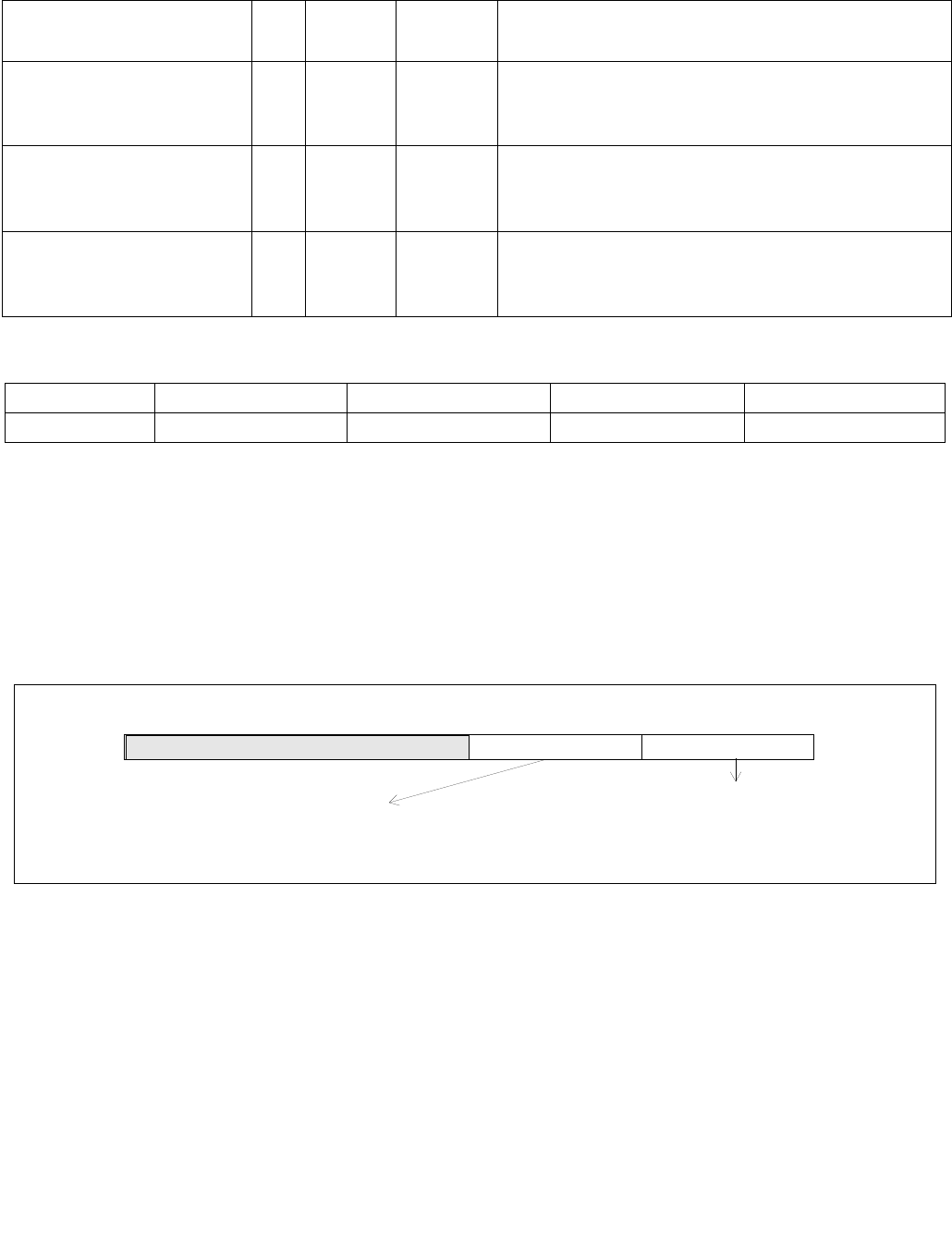
VGETMANTPD—Extract Float64 Vector of Normalized Mantissas from Float64 Vector
INSTRUCTION SET REFERENCE, V-Z
Vol. 2C 5-299
VGETMANTPD—Extract Float64 Vector of Normalized Mantissas from Float64 Vector
Instruction Operand Encoding
Description
Convert double-precision floating values in the source operand (the second operand) to DP FP values with the
mantissa normalization and sign control specified by the imm8 byte, see Figure 5-15. The converted results are
written to the destination operand (the first operand) using writemask k1. The normalized mantissa is specified by
interv (imm8[1:0]) and the sign control (sc) is specified by bits 3:2 of the immediate byte.
The destination operand is a ZMM/YMM/XMM register updated under the writemask. The source operand can be a
ZMM/YMM/XMM register, a 512/256/128-bit memory location, or a 512/256/128-bit vector broadcasted from a 64-
bit memory location.
For each input DP FP value x, The conversion operation is:
GetMant(x) = ±2k|x.significand|
where:
1 <= |x.significand| < 2
Unbiased exponent k depends on the interval range defined by interv and whether the exponent of the source is
even or odd. The sign of the final result is determined by sc and the source sign.
Opcode/
Instruction
Op/
En
64/32
bit Mode
Support
CPUID
Feature
Flag
Description
EVEX.128.66.0F3A.W1 26 /r ib
VGETMANTPD xmm1 {k1}{z},
xmm2/m128/m64bcst, imm8
FV V/V AVX512VL
AVX512F
Get Normalized Mantissa from float64 vector
xmm2/m128/m64bcst and store the result in xmm1, using
imm8 for sign control and mantissa interval normalization,
under writemask.
EVEX.256.66.0F3A.W1 26 /r ib
VGETMANTPD ymm1 {k1}{z},
ymm2/m256/m64bcst, imm8
FV V/V AVX512VL
AVX512F
Get Normalized Mantissa from float64 vector
ymm2/m256/m64bcst and store the result in ymm1, using
imm8 for sign control and mantissa interval normalization,
under writemask.
EVEX.512.66.0F3A.W1 26 /r ib
VGETMANTPD zmm1 {k1}{z},
zmm2/m512/m64bcst{sae},
imm8
FV V/V AVX512F Get Normalized Mantissa from float64 vector
zmm2/m512/m64bcst and store the result in zmm1, using
imm8 for sign control and mantissa interval normalization,
under writemask.
Op/En Operand 1 Operand 2 Operand 3 Operand 4
FVI ModRM:reg (w) ModRM:r/m (r) Imm8 NA
Figure 5-15. Imm8 Controls for VGETMANTPD/SD/PS/SS
7 02465 3 1
Normaiization IntervalMust Be Zero
Imm8[3:2] = 00b : sign(SRC)
Sign Control (SC)
Imm8[3:2] = 01b : 0
Imm8[3] = 1b : qNan_Indefinite if sign(SRC) != 0, regardless of imm8[2].
Imm8[1:0] = 00b : Interval is [ 1, 2)
Imm8[1:0] = 01b : Interval is [1/2, 2)
Imm8[1:0] = 10b : Interval is [ 1/2, 1)
Imm8[1:0] = 11b : Interval is [3/4, 3/2)
imm8

VGETMANTPD—Extract Float64 Vector of Normalized Mantissas from Float64 Vector
INSTRUCTION SET REFERENCE, V-Z
5-300 Vol. 2C
If interv != 0 then k = -1, otherwise K = 0. The encoded value of imm8[1:0] and sign control are shown in
Figure 5-15.
Each converted DP FP result is encoded according to the sign control, the unbiased exponent k (adding bias) and a
mantissa normalized to the range specified by interv.
The GetMant() function follows Table 5-9 when dealing with floating-point special numbers.
This instruction is writemasked, so only those elements with the corresponding bit set in vector mask register k1
are computed and stored into the destination. Elements in zmm1 with the corresponding bit clear in k1 retain their
previous values.
Note: EVEX.vvvv is reserved and must be 1111b; otherwise instructions will #UD.
Table 5-9. GetMant() Special Float Values Behavior
Input Result Exceptions / Comments
NaN QNaN(SRC) Ignore interv
If (SRC = SNaN) then #IE
+∞1.0 Ignore interv
+0 1.0 Ignore interv
-0 IF (SC[0]) THEN +1.0
ELSE -1.0
Ignore interv
-∞IF (SC[1]) THEN {QNaN_Indefinite}
ELSE {
IF (SC[0]) THEN +1.0
ELSE -1.0
Ignore interv
If (SC[1]) then #IE
negative SC[1] ? QNaN_Indefinite : Getmant(SRC) If (SC[1]) then #IE

VGETMANTPD—Extract Float64 Vector of Normalized Mantissas from Float64 Vector
INSTRUCTION SET REFERENCE, V-Z
Vol. 2C 5-301
Operation
GetNormalizeMantissaDP(SRC[63:0], SignCtrl[1:0], Interv[1:0])
{
// Extracting the SRC sign, exponent and mantissa fields
Dst.sign SignCtrl[0] ? 0 : Src[63]; // Get sign bit
Dst.exp SRC[62:52]; ; Get original exponent value
Dst.fraction SRC[51:0];; Get original fraction value
ZeroOperand (Dst.exp = 0) AND (Dst.fraction = 0);
DenormOperand (Dst.exp = 0h) AND (Dst.fraction != 0);
InfiniteOperand (Dst.exp = 07FFh) AND (Dst.fraction = 0);
NaNOperand (Dst.exp = 07FFh) AND (Dst.fraction != 0);
// Check for NAN operand
IF (NaNOperand)
{ IF (SRC = SNaN) {Set #IE;}
Return QNAN(SRC);
}
// Check for Zero and Infinite operands
IF ((ZeroOperand) OR (InfiniteOperand)
{Dst.exp 03FFh; // Override exponent with BIAS
Return ((Dst.sign<<63) | (Dst.exp<<52) | (Dst.fraction));
}
// Check for negative operand (including -0.0)
IF ((Src[63] = 1) AND SignCtrl[1])
{Set #IE;
Return QNaN_Indefinite;
}
// Checking for denormal operands
IF (DenormOperand)
{ IF (MXCSR.DAZ=1) Dst.fraction 0;// Zero out fraction
ELSE
{ // Jbit is the hidden integral bit. Zero in case of denormal operand.
Src.Jbit 0; // Zero Src Jbit
Dst.exp 03FFh; // Override exponent with BIAS
WHILE (Src.Jbit = 0) { // normalize mantissa
Src.Jbit Dst.fraction[51]; // Get the fraction MSB
Dst.fraction (Dst.fraction << 1); // Start normalizing the mantissa
Dst.exp-- ; // Adjust the exponent
}
SET #DE; // Set DE bit
}
} // At this point, Dst.fraction is normalized.
// Checking for exponent response
Unbiased.exp Dst.exp – 03FFh; // subtract the bias from exponent
IsOddExp Unbiased.exp[0]; // recognized unbiased ODD exponent
SignalingBit Dst.fraction[51];
CASE (interv[1:0])
00: Dst.exp 03FFh; // This is the bias
01: Dst.exp (IsOddExp) ? 03FEh : 03FFh; // either bias-1, or bias
10: Dst.exp 03FEh; // bias-1
11: Dst.exp (SignalingBit) ? 03FEh : 03FFh; // either bias-1, or bias
ESCA
// At this point Dst.exp has the correct result. Form the final destination
DEST[63:0] (Dst.sign << 63) OR (Dst.exp << 52) OR (Dst.fraction);
Return (DEST);

VGETMANTPD—Extract Float64 Vector of Normalized Mantissas from Float64 Vector
INSTRUCTION SET REFERENCE, V-Z
5-302 Vol. 2C
}
SignCtrl[1:0] IMM8[3:2];
Interv[1:0] IMM8[1:0];
VGETMANTPD (EVEX encoded versions)
(KL, VL) = (2, 128), (4, 256), (8, 512)
FOR j 0 TO KL-1
i j * 64
IF k1[j] OR *no writemask*
THEN
IF (EVEX.b = 1) AND (SRC *is memory*)
THEN
DEST[i+63:i] GetNormalizedMantissaDP(SRC[63:0], sc, interv)
ELSE
DEST[i+63:i] GetNormalizedMantissaDP(SRC[i+63:i], sc, interv)
FI;
ELSE
IF *merging-masking* ; merging-masking
THEN *DEST[i+63:i] remains unchanged*
ELSE ; zeroing-masking
DEST[i+63:i] 0
FI
FI;
ENDFOR
DEST[MAX_VL-1:VL] 0
Intel C/C++ Compiler Intrinsic Equivalent
VGETMANTPD __m512d _mm512_getmant_pd( __m512d a, enum intv, enum sgn);
VGETMANTPD __m512d _mm512_mask_getmant_pd(__m512d s, __mmask8 k, __m512d a, enum intv, enum sgn);
VGETMANTPD __m512d _mm512_maskz_getmant_pd( __mmask8 k, __m512d a, enum intv, enum sgn);
VGETMANTPD __m512d _mm512_getmant_round_pd( __m512d a, enum intv, enum sgn, int r);
VGETMANTPD __m512d _mm512_mask_getmant_round_pd(__m512d s, __mmask8 k, __m512d a, enum intv, enum sgn, int r);
VGETMANTPD __m512d _mm512_maskz_getmant_round_pd( __mmask8 k, __m512d a, enum intv, enum sgn, int r);
VGETMANTPD __m256d _mm256_getmant_pd( __m256d a, enum intv, enum sgn);
VGETMANTPD __m256d _mm256_mask_getmant_pd(__m256d s, __mmask8 k, __m256d a, enum intv, enum sgn);
VGETMANTPD __m256d _mm256_maskz_getmant_pd( __mmask8 k, __m256d a, enum intv, enum sgn);
VGETMANTPD __m128d _mm_getmant_pd( __m128d a, enum intv, enum sgn);
VGETMANTPD __m128d _mm_mask_getmant_pd(__m128d s, __mmask8 k, __m128d a, enum intv, enum sgn);
VGETMANTPD __m128d _mm_maskz_getmant_pd( __mmask8 k, __m128d a, enum intv, enum sgn);
SIMD Floating-Point Exceptions
Denormal, Invalid
Other Exceptions
See Exceptions Type E2.
#UD If EVEX.vvvv != 1111B.

VGETMANTPS—Extract Float32 Vector of Normalized Mantissas from Float32 Vector
INSTRUCTION SET REFERENCE, V-Z
Vol. 2C 5-303
VGETMANTPS—Extract Float32 Vector of Normalized Mantissas from Float32 Vector
Instruction Operand Encoding
Description
Convert single-precision floating values in the source operand (the second operand) to SP FP values with the
mantissa normalization and sign control specified by the imm8 byte, see Figure 5-15. The converted results are
written to the destination operand (the first operand) using writemask k1. The normalized mantissa is specified by
interv (imm8[1:0]) and the sign control (sc) is specified by bits 3:2 of the immediate byte.
The destination operand is a ZMM/YMM/XMM register updated under the writemask. The source operand can be a
ZMM/YMM/XMM register, a 512/256/128-bit memory location, or a 512/256/128-bit vector broadcasted from a 32-
bit memory location.
For each input SP FP value x, The conversion operation is:
GetMant(x) = ±2k|x.significand|
where:
1 <= |x.significand| < 2
Unbiased exponent k depends on the interval range defined by interv and whether the exponent of the source is
even or odd. The sign of the final result is determined by sc and the source sign.
if interv != 0 then k = -1, otherwise K = 0. The encoded value of imm8[1:0] and sign control are shown
in Figure 5-15.
Each converted SP FP result is encoded according to the sign control, the unbiased exponent k (adding bias) and a
mantissa normalized to the range specified by interv.
The GetMant() function follows Table 5-9 when dealing with floating-point special numbers.
This instruction is writemasked, so only those elements with the corresponding bit set in vector mask register k1
are computed and stored into the destination. Elements in zmm1 with the corresponding bit clear in k1 retain their
previous values.
Note: EVEX.vvvv is reserved and must be 1111b, VEX.L must be 0; otherwise instructions will #UD.
Opcode/
Instruction
Op/
En
64/32
bit Mode
Support
CPUID
Feature
Flag
Description
EVEX.128.66.0F3A.W0 26 /r ib
VGETMANTPS xmm1 {k1}{z},
xmm2/m128/m32bcst, imm8
FV V/V AVX512VL
AVX512F
Get normalized mantissa from float32 vector
xmm2/m128/m32bcst and store the result in xmm1, using
imm8 for sign control and mantissa interval normalization,
under writemask.
EVEX.256.66.0F3A.W0 26 /r ib
VGETMANTPS ymm1 {k1}{z},
ymm2/m256/m32bcst, imm8
FV V/V AVX512VL
AVX512F
Get normalized mantissa from float32 vector
ymm2/m256/m32bcst and store the result in ymm1, using
imm8 for sign control and mantissa interval normalization,
under writemask.
EVEX.512.66.0F3A.W0 26 /r ib
VGETMANTPS zmm1 {k1}{z},
zmm2/m512/m32bcst{sae},
imm8
FV V/V AVX512F Get normalized mantissa from float32 vector
zmm2/m512/m32bcst and store the result in zmm1, using
imm8 for sign control and mantissa interval normalization,
under writemask.
Op/En Operand 1 Operand 2 Operand 3 Operand 4
FVI ModRM:reg (w) ModRM:r/m (r) Imm8 NA

VGETMANTPS—Extract Float32 Vector of Normalized Mantissas from Float32 Vector
INSTRUCTION SET REFERENCE, V-Z
5-304 Vol. 2C
Operation
GetNormalizeMantissaSP(SRC[31:0] , SignCtrl[1:0], Interv[1:0])
{
// Extracting the SRC sign, exponent and mantissa fields
Dst.sign SignCtrl[0] ? 0 : Src[31]; // Get sign bit
Dst.exp SRC[30:23]; ; Get original exponent value
Dst.fraction SRC[22:0];; Get original fraction value
ZeroOperand (Dst.exp = 0) AND (Dst.fraction = 0);
DenormOperand (Dst.exp = 0h) AND (Dst.fraction != 0);
InfiniteOperand (Dst.exp = 0FFh) AND (Dst.fraction = 0);
NaNOperand (Dst.exp = 0FFh) AND (Dst.fraction != 0);
// Check for NAN operand
IF (NaNOperand)
{ IF (SRC = SNaN) {Set #IE;}
Return QNAN(SRC);
}
// Check for Zero and Infinite operands
IF ((ZeroOperand) OR (InfiniteOperand)
{Dst.exp 07Fh; // Override exponent with BIAS
Return ((Dst.sign<<31) | (Dst.exp<<23) | (Dst.fraction));
}
// Check for negative operand (including -0.0)
IF ((Src[31] = 1) AND SignCtrl[1])
{Set #IE;
Return QNaN_Indefinite;
}
// Checking for denormal operands
IF (DenormOperand)
{ IF (MXCSR.DAZ=1) Dst.fraction 0;// Zero out fraction
ELSE
{ // Jbit is the hidden integral bit. Zero in case of denormal operand.
Src.Jbit 0; // Zero Src Jbit
Dst.exp 07Fh; // Override exponent with BIAS
WHILE (Src.Jbit = 0) { // normalize mantissa
Src.Jbit Dst.fraction[22]; // Get the fraction MSB
Dst.fraction (Dst.fraction << 1); // Start normalizing the mantissa
Dst.exp-- ; // Adjust the exponent
}
SET #DE; // Set DE bit
}
} // At this point, Dst.fraction is normalized.
// Checking for exponent response
Unbiased.exp Dst.exp – 07Fh; // subtract the bias from exponent
IsOddExp Unbiased.exp[0]; // recognized unbiased ODD exponent
SignalingBit Dst.fraction[22];
CASE (interv[1:0])
00: Dst.exp 07Fh; // This is the bias
01: Dst.exp (IsOddExp) ? 07Eh : 07Fh; // either bias-1, or bias
10: Dst.exp 07Eh; // bias-1
11: Dst.exp (SignalingBit) ? 07Eh : 07Fh; // either bias-1, or bias
ESCA
// Form the final destination
DEST[31:0] (Dst.sign << 31) OR (Dst.exp << 23) OR (Dst.fraction);

VGETMANTPS—Extract Float32 Vector of Normalized Mantissas from Float32 Vector
INSTRUCTION SET REFERENCE, V-Z
Vol. 2C 5-305
Return (DEST);
}
SignCtrl[1:0] IMM8[3:2];
Interv[1:0] IMM8[1:0];
VGETMANTPS (EVEX encoded versions)
(KL, VL) = (4, 128), (8, 256), (16, 512)
FOR j 0 TO KL-1
i j * 32
IF k1[j] OR *no writemask*
THEN
IF (EVEX.b = 1) AND (SRC *is memory*)
THEN
DEST[i+31:i] GetNormalizedMantissaSP(SRC[31:0], sc, interv)
ELSE
DEST[i+31:i] GetNormalizedMantissaSP(SRC[i+31:i], sc, interv)
FI;
ELSE
IF *merging-masking* ; merging-masking
THEN *DEST[i+31:i] remains unchanged*
ELSE ; zeroing-masking
DEST[i+31:i] 0
FI
FI;
ENDFOR
DEST[MAX_VL-1:VL] 0
Intel C/C++ Compiler Intrinsic Equivalent
VGETMANTPS __m512 _mm512_getmant_ps( __m512 a, enum intv, enum sgn);
VGETMANTPS __m512 _mm512_mask_getmant_ps(__m512 s, __mmask16 k, __m512 a, enum intv, enum sgn;
VGETMANTPS __m512 _mm512_maskz_getmant_ps(__mmask16 k, __m512 a, enum intv, enum sgn);
VGETMANTPS __m512 _mm512_getmant_round_ps( __m512 a, enum intv, enum sgn, int r);
VGETMANTPS __m512 _mm512_mask_getmant_round_ps(__m512 s, __mmask16 k, __m512 a, enum intv, enum sgn, int r);
VGETMANTPS __m512 _mm512_maskz_getmant_round_ps(__mmask16 k, __m512 a, enum intv, enum sgn, int r);
VGETMANTPS __m256 _mm256_getmant_ps( __m256 a, enum intv, enum sgn);
VGETMANTPS __m256 _mm256_mask_getmant_ps(__m256 s, __mmask8 k, __m256 a, enum intv, enum sgn);
VGETMANTPS __m256 _mm256_maskz_getmant_ps( __mmask8 k, __m256 a, enum intv, enum sgn);
VGETMANTPS __m128 _mm_getmant_ps( __m128 a, enum intv, enum sgn);
VGETMANTPS __m128 _mm_mask_getmant_ps(__m128 s, __mmask8 k, __m128 a, enum intv, enum sgn);
VGETMANTPS __m128 _mm_maskz_getmant_ps( __mmask8 k, __m128 a, enum intv, enum sgn);
SIMD Floating-Point Exceptions
Denormal, Invalid
Other Exceptions
See Exceptions Type E2.
#UD If EVEX.vvvv != 1111B.

VGETMANTSD—Extract Float64 of Normalized Mantissas from Float64 Scalar
INSTRUCTION SET REFERENCE, V-Z
5-306 Vol. 2C
VGETMANTSD—Extract Float64 of Normalized Mantissas from Float64 Scalar
Instruction Operand Encoding
Description
Convert the double-precision floating values in the low quadword element of the second source operand (the third
operand) to DP FP value with the mantissa normalization and sign control specified by the imm8 byte, see
Figure 5-15. The converted result is written to the low quadword element of the destination operand (the first
operand) using writemask k1. Bits (127:64) of the XMM register destination are copied from corresponding
bits in the first source operand. The normalized mantissa is specified by interv (imm8[1:0]) and the sign control
(sc) is specified by bits 3:2 of the immediate byte.
The conversion operation is:
GetMant(x) = ±2k|x.significand|
where:
1 <= |x.significand| < 2
Unbiased exponent k depends on the interval range defined by interv and whether the exponent of the source is
even or odd. The sign of the final result is determined by sc and the source sign.
If interv != 0 then k = -1, otherwise K = 0. The encoded value of imm8[1:0] and sign control are shown in
Figure 5-15.
The converted DP FP result is encoded according to the sign control, the unbiased exponent k (adding bias) and a
mantissa normalized to the range specified by interv.
The GetMant() function follows Table 5-9 when dealing with floating-point special numbers.
This instruction is writemasked, so only those elements with the corresponding bit set in vector mask register k1
are computed and stored into zmm1. Elements in zmm1 with the corresponding bit clear in k1 retain their previous
values.
Opcode/
Instruction
Op/
En
64/32
bit Mode
Support
CPUID
Feature
Flag
Description
EVEX.NDS.LIG.66.0F3A.W1 27 /r ib
VGETMANTSD xmm1 {k1}{z}, xmm2,
xmm3/m64{sae}, imm8
T1S V/V AVX512F Extract the normalized mantissa of the low float64
element in xmm3/m64 using imm8 for sign control and
mantissa interval normalization. Store the mantissa to
xmm1 under the writemask k1 and merge with the
other elements of xmm2.
Op/En Operand 1 Operand 2 Operand 3 Operand 4
T1S ModRM:reg (w) EVEX.vvvv (r) ModRM:r/m (r) NA

VGETMANTSD—Extract Float64 of Normalized Mantissas from Float64 Scalar
INSTRUCTION SET REFERENCE, V-Z
Vol. 2C 5-307
Operation
// GetNormalizeMantissaDP(SRC[63:0], SignCtrl[1:0], Interv[1:0]) is defined in the operation section of VGETMANTPD
SignCtrl[1:0] IMM8[3:2];
Interv[1:0] IMM8[1:0];
VGETMANTSD (EVEX encoded version)
IF k1[0] OR *no writemask*
THEN DEST[63:0]
GetNormalizedMantissaDP(SRC2[63:0], sc, interv)
ELSE
IF *merging-masking* ; merging-masking
THEN *DEST[63:0] remains unchanged*
ELSE ; zeroing-masking
DEST[63:0] 0
FI
FI;
DEST[127:64] SRC1[127:64]
DEST[MAX_VL-1:128] 0
Intel C/C++ Compiler Intrinsic Equivalent
VGETMANTSD __m128d _mm_getmant_sd( __m128d a, __m128 b, enum intv, enum sgn);
VGETMANTSD __m128d _mm_mask_getmant_sd(__m128d s, __mmask8 k, __m128d a, __m128d b, enum intv, enum sgn);
VGETMANTSD __m128d _mm_maskz_getmant_sd( __mmask8 k, __m128 a, __m128d b, enum intv, enum sgn);
VGETMANTSD __m128d _mm_getmant_round_sd( __m128d a, __m128 b, enum intv, enum sgn, int r);
VGETMANTSD __m128d _mm_mask_getmant_round_sd(__m128d s, __mmask8 k, __m128d a, __m128d b, enum intv, enum sgn, int r);
VGETMANTSD __m128d _mm_maskz_getmant_round_sd( __mmask8 k, __m128d a, __m128d b, enum intv, enum sgn, int r);
SIMD Floating-Point Exceptions
Denormal, Invalid
Other Exceptions
See Exceptions Type E3.

VGETMANTSS—Extract Float32 Vector of Normalized Mantissa from Float32 Vector
INSTRUCTION SET REFERENCE, V-Z
5-308 Vol. 2C
VGETMANTSS—Extract Float32 Vector of Normalized Mantissa from Float32 Vector
Instruction Operand Encoding
Description
Convert the single-precision floating values in the low doubleword element of the second source operand (the third
operand) to SP FP value with the mantissa normalization and sign control specified by the imm8 byte, see
Figure 5-15. The converted result is written to the low doubleword element of the destination operand (the first
operand) using writemask k1. Bits (127:32) of the XMM register destination are copied from corresponding
bits in the first source operand. The normalized mantissa is specified by interv (imm8[1:0]) and the sign control
(sc) is specified by bits 3:2 of the immediate byte.
The conversion operation is:
GetMant(x) = ±2k|x.significand|
where:
1 <= |x.significand| < 2
Unbiased exponent k depends on the interval range defined by interv and whether the exponent of the source is
even or odd. The sign of the final result is determined by sc and the source sign.
if interv != 0 then k = -1, otherwise K = 0. The encoded value of imm8[1:0] and sign control are shown
in Figure 5-15.
The converted SP FP result is encoded according to the sign control, the unbiased exponent k (adding bias) and a
mantissa normalized to the range specified by interv.
The GetMant() function follows Table 5-9 when dealing with floating-point special numbers.
This instruction is writemasked, so only those elements with the corresponding bit set in vector mask register k1
are computed and stored into zmm1. Elements in zmm1 with the corresponding bit clear in k1 retain their previous
values.
Opcode/
Instruction
Op/
En
64/32
bit Mode
Support
CPUID
Feature
Flag
Description
EVEX.NDS.LIG.66.0F3A.W0 27 /r ib
VGETMANTSS xmm1 {k1}{z}, xmm2,
xmm3/m32{sae}, imm8
T1S V/V AVX512F Extract the normalized mantissa from the low float32
element of xmm3/m32 using imm8 for sign control and
mantissa interval normalization, store the mantissa to
xmm1 under the writemask k1 and merge with the
other elements of xmm2.
Op/En Operand 1 Operand 2 Operand 3 Operand 4
T1S ModRM:reg (w) EVEX.vvvv (r) ModRM:r/m (r) NA

VGETMANTSS—Extract Float32 Vector of Normalized Mantissa from Float32 Vector
INSTRUCTION SET REFERENCE, V-Z
Vol. 2C 5-309
Operation
// GetNormalizeMantissaSP(SRC[31:0], SignCtrl[1:0], Interv[1:0]) is defined in the operation section of VGETMANTPD
SignCtrl[1:0] IMM8[3:2];
Interv[1:0] IMM8[1:0];
VGETMANTSS (EVEX encoded version)
IF k1[0] OR *no writemask*
THEN DEST[31:0]
GetNormalizedMantissaSP(SRC2[31:0], sc, interv)
ELSE
IF *merging-masking* ; merging-masking
THEN *DEST[31:0] remains unchanged*
ELSE ; zeroing-masking
DEST[31:0] 0
FI
FI;
DEST[127:32] SRC1[127:64]
DEST[MAX_VL-1:128] 0
Intel C/C++ Compiler Intrinsic Equivalent
VGETMANTSS __m128 _mm_getmant_ss( __m128 a, __m128 b, enum intv, enum sgn);
VGETMANTSS __m128 _mm_mask_getmant_ss(__m128 s, __mmask8 k, __m128 a, __m128 b, enum intv, enum sgn);
VGETMANTSS __m128 _mm_maskz_getmant_ss( __mmask8 k, __m128 a, __m128 b, enum intv, enum sgn);
VGETMANTSS __m128 _mm_getmant_round_ss( __m128 a, __m128 b, enum intv, enum sgn, int r);
VGETMANTSS __m128 _mm_mask_getmant_round_ss(__m128 s, __mmask8 k, __m128 a, __m128 b, enum intv, enum sgn, int r);
VGETMANTSS __m128 _mm_maskz_getmant_round_ss( __mmask8 k, __m128 a, __m128 b, enum intv, enum sgn, int r);
SIMD Floating-Point Exceptions
Denormal, Invalid
Other Exceptions
See Exceptions Type E3.

VINSERTF128/VINSERTF32x4/VINSERTF64x2/VINSERTF32x8/VINSERTF64x4—Insert Packed Floating-Point Values
INSTRUCTION SET REFERENCE, V-Z
5-310 Vol. 2C
VINSERTF128/VINSERTF32x4/VINSERTF64x2/VINSERTF32x8/VINSERTF64x4—Insert Packed
Floating-Point Values
Instruction Operand Encoding
Description
VINSERTF128/VINSERTF32x4 and VINSERTF64x2 insert 128-bits of packed floating-point values from the second
source operand (the third operand) into the destination operand (the first operand) at an 128-bit granularity offset
multiplied by imm8[0] (256-bit) or imm8[1:0]. The remaining portions of the destination operand are copied from
the corresponding fields of the first source operand (the second operand). The second source operand can be either
an XMM register or a 128-bit memory location. The destination and first source operands are vector registers.
VINSERTF32x4: The destination operand is a ZMM/YMM register and updated at 32-bit granularity according to the
writemask. The high 6/7 bits of the immediate are ignored.
VINSERTF64x2: The destination operand is a ZMM/YMM register and updated at 64-bit granularity according to the
writemask. The high 6/7 bits of the immediate are ignored.
VINSERTF32x8 and VINSERTF64x4 inserts 256-bits of packed floating-point values from the second source operand
(the third operand) into the destination operand (the first operand) at a 256-bit granular offset multiplied by
imm8[0]. The remaining portions of the destination are copied from the corresponding fields of the first source
operand (the second operand). The second source operand can be either an YMM register or a 256-bit memory
location. The high 7 bits of the immediate are ignored. The destination operand is a ZMM register and updated at
32/64-bit granularity according to the writemask.
Opcode/
Instruction
Op /
En
64/32
bit Mode
Support
CPUID
Feature
Flag
Description
VEX.NDS.256.66.0F3A.W0 18 /r ib
VINSERTF128 ymm1, ymm2,
xmm3/m128, imm8
RVMI V/V AVX Insert 128 bits of packed floating-point values from
xmm3/m128 and the remaining values from ymm2
into ymm1.
EVEX.NDS.256.66.0F3A.W0 18 /r ib
VINSERTF32X4 ymm1 {k1}{z}, ymm2,
xmm3/m128, imm8
T4 V/V AVX512VL
AVX512F
Insert 128 bits of packed single-precision floating-
point values from xmm3/m128 and the remaining
values from ymm2 into ymm1 under writemask k1.
EVEX.NDS.512.66.0F3A.W0 18 /r ib
VINSERTF32X4 zmm1 {k1}{z}, zmm2,
xmm3/m128, imm8
T4 V/V AVX512F Insert 128 bits of packed single-precision floating-
point values from xmm3/m128 and the remaining
values from zmm2 into zmm1 under writemask k1.
EVEX.NDS.256.66.0F3A.W1 18 /r ib
VINSERTF64X2 ymm1 {k1}{z}, ymm2,
xmm3/m128, imm8
T2 V/V AVX512VL
AVX512DQ
Insert 128 bits of packed double-precision floating-
point values from xmm3/m128 and the remaining
values from ymm2 into ymm1 under writemask k1.
EVEX.NDS.512.66.0F3A.W1 18 /r ib
VINSERTF64X2 zmm1 {k1}{z}, zmm2,
xmm3/m128, imm8
T2 V/V AVX512DQ Insert 128 bits of packed double-precision floating-
point values from xmm3/m128 and the remaining
values from zmm2 into zmm1 under writemask k1.
EVEX.NDS.512.66.0F3A.W0 1A /r ib
VINSERTF32X8 zmm1 {k1}{z}, zmm2,
ymm3/m256, imm8
T8 V/V AVX512DQ Insert 256 bits of packed single-precision floating-
point values from ymm3/m256 and the remaining
values from zmm2 into zmm1 under writemask k1.
EVEX.NDS.512.66.0F3A.W1 1A /r ib
VINSERTF64X4 zmm1 {k1}{z}, zmm2,
ymm3/m256, imm8
T4 V/V AVX512F Insert 256 bits of packed double-precision floating-
point values from ymm3/m256 and the remaining
values from zmm2 into zmm1 under writemask k1.
Op/En Operand 1 Operand 2 Operand 3 Operand 4
RVMI ModRM:reg (w) VEX.vvvv ModRM:r/m (r) Imm8
T2, T4, T8 ModRM:reg (w) EVEX.vvvv ModRM:r/m (r) Imm8

VINSERTF128/VINSERTF32x4/VINSERTF64x2/VINSERTF32x8/VINSERTF64x4—Insert Packed Floating-Point Values
INSTRUCTION SET REFERENCE, V-Z
Vol. 2C 5-311
Operation
VINSERTF32x4 (EVEX encoded versions)
(KL, VL) = (8, 256), (16, 512)
TEMP_DEST[VL-1:0] SRC1[VL-1:0]
IF VL = 256
CASE (imm8[0]) OF
0: TMP_DEST[127:0] SRC2[127:0]
1: TMP_DEST[255:128] SRC2[127:0]
ESAC.
FI;
IF VL = 512
CASE (imm8[1:0]) OF
00: TMP_DEST[127:0] SRC2[127:0]
01: TMP_DEST[255:128] SRC2[127:0]
10: TMP_DEST[383:256] SRC2[127:0]
11: TMP_DEST[511:384] SRC2[127:0]
ESAC.
FI;
FOR j 0 TO KL-1
i j * 32
IF k1[j] OR *no writemask*
THEN DEST[i+31:i] TMP_DEST[i+31:i]
ELSE
IF *merging-masking* ; merging-masking
THEN *DEST[i+31:i] remains unchanged*
ELSE ; zeroing-masking
DEST[i+31:i] 0
FI
FI;
ENDFOR
DEST[MAX_VL-1:VL] 0
VINSERTF64x2 (EVEX encoded versions)
(KL, VL) = (4, 256), (8, 512)
TEMP_DEST[VL-1:0] SRC1[VL-1:0]
IF VL = 256
CASE (imm8[0]) OF
0: TMP_DEST[127:0] SRC2[127:0]
1: TMP_DEST[255:128] SRC2[127:0]
ESAC.
FI;
IF VL = 512
CASE (imm8[1:0]) OF
00: TMP_DEST[127:0] SRC2[127:0]
01: TMP_DEST[255:128] SRC2[127:0]
10: TMP_DEST[383:256] SRC2[127:0]
11: TMP_DEST[511:384] SRC2[127:0]
ESAC.
FI;
FOR j 0 TO KL-1
i j * 64
IF k1[j] OR *no writemask*
THEN DEST[i+63:i] TMP_DEST[i+63:i]
ELSE

VINSERTF128/VINSERTF32x4/VINSERTF64x2/VINSERTF32x8/VINSERTF64x4—Insert Packed Floating-Point Values
INSTRUCTION SET REFERENCE, V-Z
5-312 Vol. 2C
IF *merging-masking* ; merging-masking
THEN *DEST[i+63:i] remains unchanged*
ELSE ; zeroing-masking
DEST[i+63:i] 0
FI
FI;
ENDFOR
DEST[MAX_VL-1:VL] 0
VINSERTF32x8 (EVEX.U1.512 encoded version)
TEMP_DEST[VL-1:0] SRC1[VL-1:0]
CASE (imm8[0]) OF
0: TMP_DEST[255:0] SRC2[255:0]
1: TMP_DEST[511:256] SRC2[255:0]
ESAC.
FOR j 0 TO 15
i j * 32
IF k1[j] OR *no writemask*
THEN DEST[i+31:i] TMP_DEST[i+31:i]
ELSE
IF *merging-masking* ; merging-masking
THEN *DEST[i+31:i] remains unchanged*
ELSE ; zeroing-masking
DEST[i+31:i] 0
FI
FI;
ENDFOR
DEST[MAX_VL-1:VL] 0
VINSERTF64x4 (EVEX.512 encoded version)
VL = 512
TEMP_DEST[VL-1:0] SRC1[VL-1:0]
CASE (imm8[0]) OF
0: TMP_DEST[255:0] SRC2[255:0]
1: TMP_DEST[511:256] SRC2[255:0]
ESAC.
FOR j 0 TO 7
i j * 64
IF k1[j] OR *no writemask*
THEN DEST[i+63:i] TMP_DEST[i+63:i]
ELSE
IF *merging-masking* ; merging-masking
THEN *DEST[i+63:i] remains unchanged*
ELSE ; zeroing-masking
DEST[i+63:i] 0
FI
FI;
ENDFOR
DEST[MAX_VL-1:VL] 0

VINSERTF128/VINSERTF32x4/VINSERTF64x2/VINSERTF32x8/VINSERTF64x4—Insert Packed Floating-Point Values
INSTRUCTION SET REFERENCE, V-Z
Vol. 2C 5-313
VINSERTF128 (VEX encoded version)
TEMP[255:0] SRC1[255:0]
CASE (imm8[0]) OF
0: TEMP[127:0] SRC2[127:0]
1: TEMP[255:128] SRC2[127:0]
ESAC
DEST TEMP
Intel C/C++ Compiler Intrinsic Equivalent
VINSERTF32x4 __m512 _mm512_insertf32x4( __m512 a, __m128 b, int imm);
VINSERTF32x4 __m512 _mm512_mask_insertf32x4(__m512 s, __mmask16 k, __m512 a, __m128 b, int imm);
VINSERTF32x4 __m512 _mm512_maskz_insertf32x4( __mmask16 k, __m512 a, __m128 b, int imm);
VINSERTF32x4 __m256 _mm256_insertf32x4( __m256 a, __m128 b, int imm);
VINSERTF32x4 __m256 _mm256_mask_insertf32x4(__m256 s, __mmask8 k, __m256 a, __m128 b, int imm);
VINSERTF32x4 __m256 _mm256_maskz_insertf32x4( __mmask8 k, __m256 a, __m128 b, int imm);
VINSERTF32x8 __m512 _mm512_insertf32x8( __m512 a, __m256 b, int imm);
VINSERTF32x8 __m512 _mm512_mask_insertf32x8(__m512 s, __mmask16 k, __m512 a, __m256 b, int imm);
VINSERTF32x8 __m512 _mm512_maskz_insertf32x8( __mmask16 k, __m512 a, __m256 b, int imm);
VINSERTF64x2 __m512d _mm512_insertf64x2( __m512d a, __m128d b, int imm);
VINSERTF64x2 __m512d _mm512_mask_insertf64x2(__m512d s, __mmask8 k, __m512d a, __m128d b, int imm);
VINSERTF64x2 __m512d _mm512_maskz_insertf64x2( __mmask8 k, __m512d a, __m128d b, int imm);
VINSERTF64x2 __m256d _mm256_insertf64x2( __m256d a, __m128d b, int imm);
VINSERTF64x2 __m256d _mm256_mask_insertf64x2(__m256d s, __mmask8 k, __m256d a, __m128d b, int imm);
VINSERTF64x2 __m256d _mm256_maskz_insertf64x2( __mmask8 k, __m256d a, __m128d b, int imm);
VINSERTF64x4 __m512d _mm512_insertf64x4( __m512d a, __m256d b, int imm);
VINSERTF64x4 __m512d _mm512_mask_insertf64x4(__m512d s, __mmask8 k, __m512d a, __m256d b, int imm);
VINSERTF64x4 __m512d _mm512_maskz_insertf64x4( __mmask8 k, __m512d a, __m256d b, int imm);
VINSERTF128 __m256 _mm256_insertf128_ps (__m256 a, __m128 b, int offset);
VINSERTF128 __m256d _mm256_insertf128_pd (__m256d a, __m128d b, int offset);
VINSERTF128 __m256i _mm256_insertf128_si256 (__m256i a, __m128i b, int offset);
SIMD Floating-Point Exceptions
None
Other Exceptions
VEX-encoded instruction, see Exceptions Type 6; additionally
#UD If VEX.L = 0.
EVEX-encoded instruction, see Exceptions Type E6NF.

VINSERTI128/VINSERTI32x4/VINSERTI64x2/VINSERTI32x8/VINSERTI64x4—Insert Packed Integer Values
INSTRUCTION SET REFERENCE, V-Z
5-314 Vol. 2C
VINSERTI128/VINSERTI32x4/VINSERTI64x2/VINSERTI32x8/VINSERTI64x4—Insert Packed
Integer Values
Instruction Operand Encoding
Description
VINSERTI32x4 and VINSERTI64x2 inserts 128-bits of packed integer values from the second source operand (the
third operand) into the destination operand (the first operand) at an 128-bit granular offset multiplied by imm8[0]
(256-bit) or imm8[1:0]. The remaining portions of the destination are copied from the corresponding fields of the
first source operand (the second operand). The second source operand can be either an XMM register or a 128-bit
memory location. The high 6/7bits of the immediate are ignored. The destination operand is a ZMM/YMM register
and updated at 32 and 64-bit granularity according to the writemask.
VINSERTI32x8 and VINSERTI64x4 inserts 256-bits of packed integer values from the second source operand (the
third operand) into the destination operand (the first operand) at a 256-bit granular offset multiplied by imm8[0].
The remaining portions of the destination are copied from the corresponding fields of the first source operand (the
second operand). The second source operand can be either an YMM register or a 256-bit memory location. The
upper bits of the immediate are ignored. The destination operand is a ZMM register and updated at 32 and 64-bit
granularity according to the writemask.
VINSERTI128 inserts 128-bits of packed integer data from the second source operand (the third operand) into the
destination operand (the first operand) at a 128-bit granular offset multiplied by imm8[0]. The remaining portions
of the destination are copied from the corresponding fields of the first source operand (the second operand). The
second source operand can be either an XMM register or a 128-bit memory location. The high 7 bits of the imme-
diate are ignored. VEX.L must be 1, otherwise attempt to execute this instruction with VEX.L=0 will cause #UD.
Opcode/
Instruction
Op /
En
64/32
bit Mode
Support
CPUID
Feature
Flag
Description
VEX.NDS.256.66.0F3A.W0 38 /r ib
VINSERTI128 ymm1, ymm2,
xmm3/m128, imm8
RVMI V/V AVX2 Insert 128 bits of integer data from xmm3/m128 and
the remaining values from ymm2 into ymm1.
EVEX.NDS.256.66.0F3A.W0 38 /r ib
VINSERTI32X4 ymm1 {k1}{z}, ymm2,
xmm3/m128, imm8
T4 V/V AVX512VL
AVX512F
Insert 128 bits of packed doubleword integer values
from xmm3/m128 and the remaining values from
ymm2 into ymm1 under writemask k1.
EVEX.NDS.512.66.0F3A.W0 38 /r ib
VINSERTI32X4 zmm1 {k1}{z}, zmm2,
xmm3/m128, imm8
T4 V/V AVX512F Insert 128 bits of packed doubleword integer values
from xmm3/m128 and the remaining values from
zmm2 into zmm1 under writemask k1.
EVEX.NDS.256.66.0F3A.W1 38 /r ib
VINSERTI64X2 ymm1 {k1}{z}, ymm2,
xmm3/m128, imm8
T2 V/V AVX512VL
AVX512DQ
Insert 128 bits of packed quadword integer values
from xmm3/m128 and the remaining values from
ymm2 into ymm1 under writemask k1.
EVEX.NDS.512.66.0F3A.W1 38 /r ib
VINSERTI64X2 zmm1 {k1}{z}, zmm2,
xmm3/m128, imm8
T2 V/V AVX512DQ Insert 128 bits of packed quadword integer values
from xmm3/m128 and the remaining values from
zmm2 into zmm1 under writemask k1.
EVEX.NDS.512.66.0F3A.W0 3A /r ib
VINSERTI32X8 zmm1 {k1}{z}, zmm2,
ymm3/m256, imm8
T8 V/V AVX512DQ Insert 256 bits of packed doubleword integer values
from ymm3/m256 and the remaining values from
zmm2 into zmm1 under writemask k1.
EVEX.NDS.512.66.0F3A.W1 3A /r ib
VINSERTI64X4 zmm1 {k1}{z}, zmm2,
ymm3/m256, imm8
T4 V/V AVX512F Insert 256 bits of packed quadword integer values
from ymm3/m256 and the remaining values from
zmm2 into zmm1 under writemask k1.
Op/En Operand 1 Operand 2 Operand 3 Operand 4
RVMI ModRM:reg (w) VEX.vvvv ModRM:r/m (r) Imm8
T2, T4, T8 ModRM:reg (w) EVEX.vvvv ModRM:r/m (r) Imm8

VINSERTI128/VINSERTI32x4/VINSERTI64x2/VINSERTI32x8/VINSERTI64x4—Insert Packed Integer Values
INSTRUCTION SET REFERENCE, V-Z
Vol. 2C 5-315
Operation
VINSERTI32x4 (EVEX encoded versions)
(KL, VL) = (8, 256), (16, 512)
TEMP_DEST[VL-1:0] SRC1[VL-1:0]
IF VL = 256
CASE (imm8[0]) OF
0: TMP_DEST[127:0] SRC2[127:0]
1: TMP_DEST[255:128] SRC2[127:0]
ESAC.
FI;
IF VL = 512
CASE (imm8[1:0]) OF
00: TMP_DEST[127:0] SRC2[127:0]
01: TMP_DEST[255:128] SRC2[127:0]
10: TMP_DEST[383:256] SRC2[127:0]
11: TMP_DEST[511:384] SRC2[127:0]
ESAC.
FI;
FOR j 0 TO KL-1
i j * 32
IF k1[j] OR *no writemask*
THEN DEST[i+31:i] TMP_DEST[i+31:i]
ELSE
IF *merging-masking* ; merging-masking
THEN *DEST[i+31:i] remains unchanged*
ELSE ; zeroing-masking
DEST[i+31:i] 0
FI
FI;
ENDFOR
DEST[MAX_VL-1:VL] 0
VINSERTI64x2 (EVEX encoded versions)
(KL, VL) = (4, 256), (8, 512)
TEMP_DEST[VL-1:0] SRC1[VL-1:0]
IF VL = 256
CASE (imm8[0]) OF
0: TMP_DEST[127:0] SRC2[127:0]
1: TMP_DEST[255:128] SRC2[127:0]
ESAC.
FI;
IF VL = 512
CASE (imm8[1:0]) OF
00: TMP_DEST[127:0] SRC2[127:0]
01: TMP_DEST[255:128] SRC2[127:0]
10: TMP_DEST[383:256] SRC2[127:0]
11: TMP_DEST[511:384] SRC2[127:0]
ESAC.
FI;
FOR j 0 TO KL-1
i j * 64
IF k1[j] OR *no writemask*
THEN DEST[i+63:i] TMP_DEST[i+63:i]
ELSE

VINSERTI128/VINSERTI32x4/VINSERTI64x2/VINSERTI32x8/VINSERTI64x4—Insert Packed Integer Values
INSTRUCTION SET REFERENCE, V-Z
5-316 Vol. 2C
IF *merging-masking* ; merging-masking
THEN *DEST[i+63:i] remains unchanged*
ELSE ; zeroing-masking
DEST[i+63:i] 0
FI
FI;
ENDFOR
DEST[MAX_VL-1:VL] 0
VINSERTI32x8 (EVEX.U1.512 encoded version)
TEMP_DEST[VL-1:0] SRC1[VL-1:0]
CASE (imm8[0]) OF
0: TMP_DEST[255:0] SRC2[255:0]
1: TMP_DEST[511:256] SRC2[255:0]
ESAC.
FOR j 0 TO 15
i j * 32
IF k1[j] OR *no writemask*
THEN DEST[i+31:i] TMP_DEST[i+31:i]
ELSE
IF *merging-masking* ; merging-masking
THEN *DEST[i+31:i] remains unchanged*
ELSE ; zeroing-masking
DEST[i+31:i] 0
FI
FI;
ENDFOR
DEST[MAX_VL-1:VL] 0
VINSERTI64x4 (EVEX.512 encoded version)
VL = 512
TEMP_DEST[VL-1:0] SRC1[VL-1:0]
CASE (imm8[0]) OF
0: TMP_DEST[255:0] SRC2[255:0]
1: TMP_DEST[511:256] SRC2[255:0]
ESAC.
FOR j 0 TO 7
i j * 64
IF k1[j] OR *no writemask*
THEN DEST[i+63:i] TMP_DEST[i+63:i]
ELSE
IF *merging-masking* ; merging-masking
THEN *DEST[i+63:i] remains unchanged*
ELSE ; zeroing-masking
DEST[i+63:i] 0
FI
FI;
ENDFOR
DEST[MAX_VL-1:VL] 0

VINSERTI128/VINSERTI32x4/VINSERTI64x2/VINSERTI32x8/VINSERTI64x4—Insert Packed Integer Values
INSTRUCTION SET REFERENCE, V-Z
Vol. 2C 5-317
VINSERTI128
TEMP[255:0] SRC1[255:0]
CASE (imm8[0]) OF
0: TEMP[127:0] SRC2[127:0]
1: TEMP[255:128] SRC2[127:0]
ESAC
DEST TEMP
Intel C/C++ Compiler Intrinsic Equivalent
VINSERTI32x4 _mm512i _inserti32x4( __m512i a, __m128i b, int imm);
VINSERTI32x4 _mm512i _mask_inserti32x4(__m512i s, __mmask16 k, __m512i a, __m128i b, int imm);
VINSERTI32x4 _mm512i _maskz_inserti32x4( __mmask16 k, __m512i a, __m128i b, int imm);
VINSERTI32x4 __m256i _mm256_inserti32x4( __m256i a, __m128i b, int imm);
VINSERTI32x4 __m256i _mm256_mask_inserti32x4(__m256i s, __mmask8 k, __m256i a, __m128i b, int imm);
VINSERTI32x4 __m256i _mm256_maskz_inserti32x4( __mmask8 k, __m256i a, __m128i b, int imm);
VINSERTI32x8 __m512i _mm512_inserti32x8( __m512i a, __m256i b, int imm);
VINSERTI32x8 __m512i _mm512_mask_inserti32x8(__m512i s, __mmask16 k, __m512i a, __m256i b, int imm);
VINSERTI32x8 __m512i _mm512_maskz_inserti32x8( __mmask16 k, __m512i a, __m256i b, int imm);
VINSERTI64x2 __m512i _mm512_inserti64x2( __m512i a, __m128i b, int imm);
VINSERTI64x2 __m512i _mm512_mask_inserti64x2(__m512i s, __mmask8 k, __m512i a, __m128i b, int imm);
VINSERTI64x2 __m512i _mm512_maskz_inserti64x2( __mmask8 k, __m512i a, __m128i b, int imm);
VINSERTI64x2 __m256i _mm256_inserti64x2( __m256i a, __m128i b, int imm);
VINSERTI64x2 __m256i _mm256_mask_inserti64x2(__m256i s, __mmask8 k, __m256i a, __m128i b, int imm);
VINSERTI64x2 __m256i _mm256_maskz_inserti64x2( __mmask8 k, __m256i a, __m128i b, int imm);
VINSERTI64x4 _mm512_inserti64x4( __m512i a, __m256i b, int imm);
VINSERTI64x4 _mm512_mask_inserti64x4(__m512i s, __mmask8 k, __m512i a, __m256i b, int imm);
VINSERTI64x4 _mm512_maskz_inserti64x4( __mmask m, __m512i a, __m256i b, int imm);
VINSERTI128 __m256i _mm256_insertf128_si256 (__m256i a, __m128i b, int offset);
SIMD Floating-Point Exceptions
None
Other Exceptions
VEX-encoded instruction, see Exceptions Type 6; additionally
#UD If VEX.L = 0.
EVEX-encoded instruction, see Exceptions Type E6NF.

VMASKMOV—Conditional SIMD Packed Loads and Stores
INSTRUCTION SET REFERENCE, V-Z
5-318 Vol. 2C
VMASKMOV—Conditional SIMD Packed Loads and Stores
Instruction Operand Encoding
Description
Conditionally moves packed data elements from the second source operand into the corresponding data element of
the destination operand, depending on the mask bits associated with each data element. The mask bits are speci-
fied in the first source operand.
The mask bit for each data element is the most significant bit of that element in the first source operand. If a mask
is 1, the corresponding data element is copied from the second source operand to the destination operand. If the
mask is 0, the corresponding data element is set to zero in the load form of these instructions, and unmodified in
the store form.
The second source operand is a memory address for the load form of these instruction. The destination operand is
a memory address for the store form of these instructions. The other operands are both XMM registers (for
VEX.128 version) or YMM registers (for VEX.256 version).
Faults occur only due to mask-bit required memory accesses that caused the faults. Faults will not occur due to
referencing any memory location if the corresponding mask bit for that memory location is 0. For example, no
faults will be detected if the mask bits are all zero.
Unlike previous MASKMOV instructions (MASKMOVQ and MASKMOVDQU), a nontemporal hint is not applied to
these instructions.
Instruction behavior on alignment check reporting with mask bits of less than all 1s are the same as with mask bits
of all 1s.
VMASKMOV should not be used to access memory mapped I/O and un-cached memory as the access and the
ordering of the individual loads or stores it does is implementation specific.
Opcode/
Instruction
Op/
En
64/32-bit
Mode
CPUID
Feature
Flag
Description
VEX.NDS.128.66.0F38.W0 2C /r
VMASKMOVPS xmm1, xmm2, m128
RVM V/V AVX Conditionally load packed single-precision values from
m128 using mask in xmm2 and store in xmm1.
VEX.NDS.256.66.0F38.W0 2C /r
VMASKMOVPS ymm1, ymm2, m256
RVM V/V AVX Conditionally load packed single-precision values from
m256 using mask in ymm2 and store in ymm1.
VEX.NDS.128.66.0F38.W0 2D /r
VMASKMOVPD xmm1, xmm2, m128
RVM V/V AVX Conditionally load packed double-precision values from
m128 using mask in xmm2 and store in xmm1.
VEX.NDS.256.66.0F38.W0 2D /r
VMASKMOVPD ymm1, ymm2, m256
RVM V/V AVX Conditionally load packed double-precision values from
m256 using mask in ymm2 and store in ymm1.
VEX.NDS.128.66.0F38.W0 2E /r
VMASKMOVPS m128, xmm1, xmm2
MVR V/V AVX Conditionally store packed single-precision values from
xmm2 using mask in xmm1.
VEX.NDS.256.66.0F38.W0 2E /r
VMASKMOVPS m256, ymm1, ymm2
MVR V/V AVX Conditionally store packed single-precision values from
ymm2 using mask in ymm1.
VEX.NDS.128.66.0F38.W0 2F /r
VMASKMOVPD m128, xmm1, xmm2
MVR V/V AVX Conditionally store packed double-precision values from
xmm2 using mask in xmm1.
VEX.NDS.256.66.0F38.W0 2F /r
VMASKMOVPD m256, ymm1, ymm2
MVR V/V AVX Conditionally store packed double-precision values from
ymm2 using mask in ymm1.
Op/En Operand 1 Operand 2 Operand 3 Operand 4
RVM ModRM:reg (w) VEX.vvvv (r) ModRM:r/m (r) NA
MVR ModRM:r/m (w) VEX.vvvv (r) ModRM:reg (r) NA

VMASKMOV—Conditional SIMD Packed Loads and Stores
INSTRUCTION SET REFERENCE, V-Z
Vol. 2C 5-319
In cases where mask bits indicate data should not be loaded or stored paging A and D bits will be set in an imple-
mentation dependent way. However, A and D bits are always set for pages where data is actually loaded/stored.
Note: for load forms, the first source (the mask) is encoded in VEX.vvvv; the second source is encoded in rm_field,
and the destination register is encoded in reg_field.
Note: for store forms, the first source (the mask) is encoded in VEX.vvvv; the second source register is encoded in
reg_field, and the destination memory location is encoded in rm_field.
Operation
VMASKMOVPS -128-bit load
DEST[31:0] IF (SRC1[31]) Load_32(mem) ELSE 0
DEST[63:32] IF (SRC1[63]) Load_32(mem + 4) ELSE 0
DEST[95:64] IF (SRC1[95]) Load_32(mem + 8) ELSE 0
DEST[127:97] IF (SRC1[127]) Load_32(mem + 12) ELSE 0
DEST[VLMAX-1:128] 0
VMASKMOVPS - 256-bit load
DEST[31:0] IF (SRC1[31]) Load_32(mem) ELSE 0
DEST[63:32] IF (SRC1[63]) Load_32(mem + 4) ELSE 0
DEST[95:64] IF (SRC1[95]) Load_32(mem + 8) ELSE 0
DEST[127:96] IF (SRC1[127]) Load_32(mem + 12) ELSE 0
DEST[159:128] IF (SRC1[159]) Load_32(mem + 16) ELSE 0
DEST[191:160] IF (SRC1[191]) Load_32(mem + 20) ELSE 0
DEST[223:192] IF (SRC1[223]) Load_32(mem + 24) ELSE 0
DEST[255:224] IF (SRC1[255]) Load_32(mem + 28) ELSE 0
VMASKMOVPD - 128-bit load
DEST[63:0] IF (SRC1[63]) Load_64(mem) ELSE 0
DEST[127:64] IF (SRC1[127]) Load_64(mem + 16) ELSE 0
DEST[VLMAX-1:128] 0
VMASKMOVPD - 256-bit load
DEST[63:0] IF (SRC1[63]) Load_64(mem) ELSE 0
DEST[127:64] IF (SRC1[127]) Load_64(mem + 8) ELSE 0
DEST[195:128] IF (SRC1[191]) Load_64(mem + 16) ELSE 0
DEST[255:196] IF (SRC1[255]) Load_64(mem + 24) ELSE 0
VMASKMOVPS - 128-bit store
IF (SRC1[31]) DEST[31:0] SRC2[31:0]
IF (SRC1[63]) DEST[63:32] SRC2[63:32]
IF (SRC1[95]) DEST[95:64] SRC2[95:64]
IF (SRC1[127]) DEST[127:96] SRC2[127:96]
VMASKMOVPS - 256-bit store
IF (SRC1[31]) DEST[31:0] SRC2[31:0]
IF (SRC1[63]) DEST[63:32] SRC2[63:32]
IF (SRC1[95]) DEST[95:64] SRC2[95:64]
IF (SRC1[127]) DEST[127:96] SRC2[127:96]
IF (SRC1[159]) DEST[159:128] SRC2[159:128]
IF (SRC1[191]) DEST[191:160] SRC2[191:160]
IF (SRC1[223]) DEST[223:192] SRC2[223:192]
IF (SRC1[255]) DEST[255:224] SRC2[255:224]

VMASKMOV—Conditional SIMD Packed Loads and Stores
INSTRUCTION SET REFERENCE, V-Z
5-320 Vol. 2C
VMASKMOVPD - 128-bit store
IF (SRC1[63]) DEST[63:0] SRC2[63:0]
IF (SRC1[127]) DEST[127:64] SRC2[127:64]
VMASKMOVPD - 256-bit store
IF (SRC1[63]) DEST[63:0] SRC2[63:0]
IF (SRC1[127]) DEST[127:64] SRC2[127:64]
IF (SRC1[191]) DEST[191:128] SRC2[191:128]
IF (SRC1[255]) DEST[255:192] SRC2[255:192]
Intel C/C++ Compiler Intrinsic Equivalent
__m256 _mm256_maskload_ps(float const *a, __m256i mask)
void _mm256_maskstore_ps(float *a, __m256i mask, __m256 b)
__m256d _mm256_maskload_pd(double *a, __m256i mask);
void _mm256_maskstore_pd(double *a, __m256i mask, __m256d b);
__m128 _mm128_maskload_ps(float const *a, __m128i mask)
void _mm128_maskstore_ps(float *a, __m128i mask, __m128 b)
__m128d _mm128_maskload_pd(double *a, __m128i mask);
void _mm128_maskstore_pd(double *a, __m128i mask, __m128d b);
SIMD Floating-Point Exceptions
None
Other Exceptions
See Exceptions Type 6 (No AC# reported for any mask bit combinations);
additionally
#UD If VEX.W = 1.

VPBLENDD — Blend Packed Dwords
INSTRUCTION SET REFERENCE, V-Z
Vol. 2C 5-321
VPBLENDD — Blend Packed Dwords
Instruction Operand Encoding
Description
Dword elements from the source operand (second operand) are conditionally written to the destination operand
(first operand) depending on bits in the immediate operand (third operand). The immediate bits (bits 7:0) form a
mask that determines whether the corresponding word in the destination is copied from the source. If a bit in the
mask, corresponding to a word, is “1", then the word is copied, else the word is unchanged.
VEX.128 encoded version: The second source operand can be an XMM register or a 128-bit memory location. The
first source and destination operands are XMM registers. Bits (VLMAX-1:128) of the corresponding YMM register
are zeroed.
VEX.256 encoded version: The first source operand is a YMM register. The second source operand is a YMM register
or a 256-bit memory location. The destination operand is a YMM register.
Operation
VPBLENDD (VEX.256 encoded version)
IF (imm8[0] == 1) THEN DEST[31:0] SRC2[31:0]
ELSE DEST[31:0] SRC1[31:0]
IF (imm8[1] == 1) THEN DEST[63:32] SRC2[63:32]
ELSE DEST[63:32] SRC1[63:32]
IF (imm8[2] == 1) THEN DEST[95:64] SRC2[95:64]
ELSE DEST[95:64] SRC1[95:64]
IF (imm8[3] == 1) THEN DEST[127:96] SRC2[127:96]
ELSE DEST[127:96] SRC1[127:96]
IF (imm8[4] == 1) THEN DEST[159:128] SRC2[159:128]
ELSE DEST[159:128] SRC1[159:128]
IF (imm8[5] == 1) THEN DEST[191:160] SRC2[191:160]
ELSE DEST[191:160] SRC1[191:160]
IF (imm8[6] == 1) THEN DEST[223:192] SRC2[223:192]
ELSE DEST[223:192] SRC1[223:192]
IF (imm8[7] == 1) THEN DEST[255:224] SRC2[255:224]
ELSE DEST[255:224] SRC1[255:224]
Opcode/
Instruction
Op/
En
64/32
-bit
Mode
CPUID
Feature
Flag
Description
VEX.NDS.128.66.0F3A.W0 02 /r ib
VPBLENDD xmm1, xmm2, xmm3/m128, imm8
RVMI V/V AVX2 Select dwords from xmm2 and xmm3/m128 from
mask specified in imm8 and store the values into
xmm1.
VEX.NDS.256.66.0F3A.W0 02 /r ib
VPBLENDD ymm1, ymm2, ymm3/m256, imm8
RVMI V/V AVX2 Select dwords from ymm2 and ymm3/m256 from
mask specified in imm8 and store the values into
ymm1.
Op/En Operand 1 Operand 2 Operand 3 Operand 4
RVMI ModRM:reg (w) VEX.vvvv ModRM:r/m (r) Imm8

VPBLENDD — Blend Packed Dwords
INSTRUCTION SET REFERENCE, V-Z
5-322 Vol. 2C
VPBLENDD (VEX.128 encoded version)
IF (imm8[0] == 1) THEN DEST[31:0] SRC2[31:0]
ELSE DEST[31:0] SRC1[31:0]
IF (imm8[1] == 1) THEN DEST[63:32] SRC2[63:32]
ELSE DEST[63:32] SRC1[63:32]
IF (imm8[2] == 1) THEN DEST[95:64] SRC2[95:64]
ELSE DEST[95:64] SRC1[95:64]
IF (imm8[3] == 1) THEN DEST[127:96] SRC2[127:96]
ELSE DEST[127:96] SRC1[127:96]
DEST[VLMAX-1:128] 0
Intel C/C++ Compiler Intrinsic Equivalent
VPBLENDD: __m128i _mm_blend_epi32 (__m128i v1, __m128i v2, const int mask)
VPBLENDD: __m256i _mm256_blend_epi32 (__m256i v1, __m256i v2, const int mask)
SIMD Floating-Point Exceptions
None
Other Exceptions
See Exceptions Type 4; additionally
#UD If VEX.W = 1.

VPBLENDMB/VPBLENDMW—Blend Byte/Word Vectors Using an Opmask Control
INSTRUCTION SET REFERENCE, V-Z
Vol. 2C 5-323
VPBLENDMB/VPBLENDMW—Blend Byte/Word Vectors Using an Opmask Control
Instruction Operand Encoding
Description
Performs an element-by-element blending of byte/word elements between the first source operand byte vector
register and the second source operand byte vector from memory or register, using the instruction mask as
selector. The result is written into the destination byte vector register.
The destination and first source operands are ZMM/YMM/XMM registers. The second source operand can be a
ZMM/YMM/XMM register, a 512/256/128-bit memory location or a 512/256/128-bit memory location.
The mask is not used as a writemask for this instruction. Instead, the mask is used as an element selector: every
element of the destination is conditionally selected between first source or second source using the value of the
related mask bit (0 for first source, 1 for second source).
Opcode/
Instruction
Op /
En
64/32
bit Mode
Support
CPUID
Feature
Flag
Description
EVEX.NDS.128.66.0F38.W0 66 /r
VPBLENDMB xmm1 {k1}{z},
xmm2, xmm3/m128
FVM V/V AVX512VL
AVX512BW
Blend byte integer vector xmm2 and byte vector
xmm3/m128 and store the result in xmm1, under control
mask.
EVEX.NDS.256.66.0F38.W0 66 /r
VPBLENDMB ymm1 {k1}{z},
ymm2, ymm3/m256
FVM V/V AVX512VL
AVX512BW
Blend byte integer vector ymm2 and byte vector
ymm3/m256 and store the result in ymm1, under control
mask.
EVEX.NDS.512.66.0F38.W0 66 /r
VPBLENDMB zmm1 {k1}{z},
zmm2, zmm3/m512
FVM V/V AVX512BW Blend byte integer vector zmm2 and byte vector
zmm3/m512 and store the result in zmm1, under control
mask.
EVEX.NDS.128.66.0F38.W1 66 /r
VPBLENDMW xmm1 {k1}{z},
xmm2, xmm3/m128
FVM V/V AVX512VL
AVX512BW
Blend word integer vector xmm2 and word vector
xmm3/m128 and store the result in xmm1, under control
mask.
EVEX.NDS.256.66.0F38.W1 66 /r
VPBLENDMW ymm1 {k1}{z},
ymm2, ymm3/m256
FVM V/V AVX512VL
AVX512BW
Blend word integer vector ymm2 and word vector
ymm3/m256 and store the result in ymm1, under control
mask.
EVEX.NDS.512.66.0F38.W1 66 /r
VPBLENDMW zmm1 {k1}{z},
zmm2, zmm3/m512
FVM V/V AVX512BW Blend word integer vector zmm2 and word vector
zmm3/m512 and store the result in zmm1, under control
mask.
Op/En Operand 1 Operand 2 Operand 3 Operand 4
FVM ModRM:reg (w) EVEX.vvvv ModRM:r/m (r) NA

VPBLENDMB/VPBLENDMW—Blend Byte/Word Vectors Using an Opmask Control
INSTRUCTION SET REFERENCE, V-Z
5-324 Vol. 2C
Operation
VPBLENDMB (EVEX encoded versions)
(KL, VL) = (16, 128), (32, 256), (64, 512)
FOR j 0 TO KL-1
i j * 8
IF k1[j] OR *no writemask*
THEN DEST[i+7:i] SRC2[i+7:i]
ELSE
IF *merging-masking* ; merging-masking
THEN DEST[i+7:i] SRC1[i+7:i]
ELSE ; zeroing-masking
DEST[i+7:i] 0
FI;
FI;
ENDFOR
DEST[MAX_VL-1:VL] 0;
VPBLENDMW (EVEX encoded versions)
(KL, VL) = (8, 128), (16, 256), (32, 512)
FOR j 0 TO KL-1
i j * 16
IF k1[j] OR *no writemask*
THEN DEST[i+15:i] SRC2[i+15:i]
ELSE
IF *merging-masking* ; merging-masking
THEN DEST[i+15:i] SRC1[i+15:i]
ELSE ; zeroing-masking
DEST[i+15:i] 0
FI;
FI;
ENDFOR
DEST[MAX_VL-1:VL] 0
Intel C/C++ Compiler Intrinsic Equivalent
VPBLENDMB __m512i _mm512_mask_blend_epi8(__mmask64 m, __m512i a, __m512i b);
VPBLENDMB __m256i _mm256_mask_blend_epi8(__mmask32 m, __m256i a, __m256i b);
VPBLENDMB __m128i _mm_mask_blend_epi8(__mmask16 m, __m128i a, __m128i b);
VPBLENDMW __m512i _mm512_mask_blend_epi16(__mmask32 m, __m512i a, __m512i b);
VPBLENDMW __m256i _mm256_mask_blend_epi16(__mmask16 m, __m256i a, __m256i b);
VPBLENDMW __m128i _mm_mask_blend_epi16(__mmask8 m, __m128i a, __m128i b);
SIMD Floating-Point Exceptions
None
Other Exceptions
See Exceptions Type E4.

VPBLENDMD/VPBLENDMQ—Blend Int32/Int64 Vectors Using an OpMask Control
INSTRUCTION SET REFERENCE, V-Z
Vol. 2C 5-325
VPBLENDMD/VPBLENDMQ—Blend Int32/Int64 Vectors Using an OpMask Control
Instruction Operand Encoding
Description
Performs an element-by-element blending of dword/qword elements between the first source operand (the second
operand) and the elements of the second source operand (the third operand) using an opmask register as select
control. The blended result is written into the destination.
The destination and first source operands are ZMM registers. The second source operand can be a ZMM register, a
512-bit memory location or a 512-bit vector broadcasted from a 32-bit memory location.
The opmask register is not used as a writemask for this instruction. Instead, the mask is used as an element
selector: every element of the destination is conditionally selected between first source or second source using the
value of the related mask bit (0 for the first source operand, 1 for the second source operand).
If EVEX.z is set, the elements with corresponding mask bit value of 0 in the destination operand are zeroed.
Opcode/
Instruction
Op /
En
64/32
bit Mode
Support
CPUID
Feature
Flag
Description
EVEX.NDS.128.66.0F38.W0 64 /r
VPBLENDMD xmm1 {k1}{z},
xmm2, xmm3/m128/m32bcst
FV V/V AVX512VL
AVX512F
Blend doubleword integer vector xmm2 and doubleword
vector xmm3/m128/m32bcst and store the result in
xmm1, under control mask.
EVEX.NDS.256.66.0F38.W0 64 /r
VPBLENDMD ymm1 {k1}{z}, ymm2,
ymm3/m256/m32bcst
FV V/V AVX512VL
AVX512F
Blend doubleword integer vector ymm2 and doubleword
vector ymm3/m256/m32bcst and store the result in
ymm1, under control mask.
EVEX.NDS.512.66.0F38.W0 64 /r
VPBLENDMD zmm1 {k1}{z}, zmm2,
zmm3/m512/m32bcst
FV V/V AVX512F Blend doubleword integer vector zmm2 and doubleword
vector zmm3/m512/m32bcst and store the result in
zmm1, under control mask.
EVEX.NDS.128.66.0F38.W1 64 /r
VPBLENDMQ xmm1 {k1}{z},
xmm2, xmm3/m128/m64bcst
FV V/V AVX512VL
AVX512F
Blend quadword integer vector xmm2 and quadword
vector xmm3/m128/m64bcst and store the result in
xmm1, under control mask.
EVEX.NDS.256.66.0F38.W1 64 /r
VPBLENDMQ ymm1 {k1}{z},
ymm2, ymm3/m256/m64bcst
FV V/V AVX512VL
AVX512F
Blend quadword integer vector ymm2 and quadword
vector ymm3/m256/m64bcst and store the result in
ymm1, under control mask.
EVEX.NDS.512.66.0F38.W1 64 /r
VPBLENDMQ zmm1 {k1}{z}, zmm2,
zmm3/m512/m64bcst
FV V/V AVX512F Blend quadword integer vector zmm2 and quadword
vector zmm3/m512/m64bcst and store the result in
zmm1, under control mask.
Op/En Operand 1 Operand 2 Operand 3 Operand 4
FV ModRM:reg (w) EVEX.vvvv ModRM:r/m (r) NA

VPBLENDMD/VPBLENDMQ—Blend Int32/Int64 Vectors Using an OpMask Control
INSTRUCTION SET REFERENCE, V-Z
5-326 Vol. 2C
Operation
VPBLENDMD (EVEX encoded versions)
(KL, VL) = (4, 128), (8, 256), (16, 512)
FOR j 0 TO KL-1
i j * 32
IF k1[j] OR *no controlmask*
THEN
IF (EVEX.b = 1) AND (SRC2 *is memory*)
THEN
DEST[i+31:i] SRC2[31:0]
ELSE
DEST[i+31:i] SRC2[i+31:i]
FI;
ELSE
IF *merging-masking* ; merging-masking
THEN DEST[i+31:i] SRC1[i+31:i]
ELSE ; zeroing-masking
DEST[i+31:i] 0
FI;
FI;
ENDFOR
DEST[MAX_VL-1:VL] 0;
VPBLENDMD (EVEX encoded versions)
(KL, VL) = (4, 128), (8, 256), (16, 512)
FOR j 0 TO KL-1
i j * 32
IF k1[j] OR *no controlmask*
THEN
IF (EVEX.b = 1) AND (SRC2 *is memory*)
THEN
DEST[i+31:i] SRC2[31:0]
ELSE
DEST[i+31:i] SRC2[i+31:i]
FI;
ELSE
IF *merging-masking* ; merging-masking
THEN DEST[i+31:i] SRC1[i+31:i]
ELSE ; zeroing-masking
DEST[i+31:i] 0
FI;
FI;
ENDFOR
DEST[MAX_VL-1:VL] 0

VPBLENDMD/VPBLENDMQ—Blend Int32/Int64 Vectors Using an OpMask Control
INSTRUCTION SET REFERENCE, V-Z
Vol. 2C 5-327
Intel C/C++ Compiler Intrinsic Equivalent
VPBLENDMD __m512i _mm512_mask_blend_epi32(__mmask16 k, __m512i a, __m512i b);
VPBLENDMD __m256i _mm256_mask_blend_epi32(__mmask8 m, __m256i a, __m256i b);
VPBLENDMD __m128i _mm_mask_blend_epi32(__mmask8 m, __m128i a, __m128i b);
VPBLENDMQ __m512i _mm512_mask_blend_epi64(__mmask8 k, __m512i a, __m512i b);
VPBLENDMQ __m256i _mm256_mask_blend_epi64(__mmask8 m, __m256i a, __m256i b);
VPBLENDMQ __m128i _mm_mask_blend_epi64(__mmask8 m, __m128i a, __m128i b);
SIMD Floating-Point Exceptions
None
Other Exceptions
See Exceptions Type E4.

VPBROADCASTB/W/D/Q—Load with Broadcast Integer Data from General Purpose Register
INSTRUCTION SET REFERENCE, V-Z
5-328 Vol. 2C
VPBROADCASTB/W/D/Q—Load with Broadcast Integer Data from General Purpose Register
Instruction Operand Encoding
Description
Broadcasts a 8-bit, 16-bit, 32-bit or 64-bit value from a general-purpose register (the second operand) to all the
locations in the destination vector register (the first operand) using the writemask k1.
EVEX.vvvv is reserved and must be 1111b otherwise instructions will #UD.
Opcode/
Instruction
Op /
En
64/32
bit
Mode
Support
CPUID
Feature
Flag
Description
EVEX.128.66.0F38.W0 7A /r
VPBROADCASTB xmm1 {k1}{z}, reg
T1S V/V AVX512VL
AVX512BW
Broadcast an 8-bit value from a GPR to all bytes in the
128-bit destination subject to writemask k1.
EVEX.256.66.0F38.W0 7A /r
VPBROADCASTB ymm1 {k1}{z}, reg
T1S V/V AVX512VL
AVX512BW
Broadcast an 8-bit value from a GPR to all bytes in the
256-bit destination subject to writemask k1.
EVEX.512.66.0F38.W0 7A /r
VPBROADCASTB zmm1 {k1}{z}, reg
T1S V/V AVX512BW Broadcast an 8-bit value from a GPR to all bytes in the
512-bit destination subject to writemask k1.
EVEX.128.66.0F38.W0 7B /r
VPBROADCASTW xmm1 {k1}{z}, reg
T1S V/V AVX512VL
AVX512BW
Broadcast a 16-bit value from a GPR to all words in the
128-bit destination subject to writemask k1.
EVEX.256.66.0F38.W0 7B /r
VPBROADCASTW ymm1 {k1}{z}, reg
T1S V/V AVX512VL
AVX512BW
Broadcast a 16-bit value from a GPR to all words in the
256-bit destination subject to writemask k1.
EVEX.512.66.0F38.W0 7B /r
VPBROADCASTW zmm1 {k1}{z}, reg
T1S V/V AVX512BW Broadcast a 16-bit value from a GPR to all words in the
512-bit destination subject to writemask k1.
EVEX.128.66.0F38.W0 7C /r
VPBROADCASTD xmm1 {k1}{z}, r32
T1S V/V AVX512VL
AVX512F
Broadcast a 32-bit value from a GPR to all double-words
in the 128-bit destination subject to writemask k1.
EVEX.256.66.0F38.W0 7C /r
VPBROADCASTD ymm1 {k1}{z}, r32
T1S V/V AVX512VL
AVX512F
Broadcast a 32-bit value from a GPR to all double-words
in the 256-bit destination subject to writemask k1.
EVEX.512.66.0F38.W0 7C /r
VPBROADCASTD zmm1 {k1}{z}, r32
T1S V/V AVX512F Broadcast a 32-bit value from a GPR to all double-words
in the 512-bit destination subject to writemask k1.
EVEX.128.66.0F38.W1 7C /r
VPBROADCASTQ xmm1 {k1}{z}, r64
T1S V/N.E.1AVX512VL
AVX512F
Broadcast a 64-bit value from a GPR to all quad-words in
the 128-bit destination subject to writemask k1.
EVEX.256.66.0F38.W1 7C /r
VPBROADCASTQ ymm1 {k1}{z}, r64
T1S V/N.E.1AVX512VL
AVX512F
Broadcast a 64-bit value from a GPR to all quad-words in
the 256-bit destination subject to writemask k1.
EVEX.512.66.0F38.W1 7C /r
VPBROADCASTQ zmm1 {k1}{z}, r64
T1S V/N.E.1
NOTES:
1. EVEX.W in non-64 bit is ignored; the instructions behaves as if the W0 version is used.
AVX512F Broadcast a 64-bit value from a GPR to all quad-words in
the 512-bit destination subject to writemask k1.
Op/En Operand 1 Operand 2 Operand 3 Operand 4
T1S ModRM:reg (w) ModRM:r/m (r) NA NA

VPBROADCASTB/W/D/Q—Load with Broadcast Integer Data from General Purpose Register
INSTRUCTION SET REFERENCE, V-Z
Vol. 2C 5-329
Operation
VPBROADCASTB (EVEX encoded versions)
(KL, VL) = (16, 128), (32, 256), (64, 512)
FOR j 0 TO KL-1
i j * 8
IF k1[j] OR *no writemask*
THEN DEST[i+7:i] SRC[7:0]
ELSE
IF *merging-masking* ; merging-masking
THEN *DEST[i+7:i] remains unchanged*
ELSE ; zeroing-masking
DEST[i+7:i] 0
FI
FI;
ENDFOR
DEST[MAX_VL-1:VL] 0
VPBROADCASTW (EVEX encoded versions)
(KL, VL) = (8, 128), (16, 256), (32, 512)
FOR j 0 TO KL-1
i j * 16
IF k1[j] OR *no writemask*
THEN DEST[i+15:i] SRC[15:0]
ELSE
IF *merging-masking* ; merging-masking
THEN *DEST[i+15:i] remains unchanged*
ELSE ; zeroing-masking
DEST[i+15:i] 0
FI
FI;
ENDFOR
DEST[MAX_VL-1:VL] 0
VPBROADCASTD (EVEX encoded versions)
(KL, VL) = (4, 128), (8, 256), (16, 512)
FOR j 0 TO KL-1
i j * 32
IF k1[j] OR *no writemask*
THEN DEST[i+31:i] SRC[31:0]
ELSE
IF *merging-masking* ; merging-masking
THEN *DEST[i+31:i] remains unchanged*
ELSE ; zeroing-masking
DEST[i+31:i] 0
FI
FI;
ENDFOR
DEST[MAX_VL-1:VL] 0

VPBROADCASTB/W/D/Q—Load with Broadcast Integer Data from General Purpose Register
INSTRUCTION SET REFERENCE, V-Z
5-330 Vol. 2C
VPBROADCASTQ (EVEX encoded versions)
(KL, VL) = (2, 128), (4, 256), (8, 512)
FOR j 0 TO KL-1
i j * 64
IF k1[j] OR *no writemask*
THEN DEST[i+63:i] SRC[63:0]
ELSE
IF *merging-masking* ; merging-masking
THEN *DEST[i+63:i] remains unchanged*
ELSE ; zeroing-masking
DEST[i+63:i] 0
FI
FI;
ENDFOR
DEST[MAX_VL-1:VL] 0
Intel C/C++ Compiler Intrinsic Equivalent
VPBROADCASTB __m512i _mm512_mask_set1_epi8(__m512i s, __mmask64 k, int a);
VPBROADCASTB __m512i _mm512_maskz_set1_epi8( __mmask64 k, int a);
VPBROADCASTB __m256i _mm256_mask_set1_epi8(__m256i s, __mmask32 k, int a);
VPBROADCASTB __m256i _mm256_maskz_set1_epi8( __mmask32 k, int a);
VPBROADCASTB __m128i _mm_mask_set1_epi8(__m128i s, __mmask16 k, int a);
VPBROADCASTB __m128i _mm_maskz_set1_epi8( __mmask16 k, int a);
VPBROADCASTD __m512i _mm512_mask_set1_epi32(__m512i s, __mmask16 k, int a);
VPBROADCASTD __m512i _mm512_maskz_set1_epi32( __mmask16 k, int a);
VPBROADCASTD __m256i _mm256_mask_set1_epi32(__m256i s, __mmask8 k, int a);
VPBROADCASTD __m256i _mm256_maskz_set1_epi32( __mmask8 k, int a);
VPBROADCASTD __m128i _mm_mask_set1_epi32(__m128i s, __mmask8 k, int a);
VPBROADCASTD __m128i _mm_maskz_set1_epi32( __mmask8 k, int a);
VPBROADCASTQ __m512i _mm512_mask_set1_epi64(__m512i s, __mmask8 k, __int64 a);
VPBROADCASTQ __m512i _mm512_maskz_set1_epi64( __mmask8 k, __int64 a);
VPBROADCASTQ __m256i _mm256_mask_set1_epi64(__m256i s, __mmask8 k, __int64 a);
VPBROADCASTQ __m256i _mm256_maskz_set1_epi64( __mmask8 k, __int64 a);
VPBROADCASTQ __m128i _mm_mask_set1_epi64(__m128i s, __mmask8 k, __int64 a);
VPBROADCASTQ __m128i _mm_maskz_set1_epi64( __mmask8 k, __int64 a);
VPBROADCASTW __m512i _mm512_mask_set1_epi16(__m512i s, __mmask32 k, int a);
VPBROADCASTW __m512i _mm512_maskz_set1_epi16( __mmask32 k, int a);
VPBROADCASTW __m256i _mm256_mask_set1_epi16(__m256i s, __mmask16 k, int a);
VPBROADCASTW __m256i _mm256_maskz_set1_epi16( __mmask16 k, int a);
VPBROADCASTW __m128i _mm_mask_set1_epi16(__m128i s, __mmask8 k, int a);
VPBROADCASTW __m128i _mm_maskz_set1_epi16( __mmask8 k, int a);
Exceptions
EVEX-encoded instructions, see Exceptions Type E7NM.
#UD If EVEX.vvvv != 1111B.

VPBROADCAST—Load Integer and Broadcast
INSTRUCTION SET REFERENCE, V-Z
Vol. 2C 5-331
VPBROADCAST—Load Integer and Broadcast
Opcode/
Instruction
Op /
En
64/32
bit Mode
Support
CPUID
Feature
Flag
Description
VEX.128.66.0F38.W0 78 /r
VPBROADCASTB xmm1, xmm2/m8
RM V/V AVX2 Broadcast a byte integer in the source operand
to sixteen locations in xmm1.
VEX.256.66.0F38.W0 78 /r
VPBROADCASTB ymm1, xmm2/m8
RM V/V AVX2 Broadcast a byte integer in the source operand
to thirty-two locations in ymm1.
EVEX.128.66.0F38.W0 78 /r
VPBROADCASTB xmm1{k1}{z}, xmm2/m8
T1S V/V AVX512VL
AVX512BW
Broadcast a byte integer in the source operand
to locations in xmm1 subject to writemask k1.
EVEX.256.66.0F38.W0 78 /r
VPBROADCASTB ymm1{k1}{z}, xmm2/m8
T1S V/V AVX512VL
AVX512BW
Broadcast a byte integer in the source operand
to locations in ymm1 subject to writemask k1.
EVEX.512.66.0F38.W0 78 /r
VPBROADCASTB zmm1{k1}{z}, xmm2/m8
T1S V/V AVX512BW Broadcast a byte integer in the source operand
to 64 locations in zmm1 subject to writemask
k1.
VEX.128.66.0F38.W0 79 /r
VPBROADCASTW xmm1, xmm2/m16
RM V/V AVX2 Broadcast a word integer in the source
operand to eight locations in xmm1.
VEX.256.66.0F38.W0 79 /r
VPBROADCASTW ymm1, xmm2/m16
RM V/V AVX2 Broadcast a word integer in the source
operand to sixteen locations in ymm1.
EVEX.128.66.0F38.W0 79 /r
VPBROADCASTW xmm1{k1}{z}, xmm2/m16
T1S V/V AVX512VL
AVX512BW
Broadcast a word integer in the source
operand to locations in xmm1 subject to
writemask k1.
EVEX.256.66.0F38.W0 79 /r
VPBROADCASTW ymm1{k1}{z}, xmm2/m16
T1S V/V AVX512VL
AVX512BW
Broadcast a word integer in the source
operand to locations in ymm1 subject to
writemask k1.
EVEX.512.66.0F38.W0 79 /r
VPBROADCASTW zmm1{k1}{z}, xmm2/m16
T1S V/V AVX512BW Broadcast a word integer in the source
operand to 32 locations in zmm1 subject to
writemask k1.
VEX.128.66.0F38.W0 58 /r
VPBROADCASTD xmm1, xmm2/m32
RM V/V AVX2 Broadcast a dword integer in the source
operand to four locations in xmm1.
VEX.256.66.0F38.W0 58 /r
VPBROADCASTD ymm1, xmm2/m32
RM V/V AVX2 Broadcast a dword integer in the source
operand to eight locations in ymm1.
EVEX.128.66.0F38.W0 58 /r
VPBROADCASTD xmm1 {k1}{z}, xmm2/m32
T1S V/V AVX512VL
AVX512F
Broadcast a dword integer in the source
operand to locations in xmm1 subject to
writemask k1.
EVEX.256.66.0F38.W0 58 /r
VPBROADCASTD ymm1 {k1}{z}, xmm2/m32
T1S V/V AVX512VL
AVX512F
Broadcast a dword integer in the source
operand to locations in ymm1 subject to
writemask k1.
EVEX.512.66.0F38.W0 58 /r
VPBROADCASTD zmm1 {k1}{z}, xmm2/m32
T1S V/V AVX512F Broadcast a dword integer in the source
operand to locations in zmm1 subject to
writemask k1.
VEX.128.66.0F38.W0 59 /r
VPBROADCASTQ xmm1, xmm2/m64
RM V/V AVX2 Broadcast a qword element in source operand
to two locations in xmm1.
VEX.256.66.0F38.W0 59 /r
VPBROADCASTQ ymm1, xmm2/m64
RM V/V AVX2 Broadcast a qword element in source operand
to four locations in ymm1.
EVEX.128.66.0F38.W1 59 /r
VPBROADCASTQ xmm1 {k1}{z}, xmm2/m64
T1S V/V AVX512VL
AVX512F
Broadcast a qword element in source operand
to locations in xmm1 subject to writemask k1.
EVEX.256.66.0F38.W1 59 /r
VPBROADCASTQ ymm1 {k1}{z}, xmm2/m64
T1S V/V AVX512VL
AVX512F
Broadcast a qword element in source operand
to locations in ymm1 subject to writemask k1.
EVEX.512.66.0F38.W1 59 /r
VPBROADCASTQ zmm1 {k1}{z}, xmm2/m64
T1S V/V AVX512F Broadcast a qword element in source operand
to locations in zmm1 subject to writemask k1.
EVEX.128.66.0F38.W0 59 /r
VBROADCASTI32x2 xmm1 {k1}{z}, xmm2/m64
T2 V/V AVX512VL
AVX512DQ
Broadcast two dword elements in source
operand to locations in xmm1 subject to
writemask k1.

VPBROADCAST—Load Integer and Broadcast
INSTRUCTION SET REFERENCE, V-Z
5-332 Vol. 2C
Instruction Operand Encoding
Description
Load integer data from the source operand (the second operand) and broadcast to all elements of the destination
operand (the first operand).
VEX256-encoded VPBROADCASTB/W/D/Q: The source operand is 8-bit, 16-bit, 32-bit, 64-bit memory location or
the low 8-bit, 16-bit 32-bit, 64-bit data in an XMM register. The destination operand is a YMM register.
VPBROADCASTI128 support the source operand of 128-bit memory location. Register source encodings for
VPBROADCASTI128 is reserved and will #UD. Bits (MAX_VL-1:256) of the destination register are zeroed.
EVEX-encoded VPBROADCASTD/Q: The source operand is a 32-bit, 64-bit memory location or the low 32-bit, 64-
bit data in an XMM register. The destination operand is a ZMM/YMM/XMM register and updated according to the
writemask k1.
VPBROADCASTI32X4 and VPBROADCASTI64X4: The destination operand is a ZMM register and updated according
to the writemask k1. The source operand is 128-bit or 256-bit memory location. Register source encodings for
VBROADCASTI32X4 and VBROADCASTI64X4 are reserved and will #UD.
Note: VEX.vvvv and EVEX.vvvv are reserved and must be 1111b otherwise instructions will #UD.
If VPBROADCASTI128 is encoded with VEX.L= 0, an attempt to execute the instruction encoded with VEX.L= 0 will
cause an #UD exception.
EVEX.256.66.0F38.W0 59 /r
VBROADCASTI32x2 ymm1 {k1}{z}, xmm2/m64
T2 V/V AVX512VL
AVX512DQ
Broadcast two dword elements in source
operand to locations in ymm1 subject to
writemask k1.
EVEX.512.66.0F38.W0 59 /r
VBROADCASTI32x2 zmm1 {k1}{z}, xmm2/m64
T2 V/V AVX512DQ Broadcast two dword elements in source
operand to locations in zmm1 subject to
writemask k1.
VEX.256.66.0F38.W0 5A /r
VBROADCASTI128 ymm1, m128
RM V/V AVX2 Broadcast 128 bits of integer data in mem to
low and high 128-bits in ymm1.
EVEX.256.66.0F38.W0 5A /r
VBROADCASTI32X4 ymm1 {k1}{z}, m128
T4 V/V AVX512VL
AVX512F
Broadcast 128 bits of 4 doubleword integer
data in mem to locations in ymm1 using
writemask k1.
EVEX.512.66.0F38.W0 5A /r
VBROADCASTI32X4 zmm1 {k1}{z}, m128
T4 V/V AVX512F Broadcast 128 bits of 4 doubleword integer
data in mem to locations in zmm1 using
writemask k1.
EVEX.256.66.0F38.W1 5A /r
VBROADCASTI64X2 ymm1 {k1}{z}, m128
T2 V/V AVX512VL
AVX512DQ
Broadcast 128 bits of 2 quadword integer data
in mem to locations in ymm1 using writemask
k1.
EVEX.512.66.0F38.W1 5A /r
VBROADCASTI64X2 zmm1 {k1}{z}, m128
T2 V/V AVX512DQ Broadcast 128 bits of 2 quadword integer data
in mem to locations in zmm1 using writemask
k1.
EVEX.512.66.0F38.W0 5B /r
VBROADCASTI32X8 zmm1 {k1}{z}, m256
T8 V/V AVX512DQ Broadcast 256 bits of 8 doubleword integer
data in mem to locations in zmm1 using
writemask k1.
EVEX.512.66.0F38.W1 5B /r
VBROADCASTI64X4 zmm1 {k1}{z}, m256
T4 V/V AVX512F Broadcast 256 bits of 4 quadword integer data
in mem to locations in zmm1 using writemask
k1.
Op/En Operand 1 Operand 2 Operand 3 Operand 4
RM ModRM:reg (w) ModRM:r/m (r) NA NA
T1S, T2, T4, T8 ModRM:reg (w) ModRM:r/m (r) NA NA
Opcode/
Instruction
Op /
En
64/32
bit Mode
Support
CPUID
Feature
Flag
Description
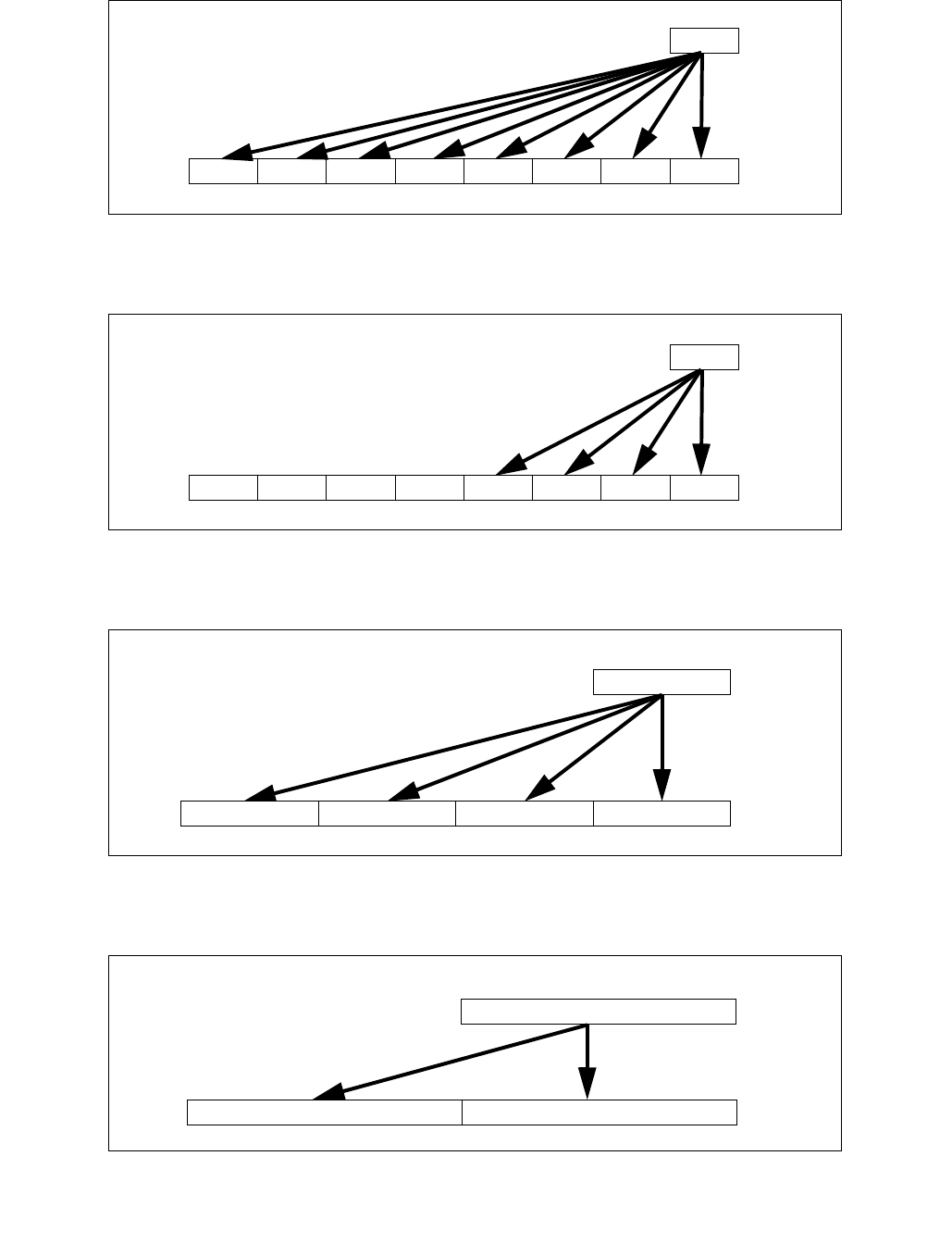
VPBROADCAST—Load Integer and Broadcast
INSTRUCTION SET REFERENCE, V-Z
Vol. 2C 5-333
Figure 5-16. VPBROADCASTD Operation (VEX.256 encoded version)
Figure 5-17. VPBROADCASTD Operation (128-bit version)
Figure 5-18. VPBROADCASTQ Operation (256-bit version)
Figure 5-19. VBROADCASTI128 Operation (256-bit version)
DEST
m32 X0
X0X0 X0X0 X0X0 X0X0
DEST
m32 X0
X0X0 X00X00 00
DEST
m64 X0
X0X0X0X0
DEST
m128 X0
X0X0
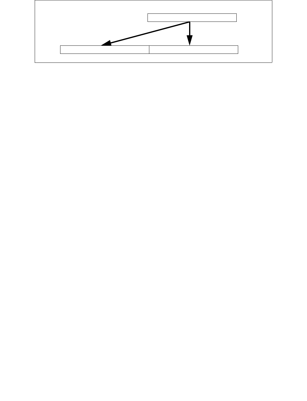
VPBROADCAST—Load Integer and Broadcast
INSTRUCTION SET REFERENCE, V-Z
5-334 Vol. 2C
Operation
VPBROADCASTB (EVEX encoded versions)
(KL, VL) = (16, 128), (32, 256), (64, 512)
FOR j 0 TO KL-1
i j * 8
IF k1[j] OR *no writemask*
THEN DEST[i+7:i] SRC[7:0]
ELSE
IF *merging-masking* ; merging-masking
THEN *DEST[i+7:i] remains unchanged*
ELSE ; zeroing-masking
DEST[i+7:i] 0
FI
FI;
ENDFOR
DEST[MAX_VL-1:VL] 0
VPBROADCASTW (EVEX encoded versions)
(KL, VL) = (8, 128), (16, 256), (32, 512)
FOR j 0 TO KL-1
i j * 16
IF k1[j] OR *no writemask*
THEN DEST[i+15:i] SRC[15:0]
ELSE
IF *merging-masking* ; merging-masking
THEN *DEST[i+15:i] remains unchanged*
ELSE ; zeroing-masking
DEST[i+15:i] 0
FI
FI;
ENDFOR
DEST[MAX_VL-1:VL] 0
VPBROADCASTD (128 bit version)
temp SRC[31:0]
DEST[31:0] temp
DEST[63:32] temp
DEST[95:64] temp
DEST[127:96] temp
DEST[MAX_VL-1:128] 0
Figure 5-20. VBROADCASTI256 Operation (512-bit version)
DEST
m256 X0
X0X0

VPBROADCAST—Load Integer and Broadcast
INSTRUCTION SET REFERENCE, V-Z
Vol. 2C 5-335
VPBROADCASTD (VEX.256 encoded version)
temp SRC[31:0]
DEST[31:0] temp
DEST[63:32] temp
DEST[95:64] temp
DEST[127:96] temp
DEST[159:128] temp
DEST[191:160] temp
DEST[223:192] temp
DEST[255:224] temp
DEST[MAX_VL-1:256] 0
VPBROADCASTD (EVEX encoded versions)
(KL, VL) = (4, 128), (8, 256), (16, 512)
FOR j 0 TO KL-1
i j * 32
IF k1[j] OR *no writemask*
THEN DEST[i+31:i] SRC[31:0]
ELSE
IF *merging-masking* ; merging-masking
THEN *DEST[i+31:i] remains unchanged*
ELSE ; zeroing-masking
DEST[i+31:i] 0
FI
FI;
ENDFOR
DEST[MAX_VL-1:VL] 0
VPBROADCASTQ (VEX.256 encoded version)
temp SRC[63:0]
DEST[63:0] temp
DEST[127:64] temp
DEST[191:128] temp
DEST[255:192] temp
DEST[MAX_VL-1:256] 0
VPBROADCASTQ (EVEX encoded versions)
(KL, VL) = (2, 128), (4, 256), (8, 512)
FOR j 0 TO KL-1
i j * 64
IF k1[j] OR *no writemask*
THEN DEST[i+63:i] SRC[63:0]
ELSE
IF *merging-masking* ; merging-masking
THEN *DEST[i+63:i] remains unchanged*
ELSE ; zeroing-masking
DEST[i+63:i] 0
FI
FI;
ENDFOR
DEST[MAX_VL-1:VL] 0
VBROADCASTI32x2 (EVEX encoded versions)
(KL, VL) = (4, 128), (8, 256), (16, 512)

VPBROADCAST—Load Integer and Broadcast
INSTRUCTION SET REFERENCE, V-Z
5-336 Vol. 2C
FOR j 0 TO KL-1
i j * 32
n (j mod 2) * 32
IF k1[j] OR *no writemask*
THEN DEST[i+31:i] SRC[n+31:n]
ELSE
IF *merging-masking* ; merging-masking
THEN *DEST[i+31:i] remains unchanged*
ELSE ; zeroing-masking
DEST[i+31:i] 0
FI
FI;
ENDFOR
DEST[MAX_VL-1:VL] 0
VBROADCASTI128 (VEX.256 encoded version)
temp SRC[127:0]
DEST[127:0] temp
DEST[255:128] temp
DEST[MAX_VL-1:256] 0
VBROADCASTI32X4 (EVEX encoded versions)
(KL, VL) = (8, 256), (16, 512)
FOR j 0 TO KL-1
i j* 32
n (j modulo 4) * 32
IF k1[j] OR *no writemask*
THEN DEST[i+31:i] SRC[n+31:n]
ELSE
IF *merging-masking* ; merging-masking
THEN *DEST[i+31:i] remains unchanged*
ELSE ; zeroing-masking
DEST[i+31:i] 0
FI
FI;
ENDFOR
DEST[MAX_VL-1:VL] 0
VBROADCASTI64X2 (EVEX encoded versions)
(KL, VL) = (8, 256), (16, 512)
FOR j 0 TO KL-1
i j * 64
n (j modulo 2) * 64
IF k1[j] OR *no writemask*
THEN DEST[i+63:i] SRC[n+63:n]
ELSE
IF *merging-masking* ; merging-masking
THEN *DEST[i+63:i] remains unchanged*
ELSE ; zeroing-masking
DEST[i+63:i] = 0
FI
FI;
ENDFOR;

VPBROADCAST—Load Integer and Broadcast
INSTRUCTION SET REFERENCE, V-Z
Vol. 2C 5-337
VBROADCASTI32X8 (EVEX.U1.512 encoded version)
FOR j 0 TO 15
i j * 32
n (j modulo 8) * 32
IF k1[j] OR *no writemask*
THEN DEST[i+31:i] SRC[n+31:n]
ELSE
IF *merging-masking* ; merging-masking
THEN *DEST[i+31:i] remains unchanged*
ELSE ; zeroing-masking
DEST[i+31:i] 0
FI
FI;
ENDFOR
DEST[MAX_VL-1:VL] 0
VBROADCASTI64X4 (EVEX.512 encoded version)
FOR j 0 TO 7
i j * 64
n (j modulo 4) * 64
IF k1[j] OR *no writemask*
THEN DEST[i+63:i] SRC[n+63:n]
ELSE
IF *merging-masking* ; merging-masking
THEN *DEST[i+63:i] remains unchanged*
ELSE ; zeroing-masking
DEST[i+63:i] 0
FI
FI;
ENDFOR
DEST[MAX_VL-1:VL] 0
Intel C/C++ Compiler Intrinsic Equivalent
VPBROADCASTB __m512i _mm512_broadcastb_epi8( __m128i a);
VPBROADCASTB __m512i _mm512_mask_broadcastb_epi8(__m512i s, __mmask64 k, __m128i a);
VPBROADCASTB __m512i _mm512_maskz_broadcastb_epi8( __mmask64 k, __m128i a);
VPBROADCASTB __m256i _mm256_broadcastb_epi8(__m128i a);
VPBROADCASTB __m256i _mm256_mask_broadcastb_epi8(__m256i s, __mmask32 k, __m128i a);
VPBROADCASTB __m256i _mm256_maskz_broadcastb_epi8( __mmask32 k, __m128i a);
VPBROADCASTB __m128i _mm_mask_broadcastb_epi8(__m128i s, __mmask16 k, __m128i a);
VPBROADCASTB __m128i _mm_maskz_broadcastb_epi8( __mmask16 k, __m128i a);
VPBROADCASTB __m128i _mm_broadcastb_epi8(__m128i a);
VPBROADCASTD __m512i _mm512_broadcastd_epi32( __m128i a);
VPBROADCASTD __m512i _mm512_mask_broadcastd_epi32(__m512i s, __mmask16 k, __m128i a);
VPBROADCASTD __m512i _mm512_maskz_broadcastd_epi32( __mmask16 k, __m128i a);
VPBROADCASTD __m256i _mm256_broadcastd_epi32( __m128i a);
VPBROADCASTD __m256i _mm256_mask_broadcastd_epi32(__m256i s, __mmask8 k, __m128i a);
VPBROADCASTD __m256i _mm256_maskz_broadcastd_epi32( __mmask8 k, __m128i a);
VPBROADCASTD __m128i _mm_broadcastd_epi32(__m128i a);
VPBROADCASTD __m128i _mm_mask_broadcastd_epi32(__m128i s, __mmask8 k, __m128i a);
VPBROADCASTD __m128i _mm_maskz_broadcastd_epi32( __mmask8 k, __m128i a);
VPBROADCASTQ __m512i _mm512_broadcastq_epi64( __m128i a);
VPBROADCASTQ __m512i _mm512_mask_broadcastq_epi64(__m512i s, __mmask8 k, __m128i a);
VPBROADCASTQ __m512i _mm512_maskz_broadcastq_epi64( __mmask8 k, __m128i a);

VPBROADCAST—Load Integer and Broadcast
INSTRUCTION SET REFERENCE, V-Z
5-338 Vol. 2C
VPBROADCASTQ __m256i _mm256_broadcastq_epi64(__m128i a);
VPBROADCASTQ __m256i _mm256_mask_broadcastq_epi64(__m256i s, __mmask8 k, __m128i a);
VPBROADCASTQ __m256i _mm256_maskz_broadcastq_epi64( __mmask8 k, __m128i a);
VPBROADCASTQ __m128i _mm_broadcastq_epi64(__m128i a);
VPBROADCASTQ __m128i _mm_mask_broadcastq_epi64(__m128i s, __mmask8 k, __m128i a);
VPBROADCASTQ __m128i _mm_maskz_broadcastq_epi64( __mmask8 k, __m128i a);
VPBROADCASTW __m512i _mm512_broadcastw_epi16(__m128i a);
VPBROADCASTW __m512i _mm512_mask_broadcastw_epi16(__m512i s, __mmask32 k, __m128i a);
VPBROADCASTW __m512i _mm512_maskz_broadcastw_epi16( __mmask32 k, __m128i a);
VPBROADCASTW __m256i _mm256_broadcastw_epi16(__m128i a);
VPBROADCASTW __m256i _mm256_mask_broadcastw_epi16(__m256i s, __mmask16 k, __m128i a);
VPBROADCASTW __m256i _mm256_maskz_broadcastw_epi16( __mmask16 k, __m128i a);
VPBROADCASTW __m128i _mm_broadcastw_epi16(__m128i a);
VPBROADCASTW __m128i _mm_mask_broadcastw_epi16(__m128i s, __mmask8 k, __m128i a);
VPBROADCASTW __m128i _mm_maskz_broadcastw_epi16( __mmask8 k, __m128i a);
VBROADCASTI32x2 __m512i _mm512_broadcast_i32x2( __m128i a);
VBROADCASTI32x2 __m512i _mm512_mask_broadcast_i32x2(__m512i s, __mmask16 k, __m128i a);
VBROADCASTI32x2 __m512i _mm512_maskz_broadcast_i32x2( __mmask16 k, __m128i a);
VBROADCASTI32x2 __m256i _mm256_broadcast_i32x2( __m128i a);
VBROADCASTI32x2 __m256i _mm256_mask_broadcast_i32x2(__m256i s, __mmask8 k, __m128i a);
VBROADCASTI32x2 __m256i _mm256_maskz_broadcast_i32x2( __mmask8 k, __m128i a);
VBROADCASTI32x2 __m128i _mm_broadcastq_i32x2(__m128i a);
VBROADCASTI32x2 __m128i _mm_mask_broadcastq_i32x2(__m128i s, __mmask8 k, __m128i a);
VBROADCASTI32x2 __m128i _mm_maskz_broadcastq_i32x2( __mmask8 k, __m128i a);
VBROADCASTI32x4 __m512i _mm512_broadcast_i32x4( __m128i a);
VBROADCASTI32x4 __m512i _mm512_mask_broadcast_i32x4(__m512i s, __mmask16 k, __m128i a);
VBROADCASTI32x4 __m512i _mm512_maskz_broadcast_i32x4( __mmask16 k, __m128i a);
VBROADCASTI32x4 __m256i _mm256_broadcast_i32x4( __m128i a);
VBROADCASTI32x4 __m256i _mm256_mask_broadcast_i32x4(__m256i s, __mmask8 k, __m128i a);
VBROADCASTI32x4 __m256i _mm256_maskz_broadcast_i32x4( __mmask8 k, __m128i a);
VBROADCASTI32x8 __m512i _mm512_broadcast_i32x8( __m256i a);
VBROADCASTI32x8 __m512i _mm512_mask_broadcast_i32x8(__m512i s, __mmask16 k, __m256i a);
VBROADCASTI32x8 __m512i _mm512_maskz_broadcast_i32x8( __mmask16 k, __m256i a);
VBROADCASTI64x2 __m512i _mm512_broadcast_i64x2( __m128i a);
VBROADCASTI64x2 __m512i _mm512_mask_broadcast_i64x2(__m512i s, __mmask8 k, __m128i a);
VBROADCASTI64x2 __m512i _mm512_maskz_broadcast_i64x2( __mmask8 k, __m128i a);
VBROADCASTI64x2 __m256i _mm256_broadcast_i64x2( __m128i a);
VBROADCASTI64x2 __m256i _mm256_mask_broadcast_i64x2(__m256i s, __mmask8 k, __m128i a);
VBROADCASTI64x2 __m256i _mm256_maskz_broadcast_i64x2( __mmask8 k, __m128i a);
VBROADCASTI64x4 __m512i _mm512_broadcast_i64x4( __m256i a);
VBROADCASTI64x4 __m512i _mm512_mask_broadcast_i64x4(__m512i s, __mmask8 k, __m256i a);
VBROADCASTI64x4 __m512i _mm512_maskz_broadcast_i64x4( __mmask8 k, __m256i a);
SIMD Floating-Point Exceptions
None
Other Exceptions
EVEX-encoded instructions, see Exceptions Type 6;
EVEX-encoded instructions, syntax with reg/mem operand, see Exceptions Type E6.
#UD If VEX.L = 0 for VPBROADCASTQ, VPBROADCASTI128.
If EVEX.L’L = 0 for VBROADCASTI32X4/VBROADCASTI64X2.
If EVEX.L’L < 10b for VBROADCASTI32X8/VBROADCASTI64X4.

VPCMPB/VPCMPUB—Compare Packed Byte Values Into Mask
INSTRUCTION SET REFERENCE, V-Z
Vol. 2C 5-339
VPCMPB/VPCMPUB—Compare Packed Byte Values Into Mask
Instruction Operand Encoding
Description
Performs a SIMD compare of the packed byte values in the second source operand and the first source operand and
returns the results of the comparison to the mask destination operand. The comparison predicate operand (imme-
diate byte) specifies the type of comparison performed on each pair of packed values in the two source operands.
The result of each comparison is a single mask bit result of 1 (comparison true) or 0 (comparison false).
VPCMPB performs a comparison between pairs of signed byte values.
VPCMPUB performs a comparison between pairs of unsigned byte values.
The first source operand (second operand) is a ZMM/YMM/XMM register. The second source operand can be a
ZMM/YMM/XMM register or a 512/256/128-bit memory location. The destination operand (first operand) is a mask
register k1. Up to 64/32/16 comparisons are performed with results written to the destination operand under the
writemask k2.
Opcode/
Instruction
Op/
En
64/32
bit Mode
Support
CPUID
Feature
Flag
Description
EVEX.NDS.128.66.0F3A.W0 3F /r ib
VPCMPB k1 {k2}, xmm2,
xmm3/m128, imm8
FVM V/V AVX512VL
AVX512BW
Compare packed signed byte values in xmm3/m128 and
xmm2 using bits 2:0 of imm8 as a comparison predicate
with writemask k2 and leave the result in mask register
k1.
EVEX.NDS.256.66.0F3A.W0 3F /r ib
VPCMPB k1 {k2}, ymm2,
ymm3/m256, imm8
FVM V/V AVX512VL
AVX512BW
Compare packed signed byte values in ymm3/m256 and
ymm2 using bits 2:0 of imm8 as a comparison predicate
with writemask k2 and leave the result in mask register
k1.
EVEX.NDS.512.66.0F3A.W0 3F /r ib
VPCMPB k1 {k2}, zmm2,
zmm3/m512, imm8
FVM V/V AVX512BW Compare packed signed byte values in zmm3/m512 and
zmm2 using bits 2:0 of imm8 as a comparison predicate
with writemask k2 and leave the result in mask register
k1.
EVEX.NDS.128.66.0F3A.W0 3E /r ib
VPCMPUB k1 {k2}, xmm2,
xmm3/m128, imm8
FVM V/V AVX512VL
AVX512BW
Compare packed unsigned byte values in xmm3/m128
and xmm2 using bits 2:0 of imm8 as a comparison
predicate with writemask k2 and leave the result in mask
register k1.
EVEX.NDS.256.66.0F3A.W0 3E /r ib
VPCMPUB k1 {k2}, ymm2,
ymm3/m256, imm8
FVM V/V AVX512VL
AVX512BW
Compare packed unsigned byte values in ymm3/m256
and ymm2 using bits 2:0 of imm8 as a comparison
predicate with writemask k2 and leave the result in mask
register k1.
EVEX.NDS.512.66.0F3A.W0 3E /r ib
VPCMPUB k1 {k2}, zmm2,
zmm3/m512, imm8
FVM V/V AVX512BW Compare packed unsigned byte values in zmm3/m512
and zmm2 using bits 2:0 of imm8 as a comparison
predicate with writemask k2 and leave the result in mask
register k1.
Op/En Operand 1 Operand 2 Operand 3 Operand 4
FVM ModRM:reg (w) vvvv (r) ModRM:r/m (r) NA

VPCMPB/VPCMPUB—Compare Packed Byte Values Into Mask
INSTRUCTION SET REFERENCE, V-Z
5-340 Vol. 2C
The comparison predicate operand is an 8-bit immediate: bits 2:0 define the type of comparison to be performed.
Bits 3 through 7 of the immediate are reserved. Compiler can implement the pseudo-op mnemonic listed in Table
5-10.
:
Operation
CASE (COMPARISON PREDICATE) OF
0: OP EQ;
1: OP LT;
2: OP LE;
3: OP FALSE;
4: OP NEQ ;
5: OP NLT;
6: OP NLE;
7: OP TRUE;
ESAC;
VPCMPB (EVEX encoded versions)
(KL, VL) = (16, 128), (32, 256), (64, 512)
FOR j 0 TO KL-1
i j * 8
IF k2[j] OR *no writemask*
THEN
CMP SRC1[i+7:i] OP SRC2[i+7:i];
IF CMP = TRUE
THEN DEST[j] 1;
ELSE DEST[j] 0; FI;
ELSE DEST[j] = 0 ; zeroing-masking onlyFI;
FI;
ENDFOR
DEST[MAX_KL-1:KL] 0
Table 5-10. Pseudo-Op and VPCMP* Implementation
Pseudo-Op PCMPM Implementation
VPCMPEQ* reg1, reg2, reg3 VPCMP* reg1, reg2, reg3, 0
VPCMPLT* reg1, reg2, reg3 VPCMP*reg1, reg2, reg3, 1
VPCMPLE* reg1, reg2, reg3 VPCMP* reg1, reg2, reg3, 2
VPCMPNEQ* reg1, reg2, reg3 VPCMP* reg1, reg2, reg3, 4
VPPCMPNLT* reg1, reg2, reg3 VPCMP* reg1, reg2, reg3, 5
VPCMPNLE* reg1, reg2, reg3 VPCMP* reg1, reg2, reg3, 6

VPCMPB/VPCMPUB—Compare Packed Byte Values Into Mask
INSTRUCTION SET REFERENCE, V-Z
Vol. 2C 5-341
VPCMPUB (EVEX encoded versions)
(KL, VL) = (16, 128), (32, 256), (64, 512)
FOR j 0 TO KL-1
i j * 8
IF k2[j] OR *no writemask*
THEN
CMP SRC1[i+7:i] OP SRC2[i+7:i];
IF CMP = TRUE
THEN DEST[j] 1;
ELSE DEST[j] 0; FI;
ELSE DEST[j] = 0 ; zeroing-masking onlyFI;
FI;
ENDFOR
DEST[MAX_KL-1:KL] 0
Intel C/C++ Compiler Intrinsic Equivalent
VPCMPB __mmask64 _mm512_cmp_epi8_mask( __m512i a, __m512i b, int cmp);
VPCMPB __mmask64 _mm512_mask_cmp_epi8_mask( __mmask64 m, __m512i a, __m512i b, int cmp);
VPCMPB __mmask32 _mm256_cmp_epi8_mask( __m256i a, __m256i b, int cmp);
VPCMPB __mmask32 _mm256_mask_cmp_epi8_mask( __mmask32 m, __m256i a, __m256i b, int cmp);
VPCMPB __mmask16 _mm_cmp_epi8_mask( __m128i a, __m128i b, int cmp);
VPCMPB __mmask16 _mm_mask_cmp_epi8_mask( __mmask16 m, __m128i a, __m128i b, int cmp);
VPCMPB __mmask64 _mm512_cmp[eq|ge|gt|le|lt|neq]_epi8_mask( __m512i a, __m512i b);
VPCMPB __mmask64 _mm512_mask_cmp[eq|ge|gt|le|lt|neq]_epi8_mask( __mmask64 m, __m512i a, __m512i b);
VPCMPB __mmask32 _mm256_cmp[eq|ge|gt|le|lt|neq]_epi8_mask( __m256i a, __m256i b);
VPCMPB __mmask32 _mm256_mask_cmp[eq|ge|gt|le|lt|neq]_epi8_mask( __mmask32 m, __m256i a, __m256i b);
VPCMPB __mmask16 _mm_cmp[eq|ge|gt|le|lt|neq]_epi8_mask( __m128i a, __m128i b);
VPCMPB __mmask16 _mm_mask_cmp[eq|ge|gt|le|lt|neq]_epi8_mask( __mmask16 m, __m128i a, __m128i b);
VPCMPUB __mmask64 _mm512_cmp_epu8_mask( __m512i a, __m512i b, int cmp);
VPCMPUB __mmask64 _mm512_mask_cmp_epu8_mask( __mmask64 m, __m512i a, __m512i b, int cmp);
VPCMPUB __mmask32 _mm256_cmp_epu8_mask( __m256i a, __m256i b, int cmp);
VPCMPUB __mmask32 _mm256_mask_cmp_epu8_mask( __mmask32 m, __m256i a, __m256i b, int cmp);
VPCMPUB __mmask16 _mm_cmp_epu8_mask( __m128i a, __m128i b, int cmp);
VPCMPUB __mmask16 _mm_mask_cmp_epu8_mask( __mmask16 m, __m128i a, __m128i b, int cmp);
VPCMPUB __mmask64 _mm512_cmp[eq|ge|gt|le|lt|neq]_epu8_mask( __m512i a, __m512i b, int cmp);
VPCMPUB __mmask64 _mm512_mask_cmp[eq|ge|gt|le|lt|neq]_epu8_mask( __mmask64 m, __m512i a, __m512i b, int cmp);
VPCMPUB __mmask32 _mm256_cmp[eq|ge|gt|le|lt|neq]_epu8_mask( __m256i a, __m256i b, int cmp);
VPCMPUB __mmask32 _mm256_mask_cmp[eq|ge|gt|le|lt|neq]_epu8_mask( __mmask32 m, __m256i a, __m256i b, int cmp);
VPCMPUB __mmask16 _mm_cmp[eq|ge|gt|le|lt|neq]_epu8_mask( __m128i a, __m128i b, int cmp);
VPCMPUB __mmask16 _mm_mask_cmp[eq|ge|gt|le|lt|neq]_epu8_mask( __mmask16 m, __m128i a, __m128i b, int cmp);
SIMD Floating-Point Exceptions
None
Other Exceptions
EVEX-encoded instruction, see Exceptions Type E4.nb.

VPCMPD/VPCMPUD—Compare Packed Integer Values into Mask
INSTRUCTION SET REFERENCE, V-Z
5-342 Vol. 2C
VPCMPD/VPCMPUD—Compare Packed Integer Values into Mask
Instruction Operand Encoding
Description
Performs a SIMD compare of the packed integer values in the second source operand and the first source operand
and returns the results of the comparison to the mask destination operand. The comparison predicate operand
(immediate byte) specifies the type of comparison performed on each pair of packed values in the two source oper-
ands. The result of each comparison is a single mask bit result of 1 (comparison true) or 0 (comparison false).
VPCMPD/VPCMPUD performs a comparison between pairs of signed/unsigned doubleword integer values.
The first source operand (second operand) is a ZMM/YMM/XMM register. The second source operand can be a
ZMM/YMM/XMM register or a 512/256/128-bit memory location or a 512-bit vector broadcasted from a 32-bit
memory location. The destination operand (first operand) is a mask register k1. Up to 16/8/4 comparisons are
performed with results written to the destination operand under the writemask k2.
The comparison predicate operand is an 8-bit immediate: bits 2:0 define the type of comparison to be performed.
Bits 3 through 7 of the immediate are reserved. Compiler can implement the pseudo-op mnemonic listed in Table
5-10.
Opcode/
Instruction
Op/
En
64/32
bit Mode
Support
CPUID
Feature
Flag
Description
EVEX.NDS.128.66.0F3A.W0 1F /r ib
VPCMPD k1 {k2}, xmm2,
xmm3/m128/m32bcst, imm8
FV V/V AVX512VL
AVX512F
Compare packed signed doubleword integer values in
xmm3/m128/m32bcst and xmm2 using bits 2:0 of imm8
as a comparison predicate with writemask k2 and leave
the result in mask register k1.
EVEX.NDS.256.66.0F3A.W0 1F /r ib
VPCMPD k1 {k2}, ymm2,
ymm3/m256/m32bcst, imm8
FV V/V AVX512VL
AVX512F
Compare packed signed doubleword integer values in
ymm3/m256/m32bcst and ymm2 using bits 2:0 of imm8
as a comparison predicate with writemask k2 and leave
the result in mask register k1.
EVEX.NDS.512.66.0F3A.W0 1F /r ib
VPCMPD k1 {k2}, zmm2,
zmm3/m512/m32bcst, imm8
FV V/V AVX512F Compare packed signed doubleword integer values in
zmm2 and zmm3/m512/m32bcst using bits 2:0 of imm8
as a comparison predicate. The comparison results are
written to the destination k1 under writemask k2.
EVEX.NDS.128.66.0F3A.W0 1E /r ib
VPCMPUD k1 {k2}, xmm2,
xmm3/m128/m32bcst, imm8
FV V/V AVX512VL
AVX512F
Compare packed unsigned doubleword integer values in
xmm3/m128/m32bcst and xmm2 using bits 2:0 of imm8
as a comparison predicate with writemask k2 and leave
the result in mask register k1.
EVEX.NDS.256.66.0F3A.W0 1E /r ib
VPCMPUD k1 {k2}, ymm2,
ymm3/m256/m32bcst, imm8
FV V/V AVX512VL
AVX512F
Compare packed unsigned doubleword integer values in
ymm3/m256/m32bcst and ymm2 using bits 2:0 of imm8
as a comparison predicate with writemask k2 and leave
the result in mask register k1.
EVEX.NDS.512.66.0F3A.W0 1E /r ib
VPCMPUD k1 {k2}, zmm2,
zmm3/m512/m32bcst, imm8
FV V/V AVX512F Compare packed unsigned doubleword integer values in
zmm2 and zmm3/m512/m32bcst using bits 2:0 of imm8
as a comparison predicate. The comparison results are
written to the destination k1 under writemask k2.
Op/En Operand 1 Operand 2 Operand 3 Operand 4
FV ModRM:reg (w) EVEX.vvvv (r) ModRM:r/m (r) Imm8

VPCMPD/VPCMPUD—Compare Packed Integer Values into Mask
INSTRUCTION SET REFERENCE, V-Z
Vol. 2C 5-343
Operation
CASE (COMPARISON PREDICATE) OF
0: OP EQ;
1: OP LT;
2: OP LE;
3: OP FALSE;
4: OP NEQ;
5: OP NLT;
6: OP NLE;
7: OP TRUE;
ESAC;
VPCMPD (EVEX encoded versions)
(KL, VL) = (4, 128), (8, 256), (16, 512)
FOR j 0 TO KL-1
i j * 32
IF k2[j] OR *no writemask*
THEN
IF (EVEX.b = 1) AND (SRC2 *is memory*)
THEN CMP SRC1[i+31:i] OP SRC2[31:0];
ELSE CMP SRC1[i+31:i] OP SRC2[i+31:i];
FI;
IF CMP = TRUE
THEN DEST[j] 1;
ELSE DEST[j] 0; FI;
ELSE DEST[j] 0 ; zeroing-masking onlyFI;
FI;
ENDFOR
DEST[MAX_KL-1:KL] 0
VPCMPUD (EVEX encoded versions)
(KL, VL) = (4, 128), (8, 256), (16, 512)
FOR j 0 TO KL-1
i j * 32
IF k2[j] OR *no writemask*
THEN
IF (EVEX.b = 1) AND (SRC2 *is memory*)
THEN CMP SRC1[i+31:i] OP SRC2[31:0];
ELSE CMP SRC1[i+31:i] OP SRC2[i+31:i];
FI;
IF CMP = TRUE
THEN DEST[j] 1;
ELSE DEST[j] 0; FI;
ELSE DEST[j] 0 ; zeroing-masking onlyFI;
FI;
ENDFOR
DEST[MAX_KL-1:KL] 0

VPCMPD/VPCMPUD—Compare Packed Integer Values into Mask
INSTRUCTION SET REFERENCE, V-Z
5-344 Vol. 2C
Intel C/C++ Compiler Intrinsic Equivalent
VPCMPD __mmask16 _mm512_cmp_epi32_mask( __m512i a, __m512i b, int imm);
VPCMPD __mmask16 _mm512_mask_cmp_epi32_mask(__mmask16 k, __m512i a, __m512i b, int imm);
VPCMPD __mmask16 _mm512_cmp[eq|ge|gt|le|lt|neq]_epi32_mask( __m512i a, __m512i b);
VPCMPD __mmask16 _mm512_mask_cmp[eq|ge|gt|le|lt|neq]_epi32_mask(__mmask16 k, __m512i a, __m512i b);
VPCMPUD __mmask16 _mm512_cmp_epu32_mask( __m512i a, __m512i b, int imm);
VPCMPUD __mmask16 _mm512_mask_cmp_epu32_mask(__mmask16 k, __m512i a, __m512i b, int imm);
VPCMPUD __mmask16 _mm512_cmp[eq|ge|gt|le|lt|neq]_epu32_mask( __m512i a, __m512i b);
VPCMPUD __mmask16 _mm512_mask_cmp[eq|ge|gt|le|lt|neq]_epu32_mask(__mmask16 k, __m512i a, __m512i b);
VPCMPD __mmask8 _mm256_cmp_epi32_mask( __m256i a, __m256i b, int imm);
VPCMPD __mmask8 _mm256_mask_cmp_epi32_mask(__mmask8 k, __m256i a, __m256i b, int imm);
VPCMPD __mmask8 _mm256_cmp[eq|ge|gt|le|lt|neq]_epi32_mask( __m256i a, __m256i b);
VPCMPD __mmask8 _mm256_mask_cmp[eq|ge|gt|le|lt|neq]_epi32_mask(__mmask8 k, __m256i a, __m256i b);
VPCMPUD __mmask8 _mm256_cmp_epu32_mask( __m256i a, __m256i b, int imm);
VPCMPUD __mmask8 _mm256_mask_cmp_epu32_mask(__mmask8 k, __m256i a, __m256i b, int imm);
VPCMPUD __mmask8 _mm256_cmp[eq|ge|gt|le|lt|neq]_epu32_mask( __m256i a, __m256i b);
VPCMPUD __mmask8 _mm256_mask_cmp[eq|ge|gt|le|lt|neq]_epu32_mask(__mmask8 k, __m256i a, __m256i b);
VPCMPD __mmask8 _mm_cmp_epi32_mask( __m128i a, __m128i b, int imm);
VPCMPD __mmask8 _mm_mask_cmp_epi32_mask(__mmask8 k, __m128i a, __m128i b, int imm);
VPCMPD __mmask8 _mm_cmp[eq|ge|gt|le|lt|neq]_epi32_mask( __m128i a, __m128i b);
VPCMPD __mmask8 _mm_mask_cmp[eq|ge|gt|le|lt|neq]_epi32_mask(__mmask8 k, __m128i a, __m128i b);
VPCMPUD __mmask8 _mm_cmp_epu32_mask( __m128i a, __m128i b, int imm);
VPCMPUD __mmask8 _mm_mask_cmp_epu32_mask(__mmask8 k, __m128i a, __m128i b, int imm);
VPCMPUD __mmask8 _mm_cmp[eq|ge|gt|le|lt|neq]_epu32_mask( __m128i a, __m128i b);
VPCMPUD __mmask8 _mm_mask_cmp[eq|ge|gt|le|lt|neq]_epu32_mask(__mmask8 k, __m128i a, __m128i b);
SIMD Floating-Point Exceptions
None
Other Exceptions
EVEX-encoded instruction, see Exceptions Type E4.

VPCMPQ/VPCMPUQ—Compare Packed Integer Values into Mask
INSTRUCTION SET REFERENCE, V-Z
Vol. 2C 5-345
VPCMPQ/VPCMPUQ—Compare Packed Integer Values into Mask
Instruction Operand Encoding
Description
Performs a SIMD compare of the packed integer values in the second source operand and the first source operand
and returns the results of the comparison to the mask destination operand. The comparison predicate operand
(immediate byte) specifies the type of comparison performed on each pair of packed values in the two source oper-
ands. The result of each comparison is a single mask bit result of 1 (comparison true) or 0 (comparison false).
VPCMPQ/VPCMPUQ performs a comparison between pairs of signed/unsigned quadword integer values.
The first source operand (second operand) is a ZMM/YMM/XMM register. The second source operand can be a
ZMM/YMM/XMM register or a 512/256/128-bit memory location or a 512-bit vector broadcasted from a 64-bit
memory location. The destination operand (first operand) is a mask register k1. Up to 8/4/2 comparisons are
performed with results written to the destination operand under the writemask k2.
The comparison predicate operand is an 8-bit immediate: bits 2:0 define the type of comparison to be performed.
Bits 3 through 7 of the immediate are reserved. Compiler can implement the pseudo-op mnemonic listed in Table
5-10.
Opcode/
Instruction
Op/
En
64/32
bit Mode
Support
CPUID
Feature
Flag
Description
EVEX.NDS.128.66.0F3A.W1 1F /r ib
VPCMPQ k1 {k2}, xmm2,
xmm3/m128/m64bcst, imm8
FV V/V AVX512VL
AVX512F
Compare packed signed quadword integer values in
xmm3/m128/m64bcst and xmm2 using bits 2:0 of imm8
as a comparison predicate with writemask k2 and leave
the result in mask register k1.
EVEX.NDS.256.66.0F3A.W1 1F /r ib
VPCMPQ k1 {k2}, ymm2,
ymm3/m256/m64bcst, imm8
FV V/V AVX512VL
AVX512F
Compare packed signed quadword integer values in
ymm3/m256/m64bcst and ymm2 using bits 2:0 of imm8
as a comparison predicate with writemask k2 and leave
the result in mask register k1.
EVEX.NDS.512.66.0F3A.W1 1F /r ib
VPCMPQ k1 {k2}, zmm2,
zmm3/m512/m64bcst, imm8
FV V/V AVX512F Compare packed signed quadword integer values in
zmm3/m512/m64bcst and zmm2 using bits 2:0 of imm8
as a comparison predicate with writemask k2 and leave
the result in mask register k1.
EVEX.NDS.128.66.0F3A.W1 1E /r ib
VPCMPUQ k1 {k2}, xmm2,
xmm3/m128/m64bcst, imm8
FV V/V AVX512VL
AVX512F
Compare packed unsigned quadword integer values in
xmm3/m128/m64bcst and xmm2 using bits 2:0 of imm8
as a comparison predicate with writemask k2 and leave
the result in mask register k1.
EVEX.NDS.256.66.0F3A.W1 1E /r ib
VPCMPUQ k1 {k2}, ymm2,
ymm3/m256/m64bcst, imm8
FV V/V AVX512VL
AVX512F
Compare packed unsigned quadword integer values in
ymm3/m256/m64bcst and ymm2 using bits 2:0 of imm8
as a comparison predicate with writemask k2 and leave
the result in mask register k1.
EVEX.NDS.512.66.0F3A.W1 1E /r ib
VPCMPUQ k1 {k2}, zmm2,
zmm3/m512/m64bcst, imm8
FV V/V AVX512F Compare packed unsigned quadword integer values in
zmm3/m512/m64bcst and zmm2 using bits 2:0 of imm8
as a comparison predicate with writemask k2 and leave
the result in mask register k1.
Op/En Operand 1 Operand 2 Operand 3 Operand 4
FV ModRM:reg (w) EVEX.vvvv (r) ModRM:r/m (r) Imm8

VPCMPQ/VPCMPUQ—Compare Packed Integer Values into Mask
INSTRUCTION SET REFERENCE, V-Z
5-346 Vol. 2C
Operation
CASE (COMPARISON PREDICATE) OF
0: OP EQ;
1: OP LT;
2: OP LE;
3: OP FALSE;
4: OP NEQ;
5: OP NLT;
6: OP NLE;
7: OP TRUE;
ESAC;
VPCMPQ (EVEX encoded versions)
(KL, VL) = (2, 128), (4, 256), (8, 512)
FOR j 0 TO KL-1
i j * 64
IF k2[j] OR *no writemask*
THEN
IF (EVEX.b = 1) AND (SRC2 *is memory*)
THEN CMP SRC1[i+63:i] OP SRC2[63:0];
ELSE CMP SRC1[i+63:i] OP SRC2[i+63:i];
FI;
IF CMP = TRUE
THEN DEST[j] 1;
ELSE DEST[j] 0; FI;
ELSE DEST[j] 0 ; zeroing-masking only
FI;
ENDFOR
DEST[MAX_KL-1:KL] 0
VPCMPUQ (EVEX encoded versions)
(KL, VL) = (2, 128), (4, 256), (8, 512)
FOR j 0 TO KL-1
i j * 64
IF k2[j] OR *no writemask*
THEN
IF (EVEX.b = 1) AND (SRC2 *is memory*)
THEN CMP SRC1[i+63:i] OP SRC2[63:0];
ELSE CMP SRC1[i+63:i] OP SRC2[i+63:i];
FI;
IF CMP = TRUE
THEN DEST[j] 1;
ELSE DEST[j] 0; FI;
ELSE DEST[j] 0 ; zeroing-masking only
FI;
ENDFOR
DEST[MAX_KL-1:KL] 0

VPCMPQ/VPCMPUQ—Compare Packed Integer Values into Mask
INSTRUCTION SET REFERENCE, V-Z
Vol. 2C 5-347
Intel C/C++ Compiler Intrinsic Equivalent
VPCMPQ __mmask8 _mm512_cmp_epi64_mask( __m512i a, __m512i b, int imm);
VPCMPQ __mmask8 _mm512_mask_cmp_epi64_mask(__mmask8 k, __m512i a, __m512i b, int imm);
VPCMPQ __mmask8 _mm512_cmp[eq|ge|gt|le|lt|neq]_epi64_mask( __m512i a, __m512i b);
VPCMPQ __mmask8 _mm512_mask_cmp[eq|ge|gt|le|lt|neq]_epi64_mask(__mmask8 k, __m512i a, __m512i b);
VPCMPUQ __mmask8 _mm512_cmp_epu64_mask( __m512i a, __m512i b, int imm);
VPCMPUQ __mmask8 _mm512_mask_cmp_epu64_mask(__mmask8 k, __m512i a, __m512i b, int imm);
VPCMPUQ __mmask8 _mm512_cmp[eq|ge|gt|le|lt|neq]_epu64_mask( __m512i a, __m512i b);
VPCMPUQ __mmask8 _mm512_mask_cmp[eq|ge|gt|le|lt|neq]_epu64_mask(__mmask8 k, __m512i a, __m512i b);
VPCMPQ __mmask8 _mm256_cmp_epi64_mask( __m256i a, __m256i b, int imm);
VPCMPQ __mmask8 _mm256_mask_cmp_epi64_mask(__mmask8 k, __m256i a, __m256i b, int imm);
VPCMPQ __mmask8 _mm256_cmp[eq|ge|gt|le|lt|neq]_epi64_mask( __m256i a, __m256i b);
VPCMPQ __mmask8 _mm256_mask_cmp[eq|ge|gt|le|lt|neq]_epi64_mask(__mmask8 k, __m256i a, __m256i b);
VPCMPUQ __mmask8 _mm256_cmp_epu64_mask( __m256i a, __m256i b, int imm);
VPCMPUQ __mmask8 _mm256_mask_cmp_epu64_mask(__mmask8 k, __m256i a, __m256i b, int imm);
VPCMPUQ __mmask8 _mm256_cmp[eq|ge|gt|le|lt|neq]_epu64_mask( __m256i a, __m256i b);
VPCMPUQ __mmask8 _mm256_mask_cmp[eq|ge|gt|le|lt|neq]_epu64_mask(__mmask8 k, __m256i a, __m256i b);
VPCMPQ __mmask8 _mm_cmp_epi64_mask( __m128i a, __m128i b, int imm);
VPCMPQ __mmask8 _mm_mask_cmp_epi64_mask(__mmask8 k, __m128i a, __m128i b, int imm);
VPCMPQ __mmask8 _mm_cmp[eq|ge|gt|le|lt|neq]_epi64_mask( __m128i a, __m128i b);
VPCMPQ __mmask8 _mm_mask_cmp[eq|ge|gt|le|lt|neq]_epi64_mask(__mmask8 k, __m128i a, __m128i b);
VPCMPUQ __mmask8 _mm_cmp_epu64_mask( __m128i a, __m128i b, int imm);
VPCMPUQ __mmask8 _mm_mask_cmp_epu64_mask(__mmask8 k, __m128i a, __m128i b, int imm);
VPCMPUQ __mmask8 _mm_cmp[eq|ge|gt|le|lt|neq]_epu64_mask( __m128i a, __m128i b);
VPCMPUQ __mmask8 _mm_mask_cmp[eq|ge|gt|le|lt|neq]_epu64_mask(__mmask8 k, __m128i a, __m128i b);
SIMD Floating-Point Exceptions
None
Other Exceptions
EVEX-encoded instruction, see Exceptions Type E4.

VPCMPW/VPCMPUW—Compare Packed Word Values Into Mask
INSTRUCTION SET REFERENCE, V-Z
5-348 Vol. 2C
VPCMPW/VPCMPUW—Compare Packed Word Values Into Mask
Instruction Operand Encoding
Description
Performs a SIMD compare of the packed integer word in the second source operand and the first source operand
and returns the results of the comparison to the mask destination operand. The comparison predicate operand
(immediate byte) specifies the type of comparison performed on each pair of packed values in the two source oper-
ands. The result of each comparison is a single mask bit result of 1 (comparison true) or 0 (comparison false).
VPCMPW performs a comparison between pairs of signed word values.
VPCMPUW performs a comparison between pairs of unsigned word values.
The first source operand (second operand) is a ZMM/YMM/XMM register. The second source operand can be a
ZMM/YMM/XMM register or a 512/256/128-bit memory location. The destination operand (first operand) is a mask
register k1. Up to 32/16/8 comparisons are performed with results written to the destination operand under the
writemask k2.
The comparison predicate operand is an 8-bit immediate: bits 2:0 define the type of comparison to be performed.
Bits 3 through 7 of the immediate are reserved. Compiler can implement the pseudo-op mnemonic listed in Table
5-10.
Opcode/
Instruction
Op/
En
64/32
bit Mode
Support
CPUID
Feature
Flag
Description
EVEX.NDS.128.66.0F3A.W1 3F /r ib
VPCMPW k1 {k2}, xmm2,
xmm3/m128, imm8
FVM V/V AVX512VL
AVX512BW
Compare packed signed word integers in xmm3/m128
and xmm2 using bits 2:0 of imm8 as a comparison
predicate with writemask k2 and leave the result in
mask register k1.
EVEX.NDS.256.66.0F3A.W1 3F /r ib
VPCMPW k1 {k2}, ymm2,
ymm3/m256, imm8
FVM V/V AVX512VL
AVX512BW
Compare packed signed word integers in ymm3/m256
and ymm2 using bits 2:0 of imm8 as a comparison
predicate with writemask k2 and leave the result in
mask register k1.
EVEX.NDS.512.66.0F3A.W1 3F /r ib
VPCMPW k1 {k2}, zmm2,
zmm3/m512, imm8
FVM V/V AVX512BW Compare packed signed word integers in zmm3/m512
and zmm2 using bits 2:0 of imm8 as a comparison
predicate with writemask k2 and leave the result in
mask register k1.
EVEX.NDS.128.66.0F3A.W1 3E /r ib
VPCMPUW k1 {k2}, xmm2,
xmm3/m128, imm8
FVM V/V AVX512VL
AVX512BW
Compare packed unsigned word integers in xmm3/m128
and xmm2 using bits 2:0 of imm8 as a comparison
predicate with writemask k2 and leave the result in
mask register k1.
EVEX.NDS.256.66.0F3A.W1 3E /r ib
VPCMPUW k1 {k2}, ymm2,
ymm3/m256, imm8
FVM V/V AVX512VL
AVX512BW
Compare packed unsigned word integers in ymm3/m256
and ymm2 using bits 2:0 of imm8 as a comparison
predicate with writemask k2 and leave the result in
mask register k1.
VPCMPUW k1 {k2}, zmm2,
zmm3/m512, imm8
FVM V/V AVX512BW Compare packed unsigned word integers in zmm3/m512
and zmm2 using bits 2:0 of imm8 as a comparison
predicate with writemask k2 and leave the result in
mask register k1.
Op/En Operand 1 Operand 2 Operand 3 Operand 4
FVM ModRM:reg (w) vvvv (r) ModRM:r/m (r) NA

VPCMPW/VPCMPUW—Compare Packed Word Values Into Mask
INSTRUCTION SET REFERENCE, V-Z
Vol. 2C 5-349
Operation
CASE (COMPARISON PREDICATE) OF
0: OP EQ;
1: OP LT;
2: OP LE;
3: OP FALSE;
4: OP NEQ ;
5: OP NLT;
6: OP NLE;
7: OP TRUE;
ESAC;
VPCMPW (EVEX encoded versions)
(KL, VL) = (8, 128), (16, 256), (32, 512)
FOR j 0 TO KL-1
i j * 16
IF k2[j] OR *no writemask*
THEN
ICMP SRC1[i+15:i] OP SRC2[i+15:i];
IF CMP = TRUE
THEN DEST[j] 1;
ELSE DEST[j] 0; FI;
ELSE DEST[j] = 0 ; zeroing-masking only
FI;
ENDFOR
DEST[MAX_KL-1:KL] 0
VPCMPUW (EVEX encoded versions)
(KL, VL) = (8, 128), (16, 256), (32, 512)
FOR j 0 TO KL-1
i j * 16
IF k2[j] OR *no writemask*
THEN
CMP SRC1[i+15:i] OP SRC2[i+15:i];
IF CMP = TRUE
THEN DEST[j] 1;
ELSE DEST[j] 0; FI;
ELSE DEST[j] = 0 ; zeroing-masking only
FI;
ENDFOR
DEST[MAX_KL-1:KL] 0

VPCMPW/VPCMPUW—Compare Packed Word Values Into Mask
INSTRUCTION SET REFERENCE, V-Z
5-350 Vol. 2C
Intel C/C++ Compiler Intrinsic Equivalent
VPCMPW __mmask32 _mm512_cmp_epi16_mask( __m512i a, __m512i b, int cmp);
VPCMPW __mmask32 _mm512_mask_cmp_epi16_mask( __mmask32 m, __m512i a, __m512i b, int cmp);
VPCMPW __mmask16 _mm256_cmp_epi16_mask( __m256i a, __m256i b, int cmp);
VPCMPW __mmask16 _mm256_mask_cmp_epi16_mask( __mmask16 m, __m256i a, __m256i b, int cmp);
VPCMPW __mmask8 _mm_cmp_epi16_mask( __m128i a, __m128i b, int cmp);
VPCMPW __mmask8 _mm_mask_cmp_epi16_mask( __mmask8 m, __m128i a, __m128i b, int cmp);
VPCMPW __mmask32 _mm512_cmp[eq|ge|gt|le|lt|neq]_epi16_mask( __m512i a, __m512i b);
VPCMPW __mmask32 _mm512_mask_cmp[eq|ge|gt|le|lt|neq]_epi16_mask( __mmask32 m, __m512i a, __m512i b);
VPCMPW __mmask16 _mm256_cmp[eq|ge|gt|le|lt|neq]_epi16_mask( __m256i a, __m256i b);
VPCMPW __mmask16 _mm256_mask_cmp[eq|ge|gt|le|lt|neq]_epi16_mask( __mmask16 m, __m256i a, __m256i b);
VPCMPW __mmask8 _mm_cmp[eq|ge|gt|le|lt|neq]_epi16_mask( __m128i a, __m128i b);
VPCMPW __mmask8 _mm_mask_cmp[eq|ge|gt|le|lt|neq]_epi16_mask( __mmask8 m, __m128i a, __m128i b);
VPCMPUW __mmask32 _mm512_cmp_epu16_mask( __m512i a, __m512i b, int cmp);
VPCMPUW __mmask32 _mm512_mask_cmp_epu16_mask( __mmask32 m, __m512i a, __m512i b, int cmp);
VPCMPUW __mmask16 _mm256_cmp_epu16_mask( __m256i a, __m256i b, int cmp);
VPCMPUW __mmask16 _mm256_mask_cmp_epu16_mask( __mmask16 m, __m256i a, __m256i b, int cmp);
VPCMPUW __mmask8 _mm_cmp_epu16_mask( __m128i a, __m128i b, int cmp);
VPCMPUW __mmask8 _mm_mask_cmp_epu16_mask( __mmask8 m, __m128i a, __m128i b, int cmp);
VPCMPUW __mmask32 _mm512_cmp[eq|ge|gt|le|lt|neq]_epu16_mask( __m512i a, __m512i b, int cmp);
VPCMPUW __mmask32 _mm512_mask_cmp[eq|ge|gt|le|lt|neq]_epu16_mask( __mmask32 m, __m512i a, __m512i b, int cmp);
VPCMPUW __mmask16 _mm256_cmp[eq|ge|gt|le|lt|neq]_epu16_mask( __m256i a, __m256i b, int cmp);
VPCMPUW __mmask16 _mm256_mask_cmp[eq|ge|gt|le|lt|neq]_epu16_mask( __mmask16 m, __m256i a, __m256i b, int cmp);
VPCMPUW __mmask8 _mm_cmp[eq|ge|gt|le|lt|neq]_epu16_mask( __m128i a, __m128i b, int cmp);
VPCMPUW __mmask8 _mm_mask_cmp[eq|ge|gt|le|lt|neq]_epu16_mask( __mmask8 m, __m128i a, __m128i b, int cmp);
SIMD Floating-Point Exceptions
None
Other Exceptions
EVEX-encoded instruction, see Exceptions Type E4.nb.

VPCOMPRESSD—Store Sparse Packed Doubleword Integer Values into Dense Memory/Register
INSTRUCTION SET REFERENCE, V-Z
Vol. 2C 5-351
VPCOMPRESSD—Store Sparse Packed Doubleword Integer Values into Dense Memory/Register
Instruction Operand Encoding
Description
Compress (store) up to 16/8/4 doubleword integer values from the source operand (second operand) to the desti-
nation operand (first operand). The source operand is a ZMM/YMM/XMM register, the destination operand can be a
ZMM/YMM/XMM register or a 512/256/128-bit memory location.
The opmask register k1 selects the active elements (partial vector or possibly non-contiguous if less than 16 active
elements) from the source operand to compress into a contiguous vector. The contiguous vector is written to the
destination starting from the low element of the destination operand.
Memory destination version: Only the contiguous vector is written to the destination memory location. EVEX.z
must be zero.
Register destination version: If the vector length of the contiguous vector is less than that of the input vector in the
source operand, the upper bits of the destination register are unmodified if EVEX.z is not set, otherwise the upper
bits are zeroed.
Note: EVEX.vvvv is reserved and must be 1111b otherwise instructions will #UD.
Note that the compressed displacement assumes a pre-scaling (N) corresponding to the size of one single element
instead of the size of the full vector.
Operation
VPCOMPRESSD (EVEX encoded versions) store form
(KL, VL) = (4, 128), (8, 256), (16, 512)
SIZE 32
k 0
FOR j 0 TO KL-1
i j * 32
IF k1[j] OR *no controlmask*
THEN
DEST[k+SIZE-1:k] SRC[i+31:i]
k k + SIZE
FI;
ENDFOR;
Opcode/
Instruction
Op/
En
64/32
bit Mode
Support
CPUID
Feature
Flag
Description
EVEX.128.66.0F38.W0 8B /r
VPCOMPRESSD xmm1/m128 {k1}{z}, xmm2
T1S V/V AVX512VL
AVX512F
Compress packed doubleword integer values from
xmm2 to xmm1/m128 using controlmask k1.
EVEX.256.66.0F38.W0 8B /r
VPCOMPRESSD ymm1/m256 {k1}{z}, ymm2
T1S V/V AVX512VL
AVX512F
Compress packed doubleword integer values from
ymm2 to ymm1/m256 using controlmask k1.
EVEX.512.66.0F38.W0 8B /r
VPCOMPRESSD zmm1/m512 {k1}{z}, zmm2
T1S V/V AVX512F Compress packed doubleword integer values from
zmm2 to zmm1/m512 using controlmask k1.
Op/En Operand 1 Operand 2 Operand 3 Operand 4
T1S ModRM:r/m (w) ModRM:reg (r) NA NA

VPCOMPRESSD—Store Sparse Packed Doubleword Integer Values into Dense Memory/Register
INSTRUCTION SET REFERENCE, V-Z
5-352 Vol. 2C
VPCOMPRESSD (EVEX encoded versions) reg-reg form
(KL, VL) = (4, 128), (8, 256), (16, 512)
SIZE 32
k 0
FOR j 0 TO KL-1
i j * 32
IF k1[j] OR *no controlmask*
THEN
DEST[k+SIZE-1:k] SRC[i+31:i]
k k + SIZE
FI;
ENDFOR
IF *merging-masking*
THEN *DEST[VL-1:k] remains unchanged*
ELSE DEST[VL-1:k] ← 0
FI
DEST[MAX_VL-1:VL] 0
Intel C/C++ Compiler Intrinsic Equivalent
VPCOMPRESSD __m512i _mm512_mask_compress_epi32(__m512i s, __mmask16 c, __m512i a);
VPCOMPRESSD __m512i _mm512_maskz_compress_epi32( __mmask16 c, __m512i a);
VPCOMPRESSD void _mm512_mask_compressstoreu_epi32(void * a, __mmask16 c, __m512i s);
VPCOMPRESSD __m256i _mm256_mask_compress_epi32(__m256i s, __mmask8 c, __m256i a);
VPCOMPRESSD __m256i _mm256_maskz_compress_epi32( __mmask8 c, __m256i a);
VPCOMPRESSD void _mm256_mask_compressstoreu_epi32(void * a, __mmask8 c, __m256i s);
VPCOMPRESSD __m128i _mm_mask_compress_epi32(__m128i s, __mmask8 c, __m128i a);
VPCOMPRESSD __m128i _mm_maskz_compress_epi32( __mmask8 c, __m128i a);
VPCOMPRESSD void _mm_mask_compressstoreu_epi32(void * a, __mmask8 c, __m128i s);
SIMD Floating-Point Exceptions
None
Other Exceptions
EVEX-encoded instruction, see Exceptions Type E4.nb.

VPCOMPRESSQ—Store Sparse Packed Quadword Integer Values into Dense Memory/Register
INSTRUCTION SET REFERENCE, V-Z
Vol. 2C 5-353
VPCOMPRESSQ—Store Sparse Packed Quadword Integer Values into Dense Memory/Register
Instruction Operand Encoding
Description
Compress (stores) up to 8/4/2 quadword integer values from the source operand (second operand) to the destina-
tion operand (first operand). The source operand is a ZMM/YMM/XMM register, the destination operand can be a
ZMM/YMM/XMM register or a 512/256/128-bit memory location.
The opmask register k1 selects the active elements (partial vector or possibly non-contiguous if less than 8 active
elements) from the source operand to compress into a contiguous vector. The contiguous vector is written to the
destination starting from the low element of the destination operand.
Memory destination version: Only the contiguous vector is written to the destination memory location. EVEX.z
must be zero.
Register destination version: If the vector length of the contiguous vector is less than that of the input vector in the
source operand, the upper bits of the destination register are unmodified if EVEX.z is not set, otherwise the upper
bits are zeroed.
Note: EVEX.vvvv is reserved and must be 1111b otherwise instructions will #UD.
Note that the compressed displacement assumes a pre-scaling (N) corresponding to the size of one single element
instead of the size of the full vector.
Operation
VPCOMPRESSQ (EVEX encoded versions) store form
(KL, VL) = (2, 128), (4, 256), (8, 512)
SIZE 64
k 0
FOR j 0 TO KL-1
i j * 64
IF k1[j] OR *no controlmask*
THEN
DEST[k+SIZE-1:k] SRC[i+63:i]
k k + SIZE
FI;
ENFOR
Opcode/
Instruction
Op/
En
64/32
bit Mode
Support
CPUID
Feature
Flag
Description
EVEX.128.66.0F38.W1 8B /r
VPCOMPRESSQ xmm1/m128 {k1}{z}, xmm2
T1S V/V AVX512VL
AVX512F
Compress packed quadword integer values from
xmm2 to xmm1/m128 using controlmask k1.
EVEX.256.66.0F38.W1 8B /r
VPCOMPRESSQ ymm1/m256 {k1}{z}, ymm2
T1S V/V AVX512VL
AVX512F
Compress packed quadword integer values from
ymm2 to ymm1/m256 using controlmask k1.
EVEX.512.66.0F38.W1 8B /r
VPCOMPRESSQ zmm1/m512 {k1}{z}, zmm2
T1S V/V AVX512F Compress packed quadword integer values from
zmm2 to zmm1/m512 using controlmask k1.
Op/En Operand 1 Operand 2 Operand 3 Operand 4
T1S ModRM:r/m (w) ModRM:reg (r) NA NA

VPCOMPRESSQ—Store Sparse Packed Quadword Integer Values into Dense Memory/Register
INSTRUCTION SET REFERENCE, V-Z
5-354 Vol. 2C
VPCOMPRESSQ (EVEX encoded versions) reg-reg form
(KL, VL) = (2, 128), (4, 256), (8, 512)
SIZE 64
k 0
FOR j 0 TO KL-1
i j * 64
IF k1[j] OR *no controlmask*
THEN
DEST[k+SIZE-1:k] SRC[i+63:i]
k k + SIZE
FI;
ENDFOR
IF *merging-masking*
THEN *DEST[VL-1:k] remains unchanged*
ELSE DEST[VL-1:k] ← 0
FI
DEST[MAX_VL-1:VL] 0
Intel C/C++ Compiler Intrinsic Equivalent
VPCOMPRESSQ __m512i _mm512_mask_compress_epi64(__m512i s, __mmask8 c, __m512i a);
VPCOMPRESSQ __m512i _mm512_maskz_compress_epi64( __mmask8 c, __m512i a);
VPCOMPRESSQ void _mm512_mask_compressstoreu_epi64(void * a, __mmask8 c, __m512i s);
VPCOMPRESSQ __m256i _mm256_mask_compress_epi64(__m256i s, __mmask8 c, __m256i a);
VPCOMPRESSQ __m256i _mm256_maskz_compress_epi64( __mmask8 c, __m256i a);
VPCOMPRESSQ void _mm256_mask_compressstoreu_epi64(void * a, __mmask8 c, __m256i s);
VPCOMPRESSQ __m128i _mm_mask_compress_epi64(__m128i s, __mmask8 c, __m128i a);
VPCOMPRESSQ __m128i _mm_maskz_compress_epi64( __mmask8 c, __m128i a);
VPCOMPRESSQ void _mm_mask_compressstoreu_epi64(void * a, __mmask8 c, __m128i s);
SIMD Floating-Point Exceptions
None
Other Exceptions
EVEX-encoded instruction, see Exceptions Type E4.nb.

VPCONFLICTD/Q—Detect Conflicts Within a Vector of Packed Dword/Qword Values into Dense Memory/ Register
INSTRUCTION SET REFERENCE, V-Z
Vol. 2C 5-355
VPCONFLICTD/Q—Detect Conflicts Within a Vector of Packed Dword/Qword Values into Dense
Memory/ Register
Instruction Operand Encoding
Description
Test each dword/qword element of the source operand (the second operand) for equality with all other elements in
the source operand closer to the least significant element. Each element’s comparison results form a bit vector,
which is then zero extended and written to the destination according to the writemask.
EVEX.512 encoded version: The source operand is a ZMM register, a 512-bit memory location, or a 512-bit vector
broadcasted from a 32/64-bit memory location. The destination operand is a ZMM register, conditionally updated
using writemask k1.
EVEX.256 encoded version: The source operand is a YMM register, a 256-bit memory location, or a 256-bit vector
broadcasted from a 32/64-bit memory location. The destination operand is a YMM register, conditionally updated
using writemask k1.
EVEX.128 encoded version: The source operand is a XMM register, a 128-bit memory location, or a 128-bit vector
broadcasted from a 32/64-bit memory location. The destination operand is a XMM register, conditionally updated
using writemask k1.
EVEX.vvvv is reserved and must be 1111b otherwise instructions will #UD.
Opcode/
Instruction
Op/
En
64/32
bit Mode
Support
CPUID
Feature
Flag
Description
EVEX.128.66.0F38.W0 C4 /r
VPCONFLICTD xmm1 {k1}{z},
xmm2/m128/m32bcst
FV V/V AVX512VL
AVX512CD
Detect duplicate double-word values in
xmm2/m128/m32bcst using writemask k1.
EVEX.256.66.0F38.W0 C4 /r
VPCONFLICTD ymm1 {k1}{z},
ymm2/m256/m32bcst
FV V/V AVX512VL
AVX512CD
Detect duplicate double-word values in
ymm2/m256/m32bcst using writemask k1.
EVEX.512.66.0F38.W0 C4 /r
VPCONFLICTD zmm1 {k1}{z},
zmm2/m512/m32bcst
FV V/V AVX512CD Detect duplicate double-word values in
zmm2/m512/m32bcst using writemask k1.
EVEX.128.66.0F38.W1 C4 /r
VPCONFLICTQ xmm1 {k1}{z},
xmm2/m128/m64bcst
FV V/V AVX512VL
AVX512CD
Detect duplicate quad-word values in
xmm2/m128/m64bcst using writemask k1.
EVEX.256.66.0F38.W1 C4 /r
VPCONFLICTQ ymm1 {k1}{z},
ymm2/m256/m64bcst
FV V/V AVX512VL
AVX512CD
Detect duplicate quad-word values in
ymm2/m256/m64bcst using writemask k1.
EVEX.512.66.0F38.W1 C4 /r
VPCONFLICTQ zmm1 {k1}{z},
zmm2/m512/m64bcst
FV V/V AVX512CD Detect duplicate quad-word values in
zmm2/m512/m64bcst using writemask k1.
Op/En Operand 1 Operand 2 Operand 3 Operand 4
FV ModRM:reg (w) ModRM:r/m (r) NA NA

VPCONFLICTD/Q—Detect Conflicts Within a Vector of Packed Dword/Qword Values into Dense Memory/ Register
INSTRUCTION SET REFERENCE, V-Z
5-356 Vol. 2C
Operation
VPCONFLICTD
(KL, VL) = (4, 128), (8, 256), (16, 512)
FOR j 0 TO KL-1
i j*32
IF MaskBit(j) OR *no writemask*THEN
FOR k 0 TO j-1
m k*32
IF ((SRC[i+31:i] = SRC[m+31:m])) THEN
DEST[i+k] 1
ELSE
DEST[i+k] 0
FI
ENDFOR
DEST[i+31:i+j] 0
ELSE
IF *merging-masking* THEN
*DEST[i+31:i] remains unchanged*
ELSE
DEST[i+31:i] 0
FI
FI
ENDFOR
DEST[MAX_VL-1:VL] ← 0
VPCONFLICTQ
(KL, VL) = (2, 128), (4, 256), (8, 512)
FOR j 0 TO KL-1
i j*64
IF MaskBit(j) OR *no writemask*THEN
FOR k 0 TO j-1
m k*64
IF ((SRC[i+63:i] = SRC[m+63:m])) THEN
DEST[i+k] 1
ELSE
DEST[i+k] 0
FI
ENDFOR
DEST[i+63:i+j] 0
ELSE
IF *merging-masking* THEN
*DEST[i+63:i] remains unchanged*
ELSE
DEST[i+63:i] 0
FI
FI
ENDFOR
DEST[MAX_VL-1:VL] 0

VPCONFLICTD/Q—Detect Conflicts Within a Vector of Packed Dword/Qword Values into Dense Memory/ Register
INSTRUCTION SET REFERENCE, V-Z
Vol. 2C 5-357
Intel C/C++ Compiler Intrinsic Equivalent
VPCONFLICTD __m512i _mm512_conflict_epi32( __m512i a);
VPCONFLICTD __m512i _mm512_mask_conflict_epi32(__m512i s, __mmask16 m, __m512i a);
VPCONFLICTD __m512i _mm512_maskz_conflict_epi32(__mmask16 m, __m512i a);
VPCONFLICTQ __m512i _mm512_conflict_epi64( __m512i a);
VPCONFLICTQ __m512i _mm512_mask_conflict_epi64(__m512i s, __mmask8 m, __m512i a);
VPCONFLICTQ __m512i _mm512_maskz_conflict_epi64(__mmask8 m, __m512i a);
VPCONFLICTD __m256i _mm256_conflict_epi32( __m256i a);
VPCONFLICTD __m256i _mm256_mask_conflict_epi32(__m256i s, __mmask8 m, __m256i a);
VPCONFLICTD __m256i _mm256_maskz_conflict_epi32(__mmask8 m, __m256i a);
VPCONFLICTQ __m256i _mm256_conflict_epi64( __m256i a);
VPCONFLICTQ __m256i _mm256_mask_conflict_epi64(__m256i s, __mmask8 m, __m256i a);
VPCONFLICTQ __m256i _mm256_maskz_conflict_epi64(__mmask8 m, __m256i a);
VPCONFLICTD __m128i _mm_conflict_epi32( __m128i a);
VPCONFLICTD __m128i _mm_mask_conflict_epi32(__m128i s, __mmask8 m, __m128i a);
VPCONFLICTD __m128i _mm_maskz_conflict_epi32(__mmask8 m, __m128i a);
VPCONFLICTQ __m128i _mm_conflict_epi64( __m128i a);
VPCONFLICTQ __m128i _mm_mask_conflict_epi64(__m128i s, __mmask8 m, __m128i a);
VPCONFLICTQ __m128i _mm_maskz_conflict_epi64(__mmask8 m, __m128i a);
SIMD Floating-Point Exceptions
None
Other Exceptions
EVEX-encoded instruction, see Exceptions Type E4.
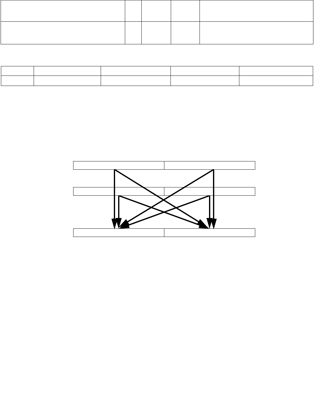
VPERM2F128 — Permute Floating-Point Values
INSTRUCTION SET REFERENCE, V-Z
5-358 Vol. 2C
VPERM2F128 — Permute Floating-Point Values
Instruction Operand Encoding
Description
Permute 128 bit floating-point-containing fields from the first source operand (second operand) and second source
operand (third operand) using bits in the 8-bit immediate and store results in the destination operand (first
operand). The first source operand is a YMM register, the second source operand is a YMM register or a 256-bit
memory location, and the destination operand is a YMM register.
Figure 5-21. VPERM2F128 Operation
Imm8[1:0] select the source for the first destination 128-bit field, imm8[5:4] select the source for the second
destination field. If imm8[3] is set, the low 128-bit field is zeroed. If imm8[7] is set, the high 128-bit field is zeroed.
VEX.L must be 1, otherwise the instruction will #UD.
Opcode/
Instruction
Op/
En
64/32 bit
Mode
Support
CPUID
Feature
Flag
Description
VEX.NDS.256.66.0F3A.W0 06 /r ib
VPERM2F128 ymm1, ymm2, ymm3/m256, imm8
RVMI V/V AVX Permute 128-bit floating-point fields in ymm2
and ymm3/mem using controls from imm8 and
store result in ymm1.
Op/En Operand 1 Operand 2 Operand 3 Operand 4
RVMI ModRM:reg (w) VEX.vvvv (r) ModRM:r/m (r) imm8
DEST
SRC1 X0X1
X0, X1, Y0, or Y1
Y0Y1
X0, X1, Y0, or Y1
SRC2

VPERM2F128 — Permute Floating-Point Values
INSTRUCTION SET REFERENCE, V-Z
Vol. 2C 5-359
Operation
VPERM2F128
CASE IMM8[1:0] of
0: DEST[127:0] SRC1[127:0]
1: DEST[127:0] SRC1[255:128]
2: DEST[127:0] SRC2[127:0]
3: DEST[127:0] SRC2[255:128]
ESAC
CASE IMM8[5:4] of
0: DEST[255:128] SRC1[127:0]
1: DEST[255:128] SRC1[255:128]
2: DEST[255:128] SRC2[127:0]
3: DEST[255:128] SRC2[255:128]
ESAC
IF (imm8[3])
DEST[127:0] 0
FI
IF (imm8[7])
DEST[VLMAX-1:128] 0
FI
Intel C/C++ Compiler Intrinsic Equivalent
VPERM2F128: __m256 _mm256_permute2f128_ps (__m256 a, __m256 b, int control)
VPERM2F128: __m256d _mm256_permute2f128_pd (__m256d a, __m256d b, int control)
VPERM2F128: __m256i _mm256_permute2f128_si256 (__m256i a, __m256i b, int control)
SIMD Floating-Point Exceptions
None.
Other Exceptions
See Exceptions Type 6; additionally
#UD If VEX.L = 0
If VEX.W = 1.
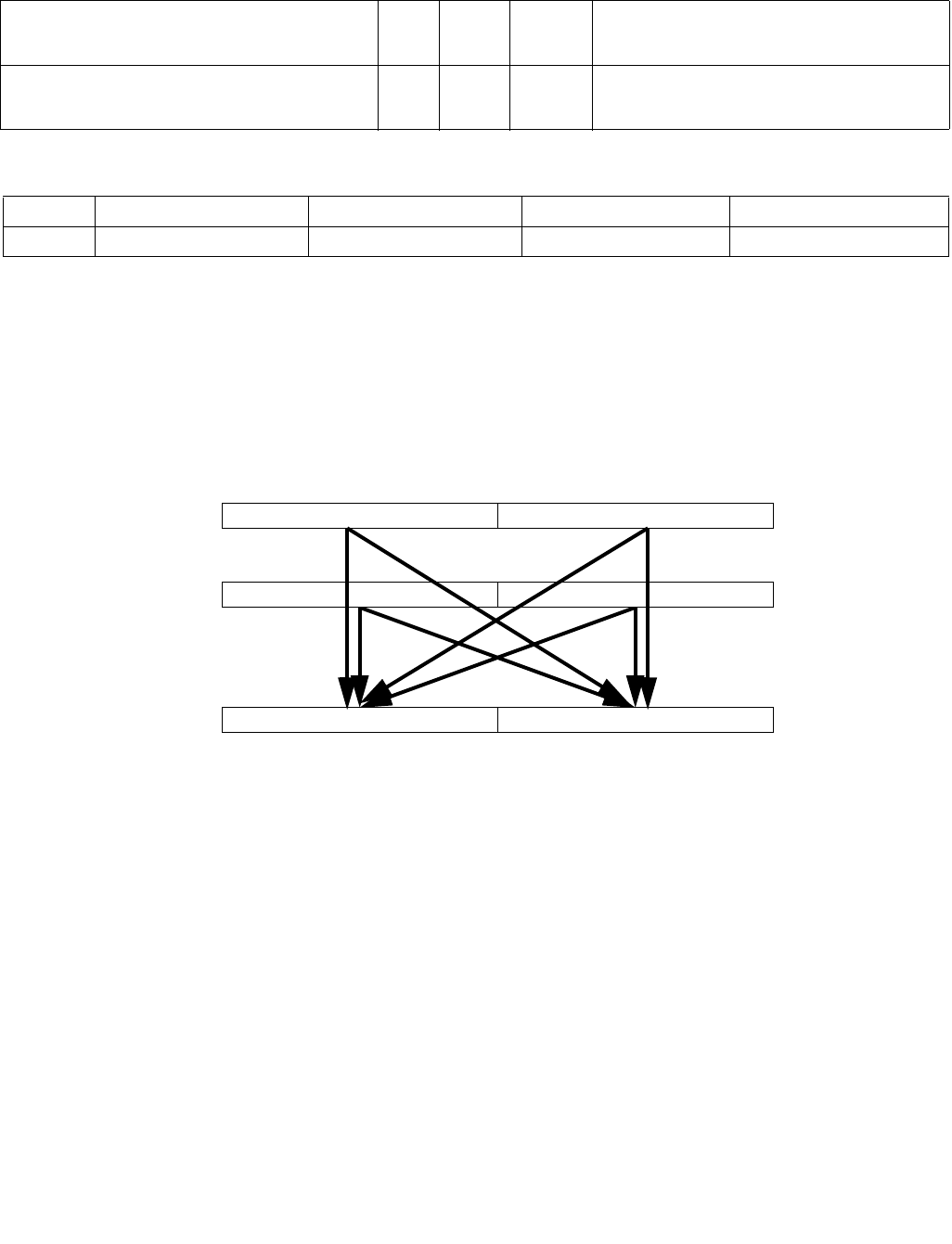
VPERM2I128 — Permute Integer Values
INSTRUCTION SET REFERENCE, V-Z
5-360 Vol. 2C
VPERM2I128 — Permute Integer Values
Instruction Operand Encoding
Description
Permute 128 bit integer data from the first source operand (second operand) and second source operand (third
operand) using bits in the 8-bit immediate and store results in the destination operand (first operand). The first
source operand is a YMM register, the second source operand is a YMM register or a 256-bit memory location, and
the destination operand is a YMM register.
Figure 5-22. VPERM2I128 Operation
Imm8[1:0] select the source for the first destination 128-bit field, imm8[5:4] select the source for the second
destination field. If imm8[3] is set, the low 128-bit field is zeroed. If imm8[7] is set, the high 128-bit field is zeroed.
VEX.L must be 1, otherwise the instruction will #UD.
Opcode/
Instruction
Op/
En
64/32
-bit
Mode
CPUID
Feature
Flag
Description
VEX.NDS.256.66.0F3A.W0 46 /r ib
VPERM2I128 ymm1, ymm2, ymm3/m256, imm8
RVMI V/V AVX2 Permute 128-bit integer data in ymm2 and
ymm3/mem using controls from imm8 and
store result in ymm1.
Op/En Operand 1 Operand 2 Operand 3 Operand 4
RVMI ModRM:reg (w) VEX.vvvv ModRM:r/m (r) Imm8
DEST
SRC1 X0X1
X0, X1, Y0, or Y1
Y0Y1
X0, X1, Y0, or Y1
SRC2

VPERM2I128 — Permute Integer Values
INSTRUCTION SET REFERENCE, V-Z
Vol. 2C 5-361
Operation
VPERM2I128
CASE IMM8[1:0] of
0: DEST[127:0] SRC1[127:0]
1: DEST[127:0] SRC1[255:128]
2: DEST[127:0] SRC2[127:0]
3: DEST[127:0] SRC2[255:128]
ESAC
CASE IMM8[5:4] of
0: DEST[255:128] SRC1[127:0]
1: DEST[255:128] SRC1[255:128]
2: DEST[255:128] SRC2[127:0]
3: DEST[255:128] SRC2[255:128]
ESAC
IF (imm8[3])
DEST[127:0] 0
FI
IF (imm8[7])
DEST[255:128] 0
FI
Intel C/C++ Compiler Intrinsic Equivalent
VPERM2I128: __m256i _mm256_permute2x128_si256 (__m256i a, __m256i b, int control)
SIMD Floating-Point Exceptions
None
Other Exceptions
See Exceptions Type 6; additionally
#UD If VEX.L = 0,
If VEX.W = 1.

VPERMD/VPERMW—Permute Packed Doublewords/Words Elements
INSTRUCTION SET REFERENCE, V-Z
5-362 Vol. 2C
VPERMD/VPERMW—Permute Packed Doublewords/Words Elements
Instruction Operand Encoding
Description
Copies doublewords (or words) from the second source operand (the third operand) to the destination operand (the
first operand) according to the indices in the first source operand (the second operand). Note that this instruction
permits a doubleword (word) in the source operand to be copied to more than one location in the destination
operand.
VEX.256 encoded VPERMD: The first and second operands are YMM registers, the third operand can be a YMM
register or memory location. Bits (MAX_VL-1:256) of the corresponding destination register are zeroed.
EVEX encoded VPERMD: The first and second operands are ZMM/YMM registers, the third operand can be a
ZMM/YMM register, a 512/256-bit memory location or a 512/256-bit vector broadcasted from a 32-bit memory
location. The elements in the destination are updated using the writemask k1.
VPERMW: first and second operands are ZMM/YMM/XMM registers, the third operand can be a ZMM/YMM/XMM
register, or a 512/256/128-bit memory location. The destination is updated using the writemask k1.
EVEX.128 encoded versions: Bits (MAX_VL-1:128) of the corresponding ZMM register are zeroed.
Opcode/
Instruction
Op /
En
64/32
bit Mode
Support
CPUID
Feature
Flag
Description
VEX.NDS.256.66.0F38.W0 36 /r
VPERMD ymm1, ymm2, ymm3/m256
RVM V/V AVX2 Permute doublewords in ymm3/m256 using indices in
ymm2 and store the result in ymm1.
EVEX.NDS.256.66.0F38.W0 36 /r
VPERMD ymm1 {k1}{z}, ymm2,
ymm3/m256/m32bcst
FV V/V AVX512VL
AVX512F
Permute doublewords in ymm3/m256/m32bcst using
indexes in ymm2 and store the result in ymm1 using
writemask k1.
EVEX.NDS.512.66.0F38.W0 36 /r
VPERMD zmm1 {k1}{z}, zmm2,
zmm3/m512/m32bcst
FV V/V AVX512F Permute doublewords in zmm3/m512/m32bcst using
indices in zmm2 and store the result in zmm1 using
writemask k1.
EVEX.NDS.128.66.0F38.W1 8D /r
VPERMW xmm1 {k1}{z}, xmm2,
xmm3/m128
FVM V/V AVX512VL
AVX512BW
Permute word integers in xmm3/m128 using indexes
in xmm2 and store the result in xmm1 using writemask
k1.
EVEX.NDS.256.66.0F38.W1 8D /r
VPERMW ymm1 {k1}{z}, ymm2,
ymm3/m256
FVM V/V AVX512VL
AVX512BW
Permute word integers in ymm3/m256 using indexes
in ymm2 and store the result in ymm1 using writemask
k1.
EVEX.NDS.512.66.0F38.W1 8D /r
VPERMW zmm1 {k1}{z}, zmm2,
zmm3/m512
FVM V/V AVX512BW Permute word integers in zmm3/m512 using indexes
in zmm2 and store the result in zmm1 using writemask
k1.
Op/En Operand 1 Operand 2 Operand 3 Operand 4
RVM ModRM:reg (w) VEX.vvvv ModRM:r/m (r) NA
FV ModRM:reg (w) EVEX.vvvv ModRM:r/m (r) NA
FVM ModRM:reg (w) VEX.vvvv ModRM:r/m (r) NA

VPERMD/VPERMW—Permute Packed Doublewords/Words Elements
INSTRUCTION SET REFERENCE, V-Z
Vol. 2C 5-363
Operation
VPERMD (EVEX encoded versions)
(KL, VL) = (8, 256), (16, 512)
IF VL = 256 THEN n 2; FI;
IF VL = 512 THEN n 3; FI;
FOR j 0 TO KL-1
i j * 32
id 32*SRC1[i+n:i]
IF k1[j] OR *no writemask*
THEN
IF (EVEX.b = 1) AND (SRC2 *is memory*)
THEN DEST[i+31:i] SRC2[31:0];
ELSE DEST[i+31:i] SRC2[id+31:id];
FI;
ELSE
IF *merging-masking* ; merging-masking
THEN *DEST[i+31:i] remains unchanged*
ELSE ; zeroing-masking
DEST[i+31:i] 0
FI
FI;
ENDFOR
DEST[MAX_VL-1:VL] 0
VPERMD (VEX.256 encoded version)
DEST[31:0] (SRC2[255:0] >> (SRC1[2:0] * 32))[31:0];
DEST[63:32] (SRC2[255:0] >> (SRC1[34:32] * 32))[31:0];
DEST[95:64] (SRC2[255:0] >> (SRC1[66:64] * 32))[31:0];
DEST[127:96] (SRC2[255:0] >> (SRC1[98:96] * 32))[31:0];
DEST[159:128] (SRC2[255:0] >> (SRC1[130:128] * 32))[31:0];
DEST[191:160] (SRC2[255:0] >> (SRC1[162:160] * 32))[31:0];
DEST[223:192] (SRC2[255:0] >> (SRC1[194:192] * 32))[31:0];
DEST[255:224] (SRC2[255:0] >> (SRC1[226:224] * 32))[31:0];
DEST[MAX_VL-1:256] 0
VPERMW (EVEX encoded versions)
(KL, VL) = (8, 128), (16, 256), (32, 512)
IF VL = 128 THEN n 2; FI;
IF VL = 256 THEN n 3; FI;
IF VL = 512 THEN n 4; FI;
FOR j 0 TO KL-1
i j * 16
id 16*SRC1[i+n:i]
IF k1[j] OR *no writemask*
THEN DEST[i+15:i] SRC2[id+15:id]
ELSE
IF *merging-masking* ; merging-masking
THEN *DEST[i+15:i] remains unchanged*
ELSE ; zeroing-masking
DEST[i+15:i] 0
FI
FI;
ENDFOR
DEST[MAX_VL-1:VL] 0

VPERMD/VPERMW—Permute Packed Doublewords/Words Elements
INSTRUCTION SET REFERENCE, V-Z
5-364 Vol. 2C
Intel C/C++ Compiler Intrinsic Equivalent
VPERMD __m512i _mm512_permutexvar_epi32( __m512i idx, __m512i a);
VPERMD __m512i _mm512_mask_permutexvar_epi32(__m512i s, __mmask16 k, __m512i idx, __m512i a);
VPERMD __m512i _mm512_maskz_permutexvar_epi32( __mmask16 k, __m512i idx, __m512i a);
VPERMD __m256i _mm256_permutexvar_epi32( __m256i idx, __m256i a);
VPERMD __m256i _mm256_mask_permutexvar_epi32(__m256i s, __mmask8 k, __m256i idx, __m256i a);
VPERMD __m256i _mm256_maskz_permutexvar_epi32( __mmask8 k, __m256i idx, __m256i a);
VPERMW __m512i _mm512_permutexvar_epi16( __m512i idx, __m512i a);
VPERMW __m512i _mm512_mask_permutexvar_epi16(__m512i s, __mmask32 k, __m512i idx, __m512i a);
VPERMW __m512i _mm512_maskz_permutexvar_epi16( __mmask32 k, __m512i idx, __m512i a);
VPERMW __m256i _mm256_permutexvar_epi16( __m256i idx, __m256i a);
VPERMW __m256i _mm256_mask_permutexvar_epi16(__m256i s, __mmask16 k, __m256i idx, __m256i a);
VPERMW __m256i _mm256_maskz_permutexvar_epi16( __mmask16 k, __m256i idx, __m256i a);
VPERMW __m128i _mm_permutexvar_epi16( __m128i idx, __m128i a);
VPERMW __m128i _mm_mask_permutexvar_epi16(__m128i s, __mmask8 k, __m128i idx, __m128i a);
VPERMW __m128i _mm_maskz_permutexvar_epi16( __mmask8 k, __m128i idx, __m128i a);
SIMD Floating-Point Exceptions
None
Other Exceptions
Non-EVEX-encoded instruction, see Exceptions Type 4.
EVEX-encoded VPERMD, see Exceptions Type E4NF.
EVEX-encoded VPERMW, see Exceptions Type E4NF.nb.
#UD If VEX.L = 0.
If EVEX.L’L = 0 for VPERMD.

VPERMI2W/D/Q/PS/PD—Full Permute From Two Tables Overwriting the Index
INSTRUCTION SET REFERENCE, V-Z
Vol. 2C 5-365
VPERMI2W/D/Q/PS/PD—Full Permute From Two Tables Overwriting the Index
Opcode/
Instruction
Op /
En
64/32
bit Mode
Support
CPUID
Feature
Flag
Description
EVEX.DDS.128.66.0F38.W1 75 /r
VPERMI2W xmm1 {k1}{z}, xmm2,
xmm3/m128
FVM V/V AVX512VL
AVX512BW
Permute word integers from two tables in
xmm3/m128 and xmm2 using indexes in xmm1 and
store the result in xmm1 using writemask k1.
EVEX.DDS.256.66.0F38.W1 75 /r
VPERMI2W ymm1 {k1}{z}, ymm2,
ymm3/m256
FVM V/V AVX512VL
AVX512BW
Permute word integers from two tables in
ymm3/m256 and ymm2 using indexes in ymm1 and
store the result in ymm1 using writemask k1.
EVEX.DDS.512.66.0F38.W1 75 /r
VPERMI2W zmm1 {k1}{z}, zmm2,
zmm3/m512
FVM V/V AVX512BW Permute word integers from two tables in
zmm3/m512 and zmm2 using indexes in zmm1 and
store the result in zmm1 using writemask k1.
EVEX.DDS.128.66.0F38.W0 76 /r
VPERMI2D xmm1 {k1}{z}, xmm2,
xmm3/m128/m32bcst
FV V/V AVX512VL
AVX512F
Permute double-words from two tables in
xmm3/m128/m32bcst and xmm2 using indexes in
xmm1 and store the result in xmm1 using writemask
k1.
EVEX.DDS.256.66.0F38.W0 76 /r
VPERMI2D ymm1 {k1}{z}, ymm2,
ymm3/m256/m32bcst
FV V/V AVX512VL
AVX512F
Permute double-words from two tables in
ymm3/m256/m32bcst and ymm2 using indexes in
ymm1 and store the result in ymm1 using writemask
k1.
EVEX.DDS.512.66.0F38.W0 76 /r
VPERMI2D zmm1 {k1}{z}, zmm2,
zmm3/m512/m32bcst
FV V/V AVX512F Permute double-words from two tables in
zmm3/m512/m32bcst and zmm2 using indices in
zmm1 and store the result in zmm1 using writemask
k1.
EVEX.DDS.128.66.0F38.W1 76 /r
VPERMI2Q xmm1 {k1}{z}, xmm2,
xmm3/m128/m64bcst
FV V/V AVX512VL
AVX512F
Permute quad-words from two tables in
xmm3/m128/m64bcst and xmm2 using indexes in
xmm1 and store the result in xmm1 using writemask
k1.
EVEX.DDS.256.66.0F38.W1 76 /r
VPERMI2Q ymm1 {k1}{z}, ymm2,
ymm3/m256/m64bcst
FV V/V AVX512VL
AVX512F
Permute quad-words from two tables in
ymm3/m256/m64bcst and ymm2 using indexes in
ymm1 and store the result in ymm1 using writemask
k1.
EVEX.DDS.512.66.0F38.W1 76 /r
VPERMI2Q zmm1 {k1}{z}, zmm2,
zmm3/m512/m64bcst
FV V/V AVX512F Permute quad-words from two tables in
zmm3/m512/m64bcst and zmm2 using indices in
zmm1 and store the result in zmm1 using writemask
k1.
EVEX.DDS.128.66.0F38.W0 77 /r
VPERMI2PS xmm1 {k1}{z}, xmm2,
xmm3/m128/m32bcst
FV V/V AVX512VL
AVX512F
Permute single-precision FP values from two tables in
xmm3/m128/m32bcst and xmm2 using indexes in
xmm1 and store the result in xmm1 using writemask
k1.
EVEX.DDS.256.66.0F38.W0 77 /r
VPERMI2PS ymm1 {k1}{z}, ymm2,
ymm3/m256/m32bcst
FV V/V AVX512VL
AVX512F
Permute single-precision FP values from two tables in
ymm3/m256/m32bcst and ymm2 using indexes in
ymm1 and store the result in ymm1 using writemask
k1.
EVEX.DDS.512.66.0F38.W0 77 /r
VPERMI2PS zmm1 {k1}{z}, zmm2,
zmm3/m512/m32bcst
FV V/V AVX512F Permute single-precision FP values from two tables in
zmm3/m512/m32bcst and zmm2 using indices in
zmm1 and store the result in zmm1 using writemask
k1.

VPERMI2W/D/Q/PS/PD—Full Permute From Two Tables Overwriting the Index
INSTRUCTION SET REFERENCE, V-Z
5-366 Vol. 2C
Instruction Operand Encoding
Description
Permutes 16-bit/32-bit/64-bit values in the second operand (the first source operand) and the third operand (the
second source operand) using indices in the first operand to select elements from the second and third operands.
The selected elements are written to the destination operand (the first operand) according to the writemask k1.
The first and second operands are ZMM/YMM/XMM registers. The first operand contains input indices to select
elements from the two input tables in the 2nd and 3rd operands. The first operand is also the destination of the
result.
D/Q/PS/PD element versions: The second source operand can be a ZMM/YMM/XMM register, a 512/256/128-bit
memory location or a 512/256/128-bit vector broadcasted from a 32/64-bit memory location. Broadcast from the
low 32/64-bit memory location is performed if EVEX.b and the id bit for table selection are set (selecting table_2).
Dword/PS versions: The id bit for table selection is bit 4/3/2, depending on VL=512, 256, 128. Bits
[3:0]/[2:0]/[1:0] of each element in the input index vector select an element within the two source operands, If
the id bit is 0, table_1 (the first source) is selected; otherwise the second source operand is selected.
Qword/PD versions: The id bit for table selection is bit 3/2/1, and bits [2:0]/[1:0] /bit 0 selects element within each
input table.
Word element versions: The second source operand can be a ZMM/YMM/XMM register, or a 512/256/128-bit
memory location. The id bit for table selection is bit 5/4/3, and bits [4:0]/[3:0]/[2:0] selects element within each
input table.
Note that these instructions permit a 16-bit/32-bit/64-bit value in the source operands to be copied to more than
one location in the destination operand. Note also that in this case, the same table can be reused for example for a
second iteration, while the index elements are overwritten.
Bits (MAX_VL-1:256/128) of the destination are zeroed for VL=256,128.
EVEX.DDS.128.66.0F38.W1 77 /r
VPERMI2PD xmm1 {k1}{z}, xmm2,
xmm3/m128/m64bcst
FV V/V AVX512VL
AVX512F
Permute double-precision FP values from two tables in
xmm3/m128/m64bcst and xmm2 using indexes in
xmm1 and store the result in xmm1 using writemask
k1.
EVEX.DDS.256.66.0F38.W1 77 /r
VPERMI2PD ymm1 {k1}{z}, ymm2,
ymm3/m256/m64bcst
FV V/V AVX512VL
AVX512F
Permute double-precision FP values from two tables in
ymm3/m256/m64bcst and ymm2 using indexes in
ymm1 and store the result in ymm1 using writemask
k1.
EVEX.DDS.512.66.0F38.W1 77 /r
VPERMI2PD zmm1 {k1}{z}, zmm2,
zmm3/m512/m64bcst
FV V/V AVX512F Permute double-precision FP values from two tables in
zmm3/m512/m64bcst and zmm2 using indices in
zmm1 and store the result in zmm1 using writemask
k1.
Op/En Operand 1 Operand 2 Operand 3 Operand 4
FVM ModRM:reg (r,w) EVEX.vvvv (r) ModRM:r/m (r) NA
FV ModRM:reg (r, w) EVEX.vvvv (r) ModRM:r/m (r) NA
Opcode/
Instruction
Op /
En
64/32
bit Mode
Support
CPUID
Feature
Flag
Description

VPERMI2W/D/Q/PS/PD—Full Permute From Two Tables Overwriting the Index
INSTRUCTION SET REFERENCE, V-Z
Vol. 2C 5-367
Operation
VPERMI2W (EVEX encoded versions)
(KL, VL) = (8, 128), (16, 256), (32, 512)
IF VL = 128
id 2
FI;
IF VL = 256
id 3
FI;
IF VL = 512
id 4
FI;
TMP_DEST DEST
FOR j 0 TO KL-1
i j * 16
off 16*TMP_DEST[i+id:i]
IF k1[j] OR *no writemask*
THEN
DEST[i+15:i]=TMP_DEST[i+id+1] ? SRC2[off+15:off]
: SRC1[off+15:off]
ELSE
IF *merging-masking* ; merging-masking
THEN *DEST[i+15:i] remains unchanged*
ELSE ; zeroing-masking
DEST[i+15:i] 0
FI
FI;
ENDFOR
DEST[MAX_VL-1:VL] 0
VPERMI2D/VPERMI2PS (EVEX encoded versions)
(KL, VL) = (4, 128), (8, 256), (16, 512)
IF VL = 128
id 1
FI;
IF VL = 256
id 2
FI;
IF VL = 512
id 3
FI;
TMP_DEST DEST
FOR j 0 TO KL-1
i j * 32
off 32*TMP_DEST[i+id:i]
IF k1[j] OR *no writemask*
THEN
IF (EVEX.b = 1) AND (SRC2 *is memory*)
THEN
DEST[i+31:i] TMP_DEST[i+id+1] ? SRC2[31:0]
: SRC1[off+31:off]
ELSE
DEST[i+31:i] TMP_DEST[i+id+1] ? SRC2[off+31:off]
: SRC1[off+31:off]

VPERMI2W/D/Q/PS/PD—Full Permute From Two Tables Overwriting the Index
INSTRUCTION SET REFERENCE, V-Z
5-368 Vol. 2C
FI
ELSE
IF *merging-masking* ; merging-masking
THEN *DEST[i+31:i] remains unchanged*
ELSE ; zeroing-masking
DEST[i+31:i] 0
FI
FI;
ENDFOR
DEST[MAX_VL-1:VL] 0
VPERMI2Q/VPERMI2PD (EVEX encoded versions)
(KL, VL) = (2, 128), (4, 256), (8 512)
IF VL = 128
id 0
FI;
IF VL = 256
id 1
FI;
IF VL = 512
id 2
FI;
TMP_DEST DEST
FOR j 0 TO KL-1
i j * 64
off 64*TMP_DEST[i+id:i]
IF k1[j] OR *no writemask*
THEN
IF (EVEX.b = 1) AND (SRC2 *is memory*)
THEN
DEST[i+63:i] TMP_DEST[i+id+1] ? SRC2[63:0]
: SRC1[off+63:off]
ELSE
DEST[i+63:i] TMP_DEST[i+id+1] ? SRC2[off+63:off]
: SRC1[off+63:off]
FI
ELSE
IF *merging-masking* ; merging-masking
THEN *DEST[i+63:i] remains unchanged*
ELSE ; zeroing-masking
DEST[i+63:i] 0
FI
FI;
ENDFOR
DEST[MAX_VL-1:VL] 0

VPERMI2W/D/Q/PS/PD—Full Permute From Two Tables Overwriting the Index
INSTRUCTION SET REFERENCE, V-Z
Vol. 2C 5-369
Intel C/C++ Compiler Intrinsic Equivalent
VPERMI2D __m512i _mm512_permutex2var_epi32(__m512i a, __m512i idx, __m512i b);
VPERMI2D __m512i _mm512_mask_permutex2var_epi32(__m512i a, __mmask16 k, __m512i idx, __m512i b);
VPERMI2D __m512i _mm512_mask2_permutex2var_epi32(__m512i a, __m512i idx, __mmask16 k, __m512i b);
VPERMI2D __m512i _mm512_maskz_permutex2var_epi32(__mmask16 k, __m512i a, __m512i idx, __m512i b);
VPERMI __m256i _mm256_permutex2var_epi32(__m256i a, __m256i idx, __m256i b);
VPERMI2D __m256i _mm256_mask_permutex2var_epi32(__m256i a, __mmask8 k, __m256i idx, __m256i b);
VPERMI2D __m256i _mm256_mask2_permutex2var_epi32(__m256i a, __m256i idx, __mmask8 k, __m256i b);
VPERMI2D __m256i _mm256_maskz_permutex2var_epi32(__mmask8 k, __m256i a, __m256i idx, __m256i b);
VPERMI2D __m128i _mm_permutex2var_epi32(__m128i a, __m128i idx, __m128i b);
VPERMI2D __m128i _mm_mask_permutex2var_epi32(__m128i a, __mmask8 k, __m128i idx, __m128i b);
VPERMI2D __m128i _mm_mask2_permutex2var_epi32(__m128i a, __m128i idx, __mmask8 k, __m128i b);
VPERMI2D __m128i _mm_maskz_permutex2var_epi32(__mmask8 k, __m128i a, __m128i idx, __m128i b);
VPERMI2PD __m512d _mm512_permutex2var_pd(__m512d a, __m512i idx, __m512d b);
VPERMI2PD __m512d _mm512_mask_permutex2var_pd(__m512d a, __mmask8 k, __m512i idx, __m512d b);
VPERMI2PD __m512d _mm512_mask2_permutex2var_pd(__m512d a, __m512i idx, __mmask8 k, __m512d b);
VPERMI2PD __m512d _mm512_maskz_permutex2var_pd(__mmask8 k, __m512d a, __m512i idx, __m512d b);
VPERMI2PD __m256d _mm256_permutex2var_pd(__m256d a, __m256i idx, __m256d b);
VPERMI2PD __m256d _mm256_mask_permutex2var_pd(__m256d a, __mmask8 k, __m256i idx, __m256d b);
VPERMI2PD __m256d _mm256_mask2_permutex2var_pd(__m256d a, __m256i idx, __mmask8 k, __m256d b);
VPERMI2PD __m256d _mm256_maskz_permutex2var_pd(__mmask8 k, __m256d a, __m256i idx, __m256d b);
VPERMI2PD __m128d _mm_permutex2var_pd(__m128d a, __m128i idx, __m128d b);
VPERMI2PD __m128d _mm_mask_permutex2var_pd(__m128d a, __mmask8 k, __m128i idx, __m128d b);
VPERMI2PD __m128d _mm_mask2_permutex2var_pd(__m128d a, __m128i idx, __mmask8 k, __m128d b);
VPERMI2PD __m128d _mm_maskz_permutex2var_pd(__mmask8 k, __m128d a, __m128i idx, __m128d b);
VPERMI2PS __m512 _mm512_permutex2var_ps(__m512 a, __m512i idx, __m512 b);
VPERMI2PS __m512 _mm512_mask_permutex2var_ps(__m512 a, __mmask16 k, __m512i idx, __m512 b);
VPERMI2PS __m512 _mm512_mask2_permutex2var_ps(__m512 a, __m512i idx, __mmask16 k, __m512 b);
VPERMI2PS __m512 _mm512_maskz_permutex2var_ps(__mmask16 k, __m512 a, __m512i idx, __m512 b);
VPERMI2PS __m256 _mm256_permutex2var_ps(__m256 a, __m256i idx, __m256 b);
VPERMI2PS __m256 _mm256_mask_permutex2var_ps(__m256 a, __mmask8 k, __m256i idx, __m256 b);
VPERMI2PS __m256 _mm256_mask2_permutex2var_ps(__m256 a, __m256i idx, __mmask8 k, __m256 b);
VPERMI2PS __m256 _mm256_maskz_permutex2var_ps(__mmask8 k, __m256 a, __m256i idx, __m256 b);
VPERMI2PS __m128 _mm_permutex2var_ps(__m128 a, __m128i idx, __m128 b);
VPERMI2PS __m128 _mm_mask_permutex2var_ps(__m128 a, __mmask8 k, __m128i idx, __m128 b);
VPERMI2PS __m128 _mm_mask2_permutex2var_ps(__m128 a, __m128i idx, __mmask8 k, __m128 b);
VPERMI2PS __m128 _mm_maskz_permutex2var_ps(__mmask8 k, __m128 a, __m128i idx, __m128 b);
VPERMI2Q __m512i _mm512_permutex2var_epi64(__m512i a, __m512i idx, __m512i b);
VPERMI2Q __m512i _mm512_mask_permutex2var_epi64(__m512i a, __mmask8 k, __m512i idx, __m512i b);
VPERMI2Q __m512i _mm512_mask2_permutex2var_epi64(__m512i a, __m512i idx, __mmask8 k, __m512i b);
VPERMI2Q __m512i _mm512_maskz_permutex2var_epi64(__mmask8 k, __m512i a, __m512i idx, __m512i b);
VPERMI2Q __m256i _mm256_permutex2var_epi64(__m256i a, __m256i idx, __m256i b);
VPERMI2Q __m256i _mm256_mask_permutex2var_epi64(__m256i a, __mmask8 k, __m256i idx, __m256i b);
VPERMI2Q __m256i _mm256_mask2_permutex2var_epi64(__m256i a, __m256i idx, __mmask8 k, __m256i b);
VPERMI2Q __m256i _mm256_maskz_permutex2var_epi64(__mmask8 k, __m256i a, __m256i idx, __m256i b);
VPERMI2Q __m128i _mm_permutex2var_epi64(__m128i a, __m128i idx, __m128i b);
VPERMI2Q __m128i _mm_mask_permutex2var_epi64(__m128i a, __mmask8 k, __m128i idx, __m128i b);
VPERMI2Q __m128i _mm_mask2_permutex2var_epi64(__m128i a, __m128i idx, __mmask8 k, __m128i b);
VPERMI2Q __m128i _mm_maskz_permutex2var_epi64(__mmask8 k, __m128i a, __m128i idx, __m128i b);

VPERMI2W/D/Q/PS/PD—Full Permute From Two Tables Overwriting the Index
INSTRUCTION SET REFERENCE, V-Z
5-370 Vol. 2C
VPERMI2W __m512i _mm512_permutex2var_epi16(__m512i a, __m512i idx, __m512i b);
VPERMI2W __m512i _mm512_mask_permutex2var_epi16(__m512i a, __mmask32 k, __m512i idx, __m512i b);
VPERMI2W __m512i _mm512_mask2_permutex2var_epi16(__m512i a, __m512i idx, __mmask32 k, __m512i b);
VPERMI2W __m512i _mm512_maskz_permutex2var_epi16(__mmask32 k, __m512i a, __m512i idx, __m512i b);
VPERMI2W __m256i _mm256_permutex2var_epi16(__m256i a, __m256i idx, __m256i b);
VPERMI2W __m256i _mm256_mask_permutex2var_epi16(__m256i a, __mmask16 k, __m256i idx, __m256i b);
VPERMI2W __m256i _mm256_mask2_permutex2var_epi16(__m256i a, __m256i idx, __mmask16 k, __m256i b);
VPERMI2W __m256i _mm256_maskz_permutex2var_epi16(__mmask16 k, __m256i a, __m256i idx, __m256i b);
VPERMI2W __m128i _mm_permutex2var_epi16(__m128i a, __m128i idx, __m128i b);
VPERMI2W __m128i _mm_mask_permutex2var_epi16(__m128i a, __mmask8 k, __m128i idx, __m128i b);
VPERMI2W __m128i _mm_mask2_permutex2var_epi16(__m128i a, __m128i idx, __mmask8 k, __m128i b);
VPERMI2W __m128i _mm_maskz_permutex2var_epi16(__mmask8 k, __m128i a, __m128i idx, __m128i b);
SIMD Floating-Point Exceptions
None
Other Exceptions
VPERMI2D/Q/PS/PD: See Exceptions Type E4NF.
VPERMI2W: See Exceptions Type E4NF.nb.

VPERMILPD—Permute In-Lane of Pairs of Double-Precision Floating-Point Values
INSTRUCTION SET REFERENCE, V-Z
Vol. 2C 5-371
VPERMILPD—Permute In-Lane of Pairs of Double-Precision Floating-Point Values
Instruction Operand Encoding
Opcode/
Instruction
Op / En 64/32
bit Mode
Support
CPUID
Feature
Flag
Description
VEX.NDS.128.66.0F38.W0 0D /r
VPERMILPD xmm1, xmm2, xmm3/m128
RVM V/V AVX Permute double-precision floating-point values in
xmm2 using controls from xmm3/m128 and store
result in xmm1.
VEX.NDS.256.66.0F38.W0 0D /r
VPERMILPD ymm1, ymm2, ymm3/m256
RVM V/V AVX Permute double-precision floating-point values in
ymm2 using controls from ymm3/m256 and store
result in ymm1.
EVEX.NDS.128.66.0F38.W1 0D /r
VPERMILPD xmm1 {k1}{z}, xmm2,
xmm3/m128/m64bcst
FV-RVM V/V AVX512VL
AVX512F
Permute double-precision floating-point values in
xmm2 using control from xmm3/m128/m64bcst
and store the result in xmm1 using writemask k1.
EVEX.NDS.256.66.0F38.W1 0D /r
VPERMILPD ymm1 {k1}{z}, ymm2,
ymm3/m256/m64bcst
FV-RVM V/V AVX512VL
AVX512F
Permute double-precision floating-point values in
ymm2 using control from ymm3/m256/m64bcst
and store the result in ymm1 using writemask k1.
EVEX.NDS.512.66.0F38.W1 0D /r
VPERMILPD zmm1 {k1}{z}, zmm2,
zmm3/m512/m64bcst
FV-RVM V/V AVX512F Permute double-precision floating-point values in
zmm2 using control from zmm3/m512/m64bcst
and store the result in zmm1 using writemask k1.
VEX.128.66.0F3A.W0 05 /r ib
VPERMILPD xmm1, xmm2/m128, imm8
RM V/V AVX Permute double-precision floating-point values in
xmm2/m128 using controls from imm8.
VEX.256.66.0F3A.W0 05 /r ib
VPERMILPD ymm1, ymm2/m256, imm8
RM V/V AVX Permute double-precision floating-point values in
ymm2/m256 using controls from imm8.
EVEX.128.66.0F3A.W1 05 /r ib
VPERMILPD xmm1 {k1}{z},
xmm2/m128/m64bcst, imm8
FV-RM V/V AVX512VL
AVX512F
Permute double-precision floating-point values in
xmm2/m128/m64bcst using controls from imm8
and store the result in xmm1 using writemask k1.
EVEX.256.66.0F3A.W1 05 /r ib
VPERMILPD ymm1 {k1}{z},
ymm2/m256/m64bcst, imm8
FV-RM V/V AVX512VL
AVX512F
Permute double-precision floating-point values in
ymm2/m256/m64bcst using controls from imm8
and store the result in ymm1 using writemask k1.
EVEX.512.66.0F3A.W1 05 /r ib
VPERMILPD zmm1 {k1}{z},
zmm2/m512/m64bcst, imm8
FV-RM V/V AVX512F Permute double-precision floating-point values in
zmm2/m512/m64bcst using controls from imm8
and store the result in zmm1 using writemask k1.
Op/En Operand 1 Operand 2 Operand 3 Operand 4
RVM ModRM:reg (w) VEX.vvvv (r) ModRM:r/m (r) NA
RM ModRM:reg (w) ModRM:r/m (r) NA NA
FV-RVM ModRM:reg (w) EVEX.vvvv (r) ModRM:r/m (r) NA
FV-RM ModRM:reg (w) ModRM:r/m (r) NA NA
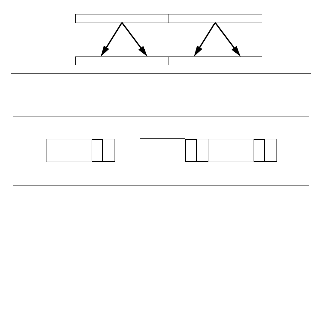
VPERMILPD—Permute In-Lane of Pairs of Double-Precision Floating-Point Values
INSTRUCTION SET REFERENCE, V-Z
5-372 Vol. 2C
Description
(variable control version)
Permute pairs of double-precision floating-point values in the first source operand (second operand), each using a
1-bit control field residing in the corresponding quadword element of the second source operand (third operand).
Permuted results are stored in the destination operand (first operand).
The control bits are located at bit 0 of each quadword element (see Figure 5-24). Each control determines which of
the source element in an input pair is selected for the destination element. Each pair of source elements must lie in
the same 128-bit region as the destination.
EVEX version: The second source operand (third operand) is a ZMM/YMM/XMM register, a 512/256/128-bit
memory location or a 512/256/128-bit vector broadcasted from a 64-bit memory location. Permuted results are
written to the destination under the writemask.
VEX.256 encoded version: Bits (MAX_VL-1:256) of the corresponding ZMM register are zeroed.
(immediate control version)
Permute pairs of double-precision floating-point values in the first source operand (second operand), each pair
using a 1-bit control field in the imm8 byte. Each element in the destination operand (first operand) use a separate
control bit of the imm8 byte.
VEX version: The source operand is a YMM/XMM register or a 256/128-bit memory location and the destination
operand is a YMM/XMM register. Imm8 byte provides the lower 4/2 bit as permute control fields.
EVEX version: The source operand (second operand) is a ZMM/YMM/XMM register, a 512/256/128-bit memory
location or a 512/256/128-bit vector broadcasted from a 64-bit memory location. Permuted results are written to
the destination under the writemask. Imm8 byte provides the lower 8/4/2 bit as permute control fields.
Note: For the imm8 versions, VEX.vvvv and EVEX.vvvv are reserved and must be 1111b otherwise instruction will
#UD.
Figure 5-23. VPERMILPD Operation
Figure 5-24. VPERMILPD Shuffle Control
X2..X3 X2..X3 X0..X1 X0..X1DEST
X3 X2
SRC1 X1 X0
1
sel
Bit
. . .
ignored
Control Field1Control Field 2Control Field 4
ignored
65
sel
ignored
194 193
sel
ignored
255
ignored
66
127
ignored
2
63

VPERMILPD—Permute In-Lane of Pairs of Double-Precision Floating-Point Values
INSTRUCTION SET REFERENCE, V-Z
Vol. 2C 5-373
Operation
VPERMILPD (EVEX immediate versions)
(KL, VL) = (8, 512)
FOR j 0 TO KL-1
i j * 64
IF (EVEX.b = 1) AND (SRC1 *is memory*)
THEN TMP_SRC1[i+63:i] SRC1[63:0];
ELSE TMP_SRC1[i+63:i] SRC1[i+63:i];
FI;
ENDFOR;
IF (imm8[0] = 0) THEN TMP_DEST[63:0] SRC1[63:0]; FI;
IF (imm8[0] = 1) THEN TMP_DEST[63:0] TMP_SRC1[127:64]; FI;
IF (imm8[1] = 0) THEN TMP_DEST[127:64] TMP_SRC1[63:0]; FI;
IF (imm8[1] = 1) THEN TMP_DEST[127:64] TMP_SRC1[127:64]; FI;
IF VL >= 256
IF (imm8[2] = 0) THEN TMP_DEST[191:128] TMP_SRC1[191:128]; FI;
IF (imm8[2] = 1) THEN TMP_DEST[191:128] TMP_SRC1[255:192]; FI;
IF (imm8[3] = 0) THEN TMP_DEST[255:192] TMP_SRC1[191:128]; FI;
IF (imm8[3] = 1) THEN TMP_DEST[255:192] TMP_SRC1[255:192]; FI;
FI;
IF VL >= 512
IF (imm8[4] = 0) THEN TMP_DEST[319:256] TMP_SRC1[319:256]; FI;
IF (imm8[4] = 1) THEN TMP_DEST[319:256] TMP_SRC1[383:320]; FI;
IF (imm8[5] = 0) THEN TMP_DEST[383:320] TMP_SRC1[319:256]; FI;
IF (imm8[5] = 1) THEN TMP_DEST[383:320] TMP_SRC1[383:320]; FI;
IF (imm8[6] = 0) THEN TMP_DEST[447:384] TMP_SRC1[447:384]; FI;
IF (imm8[6] = 1) THEN TMP_DEST[447:384] TMP_SRC1[511:448]; FI;
IF (imm8[7] = 0) THEN TMP_DEST[511:448] TMP_SRC1[447:384]; FI;
IF (imm8[7] = 1) THEN TMP_DEST[511:448] TMP_SRC1[511:448]; FI;
FI;
FOR j 0 TO KL-1
i j * 64
IF k1[j] OR *no writemask*
THEN DEST[i+63:i] TMP_DEST[i+63:i]
ELSE
IF *merging-masking* ; merging-masking
THEN *DEST[i+63:i] remains unchanged*
ELSE ; zeroing-masking
DEST[i+63:i] 0
FI
FI;
ENDFOR
DEST[MAX_VL-1:VL] 0
VPERMILPD (256-bit immediate version)
IF (imm8[0] = 0) THEN DEST[63:0]SRC1[63:0]
IF (imm8[0] = 1) THEN DEST[63:0]SRC1[127:64]
IF (imm8[1] = 0) THEN DEST[127:64]SRC1[63:0]
IF (imm8[1] = 1) THEN DEST[127:64]SRC1[127:64]
IF (imm8[2] = 0) THEN DEST[191:128]SRC1[191:128]
IF (imm8[2] = 1) THEN DEST[191:128]SRC1[255:192]
IF (imm8[3] = 0) THEN DEST[255:192]SRC1[191:128]
IF (imm8[3] = 1) THEN DEST[255:192]SRC1[255:192]
DEST[MAX_VL-1:256]0

VPERMILPD—Permute In-Lane of Pairs of Double-Precision Floating-Point Values
INSTRUCTION SET REFERENCE, V-Z
5-374 Vol. 2C
VPERMILPD (128-bit immediate version)
IF (imm8[0] = 0) THEN DEST[63:0]SRC1[63:0]
IF (imm8[0] = 1) THEN DEST[63:0]SRC1[127:64]
IF (imm8[1] = 0) THEN DEST[127:64]SRC1[63:0]
IF (imm8[1] = 1) THEN DEST[127:64]SRC1[127:64]
DEST[MAX_VL-1:128]0
VPERMILPD (EVEX variable versions)
(KL, VL) = (2, 128), (4, 256), (8, 512)
FOR j 0 TO KL-1
i j * 64
IF (EVEX.b = 1) AND (SRC2 *is memory*)
THEN TMP_SRC2[i+63:i] SRC2[63:0];
ELSE TMP_SRC2[i+63:i] SRC2[i+63:i];
FI;
ENDFOR;
IF (TMP_SRC2[1] = 0) THEN TMP_DEST[63:0] SRC1[63:0]; FI;
IF (TMP_SRC2[1] = 1) THEN TMP_DEST[63:0] SRC1[127:64]; FI;
IF (TMP_SRC2[65] = 0) THEN TMP_DEST[127:64] SRC1[63:0]; FI;
IF (TMP_SRC2[65] = 1) THEN TMP_DEST[127:64] SRC1[127:64]; FI;
IF VL >= 256
IF (TMP_SRC2[129] = 0) THEN TMP_DEST[191:128] SRC1[191:128]; FI;
IF (TMP_SRC2[129] = 1) THEN TMP_DEST[191:128] SRC1[255:192]; FI;
IF (TMP_SRC2[193] = 0) THEN TMP_DEST[255:192] SRC1[191:128]; FI;
IF (TMP_SRC2[193] = 1) THEN TMP_DEST[255:192] SRC1[255:192]; FI;
FI;
IF VL >= 512
IF (TMP_SRC2[257] = 0) THEN TMP_DEST[319:256] SRC1[319:256]; FI;
IF (TMP_SRC2[257] = 1) THEN TMP_DEST[319:256] SRC1[383:320]; FI;
IF (TMP_SRC2[321] = 0) THEN TMP_DEST[383:320] SRC1[319:256]; FI;
IF (TMP_SRC2[321] = 1) THEN TMP_DEST[383:320] SRC1[383:320]; FI;
IF (TMP_SRC2[385] = 0) THEN TMP_DEST[447:384] SRC1[447:384]; FI;
IF (TMP_SRC2[385] = 1) THEN TMP_DEST[447:384] SRC1[511:448]; FI;
IF (TMP_SRC2[449] = 0) THEN TMP_DEST[511:448] SRC1[447:384]; FI;
IF (TMP_SRC2[449] = 1) THEN TMP_DEST[511:448] SRC1[511:448]; FI;
FI;
FOR j 0 TO KL-1
i j * 64
IF k1[j] OR *no writemask*
THEN DEST[i+63:i] TMP_DEST[i+63:i]
ELSE
IF *merging-masking* ; merging-masking
THEN *DEST[i+63:i] remains unchanged*
ELSE ; zeroing-masking
DEST[i+63:i] 0
FI
FI;
ENDFOR
DEST[MAX_VL-1:VL] 0

VPERMILPD—Permute In-Lane of Pairs of Double-Precision Floating-Point Values
INSTRUCTION SET REFERENCE, V-Z
Vol. 2C 5-375
VPERMILPD (256-bit variable version)
IF (SRC2[1] = 0) THEN DEST[63:0]SRC1[63:0]
IF (SRC2[1] = 1) THEN DEST[63:0]SRC1[127:64]
IF (SRC2[65] = 0) THEN DEST[127:64]SRC1[63:0]
IF (SRC2[65] = 1) THEN DEST[127:64]SRC1[127:64]
IF (SRC2[129] = 0) THEN DEST[191:128]SRC1[191:128]
IF (SRC2[129] = 1) THEN DEST[191:128]SRC1[255:192]
IF (SRC2[193] = 0) THEN DEST[255:192]SRC1[191:128]
IF (SRC2[193] = 1) THEN DEST[255:192]SRC1[255:192]
DEST[MAX_VL-1:256]0
VPERMILPD (128-bit variable version)
IF (SRC2[1] = 0) THEN DEST[63:0]SRC1[63:0]
IF (SRC2[1] = 1) THEN DEST[63:0]SRC1[127:64]
IF (SRC2[65] = 0) THEN DEST[127:64]SRC1[63:0]
IF (SRC2[65] = 1) THEN DEST[127:64]SRC1[127:64]
DEST[MAX_VL-1:128]0
Intel C/C++ Compiler Intrinsic Equivalent
VPERMILPD __m512d _mm512_permute_pd( __m512d a, int imm);
VPERMILPD __m512d _mm512_mask_permute_pd(__m512d s, __mmask8 k, __m512d a, int imm);
VPERMILPD __m512d _mm512_maskz_permute_pd( __mmask8 k, __m512d a, int imm);
VPERMILPD __m256d _mm256_mask_permute_pd(__m256d s, __mmask8 k, __m256d a, int imm);
VPERMILPD __m256d _mm256_maskz_permute_pd( __mmask8 k, __m256d a, int imm);
VPERMILPD __m128d _mm_mask_permute_pd(__m128d s, __mmask8 k, __m128d a, int imm);
VPERMILPD __m128d _mm_maskz_permute_pd( __mmask8 k, __m128d a, int imm);
VPERMILPD __m512d _mm512_permutevar_pd( __m512i i, __m512d a);
VPERMILPD __m512d _mm512_mask_permutevar_pd(__m512d s, __mmask8 k, __m512i i, __m512d a);
VPERMILPD __m512d _mm512_maskz_permutevar_pd( __mmask8 k, __m512i i, __m512d a);
VPERMILPD __m256d _mm256_mask_permutevar_pd(__m256d s, __mmask8 k, __m256d i, __m256d a);
VPERMILPD __m256d _mm256_maskz_permutevar_pd( __mmask8 k, __m256d i, __m256d a);
VPERMILPD __m128d _mm_mask_permutevar_pd(__m128d s, __mmask8 k, __m128d i, __m128d a);
VPERMILPD __m128d _mm_maskz_permutevar_pd( __mmask8 k, __m128d i, __m128d a);
VPERMILPD __m128d _mm_permute_pd (__m128d a, int control)
VPERMILPD __m256d _mm256_permute_pd (__m256d a, int control)
VPERMILPD __m128d _mm_permutevar_pd (__m128d a, __m128i control);
VPERMILPD __m256d _mm256_permutevar_pd (__m256d a, __m256i control);
SIMD Floating-Point Exceptions
None
Other Exceptions
Non-EVEX-encoded instruction, see Exceptions Type 4; additionally
#UD If VEX.W = 1.
EVEX-encoded instruction, see Exceptions Type E4NF.
#UD If either (E)VEX.vvvv != 1111B and with imm8.

VPERMILPS—Permute In-Lane of Quadruples of Single-Precision Floating-Point Values
INSTRUCTION SET REFERENCE, V-Z
5-376 Vol. 2C
VPERMILPS—Permute In-Lane of Quadruples of Single-Precision Floating-Point Values
Instruction Operand Encoding
Opcode/
Instruction
Op / En 64/32
bit Mode
Support
CPUID
Feature
Flag
Description
VEX.NDS.128.66.0F38.W0 0C /r
VPERMILPS xmm1, xmm2, xmm3/m128
RVM V/V AVX Permute single-precision floating-point values in
xmm2 using controls from xmm3/m128 and
store result in xmm1.
VEX.128.66.0F3A.W0 04 /r ib
VPERMILPS xmm1, xmm2/m128, imm8
RM V/V AVX Permute single-precision floating-point values in
xmm2/m128 using controls from imm8 and store
result in xmm1.
VEX.NDS.256.66.0F38.W0 0C /r
VPERMILPS ymm1, ymm2, ymm3/m256
RVM V/V AVX Permute single-precision floating-point values in
ymm2 using controls from ymm3/m256 and
store result in ymm1.
VEX.256.66.0F3A.W0 04 /r ib
VPERMILPS ymm1, ymm2/m256, imm8
RM V/V AVX Permute single-precision floating-point values in
ymm2/m256 using controls from imm8 and store
result in ymm1.
EVEX.NDS.128.66.0F38.W0 0C /r
VPERMILPS xmm1 {k1}{z}, xmm2,
xmm3/m128/m32bcst
FV-RVM V/V AVX512VL
AVX512F
Permute single-precision floating-point values
xmm2 using control from xmm3/m128/m32bcst
and store the result in xmm1 using writemask k1.
EVEX.NDS.256.66.0F38.W0 0C /r
VPERMILPS ymm1 {k1}{z}, ymm2,
ymm3/m256/m32bcst
FV-RVM V/V AVX512VL
AVX512F
Permute single-precision floating-point values
ymm2 using control from ymm3/m256/m32bcst
and store the result in ymm1 using writemask k1.
EVEX.NDS.512.66.0F38.W0 0C /r
VPERMILPS zmm1 {k1}{z}, zmm2,
zmm3/m512/m32bcst
FV-RVM V/V AVX512F Permute single-precision floating-point values
zmm2 using control from zmm3/m512/m32bcst
and store the result in zmm1 using writemask k1.
EVEX.128.66.0F3A.W0 04 /r ib
VPERMILPS xmm1 {k1}{z},
xmm2/m128/m32bcst, imm8
FV-RM V/V AVX512VL
AVX512F
Permute single-precision floating-point values
xmm2/m128/m32bcst using controls from imm8
and store the result in xmm1 using writemask k1.
EVEX.256.66.0F3A.W0 04 /r ib
VPERMILPS ymm1 {k1}{z},
ymm2/m256/m32bcst, imm8
FV-RM V/V AVX512VL
AVX512F
Permute single-precision floating-point values
ymm2/m256/m32bcst using controls from imm8
and store the result in ymm1 using writemask k1.
EVEX.512.66.0F3A.W0 04 /r
ibVPERMILPS zmm1 {k1}{z},
zmm2/m512/m32bcst, imm8
FV-RM V/V AVX512F Permute single-precision floating-point values
zmm2/m512/m32bcst using controls from imm8
and store the result in zmm1 using writemask k1.
Op/En Operand 1 Operand 2 Operand 3 Operand 4
RVM ModRM:reg (w) VEX.vvvv (r) ModRM:r/m (r) NA
RM ModRM:reg (w) ModRM:r/m (r) NA NA
FV-RVM ModRM:reg (w) EVEX.vvvv (r) ModRM:r/m (r) NA
FV-RM ModRM:reg (w) ModRM:r/m (r) NA NA
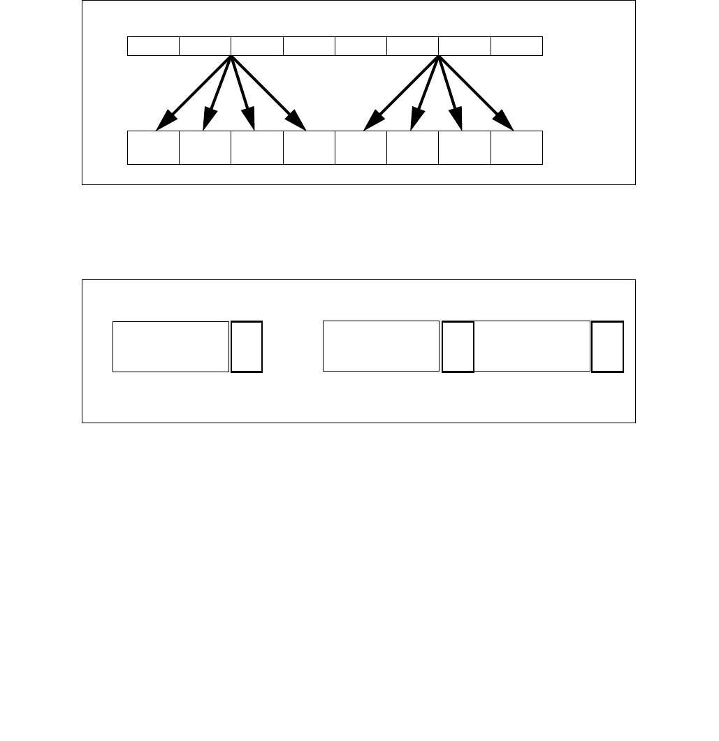
VPERMILPS—Permute In-Lane of Quadruples of Single-Precision Floating-Point Values
INSTRUCTION SET REFERENCE, V-Z
Vol. 2C 5-377
Description
(variable control version)
Permute quadruples of single-precision floating-point values in the first source operand (second operand), each
quadruplet using a 2-bit control field in the corresponding dword element of the second source operand. Permuted
results are stored in the destination operand (first operand).
The 2-bit control fields are located at the low two bits of each dword element (see Figure 5-26). Each control deter-
mines which of the source element in an input quadruple is selected for the destination element. Each quadruple of
source elements must lie in the same 128-bit region as the destination.
EVEX version: The second source operand (third operand) is a ZMM/YMM/XMM register, a 512/256/128-bit
memory location or a 512/256/128-bit vector broadcasted from a 32-bit memory location. Permuted results are
written to the destination under the writemask.
(immediate control version)
Permute quadruples of single-precision floating-point values in the first source operand (second operand), each
quadruplet using a 2-bit control field in the imm8 byte. Each 128-bit lane in the destination operand (first operand)
use the four control fields of the same imm8 byte.
VEX version: The source operand is a YMM/XMM register or a 256/128-bit memory location and the destination
operand is a YMM/XMM register.
EVEX version: The source operand (second operand) is a ZMM/YMM/XMM register, a 512/256/128-bit memory
location or a 512/256/128-bit vector broadcasted from a 32-bit memory location. Permuted results are written to
the destination under the writemask.
Note: For the imm8 version, VEX.vvvv and EVEX.vvvv are reserved and must be 1111b otherwise instruction will
#UD.
Figure 5-25. VPERMILPS Operation
Figure 5-26. VPERMILPS Shuffle Control
X7 .. X4 X7 .. X4
X3 ..X0
X3 .. X0
DEST
SRC1 X0X1X2X3X4X5X6X7
X3 .. X0
X7 .. X4 X7 .. X4
X3 ..X0
sel
Bit
34
33 32
sel
. . .
226 225 224
sel
ignored
Control Field 1Control Field 2Control Field 7
10
255
ignored ignored
63 31

VPERMILPS—Permute In-Lane of Quadruples of Single-Precision Floating-Point Values
INSTRUCTION SET REFERENCE, V-Z
5-378 Vol. 2C
Operation
Select4(SRC, control) {
CASE (control[1:0]) OF
0: TMP SRC[31:0];
1: TMP SRC[63:32];
2: TMP SRC[95:64];
3: TMP SRC[127:96];
ESAC;
RETURN TMP
}
VPERMILPS (EVEX immediate versions)
(KL, VL) = (4, 128), (8, 256), (16, 512)
FOR j 0 TO KL-1
i j * 32
IF (EVEX.b = 1) AND (SRC1 *is memory*)
THEN TMP_SRC1[i+31:i] SRC1[31:0];
ELSE TMP_SRC1[i+31:i] SRC1[i+31:i];
FI;
ENDFOR;
TMP_DEST[31:0] Select4(TMP_SRC1[127:0], imm8[1:0]);
TMP_DEST[63:32] Select4(TMP_SRC1[127:0], imm8[3:2]);
TMP_DEST[95:64] Select4(TMP_SRC1[127:0], imm8[5:4]);
TMP_DEST[127:96] Select4(TMP_SRC1[127:0], imm8[7:6]); FI;
IF VL >= 256
TMP_DEST[159:128] Select4(TMP_SRC1[255:128], imm8[1:0]); FI;
TMP_DEST[191:160] Select4(TMP_SRC1[255:128], imm8[3:2]); FI;
TMP_DEST[223:192] Select4(TMP_SRC1[255:128], imm8[5:4]); FI;
TMP_DEST[255:224] Select4(TMP_SRC1[255:128], imm8[7:6]); FI;
FI;
IF VL >= 512
TMP_DEST[287:256] Select4(TMP_SRC1[383:256], imm8[1:0]); FI;
TMP_DEST[319:288] Select4(TMP_SRC1[383:256], imm8[3:2]); FI;
TMP_DEST[351:320] Select4(TMP_SRC1[383:256], imm8[5:4]); FI;
TMP_DEST[383:352] Select4(TMP_SRC1[383:256], imm8[7:6]); FI;
TMP_DEST[415:384] Select4(TMP_SRC1[511:384], imm8[1:0]); FI;
TMP_DEST[447:416] Select4(TMP_SRC1[511:384], imm8[3:2]); FI;
TMP_DEST[479:448] Select4(TMP_SRC1[511:384], imm8[5:4]); FI;
TMP_DEST[511:480] Select4(TMP_SRC1[511:384], imm8[7:6]); FI;
FI;
FOR j 0 TO KL-1
i j * 32
IF k1[j] OR *no writemask*
THEN DEST[i+31:i] TMP_DEST[i+31:i]
ELSE
IF *merging-masking*
THEN *DEST[i+31:i] remains unchanged*
ELSE DEST[i+31:i] 0 ;zeroing-masking
FI;
FI;
ENDFOR
DEST[MAX_VL-1:VL] 0

VPERMILPS—Permute In-Lane of Quadruples of Single-Precision Floating-Point Values
INSTRUCTION SET REFERENCE, V-Z
Vol. 2C 5-379
VPERMILPS (256-bit immediate version)
DEST[31:0] Select4(SRC1[127:0], imm8[1:0]);
DEST[63:32] Select4(SRC1[127:0], imm8[3:2]);
DEST[95:64] Select4(SRC1[127:0], imm8[5:4]);
DEST[127:96] Select4(SRC1[127:0], imm8[7:6]);
DEST[159:128] Select4(SRC1[255:128], imm8[1:0]);
DEST[191:160] Select4(SRC1[255:128], imm8[3:2]);
DEST[223:192] Select4(SRC1[255:128], imm8[5:4]);
DEST[255:224] Select4(SRC1[255:128], imm8[7:6]);
VPERMILPS (128-bit immediate version)
DEST[31:0] Select4(SRC1[127:0], imm8[1:0]);
DEST[63:32] Select4(SRC1[127:0], imm8[3:2]);
DEST[95:64] Select4(SRC1[127:0], imm8[5:4]);
DEST[127:96] Select4(SRC1[127:0], imm8[7:6]);
DEST[MAX_VL-1:128]0
VPERMILPS (EVEX variable versions)
(KL, VL) = (16, 512)
FOR j 0 TO KL-1
i j * 32
IF (EVEX.b = 1) AND (SRC2 *is memory*)
THEN TMP_SRC2[i+31:i] SRC2[31:0];
ELSE TMP_SRC2[i+31:i] SRC2[i+31:i];
FI;
ENDFOR;
TMP_DEST[31:0] Select4(SRC1[127:0], TMP_SRC2[1:0]);
TMP_DEST[63:32] Select4(SRC1[127:0], TMP_SRC2[33:32]);
TMP_DEST[95:64] Select4(SRC1[127:0], TMP_SRC2[65:64]);
TMP_DEST[127:96] Select4(SRC1[127:0], TMP_SRC2[97:96]);
IF VL >= 256
TMP_DEST[159:128] Select4(SRC1[255:128], TMP_SRC2[129:128]);
TMP_DEST[191:160] Select4(SRC1[255:128], TMP_SRC2[161:160]);
TMP_DEST[223:192] Select4(SRC1[255:128], TMP_SRC2[193:192]);
TMP_DEST[255:224] Select4(SRC1[255:128], TMP_SRC2[225:224]);
FI;
IF VL >= 512
TMP_DEST[287:256] Select4(SRC1[383:256], TMP_SRC2[257:256]);
TMP_DEST[319:288] Select4(SRC1[383:256], TMP_SRC2[289:288]);
TMP_DEST[351:320] Select4(SRC1[383:256], TMP_SRC2[321:320]);
TMP_DEST[383:352] Select4(SRC1[383:256], TMP_SRC2[353:352]);
TMP_DEST[415:384] Select4(SRC1[511:384], TMP_SRC2[385:384]);
TMP_DEST[447:416] Select4(SRC1[511:384], TMP_SRC2[417:416]);
TMP_DEST[479:448] Select4(SRC1[511:384], TMP_SRC2[449:448]);
TMP_DEST[511:480] Select4(SRC1[511:384], TMP_SRC2[481:480]);
FI;
FOR j 0 TO KL-1
i j * 32
IF k1[j] OR *no writemask*
THEN DEST[i+31:i] TMP_DEST[i+31:i]
ELSE
IF *merging-masking*
THEN *DEST[i+31:i] remains unchanged*
ELSE DEST[i+31:i] 0 ;zeroing-masking

VPERMILPS—Permute In-Lane of Quadruples of Single-Precision Floating-Point Values
INSTRUCTION SET REFERENCE, V-Z
5-380 Vol. 2C
FI;
FI;
ENDFOR
DEST[MAX_VL-1:VL] 0
VPERMILPS (256-bit variable version)
DEST[31:0] Select4(SRC1[127:0], SRC2[1:0]);
DEST[63:32] Select4(SRC1[127:0], SRC2[33:32]);
DEST[95:64] Select4(SRC1[127:0], SRC2[65:64]);
DEST[127:96] Select4(SRC1[127:0], SRC2[97:96]);
DEST[159:128] Select4(SRC1[255:128], SRC2[129:128]);
DEST[191:160] Select4(SRC1[255:128], SRC2[161:160]);
DEST[223:192] Select4(SRC1[255:128], SRC2[193:192]);
DEST[255:224] Select4(SRC1[255:128], SRC2[225:224]);
DEST[MAX_VL-1:256]0
VPERMILPS (128-bit variable version)
DEST[31:0] Select4(SRC1[127:0], SRC2[1:0]);
DEST[63:32] Select4(SRC1[127:0], SRC2[33:32]);
DEST[95:64] Select4(SRC1[127:0], SRC2[65:64]);
DEST[127:96] Select4(SRC1[127:0], SRC2[97:96]);
DEST[MAX_VL-1:128]0
Intel C/C++ Compiler Intrinsic Equivalent
VPERMILPS __m512 _mm512_permute_ps( __m512 a, int imm);
VPERMILPS __m512 _mm512_mask_permute_ps(__m512 s, __mmask16 k, __m512 a, int imm);
VPERMILPS __m512 _mm512_maskz_permute_ps( __mmask16 k, __m512 a, int imm);
VPERMILPS __m256 _mm256_mask_permute_ps(__m256 s, __mmask8 k, __m256 a, int imm);
VPERMILPS __m256 _mm256_maskz_permute_ps( __mmask8 k, __m256 a, int imm);
VPERMILPS __m128 _mm_mask_permute_ps(__m128 s, __mmask8 k, __m128 a, int imm);
VPERMILPS __m128 _mm_maskz_permute_ps( __mmask8 k, __m128 a, int imm);
VPERMILPS __m512 _mm512_permutevar_ps( __m512i i, __m512 a);
VPERMILPS __m512 _mm512_mask_permutevar_ps(__m512 s, __mmask16 k, __m512i i, __m512 a);
VPERMILPS __m512 _mm512_maskz_permutevar_ps( __mmask16 k, __m512i i, __m512 a);
VPERMILPS __m256 _mm256_mask_permutevar_ps(__m256 s, __mmask8 k, __m256 i, __m256 a);
VPERMILPS __m256 _mm256_maskz_permutevar_ps( __mmask8 k, __m256 i, __m256 a);
VPERMILPS __m128 _mm_mask_permutevar_ps(__m128 s, __mmask8 k, __m128 i, __m128 a);
VPERMILPS __m128 _mm_maskz_permutevar_ps( __mmask8 k, __m128 i, __m128 a);
VPERMILPS __m128 _mm_permute_ps (__m128 a, int control);
VPERMILPS __m256 _mm256_permute_ps (__m256 a, int control);
VPERMILPS __m128 _mm_permutevar_ps (__m128 a, __m128i control);
VPERMILPS __m256 _mm256_permutevar_ps (__m256 a, __m256i control);
SIMD Floating-Point Exceptions
None
Other Exceptions
Non-EVEX-encoded instruction, see Exceptions Type 4;
#UD If VEX.W = 1.
EVEX-encoded instruction, see Exceptions Type E4NF.
#UD If either (E)VEX.vvvv != 1111B and with imm8.

VPERMPD—Permute Double-Precision Floating-Point Elements
INSTRUCTION SET REFERENCE, V-Z
Vol. 2C 5-381
VPERMPD—Permute Double-Precision Floating-Point Elements
Instruction Operand Encoding
Description
The imm8 version: Copies quadword elements of double-precision floating-point values from the source operand
(the second operand) to the destination operand (the first operand) according to the indices specified by the imme-
diate operand (the third operand). Each two-bit value in the immediate byte selects a qword element in the source
operand.
VEX version: The source operand can be a YMM register or a memory location. Bits (MAX_VL-1:256) of the corre-
sponding destination register are zeroed.
In EVEX.512 encoded version, The elements in the destination are updated using the writemask k1 and the imm8
bits are reused as control bits for the upper 256-bit half when the control bits are coming from immediate. The
source operand can be a ZMM register, a 512-bit memory location or a 512-bit vector broadcasted from a 64-bit
memory location.
The imm8 versions: VEX.vvvv and EVEX.vvvv are reserved and must be 1111b otherwise instructions will #UD.
The vector control version: Copies quadword elements of double-precision floating-point values from the second
source operand (the third operand) to the destination operand (the first operand) according to the indices in the
first source operand (the second operand). The first 3 bits of each 64 bit element in the index operand selects
which quadword in the second source operand to copy. The first and second operands are ZMM registers, the third
operand can be a ZMM register, a 512-bit memory location or a 512-bit vector broadcasted from a 64-bit memory
location. The elements in the destination are updated using the writemask k1.
Note that this instruction permits a qword in the source operand to be copied to multiple locations in the destina-
tion operand.
If VPERMPD is encoded with VEX.L= 0, an attempt to execute the instruction encoded with VEX.L= 0 will cause an
#UD exception.
Opcode/
Instruction
Op / En 64/32
bit Mode
Support
CPUID
Feature
Flag
Description
VEX.256.66.0F3A.W1 01 /r ib
VPERMPD ymm1, ymm2/m256, imm8
RMI V/V AVX2 Permute double-precision floating-point elements in
ymm2/m256 using indices in imm8 and store the
result in ymm1.
EVEX.256.66.0F3A.W1 01 /r ib
VPERMPD ymm1 {k1}{z},
ymm2/m256/m64bcst, imm8
FV-RM V/V AVX512VL
AVX512F
Permute double-precision floating-point elements in
ymm2/m256/m64bcst using indexes in imm8 and
store the result in ymm1 subject to writemask k1.
EVEX.512.66.0F3A.W1 01 /r ib
VPERMPD zmm1 {k1}{z},
zmm2/m512/m64bcst, imm8
FV-RMI V/V AVX512F Permute double-precision floating-point elements in
zmm2/m512/m64bcst using indices in imm8 and
store the result in zmm1 subject to writemask k1.
EVEX.NDS.256.66.0F38.W1 16 /r
VPERMPD ymm1 {k1}{z}, ymm2,
ymm3/m256/m64bcst
FV-RVM V/V AVX512VL
AVX512F
Permute double-precision floating-point elements in
ymm3/m256/m64bcst using indexes in ymm2 and
store the result in ymm1 subject to writemask k1.
EVEX.NDS.512.66.0F38.W1 16 /r
VPERMPD zmm1 {k1}{z}, zmm2,
zmm3/m512/m64bcst
FV-RVM V/V AVX512F Permute double-precision floating-point elements in
zmm3/m512/m64bcst using indices in zmm2 and
store the result in zmm1 subject to writemask k1.
Op/En Operand 1 Operand 2 Operand 3 Operand 4
RMI ModRM:reg (w) ModRM:r/m (r) Imm8 NA
FV-RMI ModRM:reg (w) ModRM:r/m (r) Imm8 NA
FV-RVM ModRM:reg (w) EVEX.vvvv (r) ModRM:r/m (r) NA

VPERMPD—Permute Double-Precision Floating-Point Elements
INSTRUCTION SET REFERENCE, V-Z
5-382 Vol. 2C
Operation
VPERMPD (EVEX - imm8 control forms)
(KL, VL) = (4, 256), (8, 512)
FOR j 0 TO KL-1
i j * 64
IF (EVEX.b = 1) AND (SRC *is memory*)
THEN TMP_SRC[i+63:i] SRC[63:0];
ELSE TMP_SRC[i+63:i] SRC[i+63:i];
FI;
ENDFOR;
TMP_DEST[63:0] (TMP_SRC[256:0] >> (IMM8[1:0] * 64))[63:0];
TMP_DEST[127:64] (TMP_SRC[256:0] >> (IMM8[3:2] * 64))[63:0];
TMP_DEST[191:128] (TMP_SRC[256:0] >> (IMM8[5:4] * 64))[63:0];
TMP_DEST[255:192] (TMP_SRC[256:0] >> (IMM8[7:6] * 64))[63:0];
IF VL >= 512
TMP_DEST[319:256] (TMP_SRC[511:256] >> (IMM8[1:0] * 64))[63:0];
TMP_DEST[383:320] (TMP_SRC[511:256] >> (IMM8[3:2] * 64))[63:0];
TMP_DEST[447:384] (TMP_SRC[511:256] >> (IMM8[5:4] * 64))[63:0];
TMP_DEST[511:448] (TMP_SRC[511:256] >> (IMM8[7:6] * 64))[63:0];
FI;
FOR j 0 TO KL-1
i j * 64
IF k1[j] OR *no writemask*
THEN DEST[i+63:i] TMP_DEST[i+63:i]
ELSE
IF *merging-masking* ; merging-masking
THEN *DEST[i+63:i] remains unchanged*
ELSE ; zeroing-masking
DEST[i+63:i] 0 ;zeroing-masking
FI;
FI;
ENDFOR
DEST[MAX_VL-1:VL] 0
VPERMPD (EVEX - vector control forms)
(KL, VL) = (4, 256), (8, 512)
FOR j 0 TO KL-1
i j * 64
IF (EVEX.b = 1) AND (SRC2 *is memory*)
THEN TMP_SRC2[i+63:i] SRC2[63:0];
ELSE TMP_SRC2[i+63:i] SRC2[i+63:i];
FI;
ENDFOR;
IF VL = 256
TMP_DEST[63:0] (TMP_SRC2[255:0] >> (SRC1[1:0] * 64))[63:0];
TMP_DEST[127:64] (TMP_SRC2[255:0] >> (SRC1[65:64] * 64))[63:0];
TMP_DEST[191:128] (TMP_SRC2[255:0] >> (SRC1[129:128] * 64))[63:0];
TMP_DEST[255:192] (TMP_SRC2[255:0] >> (SRC1[193:192] * 64))[63:0];
FI;
IF VL = 512
TMP_DEST[63:0] (TMP_SRC2[511:0] >> (SRC1[2:0] * 64))[63:0];

VPERMPD—Permute Double-Precision Floating-Point Elements
INSTRUCTION SET REFERENCE, V-Z
Vol. 2C 5-383
TMP_DEST[127:64] (TMP_SRC2[511:0] >> (SRC1[66:64] * 64))[63:0];
TMP_DEST[191:128] (TMP_SRC2[511:0] >> (SRC1[130:128] * 64))[63:0];
TMP_DEST[255:192] (TMP_SRC2[511:0] >> (SRC1[194:192] * 64))[63:0];
TMP_DEST[319:256] (TMP_SRC2[511:0] >> (SRC1[258:256] * 64))[63:0];
TMP_DEST[383:320] (TMP_SRC2[511:0] >> (SRC1[322:320] * 64))[63:0];
TMP_DEST[447:384] (TMP_SRC2[511:0] >> (SRC1[386:384] * 64))[63:0];
TMP_DEST[511:448] (TMP_SRC2[511:0] >> (SRC1[450:448] * 64))[63:0];
FI;
FOR j 0 TO KL-1
i j * 64
IF k1[j] OR *no writemask*
THEN DEST[i+63:i] TMP_DEST[i+63:i]
ELSE
IF *merging-masking* ; merging-masking
THEN *DEST[i+63:i] remains unchanged*
ELSE ; zeroing-masking
DEST[i+63:i] 0 ;zeroing-masking
FI;
FI;
ENDFOR
DEST[MAX_VL-1:VL] 0
VPERMPD (VEX.256 encoded version)
DEST[63:0] (SRC[255:0] >> (IMM8[1:0] * 64))[63:0];
DEST[127:64] (SRC[255:0] >> (IMM8[3:2] * 64))[63:0];
DEST[191:128] (SRC[255:0] >> (IMM8[5:4] * 64))[63:0];
DEST[255:192] (SRC[255:0] >> (IMM8[7:6] * 64))[63:0];
DEST[MAX_VL-1:256] 0
Intel C/C++ Compiler Intrinsic Equivalent
VPERMPD __m512d _mm512_permutex_pd( __m512d a, int imm);
VPERMPD __m512d _mm512_mask_permutex_pd(__m512d s, __mmask16 k, __m512d a, int imm);
VPERMPD __m512d _mm512_maskz_permutex_pd( __mmask16 k, __m512d a, int imm);
VPERMPD __m512d _mm512_permutexvar_pd( __m512i i, __m512d a);
VPERMPD __m512d _mm512_mask_permutexvar_pd(__m512d s, __mmask16 k, __m512i i, __m512d a);
VPERMPD __m512d _mm512_maskz_permutexvar_pd( __mmask16 k, __m512i i, __m512d a);
VPERMPD __m256d _mm256_permutex_epi64( __m256d a, int imm);
VPERMPD __m256d _mm256_mask_permutex_epi64(__m256i s, __mmask8 k, __m256d a, int imm);
VPERMPD __m256d _mm256_maskz_permutex_epi64( __mmask8 k, __m256d a, int imm);
VPERMPD __m256d _mm256_permutexvar_epi64( __m256i i, __m256d a);
VPERMPD __m256d _mm256_mask_permutexvar_epi64(__m256i s, __mmask8 k, __m256i i, __m256d a);
VPERMPD __m256d _mm256_maskz_permutexvar_epi64( __mmask8 k, __m256i i, __m256d a);
SIMD Floating-Point Exceptions
None
Other Exceptions
Non-EVEX-encoded instruction, see Exceptions Type 4; additionally
#UD If VEX.L = 0.
If VEX.vvvv != 1111B.
EVEX-encoded instruction, see Exceptions Type E4NF.
#UD If encoded with EVEX.128.
If EVEX.vvvv != 1111B and with imm8.

VPERMPS—Permute Single-Precision Floating-Point Elements
INSTRUCTION SET REFERENCE, V-Z
5-384 Vol. 2C
VPERMPS—Permute Single-Precision Floating-Point Elements
Instruction Operand Encoding
Description
Copies doubleword elements of single-precision floating-point values from the second source operand (the third
operand) to the destination operand (the first operand) according to the indices in the first source operand (the
second operand). Note that this instruction permits a doubleword in the source operand to be copied to more than
one location in the destination operand.
VEX.256 versions: The first and second operands are YMM registers, the third operand can be a YMM register or
memory location. Bits (MAX_VL-1:256) of the corresponding destination register are zeroed.
EVEX encoded version: The first and second operands are ZMM registers, the third operand can be a ZMM register,
a 512-bit memory location or a 512-bit vector broadcasted from a 32-bit memory location. The elements in the
destination are updated using the writemask k1.
If VPERMPS is encoded with VEX.L= 0, an attempt to execute the instruction encoded with VEX.L= 0 will cause an
#UD exception.
Operation
VPERMPS (EVEX forms)
(KL, VL) (8, 256),= (16, 512)
FOR j 0 TO KL-1
i j * 64
IF (EVEX.b = 1) AND (SRC2 *is memory*)
THEN TMP_SRC2[i+31:i] SRC2[31:0];
ELSE TMP_SRC2[i+31:i] SRC2[i+31:i];
FI;
ENDFOR;
IF VL = 256
TMP_DEST[31:0] (TMP_SRC2[255:0] >> (SRC1[2:0] * 32))[31:0];
TMP_DEST[63:32] (TMP_SRC2[255:0] >> (SRC1[34:32] * 32))[31:0];
TMP_DEST[95:64] (TMP_SRC2[255:0] >> (SRC1[66:64] * 32))[31:0];
TMP_DEST[127:96] (TMP_SRC2[255:0] >> (SRC1[98:96] * 32))[31:0];
TMP_DEST[159:128] (TMP_SRC2[255:0] >> (SRC1[130:128] * 32))[31:0];
TMP_DEST[191:160] (TMP_SRC2[255:0] >> (SRC1[162:160] * 32))[31:0];
TMP_DEST[223:192] (TMP_SRC2[255:0] >> (SRC1[193:192] * 32))[31:0];
TMP_DEST[255:224] (TMP_SRC2[255:0] >> (SRC1[226:224] * 32))[31:0];
Opcode/
Instruction
Op /
En
64/32
bit Mode
Support
CPUID
Feature
Flag
Description
VEX.256.66.0F38.W0 16 /r
VPERMPS ymm1, ymm2,
ymm3/m256
RVM V/V AVX2 Permute single-precision floating-point elements in
ymm3/m256 using indices in ymm2 and store the result in
ymm1.
EVEX.NDS.256.66.0F38.W0 16 /r
VPERMPS ymm1 {k1}{z}, ymm2,
ymm3/m256/m32bcst
FV V/V AVX512VL
AVX512F
Permute single-precision floating-point elements in
ymm3/m256/m32bcst using indexes in ymm2 and store
the result in ymm1 subject to write mask k1.
EVEX.NDS.512.66.0F38.W0 16 /r
VPERMPS zmm1 {k1}{z}, zmm2,
zmm3/m512/m32bcst
FV V/V AVX512F Permute single-precision floating-point values in
zmm3/m512/m32bcst using indices in zmm2 and store the
result in zmm1 subject to write mask k1.
Op/En Operand 1 Operand 2 Operand 3 Operand 4
RVM ModRM:reg (w) VEX.vvvv (r) ModRM:r/m (r) NA
FV ModRM:reg (w) EVEX.vvvv (r) ModRM:r/m (r) NA

VPERMPS—Permute Single-Precision Floating-Point Elements
INSTRUCTION SET REFERENCE, V-Z
Vol. 2C 5-385
FI;
IF VL = 512
TMP_DEST[31:0] (TMP_SRC2[511:0] >> (SRC1[3:0] * 32))[31:0];
TMP_DEST[63:32] (TMP_SRC2[511:0] >> (SRC1[35:32] * 32))[31:0];
TMP_DEST[95:64] (TMP_SRC2[511:0] >> (SRC1[67:64] * 32))[31:0];
TMP_DEST[127:96] (TMP_SRC2[511:0] >> (SRC1[99:96] * 32))[31:0];
TMP_DEST[159:128] (TMP_SRC2[511:0] >> (SRC1[131:128] * 32))[31:0];
TMP_DEST[191:160] (TMP_SRC2[511:0] >> (SRC1[163:160] * 32))[31:0];
TMP_DEST[223:192] (TMP_SRC2[511:0] >> (SRC1[195:192] * 32))[31:0];
TMP_DEST[255:224] (TMP_SRC2[511:0] >> (SRC1[227:224] * 32))[31:0];
TMP_DEST[287:256] (TMP_SRC2[511:0] >> (SRC1[259:256] * 32))[31:0];
TMP_DEST[319:288] (TMP_SRC2[511:0] >> (SRC1[291:288] * 32))[31:0];
TMP_DEST[351:320] (TMP_SRC2[511:0] >> (SRC1[323:320] * 32))[31:0];
TMP_DEST[383:352] (TMP_SRC2[511:0] >> (SRC1[355:352] * 32))[31:0];
TMP_DEST[415:384] (TMP_SRC2[511:0] >> (SRC1[387:384] * 32))[31:0];
TMP_DEST[447:416] (TMP_SRC2[511:0] >> (SRC1[419:416] * 32))[31:0];
TMP_DEST[479:448] (TMP_SRC2[511:0] >> (SRC1[451:448] * 32))[31:0];
TMP_DEST[511:480] (TMP_SRC2[511:0] >> (SRC1[483:480] * 32))[31:0];
FI;
FOR j 0 TO KL-1
i j * 32
IF k1[j] OR *no writemask*
THEN DEST[i+31:i] TMP_DEST[i+31:i]
ELSE
IF *merging-masking* ; merging-masking
THEN *DEST[i+31:i] remains unchanged*
ELSE ; zeroing-masking
DEST[i+31:i] 0 ;zeroing-masking
FI;
FI;
ENDFOR
DEST[MAX_VL-1:VL] 0
VPERMPS (VEX.256 encoded version)
DEST[31:0] (SRC2[255:0] >> (SRC1[2:0] * 32))[31:0];
DEST[63:32] (SRC2[255:0] >> (SRC1[34:32] * 32))[31:0];
DEST[95:64] (SRC2[255:0] >> (SRC1[66:64] * 32))[31:0];
DEST[127:96] (SRC2[255:0] >> (SRC1[98:96] * 32))[31:0];
DEST[159:128] (SRC2[255:0] >> (SRC1[130:128] * 32))[31:0];
DEST[191:160] (SRC2[255:0] >> (SRC1[162:160] * 32))[31:0];
DEST[223:192] (SRC2[255:0] >> (SRC1[194:192] * 32))[31:0];
DEST[255:224] (SRC2[255:0] >> (SRC1[226:224] * 32))[31:0];
DEST[MAX_VL-1:256] 0

VPERMPS—Permute Single-Precision Floating-Point Elements
INSTRUCTION SET REFERENCE, V-Z
5-386 Vol. 2C
Intel C/C++ Compiler Intrinsic Equivalent
VPERMPS __m512 _mm512_permutexvar_ps(__m512i i, __m512 a);
VPERMPS __m512 _mm512_mask_permutexvar_ps(__m512 s, __mmask16 k, __m512i i, __m512 a);
VPERMPS __m512 _mm512_maskz_permutexvar_ps( __mmask16 k, __m512i i, __m512 a);
VPERMPS __m256 _mm256_permutexvar_ps(__m256 i, __m256 a);
VPERMPS __m256 _mm256_mask_permutexvar_ps(__m256 s, __mmask8 k, __m256 i, __m256 a);
VPERMPS __m256 _mm256_maskz_permutexvar_ps( __mmask8 k, __m256 i, __m256 a);
SIMD Floating-Point Exceptions
None
Other Exceptions
Non-EVEX-encoded instruction, see Exceptions Type 4; additionally
#UD If VEX.L = 0.
EVEX-encoded instruction, see Exceptions Type E4NF.

VPERMQ—Qwords Element Permutation
INSTRUCTION SET REFERENCE, V-Z
Vol. 2C 5-387
VPERMQ—Qwords Element Permutation
Instruction Operand Encoding
Description
The imm8 version: Copies quadwords from the source operand (the second operand) to the destination operand
(the first operand) according to the indices specified by the immediate operand (the third operand). Each two-bit
value in the immediate byte selects a qword element in the source operand.
VEX version: The source operand can be a YMM register or a memory location. Bits (MAX_VL-1:256) of the corre-
sponding destination register are zeroed.
In EVEX.512 encoded version, The elements in the destination are updated using the writemask k1 and the imm8
bits are reused as control bits for the upper 256-bit half when the control bits are coming from immediate. The
source operand can be a ZMM register, a 512-bit memory location or a 512-bit vector broadcasted from a 64-bit
memory location.
Immediate control versions: VEX.vvvv and EVEX.vvvv are reserved and must be 1111b otherwise instructions will
#UD.
The vector control version: Copies quadwords from the second source operand (the third operand) to the destina-
tion operand (the first operand) according to the indices in the first source operand (the second operand). The first
3 bits of each 64 bit element in the index operand selects which quadword in the second source operand to copy.
The first and second operands are ZMM registers, the third operand can be a ZMM register, a 512-bit memory loca-
tion or a 512-bit vector broadcasted from a 64-bit memory location. The elements in the destination are updated
using the writemask k1.
Note that this instruction permits a qword in the source operand to be copied to multiple locations in the destina-
tion operand.
If VPERMPQ is encoded with VEX.L= 0 or EVEX.128, an attempt to execute the instruction will cause an #UD excep-
tion.
Opcode/
Instruction
Op / En 64/32
bit Mode
Support
CPUID
Feature
Flag
Description
VEX.256.66.0F3A.W1 00 /r ib
VPERMQ ymm1, ymm2/m256, imm8
RMI V/V AVX2 Permute qwords in ymm2/m256 using indices in
imm8 and store the result in ymm1.
EVEX.256.66.0F3A.W1 00 /r ib
VPERMQ ymm1 {k1}{z},
ymm2/m256/m64bcst, imm8
FV-RM V/V AVX512VL
AVX512F
Permute qwords in ymm2/m256/m64bcst using
indexes in imm8 and store the result in ymm1.
EVEX.512.66.0F3A.W1 00 /r ib
VPERMQ zmm1 {k1}{z},
zmm2/m512/m64bcst, imm8
FV-RMI V/V AVX512F Permute qwords in zmm2/m512/m64bcst using
indices in imm8 and store the result in zmm1.
EVEX.NDS.256.66.0F38.W1 36 /r
VPERMQ ymm1 {k1}{z}, ymm2,
ymm3/m256/m64bcst
FV-RVM V/V AVX512VL
AVX512F
Permute qwords in ymm3/m256/m64bcst using
indexes in ymm2 and store the result in ymm1.
EVEX.NDS.512.66.0F38.W1 36 /r
VPERMQ zmm1 {k1}{z}, zmm2,
zmm3/m512/m64bcst
FV-RVM V/V AVX512F Permute qwords in zmm3/m512/m64bcst using
indices in zmm2 and store the result in zmm1.
Op/En Operand 1 Operand 2 Operand 3 Operand 4
RMI ModRM:reg (w) ModRM:r/m (r) Imm8 NA
FV-RMI ModRM:reg (w) ModRM:r/m (r) Imm8 NA
FV-RVM ModRM:reg (w) EVEX.vvvv (r) ModRM:r/m (r) NA

VPERMQ—Qwords Element Permutation
INSTRUCTION SET REFERENCE, V-Z
5-388 Vol. 2C
Operation
VPERMQ (EVEX - imm8 control forms)
(KL, VL) = (4, 256), (8, 512)
FOR j 0 TO KL-1
i j * 64
IF (EVEX.b = 1) AND (SRC *is memory*)
THEN TMP_SRC[i+63:i] SRC[63:0];
ELSE TMP_SRC[i+63:i] SRC[i+63:i];
FI;
ENDFOR;
TMP_DEST[63:0] (TMP_SRC[255:0] >> (IMM8[1:0] * 64))[63:0];
TMP_DEST[127:64] (TMP_SRC[255:0] >> (IMM8[3:2] * 64))[63:0];
TMP_DEST[191:128] (TMP_SRC[255:0] >> (IMM8[5:4] * 64))[63:0];
TMP_DEST[255:192] (TMP_SRC[255:0] >> (IMM8[7:6] * 64))[63:0];
IF VL >= 512
TMP_DEST[319:256] (TMP_SRC[511:256] >> (IMM8[1:0] * 64))[63:0];
TMP_DEST[383:320] (TMP_SRC[511:256] >> (IMM8[3:2] * 64))[63:0];
TMP_DEST[447:384] (TMP_SRC[511:256] >> (IMM8[5:4] * 64))[63:0];
TMP_DEST[511:448] (TMP_SRC[511:256] >> (IMM8[7:6] * 64))[63:0];
FI;
FOR j 0 TO KL-1
i j * 64
IF k1[j] OR *no writemask*
THEN DEST[i+63:i] TMP_DEST[i+63:i]
ELSE
IF *merging-masking* ; merging-masking
THEN *DEST[i+63:i] remains unchanged*
ELSE ; zeroing-masking
DEST[i+63:i] 0 ;zeroing-masking
FI;
FI;
ENDFOR
DEST[MAX_VL-1:VL] 0
VPERMQ (EVEX - vector control forms)
(KL, VL) = (4, 256), (8, 512)
FOR j 0 TO KL-1
i j * 64
IF (EVEX.b = 1) AND (SRC2 *is memory*)
THEN TMP_SRC2[i+63:i] SRC2[63:0];
ELSE TMP_SRC2[i+63:i] SRC2[i+63:i];
FI;
ENDFOR;
IF VL = 256
TMP_DEST[63:0] (TMP_SRC2[255:0] >> (SRC1[1:0] * 64))[63:0];
TMP_DEST[127:64] (TMP_SRC2[255:0] >> (SRC1[65:64] * 64))[63:0];
TMP_DEST[191:128] (TMP_SRC2[255:0] >> (SRC1[129:128] * 64))[63:0];
TMP_DEST[255:192] (TMP_SRC2[255:0] >> (SRC1[193:192] * 64))[63:0];
FI;
IF VL = 512
TMP_DEST[63:0] (TMP_SRC2[511:0] >> (SRC1[2:0] * 64))[63:0];
TMP_DEST[127:64] (TMP_SRC2[511:0] >> (SRC1[66:64] * 64))[63:0];
TMP_DEST[191:128] (TMP_SRC2[511:0] >> (SRC1[130:128] * 64))[63:0];
TMP_DEST[255:192] (TMP_SRC2[511:0] >> (SRC1[194:192] * 64))[63:0];

VPERMQ—Qwords Element Permutation
INSTRUCTION SET REFERENCE, V-Z
Vol. 2C 5-389
TMP_DEST[319:256] (TMP_SRC2[511:0] >> (SRC1[258:256] * 64))[63:0];
TMP_DEST[383:320] (TMP_SRC2[511:0] >> (SRC1[322:320] * 64))[63:0];
TMP_DEST[447:384] (TMP_SRC2[511:0] >> (SRC1[386:384] * 64))[63:0];
TMP_DEST[511:448] (TMP_SRC2[511:0] >> (SRC1[450:448] * 64))[63:0];
FI;
FOR j 0 TO KL-1
i j * 64
IF k1[j] OR *no writemask*
THEN DEST[i+63:i] TMP_DEST[i+63:i]
ELSE
IF *merging-masking* ; merging-masking
THEN *DEST[i+63:i] remains unchanged*
ELSE ; zeroing-masking
DEST[i+63:i] 0 ;zeroing-masking
FI;
FI;
ENDFOR
DEST[MAX_VL-1:VL] 0
VPERMQ (VEX.256 encoded version)
DEST[63:0] (SRC[255:0] >> (IMM8[1:0] * 64))[63:0];
DEST[127:64] (SRC[255:0] >> (IMM8[3:2] * 64))[63:0];
DEST[191:128] (SRC[255:0] >> (IMM8[5:4] * 64))[63:0];
DEST[255:192] (SRC[255:0] >> (IMM8[7:6] * 64))[63:0];
DEST[MAX_VL-1:256] 0
Intel C/C++ Compiler Intrinsic Equivalent
VPERMQ __m512i _mm512_permutex_epi64( __m512i a, int imm);
VPERMQ __m512i _mm512_mask_permutex_epi64(__m512i s, __mmask8 k, __m512i a, int imm);
VPERMQ __m512i _mm512_maskz_permutex_epi64( __mmask8 k, __m512i a, int imm);
VPERMQ __m512i _mm512_permutexvar_epi64( __m512i a, __m512i b);
VPERMQ __m512i _mm512_mask_permutexvar_epi64(__m512i s, __mmask8 k, __m512i a, __m512i b);
VPERMQ __m512i _mm512_maskz_permutexvar_epi64( __mmask8 k, __m512i a, __m512i b);
VPERMQ __m256i _mm256_permutex_epi64( __m256i a, int imm);
VPERMQ __m256i _mm256_mask_permutex_epi64(__m256i s, __mmask8 k, __m256i a, int imm);
VPERMQ __m256i _mm256_maskz_permutex_epi64( __mmask8 k, __m256i a, int imm);
VPERMQ __m256i _mm256_permutexvar_epi64( __m256i a, __m256i b);
VPERMQ __m256i _mm256_mask_permutexvar_epi64(__m256i s, __mmask8 k, __m256i a, __m256i b);
VPERMQ __m256i _mm256_maskz_permutexvar_epi64( __mmask8 k, __m256i a, __m256i b);
SIMD Floating-Point Exceptions
None
Other Exceptions
Non-EVEX-encoded instruction, see Exceptions Type 4; additionally
#UD If VEX.L = 0.
If VEX.vvvv != 1111B.
EVEX-encoded instruction, see Exceptions Type E4NF.
#UD If encoded with EVEX.128.
If EVEX.vvvv != 1111B and with imm8.

VPEXPANDD—Load Sparse Packed Doubleword Integer Values from Dense Memory / Register
INSTRUCTION SET REFERENCE, V-Z
5-390 Vol. 2C
VPEXPANDD—Load Sparse Packed Doubleword Integer Values from Dense Memory / Register
Instruction Operand Encoding
Description
Expand (load) up to 16 contiguous doubleword integer values of the input vector in the source operand (the second
operand) to sparse elements in the destination operand (the first operand), selected by the writemask k1. The
destination operand is a ZMM register, the source operand can be a ZMM register or memory location.
The input vector starts from the lowest element in the source operand. The opmask register k1 selects the destina-
tion elements (a partial vector or sparse elements if less than 8 elements) to be replaced by the ascending
elements in the input vector. Destination elements not selected by the writemask k1 are either unmodified or
zeroed, depending on EVEX.z.
Note: EVEX.vvvv is reserved and must be 1111b otherwise instructions will #UD.
Note that the compressed displacement assumes a pre-scaling (N) corresponding to the size of one single element
instead of the size of the full vector.
Operation
VPEXPANDD (EVEX encoded versions)
(KL, VL) = (4, 128), (8, 256), (16, 512)
k 0
FOR j 0 TO KL-1
i j * 32
IF k1[j] OR *no writemask*
THEN
DEST[i+31:i] SRC[k+31:k];
k k + 32
ELSE
IF *merging-masking* ; merging-masking
THEN *DEST[i+31:i] remains unchanged*
ELSE ; zeroing-masking
DEST[i+31:i] 0
FI
FI;
ENDFOR
DEST[MAX_VL-1:VL] 0
Opcode/
Instruction
Op/
En
64/32
bit Mode
Support
CPUID
Feature
Flag
Description
EVEX.128.66.0F38.W0 89 /r
VPEXPANDD xmm1 {k1}{z},
xmm2/m128
T1S V/V AVX512VL
AVX512F
Expand packed double-word integer values from
xmm2/m128 to xmm1 using writemask k1.
EVEX.256.66.0F38.W0 89 /r
VPEXPANDD ymm1 {k1}{z},
ymm2/m256
T1S V/V AVX512VL
AVX512F
Expand packed double-word integer values from
ymm2/m256 to ymm1 using writemask k1.
EVEX.512.66.0F38.W0 89 /r
VPEXPANDD zmm1 {k1}{z},
zmm2/m512
T1S V/V AVX512F Expand packed double-word integer values from
zmm2/m512 to zmm1 using writemask k1.
Op/En Operand 1 Operand 2 Operand 3 Operand 4
T1S ModRM:reg (w) ModRM:r/m (r) NA NA

VPEXPANDD—Load Sparse Packed Doubleword Integer Values from Dense Memory / Register
INSTRUCTION SET REFERENCE, V-Z
Vol. 2C 5-391
Intel C/C++ Compiler Intrinsic Equivalent
VPEXPANDD __m512i _mm512_mask_expandloadu_epi32(__m512i s, __mmask16 k, void * a);
VPEXPANDD __m512i _mm512_maskz_expandloadu_epi32( __mmask16 k, void * a);
VPEXPANDD __m512i _mm512_mask_expand_epi32(__m512i s, __mmask16 k, __m512i a);
VPEXPANDD __m512i _mm512_maskz_expand_epi32( __mmask16 k, __m512i a);
VPEXPANDD __m256i _mm256_mask_expandloadu_epi32(__m256i s, __mmask8 k, void * a);
VPEXPANDD __m256i _mm256_maskz_expandloadu_epi32( __mmask8 k, void * a);
VPEXPANDD __m256i _mm256_mask_expand_epi32(__m256i s, __mmask8 k, __m256i a);
VPEXPANDD __m256i _mm256_maskz_expand_epi32( __mmask8 k, __m256i a);
VPEXPANDD __m128i _mm_mask_expandloadu_epi32(__m128i s, __mmask8 k, void * a);
VPEXPANDD __m128i _mm_maskz_expandloadu_epi32( __mmask8 k, void * a);
VPEXPANDD __m128i _mm_mask_expand_epi32(__m128i s, __mmask8 k, __m128i a);
VPEXPANDD __m128i _mm_maskz_expand_epi32( __mmask8 k, __m128i a);
SIMD Floating-Point Exceptions
None
Other Exceptions
EVEX-encoded instruction, see Exceptions Type E4.nb.
#UD If EVEX.vvvv != 1111B.

VPEXPANDQ—Load Sparse Packed Quadword Integer Values from Dense Memory / Register
INSTRUCTION SET REFERENCE, V-Z
5-392 Vol. 2C
VPEXPANDQ—Load Sparse Packed Quadword Integer Values from Dense Memory / Register
Instruction Operand Encoding
Description
Expand (load) up to 8 quadword integer values from the source operand (the second operand) to sparse elements
in the destination operand (the first operand), selected by the writemask k1. The destination operand is a ZMM
register, the source operand can be a ZMM register or memory location.
The input vector starts from the lowest element in the source operand. The opmask register k1 selects the destina-
tion elements (a partial vector or sparse elements if less than 8 elements) to be replaced by the ascending
elements in the input vector. Destination elements not selected by the writemask k1 are either unmodified or
zeroed, depending on EVEX.z.
Note: EVEX.vvvv is reserved and must be 1111b otherwise instructions will #UD.
Note that the compressed displacement assumes a pre-scaling (N) corresponding to the size of one single element
instead of the size of the full vector.
Operation
VPEXPANDQ (EVEX encoded versions)
(KL, VL) = (2, 128), (4, 256), (8, 512)
k 0
FOR j 0 TO KL-1
i j * 64
IF k1[j] OR *no writemask*
THEN
DEST[i+63:i] SRC[k+63:k];
k k + 64
ELSE
IF *merging-masking* ; merging-masking
THEN *DEST[i+63:i] remains unchanged*
ELSE ; zeroing-masking
THEN DEST[i+63:i] 0
FI
FI;
ENDFOR
DEST[MAX_VL-1:VL] 0
Opcode/
Instruction
Op/
En
64/32
bit Mode
Support
CPUID
Feature
Flag
Description
EVEX.128.66.0F38.W1 89 /r
VPEXPANDQ xmm1 {k1}{z}, xmm2/m128
T1S V/V AVX512VL
AVX512F
Expand packed quad-word integer values from
xmm2/m128 to xmm1 using writemask k1.
EVEX.256.66.0F38.W1 89 /r
VPEXPANDQ ymm1 {k1}{z}, ymm2/m256
T1S V/V AVX512VL
AVX512F
Expand packed quad-word integer values from
ymm2/m256 to ymm1 using writemask k1.
EVEX.512.66.0F38.W1 89 /r
VPEXPANDQ zmm1 {k1}{z}, zmm2/m512
T1S V/V AVX512F Expand packed quad-word integer values from
zmm2/m512 to zmm1 using writemask k1.
Op/En Operand 1 Operand 2 Operand 3 Operand 4
T1S ModRM:reg (w) ModRM:r/m (r) NA NA

VPEXPANDQ—Load Sparse Packed Quadword Integer Values from Dense Memory / Register
INSTRUCTION SET REFERENCE, V-Z
Vol. 2C 5-393
Intel C/C++ Compiler Intrinsic Equivalent
VPEXPANDQ __m512i _mm512_mask_expandloadu_epi64(__m512i s, __mmask8 k, void * a);
VPEXPANDQ __m512i _mm512_maskz_expandloadu_epi64( __mmask8 k, void * a);
VPEXPANDQ __m512i _mm512_mask_expand_epi64(__m512i s, __mmask8 k, __m512i a);
VPEXPANDQ __m512i _mm512_maskz_expand_epi64( __mmask8 k, __m512i a);
VPEXPANDQ __m256i _mm256_mask_expandloadu_epi64(__m256i s, __mmask8 k, void * a);
VPEXPANDQ __m256i _mm256_maskz_expandloadu_epi64( __mmask8 k, void * a);
VPEXPANDQ __m256i _mm256_mask_expand_epi64(__m256i s, __mmask8 k, __m256i a);
VPEXPANDQ __m256i _mm256_maskz_expand_epi64( __mmask8 k, __m256i a);
VPEXPANDQ __m128i _mm_mask_expandloadu_epi64(__m128i s, __mmask8 k, void * a);
VPEXPANDQ __m128i _mm_maskz_expandloadu_epi64( __mmask8 k, void * a);
VPEXPANDQ __m128i _mm_mask_expand_epi64(__m128i s, __mmask8 k, __m128i a);
VPEXPANDQ __m128i _mm_maskz_expand_epi64( __mmask8 k, __m128i a);
SIMD Floating-Point Exceptions
None
Other Exceptions
EVEX-encoded instruction, see Exceptions Type E4.nb.
#UD If EVEX.vvvv != 1111B.

VPLZCNTD/Q—Count the Number of Leading Zero Bits for Packed Dword, Packed Qword Values
INSTRUCTION SET REFERENCE, V-Z
5-394 Vol. 2C
VPLZCNTD/Q—Count the Number of Leading Zero Bits for Packed Dword, Packed Qword Values
Instruction Operand Encoding
Description
Counts the number of leading most significant zero bits in each dword or qword element of the source operand (the
second operand) and stores the results in the destination register (the first operand) according to the writemask.
If an element is zero, the result for that element is the operand size of the element.
EVEX.512 encoded version: The source operand is a ZMM register, a 512-bit memory location, or a 512-bit vector
broadcasted from a 32/64-bit memory location. The destination operand is a ZMM register, conditionally updated
using writemask k1.
EVEX.256 encoded version: The source operand is a YMM register, a 256-bit memory location, or a 256-bit vector
broadcasted from a 32/64-bit memory location. The destination operand is a YMM register, conditionally updated
using writemask k1.
EVEX.128 encoded version: The source operand is a XMM register, a 128-bit memory location, or a 128-bit vector
broadcasted from a 32/64-bit memory location. The destination operand is a XMM register, conditionally updated
using writemask k1.
EVEX.vvvv is reserved and must be 1111b otherwise instructions will #UD.
Opcode/
Instruction
Op/
En
64/32
bit Mode
Support
CPUID
Feature
Flag
Description
EVEX.128.66.0F38.W0 44 /r
VPLZCNTD xmm1 {k1}{z},
xmm2/m128/m32bcst
FV V/V AVX512VL
AVX512CD
Count the number of leading zero bits in each dword
element of xmm2/m128/m32bcst using writemask k1.
EVEX.256.66.0F38.W0 44 /r
VPLZCNTD ymm1 {k1}{z},
ymm2/m256/m32bcst
FV V/V AVX512VL
AVX512CD
Count the number of leading zero bits in each dword
element of ymm2/m256/m32bcst using writemask k1.
EVEX.512.66.0F38.W0 44 /r
VPLZCNTD zmm1 {k1}{z},
zmm2/m512/m32bcst
FV V/V AVX512CD Count the number of leading zero bits in each dword
element of zmm2/m512/m32bcst using writemask k1.
EVEX.128.66.0F38.W1 44 /r
VPLZCNTQ xmm1 {k1}{z},
xmm2/m128/m64bcst
FV V/V AVX512VL
AVX512CD
Count the number of leading zero bits in each qword
element of xmm2/m128/m64bcst using writemask k1.
EVEX.256.66.0F38.W1 44 /r
VPLZCNTQ ymm1 {k1}{z},
ymm2/m256/m64bcst
FV V/V AVX512VL
AVX512CD
Count the number of leading zero bits in each qword
element of ymm2/m256/m64bcst using writemask k1.
EVEX.512.66.0F38.W1 44 /r
VPLZCNTQ zmm1 {k1}{z},
zmm2/m512/m64bcst
FV V/V AVX512CD Count the number of leading zero bits in each qword
element of zmm2/m512/m64bcst using writemask k1.
Op/En Operand 1 Operand 2 Operand 3 Operand 4
FV ModRM:reg (w) ModRM:r/m (r) NA NA

VPLZCNTD/Q—Count the Number of Leading Zero Bits for Packed Dword, Packed Qword Values
INSTRUCTION SET REFERENCE, V-Z
Vol. 2C 5-395
Operation
VPLZCNTD
(KL, VL) = (4, 128), (8, 256), (16, 512)
FOR j 0 TO KL-1
i j*32
IF MaskBit(j) OR *no writemask*
THEN
temp 32
DEST[i+31:i] 0
WHILE (temp > 0) AND (SRC[i+temp-1] = 0)
DO
temp temp – 1
DEST[i+31:i] DEST[i+31:i] + 1
OD
ELSE
IF *merging-masking*
THEN *DEST[i+31:i] remains unchanged*
ELSE DEST[i+31:i] 0
FI
FI
ENDFOR
DEST[MAX_VL-1:VL] 0
VPLZCNTQ
(KL, VL) = (2, 128), (4, 256), (8, 512)
FOR j 0 TO KL-1
i j*64
IF MaskBit(j) OR *no writemask*
THEN
temp 64
DEST[i+63:i] 0
WHILE (temp > 0) AND (SRC[i+temp-1] = 0)
DO
temp temp – 1
DEST[i+63:i] DEST[i+63:i] + 1
OD
ELSE
IF *merging-masking*
THEN *DEST[i+63:i] remains unchanged*
ELSE DEST[i+63:i] 0
FI
FI
ENDFOR
DEST[MAX_VL-1:VL] 0

VPLZCNTD/Q—Count the Number of Leading Zero Bits for Packed Dword, Packed Qword Values
INSTRUCTION SET REFERENCE, V-Z
5-396 Vol. 2C
Intel C/C++ Compiler Intrinsic Equivalent
VPLZCNTD __m512i _mm512_lzcnt_epi32(__m512i a);
VPLZCNTD __m512i _mm512_mask_lzcnt_epi32(__m512i s, __mmask16 m, __m512i a);
VPLZCNTD __m512i _mm512_maskz_lzcnt_epi32( __mmask16 m, __m512i a);
VPLZCNTQ __m512i _mm512_lzcnt_epi64(__m512i a);
VPLZCNTQ __m512i _mm512_mask_lzcnt_epi64(__m512i s, __mmask8 m, __m512i a);
VPLZCNTQ __m512i _mm512_maskz_lzcnt_epi64(__mmask8 m, __m512i a);
VPLZCNTD __m256i _mm256_lzcnt_epi32(__m256i a);
VPLZCNTD __m256i _mm256_mask_lzcnt_epi32(__m256i s, __mmask8 m, __m256i a);
VPLZCNTD __m256i _mm256_maskz_lzcnt_epi32( __mmask8 m, __m256i a);
VPLZCNTQ __m256i _mm256_lzcnt_epi64(__m256i a);
VPLZCNTQ __m256i _mm256_mask_lzcnt_epi64(__m256i s, __mmask8 m, __m256i a);
VPLZCNTQ __m256i _mm256_maskz_lzcnt_epi64(__mmask8 m, __m256i a);
VPLZCNTD __m128i _mm_lzcnt_epi32(__m128i a);
VPLZCNTD __m128i _mm_mask_lzcnt_epi32(__m128i s, __mmask8 m, __m128i a);
VPLZCNTD __m128i _mm_maskz_lzcnt_epi32( __mmask8 m, __m128i a);
VPLZCNTQ __m128i _mm_lzcnt_epi64(__m128i a);
VPLZCNTQ __m128i _mm_mask_lzcnt_epi64(__m128i s, __mmask8 m, __m128i a);
VPLZCNTQ __m128i _mm_maskz_lzcnt_epi64(__mmask8 m, __m128i a);
SIMD Floating-Point Exceptions
None
Other Exceptions
EVEX-encoded instruction, see Exceptions Type E4.

VPMASKMOV — Conditional SIMD Integer Packed Loads and Stores
INSTRUCTION SET REFERENCE, V-Z
Vol. 2C 5-397
VPMASKMOV — Conditional SIMD Integer Packed Loads and Stores
Instruction Operand Encoding
Description
Conditionally moves packed data elements from the second source operand into the corresponding data element
of the destination operand, depending on the mask bits associated with each data element. The mask bits are
specified in the first source operand.
The mask bit for each data element is the most significant bit of that element in the first source operand. If a mask
is 1, the corresponding data element is copied from the second source operand to the destination operand. If the
mask is 0, the corresponding data element is set to zero in the load form of these instructions, and unmodified in
the store form.
The second source operand is a memory address for the load form of these instructions. The destination operand
is a memory address for the store form of these instructions. The other operands are either XMM registers (for
VEX.128 version) or YMM registers (for VEX.256 version).
Faults occur only due to mask-bit required memory accesses that caused the faults. Faults will not occur due to
referencing any memory location if the corresponding mask bit for that memory location is 0. For example, no
faults will be detected if the mask bits are all zero.
Unlike previous MASKMOV instructions (MASKMOVQ and MASKMOVDQU), a nontemporal hint is not applied to
these instructions.
Instruction behavior on alignment check reporting with mask bits of less than all 1s are the same as with mask bits
of all 1s.
Opcode/
Instruction
Op/
En
64/32
-bit
Mode
CPUID
Feature
Flag
Description
VEX.NDS.128.66.0F38.W0 8C /rVPMASK-
MOVD xmm1, xmm2, m128
RVM V/V AVX2 Conditionally load dword values from m128 using mask
in xmm2 and store in xmm1.
VEX.NDS.256.66.0F38.W0 8C /r
VPMASKMOVD ymm1, ymm2, m256
RVM V/V AVX2 Conditionally load dword values from m256 using mask
in ymm2 and store in ymm1.
VEX.NDS.128.66.0F38.W1 8C /r
VPMASKMOVQ xmm1, xmm2, m128
RVM V/V AVX2 Conditionally load qword values from m128 using mask
in xmm2 and store in xmm1.
VEX.NDS.256.66.0F38.W1 8C /r
VPMASKMOVQ ymm1, ymm2, m256
RVM V/V AVX2 Conditionally load qword values from m256 using mask
in ymm2 and store in ymm1.
VEX.NDS.128.66.0F38.W0 8E /r
VPMASKMOVD m128, xmm1, xmm2
MVR V/V AVX2 Conditionally store dword values from xmm2 using
mask in xmm1.
VEX.NDS.256.66.0F38.W0 8E /r
VPMASKMOVD m256, ymm1, ymm2
MVR V/V AVX2 Conditionally store dword values from ymm2 using
mask in ymm1.
VEX.NDS.128.66.0F38.W1 8E /r
VPMASKMOVQ m128, xmm1, xmm2
MVR V/V AVX2 Conditionally store qword values from xmm2 using
mask in xmm1.
VEX.NDS.256.66.0F38.W1 8E /r
VPMASKMOVQ m256, ymm1, ymm2
MVR V/V AVX2 Conditionally store qword values from ymm2 using
mask in ymm1.
Op/En Operand 1 Operand 2 Operand 3 Operand 4
RVM ModRM:reg (w) VEX.vvvv ModRM:r/m (r) NA
MVR ModRM:r/m (w) VEX.vvvv ModRM:reg (r) NA

VPMASKMOV — Conditional SIMD Integer Packed Loads and Stores
INSTRUCTION SET REFERENCE, V-Z
5-398 Vol. 2C
VMASKMOV should not be used to access memory mapped I/O as the ordering of the individual loads or stores it
does is implementation specific.
In cases where mask bits indicate data should not be loaded or stored paging A and D bits will be set in an imple-
mentation dependent way. However, A and D bits are always set for pages where data is actually loaded/stored.
Note: for load forms, the first source (the mask) is encoded in VEX.vvvv; the second source is encoded in rm_field,
and the destination register is encoded in reg_field.
Note: for store forms, the first source (the mask) is encoded in VEX.vvvv; the second source register is encoded in
reg_field, and the destination memory location is encoded in rm_field.
Operation
VPMASKMOVD - 256-bit load
DEST[31:0] IF (SRC1[31]) Load_32(mem) ELSE 0
DEST[63:32] IF (SRC1[63]) Load_32(mem + 4) ELSE 0
DEST[95:64] IF (SRC1[95]) Load_32(mem + 8) ELSE 0
DEST[127:96] IF (SRC1[127]) Load_32(mem + 12) ELSE 0
DEST[159:128] IF (SRC1[159]) Load_32(mem + 16) ELSE 0
DEST[191:160] IF (SRC1[191]) Load_32(mem + 20) ELSE 0
DEST[223:192] IF (SRC1[223]) Load_32(mem + 24) ELSE 0
DEST[255:224] IF (SRC1[255]) Load_32(mem + 28) ELSE 0
VPMASKMOVD -128-bit load
DEST[31:0] IF (SRC1[31]) Load_32(mem) ELSE 0
DEST[63:32] IF (SRC1[63]) Load_32(mem + 4) ELSE 0
DEST[95:64] IF (SRC1[95]) Load_32(mem + 8) ELSE 0
DEST[127:97] IF (SRC1[127]) Load_32(mem + 12) ELSE 0
DEST[VLMAX-1:128] 0
VPMASKMOVQ - 256-bit load
DEST[63:0] IF (SRC1[63]) Load_64(mem) ELSE 0
DEST[127:64] IF (SRC1[127]) Load_64(mem + 8) ELSE 0
DEST[195:128] IF (SRC1[191]) Load_64(mem + 16) ELSE 0
DEST[255:196] IF (SRC1[255]) Load_64(mem + 24) ELSE 0
VPMASKMOVQ - 128-bit load
DEST[63:0] IF (SRC1[63]) Load_64(mem) ELSE 0
DEST[127:64] IF (SRC1[127]) Load_64(mem + 16) ELSE 0
DEST[VLMAX-1:128] 0
VPMASKMOVD - 256-bit store
IF (SRC1[31]) DEST[31:0] SRC2[31:0]
IF (SRC1[63]) DEST[63:32] SRC2[63:32]
IF (SRC1[95]) DEST[95:64] SRC2[95:64]
IF (SRC1[127]) DEST[127:96] SRC2[127:96]
IF (SRC1[159]) DEST[159:128] SRC2[159:128]
IF (SRC1[191]) DEST[191:160] SRC2[191:160]
IF (SRC1[223]) DEST[223:192] SRC2[223:192]
IF (SRC1[255]) DEST[255:224] SRC2[255:224]

VPMASKMOV — Conditional SIMD Integer Packed Loads and Stores
INSTRUCTION SET REFERENCE, V-Z
Vol. 2C 5-399
VPMASKMOVD - 128-bit store
IF (SRC1[31]) DEST[31:0] SRC2[31:0]
IF (SRC1[63]) DEST[63:32] SRC2[63:32]
IF (SRC1[95]) DEST[95:64] SRC2[95:64]
IF (SRC1[127]) DEST[127:96] SRC2[127:96]
VPMASKMOVQ - 256-bit store
IF (SRC1[63]) DEST[63:0] SRC2[63:0]
IF (SRC1[127]) DEST[127:64] SRC2[127:64]
IF (SRC1[191]) DEST[191:128] SRC2[191:128]
IF (SRC1[255]) DEST[255:192] SRC2[255:192]
VPMASKMOVQ - 128-bit store
IF (SRC1[63]) DEST[63:0] SRC2[63:0]
IF (SRC1[127]) DEST[127:64] SRC2[127:64]
Intel C/C++ Compiler Intrinsic Equivalent
VPMASKMOVD: __m256i _mm256_maskload_epi32(int const *a, __m256i mask)
VPMASKMOVD: void _mm256_maskstore_epi32(int *a, __m256i mask, __m256i b)
VPMASKMOVQ: __m256i _mm256_maskload_epi64(__int64 const *a, __m256i mask);
VPMASKMOVQ: void _mm256_maskstore_epi64(__int64 *a, __m256i mask, __m256d b);
VPMASKMOVD: __m128i _mm_maskload_epi32(int const *a, __m128i mask)
VPMASKMOVD: void _mm_maskstore_epi32(int *a, __m128i mask, __m128 b)
VPMASKMOVQ: __m128i _mm_maskload_epi64(__int cont *a, __m128i mask);
VPMASKMOVQ: void _mm_maskstore_epi64(__int64 *a, __m128i mask, __m128i b);
SIMD Floating-Point Exceptions
None
Other Exceptions
See Exceptions Type 6 (No AC# reported for any mask bit combinations).

VPMOVM2B/VPMOVM2W/VPMOVM2D/VPMOVM2Q—Convert a Mask Register to a Vector Register
INSTRUCTION SET REFERENCE, V-Z
5-400 Vol. 2C
VPMOVM2B/VPMOVM2W/VPMOVM2D/VPMOVM2Q—Convert a Mask Register to a Vector
Register
Instruction Operand Encoding
Description
Converts a mask register to a vector register. Each element in the destination register is set to all 1’s or all 0’s
depending on the value of the corresponding bit in the source mask register.
The source operand is a mask register. The destination operand is a ZMM/YMM/XMM register.
EVEX.vvvv is reserved and must be 1111b otherwise instructions will #UD.
Opcode/
Instruction
Op/
En
64/32
bit Mode
Support
CPUID
Feature
Flag
Description
EVEX.128.F3.0F38.W0 28 /r
VPMOVM2B xmm1, k1
RM V/V AVX512VL
AVX512BW
Sets each byte in XMM1 to all 1’s or all 0’s based on the value
of the corresponding bit in k1.
EVEX.256.F3.0F38.W0 28 /r
VPMOVM2B ymm1, k1
RM V/V AVX512VL
AVX512BW
Sets each byte in YMM1 to all 1’s or all 0’s based on the value
of the corresponding bit in k1.
EVEX.512.F3.0F38.W0 28 /r
VPMOVM2B zmm1, k1
RM V/V AVX512BW Sets each byte in ZMM1 to all 1’s or all 0’s based on the value
of the corresponding bit in k1.
EVEX.128.F3.0F38.W1 28 /r
VPMOVM2W xmm1, k1
RM V/V AVX512VL
AVX512BW
Sets each word in XMM1 to all 1’s or all 0’s based on the value
of the corresponding bit in k1.
EVEX.256.F3.0F38.W1 28 /r
VPMOVM2W ymm1, k1
RM V/V AVX512VL
AVX512BW
Sets each word in YMM1 to all 1’s or all 0’s based on the value
of the corresponding bit in k1.
EVEX.512.F3.0F38.W1 28 /r
VPMOVM2W zmm1, k1
RM V/V AVX512BW Sets each word in ZMM1 to all 1’s or all 0’s based on the value
of the corresponding bit in k1.
EVEX.128.F3.0F38.W0 38 /r
VPMOVM2D xmm1, k1
RM V/V AVX512VL
AVX512DQ
Sets each doubleword in XMM1 to all 1’s or all 0’s based on the
value of the corresponding bit in k1.
EVEX.256.F3.0F38.W0 38 /r
VPMOVM2D ymm1, k1
RM V/V AVX512VL
AVX512DQ
Sets each doubleword in YMM1 to all 1’s or all 0’s based on the
value of the corresponding bit in k1.
EVEX.512.F3.0F38.W0 38 /r
VPMOVM2D zmm1, k1
RM V/V AVX512DQ Sets each doubleword in ZMM1 to all 1’s or all 0’s based on the
value of the corresponding bit in k1.
EVEX.128.F3.0F38.W1 38 /r
VPMOVM2Q xmm1, k1
RM V/V AVX512VL
AVX512DQ
Sets each quadword in XMM1 to all 1’s or all 0’s based on the
value of the corresponding bit in k1.
EVEX.256.F3.0F38.W1 38 /r
VPMOVM2Q ymm1, k1
RM V/V AVX512VL
AVX512DQ
Sets each quadword in YMM1 to all 1’s or all 0’s based on the
value of the corresponding bit in k1.
EVEX.512.F3.0F38.W1 38 /r
VPMOVM2Q zmm1, k1
RM V/V AVX512DQ Sets each quadword in ZMM1 to all 1’s or all 0’s based on the
value of the corresponding bit in k1.
Op/En Operand 1 Operand 2 Operand 3 Operand 4
RM ModRM:reg (w) ModRM:r/m (r) NA NA

VPMOVM2B/VPMOVM2W/VPMOVM2D/VPMOVM2Q—Convert a Mask Register to a Vector Register
INSTRUCTION SET REFERENCE, V-Z
Vol. 2C 5-401
Operation
VPMOVM2B (EVEX encoded versions)
(KL, VL) = (16, 128), (32, 256), (64, 512)
FOR j 0 TO KL-1
i j * 8
IF SRC[j]
THEN DEST[i+7:i] -1
ELSE DEST[i+7:i] 0
FI;
ENDFOR
DEST[MAX_VL-1:VL] 0
VPMOVM2W (EVEX encoded versions)
(KL, VL) = (8, 128), (16, 256), (32, 512)
FOR j 0 TO KL-1
i j * 16
IF SRC[j]
THEN DEST[i+15:i] -1
ELSE DEST[i+15:i] 0
FI;
ENDFOR
DEST[MAX_VL-1:VL] 0
VPMOVM2D (EVEX encoded versions)
(KL, VL) = (4, 128), (8, 256), (16, 512)
FOR j 0 TO KL-1
i j * 32
IF SRC[j]
THEN DEST[i+31:i] -1
ELSE DEST[i+31:i] 0
FI;
ENDFOR
DEST[MAX_VL-1:VL] 0
VPMOVM2Q (EVEX encoded versions)
(KL, VL) = (2, 128), (4, 256), (8, 512)
FOR j 0 TO KL-1
i j * 64
IF SRC[j]
THEN DEST[i+63:i] -1
ELSE DEST[i+63:i] 0
FI;
ENDFOR
DEST[MAX_VL-1:VL] 0

VPMOVM2B/VPMOVM2W/VPMOVM2D/VPMOVM2Q—Convert a Mask Register to a Vector Register
INSTRUCTION SET REFERENCE, V-Z
5-402 Vol. 2C
Intel C/C++ Compiler Intrinsic Equivalents
VPMOVM2B __m512i _mm512_movm_epi8(__mmask64 );
VPMOVM2D __m512i _mm512_movm_epi32(__mmask8 );
VPMOVM2Q __m512i _mm512_movm_epi64(__mmask16 );
VPMOVM2W __m512i _mm512_movm_epi16(__mmask32 );
VPMOVM2B __m256i _mm256_movm_epi8(__mmask32 );
VPMOVM2D __m256i _mm256_movm_epi32(__mmask8 );
VPMOVM2Q __m256i _mm256_movm_epi64(__mmask8 );
VPMOVM2W __m256i _mm256_movm_epi16(__mmask16 );
VPMOVM2B __m128i _mm_movm_epi8(__mmask16 );
VPMOVM2D __m128i _mm_movm_epi32(__mmask8 );
VPMOVM2Q __m128i _mm_movm_epi64(__mmask8 );
VPMOVM2W __m128i _mm_movm_epi16(__mmask8 );
SIMD Floating-Point Exceptions
None
Other Exceptions
EVEX-encoded instruction, see Exceptions Type E7NM
#UD If EVEX.vvvv != 1111B.

VPMOVB2M/VPMOVW2M/VPMOVD2M/VPMOVQ2M—Convert a Vector Register to a Mask
INSTRUCTION SET REFERENCE, V-Z
Vol. 2C 5-403
VPMOVB2M/VPMOVW2M/VPMOVD2M/VPMOVQ2M—Convert a Vector Register to a Mask
Instruction Operand Encoding
Description
Converts a vector register to a mask register. Each element in the destination register is set to 1 or 0 depending on
the value of most significant bit of the corresponding element in the source register.
The source operand is a ZMM/YMM/XMM register. The destination operand is a mask register.
EVEX.vvvv is reserved and must be 1111b otherwise instructions will #UD.
Opcode/
Instruction
Op/
En
64/32
bit Mode
Support
CPUID
Feature
Flag
Description
EVEX.128.F3.0F38.W0 29 /r
VPMOVB2M k1, xmm1
RM V/V AVX512VL
AVX512BW
Sets each bit in k1 to 1 or 0 based on the value of the most
significant bit of the corresponding byte in XMM1.
EVEX.256.F3.0F38.W0 29 /r
VPMOVB2M k1, ymm1
RM V/V AVX512VL
AVX512BW
Sets each bit in k1 to 1 or 0 based on the value of the most
significant bit of the corresponding byte in YMM1.
EVEX.512.F3.0F38.W0 29 /r
VPMOVB2M k1, zmm1
RM V/V AVX512BW Sets each bit in k1 to 1 or 0 based on the value of the most
significant bit of the corresponding byte in ZMM1.
EVEX.128.F3.0F38.W1 29 /r
VPMOVW2M k1, xmm1
RM V/V AVX512VL
AVX512BW
Sets each bit in k1 to 1 or 0 based on the value of the most
significant bit of the corresponding word in XMM1.
EVEX.256.F3.0F38.W1 29 /r
VPMOVW2M k1, ymm1
RM V/V AVX512VL
AVX512BW
Sets each bit in k1 to 1 or 0 based on the value of the most
significant bit of the corresponding word in YMM1.
EVEX.512.F3.0F38.W1 29 /r
VPMOVW2M k1, zmm1
RM V/V AVX512BW Sets each bit in k1 to 1 or 0 based on the value of the most
significant bit of the corresponding word in ZMM1.
EVEX.128.F3.0F38.W0 39 /r
VPMOVD2M k1, xmm1
RM V/V AVX512VL
AVX512DQ
Sets each bit in k1 to 1 or 0 based on the value of the most
significant bit of the corresponding doubleword in XMM1.
EVEX.256.F3.0F38.W0 39 /r
VPMOVD2M k1, ymm1
RM V/V AVX512VL
AVX512DQ
Sets each bit in k1 to 1 or 0 based on the value of the most
significant bit of the corresponding doubleword in YMM1.
EVEX.512.F3.0F38.W0 39 /r
VPMOVD2M k1, zmm1
RM V/V AVX512DQ Sets each bit in k1 to 1 or 0 based on the value of the most
significant bit of the corresponding doubleword in ZMM1.
EVEX.128.F3.0F38.W1 39 /r
VPMOVQ2M k1, xmm1
RM V/V AVX512VL
AVX512DQ
Sets each bit in k1 to 1 or 0 based on the value of the most
significant bit of the corresponding quadword in XMM1.
EVEX.256.F3.0F38.W1 39 /r
VPMOVQ2M k1, ymm1
RM V/V AVX512VL
AVX512DQ
Sets each bit in k1 to 1 or 0 based on the value of the most
significant bit of the corresponding quadword in YMM1.
EVEX.512.F3.0F38.W1 39 /r
VPMOVQ2M k1, zmm1
RM V/V AVX512DQ Sets each bit in k1 to 1 or 0 based on the value of the most
significant bit of the corresponding quadword in ZMM1.
Op/En Operand 1 Operand 2 Operand 3 Operand 4
RM ModRM:reg (w) ModRM:r/m (r) NA NA

VPMOVB2M/VPMOVW2M/VPMOVD2M/VPMOVQ2M—Convert a Vector Register to a Mask
INSTRUCTION SET REFERENCE, V-Z
5-404 Vol. 2C
Operation
VPMOVB2M (EVEX encoded versions)
(KL, VL) = (16, 128), (32, 256), (64, 512)
FOR j 0 TO KL-1
i j * 8
IF SRC[i+7]
THEN DEST[j] 1
ELSE DEST[j] 0
FI;
ENDFOR
DEST[MAX_KL-1:KL] 0
VPMOVW2M (EVEX encoded versions)
(KL, VL) = (8, 128), (16, 256), (32, 512)
FOR j 0 TO KL-1
i j * 16
IF SRC[i+15]
THEN DEST[j] 1
ELSE DEST[j] 0
FI;
ENDFOR
DEST[MAX_KL-1:KL] 0
VPMOVD2M (EVEX encoded versions)
(KL, VL) = (4, 128), (8, 256), (16, 512)
FOR j 0 TO KL-1
i j * 32
IF SRC[i+31]
THEN DEST[j] 1
ELSE DEST[j] 0
FI;
ENDFOR
DEST[MAX_KL-1:KL] 0
VPMOVQ2M (EVEX encoded versions)
(KL, VL) = (2, 128), (4, 256), (8, 512)
FOR j 0 TO KL-1
i j * 64
IF SRC[i+63]
THEN DEST[j] 1
ELSE DEST[j] 0
FI;
ENDFOR
DEST[MAX_KL-1:KL] 0

VPMOVB2M/VPMOVW2M/VPMOVD2M/VPMOVQ2M—Convert a Vector Register to a Mask
INSTRUCTION SET REFERENCE, V-Z
Vol. 2C 5-405
Intel C/C++ Compiler Intrinsic Equivalents
VPMPOVB2M __mmask64 _mm512_movepi8_mask( __m512i );
VPMPOVD2M __mmask16 _mm512_movepi32_mask( __m512i );
VPMPOVQ2M __mmask8 _mm512_movepi64_mask( __m512i );
VPMPOVW2M __mmask32 _mm512_movepi16_mask( __m512i );
VPMPOVB2M __mmask32 _mm256_movepi8_mask( __m256i );
VPMPOVD2M __mmask8 _mm256_movepi32_mask( __m256i );
VPMPOVQ2M __mmask8 _mm256_movepi64_mask( __m256i );
VPMPOVW2M __mmask16 _mm256_movepi16_mask( __m256i );
VPMPOVB2M __mmask16 _mm_movepi8_mask( __m128i );
VPMPOVD2M __mmask8 _mm_movepi32_mask( __m128i );
VPMPOVQ2M __mmask8 _mm_movepi64_mask( __m128i );
VPMPOVW2M __mmask8 _mm_movepi16_mask( __m128i );
SIMD Floating-Point Exceptions
None
Other Exceptions
EVEX-encoded instruction, see Exceptions Type E7NM
#UD If EVEX.vvvv != 1111B.

VPMOVQB/VPMOVSQB/VPMOVUSQB—Down Convert QWord to Byte
INSTRUCTION SET REFERENCE, V-Z
5-406 Vol. 2C
VPMOVQB/VPMOVSQB/VPMOVUSQB—Down Convert QWord to Byte
Instruction Operand Encoding
Description
VPMOVQB down converts 64-bit integer elements in the source operand (the second operand) into packed byte
elements using truncation. VPMOVSQB converts signed 64-bit integers into packed signed bytes using signed satu-
ration. VPMOVUSQB convert unsigned quad-word values into unsigned byte values using unsigned saturation. The
source operand is a vector register. The destination operand is an XMM register or a memory location.
Down-converted byte elements are written to the destination operand (the first operand) from the least-significant
byte. Byte elements of the destination operand are updated according to the writemask. Bits (MAX_VL-1:64) of the
destination are zeroed.
EVEX.vvvv is reserved and must be 1111b otherwise instructions will #UD.
Opcode/
Instruction
Op /
En
64/32
bit Mode
Support
CPUID
Feature
Flag
Description
EVEX.128.F3.0F38.W0 32 /r
VPMOVQB xmm1/m16 {k1}{z}, xmm2
OVM V/V AVX512VL
AVX512F
Converts 2 packed quad-word integers from xmm2
into 2 packed byte integers in xmm1/m16 with
truncation under writemask k1.
EVEX.128.F3.0F38.W0 22 /r
VPMOVSQB xmm1/m16 {k1}{z}, xmm2
OVM V/V AVX512VL
AVX512F
Converts 2 packed signed quad-word integers from
xmm2 into 2 packed signed byte integers in
xmm1/m16 using signed saturation under writemask
k1.
EVEX.128.F3.0F38.W0 12 /r
VPMOVUSQB xmm1/m16 {k1}{z}, xmm2
OVM V/V AVX512VL
AVX512F
Converts 2 packed unsigned quad-word integers
from xmm2 into 2 packed unsigned byte integers in
xmm1/m16 using unsigned saturation under
writemask k1.
EVEX.256.F3.0F38.W0 32 /r
VPMOVQB xmm1/m32 {k1}{z}, ymm2
OVM V/V AVX512VL
AVX512F
Converts 4 packed quad-word integers from ymm2
into 4 packed byte integers in xmm1/m32 with
truncation under writemask k1.
EVEX.256.F3.0F38.W0 22 /r
VPMOVSQB xmm1/m32 {k1}{z}, ymm2
OVM V/V AVX512VL
AVX512F
Converts 4 packed signed quad-word integers from
ymm2 into 4 packed signed byte integers in
xmm1/m32 using signed saturation under writemask
k1.
EVEX.256.F3.0F38.W0 12 /r
VPMOVUSQB xmm1/m32 {k1}{z}, ymm2
OVM V/V AVX512VL
AVX512F
Converts 4 packed unsigned quad-word integers
from ymm2 into 4 packed unsigned byte integers in
xmm1/m32 using unsigned saturation under
writemask k1.
EVEX.512.F3.0F38.W0 32 /r
VPMOVQB xmm1/m64 {k1}{z}, zmm2
OVM V/V AVX512F Converts 8 packed quad-word integers from zmm2
into 8 packed byte integers in xmm1/m64 with
truncation under writemask k1.
EVEX.512.F3.0F38.W0 22 /r
VPMOVSQB xmm1/m64 {k1}{z}, zmm2
OVM V/V AVX512F Converts 8 packed signed quad-word integers from
zmm2 into 8 packed signed byte integers in
xmm1/m64 using signed saturation under writemask
k1.
EVEX.512.F3.0F38.W0 12 /r
VPMOVUSQB xmm1/m64 {k1}{z}, zmm2
OVM V/V AVX512F Converts 8 packed unsigned quad-word integers
from zmm2 into 8 packed unsigned byte integers in
xmm1/m64 using unsigned saturation under
writemask k1.
Op/En Operand 1 Operand 2 Operand 3 Operand 4
OVM ModRM:r/m (w) ModRM:reg (r) NA NA

VPMOVQB/VPMOVSQB/VPMOVUSQB—Down Convert QWord to Byte
INSTRUCTION SET REFERENCE, V-Z
Vol. 2C 5-407
Operation
VPMOVQB instruction (EVEX encoded versions) when dest is a register
(KL, VL) = (2, 128), (4, 256), (8, 512)
FOR j 0 TO KL-1
i j * 8
m j * 64
IF k1[j] OR *no writemask*
THEN DEST[i+7:i] TruncateQuadWordToByte (SRC[m+63:m])
ELSE
IF *merging-masking* ; merging-masking
THEN *DEST[i+7:i] remains unchanged*
ELSE *zeroing-masking* ; zeroing-masking
DEST[i+7:i] 0
FI
FI;
ENDFOR
DEST[MAX_VL-1:VL/8] 0;
VPMOVQB instruction (EVEX encoded versions) when dest is memory
(KL, VL) = (2, 128), (4, 256), (8, 512)
FOR j 0 TO KL-1
i j * 8
m j * 64
IF k1[j] OR *no writemask*
THEN DEST[i+7:i] TruncateQuadWordToByte (SRC[m+63:m])
ELSE
*DEST[i+7:i] remains unchanged* ; merging-masking
FI;
ENDFOR
VPMOVSQB instruction (EVEX encoded versions) when dest is a register
(KL, VL) = (2, 128), (4, 256), (8, 512)
FOR j 0 TO KL-1
i j * 8
m j * 64
IF k1[j] OR *no writemask*
THEN DEST[i+7:i] SaturateSignedQuadWordToByte (SRC[m+63:m])
ELSE
IF *merging-masking* ; merging-masking
THEN *DEST[i+7:i] remains unchanged*
ELSE *zeroing-masking* ; zeroing-masking
DEST[i+7:i] 0
FI
FI;
ENDFOR
DEST[MAX_VL-1:VL/8] 0;

VPMOVQB/VPMOVSQB/VPMOVUSQB—Down Convert QWord to Byte
INSTRUCTION SET REFERENCE, V-Z
5-408 Vol. 2C
VPMOVSQB instruction (EVEX encoded versions) when dest is memory
(KL, VL) = (2, 128), (4, 256), (8, 512)
FOR j 0 TO KL-1
i j * 8
m j * 64
IF k1[j] OR *no writemask*
THEN DEST[i+7:i] SaturateSignedQuadWordToByte (SRC[m+63:m])
ELSE
*DEST[i+7:i] remains unchanged* ; merging-masking
FI;
ENDFOR
VPMOVUSQB instruction (EVEX encoded versions) when dest is a register
(KL, VL) = (2, 128), (4, 256), (8, 512)
FOR j 0 TO KL-1
i j * 8
m j * 64
IF k1[j] OR *no writemask*
THEN DEST[i+7:i] SaturateUnsignedQuadWordToByte (SRC[m+63:m])
ELSE
IF *merging-masking* ; merging-masking
THEN *DEST[i+7:i] remains unchanged*
ELSE *zeroing-masking* ; zeroing-masking
DEST[i+7:i] 0
FI
FI;
ENDFOR
DEST[MAX_VL-1:VL/8] 0;
VPMOVUSQB instruction (EVEX encoded versions) when dest is memory
(KL, VL) = (2, 128), (4, 256), (8, 512)
FOR j 0 TO KL-1
i j * 8
m j * 64
IF k1[j] OR *no writemask*
THEN DEST[i+7:i] SaturateUnsignedQuadWordToByte (SRC[m+63:m])
ELSE
*DEST[i+7:i] remains unchanged* ; merging-masking
FI;
ENDFOR

VPMOVQB/VPMOVSQB/VPMOVUSQB—Down Convert QWord to Byte
INSTRUCTION SET REFERENCE, V-Z
Vol. 2C 5-409
Intel C/C++ Compiler Intrinsic Equivalents
VPMOVQB __m128i _mm512_cvtepi64_epi8( __m512i a);
VPMOVQB __m128i _mm512_mask_cvtepi64_epi8(__m128i s, __mmask8 k, __m512i a);
VPMOVQB __m128i _mm512_maskz_cvtepi64_epi8( __mmask8 k, __m512i a);
VPMOVQB void _mm512_mask_cvtepi64_storeu_epi8(void * d, __mmask8 k, __m512i a);
VPMOVSQB __m128i _mm512_cvtsepi64_epi8( __m512i a);
VPMOVSQB __m128i _mm512_mask_cvtsepi64_epi8(__m128i s, __mmask8 k, __m512i a);
VPMOVSQB __m128i _mm512_maskz_cvtsepi64_epi8( __mmask8 k, __m512i a);
VPMOVSQB void _mm512_mask_cvtsepi64_storeu_epi8(void * d, __mmask8 k, __m512i a);
VPMOVUSQB __m128i _mm512_cvtusepi64_epi8( __m512i a);
VPMOVUSQB __m128i _mm512_mask_cvtusepi64_epi8(__m128i s, __mmask8 k, __m512i a);
VPMOVUSQB __m128i _mm512_maskz_cvtusepi64_epi8( __mmask8 k, __m512i a);
VPMOVUSQB void _mm512_mask_cvtusepi64_storeu_epi8(void * d, __mmask8 k, __m512i a);
VPMOVUSQB __m128i _mm256_cvtusepi64_epi8(__m256i a);
VPMOVUSQB __m128i _mm256_mask_cvtusepi64_epi8(__m128i a, __mmask8 k, __m256i b);
VPMOVUSQB __m128i _mm256_maskz_cvtusepi64_epi8( __mmask8 k, __m256i b);
VPMOVUSQB void _mm256_mask_cvtusepi64_storeu_epi8(void * , __mmask8 k, __m256i b);
VPMOVUSQB __m128i _mm_cvtusepi64_epi8(__m128i a);
VPMOVUSQB __m128i _mm_mask_cvtusepi64_epi8(__m128i a, __mmask8 k, __m128i b);
VPMOVUSQB __m128i _mm_maskz_cvtusepi64_epi8( __mmask8 k, __m128i b);
VPMOVUSQB void _mm_mask_cvtusepi64_storeu_epi8(void * , __mmask8 k, __m128i b);
VPMOVSQB __m128i _mm256_cvtsepi64_epi8(__m256i a);
VPMOVSQB __m128i _mm256_mask_cvtsepi64_epi8(__m128i a, __mmask8 k, __m256i b);
VPMOVSQB __m128i _mm256_maskz_cvtsepi64_epi8( __mmask8 k, __m256i b);
VPMOVSQB void _mm256_mask_cvtsepi64_storeu_epi8(void * , __mmask8 k, __m256i b);
VPMOVSQB __m128i _mm_cvtsepi64_epi8(__m128i a);
VPMOVSQB __m128i _mm_mask_cvtsepi64_epi8(__m128i a, __mmask8 k, __m128i b);
VPMOVSQB __m128i _mm_maskz_cvtsepi64_epi8( __mmask8 k, __m128i b);
VPMOVSQB void _mm_mask_cvtsepi64_storeu_epi8(void * , __mmask8 k, __m128i b);
VPMOVQB __m128i _mm256_cvtepi64_epi8(__m256i a);
VPMOVQB __m128i _mm256_mask_cvtepi64_epi8(__m128i a, __mmask8 k, __m256i b);
VPMOVQB __m128i _mm256_maskz_cvtepi64_epi8( __mmask8 k, __m256i b);
VPMOVQB void _mm256_mask_cvtepi64_storeu_epi8(void * , __mmask8 k, __m256i b);
VPMOVQB __m128i _mm_cvtepi64_epi8(__m128i a);
VPMOVQB __m128i _mm_mask_cvtepi64_epi8(__m128i a, __mmask8 k, __m128i b);
VPMOVQB __m128i _mm_maskz_cvtepi64_epi8( __mmask8 k, __m128i b);
VPMOVQB void _mm_mask_cvtepi64_storeu_epi8(void * , __mmask8 k, __m128i b);
SIMD Floating-Point Exceptions
None
Other Exceptions
EVEX-encoded instruction, see Exceptions Type E6.
#UD If EVEX.vvvv != 1111B.

VPMOVQW/VPMOVSQW/VPMOVUSQW—Down Convert QWord to Word
INSTRUCTION SET REFERENCE, V-Z
5-410 Vol. 2C
VPMOVQW/VPMOVSQW/VPMOVUSQW—Down Convert QWord to Word
Instruction Operand Encoding
Description
VPMOVQW down converts 64-bit integer elements in the source operand (the second operand) into packed words
using truncation. VPMOVSQW converts signed 64-bit integers into packed signed words using signed saturation.
VPMOVUSQW convert unsigned quad-word values into unsigned word values using unsigned saturation.
The source operand is a ZMM/YMM/XMM register. The destination operand is a XMM register or a 128/64/32-bit
memory location.
Down-converted word elements are written to the destination operand (the first operand) from the least-significant
word. Word elements of the destination operand are updated according to the writemask. Bits (MAX_VL-
1:128/64/32) of the register destination are zeroed.
EVEX.vvvv is reserved and must be 1111b otherwise instructions will #UD.
Opcode/
Instruction
Op /
En
64/32
bit Mode
Support
CPUID
Feature
Flag
Description
EVEX.128.F3.0F38.W0 34 /r
VPMOVQW xmm1/m32 {k1}{z}, xmm2
QVM V/V AVX512VL
AVX512F
Converts 2 packed quad-word integers from xmm2
into 2 packed word integers in xmm1/m32 with
truncation under writemask k1.
EVEX.128.F3.0F38.W0 24 /r
VPMOVSQW xmm1/m32 {k1}{z}, xmm2
QVM V/V AVX512VL
AVX512F
Converts 8 packed signed quad-word integers from
zmm2 into 8 packed signed word integers in
xmm1/m32 using signed saturation under writemask
k1.
EVEX.128.F3.0F38.W0 14 /r
VPMOVUSQW xmm1/m32 {k1}{z}, xmm2
QVM V/V AVX512VL
AVX512F
Converts 2 packed unsigned quad-word integers from
xmm2 into 2 packed unsigned word integers in
xmm1/m32 using unsigned saturation under
writemask k1.
EVEX.256.F3.0F38.W0 34 /r
VPMOVQW xmm1/m64 {k1}{z}, ymm2
QVM V/V AVX512VL
AVX512F
Converts 4 packed quad-word integers from ymm2
into 4 packed word integers in xmm1/m64 with
truncation under writemask k1.
EVEX.256.F3.0F38.W0 24 /r
VPMOVSQW xmm1/m64 {k1}{z}, ymm2
QVM V/V AVX512VL
AVX512F
Converts 4 packed signed quad-word integers from
ymm2 into 4 packed signed word integers in
xmm1/m64 using signed saturation under writemask
k1.
EVEX.256.F3.0F38.W0 14 /r
VPMOVUSQW xmm1/m64 {k1}{z}, ymm2
QVM V/V AVX512VL
AVX512F
Converts 4 packed unsigned quad-word integers from
ymm2 into 4 packed unsigned word integers in
xmm1/m64 using unsigned saturation under
writemask k1.
EVEX.512.F3.0F38.W0 34 /r
VPMOVQW xmm1/m128 {k1}{z}, zmm2
QVM V/V AVX512F Converts 8 packed quad-word integers from zmm2
into 8 packed word integers in xmm1/m128 with
truncation under writemask k1.
EVEX.512.F3.0F38.W0 24 /r
VPMOVSQW xmm1/m128 {k1}{z}, zmm2
QVM V/V AVX512F Converts 8 packed signed quad-word integers from
zmm2 into 8 packed signed word integers in
xmm1/m128 using signed saturation under
writemask k1.
EVEX.512.F3.0F38.W0 14 /r
VPMOVUSQW xmm1/m128 {k1}{z},
zmm2
QVM V/V AVX512F Converts 8 packed unsigned quad-word integers from
zmm2 into 8 packed unsigned word integers in
xmm1/m128 using unsigned saturation under
writemask k1.
Op/En Operand 1 Operand 2 Operand 3 Operand 4
QVM ModRM:r/m (w) ModRM:reg (r) NA NA

VPMOVQW/VPMOVSQW/VPMOVUSQW—Down Convert QWord to Word
INSTRUCTION SET REFERENCE, V-Z
Vol. 2C 5-411
Operation
VPMOVQW instruction (EVEX encoded versions) when dest is a register
(KL, VL) = (2, 128), (4, 256), (8, 512)
FOR j 0 TO KL-1
i j * 16
m j * 64
IF k1[j] OR *no writemask*
THEN DEST[i+15:i] TruncateQuadWordToWord (SRC[m+63:m])
ELSE
IF *merging-masking* ; merging-masking
THEN *DEST[i+15:i] remains unchanged*
ELSE *zeroing-masking* ; zeroing-masking
DEST[i+15:i] 0
FI
FI;
ENDFOR
DEST[MAX_VL-1:VL/4] 0;
VPMOVQW instruction (EVEX encoded versions) when dest is memory
(KL, VL) = (2, 128), (4, 256), (8, 512)
FOR j 0 TO KL-1
i j * 16
m j * 64
IF k1[j] OR *no writemask*
THEN DEST[i+15:i] TruncateQuadWordToWord (SRC[m+63:m])
ELSE
*DEST[i+15:i] remains unchanged* ; merging-masking
FI;
ENDFOR
VPMOVSQW instruction (EVEX encoded versions) when dest is a register
(KL, VL) = (2, 128), (4, 256), (8, 512)
FOR j 0 TO KL-1
i j * 16
m j * 64
IF k1[j] OR *no writemask*
THEN DEST[i+15:i] SaturateSignedQuadWordToWord (SRC[m+63:m])
ELSE
IF *merging-masking* ; merging-masking
THEN *DEST[i+15:i] remains unchanged*
ELSE *zeroing-masking* ; zeroing-masking
DEST[i+15:i] 0
FI
FI;
ENDFOR
DEST[MAX_VL-1:VL/4] 0;

VPMOVQW/VPMOVSQW/VPMOVUSQW—Down Convert QWord to Word
INSTRUCTION SET REFERENCE, V-Z
5-412 Vol. 2C
VPMOVSQW instruction (EVEX encoded versions) when dest is memory
(KL, VL) = (2, 128), (4, 256), (8, 512)
FOR j 0 TO KL-1
i j * 16
m j * 64
IF k1[j] OR *no writemask*
THEN DEST[i+15:i] SaturateSignedQuadWordToWord (SRC[m+63:m])
ELSE
*DEST[i+15:i] remains unchanged* ; merging-masking
FI;
ENDFOR
VPMOVUSQW instruction (EVEX encoded versions) when dest is a register
(KL, VL) = (2, 128), (4, 256), (8, 512)
FOR j 0 TO KL-1
i j * 16
m j * 64
IF k1[j] OR *no writemask*
THEN DEST[i+15:i] SaturateUnsignedQuadWordToWord (SRC[m+63:m])
ELSE
IF *merging-masking* ; merging-masking
THEN *DEST[i+15:i] remains unchanged*
ELSE *zeroing-masking* ; zeroing-masking
DEST[i+15:i] 0
FI
FI;
ENDFOR
DEST[MAX_VL-1:VL/4] 0;
VPMOVUSQW instruction (EVEX encoded versions) when dest is memory
(KL, VL) = (2, 128), (4, 256), (8, 512)
FOR j 0 TO KL-1
i j * 16
m j * 64
IF k1[j] OR *no writemask*
THEN DEST[i+15:i] SaturateUnsignedQuadWordToWord (SRC[m+63:m])
ELSE
*DEST[i+15:i] remains unchanged* ; merging-masking
FI;
ENDFOR

VPMOVQW/VPMOVSQW/VPMOVUSQW—Down Convert QWord to Word
INSTRUCTION SET REFERENCE, V-Z
Vol. 2C 5-413
Intel C/C++ Compiler Intrinsic Equivalents
VPMOVQW __m128i _mm512_cvtepi64_epi16( __m512i a);
VPMOVQW __m128i _mm512_mask_cvtepi64_epi16(__m128i s, __mmask8 k, __m512i a);
VPMOVQW __m128i _mm512_maskz_cvtepi64_epi16( __mmask8 k, __m512i a);
VPMOVQW void _mm512_mask_cvtepi64_storeu_epi16(void * d, __mmask8 k, __m512i a);
VPMOVSQW __m128i _mm512_cvtsepi64_epi16( __m512i a);
VPMOVSQW __m128i _mm512_mask_cvtsepi64_epi16(__m128i s, __mmask8 k, __m512i a);
VPMOVSQW __m128i _mm512_maskz_cvtsepi64_epi16( __mmask8 k, __m512i a);
VPMOVSQW void _mm512_mask_cvtsepi64_storeu_epi16(void * d, __mmask8 k, __m512i a);
VPMOVUSQW __m128i _mm512_cvtusepi64_epi16( __m512i a);
VPMOVUSQW __m128i _mm512_mask_cvtusepi64_epi16(__m128i s, __mmask8 k, __m512i a);
VPMOVUSQW __m128i _mm512_maskz_cvtusepi64_epi16( __mmask8 k, __m512i a);
VPMOVUSQW void _mm512_mask_cvtusepi64_storeu_epi16(void * d, __mmask8 k, __m512i a);
VPMOVUSQD __m128i _mm256_cvtusepi64_epi32(__m256i a);
VPMOVUSQD __m128i _mm256_mask_cvtusepi64_epi32(__m128i a, __mmask8 k, __m256i b);
VPMOVUSQD __m128i _mm256_maskz_cvtusepi64_epi32( __mmask8 k, __m256i b);
VPMOVUSQD void _mm256_mask_cvtusepi64_storeu_epi32(void * , __mmask8 k, __m256i b);
VPMOVUSQD __m128i _mm_cvtusepi64_epi32(__m128i a);
VPMOVUSQD __m128i _mm_mask_cvtusepi64_epi32(__m128i a, __mmask8 k, __m128i b);
VPMOVUSQD __m128i _mm_maskz_cvtusepi64_epi32( __mmask8 k, __m128i b);
VPMOVUSQD void _mm_mask_cvtusepi64_storeu_epi32(void * , __mmask8 k, __m128i b);
VPMOVSQD __m128i _mm256_cvtsepi64_epi32(__m256i a);
VPMOVSQD __m128i _mm256_mask_cvtsepi64_epi32(__m128i a, __mmask8 k, __m256i b);
VPMOVSQD __m128i _mm256_maskz_cvtsepi64_epi32( __mmask8 k, __m256i b);
VPMOVSQD void _mm256_mask_cvtsepi64_storeu_epi32(void * , __mmask8 k, __m256i b);
VPMOVSQD __m128i _mm_cvtsepi64_epi32(__m128i a);
VPMOVSQD __m128i _mm_mask_cvtsepi64_epi32(__m128i a, __mmask8 k, __m128i b);
VPMOVSQD __m128i _mm_maskz_cvtsepi64_epi32( __mmask8 k, __m128i b);
VPMOVSQD void _mm_mask_cvtsepi64_storeu_epi32(void * , __mmask8 k, __m128i b);
VPMOVQD __m128i _mm256_cvtepi64_epi32(__m256i a);
VPMOVQD __m128i _mm256_mask_cvtepi64_epi32(__m128i a, __mmask8 k, __m256i b);
VPMOVQD __m128i _mm256_maskz_cvtepi64_epi32( __mmask8 k, __m256i b);
VPMOVQD void _mm256_mask_cvtepi64_storeu_epi32(void * , __mmask8 k, __m256i b);
VPMOVQD __m128i _mm_cvtepi64_epi32(__m128i a);
VPMOVQD __m128i _mm_mask_cvtepi64_epi32(__m128i a, __mmask8 k, __m128i b);
VPMOVQD __m128i _mm_maskz_cvtepi64_epi32( __mmask8 k, __m128i b);
VPMOVQD void _mm_mask_cvtepi64_storeu_epi32(void * , __mmask8 k, __m128i b);
SIMD Floating-Point Exceptions
None
Other Exceptions
EVEX-encoded instruction, see Exceptions Type E6.
#UD If EVEX.vvvv != 1111B.

VPMOVQD/VPMOVSQD/VPMOVUSQD—Down Convert QWord to DWord
INSTRUCTION SET REFERENCE, V-Z
5-414 Vol. 2C
VPMOVQD/VPMOVSQD/VPMOVUSQD—Down Convert QWord to DWord
Instruction Operand Encoding
Description
VPMOVQW down converts 64-bit integer elements in the source operand (the second operand) into packed double-
words using truncation. VPMOVSQW converts signed 64-bit integers into packed signed doublewords using signed
saturation. VPMOVUSQW convert unsigned quad-word values into unsigned double-word values using unsigned
saturation.
The source operand is a ZMM/YMM/XMM register. The destination operand is a YMM/XMM/XMM register or a
256/128/64-bit memory location.
Down-converted doubleword elements are written to the destination operand (the first operand) from the least-
significant doubleword. Doubleword elements of the destination operand are updated according to the writemask.
Bits (MAX_VL-1:256/128/64) of the register destination are zeroed.
EVEX.vvvv is reserved and must be 1111b otherwise instructions will #UD.
Opcode/
Instruction
Op /
En
64/32
bit Mode
Support
CPUID
Feature
Flag
Description
EVEX.128.F3.0F38.W0 35 /r
VPMOVQD xmm1/m128 {k1}{z}, xmm2
AV/V AVX512VL
AVX512F
Converts 2 packed quad-word integers from xmm2
into 2 packed double-word integers in xmm1/m128
with truncation subject to writemask k1.
EVEX.128.F3.0F38.W0 25 /r
VPMOVSQD xmm1/m64 {k1}{z}, xmm2
AV/V AVX512VL
AVX512F
Converts 2 packed signed quad-word integers from
xmm2 into 2 packed signed double-word integers
in xmm1/m64 using signed saturation subject to
writemask k1.
EVEX.128.F3.0F38.W0 15 /r
VPMOVUSQD xmm1/m64 {k1}{z}, xmm2
AV/V AVX512VL
AVX512F
Converts 2 packed unsigned quad-word integers
from xmm2 into 2 packed unsigned double-word
integers in xmm1/m64 using unsigned saturation
subject to writemask k1.
EVEX.256.F3.0F38.W0 35 /r
VPMOVQD xmm1/m128 {k1}{z}, ymm2
AV/V AVX512VL
AVX512F
Converts 4 packed quad-word integers from ymm2
into 4 packed double-word integers in xmm1/m128
with truncation subject to writemask k1.
EVEX.256.F3.0F38.W0 25 /r
VPMOVSQD xmm1/m128 {k1}{z}, ymm2
AV/V AVX512VL
AVX512F
Converts 4 packed signed quad-word integers from
ymm2 into 4 packed signed double-word integers in
xmm1/m128 using signed saturation subject to
writemask k1.
EVEX.256.F3.0F38.W0 15 /r
VPMOVUSQD xmm1/m128 {k1}{z}, ymm2
AV/V AVX512VL
AVX512F
Converts 4 packed unsigned quad-word integers
from ymm2 into 4 packed unsigned double-word
integers in xmm1/m128 using unsigned saturation
subject to writemask k1.
EVEX.512.F3.0F38.W0 35 /r
VPMOVQD ymm1/m256 {k1}{z}, zmm2
HVM V/V AVX512F Converts 8 packed quad-word integers from zmm2
into 8 packed double-word integers in ymm1/m256
with truncation subject to writemask k1.
EVEX.512.F3.0F38.W0 25 /r
VPMOVSQD ymm1/m256 {k1}{z}, zmm2
HVM V/V AVX512F Converts 8 packed signed quad-word integers from
zmm2 into 8 packed signed double-word integers in
ymm1/m256 using signed saturation subject to
writemask k1.
EVEX.512.F3.0F38.W0 15 /r
VPMOVUSQD ymm1/m256 {k1}{z}, zmm2
HVM V/V AVX512F Converts 8 packed unsigned quad-word integers
from zmm2 into 8 packed unsigned double-word
integers in ymm1/m256 using unsigned saturation
subject to writemask k1.
Op/En Operand 1 Operand 2 Operand 3 Operand 4
HVM ModRM:r/m (w) ModRM:reg (r) NA NA

VPMOVQD/VPMOVSQD/VPMOVUSQD—Down Convert QWord to DWord
INSTRUCTION SET REFERENCE, V-Z
Vol. 2C 5-415
Operation
VPMOVQD instruction (EVEX encoded version) reg-reg form
(KL, VL) = (2, 128), (4, 256), (8, 512)
FOR j 0 TO KL-1
i j * 32
m j * 64
IF k1[j] OR *no writemask*
THEN DEST[i+31:i] TruncateQuadWordToDWord (SRC[m+63:m])
ELSE *zeroing-masking* ; zeroing-masking
DEST[i+31:i] 0
FI
FI;
ENDFOR
DEST[MAX_VL-1:VL/2] 0;
VPMOVQD instruction (EVEX encoded version) memory form
(KL, VL) = (2, 128), (4, 256), (8, 512)
FOR j 0 TO KL-1
i j * 32
m j * 64
IF k1[j] OR *no writemask*
THEN DEST[i+31:i] TruncateQuadWordToDWord (SRC[m+63:m])
ELSE *DEST[i+31:i] remains unchanged* ; merging-masking
FI;
ENDFOR
VPMOVSQD instruction (EVEX encoded version) reg-reg form
(KL, VL) = (2, 128), (4, 256), (8, 512)
FOR j 0 TO KL-1
i j * 32
m j * 64
IF k1[j] OR *no writemask*
THEN DEST[i+31:i] SaturateSignedQuadWordToDWord (SRC[m+63:m])
ELSE
IF *merging-masking* ; merging-masking
THEN *DEST[i+31:i] remains unchanged*
ELSE *zeroing-masking* ; zeroing-masking
DEST[i+31:i] 0
FI
FI;
ENDFOR
DEST[MAX_VL-1:VL/2] 0;

VPMOVQD/VPMOVSQD/VPMOVUSQD—Down Convert QWord to DWord
INSTRUCTION SET REFERENCE, V-Z
5-416 Vol. 2C
VPMOVSQD instruction (EVEX encoded version) memory form
(KL, VL) = (2, 128), (4, 256), (8, 512)
FOR j 0 TO KL-1
i j * 32
m j * 64
IF k1[j] OR *no writemask*
THEN DEST[i+31:i] SaturateSignedQuadWordToDWord (SRC[m+63:m])
ELSE *DEST[i+31:i] remains unchanged* ; merging-masking
FI;
ENDFOR
VPMOVUSQD instruction (EVEX encoded version) reg-reg form
(KL, VL) = (2, 128), (4, 256), (8, 512)
FOR j 0 TO KL-1
i j * 32
m j * 64
IF k1[j] OR *no writemask*
THEN DEST[i+31:i] SaturateUnsignedQuadWordToDWord (SRC[m+63:m])
ELSE
IF *merging-masking* ; merging-masking
THEN *DEST[i+31:i] remains unchanged*
ELSE *zeroing-masking* ; zeroing-masking
DEST[i+31:i] 0
FI
FI;
ENDFOR
DEST[MAX_VL-1:VL/2] 0;
VPMOVUSQD instruction (EVEX encoded version) memory form
(KL, VL) = (2, 128), (4, 256), (8, 512)
FOR j 0 TO KL-1
i j * 32
m j * 64
IF k1[j] OR *no writemask*
THEN DEST[i+31:i] SaturateUnsignedQuadWordToDWord (SRC[m+63:m])
ELSE *DEST[i+31:i] remains unchanged* ; merging-masking
FI;
ENDFOR

VPMOVQD/VPMOVSQD/VPMOVUSQD—Down Convert QWord to DWord
INSTRUCTION SET REFERENCE, V-Z
Vol. 2C 5-417
Intel C/C++ Compiler Intrinsic Equivalents
VPMOVQD __m256i _mm512_cvtepi64_epi32( __m512i a);
VPMOVQD __m256i _mm512_mask_cvtepi64_epi32(__m256i s, __mmask8 k, __m512i a);
VPMOVQD __m256i _mm512_maskz_cvtepi64_epi32( __mmask8 k, __m512i a);
VPMOVQD void _mm512_mask_cvtepi64_storeu_epi32(void * d, __mmask8 k, __m512i a);
VPMOVSQD __m256i _mm512_cvtsepi64_epi32( __m512i a);
VPMOVSQD __m256i _mm512_mask_cvtsepi64_epi32(__m256i s, __mmask8 k, __m512i a);
VPMOVSQD __m256i _mm512_maskz_cvtsepi64_epi32( __mmask8 k, __m512i a);
VPMOVSQD void _mm512_mask_cvtsepi64_storeu_epi32(void * d, __mmask8 k, __m512i a);
VPMOVUSQD __m256i _mm512_cvtusepi64_epi32( __m512i a);
VPMOVUSQD __m256i _mm512_mask_cvtusepi64_epi32(__m256i s, __mmask8 k, __m512i a);
VPMOVUSQD __m256i _mm512_maskz_cvtusepi64_epi32( __mmask8 k, __m512i a);
VPMOVUSQD void _mm512_mask_cvtusepi64_storeu_epi32(void * d, __mmask8 k, __m512i a);
VPMOVUSQD __m128i _mm256_cvtusepi64_epi32(__m256i a);
VPMOVUSQD __m128i _mm256_mask_cvtusepi64_epi32(__m128i a, __mmask8 k, __m256i b);
VPMOVUSQD __m128i _mm256_maskz_cvtusepi64_epi32( __mmask8 k, __m256i b);
VPMOVUSQD void _mm256_mask_cvtusepi64_storeu_epi32(void * , __mmask8 k, __m256i b);
VPMOVUSQD __m128i _mm_cvtusepi64_epi32(__m128i a);
VPMOVUSQD __m128i _mm_mask_cvtusepi64_epi32(__m128i a, __mmask8 k, __m128i b);
VPMOVUSQD __m128i _mm_maskz_cvtusepi64_epi32( __mmask8 k, __m128i b);
VPMOVUSQD void _mm_mask_cvtusepi64_storeu_epi32(void * , __mmask8 k, __m128i b);
VPMOVSQD __m128i _mm256_cvtsepi64_epi32(__m256i a);
VPMOVSQD __m128i _mm256_mask_cvtsepi64_epi32(__m128i a, __mmask8 k, __m256i b);
VPMOVSQD __m128i _mm256_maskz_cvtsepi64_epi32( __mmask8 k, __m256i b);
VPMOVSQD void _mm256_mask_cvtsepi64_storeu_epi32(void * , __mmask8 k, __m256i b);
VPMOVSQD __m128i _mm_cvtsepi64_epi32(__m128i a);
VPMOVSQD __m128i _mm_mask_cvtsepi64_epi32(__m128i a, __mmask8 k, __m128i b);
VPMOVSQD __m128i _mm_maskz_cvtsepi64_epi32( __mmask8 k, __m128i b);
VPMOVSQD void _mm_mask_cvtsepi64_storeu_epi32(void * , __mmask8 k, __m128i b);
VPMOVQD __m128i _mm256_cvtepi64_epi32(__m256i a);
VPMOVQD __m128i _mm256_mask_cvtepi64_epi32(__m128i a, __mmask8 k, __m256i b);
VPMOVQD __m128i _mm256_maskz_cvtepi64_epi32( __mmask8 k, __m256i b);
VPMOVQD void _mm256_mask_cvtepi64_storeu_epi32(void * , __mmask8 k, __m256i b);
VPMOVQD __m128i _mm_cvtepi64_epi32(__m128i a);
VPMOVQD __m128i _mm_mask_cvtepi64_epi32(__m128i a, __mmask8 k, __m128i b);
VPMOVQD __m128i _mm_maskz_cvtepi64_epi32( __mmask8 k, __m128i b);
VPMOVQD void _mm_mask_cvtepi64_storeu_epi32(void * , __mmask8 k, __m128i b);
SIMD Floating-Point Exceptions
None
Other Exceptions
EVEX-encoded instruction, see Exceptions Type E6.
#UD If EVEX.vvvv != 1111B.

VPMOVDB/VPMOVSDB/VPMOVUSDB—Down Convert DWord to Byte
INSTRUCTION SET REFERENCE, V-Z
5-418 Vol. 2C
VPMOVDB/VPMOVSDB/VPMOVUSDB—Down Convert DWord to Byte
Instruction Operand Encoding
Description
VPMOVDB down converts 32-bit integer elements in the source operand (the second operand) into packed bytes
using truncation. VPMOVSDB converts signed 32-bit integers into packed signed bytes using signed saturation.
VPMOVUSDB convert unsigned double-word values into unsigned byte values using unsigned saturation.
The source operand is a ZMM/YMM/XMM register. The destination operand is a XMM register or a 128/64/32-bit
memory location.
Down-converted byte elements are written to the destination operand (the first operand) from the least-significant
byte. Byte elements of the destination operand are updated according to the writemask. Bits (MAX_VL-
1:128/64/32) of the register destination are zeroed.
EVEX.vvvv is reserved and must be 1111b otherwise instructions will #UD.
Opcode/
Instruction
Op /
En
64/32
bit Mode
Support
CPUID
Feature
Flag
Description
EVEX.128.F3.0F38.W0 31 /r
VPMOVDB xmm1/m32 {k1}{z}, xmm2
QVM V/V AVX512VL
AVX512F
Converts 4 packed double-word integers from xmm2
into 4 packed byte integers in xmm1/m32 with
truncation under writemask k1.
EVEX.128.F3.0F38.W0 21 /r
VPMOVSDB xmm1/m32 {k1}{z}, xmm2
QVM V/V AVX512VL
AVX512F
Converts 4 packed signed double-word integers from
xmm2 into 4 packed signed byte integers in
xmm1/m32 using signed saturation under writemask
k1.
EVEX.128.F3.0F38.W0 11 /r
VPMOVUSDB xmm1/m32 {k1}{z},
xmm2
QVM V/V AVX512VL
AVX512F
Converts 4 packed unsigned double-word integers
from xmm2 into 4 packed unsigned byte integers in
xmm1/m32 using unsigned saturation under
writemask k1.
EVEX.256.F3.0F38.W0 31 /r
VPMOVDB xmm1/m64 {k1}{z}, ymm2
QVM V/V AVX512VL
AVX512F
Converts 8 packed double-word integers from ymm2
into 8 packed byte integers in xmm1/m64 with
truncation under writemask k1.
EVEX.256.F3.0F38.W0 21 /r
VPMOVSDB xmm1/m64 {k1}{z}, ymm2
QVM V/V AVX512VL
AVX512F
Converts 8 packed signed double-word integers from
ymm2 into 8 packed signed byte integers in
xmm1/m64 using signed saturation under writemask
k1.
EVEX.256.F3.0F38.W0 11 /r
VPMOVUSDB xmm1/m64 {k1}{z}, ymm2
QVM V/V AVX512VL
AVX512F
Converts 8 packed unsigned double-word integers
from ymm2 into 8 packed unsigned byte integers in
xmm1/m64 using unsigned saturation under
writemask k1.
EVEX.512.F3.0F38.W0 31 /r
VPMOVDB xmm1/m128 {k1}{z}, zmm2
QVM V/V AVX512F Converts 16 packed double-word integers from zmm2
into 16 packed byte integers in xmm1/m128 with
truncation under writemask k1.
EVEX.512.F3.0F38.W0 21 /r
VPMOVSDB xmm1/m128 {k1}{z}, zmm2
QVM V/V AVX512F Converts 16 packed signed double-word integers
from zmm2 into 16 packed signed byte integers in
xmm1/m128 using signed saturation under
writemask k1.
EVEX.512.F3.0F38.W0 11 /r
VPMOVUSDB xmm1/m128 {k1}{z},
zmm2
QVM V/V AVX512F Converts 16 packed unsigned double-word integers
from zmm2 into 16 packed unsigned byte integers in
xmm1/m128 using unsigned saturation under
writemask k1.
Op/En Operand 1 Operand 2 Operand 3 Operand 4
QVM ModRM:r/m (w) ModRM:reg (r) NA NA

VPMOVDB/VPMOVSDB/VPMOVUSDB—Down Convert DWord to Byte
INSTRUCTION SET REFERENCE, V-Z
Vol. 2C 5-419
Operation
VPMOVDB instruction (EVEX encoded versions) when dest is a register
(KL, VL) = (4, 128), (8, 256), (16, 512)
FOR j 0 TO KL-1
i j * 8
m j * 32
IF k1[j] OR *no writemask*
THEN DEST[i+7:i] TruncateDoubleWordToByte (SRC[m+31:m])
ELSE
IF *merging-masking* ; merging-masking
THEN *DEST[i+7:i] remains unchanged*
ELSE *zeroing-masking* ; zeroing-masking
DEST[i+7:i] 0
FI
FI;
ENDFOR
DEST[MAX_VL-1:VL/4] 0;
VPMOVDB instruction (EVEX encoded versions) when dest is memory
(KL, VL) = (4, 128), (8, 256), (16, 512)
FOR j 0 TO KL-1
i j * 8
m j * 32
IF k1[j] OR *no writemask*
THEN DEST[i+7:i] TruncateDoubleWordToByte (SRC[m+31:m])
ELSE *DEST[i+7:i] remains unchanged* ; merging-masking
FI;
ENDFOR
VPMOVSDB instruction (EVEX encoded versions) when dest is a register
(KL, VL) = (4, 128), (8, 256), (16, 512)
FOR j 0 TO KL-1
i j * 8
m j * 32
IF k1[j] OR *no writemask*
THEN DEST[i+7:i] SaturateSignedDoubleWordToByte (SRC[m+31:m])
ELSE
IF *merging-masking* ; merging-masking
THEN *DEST[i+7:i] remains unchanged*
ELSE *zeroing-masking* ; zeroing-masking
DEST[i+7:i] 0
FI
FI;
ENDFOR
DEST[MAX_VL-1:VL/4] 0;

VPMOVDB/VPMOVSDB/VPMOVUSDB—Down Convert DWord to Byte
INSTRUCTION SET REFERENCE, V-Z
5-420 Vol. 2C
VPMOVSDB instruction (EVEX encoded versions) when dest is memory
(KL, VL) = (4, 128), (8, 256), (16, 512)
FOR j 0 TO KL-1
i j * 8
m j * 32
IF k1[j] OR *no writemask*
THEN DEST[i+7:i] SaturateSignedDoubleWordToByte (SRC[m+31:m])
ELSE *DEST[i+7:i] remains unchanged* ; merging-masking
FI;
ENDFOR
VPMOVUSDB instruction (EVEX encoded versions) when dest is a register
(KL, VL) = (4, 128), (8, 256), (16, 512)
FOR j 0 TO KL-1
i j * 8
m j * 32
IF k1[j] OR *no writemask*
THEN DEST[i+7:i] SaturateUnsignedDoubleWordToByte (SRC[m+31:m])
ELSE
IF *merging-masking* ; merging-masking
THEN *DEST[i+7:i] remains unchanged*
ELSE *zeroing-masking* ; zeroing-masking
DEST[i+7:i] 0
FI
FI;
ENDFOR
DEST[MAX_VL-1:VL/4] 0;
VPMOVUSDB instruction (EVEX encoded versions) when dest is memory
(KL, VL) = (4, 128), (8, 256), (16, 512)
FOR j 0 TO KL-1
i j * 8
m j * 32
IF k1[j] OR *no writemask*
THEN DEST[i+7:i] SaturateUnsignedDoubleWordToByte (SRC[m+31:m])
ELSE *DEST[i+7:i] remains unchanged* ; merging-masking
FI;
ENDFOR

VPMOVDB/VPMOVSDB/VPMOVUSDB—Down Convert DWord to Byte
INSTRUCTION SET REFERENCE, V-Z
Vol. 2C 5-421
Intel C/C++ Compiler Intrinsic Equivalents
VPMOVDB __m128i _mm512_cvtepi32_epi8( __m512i a);
VPMOVDB __m128i _mm512_mask_cvtepi32_epi8(__m128i s, __mmask16 k, __m512i a);
VPMOVDB __m128i _mm512_maskz_cvtepi32_epi8( __mmask16 k, __m512i a);
VPMOVDB void _mm512_mask_cvtepi32_storeu_epi8(void * d, __mmask16 k, __m512i a);
VPMOVSDB __m128i _mm512_cvtsepi32_epi8( __m512i a);
VPMOVSDB __m128i _mm512_mask_cvtsepi32_epi8(__m128i s, __mmask16 k, __m512i a);
VPMOVSDB __m128i _mm512_maskz_cvtsepi32_epi8( __mmask16 k, __m512i a);
VPMOVSDB void _mm512_mask_cvtsepi32_storeu_epi8(void * d, __mmask16 k, __m512i a);
VPMOVUSDB __m128i _mm512_cvtusepi32_epi8( __m512i a);
VPMOVUSDB __m128i _mm512_mask_cvtusepi32_epi8(__m128i s, __mmask16 k, __m512i a);
VPMOVUSDB __m128i _mm512_maskz_cvtusepi32_epi8( __mmask16 k, __m512i a);
VPMOVUSDB void _mm512_mask_cvtusepi32_storeu_epi8(void * d, __mmask16 k, __m512i a);
VPMOVUSDB __m128i _mm256_cvtusepi32_epi8(__m256i a);
VPMOVUSDB __m128i _mm256_mask_cvtusepi32_epi8(__m128i a, __mmask8 k, __m256i b);
VPMOVUSDB __m128i _mm256_maskz_cvtusepi32_epi8( __mmask8 k, __m256i b);
VPMOVUSDB void _mm256_mask_cvtusepi32_storeu_epi8(void * , __mmask8 k, __m256i b);
VPMOVUSDB __m128i _mm_cvtusepi32_epi8(__m128i a);
VPMOVUSDB __m128i _mm_mask_cvtusepi32_epi8(__m128i a, __mmask8 k, __m128i b);
VPMOVUSDB __m128i _mm_maskz_cvtusepi32_epi8( __mmask8 k, __m128i b);
VPMOVUSDB void _mm_mask_cvtusepi32_storeu_epi8(void * , __mmask8 k, __m128i b);
VPMOVSDB __m128i _mm256_cvtsepi32_epi8(__m256i a);
VPMOVSDB __m128i _mm256_mask_cvtsepi32_epi8(__m128i a, __mmask8 k, __m256i b);
VPMOVSDB __m128i _mm256_maskz_cvtsepi32_epi8( __mmask8 k, __m256i b);
VPMOVSDB void _mm256_mask_cvtsepi32_storeu_epi8(void * , __mmask8 k, __m256i b);
VPMOVSDB __m128i _mm_cvtsepi32_epi8(__m128i a);
VPMOVSDB __m128i _mm_mask_cvtsepi32_epi8(__m128i a, __mmask8 k, __m128i b);
VPMOVSDB __m128i _mm_maskz_cvtsepi32_epi8( __mmask8 k, __m128i b);
VPMOVSDB void _mm_mask_cvtsepi32_storeu_epi8(void * , __mmask8 k, __m128i b);
VPMOVDB __m128i _mm256_cvtepi32_epi8(__m256i a);
VPMOVDB __m128i _mm256_mask_cvtepi32_epi8(__m128i a, __mmask8 k, __m256i b);
VPMOVDB __m128i _mm256_maskz_cvtepi32_epi8( __mmask8 k, __m256i b);
VPMOVDB void _mm256_mask_cvtepi32_storeu_epi8(void * , __mmask8 k, __m256i b);
VPMOVDB __m128i _mm_cvtepi32_epi8(__m128i a);
VPMOVDB __m128i _mm_mask_cvtepi32_epi8(__m128i a, __mmask8 k, __m128i b);
VPMOVDB __m128i _mm_maskz_cvtepi32_epi8( __mmask8 k, __m128i b);
VPMOVDB void _mm_mask_cvtepi32_storeu_epi8(void * , __mmask8 k, __m128i b);
SIMD Floating-Point Exceptions
None
Other Exceptions
EVEX-encoded instruction, see Exceptions Type E6.
#UD If EVEX.vvvv != 1111B.

VPMOVDW/VPMOVSDW/VPMOVUSDW—Down Convert DWord to Word
INSTRUCTION SET REFERENCE, V-Z
5-422 Vol. 2C
VPMOVDW/VPMOVSDW/VPMOVUSDW—Down Convert DWord to Word
Instruction Operand Encoding
Description
VPMOVDW down converts 32-bit integer elements in the source operand (the second operand) into packed words
using truncation. VPMOVSDW converts signed 32-bit integers into packed signed words using signed saturation.
VPMOVUSDW convert unsigned double-word values into unsigned word values using unsigned saturation.
The source operand is a ZMM/YMM/XMM register. The destination operand is a YMM/XMM/XMM register or a
256/128/64-bit memory location.
Down-converted word elements are written to the destination operand (the first operand) from the least-significant
word. Word elements of the destination operand are updated according to the writemask. Bits (MAX_VL-
1:256/128/64) of the register destination are zeroed.
EVEX.vvvv is reserved and must be 1111b otherwise instructions will #UD.
Opcode/
Instruction
Op /
En
64/32
bit Mode
Support
CPUID
Feature
Flag
Description
EVEX.128.F3.0F38.W0 33 /r
VPMOVDW xmm1/m64 {k1}{z}, xmm2
HVM V/V AVX512VL
AVX512F
Converts 4 packed double-word integers from
xmm2 into 4 packed word integers in xmm1/m64
with truncation under writemask k1.
EVEX.128.F3.0F38.W0 23 /r
VPMOVSDW xmm1/m64 {k1}{z}, xmm2
HVM V/V AVX512VL
AVX512F
Converts 4 packed signed double-word integers
from xmm2 into 4 packed signed word integers in
ymm1/m64 using signed saturation under
writemask k1.
EVEX.128.F3.0F38.W0 13 /r
VPMOVUSDW xmm1/m64 {k1}{z}, xmm2
HVM V/V AVX512VL
AVX512F
Converts 4 packed unsigned double-word integers
from xmm2 into 4 packed unsigned word integers
in xmm1/m64 using unsigned saturation under
writemask k1.
EVEX.256.F3.0F38.W0 33 /r
VPMOVDW xmm1/m128 {k1}{z}, ymm2
HVM V/V AVX512VL
AVX512F
Converts 8 packed double-word integers from
ymm2 into 8 packed word integers in xmm1/m128
with truncation under writemask k1.
EVEX.256.F3.0F38.W0 23 /r
VPMOVSDW xmm1/m128 {k1}{z}, ymm2
HVM V/V AVX512VL
AVX512F
Converts 8 packed signed double-word integers
from ymm2 into 8 packed signed word integers in
xmm1/m128 using signed saturation under
writemask k1.
EVEX.256.F3.0F38.W0 13 /r
VPMOVUSDW xmm1/m128 {k1}{z},
ymm2
HVM V/V AVX512VL
AVX512F
Converts 8 packed unsigned double-word integers
from ymm2 into 8 packed unsigned word integers
in xmm1/m128 using unsigned saturation under
writemask k1.
EVEX.512.F3.0F38.W0 33 /r
VPMOVDW ymm1/m256 {k1}{z}, zmm2
HVM V/V AVX512F Converts 16 packed double-word integers from
zmm2 into 16 packed word integers in
ymm1/m256 with truncation under writemask k1.
EVEX.512.F3.0F38.W0 23 /r
VPMOVSDW ymm1/m256 {k1}{z}, zmm2
HVM V/V AVX512F Converts 16 packed signed double-word integers
from zmm2 into 16 packed signed word integers in
ymm1/m256 using signed saturation under
writemask k1.
EVEX.512.F3.0F38.W0 13 /r
VPMOVUSDW ymm1/m256 {k1}{z},
zmm2
HVM V/V AVX512F Converts 16 packed unsigned double-word integers
from zmm2 into 16 packed unsigned word integers
in ymm1/m256 using unsigned saturation under
writemask k1.
Op/En Operand 1 Operand 2 Operand 3 Operand 4
HVM ModRM:r/m (w) ModRM:reg (r) NA NA

VPMOVDW/VPMOVSDW/VPMOVUSDW—Down Convert DWord to Word
INSTRUCTION SET REFERENCE, V-Z
Vol. 2C 5-423
Operation
VPMOVDW instruction (EVEX encoded versions) when dest is a register
(KL, VL) = (4, 128), (8, 256), (16, 512)
FOR j 0 TO KL-1
i j * 16
m j * 32
IF k1[j] OR *no writemask*
THEN DEST[i+15:i] TruncateDoubleWordToWord (SRC[m+31:m])
ELSE
IF *merging-masking* ; merging-masking
THEN *DEST[i+15:i] remains unchanged*
ELSE *zeroing-masking* ; zeroing-masking
DEST[i+15:i] 0
FI
FI;
ENDFOR
DEST[MAX_VL-1:VL/2] 0;
VPMOVDW instruction (EVEX encoded versions) when dest is memory
(KL, VL) = (4, 128), (8, 256), (16, 512)
FOR j 0 TO KL-1
i j * 16
m j * 32
IF k1[j] OR *no writemask*
THEN DEST[i+15:i] TruncateDoubleWordToWord (SRC[m+31:m])
ELSE
*DEST[i+15:i] remains unchanged* ; merging-masking
FI;
ENDFOR
VPMOVSDW instruction (EVEX encoded versions) when dest is a register
(KL, VL) = (4, 128), (8, 256), (16, 512)
FOR j 0 TO KL-1
i j * 16
m j * 32
IF k1[j] OR *no writemask*
THEN DEST[i+15:i] SaturateSignedDoubleWordToWord (SRC[m+31:m])
ELSE
IF *merging-masking* ; merging-masking
THEN *DEST[i+15:i] remains unchanged*
ELSE *zeroing-masking* ; zeroing-masking
DEST[i+15:i] 0
FI
FI;
ENDFOR
DEST[MAX_VL-1:VL/2] 0;

VPMOVDW/VPMOVSDW/VPMOVUSDW—Down Convert DWord to Word
INSTRUCTION SET REFERENCE, V-Z
5-424 Vol. 2C
VPMOVSDW instruction (EVEX encoded versions) when dest is memory
(KL, VL) = (4, 128), (8, 256), (16, 512)
FOR j 0 TO KL-1
i j * 16
m j * 32
IF k1[j] OR *no writemask*
THEN DEST[i+15:i] SaturateSignedDoubleWordToWord (SRC[m+31:m])
ELSE
*DEST[i+15:i] remains unchanged* ; merging-masking
FI;
ENDFOR
VPMOVUSDW instruction (EVEX encoded versions) when dest is a register
(KL, VL) = (4, 128), (8, 256), (16, 512)
FOR j 0 TO KL-1
i j * 16
m j * 32
IF k1[j] OR *no writemask*
THEN DEST[i+15:i] SaturateUnsignedDoubleWordToWord (SRC[m+31:m])
ELSE
IF *merging-masking* ; merging-masking
THEN *DEST[i+15:i] remains unchanged*
ELSE *zeroing-masking* ; zeroing-masking
DEST[i+15:i] 0
FI
FI;
ENDFOR
DEST[MAX_VL-1:VL/2] 0;
VPMOVUSDW instruction (EVEX encoded versions) when dest is memory
(KL, VL) = (4, 128), (8, 256), (16, 512)
FOR j 0 TO KL-1
i j * 16
m j * 32
IF k1[j] OR *no writemask*
THEN DEST[i+15:i] SaturateUnsignedDoubleWordToWord (SRC[m+31:m])
ELSE
*DEST[i+15:i] remains unchanged* ; merging-masking
FI;
ENDFOR

VPMOVDW/VPMOVSDW/VPMOVUSDW—Down Convert DWord to Word
INSTRUCTION SET REFERENCE, V-Z
Vol. 2C 5-425
Intel C/C++ Compiler Intrinsic Equivalents
VPMOVDW __m256i _mm512_cvtepi32_epi16( __m512i a);
VPMOVDW __m256i _mm512_mask_cvtepi32_epi16(__m256i s, __mmask16 k, __m512i a);
VPMOVDW __m256i _mm512_maskz_cvtepi32_epi16( __mmask16 k, __m512i a);
VPMOVDW void _mm512_mask_cvtepi32_storeu_epi16(void * d, __mmask16 k, __m512i a);
VPMOVSDW __m256i _mm512_cvtsepi32_epi16( __m512i a);
VPMOVSDW __m256i _mm512_mask_cvtsepi32_epi16(__m256i s, __mmask16 k, __m512i a);
VPMOVSDW __m256i _mm512_maskz_cvtsepi32_epi16( __mmask16 k, __m512i a);
VPMOVSDW void _mm512_mask_cvtsepi32_storeu_epi16(void * d, __mmask16 k, __m512i a);
VPMOVUSDW __m256i _mm512_cvtusepi32_epi16 __m512i a);
VPMOVUSDW __m256i _mm512_mask_cvtusepi32_epi16(__m256i s, __mmask16 k, __m512i a);
VPMOVUSDW __m256i _mm512_maskz_cvtusepi32_epi16( __mmask16 k, __m512i a);
VPMOVUSDW void _mm512_mask_cvtusepi32_storeu_epi16(void * d, __mmask16 k, __m512i a);
VPMOVUSDW __m128i _mm256_cvtusepi32_epi16(__m256i a);
VPMOVUSDW __m128i _mm256_mask_cvtusepi32_epi16(__m128i a, __mmask8 k, __m256i b);
VPMOVUSDW __m128i _mm256_maskz_cvtusepi32_epi16( __mmask8 k, __m256i b);
VPMOVUSDW void _mm256_mask_cvtusepi32_storeu_epi16(void * , __mmask8 k, __m256i b);
VPMOVUSDW __m128i _mm_cvtusepi32_epi16(__m128i a);
VPMOVUSDW __m128i _mm_mask_cvtusepi32_epi16(__m128i a, __mmask8 k, __m128i b);
VPMOVUSDW __m128i _mm_maskz_cvtusepi32_epi16( __mmask8 k, __m128i b);
VPMOVUSDW void _mm_mask_cvtusepi32_storeu_epi16(void * , __mmask8 k, __m128i b);
VPMOVSDW __m128i _mm256_cvtsepi32_epi16(__m256i a);
VPMOVSDW __m128i _mm256_mask_cvtsepi32_epi16(__m128i a, __mmask8 k, __m256i b);
VPMOVSDW __m128i _mm256_maskz_cvtsepi32_epi16( __mmask8 k, __m256i b);
VPMOVSDW void _mm256_mask_cvtsepi32_storeu_epi16(void * , __mmask8 k, __m256i b);
VPMOVSDW __m128i _mm_cvtsepi32_epi16(__m128i a);
VPMOVSDW __m128i _mm_mask_cvtsepi32_epi16(__m128i a, __mmask8 k, __m128i b);
VPMOVSDW __m128i _mm_maskz_cvtsepi32_epi16( __mmask8 k, __m128i b);
VPMOVSDW void _mm_mask_cvtsepi32_storeu_epi16(void * , __mmask8 k, __m128i b);
VPMOVDW __m128i _mm256_cvtepi32_epi16(__m256i a);
VPMOVDW __m128i _mm256_mask_cvtepi32_epi16(__m128i a, __mmask8 k, __m256i b);
VPMOVDW __m128i _mm256_maskz_cvtepi32_epi16( __mmask8 k, __m256i b);
VPMOVDW void _mm256_mask_cvtepi32_storeu_epi16(void * , __mmask8 k, __m256i b);
VPMOVDW __m128i _mm_cvtepi32_epi16(__m128i a);
VPMOVDW __m128i _mm_mask_cvtepi32_epi16(__m128i a, __mmask8 k, __m128i b);
VPMOVDW __m128i _mm_maskz_cvtepi32_epi16( __mmask8 k, __m128i b);
VPMOVDW void _mm_mask_cvtepi32_storeu_epi16(void * , __mmask8 k, __m128i b);
SIMD Floating-Point Exceptions
None
Other Exceptions
EVEX-encoded instruction, see Exceptions Type E6.
#UD If EVEX.vvvv != 1111B.

VPMOVWB/VPMOVSWB/VPMOVUSWB—Down Convert Word to Byte
INSTRUCTION SET REFERENCE, V-Z
5-426 Vol. 2C
VPMOVWB/VPMOVSWB/VPMOVUSWB—Down Convert Word to Byte
Instruction Operand Encoding
Description
VPMOVWB down converts 16-bit integers into packed bytes using truncation. VPMOVSWB converts signed 16-bit
integers into packed signed bytes using signed saturation. VPMOVUSWB convert unsigned word values into
unsigned byte values using unsigned saturation.
The source operand is a ZMM/YMM/XMM register. The destination operand is a YMM/XMM/XMM register or a
256/128/64-bit memory location.
Down-converted byte elements are written to the destination operand (the first operand) from the least-significant
byte. Byte elements of the destination operand are updated according to the writemask. Bits (MAX_VL-
1:256/128/64) of the register destination are zeroed.
Note: EVEX.vvvv is reserved and must be 1111b otherwise instructions will #UD.
Opcode/
Instruction
Op /
En
64/32
bit Mode
Support
CPUID
Feature
Flag
Description
EVEX.128.F3.0F38.W0 30 /r
VPMOVWB xmm1/m64 {k1}{z}, xmm2
HVM V/V AVX512VL
AVX512BW
Converts 8 packed word integers from xmm2 into 8
packed bytes in xmm1/m64 with truncation under
writemask k1.
EVEX.128.F3.0F38.W0 20 /r
VPMOVSWB xmm1/m64 {k1}{z},
xmm2
HVM V/V AVX512VL
AVX512BW
Converts 8 packed signed word integers from xmm2
into 8 packed signed bytes in xmm1/m64 using
signed saturation under writemask k1.
EVEX.128.F3.0F38.W0 10 /r
VPMOVUSWB xmm1/m64 {k1}{z},
xmm2
HVM V/V AVX512VL
AVX512BW
Converts 8 packed unsigned word integers from
xmm2 into 8 packed unsigned bytes in 8mm1/m64
using unsigned saturation under writemask k1.
EVEX.256.F3.0F38.W0 30 /r
VPMOVWB xmm1/m128 {k1}{z},
ymm2
HVM V/V AVX512VL
AVX512BW
Converts 16 packed word integers from ymm2 into
16 packed bytes in xmm1/m128 with truncation
under writemask k1.
EVEX.256.F3.0F38.W0 20 /r
VPMOVSWB xmm1/m128 {k1}{z},
ymm2
HVM V/V AVX512VL
AVX512BW
Converts 16 packed signed word integers from ymm2
into 16 packed signed bytes in xmm1/m128 using
signed saturation under writemask k1.
EVEX.256.F3.0F38.W0 10 /r
VPMOVUSWB xmm1/m128 {k1}{z},
ymm2
HVM V/V AVX512VL
AVX512BW
Converts 16 packed unsigned word integers from
ymm2 into 16 packed unsigned bytes in xmm1/m128
using unsigned saturation under writemask k1.
EVEX.512.F3.0F38.W0 30 /r
VPMOVWB ymm1/m256 {k1}{z},
zmm2
HVM V/V AVX512BW Converts 32 packed word integers from zmm2 into
32 packed bytes in ymm1/m256 with truncation
under writemask k1.
EVEX.512.F3.0F38.W0 20 /r
VPMOVSWB ymm1/m256 {k1}{z},
zmm2
HVM V/V AVX512BW Converts 32 packed signed word integers from zmm2
into 32 packed signed bytes in ymm1/m256 using
signed saturation under writemask k1.
EVEX.512.F3.0F38.W0 10 /r
VPMOVUSWB ymm1/m256 {k1}{z},
zmm2
HVM V/V AVX512BW Converts 32 packed unsigned word integers from
zmm2 into 32 packed unsigned bytes in ymm1/m256
using unsigned saturation under writemask k1.
Op/En Operand 1 Operand 2 Operand 3 Operand 4
HVM ModRM:r/m (w) ModRM:reg (r) NA NA

VPMOVWB/VPMOVSWB/VPMOVUSWB—Down Convert Word to Byte
INSTRUCTION SET REFERENCE, V-Z
Vol. 2C 5-427
Operation
VPMOVWB instruction (EVEX encoded versions) when dest is a register
(KL, VL) = (8, 128), (16, 256), (32, 512)
FOR j 0 TO Kl-1
i j * 8
m j * 16
IF k1[j] OR *no writemask*
THEN DEST[i+7:i] TruncateWordToByte (SRC[m+15:m])
ELSE
IF *merging-masking* ; merging-masking
THEN *DEST[i+7:i] remains unchanged*
ELSE *zeroing-masking* ; zeroing-masking
DEST[i+7:i] = 0
FI
FI;
ENDFOR
DEST[MAX_VL-1:VL/2] 0;
VPMOVWB instruction (EVEX encoded versions) when dest is memory
(KL, VL) = (8, 128), (16, 256), (32, 512)
FOR j 0 TO Kl-1
i j * 8
m j * 16
IF k1[j] OR *no writemask*
THEN DEST[i+7:i] TruncateWordToByte (SRC[m+15:m])
ELSE
*DEST[i+7:i] remains unchanged* ; merging-masking
FI;
ENDFOR
VPMOVSWB instruction (EVEX encoded versions) when dest is a register
(KL, VL) = (8, 128), (16, 256), (32, 512)
FOR j 0 TO Kl-1
i j * 8
m j * 16
IF k1[j] OR *no writemask*
THEN DEST[i+7:i] SaturateSignedWordToByte (SRC[m+15:m])
ELSE
IF *merging-masking* ; merging-masking
THEN *DEST[i+7:i] remains unchanged*
ELSE *zeroing-masking* ; zeroing-masking
DEST[i+7:i] = 0
FI
FI;
ENDFOR
DEST[MAX_VL-1:VL/2] 0;

VPMOVWB/VPMOVSWB/VPMOVUSWB—Down Convert Word to Byte
INSTRUCTION SET REFERENCE, V-Z
5-428 Vol. 2C
VPMOVSWB instruction (EVEX encoded versions) when dest is memory
(KL, VL) = (8, 128), (16, 256), (32, 512)
FOR j 0 TO Kl-1
i j * 8
m j * 16
IF k1[j] OR *no writemask*
THEN DEST[i+7:i] SaturateSignedWordToByte (SRC[m+15:m])
ELSE
*DEST[i+7:i] remains unchanged* ; merging-masking
FI;
ENDFOR
VPMOVUSWB instruction (EVEX encoded versions) when dest is a register
(KL, VL) = (8, 128), (16, 256), (32, 512)
FOR j 0 TO Kl-1
i j * 8
m j * 16
IF k1[j] OR *no writemask*
THEN DEST[i+7:i] SaturateUnsignedWordToByte (SRC[m+15:m])
ELSE
IF *merging-masking* ; merging-masking
THEN *DEST[i+7:i] remains unchanged*
ELSE *zeroing-masking* ; zeroing-masking
DEST[i+7:i] = 0
FI
FI;
ENDFOR
DEST[MAX_VL-1:VL/2] 0;
VPMOVUSWB instruction (EVEX encoded versions) when dest is memory
(KL, VL) = (8, 128), (16, 256), (32, 512)
FOR j 0 TO Kl-1
i j * 8
m j * 16
IF k1[j] OR *no writemask*
THEN DEST[i+7:i] SaturateUnsignedWordToByte (SRC[m+15:m])
ELSE
*DEST[i+7:i] remains unchanged* ; merging-masking
FI;
ENDFOR

VPMOVWB/VPMOVSWB/VPMOVUSWB—Down Convert Word to Byte
INSTRUCTION SET REFERENCE, V-Z
Vol. 2C 5-429
Intel C/C++ Compiler Intrinsic Equivalents
VPMOVUSWB __m256i _mm512_cvtusepi16_epi8(__m512i a);
VPMOVUSWB __m256i _mm512_mask_cvtusepi16_epi8(__m256i a, __mmask32 k, __m512i b);
VPMOVUSWB __m256i _mm512_maskz_cvtusepi16_epi8( __mmask32 k, __m512i b);
VPMOVUSWB void _mm512_mask_cvtusepi16_storeu_epi8(void * , __mmask32 k, __m512i b);
VPMOVSWB __m256i _mm512_cvtsepi16_epi8(__m512i a);
VPMOVSWB __m256i _mm512_mask_cvtsepi16_epi8(__m256i a, __mmask32 k, __m512i b);
VPMOVSWB __m256i _mm512_maskz_cvtsepi16_epi8( __mmask32 k, __m512i b);
VPMOVSWB void _mm512_mask_cvtsepi16_storeu_epi8(void * , __mmask32 k, __m512i b);
VPMOVWB __m256i _mm512_cvtepi16_epi8(__m512i a);
VPMOVWB __m256i _mm512_mask_cvtepi16_epi8(__m256i a, __mmask32 k, __m512i b);
VPMOVWB __m256i _mm512_maskz_cvtepi16_epi8( __mmask32 k, __m512i b);
VPMOVWB void _mm512_mask_cvtepi16_storeu_epi8(void * , __mmask32 k, __m512i b);
VPMOVUSWB __m128i _mm256_cvtusepi16_epi8(__m256i a);
VPMOVUSWB __m128i _mm256_mask_cvtusepi16_epi8(__m128i a, __mmask16 k, __m256i b);
VPMOVUSWB __m128i _mm256_maskz_cvtusepi16_epi8( __mmask16 k, __m256i b);
VPMOVUSWB void _mm256_mask_cvtusepi16_storeu_epi8(void * , __mmask16 k, __m256i b);
VPMOVUSWB __m128i _mm_cvtusepi16_epi8(__m128i a);
VPMOVUSWB __m128i _mm_mask_cvtusepi16_epi8(__m128i a, __mmask8 k, __m128i b);
VPMOVUSWB __m128i _mm_maskz_cvtusepi16_epi8( __mmask8 k, __m128i b);
VPMOVUSWB void _mm_mask_cvtusepi16_storeu_epi8(void * , __mmask8 k, __m128i b);
VPMOVSWB __m128i _mm256_cvtsepi16_epi8(__m256i a);
VPMOVSWB __m128i _mm256_mask_cvtsepi16_epi8(__m128i a, __mmask16 k, __m256i b);
VPMOVSWB __m128i _mm256_maskz_cvtsepi16_epi8( __mmask16 k, __m256i b);
VPMOVSWB void _mm256_mask_cvtsepi16_storeu_epi8(void * , __mmask16 k, __m256i b);
VPMOVSWB __m128i _mm_cvtsepi16_epi8(__m128i a);
VPMOVSWB __m128i _mm_mask_cvtsepi16_epi8(__m128i a, __mmask8 k, __m128i b);
VPMOVSWB __m128i _mm_maskz_cvtsepi16_epi8( __mmask8 k, __m128i b);
VPMOVSWB void _mm_mask_cvtsepi16_storeu_epi8(void * , __mmask8 k, __m128i b);
VPMOVWB __m128i _mm256_cvtepi16_epi8(__m256i a);
VPMOVWB __m128i _mm256_mask_cvtepi16_epi8(__m128i a, __mmask16 k, __m256i b);
VPMOVWB __m128i _mm256_maskz_cvtepi16_epi8( __mmask16 k, __m256i b);
VPMOVWB void _mm256_mask_cvtepi16_storeu_epi8(void * , __mmask16 k, __m256i b);
VPMOVWB __m128i _mm_cvtepi16_epi8(__m128i a);
VPMOVWB __m128i _mm_mask_cvtepi16_epi8(__m128i a, __mmask8 k, __m128i b);
VPMOVWB __m128i _mm_maskz_cvtepi16_epi8( __mmask8 k, __m128i b);
VPMOVWB void _mm_mask_cvtepi16_storeu_epi8(void * , __mmask8 k, __m128i b);
SIMD Floating-Point Exceptions
None
Other Exceptions
EVEX-encoded instruction, see Exceptions Type E6NF
#UD If EVEX.vvvv != 1111B.

PROLD/PROLVD/PROLQ/PROLVQ—Bit Rotate Left
INSTRUCTION SET REFERENCE, V-Z
5-430 Vol. 2C
PROLD/PROLVD/PROLQ/PROLVQ—Bit Rotate Left
Instruction Operand Encoding
Opcode/
Instruction
Op / En 64/32
bit Mode
Support
CPUID
Feature
Flag
Description
EVEX.NDS.128.66.0F38.W0 15 /r
VPROLVD xmm1 {k1}{z}, xmm2,
xmm3/m128/m32bcst
FV-RVM V/V AVX512VL
AVX512F
Rotate doublewords in xmm2 left by count in the
corresponding element of xmm3/m128/m32bcst.
Result written to xmm1 under writemask k1.
EVEX.NDD.128.66.0F.W0 72 /1 ib
VPROLD xmm1 {k1}{z},
xmm2/m128/m32bcst, imm8
FV-VMI V/V AVX512VL
AVX512F
Rotate doublewords in xmm2/m128/m32bcst left
by imm8. Result written to xmm1 using
writemask k1.
EVEX.NDS.128.66.0F38.W1 15 /r
VPROLVQ xmm1 {k1}{z}, xmm2,
xmm3/m128/m64bcst
FV-RVM V/V AVX512VL
AVX512F
Rotate quadwords in xmm2 left by count in the
corresponding element of xmm3/m128/m64bcst.
Result written to xmm1 under writemask k1.
EVEX.NDD.128.66.0F.W1 72 /1 ib
VPROLQ xmm1 {k1}{z},
xmm2/m128/m64bcst, imm8
FV-VMI V/V AVX512VL
AVX512F
Rotate quadwords in xmm2/m128/m64bcst left
by imm8. Result written to xmm1 using
writemask k1.
EVEX.NDS.256.66.0F38.W0 15 /r
VPROLVD ymm1 {k1}{z}, ymm2,
ymm3/m256/m32bcst
FV-RVM V/V AVX512VL
AVX512F
Rotate doublewords in ymm2 left by count in the
corresponding element of ymm3/m256/m32bcst.
Result written to ymm1 under writemask k1.
EVEX.NDD.256.66.0F.W0 72 /1 ib
VPROLD ymm1 {k1}{z},
ymm2/m256/m32bcst, imm8
FV-VMI V/V AVX512VL
AVX512F
Rotate doublewords in ymm2/m256/m32bcst left
by imm8. Result written to ymm1 using
writemask k1.
EVEX.NDS.256.66.0F38.W1 15 /r
VPROLVQ ymm1 {k1}{z}, ymm2,
ymm3/m256/m64bcst
FV-RVM V/V AVX512VL
AVX512F
Rotate quadwords in ymm2 left by count in the
corresponding element of ymm3/m256/m64bcst.
Result written to ymm1 under writemask k1.
EVEX.NDD.256.66.0F.W1 72 /1 ib
VPROLQ ymm1 {k1}{z},
ymm2/m256/m64bcst, imm8
FV-VMI V/V AVX512VL
AVX512F
Rotate quadwords in ymm2/m256/m64bcst left
by imm8. Result written to ymm1 using
writemask k1.
EVEX.NDS.512.66.0F38.W0 15 /r
VPROLVD zmm1 {k1}{z}, zmm2,
zmm3/m512/m32bcst
FV-RVM V/V AVX512F Rotate left of doublewords in zmm2 by count in
the corresponding element of
zmm3/m512/m32bcst. Result written to zmm1
using writemask k1.
EVEX.NDD.512.66.0F.W0 72 /1 ib
VPROLD zmm1 {k1}{z},
zmm2/m512/m32bcst, imm8
FV-VMI V/V AVX512F Rotate left of doublewords in
zmm3/m512/m32bcst by imm8. Result written to
zmm1 using writemask k1.
EVEX.NDS.512.66.0F38.W1 15 /r
VPROLVQ zmm1 {k1}{z}, zmm2,
zmm3/m512/m64bcst
FV-RVM V/V AVX512F Rotate quadwords in zmm2 left by count in the
corresponding element of zmm3/m512/m64bcst.
Result written to zmm1under writemask k1.
EVEX.NDD.512.66.0F.W1 72 /1 ib
VPROLQ zmm1 {k1}{z},
zmm2/m512/m64bcst, imm8
FV-VMI V/V AVX512F Rotate quadwords in zmm2/m512/m64bcst left
by imm8. Result written to zmm1 using
writemask k1.
Op/En Operand 1 Operand 2 Operand 3 Operand 4
FV-VMI VEX.vvvv (w) ModRM:r/m (R) Imm8 NA
FV-RVM ModRM:reg (w) EVEX.vvvv (r) ModRM:r/m (r) NA

PROLD/PROLVD/PROLQ/PROLVQ—Bit Rotate Left
INSTRUCTION SET REFERENCE, V-Z
Vol. 2C 5-431
Description
Rotates the bits in the individual data elements (doublewords, or quadword) in the first source operand to the left
by the number of bits specified in the count operand. If the value specified by the count operand is greater than 31
(for doublewords), or 63 (for a quadword), then the count operand modulo the data size (32 or 64) is used.
EVEX.128 encoded version: The destination operand is a XMM register. The source operand is a XMM register or a
memory location (for immediate form). The count operand can come either from an XMM register or a memory
location or an 8-bit immediate. Bits (MAX_VL-1:128) of the corresponding ZMM register are zeroed.
EVEX.256 encoded version: The destination operand is a YMM register. The source operand is a YMM register or a
memory location (for immediate form). The count operand can come either from an XMM register or a memory
location or an 8-bit immediate. Bits (MAX_VL-1:256) of the corresponding ZMM register are zeroed.
EVEX.512 encoded version: The destination operand is a ZMM register updated according to the writemask. For the
count operand in immediate form, the source operand can be a ZMM register, a 512-bit memory location or a 512-
bit vector broadcasted from a 32/64-bit memory location, the count operand is an 8-bit immediate. For the count
operand in variable form, the first source operand (the second operand) is a ZMM register and the counter operand
(the third operand) is a ZMM register, a 512-bit memory location or a 512-bit vector broadcasted from a 32/64-bit
memory location.
Operation
LEFT_ROTATE_DWORDS(SRC, COUNT_SRC)
COUNT COUNT_SRC modulo 32;
DEST[31:0] (SRC << COUNT) | (SRC >> (32 - COUNT));
LEFT_ROTATE_QWORDS(SRC, COUNT_SRC)
COUNT COUNT_SRC modulo 64;
DEST[63:0] (SRC << COUNT) | (SRC >> (64 - COUNT));
VPROLD (EVEX encoded versions)
(KL, VL) = (4, 128), (8, 256), (16, 512)
FOR j 0 TO KL-1
i j * 32
IF k1[j] OR *no writemask* THEN
IF (EVEX.b = 1) AND (SRC1 *is memory*)
THEN DEST[i+31:i] LEFT_ROTATE_DWORDS(SRC1[31:0], imm8)
ELSE DEST[i+31:i] LEFT_ROTATE_DWORDS(SRC1[i+31:i], imm8)
FI;
ELSE
IF *merging-masking* ; merging-masking
THEN *DEST[i+31:i] remains unchanged*
ELSE *zeroing-masking* ; zeroing-masking
DEST[i+31:i] 0
FI
FI;
ENDFOR
DEST[MAX_VL-1:VL] 0

PROLD/PROLVD/PROLQ/PROLVQ—Bit Rotate Left
INSTRUCTION SET REFERENCE, V-Z
5-432 Vol. 2C
VPROLVD (EVEX encoded versions)
(KL, VL) = (4, 128), (8, 256), (16, 512)
FOR j 0 TO KL-1
i j * 32
IF k1[j] OR *no writemask* THEN
IF (EVEX.b = 1) AND (SRC2 *is memory*)
THEN DEST[i+31:i] LEFT_ROTATE_DWORDS(SRC1[i+31:i], SRC2[31:0])
ELSE DEST[i+31:i] LEFT_ROTATE_DWORDS(SRC1[i+31:i], SRC2[i+31:i])
FI;
ELSE
IF *merging-masking* ; merging-masking
THEN *DEST[i+31:i] remains unchanged*
ELSE *zeroing-masking* ; zeroing-masking
DEST[i+31:i] 0
FI
FI;
ENDFOR
DEST[MAX_VL-1:VL] 0
VPROLQ (EVEX encoded versions)
(KL, VL) = (2, 128), (4, 256), (8, 512)
FOR j 0 TO KL-1
i j * 64
IF k1[j] OR *no writemask* THEN
IF (EVEX.b = 1) AND (SRC1 *is memory*)
THEN DEST[i+63:i] LEFT_ROTATE_QWORDS(SRC1[63:0], imm8)
ELSE DEST[i+63:i] LEFT_ROTATE_QWORDS(SRC1[i+63:i], imm8)
FI;
ELSE
IF *merging-masking* ; merging-masking
THEN *DEST[i+63:i] remains unchanged*
ELSE *zeroing-masking* ; zeroing-masking
DEST[i+63:i] 0
FI
FI;
ENDFOR
DEST[MAX_VL-1:VL] 0

PROLD/PROLVD/PROLQ/PROLVQ—Bit Rotate Left
INSTRUCTION SET REFERENCE, V-Z
Vol. 2C 5-433
VPROLVQ (EVEX encoded versions)
(KL, VL) = (2, 128), (4, 256), (8, 512)
FOR j 0 TO KL-1
i j * 64
IF k1[j] OR *no writemask* THEN
IF (EVEX.b = 1) AND (SRC2 *is memory*)
THEN DEST[i+63:i] LEFT_ROTATE_QWORDS(SRC1[i+63:i], SRC2[63:0])
ELSE DEST[i+63:i] LEFT_ROTATE_QWORDS(SRC1[i+63:i], SRC2[i+63:i])
FI;
ELSE
IF *merging-masking* ; merging-masking
THEN *DEST[i+63:i] remains unchanged*
ELSE *zeroing-masking* ; zeroing-masking
DEST[i+63:i] 0
FI
FI;
ENDFOR
DEST[MAX_VL-1:VL] 0

PROLD/PROLVD/PROLQ/PROLVQ—Bit Rotate Left
INSTRUCTION SET REFERENCE, V-Z
5-434 Vol. 2C
Intel C/C++ Compiler Intrinsic Equivalent
VPROLD __m512i _mm512_rol_epi32(__m512i a, int imm);
VPROLD __m512i _mm512_mask_rol_epi32(__m512i a, __mmask16 k, __m512i b, int imm);
VPROLD __m512i _mm512_maskz_rol_epi32( __mmask16 k, __m512i a, int imm);
VPROLD __m256i _mm256_rol_epi32(__m256i a, int imm);
VPROLD __m256i _mm256_mask_rol_epi32(__m256i a, __mmask8 k, __m256i b, int imm);
VPROLD __m256i _mm256_maskz_rol_epi32( __mmask8 k, __m256i a, int imm);
VPROLD __m128i _mm_rol_epi32(__m128i a, int imm);
VPROLD __m128i _mm_mask_rol_epi32(__m128i a, __mmask8 k, __m128i b, int imm);
VPROLD __m128i _mm_maskz_rol_epi32( __mmask8 k, __m128i a, int imm);
VPROLQ __m512i _mm512_rol_epi64(__m512i a, int imm);
VPROLQ __m512i _mm512_mask_rol_epi64(__m512i a, __mmask8 k, __m512i b, int imm);
VPROLQ __m512i _mm512_maskz_rol_epi64(__mmask8 k, __m512i a, int imm);
VPROLQ __m256i _mm256_rol_epi64(__m256i a, int imm);
VPROLQ __m256i _mm256_mask_rol_epi64(__m256i a, __mmask8 k, __m256i b, int imm);
VPROLQ __m256i _mm256_maskz_rol_epi64( __mmask8 k, __m256i a, int imm);
VPROLQ __m128i _mm_rol_epi64(__m128i a, int imm);
VPROLQ __m128i _mm_mask_rol_epi64(__m128i a, __mmask8 k, __m128i b, int imm);
VPROLQ __m128i _mm_maskz_rol_epi64( __mmask8 k, __m128i a, int imm);
VPROLVD __m512i _mm512_rolv_epi32(__m512i a, __m512i cnt);
VPROLVD __m512i _mm512_mask_rolv_epi32(__m512i a, __mmask16 k, __m512i b, __m512i cnt);
VPROLVD __m512i _mm512_maskz_rolv_epi32(__mmask16 k, __m512i a, __m512i cnt);
VPROLVD __m256i _mm256_rolv_epi32(__m256i a, __m256i cnt);
VPROLVD __m256i _mm256_mask_rolv_epi32(__m256i a, __mmask8 k, __m256i b, __m256i cnt);
VPROLVD __m256i _mm256_maskz_rolv_epi32(__mmask8 k, __m256i a, __m256i cnt);
VPROLVD __m128i _mm_rolv_epi32(__m128i a, __m128i cnt);
VPROLVD __m128i _mm_mask_rolv_epi32(__m128i a, __mmask8 k, __m128i b, __m128i cnt);
VPROLVD __m128i _mm_maskz_rolv_epi32(__mmask8 k, __m128i a, __m128i cnt);
VPROLVQ __m512i _mm512_rolv_epi64(__m512i a, __m512i cnt);
VPROLVQ __m512i _mm512_mask_rolv_epi64(__m512i a, __mmask8 k, __m512i b, __m512i cnt);
VPROLVQ __m512i _mm512_maskz_rolv_epi64( __mmask8 k, __m512i a, __m512i cnt);
VPROLVQ __m256i _mm256_rolv_epi64(__m256i a, __m256i cnt);
VPROLVQ __m256i _mm256_mask_rolv_epi64(__m256i a, __mmask8 k, __m256i b, __m256i cnt);
VPROLVQ __m256i _mm256_maskz_rolv_epi64(__mmask8 k, __m256i a, __m256i cnt);
VPROLVQ __m128i _mm_rolv_epi64(__m128i a, __m128i cnt);
VPROLVQ __m128i _mm_mask_rolv_epi64(__m128i a, __mmask8 k, __m128i b, __m128i cnt);
VPROLVQ __m128i _mm_maskz_rolv_epi64(__mmask8 k, __m128i a, __m128i cnt);
SIMD Floating-Point Exceptions
None
Other Exceptions
EVEX-encoded instruction, see Exceptions Type E4.

PRORD/PRORVD/PRORQ/PRORVQ—Bit Rotate Right
INSTRUCTION SET REFERENCE, V-Z
Vol. 2C 5-435
PRORD/PRORVD/PRORQ/PRORVQ—Bit Rotate Right
Instruction Operand Encoding
Opcode/
Instruction
Op / En 64/32
bit Mode
Support
CPUID
Feature
Flag
Description
EVEX.NDS.128.66.0F38.W0 14 /r
VPRORVD xmm1 {k1}{z}, xmm2,
xmm3/m128/m32bcst
FV-RVM V/V AVX512VL
AVX512F
Rotate doublewords in xmm2 right by count in
the corresponding element of
xmm3/m128/m32bcst, store result using
writemask k1.
EVEX.NDD.128.66.0F.W0 72 /0 ib
VPRORD xmm1 {k1}{z},
xmm2/m128/m32bcst, imm8
FV-VMI V/V AVX512VL
AVX512F
Rotate doublewords in xmm2/m128/m32bcst
right by imm8, store result using writemask k1.
EVEX.NDS.128.66.0F38.W1 14 /r
VPRORVQ xmm1 {k1}{z}, xmm2,
xmm3/m128/m64bcst
FV-RVM V/V AVX512VL
AVX512F
Rotate quadwords in xmm2 right by count in the
corresponding element of xmm3/m128/m64bcst,
store result using writemask k1.
EVEX.NDD.128.66.0F.W1 72 /0 ib
VPRORQ xmm1 {k1}{z},
xmm2/m128/m64bcst, imm8
FV-VMI V/V AVX512VL
AVX512F
Rotate quadwords in xmm2/m128/m64bcst right
by imm8, store result using writemask k1.
EVEX.NDS.256.66.0F38.W0 14 /r
VPRORVD ymm1 {k1}{z}, ymm2,
ymm3/m256/m32bcst
FV-RVM V/V AVX512VL
AVX512F
Rotate doublewords in ymm2 right by count in
the corresponding element of
ymm3/m256/m32bcst, store using result
writemask k1.
EVEX.NDD.256.66.0F.W0 72 /0 ib
VPRORD ymm1 {k1}{z},
ymm2/m256/m32bcst, imm8
FV-VMI V/V AVX512VL
AVX512F
Rotate doublewords in ymm2/m256/m32bcst
right by imm8, store result using writemask k1.
EVEX.NDS.256.66.0F38.W1 14 /r
VPRORVQ ymm1 {k1}{z}, ymm2,
ymm3/m256/m64bcst
FV-RVM V/V AVX512VL
AVX512F
Rotate quadwords in ymm2 right by count in the
corresponding element of ymm3/m256/m64bcst,
store result using writemask k1.
EVEX.NDD.256.66.0F.W1 72 /0 ib
VPRORQ ymm1 {k1}{z},
ymm2/m256/m64bcst, imm8
FV-VMI V/V AVX512VL
AVX512F
Rotate quadwords in ymm2/m256/m64bcst right
by imm8, store result using writemask k1.
EVEX.NDS.512.66.0F38.W0 14 /r
VPRORVD zmm1 {k1}{z}, zmm2,
zmm3/m512/m32bcst
FV-RVM V/V AVX512F Rotate doublewords in zmm2 right by count in
the corresponding element of
zmm3/m512/m32bcst, store result using
writemask k1.
EVEX.NDD.512.66.0F.W0 72 /0 ib
VPRORD zmm1 {k1}{z},
zmm2/m512/m32bcst, imm8
FV-VMI V/V AVX512F Rotate doublewords in zmm2/m512/m32bcst
right by imm8, store result using writemask k1.
EVEX.NDS.512.66.0F38.W1 14 /r
VPRORVQ zmm1 {k1}{z}, zmm2,
zmm3/m512/m64bcst
FV-RVM V/V AVX512F Rotate quadwords in zmm2 right by count in the
corresponding element of zmm3/m512/m64bcst,
store result using writemask k1.
EVEX.NDD.512.66.0F.W1 72 /0 ib
VPRORQ zmm1 {k1}{z},
zmm2/m512/m64bcst, imm8
FV-VMI V/V AVX512F Rotate quadwords in zmm2/m512/m64bcst right
by imm8, store result using writemask k1.
Op/En Operand 1 Operand 2 Operand 3 Operand 4
FV-VMI VEX.vvvv (w) ModRM:r/m (R) Imm8 NA
FV-RVM ModRM:reg (w) EVEX.vvvv (r) ModRM:r/m (r) NA

PRORD/PRORVD/PRORQ/PRORVQ—Bit Rotate Right
INSTRUCTION SET REFERENCE, V-Z
5-436 Vol. 2C
Description
Rotates the bits in the individual data elements (doublewords, or quadword) in the first source operand to the right
by the number of bits specified in the count operand. If the value specified by the count operand is greater than 31
(for doublewords), or 63 (for a quadword), then the count operand modulo the data size (32 or 64) is used.
EVEX.128 encoded version: The destination operand is a XMM register. The source operand is a XMM register or a
memory location (for immediate form). The count operand can come either from an XMM register or a memory
location or an 8-bit immediate. Bits (MAX_VL-1:128) of the corresponding ZMM register are zeroed.
EVEX.256 encoded version: The destination operand is a YMM register. The source operand is a YMM register or a
memory location (for immediate form). The count operand can come either from an XMM register or a memory
location or an 8-bit immediate. Bits (MAX_VL-1:256) of the corresponding ZMM register are zeroed.
EVEX.512 encoded version: The destination operand is a ZMM register updated according to the writemask. For the
count operand in immediate form, the source operand can be a ZMM register, a 512-bit memory location or a 512-
bit vector broadcasted from a 32/64-bit memory location, the count operand is an 8-bit immediate. For the count
operand in variable form, the first source operand (the second operand) is a ZMM register and the counter operand
(the third operand) is a ZMM register, a 512-bit memory location or a 512-bit vector broadcasted from a 32/64-bit
memory location.
Operation
RIGHT_ROTATE_DWORDS(SRC, COUNT_SRC)
COUNT COUNT_SRC modulo 32;
DEST[31:0] (SRC >> COUNT) | (SRC << (32 - COUNT));
RIGHT_ROTATE_QWORDS(SRC, COUNT_SRC)
COUNT COUNT_SRC modulo 64;
DEST[63:0] (SRC >> COUNT) | (SRC << (64 - COUNT));
VPRORD (EVEX encoded versions)
(KL, VL) = (4, 128), (8, 256), (16, 512)
FOR j 0 TO KL-1
i j * 32
IF k1[j] OR *no writemask* THEN
IF (EVEX.b = 1) AND (SRC1 *is memory*)
THEN DEST[i+31:i] RIGHT_ROTATE_DWORDS( SRC1[31:0], imm8)
ELSE DEST[i+31:i] RIGHT_ROTATE_DWORDS(SRC1[i+31:i], imm8)
FI;
ELSE
IF *merging-masking* ; merging-masking
THEN *DEST[i+31:i] remains unchanged*
ELSE *zeroing-masking* ; zeroing-masking
DEST[i+31:i] 0
FI
FI;
ENDFOR
DEST[MAX_VL-1:VL] 0

PRORD/PRORVD/PRORQ/PRORVQ—Bit Rotate Right
INSTRUCTION SET REFERENCE, V-Z
Vol. 2C 5-437
VPRORVD (EVEX encoded versions)
(KL, VL) = (4, 128), (8, 256), (16, 512)
FOR j 0 TO KL-1
i j * 32
IF k1[j] OR *no writemask* THEN
IF (EVEX.b = 1) AND (SRC2 *is memory*)
THEN DEST[i+31:i] RIGHT_ROTATE_DWORDS(SRC1[i+31:i], SRC2[31:0])
ELSE DEST[i+31:i] RIGHT_ROTATE_DWORDS(SRC1[i+31:i], SRC2[i+31:i])
FI;
ELSE
IF *merging-masking* ; merging-masking
THEN *DEST[i+31:i] remains unchanged*
ELSE *zeroing-masking* ; zeroing-masking
DEST[i+31:i] 0
FI
FI;
ENDFOR
DEST[MAX_VL-1:VL] 0
VPRORQ (EVEX encoded versions)
(KL, VL) = (2, 128), (4, 256), (8, 512)
FOR j 0 TO KL-1
i j * 64
IF k1[j] OR *no writemask* THEN
IF (EVEX.b = 1) AND (SRC1 *is memory*)
THEN DEST[i+63:i] RIGHT_ROTATE_QWORDS(SRC1[63:0], imm8)
ELSE DEST[i+63:i] RIGHT_ROTATE_QWORDS(SRC1[i+63:i], imm8])
FI;
ELSE
IF *merging-masking* ; merging-masking
THEN *DEST[i+63:i] remains unchanged*
ELSE *zeroing-masking* ; zeroing-masking
DEST[i+63:i] 0
FI
FI;
ENDFOR
DEST[MAX_VL-1:VL] 0

PRORD/PRORVD/PRORQ/PRORVQ—Bit Rotate Right
INSTRUCTION SET REFERENCE, V-Z
5-438 Vol. 2C
VPRORVQ (EVEX encoded versions)
(KL, VL) = (2, 128), (4, 256), (8, 512)
FOR j 0 TO KL-1
i j * 64
IF k1[j] OR *no writemask* THEN
IF (EVEX.b = 1) AND (SRC2 *is memory*)
THEN DEST[i+63:i] RIGHT_ROTATE_QWORDS(SRC1[i+63:i], SRC2[63:0])
ELSE DEST[i+63:i] RIGHT_ROTATE_QWORDS(SRC1[i+63:i], SRC2[i+63:i])
FI;
ELSE
IF *merging-masking* ; merging-masking
THEN *DEST[i+63:i] remains unchanged*
ELSE *zeroing-masking* ; zeroing-masking
DEST[i+63:i] 0
FI
FI;
ENDFOR
DEST[MAX_VL-1:VL] 0

PRORD/PRORVD/PRORQ/PRORVQ—Bit Rotate Right
INSTRUCTION SET REFERENCE, V-Z
Vol. 2C 5-439
Intel C/C++ Compiler Intrinsic Equivalent
VPRORD __m512i _mm512_ror_epi32(__m512i a, int imm);
VPRORD __m512i _mm512_mask_ror_epi32(__m512i a, __mmask16 k, __m512i b, int imm);
VPRORD __m512i _mm512_maskz_ror_epi32( __mmask16 k, __m512i a, int imm);
VPRORD __m256i _mm256_ror_epi32(__m256i a, int imm);
VPRORD __m256i _mm256_mask_ror_epi32(__m256i a, __mmask8 k, __m256i b, int imm);
VPRORD __m256i _mm256_maskz_ror_epi32( __mmask8 k, __m256i a, int imm);
VPRORD __m128i _mm_ror_epi32(__m128i a, int imm);
VPRORD __m128i _mm_mask_ror_epi32(__m128i a, __mmask8 k, __m128i b, int imm);
VPRORD __m128i _mm_maskz_ror_epi32( __mmask8 k, __m128i a, int imm);
VPRORQ __m512i _mm512_ror_epi64(__m512i a, int imm);
VPRORQ __m512i _mm512_mask_ror_epi64(__m512i a, __mmask8 k, __m512i b, int imm);
VPRORQ __m512i _mm512_maskz_ror_epi64(__mmask8 k, __m512i a, int imm);
VPRORQ __m256i _mm256_ror_epi64(__m256i a, int imm);
VPRORQ __m256i _mm256_mask_ror_epi64(__m256i a, __mmask8 k, __m256i b, int imm);
VPRORQ __m256i _mm256_maskz_ror_epi64( __mmask8 k, __m256i a, int imm);
VPRORQ __m128i _mm_ror_epi64(__m128i a, int imm);
VPRORQ __m128i _mm_mask_ror_epi64(__m128i a, __mmask8 k, __m128i b, int imm);
VPRORQ __m128i _mm_maskz_ror_epi64( __mmask8 k, __m128i a, int imm);
VPRORVD __m512i _mm512_rorv_epi32(__m512i a, __m512i cnt);
VPRORVD __m512i _mm512_mask_rorv_epi32(__m512i a, __mmask16 k, __m512i b, __m512i cnt);
VPRORVD __m512i _mm512_maskz_rorv_epi32(__mmask16 k, __m512i a, __m512i cnt);
VPRORVD __m256i _mm256_rorv_epi32(__m256i a, __m256i cnt);
VPRORVD __m256i _mm256_mask_rorv_epi32(__m256i a, __mmask8 k, __m256i b, __m256i cnt);
VPRORVD __m256i _mm256_maskz_rorv_epi32(__mmask8 k, __m256i a, __m256i cnt);
VPRORVD __m128i _mm_rorv_epi32(__m128i a, __m128i cnt);
VPRORVD __m128i _mm_mask_rorv_epi32(__m128i a, __mmask8 k, __m128i b, __m128i cnt);
VPRORVD __m128i _mm_maskz_rorv_epi32(__mmask8 k, __m128i a, __m128i cnt);
VPRORVQ __m512i _mm512_rorv_epi64(__m512i a, __m512i cnt);
VPRORVQ __m512i _mm512_mask_rorv_epi64(__m512i a, __mmask8 k, __m512i b, __m512i cnt);
VPRORVQ __m512i _mm512_maskz_rorv_epi64( __mmask8 k, __m512i a, __m512i cnt);
VPRORVQ __m256i _mm256_rorv_epi64(__m256i a, __m256i cnt);
VPRORVQ __m256i _mm256_mask_rorv_epi64(__m256i a, __mmask8 k, __m256i b, __m256i cnt);
VPRORVQ __m256i _mm256_maskz_rorv_epi64(__mmask8 k, __m256i a, __m256i cnt);
VPRORVQ __m128i _mm_rorv_epi64(__m128i a, __m128i cnt);
VPRORVQ __m128i _mm_mask_rorv_epi64(__m128i a, __mmask8 k, __m128i b, __m128i cnt);
VPRORVQ __m128i _mm_maskz_rorv_epi64(__mmask8 k, __m128i a, __m128i cnt);
SIMD Floating-Point Exceptions
None
Other Exceptions
EVEX-encoded instruction, see Exceptions Type E4.

VPSCATTERDD/VPSCATTERDQ/VPSCATTERQD/VPSCATTERQQ—Scatter Packed Dword, Packed Qword with Signed Dword, Signed
INSTRUCTION SET REFERENCE, V-Z
5-440 Vol. 2C
VPSCATTERDD/VPSCATTERDQ/VPSCATTERQD/VPSCATTERQQ—Scatter Packed Dword, Packed
Qword with Signed Dword, Signed Qword Indices
Instruction Operand Encoding
Description
Stores up to 16 elements (8 elements for qword indices) in doubleword vector or 8 elements in quadword vector to
the memory locations pointed by base address BASE_ADDR and index vector VINDEX, with scale SCALE. The
elements are specified via the VSIB (i.e., the index register is a vector register, holding packed indices). Elements
will only be stored if their corresponding mask bit is one. The entire mask register will be set to zero by this instruc-
tion unless it triggers an exception.
This instruction can be suspended by an exception if at least one element is already scattered (i.e., if the exception
is triggered by an element other than the rightmost one with its mask bit set). When this happens, the destination
register and the mask register are partially updated. If any traps or interrupts are pending from already scattered
elements, they will be delivered in lieu of the exception; in this case, EFLAG.RF is set to one so an instruction break-
point is not re-triggered when the instruction is continued.
Note that:
•Only writes to overlapping vector indices are guaranteed to be ordered with respect to each other (from LSB to
MSB of the source registers). Note that this also include partially overlapping vector indices. Writes that are not
overlapped may happen in any order. Memory ordering with other instructions follows the Intel-64 memory
ordering model. Note that this does not account for non-overlapping indices that map into the same physical
address locations.
Opcode/
Instruction
Op/
En
64/32
bit Mode
Support
CPUID
Feature
Flag
Description
EVEX.128.66.0F38.W0 A0 /vsib
VPSCATTERDD vm32x {k1}, xmm1
T1S V/V AVX512VL
AVX512F
Using signed dword indices, scatter dword values to
memory using writemask k1.
EVEX.256.66.0F38.W0 A0 /vsib
VPSCATTERDD vm32y {k1}, ymm1
T1S V/V AVX512VL
AVX512F
Using signed dword indices, scatter dword values to
memory using writemask k1.
EVEX.512.66.0F38.W0 A0 /vsib
VPSCATTERDD vm32z {k1}, zmm1
T1S V/V AVX512F Using signed dword indices, scatter dword values to
memory using writemask k1.
EVEX.128.66.0F38.W1 A0 /vsib
VPSCATTERDQ vm32x {k1}, xmm1
T1S V/V AVX512VL
AVX512F
Using signed dword indices, scatter qword values to
memory using writemask k1.
EVEX.256.66.0F38.W1 A0 /vsib
VPSCATTERDQ vm32x {k1}, ymm1
T1S V/V AVX512VL
AVX512F
Using signed dword indices, scatter qword values to
memory using writemask k1.
EVEX.512.66.0F38.W1 A0 /vsib
VPSCATTERDQ vm32y {k1}, zmm1
T1S V/V AVX512F Using signed dword indices, scatter qword values to
memory using writemask k1.
EVEX.128.66.0F38.W0 A1 /vsib
VPSCATTERQD vm64x {k1}, xmm1
T1S V/V AVX512VL
AVX512F
Using signed qword indices, scatter dword values to
memory using writemask k1.
EVEX.256.66.0F38.W0 A1 /vsib
VPSCATTERQD vm64y {k1}, xmm1
T1S V/V AVX512VL
AVX512F
Using signed qword indices, scatter dword values to
memory using writemask k1.
EVEX.512.66.0F38.W0 A1 /vsib
VPSCATTERQD vm64z {k1}, ymm1
T1S V/V AVX512F Using signed qword indices, scatter dword values to
memory using writemask k1.
EVEX.128.66.0F38.W1 A1 /vsib
VPSCATTERQQ vm64x {k1}, xmm1
T1S V/V AVX512VL
AVX512F
Using signed qword indices, scatter qword values to
memory using writemask k1.
EVEX.256.66.0F38.W1 A1 /vsib
VPSCATTERQQ vm64y {k1}, ymm1
T1S V/V AVX512VL
AVX512F
Using signed qword indices, scatter qword values to
memory using writemask k1.
EVEX.512.66.0F38.W1 A1 /vsib
VPSCATTERQQ vm64z {k1}, zmm1
T1S V/V AVX512F Using signed qword indices, scatter qword values to
memory using writemask k1.
Op/En Operand 1 Operand 2 Operand 3 Operand 4
T1S BaseReg (R): VSIB:base,
VectorReg(R): VSIB:index ModRM:reg (r) NA NA

VPSCATTERDD/VPSCATTERDQ/VPSCATTERQD/VPSCATTERQQ—Scatter Packed Dword, Packed Qword with Signed Dword, Signed
INSTRUCTION SET REFERENCE, V-Z
Vol. 2C 5-441
•If two or more destination indices completely overlap, the “earlier” write(s) may be skipped.
•Faults are delivered in a right-to-left manner. That is, if a fault is triggered by an element and delivered, all
elements closer to the LSB of the destination ZMM will be completed (and non-faulting). Individual elements
closer to the MSB may or may not be completed. If a given element triggers multiple faults, they are delivered
in the conventional order.
•Elements may be scattered in any order, but faults must be delivered in a right-to left order; thus, elements to
the left of a faulting one may be gathered before the fault is delivered. A given implementation of this
instruction is repeatable - given the same input values and architectural state, the same set of elements to the
left of the faulting one will be gathered.
•This instruction does not perform AC checks, and so will never deliver an AC fault.
•Not valid with 16-bit effective addresses. Will deliver a #UD fault.
•If this instruction overwrites itself and then takes a fault, only a subset of elements may be completed before
the fault is delivered (as described above). If the fault handler completes and attempts to re-execute this
instruction, the new instruction will be executed, and the scatter will not complete.
Note that the presence of VSIB byte is enforced in this instruction. Hence, the instruction will #UD fault if
ModRM.rm is different than 100b.
This instruction has special disp8*N and alignment rules. N is considered to be the size of a single vector element.
The scaled index may require more bits to represent than the address bits used by the processor (e.g., in 32-bit
mode, if the scale is greater than one). In this case, the most significant bits beyond the number of address bits
are ignored.
The instruction will #UD fault if the k0 mask register is specified.
The instruction will #UD fault if EVEX.Z = 1.

VPSCATTERDD/VPSCATTERDQ/VPSCATTERQD/VPSCATTERQQ—Scatter Packed Dword, Packed Qword with Signed Dword, Signed
INSTRUCTION SET REFERENCE, V-Z
5-442 Vol. 2C
Operation
BASE_ADDR stands for the memory operand base address (a GPR); may not exist
VINDEX stands for the memory operand vector of indices (a ZMM register)
SCALE stands for the memory operand scalar (1, 2, 4 or 8)
DISP is the optional 1, 2 or 4 byte displacement

VPSCATTERDD/VPSCATTERDQ/VPSCATTERQD/VPSCATTERQQ—Scatter Packed Dword, Packed Qword with Signed Dword, Signed
INSTRUCTION SET REFERENCE, V-Z
Vol. 2C 5-443
VPSCATTERDD (EVEX encoded versions)
(KL, VL)= (4, 128), (8, 256), (16, 512)
FOR j 0 TO KL-1
i j * 32
IF k1[j] OR *no writemask*
THEN MEM[BASE_ADDR +SignExtend(VINDEX[i+31:i]) * SCALE + DISP] SRC[i+31:i]
k1[j] 0
FI;
ENDFOR
k1[MAX_KL-1:KL] 0
VPSCATTERDQ (EVEX encoded versions)
(KL, VL)= (2, 128), (4, 256), (8, 512)
FOR j 0 TO KL-1
i j * 64
k j * 32
IF k1[j] OR *no writemask*
THEN MEM[BASE_ADDR +SignExtend(VINDEX[k+31:k]) * SCALE + DISP] SRC[i+63:i]
k1[j] 0
FI;
ENDFOR
k1[MAX_KL-1:KL] 0
VPSCATTERQD (EVEX encoded versions)
(KL, VL)= (2, 128), (4, 256), (8, 512)
FOR j 0 TO KL-1
i j * 32
k j * 64
IF k1[j] OR *no writemask*
THEN MEM[BASE_ADDR + (VINDEX[k+63:k]) * SCALE + DISP] SRC[i+31:i]
k1[j] 0
FI;
ENDFOR
k1[MAX_KL-1:KL] 0
VPSCATTERQQ (EVEX encoded versions)
(KL, VL)= (2, 128), (4, 256), (8, 512)
FOR j 0 TO KL-1
i j * 64
IF k1[j] OR *no writemask*
THEN MEM[BASE_ADDR + (VINDEX[j+63:j]) * SCALE + DISP] SRC[i+63:i]
FI;
ENDFOR
k1[MAX_KL-1:KL] 0

VPSCATTERDD/VPSCATTERDQ/VPSCATTERQD/VPSCATTERQQ—Scatter Packed Dword, Packed Qword with Signed Dword, Signed
INSTRUCTION SET REFERENCE, V-Z
5-444 Vol. 2C
Intel C/C++ Compiler Intrinsic Equivalent
VPSCATTERDD void _mm512_i32scatter_epi32(void * base, __m512i vdx, __m512i a, int scale);
VPSCATTERDD void _mm256_i32scatter_epi32(void * base, __m256i vdx, __m256i a, int scale);
VPSCATTERDD void _mm_i32scatter_epi32(void * base, __m128i vdx, __m128i a, int scale);
VPSCATTERDD void _mm512_mask_i32scatter_epi32(void * base, __mmask16 k, __m512i vdx, __m512i a, int scale);
VPSCATTERDD void _mm256_mask_i32scatter_epi32(void * base, __mmask8 k, __m256i vdx, __m256i a, int scale);
VPSCATTERDD void _mm_mask_i32scatter_epi32(void * base, __mmask8 k, __m128i vdx, __m128i a, int scale);
VPSCATTERDQ void _mm512_i32scatter_epi64(void * base, __m256i vdx, __m512i a, int scale);
VPSCATTERDQ void _mm256_i32scatter_epi64(void * base, __m128i vdx, __m256i a, int scale);
VPSCATTERDQ void _mm_i32scatter_epi64(void * base, __m128i vdx, __m128i a, int scale);
VPSCATTERDQ void _mm512_mask_i32scatter_epi64(void * base, __mmask8 k, __m256i vdx, __m512i a, int scale);
VPSCATTERDQ void _mm256_mask_i32scatter_epi64(void * base, __mmask8 k, __m128i vdx, __m256i a, int scale);
VPSCATTERDQ void _mm_mask_i32scatter_epi64(void * base, __mmask8 k, __m128i vdx, __m128i a, int scale);
VPSCATTERQD void _mm512_i64scatter_epi32(void * base, __m512i vdx, __m256i a, int scale);
VPSCATTERQD void _mm256_i64scatter_epi32(void * base, __m256i vdx, __m128i a, int scale);
VPSCATTERQD void _mm_i64scatter_epi32(void * base, __m128i vdx, __m128i a, int scale);
VPSCATTERQD void _mm512_mask_i64scatter_epi32(void * base, __mmask8 k, __m512i vdx, __m256i a, int scale);
VPSCATTERQD void _mm256_mask_i64scatter_epi32(void * base, __mmask8 k, __m256i vdx, __m128i a, int scale);
VPSCATTERQD void _mm_mask_i64scatter_epi32(void * base, __mmask8 k, __m128i vdx, __m128i a, int scale);
VPSCATTERQQ void _mm512_i64scatter_epi64(void * base, __m512i vdx, __m512i a, int scale);
VPSCATTERQQ void _mm256_i64scatter_epi64(void * base, __m256i vdx, __m256i a, int scale);
VPSCATTERQQ void _mm_i64scatter_epi64(void * base, __m128i vdx, __m128i a, int scale);
VPSCATTERQQ void _mm512_mask_i64scatter_epi64(void * base, __mmask8 k, __m512i vdx, __m512i a, int scale);
VPSCATTERQQ void _mm256_mask_i64scatter_epi64(void * base, __mmask8 k, __m256i vdx, __m256i a, int scale);
VPSCATTERQQ void _mm_mask_i64scatter_epi64(void * base, __mmask8 k, __m128i vdx, __m128i a, int scale);
SIMD Floating-Point Exceptions
None
Other Exceptions
See Exceptions Type E12.

VPSLLVW/VPSLLVD/VPSLLVQ—Variable Bit Shift Left Logical
INSTRUCTION SET REFERENCE, V-Z
Vol. 2C 5-445
VPSLLVW/VPSLLVD/VPSLLVQ—Variable Bit Shift Left Logical
Instruction Operand Encoding
Opcode/
Instruction
Op /
En
64/32
bit Mode
Support
CPUID
Feature
Flag
Description
VEX.NDS.128.66.0F38.W0 47 /r
VPSLLVD xmm1, xmm2, xmm3/m128
RVM V/V AVX2 Shift doublewords in xmm2 left by amount specified in
the corresponding element of xmm3/m128 while
shifting in 0s.
VEX.NDS.128.66.0F38.W1 47 /r
VPSLLVQ xmm1, xmm2, xmm3/m128
RVM V/V AVX2 Shift quadwords in xmm2 left by amount specified in
the corresponding element of xmm3/m128 while
shifting in 0s.
VEX.NDS.256.66.0F38.W0 47 /r
VPSLLVD ymm1, ymm2, ymm3/m256
RVM V/V AVX2 Shift doublewords in ymm2 left by amount specified in
the corresponding element of ymm3/m256 while
shifting in 0s.
VEX.NDS.256.66.0F38.W1 47 /r
VPSLLVQ ymm1, ymm2, ymm3/m256
RVM V/V AVX2 Shift quadwords in ymm2 left by amount specified in
the corresponding element of ymm3/m256 while
shifting in 0s.
EVEX.NDS.128.66.0F38.W1 12 /r
VPSLLVW xmm1 {k1}{z}, xmm2,
xmm3/m128
FVM V/V AVX512VL
AVX512BW
Shift words in xmm2 left by amount specified in the
corresponding element of xmm3/m128 while shifting
in 0s using writemask k1.
EVEX.NDS.256.66.0F38.W1 12 /r
VPSLLVW ymm1 {k1}{z}, ymm2,
ymm3/m256
FVM V/V AVX512VL
AVX512BW
Shift words in ymm2 left by amount specified in the
corresponding element of ymm3/m256 while shifting
in 0s using writemask k1.
EVEX.NDS.512.66.0F38.W1 12 /r
VPSLLVW zmm1 {k1}{z}, zmm2,
zmm3/m512
FVM V/V AVX512BW Shift words in zmm2 left by amount specified in the
corresponding element of zmm3/m512 while shifting
in 0s using writemask k1.
EVEX.NDS.128.66.0F38.W0 47 /r
VPSLLVD xmm1 {k1}{z}, xmm2,
xmm3/m128/m32bcst
FV V/V AVX512VL
AVX512F
Shift doublewords in xmm2 left by amount specified in
the corresponding element of xmm3/m128/m32bcst
while shifting in 0s using writemask k1.
EVEX.NDS.256.66.0F38.W0 47 /r
VPSLLVD ymm1 {k1}{z}, ymm2,
ymm3/m256/m32bcst
FV V/V AVX512VL
AVX512F
Shift doublewords in ymm2 left by amount specified in
the corresponding element of ymm3/m256/m32bcst
while shifting in 0s using writemask k1.
EVEX.NDS.512.66.0F38.W0 47 /r
VPSLLVD zmm1 {k1}{z}, zmm2,
zmm3/m512/m32bcst
FV V/V AVX512F Shift doublewords in zmm2 left by amount specified in
the corresponding element of zmm3/m512/m32bcst
while shifting in 0s using writemask k1.
EVEX.NDS.128.66.0F38.W1 47 /r
VPSLLVQ xmm1 {k1}{z}, xmm2,
xmm3/m128/m64bcst
FV V/V AVX512VL
AVX512F
Shift quadwords in xmm2 left by amount specified in
the corresponding element of xmm3/m128/m64bcst
while shifting in 0s using writemask k1.
EVEX.NDS.256.66.0F38.W1 47 /r
VPSLLVQ ymm1 {k1}{z}, ymm2,
ymm3/m256/m64bcst
FV V/V AVX512VL
AVX512F
Shift quadwords in ymm2 left by amount specified in
the corresponding element of ymm3/m256/m64bcst
while shifting in 0s using writemask k1.
EVEX.NDS.512.66.0F38.W1 47 /r
VPSLLVQ zmm1 {k1}{z}, zmm2,
zmm3/m512/m64bcst
FV V/V AVX512F Shift quadwords in zmm2 left by amount specified in
the corresponding element of zmm3/m512/m64bcst
while shifting in 0s using writemask k1.
Op/En Operand 1 Operand 2 Operand 3 Operand 4
RVM ModRM:reg (w) VEX.vvvv (r) ModRM:r/m (r) NA
FVM ModRM:reg (w) EVEX.vvvv (r) ModRM:r/m (r) NA
FV ModRM:reg (w) EVEX.vvvv (r) ModRM:r/m (r) NA

VPSLLVW/VPSLLVD/VPSLLVQ—Variable Bit Shift Left Logical
INSTRUCTION SET REFERENCE, V-Z
5-446 Vol. 2C
Description
Shifts the bits in the individual data elements (words, doublewords or quadword) in the first source operand to the
left by the count value of respective data elements in the second source operand. As the bits in the data elements
are shifted left, the empty low-order bits are cleared (set to 0).
The count values are specified individually in each data element of the second source operand. If the unsigned
integer value specified in the respective data element of the second source operand is greater than 15 (for word),
31 (for doublewords), or 63 (for a quadword), then the destination data element are written with 0.
VEX.128 encoded version: The destination and first source operands are XMM registers. The count operand can be
either an XMM register or a 128-bit memory location. Bits (MAX_VL-1:128) of the corresponding destination
register are zeroed.
VEX.256 encoded version: The destination and first source operands are YMM registers. The count operand can be
either an YMM register or a 256-bit memory. Bits (MAX_VL-1:256) of the corresponding ZMM register are zeroed.
EVEX encoded VPSLLVD/Q: The destination and first source operands are ZMM/YMM/XMM registers. The count
operand can be either a ZMM/YMM/XMM register, a 512/256/128-bit memory location or a 512-bit vector broad-
casted from a 32/64-bit memory location. The destination is conditionally updated with writemask k1.
EVEX encoded VPSLLVW: The destination and first source operands are ZMM/YMM/XMM registers. The count
operand can be either a ZMM/YMM/XMM register, a 512/256/128-bit memory location. The destination is condition-
ally updated with writemask k1.
Operation
VPSLLVW (EVEX encoded version)
(KL, VL) = (8, 128), (16, 256), (32, 512)
FOR j 0 TO KL-1
i j * 16
IF k1[j] OR *no writemask*
THEN DEST[i+15:i] ZeroExtend(SRC1[i+15:i] << SRC2[i+15:i])
ELSE
IF *merging-masking* ; merging-masking
THEN *DEST[i+15:i] remains unchanged*
ELSE ; zeroing-masking
DEST[i+15:i] 0
FI
FI;
ENDFOR;
DEST[MAX_VL-1:VL] 0;

VPSLLVW/VPSLLVD/VPSLLVQ—Variable Bit Shift Left Logical
INSTRUCTION SET REFERENCE, V-Z
Vol. 2C 5-447
VPSLLVD (VEX.128 version)
COUNT_0 SRC2[31 : 0]
(* Repeat Each COUNT_i for the 2nd through 4th dwords of SRC2*)
COUNT_3 SRC2[100 : 96];
IF COUNT_0 < 32 THEN
DEST[31:0] ZeroExtend(SRC1[31:0] << COUNT_0);
ELSE
DEST[31:0] 0;
(* Repeat shift operation for 2nd through 4th dwords *)
IF COUNT_3 < 32 THEN
DEST[127:96] ZeroExtend(SRC1[127:96] << COUNT_3);
ELSE
DEST[127:96] 0;
DEST[MAX_VL-1:128] 0;
VPSLLVD (VEX.256 version)
COUNT_0 SRC2[31 : 0];
(* Repeat Each COUNT_i for the 2nd through 7th dwords of SRC2*)
COUNT_7 SRC2[228 : 224];
IF COUNT_0 < 32 THEN
DEST[31:0] ZeroExtend(SRC1[31:0] << COUNT_0);
ELSE
DEST[31:0] 0;
(* Repeat shift operation for 2nd through 7th dwords *)
IF COUNT_7 < 32 THEN
DEST[255:224] ZeroExtend(SRC1[255:224] << COUNT_7);
ELSE
DEST[255:224] 0;
DEST[MAX_VL-1:256] 0;
VPSLLVD (EVEX encoded version)
(KL, VL) = (4, 128), (8, 256), (16, 512)
FOR j 0 TO KL-1
i j * 32
IF k1[j] OR *no writemask* THEN
IF (EVEX.b = 1) AND (SRC2 *is memory*)
THEN DEST[i+31:i] ZeroExtend(SRC1[i+31:i] << SRC2[31:0])
ELSE DEST[i+31:i] ZeroExtend(SRC1[i+31:i] << SRC2[i+31:i])
FI;
ELSE
IF *merging-masking* ; merging-masking
THEN *DEST[i+31:i] remains unchanged*
ELSE ; zeroing-masking
DEST[i+31:i] 0
FI
FI;
ENDFOR;
DEST[MAX_VL-1:VL] 0;

VPSLLVW/VPSLLVD/VPSLLVQ—Variable Bit Shift Left Logical
INSTRUCTION SET REFERENCE, V-Z
5-448 Vol. 2C
VPSLLVQ (VEX.128 version)
COUNT_0 SRC2[63 : 0];
COUNT_1 SRC2[127 : 64];
IF COUNT_0 < 64THEN
DEST[63:0] ZeroExtend(SRC1[63:0] << COUNT_0);
ELSE
DEST[63:0] 0;
IF COUNT_1 < 64 THEN
DEST[127:64] ZeroExtend(SRC1[127:64] << COUNT_1);
ELSE
DEST[127:96] 0;
DEST[MAX_VL-1:128] 0;
VPSLLVQ (VEX.256 version)
COUNT_0 SRC2[63 : 0];
(* Repeat Each COUNT_i for the 2nd through 4th dwords of SRC2*)
COUNT_3 SRC2[197 : 192];
IF COUNT_0 < 64THEN
DEST[63:0] ZeroExtend(SRC1[63:0] << COUNT_0);
ELSE
DEST[63:0] 0;
(* Repeat shift operation for 2nd through 4th dwords *)
IF COUNT_3 < 64 THEN
DEST[255:192] ZeroExtend(SRC1[255:192] << COUNT_3);
ELSE
DEST[255:192] 0;
DEST[MAX_VL-1:256] 0;
VPSLLVQ (EVEX encoded version)
(KL, VL) = (2, 128), (4, 256), (8, 512)
FOR j 0 TO KL-1
i j * 64
IF k1[j] OR *no writemask* THEN
IF (EVEX.b = 1) AND (SRC2 *is memory*)
THEN DEST[i+63:i] ZeroExtend(SRC1[i+63:i] << SRC2[63:0])
ELSE DEST[i+63:i] ZeroExtend(SRC1[i+63:i] << SRC2[i+63:i])
FI;
ELSE
IF *merging-masking* ; merging-masking
THEN *DEST[i+63:i] remains unchanged*
ELSE ; zeroing-masking
DEST[i+63:i] 0
FI
FI;
ENDFOR;
DEST[MAX_VL-1:VL] 0;

VPSLLVW/VPSLLVD/VPSLLVQ—Variable Bit Shift Left Logical
INSTRUCTION SET REFERENCE, V-Z
Vol. 2C 5-449
Intel C/C++ Compiler Intrinsic Equivalent
VPSLLVW __m512i _mm512_sllv_epi16(__m512i a, __m512i cnt);
VPSLLVW __m512i _mm512_mask_sllv_epi16(__m512i s, __mmask32 k, __m512i a, __m512i cnt);
VPSLLVW __m512i _mm512_maskz_sllv_epi16( __mmask32 k, __m512i a, __m512i cnt);
VPSLLVW __m256i _mm256_mask_sllv_epi16(__m256i s, __mmask16 k, __m256i a, __m256i cnt);
VPSLLVW __m256i _mm256_maskz_sllv_epi16( __mmask16 k, __m256i a, __m256i cnt);
VPSLLVW __m128i _mm_mask_sllv_epi16(__m128i s, __mmask8 k, __m128i a, __m128i cnt);
VPSLLVW __m128i _mm_maskz_sllv_epi16( __mmask8 k, __m128i a, __m128i cnt);
VPSLLVD __m512i _mm512_sllv_epi32(__m512i a, __m512i cnt);
VPSLLVD __m512i _mm512_mask_sllv_epi32(__m512i s, __mmask16 k, __m512i a, __m512i cnt);
VPSLLVD __m512i _mm512_maskz_sllv_epi32( __mmask16 k, __m512i a, __m512i cnt);
VPSLLVD __m256i _mm256_mask_sllv_epi32(__m256i s, __mmask8 k, __m256i a, __m256i cnt);
VPSLLVD __m256i _mm256_maskz_sllv_epi32( __mmask8 k, __m256i a, __m256i cnt);
VPSLLVD __m128i _mm_mask_sllv_epi32(__m128i s, __mmask8 k, __m128i a, __m128i cnt);
VPSLLVD __m128i _mm_maskz_sllv_epi32( __mmask8 k, __m128i a, __m128i cnt);
VPSLLVQ __m512i _mm512_sllv_epi64(__m512i a, __m512i cnt);
VPSLLVQ __m512i _mm512_mask_sllv_epi64(__m512i s, __mmask8 k, __m512i a, __m512i cnt);
VPSLLVQ __m512i _mm512_maskz_sllv_epi64( __mmask8 k, __m512i a, __m512i cnt);
VPSLLVD __m256i _mm256_mask_sllv_epi64(__m256i s, __mmask8 k, __m256i a, __m256i cnt);
VPSLLVD __m256i _mm256_maskz_sllv_epi64( __mmask8 k, __m256i a, __m256i cnt);
VPSLLVD __m128i _mm_mask_sllv_epi64(__m128i s, __mmask8 k, __m128i a, __m128i cnt);
VPSLLVD __m128i _mm_maskz_sllv_epi64( __mmask8 k, __m128i a, __m128i cnt);
VPSLLVD __m256i _mm256_sllv_epi32 (__m256i m, __m256i count)
VPSLLVQ __m256i _mm256_sllv_epi64 (__m256i m, __m256i count)
SIMD Floating-Point Exceptions
None
Other Exceptions
VEX-encoded instructions, see Exceptions Type 4.
EVEX-encoded VPSLLVD/VPSLLVQ, see Exceptions Type E4.
EVEX-encoded VPSLLVW, see Exceptions Type E4.nb.

VPSRAVW/VPSRAVD/VPSRAVQ—Variable Bit Shift Right Arithmetic
INSTRUCTION SET REFERENCE, V-Z
5-450 Vol. 2C
VPSRAVW/VPSRAVD/VPSRAVQ—Variable Bit Shift Right Arithmetic
Instruction Operand Encoding
Opcode/
Instruction
Op/
En
64/32
bit Mode
Support
CPUID
Feature
Flag
Description
VEX.NDS.128.66.0F38.W0 46 /r
VPSRAVD xmm1, xmm2, xmm3/m128
RVM V/V AVX2 Shift doublewords in xmm2 right by amount specified
in the corresponding element of xmm3/m128 while
shifting in sign bits.
VEX.NDS.256.66.0F38.W0 46 /r
VPSRAVD ymm1, ymm2, ymm3/m256
RVM V/V AVX2 Shift doublewords in ymm2 right by amount specified
in the corresponding element of ymm3/m256 while
shifting in sign bits.
EVEX.NDS.128.66.0F38.W1 11 /r
VPSRAVW xmm1 {k1}{z}, xmm2,
xmm3/m128
FVM V/V AVX512VL
AVX512BW
Shift words in xmm2 right by amount specified in the
corresponding element of xmm3/m128 while shifting
in sign bits using writemask k1.
EVEX.NDS.256.66.0F38.W1 11 /r
VPSRAVW ymm1 {k1}{z}, ymm2,
ymm3/m256
FVM V/V AVX512VL
AVX512BW
Shift words in ymm2 right by amount specified in the
corresponding element of ymm3/m256 while shifting
in sign bits using writemask k1.
EVEX.NDS.512.66.0F38.W1 11 /r
VPSRAVW zmm1 {k1}{z}, zmm2,
zmm3/m512
FVM V/V AVX512BW Shift words in zmm2 right by amount specified in the
corresponding element of zmm3/m512 while shifting
in sign bits using writemask k1.
EVEX.NDS.128.66.0F38.W0 46 /r
VPSRAVD xmm1 {k1}{z}, xmm2,
xmm3/m128/m32bcst
FV V/V AVX512VL
AVX512F
Shift doublewords in xmm2 right by amount specified
in the corresponding element of
xmm3/m128/m32bcst while shifting in sign bits
using writemask k1.
EVEX.NDS.256.66.0F38.W0 46 /r
VPSRAVD ymm1 {k1}{z}, ymm2,
ymm3/m256/m32bcst
FV V/V AVX512VL
AVX512F
Shift doublewords in ymm2 right by amount specified
in the corresponding element of
ymm3/m256/m32bcst while shifting in sign bits
using writemask k1.
EVEX.NDS.512.66.0F38.W0 46 /r
VPSRAVD zmm1 {k1}{z}, zmm2,
zmm3/m512/m32bcst
FV V/V AVX512F Shift doublewords in zmm2 right by amount specified
in the corresponding element of
zmm3/m512/m32bcst while shifting in sign bits using
writemask k1.
EVEX.NDS.128.66.0F38.W1 46 /r
VPSRAVQ xmm1 {k1}{z}, xmm2,
xmm3/m128/m64bcst
FV V/V AVX512VL
AVX512F
Shift quadwords in xmm2 right by amount specified
in the corresponding element of
xmm3/m128/m64bcst while shifting in sign bits
using writemask k1.
EVEX.NDS.256.66.0F38.W1 46 /r
VPSRAVQ ymm1 {k1}{z}, ymm2,
ymm3/m256/m64bcst
FV V/V AVX512VL
AVX512F
Shift quadwords in ymm2 right by amount specified
in the corresponding element of
ymm3/m256/m64bcst while shifting in sign bits
using writemask k1.
EVEX.NDS.512.66.0F38.W1 46 /r
VPSRAVQ zmm1 {k1}{z}, zmm2,
zmm3/m512/m64bcst
FV V/V AVX512F Shift quadwords in zmm2 right by amount specified in
the corresponding element of zmm3/m512/m64bcst
while shifting in sign bits using writemask k1.
Op/En Operand 1 Operand 2 Operand 3 Operand 4
RVM ModRM:reg (w) VEX.vvvv (r) ModRM:r/m (r) NA
FVM ModRM:reg (w) EVEX.vvvv (r) ModRM:r/m (r) NA
FV ModRM:reg (w) EVEX.vvvv (r) ModRM:r/m (r) NA

VPSRAVW/VPSRAVD/VPSRAVQ—Variable Bit Shift Right Arithmetic
INSTRUCTION SET REFERENCE, V-Z
Vol. 2C 5-451
Description
Shifts the bits in the individual data elements (word/doublewords/quadword) in the first source operand (the
second operand) to the right by the number of bits specified in the count value of respective data elements in the
second source operand (the third operand). As the bits in the data elements are shifted right, the empty high-order
bits are set to the MSB (sign extension).
The count values are specified individually in each data element of the second source operand. If the unsigned
integer value specified in the respective data element of the second source operand is greater than 15 (for words),
31 (for doublewords), or 63 (for a quadword), then the destination data element are filled with the corresponding
sign bit of the source element.
The count values are specified individually in each data element of the second source operand. If the unsigned
integer value specified in the respective data element of the second source operand is greater than 16 (for word),
31 (for doublewords), or 63 (for a quadword), then the destination data element are written with 0.
VEX.128 encoded version: The destination and first source operands are XMM registers. The count operand can be
either an XMM register or a 128-bit memory location. Bits (MAX_VL-1:128) of the corresponding destination
register are zeroed.
VEX.256 encoded version: The destination and first source operands are YMM registers. The count operand can be
either an YMM register or a 256-bit memory. Bits (MAX_VL-1:256) of the corresponding destination register are
zeroed.
EVEX.512/256/128 encoded VPSRAVD/W: The destination and first source operands are ZMM/YMM/XMM registers.
The count operand can be either a ZMM/YMM/XMM register, a 512/256/128-bit memory location or a
512/256/128-bit vector broadcasted from a 32/64-bit memory location. The destination is conditionally updated
with writemask k1.
EVEX.512/256/128 encoded VPSRAVQ: The destination and first source operands are ZMM/YMM/XMM registers.
The count operand can be either a ZMM/YMM/XMM register, a 512/256/128-bit memory location. The destination
is conditionally updated with writemask k1.
Operation
VPSRAVW (EVEX encoded version)
(KL, VL) = (8, 128), (16, 256), (32, 512)
FOR j 0 TO KL-1
i j * 16
IF k1[j] OR *no writemask*
THEN
COUNT SRC2[i+3:i]
IF COUNT < 16
THEN DEST[i+15:i] SignExtend(SRC1[i+15:i] >> COUNT)
ELSE
FOR k 0 TO 15
DEST[i+k] SRC1[i+15]
ENDFOR;
FI
ELSE
IF *merging-masking* ; merging-masking
THEN *DEST[i+15:i] remains unchanged*
ELSE ; zeroing-masking
DEST[i+15:i] 0
FI
FI;
ENDFOR;
DEST[MAX_VL-1:VL] 0;

VPSRAVW/VPSRAVD/VPSRAVQ—Variable Bit Shift Right Arithmetic
INSTRUCTION SET REFERENCE, V-Z
5-452 Vol. 2C
VPSRAVD (VEX.128 version)
COUNT_0 SRC2[31 : 0]
(* Repeat Each COUNT_i for the 2nd through 4th dwords of SRC2*)
COUNT_3 SRC2[100 : 96];
DEST[31:0] SignExtend(SRC1[31:0] >> COUNT_0);
(* Repeat shift operation for 2nd through 4th dwords *)
DEST[127:96] SignExtend(SRC1[127:96] >> COUNT_3);
DEST[MAX_VL-1:128] 0;
VPSRAVD (VEX.256 version)
COUNT_0 SRC2[31 : 0];
(* Repeat Each COUNT_i for the 2nd through 8th dwords of SRC2*)
COUNT_7 SRC2[228 : 224];
DEST[31:0] SignExtend(SRC1[31:0] >> COUNT_0);
(* Repeat shift operation for 2nd through 7th dwords *)
DEST[255:224] SignExtend(SRC1[255:224] >> COUNT_7);
DEST[MAX_VL-1:256] 0;
VPSRAVD (EVEX encoded version)
(KL, VL) = (4, 128), (8, 256), (16, 512)
FOR j 0 TO KL-1
i j * 32
IF k1[j] OR *no writemask* THEN
IF (EVEX.b = 1) AND (SRC2 *is memory*)
THEN
COUNT SRC2[4:0]
IF COUNT < 32
THEN DEST[i+31:i] SignExtend(SRC1[i+31:i] >> COUNT)
ELSE
FOR k 0 TO 31
DEST[i+k] SRC1[i+31]
ENDFOR;
FI
ELSE
COUNT SRC2[i+4:i]
IF COUNT < 32
THEN DEST[i+31:i] SignExtend(SRC1[i+31:i] >> COUNT)
ELSE
FOR k 0 TO 31
DEST[i+k] SRC1[i+31]
ENDFOR;
FI
FI;
ELSE
IF *merging-masking* ; merging-masking
THEN *DEST[31:0] remains unchanged*
ELSE ; zeroing-masking
DEST[31:0] 0
FI
FI;
ENDFOR;
DEST[MAX_VL-1:VL] 0;

VPSRAVW/VPSRAVD/VPSRAVQ—Variable Bit Shift Right Arithmetic
INSTRUCTION SET REFERENCE, V-Z
Vol. 2C 5-453
VPSRAVQ (EVEX encoded version)
(KL, VL) = (2, 128), (4, 256), (8, 512)
FOR j 0 TO KL-1
i j * 64
IF k1[j] OR *no writemask* THEN
IF (EVEX.b = 1) AND (SRC2 *is memory*)
THEN
COUNT SRC2[5:0]
IF COUNT < 64
THEN DEST[i+63:i] SignExtend(SRC1[i+63:i] >> COUNT)
ELSE
FOR k 0 TO 63
DEST[i+k] SRC1[i+63]
ENDFOR;
FI
ELSE
COUNT SRC2[i+5:i]
IF COUNT < 64
THEN DEST[i+63:i] SignExtend(SRC1[i+63:i] >> COUNT)
ELSE
FOR k 0 TO 63
DEST[i+k] SRC1[i+63]
ENDFOR;
FI
FI;
ELSE
IF *merging-masking* ; merging-masking
THEN *DEST[63:0] remains unchanged*
ELSE ; zeroing-masking
DEST[63:0] 0
FI
FI;
ENDFOR;
DEST[MAX_VL-1:VL] 0;

VPSRAVW/VPSRAVD/VPSRAVQ—Variable Bit Shift Right Arithmetic
INSTRUCTION SET REFERENCE, V-Z
5-454 Vol. 2C
Intel C/C++ Compiler Intrinsic Equivalent
VPSRAVD __m512i _mm512_srav_epi32(__m512i a, __m512i cnt);
VPSRAVD __m512i _mm512_mask_srav_epi32(__m512i s, __mmask16 m, __m512i a, __m512i cnt);
VPSRAVD __m512i _mm512_maskz_srav_epi32(__mmask16 m, __m512i a, __m512i cnt);
VPSRAVD __m256i _mm256_srav_epi32(__m256i a, __m256i cnt);
VPSRAVD __m256i _mm256_mask_srav_epi32(__m256i s, __mmask8 m, __m256i a, __m256i cnt);
VPSRAVD __m256i _mm256_maskz_srav_epi32(__mmask8 m, __m256i a, __m256i cnt);
VPSRAVD __m128i _mm_srav_epi32(__m128i a, __m128i cnt);
VPSRAVD __m128i _mm_mask_srav_epi32(__m128i s, __mmask8 m, __m128i a, __m128i cnt);
VPSRAVD __m128i _mm_maskz_srav_epi32(__mmask8 m, __m128i a, __m128i cnt);
VPSRAVQ __m512i _mm512_srav_epi64(__m512i a, __m512i cnt);
VPSRAVQ __m512i _mm512_mask_srav_epi64(__m512i s, __mmask8 m, __m512i a, __m512i cnt);
VPSRAVQ __m512i _mm512_maskz_srav_epi64( __mmask8 m, __m512i a, __m512i cnt);
VPSRAVQ __m256i _mm256_srav_epi64(__m256i a, __m256i cnt);
VPSRAVQ __m256i _mm256_mask_srav_epi64(__m256i s, __mmask8 m, __m256i a, __m256i cnt);
VPSRAVQ __m256i _mm256_maskz_srav_epi64( __mmask8 m, __m256i a, __m256i cnt);
VPSRAVQ __m128i _mm_srav_epi64(__m128i a, __m128i cnt);
VPSRAVQ __m128i _mm_mask_srav_epi64(__m128i s, __mmask8 m, __m128i a, __m128i cnt);
VPSRAVQ __m128i _mm_maskz_srav_epi64( __mmask8 m, __m128i a, __m128i cnt);
VPSRAVW __m512i _mm512_srav_epi16(__m512i a, __m512i cnt);
VPSRAVW __m512i _mm512_mask_srav_epi16(__m512i s, __mmask32 m, __m512i a, __m512i cnt);
VPSRAVW __m512i _mm512_maskz_srav_epi16(__mmask32 m, __m512i a, __m512i cnt);
VPSRAVW __m256i _mm256_srav_epi16(__m256i a, __m256i cnt);
VPSRAVW __m256i _mm256_mask_srav_epi16(__m256i s, __mmask16 m, __m256i a, __m256i cnt);
VPSRAVW __m256i _mm256_maskz_srav_epi16(__mmask16 m, __m256i a, __m256i cnt);
VPSRAVW __m128i _mm_srav_epi16(__m128i a, __m128i cnt);
VPSRAVW __m128i _mm_mask_srav_epi16(__m128i s, __mmask8 m, __m128i a, __m128i cnt);
VPSRAVW __m128i _mm_maskz_srav_epi32(__mmask8 m, __m128i a, __m128i cnt);
VPSRAVD __m256i _mm256_srav_epi32 (__m256i m, __m256i count)
SIMD Floating-Point Exceptions
None
Other Exceptions
Non-EVEX-encoded instruction, see Exceptions Type 4.
EVEX-encoded instruction, see Exceptions Type E4.

VPSRLVW/VPSRLVD/VPSRLVQ—Variable Bit Shift Right Logical
INSTRUCTION SET REFERENCE, V-Z
Vol. 2C 5-455
VPSRLVW/VPSRLVD/VPSRLVQ—Variable Bit Shift Right Logical
Instruction Operand Encoding
Opcode/
Instruction
Op /
En
64/32
bit Mode
Support
CPUID
Feature
Flag
Description
VEX.NDS.128.66.0F38.W0 45 /r
VPSRLVD xmm1, xmm2, xmm3/m128
RVM V/V AVX2 Shift doublewords in xmm2 right by amount specified
in the corresponding element of xmm3/m128 while
shifting in 0s.
VEX.NDS.128.66.0F38.W1 45 /r
VPSRLVQ xmm1, xmm2, xmm3/m128
RVM V/V AVX2 Shift quadwords in xmm2 right by amount specified in
the corresponding element of xmm3/m128 while
shifting in 0s.
VEX.NDS.256.66.0F38.W0 45 /r
VPSRLVD ymm1, ymm2, ymm3/m256
RVM V/V AVX2 Shift doublewords in ymm2 right by amount specified
in the corresponding element of ymm3/m256 while
shifting in 0s.
VEX.NDS.256.66.0F38.W1 45 /r
VPSRLVQ ymm1, ymm2, ymm3/m256
RVM V/V AVX2 Shift quadwords in ymm2 right by amount specified in
the corresponding element of ymm3/m256 while
shifting in 0s.
EVEX.NDS.128.66.0F38.W1 10 /r
VPSRLVW xmm1 {k1}{z}, xmm2,
xmm3/m128
FVM V/V AVX512VL
AVX512BW
Shift words in xmm2 right by amount specified in the
corresponding element of xmm3/m128 while shifting
in 0s using writemask k1.
EVEX.NDS.256.66.0F38.W1 10 /r
VPSRLVW ymm1 {k1}{z}, ymm2,
ymm3/m256
FVM V/V AVX512VL
AVX512BW
Shift words in ymm2 right by amount specified in the
corresponding element of ymm3/m256 while shifting
in 0s using writemask k1.
EVEX.NDS.512.66.0F38.W1 10 /r
VPSRLVW zmm1 {k1}{z}, zmm2,
zmm3/m512
FVM V/V AVX512BW Shift words in zmm2 right by amount specified in the
corresponding element of zmm3/m512 while shifting
in 0s using writemask k1.
EVEX.NDS.128.66.0F38.W0 45 /r
VPSRLVD xmm1 {k1}{z}, xmm2,
xmm3/m128/m32bcst
FV V/V AVX512VL
AVX512F
Shift doublewords in xmm2 right by amount specified
in the corresponding element of xmm3/m128/m32bcst
while shifting in 0s using writemask k1.
EVEX.NDS.256.66.0F38.W0 45 /r
VPSRLVD ymm1 {k1}{z}, ymm2,
ymm3/m256/m32bcst
FV V/V AVX512VL
AVX512F
Shift doublewords in ymm2 right by amount specified
in the corresponding element of ymm3/m256/m32bcst
while shifting in 0s using writemask k1.
EVEX.NDS.512.66.0F38.W0 45 /r
VPSRLVD zmm1 {k1}{z}, zmm2,
zmm3/m512/m32bcst
FV V/V AVX512F Shift doublewords in zmm2 right by amount specified
in the corresponding element of zmm3/m512/m32bcst
while shifting in 0s using writemask k1.
EVEX.NDS.128.66.0F38.W1 45 /r
VPSRLVQ xmm1 {k1}{z}, xmm2,
xmm3/m128/m64bcst
FV V/V AVX512VL
AVX512F
Shift quadwords in xmm2 right by amount specified in
the corresponding element of xmm3/m128/m64bcst
while shifting in 0s using writemask k1.
EVEX.NDS.256.66.0F38.W1 45 /r
VPSRLVQ ymm1 {k1}{z}, ymm2,
ymm3/m256/m64bcst
FV V/V AVX512VL
AVX512F
Shift quadwords in ymm2 right by amount specified in
the corresponding element of ymm3/m256/m64bcst
while shifting in 0s using writemask k1.
EVEX.NDS.512.66.0F38.W1 45 /r
VPSRLVQ zmm1 {k1}{z}, zmm2,
zmm3/m512/m64bcst
FV V/V AVX512F Shift quadwords in zmm2 right by amount specified in
the corresponding element of zmm3/m512/m64bcst
while shifting in 0s using writemask k1.
Op/En Operand 1 Operand 2 Operand 3 Operand 4
RVM ModRM:reg (w) VEX.vvvv (r) ModRM:r/m (r) NA
FVM ModRM:reg (w) EVEX.vvvv (r) ModRM:r/m (r) NA
FV ModRM:reg (w) EVEX.vvvv (r) ModRM:r/m (r) NA

VPSRLVW/VPSRLVD/VPSRLVQ—Variable Bit Shift Right Logical
INSTRUCTION SET REFERENCE, V-Z
5-456 Vol. 2C
Description
Shifts the bits in the individual data elements (words, doublewords or quadword) in the first source operand to the
right by the count value of respective data elements in the second source operand. As the bits in the data elements
are shifted right, the empty high-order bits are cleared (set to 0).
The count values are specified individually in each data element of the second source operand. If the unsigned
integer value specified in the respective data element of the second source operand is greater than 15 (for word),
31 (for doublewords), or 63 (for a quadword), then the destination data element are written with 0.
VEX.128 encoded version: The destination and first source operands are XMM registers. The count operand can be
either an XMM register or a 128-bit memory location. Bits (MAX_VL-1:128) of the corresponding destination
register are zeroed.
VEX.256 encoded version: The destination and first source operands are YMM registers. The count operand can be
either an YMM register or a 256-bit memory. Bits (MAX_VL-1:256) of the corresponding ZMM register are zeroed.
EVEX encoded VPSRLVD/Q: The destination and first source operands are ZMM/YMM/XMM registers. The count
operand can be either a ZMM/YMM/XMM register, a 512/256/128-bit memory location or a 512-bit vector broad-
casted from a 32/64-bit memory location. The destination is conditionally updated with writemask k1.
EVEX encoded VPSRLVW: The destination and first source operands are ZMM/YMM/XMM registers. The count
operand can be either a ZMM/YMM/XMM register, a 512/256/128-bit memory location. The destination is condition-
ally updated with writemask k1.
Operation
VPSRLVW (EVEX encoded version)
(KL, VL) = (8, 128), (16, 256), (32, 512)
FOR j 0 TO KL-1
i j * 16
IF k1[j] OR *no writemask*
THEN DEST[i+15:i] ZeroExtend(SRC1[i+15:i] >> SRC2[i+15:i])
ELSE
IF *merging-masking* ; merging-masking
THEN *DEST[i+15:i] remains unchanged*
ELSE ; zeroing-masking
DEST[i+15:i] 0
FI
FI;
ENDFOR;
DEST[MAX_VL-1:VL] 0;

VPSRLVW/VPSRLVD/VPSRLVQ—Variable Bit Shift Right Logical
INSTRUCTION SET REFERENCE, V-Z
Vol. 2C 5-457
VPSRLVD (VEX.128 version)
COUNT_0 SRC2[31 : 0]
(* Repeat Each COUNT_i for the 2nd through 4th dwords of SRC2*)
COUNT_3 SRC2[127 : 96];
IF COUNT_0 < 32 THEN
DEST[31:0] ZeroExtend(SRC1[31:0] >> COUNT_0);
ELSE
DEST[31:0] 0;
(* Repeat shift operation for 2nd through 4th dwords *)
IF COUNT_3 < 32 THEN
DEST[127:96] ZeroExtend(SRC1[127:96] >> COUNT_3);
ELSE
DEST[127:96] 0;
DEST[MAX_VL-1:128] 0;
VPSRLVD (VEX.256 version)
COUNT_0 SRC2[31 : 0];
(* Repeat Each COUNT_i for the 2nd through 7th dwords of SRC2*)
COUNT_7 SRC2[255 : 224];
IF COUNT_0 < 32 THEN
DEST[31:0] ZeroExtend(SRC1[31:0] >> COUNT_0);
ELSE
DEST[31:0] 0;
(* Repeat shift operation for 2nd through 7th dwords *)
IF COUNT_7 < 32 THEN
DEST[255:224] ZeroExtend(SRC1[255:224] >> COUNT_7);
ELSE
DEST[255:224] 0;
DEST[MAX_VL-1:256] 0;
VPSRLVD (EVEX encoded version)
(KL, VL) = (4, 128), (8, 256), (16, 512)
FOR j 0 TO KL-1
i j * 32
IF k1[j] OR *no writemask* THEN
IF (EVEX.b = 1) AND (SRC2 *is memory*)
THEN DEST[i+31:i] ZeroExtend(SRC1[i+31:i] >> SRC2[31:0])
ELSE DEST[i+31:i] ZeroExtend(SRC1[i+31:i] >> SRC2[i+31:i])
FI;
ELSE
IF *merging-masking* ; merging-masking
THEN *DEST[i+31:i] remains unchanged*
ELSE ; zeroing-masking
DEST[i+31:i] 0
FI
FI;
ENDFOR;
DEST[MAX_VL-1:VL] 0;

VPSRLVW/VPSRLVD/VPSRLVQ—Variable Bit Shift Right Logical
INSTRUCTION SET REFERENCE, V-Z
5-458 Vol. 2C
VPSRLVQ (VEX.128 version)
COUNT_0 SRC2[63 : 0];
COUNT_1 SRC2[127 : 64];
IF COUNT_0 < 64 THEN
DEST[63:0] ZeroExtend(SRC1[63:0] >> COUNT_0);
ELSE
DEST[63:0] 0;
IF COUNT_1 < 64 THEN
DEST[127:64] ZeroExtend(SRC1[127:64] >> COUNT_1);
ELSE
DEST[127:64] 0;
DEST[MAX_VL-1:128] 0;
VPSRLVQ (VEX.256 version)
COUNT_0 SRC2[63 : 0];
(* Repeat Each COUNT_i for the 2nd through 4th dwords of SRC2*)
COUNT_3 SRC2[255 : 192];
IF COUNT_0 < 64 THEN
DEST[63:0] ZeroExtend(SRC1[63:0] >> COUNT_0);
ELSE
DEST[63:0] 0;
(* Repeat shift operation for 2nd through 4th dwords *)
IF COUNT_3 < 64 THEN
DEST[255:192] ZeroExtend(SRC1[255:192] >> COUNT_3);
ELSE
DEST[255:192] 0;
DEST[MAX_VL-1:256] 0;
VPSRLVQ (EVEX encoded version)
(KL, VL) = (2, 128), (4, 256), (8, 512)
FOR j 0 TO KL-1
i j * 64
IF k1[j] OR *no writemask* THEN
IF (EVEX.b = 1) AND (SRC2 *is memory*)
THEN DEST[i+63:i] ZeroExtend(SRC1[i+63:i] >> SRC2[63:0])
ELSE DEST[i+63:i] ZeroExtend(SRC1[i+63:i] >> SRC2[i+63:i])
FI;
ELSE
IF *merging-masking* ; merging-masking
THEN *DEST[i+63:i] remains unchanged*
ELSE ; zeroing-masking
DEST[i+63:i] 0
FI
FI;
ENDFOR;
DEST[MAX_VL-1:VL] 0;

VPSRLVW/VPSRLVD/VPSRLVQ—Variable Bit Shift Right Logical
INSTRUCTION SET REFERENCE, V-Z
Vol. 2C 5-459
Intel C/C++ Compiler Intrinsic Equivalent
VPSRLVW __m512i _mm512_srlv_epi16(__m512i a, __m512i cnt);
VPSRLVW __m512i _mm512_mask_srlv_epi16(__m512i s, __mmask32 k, __m512i a, __m512i cnt);
VPSRLVW __m512i _mm512_maskz_srlv_epi16( __mmask32 k, __m512i a, __m512i cnt);
VPSRLVW __m256i _mm256_mask_srlv_epi16(__m256i s, __mmask16 k, __m256i a, __m256i cnt);
VPSRLVW __m256i _mm256_maskz_srlv_epi16( __mmask16 k, __m256i a, __m256i cnt);
VPSRLVW __m128i _mm_mask_srlv_epi16(__m128i s, __mmask8 k, __m128i a, __m128i cnt);
VPSRLVW __m128i _mm_maskz_srlv_epi16( __mmask8 k, __m128i a, __m128i cnt);
VPSRLVW __m256i _mm256_srlv_epi32 (__m256i m, __m256i count)
VPSRLVD __m512i _mm512_srlv_epi32(__m512i a, __m512i cnt);
VPSRLVD __m512i _mm512_mask_srlv_epi32(__m512i s, __mmask16 k, __m512i a, __m512i cnt);
VPSRLVD __m512i _mm512_maskz_srlv_epi32( __mmask16 k, __m512i a, __m512i cnt);
VPSRLVD __m256i _mm256_mask_srlv_epi32(__m256i s, __mmask8 k, __m256i a, __m256i cnt);
VPSRLVD __m256i _mm256_maskz_srlv_epi32( __mmask8 k, __m256i a, __m256i cnt);
VPSRLVD __m128i _mm_mask_srlv_epi32(__m128i s, __mmask8 k, __m128i a, __m128i cnt);
VPSRLVD __m128i _mm_maskz_srlv_epi32( __mmask8 k, __m128i a, __m128i cnt);
VPSRLVQ __m512i _mm512_srlv_epi64(__m512i a, __m512i cnt);
VPSRLVQ __m512i _mm512_mask_srlv_epi64(__m512i s, __mmask8 k, __m512i a, __m512i cnt);
VPSRLVQ __m512i _mm512_maskz_srlv_epi64( __mmask8 k, __m512i a, __m512i cnt);
VPSRLVQ __m256i _mm256_mask_srlv_epi64(__m256i s, __mmask8 k, __m256i a, __m256i cnt);
VPSRLVQ __m256i _mm256_maskz_srlv_epi64( __mmask8 k, __m256i a, __m256i cnt);
VPSRLVQ __m128i _mm_mask_srlv_epi64(__m128i s, __mmask8 k, __m128i a, __m128i cnt);
VPSRLVQ __m128i _mm_maskz_srlv_epi64( __mmask8 k, __m128i a, __m128i cnt);
VPSRLVQ __m256i _mm256_srlv_epi64 (__m256i m, __m256i count)
VPSRLVD __m128i _mm_srlv_epi32( __m128i a, __m128i cnt);
VPSRLVQ __m128i _mm_srlv_epi64( __m128i a, __m128i cnt);
SIMD Floating-Point Exceptions
None
Other Exceptions
VEX-encoded instructions, see Exceptions Type 4.
EVEX-encoded VPSRLVD/Q, see Exceptions Type E4.
EVEX-encoded VPSRLVW, see Exceptions Type E4.nb.

VPTERNLOGD/VPTERNLOGQ—Bitwise Ternary Logic
INSTRUCTION SET REFERENCE, V-Z
5-460 Vol. 2C
VPTERNLOGD/VPTERNLOGQ—Bitwise Ternary Logic
Instruction Operand Encoding
Description
VPTERNLOGD/Q takes three bit vectors of 512-bit length (in the first, second and third operand) as input data to
form a set of 512 indices, each index is comprised of one bit from each input vector. The imm8 byte specifies a
boolean logic table producing a binary value for each 3-bit index value. The final 512-bit boolean result is written
to the destination operand (the first operand) using the writemask k1 with the granularity of doubleword element
or quadword element into the destination.
The destination operand is a ZMM (EVEX.512)/YMM (EVEX.256)/XMM (EVEX.128) register. The first source operand
is a ZMM/YMM/XMM register. The second source operand can be a ZMM/YMM/XMM register, a 512/256/128-bit
memory location or a 512/256/128-bit vector broadcasted from a 32/64-bit memory location The destination
operand is a ZMM register conditionally updated with writemask k1.
Opcode/
Instruction
Op /
En
64/32
bit Mode
Support
CPUID
Feature
Flag
Description
EVEX.DDS.128.66.0F3A.W0 25 /r ib
VPTERNLOGD xmm1 {k1}{z}, xmm2,
xmm3/m128/m32bcst, imm8
FV V/V AVX512VL
AVX512F
Bitwise ternary logic taking xmm1, xmm2 and
xmm3/m128/m32bcst as source operands and writing
the result to xmm1 under writemask k1 with dword
granularity. The immediate value determines the specific
binary function being implemented.
EVEX.DDS.256.66.0F3A.W0 25 /r ib
VPTERNLOGD ymm1 {k1}{z}, ymm2,
ymm3/m256/m32bcst, imm8
FV V/V AVX512VL
AVX512F
Bitwise ternary logic taking ymm1, ymm2 and
ymm3/m256/m32bcst as source operands and writing
the result to ymm1 under writemask k1 with dword
granularity. The immediate value determines the specific
binary function being implemented.
EVEX.DDS.512.66.0F3A.W0 25 /r ib
VPTERNLOGD zmm1 {k1}{z}, zmm2,
zmm3/m512/m32bcst, imm8
FV V/V AVX512F Bitwise ternary logic taking zmm1, zmm2 and
zmm3/m512/m32bcst as source operands and writing
the result to zmm1 under writemask k1 with dword
granularity. The immediate value determines the specific
binary function being implemented.
EVEX.DDS.128.66.0F3A.W1 25 /r ib
VPTERNLOGQ xmm1 {k1}{z}, xmm2,
xmm3/m128/m64bcst, imm8
FV V/V AVX512VL
AVX512F
Bitwise ternary logic taking xmm1, xmm2 and
xmm3/m128/m64bcst as source operands and writing
the result to xmm1 under writemask k1 with qword
granularity. The immediate value determines the specific
binary function being implemented.
EVEX.DDS.256.66.0F3A.W1 25 /r ib
VPTERNLOGQ ymm1 {k1}{z}, ymm2,
ymm3/m256/m64bcst, imm8
FV V/V AVX512VL
AVX512F
Bitwise ternary logic taking ymm1, ymm2 and
ymm3/m256/m64bcst as source operands and writing
the result to ymm1 under writemask k1 with qword
granularity. The immediate value determines the specific
binary function being implemented.
EVEX.DDS.512.66.0F3A.W1 25 /r ib
VPTERNLOGQ zmm1 {k1}{z}, zmm2,
zmm3/m512/m64bcst, imm8
FV V/V AVX512F Bitwise ternary logic taking zmm1, zmm2 and
zmm3/m512/m64bcst as source operands and writing
the result to zmm1 under writemask k1 with qword
granularity. The immediate value determines the specific
binary function being implemented.
Op/En Operand 1 Operand 2 Operand 3 Operand 4
FV ModRM:reg (r, w) EVEX.vvvv (r) ModRM:r/m (r) Imm8

VPTERNLOGD/VPTERNLOGQ—Bitwise Ternary Logic
INSTRUCTION SET REFERENCE, V-Z
Vol. 2C 5-461
Table 5-11 shows two examples of Boolean functions specified by immediate values 0xE2 and 0xE4, with the look
up result listed in the fourth column following the three columns containing all possible values of the 3-bit index.
Specifying different values in imm8 will allow any arbitrary three-input Boolean functions to be implemented in
software using VPTERNLOGD/Q. Table 5-1 and Table 5-2 provide a mapping of all 256 possible imm8 values to
various Boolean expressions.
Operation
VPTERNLOGD (EVEX encoded versions)
(KL, VL) = (4, 128), (8, 256), (16, 512)
FOR j 0 TO KL-1
i j * 32
IF k1[j] OR *no writemask*
THEN
FOR k 0 TO 31
IF (EVEX.b = 1) AND (SRC2 *is memory*)
THEN DEST[j][k] imm[(DEST[i+k] << 2) + (SRC1[ i+k ] << 1) + SRC2[ k ]]
ELSE DEST[j][k] imm[(DEST[i+k] << 2) + (SRC1[ i+k ] << 1) + SRC2[ i+k ]]
FI;
; table lookup of immediate bellow;
ELSE
IF *merging-masking* ; merging-masking
THEN *DEST[31+i:i] remains unchanged*
ELSE ; zeroing-masking
DEST[31+i:i] 0
FI;
FI;
ENDFOR;
DEST[MAX_VL-1:VL] 0
Table 5-11. Examples of VPTERNLOGD/Q Imm8 Boolean Function and Input Index Values
VPTERNLOGD reg1, reg2, src3, 0xE2 Bit Result with
Imm8=0xE2
VPTERNLOGD reg1, reg2, src3, 0xE4 Bit Result with
Imm8=0xE4
Bit(reg1) Bit(reg2) Bit(src3) Bit(reg1) Bit(reg2) Bit(src3)
0000 0000
0011 0010
0100 0101
0110 0110
1000 1000
1011 1011
1101 1101
1111 1111

VPTERNLOGD/VPTERNLOGQ—Bitwise Ternary Logic
INSTRUCTION SET REFERENCE, V-Z
5-462 Vol. 2C
VPTERNLOGQ (EVEX encoded versions)
(KL, VL) = (2, 128), (4, 256), (8, 512)
FOR j 0 TO KL-1
i j * 64
IF k1[j] OR *no writemask*
THEN
FOR k 0 TO 63
IF (EVEX.b = 1) AND (SRC2 *is memory*)
THEN DEST[j][k] imm[(DEST[i+k] << 2) + (SRC1[ i+k ] << 1) + SRC2[ k ]]
ELSE DEST[j][k] imm[(DEST[i+k] << 2) + (SRC1[ i+k ] << 1) + SRC2[ i+k ]]
FI; ; table lookup of immediate bellow;
ELSE
IF *merging-masking* ; merging-masking
THEN *DEST[63+i:i] remains unchanged*
ELSE ; zeroing-masking
DEST[63+i:i] 0
FI;
FI;
ENDFOR;
DEST[MAX_VL-1:VL] 0
Intel C/C++ Compiler Intrinsic Equivalents
VPTERNLOGD __m512i _mm512_ternarylogic_epi32(__m512i a, __m512i b, int imm);
VPTERNLOGD __m512i _mm512_mask_ternarylogic_epi32(__m512i s, __mmask16 m, __m512i a, __m512i b, int imm);
VPTERNLOGD __m512i _mm512_maskz_ternarylogic_epi32(__mmask m, __m512i a, __m512i b, int imm);
VPTERNLOGD __m256i _mm256_ternarylogic_epi32(__m256i a, __m256i b, int imm);
VPTERNLOGD __m256i _mm256_mask_ternarylogic_epi32(__m256i s, __mmask8 m, __m256i a, __m256i b, int imm);
VPTERNLOGD __m256i _mm256_maskz_ternarylogic_epi32( __mmask8 m, __m256i a, __m256i b, int imm);
VPTERNLOGD __m128i _mm_ternarylogic_epi32(__m128i a, __m128i b, int imm);
VPTERNLOGD __m128i _mm_mask_ternarylogic_epi32(__m128i s, __mmask8 m, __m128i a, __m128i b, int imm);
VPTERNLOGD __m128i _mm_maskz_ternarylogic_epi32( __mmask8 m, __m128i a, __m128i b, int imm);
VPTERNLOGQ __m512i _mm512_ternarylogic_epi64(__m512i a, __m512i b, int imm);
VPTERNLOGQ __m512i _mm512_mask_ternarylogic_epi64(__m512i s, __mmask8 m, __m512i a, __m512i b, int imm);
VPTERNLOGQ __m512i _mm512_maskz_ternarylogic_epi64( __mmask8 m, __m512i a, __m512i b, int imm);
VPTERNLOGQ __m256i _mm256_ternarylogic_epi64(__m256i a, __m256i b, int imm);
VPTERNLOGQ __m256i _mm256_mask_ternarylogic_epi64(__m256i s, __mmask8 m, __m256i a, __m256i b, int imm);
VPTERNLOGQ __m256i _mm256_maskz_ternarylogic_epi64( __mmask8 m, __m256i a, __m256i b, int imm);
VPTERNLOGQ __m128i _mm_ternarylogic_epi64(__m128i a, __m128i b, int imm);
VPTERNLOGQ __m128i _mm_mask_ternarylogic_epi64(__m128i s, __mmask8 m, __m128i a, __m128i b, int imm);
VPTERNLOGQ __m128i _mm_maskz_ternarylogic_epi64( __mmask8 m, __m128i a, __m128i b, int imm);
SIMD Floating-Point Exceptions
None
Other Exceptions
See Exceptions Type E4.

VPTESTMB/VPTESTMW/VPTESTMD/VPTESTMQ—Logical AND and Set Mask
INSTRUCTION SET REFERENCE, V-Z
Vol. 2C 5-463
VPTESTMB/VPTESTMW/VPTESTMD/VPTESTMQ—Logical AND and Set Mask
Instruction Operand Encoding
Opcode/
Instruction
Op/
En
64/32
bit Mode
Support
CPUID
Feature
Flag
Description
EVEX.NDS.128.66.0F38.W0 26 /r
VPTESTMB k2 {k1}, xmm2,
xmm3/m128
FVM V/V AVX512VL
AVX512BW
Bitwise AND of packed byte integers in xmm2 and
xmm3/m128 and set mask k2 to reflect the zero/non-zero
status of each element of the result, under writemask k1.
EVEX.NDS.256.66.0F38.W0 26 /r
VPTESTMB k2 {k1}, ymm2,
ymm3/m256
FVM V/V AVX512VL
AVX512BW
Bitwise AND of packed byte integers in ymm2 and
ymm3/m256 and set mask k2 to reflect the zero/non-zero
status of each element of the result, under writemask k1.
EVEX.NDS.512.66.0F38.W0 26 /r
VPTESTMB k2 {k1}, zmm2,
zmm3/m512
FVM V/V AVX512BW Bitwise AND of packed byte integers in zmm2 and
zmm3/m512 and set mask k2 to reflect the zero/non-zero
status of each element of the result, under writemask k1.
EVEX.NDS.128.66.0F38.W1 26 /r
VPTESTMW k2 {k1}, xmm2,
xmm3/m128
FVM V/V AVX512VL
AVX512BW
Bitwise AND of packed word integers in xmm2 and
xmm3/m128 and set mask k2 to reflect the zero/non-zero
status of each element of the result, under writemask k1.
EVEX.NDS.256.66.0F38.W1 26 /r
VPTESTMW k2 {k1}, ymm2,
ymm3/m256
FVM V/V AVX512VL
AVX512BW
Bitwise AND of packed word integers in ymm2 and
ymm3/m256 and set mask k2 to reflect the zero/non-zero
status of each element of the result, under writemask k1.
EVEX.NDS.512.66.0F38.W1 26 /r
VPTESTMW k2 {k1}, zmm2,
zmm3/m512
FVM V/V AVX512BW Bitwise AND of packed word integers in zmm2 and
zmm3/m512 and set mask k2 to reflect the zero/non-zero
status of each element of the result, under writemask k1.
EVEX.NDS.128.66.0F38.W0 27 /r
VPTESTMD k2 {k1}, xmm2,
xmm3/m128/m32bcst
FV V/V AVX512VL
AVX512F
Bitwise AND of packed doubleword integers in xmm2 and
xmm3/m128/m32bcst and set mask k2 to reflect the
zero/non-zero status of each element of the result, under
writemask k1.
EVEX.NDS.256.66.0F38.W0 27 /r
VPTESTMD k2 {k1}, ymm2,
ymm3/m256/m32bcst
FV V/V AVX512VL
AVX512F
Bitwise AND of packed doubleword integers in ymm2 and
ymm3/m256/m32bcst and set mask k2 to reflect the
zero/non-zero status of each element of the result, under
writemask k1.
EVEX.NDS.512.66.0F38.W0 27 /r
VPTESTMD k2 {k1}, zmm2,
zmm3/m512/m32bcst
FV V/V AVX512F Bitwise AND of packed doubleword integers in zmm2 and
zmm3/m512/m32bcst and set mask k2 to reflect the
zero/non-zero status of each element of the result, under
writemask k1.
EVEX.NDS.128.66.0F38.W1 27 /r
VPTESTMQ k2 {k1}, xmm2,
xmm3/m128/m64bcst
FV V/V AVX512VL
AVX512F
Bitwise AND of packed quadword integers in xmm2 and
xmm3/m128/m64bcst and set mask k2 to reflect the
zero/non-zero status of each element of the result, under
writemask k1.
EVEX.NDS.256.66.0F38.W1 27 /r
VPTESTMQ k2 {k1}, ymm2,
ymm3/m256/m64bcst
FV V/V AVX512VL
AVX512F
Bitwise AND of packed quadword integers in ymm2 and
ymm3/m256/m64bcst and set mask k2 to reflect the
zero/non-zero status of each element of the result, under
writemask k1.
EVEX.NDS.512.66.0F38.W1 27 /r
VPTESTMQ k2 {k1}, zmm2,
zmm3/m512/m64bcst
FV V/V AVX512F Bitwise AND of packed quadword integers in zmm2 and
zmm3/m512/m64bcst and set mask k2 to reflect the
zero/non-zero status of each element of the result, under
writemask k1.
Op/En Operand 1 Operand 2 Operand 3 Operand 4
FVM ModRM:reg (w) EVEX.vvvv (r) ModRM:r/m (r) NA
FV ModRM:reg (w) EVEX.vvvv (r) ModRM:r/m (r) NA

VPTESTMB/VPTESTMW/VPTESTMD/VPTESTMQ—Logical AND and Set Mask
INSTRUCTION SET REFERENCE, V-Z
5-464 Vol. 2C
Description
Performs a bitwise logical AND operation on the first source operand (the second operand) and second source
operand (the third operand) and stores the result in the destination operand (the first operand) under the
writemask. Each bit of the result is set to 1 if the bitwise AND of the corresponding elements of the first and second
src operands is non-zero; otherwise it is set to 0.
VPTESTMD/VPTESTMQ: The first source operand is a ZMM/YMM/XMM register. The second source operand can be a
ZMM/YMM/XMM register, a 512/256/128-bit memory location or a 512/256/128-bit vector broadcasted from a
32/64-bit memory location. The destination operand is a mask register updated under the writemask.
VPTESTMB/VPTESTMW: The first source operand is a ZMM/YMM/XMM register. The second source operand can be a
ZMM/YMM/XMM register or a 512/256/128-bit memory location. The destination operand is a mask register
updated under the writemask.
Operation
VPTESTMB (EVEX encoded versions)
(KL, VL) = (16, 128), (32, 256), (64, 512)
FOR j 0 TO KL-1
i j * 8
IF k1[j] OR *no writemask*
THEN DEST[j] (SRC1[i+7:i] BITWISE AND SRC2[i+7:i] != 0)? 1 : 0;
ELSE DEST[j] = 0 ; zeroing-masking only
FI;
ENDFOR
DEST[MAX_KL-1:KL] 0
VPTESTMW (EVEX encoded versions)
(KL, VL) = (8, 128), (16, 256), (32, 512)
FOR j 0 TO KL-1
i j * 16
IF k1[j] OR *no writemask*
THEN DEST[j] (SRC1[i+15:i] BITWISE AND SRC2[i+15:i] != 0)? 1 : 0;
ELSE DEST[j] = 0 ; zeroing-masking only
FI;
ENDFOR
DEST[MAX_KL-1:KL] 0
VPTESTMD (EVEX encoded versions)
(KL, VL) = (4, 128), (8, 256), (16, 512)
FOR j 0 TO KL-1
i j * 32
IF k1[j] OR *no writemask*
THEN
IF (EVEX.b = 1) AND (SRC2 *is memory*)
THEN DEST[j] (SRC1[i+31:i] BITWISE AND SRC2[31:0] != 0)? 1 : 0;
ELSE DEST[j] (SRC1[i+31:i] BITWISE AND SRC2[i+31:i] != 0)? 1 : 0;
FI;
ELSE DEST[j] 0 ; zeroing-masking only
FI;
ENDFOR
DEST[MAX_KL-1:KL] 0

VPTESTMB/VPTESTMW/VPTESTMD/VPTESTMQ—Logical AND and Set Mask
INSTRUCTION SET REFERENCE, V-Z
Vol. 2C 5-465
VPTESTMQ (EVEX encoded versions)
(KL, VL) = (2, 128), (4, 256), (8, 512)
FOR j 0 TO KL-1
i j * 64
IF k1[j] OR *no writemask*
THEN
IF (EVEX.b = 1) AND (SRC2 *is memory*)
THEN DEST[j] (SRC1[i+63:i] BITWISE AND SRC2[63:0] != 0)? 1 : 0;
ELSE DEST[j] (SRC1[i+63:i] BITWISE AND SRC2[i+63:i] != 0)? 1 : 0;
FI;
ELSE DEST[j] 0 ; zeroing-masking only
FI;
ENDFOR
DEST[MAX_KL-1:KL] 0
Intel C/C++ Compiler Intrinsic Equivalents
VPTESTMB __mmask64 _mm512_test_epi8_mask( __m512i a, __m512i b);
VPTESTMB __mmask64 _mm512_mask_test_epi8_mask(__mmask64, __m512i a, __m512i b);
VPTESTMW __mmask32 _mm512_test_epi16_mask( __m512i a, __m512i b);
VPTESTMW __mmask32 _mm512_mask_test_epi16_mask(__mmask32, __m512i a, __m512i b);
VPTESTMD __mmask16 _mm512_test_epi32_mask( __m512i a, __m512i b);
VPTESTMD __mmask16 _mm512_mask_test_epi32_mask(__mmask16, __m512i a, __m512i b);
VPTESTMQ __mmask8 _mm512_test_epi64_mask(__m512i a, __m512i b);
VPTESTMQ __mmask8 _mm512_mask_test_epi64_mask(__mmask8, __m512i a, __m512i b);
SIMD Floating-Point Exceptions
None
Other Exceptions
VPTESTMD/Q: See Exceptions Type E4.
VPTESTMB/W: See Exceptions Type E4.nb.

VPTESTNMB/W/D/Q—Logical NAND and Set
INSTRUCTION SET REFERENCE, V-Z
5-466 Vol. 2C
VPTESTNMB/W/D/Q—Logical NAND and Set
Opcode/
Instruction
Op/
En
64/32
bit Mode
Support
CPUID Description
EVEX.NDS.128.F3.0F38.W0 26 /r
VPTESTNMB k2 {k1}, xmm2,
xmm3/m128
FVM V/V AVX512VL
AVX512BW
Bitwise NAND of packed byte integers in xmm2 and
xmm3/m128 and set mask k2 to reflect the zero/non-zero
status of each element of the result, under writemask k1.
EVEX.NDS.256.F3.0F38.W0 26 /r
VPTESTNMB k2 {k1}, ymm2,
ymm3/m256
FVM V/V AVX512VL
AVX512BW
Bitwise NAND of packed byte integers in ymm2 and
ymm3/m256 and set mask k2 to reflect the zero/non-zero
status of each element of the result, under writemask k1.
EVEX.NDS.512.F3.0F38.W0 26 /r
VPTESTNMB k2 {k1}, zmm2,
zmm3/m512
FVM V/V AVX512F
AVX512BW
Bitwise NAND of packed byte integers in zmm2 and
zmm3/m512 and set mask k2 to reflect the zero/non-zero
status of each element of the result, under writemask k1.
EVEX.NDS.128.F3.0F38.W1 26 /r
VPTESTNMW k2 {k1}, xmm2,
xmm3/m128
FVM V/V AVX512VL
AVX512BW
Bitwise NAND of packed word integers in xmm2 and
xmm3/m128 and set mask k2 to reflect the zero/non-zero
status of each element of the result, under writemask k1.
EVEX.NDS.256.F3.0F38.W1 26 /r
VPTESTNMW k2 {k1}, ymm2,
ymm3/m256
FVM V/V AVX512VL
AVX512BW
Bitwise NAND of packed word integers in ymm2 and
ymm3/m256 and set mask k2 to reflect the zero/non-zero
status of each element of the result, under writemask k1.
EVEX.NDS.512.F3.0F38.W1 26 /r
VPTESTNMW k2 {k1}, zmm2,
zmm3/m512
FVM V/V AVX512F
AVX512BW
Bitwise NAND of packed word integers in zmm2 and
zmm3/m512 and set mask k2 to reflect the zero/non-zero
status of each element of the result, under writemask k1.
EVEX.NDS.128.F3.0F38.W0 27 /r
VPTESTNMD k2 {k1}, xmm2,
xmm3/m128/m32bcst
FV V/V AVX512VL
AVX512F
Bitwise NAND of packed doubleword integers in xmm2 and
xmm3/m128/m32bcst and set mask k2 to reflect the
zero/non-zero status of each element of the result, under
writemask k1.
EVEX.NDS.256.F3.0F38.W0 27 /r
VPTESTNMD k2 {k1}, ymm2,
ymm3/m256/m32bcst
FV V/V AVX512VL
AVX512F
Bitwise NAND of packed doubleword integers in ymm2 and
ymm3/m256/m32bcst and set mask k2 to reflect the
zero/non-zero status of each element of the result, under
writemask k1.
EVEX.NDS.512.F3.0F38.W0 27 /r
VPTESTNMD k2 {k1}, zmm2,
zmm3/m512/m32bcst
FV V/V AVX512F Bitwise NAND of packed doubleword integers in zmm2 and
zmm3/m512/m32bcst and set mask k2 to reflect the
zero/non-zero status of each element of the result, under
writemask k1.
EVEX.NDS.128.F3.0F38.W1 27 /r
VPTESTNMQ k2 {k1}, xmm2,
xmm3/m128/m64bcst
FV V/V AVX512VL
AVX512F
Bitwise NAND of packed quadword integers in xmm2 and
xmm3/m128/m64bcst and set mask k2 to reflect the
zero/non-zero status of each element of the result, under
writemask k1.
EVEX.NDS.256.F3.0F38.W1 27 /r
VPTESTNMQ k2 {k1}, ymm2,
ymm3/m256/m64bcst
FV V/V AVX512VL
AVX512F
Bitwise NAND of packed quadword integers in ymm2 and
ymm3/m256/m64bcst and set mask k2 to reflect the
zero/non-zero status of each element of the result, under
writemask k1.
EVEX.NDS.512.F3.0F38.W1 27 /r
VPTESTNMQ k2 {k1}, zmm2,
zmm3/m512/m64bcst
FV V/V AVX512F Bitwise NAND of packed quadword integers in zmm2 and
zmm3/m512/m64bcst and set mask k2 to reflect the
zero/non-zero status of each element of the result, under
writemask k1.

VPTESTNMB/W/D/Q—Logical NAND and Set
INSTRUCTION SET REFERENCE, V-Z
Vol. 2C 5-467
Instruction Operand Encoding
Description
Performs a bitwise logical NAND operation on the byte/word/doubleword/quadword element of the first source
operand (the second operand) with the corresponding element of the second source operand (the third operand)
and stores the logical comparison result into each bit of the destination operand (the first operand) according to the
writemask k1. Each bit of the result is set to 1 if the bitwise AND of the corresponding elements of the first and
second src operands is zero; otherwise it is set to 0.
EVEX encoded VPTESTNMD/Q: The first source operand is a ZMM/YMM/XMM registers. The second source operand
can be a ZMM/YMM/XMM register, a 512/256/128-bit memory location, or a 512/256/128-bit vector broadcasted
from a 32/64-bit memory location. The destination is updated according to the writemask.
EVEX encoded VPTESTNMB/W: The first source operand is a ZMM/YMM/XMM registers. The second source operand
can be a ZMM/YMM/XMM register, a 512/256/128-bit memory location. The destination is updated according to the
writemask.
Operation
VPTESTNMB
(KL, VL) = (16, 128), (32, 256), (64, 512)
FOR j ← 0 TO KL-1
i ← j*8
IF MaskBit(j) OR *no writemask*
THEN
DEST[j] ← (SRC1[i+7:i] BITWISE AND SRC2[i+7:i] == 0)? 1 : 0
ELSE DEST[j] ← 0; zeroing masking only
FI
ENDFOR
DEST[MAX_KL-1:KL] ← 0
VPTESTNMW
(KL, VL) = (8, 128), (16, 256), (32, 512)
FOR j ← 0 TO KL-1
i ← j*16
IF MaskBit(j) OR *no writemask*
THEN
DEST[j] ← (SRC1[i+15:i] BITWISE AND SRC2[i+15:i] == 0)? 1 : 0
ELSE DEST[j] ← 0; zeroing masking only
FI
ENDFOR
DEST[MAX_KL-1:KL] ← 0
Op/En Operand 1 Operand 2 Operand 3 Operand 4
FVM ModRM:reg (w) EVEX.vvvv (r) ModRM:r/m (r) NA
FV ModRM:reg (w) EVEX.vvvv (r) ModRM:r/m (r) NA

VPTESTNMB/W/D/Q—Logical NAND and Set
INSTRUCTION SET REFERENCE, V-Z
5-468 Vol. 2C
VPTESTNMD
(KL, VL) = (4, 128), (8, 256), (16, 512)
FOR j 0 TO KL-1
i j*32
IF MaskBit(j) OR *no writemask*
THEN
IF (EVEX.b = 1) AND (SRC2 *is memory*)
THEN DEST[i+31:i] (SRC1[i+31:i] BITWISE AND SRC2[31:0] == 0)? 1 : 0
ELSE DEST[j] (SRC1[i+31:i] BITWISE AND SRC2[i+31:i] == 0)? 1 : 0
FI
ELSE DEST[j] 0; zeroing masking only
FI
ENDFOR
DEST[MAX_KL-1:KL] 0
VPTESTNMQ
(KL, VL) = (2, 128), (4, 256), (8, 512)
FOR j 0 TO KL-1
i j*64
IF MaskBit(j) OR *no writemask*
THEN
IF (EVEX.b = 1) AND (SRC2 *is memory*)
THEN DEST[j] (SRC1[i+63:i] BITWISE AND SRC2[63:0] != 0)? 1 : 0;
ELSE DEST[j] (SRC1[i+63:i] BITWISE AND SRC2[i+63:i] != 0)? 1 : 0;
FI;
ELSE DEST[j] 0; zeroing masking only
FI
ENDFOR
DEST[MAX_KL-1:KL] 0

VPTESTNMB/W/D/Q—Logical NAND and Set
INSTRUCTION SET REFERENCE, V-Z
Vol. 2C 5-469
Intel C/C++ Compiler Intrinsic Equivalent
VPTESTNMB __mmask64 _mm512_testn_epi8_mask( __m512i a, __m512i b);
VPTESTNMB __mmask64 _mm512_mask_testn_epi8_mask(__mmask64, __m512i a, __m512i b);
VPTESTNMB __mmask32 _mm256_testn_epi8_mask(__m256i a, __m256i b);
VPTESTNMB __mmask32 _mm256_mask_testn_epi8_mask(__mmask32, __m256i a, __m256i b);
VPTESTNMB __mmask16 _mm_testn_epi8_mask(__m128i a, __m128i b);
VPTESTNMB __mmask16 _mm_mask_testn_epi8_mask(__mmask16, __m128i a, __m128i b);
VPTESTNMW __mmask32 _mm512_testn_epi16_mask( __m512i a, __m512i b);
VPTESTNMW __mmask32 _mm512_mask_testn_epi16_mask(__mmask32, __m512i a, __m512i b);
VPTESTNMW __mmask16 _mm256_testn_epi16_mask(__m256i a, __m256i b);
VPTESTNMW __mmask16 _mm256_mask_testn_epi16_mask(__mmask16, __m256i a, __m256i b);
VPTESTNMW __mmask8 _mm_testn_epi16_mask(__m128i a, __m128i b);
VPTESTNMW __mmask8 _mm_mask_testn_epi16_mask(__mmask8, __m128i a, __m128i b);
VPTESTNMD __mmask16 _mm512_testn_epi32_mask( __m512i a, __m512i b);
VPTESTNMD __mmask16 _mm512_mask_testn_epi32_mask(__mmask16, __m512i a, __m512i b);
VPTESTNMD __mmask8 _mm256_testn_epi32_mask(__m256i a, __m256i b);
VPTESTNMD __mmask8 _mm256_mask_testn_epi32_mask(__mmask8, __m256i a, __m256i b);
VPTESTNMD __mmask8 _mm_testn_epi32_mask(__m128i a, __m128i b);
VPTESTNMD __mmask8 _mm_mask_testn_epi32_mask(__mmask8, __m128i a, __m128i b);
VPTESTNMQ __mmask8 _mm512_testn_epi64_mask(__m512i a, __m512i b);
VPTESTNMQ __mmask8 _mm512_mask_testn_epi64_mask(__mmask8, __m512i a, __m512i b);
VPTESTNMQ __mmask8 _mm256_testn_epi64_mask(__m256i a, __m256i b);
VPTESTNMQ __mmask8 _mm256_mask_testn_epi64_mask(__mmask8, __m256i a, __m256i b);
VPTESTNMQ __mmask8 _mm_testn_epi64_mask(__m128i a, __m128i b);
VPTESTNMQ __mmask8 _mm_mask_testn_epi64_mask(__mmask8, __m128i a, __m128i b);
SIMD Floating-Point Exceptions
None
Other Exceptions
VPTESTNMD/VPTESTNMQ: See Exceptions Type E4.
VPTESTNMB/VPTESTNMW: See Exceptions Type E4.nb.
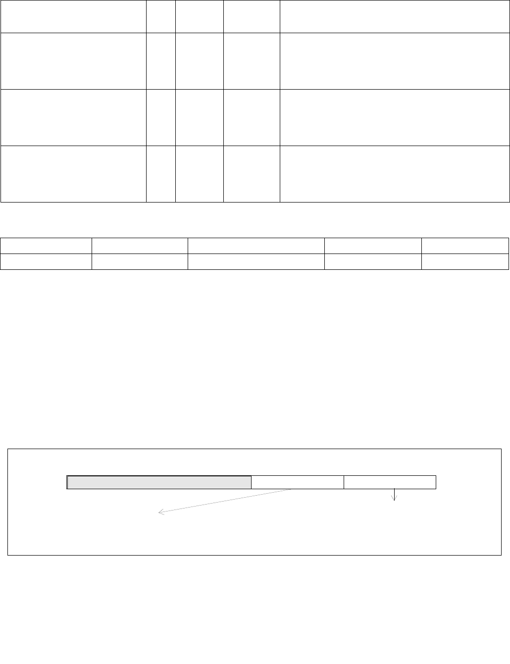
VRANGEPD—Range Restriction Calculation For Packed Pairs of Float64 Values
INSTRUCTION SET REFERENCE, V-Z
5-470 Vol. 2C
VRANGEPD—Range Restriction Calculation For Packed Pairs of Float64 Values
Instruction Operand Encoding
Description
This instruction calculates 2/4/8 range operation outputs from two sets of packed input double-precision FP values
in the first source operand (the second operand) and the second source operand (the third operand). The range
outputs are written to the destination operand (the first operand) under the writemask k1.
Bits7:4 of imm8 byte must be zero. The range operation output is performed in two parts, each configured by a
two-bit control field within imm8[3:0]:
•Imm8[1:0] specifies the initial comparison operation to be one of max, min, max absolute value or min
absolute value of the input value pair. Each comparison of two input values produces an intermediate result that
combines with the sign selection control (Imm8[3:2]) to determine the final range operation output.
•Imm8[3:2] specifies the sign of the range operation output to be one of the following: from the first input
value, from the comparison result, set or clear.
The encodings of Imm8[1:0] and Imm8[3:2] are shown in Figure 5-27.
Opcode/
Instruction
Op /
En
64/32
bit Mode
Support
CPUID
Feature
Flag
Description
EVEX.NDS.128.66.0F3A.W1 50 /r ib
VRANGEPD xmm1 {k1}{z}, xmm2,
xmm3/m128/m64bcst, imm8
FV V/V AVX512VL
AVX512DQ
Calculate two RANGE operation output value from 2 pairs
of double-precision floating-point values in xmm2 and
xmm3/m128/m32bcst, store the results to xmm1 under
the writemask k1. Imm8 specifies the comparison and sign
of the range operation.
EVEX.NDS.256.66.0F3A.W1 50 /r ib
VRANGEPD ymm1 {k1}{z}, ymm2,
ymm3/m256/m64bcst, imm8
FV V/V AVX512VL
AVX512DQ
Calculate four RANGE operation output value from 4pairs
of double-precision floating-point values in ymm2 and
ymm3/m256/m32bcst, store the results to ymm1 under
the writemask k1. Imm8 specifies the comparison and sign
of the range operation.
EVEX.NDS.512.66.0F3A.W1 50 /r ib
VRANGEPD zmm1 {k1}{z}, zmm2,
zmm3/m512/m64bcst{sae}, imm8
FV V/V AVX512DQ Calculate eight RANGE operation output value from 8
pairs of double-precision floating-point values in zmm2
and zmm3/m512/m32bcst, store the results to zmm1
under the writemask k1. Imm8 specifies the comparison
and sign of the range operation.
Op/En Operand 1 Operand 2 Operand 3 Operand 4
FV ModRM:reg (w) EVEX.vvvv (r) ModRM:r/m (r) Imm8
Figure 5-27. Imm8 Controls for VRANGEPD/SD/PS/SS
7 02465 3 1
Compare Operation SelectMust Be Zero
Imm8[3:2] = 00b : Select sign(SRC1)
Sign Control (SC)
Imm8[3:2] = 01b : Select sign(Compare_Result)
Imm8[3:2] = 10b : Set sign to 0
Imm8[1:0] = 00b : Select Min value
Imm8[1:0] = 01b : Select Max value
Imm8[1:0] = 10b : Select Min-Abs value
Imm8[1:0] = 11b : Select Max-Abs value
imm8
Imm8[3:2] = 11b : Set sign to 1

VRANGEPD—Range Restriction Calculation For Packed Pairs of Float64 Values
INSTRUCTION SET REFERENCE, V-Z
Vol. 2C 5-471
When one or more of the input value is a NAN, the comparison operation may signal invalid exception (IE). Details
with one of more input value is NAN is listed in Table 5-12. If the comparison raises an IE, the sign select control
(Imm8[3:2] has no effect to the range operation output, this is indicated also in Table 5-12.
When both input values are zeros of opposite signs, the comparison operation of MIN/MAX in the range compare
operation is slightly different from the conceptually similar FP MIN/MAX operation that are found in the instructions
VMAXPD/VMINPD. The details of MIN/MAX/MIN_ABS/MAX_ABS operation for VRANGEPD/PS/SD/SS for magni-
tude-0, opposite-signed input cases are listed in Table 5-13.
Additionally, non-zero, equal-magnitude with opposite-sign input values perform MIN_ABS or MAX_ABS compar-
ison operation with result listed in Table 5-14.
Table 5-12. Signaling of Comparison Operation of One or More NaN Input Values and Effect of Imm8[3:2]
Src1 Src2 Result IE Signaling Due to Comparison Imm8[3:2] Effect to Range Output
sNaN1 sNaN2 Quiet(sNaN1) Yes Ignored
sNaN1 qNaN2 Quiet(sNaN1) Yes Ignored
sNaN1 Norm2 Quiet(sNaN1) Yes Ignored
qNaN1 sNaN2 Quiet(sNaN2) Yes Ignored
qNaN1 qNaN2 qNaN1 No Applicable
qNaN1 Norm2 Norm2 No Applicable
Norm1 sNaN2 Quiet(sNaN2) Yes Ignored
Norm1 qNaN2 Norm1 No Applicable
Table 5-13. Comparison Result for Opposite-Signed Zero Cases for MIN, MIN_ABS and MAX, MAX_ABS
MIN and MIN_ABS MAX and MAX_ABS
Src1 Src2 Result Src1 Src2 Result
+0 -0 -0 +0 -0 +0
-0 +0 -0 -0 +0 +0
Table 5-14. Comparison Result of Equal-Magnitude Input Cases for MIN_ABS and MAX_ABS, (|a| = |b|, a>0, b<0)
MIN_ABS (|a| = |b|, a>0, b<0) MAX_ABS (|a| = |b|, a>0, b<0)
Src1 Src2 Result Src1 Src2 Result
ab b ab a
ba b ba a

VRANGEPD—Range Restriction Calculation For Packed Pairs of Float64 Values
INSTRUCTION SET REFERENCE, V-Z
5-472 Vol. 2C
Operation
RangeDP(SRC1[63:0], SRC2[63:0], CmpOpCtl[1:0], SignSelCtl[1:0])
{
// Check if SNAN and report IE, see also Table 5-12
IF (SRC1 = SNAN) THEN RETURN (QNAN(SRC1), set IE);
IF (SRC2 = SNAN) THEN RETURN (QNAN(SRC2), set IE);
Src1.exp SRC1[62:52];
Src1.fraction SRC1[51:0];
IF ((Src1.exp = 0 ) and (Src1.fraction != 0)) THEN// Src1 is a denormal number
IF DAZ THEN Src1.fraction 0;
ELSE IF (SRC2 <> QNAN) Set DE; FI;
FI;
Src2.exp SRC2[62:52];
Src2.fraction SRC2[51:0];
IF ((Src2.exp = 0) and (Src2.fraction !=0 )) THEN// Src2 is a denormal number
IF DAZ THEN Src2.fraction 0;
ELSE IF (SRC1 <> QNAN) Set DE; FI;
FI;
IF (SRC2 = QNAN) THEN{TMP[63:0] SRC1[63:0]}
ELSE IF(SRC1 = QNAN) THEN{TMP[63:0] SRC2[63:0]}
ELSE IF (Both SRC1, SRC2 are magnitude-0 and opposite-signed) TMP[63:0] from Table 5-13
ELSE IF (Both SRC1, SRC2 are magnitude-equal and opposite-signed and CmpOpCtl[1:0] > 01) TMP[63:0] from Table 5-14
ELSE
Case(CmpOpCtl[1:0])
00: TMP[63:0] (SRC1[63:0] ≤ SRC2[63:0]) ? SRC1[63:0] : SRC2[63:0];
01: TMP[63:0] (SRC1[63:0] ≤ SRC2[63:0]) ? SRC2[63:0] : SRC1[63:0];
10: TMP[63:0] (ABS(SRC1[63:0]) ≤ ABS(SRC2[63:0])) ? SRC1[63:0] : SRC2[63:0];
11: TMP[63:0] (ABS(SRC1[63:0]) ≤ ABS(SRC2[63:0])) ? SRC2[63:0] : SRC1[63:0];
ESAC;
FI;
Case(SignSelCtl[1:0])
00: dest (SRC1[63] << 63) OR (TMP[62:0]);// Preserve Src1 sign bit
01: dest TMP[63:0];// Preserve sign of compare result
10: dest (0 << 63) OR (TMP[62:0]);// Zero out sign bit
11: dest (1 << 63) OR (TMP[62:0]);// Set the sign bit
ESAC;
RETURN dest[63:0];
}
CmpOpCtl[1:0]= imm8[1:0];
SignSelCtl[1:0]=imm8[3:2];

VRANGEPD—Range Restriction Calculation For Packed Pairs of Float64 Values
INSTRUCTION SET REFERENCE, V-Z
Vol. 2C 5-473
VRANGEPD (EVEX encoded versions)
(KL, VL) = (2, 128), (4, 256), (8, 512)
FOR j 0 TO KL-1
i j * 64
IF k1[j] OR *no writemask* THEN
IF (EVEX.b == 1) AND (SRC2 *is memory*)
THEN DEST[i+63:i] RangeDP (SRC1[i+63:i], SRC2[63:0], CmpOpCtl[1:0], SignSelCtl[1:0]);
ELSE DEST[i+63:i] RangeDP (SRC1[i+63:i], SRC2[i+63:i], DAZ, CmpOpCtl[1:0], SignSelCtl[1:0]);
FI;
ELSE
IF *merging-masking* ; merging-masking
THEN *DEST[i+63:i] remains unchanged*
ELSE ; zeroing-masking
DEST[i+63:i] = 0
FI;
FI;
ENDFOR;
DEST[MAX_VL-1:VL] 0
The following example describes a common usage of this instruction for checking that the input operand is
bounded between ±1023.
VRANGEPD zmm_dst, zmm_src, zmm_1023, 02h;
Where:
zmm_dst is the destination operand.
zmm_src is the input operand to compare against ±1023 (this is SRC1).
zmm_1023 is the reference operand, contains the value of 1023 (and this is SRC2).
IMM=02(imm8[1:0]='10) selects the Min Absolute value operation with selection of SRC1.sign.
In case |zmm_src| < 1023 (i.e. SRC1 is smaller than 1023 in magnitude), then its value will be written into
zmm_dst. Otherwise, the value stored in zmm_dst will get the value of 1023 (received on zmm_1023, which is
SRC2).
However, the sign control (imm8[3:2]='00) instructs to select the sign of SRC1 received from zmm_src. So, even
in the case of |zmm_src| ≥ 1023, the selected sign of SRC1 is kept.
Thus, if zmm_src < -1023, the result of VRANGEPD will be the minimal value of -1023 while if zmm_src > +1023,
the result of VRANGE will be the maximal value of +1023.

VRANGEPD—Range Restriction Calculation For Packed Pairs of Float64 Values
INSTRUCTION SET REFERENCE, V-Z
5-474 Vol. 2C
Intel C/C++ Compiler Intrinsic Equivalent
VRANGEPD __m512d _mm512_range_pd ( __m512d a, __m512d b, int imm);
VRANGEPD __m512d _mm512_range_round_pd ( __m512d a, __m512d b, int imm, int sae);
VRANGEPD __m512d _mm512_mask_range_pd (__m512 ds, __mmask8 k, __m512d a, __m512d b, int imm);
VRANGEPD __m512d _mm512_mask_range_round_pd (__m512d s, __mmask8 k, __m512d a, __m512d b, int imm, int sae);
VRANGEPD __m512d _mm512_maskz_range_pd ( __mmask8 k, __m512d a, __m512d b, int imm);
VRANGEPD __m512d _mm512_maskz_range_round_pd ( __mmask8 k, __m512d a, __m512d b, int imm, int sae);
VRANGEPD __m256d _mm256_range_pd ( __m256d a, __m256d b, int imm);
VRANGEPD __m256d _mm256_mask_range_pd (__m256d s, __mmask8 k, __m256d a, __m256d b, int imm);
VRANGEPD __m256d _mm256_maskz_range_pd ( __mmask8 k, __m256d a, __m256d b, int imm);
VRANGEPD __m128d _mm_range_pd ( __m128 a, __m128d b, int imm);
VRANGEPD __m128d _mm_mask_range_pd (__m128 s, __mmask8 k, __m128d a, __m128d b, int imm);
VRANGEPD __m128d _mm_maskz_range_pd ( __mmask8 k, __m128d a, __m128d b, int imm);
SIMD Floating-Point Exceptions
Invalid, Denormal
Other Exceptions
See Exceptions Type E2.

VRANGEPS—Range Restriction Calculation For Packed Pairs of Float32 Values
INSTRUCTION SET REFERENCE, V-Z
Vol. 2C 5-475
VRANGEPS—Range Restriction Calculation For Packed Pairs of Float32 Values
Instruction Operand Encoding
Description
This instruction calculates 4/8/16 range operation outputs from two sets of packed input single-precision FP values
in the first source operand (the second operand) and the second source operand (the third operand). The range
outputs are written to the destination operand (the first operand) under the writemask k1.
Bits7:4 of imm8 byte must be zero. The range operation output is performed in two parts, each configured by a
two-bit control field within imm8[3:0]:
•Imm8[1:0] specifies the initial comparison operation to be one of max, min, max absolute value or min
absolute value of the input value pair. Each comparison of two input values produces an intermediate result
that combines with the sign selection control (Imm8[3:2]) to determine the final range operation output.
•Imm8[3:2] specifies the sign of the range operation output to be one of the following: from the first input
value, from the comparison result, set or clear.
The encodings of Imm8[1:0] and Imm8[3:2] are shown in Figure 5-27.
When one or more of the input value is a NAN, the comparison operation may signal invalid exception (IE). Details
with one of more input value is NAN is listed in Table 5-12. If the comparison raises an IE, the sign select control
(Imm8[3:2]) has no effect to the range operation output, this is indicated also in Table 5-12.
When both input values are zeros of opposite signs, the comparison operation of MIN/MAX in the range compare
operation is slightly different from the conceptually similar FP MIN/MAX operation that are found in the instructions
VMAXPD/VMINPD. The details of MIN/MAX/MIN_ABS/MAX_ABS operation for VRANGEPD/PS/SD/SS for magni-
tude-0, opposite-signed input cases are listed in Table 5-13.
Additionally, non-zero, equal-magnitude with opposite-sign input values perform MIN_ABS or MAX_ABS compar-
ison operation with result listed in Table 5-14.
Opcode/
Instruction
Op /
En
64/32
bit Mode
Support
CPUID
Feature
Flag
Description
EVEX.NDS.128.66.0F3A.W0 50 /r ib
VRANGEPS xmm1 {k1}{z}, xmm2,
xmm3/m128/m32bcst, imm8
FV V/V AVX512VL
AVX512DQ
Calculate four RANGE operation output value from 4 pairs
of single-precision floating-point values in xmm2 and
xmm3/m128/m32bcst, store the results to xmm1 under
the writemask k1. Imm8 specifies the comparison and sign
of the range operation.
EVEX.NDS.256.66.0F3A.W0 50 /r ib
VRANGEPS ymm1 {k1}{z}, ymm2,
ymm3/m256/m32bcst, imm8
FV V/V AVX512VL
AVX512DQ
Calculate eight RANGE operation output value from 8 pairs
of single-precision floating-point values in ymm2 and
ymm3/m256/m32bcst, store the results to ymm1 under
the writemask k1. Imm8 specifies the comparison and sign
of the range operation.
EVEX.NDS.512.66.0F3A.W0 50 /r ib
VRANGEPS zmm1 {k1}{z}, zmm2,
zmm3/m512/m32bcst{sae}, imm8
FV V/V AVX512DQ Calculate 16 RANGE operation output value from 16 pairs
of single-precision floating-point values in zmm2 and
zmm3/m512/m32bcst, store the results to zmm1 under
the writemask k1. Imm8 specifies the comparison and sign
of the range operation.
Op/En Operand 1 Operand 2 Operand 3 Operand 4
FV ModRM:reg (w) EVEX.vvvv (r) ModRM:r/m (r) Imm8

VRANGEPS—Range Restriction Calculation For Packed Pairs of Float32 Values
INSTRUCTION SET REFERENCE, V-Z
5-476 Vol. 2C
Operation
RangeSP(SRC1[31:0], SRC2[31:0], CmpOpCtl[1:0], SignSelCtl[1:0])
{
// Check if SNAN and report IE, see also Table 5-12
IF (SRC1=SNAN) THEN RETURN (QNAN(SRC1), set IE);
IF (SRC2=SNAN) THEN RETURN (QNAN(SRC2), set IE);
Src1.exp SRC1[30:23];
Src1.fraction SRC1[22:0];
IF ((Src1.exp = 0 ) and (Src1.fraction != 0 )) THEN// Src1 is a denormal number
IF DAZ THEN Src1.fraction 0;
ELSE IF (SRC2 <> QNAN) Set DE; FI;
FI;
Src2.exp SRC2[30:23];
Src2.fraction SRC2[22:0];
IF ((Src2.exp = 0 ) and (Src2.fraction != 0 )) THEN// Src2 is a denormal number
IF DAZ THEN Src2.fraction 0;
ELSE IF (SRC1 <> QNAN) Set DE; FI;
FI;
IF (SRC2 = QNAN) THEN{TMP[31:0] SRC1[31:0]}
ELSE IF(SRC1 = QNAN) THEN{TMP[31:0] SRC2[31:0]}
ELSE IF (Both SRC1, SRC2 are magnitude-0 and opposite-signed) TMP[31:0] from Table 5-13
ELSE IF (Both SRC1, SRC2 are magnitude-equal and opposite-signed and CmpOpCtl[1:0] > 01) TMP[31:0] from Table 5-14
ELSE
Case(CmpOpCtl[1:0])
00: TMP[31:0] (SRC1[31:0] ≤ SRC2[31:0]) ? SRC1[31:0] : SRC2[31:0];
01: TMP[31:0] (SRC1[31:0] ≤ SRC2[31:0]) ? SRC2[31:0] : SRC1[31:0];
10: TMP[31:0] (ABS(SRC1[31:0]) ≤ ABS(SRC2[31:0])) ? SRC1[31:0] : SRC2[31:0];
11: TMP[31:0] (ABS(SRC1[31:0]) ≤ ABS(SRC2[31:0])) ? SRC2[31:0] : SRC1[31:0];
ESAC;
FI;
Case(SignSelCtl[1:0])
00: dest (SRC1[31] << 31) OR (TMP[30:0]);// Preserve Src1 sign bit
01: dest TMP[31:0];// Preserve sign of compare result
10: dest (0 << 31) OR (TMP[30:0]);// Zero out sign bit
11: dest (1 << 31) OR (TMP[30:0]);// Set the sign bit
ESAC;
RETURN dest[31:0];
}
CmpOpCtl[1:0]= imm8[1:0];
SignSelCtl[1:0]=imm8[3:2];

VRANGEPS—Range Restriction Calculation For Packed Pairs of Float32 Values
INSTRUCTION SET REFERENCE, V-Z
Vol. 2C 5-477
VRANGEPS
(KL, VL) = (4, 128), (8, 256), (16, 512)
FOR j 0 TO KL-1
i j * 32
IF k1[j] OR *no writemask* THEN
IF (EVEX.b == 1) AND (SRC2 *is memory*)
THEN DEST[i+31:i] RangeSP (SRC1[i+31:i], SRC2[31:0], CmpOpCtl[1:0], SignSelCtl[1:0]);
ELSE DEST[i+31:i] RangeSP (SRC1[i+31:i], SRC2[i+31:i], DAZ, CmpOpCtl[1:0], SignSelCtl[1:0]);
FI;
ELSE
IF *merging-masking* ; merging-masking
THEN *DEST[i+31:i] remains unchanged*
ELSE ; zeroing-masking
DEST[i+31:i] = 0
FI;
FI;
ENDFOR;
DEST[MAX_VL-1:VL] 0
The following example describes a common usage of this instruction for checking that the input operand is
bounded between ±150.
VRANGEPS zmm_dst, zmm_src, zmm_150, 02h;
Where:
zmm_dst is the destination operand.
zmm_src is the input operand to compare against ±150.
zmm_150 is the reference operand, contains the value of 150.
IMM=02(imm8[1:0]=’10) selects the Min Absolute value operation with selection of src1.sign.
In case |zmm_src| < 150, then its value will be written into zmm_dst. Otherwise, the value stored in zmm_dst
will get the value of 150 (received on zmm_150).
However, the sign control (imm8[3:2]=’00) instructs to select the sign of SRC1 received from zmm_src. So, even
in the case of |zmm_src| ≥ 150, the selected sign of SRC1 is kept.
Thus, if zmm_src < -150, the result of VRANGEPS will be the minimal value of -150 while if zmm_src > +150,
the result of VRANGE will be the maximal value of +150.

VRANGEPS—Range Restriction Calculation For Packed Pairs of Float32 Values
INSTRUCTION SET REFERENCE, V-Z
5-478 Vol. 2C
Intel C/C++ Compiler Intrinsic Equivalent
VRANGEPS __m512 _mm512_range_ps ( __m512 a, __m512 b, int imm);
VRANGEPS __m512 _mm512_range_round_ps ( __m512 a, __m512 b, int imm, int sae);
VRANGEPS __m512 _mm512_mask_range_ps (__m512 s, __mmask16 k, __m512 a, __m512 b, int imm);
VRANGEPS __m512 _mm512_mask_range_round_ps (__m512 s, __mmask16 k, __m512 a, __m512 b, int imm, int sae);
VRANGEPS __m512 _mm512_maskz_range_ps ( __mmask16 k, __m512 a, __m512 b, int imm);
VRANGEPS __m512 _mm512_maskz_range_round_ps ( __mmask16 k, __m512 a, __m512 b, int imm, int sae);
VRANGEPS __m256 _mm256_range_ps ( __m256 a, __m256 b, int imm);
VRANGEPS __m256 _mm256_mask_range_ps (__m256 s, __mmask8 k, __m256 a, __m256 b, int imm);
VRANGEPS __m256 _mm256_maskz_range_ps ( __mmask8 k, __m256 a, __m256 b, int imm);
VRANGEPS __m128 _mm_range_ps ( __m128 a, __m128 b, int imm);
VRANGEPS __m128 _mm_mask_range_ps (__m128 s, __mmask8 k, __m128 a, __m128 b, int imm);
VRANGEPS __m128 _mm_maskz_range_ps ( __mmask8 k, __m128 a, __m128 b, int imm);
SIMD Floating-Point Exceptions
Invalid, Denormal
Other Exceptions
See Exceptions Type E2.

VRANGESD—Range Restriction Calculation From a pair of Scalar Float64 Values
INSTRUCTION SET REFERENCE, V-Z
Vol. 2C 5-479
VRANGESD—Range Restriction Calculation From a pair of Scalar Float64 Values
Instruction Operand Encoding
Description
This instruction calculates a range operation output from two input double-precision FP values in the low qword
element of the first source operand (the second operand) and second source operand (the third operand). The
range output is written to the low qword element of the destination operand (the first operand) under the
writemask k1.
Bits7:4 of imm8 byte must be zero. The range operation output is performed in two parts, each configured by a
two-bit control field within imm8[3:0]:
•Imm8[1:0] specifies the initial comparison operation to be one of max, min, max absolute value or min
absolute value of the input value pair. Each comparison of two input values produces an intermediate result
that combines with the sign selection control (Imm8[3:2]) to determine the final range operation output.
•Imm8[3:2] specifies the sign of the range operation output to be one of the following: from the first input
value, from the comparison result, set or clear.
The encodings of Imm8[1:0] and Imm8[3:2] are shown in Figure 5-27.
Bits 128:63 of the destination operand are copied from the respective element of the first source operand.
When one or more of the input value is a NAN, the comparison operation may signal invalid exception (IE). Details
with one of more input value is NAN is listed in Table 5-12. If the comparison raises an IE, the sign select control
(Imm8[3:2] has no effect to the range operation output, this is indicated also in Table 5-12.
When both input values are zeros of opposite signs, the comparison operation of MIN/MAX in the range compare
operation is slightly different from the conceptually similar FP MIN/MAX operation that are found in the instructions
VMAXPD/VMINPD. The details of MIN/MAX/MIN_ABS/MAX_ABS operation for VRANGEPD/PS/SD/SS for magni-
tude-0, opposite-signed input cases are listed in Table 5-13.
Additionally, non-zero, equal-magnitude with opposite-sign input values perform MIN_ABS or MAX_ABS compar-
ison operation with result listed in Table 5-14.
Opcode/
Instruction
Op /
En
64/32
bit Mode
Support
CPUID
Feature
Flag
Description
EVEX.NDS.LIG.66.0F3A.W1 51 /r
VRANGESD xmm1 {k1}{z},
xmm2, xmm3/m64{sae}, imm8
T1S V/V AVX512DQ Calculate a RANGE operation output value from 2 double-
precision floating-point values in xmm2 and xmm3/m64,
store the output to xmm1 under writemask. Imm8 specifies
the comparison and sign of the range operation.
Op/En Operand 1 Operand 2 Operand 3 Operand 4
T1S ModRM:reg (w) EVEX.vvvv (r) ModRM:r/m (r) Imm8

VRANGESD—Range Restriction Calculation From a pair of Scalar Float64 Values
INSTRUCTION SET REFERENCE, V-Z
5-480 Vol. 2C
Operation
RangeDP(SRC1[63:0], SRC2[63:0], CmpOpCtl[1:0], SignSelCtl[1:0])
{
// Check if SNAN and report IE, see also Table 5-12
IF (SRC1 = SNAN) THEN RETURN (QNAN(SRC1), set IE);
IF (SRC2 = SNAN) THEN RETURN (QNAN(SRC2), set IE);
Src1.exp SRC1[62:52];
Src1.fraction SRC1[51:0];
IF ((Src1.exp = 0 ) and (Src1.fraction != 0)) THEN// Src1 is a denormal number
IF DAZ THEN Src1.fraction 0;
ELSE IF (SRC2 <> QNAN) Set DE; FI;
FI;
Src2.exp SRC2[62:52];
Src2.fraction SRC2[51:0];
IF ((Src2.exp = 0) and (Src2.fraction !=0 )) THEN// Src2 is a denormal number
IF DAZ THEN Src2.fraction 0;
ELSE IF (SRC1 <> QNAN) Set DE; FI;
FI;
IF (SRC2 = QNAN) THEN{TMP[63:0] SRC1[63:0]}
ELSE IF(SRC1 = QNAN) THEN{TMP[63:0] SRC2[63:0]}
ELSE IF (Both SRC1, SRC2 are magnitude-0 and opposite-signed) TMP[63:0] from Table 5-13
ELSE IF (Both SRC1, SRC2 are magnitude-equal and opposite-signed and CmpOpCtl[1:0] > 01) TMP[63:0] from Table 5-14
ELSE
Case(CmpOpCtl[1:0])
00: TMP[63:0] (SRC1[63:0] ≤ SRC2[63:0]) ? SRC1[63:0] : SRC2[63:0];
01: TMP[63:0] (SRC1[63:0] ≤ SRC2[63:0]) ? SRC2[63:0] : SRC1[63:0];
10: TMP[63:0] (ABS(SRC1[63:0]) ≤ ABS(SRC2[63:0])) ? SRC1[63:0] : SRC2[63:0];
11: TMP[63:0] (ABS(SRC1[63:0]) ≤ ABS(SRC2[63:0])) ? SRC2[63:0] : SRC1[63:0];
ESAC;
FI;
Case(SignSelCtl[1:0])
00: dest (SRC1[63] << 63) OR (TMP[62:0]);// Preserve Src1 sign bit
01: dest TMP[63:0];// Preserve sign of compare result
10: dest (0 << 63) OR (TMP[62:0]);// Zero out sign bit
11: dest (1 << 63) OR (TMP[62:0]);// Set the sign bit
ESAC;
RETURN dest[63:0];
}
CmpOpCtl[1:0]= imm8[1:0];
SignSelCtl[1:0]=imm8[3:2];

VRANGESD—Range Restriction Calculation From a pair of Scalar Float64 Values
INSTRUCTION SET REFERENCE, V-Z
Vol. 2C 5-481
VRANGESD
IF k1[0] OR *no writemask*
THEN DEST[63:0] RangeDP (SRC1[63:0], SRC2[63:0], CmpOpCtl[1:0], SignSelCtl[1:0]);
ELSE
IF *merging-masking* ; merging-masking
THEN *DEST[63:0] remains unchanged*
ELSE ; zeroing-masking
DEST[63:0] = 0
FI;
FI;
DEST[127:64] SRC1[127:64]
DEST[MAX_VL-1:128] 0
The following example describes a common usage of this instruction for checking that the input operand is
bounded between ±1023.
VRANGESD xmm_dst, xmm_src, xmm_1023, 02h;
Where:
xmm_dst is the destination operand.
xmm_src is the input operand to compare against ±1023.
xmm_1023 is the reference operand, contains the value of 1023.
IMM=02(imm8[1:0]=’10) selects the Min Absolute value operation with selection of src1.sign.
In case |xmm_src| < 1023, then its value will be written into xmm_dst. Otherwise, the value stored in xmm_dst
will get the value of 1023 (received on xmm_1023).
However, the sign control (imm8[3:2]=’00) instructs to select the sign of SRC1 received from xmm_src. So, even
in the case of |xmm_src| ≥ 1023, the selected sign of SRC1 is kept.
Thus, if xmm_src < -1023, the result of VRANGEPD will be the minimal value of -1023while if xmm_src > +1023,
the result of VRANGE will be the maximal value of +1023.
Intel C/C++ Compiler Intrinsic Equivalent
VRANGESD __m128d _mm_range_sd ( __m128d a, __m128d b, int imm);
VRANGESD __m128d _mm_range_round_sd ( __m128d a, __m128d b, int imm, int sae);
VRANGESD __m128d _mm_mask_range_sd (__m128d s, __mmask8 k, __m128d a, __m128d b, int imm);
VRANGESD __m128d _mm_mask_range_round_sd (__m128d s, __mmask8 k, __m128d a, __m128d b, int imm, int sae);
VRANGESD __m128d _mm_maskz_range_sd ( __mmask8 k, __m128d a, __m128d b, int imm);
VRANGESD __m128d _mm_maskz_range_round_sd ( __mmask8 k, __m128d a, __m128d b, int imm, int sae);
SIMD Floating-Point Exceptions
Invalid, Denormal
Other Exceptions
See Exceptions Type E3.

VRANGESS—Range Restriction Calculation From a Pair of Scalar Float32 Values
INSTRUCTION SET REFERENCE, V-Z
5-482 Vol. 2C
VRANGESS—Range Restriction Calculation From a Pair of Scalar Float32 Values
Instruction Operand Encoding
Description
This instruction calculates a range operation output from two input single-precision FP values in the low dword
element of the first source operand (the second operand) and second source operand (the third operand). The
range output is written to the low dword element of the destination operand (the first operand) under the
writemask k1.
Bits7:4 of imm8 byte must be zero. The range operation output is performed in two parts, each configured by a
two-bit control field within imm8[3:0]:
•Imm8[1:0] specifies the initial comparison operation to be one of max, min, max absolute value or min
absolute value of the input value pair. Each comparison of two input values produces an intermediate result that
combines with the sign selection control (Imm8[3:2]) to determine the final range operation output.
•Imm8[3:2] specifies the sign of the range operation output to be one of the following: from the first input
value, from the comparison result, set or clear.
The encodings of Imm8[1:0] and Imm8[3:2] are shown in Figure 5-27.
Bits 128:31 of the destination operand are copied from the respective elements of the first source operand.
When one or more of the input value is a NAN, the comparison operation may signal invalid exception (IE). Details
with one of more input value is NAN is listed in Table 5-12. If the comparison raises an IE, the sign select control
(Imm8[3:2]) has no effect to the range operation output, this is indicated also in Table 5-12.
When both input values are zeros of opposite signs, the comparison operation of MIN/MAX in the range compare
operation is slightly different from the conceptually similar FP MIN/MAX operation that are found in the instructions
VMAXPD/VMINPD. The details of MIN/MAX/MIN_ABS/MAX_ABS operation for VRANGEPD/PS/SD/SS for magni-
tude-0, opposite-signed input cases are listed in Table 5-13.
Additionally, non-zero, equal-magnitude with opposite-sign input values perform MIN_ABS or MAX_ABS compar-
ison operation with result listed in Table 5-14.
Opcode/
Instruction
Op /
En
64/32
bit Mode
Support
CPUID
Feature
Flag
Description
EVEX.NDS.LIG.66.0F3A.W0 51 /r
VRANGESS xmm1 {k1}{z},
xmm2, xmm3/m32{sae}, imm8
T1S V/V AVX512DQ Calculate a RANGE operation output value from 2 single-
precision floating-point values in xmm2 and xmm3/m32,
store the output to xmm1 under writemask. Imm8 specifies
the comparison and sign of the range operation.
Op/En Operand 1 Operand 2 Operand 3 Operand 4
T1S ModRM:reg (w) EVEX.vvvv (r) ModRM:r/m (r) NA

VRANGESS—Range Restriction Calculation From a Pair of Scalar Float32 Values
INSTRUCTION SET REFERENCE, V-Z
Vol. 2C 5-483
Operation
RangeSP(SRC1[31:0], SRC2[31:0], CmpOpCtl[1:0], SignSelCtl[1:0])
{
// Check if SNAN and report IE, see also Table 5-12
IF (SRC1=SNAN) THEN RETURN (QNAN(SRC1), set IE);
IF (SRC2=SNAN) THEN RETURN (QNAN(SRC2), set IE);
Src1.exp SRC1[30:23];
Src1.fraction SRC1[22:0];
IF ((Src1.exp = 0 ) and (Src1.fraction != 0 )) THEN// Src1 is a denormal number
IF DAZ THEN Src1.fraction 0;
ELSE IF (SRC2 <> QNAN) Set DE; FI;
FI;
Src2.exp SRC2[30:23];
Src2.fraction SRC2[22:0];
IF ((Src2.exp = 0 ) and (Src2.fraction != 0 )) THEN// Src2 is a denormal number
IF DAZ THEN Src2.fraction 0;
ELSE IF (SRC1 <> QNAN) Set DE; FI;
FI;
IF (SRC2 = QNAN) THEN{TMP[31:0] SRC1[31:0]}
ELSE IF(SRC1 = QNAN) THEN{TMP[31:0] SRC2[31:0]}
ELSE IF (Both SRC1, SRC2 are magnitude-0 and opposite-signed) TMP[31:0] from Table 5-13
ELSE IF (Both SRC1, SRC2 are magnitude-equal and opposite-signed and CmpOpCtl[1:0] > 01) TMP[31:0] from Table 5-14
ELSE
Case(CmpOpCtl[1:0])
00: TMP[31:0] (SRC1[31:0] ≤ SRC2[31:0]) ? SRC1[31:0] : SRC2[31:0];
01: TMP[31:0] (SRC1[31:0] ≤ SRC2[31:0]) ? SRC2[31:0] : SRC1[31:0];
10: TMP[31:0] (ABS(SRC1[31:0]) ≤ ABS(SRC2[31:0])) ? SRC1[31:0] : SRC2[31:0];
11: TMP[31:0] (ABS(SRC1[31:0]) ≤ ABS(SRC2[31:0])) ? SRC2[31:0] : SRC1[31:0];
ESAC;
FI;
Case(SignSelCtl[1:0])
00: dest (SRC1[31] << 31) OR (TMP[30:0]);// Preserve Src1 sign bit
01: dest TMP[31:0];// Preserve sign of compare result
10: dest (0 << 31) OR (TMP[30:0]);// Zero out sign bit
11: dest (1 << 31) OR (TMP[30:0]);// Set the sign bit
ESAC;
RETURN dest[31:0];
}
CmpOpCtl[1:0]= imm8[1:0];
SignSelCtl[1:0]=imm8[3:2];

VRANGESS—Range Restriction Calculation From a Pair of Scalar Float32 Values
INSTRUCTION SET REFERENCE, V-Z
5-484 Vol. 2C
VRANGESS
IF k1[0] OR *no writemask*
THEN DEST[31:0] RangeSP (SRC1[31:0], SRC2[31:0], CmpOpCtl[1:0], SignSelCtl[1:0]);
ELSE
IF *merging-masking* ; merging-masking
THEN *DEST[31:0] remains unchanged*
ELSE ; zeroing-masking
DEST[31:0] = 0
FI;
FI;
DEST[127:32] SRC1[127:32]
DEST[MAX_VL-1:128] 0
The following example describes a common usage of this instruction for checking that the input operand is bound-
ed between ±150.
VRANGESS zmm_dst, zmm_src, zmm_150, 02h;
Where:
xmm_dst is the destination operand.
xmm_src is the input operand to compare against ±150.
xmm_150 is the reference operand, contains the value of 150.
IMM=02(imm8[1:0]=’10) selects the Min Absolute value operation with selection of src1.sign.
In case |xmm_src| < 150, then its value will be written into zmm_dst. Otherwise, the value stored in xmm_dst
will get the value of 150 (received on zmm_150).
However, the sign control (imm8[3:2]=’00) instructs to select the sign of SRC1 received from xmm_src. So, even
in the case of |xmm_src| ≥ 150, the selected sign of SRC1 is kept.
Thus, if xmm_src < -150, the result of VRANGESS will be the minimal value of -150 while if xmm_src > +150,
the result of VRANGE will be the maximal value of +150.
Intel C/C++ Compiler Intrinsic Equivalent
VRANGESS __m128 _mm_range_ss ( __m128 a, __m128 b, int imm);
VRANGESS __m128 _mm_range_round_ss ( __m128 a, __m128 b, int imm, int sae);
VRANGESS __m128 _mm_mask_range_ss (__m128 s, __mmask8 k, __m128 a, __m128 b, int imm);
VRANGESS __m128 _mm_mask_range_round_ss (__m128 s, __mmask8 k, __m128 a, __m128 b, int imm, int sae);
VRANGESS __m128 _mm_maskz_range_ss ( __mmask8 k, __m128 a, __m128 b, int imm);
VRANGESS __m128 _mm_maskz_range_round_ss ( __mmask8 k, __m128 a, __m128 b, int imm, int sae);
SIMD Floating-Point Exceptions
Invalid, Denormal
Other Exceptions
See Exceptions Type E3.

VRCP14PD—Compute Approximate Reciprocals of Packed Float64 Values
INSTRUCTION SET REFERENCE, V-Z
Vol. 2C 5-485
VRCP14PD—Compute Approximate Reciprocals of Packed Float64 Values
Instruction Operand Encoding
Description
This instruction performs a SIMD computation of the approximate reciprocals of eight/four/two packed double-
precision floating-point values in the source operand (the second operand) and stores the packed double-precision
floating-point results in the destination operand. The maximum relative error for this approximation is less than 2-
14.
The source operand can be a ZMM register, a 512-bit memory location, or a 512-bit vector broadcasted from a 64-
bit memory location. The destination operand is a ZMM register conditionally updated according to the writemask.
The VRCP14PD instruction is not affected by the rounding control bits in the MXCSR register. When a source value
is a 0.0, an ∞ with the sign of the source value is returned. A denormal source value will be treated as zero only in
case of DAZ bit set in MXCSR. Otherwise it is treated correctly (i.e. not as a 0.0). Underflow results are flushed to
zero only in case of FTZ bit set in MXCSR. Otherwise it will be treated correctly (i.e. correct underflow result is
written) with the sign of the operand. When a source value is a SNaN or QNaN, the SNaN is converted to a QNaN
or the source QNaN is returned.
EVEX.vvvv is reserved and must be 1111b otherwise instructions will #UD.
MXCSR exception flags are not affected by this instruction and floating-point exceptions are not reported.
* in this case the mantissa is shifted right by one or two bits
A numerically exact implementation of VRCP14xx can be found at https://software.intel.com/en-us/articles/refer-
ence-implementations-for-IA-approximation-instructions-vrcp14-vrsqrt14-vrcp28-vrsqrt28-vexp2.
Opcode/
Instruction
Op /
En
64/32
bit Mode
Support
CPUID
Feature
Flag
Description
EVEX.128.66.0F38.W1 4C /r
VRCP14PD xmm1 {k1}{z},
xmm2/m128/m64bcst
FV V/V AVX512VL
AVX512F
Computes the approximate reciprocals of the packed double-
precision floating-point values in xmm2/m128/m64bcst and
stores the results in xmm1. Under writemask.
EVEX.256.66.0F38.W1 4C /r
VRCP14PD ymm1 {k1}{z},
ymm2/m256/m64bcst
FV V/V AVX512VL
AVX512F
Computes the approximate reciprocals of the packed double-
precision floating-point values in ymm2/m256/m64bcst and
stores the results in ymm1. Under writemask.
EVEX.512.66.0F38.W1 4C /r
VRCP14PD zmm1 {k1}{z},
zmm2/m512/m64bcst
FV V/V AVX512F Computes the approximate reciprocals of the packed double-
precision floating-point values in zmm2/m512/m64bcst and
stores the results in zmm1. Under writemask.
Op/En Operand 1 Operand 2 Operand 3 Operand 4
FV ModRM:reg (w) ModRM:r/m (r) NA NA
Table 5-15. VRCP14PD/VRCP14SD Special Cases
Input value Result value Comments
0 ≤ X ≤ 2-1024 INF Very small denormal
-2-1024 ≤ X ≤ -0 -INF Very small denormal
X > 21022 Underflow Up to 18 bits of fractions are returned*
X < -21022 -Underflow Up to 18 bits of fractions are returned*
X = 2-n 2n
X = -2-n -2n

VRCP14PD—Compute Approximate Reciprocals of Packed Float64 Values
INSTRUCTION SET REFERENCE, V-Z
5-486 Vol. 2C
Operation
VRCP14PD ((EVEX encoded versions)
(KL, VL) = (2, 128), (4, 256), (8, 512)
FOR j 0 TO KL-1
i j * 64
IF k1[j] OR *no writemask* THEN
IF (EVEX.b = 1) AND (SRC *is memory*)
THEN DEST[i+63:i] APPROXIMATE(1.0/SRC[63:0]);
ELSE DEST[i+63:i] APPROXIMATE(1.0/SRC[i+63:i]);
FI;
ELSE
IF *merging-masking* ; merging-masking
THEN *DEST[i+63:i] remains unchanged*
ELSE ; zeroing-masking
DEST[i+63:i] 0
FI;
FI;
ENDFOR;
DEST[MAX_VL-1:VL] 0
Intel C/C++ Compiler Intrinsic Equivalent
VRCP14PD __m512d _mm512_rcp14_pd( __m512d a);
VRCP14PD __m512d _mm512_mask_rcp14_pd(__m512d s, __mmask8 k, __m512d a);
VRCP14PD __m512d _mm512_maskz_rcp14_pd( __mmask8 k, __m512d a);
SIMD Floating-Point Exceptions
None
Other Exceptions
See Exceptions Type E4.

VRCP14SD—Compute Approximate Reciprocal of Scalar Float64 Value
INSTRUCTION SET REFERENCE, V-Z
Vol. 2C 5-487
VRCP14SD—Compute Approximate Reciprocal of Scalar Float64 Value
Instruction Operand Encoding
Description
This instruction performs a SIMD computation of the approximate reciprocal of the low double-precision floating-
point value in the second source operand (the third operand) stores the result in the low quadword element of the
destination operand (the first operand) according to the writemask k1. Bits (127:64) of the XMM register destina-
tion are copied from corresponding bits in the first source operand (the second operand). The maximum relative
error for this approximation is less than 2-14. The source operand can be an XMM register or a 64-bit memory loca-
tion. The destination operand is an XMM register.
The VRCP14SD instruction is not affected by the rounding control bits in the MXCSR register. When a source value
is a 0.0, an ∞ with the sign of the source value is returned. A denormal source value will be treated as zero only in
case of DAZ bit set in MXCSR. Otherwise it is treated correctly (i.e. not as a 0.0). Underflow results are flushed to
zero only in case of FTZ bit set in MXCSR. Otherwise it will be treated correctly (i.e. correct underflow result is
written) with the sign of the operand. When a source value is a SNaN or QNaN, the SNaN is converted to a QNaN
or the source QNaN is returned. See Table 5-15 for special-case input values.
MXCSR exception flags are not affected by this instruction and floating-point exceptions are not reported.
A numerically exact implementation of VRCP14xx can be found at https://software.intel.com/en-us/articles/refer-
ence-implementations-for-IA-approximation-instructions-vrcp14-vrsqrt14-vrcp28-vrsqrt28-vexp2.
Operation
VRCP14SD (EVEX version)
IF k1[0] OR *no writemask*
THEN DEST[63:0] APPROXIMATE(1.0/SRC2[63:0]);
ELSE
IF *merging-masking* ; merging-masking
THEN *DEST[63:0] remains unchanged*
ELSE ; zeroing-masking
DEST[63:0] 0
FI;
FI;
DEST[127:64] SRC1[127:64]
DEST[MAX_VL-1:128] 0
Opcode/
Instruction
Op
/ En
64/32
bit Mode
Support
CPUID
Feature
Flag
Description
EVEX.NDS.LIG.66.0F38.W1 4D /r
VRCP14SD xmm1 {k1}{z}, xmm2,
xmm3/m64
T1S V/V AVX512F Computes the approximate reciprocal of the scalar double-
precision floating-point value in xmm3/m64 and stores the
result in xmm1 using writemask k1. Also, upper double-precision
floating-point value (bits[127:64]) from xmm2 is copied to
xmm1[127:64].
Op/En Operand 1 Operand 2 Operand 3 Operand 4
T1S ModRM:reg (w) EVEX.vvvv (r) ModRM:r/m (r) NA

VRCP14SD—Compute Approximate Reciprocal of Scalar Float64 Value
INSTRUCTION SET REFERENCE, V-Z
5-488 Vol. 2C
Intel C/C++ Compiler Intrinsic Equivalent
VRCP14SD __m128d _mm_rcp14_sd( __m128d a, __m128d b);
VRCP14SD __m128d _mm_mask_rcp14_sd(__m128d s, __mmask8 k, __m128d a, __m128d b);
VRCP14SD __m128d _mm_maskz_rcp14_sd( __mmask8 k, __m128d a, __m128d b);
SIMD Floating-Point Exceptions
None
Other Exceptions
See Exceptions Type E5.

VRCP14PS—Compute Approximate Reciprocals of Packed Float32 Values
INSTRUCTION SET REFERENCE, V-Z
Vol. 2C 5-489
VRCP14PS—Compute Approximate Reciprocals of Packed Float32 Values
Instruction Operand Encoding
Description
This instruction performs a SIMD computation of the approximate reciprocals of the packed single-precision
floating-point values in the source operand (the second operand) and stores the packed single-precision floating-
point results in the destination operand (the first operand). The maximum relative error for this approximation is
less than 2-14.
The source operand can be a ZMM register, a 512-bit memory location or a 512-bit vector broadcasted from a 32-
bit memory location. The destination operand is a ZMM register conditionally updated according to the writemask.
The VRCP14PS instruction is not affected by the rounding control bits in the MXCSR register. When a source value
is a 0.0, an ∞ with the sign of the source value is returned. A denormal source value will be treated as zero only in
case of DAZ bit set in MXCSR. Otherwise it is treated correctly (i.e. not as a 0.0). Underflow results are flushed to
zero only in case of FTZ bit set in MXCSR. Otherwise it will be treated correctly (i.e. correct underflow result is
written) with the sign of the operand. When a source value is a SNaN or QNaN, the SNaN is converted to a QNaN
or the source QNaN is returned.
EVEX.vvvv is reserved and must be 1111b otherwise instructions will #UD.
MXCSR exception flags are not affected by this instruction and floating-point exceptions are not reported.
* in this case the mantissa is shifted right by one or two bits
A numerically exact implementation of VRCP14xx can be found at https://software.intel.com/en-us/articles/refer-
ence-implementations-for-IA-approximation-instructions-vrcp14-vrsqrt14-vrcp28-vrsqrt28-vexp2.
Opcode/
Instruction
Op /
En
64/32
bit Mode
Support
CPUID
Feature
Flag
Description
EVEX.128.66.0F38.W0 4C /r
VRCP14PS xmm1 {k1}{z},
xmm2/m128/m32bcst
FV V/V AVX512VL
AVX512F
Computes the approximate reciprocals of the packed single-
precision floating-point values in xmm2/m128/m32bcst and
stores the results in xmm1. Under writemask.
EVEX.256.66.0F38.W0 4C /r
VRCP14PS ymm1 {k1}{z},
ymm2/m256/m32bcst
FV V/V AVX512VL
AVX512F
Computes the approximate reciprocals of the packed single-
precision floating-point values in ymm2/m256/m32bcst and
stores the results in ymm1. Under writemask.
EVEX.512.66.0F38.W0 4C /r
VRCP14PS zmm1 {k1}{z},
zmm2/m512/m32bcst
FV V/V AVX512F Computes the approximate reciprocals of the packed single-
precision floating-point values in zmm2/m512/m32bcst and
stores the results in zmm1. Under writemask.
Op/En Operand 1 Operand 2 Operand 3 Operand 4
FV ModRM:reg (w) ModRM:r/m (r) NA NA
Table 5-16. VRCP14PS/VRCP14SS Special Cases
Input value Result value Comments
0 ≤ X ≤ 2-128 INF Very small denormal
-2-128 ≤ X ≤ -0 -INF Very small denormal
X > 2126 Underflow Up to 18 bits of fractions are returned*
X < -2126 -Underflow Up to 18 bits of fractions are returned*
X = 2-n 2n
X = -2-n -2n

VRCP14PS—Compute Approximate Reciprocals of Packed Float32 Values
INSTRUCTION SET REFERENCE, V-Z
5-490 Vol. 2C
Operation
VRCP14PS (EVEX encoded versions)
(KL, VL) = (4, 128), (8, 256), (16, 512)
FOR j 0 TO KL-1
i j * 32
IF k1[j] OR *no writemask* THEN
IF (EVEX.b = 1) AND (SRC *is memory*)
THEN DEST[i+31:i] APPROXIMATE(1.0/SRC[31:0]);
ELSE DEST[i+31:i] APPROXIMATE(1.0/SRC[i+31:i]);
FI;
ELSE
IF *merging-masking* ; merging-masking
THEN *DEST[i+31:i] remains unchanged*
ELSE ; zeroing-masking
DEST[i+31:i] 0
FI;
FI;
ENDFOR;
DEST[MAX_VL-1:VL] 0
Intel C/C++ Compiler Intrinsic Equivalent
VRCP14PS __m512 _mm512_rcp14_ps( __m512 a);
VRCP14PS __m512 _mm512_mask_rcp14_ps(__m512 s, __mmask16 k, __m512 a);
VRCP14PS __m512 _mm512_maskz_rcp14_ps( __mmask16 k, __m512 a);
VRCP14PS __m256 _mm256_rcp14_ps( __m256 a);
VRCP14PS __m256 _mm512_mask_rcp14_ps(__m256 s, __mmask8 k, __m256 a);
VRCP14PS __m256 _mm512_maskz_rcp14_ps( __mmask8 k, __m256 a);
VRCP14PS __m128 _mm_rcp14_ps( __m128 a);
VRCP14PS __m128 _mm_mask_rcp14_ps(__m128 s, __mmask8 k, __m128 a);
VRCP14PS __m128 _mm_maskz_rcp14_ps( __mmask8 k, __m128 a);
SIMD Floating-Point Exceptions
None
Other Exceptions
See Exceptions Type E4.

VRCP14SS—Compute Approximate Reciprocal of Scalar Float32 Value
INSTRUCTION SET REFERENCE, V-Z
Vol. 2C 5-491
VRCP14SS—Compute Approximate Reciprocal of Scalar Float32 Value
Instruction Operand Encoding
Description
This instruction performs a SIMD computation of the approximate reciprocal of the low single-precision floating-
point value in the second source operand (the third operand) and stores the result in the low quadword element of
the destination operand (the first operand) according to the writemask k1. Bits (127:32) of the XMM register desti-
nation are copied from corresponding bits in the first source operand (the second operand). The maximum relative
error for this approximation is less than 2-14. The source operand can be an XMM register or a 32-bit memory loca-
tion. The destination operand is an XMM register.
The VRCP14SS instruction is not affected by the rounding control bits in the MXCSR register. When a source value
is a 0.0, an ∞ with the sign of the source value is returned. A denormal source value will be treated as zero only in
case of DAZ bit set in MXCSR. Otherwise it is treated correctly (i.e. not as a 0.0). Underflow results are flushed to
zero only in case of FTZ bit set in MXCSR. Otherwise it will be treated correctly (i.e. correct underflow result is
written) with the sign of the operand. When a source value is a SNaN or QNaN, the SNaN is converted to a QNaN
or the source QNaN is returned. See Table 5-16 for special-case input values.
MXCSR exception flags are not affected by this instruction and floating-point exceptions are not reported.
A numerically exact implementation of VRCP14xx can be found at https://software.intel.com/en-us/articles/refer-
ence-implementations-for-IA-approximation-instructions-vrcp14-vrsqrt14-vrcp28-vrsqrt28-vexp2.
Operation
VRCP14SS (EVEX version)
IF k1[0] OR *no writemask*
THEN DEST[31:0] APPROXIMATE(1.0/SRC2[31:0]);
ELSE
IF *merging-masking* ; merging-masking
THEN *DEST[31:0] remains unchanged*
ELSE ; zeroing-masking
DEST[31:0] 0
FI;
FI;
DEST[127:32] SRC1[127:32]
DEST[MAX_VL-1:128] 0
Opcode/
Instruction
Op /
En
64/32
bit Mode
Support
CPUID
Feature
Flag
Description
EVEX.NDS.LIG.66.0F38.W0 4D /r
VRCP14SS xmm1 {k1}{z}, xmm2,
xmm3/m32
T1S V/V AVX512F Computes the approximate reciprocal of the scalar single-
precision floating-point value in xmm3/m32 and stores the
results in xmm1 using writemask k1. Also, upper double-
precision floating-point value (bits[127:32]) from xmm2 is
copied to xmm1[127:32].
Op/En Operand 1 Operand 2 Operand 3 Operand 4
T1S ModRM:reg (w) EVEX.vvvv (r) ModRM:r/m (r) NA

VRCP14SS—Compute Approximate Reciprocal of Scalar Float32 Value
INSTRUCTION SET REFERENCE, V-Z
5-492 Vol. 2C
Intel C/C++ Compiler Intrinsic Equivalent
VRCP14SS __m128 _mm_rcp14_ss( __m128 a, __m128 b);
VRCP14SS __m128 _mm_mask_rcp14_ss(__m128 s, __mmask8 k, __m128 a, __m128 b);
VRCP14SS __m128 _mm_maskz_rcp14_ss( __mmask8 k, __m128 a, __m128 b);
SIMD Floating-Point Exceptions
None
Other Exceptions
See Exceptions Type E5.

VRCP28PD—Approximation to the Reciprocal of Packed Double-Precision Floating-Point Values with Less Than 2^-28 Relative Error
INSTRUCTION SET REFERENCE, V-Z
Vol. 2C 5-493
VRCP28PD—Approximation to the Reciprocal of Packed Double-Precision Floating-Point Values
with Less Than 2^-28 Relative Error
Instruction Operand Encoding
Description
Computes the reciprocal approximation of the float64 values in the source operand (the second operand) and store
the results to the destination operand (the first operand). The approximate reciprocal is evaluated with less than
2^-28 of maximum relative error.
Denormal input values are treated as zeros and do not signal #DE, irrespective of MXCSR.DAZ. Denormal results
are flushed to zeros and do not signal #UE, irrespective of MXCSR.FZ.
If any source element is NaN, the quietized NaN source value is returned for that element. If any source element is
±∞, ±0.0 is returned for that element. Also, if any source element is ±0.0, ±∞ is returned for that element.
The source operand is a ZMM register, a 512-bit memory location or a 512-bit vector broadcasted from a 64-bit
memory location. The destination operand is a ZMM register, conditionally updated using writemask k1.
EVEX.vvvv is reserved and must be 1111b otherwise instructions will #UD.
A numerically exact implementation of VRCP28xx can be found at https://software.intel.com/en-us/articles/refer-
ence-implementations-for-IA-approximation-instructions-vrcp14-vrsqrt14-vrcp28-vrsqrt28-vexp2.
Operation
VRCP28PD (EVEX encoded versions)
(KL, VL) = (8, 512)
FOR j 0 TO KL-1
i j * 64
IF k1[j] OR *no writemask* THEN
IF (EVEX.b = 1) AND (SRC *is memory*)
THEN DEST[i+63:i] RCP_28_DP(1.0/SRC[63:0]);
ELSE DEST[i+63:i] RCP_28_DP(1.0/SRC[i+63:i]);
FI;
ELSE
IF *merging-masking* ; merging-masking
THEN *DEST[i+63:i] remains unchanged*
ELSE ; zeroing-masking
DEST[i+63:i] 0
FI;
FI;
ENDFOR;
Opcode/
Instruction
Op /
En
64/32
bit Mode
Support
CPUID
Feature
Flag
Description
EVEX.512.66.0F38.W1 CA /r
VRCP28PD zmm1 {k1}{z},
zmm2/m512/m64bcst {sae}
FV V/V AVX512ER Computes the approximate reciprocals ( < 2^-28 relative error)
of the packed double-precision floating-point values in
zmm2/m512/m64bcst and stores the results in zmm1. Under
writemask.
Op/En Operand 1 Operand 2 Operand 3 Operand 4
FV ModRM:reg (w) ModRM:r/m (r) NA NA

VRCP28PD—Approximation to the Reciprocal of Packed Double-Precision Floating-Point Values with Less Than 2^-28 Relative Error
INSTRUCTION SET REFERENCE, V-Z
5-494 Vol. 2C
Intel C/C++ Compiler Intrinsic Equivalent
VRCP28PD __m512d _mm512_rcp28_round_pd ( __m512d a, int sae);
VRCP28PD __m512d _mm512_mask_rcp28_round_pd(__m512d a, __mmask8 m, __m512d b, int sae);
VRCP28PD __m512d _mm512_maskz_rcp28_round_pd( __mmask8 m, __m512d b, int sae);
SIMD Floating-Point Exceptions
Invalid (if SNaN input), Divide-by-zero
Other Exceptions
See Exceptions Type E2.
Table 5-17. VRCP28PD Special Cases
Input value Result value Comments
NAN QNAN(input) If (SRC = SNaN) then #I
0 ≤ X < 2-1022 INF Positive input denormal or zero; #Z
-2-1022 < X ≤ -0 -INF Negative input denormal or zero; #Z
X > 21022 +0.0f
X < -21022 -0.0f
X = +∞+0.0f
X = -∞-0.0f
X = 2-n 2nExact result (unless input/output is a denormal)
X = -2-n -2nExact result (unless input/output is a denormal)

VRCP28SD—Approximation to the Reciprocal of Scalar Double-Precision Floating-Point Value with Less Than 2^-28 Relative Error
INSTRUCTION SET REFERENCE, V-Z
Vol. 2C 5-495
VRCP28SD—Approximation to the Reciprocal of Scalar Double-Precision Floating-Point Value
with Less Than 2^-28 Relative Error
Instruction Operand Encoding
Description
Computes the reciprocal approximation of the low float64 value in the second source operand (the third operand)
and store the result to the destination operand (the first operand). The approximate reciprocal is evaluated with
less than 2^-28 of maximum relative error. The result is written into the low float64 element of the destination
operand according to the writemask k1. Bits 127:64 of the destination is copied from the corresponding bits of the
first source operand (the second operand).
A denormal input value is treated as zero and does not signal #DE, irrespective of MXCSR.DAZ. A denormal result
is flushed to zero and does not signal #UE, irrespective of MXCSR.FZ.
If any source element is NaN, the quietized NaN source value is returned for that element. If any source element is
±∞, ±0.0 is returned for that element. Also, if any source element is ±0.0, ±∞ is returned for that element.
The first source operand is an XMM register. The second source operand is an XMM register or a 64-bit memory
location. The destination operand is a XMM register, conditionally updated using writemask k1.
A numerically exact implementation of VRCP28xx can be found at https://software.intel.com/en-us/articles/refer-
ence-implementations-for-IA-approximation-instructions-vrcp14-vrsqrt14-vrcp28-vrsqrt28-vexp2.
Operation
VRCP28SD ((EVEX encoded versions)
IF k1[0] OR *no writemask* THEN
DEST[63: 0] RCP_28_DP(1.0/SRC2[63: 0]);
ELSE
IF *merging-masking* ; merging-masking
THEN *DEST[63: 0] remains unchanged*
ELSE ; zeroing-masking
DEST[63: 0] 0
FI;
FI;
ENDFOR;
DEST[127:64] SRC1[127: 64]
DEST[MAX_VL-1:128] 0
Opcode/
Instruction
Op /
En
64/32
bit Mode
Support
CPUID
Feature
Flag
Description
EVEX.NDS.LIG.66.0F38.W1 CB /r
VRCP28SD xmm1 {k1}{z}, xmm2,
xmm3/m64 {sae}
T1S V/V AVX512ER Computes the approximate reciprocal ( < 2^-28 relative
error) of the scalar double-precision floating-point value
in xmm3/m64 and stores the results in xmm1. Under
writemask. Also, upper double-precision floating-point
value (bits[127:64]) from xmm2 is copied to
xmm1[127:64].
Op/En Operand 1 Operand 2 Operand 3 Operand 4
T1S ModRM:reg (w) EVEX.vvvv ModRM:r/m (r) NA

VRCP28SD—Approximation to the Reciprocal of Scalar Double-Precision Floating-Point Value with Less Than 2^-28 Relative Error
INSTRUCTION SET REFERENCE, V-Z
5-496 Vol. 2C
Intel C/C++ Compiler Intrinsic Equivalent
VRCP28SD __m128d _mm_rcp28_round_sd ( __m128d a, __m128d b, int sae);
VRCP28SD __m128d _mm_mask_rcp28_round_sd(__m128d s, __mmask8 m, __m128d a, __m128d b, int sae);
VRCP28SD __m128d _mm_maskz_rcp28_round_sd(__mmask8 m, __m128d a, __m128d b, int sae);
SIMD Floating-Point Exceptions
Invalid (if SNaN input), Divide-by-zero
Other Exceptions
See Exceptions Type E3.
Table 5-18. VRCP28SD Special Cases
Input value Result value Comments
NAN QNAN(input) If (SRC = SNaN) then #I
0 ≤ X < 2-1022 INF Positive input denormal or zero; #Z
-2-1022 < X ≤ -0 -INF Negative input denormal or zero; #Z
X > 21022 +0.0f
X < -21022 -0.0f
X = +∞+0.0f
X = -∞-0.0f
X = 2-n 2nExact result (unless input/output is a denormal)
X = -2-n -2nExact result (unless input/output is a denormal)

VRCP28PS—Approximation to the Reciprocal of Packed Single-Precision Floating-Point Values with Less Than 2^-28 Relative Error
INSTRUCTION SET REFERENCE, V-Z
Vol. 2C 5-497
VRCP28PS—Approximation to the Reciprocal of Packed Single-Precision Floating-Point Values
with Less Than 2^-28 Relative Error
Instruction Operand Encoding
Description
Computes the reciprocal approximation of the float32 values in the source operand (the second operand) and store
the results to the destination operand (the first operand) using the writemask k1. The approximate reciprocal is
evaluated with less than 2^-28 of maximum relative error prior to final rounding. The final results are rounded to
< 2^-23 relative error before written to the destination.
Denormal input values are treated as zeros and do not signal #DE, irrespective of MXCSR.DAZ. Denormal results
are flushed to zeros and do not signal #UE, irrespective of MXCSR.FZ.
If any source element is NaN, the quietized NaN source value is returned for that element. If any source element is
±∞, ±0.0 is returned for that element. Also, if any source element is ±0.0, ±∞ is returned for that element.
The source operand is a ZMM register, a 512-bit memory location, or a 512-bit vector broadcasted from a 32-bit
memory location. The destination operand is a ZMM register, conditionally updated using writemask k1.
EVEX.vvvv is reserved and must be 1111b otherwise instructions will #UD.
A numerically exact implementation of VRCP28xx can be found at https://software.intel.com/en-us/articles/refer-
ence-implementations-for-IA-approximation-instructions-vrcp14-vrsqrt14-vrcp28-vrsqrt28-vexp2.
Operation
VRCP28PS (EVEX encoded versions)
(KL, VL) = (16, 512)
FOR j 0 TO KL-1
i j * 32
IF k1[j] OR *no writemask* THEN
IF (EVEX.b = 1) AND (SRC *is memory*)
THEN DEST[i+31:i] RCP_28_SP(1.0/SRC[31:0]);
ELSE DEST[i+31:i] RCP_28_SP(1.0/SRC[i+31:i]);
FI;
ELSE
IF *merging-masking* ; merging-masking
THEN *DEST[i+31:i] remains unchanged*
ELSE ; zeroing-masking
DEST[i+31:i] 0
FI;
FI;
ENDFOR;
Opcode/
Instruction
Op /
En
64/32
bit Mode
Support
CPUID
Feature
Flag
Description
EVEX.512.66.0F38.W0 CA /r
VRCP28PS zmm1 {k1}{z},
zmm2/m512/m32bcst {sae}
FV V/V AVX512ER Computes the approximate reciprocals ( < 2^-28 relative
error) of the packed single-precision floating-point values in
zmm2/m512/m32bcst and stores the results in zmm1. Under
writemask.
Op/En Operand 1 Operand 2 Operand 3 Operand 4
FV ModRM:reg (w) ModRM:r/m (r) NA NA

VRCP28PS—Approximation to the Reciprocal of Packed Single-Precision Floating-Point Values with Less Than 2^-28 Relative Error
INSTRUCTION SET REFERENCE, V-Z
5-498 Vol. 2C
Intel C/C++ Compiler Intrinsic Equivalent
VRCP28PS _mm512_rcp28_round_ps ( __m512 a, int sae);
VRCP28PS __m512 _mm512_mask_rcp28_round_ps(__m512 s, __mmask16 m, __m512 a, int sae);
VRCP28PS __m512 _mm512_maskz_rcp28_round_ps( __mmask16 m, __m512 a, int sae);
SIMD Floating-Point Exceptions
Invalid (if SNaN input), Divide-by-zero
Other Exceptions
See Exceptions Type E2.
Table 5-19. VRCP28PS Special Cases
Input value Result value Comments
NAN QNAN(input) If (SRC = SNaN) then #I
0 ≤ X < 2-126 INF Positive input denormal or zero; #Z
-2-126 < X ≤ -0 -INF Negative input denormal or zero; #Z
X > 2126 +0.0f
X < -2126 -0.0f
X = +∞+0.0f
X = -∞-0.0f
X = 2-n 2nExact result (unless input/output is a denormal)
X = -2-n -2nExact result (unless input/output is a denormal)

VRCP28SS—Approximation to the Reciprocal of Scalar Single-Precision Floating-Point Value with Less Than 2^-28 Relative Error
INSTRUCTION SET REFERENCE, V-Z
Vol. 2C 5-499
VRCP28SS—Approximation to the Reciprocal of Scalar Single-Precision Floating-Point Value
with Less Than 2^-28 Relative Error
Instruction Operand Encoding
Description
Computes the reciprocal approximation of the low float32 value in the second source operand (the third operand)
and store the result to the destination operand (the first operand). The approximate reciprocal is evaluated with
less than 2^-28 of maximum relative error prior to final rounding. The final result is rounded to < 2^-23 relative
error before written into the low float32 element of the destination according to writemask k1. Bits 127:32 of the
destination is copied from the corresponding bits of the first source operand (the second operand).
A denormal input value is treated as zero and does not signal #DE, irrespective of MXCSR.DAZ. A denormal result
is flushed to zero and does not signal #UE, irrespective of MXCSR.FZ.
If any source element is NaN, the quietized NaN source value is returned for that element. If any source element is
±∞, ±0.0 is returned for that element. Also, if any source element is ±0.0, ±∞ is returned for that element.
The first source operand is an XMM register. The second source operand is an XMM register or a 32-bit memory
location. The destination operand is a XMM register, conditionally updated using writemask k1.
A numerically exact implementation of VRCP28xx can be found at https://software.intel.com/en-us/articles/refer-
ence-implementations-for-IA-approximation-instructions-vrcp14-vrsqrt14-vrcp28-vrsqrt28-vexp2.
Operation
VRCP28SS ((EVEX encoded versions)
IF k1[0] OR *no writemask* THEN
DEST[31: 0] RCP_28_SP(1.0/SRC2[31: 0]);
ELSE
IF *merging-masking* ; merging-masking
THEN *DEST[31: 0] remains unchanged*
ELSE ; zeroing-masking
DEST[31: 0] 0
FI;
FI;
ENDFOR;
DEST[127:32] SRC1[127: 32]
DEST[MAX_VL-1:128] 0
Opcode/
Instruction
Op /
En
64/32
bit Mode
Support
CPUID
Feature
Flag
Description
EVEX.NDS.LIG.66.0F38.W0 CB /r
VRCP28SS xmm1 {k1}{z},
xmm2, xmm3/m32 {sae}
T1S V/V AVX512ER Computes the approximate reciprocal ( < 2^-28 relative
error) of the scalar single-precision floating-point value in
xmm3/m32 and stores the results in xmm1. Under
writemask. Also, upper 3 single-precision floating-point
values (bits[127:32]) from xmm2 is copied to
xmm1[127:32].
Op/En Operand 1 Operand 2 Operand 3 Operand 4
T1S ModRM:reg (w) EVEX.vvvv ModRM:r/m (r) NA

VRCP28SS—Approximation to the Reciprocal of Scalar Single-Precision Floating-Point Value with Less Than 2^-28 Relative Error
INSTRUCTION SET REFERENCE, V-Z
5-500 Vol. 2C
Intel C/C++ Compiler Intrinsic Equivalent
VRCP28SS __m128 _mm_rcp28_round_ss ( __m128 a, __m128 b, int sae);
VRCP28SS __m128 _mm_mask_rcp28_round_ss(__m128 s, __mmask8 m, __m128 a, __m128 b, int sae);
VRCP28SS __m128 _mm_maskz_rcp28_round_ss(__mmask8 m, __m128 a, __m128 b, int sae);
SIMD Floating-Point Exceptions
Invalid (if SNaN input), Divide-by-zero
Other Exceptions
See Exceptions Type E3.
Table 5-20. VRCP28SS Special Cases
Input value Result value Comments
NAN QNAN(input) If (SRC = SNaN) then #I
0 ≤ X < 2-126 INF Positive input denormal or zero; #Z
-2-126 < X ≤ -0 -INF Negative input denormal or zero; #Z
X > 2126 +0.0f
X < -2126 -0.0f
X = +∞+0.0f
X = -∞-0.0f
X = 2-n 2nExact result (unless input/output is a denormal)
X = -2-n -2nExact result (unless input/output is a denormal)

VREDUCEPD—Perform Reduction Transformation on Packed Float64 Values
INSTRUCTION SET REFERENCE, V-Z
Vol. 2C 5-501
VREDUCEPD—Perform Reduction Transformation on Packed Float64 Values
Instruction Operand Encoding
Description
Perform reduction transformation of the packed binary encoded double-precision FP values in the source operand
(the second operand) and store the reduced results in binary FP format to the destination operand (the first
operand) under the writemask k1.
The reduction transformation subtracts the integer part and the leading M fractional bits from the binary FP source
value, where M is a unsigned integer specified by imm8[7:4], see Figure 5-28. Specifically, the reduction transfor-
mation can be expressed as:
dest = src – (ROUND(2M*src))*2-M;
where “Round()” treats “src”, “2M”, and their product as binary FP numbers with normalized significand and bi-
ased exponents.
The magnitude of the reduced result can be expressed by considering src= 2p*man2,
where ‘man2’ is the normalized significand and ‘p’ is the unbiased exponent
Then if RC = RNE: 0<=|Reduced Result|<=2p-M-1
Then if RC ≠ RNE: 0<=|Reduced Result|<2p-M
This instruction might end up with a precision exception set. However, in case of SPE set (i.e. Suppress Precision
Exception, which is imm8[3]=1), no precision exception is reported.
EVEX.vvvv is reserved and must be 1111b otherwise instructions will #UD.
Opcode/
Instruction
Op /
En
64/32
bit Mode
Support
CPUID
Feature
Flag
Description
EVEX.128.66.0F3A.W1 56 /r ib
VREDUCEPD xmm1 {k1}{z},
xmm2/m128/m64bcst, imm8
FV V/V AVX512VL
AVX512DQ
Perform reduction transformation on packed double-precision
floating point values in xmm2/m128/m32bcst by subtracting
a number of fraction bits specified by the imm8 field. Stores
the result in xmm1 register under writemask k1.
EVEX.256.66.0F3A.W1 56 /r ib
VREDUCEPD ymm1 {k1}{z},
ymm2/m256/m64bcst, imm8
FV V/V AVX512VL
AVX512DQ
Perform reduction transformation on packed double-precision
floating point values in ymm2/m256/m32bcst by subtracting
a number of fraction bits specified by the imm8 field. Stores
the result in ymm1 register under writemask k1.
EVEX.512.66.0F3A.W1 56 /r ib
VREDUCEPD zmm1 {k1}{z},
zmm2/m512/m64bcst{sae},
imm8
FV V/V AVX512DQ Perform reduction transformation on double-precision floating
point values in zmm2/m512/m32bcst by subtracting a
number of fraction bits specified by the imm8 field. Stores the
result in zmm1 register under writemask k1.
Op/En Operand 1 Operand 2 Operand 3 Operand 4
FV ModRM:reg (w) ModRM:r/m (r) Imm8 NA
Figure 5-28. Imm8 Controls for VREDUCEPD/SD/PS/SS
7 0246531
Round Control OverrideFixed point length
Imm8[7:4] : Number of fixed points to subtract
RS
Imm8[1:0] = 00b : Round nearest even
Imm8[1:0] = 01b : Round down
Imm8[1:0] = 10b : Round up
Imm8[1:0] = 11b : Truncate
imm8 SPE
Round Select: Imm8[2]
Imm8[2] = 0b : Use Imm8[1:0]
Imm8[2] = 1b : Use MXCSR
Suppress Precision Exception: Imm8[3]
Imm8[3] = 0b : Use MXCSR exception mask
Imm8[3] = 1b : Suppress

VREDUCEPD—Perform Reduction Transformation on Packed Float64 Values
INSTRUCTION SET REFERENCE, V-Z
5-502 Vol. 2C
Handling of special case of input values are listed in Table 5-21.
* Round control = (imm8.MS1)? MXCSR.RC: imm8.RC
Operation
ReduceArgumentDP(SRC[63:0], imm8[7:0])
{
// Check for NaN
IF (SRC [63:0] = NAN) THEN
RETURN (Convert SRC[63:0] to QNaN); FI;
M imm8[7:4]; // Number of fraction bits of the normalized significand to be subtracted
RC imm8[1:0];// Round Control for ROUND() operation
RC source imm[2];
SPE 0;// Suppress Precision Exception
TMP[63:0] 2-M *{ROUND(2M*SRC[63:0], SPE, RC_source, RC)}; // ROUND() treats SRC and 2M as standard binary FP values
TMP[63:0] SRC[63:0] – TMP[63:0]; // subtraction under the same RC,SPE controls
RETURN TMP[63:0]; // binary encoded FP with biased exponent and normalized significand
}
VREDUCEPD
(KL, VL) = (2, 128), (4, 256), (8, 512)
FOR j 0 TO KL-1
i j * 64
IF k1[j] OR *no writemask* THEN
IF (EVEX.b == 1) AND (SRC *is memory*)
THEN DEST[i+63:i] ReduceArgumentDP(SRC[63:0], imm8[7:0]);
ELSE DEST[i+63:i] ReduceArgumentDP(SRC[i+63:i], imm8[7:0]);
FI;
ELSE
IF *merging-masking* ; merging-masking
THEN *DEST[i+63:i] remains unchanged*
ELSE ; zeroing-masking
DEST[i+63:i] = 0
FI;
FI;
ENDFOR;
DEST[MAX_VL-1:VL] 0
Table 5-21. VREDUCEPD/SD/PS/SS Special Cases
Round Mode Returned value
|Src1| < 2-M-1 RNE Src1
|Src1| < 2-M
RPI, Src1 > 0 Round (Src1-2-M) *
RPI, Src1 ≤ 0Src1
RNI, Src1 ≥ 0Src1
RNI, Src1 < 0 Round (Src1+2-M) *
Src1 = ±0, or
Dest = ±0 (Src1!=INF)
NOT RNI +0.0
RNI -0.0
Src1 = ±INF any +0.0
Src1= ±NAN n/a QNaN(Src1)

VREDUCEPD—Perform Reduction Transformation on Packed Float64 Values
INSTRUCTION SET REFERENCE, V-Z
Vol. 2C 5-503
Intel C/C++ Compiler Intrinsic Equivalent
VREDUCEPD __m512d _mm512_mask_reduce_pd( __m512d a, int imm, int sae)
VREDUCEPD __m512d _mm512_mask_reduce_pd(__m512d s, __mmask8 k, __m512d a, int imm, int sae)
VREDUCEPD __m512d _mm512_maskz_reduce_pd(__mmask8 k, __m512d a, int imm, int sae)
VREDUCEPD __m256d _mm256_mask_reduce_pd( __m256d a, int imm)
VREDUCEPD __m256d _mm256_mask_reduce_pd(__m256d s, __mmask8 k, __m256d a, int imm)
VREDUCEPD __m256d _mm256_maskz_reduce_pd(__mmask8 k, __m256d a, int imm)
VREDUCEPD __m128d _mm_mask_reduce_pd( __m128d a, int imm)
VREDUCEPD __m128d _mm_mask_reduce_pd(__m128d s, __mmask8 k, __m128d a, int imm)
VREDUCEPD __m128d _mm_maskz_reduce_pd(__mmask8 k, __m128d a, int imm)
SIMD Floating-Point Exceptions
Invalid, Precision
If SPE is enabled, precision exception is not reported (regardless of MXCSR exception mask).
Other Exceptions
See Exceptions Type E2, additionally
#UD If EVEX.vvvv != 1111B.

VREDUCESD—Perform a Reduction Transformation on a Scalar Float64 Value
INSTRUCTION SET REFERENCE, V-Z
5-504 Vol. 2C
VREDUCESD—Perform a Reduction Transformation on a Scalar Float64 Value
Instruction Operand Encoding
Description
Perform a reduction transformation of the binary encoded double-precision FP value in the low qword element of
the second source operand (the third operand) and store the reduced result in binary FP format to the low qword
element of the destination operand (the first operand) under the writemask k1. Bits 127:64 of the destination
operand are copied from respective qword elements of the first source operand (the second operand).
The reduction transformation subtracts the integer part and the leading M fractional bits from the binary FP source
value, where M is a unsigned integer specified by imm8[7:4], see Figure 5-28. Specifically, the reduction transfor-
mation can be expressed as:
dest = src – (ROUND(2M*src))*2-M;
where “Round()” treats “src”, “2M”, and their product as binary FP numbers with normalized significand and bi-
ased exponents.
The magnitude of the reduced result can be expressed by considering src= 2p*man2,
where ‘man2’ is the normalized significand and ‘p’ is the unbiased exponent
Then if RC = RNE: 0<=|Reduced Result|<=2p-M-1
Then if RC ≠ RNE: 0<=|Reduced Result|<2p-M
This instruction might end up with a precision exception set. However, in case of SPE set (i.e. Suppress Precision
Exception, which is imm8[3]=1), no precision exception is reported.
The operation is write masked.
Handling of special case of input values are listed in Table 5-21.
Operation
ReduceArgumentDP(SRC[63:0], imm8[7:0])
{
// Check for NaN
IF (SRC [63:0] = NAN) THEN
RETURN (Convert SRC[63:0] to QNaN); FI;
M imm8[7:4]; // Number of fraction bits of the normalized significand to be subtracted
RC imm8[1:0];// Round Control for ROUND() operation
RC source imm[2];
SPE 0;// Suppress Precision Exception
TMP[63:0] 2-M *{ROUND(2M*SRC[63:0], SPE, RC_source, RC)}; // ROUND() treats SRC and 2M as standard binary FP values
TMP[63:0] SRC[63:0] – TMP[63:0]; // subtraction under the same RC,SPE controls
RETURN TMP[63:0]; // binary encoded FP with biased exponent and normalized significand
}
Opcode/
Instruction
Op /
En
64/32 bit
Mode
Support
CPUID
Feature
Flag
Description
EVEX.NDS.LIG.66.0F3A.W1 57
VREDUCESD xmm1 {k1}{z},
xmm2, xmm3/m64{sae},
imm8/r
T1S V/V AVX512D
Q
Perform a reduction transformation on a scalar double-precision
floating point value in xmm3/m64 by subtracting a number of
fraction bits specified by the imm8 field. Also, upper double
precision floating-point value (bits[127:64]) from xmm2 are
copied to xmm1[127:64]. Stores the result in xmm1 register.
Op/En Operand 1 Operand 2 Operand 3 Operand 4
T1S ModRM:reg (w) EVEX.vvvv (r) ModRM:r/m (r) NA

VREDUCESD—Perform a Reduction Transformation on a Scalar Float64 Value
INSTRUCTION SET REFERENCE, V-Z
Vol. 2C 5-505
VREDUCESD
IF k1[0] or *no writemask*
THEN DEST[63:0] ReduceArgumentDP(SRC2[63:0], imm8[7:0])
ELSE
IF *merging-masking* ; merging-masking
THEN *DEST[63:0] remains unchanged*
ELSE ; zeroing-masking
THEN DEST[63:0] = 0
FI;
FI;
DEST[127:64] SRC1[127:64]
DEST[MAX_VL-1:128] 0
Intel C/C++ Compiler Intrinsic Equivalent
VREDUCESD __m128d _mm_mask_reduce_sd( __m128d a, __m128d b, int imm, int sae)
VREDUCESD __m128d _mm_mask_reduce_sd(__m128d s, __mmask16 k, __m128d a, __m128d b, int imm, int sae)
VREDUCESD __m128d _mm_maskz_reduce_sd(__mmask16 k, __m128d a, __m128d b, int imm, int sae)
SIMD Floating-Point Exceptions
Invalid, Precision
If SPE is enabled, precision exception is not reported (regardless of MXCSR exception mask).
Other Exceptions
See Exceptions Type E3.

VREDUCEPS—Perform Reduction Transformation on Packed Float32 Values
INSTRUCTION SET REFERENCE, V-Z
5-506 Vol. 2C
VREDUCEPS—Perform Reduction Transformation on Packed Float32 Values
Instruction Operand Encoding
Description
Perform reduction transformation of the packed binary encoded single-precision FP values in the source operand
(the second operand) and store the reduced results in binary FP format to the destination operand (the first
operand) under the writemask k1.
The reduction transformation subtracts the integer part and the leading M fractional bits from the binary FP source
value, where M is a unsigned integer specified by imm8[7:4], see Figure 5-28. Specifically, the reduction transfor-
mation can be expressed as:
dest = src – (ROUND(2M*src))*2-M;
where “Round()” treats “src”, “2M”, and their product as binary FP numbers with normalized significand and bi-
ased exponents.
The magnitude of the reduced result can be expressed by considering src= 2p*man2,
where ‘man2’ is the normalized significand and ‘p’ is the unbiased exponent
Then if RC = RNE: 0<=|Reduced Result|<=2p-M-1
Then if RC ≠ RNE: 0<=|Reduced Result|<2p-M
This instruction might end up with a precision exception set. However, in case of SPE set (i.e. Suppress Precision
Exception, which is imm8[3]=1), no precision exception is reported.
EVEX.vvvv is reserved and must be 1111b otherwise instructions will #UD.
Handling of special case of input values are listed in Table 5-21.
Opcode/
Instruction
Op /
En
64/32
bit Mode
Support
CPUID
Feature
Flag
Description
EVEX.128.66.0F3A.W0 56 /r ib
VREDUCEPS xmm1 {k1}{z},
xmm2/m128/m32bcst, imm8
FV V/V AVX512VL
AVX512DQ
Perform reduction transformation on packed single-precision
floating point values in xmm2/m128/m32bcst by subtracting
a number of fraction bits specified by the imm8 field. Stores
the result in xmm1 register under writemask k1.
EVEX.256.66.0F3A.W0 56 /r ib
VREDUCEPS ymm1 {k1}{z},
ymm2/m256/m32bcst, imm8
FV V/V AVX512VL
AVX512DQ
Perform reduction transformation on packed single-precision
floating point values in ymm2/m256/m32bcst by subtracting
a number of fraction bits specified by the imm8 field. Stores
the result in ymm1 register under writemask k1.
EVEX.512.66.0F3A.W0 56 /r ib
VREDUCEPS zmm1 {k1}{z},
zmm2/m512/m32bcst{sae},
imm8
FV V/V AVX512DQ Perform reduction transformation on packed single-precision
floating point values in zmm2/m512/m32bcst by subtracting
a number of fraction bits specified by the imm8 field. Stores
the result in zmm1 register under writemask k1.
Op/En Operand 1 Operand 2 Operand 3 Operand 4
FV ModRM:reg (w) ModRM:r/m (r) Imm8 NA

VREDUCEPS—Perform Reduction Transformation on Packed Float32 Values
INSTRUCTION SET REFERENCE, V-Z
Vol. 2C 5-507
Operation
ReduceArgumentSP(SRC[31:0], imm8[7:0])
{
// Check for NaN
IF (SRC [31:0] = NAN) THEN
RETURN (Convert SRC[31:0] to QNaN); FI
M imm8[7:4]; // Number of fraction bits of the normalized significand to be subtracted
RC imm8[1:0];// Round Control for ROUND() operation
RC source imm[2];
SPE 0;// Suppress Precision Exception
TMP[31:0] 2-M *{ROUND(2M*SRC[31:0], SPE, RC_source, RC)}; // ROUND() treats SRC and 2M as standard binary FP values
TMP[31:0] SRC[31:0] – TMP[31:0]; // subtraction under the same RC,SPE controls
RETURN TMP[31:0]; // binary encoded FP with biased exponent and normalized significand
}
VREDUCEPS
(KL, VL) = (4, 128), (8, 256), (16, 512)
FOR j 0 TO KL-1
i j * 32
IF k1[j] OR *no writemask* THEN
IF (EVEX.b == 1) AND (SRC *is memory*)
THEN DEST[i+31:i] ReduceArgumentSP(SRC[31:0], imm8[7:0]);
ELSE DEST[i+31:i] ReduceArgumentSP(SRC[i+31:i], imm8[7:0]);
FI;
ELSE
IF *merging-masking* ; merging-masking
THEN *DEST[i+31:i] remains unchanged*
ELSE ; zeroing-masking
DEST[i+31:i] = 0
FI;
FI;
ENDFOR;
DEST[MAX_VL-1:VL] 0
Intel C/C++ Compiler Intrinsic Equivalent
VREDUCEPS __m512 _mm512_mask_reduce_ps( __m512 a, int imm, int sae)
VREDUCEPS __m512 _mm512_mask_reduce_ps(__m512 s, __mmask16 k, __m512 a, int imm, int sae)
VREDUCEPS __m512 _mm512_maskz_reduce_ps(__mmask16 k, __m512 a, int imm, int sae)
VREDUCEPS __m256 _mm256_mask_reduce_ps( __m256 a, int imm)
VREDUCEPS __m256 _mm256_mask_reduce_ps(__m256 s, __mmask8 k, __m256 a, int imm)
VREDUCEPS __m256 _mm256_maskz_reduce_ps(__mmask8 k, __m256 a, int imm)
VREDUCEPS __m128 _mm_mask_reduce_ps( __m128 a, int imm)
VREDUCEPS __m128 _mm_mask_reduce_ps(__m128 s, __mmask8 k, __m128 a, int imm)
VREDUCEPS __m128 _mm_maskz_reduce_ps(__mmask8 k, __m128 a, int imm)
SIMD Floating-Point Exceptions
Invalid, Precision
If SPE is enabled, precision exception is not reported (regardless of MXCSR exception mask).
Other Exceptions
See Exceptions Type E2, additionally
#UD If EVEX.vvvv != 1111B.

VREDUCESS—Perform a Reduction Transformation on a Scalar Float32 Value
INSTRUCTION SET REFERENCE, V-Z
5-508 Vol. 2C
VREDUCESS—Perform a Reduction Transformation on a Scalar Float32 Value
Instruction Operand Encoding
Description
Perform a reduction transformation of the binary encoded single-precision FP value in the low dword element of the
second source operand (the third operand) and store the reduced result in binary FP format to the low dword
element of the destination operand (the first operand) under the writemask k1. Bits 127:32 of the destination
operand are copied from respective dword elements of the first source operand (the second operand).
The reduction transformation subtracts the integer part and the leading M fractional bits from the binary FP source
value, where M is a unsigned integer specified by imm8[7:4], see Figure 5-28. Specifically, the reduction transfor-
mation can be expressed as:
dest = src – (ROUND(2M*src))*2-M;
where “Round()” treats “src”, “2M”, and their product as binary FP numbers with normalized significand and bi-
ased exponents.
The magnitude of the reduced result can be expressed by considering src= 2p*man2,
where ‘man2’ is the normalized significand and ‘p’ is the unbiased exponent
Then if RC = RNE: 0<=|Reduced Result|<=2p-M-1
Then if RC ≠ RNE: 0<=|Reduced Result|<2p-M
This instruction might end up with a precision exception set. However, in case of SPE set (i.e. Suppress Precision
Exception, which is imm8[3]=1), no precision exception is reported.
Handling of special case of input values are listed in Table 5-21.
Operation
ReduceArgumentSP(SRC[31:0], imm8[7:0])
{
// Check for NaN
IF (SRC [31:0] = NAN) THEN
RETURN (Convert SRC[31:0] to QNaN); FI
M imm8[7:4]; // Number of fraction bits of the normalized significand to be subtracted
RC imm8[1:0];// Round Control for ROUND() operation
RC source imm[2];
SPE 0;// Suppress Precision Exception
TMP[31:0] 2-M *{ROUND(2M*SRC[31:0], SPE, RC_source, RC)}; // ROUND() treats SRC and 2M as standard binary FP values
TMP[31:0] SRC[31:0] – TMP[31:0]; // subtraction under the same RC,SPE controls
RETURN TMP[31:0]; // binary encoded FP with biased exponent and normalized significand
}
Opcode/
Instruction
Op /
En
64/32
bit Mode
Support
CPUID
Feature
Flag
Description
EVEX.NDS.LIG.66.0F3A.W0 57
/r /ib
VREDUCESS xmm1 {k1}{z},
xmm2, xmm3/m32{sae},
imm8
T1S V/V AVX512DQ Perform a reduction transformation on a scalar single-precision
floating point value in xmm3/m32 by subtracting a number of
fraction bits specified by the imm8 field. Also, upper single
precision floating-point values (bits[127:32]) from xmm2 are
copied to xmm1[127:32]. Stores the result in xmm1 register.
Op/En Operand 1 Operand 2 Operand 3 Operand 4
T1S ModRM:reg (w) EVEX.vvvv (r) ModRM:r/m (r) NA

VREDUCESS—Perform a Reduction Transformation on a Scalar Float32 Value
INSTRUCTION SET REFERENCE, V-Z
Vol. 2C 5-509
VREDUCESS
IF k1[0] or *no writemask*
THEN DEST[31:0] ReduceArgumentSP(SRC2[31:0], imm8[7:0])
ELSE
IF *merging-masking* ; merging-masking
THEN *DEST[31:0] remains unchanged*
ELSE ; zeroing-masking
THEN DEST[31:0] = 0
FI;
FI;
DEST[127:32] SRC1[127:32]
DEST[MAX_VL-1:128] 0
Intel C/C++ Compiler Intrinsic Equivalent
VREDUCESS __m128 _mm_mask_reduce_ss( __m128 a, __m128 b, int imm, int sae)
VREDUCESS __m128 _mm_mask_reduce_ss(__m128 s, __mmask16 k, __m128 a, __m128 b, int imm, int sae)
VREDUCESS __m128 _mm_maskz_reduce_ss(__mmask16 k, __m128 a, __m128 b, int imm, int sae)
SIMD Floating-Point Exceptions
Invalid, Precision
If SPE is enabled, precision exception is not reported (regardless of MXCSR exception mask).
Other Exceptions
See Exceptions Type E3.

VRNDSCALEPD—Round Packed Float64 Values To Include A Given Number Of Fraction Bits
INSTRUCTION SET REFERENCE, V-Z
5-510 Vol. 2C
VRNDSCALEPD—Round Packed Float64 Values To Include A Given Number Of Fraction Bits
Instruction Operand Encoding
Description
Round the double-precision floating-point values in the source operand by the rounding mode specified in the
immediate operand (see Figure 5-29) and places the result in the destination operand.
The destination operand (the first operand) is a ZMM/YMM/XMM register conditionally updated according to the
writemask. The source operand (the second operand) can be a ZMM/YMM/XMM register, a 512/256/128-bit
memory location, or a 512/256/128-bit vector broadcasted from a 64-bit memory location.
The rounding process rounds the input to an integral value, plus number bits of fraction that are specified by
imm8[7:4] (to be included in the result) and returns the result as a double-precision floating-point value.
It should be noticed that no overflow is induced while executing this instruction (although the source is scaled by
the imm8[7:4] value).
The immediate operand also specifies control fields for the rounding operation, three bit fields are defined and
shown in the “Immediate Control Description” figure below. Bit 3 of the immediate byte controls the processor
behavior for a precision exception, bit 2 selects the source of rounding mode control. Bits 1:0 specify a non-sticky
rounding-mode value (Immediate control table below lists the encoded values for rounding-mode field).
The Precision Floating-Point Exception is signaled according to the immediate operand. If any source operand is an
SNaN then it will be converted to a QNaN. If DAZ is set to ‘1 then denormals will be converted to zero before
rounding.
The sign of the result of this instruction is preserved, including the sign of zero.
The formula of the operation on each data element for VRNDSCALEPD is
ROUND(x) = 2-M*Round_to_INT(x*2M, round_ctrl),
round_ctrl = imm[3:0];
M=imm[7:4];
The operation of x*2M is computed as if the exponent range is unlimited (i.e. no overflow ever occurs).
Opcode/
Instruction
Op /
En
64/32
bit Mode
Support
CPUID
Feature
Flag
Description
EVEX.128.66.0F3A.W1 09 /r ib
VRNDSCALEPD xmm1 {k1}{z},
xmm2/m128/m64bcst, imm8
FV V/V AVX512VL
AVX512F
Rounds packed double-precision floating point values in
xmm2/m128/m64bcst to a number of fraction bits
specified by the imm8 field. Stores the result in xmm1
register. Under writemask.
EVEX.256.66.0F3A.W1 09 /r ib
VRNDSCALEPD ymm1 {k1}{z},
ymm2/m256/m64bcst, imm8
FV V/V AVX512VL
AVX512F
Rounds packed double-precision floating point values in
ymm2/m256/m64bcst to a number of fraction bits
specified by the imm8 field. Stores the result in ymm1
register. Under writemask.
EVEX.512.66.0F3A.W1 09 /r ib
VRNDSCALEPD zmm1 {k1}{z},
zmm2/m512/m64bcst{sae}, imm8
FV V/V AVX512F Rounds packed double-precision floating-point values in
zmm2/m512/m64bcst to a number of fraction bits
specified by the imm8 field. Stores the result in zmm1
register using writemask k1.
Op/En Operand 1 Operand 2 Operand 3 Operand 4
FV ModRM:reg (w) ModRM:r/m (r) Imm8 NA

VRNDSCALEPD—Round Packed Float64 Values To Include A Given Number Of Fraction Bits
INSTRUCTION SET REFERENCE, V-Z
Vol. 2C 5-511
VRNDSCALEPD is a more general form of the VEX-encoded VROUNDPD instruction. In VROUNDPD, the formula of
the operation on each element is
ROUND(x) = Round_to_INT(x, round_ctrl),
round_ctrl = imm[3:0];
Note: EVEX.vvvv is reserved and must be 1111b, otherwise instructions will #UD.
Handling of special case of input values are listed in Table 5-22.
Figure 5-29. Imm8 Controls for VRNDSCALEPD/SD/PS/SS
Table 5-22. VRNDSCALEPD/SD/PS/SS Special Cases
Returned value
Src1=±inf Src1
Src1=±NAN Src1 converted to QNAN
Src1=±0 Src1
7 0246531
Round Control OverrideFixed point length
Imm8[7:4] : Number of fixed points to preserve
RS
Imm8[1:0] = 00b : Round nearest even
Imm8[1:0] = 01b : Round down
Imm8[1:0] = 10b : Round up
Imm8[1:0] = 11b : Truncate
imm8 SPE
Round Select: Imm8[2]
Imm8[2] = 0b : Use Imm8[1:0]
Imm8[2] = 1b : Use MXCSR
Suppress Precision Exception: Imm8[3]
Imm8[3] = 0b : Use MXCSR exception mask
Imm8[3] = 1b : Suppress

VRNDSCALEPD—Round Packed Float64 Values To Include A Given Number Of Fraction Bits
INSTRUCTION SET REFERENCE, V-Z
5-512 Vol. 2C
Operation
RoundToIntegerDP(SRC[63:0], imm8[7:0]) {
if (imm8[2] = 1)
rounding_direction MXCSR:RC ; get round control from MXCSR
else
rounding_direction imm8[1:0] ; get round control from imm8[1:0]
FI
M imm8[7:4] ; get the scaling factor
case (rounding_direction)
00: TMP[63:0] round_to_nearest_even_integer(2M*SRC[63:0])
01: TMP[63:0] round_to_equal_or_smaller_integer(2M*SRC[63:0])
10: TMP[63:0] round_to_equal_or_larger_integer(2M*SRC[63:0])
11: TMP[63:0] round_to_nearest_smallest_magnitude_integer(2M*SRC[63:0])
ESAC
Dest[63:0] 2-M* TMP[63:0] ; scale down back to 2-M
if (imm8[3] = 0) Then ; check SPE
if (SRC[63:0] != Dest[63:0]) Then ; check precision lost
set_precision() ; set #PE
FI;
FI;
return(Dest[63:0])
}

VRNDSCALEPD—Round Packed Float64 Values To Include A Given Number Of Fraction Bits
INSTRUCTION SET REFERENCE, V-Z
Vol. 2C 5-513
VRNDSCALEPD (EVEX encoded versions)
(KL, VL) = (2, 128), (4, 256), (8, 512)
IF *src is a memory operand*
THEN TMP_SRC BROADCAST64(SRC, VL, k1)
ELSE TMP_SRC SRC
FI;
FOR j 0 TO KL-1
i j * 64
IF k1[j] OR *no writemask*
THEN DEST[i+63:i] RoundToIntegerDP((TMP_SRC[i+63:i], imm8[7:0])
ELSE
IF *merging-masking* ; merging-masking
THEN *DEST[i+63:i] remains unchanged*
ELSE ; zeroing-masking
DEST[i+63:i] 0
FI;
FI;
ENDFOR;
DEST[MAX_VL-1:VL] 0
Intel C/C++ Compiler Intrinsic Equivalent
VRNDSCALEPD __m512d _mm512_roundscale_pd( __m512d a, int imm);
VRNDSCALEPD __m512d _mm512_roundscale_round_pd( __m512d a, int imm, int sae);
VRNDSCALEPD __m512d _mm512_mask_roundscale_pd(__m512d s, __mmask8 k, __m512d a, int imm);
VRNDSCALEPD __m512d _mm512_mask_roundscale_round_pd(__m512d s, __mmask8 k, __m512d a, int imm, int sae);
VRNDSCALEPD __m512d _mm512_maskz_roundscale_pd( __mmask8 k, __m512d a, int imm);
VRNDSCALEPD __m512d _mm512_maskz_roundscale_round_pd( __mmask8 k, __m512d a, int imm, int sae);
VRNDSCALEPD __m256d _mm256_roundscale_pd( __m256d a, int imm);
VRNDSCALEPD __m256d _mm256_mask_roundscale_pd(__m256d s, __mmask8 k, __m256d a, int imm);
VRNDSCALEPD __m256d _mm256_maskz_roundscale_pd( __mmask8 k, __m256d a, int imm);
VRNDSCALEPD __m128d _mm_roundscale_pd( __m128d a, int imm);
VRNDSCALEPD __m128d _mm_mask_roundscale_pd(__m128d s, __mmask8 k, __m128d a, int imm);
VRNDSCALEPD __m128d _mm_maskz_roundscale_pd( __mmask8 k, __m128d a, int imm);
SIMD Floating-Point Exceptions
Invalid, Precision
If SPE is enabled, precision exception is not reported (regardless of MXCSR exception mask).
Other Exceptions
See Exceptions Type E2.

VRNDSCALESD—Round Scalar Float64 Value To Include A Given Number Of Fraction Bits
INSTRUCTION SET REFERENCE, V-Z
5-514 Vol. 2C
VRNDSCALESD—Round Scalar Float64 Value To Include A Given Number Of Fraction Bits
Instruction Operand Encoding
Description
Rounds a double-precision floating-point value in the low quadword (see Figure 5-29) element the second source
operand (the third operand) by the rounding mode specified in the immediate operand and places the result in the
corresponding element of the destination operand (the third operand) according to the writemask. The quadword
element at bits 127:64 of the destination is copied from the first source operand (the second operand).
The destination and first source operands are XMM registers, the 2nd source operand can be an XMM register or
memory location. Bits MAX_VL-1:128 of the destination register are cleared.
The rounding process rounds the input to an integral value, plus number bits of fraction that are specified by
imm8[7:4] (to be included in the result) and returns the result as a double-precision floating-point value.
It should be noticed that no overflow is induced while executing this instruction (although the source is scaled by
the imm8[7:4] value).
The immediate operand also specifies control fields for the rounding operation, three bit fields are defined and
shown in the “Immediate Control Description” figure below. Bit 3 of the immediate byte controls the processor
behavior for a precision exception, bit 2 selects the source of rounding mode control. Bits 1:0 specify a non-sticky
rounding-mode value (Immediate control table below lists the encoded values for rounding-mode field).
The Precision Floating-Point Exception is signaled according to the immediate operand. If any source operand is an
SNaN then it will be converted to a QNaN. If DAZ is set to ‘1 then denormals will be converted to zero before
rounding.
The sign of the result of this instruction is preserved, including the sign of zero.
The formula of the operation for VRNDSCALESD is
ROUND(x) = 2-M*Round_to_INT(x*2M, round_ctrl),
round_ctrl = imm[3:0];
M=imm[7:4];
The operation of x*2M is computed as if the exponent range is unlimited (i.e. no overflow ever occurs).
VRNDSCALESD is a more general form of the VEX-encoded VROUNDSD instruction. In VROUNDSD, the formula of
the operation is
ROUND(x) = Round_to_INT(x, round_ctrl),
round_ctrl = imm[3:0];
EVEX encoded version: The source operand is a XMM register or a 64-bit memory location. The destination operand
is a XMM register.
Handling of special case of input values are listed in Table 5-22.
Opcode/
Instruction
Op /
En
64/32
bit Mode
Support
CPUID
Feature
Flag
Description
EVEX.NDS.LIG.66.0F3A.W1 0B /r ib
VRNDSCALESD xmm1 {k1}{z}, xmm2,
xmm3/m64{sae}, imm8
T1S V/V AVX512F Rounds scalar double-precision floating-point value in
xmm3/m64 to a number of fraction bits specified by the
imm8 field. Stores the result in xmm1 register.
Op/En Operand 1 Operand 2 Operand 3 Operand 4
T1S ModRM:reg (w) EVEX.vvvv (r) ModRM:r/m (r) Imm8

VRNDSCALESD—Round Scalar Float64 Value To Include A Given Number Of Fraction Bits
INSTRUCTION SET REFERENCE, V-Z
Vol. 2C 5-515
Operation
RoundToIntegerDP(SRC[63:0], imm8[7:0]) {
if (imm8[2] = 1)
rounding_direction MXCSR:RC ; get round control from MXCSR
else
rounding_direction imm8[1:0] ; get round control from imm8[1:0]
FI
M imm8[7:4] ; get the scaling factor
case (rounding_direction)
00: TMP[63:0] round_to_nearest_even_integer(2M*SRC[63:0])
01: TMP[63:0] round_to_equal_or_smaller_integer(2M*SRC[63:0])
10: TMP[63:0] round_to_equal_or_larger_integer(2M*SRC[63:0])
11: TMP[63:0] round_to_nearest_smallest_magnitude_integer(2M*SRC[63:0])
ESAC
Dest[63:0] 2-M* TMP[63:0] ; scale down back to 2-M
if (imm8[3] = 0) Then ; check SPE
if (SRC[63:0] != Dest[63:0]) Then ; check precision lost
set_precision() ; set #PE
FI;
FI;
return(Dest[63:0])
}
VRNDSCALESD (EVEX encoded version)
IF k1[0] or *no writemask*
THEN DEST[63:0] RoundToIntegerDP(SRC2[63:0], Zero_upper_imm[7:0])
ELSE
IF *merging-masking* ; merging-masking
THEN *DEST[63:0] remains unchanged*
ELSE ; zeroing-masking
THEN DEST[63:0] 0
FI;
FI;
DEST[127:64] SRC1[127:64]
DEST[MAX_VL-1:128] 0
Intel C/C++ Compiler Intrinsic Equivalent
VRNDSCALESD __m128d _mm_roundscale_sd ( __m128d a, __m128d b, int imm);
VRNDSCALESD __m128d _mm_roundscale_round_sd ( __m128d a, __m128d b, int imm, int sae);
VRNDSCALESD __m128d _mm_mask_roundscale_sd (__m128d s, __mmask8 k, __m128d a, __m128d b, int imm);
VRNDSCALESD __m128d _mm_mask_roundscale_round_sd (__m128d s, __mmask8 k, __m128d a, __m128d b, int imm, int sae);
VRNDSCALESD __m128d _mm_maskz_roundscale_sd ( __mmask8 k, __m128d a, __m128d b, int imm);
VRNDSCALESD __m128d _mm_maskz_roundscale_round_sd ( __mmask8 k, __m128d a, __m128d b, int imm, int sae);
SIMD Floating-Point Exceptions
Invalid, Precision
If SPE is enabled, precision exception is not reported (regardless of MXCSR exception mask).
Other Exceptions
See Exceptions Type E3.

VRNDSCALEPS—Round Packed Float32 Values To Include A Given Number Of Fraction Bits
INSTRUCTION SET REFERENCE, V-Z
5-516 Vol. 2C
VRNDSCALEPS—Round Packed Float32 Values To Include A Given Number Of Fraction Bits
Instruction Operand Encoding
Description
Round the single-precision floating-point values in the source operand by the rounding mode specified in the imme-
diate operand (see Figure 5-29) and places the result in the destination operand.
The destination operand (the first operand) is a ZMM register conditionally updated according to the writemask.
The source operand (the second operand) can be a ZMM register, a 512-bit memory location, or a 512-bit vector
broadcasted from a 32-bit memory location.
The rounding process rounds the input to an integral value, plus number bits of fraction that are specified by
imm8[7:4] (to be included in the result) and returns the result as a single-precision floating-point value.
It should be noticed that no overflow is induced while executing this instruction (although the source is scaled by
the imm8[7:4] value).
The immediate operand also specifies control fields for the rounding operation, three bit fields are defined and
shown in the “Immediate Control Description” figure below. Bit 3 of the immediate byte controls the processor
behavior for a precision exception, bit 2 selects the source of rounding mode control. Bits 1:0 specify a non-sticky
rounding-mode value (Immediate control table below lists the encoded values for rounding-mode field).
The Precision Floating-Point Exception is signaled according to the immediate operand. If any source operand is an
SNaN then it will be converted to a QNaN. If DAZ is set to ‘1 then denormals will be converted to zero before
rounding.
The sign of the result of this instruction is preserved, including the sign of zero.
The formula of the operation on each data element for VRNDSCALEPS is
ROUND(x) = 2-M*Round_to_INT(x*2M, round_ctrl),
round_ctrl = imm[3:0];
M=imm[7:4];
The operation of x*2M is computed as if the exponent range is unlimited (i.e. no overflow ever occurs).
VRNDSCALEPS is a more general form of the VEX-encoded VROUNDPS instruction. In VROUNDPS, the formula of
the operation on each element is
ROUND(x) = Round_to_INT(x, round_ctrl),
round_ctrl = imm[3:0];
Opcode/
Instruction
Op /
En
64/32
bit Mode
Support
CPUID
Feature
Flag
Description
EVEX.128.66.0F3A.W0 08 /r ib
VRNDSCALEPS xmm1 {k1}{z},
xmm2/m128/m32bcst, imm8
FV V/V AVX512VL
AVX512F
Rounds packed single-precision floating point values in
xmm2/m128/m32bcst to a number of fraction bits
specified by the imm8 field. Stores the result in xmm1
register. Under writemask.
EVEX.256.66.0F3A.W0 08 /r ib
VRNDSCALEPS ymm1 {k1}{z},
ymm2/m256/m32bcst, imm8
FV V/V AVX512VL
AVX512F
Rounds packed single-precision floating point values in
ymm2/m256/m32bcst to a number of fraction bits
specified by the imm8 field. Stores the result in ymm1
register. Under writemask.
EVEX.512.66.0F3A.W0 08 /r ib
VRNDSCALEPS zmm1 {k1}{z},
zmm2/m512/m32bcst{sae}, imm8
FV V/V AVX512F Rounds packed single-precision floating-point values in
zmm2/m512/m32bcst to a number of fraction bits
specified by the imm8 field. Stores the result in zmm1
register using writemask.
Op/En Operand 1 Operand 2 Operand 3 Operand 4
FV ModRM:reg (w) ModRM:r/m (r) Imm8 NA

VRNDSCALEPS—Round Packed Float32 Values To Include A Given Number Of Fraction Bits
INSTRUCTION SET REFERENCE, V-Z
Vol. 2C 5-517
Note: EVEX.vvvv is reserved and must be 1111b, otherwise instructions will #UD.
Handling of special case of input values are listed in Table 5-22.
Operation
RoundToIntegerSP(SRC[31:0], imm8[7:0]) {
if (imm8[2] = 1)
rounding_direction MXCSR:RC ; get round control from MXCSR
else
rounding_direction imm8[1:0] ; get round control from imm8[1:0]
FI
M imm8[7:4] ; get the scaling factor
case (rounding_direction)
00: TMP[31:0] round_to_nearest_even_integer(2M*SRC[31:0])
01: TMP[31:0] round_to_equal_or_smaller_integer(2M*SRC[31:0])
10: TMP[31:0] round_to_equal_or_larger_integer(2M*SRC[31:0])
11: TMP[31:0] round_to_nearest_smallest_magnitude_integer(2M*SRC[31:0])
ESAC;
Dest[31:0] 2-M* TMP[31:0] ; scale down back to 2-M
if (imm8[3] = 0) Then ; check SPE
if (SRC[31:0] != Dest[31:0]) Then ; check precision lost
set_precision() ; set #PE
FI;
FI;
return(Dest[31:0])
}
VRNDSCALEPS (EVEX encoded versions)
(KL, VL) = (4, 128), (8, 256), (16, 512)
IF *src is a memory operand*
THEN TMP_SRC BROADCAST32(SRC, VL, k1)
ELSE TMP_SRC SRC
FI;
FOR j 0 TO KL-1
i j * 32
IF k1[j] OR *no writemask*
THEN DEST[i+31:i] RoundToIntegerSP(TMP_SRC[i+31:i]), imm8[7:0])
ELSE
IF *merging-masking* ; merging-masking
THEN *DEST[i+31:i] remains unchanged*
ELSE ; zeroing-masking
DEST[i+31:i] 0
FI;
FI;
ENDFOR;
DEST[MAX_VL-1:VL] 0

VRNDSCALEPS—Round Packed Float32 Values To Include A Given Number Of Fraction Bits
INSTRUCTION SET REFERENCE, V-Z
5-518 Vol. 2C
Intel C/C++ Compiler Intrinsic Equivalent
VRNDSCALEPS __m512 _mm512_roundscale_ps( __m512 a, int imm);
VRNDSCALEPS __m512 _mm512_roundscale_round_ps( __m512 a, int imm, int sae);
VRNDSCALEPS __m512 _mm512_mask_roundscale_ps(__m512 s, __mmask16 k, __m512 a, int imm);
VRNDSCALEPS __m512 _mm512_mask_roundscale_round_ps(__m512 s, __mmask16 k, __m512 a, int imm, int sae);
VRNDSCALEPS __m512 _mm512_maskz_roundscale_ps( __mmask16 k, __m512 a, int imm);
VRNDSCALEPS __m512 _mm512_maskz_roundscale_round_ps( __mmask16 k, __m512 a, int imm, int sae);
VRNDSCALEPS __m256 _mm256_roundscale_ps( __m256 a, int imm);
VRNDSCALEPS __m256 _mm256_mask_roundscale_ps(__m256 s, __mmask8 k, __m256 a, int imm);
VRNDSCALEPS __m256 _mm256_maskz_roundscale_ps( __mmask8 k, __m256 a, int imm);
VRNDSCALEPS __m128 _mm_roundscale_ps( __m256 a, int imm);
VRNDSCALEPS __m128 _mm_mask_roundscale_ps(__m128 s, __mmask8 k, __m128 a, int imm);
VRNDSCALEPS __m128 _mm_maskz_roundscale_ps( __mmask8 k, __m128 a, int imm);
SIMD Floating-Point Exceptions
Invalid, Precision
If SPE is enabled, precision exception is not reported (regardless of MXCSR exception mask).
Other Exceptions
See Exceptions Type E2.

VRNDSCALESS—Round Scalar Float32 Value To Include A Given Number Of Fraction Bits
INSTRUCTION SET REFERENCE, V-Z
Vol. 2C 5-519
VRNDSCALESS—Round Scalar Float32 Value To Include A Given Number Of Fraction Bits
Instruction Operand Encoding
Description
Rounds the single-precision floating-point value in the low doubleword element of the second source operand (the
third operand) by the rounding mode specified in the immediate operand (see Figure 5-29) and places the result in
the corresponding element of the destination operand (the first operand) according to the writemask. The double-
word elements at bits 127:32 of the destination are copied from the first source operand (the second operand).
The destination and first source operands are XMM registers, the 2nd source operand can be an XMM register or
memory location. Bits MAX_VL-1:128 of the destination register are cleared.
The rounding process rounds the input to an integral value, plus number bits of fraction that are specified by
imm8[7:4] (to be included in the result) and returns the result as a single-precision floating-point value.
It should be noticed that no overflow is induced while executing this instruction (although the source is scaled by
the imm8[7:4] value).
The immediate operand also specifies control fields for the rounding operation, three bit fields are defined and
shown in the “Immediate Control Description” figure below. Bit 3 of the immediate byte controls the processor
behavior for a precision exception, bit 2 selects the source of rounding mode control. Bits 1:0 specify a non-sticky
rounding-mode value (Immediate control tables below lists the encoded values for rounding-mode field).
The Precision Floating-Point Exception is signaled according to the immediate operand. If any source operand is an
SNaN then it will be converted to a QNaN. If DAZ is set to ‘1 then denormals will be converted to zero before
rounding.
The sign of the result of this instruction is preserved, including the sign of zero.
The formula of the operation for VRNDSCALESS is
ROUND(x) = 2-M*Round_to_INT(x*2M, round_ctrl),
round_ctrl = imm[3:0];
M=imm[7:4];
The operation of x*2M is computed as if the exponent range is unlimited (i.e. no overflow ever occurs).
VRNDSCALESS is a more general form of the VEX-encoded VROUNDSS instruction. In VROUNDSS, the formula of
the operation on each element is
ROUND(x) = Round_to_INT(x, round_ctrl),
round_ctrl = imm[3:0];
EVEX encoded version: The source operand is a XMM register or a 32-bit memory location. The destination operand
is a XMM register.
Handling of special case of input values are listed in Table 5-22.
Opcode/
Instruction
Op /
En
64/32
bit Mode
Support
CPUID
Feature
Flag
Description
EVEX.NDS.LIG.66.0F3A.W0 0A /r ib
VRNDSCALESS xmm1 {k1}{z}, xmm2,
xmm3/m32{sae}, imm8
T1S V/V AVX512F Rounds scalar single-precision floating-point value in
xmm3/m32 to a number of fraction bits specified by the
imm8 field. Stores the result in xmm1 register under
writemask.
Op/En Operand 1 Operand 2 Operand 3 Operand 4
T1S ModRM:reg (w) EVEX.vvvv (r) ModRM:r/m (r) NA

VRNDSCALESS—Round Scalar Float32 Value To Include A Given Number Of Fraction Bits
INSTRUCTION SET REFERENCE, V-Z
5-520 Vol. 2C
Operation
RoundToIntegerSP(SRC[31:0], imm8[7:0]) {
if (imm8[2] = 1)
rounding_direction MXCSR:RC ; get round control from MXCSR
else
rounding_direction imm8[1:0] ; get round control from imm8[1:0]
FI
M imm8[7:4] ; get the scaling factor
case (rounding_direction)
00: TMP[31:0] round_to_nearest_even_integer(2M*SRC[31:0])
01: TMP[31:0] round_to_equal_or_smaller_integer(2M*SRC[31:0])
10: TMP[31:0] round_to_equal_or_larger_integer(2M*SRC[31:0])
11: TMP[31:0] round_to_nearest_smallest_magnitude_integer(2M*SRC[31:0])
ESAC;
Dest[31:0] 2-M* TMP[31:0] ; scale down back to 2-M
if (imm8[3] = 0) Then ; check SPE
if (SRC[31:0] != Dest[31:0]) Then ; check precision lost
set_precision() ; set #PE
FI;
FI;
return(Dest[31:0])
}
VRNDSCALESS (EVEX encoded version)
IF k1[0] or *no writemask*
THEN DEST[31:0] RoundToIntegerSP(SRC2[31:0], Zero_upper_imm[7:0])
ELSE
IF *merging-masking* ; merging-masking
THEN *DEST[31:0] remains unchanged*
ELSE ; zeroing-masking
THEN DEST[31:0] 0
FI;
FI;
DEST[127:32] SRC1[127:32]
DEST[MAX_VL-1:128] 0
Intel C/C++ Compiler Intrinsic Equivalent
VRNDSCALESS __m128 _mm_roundscale_ss ( __m128 a, __m128 b, int imm);
VRNDSCALESS __m128 _mm_roundscale_round_ss ( __m128 a, __m128 b, int imm, int sae);
VRNDSCALESS __m128 _mm_mask_roundscale_ss (__m128 s, __mmask8 k, __m128 a, __m128 b, int imm);
VRNDSCALESS __m128 _mm_mask_roundscale_round_ss (__m128 s, __mmask8 k, __m128 a, __m128 b, int imm, int sae);
VRNDSCALESS __m128 _mm_maskz_roundscale_ss ( __mmask8 k, __m128 a, __m128 b, int imm);
VRNDSCALESS __m128 _mm_maskz_roundscale_round_ss ( __mmask8 k, __m128 a, __m128 b, int imm, int sae);
SIMD Floating-Point Exceptions
Invalid, Precision
If SPE is enabled, precision exception is not reported (regardless of MXCSR exception mask).
Other Exceptions
See Exceptions Type E3.

VRSQRT14PD—Compute Approximate Reciprocals of Square Roots of Packed Float64 Values
INSTRUCTION SET REFERENCE, V-Z
Vol. 2C 5-521
VRSQRT14PD—Compute Approximate Reciprocals of Square Roots of Packed Float64 Values
Instruction Operand Encoding
Description
This instruction performs a SIMD computation of the approximate reciprocals of the square roots of the eight
packed double-precision floating-point values in the source operand (the second operand) and stores the packed
double-precision floating-point results in the destination operand (the first operand) according to the writemask.
The maximum relative error for this approximation is less than 2-14.
EVEX.512 encoded version: The source operand can be a ZMM register, a 512-bit memory location, or a 512-bit
vector broadcasted from a 64-bit memory location. The destination operand is a ZMM register, conditionally
updated using writemask k1.
EVEX.256 encoded version: The source operand is a YMM register, a 256-bit memory location, or a 256-bit vector
broadcasted from a 64-bit memory location. The destination operand is a YMM register, conditionally updated using
writemask k1.
EVEX.128 encoded version: The source operand is a XMM register, a 128-bit memory location, or a 128-bit vector
broadcasted from a 64-bit memory location. The destination operand is a XMM register, conditionally updated using
writemask k1.
The VRSQRT14PD instruction is not affected by the rounding control bits in the MXCSR register. When a source
value is a 0.0, an ∞ with the sign of the source value is returned. When the source operand is an +∞ then +ZERO
value is returned. A denormal source value is treated as zero only if DAZ bit is set in MXCSR. Otherwise it is treated
correctly and performs the approximation with the specified masked response. When a source value is a negative
value (other than 0.0) a floating-point QNaN_indefinite is returned. When a source value is an SNaN or QNaN, the
SNaN is converted to a QNaN or the source QNaN is returned.
MXCSR exception flags are not affected by this instruction and floating-point exceptions are not reported.
Note: EVEX.vvvv is reserved and must be 1111b, otherwise instructions will #UD.
A numerically exact implementation of VRSQRT14xx can be found at https://software.intel.com/en-us/arti-
cles/reference-implementations-for-IA-approximation-instructions-vrcp14-vrsqrt14-vrcp28-vrsqrt28-vexp2.
Opcode/
Instruction
Op /
En
64/32
bit Mode
Support
CPUID
Feature
Flag
Description
EVEX.128.66.0F38.W1 4E /r
VRSQRT14PD xmm1 {k1}{z},
xmm2/m128/m64bcst
FV V/V AVX512VL
AVX512F
Computes the approximate reciprocal square roots of the
packed double-precision floating-point values in
xmm2/m128/m64bcst and stores the results in xmm1.
Under writemask.
EVEX.256.66.0F38.W1 4E /r
VRSQRT14PD ymm1 {k1}{z},
ymm2/m256/m64bcst
FV V/V AVX512VL
AVX512F
Computes the approximate reciprocal square roots of the
packed double-precision floating-point values in
ymm2/m256/m64bcst and stores the results in ymm1.
Under writemask.
EVEX.512.66.0F38.W1 4E /r
VRSQRT14PD zmm1 {k1}{z},
zmm2/m512/m64bcst
FV V/V AVX512F Computes the approximate reciprocal square roots of the
packed double-precision floating-point values in
zmm2/m512/m64bcst and stores the results in zmm1
under writemask.
Op/En Operand 1 Operand 2 Operand 3 Operand 4
FV ModRM:reg (w) ModRM:r/m (r) NA NA

VRSQRT14PD—Compute Approximate Reciprocals of Square Roots of Packed Float64 Values
INSTRUCTION SET REFERENCE, V-Z
5-522 Vol. 2C
Operation
VRSQRT14PD (EVEX encoded versions)
(KL, VL) = (2, 128), (4, 256), (8, 512)
FOR j 0 TO KL-1
i j * 64
IF k1[j] OR *no writemask* THEN
IF (EVEX.b = 1) AND (SRC *is memory*)
THEN DEST[i+63:i] APPROXIMATE(1.0/ SQRT(SRC[63:0]));
ELSE DEST[i+63:i] APPROXIMATE(1.0/ SQRT(SRC[i+63:i]));
FI;
ELSE
IF *merging-masking* ; merging-masking
THEN *DEST[i+63:i] remains unchanged*
ELSE ; zeroing-masking
DEST[i+63:i] 0
FI;
FI;
ENDFOR;
DEST[MAX_VL-1:VL] 0
Intel C/C++ Compiler Intrinsic Equivalent
VRSQRT14PD __m512d _mm512_rsqrt14_pd( __m512d a);
VRSQRT14PD __m512d _mm512_mask_rsqrt14_pd(__m512d s, __mmask8 k, __m512d a);
VRSQRT14PD __m512d _mm512_maskz_rsqrt14_pd( __mmask8 k, __m512d a);
VRSQRT14PD __m256d _mm256_rsqrt14_pd( __m256d a);
VRSQRT14PD __m256d _mm512_mask_rsqrt14_pd(__m256d s, __mmask8 k, __m256d a);
VRSQRT14PD __m256d _mm512_maskz_rsqrt14_pd( __mmask8 k, __m256d a);
VRSQRT14PD __m128d _mm_rsqrt14_pd( __m128d a);
VRSQRT14PD __m128d _mm_mask_rsqrt14_pd(__m128d s, __mmask8 k, __m128d a);
VRSQRT14PD __m128d _mm_maskz_rsqrt14_pd( __mmask8 k, __m128d a);
SIMD Floating-Point Exceptions
None
Other Exceptions
See Exceptions Type E4.
Table 5-23. VRSQRT14PD Special Cases
Input value Result value Comments
Any denormal Normal Cannot generate overflow
X = 2-2n 2n
X < 0 QNaN_Indefinite Including -INF
X = -0 -INF
X = +0 +INF
X = +INF +0

VRSQRT14SD—Compute Approximate Reciprocal of Square Root of Scalar Float64 Value
INSTRUCTION SET REFERENCE, V-Z
Vol. 2C 5-523
VRSQRT14SD—Compute Approximate Reciprocal of Square Root of Scalar Float64 Value
Instruction Operand Encoding
Description
Computes the approximate reciprocal of the square roots of the scalar double-precision floating-point value in the
low quadword element of the source operand (the second operand) and stores the result in the low quadword
element of the destination operand (the first operand) according to the writemask. The maximum relative error for
this approximation is less than 2-14. The source operand can be an XMM register or a 32-bit memory location. The
destination operand is an XMM register.
Bits (127:64) of the XMM register destination are copied from corresponding bits in the first source operand. Bits
(MAX_VL-1:128) of the destination register are zeroed.
The VRSQRT14SD instruction is not affected by the rounding control bits in the MXCSR register. When a source
value is a 0.0, an ∞ with the sign of the source value is returned. When the source operand is an +∞ then +ZERO
value is returned. A denormal source value is treated as zero only if DAZ bit is set in MXCSR. Otherwise it is treated
correctly and performs the approximation with the specified masked response. When a source value is a negative
value (other than 0.0) a floating-point QNaN_indefinite is returned. When a source value is an SNaN or QNaN, the
SNaN is converted to a QNaN or the source QNaN is returned.
MXCSR exception flags are not affected by this instruction and floating-point exceptions are not reported.
A numerically exact implementation of VRSQRT14xx can be found at https://software.intel.com/en-us/arti-
cles/reference-implementations-for-IA-approximation-instructions-vrcp14-vrsqrt14-vrcp28-vrsqrt28-vexp2.
Operation
VRSQRT14SD (EVEX version)
IF k1[0] or *no writemask*
THEN DEST[63:0] APPROXIMATE(1.0/ SQRT(SRC2[63:0]))
ELSE
IF *merging-masking* ; merging-masking
THEN *DEST[63:0] remains unchanged*
ELSE ; zeroing-masking
THEN DEST[63:0] 0
FI;
FI;
DEST[127:64] SRC1[127:64]
DEST[MAX_VL-1:128] 0
Opcode/
Instruction
Op /
En
64/32
bit Mode
Support
CPUID
Feature
Flag
Description
EVEX.NDS.LIG.66.0F38.W1 4F /r
VRSQRT14SD xmm1 {k1}{z},
xmm2, xmm3/m64
T1S V/V AVX512F Computes the approximate reciprocal square root of the
scalar double-precision floating-point value in xmm3/m64
and stores the result in the low quadword element of xmm1
using writemask k1. Bits[127:64] of xmm2 is copied to
xmm1[127:64].
Op/En Operand 1 Operand 2 Operand 3 Operand 4
T1S ModRM:reg (w) EVEX.vvvv (r) ModRM:r/m (r) NA

VRSQRT14SD—Compute Approximate Reciprocal of Square Root of Scalar Float64 Value
INSTRUCTION SET REFERENCE, V-Z
5-524 Vol. 2C
Intel C/C++ Compiler Intrinsic Equivalent
VRSQRT14SD __m128d _mm_rsqrt14_sd( __m128d a, __m128d b);
VRSQRT14SD __m128d _mm_mask_rsqrt14_sd(__m128d s, __mmask8 k, __m128d a, __m128d b);
VRSQRT14SD __m128d _mm_maskz_rsqrt14_sd( __mmask8d m, __m128d a, __m128d b);
SIMD Floating-Point Exceptions
None
Other Exceptions
See Exceptions Type E5.
Table 5-24. VRSQRT14SD Special Cases
Input value Result value Comments
Any denormal Normal Cannot generate overflow
X = 2-2n 2n
X < 0 QNaN_Indefinite Including -INF
X = -0 -INF
X = +0 +INF
X = +INF +0

VRSQRT14PS—Compute Approximate Reciprocals of Square Roots of Packed Float32 Values
INSTRUCTION SET REFERENCE, V-Z
Vol. 2C 5-525
VRSQRT14PS—Compute Approximate Reciprocals of Square Roots of Packed Float32 Values
Instruction Operand Encoding
Description
This instruction performs a SIMD computation of the approximate reciprocals of the square roots of 16 packed
single-precision floating-point values in the source operand (the second operand) and stores the packed single-
precision floating-point results in the destination operand (the first operand) according to the writemask. The
maximum relative error for this approximation is less than 2-14.
EVEX.512 encoded version: The source operand can be a ZMM register, a 512-bit memory location or a 512-bit
vector broadcasted from a 32-bit memory location. The destination operand is a ZMM register, conditionally
updated using writemask k1.
EVEX.256 encoded version: The source operand is a YMM register, a 256-bit memory location, or a 256-bit vector
broadcasted from a 32-bit memory location. The destination operand is a YMM register, conditionally updated using
writemask k1.
EVEX.128 encoded version: The source operand is a XMM register, a 128-bit memory location, or a 128-bit vector
broadcasted from a 32-bit memory location. The destination operand is a XMM register, conditionally updated using
writemask k1.
The VRSQRT14PS instruction is not affected by the rounding control bits in the MXCSR register. When a source
value is a 0.0, an ∞ with the sign of the source value is returned. When the source operand is an +∞ then +ZERO
value is returned. A denormal source value is treated as zero only if DAZ bit is set in MXCSR. Otherwise it is treated
correctly and performs the approximation with the specified masked response. When a source value is a negative
value (other than 0.0) a floating-point QNaN_indefinite is returned. When a source value is an SNaN or QNaN, the
SNaN is converted to a QNaN or the source QNaN is returned.
MXCSR exception flags are not affected by this instruction and floating-point exceptions are not reported.
Note: EVEX.vvvv is reserved and must be 1111b, otherwise instructions will #UD.
A numerically exact implementation of VRSQRT14xx can be found at https://software.intel.com/en-us/arti-
cles/reference-implementations-for-IA-approximation-instructions-vrcp14-vrsqrt14-vrcp28-vrsqrt28-vexp2.
Opcode/
Instruction
Op /
En
64/32
bit Mode
Support
CPUID
Feature
Flag
Description
EVEX.128.66.0F38.W0 4E /r
VRSQRT14PS xmm1 {k1}{z},
xmm2/m128/m32bcst
FV V/V AVX512VL
AVX512F
Computes the approximate reciprocal square roots of the
packed single-precision floating-point values in
xmm2/m128/m32bcst and stores the results in xmm1.
Under writemask.
EVEX.256.66.0F38.W0 4E /r
VRSQRT14PS ymm1 {k1}{z},
ymm2/m256/m32bcst
FV V/V AVX512VL
AVX512F
Computes the approximate reciprocal square roots of the
packed single-precision floating-point values in
ymm2/m256/m32bcst and stores the results in ymm1.
Under writemask.
EVEX.512.66.0F38.W0 4E /r
VRSQRT14PS zmm1 {k1}{z},
zmm2/m512/m32bcst
FV V/V AVX512F Computes the approximate reciprocal square roots of the
packed single-precision floating-point values in
zmm2/m512/m32bcst and stores the results in zmm1. Under
writemask.
Op/En Operand 1 Operand 2 Operand 3 Operand 4
FV ModRM:reg (w) ModRM:r/m (r) NA NA

VRSQRT14PS—Compute Approximate Reciprocals of Square Roots of Packed Float32 Values
INSTRUCTION SET REFERENCE, V-Z
5-526 Vol. 2C
Operation
VRSQRT14PS (EVEX encoded versions)
(KL, VL) = (4, 128), (8, 256), (16, 512)
FOR j 0 TO KL-1
i j * 32
IF k1[j] OR *no writemask* THEN
IF (EVEX.b = 1) AND (SRC *is memory*)
THEN DEST[i+31:i] APPROXIMATE(1.0/ SQRT(SRC[31:0]));
ELSE DEST[i+31:i] APPROXIMATE(1.0/ SQRT(SRC[i+31:i]));
FI;
ELSE
IF *merging-masking* ; merging-masking
THEN *DEST[i+31:i] remains unchanged*
ELSE ; zeroing-masking
DEST[i+31:i] 0
FI;
FI;
ENDFOR;
DEST[MAX_VL-1:VL] 0
Intel C/C++ Compiler Intrinsic Equivalent
VRSQRT14PS __m512 _mm512_rsqrt14_ps( __m512 a);
VRSQRT14PS __m512 _mm512_mask_rsqrt14_ps(__m512 s, __mmask16 k, __m512 a);
VRSQRT14PS __m512 _mm512_maskz_rsqrt14_ps( __mmask16 k, __m512 a);
VRSQRT14PS __m256 _mm256_rsqrt14_ps( __m256 a);
VRSQRT14PS __m256 _mm256_mask_rsqrt14_ps(__m256 s, __mmask8 k, __m256 a);
VRSQRT14PS __m256 _mm256_maskz_rsqrt14_ps( __mmask8 k, __m256 a);
VRSQRT14PS __m128 _mm_rsqrt14_ps( __m128 a);
VRSQRT14PS __m128 _mm_mask_rsqrt14_ps(__m128 s, __mmask8 k, __m128 a);
VRSQRT14PS __m128 _mm_maskz_rsqrt14_ps( __mmask8 k, __m128 a);
SIMD Floating-Point Exceptions
None
Other Exceptions
See Exceptions Type 4.
Table 5-25. VRSQRT14PS Special Cases
Input value Result value Comments
Any denormal Normal Cannot generate overflow
X = 2-2n 2n
X < 0 QNaN_Indefinite Including -INF
X = -0 -INF
X = +0 +INF
X = +INF +0

VRSQRT14SS—Compute Approximate Reciprocal of Square Root of Scalar Float32 Value
INSTRUCTION SET REFERENCE, V-Z
Vol. 2C 5-527
VRSQRT14SS—Compute Approximate Reciprocal of Square Root of Scalar Float32 Value
Instruction Operand Encoding
Description
Computes of the approximate reciprocal of the square root of the scalar single-precision floating-point value in the
low doubleword element of the source operand (the second operand) and stores the result in the low doubleword
element of the destination operand (the first operand) according to the writemask. The maximum relative error for
this approximation is less than 2-14. The source operand can be an XMM register or a 32-bit memory location. The
destination operand is an XMM register.
Bits (127:32) of the XMM register destination are copied from corresponding bits in the first source operand. Bits
(MAX_VL-1:128) of the destination register are zeroed.
The VRSQRT14SS instruction is not affected by the rounding control bits in the MXCSR register. When a source
value is a 0.0, an ∞ with the sign of the source value is returned. When the source operand is an ∞, zero with the
sign of the source value is returned. A denormal source value is treated as zero only if DAZ bit is set in MXCSR.
Otherwise it is treated correctly and performs the approximation with the specified masked response. When a
source value is a negative value (other than 0.0) a floating-point indefinite is returned. When a source value is an
SNaN or QNaN, the SNaN is converted to a QNaN or the source QNaN is returned.
MXCSR exception flags are not affected by this instruction and floating-point exceptions are not reported.
A numerically exact implementation of VRSQRT14xx can be found at https://software.intel.com/en-us/arti-
cles/reference-implementations-for-IA-approximation-instructions-vrcp14-vrsqrt14-vrcp28-vrsqrt28-vexp2.
Operation
VRSQRT14SS (EVEX version)
IF k1[0] or *no writemask*
THEN DEST[31:0] APPROXIMATE(1.0/ SQRT(SRC2[31:0]))
ELSE
IF *merging-masking* ; merging-masking
THEN *DEST[31:0] remains unchanged*
ELSE ; zeroing-masking
THEN DEST[31:0] 0
FI;
FI;
DEST[127:32] SRC1[127:32]
DEST[MAX_VL-1:128] 0
Opcode/
Instruction
Op /
En
64/32
bit Mode
Support
CPUID
Feature
Flag
Description
EVEX.NDS.LIG.66.0F38.W0 4F /r
VRSQRT14SS xmm1 {k1}{z},
xmm2, xmm3/m32
T1S V/V AVX512F Computes the approximate reciprocal square root of the
scalar single-precision floating-point value in xmm3/m32
and stores the result in the low doubleword element of
xmm1 using writemask k1. Bits[127:32] of xmm2 is copied
to xmm1[127:32].
Op/En Operand 1 Operand 2 Operand 3 Operand 4
T1S ModRM:reg (w) VEX.vvvv ModRM:r/m (r) NA

VRSQRT14SS—Compute Approximate Reciprocal of Square Root of Scalar Float32 Value
INSTRUCTION SET REFERENCE, V-Z
5-528 Vol. 2C
Intel C/C++ Compiler Intrinsic Equivalent
VRSQRT14SS __m128 _mm_rsqrt14_ss( __m128 a, __m128 b);
VRSQRT14SS __m128 _mm_mask_rsqrt14_ss(__m128 s, __mmask8 k, __m128 a, __m128 b);
VRSQRT14SS __m128 _mm_maskz_rsqrt14_ss( __mmask8 k, __m128 a, __m128 b);
SIMD Floating-Point Exceptions
None
Other Exceptions
See Exceptions Type E5.
Table 5-26. VRSQRT14SS Special Cases
Input value Result value Comments
Any denormal Normal Cannot generate overflow
X = 2-2n 2n
X < 0 QNaN_Indefinite Including -INF
X = -0 -INF
X = +0 +INF
X = +INF +0

VRSQRT28PD—Approximation to the Reciprocal Square Root of Packed Double-Precision Floating-Point Values with Less Than 2^-28
INSTRUCTION SET REFERENCE, V-Z
Vol. 2C 5-529
VRSQRT28PD—Approximation to the Reciprocal Square Root of Packed Double-Precision
Floating-Point Values with Less Than 2^-28 Relative Error
Instruction Operand Encoding
Description
Computes the reciprocal square root of the float64 values in the source operand (the second operand) and store
the results to the destination operand (the first operand). The approximate reciprocal is evaluated with less than
2^-28 of maximum relative error.
If any source element is NaN, the quietized NaN source value is returned for that element. Negative (non-zero)
source numbers, as well as -∞, return the canonical NaN and set the Invalid Flag (#I).
A value of -0 must return -∞ and set the DivByZero flags (#Z). Negative numbers should return NaN and set the
Invalid flag (#I). Note however that the instruction flush input denormals to zero of the same sign, so negative
denormals return -∞ and set the DivByZero flag.
The source operand is a ZMM register, a 512-bit memory location or a 512-bit vector broadcasted from a 64-bit
memory location. The destination operand is a ZMM register, conditionally updated using writemask k1.
EVEX.vvvv is reserved and must be 1111b otherwise instructions will #UD.
A numerically exact implementation of VRSQRT28xx can be found at https://software.intel.com/en-us/arti-
cles/reference-implementations-for-IA-approximation-instructions-vrcp14-vrsqrt14-vrcp28-vrsqrt28-vexp2.
Operation
VRSQRT28PD (EVEX encoded versions)
(KL, VL) = (8, 512)
FOR j 0 TO KL-1
i j * 64
IF k1[j] OR *no writemask* THEN
IF (EVEX.b = 1) AND (SRC *is memory*)
THEN DEST[i+63:i] (1.0/ SQRT(SRC[63:0]));
ELSE DEST[i+63:i] (1.0/ SQRT(SRC[i+63:i]));
FI;
ELSE
IF *merging-masking* ; merging-masking
THEN *DEST[i+63:i] remains unchanged*
ELSE ; zeroing-masking
DEST[i+63:i] 0
FI;
FI;
ENDFOR;
Opcode/
Instruction
Op /
En
64/32
bit Mode
Support
CPUID
Feature
Flag
Description
EVEX.512.66.0F38.W1 CC /r
VRSQRT28PD zmm1 {k1}{z},
zmm2/m512/m64bcst {sae}
FV V/V AVX512ER Computes approximations to the Reciprocal square root (<2^-
28 relative error) of the packed double-precision floating-point
values from zmm2/m512/m64bcst and stores result in
zmm1with writemask k1.
Op/En Operand 1 Operand 2 Operand 3 Operand 4
FV ModRM:reg (w) ModRM:r/m (r) NA NA

VRSQRT28PD—Approximation to the Reciprocal Square Root of Packed Double-Precision Floating-Point Values with Less Than 2^-28
INSTRUCTION SET REFERENCE, V-Z
5-530 Vol. 2C
Intel C/C++ Compiler Intrinsic Equivalent
VRSQRT28PD __m512d _mm512_rsqrt28_round_pd(__m512d a, int sae);
VRSQRT28PD __m512d _mm512_mask_rsqrt28_round_pd(__m512d s, __mmask8 m,__m512d a, int sae);
VRSQRT28PD __m512d _mm512_maskz_rsqrt28_round_pd(__mmask8 m,__m512d a, int sae);
SIMD Floating-Point Exceptions
Invalid (if SNaN input), Divide-by-zero
Other Exceptions
See Exceptions Type E2.
Table 5-27. VRSQRT28PD Special Cases
Input value Result value Comments
NAN QNAN(input) If (SRC = SNaN) then #I
X = 2-2n 2n
X < 0 QNaN_Indefinite Including -INF
X = -0 or negative denormal -INF #Z
X = +0 or positive denormal +INF #Z
X = +INF +0

VRSQRT28SD—Approximation to the Reciprocal Square Root of Scalar Double-Precision Floating-Point Value with Less Than 2^-28
INSTRUCTION SET REFERENCE, V-Z
Vol. 2C 5-531
VRSQRT28SD—Approximation to the Reciprocal Square Root of Scalar Double-Precision
Floating-Point Value with Less Than 2^-28 Relative Error
Instruction Operand Encoding
Description
Computes the reciprocal square root of the low float64 value in the second source operand (the third operand) and
store the result to the destination operand (the first operand). The approximate reciprocal square root is evaluated
with less than 2^-28 of maximum relative error. The result is written into the low float64 element of xmm1
according to the writemask k1. Bits 127:64 of the destination is copied from the corresponding bits of the first source operand
(the second operand).
If any source element is NaN, the quietized NaN source value is returned for that element. Negative (non-zero)
source numbers, as well as -∞, return the canonical NaN and set the Invalid Flag (#I).
A value of -0 must return -∞ and set the DivByZero flags (#Z). Negative numbers should return NaN and set the
Invalid flag (#I). Note however that the instruction flush input denormals to zero of the same sign, so negative
denormals return -∞ and set the DivByZero flag.
The first source operand is an XMM register. The second source operand is an XMM register or a 64-bit memory
location. The destination operand is a XMM register.
A numerically exact implementation of VRSQRT28xx can be found at https://software.intel.com/en-us/arti-
cles/reference-implementations-for-IA-approximation-instructions-vrcp14-vrsqrt14-vrcp28-vrsqrt28-vexp2.
Operation
VRSQRT28SD (EVEX encoded versions)
IF k1[0] OR *no writemask* THEN
DEST[63: 0] (1.0/ SQRT(SRC[63: 0]));
ELSE
IF *merging-masking* ; merging-masking
THEN *DEST[63: 0] remains unchanged*
ELSE ; zeroing-masking
DEST[63: 0] 0
FI;
FI;
ENDFOR;
DEST[127:64] SRC1[127: 64]
DEST[MAX_VL-1:128] 0
Opcode/
Instruction
Op /
En
64/32
bit Mode
Support
CPUID
Feature
Flag
Description
EVEX.NDS.LIG.66.0F38.W1 CD /r
VRSQRT28SD xmm1 {k1}{z},
xmm2, xmm3/m64 {sae}
T1S V/V AVX512ER Computes approximate reciprocal square root (<2^-28
relative error) of the scalar double-precision floating-point
value from xmm3/m64 and stores result in xmm1with
writemask k1. Also, upper double-precision floating-point
value (bits[127:64]) from xmm2 is copied to
xmm1[127:64].
Op/En Operand 1 Operand 2 Operand 3 Operand 4
T1S ModRM:reg (w) EVEX.vvvv (r) ModRM:r/m (r) NA

VRSQRT28SD—Approximation to the Reciprocal Square Root of Scalar Double-Precision Floating-Point Value with Less Than 2^-28
INSTRUCTION SET REFERENCE, V-Z
5-532 Vol. 2C
Intel C/C++ Compiler Intrinsic Equivalent
VRSQRT28SD __m128d _mm_rsqrt28_round_sd(__m128d a, __m128b b, int sae);
VRSQRT28SD __m128d _mm_mask_rsqrt28_round_pd(__m128d s, __mmask8 m,__m128d a, __m128d b, int sae);
VRSQRT28SD __m128d _mm_maskz_rsqrt28_round_pd( __mmask8 m,__m128d a, __m128d b, int sae);
SIMD Floating-Point Exceptions
Invalid (if SNaN input), Divide-by-zero
Other Exceptions
See Exceptions Type E3.
Table 5-28. VRSQRT28SD Special Cases
Input value Result value Comments
NAN QNAN(input) If (SRC = SNaN) then #I
X = 2-2n 2n
X < 0 QNaN_Indefinite Including -INF
X = -0 or negative denormal -INF #Z
X = +0 or positive denormal +INF #Z
X = +INF +0

VRSQRT28PS—Approximation to the Reciprocal Square Root of Packed Single-Precision Floating-Point Values with Less Than 2^-28
INSTRUCTION SET REFERENCE, V-Z
Vol. 2C 5-533
VRSQRT28PS—Approximation to the Reciprocal Square Root of Packed Single-Precision
Floating-Point Values with Less Than 2^-28 Relative Error
Instruction Operand Encoding
Description
Computes the reciprocal square root of the float32 values in the source operand (the second operand) and store
the results to the destination operand (the first operand). The approximate reciprocal is evaluated with less than
2^-28 of maximum relative error prior to final rounding. The final results is rounded to < 2^-23 relative error
before written to the destination.
If any source element is NaN, the quietized NaN source value is returned for that element. Negative (non-zero)
source numbers, as well as -∞, return the canonical NaN and set the Invalid Flag (#I).
A value of -0 must return -∞ and set the DivByZero flags (#Z). Negative numbers should return NaN and set the
Invalid flag (#I). Note however that the instruction flush input denormals to zero of the same sign, so negative
denormals return -∞ and set the DivByZero flag.
The source operand is a ZMM register, a 512-bit memory location, or a 512-bit vector broadcasted from a 32-bit
memory location. The destination operand is a ZMM register, conditionally updated using writemask k1.
EVEX.vvvv is reserved and must be 1111b otherwise instructions will #UD.
A numerically exact implementation of VRSQRT28xx can be found at https://software.intel.com/en-us/arti-
cles/reference-implementations-for-IA-approximation-instructions-vrcp14-vrsqrt14-vrcp28-vrsqrt28-vexp2.
Operation
VRSQRT28PS (EVEX encoded versions)
(KL, VL) = (16, 512)
FOR j 0 TO KL-1
i j * 32
IF k1[j] OR *no writemask* THEN
IF (EVEX.b = 1) AND (SRC *is memory*)
THEN DEST[i+31:i] (1.0/ SQRT(SRC[31:0]));
ELSE DEST[i+31:i] (1.0/ SQRT(SRC[i+31:i]));
FI;
ELSE
IF *merging-masking* ; merging-masking
THEN *DEST[i+31:i] remains unchanged*
ELSE ; zeroing-masking
DEST[i+31:i] 0
FI;
FI;
ENDFOR;
Opcode/
Instruction
Op /
En
64/32
bit Mode
Support
CPUID
Feature
Flag
Description
EVEX.512.66.0F38.W0 CC /r
VRSQRT28PS zmm1 {k1}{z},
zmm2/m512/m32bcst {sae}
FV V/V AVX512ER Computes approximations to the Reciprocal square root
(<2^-28 relative error) of the packed single-precision
floating-point values from zmm2/m512/m32bcst and stores
result in zmm1with writemask k1.
Op/En Operand 1 Operand 2 Operand 3 Operand 4
FV ModRM:reg (w) ModRM:r/m (r) NA NA

VRSQRT28PS—Approximation to the Reciprocal Square Root of Packed Single-Precision Floating-Point Values with Less Than 2^-28
INSTRUCTION SET REFERENCE, V-Z
5-534 Vol. 2C
Intel C/C++ Compiler Intrinsic Equivalent
VRSQRT28PS __m512 _mm512_rsqrt28_round_ps(__m512 a, int sae);
VRSQRT28PS __m512 _mm512_mask_rsqrt28_round_ps(__m512 s, __mmask16 m,__m512 a, int sae);
VRSQRT28PS __m512 _mm512_maskz_rsqrt28_round_ps(__mmask16 m,__m512 a, int sae);
SIMD Floating-Point Exceptions
Invalid (if SNaN input), Divide-by-zero
Other Exceptions
See Exceptions Type E2.
Table 5-29. VRSQRT28PS Special Cases
Input value Result value Comments
NAN QNAN(input) If (SRC = SNaN) then #I
X = 2-2n 2n
X < 0 QNaN_Indefinite Including -INF
X = -0 or negative denormal -INF #Z
X = +0 or positive denormal +INF #Z
X = +INF +0

VRSQRT28SS—Approximation to the Reciprocal Square Root of Scalar Single-Precision Floating-Point Value with Less Than 2^-28 Rel-
INSTRUCTION SET REFERENCE, V-Z
Vol. 2C 5-535
VRSQRT28SS—Approximation to the Reciprocal Square Root of Scalar Single-Precision Floating-
Point Value with Less Than 2^-28 Relative Error
Instruction Operand Encoding
Description
Computes the reciprocal square root of the low float32 value in the second source operand (the third operand) and
store the result to the destination operand (the first operand). The approximate reciprocal square root is evaluated
with less than 2^-28 of maximum relative error prior to final rounding. The final result is rounded to < 2^-23 rela-
tive error before written to the low float32 element of the destination according to the writemask k1. Bits 127:32 of
the destination is copied from the corresponding bits of the first source operand (the second operand).
If any source element is NaN, the quietized NaN source value is returned for that element. Negative (non-zero)
source numbers, as well as -∞, return the canonical NaN and set the Invalid Flag (#I).
A value of -0 must return -∞ and set the DivByZero flags (#Z). Negative numbers should return NaN and set the
Invalid flag (#I). Note however that the instruction flush input denormals to zero of the same sign, so negative
denormals return -∞ and set the DivByZero flag.
The first source operand is an XMM register. The second source operand is an XMM register or a 32-bit memory
location. The destination operand is a XMM register.
A numerically exact implementation of VRSQRT28xx can be found at https://software.intel.com/en-us/arti-
cles/reference-implementations-for-IA-approximation-instructions-vrcp14-vrsqrt14-vrcp28-vrsqrt28-vexp2.
Operation
VRSQRT28SS (EVEX encoded versions)
IF k1[0] OR *no writemask* THEN
DEST[31: 0] (1.0/ SQRT(SRC[31: 0]));
ELSE
IF *merging-masking* ; merging-masking
THEN *DEST[31: 0] remains unchanged*
ELSE ; zeroing-masking
DEST[31: 0] 0
FI;
FI;
ENDFOR;
DEST[127:32] SRC1[127: 32]
DEST[MAX_VL-1:128] 0
Opcode/
Instruction
Op /
En
64/32
bit Mode
Support
CPUID
Feature
Flag
Description
EVEX.NDS.LIG.66.0F38.W0 CD /r
VRSQRT28SS xmm1 {k1}{z},
xmm2, xmm3/m32 {sae}
T1S V/V AVX512ER Computes approximate reciprocal square root (<2^-28
relative error) of the scalar single-precision floating-point
value from xmm3/m32 and stores result in xmm1with
writemask k1. Also, upper 3 single-precision floating-point
value (bits[127:32]) from xmm2 is copied to
xmm1[127:32].
Op/En Operand 1 Operand 2 Operand 3 Operand 4
T1S ModRM:reg (w) EVEX.vvvv (r) ModRM:r/m (r) NA

VRSQRT28SS—Approximation to the Reciprocal Square Root of Scalar Single-Precision Floating-Point Value with Less Than 2^-28 Rel-
INSTRUCTION SET REFERENCE, V-Z
5-536 Vol. 2C
Intel C/C++ Compiler Intrinsic Equivalent
VRSQRT28SS __m128 _mm_rsqrt28_round_ss(__m128 a, __m128 b, int sae);
VRSQRT28SS __m128 _mm512_mask_rsqrt28_round_ss(__m128 s, __mmask8 m,__m128 a,__m128 b, int sae);
VRSQRT28SS __m128 _mm512_maskz_rsqrt28_round_ss(__mmask8 m,__m128 a,__m128 b, int sae);
SIMD Floating-Point Exceptions
Invalid (if SNaN input), Divide-by-zero
Other Exceptions
See Exceptions Type E3.
Table 5-30. VRSQRT28SS Special Cases
Input value Result value Comments
NAN QNAN(input) If (SRC = SNaN) then #I
X = 2-2n 2n
X < 0 QNaN_Indefinite Including -INF
X = -0 or negative denormal -INF #Z
X = +0 or positive denormal +INF #Z
X = +INF +0

VSCALEFPD—Scale Packed Float64 Values With Float64 Values
INSTRUCTION SET REFERENCE, V-Z
Vol. 2C 5-537
VSCALEFPD—Scale Packed Float64 Values With Float64 Values
Instruction Operand Encoding
Description
Performs a floating-point scale of the packed double-precision floating-point values in the first source operand by
multiplying it by 2 power of the double-precision floating-point values in second source operand.
The equation of this operation is given by:
zmm1 := zmm2*2floor(zmm3).
Floor(zmm3) means maximum integer value ≤ zmm3.
If the result cannot be represented in double precision, then the proper overflow response (for positive scaling
operand), or the proper underflow response (for negative scaling operand) is issued. The overflow and underflow
responses are dependent on the rounding mode (for IEEE-compliant rounding), as well as on other settings in
MXCSR (exception mask bits, FTZ bit), and on the SAE bit.
The first source operand is a ZMM/YMM/XMM register. The second source operand is a ZMM/YMM/XMM register, a
512/256/128-bit memory location or a 512/256/128-bit vector broadcasted from a 64-bit memory location. The
destination operand is a ZMM/YMM/XMM register conditionally updated with writemask k1.
Handling of special-case input values are listed in Table 5-31 and Table 5-32.
Table 5-31. \VSCALEFPD/SD/PS/SS Special Cases
Opcode/
Instruction
Op /
En
64/32
bit Mode
Support
CPUID
Feature
Flag
Description
EVEX.NDS.128.66.0F38.W1 2C /r
VSCALEFPD xmm1 {k1}{z}, xmm2,
xmm3/m128/m64bcst
FV V/V AVX512VL
AVX512F
Scale the packed double-precision floating-point values in
xmm2 using values from xmm3/m128/m64bcst. Under
writemask k1.
EVEX.NDS.256.66.0F38.W1 2C /r
VSCALEFPD ymm1 {k1}{z}, ymm2,
ymm3/m256/m64bcst
FV V/V AVX512VL
AVX512F
Scale the packed double-precision floating-point values in
ymm2 using values from ymm3/m256/m64bcst. Under
writemask k1.
EVEX.NDS.512.66.0F38.W1 2C /r
VSCALEFPD zmm1 {k1}{z}, zmm2,
zmm3/m512/m64bcst{er}
FV V/V AVX512F Scale the packed double-precision floating-point values in
zmm2 using values from zmm3/m512/m64bcst. Under
writemask k1.
Op/En Operand 1 Operand 2 Operand 3 Operand 4
FV ModRM:reg (w) EVEX.vvvv (r) ModRM:r/m (r) NA
Src2 Set IE
±NaN +Inf -Inf 0/Denorm/Norm
Src1 ±QNaN QNaN(Src1) +INF +0 QNaN(Src1) IF either source is SNAN
±SNaN QNaN(Src1) QNaN(Src1) QNaN(Src1) QNaN(Src1) YES
±Inf QNaN(Src2) Src1 QNaN_Indefinite Src1 IF Src2 is SNAN or -INF
±0 QNaN(Src2) QNaN_Indefinite Src1 Src1 IF Src2 is SNAN or +INF
Denorm/Norm QNaN(Src2) ±INF (Src1 sign) ±0 (Src1 sign) Compute Result IF Src2 is SNAN

VSCALEFPD—Scale Packed Float64 Values With Float64 Values
INSTRUCTION SET REFERENCE, V-Z
5-538 Vol. 2C
Operation
SCALE(SRC1, SRC2)
{
TMP_SRC2 SRC2
TMP_SRC1 SRC1
IF (SRC2 is denormal AND MXCSR.DAZ) THEN TMP_SRC2=0
IF (SRC1 is denormal AND MXCSR.DAZ) THEN TMP_SRC1=0
/* SRC2 is a 64 bits floating-point value */
DEST[63:0] TMP_SRC1[63:0] * POW(2, Floor(TMP_SRC2[63:0]))
}
VSCALEFPD (EVEX encoded versions)
(KL, VL) = (2, 128), (4, 256), (8, 512)
IF (VL = 512) AND (EVEX.b = 1) AND (SRC2 *is register*)
THEN
SET_RM(EVEX.RC);
ELSE
SET_RM(MXCSR.RM);
FI;
FOR j 0 TO KL-1
i j * 64
IF k1[j] OR *no writemask* THEN
IF (EVEX.b = 1) AND (SRC2 *is memory*)
THEN DEST[i+63:i] SCALE(SRC1[i+63:i], SRC2[63:0]);
ELSE DEST[i+63:i] SCALE(SRC1[i+63:i], SRC2[i+63:i]);
FI;
ELSE
IF *merging-masking* ; merging-masking
THEN *DEST[i+63:i] remains unchanged*
ELSE ; zeroing-masking
DEST[i+63:i] 0
FI
FI;
ENDFOR
DEST[MAX_VL-1:VL] 0
Table 5-32. Additional VSCALEFPD/SD Special Cases
Special Case Returned value Faults
|result| < 2-1074 ±0 or ±Min-Denormal (Src1 sign) Underflow
|result| ≥ 21024 ±INF (Src1 sign) or ±Max-normal (Src1 sign) Overflow

VSCALEFPD—Scale Packed Float64 Values With Float64 Values
INSTRUCTION SET REFERENCE, V-Z
Vol. 2C 5-539
Intel C/C++ Compiler Intrinsic Equivalent
VSCALEFPD __m512d _mm512_scalef_round_pd(__m512d a, __m512d b, int);
VSCALEFPD __m512d _mm512_mask_scalef_round_pd(__m512d s, __mmask8 k, __m512d a, __m512d b, int);
VSCALEFPD __m512d _mm512_maskz_scalef_round_pd(__mmask8 k, __m512d a, __m512d b, int);
VSCALEFPD __m256d _mm256_scalef_round_pd(__m256d a, __m256d b, int);
VSCALEFPD __m256d _mm256_mask_scalef_round_pd(__m256d s, __mmask8 k, __m256d a, __m256d b, int);
VSCALEFPD __m256d _mm256_maskz_scalef_round_pd(__mmask8 k, __m256d a, __m256d b, int);
VSCALEFPD __m128d _mm_scalef_round_pd(__m128d a, __m128d b, int);
VSCALEFPD __m128d _mm_mask_scalef_round_pd(__m128d s, __mmask8 k, __m128d a, __m128d b, int);
VSCALEFPD __m128d _mm_maskz_scalef_round_pd(__mmask8 k, __m128d a, __m128d b, int);
SIMD Floating-Point Exceptions
Overflow, Underflow, Invalid, Precision, Denormal (for Src1).
Denormal is not reported for Src2.
Other Exceptions
See Exceptions Type E2.

VSCALEFSD—Scale Scalar Float64 Values With Float64 Values
INSTRUCTION SET REFERENCE, V-Z
5-540 Vol. 2C
VSCALEFSD—Scale Scalar Float64 Values With Float64 Values
Instruction Operand Encoding
Description
Performs a floating-point scale of the packed double-precision floating-point value in the first source operand by
multiplying it by 2 power of the double-precision floating-point value in second source operand.
The equation of this operation is given by:
xmm1 := xmm2*2floor(xmm3).
Floor(xmm3) means maximum integer value ≤ xmm3.
If the result cannot be represented in double precision, then the proper overflow response (for positive scaling
operand), or the proper underflow response (for negative scaling operand) is issued. The overflow and underflow
responses are dependent on the rounding mode (for IEEE-compliant rounding), as well as on other settings in
MXCSR (exception mask bits, FTZ bit), and on the SAE bit.
EVEX encoded version: The first source operand is an XMM register. The second source operand is an XMM register
or a memory location. The destination operand is an XMM register conditionally updated with writemask k1.
Handling of special-case input values are listed in Table 5-31 and Table 5-32.
Operation
SCALE(SRC1, SRC2)
{
; Check for denormal operands
TMP_SRC2 SRC2
TMP_SRC1 SRC1
IF (SRC2 is denormal AND MXCSR.DAZ) THEN TMP_SRC2=0
IF (SRC1 is denormal AND MXCSR.DAZ) THEN TMP_SRC1=0
/* SRC2 is a 64 bits floating-point value */
DEST[63:0] TMP_SRC1[63:0] * POW(2, Floor(TMP_SRC2[63:0]))
}
Opcode/
Instruction
Op /
En
64/32
bit Mode
Support
CPUID
Feature
Flag
Description
EVEX.NDS.LIG.66.0F38.W1 2D /r
VSCALEFSD xmm1 {k1}{z}, xmm2,
xmm3/m64{er}
T1S V/V AVX512F Scale the scalar double-precision floating-point values in
xmm2 using the value from xmm3/m64. Under writemask
k1.
Op/En Operand 1 Operand 2 Operand 3 Operand 4
T1S ModRM:reg (w) EVEX.vvvv (r) ModRM:r/m (r) NA

VSCALEFSD—Scale Scalar Float64 Values With Float64 Values
INSTRUCTION SET REFERENCE, V-Z
Vol. 2C 5-541
VSCALEFSD (EVEX encoded version)
IF (EVEX.b= 1) and SRC2 *is a register*
THEN
SET_RM(EVEX.RC);
ELSE
SET_RM(MXCSR.RM);
FI;
IF k1[0] OR *no writemask*
THEN DEST[63:0] SCALE(SRC1[63:0], SRC2[63:0])
ELSE
IF *merging-masking* ; merging-masking
THEN *DEST[63:0] remains unchanged*
ELSE ; zeroing-masking
DEST[63:0] 0
FI
FI;
DEST[127:64] SRC1[127:64]
DEST[MAX_VL-1:128] 0
Intel C/C++ Compiler Intrinsic Equivalent
VSCALEFSD __m128d _mm_scalef_round_sd(__m128d a, __m128d b, int);
VSCALEFSD __m128d _mm_mask_scalef_round_sd(__m128d s, __mmask8 k, __m128d a, __m128d b, int);
VSCALEFSD __m128d _mm_maskz_scalef_round_sd(__mmask8 k, __m128d a, __m128d b, int);
SIMD Floating-Point Exceptions
Overflow, Underflow, Invalid, Precision, Denormal (for Src1).
Denormal is not reported for Src2.
Other Exceptions
See Exceptions Type E3.

VSCALEFPS—Scale Packed Float32 Values With Float32 Values
INSTRUCTION SET REFERENCE, V-Z
5-542 Vol. 2C
VSCALEFPS—Scale Packed Float32 Values With Float32 Values
Instruction Operand Encoding
Description
Performs a floating-point scale of the packed single-precision floating-point values in the first source operand by
multiplying it by 2 power of the float32 values in second source operand.
The equation of this operation is given by:
zmm1 := zmm2*2floor(zmm3).
Floor(zmm3) means maximum integer value ≤ zmm3.
If the result cannot be represented in single precision, then the proper overflow response (for positive scaling
operand), or the proper underflow response (for negative scaling operand) is issued. The overflow and underflow
responses are dependent on the rounding mode (for IEEE-compliant rounding), as well as on other settings in
MXCSR (exception mask bits, FTZ bit), and on the SAE bit.
EVEX.512 encoded version: The first source operand is a ZMM register. The second source operand is a ZMM
register, a 512-bit memory location or a 512-bit vector broadcasted from a 32-bit memory location. The destination
operand is a ZMM register conditionally updated with writemask k1.
EVEX.256 encoded version: The first source operand is a YMM register. The second source operand is a YMM
register, a 256-bit memory location, or a 256-bit vector broadcasted from a 32-bit memory location. The destina-
tion operand is a YMM register, conditionally updated using writemask k1.
EVEX.128 encoded version: The first source operand is an XMM register. The second source operand is a XMM
register, a 128-bit memory location, or a 128-bit vector broadcasted from a 32-bit memory location. The destina-
tion operand is a XMM register, conditionally updated using writemask k1.
Handling of special-case input values are listed in Table 5-31 and Table 5-33.
Opcode/
Instruction
Op /
En
64/32
bit Mode
Support
CPUID
Feature
Flag
Description
EVEX.NDS.128.66.0F38.W0 2C /r
VSCALEFPS xmm1 {k1}{z}, xmm2,
xmm3/m128/m32bcst
FV V/V AVX512VL
AVX512F
Scale the packed single-precision floating-point values in
xmm2 using values from xmm3/m128/m32bcst. Under
writemask k1.
EVEX.NDS.256.66.0F38.W0 2C /r
VSCALEFPS ymm1 {k1}{z}, ymm2,
ymm3/m256/m32bcst
FV V/V AVX512VL
AVX512F
Scale the packed single-precision values in ymm2 using
floating point values from ymm3/m256/m32bcst. Under
writemask k1.
EVEX.NDS.512.66.0F38.W0 2C /r
VSCALEFPS zmm1 {k1}{z}, zmm2,
zmm3/m512/m32bcst{er}
FV V/V AVX512F Scale the packed single-precision floating-point values in
zmm2 using floating-point values from
zmm3/m512/m32bcst. Under writemask k1.
Op/En Operand 1 Operand 2 Operand 3 Operand 4
FV ModRM:reg (w) EVEX.vvvv (r) ModRM:r/m (r) NA
Table 5-33. Additional VSCALEFPS/SS Special Cases
Special Case Returned value Faults
|result| < 2-149 ±0 or ±Min-Denormal (Src1 sign) Underflow
|result| ≥ 2128 ±INF (Src1 sign) or ±Max-normal (Src1 sign) Overflow

VSCALEFPS—Scale Packed Float32 Values With Float32 Values
INSTRUCTION SET REFERENCE, V-Z
Vol. 2C 5-543
Operation
SCALE(SRC1, SRC2)
{ ; Check for denormal operands
TMP_SRC2 SRC2
TMP_SRC1 SRC1
IF (SRC2 is denormal AND MXCSR.DAZ) THEN TMP_SRC2=0
IF (SRC1 is denormal AND MXCSR.DAZ) THEN TMP_SRC1=0
/* SRC2 is a 32 bits floating-point value */
DEST[31:0] TMP_SRC1[31:0] * POW(2, Floor(TMP_SRC2[31:0]))
}
VSCALEFPS (EVEX encoded versions)
(KL, VL) = (4, 128), (8, 256), (16, 512)
IF (VL = 512) AND (EVEX.b = 1) AND (SRC2 *is register*)
THEN
SET_RM(EVEX.RC);
ELSE
SET_RM(MXCSR.RM);
FI;
FOR j 0 TO KL-1
i j * 32
IF k1[j] OR *no writemask* THEN
IF (EVEX.b = 1) AND (SRC2 *is memory*)
THEN DEST[i+31:i] SCALE(SRC1[i+31:i], SRC2[31:0]);
ELSE DEST[i+31:i] SCALE(SRC1[i+31:i], SRC2[i+31:i]);
FI;
ELSE
IF *merging-masking* ; merging-masking
THEN *DEST[i+31:i] remains unchanged*
ELSE ; zeroing-masking
DEST[i+31:i] 0
FI
FI;
ENDFOR
DEST[MAX_VL-1:VL] 0;
Intel C/C++ Compiler Intrinsic Equivalent
VSCALEFPS __m512 _mm512_scalef_round_ps(__m512 a, __m512 b, int);
VSCALEFPS __m512 _mm512_mask_scalef_round_ps(__m512 s, __mmask16 k, __m512 a, __m512 b, int);
VSCALEFPS __m512 _mm512_maskz_scalef_round_ps(__mmask16 k, __m512 a, __m512 b, int);
VSCALEFPS __m256 _mm256_scalef_round_ps(__m256 a, __m256 b, int);
VSCALEFPS __m256 _mm256_mask_scalef_round_ps(__m256 s, __mmask8 k, __m256 a, __m256 b, int);
VSCALEFPS __m256 _mm256_maskz_scalef_round_ps(__mmask8 k, __m256 a, __m256 b, int);
VSCALEFPS __m128 _mm_scalef_round_ps(__m128 a, __m128 b, int);
VSCALEFPS __m128 _mm_mask_scalef_round_ps(__m128 s, __mmask8 k, __m128 a, __m128 b, int);
VSCALEFPS __m128 _mm_maskz_scalef_round_ps(__mmask8 k, __m128 a, __m128 b, int);
SIMD Floating-Point Exceptions
Overflow, Underflow, Invalid, Precision, Denormal (for Src1).
Denormal is not reported for Src2.
Other Exceptions
See Exceptions Type E2.

VSCALEFSS—Scale Scalar Float32 Value With Float32 Value
INSTRUCTION SET REFERENCE, V-Z
5-544 Vol. 2C
VSCALEFSS—Scale Scalar Float32 Value With Float32 Value
Instruction Operand Encoding
Description
Performs a floating-point scale of the scalar single-precision floating-point value in the first source operand by
multiplying it by 2 power of the float32 value in second source operand.
The equation of this operation is given by:
xmm1 := xmm2*2floor(xmm3).
Floor(xmm3) means maximum integer value ≤ xmm3.
If the result cannot be represented in single precision, then the proper overflow response (for positive scaling
operand), or the proper underflow response (for negative scaling operand) is issued. The overflow and underflow
responses are dependent on the rounding mode (for IEEE-compliant rounding), as well as on other settings in
MXCSR (exception mask bits, FTZ bit), and on the SAE bit.
EVEX encoded version: The first source operand is an XMM register. The second source operand is an XMM register
or a memory location. The destination operand is an XMM register conditionally updated with writemask k1.
Handling of special-case input values are listed in Table 5-31 and Table 5-33.
Opcode/
Instruction
Op /
En
64/32
bit Mode
Support
CPUID
Feature
Flag
Description
EVEX.NDS.LIG.66.0F38.W0 2D /r
VSCALEFSS xmm1 {k1}{z}, xmm2,
xmm3/m32{er}
T1S V/V AVX512F Scale the scalar single-precision floating-point value in
xmm2 using floating-point value from xmm3/m32. Under
writemask k1.
Op/En Operand 1 Operand 2 Operand 3 Operand 4
T1S ModRM:reg (w) EVEX.vvvv (r) ModRM:r/m (r) NA

VSCALEFSS—Scale Scalar Float32 Value With Float32 Value
INSTRUCTION SET REFERENCE, V-Z
Vol. 2C 5-545
Operation
SCALE(SRC1, SRC2)
{
; Check for denormal operands
TMP_SRC2 SRC2
TMP_SRC1 SRC1
IF (SRC2 is denormal AND MXCSR.DAZ) THEN TMP_SRC2=0
IF (SRC1 is denormal AND MXCSR.DAZ) THEN TMP_SRC1=0
/* SRC2 is a 32 bits floating-point value */
DEST[31:0] TMP_SRC1[31:0] * POW(2, Floor(TMP_SRC2[31:0]))
}
VSCALEFSS (EVEX encoded version)
IF (EVEX.b= 1) and SRC2 *is a register*
THEN
SET_RM(EVEX.RC);
ELSE
SET_RM(MXCSR.RM);
FI;
IF k1[0] OR *no writemask*
THEN DEST[31:0] SCALE(SRC1[31:0], SRC2[31:0])
ELSE
IF *merging-masking* ; merging-masking
THEN *DEST[31:0] remains unchanged*
ELSE ; zeroing-masking
DEST[31:0] 0
FI
FI;
DEST[127:32] SRC1[127:32]
DEST[MAX_VL-1:128] 0
Intel C/C++ Compiler Intrinsic Equivalent
VSCALEFSS __m128 _mm_scalef_round_ss(__m128 a, __m128 b, int);
VSCALEFSS __m128 _mm_mask_scalef_round_ss(__m128 s, __mmask8 k, __m128 a, __m128 b, int);
VSCALEFSS __m128 _mm_maskz_scalef_round_ss(__mmask8 k, __m128 a, __m128 b, int);
SIMD Floating-Point Exceptions
Overflow, Underflow, Invalid, Precision, Denormal (for Src1).
Denormal is not reported for Src2.
Other Exceptions
See Exceptions Type E3.

VSCATTERDPS/VSCATTERDPD/VSCATTERQPS/VSCATTERQPD—Scatter Packed Single, Packed Double with Signed Dword and Qword
INSTRUCTION SET REFERENCE, V-Z
5-546 Vol. 2C
VSCATTERDPS/VSCATTERDPD/VSCATTERQPS/VSCATTERQPD—Scatter Packed Single, Packed
Double with Signed Dword and Qword Indices
Instruction Operand Encoding
Description
Stores up to 16 elements (or 8 elements) in doubleword/quadword vector zmm1 to the memory locations pointed
by base address BASE_ADDR and index vector VINDEX, with scale SCALE. The elements are specified via the VSIB
(i.e., the index register is a vector register, holding packed indices). Elements will only be stored if their corre-
sponding mask bit is one. The entire mask register will be set to zero by this instruction unless it triggers an excep-
tion.
This instruction can be suspended by an exception if at least one element is already scattered (i.e., if the exception
is triggered by an element other than the rightmost one with its mask bit set). When this happens, the destination
register and the mask register (k1) are partially updated. If any traps or interrupts are pending from already scat-
tered elements, they will be delivered in lieu of the exception; in this case, EFLAG.RF is set to one so an instruction
breakpoint is not re-triggered when the instruction is continued.
Note that:
•Only writes to overlapping vector indices are guaranteed to be ordered with respect to each other (from LSB to
MSB of the source registers). Note that this also include partially overlapping vector indices. Writes that are not
overlapped may happen in any order. Memory ordering with other instructions follows the Intel-64 memory
ordering model. Note that this does not account for non-overlapping indices that map into the same physical
address locations.
Opcode/
Instruction
Op/E
n
64/32
bit Mode
Support
CPUID
Feature
Flag
Description
EVEX.128.66.0F38.W0 A2 /vsib
VSCATTERDPS vm32x {k1}, xmm1
T1S V/V AVX512VL
AVX512F
Using signed dword indices, scatter single-precision
floating-point values to memory using writemask k1.
EVEX.256.66.0F38.W0 A2 /vsib
VSCATTERDPS vm32y {k1}, ymm1
T1S V/V AVX512VL
AVX512F
Using signed dword indices, scatter single-precision
floating-point values to memory using writemask k1.
EVEX.512.66.0F38.W0 A2 /vsib
VSCATTERDPS vm32z {k1}, zmm1
T1S V/V AVX512F Using signed dword indices, scatter single-precision
floating-point values to memory using writemask k1.
EVEX.128.66.0F38.W1 A2 /vsib
VSCATTERDPD vm32x {k1}, xmm1
T1S V/V AVX512VL
AVX512F
Using signed dword indices, scatter double-precision
floating-point values to memory using writemask k1.
EVEX.256.66.0F38.W1 A2 /vsib
VSCATTERDPD vm32x {k1}, ymm1
T1S V/V AVX512VL
AVX512F
Using signed dword indices, scatter double-precision
floating-point values to memory using writemask k1.
EVEX.512.66.0F38.W1 A2 /vsib
VSCATTERDPD vm32y {k1}, zmm1
T1S V/V AVX512F Using signed dword indices, scatter double-precision
floating-point values to memory using writemask k1.
EVEX.128.66.0F38.W0 A3 /vsib
VSCATTERQPS vm64x {k1}, xmm1
T1S V/V AVX512VL
AVX512F
Using signed qword indices, scatter single-precision
floating-point values to memory using writemask k1.
EVEX.256.66.0F38.W0 A3 /vsib
VSCATTERQPS vm64y {k1}, xmm1
T1S V/V AVX512VL
AVX512F
Using signed qword indices, scatter single-precision
floating-point values to memory using writemask k1.
EVEX.512.66.0F38.W0 A3 /vsib
VSCATTERQPS vm64z {k1}, ymm1
T1S V/V AVX512F Using signed qword indices, scatter single-precision
floating-point values to memory using writemask k1.
EVEX.128.66.0F38.W1 A3 /vsib
VSCATTERQPD vm64x {k1}, xmm1
T1S V/V AVX512VL
AVX512F
Using signed qword indices, scatter double-precision
floating-point values to memory using writemask k1.
EVEX.256.66.0F38.W1 A3 /vsib
VSCATTERQPD vm64y {k1}, ymm1
T1S V/V AVX512VL
AVX512F
Using signed qword indices, scatter double-precision
floating-point values to memory using writemask k1.
EVEX.512.66.0F38.W1 A3 /vsib
VSCATTERQPD vm64z {k1}, zmm1
T1S V/V AVX512F Using signed qword indices, scatter double-precision
floating-point values to memory using writemask k1.
Op/En Operand 1 Operand 2 Operand 3 Operand 4
T1S BaseReg (R): VSIB:base,
VectorReg(R): VSIB:index ModRM:reg (r) NA NA

VSCATTERDPS/VSCATTERDPD/VSCATTERQPS/VSCATTERQPD—Scatter Packed Single, Packed Double with Signed Dword and Qword
INSTRUCTION SET REFERENCE, V-Z
Vol. 2C 5-547
•If two or more destination indices completely overlap, the “earlier” write(s) may be skipped.
•Faults are delivered in a right-to-left manner. That is, if a fault is triggered by an element and delivered, all
elements closer to the LSB of the destination zmm will be completed (and non-faulting). Individual elements
closer to the MSB may or may not be completed. If a given element triggers multiple faults, they are delivered
in the conventional order.
•Elements may be scattered in any order, but faults must be delivered in a right-to left order; thus, elements to
the left of a faulting one may be gathered before the fault is delivered. A given implementation of this
instruction is repeatable - given the same input values and architectural state, the same set of elements to the
left of the faulting one will be gathered.
•This instruction does not perform AC checks, and so will never deliver an AC fault.
•Not valid with 16-bit effective addresses. Will deliver a #UD fault.
•If this instruction overwrites itself and then takes a fault, only a subset of elements may be completed before
the fault is delivered (as described above). If the fault handler completes and attempts to re-execute this
instruction, the new instruction will be executed, and the scatter will not complete.
Note that the presence of VSIB byte is enforced in this instruction. Hence, the instruction will #UD fault if
ModRM.rm is different than 100b.
This instruction has special disp8*N and alignment rules. N is considered to be the size of a single vector element.
The scaled index may require more bits to represent than the address bits used by the processor (e.g., in 32-bit
mode, if the scale is greater than one). In this case, the most significant bits beyond the number of address bits
are ignored.
The instruction will #UD fault if the k0 mask register is specified

VSCATTERDPS/VSCATTERDPD/VSCATTERQPS/VSCATTERQPD—Scatter Packed Single, Packed Double with Signed Dword and Qword
INSTRUCTION SET REFERENCE, V-Z
5-548 Vol. 2C
Operation
BASE_ADDR stands for the memory operand base address (a GPR); may not exist
VINDEX stands for the memory operand vector of indices (a ZMM register)
SCALE stands for the memory operand scalar (1, 2, 4 or 8)
DISP is the optional 1, 2 or 4 byte displacement

VSCATTERDPS/VSCATTERDPD/VSCATTERQPS/VSCATTERQPD—Scatter Packed Single, Packed Double with Signed Dword and Qword
INSTRUCTION SET REFERENCE, V-Z
Vol. 2C 5-549
VSCATTERDPS (EVEX encoded versions)
(KL, VL)= (4, 128), (8, 256), (16, 512)
FOR j 0 TO KL-1
i j * 32
IF k1[j] OR *no writemask*
THEN MEM[BASE_ADDR +SignExtend(VINDEX[i+31:i]) * SCALE + DISP]
SRC[i+31:i]
k1[j] 0
FI;
ENDFOR
k1[MAX_KL-1:KL] 0
VSCATTERDPD (EVEX encoded versions)
(KL, VL)= (2, 128), (4, 256), (8, 512)
FOR j 0 TO KL-1
i j * 64
k j * 32
IF k1[j] OR *no writemask*
THEN MEM[BASE_ADDR +SignExtend(VINDEX[k+31:k]) * SCALE + DISP]
SRC[i+63:i]
k1[j] 0
FI;
ENDFOR
k1[MAX_KL-1:KL] 0
VSCATTERQPS (EVEX encoded versions)
(KL, VL)= (2, 128), (4, 256), (8, 512)
FOR j 0 TO KL-1
i j * 32
k j * 64
IF k1[j] OR *no writemask*
THEN MEM[BASE_ADDR + (VINDEX[k+63:k]) * SCALE + DISP]
SRC[i+31:i]
k1[j] 0
FI;
ENDFOR
k1[MAX_KL-1:KL] 0
VSCATTERQPD (EVEX encoded versions)
(KL, VL)= (2, 128), (4, 256), (8, 512)
FOR j 0 TO KL-1
i j * 64
IF k1[j] OR *no writemask*
THEN MEM[BASE_ADDR + (VINDEX[i+63:i]) * SCALE + DISP]
SRC[i+63:i]
k1[j] 0
FI;
ENDFOR
k1[MAX_KL-1:KL] 0

VSCATTERDPS/VSCATTERDPD/VSCATTERQPS/VSCATTERQPD—Scatter Packed Single, Packed Double with Signed Dword and Qword
INSTRUCTION SET REFERENCE, V-Z
5-550 Vol. 2C
Intel C/C++ Compiler Intrinsic Equivalent
VSCATTERDPD void _mm512_i32scatter_pd(void * base, __m256i vdx, __m512d a, int scale);
VSCATTERDPD void _mm512_mask_i32scatter_pd(void * base, __mmask8 k, __m256i vdx, __m512d a, int scale);
VSCATTERDPS void _mm512_i32scatter_ps(void * base, __m512i vdx, __m512 a, int scale);
VSCATTERDPS void _mm512_mask_i32scatter_ps(void * base, __mmask16 k, __m512i vdx, __m512 a, int scale);
VSCATTERQPD void _mm512_i64scatter_pd(void * base, __m512i vdx, __m512d a, int scale);
VSCATTERQPD void _mm512_mask_i64scatter_pd(void * base, __mmask8 k, __m512i vdx, __m512d a, int scale);
VSCATTERQPS void _mm512_i64scatter_ps(void * base, __m512i vdx, __m256 a, int scale);
VSCATTERQPS void _mm512_mask_i64scatter_ps(void * base, __mmask8 k, __m512i vdx, __m256 a, int scale);
VSCATTERDPD void _mm256_i32scatter_pd(void * base, __m128i vdx, __m256d a, int scale);
VSCATTERDPD void _mm256_mask_i32scatter_pd(void * base, __mmask8 k, __m128i vdx, __m256d a, int scale);
VSCATTERDPS void _mm256_i32scatter_ps(void * base, __m256i vdx, __m256 a, int scale);
VSCATTERDPS void _mm256_mask_i32scatter_ps(void * base, __mmask8 k, __m256i vdx, __m256 a, int scale);
VSCATTERQPD void _mm256_i64scatter_pd(void * base, __m256i vdx, __m256d a, int scale);
VSCATTERQPD void _mm256_mask_i64scatter_pd(void * base, __mmask8 k, __m256i vdx, __m256d a, int scale);
VSCATTERQPS void _mm256_i64scatter_ps(void * base, __m256i vdx, __m128 a, int scale);
VSCATTERQPS void _mm256_mask_i64scatter_ps(void * base, __mmask8 k, __m256i vdx, __m128 a, int scale);
VSCATTERDPD void _mm_i32scatter_pd(void * base, __m128i vdx, __m128d a, int scale);
VSCATTERDPD void _mm_mask_i32scatter_pd(void * base, __mmask8 k, __m128i vdx, __m128d a, int scale);
VSCATTERDPS void _mm_i32scatter_ps(void * base, __m128i vdx, __m128 a, int scale);
VSCATTERDPS void _mm_mask_i32scatter_ps(void * base, __mmask8 k, __m128i vdx, __m128 a, int scale);
VSCATTERQPD void _mm_i64scatter_pd(void * base, __m128i vdx, __m128d a, int scale);
VSCATTERQPD void _mm_mask_i64scatter_pd(void * base, __mmask8 k, __m128i vdx, __m128d a, int scale);
VSCATTERQPS void _mm_i64scatter_ps(void * base, __m128i vdx, __m128 a, int scale);
VSCATTERQPS void _mm_mask_i64scatter_ps(void * base, __mmask8 k, __m128i vdx, __m128 a, int scale);
SIMD Floating-Point Exceptions
Invalid, Overflow, Underflow, Precision, Denormal
Other Exceptions
See Exceptions Type E12.

VSCATTERPF0DPS/VSCATTERPF0QPS/VSCATTERPF0DPD/VSCATTERPF0QPD—Sparse Prefetch Packed SP/DP Data Values with
INSTRUCTION SET REFERENCE, V-Z
Vol. 2C 5-551
VSCATTERPF0DPS/VSCATTERPF0QPS/VSCATTERPF0DPD/VSCATTERPF0QPD—Sparse Prefetch
Packed SP/DP Data Values with Signed Dword, Signed Qword Indices Using T0 Hint with Intent
to Write
Instruction Operand Encoding
Description
The instruction conditionally prefetches up to sixteen 32-bit or eight 64-bit integer byte data elements. The
elements are specified via the VSIB (i.e., the index register is an zmm, holding packed indices). Elements will only
be prefetched if their corresponding mask bit is one.
cache lines will be brought into exclusive state (RFO) specified by a locality hint (T0):
• T0 (temporal data)—prefetch data into the first level cache.
[PS data] For dword indices, the instruction will prefetch sixteen memory locations. For qword indices, the instruc-
tion will prefetch eight values.
[PD data] For dword and qword indices, the instruction will prefetch eight memory locations.
Note that:
(1) The prefetches may happen in any order (or not at all). The instruction is a hint.
(2) The mask is left unchanged.
(3) Not valid with 16-bit effective addresses. Will deliver a #UD fault.
(4) No FP nor memory faults may be produced by this instruction.
(5) Prefetches do not handle cache line splits
(6) A #UD is signaled if the memory operand is encoded without the SIB byte.
Operation
BASE_ADDR stands for the memory operand base address (a GPR); may not exist
VINDEX stands for the memory operand vector of indices (a vector register)
SCALE stands for the memory operand scalar (1, 2, 4 or 8)
DISP is the optional 1, 2 or 4 byte displacement
PREFETCH(mem, Level, State) Prefetches a byte memory location pointed by ‘mem’ into the cache level specified by ‘Level’; a request
for exclusive/ownership is done if ‘State’ is 1. Note that the memory location ignore cache line splits. This operation is considered a
hint for the processor and may be skipped depending on implementation.
Opcode/
Instruction
Op/
En
64/32
bit Mode
Support
CPUID
Feature
Flag
Description
EVEX.512.66.0F38.W0 C6 /5 /vsib
VSCATTERPF0DPS vm32z {k1}
T1S V/V AVX512PF Using signed dword indices, prefetch sparse byte
memory locations containing single-precision data using
writemask k1 and T0 hint with intent to write.
EVEX.512.66.0F38.W0 C7 /5 /vsib
VSCATTERPF0QPS vm64z {k1}
T1S V/V AVX512PF Using signed qword indices, prefetch sparse byte
memory locations containing single-precision data using
writemask k1 and T0 hint with intent to write.
EVEX.512.66.0F38.W1 C6 /5 /vsib
VSCATTERPF0DPD vm32y {k1}
T1S V/V AVX512PF Using signed dword indices, prefetch sparse byte
memory locations containing double-precision data
using writemask k1 and T0 hint with intent to write.
EVEX.512.66.0F38.W1 C7 /5 /vsib
VSCATTERPF0QPD vm64z {k1}
T1S V/V AVX512PF Using signed qword indices, prefetch sparse byte
memory locations containing double-precision data
using writemask k1 and T0 hint with intent to write.
Op/En Operand 1 Operand 2 Operand 3 Operand 4
T1S BaseReg (R): VSIB:base,
VectorReg(R): VSIB:index
NA NA NA

VSCATTERPF0DPS/VSCATTERPF0QPS/VSCATTERPF0DPD/VSCATTERPF0QPD—Sparse Prefetch Packed SP/DP Data Values with
INSTRUCTION SET REFERENCE, V-Z
5-552 Vol. 2C
VSCATTERPF0DPS (EVEX encoded version)
(KL, VL) = (16, 512)
FOR j 0 TO KL-1
i j * 32
IF k1[j]
Prefetch( [BASE_ADDR + SignExtend(VINDEX[i+31:i]) * SCALE + DISP], Level=0, RFO = 1)
FI;
ENDFOR
VSCATTERPF0DPD (EVEX encoded version)
(KL, VL) = (8, 512)
FOR j 0 TO KL-1
i j * 64
k j * 32
IF k1[j]
Prefetch( [BASE_ADDR + SignExtend(VINDEX[k+31:k]) * SCALE + DISP], Level=0, RFO = 1)
FI;
ENDFOR
VSCATTERPF0QPS (EVEX encoded version)
(KL, VL) = (8, 256)
FOR j 0 TO KL-1
i j * 64
IF k1[j]
Prefetch( [BASE_ADDR + SignExtend(VINDEX[i+63:i]) * SCALE + DISP], Level=0, RFO = 1)
FI;
ENDFOR
VSCATTERPF0QPD (EVEX encoded version)
(KL, VL) = (8, 512)
FOR j 0 TO KL-1
i j * 64
k j * 64
IF k1[j]
Prefetch( [BASE_ADDR + SignExtend(VINDEX[k+63:k]) * SCALE + DISP], Level=0, RFO = 1)
FI;
ENDFOR
Intel C/C++ Compiler Intrinsic Equivalent
VSCATTERPF0DPD void _mm512_prefetch_i32scatter_pd(void *base, __m256i vdx, int scale, int hint);
VSCATTERPF0DPD void _mm512_mask_prefetch_i32scatter_pd(void *base, __mmask8 m, __m256i vdx, int scale, int hint);
VSCATTERPF0DPS void _mm512_prefetch_i32scatter_ps(void *base, __m512i vdx, int scale, int hint);
VSCATTERPF0DPS void _mm512_mask_prefetch_i32scatter_ps(void *base, __mmask16 m, __m512i vdx, int scale, int hint);
VSCATTERPF0QPD void _mm512_prefetch_i64scatter_pd(void * base, __m512i vdx, int scale, int hint);
VSCATTERPF0QPD void _mm512_mask_prefetch_i64scatter_pd(void * base, __mmask8 m, __m512i vdx, int scale, int hint);
VSCATTERPF0QPS void _mm512_prefetch_i64scatter_ps(void * base, __m512i vdx, int scale, int hint);
VSCATTERPF0QPS void _mm512_mask_prefetch_i64scatter_ps(void * base, __mmask8 m, __m512i vdx, int scale, int hint);
SIMD Floating-Point Exceptions
None
Other Exceptions
See Exceptions Type E12NP.

VSCATTERPF1DPS/VSCATTERPF1QPS/VSCATTERPF1DPD/VSCATTERPF1QPD—Sparse Prefetch Packed SP/DP Data Values with
INSTRUCTION SET REFERENCE, V-Z
Vol. 2C 5-553
VSCATTERPF1DPS/VSCATTERPF1QPS/VSCATTERPF1DPD/VSCATTERPF1QPD—Sparse Prefetch
Packed SP/DP Data Values with Signed Dword, Signed Qword Indices Using T1 Hint with Intent
to Write
Instruction Operand Encoding
Description
The instruction conditionally prefetches up to sixteen 32-bit or eight 64-bit integer byte data elements. The
elements are specified via the VSIB (i.e., the index register is an zmm, holding packed indices). Elements will only
be prefetched if their corresponding mask bit is one.
cache lines will be brought into exclusive state (RFO) specified by a locality hint (T1):
• T1 (temporal data)—prefetch data into the second level cache.
[PS data] For dword indices, the instruction will prefetch sixteen memory locations. For qword indices, the instruc-
tion will prefetch eight values.
[PD data] For dword and qword indices, the instruction will prefetch eight memory locations.
Note that:
(1) The prefetches may happen in any order (or not at all). The instruction is a hint.
(2) The mask is left unchanged.
(3) Not valid with 16-bit effective addresses. Will deliver a #UD fault.
(4) No FP nor memory faults may be produced by this instruction.
(5) Prefetches do not handle cache line splits
(6) A #UD is signaled if the memory operand is encoded without the SIB byte.
Operation
BASE_ADDR stands for the memory operand base address (a GPR); may not exist
VINDEX stands for the memory operand vector of indices (a vector register)
SCALE stands for the memory operand scalar (1, 2, 4 or 8)
DISP is the optional 1, 2 or 4 byte displacement
PREFETCH(mem, Level, State) Prefetches a byte memory location pointed by ‘mem’ into the cache level specified by ‘Level’; a request
for exclusive/ownership is done if ‘State’ is 1. Note that the memory location ignore cache line splits. This operation is considered a
hint for the processor and may be skipped depending on implementation.
Opcode/
Instruction
Op/
En
64/32
bit Mode
Support
CPUID
Feature
Flag
Description
EVEX.512.66.0F38.W0 C6 /6 /vsib
VSCATTERPF1DPS vm32z {k1}
T1S V/V AVX512PF Using signed dword indices, prefetch sparse byte memory
locations containing single-precision data using writemask
k1 and T1 hint with intent to write.
EVEX.512.66.0F38.W0 C7 /6 /vsib
VSCATTERPF1QPS vm64z {k1}
T1S V/V AVX512PF Using signed qword indices, prefetch sparse byte memory
locations containing single-precision data using writemask
k1 and T1 hint with intent to write.
EVEX.512.66.0F38.W1 C6 /6 /vsib
VSCATTERPF1DPD vm32y {k1}
T1S V/V AVX512PF Using signed dword indices, prefetch sparse byte memory
locations containing double-precision data using
writemask k1 and T1 hint with intent to write.
EVEX.512.66.0F38.W1 C7 /6 /vsib
VSCATTERPF1QPD vm64z {k1}
T1S V/V AVX512PF Using signed qword indices, prefetch sparse byte memory
locations containing double-precision data using
writemask k1 and T1 hint with intent to write.
Op/En Operand 1 Operand 2 Operand 3 Operand 4
T1S BaseReg (R): VSIB:base,
VectorReg(R): VSIB:index
NA NA NA

VSCATTERPF1DPS/VSCATTERPF1QPS/VSCATTERPF1DPD/VSCATTERPF1QPD—Sparse Prefetch Packed SP/DP Data Values with
INSTRUCTION SET REFERENCE, V-Z
5-554 Vol. 2C
VSCATTERPF1DPS (EVEX encoded version)
(KL, VL) = (16, 512)
FOR j 0 TO KL-1
i j * 32
IF k1[j]
Prefetch( [BASE_ADDR + SignExtend(VINDEX[i+31:i]) * SCALE + DISP], Level=1, RFO = 1)
FI;
ENDFOR
VSCATTERPF1DPD (EVEX encoded version)
(KL, VL) = (8, 512)
FOR j 0 TO KL-1
i j * 64
k j * 32
IF k1[j]
Prefetch( [BASE_ADDR + SignExtend(VINDEX[k+31:k]) * SCALE + DISP], Level=1, RFO = 1)
FI;
ENDFOR
VSCATTERPF1QPS (EVEX encoded version)
(KL, VL) = (8, 512)
FOR j 0 TO KL-1
i j * 64
IF k1[j]
Prefetch( [BASE_ADDR + SignExtend(VINDEX[i+63:i]) * SCALE + DISP], Level=1, RFO = 1)
FI;
ENDFOR
VSCATTERPF1QPD (EVEX encoded version)
(KL, VL) = (8, 512)
FOR j 0 TO KL-1
i j * 64
k j * 64
IF k1[j]
Prefetch( [BASE_ADDR + SignExtend(VINDEX[k+63:k]) * SCALE + DISP], Level=1, RFO = 1)
FI;
ENDFOR
Intel C/C++ Compiler Intrinsic Equivalent
VSCATTERPF1DPD void _mm512_prefetch_i32scatter_pd(void *base, __m256i vdx, int scale, int hint);
VSCATTERPF1DPD void _mm512_mask_prefetch_i32scatter_pd(void *base, __mmask8 m, __m256i vdx, int scale, int hint);
VSCATTERPF1DPS void _mm512_prefetch_i32scatter_ps(void *base, __m512i vdx, int scale, int hint);
VSCATTERPF1DPS void _mm512_mask_prefetch_i32scatter_ps(void *base, __mmask16 m, __m512i vdx, int scale, int hint);
VSCATTERPF1QPD void _mm512_prefetch_i64scatter_pd(void * base, __m512i vdx, int scale, int hint);
VSCATTERPF1QPD void _mm512_mask_prefetch_i64scatter_pd(void * base, __mmask8 m, __m512i vdx, int scale, int hint);
VSCATTERPF1QPS void _mm512_prefetch_i64scatter_ps(void *base, __m512i vdx, int scale, int hint);
VSCATTERPF1QPS void _mm512_mask_prefetch_i64scatter_ps(void *base, __mmask8 m, __m512i vdx, int scale, int hint);
SIMD Floating-Point Exceptions
None
Other Exceptions
See Exceptions Type E12NP.

VSHUFF32x4/VSHUFF64x2/VSHUFI32x4/VSHUFI64x2—Shuffle Packed Values at 128-bit Granularity
INSTRUCTION SET REFERENCE, V-Z
Vol. 2C 5-555
VSHUFF32x4/VSHUFF64x2/VSHUFI32x4/VSHUFI64x2—Shuffle Packed Values at 128-bit
Granularity
Instruction Operand Encoding
Description
256-bit Version: Moves one of the two 128-bit packed single-precision floating-point values from the first source
operand (second operand) into the low 128-bit of the destination operand (first operand); moves one of the two
packed 128-bit floating-point values from the second source operand (third operand) into the high 128-bit of the
destination operand. The selector operand (third operand) determines which values are moved to the destination
operand.
512-bit Version: Moves two of the four 128-bit packed single-precision floating-point values from the first source
operand (second operand) into the low 256-bit of each double qword of the destination operand (first operand);
moves two of the four packed 128-bit floating-point values from the second source operand (third operand) into
the high 256-bit of the destination operand. The selector operand (third operand) determines which values are
moved to the destination operand.
The first source operand is a vector register. The second source operand can be a ZMM register, a 512-bit memory
location or a 512-bit vector broadcasted from a 32/64-bit memory location. The destination operand is a vector
register.
The writemask updates the destination operand with the granularity of 32/64-bit data elements.
Opcode/
Instruction
Op /
En
64/32
bit Mode
Support
CPUID
Feature
Flag
Description
EVEX.NDS.256.66.0F3A.W0 23 /r ib
VSHUFF32X4 ymm1{k1}{z}, ymm2,
ymm3/m256/m32bcst, imm8
FV V/V AVX512VL
AVX512F
Shuffle 128-bit packed single-precision floating-point
values selected by imm8 from ymm2 and
ymm3/m256/m32bcst and place results in ymm1
subject to writemask k1.
EVEX.NDS.512.66.0F3A.W0 23 /r ib
VSHUFF32x4 zmm1{k1}{z}, zmm2,
zmm3/m512/m32bcst, imm8
FV V/V AVX512F Shuffle 128-bit packed single-precision floating-point
values selected by imm8 from zmm2 and
zmm3/m512/m32bcst and place results in zmm1
subject to writemask k1.
EVEX.NDS.256.66.0F3A.W1 23 /r ib
VSHUFF64X2 ymm1{k1}{z}, ymm2,
ymm3/m256/m64bcst, imm8
FV V/V AVX512VL
AVX512F
Shuffle 128-bit packed double-precision floating-point
values selected by imm8 from ymm2 and
ymm3/m256/m64bcst and place results in ymm1
subject to writemask k1.
EVEX.NDS.512.66.0F3A.W1 23 /r ib
VSHUFF64x2 zmm1{k1}{z}, zmm2,
zmm3/m512/m64bcst, imm8
FV V/V AVX512F Shuffle 128-bit packed double-precision floating-point
values selected by imm8 from zmm2 and
zmm3/m512/m64bcst and place results in zmm1
subject to writemask k1.
EVEX.NDS.256.66.0F3A.W0 43 /r ib
VSHUFI32X4 ymm1{k1}{z}, ymm2,
ymm3/m256/m32bcst, imm8
FV V/V AVX512VL
AVX512F
Shuffle 128-bit packed double-word values selected by
imm8 from ymm2 and ymm3/m256/m32bcst and place
results in ymm1 subject to writemask k1.
EVEX.NDS.512.66.0F3A.W0 43 /r ib
VSHUFI32x4 zmm1{k1}{z}, zmm2,
zmm3/m512/m32bcst, imm8
FV V/V AVX512F Shuffle 128-bit packed double-word values selected by
imm8 from zmm2 and zmm3/m512/m32bcst and place
results in zmm1 subject to writemask k1.
EVEX.NDS.256.66.0F3A.W1 43 /r ib
VSHUFI64X2 ymm1{k1}{z}, ymm2,
ymm3/m256/m64bcst, imm8
FV V/V AVX512VL
AVX512F
Shuffle 128-bit packed quad-word values selected by
imm8 from ymm2 and ymm3/m256/m64bcst and place
results in ymm1 subject to writemask k1.
EVEX.NDS.512.66.0F3A.W1 43 /r ib
VSHUFI64x2 zmm1{k1}{z}, zmm2,
zmm3/m512/m64bcst, imm8
FV V/V AVX512F Shuffle 128-bit packed quad-word values selected by
imm8 from zmm2 and zmm3/m512/m64bcst and place
results in zmm1 subject to writemask k1.
Op/En Operand 1 Operand 2 Operand 3 Operand 4
FV ModRM:reg (w) EVEX.vvvv (r) ModRM:r/m (r) NA

VSHUFF32x4/VSHUFF64x2/VSHUFI32x4/VSHUFI64x2—Shuffle Packed Values at 128-bit Granularity
INSTRUCTION SET REFERENCE, V-Z
5-556 Vol. 2C
Operation
Select2(SRC, control) {
CASE (control[0]) OF
0: TMP SRC[127:0];
1: TMP SRC[255:128];
ESAC;
RETURN TMP
}
Select4(SRC, control) {
CASE (control[1:0]) OF
0: TMP SRC[127:0];
1: TMP SRC[255:128];
2: TMP SRC[383:256];
3: TMP SRC[511:384];
ESAC;
RETURN TMP
}
VSHUFF32x4 (EVEX versions)
(KL, VL) = (8, 256), (16, 512)
FOR j 0 TO KL-1
i j * 32
IF (EVEX.b = 1) AND (SRC2 *is memory*)
THEN TMP_SRC2[i+31:i] SRC2[31:0]
ELSE TMP_SRC2[i+31:i] SRC2[i+31:i]
FI;
ENDFOR;
IF VL = 256
TMP_DEST[127:0] Select2(SRC1[255:0], imm8[0]);
TMP_DEST[255:128] Select2(SRC2[255:0], imm8[1]);
FI;
IF VL = 512
TMP_DEST[127:0] Select4(SRC1[511:0], imm8[1:0]);
TMP_DEST[255:128] Select4(SRC1[511:0], imm8[3:2]);
TMP_DEST[383:256] Select4(TMP_SRC2[511:0], imm8[5:4]);
TMP_DEST[511:384] Select4(TMP_SRC2[511:0], imm8[7:6]);
FI;
FOR j 0 TO KL-1
i j * 32
IF k1[j] OR *no writemask*
THEN DEST[i+31:i] TMP_DEST[i+31:i]
ELSE
IF *merging-masking* ; merging-masking
THEN *DEST[i+31:i] remains unchanged*
ELSE *zeroing-masking* ; zeroing-masking
THEN DEST[i+31:i] 0
FI;
FI;
ENDFOR
DEST[MAX_VL-1:VL] 0

VSHUFF32x4/VSHUFF64x2/VSHUFI32x4/VSHUFI64x2—Shuffle Packed Values at 128-bit Granularity
INSTRUCTION SET REFERENCE, V-Z
Vol. 2C 5-557
VSHUFF64x2 (EVEX 512-bit version)
(KL, VL) = (4, 256), (8, 512)
FOR j 0 TO KL-1
i j * 64
IF (EVEX.b = 1) AND (SRC2 *is memory*)
THEN TMP_SRC2[i+63:i] SRC2[63:0]
ELSE TMP_SRC2[i+63:i] SRC2[i+63:i]
FI;
ENDFOR;
IF VL = 256
TMP_DEST[127:0] Select2(SRC1[255:0], imm8[0]);
TMP_DEST[255:128] Select2(SRC2[255:0], imm8[1]);
FI;
IF VL = 512
TMP_DEST[127:0] Select4(SRC1[511:0], imm8[1:0]);
TMP_DEST[255:128] Select4(SRC1[511:0], imm8[3:2]);
TMP_DEST[383:256] Select4(TMP_SRC2[511:0], imm8[5:4]);
TMP_DEST[511:384] Select4(TMP_SRC2[511:0], imm8[7:6]);
FI;
FOR j 0 TO KL-1
i j * 64
IF k1[j] OR *no writemask*
THEN DEST[i+63:i] TMP_DEST[i+63:i]
ELSE
IF *merging-masking* ; merging-masking
THEN *DEST[i+63:i] remains unchanged*
ELSE *zeroing-masking* ; zeroing-masking
THEN DEST[i+63:i] 0
FI
FI;
ENDFOR
DEST[MAX_VL-1:VL] 0
VSHUFI32x4 (EVEX 512-bit version)
(KL, VL) = (8, 256), (16, 512)
FOR j 0 TO KL-1
i j * 32
IF (EVEX.b = 1) AND (SRC2 *is memory*)
THEN TMP_SRC2[i+31:i] SRC2[31:0]
ELSE TMP_SRC2[i+31:i] SRC2[i+31:i]
FI;
ENDFOR;
IF VL = 256
TMP_DEST[127:0] Select2(SRC1[255:0], imm8[0]);
TMP_DEST[255:128] Select2(SRC2[255:0], imm8[1]);
FI;
IF VL = 512
TMP_DEST[127:0] Select4(SRC1[511:0], imm8[1:0]);
TMP_DEST[255:128] Select4(SRC1[511:0], imm8[3:2]);
TMP_DEST[383:256] Select4(TMP_SRC2[511:0], imm8[5:4]);
TMP_DEST[511:384] Select4(TMP_SRC2[511:0], imm8[7:6]);
FI;
FOR j 0 TO KL-1
i j * 32

VSHUFF32x4/VSHUFF64x2/VSHUFI32x4/VSHUFI64x2—Shuffle Packed Values at 128-bit Granularity
INSTRUCTION SET REFERENCE, V-Z
5-558 Vol. 2C
IF k1[j] OR *no writemask*
THEN DEST[i+31:i] TMP_DEST[i+31:i]
ELSE
IF *merging-masking* ; merging-masking
THEN *DEST[i+31:i] remains unchanged*
ELSE *zeroing-masking* ; zeroing-masking
THEN DEST[i+31:i] 0
FI
FI;
ENDFOR
DEST[MAX_VL-1:VL] 0
VSHUFI64x2 (EVEX 512-bit version)
(KL, VL) = (4, 256), (8, 512)
FOR j 0 TO KL-1
i j * 64
IF (EVEX.b = 1) AND (SRC2 *is memory*)
THEN TMP_SRC2[i+63:i] SRC2[63:0]
ELSE TMP_SRC2[i+63:i] SRC2[i+63:i]
FI;
ENDFOR;
IF VL = 256
TMP_DEST[127:0] Select2(SRC1[255:0], imm8[0]);
TMP_DEST[255:128] Select2(SRC2[255:0], imm8[1]);
FI;
IF VL = 512
TMP_DEST[127:0] Select4(SRC1[511:0], imm8[1:0]);
TMP_DEST[255:128] Select4(SRC1[511:0], imm8[3:2]);
TMP_DEST[383:256] Select4(TMP_SRC2[511:0], imm8[5:4]);
TMP_DEST[511:384] Select4(TMP_SRC2[511:0], imm8[7:6]);
FI;
FOR j 0 TO KL-1
i j * 64
IF k1[j] OR *no writemask*
THEN DEST[i+63:i] TMP_DEST[i+63:i]
ELSE
IF *merging-masking* ; merging-masking
THEN *DEST[i+63:i] remains unchanged*
ELSE *zeroing-masking* ; zeroing-masking
THEN DEST[i+63:i] 0
FI
FI;
ENDFOR
DEST[MAX_VL-1:VL] 0

VSHUFF32x4/VSHUFF64x2/VSHUFI32x4/VSHUFI64x2—Shuffle Packed Values at 128-bit Granularity
INSTRUCTION SET REFERENCE, V-Z
Vol. 2C 5-559
Intel C/C++ Compiler Intrinsic Equivalent
VSHUFI32x4 __m512i _mm512_shuffle_i32x4(__m512i a, __m512i b, int imm);
VSHUFI32x4 __m512i _mm512_mask_shuffle_i32x4(__m512i s, __mmask16 k, __m512i a, __m512i b, int imm);
VSHUFI32x4 __m512i _mm512_maskz_shuffle_i32x4( __mmask16 k, __m512i a, __m512i b, int imm);
VSHUFI32x4 __m256i _mm256_shuffle_i32x4(__m256i a, __m256i b, int imm);
VSHUFI32x4 __m256i _mm256_mask_shuffle_i32x4(__m256i s, __mmask8 k, __m256i a, __m256i b, int imm);
VSHUFI32x4 __m256i _mm256_maskz_shuffle_i32x4( __mmask8 k, __m256i a, __m256i b, int imm);
VSHUFF32x4 __m512 _mm512_shuffle_f32x4(__m512 a, __m512 b, int imm);
VSHUFF32x4 __m512 _mm512_mask_shuffle_f32x4(__m512 s, __mmask16 k, __m512 a, __m512 b, int imm);
VSHUFF32x4 __m512 _mm512_maskz_shuffle_f32x4( __mmask16 k, __m512 a, __m512 b, int imm);
VSHUFI64x2 __m512i _mm512_shuffle_i64x2(__m512i a, __m512i b, int imm);
VSHUFI64x2 __m512i _mm512_mask_shuffle_i64x2(__m512i s, __mmask8 k, __m512i b, __m512i b, int imm);
VSHUFI64x2 __m512i _mm512_maskz_shuffle_i64x2( __mmask8 k, __m512i a, __m512i b, int imm);
VSHUFF64x2 __m512d _mm512_shuffle_f64x2(__m512d a, __m512d b, int imm);
VSHUFF64x2 __m512d _mm512_mask_shuffle_f64x2(__m512d s, __mmask8 k, __m512d a, __m512d b, int imm);
VSHUFF64x2 __m512d _mm512_maskz_shuffle_f64x2( __mmask8 k, __m512d a, __m512d b, int imm);
SIMD Floating-Point Exceptions
None
Other Exceptions
See Exceptions Type E4NF.
#UD If EVEX.L’L = 0 for VSHUFF32x4/VSHUFF64x2.

VTESTPD/VTESTPS—Packed Bit Test
INSTRUCTION SET REFERENCE, V-Z
5-560 Vol. 2C
VTESTPD/VTESTPS—Packed Bit Test
Instruction Operand Encoding
Description
VTESTPS performs a bitwise comparison of all the sign bits of the packed single-precision elements in the first
source operation and corresponding sign bits in the second source operand. If the AND of the source sign bits with
the dest sign bits produces all zeros, the ZF is set else the ZF is clear. If the AND of the source sign bits with the
inverted dest sign bits produces all zeros the CF is set else the CF is clear. An attempt to execute VTESTPS with
VEX.W=1 will cause #UD.
VTESTPD performs a bitwise comparison of all the sign bits of the double-precision elements in the first source
operation and corresponding sign bits in the second source operand. If the AND of the source sign bits with the dest
sign bits produces all zeros, the ZF is set else the ZF is clear. If the AND the source sign bits with the inverted dest
sign bits produces all zeros the CF is set else the CF is clear. An attempt to execute VTESTPS with VEX.W=1 will
cause #UD.
The first source register is specified by the ModR/M reg field.
128-bit version: The first source register is an XMM register. The second source register can be an XMM register or
a 128-bit memory location. The destination register is not modified.
VEX.256 encoded version: The first source register is a YMM register. The second source register can be a YMM
register or a 256-bit memory location. The destination register is not modified.
Note: In VEX-encoded versions, VEX.vvvv is reserved and must be 1111b, otherwise instructions will #UD.
Opcode/
Instruction
Op/
En
64/32 bit
Mode
Support
CPUID
Feature
Flag
Description
VEX.128.66.0F38.W0 0E /r
VTESTPS xmm1, xmm2/m128
RM V/V AVX Set ZF and CF depending on sign bit AND and
ANDN of packed single-precision floating-point
sources.
VEX.256.66.0F38.W0 0E /r
VTESTPS ymm1, ymm2/m256
RM V/V AVX Set ZF and CF depending on sign bit AND and
ANDN of packed single-precision floating-point
sources.
VEX.128.66.0F38.W0 0F /r
VTESTPD xmm1, xmm2/m128
RM V/V AVX Set ZF and CF depending on sign bit AND and
ANDN of packed double-precision floating-point
sources.
VEX.256.66.0F38.W0 0F /r
VTESTPD ymm1, ymm2/m256
RM V/V AVX Set ZF and CF depending on sign bit AND and
ANDN of packed double-precision floating-point
sources.
Op/En Operand 1 Operand 2 Operand 3 Operand 4
RM ModRM:reg (r) ModRM:r/m (r) NA NA

VTESTPD/VTESTPS—Packed Bit Test
INSTRUCTION SET REFERENCE, V-Z
Vol. 2C 5-561
Operation
VTESTPS (128-bit version)
TEMP[127:0] SRC[127:0] AND DEST[127:0]
IF (TEMP[31] = TEMP[63] = TEMP[95] = TEMP[127] = 0)
THEN ZF 1;
ELSE ZF 0;
TEMP[127:0] SRC[127:0] AND NOT DEST[127:0]
IF (TEMP[31] = TEMP[63] = TEMP[95] = TEMP[127] = 0)
THEN CF 1;
ELSE CF 0;
DEST (unmodified)
AF OF PF SF 0;
VTESTPS (VEX.256 encoded version)
TEMP[255:0] SRC[255:0] AND DEST[255:0]
IF (TEMP[31] = TEMP[63] = TEMP[95] = TEMP[127]= TEMP[160] =TEMP[191] = TEMP[224] = TEMP[255] = 0)
THEN ZF 1;
ELSE ZF 0;
TEMP[255:0] SRC[255:0] AND NOT DEST[255:0]
IF (TEMP[31] = TEMP[63] = TEMP[95] = TEMP[127]= TEMP[160] =TEMP[191] = TEMP[224] = TEMP[255] = 0)
THEN CF 1;
ELSE CF 0;
DEST (unmodified)
AF OF PF SF 0;
VTESTPD (128-bit version)
TEMP[127:0] SRC[127:0] AND DEST[127:0]
IF ( TEMP[63] = TEMP[127] = 0)
THEN ZF 1;
ELSE ZF 0;
TEMP[127:0] SRC[127:0] AND NOT DEST[127:0]
IF ( TEMP[63] = TEMP[127] = 0)
THEN CF 1;
ELSE CF 0;
DEST (unmodified)
AF OF PF SF 0;
VTESTPD (VEX.256 encoded version)
TEMP[255:0] SRC[255:0] AND DEST[255:0]
IF (TEMP[63] = TEMP[127] = TEMP[191] = TEMP[255] = 0)
THEN ZF 1;
ELSE ZF 0;
TEMP[255:0] SRC[255:0] AND NOT DEST[255:0]
IF (TEMP[63] = TEMP[127] = TEMP[191] = TEMP[255] = 0)
THEN CF 1;
ELSE CF 0;
DEST (unmodified)
AF OF PF SF 0;

VTESTPD/VTESTPS—Packed Bit Test
INSTRUCTION SET REFERENCE, V-Z
5-562 Vol. 2C
Intel C/C++ Compiler Intrinsic Equivalent
VTESTPS
int _mm256_testz_ps (__m256 s1, __m256 s2);
int _mm256_testc_ps (__m256 s1, __m256 s2);
int _mm256_testnzc_ps (__m256 s1, __m128 s2);
int _mm_testz_ps (__m128 s1, __m128 s2);
int _mm_testc_ps (__m128 s1, __m128 s2);
int _mm_testnzc_ps (__m128 s1, __m128 s2);
VTESTPD
int _mm256_testz_pd (__m256d s1, __m256d s2);
int _mm256_testc_pd (__m256d s1, __m256d s2);
int _mm256_testnzc_pd (__m256d s1, __m256d s2);
int _mm_testz_pd (__m128d s1, __m128d s2);
int _mm_testc_pd (__m128d s1, __m128d s2);
int _mm_testnzc_pd (__m128d s1, __m128d s2);
Flags Affected
The 0F, AF, PF, SF flags are cleared and the ZF, CF flags are set according to the operation.
SIMD Floating-Point Exceptions
None.
Other Exceptions
See Exceptions Type 4; additionally
#UD If VEX.vvvv ≠ 1111B.
If VEX.W = 1 for VTESTPS or VTESTPD.

VZEROALL—Zero All YMM Registers
INSTRUCTION SET REFERENCE, V-Z
Vol. 2C 5-563
VZEROALL—Zero All YMM Registers
Instruction Operand Encoding
Description
The instruction zeros contents of all XMM or YMM registers.
Note: VEX.vvvv is reserved and must be 1111b, otherwise instructions will #UD. In Compatibility and legacy 32-
bit mode only the lower 8 registers are modified.
Operation
VZEROALL (VEX.256 encoded version)
IF (64-bit mode)
YMM0[VLMAX-1:0] 0
YMM1[VLMAX-1:0] 0
YMM2[VLMAX-1:0] 0
YMM3[VLMAX-1:0] 0
YMM4[VLMAX-1:0] 0
YMM5[VLMAX-1:0] 0
YMM6[VLMAX-1:0] 0
YMM7[VLMAX-1:0] 0
YMM8[VLMAX-1:0] 0
YMM9[VLMAX-1:0] 0
YMM10[VLMAX-1:0] 0
YMM11[VLMAX-1:0] 0
YMM12[VLMAX-1:0] 0
YMM13[VLMAX-1:0] 0
YMM14[VLMAX-1:0] 0
YMM15[VLMAX-1:0] 0
ELSE
YMM0[VLMAX-1:0] 0
YMM1[VLMAX-1:0] 0
YMM2[VLMAX-1:0] 0
YMM3[VLMAX-1:0] 0
YMM4[VLMAX-1:0] 0
YMM5[VLMAX-1:0] 0
YMM6[VLMAX-1:0] 0
YMM7[VLMAX-1:0] 0
YMM8-15: Unmodified
FI
Opcode/
Instruction
Op/
En
64/32 bit
Mode
Support
CPUID
Feature
Flag
Description
VEX.256.0F.WIG 77
VZEROALL
NP V/V AVX Zero all YMM registers.
Op/En Operand 1 Operand 2 Operand 3 Operand 4
NP NA NA NA NA

VZEROALL—Zero All YMM Registers
INSTRUCTION SET REFERENCE, V-Z
5-564 Vol. 2C
Intel C/C++ Compiler Intrinsic Equivalent
VZEROALL: _mm256_zeroall()
SIMD Floating-Point Exceptions
None.
Other Exceptions
See Exceptions Type 8.

VZEROUPPER—Zero Upper Bits of YMM Registers
INSTRUCTION SET REFERENCE, V-Z
Vol. 2C 5-565
VZEROUPPER—Zero Upper Bits of YMM Registers
Instruction Operand Encoding
Description
The instruction zeros the bits in position 128 and higher of all YMM registers. The lower 128-bits of the registers
(the corresponding XMM registers) are unmodified.
This instruction is recommended when transitioning between AVX and legacy SSE code - it will eliminate perfor-
mance penalties caused by false dependencies.
Note: VEX.vvvv is reserved and must be 1111b otherwise instructions will #UD. In Compatibility and legacy 32-bit
mode only the lower 8 registers are modified.
Operation
VZEROUPPER
IF (64-bit mode)
YMM0[VLMAX-1:128] 0
YMM1[VLMAX-1:128] 0
YMM2[VLMAX-1:128] 0
YMM3[VLMAX-1:128] 0
YMM4[VLMAX-1:128] 0
YMM5[VLMAX-1:128] 0
YMM6[VLMAX-1:128] 0
YMM7[VLMAX-1:128] 0
YMM8[VLMAX-1:128] 0
YMM9[VLMAX-1:128] 0
YMM10[VLMAX-1:128] 0
YMM11[VLMAX-1:128] 0
YMM12[VLMAX-1:128] 0
YMM13[VLMAX-1:128] 0
YMM14[VLMAX-1:128] 0
YMM15[VLMAX-1:128] 0
ELSE
YMM0[VLMAX-1:128] 0
YMM1[VLMAX-1:128] 0
YMM2[VLMAX-1:128] 0
YMM3[VLMAX-1:128] 0
YMM4[VLMAX-1:128] 0
YMM5[VLMAX-1:128] 0
YMM6[VLMAX-1:128] 0
YMM7[VLMAX-1:128] 0
YMM8-15: unmodified
FI
Opcode/
Instruction
Op/
En
64/32 bit
Mode
Support
CPUID
Feature
Flag
Description
VEX.128.0F.WIG 77
VZEROUPPER
NP V/V AVX Zero upper 128 bits of all YMM registers.
Op/En Operand 1 Operand 2 Operand 3 Operand 4
NP NA NA NA NA

VZEROUPPER—Zero Upper Bits of YMM Registers
INSTRUCTION SET REFERENCE, V-Z
5-566 Vol. 2C
Intel C/C++ Compiler Intrinsic Equivalent
VZEROUPPER: _mm256_zeroupper()
SIMD Floating-Point Exceptions
None.
Other Exceptions
See Exceptions Type 8.

WAIT/FWAIT—Wait
INSTRUCTION SET REFERENCE, V-Z
Vol. 2C 5-567
WAIT/FWAIT—Wait
Instruction Operand Encoding
Description
Causes the processor to check for and handle pending, unmasked, floating-point exceptions before proceeding.
(FWAIT is an alternate mnemonic for WAIT.)
This instruction is useful for synchronizing exceptions in critical sections of code. Coding a WAIT instruction after a
floating-point instruction ensures that any unmasked floating-point exceptions the instruction may raise are
handled before the processor can modify the instruction’s results. See the section titled “Floating-Point Exception
Synchronization” in Chapter 8 of the Intel® 64 and IA-32 Architectures Software Developer’s Manual, Volume 1,
for more information on using the WAIT/FWAIT instruction.
This instruction’s operation is the same in non-64-bit modes and 64-bit mode.
Operation
CheckForPendingUnmaskedFloatingPointExceptions;
FPU Flags Affected
The C0, C1, C2, and C3 flags are undefined.
Floating-Point Exceptions
None.
Protected Mode Exceptions
#NM If CR0.MP[bit 1] = 1 and CR0.TS[bit 3] = 1.
#UD If the LOCK prefix is used.
Real-Address Mode Exceptions
Same exceptions as in protected mode.
Virtual-8086 Mode Exceptions
Same exceptions as in protected mode.
Compatibility Mode Exceptions
Same exceptions as in protected mode.
64-Bit Mode Exceptions
Same exceptions as in protected mode.
Opcode Instruction Op/
En
64-Bit
Mode
Compat/
Leg Mode
Description
9B WAIT NP Valid Valid Check pending unmasked floating-point
exceptions.
9B FWAIT NP Valid Valid Check pending unmasked floating-point
exceptions.
Op/En Operand 1 Operand 2 Operand 3 Operand 4
NP NA NA NA NA

WBINVD—Write Back and Invalidate Cache
INSTRUCTION SET REFERENCE, V-Z
5-568 Vol. 2C
WBINVD—Write Back and Invalidate Cache
Instruction Operand Encoding
Description
Writes back all modified cache lines in the processor’s internal cache to main memory and invalidates (flushes) the
internal caches. The instruction then issues a special-function bus cycle that directs external caches to also write
back modified data and another bus cycle to indicate that the external caches should be invalidated.
After executing this instruction, the processor does not wait for the external caches to complete their write-back
and flushing operations before proceeding with instruction execution. It is the responsibility of hardware to respond
to the cache write-back and flush signals. The amount of time or cycles for WBINVD to complete will vary due to
size and other factors of different cache hierarchies. As a consequence, the use of the WBINVD instruction can have
an impact on logical processor interrupt/event response time. Additional information of WBINVD behavior in a
cache hierarchy with hierarchical sharing topology can be found in Chapter 2 of the Intel® 64 and IA-32 Architec-
tures Software Developer’s Manual, Volume 3A.
The WBINVD instruction is a privileged instruction. When the processor is running in protected mode, the CPL of a
program or procedure must be 0 to execute this instruction. This instruction is also a serializing instruction (see
“Serializing Instructions” in Chapter 8 of the Intel® 64 and IA-32 Architectures Software Developer’s Manual,
Volume 3A).
In situations where cache coherency with main memory is not a concern, software can use the INVD instruction.
This instruction’s operation is the same in non-64-bit modes and 64-bit mode.
IA-32 Architecture Compatibility
The WBINVD instruction is implementation dependent, and its function may be implemented differently on future
Intel 64 and IA-32 processors. The instruction is not supported on IA-32 processors earlier than the Intel486
processor.
Operation
WriteBack(InternalCaches);
Flush(InternalCaches);
SignalWriteBack(ExternalCaches);
SignalFlush(ExternalCaches);
Continue; (* Continue execution *)
Flags Affected
None.
Protected Mode Exceptions
#GP(0) If the current privilege level is not 0.
#UD If the LOCK prefix is used.
Opcode Instruction Op/
En
64-Bit
Mode
Compat/
Leg Mode
Description
0F 09 WBINVD NP Valid Valid Write back and flush Internal caches; initiate
writing-back and flushing of external caches.
Op/En Operand 1 Operand 2 Operand 3 Operand 4
NP NA NA NA NA

WBINVD—Write Back and Invalidate Cache
INSTRUCTION SET REFERENCE, V-Z
Vol. 2C 5-569
Real-Address Mode Exceptions
#UD If the LOCK prefix is used.
Virtual-8086 Mode Exceptions
#GP(0) WBINVD cannot be executed at the virtual-8086 mode.
Compatibility Mode Exceptions
Same exceptions as in protected mode.
64-Bit Mode Exceptions
Same exceptions as in protected mode.

WRFSBASE/WRGSBASE—Write FS/GS Segment Base
INSTRUCTION SET REFERENCE, V-Z
5-570 Vol. 2C
WRFSBASE/WRGSBASE—Write FS/GS Segment Base
Instruction Operand Encoding
Description
Loads the FS or GS segment base address with the general-purpose register indicated by the modR/M:r/m field.
The source operand may be either a 32-bit or a 64-bit general-purpose register. The REX.W prefix indicates the
operand size is 64 bits. If no REX.W prefix is used, the operand size is 32 bits; the upper 32 bits of the source
register are ignored and upper 32 bits of the base address (for FS or GS) are cleared.
This instruction is supported only in 64-bit mode.
Operation
FS/GS segment base address ← SRC;
Flags Affected
None
C/C++ Compiler Intrinsic Equivalent
WRFSBASE: void _writefsbase_u32( unsigned int );
WRFSBASE: _writefsbase_u64( unsigned __int64 );
WRGSBASE: void _writegsbase_u32( unsigned int );
WRGSBASE: _writegsbase_u64( unsigned __int64 );
Protected Mode Exceptions
#UD The WRFSBASE and WRGSBASE instructions are not recognized in protected mode.
Real-Address Mode Exceptions
#UD The WRFSBASE and WRGSBASE instructions are not recognized in real-address mode.
Virtual-8086 Mode Exceptions
#UD The WRFSBASE and WRGSBASE instructions are not recognized in virtual-8086 mode.
Compatibility Mode Exceptions
#UD The WRFSBASE and WRGSBASE instructions are not recognized in compatibility mode.
Opcode/
Instruction
Op/
En
64/32-
bit
Mode
CPUID Fea-
ture Flag
Description
F3 0F AE /2
WRFSBASE r32
M V/I FSGSBASE Load the FS base address with the 32-bit value in
the source register.
F3 REX.W 0F AE /2
WRFSBASE r64
M V/I FSGSBASE Load the FS base address with the 64-bit value in
the source register.
F3 0F AE /3
WRGSBASE r32
M V/I FSGSBASE Load the GS base address with the 32-bit value in
the source register.
F3 REX.W 0F AE /3
WRGSBASE r64
M V/I FSGSBASE Load the GS base address with the 64-bit value in
the source register.
Op/En Operand 1 Operand 2 Operand 3 Operand 4
M ModRM:r/m (r) NA NA NA

WRFSBASE/WRGSBASE—Write FS/GS Segment Base
INSTRUCTION SET REFERENCE, V-Z
Vol. 2C 5-571
64-Bit Mode Exceptions
#UD If the LOCK prefix is used.
If CR4.FSGSBASE[bit 16] = 0.
If CPUID.07H.0H:EBX.FSGSBASE[bit 0] = 0
#GP(0) If the source register contains a non-canonical address.

WRMSR—Write to Model Specific Register
INSTRUCTION SET REFERENCE, V-Z
5-572 Vol. 2C
WRMSR—Write to Model Specific Register
Instruction Operand Encoding
Description
Writes the contents of registers EDX:EAX into the 64-bit model specific register (MSR) specified in the ECX register.
(On processors that support the Intel 64 architecture, the high-order 32 bits of RCX are ignored.) The contents of
the EDX register are copied to high-order 32 bits of the selected MSR and the contents of the EAX register are
copied to low-order 32 bits of the MSR. (On processors that support the Intel 64 architecture, the high-order 32
bits of each of RAX and RDX are ignored.) Undefined or reserved bits in an MSR should be set to values previously
read.
This instruction must be executed at privilege level 0 or in real-address mode; otherwise, a general protection
exception #GP(0) is generated. Specifying a reserved or unimplemented MSR address in ECX will also cause a
general protection exception. The processor will also generate a general protection exception if software attempts
to write to bits in a reserved MSR.
When the WRMSR instruction is used to write to an MTRR, the TLBs are invalidated. This includes global entries (see
“Translation Lookaside Buffers (TLBs)” in Chapter 3 of the Intel® 64 and IA-32 Architectures Software Developer’s
Manual, Volume 3A).
MSRs control functions for testability, execution tracing, performance-monitoring and machine check errors.
Chapter 35, “Model-Specific Registers (MSRs)”, in the Intel® 64 and IA-32 Architectures Software Developer’s
Manual, Volume 3C, lists all MSRs that can be written with this instruction and their addresses. Note that each
processor family has its own set of MSRs.
The WRMSR instruction is a serializing instruction (see “Serializing Instructions” in Chapter 8 of the Intel® 64 and
IA-32 Architectures Software Developer’s Manual, Volume 3A). Note that WRMSR to the IA32_TSC_DEADLINE
MSR (MSR index 6E0H) and the X2APIC MSRs (MSR indices 802H to 83FH) are not serializing.
The CPUID instruction should be used to determine whether MSRs are supported (CPUID.01H:EDX[5] = 1) before
using this instruction.
IA-32 Architecture Compatibility
The MSRs and the ability to read them with the WRMSR instruction were introduced into the IA-32 architecture with
the Pentium processor. Execution of this instruction by an IA-32 processor earlier than the Pentium processor
results in an invalid opcode exception #UD.
Operation
MSR[ECX] ← EDX:EAX;
Flags Affected
None.
Opcode Instruction Op/
En
64-Bit
Mode
Compat/
Leg Mode
Description
0F 30 WRMSR NP Valid Valid Write the value in EDX:EAX to MSR specified
by ECX.
Op/En Operand 1 Operand 2 Operand 3 Operand 4
NP NA NA NA NA

WRMSR—Write to Model Specific Register
INSTRUCTION SET REFERENCE, V-Z
Vol. 2C 5-573
Protected Mode Exceptions
#GP(0) If the current privilege level is not 0.
If the value in ECX specifies a reserved or unimplemented MSR address.
If the value in EDX:EAX sets bits that are reserved in the MSR specified by ECX.
If the source register contains a non-canonical address and ECX specifies one of the following
MSRs: IA32_DS_AREA, IA32_FS_BASE, IA32_GS_BASE, IA32_KERNEL_GS_BASE,
IA32_LSTAR, IA32_SYSENTER_EIP, IA32_SYSENTER_ESP.
#UD If the LOCK prefix is used.
Real-Address Mode Exceptions
#GP If the value in ECX specifies a reserved or unimplemented MSR address.
If the value in EDX:EAX sets bits that are reserved in the MSR specified by ECX.
If the source register contains a non-canonical address and ECX specifies one of the following
MSRs: IA32_DS_AREA, IA32_FS_BASE, IA32_GS_BASE, IA32_KERNEL_GS_BASE,
IA32_LSTAR, IA32_SYSENTER_EIP, IA32_SYSENTER_ESP.
#UD If the LOCK prefix is used.
Virtual-8086 Mode Exceptions
#GP(0) The WRMSR instruction is not recognized in virtual-8086 mode.
Compatibility Mode Exceptions
Same exceptions as in protected mode.
64-Bit Mode Exceptions
Same exceptions as in protected mode.

WRPKRU—Write Data to User Page Key Register
INSTRUCTION SET REFERENCE, V-Z
5-574 Vol. 2C
WRPKRU—Write Data to User Page Key Register
Instruction Operand Encoding
Description
Writes the value of EAX into PKRU. ECX and EDX must be 0 when WRPKRU is executed; otherwise, a general-
protection exception (#GP) occurs.
WRPKRU can be executed only if CR4.PKE = 1; otherwise, an invalid-opcode exception (#UD) occurs. Software can
discover the value of CR4.PKE by examining CPUID.(EAX=07H,ECX=0H):ECX.OSPKE [bit 4].
On processors that support the Intel 64 Architecture, the high-order 32-bits of RCX, RDX and RAX are ignored.
Operation
IF (ECX = 0 AND EDX = 0)
THEN PKRU ← EAX;
ELSE #GP(0);
FI;
Flags Affected
None.
C/C++ Compiler Intrinsic Equivalent
WRPKRU: void _wrpkru(uint32_t);
Protected Mode Exceptions
#GP(0) If ECX ≠ 0.
If EDX ≠ 0.
#UD If the LOCK prefix is used.
If CR4.PKE = 0.
Real-Address Mode Exceptions
Same exceptions as in protected mode.
Virtual-8086 Mode Exceptions
Same exceptions as in protected mode.
Compatibility Mode Exceptions
Same exceptions as in protected mode.
64-Bit Mode Exceptions
Same exceptions as in protected mode.
Opcode* Instruction Op/
En
64/32bit
Mode
Support
CPUID
Feature
Flag
Description
0F 01 EF WRPKRU NP V/V OSPKE Writes EAX into PKRU.
Op/En Operand 1 Operand 2 Operand 3 Operand 4
NP NA NA NA NA

XACQUIRE/XRELEASE — Hardware Lock Elision Prefix Hints
INSTRUCTION SET REFERENCE, V-Z
Vol. 2C 5-575
XACQUIRE/XRELEASE — Hardware Lock Elision Prefix Hints
Description
The XACQUIRE prefix is a hint to start lock elision on the memory address specified by the instruction and the
XRELEASE prefix is a hint to end lock elision on the memory address specified by the instruction.
The XACQUIRE prefix hint can only be used with the following instructions (these instructions are also referred to
as XACQUIRE-enabled when used with the XACQUIRE prefix):
•Instructions with an explicit LOCK prefix (F0H) prepended to forms of the instruction where the destination
operand is a memory operand: ADD, ADC, AND, BTC, BTR, BTS, CMPXCHG, CMPXCHG8B, DEC, INC, NEG, NOT,
OR, SBB, SUB, XOR, XADD, and XCHG.
•The XCHG instruction either with or without the presence of the LOCK prefix.
The XRELEASE prefix hint can only be used with the following instructions (also referred to as XRELEASE-enabled
when used with the XRELEASE prefix):
•Instructions with an explicit LOCK prefix (F0H) prepended to forms of the instruction where the destination
operand is a memory operand: ADD, ADC, AND, BTC, BTR, BTS, CMPXCHG, CMPXCHG8B, DEC, INC, NEG, NOT,
OR, SBB, SUB, XOR, XADD, and XCHG.
•The XCHG instruction either with or without the presence of the LOCK prefix.
•The “MOV mem, reg” (Opcode 88H/89H) and “MOV mem, imm” (Opcode C6H/C7H) instructions. In these
cases, the XRELEASE is recognized without the presence of the LOCK prefix.
The lock variables must satisfy the guidelines described in Intel® 64 and IA-32 Architectures Software Developer’s
Manual, Volume 1, Section 16.3.3, for elision to be successful, otherwise an HLE abort may be signaled.
If an encoded byte sequence that meets XACQUIRE/XRELEASE requirements includes both prefixes, then the HLE
semantic is determined by the prefix byte that is placed closest to the instruction opcode. For example, an F3F2C6
will not be treated as a XRELEASE-enabled instruction since the F2H (XACQUIRE) is closest to the instruction
opcode C6. Similarly, an F2F3F0 prefixed instruction will be treated as a XRELEASE-enabled instruction since F3H
(XRELEASE) is closest to the instruction opcode.
Opcode/Instruction 64/32bit
Mode
Support
CPUID
Feature
Flag
Description
F2
XACQUIRE
V/V HLE1
NOTES:
1. Software is not required to check the HLE feature flag to use XACQUIRE or XRELEASE, as they are treated as regular prefix if HLE
feature flag reports 0.
A hint used with an “XACQUIRE-enabled“ instruction to start lock
elision on the instruction memory operand address.
F3
XRELEASE
V/V HLE A hint used with an “XRELEASE-enabled“ instruction to end lock
elision on the instruction memory operand address.

XACQUIRE/XRELEASE — Hardware Lock Elision Prefix Hints
INSTRUCTION SET REFERENCE, V-Z
5-576 Vol. 2C
Intel 64 and IA-32 Compatibility
The effect of the XACQUIRE/XRELEASE prefix hint is the same in non-64-bit modes and in 64-bit mode.
For instructions that do not support the XACQUIRE hint, the presence of the F2H prefix behaves the same way as
prior hardware, according to
•REPNE/REPNZ semantics for string instructions,
•Serve as SIMD prefix for legacy SIMD instructions operating on XMM register
•Cause #UD if prepending the VEX prefix.
•Undefined for non-string instructions or other situations.
For instructions that do not support the XRELEASE hint, the presence of the F3H prefix behaves the same way as in
prior hardware, according to
•REP/REPE/REPZ semantics for string instructions,
•Serve as SIMD prefix for legacy SIMD instructions operating on XMM register
•Cause #UD if prepending the VEX prefix.
•Undefined for non-string instructions or other situations.
Operation
XACQUIRE
IF XACQUIRE-enabled instruction
THEN
IF (HLE_NEST_COUNT < MAX_HLE_NEST_COUNT) THEN
HLE_NEST_COUNT++
IF (HLE_NEST_COUNT = 1) THEN
HLE_ACTIVE ← 1
IF 64-bit mode
THEN
restartRIP ← instruction pointer of the XACQUIRE-enabled instruction
ELSE
restartEIP ← instruction pointer of the XACQUIRE-enabled instruction
FI;
Enter HLE Execution (* record register state, start tracking memory state *)
FI; (* HLE_NEST_COUNT = 1*)
IF ElisionBufferAvailable
THEN
Allocate elision buffer
Record address and data for forwarding and commit checking
Perform elision
ELSE
Perform lock acquire operation transactionally but without elision
FI;
ELSE (* HLE_NEST_COUNT = MAX_HLE_NEST_COUNT *)
GOTO HLE_ABORT_PROCESSING
FI;
ELSE
Treat instruction as non-XACQUIRE F2H prefixed legacy instruction
FI;

XACQUIRE/XRELEASE — Hardware Lock Elision Prefix Hints
INSTRUCTION SET REFERENCE, V-Z
Vol. 2C 5-577
XRELEASE
IF XRELEASE-enabled instruction
THEN
IF (HLE_NEST_COUNT > 0)
THEN
HLE_NEST_COUNT--
IF lock address matches in elision buffer THEN
IF lock satisfies address and value requirements THEN
Deallocate elision buffer
ELSE
GOTO HLE_ABORT_PROCESSING
FI;
FI;
IF (HLE_NEST_COUNT = 0)
THEN
IF NoAllocatedElisionBuffer
THEN
Try to commit transactional execution
IF fail to commit transactional execution
THEN
GOTO HLE_ABORT_PROCESSING;
ELSE (* commit success *)
HLE_ACTIVE ← 0
FI;
ELSE
GOTO HLE_ABORT_PROCESSING
FI;
FI;
FI; (* HLE_NEST_COUNT > 0 *)
ELSE
Treat instruction as non-XRELEASE F3H prefixed legacy instruction
FI;
(* For any HLE abort condition encountered during HLE execution *)
HLE_ABORT_PROCESSING:
HLE_ACTIVE ← 0
HLE_NEST_COUNT ← 0
Restore architectural register state
Discard memory updates performed in transaction
Free any allocated lock elision buffers
IF 64-bit mode
THEN
RIP ← restartRIP
ELSE
EIP ← restartEIP
FI;
Execute and retire instruction at RIP (or EIP) and ignore any HLE hint
END

XACQUIRE/XRELEASE — Hardware Lock Elision Prefix Hints
INSTRUCTION SET REFERENCE, V-Z
5-578 Vol. 2C
SIMD Floating-Point Exceptions
None
Other Exceptions
#GP(0) If the use of prefix causes instruction length to exceed 15 bytes.

XABORT — Transactional Abort
INSTRUCTION SET REFERENCE, V-Z
Vol. 2C 5-579
XABORT — Transactional Abort
Instruction Operand Encoding
Description
XABORT forces an RTM abort. Following an RTM abort, the logical processor resumes execution at the fallback
address computed through the outermost XBEGIN instruction. The EAX register is updated to reflect an XABORT
instruction caused the abort, and the imm8 argument will be provided in bits 31:24 of EAX.
Operation
XABORT
IF RTM_ACTIVE = 0
THEN
Treat as NOP;
ELSE
GOTO RTM_ABORT_PROCESSING;
FI;
(* For any RTM abort condition encountered during RTM execution *)
RTM_ABORT_PROCESSING:
Restore architectural register state;
Discard memory updates performed in transaction;
Update EAX with status and XABORT argument;
RTM_NEST_COUNT ← 0;
RTM_ACTIVE ← 0;
IF 64-bit Mode
THEN
RIP ← fallbackRIP;
ELSE
EIP ← fallbackEIP;
FI;
END
Flags Affected
None
Intel C/C++ Compiler Intrinsic Equivalent
XABORT: void _xabort( unsigned int);
SIMD Floating-Point Exceptions
None
Opcode/Instruction Op/
En
64/32bit
Mode
Support
CPUID
Feature
Flag
Description
C6 F8 ib
XABORT imm8
A V/V RTM Causes an RTM abort if in RTM execution
Op/En Operand 1 Operand2 Operand3 Operand4
Aimm8 NA NA NA

XABORT — Transactional Abort
INSTRUCTION SET REFERENCE, V-Z
5-580 Vol. 2C
Other Exceptions
#UD CPUID.(EAX=7, ECX=0):EBX.RTM[bit 11] = 0.
If LOCK prefix is used.

XADD—Exchange and Add
INSTRUCTION SET REFERENCE, V-Z
Vol. 2C 5-581
XADD—Exchange and Add
Instruction Operand Encoding
Description
Exchanges the first operand (destination operand) with the second operand (source operand), then loads the sum
of the two values into the destination operand. The destination operand can be a register or a memory location; the
source operand is a register.
In 64-bit mode, the instruction’s default operation size is 32 bits. Using a REX prefix in the form of REX.R permits
access to additional registers (R8-R15). Using a REX prefix in the form of REX.W promotes operation to 64 bits. See
the summary chart at the beginning of this section for encoding data and limits.
This instruction can be used with a LOCK prefix to allow the instruction to be executed atomically.
IA-32 Architecture Compatibility
IA-32 processors earlier than the Intel486 processor do not recognize this instruction. If this instruction is used,
you should provide an equivalent code sequence that runs on earlier processors.
Operation
TEMP ← SRC + DEST;
SRC ← DEST;
DEST ← TEMP;
Flags Affected
The CF, PF, AF, SF, ZF, and OF flags are set according to the result of the addition, which is stored in the destination
operand.
Protected Mode Exceptions
#GP(0) If the destination is located in a non-writable segment.
If a memory operand effective address is outside the CS, DS, ES, FS, or GS segment limit.
If the DS, ES, FS, or GS register contains a NULL segment selector.
#SS(0) If a memory operand effective address is outside the SS segment limit.
#PF(fault-code) If a page fault occurs.
#AC(0) If alignment checking is enabled and an unaligned memory reference is made while the
current privilege level is 3.
#UD If the LOCK prefix is used but the destination is not a memory operand.
Opcode Instruction Op/
En
64-Bit
Mode
Compat/
Leg Mode
Description
0F C0 /rXADD r/m8, r8 MR Valid Valid Exchange r8 and r/m8; load sum into r/m8.
REX + 0F C0 /rXADD r/m8*, r8* MR Valid N.E. Exchange r8 and r/m8; load sum into r/m8.
0F C1 /rXADD r/m16, r16 MR Valid Valid Exchange r16 and r/m16; load sum into r/m16.
0F C1 /rXADD r/m32, r32 MR Valid Valid Exchange r32 and r/m32; load sum into r/m32.
REX.W + 0F C1 /rXADD r/m64, r64 MR Valid N.E. Exchange r64 and r/m64; load sum into r/m64.
NOTES:
* In 64-bit mode, r/m8 can not be encoded to access the following byte registers if a REX prefix is used: AH, BH, CH, DH.
Op/En Operand 1 Operand 2 Operand 3 Operand 4
MR ModRM:r/m (r, w) ModRM:reg (r, w) NA NA

XADD—Exchange and Add
INSTRUCTION SET REFERENCE, V-Z
5-582 Vol. 2C
Real-Address Mode Exceptions
#GP If a memory operand effective address is outside the CS, DS, ES, FS, or GS segment limit.
#SS If a memory operand effective address is outside the SS segment limit.
#UD If the LOCK prefix is used but the destination is not a memory operand.
Virtual-8086 Mode Exceptions
#GP(0) If a memory operand effective address is outside the CS, DS, ES, FS, or GS segment limit.
#SS(0) If a memory operand effective address is outside the SS segment limit.
#PF(fault-code) If a page fault occurs.
#AC(0) If alignment checking is enabled and an unaligned memory reference is made.
#UD If the LOCK prefix is used but the destination is not a memory operand.
Compatibility Mode Exceptions
Same exceptions as in protected mode.
64-Bit Mode Exceptions
#SS(0) If a memory address referencing the SS segment is in a non-canonical form.
#GP(0) If the memory address is in a non-canonical form.
#PF(fault-code) If a page fault occurs.
#AC(0) If alignment checking is enabled and an unaligned memory reference is made while the
current privilege level is 3.
#UD If the LOCK prefix is used but the destination is not a memory operand.

XBEGIN — Transactional Begin
INSTRUCTION SET REFERENCE, V-Z
Vol. 2C 5-583
XBEGIN — Transactional Begin
Instruction Operand Encoding
Description
The XBEGIN instruction specifies the start of an RTM code region. If the logical processor was not already in trans-
actional execution, then the XBEGIN instruction causes the logical processor to transition into transactional execu-
tion. The XBEGIN instruction that transitions the logical processor into transactional execution is referred to as the
outermost XBEGIN instruction. The instruction also specifies a relative offset to compute the address of the fallback
code path following a transactional abort.
On an RTM abort, the logical processor discards all architectural register and memory updates performed during
the RTM execution and restores architectural state to that corresponding to the outermost XBEGIN instruction. The
fallback address following an abort is computed from the outermost XBEGIN instruction.
Operation
XBEGIN
IF RTM_NEST_COUNT < MAX_RTM_NEST_COUNT
THEN
RTM_NEST_COUNT++
IF RTM_NEST_COUNT = 1 THEN
IF 64-bit Mode
THEN
fallbackRIP ← RIP + SignExtend64(IMM)
(* RIP is instruction following XBEGIN instruction *)
ELSE
fallbackEIP ← EIP + SignExtend32(IMM)
(* EIP is instruction following XBEGIN instruction *)
FI;
IF (64-bit mode)
THEN IF (fallbackRIP is not canonical)
THEN #GP(0)
FI;
ELSE IF (fallbackEIP outside code segment limit)
THEN #GP(0)
FI;
FI;
RTM_ACTIVE ← 1
Enter RTM Execution (* record register state, start tracking memory state*)
FI; (* RTM_NEST_COUNT = 1 *)
Opcode/Instruction Op/
En
64/32bit
Mode
Support
CPUID
Feature
Flag
Description
C7 F8
XBEGIN rel16
A V/V RTM Specifies the start of an RTM region. Provides a 16-bit relative
offset to compute the address of the fallback instruction address at
which execution resumes following an RTM abort.
C7 F8
XBEGIN rel32
A V/V RTM Specifies the start of an RTM region. Provides a 32-bit relative
offset to compute the address of the fallback instruction address at
which execution resumes following an RTM abort.
Op/En Operand 1 Operand2 Operand3 Operand4
AOffset NA NA NA

XBEGIN — Transactional Begin
INSTRUCTION SET REFERENCE, V-Z
5-584 Vol. 2C
ELSE (* RTM_NEST_COUNT = MAX_RTM_NEST_COUNT *)
GOTO RTM_ABORT_PROCESSING
FI;
(* For any RTM abort condition encountered during RTM execution *)
RTM_ABORT_PROCESSING:
Restore architectural register state
Discard memory updates performed in transaction
Update EAX with status
RTM_NEST_COUNT ← 0
RTM_ACTIVE ← 0
IF 64-bit mode
THEN
RIP ← fallbackRIP
ELSE
EIP ← fallbackEIP
FI;
END
Flags Affected
None
Intel C/C++ Compiler Intrinsic Equivalent
XBEGIN: unsigned int _xbegin( void );
SIMD Floating-Point Exceptions
None
Protected Mode Exceptions
#UD CPUID.(EAX=7, ECX=0):EBX.RTM[bit 11]=0.
If LOCK prefix is used.
#GP(0) If the fallback address is outside the CS segment.
Real-Address Mode Exceptions
#GP(0) If the fallback address is outside the address space 0000H and FFFFH.
#UD CPUID.(EAX=7, ECX=0):EBX.RTM[bit 11]=0.
If LOCK prefix is used.
Virtual-8086 Mode Exceptions
#GP(0) If the fallback address is outside the address space 0000H and FFFFH.
#UD CPUID.(EAX=7, ECX=0):EBX.RTM[bit 11]=0.
If LOCK prefix is used.
Compatibility Mode Exceptions
Same exceptions as in protected mode.

XBEGIN — Transactional Begin
INSTRUCTION SET REFERENCE, V-Z
Vol. 2C 5-585
64-bit Mode Exceptions
#UD CPUID.(EAX=7, ECX=0):EBX.RTM[bit 11] = 0.
If LOCK prefix is used.
#GP(0) If the fallback address is non-canonical.

XCHG—Exchange Register/Memory with Register
INSTRUCTION SET REFERENCE, V-Z
5-586 Vol. 2C
XCHG—Exchange Register/Memory with Register
Instruction Operand Encoding
Description
Exchanges the contents of the destination (first) and source (second) operands. The operands can be two general-
purpose registers or a register and a memory location. If a memory operand is referenced, the processor’s locking
protocol is automatically implemented for the duration of the exchange operation, regardless of the presence or
absence of the LOCK prefix or of the value of the IOPL. (See the LOCK prefix description in this chapter for more
information on the locking protocol.)
This instruction is useful for implementing semaphores or similar data structures for process synchronization. (See
“Bus Locking” in Chapter 8 of the Intel® 64 and IA-32 Architectures Software Developer’s Manual, Volume 3A, for
more information on bus locking.)
The XCHG instruction can also be used instead of the BSWAP instruction for 16-bit operands.
In 64-bit mode, the instruction’s default operation size is 32 bits. Using a REX prefix in the form of REX.R permits
access to additional registers (R8-R15). Using a REX prefix in the form of REX.W promotes operation to 64 bits. See
the summary chart at the beginning of this section for encoding data and limits.
Opcode Instruction Op/
En
64-Bit
Mode
Compat/
Leg Mode
Description
90+rw XCHG AX, r16 O Valid Valid Exchange r16 with AX.
90+rw XCHG r16, AX O Valid Valid Exchange AX with r16.
90+rd XCHG EAX, r32 O Valid Valid Exchange r32 with EAX.
REX.W + 90+rd XCHG RAX, r64 O Valid N.E. Exchange r64 with RAX.
90+rd XCHG r32, EAX O Valid Valid Exchange EAX with r32.
REX.W + 90+rd XCHG r64, RAX O Valid N.E. Exchange RAX with r64.
86 /rXCHG r/m8, r8 MR Valid Valid Exchange r8 (byte register) with byte from
r/m8.
REX + 86 /rXCHG r/m8*, r8* MR Valid N.E. Exchange r8 (byte register) with byte from
r/m8.
86 /rXCHG r8, r/m8 RM Valid Valid Exchange byte from r/m8 with r8 (byte
register).
REX + 86 /rXCHG r8*, r/m8* RM Valid N.E. Exchange byte from r/m8 with r8 (byte
register).
87 /rXCHG r/m16, r16 MR Valid Valid Exchange r16 with word from r/m16.
87 /rXCHG r16, r/m16 RM Valid Valid Exchange word from r/m16 with r16.
87 /rXCHG r/m32, r32 MR Valid Valid Exchange r32 with doubleword from r/m32.
REX.W + 87 /rXCHG r/m64, r64 MR Valid N.E. Exchange r64 with quadword from r/m64.
87 /rXCHG r32, r/m32 RM Valid Valid Exchange doubleword from r/m32 with r32.
REX.W + 87 /rXCHG r64, r/m64 RM Valid N.E. Exchange quadword from r/m64 with r64.
NOTES:
* In 64-bit mode, r/m8 can not be encoded to access the following byte registers if a REX prefix is used: AH, BH, CH, DH.
Op/En Operand 1 Operand 2 Operand 3 Operand 4
O AX/EAX/RAX (r, w) opcode + rd (r, w) NA NA
O opcode + rd (r, w) AX/EAX/RAX (r, w) NA NA
MR ModRM:r/m (r, w) ModRM:reg (r) NA NA
RM ModRM:reg (w) ModRM:r/m (r) NA NA

XCHG—Exchange Register/Memory with Register
INSTRUCTION SET REFERENCE, V-Z
Vol. 2C 5-587
NOTE
XCHG (E)AX, (E)AX (encoded instruction byte is 90H) is an alias for NOP regardless of data size
prefixes, including REX.W.
Operation
TEMP ← DEST;
DEST ← SRC;
SRC ← TEMP;
Flags Affected
None.
Protected Mode Exceptions
#GP(0) If either operand is in a non-writable segment.
If a memory operand effective address is outside the CS, DS, ES, FS, or GS segment limit.
If the DS, ES, FS, or GS register contains a NULL segment selector.
#SS(0) If a memory operand effective address is outside the SS segment limit.
#PF(fault-code) If a page fault occurs.
#AC(0) If alignment checking is enabled and an unaligned memory reference is made while the
current privilege level is 3.
#UD If the LOCK prefix is used but the destination is not a memory operand.
Real-Address Mode Exceptions
#GP If a memory operand effective address is outside the CS, DS, ES, FS, or GS segment limit.
#SS If a memory operand effective address is outside the SS segment limit.
#UD If the LOCK prefix is used but the destination is not a memory operand.
Virtual-8086 Mode Exceptions
#GP(0) If a memory operand effective address is outside the CS, DS, ES, FS, or GS segment limit.
#SS(0) If a memory operand effective address is outside the SS segment limit.
#PF(fault-code) If a page fault occurs.
#AC(0) If alignment checking is enabled and an unaligned memory reference is made.
#UD If the LOCK prefix is used but the destination is not a memory operand.
Compatibility Mode Exceptions
Same exceptions as in protected mode.
64-Bit Mode Exceptions
#SS(0) If a memory address referencing the SS segment is in a non-canonical form.
#GP(0) If the memory address is in a non-canonical form.
#PF(fault-code) If a page fault occurs.
#AC(0) If alignment checking is enabled and an unaligned memory reference is made while the
current privilege level is 3.
#UD If the LOCK prefix is used but the destination is not a memory operand.

XEND — Transactional End
INSTRUCTION SET REFERENCE, V-Z
5-588 Vol. 2C
XEND — Transactional End
Instruction Operand Encoding
Description
The instruction marks the end of an RTM code region. If this corresponds to the outermost scope (that is, including
this XEND instruction, the number of XBEGIN instructions is the same as number of XEND instructions), the logical
processor will attempt to commit the logical processor state atomically. If the commit fails, the logical processor will
rollback all architectural register and memory updates performed during the RTM execution. The logical processor
will resume execution at the fallback address computed from the outermost XBEGIN instruction. The EAX register
is updated to reflect RTM abort information.
XEND executed outside a transactional region will cause a #GP (General Protection Fault).
Operation
XEND
IF (RTM_ACTIVE = 0) THEN
SIGNAL #GP
ELSE
RTM_NEST_COUNT--
IF (RTM_NEST_COUNT = 0) THEN
Try to commit transaction
IF fail to commit transactional execution
THEN
GOTO RTM_ABORT_PROCESSING;
ELSE (* commit success *)
RTM_ACTIVE ← 0
FI;
FI;
FI;
(* For any RTM abort condition encountered during RTM execution *)
RTM_ABORT_PROCESSING:
Restore architectural register state
Discard memory updates performed in transaction
Update EAX with status
RTM_NEST_COUNT ← 0
RTM_ACTIVE ← 0
IF 64-bit Mode
THEN
RIP ← fallbackRIP
ELSE
EIP ← fallbackEIP
FI;
END
Opcode/Instruction Op/
En
64/32bit
Mode
Support
CPUID
Feature
Flag
Description
0F 01 D5
XEND
A V/V RTM Specifies the end of an RTM code region.
Op/En Operand 1 Operand2 Operand3 Operand4
ANA NA NA NA

XEND — Transactional End
INSTRUCTION SET REFERENCE, V-Z
Vol. 2C 5-589
Flags Affected
None
Intel C/C++ Compiler Intrinsic Equivalent
XEND: void _xend( void );
SIMD Floating-Point Exceptions
None
Other Exceptions
#UD CPUID.(EAX=7, ECX=0):EBX.RTM[bit 11] = 0.
If LOCK or 66H or F2H or F3H prefix is used.
#GP(0) If RTM_ACTIVE = 0.

XGETBV—Get Value of Extended Control Register
INSTRUCTION SET REFERENCE, V-Z
5-590 Vol. 2C
XGETBV—Get Value of Extended Control Register
Instruction Operand Encoding
Description
Reads the contents of the extended control register (XCR) specified in the ECX register into registers EDX:EAX. (On
processors that support the Intel 64 architecture, the high-order 32 bits of RCX are ignored.) The EDX register is
loaded with the high-order 32 bits of the XCR and the EAX register is loaded with the low-order 32 bits. (On proces-
sors that support the Intel 64 architecture, the high-order 32 bits of each of RAX and RDX are cleared.) If fewer
than 64 bits are implemented in the XCR being read, the values returned to EDX:EAX in unimplemented bit loca-
tions are undefined.
XCR0 is supported on any processor that supports the XGETBV instruction. If
CPUID.(EAX=0DH,ECX=1):EAX.XG1[bit 2] = 1, executing XGETBV with ECX = 1 returns in EDX:EAX the logical-
AND of XCR0 and the current value of the XINUSE state-component bitmap. This allows software to discover the
state of the init optimization used by XSAVEOPT and XSAVES. See Chapter 13, “Managing State Using the XSAVE
Feature Set‚” in Intel® 64 and IA-32 Architectures Software Developer’s Manual, Volume 1.
Use of any other value for ECX results in a general-protection (#GP) exception.
Operation
EDX:EAX ← XCR[ECX];
Flags Affected
None.
Intel C/C++ Compiler Intrinsic Equivalent
XGETBV: unsigned __int64 _xgetbv( unsigned int);
Protected Mode Exceptions
#GP(0) If an invalid XCR is specified in ECX (includes ECX = 1 if
CPUID.(EAX=0DH,ECX=1):EAX.XG1[bit 2] = 0).
#UD If CPUID.01H:ECX.XSAVE[bit 26] = 0.
If CR4.OSXSAVE[bit 18] = 0.
If the LOCK prefix is used.
If 66H, F3H or F2H prefix is used.
Real-Address Mode Exceptions
#GP(0) If an invalid XCR is specified in ECX (includes ECX = 1 if
CPUID.(EAX=0DH,ECX=1):EAX.XG1[bit 2] = 0).
#UD If CPUID.01H:ECX.XSAVE[bit 26] = 0.
If CR4.OSXSAVE[bit 18] = 0.
If the LOCK prefix is used.
If 66H, F3H or F2H prefix is used.
Opcode Instruction Op/
En
64-Bit
Mode
Compat/
Leg Mode
Description
0F 01 D0 XGETBV NP Valid Valid Reads an XCR specified by ECX into EDX:EAX.
Op/En Operand 1 Operand 2 Operand 3 Operand 4
NP NA NA NA NA

XGETBV—Get Value of Extended Control Register
INSTRUCTION SET REFERENCE, V-Z
Vol. 2C 5-591
Virtual-8086 Mode Exceptions
Same exceptions as in protected mode.
Compatibility Mode Exceptions
Same exceptions as in protected mode.
64-Bit Mode Exceptions
Same exceptions as in protected mode.

XLAT/XLATB—Table Look-up Translation
INSTRUCTION SET REFERENCE, V-Z
5-592 Vol. 2C
XLAT/XLATB—Table Look-up Translation
Instruction Operand Encoding
Description
Locates a byte entry in a table in memory, using the contents of the AL register as a table index, then copies the
contents of the table entry back into the AL register. The index in the AL register is treated as an unsigned integer.
The XLAT and XLATB instructions get the base address of the table in memory from either the DS:EBX or the DS:BX
registers (depending on the address-size attribute of the instruction, 32 or 16, respectively). (The DS segment may
be overridden with a segment override prefix.)
At the assembly-code level, two forms of this instruction are allowed: the “explicit-operand” form and the “no-
operand” form. The explicit-operand form (specified with the XLAT mnemonic) allows the base address of the table
to be specified explicitly with a symbol. This explicit-operands form is provided to allow documentation; however,
note that the documentation provided by this form can be misleading. That is, the symbol does not have to specify
the correct base address. The base address is always specified by the DS:(E)BX registers, which must be loaded
correctly before the XLAT instruction is executed.
The no-operands form (XLATB) provides a “short form” of the XLAT instructions. Here also the processor assumes
that the DS:(E)BX registers contain the base address of the table.
In 64-bit mode, operation is similar to that in legacy or compatibility mode. AL is used to specify the table index
(the operand size is fixed at 8 bits). RBX, however, is used to specify the table’s base address. See the summary
chart at the beginning of this section for encoding data and limits.
Operation
IF AddressSize = 16
THEN
AL ← (DS:BX + ZeroExtend(AL));
ELSE IF (AddressSize = 32)
AL ← (DS:EBX + ZeroExtend(AL)); FI;
ELSE (AddressSize = 64)
AL ← (RBX + ZeroExtend(AL));
FI;
Flags Affected
None.
Protected Mode Exceptions
#GP(0) If a memory operand effective address is outside the CS, DS, ES, FS, or GS segment limit.
If the DS, ES, FS, or GS register contains a NULL segment selector.
#SS(0) If a memory operand effective address is outside the SS segment limit.
#PF(fault-code) If a page fault occurs.
Opcode Instruction Op/
En
64-Bit
Mode
Compat/
Leg Mode
Description
D7 XLAT m8 NP Valid Valid Set AL to memory byte DS:[(E)BX + unsigned
AL].
D7 XLATB NP Valid Valid Set AL to memory byte DS:[(E)BX + unsigned
AL].
REX.W + D7 XLATB NP Valid N.E. Set AL to memory byte [RBX + unsigned AL].
Op/En Operand 1 Operand 2 Operand 3 Operand 4
NP NA NA NA NA

XLAT/XLATB—Table Look-up Translation
INSTRUCTION SET REFERENCE, V-Z
Vol. 2C 5-593
#UD If the LOCK prefix is used.
Real-Address Mode Exceptions
#GP If a memory operand effective address is outside the CS, DS, ES, FS, or GS segment limit.
#SS If a memory operand effective address is outside the SS segment limit.
#UD If the LOCK prefix is used.
Virtual-8086 Mode Exceptions
#GP(0) If a memory operand effective address is outside the CS, DS, ES, FS, or GS segment limit.
#SS(0) If a memory operand effective address is outside the SS segment limit.
#PF(fault-code) If a page fault occurs.
#UD If the LOCK prefix is used.
Compatibility Mode Exceptions
Same exceptions as in protected mode.
64-Bit Mode Exceptions
#SS(0) If a memory address referencing the SS segment is in a non-canonical form.
#GP(0) If the memory address is in a non-canonical form.
#PF(fault-code) If a page fault occurs.
#UD If the LOCK prefix is used.

XOR—Logical Exclusive OR
INSTRUCTION SET REFERENCE, V-Z
5-594 Vol. 2C
XOR—Logical Exclusive OR
Instruction Operand Encoding
Description
Performs a bitwise exclusive OR (XOR) operation on the destination (first) and source (second) operands and
stores the result in the destination operand location. The source operand can be an immediate, a register, or a
memory location; the destination operand can be a register or a memory location. (However, two memory oper-
ands cannot be used in one instruction.) Each bit of the result is 1 if the corresponding bits of the operands are
different; each bit is 0 if the corresponding bits are the same.
This instruction can be used with a LOCK prefix to allow the instruction to be executed atomically.
Opcode Instruction Op/
En
64-Bit
Mode
Compat/
Leg Mode
Description
34 ib XOR AL, imm8 IValid Valid AL XOR imm8.
35 iw XOR AX, imm16 IValid Valid AX XOR imm16.
35 id XOR EAX, imm32 I Valid Valid EAX XOR imm32.
REX.W + 35 id XOR RAX, imm32 I Valid N.E. RAX XOR imm32 (sign-extended).
80 /6 ib XOR r/m8, imm8 MI Valid Valid r/m8 XOR imm8.
REX + 80 /6 ib XOR r/m8*, imm8 MI Valid N.E. r/m8 XOR imm8.
81 /6 iw XOR r/m16, imm16 MI Valid Valid r/m16 XOR imm16.
81 /6 id XOR r/m32, imm32 MI Valid Valid r/m32 XOR imm32.
REX.W + 81 /6 id XOR r/m64, imm32 MI Valid N.E. r/m64 XOR imm32 (sign-extended).
83 /6 ib XOR r/m16, imm8 MI Valid Valid r/m16 XOR imm8 (sign-extended).
83 /6 ib XOR r/m32, imm8 MI Valid Valid r/m32 XOR imm8 (sign-extended).
REX.W + 83 /6 ib XOR r/m64, imm8 MI Valid N.E. r/m64 XOR imm8 (sign-extended).
30 /rXOR r/m8, r8 MR Valid Valid r/m8 XOR r8.
REX + 30 /rXOR r/m8*, r8* MR Valid N.E. r/m8 XOR r8.
31 /rXOR r/m16, r16 MR Valid Valid r/m16 XOR r16.
31 /rXOR r/m32, r32 MR Valid Valid r/m32 XOR r32.
REX.W + 31 /rXOR r/m64, r64 MR Valid N.E. r/m64 XOR r64.
32 /rXOR r8, r/m8 RM Valid Valid r8 XOR r/m8.
REX + 32 /rXOR r8*, r/m8* RM Valid N.E. r8 XOR r/m8.
33 /rXOR r16, r/m16 RM Valid Valid r16 XOR r/m16.
33 /rXOR r32, r/m32 RM Valid Valid r32 XOR r/m32.
REX.W + 33 /rXOR r64, r/m64 RM Valid N.E. r64 XOR r/m64.
NOTES:
* In 64-bit mode, r/m8 can not be encoded to access the following byte registers if a REX prefix is used: AH, BH, CH, DH.
Op/En Operand 1 Operand 2 Operand 3 Operand 4
I AL/AX/EAX/RAX imm8/16/32 NA NA
MI ModRM:r/m (r, w) imm8/16/32 NA NA
MR ModRM:r/m (r, w) ModRM:reg (r) NA NA
RM ModRM:reg (r, w) ModRM:r/m (r) NA NA

XOR—Logical Exclusive OR
INSTRUCTION SET REFERENCE, V-Z
Vol. 2C 5-595
In 64-bit mode, using a REX prefix in the form of REX.R permits access to additional registers (R8-R15). Using a
REX prefix in the form of REX.W promotes operation to 64 bits. See the summary chart at the beginning of this
section for encoding data and limits.
Operation
DEST ← DEST XOR SRC;
Flags Affected
The OF and CF flags are cleared; the SF, ZF, and PF flags are set according to the result. The state of the AF flag is
undefined.
Protected Mode Exceptions
#GP(0) If the destination operand points to a non-writable segment.
If a memory operand effective address is outside the CS, DS, ES, FS, or GS segment limit.
If the DS, ES, FS, or GS register contains a NULL segment selector.
#SS(0) If a memory operand effective address is outside the SS segment limit.
#PF(fault-code) If a page fault occurs.
#AC(0) If alignment checking is enabled and an unaligned memory reference is made while the
current privilege level is 3.
#UD If the LOCK prefix is used but the destination is not a memory operand.
Real-Address Mode Exceptions
#GP If a memory operand effective address is outside the CS, DS, ES, FS, or GS segment limit.
#SS If a memory operand effective address is outside the SS segment limit.
#UD If the LOCK prefix is used but the destination is not a memory operand.
Virtual-8086 Mode Exceptions
#GP(0) If a memory operand effective address is outside the CS, DS, ES, FS, or GS segment limit.
#SS(0) If a memory operand effective address is outside the SS segment limit.
#PF(fault-code) If a page fault occurs.
#AC(0) If alignment checking is enabled and an unaligned memory reference is made.
#UD If the LOCK prefix is used but the destination is not a memory operand.
Compatibility Mode Exceptions
Same exceptions as in protected mode.
64-Bit Mode Exceptions
#SS(0) If a memory address referencing the SS segment is in a non-canonical form.
#GP(0) If the memory address is in a non-canonical form.
#PF(fault-code) If a page fault occurs.
#AC(0) If alignment checking is enabled and an unaligned memory reference is made while the
current privilege level is 3.
#UD If the LOCK prefix is used but the destination is not a memory operand.

XORPD—Bitwise Logical XOR of Packed Double Precision Floating-Point Values
INSTRUCTION SET REFERENCE, V-Z
5-596 Vol. 2C
XORPD—Bitwise Logical XOR of Packed Double Precision Floating-Point Values
Instruction Operand Encoding
Description
Performs a bitwise logical XOR of the two, four or eight packed double-precision floating-point values from the first
source operand and the second source operand, and stores the result in the destination operand
EVEX.512 encoded version: The first source operand is a ZMM register. The second source operand can be a ZMM
register or a vector memory location. The destination operand is a ZMM register conditionally updated with
writemask k1.
VEX.256 and EVEX.256 encoded versions: The first source operand is a YMM register. The second source operand
is a YMM register or a 256-bit memory location. The destination operand is a YMM register (conditionally updated
with writemask k1 in case of EVEX). The upper bits (MAX_VL-1:256) of the corresponding ZMM register destination
are zeroed.
VEX.128 and EVEX.128 encoded versions: The first source operand is an XMM register. The second source operand
is an XMM register or 128-bit memory location. The destination operand is an XMM register (conditionally updated
with writemask k1 in case of EVEX). The upper bits (MAX_VL-1:128) of the corresponding ZMM register destination
are zeroed.
128-bit Legacy SSE version: The second source can be an XMM register or an 128-bit memory location. The desti-
nation is not distinct from the first source XMM register and the upper bits (MAX_VL-1:128) of the corresponding
register destination are unmodified.
Operation
VXORPD (EVEX encoded versions)
(KL, VL) = (2, 128), (4, 256), (8, 512)
FOR j 0 TO KL-1
i j * 64
IF k1[j] OR *no writemask* THEN
Opcode/
Instruction
Op /
En
64/32
bit Mode
Support
CPUID
Feature
Flag
Description
66 0F 57/r
XORPD xmm1, xmm2/m128 RM V/V SSE2 Return the bitwise logical XOR of packed double-
precision floating-point values in xmm1 and xmm2/mem.
VEX.NDS.128.66.0F.WIG 57 /r
VXORPD xmm1,xmm2,
xmm3/m128
RVM
V/V AVX Return the bitwise logical XOR of packed double-
precision floating-point values in xmm2 and xmm3/mem.
VEX.NDS.256.66.0F.WIG 57 /r
VXORPD ymm1, ymm2,
ymm3/m256
RVM V/V AVX Return the bitwise logical XOR of packed double-
precision floating-point values in ymm2 and ymm3/mem.
EVEX.NDS.128.66.0F.W1 57 /r
VXORPD xmm1 {k1}{z}, xmm2,
xmm3/m128/m64bcst
FV V/V AVX512VL
AVX512DQ
Return the bitwise logical XOR of packed double-
precision floating-point values in xmm2 and
xmm3/m128/m64bcst subject to writemask k1.
EVEX.NDS.256.66.0F.W1 57 /r
VXORPD ymm1 {k1}{z}, ymm2,
ymm3/m256/m64bcst
FV V/V AVX512VL
AVX512DQ
Return the bitwise logical XOR of packed double-
precision floating-point values in ymm2 and
ymm3/m256/m64bcst subject to writemask k1.
EVEX.NDS.512.66.0F.W1 57 /r
VXORPD zmm1 {k1}{z}, zmm2,
zmm3/m512/m64bcst
FV V/V AVX512DQ Return the bitwise logical XOR of packed double-
precision floating-point values in zmm2 and
zmm3/m512/m64bcst subject to writemask k1.
Op/En Operand 1 Operand 2 Operand 3 Operand 4
RM ModRM:reg (r, w) ModRM:r/m (r) NA NA
RVM ModRM:reg (w) VEX.vvvv (r) ModRM:r/m (r) NA
FV ModRM:reg (w) EVEX.vvvv (r) ModRM:r/m (r) NA

XORPD—Bitwise Logical XOR of Packed Double Precision Floating-Point Values
INSTRUCTION SET REFERENCE, V-Z
Vol. 2C 5-597
IF (EVEX.b == 1) AND (SRC2 *is memory*)
THEN DEST[i+63:i] SRC1[i+63:i] BITWISE XOR SRC2[63:0];
ELSE DEST[i+63:i] SRC1[i+63:i] BITWISE XOR SRC2[i+63:i];
FI;
ELSE
IF *merging-masking* ; merging-masking
THEN *DEST[i+63:i] remains unchanged*
ELSE *zeroing-masking* ; zeroing-masking
DEST[i+63:i] = 0
FI
FI;
ENDFOR
DEST[MAX_VL-1:VL] 0
VXORPD (VEX.256 encoded version)
DEST[63:0] SRC1[63:0] BITWISE XOR SRC2[63:0]
DEST[127:64] SRC1[127:64] BITWISE XOR SRC2[127:64]
DEST[191:128] SRC1[191:128] BITWISE XOR SRC2[191:128]
DEST[255:192] SRC1[255:192] BITWISE XOR SRC2[255:192]
DEST[MAX_VL-1:256] 0
VXORPD (VEX.128 encoded version)
DEST[63:0] SRC1[63:0] BITWISE XOR SRC2[63:0]
DEST[127:64] SRC1[127:64] BITWISE XOR SRC2[127:64]
DEST[MAX_VL-1:128] 0
XORPD (128-bit Legacy SSE version)
DEST[63:0] DEST[63:0] BITWISE XOR SRC[63:0]
DEST[127:64] DEST[127:64] BITWISE XOR SRC[127:64]
DEST[MAX_VL-1:128] (Unmodified)
Intel C/C++ Compiler Intrinsic Equivalent
VXORPD __m512d _mm512_xor_pd (__m512d a, __m512d b);
VXORPD __m512d _mm512_mask_xor_pd (__m512d a, __mmask8 m, __m512d b);
VXORPD __m512d _mm512_maskz_xor_pd (__mmask8 m, __m512d a);
VXORPD __m256d _mm256_xor_pd (__m256d a, __m256d b);
VXORPD __m256d _mm256_mask_xor_pd (__m256d a, __mmask8 m, __m256d b);
VXORPD __m256d _mm256_maskz_xor_pd (__mmask8 m, __m256d a);
XORPD __m128d _mm_xor_pd (__m128d a, __m128d b);
VXORPD __m128d _mm_mask_xor_pd (__m128d a, __mmask8 m, __m128d b);
VXORPD __m128d _mm_maskz_xor_pd (__mmask8 m, __m128d a);
SIMD Floating-Point Exceptions
None

XORPD—Bitwise Logical XOR of Packed Double Precision Floating-Point Values
INSTRUCTION SET REFERENCE, V-Z
5-598 Vol. 2C
Other Exceptions
Non-EVEX-encoded instructions, see Exceptions Type 4.
EVEX-encoded instructions, see Exceptions Type E4.

XORPS—Bitwise Logical XOR of Packed Single Precision Floating-Point Values
INSTRUCTION SET REFERENCE, V-Z
Vol. 2C 5-599
XORPS—Bitwise Logical XOR of Packed Single Precision Floating-Point Values
Instruction Operand Encoding
Description
Performs a bitwise logical XOR of the four, eight or sixteen packed single-precision floating-point values from the
first source operand and the second source operand, and stores the result in the destination operand
EVEX.512 encoded version: The first source operand is a ZMM register. The second source operand can be a ZMM
register or a vector memory location. The destination operand is a ZMM register conditionally updated with
writemask k1.
VEX.256 and EVEX.256 encoded versions: The first source operand is a YMM register. The second source operand
is a YMM register or a 256-bit memory location. The destination operand is a YMM register (conditionally updated
with writemask k1 in case of EVEX). The upper bits (MAX_VL-1:256) of the corresponding ZMM register destination
are zeroed.
VEX.128 and EVEX.128 encoded versions: The first source operand is an XMM register. The second source operand
is an XMM register or 128-bit memory location. The destination operand is an XMM register (conditionally updated
with writemask k1 in case of EVEX). The upper bits (MAX_VL-1:128) of the corresponding ZMM register destination
are zeroed.
128-bit Legacy SSE version: The second source can be an XMM register or an 128-bit memory location. The desti-
nation is not distinct from the first source XMM register and the upper bits (MAX_VL-1:128) of the corresponding
register destination are unmodified.
Opcode/
Instruction
Op /
En
64/32
bit Mode
Support
CPUID
Feature
Flag
Description
0F 57 /r
XORPS xmm1, xmm2/m128
RM V/V SSE Return the bitwise logical XOR of packed single-
precision floating-point values in xmm1 and
xmm2/mem.
VEX.NDS.128.0F.WIG 57 /r
VXORPS xmm1,xmm2, xmm3/m128
RVM V/V AVX Return the bitwise logical XOR of packed single-
precision floating-point values in xmm2 and
xmm3/mem.
VEX.NDS.256.0F.WIG 57 /r
VXORPS ymm1, ymm2, ymm3/m256
RVM V/V AVX Return the bitwise logical XOR of packed single-
precision floating-point values in ymm2 and
ymm3/mem.
EVEX.NDS.128.0F.W0 57 /r
VXORPS xmm1 {k1}{z}, xmm2,
xmm3/m128/m32bcst
FV V/V AVX512VL
AVX512DQ
Return the bitwise logical XOR of packed single-
precision floating-point values in xmm2 and
xmm3/m128/m32bcst subject to writemask k1.
EVEX.NDS.256.0F.W0 57 /r
VXORPS ymm1 {k1}{z}, ymm2,
ymm3/m256/m32bcst
FV V/V AVX512VL
AVX512DQ
Return the bitwise logical XOR of packed single-
precision floating-point values in ymm2 and
ymm3/m256/m32bcst subject to writemask k1.
EVEX.NDS.512.0F.W0 57 /r
VXORPS zmm1 {k1}{z}, zmm2,
zmm3/m512/m32bcst
FV V/V AVX512DQ Return the bitwise logical XOR of packed single-
precision floating-point values in zmm2 and
zmm3/m512/m32bcst subject to writemask k1.
Op/En Operand 1 Operand 2 Operand 3 Operand 4
RM ModRM:reg (r, w) ModRM:r/m (r) NA NA
RVM ModRM:reg (w) VEX.vvvv ModRM:r/m (r) NA
FV ModRM:reg (w) EVEX.vvvv ModRM:r/m (r) NA

XORPS—Bitwise Logical XOR of Packed Single Precision Floating-Point Values
INSTRUCTION SET REFERENCE, V-Z
5-600 Vol. 2C
Operation
VXORPS (EVEX encoded versions)
(KL, VL) = (4, 128), (8, 256), (16, 512)
FOR j 0 TO KL-1
i j * 32
IF k1[j] OR *no writemask* THEN
IF (EVEX.b == 1) AND (SRC2 *is memory*)
THEN DEST[i+31:i] SRC1[i+31:i] BITWISE XOR SRC2[31:0];
ELSE DEST[i+31:i] SRC1[i+31:i] BITWISE XOR SRC2[i+31:i];
FI;
ELSE
IF *merging-masking* ; merging-masking
THEN *DEST[i+31:i] remains unchanged*
ELSE *zeroing-masking* ; zeroing-masking
DEST[i+31:i] = 0
FI
FI;
ENDFOR
DEST[MAX_VL-1:VL] 0
VXORPS (VEX.256 encoded version)
DEST[31:0] SRC1[31:0] BITWISE XOR SRC2[31:0]
DEST[63:32] SRC1[63:32] BITWISE XOR SRC2[63:32]
DEST[95:64] SRC1[95:64] BITWISE XOR SRC2[95:64]
DEST[127:96] SRC1[127:96] BITWISE XOR SRC2[127:96]
DEST[159:128] SRC1[159:128] BITWISE XOR SRC2[159:128]
DEST[191:160] SRC1[191:160] BITWISE XOR SRC2[191:160]
DEST[223:192] SRC1[223:192] BITWISE XOR SRC2[223:192]
DEST[255:224] SRC1[255:224] BITWISE XOR SRC2[255:224].
DEST[MAX_VL-1:256] 0
VXORPS (VEX.128 encoded version)
DEST[31:0] SRC1[31:0] BITWISE XOR SRC2[31:0]
DEST[63:32] SRC1[63:32] BITWISE XOR SRC2[63:32]
DEST[95:64] SRC1[95:64] BITWISE XOR SRC2[95:64]
DEST[127:96] SRC1[127:96] BITWISE XOR SRC2[127:96]
DEST[MAX_VL-1:128] 0
XORPS (128-bit Legacy SSE version)
DEST[31:0] SRC1[31:0] BITWISE XOR SRC2[31:0]
DEST[63:32] SRC1[63:32] BITWISE XOR SRC2[63:32]
DEST[95:64] SRC1[95:64] BITWISE XOR SRC2[95:64]
DEST[127:96] SRC1[127:96] BITWISE XOR SRC2[127:96]
DEST[MAX_VL-1:128] (Unmodified)
Intel C/C++ Compiler Intrinsic Equivalent
VXORPS __m512 _mm512_xor_ps (__m512 a, __m512 b);
VXORPS __m512 _mm512_mask_xor_ps (__m512 a, __mmask16 m, __m512 b);
VXORPS __m512 _mm512_maskz_xor_ps (__mmask16 m, __m512 a);
VXORPS __m256 _mm256_xor_ps (__m256 a, __m256 b);
VXORPS __m256 _mm256_mask_xor_ps (__m256 a, __mmask8 m, __m256 b);
VXORPS __m256 _mm256_maskz_xor_ps (__mmask8 m, __m256 a);
XORPS __m128 _mm_xor_ps (__m128 a, __m128 b);
VXORPS __m128 _mm_mask_xor_ps (__m128 a, __mmask8 m, __m128 b);

XORPS—Bitwise Logical XOR of Packed Single Precision Floating-Point Values
INSTRUCTION SET REFERENCE, V-Z
Vol. 2C 5-601
VXORPS __m128 _mm_maskz_xor_ps (__mmask8 m, __m128 a);
SIMD Floating-Point Exceptions
None
Other Exceptions
Non-EVEX-encoded instructions, see Exceptions Type 4.
EVEX-encoded instructions, see Exceptions Type E4.

XRSTOR—Restore Processor Extended States
INSTRUCTION SET REFERENCE, V-Z
5-602 Vol. 2C
XRSTOR—Restore Processor Extended States
Instruction Operand Encoding
Description
Performs a full or partial restore of processor state components from the XSAVE area located at the memory
address specified by the source operand. The implicit EDX:EAX register pair specifies a 64-bit instruction mask. The
specific state components restored correspond to the bits set in the requested-feature bitmap (RFBM), which is the
logical-AND of EDX:EAX and XCR0.
The format of the XSAVE area is detailed in Section 13.4, “XSAVE Area,” of Intel® 64 and IA-32 Architectures Soft-
ware Developer’s Manual, Volume 1.
Section 13.8, “Operation of XRSTOR,” of Intel® 64 and IA-32 Architectures Software Developer’s Manual, Volume
1 provides a detailed description of the operation of the XRSTOR instruction. The following items provide a high-
level outline:
•Execution of XRSTOR may take one of two forms: standard and compacted. Bit 63 of the XCOMP_BV field in the
XSAVE header determines which form is used: value 0 specifies the standard form, while value 1 specifies the
compacted form.
•If RFBM[i] = 0, XRSTOR does not update state component i.1
•If RFBM[i] = 1 and bit i is clear in the XSTATE_BV field in the XSAVE header, XRSTOR initializes state
component i.
•If RFBM[i]= 1 and XSTATE_BV[i] = 1, XRSTOR loads state component i from the XSAVE area.
•The standard form of XRSTOR treats MXCSR (which is part of state component 1 — SSE) differently from the
XMM registers. If either form attempts to load MXCSR with an illegal value, a general-protection exception
(#GP) occurs.
•XRSTOR loads the internal value XRSTOR_INFO, which may be used to optimize a subsequent execution of
XSAVEOPT or XSAVES.
•Immediately following an execution of XRSTOR, the processor tracks as in-use (not in initial configuration) any
state component i for which RFBM[i]= 1 and XSTATE_BV[i] = 1; it tracks as modified any state component
ifor which RFBM[i]= 0.
Use of a source operand not aligned to 64-byte boundary (for 64-bit and 32-bit modes) results in a general-protec-
tion (#GP) exception. In 64-bit mode, the upper 32 bits of RDX and RAX are ignored.
Operation
RFBM ← XCR0 AND EDX:EAX; /* bitwise logical AND */
COMPMASK ← XCOMP_BV field from XSAVE header;
RSTORMASK ← XSTATE_BV field from XSAVE header;
IF in VMX non-root operation
THEN VMXNR ← 1;
Opcode Instruction Op/
En
64-Bit
Mode
Compat/
Leg Mode
Description
0F AE /5 XRSTOR mem M Valid Valid Restore state components specified by
EDX:EAX from mem.
REX.W+ 0F AE /5 XRSTOR64 mem M Valid N.E. Restore state components specified by
EDX:EAX from mem.
Op/En Operand 1 Operand 2 Operand 3 Operand 4
M ModRM:r/m (r) NA NA NA
1. There is an exception if RFBM[1] = 0 and RFBM[2] = 1. In this case, the standard form of XRSTOR will load MXCSR from memory,
even though MXCSR is part of state component 1 — SSE. The compacted form of XRSTOR does not make this exception.

XRSTOR—Restore Processor Extended States
INSTRUCTION SET REFERENCE, V-Z
Vol. 2C 5-603
ELSE VMXNR ← 0;
FI;
LAXA ← linear address of XSAVE area;
IF COMPMASK[63] = 0
THEN
/* Standard form of XRSTOR */
If RFBM[0] = 1
THEN
IF RSTORMASK[0] = 1
THEN load x87 state from legacy region of XSAVE area;
ELSE initialize x87 state;
FI;
FI;
If RFBM[1] = 1
THEN
IF RSTORMASK[1] = 1
THEN load XMM registers from legacy region of XSAVE area;
ELSE set all XMM registers to 0;
FI;
FI;
If RFBM[2] = 1
THEN
IF RSTORMASK[2] = 1
THEN load AVX state from extended region (standard format) of XSAVE area;
ELSE initialize AVX state;
FI;
FI;
If RFBM[1] = 1 or RFBM[2] = 1
THEN load MXCSR from legacy region of XSAVE area;
FI;
FI;
ELSE
/* Compacted form of XRSTOR */
IF CPUID.(EAX=0DH,ECX=1):EAX.XSAVEC[bit 1] = 0
THEN /* compacted form not supported */
#GP(0);
FI;
If RFBM[0] = 1
THEN
IF RSTORMASK[0] = 1
THEN load x87 state from legacy region of XSAVE area;
ELSE initialize x87 state;
FI;
FI;
If RFBM[1] = 1
THEN
IF RSTORMASK[1] = 1
THEN load SSE state from legacy region of XSAVE area;
ELSE initialize SSE state;
FI;
FI;
If RFBM[2] = 1
THEN

XRSTOR—Restore Processor Extended States
INSTRUCTION SET REFERENCE, V-Z
5-604 Vol. 2C
IF RSTORMASK[2] = 1
THEN load AVX state from extended region (compacted format) of XSAVE area;
ELSE initialize AVX state;
FI;
FI;
FI;
XRSTOR_INFO ← CPL,VMXNR,LAXA,COMPMASK;
Flags Affected
None.
Intel C/C++ Compiler Intrinsic Equivalent
XRSTOR: void _xrstor( void * , unsigned __int64);
XRSTOR: void _xrstor64( void * , unsigned __int64);
Protected Mode Exceptions
#GP(0) If a memory operand effective address is outside the CS, DS, ES, FS, or GS segment limit.
If a memory operand is not aligned on a 64-byte boundary, regardless of segment.
If bit 63 of the XCOMP_BV field of the XSAVE header is 1 and
CPUID.(EAX=0DH,ECX=1):EAX.XSAVEC[bit 1] = 0.
If the standard form is executed and a bit in XCR0 is 0 and the corresponding bit in the
XSTATE_BV field of the XSAVE header is 1.
If the standard form is executed and bytes 23:8 of the XSAVE header are not all zero.
If the compacted form is executed and a bit in XCR0 is 0 and the corresponding bit in the
XCOMP_BV field of the XSAVE header is 1.
If the compacted form is executed and a bit in the XCOMP_BV field in the XSAVE header is 0
and the corresponding bit in the XSTATE_BV field is 1.
If the compacted form is executed and bytes 63:16 of the XSAVE header are not all zero.
If attempting to write any reserved bits of the MXCSR register with 1.
#SS(0) If a memory operand effective address is outside the SS segment limit.
#PF(fault-code) If a page fault occurs.
#NM If CR0.TS[bit 3] = 1.
#UD If CPUID.01H:ECX.XSAVE[bit 26] = 0.
If CR4.OSXSAVE[bit 18] = 0.
If any of the LOCK, 66H, F3H or F2H prefixes is used.
#AC If this exception is disabled a general protection exception (#GP) is signaled if the memory
operand is not aligned on a 16-byte boundary, as described above. If the alignment check
exception (#AC) is enabled (and the CPL is 3), signaling of #AC is not guaranteed and may
vary with implementation, as follows. In all implementations where #AC is not signaled, a
general protection exception is signaled in its place. In addition, the width of the alignment
check may also vary with implementation. For instance, for a given implementation, an align-
ment check exception might be signaled for a 2-byte misalignment, whereas a general protec-
tion exception might be signaled for all other misalignments (4-, 8-, or 16-byte
misalignments).
Real-Address Mode Exceptions
#GP If a memory operand is not aligned on a 64-byte boundary, regardless of segment.
If any part of the operand lies outside the effective address space from 0 to FFFFH.
If bit 63 of the XCOMP_BV field of the XSAVE header is 1 and
CPUID.(EAX=0DH,ECX=1):EAX.XSAVEC[bit 1] = 0.

XRSTOR—Restore Processor Extended States
INSTRUCTION SET REFERENCE, V-Z
Vol. 2C 5-605
If the standard form is executed and a bit in XCR0 is 0 and the corresponding bit in the
XSTATE_BV field of the XSAVE header is 1.
If the standard form is executed and bytes 23:8 of the XSAVE header are not all zero.
If the compacted form is executed and a bit in XCR0 is 0 and the corresponding bit in the
XCOMP_BV field of the XSAVE header is 1.
If the compacted form is executed and a bit in the XCOMP_BV field in the XSAVE header is 0
and the corresponding bit in the XSTATE_BV field is 1.
If the compacted form is executed and bytes 63:16 of the XSAVE header are not all zero.
If attempting to write any reserved bits of the MXCSR register with 1.
#NM If CR0.TS[bit 3] = 1.
#UD If CPUID.01H:ECX.XSAVE[bit 26] = 0.
If CR4.OSXSAVE[bit 18] = 0.
If any of the LOCK, 66H, F3H or F2H prefixes is used.
Virtual-8086 Mode Exceptions
Same exceptions as in protected mode
Compatibility Mode Exceptions
Same exceptions as in protected mode.
64-Bit Mode Exceptions
#GP(0) If a memory address is in a non-canonical form.
If a memory operand is not aligned on a 64-byte boundary, regardless of segment.
If bit 63 of the XCOMP_BV field of the XSAVE header is 1 and
CPUID.(EAX=0DH,ECX=1):EAX.XSAVEC[bit 1] = 0.
If the standard form is executed and a bit in XCR0 is 0 and the corresponding bit in the
XSTATE_BV field of the XSAVE header is 1.
If the standard form is executed and bytes 23:8 of the XSAVE header are not all zero.
If the compacted form is executed and a bit in XCR0 is 0 and the corresponding bit in the
XCOMP_BV field of the XSAVE header is 1.
If the compacted form is executed and a bit in the XCOMP_BV field in the XSAVE header is 0
and the corresponding bit in the XSTATE_BV field is 1.
If the compacted form is executed and bytes 63:16 of the XSAVE header are not all zero.
If attempting to write any reserved bits of the MXCSR register with 1.
#SS(0) If a memory address referencing the SS segment is in a non-canonical form.
#PF(fault-code) If a page fault occurs.
#NM If CR0.TS[bit 3] = 1.
#UD If CPUID.01H:ECX.XSAVE[bit 26] = 0.
If CR4.OSXSAVE[bit 18] = 0.
If any of the LOCK, 66H, F3H or F2H prefixes is used.
#AC If this exception is disabled a general protection exception (#GP) is signaled if the memory
operand is not aligned on a 16-byte boundary, as described above. If the alignment check
exception (#AC) is enabled (and the CPL is 3), signaling of #AC is not guaranteed and may
vary with implementation, as follows. In all implementations where #AC is not signaled, a
general protection exception is signaled in its place. In addition, the width of the alignment
check may also vary with implementation. For instance, for a given implementation, an align-
ment check exception might be signaled for a 2-byte misalignment, whereas a general protec-
tion exception might be signaled for all other misalignments (4-, 8-, or 16-byte
misalignments).

XRSTORS—Restore Processor Extended States Supervisor
INSTRUCTION SET REFERENCE, V-Z
5-606 Vol. 2C
XRSTORS—Restore Processor Extended States Supervisor
Instruction Operand Encoding
Description
Performs a full or partial restore of processor state components from the XSAVE area located at the memory
address specified by the source operand. The implicit EDX:EAX register pair specifies a 64-bit instruction mask. The
specific state components restored correspond to the bits set in the requested-feature bitmap (RFBM), which is the
logical-AND of EDX:EAX and the logical-OR of XCR0 with the IA32_XSS MSR. XRSTORS may be executed only if
CPL = 0.
The format of the XSAVE area is detailed in Section 13.4, “XSAVE Area,” of Intel® 64 and IA-32 Architectures Soft-
ware Developer’s Manual, Volume 1.
Section 13.12, “Operation of XRSTORS,” of Intel® 64 and IA-32 Architectures Software Developer’s Manual,
Volume 1 provides a detailed description of the operation of the XRSTOR instruction. The following items provide a
high-level outline:
•Execution of XRSTORS is similar to that of the compacted form of XRSTOR; XRSTORS cannot restore from an
XSAVE area in which the extended region is in the standard format (see Section 13.4.3, “Extended Region of an
XSAVE Area”).
•XRSTORS differs from XRSTOR in that it can restore state components corresponding to bits set in the
IA32_XSS MSR.
•If RFBM[i] = 0, XRSTORS does not update state component i.
•If RFBM[i] = 1 and bit i is clear in the XSTATE_BV field in the XSAVE header, XRSTORS initializes state
component i.
•If RFBM[i]= 1 and XSTATE_BV[i] = 1, XRSTORS loads state component i from the XSAVE area.
•If XRSTORS attempts to load MXCSR with an illegal value, a general-protection exception (#GP) occurs.
•XRSTORS loads the internal value XRSTOR_INFO, which may be used to optimize a subsequent execution of
XSAVEOPT or XSAVES.
•Immediately following an execution of XRSTORS, the processor tracks as in-use (not in initial configuration)
any state component i for which RFBM[i] = 1 and XSTATE_BV[i] = 1; it tracks as modified any state component
ifor which RFBM[i]= 0.
Use of a source operand not aligned to 64-byte boundary (for 64-bit and 32-bit modes) results in a general-protec-
tion (#GP) exception. In 64-bit mode, the upper 32 bits of RDX and RAX are ignored.
Operation
RFBM ← (XCR0 OR IA32_XSS) AND EDX:EAX; /* bitwise logical OR and AND */
COMPMASK ← XCOMP_BV field from XSAVE header;
RSTORMASK ← XSTATE_BV field from XSAVE header;
IF in VMX non-root operation
THEN VMXNR ← 1;
ELSE VMXNR ← 0;
FI;
Opcode Instruction Op/
En
64-Bit
Mode
Compat/
Leg Mode
Description
0F C7 /3 XRSTORS mem M Valid Valid Restore state components specified by
EDX:EAX from mem.
REX.W+ 0F C7 /3 XRSTORS64 mem M Valid N.E. Restore state components specified by
EDX:EAX from mem.
Op/En Operand 1 Operand 2 Operand 3 Operand 4
M ModRM:r/m (r) NA NA NA

XRSTORS—Restore Processor Extended States Supervisor
INSTRUCTION SET REFERENCE, V-Z
Vol. 2C 5-607
LAXA ← linear address of XSAVE area;
If RFBM[0] = 1
THEN
IF RSTORMASK[0] = 1
THEN load x87 state from legacy region of XSAVE area;
ELSE initialize x87 state;
FI;
FI;
If RFBM[1] = 1
THEN
IF RSTORMASK[1] = 1
THEN load SSE state from legacy region of XSAVE area;
ELSE initialize SSE state;
FI;
FI;
If RFBM[2] = 1
THEN
IF RSTORMASK[2] = 1
THEN load AVX state from extended region (compacted format) of XSAVE area;
ELSE initialize AVX state;
FI;
FI;
XRSTOR_INFO ← CPL,VMXNR,LAXA,COMPMASK;
Flags Affected
None.
Intel C/C++ Compiler Intrinsic Equivalent
XRSTORS: void _xrstors( void * , unsigned __int64);
XRSTORS64: void _xrstors64( void * , unsigned __int64);
Protected Mode Exceptions
#GP(0) If CPL > 0.
If a memory operand effective address is outside the CS, DS, ES, FS, or GS segment limit.
If a memory operand is not aligned on a 64-byte boundary, regardless of segment.
If bit 63 of the XCOMP_BV field of the XSAVE header is 0.
If a bit in XCR0 is 0 and the corresponding bit in the XCOMP_BV field of the XSAVE header is 1.
If a bit in the XCOMP_BV field in the XSAVE header is 0 and the corresponding bit in the
XSTATE_BV field is 1.
If bytes 63:16 of the XSAVE header are not all zero.
If attempting to write any reserved bits of the MXCSR register with 1.
#SS(0) If a memory operand effective address is outside the SS segment limit.
#PF(fault-code) If a page fault occurs.
#NM If CR0.TS[bit 3] = 1.
#UD If CPUID.01H:ECX.XSAVE[bit 26] = 0 or CPUID.(EAX=0DH,ECX=1):EAX.XSS[bit 3] = 0.
If CR4.OSXSAVE[bit 18] = 0.
If any of the LOCK, 66H, F3H or F2H prefixes is used.
#AC If this exception is disabled a general protection exception (#GP) is signaled if the memory
operand is not aligned on a 16-byte boundary, as described above. If the alignment check

XRSTORS—Restore Processor Extended States Supervisor
INSTRUCTION SET REFERENCE, V-Z
5-608 Vol. 2C
exception (#AC) is enabled (and the CPL is 3), signaling of #AC is not guaranteed and may
vary with implementation, as follows. In all implementations where #AC is not signaled, a #GP
is signaled in its place. In addition, the width of the alignment check may also vary with imple-
mentation. For instance, for a given implementation, an alignment check exception might be
signaled for a 2-byte misalignment, whereas a #GP might be signaled for all other misalign-
ments (4-, 8-, or 16-byte misalignments).
Real-Address Mode Exceptions
#GP If a memory operand is not aligned on a 64-byte boundary, regardless of segment.
If any part of the operand lies outside the effective address space from 0 to FFFFH.
If bit 63 of the XCOMP_BV field of the XSAVE header is 0.
If a bit in XCR0 is 0 and the corresponding bit in the XCOMP_BV field of the XSAVE header is 1.
If a bit in the XCOMP_BV field in the XSAVE header is 0 and the corresponding bit in the
XSTATE_BV field is 1.
If bytes 63:16 of the XSAVE header are not all zero.
If attempting to write any reserved bits of the MXCSR register with 1.
#NM If CR0.TS[bit 3] = 1.
#UD If CPUID.01H:ECX.XSAVE[bit 26] = 0 or CPUID.(EAX=0DH,ECX=1):EAX.XSS[bit 3] = 0.
If CR4.OSXSAVE[bit 18] = 0.
If any of the LOCK, 66H, F3H or F2H prefixes is used.
Virtual-8086 Mode Exceptions
Same exceptions as in protected mode
Compatibility Mode Exceptions
Same exceptions as in protected mode.
64-Bit Mode Exceptions
#GP(0) If CPL > 0.
If a memory address is in a non-canonical form.
If a memory operand is not aligned on a 64-byte boundary, regardless of segment.
If bit 63 of the XCOMP_BV field of the XSAVE header is 0.
If a bit in XCR0 is 0 and the corresponding bit in the XCOMP_BV field of the XSAVE header is 1.
If a bit in the XCOMP_BV field in the XSAVE header is 0 and the corresponding bit in the
XSTATE_BV field is 1.
If bytes 63:16 of the XSAVE header are not all zero.
If attempting to write any reserved bits of the MXCSR register with 1.
#SS(0) If a memory address referencing the SS segment is in a non-canonical form.
#PF(fault-code) If a page fault occurs.
#NM If CR0.TS[bit 3] = 1.
#UD If CPUID.01H:ECX.XSAVE[bit 26] = 0 or CPUID.(EAX=0DH,ECX=1):EAX.XSS[bit 3] = 0.
If CR4.OSXSAVE[bit 18] = 0.
If any of the LOCK, 66H, F3H or F2H prefixes is used.
#AC If this exception is disabled a general protection exception (#GP) is signaled if the memory
operand is not aligned on a 16-byte boundary, as described above. If the alignment check
exception (#AC) is enabled (and the CPL is 3), signaling of #AC is not guaranteed and may
vary with implementation, as follows. In all implementations where #AC is not signaled, a
general protection exception is signaled in its place. In addition, the width of the alignment
check may also vary with implementation. For instance, for a given implementation, an align-
ment check exception might be signaled for a 2-byte misalignment, whereas a general protec-

XRSTORS—Restore Processor Extended States Supervisor
INSTRUCTION SET REFERENCE, V-Z
Vol. 2C 5-609
tion exception might be signaled for all other misalignments (4-, 8-, or 16-byte
misalignments).

XSAVE—Save Processor Extended States
INSTRUCTION SET REFERENCE, V-Z
5-610 Vol. 2C
XSAVE—Save Processor Extended States
Instruction Operand Encoding
Description
Performs a full or partial save of processor state components to the XSAVE area located at the memory address
specified by the destination operand. The implicit EDX:EAX register pair specifies a 64-bit instruction mask. The
specific state components saved correspond to the bits set in the requested-feature bitmap (RFBM), which is the
logical-AND of EDX:EAX and XCR0.
The format of the XSAVE area is detailed in Section 13.4, “XSAVE Area,” of Intel® 64 and IA-32 Architectures Soft-
ware Developer’s Manual, Volume 1.
Section 13.7, “Operation of XSAVE,” of Intel® 64 and IA-32 Architectures Software Developer’s Manual, Volume 1
provides a detailed description of the operation of the XSAVE instruction. The following items provide a high-level
outline:
•XSAVE saves state component i if and only if RFBM[i]= 1.
1
•XSAVE does not modify bytes 511:464 of the legacy region of the XSAVE area (see Section 13.4.1, “Legacy
Region of an XSAVE Area”).
•XSAVE reads the XSTATE_BV field of the XSAVE header (see Section 13.4.2, “XSAVE Header”) and writes a
modified value back to memory as follows. If RFBM[i] = 1, XSAVE writes XSTATE_BV[i] with the value of
XINUSE[i]. (XINUSE is a bitmap by which the processor tracks the status of various state components. See
Section 13.6, “Processor Tracking of XSAVE-Managed State.”) If RFBM[i] = 0, XSAVE writes XSTATE_BV[i] with
the value that it read from memory (it does not modify the bit). XSAVE does not write to any part of the XSAVE
header other than the XSTATE_BV field.
•XSAVE always uses the standard format of the extended region of the XSAVE area (see Section 13.4.3,
“Extended Region of an XSAVE Area”).
Use of a destination operand not aligned to 64-byte boundary (in either 64-bit or 32-bit modes) results in a
general-protection (#GP) exception. In 64-bit mode, the upper 32 bits of RDX and RAX are ignored.
Operation
RFBM ← XCR0 AND EDX:EAX; /* bitwise logical AND */
OLD_BV ← XSTATE_BV field from XSAVE header;
IF RFBM[0] = 1
THEN store x87 state into legacy region of XSAVE area;
FI;
IF RFBM[1] = 1
THEN store XMM registers into legacy region of XSAVE area;
FI;
Opcode Instruction Op/
En
64-Bit
Mode
Compat/
Leg Mode
Description
0F AE /4 XSAVE mem M Valid Valid Save state components specified by EDX:EAX
to mem.
REX.W+ 0F AE /4 XSAVE64 mem M Valid N.E. Save state components specified by EDX:EAX
to mem.
Op/En Operand 1 Operand 2 Operand 3 Operand 4
M ModRM:r/m (w) NA NA NA
1. An exception is made for MXCSR and MXCSR_MASK, which belong to state component 1 — SSE. XSAVE saves these values to mem-
ory if either RFBM[1] or RFBM[2] is 1.

XSAVE—Save Processor Extended States
INSTRUCTION SET REFERENCE, V-Z
Vol. 2C 5-611
IF RFBM[2] = 1
THEN store AVX state into extended region of XSAVE area;
FI;
IF RFBM[1] = 1 or RFBM[2] = 1
THEN store MXCSR and MXCSR_MASK into legacy region of XSAVE area;
FI;
XSTATE_BV field in XSAVE header ← (OLD_BV AND ~RFBM) OR (XINUSE AND RFBM);
Flags Affected
None.
Intel C/C++ Compiler Intrinsic Equivalent
XSAVE: void _xsave( void * , unsigned __int64);
XSAVE: void _xsave64( void * , unsigned __int64);
Protected Mode Exceptions
#GP(0) If a memory operand effective address is outside the CS, DS, ES, FS, or GS segment limit.
If a memory operand is not aligned on a 64-byte boundary, regardless of segment.
#SS(0) If a memory operand effective address is outside the SS segment limit.
#PF(fault-code) If a page fault occurs.
#NM If CR0.TS[bit 3] = 1.
#UD If CPUID.01H:ECX.XSAVE[bit 26] = 0.
If CR4.OSXSAVE[bit 18] = 0.
If any of the LOCK, 66H, F3H or F2H prefixes is used.
#AC If this exception is disabled a general protection exception (#GP) is signaled if the memory
operand is not aligned on a 16-byte boundary, as described above. If the alignment check
exception (#AC) is enabled (and the CPL is 3), signaling of #AC is not guaranteed and may
vary with implementation, as follows. In all implementations where #AC is not signaled, a
general protection exception is signaled in its place. In addition, the width of the alignment
check may also vary with implementation. For instance, for a given implementation, an align-
ment check exception might be signaled for a 2-byte misalignment, whereas a general protec-
tion exception might be signaled for all other misalignments (4-, 8-, or 16-byte
misalignments).
Real-Address Mode Exceptions
#GP If a memory operand is not aligned on a 64-byte boundary, regardless of segment.
If any part of the operand lies outside the effective address space from 0 to FFFFH.
#NM If CR0.TS[bit 3] = 1.
#UD If CPUID.01H:ECX.XSAVE[bit 26] = 0.
If CR4.OSXSAVE[bit 18] = 0.
If any of the LOCK, 66H, F3H or F2H prefixes is used.
Virtual-8086 Mode Exceptions
Same exceptions as in protected mode.
Compatibility Mode Exceptions
Same exceptions as in protected mode.

XSAVE—Save Processor Extended States
INSTRUCTION SET REFERENCE, V-Z
5-612 Vol. 2C
64-Bit Mode Exceptions
#GP(0) If the memory address is in a non-canonical form.
If a memory operand is not aligned on a 64-byte boundary, regardless of segment.
#SS(0) If a memory address referencing the SS segment is in a non-canonical form.
#PF(fault-code) If a page fault occurs.
#NM If CR0.TS[bit 3] = 1.
#UD If CPUID.01H:ECX.XSAVE[bit 26] = 0.
If CR4.OSXSAVE[bit 18] = 0.
If any of the LOCK, 66H, F3H or F2H prefixes is used.
#AC If this exception is disabled a general protection exception (#GP) is signaled if the memory
operand is not aligned on a 16-byte boundary, as described above. If the alignment check
exception (#AC) is enabled (and the CPL is 3), signaling of #AC is not guaranteed and may
vary with implementation, as follows. In all implementations where #AC is not signaled, a
general protection exception is signaled in its place. In addition, the width of the alignment
check may also vary with implementation. For instance, for a given implementation, an align-
ment check exception might be signaled for a 2-byte misalignment, whereas a general protec-
tion exception might be signaled for all other misalignments (4-, 8-, or 16-byte
misalignments).

XSAVEC—Save Processor Extended States with Compaction
INSTRUCTION SET REFERENCE, V-Z
Vol. 2C 5-613
XSAVEC—Save Processor Extended States with Compaction
Instruction Operand Encoding
Description
Performs a full or partial save of processor state components to the XSAVE area located at the memory address
specified by the destination operand. The implicit EDX:EAX register pair specifies a 64-bit instruction mask. The
specific state components saved correspond to the bits set in the requested-feature bitmap (RFBM), which is the
logical-AND of EDX:EAX and XCR0.
The format of the XSAVE area is detailed in Section 13.4, “XSAVE Area,” of Intel® 64 and IA-32 Architectures Soft-
ware Developer’s Manual, Volume 1.
Section 13.10, “Operation of XSAVEC,” of Intel® 64 and IA-32 Architectures Software Developer’s Manual, Volume
1 provides a detailed description of the operation of the XSAVEC instruction. The following items provide a high-
level outline:
•Execution of XSAVEC is s imilar to that of XSAV E. XSAVEC differs fr om XSAV E in that it uses compaction and t hat
it may use the init optimization.
•XSAVEC saves state component i if and only if RFBM[i]= 1 and XINUSE[i]= 1.
1 (XINUSE is a bitmap by which
the processor tracks the status of various state components. See Section 13.6, “Processor Tracking of XSAVE-
Managed State.”)
•XSAVEC does not modify bytes 511:464 of the legacy region of the XSAVE area (see Section 13.4.1, “Legacy
Region of an XSAVE Area”).
•XSAVEC writes the logical AND of RFBM and XINUSE to the XSTATE_BV field of the XSAVE header.2,3 (See
Section 13.4.2, “XSAVE Header.”) XSAVEC sets bit 63 of the XCOMP_BV field and sets bits 62:0 of that field to
RFBM[62:0]. XSAVEC does not write to any parts of the XSAVE header other than the XSTATE_BV and
XCOMP_BV fields.
•XSAVEC always uses the compacted format of the extended region of the XSAVE area (see Section 13.4.3,
“Extended Region of an XSAVE Area”).
Use of a destination operand not aligned to 64-byte boundary (in either 64-bit or 32-bit modes) results in a
general-protection (#GP) exception. In 64-bit mode, the upper 32 bits of RDX and RAX are ignored.
Operation
RFBM ← XCR0 AND EDX:EAX; /* bitwise logical AND */
COMPMASK ← RFBM OR 80000000_00000000H;
IF RFBM[0] = 1 and XINUSE[0] = 1
Opcode Instruction Op/
En
64-Bit
Mode
Compat/
Leg Mode
Description
0F C7 /4 XSAVEC mem M Valid Valid Save state components specified by EDX:EAX
to mem with compaction.
REX.W+ 0F C7 /4 XSAVEC64 mem M Valid N.E. Save state components specified by EDX:EAX
to mem with compaction.
Op/En Operand 1 Operand 2 Operand 3 Operand 4
MModRM:r/m (w) NA NA NA
1. There is an exception for state component 1 (SSE). MXCSR is part of SSE state, but XINUSE[1] may be 0 even if MXCSR does not
have its initial value of 1F80H. In this case, XSAVEC saves SSE state as long as RFBM[1] = 1.
2. Unlike XSAVE and XSAVEOPT, XSAVEC clears bits in the XSTATE_BV field that correspond to bits that are clear in RFBM.
3. There is an exception for state component 1 (SSE). MXCSR is part of SSE state, but XINUSE[1] may be 0 even if MXCSR does not
have its initial value of 1F80H. In this case, XSAVEC sets XSTATE_BV[1] to 1 as long as RFBM[1] = 1.

XSAVEC—Save Processor Extended States with Compaction
INSTRUCTION SET REFERENCE, V-Z
5-614 Vol. 2C
THEN store x87 state into legacy region of XSAVE area;
FI;
IF RFBM[1] = 1 and (XINUSE[1] = 1 or MXCSR ≠ 1F80H)
THEN store SSE state into legacy region of XSAVE area;
FI;
IF RFBM[2] = 1 AND XINUSE[2] = 1
THEN store AVX state into extended region of XSAVE area;
FI;
XSTATE_BV field in XSAVE header ← XINUSE AND RFBM;1
XCOMP_BV field in XSAVE header ← COMPMASK;
Flags Affected
None.
Intel C/C++ Compiler Intrinsic Equivalent
XSAVEC: void _xsavec( void * , unsigned __int64);
XSAVEC64: void _xsavec64( void * , unsigned __int64);
Protected Mode Exceptions
#GP(0) If a memory operand effective address is outside the CS, DS, ES, FS, or GS segment limit.
If a memory operand is not aligned on a 64-byte boundary, regardless of segment.
#SS(0) If a memory operand effective address is outside the SS segment limit.
#PF(fault-code) If a page fault occurs.
#NM If CR0.TS[bit 3] = 1.
#UD If CPUID.01H:ECX.XSAVE[bit 26] = 0 or CPUID.(EAX=0DH,ECX=1):EAX.XSAVEC[bit 1] = 0.
If CR4.OSXSAVE[bit 18] = 0.
If any of the LOCK, 66H, F3H or F2H prefixes is used.
#AC If this exception is disabled a general protection exception (#GP) is signaled if the memory
operand is not aligned on a 16-byte boundary, as described above. If the alignment check
exception (#AC) is enabled (and the CPL is 3), signaling of #AC is not guaranteed and may
vary with implementation, as follows. In all implementations where #AC is not signaled, a
general protection exception is signaled in its place. In addition, the width of the alignment
check may also vary with implementation. For instance, for a given implementation, an align-
ment check exception might be signaled for a 2-byte misalignment, whereas a general protec-
tion exception might be signaled for all other misalignments (4-, 8-, or 16-byte
misalignments).
Real-Address Mode Exceptions
#GP If a memory operand is not aligned on a 64-byte boundary, regardless of segment.
If any part of the operand lies outside the effective address space from 0 to FFFFH.
#NM If CR0.TS[bit 3] = 1.
#UD If CPUID.01H:ECX.XSAVE[bit 26] = 0 or CPUID.(EAX=0DH,ECX=1):EAX.XSAVEC[bit 1] = 0.
If CR4.OSXSAVE[bit 18] = 0.
If any of the LOCK, 66H, F3H or F2H prefixes is used.
1. If MXCSR does not have its initial value of 1F80H, XSAVEC sets XSTATE_BV[1] to 1 as long as RFBM[1] = 1, regardless of the value
of XINUSE[1].

XSAVEC—Save Processor Extended States with Compaction
INSTRUCTION SET REFERENCE, V-Z
Vol. 2C 5-615
Virtual-8086 Mode Exceptions
Same exceptions as in protected mode.
Compatibility Mode Exceptions
Same exceptions as in protected mode.
64-Bit Mode Exceptions
#GP(0) If the memory address is in a non-canonical form.
If a memory operand is not aligned on a 64-byte boundary, regardless of segment.
#SS(0) If a memory address referencing the SS segment is in a non-canonical form.
#PF(fault-code) If a page fault occurs.
#NM If CR0.TS[bit 3] = 1.
#UD If CPUID.01H:ECX.XSAVE[bit 26] = 0 or CPUID.(EAX=0DH,ECX=1):EAX.XSAVEC[bit 1] = 0.
If CR4.OSXSAVE[bit 18] = 0.
If any of the LOCK, 66H, F3H or F2H prefixes is used.
#AC If this exception is disabled a general protection exception (#GP) is signaled if the memory
operand is not aligned on a 16-byte boundary, as described above. If the alignment check
exception (#AC) is enabled (and the CPL is 3), signaling of #AC is not guaranteed and may
vary with implementation, as follows. In all implementations where #AC is not signaled, a
general protection exception is signaled in its place. In addition, the width of the alignment
check may also vary with implementation. For instance, for a given implementation, an align-
ment check exception might be signaled for a 2-byte misalignment, whereas a general protec-
tion exception might be signaled for all other misalignments (4-, 8-, or 16-byte
misalignments).

XSAVEOPT—Save Processor Extended States Optimized
INSTRUCTION SET REFERENCE, V-Z
5-616 Vol. 2C
XSAVEOPT—Save Processor Extended States Optimized
Instruction Operand Encoding
Description
Performs a full or partial save of processor state components to the XSAVE area located at the memory address
specified by the destination operand. The implicit EDX:EAX register pair specifies a 64-bit instruction mask. The
specific state components saved correspond to the bits set in the requested-feature bitmap (RFBM), which is the
logical-AND of EDX:EAX and XCR0.
The format of the XSAVE area is detailed in Section 13.4, “XSAVE Area,” of Intel® 64 and IA-32 Architectures Soft-
ware Developer’s Manual, Volume 1.
Section 13.9, “Operation of XSAVEOPT,” of Intel® 64 and IA-32 Architectures Software Developer’s Manual,
Volume 1 provides a detailed description of the operation of the XSAVEOPT instruction. The following items provide
a high-level outline:
•Execution of XSAVEOPT is similar to that of XSAVE. XSAVEOPT differs from XSAVE in that it uses compaction
and that it may use the init and modified optimizations. The performance of XSAVEOPT will be equal to or better
than that of XSAVE.
•XSAVEOPT saves state component i only if RFBM[i]= 1 and XINUSE[i]= 1.
1 (XINUSE is a bitmap by which the
processor tracks the status of various state components. See Section 13.6, “Processor Tracking of XSAVE-
Managed State.”) Even if both bits are 1, XSAVEOPT may optimize and not save state component i if (1) state
component i has not been modified since the last execution of XRTOR or XRSTORS; and (2) this execution of
XSAVES corresponds to that last execution of XRTOR or XRSTORS as determined by the internal value
XRSTOR_INFO (see the Operation section below).
•XSAVEOPT does not modify bytes 511:464 of the legacy region of the XSAVE area (see Section 13.4.1, “Legacy
Region of an XSAVE Area”).
•XSAVEOPT reads the XSTATE_BV field of the XSAVE header (see Section 13.4.2, “XSAVE Header”) and writes a
modified value back to memory as follows. If RFBM[i] = 1, XSAVEOPT writes XSTATE_BV[i] with the value of
XINUSE[i]. If RFBM[i] = 0, XSAVEOPT writes XSTATE_BV[i] with the value that it read from memory (it does
not modify the bit). XSAVEOPT does not write to any part of the XSAVE header other than the XSTATE_BV field.
•XSAVEOPT always uses the standard format of the extended region of the XSAVE area (see Section 13.4.3,
“Extended Region of an XSAVE Area”).
Use of a destination operand not aligned to 64-byte boundary (in either 64-bit or 32-bit modes) will result in a
general-protection (#GP) exception. In 64-bit mode, the upper 32 bits of RDX and RAX are ignored.
Operation
RFBM ← XCR0 AND EDX:EAX; /* bitwise logical AND */
OLD_BV ← XSTATE_BV field from XSAVE header;
Opcode/
Instruction
Op/
En
64/32 bit
Mode
Support
CPUID
Feature
Flag
Description
0F AE /6
XSAVEOPT mem
M V/V XSAVEOPT Save state components specified by EDX:EAX
to mem, optimizing if possible.
REX.W + 0F AE /6
XSAVEOPT64 mem
M V/V XSAVEOPT Save state components specified by EDX:EAX
to mem, optimizing if possible.
Op/En Operand 1 Operand 2 Operand 3 Operand 4
M ModRM:r/m (w) NA NA NA
1. There is an exception made for MXCSR and MXCSR_MASK, which belong to state component 1 — SSE. XSAVEOPT always saves
these to memory if RFBM[1] = 1 or RFBM[2] = 1, regardless of the value of XINUSE.

XSAVEOPT—Save Processor Extended States Optimized
INSTRUCTION SET REFERENCE, V-Z
Vol. 2C 5-617
IF in VMX non-root operation
THEN VMXNR ← 1;
ELSE VMXNR ← 0;
FI;
LAXA ← linear address of XSAVE area;
COMPMASK ← 00000000_00000000H;
IF XRSTOR_INFO = CPL,VMXNR,LAXA,COMPMASK
THEN MODOPT ← 1;
ELSE MODOPT ← 0;
FI;
IF RFBM[0] = 1 and XINUSE[0] = 1
THEN store x87 state into legacy region of XSAVE area;
/* might avoid saving if x87 state is not modified and MODOPT = 1 */
FI;
IF RFBM[1] = 1 and XINUSE[1]
THEN store XMM registers into legacy region of XSAVE area;
/* might avoid saving if XMM registers are not modified and MODOPT = 1 */
FI;
IF RFBM[2] = 1 AND XINUSE[2] = 1
THEN store AVX state into extended region of XSAVE area;
/* might avoid saving if AVX state is not modified and MODOPT = 1 */
FI;
IF RFBM[1] = 1 or RFBM[2] = 1
THEN store MXCSR and MXCSR_MASK into legacy region of XSAVE area;
FI;
XSTATE_BV field in XSAVE header ← (OLD_BV AND ~RFBM) OR (XINUSE AND RFBM);
Flags Affected
None.
Intel C/C++ Compiler Intrinsic Equivalent
XSAVEOPT: void _xsaveopt( void * , unsigned __int64);
XSAVEOPT: void _xsaveopt64( void * , unsigned __int64);
Protected Mode Exceptions
#GP(0) If a memory operand effective address is outside the CS, DS, ES, FS, or GS segment limit.
If a memory operand is not aligned on a 64-byte boundary, regardless of segment.
#SS(0) If a memory operand effective address is outside the SS segment limit.
#PF(fault-code) If a page fault occurs.
#NM If CR0.TS[bit 3] = 1.
#UD If CPUID.01H:ECX.XSAVE[bit 26] = 0 or CPUID.(EAX=0DH,ECX=1):EAX.XSAVEOPT[bit 0] =
0.
If CR4.OSXSAVE[bit 18] = 0.
If the LOCK prefix is used.
If 66H, F3H or F2H prefix is used.
Real-Address Mode Exceptions
#GP If a memory operand is not aligned on a 64-byte boundary, regardless of segment.
If any part of the operand lies outside the effective address space from 0 to FFFFH.

XSAVEOPT—Save Processor Extended States Optimized
INSTRUCTION SET REFERENCE, V-Z
5-618 Vol. 2C
#NM If CR0.TS[bit 3] = 1.
#UD If CPUID.01H:ECX.XSAVE[bit 26] = 0 or CPUID.(EAX=0DH,ECX=1):EAX.XSAVEOPT[bit 0] =
0.
If CR4.OSXSAVE[bit 18] = 0.
If the LOCK prefix is used.
If 66H, F3H or F2H prefix is used.
Virtual-8086 Mode Exceptions
Same exceptions as in protected mode.
Compatibility Mode Exceptions
Same exceptions as in protected mode.
64-Bit Mode Exceptions
#SS(0) If a memory address referencing the SS segment is in a non-canonical form.
#GP(0) If the memory address is in a non-canonical form.
If a memory operand is not aligned on a 64-byte boundary, regardless of segment.
#PF(fault-code) If a page fault occurs.
#NM If CR0.TS[bit 3] = 1.
#UD If CPUID.01H:ECX.XSAVE[bit 26] = 0 or CPUID.(EAX=0DH,ECX=1):EAX.XSAVEOPT[bit 0] =
0.
If CR4.OSXSAVE[bit 18] = 0.
If the LOCK prefix is used.
If 66H, F3H or F2H prefix is used.

XSAVES—Save Processor Extended States Supervisor
INSTRUCTION SET REFERENCE, V-Z
Vol. 2C 5-619
XSAVES—Save Processor Extended States Supervisor
Instruction Operand Encoding
Description
Performs a full or partial save of processor state components to the XSAVE area located at the memory address
specified by the destination operand. The implicit EDX:EAX register pair specifies a 64-bit instruction mask. The
specific state components saved correspond to the bits set in the requested-feature bitmap (RFBM), the logical-
AND of EDX:EAX and the logical-OR of XCR0 with the IA32_XSS MSR. XSAVES may be executed only if CPL = 0.
The format of the XSAVE area is detailed in Section 13.4, “XSAVE Area,” of Intel® 64 and IA-32 Architectures Soft-
ware Developer’s Manual, Volume 1.
Section 13.11, “Operation of XSAVES,” of Intel® 64 and IA-32 Architectures Software Developer’s Manual, Volume
1 provides a detailed description of the operation of the XSAVES instruction. The following items provide a high-
level outline:
•Execution of XSAVES is similar to that of XSAVEC. XSAVES differs from XSAVEC in that it can save state
components corresponding to bits set in the IA32_XSS MSR and that it may use the modified optimization.
•XSAVES saves state component i only if RFBM[i]= 1 and XINUSE[i]= 1.
1 (XINUSE is a bitmap by which the
processor tracks the status of various state components. See Section 13.6, “Processor Tracking of XSAVE-
Managed State.”) Even if both bits are 1, XSAVES may optimize and not save state component i if (1) state
component i has not been modified since the last execution of XRTOR or XRSTORS; and (2) this execution of
XSAVES correspond to that last execution of XRTOR or XRSTORS as determined by XRSTOR_INFO (see the
Operation section below).
•XSAVES does not modify bytes 511:464 of the legacy region of the XSAVE area (see Section 13.4.1, “Legacy
Region of an XSAVE Area”).
•XSAVES writes the logical AND of RFBM and XINUSE to the XSTATE_BV field of the XSAVE header.2 (See Section
13.4.2, “XSAVE Header.”) XSAVES sets bit 63 of the XCOMP_BV field and sets bits 62:0 of that field to
RFBM[62:0]. XSAVES does not write to any parts of the XSAVE header other than the XSTATE_BV and
XCOMP_BV fields.
•XSAVES always uses the compacted format of the extended region of the XSAVE area (see Section 13.4.3,
“Extended Region of an XSAVE Area”).
Use of a destination operand not aligned to 64-byte boundary (in either 64-bit or 32-bit modes) results in a
general-protection (#GP) exception. In 64-bit mode, the upper 32 bits of RDX and RAX are ignored.
Opcode Instruction Op/
En
64-Bit
Mode
Compat/
Leg Mode
Description
0F C7 /5 XSAVES mem M Valid Valid Save state components specified by EDX:EAX
to mem with compaction, optimizing if
possible.
REX.W+ 0F C7 /5 XSAVES64 mem M Valid N.E. Save state components specified by EDX:EAX
to mem with compaction, optimizing if
possible.
Op/En Operand 1 Operand 2 Operand 3 Operand 4
MModRM:r/m (w) NA NA NA
1. There is an exception for state component 1 (SSE). MXCSR is part of SSE state, but XINUSE[1] may be 0 even if MXCSR does not
have its initial value of 1F80H. In this case, the init optimization does not apply and XSAVEC will save SSE state as long as RFBM[1] =
1 and the modified optimization is not being applied.
2. There is an exception for state component 1 (SSE). MXCSR is part of SSE state, but XINUSE[1] may be 0 even if MXCSR does not
have its initial value of 1F80H. In this case, XSAVES sets XSTATE_BV[1] to 1 as long as RFBM[1] = 1.

XSAVES—Save Processor Extended States Supervisor
INSTRUCTION SET REFERENCE, V-Z
5-620 Vol. 2C
Operation
RFBM ← (XCR0 OR IA32_XSS) AND EDX:EAX; /* bitwise logical OR and AND */
IF in VMX non-root operation
THEN VMXNR ← 1;
ELSE VMXNR ← 0;
FI;
LAXA ← linear address of XSAVE area;
COMPMASK ← RFBM OR 80000000_00000000H;
IF XRSTOR_INFO = CPL,VMXNR,LAXA,COMPMASK
THEN MODOPT ← 1;
ELSE MODOPT ← 0;
FI;
IF RFBM[0] = 1 and XINUSE[0] = 1
THEN store x87 state into legacy region of XSAVE area;
/* might avoid saving if x87 state is not modified and MODOPT = 1 */
FI;
IF RFBM[1] = 1 and (XINUSE[1] = 1 or MXCSR ≠ 1F80H)
THEN store SSE state into legacy region of XSAVE area;
/* might avoid saving if SSE state is not modified and MODOPT = 1 */
FI;
IF RFBM[2] = 1 AND XINUSE[2] = 1
THEN store AVX state into extended region of XSAVE area;
/* might avoid saving if AVX state is not modified and MODOPT = 1 */
FI;
XSTATE_BV field in XSAVE header ← XINUSE AND RFBM;1
XCOMP_BV field in XSAVE header ← COMPMASK;
Flags Affected
None.
Intel C/C++ Compiler Intrinsic Equivalent
XSAVES: void _xsaves( void * , unsigned __int64);
XSAVES64: void _xsaves64( void * , unsigned __int64);
Protected Mode Exceptions
#GP(0) If a memory operand effective address is outside the CS, DS, ES, FS, or GS segment limit.
If a memory operand is not aligned on a 64-byte boundary, regardless of segment.
#SS(0) If a memory operand effective address is outside the SS segment limit.
#PF(fault-code) If a page fault occurs.
#NM If CR0.TS[bit 3] = 1.
#UD If CPUID.01H:ECX.XSAVE[bit 26] = 0 or CPUID.(EAX=0DH,ECX=1):EAX.XSS[bit 3] = 0.
If CR4.OSXSAVE[bit 18] = 0.
If any of the LOCK, 66H, F3H or F2H prefixes is used.
#AC If this exception is disabled a general protection exception (#GP) is signaled if the memory
operand is not aligned on a 16-byte boundary, as described above. If the alignment check
1. If MXCSR does not have its initial value of 1F80H, XSAVES sets XSTATE_BV[1] to 1 as long as RFBM[1] = 1, regardless of the value
of XINUSE[1].

XSAVES—Save Processor Extended States Supervisor
INSTRUCTION SET REFERENCE, V-Z
Vol. 2C 5-621
exception (#AC) is enabled (and the CPL is 3), signaling of #AC is not guaranteed and may
vary with implementation, as follows. In all implementations where #AC is not signaled, a
general protection exception is signaled in its place. In addition, the width of the alignment
check may also vary with implementation. For instance, for a given implementation, an align-
ment check exception might be signaled for a 2-byte misalignment, whereas a general protec-
tion exception might be signaled for all other misalignments (4-, 8-, or 16-byte
misalignments).
Real-Address Mode Exceptions
#GP If a memory operand is not aligned on a 64-byte boundary, regardless of segment.
If any part of the operand lies outside the effective address space from 0 to FFFFH.
#NM If CR0.TS[bit 3] = 1.
#UD If CPUID.01H:ECX.XSAVE[bit 26] = 0 or CPUID.(EAX=0DH,ECX=1):EAX.XSS[bit 3] = 0.
If CR4.OSXSAVE[bit 18] = 0.
If any of the LOCK, 66H, F3H or F2H prefixes is used.
Virtual-8086 Mode Exceptions
Same exceptions as in protected mode.
Compatibility Mode Exceptions
Same exceptions as in protected mode.
64-Bit Mode Exceptions
#GP(0) If the memory address is in a non-canonical form.
If a memory operand is not aligned on a 64-byte boundary, regardless of segment.
#SS(0) If a memory address referencing the SS segment is in a non-canonical form.
#PF(fault-code) If a page fault occurs.
#NM If CR0.TS[bit 3] = 1.
#UD If CPUID.01H:ECX.XSAVE[bit 26] = 0 or CPUID.(EAX=0DH,ECX=1):EAX.XSS[bit 3] = 0.
If CR4.OSXSAVE[bit 18] = 0.
If any of the LOCK, 66H, F3H or F2H prefixes is used.
#AC If this exception is disabled a general protection exception (#GP) is signaled if the memory
operand is not aligned on a 16-byte boundary, as described above. If the alignment check
exception (#AC) is enabled (and the CPL is 3), signaling of #AC is not guaranteed and may
vary with implementation, as follows. In all implementations where #AC is not signaled, a
general protection exception is signaled in its place. In addition, the width of the alignment
check may also vary with implementation. For instance, for a given implementation, an align-
ment check exception might be signaled for a 2-byte misalignment, whereas a general protec-
tion exception might be signaled for all other misalignments (4-, 8-, or 16-byte
misalignments).

XSETBV—Set Extended Control Register
INSTRUCTION SET REFERENCE, V-Z
5-622 Vol. 2C
XSETBV—Set Extended Control Register
Instruction Operand Encoding
Description
Writes the contents of registers EDX:EAX into the 64-bit extended control register (XCR) specified in the ECX
register. (On processors that support the Intel 64 architecture, the high-order 32 bits of RCX are ignored.) The
contents of the EDX register are copied to high-order 32 bits of the selected XCR and the contents of the EAX
register are copied to low-order 32 bits of the XCR. (On processors that support the Intel 64 architecture, the high-
order 32 bits of each of RAX and RDX are ignored.) Undefined or reserved bits in an XCR should be set to values
previously read.
This instruction must be executed at privilege level 0 or in real-address mode; otherwise, a general protection
exception #GP(0) is generated. Specifying a reserved or unimplemented XCR in ECX will also cause a general
protection exception. The processor will also generate a general protection exception if software attempts to write
to reserved bits in an XCR.
Currently, only XCR0 is supported. Thus, all other values of ECX are reserved and will cause a #GP(0). Note that
bit 0 of XCR0 (corresponding to x87 state) must be set to 1; the instruction will cause a #GP(0) if an attempt is
made to clear this bit. In addition, the instruction causes a #GP(0) if an attempt is made to set XCR0[2] (AVX state)
while clearing XCR0[1] (SSE state); it is necessary to set both bits to use AVX instructions; Section 13.3, “Enabling
the XSAVE Feature Set and XSAVE-Enabled Features,” of Intel® 64 and IA-32 Architectures Software Developer’s
Manual, Volume 1.
Operation
XCR[ECX] ← EDX:EAX;
Flags Affected
None.
Intel C/C++ Compiler Intrinsic Equivalent
XSETBV: void _xsetbv( unsigned int, unsigned __int64);
Protected Mode Exceptions
#GP(0) If the current privilege level is not 0.
If an invalid XCR is specified in ECX.
If the value in EDX:EAX sets bits that are reserved in the XCR specified by ECX.
If an attempt is made to clear bit 0 of XCR0.
If an attempt is made to set XCR0[2:1] to 10b.
#UD If CPUID.01H:ECX.XSAVE[bit 26] = 0.
If CR4.OSXSAVE[bit 18] = 0.
If the LOCK prefix is used.
If 66H, F3H or F2H prefix is used.
Opcode Instruction Op/
En
64-Bit
Mode
Compat/
Leg Mode
Description
0F 01 D1 XSETBV NP Valid Valid Write the value in EDX:EAX to the XCR
specified by ECX.
Op/En Operand 1 Operand 2 Operand 3 Operand 4
NP NA NA NA NA

XSETBV—Set Extended Control Register
INSTRUCTION SET REFERENCE, V-Z
Vol. 2C 5-623
Real-Address Mode Exceptions
#GP If an invalid XCR is specified in ECX.
If the value in EDX:EAX sets bits that are reserved in the XCR specified by ECX.
If an attempt is made to clear bit 0 of XCR0.
If an attempt is made to set XCR0[2:1] to 10b.
#UD If CPUID.01H:ECX.XSAVE[bit 26] = 0.
If CR4.OSXSAVE[bit 18] = 0.
If the LOCK prefix is used.
If 66H, F3H or F2H prefix is used.
Virtual-8086 Mode Exceptions
#GP(0) The XSETBV instruction is not recognized in virtual-8086 mode.
Compatibility Mode Exceptions
Same exceptions as in protected mode.
64-Bit Mode Exceptions
Same exceptions as in protected mode.

XTEST — Test If In Transactional Execution
INSTRUCTION SET REFERENCE, V-Z
5-624 Vol. 2C
XTEST — Test If In Transactional Execution
Instruction Operand Encoding
Description
The XTEST instruction queries the transactional execution status. If the instruction executes inside a transaction-
ally executing RTM region or a transactionally executing HLE region, then the ZF flag is cleared, else it is set.
Operation
XTEST
IF (RTM_ACTIVE = 1 OR HLE_ACTIVE = 1)
THEN
ZF ← 0
ELSE
ZF ← 1
FI;
Flags Affected
The ZF flag is cleared if the instruction is executed transactionally; otherwise it is set to 1. The CF, OF, SF, PF, and
AF, flags are cleared.
Intel C/C++ Compiler Intrinsic Equivalent
XTEST: int _xtest( void );
SIMD Floating-Point Exceptions
None
Other Exceptions
#UD CPUID.(EAX=7, ECX=0):HLE[bit 4] = 0 and CPUID.(EAX=7, ECX=0):RTM[bit 11] = 0.
If LOCK or 66H or F2H or F3H prefix is used.
Opcode/Instruction Op/
En
64/32bit
Mode
Support
CPUID
Feature
Flag
Description
0F 01 D6
XTEST
AV/V HLE or
RTM
Test if executing in a transactional region
Op/En Operand 1 Operand2 Operand3 Operand4
ANA NA NA NA
