Intel® I/O Controller Hub 9 (ICH9) Family Thermal And Mechanical Design Guidelines GM5478 Io
User Manual: GM5478
Open the PDF directly: View PDF ![]() .
.
Page Count: 30

Document Number: 316974-001
Intel® I/O Controller Hub 9
(ICH9) Family
Thermal and Mechanical Design Guidelines
— For the Intel® I/O Controller Hub 9 (ICH9) Desktop Family
June 2007

2 Thermal Design Guidelines
THIS DOCUMENT AND RELATED MATERIALS AND INFORMATION ARE PROVIDED "AS IS” WITH NO WARRANTIES,
EXPRESS OR IMPLIED, INCLUDING BUT NOT LIMITED TO ANY IMPLIED WARRANTY OF MERCHANTABILITY, FITNESS
FOR A PARTICULAR PURPOSE, NON-INFRINGEMENT OF INTELLECTUAL PROPERTY RIGHTS, OR ANY WARRANTY
OTHERWISE ARISING OUT OF ANY PROPOSAL, SPECIFICATION, OR SAMPLE. INTEL ASSUMES NO RESPONSIBILITY
FOR ANY ERRORS CONTAINED IN THIS DOCUMENT AND HAS NO LIABILITIES OR OBLIGATIONS FOR ANY DAMAGES
ARISING FROM OR IN CONNECTION WITH THE USE OF THIS DOCUMENT. Intel products are not intended for use in
medical, life saving, life sustaining, critical control or safety systems, or in nuclear facility applications.
Intel Corporation may have patents or pending patent applications, trademarks, copyrights, or other intellectual
property rights that relate to the presented subject matter. The furnishing of documents and other materials and
information does not provide any license, express or implied, by estoppel or otherwise, to any such patents,
trademarks, copyrights, or other intellectual property rights.
Intel may make changes to specifications and product descriptions at any time, without notice. Intel is not
obligated to provide any support, installation or other assistance with regard to the information or products made
in accordance with it.
The Intel® I/O Controller Hub 9 (ICH9) may contain design defects or errors known as errata, which may cause
the product to deviate from published specifications. Current characterized errata are available on request.
Intel, Pentium, Intel Core, Intel Inside, and the Intel logo are trademarks of Intel Corporation in the U.S. and other countries.
*Other names and brands may be claimed as the property of others.
Copyright © 2007 Intel Corporation. All rights reserved.

Thermal Design Guidelines 3
Contents
1 Introduction.....................................................................................................7
1.1 Terminology ..........................................................................................8
1.2 Reference Documents .............................................................................8
2 Product Specifications........................................................................................9
2.1 Package Description................................................................................9
2.2 Package Loading Specifications.................................................................9
2.3 Thermal and Power Specifications.............................................................9
2.4 TCONTROL Limit.......................................................................................11
3 Thermal Metrology..........................................................................................13
3.1 Case Temperature Measurements...........................................................13
3.2 0° Angle Thermocouple Attach Methodology.............................................13
3.3 Ambient Temperature and Airflow Measurement .......................................14
4 ATX Reference Thermal Solution .......................................................................17
4.1 Environmental Reliability Requirements...................................................18
4.2 ATX boundary conditions.......................................................................18
5 Balanced Technology Extended (BTX) Thermal Solution Guidance ..........................21
Appendix A Currently Enabled Suppliers..............................................................................23
Appendix B Mechanical Drawings.......................................................................................25

4 Thermal Design Guidelines
Figures
Figure 1. 0° Angle Attach Methodology (top view, not to scale) .............................14
Figure 2. 0° Angle Attach Heatsink Modifications (generic heatsink shown, not to
scale)......................................................................................................14
Figure 3. Recommended Temperature Measurement Placement: Top View..............15
Figure 4. Recommended Airflow and Temperature Placement: Side View ................15
Figure 8. ATX Boundary Conditions ...................................................................19
Figure 9. Intel® ICH9 Component Package Drawing.............................................26
Figure 10. Motherboard Keep-Out for Reference Heatsink .....................................27
Figure 11. Reference Heatsink Extrusion.............................................................28
Figure 12. Reference Heatsink Clip ....................................................................29
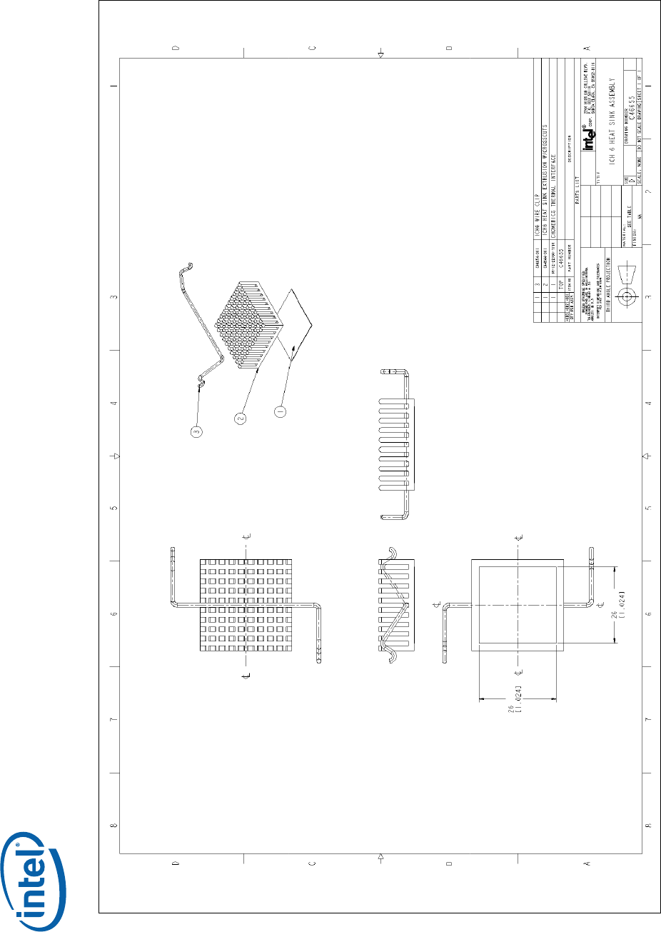
Figure 13. Reference Heatsink Assembly ............................................................30
Tables
Table 1. Package Loading Specifications..............................................................9
Table 2. Intel® ICH9 Thermal Configurations and Power Specifications ..................10
Table 5. Reference Thermal Solution Environmental Reliability Requirements.........18
Table 6. Projected Chassis Conditions by Case for BTX Form Factor ......................21
Table 7. Enabled Suppliers for the Intel® ICH6, ICH7, ICH8 & ICH9 Reference
Heatsink..................................................................................................23

Thermal Design Guidelines 5
Revision History
Rev.
No. Description Date
-001 • Initial Release. June 2007
§

6 Thermal Design Guidelines

Introduction
Thermal Design Guidelines 7
1 Introduction
The objective of thermal management is to ensure that the temperatures of all
components in a system are maintained within functional limits. The functional
temperature limit is the range within which the electrical circuits can be expected to
meet specified performance requirements. Operation outside the functional limit can
degrade system performance, cause logic errors, or cause component and/or system
damage. Temperatures exceeding the maximum operating limits may result in
irreversible changes in the operating characteristics of the component. The goal of this
document is to provide an understanding of the operating limits of the Intel® ICH9
component.
As the complexity of computer systems increases, so do power dissipation
requirements. The additional power of next generation systems must be properly
dissipated. Heat can be dissipated using improved system cooling, selective use of
ducting, and/or passive heatsinks.
The simplest and most cost-effective method is to improve the inherent system
cooling characteristics of the ICH9 through careful design and placement of fans,
vents, and ducts. When additional cooling is required, component thermal solutions
may be implemented in conjunction with system thermal solutions. The size of the fan
or heatsink can be varied to balance size and space constraints with acoustic noise.
This document presents the conditions and requirements to properly design a cooling
solution for systems that implement the ICH9 component. Properly designed solutions
provide adequate cooling to maintain the ICH9 component case temperature at or
below thermal specifications. This is accomplished by providing a low local-ambient
temperature, ensuring adequate local airflow, and minimizing the case to local-
ambient thermal resistance. By maintaining the ICH9 component case temperature at
or below maximum specifications, a system designer can ensure the proper
functionality, performance, and reliability of this component.
Note: This document only applies to the desktop implementation of the Intel® ICH9
component.
Note: References to RAID in this document only apply to the Intel® 82801IR ICH9R I/O
Controller Hub with RAID capabilities.
Introduction
8 Thermal Design Guidelines
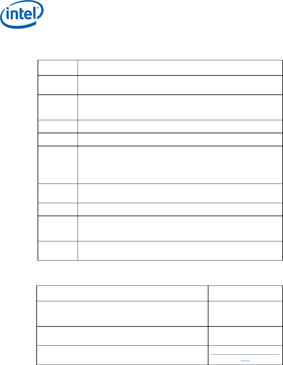
1.1 Terminology
Term Description
mBGA Mini Ball Grid Array. Smaller versions of the BGA and wire bonded package with
die encased with a mold encapsulant.
TC The measured case temperature of a component. It is generally measured at
the geometric center of the die or case, as specified in the component
documentation.
TC-MAX The maximum case/die temperature.
TC-MIN The minimum case/die temperature.
TDP Thermal Design Power is specified as the highest sustainable power level of
most or all of the real applications expected to be run on the given product,
based on extrapolations in both hardware and software technology over the life
of the component. Thermal solutions should be designed to dissipate this target
power level.
TIM Thermal Interface Material: thermally conductive material installed between two
surfaces to improve heat transfer and reduce interface contact resistance.
LFM Linear Feet per Minute. Units of airflow velocity.
PTC Package Thermal Capability. The maximum power level at which the component
does not require a heatsink under the reference boundary condition
assumptions.
Theta_CA Thermal Resistance described using power dissipated between two points. Here,
theta_ca is defined as: (Tc – Tambient)/(PowerCA)
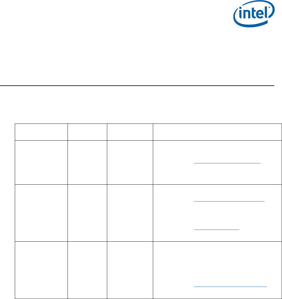
1.2 Reference Documents
Document Comments
Intel® Core™2 Duo Desktop Processor, Intel® Pentium® Dual Core
Processor, and Intel® Pentium® 4 Processor 6x1 Δ Sequence www.intel.com/design/
processor/designex/
313685.htm
Intel® I/O Controller Hub 9 (ICH9) Family Datasheet www.intel.com/design/chips
ets/datashts/316972.htm
Various System Thermal Design Suggestions http://www.formfactors.
org
§
Product Specifications
Thermal Design Guidelines 9
2 Product Specifications
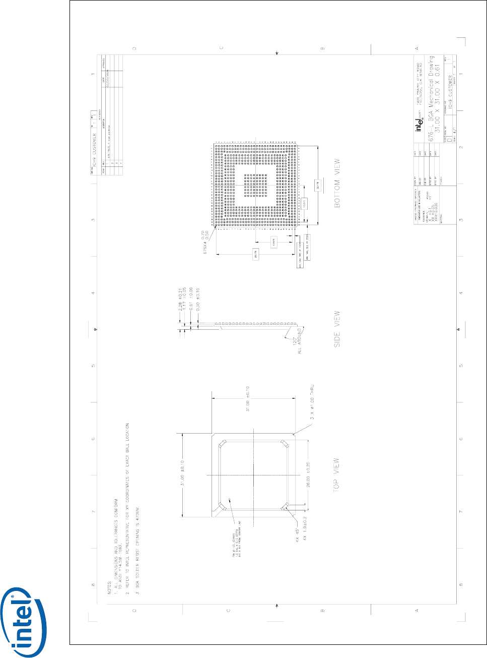
2.1 Package Description
The ICH9 component is available in a 676 ball, 31 mm square mBGA package shown
in Figure 6 in Appendix B. The die size is 8.19 mm [0.323in] x 7.91 mm [0.311in].
2.2 Package Loading Specifications
Table 1 provides static load specifications for the ICH9 package. This mechanical
maximum load limit should not be exceeded during heatsink assembly, shipping
conditions, or standard use condition. Also, any mechanical system or component
testing should not exceed the maximum limit. The chipset package substrate should
not be used as a mechanical reference or load-bearing surface for the thermal and
mechanical solution.
Table 1. Package Loading Specifications
Parameter Maximum Notes
Static 15 lbf 1,2,3
NOTES:
1. These specifications apply to uniform compressive loading in a direction normal to the
chipset package
2. This is the maximum force that can be applied by a heatsink retention clip. The clip
must also provide the minimum specified load on the ICH package for the thermal
interface material.
3. These specifications are based on limited testing for design characterization. Loading
limits are for the package only.
2.3 Thermal and Power Specifications
To ensure proper operation and reliability of the ICH9 component, the case
temperature (TC) must be at or below the maximum value TC-MAX specified when
dissipating TDP power listed in Table 2. The specifications define five configurations
with slightly different requirements, which represent the expected usage of the ICH9
component on desktop motherboards. Configuration 3 is the configuration used for the
Intel reference thermal solution analysis and design.
Note: The TC-MAX specification is a requirement for sustained power dissipation equal to
TDP. When the component is dissipating less than TDP, the case temperature must be
maintained at temperatures less than TC-MAX
The actual ICH9 power dissipation is dependent on various factors including: system
configuration, bandwidth & utilization of the available and connected ports, the
component temperature & voltage and part-to-part variance. The TDP values assume
Product Specifications
10 Thermal Design Guidelines
the part is operating at the TDP power dissipation and maximum case temperature
and operating voltage.
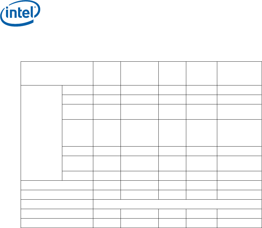
Table 2. Intel® ICH9 Thermal Configurations and Power Specifications
Configuration 1 2 3 4 Energy Star
Configuration
DMI x4 X4 X4 X4 x4 x4
PCI 3 3 3 3 0
PCI
Express* Two x1 s Two x1 s Two x1 s
One each
x4 and x1 0
LAN Gigabit LAN
Connect
Interface
(GLCI)
GLCI GLCI GLCI
SATA2 4 4 6 6 3
USB
(HS/FS)1 10/2 10/2 10/2 10/2 0/2
Devices
HD Audio Yes Yes Yes Yes Yes
TC-MAX – with heatsink 100 °C 100 °C 97 °C 96 °C
TC-MAX – without heatsink6 113 °C 113°C 110 °C 110 °C
TC-MIN 0 °C
Configuration Based Power3 3.4 W 3.7 W 4.0 W 4.3 W
Idle Power 0.76 0.92 0.96 0.96 0.90 W
NOTES:
1. USB HS = USB 2.0 High Speed Device (480 MB/s), USB FS = USB 2.0 Full Speed
Device (12 MB/s)
2. 4 devices assume RAID 5 with 3 hard drives (3 GB/s) and 1 optical drive (1.5 GB/s)
6 devices assumes RAID 5 with 4 hard drives (3 GB/s) and 2 optical drives (1.5 GB/s)
3. The number of devices refers to both the number of ports supported on the board as
well as the quantity of devices attached. Any port not routed to a connector is assumed
to be functionally disabled according to Intel guidelines.
4. Configuration 3 is the configuration for Thermal Design Power and is the target for the
Intel reference design.
5. The Idle power references ICH9 core and I/O interfaces idle with all low power features
enabled. For Energy Star Configuration idle power, though there is no PCI Express and
PCI devices connected, PCI Express and PCI are not functionally disabled.
6. Without a heatsink, most of the heat dissipated by ICH9 goes through the PCB, with the
PCB acting as a heat spreader and then into the ambient air. When a heatsink is
installed on the package, more power is now being pulled through the case. As a result
the maximum case temperature must be maintained at lower level than without a
heatsink to remain within specification.
The ICH9 package has a molded plastic encapsulant, and because plastic is such a
poor heat conductor, the relative importance of the motherboard heat transfer
characteristics increases. The heat transfer capability of the motherboard in the area
of the ICH should be characterized. Knowledge of these heat transfer paths can be
used to determine if an ICH heatsink is required.

Product Specifications
Thermal Design Guidelines 11
In addition, high power PCI Express* graphic cards may alter the local ambient
temperature as well as the airflow patterns in the vicinity of the chipset. Systems that
have interface utilization less than that of the TDP configuration may be at power
levels that may not require a heatsink.
In conclusion, thermal validation should be performed in your anticipated system
environment, in particular measuring the ICH9 case temperature to ensure it does not
exceed its maximum case temperature specification. To evaluate the capability of your
system for cooling the ICH9, the following system level tests are suggested to assess
ICH9 case temperature compliancy:
1. Shipping configuration(s) with expected end user add-in cards and I/O peripherals
installed.
2. All available slots and IO ports populated (only worst case if all I/O is fully
populated including SATA, USB, etc.).
For completeness, both room ambient conditions (approximately 23 °C, to simulate
impact of fan speed control) and worse case maximum external temperature (35 °C)
conditions should be considered in the validation test suite. If the ICH9 case
temperature is above the published Tc-max – without heatsink in any test scenario, a
heatsink is required.
If you determine that the ICH9 package requires a heatsink in your system
configuration, please refer to Appendix A for the reference ICH9 heatsink vendor
information.
2.4 TCONTROL Limit
Intel® Quiet System Technology (Intel® QST) monitors an embedded thermal sensor.
The maximum operating limit when monitoring this thermal sensor is TCONTROL. For the
Intel® ICH9 family this value has been defined as 101°C. This value should be
programmed into the appropriate fields of Intel QST as the maximum sensor
temperature for operation of the Intel ICH9 family
§

Product Specifications
12 Thermal Design Guidelines

Thermal Metrology
Thermal Design Guidelines 13
3 Thermal Metrology
The system designer must make temperature measurements in order to accurately
determine the thermal performance of the system. Intel has established guidelines for
measuring chipset component case temperatures.
3.1 Case Temperature Measurements
To ensure functionality and reliability, the chipset component is specified for proper
operation when TC is maintained at or below the maximum temperature listed in
Table 2. The surface temperature at the geometric center of the mold encapsulant
corresponds to TC. Measuring TC requires special care to ensure an accurate
temperature measurement.
Temperature differences between the temperature of a surface and the surrounding
local ambient air can introduce error in the measurements. The measurement errors
could be due to a poor thermal contact between the thermocouple junction and the
surface of the package, heat loss by radiation and/or convection, and/or conduction
through thermocouple leads. To minimize these measurement errors, the approach
described below titled 0° Angle Thermocouple Attach Methodology is recommended.
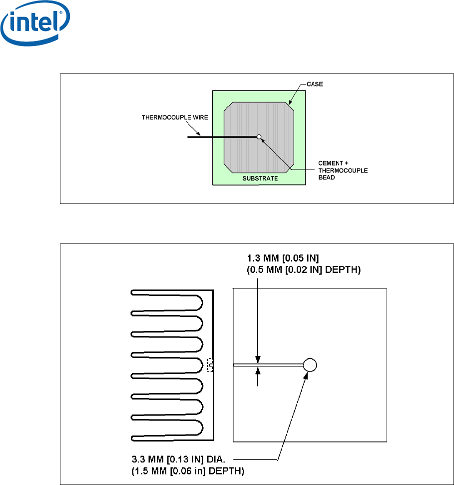
3.2 0° Angle Thermocouple Attach Methodology
1. Mill a 3.3 mm [0.13 in] diameter hole centered on bottom of the heatsink base.
The milled hole should be approximately 1.5 mm [0.06 in] deep.
2. Mill a 1.3 mm [0.05 in] wide slot, 0.5 mm [0.02 in] deep, from the centered hole
to one edge of the heatsink. The slot should be in the direction parallel to the
heatsink fins (see Figure 2).
3. Attach thermal interface material (TIM) to the bottom of the heatsink base.
4. Cut out portions of the TIM to make room for the thermocouple wire and bead.
The cutouts should match the slot and hole milled into the heatsink base.
5. Attach a 36 gauge or smaller calibrated K-type thermocouple bead or junction to
the center of the top surface of the case using high thermal conductivity cement.
During this step, make sure no contact is present between the thermocouple
cement and the heatsink base because any contact will affect the thermocouple
reading. It is critical that the thermocouple bead makes contact with the case (see
Figure 1).
6. Attach heatsink assembly to the ICH, and route thermocouple wires out through
the milled slot.
Thermal Metrology
14 Thermal Design Guidelines
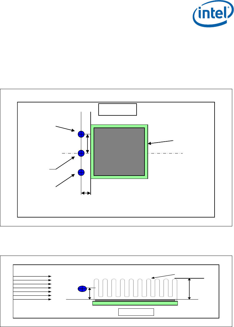
Figure 1. 0° Angle Attach Methodology (top view, not to scale)
Figure 2. 0° Angle Attach Heatsink Modifications (generic heatsink shown, not to
scale)
3.3 Ambient Temperature and Airflow Measurement
Figure 3 describes the recommended location for air temperature measurements
measured relative to the component. For a more accurate measurement of the
average approach air temperature, Intel recommends averaging temperatures
recorded from two thermocouples spaced about 25 mm [1.0 in] apart. Locations for
both a single thermocouple and a pair of thermocouples are presented.
Airflow velocity should be measured using industry standard air velocity sensors.
Typical airflow sensor technology may include hot wire anemometers.
Figure 4 provides guidance for airflow velocity measurement locations. These
locations are for a typical JEDEC test setup and may not be compatible with all chassis
Thermal Metrology
Thermal Design Guidelines 15
layouts due to the proximity of the processor to the ICH, PCI and PCI Express* add-in
cards. The user may have to adjust the locations for a specific chassis. Be aware that
sensors may need to be aligned perpendicular to the airflow velocity vector or an
inaccurate measurement may result. Measurements should be taken with the chassis
fully sealed in its operational configuration to achieve a representative airflow profile
within the chassis.
Figure 3. Recommended Temperature Measurement Placement: Top View
13 mm
(0.5in)
13 mm
(0.5in)
CL
Single T/C
location
ICH package
T/C pair
location
T/C pair
location
T
op
V
iew
Figure 4. Recommended Airflow and Temperature Placement: Side View
H/2
H
Side View
Airflow ICH Heatsink, if
required
§

Thermal Metrology
16 Thermal Design Guidelines

ATX Reference Thermal Solution
Thermal Design Guidelines 17
4 ATX Reference Thermal
Solution
The ICH9 reference solution for an ATX platform assumes a component local operating
environment as described in Section 4.2.
Using the TPD configuration (Config #3) given in Table 2, the ICH9 component
requires an attached heatsink to meet thermal specifications. The local-ambient
conditions are based on a 35 °C external-ambient temperature at sea level, where
external-ambient refers to the environment external to the system. Refer to
Appendix A for enabled suppliers for the reference thermal solution and Appendix B
for reference thermal solution mechanical drawings.
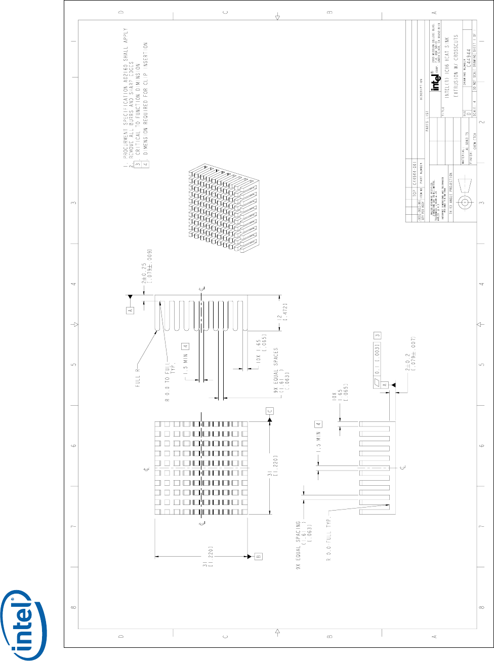
Note: The reference heatsink for the ICH9 is the same reference heatsink originally
developed Intel® ICH6 which was also used for the Intel® ICH7 and Intel® ICH8.
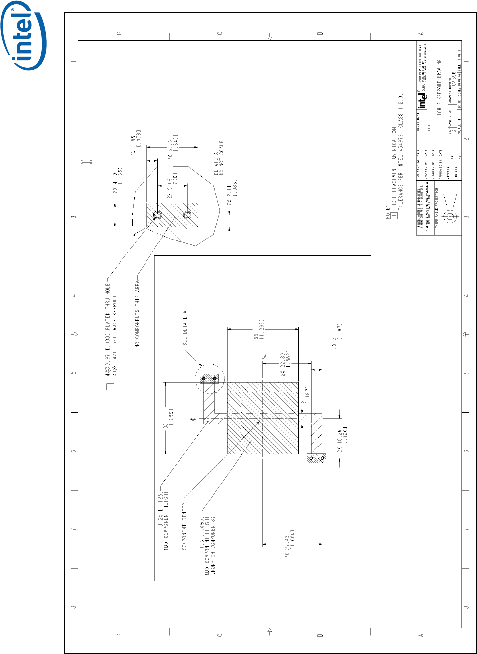
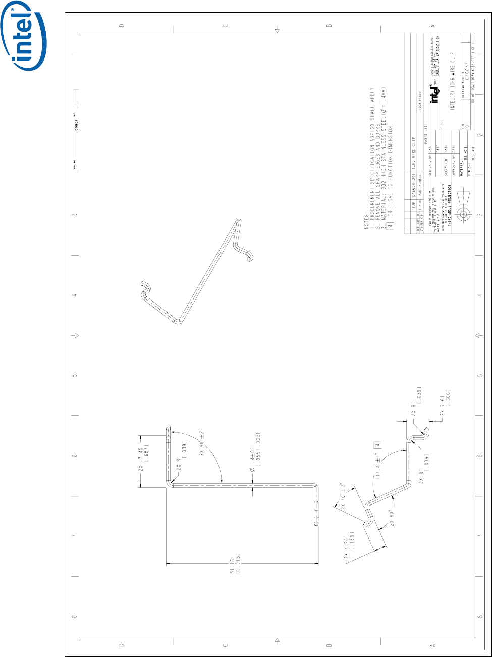
Refer to Figure 7 for reference ATX/μATX motherboard keep-out information. Heatsink
can be tape-attached, or attached with a Z-clip. The motherboard keep-out allows for
a Z-clip heatsink attach.
Note: Intel has not completed nor plans to perform thermal or mechanical validation with a
tape-attached heatsink solution.

ATX Reference Thermal Solution
18 Thermal Design Guidelines
4.1 Environmental Reliability Requirements
If an attached heatsink is implemented the reliability requirements in Table 3 are
recommended. The mechanical loading of the component may vary depending on the
heatsink, and attach method used. The user should define validation tests based on
the anticipated use conditions and resulting reliability requirements.
Table 3. Reference Thermal Solution Environmental Reliability Requirements
Test1 Requirement Pass/Fail
Criteria2
Mechanical
Shock • 3 drops for + and - directions in each of 3
perpendicular axes (i.e., total 18 drops).
• Profile: 50 G trapezoidal waveform, 11 ms
duration, 170 inches/sec minimum velocity change.
• Setup: Mount sample board on test fixture.
Visual\Electrical
Check
Random
Vibration • Duration: 10 min/axis, 3 axes
• Frequency Range: 5 Hz to 500 Hz
• Power Spectral Density (PSD) Profile: 3.13 g RMS
Visual/Electrical
Check
Thermal
Cycling • -40 °C to +85 °C, 1000 cycles Visual Check
Temperature
Life
• 85 °C, 1000 hours total Visual/Electrical
Check
Unbiased
Humidity
• 85 % relative humidity / 55 °C, 1000 hours Visual Check
NOTES:
1. The above tests should be performed on a sample size of at least 12 assemblies from 3
different lots of material.
2. Additional Pass/Fail Criteria may be added at the discretion of the user.
4.2 ATX boundary conditions
Intel’s reference boundary conditions for ICH9 in an ATX system are 60°C inlet
ambient temperature and 0.25m/s [50 lfm] of airflow. See Figure 5 for more details
on the ATX boundary conditions.
In the ATX boundary conditions listed above, the ICH9 will not require a heatsink
when power dissipation is at or below 2.7 W. This value is referred to as the Package
Thermal Capability, or PTC. Note that the power level at which a heatsink is required
will also change depending on system local operating ambient conditions and system
configuration.
ATX Reference Thermal Solution
Thermal Design Guidelines 19
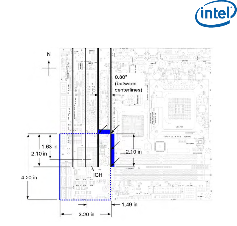
Figure 5. ATX Boundary Conditions
NOTES:
1. Airflow is entering at 45° angle (see arrows) at 50 LFM at 60°C – through the two
shaded boxes shown.
The assumed opening is 0.63 x 0.80 inches on the north face and 0.63 x 2.10 inches on
the east face.
2. Airflow condition boundary box (blue dashed lines):
West face completely blocked by chassis wall.
East face aligned with the graphics card.
North, South and East faces open except for add-in card obstructions.
The add-in cards have a 0.63 inch gap from the motherboard to the card bottom edge.
3. Motherboard thickness 0.062 inches with 0.25 gap below board.
§

ATX Reference Thermal Solution
20 Thermal Design Guidelines

Balanced Technology Extended (BTX) Thermal Solution Guidance
Thermal Design Guidelines 21
5 Balanced Technology Extended
(BTX) Thermal Solution
Guidance
In BTX systems the Thermal Module Assembly (TMA) is the primary fan in the system.
A set of three system level boundary conditions have been established to determine
ICH thermal solution requirement.
• High ambient / TDP for the components (Case 1). This covers the maximum TMA
fan speed condition.
• Low external ambient / TDP for the components (Case 2). The TMA fan speed is
limited by the thermistor in the fan hub.
• Low external ambient / Low power for the components (Case 3). This covers the
system idle acoustic condition
In addition to the 3 cases listed above the analysis will review two chassis
configurations to determine the worst case
• Small Form Factor Entertainment PC (EPC) with the Type II 65 W TMA developed
for the Intel® Core™2 Duo Processors. See Intel® Core™2 Duo Desktop Processor
Thermal Mechanical Design Guidelines (TMDG) for details on the reference thermal
design.
• BTX Tower System with a Type I TMA optimized for 65 W processor power.
Current design analysis indicates the Small Form Factor Entertainment PC (EPC) is the
limiting thermal condition for Case 2 and 3 (see Table 4).
Table 4. Projected Chassis Conditions by Case for BTX Form Factor
Case TA above
motherboard
(°C)
Airflow
above
motherboard
(LFM)
TA below
motherboard
(°C)
Airflow
below
motherboard
(LFM)
PTC
(W)
Case 1 51.3 91.3 57.8 52.8 4.8
Case 2 56.5 47.5 79.4 29.9 4.0
Case 3 55.9 10.9 71.7 15.4 2.9
NOTES:
1. PTC is Package Thermal Capability which is a measure of the power that can be
dissipated without a thermal solution.

Balanced Technology Extended (BTX) Thermal Solution Guidance
22 Thermal Design Guidelines
The customer should analyze their system design to verify the boundary conditions
prior to design.
For example, the local inlet ambient air for the ICH9 component in a BTX system is
projected to be approximately 55 °C to 60 °C.
The analysis of the ICH cooling should account for the airflow above and below the
motherboard. Without a heatsink the ICH package will dissipate a significant portion of
the heat into the motherboard.
§
Currently Enabled Suppliers
Thermal Design Guidelines 23
Appendix A Currently Enabled
Suppliers
The currently enabled suppliers for the Reference thermal solution supporting the
ICH6, ICH7, ICH8 and ICH9 are listed in Table 5.
Table 5. Enabled Suppliers for the Intel® ICH6, ICH7, ICH8 & ICH9 Reference Heatsink
Supplier Intel Part
Number Vendor Part
Number Contact Information
AVC *
(Asia Vital
Components) C46655-001 S702C00001
Taiwan: David Chao - +886 (-2) -2299-6930
x7619
Email:
david_chao@avc.com.tw
Taiwan: Raichel Hsu +886 (-2) -2299-6930 x7630
raichel_hsi@avc.com.tw
CCI*
(Chaun-Choung
Technology Corp.) C46655-001 00C855802B
Taiwan: Monica Chi
Email:
monica_chih@ccic.com.tw
Tel: +886 - 2 -2995-2666 Ext 131
USA: Harry Lin
Email:
hlinack@aol.com
Tel: (714) 739-5797
Foxconn* C46655-001 2Z802-009
USA: Jack Chen, PH.D
Email: jack.chen@foxconn.com
Tel: (408) 919-6121
USA: Wanchi Chen
Email:
wanchi.chen@foxconn.com
Tel: (408) 919-6135
NOTES: These vendors and devices are listed by Intel as a convenience to Intel's general
customer base, but Intel does not make any representations or warranties whatsoever
regarding quality, reliability, functionality, or compatibility of these devices. This list
and/or these devices may be subject to change without notice.
§

Currently Enabled Suppliers
24 Thermal Design Guidelines
Mechanical Drawings
Thermal Design Guidelines 25
Appendix B Mechanical Drawings
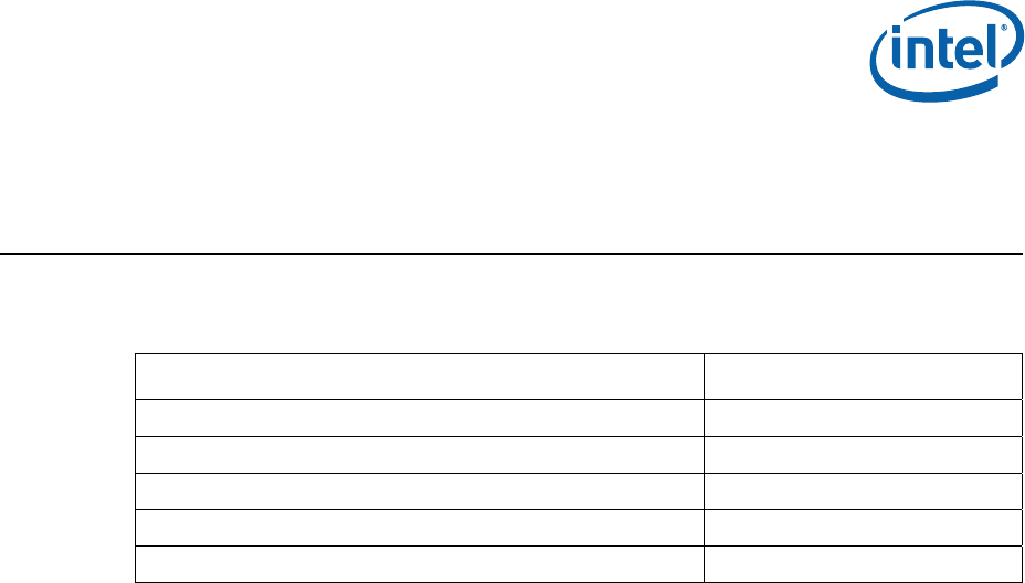
The following table lists the mechanical drawings available in this document:
Drawing Name Page Number
Intel® ICH9 Component Package Drawing 26
Motherboard Keep-Out for Reference Heatsink 27
Reference Heatsink Extrusion 28
Reference Heatsink Clip 29
Reference Heatsink Assembly 30
Mechanical Drawings
26 Thermal Design Guidelines
Figure 6. Intel® ICH9 Component Package Drawing
Mechanical Drawings
Thermal Design Guidelines 27
Figure 7. Motherboard Keep-Out for Reference Heatsink
Mechanical Drawings
28 Thermal Design Guidelines
Figure 8. Reference Heatsink Extrusion
Mechanical Drawings
Thermal Design Guidelines 29
Figure 9. Reference Heatsink Clip
Mechanical Drawings
30 Thermal Design Guidelines
Figure 10. Reference Heatsink Assembly
