User Manual Irdrmfao_user_guide Irdrmfao Guide
User Manual: irdrmfao_user_guide user guide pdf - FTP File Search (13/20)
Open the PDF directly: View PDF ![]() .
.
Page Count: 176 [warning: Documents this large are best viewed by clicking the View PDF Link!]
- 1 Overview
- 2 Introduction
- 3 Getting started with IRDRMFAO
- 4 Requirement analysis
- 5 Defining the IVV solution
- 6 Managing your data from a document point of view
- 6.1 Introduction
- 6.2 The document view
- 6.3 Editing paragraph styles
- 6.4 Exporting a WORD document
- 6.4.1 The standard DOORS WORD exporter
- 6.4.2 Creation of a basic Word template (.dot)
- 6.4.3 Setting up the appropriate RMF Views and Attributes
- 6.4.3.1 Extracting UML diagrams
- 6.4.3.2 Bookmark & Export Bookmark
- 6.4.3.3 Module Name \ Module view \ Export Style
- 6.4.3.4 Page break, Section break & Blank page rubrics
- 6.4.3.5 Index On
- 6.4.3.6 Footnotes
- 6.4.3.7 OLE Width & OLE Height
- 6.4.3.8 OLE Caption
- 6.4.3.9 Object Template
- 6.4.3.10 Filename
- 6.4.3.11 Hyperlinks
- 6.4.3.12 References
- 6.4.3.13 Description of cells options
- 6.4.3.14 Description of columns options
- 7 Datamodel customization
- 8 Acquisition and identification of RMF objects
- 9 Using the dashboard
- 10 Managing requirement changes
- 10.1 Introduction
- 10.2 Managing changes originating outside doors
- 10.2.1 INTRODUCTION
- 10.2.2 1st step: import of a new version of the source document
- 10.2.3 2nd step: comparison of the two versions of the source document
- 10.2.4 3rd step: Human check
- 10.2.5 4th step: Transfer analysis
- 10.2.6 5th step: optional deletion of the older version of the source document
- 10.3 Managing change within DOORS
- Appendix A. User Requirements Module Description Form
- Appendix B. System Requirements Module Description Form
- Appendix C. PBS Module Description Form
- Appendix D. Issues and Decisions and Justifications Module Description Form
- Appendix E. IVV Procedures Module Description Form
- Appendix F. Project Profile Module Description Form
- Appendix G. FREQUENTLY ASKED QUESTIONS (FAQ)
- Notices


IBM Rational DOORS Requirements
Management Framework Add-on
User manual
Release 5.4

Before using this information, be sure to read the general information under the “Notices” chapter on page
174.
This edition applies to VERSION 5.4, IBM Rational DOORS Requirements Management Framework
Add-on and to all subsequent releases and modifications until otherwise indicated in new editions.
© Copyright IBM Corporation 2009
US Government Users Restricted Rights—Use, duplication or disclosure restricted by GSA ADP Schedule
Contract with IBM Corp.

1 OVERVIEW ................................................................................................... 10
2 INTRODUCTION .......................................................................................... 11
2.1 DOORS VERSUS IRDRMFAO ..................................................................................................... 11
2.2 RMF GENERIC DATA MODEL .................................................................................................. 11
2.3 DATABASE AND DOCUMENT APPROACHES ....................................................................... 13
3 GETTING STARTED WITH IRDRMFAO .................................................... 14
3.1 RMF PROJECT INITIALIZATION ............................................................................................. 14
3.1.1 CREATE A NEW RMF PROJECT ........................................................................................... 14
3.1.2 MIGRATE AN EXISTING DOORS PROJECT INTO RMF FORMAT ................................. 16
3.1.3 RMF PROJECT CONFIGURATION ........................................................................................ 16
3.1.3.1 PUID ................................................................................................................................... 17
3.1.3.2 WORD ................................................................................................................................ 21
3.1.3.3 RCM ................................................................................................................................... 22
3.1.3.4 DOC .................................................................................................................................... 23
3.1.3.5 EXCHANGE ...................................................................................................................... 24
3.1.3.6 CHECK .............................................................................................................................. 25
3.2 RMF MODULE INITIALIZATION ............................................................................................. 28
3.2.1 WHAT IS A Module type ? ....................................................................................................... 28
3.2.2 CREATE A NEW RMF Module ............................................................................................... 32
3.2.3 MIGRATE A EXISTING DOORS MODULE INTO RMF FORMAT .................................... 35
3.2.4 MIGRATE SEVERAL EXISTING DOORS MODULES INTO RMF FORMAT ................... 37
3.2.5 RMF MODULE CONFIGURATION ....................................................................................... 39
3.2.5.1 PUID ................................................................................................................................... 39
3.2.5.2 Objects ................................................................................................................................ 40
3.2.5.3 Styles .................................................................................................................................. 41
3.2.5.4 RCM and RCM attributes ................................................................................................... 43
3.2.5.5 Check .................................................................................................................................. 45
3.3 DEFINE THE DEFAULT LINKSET PAIRING .......................................................................... 46
4 REQUIREMENT ANALYSIS ........................................................................ 49
4.1 CHARACTERIZE REQUIREMENTS ......................................................................................... 49
4.2 DEFINE ISSUES AND DECISIONS ............................................................................................. 50
4.3 Identify RISK and key requirements ............................................................................................. 50
4.3.1 Introduction ................................................................................................................................ 50
4.3.2 critical requirements ................................................................................................................... 50
4.3.3 Key requirements ....................................................................................................................... 51
4.4 LINK RMF OBJECTS .................................................................................................................... 51
4.4.1 LINK SET SELECTION ........................................................................................................... 51
4.4.2 LINKING RMF OBJECTS ........................................................................................................ 52

4.4.2.1 GENERAL PRINCIPLES .................................................................................................. 52
4.4.2.2 Requirements satisfY upper level requirements ................................................................. 52
4.4.2.3 REQUIREMENTS / FUNCTIONS ARE ALLOCATED TO CONFIGURATION ITEMS
........................................................................................................................................................ 52
4.4.2.4 LINK RMF OBJECTS WITHIN A SAME MODULE ..................................................... 52
4.4.3 CHECK THAT YOUR PROJECT LINKS CONFORM WITH DATA MODEL .................... 53
4.5 CHECK DATA CONSISTENCY ................................................................................................... 54
4.5.1 CHECK PROJECT AND MODULE CONSISTENCY TOOL ................................................ 54
4.5.2 INTEGRITY CHECK ................................................................................................................ 58
4.5.2.1 Integrity check at project level ........................................................................................... 61
4.5.2.2 Integrity check at module level .......................................................................................... 62
4.5.2.3 Integrity check report dialog .............................................................................................. 63
4.5.2.4 Integrity check in triggers ................................................................................................... 64
4.5.2.5 Predefined integrity rules ................................................................................................... 65
4.5.2.6 User defined integrity rules ................................................................................................ 67
5 DEFINING THE IVV SOLUTION .................................................................. 69
5.1 Introduction ...................................................................................................................................... 69
5.2 IVV OBJECT ATTRIBUTES ........................................................................................................ 69
5.2.1 IE Object type ............................................................................................................................ 69
5.2.2 IE PUID ...................................................................................................................................... 70
5.2.3 IE IVV Type ............................................................................................................................... 70
5.2.4 IE IVV Test Method ................................................................................................................... 70
5.2.5 IE IVV APPROVAL LEVEL .................................................................................................... 70
5.2.6 IE IVV responsible ..................................................................................................................... 70
5.2.7 IE IVV SKILLS ......................................................................................................................... 70
5.2.8 IE IVV EVENT .......................................................................................................................... 71
5.2.9 IE IVV EVENT PROVIDER ..................................................................................................... 71
5.2.10 IE IVV Non Regression ........................................................................................................... 71
5.2.11 IE IVV Test SCOPE ................................................................................................................. 71
5.3 IVV RELATIONSHIPS .................................................................................................................. 71
5.3.1 JUSTIFICATION ....................................................................................................................... 71
5.3.2 UNDER ISSUE PROCESS ........................................................................................................ 72
5.3.3 VERIFICATION ........................................................................................................................ 72
5.3.4 ALLOCATION .......................................................................................................................... 72
5.4 IVV VIEWS ...................................................................................................................................... 72
5.4.1 STANDARD VIEW ................................................................................................................... 72
5.4.2 IVV ASSOCIATED ISSUES VIEW ......................................................................................... 72
5.4.3 IVV DOCUMENT VIEW .......................................................................................................... 72
5.4.4 IVV MATRIX VIEW ................................................................................................................ 72
5.4.5 IVV PROCEDURES DEFINITION VIEW ............................................................................... 72
5.4.6 IVV PROCEDURES PLANNING VIEW ................................................................................. 73
5.4.7 IVV JUSTIFICATION VIEW ................................................................................................... 73
5.4.8 IVV TEST EQUIPMENT VIEW ............................................................................................... 73
6 MANAGING YOUR DATA FROM A DOCUMENT POINT OF VIEW .......... 74
6.1 Introduction ...................................................................................................................................... 74
6.2 The document view .......................................................................................................................... 74

6.3 Editing paragraph styles ................................................................................................................. 75
6.3.1 Using The IRDRMFAO Utility “EDIT STYLE” ...................................................................... 75
6.3.2 the DOORS standard tool “Edit paragraph style attribute” ....................................................... 76
6.4 Exporting a WORD document ....................................................................................................... 76
6.4.1 The standard DOORS WORD exporter ..................................................................................... 76
6.4.1.1 Introduction ........................................................................................................................ 77
6.4.1.2 The enhanced WORD EXPORTER ................................................................................... 77
6.4.2 Creation of a basic Word template (.dot) ................................................................................... 79
6.4.2.1 Style Definition .................................................................................................................. 79
6.4.2.2 Insertion of attributes .......................................................................................................... 80
6.4.2.3 Insertion of "Table of contents" & "Table of figures" ....................................................... 82
6.4.2.4 Insertion of bookmarks ....................................................................................................... 83
6.4.3 Setting up the appropriate RMF Views and Attributes .............................................................. 84
6.4.3.1 Extracting UML diagrams .................................................................................................. 85
6.4.3.2 Bookmark & Export Bookmark ......................................................................................... 87
6.4.3.3 Module Name \ Module view \ Export Style ..................................................................... 87
6.4.3.4 Page break, Section break & Blank page rubrics ............................................................... 91
6.4.3.5 Index On ............................................................................................................................. 91
6.4.3.6 Footnotes ............................................................................................................................ 93
6.4.3.7 OLE Width & OLE Height ................................................................................................ 94
6.4.3.8 OLE Caption ....................................................................................................................... 94
6.4.3.9 Object Template ................................................................................................................. 94
6.4.3.10 Filename ........................................................................................................................... 96
6.4.3.11 Hyperlinks ........................................................................................................................ 97
6.4.3.12 References ........................................................................................................................ 98
6.4.3.13 Description of cells options .............................................................................................. 98
6.4.3.14 Description of columns options ........................................................................................ 99
7 DATAMODEL CUSTOMIZATION .............................................................. 103
7.1 DESCRIPTION OF A RMF PROJECT STRUCTURE ............................................................ 103
7.2 ADAPTING MODULE ATTRIBUTES ...................................................................................... 104
7.3 ADAPTING PROJECT PROFILE .............................................................................................. 105
7.3.1 ADD A NEW OBJECT TYPE ................................................................................................ 106
7.3.2 ADD A NEW TEMPLATE ..................................................................................................... 107
7.3.3 ADD A NEW MODULE TYPE .............................................................................................. 108
7.3.4 ADD A NEW RELATIONSHIP ............................................................................................. 109
7.3.5 ERROR HANDLING .............................................................................................................. 110
8 ACQUISITION AND IDENTIFICATION OF RMF OBJECTS .................... 111
8.1 Introduction .................................................................................................................................... 111
8.2 RMF Object structure within a module ....................................................................................... 111
8.2.1 requirement Type Structures .................................................................................................... 111
8.2.2 Breakdown Type Structures ..................................................................................................... 112
8.2.3 Issue/Decision Type Structures ................................................................................................ 112
8.3 HOW TO Import a document into DOORS ................................................................................ 112
8.4 HOW TO IDENTIFY RMF OBJECTS: REQUIREMENTS, FUNCTIONS, ......................... 113
8.4.1 Introduction .............................................................................................................................. 113
8.4.2 Identifying an existing DOORS object .................................................................................... 113

8.4.2.1 Identifying a selection of objects ...................................................................................... 113
8.4.2.2 Applying a MS Word Style .............................................................................................. 114
8.4.2.3 Parsing the text of the identified object ............................................................................ 114
8.4.3 Creating new RMF objects ....................................................................................................... 115
8.5 WORKING IN EDIT SHAREABLE MODE .............................................................................. 116
8.6 Defining IRDRMFAO behaviour for New module Types .......................................................... 116
9 USING THE DASHBOARD ........................................................................ 117
10 MANAGING REQUIREMENT CHANGES ............................................... 118
10.1 Introduction .................................................................................................................................. 118
10.2 Managing changes originating outside doors ............................................................................ 118
10.2.1 INTRODUCTION .................................................................................................................. 118
10.2.2 1st step: import of a new version of the source document ..................................................... 120
10.2.3 2nd step: comparison of the two versions of the source document ........................................ 120
10.2.3.1 GUI and setup ................................................................................................................. 120
10.2.3.2 Pre-processing verifications ........................................................................................... 124
10.2.3.3 Processing verifications and log window ...................................................................... 125
10.2.3.4 Classic algorithm ............................................................................................................ 125
10.2.3.5 Hierarchical algorithm .................................................................................................... 131
10.2.4 3rd step: Human check ........................................................................................................... 135
10.2.5 4th step: Transfer analysis ...................................................................................................... 136
10.2.5.1 Graphic User interface .................................................................................................... 136
10.2.5.2 Use and Parameters ........................................................................................................ 138
10.2.5.3 Pre-processing verifications and log window ................................................................ 140
10.2.5.4 Processing verifications and log window ...................................................................... 141
10.2.6 5th step: optional deletion of the older version of the source document ................................ 141
10.3 Managing change within DOORS .............................................................................................. 143
10.3.1 Introduction ............................................................................................................................ 143
10.3.2 CPS Administration ............................................................................................................... 144
10.3.3 CPS limitations ....................................................................................................................... 144
APPENDIX A. USER REQUIREMENTS MODULE DESCRIPTION FORM 146
APPENDIX B. SYSTEM REQUIREMENTS MODULE DESCRIPTION FORM
....................................................................................................................... 152
APPENDIX C. PBS MODULE DESCRIPTION FORM ................................. 158
APPENDIX D. ISSUES AND DECISIONS AND JUSTIFICATIONS MODULE
DESCRIPTION FORM ................................................................................... 162
APPENDIX E. IVV PROCEDURES MODULE DESCRIPTION FORM ...... 165
APPENDIX F. PROJECT PROFILE MODULE DESCRIPTION FORM ..... 169


This document relates to the requirements management add-on IBM® Rational®
DOORS® Requirements Management Framework Add-on, based upon DOORS.
IBM® Rational® DOORS® Requirements Management Framework Add-on is a
solution which will save your time starting your project with one of the best possible
practices you can handle with DOORS. Originating from Thales company, and previously
delivered under the name DOORS T-REK, IBM® Rational® DOORS® Requirements
Management Framework Add-on is a solution developed for the industry by industrials.
It implements a methodology in compliance with EIA632 , ISO 15288 and CMMI.
IBM® Rational® DOORS® Requirements Management Framework Add-on can be
used by System Engineers, Software Engineers, Hardware…a wide set of disciplines.
IBM® Rational® DOORS® Requirements Management Framework Add-on adds a
process, a data model and utilities to DOORS. This user manual describes how to use the
data model and how to apply the tool.
In the body of the document the acronym IRDRMFAO will frequently be used to designate
the product IBM® Rational® DOORS® Requirements Management Framework
Add-on.
The acronym RMF will be used to qualify an operation of the product, or a piece of
information managed by the product.
Note: The word “project” used in the following is generic and could designate a project
before or after the contract has been signed. IRDRMFAO applies to both of these two
phases.
!"!#
IRDRMFAO is a solution that implements a methodology in compliance with EIA632 ,
ISO 15288 and CMMI.
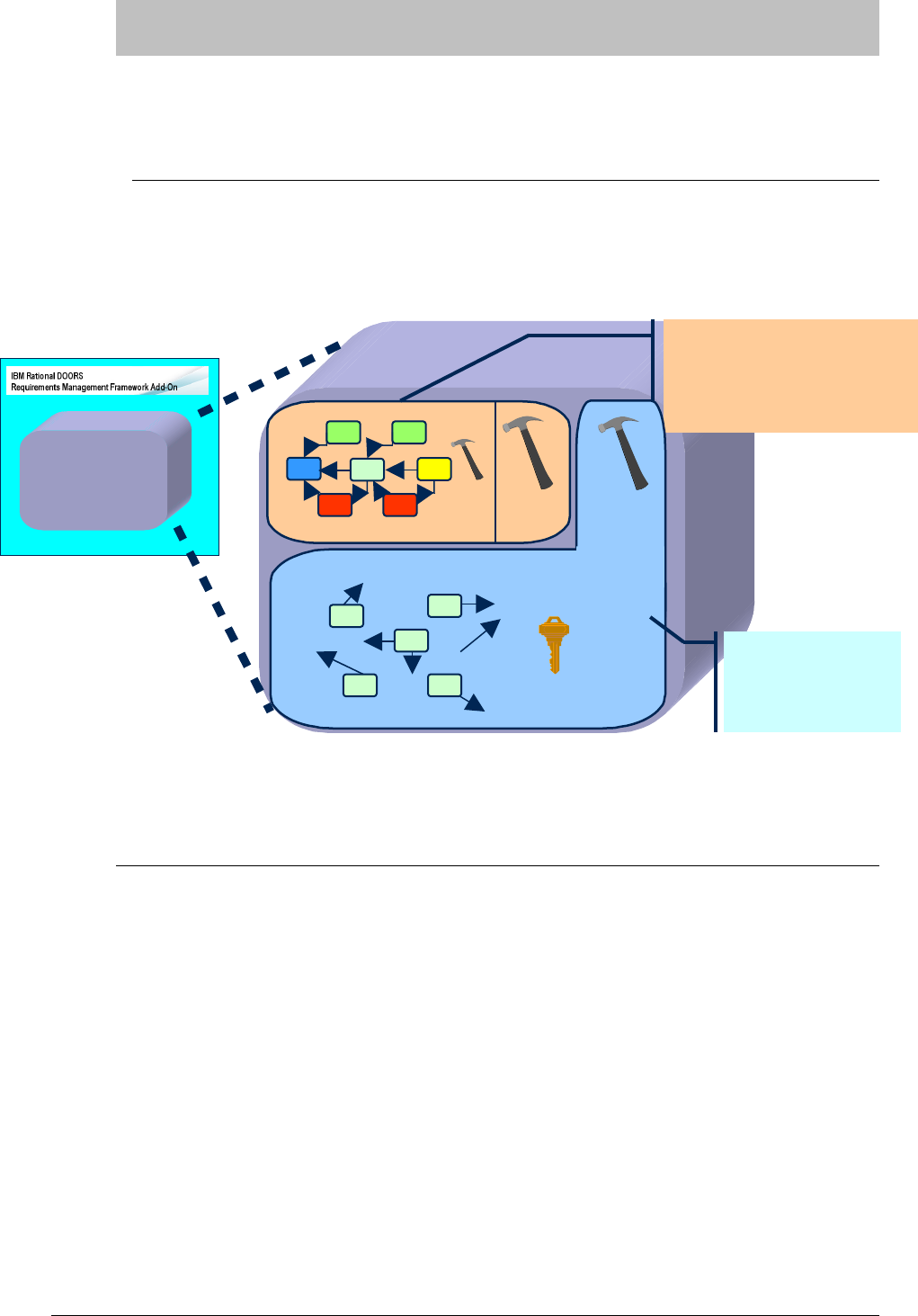
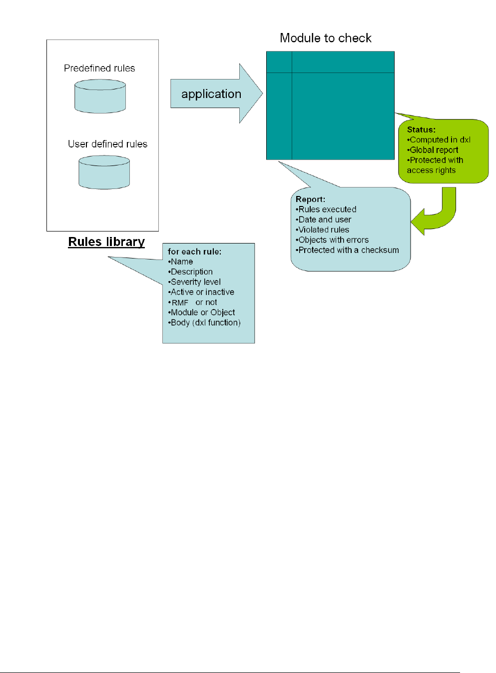
To achieve this, IRDRMFAO adds a process, a data model and utilities to DOORS. Notice
that IRDRMFAO doesn't hide DOORS layout, all DOORS commands are still available to
users.
Figure 1: Product Layout
#$!!
IRDRMFAO proposes a generic data model but does not constraint you to use it precisely.
In fact, it implements a collection of module types and links that you will pick from to
build your own data model to fit your project needs.
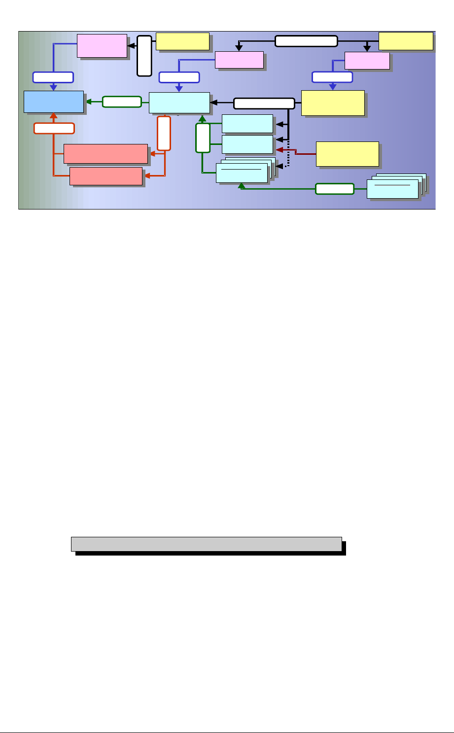
The following figure shows a example of a RMF generic data model. It is composed of
modules and relationships between them.
REQUIREMENTS
MANAGEMENT
IRDRMFAO
IRDRMFAO
(Extension)
IRDRMFAO
UTILITIES
IRDRMFAO DATAMODEL
DOORS
DOORS
(Kernel)
DOORS
UTILITIES
Verification
Procedures
Verification
Verification
Procedures
Procedures
""
System
Requirements
System
System
Requirements
Requirements
Sub-System
Requirements
Sub-System
Sub-System
Requirements
Requirements
User
Requirements
User
User
Requirements
Requirements
Product
Breakdown
Structure
Product
Product
Breakdown
Breakdown
Structure
Structure
%&
Validation &
Installation
Procedures
Validation &
Validation &
Installation
Installation
Procedures
Procedures
""
Integration
Procedures
Integration
Integration
Procedures
Procedures
""
Internal
Interfaces
Internal
Internal
Interfaces
Interfaces
External
Systems
Assumptions
External
External
Systems
Systems
Assumptions
Assumptions
%&
External
Interfaces
External
External
Interfaces
Interfaces
Prime Item
Requirements
Prime Item
Prime Item
Requirements
Requirements
'
Requirements Analysis
Issues & Decisions
Requirements Analysis
Requirements Analysis
Issues & Decisions
Issues & Decisions
!
Operational Concept
Operational Concept
Operational Concept
!
Is justified by
System
Test Equipment
System
System
Test Equipment
Test Equipment
%&
'
Acceptance
Test Equipment
Acceptance
Acceptance
Test Equipment
Test Equipment
%&
'
Figure 2 : RMF generic data model example
Each box represents a module of a predefined type (DOORS formal modules), connected
between them by links (DOORS link modules). Note that in this data model the links are
bottom-up oriented. This feature assists impact analysis and traceability, but more
importantly it means that links can be added even if the current user does not have write
access higher level module. All links can of course be browsed in either direction.
This data model is adaptable to your project. IRDRMFAO does not constraint it;
you can use some parts of it and if needed, progressively implement it. Eventualy,
you may modify it entirely. Each module of a certain type is not necessary unique.
For example, you can have multiple modules of type “User Requirements” or
“System Requirements”. In short, the data model can be adapted to fit to your
project (small and large ones).
Briefly, each activity supported by the Requirements Management process deals with a part
of the data model, and uses different kinds of modules and links:
System requirements analysis : UR, SR, IDJ modules and “satisfies”,” is justified
by” and “refers to” links,
Design analysis : SR, PBS, IDJ modules and “is allocated by”, ”is justified by” and
“refers to” links,
Validation test : IVV, UR modules and “verifies” link,
Verification and integration tests : IVV, SR modules and “verifies” link.
For more detail on the modules, consult the appendix.

( !&!!%%)
IRDRMFAO allows the user to swap instantly between the display of data in two types of
visualization: document or database.
The document approach is used to obtain:
a global and linear visualization,
structured information (Section, chapters, paragraph,…),
a snapshot or baseline in a book format (export) for communicate with customers,
contractors,…
The database approach is used to:
analyze information and characterize data with attributes,
concentrate the relevant information (filters)
display traceability matrices.
The instantaneous display swapping between the two approaches is performed through the
predefined views in RMF modules.

( $*+!#
The steps necessary to create a RMF project are shown below:
Project initialization (Create a RMF structure)
Define and fill your own project data model
( #%,-
It is assumed that :
DOORS and IRDRMFAO have already been installed
A DOORS database has been created with users, groups and access rights defined
The reader is familiar with DOORS.
( .#%,
To create a new RMF project:
Run DOORS,
You should be logged with the “Database Manager” profile, to be able to
create a project and restore a project archive,
In the project manager window (also called “Database window”), select a location
with the DOORS Explorer (left part of the “Database window”). You should see
the root of database called “DOORS Database”, otherwise select the menu “View
->Database view”,
From the project manager window, call the menu “RMF ->Create/Tag a RMF
project”,
To create a new RMF project, give a name and a description to new project. Both
fields are mandatory. Check if your company has adopted naming convention.
Note that project name and description can be modified later.
Select a data model in the list (a company can create several customized data
model). By default select the Generic RMF data model.
The option "Launch the project configuration tool" allows to directly follow on a
other tool described in the next paragraph. We suggest to unset it for this first try.
Click on the 'Create' button, if successful, an acknowledgement window is then
displayed.
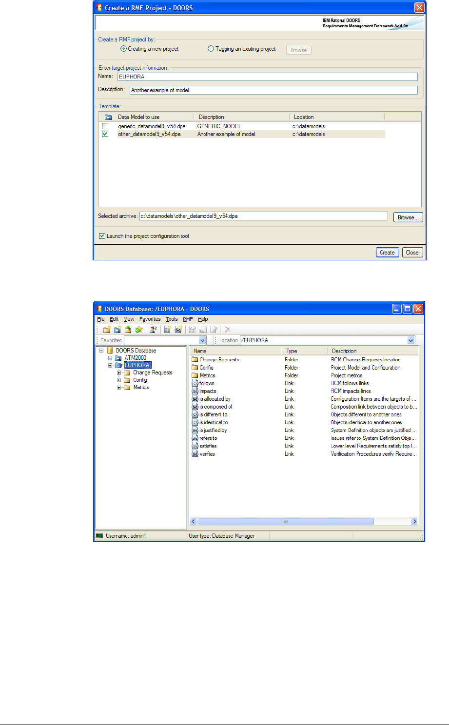
Figure 3 : Create a new RMF project window
Your project contains now a folder "Config" and links modules.
Figure 4 : RMF project creation example
Notice that some links (“is identical to”, “is different to” and “is composed of”) don’t appear in
the generic data model description but are used by the comparison tool or used as internal
links to show a composition relation between objects within the same module.

( $/$!%,#
#
To migrate an existing DOORS project to a RMF structured project, you have to follow 3
steps:
Tag the project : Call the menu “RMF ->Create/Tag a RMF project” from the
project manager window. Set the option "Tagging an existing project" and browse
the project. Then the options are the same as those described above for project
creation.
At this step, your project contains now additional data like a "Config" folder and
links modules.
Treat existing links : To treat links, you have to find a match between your own
Link Modules and the Link Modules defined by RMF data model (is justified by, refers
to, satisfies, is allocated by, verifies,…). Then, move Links modules (for expert users
only!) by renaming your own Link Modules to the RMF ones if match is possible or
using the command “Manage Linksets”
Treat formal modules : Refer to the paragraph § 3.2.3 MIGRATE A EXISTING
DOORS MODULE INTO RMF FORMAT
( (#%,#$
IRDRMFAO allows the definition for the whole project of some parameters that are
applied by default in modules, but that may be modified locally for some specific modules.
To configure parameters applicable to the project,
Open the RMF project,
Run the menu “RMF ->Configure a RMF Project”,
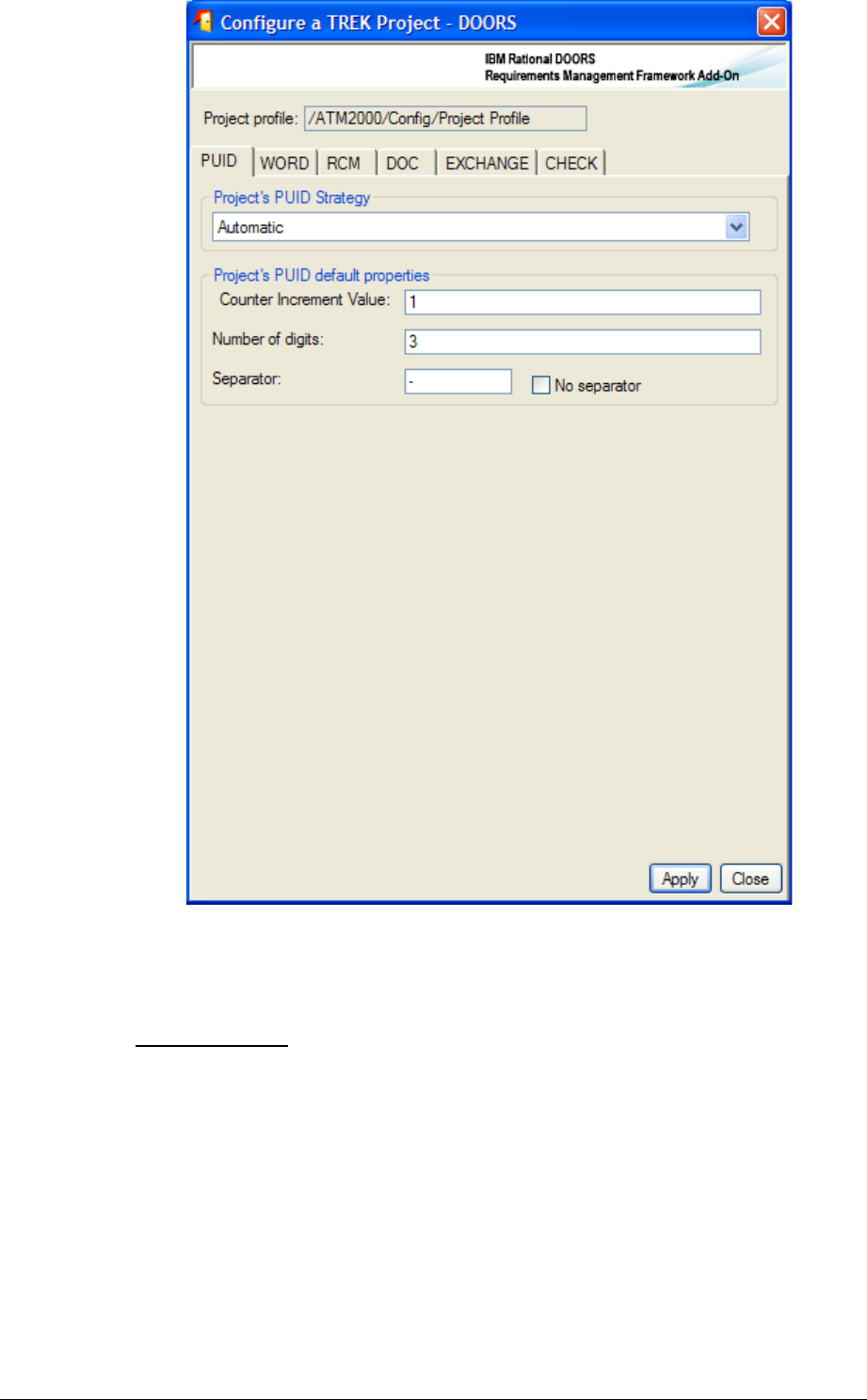
Figure 5 : Project configuration PUID tab
The different parameters are visible into different tabs.
3.1.3.1 PUID
What is a PUID ?
The PUID means Project Unique Identifier. It's the reference name of RMF objects like
Requirements.
You can either decide to manage yourself the PUID entering their values manually or let
IRDRMFAO set it automatically. This last case is the default mode called "Automatic
PUID strategy". In automatic mode the PUID is composed of 3 parts (Prefix, Object Type
and Number) separate by a separator.
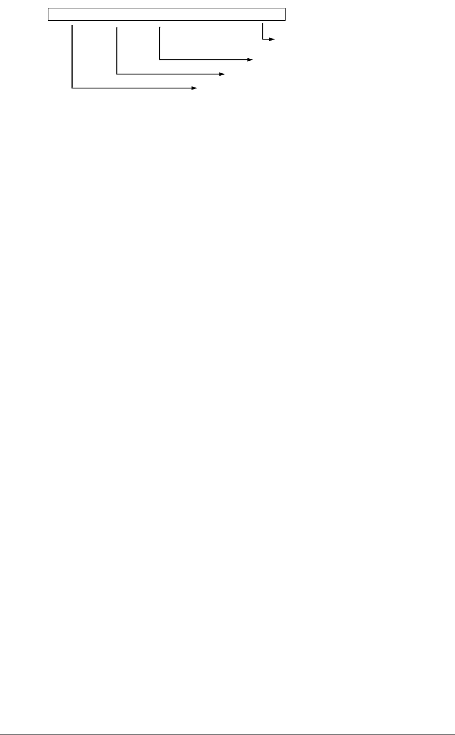
<Prefix><
Sep
><Object Type ><
Sep
><N°>
e .g .: R F P -R E Q -0 1 5
The module prefix (definition local to module)
The separator
The Object Type (definition global
to the project)
The number (relatively to the
Object Type category)
Figure 6 : PUID structure in automatic mode
To configure parameters applicable to the whole project,
In the project manager window (also called “Database window”), select the RMF
project with the DOORS Explorer (left part of the “Database window”),
Run the menu “RMF ->Configure a RMF project”,
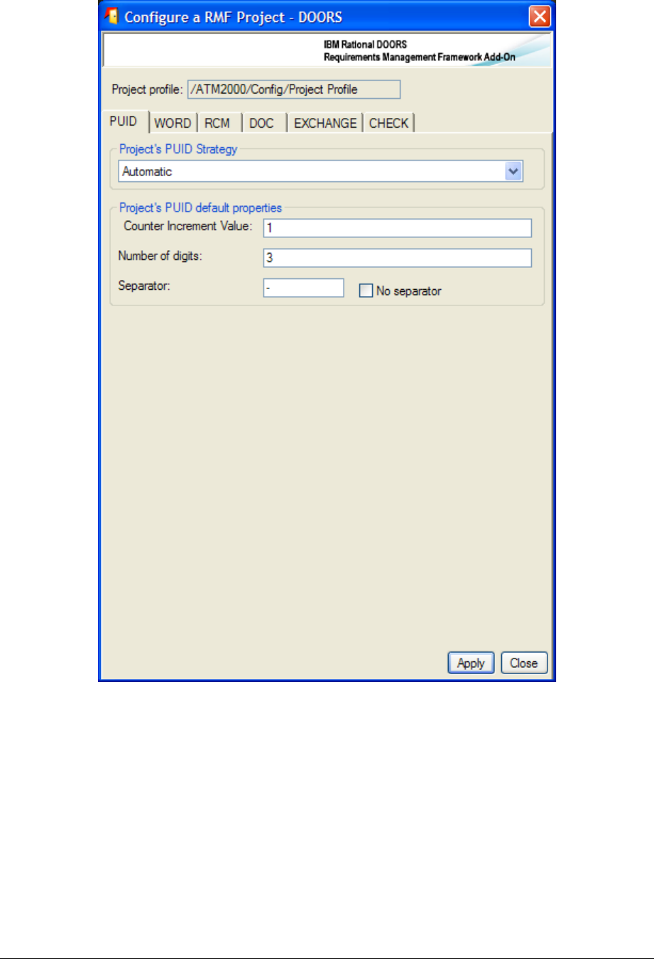
Figure 7 : RMF project configuration, PUID tab
Select the project PUID strategy : Automatic (default) or Manual,
Then for Automatic mode, set the PUID properties:
oCounter increment value (e.g. if 10 : RFP-REQ-10, RFP-REQ-20, RFP-
REQ-30,…),

oThe number of fixed digit for the counter (e.g. if 3 : RFP-REQ-003, RFP-
REQ-020, RFP-REQ-234,…)
Set "0" if you don't want a number of fixed digit,
oThe separator character. If you want an empty separator you should select
the toggle “no separator”. If not an empty value will be replaced by a
space character.
Remark: In Automatic mode, the Prefix part of the PUID is defined at module level by the
"Module Configuration" utility.
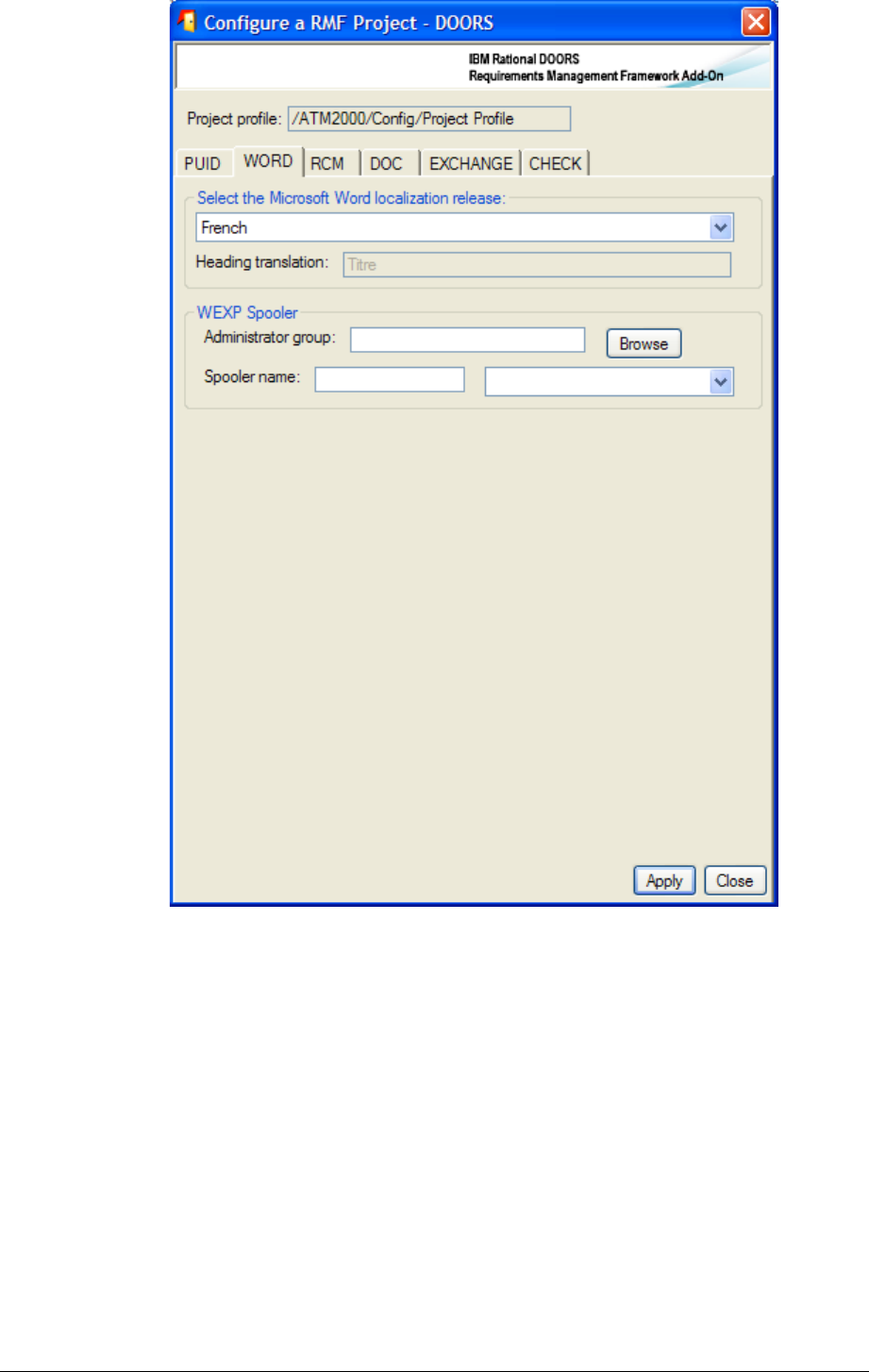
3.1.3.2 WORD
Figure 8 : RMF project configuration, WORD tab
This tab contains some parameters used for the document generation function.
Document generation with IRDRMFAO is possible only with Word.
Select the Microsoft Word language release. This is used by the document
production utility to decide the style name to export for headings. Notice that
there is no relation between that parameter and the spelling checker to use.
For the spooler configuration, that can be used to manage WEXP exports on a
dedicated computer, you should consult the WEXP manual.
.
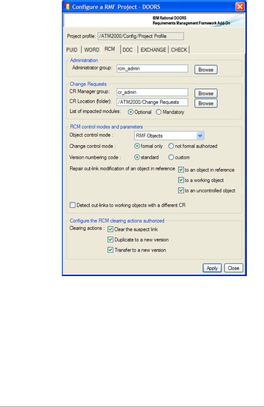
3.1.3.3 RCM
Figure 9 : RMF project configuration, RCM tab
The definition of these parameters is required to deploy the RCM functionality. This
configuration is documented into the RCM reference manual.
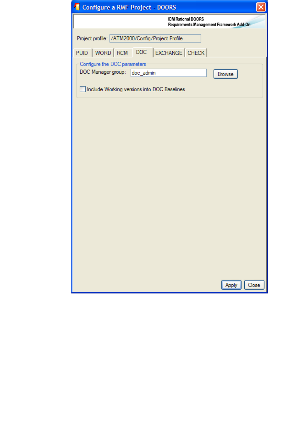
3.1.3.4 DOC
Figure 10 : RMF project configuration, DOC tab
The definition of these parameters is required to deploy the DOC functionality. This
configuration is documented into the DOC reference manual.
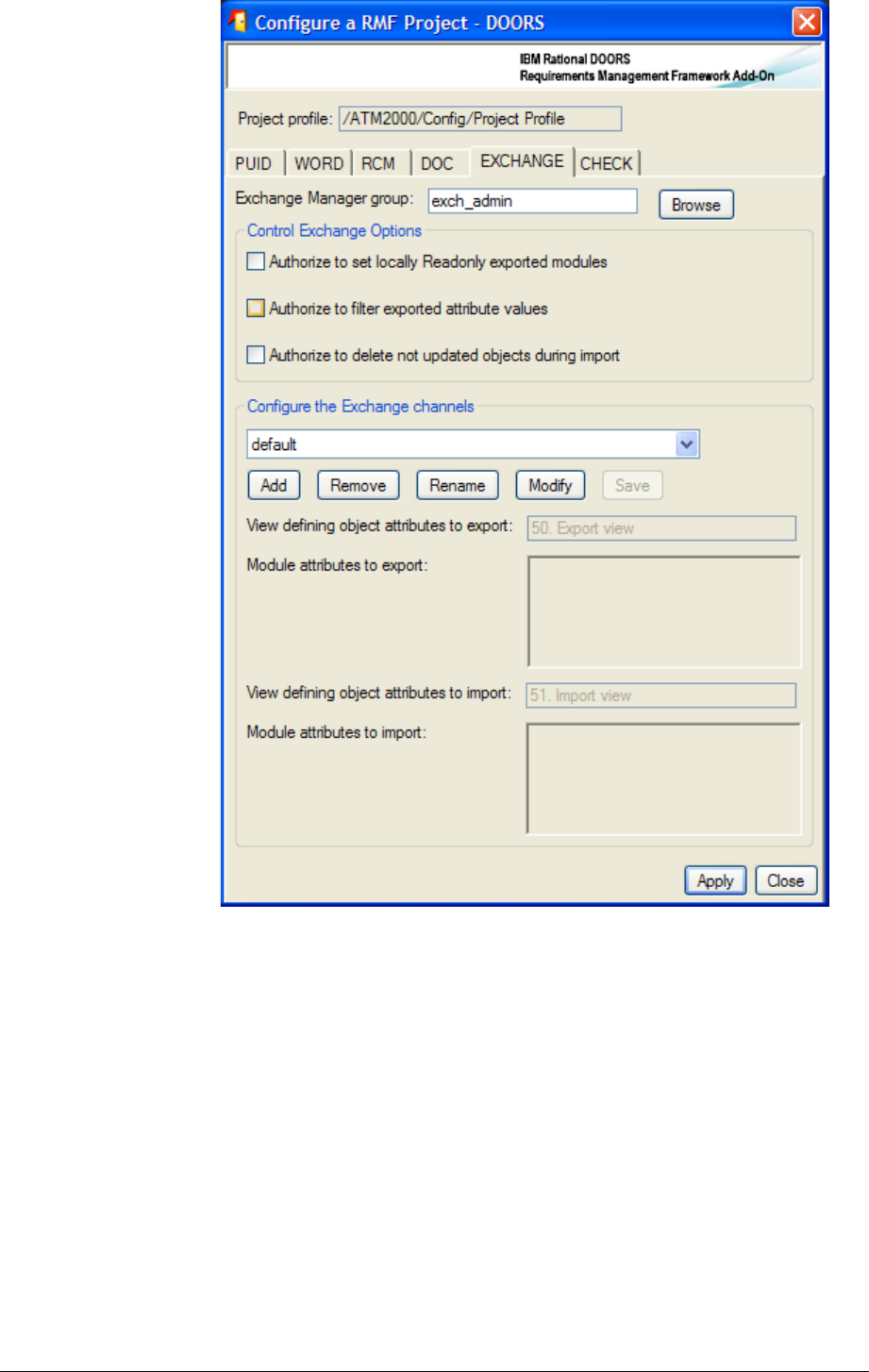
3.1.3.5 EXCHANGE
Figure 11 : RMF project configuration, EXCHANGE tab
The definition of these parameters is required to use the Exchange functionality. This
configuration is documented into the Exchange reference manual.
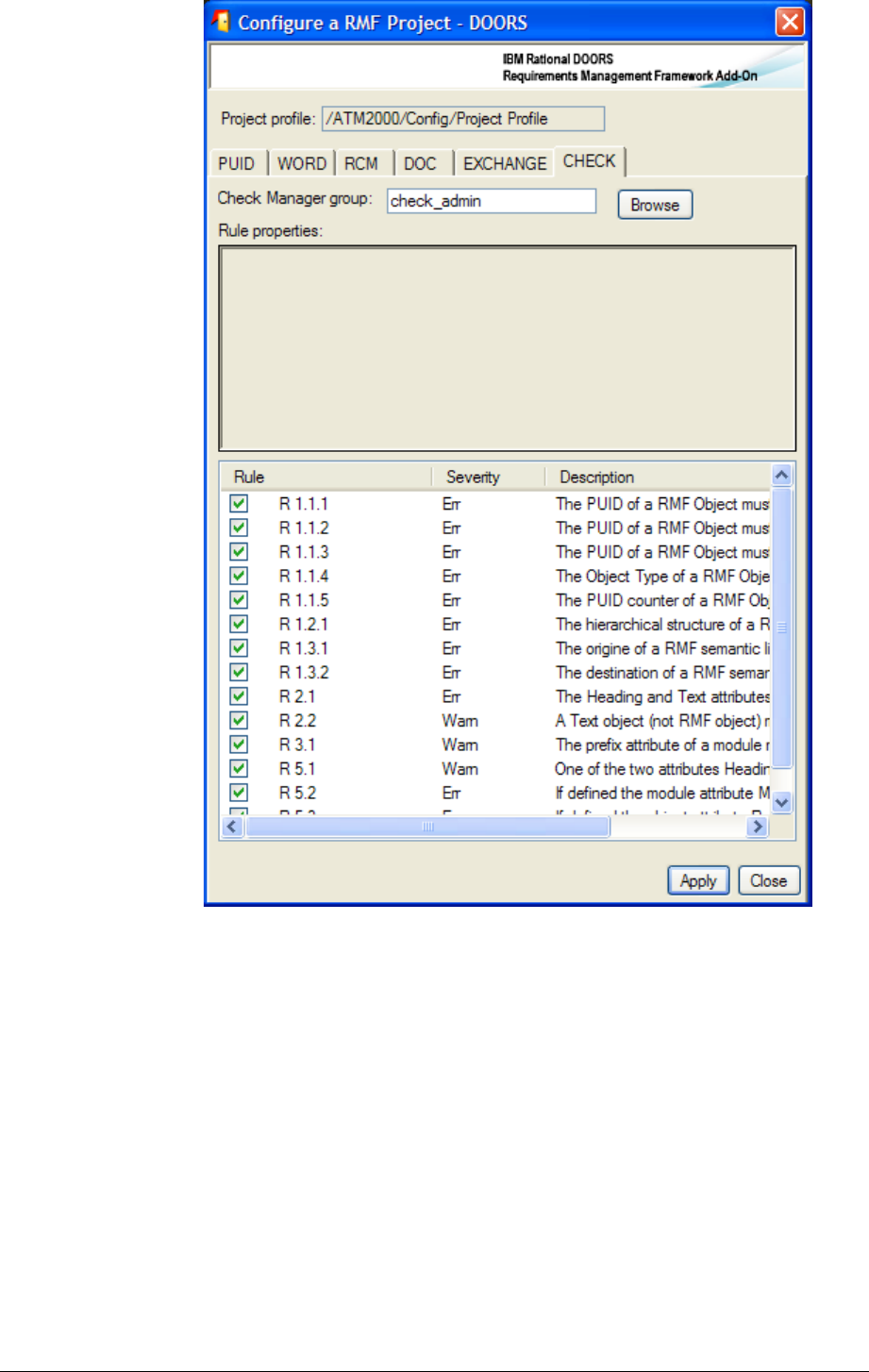
3.1.3.6 CHECK
Figure 12 : RMF project configuration, CHECK tab
The definition of these parameters is required to use the Integrity Check functionality.
The first parameter is the definition of the Check Manager group for the project. This role
gives the ability to change the Integrity check configuration at module level, it is also used
to “protect” the integrity status of each module with specific access rights.
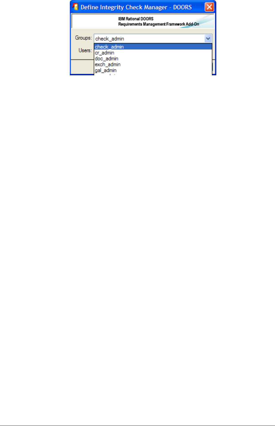
To define the Check Manager click the “Browse” button, and then select a group from the
displayed dialog.
The second parameter is the list of integrity rules that are available with the IRDRMFAO
version installed. The integrity rules should be defined into DXL, in some specific place of
the IRDRMFAO software. There is a predefined set of rules delivered with IRDRMFAO ,
these rules are generic and applicable to any RMF project. It is also possible to define
specific rules by developing new rules.
When defined, a rule may be activated or not into the project. It is also possible to redefine
for some specific modules the set of activated or non activated rules.
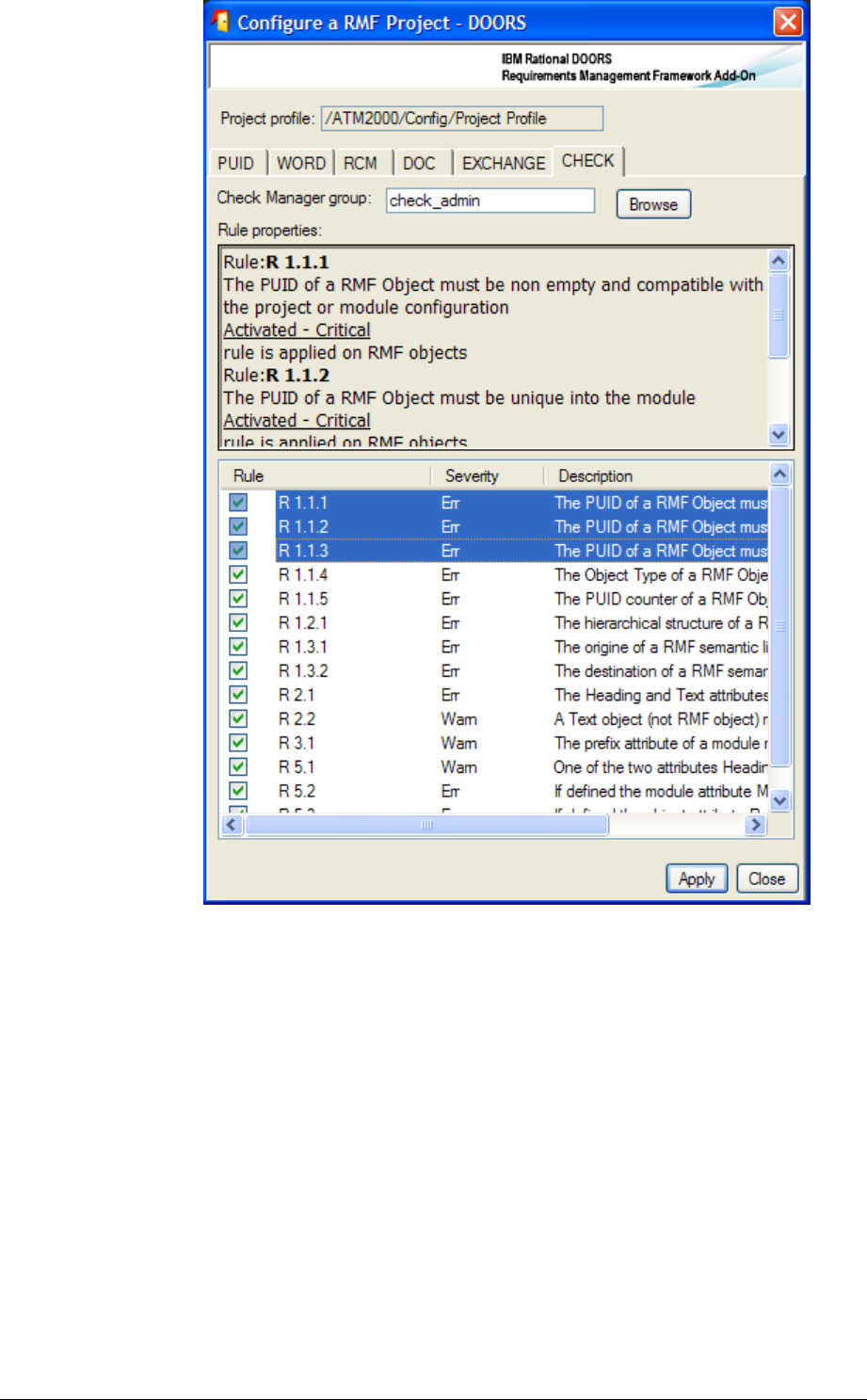
To activate or inactivate a rule, you may check or uncheck the check box associated with
each rule, or you may select several rules and apply the operations “Activate selection” and
“Inactivate selection” from the contextual menu (right button of the mouse).
The operations “Error” and “Warning” may be used to change the severity level associated
with each rule. The initial severity level is defined into the DXL code.
When a rule is selected, a description of the rule is displayed in the text field above the rule
list.
To get more information on the Integrity Check functionality, refers to chapter § 4.5
CHECK DATA CONSISTENCY.
( #!-
Your project initialization needs careful thought:
First, does the generic data model proposed in IRDRMFAO and composed of
RMF Module Types fit your problem? Which part of the data model may you
need? Without having to have a complete answer at the start, you can make a list
of the retained modules.
Second, for each module retained from the data model, are the default attributes
proposed relevant for your project? Then, according to your need, you can delete
or add attributes within the modules.
If the RMF generic data model or your company data model needs customization see
chapter 7 for explaination to what can be done on your project and how.
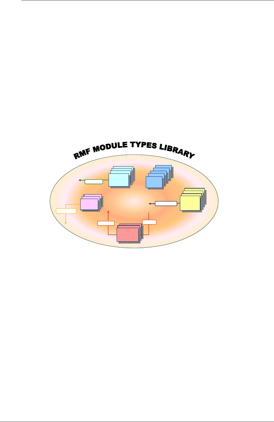
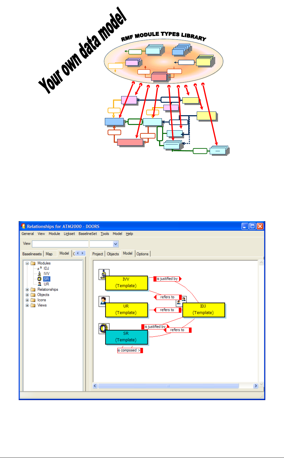
( .)'01
The implementation of a RMF data model can be compared as a library of RMF module
types.
%&
%&
%&
%&
%&
%&
%&
%&
Is allocated b y
satisfies
!
!
!
!
Refers to
!
!
Is justified by
""
""
""
""
""
""
Verifies
Figure 13 : RMF module types library
IRDRMFAO provides different kinds of predefined module types, and each module type
can be used for several purposes, for example:
Several modules in the data model. The IVV module type implements a “verification
procedure” module, a “validation procedure” module and an “integration procedure”
module…and it’s not an exhaustive list.
Several documents. The SR module type can be used to store a System
Specification document, a Sub-system Specification document, Other Stakeholders
requirements or Interface Specification.
The generic data model, and your own version that is derived from it, can be seen as an
assembly of building blocks.
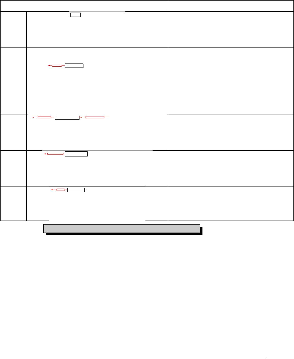
Each building block is a module type characterized by its attributes, views and
incoming/outgoing links. These are summarized in the table below.
Tableau 1: List of RMF generic module types
MODULE TYPES UTILIZATION
UR
User
Requirements
User
Requirements
UR
Module
User Requirements Module
Ex: Contract
Request For Proposal
SR
System
Requiremen ts
System
Requiremen ts
satisfies
SR
Module
System Requirements Module
Ex: SSS
Sub-System Requirements Module
PIDS Module
Ex: SRS
Other stakeholders Requirements
Modules
ID
Issues and
Decisions
Issues and
Decisions
refers to is justified by
ID
Module
Requirements Analysis Module
Design Analysis Module
PBS
Product Breakdown
Structure
Product Breakdown
Structure
is allocated by
PBS
Module
PBS Module
Ex: SSDD
IVV
Tests
Procedures
Tests
Procedures
verifies
IVV
Module
Integration Procedures Module
Verification Procedures Module
Validation Procedures Module
For more detail on the modules, consult the appendix.
When implementing a module type into the model, two different concepts are used:
•The formal module containing the attribute and view definitions associated with
the type is called a “Module Template”. This template concept is completely
different from the DOORS template concept, a DOORS template defines only a
document plan. A RMF template may define also the plan of the formal modules,
but the most important part is the attribute and view definitions.
•A “Module Type” is implemented by a “Module Template”. All the types derived
from the same template contain the same set of definitions. It is the type that is
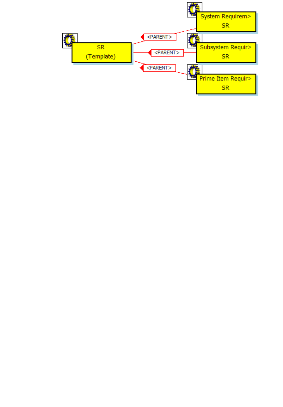
saved into a formal module, when created by IRDRMFAO from a type. The
associations between types may be different of the associations between templates.
Example: The “SR” template implements the types “System Requirements”, “Subsystem
requiremenrs” and “Prime Item Requirements”.
Figure 14 : the SR template
The RMF model contains also the definition of some other module types, such as
Dashboard, Change Request (CR) and Document Index (DI). The corresponding
templates and module types are not dependant on the data model used by the project and
are required by the corresponding components IRDRMFAO .
To create your own project, you have to pick from the module type library in order to
build your project data model, drawing one's inspiration from the generic RMF data model.
%&
%&
%&
%&
%&
%&
%&
%&
Is allocated b y
satisfies
!
!
!
!
Refers to
!
!
Is justified by
""
""
""
""
""
""
Verifies
Verification
Procedures
Verification
Verification
Procedures
Procedures
""
System
Requirements
System
System
Requirements
Requirements
Sub-System
Requirements
Sub
Sub-
-System
System
Requirements
Requirements
User
Requirements
User
User
Requirements
Requirements
Product
Breakdown
Structure
Product
Product
Breakdown
Breakdown
Structure
Structure
%&
Validation &
Installation
Procedures
Validation &
Validation &
Installation
Installation
Procedures
Procedures
""
Internal
Interfaces
Internal
Internal
Interfaces
Interfaces
SRS
SRS
SRS
'
Requirements Analysis
Issues & Decisions
Requirements Analysis
Requirements Analysis
Issues & Decisions
Issues & Decisions
!
Is justified by
Acceptance
Test Equipment
Acceptance
Acceptance
Test Equipment
Test Equipment
%&
'
Figure 15 : Build your own data model from module types library
You may examine your RMF Project Model with the Explorer tool, by executing the
operation “Explore Model” from the RMF project menu.
Example: partial view of the generic model with the Explorer tool
Figure 16 : Explorer (template level)
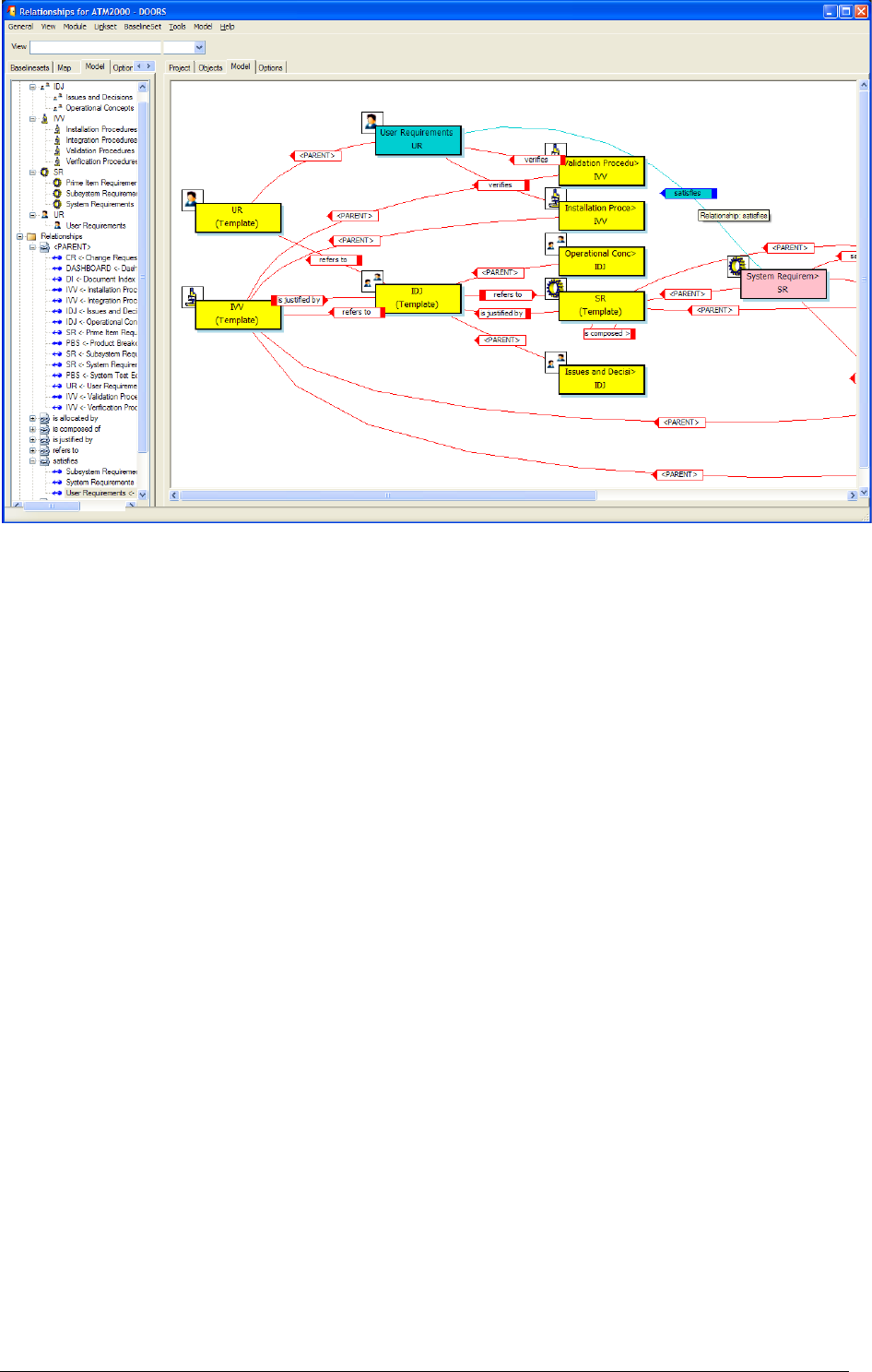
Figure 17 : Explorer (template and module type levels)
This tool allows you to display different views of your RMF Project Model, according to
your process. You may examine for example what is the expected traceability between the
different module types and module templates. To have more information about this tool
you should read the description of the Explorer tool.
The model defines an abstract data model, allowing to understand the nature of the
information, the project contains the concrete data model.
( .#
Each time you need to create a module, you have to determine the required module type to
describe the information contained into the module.
Having done that, you can instanciate the module from the model, by chosing the
corresponding RMF template and type. Then you will have to configure the traceability
between this new module and the already existing modules into the project.
Note that for document importation into DOORS, in particular for Microsoft Word
document, you can start to export the document (using the specific icon for Word) into
DOORS. A DOORS module is then created. In a second step, you have to tag this
DOORS module into one of the RMF module types list (see next paragraph).
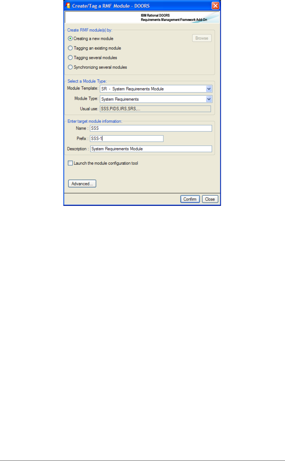
To create a new RMF module:
First select its directory location with the DOORS Explorer (left part of the
“Database window”),
Run the menu “RMF ->Create/Tag a RMF module”,
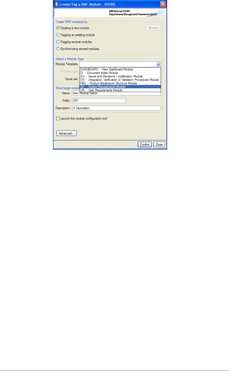
Figure 18: RMF module creation window
Select the appropriate template in the list. The followings are example provided by
the generic data model:
oUR for Users Requirements,
oSR for System Requirements,
oIDJ for Issues & Decisions and Justifications,
oPBS for Product Breakdown Structure,
oIVV for Integration, Verification & Validation,
oDI for Document Index,
oDASHBOARD for dashboard module.
Select the appropriate module type amongst the list of available types according to
the selected template
Give a name, a prefix and a description to the new module. Only name field is
mandatory, RMF will put a default description if the field is left empty. Note that
the module name and description can be modified later.
Click on the 'Create' button, if successful, an acknowledgement window is then
displayed.
The tool supports also other functionalities:
•Tagging an existing module: to add the RMF definitions of the selected module
type to an existing module. Can be used also to upgrade a module after an
evolution of the model.
•Tagging several modules: to add the RMF definitions of the selected module
types to a set of modules.
•Synchronizing several modules: to upgrade a set of modules after an evolution
of the model.
The Advanced button allows the selection of the definitions to add to the module to tag.
You may also create a new module from the Explorer tool, by calling the operation
“Create module” from the selected type:
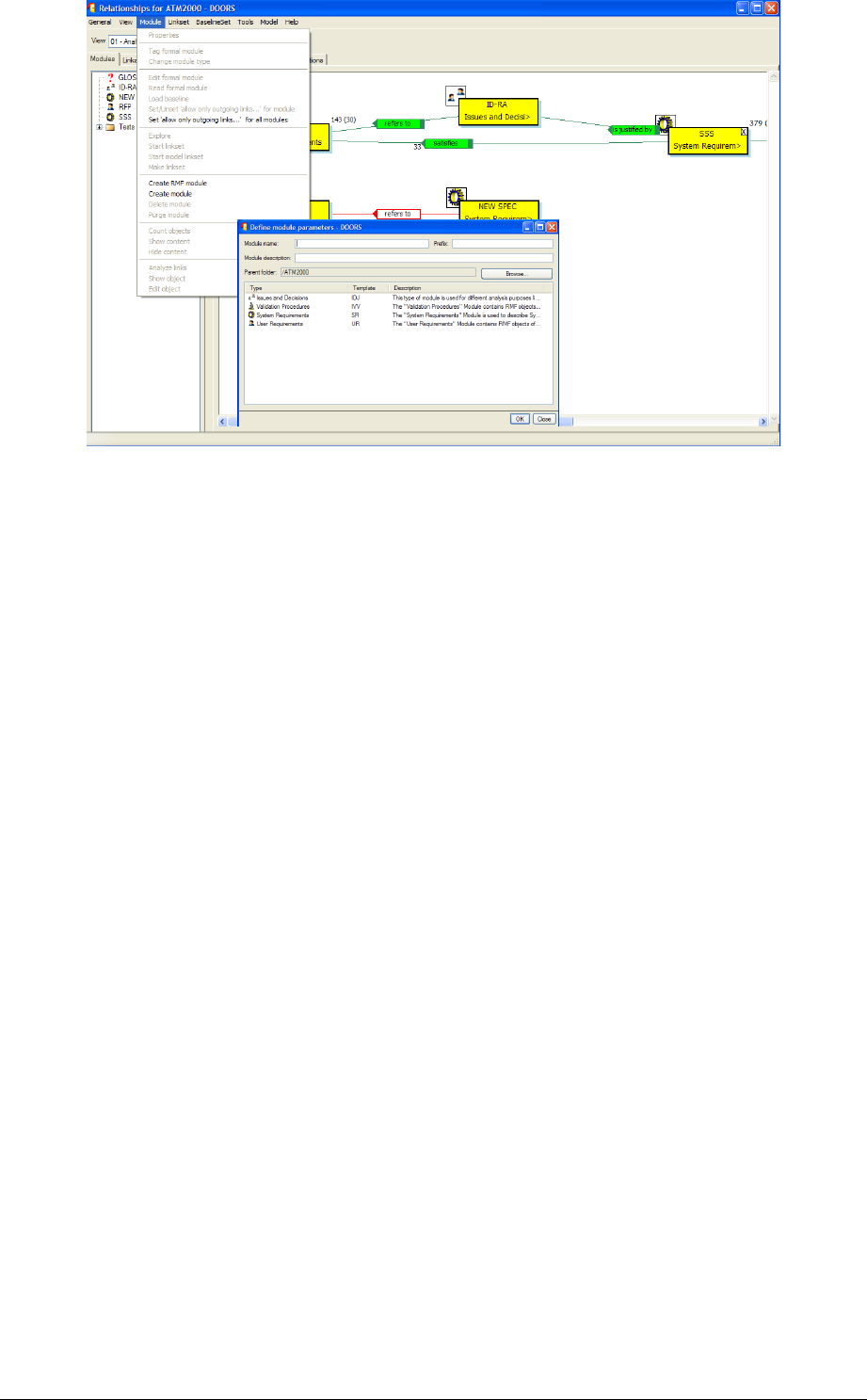
Figure 19 : Create module in Explorer
This operation calls the “RMF ->Create/Tag a RMF module” with some predefined
parameters. The new module is created in the folder from which the Model Explorer has
nee executed. The IE Mod Type attribute is automatically set to the right value, you have
not for example to change the “System Requirements” default value into “Subsystem
Requirements”.
At this point, you can create the default linkset pairing making use of a DOORS feature
(refer to § 3.3 DEFINE THE DEFAULT LINKSET PAIRING).
( ($/$!!#
#
To migrate an existing DOORS module to a RMF structured Module Type, you have to
proceed with the same manner as described in the previous paragraph for RMF module
creation, but this time select the toggle "Tagging an existing module" and browe to find the
module to tag.
Alternatively you can also:
Select a module in the database browser interface
Launch the “RMF -> Create/tag a RMF module” command
This way, the option “Tagging an existing module” is already selected and you don’t need
to browse the module to tag.
Example:
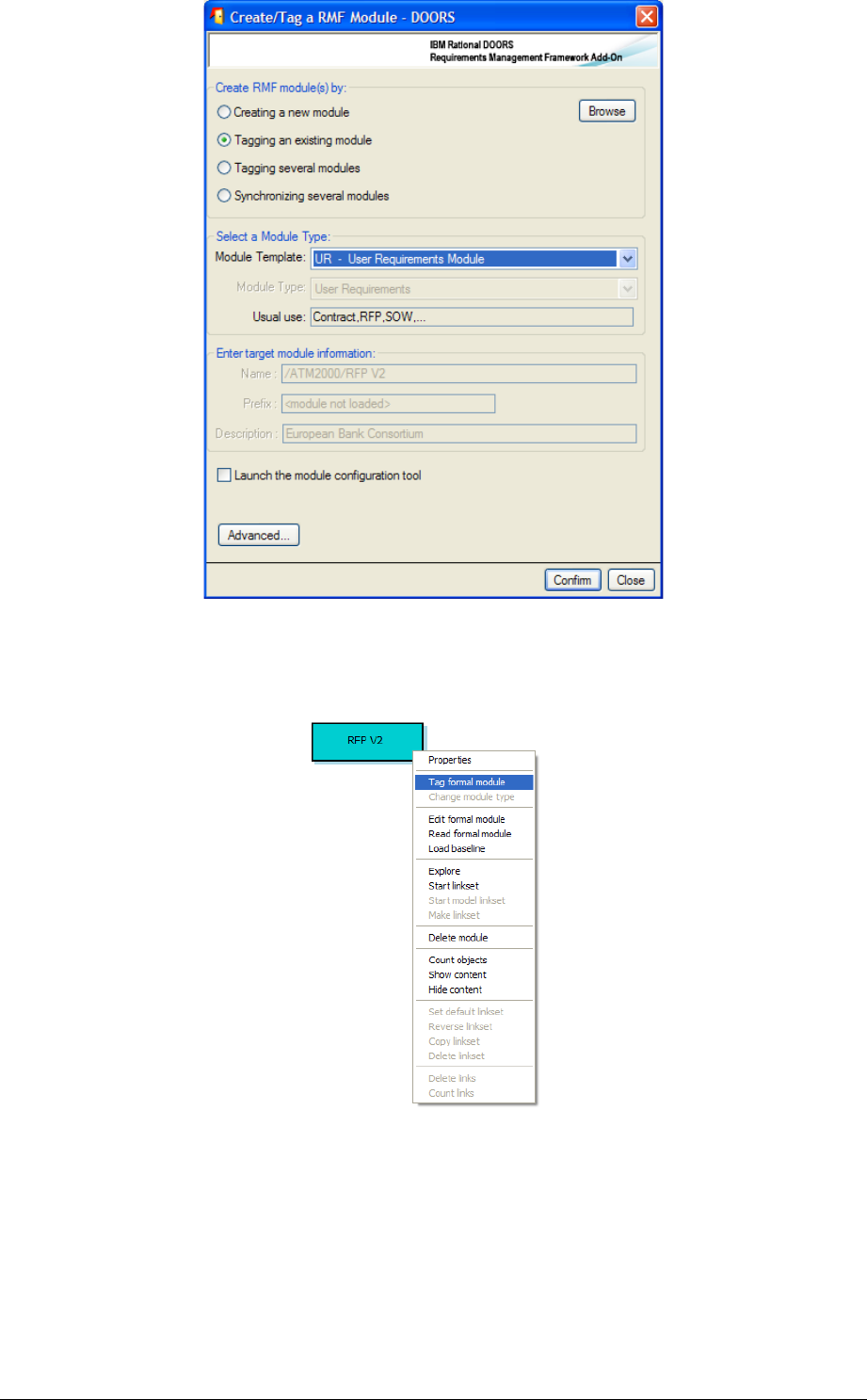
Figure 20 : Create/Tag a RMF Module
An alternative way is the call of the operation “Tag module” in the Explorer tool:
Figure 21 : Tag module in Explorer
This operation calls the “RMF ->Create/Tag a RMF module” with some predefined
parameters.
The IE Mod Type attribute is automatically set to the right value, you have not for
example to change the “System Requirements” default value into “Subsystem
Requirements”.
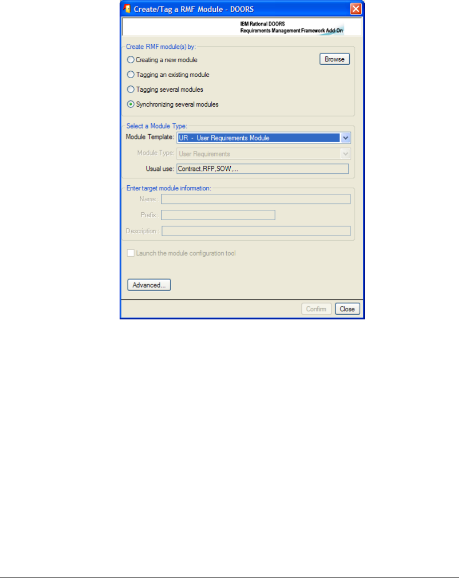
( 2$"/$!!
##
This is also possible by using the third option “Tagging several modules”:
Launch the “Create/tag a RMF module” command
Select the “Module Type” value in the list
Select the “Tagging several modules” option
Click the “Browse” button, the following dialog box appears:
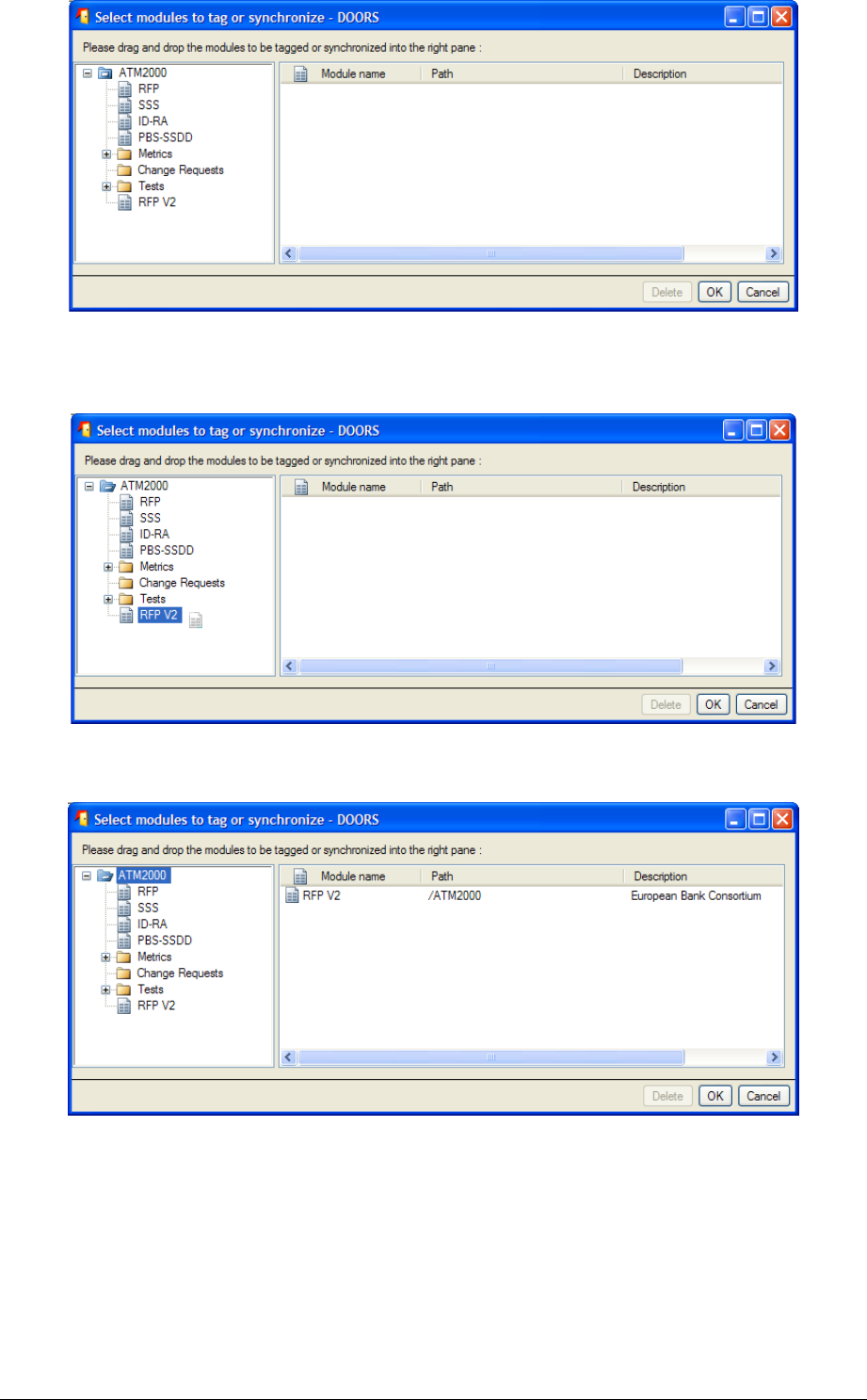
Figure 22 : Browse dialog (1) in Create/Tag a RMF module
Select the modules that you want to synchronize with the same module type by dragging
and droping them in the right pane:
Figure 23 : Browse dialog (2) in Create/Tag a RMF module
The dragged module shows in the right pane, as follows:
Figure 24 : Browse dialog (3) in Create/Tag a RMF module
Then click on the “OK” button. The browse dialog disappears.
Select the module type to use as a model and then click on the “Create” button of the main
dialog box.
You may drag several modules in only one operation by dragging a folder or a project: all
the modules contained by the folder or the project are automatically dragged.
The operation “Synchronizing several modules” has a different behaviour: when selecting
this mode, the tagging operation is applied only to the modules that have already been
tagged with the selected type. This mode should be used to propagate an evolution in the
model (new attributes or new views) to the already existing modules.
( 3#!#$
IRDRMFAO allows the definition of some parameters that are applied at module level.
Some are defined at project level but you may modified them locally.
To configure parameters applicable to a particular RMF module,
Open the module,
Run the menu “RMF ->Configure Module”,
Figure 25 : RMF module configuration window
The different items of the module configuration are visible into different tabs.
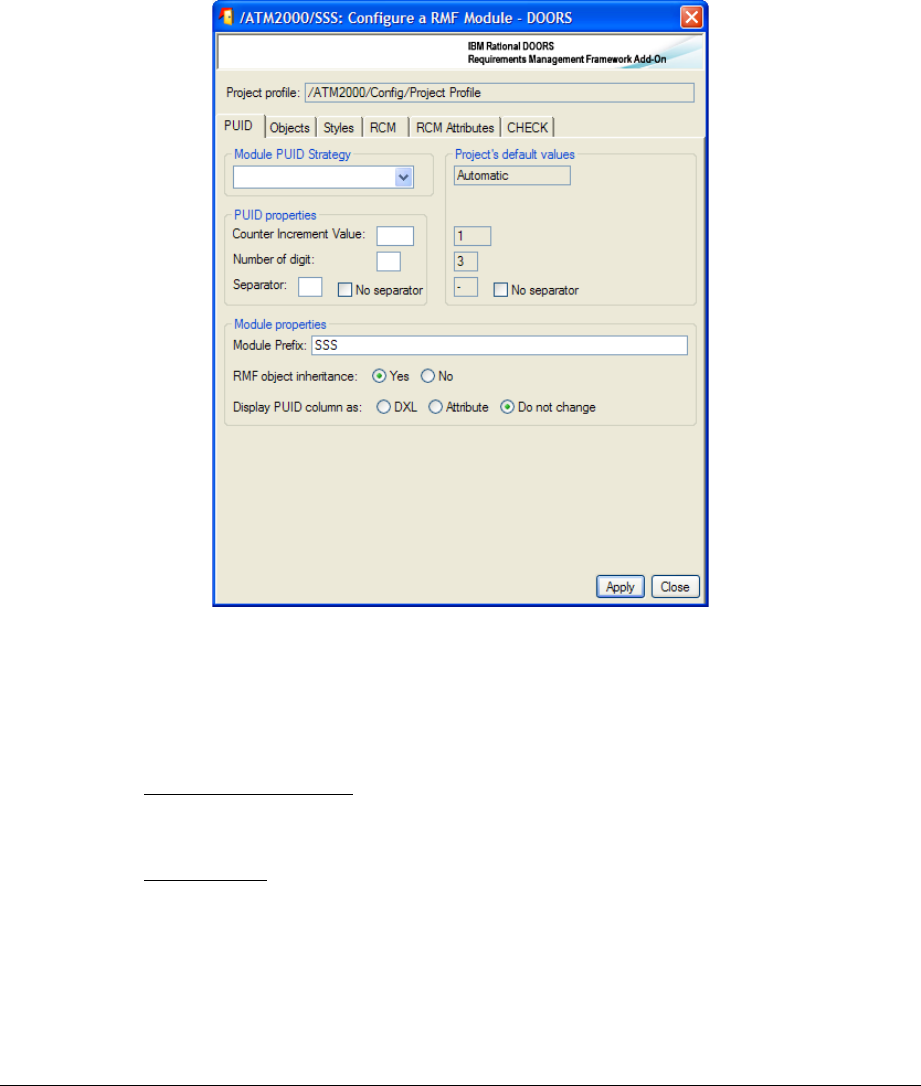
3.2.5.1 PUID
This tab contains all the PUID configuration options.
Top part of the window : concerns overridable project parameters. Refers to § 3.1.3 RMF
PROJECT CONFIGURATION to know more about PUID meaning, setting strategy and
properties.
Module Prefix: In Automatic mode, defined the Prefix part of the PUID (Refers to § 3.1.3
RMF PROJECT CONFIGURATION).
RMF Object inheritance : « Yes » makes the attribute « IE Object Type » to be inherited…
by defaut choose this option except if you want to make some chapter object to be
identified (not recommended, but usefull for PBS module objects.
Display PUID column: "DXL" option allows to prevent direct modification of PUID
displayed in views whereas "Attribute" option allows it. All the views of this module are
going to be checked and modified. The option "Nor" let the views as they are.
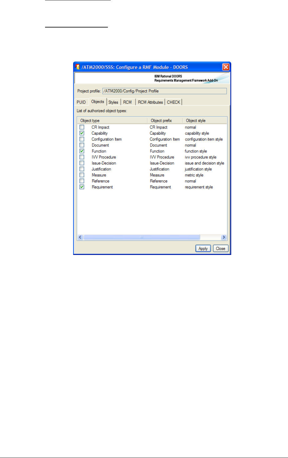
3.2.5.2 Objects
Figure 26 : RMF module configuration Objects tab
This is the list of the Object Types that you can identify. By default, the checked boxes are
those allowed according to the Module Type. It can be modified by checking/unchecking
the boxes.
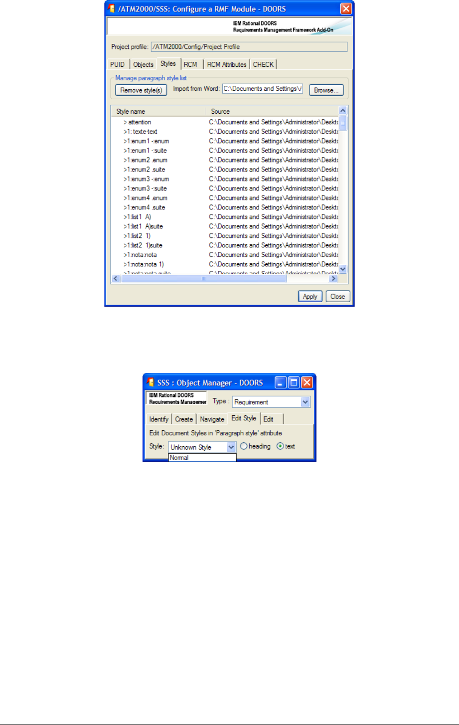
3.2.5.3 Styles
Figure 27 : RMF module configuration Styles tab
You can use the browse operation to pick all paragraph styles defined into a document
template. The styles are then usable into the Manage Object dialog to associate a Word
paragraph style with an object text.
You may also remove some defined styles by selecting the style names into the list, and
then click the Remove style(s) button.
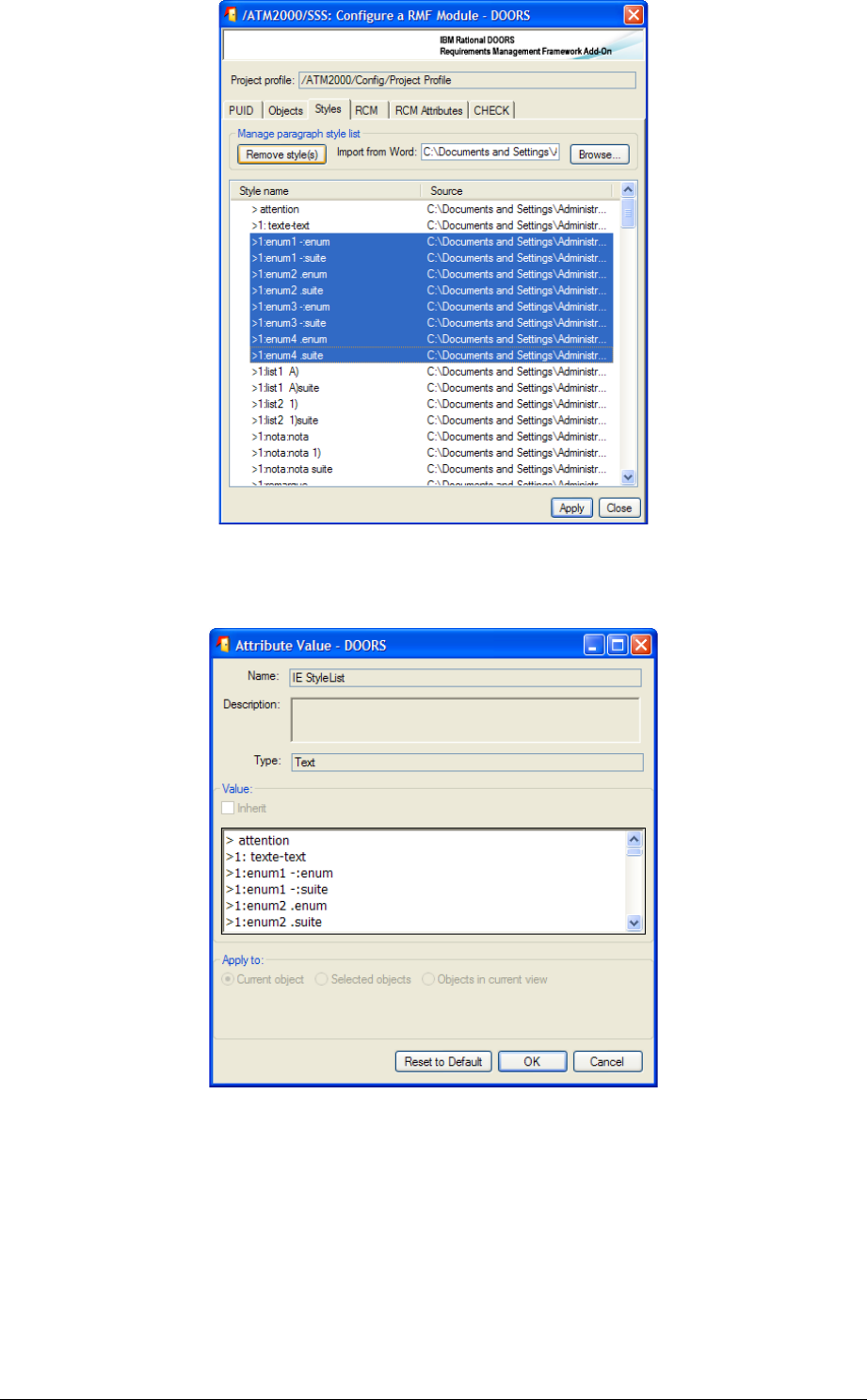
The list contains only the style name, the style definition is only in the Word template, and
the styles must be defined in the templates used by the document generation.
This information is saved into the module attribute “IE Style List”:
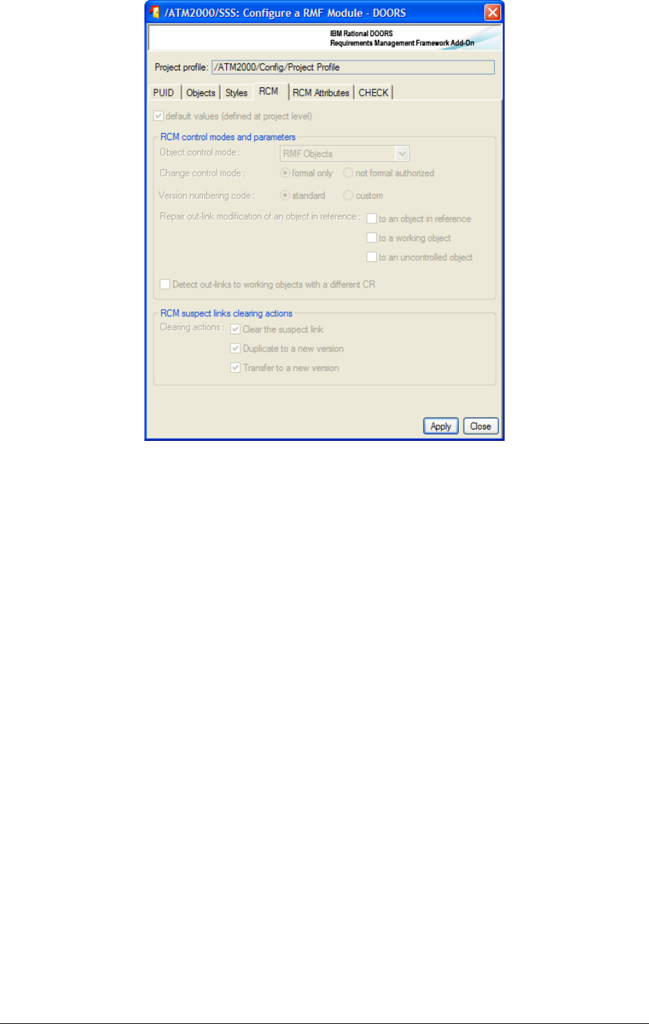
3.2.5.4 RCM and RCM attributes
Figure 28 : RMF module configuration RCM tab
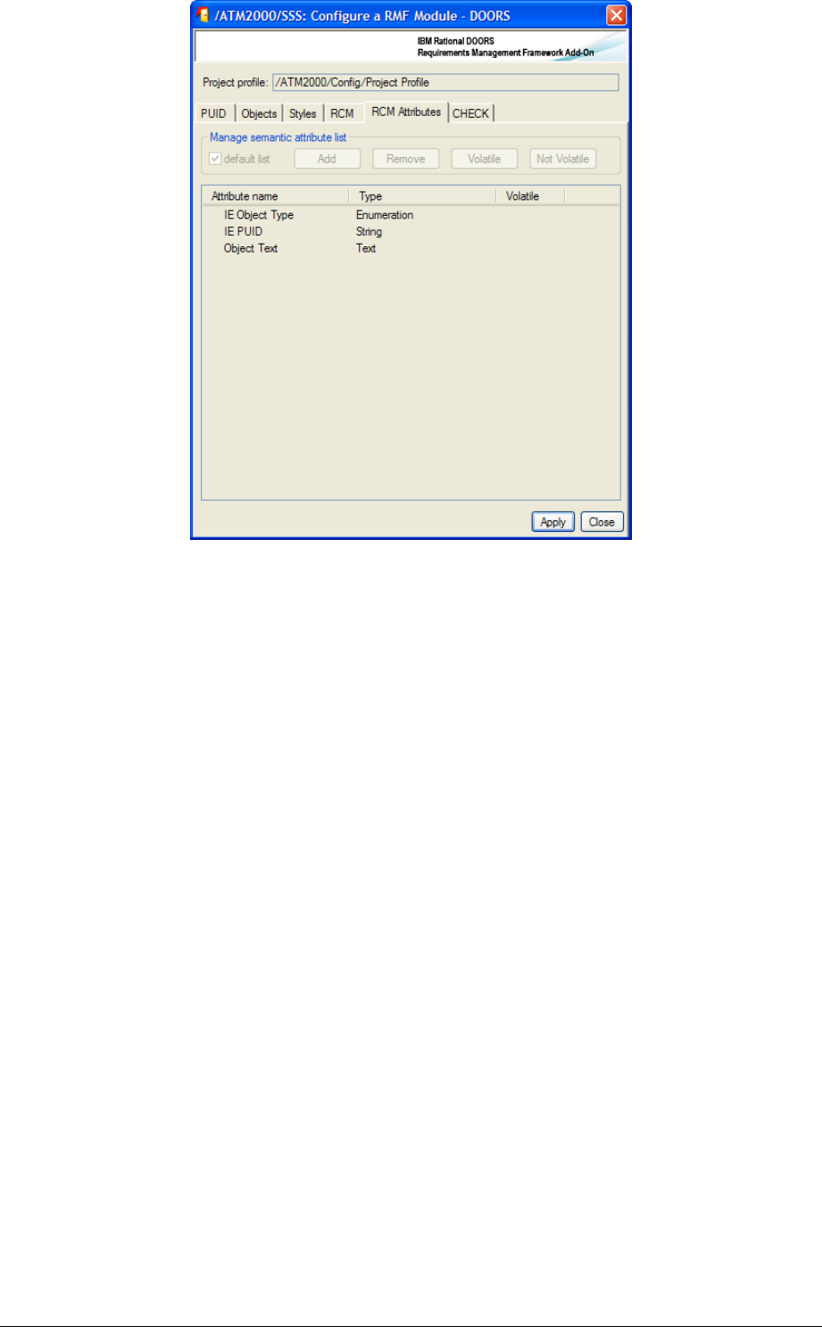
Figure 29 : RMF module configuration RCM attributes tab
You should consult the RCM documentation to understand the use of these parameters.
They are accessible only if RCM is initialized into the project and if the module is under
RCM control. Only a user defined into the project as a RCM administrator is able to
modify these parameters.
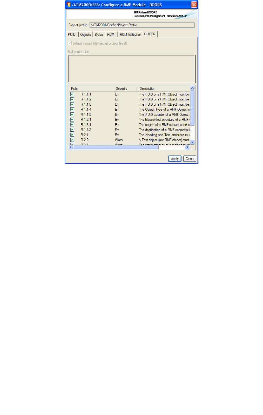
3.2.5.5 Check
Figure 30 : RMF module configuration Check tab
This windows can be used to modify the Integrity Check configuration specifically for a
module. It is possible only:
•Integrity Check is already configured at project level
•You have the role Integrity Check Manager for the current project
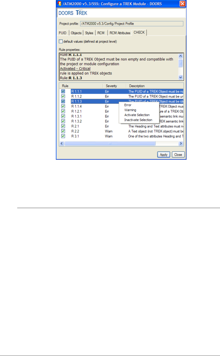
To define the Integrity Check configuration you must first uncheck the toggle “default
values” at the top of the window.
The configuration dialog allows you to:
•Activate or inactivate a rule. By default the activation state is inherited from the
project level activation state
•Change the severity level of the rule. The severity level may be Error or Warning.
By default it is inherited from the project level severity level.
You may select one or several integrity rules, and use the operations from the contextual
menu (right button of the mouse) to change the status of a rule, or you can check or
uncheck the check box associated with each rule to activate or inactivate the rule.
TBU
To get more information on the Integrity Check functionality, refers to chapter § 4.5
CHECK DATA CONSISTENCY.
( ( !#)!#4%$
Once, you have created several modules in your project, you have to teach to DOORS
which link types should be used by default (or be prohibited !) between pairs of module:
DOORS allows this (this is not a IRDRMFAO feature). For each pair of modules, you
have to define the default link modules between this module and the others that are used
whenever anyone creates a link between them.
To do this, run “File->Module properties…”, select “Linksets” tab and add all the default
linkset pairings (only the outgoing links from that current module). Remember to define all
links in the ‘upward’ direction.
Example:
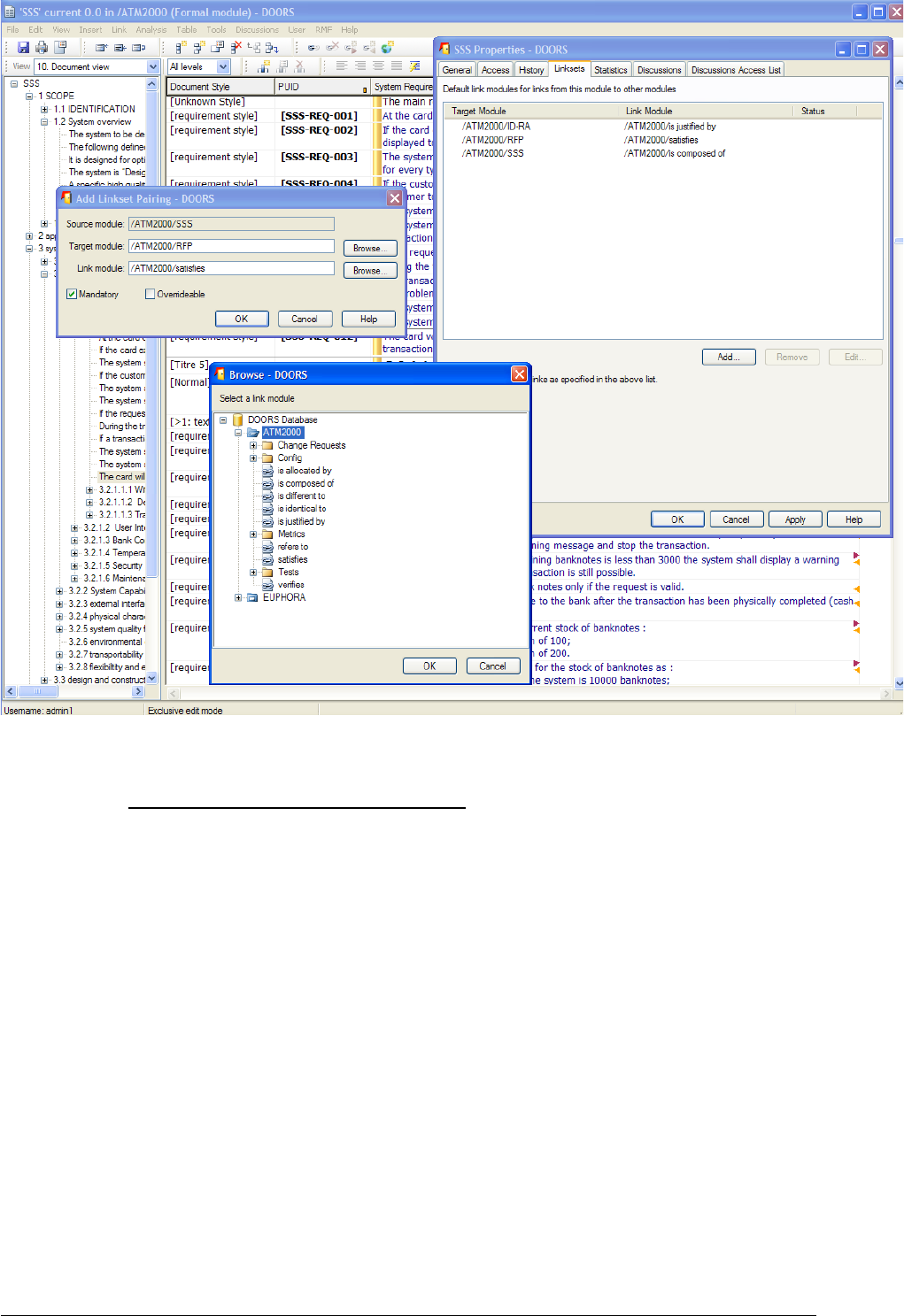
Figure 31 : linkset pairing configuration with DOORRS
Why IRDRMFAO can't do it automatically ?
To do this, you need a macro-vision of your data model that IRDRMFAO can't determine
alone: for example, you can have 3 ranks of SR modules and authorize "satisfies" links
between rank n & n-1, and n-1 & n-2, but prevent direct link between n & n-2.
With IRDRMFAO , there is now a better support to do this operation: you may use the
Explorer tool to display a map of your project, and to manage the dependencies between
modules. The tool shows you what are the linksets compatible or not compatible with your
RMF Project Model.
Example:
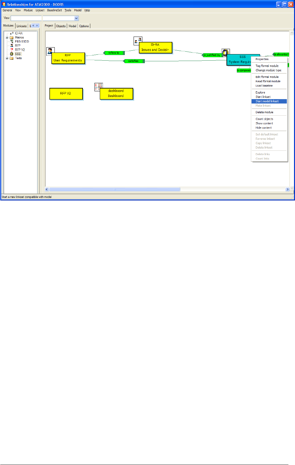
Figure 32 : Start model linkset in Explorer
You may use the operations “Start model linkset” and “Make linkset” to create a new
default linkset, compatible with the RMF Project Model, between two modules. To have
more details about this tool you should read the document describing the Explorer tool.
The Explorer has a lot of other functionalities.
2 56'
2 )-7
Once your RMF objects (i.e. requirements, capabilities, configuration items,…) have been
identified in your module, you have to manage them by making use of attributes. For this,
all RMF module types make available at least an “Analysis” view, and sometime specific
analysis views like “Critical requirement list”. In addition, most of the traceability matrix
views add columns with attributes for analysis. For more details on the contents of views
and the attribute meanings, refer to the appendix A. To customize attributes, refer to § 7.2
ADAPTING MODULE ATTRIBUTES.
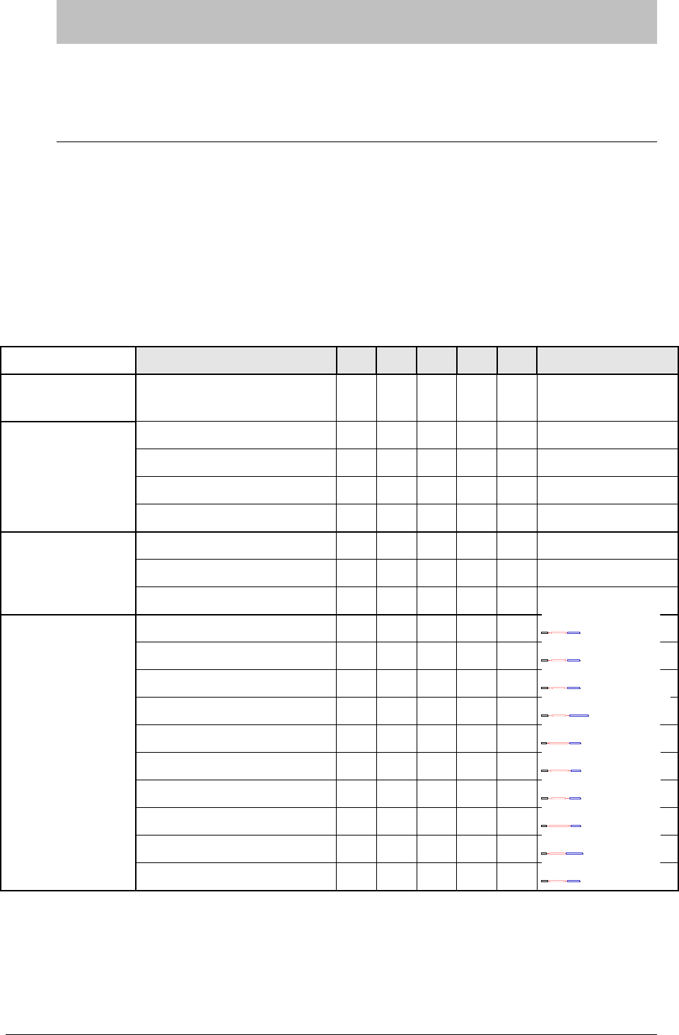
The following table summarizes the availability and intended usage of the views that you
will find in RMF predefined module types.
Tableau 2: List of standard RMF views
View name UR SR PBS ID IVV Remarks
Document
approach
Document view X X X X X
Generic Analysis
Views
Requirements analysis X X
Configuration item analysis X
IVV procedure analysis X
Issues and Decisions analysis X
Specific Analysis
Views to point out
a particular aspect
Critical requirements list X X
Key requirements list X X
Requirements in negotiation X X
Traceability Matrix
Views
Associated issues X X X X
ID
ID
Refers to
X
X
Compliance matrix X X
SR
SR
Satisfies
X
X
Verification/Validation matrix X X
IVV
IVV
verifies
X
X
IVV matrix X
UR/SR/PBS
UR/SR/PBSverifies
X
X
Allocation matrix X
PBS
PBS
Is allocated by
X
X
Justification X X X
ID
ID
Is justify by
X
X
Upper requirements satisfy X
UR/SR
UR/SR
satisfies
X
X
Allocated requirements X
SR
SR
Is allocated by
X
X
Decisions justify X
SR/PBS/IVV
SR/PBS/IVV
Is justify by
X
X
Issues refers to X
UR/SR
UR/SR
Refers to
X
X

2 !#!!
In order to keep track of significant issues encountered during your analysis and to record
the decisions taken , it is highly recommended that the “Issues and Decisions” module
(ID) type is used.
Issues a nd
Decisio ns
Issues a nd
Decisi ons
refers to is justified by
ID
Module
The IDJ module provides enriched traceability between a pair of modules, as for example
between the following pairs: UR-SR, IVV-UR, IVV-SR or PBS-SR.
The IDJ module connects together only relevant RMF objects with issues, not the whole
module. So it is not necessary to have links to all objects in the “incoming” module. In the
same way, reference links to all objects in the “outgoing” module are not mandatory.
For significant issues with impact outside the local team (customer, subcontractor,
business, major tradeoffs, etc) use the "Issue - Decision" construct in the Requirements
Analysis and Design Analysis modules to capture the issue and, when resolved, the
decision. It is usefull to manage negotiation with customer using the “status” attribute
and/or other attributes you may want to create.
Notice also that a "Rationale" object attribute field exists in the User Requirement and
System Requirement modules for "routine" decisions and issues within the responsibility
of individual engineers or co-located teams. It is recommended that this mechanism is used
to record less significant issues and decisions.
2 ( '48'56
2 (
IRDRMFAO provides specific facilities to assist in the management of requirements which
are particularly important to the project, either because they are risky or because they are
key for another reason (e.g. stage payment milestones). The former category are called
‘Critical requirements’ and the latter are called ‘Key requirements’, and of course some
requirements can be in both categories.
2 ( 56
During requirements analysis, you may identify some requirements as being particularly
risky for the project. To lend weight to them and allow you to follow them closely,
IRDRMFAO provides a dedicated view “Critical requirements list”.
The procedure is:
First step, in the view “Requirements analysis”, set the enumerated “risk impact”
attribute. Setting this attribute both marks the requirement as risky and qualifies
the type of risk (Technology, performance, cost, delivery,…). Notice that the
attribute can take several values.
Second step, in the view “Risk analysis” (which is filtered on risk,see figure below),
you can additionally quantify the level of risk by setting the attribute “Risk Level”,
and quantify the probability of the risk occurring by setting the “IE Risk
Probability” attribute. A graphic bar chart allows you to quickly spot risk visually,
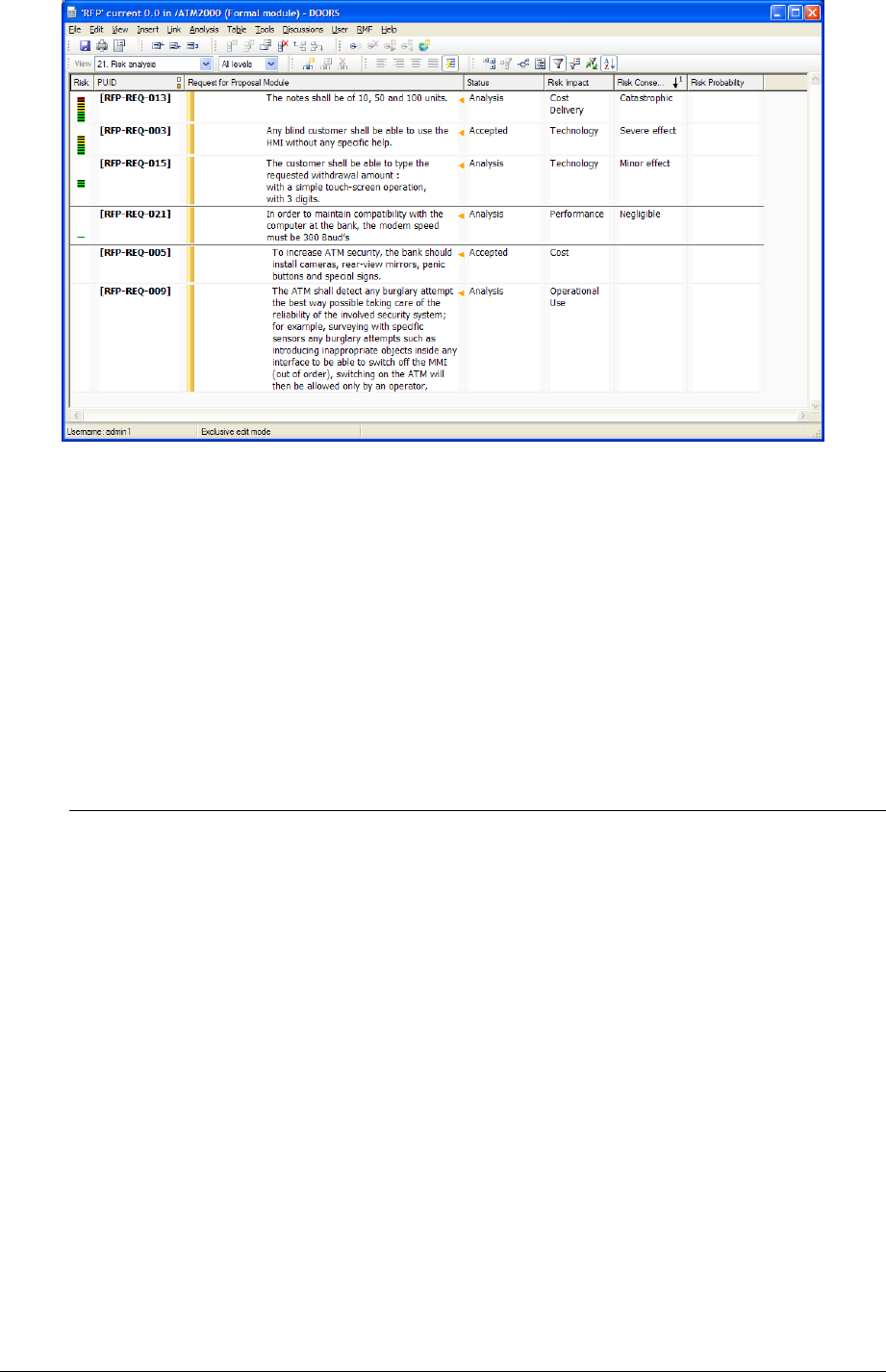
as ‘risky’ requirements have a coloured border. This is particularly usefull when
you unset the filter icon and see the critical requirements among all others.
2 ( (4'56
During requirements analysis, you can identify some requirements as key for the project.
To lend weight to them and allow you to follow them closely, IRDRMFAO provides
another dedicated view “Key requirements list”.
The procedure is:
First step, in the view “Requirements analysis”, for the key requirements set the
boolean “Key requirement” to true.
Second step, display the view “Key requirement list”.
2 2 4#&,
Once RMF objects have been identified (Requirements, functions,…), you will have to link
them according to the RMF data model (See §2.2 RMF GENERIC DATA MODEL) or
your own customization.
There are two steps to link objects:
- Select a link name (optional),
- Link objects.
2 2 4
Most of the time, you will not need to select the link name because you will use the default
linkset you had already defined (Refers to § 3.2.2 CREATE A NEW RMF Module).
If you have not define the default link set or want to use another one, select a link module
which will be the default link set for all links you will make in the current session, until you
select another one.
To select a link module, activate the utility by the menu “RMF ->Define default link module”
from database window or the module window.

2 2 4$#&,
4.4.2.1 GENERAL PRINCIPLES
RMF objects are linked with the standard way of DOORS.
Notice that if your RMF objects have a hierarchy, the incoming or outgoing links must
connect the main object (father, not children objects).
Caution : Pay attention to respect the directions of the data model links. Notice that
in the data model the links are bottom-up oriented. This is not a coincidence, it is for
traceability convenience!
Badly oriented links can be corrected with the utility “Explore -> Project” (see §4.4.3), from
the RMF menu in the DOORS Database window. This tool will point out the linksets that
are not compatible with your RMF Project Model.
As you put links inside your project, you will be quickly able to see the effect by displaying
the predefined traceability views. Refer to the table §4.1 “List of standard RMF views” to
quickly locate the right view according to module type and link module.
4.4.2.2 REQUIREMENTS SATISFY UPPER LEVEL REQUIREMENTS
Typically System Requirements (SR) satify User Requirements (UR). This is the typical use
of the link module “satisfies”, but the data model also allows a cascade of modules of the
“System Requirement” module type. For example sub-system requirements satisfy system
requirements.The link module “satisfies” should also be used in this situation between
pairs of modules of the SR type.
4.4.2.3 REQUIREMENTS / FUNCTIONS ARE ALLOCATED TO
CONFIGURATION ITEMS
System Requirements are allocated to Functions and Functions are allocated to
Configuration Items, both using the link module “is allocated by” . This is the correct
methodology. IRDRMFAO also allows Requirements to be allocated directly
Configuration Items, again by using the “is allocated by” link module.
4.4.2.4 LINK RMF OBJECTS WITHIN A SAME MODULE
It is possible to link objects within a same module. One use of a such links is to model an
additional hierarchy.to that modelled by standard DOORS headings, for example if the
DOORS hierarchy is used to model a functional decomposition, explicit links could be
used to model a physical hierarchy.
Another use is to mimic the implicit DOORS hierarchy with an explicit one created from
links, because this greatly facilitates the creation of traceability or impact views, without
DXL development. For this situation, IRDRMFAO provides a utility which will automate
the process.
For example, if your document structure in DOORS, reflects the decomposition between
Capabilities and Requirements, it is possible to automatically generate explicit links
between them.
2 2 ()4)9%,4#.)
!!
Users working with DOORS may have several DOORS Link Modules, either from the
RMF Data Model or defined by the users.
The creation of links using for example drag and drop mouse operation will sometimes
result in inconsistencies such as being in the wrong direction or being created in the wrong
link module.
No automatic consistency checks are provided by DOORS and the only way to ensure the
links are compliant with the Project Data Model, is to do check by hand or to use a specific
tool. Within IRDRMFAO , this functionality is supported by the Relationship Manager
tool. This tool allows you to examine your project from the dependencies point of view.
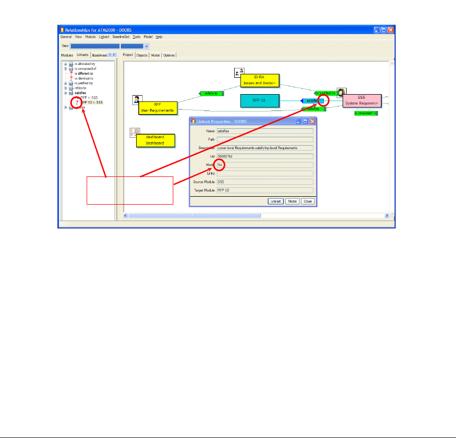
Example:
In the example, you can see that the selected linkset (from “SSS” to “RFP V2”) is not
compatible with the model because of three displayed information:
•The arrow containing the name of the link module is “opened” (i.e. no square at
the opposite extremity of the arrow)
•The linkset has the symbol ? in the link module/linkset explorer
•When using the operation “Properties”, the field “Model” has the value “No”
Linkset not compatible
with model
Figure 33 : Invalid linkset in Relationship Manager
The tool offers you a set of operations allowing to manage the linksets in order to make
your project consistent with the RMF Project Model:
•Reverse the direction of the links/linkset

•Copying the links/linkset into a different link module
•Deleting the links/linkset
•…
Refers to the Relationship Manager user manual for more details on this tool.
2 3 )4!9
When you have identified and linked your requirements, you need to check and validate
your data, to detect and correct errors.
This verification may be manual, only by reading the information saved in DOORS, but
before this manual task you may detect a lot of errors by using at least one of the two
functionalities provided by IRDRMFAO.
•The check project or module consistency tool is able to check a set of some
predefined rules.
•The new functionality Integrity Check has been designed to be flexible and
opened, allowing the users of IRDRMFAO to define their own integrity rules,
specific of the process or of the data model deployed, in order to complement the
generic rules already provided by IRDRMFAO.
The two functionalities are different and not compatible. The old one (check consistency
tool) will be probably removed from IRDRMFAO is some future version.
2 3 )4%,!!9
This tool should be used to verify that:
•The unicity of the requirement identifiers
•The model links are only between RMF objects
•The links associated with the RCM objects in the Working or Deleted state.
This tool may be executed at project level or at module level. When executed at project
level, all the modules are scanned, and the unicity of a requirement identifier is verified in
all the project. At module level, the unicity is checked only in the scope of the module.
To check the consistency of a module, calls the “Consistency check” operation. It opens a
dialog box such as :
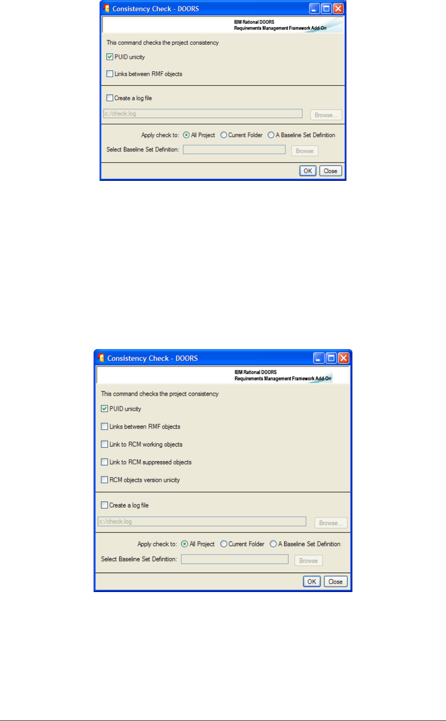
Figure 34 : Consistency check (no RCM configured)
The corresponding check rules are:
•PUID unicity: check that each RMF object in the selected scope as a unique
RMF identifier (the prefix of each module must be unique)
•Links between RMF objects: check that the semantic links (i.e. the relationships
defined in the project model) are only between RMF objects. A RMF object is an
object with the an “IE Object Type” attribute value non empty.
If the RCM management is activated for the current project, the dialog box will be such as:
Figure 35 : Consistency check (with RCM configured)
The complementary check rules are:
•Links to RCM working objects: check that they are no links to objects with the
Working RCM status in modules under RCM control .
•Links to RCM obsolete objects: check that they are no links to objects with the
Obsolete RCM status in modules under RCM control .
•RCM objects version unicity: check that if there is a link to an object in a
module under RCM control, they are no links to another object of the same
version graph (for example links to the version 1 and to the version 2 of a
requirement).
To have more details about the RCM behaviour you should look at the RCM manual.
The next option allows the definition of a Log file, to memorize the rules violations
detected by the consistency check.
The last option is the definition of the part of the project in which the consistency check
should be executed. It is possible to select:
•The all project
•A sub-folder inside the project
•A baseline set definition, i.e. a set of modules in the project
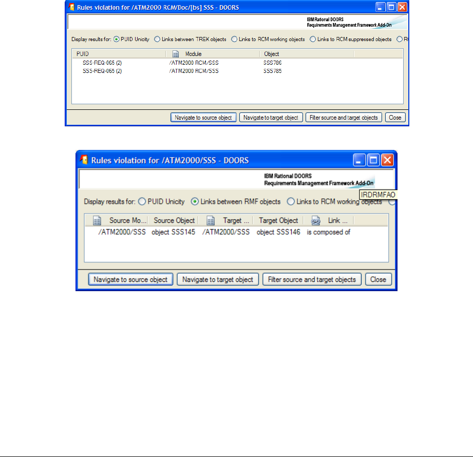
After having defined the options, click on the OK button. You get a dialog such as:
Figure 36 : Violated rules for “PUID unicity”
Figure 37 : Violated rules for links
The result list displays the violated rules. To see the different types of violations you must
select the rule that you want to examine. The information displayed is not the same, if the
violated rule is associated to an object (“PUID unicity”) or to a link (all other rules).
A violation associated with an object contains only the reference of the object (source
module and object reference), a violation for a link contains the description of the source
and target modules and objects, and also the link module.
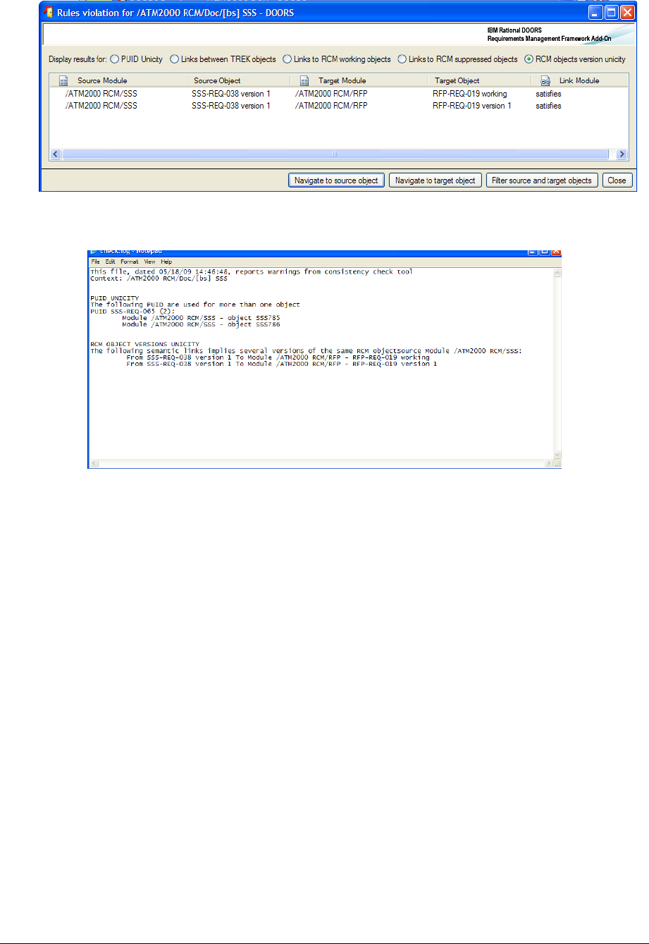
The object is described by the RMF identifier if any, or by the DOORS identifier. For an
object under RCM control, the version or the status of the object is added to the PUID.
Figure 38 : Violated rules in “RCM objects version unicity”
Example of log file:
Figure 39 : consistency check log file
To examine the violation you can use the different buttons or execute a double-click on a
rule violation. The double-click is equivalent to the “Navigate to object” operation.
The available operations are:
•Navigate to source object: open the source module and the source object
corresponding to the selected violation
•Navigate to target object : open the target module and the target object
corresponding to the selected violation
•Filter source and target objects: open all source and target modules and filter
the objects listed in the violations
You may execute the tool from a module, in this case you do not have the “Apply check”
and “Baseline set” fields defined in the dialog box. The scope of the check is implicitely
the current module.
2 3 $9)4
A new data verification mechanism has been . This mechanism is more flexible, more
automatic and more secure than the previous tool.
Architecture of the Integrity Check:
The rules are defined by coding some DXL functions with an interface like:
bool rmf_object_puid_syntax_(Module,Object,DxlObject)
The first parameter is a module to check, the second may be null if the rule is at module
level, or it is the current object is the rule is at object level. The third parameter is a
DxlObject allowing to store information during the execution of the rule. The result is
TRUE if no violation is detected, and FALSE if a violation is detected.
The rules are “linked” with the Integrity Check mechanism, and associated with some
information allowing to manage the rule. The different information associated with the
rules are:
•The name of the rule. For example “R 1.1.1”.
•The description of the rule. For example “The PUID of a RMF Object must be
non empty and compatible with the project or module configuration”.
•The level of the rule: it can be module level or object level.
•The RMF level of the rule: it can be RMF , i.e. only a RMF module or a RMF
object should be verified, or not RMF. In this last case any module or object may
be verified.
•The severity level. It can be a critical violation (Error) or a non critical violation
(Warning).
•The activation status. If the rule is inactive, it can not be seen in the configuration
or applied to a module.
The name associated with a rule should be unique for the set of rules (predefined AND
user defined).
This information is already defined for the predefined rules, but it is possible to change
these values, the corresponding DXL file is not encrypted. The code itself is not public. To
modify the behaviour of a predefined rule, you have to inactive it or not to “link” it, and to
write a new DXL function to replace it.
At execution time, the set of active rules is applied on the module to verify. The
verification of one module is independent of the verification of the other ones: it is not
possible for example to check the unicity of the PUID on a set of modules with this
mechanism.
When executed on a module, two module attributes will be created if required, and
initialized.
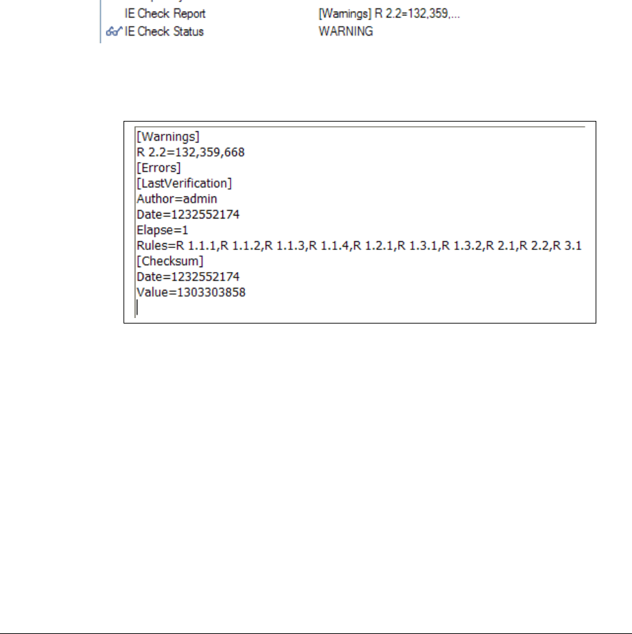
•IE Check Report is a Text attribute. It contains the execution report in a
compact format.
Example:
The information contained is:
oThe list of executed rules
oThe date and time of the last execution, with the user and the elapse time
oThe violated rules, and the objects on which the rules are violated
oThe checksum value
•IE Check Status is a DXL enumerated attribute. The code of the attribute is
located into IRDRMFAO code and encrypted. The goal is to protect the attribute
from any manual modification. The attribute definition is protected with access
rights.
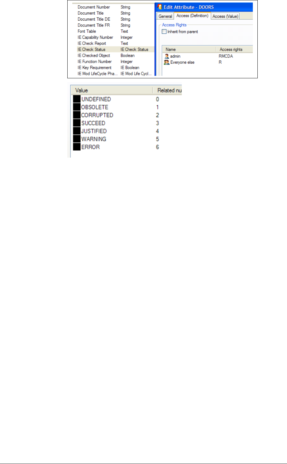
The algorithm implemented in the DXL status attribute has been defined to be able to
detect any corruption or modification. The different possible values are:
•UNDEFINED: no report yet. The rules have not been executed.
•OBSOLETE: some modification has been done into the module since the last
verification. This status is based on the history. A modification not recorded into
the history will not be taken into account.
•CORRUPTED: the report checksum is invalid or the format of the report is
wrong.
•SUCCEED: no integrity violation has been detected.
•JUSTIFIED: some integrity violation has been detected, but a Check Manager
has “accepted” the report.
•WARNING: at least one not critical integrity violation has been detected.
•ERROR: at least one critical integrity violation has been detected.
Several possibilities are provided by IRDRMFAO to apply the integrity rules on a given
module. You may execute the rules through triggers. In this case the trigger is a module
close trigger, applied only if the module has been opened in Visible Edit mode. The trigger
must be defined locally for some modules. It is also possible to execute the check directly
on user decision, by calling an operation from the graphic user interface. You can apply the
check on the current module, it can be also on a set of selected modules.
In any case, you must first define the integrity check configuration at project level to be
able to use any of the integrity check functions.
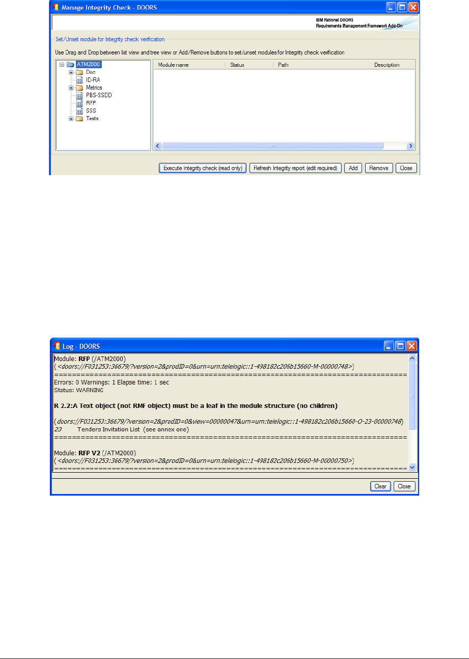
4.5.2.1 Integrity check at project level
You may execute the operation “Manage Integrity Check”. Only a “Check Manager” may
use this operation. You should use it only on small size projects, if the majority of users are
not well trained.
A dialog box opens:
To check the integrity status of a set of modules, you must drag the modules from the tree
view to the list view, select one or several modules in the list view and then you may click
the button “Execute Integrity check (read only)” or the button “Refresh integrity report
(edit required)”.
You may drag a folder or the all project to initialize the list view with all contained
modules. You may also select an item in the tree view and click to the “Add” button.
To clear the list view, you may also drag the modules from the list to the tree view, or
select one or several list elements and click the “Remove” button.
Example:
Each detected violation is written into the Log window. This window may be saved into a
text file or printed. In this mode of operation, no attribute is created into the checked
module.
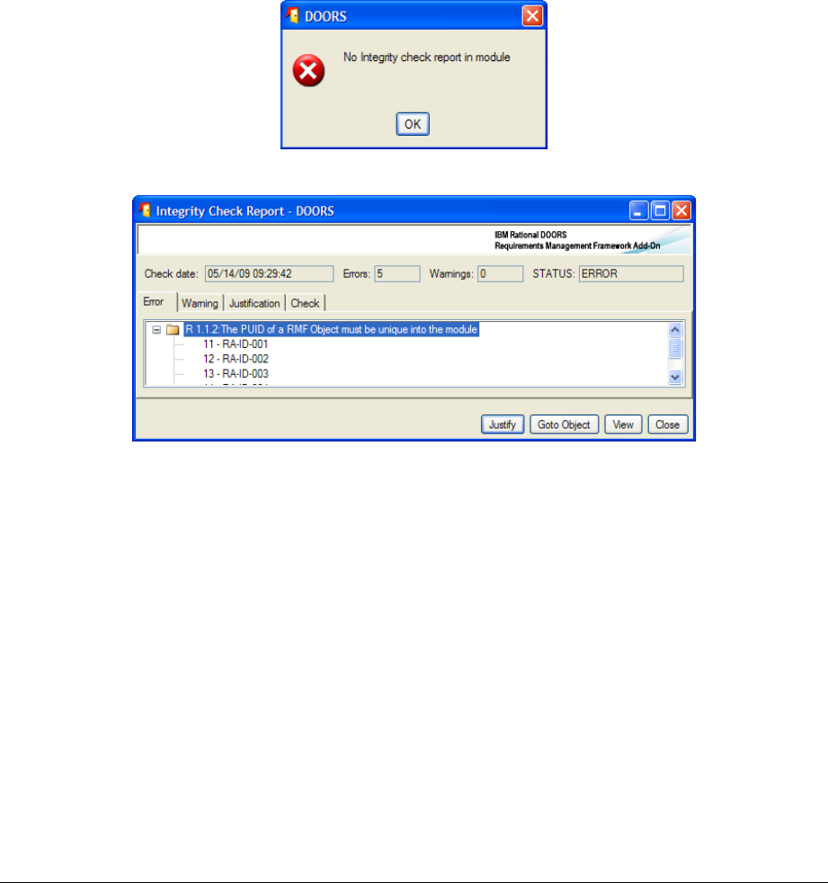
The operation “Execute Integrity check” do not create any report or status attribute into
the checked modules, that are opened in read mode. The report is in the log window and
the status is in a column of the list view.
The operation “Refresh Integrity report” creates and initializes the report and the status
attribute into the checked modules, that are opened in edit mode. The report is also in the
log window and the status is also in a column of the list view.
4.5.2.2 Integrity check at module level
Different operations are possible at module level. The two main operations are “Integrity
Check” “Execute Rules” and “Integrity Check” “Display Report”.
“Execute Rules” should be used to apply the configured integrity rules for the module.
This list of rules to execute may be defined from the project configuration, or from the
module configuration if it has been defined locally.
The rules may be executed in Edit mode or in Read mode, and even in a baseline of a
module. The report and status attributes are created or refreshed only in Edit mode.
At the end of the execution:
•If no violation is detected, a message is displayed
•If at least one violation is detected, the report display tool is opened:
In Edit mode, the result of the verification is saved into the report module attribute,
and it is possible to consult it even after having closed the session, by using the
operation “Integrity Check” “Display Report”. In Read mode, the report is not
saved and you will have ti execute again the check to find the violations.
You can also use the operations “Integrity Check” “Create trigger” and Integrity
Check” “Delete trigger” to manage the integrity check trigger of the module. It is
possible only in Edit mode.
The “Create trigger” operation defines a module close trigger that will apply the integrity
rules each time the module is closed after an edit session in visible mode.
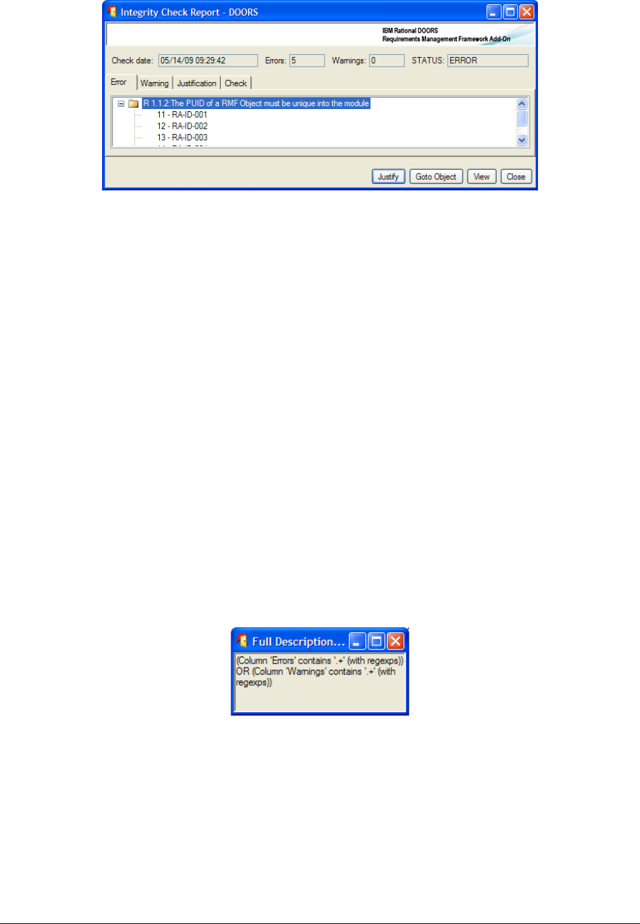
4.5.2.3 Integrity check report dialog
This dialog is dedicated to the analysis of the integrity check report information. The
information find into the report attribute (or from another source in case of read mode) is
compared with the configuration and displayed in a more readable form.
Example of display:
The meaning of the fields in the top of the window is:
•Check date: contains the date of the last execution of the integrity check.
•Errors: number of cirtical integrity rules violated
•Warnings: number of not critical integrity rules violated
•STATUS: global integrity status of the module (identical to the status module
attribute)
The different tabs contain the information required to execute a fine grain analysis of the
problems.
•Error: contain the list of violated critical rules, and the objects violating the rules
for object level rules
This tab and the Warning tab may be used to find easily the wrong objects. You can
click on one object visible below a violated rule, or click the “Goto oject” button. The
corresponding object is selected into the module.
You may also click the “View” button. The current view of the module is modified to
display all anomalies into the module:
Two DXL columns are added before the main column, to display the rules violated by
each object. One column for critical rules and another for non critical rules. These
columns are DXL columns pointing to the IRDRMFAO code.
A filter is also created:
The columns and the filter may be saved into a view. They will be automatically
refresh in case of modification of the integrity check report embedded into the
module.
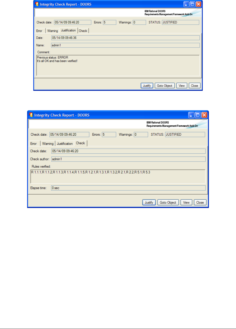
•Warning: contain the list of violated not critical rules, and the objects violating the
rules for object level rules
•Justification: if a Check Manager has accepted the report, contains the
information required to validate the acceptance. By default this tab do not contain
any information. It is not empty only if the integrity check report has been
accepted, even in case of error, by clicking the button “Justify”. The definition of a
“comment” is mandatory.
•Check: contains some useful information about the last integrity check
(check date, user, rules in the configuration , elapse time of the check)
4.5.2.4 Integrity check in triggers
If an integrity check trigger has been defined for a module, at project level or locally at
module level, it is a module close trigger that will be executed:
•If all configuration information is consistent
•If the module is in Edit mode and if it is visible
•If the check status is not JUSTIFIED
In case of detection of an error, a confirm message is displayed to prevent from closing the
module:
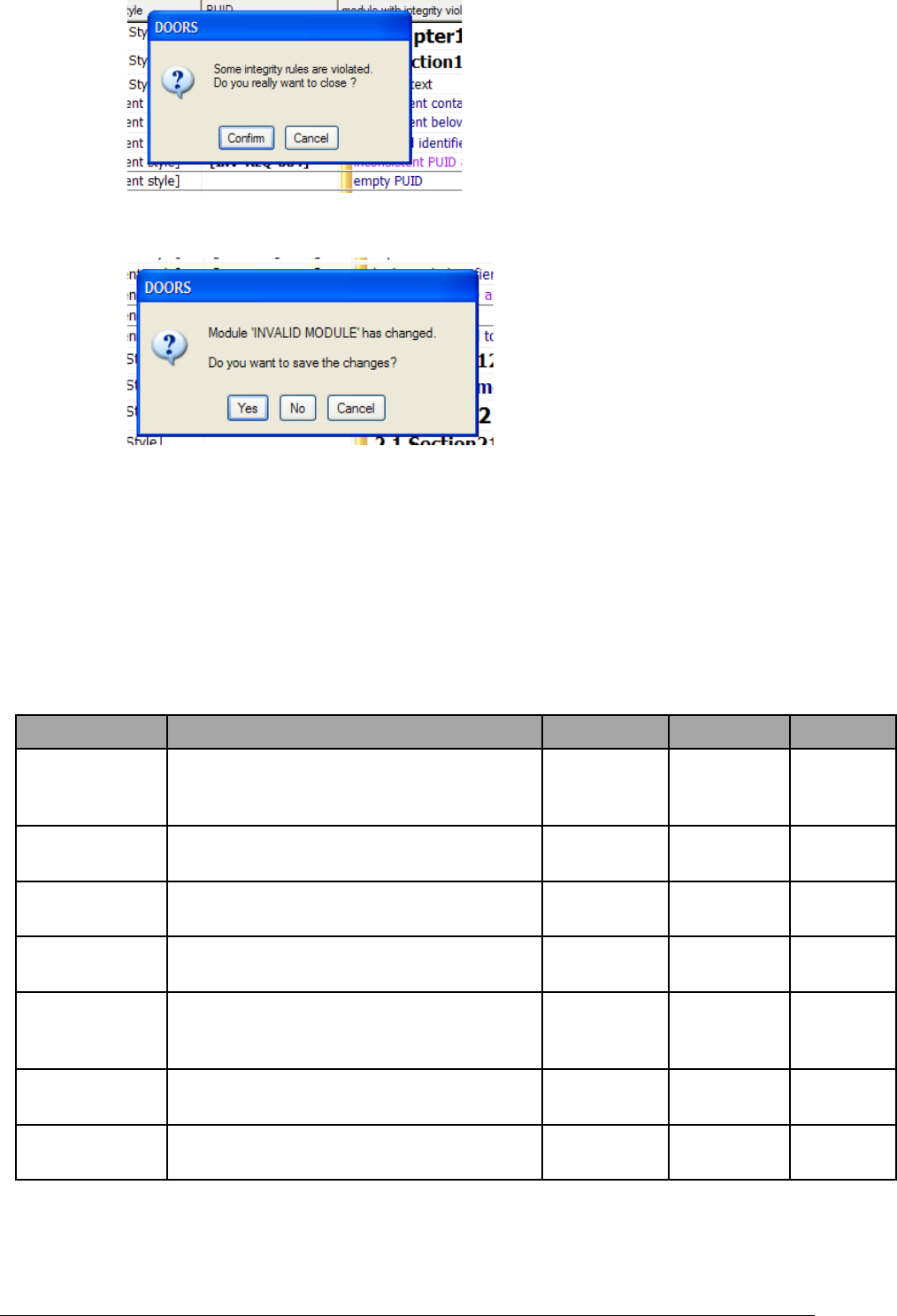
In general, even in case of save before the execution of the close, the execution of the
trigger modifies the data inside the module, and you need to save again the module:
If you choose “Cancel” for the first message, the module will not be closed and the check
report display box is automatically opened to allow you to repair the errors.
4.5.2.5 Predefined integrity rules
IRDRMFAO contains a set of predefined integrity rules. These rules are generic, and
applicable to any project, even if the data model is different from the default RMF model.
This set of rules will be extended in the next versions of IRDRMFAO to cover the
maximum number of errors.
Name Description Level RMF Level Criticality
R 1.1.1 The PUID of a RMF Object must be non
empty and compatible with the project or
module configuration
Object IRDRMFAO Error
R 1.1.2 The PUID of a RMF Object must be unique
into the module
Object IRDRMFAO Error
R 1.1.3 The PUID of a RMF Object must be identical
compared to the last Major baseline
Object IRDRMFAO Error
R 1.1.4 The Object Type of a RMF Object must be
identical compared to the last Major baseline
Object IRDRMFAO Error
R 1.2.1 The hierarchical structure of a RMF Object
must be compatible with the project or module
configuration
Object IRDRMFAO Error
R 1.3.1 The origine of a RMF semantic link must be a
RMF object
Object DOORS Error
R 1.3.2 The destination of a RMF semantic link must
be a RMF object
Object DOORS Error

R 2.1 The Heading and Text attributes must never
be defined together
Object DOORS Error
R 2.2 A Text object (not RMF object) must be a leaf
in the module structure (no children)
Object DOORS Warning
R 3.1 The prefix attribute of a module must not be
empty
Module DOORS Warning
If you want to modify the parameters associated with the different rules, you have to open
the DXL source file:
[IRDRMFAO DIR]/lib/dxl/addins/irdrmfao/check/predefdcl.inc
The file contains a sequence of declarations like :
{
int idx = CheckRuleDeclare(
"R 1.1.1" ,
"The PUID of a RMF Object must be non empty and
compatible with the project or module configuration",
false,
true,
true,
true)
if(idx != -1)
put(CHECK_RULE_TABLE,
rmf_object_puid_syntax_
, idx, CHECK_RULE_FUNCTION_FIELD)
}
You may modify the different parameters of the call to the function « CheckRuleDeclare »,
but do not modify the « put » instruction.
The order of the parameters is :
•Name
•Description
•Module or Object level (true is Module level and false is Object level)
•RMF or not RMF (true is IRDRMFAO level and false is DOORS level)

•Criticality (true is Error and false is Warning)
•Activation (true is active and false is inactive)
4.5.2.6 User defined integrity rules
You may replace predefined rules or complete the set of rules by inserting your own rules
into the DXL source file:
[IRDRMFAO DIR]/lib/dxl/addins/irdrmfao/check/userdef.inc
This file contains already three examples of rules:
•R 5.1. This rule checks that an object is not empty, i.e. that the Object Heading or
the Object Text attributes have a value. The rule is an object level, IRDRMFAO
level, not critical rule.
•R 5.2. This rule checks that the module attribute “ModStatus” is not empty if it is
defined into any module (RMF and not RMF ). The rule is a module level, not
IRDRMFAO level, critical rule.
•R 5.3. This rule checks that the object attribute “ReqStatus” is not empty for a
RMF object, if it is defined into a RMF module. The rule is an object level,
IRDRMFAO level, critical rule.
The interface of all rules is identical:
bool <function_name> (
Module curMod,
Object curObj,
DxlObject context
)
The call of the function by the integrity check mechanism depends on the declarations
associated with the function:
•Module level
The curObj and context parameters are not used. The function is called only once for a
module.
oRMF level
The function is called only for a RMF module, i.e. a module with the module
attribute “IE Mod Type” not empty.
oNot RMF level
The function is called for any module.
•Object level
All parameters are used. The parameter context is always defined. The function is called
a first time with curMod defined and curObj null. The goal is to give the ability to the
function developer to initialize some data that are saved into the DxlObject object, for
example a skip list to memorize a list of values. Then the function is called on the
different objects to check. Finally, the function is called with curMod null. The goal is to
give the ability to the function developer to release the data saved into the DxlObject
during initialization or function execution. The DxlObject object itself must not be

deleted. You can also test the execution of the constructor by using the “init” field of
the DxlObject. It is defined to “false” by IRDRMFAO before calling the constructor,
and to “true” after.
oRMF level
The function is called on non deleted RMF objects (only the root in case of a
composite RMF object).
oNot RMF level
The function is called on all non deleted objects.
When developing new rules, you must pay attention to their robustness and efficiency,
because it can be executed many times and on any module of your project, specifically if
you decide to check integrity rules with triggers at module or project level.

3 !*+""
3
Each RMF object identified as a “Requirement” in UR/SR modules is a "Reference
Requirement" and should be formally tested (Refer to SYS-EM methodology). The test is
described as an Integration, Verification or Validation test according to its level (Refer to
SYS-EM methodology), in summary the terms are applied as follows:
User Requirements are proven by Validation testing,
System Requirements are proven by Verification testing, and
Design Requirements/Specifications are proven Integration testing
Each test should be defined in terms of (1) its method, (2) who the approval authority will
be and (3) where (i.e. at what level) the test will be performed. The collection of these three
definitions for a requirement is termed its ‘IVV solution’. In addition, the IVV solution
usually contains some form of textual description of the scope of the testing, which acts as
a constraint on customer aspirations for unnecessarily rigorous test regimes.
The RMF object that holds the IVV solution is called a test procedure. These procedures
are typically located and identified in modules of the IVV type, and are linked to
requirements with a “Verifies” link.
This means that each "Reference Requirement" must be reached by at least one "Verifies"
link from an IVV module. The end objective is to ensure that the customer and contractor
are both satisfied that the IVV solution defined is adequate to prove the requirement, and
therefore a good basis for progressive project sign-off.
The standard RMF datamodel reflects these three levels of IVV solution, but uses the same
generic module type “IVV” for initializing any level.
Comments: In the case of a SSS document, Section 4 requirements are very general and not linked
requirement by requirement to section 3. In the SSS section 4, we found a verification matrix (method used
for each Req.) which corresponds in DOORS to a devoted view "Verification matrix” in SR module. The
Enhanced Word Exporter is able to generate this matrix in SSS section 4.
The following sections describe how the various aspects of the IVV solution should be
defined and controlled, and how RMF attributes and views can assist. The detailed
definition of the attributes, relationships and views of the IVV module type are given in
Appendix A Section 5.
3 ""&,&
3 :'0
The default setting of this attribute is “IVV Procedure”.
Suggestion: Small projects may find it convenient to customize their IVV module by
introducing three different object types for Integration, Verification and Validation
Procedures; rather than having three separate modules, one of each module type.

3 %!
This attribute is the unique RMF object identifier, generated automatically by IRDRMFAO
. Identifiers are not normally re-used, unless the utility “Renumber objects PUID” is
invoked. The structure is detailed in Appendix A Section 5.
3 (""'0
This attribute defines whether the IVV procedure applies to design or production testing,
or both.
3 2""+
A test method (Inspection, Analysis, Demonstration or Test) is associated with each
procedure.
This information is accessible by means of the “IVV matrix” view within any module type
(not only in IVV module type).
Comments: The method information (IADT) is located in IVV module for a methodology reason: test
choices are very important, and bad choice could be catastrophic in term of cost. So, this way obliges the
system engineer to create a "test procedure" object before setting the method attribute and he is thus forced to
consider the testability whilst defining the requirement. The alternative (which is not prohibited in
IRDRMFAO) is to create an attribute "method" in SR module but with the risk that it is either never
set or remains at its default value. The recommendation to enter a scoping constraint in the test procedure
object reinforces the need to consider testability as the requirement is phrased.
3 3""%%""
The objective is to persuade the customer that only specific key requirement testing need
be approved by the customer, and that the tests for many requirements may be approved
by the prime contractor or sub-contractors under their enterprise level QA accreditation.
Approval by the customer implies the need for approval of each test specification, each
test execution and each test result document. This not only causes much cost to the
customer but also adds risk to the programme as more of the customer’s activities get onto
the critical path and out of the control of the Project Manager.
The delivered IRDRMFAO offers an enumerated list of four levels, but projects should
customize this as appropriate.
3 ;""0
This attribute is used to record the name of the person responsible for the IVV procedure,
who will usually be from the test or engineering departments.
3 <""4
This attribute is used to list any specific skills that are necessary to conduct the tests called
up by the procedure.
Suggestion: projects may wish to make this an enumerated field so that filters for specific
skill requirements may be set up.

3 ="""
The third important aspect of the proposed test solution is where or at what event the test
is proposed to take place. This could range from a design-proving test on an equipment or
software package at a subcontractor’s premises through to a system user trial conducted on
the whole system by the customer’s end user.
IRDRMFAO as delivered sets this attribute as a ‘string’. It is recommended that projects
customize it to an enumerated list, which should be tailored to suit the particular project
being supported. For example, the complete list of factory, harbour and sea trials planned
for a naval project could be made an enumerated list type.
3 >"""%"!
This attribute defines which party to the contract is responsible for planning, providing
and/or conducting the IVV Event.
IRDRMFAO as delivered provides an enumerated list of ‘Customer’, ‘Prime Contractor’
and ‘Sub-contractor’. Projects should customize this enumerated type to define, at least,
the names of the sub-contractors.
3 ? ""*
This attribute records whether it is unlikely that a test procedure would need to be repeated
in the event of a future change to the system. It is a binary; set to ‘True’ if the procedure is
unlikely to be part of a regression test.
3 ""%
Documenting and agreeing the objectives and scope of a test are very important; often the
customer and contractor have very different views on the extent of testing necessary. For
example, if the operating temperature range and the vibration performance are specified in
separate requirements, the contractor might assume that vibration tests need only be
conducted at standard temperatures whereas the customer might insist on vibration tests
across the whole temperature range. The scoping statement would document the
agreement on this, and in effect, it becomes an extension of the requirements.
Another example might be where the customer aspiration is for an actual network test with
a large number of nodes, whereas the contractor anticipated a small network test and an
analysis to justify the performance of the larger network.
3 ( "")%
3 ( ,#
The ‘Justification’ relationship is used to link the procedure to some rationale in an Issue/
Decision module that explains why any attribute of the IVV object has been set in the way
it has. Typical usage might be to record why the customer felt it important to conduct
vibration testing at temperature extremes.
Initially the relationship would point to an outstanding issue, when the issue is resolved
and the resolution is recorded as a decision, the relationship becomes one of
“Justification”.
According to the standard RMF data model, this relationship is only used for issues with
requirements, but projects may customize this model.

3 ( !%
The ‘Under Issue Process’ relationship is used to link the procedure to a problem
statement in an Issue/Decision module, from which the progress of the Issue/Decision
process can be determined. The usual situation is that some attribute of the IVV object
cannot be completed until the issue is resolved.
According to the standard RMF data model, this relationship is only used for issues with
test support equipment, but projects may customize this model.
3 ( ("#
The ‘Verification’ relationship is used to link the procedure to one or requirements that it
verifies, in a Requirement module.
3 ( 2
The ‘Allocation’ relationship is used to link the procedure to Test Equipment that is
necessary in order to execute the procedure.
3 2 """.
3 2 !!".
This view is the DOORS standard default view and shows the DOORS unique Object
Identifier and the Object Heading/Text, only.
3 2 ""!".
This view is used when it is required to determine whether any issues have been raised
about any IVV procedures. It directly provides the identity and description of any issues
raised; it is necessary to follow the DOORS link to determine the status and decision of
each issue.
Because the view is derived from traceability via incoming “refers to” links, it is most
useful when analyzing issues that may have been raised over the allocation of test
equipment, for example. Issued raised in the context of how the procedure verifies
requirements, should be analyzed using the IVV Justification View.
3 2 (""!".
This view is useful to initiate a standard DOORS export to Word ( File, Export, Microsoft
Office, Word). The Document Style is used to pick up the Paragraph Styles in the template
(e.g. normal.dot), the PUID is ignored and the Object Header/Object text field is printed
3 2 2""/".
The IVV matrix view is useful to show which requirements an IVV procedure is required
to verify. It directly provides the identity and text of each requirement to be verified, from
these the standard DOORS links can be followed for more information about particular
requirements.
3 2 3""%!!#".
This view is used for the initial definition of the IVV procedure, particularly when agreeing
the IVV solution with a customer or a supplier. In addition to the procedure PUID and

Object Text, it shows the attributes most relevant to this phase of a project. It is probably
the view that may need to be exported, printed and made contractual.
3 2 ;""%!%$".
The IVV Procedures Planning View is useful during the progress of the contract to assist
in the management of the IVV planning and preparation phases. In addition to the
procedure PUID and Object Text, it shows the attributes most relevant to this phase of a
project
3 2 <"",#".
The Justification view is a useful view to use when analyzing why particular IVV
procedures are claimed to verify particular requirements. The descriptions of any issues
previously raised are directly presented; it is necessary to follow the DOORS link to
determine the status and decision of each issue.
Because the view is derived from traceability via outgoing “is justified by” links, it is most
useful when analyzing issues that may have been raised in the context of how the
procedure verifies requirements. Any issues that may have been raised over the allocation
of test equipment, for example, should be analyzed using the IVV Associated Issues View.
3 2 =""7%".
The IVV Test equipment view is used to analyse what test or other support equipment
and/or facilities have been allocated to a procedure. The allocation may be amended by
adding or deleting links, remember to define the default link module first, and to source
any new links in the other (PBS) module.
The descriptions of any test equipment or facility are directly presented; it is necessary to
follow the DOORS link to determine any more detail about the support item. These
descriptions are derived from incoming ”is allocated to” links.

; **'6
60
;
In the IRDRMFAO workbench, the data reference is the DOORS database, it is not any
documents produced from the database. Data, however, may be imported from word
processed documents (e.g. import an external customer document), or data may be output
to a word processor and formatted in a pleasing style (e.g. to produce final or intermediate
results).
For some people, it could be more convenient to write the major part of a new document
outside DOORS with a word processor tool and then import it. Once such a document is
imported into DOORS, the DOORS Database becomes the reference. As far as possible,
textual modifications should be done within DOORS. Editing DOORS reference data by
export from DOORS to a publication tool, and re-importing, is always possible but
probably never cost-effective and should be done for consulting only.
Recognising this position, IRDRMFAO provides specific functionality to improve the
exchange of DOORS data with external document formats..
; +6
According to the introduction § 2.3 “DATABASE AND DOCUMENT APPROACHES”
each RMF module type provides a view named “Document view” that is set as the default
view. This view displays the paragraph style, the PUID and the object text attributes, as
shown in Figure 8.1 below These attributes are the there by default in the standard RMF
modules and support the standard DOORS export to Word.
The view allows the paragraph style assigned to each object to be viewed, in the column
headed ‘Document Style’. Provided this style name exists in the template of the document
being exported to, each object will be displayed and printed according to that style
definition in Word.
The style for each object may be changed in the Document View using the IRDRMFAO
utility “Edit Document Styles”
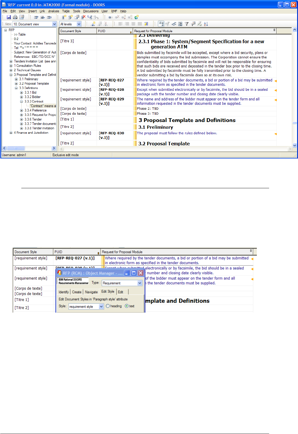
Figure 40 : Example of Document View
; ( *0*0+'
; ( *+!#'@!9A
The paragraph style for an object, can be modified by using the IRDRMFAO utility
“Manage Objects” (the “Edit Style” tab), which provides an enumerated drop down list to
choose from. It is also possible to change the object attribute containing the text value,
that can be the “Object Heading” or the “Object Text” attribute. The chosen style is
applied to the chosen attribute.
Figure 41 : Edit Document Styles dialog box
The list of paragraph styles offered by the utility comes
•from the Module definition object in the Project Profile module. (The Object
definition objects in the Project Profile module define the default paragraph style
used when a RMF object is first created or identified). By this means, the
enterprise or project documentation formatting style is enforced by IRDRMFAO.
and, also
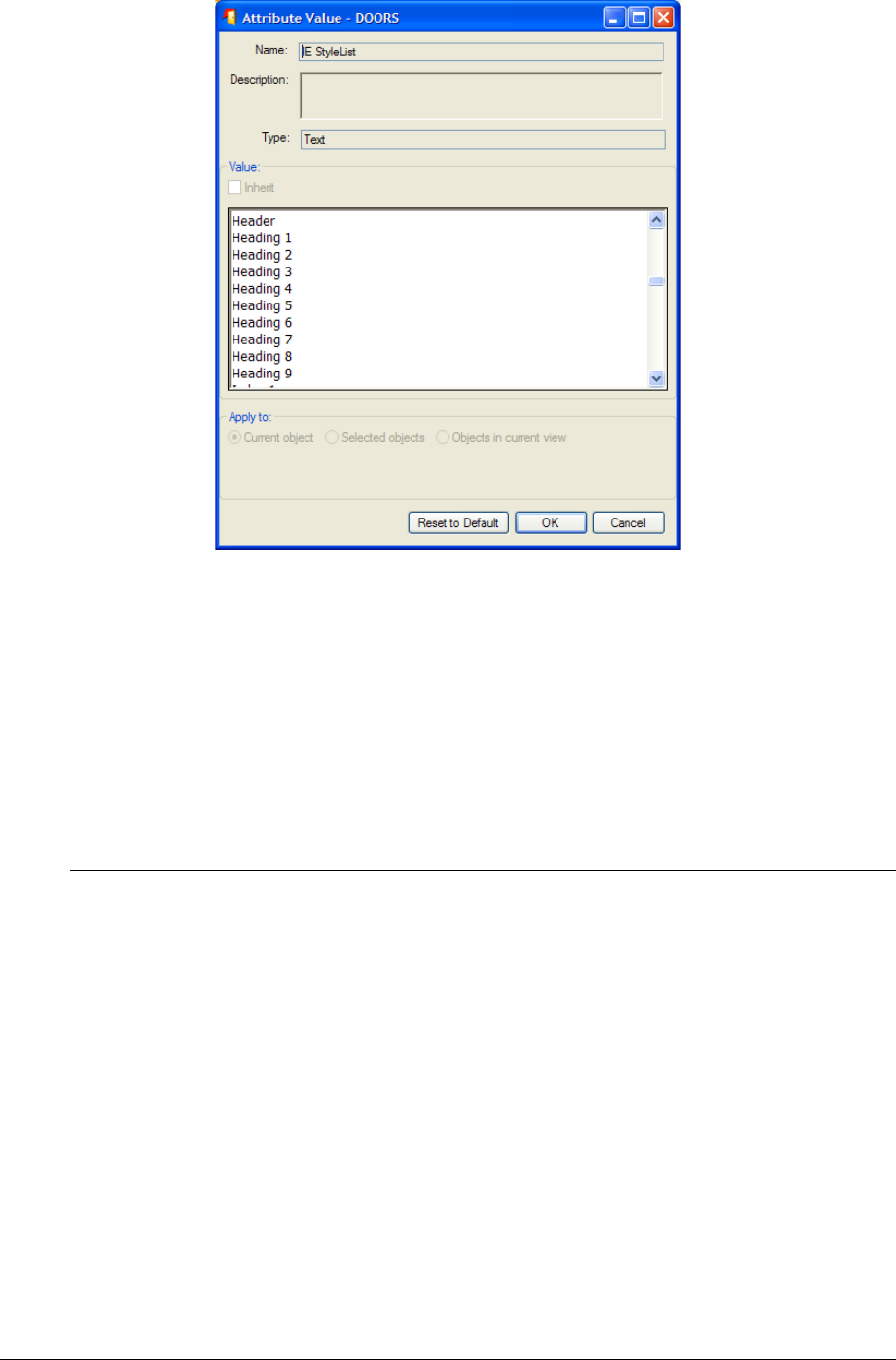
•from the Module attribute “IE StyleList” value that allows you to let additional
styles be available in this module. You shall enter those additional styles as in the
example below :
; ( +!@0*0+'
A
DOORS supports the concept of assigning a different paragraph style to each attribute in
each object, but this feature is not encouraged under IRDRMFAO. IRDRMFAO
recommends a single style for all attributes within each object type, using only the styles
defined in the Project Profile module.
The “Edit Paragraph Style Attribute” DOORS tool allows the user to type in Style names
for individual attributes.For more information, refer to the Style Definition.
; 2 B0*.!6
There are two ways to export data to WORD: (1) using the standard DOORS Word
Exporter or (2) using the IRDRMFAO Enhanced Word Exporter. Briefly, use the first one
if you want a quick export but with limited possibilities and if you are not too demanding
on the final result. Use the second, if you want to build complex documents, which are
updated and edited regularly, with a nice final result and needing practically no retouching
on the output.
; 2 +!.!B0
The standard DOORS “Export to Word tool” creates a Microsoft Word document, and
exports the current view to it. The structure of the document is the same as the structure
of the current view.
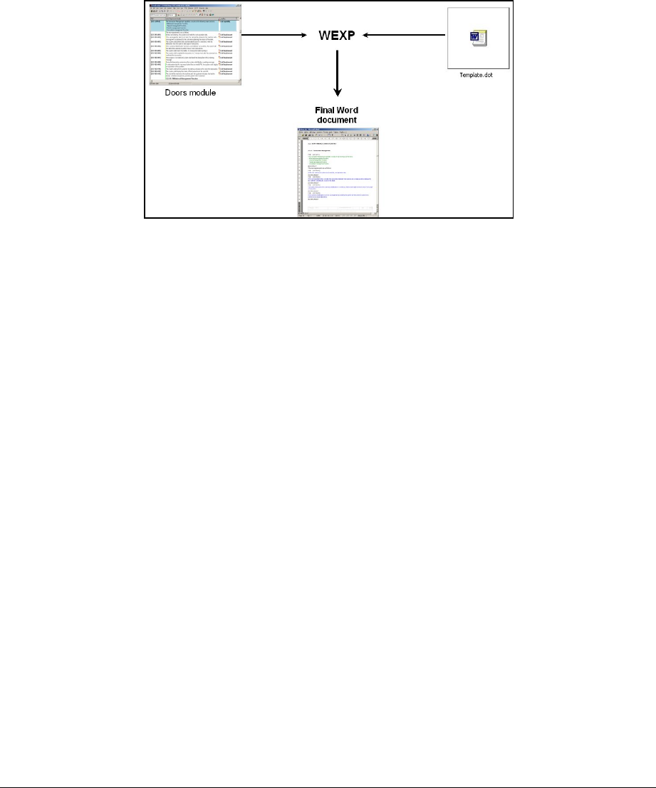
You can export in Table format (the document looks like the view you are exporting) or
export in Book format (Object Text and Object Headings only, with style applied).
Enhanced Word Exporter (WEXP)
6.4.1.1 Introduction
The Enhanced Word Exporter (WEXP) provides many extra features as listed below. It
needs to be configured for the particular document you want to create, but once this has
been done, the exporter is simple to invoke. This makes it ideal for reports that need to be
re-issued at regular intervals.
There are two aspects to the configuration of the customised exporter:
setting up an appropriate Word Document Template (.DOT) file,
setting up appropriate RMF views and attributes (at both module and object
levels).
Figure 42 : WEXP representation.
These two aspects are described in the following sections. In addition, the complete
example provided in the ATM2000 project example, (inside the “SSS” module), is
summarised.
The IRDRMFAO Enhanced Word Exporter actually implements a subset of the facilities
available from the full DOORS enhanced export utility.
6.4.1.2 The enhanced WORD EXPORTER
The Enhanced Word Exporter adds lots of new features in comparison to the standard
DOORS exporter. The complete features are exposed in the Word Exporter reference
Manual . Here are listed some of them:
Ability to export to a Word Document Template
Ability to export to a (partially complete) Word Document
Ability to specify the paragraph style for individual objects and attributes
Ability to specify a template for the export of different types of object, based on
the positioning of object attributes
Ability to specify the position of arbitrary page breaks in a document
Ability to export some objects from different DOORS views as Word tables
embedded in normal paragraph text
Ability to export complete views from named modules into the Word document
Ability to set a filter to export a view different from the view filter (filter defined
by another view or by an attribute value)
Ability to export views constructed from linked objects in named modules into the
Word document

Ability to export module attributes into the title page
Ability to export module attributes into headers and footers
Ability to export sections of modules into appendices, or other sections of Word
Document Templates
Ability to export attributes as in-line text following the object paragraph
Ability to export attributes as labels on paragraphs
Ability to export requirement numbers against requirements paragraphs
Ability to make one or more indexes of requirements, distinguishing defining
occurrences from others
Ability to export multiple modules into a single Word Master Document
Ability to place page breaks at certain places
Ability to place section breaks at certain places with odd even page boundaries
Ability to switch the orientation of the page between portrait and landscape
Ability to rotate the text of headings in tables
Ability to export multiple spanning table headings
Ability to name the repeating header rows in tables
Ability to shade selected table cells
Ability to export embedded OLE objects
Ability to specify the size of OLE objects in the Word document.
Ability to define a figure caption for OLE objects.
Ability to make specific enhancements to the exporter.
Ability to align pages to odd and even numbers.
Ability to place a rubric on blank pages used to align to odd and even numbers.
Ability to scale tables to fit into width of page
Ability to place revision marks on attributes that have changed since a named
baselines of the same module
Ability to export a named bookmark at a points in the document
Ability to export hyper-links to other documents
Ability to export hyper-links to within the exported document
Ability to export hyperlinks
Ability to export attributes as footnotes
Ability to export from the current filter in the module
Ability to export from baselines
Ability to export without having to set any DOORS attributes at all
Ability to export entirely in table mode
Ability to export views based on objects linked to the current object
Ability to execute a Word Visual Basic macro after export
Ability to export in non interactive or batch mode
Ability to extract diagrams from UML tools (or more generaly external tool).
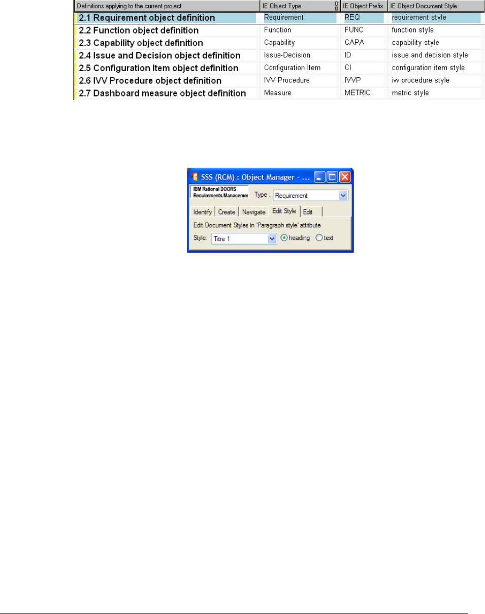
; 2 .60C D
6.4.2.1 Style Definition
6.4.2.1.1 Definition of the style used in Doors Modules:
To access to the style definition of objects types, there are declared in the "Config\Project
Profile" module; view: "Definitions of the Objects types". You will find the definition of
the default types and their style: i.e. "requirement style", "function style", "capability style",
etc…
Figure 43 : "Project Profil" module view "Definitions of the Objects Types".
Once you have defined styles for a type in the previous module, you can affect objects with
these styles with the "RMF -> Manage Object" function of the RMF menu (described
above:Editing paragraph styles):
Figure 44 : Edit Document Style.
You can also change object style by changing its attribute "Paragraph Style".
To do so, select the object; display its properties (right click, properties). Then edit the
paragraph style field. For example, you want to affect an object to the "OLE style". Fill the
attribute with the following text: <Attribute Name:Style Name> (i.e.
<ObjectText:requirement style>)
"Style Name" has the exact spelling of a style defined in the template (cf.Style definition in
MS Word:).
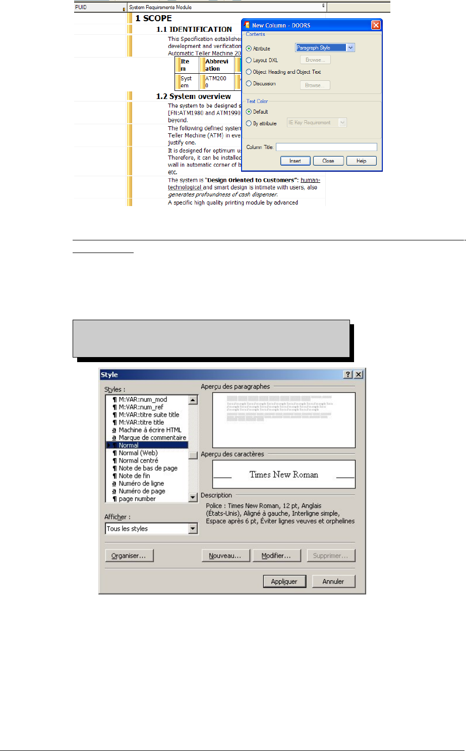
Figure 45 : Creation of the new column with the "Paragraph Style" attribute.
All styles used in Doors have to be defined in the template that you will use for
exportations.
6.4.2.1.2 Style definition in MS Word:
To access the style definition, click on the pop up menu: Format/Style.
And the window on the right should appear.
You have to define all styles used in your project,
otherwise, the exporter will use the default style:
Normal.
Figure 46 : Editing style in MS Word.
6.4.2.2 Insertion of attributes
6.4.2.2.1 Insertion of attributes in templates
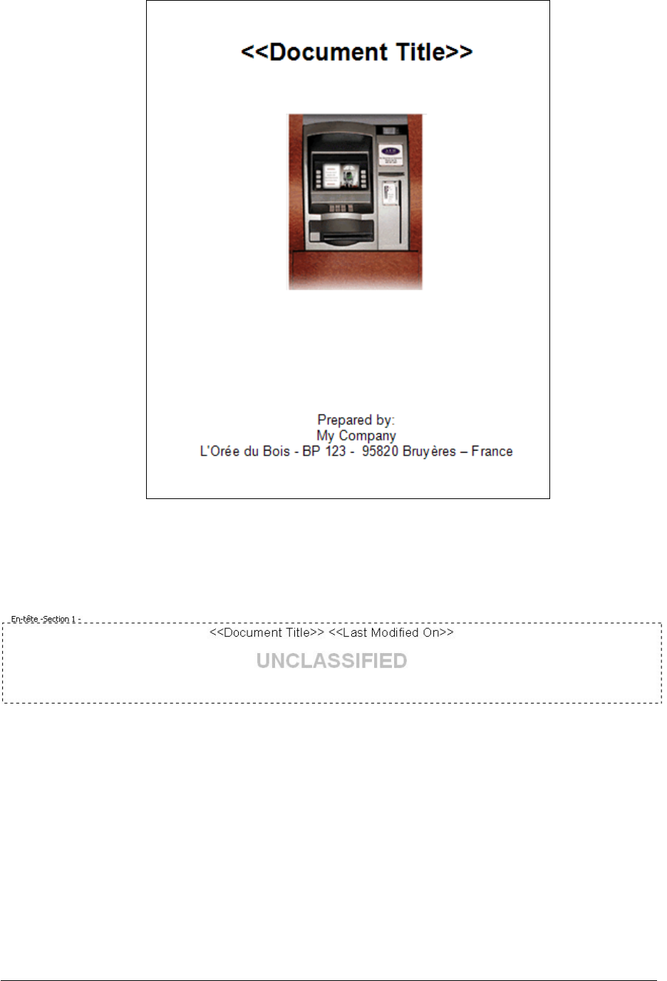
To insert an attribute in templates you need to insert its name in angle brackets: i.e. to
insert the document title attribute on the front page: <<Document title >>. While the
exportation, WEXP will recognize this "macro" and insert the value of the attribute instead
of the "macro". The style used, will be the same as "macro" style of the template.
Figure 47 : ATM2000 title page, in the template file.
6.4.2.2.2 example of application:
You can add attributes in headers & footers:
Header:
Figure 48 : ATM2000 header, in the template file
Footer:

Figure 49 : ATM2000 footer, in the template file.
6.4.2.3 Insertion of "Table of contents" & "Table of figures"
6.4.2.3.1 Table of contents:
You can insert a table of contents, which will be updated after an exportation. To insert a
table from the pop up menu: Insertion/Tables & Index, then select the "Table of
Contents" tab.
Then specify a table as you wish, don't forget to specify the depth of the table in the
option:
Figure 50 : Table of contents, depth options.
6.4.2.3.2 Table of figures
Like for a table of contents, you can insert a table of figures, which will be updated after
the exportation. From the pop up menu: Insertion/Tables & Index, Tables of figures tab.
Then you will have to specify the style to be selected as figures comment in the options, i.e.
select the ">fig:titre-title" style, which is the same style used in your Doors Project.
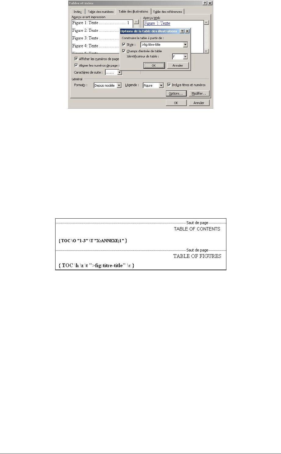
Figure 51: Table of figures, style selection.
Alternatively, you may set the attribute “WEXP Figure Caption” of the object containing
the OLE object to specify the title of the figure.
6.4.2.3.3 Display options:
You can change the options of the tables by modifying their "Field Code". To access them,
right click a table, then "Toggle macro code"; or from the pop up menu: Tools/options
View tab, then check "Field code", or simply update them by calling back the
corresponding windows (cf. previous paragraphs).
For the table of figures, when you are displaying the "Field Code", you can modify your
choice of style by changing the selected style between quotes.
Figure 52 : Field codes of both tables
6.4.2.4 Insertion of bookmarks
6.4.2.4.1 Required Bookmark
If you don't insert any bookmark to your template, WEXP will export object text at the
beginning of the document, therefore all your tables, revision marks will be moved to the
end of your document. To avoid this, will have to add at least one bookmark to your
template, generally after tables.
6.4.2.4.2 In the template file
Use the pop up menu: Insertion/Bookmark, and you will get the window on right. As you
can see, there are several bookmark declared, you can see two of them (in the red ellipse,
to allow the display of the bookmark symbol, go the pop up menu: Tools/options, View
tab, then check "Bookmark").
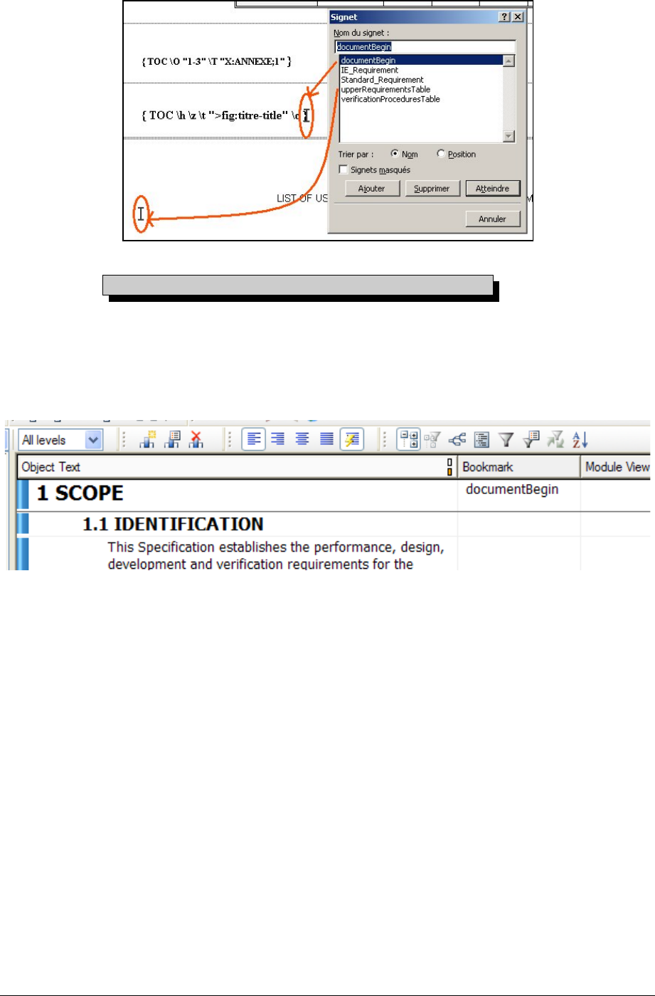
The first bookmark, called "documentBegin" is placed after the last table and the
second one is place in an appendix to export a matrix (in this case, the upper Requirement
Matrix of the ATM2000 project).
Figure 53 : Visualization of the template bookmarks.
You can add as many bookmarks as you need.
6.4.2.4.3 In DOORS
The configuration in Doors is very simple, I just have to insert the bookmark in the
WEXP attribute called: "WEXP BookMark" to the object you want. i.e. The first object of
the exported module should have the "DocumentBegin" bookmark. For more information
about the WEXP bookmark attribute, please refer to Bookmark attribute:.
Figure 54 : ATM200 project, SSS module, configuration of the "WEXP Bookmark" attribute.
; 2 (*0+000#"
The Enhanced Word Exporter needs at least two additional views: “WEXP document export
view” and “WEXP document maintenance” view and several additional module attributes and
object attributes.
These are initialized for a given module by performing only once the RMF command
“RMF->Enhanced Word Exporter ->WEXP views initialization”., as shown in Figure 37.
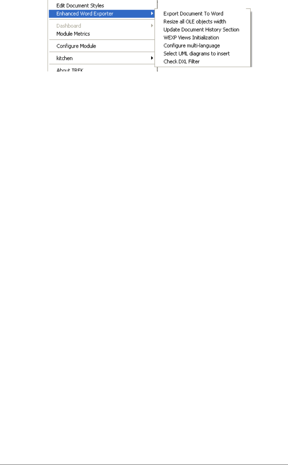
Figure 55 : Initialazing WEXP views
This utility creates:
The “
WEXP document export view
” : this is the main view used to initiate the
export. The Object Heading and Object Text are exported as heading and
paragraph, and the values in all other columns, if non-null, are exported as labelled
in-line paragraphs underneath. Notice that by default, this view contains a
“PUID” column in order to write the identification at the begining of RMF
objects (Requirements,…), and also contains a “End requirement” column to
mark it in the generated document. This last column is a calculated one. It takes
into account RMF objects composed of an hierarchy of objects. If you don’t want
to have all this information (for example if the PUID is already part of the text),
you have just to delete one or both columns, and do not forget to save the view.
The “
WEXP document maintenance
“
view
: this is the view for setting the
export control parameters, by editing the relevant attributes defined in the next
chapter.
These
object attributes
are needed by the Enhanced Word Exporter and are
automatically created if they do not already exist. They are used to control
formatting.
The following
module attributes
are also needed by Enhanced Word Exporter
and are automatically created if they do not already exist.
"
Export view name
": Select the view to export.
"
Template
name
": Pathname of the template to use
"
Existing
document
": If set to a pathname, append in this document.
"
Export
file
name
": Pathname of the output file.
These values are modifiable in the graphical user interface of the tool. The modifications
are stored as default values for the next session.
Additional
module attributes
may be created by the user and used to transmit data fields
to the exported document, for example the document name and issue could be insereted
on the title page and footer, refer to Wexp reference manual for full details.
6.4.3.1 Extracting UML diagrams
6.4.3.1.1 Foreword
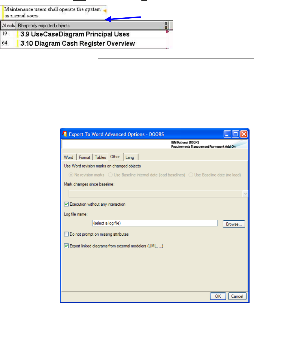
Currently, only one single UML modeling tool is “natively” supported : Rhapsody.
However this functionality was designed so that you can design yourself other intefaces
towards other modeling tools. Contact the IRDRMFAO support to get the relevant
information.
6.4.3.1.2 Setup
First of all, a surrogate module should be imported from the modeling tool. This module is
a kind of table of content of the UML tool data. Use the integration with your modeling
tool to do so.
You need then to establish the traceability between your module (to be exported to Word)
with the surrogate module data (references to UML diagrams). You have to create those
links from the surogate module to your module. But you can use any link module.
Establish the traceability between the surrogate module and your module
Then select which diagrams should be extracted for each objects which has traceability
links from the surogate module. Run “Select UML diagrams to insert” (RMF ->Enhanced
Word Exporter-> Select UML diagrams to insert).
6.4.3.1.3 Export
By default, such diagrams are not extracted. You can have WEXP extract them by
checking the advanced option “Export linked diagrams from external modelers (UML, ...)”
in the “Other” tab :
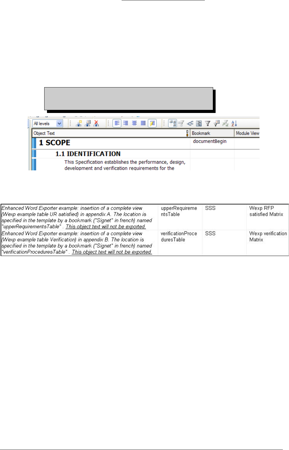
Activating the extraction of diagrams
6.4.3.2 Bookmark & Export Bookmark
6.4.3.2.1 Bookmark attribute:
As explain in the paragraph: "Insertion of bookmarks", you can decide to export Objects
wherever you want in the word document, but you will need to define bookmarks into the
template file, and insert those defined bookmarks into the Wexp attribute called "WEXP
Bookmark" on the cooresponding object.
The following screen shot shows that the first object will be placed on the
"documentBegin" bookmark.
Warning: bookmarks are case sensitive, and do not
tolerate space: i.e. "Document Begin" is not a valid
bookmark.
Figure 56 : ATM200 project, SSS module, configuration of the "WEXP Bookmark" attribute
The next screen shot shows that matrixes will be exported in defined places, in this case in
appendix A for the "Satisfy Matrix" and Appendix B for the "Verification Matrix":
Figure 57 : Configuration of bookmarks for exporting matrixes in appendix.
6.4.3.2.2 Export Bookmark attribute:
A named bookmark can be inserted into the Word document as user-determined points.
This is achieved by placing a single bookmark name into the attribute "WEXP Export
Bookmark" on the appropriate object.
Word will not accept bookmark names with spaces in them, so the exporter will do a
conversion by replacing spaces by underscores. The user is prompted to accept and save
such conversions.
6.4.3.3 Module Name \ Module view \ Export Style
You will need to configure these attributes to export an object from on a different view, or
a whole view.
6.4.3.3.1 Export Style
When exporting a view, you have the choice to export this view as a book or a table.
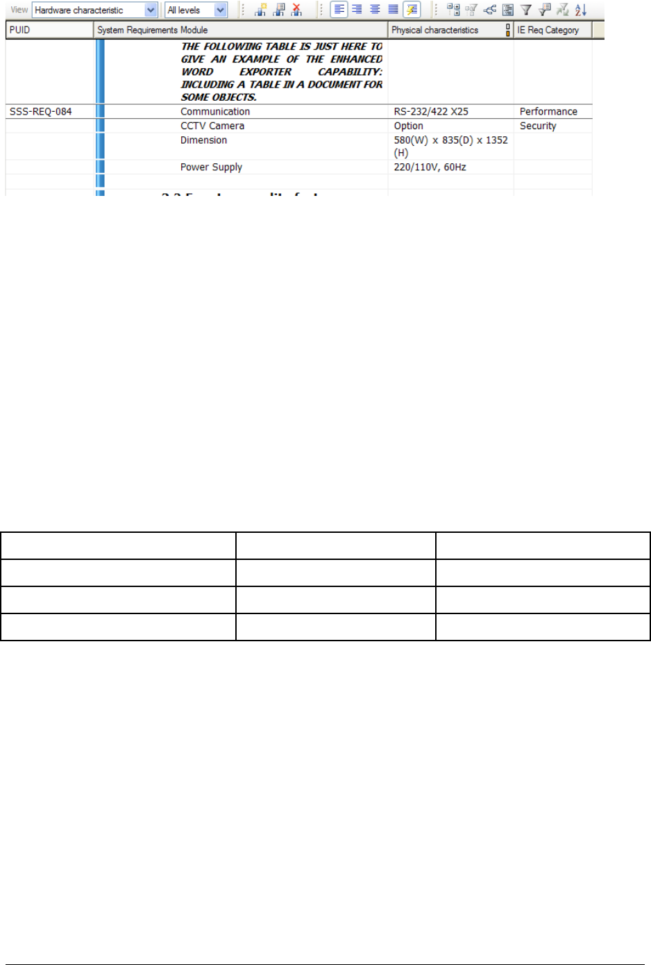
As a book means that each columns will be exported as a new paragraph and exporting as
a table means that the exportation will keeps the table view configuration.
For example, these objects:
Figure 58 : Portion of the "Hardware characteristic" view of the SSS module, ATM2000 Project
Result of the exportation in book format: (cf. Description of columns options)
System Requirements Module: CCTV Camera
Physical characteristics: Option
IE Req Category: Security
System Requirements Module: Dimension
Physical characteristics: 580(W) x 835(D) x 1352(H)
IE Req Category:
System Requirements Module: Power supply
Physical characteristics: 220/110, 60Hz
IE Req Category:
And in table format :
System Requirements Module Physical characteristics IE Req Category
Module: CCTV Camera Option Security
Dimension 580(W) x 835(D) x 1352(H)
Power supply 220/110, 60Hz
6.4.3.3.2 Module View
For an object, if you leave the attribute "Module Name" empty and you fill in the "Module
view" attribute, you will export this object as it is displayed in named view, in function of
the "Export Style" attribute.
For example, in the export view we have:
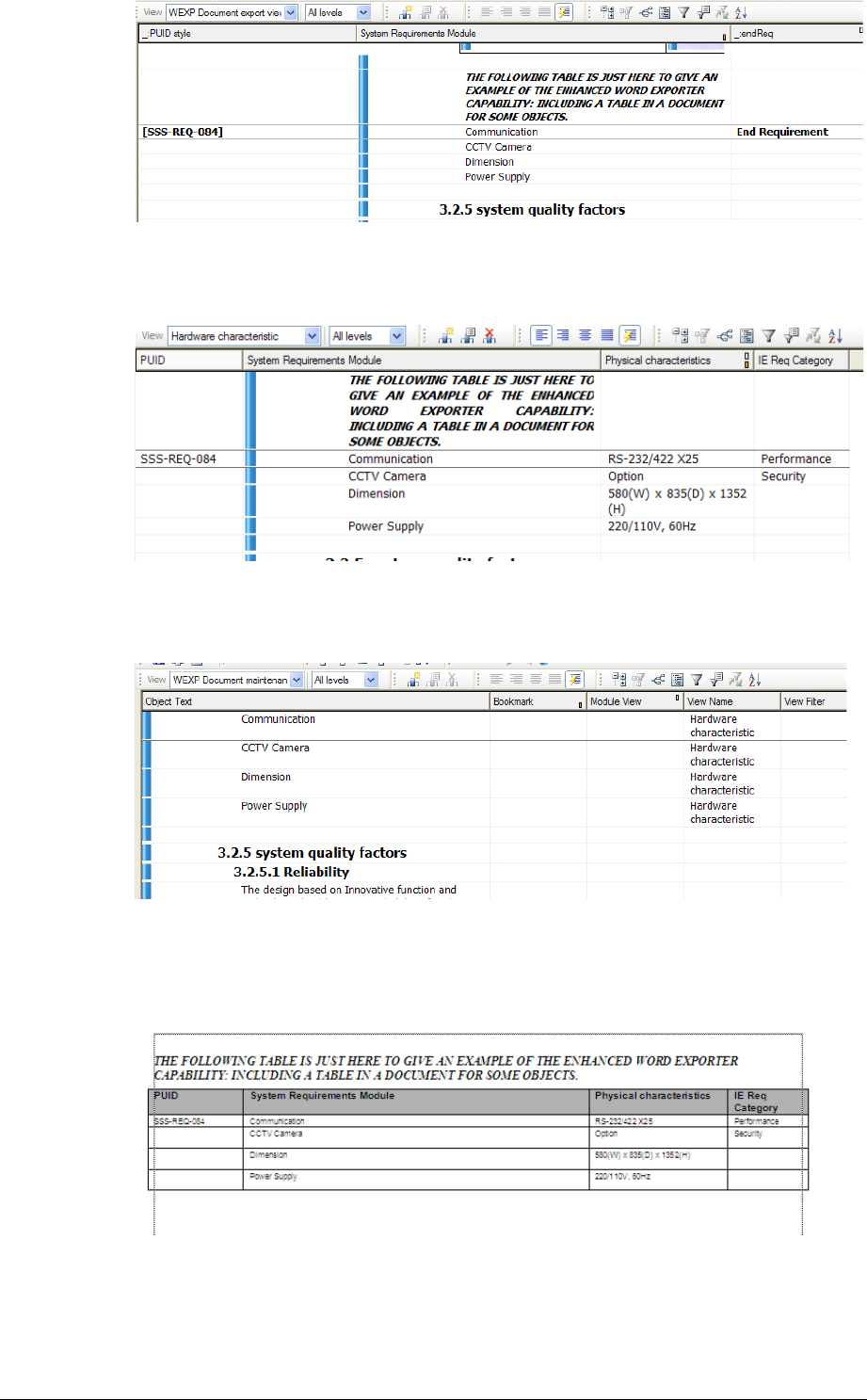
Figure 59 : Portion of the "WEXP Document export view" of the SSS module, ATM2000 Project
But we want to export the hardware characteristics described in the "Hardware
Characteristic " view:
Figure 60 : Portion of the "Hardware characteristic" view of the SSS module, ATM2000 Project
So, in the maintenance view we affect the "Module view" attribute to ""Hardware
Characteristic ":
Figure 61 : Portion of the "WEXP document Maintenance " view of the SSS module, ATM2000
Project
Here is the result of the exportation:
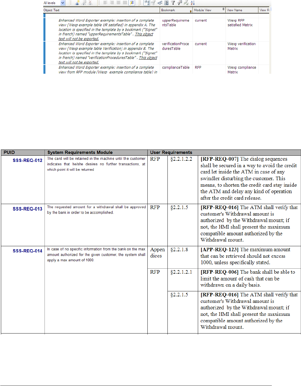
6.4.3.3.3 Module name
To export an entire view, like a matrix. You need to fill in the three following attributes:
"Module Name": name of the module where the matrix or the view to export is.
" Module View": name of the view of the matrix or of the required view.
"Export Style": either "Book" or "Table", in function of your needs.
Figure 62 : Complete configuration to export an other view (Matrixes)
If the module containing the view is the current module, you can simply enter “current” in
the “Module Name” column.
If a module is not in the same folder or project, you shall enter the full pathname of the
module in the "Module Name" column like the following example: "/ATM2000/SSS"
instead of "SSS".
The result is a table such as the example below:

You can notice that some cells can be split. For more information on this subject, please
refer to the WEXP Reference Manual (wexprefman.doc)
6.4.3.4 Page break, Section break & Blank page rubrics
6.4.3.4.1 Page break:
Page breaks can be inserted into the exported document using the enumerated object
attribute "WEXP Page Break". The attribute can have the following values:
Next Page - insert an ordinary page break
Even Page - insert a section break that aligns to the next even page
Odd page - insert a section break that aligns to the next odd page
All page breaks are applied before exporting the object text.
6.4.3.4.2 section Break
Section breaks can be inserted into the exported document using the enumerated object
attribute "WEXP Section Break". The only purpose for doing this at present is to change
the orientation of the page to landscape or portrait. The value of the attribute can therefore
be "Portrait" or "Landscape", to indicate the desired orientation.
To affect a page or section break just before a table, the break may be placed on the first
cell of the table.
If page orientation is changed to enable a wide table to fit on the page, then the section
break attribute should be set on the objects immediately before and after the table, and not
on table cells.
If the attribute is not specified, it will keep exporting in the same orientation.
6.4.3.4.3 Blank page rubrics
It is frequently required to place a text on blank pages, such as "This page intentionally left
blank."
This can be arranged by switching on the advanced option "Insert blank page rubric on
alignment pages", and by placing the text of the rubric in the module attribute "WEXP
Blank Page Rubric". The format for this is "Text:Paragraph style".
For instance, the "WEXP Blank Page Rubric" attribute defaults to "(This page
intentionally left blank.): WEXP Blank Page Rubric".
The effect of this is to export the text "(This page intentionally left blank.)" as the only
paragraph on the blank page using the style "WEXP Blank Page Rubric".
So positioning of the rubric is achieved by creating and using a Word style defined in the
DOT file. This style, for instance, can center the text on the page (cf. Style Definition).
6.4.3.5 Index On
The main use of this attribute is the possibility to create a indexes of attributes. The
following example explains how to do it.
6.4.3.5.1 Creation of a simple index of attributes (I.E. index of PUID)
To create an index of attribute, you will have to define the attribute "WEXP Index On".
You can define it with an attribute name (i.e. IE PUID) followed by a semi-colon. If you
forget the semi-colon, it won't be interpreted it as an attribute, but as text.
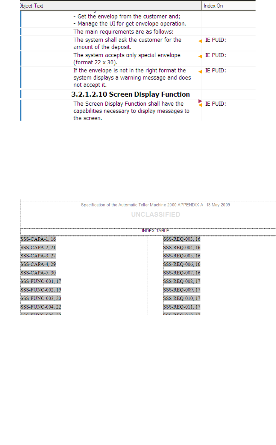
Figure 63 : Configuration of the WEWP attribute "WEXP Index On"
In the template, insert an Index via the pop up menu: Insertion/Tables & Index, Index
tab. You don't need the specify any entries, it will take all PUID because it is the only
entry.
Example of the result after an exportation:
Figure 64 : Portion of the resulting index of requirements
6.4.3.5.2 creation of several indexes
It is possible to distinguish some index entries from others. To do so, add a "::" after the
attribute name and add also a comment, i.e. "IE PUID::CAPA" for a capability object and
"IE PUID::FUNC" for a functionality object.
Then in the template, it is possible to create multiple indexes by using the Word "\f
<index name>" option on the "INDEX" field code (to display the field code: right click,
then "Toggle Field Code").
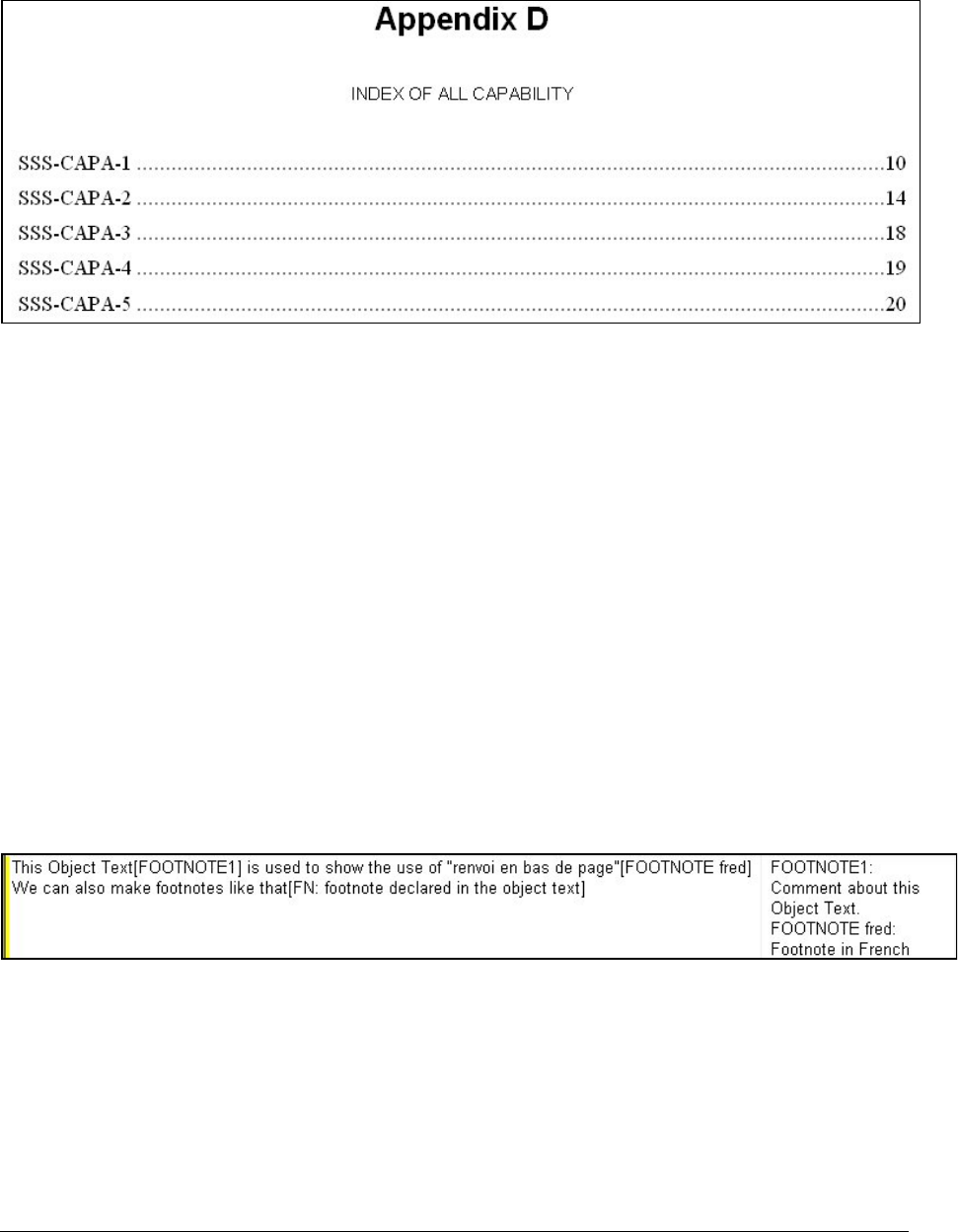
For example, "WEXP Index On" = "IE PUID::CAPA" causes the index entry to be
generated as {XE "....." \f " CAPA"}. The Word index can then be built using {INDEX \
f " CAPA"} to contain just those index entries label with " CAPA".
With this example, you will have three indexes:
One with all requirements
One wit all capacity
One with all functionality
Figure 65 : Result of the index of capability
6.4.3.6 Footnotes
There are two different ways to insert footnotes in a documents:
6.4.3.6.1 First method, in object text
Insertion of a footnote is very easy, you just need to add in square brackets "FN:" followed
by the footnote comment. For example:
We can make footnotes like that [FN: footnote declared in the object text].
6.4.3.6.2 Second method, with Wexp attribute
In the "Object Text" you can add footnotes represented by a number as well by text.
Simply add "[FOOTNOTE x]" or "[FOOTNOTE text]" where "x" is a number and
"text" is any word.
Then in the "WEXP Footnote" attribute, insert the exact name of the footnote followed
by semi-columns and the footnote comment. Note that if you have several footnotes for a
single object, you will have to separated each footnote with a carriage return (in the
"footnote" attribute):
Figure 66 : Example of configuration for foonotes
Here is the resulting output:
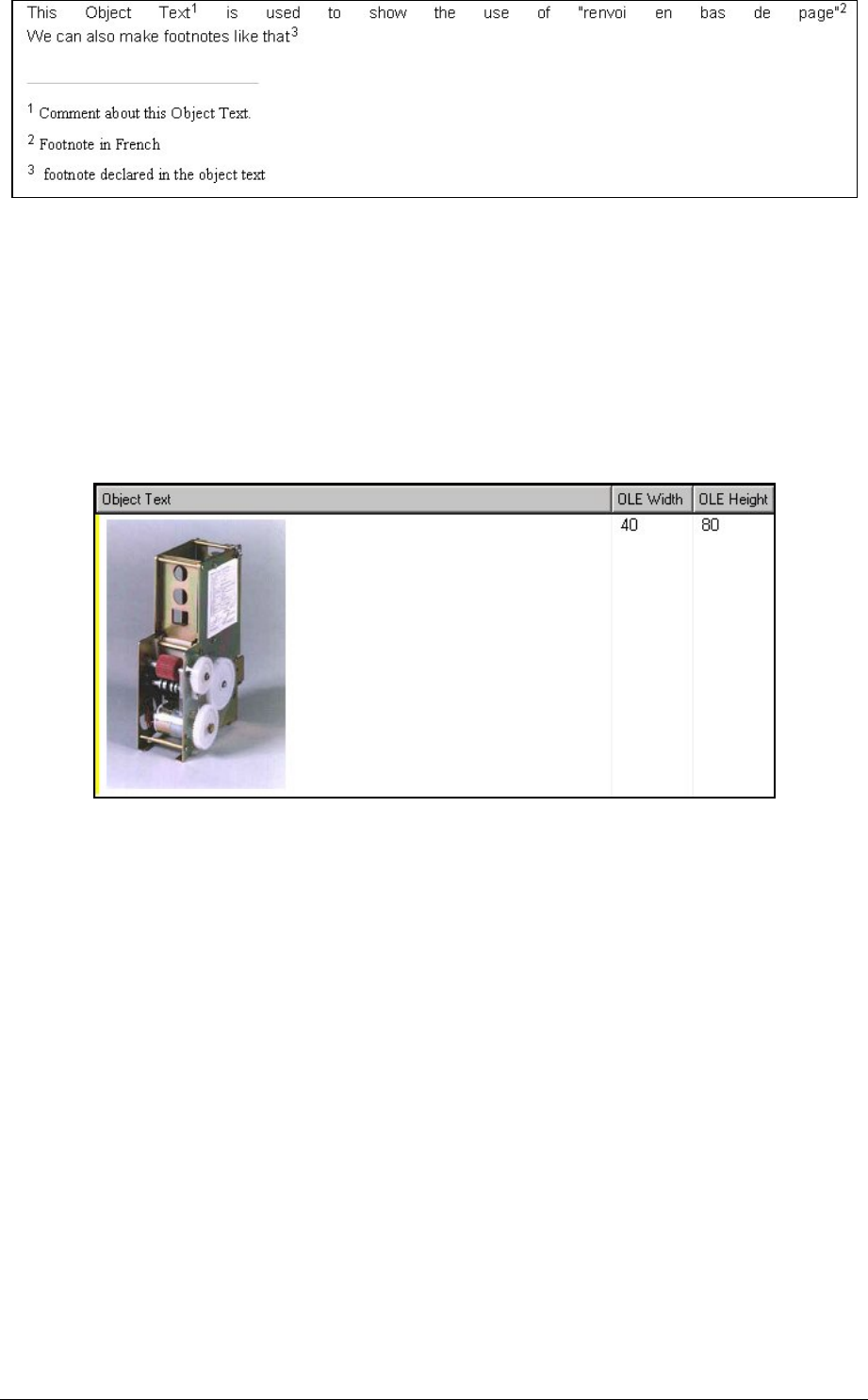
Figure 67 : Visualization of the result of the exportation
6.4.3.7 OLE Width & OLE Height
OLE objects embedded in DOORS objects are exported into the Word document. Using
the DOORS object attributes called “WEXP Width" and "WEXP Height” can control the
size of the objects in Word. The measurement units are millimetres. For DOORS 6/7/8,
these attributes are valid only if the object text contains only one OLE object without any
text.
If these attributes are not set, it will export the OLE object to its real size.
Example of OLE confiuration:
Figure 68 : Configuration of the size of a OLE object
These attributes are available only for OLE objects compatible with the DOORS 5 format
(i.e. only one OLE object at the end of the “Object Text attribute”).
A better solution is to use the operation “Resize all OLE object width”. The width of all
OLE objects will be decrease to be inferior to the width of the main column in the current
view.
6.4.3.8 OLE Caption
Object texts containing one OLE object may be exported with a figure or table caption, by
setting one of the two attributes “WEXP Figure Caption” or “WEXP Table Caption”. The
corresponding caption will be automatically inserted into the Figure Index or Table Index.
6.4.3.9 Object Template
Thanks object templates you can export objects with a desired format in few steps.
6.4.3.9.1 In the template
First, we have to define your format in the template.
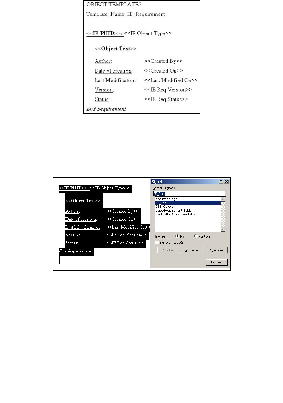
At the end of the template file, add a new section.
Then add a new title called: OBJECT TEMPLATE.
The next lines will be your object template name followed your the format
specification.
For example you want to export each requirement in a formal format:
Figure 69 : Definition of a object template, in the last section of the template file.
Then select all your format and set it as a bookmark called with the name of your object
template (i.e. here, set the bookmark to: IE_Req):
You can declare as many object templates as you want by repeating the 2 last steps.
During the exportation, the object template will be pasted into the document, and then the
attribute field will be filled.
Figure 70 : Affectation of the object template to a bookmark with the same name.
6.4.3.9.2 In Doors
In Doors, fill in the attribute "WEXP Template" with your object template for all desired
objects.
Template “Requirement” example:
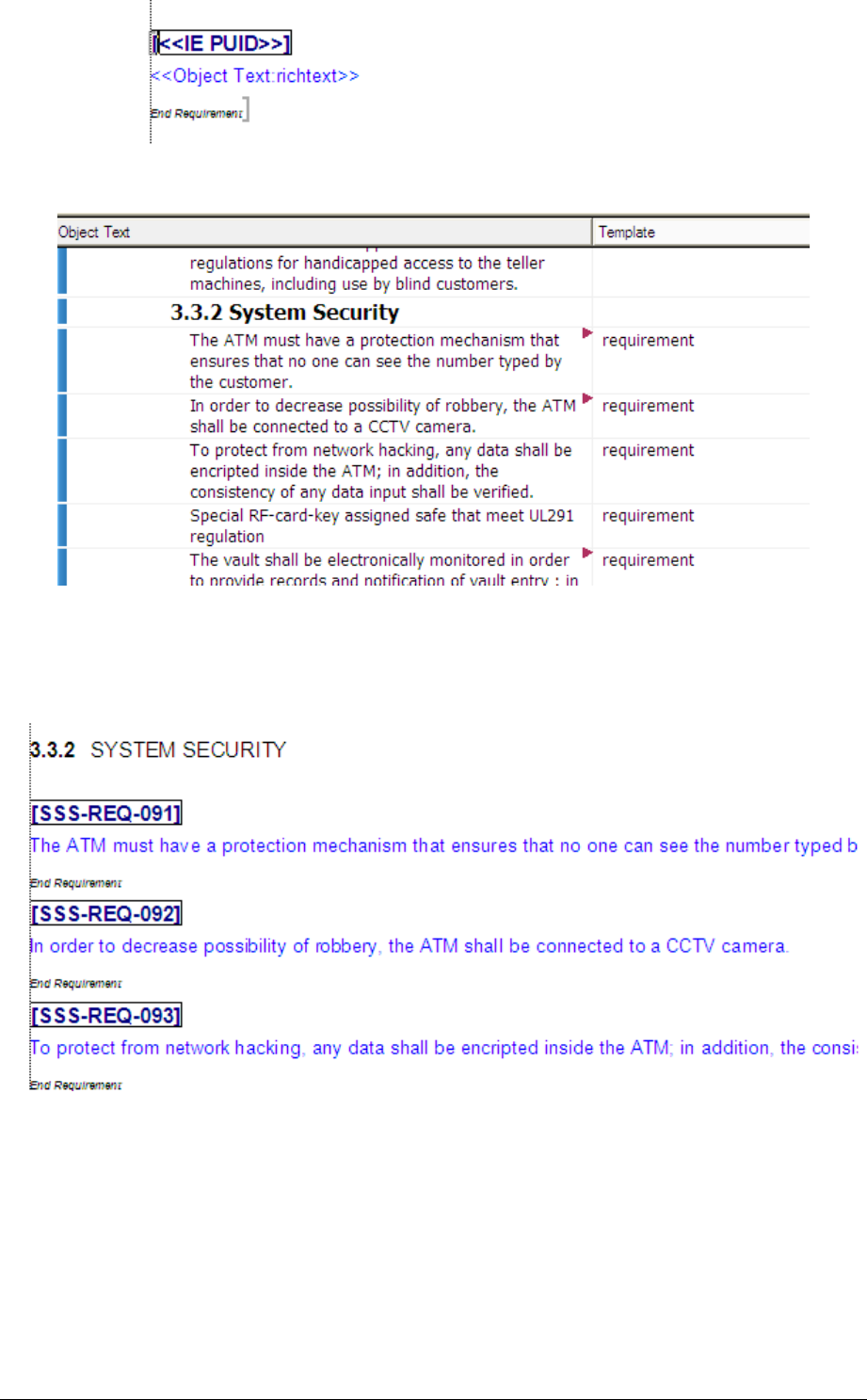
For example, select all requirements, edit the properties of one and change its "WEXP
Template" attribute and apply the modification to all the selection:
Figure 71 : Configuration of the "WEXP Template" attributes.
After the exportation, the last section, corresponding to Object templates, will be remove
from the document.
Example of the resulting document:
Figure 72 : Result of an exportation with an object template IE_Req
6.4.3.10 Filename
There are two ways to insert a subdocument (but only ".doc" files) into the export file:
6.4.3.10.1 First Method, with attribute
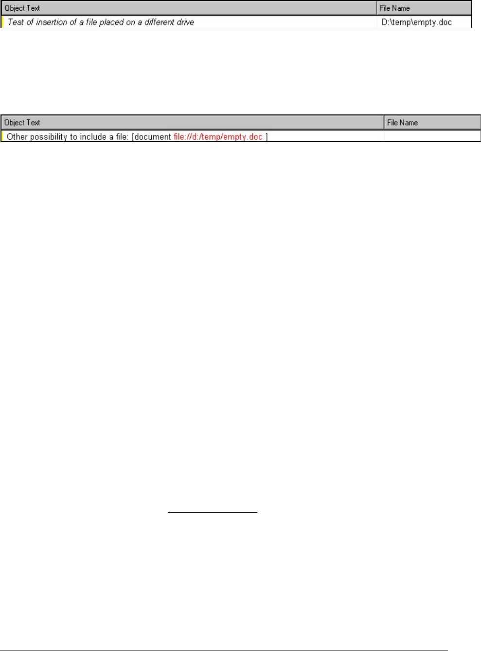
A sub-document can be inserted into a Word document at given positions by using the
"WEXP File Name" attribute. If this attribute has a value, it is supposed to be the name of
a Word document to be inserted at the current position as a sub-document.
The name of the Word document in "WEXP File Name" may be an absolute path, or a
path relative to the path of the master document:
Figure 73 : Configuration on a "WEXP Filename" attribute to export a subdocument
6.4.3.10.2 Second method, in the Object Text
In the "Object text", add the following syntax "[document file:://" then complete with the
full path of the file:
Figure 74 : Configuration on a "Object Text" to also export a subdocument
If you already have document referenced, you don't need to change the object text with the
previous syntax. There is a special command in the WEXP Advanced Options infra.
6.4.3.10.3 Creation of a master document
The procedure for combining several modules into a master document is as follows:
1. Export each of the DOORS modules into Word files.
2. Create a master DOORS module that is an index to the DOORS sub-modules.
This should contain one object per module to be included, with the "WEXP File Name"
attribute set to the name of the file name of the exported sub-document (see tool for
assisting in this).
3. Export the master DOORS module.
Thereafter, individual sub-modules can be re-exported without the need to re-export the
master module; Word will take care of updating the Master Do cument.
6.4.3.11 Hyperlinks
DOORS permits hyperlinks to be inserted into attribute text. In the standard DOORS
Word exporter, these are exported as ordinary text. WEXP automatically exports these as
hyperlinks in the Word document without any special action.
DOORS does not, as standard, allow hyperlinks to be defined with highlighted text
different from the hyperlink address, whereas Word 2000 does. Therefore, the exporter
recognizes the following pattern enclosed in square brackets as a specification of text to be
displayed and highlighted:
Attribute text here [ hyperlink text to be displayed "type://www.telelogic.com" ] followed
by more attribute text.
Where "type" is one of "http", "file" or "ftp".
NOTE: the quote marks surrounding the hyperlink address are optional. If absent, there
has to be a space between the hyperlink and the closing square bracket in the DOORS
text.
This will result in the following being exported into Word:

Attribute text here hyperlink text to be displayed followed by more attribute text.
with a hyperlink attached to the underlined text.
A hyperlink within the same document can also be created. The target must be a
bookmark, and the address is of the form "#bookmark".
Word 97, like DOORS, does not have this displayed text feature. If exporting to Word 97,
the displayed text will be exported followed by the hyperlink.
6.4.3.12 References
The exporter can cause Word to create references on bookmarks. The bookmark may be
defined in the template file, or it can be exported by WEXP.
The syntax is similar to the syntax of the hyperlinks:
Attribute text here [ refer to "type:bookmark" ] followed by more attribute text.
where type is one of text, title or bookmark and bookmark should be replaced by the name
of a bookmark.
The nature of the generated reference depends on the type value.
NOTE:
when using bookrmarks generated by WEXP and generated into text objects,
there is no text associated with the reference because WEXP do not generate bookmarks
containing text.
6.4.3.13 Description of cells options
6.4.3.13.1 Three possible options:
"Shaded" with "WEXP Cell shade" attribute: to shade a cell.
"Rotated Cell" with "WEXP Cell rotate" attribute: to rotated the text of the cell, it
can improve the space used in cells.
"Row header" with "WEXP Row Header" attribute: to make the selected row to
be repeated on each new page when tables are greater than a page.
6.4.3.13.2 Affectation of these options
To change a cell option, select it and edit its properties via (Edit/Object/Properties, or
Ctrl + E or right click and select properties). Then select the attribute tab, and modify the
Wexp attributes as you whish.
For example the following table if the ATM2000 project:
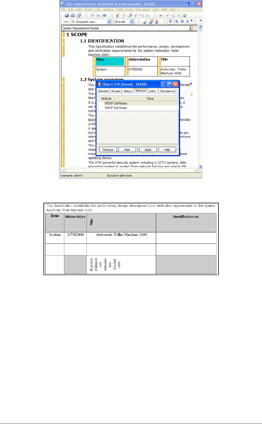
Figure 75 : Accessing cell properties
Result in:
Figure 76 : Exportation result of the previous table
6.4.3.14 Description of columns options
Columns options are used to apply styles to their title and attributes. They are only set to
the columns title but are applicable for both title and column. To access this options, you
have to display the properties window of columns as shown of figure 9.37.
Here are the different possibilities:
"Title" : Export "Title : Object Value" as a separate paragraph.
"Title:style": define a style for both title and objects values.
"Title:join(\t)": The column will be exported in the same paragraph that its right
column but separated by the symbol in brackets.
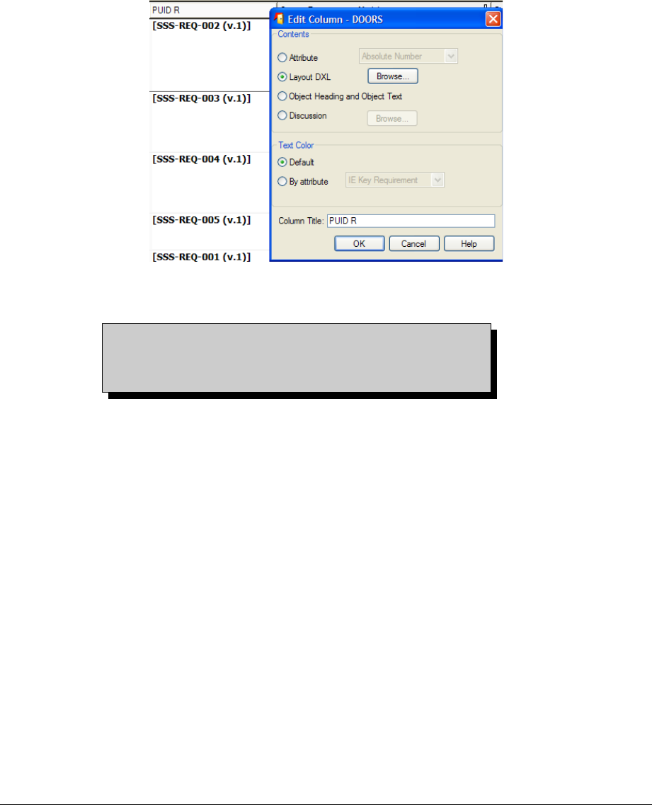
"_:style" : export "values" of the column in a separate paragraph in Word Style
style.
"_": Columns title not exported.
"Title:noexport": Column not exported.
“span:style”: the header cell shall be merged with the previous one, and the MS
Word style “style” be applied to the content of the column
“span\ntext”: multiple table header rows should be generated (see the WEXP
Reference Manual (wexprefman.doc) for more details) (not supported if the table
is exported in RTF format).
"Title R": Rotate the column title (not supported if the table is exported in RTF
format).
Figure 77 : Editing a title to be rotated
Warning, the style definition of columns on the left of
the main column is only applicable if the Wexp
Advanced option "Join columns on the left of main
column" is not set. (cf WEXP Advanced Options infra)
The ATM2000 project example:
To illustrate the Enhanced Word Exporter, IRDRMFAO provides an example of
implementation.
Restore the project ATM2000 (File->Restore->Project, Browse
<DOORS_HOME>/IRDRMFAO /examples /ATM2000.dpa) and open the module
SSS.
Watch the views:
“
WEXP document export view
” and
“
WEXP document maintenance”
as described
aboved,
“
Wexp example table UR satisfied
” and
“Wexp example table verification”
: example
of insertion of complete views as tables in appendix A and B.
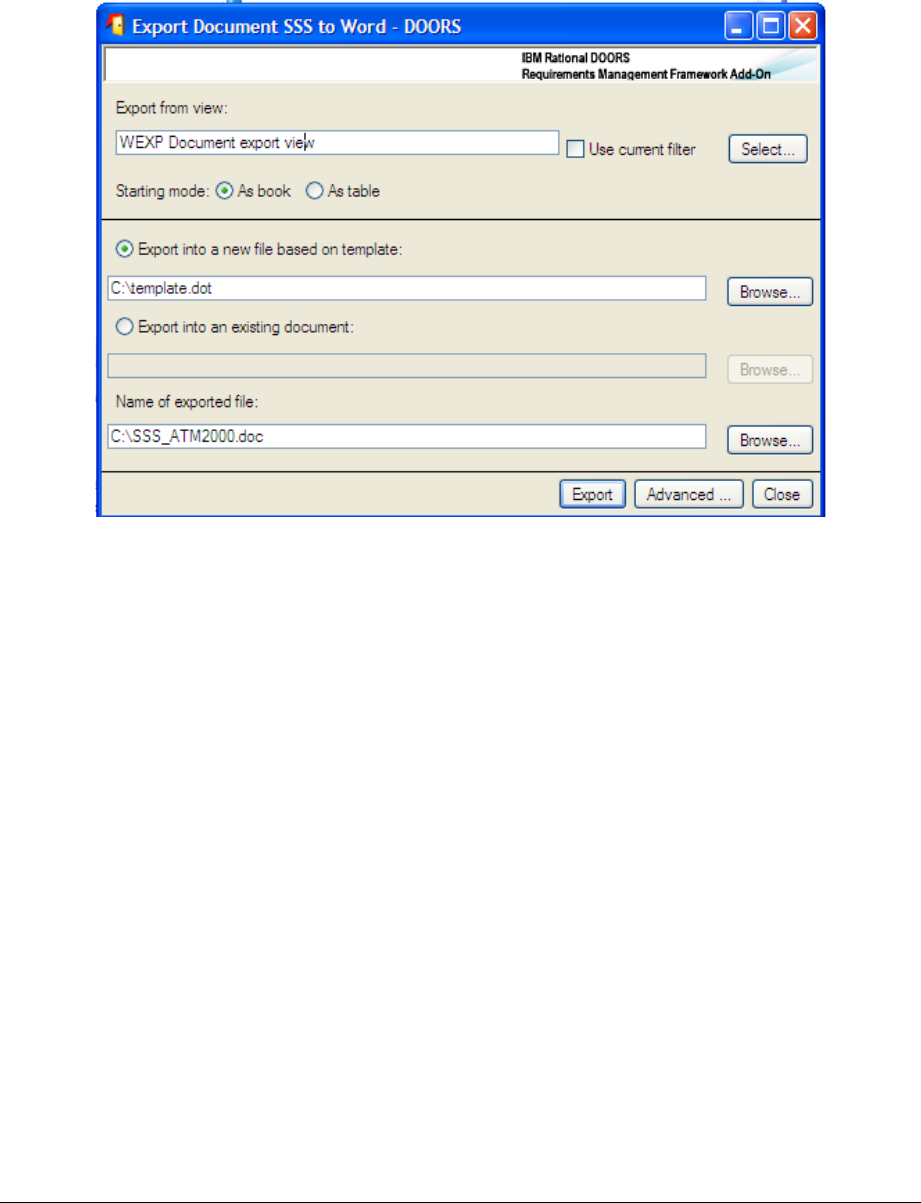
“
Hardware characteristic”
: example of a view used to export a table format for some
objects in particular in the §3.2.4.6 of SSS.
Indexes in appendix C,D & E.
Watch the template (<DOORS_HOME>/IRDRMFAO /examples/template.dot):
Bookmarks, attributes in macro, styles, sections, appendix, headers & footers …
Run the Enhanced Word Exporter and Insert in the appropriate field the valid
template pathname installed on your system
(<DOORS_HOME>/IRDRMFAO/examples/template.dot), 8.4.
Figure 78 : Enhanced Word Export Dialog Box
In the case of a module under RCM control:
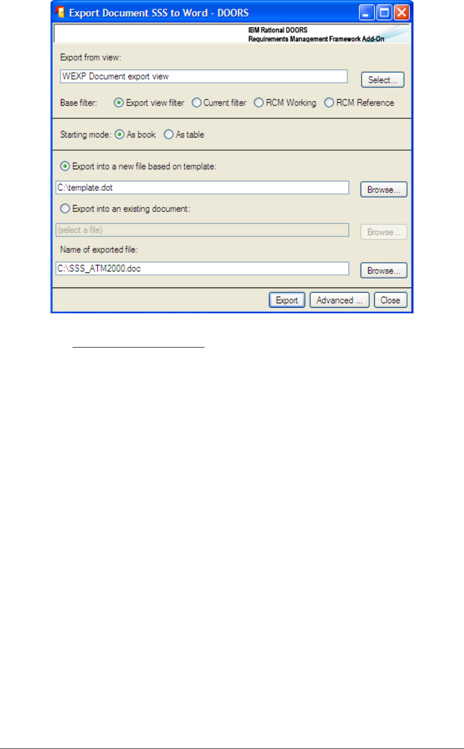
Figure 79 : Enhanced Word Export Dialog Box (RCM)
WEXP Advanced options: look in the WEXP manual to have the list of advanced
options.
1 The first two options relate to the export of master and subdocuments.
By default, the only document exported from the module is the one based in the
data of the module itself. You can also ask for all the subdocuments defined in
the current module to be exported separately, by selecting the "Export
subdocuments referenced in this module" option. Just the subdocuments can be
exported by deselecting the "Export document from this module" option.
2 By default, the exporter switches off the Word screen update and the
window display to speed up the export. You can manually switch the screen
update on by clicking in the check box marked "Refresh window".
3 You can tell the exporter to execute a Word Visual Basic macro after
the export. The macro should exist in the named Word DOT file. The exact
name must be placed in the macro name field.
4 You can ask the exporter to retain the object templates in the last
section of the document to allow subsequent exports into the same document.
exporter will not use RTF format for the inserted views in table format
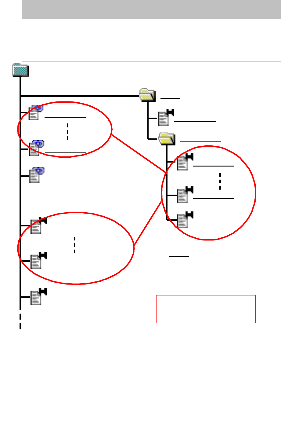
< !66E
< !%##%,
Config
Module type 1
Link module 1
Link module n
Project Profile
Module Types
Module type n
My link module
My module type
My RMF Document 1
My RMF Document n
My non-RMF Document
Name :
Element from the initial
datamodel archive
Name :
Element created in the
project
A RMF project
When in italic,the name is
a conceptual one
Modules type
views based on
Type
Figure 80 : RMF project structure
When you create a new RMF project , you have a “Config” folder under the root project
folder, and a set of link module to buid your datamodel for the current project.
The “Config” folder contains a formal module named “Project Profile”. This module
describes the metamodel used to define the datamodel for the current project. In this
module you’ll be able to define:
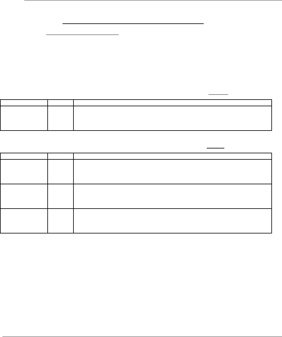
a reference of each module type allowed by IRDRMFAO in the current project;
the template of each module type is stored in the “Module Types” (cf. §7.3.2). In
each module type, can be defined some default views, and these views can
contains some DXL columns based on link modules; these module are stored in
the project root directory.
a reference of each object type allowed to create (or identify) within a RMF
module
a reference of each relationship name supported by RMF , and the definition of
the linksets allowed by the model.
It’s possible to modify this “Project Profile” to adapt the meta-model for your project (cf.
§7.3).
< !%$!&
The default attributes proposed in module types may be not relevant for your project.
Then, according to your need, you can delete, modify or add attributes in RMF module
types, except for reserved RMF attributes as described below .
Reserved RMF attributes
All the formal modules of an RMF project, except the Project Profile formal module, will
have at least four main, reserved, attributes.
The IRDRMFAO utilities use these four main attributes, and they should not be modified
manually.
Module attribute:
Each module has the following attribute defined as a DOORS module attribute:
Attribute name Type Description
IE Mod Type enum This attribute represents the type of the current module.
The Project Profile module contains the list of all the possible values defined for the
current project. But for a given module, this attribute will have a value assigned once and
for all. The value should be one from the list defined in the Project Profile.
Object attributes:
Each module has the following attributes defined as DOORS object attributes
Attribute name Type Description
IE Object Type
(inherited attribute)
enum This attribute represents the type of the object.
The Project Profile module contains the list of all the possible values defined for all the
modules within the current project. The value should be one from the list defined in the
Project Profile.
IE PUID string Project Unique ID. This attribute represents the identification of the object. It is managed
either:
- automatically using IRDRMFAO utility Renumber All Objects,
- or by hand.
Paragraph Style string This attribute is not an RMF attribute. It comes from DOORS. You can capture the style
formatting of paragraphs in your Word document, and store it in the Paragraph Style
attribute. If you later export the module to a new Word document, the styles named in the
Paragraph Style attribute are used to format the document.
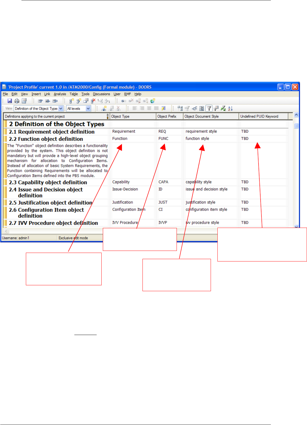
< ( !%$%,%#
The Project Profile formal module describes the available templates, object types and module
types in the project. The Project Profile module must be modified, as described below, if
new object, module type or template is added to the project.
A RMF project always contains a Project Profile formal module.
The “object types” represent all the data suitable for System Engineering, like
requirements, capabilities, issues and decisions, etc. The possible values for Object
Type are: Requirement, Function, Capability, Issue-Decision, Configuration Item,
IVV Procedure.
The “templates” are the available models when creating a new module in the
project.
Each template has one or several “module types”.
Exemple:
oThe Module Types of the template “SR” are:
System Requirements,
Subsystem Requirements,
Prime Item Requirements,
Enumeration for « IE
Object Type » attribute
for RMF modules
Prefix used for object
identification
Wod style used by
default with Word
Exporter
String used to initialize the
number part of PUID when
manual strategy set
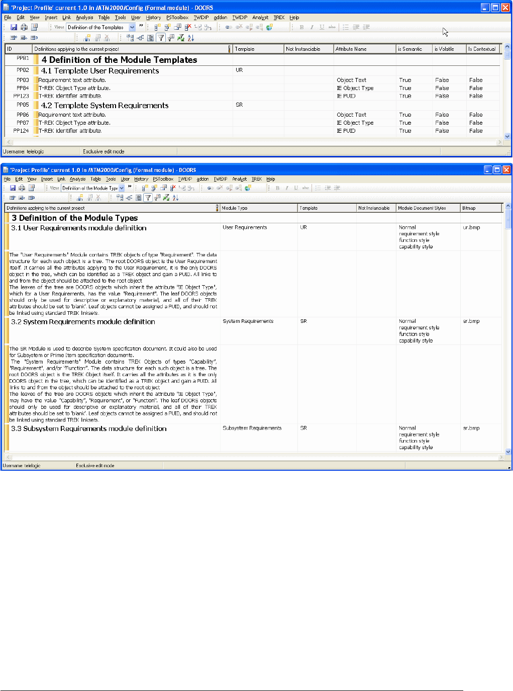
oThe Module Types of the template “IDJ” are:
Issues and Decisions,
Operational Concepts.
< ( !!.&,9%
To add a new object type, follow the steps below.. The example shows the creation of an
object type "Problem Report".
Within DOORS, open the Project Profile module and select the view "definition of
the object types".
Select the last object, and create a new object (Menu "Object->New"). Fill the
attributes:
Text = "Problem Report object definition",
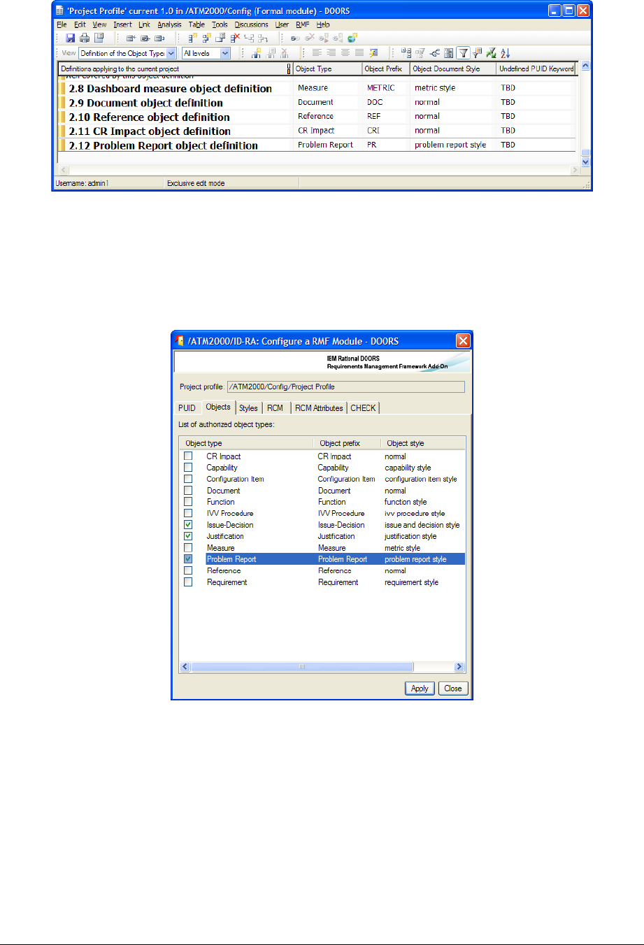
Object type = "Problem Report"
Object prefix = "PR"
Object document style = "problem report style"
Undefined PUID keyword = "TBD"
Save the Project Profile module.
Now, to use this new object, you have to declare it in each module you want to
use it. Let's take as example that you want to use it in a existing UR module type.
Open the UR type module, and run the menu "RMF ->Configure module…".
Click on the type name you want to use in this RMF module
< ( !!.%
IRDRMFAO provides several standard module types : UR, SR, PBS,…but if you need to
add a specific module type for your project, follow the steps shown below. The example
shows the creation of a new template named “PR” for "Problem Report".
Within DOORS, open the Project Profile module and select the view "definition of
the tempates".
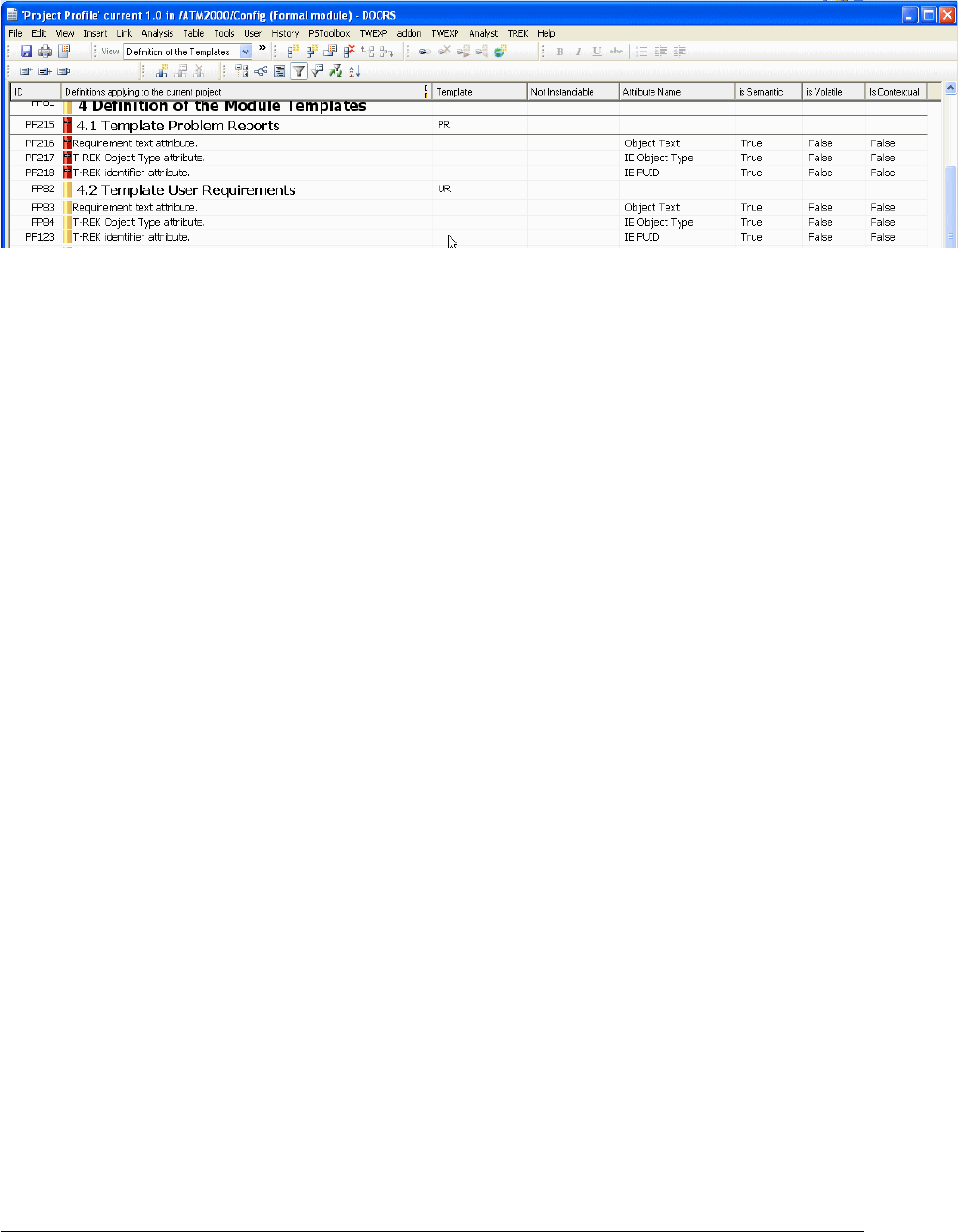
Duplicate the object 4.1 with its descendatnts (copy with hierarchy + Paste)
Modify the new first pasted object as below :
Heading = "Template Problem Reports",
Template = "PR"
Not instanciable = <leave blank>
Optionaly add new semantic attributes. Do not remove one of the tree default
semantic attributes (Object Text, IE Object Type, IE PUID)
Object Text = "attribute description",
IE Attribute Name = <attribute name>
IE Is Semantic = True
Save the Project Profile module.
A template must have at least one module type. So you must also declare a module type. In
the example below, the module type “Problem Reports” will be created for the template
“PR”.
< ( (!!.!9%
The example shows the declaration of a module type named "Problem Report" available in
the template “PR”.
Within DOORS, open the Project Profile module and select the view "definition of
the module types".
Select the last object, and create a new object (Menu "Object->New"). Fill the
attributes:
Object Heading = "Problem Report module
definition",
IE Module type = "Problem Reports"
IE Template = "PR"
IE Module word styles = <list of the styles that can be
chosen>
IE Bitmap = <bitmap file name (for the
relationship manager)>
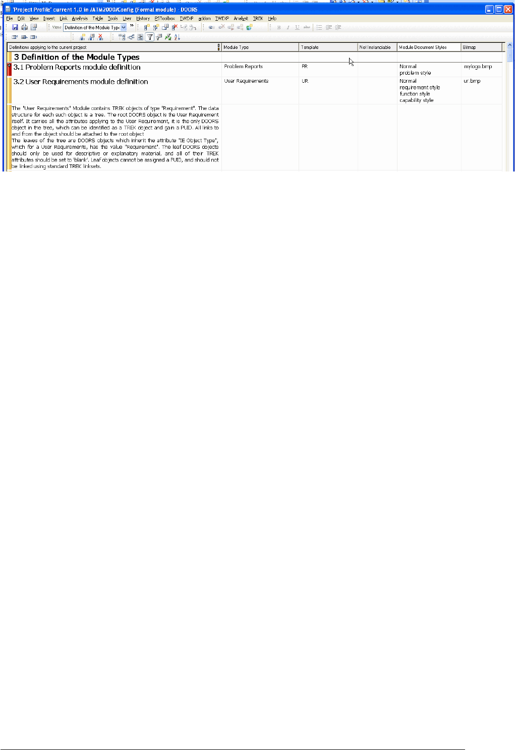
Save the Project Profile module.
From now, you are able to create a formal module of type "Problem Reports" using the
template “PR”.
You can create the template “PR” from an existing RMF standard module or create it from
scratch but do not forget to create and set mandatory RMF attributes. Refer to § Adapting
module attributes. In particular, the attribute "IE Mod Type" defined at the module level
with the value "Problem Reports", and the attribute "IE Object Type" defined at the
object level with at least the value "Problem Report" in our example.
You may also set a value to the attribute “IE Bitmap” to define the bitmap associated
with the module type and displayed by the Relationship Manager.
< ( 2!!.)%
The Relationship Manager utility of IRDRMFAO introduced in version 3.2 allows to
check that the relationships in your project conform to a definition made into the project
profile. It also provides several means to fix any problem.
You may add a new relationship, or a new linkset in an existing relationship.
To add a new relationship:
Add a new object after the last relationship object. Set the heading of the object
with a short description of the relationship. Set the attribute “IE Relationship”
with the name of the relationshuip (this attribute is mandatory).
For each linkset (i.e. a pair source module type, target module type), create a new
object under the relationship object. Enter in the heading a short description of
the linkset. Set the attribute “IE Relationship” with the name of the relationship.
Set the attribute “IE Source Module” with the name of the source module type.
Set the attribute “IE Target Module” with the name of the target module type.
You may add text objects under the relationship object and the linkset objects to
enter comments.
View of the project profile:
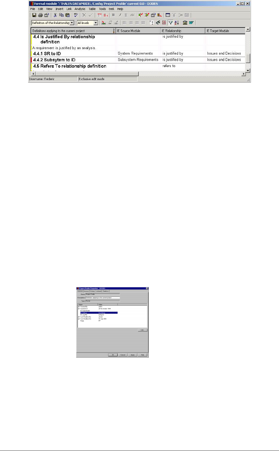
Save the Project Profile module.
From now on, any “is justified by” link between those two kinds of module will be
recognize by the Relationship Manager as correct.
< ( 3)!$
The Project Profile formal module also allows to switch the IRDRMFAO debug mode on to
control the handling of error messages from the utilities.
Use this advanced feature only if you are an experienced user or if your support team
wants to track a bug.
To change the debug mode, edit the Project Profile attributes (menu File->Module properties…)
and set “IE Debug” to
No Debug (default value),
DXL window (to make appear the DXL program when a problem occurs),
Log file (to send the output error messages in a log file),
Window and Log (to send the output error messages in a log file and on the
screen),
Ack and Log (to send the output error messages in a log file and a screen problem
acknowledgement).
Set the attribute “IE Log File” to define the name and the location of the output errors
messages (default is “errlog.txt”)

= 5
#:
=
RMF objects are DOORS objects with specific values in their type and identification
attributes. The permissible values for the RMF object type(s) in each RMF module type,
are defined in the Project Profile module, see para 4.2.3.
RMF objects are acquired by either ‘Identifying’ an existing DOORS object, or by
‘Creating’ a new RMF object, or by a combination of both.
Establishing an appropriate hierarchical structure of the RMF objects is an important issue,
and the significant differences between requirement modules and breakdown structure
modules are outlined below.
The detailed operation of the IRDRMFAO utilities is described in the Reference Manual, a
summary of their usage is described here.
= #:+6
= 56'0
It is an important methodology issue that requirement statements do not have a hierarchy,
they must be self-contained verifiable statements. (Any decomposition of the requirement
into sub-requirements in lower level entities should be held in different modules, and
linked back to the parent requirement object.)
However, it is also necessary to structure long lists of requirement statements into sections
and sub-sections for clarity and ease of use.
These two objectives are achieved within IRDRMFAO by using the DOORS concepts of
‘Heading’ or ‘Normal Text’. All requirement statements are ‘Normal Text’, grouped at the
same DOORS level under a particular heading.
A DOORS hierarchy of ‘Headings’ (ie Object text is blank) should be established to aid
clarity,
IRDRMFAO enforces this methodology in requirement type modules by only allowing
‘Normal Text’ objects (i.e. not ‘Headings’) to be created or identified as RMF Objects, and
by not allowing RMF objects to be created or identified if a parent or ancestor object is
already a RMF object.
The IRDRMFAO ‘Manage Objects’ tool will create a new RMF object at the same level as
the current object if the current object is ‘Normal Text’; and will create a new RMF object
one level below if the current object is a ‘Heading’.
In addition, requirements may be structured into Functions and Capabilities, as described
in para 5.4.4.

= &8'0
In equipment or system breakdown structure type modules there is no methodology
restriction on the object hierarchy, in fact configuration objects may need to be related in
more than one hierarchy. For these modules, such as the PBS module type, IRDRMFAO
allows the natural DOORS level hierarchy to be used. Additional hierarchical relationships
between the objects can be set up using the “is composed of” or additional project-specific
linksets.
Configuration objects should be entered as ‘Headings’, i.e. with the Object Text blank and
with the name in the Object Heading attribute. DOORS will then assign outline paragraph
numbering and display the hierarchy in the DOORS Explorer window. Note that this
numbering may change if items are added, moved or deleted.
IRDRMFAO provides a utility under ‘Kitchen Tool Box’, ‘Objects’ to convert the current
object to a heading, which may be useful if the structured is initially imported.
If the current object is a ‘Heading’, the IRDRMFAO ‘Manage Objects’ tool will create a
new ‘Normal Text’ RMF object at one level below the current object, the new object
should then be converted to a heading.
Because of the volatility of the outline numbering, the RMF PUID should be used as the
principal referencing system, but note the behavior of the PUID numbering in a shared-
edit environment as described below. Projects should also add an attribute to hold a part
number as assigned by the company PDM system.
The DOORS outline hierarchy is recommended for the design hierarchy of a system, and
physical structures should be created using explicit RMF “is composed of “ links between
the objects. Within the design hierarchy, a configuration item should only appear once,
within a physical hierarchy it may appear in several places. The use of links internal to the
module allows this. If required, a project could define more link types and use them to
represent more hierarchies, such as integration threads for example.
= (F!'0
In the common case, Issue/decision type modules are linear lists of objects that do not
need an implicit structure. They are accessed via explicit links from relevant requirement or
configuration objects in other modules; reports are usually generated using sorting and/or
filtering on specific attributes. A long list of objects at a single level is not a problem. One
only reason for imposing a structure might be to divide the module into sections to enable
multi-user access under DOORS, but this is an implementation solution rather than a
methodology imperative. Issue/decision RMF objects should therefore be created as
‘Normal Text’, with ‘Headings’ only used if required to divide the module into shareable
sections.
In other cases, Issue/decision type modules could be structured to produce document
such as Justification documents.
= ( ).606!
Often the first action you will carry out will be to import a document into DOORS, this
will create a set of general DOORS objects, which must subsequently be ‘Identified’ as
RMF objects.
The imported documents can be:
the customer requirements (into a UR Module) ,
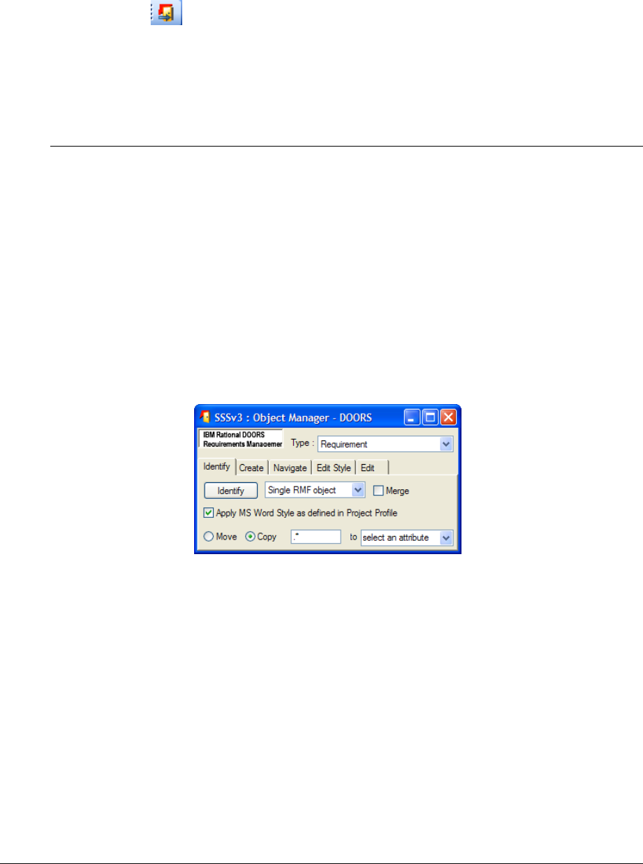
existing documents in a reuse case (e.g.: the existing specification of a previous
system that is close to your customer needs (into an SR Module)).
In all case, you need the electronic format of the document to be available.
The procedure is:
First, always start by creating an appropriate RMF module type to receive the
document,
Second, use the standard DOORS utilities to Import (From DOORS menu “File-
> Import” or from WORD application using the “Export to DOORS” icon
).
Once the document is imported into a RMF module, it must be structured as
described in the previous section and the objects identified as RMF objects.
= 2 ).!#9#&,G
7H#H
= 2
There are two basic methods of achieving an identified RMF object, as follows:
Identify a ‘Normal Text’ DOORS object, or
Create a new RMF object.
= 2 '*B*!:
To identify an RMF object, select a DOORS object or several and activate the utility
“Manage Objects” in the current module menu “RMF”. Notice that the dialog window
stays displayed in front of the screen, allowing quick repeated object identification,
scanning the DOORS module. The same dialog box can also be used to identify objects in
other modules, and be used to create RMF objects as well.
Figure 81 : “Manage Objects” Identify Tab
8.4.2.1 Identifying a selection of objects
The identification tool provides two different modes:
Single RMF object (default mode)
Several RMF objects
In “Single RMF object” mode, only one RMF object is created.
In “Several RMF objects” mode, the tool creates as many RMF objects as there are
selected objects (except if some objects can’t be identified).
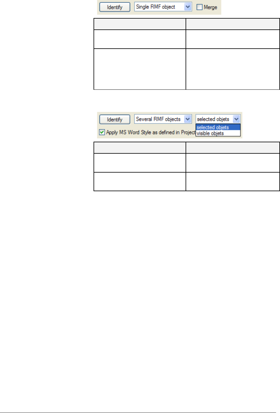
Each mode provides its options :
“Single RMF object” mode options :
Option description
Merge objects ON The tool merges the selected
objects and then identify if.
Merge objects OFF (default) The tool identifiies the first
selected object and move the
following objects so that they
become childs of the newly
identified object.
“Several RMF objects” mode options:
Option description
Visible objects The tool identifies all the visible
objects.
Selected objects (default) The tool identifiies the selected
objects.
8.4.2.2 Applying a MS Word Style
By default the option “Apply MS Word Style as defined in Project Profile” is checked.
Therefore the paragraph style of the new object is set with the value defined in "Project
Profile" module.
8.4.2.3 Parsing the text of the identified object
The tool allows to move or copy a piece of the “Object Text” attribute value of the
identified object, into an attribute to be selected.
The pattern to look for shall be described as a regular expression. Please refer to the
DOORS inline help for a comprehensive explanation on the regular expressions syntax.
The tool allows to copy or move only a subset of the pattern to look for. To do so, insert
brackets before and after this subset.
For instance, in the example below, the pattern to look for is <SSS-[0-9]+>, but the
characters “<” and “>” shall not be moved (or copied). This can be achieved by adding
bracket so that the regular expression becomes <(SSS-[0-9]+)>.
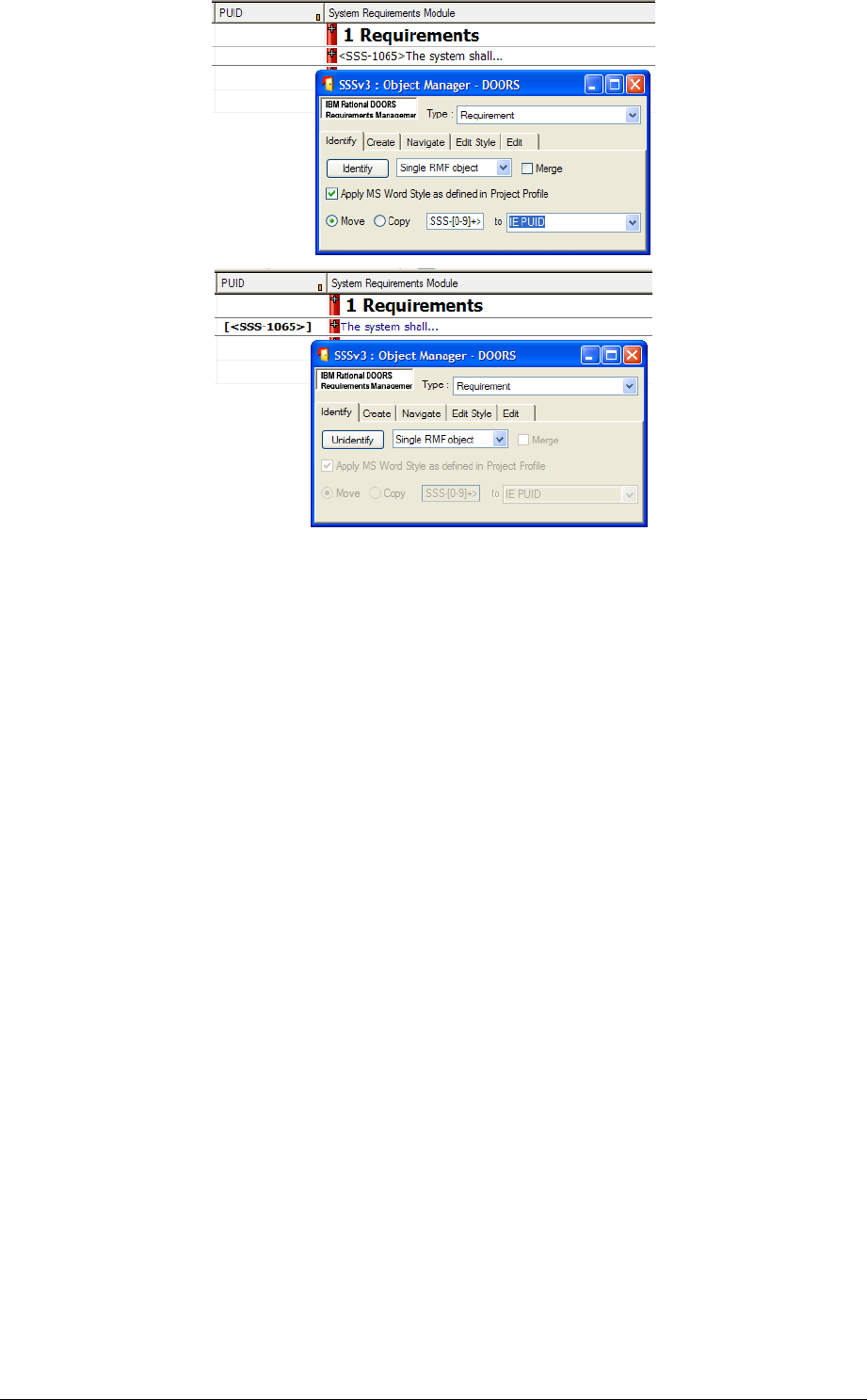
= 2 (*#:
To create an RMF object, select a DOORS object and activate the utility “ RMF ->Manage
Object”. Then choose the “Create” Tab.
Notice that the dialog window stays displayed in front of the screen, allowing repeated
object creation with single mouse clicks. Notice also that you cannot create a RMF object
within a hierarchy of DOORS ‘Normal Text’ objects with this utility.
This utility creates a new RMF object after the selected DOORS object:
- at the same level if the current is an object text,
- below if the current is a heading.
The paragraph style of the new object is set with the value defined in "Project Profile"
module, and the PUID is generated. The new ‘object text’ field is initialized with the PUID
but it should then be replaced by the desired text.
Once the requirements have been captured and identified as RMF objects, they should be
rationalized. Rationalization means splitting up, rephrasing or joining requirements in
accordance with the guidelines given in the DOORS 5 booklet from Telelogic “Writing
Better Requirements”.
Splitting a requirement into two or more requirements is best achieved by 'Creating' one or
more new requirement objects and cut and pasting the required text.
Joining two requirements can be achieved by cutting and pasting the text from one
requirement into another, and then deleting the empty requirement. Alternatively you can
also use the same “manage Object” dialog box that provides a button labelled “Join Text
of Selected Objects”, which is useful for DOORS objects, prior to them being identified as
RMF objects.
In addition, IRDRMFAO allows requirements to be grouped within Functions, which in
turn may be grouped within Capabilities, if this aids clarity and understanding. Note that

‘Requirement’, ‘Function’ and ‘Capability’ are just RMF Object Types and that they must
all exist at the same DOORS level within a DOORS Heading. The IRDRMFAO utility
“Create Links from Object Hierarchy” can be used to aid in the creation of a hierarchy
within IRDRMFAO using links such as “is composed of”.
Once the requirements have been initially rationalized, the PUID numbering will appear to
be randomized or even be absent if editing has been in shared mode. At a convenient time,
before releasing the requirements, when ‘Exclusive Edit’ mode is available, they should be
renumbered using the IRDRMFAO utility “Renumber Objects PUID”, and the module
baselined.
= 3 .4$!)&!
The "Edit Shareable" mode is a DOORS feature allowing several users on a network to
simultaneously modify different sections in the same module. If you are working in such a
mode, some of the IRDRMFAO commands have a different behavior than in simple and
exclusive "Edit" mode. All of those commands involve allocation or calculation of a
PUID, which is impossible in this mode. So the different behavior is the setting of "IE
Object Type" and the "PUID" attribute, which has to be decoupled in «Edit Shareable»
mode.
The "Manage objects" utility sets the "IE object type" attribute but sets the PUID to
a keyword ("TBD",..., or empty) defined in the "Project Profile" module (.view
"definition of the object types", attribute “IE Undefined PUID Keyword").
The "Renumber object" and "Update Version Attribute" utilities are disabled in “Edit
Shareable” mode.
Then, to complete the setting of PUID attribute, the module must be open in simple
“Edit” mode. The "Renumber object" utility is able to only calculate an appropriate PUID
for any objects whose "IE object type" attribute is set and which have a PUID set to the
predefined keyword or empty.
= ; !*!#+6
'0
As described above, IRDRMFAO behaves differently in Requirement type modules from
Breakdown structure type modules. This is due to the inheritance setting of the RMF
attribute “IE Object Type”.
In requirement type modules, the “IE Object Type” is set to inherit its value from its
parent, in Breakdown type modules it is not.
To modifying this setting of the attribute “IE Object Type” in a new module type:
Open the module, activate the menu “Edit->Attribute”, select in the list the
attribute “IE Object Type” and set or unset the “Inherit value” property.

> *++
The Dashboard is a module that can be integrated to each DOORS projet in order to
visualize metrics.
You can have as many Dashboard modules you want within a DOORS project
A dedicated manual is available . Please refer to it (dashboardman.doc) .

? **56+*
?
By definition, changes to requirements will occur either outside or inside the IRDRMFAO
environment. This section describes how IRDRMFAO assists in the control of both
situations.
Changes occurring outside the DOORS environment will in general result in the System
Engineer being presented with a later edition of a document which has already been
imported and processed within IRDRMFAO , and the changes will probably not be
annotated.
Changes occurring inside the DOORS environment will be formally controlled and, if
approved, will be applied directly to the reference data.
? **+***
? !
This paragraph deals with the problem of source documents already imported into
DOORS and analysed within IRDRMFAO , but subsequently modified and up-issued
outside DOORS. Typically, such documents come from the customer or other
stakeholder.
The IRDRMFAO goal is to reduce as far as possible the work of re-engineering the data
by copying the already done analysis on unchanged parts of the document. Unchanged
data should not be analysed a second time and existing analysis shall be applied to the new
version of the source document module in DOORS.
The process is decomposed into 3 phases:
The changes to the source document are tracked by comparison mechanisms,
NB: Since the 3.2 version a second comparison algorithm featuring different functionalities
is available.
Then a human analysis completes the comparison,
The analysis is transferred to the new document module, including links, attributes
and views.
To understand the process, assume that we already have a document called “RFP” for
example at release V1. This document has already been analysed within a RMF module, as
shown in Figure 82. And we’ve just received a new release (V2) of the document.
RFP V1
Requirements
RFP V1
Requirements
Requirement
UR M odul e
System
Requirements
System
Requirements
Requirement
SR M odule
analyse RFP V1 : create attributes and links
RFP V1
Import RFP V1 to DOORS
Figure 82 : A source document has been analysed within IRDRMFAO
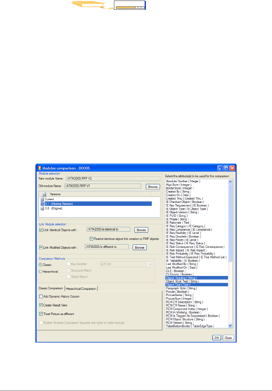
? 0G60+
6
This step uses the standard importer depending on the format of the new version of the
source document. The document is imported into a new module.
RFP V2
RFP V2
Requirements
RFP V2
Requirements
Requirement
UR Module
Import RFP V2 to D OORS
Figure 83 : The new version of the source document is imported
? ( 0G60++
6
From the 5.2 version on:
•the former “Original” algorithm shall be called the “Classic” one;
•the former “New” algorithm shall be called the “Hierarchical” one, for it’s
much more based upon structural considerations than on textual ones.
10.2.3.1 GUI and setup
The comparison functions have been enhanced and now converge to a single module level
menu command: “RMF – Compare Modules”, and to a single graphic user interface
hereafter displayed (Figure 84).
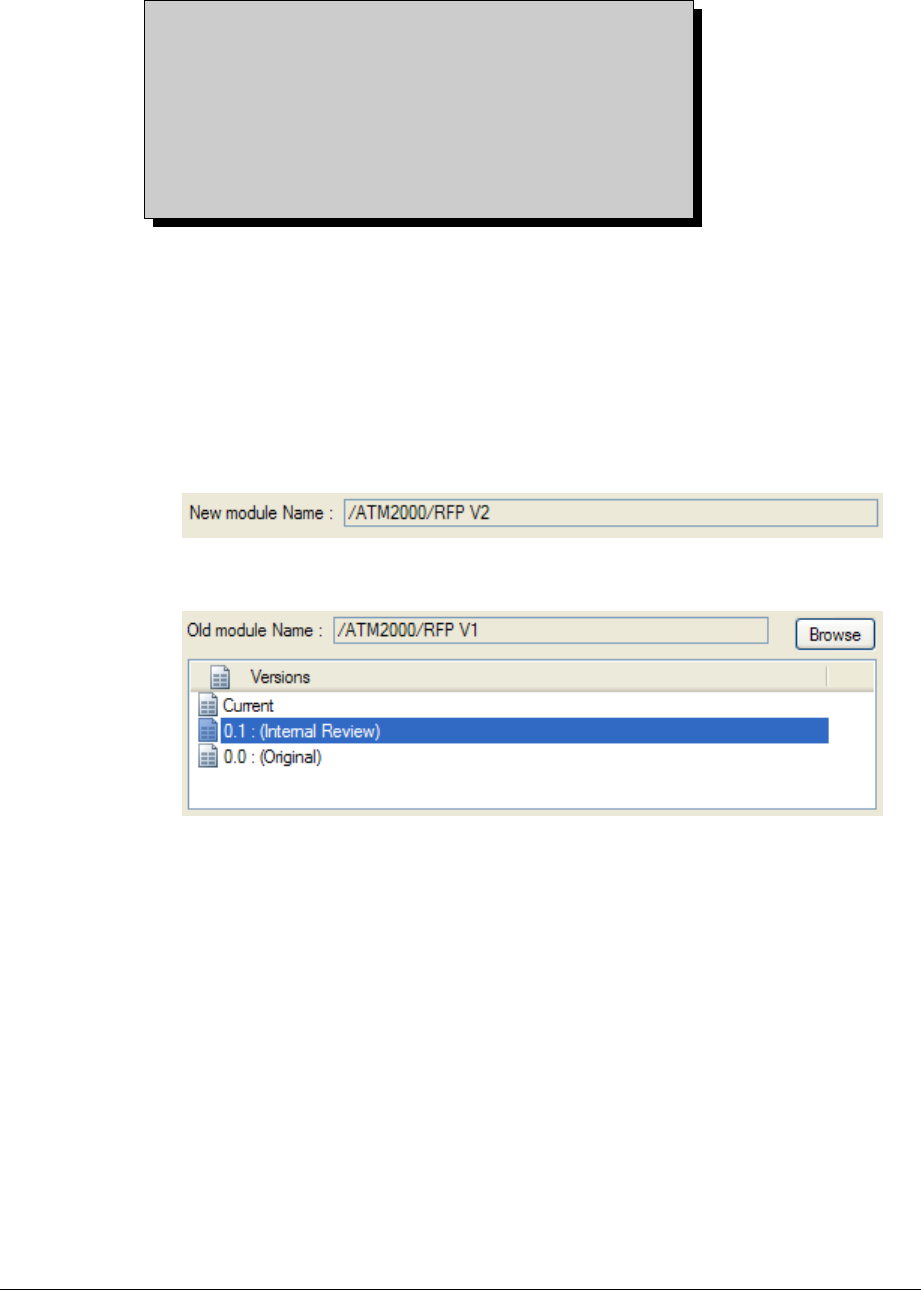
Figure 84 : “Compare Modules” Graphic User Interface
The main features of the “Compare Modules” function are:
Compare a module current version to any module current version or baseline.
Create links between the two compared modules to track the changed or
unchanged objects. These links are created from
the New module
to the
Old
one
, whatever the chosen algorithm.
There is an important difference between running the
tool in the New
➞
Old direction, and in the reverse
direction (Old
➞
New). If running in the direction
New
➞
Old, the tool generates some new attributes and
views in the New module, to which it must therefore
have write access. It will be incapable of displaying any
objects unique to the Old module, that is to say it
cannot display any objects that were deleted between
the old and new issues of the document.
To run in the direction New➞Old, open the new module (RFP V2), and launch the
“
Compare Modules
“ command in RMF menu..
To run in the direction Old➞New, open the old module (RFP V1), and launch the
“
Compare Modules
“ compare in RMF menu.
The various parameters to be defined are:
Select the new module. Use the RMF - “Compare Modules” from the RFP V2
module; then the New Module Name will automatically be “RFP V2”, and there is
no way to change it.
Select the old module and its version. Use the browse button to select the old
module, and use the list to select the version.
Select the attributes to be used for the comparison. The default selection is
“Object Heading” and “Object Text”.
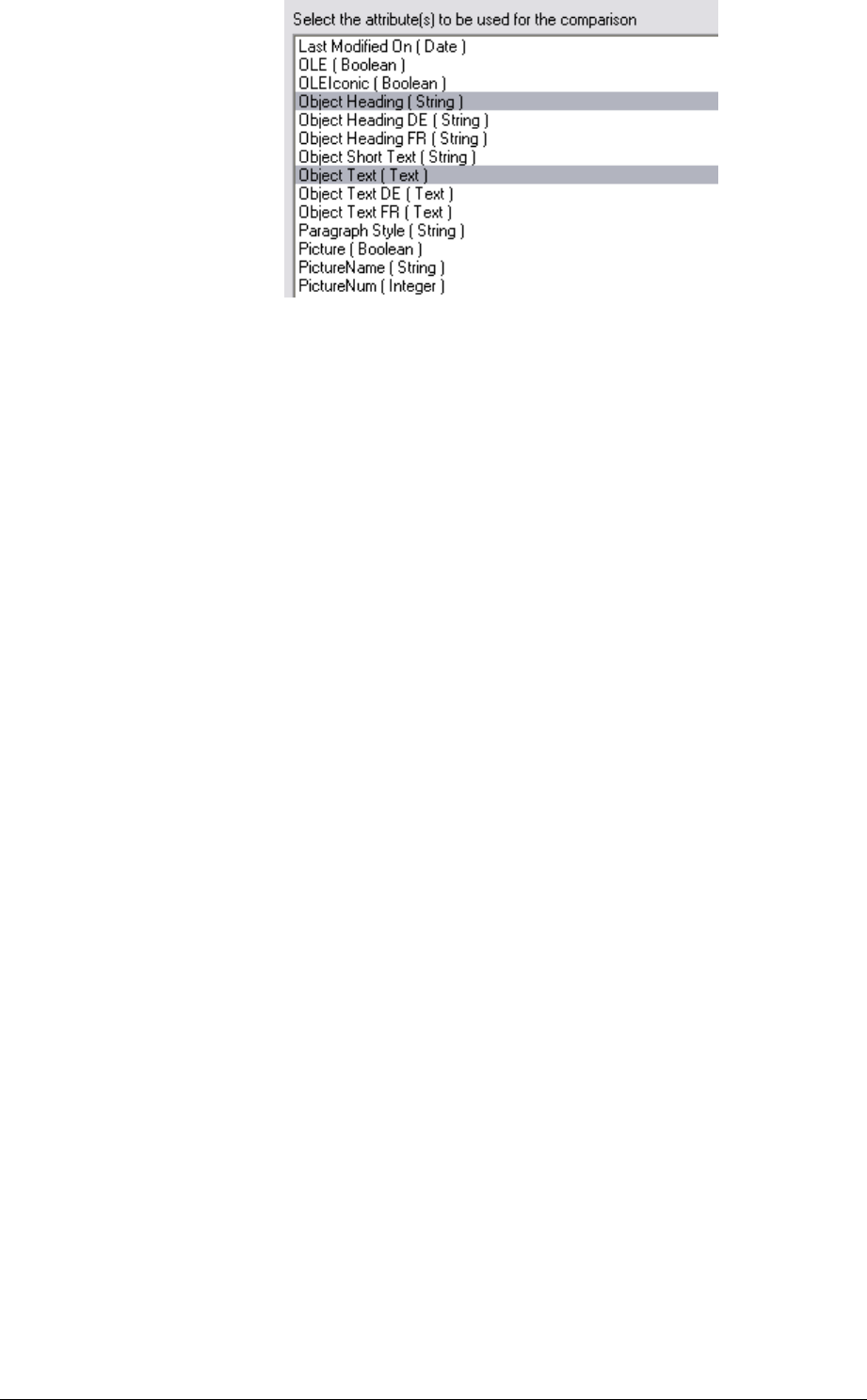
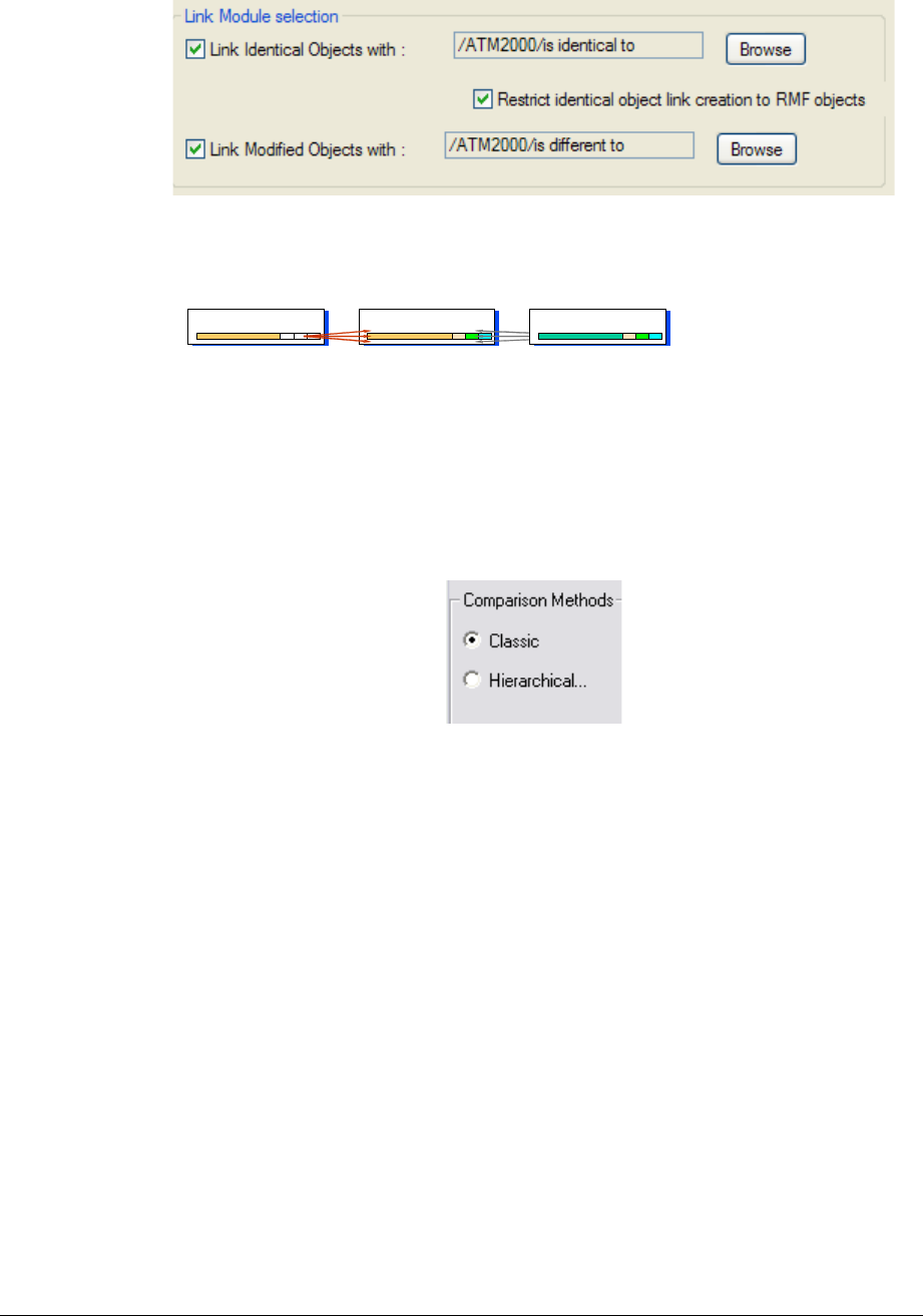
Select Link Module for identical objects. It is the link module to be used to
link the identical objects between the two modules. If no link module is selected,
the identical objects won’t be linked together. Default value is “is identical to”
Select Link Module for modified objects. It is the link module to be used to
link the similar objects between the two modules. If no link module is selected,
the similar objects won’t be linked together. Default value is “is different to”
“Identical Objects” and “Modified Objects” links are created from the new module to the
old one, and are stored as specified.
The following figure shows how links are created:
RFP V2
Requireme nts
RFP V2
Requirements
Requirement
UR Mo dule
RFP V1
Requireme nts
RFP V1
Require ments
Requirement
UR Mo dule
Links created from analysis of RFP V1
System
Requireme nts
System
Requireme nts
Requirement
SR Mo dule
“is identical to” links created from
comparison of RFP V1 and V2
Figure 85 : Links created between V1 and V2
Select the algorithm to be used. Select the “Classic” or the “Hierarchical”
comparison method using the “Comparison Methods” radio buttons:
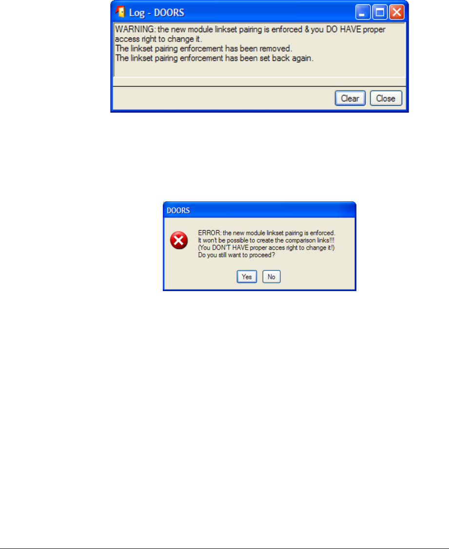
10.2.3.2 Pre-processing verifications
Before trying to process the comparison, tests are made regarding the linkset pairing
definition.
•If no comparison link creation is required no tests are made.
•If comparison link creation is required:
oWhen the linkset pairing
is not enforced
then links will be created.
oWhen the linkset paring
is enforced
:
Either you have the “administrate right” on the folder
containing the new module; then the enforcement will be cleared
and restored. The action will be notified in the log window.
Figure 86 : pre-processing log example (temporary linkset pairing unenforcement)
Or you don’t have the “administrate right” on the folder
containing the new module; then the following window is
displayed, which allows you to go on (in which case errors will
occur) or not to launch the comparison. The choices made will
be logged.
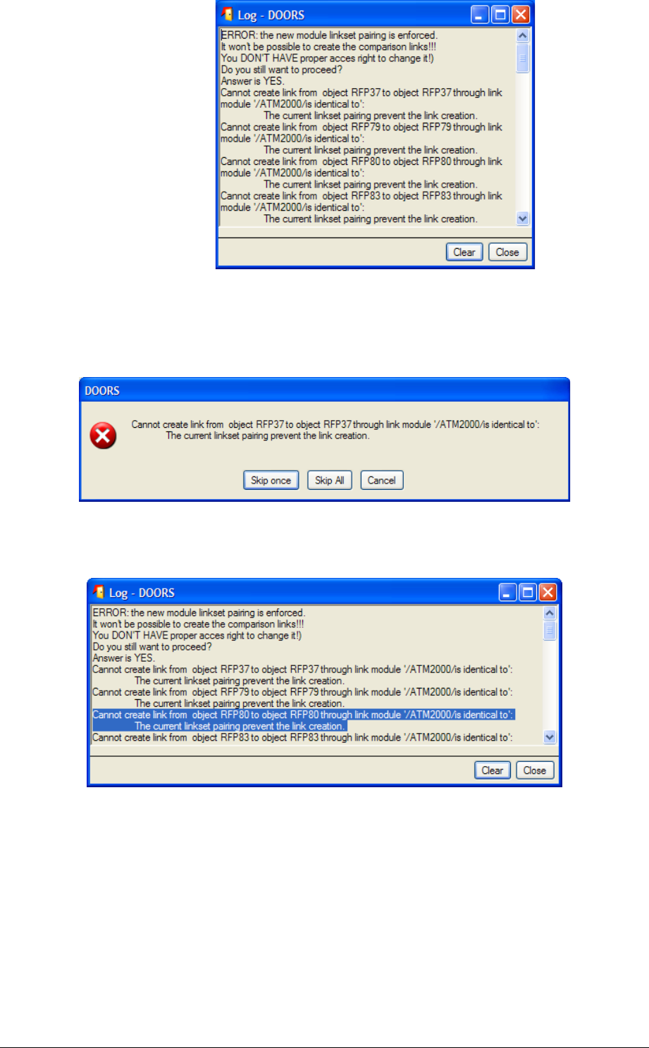
Figure 87 : pre-processing error window and log example (linkset pairing prevents link creation)
10.2.3.3 Processing verifications and log window
If errors occur during the link creation, you’ll be asked to skip the current single error, or
to skip all the errors, or to cancel the comparison.
Figure 88 : processing error confirmation window example
A log window is displayed at the end of the processing to keep trace of all the errors that
occurred:
Figure 89 : processing log window example
10.2.3.4 Classic algorithm
10.2.3.4.1 Use and Parameters
The specific parameters for this algorithm are the ones displayed in the “Classic
Comparison” tab.
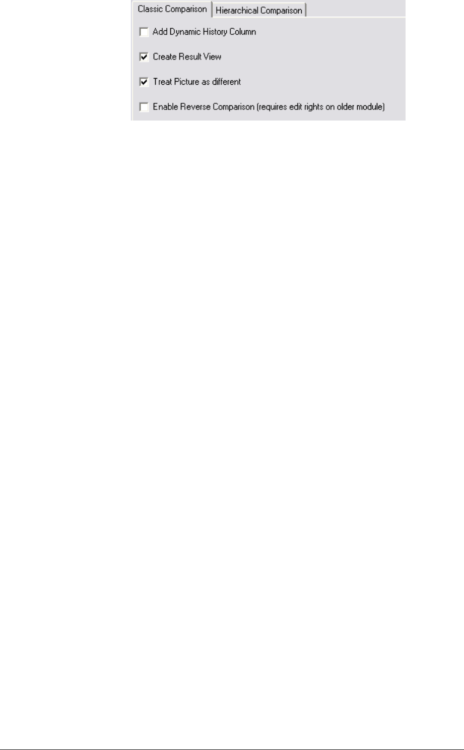
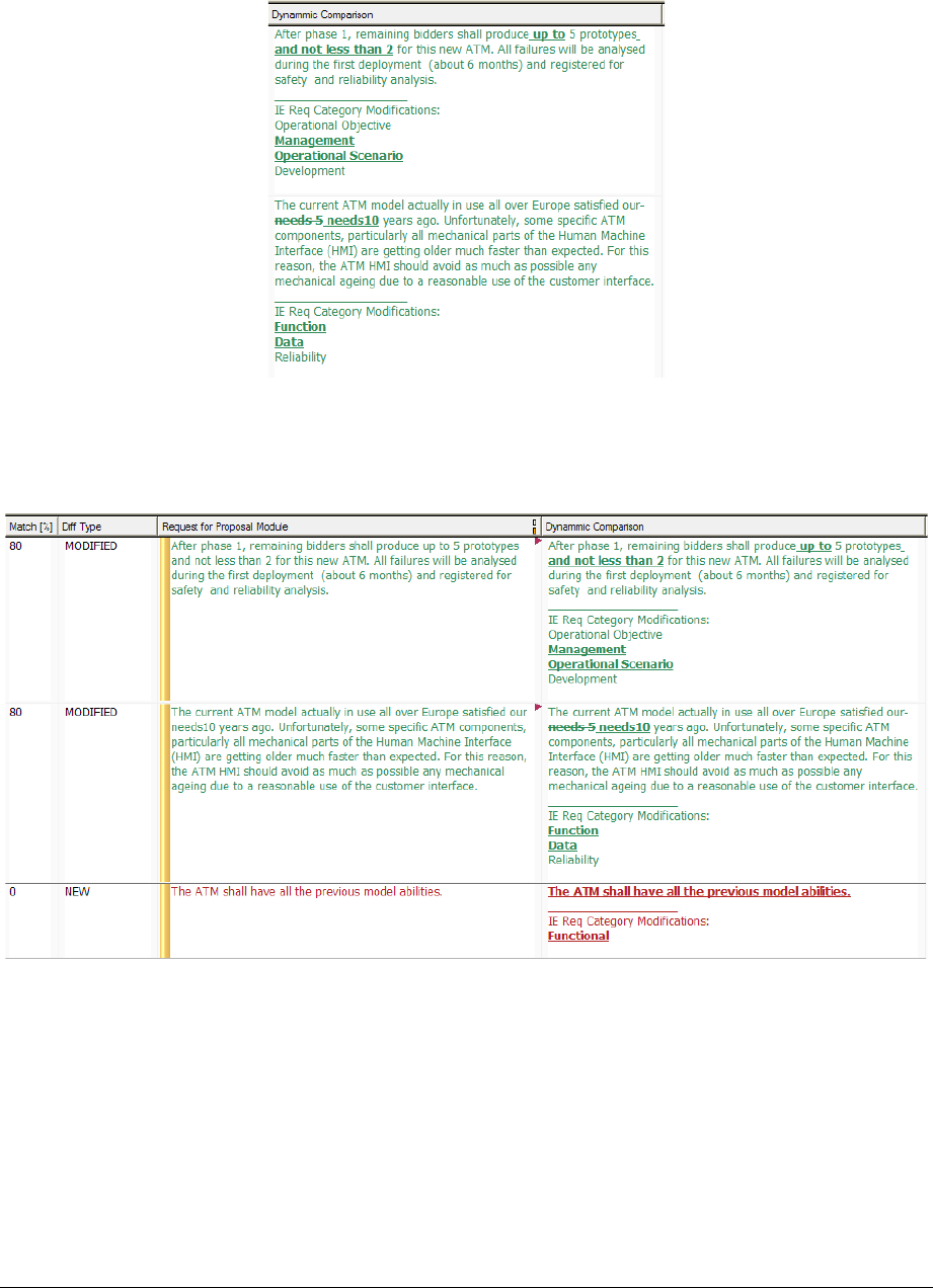
Add Dynamic History Column. If checked, a dynamic DXL column will be
added to the current view (in the far right-end position) and shall display the
differences between the old and the new module. Standard rules are used to mark
the differences relative to the non-current module. Deleted text is struck through
and inserted text is underlined. For example, if some text has been added to the
new module it is underlined when the new module is current (i.e. Compare has
been run in the direction New➞Old). On the other hand, if the old module is
current (i.e. Reverse Compare has been run), this same text is struck through.
Figure 90 : Example of Dynamic comparison column for classic comparison
Create Result View. If checked, a specific view including the DXL Column
“Dynamic History” is created and saved. A filter will automatically be set to show
only modified, new or deleted objects.
Figure 91 : Example of a result view for classic comparison
Treat Picture as different. As the algorithm is not able to compare pictures, it’s
possible to force pictures to be considered as different, and a human analysis shall
be done to set the result attribute to identical or modified regarding the applied
modifications to the pictures.

Enable Reverse Comparison.
To be able to see deleted objects within a result view,
the Classic method offers the ‘reverse compare’ option
– when run in the direction Old
➞
New, deleted objects
will be displayed, but conversely objects added to the
new module will not.
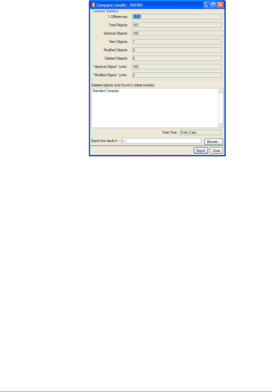
10.2.3.4.2 Final result window
At the end of the comparison a log window displays some figures that can be exported to a
text file.
10.2.3.4.2.1 Standard (ie non reverse) comparison
Figure 92 : Final result window for (classic) non reverse comparison
10.2.3.4.2.2 Reverse comparison
In this case, the final result window is slightly different.
For each figure, the result for the standard comparison and the one for the reverse
comparison are displayed separated with a slash character. The first value is for the
standard comparison and the second one is for the reverse comparison.
As for the “Deleted objects” list, you have a Standard Compare set of deleted
objects AND a “Reverse Compare” set of deleted objects.
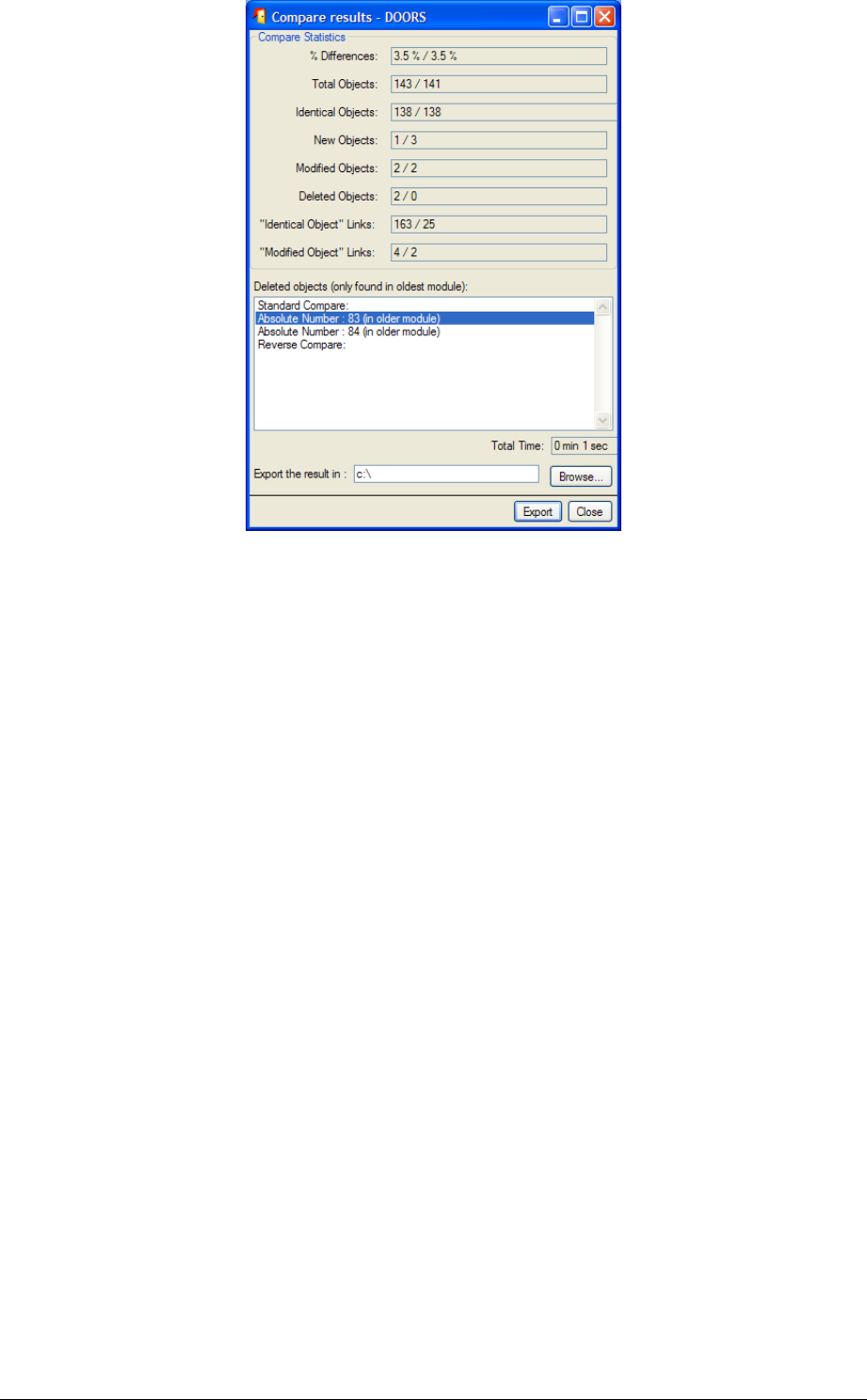
Figure 93 : Final reslult window for (classic) reverse comparison
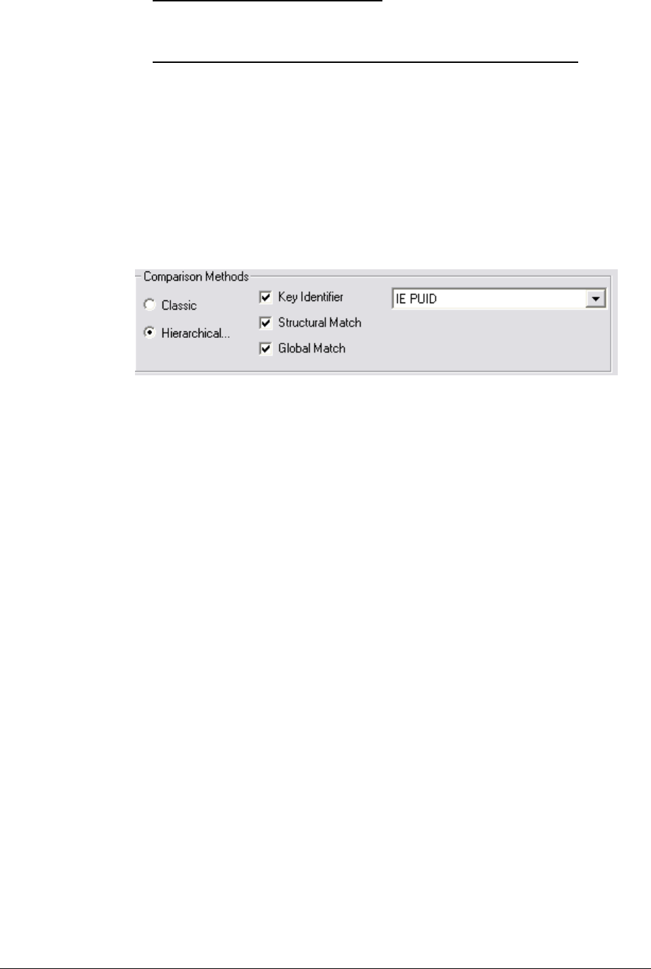
10.2.3.5 Hierarchical algorithm
In comparison with the “Classic” algorithm, this one can:
handle requirements in a special way : as requirements have an identifier which
should remain unchanged, the algorithm can look for requirements knowing their
identifying attribute,
perform a comparison based on the structure of the modules (for non-
requirement objects). This option dramatically speeds up the comparison, but
requires that the structure of the two modules compared is rather similar.
This tool cannot:
compare graphical objects and OLE objects (In general this is not a restriction
insofar as these objects do not contain requirements. If they do, they should be
treated manually).
10.2.3.5.1 Use and Parameters
For this algorithm you can mingle several comparison methods: key identifier, structural
match and global match.
Key Identifier. Activation or not of the research algorithm using an identifier
attribute. Simply check the “Key Identifier” box to enable this functionality and
select the attribute (only integer and string attribute are listed in this choice list).
Whenever this attribute is not empty, it is supposed to be a single and stable
identifier of the current object, and can be used to find the equivalent object in the
other document. Default value is “IE PUID”.
Structural Match. Activation or not of the structural research algorithm. This
research is based upon the structure of the document. Two objects are equivalent
if their parents are equivalent and if the values of their compared attributes are
equal or similar. This option is active by default.
Global Match. Activation or not of the full research algorithm. By default it is
not selected. If the difference between the two modules is light, and in particular if
there is no difference in structure, this additional stage is not necessary. If the
number of objects remaining after the first stage is important (more than one
thousand), then this second stage can be time consuming.
Other parameters are available in the “Classic Comparison” tab. As soon as one of the
following parameter is set “on”, a view named “Compare(Hierarchical)Result” is created
and automatically saved, if ever you ask it to be at the end of the comparison.
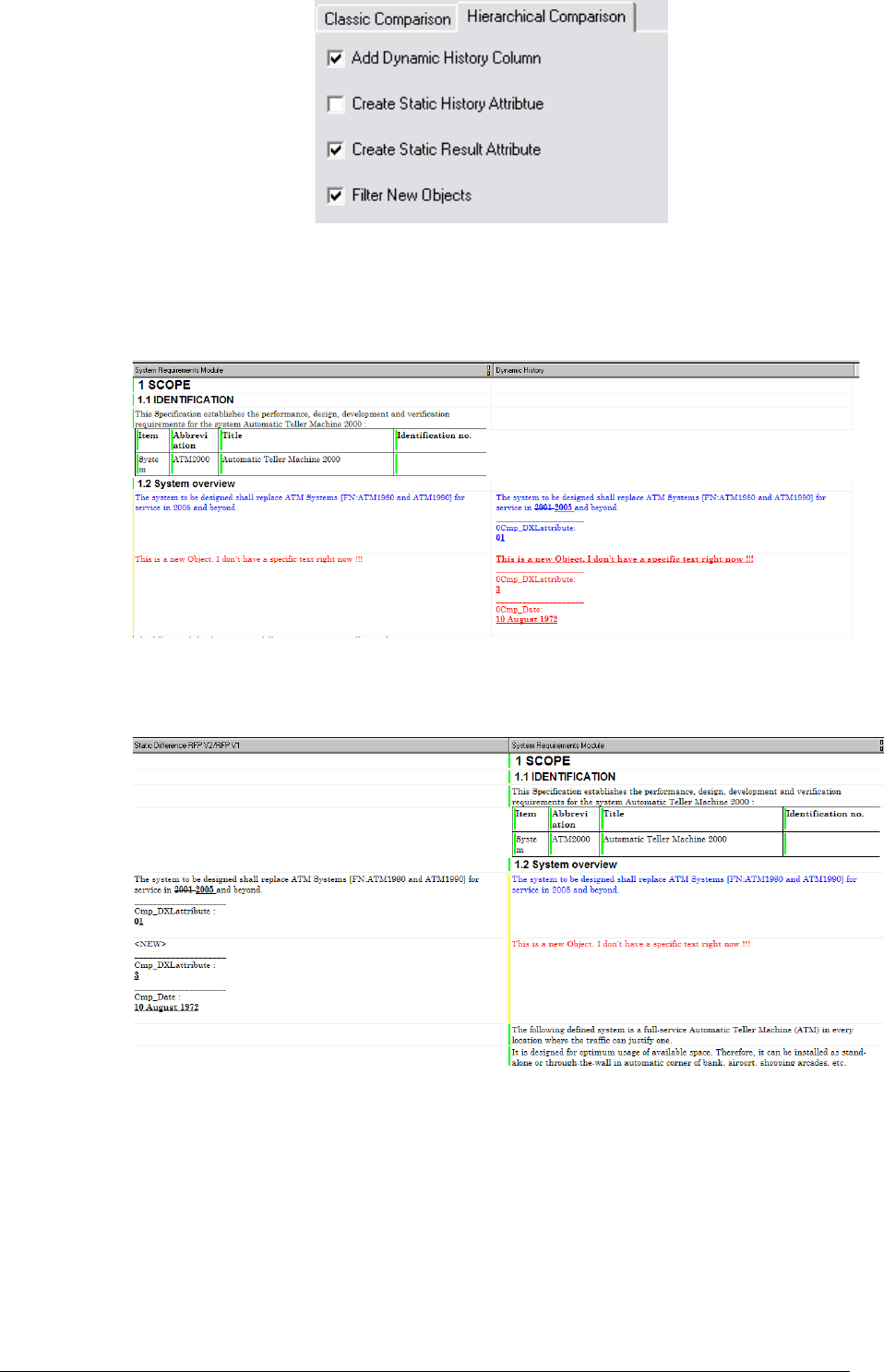
Add Dynamic History. If activated a DXL column is created in the current view.
It shows the differences between the old and the new objects in a dynamic way.
The “Old” attributes are created and initialized with the values found in the old
module. This column is automatically updated whenever a modification is made in
the text of the new module.
Figure 94 : Example of “dynamic history” column for hierarchical comparison
Create Static History Attribute. Same as last parameter, but the difference is
computed only once and recorded into the attribute “Static Difference”.
Figure 95 : Example of “static difference” column for hierarchical comparison
Create Static Result Attribute. If activated, the attribute
“CompareHierarchicalResult” is created and records for each object whenever
it is changed, unchanged or new. It is displayed in the “Diff Type” column.
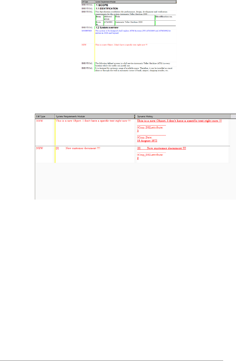
Figure 96 : Example of “static result attribute” column for hierarchical comparison
Filter new objects. If activated only the objects without equivalents will show in
the two modules after the comparison (objects destroyed in the old version and
created in the new).
Figure 97 : Example of filtered view for hierarchical comparison
The color of the objects has the following meaning:
The black-colored objects are unchanged and may have outgoing links stored in
the “is identical to” link module (or similar).
The blue-colored objects are changed as compared to the object of the other
module and may have outgoing links stored in the “is different to” link module (or
similar).
The red-colored objects are new and won’t have newly created link.
Views can be created to display the results of the comparison by using:
The links, (and possibly traceability columns)
The attribute “CompareHierarchicalResult” (whose values are IDENTICAL,
MODIFIED or NEW)
The attribute Static History, which shows the differences in the text between the
new and the old versions, using various styles:

oStrike-through for deleted characters,
oUnderlined for additional characters
The “Dynamic History” column (similar to the “Static Difference” attribute)
and the “Old” attributes.
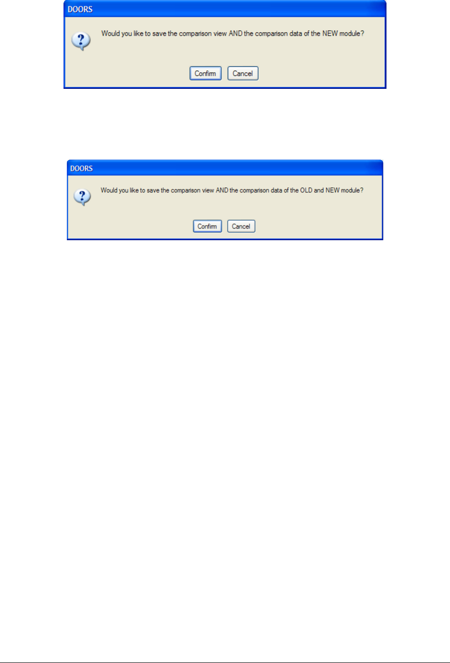
10.2.3.5.2 Save confirmation window
At the very end of the comparison, a confirmation window is displayed:
Figure 98 : Final confirmation window for a non reverse comparison
In this case it means: “Do you want to save the comparison view in the new module?” and
“Do you want to save the new module?”
Figure 99 : Final confirmation window for a reverse comparison
In this case it means: “Do you want to save the comparison view in the old and in the new
module?” and “Do you want to save the old and the new module?”
Be careful, if you decide not to save (i.e. click on the “Cancel” button), just avoid
saving the views without the related modules or else the views will generate DXL
errors, for views will miss useful attributes.
? 2 (0G)6+8
At this phase, just before transfer analysis, if needed the user may create additional “is
identical to” or “is different to” links in order to link objects he wants to be treated as
unchanged (even if the text has been changed, due to spelling, paragraph styles, ...).
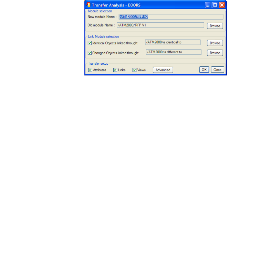
? 3 2+0G'
This step uses a Error! Unknown document property name. utility : “Transfer Analysis”.
From the 5.2 version on, there is only a single “Transfer Analysis” function. Henceforth it
only deals with links from the new version to the old one.
It’s possible to transfer attribute type, definitions and values, links and views. As for views
and attribute definition, the behaviour is now based upon the synchronization mechanism.
Notice that composite “objects” would be restructured under certain conditions:
•The old module is a RMF module
•The old “object” is a RMF composite “object”
•All the objects part of the composite “object” shall have comparison links
•All the linked new objects shall be contiguous and in the same relative
position.
10.2.5.1 Graphic User interface
10.2.5.1.1 Simple GUI (i.e. collapsed advanced panel)
Figure 100 : Simple Graphic User Interface for Transer Analysis

10.2.5.1.2 Advanced GUI i.e. (including the advanced panel)
Figure 101 : Advanced Graphic User Interface for Transfer Analysis: Attribute & View selection
Notice that system attributes that are read only (for instance the “Absolute Number”
attribute) in the target module are not proposed.
Figure 102 : Advanced Graphic User Interface for Transfer Analysis: Linkset selection
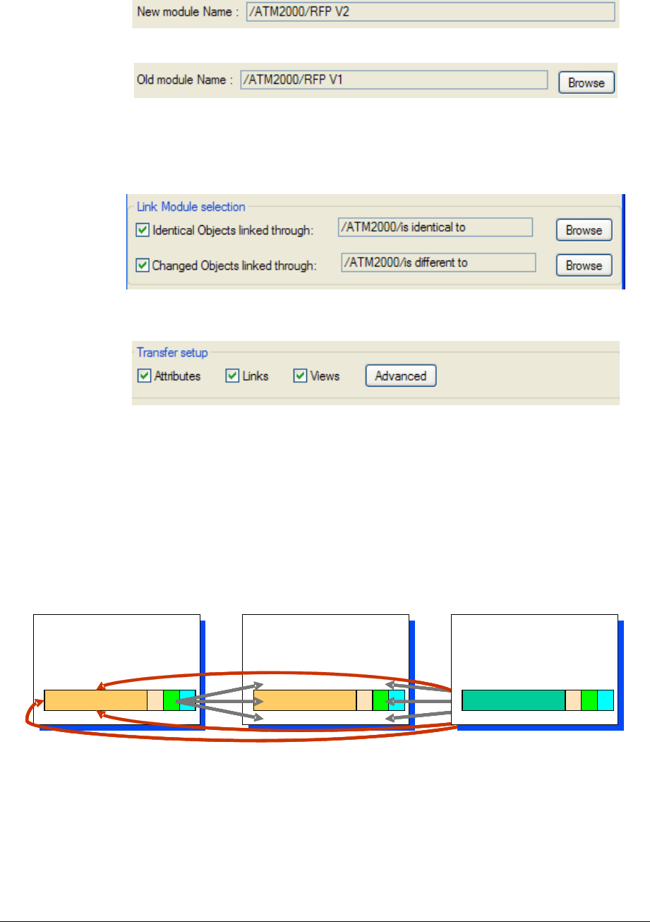
10.2.5.2 Use and Parameters
The “Transfer”parameters are hereafter described.
Select the new module. Use the RMF - “Compare Modules” from the RFP V2
module; then the New Module Name will automatically be “RFP V2”, and there is
no way to change it.
Select the old module. Use the browse button to select the old module.
Select Link Modules for identical objects. It is the link module to be used to
find the old object information to be transferred, for new identical objects.
Select Link Module for modified objects. It is the link module to be used to
find the old object information to be transferred, for new similar objects.
Transfer setup. Just check the boxes in order to define what shall be transferred
from the old module to the new.
Advanced Transfer setup. Specify amongst all the possible data what data you
want to transfer. For instance you can transfer a subset of all the available
attributes, only specific links (chosen amongst linksets), and a subset of all the
available views. The lists of attributes, links and views are built in order to propose
the old module data. See advanced GUI screen shots.
Be cautious using these attributes for it may result in inconsistent configuration,
especially between attributes and views.
So, in our example, it copies to RFP V2 the attributes and the links of RFP V1 unchanged
objects in RFP V2, as shown in Figure 103. Note that if they exist, both incoming and
outgoing links can be copied.
RFP V2
Requirements
RFP V2
Requirements
Requirement
UR Module
RFP V1
Requirements
RFP V1
Requirements
Requirement
UR Module
System
Requirements
System
Requirements
Requirement
SR Module
RFP V2
Requirements
RFP V2
Requirements
Requirement
UR Module
RFP V2
Requirements
RFP V2
Requirements
Requirement
UR Module
RFP V1
Requirements
RFP V1
Requirements
Requirement
UR Module
RFP V1
Requirements
RFP V1
Requirements
Requirement
UR Module
System
Requirements
System
Requirements
Requirement
SR Module
System
Requirements
System
Requirements
RequirementRequirement
SR Module
Figure 104 : Attributes and Links copied from comparison of RFP V1 and V2

Notice that the default selections are set as followed:
•Attribtues:
oIf the old module is NOT RMF and the new one is NOT RMF
All the attributes are selected except “Object Heading”, “Object
Text”, and “Paragraph Style”.
oIf the old module is NOT RMF and the new one is RMF
All the attributes are selected except “Object Heading”, “Object
Text”, and “Paragraph Style”
oIf the old module is RMF and the new one is NOT RMF
All the attributes are selected except “Object Heading”, “Object
Text”, “Paragraph Style”, RCM and PFM attributes (the “IE
PUID” and “IE Object type” attributes are selected).
oIf the old module is RMF and the new one is RMF
All the attributes are selected except “Object Heading”, “Object
Text”, “Paragraph Style”, RCM and PFM attributes, “IE PUID”
and “IE Object type” attributes.
•Linksets
oThe default selection includes all the linksets save the comparison ones.
•View
oThe default selection includes all the views.
Notice too, that default selections can be changed through a modification of user callout
functions. See the comments in the code to know how to use them.
The functions are located at:
“[IRDRMFAO HOME]\lib\dxl\addins\IRDRMFAO
\brandnewtransfer\includes\usercallouts.inc”
The functions are :
•
processDefaultAttributeSelection
: function to be modified (see the end of the
function for an example) to change the default attribute selection.
•
processDefaultLinksetSelection
: function to be modified (see the end of the
function for an example) to change the default linkset selection.
•
processDefaultViewSelection
: function to be modified (see the end of the
function for an example) to change the default view selection.
processCheckBeforeExecution
: function to be modified (see the end of the function for
an example) to add a specific check before the transfer execution.
The “Paragraph Style” attribute is copied in a specific way:
•If the attribute is transferred from a RMF object, the local value is not modified
(no transfer)
•If the attribute is transferred from a non RMF object, the local value is replaced by
the transferred value.
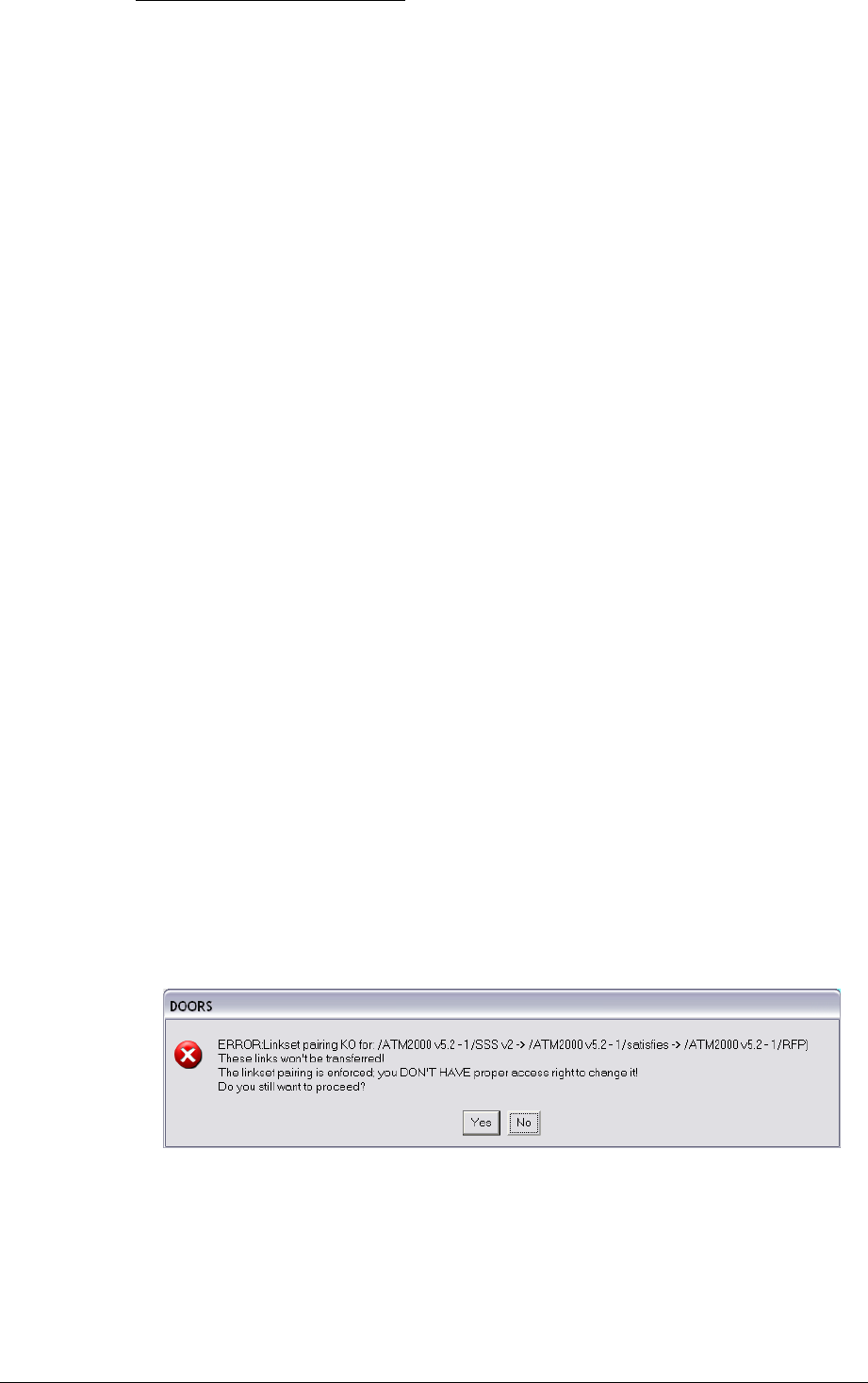
Notice the following contraint:
To transfer incoming links, you need write access rights to the source module(s) of
those links.
10.2.5.3 Pre-processing verifications and log window
Before trying to process the transfer, tests are made regarding the linkset pairing definition.
•If no link transfer is required no test are made.
•If link transfer is required, the linkset pairing will be checked for all the necessary
couples of modules. Interesting events and modifications will be logged in a log
window.
oGenerally, the transfer script will try to update the linkset pairing so that
to reproduce the “same” new module linkset pairing as the old module
one. It can be an update of:
either the new module linkset pairing itself in the case of an
outgoing link transfer
or a reference to the new module in another module linkset
pairing in the case of incoming link transfer
oWhen the linkset pairing
is not enforced
Either you have the “administrate right” on the proper folder;
then the linkset pairing will be updated only if ever a linkset
pairing was defined for the old module. If not, there will just be a
link transfer.
Or you don’t have the “administrate right” on the proper
folder. You will then be informed of the situation in the log
window. The links will be transferred anyway.
oWhen the linkset paring
is enforced
:
Either you have the “administrate right” on the proper folder.
In this case the linkset pairing will be updated only if ever a
linkset pairing was defined for the old module. If not, the
enforcement will be temporarily removed.
Or you don’t have the “administrate right” on the proper
folder. In this case the link won’t be transferred but you can go
on still. The Errors will be logged (see § 10.2.5.4).
Figure 105 : Linkset pairing error example
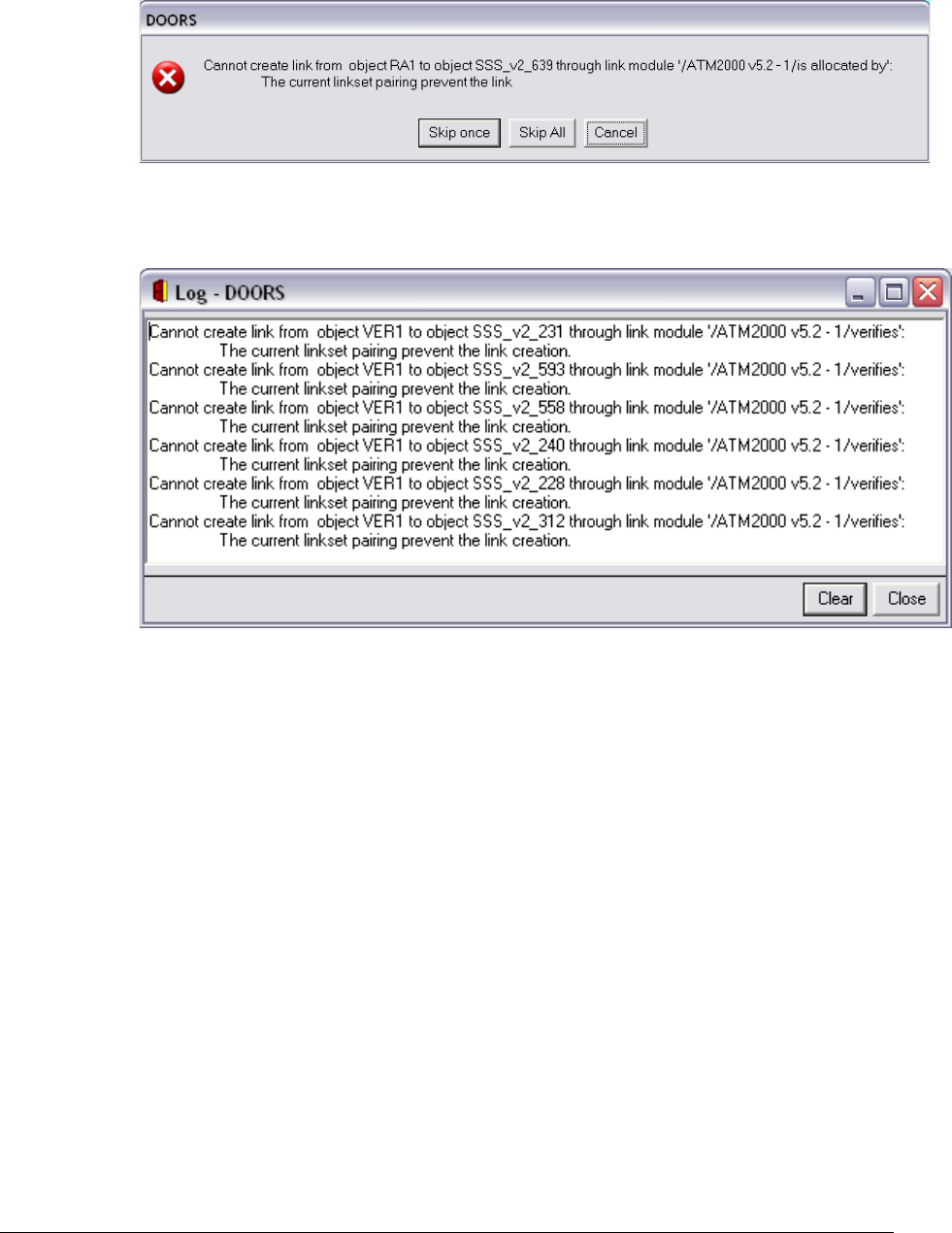
10.2.5.4 Processing verifications and log window
If errors occur during the attribute transfer, the log window will list the errors.
If errors occur during the link creation, you’ll be asked to skip the single current error, or
to skip all the errors, or to cancel the transfer.
Figure 106 : processing error window example (linkset pairing prevent link transfer)
A log window is displayed at the end of the processing to keep trace of all the errors that
occurred, including informations from the pre-processing verifications:.
Figure 107 : processing log window example (linkset pairing prevent link transfer)
? ; 3+0G0+
+6
Now RFP V1 could be deleted, or archived (in order to keep trace of the history), because
it is no longer necessary for the traceability from System Requirements to new version of
RFP V2. Its continued presence in the list of modules in a project becomes a source of
potential confusion.
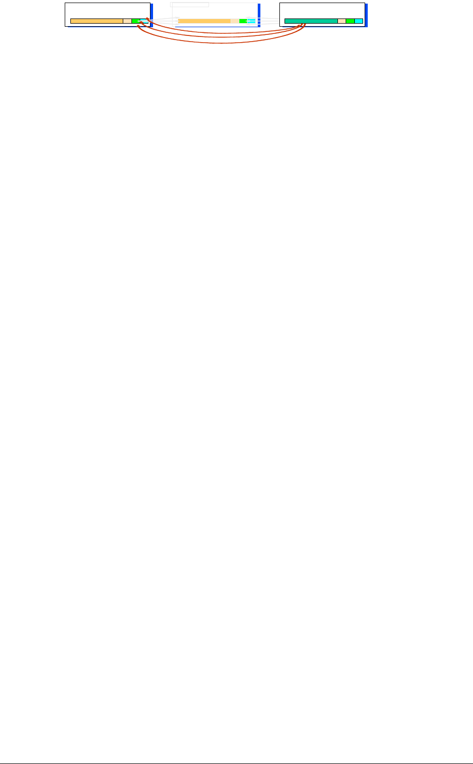
RFP V2
Requirements
RFP V2
Requirements
Requirement
UR Module
RFP V1
Requirements
RFP V1
Requirements
Requirement
UR Module
System
Requirements
System
Requirements
Requirement
SR Module
Deletion of
RFP V1
Figure 108 : Deletion of old version of the DOORS module.
NB: you can use the relationship manager to do this easily.
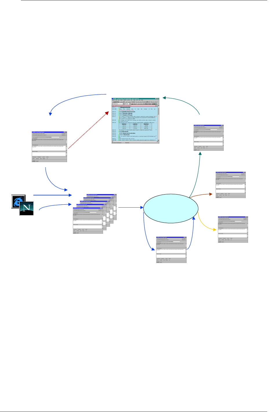
? ( **+*+!
? (
Within a DOORS environment, change is best managed on a change by change basis,
rather than having to first find and then process a batch of changes as described in the
previous section. Change proposals will originate from any stakeholder or system
engineeer, but only those approved by the relevant authorities should be applied. Each
change proposal should also contain details of any implied changes to existing analysis (eg
links). The standard DOORS feature : “Change Proposal System” should be used in this
situation. The process is summarised below in Figure 9.8
2. All Users submit CPs
(DOORS &
DOORSNet)
1. A ‘Read-only’ User
submits a CP 4. Change manager
automatically
updates Module
00
8
Module under control
A change proposal
(CP)
All CPs
:
Rejected CP
Approved CP
Change Control
Board
+
On hold CP
In review CP
3. Review CPs
Figure 109 : The formal change proposal cycle
The DOORS CP system recognises three types of users, who are given different access
rights, as follows;
‘Standard’, who carry out activities 1 and 2 in Figure 9.8,
‘CP Reviewer’, who carry out activity 3 in Figure 9.8, and
‘CP Manager’, who carries out activity 4 in Figure 9.8, plus overall administration..

? ( %6
The module under control should be set up so that Standard users only have read access
rights, but the Change Manager should have write access. This will enable any user to raise
a CP, and the Change Manager to launch the automatic application of Approved CPs.
The action of raising a CP causes an change object to be created in a CP partner module,
which will have a name that begins with ‘proposals’ followed by a number, e.g.’Proposals
35’. The CP partner module is divided into edit shareable sections, one per user who is
entered into the CPS system (by the CP manager). The access rights to these sections
should be set up so that Standard users can read each others CPs but only create and
modify their own.
The CP Reviewers should be able to modify all CPs, since it is often convenient for a
review meeting to make changes without having to involve the originator. The CP status
attribute should be set so that Standard users only have read access.
When the CPS is being configured for a particular ‘module under control’, the default is to
provide change control over the Object Text and Object Heading only. Any other
attributes over which change control is required must be specifically selected.
? ( ( %6
The CPS can be cumbersome when there are a large number of changes to be reviewed,
and it may be more convenient to export a view of a change module to a spreadsheet in
order to review a large number of changes off-line. The results of the review should then
be input back into the CPS by a CP Reviewer login, without involving the whole Review
Board in a protracted on-line session.
The DOORS CPS allows the five status values shown diagonally across the screen shots in
Figure 9.8, plus ‘Applied’. This set is adequate for a single level approval process, but is
inadequate for more levels. For example it is often necessary to approve a change proposal
internally before it is submitted to the customer for his approval. The solution is either to
pay Telelogic for an enhancement (on a previous version od DOORS this took around 5
days of consultancy), or to raise a new change for each additional level of approval.

APPENDIX A : MODULE DESCRIPTION FORMS

IBM Rational DOORS Requirements Management Framework Add-on - Release 5.4
00B 56!0
#6
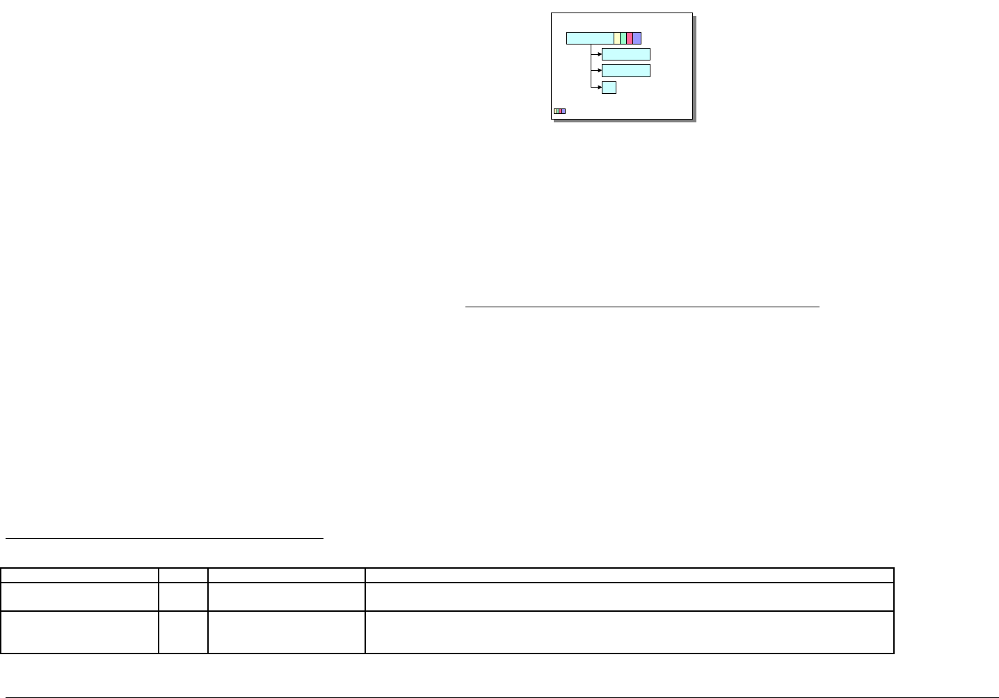
IBM Rational DOORS Requirements Management Framework Add-on - Release 5.4
Module attributes of User Requirements module
Attribute name Type Value Description
IE Mod Type enum User Requirements Type of the module, always "User Requirements" in this case.
For the whole list of values, see the "Project Profile" Module Description.
IE Mod LifeCycle Phase enum Feasibility Study
Model Simulation
Demonstrator
Represents the life cycle phase of the project to which the requirements identified in the module apply.
.
This module description form contains information about DOORS
formal module of type "User Requirements".
The "User Requirements" Module contains RMF objects of type
"Requirement". The data structure for each such object is a tree. The
root DOORS object is the User Requirement itself. It carries all the
attributes applying to the User Requirement, it is the only DOORS
object in the tree, which can be identified as a RMF object and gain a
PUID. All links to and from the object should be attached to the root
object
The leaves of the tree are DOORS objects which inherit the attribute "IE
Object Type", which for a User Requirements, has the value
"Requirement". The leaf DOORS objects should only be used for
descriptive or explanatory material, and all of their RMF attributes should
be set to ‘blank’. Leaf objects cannot be assigned a PUID, and should
not be linked using standard RMF linksetsThe enumerated lists shown in
the following tables are the defaults supplied with the delivered
IRDRMFAO. They should all be customised to be appropriate to the
individual project
Description 1
UR-REQ-0001
Description 2
...
: Attributes
UR data structure
UR : User Requirement
Typical setup/process for the "User Requirements" Module
Assumption : Originating Document is available from WORD. It could be any other
format readable by DOORS (see import format supported).
1) Create a new empty "User Requirements" module, by restoring (using
file>restore>module in the Database Window) the file UR.dma.
1) From WORD, export the document to DOORS, by clicking the "Export To
Doors" icon in the WORD tool bar,
2) Within DOORS, select paragraphs that represent a user requirement and use
the IRDRMFAO command "Manage Objects” to identify Requirements,
4) For each user requirement identified, fill the attributes using the DOORS views.
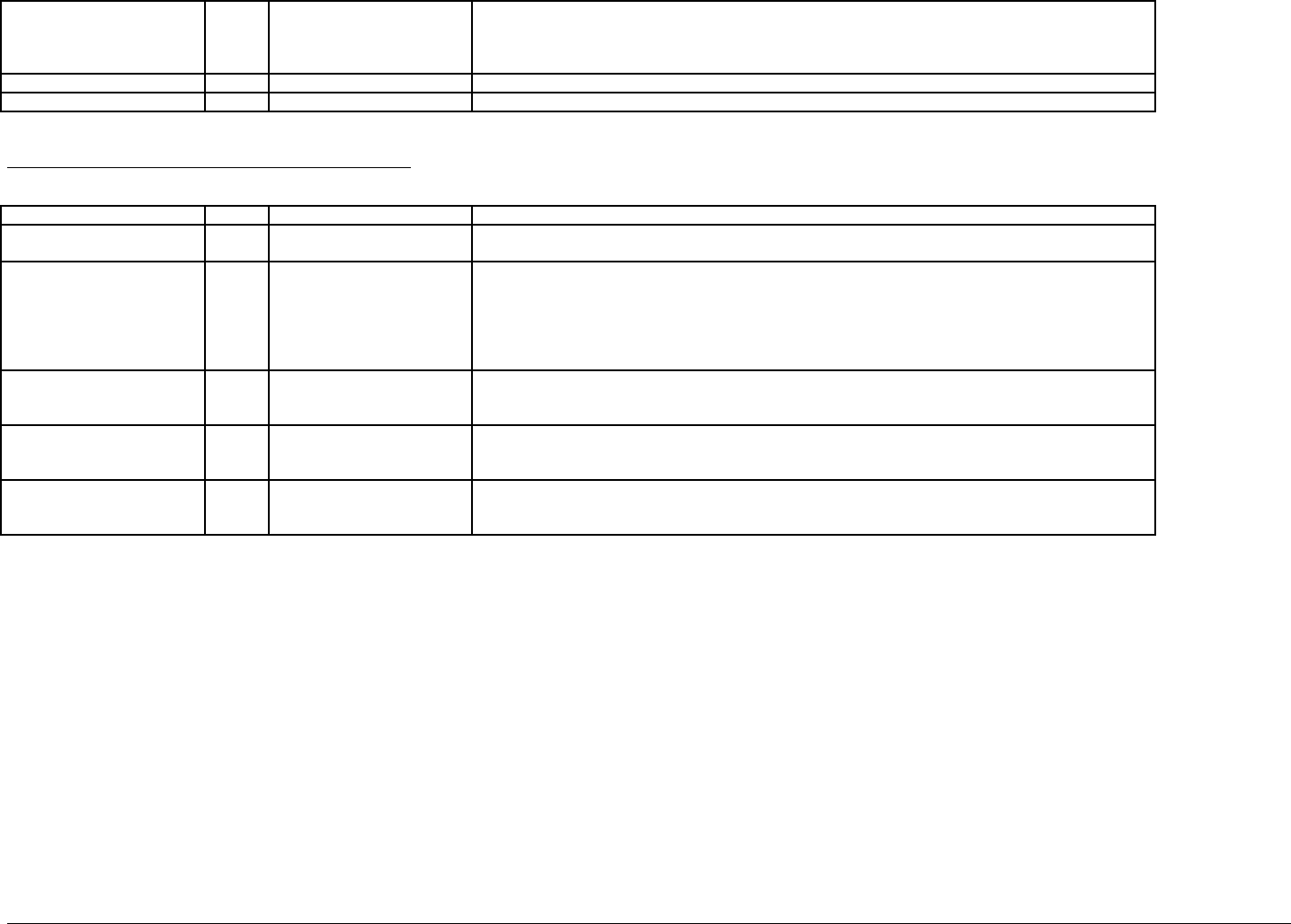
IBM Rational DOORS Requirements Management Framework Add-on - Release 5.4
Prototype
Full Development
Production
Operation & Support
IE Requirement Number Integer An internal counter used by IRDRMFAO, do not edit.
IE Release string see description Stores the IRDRMFAO release which has been used to create this module.
Object attributes of User Requirements module
These attributes apply to the requirements (i.e. "IE Object Type" attribute is "Requirement")
Attribute name Type Value Description
IE Object Type enum Requirement Type of the object, always "Requirement" in this case, or null.
For the whole list of values, see the "Project Profile" Module Description.
IE PUID string see description Project Unique ID. This attribute is automatically set with the following concatenation rule : [module
prefix]-[requirement prefix]-[number]
- the [module prefix] is obtained from the DOORS module attribute "Module Prefix",
- the [requirement prefix] is obtained from the DOORS attribute "IE Object Prefix" (see the "Project
Profile" Module Description),
- the [number] is incremented by one every new requirement.
IE Req Priority enum Low
Medium
High
Represents the level of priority the customer has set to the requirement.
IE Req Compliance enum Not Met
Partially Met
Met
Represents the level of compliance obtained with the System Requirements (see "System Requirements"
Module Description) against the customer requirement.
IE Req Flexibility enum Low
Medium
High
Represents the level of flexibility the customer could have when negotiating the requirement.
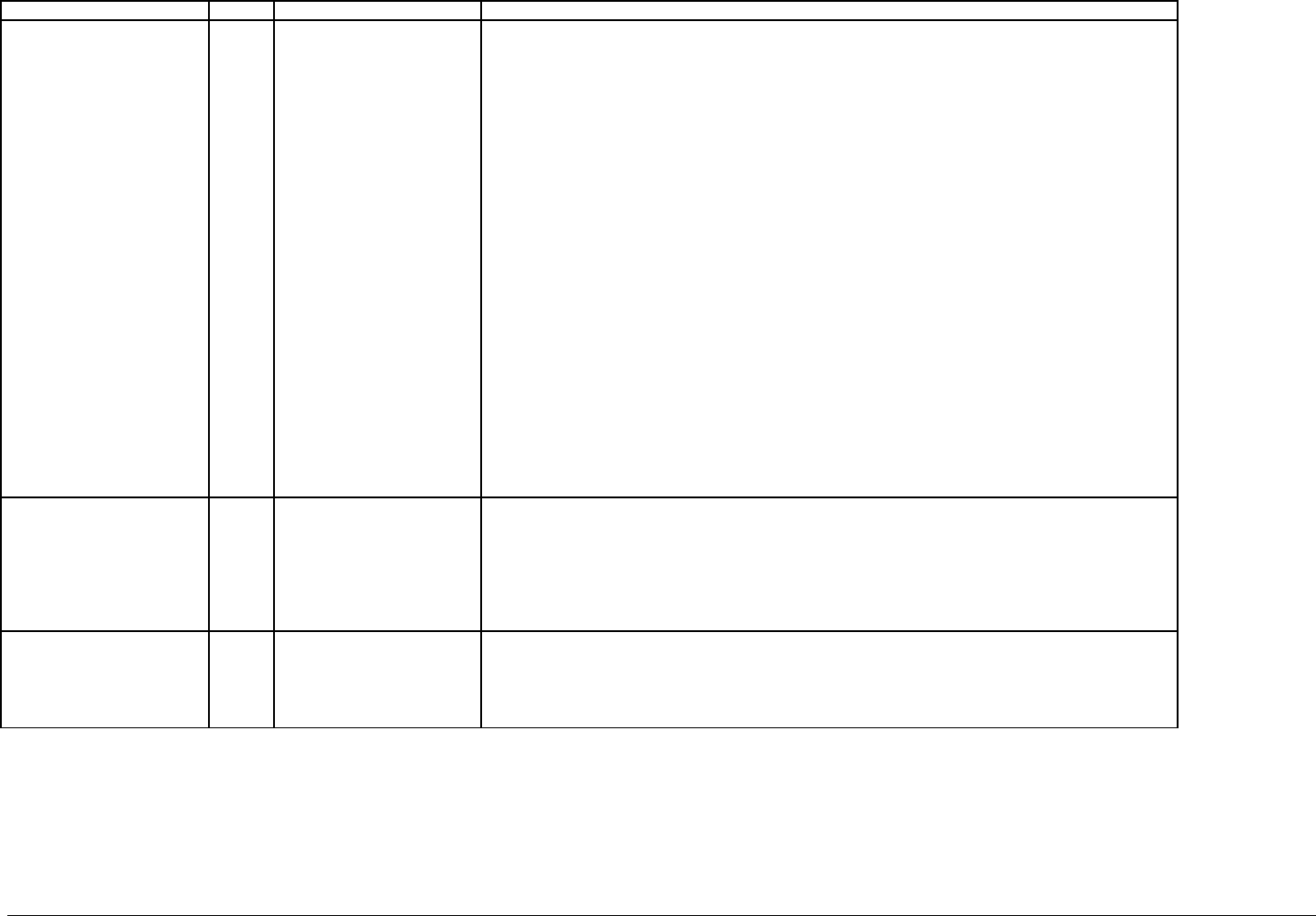
IBM Rational DOORS Requirements Management Framework Add-on - Release 5.4
Attribute name Type Value Description
IE Req Category Enum
multival
█ Mission
█ Operational Objective
█ Operational Scenario
█ Contract
█ Management
█ Functional
█ - Function
█ - Data
█ - Behavior
█ Performance
█ Dependability
█ - Reliability
█ - Availability
█ - Maintainability
█ - Security
█ - Safety
█ Constraints
█ - Cost
█ - Schedule
█ - Architecture
█ - IV&V
█ - Development
█ - Production
█ - Delivery
█ - Ergonomy
█ - Installation
Allow categorization of requirements. The categories are colored for user interface purpose.
Note that a requirement may be assigned to several of these categories.
The principle use of this attribute is to allow filtering within the various views, in order to manage large
sets of requirements efficiently.
IE Risk Impact enum
multival Operational Use
Performance
Cost
Timescale
Technology
Organization
Delivery
This attribute is used to classify the type of risk, if any, associated with a requirement.
Note that a requirement may be assigned to several of these categories.
IE Risk Consequence enum Negligible
Marginal
Significant
Critical
Catastrophic
This attribute is used to assign an impact level to the risk.
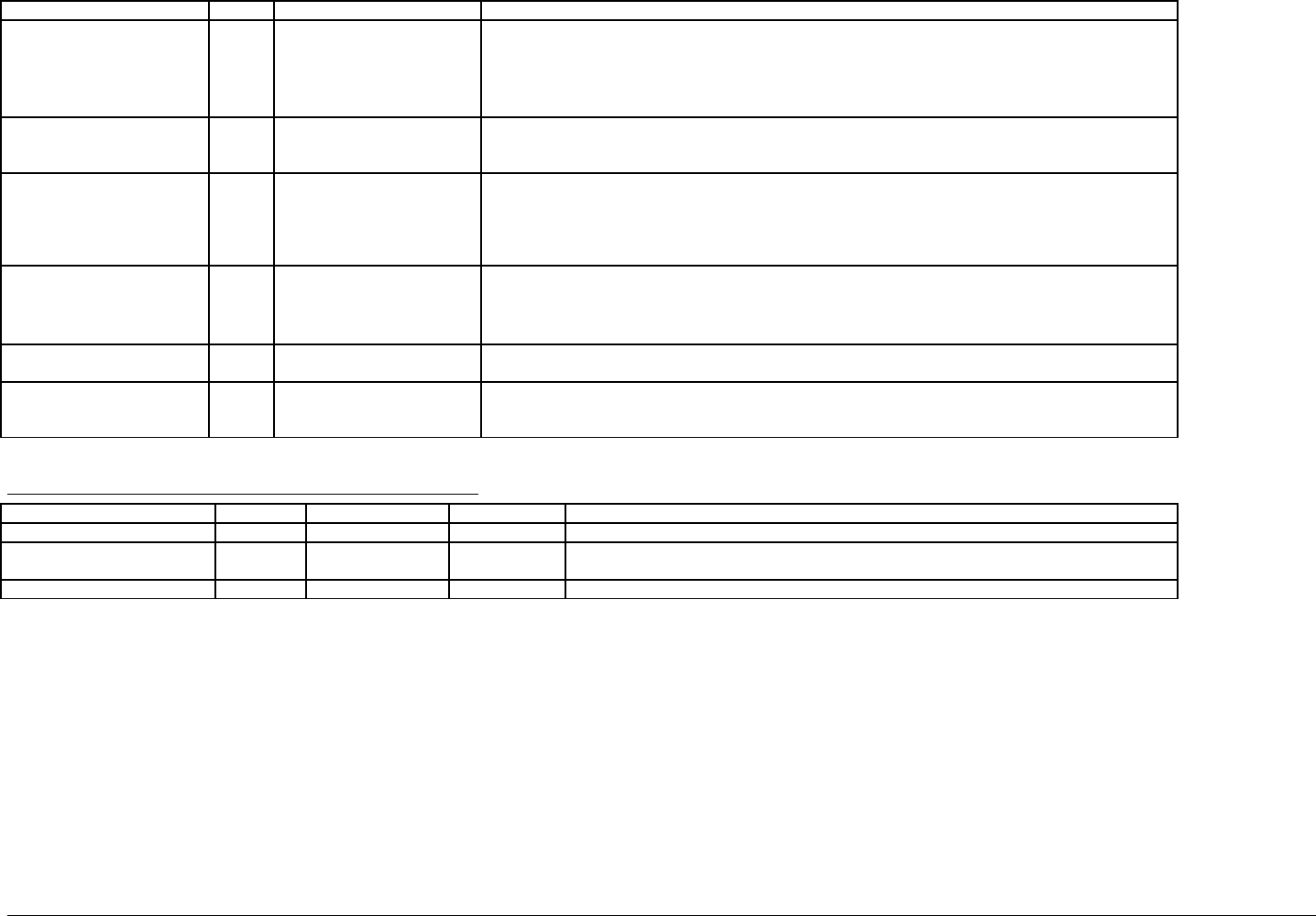
IBM Rational DOORS Requirements Management Framework Add-on - Release 5.4
Attribute name Type value Description
IE Risk Probability enum Negligible
Low
Likely
very Likely
Inevitable
This attribute is used to assign a probability of occurrence to a risk.
IE Key Requirement enum true
false
This attribute is used to identify the given Requirement as a key Requirement.
Alternatively, a project could delete this attribute and add “Key” to the “IE Req Priority” enumerations in
the “IE Level” type.
IE Phase string see description This attribute is used to define the increment phase in which the requirement is implemented into a
system/product. Typically it is used to define the future release at which new functionality will be
available.
It may be appropriate for some projects to control this attribute more precisely by setting up an
enumerated list of approved future releases.
IE Req Status enum In negotiation
Accepted
Analysis
Obsolete
This attribute is used to define the progress status of the requirement analysis activity..
IE Object Version string see description This attribute is managed by DXL, specifically by the “Update Version Attribute ” utility.
The attribute holds the designation of the baseline of the module in which the object was last changed.
IE Rationale Text This attribute is used to record "routine" decisions and issues within the responsibility of individual
engineers or co-located teams. (Major issues and decisions should be recorded in the associated issue/
Decision module)
Available relationships for User Requirements objects
link link way target type link module Description
Compliance Incoming Requirement satisfies The linked requirements satisfy the given User Requirement.
Issue raised Incoming Issue-Decision refers to Shows that this User Requirement is to be (or has been) analyzed through a Issue and
Decision process.
Verification Incoming IVV Procedure verifies The linked IVV Procedures verify the given User Requirement.
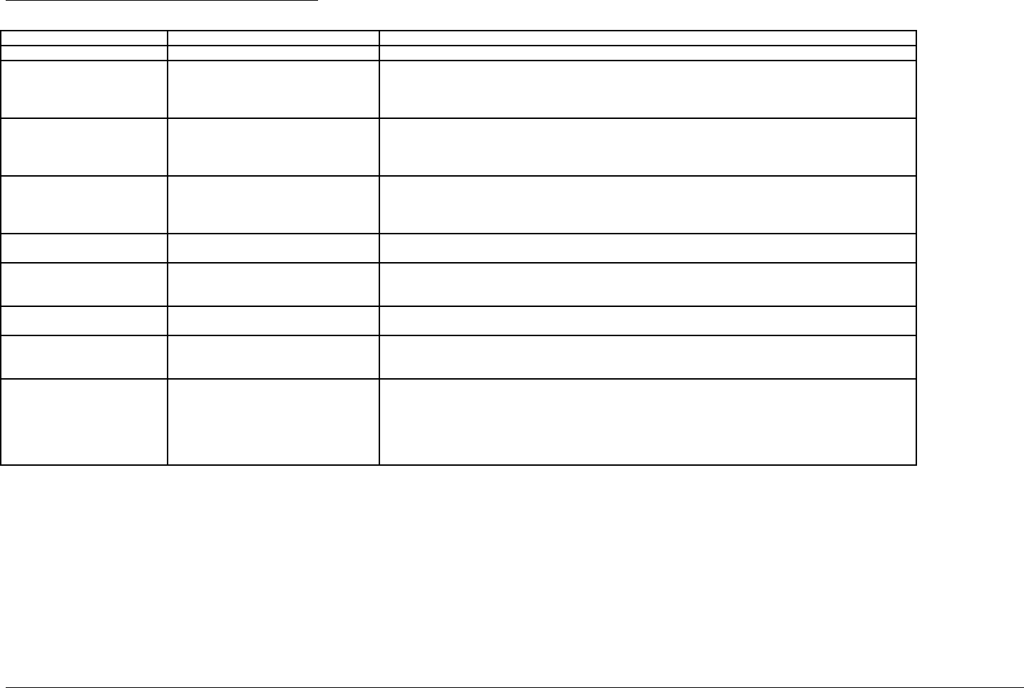
IBM Rational DOORS Requirements Management Framework Add-on - Release 5.4
Available views of User Requirements module
View name filter/sort available Description
Standard view none DOORS default view, which shows the DOORS ID and Object Heading/Text.
Associated issues inactive filter, no sort:
IE Object Type == Requirement
Displays the attributes: PUID, Object Text, Compliance, Status, Flexibility, Priority, Risk Impact,
Rationale, and also a traceability column obtained with the objects reached by an incoming "refers to"
link. This traceability column is headed “referred by…” and (for each link found) shows the name of the
module referred to, the PUID of the object referred to, and its Object Text.
Compliance matrix active filter, no sort:
IE Object Type == Requirement
Displays the attributes: PUID, Object Text, Category, Compliance, Priority, Phase, Risk Impact, and also
a traceability column obtained with the objects reached by an incoming "satisfies" link. This traceability
column is headed “satisfied by…” and (for each link found) shows the name of the module referred to,
the PUID of the object referred to, and its Object Text.
Critical requirements list active filter and active sort:
IE Object Type == Requirement
and IE Risk Impact != NULL
sorting by IE Risk Consequence
Displays the attributes: Risk Level (as a LED chart), PUID, Object Text, Category, Status, Risk Impact,
Risk Level and probability of occurrence.
Document view inactive filter, no sort:
IE Object Type == Requirement
Displays the attributes: Document Style, PUID and Object Heading/Text.
Key requirements list active filter, no sort:
IE Object Type == Requirement
and IE Key Requirement == true
Displays the attributes: PUID, Key Requirement, Object Text, Category, Compliance, Status, Flexibility,
Priority, Phase and Risk Impact.
Requirements analysis inactive filter, no sort:
IE Object Type == Requirement
Displays the attributes: PUID, Object Text, Category, Compliance, Status, Flexibility, Priority, Key
Requirement, Phase, Risk Impact and Rationale.
Requirements in negotiation active filter, no sort:
IE Object Type == Requirement and IE
Req Status == in negotiation
Displays attributes PUID, Object Text, Category, Compliance, Status, Flexibility, Priority, Phase and
Risk Impact.
Validation matrix active filter, no sort:
IE Object Type == Requirement
Displays the attributes: PUID, Object Text, Flexibility, Compliance, Status, Priority, Risk Impact and Risk
Level, and also 2 traceability columns obtained with the IVV Procedures reached by an incoming
"verifies" link, one for the IVV Procedures description and one for the Verification Method. The first
traceability column is headed “verified by…” and (for each link found) shows the name of the module
referred to, the PUID of the object referred to, and its Object Text. The second traceability column is
headed “Verification Method” and just shows the code I, A, T, D or null as appropriate.

IBM Rational DOORS Requirements Management Framework Add-on - Release 5.4
00B& '656!0
#6
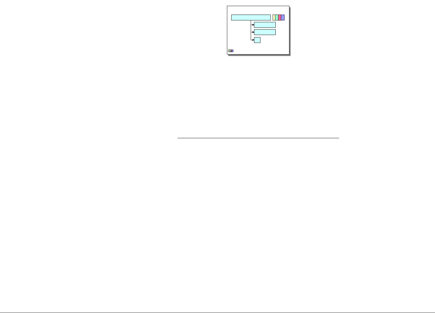
IBM Rational DOORS Requirements Management Framework Add-on - Release 5.4
This module description form contains information about
DOORS formal module of type "System Requirements". SR
Module is used to describe System specification document. It
could also be used for Subsystem or Prime Item specification
documents.
The "System Requirements" Module contains RMF Objects
of types “Capability”, "Requirement", and/or “Function”. The
data structure for each such object is a tree. The root
DOORS object is the RMF Object itself. It carries all the
attributes as it is the only DOORS object in the tree, which
can be identified as a RMF object and gain a PUID. All links
to and from the object should be attached to the root object
The leaves of the tree are DOORS objects which inherit the
attribute "IE Object Type", may have the value “Capability”,
"Requirement", or “Function”. The leaf DOORS objects
should only be used for descriptive or explanatory material,
and all of their RMF attributes should be set to ‘blank’. Leaf
objects cannot be assigned a PUID, and should not be linked
using standard RMF linksets.
The enumerated lists shown in the following tables are the
defaults supplied with the delivered IRDRMFAO. They should
all be customised to be appropriate to the individual project.
Description 1
SR-CAPA/REQ/FUNC-0001
Description 2
...
: Attributes
SR data structure
SR : System Requirement
Typical setup/process for the "System Requirements" Module
1) Assumption : Originating Document is available from WORD. It could be any other format
readable by DOORS (see import format supported).
2) Create a new empty "User Requirements" module, by restoring (using
file>restore>module in the Database Window) the file SR.dma.
3) From WORD, export the document to DOORS, by clicking the "Export To Doors" icon in
the WORD tool bar,
4) Within DOORS, select paragraphs that represent capabilities, requirements or functions
and use the IRDRMFAO interface "Manage Objects” to assign the appropriate object
type.
5) For each RMF object, fill in the attributes using the DOORS views..
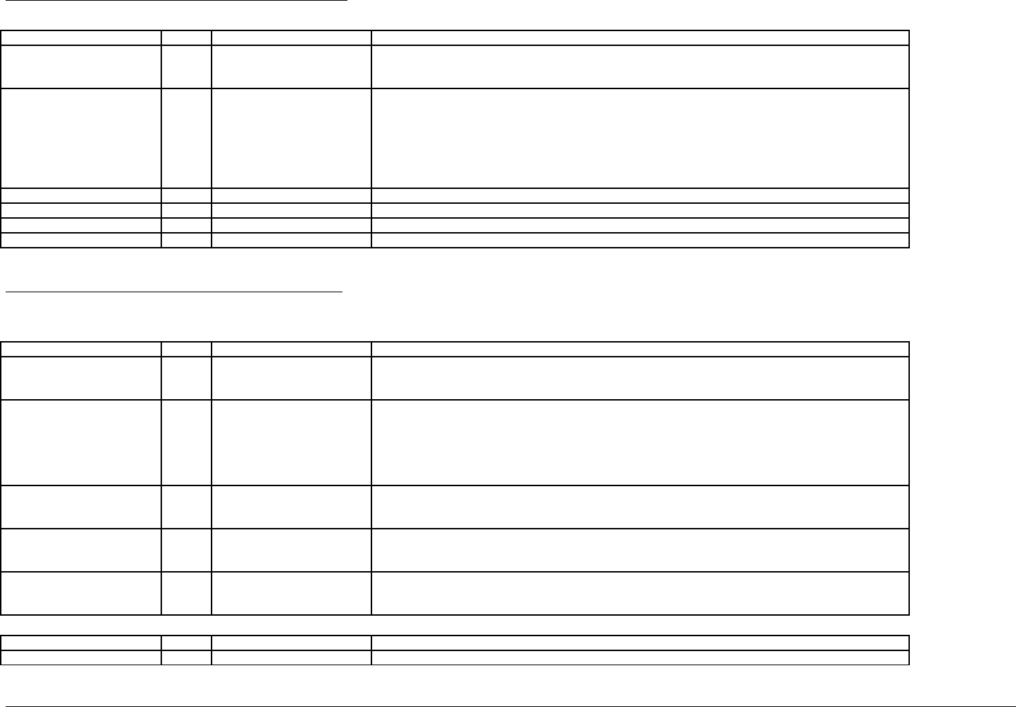
IBM Rational DOORS Requirements Management Framework Add-on - Release 5.4
Module attributes of System Requirements module
Attribute name Type value Description
IE Mod Type enum System Requirements
Subsystem Requirements
Prime Item Requirements
Type of the module : "System Requirements", "Subsystem Requirements" or "Prime Item Requirements".
The Value is set by default to "System Requirements" but could be changed on need. For the whole list
of values, see the "Project Profile" Module Description.
IE Mod LifeCycle Phase enum Feasibility Study
Model Simulation
Demonstrator
Prototype
Full Development
Production
Operation & Support
Represents the life cycle phase of the project to which the objects identified in the module apply.
IE Capability Number Integer An internal counter used by IRDRMFAO, do not edit.
IE Requirement Number Integer An internal counter used by IRDRMFAO, do not edit.
IE Function Number Integer An internal counter used by IRDRMFAO, do not edit.
IE Release string see description Stores the IRDRMFAOrelease which has been used to create this module.
Object attributes of System Requirements module
These attributes apply mostly to the requirements (i.e. "IE Object Type" attribute is "Requirement"). It may not be appropriate to apply all of them to capabilities or
functions (i.e. "IE Object Type" attribute is "Capability" or “Function”) .
Attribute name Type value Description
IE Object Type enum Requirement
Function
Capability
Type of the object, null if object is not identified as a RMF root object..
For the whole list of values, see the "Project Profile" Module Description.
IE PUID string see description Project Unique ID. This attribute is automatically set with the following concatenation rule : [module
prefix]-[object prefix]-[number]
- the [module prefix] is obtained from the DOORS module attribute "Module Prefix",
- the [object prefix] is obtained from the DOORS attribute "IE Object Prefix" (see the "Project Profile"
Module Description),
- the [number] is incremented by one every new RMF object.
IE Req Priority enum Low
Medium
High
This attribute represents the level of priority the System Engineer has set to the requirement.
IE Req Compliance enum Not Met
Partially Met
Met
This attribute represents the level of compliance obtained from the succeeding level in the design
hierarchy. If compliance is not “Met”, there should be a commentary in the “Rationale” attribute or a
specific issue raised in the appropriate Issue-Decision module.
IE Req Flexibility enum Low
Medium
High
Represent the level of flexibility the system engineer could have when negotiating the requirement with a
sub-contractor.
Attribute name Type value Description
IE Req Category enum █ Mission Allow categorization of capabilities, requirements and functions. The categories are colored for user
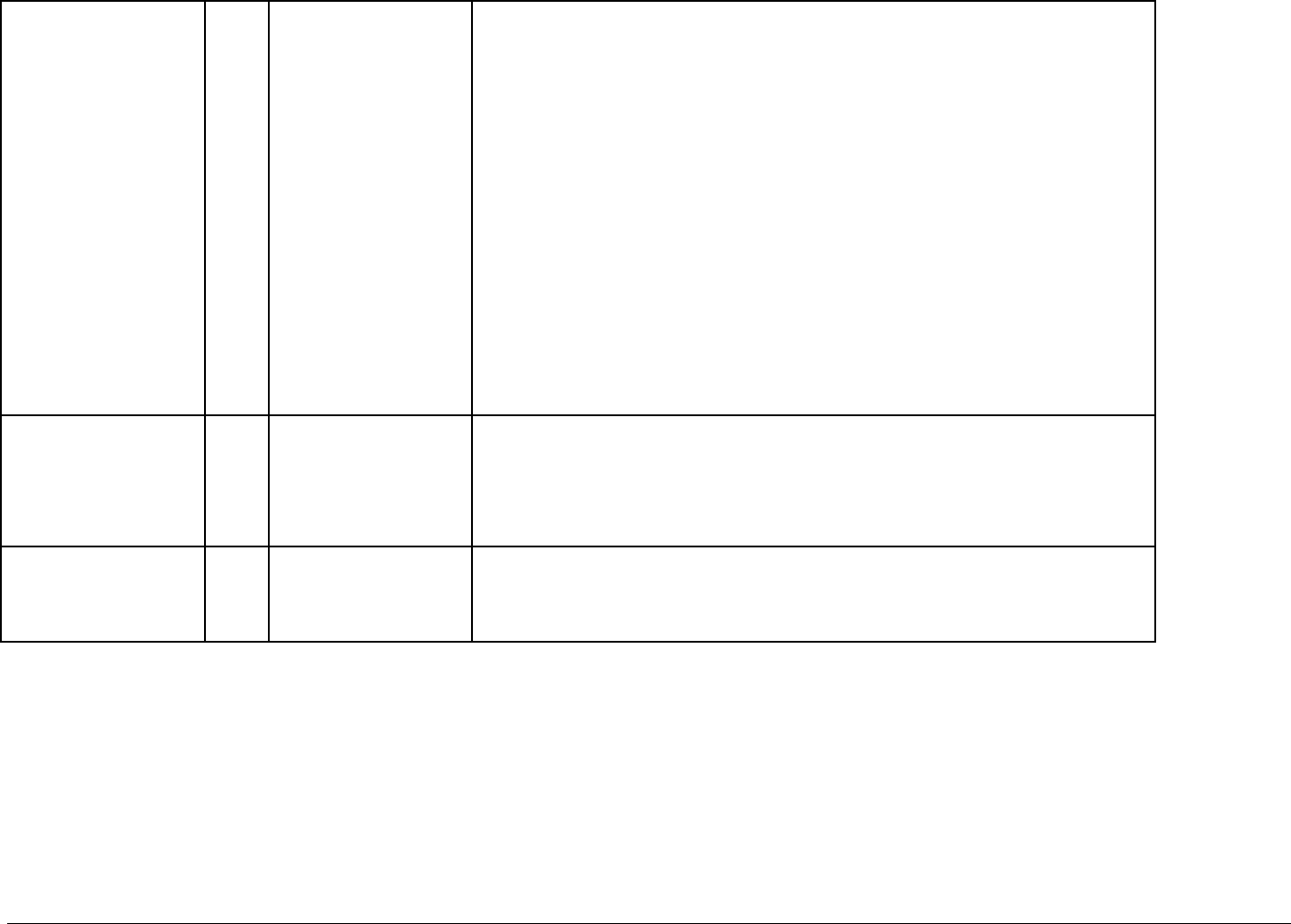
IBM Rational DOORS Requirements Management Framework Add-on - Release 5.4
multival █ Operational Objective
█ Operational Scenario
█ Functional
█ - Function
█ - Data
█ - Behavior
█ Performance
█ Dependability
█ - Reliability
█ - Availability
█ - Maintainability
█ - Security
█ - Safety
█ Constraints
█ - Cost
█ - Schedule
█ - Architecture
█ - IV&V
█ - Development
█ - Production
█ - Delivery
█ - Ergonomy
█ - Installation
interface purpose.
IE Risk Impact enum
multival Operational Use
Performance
Cost
Timescale
Technology
Organization
Delivery
This attribute is used to classify the type of risk, if any, associated with a capibility, requirement or
function.
Note that several classifications amy be assigned a single RMF object.
IE Risk Level enum Negligible
Marginal
Significant
Critical
Catastrophic
This objecxt is used to assign an impact level to the risk.
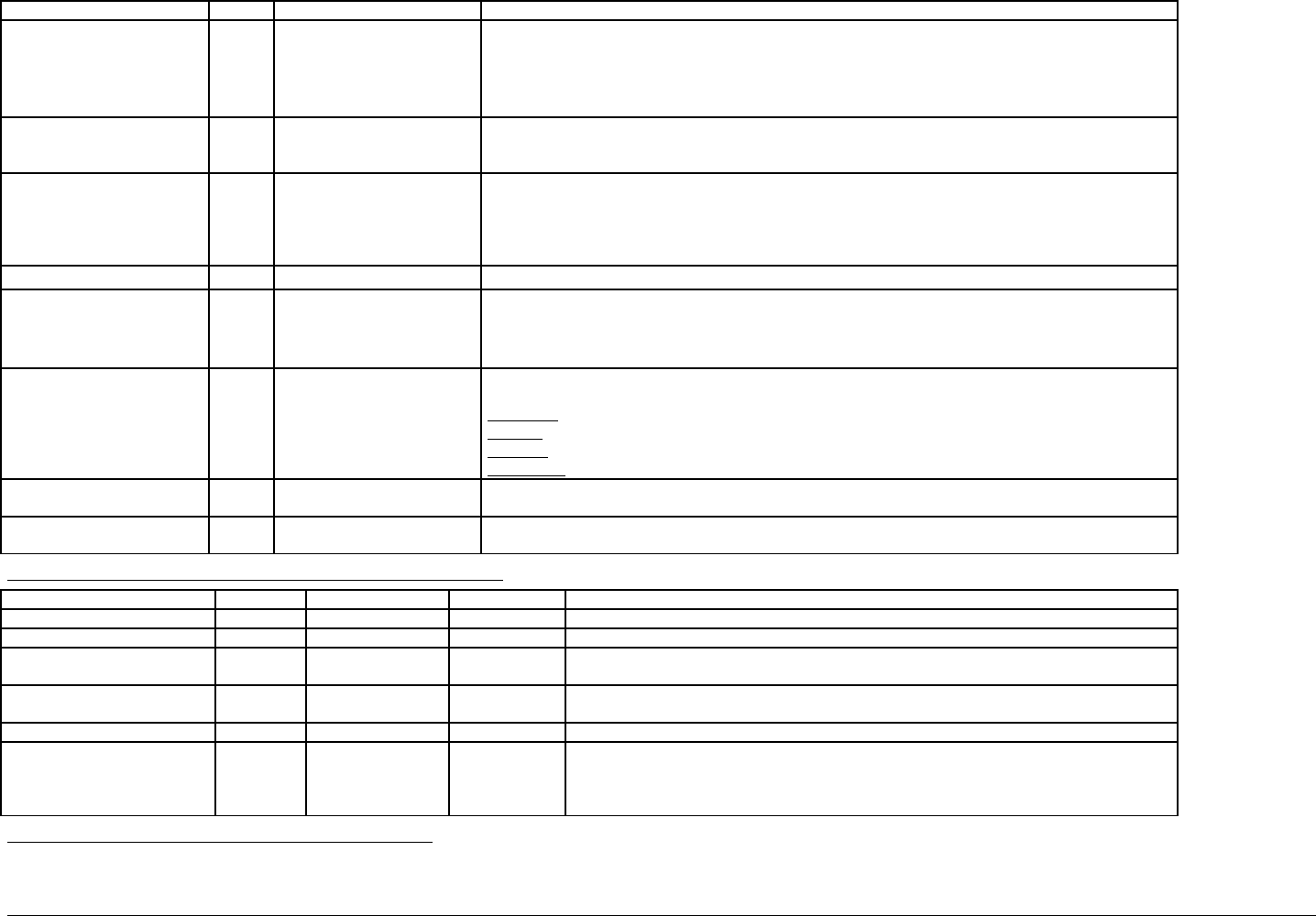
IBM Rational DOORS Requirements Management Framework Add-on - Release 5.4
Attribute name Type value Description
IE Risk Probability enum Negligible
Low
Likely
Very Likely
Inevitable
This attribute is used to assign a probability of occurrence to a risk.
IE Key Requirement enum true
false
This attribute is used to identify the given Capability, Requirement or Function as a Key requirement.
This usually means that the requirement has a strong influence on cost, schedule, functionality, risk or
performance.
IE Phase string see description This attribute is used to define the increment phase in which the requirement is implemented into a
system/product. Typically it is used to define the future release at which new functionality will be
available.
It may be appropriate for some projects to control this attribute more precisely by setting up an
enumerated list of approved future releases.
IE Req Tolerance string see description This attribute defines the tolerance for the requirement (performance requirements only).
IE Req Status enum In negotiation
Accepted
Analysis
Obsolete
This attribute is used to define the progress of the requirement analysis and/or system design activity.
IE Req Type enum Originating
Deriv:ed
Induced
Calculated
This attribute defines the type of the requirement, it is useful to record how the requirement was created.
The followingdefinitions, derived from SYS-EM, are offered as IRDRMFAO standards:
Originating: Can be traced with little or no modificastion to a higher level requirement.
Derived The result of functional partitioning of a higher level requirement.
Induced: A new requirement produced as a result of a design decision at this level.
Calculated:. The result of numerical partitioning of a higher level performance parameter.
IE Object Version string see description This attribute is managed by DXL, specifically by the “Update Version Attribute” utility.
The attribute holds the designation of the baseline of the module in which the object was last changed.
IE Rationale Text See description This attribute records "routine" decisions and issues within the responsibility of individual engineers or co-
located teams.
Available relationships for System Requirements objects
Link link way target type link module Description
Allocation incoming Configuration Item is allocated by the given capability, requirement or function is allocated to the linked configuration items.
Compliance outgoing Requirement satisfies the linked upper requirements are satisfied by the given requirement or function.
Justification outgoing Issue-Decision is justified by represent the justification of the Capability/Requirement/function object, i.e. link to a
decision.
Issue raised incoming Issue-Decision refers to Shows that the Capability/Requirement/Function is to be (or has been) analyzed through an
Issue and Decision process.
Verification incoming IVV Procedure verifies Shows which IVV procedures verify the given Capability/Requirement/Function.
Composition internal Capability/
Requirement/
Function
Is composed of An internal link to the SR module which is used to establish a Capability > Requirement >
Function hierarchy.
Each link should be sourced at the higher level object (which is contrary to the convention
established for external links).
Available views of System Requirements module
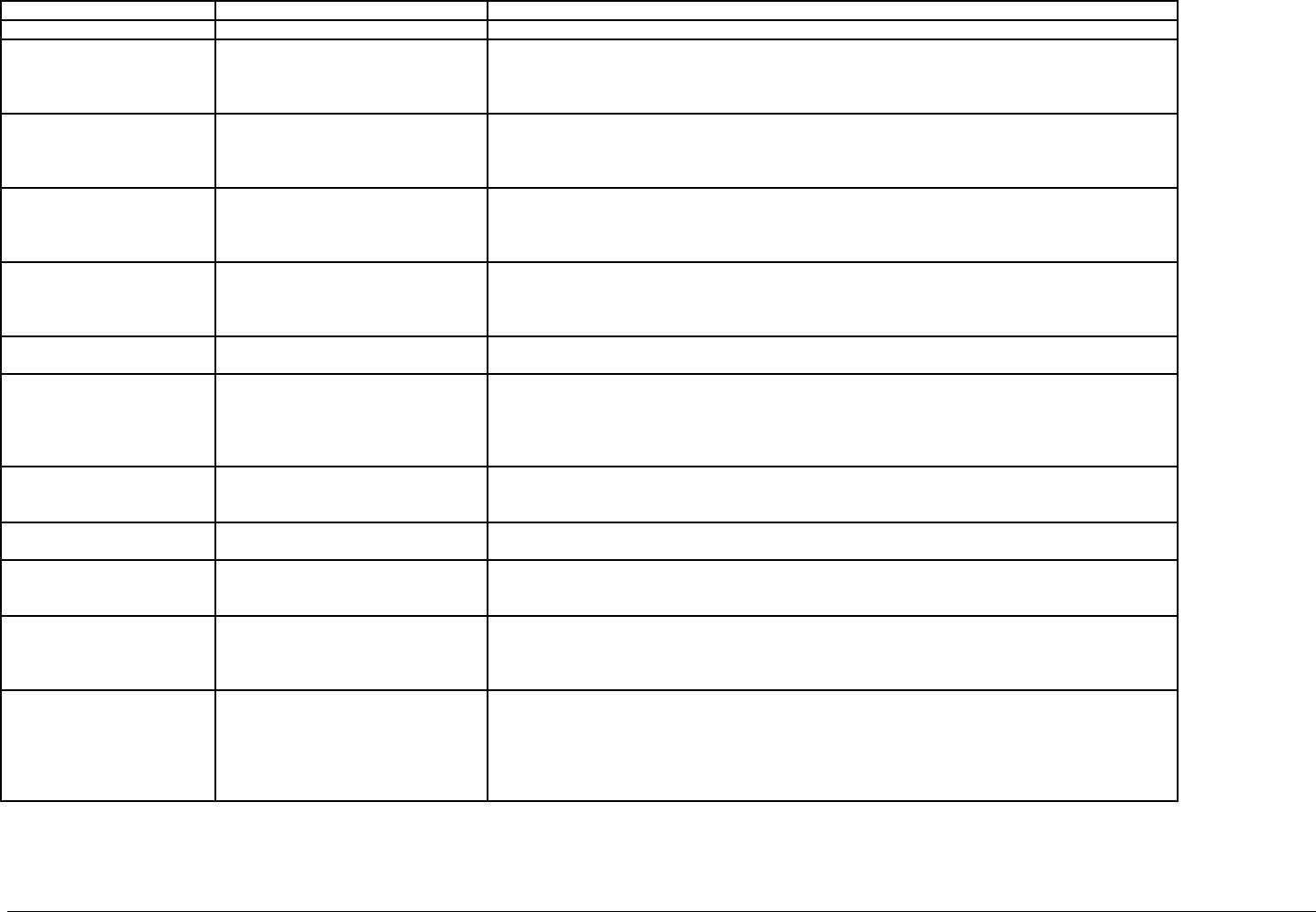
IBM Rational DOORS Requirements Management Framework Add-on - Release 5.4
View name filter/sort available Description
Standard view none The DOORS default view, which shows the DOORS ID and Object Heading/Text.
Allocation matrix active filter, no sort:
IE Object Type != NULL
Displays the attributes: PUID, Object Text, Category, Compliance, Status, Priority, Phase, Risk Impact,
and also a traceability column obtained with the objects reached by an incoming "is allocated by" link.
This traceability column is headed “allocated to…” and (for each link found) shows the name of the
module referred to, the PUID of the object referred to, and its Object Text.
Associated issues inactive filter, no sort:
IE Object Type != NULL
Displays the attributes: PUID, Object Text, Compliance, Type, Status, Flexibility, Priority, Risk Impact,
and also a traceability column obtained with the objects reached by an incoming "refers to" link.
This traceability column is headed “referred by…” and (for each link found) shows the name of the
module referred to, the PUID of the object referred to, and its Object Text.
Compliance matrix active filter, no sort:
IE Object Type == Requirement
Displays the attributes: PUID, Object Text, Category, Compliance, Status, Priority, Phase, Risk Impact,
and also a traceability column obtained with the objects reached by an incoming "satisfies" link. This
traceability column is headed “satisfied by…” and (for each link found) shows the name of the module
referred to, the PUID of the object referred to, and its Object Text.
Critical requirements list active filter and active sort:
IE Object Type == Requirement
and IE Risk Impact != NULL
sorting by IE Risk Level
Displays the attributes: Risk Level (as a LED chart), PUID, Object Text, Status, Risk Impact, Risk Level
and probability of occurence.
Document view inactive filter, no sort:
IE Object Type != NULL
Displays the attributes: Document Style, PUID and Object Text.
Justification inactive filter, no sort:
IE Object Type != NULL
Displays the attributes PUID, Object Text, rationale, Compliance, Type, Status, Flexibility, Priority, Risk
Impact, and also a traceability column obtained with the objects reached by a "is justified by" outgoing
link.
.This traceability column is headed “is justified by…” and (for each link found) shows the name of the
module referred to, the PUID of the object referred to, and its Object Text.
Key requirements list active filter, no sort:
IE Object Type == Requirement
and IE Key Requirement == true
Displays the attributes: PUID, Key Requirement, Object Text, Category, Compliance, Type, Status,
Flexibility, Tolerance, Priority, Phase and Risk Impact.
Requirements analysis inactive filter, no sort:
IE Object Type != NULL
Displays the attributes: PUID, Object Text, Category, Compliance, Type, Status, Flexibility, Tolerance,
Priority, Phase, Key Requirement, Risk Impact and Rationale.
Requirements in negotiation active filter, no sort:
IE Object Type == Requirement
and IE Req Status == in negotiation
Displays the attributes: PUID, Object Text, Category, Compliance, Status, Flexibility, Priority, Phase
and Risk Impact.
Upper requirements satisfied active filter, no sort:
IE Object Type == Requirement
Displays the attributes: PUID, Object Text, Category, Type, Status, Phase and Risk Impact, and also a
traceability column obtained with the objects reached by a "satisfies" outgoing link.
This traceability column is headed “satisfies…” and (for each link found) shows the name of the module
referred to, the PUID of the object referred to, and its Object Text.
Verification matrix active filter, no sort:
IE Object Type == Requirement
Displays the attributes: PUID, Object Text, Flexibility, Compliance, Status, Priority, Risk Impact and
Risk Level, and also 2 traceability columns obtained with the IVV Procedures reached by an incoming
"verifies" link, one for the IVV Procedures description and one for the Verification Method.
The first traceability column is headed “verified by…” and (for each link found) shows the name of the
module referred to, the PUID of the object referred to, and its Object Text. The second traceability
column is headed “Verification Method” and just shows the code I, A, T, D or null as appropriate

IBM Rational DOORS Requirements Management Framework Add-on - Release 5.4
00B %&!0#6
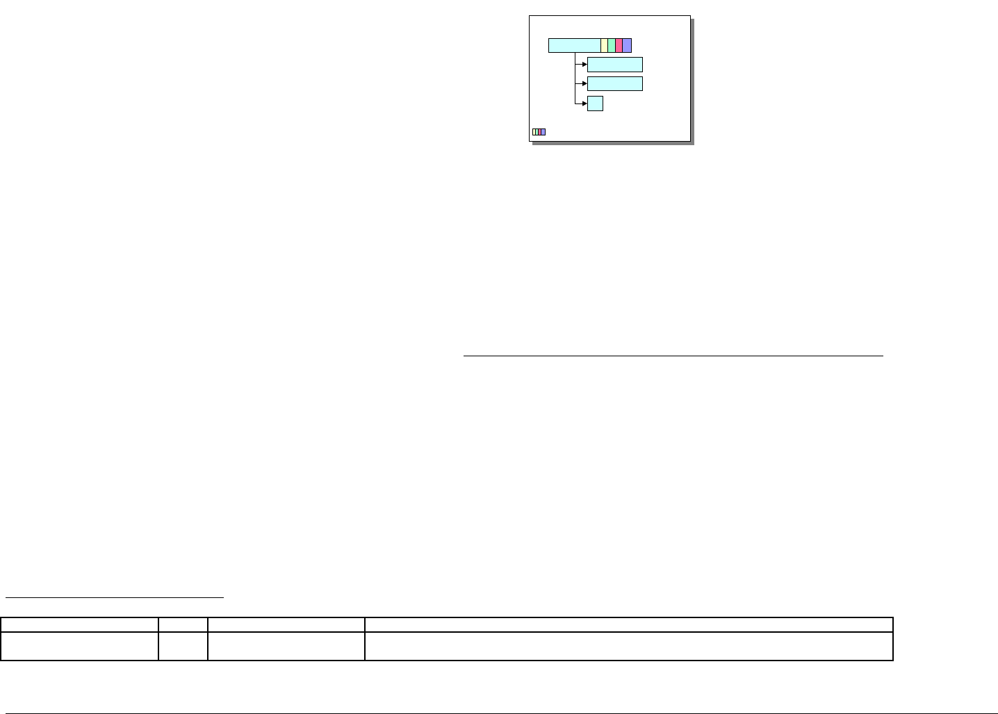
IBM Rational DOORS Requirements Management Framework Add-on - Release 5.4
This module description form contains information about DOORS
formal module of type "Product Breakdown Structure" (PBS).
The "PBS" Module contains RMF Objects of type “Configuration Item”.
The data structure for each such object is a tree. The root DOORS
object is the RMF Object itself. It carries all the attributes as it is the
only DOORS object in the tree, which can be identified as a RMF
object and gain a PUID. All links to and from the object should be
attached to the root object
The leaves of the tree are DOORS objects which inherit the attribute
"IE Object Type", may have the value “Configuration Item”. The leaf
DOORS objects should only be used for descriptive or explanatory
material, and all of their RMF attributes should be set to ‘blank’. Leaf
objects cannot be assigned a PUID, and should not be linked using
standard RMF linksets.
The enumerated lists shown in the following tables are the defaults
supplied with the delivered IRDRMFAO. They should all be
customised to be appropriate to the individual project
Description 1
PBS-CI-0001
Description 2
...
: Attributes
PBS data structure
PBS : Product Breakdown Structure
Typical setup/process for the "Product Breakdown Structure" Module
1) Assumption : Originating Document is available from WORD. It could be any other
format readable by DOORS (see import format supported).
2) Create a new empty "PBS" module, by restoring (using file>restore>module in
the Database Window) the file PBS.dma.
3) From WORD, export the document to DOORS, by clicking the "Export To Doors"
icon in the WORD tool bar,
4) Within DOORS, select paragraphs that configyration items and use the
IRDRMFAO interface "Manage Objects” to assign the appropriate object type.
For each RMF object, fill in the attributes using the DOORS views..
Module attributes of PBS module
Attribute name Type value Description
IE Mod Type enum Product Breakdown Structure Type of the module, always "Product Breakdown Structure" in this case.
For the whole list of values, see the "Project Profile" Module Description.
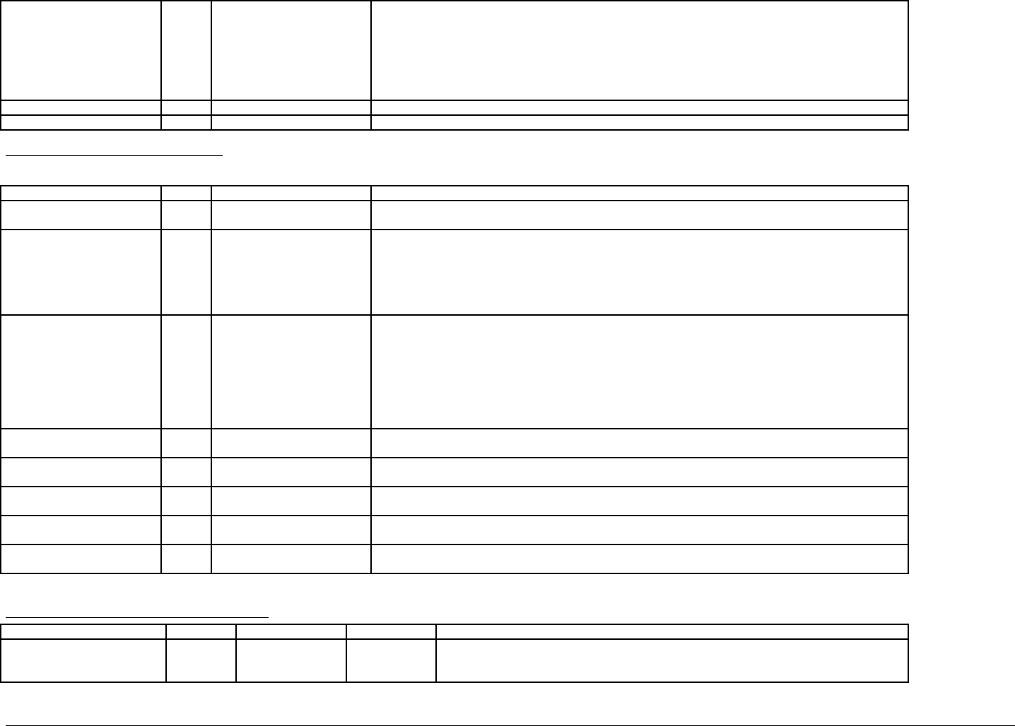
IBM Rational DOORS Requirements Management Framework Add-on - Release 5.4
IE Mod LifeCycle Phase enum Feasibility Study
Model Simulation
Demonstrator
Prototype
Full Development
Production
Operation & Support
Represents the life cycle phase of the project to which the objects identified in the module apply.
IE Configuration Item Number Integer An internal counter used by IRDRMFAO, do not edit.
IE Release string see description Stores the IRDRMFAO release which has been used to create this module.
Object attributes of PBS module
These attributes apply to the "Configuration Item" objects (i.e. "IE Object Type" attribute is "Configuration Item")
Attribute name Type value Description
IE Object Type enum Configuration Item Type of the object, always "Configuration Item" in this case, or null.
For the whole list of values, see the "Project Profile" Module Description.
IE PUID string see description Project Unique IDentifier. This attribute is automatically set with the following concatenation rule :
[module prefix]-[CI prefix]-[number]
- the [module prefix] is obtained from the DOORS module attribute "Module Prefix",
- the [CI prefix] is obtained from the DOORS attribute "IE Object Prefix" (see the "Project Profile" Module
Description),
- the [number] is incremented by one every new RMF Object.
IE CI Type enum System
Subsystem
Prime Item
HWCI
CSCI
Interface
NDI
COTS
Represent the type of the Configuration Item.
This list shows sample items, each project should define an appropriate list. A ‘Platform’ CI type is often
useful.
IE CI Serial Number string see description Represent the identification of the Configuration Item as identified by the Configuration Management
function. The numbering will be project specific.
IE CI Version Number string see description Represent the version of the Configuration Item as identified by the Configuration Management function.
The numbering will be project specific.
IE CI Revision Number string see description Represent the revision of the Configuration Item as identified by the Configuration Management function.
The numbering will be project specific.
IE CI Supplier Id string see description Represent the identification of the Supplier of the Configuration Item as identified by the Configuration
Management function.
IE Object Version string see description This attribute is managed by DXL, specifically by the “Update Version Attribute ” utility.
The attribute holds the designation of the baseline of the module in which the object was last changed.
Available relationships for PBS objects
link link way target type link module Description
allocation outgoing Capability ,
Requirement,or
Function
is allocated by The linked capabilities, requirements or functions are allocated to the given configuration
item.
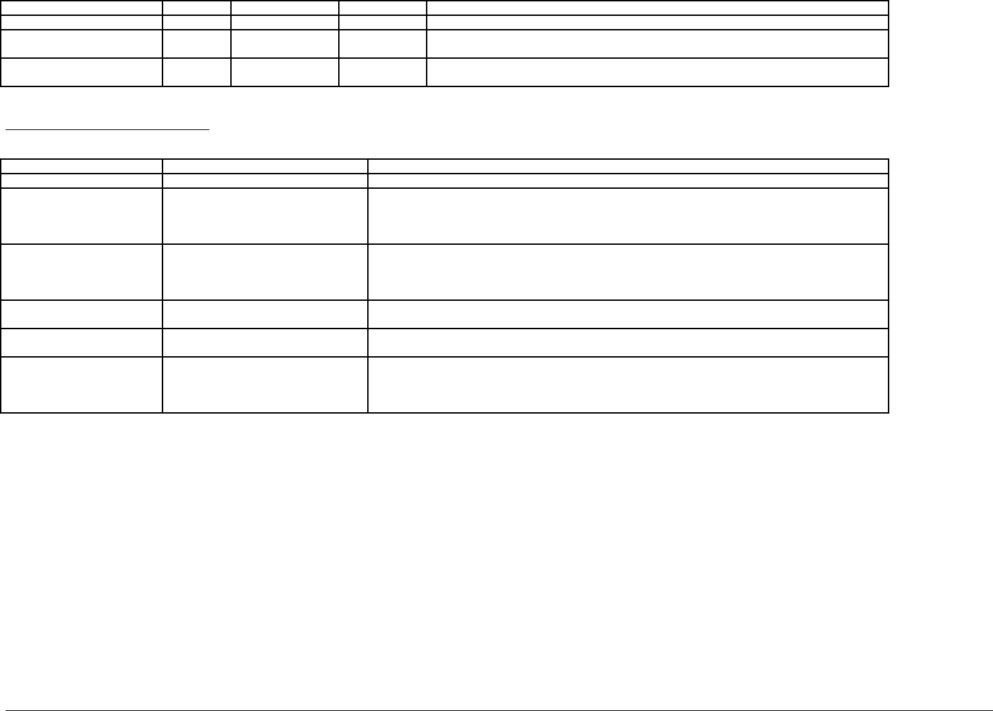
IBM Rational DOORS Requirements Management Framework Add-on - Release 5.4
justification outgoing Issue-Decision is justified by Represents the justification of the Configuration Item object, i.e. link to a decision.
Issueraised incoming Issue-Decision refers to Shows that the Configuration Item is to be (or has been) analyzed through a Issue and
Decision process.
Design hierarchy None Configuration Item None The DOORS Outline heading numbering can be used to establish a design hierarchy for a
system.
Available views of PBS module
View name Filter Description
Standard view None The DOORS default view, which shows the DOORS ID and Object Heading/Text.
Allocated requirements active filter, no sort:
IE Object Type == Configuration Item
Displays the attributes: PUID, Object Text, Type, and also a traceability column obtained with the
objects reached by a "is allocated by" outgoing link.
This traceability column is headed “allocated by…” and (for each link found) shows the name of the
module referred to, the PUID of the object referred to, and its Object Text.
Associated issues inactive filter, no sort:
IE Object Type == Configuration Item
Displays the attributes: PUID, Object Text, Type, and also a traceability column obtained with the
objects reached by an incoming "refers to" link.
This traceability column is headed “referred by…” and (for each link found) shows the name of the
module referred to, the PUID of the object referred to, and its Object Text.
Configuration Item Analysis active filter, no sort :
IE Object Type == Configuration Item
Displays the attributes: PUID, Object Text, Type, Supplier, CM identification, CM version and CM
revision.
Document view inactive filter, no sort :
IE Object Type == Configuration Item
Displays the attributes: Document Style, PUID and Object Text.
Justification inactive filter, no sort:
IE Object Type == Configuration Item
Displays the attributes: PUID, Object Text, Type, and also a traceability column obtained with the
objects reached by a "is justified by" outgoing link.
This traceability column is headed “is justified by…” and (for each link found) shows the name of the
module referred to, the PUID of the object referred to, and its Object Text.
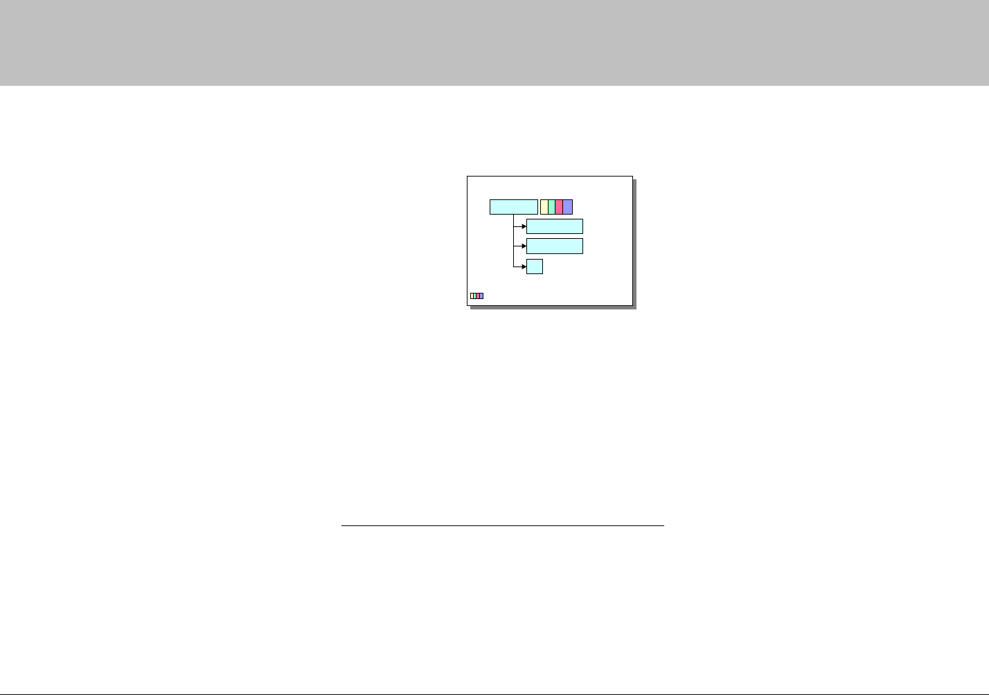
IBM Rational DOORS Requirements Management Framework Add-on - Release 5.4
00B! !,
!0#6
This module description form contains information
about DOORS formal module of type "Issues and
Decisions" and Justifications. This type of module
is used for different analysis purposes like
Requirements Analysis, Design Analysis, etc.
The "IDJ" Module contains RMF Objects of type
“Issue-Decision”. The data structure for each such
object is a tree. The root DOORS object is the RMF
Object itself. It carries all the attributes as it is the
only DOORS object in the tree, which can be
identified as a RMF object and gain a PUID. All
links to and from the object should be attached to
the root object
The leaves of the tree are DOORS objects which
inherit the attribute "IE Object Type", may have the
value “Issue-Decision”. The leaf DOORS objects
should only be used for descriptive or explanatory
material, and all of their RMF attributes should be
set to ‘blank’. Leaf objects cannot be assigned a
PUID, and should not be linked using standard
RMF linksets.
The enumerated lists shown in the following tables
are the defaults supplied with the delivered
IRDRMFAO. They should all be customised to be
appropriate to the individual project
Description 1
ID-I-D-0001
Description 2
...
: Attributes
ID data structure
ID : Issue-Decision
Typical setup/process for the "Issue-Decision" Module
1) Assumption : Originating Document is available from WORD.
2) Create a new empty "IDJ" module, by restoring the file IDJ.dma.
3) From WORD, export the document to DOORS, by clicking on the "Export To Doors" icon,
4) Within DOORS, use the IRDRMFAO interface "Manage Objects” to assign appropriate type.
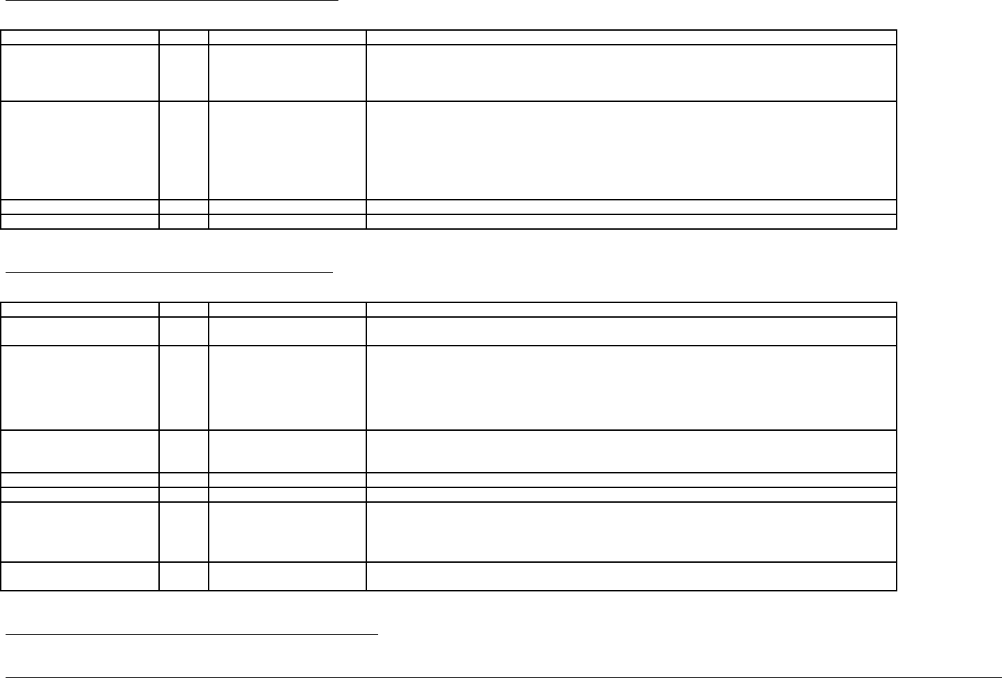
IBM Rational DOORS Requirements Management Framework Add-on - Release 5.4
Module attributes of Issues and Decisions module
Attribute name Type value Description
IE Mod Type enum Issues and Decisions
Requirement Analysis ID
Design Analysis ID
Operational Concepts
For the whole list of values, see the "Project Profile" Module Description.
IE Mod LifeCycle Phase enum Feasibility Study
Model Simulation
Demonstrator
Prototype
Full Development
Production
Operation & Support
Represents the life cycle phase of the project to which the objects identified in the module apply.
IE Issue-Decision Number Integer An internal counter used by IRDRMFAO , do not edit.
IE Release string see description Stores the IRDRMFAO release which has been used to create this module.
Object attributes of Issues and Decisions module
These attributes apply to the "Issue and Decision" objects (i.e. "IE Object Type" attribute is "Issue-Decision")
Attribute name Type value Description
IE Object Type enum Issue-Decision
Justification
Type of the object, always "Issue-Decision" in this case, or null.
For the whole list of values, see the "Project Profile" Module Description.
IE PUID string see description Project Unique IDentifier. This attribute is automatically set with the following concatenation rule :
[module prefix]-[I-D prefix]-[number]
- the [module prefix] is obtained from the DOORS module attribute "Module Prefix",
- the [I-D prefix] is obtained from the DOORS attribute "IE Object Prefix" (see the "Project Profile" Module
Description),
- the [number] is incremented by one every new Issue-Decision RMF object.
IE I-D Priority enum Low
Medium
High
This attribute represents the level of priority set to the Issue-Decision.
IE I-D Decision text see description This attribute records the decision associated with the Issue-Decision.
IE I-D Decision date date see description This attribute records the date of the decision associated with the Issue-Decision.
IE I-D Status enum In negotiation
Accepted
Analysis
Obsolete
This attribute is used to define the progress of the Issue-Decision.
IE Object Version string see description This attribute is managed by DXL, specifically by the “Update Version Attribute ” utility.
The attribute holds the designation of the baseline of the module in which the object was last changed.
Available relationships for Issues and Decisions objects
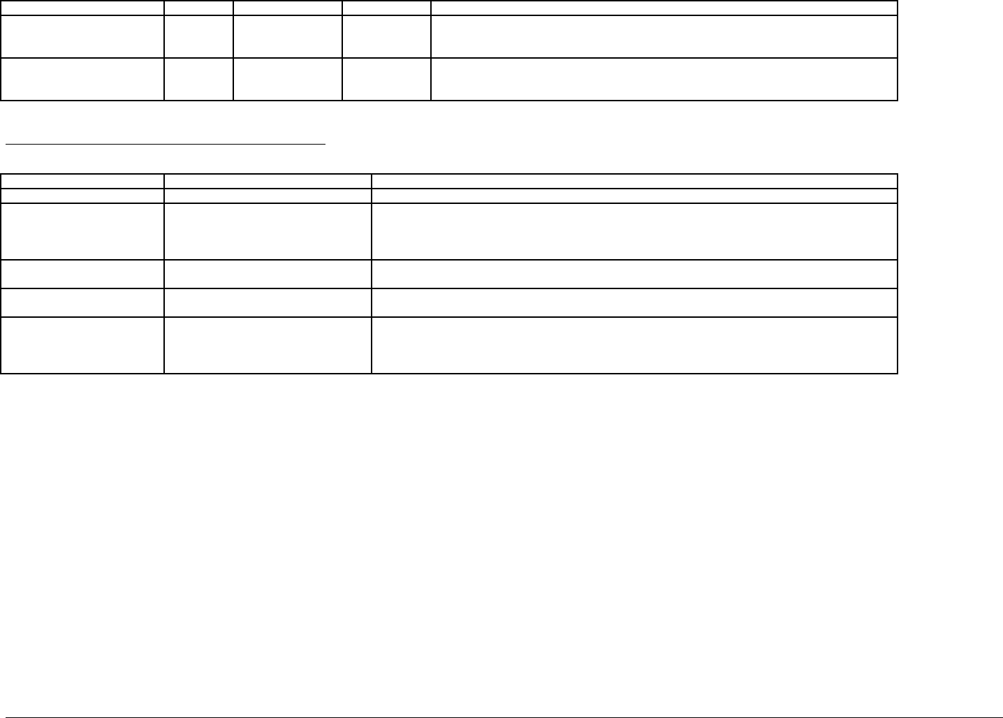
IBM Rational DOORS Requirements Management Framework Add-on - Release 5.4
link link way target type link module Description
justification incoming All types of object,
except Issue-
Decision objects
is justified by This relationship represents the justification for an object, i.e. a decision. The Issue-Decision
object justifies the linked source objects.
Issue raised outgoing All types of object,
except Issue-
Decision objects .
refers to This relationship represents the fact that he linked target objects are (or have been) the
subject of an issue-decision process.
Available views of Issues and Decisions module
View name filter Description
Standard view none The DOORS default view, which shows the DOORS ID and Object Heading/Text..
Decisions justify... active filter, no sort :
IE Object Type == Issue-Decision
Displays the attributes: PUID, Object Text, Status, and also a traceability column obtained with the
objects reached by a "is justified by" incoming link.
This traceability column is headed “decision justifies…” and (for each link found) shows the name of the
module referred to, the PUID of the object referred to, and its Object Text.
Document view inactive filter, no sort :
IE Object Type == Issue-Decision
Displays the attributes: Document Style, PUID and Object Text.
Issues and Decisions Analysis inactive filter, no sort :
IE Object Type == Issue-Decision
Displays the attributes: PUID, Object Text, Decision, Priority, Status and Decision Date
Issues refer to... active filter, no sort :
IE Object Type == Issue-Decision
Displays the attributes: PUID, Object Text, Status, and also a traceability column obtained with the
objects reached by a "refers to" outgoing link.
This traceability column is headed “Issue refers to…” and (for each link found) shows the name of the
module referred to, the PUID of the object referred to, and its Object Text.
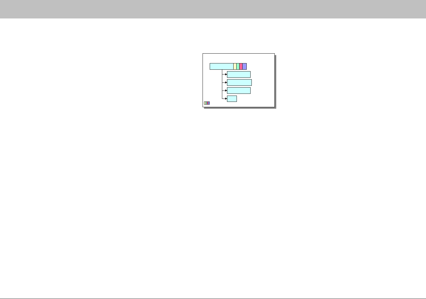
IBM Rational DOORS Requirements Management Framework Add-on - Release 5.4
00B ""%!0#6
This module description form contains information about the DOORS
formal module of type "Integration, Verification or Validation
Procedures", as delivered with IRDRMFAO.
The "IVV Procedures" Module contains RMF objects of type "IVV
Procedure". The data structure for each such object is a tree. The root
DOORS object is the IVV Procedure itself. It carries all the attributes
applying to the IVV Procedure, it is the only DOORS object in the tree,
which can be identified as a RMF object and gain a PUID. All links to
and from the object should be attached to the root object
The leaves of the tree are DOORS objects which inherit the attribute
"IE Object Type", which for an IVV Procedure, has the value "IVV
Procedure". The leaf DOORS objects should only be used for
descriptive or explanatory material, and all of their RMF attributes
should be set to ‘blank’. Leaf objects cannot be assigned a PUID, and
should not be linked using standard RMF linksets.
The standard IRDRMFAO ‘as delivered’ module attributes, object
attributes, attribute types, link relationships and views are defined in
the following tables. These should all be tailored to the particular
project when it is set up..
Description 1
IVV-IVVP-0001
Description 2
…...
: Attributes
IVV data structure
Description 3
IVV : Integration, Verification
& Validation
Suggestion: - The basic RMF IVV Procedure is designed to specify
a group of tests which can be planned and approved as a whole. At
a later stage individual tests will need to be specified in sufficient
detail that test engineers can execute them and the results can be
validated. The operating instructions and expected results for the
detailed tests could be entered as leaves within the RMF IVV object,
and a test specification document created using the Enhanced Word
Exporter utility.
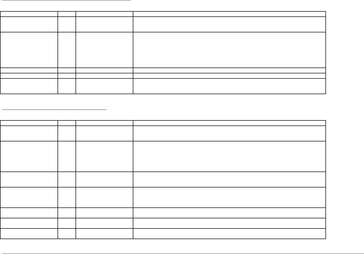
IBM Rational DOORS Requirements Management Framework Add-on - Release 5.4
Module attributes of IVV Procedures template module
Attribute name Type Value Description
IE Mod Type Enum Integration Procedures
Verification Procedures
Validation Procedures
Type of the module, based on the IVV template.
Additional types could be added, but these must be first defined as Module Types in the "Project Profile"
Module Description.
IE Mod LifeCycle Phase Enum Feasibility Study
Model Simulation
Demonstrator
Prototype
Full Development
Production
Operation & Support
Represents the life cycle phase of the project applying to the verification procedures identified in the
module.
IE Release String See description Stores the IRDRMFAO release which has been used for create this module.
IE IVV Procedure Number Integer An internal counter used by IRDRMFAO, do not edit.
Prefix String IVV Module prefix, used by IRDRMFAO to generate the PUID. In IRDRMFAO v2.0, this must be edited
manually if necessary. In later versions it may be driven from the Module Object in the "Project Profile"
Module Description
Object attributes of IVV Procedures module
These attributes apply to the IVV Procedures (i.e. "IE Object Type" attribute is "IVV Procedure")
Attribute name Type Value Description
IE Object Type Enum IVV Procedure Type of the object, always "IVV Procedure" in the delivered IRDRMFAO, or null.
Additional types could be added, but these must first be defined as Object types in the "Project Profile"
Module Description.
IE PUID String See description Project Unique ID. This attribute is automatically set with the following concatenation rule: [module
prefix]-[IVV prefix]-[number]
- the [module prefix] is obtained from the DOORS module attribute "Module Prefix".
- The [IVV prefix] is obtained from the DOORS object attribute "IE Object Prefix" (see the "Project Profile"
Module Description).
- The [number] is incremented by one every new verification procedure object created or identified.
IE IVV Type Enum Prototype
production
prototype and production
For each IVV Procedure, this attribute records the kind of the procedure. Production tests are those
intended to prove that each product has been built correctly to its design, prototype tests are intended to
prove that the design meets the product specifications.
IE IVV Approval Level Enum Customer
Prime Contractor
Sub-Contractor
Independent Test House
For each IVV Procedure, this attribute defines which party to the contract is to be responsible for the
approval of the test specifications and the test results.
IE IVV Responsible String Use this attribute to store the identification of the person responsible in charge of the given IVV
Procedure (from the engineering or test organizations).
IE IVV Skills Text Represents the list of specific skills needed for the IVV procedure, or identification of the people having
these specific skills (for instance, special operation or equipment skills).
IE IVV Event String Defines the event or location at which the procedure will be executed. Examples are ‘supplier factory
test’, ‘customer platform test’, ‘prime contractor integration facility’.
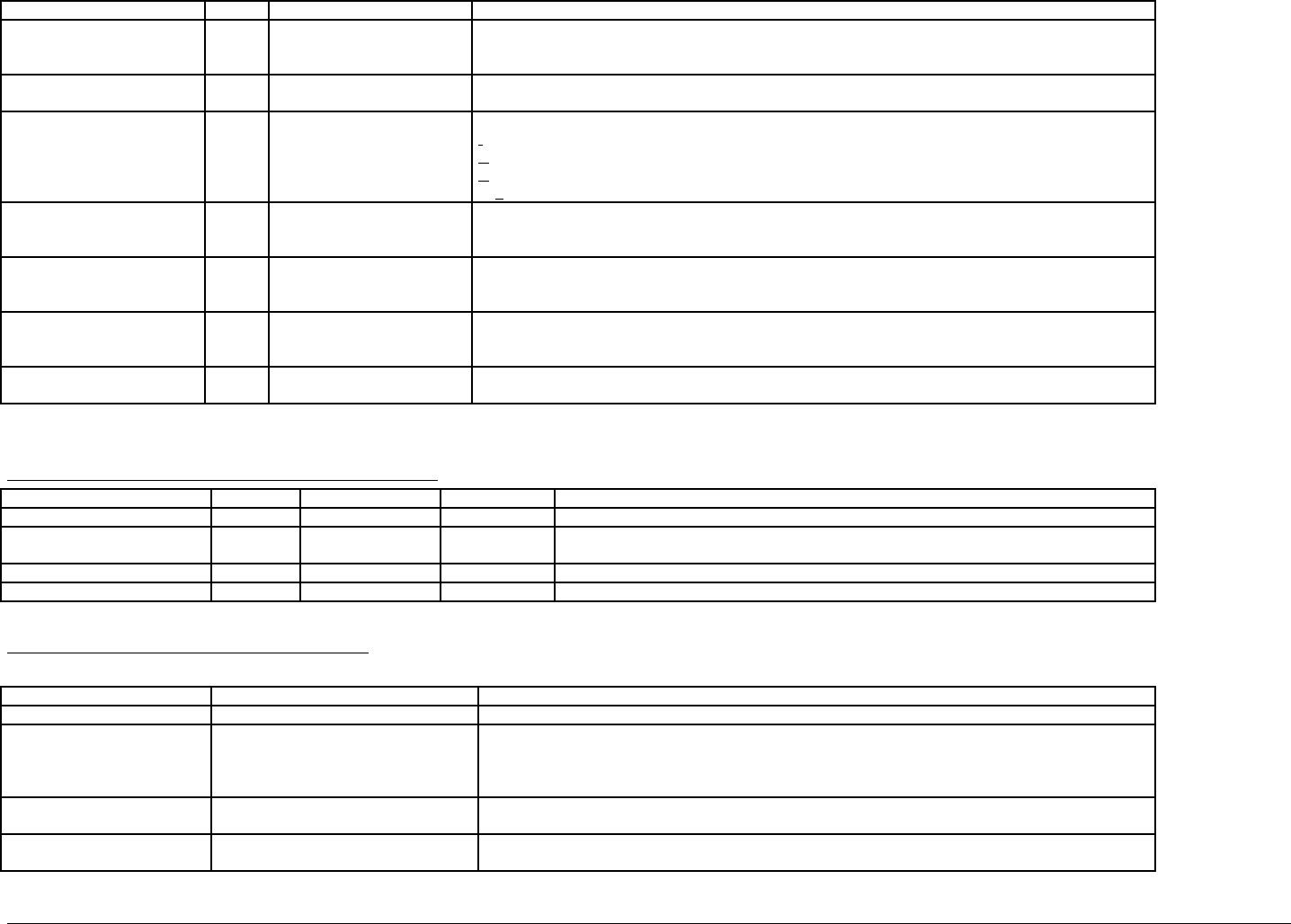
IBM Rational DOORS Requirements Management Framework Add-on - Release 5.4
Suggestion: - Projects could set this attribute up as an enumerated type.
IE IVV Event Provider Enum customer
prime contractor
sub contractor
Represents the party responsible for the conduct of the IVV event.).
Suggestion: - Projects could set this attribute up as an enumerated type, giving named sub-contractors
etc.
IE IVV Non Regression Enum true
false
Allow identification of non-regression IVV procedures. These are procedures that are unlikely to have to
be repeated in the event of a change to the system.
IE IVV Method Enum I
A
D
T
Identify the verification method of the requirements (I, A, D, T methods) :
Inspection (for example, inspection of drawings),
Analysis (for example, using simulation or virtual reality prototype),
Demonstration (for example, using mock-ups or physical models),
or Test (for example, by testing physical prototypes, breadboards)
IE IVV Scope Text This attribute is used to record agreement with customers and suppliers on the general scope and
objectives of the IVV activity before too much effort is expended on the creation of detail test
specifications.
IE IVV Pre and Post test
Actions
Text This attribute is used define and constrain significant actions necessary before and after the execution of
the IVV procedure. Examples are commitment to deliver specifications for approval at a minimum time
ahead of the event, and similarly commitments to approve documents in specific timescales.
IE IVV Acceptance criteria Text Used to define general principles of acceptance criteria for the group of tests within this procedure, for
example ‘what statistical confidence level needs to be achieved’, ‘what allowance for instrument error is
acceptable?
IE Object Version String See description This attribute is managed by DXL, specifically by the “Update Version Attribute ” utility.
The attribute holds the designation of the baseline of the module in which the object was last changed.
Available relationships for IVV Procedures objects
Link Link way target type Link module Description
Justification Outgoing Issue-Decision is justified by Represents the justification of the IVV Procedure objects i.e. link to a decision.
under issue process Incoming Issue-Decision Refers to Shows that this IVV Procedure is to be (or has been) analyzed through an Issue and
decision process.
Verification Outgoing Requirement Verifies Shows which requirements are verified by this IVV procedure.
Allocation Incoming PBS (test equip) Is allocated by Shows which test or other support equipment is allocated to this procedure.
Available views of IVV Procedures module
View name Filter/sort available Description
Standard view None DOORS default view, which shows the DOORS ID and Object Heading/Text
Associated issues Inactive filter, no sort:
IE Object Type == IVV Procedure
Display attributes PUID, Object Text, Method, Type, and also a traceability column obtained with the
objects reached by an incoming "refers to" link. This traceability column is headed “referred by…” and
(for each link found) shows the name of the module referred to, the PUID of the object referred to, and
its Object Text
Document View Inactive filter, no sort:
IE Object Type == IVV Procedure
Displays the attributes: Document Styles, PUID and Object Header/Text.
IVV Matrix View Active filter, no sort:
IE Object Type == IVV Procedure
Displays the attributes: PUID, Object Text, Method, Type, and also a traceability column obtained with
the Requirements reached by an incoming "verifies" link. . This traceability column is headed “verifies…”
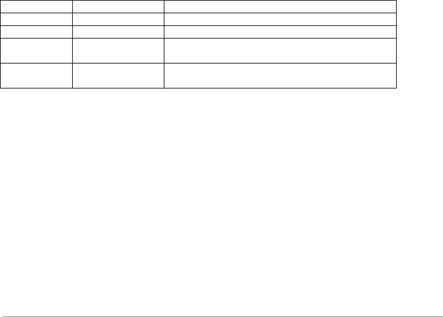
IBM Rational DOORS Requirements Management Framework Add-on - Release 5.4
and (for each link found) shows the name of the module referred to, the PUID of the object referred to,
and its Object Text
IVV Procedure Definition View Inactive filter, no sort:
IE Object Type == IVV Procedure
Displays the attributes: PUID, Object Text, Scope/Objectives, Method, Type, Approval, Acceptance
Criteria, Pre & Post Event Actions.
IVV Procedure Planning View Inactive filter, no sort:
IE Object Type == IVV Procedure
Displays the attributes: PUID, Object Text, Responsible, Event, Event provider, Specific skills needed
and Non-Regression.
Justification View Inactive filter, no sort:
IE Object Type == IVV Procedure
Displays the attributes: PUID, Object Text, Method, Type, and also a traceability column obtained with
the objects reached by a "is justified by" outgoing link. This traceability column is headed “is justified
by…” and (for each link found) shows the name of the module referred to, the PUID of the object
referred to, and its Object Text
Test Equipment View Inactive filter, no sort:
IE Object Type == IVV Procedure
Displays the attributes: PUID, Object Text, Method, Type and also a traceability column obtained with
the objects reached by a "is allocated by" incoming link. This traceability column is headed “Support
items needed” and (for each link found) shows the name of the module referred to, the PUID of the
object referred to, and its Object Text
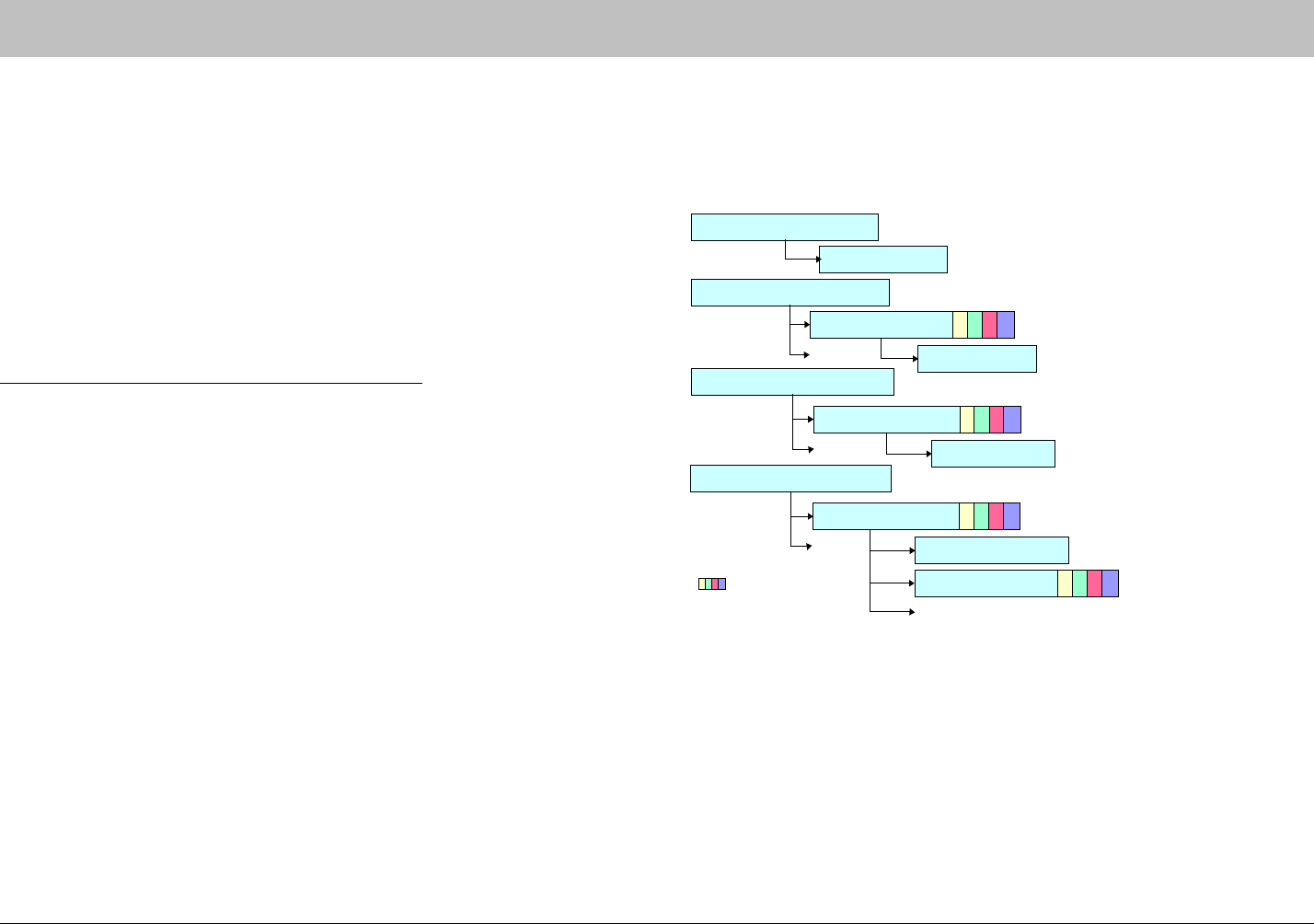
IBM Rational DOORS Requirements Management Framework Add-on - Release 5.4
00B# %:%!0#6
This module description form contains information about DOORS formal
module named "Project Profile".
The "Project Profile" module defines the available object types, module types
and relationships usable for the current RMF project, together with other
project standards such as paragraph styles. In general it controls the DOORS
project by defines the drop down lists presented by the IRDRMFAO utilities.
The objects represent all the data suitable for System Engineering, like
requirements, capabilities, critical issues, etc. The modules contain the
objects. Typical modules are User Requirements, System Requirements,
Issue-and Decision, etc.
Typical setup/process for creating a new project
1) To create a new RMF project , run DOORS and from the DOORS
Database window, run the IRDRMFAO utility “Create a new RMF project”.
Type the project name and description when prompted by the utility.
2) Your project contains now a formal module named "Project Profile" and-
eight link modules "is allocated by", "is composed of", “is different to”, “is
identical to”, "is justified by", ,refers to",."satisfies", and "verifies".
Read the descriptive paragraphs in the Project Profile module which define
the default customization provided with IRDRMFAO, as delivered. If
necessary, change the values of attribute types, add new object types or new
module types in order to further customize the model for your project. Do not
forget to update the data model diagram as necessary.
Object definition
2. Definition of the Object Types
Object description
: Attributes
Project Profile data structure
Module definition
3. Definition of the Module Types
Module description
1. Definition of the Data Model
Data model diagram
Link Module
4. Definition of the Relationships
Relationship definition
Relationship description
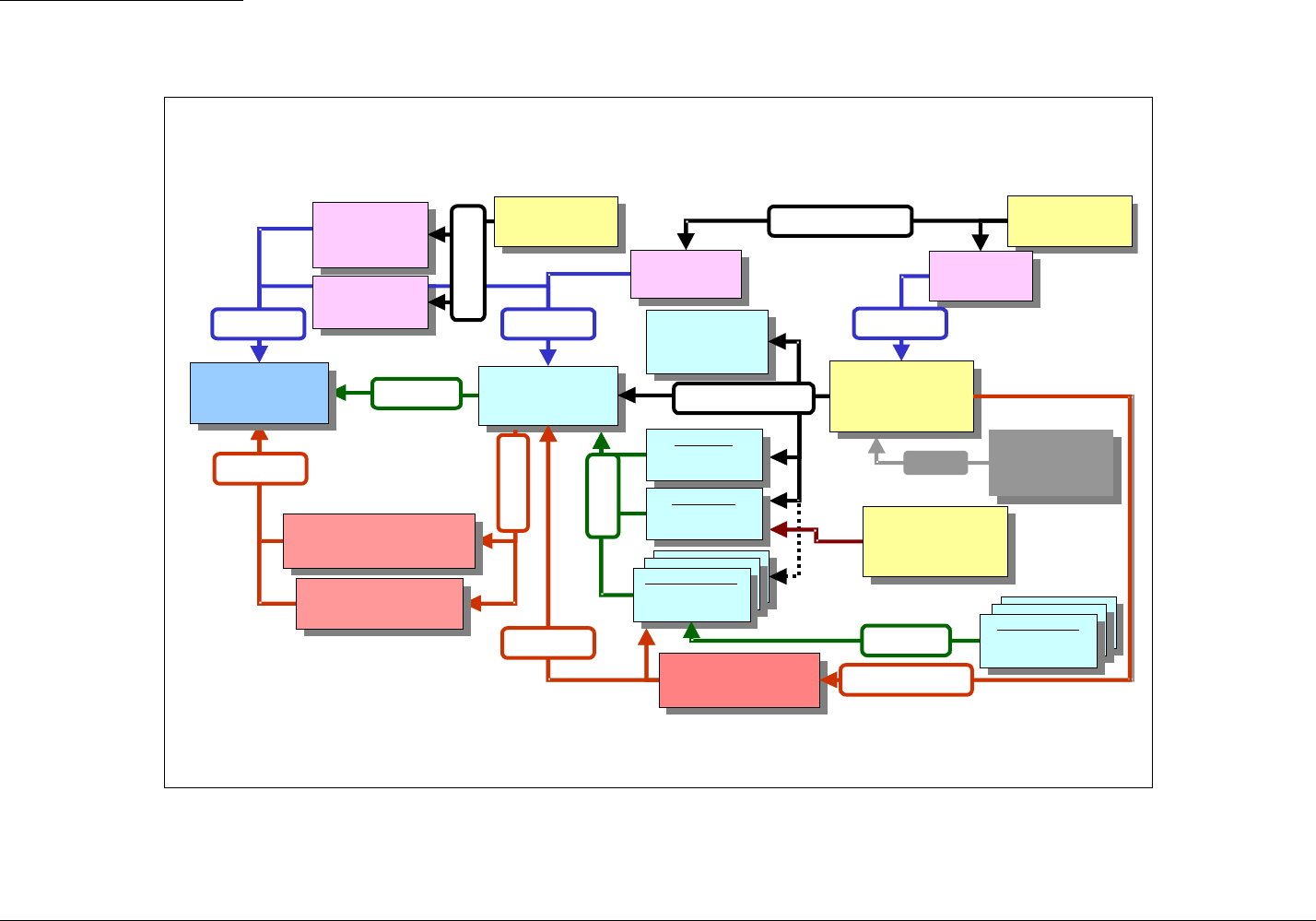
IBM Rational DOORS Requirements Management Framework Add-on - Release 5.4
Definition of the Data Model
One Data Model currently supported by this IRDRMFAO version is shown below. The diagram provided within the delivery of IRDRMFAO shows a slightly
simpler model. Projects should produce a specific data model which represents how System Engineering is to be carried out It is anticipated that the project data
model should be defined , documented and approved as part of the Systems Engineering Management Plan (SEMP)
System
Test Equipment
System
System
Test Equipment
Test Equipment
%&
Verification
Procedures
Verification
Verification
Procedures
Procedures
""
System
Requirements
System
System
Requirements
Requirements
Sub-System
Requirements
Sub-System
Sub-System
Requirements
Requirements
Extended data Model
Other
Stakeholders
Requirements
Other
Other
Stakeholders
Stakeholders
Requirements
Requirements
'
Requirements Analysis
Issues & Decisions
Requirements Analysis
Requirements Analysis
Issues & Decisions
Issues & Decisions
!
User
Requirements
User
User
Requirements
Requirements
Product
Breakdown
Structure
Product
Product
Breakdown
Breakdown
Structure
Structure
%&
Acceptation
Procedures
Acceptation
Acceptation
Procedures
Procedures
""
Validation &
Installation
Procedures
Validation &
Validation &
Installation
Installation
Procedures
Procedures
""
Acceptance
Test Equipment
Acceptance
Acceptance
Test Equipment
Test Equipment
%&
Integration
Procedures
Integration
Integration
Procedures
Procedures
""
Operational Concept
Operational Concept
Operational Concept
!
External
Systems
Assumptions
External
External
Systems
Systems
Assumptions
Assumptions
%&
Internal
Interfaces
Internal
Internal
Interfaces
Interfaces
External
Interfaces
External
External
Interfaces
Interfaces
Prime Item
Requirements
Prime Item
Prime Item
Requirements
Requirements
'
Is justified by
Design Analysis
Issues & Decisions
Design Analysis
Design Analysis
Issues & Decisions
Issues & Decisions
!
:'
'
IJJKL9M'0
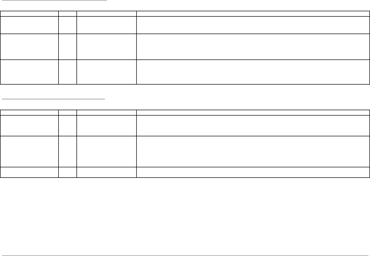
IBM Rational DOORS Requirements Management Framework Add-on - Release 5.4
Module attributes of Project Profile module
These attributes apply to the module, and are interpreted to apply throughout the project by IRDRMFAO utilities.
Attribute name Type value Description
IE Log File string See description
default is errlog.txt
Pathname of log file (full or not, e.g. C:\doors\errlog.txt or errlog.txt), which can be set by the user if desired. The default path
is DOORSHOME errlog.txt which is always used if the Project Profile module is missing or the Log File attribute is missing
from it.
IE Debug enum No Debug
DXL Window
Log File
Ack and Log
Window and Log
Flag indicating where error messages should be directed. In No Debug mode, tools ack and halt. Otherwise they attempt to
continue.
IE Data Model text See description This attribute holds a description of the Data Model of your project, by means of definition of every linkset used.. This attribute is used by,
and the data model maintained by, the "Manage LinkSets" command.
The format of each linkset definition is:-
/<<projectname>>/<<linkmodulename>>: /<<sourceprojectname>>/<<sourcemodulename>> > /
<<sinkprojectname>>/<<sinkmodulename>>➦
Object attributes of Project Profile module
The following attributes apply to the definition of objects, and are set to null in other objects.
Attribute name Type value Description
IE Object Type string
enum
see description. Typical values
are Requirement, Capability,
Issue-Decision, Configuration
Item, IVV Procedure.
Represents an object type usable in the current project. The objects with this attribute set to a value (i.e. not NULL) describe
the data definition of objects suitable for System Engineering, like requirements, capabilities, issues, configuration items, IVV
procedures, etc.
IE Object Prefix string see description Used to set the Project Unique ID attribute within formal modules. Note that the PUID is calculated with the following rule :
[module prefix]-[object prefix]-[number]
- the [module prefix] is obtained from the DOORS module attribute "Module Prefix" of the formal module,
- the [object prefix] is obtained from this attribute ("IE Object Prefix"), for the appropriate object type
- the [number] is incremented by one every new Object.
Thus for a given Object Type, the object prefix is the same for the whole project, as it is defined once in the PP module
IE Object Word Style string see description This attribute defines the paragraph style to applied to each RMF object when it is created. This style is used if the object is
exported to Word, and a style definition with the same name is found in the Word template.
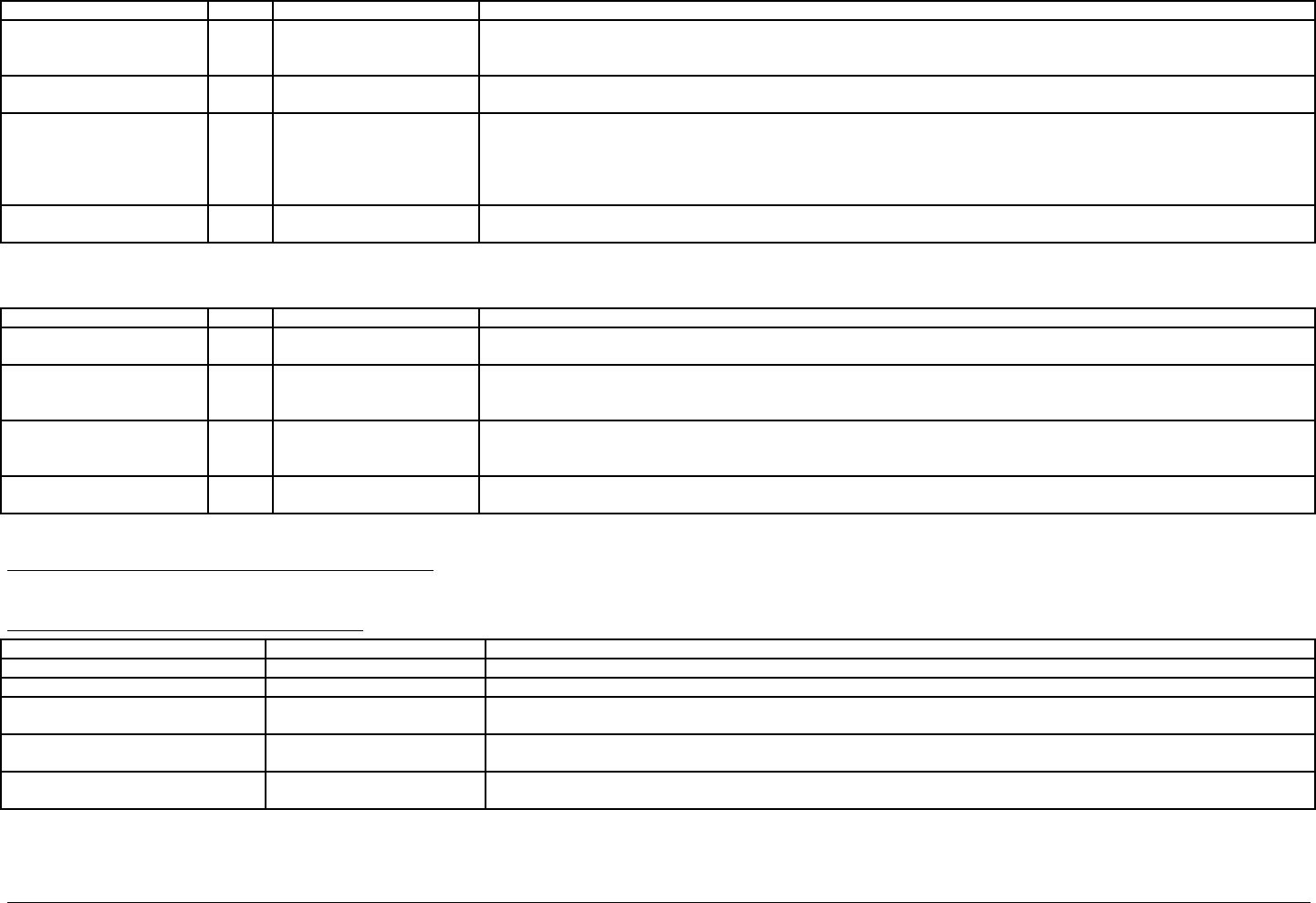
IBM Rational DOORS Requirements Management Framework Add-on - Release 5.4
The following attributes apply to the definition of modules, and are set to null in other objects
Attribute name Type value Description
IE Module Type string see description Represents a module type usable in the current project. The objects with this attribute set to a value (i.e. not NULL) describe
the data definition of modules suitable to build the project structure. The modules contain the objects. Typical modules are User
Requirements, System Requirements, Issues and Decisions, PBS, IVV Procedures, etc.
IE Module Word Styles text see description This attribute is used to record the list of possible Document (ie Paragraph) styles which may be applied to objects within the
given Module Type. Each line of this text attribute represents a style.
IE undefined PUID keyword string See description Contains the keyword to set in the PUID attribute when the Manage objects tool is used in a particular context: module open in
edit shareable mode. PUIDs can only be assigned in Exclusive Edit mode, so in the Edit Shareable mode context it is assigned
to the default value set by this attribute.
It can be an empty keyword. The “Renumber object” tool can complete the PUID later, but it is recommended that it is set to a
meaningful reminder, such as “PUID TBD later”
IE Bitmap string A bitmap filename with a
.bmp extension
Name of a file containing a bitmap associated with the current module type and which will be displayed in the Relationship
Manager.
The following attributes apply to the definition of relationships, and are set to null in other objects
Attribute name Type value Description
IE Relationhip string see description Represents the name of a link module
It must be one of the link module available in the current project.
IE Source Module string see description Represents the source module of an authorized relationship.
It must be a module type usable in the current project.
Typical values are User Requirements, System Requirements, Issues and Decisions, PBS, IVV Procedures, etc.
IE Target Module string see description Represents the target module of an authorized relationship.
It must be a module type usable in the current project.
Typical values are User Requirements, System Requirements, Issues and Decisions, PBS, IVV Procedures, etc.
IE Mapping string Many-to-Many, Many-to-One,
One-to-Many, One-to-One
Describes the authorized cardinality of the relationship
Available relationships for Project Profile objects
none
Available views of Project Profile module
View name Filter Description
standard view None DOORS default view, which shows the DOORS ID and Object Heading/Text.
definition of the module types IE Module Type != NULL Displays the attributes: Object Text, IE Module Type, IE Module Document Styles and IE Bitmap.
definition of the object types IE Object Type != NULL Displays the attributes: Object Text, IE Object Type, IE Object Prefix, IE Object Document Style and IE undefined PUID
keyword.
Definition of the Relationships include object 41
show descendants
Displays the attributes: Object Text and Heading, IE Relationship, IE Source Module, IE Target Module, IE Mapping.
Project Data Model representation include object 17
show descendants
Displays the picture showing a graphical representation of the project data model.

IBM Rational DOORS Requirements Management Framework Add-on - Release 5.4
00B$ #794!
7C#7D
Why it is impossible to identify a RMF object within a table ?
Because this is not convenient and practical to manage data in tables with DOORS :
-No direct display of the attributes of cells (no analysis view),
-Table can’t be displayed in traceability matrix (DXL column),
-DOORS does not allow the selection of multiple cells or a row, so it’s not possible to identify such
requirements or make join operations. DOORS only allows the selection of one cell or the complete
table.
Note : A complete table can be identified as a requirement.
After installing DOORS, I did not obtain the « Export to Word » icon in my WORD application.
How can I remedy this?
When you launch WORD, it loads all the files located in the start directory (path defined as an option in
WORD menu). DOORS installation attempts to put a file "doors.dot" in this directory.
1) Run WORD and check the start directory path in WORD option (French release: menu outil->Option /
Dossiers par défaut/ Fichiers de démarrage),(English release: menu Tools->Options>File Locations-
>Startup).
2) With an explorer, check if the file “doors.dot” has been copied to the located directory. If not, copy it
yourself or by an administrator. You will find it in <DOORS_HOME>/lib/word.
I specified colors for my enumerated attribute and they are not displayed in the views. Why ?
Check if in the column properties, the option “Color by attribute” is set. Don’t forget to save the view.
How can I change the color of the text of RMF Objects in a view to distinguish them from
ordinary text ?
First, define colors for the type "IE Object type" and then in the text column of a view, edit the column
properties in order to set the option “Color by attribute” selecting the attribute "IE Object type". Don’t
forget to save the view. Notice that the chosen enumerated attribute must not be multi-valued.

IBM Rational DOORS Requirements Management Framework Add-on - Release 5.4
This information was developed for products and services offered in the U.S.A. IBM
may not offer the products, services, or features discussed in this document in other
countries. Consult your local IBM representative for information on the products and
services currently available in your area. Any reference to an IBM product, program, or
service is not intended to state or imply that only that IBM product, program, or service
may be used. Any functionally equivalent product, program, or service that does not
infringe any IBM intellectual property right may be used instead. However, it is the
user's responsibility to evaluate and verify the operation of any non-IBM product,
program, or service.
IBM may have patents or pending patent applications covering subject matter described
in this document. The furnishing of this document does not grant you any license to
these patents. You can send written license inquiries to:
IBM Director of Licensing
IBM Corporation
North Castle Drive
Armonk, NY 10504-1785
U.S.A.
For license inquiries regarding double-byte character set (DBCS) information,
contact the IBM Intellectual Property Department in your country or send written
inquiries to:
IBM World Trade Asia Corporation
Licensing
2-31 Roppongi 3-chome, Minato-ku
Tokyo 106-0032, Japan
The following paragraph does not apply to the United Kingdom or any other
country where such provisions are inconsistent with local law:
IN T E R N A T I O N A L BU S I N E S S M A C H I N E S C O R P O R A T I O N
P R O V I D E S T H I S PU B L I C A T I O N “AS IS” W I T H O U T W A R R A N T Y O F
A N Y KI N D , EI T H E R E X P R E S S O R IM P L I E D , IN C L U D I N G , B U T N O T
LI M I T E D T O , T H E IM P L I E D W A R R A N T I E S O F N O N-
IN F R I N G E M E N T , M E R C H A N T A B I L I T Y O R FI T N E S S F O R A
P A R T I C U L A R P U R P O S E .
Some states do not allow disclaimer of express or implied warranties in certain
transactions. Therefore, this statement may not apply to you.
This information could include technical inaccuracies or typographical errors. Changes
are periodically made to the information herein; these changes will be incorporated in
new editions of the publication. IBM may make improvements and/or changes in the
product(s) and/or the program(s) described in this publication at any time without
notice.

IBM Rational DOORS Requirements Management Framework Add-on - Release 5.4
Any references in this information to non-IBM Web sites are provided for convenience
only and do not in any manner serve as an endorsement of those Web sites. The
materials at those Web sites are not part of the materials for this IBM product and use
of those Web sites is at your own risk.
IBM may use or distribute any of the information you supply in any way it
believes appropriate without incurring any obligation to you. Licensees of this program
who wish to have information about it for the purpose of enabling: (i) the exchange of
information between independently created programs and other programs (including
this one) and (ii) the mutual use of the information which has been exchanged, should
contact:
Intellectual Property Dept. for Rational Software
IBM Corporation
1 Rogers Street
Cambridge, Massachusetts 02142
U.S.A.
Such information may be available, subject to appropriate terms and conditions,
including in some cases, payment of a fee.
The licensed program described in this document and all licensed material available for it
are provided by IBM under terms of the IBM Customer Agreement, IBM International
Program License Agreement or any equivalent agreement between us.
Any performance data contained herein was determined in a controlled environment.
Therefore, the results obtained in other operating environments may vary significantly.
Some measurements may have been made on development-level systems and there is no
guarantee that these measurements will be the same on generally available systems.
Furthermore, some measurements may have been estimated through extrapolation.
Actual results may vary. Users of this document should verify the applicable data for
their specific environment.
Information concerning non-IBM products was obtained from the suppliers of those
products, their published announcements or other publicly available sources. IBM has
not tested those products and cannot confirm the accuracy of performance,
compatibility or any other claims related to non-IBM products. Questions on the
capabilities of non-IBM products should be addressed to the suppliers of those
products.
This information contains examples of data and reports used in daily business
operations. To illustrate them as completely as possible, the examples include the names
of individuals, companies, brands, and products. All of these names are fictitious and
any similarity to the names and addresses used by an actual business enterprise is entirely
coincidental.
If you are viewing this information softcopy, the photographs and color
illustrations may not appear.

IBM Rational DOORS Requirements Management Framework Add-on - Release 5.4
Tr a d e m a r k s
IBM, the IBM logo, ibm.com, Rational, DOORS, are trademarks or registered
trademarks of International Business Machines Corporation in the United States, other
countries, or both, are trademarks of Telelogic, an IBM Company, in the United States,
other countries, or both. These and other IBM trademarked terms are marked on their
first occurrence in this information with the appropriate symbol (® or ™), indicating US
registered or common law trademarks owned by IBM at the time this information was
published. Such trademarks may also be registered or common law trademarks in other
countries. A current list of IBM trademarks is available on the Web at
www.ibm.com/legal/copytrade.html.
Adobe, the Adobe logo, Acrobat, the Acrobat logo, FrameMaker, and PostScript are
trademarks of Adobe Systems Incorporated or its subsidiaries and may be registered in
certain jurisdictions.
Microsoft, Windows, Windows 2003, Windows XP, Windows Vista, Excel and/or other
Microsoft products referenced herein are either trademarks or registered trademarks of
Microsoft Corporation.
