Libretto Junior 633 E 650 GB.FH11 Istr_junior633 650_gb Istr Junior633 Gb
User Manual: istr_junior633-650_gb
Open the PDF directly: View PDF ![]() .
.
Page Count: 20
Dis. 6399
meccanica
FADINI
Via Mantova 177/A - C.P. 126 - 37053 Cerea (VR) Italy -
Tel. +39 0442 330422 - Fax +39 0442 331054 - info@fadini.net - www.fadini.net
I
Junior 624 - Junior 633 - Junior 650
IL PROGRAMMATORE È GIÀ COLLEGATO IN FABBRICA PER IL CORRETTO FUNZIONAMENTO DEI FINECORSA, PERTANTO NON INVERTIRE
MAI FILI O CONNETTORI GIÀ INSTALLATI E COLLEGATI DALLA DITTA COSTRUTTRICE.
INSTALLATO FISICAMENTE IL JUNIOR ALLA BASE DEL CANCELLO, PROSEGUIRE CON TUTTI I DIP-SWITCH IN OFF AD ESCLUSIONE DEL DIP-
SWITCH 11 CHE IDENTIFICA L'INSTALLAZIONE DESTRA O SINISTRA. SELEZIONARE PROGRESSIVAMENTE I DIP-SWITCH DELLE FUNZIONI SOLO
DOPO AVER LETTO E COMPRESO ATTENTAMENTE LE SINGOLE FUNZIONI SUL LIBRETTO ISTRUZIONI.
NON È GARANTITO IL FUNZIONAMENTO DEL JUNIOR CON ACCESSORI NON ORIGINALI FADINI: la certificazione secondo normative
EN 12445 e EN 12453 e' stata ottenuta con test di laboratorio con l'uso esclusivo degli accessori originali della MECCANICA FADINI.
In particolare il JUNIOR 624 deve essere installato solo con fotocellule FIT 55 o ORBITA 57.
DURANTE LA PROCEDURA DI APPRENDIMENTO (Fig.18-Fig.29 del Libretto Istruzioni) TUTTE LE SICUREZZE SONO DISATTIVATE
prestare quindi la massima attenzione affinchè non ci sia alcun transito nella zona di movimento del cancello.
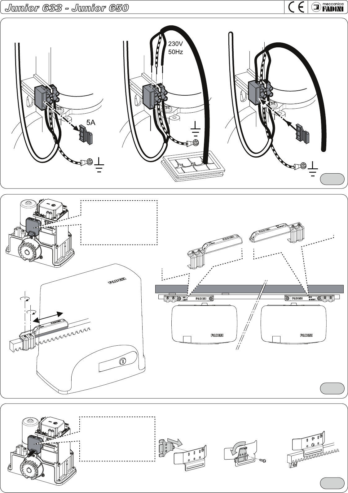
LE ASOLE DI FINECORSA MAGNETICO HANNO I MAGNETI INTERNI GIÀ INSTALLATI CORRETTAMENTE SULLE STAFFE METALLICHE, NON APRIRLE
O INVERTIRE I MAGNETI.
DEVONO ESSERE INSTALLATE SUL LATO DESTRO E SINISTRO SULLA CREMAGLIERA, COME STAMPIGLIATO SULLA COPERTURA PLASTICA DELLE
STESSE (Fig.15 e Fig.16 a pag. 8 del Libretto Istruzioni), PENA IL NON FUNZIONAMENTO CORRETTO DELL'APRICANCELLO: IN TAL CASO
TOGLIERE IMMEDIATAMENTE IL FUSIBILE DI RETE DA 5A E RIPOSIZIONARE CORRETTAMENTE LE ASOLE.
PRIMA DI DARE TENSIONE VERIFICARE LA POSIZIONE DI MONTAGGIO DELL'APRICANCELLO "JUNIOR INSTALLATO DESTRO OPPURE SINISTRO"
VISTO ALL'INTERNO DEL CANCELLO DA MUOVERE.
Selezionare il Dip/Switch 11 a tensione assente (Fig. 4 a pag. 4 del Libretto Istruzioni): posizionare il cancello a metà corsa circa, tenere
premuto il pulsante di programmazione LP e dare tensione inserendo il fusibile di linea da 5A, quindi trascorsi 3 secondi rilasciare il
pulsante di programmazione, il led corrispondente lampeggia segnalando la modalità di apprendimento della corsa.
Premere con un impulso per far aprire il cancello e proseguire come descritto da Fig. 18 a Fig. 29 del libretto istruzioni.
IMPORTANTE: SE INVECE IL CANCELLO CHIUDE, TOGLIERE IL FUSIBILE DI LINEA DA 5A PER FERMARLO: SI E' VERIFICATO UN ERRORE DI
PARTENZA, SICURAMENTE NON SI E' SELEZIONATO LA CORRETTA INSTALLAZIONE DESTRA O SINISTRA CON IL DIP-SWITCH 11 A TENSIONE
ASSENTE. RIPETERE LA PROCEDURA PARTENDO DALL'INIZIO: IL PRIMO IMPULSO DI PROGRAMMAZIONE DEVE ESSERE SEMPRE IN APERTURA.
ALLA PRIMA ACCENSIONE VERIFICARE CHE I LED COLOR VERDE SIANO CORRETTAMENTE ACCESI; PROCEDERE POI SENZA DARE ULTERIORI
COMANDI ALLA VERIFICA DELLA LETTURA DEI FINECORSA: I LED X E Y DEI FINECORSA SI TROVANO SUL LATO DIETRO LA SCHEDA A FIANCO
IL CONNETTORE DEL FINECORSA (Fig.17).
IL DIP-SWITCH 10 DEL CONTROLLO "DSA" DELLE FOTOCELLULE DEVE ESSERE SELEZIONATO SOLO SE I TRASMETTITORI DELLE FOTOCELLULE
SONO ALIMENTATI ATTRAVERSO I MORSETTI DEDICATI 13-14 (Fig.17 DEL LIBRETTO ISTRUZIONI), PENA IL BLOCCO COSTANTE DEL CANCELLO.
!
GB
= IMPORTANTE
!
= IMPORTANT
!
Junior 624 - Junior 633 - Junior 650
THE CONTROL BOARD IS FACTORY PRE-WIRED FOR THE CORRECT FUNCTIONING OF THE LIMIT SWITCHES, NEVER CHANGE THE CONNECTIONS
OR CONNECTORS AS SET BY THE MANUFACTURER.
ONCE JUNIOR IS INSTALLED ON TO THE GATE, GO ON WITH ALL THE DIP-SWITCHES TO OFF, WITH THE EXCLUSION OF DIP-SWITCH 11 TO
BE SET TO THE INSTALLATION REQUIREMENTS EITHER RIGHT OR LEFT. THE DIP-SWITCHES ARE TO BE SET SO TO MEET THE APPLICATION
REQUIREMENTS, AFTER CORRECT UNDERSTANDING OF THEIR RESPECTIVE FUNCTIONS AS EXPLAINED IN THE INSTALLATION HANDBOOK.
THERE IS NO GUARANTEE OF CORRECT FUNCTIONING FOR JUNIOR UNLESS ORIGINAL FADINI ACCESSORIES ARE USED:the certificate of
compliance to EN 12445 and EN 12453 norms has been obtained through lab tests only with original accessories by MECCANICA FADINI.
It is recommended that JUNIOR 624 is installed only along the FIT 55 or ORBITA 57 photocells.
DURING THE SELF-LEARNING PHASE (Fig. 18- Fig. 29 in the installation handbook) ALL THE SAFETY DEVICES ARE OUT OF SERVICE, make
absolutely sure that there is no transiting at all in the gate travel area.
THE MAGNETS ARE FACTORY-FITTED INSIDE THE LIMIT SWITCH METALLIC BRACKETS, DO NOT OPEN THEM OR CHANGE THE POSITION OF
THE MAGNETS. THE BRACKETS ARE DESIGNED TO BE FIXED ON TO THE GEAR RACK TO THE RIGHT AND LEFT SIDES OF THE GATE, AS MARKED
ON THE PLASTIC COVERS OF THEM (Fig. 15 and 16 page 8 in the installation handbook), INCORRECT POSITIONING WILL RESULT INTO
FAILURE OF THE GATE OPERATOR: IF THIS IS THE CASE REMOVE THE 5A MAINS FUSE AND POSITION THE BRACKETS IN THE CORRECT WAY.
BEFORE POWERING THE SYSTEM, CHECK THE MOUNTING POSITION OF THE GATE OPERATOR “JUNIOR RIGHT OR LEFT INSTALLATION”, VIEW
THE OPERATOR FROM INSIDE THE GATE.
Set dip-switch 11 as required (Fig. 4 on page 4 in the fitting instructions manual), no power supply: drive the gate to halfway of its total
travel, press and hold the programming LP button and power the operator by fitting the 5A mains fuse. After 3 seconds release the
button, the corresponding Led flashes to indicate that gate travel learning mode is on. Give a pulse to open the gate and carry on as
described from Fig. 18 to Fig. 29 in the installation handbook.
IMPORTANT: SHOULD THE GATE MOVE TO CLOSE INSTEAD, REMOVE THE 5A FUSE TO STOP IT: A MISTAKE MUST HAVE OCCURRED ON
STARTING, YOU MUST HAVE FAILED TO SELECT THE CORRECT INSTALLATION POSITION LEFT OR RIGHT WITH DIP-SWITCH 11, IN ABSENCE
OF POWER. START AGAIN FROM THE BEGINNING: ON PROGRAMMING THE UNIT, THE FIRST PULSE MUST BE OPEN, ALWAYS.
ON FIRST SWITCHING THE UNIT ON, THE GREEN LEDS MUST BE ALIGHT; NO OTHER COMMANDS ARE TO BE GIVEN, AND CHECK THE LEDS
CORRESPONDING TO THE LIMIT SWITCHES: THE LIMIT SWITCH X and Y LEDS ARE ON TOP SIDE OF THE PCB NEXT TO THE LIMIT SWITCH
CONNECTOR (Fig. 17).
DIP-SWITCH 10 “DSA” CONTROL ON THE PHOTOCELLS MUST BE ACTIVATED ONLY IF THE TRANSMITTERS OF THE PHOTOCELLS ARE POWERED
BY TERMINALS 13-14 Fig. 17 of the instructions), OTHERWISE THE SYSTEM IS TURNED INTO A PERMANENT STOP CONDITION.
1 -
2 -
3 -
4 -
5 -
6 -
7 -
8 -
!
- ATTENZIONE ! -
LEGGERE LE SEGUENTI INFORMAZIONI PRIMA DI PROCEDERE ALLA PRIMA INSTALLAZIONE
- ATTENTION ! -
READ THE FOLLOWING NOTICE BIFORE GOING ON WITH THE FIRST INSTALLATION
1 -
2 -
3 -
4 -
5 -
6 -
7 -
8 -
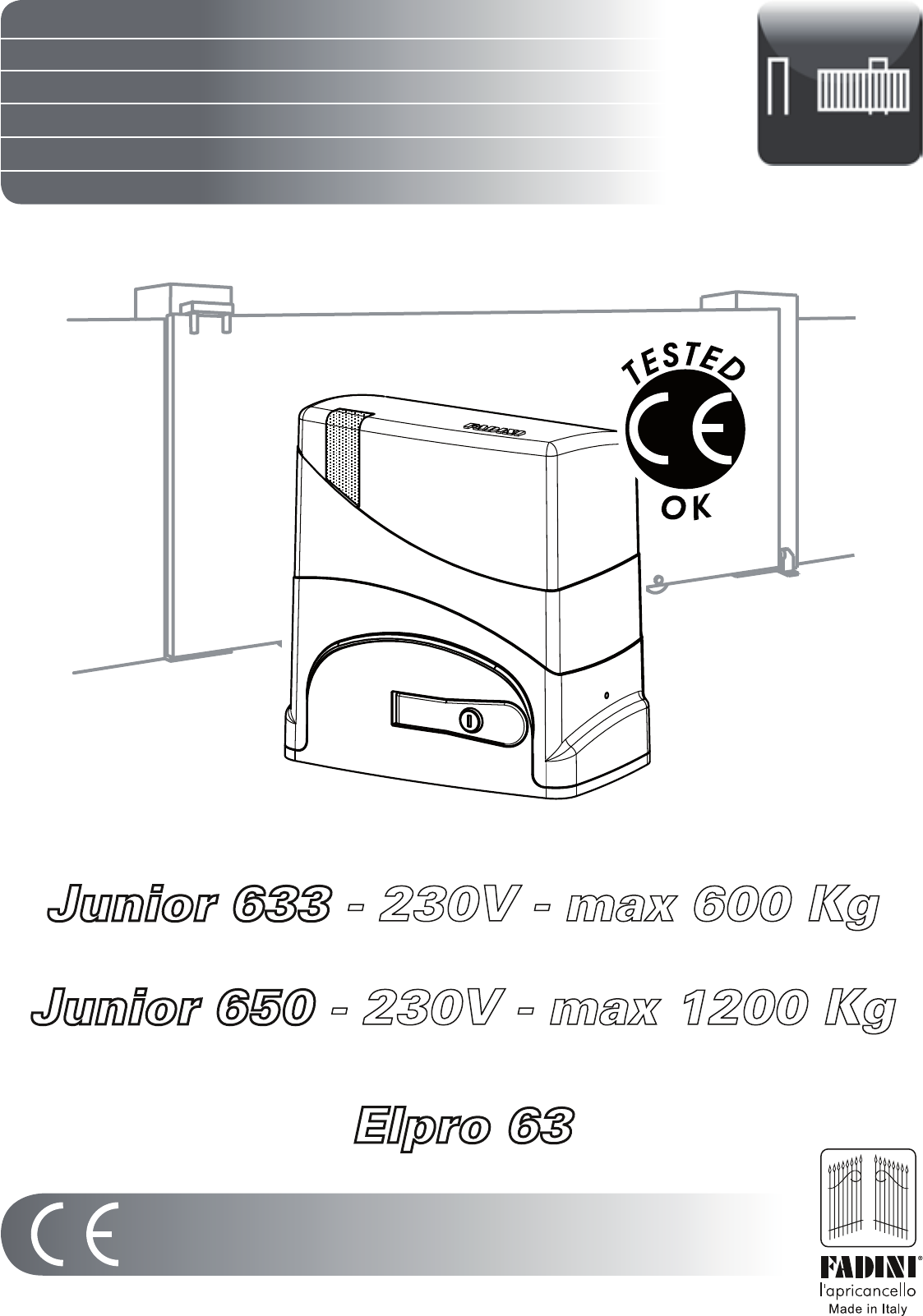
Junior 633
Junior 650
Elpro 63
EN 13241
EN 12453
EN 12445
I - Libretto di istruzioni pag. 1-16
GB - Instructions Manual pag. 1-8 17-24
F - Notice de montage pag. 1-8 25-32
D - Betriebsanleitung pag. 1-8 33-40
E - Manual de instrucciones pag. 1-8 41-48
NL - Instructieboekje pag. 1-8 49-56
ITT-PDC/0977-2010-30/04/2010
ITT-PDC/0978-2010-30/04/2010
pag. 4
Fig. 3
Fig. 4
I
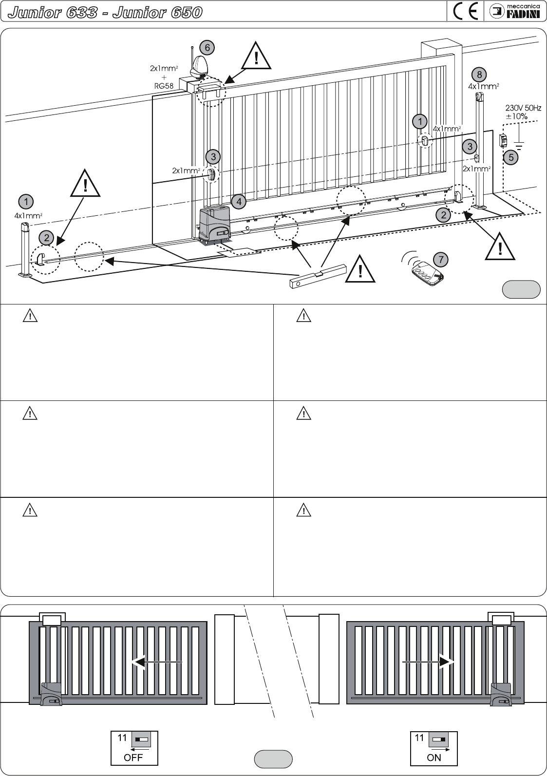
Componenti principali per una installazione:
1 - Fotocellula ricevitore Fit 55
2 - Battuta di arresto
3 - Fotocellula proiettore Fit 55
4 - Junior 633/Junior 650 con programmatore Elpro 63 e radio innesto
5 - Interruttore di linea 230V - 50Hz magneto-termico differenziale da 0,03A
6 - Lampeggiatore Miri 4 con antenna
7 - Trasmettitore radio
8 - Selettore a chiave CHIS 37
= Attenzione: verificare l’integrità della struttura e la linearità del
movimento del cancello, togliendo eventuali attriti.
GB
Main installation components:
1 - Fit 55 photocell receiver
2 - Gate end stop
3 - Fit 55 photocell projector
4 - Junior 633/Junior 650 with programmer Elpro 63 plug-in radio receiver
5 - 230V - 50Hz magneto-thermal differential line circuit breaker, 0.03A
6 - Miri 4 flasher with rod aerial
7 - Radio transmitter
8 - Key-switch CHIS 37
= Attention: verify the integrity of the structure and the linearity of the
gate movement, removing any noted friction or resistance.
F
Composants principaux de l’installation:
1- Photocellule récepteur Fit 55
2 - Butée d’arrêt
3 - Photocellule projecteur Fit 55
4 - Junior 633 et Junior 650 avec programmateur Elpro 63 et carte radio enfichable
5 - Interrupteur de ligne 230V - 50Hz magnéto thermique différentiel de 0,03A
6 - Lampe clignotante Miri 4 avec antenne
7 - Emetteur radio
8 - Sélecteur à clé CHIS 37
= Attention: vérifier l’intégrité de la structure et la linéarité du
mouvement du portail, en éliminant d’éventuels frottements
E
Componentes principales para una instalación:
1 - Fotocélula receptor Fit 55
2 - Tope de parada
3- Fotocélula proyector Fit 55
4 - Junior 633 o junior 650 con programador Elpro 63 y radio enchufable
5 - Interruptor de línea 230V - 50Hz magnetotérmico diferencial de 0,03A
6 - Destellador Miri 4 con antena
7 - Transmisor radio
8 - Llave de selector CHIS 37
= Atención: comprobar el buen estado de la estructura y la linealidad
del movimiento de la verja, quitando posibles roces.
NL
Hoofdcomponenten voor een installatie:
1 - Fotocel ontvanger Fit 55
2 - Stopsleuf
3 - Fotocel projector Fit 55
4 - Junior 633 of Junior 650 met Elpro 63 programmeerinrichting en aansluitpunt radio
5 - Lijnschakelaar 230V - 50Hz Magnetothermische differentieel 0,03A
6 - Knipperlicht Miri 4 met antenne
7 - Radiozender
8 - Sleutelschakelaar CHIS 37
= Let op: controleer dat de structuur heel en uitgelijnd is met de
beweging van het hek. Verwijder mogelijke obstakels
D
Grundlegende Bauteile zur Installation:
1 - Empfangs-Fotozelle Fit 55
2 - Anschlag
3 - Sende-Fotozelle Fit 55
4 - Junior 633/Junior 650 mit Steuerung Elpro 63 und Einsteckempfänger
5 - Linien-Trennschalter 230V - 50Hz Differential-Überlastschalter 0,03A
6 - Blinkleuchte Miri 4 mit Antenne
7 - Funksender
8 - Schlüsselschalter CHIS 37
= Achtung: Unversehrtheit der Struktur und lineare Torbewegung prüfen
und bei etwaiger Reibung Abhilfe schaffen.
Junior DX
Junior RIGHT
Junior DROIT
Junior RECHTS
Junior DERECHA
Junior RECHTS
Junior SX
Junior LEFT
Junior GAUCHE
Junior LINKS
Junior IZQUIERDA
Junior LINKS
Dip-Switch Dip-Switch
pag. 2
Fig. 1
1 2 3 4 5 6 7
8 9 10 11
I
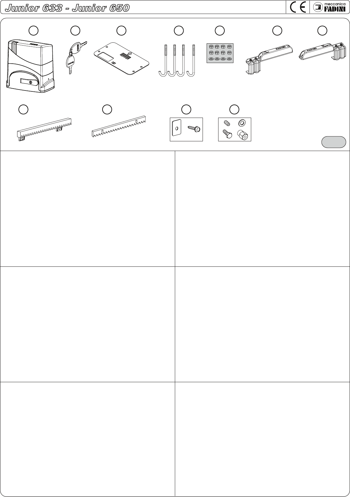
Componenti principali per una installazione del Junior 633/Junior 650 in fig.1
1 - Motoriduttore scorrevole elettromeccanico serie Junior completo di
programmatore
2 - n° 2 chiavi cifrate per lo sblocco manuale
3 - Piastra di fondazione
4 - n° 4 Tirafondi di fissaggio
5 - n° 8 dadi esagonali M10 + rondelle
6 - Staffa Sx per finecorsa magnetico
7 - Staffa Dx per finecorsa magnetico
8 - cod. 2060 Cremagliera in nylon (non in dotazione nel kit)
9 - cod. 204 Cremagliera 30x8 (non in dotazione nel kit)
10 - cod. 2062 n° 30 pz Viti autofilettanti con rondelle quadre per cremagliera in
nylon (non in dotazione nel kit)
11 - cod. 208 n° 30 pz Distanziali e bulloni di fissaggio (non in dotazione nel kit)
GB
Main components for installation of the Junior 633/Junior 650 in fig.1
1- Junior series sliding electro-mechanical operator
complete with programmer
2 - n° 2 coded keys for manual unlocking
3 - Base plate
4 - n° 4 Anchor bolts
5 - n° 8 M 10 hexagonal nuts+washers
6 - LH magnet bracket for limit switch
7 - RH magnet bracket for limit switch
8 - code 2060 nylon gear rack (not supplied in the kit)
9 - code 204 30x8 gear rack (not supplied in the kit)
10 - code 2062 n° 30 pcs. Self-threading screws with square washer for nylon
gear rack (not supplied in the kit)
11 - code 208 n° 30 pcs. Washers and fixing bolts (not supplied in the kit)
F
Eléments principaux pour l’installation du Junior 633/Junior 650 (fig.1)
1- Motoréducteur coulissant électromécanique série Junior avec
programmateur
2 - n. 2 clés chiffrées pour le déverrouillage manuel
3 - Plaque de fondation
4 - n. 4 Crosses filetées de fixation
5 - n. 8 écrous hexagonaux M10 + rondelles
6 - Etrier Gauche pour fin de course magnétique
7 - Etrier Droit pour fin de course magnétique
8 - code 2060 Crémaillère en nylon (pas comprise dans le kit)
9 - code 204 Crémaillère 30x8 (pas comprise dans le kit)
10 - code 2062 n.30 pièces Vis autotaraudeuses avec rondelles carrées pour
crémaillère en nylon (pas comprises dans le kit)
11 - code 208 n.30 pièces entretoises et boulons de fixation (pas compris dans le kit)
E
Componentes principales para una instalación del Junior 633/Junior 650 en la Fig.1
1- Motorreductor deslizante electromecánico serie Junior con programador
2 - n° 2 llaves cifradas para el desbloqueo manual
3 - Placas de anclaje
4 - n° 4 Tirafondos de fijación
5 - n° 8 tuercas hexagonales M10 + arandelas
6 - Estrilo izquierda para tope de recorrido magnético
7 - Estrilo derecha para tope de recorrido magnético
8 - cod. 2060 Cremallera de nylon (no en dotación en el kit)
9 - cod. 204 Cremallera 30x8 (no en dotación en el kit)
10 - cod. 2062 n° 30 pz Tornillos autorroscantes con arandelas cuadradas para
cremallera de nylon (no en dotación en el kit)
11 - cod. 208 n° 30 pz Distanciadores y pernos de fijación (no en dotación en el kit)
NL
Hoofdcomponenten voor de installatie van Junior 633/Junior 650 van fig.1
1- Reductiemotor elektromechanisch schuifhek Junior serie voorzien van een
programmeerinrichting
2 - nr. 2 gecodeerde sleutels voor de handmatige ontgrendeling
3 - Grondplaat
4 - nr. 4 Ankerbouten
5 - nr. 8 Zeshoekige moeren M10 + ringen
6 - Stijgbeugel L voor magnetische eindslag
7 - Stijgbeugel R voor magnetische eindslag
8 - code 2060 Nylon tandheugel (maakt geen deel uit van de kit)
9 - code 204 Tandheugel 30x8 (maakt geen deel uit van de kit)
10 - code 2062 nr. 30 Zelfborgende schroeven met vierrand plaatje voor nylon
tandheugel (maakt geen deel uit van de kit)
11 - code 208 nr. 30 Opvulringen en borgbouten (maakt geen deel uit van de kit)
D
Grundlegende Bauteile zur Installation von Junior 633/Junior 650 in Abb.1
1 - Elektromechanischer Schiebetorantrieb Junior mit Steuerung
2 - 2 codierte Schlüssel zur manuellen Entriegelung
3 - Verankerungsplatte
4 - 4 Verankerungsbolzen
5 - 8 Sechskantmuttern M10 + Scheiben
6 - Linker Magnetbügel für Endschalter
7 - Rechter Magnetbügel für Endschalter
8 - Art.-Nr. 2060 Zahnstange aus Nylon (nicht im Lieferumfang enthalten)
9 - Art.-Nr. 204 Zahnstange 30x8 (nicht im Lieferumfang enthalten)
10 - Art.-Nr. 2062 30 selbstschneidende Schrauben mit rechteckigen Unterleg-
scheiben für Zahnstange aus Nylon (nicht im Lieferumfang enthalten)
11 - Art.-Nr.208 30 Distanzstücke und Sperrbolzen (nicht im Lieferumfang
enthalten)
1m 1m
pag. 3
Fig. 2
A
B
C
D
Q
B
I
R
E
F
G
H
I
L
M
N
O
P
S
T
E
F
G
H
I
L
M
N
U
P
Q
R
S
T
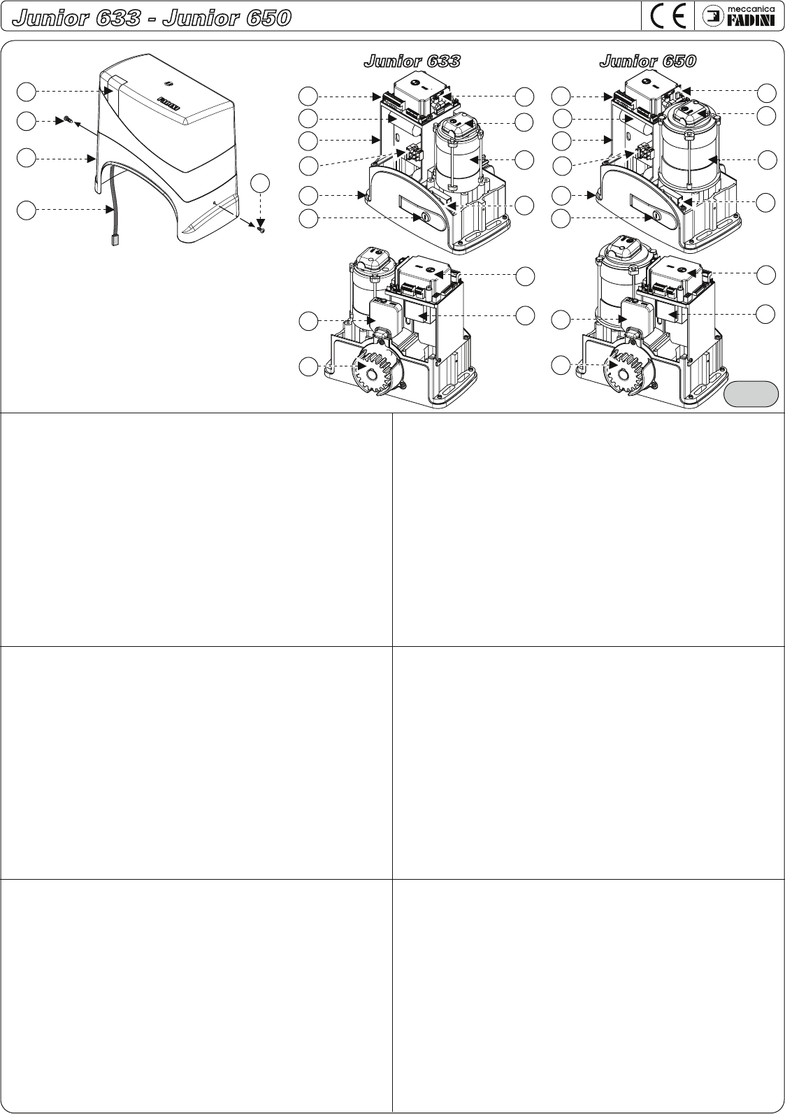
Distinta dei componenti principali di fig.2:
A - Luce a led blu e ambra di segnalazione dello stato dell’automazione
B - Viti di fissaggio cofano
C - Cofano di copertura
D - Cavo alimentazione led
E - Programmatore Elpro 63 per Junior 633 e Junior 650
F - Condensatore 12,5µF
G - Supporto programmatore
H - Morsetto ingresso alimentazione 230V con fusibile estraibile
I - Carcassa motoridutore serie Junior
L - Maniglia di sblocco manuale con chiave cifrata
M - Radio innesto
N - Encoder
O - Motore elettrico 230V - 0,33CV
P - Micro di stacco tensione alla maniglia di sblocco
Q - Finecorsa magnetico
R - Pignone m4 Z18
S - Coperchio programmatore
T - Trasformatore 230V - 24V - 20VA per Junior 633 e Junior 650
U - Motore elettrico 230V - 0,5CV
GB Main component list in fig. 2:
A - Led light, blue and amber colours, for automation status indication
B - Casing fixing screws
C - Casing
D - LED power supply cable
E - Elpro 63 programmer for Junior 633 and Junior 650
F - Condenser 12.5µF
G - Programmer support
H - 230V input power supply terminals with removable fuse
I - Junior series gear box
L - Manual unlock handle with coded key
M - Plug-in radio receiver
N - Encoder
U - Electrical Motor 230V - 0.33 HP
P - Electrical power disconnection microswitch for the unlocking handle
Q - Magnetic limit switch
R - m4 Z18 pinion
S - Programmer cover
T - 230V - 24V - 20VA Transformer for Junior 633 and Junior 650
U - Electrical motor 230V - 0.5 HP
FComposants principaux (fig.2):
A - Voyant à led bleue et ambre pour la signalisation de l’état de l’automation
B - Vis de fixation du coffre
C - Coffre de couverture
D - Câble d’alimentation led
E - Programmateur Elpro 63 pour Junior 633 et Junior 650
F - Condensateur 12,5µF
G - Support du programmateur
H - Borne d’entrée alimentation 230V avec fusible amovible
I - Boîtier du motoréducteur série Junior
L - Levier de déverrouillage manuel avec clé chiffrée
M - Carte récepteur radio enfichable
N - Encoder
O - Moteur électrique 230V - 0,33CV
P - Micro de coupure tension sur le levier de déverrouillage
Q - Fin de course magnétique
R - Pignon m4 Z18
S - Couvercle du programmateur
T - Transformateur 230V-24V-20VA pour Junior 633 et Junior 650
U - Moteur électrique 230V – 0,5CV
DÜbersicht der grundlegenden Bauteile in Abb.2:
A - Blau-gelbe Led-Signalleuchte zur Anzeige des Anlagenstatus
B - Befestigungsschrauben am Gehäuse
C - Gehäuse
D - Led-Versorgungskabel
E - Steuerung Elpro 63 für Junior 633/Junior 650
F - Kondensator 12,5 µF
G - Halterung der Steuerung
H - Versorgungs-Eingangklemme 230 V mit herausnehmbarer Sicherung
I - Gehäuse Getriebemotor Serie Junior
L - Manueller Entriegelungsgriff mit codiertem Schlüssel
M - Einsteckempfänger
N - Encoder
O - Elektromotor 24Vdc
P - Mikro-Trennschalter am Entriegelungsgriff
Q - Magnetischer Endschalter
R - Zahnrad m4 Z18
S - Abdeckung der Steuerung
T - Transformator 230V-24V 20VA für Junior 633/Junior 650
U - Elektromotor 230 V - 0,5 PS
ELista de los componentes principales ilustrados en la Fig.2:
A - Luz de led azul y ámbar de señalización del estado de la automatización
B - Tornillos de fijación capó
C - Capó de cobertura
D - Cable de alimentación led
E - Programador Elpro 63 para Junior 633 y Junior 650
F - Condensador 12,5µF
G - Soporte programador
H - Borne entrada alimentación 230V con fusible extraíble
I - Carcasa motorreductor serie Junior
L - Manilla de desbloqueo manual con llave cifrada
M - Radio enchufable
N - Codificador
O - Motor eléctrico 230V - 0,33CV
P - Microinterruptor de corte tensión a la manilla de desbloqueo
Q - Tope de recorrido magnético
R - Piñón m4 Z18
S - Tapa programador
T - Transformador 230V - 24V - 20VA para Junior 633 y Junior 650
U - Motor eléctrico 230V - 0,5CV
NL Lijst met hoofdcomponenten van fig.2:
A - Blauwe en gele Led signalering voor de staat van de automatisering
B - Borgschroeven kap
C - Deksel kap
D - Voedingskabel led
E - Elpro 63 programmeerinrichting voor Junior 633 en Junior 650
F - Condensator 12,5µF
G - Steun programmeerinrichting
H - Ingangklem voeding 230V met verwijderbare zekering
I - Behuizing reductiemotor Junior serie
L - Handmatige ontgrendelhendel met gecodeerde sleutel
M - Aansluitpunt radio
N - Encoder
O - Elektromotor 230V – 0,33PK
P - Micro voor onderbreking spanning naar ontgrendelhendel
Q - Magnetische eindslag
R - Tandwiel m4 Z18
S - Deksel programmeerinrichting
T - Transformator 230V – 24V -20VA voor Junior 633 en Junior 650
U - Elektromotor 230V – 0,5PK
pag. 5
Fig. 5 Fig. 6
60mm
Fig. 7 Fig. 8
60mm
60mm
60mm
pag. 6
Fig. 9
Fig. 10
96mm
96mm
60mm
96mm
60mm
2mm
96mm
60mm
96mm
60mm
2mm
22x8
Ø 6,5
M8
96mm
pag. 7
Fig. 11
Fig. 12
1°
2°
3°
1°
2°
3°
Fig. 13
pag. 8
Fig. 14
1° 2° 3°
Fig. 15
Fig. 16
1° 2° 3°
SX
LEFT
GAUCHE
LINKS
IZQUIERDA
LINKS
DX
RIGHT
DROIT
RECHTS
DERECHA
RECHTS
I - Finecorsa magnetico
GB - Magnetic limit switch
F - Fin de course magnétique
D - Magnetischer Endschalter
E - Final de carrera magnético
NL - Magnetische eindslag
SX
LEFT
GAUCHE
LINKS
IZQUIERDA
LINKS
I - Finecorsa meccanico
GB - Mechanical limit switch
F - Fin de course mécanique
D - Mechanischer Endschalter
E - Final de carrera mecánico
NL - Mechanische eindslag
16
45 3
pag 17
Junior 633 - Junior 650
meccanica
FADINI
Elpro 63
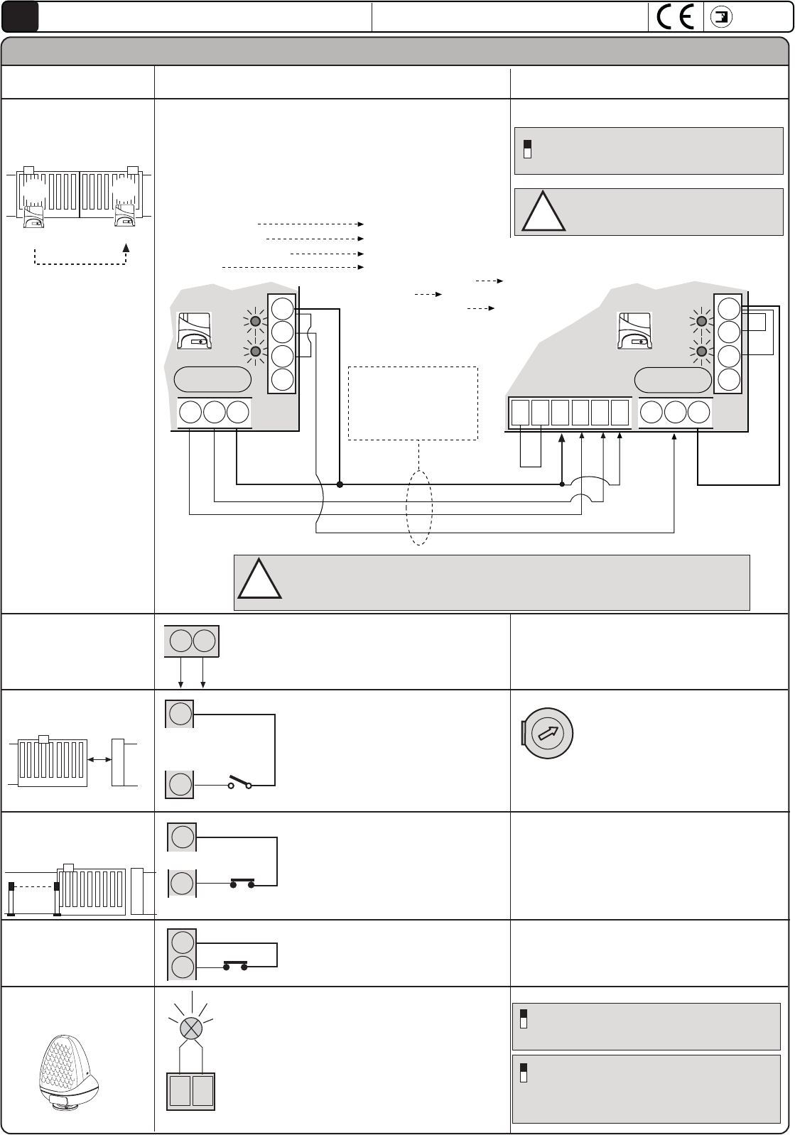
GB
PLEASE NOTE. The LEDs shown here
are in their normal operational status
for correct ELPRO 62 PCB
LED ON
LED OFF
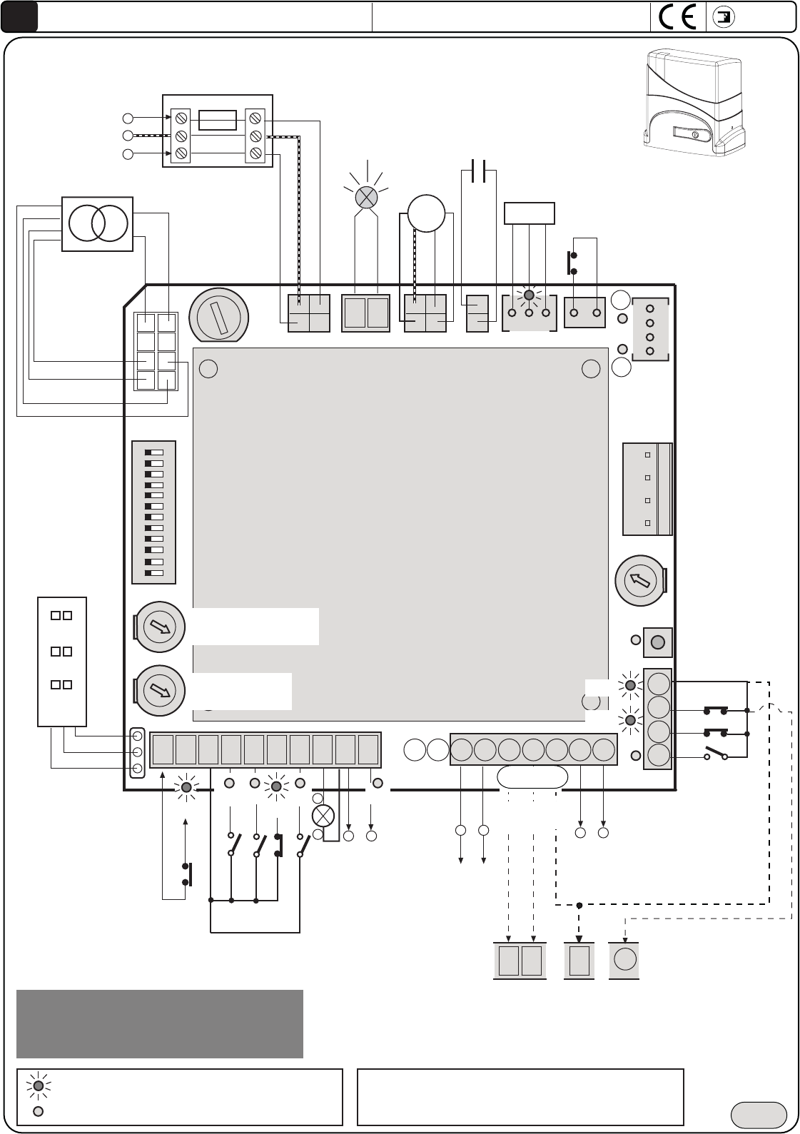
Fig. 17
NOTE: all of the possible connections at the programmer
terminal boards are also illustrated in the respective instruction
sheets for each individual accessory.
12345678910 13 14 18 19
NC
15 16 1711 12
20 21 22 23
-
+Trimmer
Force
Pulse of
programming
STOP
COMON
OPEN
CLOSE
NC
photocell
coast
RADIO CONTAC
Light 24V - 1W
+-
OUTPUT
230V-25W for
flasher
-
+
Relay Output
courtesy lamp
max
24V 50mA
LP
NC
Unlock handle
switch
L20
L2
L4 L5 L6 L7 L10
Condenser
12,5µF
230V
Transformer
F1= 630mA
Transformer
Radio
contact
LED card
cover
Elpro 63
for Junior 633
and Junior 650
230V
5A
Terminal with
fuse
Output for 2°
sliding leaf
OPEN
CLOSE
Common
123456789101112
clutch limit
switch
Y
X
0V
12V
24V
20V
24 25
COMMON
Junior 633 - 0,33CV
Junior 650 - 0,5CV
-
+
Trimmer Pause
da 1s - 120s
-
+
Dip-Switch
Encoder
M
commo
n
NC
Pedestrian
L22
L21
Elpro 63 SLAVE terminal for
2° sliding
Dip- Switch 12= ON
AP
CH
C
Auxiliary
for 2° Junior
Trimmer Pedestrian
max 3m
External Electrical
power supply 230V
50Hz ±10%
for superior distances
the 50m to increase
the section wires
Output 24V cc/ca for
photocell TX set up for
DSA control
-
+
24V OUTPUT for max load 500mA:
n°2 pairs of photocelles
n°1 Radio receiver
n°1 Led selector Chis 37 and Chis E37
ATTENTION: USING ACCESSORIES THAT
ARE NOT FADINI MAY RESULT INTO
DAMAGES TO THE BOARD: ALWAYS USE
CLEAN CONTACTS FOR THE NO-NC INPUTS
pag 18
ATTENTION !! The installation of this product must be performed by professionally trained and qualified personnel according to the safety regulations
in force.
It is important to carefully read and follow the instructions so as to avoid a faulty use of the same product. The ELPRO 63 electronic programmer
was conceived and manufactured for the management of the electromechanical Junior 633 and Junior 650 sliding gate openers with 230 V motors
Any other use different from that specified in this instruction booklet is to be considered prohibited.
ATTENTION !! The Meccanica Fadini Company declines any and all responsibility for ensuing damages to things and/or persons due to any faulty
installation or the lack of bringing the system up to code according to the laws and regulations in force. The application of the Machine Directive
98/37/EEC is required.
All of the maintenance and/or test operations of the status of the product must be performed by professionally trained and qualified personnel.
ATTENTION !! Important: before carrying out any procedure on the PCB card, disconnect the electrical power supply mains.
It is furthermore recommended that the booklet "Safety Regulations" made available by Meccanica Fadini be examined thoroughly.
General Description: The Elpro 63 is a PCB card with microprocessor for the command and management of the Junior 633 and Junior 650 sliding
gate openers with programming for self-learning of the different movement phases of the gate.
Power Supply 230V 50Hz±10% mono phase. Corresponding to the BT 73/23/CEE - 93/68/EEC safety regulations for low voltage and the EMC 89/336/EEC
- 92/31/EEC Electromagnetic Compatibility Regulations.
Logic operation: given the Open command impulse, it performs the function for open-pause-close in automatic or semi-automatic with programmable
slow down, possibility of step by step radio command, radio no reverse on opening, with or without pre-flashing, exclusion of closing slow down,
reverse run upon contact with an obstacle and LED diagnostics, Dipswitch definition of the Right-Hand and Left-Hand installations, Blue/Amber lamp
on the casing cover for the signalling of the gate opener status.
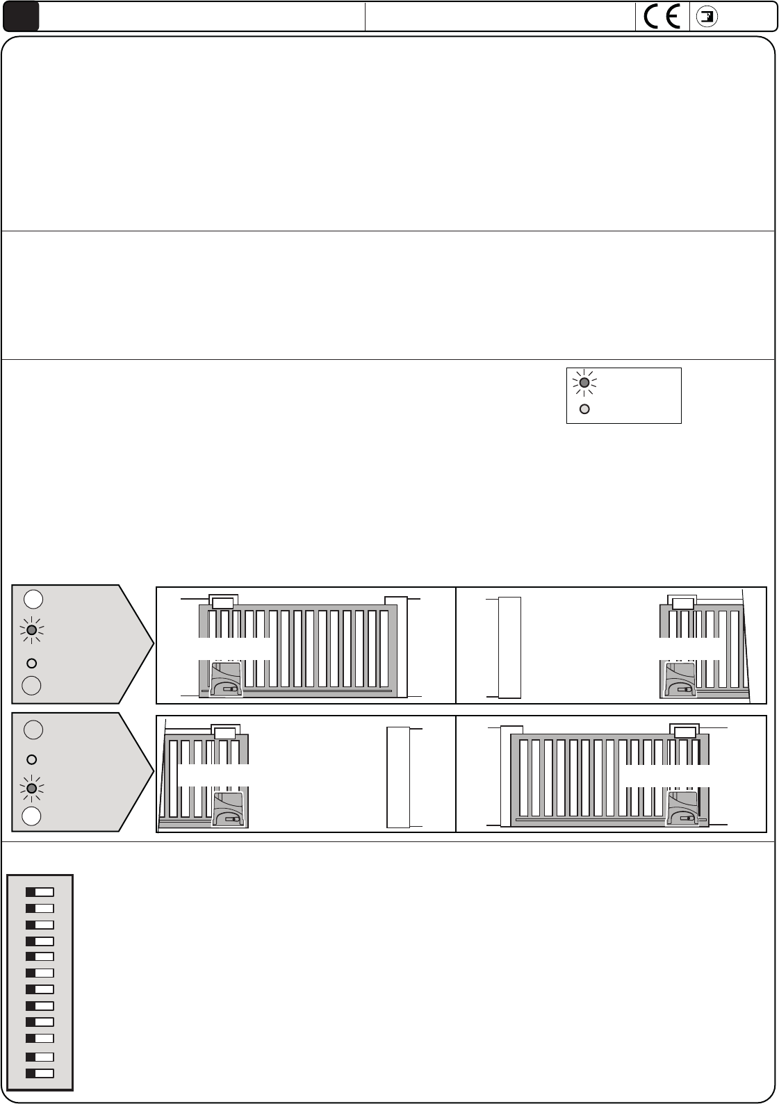
DIP-SWITCH: enables the performance of all of the possible functions of the Junior 633 and Junior 650 sliding gate openers
LED off
LED on
123456789101112
ONOFF
meccanica
FADINI
Elpro 63
GB
1 = OFF : Photocell not stopped in opening
2 = OFF: Radio in opening stops and reverses
3 = OFF:Semiautomatic operation
4 = OFF:Without pre-reflashing before opening
5 = OFF:Radio reverses direction on every impulse
6 = OFF:Slowdowns ( to be programmed)
7 = OFF: Activates "Reverse": reversed the running upon contact
8 = OFF:Flasher on in pause
9 = OFF:No closing after passage by the photocell
10 = OFF:No DSA cotrol on the phtocells
11 = OFF:Junior 633/ Junior 650 installed on the left
12 =OFF:Single Elpro 63, or the 1st Junior 633/650 MASTER
ON:Photocell stopped in opening
ON:Radio does not reverse ( and does not stop) in opening
ON:Close in automatic after pause time
ON:Pre-flashing before opening
ON:Radio switch: open-stop-close-stop
ON: Eliminates Slowdowns
ON:No reverse direction on contact
ON:Flasher off in pause
ON:Closing after passage by the photocell
ON: Check DSA Photocell before start up
ON: Junior 633/ Junior 650 installed on the right
ON: Elpro 63 SLAVE of the 2nd Junior 633/Junior 650
Junior 633 - Junior 650
DIAGNOSTIC LED: LED status during proper operation of the system
L2 (on)= Photocells, turns off with obstacle present
L4 (off)= Open, lights up with the opening command impulse
L5 (on)= Close, lights up with the opening command impulse
L6 (on)= Stop, goes off with the stop command impulse
L7 (off)= Radio, lights up with each transmitter impulse
L10 (off)= Light up in case of short 24 Vcc. Light off when take off the short
L20 (off)= Pedestrian, lights up with the open for pedestrian switch
L21 (on)= Photocell in open, turn off with present obstacle
L22 (on)= Enter of 2° Junior
LP (off) = Led of program, light on in phase of programming
X = led limit switch, always light on during the movement
Y = led limit switch, always light on during the movement
Junior LEFT Junior RIGHT
X
Y
LED X on
LED Y on
X
Y
Junior LEFT Junior RIGHT
pag 19
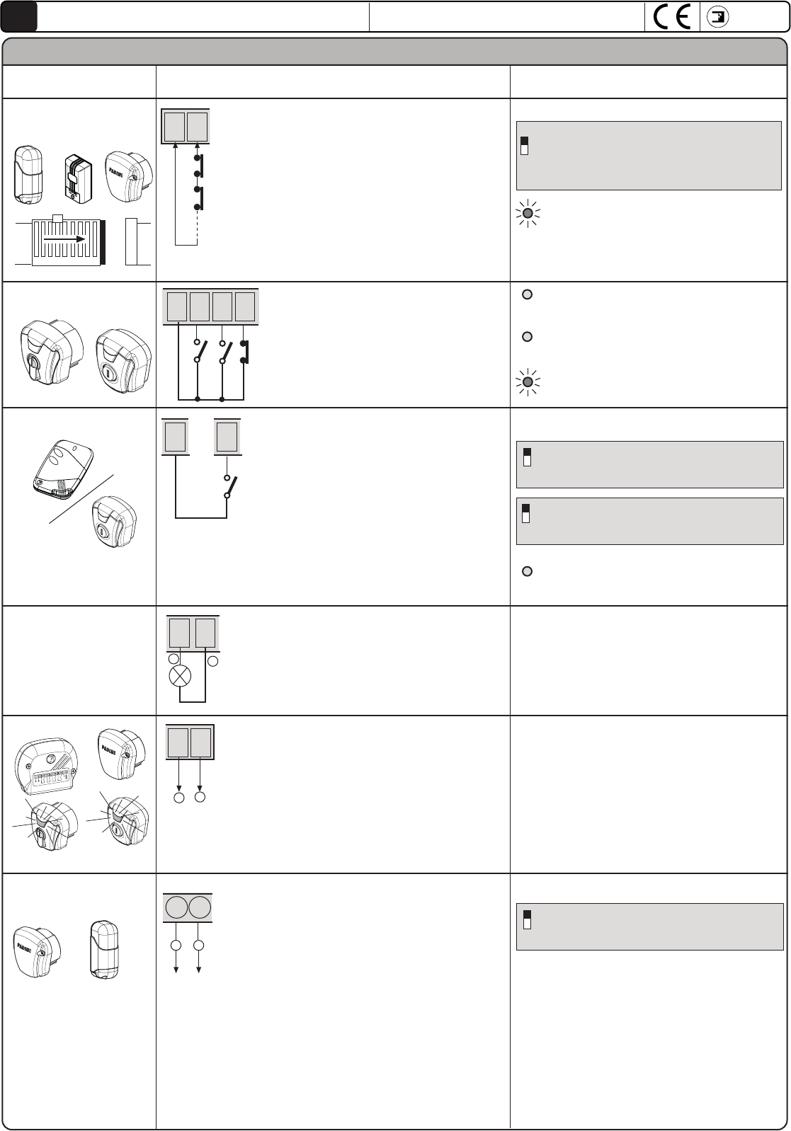
Keyed selector:
Photocells and
safety edges:
1
DIP-SWITCH 1:
ON: stopped in opening and inverts in
closing or with obstacle removed
OFF: not stopped in opening and inverts in
closing or in presence of obstacle
Output for a possible automation status warning lamp
Warning Lamp On = Gate Open
Warning Lamp Off = Gate Closed
Flashing at 0.5s (rapid)= closing movement
Flashing at 1s (normal)= opening movement
Flashing at 2s (slow)= automation stopped
24V- 1W Warning
Lamp Output:
Radio contact: connecting any contact NA between the two
terminals one may obtain upon each impulse:
- Only opening: Dip 2=ON e Dip 5=OFF
- Reverse direction on each impulse
Dip 2=OFF e Dip 5=OFF
- Step by step: Open-Stop-Close-Stop
Dip 2=OFF e Dip 5=ON
ON: does not reverse and does not stop in opening
OFF: In oopening always stops and inverts
2
ON: Step by step with intermediate stop
OFF: Reverses direction on every impulse contemporaneously ON
5
DIP-SWITCH 2 e 5 (MUST NOT ever be ON at
the same time):
All of the NC contacts for the safety
accessories such as photocells (receivers)
and edges must be connected in series to
terminals 1 and 2.
ELECTRICAL CONNECTIONS TO THE TERMINALS AND THEIR FUNCTIONS
Accessory Electrical connctions Dip - Switch and LED signals for the different function
NO and NC contacts to be connected to their
respective terminal boards or button panels.
All of the possible configurations are attached
to their respective command accessories
FADINI
Output 24V:
FADINI
FADINI
Astro 43
FADINI
NC
NC
12
3456
NC
OPEN
CLOSE
STOP
COMMON
RADIO
CONTACT
COMMON
3 7
109
+-
OUTPUT 24V for max load:
2 pairs of photocells
1 Radio receiver
1 LED selector Chis 37 / Chis E37
All of the instructions are attached to their
respective command accessories
L2 ON= No obstacle present, it turns off off
with obstacle present
L4 OFF= no contact open, it lights up with
each opening impulse
L5 OFF= no contact close, it lights up with
each closing impulse
L6 ON= STOP contact closed, goes on at
each stop contact
L7 OFF= no contact radio, it lights up with
each radio contact impulse
FADINI
FADINI
13 14
-
+
Output 24V cc/ca
for DSA control:
24V Output to power the photocell transmitters
(connected in parallel) for the DSA Control:
Autotest Safety Device = before each movement of
the gate, if this function is enabled, there is check of
all of the safety devices because they are free, in the
event that this is not so, the gate will not start up.
ON:DSA control of the photocells
OFF: No DSA control on the photocells
10
DIP-SWITCH 10
TX
FADINI
TX
meccanica
FADINI
Elpro 63
GB
Junior 633 - Junior 650
8 9
-+
pag 20
Accessorio Collegamenti elettrici Dip - Switch e segnalazione LED delle varie funzioni
ELECTRICAL CONNECTIONS TO THE TERMINALS AND THEIR FUNCTIONS
Collegamenti per n°2
scorrevoli Junior 633
- Junior 650
It is important to determine which Elpro 63 MASTER will command
and control the Elpro 63 SLAVE
All of the accessories for command, signalling and safety must
be connected to the terminals of the Elpro 63 MASTER
Relay output
courtesy lamp max 24V 50mA
Output for courtesy
lamp relay max 24V
50mA
18 19
2
1
Pedestrian
Common
Input pedestrian
20 23
-
+
Master Slave
12
ON: Elpro 63 SLAVE (2° Junior 633 - 650)
OFF: Elpro 63 MASTER (1° Junior 633 - 650
DIP-SWITCH 12:
n°4 x 1
eseguire i seguenti collegamenti:
Elpro 63 MASTER Elpro 63 SLAVE
Dip-Switch 12=OFF: Dip-Switch 12=ON:
terminal 15 (open) terminal 4 (open)
terminal 16 (close) terminal 5 (close)
terminal 17-23 (common) terminal 3 (common)
terminal 22 terminal 16 (close)
terminal 17 (common) 23
terminal 1 2
terminal 3(common) 6 (stop)
!
meccanica
FADINI
Elpro 63
GB
Junior 633 - Junior 650
Photocelles opening
Input
NC
Common
2321
Input NC for photocel installed in the
opening of the gate: in case of di
obstacle is detected during the opening,
reverses the direction for 20cm about
freeing the obstacle, then blocks waiting
for a command.
NC input contact 2°
Junior
2322
NC
Common
Pedestrian Trimmer: the opening
distance of the gate up to 3 metres is
adjusted for the pedestrian opening
OUTPUT230V max 25W for flasher
Flasher 230V
max 25W
DIP-SWITCH 4 e 8
ON: Preflashing before opening
OFF: without preflashing
4
ON: Flasher deactivated during pause in
automatic operation (with Dip 3= ON)
OFF: LFlasher during pause in automatic
operation (withDip 3= ON)
8
FADINI
l'apricancello
24 25
Entrance NA for external contact per
pedestrian opening
NC contact for connexion at 2° Junior
Refer to the previous pages for the
Dip-switch composition relative to the
individual accessories and functions.
A 4-wire cable is
necessary for the
connection between the
two Elpro 63
programmers
!
PROGRAMME JUNIOR MASTER AND SLAVE SEPARATELY ONCE THE ELECTRICAL
CONNECTIONS HAVE BEEN MADE AND THE DIP-SWITCHES SET CORRECTLY
OPEN
CLOSE
15 16 17
Master
COMMON
AP
CH
C
20 21 22 23
20 21 22 23
AP
CH
C
Slave
15 16 17
3
17
23
453 621
STOP
L22
L21
L22
L21
pag 21
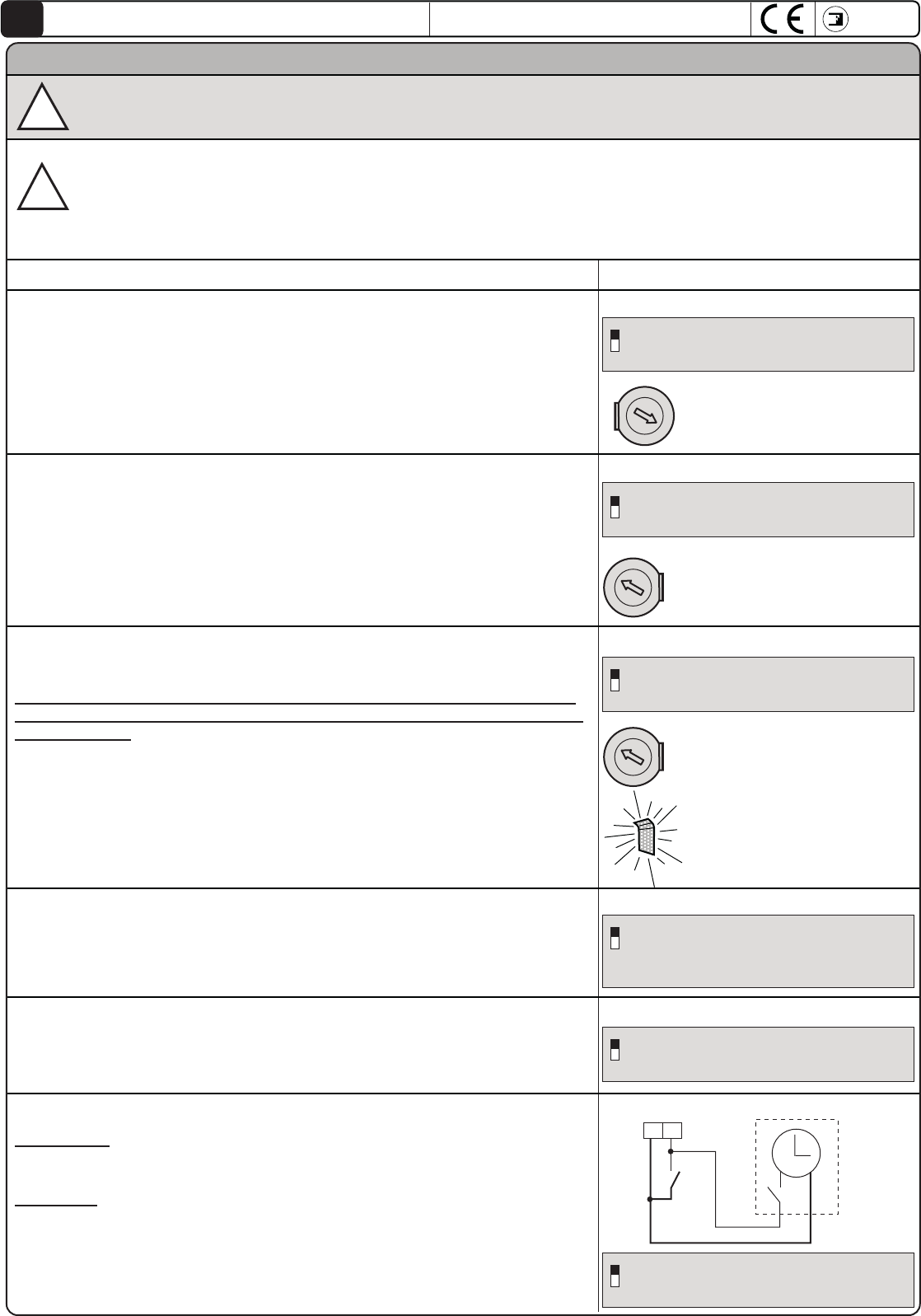
Automatic / Semiautomatic:
43
COMUNE
COMUNE
APRE
NA
External clock
Opening by way of an external clock:
Connection: connect the NO contact of the Clock with terminal 4 OPEN and
terminal 3 COMMON in parallel, enabling the automatic closing with the Dipswitch
3=ON
Operation: program the opening time on the clock, at the time set the gate
will open and remain open (the flasher goes off) and it will not accept other
commands (not even radio) until the time that has been set on the clock runs
out. Once that time has expired, after the pause time, the automatic closing
will follow.
Automatic cycle: upon open command impulse, the gate opens, stops in
pause for the time set in the Pause Trimmer, which, once passed will reclose
automatically
Semiautomatic Cycle: with an open command impulse the gate moves to
opening. To close the passage it is necessary to give the close command
Dip - Switch and LED signalling of the different functions
-
+
Pause Trimmer: the pause time in the
automatic mode is adjusted to 120s
3
ON: Close in automatic
OFF: Semiautomatic
DIP-SWITCH 3:
Slowdowns:
During programming it is recommended that the positions of initiate slow down
in opening and in closing be set. Afterwards, these may be removed or
recovered by way of the 6 Dipswitch.
The speed of the final run slowdown of the gate is calibrated at the factory,
while the torque is proportional to the force exerted by the Junior operator by
way of the Force Trimmer Trimmer Force: adjust the torque applied
on the gate
6
ON: Eliminates slowdowns
OFF: Activates slowdowns programm
DIP-SWITCH 6:
Desction
Force Trimmer: adjusts the torque applied
on the gate.
Beyond 3/4 of the adjustment it is possible
to obtain a greater force, which does
not enable the gate to detect an
obstacle.
7OFF: Attiva la rilevazione degli ostacoli
ON: Nessuna rilevazione all'urto dell'ostacolo
DIP-SWITCH 7:
Closing after passage by the pair of photocells:
This Function enables the automatic closing the passage through the pair of
photocells after 3 seconds. 9
ON: Enables the automatic closing after the
passage through the pairs of photocells
OFF: No automatic closing
DIP-SWITCH 9:
Check photocells before start up:
This Function enables the check of the safety devices such as the photocells
before starting up the movement of the gate.
10
ON: Enables the check of the safety devices
OFF: Deactivates the check of the safety devices
DIP-SWITCH 10:
3
ON: Closes in automatic
ATTENTION: each variation or action on the Dipswitches for the functions, at any time, will be executed at the moment
of the next opening or closing command!
!
Reverse direction upon contact with an obstacle:
This Function enables the inversion of the movement upon contact with an
obstacle.
If this function is active, upon contact with an obstacle the cover casing LED
turns AMBER for a complete cycle of opening and closing after the detection
of the obstacle.
- Opening phase: the function reverses the direction for 10 cm freeing the
obstacle
- Closing phase: the function reverses the direction up to the limit switch
The sensitivity of the function is proportional to the force exerted by the Junior
by way of the Force Trimmer
PLEASE NOTE. If the gate detects an obstacle 5 consecutive times during a
complete open - stop - close cycle, the gate will remain open and the lamp
will flash with a Blue light
-
+
-
+
ADJUSTMENT OF STRENGTH:
The adjustment of the Force by the Trimmer must be necessary to move the gate. This adjustment also determines the
strength and impact resistance slowing down with an obstacle. A force too high inertia of the gate leads to incorrect
installation according to safety standards EN 12445 and EN 12453
Therefore, it requires the installer once adjusted the force applied to the gate operator to check the forces in play as
determined by the regulations EN12445 and EN12453 documented in the manual "Safety Standards" that the manufacturer
provides
!
meccanica
FADINI
Elpro 63
Junior 633 - Junior 650
GB
FUNCTIONS: DESCRIPTION OF THE FUNCTIONS OF THE JUNIOR 624 SLIDING OPERATOR
pag 22
!
==
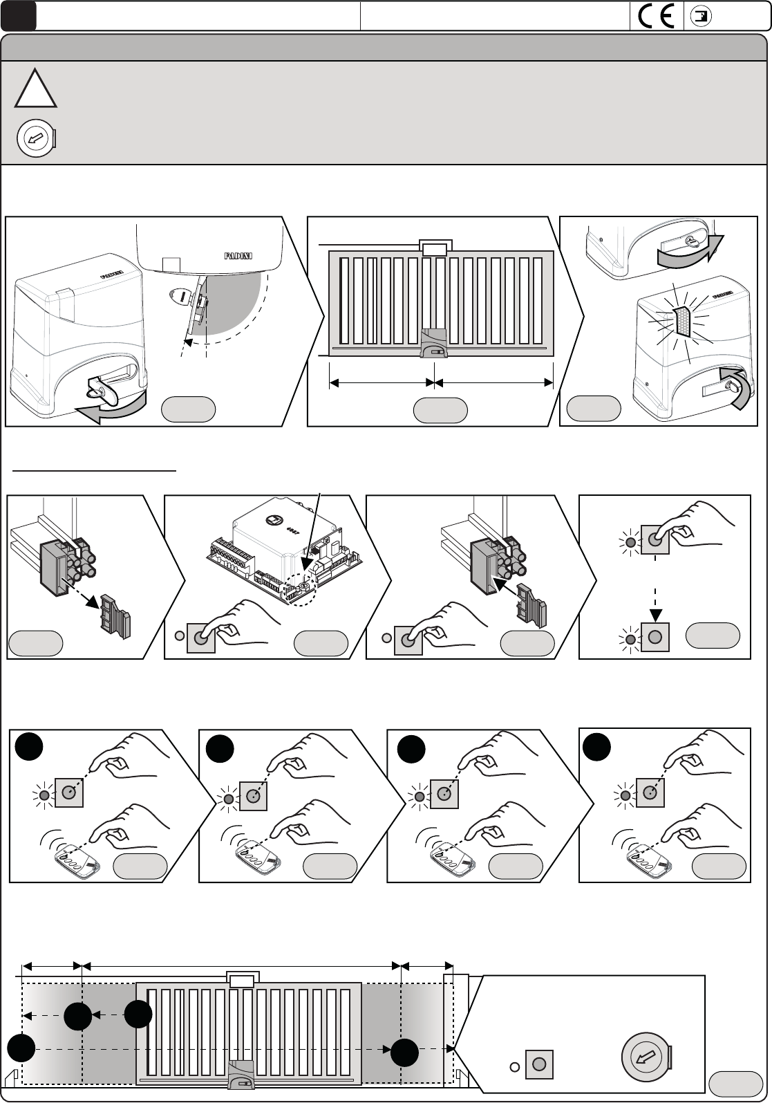
PROGRAMMING AND SELF-LEARNING OF THE OPERATION
1st Operation: unlock the unlocking handle lever with the coded key and pull it out the until it stops (beyond 90°) freeing the gate from
the Junior operator; then position the gate at about half of its course. Return the lock by closing the handle lever
As a safety measure, when the unlocking handle is freed, the electrical power supply to the Elpro 63 PCB is disconnected.
2nd Operation: Remove the electrical power supply to the electronic PCB by completely extracting the 230 V line fuse from its seat, found on the front,
underneath the Elpro 63 PCB.
Push and hold down the P button and then afterwards install the line fuse. After 2-3 seconds release the P button: the LP LED will begin to flash signalling
the programming phase
+90°
LP LP
3rd Operation: learning of the run pattern and the slowdowns
It is possible to perform programming with the dedicated P button or else with an impulse form the coded remote control transmitter.
It is important that both end stops, for opening and closing, are installed. Position the magnetic or mechanical limit switches in
correspondence with the final opening and closing positions for the magnetic detector or the Junior feeler.
Push for an impulse: The Junior operator
will begin to move in opening
LP
Beginning of the slowdown
Push for an impulse: The Junior
will begin to slow down until the
limit switch is detected
Push for an impulse: The Junior
will begin to move the gate in
closing
Beginning of the slowdown
Push for an impulse: The Junior will
begin to slow down until the limit
switch is detected
3.1
3.2
3.3 3.4
3.2 3.3 3.4
FADINI
normal speed
slowdown slowdown
Fig. 18 Fig. 19 Fig. 20
Fig. 21 Fig. 22 Fig. 23 Fig. 24
End of programming: adjust the
Trimmer Force necessary to move
the gate
LP LP
LP
LP
2-3 sec
LP
3.1
LP
Fig. 25 Fig. 26 Fig. 27 Fig. 28
Fig. 29
-
+
-
+
IMPORTANT: programming Junior is performed at first installation. Even in absence of mains power , programming is
stored for any changes in the position of slow programming can be performed by the same procedure.
Adjust the Trimmer Force necessary to move the gate. This adjustment also determines the strenght and impact resistance
with an obstacle in slowdown. An high force to inertia of the gate is leads to incorrect installation according to safety
regulation EN 12445 and EN 12453
meccanica
FADINI
Elpro 63
Junior 633 - Junior 650
GB
pag 23
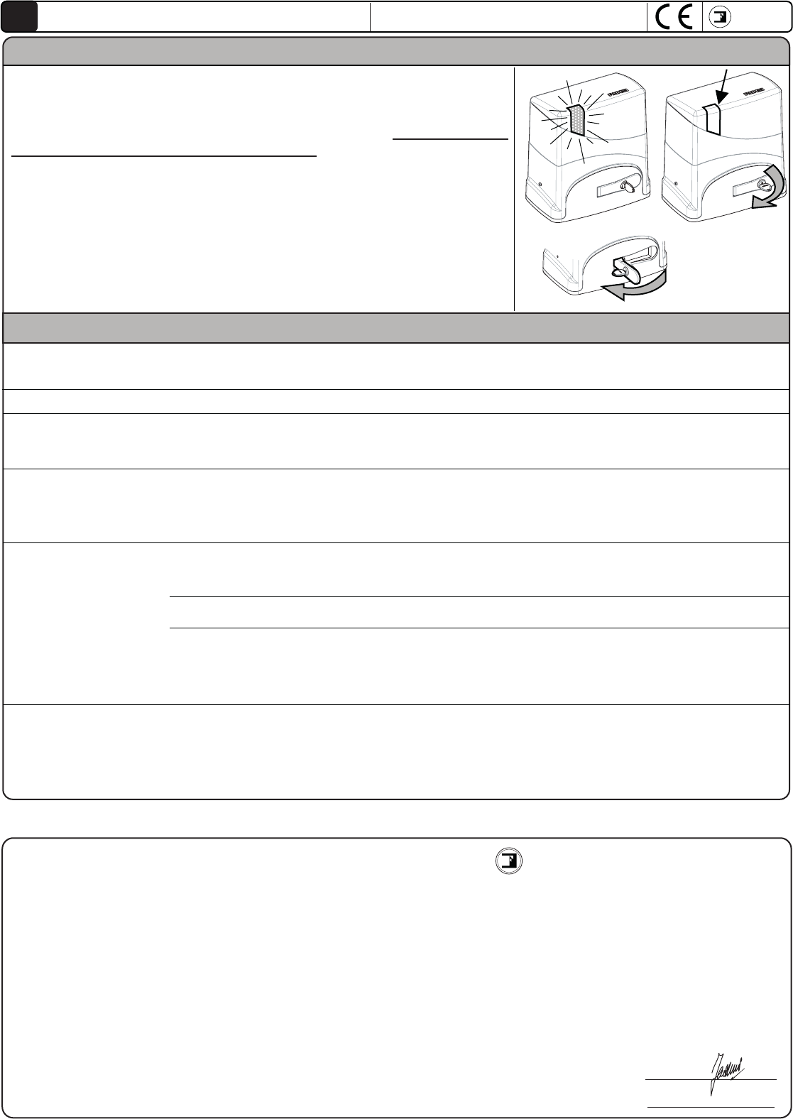
POSSIBLE MALFUNCTIONS
The LED device on the protective casing enables the installer and the end user to see if the system is actually working
properly (Blue light) or if there is some fault that does not permit proper operation (amber light).
OPENING OF THE UNLOCKING HANDLE FOR THE MANUAL OPERATION OF THE GATE
Using the unlocking handle lever with the coded key, the electrical power supply
is always disconnected from the system.
For the unlocking and later manual movement of the gate, it is necessary that
the handle be opened until it stops beyond 90°.
Upon closing and later locking of the lock, the electrical power supply is
reconnected to the mains at the PCB.
IMPORTANT: Once the electrical power supply has been disconnected using
the unlocking key, upon reconnection of the mains electrical power, the first
movement of the Junior is always toward closing at a normal operational
speed with no programmed slowdowns. To recover all of its functions (such
as slowdowns) it is necessary that a full cycle be completed all the way to
the opening limit switch.
FADINI
meccanica
FADINI
Elpro 63
GB
1) 2)
3)
Fault Causes Procedures
Led lamp off
- Check lthe line and all fuses
- Close and remove the key from
the lock
+90°
Led lamp remains
Amber
- Detects the continuous presence of an obstacle or
of possible friction during movements
- Remove the present obstacle
- Remove eventual causes of friction
on the sliding gate guides
- Operational force too low for the inertia of the gate - Increase the Trimmer Force
- Contact on photocell
- Clean the covers of photocells
- Photocells not aligned
- Batteries dead (Orbita 57)
- Pair of photocells too far apart
The gate starts to move
but then stops or
reverses direction
- - Operational force too low for the inertia of the gate
- Detects the continuous presence of an obstacle or of
possible friction during movements
- Increase the force on Trimmer
- Remove eventual causes of friction
on the sliding gate guides
Junior 633 - Junior 650
The Meccanica Fadini Company declares under its own responsibility that the models Junior 633 and Junior 650 are electromechanical gate openers
conceived for being sold and installed in "automated systems" with original accessories and components indicated by the Manufacturing Firm.
The installer must leave a personal Declaration of Conformity and to perform all necessary tests so as to make the system compliant with the regulations.
The manufacturing firm assumes no responsibility for the improper use of the product.
The product has been deemed compliant with the following specific regulations:
- Risk Analysis and later elimination procedures: EN 12445 e EN 12453
- Directive machine
2006/42/CE
- Low Voltage Directive 2006/95 CE
- Electromagnetic Compatibility Directive 2004/108/CEE e 92/31 CEE
- R&TTE Directive 99/5/CE
Organism and laboratoriy notify DM 2004/108/CE:
Institure of Research and Collaudi M.Masini srl - moscova street,11 20017 Rho (MI)
Notify CE 0068 - Creditated SINCERT 047A - Creditated SINAL 0019
Conformity follow the norms: UNI EN 1324-1, UNI EN 12604, UNI EN 12605, UNI EN 12445, UNI EN 12453
Declaration of conformity of the manufacture Via Mantova 177/A - 37053 Cerea (VR) Italy
Tel. 0442 330422 Fax 0442 331054
info@fadini.net - www.fadini.net
meccanica
FADINI
Responsable
Date:
03-03-10
The gate does not move - one or more contac NC are open
- fuses burnt
- Check all NC contacts
- Check fuses state
- lack of mains electrical power supply 230V
- 5A line fuse burned
- 6,3A 24 V line fuse burned
- Unlocking handle lock not locked
Via Mantova 177/A - 37053 Cerea (VR) Italy
Tel. 0442 330422 - Fax 0442 331054
e-mail: info@fadini.net - www.fadini.net
Installer's stamp
The manufacturing firm reserves the right to modify this manualwithout notice; in addition it
it assumes no responsibility for possible errors or damages to things or persons
The development of the MECCANICA FADINI Company has always been based upon the guarantee of the quality of its products and on
the existence of a system TOTAL QUALITY CONTROL, which has guaranteed the maintenance of quality levels over time and a constant
updating of the European Regulations, in the framework of a continuous process of improvement
meccanica
FADINI
meccanica
FADINI
GB
For optimum performance of the system over time according to safety regulations, it is necessary to perform proper maintenance and monitoring
of the entire installation for the automation, the electronic equipment installed and for the cabling connected to these. The entire installation must
be carried out by qualified technical personnel, filling out the Maintenance Manual indicated in the specific Regulation Book to be requested:
- Electromechanical automation: maintenance inspection check at least every 6 months;
- Electronic equipment and safety systems: inspection check at least once every month;
-Ordinary and extraordinary maintenance must be agreed to between the principal and the maintenance firm.
- Dispose of the packaging containers, such as the cardboard, plastic sheeting, foam padding, etc., through specialised waste disposal firms.
- DO NOT DISPOSE OF TOXIC SUBSTANCES FOR THE ENVIRONMENT IN DOMESTIC WASTE DISPOSAL .
- In the event of the removal of the actuator, do not cut the electrical wires, but remove them from the terminal by loosening the set screws.
pag 24
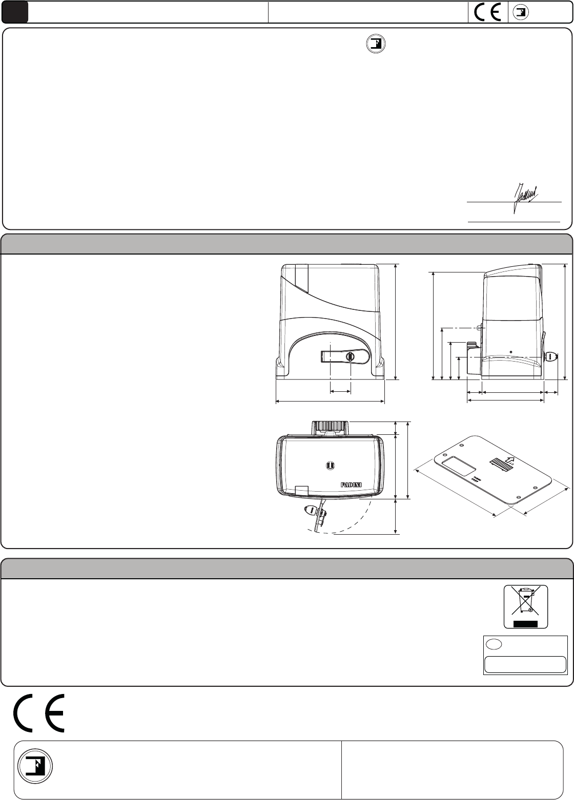
Junior 633 - Junior 650
TECHNICAL SPECIFICATIONS AND DIMENSION
316
293
140
102
62,5
40 170 38
210
290
160
95
40
170
210
296
55
316
Technical specification JUNIOR 633 JUNIOR 650
Power yield 0,25KW (0,33CV) 0,37KW (0,50CV)
Electrical power supply voltag 230V - 50Hz 230V - 50Hz
Power absorbed 400W 510W
Current absorbed 2A 2,4A
Maximum thrust force 600N 1000N
Motor revolution 1'350 rpm 1'350 rpm
Speed 10m/1' 10m/1'
Ratio 1:31 1:31
Protection Grade IP54 IP54
Lubrication
Operational Temperature -20°C +50°C -20°C +50°C
Weight 11,3Kg 13,5Kg
Service cycle: 60s open/close - 30s pause
Complete cycle time: 180s = 20 cycle/hour
The Meccanica Fadini Company declares under its own responsibility that the models Junior 633 and Junior 650 are electromechanical gate openers
conceived for being sold and installed in "automated systems" with original accessories and components indicated by the Manufacturing Firm.
The installer must leave a personal Declaration of Conformity and to perform all necessary tests so as to make the system compliant with the regulations.
The manufacturing firm assumes no responsibility for the improper use of the product.
The product has been deemed compliant with the following specific regulations:
- Analysis of Risks and successive procedures for eliminating them: EN 12445 e EN 12453
- Low Voltage directive 2006/95 CE
- Electromagnetic Compatibility Directive 2004/108/CEE e 92/31 CEE
- Directive R&TTE 99/5/CE
Organism and laboratory notify DM 2004/108/CE:
Institute of Researches and Collaudi M.Masini srl - moscova street,11 20017 Rho (MI)
Notify CE 0068 - Accreditato SINCERT 047A - Accreditato SINAL 0019
Conformity follow regulations: UNI EN 1324-1, UNI EN 12604, UNI EN 12605, UNI EN 12445, UNI EN 12453
Declaration of Conformity of the Manufacturer Via Mantova 177/A - 37053 Cerea (VR) Italy
Tel. 0442 330422 Fax 0442 331054
info@fadini.net - www.fadini.net
meccanica
FADINI
The responsable
Date:
03-03-10
ORDINARY MAINTENANCE AND DISPOSAL
Directive 2003/108/CE
Disposal of electrical and
electronic goods
Disposal of substances hazardous
for the environment is prohibited
GB

La Ditta costruttrice si riserva di apportare modifiche al presente libretto senza preavviso, inoltre non si assume nessuna
responsabilità per eventuali errori o danni a cose e persone.
The manufacturing firm reserves the right to modify this manual without notice; in addition it assumes no responsibility
for possible errors or damages to properties or persons.
Le fabricant se réserve le droit de modifier ce manuel d’instructions sans préavis et décline toute responsabilité en cas
d’erreurs et/ou dommages matériels ou personnels.
Der Hersteller behält sich vor, etwaige Änderungen an diesem Handbuch ohne Vorankündigung vorzunehmen und
übernimmt für etwaige Fehler bzw. Sach- und Personenschäden keinerlei Haftung.
El fabricante se reserva el derecho a aportar modificaciones al presente manual sin previo aviso, además no se asume
ninguna responsabilidad por posibles errores o daños a cosas y personas.
De Fabrikant behoudt zich het recht om zonder mededeling wijzigingen aan deze handleiding uit te voeren. Bovendien
acht de Fabrikant zich niet verantwoordelijk voor eventuele fouten of schade aan personen of voorwerpen.
Via Mantova, 177/A - C.P. 126 - 37053 Cerea (VR) Italy - Tel. +39 0442 330422 - Fax +39 0442 331054
e-mail: info@fadini.net - www.fadini.net
Timbro dell’Installatore
Installer’s Stamp
Cachet de l’installateur
Stempel des Installateurs
Timbre del instalador
Stempel van de Installateur
09-2010
