MS3100 Knowconnectors
User Manual: MS3100
Open the PDF directly: View PDF ![]() .
.
Page Count: 36


0
This booklet is intended to be used as a ready reference to typ-
ical standard, miniature and subminiature cylindrical connector
part numbers and terminology. Reading its brief pages will not
make you a connector expert, but should guide you in becom-
ing familiar with the product, in order to better serve our custom-
ers.
AAO, Amphenol Aerospace division of Amphenol Corporation,
is the leading manufacture of military aerospace interconnect
products in the word. Brand names include Amphenol® and
Pyle-National® and Matrix®.
AIO, Amphenol Industrial division of Amphenol Corporation, is a
worldwide leader in the manufacture of industrial and powerbus
interconnect products. Brand names include Amphenol® and
Pyle-National®.
Note: Many of the connector products in this brochure were for-
merly known as “Bendix” products. These products are now
manufactured and sold under the Amphenol ® brand name. The
name “Amphenol” will replace the name “Bendix” on products
and literature in the future.
Amphenol operates a quality system that is third-party
certified to ISO9001:2000 and AS9100.
For more information and for Amphenol catalogs online
go to: www.amphenol-aerospace.com or
www. amphenol-industrial.com.
Amphenol Corporation
Amphenol Aerospace and
Amphenol Industrial Operations
40-60 Delaware Avenue
Sidney, New York 13838-1395
Phone: 800-678-0141 or 607-563-5011
Fax: 607-563-5157
Contents
SECTION I
Nomenclature: Cylindrical Connectors ..................................1-3
Basic Components
SECTION II
Major MIL-Specifications by Type
Standard, MIL-DTL-5015
Amphenol 97 Series
Heavy Duty, MIL-DTL-22992
Proprietary Variations............................................................4-5
MIL-DTL-5015 and 97 Series Part Number Breakdown
MIL-DTL-22992 Part Number Breakdown
SECTION III
Major MIL-Specifications by Type
Miniature, MIL-DTL-26482...................................................6-10
MIL-DTL-26482 Part Number Breakdown
Miniature Crimp, Solder Part Number Breakdown
SECTION IV
Major MIL-Specifications by Type
Subminiature, MIL-DTL-38999, MIL-DTL-27599............... 11-22
Subminiature – JT/LJT, Tri-Start, SJT Features
JT/LJT Part Number Breakdown and Specifications
LJT-R/JT-R and Accessories Cross Reference List
Tri-Start Series III Part Number Breakdown (metal,
composite and Clutch-Lok)
Tri-Start Specifications
SJT Part Number Breakdown
SECTION V
Cross Reference by MIL-Spec to Competitor’s
and Amphenol Part Numbers ............................................23-25
Intermating Chart
SECTION VI
Qualified Products List by Connector
Specification ........................................................................... 26
Amphenol®/Pyle®/Matrix® Quick Product Guide................. 27-28
SECTION VII
Know the Language........................................................... 29-31
Basic Questions to Determine Connector Requirements ....... 32
What Do You Need to Sell.............................Inside Back Cover
Checklist
Conclusion
NOTE: MIL-DTL-5015 supersedes MIL-C-5015
MIL-DTL-22992 supersedes MIL-C-22992
MIL-DTL-26482 supersedes MIL-C-26482
MIL-DTL-38999 supersedes MIL-C-38999
These MIL-spec numbers will be updated in catalogs as they are printed
in the future.
1
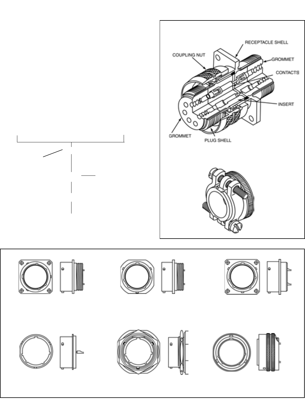
SECTION I
PLUG RECEPTACLE
SHELL
COUPLING NUT
INSERT ENVIRONMENTAL
SEALING GROMMET
CONTACTS
REAR ACCESSORIES
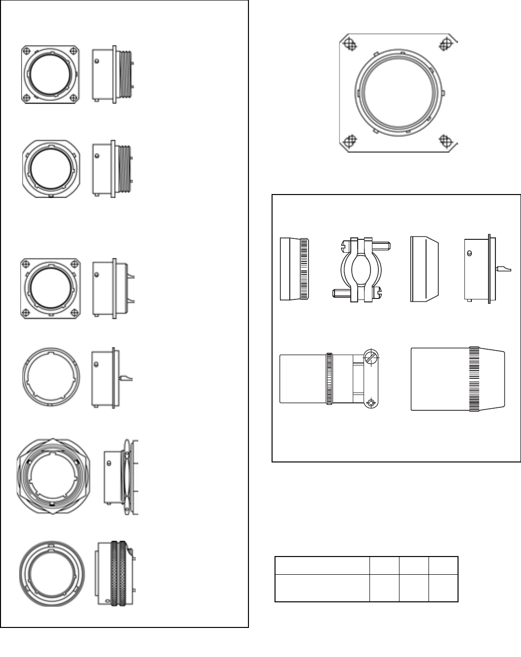
Shell Styles
WALL MOUNT RECEPTACLE LINE MOUNT RECEPTACLE OR BOX MOUNT RECEPTACLE
DESIGNATION: 00 CABLE CONNECTING RECEPTACLE* DESIGNATION: 02
DESIGNATION: 01
SOLDER MOUNT RECEPTACLE JAM NUT RECEPTACLE STRAIGHT PLUG
(HERMETIC) DESIGNATION: 07 DESIGNATION: 06
DESIGNATION:IH
* This connector style is sometimes referred to as a cable connecting “plug.”
It does, however, mate with either a straight or 90 degree plug.
Nomenclature: Cylindrical Connectors
Basic Components
1. Shell (Houses Inserts & Contacts)
2. Insert (Dielectric Contact Insulator) Pin or Socket
3. Contact (Wire End Termination) (Electrical Engagement)
4. Coupling Nut
5. Accessories (Wire Seals, Cable Seals, Wire Support, etc.)
Mated Pair
Rear Accessory
2
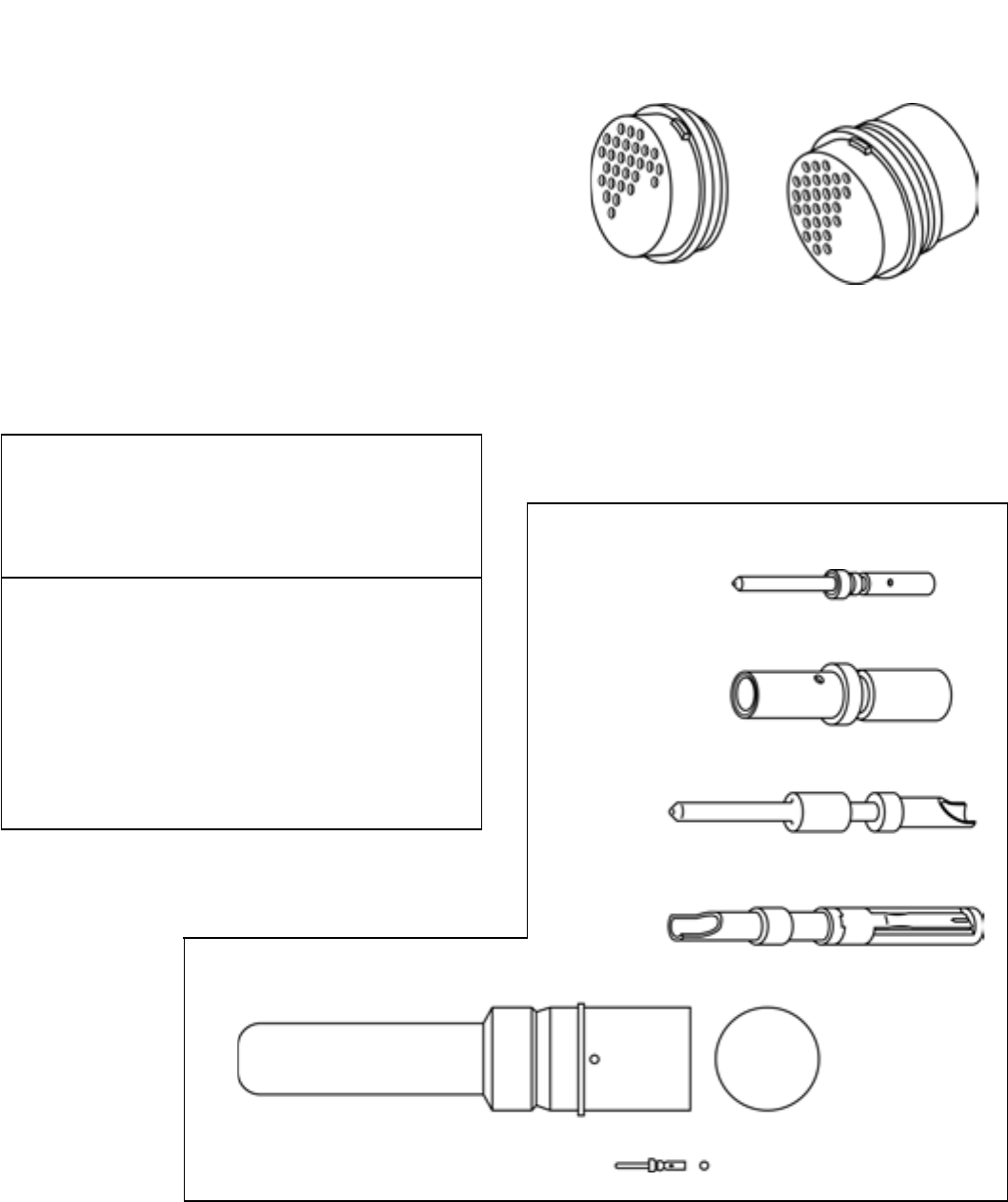
Inserts
Insert Insert &
(Pin or Socket) Grommet Assy.
• Solder
•Crimp
• Metal Clip Retention
• Dielectric Retention
May include a soft front interfacial seal (Bonded) if dielectric is
hard, and a rear sealing grommet separate or attached.
Nomenclature: Cylindrical Connectors and
Contacts
Shell Styles (Cont’d.)
Coupling
Threaded, Bayonet
Shell Sizes (Typical MIL-DTL-5015)
8S, 10S, 10SL, 12S, 12,
14S, 14, 16S, 16, 18
20, 22, 24, 28, 32, 36, 40, 44, 48
“S” designates short shell and short contacts
Shell size denotes mating thread diameter in 16ths of an inch.
For example, a size 8 shell denotes 8/16 of an inch with a
.5000-28 UNEF thread.
Style Designation (PT)
PLUG SHELL STYLES
06 Straight
08 Angle
09 Flange Mount Receptacle
05 Straight, Less Rear Accessory
RECEPTACLE SHELL STYLES
00 Wall Mount
01 Cable Connecting or
Line Mount Receptacle
02 Box Mount
03 Wall Mount, Less Rear Accessory
04 Line Mount, Less Rear Accessory
07 Jam Nut
IH Solder Mount Hermetic
Contact and Contact Termination Style
Pin – Crimp*
Socket – Crimp*
Pin – Solder
Socket – Solder
Sizes by Wire Gauge, Examples: *Crimp is removable
4/0 American
Wire Gauge 4/0
22D American Wire Gauge 22-28
3
Nomenclature: Cylindrical Connectors and
Contacts, cont.
Contacts
Pin Socket
Crimp or Solder
Usually separate from insert,
shipped loose or in bulk, tools
needed to crimp, install and remove.
Usually installed in insert, fre-
quently bonded in place.
Contact Options:
Solderless Wrap (Wire Wrap),
PC Tail, Coaxial, Thermocouple,
Triaxial, Fiber Optic, Filter, Twinax, Quadrax
Accessories
• Adapters
– straight, 90°, 75°
– conduit, environmental, open wire bundle, EMI, etc.
• Compression ring – wire seal
• Clamp – cable sealing
• Stain relief – clamp, kellems grip
• Potting boot
– straight, angle, universal
Contact Sizes
Contact Size 22D 22M 22 20 16
American Wire Gauge
Wire Size (AWG)
22-28 24-28 22-26 20-24 16-20
Contact Size 12 8 4 0
American Wire Gauge
Wire Size (AWG)
12-14 8-10 4-6 0-2
Contact Versatility - Several types of Contacts can be
designed into a Connector Shell
MIL-DTL-38999 connectors allow users to mix a variety of differ-
ent power, signal, shielded, fiber optic and high speed contact
styles within a common insert.
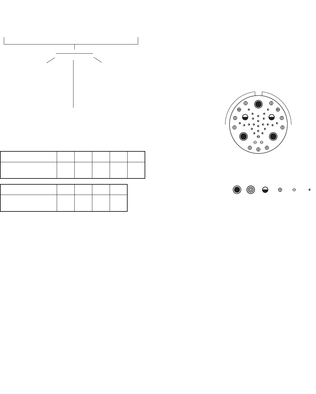
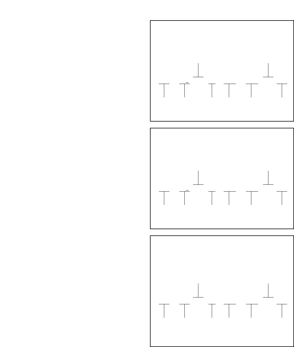
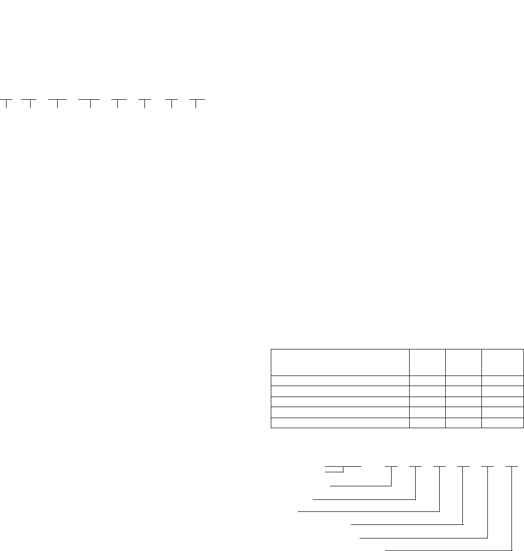
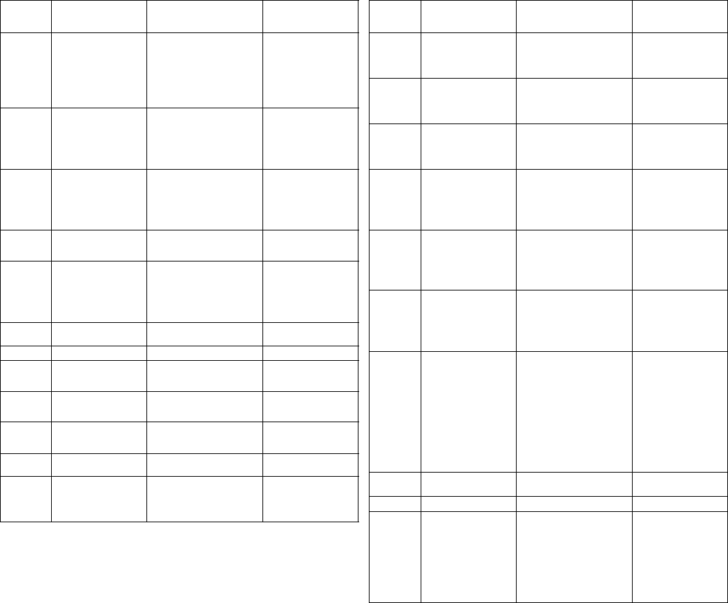
The insert arrangement below is an arrangement for Tri-Start
MIL-DTL-38999 Series III connectors. It shows the variety of con-
tacts that can be designed into a shell size 25. Typically, custom-
ers specify the contacts sizes and power they require and chose
an existing arrangement that fits their needs. For special new
configurations, engineering will design the arrangement of con-
tacts to fit within material and performance criteria.
Insert Arrangement 25-41
Number of Contacts 22 3 11 2 3
Contact Size 22D 20 16 12 Coax 8 Twinax
Contact Legend 8 10 12 16 20 22D
Contacts and Fiber Optic Termini for
Cylindrical Connectors
Amphenol’s broad contact product range for Cylindrical Connec-
tors includes:
• Standard 500 cycle and 1500 cycle, M39029 type power and
signal contacts
• Crimp contacts for front or rear release connector applications
• Solder type, fixed contacts with cup or eyelet termination
• Thermocouple contacts
• RADSOK® sockets for high amperage power contacts
• Spring-loaded and push-pull types
• Filter contacts: Pi type tubular or Pi type planar for MF, HF,
VHF, and UHF frequencies
• High frequency shielded coax, triax and twinax contacts
• High speed differential twinax and quadrax contacts
• For cylindrical connector attachment to Printed Circuit Boards:
• PC tail contacts for signal and power applications, in coax,
twinax, triax, differential twinax and quadrax designs
• Compliant pin (Press fit) contacts
• Fiber optic Termini: MIL-T-29504 type or MT ferrules or ARINC
801 termini
BP
CN
DM
EL
F
G
H
J
K
A
RY
XS
W
Z
T
UV
de
npqg
ac
b
j
kh
m
st
r
i
4
Major MIL-Specifications by Type
• Standard, MIL-DTL-5015
• Amphenol 97 Series
• Heavy Duty, MIL-DTL-22992
• Proprietary Variations
• Older larger series of connectors
• Found on many pieces of military equipment and commercial
applications
• Mostly heavy current carrying connectors
• Early types had only solder type contacts
• Later revision to MIL Spec also added crimp type contacts
• Amphenol supplies both the solder and crimp types to the
MIL Spec
• Amphenol supplies both solder and crimp versions under pro-
prietary part numbers
• Several variations of basic MIL-DTL-5015 and MIL-DTL-
22992 types are available in the same and additional contact
arrangements, such as the QWL, QWLD, 10-214000 Series,
10-244000 Series and others.
• See Amphenol catalog sections:
– MIL-DTL-5015 Cylindrical 12-020,
– MIL-DTL-5015 Modifications 12-021,
– Heavy Duty Cylindrical 12-052,
– Commercial Aircraft Cylindrical 12-101,
– 97 Series (MIL-DTL-5015 Proprietary) 12-022,
– GT Series Bayonet 12-024.
• Basic part number for MIL-DTL-5015 Series as supplied by
Amphenol is MS310X A, C, E, F or R
• MIL-DTL-5015 threaded coupling - 1 key/keyway shell
polarization
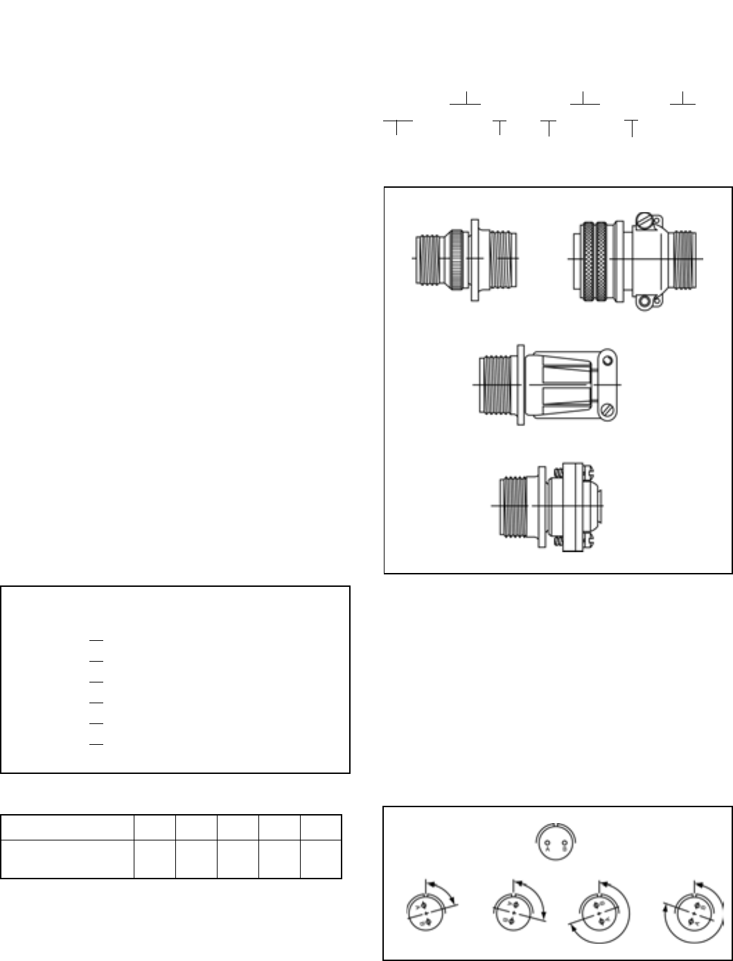
MIL-DTL-5015 Shell Styles
3100 Wall Mount Receptacle
3101 Cable Connecting Receptacle*
3102 Box Mount Receptacle
3106 Straight Plug
3108 90° Plug
3107 Quick Disconnect Plug
(97 Series only)
Contact Sizes
* This connector style is sometimes referred to as a cable connecting “plug.”
It does, however, mate with either a straight or 90 degree plug.
** Crimp adapter for small gauge wire is available, part number 10-074696-XXX.
Contact Size 16 12 8 4 0
American Wire Gauge
Wire Size (AWG)** 16-20 12-14 8-10 4-6 0-2
Mating Halves
• Plugs: MS3106, MS3107, MS3108 or
97-3106, 97-3107, 97-3108
• Receptacles: MS3100, MS3102, MS3101, 97-3101,
97-3100, 97-3102
Other Non-MIL-Mates, Flange Mounted
• Flange Mounted Plug: FP3106, 97-5105
• Thru-bulkhead Receptacle: TBF
See also 10-74XXX and 10-873XX in catalog section MIL-DTL-5015 Mods. for
jam nut receptacles (Non-MIL)
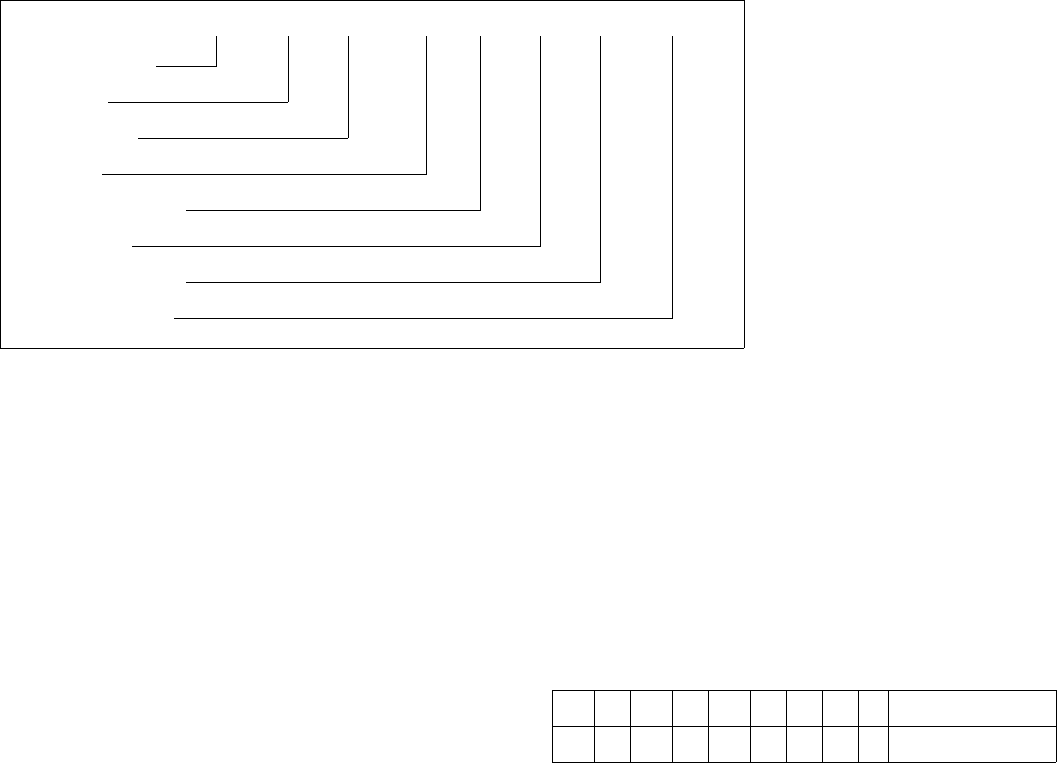
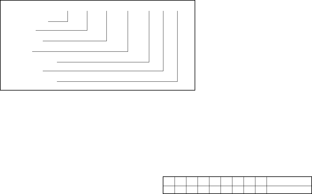
Alternate Positions
of Insert Arrangements
NORMAL POSITION
POSITION W POSITION X POSITION Y POSITION Z
MIL-DTL-5015 Part Number
Shell Insert Alternate
Style Arrangement Rotation
MS* 3102 A 18 -3 S W
Military Class Shell Contact
Standard Size Type
*or 97 Series Proprietary
MIL-DTL-5015
Class A or C Class B
Class E/F
Class R
SECTION II

5
Heavy Duty Cylindrical Connectors
• Class L - for the heaviest loads
– Current range 40 to 200 amperes
– Direct current or single/three phase, 60/400 Hertz
alternating current
– Automatic grounding for safety
•QWLD - for most power and control circuits
– Military qualified connectors and commercial
equivalents available
– Increased shell size for greater durability than similar stan-
dard connectors
•Class L and QWLD have 5 key/keyway shell polarization
and double stub thread coupling
•QWL – a more economical, compact heavy duty design for
commercial power and control applications; single key shell
polarization and double stub thread coupling
MIL-DTL-22992 Series Connectors
Classes C, R and L
Part Number Breakdown
The ordering procedure for QWLD MS-Approved Connectors is
illustrated by part number MS17343R20N27PW as shown
below: Part Number
MS17343 R 20 N 27 P W
1 2 3456 7
See code below:
1. MS Numbers
MS17343 designates wall mount receptacle
MS17344 designates straight plug
MS17345 designates cable connecting receptacle
MS17346 designates box mount receptacle
MS17347 designates jam nut receptacle with rear
accessory threads (wall mount)
MS17348 designates jam nut receptacle (box mount)
2. Class
C designates pressurized; used where circuit integrity is
protected by a pressure differential
R designates environmental; (see Heavy Duty Cylindrical
catalog 12-052 for definition)
3. Shell Size
Available in shell sizes 12 through 44. See catalog 12-052
for dimensional data
4. Shell Finish
C for conductive or N for non-conductive
5. Insert Arrangement
Current MS insert arrangements are listed in catalog 12-052,
Heavy Duty Cylindrical
6. Contact Type
“P” designates pin contacts; “S” for socket contacts
7. Alternate Insert Rotations:
Used to prevent cross-mating of connectors. Absence of a
letter in this space indicates normal (0°) position of the
insert. See catalog for alternate insert rotation illustrations.
See catalog 12-052 for proprietary equivalents such as 10-
194XXX Series. Also see catalog 12-053 for QWL Series.
The ordering procedure for Class “L” Connectors is illustrated
by part number MS90555C32412SY as shown below:
Part Number
MS90555 C 32 4 12 S Y
1 234567
See code below:
1. MS Numbers
MS90555 designates wall mount receptacle (power
source)
MS90556 designates straight plug
MS90557 designates cable connecting receptacle without
coupling ring
MS90558 designates wall mount plug with coupling ring
(equipment end)
2. Shell Finish
C (conductive) for AC or N (non-conductive) for DC circuits
3. Shell Size
Relates directly to current carrying capability
Size 28 – 40 amperes
Size 32 – 60 amperes
Size 44 – 100 amperes
Size 52 – 200 amperes
4. Main shell Key/keyway Position
N designates normal position. Three other positions (4, 5
and 6) of the main shell key/keyway prevent cross-mating or
incompatible voltages. Refer to the individual connector style
descriptions in catalog 12-052 for applicability.
5. Insert Arrangement
Determined by connector size (current carrying capability)
and cable configuration to be accommodated. See catalog
for insert arrangement pattern illustrations.
6. Contact Type
“P” designates pin contacts. “S” for socket contacts.
MS90555 and MS90557 are supplied with socket contacts
only. MS90556 and MS90558 are supplied with pin contacts
only.
7. Alternate Insert Rotation
Used to prevent cross-mating of incompatible frequencies.
Absence of a letter in this space indicates normal (0°) posi-
tion of the insert. See catalog for individual insert arrange-
ment description.
6
Major MIL-Specifications by Type
• Miniature, MIL-DTL-26482
Miniature PT-Types MIL-DTL-26482
• Widely used smaller connectors
• Extensive use on military equipment including aircraft as well
as commercial applications
• Available with either crimp or solder type contacts
• 3 point bayonet coupling
• Popular low cost series
• 5 Key/keyway shell polarization
• Amphenol supplies MIL-Spec types as well as proprietary
versions
• MS311X or PT, solder type contacts (Series 1)
• MS312X or PT-SE, crimp type contacts (front release)
(Series 1)
• MS347X or MB1, crimp type contacts (rear release)
(Series 2)
• Modifications of Basic Series are:
– PT-CE, crimp type contacts (front release) no MIL P/N,
intermates with MS connectors
– PC, double stub threaded coupling, bright cadmium plated,
- (available with either crimp or solder contacts) no MIL P/
N, does not intermate with PT types
– SP, same as PT except wider flanges for back panel
mounting, anodic coating, no MIL P/N, intermates with MS
connectors
– DC, same as PT except resistant to aircraft fluids, no MIL
P/N, intermates with MS connectors
– Other modifications and specials available
• For details on above series see Amphenol catalog sections:
– “Miniature Cylindrical” 12-070
– “Commercial Aircraft Cylindricals” 12-101.
MIL-DTL-26482 Series 2 is the same as MIL-DTL-83723 Series
1 and will intermate with all PT connectors. The Series features
rear removable contacts – accessories are ordered separately.
MIL-DTL-83723 Series 1 has been superseded by MIL-DTL-
26482 Series 2.
MIL-DTL-26482 Part Number
MS/PT-SE Crimp Series 1
Shell Contact
Style Type
MS 312 0E 22–55 PW
Military Crimp Class Shell Insert Alternate
Std. Type Size Arrangement Rotation
MIL-DTL-26482 Part Number
MS/PT Solder Series 1
Shell Contact
Style Type
MS 311 0E 22–55 PX
Military Solder Class Shell Insert Alternate
Std. Type Size Arrangement Rotation
MIL-DTL-26482 Part Number
MB1 Series 2, Rear Release Crimp
Shell Contact
Style Type
MS 347 0 L 22 – 55 S Y
Military 26482 Class Shell Insert Alternate
Std. Series 2 Size Arrangement Rotation
Rear Release
Crimp
SECTION III

7
How to Order BY MILITARY PART NUMBER
MIL-DTL-26482 Series 2 Connectors
MS 3470 W12 –10 P W
1 2 34567
1. Connector Type
MS designates Military Standard
2. Connector Style
3470 wall mounting receptacle with narrow flange
3472 wall mounting receptacle with wide flange
3471 cable connecting receptacle
3474 jam nut receptacle
3476 straight plug
3475 straight plug with RFI grounding fingers
3. Service Class
L aluminum shell, electroless nickel finish, fluid
resistant insert
A aluminum shell, black anodized finish, non-conduc-
tive fluid resistant insert
W aluminum shell, olive drab cadmium plated, fluid
resistant insert
Note: For stainless steel shell, passivated, order by Amphenol®/Matrix®
proprietary Class G.
Class L inactivates older classes E and R (Ref. MIL-C-26482)
4., 5. Shell size and insert arrangement - See chart on page 9
and pattern drawings that follow.
6. Contact Types
P designates pin
S designates socket
A designates less pins
B designates less sockets
Note: Use A & B only when other than a full complement of power con-
tacts is to be installed.
7. Insert Rotation
“W”, “X”, “Y”, “Z” designate that insert is rotated in its shell
from normal position. No letter required for normal (no
rotation) position.
How to Order BY PROPRIETARY PART NUMBER
MIL-DTL-26482 Series 2 Connectors
MB1 0 W –12 10 P W ***
12345678
1. Connector Type
MB1 designates Amphenol®/Matrix® Bayonet Coupling
Connector
2. Connector Style
0 wall mounting receptacle with narrow flange
1 wall mounting receptacle with wide flange
3 cable connecting receptacle
4 jam nut receptacle
6 straight plug
8 straight plug with RFI grounding fingers
3. Service Class
A aluminum shell, black anodize finish, non-conduc-
tive, fluid resistant insert
R aluminum shell, electroless nickel finish, fluid
resistant insert
G stainless steel shell, passivated, fluid resistant
insert
W aluminum shell, cadmium plated, olive drab finish,
fluid resistant insert
4., 5. Shell size and insert arrangement - See chart on page 9
and pattern drawings that follow.
6. Contact Types
P designates pin
S designates socket
7. Insert Rotation
“W”, “X”, “Y”, “Z” designate that insert is rotated in its shell
from normal position. No letter required for normal (no
rotation) position.
8. Modification Number
Consult Amphenol, Sidney, NY for information.
For strain reliefs use the following modification codes:
(189) E-nut M85049/31 configuration
(190) Straight strain relief M85049/52 configuration
(191) 90° strain relief M85049/51 configuration
For ordering information on accessories, such as protection
caps and backshell hardware, contact Amphenol, Sidney, NY.
8
Miniature Crimp Connectors
Part Number Breakdown
Proprietary Part Number Construction for Miniature Crimp
Connectors
To more easily illustrate ordering procedures, part number
PT00SE-20-41PW (SR) is shown as follows:
Part Number
PT 00 SE – 20 - 41 P W (SR)
123 45 678
See code below:
1. Connector Family
PT designates standard olive drab cadmium plated Tri-Lock
coupling connector
SP designates connector similar to PT except for anodic
coating and larger flange and mounting holes for back
panel mounting of receptacles
2. Shell Style
“00” designates wall mount receptacle
“01” designates cable connecting receptacle
“02” designates box mount receptacle
“06” designates straight plug
“07” designates jam nut receptacle
“08” designates 90° plug
3. Service Class
“SE” designates crimp, environmental (MIL-DTL-26482)
“SP” designates crimp, potted type (MIL-DTL-26482)
Both of the above are Amphenol proprietary versions of the
MIL-DTL-26482 Series 1 crimp contact connector and offer
15 lbs. contact retention for size 20 contacts, 25 lbs. for size
16 contacts.
“CE” designates crimp, environmental
“CP” designates crimp, potted type
Both of the above are original Amphenol crimp connectors
and offer 7 lbs. contact retention for size 20 contacts, 9 lbs.
for size 16 contacts.
4. “20” designates shell size. Shell sizes available are
8 through 24.
5. “20-41” designates insert arrangement
6. “P” designates pin contacts; “S” for socket contacts
7. “W” designates that insert is rotated in its shell from the stan-
dard position to alternate position W. The basic rotations are
W, X, Y, and Z. No letter required for normal (no rotation)
position.
8. “SR” designates a strain relief clamp. Deviation suffixes
would be inserted here. For example, (005) would indicate
the metal parts (except contacts) would have anodic coating.
Part Number Nomenclatures for MS/PT Crimp Connectors
to MIL-DTL-26482 Specification
To more easily illustrate ordering procedures, part number
MS3120E-20-41PW is broken down as follows:
Part Number
MS 312 0 E 20 - 41 P W
12345678
See code below:
1. “MS” designates Military Standard
2. “312” designates basic family number for MIL-Spec 26482
crimp type
3. Shell Style
“0” designates wall mount receptacle
“1” designates cable connecting receptacle
“2” designates box mount receptacle
“4” designates jam nut receptacle
“6” designates straight plug
“7” designates box mount receptacle with dual
mounting holes
“8” designates wall mount receptacle with dual
mounting holes
4. Service Class
“E” designates environmental resisting connector
“F” designates environmental resisting connector with strain
relief
“P” designates potted type with potting boot
5. “20” designates shell size. Shell sizes available are
8 through 24.
6. “20-41” designates insert arrangement
7. “P” designates pin contacts; “S” for socket contacts
8. “W” designates that the insert is rotated in its shell from the
standard position to alternate position W. The basic rotations
are W, X, Y, and Z. No letter required for normal (no rotation)
position.
Cross Reference - Commercial PT to Comparable
Military MS Types
Amphenol P/N MS P/N Amphenol P/N MS P/N
PT00SE MS3120E PT06SE(SR) MS3126F
PT01SE MS3121E MF00SE(SR) MS3128F
PT02SE MS3122E PT07SE(SR) MS3124F
PT06SE MS3126E PT08SE(SR) None
MF02SE MS3127E PT00SP MS3120P
MF00SE MS3128E PT01SP MS3121P
PT07SE MS3124E PT02SP MS3122P
PT08SE None PT06SP MS3126P
PT00SE(SR) MS3120F PT07SP MS3124P
PT01SE(SR) MS3121F
9
Miniature Solder Connectors
Part Number Breakdown
Part Number Nomenclature for Miniature Solder
Connectors
To more easily illustrate ordering procedures, part number
PT00A-20-41PW (SR) is shown as follows:
Part Number
PT 00 A- 20 - 41 P W (SR)
123 45 678
See code below:
1. Connector Family
PT designates standard olive drab cadmium plated Tri-Lock
coupling connector. This is the Amphenol® proprietary
version of the MIL-DTL-26482 solder contact connector.
PC designates a bright cadmium plated connector with dou-
ble stub thread coupling
SP designates connector similar to PT except for anodic
coating and larger flange and mounting holes for back
panel mounting
2. Shell Style
“00” designates wall mount receptacle
“01” designates cable connecting receptacle
“02” designates box mount receptacle
“06” designates straight plug
“07” designates jam nut receptacle
PTB designates thru-bulkhead receptacle
PTI designates solder mount receptacle
3. Service Class
“A” designates general duty backshell
“C” designates pressurized receptacle
“E” designates environmental resisting with grommet and
clamping nut
“J” designates clamp assembly for moisture proofing multi-
jacketed cables, with strain relief
“P” designates potted with potting boot
“W” designates clamp assembly for moisture-proofing, multi-
jacketed cables
“H” designates hermetic seal receptacle
4. “20” designates shell size. Shell sizes available are
6 through 24.
5. “20-41” designates insert arrangement
6. “P” designates pin contacts; “S” for socket contacts
7. “W” designates that insert is rotated in its shell from the stan-
dard position to alternate position W. The basic rotations are
W, X, Y, and Z. No letter required for normal (no rotation)
position.
8. “SR” designates a strain relief clamp. Deviation suffixes
would be inserted here. For example, (005) would indicate
the metal parts (except contacts) would have alumilite plat-
ing.
Part Number Nomenclatures for MS/PT Solder Connectors
to MIL-DTL-26482 Specification
To more easily illustrate ordering procedures, part number
MS3110E20-41PW is shown as follows:
Part Number
MS 311 0 E 20 - 41 P W
12345678
See code below:
1. “MS” designates Military Standard
2. “311” designates basic family number for MIL-Spec 26482
solder type
3. Shell Style
“0” designates wall mount receptacle
“1” designates cable connecting receptacle
“2” designates box mount receptacle
“4” designates jam nut receptacle
“6” designates straight plug
4. Service Class
“E” designates environmental resisting connector with grom-
met and clamping nut
“F” designates environmental resisting connector with grom-
met and strain relief
“J” designates clamp assembly for moisture proofing multi-
jacketed cables, with strain relief
“P” designates potted type with potting boot
5. “20” designates shell size. Shell sizes available are
8 through 24.
6. “20-41” designates insert arrangement
7. “P” designates pin contacts; “S” for socket contacts
8. “W” designates that the insert is rotated in its shell from the
standard position to alternate position W. The basic rotations
are W, X, Y, and Z. No letter required for normal (no rotation)
position.
Cross Reference - Commercial PT to Comparable
Military MS Types
Amphenol P/N MS P/N Amphenol P/N MS P/N
PT00A None PT00E(SR) MS3110F
PT01A None PT01E(SR) MS3111F
PT02A None PT06E(SR) MS3116F
PT06A None PT07E(SR) MS3114F
PT07A None PT00P MS3110P
PT00C None PT01P MS3111P
PT02C None PT02P None
PT07C None PT06P MS3116P
PTB MS3119Ref PT07P MS3114P
PT00E MS3110E PT00W None
PT01E MS3111E PT01W None
PT02E MS3112E PT06W None
PT06E MS3116E PT02H None
PT07E MS3114E PT07H MS3114H
PT1H MS3113H
10
Also see PTB - Thru- bulkhead, double-ended receptacle in
Miniature Cylindrical catalog.
Wide Flange - Back Panel Mount:
MS3127 Box Mount, MS3128 Wall Mount
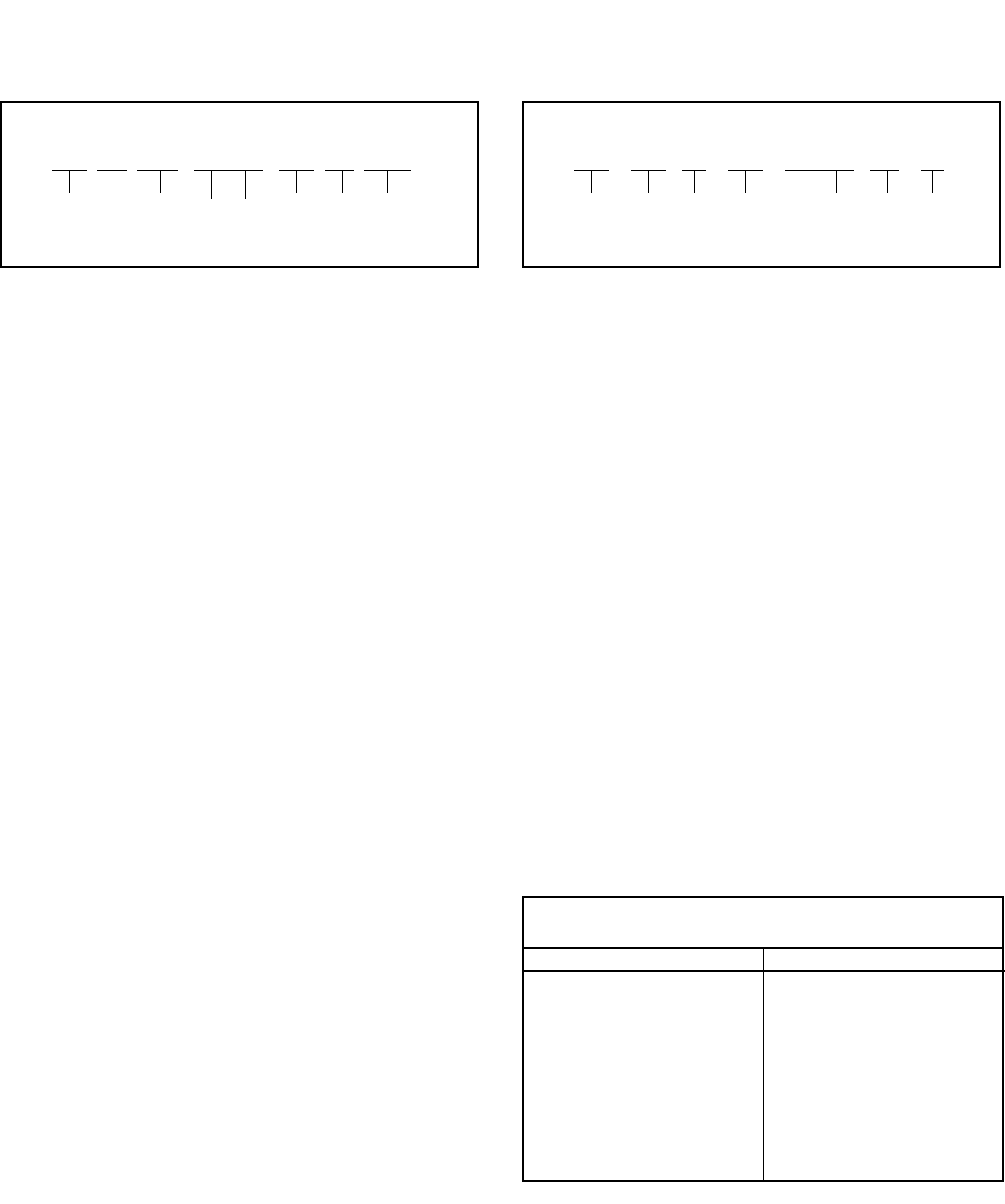
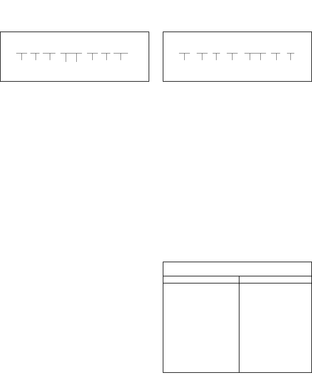
Miniature Shell Styles
Wall Mount
Receptacle
Cable Connecting
or Line Mount
Receptacle*
Box Mount
Receptacle
Solder Mount
Receptacle
(Hermetic)
Jam Nut
Receptacle
Straight Plug
MIL-DTL-26482
Class E Class F Class P Class H
Class J Class W
(Non-MIL)
Shell Sizes
6, 8, 10, 12, 14, 16, 18, 20, 22, 24
Contact Sizes
Contact Size 20 16 12
American Wire Gauge
Wire Size (AWG) 20-24 16-20 12-14
* This connector style is sometimes referred to as a cable connecting “plug.”
It does, however, mate with either a straight or 90 degree plug.

11
Major MIL-Specifications by Type
• Subminiature, MIL-DTL-38999*
• MIL-DTL-27599
Subminiature - JT/LJT, Tri-Start, SJT
• Preferred for new design by the Military
• Greatest growth potential of all cylindricals
• “State of the Art” technology and performance
• MIL-DTL-27599 has molded-in solder type contacts
• MIL-DTL-38999 has rear release, crimp removable contacts
• SJT has features of both the JT and LJT and is a NATO pre-
ferred connector in Europe
• MIL-DTL-38999 Series I & II will not intermate
• MIL-DTL-27599 Series I & II will not intermate
• MIL-DTL-38999 and MIL-DTL-27599, Series I and II will inter-
mate respectively
• For more information, see Amphenol catalog section:
– 12-C1*, Subminiature Cylindrical Connectors designed to
MIL-DTL-38999 and MIL-DTL-27599
– 12-C1*, Tri-Start Connector - MIL-DTL-38999 Series III
– 12-091, SJT - Proprietary MIL-DTL-38999 type
– 12-130, High Frequency Contact Catalog
MIL-DTL-27599
Series I (LJT-Solder)
• 100% scoop-proof
• Molded-in solder type contacts
• Options include PCB, wire wrap contacts
• High contact density (up to 128 contacts)
• Shell grounding fingers standard on all plugs
• Intermateable with MIL-DTL-38999 Series I
• Bayonet coupling
• 5 key/keyway polarization with 4 alternate keyings
Series II (JT-Solder)
• Low profile, light-weight, non-scoop-proof
• Molded-in solder type contacts
• Options include PCB, wire wrap contacts
• High contact density (up to 128 contacts)
• Shell grounding fingers available as option on plug
• Intermateable with MIL-DTL-38999 Series II
• Bayonet coupling
• 5 key/keyway polarization with 4 alternate keyings
MIL-DTL-38999
Series I (LJT-R)
• 100% scoop-proof
• High density arrangements (up to 128 contacts)
• Contact sizes 12 through 22D plus size 16, 12, 8 coax, and
size 8 twinax
• Bayonet coupling
• DOD preferred
• Corrosion resistant (500 hr. salt spray) finish available
• Removable crimp, PCB, wire wrap, twinax, and coax contacts
available
• Options include Hermetics, Filters and Thermocouples
• 5 key/keyway polarization with 4 alternate keyings
• Shell grounding fingers are standard on all plug
• Triple-web grommet seal
• Available in a Fail Safe Lanyard Release plug: see Amphenol
catalog 12-C1.
Series II (JT-R)
• High density arrangements (up to 128 contacts)
• Low silhouette, light-weight non-scoop-proof
• Bayonet coupling
• Contact sizes 12 through 22D plus size 16 & 12 coax
• 5 key/keyway polarization with 4 alternate keyings
• Removable crimp, PCB, wire wrap and coax contacts
available
• Corrosion resistant (500 hr. salt spray) finish available
• Options include Hermetics, Filters and Thermocouples
• Shell grounding fingers on plugs are an option
• Triple-web grommet seal
• Available in Fail Safe Lanyard Release plug
* Catalog 12-C1 is Amphenol’s new catalog - combining 38999 Series I, II and III
Connectors. These were formerly catalogs 12-090 (Series I, II) and catalog 12-
092 (Series III). Consult Amphenol Aerospace for the availability of this new
catalog.
SECTION IV
12
Subminiature JT/LJT
Part Number Breakdown
PROPRIETARY PART NUMBER
To more easily illustrate ordering procedure, part number
JT00RE-22-2PA( ) is shown as follows:
Part Number
JT 00 RE- 22- 2 P A ( )
12 3 4 5 678/9
See code below:
1. Connector Type:
JT designates standard Junior Tri-Lock connec-
tor
LJT designates long Junior Tri-Lock connector
LJTS JTS designates high temperature connector
LJTN JTN designates chemical and fuel resistant
JTL designates miniature mounting dimensions
JTLN designates miniature mounting dimensions –
chemical resistant
JTLS designates miniature mounting dimensions –
high temperature
LJTPQ JTPQ designates back panel mounted wall mount-
ing receptacle
LJTP JTP designates back panel mounted box mounting
receptacle
LJTPN JTPN designates back panel mounted –
chemical resistant
LJTPS JTPS designates back panel mounted –
high temperature
JTG* designates plug with grounding fingers
JTNG* designates plug with grounding fingers –
chemical resistant
*Grounding fingers standard on all LJT plugs.
2. Shell Style
“00” designates wall mount receptacle
“01” designates line mount receptacle
“02” designates box mount receptacle
“06” designates straight plug
“07” designates jam nut receptacle
“08” designates 90-degree plug
“I” designates solder mount receptacle – hermetic
3. Service Class: Solder contacts/connectors
“P” for potting applications – These connectors are sup-
plied with a potting boot.† All shells are designed
with integral features to retain potting boots
“A” for general duty applications (JT series only)
“A (SR)” – threaded rear design with strain relief †
“C” for pressurized applications
“C” (SR)” – threaded rear design with strain relief †
“H” for hermetic applications – Fused compression
glass sealed inserts. Leakage rate less than .01
micron cu. ft/hr. (1 x 10⁻⁷ cc/sec.) at 15 psi differen-
tial.
“Y” same as “H” with interfacial seal
“T” for MS27599A applications – General duty – pres-
surized (receptacles only) (LJT series only)
3. Service Class: Crimp contacts/connectors
“RP” for potting crimp applications – Supplied with spacer
grommet and potting boot.†
“RE” for environmental crimp applications – Supplied with a
grommet and compression nut† (JT Series only). Can
be supplied with strain relief integral with compression
nut “RE (SR).”
“RT” for environmental applications – Supplied without rear
accessories. Design provides serrations on rear
threads of shells. For additional information defining
complete description of service class, consult Amphe-
nol, Sidney, NY.
4. Shell Size
JT shell sizes available from 8 through 24. LJT shell sizes
available from 9 through 25.
5. Insert Arrangement:
22-2 designates insert arrangement. Refer to catalog 12-C1
for additional insert patterns.
6. Contact Style
“P” designates pin contacts; “S” designates socket contacts.
7. Alternating Keying
“A” designates alternate keying connector assembly. Other
basic alternate keys are “B”, “C” and “D”. No letter
required for normal (no rotation) position.
8. “SR” designates a strain relief clamp. Strain reliefs are avail-
able only on “A”, “C” and “RE” class connectors.
9. Finish variation suffix.
†Not applicable to box mounting style.
Finish Military
Finish
Data
Finish
Suffix
Finish
plus “SR”
Suffix
Cadmium plated nickel base A (SR)
Olive drab cadmium plate nickel base B (014) (386)
Electroless nickel F (023) (424)
Anodic coating (Alumilite) C (005) (300)
Chromate treated (Iridite 14-2) (011) (344)
MILITARY TYPES
MS27473 E 14 A 18 P A
MS Number
Service Class
Shell Size
Finish
Insert Arrangement
Contact Style (P or S)
Alternate Keying –No letter
required for normal position
Military Service Class
E Environmental, same as RE
T Environmental, same as RT
Y Hermetically sealed, same as Y
P Potting, same as RP
For finish variations see finish data on following page.
For MS depictions and dimensional data see applicable MIL-
Spec. (MIL-DTL-38999, MIL-DTL-27599).
Amphenol Gage Code 77820
13
Subminiature JT/LJT
Specifications
* When tested using silver plated wire
** Please note that the establishment of electrical safety factors is left entirely in the designer’s hands, since he is in the best position to know what peak voltages, switching
surges, transients, etc. can be expected in a particular circuit.
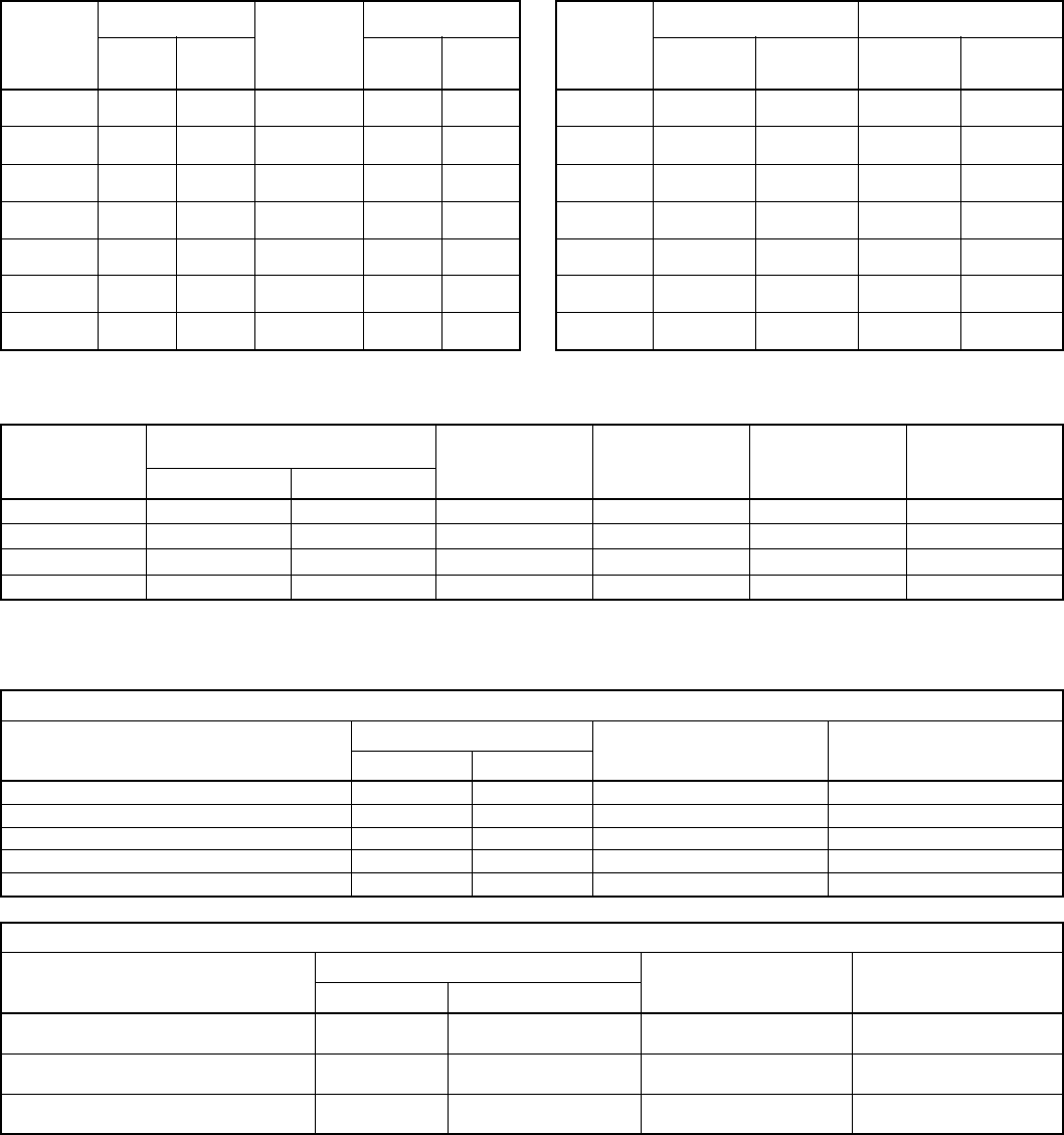
CONTACT RATING
Contact
Size
Test Current Maximum
Millivolt Drop
Crimp*
Maximum Millivolt Drop
Contact
Size
Crimp Well Data Solder Well Data
Solder &
Crimp Hermetic Solder* Hermetic* Well
Diameter Nominal
Well Depth W
Diameter Nominal
Well Depth
22M 3 2 45 20 60 22M .028 ± .001 .141 .029 .094
22D 5 3 73 85 22D .0345 ±.0010 .141 .034 .094
22 5 3 73 20 85 22 .0365 ±.0010 .141 .036 .094
20 7.5 5 55 20 60 20 .047 ±. 001 .209 .044 .125
16 13 10 49 20 85 16 .067 ± .001 .209 .078 .141
12 23 17 42 20 85 12 .100 ± .002 .209 .116 .141
10 Power 33 NA 33 NA NA 10 Power .137 ± .002 .355 NA NA
SERVICE RATING**
Service
Rating
Suggested Operating Voltage
(Sea Level) Test Voltage
(Sea Level) Test Voltage
50,000 Ft. Test Voltage
70,000 Ft. Test Voltage
110,000 Ft.
AC (RMS) DC
M 400 500 1300 VRMS 550 VRMS 350 VRMS 200 VRMS
N 300 450 1000 VRMS 400 VRMS 260 VRMS 200 VRMS
I 600 850 1800 VRMS 600 VRMS 400 VRMS 200 VRMS
II 900 1250 2300 VRMS 800 VRMS 500 VRMS 200 VRMS
FINISH DATA
Aluminum Shell Components Non-Hermetic
Finish Suffix Indicated Finish Standard for
JT Types Listed Below Standard for LJT Types
Listed Below
Military Proprietary
Cadmium Plated Nickel Base MS (A) – JT/JTG/JTL/JTP LJT/LJTP
Anodic Coating (Alumilite) MS (C) (005) JTS/JTPS/JTLS LJTPS/LJTS
Chromate Treated (Iridite 14-2) (011) JTN/JTPN/JTLN LJTN/LJTPN
Olive Drab Cadmium Plate Nickel Base MS (B) (014)
Electroless Nickel MS (F) (023)
Hermetic Connectors
Material Finish Suffix Indicated Finish Standard for
JT Types Listed Below Indicated Finish Standard for
LJT Types Listed Below
Military Proprietary
Carbon Steel Shell
Tin Plated Shell and Contacts JT ( ) H/JT ( ) Y
JTL ( ) H/JTL ( ) Y LJT ( ) Y/LJT ( ) H
Carbon Steel Shell
Tin Plated Shell and Gold Plated Contacts MS (D) (452) special termination
(468) solder cup
Stainless Steel Shell
Gold Plated Contacts MS (E) (162) JTS ( ) Y
JTLS ( ) Y LJTS ( ) Y
+.004
–.000
+.004
–.000
+.004
–.004
+.000
–.004
+.004
–.002
+.004
–.000
14
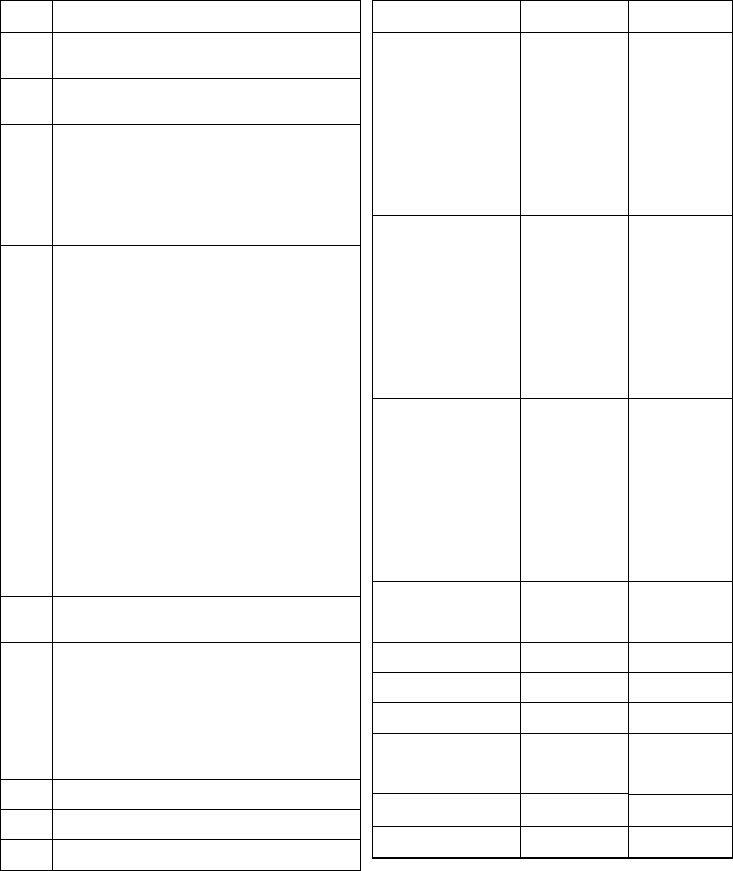
MIL-DTL-38999 LJT-R/JT-R and Accessories
Cross Reference List
Series or
Accessory MS
Part No. Amphenol
Part No. Description
Ac MS27502AXXA
10-275197-XX7
Cap, Recept. Series I
No Chain
Ac MS27502BXXA
10-275197-XX9
Ac MS27502FXXA
10-275197-XXG
Ac MS27501AXXA
10-275196-XX7
Cap, Plug Series I,
No Chain
Ac MS27501BXXA
10-275196-XX9
Ac MS27501FXXA
10-275196-XXG
Ac MS27342AXX-1
10-440390-XX7 (Series II)
Adapter
Ac MS27342BXX-1
10-440390-XX9 (Series II)
Ac MS27342CXX-1
10-440390-XX5 (Series II)
Ac MS27342FXX-1
10-440390-XXG (Series II)
Ac MS27342AXX-2
10-241055 Series II
Ac MS27342BXX-2
10-457452 Series I
Ac MS27342CXX-2
Ac MS27342FXX-2
Ac MS27510AXXA
10-241853-XX7
Cap, Plug Series II,
No Chain
Ac MS27510BXXA
10-241853-XX9
Ac MS27510CXXA
10-241853-XX5
Ac MS27510FXXA
10-241853-XXG
Ac MS27511AXXA
10-241856-XX7
Cap, Recept. Series II,
No Chain
Ac MS27511BXXA
10-241856-XX9
Ac MS27511CXXA
10-241856-XX5
Ac MS27511FXXA
10-241856-XXG
I MS27466EXXAXXP/S
LJT00RE-XX-XXP/S
Wall Mount
Receptacle
I MS27466EXXBXXP/S
LJT00RE-XX-XXP/S (014)
I MS27466EXXFXXP/S
LJT00RE-XX-XXP/S (023)
I MS27466TXXAXXP/S
LJT00RT-XX-XXP/S
I MS27466TXXBXXP/S
LJT00RT-XX-XXP/S (014)
I MS27466TXXFXXP/S
LJT00RT-XX-XXP/S (023)
I MS27466PXXAXXP/S
LJT00RP-XX-XXP/S
I MS27466PXXBXXP/S
LJT00RP-XX-XXP/S (014)
I MS27466PXXFXXP/S
LJT00RP-XX-XXP/S (023)
I MS27467EXXAXXP/S
LJT06RE-XX-XXP/S
Straight Plug
I MS27467EXXBXXP/S
LJT06RE-XX-XXP/S (014)
I MS27467EXXFXXP/S
LJT06RE-XX-XXP/S (023)
I MS27467TXXAXXP/S
LJT06RT-XX-XXP/S
I MS27467TXXBXXP/S
LJT06RT-XX-XXP/S (014)
I MS27467TXXFXXP/S
LJT06RT-XX-XXP/S (023)
I MS27467PXXAXXP/S
LJT06RP-XX-XXP/S
Straight PlugI MS27467PXXBXXP/S
LJT06RP-XX-XXP/S (014)
I MS27467PXXFXXP/S
LJT06RP-XX-XXP/S (023)
I MS27468EXXAXXP/S
LJT07RE-XX-XXP/S
Jam Nut Mount
Receptacle
I MS27468EXXBXXP/S
LJT07RE-XX-XXP/S (014)
I MS27468EXXFXXP/S
LJT07RE-XX-XXP/S (023)
I MS27468TXXAXXP/S
LJT07RT-XX-XXP/S
I MS27468TXXBXXP/S
LJT07RT-XX-XXP/S (014)
I MS27468TXXFXXP/S
LJT07RT-XX-XXP/S (023)
I MS27468PXXAXXP/S
LJT07RP-XX-XXP/S
I MS27468PXXBXXP/S
LJT07RP-XX-XXP/S (014)
I MS27468PXXFXXP/S
LJT07RP-XX-XXP/S (023)
I MS27469YXXDXXP
LJT00Y-XX-XXP
Wall Mount Recept.,
Hermetic Seal
I MS27469YXXEXXP
LJTS00Y-XX-XXP
I MS27470YXXDXXP
LJT07Y-XX-XXP
Jam Nut Mount Recept.,
Hermetic Seal
I MS27470YXXEXXP
LJTS07Y-XX-XXP
I MS27471YXXDXXP
LJTIY-XX-XXP
Solder Mount Recept.,
Hermetic Seal
I MS27471YXXEXXP
LJTSIY-XX-XXP
Series or
Accessory MS
Part No. Amphenol
Part No. Description
II MS27472EXXAXXP/S
JT00R-EXX-XXP/S
Wall Mount
Receptacle
II MS27472EXXBXXP/S
JT00RE-XX-XXP/S (014)
II MS27472EXXCXXP/S
JTS00R-EXX-XXP/S
II MS27472EXXFXXP/S
JT00RE-XX-XXP/S (023)
II MS27472TXXAXXP/S
JT00RT-XX-XXP/S
II MS27472TXXBXXP/S
JT00RT-XX-XXP/S (014)
II MS27472TXXCXXP/S
JTS00RT-XX-XXP/S
II MS27472TXXFXXP/S
JT00RT-XX-XXP/S (023)
II MS27472PXXAXXP/S
JT00RP-XX-XXP/S
II MS27472PXXBXXP/S
JT00RP-XX-XXP/S (014)
II MS27472PXXCXXP/S
JTS00RP-XX-XXP/S
II MS27472PXXFXXP/S
JT00RP-XX-XXP/S (023)
II MS27473EXXAXXP/S
JT06RE-XX-XXP/S
Straight Plug
II MS27473EXXBXXP/S
JT06RE-XXP/S (014)
II MS27473EXXCXXP/S
JT06RE-XX-XXP/S
II MS27473EXXFXXP/S
JT06RE-XX-XXP/S (023)
II MS27473TXXAXXP/S
JT06RT-XX-XXP/S
II MS27473TXXBXXP/S
JT06RT-XX-XXP/S (014)
II MS27473TXXCXXP/S
JT06RT-XX-XXP/S
II MS27473TXXFXXP/S
JT06RT-XX-XXP/S (023)
II MS27473PXXAXXP/S
JT06RP-XX-XXP/S
II MS27473PXXBXXP/S
JT06RP-XX-XXP/S (014)
II MS27473PXXCXXP/S
JTS06RP-XX-XXP/S
II MS27473PXXFXXP/S
JT06RP-XX-XXP/S (023)
II MS27474EXXAXXP/S
JT07RE-XX-XXP/S
Jam Nut Mount
Receptacle
II MS27474EXXBXXP/S
JT07RE-XX-XXP/S (014)
II MS27474EXXCXXP/S
JTS07RE-XX-XXP/S
II MS27474EXXFXXP/S
JT07RE-XX-XXP/S (023)
II MS27474TXXAXXP/S
JT07RT-XX-XXP/S
II MS27474TXXBXXP/S
JT07RT-XX-XXP/S (014)
II MS27474TXXCXXP/S
JTS07RT-XX-XXP/S
II MS27474TXXFXXP/S
JT07RT-XX-XXP/S (023)
II MS27474PXXAXXP/S
JT07RP-XX-XXP/S
II MS27474PXXBXXP/S
JT07RP-XX-XXP/S (014)
II MS27474PXXCXXP/S
JTS07RP-XX-XXP/S
II MS27474PXXFXXP/S
JT07RP-XX-XXP/S (023)
II MS27475YXXDXXP
JT00Y-XX-XXP
Wall Mount Recept.,
Hermetic Seal
II MS27475YXXEXXP
JTS00Y-XX-XXP
II MS27476YXXDXXP
JT02Y-XX-XXP
Box Mount Recept.,
Hermetic Seal
II MS27476YXXEXXP
JTS0Y-XX-XXP
II MS27477YXXDXXP
JT07Y-XX-XXP
Jam Nut Mount Recept.,
Hermetic Seal
II MS27477YXXEXXP
JTS07Y-XX-XXP
II MS27478YXXDXXP
JTIY-XX-XXP
Solder Mount Recept.,
Hermetic Seal
II MS27478YXXEXXP
JTSIY-XX-XXP
II MS27479EXXCXXP/S
JTS00RE-XX-XXP/S
Wall Mount Recept.,
Inactive, Use MS27472
II MS27479TXXCXXP/S
JTS00RT-XX-XXP/S
II MS27480EXXCXXP/S
JTS06RE-XX-XXP/S
Straight Plug, Inactive,
Use MS27473
II MS27480TXXCXXP/S
JTS06RT-XX-XXP/S
II MS27481EXXCXXP/S
JTS07RE-XX-XXP/S
Jam Nut Mount Recept.,
Inactive, Use MS27474
II MS27481TXXCXXP/S
JTS07RT-XX-XXP/S
II MS27482YXXEXXP
JTS00Y-XX-XXP
Wall Mount Recept.,
Hermetic Seal, Inactive,
Use MS27475
II MS27483YXXEXXP
JTS07Y-XX-XXP
Jam Nut Mount Recept.,
Hermetic Seal, Inactive,
Use MS27477
15
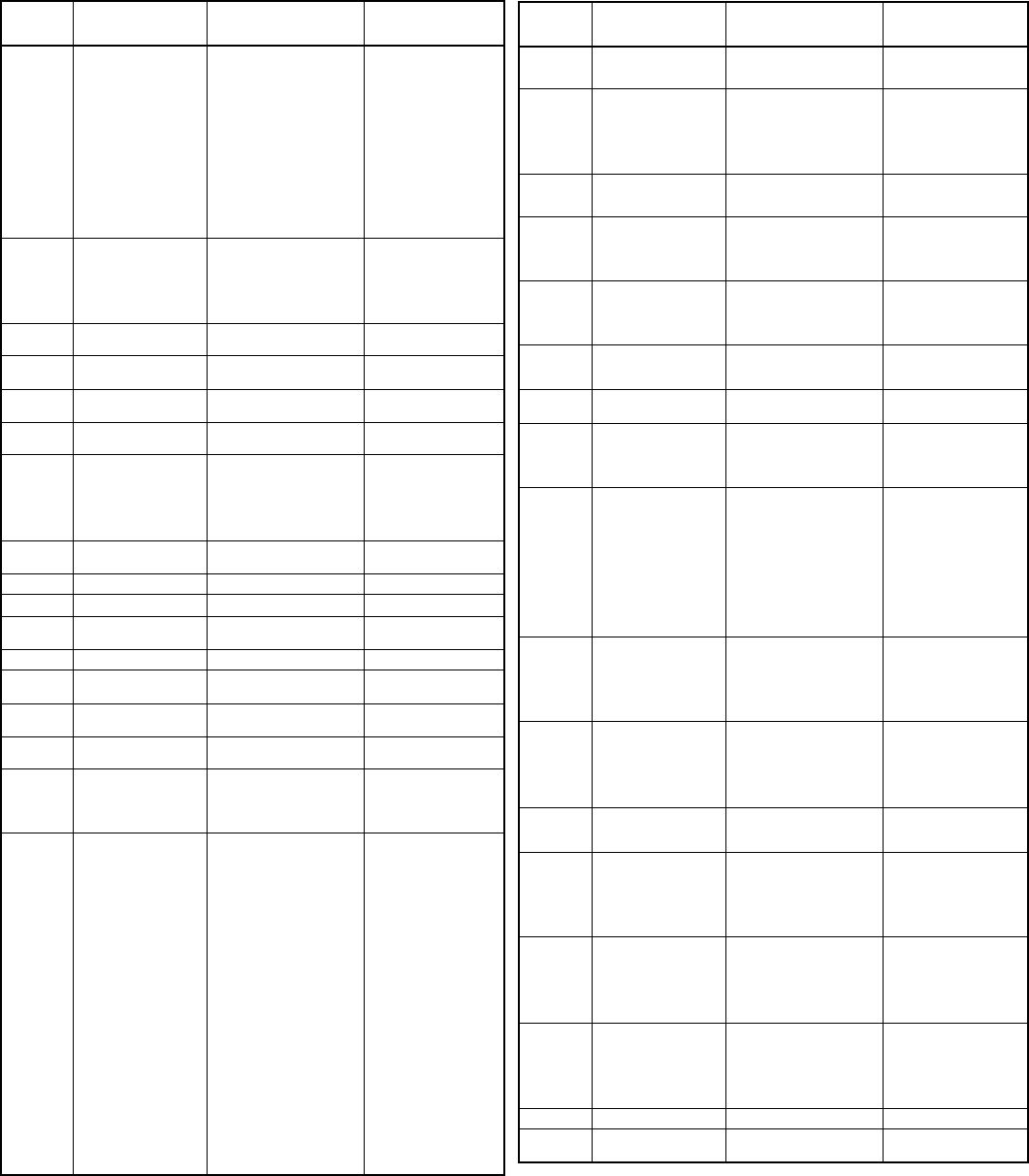
MIL-DTL-38999 LJT-R/JT-R and Accessories
Cross Reference List (Cont.)
Series or
Accessory MS
Part No. Amphenol
Part No. Description
II MS27484EXXAXXP/S
JTG06RE-XX-XXP/S
Straight Plug with
Grounding Spring
II MS27484EXXBXXP/S
JTG06RE-XX-XXP/S (014)
II MS27484EXXFXXP/S
JTG06RE-XX-XXP/S (023)
II MS27484TXXAXXP/S
JTG06RT-XX-XXP/S
II MS27484TXXBXXP/S
JTG06RT-XX-XXP/S (014)
II MS27484TXXFXXP/S
JTG06RT-XX-XXP/S (023)
II MS27484PXXAXXP/S
JTG06RP-XX-XXP/S
II MS27484PXXBXXP/S
JTG06RP-XX-XXP/S (014)
II MS27484PXXFXXP/S
JTG06RP-XX-XXP/S (023)
Ac MS27485AXX
10-528399-XX7
Ring, Potting Boot,
Series II
Ac MS27485BXX
10-528399-XX9
Ac MS27485CXX
10-528399-XX5
Ac MS27485FXX
10-528399-XXG
Ac MS27486-XX-1
10-241912-XX
Potting, Boot Straight,
Series II
Ac MS27486-XX-2
10-241990-XX
Potting, Boot 90 Degree
Series II
Ac MS27487-XX-1
10-450910-XX, Includes
MS27489
Kit, EMR Adapter,
Straight, Series I & II
Ac MS27487-XX-2
10-450911-XX
Kit, EMR Adapter, 90
Degree Series I & II,
Ac MS27488-12-1
10-405996-121
Plug, Sealing Grommet
Ac MS27488-16-1
10-405996-161
Ac MS27488-20-1
10-405996-201
Ac MS27488-22-1
10-405996-241
Ac MS27489-XXX
10-352425-XX
Adapter, Reducer EMR
for use with MS27487
I MS27490-XX
10-407035-XX5
Contact-Socket
II MS27491-XX
10-251416-XX5
Contact-Socket
II MS27492-XX
10-251416-XXH
Contact-Socket, Inac-
tive, use MS27491
II MS27493-XX
10-251415-XX5
Contact-Pin
II MS27494-XX
10-251415-XXH
Contact-Pin, Inactive,
use MS27493
I & II MS27495R-XX
11-8675-XX
Tool, Contact, Remov-
able, Metal
I & II MS27495A-XX
11-8674-XX
Tool, Contact,
Assembly, Metal
I MS27496EXXAXXP/S
LJT02RE-XX-XXP/S
Box Mount ReceptacleI MS27496EXXBXXP/S
LJT02RE-XX-XXP/S (014)
I MS27496EXXFXXP/S
LJT02RE-XX-XXP/S (023)
II MS27497EXXAXXP/S
JTPQ00RE-XX-XXP/S
Back Panel Wall Mount
Receptacle.
II MS27497EXXBXXP/S
JTPQ00RE-XX-XXP/S (014)
II MS27497EXXCXXP/S
JTPSQ00RE-XX-XXP/S
II MS27497EXXFXXP/S
JTPQ00RE-XX-XXP/S (023)
II MS27497TXXAXXP/S
JTPQ00RT-XX-XXP/S
II MS27497TXXBXXP/S
JTPQ00RT-XX-XXP/S (014)
II MS27497TXXCXXP/S
JTPSQ00RT-XX-XXP/S
II MS27497TXXFXXP/S
JTPQ00RT-XX-XXP/S (023)
II MS27497PXXAXXP/S
JTPQ002P-XX-XXP/S
II MS27497PXXBXXP/S
JTPQ002P-XX-XXP/S (014)
II MS27497PXXCXXP/S
JTPSQ002P-XX-XXP/S
II MS27497PXXFXXP/S
JTPQ00RP-XX-XXP/S (023)
II MS27497VXXAXXP/S
JTP00RE-XX-XXP/S
II MS27497VXXBXXP/S
JTP00RE-XX-XXP/S (014)
II MS27497VXXCXXP/S
JTPS00RE-XX-XXP/S
II MS27497VXXFXXP/S
JTP00RE-XX-XXP/S (023)
Series or
Accessory MS
Part No. Amphenol
Part No. Description
I MS27498EXXAXXP/S
LJT08RE-XX-XXP/S
90 Degree Plug, Inactive
for Design
I MS27498EXXBXXP/S
LJT08RE-XX-XXP/S (014)
II MS27499EXXAXXP/S
JT02RE-XX-XXP/S
Box Mount Receptacle
II MS27499EXXBXXP/S
JT02RE-XX-XXP/S (014)
II MS27499EXXCXXP/S
JTS02RE-XX-XXP/S
II MS27499EXXFXXP/S
JT02RE-XX-XXP/S (023)
II MS27500EXXAXXP/S
JT08RE-XX-XXP/S
90 Degree Plug, Inactive
for Design
II MS27500EXXBXXP/S
JT08RE-XX-XXP/S (014)
I MS27501AXXC
10-421399-XX7
Cover, Plug, with chainI MS27501BXXC
10-421399-XX9
I MS27501FXXC
10-421399-XXG
I MS27502AXXC
10-427406-XX7
Cover Receptacle,
with chain
I MS27502BXXC
10-427406-XX9
I MS27502FXXC
10-427406-XXG
II MS27503YXXEXXP
JTSIY-XX-XXP
Solder Mount Receptacle,
Hermetic Seal Inactive,
use MS27503
II MS27504EXXCXXP/S
JTS00RE-XX-XXP/S
Box Mount Receptacle,
Inactive, use MS27499
I MS27505EXXAXXP/S
LJTP02RE-XX-XXP/S (023)
Back Panel Wall Mount
Receptacle
I MS27505EXXBXXP/S
LJTP02RE-XX-XXP/S (014)
I MS27505EXXFXXP/S
LJTP02RE-XX-XXP/S (023)
I MS27506AXX-1
10-436792-XX7
Adapter, Strain Relief,
Clamp Bars
I MS27506BXX-1
10-436792-XX9
I MS27506FXX-1
10-436792-XXG
II MS27506AXX-2
10-433992-XX7
II MS27506BXX-2
10-433992-XX9
II MS27506CXX-2
10-433992-XX5
II MS27506FXX-2
10-433992-XXG
I & II MS27507A-XX
10-415693-XX7
Adapter, 90 Degree,
Strain Relief,
Clamp Bars
I & II MS27507B-XX
10-415693-XX9
I & II MS27507C-XX
10-415693-XX5
I & II MS27507F-XX
10-415693-XXG
II MS27508EXXAXXP/S
JTP02RE-XX-XXP/S
Back Panel Box Mount
Receptacle
II MS27508EXXBXXP/S
JTP02RE-XX-XXP/S (014)
II MS27508EXXCXXP/S
JTPS02RE-XX-XXP/S
II MS27508EXXFXXP/S
JTP02RE-XX-XXP/S (023)
I & II MS27509R-XX
10-296943-XX
Tool, Contact Removal
and Assembly, Plastic
Inactive, use M81969/14
I & II MS27509A-XX
10-296940-XX
II MS27510AXXC
10-241801-XX7
Cap, Plug with chain
II MS27510BXXC
10-241801-XX9
II MS27510CXXC
10-241801-XX5
II MS27510FXXC
10-241801-XXG
II MS27511AXXC
10-241800-XX7
Cap, Receptacle, with
chain
II MS27511BXXC
10-241800-XX9
II MS27511CXXC
10-241800-XX5
II MS27511FXXC
10-241800-XXG
II MS27511AXXR
10-241866-XX7
Cap, Receptacle with
wire rope
II MS27511BXXR
10-241866-XX9
II MS27511CXXR
10-241866-XX5
II MS27511FXXR
10-241866-XXG
II MS27510 ( )XXR
10-241864-
Cap, Plug with wire rope
II MS27511( )XXN
10-241802-
Cap, Receptacle, Jam
Nut, with chain
16
MIL-DTL-38999 LJT-R/JT-R and Accessories
Cross Reference List (Cont.)
Series or
Accessory MS
Part No. Amphenol
Part No. Description
II MS27512-XXA
10-101917-XX7
Nut, Hex
II MS27512-XXB
10-101917-XX9
II MS27512-XXC
10-101917-XX5
II MS27512-XXE
10-260548-XX
II MS27512-XXF
10-101917-XXG
II MS27513EXXAXXP/S
JT02RE-XX-XXP/S
Box Mount Receptacle,
Full Length Grommet
II MS27513EXXAXXP/S
JT02RE-XX-XXP/S (014)
II MS27513EXXCXXP/S
JTS02RE-XX-XXP/S
II MS27513EXXFXXP/S
JT02RE-XX-XXP/S (023)
I
10-123017-XX7
Nut, Hex
I MS3186AXXW
10-123017-XX9
I
10-195959-XX
I MS3186AXXN
10-123017-XXG
I MS27515EXXAXXP/S
LJTP00RE-XX-XXP/S
Black Panel Wall Mount
Receptacle, Inactive,
Use MS27656
I MS27515EXXBXXP/S
LJTP00RE-XX-XXP/S (014)
I & II MS81969/14-04
10-538988-12
Tool, Contact Inser-
tion/ Removal, Plastic
I & II MS81969/14-03
10-538988-16
I & II MS81969/14-10
10-538988-20
I & II MS81969/14-01
10-538988-22D
I MS39029/59
21-33101-XX
Contact, Socket,
Shielded
I MS39029/60
21-33102-XX
Contact, Pin, Shielded
I MS27652EXXFXXP/S
LJTS00RE-XX-XXP/S (023)
Wall Mount Receptacle
Inactive, Use MS27466
I MS27652TXXFXXP/S
LJTS00RT-XX-XXP/S (023)
I MS27653EXXFXXP/S
LJTS06RE-XX-XXP/S (023)
Straight Plug, Inactive,
Use MS27467
I MS27653TXXFXXP/S
LJTS06RT-XX-XXP/S (023)
I MS27654EXXFXXP/S
LJTPS00RE-XX-XXP/S (023)
Back Panel Wall Mount
Recept. Inactive,
Use MS27656
I MS27654TXXFXXP/S
LJTPS00RT-XX-XXP/S (023)
I MS27655-XX
10-407035-XXH
Contact, Socket, Inac-
tive, Use MS27490
I MS27656EXXAXXP/S
LJTPQ00RE-XX-XXP/S
Back Panel Wall Mount
Receptacle
I MS27656EXXFXXP/S
LJTPQ00RE-XX-XXP/S (014)
I MS27656EXXFXXP/S
LJTPQ00RE-XX-XXP/S (023
Series or
Accessory MS
Part No. Amphenol
Part No. Description
I MS27656TXXAXXP/S
LJTPQ00RT-XX-XXP/S
Back Panel Wall Mount
Receptacle
I MS27656PXXBXXP/S
LJTPQ00RT-XX-XXP/S (014)
I MS27656PXXFXXP/S
LJTPQ00RT-XX-XXP/S (023)
I MS27656PXXAXXP/S
LJTPQ00RP-XX-XXP/S
Back Panel Wall Mount
Receptacle
I MS27656PXXBXXP/S
LJTPQ00RP-XX-XXP/S (014)
I MS27656PXXFXXP/S
LJTPQ00RP-XX-XXP/S (023)
I MS27661EXXAXXP/S
87-538800/74
Straight Plug, Lanyard
Release
I MS27661EXXBXXP/S
88-538800/74
I MS27661EXXFXXP/S
91-538800/74
I MS27662EXXAXXC
LJTB-XX-XXX
Thru-Bulkhead Mount
Receptacle
I MS27662EXXBXXC
LJTB-XX-XXX
I MS27662EXXCXXC
LJTB-XX-XXX
I MS27662EXXFXXC
LJTB-XX-XXX
I & II MS27663AXX-1
10-482790-XX7
Adapter Nut,
Non-Metallic
(Nylon Only)
I & II MS27663BXX-1
10-482790-XX9
I & II MS27663CXX-1
10-482790-XX5
I & II MS27663FXX-1
10-482790-XX6
I & II MS27663AXX-2
10-482494-XX7
Adapter 90 Degree,
Non-Metallic
(Nylon Only)
I & II MS27663BXX-2
10-482494-XX9
I & II MS27663CXX-2
10-482494-XX5
I & II MS27663FXX-2
10-482494-XX6
II MS27664EXXAXXP/S
JTPQ00RE-XX-XXP/S
Back Panel Wall Mount
Receptacle,
Inactive Use MS27497
II MS27664EXXBXXP/S
JTPQ00RE-XX-XXP/S (014)
II MS27664EXXCXXP/S
JTPSQ00RE-XX-XXP/S
II MS27664EXXFXXP/S
JTPQ00RE-XX-XXP/S (023)
II MS27664TXXAXXP/S
JTPQ00RT-XX-XXP/S
II MS27664TXXBXXP/S
JTPQ00RT-XX-XXP/S (014)
II MS27664TXXCXXP/S
JTPSQ00RT-XX-XXP/S
II MS27664TXXFXXP/S
JTPQ00RT-XX-XXP/S (023)
I MS27665 Rack and Panel,
Cancelled
MS27666
DNS
II MS27667EXXBXXC
JTB-XX-XX
Thru-Bulkhead
UTZ Receptacle
II MS27667EXXCXXC
JTB-XX-XX
II MS27667EXXFXXC
JTB-XX-XX
MS27668
DNS
MS27669
DNS
MS27670
DNS
17
Subminiature Tri-Start
How to Order – Amphenol® TV, metal and Amphenol® TV26 CLUTCH-LOK®
Proprietary Part Number
Amphenol® Tri-Start Connectors (metal) can be ordered by coded part number.
Ordering procedure is illustrated by part number TVPS00RF-9-35PB( ) as shown below:
TVPS 00 RF - 9 -35 P B (XXX)
Connector Type
Shell Style
Service Class
Shell Size
Insert Arrangement
Contact Type
Alternate Positions
Special Variations
Connector Type
TV designates Tri-Start Series Connector
TVP designates back panel mounted receptacle
TVS designates 200°C rated
TVPS designates back panel mounted, 200°C rated receptacle
Shell Style
00 designates wall mount receptacle
01 designates line receptacle
02 designates box mount receptacle
06 designates straight plug
26 designates proprietary CLUTCH-LOK high vibration straight
plug (available in service classes RK and RS only)
07 designates jam nut receptacle
09 designates flange mounted plug
IY designates solder mounted receptacle, hermetic only
HIY designates weld mounted receptacle, hermetic only
Service Class
RX alternate finish, requires special variation suffix. Example:
non-conductive, anodic coated aluminum is defined by
variation suffix 005. Consult Amphenol, Sidney NY for
details, options and availability of non-cadmium or nickel
finishes.
RF electroless nickel plated aluminum, optimum EMI
shielding effectiveness –65dB @ 10GHz specification
min., 48 hour salt spray, 200°C
RGF** electroless nickel plated ground plane aluminum, 200°C
RGW** olive drab cadmium plated ground plane aluminum, 175°C
RK* corrosion resistant stainless steel, firewall capability, plus
500 hour salt spray resistance, EMI –45 dB @ GHz
specification min., 200°C
RW corrosion resistant olive drab cadmium plate aluminum,
500 hour extended salt spray, EMI –50 dB @ 10 GHz
specification min., 175°C
RQF same as RF except with Quadrax contacts
RGQF same as RGF except with Quadrax contacts
RGQW same as RGW except with Quadrax contacts
RQK same as RK except with Quadrax contacts and not
firewall capable
RQW same as RW except with Quadrax contacts
Y hermetic seal, passivated stainless steel, 200°C
RS* (non-hermetic connectors), nickel plated stainless
steel, optimum EMI shielding effectiveness –65dB
@ 10 GHz specification min., 500 hour salt spray,
200°C, firewall barrier
YN (hermetic connectors), nickel plated stainless steel,
200°C
DN Durmalon plated, Nickel-PTFE alternative to cadmium.
Corrosion resistant, 1,000 hour salt spray, EMI-50dB at
10GHz specification min., 175 degrees
Shell Size
MIL-DTL-38999, Sizes 9-25.
A B C D E F G H J MIL Shell Size
9 11 13 15 17 19 21 23 25 Amphenol® Shell Size
Insert Arrangement
MIL-DTL-38999, see insert arrangement charts in catalog 12-C1
Contact Type
P designates pin contacts
S designates socket contacts
Alternate Positions
Locksmith keying - rotation of minor keys. See catalog 12-C1
“N” not required for normal position.
Special Variations
Consult Amphenol Aerospace, Sidney, NY for variations.
* Coaxial arrangements are not available in these classes.
** For more information on Coax/Triax/Twinax Ground Plane
Connectors consult Amphenol Aerospace.
NOTE:Catalog 12-C1 is Amphenol’s new catalog - combining 38999
Series I, II and II. These were formerly catalogs 12-090 (Series
I, II) and catalog 12-092 (Series III). This combined catalog will
be available 4th Qtr. 2008.
18
Subminiature Tri-Start
How to Order – D38999, TV Military, metal and MTV26 CLUTCH-LOK®
Military Part Number
To more easily illustrate ordering procedure by military designation,
part number D38999/20F A35PB is shown as follows:
D38999 / 20 F A 35 P B
Connector Type
Shell Style
Service Class
Shell Size
Insert Arrangement
Contact Type
Alternate Positions
Connector Type
D38999/ designates MIL-DTL-38999 Series III Connector
MTV designates military D38999/26 CLUTCH-LOK high vibration
straight plug (available in service class RK only)
Shell Style
20 designates wall mount receptacle
21 designates box mount receptacle, hermetic
23 designates jam nut receptacle, hermetic
24 designates jam nut receptacle
25 designates solder mount receptacle, hermetic
26 designates straight plug
27 designates weld mount receptacle, hermetic
29 designates Lanyard Release plug with pin contacts*
30 designates Lanyard Release plug with socket contacts*
31 designates Lanyard Release plug with MIL-STD-1760 pin
contacts*
* For ordering Amphenol® Lanyard Release Connectors, consult catalog 12-C1.
Ordering procedure for Lanyard Release Connectors includes specifying lanyard
length codes and designating Stye 1 or 2.
Protection Caps (see catalog 12-C1)
32 designates plug protection cap
33 designates receptacle protection cap
Service Class
C non-conductive, anodic coated aluminum, 500 hour salt
spray, 200°C (environmental resisting)
F electroless nickel plated aluminum, optimum EMI shielding
effectiveness – 65dB @ 10GHz specification min., 48 hour
salt spray, 200°C (conductive, environmental resisting)
G space grade, electroless nickel, 48 hour salt spray, 200°C
K corrosion resistant stainless steel, firewall capability, plus
500 hour salt spray resistance, EMI – 45 dB @ 10 GHz
specification min., 200°C
L corrosion resistant steel, electro-deposited nickel, 48 hour
salt spray, 200°C
W corrosion resistant olive drab cadmium plate aluminum,
500 hour extended salt spray, EMI – 50 dB @ 10GHz
specification min., 175°C
Y hermetic seal, passivated stainless steel, 200°C
S (non-hermetic connectors), nickel plated stainless steel,
optimum EMI shielding effectiveness – 65 dB @10 GHz
specification min., 48 hour salt spray, 200°C
N (hermetic connectors), nickel plated stainless steel, 200°C
Shell Size
MIL-DTL-38999, Size 9 – 25
Insert Arrangement
MIL-DTL-38999, see catalog 12-C1
Contact Type
P designates pin contacts
S designates socket contacts
A designates same as “P” except supplied less pin contacts
B designates same as “S” except supplied less socket con-
tacts (A & B designates non-standard contact applications)
X designates eyelet contacts, hermetics only
Alternate Positions
Locksmith keying - rotation of minor keys. See catalog 12-C1.
Use “N” for normal position
Special Variations
Consult Amphenol Aerospace, Sidney, NY for variations.
Amphenol® Cage Code 77820
A B C D E F G H J MIL Shell Size
9 1113151719212325
Amphenol® Shell Size
19
Subminiature Tri-Start
How to Order –Amphenol® CTV, composite
Proprietary Part Number
Amphenol® Tri-Start Composite Connectors can be ordered by coded part number.
Ordering procedure is illustrated by part number CTVPS00RF-9-35PB as shown below:
CTVPS 00 RF – 9 – 35 P B
Connector Type
Shell Style
Service Class
Shell Size
Insert Arrangement
Contact Type
Alternate Positions
Connector Type
CTV designates Tri-Start Series Connector
CTVP designates panel mounted receptacle
CTVS designates 200°C rated
CTVPS designates panel mounted, 200°C rated receptacle
Shell Style
00 designates wall mount receptacle
01 designates line receptacle
02 designates box mount receptacle*
06 designates straight plug
07 designates jam nut receptacle
Service Class
RF electroless nickel plated composite, 200°C, 2000 hour
salt spray
RW olive drab cadmium plated composite, 175°C
RGF** electroless nickel plated ground plane composite,
200°C
RGW** olive drab cadmium plated ground plane composite,
175°C
RQF same as RF composite except with Quadrax contacts
RQW same as RW composite except with Quadrax contacts
RGQF same as RGF composite except with Quadrax contacts
RGQW same as RGW composite except with Quadrax contacts
DN Durmalon plated, Nickel-PTFE alternative to Cadmium.
Corrosion resistant, 1,000 hour salt spray, EMI-50dB at
10GHz specification min., 175 degrees
Shell Size
9 thru 25 available
Insert Arrangement
MIL-DTL-38999, see catalog 12-C1
Contact Type
H designates 1500 cycle pin contacts
J designates 1500 cyclesocket contacts
P designates 500 cycle pin contacts
S designates 500 cycle socket contacts
Alternate Positions
Locksmith keying - rotation of minor keys. See catalog 12-
C1. “N” not required for normal position.
* Consult Amphenol Aerospace, Sidney, NY for availability.
** For more information on Coax/Triax/Twinax Ground Plane
Connectors consult Amphenol Aerospace.
Amphenol® Cage Code 77820
NOTE:Catalog 12-C1 is Amphenol’s new catalog - combining 38999 Series I,
II and II. These were formerly catalogs 12-090 (Series I, II) and catalog 12-092
(Series III). This combined catalog will be available 4th Qtr. 2008.
20
Subminiature Tri-Start
How to Order –D38999, CTV military, composite
Military Part Number
To more easily illustrate ordering procedure of Tri-Start Composite Connectors by military
designation, part number D38999/20JG35PN is shown as follows:
D38999/ 20 J G 35 P N
Connector Type
Shell Style
Service Class
Shell Size
Insert Arrangement
Contact Type
Alternate Positions
Connector Type
D38999/ designates MIL-DTL-38999 Series III Connector
Shell Style
20 designates wall mount receptacle
24 designates jam nut receptacle
26 designates straight plug
(Consult Amphenol Aerospace for availability of composite box
mount receptacles)
Service Class
J olive drab cadmium plate (175°C),
2000 hrs. dynamic salt spray
M electroless nickel plate (200°C),
2000 hrs. dynamic salt spray
Shell Size
MIL-DTL-38999, Sizes 9-25
A B C D E F G H J MIL Shell Size
9 1113151719212325
Amphenol® Shell Size
Insert Arrangement
MIL-DTL-38999, see catalog 12-C1
Contact Type
H designates 1500 cycle pin contacts
J designates 1500 cycle socket contacts
P designates 500 cycle pin contacts
S designates 500 cycle socket contacts
A designates same as “P” except supplied less pin
contacts
B designates same as “S” except supplied less socket
contacts
(A & B designate non-standard contact applications)
Alternate Positions
Locksmith keying - rotation of minor keys. See catalog 12-
C1 (Use N for normal).
21
Subminiature Tri-Start
Specifications
MIL-DTL-38999, Series III (TV)
• 100% scoop-proof
• High density contact arrangements
• Contact sizes 12 through 22D plus size 8, 12, 16 coax, and
size 8 twinax
• Removable crimp, PCB, wire wrap, coax, triax, twinax and
high speed quadrax and differential twinax contacts
• Fiber optics available with MIL-PRF-29504 termini, MT ferrule
termini and ARINC 801 termini
• Options include Hermetics, Filters and Thermocouples
• Self-locking, quick disconnect threaded coupling
• Corrosion resistant - shells of stainless steel or cadmium
plate over nickel withstand a 500 hour salt spray exposure
• Moisture resistance - improved interfacial seal design pre-
vents electrolytic erosion of contacts
• EMI shielding - designed to obtain metal-to-metal coupling,
the TV connector provides a superior EMI shielding capability
• Vibration/Shock - operates under severe, high temperature
shock and vibration testing through 200° C
• Clutch-LokTM MIL-DTL-38999 Series III High Vibration Con-
nector - All advantages of stainless steel/Class K firewall Tri-
Start connectors plus a unique clutch design that actually
tightens itself under vibration
• Firewall capability - available in stainless steel shell, Class K
• Composite Tri-Start, qualified to MIL-DTL-38999, Rev. J -
offers a lightweight, corrosion resistant connector with the
same high performance features as it’s metal counterpart.
• Light weight: 17% – 70% weight savings
• Corrosion resistance: withstands 2000 hrs. of salt spray
exposure
• Durability: 1500 connector couplings
• Locksmith keying - 5 keyway polarization provides 5 alternate
rotations
• Shell grounding fingers are standard on all plugs
• Triple-web grommet seal
• DOD preferred
• Available in a Fail Safe Lanyard Release plug
• See catalog 12-C1
* Maximum Millivolt Drop data is determined by measuring resistance of mated con-
tacts from end to end
** When using silver plated wire
*** Add suffix (005) to part number
CONTACT RATING
Contact
Size
Test Current Maximum Millivolt Drop*
Crimp Hermetic Crimp** Hermetic**
22D 5 3 73 85
20 7.5 5 55 60
16 13 10 49 85
12 23 17 42 85
10 (Power) 33 NA 33 NA
Contact
Size
Crimp Well Data Hermetic Well Data
Well
Diameter Nominal
Well Depth Well Diameter Min.
Well Depth
22D .0345 ± .0010 .141 .036 .094
20 .047 ± .001 .209 .044 .125
16 .067 ± .001 .209 .078 .141
12 .100 ± .002 .209 .116 .141
10 (Power) .137 ± .002 .355 NA NA
FINISH DATA
Non-Hermetic Shell Components
Finish
Service Class
Military Proprietary
Anodic Coating (Non-Conductive) C RX***
Electroless Nickel F RF
Olive Drab Cadmium Plate Nickel Base W RW
Stainless Steel with Nickel Plate S RS
Stainless Steel K RK
Olive Drab Cadmium Plate, Composite J RW
Electroless Nickel Plate, Composite M RF
Hermetic Connectors
Material/Finish
Suffix
Military Proprietary
Stainless Steel Y Y
Stainless Steel, Nickel Plate N YN
† Please note that the establishment of electrical safety factors is left entirely in the designer’s hands, since he is in the best position to know what peak voltages, switching
surges, transients, etc. can be expected in a particular circuit.
SERVICE RATING†
Service
Rating
Suggested Operating Voltage
(Sea Level) Test Voltage
(Sea Level) Test Voltage
50,000 Ft. Test Voltage
70,000 Ft. Test Voltage
110,000 Ft.AC (RMS) DC
M 400 550 1300 VRMS 550 VRMS 350 VRMS 200 VRMS
N 300 450 1000 VRMS 400 VRMS 260 VRMS 200 VRMS
I 600 850 1800 VRMS 600 VRMS 400 VRMS 200 VRMS
II 900 1250 2300 VRMS 800 VRMS 500 VRMS 200 VRMS
+.004
–.000
+.004
–.000
+.004
–.002
+.004
–.002
NOTE:Catalog 12-C1 is Amphenol’s new catalog - combining
38999 Series I, II and II. These were formerly catalogs
12-090 (Series I, II) and catalog 12-092 (Series III)

22
Subminiature SJT
Features, Part Number Breakdown
• 100% scoop-proof – Basic LJT lengths
• Basic JT mounting dimensions
• Bayonet coupling
• 5 key/keyway polarization with 4 alternate keyings
• Rear release crimp contacts
• PCB, wire wrap, twinax and coax contacts available
• High density insert patterns available
• Shell grounding fingers are an option on the plug
• Options include Hermetics, Filters and Thermocouples
• See catalog 12-091
SJT How to Order PART NUMBER
To more easily illustrate ordering procedure, part number
SJT00RT-18-66PA( ) is shown as follows:
SJT00 RT–18–66 P A ()
123 4 5678
See code below:
1. Connector Type
SJT designates standard scoop-proof Junior Tri-Lock
Connector
SJTS designates high temperature connector
SJTG designates plug with grounding fingers
SJTP designates back panel mounted
2. Shell Style
00 designates wall mount receptacle
06 designates straight plug
07 designates jam nut receptacle
I designates solder mount receptacle – hermetic
3. Service Class
“Y” for hermetic applications, fused compression glass
sealed inserts. Leakage rate less than .01 micron cu.
ft./hr. (1 x 10⁻⁷ cc/sec.) at 15 psi differential, with inter-
facial seal.
“RT” for environmental applications - supplied without rear
accessories. Design provides serrations on rear
threads of shells.
For additional information defining complete description of
service class, consult Amphenol, Sidney, NY.
4. SJT shell sizes available from 8 through 24.
5. – 66 designates insert arrangement
6. P designates pin contacts; S for socket contacts
7. A designates a rotated connector assembly (alternate key-
ing). Other basic rotations are B, C and D. No letter
required for normal, (no rotation) position
8. Finish variation suffix
23
Cross Reference by MIL-Spec
to Competitor’s Part Number
Amphenol Proprietary Intermates: 10-214XXX, 10-244XXX
(Crimp types - front removal)
Amphenol Proprietary Non-Intermates: (5015 Type)
See also Heavy Duty Class “L”, Amphenol QWLD (MIL-DTL-22992),
catalog 12-052
See also Heavy Duty QWL, catalog 12-053
See also GT Series Reverse Bayonet Coupling, catalog 12-024
*DNS - Do not supply
MIL-DTL-5015 (Solder Type)
Typical Part No. - MS310X
Amphenol ITT Cannon
Class A, C, E, F, R A, B A, C, E, F, B, K, R
Proprietary
Part No.
(A.N.-M.S.)
GP, SC, SF
CS, SG, SB
SM, ACS
MS310X
or
97310X CA310X
Shell Size:
MS3100
MS3101
MS3102
MS3103
MS3106
MS3107
MS3108
X
X
X
X
X
see 97 Series
X
X
X
X
X
X
X
X
X
X
X
X
X
X
X
MIL-DTL-5015 (Crimp - Front Release)
Typical Part No. - MS340X
Amphenol S.A.E. Trans Tech
(Flight) Cannon
DNS* MOXD, MIXD FF WFS
MIL-DTL-5015 (Crimp - Rear Release)
Typical Part No. - MS3450X
Amphenol ITT S.A.E. Trans
Tech Aero
Electric
944X CV345X M5X MS AE
MIL-DTL-22992
Typical Part No. - MS1734X
Amphenol ITT Cannon
10-194XXX WLDX (shell sizes 18 & 32 only)
MIL-DTL-22992 Class L (Power Connector)
Typical Part No. - MS9055X
Amphenol General Connector
10-473XXX GLCXX
MIL-DTL-26500 (Crimp - Front Release)
Typical Part No. - MS24266X
Amphenol/
Pyle Amphenol Cinch RMS Aero
ZZ( ) - 48-XX C48-XX R071X AE66X
Amphenol Proprietary Intermates: DC, SP, BP; also PT-CE.
MIL-DTL-26482 (Solder Type) Series 1
Typical Part No. - MS311X
Amphenol Souriau Cannon Framatome Array Veam
Type PT BT/851 KPT 851-00 PW VPT
Shell Style:
MS3110
MS3111
MS3112
MS3113
MS3116
MS3114
X
X
X
X
X
X
X
X
X
X
X
X
X
X
X
X
X
X
X
X
X
X
X
X
X
X
X
X
X
X
X
X
X
X
MIL-DTL-26482 (Crimp - Front Release) Series 1
Typical Part No. - MS312X
Amphenol Burndy Cannon Array
Type PT-SE LTE, LTF KP-SE PWF
Shell Style:
MS3120
MS3121
MS3122
MS3126
MS3124
MS3127
MS3128
X
X
X
X
X
X
X
X
X
X
X
X
X
X
X
X
X
X
X
X
X
X
X
X
X
X
MIL-DTL-26482 (Crimp - Rear Release) Series 2
Typical Part No. - MS347X
Amphenol Cannon Deutsch Aero Corsair
MB1 PV AFD AE CT097
MIL-DTL-81511 (Crimp - Rear Release) Series I &II
Typical Part No. - M81511/0X
Amphenol
348-
MIL-DTL-81511 (Crimp - Rear Release) Series III & IV
Typical Part No. - M81511/4X
Amphenol Deutsch
DNS* B815
MIL-DTL-83723 (Crimp - Rear Release) Series III
Typical Part No. - M83723/71X
Amphenol/Pyle Amphenol/Matrix Amphenol Deutsch
BTX/BYX MB3X/MT3X 518- DL60X
SECTION V
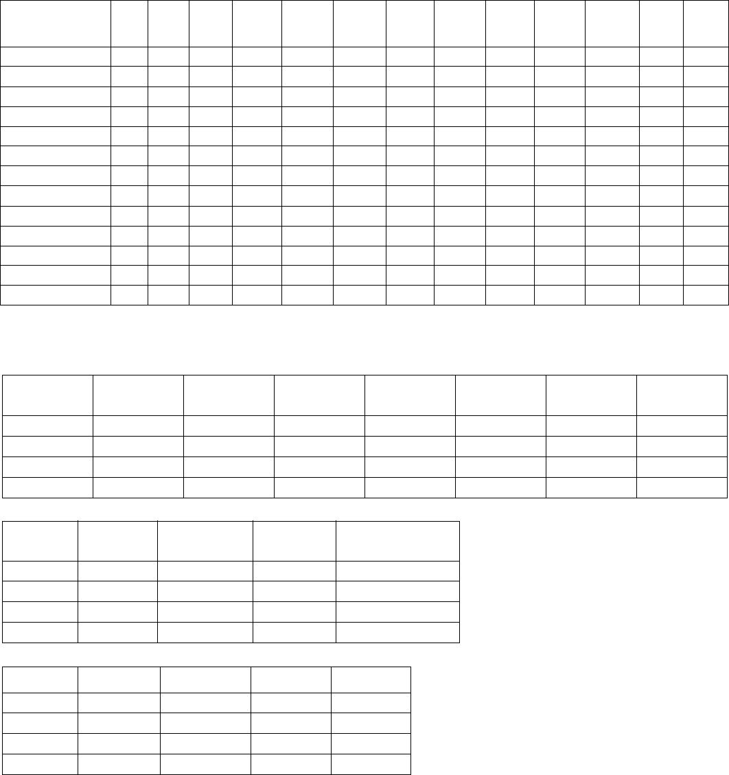
24
* Except push pull coupling
Intermating Chart
MIL Series All
5015 All*
26482 All
26500 Series I
38999 Series II
38999 Series III
38999 Series I
27599 Series II
27599 Series I
83723 Series II
82723 Series III
83723
Series
I & II
81511
Series
III & IV
81511
All 5015 X X
All 26482* X X
All 26500 X X
Series I 38999 X X
Series II 38999 X X
Series III 38999 X
Series I 27599 X X
Series II 27599 X X
Series I 83723 X X
Series II 83723 X X
Series III 83723 X
Series I & II 81511 XX
Series III & IV 81511 XX
Cross Reference by MIL-Spec to Competitor’s Part No.
MIL-DTL-38999 (Crimp Rear Release) Series I, II, III and IV
Series Amphenol Cannon/Veam G & H American
Pyle-National Deutsch Souriau American
Micro Products
I LJT KJL/LTT – TI DJT 8LT 3C&B
II JT KJ – – DJT 8T XC7C-( )
III TV-CTV KJA/VTTG3XXX G-300 T3 DTS 8D X ( )C-(
IV – – BLXX – DIV –
Series Socapex Amphenol
LTD Aero
Electric Deutsch LTD/
Dagan
I LJT LJT AE16 DJT
II – JT AE27 DTL
III TV TV AE32 ACT/DTS
IV – – – –
Series Herm Seal Hi-Rel Sealtron Glenair
I 9150 7600 A9703 23X
II 9XXX 5X000 A980X 23X
III HR 8000 A9903 23X
IV – – – 23X

25
* Denotes inactive
MIL-SPEC Cross Reference Data and General Information
MIL-Spec Description Amphenol
Proprietary
Mates
Contact
Termination &
Removal
Contact Sizes in
Series
(Wire Gauge)
Coupling
Method Other
Notes
MIL-DTL-5015 Power type connectors, large con-
tacts
Older series had solder contacts;
newer has crimp
CS, SM,
TBF 10-72XXX,
GP, SC, SF, SG, SB, FP,
10-214XXX,
10-244XXX,
10-87XXX, etc.
Solder or crimp,
front or rear removal 16 thru 0 Threaded 310X solder,
340X crimp F. R.,
345X crimp R. R.,
GT Series Reverse
Bayonet Coupling
MIL-DTL-26482
* Series 1 crimp
Miniature connector. Contacts are
medium size, both power and signal
currents, solder or crimp
PT, PT-SE, PT-CE, PTS-
DR, BP, SP, DC Solder or crimp,
front or rear removal 20, 16, 12 Bayonet thread,
version Non-Mili-
tary
311X solder,
312X crimp F. R.
347X crimp R. R.
MIL-DTL-22992 Power type connector, heavy duty.
MIL-C-5015 insert patterns, rugged.
Solder or crimp contacts
QWLD 10-193XXX,
Class L 10-473XXX,
HK - potted backshell
Solder for MS1734X,
Crimp for Military
Class “L”
16 thru 0 Threaded (quick
thread), double
stub
Class L Series is for
heavy power.
MS9055X Class “L”
MIL-DTL-83723
*Series I, II & III
Series I mates with MIL-C-26482, 2
Series II mates with MIL-C-5015
Series III mates with MIL-C-26500
Refer to applicable series.
BTK, BTW, BTR, BTA,
BNK, BYK, BYR, BYW,
BYA, BTY, BYY
Crimp, rear removal 20, 16, 12, 8, 0 Threaded and
bayonet,
depending on
series
83723/1 thru 14,
36 thru 49 Series I,
17 thru 27 -29 -30
-33 -34 -35 -50 -52
-53 Series II,
7X -8X -9X Series III
MIL-DTL-38999 Subminiature - medium and high
contact density, crimp contacts.
Series I - scoop-proof
Series I, LJT-R,
(Also see MIL-DTL-27599
solder)
Crimp, rear removal 22D, 20, 16, 12,
and coax sizes 8,
12, 16
Bayonet Intermates with
Series I of MIL-DTL-
27599
Series II - lightweight, low profile Series II, JT-R,
(Also see MIL-DTL-27599
solder)
Crimp, rear removal 22D, 20, 16, 12,
and coax sizes
12, 16
Bayonet Intermates with
Series II of MIL-DTL-
27599
Series III - High performance, but
suited for general duty Series III, TV-R, T3W,
T3K, T3F, T3S, T3N, T3Y,
Series III CTV - Composite
Crimp, rear removal 22D, 20, 16, 12,
and coax sizes 8,
12, 16
Threaded Available in Class K
Firewall and Lan-
yard Release Break-
away
Series IV Breech-Lok,
expensive design, can be difficult to
mate
None Crimp, rear release 22D, 20, 16, 12,
and coax sizes 8,
12, 16
Breech-Lok Does not meet total
performance require-
ments of Series III
MIL-DTL-26500 Miniature connector. Contacts are
medium size, both power and sig-
nal, solder or crimp
ZZW, ZZL, ZZY, ZZB Crimp, front removal 20, 16, 12 Bayonet and
Threaded Intermates with
Series III of MIL-
DTL-83723
MIL-DTL-
81511* Subminiature - medium and high
contact density, crimp contacts.
Series I & II - front release contacts
Series III & IV - rear release con-
tacts
348 Series Crimp, front (gang) &
rear removal 22, 20, 16, 12 Bayonet M81511/0X F. R.
M81511/4X R. R.
MIL-DTL-27599 Subminiature, similar to MIL-DTL-
38999 except has non-removable
solder contacts. Fully mateable with
MIL-DTL-38999
LJT-T, P - Series I
LJT-A, C, P - Series II Solder 22, 20, 16 Bayonet Intermates with
Series I and II of MIL-
DTL-38999

26
Qualified Products List
by Connector Specification
QPL No./Date Qualified Product List Manufacturer
QPL-5015-43
(6/07)
Series I, Solder Type
MS3100 Series Amphenol, ITT Cannon
Series II, Front Release Crimp
MS3400 Series ElecSys. Inc., J-Tech, TRW Cinch
Series III, Rear Release Crimp
MS3450 Series Amphenol/Matrix, ITT Cannon, J Tech, Aero Electric, ElecSys. Inc.
Accessories only* Glenair, Sunbank, Electro-Adapter, Electro-Sonic Components,
Raychem, Triangle Electronics
QPL-26482-100
(4/08)
Series I, Solder
MS3110 Series Amphenol, Array, ITT Cannon, Souriau
Hermetics only Amphenol, ITT Cannon, Glasseal, Deutsch, Sealtron, CIA, Herm Seal
Series I, Crimp
MS3120 Series Amphenol, Burndy, Cannon, Veam, Souriau, Array
Series II, Hermetic
(MS3400) Series Deutsch, Glasseal, Herm Seal, Array, Sealtron
Series II, Crimp
MS3470 Series Amphenol, Aero Electric, ITT Cannon, Deutsch, Corsair, Souriau
Accessories only* Sunbank, Glenair, Array
QPL-83723-66
(11/06)
Series I Superseded by and transferred to MIL-DTL-26482 Series II
Series II ITT Cannon
Series III Amphenol, TRW Cinch, Deutsch, Pyle-National, Aero Electric,
ITT Cannon
Hermetics only Connector Industries, Herm Seal, Sealtron
Accessories only* Glenair, Joslyn Sunbank
QPL-38999
(4/08) Series I Amphenol/Pyle, Amphenol Limited, Amphenol Socapex, Souriau, ITT Cannon,
Deutsch, Aero Electric, JEC, Hi Rel
Series II Amphenol, ITT Cannon, Deutsch, Souriau, Aero Electric, Hi Rel
Hermetics only Herm Seal, Sealtron, American Micro Products, Glenair
Series III
Amphenol, Amphenol Socapex, Amphenol/Pyle, TEC, Deutsch, Souriau,
ITT Cannon, Amphenol Limited, Deutsch LTD, Hi Rel, Aero Electric,
American Micro Products, Glenair
Series IV G & H Technology, Deutsch, Glenair
Accessories only* ESC, Joslyn Sunbank
QPL-22992-38
(1/08)
MS17340 Series (QWLD) Amphenol, ITT Cannon
Class “L” (MS90555) Series) Amphenol, General Connector
QPL-27599-14
(12/07) 38999 Solder Amphenol
QPL-26500-70
(12/05)
Miniature Cylindrical Amphenol/Pyle, TRW Cinch, Aero Electric, Herm Seal, RMS
Accessories only* Glenair, ESC
QPL-81511-9
(12/98) Amphenol, Deutsch
QPL-AS39029-2
(7/07)
MIL-C-26482 Series 1, Contacts Amphenol/Pyle, Deutsch, ITT Cannon, Tri-Star, Cinch, Veam
MIL-C-26482 Series 2, Contacts Amphenol/Pyle, Deutsch, ITT Cannon, Tri-Star, NCMI
MIL-DTL-38999, Contacts Amphenol/Pyle, ITT Cannon, Tri-Star, AMP, General Connector
MIL-C-22992, Class “L”,
Contacts Amphenol, General Connector
Other Contacts
May include all of the above, plus:
Continental Connector, AMP, J Tech. Precision Technology,
Winchester and others
* A General Note: Connector manufacturers also supply many of the accessories. QPL listings change often. Manufacturers can be added or dropped at
any time. This listing is current at the time of the printing of this publica-
tion (See back cover for printing date).
Please check the current QPL when accurate information is required.
SECTION VI
27
Amphenol®/Pyle®/Matrix® Quick Product Guide
Subminiature
Cylindrical Connectors
MIL-DTL-27599 Solder
Military # Proprietary #
MS20026 LJT00
MS20027 LJT01
MS20028 LJT06
MS20029 LJT07
MS27334 JT00
MS27335 JT02
MS27336 JT06
MS27337 JT07
MIL-DTL-38999 Series I & II
Military # Proprietary #
MS27466 LJT00R
MS27467 LJT06R
MS27468 LJT07R
MS27469 LJT00Y
MS27470 LJT07Y
MS27472 JT00R
MS27473 JT06R
MS27474 JT06R
MS27475 JT00Y
MS27476 JT02Y
MS27477 JT07Y
MS27478 JTIY
MS27479 JTS00R
MS27482 JTS00Y
MS27483 JTS07Y
MS27484 JTG06R
MS27496 LJT02R
MS27497 JTPQ00R
MS27499 JT02R
MS27500 JT08R
MS27503 JTSIY
MS27505 LJTP02R
MS27508 JTP02R
MS27656 LJTPQ00R
MIL-DTL-38999 Series III
Metal Composite (CTV)
D38999/20 TVP00R CTVP00R
TVP02R CTVP02R
D38999/26 TV06R CTV06R
D38999/24 TV07R CTV06R
TV01R CTV01R
TV09R
D38999/21 TVPS02Y
D38999/23 TVS07Y Hermetic
D38999/25 TVSIY
D38999/27
D38999/29 TV Failsafe Lanyard
D38999/30 Release Plug
D38999/31 MIL-STD-1760 Plug
High Density 38999
Inserts with 30% higher densities
Other Proprietary 38999 Types
38999 with High speed shielded contacts
38999 with PCB contacts
38999 with High Frequency contacts
Clutch-Lok TV/MTV (for high vibration)
38999 with Flex circuitry
38999 Power with RADSOK® contacts
T-Line Series
Amphe-Lite Industrial
SJT (meets European Specifications)
MIL-C-81511
Military # Proprietary #
M81511/01E 348-40E
M81511/03E 348-43E
M81511/05E 348-41E
M81511/06E 348-46E
M81511/18 348-140
M81511/21E 348-30E
M81511/23E 348-33E
M81511/25E 348-31E
M81511/26E 348-36E
Miniature
Cylindrical Connectors
MIL-DTL-26482 Series 1 Solder
Military # Proprietary #
MS3110 PT00
MS3111 PT01
MS3112 PT02
MS3113 PTIH
MS3114 PT07
MS3114 PT07
MS3116 PT06
MIL-DTL-26482 Series 1 Crimp
Military # Proprietary #
MS3120 PT00SE
MS3121 PT01SE
MS3122 PT02SE
MS3124 PT07SE
MS3126 PT06SE
MS23127 MF02SE
MS3128 MF00SE
MIL-DTL-26482 Series 2
Amphenol part # Matrix part #
MS3470 PTS00DR MB10
MS3471 PTS01DR MB13
MS3472 PTPS00DR MB11
MS3474 PTS07DR MB14
MS3475 PTGS06DR MB16
MS3476 PTS06DR MB18
Other Proprietary
(MIL-DTL-26482 Type)
PT-CE SP-CE PC-SE
SP PC PC-CE
SP-SE Matrix MBL RPT
MIL-DTL-83723 Series III
Available in Pyle or Matrix Part No.
M83723/71 thru /78
M83723/82 thru /92
M83723/95, /96
Matrix only: M83723/66 thru /69 Quick Disconnect
MB3, MT3
MIL-DTL-26500
MS24264 ZZY
MS24265 ZZW
MS24266 MS27613
BACC45FN, FT, FS, FM
MS27614
BACC63BP, BV MS27615
BACC63CB, CC
Other Proprietary Miniature Types
67 Series 165 Series
Engine Connectors
(Class K Firewall)
D38999/20 BACC63BR/BT
D38999/24 BACC63CN/CM
D38999/26 M83723/82-92
ESC-10, 11 M83723/95, /96, /97
EN2997 ASN-EO
MIL-DTL-26500 types:
FPK, FPL, FP5K, FYL
Standard/Heavy Duty
Cylindrical Connectors
MIL-DTL-5015 97 Series 97 Series
Solder Solder Crimp
MS3100 97-3100 97-4100
MS3101 97-3101 97-4101
MS3102 97-3102 97-4102
MS3106 97-3106 97-4106
MS3107 97-3107 97-4107
MS3108 97-3108 97-4108
97 Series is UL Approved file E115497(N) and
CSA Approved certification file LR69183
Matrix MIL-DTL-5015, Series III
Crimp Rear Release
MS3450 9440
MS3451 9441
MS3452 9442
MS3454 9444
MS3456 9446
MS3459 9816
9817 Quick Disconnect
9818 Quick Disconnect
Proprietary GT Series (5015 inserts)
(Reverse Bayonet)
GT-A GT-G GT-AGG
GT-AF/F GT-R GT-PP
GT-CF/CFZ GT-RV GT-PC
GT-CFGG GT-E GTC-M
GT-LCF/LCFZ Vortex GT
Proprietary ACA-B Series
ACA-B Reverse Bayonet (5015 inserts)
Proprietary AC Series
AC Threaded (5015 inserts)
Heavy Duty
QWLD Class L
MS17343 MS90555
MS17344 MS90556
MS17345 MS90557
MS17346 MS90558
MS17347
MS17348
Pyle Star-Line (UL, CSA listed)
Pyle Star-Line EX (certified for use in
Zone 1-IIC hazardous environment)
Pyle Star-Lok (UL, CSA listed)
Amphe-EX (ATEX and IECex rated)
RIG-Power & VFD rated inserts
Other Proprietary Standard
and Heavy Duty Types
Commercial Aircraft types:
DC Series and 10-244 Series
BT-M, BT-MA and BT-RA
Other Proprietary types:
Pre-Earth FMLB Series, 7 Series,
MS Modified types,
QWL, QWP Heavy duty types
Amphe-Power Connectors with
High Amperage RADSOK
®
Sockets
Amphe-Power P-Lok
Amphe-Power GT (Amphe-GTR and
Power GT)
Amphe-Power 5015 (AC Series)
Amphe-BU, Amphe-Armor, Amphe-Y
RADSOK® technology is being incor-
porated into Mil-Aero products:
Rectangulars and LRM, 38999, 5015
RADSOK
®
Busbar Products
Amphe-PD RADLOK
SurLok RADSERT
Tru-Loc PGY
Amphe-Base PowerBlok
Amphe-Com

28
Amphenol®/Pyle®/Matrix® Quick Product Guide
EMI Filter/Transient
Protection Devices
Intermateable with/Features of
FTV - MIL-DTL-38999 Series III
FJT - MIL_DTL-38999/27599 Series II
FLJT - MIL-DTL 38999/27599 Series I
FSJT - Proprietary SJT
FBL - MIL-DTL-38999 Series IV
FPT - MIL-DTL-26482 Series 1 & 2
- MIL-DTL-83723 Series I
Other EMI/Transient Protection
MOV’s Hermetic Filters
Diodes Filter Adapters
EMP Filtered Plugs
“AN” Filters
Amphenol Canada Filter Products:
485 Series Filtered ARINC 404 & 600
MIL-DTL-24308 Filter D-Subs
MIL-DTL-83513 Micro D-Subs
Fiber Optic Products
Fiber Optic Termini:
MIL-PRF-29504/4 & /5 Multi-mode size 16
Multi-mode, HD20
MIL-PRF-20504/4 & /5 Single mode size 16
90° Multi-mode size 16
ARINC 801
MT ferrule
Fiber Optic Cylindrical Connectors -
Tri-Start, MIL-DTL-38999 Series III
Incorporating MIL-PRF-29504 or ARINC 801 or
MT termini
Fiber Optic Bulkhead Feed-through
Fiber Optic Rectangular Connectors:
PCB - Brush & Fiber Optic Combinations
LRM - Brush & Fiber Optic Combinations
VMEP0/J0, Ruggedized VITA-46
Fiber Optic Rack & Panel Connectors:
ARINC 600, R27 and R58 Series
Other Fiber Optic Products
Fiber Optic Cable Systems
MFM Family: Hermaphroditic, Duplex, Simplex
TFOCA-II
CTOS, CTOL, AXOS Field Deployable Lens
ST Fiber Optics
MIL-PRF-NGCON
MTRJ Field
Tactical Optical Splice
Fiber Optic Termination Tools
Printed Circuit Boards
and Flex Circuitry
Design formats of Mentor, PADS, Cadence,
Zuken. Panel thickness: .500”
Panel Sizes: 24” x 54”, 30” x 44”, 36” x 42”
Layer count up to 64
Interconnect formation types: back drilled,
dual dia., thru hole, blind, electrically isolated,
buried, SMT
Many other options and material choices
Flexible and Rigid-Flex
For attachment to Printed circuit boards:
Press fit connectors
Cylindricals with PC Tail contacts
Universal Header Assemblies
Flex Circuit Assemblies
Printed Circuit Bd. Terminal Blocks
Wiring Interface Modules
Board Level
Rectangular Connectors
MIL-DTL-55302
with Bristle Brush Contacts
M55302/166 MB ( )-( )P
M55302/167 MB ( )-( )W
M55302/168 PC ( )-( )P
M55302/169 IO ( )-( )C
M55302/169 IO ( )-( )P
M55302/170 DB ( )-( )P
MIL-DTL-55302
with Crimp, Solder or PCB Contacts
M55302/67-69 PCB90A
M55302/70-71 PCB100A
M55302/76-77 PCB100B
M55302/74-75 PCB100C
M55302/72-73 PCB150A
High Density Rectangular Connectors
HDB3 Mother Board/Daughter Board
HiLinx
Viper
LRM Surface Mount
with Bristle Brush Contacts
Module and Backplane connectors with
standard Brush contacts
Staggered Grid - 180 contact pattern grid
GEN-X Grid - 236 contact pattern grid
SEM-E or custom form factors
Air-flow inserts for wider boards
LRM can incorporate Fiber Optics,
RF contacts, shielded high speed contacts,
in combinations with Brush contacts
LRM with flex circuitry
LRM power supply modules
VME Rectangular Products
Ruggedized VME64-X
Ruggedized VME P0/J0
Backplane Connectors
with Tuning Fork & Blade Contacts
UHD (Ultra High Density) Connectors
NAFI (Daughtercard/Backplane Conn.
Other Rectangular Connectors
I/O NAFI Series
LMD and LMS Modules
Amphenol AirLB SIM Modulars
SIHD, SIAL Interconnects
VITA -46
Heat Sink Manufacturing
Amphenol Canada products: R39, R58
and SD308, CD308
Backplane Systems
Electrical and Optical Backplane Systems that
can incorporate:
MIL-DTL-55302 brush contacts
NAFI fork and blade contacts
UHD fork and blade
ARINC
MIL-DTL-38999 Cylindricals
MT Optical Ferrules
Rack & Panel Connectors
Rectangular Rack and Panel:
Ruggedized, Non-Floating Brush
LPSRC, SR
217 Series
LE, LPX Series
ARINC 404, ARINC 600
R27 Series
RFM Modular Series
Micro D-Subs
Cylindrical Rack and Panel:
RNJ Series
Special Purpose
Interconnection Products
Hermetics
Available in the following series:
MS Standard MIL-DTL-5015
Miniature MIL-DTL-26482
Subminiature MIL-DTL-38999, I, II, III
Breakaway/Lanyard Release
Available in the following series:
Fail-Safe Subminiature MIL-DTL-38999
Twist-Pull Miniature MIL-DTL-26482
Quick Disconnect Matrix MIL-DTL-83723
Quick Disconnect Matrix MIL-DTL-5015
Stores Management Type II, Rail Launch
1760 Weapons Release
Gatelink Breakaway
Battlefield Interconnects & Cables
Stinger Missile types
EMC Protected & Over-molded Cable
Sincgars, Bowman Program Connectors
Wind Corrected Munitions Dispenser
Rail Mass Transit/Industrial
Interconnects & Cables
Freight-Mate Cable Assemblies
Trans-Power & 27 Pole Train-Line
Over-molded Cable available with any
Amphenol cylindrical industrial connector
Data Bus Products
Can Couplers, Box Couplers
ARINC 629 Current Mode Couplers
Wire Integrated Connectors (W.I.C.s)
711 Data Bus
Other Special Purpose Products
RJ Field, USB Field, MTRJ Field, EZ Field
Amphenol Nexus Technologies Products
for Audio Frequency Protection
SV Microwave Connectors
Aquacon Immersible
Pyle Pon Series Indicator Lights
WFRS Interlocked Safety Switches
Astronaut Zero-G Connectors
PMAT (ARINC 644)
Geophysical Miniatures
SCE and Mini SCE Push Pull
PPM Push-Pull
Shorting Plugs
Micro-Miniature Connectors
ECTA 133, ECTA 544
Quick Connection Modules
1900 Rectangulars
AT Series Circular J1939 Diagnostic.
Contacts and
Accessories
Crimp M39029, Thermocouple, Wire wrap,
Coaxial, Twinax, Triax, Quadrax and
Differential Twinax Shielded Contacts
Bristle Brush Contacts for Rectangulars
Fork & Blade Contacts for Rectangulars
Fiber Optic Termini
RADSOK® Contacts for High Amperage
High Frequency Contacts with “Float
Mount Technology
AT Series Contacts
M85049 Accessories
Backshells
Industrial Cord Grips and Cable Glands
Pipe & Cable Supports
Relay Sockets and Junction Modules
We invite you to visit our websites where you
can find product catalogs that can be down-
loaded and printed. Catalogs will be added
and updated on an on
-
going basis.
www.amphenol-aerospace.com
www.amphenol-industrial.com
www.amphenol-abs
29
Know the Language
Common terms you should know
(listed alphabetically)
• Accessories -
Mechanical devices, such as cable added to
connector shells and other such hardware that are attach-
able to connectors to make up the total connector configura-
tion; while providing wire support and/or wire sealing
• Bayonet Coupling -
A non-threaded, ramp type of
coupling
• Cable Assembly -
A cable with plugs or connectors on each
end
• Configuration -
Arrangement of contacts in a multiple-con-
tact connector
• Contacts -
Mechanical component to which electrical
engagement is accomplished
• Contact Size - (Also known as Wire Gauge) -
the largest
wire that can be used with a specific contact
• Contact Spacing -
The distance between the center-lines of
adjacent contact areas.
• Coupling Nut -
Outer threaded or grooved ring which holds
mated pair together
•Crimp Contact -
A contact to which wire is joined by
mechanical squeeze
• EMI or RFI Backshell -
A type of accessory to terminate
wire shielding
• Environmentally Sealed -
Connector provided with gas-
kets, seals, potting or other devices to keep out moisture,
dirt, air or dust that might reduce its performance
• Extraction/Removal Tool -
A handheld tool used for remov-
ing a contact from a connector.
• Fiber Optic Termini -
Comparable to electrical pin and
socket contacts, except they transmit data optically through
fibers instead of electrically through wires.
• Gland -
Resilient ring in rear accessory, provides seal on
jacketed cable
• Grounding Fingers -
A metal strap around plug shell for
positive shell-to-shell conductivity/shielding
•Grommet -
Resilient part at back of insert (attached or sepa-
rate); gives wire moisture seal
• Hermetic -
A connector with fused glass insert for air
tightness
• Insert -
The dielectric or insulating inner core, holds
contacts
• Insert Arrangement -
The number, spacing and arrange-
ment of contacts in a connector
• Insertion Tool -
A small, handheld tool used to insert con-
tacts into a connector
• Interfacial Seal -
A resilient part on the face of pin inserts
which provides moisture seal.
• Jam Nut -
Hex nut that holds receptacle to a panel
• Mating Pair -
Two connectors that couple together. Shell
size insert arrangement and rotation must be compatible
• Mating/Unmating Forces -
Torque required to couple/
uncouple a mating pair of connectors or contacts
•“O” Ring -
Doughnut-shaped ring of rubber used as a seal
around the mating insulator interface of cylindrical
connectors
• Pin Contact -
Male half of a mated pair of contacts*
• Plating -
The metal finish applied to contacts and or shell
components (protective) to resist corrosion and wear
•Plug -
The cable/coupling half of a mating pair
• Potting Boot -
A type of accessory which forms a mold for
potting compound
• Rear Termination -
An accessory which threads to back of
shell
• Receptacle -
The panel/receiving half of a mating pair
• Sealing Plug -
Plastic type slug, placed in unused grommet
holes to seal
• Service Rating (Also known as Current Rating) -
The
maximum voltage or current that a connector is designed to
carry continuously.
• Shell -
Houses insert and contacts
• Socket Contact -
Female half of a mated pair of contacts
• Solder Contact -
A contact to which wire is joined by solder-
ing. Has a cup, hollow cylinder, eyelet or hook to accept a
wire for conventional soldered termination.
• Strain Relief (Also known as Cable Clamp) -
A type of
accessory which clamps wires for support
*Note: Male half always goes into female.
SECTION VII
Connector:
A device providing electrical
or signal connection.
It consists of a plug and receptacle.

30
Know the Language - Other Interconnection Product Terms
• Alternate Rotations -
In cylindrical connectors:
Rotation of
either an insert or designated key/keyway locations (Alternate
Keying) in a connector shell to a different angle than normal
position. Allows for variations of mating two halves of cylindri-
cal connectors.
• Anodize -
Formation of a protective, insulating oxide layer on
metal bay electrolytic action.
• Arc Resistance -
The characteristic of insulating materials to
resist carbonization (also known as tracking) of the material
surface between electrodes resulting from voltage break-
down.
• Attenuation -
(this term is used in Filters) The ratio of the
input to output power levels in a network (transmission line)
when it is excited by a matched source and terminated in a
matched load.
• Back-mounted -
When a connector is mounted from the
inside of a panel or box with its mounting flanges inside the
equipment.
• Circuit -
A complete path or electron flow from a negative ter-
minal of voltage source through a conductor and back to the
positive terminal.
• Closed Entry Socket Contacts -
A female contact designed
to prevent the entry of a pin or probing device having a cross-
sectional dimension greater than the mating pin.
• Coaxial Cable -
A high-bandwidth cable consisting of two
concentric cylindrical conductors with a common axis that is
used for high speed data communication and video signals.
• Compliant Contact -
A press-fit type contact used to attach
to a printed circuit board. Has an eyelet end.
• Conductivity -
The ability of a material to conduct electric
current, expressed in terms of the current per unit of applied
voltage. It is reciprocal of resistivity.
• Contact Durability -
Endurance measured by the number of
insertion and withdrawal cycles that a connector withstands
remaining within its specified performance level.
• Contact Engaging and Separating Force -
Force needed to
either engage or separate pins and sockets when they are
out of connector inserts. Values are generally established for
maximum and minimum forces.
• Contact Resistance -
Maximum permitted electrical resis-
tance of pin and socket contacts when assembled in a con-
nector under typical service use.
• Contact Retention -
The minimum axial load in either direc-
tion that a contact must withstand while remaining firmly fixed
in its normal position within the connector insert or housing.
• Continuity -
A continuous path for the flow of current in an
electrical circuit.
• Corrosion -
The destruction of the surface of a metal by
chemical reaction.
• Coupling Torque -
Force required to rotate a coupling ring or
jackscrew when engaging a mating pair of connectors.
• Diallyl Phthalate (DAP) - (
Blue insert in 97 Series) A thermo-
setting plastic that offers outstanding dimensional stability
and resistance to most chemicals and chemical compounds.
• Dielectric -
Any insulating medium that intervenes between
two conductors.
• Dielectric Withstanding Voltage -
Maximum potential gradi-
ent that a dielectric material can withstand without
failure.
• Discontinuity -
A broken connection or the loss of a specific
connection characteristic.
• Edge Connector -
One piece receptacle, containing female
contacts designed to receive the edge of a printed circuit
board and interconnect on which the male contacts are
etched or printed. The connector may contain either a single
or double row of female contacts.
• Edgeboard Connector -
A connector that mates with printed
wiring leads running to edge of a PC board.
• Feed-through -
A conductor that connects patterns on oppo-
site sides of a PC board. Also called interfacial
connection.
• Fiber Optics -
A data transmission medium consisting of
glass fibers. Light-emitting diodes send light through the fiber
to a detractor, which then converts the light back into electri-
cal signals.
• First Article -
A sample part or assembly manufactured prior
to the start of production for the purpose of assuring that the
manufacturer is capable of manufacturing a product that will
meet the requirements.
• Front-mounted -
A connector is front-mounted when it is
attached to the outside or mating side of a panel. (Can only
be installed or removed from the outside of the equipment.
• Front Release Contacts -
Connector contacts are released
from the front side of the connector and then removed from
the back wire side of the connector. The removal tool
engages the front portion of the contact and pushes it out the
back where it is removed by hand.
• Harsh or Hostile Environment Connector -
A connector
designed and engineered for operation in hostile environment
conditions, such as extreme high temperatures of 677°C
(1,250°F), extreme low temperatures of absolute zero and
severe water tight conditions.
•Header -
A feed through device that introduces a conductive
path through an insulating plate.
• Hermaphroditic Connector - I
nterconnecting device in
which both mating parts are identical at their mating surfaces.
(Also called Sexless Connector)
• Hermaphroditic Contact -
A contact in which both mating
elements are precisely alike at their mating face.
• Input/Output Connector -
A mating pair of connectors used
to carry signals into and out of a panel-mounted subsystem.
An example is connector pair that interconnects the individual
back panels in a large array of panels.
• Insert Retention -
Axial load in either direction that an insert
must withstand without being dislocated from its normal posi-
tion in the connector shell.
• Insertion Force -
The effort, usually measured in ounces,
required to engage mating components.
• Interchangeable -
Characteristic of connectors in which one
manufacturer’s connector can be replaced by the connector
of another manufacturer and provide the same function in the
same panel space as the connector it is replacing.
• Intermateable -
Characteristic of connectors in which a con-
nector half manufactured by one connector will mate directly
with a connector half manufactured by a different company
SECTION VII

31
Know the Language - Other Interconnection Product Terms
•
.
Keying -
Mechanical arrangement of guide pins and sock-
ets, keying plugs, contacts, bosses, slots, keyways, inserts or
grooves in a connector housing, shell or insert that allows
connectors of the same size and type to be lined up without
the danger of making a wrong connection.
• Lanyard -
A device attached to certain connectors that permit
uncoupling and separation of connector halves by a pull on a
wire or cable.
• Life Cycle -
A test that indicates the time span before failure;
the test occurs in a controlled, usually accelerated, environ-
ment.
• Mass Termination -
Method of termination in which termi-
nals that pierce flat cable insulation without stripping to cold
flow mate with conductors and form a metal-to-metal joint.
• Motherboard -
A printed board used for interconnecting
arrays of plug-in electronic modules.
• Operating Temperature -
Maximum internal temperature-
resistant capabilities of a connector in continuous service
.
• Outgassing -
De-aeration or other gaseous emission from a
printed board assembly (printed board, component of con-
nector) when exposed to a reduced pressure or heat, or both.
• Panel-mount -
Fixing a connector half to a board, panel or
frame. Usually, the female portion of the connector is
mounted, and the male half is the removable portion.
• Plated Through-Hole -
A hole-formed deposition of metal on
the sides of the hole and on both sides of the base to provide
electrical connection from the conductive pattern on one side
to that on the opposite side of the PC board.
• Poke-Home Contact -
Term applied to a male or female con-
tact to which a wire has been permanently affixed prior to the
assembly of the contact into the insert.
• Positioner -
Device attached to the crimping tool to position
conductor barrels between the indentors.
• Potting -
Sealing of a component (for example the cable end
of a multiple contact connector) with a plastic compound or
material to exclude moisture, prevent short circuits and pro-
vide strain relief.
•Pre-tinned -
Solder applied to an electrical component prior
to soldering.
• Pre-tinned Solder Cup -
Solder cups with inner surfaces that
have been pre-coated with a small amount of tin lead solder
or RoHs approved solder.
• Press-fit Contact -
Either a solid pin or a pin having a com-
pliant member that makes an interference connection with a
through-hole on a PC board. The pressure developed
between interconnecting surfaces is sufficient to provide gas-
tight electrical reliability without the use of solder.
• Qualified Products List (QPL) -
A list of commercial prod-
ucts that have been pretested and found to meet the require-
ments of a specification, especially government
specifications.
• Quick-disconnect Coupling -
A design feature, apparent in
the quick-disconnect connector; it permits relatively rapid
joining and separation.
• RADSOK
®
Contact* -
A unique socket contact design with a
stamped and formed twisted inner grid. Socket cylinder within
the female contact has several equally space longitudinal
beams twisted into a hyperbolic shape. As male pin is
inserted, axial members in the female half deflect, imparting
high current flow across the connections.
•Ramp -
The sloped channel that accepts the detent pin in a
bayonet connector.
• Rear Release Contacts -
Connector contacts are released
and removed from the rear (wire side) of the connector. The
removal tool engages the contact from the rear and pulls the
contact out of the connector contact retainer.
• Rear Seal -
Design feature that provides an environmental
seal at the rear of plug or receptacle.
• Removable Contact -
A contact that can be mechanically
joined to or removed from an insert. Usually, special tools are
required to lock the contact in place or remove it for repair or
replacement.
• RoHS (Restrictions of Hazardous Substances) -
The
RoHS Directive bans the placing on the EU market of new
electrical and electronic equipment containing more than
agreed levels of lead, cadmium, mercury, hexavalent chro-
mium, polybrominated biphenyl (PBB) and polybrominated
diphenyl ether (PBDE) flame retardants.
• Scoop Proof -
Design feature whereby exposed contacts of
a connector cannot be touched or damaged by any portion of
the mating connector.
• Serrations -
Small grooves or indentations within a terminal
wire barrel that increase the tensile strength and electrical
conductivity of the crimped termination.
• Soldering -
Process of joining metallic surfaces with solder,
without the melting of the base metals. Soldering is an eco-
nomical, versatile and fast termination method. A soldered
connection has metallic continuity and excellent long term
reliability.
• Splice Connector -
A joint connecting conductors with good
mechanical strength and good conductivity; a terminal that
permanently joins two or more wires.
• Surface Mounting - T
he electrical connection of components
to the surface of a conductive pattern without utilizing compo-
nent holes.
• Thermal Shock -
The effect of heat or cold applied to a
material at such a rate that non-uniform thermal expansion or
contraction occur. In connectors, the effect can cause inserts
and other insulation materials to pull away from metal parts.
• Thermocouple Contact -
A contact of special material used
in connectors employed in thermocouple applications. Materi-
als often used are iron, constantan, copper, chromel and
alumel.
• Tuning Fork Contact -
U-shaped female contact that resem-
bles a tuning fork. It can be stamped or formed.
• Umbilical Connector -
A connector used to connect cables
to a rocket or missile prior to launching, and which is removed
from the missile at the time of launching.
• Wire-Wrapped Connection (Also known as Solderless
Wrap) -
A solderless connection made by wrapping bare wire
around a square or rectangular terminal with a power or hand
tool.
* RADSOK® is a registered trademark of Amphenol Industrial Operations.
SECTION VII

32
Basic Questions to Determine Connector Requirements
• How many conductors (wires) and what are the
wire gauges (size)?
Smallest contact sizes available by Military Specifica-
tions:
MIL-DTL-5015 - size 16
MIL-DTL-22992 - size 16
MIL-DTL-26482 - size 20
MIL-DTL-38999 - size 22D
• What’s your working voltage requirement?
See catalog insert arrangement table
Catalog 12-024 ....GT Reverse Bayonet
Catalog 12-020 ....MIL-DTL-5015
Catalog 12-026 ....MIL-DTL-5015 Matrix
Catalog 12-052 ....MIL-DTL-22992 Class L, QWLD
Catalog 12-053 ....MIL-DTL-22992 QWL
Catalog 12-070 ....MIL-DTL-26482, Series 1
Catalog 12-071 ....MIL-DTL-26482, Series 2
Catalog MS-102...MIL-DTL-83723, Series III Pyle
Catalog 12-073 ....MIL-DTL-83723, Series III Matrix
Catalog 12-090*...MIL-DTL-38999, Series I, II
Catalog 12-092*...MIL-DTL-38999, Series III
• Are you using your connector in a benign envi-
ronment or a harsh environment?
Harsh environment - will need gaskets, grommets
and/or glands for environmental sealing
• Do you want to Solder or Crimp your wires?
• Are you going cable to cable or cable to panel?
Cable plug to Cable receptacle use:
– Straight plug with Inline cable receptacle
– 90° Plug with Inline cable receptacle
Cable plug to Panel receptacle use:
– Straight plug with either a wall mount receptacle,
box mount receptacle, or jam nut receptacle
– 90° plug with either a wall mount receptacle, box
mount receptacle, or jam nut receptacle
• What’s your cable outer diameter (OD)? Or are
you using discrete wires?
• Do you have any material restrictions?
– RoHS requirement
– Stainless steel
– Aluminum
– Neoprene
– Silicon
– Viton
• What type of plating or finish is preferred?
Common platings or finishes:
– Olive drab cadmium
– Nickel
– Black zinc alloy
– Electroless nickel
– Anodic coating
• Will you need accessories?
– Cable clamp
– Bushing
– Protection caps (metal or plastic)
– Dummy receptacle
• Are you using an electrical or signal connector?
POWER
MIL-DTL-5015 and Amphenol GT Reverse Bayonet
– Standard contacts or (High Amperage) RADSOK®
MIL-DTL-22992
MIL-DTL-26482
MIL-DTL-38999 Series I, II, III
Hermetic
MIL-DTL-26482
MIL-DTL-83723
MIL-DTL-38999 Series I, II, III
SIGNAL
MIL-DTL-5015
– High Frequency contacts
MIL-DTL-22992
– High Frequency contacts
MIL-DTL-38999, Series I, II, III
– High Frequency contacts
– Fiber Optics
Brush Technology
– Rectangular PCB
–LRM
– Fiber Optics
Filter
MIL-DTL-38999 Series I, II, III
MIL-DTL-26482
Hermetic
MIL-DTL-26482
MIL-DTL-83723
MIL-DTL-38999 Series I, II, III
NOTE: Socket contacts are to be used in the connector
feeding the power
NOTE: Not all connectors are limited to solely either power
or signal. Many connectors can perform both functions.
SECTION VII, cont.
* Catalog 12-C1 combined catalog for 38999 Series I, II and III Connectors
will replace catalog 12-090 (Series I, II) and catalog 12-092 (Series III).
Consult Amphenol Aerospace for the availability of this new catalog.
33
What do you need to Sell?
✓A Basic Product Knowledge
•Why connectors are needed
• Nomenclature (component parts)
• Typical terms or descriptive words
• Pertinent references to MIL-Spec
• Cross reference Amphenol P/N to MIL P/N
✓A Catalog
• Know how it is organized
• Keep it current
• Add your own notes for reference
✓Know Our Websites
www.amphenol-aerospace.com
www.amphenol-industrial.com
• Quickly navigate on-line to -
• Connector Catalogs
• Service Instructions
• Your Contact Information
• Markets Served
• Connector Basics has this brochure and other
valuable basic connector information
• Amphenol One for Distributor Information and
Latest Product News
✓Know Your Organization and Ours
• Who has pricing & delivery data
• Who has technical data
• Who can expedite
• Who can negotiate
• A back up for each of the above
✓Know Yourself and Your Competitors
• What is negotiable at your account
• What are your strong points
• What are your weak points
• What are your protection points
• Who is your competition
✓Know Your Customers
• What are their Needs?
• Company Needs – Personal Needs
✓Learn to Listen (and to See)
• What are they saying?
• What do they mean?
– How they say it may mean more than what they say
– What you both see may say more than conversation
✓Each account is unique
• Don’t use a carbon copy approach
• Let your customers know you see them that way
✓Take time to know the people you deal with
• Both at your account and your facility
• Manage your time and territory like assets
• If business or potential isn’t there, maybe you shouldn’t be
Conclusion
The data in this booklet was designed to provide you with
basic information on Amphenol connector products.
In order to effectively sell, it is important to remember that
knowing your customer and your product go hand in hand.
The sale begins with you!
We have a great line, you can sell on the quality that it is.
Don’t promise more than you can deliver, simply tell it like it
is. You may lose some sales, but your credibility will grow.
SECTION VII, cont.

34
L-1102-7 Printed in U.S.A. JCP 9/08
AMPHENOL CORPORATION
Amphenol Aerospace Operations
Amphenol Industrial Operations
607-563-5011
40-60 Delaware Avenue
Sidney, New York 13838-1395
