Air Hogs Ornithopter Kpeterson Iros11
User Manual: Air Hogs Ornithopter
Open the PDF directly: View PDF ![]() .
.
Page Count: 7
Experimental Dynamics of Wing Assisted Running for a Bipedal
Ornithopter
Kevin Peterson and Ronald S. Fearing
Abstract— BOLT is a lightweight bipedal ornithopter capa-
ble of high-speed dynamic running and effecting transitions
between aerial and terrestrial locomotion modes. The gait
dynamics of both quasi-static and dynamic locomotion are
examined through the use of an on-board accelerometer, part
of a one gram electronics package also containing a processor
and radio. We discuss the accelerations in the context of the
traditional spring-loaded inverted pendulum model seen in
nearly all legged locomotion in organisms. Flapping wings are
shown to provide damping along with propulsive force. The
aerodynamic forces of the flapping wings also impart passive
stability to the robot, enabling it to run bipedally with only
a single actuator. BOLT transitions from ground running to
aerial hovering in as little as one meter of runway. Overall, the
advantages provided by wings in terrestrial locomotion, coupled
with aerial capabilities, allow BOLT to navigate complex
three dimensional environments, switching between locomotion
modes when necessary.
I. INTRODUCTION
Navigating complex three dimensional environments is an
ability that is seemingly trivial for small animals, yet pro-
vides significant challenges for robots today. Small, mobile
robots (mass on the order of grams, linear dimensions on
the order of centimeters) provide many advantages when
exploring an environment, and are capable of operating in
small spaces unreachable by a larger robot. In addition,
their small size allows multiple robots to be transported and
deployed, greatly increasing the amount of area they can
cover.
While there are many advantages to small robots, there are
also many obstacles they have trouble navigating. Obstacles
much larger than the robot present a significant challenge
in legged locomotion, and even robots with the ability to
climb up obstacles would be impeded when confronted with
an aquatic obstacle. In confined spaces, aerial robots are
often unable to navigate, giving an advantage to a terrestrial
robot. Flying also requires a large amount of energy, and no
robot can stay aloft indefinitely. Terrestrial locomotion may
be more energy efficient for shorter distances, and would
allow for locomotion even if the energy for flight is spent.
By being capable of both aerial and terrestrial locomotion,
This work was supported by the United States Army Research Labora-
tory under the Micro Autonomous Science and Technology Collaborative
Technology Alliance
Kevin Peterson is with Department of Electrical Engineering and
Computer Sciences, University of California, Berkeley, CA 94720, USA
kevincp@eecs.berkeley.edu
Ronald S. Fearing is with Department of Electrical Engineering and
Computer Sciences, University of California, Berkeley, CA 94720, USA
ronf@eecs.berkeley.edu
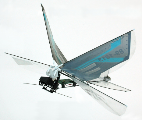
Fig. 1. BOLT: a bipedal ornithopter capable of both arial and terrestrial
locomotion.
a hybrid robot could choose the best mode of locomotion
given the obstacles confronting it.
Many successful small terrestrial robots have been pre-
viously developed, including DASH [1], DynaRoACH [2],
Mini-Whegs [3], Sprawlita [4], iSprawl [5], and RHex [6].
With the exception of Mini-Whegs, these robots all use
six legs arranged in an alternating tripod configuration for
passive stability when running. In contrast, dynamic bipedal
running has generally required a complex controller and
multiple actuators to maintain stability. Dynamic bipedal
running has been previously demonstrated by RHex [7],
along with an extensive list of larger bipedal robots. At the
very small scale, dynamic bipedal running can be seen in the
cockroach Periplaneta americana when it is running at its
fastest speeds [8]. The locomotion dynamics of these robots
is characterized by the spring loaded inverted pendulum
model (SLIP) [9], a pattern exhibited by nearly all legged
organisms despite widely varying leg numbers [10].
There have also been many ornithopters capable of hov-
ering in an indoor environment, namely DelFly II [11], a
hummingbird sized ornithopter developed by Nathan Chro-
nister [12], and the Aerovironment Nano Hummingbird
[13]. Previous work on small hybrid robots includes MALV
[14] and its descendant MMALV [15], the SkyhopperTMby
WowWeeTM, and the EPFL microglider [16] currently under
development. Work has also been done on aerial-terrestrial
transitions, with [17] and [18] both capable of wall perching.
Other hybrid robots which have been developed primarily
focus on terrestrial and aquatic locomotion such as Boxybot
[19] and AQUA, a waterproof version of RHex [20].
The Bipedal Ornithopter for Locomotion Transitioning, or
BOLT (Fig. 1), is a small lightweight robot capable of both
aerial and terrestrial locomotion modes. The integration of an
electronics package allows two-way communication and the
investigation of the robot dynamics with a six-axis inertial
measurement unit (IMU). BOLT has a total weight of 11.4
grams, with a wingspan of 28 cm and a length of 17.5 cm.
The robot is capable of dynamic high-speed bipedal loco-
motion by exploiting its aerodynamic properties for stability.
The use of aerodynamics during bipedal locomotion has been
previously seen in some birds [21], although generally only
in inclined running. BOLT can transition from terrestrial
locomotion to hovering in as little as one meter of space,
and has demonstrated the ability to takeoff on smooth tile,
foam, carpeted flooring, and plywood. BOLT can also take
off from inclined ledges, with up to a 45 degree slope tested.
The Smart Composite Microstructures (SCM) [22] process
allows the integration of a lightweight leg structure with the
rest of the body, comprised mainly of carbon fiber spars.
II. MECHANICAL DESIGN
The primary design goal for BOLT is developing a plat-
form capable of both terrestrial and aerial locomotion. To ac-
complish this goal, we combine the gearbox and wings from
a commercial ornithopter (Air HogsTMV-wing AvengerTM)
with a custom airframe, leg design, and electronics package.
Because of the desire for stable hovering flight, weight and
weight distribution are a key consideration in all design
decisions. A single motor drives both the leg and the wings,
allowing sufficiently high power density to maintain hovering
flight.
A. Airframe Design
BOLT’s airframe uses carbon fiber spars for structural
rigidity. The lightweight properties of carbon fiber make
it ideal for use in a flying platform. A rigid airframe is
critical in preventing serial compliance from reducing the
wing thrust. To create a lightweight tail, carbon fiber spars
are placed in a cardboard pattern and a 12.7 µmfilm of
polyethylene terephthalate (PET) is overlaid and attached to
the spars with cyanoacrylate (Fig. 2(a)). The construction
materials of the tail are similar to those used in [11], a
successful ornithopter on the same size scale as BOLT.
The center of mass location of the robot is important for
determining the posture of the robot when it is in the air.
We place the battery at the very posterior of the robot on the
tail, while the controller board is placed within the airframe.
This gives the robot a vertical posture, with the majority of
the wing thrust directed downward. By adjusting the position
of the controller board, the robot can be set to either hover
in place or fly forward at a slow rate. The airframe of the
robot also protects the controller board during operation.
Directly mounting the controller board to the rigid carbon
fiber airframe overwhelms the accelerometer due to the high
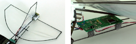
(a) (b)
Fig. 2. (a) shows the tail of the robot, constructed from carbon fiber spars
and 12.7 micron thick PET film. The battery is placed at the back of the
tail to maintain proper weight distribution. (b) shows the controller board
mounted on small foam offsets. The foam offsets are critical for dampening
the high frequency vibrations of the body.
frequency vibrations produced by the motor transmission.
To accurately study the dynamics of the robot, the board is
moved forward and placed on foam mounts (Fig. 2(b)) to
dampen the vibration noise and improve the quality of the
acceleration measurements.
A critical feature enabling ground-to-air transitions of the
robot is the angle of attack of the wings. The clap-and-peel
design of the wings produces force directed perpendicularly
to the stroke plane. On the initial iterations of BOLT, the
wings had a low angle of attack, directing propulsive force
horizontally when running along the ground. This robot was
capable of flight, but could only takeoff by running from
a one meter or higher ledge. Once in the air, the center of
mass location caused the tail to swing under the robot and it
entered a stable flight posture. Increasing the wing angle of
attack allows the robot to build lift as the forward speed
increases, eventually causing the robot to pitch upwards,
directing the main flapping force downwards. This leads to
takeoff from the ground and the robot entering a stable flight
posture due to the center of mass location with respect to
the center of lift. On BOLT, the angle of attack is set to 28
degrees. This value was chosen experimentally to provide a
balance between the robot’s maximum terrestrial speed, and
the distance required for takeoff.
B. Leg Design
BOLT has a bipedal leg design, with each leg going
through a symmetrical motion 180 degrees out of phase with
the another. The legs are built using the SCM process [22],
which allows the implementation of a lightweight structure
that transforms the output of the motor to the desired leg
trajectory. Four layers of unidirectional carbon fiber pre-
preg are sandwiched around 50.8 µmPET to create the leg
structure. The layers of the unidirectional carbon fiber are
arranged crosswise to provide stiffness in two directions,
and are mirrored across the flexure layer. The structure is
designed to provide protection to the hips in case of high
velocity impacts, while allowing the legs to still extend in
front and below the body.
Fig. 3 shows a simplified version of the mechanisms that
transform the rotation of the motor in the transverse plane
of the robot to the desired leg trajectories. A set of parallel
four-bars drives the vertical motion of the legs (Fig. 3(a)),

FRONT
VIEW
Top
Bottom
(a)
Front
Back
TOP
VIEW
(b)
Fig. 3. Simplified representation of the mechanisms that enable the (a)
vertical motion and (b) fore-aft motion of the legs.
TABLE I
PHYSICAL PARAMETERS AND COMPONENTS OF BOLT
Total Mass 11.4 grams
Body Size 17.5 x 28 x 15 cm
Battery Full River 60 mAh lithium polymer
Micro-controller Microchip dsPIC33F
Communications Atmel AT86RF231
Accelerometer Analog Devices ADXL345
Gyroscope Invensense ITG-3200
while a crank-slider mechanism drives the fore-aft motion of
the legs (Fig. 3(b)). One revolution of the motor output gear
(hereafter referred to as a single motor cycle) corresponds to
a full left and right leg stride, and a single complete wing
beat (opening stroke and closing stroke). In implementing the
mechanisms shown in Fig. 3, several implementation details
are necessary due to the properties of the SCM process. The
structure is designed such that each of the flexures is in a
straight default configuration, reducing the effect of off-axis
forces and minimizing the strain of the PET (Fig. 4(a)). The
motion of the legs is shown in Fig. 4, and in the companion
video.
C. Power, Communications, and Control
BOLT uses a custom electronics package (ImageProc 2.2)
that incorporates a 40 MHz dsPIC processor with a motor
driver, six-axis IMU, and 1 MB of Flash memory (Table
I) [23]. In addition, the board has an Atmel 802.15.4 radio
for communication with a laptop. A Python interface sends
commands to the robot and receives data from the board’s
sensors. A 60 mAh battery powers the electronics board and
motor.
III. METHODS AND RESULTS
BOLT has two regimes of operation when locomoting
terrestrially, a quasi-static gait (9 Hz) and a dynamic gait
(12.5 Hz). To study the dynamics in each of these modes,
we use the accelerometer to examine the intra-stride forces
at steady-state velocity. The rate gyroscope allows the accel-
eration data to be corrected for the pitch and roll of the body,
(a) (b) θ=0◦
(c) θ=135◦(d) θ=205◦
Fig. 4. The implementation of the mechanism described in Fig. 3 is shown
by (a). Here, the movable flexures have been straightened, reducing the
strain and the effect of off-axis forces. (b)-(d) show screenshots from the
companion video of the left leg moving through its stride. The right leg
exhibits similar motion in anti-phase with the left.
aligning the acceleration components in the horizontal and
vertical directions. We use the maximum velocity obtained
by the robot as a relative measure of the maximum effective
locomotive force on the robot. The data are parameterized
by the output gear phase, obtained by integrating the highly
periodic back EMF signal. By performing the tests on carpet,
we ensure the legs have good traction with the ground during
the trials.
We consider two control cases to distinguish between the
force contributions of the flapping wings and the legs when
running along the ground. We replace the legs on BOLT with
lightweight wheels (Fig. 5(a)) to isolate the effects of the
flapping wings (wings-only, WO). In this configuration, the
flapping wings supply all of the locomotive force. Removing
the linkage driving the wings (Fig. 5(b)) reduces the wings to
a passive element with the locomotive force coming entirely
from the legs, (wings-passive, WP). This configuration also
allows the differentiation between the effects of flapping the
wings and the passive properties of the airfoil.
(a) Wings-Only (WO) (b) Wings-Passive (WP)
Fig. 5. (a) shows the first control case, the robot with wheels instead of
legs, allowing the investigation of the wing effects alone. For the second
control case (b), we disconnect the linkage driving the wings, removing any
active effects from flapping.
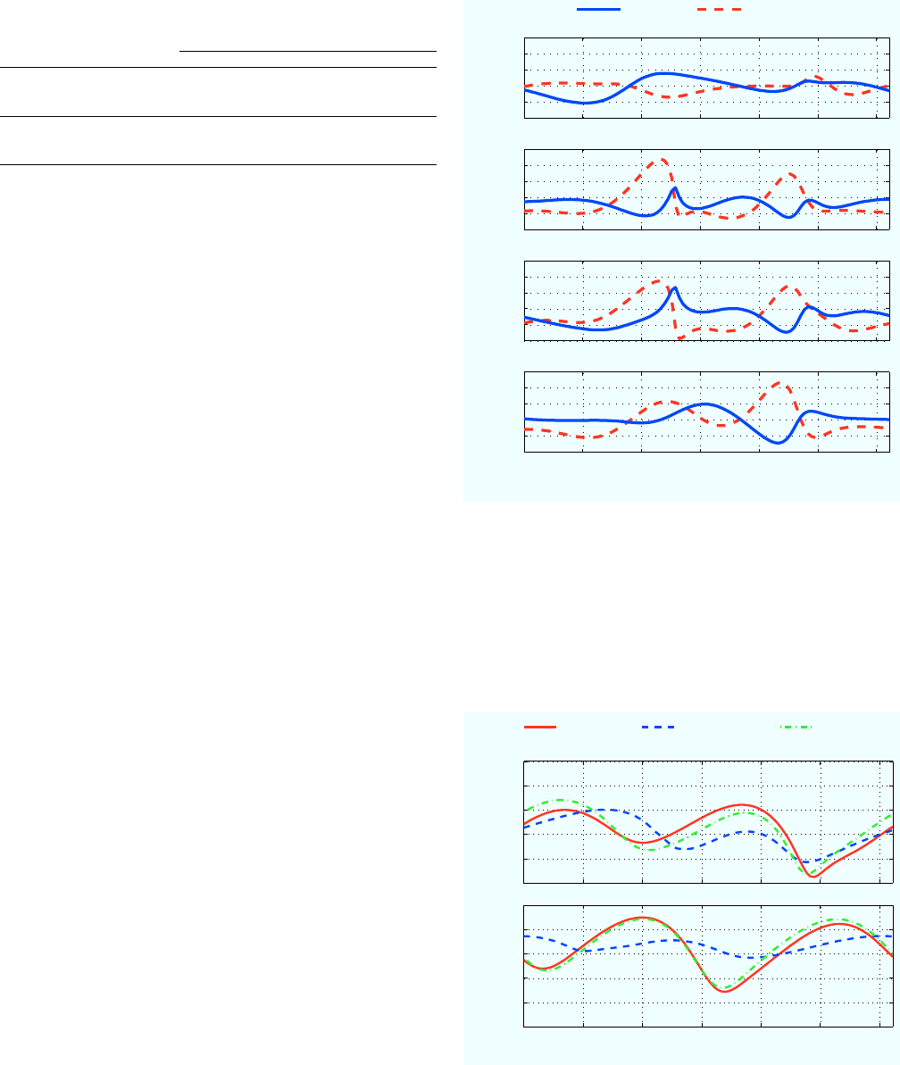
TABLE II
FORWARD VELOCITY (m/s), MOTOR INPUT POWER (W), AND COST OF
TRANSPORT (J/(kg ·m))FOR DIFFERENT CONFIGURATIONS AND GAITS
Gait Configuration
(frequency) Wings-Passive Wings-Only Hybrid
Quasi-static
(9 Hz)
Velocity 0.33 0.17 0.50
Power 0.36 0.65 0.89
COT 96.8 337.4 155.8
Dynamic
(12.5 Hz)
Velocity 0.35 1.5 1.5
Power 0.36 0.79 0.91
COT 89.7 45.9 53.1
A. Quasi-static Terrestrial Locomotion
BOLT exhibits a quasi-static walking gait when running
at a flapping frequency of 9 Hz. The aerodynamic effects
of the flapping wings are minimal in this gait, with the WO
robot reaching a maximum velocity of 0.17 m/s. In contrast,
the legs of the WP robot propel it at 0.33 m/s. Overall, the
hybrid robot reaches 0.5 m/s, suggesting a superposition of
the leg and wing thrust components may explain the hybrid
gait.
Fig. 6 shows the fore-aft and vertical accelerations of the
robot over a representative cycle. We show the accelerations
for the WO robot, the WP robot, the superposition of the WO
and WP robots, and the hybrid robot. The accelerations of the
hybrid robot are similar in both magnitude and shape to the
superposition of the WO and WP robots, suggesting a lower
degree of interaction between the leg and wing forces in this
gait. An effect of leg/wing force coupling that can be seen
is the smoother accelerations of the hybrid robot compared
to those the WO+WP model predicts. The flapping wings
provide a higher amount of dampening on the impulsive leg
forces the robot generates than the passive wings.
The motor velocity over a representative cycle of the
quasi-static gait is shown in Fig. 7. The robot uses constant
PWM control for the motor, causing the motor velocity to
vary dependent upon load. Over a single cycle, the effect of
the varying load due to the flapping wings or legs is seen
clearly from the change in motor velocity. The variation in
motor velocity for the hybrid robot and the WO robot is
nearly identical, implying a similar load in the two cases.
Thus, despite the wings ineffectiveness in this gait they are
responsible for the majority of the power consumption of the
motor. Table II shows the WO robot consumes 80% more
power than the WP robot despite traveling at only half the
speed. This is reflected by the cost of transport: the WP robot
is the most efficient while the WO robot is the least efficient.
The hybrid robot has an efficiency between the two controls.
B. Dynamic Locomotion
The second running gait of BOLT is dynamic bipedal
locomotion, seen at a flapping frequency of 12.5 Hz. The
aerodynamic force the flapping wings provide increases
greatly, with the WO robot running at 1.5 m/s. The hybrid
robot also runs at 1.5 m/s, while the WP robot is only capable
−20
0
30
Wings−Only
Fore−Aft Vertical
−20
0
30 Wings−Passive
Acceleration (m/s 2)
0123456
−20
0
30 Hybrid
Phase (rad)
−20
0
30 Wings−Only + Wings−Passive
Fig. 6. Fore-aft and vertical accelerations shown over a single representative
cycle when running at 9 Hz at a steady state velocity. At slow frequencies the
robot exhibits quasi-static motion. In this regime, the forces on the hybrid
robot are consistent with the superposition model of the individual leg and
wing forces.
0123456
20
40
60
80
100
120
Phase (rad)
Dynamic Gait
Wings−Only Passive Wings Hybrid
20
40
60
80
100
120
Motor Velocity (rad/s)
Quasi−static Gait
Fig. 7. Motor velocity over a representative cycle for both the quasi-static
gait (9 Hz) and the dynamic gait (12.5 Hz).
of 0.35 m/s. In this gait, there is a strong interaction between
the wing and leg dynamics.
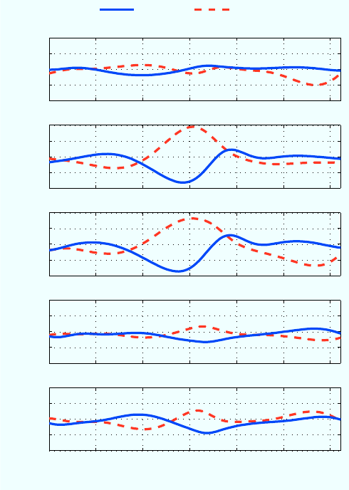
The acceleration plots of Fig. 8 show the same four cases
as above (WO, WP, WO+WP, Hybrid), along with a fifth
case: the WO case subtracted from the hybrid case. For
this gait, the WO+WP model is a poor predictor of the
hybrid accelerations, predicting magnitudes over double the
measured values.
The WP case shows one overly large single acceleration
caused by a footfall centered at a phase of π, propelling the
robot into the air preventing the next footfall from generating
the same amount of force. Between footfalls, the robot is
in free-fall, with zero fore-aft acceleration, and a vertical
acceleration of −9.8m/s2. The high accelerations and gait
asymmetry of the WP case are generally indicative of poor
leg tuning on a robot with a traditional SLIP gait. The
hybrid robot uses the same legs as the WP robot at the same
frequency, but the accelerations experienced by the robot are
much lower. We again see the effect of the flapping wings
dampening the leg impulses from the quasi-static case, but
to a higher degree now. The hybrid robot does not have the
free-fall state shown by the WP robot; stopping this free-fall
leads to the high accelerations seen in the WP case. The
hybrid robot is “flying between footfalls” instead of falling,
greatly reducing the accelerations that must be effected by
the legs.
The WO robot and the hybrid robot both run at the same
forward velocity and motor frequency (see Fig. 7). This leads
to the assumption that the wing forces are nearly the same
in both cases regardless of the ground contacts. Subtracting
the WO case from the hybrid case shows the leg forces for
the hybrid robot. While they still differ from a traditional
SLIP gait due to the leg/wing interactions, the legs no longer
appear poorly tuned. From this data, we conclude a flapping
wing robot should use stiffer legs than would normally be
expected for a robot running with legs alone.
The motor velocities, and thus the dynamic loading, are
nearly identical between the hybrid robot and the WO robot
during the dynamic gait (Fig. 7). As in the quasi-static case,
the WP robot uses the least amount of power, followed by the
WO robot with the hybrid robot consuming the most power
(see Table II). Due to the differing forward speeds the COT
relationship is now markedly different, with the WO case
the most efficient and the WP case the least efficient. Once
again, the hybrid provides a compromise between the cases.
C. Terrestrial to Aerial Transitions
By running along the ground at a high speed, BOLT can
generate enough aerodynamic lift to take off. Depending
upon the center of mass location, BOLT requires between
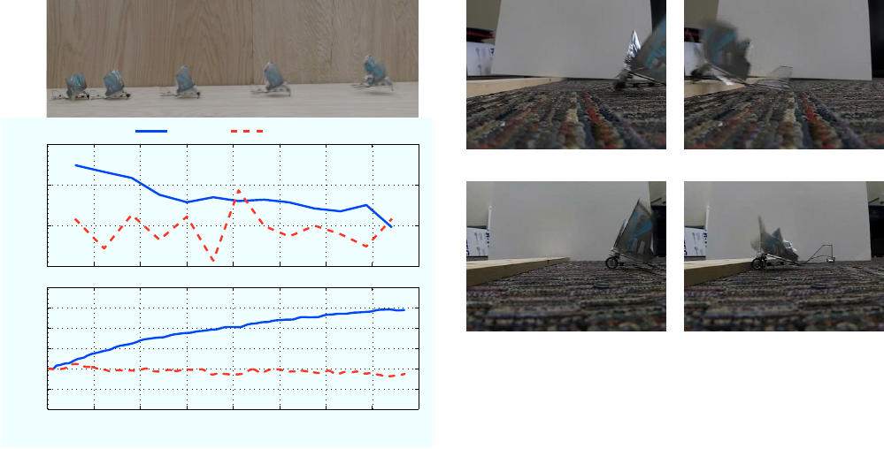
one and two meters of runway space. Fig. 9 shows the robot
during a takeoff maneuver with the controller board mounted
forward, causing a takeoff distance just under 2 meters when
flapping at 18 Hz. The average acceleration for each stride
is shown, along with the instantaneous velocity obtained by
integrating the accelerometer data. BOLT accelerates very
quickly from a standstill, reaching 1 m/s in 0.14 s and 2
−50
0
50
Wings−Only
Fore−Aft Vertical
−50
0
50 Wings−Passive
−50
0
50 Hybrid
−50
0
50 Wings−Only + Wings−Passive
Acceleration (m/s 2)
0123456
−50
0
50 Hybrid − Wings−Only
Phase (rad)
Fig. 8. Fore-aft and vertical accelerations shown over a single representative
cycle when running at 12.5 Hz. At high speeds, a simple superposition of
the leg and wing forces does not accurately predict the overall force on
BOLT. The interactions between the legs and the wings are an important
component of the forces during dynamic locomotion, altering the range of
leg stiffnesses that give stable locomotion.
m/s in 0.38 s. Upon reaching a velocity of 2.5 m/s, BOLT
has taken off and is no longer touching the ground. The
robot continues to accelerate until reaching 3 m/s. At this
point the tail begins to swing under the robot and it enters
a vertical flight posture. The vertical accelerations oscillate
around zero throughout the maneuver as the robot bounces
along the runway. The total vertical velocity stays very near
zero however, as the accelerometer does not pick up the slow
movement upwards of the robot.
By moving the location of the controller board (and the
center of mass), BOLT can be configured to have different
transition properties. Moving the controller board forward
increases the distance required for takeoff (∼2 m), but also
increases the maximum terrestrial speed (2.5 m/s). Addi-
tionally, it allows the board to be placed on foam offsets,
improving the IMU measurements. When the board is moved
to the back of the airframe, the takeoff distance is reduced
to 1 meter. The speed where takeoff occurs is also reduced
to 1.75 m/s.
−5
0
5
10
Acceleration (m/s 2)
Fore−Aft Vertical
0 0.1 0.2 0.3 0.4 0.5 0.6 0.7 0.8
−1
0
1
2
3
Velocity (m/s)
Time (s)
A B C D E
A B C D E
Fig. 9. BOLT transitioning from terrestrial locomotion to aerial locomotion.
The average acceleration of each stride/wingbeat is plotted, along with the
velocity obtained by integrating the accelerometer data. The robot quickly
builds speed (A-C), lifting off at 2.5 m/s (D) and continuing to accelerate
until it reaches 3 m/s (E). The vertical acceleration oscillates around zero,
giving near zero vertical velocity throughout the run.
IV. DISCUSSION
The method BOLT uses to maintain stability when running
differ between the quasi-static and dynamic gait. At low
speeds, the tail of the robot remains in contact with the
ground and provides an extra point of stability. At higher
speeds, the tail of the robot lifts off of the ground, and
the robot is truly bipedal. The aerodynamic forces from
the flapping wings and the tail allow the robot to maintain
passive stability despite its bipedal locomotion in the absence
of any closed loop control. The sprawled posture of the
legs and low-to-the-ground design help the robot maintain
stability during both modes of locomotion.
By using the flapping wings to provide additional thrust,
the terrestrial speed of the robot is significantly increased
from a legged robot. With a quasi-static gait, the wings-
passive robot has the best COT, while the wings-only robot
performed best at a dynamic gait. The hybrid robot provides
a compromise between the two, allowing more efficient
locomotion when a range of speeds is necessary. At slow
speeds legs provide more efficient thrust than wing flapping;
at high speeds the wings allow the robot to “fly” along the
ground, dramatically reducing the cost of transport.
BOLT has also shown the ability to clear terrestrial obsta-
cles, both with a running start and from standstill. Fig. 10
shows BOLT clearing a 2 cm obstacle, the highest obstacle
it can clear with a purely terrestrial gait. In the wings-only
configuration the robot is unable to clear the 2 cm obstacle,
clearly showing the necessity of the legs. The wings-passive
(a) BOLT (b) BOLT
(c) Wings-only (d) Wings-only
Fig. 10. (a-b) show BOLT running at a 2 cm obstacle and easily clearing
the top of it. By contrast, (c-d) show the wings-only robot incapable of
getting over the barrier. The wings-passive robot is capable of clearing the
barrier, but is not always successful.
robot can clear the obstacle, but does so inconsistently. BOLT
has shown two methods of clearing this obstacle, depending
on the initial condition when first encountering the obstacle.
If the obstacle is encountered at the low point in the stride,
the robot will run at the obstacle for a few strides until its
legs are able to pull it over the top. During the high point of
its stride, the robot simply leaps over the obstacle without
stopping. These scenarios are shown in the accompanying
video.
V. CONCLUSIONS AND FUTURE WORK
BOLT achieves its goal of being capable of both aerial
and terrestrial locomotion, and transitioning between the
two in an indoor environment. During dynamic running,
BOLT uses a unique method for maintaining passively stable
bipedal locomotion, exploiting the aerodynamic effects of its
flapping wings. Because of the aerodynamic forces present
on the robot, BOLT does not run using a traditional SLIP
gait. Despite this fact, the robot is capable of high speed
locomotion, “flying” along the ground using a combination
of aerodynamic forces and ground reaction forces to propel
itself. The hybrid robot also provides a compromise in
efficiency across a range of speeds, when compared to the
wings-only and wings-passive robots. The legs and wings
hybrid configuration is also particularly adept at crossing
low obstacles placed in its path without needing to resort
to aerial locomotion.
While not the first hybrid aerial/terrestrial robot, BOLT is
currently the smallest. Its ability to transition from terrestrial
locomotion to aerial locomotion in a small space enables it to
take advantage of both modes of transportation, especially in
a confined environment. The key contribution setting BOLT
apart is the integration of a smart electronics package capable
of measuring the dynamics of a fully capable hybrid plat-
form. BOLT has begun to provide insights into the dynamics
of wing assisted locomotion, and allows the interactions
between legs and wings to be examined.
Future work on BOLT will further explore the dynamics
of running with flapping wings, attempting to determine
the proper leg stiffness to achieve a stable gait with high
efficiency in a terrestrial mode where SLIP does not apply.
Additionally, a transmission capable of selectively driving
the legs or wings would further improve the efficiency of
the robot. By turning off the wings at low terrestrial speeds,
or disengaging the legs when flying, the robot can minimize
the power lost to unnecessary appendages. Techniques for
steering, both in aerial and terrestrial locomotion modes also
bear further investigation.
ACKNOWLEDGMENTS
The authors gratefully thank Stan Baek for his design of
the ImageProc 2.2 electronics board, and Stan and Aaron
Hoover for their diligent work developing the drivers for the
electronics board.
REFERENCES
[1] P. Birkmeyer, K. Peterson, and R. Fearing, “DASH: A dynamic 16g
hexapedal robot,” in IEEE/RSJ International Conference on Intelligent
Robots and Systems, October 2009, pp. 2683–2689.
[2] A. Hoover, S. Burden, X. Fu, S. Sastry, and R. Fearing, “Bio-inspired
design and dynamic maneuverability of a minimally actuated six-
legged robot,” in 3rd IEEE RAS and EMBS International Conference
on Biomedical Robotics and Biomechatronics (BioRob), September
2010, pp. 869–876.
[3] J. M. Morrey, B. Lambrecht, A. D. Horchler, R. E. Ritzmann, and
R. D. Quinn, “Highly mobile and robust small quadruped robot,” in
IEEE/RSJ International Conference on Intelligent Robots and Systems,
October 2003, pp. 82–87.
[4] J. G. Cham, S. A. Bailey, J. E. Clark, R. J. Full, and M. R.
Cutkosky, “Fast and robust: Hexapedal robots via shape deposition
manufacturing,” International Journal of Robotics Research, vol. 21,
no. 10, 2002.
[5] S. Kim, J. E. Clark, and M. R. Cutkosky, “isprawl: Design and tuning
for high-speed autonomous open-loop running,” International Journal
of Robotics Research, vol. 25, no. 9, pp. 903–912, 2006.
[6] U. Saranli, M. Buehler, and D. E. Koditschek, “Rhex: A simple
and highly mobile hexapod robot,” International Journal of Robotics
Research, vol. 20, no. 7, pp. 616 – 631, July 2001.
[7] N. Neville, M. Buehler, and I. Sharf, “A bipedal running robot with
one actuator per leg,” in IEEE International Conference on Robotics
and Automation, May 2006, pp. 848 –853.
[8] R. Full and M. Tu, “Mechanics of rapid running insects: two-, four-
, and six-legged locomotion,” Journal of Experimental Biology, vol.
156, pp. 215–231, 1991.
[9] P. Holmes, R. J. Full, D. Koditschek, and J. Guckenheimer, “The
dynamics of legged locomotion: Models, analyses, and challenges,”
SIAM Review, vol. 48, no. 2, pp. 207–304, 2006.
[10] R. Blickhan and R. J. Full, “Similarity in multilegged locomotion:
Bouncing like a monopode,” Journal of Comparative Physiology A:
Neuroethology, Sensory, Neural, and Behavioral Physiology, vol. 173,
no. 5, pp. 509–517, November 1993.
[11] D. Lentink, S. Jongerius, and N. Bradshaw, “The scalable design of
flapping micro-air vehicles inspired by insect flight,” Flying Insects
and Robots, p. 185, 2009.
[12] (2011). [Online]. Available: http://www.ornithopter.org/
[13] (2011). [Online]. Available: http://www.avinc.com/nano
[14] R. J. Bachmann, F. J. Boria, R. Vaidyanathan, P. G. Ifju, and R. D.
Quinn, “A biologically inspired micro-vehicle capable of aerial and
terrestrial locomotion,” Mechanism and Machine Theory, vol. 44,
no. 3, pp. 513 – 526, 2009, special issue on Bio-Inspired Mechanism
Engineering.
[15] F. Boria, R. Bachmann, P. Ifju, R. Quinn, R. Vaidyanathan, C. Perry,
and J. Wagener, “A sensor platform capable of aerial and terrestrial
locomotion,” in IEEE/RSJ International Conference on Intelligent
Robots and Systems, August 2005, pp. 3959–3964.
[16] M. Kovac, J. Zufferey, and D. Floreano, “Towards a self-deploying
and gliding robot,” Flying Insects and Robots, 2009.
[17] M. Kovac¸, J. Germann, C. Hrzeler, R. Siegwart, and D. Floreano, “A
perching mechanism for micro aerial vehicles,” Journal of Micro-Nano
Mechatronics, vol. 5, pp. 77–91, 2009.
[18] A. Lussier Desbiens, A. Asbeck, and M. Cutkosky, “Landing, perching
and taking off from vertical surfaces,” The International Journal of
Robotics Research, vol. 30, no. 3, p. 355, 2011.
[19] D. Lachat, A. Crespi, and A. Ijspeert, “Boxybot: a swimming and
crawling fish robot controlled by a central pattern generator,” in
The First IEEE/RAS-EMBS International Conference on Biomedical
Robotics and Biomechatronics (BioRob), February 2006, pp. 643–648.
[20] C. Georgiades, A. German, A. Hogue, H. Liu, C. Prahacs, A. Ripsman,
R. Sim, L. Torres, P. Zhang, M. Buehler et al., “AQUA: an aquatic
walking robot,” in IEEE/RSJ International Conference on Intelligent
Robots and Systems, vol. 4, September 2004, pp. 3525–3531.
[21] M. Bundle and K. Dial, “Mechanics of wing-assisted incline running
(WAIR),” Journal of Experimental Biology, vol. 206, no. 24, pp. 4553–
4564, 2003.
[22] R. Wood, S. Avadhanula, R. Sahai, E. Steltz, and R. Fearing, “Micro-
robot design using fiber reinforced composites,” Journal of Mechanical
Design, vol. 130, p. 052304, 2008.
[23] S. Baek, F. G. Bermudez, and R. Fearing, “Flight control for target
seeking by 13 gram ornithopter,” in IEEE International Conference
on Intelligent RObots and Systems(IROS), September 2011.
