L200_e L200 E
User Manual: l200_e
Open the PDF directly: View PDF ![]() .
.
Page Count: 34

© by SYSTEME LAUER GMBH & CO. KG • KELTERSTR. 59 • D 72669 UNTERENSINGEN • TEL 07022/9660-0 • FAX 07022/9660-103
Find out what's going on virtually free off charge
A text display system which saves more than it costs
The universally applicable text display LCA 200 shows what your
machines and control can do. If you wish, it can do this 1024
times in different languages.
You make a precise display or message out of everything you
have. All you need are simple contacts or PLC outputs.
The small and compact LCA 200 with its enormous performance
capabilities, easily blends in with your machine design, whether it
be once, twice or, to put it a nutshell, as often as you want, as
often as you have something to display.
And why not in any case if you can have two text displays for the
price of one.
Programming the LCA 200 with any PC is such a dream that you
could fall into the temptation of not wanting to do anything else.
It only remains to be said: just simply try out this universally
applicable LCA 200 text display!
CiS-Nr.: 360.000.0400
Version 2/06.94
© Systeme Lauer GmbH & Co. KG
LCA 200
Text Display
© by SYSTEME LAUER GMBH & CO. KG • KELTERSTR. 59 • D 72669 UNTERENSINGEN • TEL 07022/9660-0 • FAX 07022/9660-103
LCA 200
LCD DISPLAY LED BACKGROUND ILLUMINATION
2 LINES EACH WITH 40 CHARACTERS
■4 Ways of Operating (Modes)
Direct drive, binary drive, cyclical transfer,
selective transfer
■3 Message Formats
Last message, initial message, cyclical dis-
play
■6 Variable Formats
BIT, STRING, BCD, BIN, VBIN and ASCII
variables
■16 Function bits (external)
• Help text call
• Quitting (flashing called message text is
made static with Q-key)
• Forward/back paging in the message
memory
• Call additional lines
• Call main lines
• Supression of infos and faults
• Selection of message formats
• Selection of default text/help text number
■LCD-Display 2 x 40 characters
with LED background illumination
■Integrated EEPROM
for firmware, texts and variable definitions
■10 Inputs
for a comprehensive text display drive
■RS 232 Serial Interface
for programming with the software
LCAPRO
■Up to 1024 Message Texts
with 2 main lines and 30 additional lines,
every text is combinable with variables. Each
message text can be formulated as info or
fault.
■Up to 16 Help Texts
with 2 main lines and 30 additional lines
■Up to 4 Default Texts
with 2 main lines and 30 additional lines
The LCA 200 text display can be easily incorporated into your automation
concept. The drive and message text call which can be selected by means of
individual contacts (connectors) or any PLC system is extremely simple. The
same applies for the programming and parameterization of the LCA 200 with
the LCAPRO planning software.
Here is an outline of the most important performance capabilities
of the LCA 200
© by SYSTEME LAUER GMBH & CO. KG • KELTERSTR. 59 • D 72669 UNTERENSINGEN • TEL 07022/9660-0 • FAX 07022/9660-103
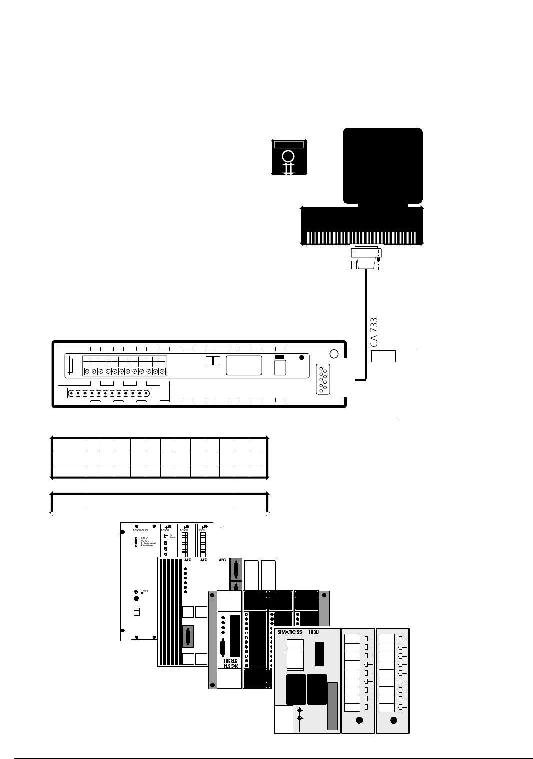
LCA 200 back panel
LCA 200.
1 2 3 4 5 6 7 8 9 10
24V 0V D0 D1 D2 D3 D4 D5 D6 D7
11
S
12
T
CONTRAST
COM
RUN STOP
SERIAL-NR
FUSE
400mAT
LCAPRO
E
Programming the LCA 200 text display is
done with a PC (MSDOS). We supply the
LCAPRO planning software for this. The indi-
vidual project data and the firmware are
loaded per down load into the EEPROM.
The connection from the PC (COM1 or
COM2) to the LCA 200 is done with the LCA
733 cable
BIT
10 PLC outputs for max. 1024 messages
STATUS
TERMINAL
0
D0
3
2
D2
5
3
D3
6
4
D4
7
5
D5
8
6
D6
9
7
D7
10
0V
2
24V
1
1
D1
4
8
S
11
9
T
12
The LCA 200 fits
every PLC
▲

© by SYSTEME LAUER GMBH & CO. KG • KELTERSTR. 59 • D 72669 UNTERENSINGEN • TEL 07022/9660-0 • FAX 07022/9660-103
CONTENTS OF THE LCA 200 MANUAL
Topics Pages
The text display connections 1
Technical data 2
Dimensions and cross section of front panel 3
The character table 4
General interference safeguard precautions for LCA devices 5
Installation instructions 6
Current supply 7
The Communication Concept 8
Mode 1: Direct drive 8
Mode 2: Binary drive 9
Mode 3: Cyclical transfer 10
Mode 4: Selective transfer 13
Operation of the LCA 200 (Modes 3, 4) 16
The function area of LCA 200 functions 16
The priorities of the LCA 200 17
The text organization of the LCA 200 18
The variables of the LCA 200 19
Example of BIT variable 20
Example of STRING variable 21
Example of BINARY (BIN BYTE/BIN WORD/VBIN BYTE/VBIN WORD) variable 22
Example of BCD variable 24
Example of ASCII variable 25
The diagnostic operation of the LCA 200 26
Time switch differences of the PLC outputs 28
PLC Cycle Time ≤ 1 ms 29

© by SYSTEME LAUER GMBH & CO. KG • KELTERSTR. 59 • D 72669 UNTERENSINGEN • TEL 07022/9660-0 • FAX 07022/9660-103
Operating instructions, manuals and software are protected by copyright. All
rights reserved. The copying, production, translation and conversion of the whole
or part of it, is not allowed. An exception is made for a back-up copy of the
software for own use.

TEXT DISPLAY LCA 200 Description 1
© 1994 by SYSTEME LAUER GMBH & CO. KG D 72669 Unterensingen • TEL 07022 / 9660-0 • FAX 07022 / 9660-274
The Text Display Connections
The connection between the PLC and the LCA 200 is achieved by means
of the 12pin terminal connector. Every function is brought into play by
means of this interface:
- Call help texts
- Call message texts
- Supply variables
- Operation of the text display
LCA 200
+ 24VDC (19...33V)
0 V
D5 (DATALINE 5)
D4 (DATALINE 4)
D3 (DATALINE 3)
D2 (DATALINE 2)
PLC OUTPUTS
OPERATING VOLTAGE
1 2 3 4 5 6 7 8 9 10
D0 (DATALINE 0)
D1 (DATALINE 1)
11
S (SYNCHRONIZATION) or D8
12
T (CLOCK) or D9
D6 (DATALINE 6)
D7 (DATALINE 7)
LCD DISPLAY LED BACKGROUND ILLUMINATION
2 LINES EACH WITH 40 CHARACTERS
TEXT DISPLAY LCA 200 Description 2
© 1994 by SYSTEME LAUER GMBH & CO. KG D 72669 Unterensingen • TEL 07022 / 9660-0 • FAX 07022 / 9660-274
Technical Details
Operating voltage +19 ... 33V= (DC)
Signal voltage +19 ... 33V= (DC)
Power dissipation 6 W
Connections 12pin strip connection, plug
Safeguard Front panel: IP 65
Back panel: IP 20 (as IEC 529)
Dimensions (without plug) 216 x 48 x 40 mm
Weight ca. 275 g
Humidity no rear panel condensation max. 95%
Input resistance ca. 5.8 KOhm
Input level LOW: < 9 V (typ. 10,5 V)
HIGH: > 16 V (typ. 14,5 V)
Resistance to interference per IEC 801-1 Operating voltage
per IEC 801-1 discharging on rear panel
Temperature Storage -25...+70° C
Operating 0...+50° C
Fuse Glass fuse 400 mAT
Display LCD (LED background illumination)
Reading angle (60° above/below) 120°
Lines 2
Characters per line 40
Height of character, pixel matrix 5 mm, 5 x 7 dots
Character set ASCII (8 free definable characters)
Message call direct, binary or in multiplex procedure
Message pages maximum 1024
Idle, message, help texts 2 main lines, 30 additional lines
per page
Memory (for firmware and texts) EEPROM 32 kB
for texts ca. 22 kB available
Variable formats BIT, STRING, BCD, BIN, VBIN, ASCII
TEXT DISPLAY LCA 200 Description 3
© 1994 by SYSTEME LAUER GMBH & CO. KG D 72669 Unterensingen • TEL 07022 / 9660-0 • FAX 07022 / 9660-274
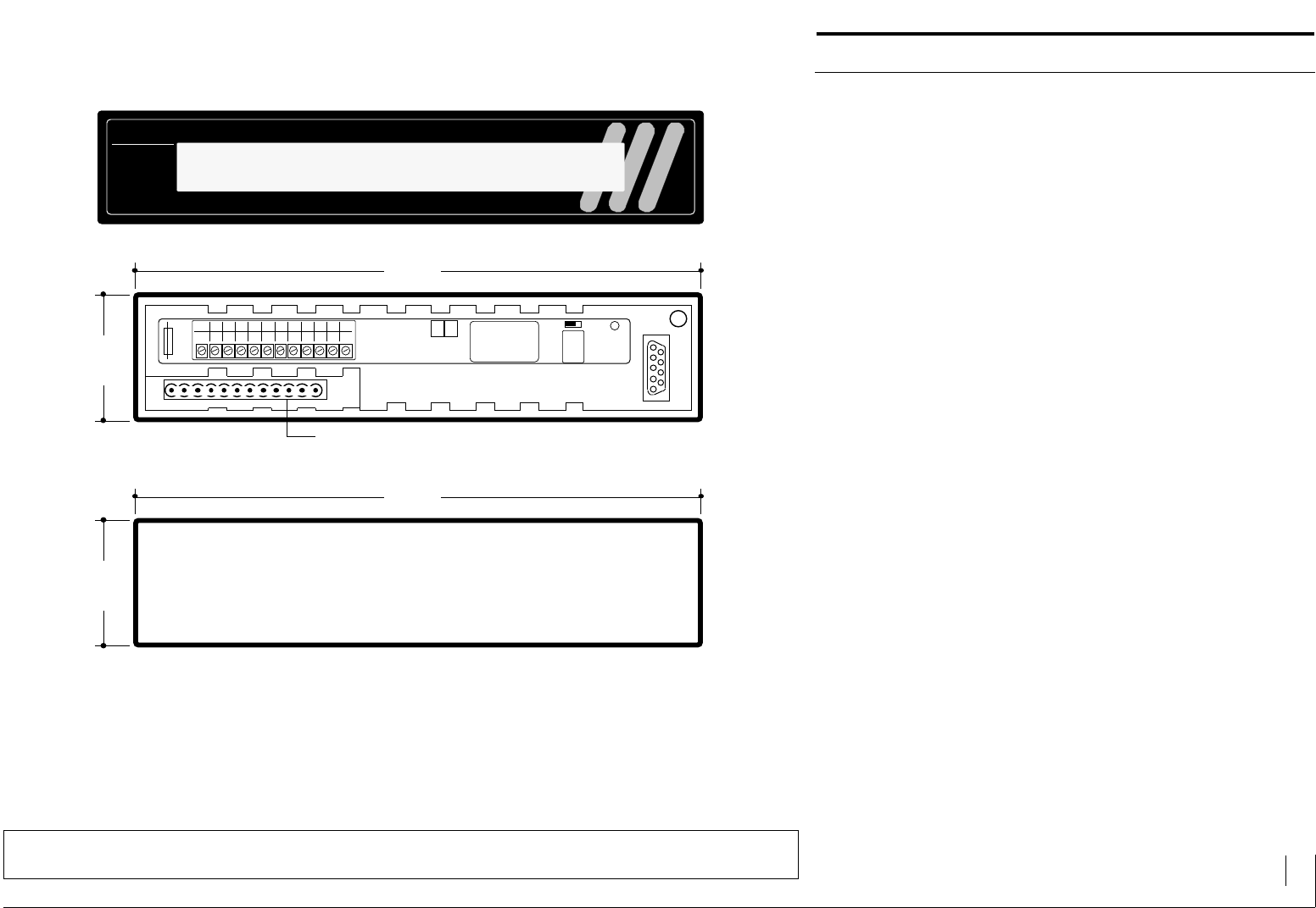
Dimensions and Front Cross-section
LCA 200
PLC Connection/supply
48,0 mm
216,0 mm
LCA 200 Rear panel
LCA 200.
1 2 3 4 5 6 7 8 9 10
24V 0V D0 D1 D2 D3 D4 D5 D6 D7
11
S
12
T
CONTRAST
COM
RUN STOP
SERIAL-NR:
FUSE
400mAT
208 mm (+1)
40 mm (+1)
Mounting depth 40 mm
LCD DISPLAY LED BACKGROUND ILLUMINATION
2 LINES EACH WITH 40 CHARACTERS
TEXT DISPLAY LCA 200 Description 4
© 1994 by SYSTEME LAUER GMBH & CO. KG D 72669 Unterensingen • TEL 07022 / 9660-0 • FAX 07022 / 9660-274
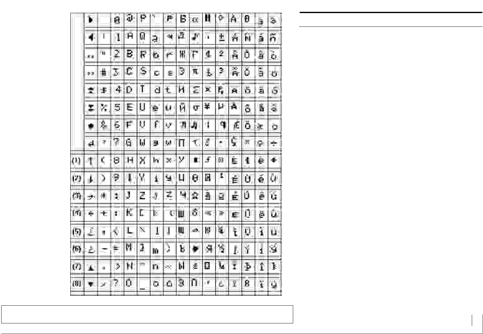
Character Table
The character table shows all the ASCII and special characters with the
corresponding decimal coding that can be displayed on the LCA 200.
You can create your own special characters with the 8 definable charac-
ters.
TEXT DISPLAY LCA 200 Description 5
© 1994 by SYSTEME LAUER GMBH & CO. KG D 72669 Unterensingen • TEL 07022 / 9660-0 • FAX 07022 / 9660-274
General Interference Protection Measures
Even the best electronic can only guarantee a secure function up to a
certain interference level. In order to avoid unnecessary breakdowns of
apparatus, the following information should be born in mind when plan-
ning:
1. If possible put the supply and signal wires of the LCA device in separate
cable channels.
2. The safety distance to the source of interference should be at least 250
mm.
3. The built-in safety and relais coil inductances in the same switch cabinet
must be switched on with the corresponding recovery diodes, resprec-
tively R-C-erasure parts.
4. Do not use fluorescent lamps for illumination of the control cabinet.
5. Fix a central earthing point with a large enough cross section to connect
the PE earth wire.
6. If there's great field strength as with a large transformer, we recom-
mend the installation of a separate insulating plate.
7. Frequency converters and other devices can only be suppressed with
shielded filter switches.
8. The best drainage of high frequency interferences is achieved with
shielded signal wires, whereby the protection should be earthed both
sides. However steps to incorporate an equipotential bonding
conductor M 10 mm2 must be made (refer to VDE 0100. Part 547).
9. Ready made filters inserted before the supply circuit, have proven
themselves to be effective in the case of large interferences.
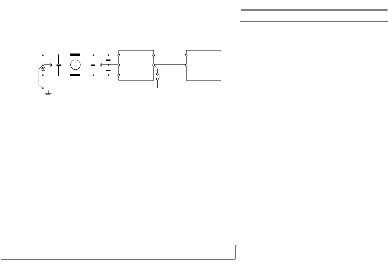
Example of a suppressor with filter switch for large interference levels
P
E
N
Power pack
unstable or
stablized
LCA 200
+24 V
0 V
Power supply
Separation
point
According to the VDE 0113, it must be possible to measure the current to earth
at the separation point.
TEXT DISPLAY LCA 200 Description 6
© 1994 by SYSTEME LAUER GMBH & CO. KG D 72669 Unterensingen • TEL 07022 / 9660-0 • FAX 07022 / 9660-274
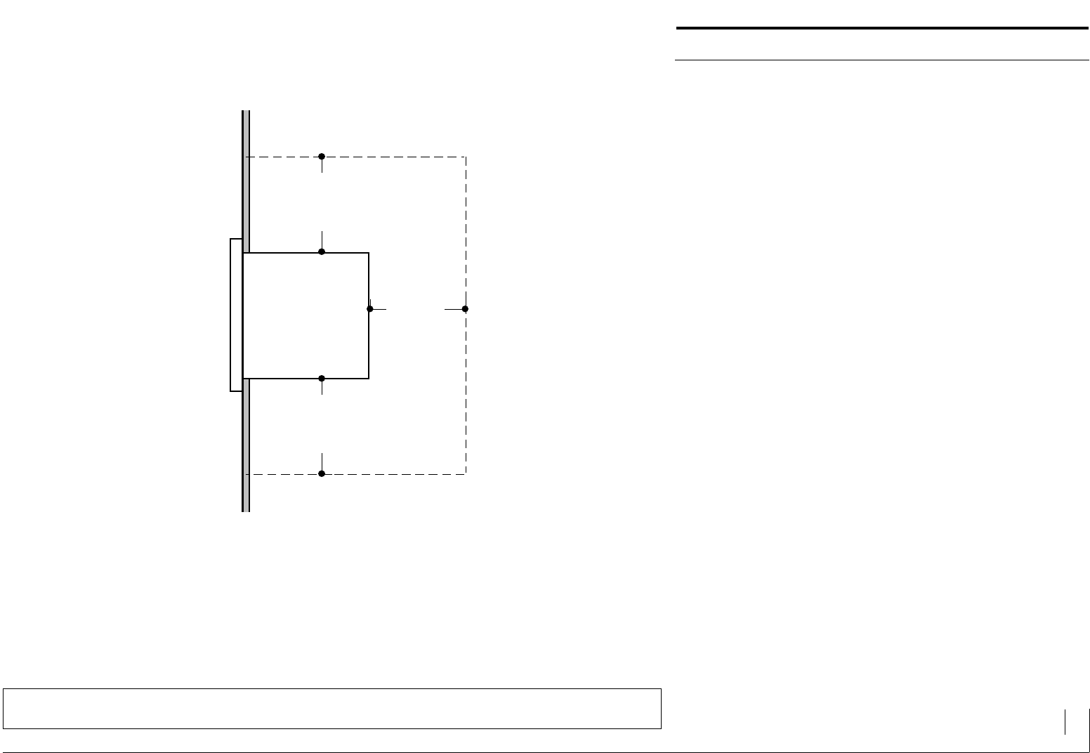
Installation Instructions
To maintain a stable operation of the text display, all the perturbing
radiation sources should be at least 250 mm distance from the LCA 200.
This also applies to the data and supply lines of the LCA 200.
With cable lengths > 5 m, we recommend protected lines earthed on both
sides. Please note that in this case, an equipotential bonding conductor
with a minimum diameter of 10 times cable sheathing will be necessary.
The reason being the compensating current!
Feed lines to the LCA 200 should not be lead in along with high tension
or high frequency cables.
TEXT DISPLAY
LCA 200
>250 mm
>250 mm>250 mm
PERTURBING RADIATION SOURCE
PERTURBING RADIATION SOURCE
PERTURBING RADIATION SOURCE
TEXT DISPLAY LCA 200 Description 7
© 1994 by SYSTEME LAUER GMBH & CO. KG D 72669 Unterensingen • TEL 07022 / 9660-0 • FAX 07022 / 9660-274
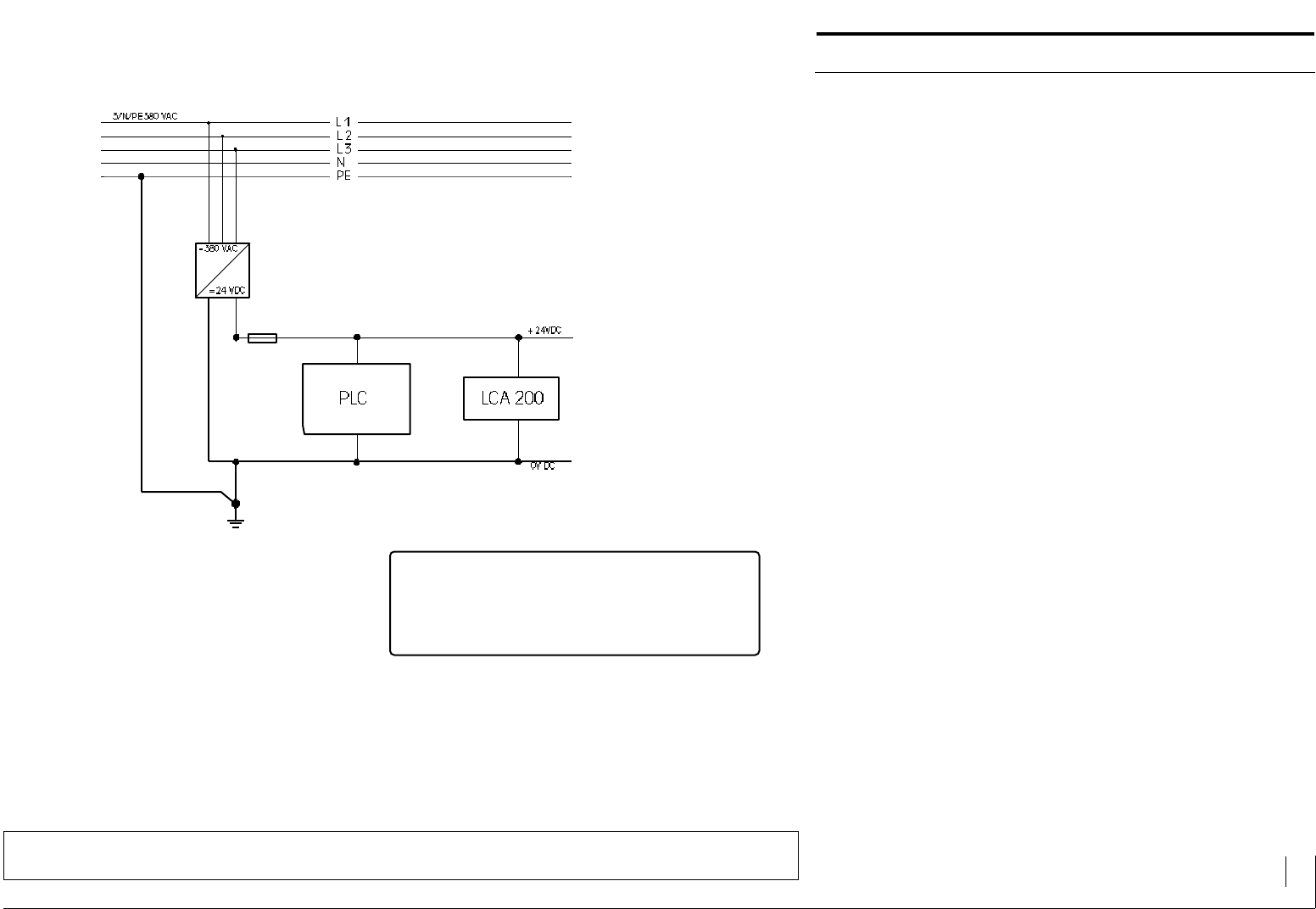
Current Supply
To maintain stable operation of the LCA 200 text display, the following
information appertaining to current supply should be taken into conside-
ration:
Only run the LCA 200 within the specified range of operating voltage.
Short term voltage interruptions of m 4 ms are permissible.
An operating voltage UB of 35 V is permissible for the duration of m 100
ms (repeating frequency ca. 1 Hz).
The LCA devices may only be run with the safety »low voltage« as of
VDE 100. The control transformer must confirm to the VDE 0551.
Thereupon according to the VDE a single pin earthing of the operating
current is possible. We recommend this earthing when running our
devices.
Without single pin earthing of the operating voltage, you require your
own control transformer to operate the LCA 200.
If switching on is done with the operating/signal voltage
safeguards or relais, they must be equipped with recovery
diodes and/or interference protection switches.
Operating current UB: 24 VDC m ( 5% residual ripples)
per DIN 19240 UBmax : 33 VDC
UBmin : 19 VDC
Current consumption : ~200 mA (to +24VDC)

TEXT DISPLAY LCA 200 Description 8
© 1994 by SYSTEME LAUER GMBH & CO. KG D 72669 Unterensingen • TEL 07022 / 9660-0 • FAX 07022 / 9660-274
The Communication Concept
The LCA 200 text display possesses 10 digital inputs for driving. For
example, 10 digital PLC outputs can be used to call and update texts and
variables.
The functionality of the 10 inputs is determined with the LCAPRO planning
software.
After a data record has been created which contains text and variable defi-
nitions it is transfered into the text display together with the firmware for
the selected mode through the serial RS 232 interface of a PC. This data
finally ends up non-volatile in the integrated EEPROM of the LCA 200 text
display.
At the moment, 4 drive modes are available. There is a diagnostic module
for every mode which can be activated with the LCAPRO planning soft-
ware. This diagnostic module provides a means of assistance in facilitating
the primary commissioning and in the search for faults in the drive soft-
ware.
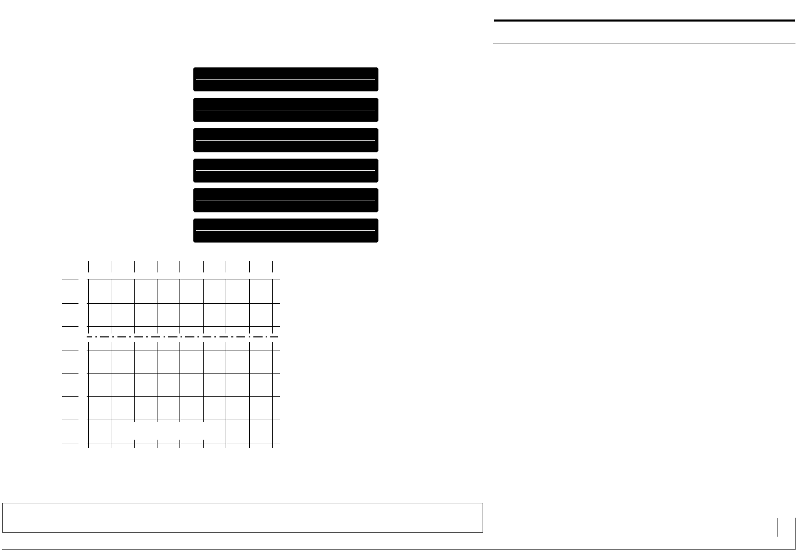
Mode 1: Direct Drive (without Clock and Synchronization)
This mode presents the simplest type of drive. Filing log 1 (24V) permits
double line message texts to be activated with the terminals 3...11
(Do...D7,S) 9.
If all the inputs are log 0, a double line idle text appears.
With log 1 at the terminals 12 (T), a second plane can be activated (e.g. for
language selection). Whereby there are 2 idle and 18 message texts availa-
ble.
If several inputs are log 1, the texts roll through in a time cycle preset by
the planning software.
With the text groups "idle texts" and "message texts", so called default
texts or category texts can be defined.
If a text is lined up but not projected, an empty display appears.
The internal variable "text number" can be applied in the filed texts.
LCA 200
+ 24VDC (19...33V)
0 V
MESSAGE 5, 14
MESSAGE 4, 13
MESSAGE 3, 12
MESSAGE 2, 11
PLC OUTPUTS
OPERATING VOLTAGE
1 2 3 4 5 6 7 8 9 10
MESSAGE 0, 9
MESSAGE 1, 10
11
MESSAGE 8, 17
12
SELECTION OF PLANE 0, 1
MESSAGE 6, 15
MESSAGE 7, 16
Mode 1: Direct drive
LCD DISPLAY LED BACKGROUND ILLUMINATION
2 LINES EACH WITH 40 CHARACTERS

TEXT DISPLAY LCA 200 Description 9
© 1994 by SYSTEME LAUER GMBH & CO. KG D 72669 Unterensingen • TEL 07022 / 9660-0 • FAX 07022 / 9660-274
The Communication Concept
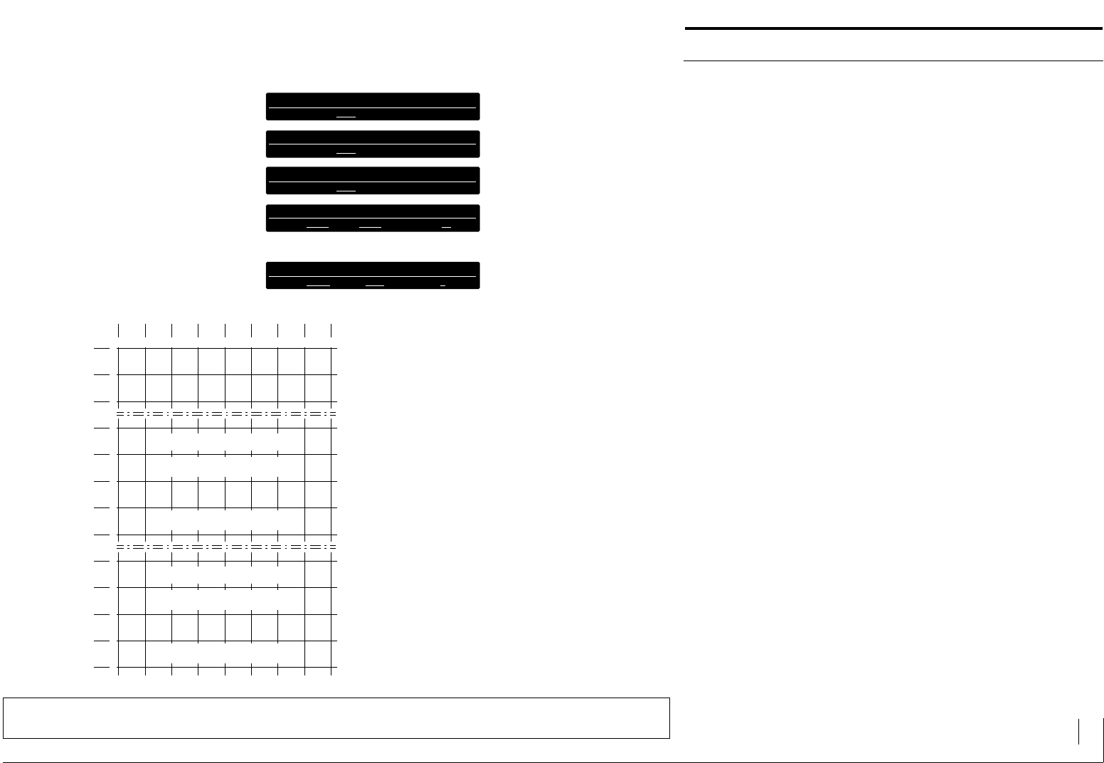
Mode 2: Binary drive (without Clock and Synchronization)
On apply a binary value (10 bit) with this mode, it is possible to activate a
maximum of 1024 double line messages (0...1023).
The binary values are filed with the terminals 3...12 (Do...D7, S, T). The
most significant bit (MSB) is terminal 12 (T), the lowest significant (LSB) is
terminal 3 (D0).
A default message text can be defined for non-planned message texts. It
is advisable to integrate the variable "text number" here.
If a text is lined up but hasn’t been planned, an empty display appears.
LCA 200
+ 24VDC (19...33V)
0 V
PLC OUTPUTS
OPERATING VOLTAGE
1 2 3 4 5 6 7 8 9 10 11 12
D0 = BIN (2 ) = 1
0
D1 = BIN (2 ) = 2
1
D2 = BIN (2 ) = 4
2
D3 = BIN (2 ) = 8
3
D4 = BIN (2 ) = 16
4
D5 = BIN (2 ) = 32
5
D6 = BIN (2 ) = 64
6
D7 = BIN (2 ) = 128
7
S = BIN (2 ) = 256
8
T = BIN (2 ) = 512
9
Mode 2: Binary drive
LCD DISPLAY LED BACKGROUND ILLUMINATION
2 LINES EACH WITH 40 CHARACTERS

TEXT DISPLAY LCA 200 Description 10
© 1994 by SYSTEME LAUER GMBH & CO. KG D 72669 Unterensingen • TEL 07022 / 9660-0 • FAX 07022 / 9660-274
The Communication Concept
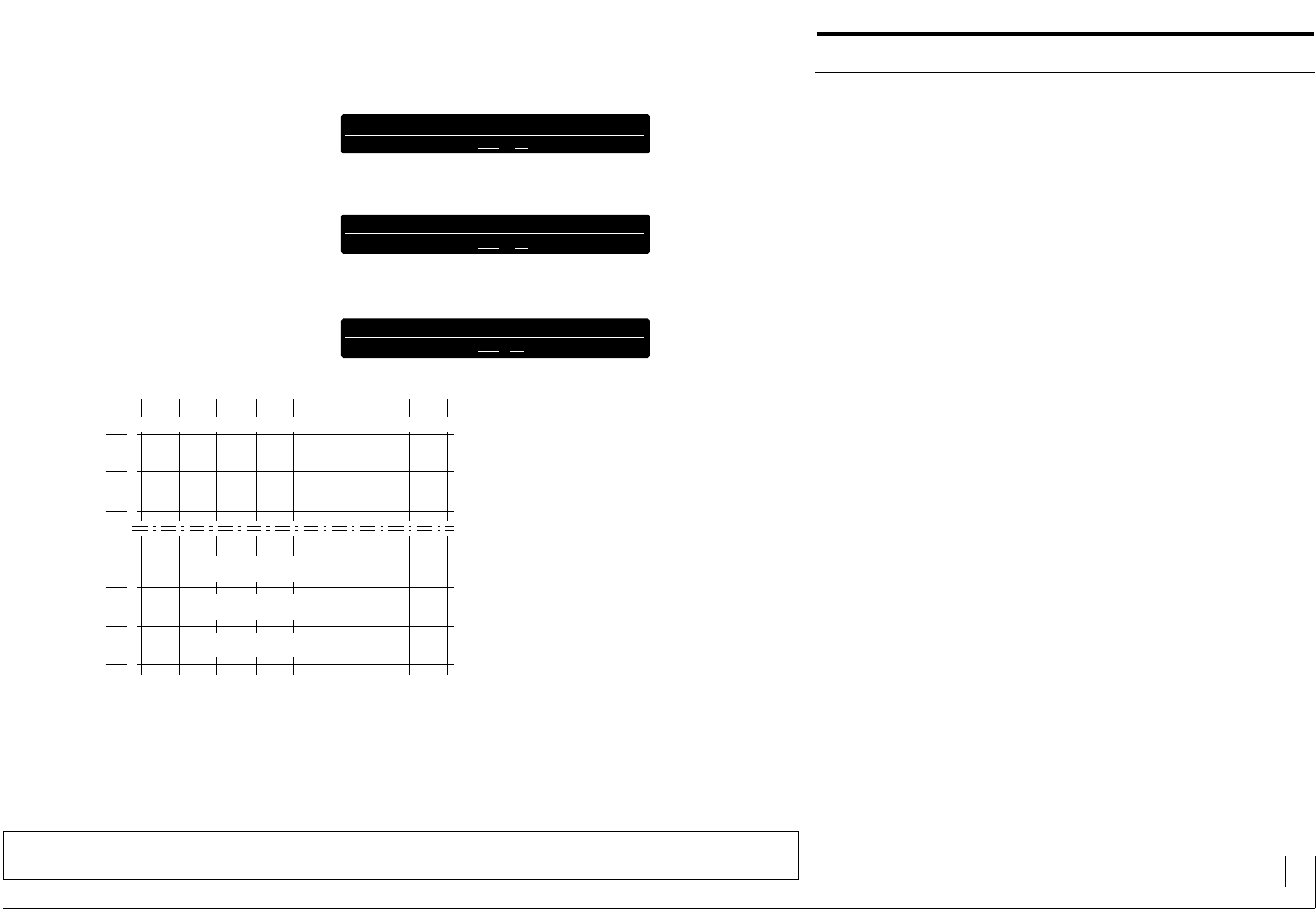
Mode 3: Cyclical Transfer (Multiplex with Clock and Synchroniza-
tion)
A maximum of 256 bytes (terminals 3...10 = D0...7 = data bit 0...7) are
cyclically transfered with the terminals 11 (S= synchronbit) and 12
(T=Clock).
The text display absorbs the applied bytes (data bits D0...7) with every
positive as well as negative edge of the clock bit.
The first byte is marked with the terminal 11 (S) = log 1. All the following
bytes are transfered with the reset synchronous input terminals 11 (S) = log
0.
It is absolutely essential as the distance between two clock edges amounts
to at least a millisecond.
As the outputs of the various PLC and componentry manufacturers have
differing switching delays for log 0/log 1 - and log 1/log 0 transfers, a
"clock delay time" can be set with the planning software. It can be set
within the range 250 µs and 10ms.
The cyclical transfer is to be recommended if the PLC cycle time is short (<
10ms) or the PLC has a timer interrupter facility <10ms with fast periphery
access. All the data bits of the address area are transfered into the LCA 200
cyclically.
Advantage: minimum programming and execution time. The PLC only
has to present the information for the respective addresses that follow and
to invert the clock bit. 256 PLC cycles are necessary for the maximum
number of 256 addresses. In order to increase the speed for updating the
data, the number of maximum addresses must be reduced to the highest
number of applied addresses if they are less than 256.
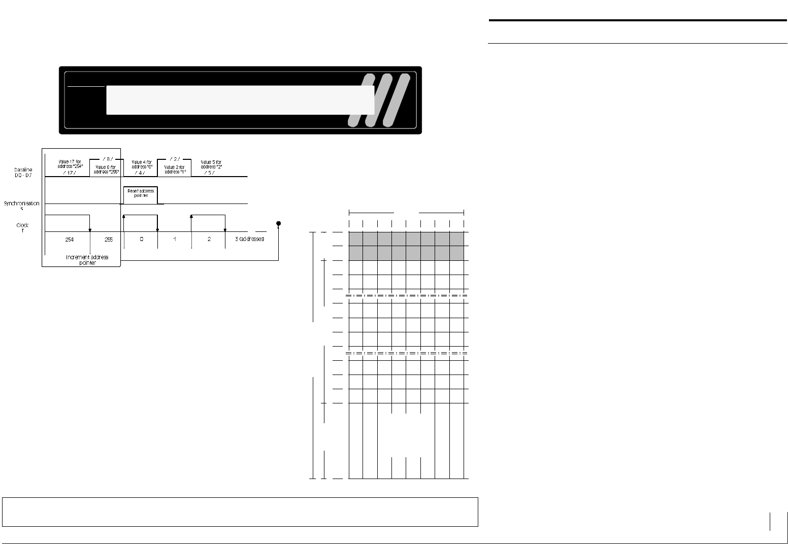
The synchronising S log 1 and the clock flank puts the address pointer onto
the address 00. Every positive (0 -> 1) or negative (1 -> 0) flank of the clock
T increases the address pointer (+1). The LCA reads the data bits of this
allocated address and calls functions, messages and/or variables. The clock
bit is inverted with every writing of the PLC output byte.
LCA 200
+ 24VDC (19...33V)
0 V
D5 (DATALINE 5)
D4 (DATALINE 4)
D3 (DATALINE 3)
D2 (DATALINE 2)
PLC OUTPUTS
OPERATING VOLTAGE
1 2 3 4 5 6 7 8 9 10
D0 (DATALINE 0)
D1 (DATALINE 1)
11
S (SYNCHRONIZATION) or D8
12
T (CLOCK) or D9
D6 (DATALINE 6)
D7 (DATALINE 7)
Mode 3: Cyclical transfer
LCD DISPLAY LED BACKGROUND ILLUMINATION
2 LINES EACH WITH 40 CHARACTERS
TEXT DISPLAY LCA 200 Description 11
© 1994 by SYSTEME LAUER GMBH & CO. KG D 72669 Unterensingen • TEL 07022 / 9660-0 • FAX 07022 / 9660-274
The Communication Concept
If the address pointer reaches the address 255, it must be reset again to
address 00 with the synchronization S (log 1). If the address pointer is not
reset, it remains on address 255.
With every address, the address pointer can be reset to address 0 with the
synchronization (log 1).
Data bits of the respective address must always be filed on the dataline
D0...D7.
You can glean the driving concept from the following flow diagram.
Whereby the creation of a PLC program will be made easier.
LCA 200
Example:
Cyclical Transfer of
addresses 0 to 255
LCD DISPLAY LED BACKGROUND ILLUMINATION
2 LINES EACH WITH 40 CHARACTERS
7
0
6 5 4 3 2
258 M = MESSAGE TEXTS # 258 (ADDRESSES 34.2)
1
3
27M6M5M4M3M2
M
10M11M12M13M14M15M
33 250M251M252M253M254M255M
35
34 263M262M261M260M259M258M
266M267M268M269M270M271M
127 1002M1003M1004M1005M1006M1007M
129
128 1015M1014M1013M1012M1011M1010M
1018M1019M1020M1021M1022M1023M
0
0M
8M
248M
256M
264M
1000M
1008M
1016M
1
1M
9M
249M
257M
265M
1001M
1009M
1017M
a
b
HQI ZUHUS
H0H1F1 F0R0R1 H3 H2
BIT VARIABLES
STRING VARIABLES
BCD VARIABLES
BIN VARIABLES
VBIN VARIABLES
ASCII VARIABLES
255
MAX. ADDRESS RANGE
DATABIT
VARIABLES MESSAGE TEXTS FUNCTION
TEXT DISPLAY LCA 200 Description 12
© 1994 by SYSTEME LAUER GMBH & CO. KG D 72669 Unterensingen • TEL 07022 / 9660-0 • FAX 07022 / 9660-274
The Communication Concept
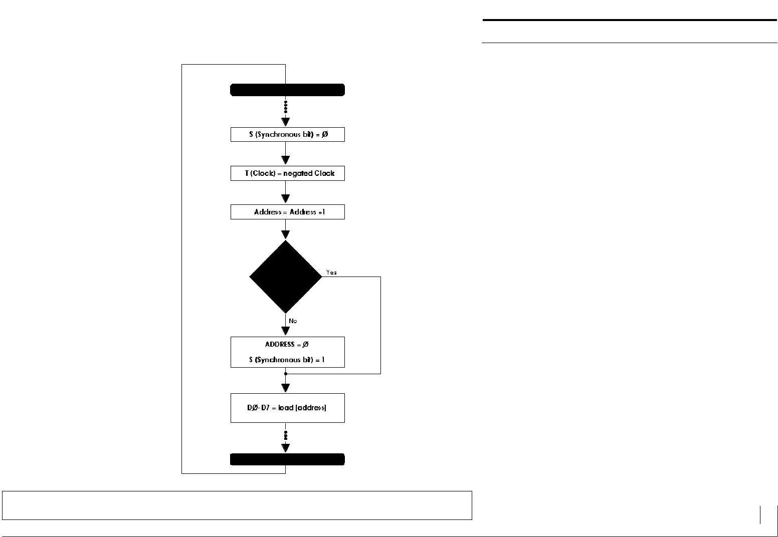
Flow diagram in Mode 3
;PLC operated inputs/outputs
;Synchronous bit preferably previously occupied with 0 (reset)
;Invert clock bit
(Clock exchange 0/1 -> 1/0 -> 0/1)
;Address +1
;Load 8 databits corresponding to the selected addresses
from the data array, e.g. by indirect addressing.
;Reset the address
;Zero run synchronization
S = set log 1
;In our example the end address is the same as the maximum
address 255 => query on end address + 1.
If there are less addresses, the end address must be
correspondingly reduced.
With a PLC fresh run, the address counter is to be initialized
with the end address +1 so that in the 1st PLC cycle, the
address 0 will be transfered with synchronization.

TEXT DISPLAY LCA 200 Description 13
© 1994 by SYSTEME LAUER GMBH & CO. KG D 72669 Unterensingen • TEL 07022 / 9660-0 • FAX 07022 / 9660-274
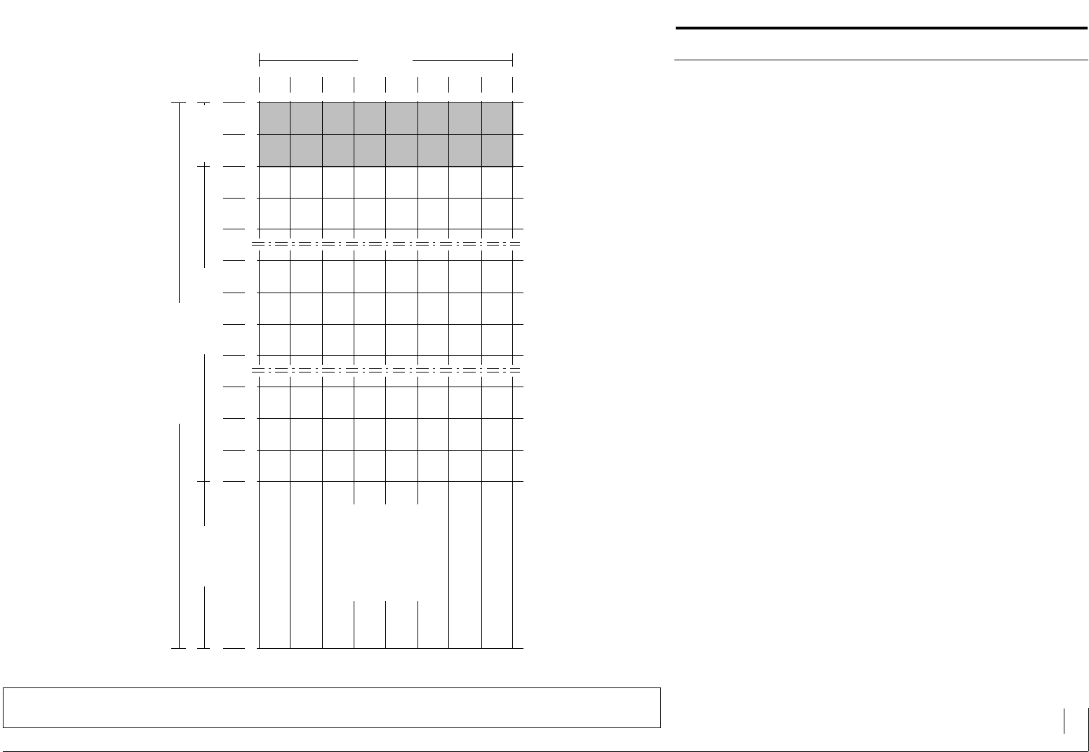
The Communication Concept
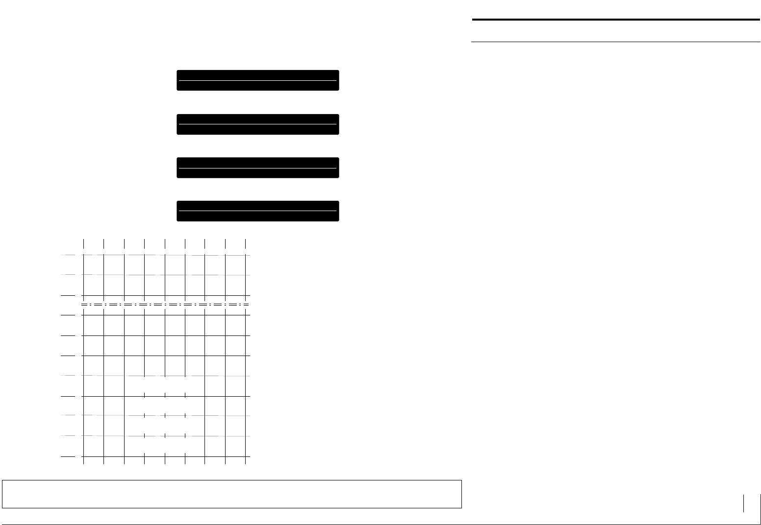
Mode 4: Selective Transfer (Multiplex with Clock and Synchroni-
zation)
Up to 256 selective bytes (terminals 3...10 = D0...7 = data bit 0...7) are
transfered through the terminals 11 (S = synchronous bit) and 12 (T =
Clock). Selective means that only data which has been changed will be
transfered from the PLC.
The text display incorporates the applied bytes (data bits D0...7) for every
positive as well as every negative edge of the clock bit (T).
Using the terminal 11 (S) = log 1, the address pointer which shows to the
transfer block of 256 bytes size, can be positioned. If the terminal 11 (S)
= log 0, data will be transfered to the previous set address.
If several bytes are to be transfered to the consecutive unbroken chain of
addresses, it is only necessary to position the address pointer at the begin-
ning. All the subsequent bytes can be transfered directly one after another,
as the text display automatically increments the address pointer after every
clock.
It is essential that there is a minimum interval of a millisecond between two
clock flanks.
As the outputs of the various PLC manufacturers and componentry have
differing switching delays for log 0/log 1 - and log 1/log 0 transfers, a
"clock delay time" can be set with the planning software. It can be set
within the range 250 µs and 10ms.
Selective transfer is to be recommended if the PLC cycle time is long. Only
addresses in which the data bits are altered, are transfered into the LCA
200.
Advantage: Fast reaction. However the PLC program is more complica-
ted and requires more execution time than the cyclical transfer.
LCA 200
+ 24VDC (19...33V)
0 V
D5 (DATALINE 5)
D4 (DATALINE 4)
D3 (DATALINE 3)
D2 (DATALINE 2)
PLC OUTPUTS
OPERATING VOLTAGE
1 2 3 4 5 6 7 8 9 10
D0 (DATALINE 0)
D1 (DATALINE 1)
11
S (SYNCHRONIZATION) or D8
12
T (CLOCK) or D9
D6 (DATALINE 6)
D7 (DATALINE 7)
Mode 4: Selective transfer
LCD DISPLAY LED BACKGROUND ILLUMINATION
2 LINES EACH WITH 40 CHARACTERS
TEXT DISPLAY LCA 200 Description 14
© 1994 by SYSTEME LAUER GMBH & CO. KG D 72669 Unterensingen • TEL 07022 / 9660-0 • FAX 07022 / 9660-274
The Communication Concept
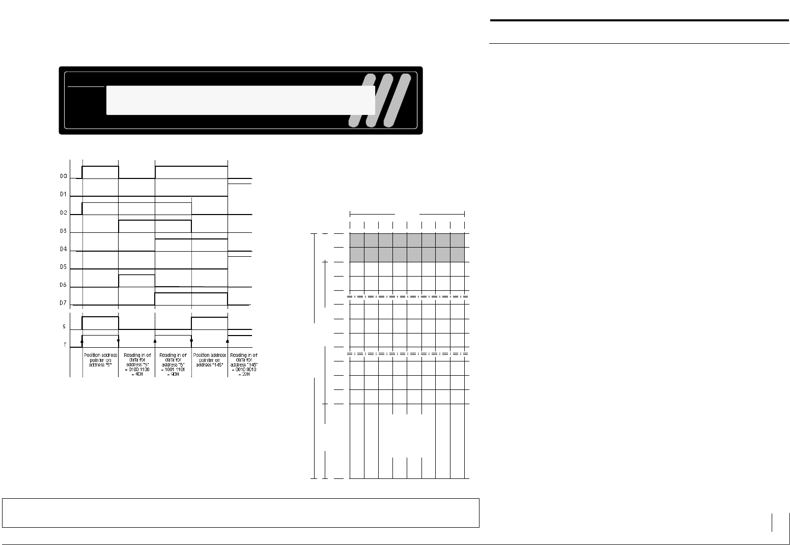
As long as the synchronous input S is log 1, the binary coded address lies
with the datalines D0...D7. If the synchronous input S changes to log 0, the
data bits for functions, messages and/or variables lie with the datalines
D0...D7.
If the synchronous input S remains log 0, the address pointer (+1) is in-
creased with every clock flank. The transfer then corresponds to the cyclical
transfer. Thereupon there is a saving of a clock cycle for a renewed address
pointer positioning.
You can glean the drive principle from the following flow diagram. Where-
by the creation of a PLC program is made easier.
LCA 200
7
0
6 5 4 3 2
258 M = MESSAGE TEXTS # 258 (ADDRESSES 34.2)
1
3
27M6M5M4M3M2
M
10M11M12M13M14M15M
33 250M251M252M253M254M255M
35
34 263M262M261M260M259M258M
266M267M268M269M270M271M
127 1002M1003M1004M1005M1006M1007M
129
128 1015M1014M1013M1012M1011M1010M
1018M1019M1020M1021M1022M1023M
0
0M
8M
248M
256M
264M
1000M
1008M
1016M
1
1M
9M
249M
257M
265M
1001M
1009M
1017M
a
b
HQI ZUHUS
H0H1F1 F0R0R1 H3 H2
BIT VARIABLES
STRING VARIABLES
BCD VARIABLES
BIN VARIABLES
VBIN VARIABLES
ASCII VARIABLES
255
MAX. ADDRESS RANGE
DATABIT
VARIABLES MESSAGE TEXTS FUNCTION
Example:
Transfer of addresses
5, 6 and 145
Contents of address 5 = 0100 1100
Contents of address 6 = 1001 1101
Contents of address 145 = 0010 0010
LCD DISPLAY LED BACKGROUND ILLUMINATION
2 LINES EACH WITH 40 CHARACTERS
TEXT DISPLAY LCA 200 Description 15
© 1994 by SYSTEME LAUER GMBH & CO. KG D 72669 Unterensingen • TEL 07022 / 9660-0 • FAX 07022 / 9660-274
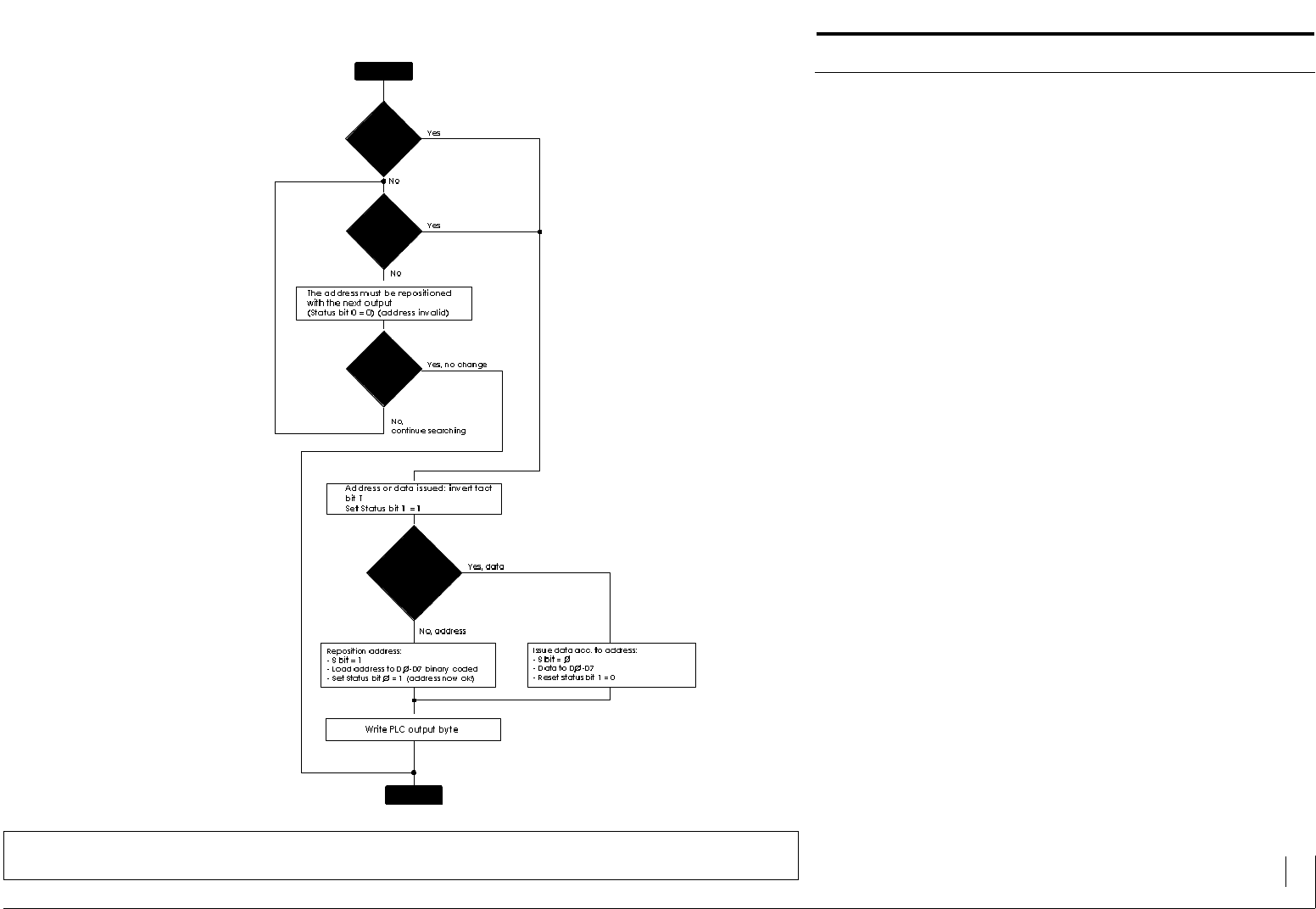
Status bit 0:log 1 = address pointer is positioned
correctly
Status bit 1:log 1 = actual data has still to be issued
The Communication Concept
Flow diagram in Mode 4
H
E
E
H
G
H
H
H
H
H
H
H
TEXT DISPLAY LCA 200 Description 16
© 1994 by SYSTEME LAUER GMBH & CO. KG D 72669 Unterensingen • TEL 07022 / 9660-0 • FAX 07022 / 9660-274
Operation of the LCA 200 (Modes 3, 4)
The Function Range of the LCA 200
Operation of the LCA 200 is done with the first 16 function bits. They
determine the respective function of the text display.
General Outline of the LCA 200 Functions:
SYMBOL ADR/BIT FUNCTION
H = 00.0 Calling a help text
Q = 00.1 Quitting a flashing text
▼= 00.2 Leafing forwards in active message memory
▲= 00.3 Leafing backwards in active message memory
Z = 00.4 Call additional information (lines 3..32)
i = 00.5 Call main information (lines 1 + 2)
UH = 00.6 Suppression of information
US = 00.7 Suppression of faults
H0 = 01.0 Selection of the help text bit 0
H1 = 01.1 Selection of the help text bit 1
H2 = 01.2 Selection of the help text bit 2
H3 = 01.3 Selection of the help text bit 3
F0 = 01.4 Selection of the message format bit 0
F1 = 01.5 Selection of the message format bit 1
R0 = 01.6 Selection of the idle text bit 0
R1 = 01.7 Selection of the idle text bit 1
7
00
6 5 4 3 2
01
01
a
b
HQI ZUHUS
H0H1F1 F0R0R1 H3 H2
ADDRESS 00 ADDRESS 01
BIT 0 Call Help Texts H
The help text, having been preselected with
the bits H0...H3 is called with log 1.
BIT 1 Quit Flashing Texts Q
The flashing message text currently being pre-
sented is quitted with the positive edge (0/1)
and thereafter displayed as an established text.
If there is a fresh call for the message text, it will
be necessary to have renewed quitting.
BIT 2 Leaf Forwards in the Message Memory ▼
Leafing forward is done from the older to the
next latest message in the active display me-
mory (information or fault) with the positive
edge (0/1).
BIT 3 Leaf Backwards in the Message Memory ▲
Leafing backwards is done from the latest to
the next older message in the active display
memory (information or fault) with the positive
edge (0/1).
BIT 4 Call Additional Information Z
Always the next 2 text lines of the actual text
are called with the positive edge (0/1). This
function applies for the text groups: message,
help and idle text.
BIT 5 Call Main Information i
The first two lines of the actual text are called
with the positive edge (0/1). This function
applies for the text groups: message, help and
idle text.
BIT 6 Suppress Information UH
Active information are suppressed with log 1
(messages).
BIT 7 Suppress Faults US
Active faults are suppressed with log 1 (mes-
sages).
BIT 0...3 Call Help Texts H0...H3
A help text is binary coded selected out of 16
possible ones using this 4 bit. The call of the
address takes place in bit 0 (address 00).
BIT 4 + 5 Message Format F0 + F1
The message format for the maximum 128 re-
gistered messages in the message memory*) is
determined with these 2 bits. The following
combinations are possible:
F1 F0
0 0 Last value message
0 1 First value message
1 0 Cyclical display
1 1 Reserve function
BIT 6 + 7 Call idle texts R0...R1
A binary coded idle text is selected from a
selection of 4 with these 2 bits. The text is
called if there isn't a higher priority (message
or help text) active.
*) When there over 128 active messages, the latest messages
can only be considered, if older messages are cleared. It is
not then possible to achieve the time sequence.

TEXT DISPLAY LCA 200 Description 17
© 1994 by SYSTEME LAUER GMBH & CO. KG D 72669 Unterensingen • TEL 07022 / 9660-0 • FAX 07022 / 9660-274
Operation of the LCA 200 (Modes 3, 4)
Priorities of the LCA 200
The LCA 200 possesses 4 priority stages:
- Idle priority (priority 0 = lowest priority)
- Info priority (priority 1)
- Fault priority (priority 2)
- Help priority (priority 3 = highest priority)
The LCA 200 puts the respectively highest (released) priority on display. By
setting the bit "H" in address 0, the help priority (highest priority) can be
displayed at any time. The desired help text number 0...15 is then to be filed
through the bits H0...3 in address 1.
The fault priority will then be displayed if the message bit is set with
parameterized message text of the priority "fault" and the bit "US" in
address 0 is set on log 0. Faults can be suppressed at any time by setting
the bit "US".
The info priority is displayed if a message bit with parameterized message
text of the "info" priority is set and the bit "UH" in address 0 is set to log
0. Infos can be suppressed at any time by setting the bit "UH".
The idle priority (lowest priority) is displayed, if the bit "H" in address 0 is
set to log 0 and no infos or faults are active.
TEXT DISPLAY LCA 200 Description 18
© 1994 by SYSTEME LAUER GMBH & CO. KG D 72669 Unterensingen • TEL 07022 / 9660-0 • FAX 07022 / 9660-274
Operation of the LCA 200 (Modes 3, 4)
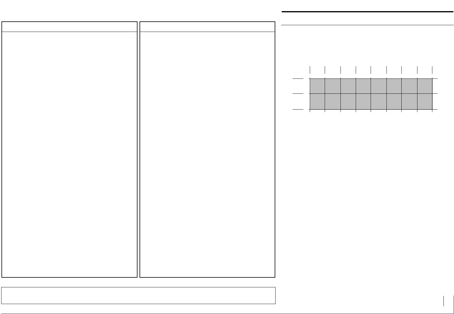
The Text Organization of the LCA 200
The LCA 200 can call a maximum of:
- 16 help texts
- 1024 message texts (infos and faults)
- 4 idle texts
Every help, message and idle text can be 32 lines, 40 characters (double
line information and 30 line additional information). The text groups are
lined up in order of priority. The help text has the highest priority, the idle
text has lowest priority.
Every message text is attached a message bit in the PLC. The 1024 message
bits in the LCA 200 have the addresses 2.0...129.7 (messages 0...1023).
If the message bit is log 1, the message text is switched on and if it is log
0 it will be switched off. If several message bits are log 1 at the same time,
then the message memory of the LCA 200 will register this. The message
memory can absorb maximum 128 infos and 128 faults. These are not
"non-volatile". If the message memory is full up and messages are
selectively deleted or new messages activated, there is no longer a timed
sequence. The display appears according to the selected message format
(F0, F1): as either first or last message or cyclical.
As long as the function bit H (00.0) is log 1, a help text is displayed. Owing
to the higher priority of the help text the idle or message texts are suppres-
sed.
The LCA 200 will show the idle text if there is no active help or message
text.
Calculation Formula:
Address a.b. -> Message text
((a-2) x 8) + b
Example:
34.2 -> 258
7
0
6 5 4 3 2
258 M = MESSAGE TEXTS # 258 (ADDRESSES 34.2)
1
3
27M6M5M4M3
M
2M
10M11M12M13M14M15M
33 250M251M252M253M254M255M
35
34 263M262M261M260M259M258M
266M267M268M269M270M271M
127 1002M1003M1004M1005M1006M1007M
129
128 1015M1014M1013M1012M1011M1010M
1018M1019M1020M1021M1022M1023M
0
0M
8M
248M
256M
264M
1000M
1008M
1016M
1
1M
9M
249M
257M
265M
1001M
1009M
1017M
abHQI ZUHUS
H0H1F1 F0R0R1 H3 H2
BIT VARIABLES
STRING VARIABLES
BCD VARIABLES
BIN VARIABLES
VBIN VARIABLES
ASCII VARIABLES
255
MAX. ADDRESS RANGE
DATABIT
VARIABLES MESSAGE TEXTS FUNCTION
The Data Block:
TEXT DISPLAY LCA 200 Description 19
© 1994 by SYSTEME LAUER GMBH & CO. KG D 72669 Unterensingen • TEL 07022 / 9660-0 • FAX 07022 / 9660-274
Operation of the LCA 200 (Modes 3, 4)
The Variables of the LCA 200
The LCA 200 possesses character variables and numerical variables with
differing formats.
With the character variables, a string is allocated to the log states of indivi-
dual (bit variable) or several (STRING variable) bits.
With numerical variables it is decided upon as to whether the transfered
value from the PLC is either binary or BCD coded. The LCA 200 transforms
the numerical variable and presents it in decimal form.
Variables can be positioned on all addresses (0...255). The user is responsi-
ble to differentiate between function and message bit blocks.
The message bit block is automatically limited by a filed message text used
bit on the block byte 2 up to the highest amount.
If, for example, the M250 (byte 33.2) is planned as the maximum message
text, the addresses can be used for variables as of byte 34.
NUMERICAL VARIABLES
CHARACTER VARIABLES
BIT Variable
A string is allocated to each one of the 2 log states of any particular
bit in the data block. The string is user-defined and may have a maxi-
mum length of 40 characters. The string itself may not have any
further variable. The longest of both strings determines by the reser-
ved space.
Example:
Bit nn = log 0 » End switch off«
Bit nn = log 1 » End switch on«
STRING Variable
A string can allocated to any binary value of any particular byte in the
data block (0...255). That's a maximum of 256 strings. The strings are
user-defined and may have a maximum length of 40 characters. The
string itself may not have any further variable. If a value is outside the
value area, an inverse field will be presented on the display.
Example:
Byte nn = 0 >> Default setting <<
Byte nn = 1 >> Hot phase <<
Byte nn = 2 >> Cool phase <<
. .
. .
. .
ASCII Variable
The corresponding character from the character table will be alloca-
ted to each binary value of a byte in the data block.
BIN BYTE Variable
The transfered value at any particular byte in the data block will be
presented as a unsigned number. The value range can be parame-
terized and lies between 0...255. Pre-zeroes as well as pre-commas
and post comma positions can be parameterized. If the value is out-
side the MIN/MAX values, an inverse field will appear.
BIN WORD Variable
The transfered value at any particular word in the data block (2 conse-
cutive bytes) is presented as a unsigned number. The value range can
be parameterized and lies between 0...65535. Pre-zeroes, as well as
pre-comma and post comma positions can be parameterized.
Address nn = higher valued byte
Address nn+1 = lower valued byte
If the value is outside the MIN/MAX values, an inverse field will appear.
VBIN BYTE Variable
The transfered value at any particular byte in the data block will be
presented as a fixed signed number. The value range can be parame-
terized and lies between -128 and +127. Pre-zeroes, as well as pre-
comma and post comma positions can be parameterized. If the value
is outside the MIN/MAX value, an inverse field will appear.
VBIN WORD Variable
The transfered value at any particular word in the data block (2 conse-
cutive bytes) will be presented as a fixed signed number. The value
range can be parameterized and lies between -32768 and +32767.
Pre-zeroes, as well as pre-comma and post comma positions can be
parameterized.
Address nn = higher valued byte
Address nn+1 = lower valued byte
If the value is outside the MIN/MAX values, an inverse field will appear.
BCD Variable
The value transfered through the 4 or 8 datalines (D0...D3 or D0...D8)
is evaluated as a single or double digit BCD value and is showed in the
display.
To achieve a great amount of digit number presentations, more BCD
variables can be joined onto on another.
It is possible to fade in the following characters with the pseudote-
trades:
$ 0B hex corresponds to "+"
$ 0C corresponds to "-"
$ 0E corresponds to "."
$ 0A, 0D corresponds to "_" (Blank)
$ 0F corresponds to flashing blank
TEXT DISPLAY LCA 200 Description 20
© 1994 by SYSTEME LAUER GMBH & CO. KG D 72669 Unterensingen • TEL 07022 / 9660-0 • FAX 07022 / 9660-274
Operation of the LCA 200 (Modes 3, 4)
Example BIT Variable
Two inscriptions (strings) are aligned to the two log states of a bit.
For example the message text 253 combines texts with the three bit varia-
bles:
Variable VAR1 (address 160.1)
Variable VAR2 (address 160.2)
Variable VAR3 (address 160.3)
Definition of the BIT Variable (2 texts per variable)
Name 1: VAR 1
Format : BIT
Text if bit log 0 2: WITHOUT
Text if bit log 1 2: WITH
Address 3: 160.1
Definition of the BIT Variable (2 texts per variable)
Name 1: VAR 2
Format : BIT
Text if bit log 0 2: OFF
Text if bit log 1 2: ON
Address 3: 160.2
Definition of the BIT Variable (2 texts per variable)
Name 1: VAR 3
Format : BIT
Text if bit log 0 2: OFF
Text if bit log 1 2: ON
Address 3: 160.3
Definition of the Message Text 185
TRANSPORT jjjj
VENTILATION jjj COOL WATER jjj
4
The message bit 253 (address 33.5) is log 1 and the appertaining message
text is presented in the text display. The texts "ON, WITH" for log 1 or "OFF,
WITHOUT" for log 0 are blended in on a selection basis dependent of the
log state of the databits for the variables VAR1, VAR2, VAR3 (addresses
160.1, 160.2, 160.3).
1Name of the variable has maximum length of 16 cha-
racters
22 texts of the bit variable each one having a maximum
length of 40 characters are for log 0 and log 1
38 BIT variables can be delegated to each address
4Reserved place for the variables in the idle, message
or help text. The length of the field is determined by
the length of the longest text of the variable
2)* 3)*
1)*
* 1) VAR1
2) VAR2
3) VAR3
Message bit 33.5
BIT Variable 1 160.1
BIT Variable 2 160.2
BIT Variable 3 160.3
-TRANSPORT - ON
-VENTILATION -OFF -COOL WATER - OFF
Message bit 33.5
BIT Variable 1 160.1
BIT Variable 2 160.2
BIT Variable 3 160.3
Message bit 33.5
BIT Variable 1 160.1
BIT Variable 2 160.2
BIT Variable 3 160.3
Message bit 33.5
BIT Variable 1 160.1
BIT Variable 2 160.2
BIT Variable 3 160.3
7
161
160
34
33
6 5 4 3 2
255M
254M253M252M251M250M
263M262M261M260M259M258M
-TRANSPORT - OFF
-VENTILATION - ON -COOL WATER - OFF
-TRANSPORT - OFF
-VENTILATION - ON -COOL WATER - ON
-TRANSPORT - ON
-VENTILATION - ON -COOL WATER - ON
0
248M
256M
1
BIT
VAR1
249M
257M
BIT
VAR2
BIT
VAR3
= log 1
=log1
=log0
=log0
= log 1
=log0
=log1
=log0
= log 1
=log0
=log1
=log 1
= log 1
=log1
=log1
=log1
TEXT DISPLAY LCA 200 Description 21
© 1994 by SYSTEME LAUER GMBH & CO. KG D 72669 Unterensingen • TEL 07022 / 9660-0 • FAX 07022 / 9660-274
Operation of the LCA 200 (Modes 3, 4)
Example STRING Variable
The 256 states of a byte in the data block are allocated to up to 256
inscriptions (strings). Our example shows 6 inscriptions.
The message text 250 (as in the example) combines commentary texts with
a STRING variable:
Variable STATUS (address 163)
Definition of a STRING Variable (max. 256 texts per variable)
Name 1: STATUS
Format : STRING
Text if STRING 0000 0000 2: SETTING UP
Text if STRING 0000 0001 2: SINGLE CLOCK
Text if STRING 0000 0010 2: SEMI-AUTOMATIC
Text if STRING 0000 0011 2: AUTOMATIC
Text if STRING 0000 0100 2: AUTOMATIC WITH PREHEAT
Text if STRING 0000 0101 2: AUTOMATIC WITH HEAT REGULATION
Address : 163
Definition of a message text 250
PACKUNG MACHINE
STATUS: jjjjjjjjjjjjjjjjjjjjjjjjjj
3
The message bit 250 (address 33.2) is log 1 and the appertaining message
text is presented in the display. Texts are blended in on a selection basis
SETTING UP, SINGLE CLOCK, SEMI-AUTOMATIC, AUTOMATIC, AUTOMATIC
WITH PREHEAT, AUTOMATIC WITH HEAT REGULATION
for the variable STATUS (address 163) dependent of the log state of the
data bits.
1Name of the variable has maximum length of 16 cha-
racters
2256 texts (maximum 40 characters long) of the
STRING variables: from log 0000 0000 to log 1111
1111
3Reserved place for the variables in the idle, message
or help text. The length of the field is determined by
the length of the longest text of the variable
-PACKING MACHINE
-STATUS: -SETTING UP
Message bit 33.2
STRING Variable 163
-PACKING MACHINE
-STATUS: -SINGLE TACT
-PACKING MACHINE
-STATUS: -SEMI-AUTOMATIC
Message bit 33.2
STRING Variable 163
-PACKING MACHINE
-STATUS: -AUTOMATIC
Message bit 33.2
STRING Variable 163
-PACKING MACHINE
-STATUS: -AUTOMATIC WITH PREHEAT
7
163
162
161
160
34
33
6 5 4 3 2
Message bit 33.2
STRING Variable 163
-PACKING MACHINE
-STATUS: -AUTOMATIC WITH HEAT REGULATION
STRING VARIABLE
255M254M253M252M251M250M
258M259M260M261M262M263M
0
248M
256M
1
249M
257M
Message bit 33.2
STRING Variable 163
= log 1
=log0000 0000
= log 1
=log0000 0001
Message bit 33.2
STRING Variable 163
= log 1
=log0000 0010
= log 1
=log0000 0011
= log 1
=log0000 0100
= log 1
=log0000 0101
TEXT DISPLAY LCA 200 Description 22
© 1994 by SYSTEME LAUER GMBH & CO. KG D 72669 Unterensingen • TEL 07022 / 9660-0 • FAX 07022 / 9660-274
Operation of the LCA 200 (Modes 3, 4)
Example BINARY (BIN BYTE, BIN WORD, VBIN BYTE, VBIN WORD) Variable
Any byte or word from the data block can be presented as a decimal
number, and be selected as either without sign (BIN BYTE, BIN WORD),
with sign (VBIN BYTE, VBIN WORD), with or without pre-/post comma
positions, with or without pre-zeroes as well as having a limit on MIN/MAX
value . The message texts 248 and 256 (example) combine commentary
texts with BIN and VBIN variables:
BIN WORD variable NUMBER OF PIECES (address 160 + 161)
BIN BYTE variable CYLINDER NUMBER (address 163)
VBIN WORD variable TEMPERATURE (address 200 + 201)
VBIN BYTE variable POSITION (address 255)
Definition of the BIN BYTE Variables
Name 1: CYLINDER NUMBER
Format : BIN-1
Address : 163
Pre-comma positions : 2
Post comma positions : 0
Minimum : 0
Maximum : 99
Pre-zeroes : None
Definition of the BIN WORD Variables
Name 1: NUMBER OF PIECES
Format : BIN-2
Address 2: 160
Pre-comma positions : 4
Post comma positions : 0
Minimum : 0
Maximum : 9999
Pre-zeroes : None
Definition of the VBIN BYTE Variables
Name 1: TEMPERATURE
Format : VBIN BYTE
Address 2: 255
Pre-comma positions : 2
Post comma positions : 1
Minimum : -999
Maximum : +999
Pre-zeroes : Yes
1Name of the variable has a maximum length of 16
characters
2WORD variables always require two addresses
3Reserved place for the variables in the idle, message
and help texts
Message bit 34.4
BIN WORD Variable 160 (HIGH)
BIN WORD Variable 161 (LOW)
Message bit 34.4
BIN WORD Variable 160 (HIGH)
BIN WORD Variable 161 (LOW)
Message bit 34.4
BIN WORD Variable 160 (HIGH)
BIN WORD Variable 161 (LOW)
Message bit 33.0
BIN BYTE Variable 163
VBIN WORD Variable 200 (HIGH )
VBIN WORD Variable 201 (LOW)
VBIN BYTE Variable 255
Message bit 33.0
BIN BYTE Variable 163
VBIN WORD Variable 200 (HIGH)
VBIN WORD Variable 201 (LOW)
VBIN BYTE Variable 255
-PACKING MACHINE
-COMPLETED: -2081 -PIECES
-PACKING MACHINE
-COMPLETED: -2082 -PIECES
-PACKING MACHINE
-COMPLETED: -2083 -PIECES
-PACKING MACHINE
-TEMP: - 02,8 POS: - 0,81 CYLINDER -36
-PACKING MACHINE
-TEMP: + 12,4 POS: + 3,21 CYLINDER -4
7
34
33
6 5 4 3 2
255M254M253M252M251M250M
258M259M260M261M262M263M
01
248M
256M
249M
257M
BIN WORD VARIABLE BIT 0...7
BIN BYTE VARIABLE BIT 0...7
BIN WORD VARIABLE BIT 8...15
VBIN WORD VARIABLE BIT 0...7
VBIN WORD VARIABLE BIT 8...15
VBIN BYTE VARIABLE BIT 0...7
= log 1
=0000 1000
=0010 0001
= log 1
=0000 1000
=0010 0010
= log 1
=0000 1000
=0010 0011
= log 1
= 0010 0100
= 1111 1111
= 1010 1111
= 1110 0100
= log 1
= 0000 0100
= 0000 0001
= 0100 0001
= 0111 1100
255
201
200
163
162
161
160

TEXT DISPLAY LCA 200 Description 23
© 1994 by SYSTEME LAUER GMBH & CO. KG D 72669 Unterensingen • TEL 07022 / 9660-0 • FAX 07022 / 9660-274
Operation of the LCA 200 (Modes 3, 4)
Definition of the VBIN WORD Variables
Name 1: POSITION
Format : VBIN WORD
Address 2: 200
Pre-comma positions : 1
Post comma positions : 2
Minimum : -458
Maximum : +299
Pre-zeroes : None
Definition of the Message Text 248
PACKING MACHINE
COMPLETED: jjjj PIECES
Definition of the Message Text 256
PACKING MACHINE
CYLINDER: jj
TEMPERATURE: jjj.j °C
POSITION: jj.jj
3
The message bit 256 (address 34.0) is log 1, and the appertaining message
text is presented in the text display. The actual number of pieces is display-
ed dependent of the BINARY value of the variable NUMBER OF PIECES
(addresses 160 + 161).
The message bit 248 (address 33.0) is log 1 and the appertaining message
text is presented in the text display. The actual number of pieces is display-
ed dependent of the BINARY value of the variable CYLINDER NUMBER
(address 163).
The actual temperature is displayed dependently of the BINARY value of
the variable TEMPERATURE (address 255).
The actual position is displayed dependently of the BINARY value of the
variable POSITION (address 200 + 201).
1Name of the variable has a maximum length of 16
characters
2WORD variables always require two addresses
3Reserved place for the variables in the idle, message
and help texts
1)*
* 1) NUMBER OF PIECES
2) CYLINDER NUMBER
3) TEMPERATURE
4) POSITION
2)*
Message bit 34.4
BIN WORD Variable 160 (HIGH)
BIN WORD Variable 161 (LOW)
Message bit 34.4
BIN WORD Variable 160 (HIGH)
BIN WORD Variable 161 (LOW)
Message bit 34.4
BIN WORD Variable 160 (HIGH)
BIN WORD Variable 161 (LOW)
Message bit 33.0
BIN BYTE Variable 163
VBIN WORD Variable 200 (HIGH )
VBIN WORD Variable 201 (LOW)
VBIN BYTE Variable 255
Message bit 33.0
BIN BYTE Variable 163
VBIN WORD Variable 200 (HIGH)
VBIN WORD Variable 201 (LOW)
VBIN BYTE Variable 255
-PACKING MACHINE
-COMPLETED: -2081 -PIECES
-PACKING MACHINE
-COMPLETED: -2082 -PIECES
-PACKING MACHINE
-COMPLETED: -2083 -PIECES
-PACKING MACHINE
-TEMP: - 02,8 POS: - 0,81 CYLINDER -36
-PACKING MACHINE
-TEMP: + 12,4 POS: + 3,21 CYLINDER -4
7
34
33
6 5 4 3 2
255M254M253M252M251M250M
258M259M260M261M262M263M
01
248M
256M
249M
257M
BIN WORD VARIABLE BIT 0...7
BIN BYTE VARIABLE BIT 0...7
BIN WORD VARIABLE BIT 8...15
VBIN WORD VARIABLE BIT 0...7
VBIN WORD VARIABLE BIT 8...15
VBIN BYTE VARIABLE BIT 0...7
= log 1
=0000 1000
=0010 0001
= log 1
=0000 1000
=0010 0010
= log 1
=0000 1000
=0010 0011
= log 1
= 0010 0100
= 1111 1111
= 1010 1111
= 1110 0100
= log 1
= 0000 0100
= 0000 0001
= 0100 0001
= 0111 1100
255
201
200
163
162
161
160
TEXT DISPLAY LCA 200 Description 24
© 1994 by SYSTEME LAUER GMBH & CO. KG D 72669 Unterensingen • TEL 07022 / 9660-0 • FAX 07022 / 9660-274
1Name of the variable has a maximum length of 16
characters
4Reserved place for the variable in the idle, message or
help text
1) 2) 3)*
Operation of the LCA 200 (Modes 3, 4)
Example BCD Variable
The contents of any particular byte of a data block can be presented either
as one or two BCD numerals. The message text 259 (as in the example)
combines the commentary text with the BCD variable (length 5 digits):
BCD/DIGIT 0_1 (address 159)
BCD/DIGIT 2_3 (address 160)
BCD/DIGIT 4 (address 161)
Definition of the BCD Variables
Name 1: DIGIT 0_1
Format : BCD
Address : 159
Length of presentation : 2 positions
Name 1: DIGIT 2_3
Format : BCD
Address : 160
Length of presentation : 2 positions
Name 1: DIGIT 4
Format : BCD
Address : 161
Length of presentation : 1 position
Definition of the Message Text 259
HEATING 1
BOILER PRESSURE: jjj . jj bar
2
The message bit 259 (address 33.3) is log 1 and the appertaining message
text is presented in the text display. The actual pressure is displayed in bar
dependently of the value of the BCD variable DIGIT 0...4 (address
159...161).
If the BCD variable is only of one place, the lower valued nibble of the byte
is evaluated. The higher valued nibble can, for example, be used for
another variable.
Message bit 34.3
BCD Variable 159 (Digit 0_1)
BCD Variable 160 (Digit 2_3)
BCD Variable 161 (Digit 4)
Message bit 34.3
BCD Variable 159 (Digit 0_1)
BCD Variable 160 (Digit 2_3)
BCD Variable 161 (Digit 4)
Message bit 34.3
BCD Variable 159 (Digit 0_1)
BCD Variable 160 (Digit 2_3)
BCD Variable 161 (Digit 4)
-HEATING 1
-BOILER PRESSURE: -120-. -00-bar
-HEATING 1
-BOILER PRESSURE: -239-. -14-bar
-HEATING 1
-BOILER PRESSURE: -158-.-08-bar
7
34
33
6 5 4 3 2
= log 1
=0001 0010
=0000 0000
=0000 0000
= log 1
=0010 0011
=1001 0001
=0000 0100
= log 1
=0001 0101
=1000 0000
=0000 1000
1 0
255M254M253M252M251M250M
258M259M260M261M262M263M
249M248M
256M257M
BCD VARIABLE DIGIT 0_1
BCD VARIABLE DIGIT 2_3
BCD VARIABLE DIGIT 4
161
160
159
* 1) DIGIT 0_1
2) DIGIT 2_3
3) DIGIT 4
TEXT DISPLAY LCA 200 Description 25
© 1994 by SYSTEME LAUER GMBH & CO. KG D 72669 Unterensingen • TEL 07022 / 9660-0 • FAX 07022 / 9660-274
Operation of the LCA 200 (Modes 3, 4)
Example ASCII Variable
Any particular byte of the data block can be presented as ASCII character
(refer to character list).
The message text 250 (for example), combines the commentary texts with
several ASCII variables:
Variable STATUS (address 163)
Definition of the ASCII Variable (64 texts per variable)
Name 1: NAME 1
Format : ASCII
Address : 163
Name 1: NAME 2
Format : ASCII
Address : 164
Name 1: NAME 3
Format : ASCII
Address : 165
Name 1: NAME 4
Format : ASCII
Address : 166
Definition of the Message Text
182
PACKING MACHINE
OPERATOR: jjjj
2
The message bit 250 (address 32.2) is log 1 and the appertaining text is
presented in the text display. The corresponding ASCII characters (refer to
character list) are dependent of the contents of the ASCII variables NAME
1 - NAME 4 (address 163...166).
1Name of the variable has a maximum length of 16
characters
2Reserved place for the variable in the idle, message or
help text.
Message bit 33.2
ASCII Variable 163
ASCII Variable 164
ASCII Variable 165
ASCII Variable 166
Message bit 33.2
ASCII Variable 163
ASCII Variable 164
ASCII Variable 165
ASCII Variable 166
Message bit 33.2
ASCII Variable 163
ASCII Variable 164
ASCII Variable 165
ASCII Variable 166
Message bit 33.2
ASCII Variable 163
ASCII Variable 164
ASCII Variable 165
ASCII Variable 166
-PACKING MACHINE
-OPERATOR: -KNUT
-PACKING MACHINE
-OPERATOR: -SWEN
-PACKING MACHINE
-OPERATOR: -OTTO
-PACKING MACHINE
-OPERATOR: -KARL
7
163
162
161
160
33
32
6 5 4 3 2
255M254M253M252M251M250M
258M259M260M261M262M263M
= log 1
=0100 1011 "K"
= 0100 1110 "N"
= 0101 0101 "U"
= 0101 0100 "T"
= log 1
=0100 1011 "S"
= 0100 1110 "W"
= 0101 0101 "E"
= 0101 0100 "N"
= log 1
=0100 1011 "O"
= 0100 1110 "T"
= 0101 0101 "T"
= 0101 0100 "O"
= log 1
=0100 1011 "K"
= 0100 1110 "A"
= 0101 0101 "R"
= 0101 0100 "L"
1 0
249M248M
256M257M
NAME 1
166
165
164
NAME 4
NAME 2
NAME 3
TEXT DISPLAY LCA 200 Description 26
© 1994 by SYSTEME LAUER GMBH & CO. KG D 72669 Unterensingen • TEL 07022 / 9660-0 • FAX 07022 / 9660-274
The Diagnostic Operation of the LCA 200
If problems should arise during the commissioning phase of the PLC and
LCA 200, then first check over the parallel connection from the PLC to the
LCA.
In order to check over the drive program from the PLC to the LCA, a
diagnostic module is available in the LCA and it can be switched on or off
through the parameterization LCAPRO software under the menu heading
"Transfer-Diagnoses". During the initial commissioning phase it is recom-
mended to install a time delay in the PLC program between the clock
flanks, as for example, with a PLC timer.
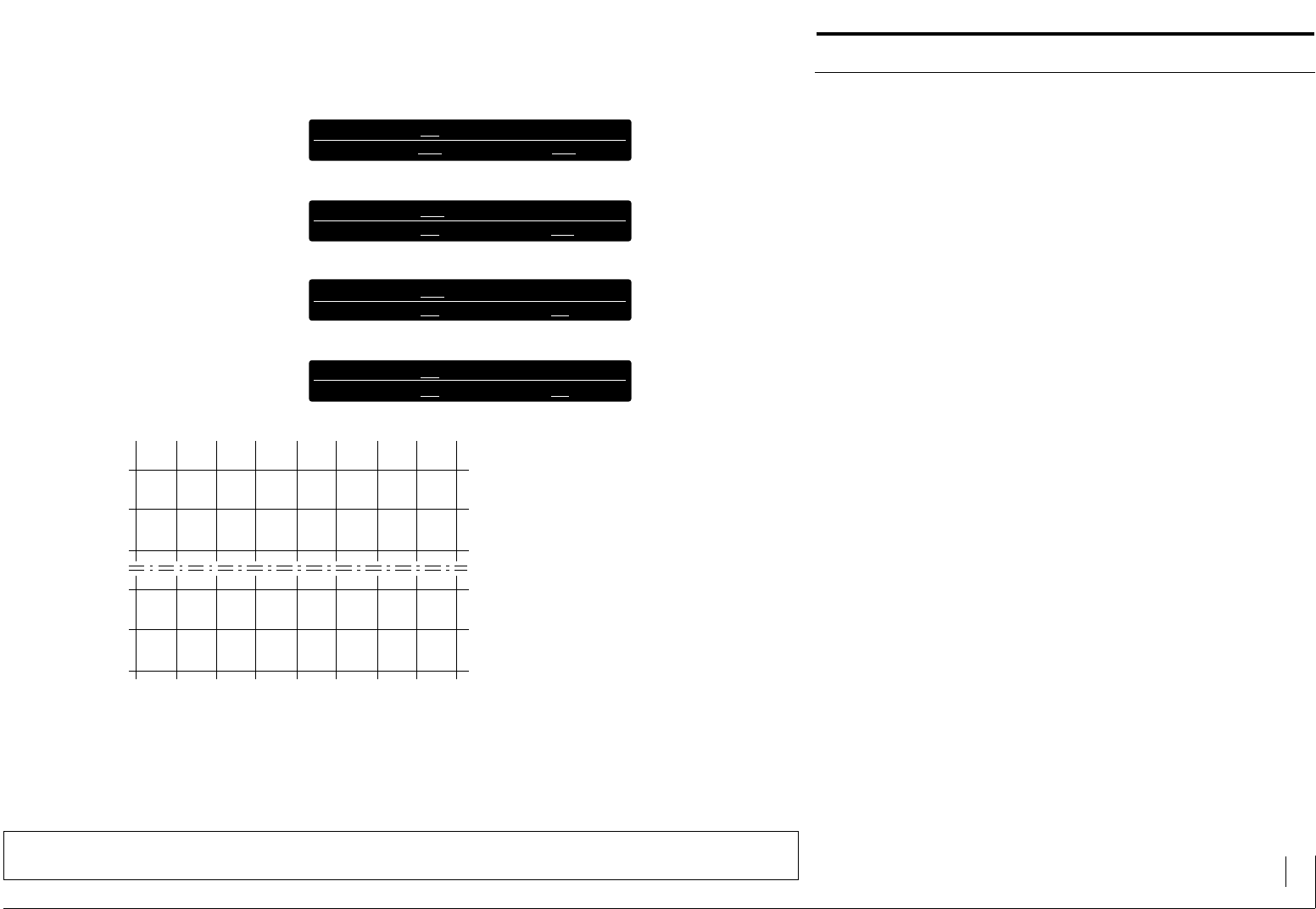
After switching on the diagnostic operation, a definite text depending on
the transfered modes, appears in the display:
Mode 1:
DIAGNOSTIC1 INPUTS: XXXXXXXXXX
SELECTED PLANE: X TEXTNR.: XX (X)
In the top line, the inputs of the LCA 200 are displayed in order of sequence
(T, S, D7...D0, therefore 12...3).
If the corresponding input is log 0, an 0 appears.
If the corresponding input is log 1, a 1 appears.
In the lower line you will see the currently active plane and text number.
If several inputs are log 1, the text number alters with the parameterized
"cycle time".
Text numbers are filed in brackets whether it concerns a idle text "R" or
a message text "M".
Mode 2:
DIAGNOSTIC2 INPUTS: XXXXXXXXXX
TEXTNR.: XXXX
In the top line, the inputs of the LCA 200 are presented in order of sequen-
ce (T, S, D7, therefore terminals 12...3).
If the corresponding input is log 0, an 0 appears.
If the corresponding input is log 1, a 1 appears.
You’ll see the currently activated text number in the bottom line.
TEXT DISPLAY LCA 200 Description 27
© 1994 by SYSTEME LAUER GMBH & CO. KG D 72669 Unterensingen • TEL 07022 / 9660-0 • FAX 07022 / 9660-274
The Diagnostic Operation of the LCA 200
Mode 3:
DIAGNOSTIC3 ADDR.: XXX D7...D0: XXXXXXXXXX
LAST CHANGE ADDR.: XXX D7...D0: XXXXXXXXXX
Every data transfer is displayed in the top line. The address and the apper-
taining date is displayed with each change of clock. In order that every
clock edge is visibly recognized, the displayed value always moves one
place to the left or one place to the right.
In respect of the contents of the LCA 200, the bottom line only shows
amendments to data currently being transfered. Whereby it is easy to see
if the drive program is working correctly.
Mode 4:
DIAGNOSTIC4 ADDR.: XXX D7...D0: XXXXXXXXXX
LAST CHANGE ADDR.: XXX D7...D0: XXXXXXXXXX
Every data transfer is displayed in the top line. The address and the accom-
panying date is displayed with every change in clock. In order that the every
clock edge is visibly recognized, the displayed value always moves one
place to the left or one place to the right. If only one address is transfered
(set synchronous bit), the character "********" appears in the field D7...D0.
With respect to the contents of the LCA 200, the bottom lines only shows
ammendments to data currently being transfered. Whereby it is easy to see
if the drive program is working correctly.
TEXT DISPLAY LCA 200 Description 28
© 1994 by SYSTEME LAUER GMBH & CO. KG D 72669 Unterensingen • TEL 07022 / 9660-0 • FAX 07022 / 9660-274
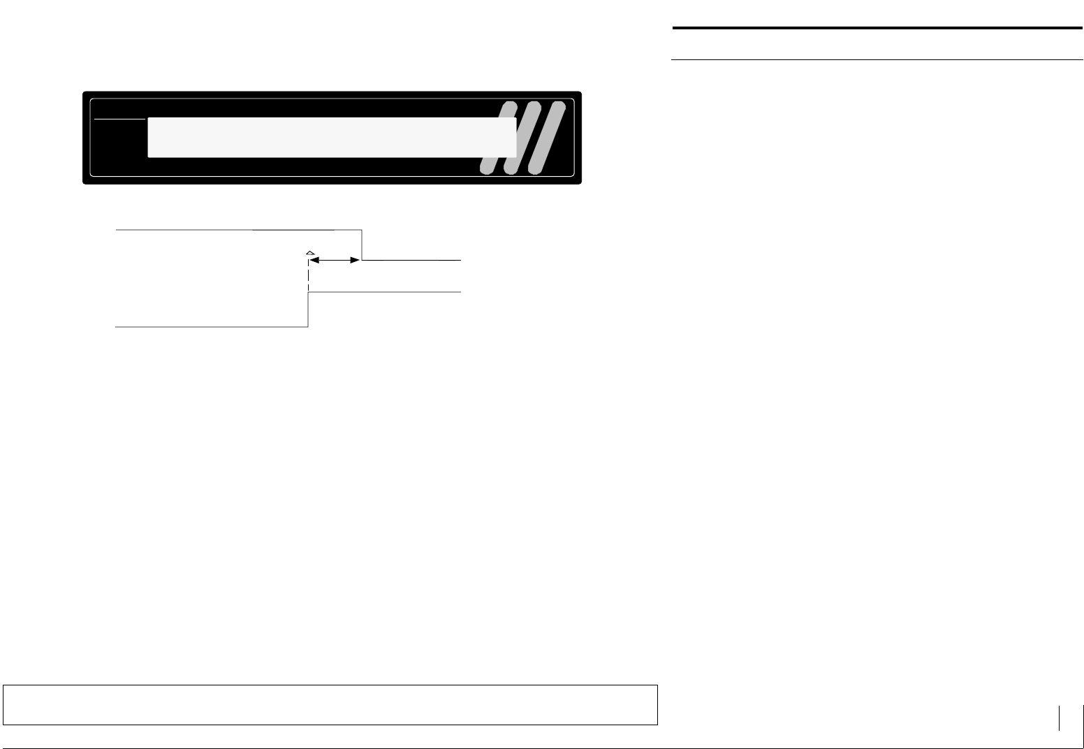
Switching Time Differences of the PLC Outputs
Should there be large time differences between the switching on and
switching off (more than 100µs), the clock delay time in the LCAPRO
software (menu heading "PROJECT", sub menu heading "TIMES", must
be increased.
With the Siemens digital outputs, the clock delay time should be set to a
value M 1000 µs. The clock delay time should not be larger than 1/3 of the
minimum PLC cycle.
LCA 200
H
L
H
L
t ≥ 100 µS PLC output with
change from 1 to 0
Other PLC output with
change from 0 to 1
LCD DISPLAY LED BACKGROUND ILLUMINATION
2 LINES EACH WITH 40 CHARACTERS
TEXT DISPLAY LCA 200 Description 29
© 1994 by SYSTEME LAUER GMBH & CO. KG D 72669 Unterensingen • TEL 07022 / 9660-0 • FAX 07022 / 9660-274
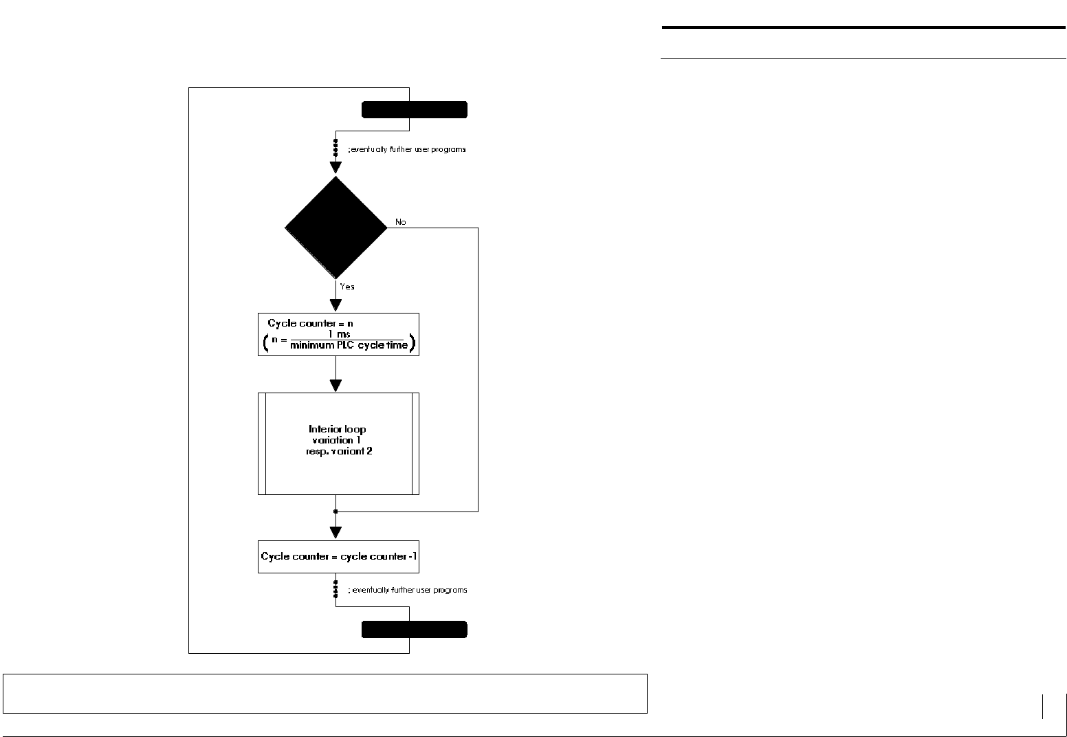
PLC Cycle Time m 1 ms
If the cycle time of the PLC is m 1 ms or the output switch delay M the cycle
time, a "delay" must be programmed. Only the drive program (inner loop)
is called every n-PLC cycle.
