LA7851 Datasheet. Www.s Manuals.com. Sanyo
User Manual: Datasheets LA7851.
Open the PDF directly: View PDF ![]() .
.
Page Count: 5
Any and all SANYO products described or contained herein do not have specifications that can handle
applications that require extremely high levels of reliability, such as life-support systems, aircraft’s
control systems, or other applications whose failure can be reasonably expected to result in serious
physical and/or material damage. Consult with your SANYO representative nearest you before using
any SANYO products described or contained herein in such applications.
SANYO assumes no responsibility for equipment failures that result from using products at values that
exceed, even momentarily, rated values (such as maximum ratings, operating condition ranges,or other
parameters) listed in products specifications of any and all SANYO products described or contained
herein.
Monolithic Linear IC
CRT Display Synchronization
Deflection Circuit
Ordering number:ENN1775A
LA7851
SANYO Electric Co.,Ltd. Semiconductor Company
TOKYO OFFICE Tokyo Bldg., 1-10, 1 Chome, Ueno, Taito-ku, TOKYO, 110-8534 JAPAN
O2500TN (KT)/N218TA/4015MW/6114KI, TS No.1775–1/4
110
20 11
0.5
(3.25)
3.3 3.9max
24.0
(0.57) 2.54 1.2
0.25
7.62
6.4
0.51min
1.0
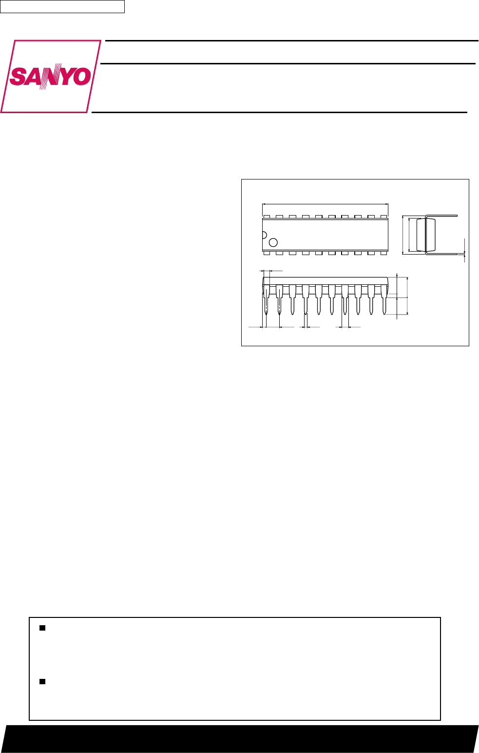
Package Dimensions
unit:mm
3021C-DIP20
[LA7851]
SANYO : DIP20
Overview
The LA7851 is a sync deflection circuit IC dedicated to
CRT display use. It can be connected to the LA7832, 7833
(for vertical output use) to form a sync deflection circuit
that meets every requirement for CRT display use.
So far, ICs for color TV use have been applied to the sync
deflection circuit for CRT display use and general-purpose
ICs such as one-shot multivibrator, inverter and a lot of
transistors have been used to form the peripherals such as
sync input interface, horizontal phase shifter. The LA7851
contains these peripherals on chip, has a wide vertical pull-
in range of 20Hz, and adopts a stable circuit for horizontal
oscillation from 15kHz to 100kHz aiming at improving the
characteristics requierd for CRT display use.
Features
• The vertical pull-in range 20Hz permits non-adjusting at
vertical sync 50Hz/60Hz.
• The horizontal oscillation frequency can be adjusted sta-
bly from 15kHz to 100kHz.
• The horizontal display can be shifted right/left.
• The horizontal/vertical sync input can be used intact re-
gardless of the difference in pulse polarity and pulse width.
• The AFC feedback sawtooth wave can be obtained by
simply applying a flyback pulse to the IC as a trigger
pulse.
• Any duty of the horizontal pulse can be set.
• Good linearity because DC bias at vertical output stage is
subject to sampling control within retrace time.
On-Chip Functions
[Horizontal Block] [Vertical Block]
• AFC • Vertical OSC
• Horizontal OSC • Vertical sawtooth wave generator
• X-ray protector • Sampling type DC voltage control
• Horizontal phase shift
• AFC sawtooth wave generator
• Horizontal pulse duty setting
LA7851
No.1775–2/4
retemaraPlobmySsnoitidnoC sgnitaR tinU
nimpytxam
V01CC niardtnerrucI
01 2103Am
V02CC niardtnerrucI
02 521Am
egnarni-llupycneuqerflacitreVV
NIP zH06cnyslacitreV0.120.32zH
ycneuqerfgninnur-eerflacitreVf
VfVzH55retnec0506zH
focitsiretcarahcegatlovdecuder/desaercnI ycneuqerflacitrev ∆fVV V22 V21tazH55,V1±21=1.0–1.0+zH
leveldlohserhtlortnoctniopdiM 8.34.4V
egatlovtratsCSOlacitreVf
ts,v 0.4V
ycneuqerflacitrevfocitsiretcarahcerutarapmeT 820.0–820.0+
rotcafnoitacifilpmarevirdlacitreVG
v2181Bd
niagpoolCDCFAlatnoziroHI
CFA 58.0±6.1±Am
ycneuqerfgninnur-eerflatnoziroHf
HfHzHk437.51retnec057–057+zH
egatlovtratsCSOlatnoziroHf
,H ts 0.4V
focitsiretcarahcegatlovdecuder/desaercnI ycneuqerflatnoziroh ∆f,HV V11 V21tazHk437.51,V1±21=05–05+zH
tfirdpu-mrawCSOlatnoziroH ∆fHrewopfonoitacilpparetfa.nim03ot.s505–05+zH
latnozirohfocitsiretcarahcerutarepmeT ycneuqerf 9.2–9.2+
tnerrucevirdtuptuolatnoziroHI
21 0.60.21Am
focitsiretcarahcegatlovdecuder/desaercnI emityaledretfihsesahp V01 V1±21=5.0–5.0+V/%
retfihsesahpfocitsiretcarahcerutarepmeT emityaled 1.0–1.0+
focitsiretcarahcegatlovdecuder/desaercnI emityaledretfihsesahp V01 V1±21=0.1–0.1+V/%
retfihsesahpfocitsiretcarahcerutarepmeT htdiweslup 31.0–31.0+
emitretnecnosirapmocesahpCFA tupni.P.B.FretfazHk437.519.95.11sµ
CFAfocitsiretcarahcegatlovdecuder/desaercnI emitretnecnosirapmocesahp V01 V1±21=5.1–5.1+V/%
esahpCFAfocitsiretcarahcerutarepmeT emitretnecnosirapmoc 2.0–2.0+
tupnignitarenegmrofevawnosirapmoC egatlovnoitarepo V46.09.0V
tratsnoitareponwod-dlohtaegatlov31nip31V5.08.0V
Operating Characteristics at Ta = 25˚C, V11, V22=12V
Operating Conditions at Ta = 25˚C
Specifications
Maximum Ratings at Ta = 25˚C
˚C
˚C
Ta≤65˚C
Hz/˚C
Ta=–10 to +60˚C
Hz/˚C
Ta=–10 to +60˚C
%/˚C
Ta=–10 to +60˚C
%/˚C
Ta=–10 to +60˚C
%/˚CTa=–10 to +60˚C
retemaraPlobmySsnoitidnoCsgnitaRtinU
egatlovylppusmumixaM
V01 V, 02 xam
41V
noitapissidrewopelbawollAxamdP 087Wm
erutarepmetgnitarepOrpoT 58+ot02–
erutarepmetegarotSgtsT 521+ot55–
retemaraPlobmySsnoitidnoCsgnitaRtinU
egatlovylppusdednemmoceRV
01 V, 02 0.21V
egnaregatlovgnitarepO
V01 V, po02
5.31ot9V
eulavkaeptupniesluplacitrevdednemmoceRV
ESLUP 0.5p-pV
egnareulavkaeptupniesluplacitrevgnitarepOV
ESLUP 0.6ot0.2p-pV
kaeptupniesluplatnozirohdednemmoceR eulav HESLUP 0.5p-pV
eulavkaeptupniesluplatnozirohgnitarepO egnar HESLUP 0.6ot0.2p-pV
LA7851
No.1775–3/4
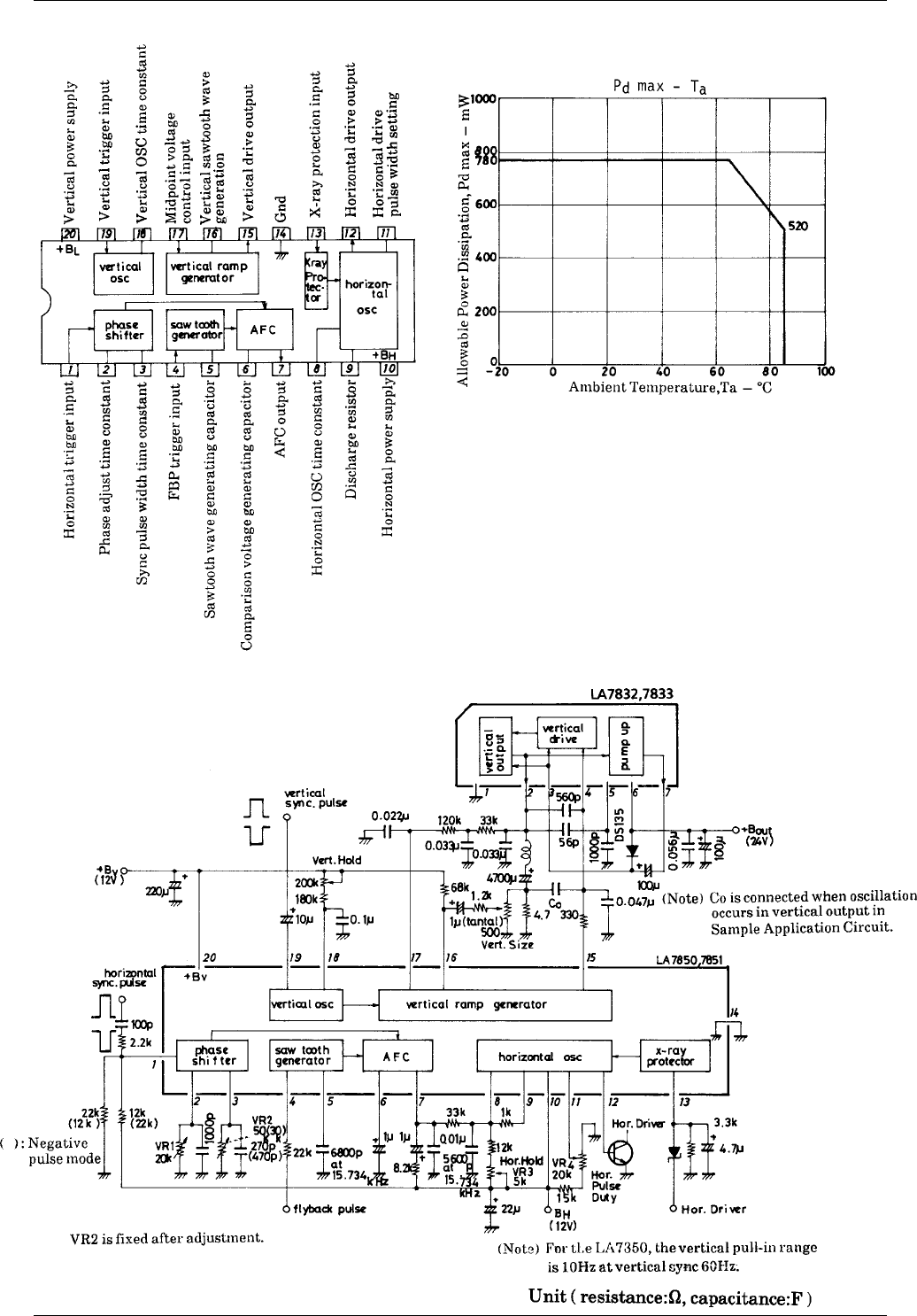
Equivalent Circuit Block Diagram
Sample Application Circuit : 14” Color Monitor/fV=60Hz, fH=15.734kHz
Specifications of any and all SANYO products described or contained herein stipulate the performance,
characteristics, and functions of the described products in the independent state, and are not guarantees
of the performance, characteristics, and functions of the described products as mounted in the customer's
products or equipment. To verify symptoms and states that cannot be evaluated in an independent device,
the customer should always evaluate and test devices mounted in the customer's products or equipment.
SANYO Electric Co., Ltd. strives to supply high-quality high-reliability products. However, any and all
semiconductor products fail with some probability. It is possible that these probabilistic failures could
give rise to accidents or events that could endanger human lives, that could give rise to smoke or fire,
or that could cause damage to other property. When designing equipment, adopt safety measures so
that these kinds of accidents or events cannot occur. Such measures include but are not limited to protective
circuits and error prevention circuits for safe design, redundant design, and structural design.
In the event that any or all SANYO products(including technical data,services) described or
contained herein are controlled under any of applicable local export control laws and regulations,
such products must not be exported without obtaining the export license from the authorities
concerned in accordance with the above law.
No part of this publication may be reproduced or transmitted in any form or by any means, electronic or
mechanical, including photocopying and recording, or any information storage or retrieval system,
or otherwise, without the prior written permission of SANYO Electric Co. , Ltd.
Any and all information described or contained herein are subject to change without notice due to
product/technology improvement, etc. When designing equipment, refer to the "Delivery Specification"
for the SANYO product that you intend to use.
Information (including circuit diagrams and circuit parameters) herein is for example only ; it is not
guaranteed for volume production. SANYO believes information herein is accurate and reliable, but
no guarantees are made or implied regarding its use or any infringements of intellectual property rights
or other rights of third parties.
This catalog provides information as of October, 2000. Specifications and information herein are subject
to change without notice.
LA7851
PS No.1775–4/4