LG 60PG60, 60PG60F UA Service Manual. Www.s Manuals.com. 60pg60 Chassis Pu82c Manual
User Manual: Plasma TV LG 60PG60F-UA, PU82C Chassis - Service manuals and Schematics. Free.
Open the PDF directly: View PDF ![]() .
.
Page Count: 30
PLASMA TV
SERVICE MANUAL
CAUTION
BEFORE SERVICING THE CHASSIS,
READ THE SAFETY PRECAUTIONS IN THIS MANUAL.
CHASSIS : PU82C
MODEL : 60PG60 60PG60F-UA
CANADA : http//biz.lgservice.com
USA : http//www.lgservice.com
: http//biz.lgservice.com
Internal Use Only
CH
VOL
MENU
INPUT ENTER
- 2 -
Copyright©2008 LG Electronics. Inc. All right reserved.
Only for training and service purposes LGE Internal Use Only
SAFETY PRECAUTIONS
Many electrical and mechanical parts in this chassis have special safety-related characteristics. These parts are identified by in the
Schematic Diagram and Replacement Parts List.
It is essential that these special safety parts should be replaced with the same components as recommended in this manual to prevent
X-RADIATION, Shock, Fire, or other Hazards.
Do not modify the original design without permission of manufacturer.
General Guidance
An lsolation Transformer should always be used during the
servicing of a receiver whose chassis is not isolated from the AC
power line. Use a transformer of adequate power rating as this
protects the technician from accidents resulting in personal injury
from electrical shocks.
It will also protect the receiver and it's components from being
damaged by accidental shorts of the circuitary that may be
inadvertently introduced during the service operation.
If any fuse (or Fusible Resistor) in this monitor is blown, replace it
with the same specified type.
When replacing a high wattage resistor (Oxide Metal Film Resistor,
over 1W), keep the resistor 10mm away from PCB.
Keep wires away from high voltage or high temperature parts.
Leakage Current Cold Check(Antenna Cold Check)
With the instrument AC plug removed from AC source, connect an
electrical jumper across the two AC plug prongs. Place the AC
switch in the on positioin, connect one lead of ohm-meter to the AC
plug prongs tied together and touch other ohm-meter lead in turn to
each exposed metallic parts such as antenna terminals, phone
jacks, etc.
If the exposed metallic part has a return path to the chassis, the
measured resistance should be between 1MΩand 5.2MΩ.
When the exposed metal has no return path to the chassis the
reading must be infinite.
An other abnormality exists that must be corrected before the
receiver is returned to the customer.
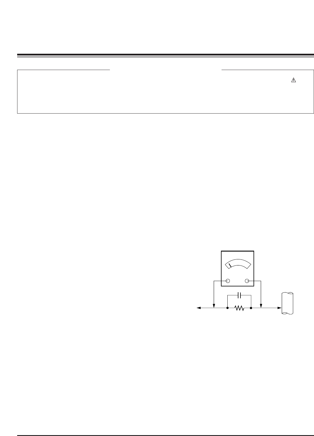
Leakage Current Hot Check (See below Figure)
Plug the AC cord directly into the AC outlet.
Do not use a line Isolation Transformer during this check.
Connect 1.5K/10watt resistor in parallel with a 0.15uF capacitor
between a known good earth ground (Water Pipe, Conduit, etc.)
and the exposed metallic parts.
Measure the AC voltage across the resistor using AC voltmeter
with 1000 ohms/volt or more sensitivity.
Reverse plug the AC cord into the AC outlet and repeat AC voltage
measurements for each esposed metallic part. Any voltage
measured must not exceed 0.75 volt RMS which is corresponds to
0.5mA.
In case any measurement is out of the limits sepcified, there is
possibility of shock hazard and the set must be checked and
repaired before it is returned to the customer.
Leakage Current Hot Check circuit
CANADA: LG Electronics Canada, Inc. 550 Matheson
Boulevard East Mississauga, Ontario L4Z 4G3
USA : LG Customer Interactive Center
P.O.Box 240007, 201 James Record Road Huntsville,
AL 35824
Digital TV Hotline 1-800-243-0000
1.5 Kohm/10W
To Instrument's
exposed
METALLIC PARTS
Good Earth Ground
such as WATER PIPE,
CONDUIT etc.
AC Volt-meter
IMPORTANT SAFETY NOTICE
0.15uF

- 3 -
Copyright©2008 LG Electronics. Inc. All right reserved.
Only for training and service purposes LGE Internal Use Only
SPECIFICATIONS.................................................................4
ADJUSTMENT INSTRUCTIONS ..........................................5
TROUBLE SHOOTING GUIDE...........................................11
BLOCK DIAGRAM...............................................................16
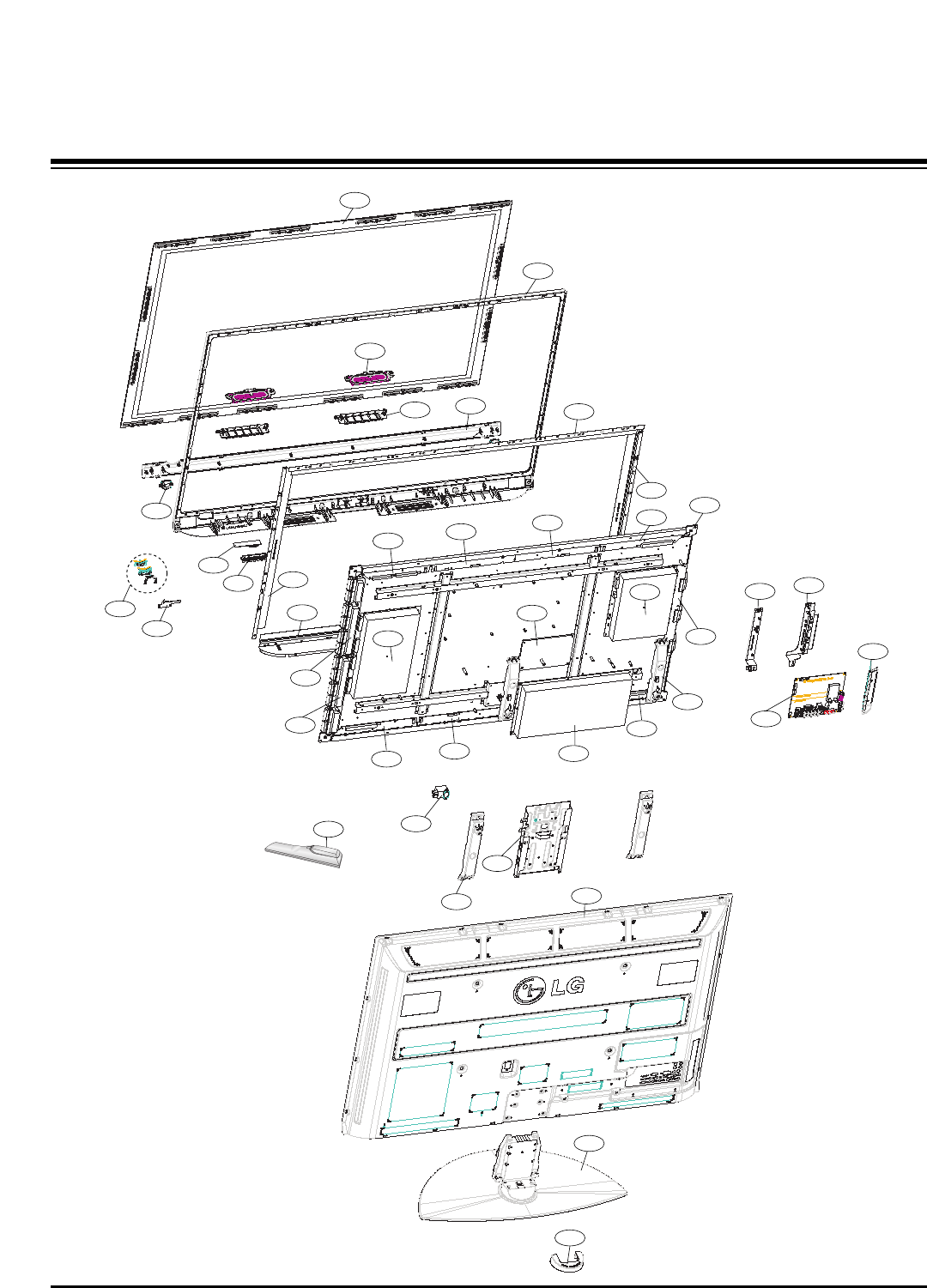
EXPLODED VIEW...............................................................24
EXPLODED VIEW PARTS LIST .........................................25
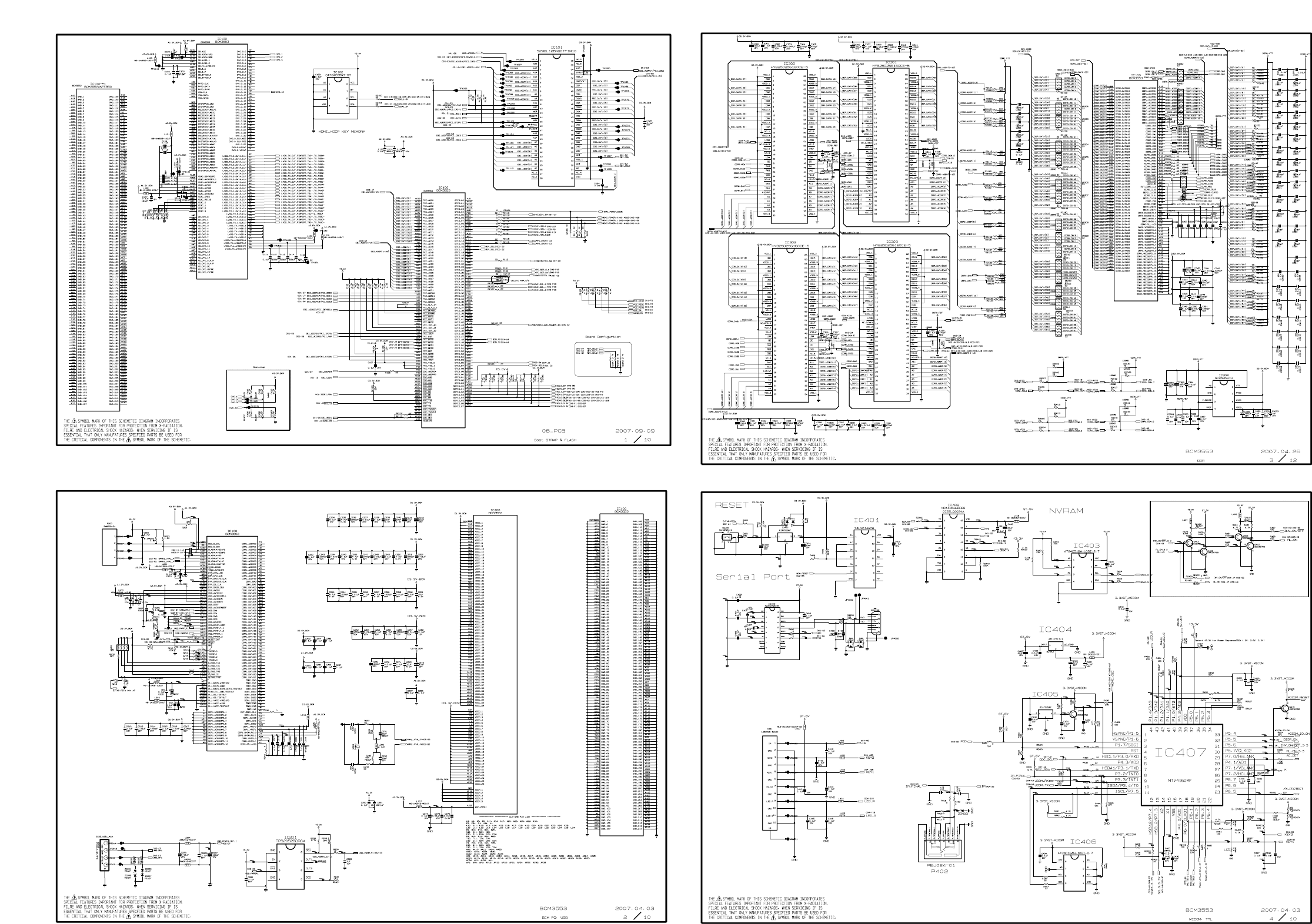
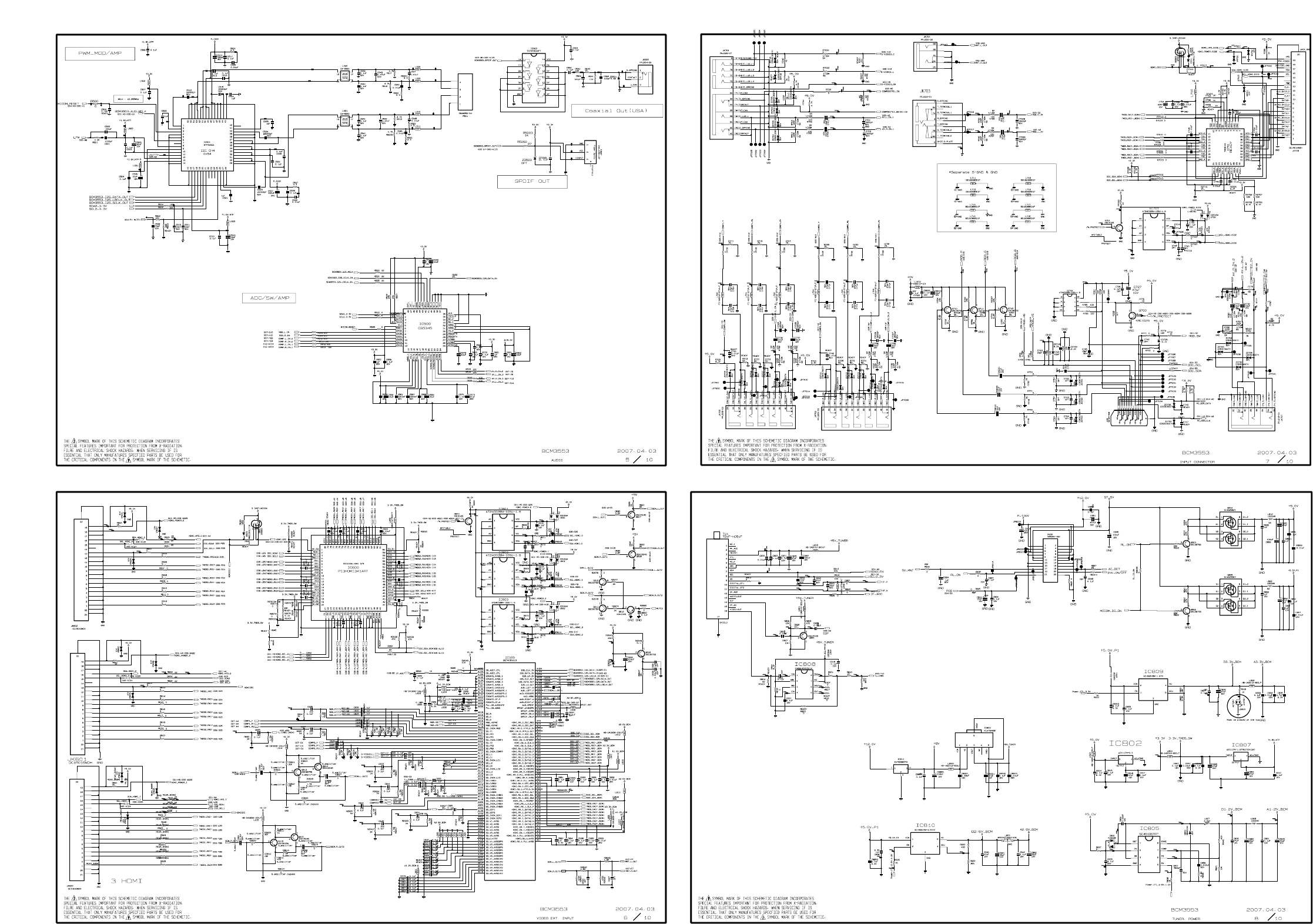
SCHEMATIC DIAGRAM..........................................................
PRINTED CIRCUIT BOARDS.................................................
TABLE OF CONTENTS
- 4 -
Copyright©2008 LG Electronics. Inc. All right reserved.
Only for training and service purposes LGE Internal Use Only
The specifications shown above may be changed without prior notice for quality improvement.
MODELS
AC100-240V ~ 50/60Hz
NTSC-M, ATSC, 64 & 256 QAM
VHF 2-13, UHF 14-69, CATV 1-135, DTV 2-69, CADTV 1-135
75 ohm
32 ~ 104°F (0 ~ 40°C)
Less than 80%
-4 ~ 140°F (-20 ~ 60°C)
Less than 85%
Dimensions
(Width x Height
x Depth)
Weight
Power requirement
Television System
Program Coverage
External Antenna
Impedance
Environment
condition
With stand
Without stand
With stand
Without stand
Operating Temperature
Operating Humidity
Storage Temperature
Storage Humidity
42PG60
(42PG60-UA) 50PG60
(50PG60F-UA) 60PG60
(60PG60F-UA)
41.1 x 28.9 x 12.1 inches
1044.4 x 735.4 x 308.0 mm
41.1 x 26.7 x 3.1 inches
1044.4 x 680.6 x 79.6 mm
61.7 pounds / 28.0 kg
55.1 pounds / 25.0 kg
48.6 x 33.4x 14.3 inches
1235.6 x 849.3 x 364.1 mm
48.6 x 31.2 x 3.1 inches
1235.6 x 792.8 x 79.6 mm
96.1 pounds / 43.6 kg
87.5 pounds / 39.7 kg
57.2 x 38.7x 16.2 inches
1455.0 x 985.0 x 414.0 mm
57.2 x 36.4 x 3.3 inches
1455.0 x 924.8 x 84.1 mm
130.5 pounds / 59.2 kg
113.9 pounds / 51.7 kg
SPECIFICATIONS
- 5 -
Copyright©2008 LG Electronics. Inc. All right reserved.
Only for training and service purposes LGE Internal Use Only
ADJUSTMENT INSTRUCTIONS
1. Application Range
This spec sheet is applied all of the PDP TV, PU82C chassis.
2. Specification
(1) Because this is not a hot chassis, it is not necessary to use
an isolation transformer. However, the use of isolation
transformer will help protect test equipment.
(2) Adjustments must be done in the correct order.
(3) The adjustments must be performed in the circumstance of
25±5°C of temperature and 65±10% of relative humidity if
there is no specific designation.
(4) The input voltage of the receiver be must kept 220V, 60Hz
when adjusting.
(5) The receiver must be operational for about 15 minutes
prior to the adjustments.
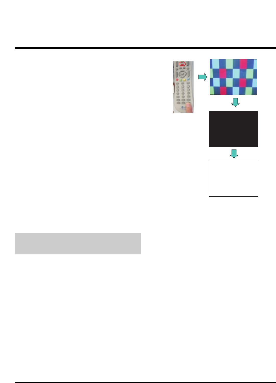
1) After receiving 100% white pattern, the receiver must be
operated prior to adjustment. (Or 8. Test Pattern
condition in EZ - Adjust)
2) Enter into White Pattern
- Press POWER ON Key on the Service Remote
Control (S R/C)
- Enter the Ez - Adjust by pressing ADJ Key on the
Service Remote Control (S R/C).
- Select 10. Test Pattern using the CH +/- Key and
select the White by pressing the direction Key.
Display the 100% Full White Pattern.
[Set is activated HEAT-RUN without signal generator in
this mode.
OHEAT RUN
Preliminary action is applied to the test for afterimage
discharge detection, and 100% FULL WHITE PATTERN
must be operated automatically.
OTest for afterimage discharge detection
1) Pressing Power On key
- Only operating by pressing Power On key
2) Full Test Pattern(2 min 30sec) --> Full Black
Pattern(30sec) --> Full White Pattern(maintenance)
- Full White Pattern when the main power is turned on
again after being turned off
3) Pattern Mode is deselected by pressing CH +/-, Exit Key.
[Set is activated HEAT-RUN without signal generator in this
mode.
If you turn on a still screen more than 20 minutes (Especially
Digital pattern(13 CH), Cross Hatch Pattern), an afterimage
may occur in the black level part of the screen.
Test Pattern 2min 30sec
Test Pattern 30sec
- 6 -
Copyright©2008 LG Electronics. Inc. All right reserved.
Only for training and service purposes LGE Internal Use Only
ADJUSTMENT INSTRUCTIONS
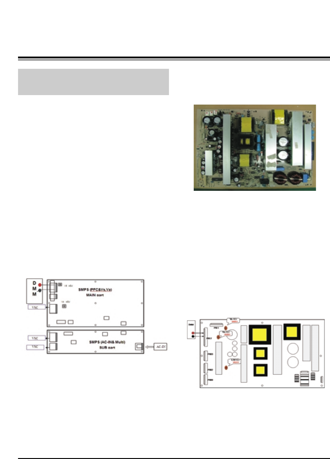
3. PSU(Power Supply Unit) Voltage
Adjustment (Va, Vs Voltage Adjustment)
Adjust the voltages Va and Vs supplied from the PSU to the
module within the specified range of each module to supply
the stable power
3-1. Test Equipment
(1) D.M.M 1EA
(2) Voltage adjustment bar
3-2. Adjustment(60”)
(1) Va Voltage Adjustment
1) Connect + terminal of D.M.M to Va pin of P812 and
connect – terminal to GND pin of P812.
2) Adjust VR901 voltage to match that of the label on the
Top/Right of the panel. (Deviation : ±0.5V)
(2) Vs Voltage Adjustment
1) Connect + terminal of D.M.M to Vs pin of P812 and
connect – terminal to GND pin of P812.
2) Adjust VR951 voltage to match that of the label on the
Top/Right of the panel. (Deviation : ±0.5V)
3-3. Adjustment (50”)
(1) Va Adjustment
1) Connect + terminal of D.M.M to Va pin of P12 and
connect – terminal to GND pin of P12.
2) Adjust VR951 voltage to match that of the label on the
Top/Right of the panel. (Deviation : ±0.5V)
(2) Vs Adjustment
1) Connect + terminal of D.M.M to Vs pin of P12 and
connect – terminal to GND pin of P12.
2) Adjust VR901 voltage to match that of the label on the
Top/Right of the panel. (Deviation : ±0.5V)
3-4. Adjustment(42”)
(1) Va Voltage Adjustment
1) Connect + terminal of D.M.M to Va pin of P812 and
connect – terminal to GND pin of P812.
2) Adjust VR901 voltage to match that of the label on the
Top/Right of the panel. (Deviation : ±0.5V)
(2) Vs Voltage Adjustment
1) Connect + terminal of D.M.M to Vs pin of P812 and
connect – terminal to GND pin of P812.
2) Adjust VR951 voltage to match that of the label on the
Top/Right of the panel. (Deviation : ±0.5V)
Each PCB assembly must be checked by check JIG set.
(Because power PCB Assembly damages to PDP Module,
especially be careful)
Connection Diagram of Power Adjustment for Measuring
(Power Board): 60”
Connection Diagram of Power Adjustment for Measuring
(Power Board): 50”
Connection Diagram of Power Adjustment for Measuring
(Power Board): 42”(EAY32808901)
- 7 -
Copyright©2008 LG Electronics. Inc. All right reserved.
Only for training and service purposes LGE Internal Use Only
ADJUSTMENT INSTRUCTIONS
4. Component 480i/1080p RGB
1080p Adjustment
Component 480i/1080p RGB 1080p adjustment to set the
black level and the Gain to optimum.
4-1. Test Equipment
(1) Service R/C
(2) 801GF(802B, 802F, 802R) or MSPG925FA Pattern
Generator (480i/1080p The Horizontal 100% Color Bar
Pattern adjust to within 0.7±0.1Vp-p)
[Because the above pattern can differ by the model and
pattern for each device, you must check the pattern first.
4-2. ADC 480i Component1 Adjustment
(1) Check the connection Component1 to the Test Equipment.
(MSPG-925FA => Model: 209, Pattern: 65)
(2) Select Component1 as the input with 100% Horizontal
Color Bar Pattern(HozTV31Bar) in 480i Mode and select
‘Normal’ in screen.
(3) After receiving signal for at least 1 second, press the ADJ
Key on the Service R/C to enter the ‘Ez - Adjust’ and select
the ‘3. ADC 480i Comp1’.
Pressing the Enter Key to adjust automatically.
(4) When the adjustment is over, 'ADC Component1 Success’
is displayed.
(5) If the adjustment has errors, 'ADC Component1 480i Fail’
is displayed. And error massage(‘Component1 Not
Connected’ or ‘Not Valid Format’ or ‘Check Signal Status’)
is displayed for 1 second.
4-3. ADC 1080p Component1/RGB
Adjustment
(1) Check the connection Component1, RGB to the Test
Equipment (MSPG-925FA => Model: 225, Pattern: 65)
(2) Select Component1 as the input with 100% Horizontal
Color Bar Pattern(HozTV31Bar) in 1080p Mode and select
‘Normal’ in screen.
(3) After receiving signal for at least 1 second, press the ADJ
Key on the Service R/C to enter the ‘Ez - Adjust’ and select
the ‘4. ADC 1080p Comp1/RGB’.
Pressing the Enter Key to adjust automatically component1.
(4) When the adjustment is over, 'ADC Component1 Success’
is displayed. If the adjustment has errors, 'ADC
Component1 1080p Fail’ is displayed.
(5) After the Component1 adjustment is over, convert the
RGB-DTV Mode and start RGB adjustment.
When the adjustment is over, 'ADC RGB 1080P Success’
is displayed.
(6) Readjust after confirming the case Pattern or adjustment
condition where the adjustment errors.
Error massage is ‘Component1 Not Connected’ or ‘Not
Valid Format’ or ‘Check Signal Status’.
(7) After adjustment is complete, exit the adjustment mode by
pressing the ADJ KEY.
5. EDID(The Extended Display
Identification Data)/DDC
(Display Data Channel) Download
It is the feature to implement the “Plug and Play” which
automatically reconfigures the user’sl environment to directly
use by exchanging information without any command directly
to the PC or the monitor by the user, which is established by
the VESA
5-1. HDMI EDID Data Input
(1) Required Test Equipment
1) PC, Jig for adjusting DDC. (PC serial to D-sub
Connection equipment)
2) S/W for writing DDC(EDID data write & read)
3) D-Sub cable
4) Jig for HDMI Cable connection
(2) Preparation for Adjustments &
Setting of Device
1) Set devices as below and turn on the PC and JIG.
2) Open S/W for writing DDC (EDID data write & read).
(operated in DOS mode)
<Fig. 1> Adjustment Pattern: 480i/1080p 60Hz Pattern
LCD TV SET
(or Digital Board)
- 8 -
Copyright©2008 LG Electronics. Inc. All right reserved.
Only for training and service purposes LGE Internal Use Only
ADJUSTMENT INSTRUCTIONS
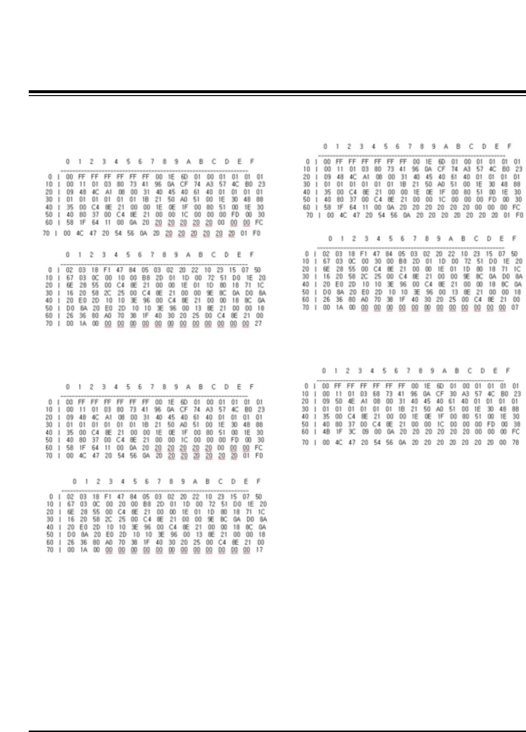
5-2. EDID DATA for PU82C
:EDID for HDMI-1 (DDC (Display Data Channel) Data)
EDID table =
:EDID for HDMI-2 (DDC (Display Data Channel) Data)
EDID table =
:EDID for HDMI-3 (DDC (Display Data Channel) Data)
EDID table =
:EDID DATA for RGB
EDID table =
- 9 -
Copyright©2008 LG Electronics. Inc. All right reserved.
Only for training and service purposes LGE Internal Use Only
ADJUSTMENT INSTRUCTIONS
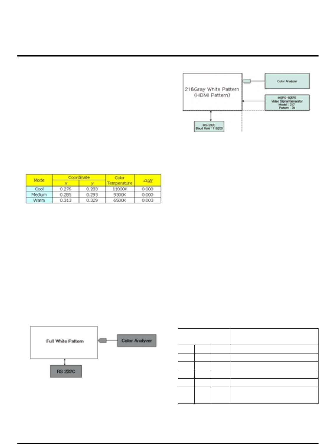
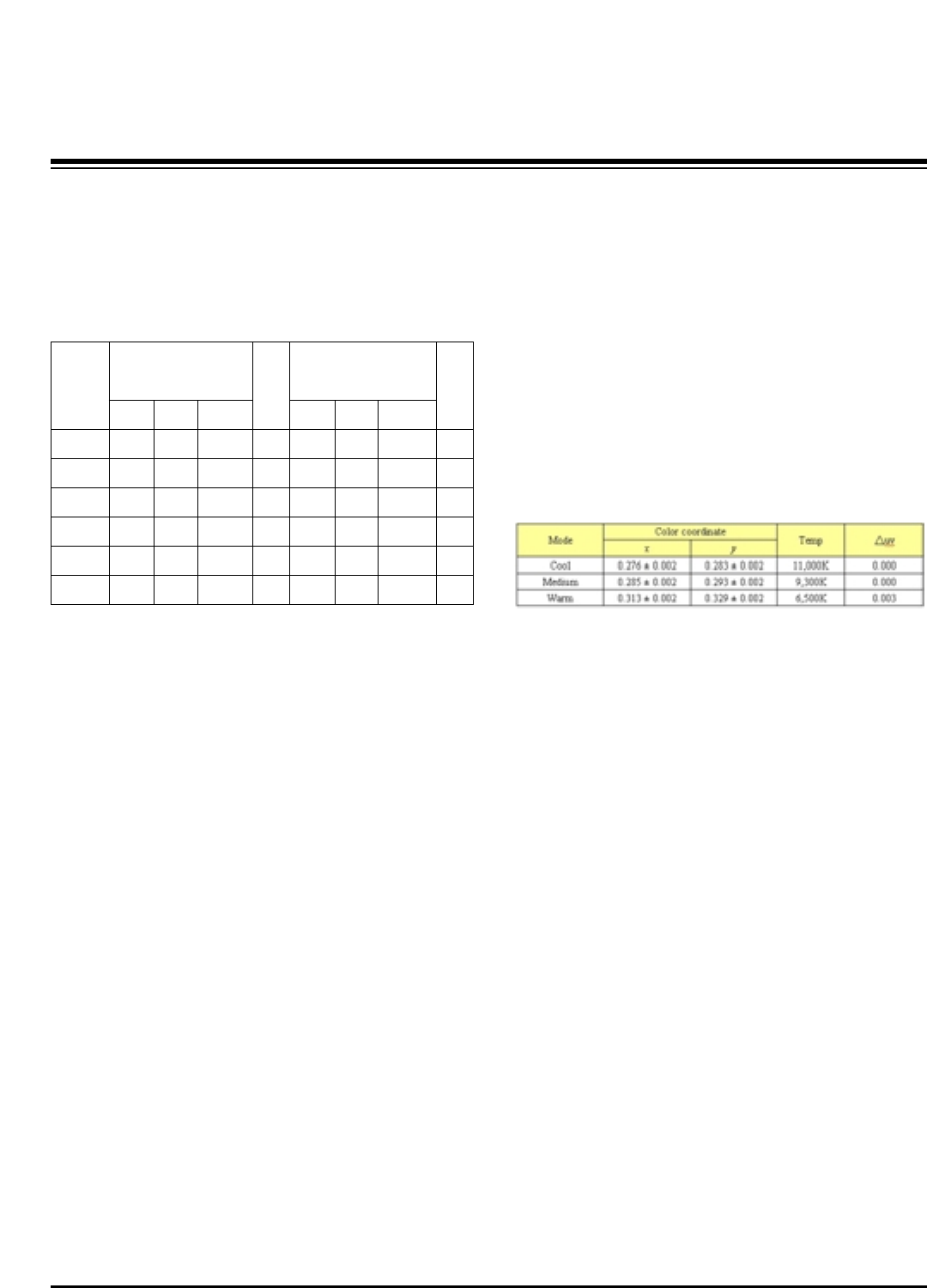
6. Adjustment of White Balance
6-1. Required Test Equipment
(1) Color Analyzer : CA-210 (CH 10), CA-100(CH-10), CA-
100+(CH-10)
=> To adjust color temperature of Plasma, CS-1000 is the
Color Analyzer and should be set to use CH 10 in which
white, red, green, and blue color are corrected. Conduct
the adjustment according to the coordinates for White
Balance adjustment in the table below.
(2) Computer for adjusting (necessary for the automatic
adjustment, possible to communicate with the RS-232C,
Baud Rate : 115200)
(3) Video Signal Generator MSPG-925F 720p, 216Gray
(Model :217, Pattern 78)
[Requirements for Automatic Adjustment
(1) The illuminance of surroundings
10 lux or less; preventing light in surroundings as much as
possible
(2) The location of the Probe
1) For PDP: place the color analyzer (CA-100, CA-100+)
close to the surface of a module and start the
adjustment.
2) For LCD: place the color analyzer (CA-210) close to the
surface of a module within 10 cm and keep the probe of
the color analyzer at 80°to 100°angle from the surface
of a module.
6-2. Connection Diagram of Equipment
for Measuring (Automatic Adjustment)
6-3. White Balance Adjustment Method
Basically it uses the internal pattern but when internal pattern
is not possible, you can select HDMI input for adjustment.
Through the option at the most bottom part of the Ez Adjust
Menu 7.White Balance menu, you can select NONE, INNER
and HDMI, and the default is set to INNER. When the
adjustment cannot be done with the internal pattern, you can
select HDMI input for adjustment.
For manual adjustment, press the ADJ KEY of the adjustment
R/C to enter Ez Adjust 7.White-Balance, and the pattern is
automatically displayed. (When you set the Option to INNER,
the default is always set to INNER)
(1) Connect the set according to the internal pattern or HDMI
input in accordance with measuring device connection
diagram.
(2) Set the Baud Rate of RS-232C to 115200. It is set to
115200 as default.
(3) Connect the RS-232C Cable to the set.
(4) Connect the HDMI Cable to the set. (Limited to the set with
HDMI option)
(5) Select and adjust the model applicable to PU82C chassis
from the adjuster.
[RS-232C command used for the automatic adjustment]
ÔWb 00 00-----white balance Automatic Adjustment Start
ÔWb 00 10-----Gain Adjustment start (Internal pattern)
ÔJa 00 ff------Adjustment Data
(internal pattern)
Connection Diagram for Internal Pattern
Connection Diagram for HDMI Input
wb
wb
wb
wb
wb
wb
00
00
00
00
00
00
00
10
1f
20
2f
ff
White Balance Adjustment Start
Gain Adjustment Start(Internal white pattern)
Gain Adjustment End
Offset Adjustment Start(Internal white pattern)
Offset Adjustment End
White Balance Adjustment End
(Disappear Internal pattern)
RS-232C COMMAND
[CMD ID DATA]
Meaning
- 10 -
Copyright©2008 LG Electronics. Inc. All right reserved.
Only for training and service purposes LGE Internal Use Only
ADJUSTMENT INSTRUCTIONS
ÔJb 00 c0
Ô...
ÔWb 00 1f-----Gain Adjustment End
Ô*(wb 00 20(Start), wb 00 2f(End))----- When adjust Off-set
ÔWb 00 ff------White Balance Automatic Adjustment End
(Disappear Inside pattern)
[Adjustment Map]
6-4. Automatic Adjustment
(1) Execute POWER ON(Â) of the adjustment R/C to execute
automatic adjustment.
(2) Set the Baud Rate to 115200.
(3) Always start adjustment with “wb 00 00” and end
adjustment with “wb 00 ff”
(4) Adjust the offset if necessary
6-5. Manual Adjustment
(1) Required Test Equipment: CA-210 (CH 10), CA-100(CH-
10), CA-100+(CH-10)
=> To adjust color temperature of Plasma, CS-1000 is the
Color Analyzer and should be set to use CH 10 in which
white, red, green, and blue color are corrected. Conduct
the adjustment according to the coordinates for White
Balance adjustment in the table below.
(2) Enter the ‘Ez - Adjust’ by pressing the ADJ on the Service
R/C.
(3) Select 10.TEST PATTERN using the CH + / - KEY and
press the Enter KEY to execute a heat run for more than
30 minutes.
(4) Execute a Zero Calibration for CA-210 and put it at
distance of less than 10Cm from the PDP module surface
center during the adjustment.
(5) Select ‘7. White-Balance’ of ‘Ez - Adjust’ by pressing the
ADJ KEY on the Service R/C. Then enter adjustment mode
by pressing the Right KEY (
G
) .
(The internal pattern of full white appears by pressing
G
)
(6) The adjustment is conducted in three levels of color
temperature; COOL, MEDIUM, and WARM.
-When R Gain is Fixed at Default value(192)
Adjust G gain and B gain with decreasing Default values
from 192
-When B Gain is Fixed at Default value(192)
Adjust R gain and G gain with decreasing Default values
from 192
-When G Gain is Fixed at Default value(192)
Adjust R gain and B gain with decreasing Default values
from 192
One of R/G.B Gain should be fixed at 192 and adjust two
Gain Value with decreasing the Default values from 192.
(7) Use the Vol. +, - key for adjustment.
(8) When the adjustment is completed, press the ENTER (Á
KEY) button to move to the Ez –Adjust screen. Press the
ADJ KEY to exit the adjustment mode.
R Gain
G Gain
B Gain
R Cut
G Cut
B Cut
Jg
Jh
Ji
Cool
Ja
Jb
Jc
Mid
RS-232C COMMAND
[CMD ID DATA]
CENTER
(DEFAULT)
Jd
Je
Jf
00
00
00
192
192
192
127
127
127
Warm
Min Max
184
187
192
64
64
64
Cool
192
183
161
64
64
64
Mid
192
159
95
64
64
64
Warm
- 11 -
Copyright©2008 LG Electronics. Inc. All right reserved.
Only for training and service purposes LGE Internal Use Only
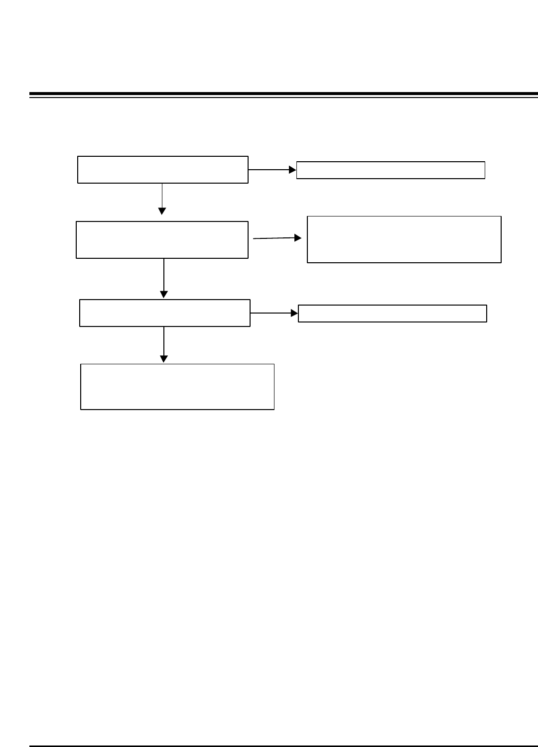
TROUBLE SHOOTING GUIDE
TV/CATV(Analog ) doesn t display
Check TU1 Pin16(Video output)
Can you see the normal signal?
Check the input(Pin1) of Low-Pass Filter
(IC808).
Can you see the normal waveform?
Check the output(pin8) of Low-Pass
Filter(IC808).
Can you see the normal waveform?
Check the Capaciter(C658) in front of
BCM3553 chip.
Can you see the normal waveform?
YES
YES
YES
NO Could you measure VCC voltage(3Pin) of TU1 & IIC
lines(7,8Pin)?
Are they all normal?
YES
You should replace TUNER.
NO After checking the C800(0.1uF Cap), you can
suspect that PCB is bad.
NO After checking the Power of Low-Pass Filter you
should decide to replace Low-Pass Filter or not.
NO After checking the pattern between pin8 of IC808
and C658, you can suspect that PCB is bad..
YES This board has big problem because Main
chip(BCM3550) have some troubles.
After checking thoroughly all path once again,
You should decide to replace BCM3553 or not.
- 12 -
Copyright©2008 LG Electronics. Inc. All right reserved.
Only for training and service purposes LGE Internal Use Only
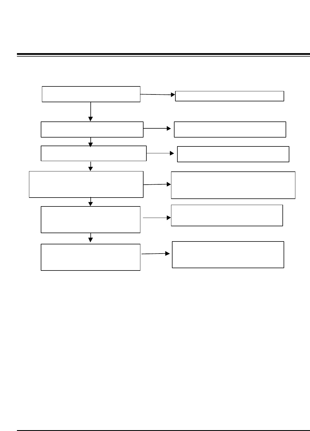
TROUBLE SHOOTING GUIDE
Video doesn t display
Check JP7004.
Can you see the normal waveform?
Check the Registor(R732).
Can you see the normal waveform?
YES
YES
NO JK701 may have problem. Replace this
Jack.
Check the C651 in front of BCM3553 chip.
Can you see the normal waveform?
NO replace Part(R732).
YES This board has big problem because Main
chip(BCM3553) have some troubles.
After checking thoroughly all path once again,
You should decide to replace BCM3553 or not.
NO After check the pattern between R703 and C651,
You can suspect that PCB is bad.
- 13 -
Copyright©2008 LG Electronics. Inc. All right reserved.
Only for training and service purposes LGE Internal Use Only
TROUBLE SHOOTING GUIDE
Component doesn t display
Check JP7001,J7015.
Can you see the normal waveform?
Check the L700, L704.
Can you see the normal waveform?
Check the C638, C628 in front of BCM3553.
Can you see the normal waveform?
YES
YES
NO JK700, JK702 may have problem. Replace this
Jack.
NO Replace the Part (L700, L704)
NO After check the pattern between L703 and C651,
You can suspect that PCB is bad.
YES This board has big problem because Main
chip(BCM3553) have some troubles.
After checking thoroughly all path once again,
You should decide to replace BCM3553 or not.
- 14 -
Copyright©2008 LG Electronics. Inc. All right reserved.
Only for training and service purposes LGE Internal Use Only
TROUBLE SHOOTING GUIDE
Check JP7032,JP7033,JP7034.
Can you see the normal waveform?
Check the C635, C636, C637 in front of
BCM3553.
Can you see the normal waveform?
YES
NO
JK705 may have problem. Replace this Jack.
NO After check the pattern between input of
BCM3553 and JK705 ,
You can suspect that PCB is bad.
RGB_PC doesn t display
Check JP7029,JP7030.
Can you see the normal waveform?
YES
NO
JK705 may have problem. Replace this Jack.
YES
This board has big problem because Main
chip(BCM3553) have some troubles.
After checking thoroughly all path once again,
You should decide to replace BCM3553 or not.
- 15 -
Copyright©2008 LG Electronics. Inc. All right reserved.
Only for training and service purposes LGE Internal Use Only
TROUBLE SHOOTING GUIDE
HDMI doesn t display
Check input connect JK602.
Can you see the normal waveform?
Check DDC communication lines(IC601
Pin5,6)
Check the input of PI3HDMI341ART(IC600),
& IC703(TMDS141RHAR, HDMI4)
This signal is TMDS.
Can you see the normal waveform?
YES
YES
NO
JK602 may have problem. Replace this Jack.
Check the output of PI3HDMI341ART(IC600
) & IC703(TMDS141RHAR, HDMI4).
Can you see the normal waveform?
YES
Check the input and output of BCM3553.
Especially you should check
The H,V sync and clock.
Can you see the normal waveform?
YES
NO
NO After checking the trace of TMDS lines and power of
PI3HDMI341ART & IC703(TMDS141RHAR, HDMI4), you
should decide to replace PI3HDMI341ART &
IC703(TMDS141RHAR, HDMI4) or not.
NO
YES This board has big problem because Main
chip(BCM3550) have some troubles.
After checking thoroughly all path once again,
You should decide to replace BCM3550 or not.
After checking the Power of this chip, you
should decide to replace this or not.
After checking the Power of PI3HDMI341ART or
TMDS141RHAR. you should decide to replace
PI3HDMI341ART & TMDS141RHAR or not.
YES
Check HDCP communication lines(IC102
Pin5,6)
NO After checking the Power of this chip, you
should decide to replace this or not.
- 16 -
Copyright©2008 LG Electronics. Inc. All right reserved.
Only for training and service purposes LGE Internal Use Only
BLOCK DIAGRAM
Block Diagram - Overview
Flash
(16MB)
74LVC14APW
CS5345
(Audio
SW/ADC/OP_A
MP)
MTV416
(Micom)
NTP3000
(Digital AMP)
X-tal(54M)
PI3HDMI341ART
(3x1,S/W)
EEPROM
AT/NT
Tuner 64Bit I/F
Reset
CVBS
Y/Pb/Pr
R/G/B
H/V Sync
RGB-PC
HDMI
0/1/2
COMP 1
COMP 2
AV 1
AV 2
RGB-PC
Audio L/R
I2S
MNT out
( L/R) SPDIF OUT
I2S
RS-232C Dead IC when Standby
Option
Alive IC when Standby
Video
Audio
Video
Front
End
Dual
HDMI
Rx
HD/SD
Video
Encoder
Audio
DSP
BCM3552(HD)/3(FHD) MCLK
MCLK
HDMI CEC
HDMI CEC
(To Micom)
To Micom
SDA
SCL
SIF
IF(AT)
Buffer
Single Channel
Digital out (W)XGA
Local KEY
IR
Buffer Buffer
24C16
AGC CTL (From BCM)
USB2.0
I2S Audio Input
VSB/QAM/NTSC/SIF
DDR(128MB)
CVBS/Y/C
CVBS
FHD Dual Channel
Y/Pb/Pr
- 17 -
Copyright©2008 LG Electronics. Inc. All right reserved.
Only for training and service purposes LGE Internal Use Only
BLOCK DIAGRAM
Signal path for CVBS, Component, RGB
Comp1_Y
H Sync
V Sync
BCM3552/3
Comp1_Pb
Comp1_Pr
Component 1
Input
Component 2
Input
RGB Input
RGB H_Sync
Side AV CVBS
Rear AV
Rear S_Video Y/C
CVBS CVBS 2
L1/C1
CVBS 3
L2/C2
ANT/ Cable
TUNER
IF_P
IF_N
IF_P from TUNER for DTV
IF_N from TUNER for DTV
CVBS 1
EEPROM
FOR EDID
DDC SDA
DDC SCL
RGB V_Sync
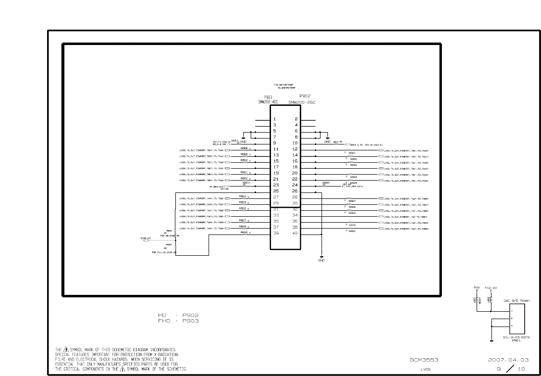
LVDS_Tx
Out
Component_1 S/W
Component_2 S/W
Rear_CVBS_ S/W
RGB S/W
GPIO[0:6]
Comp2_Y
Comp2_Pb
Comp2_Pr
RGB_G
RGB_B
RGB_R
DDC SCL to Micom
for Download
LPF 6 Mhz
LPF 30Mhz
LPF 30Mhz
LPF 30Mhz
LPF 30Mhz
LPF 30Mhz
LPF 30Mhz
LPF 6 Mhz
LPF 6 Mhz
DDC SDA to Micom
for Download
DVO Out[0:29]
Rear_S-Video_ S/W
Side_CVBS_ S/W
LVDS
Con.
26P(HD)
40P(FHD)
LVDS
Con.
- 18 -
Copyright©2008 LG Electronics. Inc. All right reserved.
Only for training and service purposes LGE Internal Use Only
BLOCK DIAGRAM
Signal path for HDMI
BCM355/23
HDCP SDA
HDCP SCL
NDA
NCL
HDMI 1 TMDS1 RX0+/-
TMDS1 RX1+/-
TMDS1 RX2+/-
TMDS1 RXCLK+/-
DDC SDA1
DDC SCL1 EEPROM
For EDID
HDMi — CEC
+5V Power_1
Hot Plug Detect_1
LVDS_Tx
Out
HDMI 2 TMDS2 RX0+/-
TMDS2 RX1+/-
TMDS2 RX2+/-
TMDS2 RXCLK+/-
DDC SDA2
DDC SCL2 EEPROM
For EDID
HDMi — CEC
+5V Power_2
Hot Plug Detect_2
TMDS341A
TMDS0
INPUT
DDC SDA
DDC SCL
TMDS1
INPUT
TMDS2
INPUT
TMDS RX0+/-
TMDS RX1+/-
TMDS RX2+/-
TMDS RXCLK+/-
Hot Plug Detect_0
TMDS
Out TMDS_Rx
Input0
HDMi_Sel_0
HDMi_Sel_1
HDMi_Sel_2
Hot Plug Detect_1
Hot Plug Detect_2
+5V Power_0
+5V Power_1
+5V Power_2
GPIO[0:8]
Switch
Selection
DDC
INPUT
MTV416
Micom
HDMi — CEC
Parallel connections with
HDMi 0,1,2,4
LVDS out 31P
Con.
31P
LVDS
Con.
EEPROM
for HDCP
DDC SDA1
DDC SCL1
DDC SDA2
DDC SCL2
TMDS0 RX0+/-
TMDS0 RX1+/-
TMDS0 RX2+/-
TMDS0 RXCLK+/-
DDC SDA0
DDC SCL0 EEPROM
For EDID
HDMI 0
HDMi — CEC
+5V Power_0
Hot Plug Detect_0
DDC SDA0
DDC SCL0
DDC
OUT
HDMI 4
TMDS3 RX0+/-
TMDS3 RX1+/-
TMDS3 RX2+/-
TMDS3 RXCLK+/-
DDC SDA3
DDC SCL3
EEPROM
For EDID
HDMi — CEC
+5V Power_3
Hot Plug Detect_3
DDC SDA3
DDC SCL3
TMDS_Rx
Input1
- 19 -
Copyright©2008 LG Electronics. Inc. All right reserved.
Only for training and service purposes LGE Internal Use Only
BLOCK DIAGRAM
AV1_Audio
AV2_Audio
MNT_Audio
HDMI
(PC/DTV)
Comp2_Audio
RGB_Audio
Comp1_Audio I2C SCL/SDA
[L1 / R1]
[L2 / R2]
[L3 / R3]
[L4 / R4]
[L5 / R5]
Switch
Switch
[Rout/Lout]
Audio
Switch
[CS5345]
I2S_CLK_IN/DATA_IN
/LR IN
(I2S_MCLK)
SPDIF OUT
Buffer
Buffer
PWM MODULATOR/
POWER AMP
[NTP3000A]
SIF IN
Broadcom
[BCM3552/3]
AUD_SPDIF
ANA L/R IN
BCM_MCLK
BCM_MCLK
I2S_CLK_IN
I2S_DATA_IN
I2S_LR_IN
RESET
RESET
I2S_CLK_OUT
I2S_DATA_OUT
I2S_LR_OUT
(NTP3000A)
I2S_CLK_OUT/
DATA_OUT/
LRCH OUT
I2C SCL/SDA
OUT1A/B
OUT2A/B
SPK R
SPK L
MNT_L/R OUT
HDMI Rx
Built in
Internal
I2S/SPDIF
Convert
HDMI_TMDS 0/1/2/3CLK
TUNER (ATSC/NTSC )
I2C SCL/SDA
Buffer
Buffer SIF
IF_P
IF_N
AUD_LEFT/RIGHT P
HDMI_RX_DATA/CLK
BTSC
Decoder
MPEG2
Dolby
AUDIO
Processor
Signal path for AUDIO/ IF
SPDIF OUT(coaxial)
BCM_MCLK
IF AGC
CVBS
FRONT END
- 20 -
Copyright©2008 LG Electronics. Inc. All right reserved.
Only for training and service purposes LGE Internal Use Only
BLOCK DIAGRAM
BCM3553 4.7K ‰
5.0V
I2C_Channel 0
I2C_Channel 1
ATSC/NTSC Tuner
I2C_Channel 2
I2C_Channel 3
I2C0_5V
I2C1_5V
4.7K‰
5.0V
Address
0xC2
0x9A
0x74
0xA6
0x94
0x54
0x50
0x??
0xD4
0x
I2C MAP
HDCP Key EEPROM
NTP3000
NVRAM
I2C2_3.3V
I2C3_3.3V MTV416
4.7K ‰
3.3VST
1K ‰
3.3V
CS5345
PDP MODULE
- 21 -
Copyright©2008 LG Electronics. Inc. All right reserved.
Only for training and service purposes LGE Internal Use Only
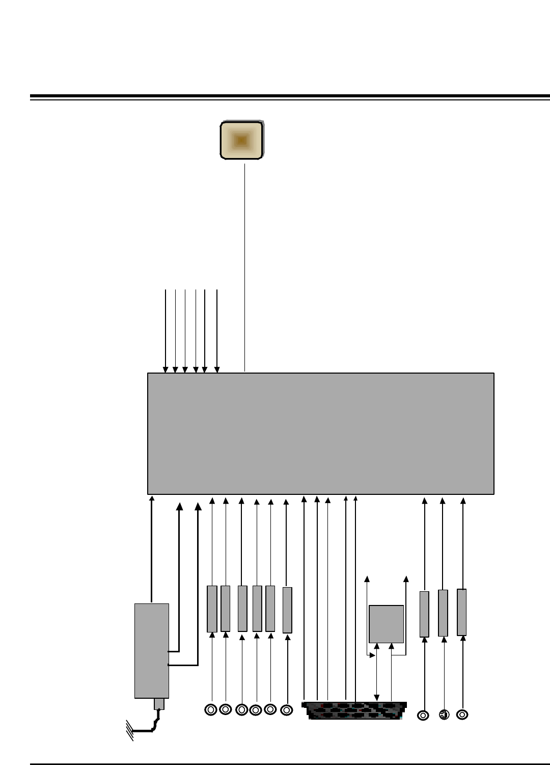
BLOCK DIAGRAM
Power Sequence and Flow Diagram
+16V
+16V NTP3000A
(Sound IC)
REG IC BIAS Side power
+12.0V
+12.0V +9V
IC811
KA7809
IC803
KIA78R05F
+5V_TUNER TU1
TDVF-H051F
ST_5V
ST_5V Local key/IR power
IC202
ICL3232
RS-232C RX/TX
Q804
SI4925BDY
IC102
AT24C16AN
(EEPROM)
+5.0
IC407
MTV416GMF
( micom)
HDMI CEC Inv/RL
3.3V->5V
Q805
SI4925BDY
IC408
Comercial
IC404
3.3V_MICOM
IC402
RS232C Driver
BCM
I2C Pull up
IC201
USB_Power
IC403
NVRAM
IC500
CS5345
HPD 5V
IF AGC
RGB SW
AV1/2
Component1/2
IC809
3.3V_Reg
IC805
1.2V_Reg
IC810
2.6V_Reg
- 22 -
Copyright©2008 LG Electronics. Inc. All right reserved.
Only for training and service purposes LGE Internal Use Only
BLOCK DIAGRAM
Power Sequence and Flow Diagram
+12V
+12V
REG IC BIAS Side power
IC811
KA7809ERTM
TUNER
+5V_TU
Tuner SIF
IC803
KIA78R05F
+9.0V
BIAS BCM L/R OUT
RGB Buffer
BIAS
+16V
+16V IC500
NTP300A

- 23 -
NOTES
Copyright©2008 LG Electronics. Inc. All right reserved.
Only for training and service purposes LGE Internal Use Only
- 24 -
Copyright©2008 LG Electronics. Inc. All right reserved.
Only for training and service purposes LGE Internal Use Only
EXPLODED VIEW
A2
580
240
501
590
603
200
210
206
201
204
207
208
209
205
205
207
206
202
203
250
304
305
300
120
121
570
571
560
310 301
302
307 303
306
602
601
520
400
900
901
Copyright©2008 LG Electronics. Inc. All right reserved.
Only for training and service purposes LGE Internal Use Only
Copyright©2008 LG Electronics. Inc. All right reserved.
Only for training and service purposes LGE Internal Use Only
Copyright©2008 LG Electronics. Inc. All right reserved.
Only for training and service purposes LGE Internal Use Only
Copyright©2008 LG Electronics. Inc. All right reserved.
Only for training and service purposes LGE Internal Use Only
MAIN(TOP) MAIN(BOTTOM)
CONTROL(TOP)
CONTROL(BOTTOM)
PRE AMP(TOP)
PRE AMP(BOTTOM)

Feb., 2008
Printed in KoreaP/NO : MFL42040401
CANADA: LG Electronics Canada, Inc. 550 Matheson
Boulevard East Mississauga, Ontario L4Z 4G3
USA : LG Electronics Alabama, Inc.
P.O.Box 240007, 201 James Record Road Bldg 3
Huntsville, AL 35824