MEDLINE LA32 Linak Linear Actuators And Electronics User Manual Eng
User Manual: MEDLINE LA32
Open the PDF directly: View PDF ![]() .
.
Page Count: 148 [warning: Documents this large are best viewed by clicking the View PDF Link!]

Page 2 of 148
Contents
Preface .................................................................................. 5
Valid for ................................................................................. 6
Important information ..................................................................... 7
Lithium ion batteries ..................................................................... 10
Generel assembly instructions ............................................................. 11
Declaration of incorporation of partly completed machinery ................................... 12
1. System description ..................................................................... 13
Electrostatic discharge (ESD)................................................................ 14
Fundamental actuator construction .......................................................... 14
Warranty and service life .................................................................. 14
IP Protection degree ..................................................................... 15
IPX6 Washable - Description of washing test ................................................... 16
Cable Wash ............................................................................ 17
Maintenance ........................................................................... 18
Environmental conditions ................................................................. 18
Insulation class ......................................................................... 19
Key to symbols ......................................................................... 19
ETL-marking ........................................................................... 20
Mounting ............................................................................. 20
Connecting the system ................................................................... 21
JUMBO system (special information) ......................................................... 22
Batteries .............................................................................. 24
2. Information on start-up, de-installation and operation ...................................... 26
Troubleshooting Actuators / Lifting columns .................................................... 27
Troubleshooting Electronics ................................................................ 27
3. Information on specific actuators ........................................................ 28
LA22 ................................................................................. 28
LA23 DESKLINE® ........................................................................ 28
LA23 MEDLINE® CARELINE® TECHLINE® ...................................................... 29
LA23 IC .............................................................................. 34
LA27 ................................................................................. 38
LA28 ................................................................................. 39
LA28 Compact.......................................................................... 40
LA29 ................................................................................. 40
LA30 ................................................................................. 41
LA31 ................................................................................. 42
LA32 ................................................................................. 44
LA34 ................................................................................. 45
LA40 HOMELINE® ....................................................................... 47
LA40 MEDLINE® CARELINE® ............................................................... 48
LA43 ................................................................................. 50
LA43 IC .............................................................................. 52
LA44 ................................................................................. 54
LA44 IC ............................................................................... 56
4. Information on specific columns ......................................................... 57
BB3 .................................................................................. 57
BL1 .................................................................................. 57
BL4 .................................................................................. 61
LC2 .................................................................................. 64
LP2 .................................................................................. 64
LP3 .................................................................................. 65
Page 3 of 148
5. Information on specific control boxes ..................................................... 66
Generel information ...................................................................... 66
CA30 / CA40 ........................................................................... 67
CB6 ................................................................................. 71
CB6 OBMe ............................................................................ 72
CB6P2 ............................................................................... 73
CB6S ................................................................................ 74
CB7 ................................................................................. 76
CB8A ................................................................................ 76
CB8-T ................................................................................ 77
CB9 HOMELINE® ........................................................................ 77
CB9 MEDLINE® CARELINE® ................................................................ 77
CB9 CARELINE® BASIC ................................................................... 79
CB12 ................................................................................. 79
CB14 ................................................................................. 80
CB16 ................................................................................. 80
CB20 ................................................................................. 82
CBR1 ................................................................................. 82
CO41................................................................................. 83
CO61................................................................................. 88
CO71................................................................................. 93
6. Information on specific controls ......................................................... 98
ACC.................................................................................. 98
ACK .................................................................................. 98
ACL . . . . . . . . . . . . . . . . . . . . . . . . . . . . . . . . . . . . . . . . . . . . . . . . . . . . . . . . . . . . . . . . . . . . . . . . . . . . . . . . . . 98
ACM ................................................................................. 99
ACO.................................................................................. 99
ACOM ................................................................................ 99
ACP ................................................................................. 100
ACT ................................................................................. 100
DPH Medical .......................................................................... 102
FPP ................................................................................. 103
FS ................................................................................. 105
FS2 ................................................................................. 105
FS3 ................................................................................. 105
HB20 ................................................................................ 106
HB30 ................................................................................ 107
HB40 ................................................................................ 108
HB50 ................................................................................ 109
HB60 ................................................................................ 109
HB70 ................................................................................ 109
HB80 ................................................................................ 110
HD80................................................................................ 111
HD80 JUMBO.......................................................................... 112
HL70 ................................................................................ 112
HL80 ................................................................................ 113
IRO ................................................................................. 114
LS ................................................................................. 114
LSD ................................................................................. 114
7. Information on specific JUMBO ......................................................... 115
BAJ1 / BAJ2 .......................................................................... 115
BAJL Li-Ion............................................................................ 115
CBJ1 / CBJ2 ........................................................................... 117
CBJ-Care ............................................................................. 119
CBJ-Home ............................................................................ 122
COBO ............................................................................... 123
COBO20 ............................................................................. 124
CH01................................................................................ 125
CHJ2 ................................................................................ 125
MBJ1/2/3............................................................................. 125
Page 4 of 148
8. Information on specific accessories ...................................................... 126
Generel information ..................................................................... 126
BA18 ................................................................................ 126
BA19 lead acid ........................................................................ 126
BA21 .................................................................................128
CS16 ................................................................................ 129
DJB ................................................................................. 129
EBC ................................................................................. 130
Massage Motor Medical.................................................................. 131
MJB ..................................................................................131
Simulator tool ......................................................................... 132
SLS ................................................................................. 133
SMPS30.............................................................................. 133
Under Bed Light 2 ...................................................................... 135
9. Repair and disposal ................................................................... 136
Main groups of disposal ................................................................. 137
Practical information..................................................................... 140
Drawings .............................................................................. 142
Addresses .............................................................................. 148
Page 5 of 148
Preface
Dear User,
We are delighted that you have chosen a product from LINAK®.
LINAK systems are high-tech products based on many years of experience in the manufacture and development of actuators, electric
control boxes, controls and chargers.
This User Manual does not address the end-user. It is intended as a source of information for the manufacturer of the equipment or
system only, and it will tell you how to install, use and maintain your LINAK electronics. It is the responsibility of the manufacturer of the
end-use product to provide a User Manual where relevant safety information from this manual is passed on to the end-user.
We are sure that your LINAK system will give you many years of problem-free operation.
Before our products leave the factory they undergo full function and quality testing. Should you nevertheless experience problems with
your systems, you are always welcome to contact your local dealer.
LINAK subsidiaries and some distributors situated all over the world have authorised service centres, which are always ready to help you.
LINAK provides a warranty on all its products.
This warranty, however, is subject to correct use in accordance with the specifications, maintenance being done correctly and any repairs
being carried out at a service centre, which is authorised to repair LINAK products.
Changes in installation and use of LINAK systems can affect their operation and durability. The products are not to be opened by
unauthorised personnel.
The User Manual has been written based on of our present technical knowledge. We are constantly working on updating the information
and we therefore reserve the right to carry out technical modifications.
LINAK A/S
Page 6 of 148
Valid for
This User Manual is valid for the following products:
(See the first 3 - 5 characters on the label)
Actuators: LA22, LA23 DESKLINE®, LA23 MEDLINE® CARELINE® TECHLINE®, LA23 IC, LA27, LA28, LA28 Compact, LA29,
LA30, LA31, LA32, LA34, LA40 HOMELINE®, LA40 MEDLINE® CARELINE®, LA43, LA43 IC, LA44, LA44 IC
Columns: BB3, BL1, BL4, LC2, LP2, LP3
Control boxes: CA30, CA40, CB6, CB6 OBMe, CB6P2, CB6S, CB7, CB8A, CB8-T, CB9 HOMELINE®, CB9 MEDLINE® CARELINE®,
CB9 CARELINE® Basic, CB12, CB14, CB16, CB20, CBR1, CO61
Controls: ACC, ACK, ACL, ACM, ACO, ACOM, ACP, ACT, DPH Medical, FPP, FS, FS2, FS3, HB20, HB30, HB40, HB50, HB60,
HB70, HB80, HD80, HD80 JUMBO, HL70, HL80, IRO, LS, LSD
JUMBO systems: BAJ1/2, BAJL Li-ion, CBJ1/2, CBJ-Care, CBJ-Home, COBO, COBO20, CH01, CHJ2, MBJ1/2/3
Accessories: BA18, BA19 lead acid, BA21, CS16, DJB, EBC, Massage Motor Medical, MJB, Simulator tool, SLS, SMPS30,
Under Bed Light 2

Page 7 of 148
Important information
Description of the various signs used in this manual.
Warning
Failure to comply with these instructions may result in accidents involving serious personal injury.
Failing to follow these instructions can result in the product being damaged or destroyed.
Please read the following safety information carefully.
It is important for everyone who is to connect, install or use the systems to have the necessary information and access to this User Manual.
Please be advised that LINAK has taken precautions to ensure the safety of the actuator system. It is the responsibility of the manufacturer/OEM to
get the overall approval for the complete application.
LINAK recommends that the actuators should be used in push applications, rather than pull applications.
LINAK actuators are not to be used for repeated dynamic push-to-pull movements. This cause extra strain to the actuator and can give safety
considerations, the consequence being possible damage to the actuator, e.g.:
• Piston rod eye/back fixture cracks due to fatigue.
• Extra play as parts are deformed.
• Noise as internal parts are moving due to the shifting force direction.
Therefore, if repeated dynamic push-to-pull movements are essential for the application, perform tests to validate the performance.
Moreover, consider strengthening the actuator (e.g. using a steel piston rod eye) – contact LINAK A/S if in doubt.
If the actuator is used for push in an application where personal injury can occur (e.g. patient hoists), a special safety nut must be used.
In general the LA12 actuator is not to be used in push/pull situations.
LINAK® actuators and electronics generally fall outside the IEC 60601-1:2005 definition of applied parts and are not marked as such (IEC 60417-5840).
However assessing the risk, whether actuators and electronics unintentionally can come into contact with the patient, determines that they are subject to
the requirements for applied parts. All the relevant requirements and tests of the standard are carried out as part of the IEC CB-Scheme assessment.
Output ratings:
Nominal values:
On the marking plate on LINAK Control Boxes, Battery Boxes and Power Supplies, we may state the nominal output voltage at a certain load for a
certain product.
Depending on product and load, this value may vary significantly due to construction.
E.g.: For a product with a nominal output voltage of 24VDC, the expected output voltage may vary depending on product and load within a range from
approximately 20VDC to approximately 50VDC due to construction.
When combining LINAK Control Boxes, Battery Boxes and Power Supplies with other LINAK components, compatibility is ensured.
When combining LINAK Control Boxes, Battery Boxes or Power Supplies with third party products, special precautions may be taken.
Relative or absolute positioning for the PLC connection
Relative positioning - By means of a magnetic disc and a hall sensor in the PLC-actuator, it is possible to have encoder pulses with an accuracy down
to 0.5 mm per pulse. This signal can be connected directly to the PLC’s standard digital input.
Absolute positioning - As an alternative the user can have a 0-10V analogue signal from a potentiometer integrated in the PLC-actuator (max. stroke
100 mm). This signal can be connected directly to an analogue PLC input.
Classification:
The equipment is not suitable for use in the presence of a flammable anesthetic mixture with air or with oxygen or nitrous oxide.
Warning
Electromagnetic compatibility - general
LINAK Actuator Systems bear the CE marking as an attestation of compliance With the EMC Directive 2014/30/EU; the systems are designed
to meet all requirements of applicable standards and have been tested to meet requirements of IEC 60601-1-2:2014.
Emission:
LINAK Actuator Systems are CISPR 11, Group 1, Class B products, unless stated otherwise in the relevant section of this document.
Immunity:
Test levels are according to Professional Healthcare Facility Environment.
Electromagnetic phenomena are evaluated on a system level, with the actuator either connected to a LINAK Control Box and accessories
or to some customer-built electronic control circuitry.
...to be continued

Page 8 of 148
Warning
Electromagnetic compatibility – third party components
Use of accessories, transducers and cables other than those specified or provided by the manufacturer of the Actuator System could result
in increased electromagnetic emissions or decreased electromagnetic immunity of the Actuator System and result in improper operation.
Warning
Electromagnetic compatibility – interference with other equipment, general
Use of the Actuator System adjacent to or stacked with other equipment should be avoided as it could result in improper operation.
If such use is necessary, the Actuator System and the other equipment should be observed to verify that they are operating normally.
If the user notes unusual behavior of the Actuator System, in particular if such behavior is intermittent and associated with the standing
right next to mobile phones, microwaves and radio broadcast masts, this could be an indication of electromagnetic interference.
If such behavior occurs, try to move the Actuator System further away from the interfering equipment.
Warning
Electromagnetic compatibility – interference with other equipment, RF communications
Portable RF communications equipment (including peripherals such as antenna cables and external antennas) should be used no closer
than 30 cm (12 inches) to any part of the Actuator System, including cables specified by the manufacturer. Otherwise, degradation of the
performance of this equipment could result.
Warning
If the actuator or lifting column is used for pull in an application where personal injury can occur, the following is valid:
It is the application manufacturer’s responsibility to incorporate a suitable safety arrangement, which will prevent personal injury from
occurring, if the actuator should fail.
Residual risk
Some of the products contains software based components. LINAK has done various possible efforts to assure that the software is free of
errors and that the software has been developed according to the rules of IEC 60601-1-4 (software in Medical products). That involves risk
analysis which shows a small residual risk for unwanted/unintended mow of actuators under specific conditions.
According to the above rules it must be informed and if nescessary considered in the risk analysis of the final application - More details to
residual risk can be provided by LINAK if nescessary.
Warning
Note that during construction of applications, in which the actuator is to be fitted, there must be no possibility of personal injury, for
example the squeezing of fingers or arms.
Warning
The plastic parts in the system cannot tolerate cutting oil.
Warning
Assure free space for movement of application in both directions to avoid blockade
Warning
Uninstructed personell must not operate the application or the actuator
Warning
In the event of blockage by an obsticle when application is moving inwards, removing the obsticle will cause the load to drop until spindle
hits the nut
Warning
Do not turn outer tube
Warning
Do not use chemicals, and inspect yearly for damage and wear.
Warning
Do not expose LINAK Actuator System Components to high intensity ultraviolet radiation disinfection lamps. This may damage enclosure,
supporting parts and cables.
Warnings
LINAK’s actuators and electronics are not constructed for use within the following fields:
• Planes and other aircrafts
• Explosive environments
• Nuclear power generation
Warning
LINAK recommends that the actuators should be used in push applications, rather than pull applications.
If the actuator is used for push in an application where personal injury can occur (e.g. patient hoists), a special safety nut must be used.
Except for the LA34 which can be used for both push or pull applications, if mounted with safety nuts in both directions.

Page 9 of 148
Warning
• If faults are observed, the products must be replaced.
• Never spray directly on the products with a highpressure cleaner.
Warning
A LINAK control box, actuator and accessory component must, in the final application, be placed where it is not imposed to any impact.
This is to prevent damage by accidentally being struck by an object in the hand of a passer-by or by a broomstick or a mop handle during
cleaning the floor. On a medical bed e.g. this might be underneath the mattress support platform. If necessary to mitigate this risk,
additional protection might be required.
Warning
Do not shorten the battery, other loads than self-discharge flatten the battery and cause formation of lead sulphate, which, if left in this
state for too long, will irreversibly damage the battery. Avoid bad impact on individuals and environment.
Warnings
Prevent foreign objects or persons from unintentionally activating a footswitch or a hand control at any time e.g. during normal use or
maintenance.
A hand control could be activated by squeezing e.g. between the mattress and the bed frame/rails or when it hangs on an application
that is activated by moving another application into it or by moving the application into something else, e.g. a wall, furniture, another
application etc.
Warning
Handle batteries carefully.
LINAK battery packs may emit flammable gases. So do not bring fire or a heated object close to the battery pack, and never use the battery
near a spark, fuses and/or equipment that emits sparks. Further, do not store the battery in a closed environment or incorporate it into a
closed structure of an enclosure. Doing so can cause an explosion, fire, equipment damage and bodily injury.
Do not connect the positive terminal and the negative terminal of the LINAK battery packs with a wire or other metals. Be careful with
tools and do not wear jewelery when handling batteries. Short-circuiting the terminals of the battery can cause burn injuries, damage to
the storage battery or trigger explosions.
Never connect the LINAK battery packs directly to a power supply socket or an automobile’s cigarette lighter without using a charger
as a medium. Connecting the battery directly can cause the battery to leak fluid, generate heat, explode, cause fires or bodily burns and
injuries.
LINAK battery packs contain toxic substances. If the battery’s internal fluid leaks out and gets onto your skin or clothing, make sure it is
washed off with clean water. Additionally, if the fluid gets in your eyes, wash them with clean water immediately, and see a doctor.
If battery fluid gets into your eyes, it can cause a loss of eyesight and when it gets on your skin, it can cause a burn on your skin.
Do not use or store LINAK battery packs where the surrounding temperature exceed 50°C, such as inside a hot automobile, in direct
sunlight, or in front of a stove or a source of intense heat. Doing so can shorten battery life, lower its performance level, cause the battery
to leak fluid explode, cause fire, be damaged or deformed.
Do not use a LINAK cord set for other devices than LINAK control boxes or LINAK power supplies.
For actuators without plugs, which are not connected to a LINAK control box, the mains supply or the actuator must always be equipped
with an arrangement that switches off the actuator at the end-stop, for example, LS or LSD limit switch. If there is a risk of overloading the
actuator, the mains supply must be equipped with a safety device against overloading (for example a CS16-PCB). If these precautions are
not observed, the actuator can be damaged.
The LINAK products cannot tolerate the influence of strong solvents, basic or alkaline liquids.
Non-LINAK handsets
LINAK handsets are designed specially for LINAK control boxes, and they are designed to be highly reliable and flexible. If the customer
still wishes to use his own handset, it is important to contact a LINAK sales person to find out the requirements with regard to the
switches in the handset. Poor switches can destroy the control box.
The duty cycle printed on the label of the control box must always be noted. If this is exceeded, there is a risk of the control box being
overheated and damaged. Unless otherwise specified on the label, the duty cycle is max. 10% : max. 2 min. in use followed by 18 min.
not in use.
Page 10 of 148
Lithium ion batteries
Li-ion batteries are moving in the direction of minimising the physical size and at the same time, increasing the capacity. This gives a very size-
effective battery but with a high concentration of energy within a small physical size. It also increases the risk of thermal runaway (see note below)
due to internal short circuits.
The general use of Li-ion batteries have increased and the inherent risk of thermal runaway has led to stricter rules within the transport industry,
specifically air transport with tightened restrictions placed on the quantity transported, handling, and storage of specific products moving via air.
The OEMs and consumers have to recognise that although safe to use, there will always remain a very small risk of thermal runaway on a Li-ion cell.
The size of that risk could be as little as 1PPM or even less.
LINAK currently bases our Li-ion battery design on industry proven cell types that have a proven history (e.g. electric cars). The use of well-proven
cell technology reduces the risk of thermal runaway, but it does not eliminate it. LINAK has completed activities to reduce this risk and the complete
battery package is UL approved.
An external, internationally recognised expert has also reviewed the design to ensure that it is according to latest recommendations. Further to that,
we only use cells from well-recognised manufacturers.
LINAK recommends that when using Li-ion batteries, the customer should do a proper risk analysis on their application. The risk analysis must also
focus on not mounting these products where they can be in direct contact with flammable materials.
LINAK Li-ion have no more risk of thermal runaway compared to other Li-ion cells from well-recognised manufacturers within the market. Therefore, it
is clear that LINAK cannot take responsibility for any failures that occur due to a failure that is inherent in the nature of Li-ion batteries.
If any of the Li-ion batteries built into LINAK products are found to be defective under warranty, LINAK will provide a new product to the OEM. LINAK
explicitly disclaims all other remedies. LINAK shall not in any event be liable under any circumstances for any special indirect punitive incidental or
consequential damages or losses arising from any incident related to the inherent risk of thermal runaway in the Li-ion cell and any use of LINAK
products. Moreover, LINAK explicitly disclaims lost profits, failure to realise expected savings, any claim against our customer by a third party, or any
other commercial or economic losses of any kind, even if LINAK has been advised of the possibility of such damages or losses.
Note: ‘Thermal runaway’ is overheating of a cell and it could lead to a small fire and smoke from the cell.
Transportation
The lithium ion batteries must be packed and transported according to applicable regulations. Always ask your local transportation provider how to
handle the transportation of lithium ion batteries.
Please see the general assembly instructions on page 11 and the mounting section on page 24 for detailed information.

Page 11 of 148
Warnings
Failure to comply with these instructions may result in accidents involving serious personal injury. It is important for everyone who is to
connect, install, or use the systems to have the necessary information and access to the User Manual on www.linak.com.
• If there is visible damage on the product it must not be installed.
• IIf the control box/TWINDRIVE makes unusual noises or smells, switch off the mains voltage immediately.
• The products must only be used in an environment that corresponds to their IP protection.
• The cleaners and disinfectants must not be highly alkaline or acidic (pH value 6-8).
• Irrespective of the load the duty cycle stated in the data sheets, must NOT be exceeded.
• The DESKLINE® systems can only be used in push applications.
• The control box/TWINDRIVE must only be connected to the voltage stated on the label.
• System not specified for pull must only be used in push applications.
• Fastening screws and bolts must be correct tightened.
• Do not open the closing device on the TWINDRIVE during operation.
• Specifications on the label must under no circumstances be exesided.
• NOT TO BE OPENED BY UNAUTORIZED PERSONNEL.
• Do only use the actuator within specified working limits.
• Note that during construction of applications, in which the actuator is to be fitted, there must be no possibility of personal injury,
for example the squeezing or fingers or arms.
• If irregularities are observed, the actuator must be replaced.
• If the actuator is used for pull in an application where personal injury can occur, the following is valid: It is the application manufacturer’s
responsibility to incorporate a suitable safety arrangement, which will prevent personal injury from occurring, if the actuator should fail.
• MEDLINE and CARELINE products are rated to operate at an altitude < 2000 m.
Generel assembly instructions
Please read the following safety information carefully. Ensure that all staff who are to connect, mount, or use the actuator are in possession of the
necessary information and that they have access to this assembly instruction.
Persons who do not have the necessary experience or knowledge of the product/products must not use the product/products. Besides, persons with
reduced physical or mental abilities must not use the product/products, unless they are under surveillance or they have been thoroughly instructed in
the use of the apparatus by a person who is responsible for the safety of these persons. Moreover, children must be under surveillance to ensure that
they do not play with the product.
Failing to follow these instructions can result in the actuator suffering damage or being ruined.
• Before you start mounting/dismounting, ensure that the following points are observed:
- The actuator is not in operation.
- The mains current supply is switched off and the plug has been pulled out.
- The actuator is free from loads that could be released during this work.
• Before you put the actuator into operation, check the following:
- The actuator is correctly mounted as indicated in the relevant user instructions.
- The equipment can be freely moved over the actuator’s whole working area.
- The actuator is connected to a mains electricity supply/transformer with the correct voltage and which is dimensioned
and adapted to the actuator in question.
- Ensure that the voltage applied matches to the voltage specified on the actuator label.
- Ensure that the connection bolts can withstand the wear.
- Ensure that the connection bolts are secured safely.
• During operation
- Listen for unusual sounds and watch out for uneven running. Stop the actuator immediately if anything unusual is observed.
- Do not side load the actuator.
- Use only the actuator within the specified working limits.
- Do not step or kick on the actuator.
• When the equipment is not in use
- Switch off the mains supply or pull out the plug in order to prevent unintentional operation.
- Check regularly the actuator and joints for extraordinary wear.
• Note:
- If the actuator is operated as a hand crank, it must be operated by hand, otherwise there is a risk of overloading the
actuator and hereby damage the actuator.
• Note:
- When changing the cables on a LINAK actuator, it is important that this is done carefully, in order to protect the plugs and pins.
Please be sure that the plug is in the right location and fully pressed in before the cable lid is mounted.

Page 12 of 148
LINAK A/S
Smedevænget 8
DK - 6430 Nordborg
DECLARATION OF INCORPORATION OF PARTLY
COMPLETED MACHINERY
Herewith declares that LINAK DESKLINE® products as characterised by the following models and types:
Control Boxes CBD6S
Linear Actuators DB5, DB6, DB7, DB9, DB12, DB14, DB16, LA23, LA31
Lifting Columns DL1A, DL2, DL4S, DL5, DL6, DL7, DL8, DL9, DL10, DL11, DL12, DL14, DL15, DL16, DL17, DL19, BASE1
Desk Panels DPA, DPB, DPH, DPF, DPG1K, DPG1M, DPG1B, DPG1C, DPT, DP1, DP1CS, DP1K, DP1V, DP1U
RF Controls HB10RF, HB20RF, RFT, RFRL
Accessories BA001, SLS, Kick & Click
Herewith declares that LINAK HOMELINE® products as characterised by the following models and types:
Control Boxes CB9H, CBH Advanced, CBH Basic
Linear Actuators LA27, LA28, LA29, LA31 HOMELINE, LA40 HOMELINE
Dual Actuators TD3, TD4
Controls HB10, HB10 Wireless, HB20, HB40, HB60, HC05 Wireless, HC10, HC10 Wireless, HC20 Wireless, HC30 Wireless
Accessories Bluetooth® Adapter, DC CONNECTOR, LED Lightbox, LED Light Rail, Lightplug001, Massage Motor, SMPS001, SMPS002, SMPS006
Herewith declares that LINAK MEDLINE® & CARELINE® products as characterised by the following models and types:
Control Boxes CA30, CA40, CB6, CB6S, CB6OBMe, CB6P2, CB8, CB9, CB12, CB14, CB16, CB20, CBJ, CBJ-Care, CBJ-Home, CO61
Linear Actuators LA12, LA22, LA23, LA27, LA28, LA29, LA30, LA31 CARELINE, LA32, LA34, LA40, LA43, LA43IC, LA44, LA44IC
Lifting Columns BL1, LP2, LP3, LC2
Controls ACC, ACK, ACO, ACL, ACM, ACP, ACT, DP, DPH, FS, FS3, FPP, HB20, HB30, HB40, HB50, HB70, HB80, HD80, HL70, HL80, IRO
Accessories BA18, BA19, BA21, BAJ, BAJL, CH01, CHJ2, COBO, DJB, EBC, IRO, MJB, SMPS19, SMPS30, Scale, SCO SLS, Massage Motor, UBL22
Herewith declares that LINAK TECHLINE® products as characterised by the following models and types:
Linear Actuators LA12, LA14, LA22, LA23, LA25, LA30, LA33, LA35, LA36, LA37
Power Supply SMPS-T160
Nordborg, 2017-12-08
LINAK A/S
John Kling, B.Sc.E.E.
Certification and Regulatory Affairs
Authorized to compile the relevant technical documentation
comply with the following parts of the Machinery Directive 2006/42/EC, ANNEX I, Essential health and safety requirements relating to the design and construction of machinery:
1.5.1 Electricity supply
The relevant technical documentation is compiled in accordance with part B of Annex VII and that this documentation or part hereof will be transmitted by post or electronically
to a reasoned request by the national authorities.
This partly completed machinery must not be put into service until the final machinery into which it is to be incorporated has been declared in
conformity with the provisions of the Machinery Directive 2006/42/EC where appropriate.
Page 13 of 148
Attention should be paid to the following:
• Control boxes must only be connected to the mains voltage specified on the label. All DIN, jack, or minifit plugs from the CB6S/CB12/CB14/CB16/
CB20 IPX6 Washable should be locked by using a LINAK locking mechanism.
• The control box must be connected in such a way that the cables are not trapped, exposed to tension or sharp objects when the application is
moved in different directions.
• All Control boxes with mains supply should be connected to the mains before they are able to work.
• On an Openbus system the maximum power consumption is max 200 mA on 8V and on 40 V lines for all connected units.
• On an Openbus system the maximum connected number of unit are 12 version 1.0” and for version 1.1 the max numbers are 20.
Prior to first use of LINAK batteries, please make sure that they are being charged 24 hours in order to reach proper function and prolong the lifetime
of the batteries.
If the customer uses a non-LINAK battery, it is important to check that the current is not reversed (plus and minus swapped over) This applies to both
control boxes, which always run off battery and control boxes with battery backup. Contact your nearest LINAK dealer for specification of type, size etc.
The control current in the handset cable must not exceed 100 mA.
The control box is the heart of the system and connects the various outlying units (actuators, lifting columns, handsets and attendent controls). Control
boxes differ widely in complexity. The simplest are only able to convert control signals from the handset into operating voltage for the actuator. The most
advanced are microprocessor controlled and have advanced functions such as, parallel running of several actuators and other complex correlations. Most
LINAK control boxes provide an Electronic Overload Protection (EOP), designed to protect the actuator (excl. LA12, LA29, LA31, LA34), against overload
by disconnecting the current when the actuator is fully extended or retracted. If an LA12, LA29, LA31, LA34 actuator is used, the built-in limit swit ches
stop the actuator when fully extended or retracted, and the control box only disconnects when the maximum current is exceeded. Please contact LINAK
for further details on specific systems.
The actuator is the unit, which converts the operating voltage from the control box into a linear movement.
The principle of the LINAK actuator’s mode of operation is that a low voltage DC motor (5), via a gear system (12), rotates a threaded spindle, onto
which a nut is fitted. As this nut cannot rotate, since the piston rod (2) is restrained, the piston rod will move forwards or backwards, when the
threaded spindle rotates.
On the basis of motor type, gearing, and the threaded spindle’s pitch, the actuator’s thrust and speed are determined.
The handset is the unit to be used when you want the LINAK® system to perform a movement. It determines whether the control box will make the
actuator move in or out. There are many variants of LINAK handsets.
The Attendant Control (ACC, ACK, ACL, ACM, ACP, ACO) is an accessory used when nursing staff want to restrict the patients adjustment options
of a bed. It is often used in conjunction with a handset and disables selected functions on the handset. It can also have control functions with the
same function as those on the handset.
For safety reasons, open function activation of ACP and ACO (ACC, ACK) requires activation of two buttons.
1. System description:
Usage/type of applications:
LINAK actuators, lifting columns and electronics have been developed for use in all places where a linear movement is required.
LINAK’s products can, for example, be used for:
• Adjustment of beds
• Adjustment of furniture
• Adjustment of table heights and angles
• Patient hoists within the care and hospital sector
Recommendation
It is recommended to have options like quick release, manual lowering or similar built into the system, in case of power loss or system
failure, if movement of the system is critical. After service it is recommended to test the system for correct functionality before it is put
back into operation.
LINAK
control box
LINAK handset
LINAK actuators or lifting columns
The principles of a LINAK system are as follows:
• Adjustment of industrial processing machines
• Adjustment of agricultural machines
• Adjustment of ventilation systems
• Adjustment of dentist chairs/gynaecological chairs
• Etc.
Page 14 of 148
Electrostatic discharge (ESD)
LINAK considers ESD to be an important issue and years of experience have shown that equipment designed to meet the 8kV level specified in the
Standards such as IEC 60601-1-2, EN50082-2 are insufficient to protect electronic equipment in certain enviroments.
LINAK handles all Electro Static Discharge Sensitive devices (ESDS) according to EN61340
1. Handling and Mounting of ESDS devices.
• Handling of sensitive components only takes place in an ESD Protected Area (EPA) under protected and controlled conditions.
• Wrist straps and/or conductive footwear (personal grounding) are always used when handling ESDS devices.
• Sensitive devices are protected outside the EPA by the use of ESD protective packaging.
2. Responsibility LINAK/Customer.
• ESDS devices must under no circumstances, during transport, storage, handling, production or mounting in an aplication, be exposed to harmfull ESD.
• LINAK can only guarantee the lifetime of ESDS devices if they are handled in the same way from production at LINAK A/S until they are mounted
in the manufacturers application. It is therefore important that the ESDS devices are not removed from the ESD protected packaging before they
are within the EPA area at the customers premises.
Please refer to EN61340 for further information:
EN61340-5-1, Electrostatics - Protection of electronic devices from electrostatic phenomena - General requirements
EN61340-5-2, Electrostatics - Protection of electronic devices from electrostatic phenomena - User guide
Fundamental actuator construction
8765
11 12
13
10
943 12
1. Piston rod eye
2. Piston rod
3. Location of mechanical splines
4. Location of brake
5. Motor
6. Motor with optical switch
7. Motor with potentiometer
8. Motor with reed-switch
9. Back fixture
10. Back fixture with electrical splines
11. Quick release mechanism
12. Transmission between motor and spindle
13. Cable for connection to 12/24/36V DC by
means of plug via control box
Warranty and service life
The LINAK® warranty covers manufacturing defects in the products, starting from the date of manufacture. There is 36 months’ warranty on the
HOMELINE® products, 60 months’ for MEDLINE® and CARELINE® products, and 18 months’ for the TECHLINE® products. There is 12 months’
warranty on batteries. The warranty is limited to the value of the LINAK product.
LINAK’s guarantee is only valid so far as the products have been used and maintained correctly and has not been tampered with. Furthermore, the
products must not be exposed to violent treatment. In the event of this, the warranty will be ineffective / invalid. LINAK’s warranty is only valid if the
system is unopened and has been used correctly.
All LINAK products are designed to have an optimum service life as a matter of course, but the expected service life in a specific application is very
dependent on how the products are used.
Page 15 of 148
IP Protection degree
The products can be cleaned as follows according to their IP protection, which is stated on the product label.
The IP code specifies the degrees of protection provided by the enclosures. For most products only the protection against ingress of water (second
characteristic numeral) is specified, ingress of solid foreign objects or dust (first characteristic numeral) is not specified and therefore replaced by the
letter X in the code. For some special industrial products both the first and second characteristic numerals are specified. This is a demand from the
marked and will only be specified if tested and approved.
IP protection Cleaning instructions
IPX0 Clean with a damp cloth
IPX1 Clean with a damp cloth
IPX2 Clean with a damp cloth
IPX3 Clean with a damp cloth
IPX4 Clean with a damp cloth
IPX5 Wash with a brush and water, but not water under pressure
IPX6 Wash with a brush and water. The water can be under pressure, but the system must not be hosed
down directly with a highpressure cleaner. Max. 20oC
IPX6 Washable according to IEC 60601-2-52 Clean by the use of wash tunnels according to IEC 60601-2-52
To avoid degreasing of the piston rod, the actuator should be retracted to minimum stroke and without load before washing.
Warning
The systems must not be sprayed directly with a highpressure cleaner.
Warning
Interconnecting cables must remain plugged in during cleaning to prevent the ingress of water.
Warning
Cleaning with a steam cleaner is not permitted.
Page 16 of 148
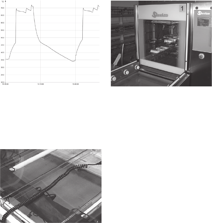
IPX6 Washable - Description of washing test
LINAK washable products are frequently put through a fully regulated washing test.
LINAK understanding of the word washable is that the products conform to this test and none other.
Reference: The Norm EN 60601-2-52, which includes special demands to fundamental safety and relevant functional characteristics for
hospital beds.
The demands for the washing process are described in the German “Maschinelle Dekontamination” from the organization
AK-BWA.
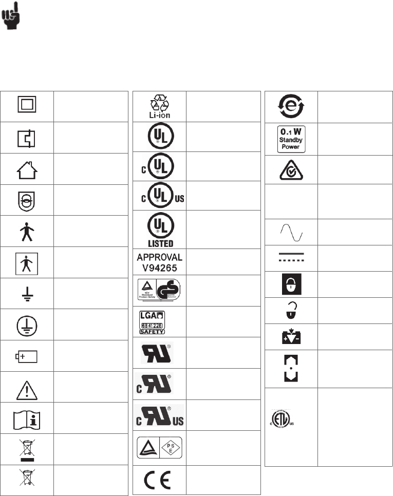
Description: At LINAK the washing test takes place in an instrument washing machine, which is fitted and programmed in such a way that
it duplicates the process used in a typical hospital installation for the cleaning of beds and other medical equipment.
During the test the products are exposed to both thermal and chemical effects.
To avoid degreasing of the piston rod, the actuator should be retracted to minimum stroke and without load before washing.
Preparation: As plastic materials to a larger or lesser degree change characteristics and shape with time and climatical exposure, an aging
of the products is carried out first.The conditions for aging are 65 °C +/- 2°C in normal dry air for10 days followed by a
minimum of 16 hours at room temperature before the washing process starts.
Procedure: Aging for 10 days at 65°C.
Rest for a minimum of 16 hours.
The washing process proceeds in the following way:
• Wash with Alkaline detergent for 2 min. with 70 °C warm water in the tank
• Rinse with neutral rinsing product for 20 sec. with 85 °C warm water in the tank
• Drying and cooling for 10 min. in open air at normal room temperature approx. 20 °C
• The washing process is repeated 50 times
Washing machine: Only flat squirt nozzles are allowed. An approved setup could be:
Water Pressure 3 Bar, water volume 5,61 L/min, Dispersion angle 120 degree, flat squirt nozzle.
Washable products and mounting: The products used in washable applications should be specified as such in the specification
phase. The washable components must be mounted according this guideline to guarantee washability:
The components should be mounted with the plug inserts facing downwards, or situated so that they are protected from direct
impact from the water nozzles. The cables should be guided in such a manner, that there is no apparent strain to the interface
between the cable and its connection (for instance between cable and control box).
It is furthermore also recommended that the control box is situated as far away from the water nozzles as possible. For instance
in the center of the bed frame. Industrial high pressure cleaning is NOT allowed.
It is the application manufacture’s responsibility to ensure washability of the application. LINAK can be contacted for technical
support if needed.
Water: Degree of hardness not more than 5° dH and no demineralized water.
Detergents: LINAK recommend the following products:
• Sekumatic FDR or FRE from Ecolab
• Neodisher Dekonta from Dr. Weigert
• Thermosept NDR from Schülke or similar with a pH-value of 5-8 and in a concentration of 0.5%
Rinsing aids: LINAK recommend the following products:
• Sekumatic FKN from Ecolab
• Neodisher BP or TN from Dr. Weigert
• Thermosept BSK from Schülke or similar with a pH-value of 5-8 and in a concentration of 0.2%.
Demands to products:
• They must not contain caustic solutions
• They must not change the surface structure or adhesive properties of the plastic
• Must not break down grease.
Page 17 of 148
LINAK washing profile according to EN60601-2-52 LINAK washing machine
Cable Wash
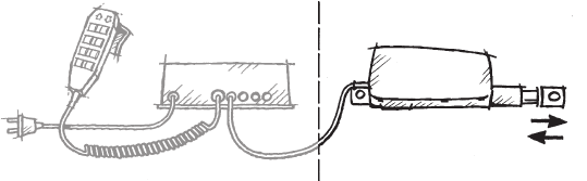
Before the washing procedure starts!
In order to maintain the flexibility of the cables, it is important that the cable is placed in such a way that the cable’s own weight does not strain the
coil during the washing process.
This can be done by placing the cable ON the bed or another form of support for the cable.
Please see the examples in the below pictures

Page 18 of 148
Maintenance
Valid for all LINAK products
• The LINAK products must be cleaned at regular intervals to remove dust and dirt and inspected for mechanical damage, wear and breaks,
- worn out parts must be replaced.
• Inspection/maintenance intervals shall be defined by the equipment manufacturer
• The LINAK products are closed units and require no internal maintenance.
• Only type IPX6 is waterproof and type IPX6 Washable tolerates being washed in tunnels.
• The LINAK products must be IPX6 Washable when cleaning in wash tunnels. Make sure that the plugs are correctly fitted with O-rings before washing.
• O-rings: When individual parts are replaced in a LINAK IPX6 or IPX6 Washable system, the O-rings on all parts, must be replaced at the same time.
On control boxes with a replaceable mains fuse, the O-ring in the fuse cover must be replaced every time the cover has been removed.
The O-rings must be greased in water free vaseline when replacing them. Make sure that the counterpart - the socket - is clean and undamaged.
Valid for all LINAK actuators and lifting columns
• Actuators/lifting columns must be inspected at attachment points, wires, piston rod, cabinet, and plugs, as well as checking that the actuator/
lifting columns function correctly.
• To ensure that the pregreased inner tube remain lubricated the actuator must only be washed down when the piston rod is fully retracted.
Valid for all LINAK control boxes and handsets
• Electronics must be inspected at attachment points, wires, cabinet, and plugs.
• Inspect the connections, cables, cabinet, and plugs, and check for correct functioning (does not apply to battery versions).
• With the exception of the CS16 the control box is sealed and maintenance free.
• Inspect at regular intervals that the ventilation aperture on the external battery is positioned correctly and is intact throughout its length,
approx. 20 mm., see figure 1.
Environmental conditions
Storage and transport
Operating
Temperature
Relative humidity
Atmospheric pressure
5°C to 40°C
20% to 90% @ 30°C – not condensing
800 to 1060 hPa (Rated to operate at an altitude ≤ 2000 m)
Storage
Temperature
Relative humidity
Atmospheric pressure
-10°C to +50°C
20% to 90% @ 30°C – not condensing
800 to 1060 hPa (Rated to operate at an altitude ≤ 2000 m)
Transport
Temperature
Relative humidity
Atmospheric pressure
-10°C to +50°C
20% to 90% @ 30°C – not condensing
800 to 1060 hPa (Rated to operate at an altitude ≤ 2000 m)
If the actuator is assembled in the application and is exposed to push or
pull during transportation, the actuator can be damaged.
Do not drop an actuator or otherwise damage the housing during
disassembly or transportation.
We do not recommend using an actuator which has been damaged.
Valid where nothing otherwise is stated under the specific products in a later section.
Page 19 of 148
China
Pollution control mark (also
indicates recyclability)
ZERO standby power
Regulatory Compliance Mark:
The Australian Safety/EMC
Regulations
Protection against contact/
foreign matter (first character)
and water (second character)
as per EN60529
Alternating Current
Direct current
Lock function
Release function
Charge indicator
Safety switch/enable button
Reduced ETL Recognized
Component mark for Canada
and United States.
X: The mark is always
accompanied by a Control
Number of 6 or 7 figures.
For complete description, see
ETL-marking on next page.
Insulation class
LINAK control boxes are available in insulation class 1 and insulation class 2.
Class 1 means with earth connection
Class 2 means without earth connection
When measuring the resistance in the earth connection in LINAK Control Boxes (class 1), it is recommended to use equipment, delivering a test
current of no less than 5A. The resulting voltage will correspond to the resistance in the earth connection. Test currents below 5A, would yield no
exact measurements.
Key to symbols
The following symbols are used on the label on the LINAK products.
If the application is insulation dielectric strength tested by applying a test voltage from the terminals of the mains connection to any
accessible metal parts (e.g. 4 kV for 240 V rated medical equipment), corona discharge or a momentary flashover might occur within
the actuator. This is not considered as an insulation breakdown.
However to avoid to overstress different types and levels of insulation, the control box and the actuator must be tested individually
(disconnected) with the respective dielectric strength test voltages (e.g. 4 kV for a 240 V rated control box and 500 V for the actuator).
This principle is in accordance with IEC 60601-1:2005, cl. 8.8.3.
Recycle
UL Listing Mark
UL Listing Mark for Canada
UL Listing Mark for Canada
and the United States
UL Listing Mark
AS 3108
Australian approval mark
Various
TÜV Rheinland - LGA tested
Recognised
Component Mark
Canadian
Recognised - Component
Mark
Recognised
Component Mark for Canada
and the United States
PSE-Mark
Compliance to all relevant EC
directives
IEC 60417-5172:
Class II equipment
Product with a thermofuse
IEC 60417-5957:
For indoor use only
IEC 60417-5222:
Safety isolating transformer,
general
IEC 60417-5840:
Patient part of type B
Patient part of type BF
Earth
IEC 60417-5019:
Protective earth; protective
ground
IEC 60417-5002:
Positioning of cell
ISO 7000-0434A:
Caution, consult
accompanying document
ISO 7000-1641
Operating instructions
Electronics scrap
Electronics scrap
IPXX
XXXXXX

Page 20 of 148
ETL-marking
Due to space limitations, the complete ETL-marking demands are not represented on the marking plates.
The full ETL Recognized Component markings are shown here.
C/N 120690
Conforms to ANSI/AAMI Std. ES60601-1
Cert. to CSA Std. C22.2 No. 60601-1
C/N 9901916
Conforms to ANSI/AAMI Std. ES60601-1
Cert. to CSA Std. C22.2 No. 60601-1
C/N 4008003
Conforms to ANSI/AAMI Std. ES60601-1
Cert. to CSA Std. C22.2 No. 60601-1
C/N 4008004
Conforms to ANSI/AAMI Std. ES60601-1
Cert. to CSA Std. C22.2 No. 60601-1
C/N 4008005
Conforms to ANSI/AAMI Std. ES60601-1
Cert. to CSA Std. C22.2 No. 60601-1
C/N 4008623
Conforms to ANSI/AAMI Std. ES60601-1
Cert. to CSA Std. C22.2 No. 60601-1
C/N 4008838
Conforms to ANSI/AAMI Std. ES60601-1
Cert. to CSA Std. C22.2 No. 60601-1
C/N 4008671
Conforms to ANSI/AAMI Std. ES60601-1
Cert. to CSA Std. C22.2 No. 60601-1
C/N 4009507
Conforms to ANSI/AAMI Std. ES60601-1
Cert. to CSA Std. C22.2 No. 60601-1
Mounting
Actuator:
Do not use any other screws for the mounting brackets than those recommended by LINAK. If longer screws are used they will come into contact with
the inner parts of the actuator. This will result in an irregular operation or even damage the actuator.
During mounting, the actuator must always be:
• Fixed, to protect it against torque and bending. See Figure 2.
• Fixed, so that it is restrained, but free to move on its mountings. See Figure 3.
• Fixed in brackets, which can take up the torque reaction. See Figure 3.
• Mounted at right angles, so that the right angle requirement is observed. See Figure 4.
• Mounted with correct bolt dimension.
• Mounted with bolts and nuts made of high quality steel grade (e.g. 10.8). No thread on bolt inside back fixture or piston rod eye.
• Bolts and nuts must be protected from being able to fall out.
• Inspect the actuator for damage before mounting. Damaged actuator must not be mounted. Watch e.g. for damaged packaging.
• Do not use a too high tourque when mounting the bolts for back fixture or piston rod eye
Control boxes:
• The mounting screws on the control box must be tightened with a maximum torque of 1 Nm
• The mounting surface to which the control box is attached should have a surface evenness better than ± 0.5 mm.
• Systems must not be installed/deinstalled while in operation.
• Control boxes with a wet alarm must be mounted as shown on figure 5.
• Nuts and bolts must be made of steel.
• Nuts and bolts must be tightened securely.
• Control boxes with earth connection (Class 1), here the nut must be tightened with a torque of 1-1,2 Nm.
The correct bolt size for securing the CB8, CB12, CB14, CB16, CB20 and CUDM, is Ø5 mm and the ACP box is M5.
Cables:
It is important to remove the transport plastic bag before using the cable. Cables need to be fixed to the application or to be placed in
such a way that users cannot stumble and injure themselves.
Accessories:
The mounting screws on the accessories must be tightened with a maximum torque of 1 Nm. IRO can be mounted with a higher torque, up to 2 Nm.
• The mounting surface to which the accessory is attached should have a surface evenness better than ± 0.5 mm.
• Systems must not be installed/de-installed while in operation.
• Nuts and bolts must be made of steel.
• Nuts and bolts must be tightened securely. The correct bolt size for securing the DJB, IRO, MJB, SLS and SMPS30 is M4 and the BA18 is M5.
• Mounting 0964135-C (UBL) must be with M3 bolt and a maximum torque of 0,25 Nm.
Controls:
The mounting screws on the controls must be tightened with a maximum torque of 1 Nm.
• The mounting surface to which the accessory is attached should have a surface evenness better than ± 0.5 mm.
• Systems must not be installed/de-installed while in operation.
• Nuts and bolts must be made of steel.
• Nuts and bolts must be tightened securely.
The correct bolt size for securing the ACC and ACL is M4, for ACP is it M5 and for the ACM is it M6.
For further instructions regarding mounting, see the data sheet for
the individual product or in chapter 5, 6 or 8 in this manual.
Page 21 of 148
Connecting the system
Do not connect the mains cable until all actuators and handsets have been connected to the control box.
Start by connecting the handset to the control box. The connection in the control box is marked with “HB”.
Connect the different actuators to the different channels on the control box. Each channel is marked with a number (e.g. “1”, “2”, “3”…….).
Check that all plugs are well connected and firm pushed into the connection plug. Due to the fact that LINAK control boxes are designed for a high IP
degree a firm force can be required.
Connect the mains cable.
The actuators can now be operated by pushing a button on the handset. Use only one button at the time.
If the control box is equipped with a special software an initializing process might be necessary. This process is described in the software specification.
LINAK
control box
LINAK handset LINAK actuator or lifting column
Attention should be paid to the following:
• Control boxes must only be connected to the mains voltage specified on the label. All DIN, jack or minifit plugs from the CB6S/CB12/CB14/CB16/
CB20 IPX6 Washable should be locked by using a LINAK locking mechanism.
• The control box must be connected in such a way that the cables are not trapped, exposed to tension or sharp objects when the application is
moved in different directions.
• All Control boxes with mains supply should be connected to the mains before they are able to work.
Prior to first use of LINAK batteries, please make sure that they are being charged 24 hours in order to reach proper function and prolong the lifetime
of the batteries.
If the customer uses a non-LINAK battery, it is important to check that the current is not reversed (plus and minus swapped over) This applies to both
control boxes, which always run off battery and control boxes with battery backup. Contact your nearest LINAK dealer for specification of type, size
etc. The control current in the handset cable must not exceed 100 mA.
Any non-detachable power supply cord with mains plug is considered as the disconnecting device.
Charging is only allowed in dry environment, and appliance inlet must be thoroughly dried before connecting to mains.
All types of actuators may only be connected according to the label, where the voltages 12, 24, or 36 VDC are indicated.
a) Actuators with jack plugs may only be connected to LINAK control boxes
b) Actuators without plugs are connected as shown in Figures 6.1 - 6.12.
For actuators operating without a control box, the mains supply of the actuator must be equipped with an arrangement, which switches off the
actuator at end-stop (e.g. LS or LSD limit switch). If there is a risk of overloading the actuator, the mains supply must be equipped with a safety device
against overloading (e.g. a CS16 PCB). If this requirement is not observed, the actuator may be damaged.
Actuators with internal control PCBs’s are not first failure safe if used in a system combination without power request (power for actuator switched
ON only when handset key active).
Page 22 of 148
JUMBOTM system (special information)
The LINAK JUMBO system is specially developed for patient lifts, offering various combinations of actuators and control boxes.
Connecting the system:
Mount the mounting bracket (MBJ) to the application. Mount control box and battery (and charger (CHJ2) if equipped).
If it is a JUMBO Home system mount the control box on the application (no mounting bracket is needed).
Only vertical mounting allowed (connectors facing downwards).
Connect the handset to the control box. The connection in the control box is marked with “HB”.
Connect the actuators to the control box. Each channel is marked with a number (e.g. “1”, “2”). Channel “1” has always to be used for the High /
Low (Lifting) function.
The actuators can now be operated by pushing a button on the handset. Use only one button at the time.
Example of JUMBO patient lift system
System components: Actuators types LA28, LA32, LA34, LA44
Control Box types CBJ1/CBJ2, CBJC
Batteries types BAJ1, BAJ2, BAJL
Handsets types HB5, HB7, HB8
Battery Charger type CH01
1 Handset
2 Battery
3 Charger
4 Control box
5 Mains plug
6 + 7 Actuators
Configuration of the JUMBO System
1 Battery
2 Emergency stop
3 Control box
4 LCD-display for battery
condition
1 Battery
2 Charger
3 Light indication for mains connection
4 Light indication for charging
1 Battery
2 Charger
3 Control box
4 Output for hand
5 + 6 Output actuator
1
2
3
4
1
2
3
4
1
2
3
456
1) 2)
3)
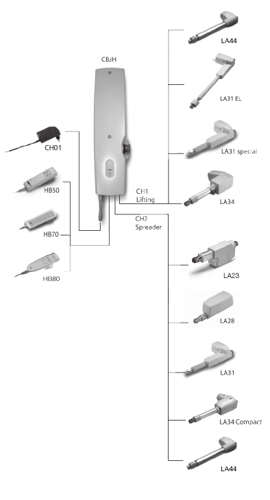
Page 23 of 148
JUMBO Home System

Page 24 of 148
Warnings
• When using BAJL and JUMBO control boxes, loss of power might happen due to the battery deep discharge protection. This will only happen in
case of continuous battery use despite warnings. In this event, there may be no warning and the application may not be able to move when
expected.
• In his risk analysis, the customer must take into consideration how to assure alternative means to make movement, e.g. quick release or manual
lowering.
• The combination of CBJ1 or CBJ2 with BAJL might not be able to complete a full cycle after low battery warning.
• Do not open the battery housing as damaging the cell or circuitry may develop excessive heat.
• If product caution is not clearly visible at low light intensity, read the product label instructions symbol. A warning must be included in the
application manufacturer’s manual for the medical device.
• The application manufacturer must test the application and ensure that intentional and unintended operations do not exceed the battery
specification limits. The application manufacturer must assure other means of movement, e.g. quick release or manual lowering.
• Defective or damaged li-ion batteries are not allowed for transportation.
• For safety reasons, please adhere to the indicated charging and operation temperature.
• In case the battery is too hot, disconnect it and evacuate the room and wait for 2 hours before taking further steps.
• Mounting instructions must be followed in order to avoid exposing batteries to water.
• Recharging of battery must take place every 6 months.
• Disposal of the battery takes place in accordance with local regulations.
Recommendations:
• Do not exceed the storage temperature as it will shorten the product life and performance.
• Allow the battery to settle to room temperature before use.
• Do not exceed the duty cycle (see product label) as it will shorten the product life, reduce performance and eventually activate excess temperature
protection.
• Lithium ion batteries are not intended for use in outdoor applications and indoor pool environments.
• If the battery is completely discharged, then recharge the battery before storage.
• Always use correct LINAK charger.
DO NOT:
• Heat or burn the batteries.
• Short circuit the batteries.
• Expose the batteries to high impact / excessive force.
• Crush or puncture the batteries.
• Use batteries with signs of damage or corrosion.
• Charge or store the batteries near combustible material.
• Expose the batteries to water or other liquids.
• Overcharge or fully discharge the batteries.
For detailed information on specific use of batteries, please see the product information in chapter 5.
Safety feature
Lithium ion batteries contain several mechanisms to protect itself from being damaged due to excessive use.
In case of overheating, the device will activate a thermal protection. No power output will be available until the temperature is back again within
normal operating range.
Overheating may occur by extensive use at high temperature or when exceeding the duty cycle. (see product label)
Batteries
Lithium ion batteries

Page 25 of 148
Lead acid batteries
Maintenance of batteries
Prior to first use of LINAK batteries, please make sure that they are being charged at least 24 hours and longer if possible in order to reach proper
function and prolong the lifetime of the batteries.
Warnings
• Please observe the following maintenance, replacement, and disposal requirements to ensure a safe and reliable operation.
• The batteries are to be replaced after 4 years at the latest. Perhaps earlier, dependent on the pattern of use. Frequent and high-powered
discharges reduce the battery life. For an optimum lifetime the product must be connected to the mains voltage as often as possible. It is
recommended that the batteries are to be charged at least every 6 months - otherwise will the batteries have reduced capacity due to self-
discharge. It is recommended to test the battery function at least once every year.
Replacement of batteries
The batteries must only be replaced by the same type of batteries or mechanical and electrical equivalent types. The batteries must be new or
maintained by means of charging at least every 6 months. The batteries, which make a set, must be supplied with identical production codes.
Mismatching of production codes may lead to a severely reduced lifetime expectancy.
Before mounting ensure that the battery set is correctly connected, compare with the drawing in the battery room, and check that no connectors are
loose.
Warnings
• From the factory, the battery room is hermetically separated from the electronics room. When replacing the batteries this separation must not be
damaged or modified as this may allow penetration of battery gas into the electronics room with risk of explosion.
• When replacing batteries in waterproof products (IPX5 and IPX6) precautions must be taken that the sealing material (silicone ring or joint filler)
is not damaged and that it is correctly placed in the groove. Hereafter the screws in the cover are to be fastened with approx. 1 Nm. If the seal is
damaged it must be replaced by a new silicone string (LINAK article no. 0008004 for a roll of 100 meters).
Disposal
The batteries, which are lead-acid batteries, can be returned to LINAK or disposed in the same way as car batteries.
Warnings
• The battery room is supplied with ventilation that ensures correct and necessary airing of the battery room. This airing must not be blocked or
covered as a positive pressure may occur with risk of explosion.
• If the product has been exposed to mechanical overload (lost on the floor, collision/squeezing in the application or a powerful stroke) the product
must be sent to an authorised workshop for control of the hermetic separation between the battery and electronics rooms.

Page 26 of 148
2. Information on start-up, de-installation and operation
Before installation, de-installation, or troubleshooting:
• Stop the actuator/lifting column.
• Switch off the power supply or pull out the mains plug and pull out the plug to the actuator/lifting column.
• Relieve the actuator/lifting column of any loads, which may be released during the work.
Prior to first use of LINAK batteries, please make sure that they are being charged 24 hours in order to reach proper function and prolong the lifetime
of the batteries.
Before start-up:
• Make sure that the system has been installed as instructed in the User Manual.
• The individual parts (actuator/lifting column/handsets etc.) must be connected before the control box is connected to the mains.
• Make sure that the voltage of the mains to be connected to the product or the system is the one stated on the label.
• Make sure that the actuator/lifting column is connected to a mains electricity supply/transformer with the correct voltage and which is
dimensioned and adapted for the actuator in question.
• The equipment can be freely moved over the actuator/lifting column’s whole working area.
• Check correct function after mounting.
• The actuator/lifting column must not be loaded in excess of the values indicated in the specifications on the product label.
• The duty cycle noted on the product label must always be noted. Otherwise there is a risk of damaging the products.
Exceeding the duty cycle will result in a dramatic reduction of the life time of the system.
Unless specified otherwise on the product label the duty cycle is max. 10% : Max. 2 minutes in use followed by 18 minutes not in use.
• The actuator/lifting column system may only be used in an environment corresponding to the system’s IP-rating.
LINAK products are marked with the actual IP-rating on the label.
• If any individual parts are suspected to be damages, do not install the parts, but return them for inspection/service.
During operation:
• Listen for unusual sounds and watch out for uneven running. Stop the actuator/lifting column immediately if anything unusual is observed.
• If the control box makes unusual noises or smells, switch off the mains voltage immediately and the external battery, if any.
• Take care that the cables are not damaged.
• Unplug the mains cable on mobile equipment before it is moved.

Page 27 of 148
Troubleshooting Actuators / Lifting columns
Symptom Possible cause Action
No motor sound or movement of piston rod - The actuator is not connnected to the control box - Connect the actuator to the control box
- Blown fuse in the control box - Fuse must be changed
- Cable damaged - Send actuator for repair
Excessive electricity consumption - Send actuator for repair
Motor runs but spindle does not move - Gear wheel or spindle damaged - Send actuator for repair
Actuator cannot lift full load - Clutch is worn - Send actuator for repair
- Motor is damaged
Motor sound but no movement of piston rod - Send actuator for repair
No signal from Reed or Hall switch - Send actuator for repair
Motor runs and quick release does not - Declutching arm turns less than approx. 75° - Adjust cable
function or is noisy
Piston rod will only move inwards and not - Safety nut has operated - Send actuator for repair
outwards
Motor runs too slowly or does not give - Insufficient power supply - Increase power supply
full force - Voltage drop in cable - Thicker cable
Troubleshooting Electronics
Symptom Possible cause Action
Power indicator does not light up - Not connected to mains - Connect to mains
- The fuse has blown - Replace fuse, if the system is prepared for external
fuse replacement, or send the system for repair
- Defective power cable - On control boxes with exchangeable power cable
change the cable.
- On control boxes with fixed cable send it for repair
- Control box defective - Send control box for repair
Power indicator lights up, but actuator - Actuator plug not pushed into control - Push actuator plug into control box properly
does not run box properly
Relays in control box are heard clicking - Actuator defective - Replace actuator
- Control box defective
- Replace the control box
Power indicator lights up, but actuator - Control box defective - Send control box for repair
does not run
No relay noise is heard from control box - Handset defective - Send handset for repair
Not valid for CB20/CB6S OBF/CB16 OBF
Control box completely dead on battery - Battery completely flat - Charge battery
and no relay clicking is heard
- Battery defective - Replace battery
Actuator does not run on battery, but - Actuator plug not properly pushed into - Push actuator plug properly into control box
relay clicking is heard control box
- Actuator defective - Replace actuator
- Control box defective - Replace control box
Control box okay apart from one direction - Handset defective - Send handset for repair
on one channel - Control box defective - Send control box for repair
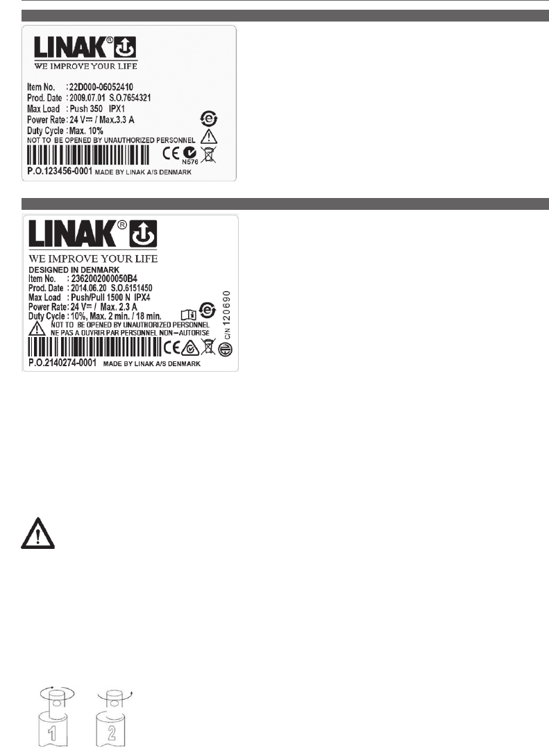
Page 28 of 148
The LA22 is an in-line actuator specially designed with a small overall dimension for
easy use in industrial, agricultural, and rehabilitation products.
Thanks to its small outer dimensions and linear design, the LA22 is well suited for
applications where installation space is limited, such as on wheelchairs.
The LA23 is a small and strong push actuator (up to 2500 N). The LA23 can be used
in various applications where size is important. The LA23 is e.g. ideal for adding tilt-
function to a desk, so the table top can tilt or for adjustment in handicap kitchens.
Some of the benefits the LA23 offers you are:
• Compact design
• High lifting force
• Exchangeable cables
3. Information on specific actuators
Usage:
• Duty cycle: 10%, 2 minutes continuous use followed by 18 minutes not in use
• Usage temperature: +5° - +40° normal operating temp.
-30° - +50° according to test conditions: ISO 7176-9
• Storage temperature: -45°C to +70°C (according to ISO 7176-9)
• Compatibility: DESKLINE Control boxes.
SLS must be ignored Up + Down in the CBD4, when configured for LA23 and in the CBD6S with old actuators.
• Approved according to EN60335-1 with CBD6S
• Fire catagory: Enclosure UL94-V0
• Cycles: The LA23 Life cycle test has been performed with a stabilised power supply (10% duty cycle) on a 200 mm stroke
actuator at max. load at 5000 cycles
1. LA22 (MEDLINE® CARELINE® TECHLINE®)
2. LA23 (DESKLINE®)
Warnings
• Do not sideload the actuator.
• Only use the actuator within specified working limits.
• When mounting the LA23 in the application ensure that the bolts can withstand the wear and that they are secured safely.
• If an actuator with stroke length below 50 mm is used, and the electrical end-stop switch fails, please be aware that the distance before reaching
the mechanical end- stop will be prolonged. The extra distance will be 50 mm minus actual stroke length.
I.e. If an actuator with 20 mm stroke length is used and the switch fails, it will travel an additional 30 mm before reaching the mechanical end-stop.
• Instruction concerning the turning of the piston rod eye
When mounting and taking into use, it is not permitted to make excessive turns of the piston rod eye. In cases where the eye is not positioned
correctly, it is permitted to first screw the eye down to its bottom position, at a maximum torque of 2 Nm (1), and thereafter a maximum half
turn outwards again (2).
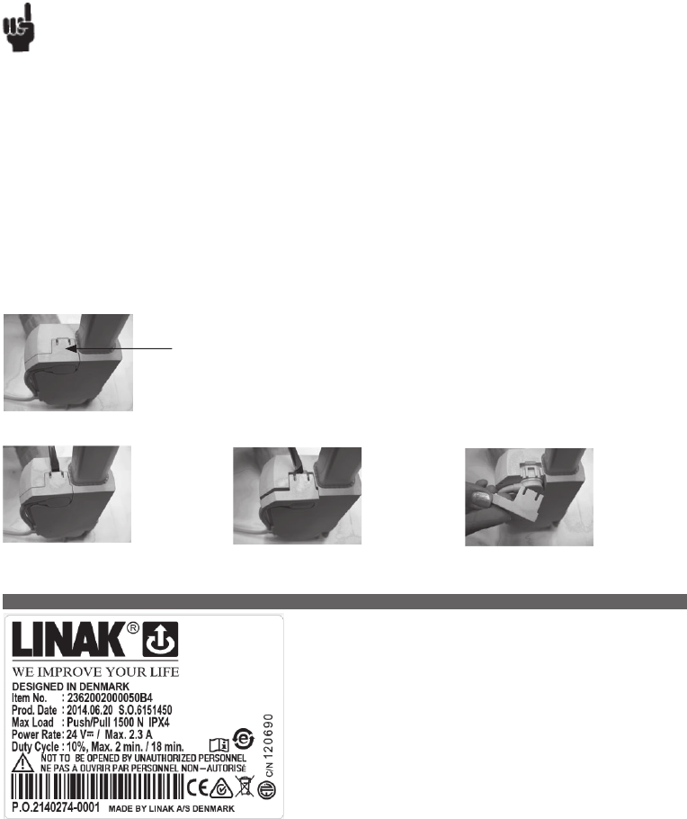
Page 29 of 148
Recommendations:
• Do not place load on the actuator housing and do prevent impact or blows, or any other form of stress to the housing.
• Ensure that the cable lock is mounted correctly.
• Ensure that the duty cycle and the usage temperatures for LA23 actuators is respected.
• Ensure that the cable cannot be squeezed, pulled or subjected to any other stress.
• The LA23 is not suitable for use in outdoor applications where it can be exposed to sun and rain.
If outdoor use cannot be avoided, it is very important that the LA23 is mounted in a position where it is well shielded. It is up to the customer to
provide the shielding. Furthermore, it will be good practice to ensure that the actuator is fully retracted in the “normal” position. The reason is that
there will be a vacuum inside the actuator if it is extended which over time can lead to water entering the actuator.
The item numbers for ordering the Cable Lock are:
• Item number: 0231007 (light grey) for one cable lock (1 piece).
• Item number: 0231037 (black) for one cable lock (1 piece).
Below you see an instruction in how to mount and remove the cable lock from LA23.
a) Mount a cable lock:
Push down until the cable lock clicks into place.
Step 1:
Insert e.g. a
screwdriver at
a 45° angle
as illustrated.
Step 2:
Turn the screw-
driver to release
the cable lock.
Step 3:
Now the cable
lock can be
removed by hand.
b) Cable lock removal
Note: When a cable lock has been removed, it is recommended to replace it with a new.
The LA23 is a small and strong push/pull actuator (up to 2500N). The LA23 can be
used in various applications where size is important.
Some of the benefits the LA23 offers you are:
• Compact design
• High lifting force
• Exchangeable cables
Usage:
• Duty cycle: 10%, 2 minutes continuous use followed by 18 minutes not in use
• Usage temperature: +5° - +40° normal operating temp.
-30° - +50° according to test conditions: ISO 7176-9
• Storage temperature: - 45°C to + 70°C (according to ISO 7176-9)
• Compatibility: CB20, CB16, CB6S, CBJ 1/2, CBJC, CBJH, CBD4, CBD5 & CBD6*, CA30, CA40, CO61, and SMPS-T160 (for combination
possibilities, please see the User Manual for SMPS-T160 on our website)
* SLS must be ignored Up + Down in the CBD4, CBD5 or CBD6 when configured for LA23
* Only the 3, 6 & 12 mm versions can be configured in the CBD4, CBD5 or CBD6
* Only tested for single use.
• Approvals: IEC60601-1:2005 3rd ed., ANSI / AAMI ES60601-1:2005, 3rd edition LA23 in combination with CBD4, 5 & 6 has no approvals
• Fire catagory: Enclosure UL94-V0
3. LA23 (MEDLINE® CARELINE® TECHLINE®)
...to be continued
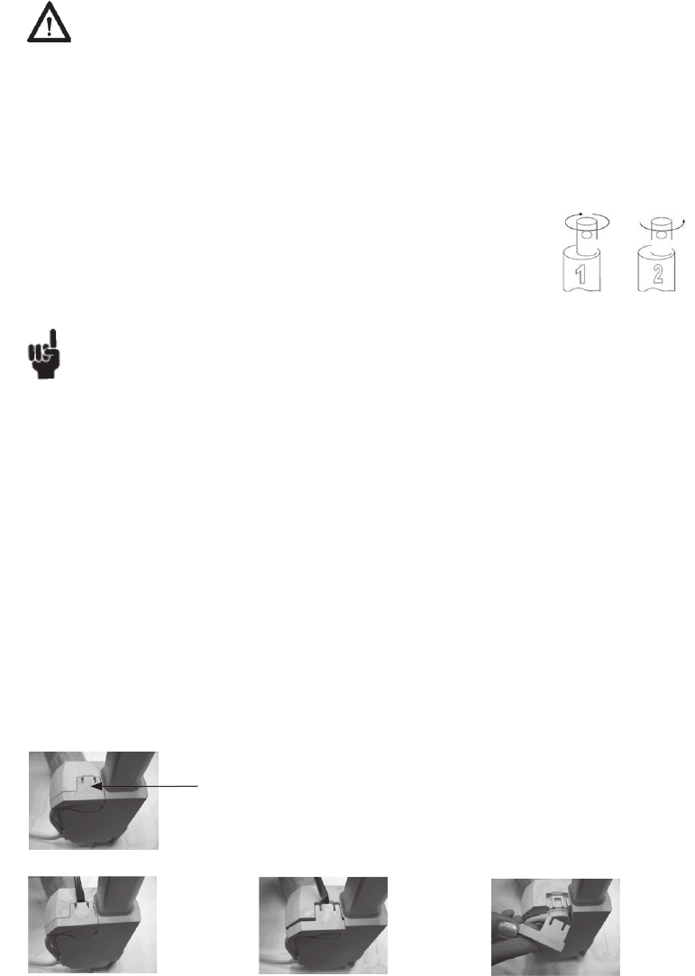
Page 30 of 148
Warnings
• Do not sideload the actuator.
• Only use the actuator within specified working limits.
• Always use steel backfixture for LA23 over 1500N and for pull loads.
• The B and G 24V motors must only be used with their respective control box types.
- Motor type A: 12V motor must be used with CBD4, CBD5 and CBD6
- Motor type B: 24V motor which must be used with JUMBO; CBJ1/2, CBJC and CBJH or generally in applications which are mainly driven with battery
- Motor type G: 24V motor which must be used with OpenBusTM control boxes; CB20, CB16, CB6S, CA30, CA40, CO61
• If an actuator with stroke length below 50 mm is used, and the electrical end-stop switch fails, please be aware that the distance before reaching the
mechanical end-stop will be prolonged. The extra distance will be 50 mm minus actual stroke length. I.e. If an actuator with 20 mm stroke length is
used and the switch fails, it will travel an additional 30 mm before reaching the mechanical end-stop. Please make sure that the application can
withstand this in a safe way.
• Instruction concerning the turning of the piston rod eye. When mounting and taking into use, it is not
permitted to make excessive turns of the piston rod eye. In cases where the eye is not positioned correctly,
it is permitted to first screw the eye down to its bottom position, at a maximum torque of 2 Nm (1), and
thereafter a maximum half turn outwards again (2).
• When mounting the LA23 in the application ensure that the bolts can withstand the wear and that
they are secured safely.
The item numbers for ordering the Cable Lock are:
• Item number: 0231007 (light grey) for one cable lock (1 piece).
• Item number: 0231037 (black) for one cable lock (1 piece).
Below you see an instruction in how to mount and remove the cable lock from LA23.
a) Mount a cable lock:
Push down until the cable lock clicks into place.
Step 1:
Insert e.g. a
screwdriver at
a 45° angle
as illustrated.
Step 2:
Turn the screw-
driver to release
the cable lock.
Step 3:
Now the cable
lock can be
removed by hand.
b) Cable lock removal
Note: When a cable lock has been removed, it is recommended to replace it with a new.
Recommendations
• Do not place load on the actuator housing and do prevent impact or blows, or any other form of stress to the housing.
• Ensure that the cable lock is mounted correct.
• Ensure that the duty cycle and the usage temperatures for LA23 actuators is respected
• Ensure that the cable cannot be squeezed, pulled or subjected to any other stress.
• If a cable lock has been removed it is recommended to check if it is has been damaged during removal. If so it is recommended to replace with a new one.
• Before mounting a cable, ensure that the cable, cable plug or o-ring is not damaged. If damage is observed, the cable must be replaced with a new one.
• The B and G 24V motors must only be used with their respective control box types.
• Not acceptable: B motor with OpenBus™ control boxes!
Reason: The actuator will be too strong, it will run too fast, be noisy and only have a short lifetime. The actuator will not live up to what we promise.
• Not acceptable: G motor with 24V supply!
Reason: The actuator will be too weak, this means it will only run slowly, not be able to lift as much in the cold and under low current conditions.
The actuator will not live up to what we promise.
• The LA23 is not suitable for use in outdoor applications where it can be exposed to sun and rain.
If outdoor use cannot be avoided, it is very important that the LA23 is mounted in a position where it is well shielded. It is up to the customer to
provide the shielding.
Furthermore, it will be good practice to ensure that the actuator is fully retracted in the “normal” position. The reason is that there will be a
vacuum inside the actuator if it is extended which over time can lead to water entering the actuator.
Page 31 of 148
Connection diagrams:
Standard electrical end stop and potential free end stop - no positioning
23XXXXXX01XXXXX
Dual Hall digital positioning
23XXXXXX02XXXXX
Dual Hall PNP positioning
23XXXXXX03XXXXX
}
6 poles connector
}
}
6 poles connector
6 poles connector
Standard electrical end stop - no positioning
23XXXXXX00XXXXX
Note: If reversed driving is wanted this has to be done by using different cables.
Note: Connection colours only fit with “open end” cables.
...to be continued
BLUE
BROWN
M
_
M+
M
M
_
M+
M
IN
Common
OUT
BLUE
GREEN
BROWN
YELLOW
RED
BLUE
GREEN
BROWN
YELLOW
RED
M
_
M+
M
HALL A
VCC +
HALL B
GND _BLACK

Page 32 of 148
Hall Potentiometer feedback and potential free end stop
23XXXXXX2XXXXXX
Hall Potentiometer feedback
23XXXXXX1XXXXXX
Hall PWM position feedback and potential free end stop
23XXXXXX4XXXXXX
}
10 poles connector
}
}
10 poles connector
10 poles connector
Note: Connection colours only fit with “open end” cables.
BLUE
BLACK
BROWN
VIOLET
WHITE
M
_
M+
ANALOG
VCC +
GND _
Common RED
IN
OUT
M
YELLOW
GREEN
BLUE
BLACK
BROWN
VIOLET
WHITE
M
_
M+
ANALOG
VCC +
GND _
BLUE
BLACK
BROWN
VIOLET
WHITE
M
_
M+
PWM
VCC +
GND _
Common RED
IN
OUT YELLOW
GREEN
M
M
Page 33 of 148
Standard Integrated Control
23XXXXXX5XXXXXX
Integrated Control with Hall Potentiometer position feedback
23XXXXXX6XXXXXX
Integrated Control with Hall PWM position feedback
23XXXXXX7XXXXXX
LA23 with integrated control is not approved according to IEC60601-1:2005 3rd ed., ANSI / AAMI ES60601-1:2005, 3rd edition.
Hall PWM position feedback
23XXXXXX3XXXXXX
}
10 poles connector
Drawing no.: 0239010-A
}
10 poles connector
Note: Connection colours only fit with “open-end” cables.
M
_
M+
PWM
VCC +
GND _
BLUE
BLACK
BROWN
VIOLET
WHITE
BLUE
YELLOW
BROWN
RED
BLACK
INWARDS
OUTWARDS
ENDSTOP IN
ENDSTOP OUT
FEEDBACK
SIGNAL GND
GREEN
VIOLET
WHITE
POWER
INPUT
OUTPUT
Page 34 of 148
The LA23 is a small and strong push/pull actuator (up to 2500N). LA23 can be used in
various applications where size is important. The actuator does have build in electrical
limit switches and guided nut.
Usage:
• Duty cycle: 10%, 2 minutes continuous use followed by 18 minutes not in use
• Usage temperature: -30°C to +55°C (according to ISO 7176-9)
• Storage temperature: -45°C to +70°C (according to ISO 7176-9)
• Fire catagory: Enclosure UL94-V0
Warnings
• All LA23 IC (Integrated Controls) versions are not compliant for Medical use.
• Do not sideload the actuator.
• Only use the actuator within specified working limits.
• Always use steel backfixture for LA23 over 1500N and for pull loads.
• When mounting the LA23 in the application ensure that the bolts can withstand the wear and that they are secured safely.
• Motor type A: 12V motor
Motor type B: 24V motor.
• If an actuator with stroke length below 50 mm is used, and the electrical end-stop switch fails, please be aware that the distance before reaching
the mechanical end-stop will be prolonged. The extra distance will be 50 mm minus actual stroke length. I.e. If an actuator with 20 mm stroke
length is used and the switch fails, it will travel an additional 30 mm before reaching the mechanical end-stop.
• Instruction concerning the turning of the piston rod eye. When mounting and taking into use, it is not permitted
to make excessive turns of the piston rod eye. In cases where the eye is not positioned correctly, it is permitted
to first screw the eye down to its bottom position, at a maximum torque of 2 Nm (1), and thereafter a
maximum half turn outwards again (2).
Recommendations
• Do not place load on the actuator housing and do prevent impact or blows, or any other form of stress to the housing.
• Ensure that the cable lock is mounted correctly.
• Ensure that the duty cycle and the usage temperatures for LA23 actuators is respected.
• Ensure that the cable cannot be squeezed, pulled or subjected to any other stress.
The item numbers for ordering the Cable Lock are:
• Item number: 0231007 (light grey) for one cable lock (1 piece).
• Item number: 0231037 (black) for one cable lock (1 piece). Below you see an instruction in how to mount and remove the cable lock from LA23.
a) Mount a cable lock:
Push down until the cable lockclicks into place.
Step 1:
Insert e.g. a screw-
driver at a 45°
angle as illustrated.
Step 2:
Turn the screw-
driver to release
the cable lock.
Step 3:
Now the cable
lock can be re-
moved by hand.
b) Cable lock removal
Note: When a cable lock has been removed, it is recommended to replace it with a new.
3. LA23 IC (TECHLINE®)
Page 35 of 148
Connection diagrams:
Standard electrical end stop and potential free end stop - no positioning
23XXXXXX01XXXXX
Dual Hall digital positioning
23XXXXXX02XXXXX
Note: If reversed driving is wanted this has to be done by using different cables.
Dual Hall PNP positioning
23XXXXXX03XXXXX
Note: Connection colours only fit with “open end” cables.
}
6 poles connector
}
6 poles connector
}
6 poles connector
Standard electrical end stop - no positioning
23XXXXXX00XXXXX
...to be continued
BLUE
BROWN
M
_
M+
M
M
_
M+
M
IN
Common
OUT
BLUE
GREEN
BROWN
YELLOW
RED
BLUE
GREEN
BROWN
YELLOW
RED
M
_
M+
M
HALL A
VCC +
HALL B
GND _BLACK
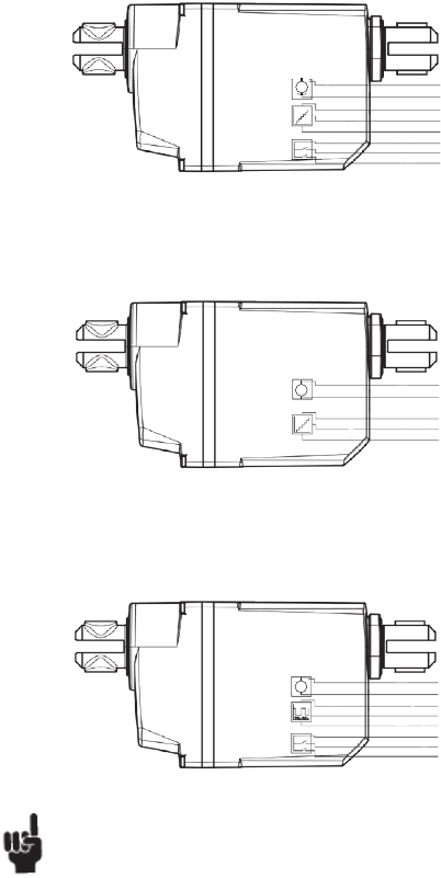
Page 36 of 148
Hall Potentiometer feedback and potential free end stop
23XXXXXX2XXXXXX
Hall Potentiometer feedback
23XXXXXX1XXXXXX
Hall PWM position feedback and potential free end stop
23XXXXXX4XXXXXX
}
10 poles connector
}
}
10 poles connector
10 poles connector
Note: Connection colours only fit with “open end” cables.
}
BLUE
BLACK
BROWN
VIOLET
WHITE
M
_
M+
ANALOG
VCC +
GND _
Common RED
IN
OUT
M
YELLOW
GREEN
BLUE
BLACK
BROWN
VIOLET
WHITE
M
_
M+
ANALOG
VCC +
GND _
BLUE
BLACK
BROWN
VIOLET
WHITE
M
_
M+
PWM
VCC +
GND _
Common RED
IN
OUT YELLOW
GREEN
M
M
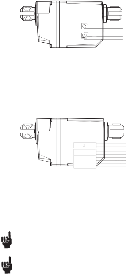
Page 37 of 148
Standard Integrated Control
23XXXXXX5XXXXXX
Integrated Control with Hall Potentiometer position feedback
23XXXXXX6XXXXXX
Integrated Control with Hall PWM position feedback
23XXXXXX7XXXXXX
LA23 with integrated control is not approved according to IEC60601-1:2005 3rd ed., ANSI / AAMI ES60601-1:2005, 3rd edition.
Drawing no.: 0239010-A
Hall PWM position feedback
23XXXXXX3XXXXXX
}
}
10 poles connector
10 poles connector
Note: Connection colours only fit with “openend” cables.
M
_
M+
PWM
VCC +
GND
_
BLUE
BLACK
BROWN
VIOLET
WHITE
BLUE
YELLOW
BROWN
RED
BLACK
INWARDS
OUTWARDS
ENDSTOP IN
ENDSTOP OUT
FEEDBACK
SIGNAL GND
GREEN
VIOLET
WHITE
POWER
INPUT
OUTPUT
Page 38 of 148
The LA27 actuator is a powerful actuator designed for applications such as furniture
and care beds.
Built-in end-stop circuit (CS27)
In the LA27/CS27 the actuator is switched off at the end position. There is no overload
protection.
• The LA27CS27 has no IP classification and is connected to a HB71 or HB72.
The power supply is the TR6 or TR7.
It is important that the supply voltage 24 VDC is connected correctly (see Figure 6.7)
otherwise the CS-circuit may be destroyed.
Mechanical spline:
The splines function so that the actuator can only push, not pull. During pull in the
actuator, the inner tube is lifted off the thread bush, and the actuator can therefore
never pull a load, only push.
Functional test of mechanical splines:
When the piston rod is at the innermost position, it must be possible to pull it out manually to its full travel length and to press it in again without
much resistance and without using the motor. If this is not possible, contact your nearest LINAK dealer.
Quick Release:
The LA27 with QR is designed to be used as a part of the backrest function in a Care/Hospital bed. The QR function allows a patient to be lowered
manually to a flat position very quickly (CPR) in case of an emergency.
Functional test of QR:
To test a LA27QR it is necesarry to have the actuator built into an application. The release cable has to be provided and mounted by the customer.
The necesarry force on the cable requiered to operate the Quick Release is approx. 20 kg. The necesarry force on the actuator to operate the quick
release is approx. 50 kg. Wenn operating the QR, it is recommended that the QR is activated all the way down.
Usage:
• Duty cycle: 2/18; 2 minutes continuous use followed by 18 minutes not in use
• Duty cycle: Max 5% or 1 min. continuous use followed by 19 minutes not in use - with 8000 N version.
• Lifetime limited to only 3000 cycles according to EN1970 - with 8000 N version
• Ambient temperature: +5o to +40oC (the actuator must also be at this temp.)
• Approvals: LA27 is approved according to the 3rd edition of IEC 60601-1, ANSI/AAMI ES 60601-1 and CAN/CSA C-22.2 No. 60601-1
NOTE: re. LA27 with 6.000N specification (274x3xxx1xxx0xZ; Z = A or B with worm shaft*) for OpenBus™: I.e. to use such combination a
preceding test MUST be carried out.
This combination reduces the self-lock ability because of lower friction from the worm shaft which has a rolled axle. The worm shaft is however
needed because of the OpenBus™ output power.
The problem related to an application:
The self-lock ability may be reduced in cases where the load curve is 6.000 N in both minimum and maximum stroke length.
Warnings
• The actuator must not be used in pull applications when the quick release is activated, as the risk of personal injury can arise.
• Do only use the actuator within specified working limits.
• Do not sideload the actuator.
Recommendations
• LA27 is not meant to have CB6S OBL/OBF mounted on the actuator. The CB6S OBL/OBF must be mounted separately using a bracket.
• LA27 must have a minimum installation dimension of 320 mm if control box CB6 is to be mounted on the actuator.
• The cable for the LA27 is not part of the actuator therefore it must be ordered separately.
• Piston rod eye: The distance from the centre of the eye, to the end of the actuator.
• Change between push and pull not allowed
• Inspect actuator once a year, for wear and jarring sound.
• We recommend using a safety nut in medical applications
• Do not expose actuators without all cables fitted to water/cleaning.
• No thread on bolt inside back fixture.
Note:
For CB6 the current will be cut off when the total current on all channels reaches approx. 5.1 to 5.4 Amp. This means that when two LA27´s running
simultaneously are connected to a CB6 they will not be able to lift the max. load mentioned under technical specifications.
4. LA27 (MEDLINE® CARELINE® HOMELINE®)
Page 39 of 148
The LA28 is primarily a system actuator. The actuator is very quiet and powerful designed
for use in the furniture, rehabilitation, and hospital bed line of businesses.
The actuator is also ideal for use in agricultural machinery and for a wide range of
industrial applications.
Reed-switch:
Reed-switch gives a number of pulses for each rotation of the motor. These pulses are
used to calculate the piston rod’s position as well as to control several actuators running
in parallel.
Your nearest LINAK dealer can inform the number of pulses per stroke length.
Regarding Reed-switch connection, Figure 6.8 (LA28R)
Built-in end-stop circuit (CS28/CS28S)
In the LA28 actuator, with built-in CS28 A-, B- or C-PCB, the actuator is switched off at the end position or when overloaded.
LA28 actuator with:
• The CS28 A is standard IPX1 and is connected to a HB41 handset with a telephone plug.
• The CS28 B is standard IPX5 and is connected to a HB41 handset with a DIN plug. CS32 B is also available in IPX6.
• The CS28 C is standard IPX1 and is connected to an external contact or control. See figure 6.7.
Mechanical spline:
The splines function so that the actuator can only push, not pull. During pull in the actuator, the inner tube is lifted off the thread bush, and the actuator
can therefore never pull a load, only push.
Functional test of mechanical splines:
When the piston rod is at the innermost position, it must be possible to pull it out manually to its full travel length and to press it in again without much
resistance and without using the motor. If this is not possible, contact your nearest LINAK dealer.
Warning
Do only use the actuator within specified working limits.
Usage:
• Duty cycle: Max. 10 % or max. 2 min. continuous use followed by 18 min. not in use.
• Ambient temperatures: + 5° to + 40°C
• Compatibility: CB8, CB12, CB14, and CBJ
• Approvals: IEC60601-1:2005 3rd edition, ANSI / AAMI ES60601-1:2005, 3rd edition and CAN / CSA-22.2 No 60601-1:2008 approved
Recommendations
• LINAK control boxes are designed so that they will short-circuit the motor terminals of the actuator(s), when the actuator(s) are not running.
This solution gives the actuator(s) a higher self-locking ability. If the actuator(s) are not connected to a LINAK control box, the terminals of the
motor must be short-circuited to enable self-locking of the actuator.
• The maximum load in pull is 2000 N.
• Min. stroke length for the LA28 with splines is 80 mm
• The current supply to LINAK actuators must be cut off in case of overload and when the actuators reach end position.
• Ambient operating temperature is 22°C.
• LA28 Compact cannot be used in pull applications, unless fitted with an aluminium back fixture.
“Crimped” piston rod eye Piston rod without eye (are not tested)
Protective
cap
Further information:
Noise level:
• LA28: dB(A) 45; measuring method DS/EN ISO 3743-1, actuator not loaded
• LA28S: dB(A) 54; measuring method DS/EN ISO 3743-1, actuator not loaded
Material:
• The piston rod eyes are “crimped” in place and cannot be unscrewed.
5. LA28 ( MEDLINE® CARELINE® HOMELINE®)
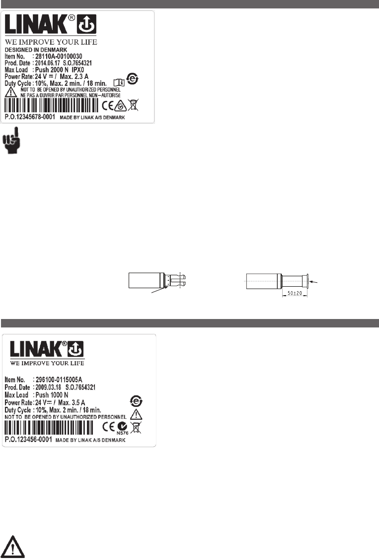
Page 40 of 148
The LA29 actuator is a HOMELINE® actuator specially made for domestic applications.
The actuator has a very short installation dimension as the distance between the two
fixing points is small when the actuator is retracted and at the same time independent
of the stroke length. This feature makes the actuator ideal as a lifting actuator for
self-lifting recliners.
Another special feature here is the flexible back fixture, which can adapt misalign-
ments in e.g. a recliner application.
The LA29 is compatible with various HOMELINE® control boxes.
Reed switch:
The Reed switch gives a number of pulses for each rotation of the motor. These pulses
are used to calculate the position as well as to control several actuators running in
parallel.
Your nearest LINAK dealer can inform the number of pulses per stroke length.
Regarding Reed-switch connection, see Figure 6.10.
Hall
The Hall principle is very similar to the Reed principle. A Hall sensor is based on a magnet that rotates. Two hall sensors are placed close to the magnet
field. The control box (CB20/CB6S OBF/CB16 OBF/CBD4/CBD5) can detect whenever the magnetic field changes direction.
The two Hall sensors are placed close to each other, but with a small displacement. This distance leads to a timing difference between the two pulses.
Whichever one of them comes first indicates the direction of movement. Therefore, there will be no error summary (as with the reed switch) Hall is
therefore a very precise system. Hall is not suitable for use in quick release actuators - see figure 10.
Built-in end-stop circuit
The end-stop switch is part of the actuator construction. Each time the actuator reaches end-stop position the switch is activated and the current is
cut off.
Warning
Do only use the actuator within specified working limits.
The LA28 Compact is a small and powerful actuator designed for use in system
solutions for healthcare equipment or industrial applications. Ideal applications are for
example wheelchairs, treatment chairs, patient lifts or beds.
Usage:
• Duty cycle: Max 10 % or max. 2 min. continuous use followed by
18 min. not in use.
• Ambient temperatures: + 5° to + 40°C
• Compatibility: CB8, CB12, CB14 and CBJ
• Approvals: IEC 60601-1:2005, 3rd edition,
ANSI / AAMI ES60601-1:2005, 3rd edition
and CAN / CSA-22.2 No 60601-1:2008 approved
Recommendations
• *LINAK control boxes are designed so that they will short-circuit the motor terminals of the actuator(s), when the actuator(s) are not running.
This solution gives the actuator(s) a higher self-locking ability. If the actuator(s) are not connected to a LINAK control box, the terminals of
the motor must be short-circuited to enable selflocking of the actuator.
• Min. stroke length for LA28 with splines is 80 mm
• The current supply to LINAK actuators must be cut off in case of overload and when the actuators reach end position.
• Ambient operating temperature is 22°C.
• LA28 Compact cannot be used in pull applications, unless fitted with an aluminium back fixture.
“Crimped” piston rod eye Piston rod without eye (are not tested)
Protective
cap
Further information:
Noise level:
• LA28: dB(A) 45; measuring method DS/EN ISO 3743-1, actuator not loaded
• LA28S: dB(A) 54; measuring method DS/EN ISO 3743-1, actuator not loaded
Material:
• The piston rod eyes are “crimped” in
place and cannot be screwed loose.
6. LA28 Compact ( MEDLINE® CARELINE® TECHLINE®)
7. LA29 (HOMELINE®)
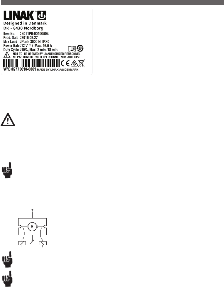
Page 41 of 148
The LA30 is a powerful actuator yet small enough to fit most applications.
The actuator can be supplied with options such as built-in potentiometer for servo
operation or an extra powerful motor for increased speed and strength (S-motor).
In addition to industrial and agricultural applications, the actuator is also ideal for
positioning satellite dishes.
Reed-switch:
The Reed-switch gives a number of pulses for each rotation of the motor. These pulses
are used to calculate the piston rod’s position as well as to control several actuators
running in parallel.
Your nearest LINAK dealer can inform the number of pulses per stroke length.
Regarding Reed-switch connection, see Figure 6.10.
Mechanical spline:
The splines function so that the actuator can only push, not pull.
During pull in the actuator, the inner tube is lifted off the thread bush, and the actuator can therefore never pull a load, only push. See Figure 8.
Functional test of mechanical splines:
When the piston rod is at the innermost position, it must be possible to pull it out manually to its full travel length and to press it in again without
much resistance and without using the motor. If this is not possible, contact your nearest LINAK dealer.
Usage:
• Duty cycle: 10%, 2 minutes continuous use followed by 18 minutes not in use
• Ambient temperature: + 5° to + 40°C
• Storage temperature: - 40° to + 70°C
• Compatibility: CB8, CB12,
• Should the LA30 be used with a non LINAK control unit, please ask the nearest LINAK representative for further details
Warning
Do only use the actuator within specified working limits.
Recommendations
LINAK control boxes are designed so that they will short-circuit the motor terminals (poles) of the actuator(s), when the actuator(s) are not running.
This solution gives the actuator(s) a higher self-locking ability. If the actuator(s) are not connected to a LINAK control box the terminals of the motor
must be short-circuited to achieve the self-locking ability of the actuator.
Improved self-locking ability
When using the LA30 with stereo jack plug be aware of the reversed direction of travel as standard.
The current supply to LINAK actuators must be cut off in case of overload when the actuators reach end position.
Various other information:
Noise levels:
LA30: dB(A) 50; LA30S: dB (A) 55; LA30L: dB(A) 48.
Measuring method DS/EN ISO 3743-1, actuator not loaded.
The H-bridge ensures that the motor is shorted when the relays are incactive.
This is necessary to improve the self-locking of the actuator.
8. LA30 (MEDLINE® CARELINE® TECHLINE®)

Page 42 of 148
The LA31 actuator is a very quiet and powerful actuator designed for a variety of
applications such as furniture, care, or hospital beds. The standard LA31 actuator is
available for both the HOMELINE and CARELINE product ranges.
Reed-switch:
The Reed-switch gives a number of pulses for each rotation of the motor. These pulses
are used to calculate the piston rod’s position as well as to control several actuators
running in parallel.
Your nearest LINAK dealer can inform the number of pulses per stroke length.
Regarding Reed-switch connection, see Figure 6.10.
Usage
• Duty cycle: Max 10% or 2 minutes continuous use followed by 18 minutes not in use.
• Ambient temperature: + 5° to + 40°C
• The CARELINE system has full compliance with EN 60601-1
Hall
The Hall principle is very similar to the Reed principle. A Hall sensor is based on a magnet that rotates. Two hall sensors are placed close to the
magnet field. The control box (CB20/CB6S OBF/CB16 OBF/CBD4/CBD5) can detect whenever the magnetic field changes direction. The two Hall-
sensors are placed close to each other, but with a small displacement. This distance leads to a timing difference between the two pulses. Whichever
one of them comes first indicates the direction of movement. Therefore, there will be no error summary (as with the reed-switch) Hall is therefore a
very precise system. Hall is not suitable for use in quick release actuators. see figure 10.
Built-in end-stop circuit
In the actuators mentioned the end-stop switch is part of the actuator construction. Each time the actuator reaches end-stop position, the switch is
activated and the current is cut off. In addition to the end-stop switch, we also recommend a mechanical end stop function as an additional safety
option for applications where it will be necessary.
Quick Release:
The LA31 with Quick Release is designed to be used as a part of the backrest function in a Care/Hospital bed. The Quick Release function allowes a
patient to be lowered manually to a flat position very quickly (CPR) in case of an emergency.
New version of Quick Release (Internal Quick Release)
The new version of the Quick Release is integrated in the clutch of the LA31. It operates by way of a release cable that is pulled. Hereafter, the
clutch is declutched and the spindle can turn freely. Due to the pressure on the piston rod end from the application, the spindle will rotate thus
moving the actuator inwards. Due to this new version the LA31 actuator can keep its standard installation dimension and has a protection class up
to IPX6 washable.
The Quick Release is e.g. used for emergency lowering of the headrest part of a bed.
External Quick Release
The quick release function is placed in the piston rod end, in which a wrappedspring clutch can be loosened by means of turning the spring housing
either by the handle or a cable. Hereafter, the inner tube can turn freely and due to the pressure on the piston rod end from the application, the
inner tube will rotate and thus screw itself downwards.
Functional test of QR:
To test a LA31QR it is necesarry to have the actuator built into an application. The release cable has to be provided and mounted by the customer.
The necessary force on the cable requiered to operate the Quick release is approx. 5 kg. The minimum actuator load required to drive the actuator
downwards is approx. 50 or 75 kg depending on the type of quick release. When operating the Quick Release, it is recommended that the Quick
Release is activated all the way down.
Mechanical spline:
The splines functions so that the actuator can only push, not pull. During pull in the actuator, the inner tube is lifted off the thread bush, and the
actuator can therefore never pull a load, only push. See figure 8.
Functional test of mechanical splines:
When the piston rod is at the innermost position, it must be possible to pull it out manually to its full travel length and to press it in again without
much resistance and without using the motor. If this is not possible, contact your nearest LINAK dealer.
9. LA31 (MEDLINE® CARELINE® HOMELINE® DESKLINE®)
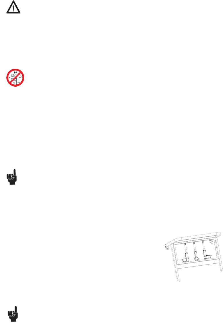
Page 43 of 148
Warning
• If the actuator does not work as described above, the risk of injury due to squeezing can arise. Therefore, the actuator must immediately be sent
for service at the nearest, authorised LINAK workshop.
• The actuator must not be used in pull applications when the Quick Release is activated, as the risk of personal injury can arise.
• Do only use the actuator within specified working limits.
• Bowden cable cover must click twice, in order to be locked sufficiently
• Do not sideload the actuator
• Inspect the actuator minimum once a year for wear and jarring sound
• If an LA31 is used in an application where there are repeated dynamic (push/pull) movements in the area 2000 – 4000 N, then it is necessary to
contact LINAK A/S in order to make a correct specification of the actuator. Repeated push/pull movements cause extra strain to the actuator and
can give safety considerations, the consequence being possible damage to the actuator.
LA31 actuators for patient hoists are marked with a label to ensure the user is aware that it is not permitted to handle the patient hoist
by pulling the actuator or otherwise expose it to side forces.
LA31 with mechanical end stop - a first failure safe option:
In many applications our customers have approvals according to EN 60601-1.
The typical applications can be beds, massage couches etc.
In the norm, EN 60601-1, it is mentioned that the application must be first failure safe.
The manufacturer is responsible for making a risk analysis in order to check this. If a risk is identified it is the manufacturer of the application who
makes sure that the risk is eliminated.
Normally the result of this risk analysis will state that the end stop switch in the LA31 would be questioned: Is this switch first failure safe?
The answer to this will be: No, a switch cannot be first failure safe. - In practical life we have discovered only very few defect switches.
Ask the customer: - What was the result of your risk analysis when you achieved the EN 60601-1 approval on your application?
There are several ways that an application can be made first failure safe:
• Use a mechanical stop in the application
• Use of a mechanical end stop in LA31 - is a possible option.
• Use an SLS (safety limit switch) in connection with the actuator.
• As a special solution we can offer LA31 with mechanical end stop with the same installation dimension as a standard LA31.
Contact LINAK A/S for further information if you need this solution.
Recommendations
• LA31 with brake. An LA31 brake in a push application brakes actively when the actuator moves in an inward direction. The same applies to an
actuator mounted with a brake in a pull direction. It brakes in an outward direction. Under this condition the standard motor uses up to 4 Amp.
and the fast motor uses up to 6 Amp. (Measured after 5 cycles at normal room temperature).
Therefore if the LA31 with brake is used together with a CB7 it is important that the current cut-off limit of the control box is higher than the used
Amp. i.e. not lower than 4 Amp.
LA31 with brake cannot be combined with CB9/CB7 with emergency lowering. For all LA31 actuators with brake self-locking ability up to max.
load it is only possible in one direction: push or pull.
• The LA31 actuator must not be exposed to more than 4000 N in pull. In applications where misalignments may occur the normal back fixture can
take max. 1500 N in pull whereas the flexible back fixture can take up to 4000 N in pull.
The actuator must be mounted at right angles (90º) to it is fixing/load (max.1.5º deviation)
• LA31 actuators with protection class IPX6 must be mounted with the screw holes mounted facing downwards.
To ensure that any water remaining from cleaning / washing is not collected in the screw holes.
Max. load and safety factor of 2.5 according to EN60601-1:
• 6000 N is only possible from S = 0 - 250 mm stroke
• Only max. load of 4000N from S = 250 - 350 mm stroke. See details on later pages.
• Stroke above S> 350 mm is to be treated as a special article, please contact LINAK A/S.
If electrical end stop fails to function the actuator will continue to retract or extend until mechanical end stop is reached.
The application of the customer must be able to obtain or withstand an actuator with failing electrical end stop.
Minimum length of actuator reaching mechanical end stop: nominal BID - 7 mm.
Maximum length of actuator reaching mechanical end stop: nominal BID + nominal SL + increase + 7 mm.
With QR types A and B, when operating the QR function the QR must be activated all the way down. Otherwise the QR will no longer function.
Not OK OK OK
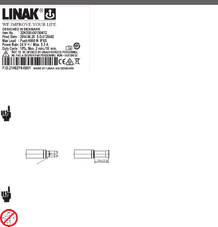
Page 44 of 148
Freewheeling of piston rod
All LA32 actuators with freewheeling as well as with quick release have the designation W on the label.
The function causes the following:
• The piston rod can be pulled out with a thrust of approx. 300 N and it remains in the new position without declutching.
• The actuator cannot pull, but only push.
Functional test:
It must be possible to pull the piston rod out with a thrust of approx. 300 N and it must remain in the new position without releasing. If this is not
possible, contact your nearest LINAK dealer.
Built-in end-stop circuit (CS32)
In the LA32 actuators, with built-in CS32 A-, B- or C-PCB, the actuator is switched off at the end position or when overloaded.
LA32 actuator with:
• The CS32 A is standard IPX1 and is connected to a HB41 handset with a telephone plug.
• The CS32 B is standard IPX5 and is connected to a HB41 handset with a DIN plug. CS32 B is also available in IPX6.
• The CS32 C is standard IPX1 and is connected to an external contact or control. See Figure 6.7.
Usage:
• Duty cycle: Max. 10% or 2 minutes continuous use followed by 18 min. not in use
• Ambient temperature + 5° to + 40° C
• For use with LINAK control boxes CB8, CB12, CB14 and CS16 PCB or internal CS32 PCB
• Should the LA32 be used with a non LINAK control unit, please ask the nearest LINAK representative for further details
• Approvals: IEC 60601-1:2005, 3rd edition, ANSI / AAMI ES60601-1:2005, 3rd edition and CAN / CSA-22.2
No 60601-1:2008 approved
The LA32 actuator is a powerful actuator that can be supplied with a ball screw
spindle to give outstanding performance. The ideal choice for a wide range of
applications including adjustment of hospital beds.
The LA32 actuator has many special options including a safety nut, splines, quick
release (F) and an optional protection up to IPX6 standard.
Reed-switch:
The Reed-switch gives a number of pulses for each rotation of the motor. These pulses
are used to calculate the piston rod’s position as well as to control several actuators
running in parallel.
Your nearest LINAK dealer can inform the number of pulses per stroke length.
Regarding Reed-switch connection, see Figure 6.10.
Protective cap
“Crimped” piston rod eye Piston rod without eye
Recommendations
• As there is friction in the spindle/gear system, a load of 800 N is necessary to start the lowering function with the LA32F.
The actuator will use up to 3.5 Amp. in inward direction unloaded due to a brake system that is fitted as standard on all types of the LA32F.
• Release of the QR is only possible with a Bowden cable release force 25–60 N.
• The piston rod eyes are “crimped” in place and cannot be screwed loose.
• Piston rods without eyes have not been tested
• LA32 with quick release and freewheeling function must not be sold to new products
Maximum load in pull = 2000N
LA32 actuators for patient hoists are marked with a label to ensure the user is aware that it is not permitted to handle the patient hoist
by pulling the actuator or otherwise expose it to side forces.
10. LA32 (MEDLINE® CARELINE®)
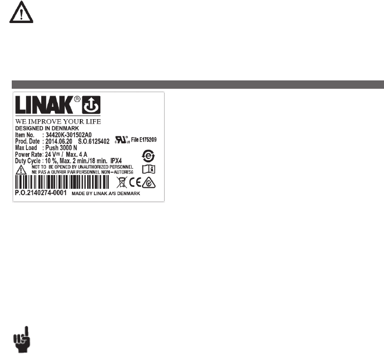
Page 45 of 148
Mechanical spline:
The splines function so that the actuator can only push, not pull. During pull in the actuator, the inner tube is lifted off the thread bush, and the
actuator can therefore never pull a load, only push. See figure 8.
Functional test of mechanical splines:
When the piston rod is at the innermost position, it must be possible to pull it out manually to its full travel length and to press it in again without
much resistance and without using the motor. If this is not possible, contact your nearest LINAK dealer.
Electrical splines:
In the rear fixture on the actuator, a microswitch is fitted, which turns off the motor, if the actuator is exposed to pull forces.
Functional test of electrical splines
When the actuator is correctly fixed/mounted, the inward movement of the piston must stop, when the actuator is pulled or the movement is blocked,
so that the back fixture is not put under undue stress/tension. For mounting, see Figure 7.
Quick release
When the quick release arm, see Figure 9, is turned counter clockwise approx. 75° and fixed here, the piston rod is released and can now be
pressed in to its innermost position or pulled out to its outermost position. When the quick release arm is released, the arm turns back and the
actuator functions normally again. The cable must not be tight.
Warning
• If the actuator does not work as described above, the risk of injury due to squeezing can arise. Therefore, the actuator must immediately be sent
for service at the nearest, authorised LINAK workshop.
• The actuator must not be used in pull applications when the quick release is activated, as the risk of personal injury can arise.
• Do only use the actuator within specified working limits.
Options:
• Mechanical spline: When using the actuator in a vertical position, the force needed to activate the mechanical spline is maximum 60 N + the
weight of the application. To reengage the spline function, a force of maximum 60N is needed. Same installation dim. as standard actuator.
• A modified Bowden cable holder is available (as a special article), with better cable alignment and improved guidance of the cables.
• Electric spline: When using the actuator in a vertical position, the force needed to activate the electric spline is maximum 100 N + the weight
of the application. To reengage the spline function, a force of maximum 100 N is needed.
Usage:
• Duty cycle: 2/18 – 2 minutes continuous use followed by 18 minutes not in use
• Ambient temperature: + 5° to + 40° C
• Compatibility: CB9 with EAS, CB12 with EAS, CB14*, CB18, CB20 and CBJ, CB6 OBL/ F, CB16 OBL/ F,
(* = only possible with customized software)
• Approvals: IEC60601-1:2005 3rd edition, ANSI / AAMI ES60601-1:2005 3rd edition, and CAN / CSA-22.2 No 60601-1:2008
for LA34 24V zinc and composite versions.
LA34 is a technological state-of-the-art actuator that, due to its innovative construction
can push up to 10,000 N at a speed of 5 mm/sec. and with a current consumption of
approx. 7 Amp. The strong LA34 actuator is made in a low weight composite material.
Its compact design, the outstanding performance and a wide range of safety options
makes LA34 the right choice for a variety of medical and industrial applications.
Reed-switch:
The Reed-switch gives a number of pulses for each rotation of the motor. These pulses
are used to calculate the piston rod’s position as well as to control several actuators
running in parallel.
Your nearest LINAK dealer can inform the number of pulses per stroke length.
Regarding Reed-switch connection, see Figure 6.10.
Recommendations
• Power supply without current cut-off can cause serious damage to the actuator if mechanical stop is encountered or the actuator movement is
blocked in another way.
• LINAK control boxes are designed so that they will short-circuit the motor terminals (poles) of the actuator(s) when the actuator(s) are not running.
This solution gives the actuator(s) a higher self-locking ability. If the actuator(s) are not connected to a LINAK control box the terminals of the
motor must be short-circuited to achieve the self-locking ability of the actuator.
11. LA34 (MEDLINE® CARELINE®)
...to be continued

Page 46 of 148
Warning
An LA34 actuator is not designed for repeated dynamic push-to-pull movements. This cause extra strain to the actuator and can give
safety considerations, the consequence being possible damage to the actuator. Therefore, if repeated dynamic push-to-pull movements are
essential for the application, perform tests to validate the performance and use a steel piston rod eye (contact LINAK A/S).
LA34 actuators for patient hoists are marked with a label to ensure the user is aware that it is not permitted to handle the patient
hoist by pulling the actuator or otherwise expose it to side forces.
Tests show that uneven running can occur when retracting the LA34 composite actuator with a low load below 500N.
This has no impact on the safety of the actuator and is caused by internal frictions.
If the LA34 actuator is used in connection with a non-LINAK power supply the system must be equipped with current trip cut-off.
Adjustment of the installation dimension N
As standard the installation dimension on the LA34 actuator can be manually adjusted by +4/-0 mm (not possible for mechanical splines).
The adjustment of the installation dimension must only be made without use of tools only, or hand). It is not allowed to use tools to adjust the
installation dimension of the LA34 actuator as there is a risk that the inner tube may be unscrewed.
Hall
The Hall principle is very similar to the Reed principle. It is a control box, which based on Hall signals, can decide whether the actuator runs out or in.
Hall, however, can detect whether the actuator runs in or out. The number of pulses is like Reed. Hall and Reed are placed opposite the potentiometer
on the actuator’s worm wheel. Therefore, it is not suitable for use in quick release /free wheelingactuators. see figure 10.
Potentiometer
The potentiometer function is mechanically attached to the spindle and registers the number of spindle revolutions. The signal from the potentiometer
is measured in Ohm, where the lowest value is measured when the actuator has been run into inward switch stop. The potentiometer is a 10-turn
and therefore it is dependent on the stroke length/spindle pitch. see figure 6.5
Mechanical spline:
The splines function so that the actuator can only push, not pull. During pull in the actuator, the inner tube is lifted off the thread bush, and the
actuator can therefore never pull a load, only push. See Figure 8.
Functional test of mechanical splines:
When the piston rod is at the innermost position, it must be possible to pull it out manually to its full travel length and to press it in again. When
used in a vertical position the force needed to activate the mechanical spline is maximum 60N + the weight of the application. To reengage the
spline function, a force of maximum 60 N is needed. If this is not possible, contact your nearest LINAK dealer.
Electrical splines:
In the rear fixture on the actuator, a microswitch is fitted, which turns off the motor, if the actuator is exposed to pull forces.
Functional test of electrical splines
It is important that the actuator is correctly fixed with regard to the section on page 11. For mounting, see Figure 7.
When the actuator is correctly fixed/mounted, the inward movement of the piston must stop, when the actuator is pulled or the movement is blocked,
so that the back fixture is not put under undue stress/tension.
Quick Release
LA34 (34xxxF/H) is equipped with a function which permits operation of the actuator should the power source fail. Condition for functioning: the
actuator must be loaded in push direction (LA34xxxF) or pull direction (LA34xxxsH).
Warning
• If the actuator does not work as described above, the risk of injury due to squeezing can arise. Therefore, the actuator must be sent immediately
for service at the nearest, authorised LINAK workshop.
• The actuator must not be used in pull applications when the Quick Release is activated, as the risk of personal injury can arise.
• Do only use the actuator within specified working limits.
Activation of Quick Release
Pull the release handle in the direction of the piston rod eye (outwards), the harder you pull the button the quicker the actuator runs down.
When releasing the button the emergency lowering stops immediately. The emergency lowering is activated as long as the load on the actuator is
above 100-150 kg. The actuator is ready for normal use when the emergency lowering is finished.
Safety device regarding functional failure of the nut (Safety nut):
The LA34 has a built-in safety nut in push as standard and is available with a safety nut in pull as an option. Actuators with safety nut in push can
only function when used in push applications. The safety nut comes into operation should the main nut fail.
Afterwards it is only possible to drive the actuator into the innermost position. Safety nut in pull is for pull applications and works the opposite way
as described above. Thereafter, the actuator will not function any more and must be sent for service.
Built-in end-stop circuit
In the actuators mentioned the end-stop switch is part of the actuator construction. Each time the actuator reaches end-stop position, the switch is
activated and the current is cut off.
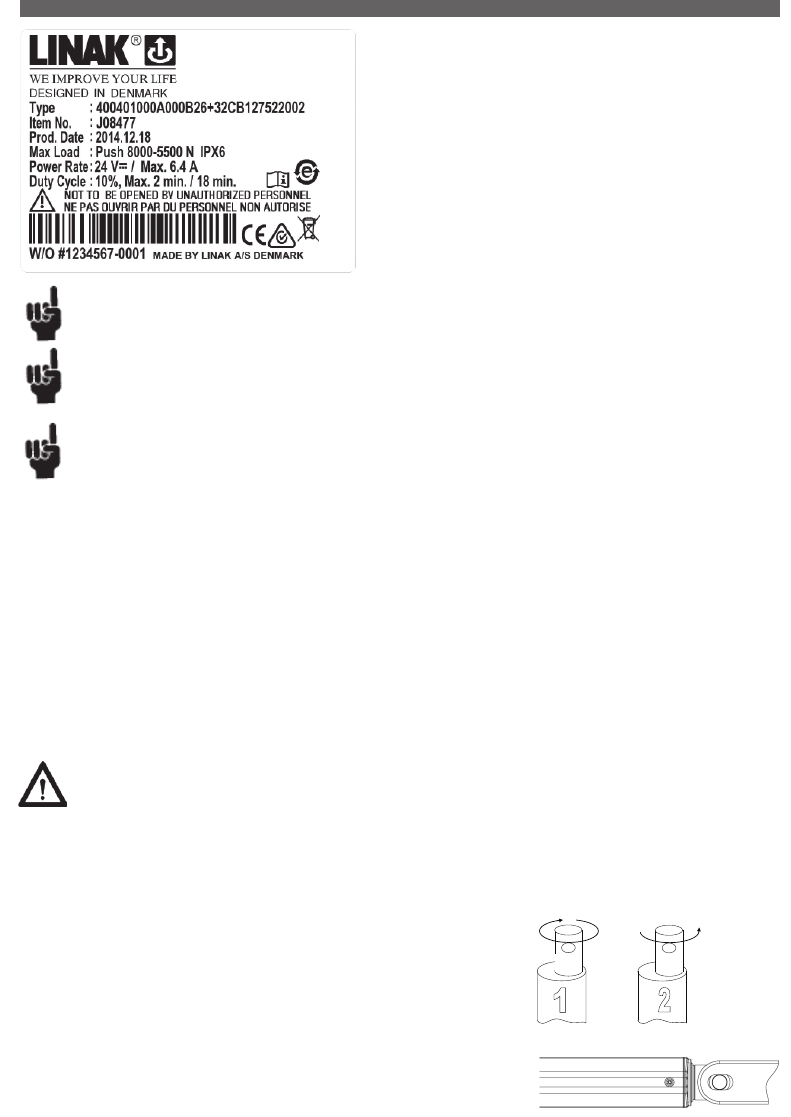
Page 47 of 148
Recommendations
• Power supply without current cut-off can cause serious damage to the actuator if a mechanical stop is encountered or the actuator movement is
blocked in another way.
• Connection bolts must be dimensioned so that they have the necessary strength and tolerance in order to obtain the minimum safety factor
according to the require- ments of the authorities.
• The actuator must not be subject to a side load, as this can cause bending/collapse of the actuator. The actuator must never be used as a handle.
• The actuator must not be subject to off-centre loading, as this can cause bending/ collapse of the actuator.
• The actuator must not be subject to impact, or any form of stress to the casing.
• The actuator must not be subject to overload, as this can reduce the lifetime of the actuator and in the worst case cause damage to the actuator.
• The actuator must never be used in dynamic pull applications, as this can cause collapse.
• Only use the actuator within the specifications.
• Connection bolts and brackets are to be inspected in connection with service, and must be replaced if there are signs of wear.
• Ensure that the cable lock is mounted correctly.
• Ensure that the duty cycle and the usage temperatures for LA40 actuators are respected.
• Ensure that the cable cannot be squeezed, pulled or subjected to any other stress.
• The LA40 is not suitable for use in outdoor applications where it can be exposed to sun and rain.
The LA40 is a low noise and powerful actuator which is available in a 1500N,
4000N, 6000N and an 8000N version. Based on the extensive knowledge and
experience from previous actuator families, LINAK has developed new gear and
braking principles that improve the efficiency of the new LA40. These innovative
solutions are covered by several patents.
Usage:
• Duty cycle: 10 %, 2 minutes continuous use, followed by 18 minutes not in use
• Usage temperature: 5 oC to 40 oC
• Compatibility: CBHA220A software 30002001 version 1.08
In combination with TD4 software version 30002001, Version 1.21
• Relative humidity: 20 % to 90 % @ 30 oC - not condensing
• Atmospheric pressure: 700 to 1060 hPa
• Approvals: Will be approved according to EN60335-1
Please note that extension of the built-in dimension may reduce the safety factor.
If electrical endstop fails to function the actuator will continue to retract or extend until mechanical endstop is reached.
The application of the customer must be able to obtain or withstand an actuator with failing electrical endstop.
Minimum length of actuator reaching mechanical endstop: BID - 7 mm.
Maximum length of actuator reaching mechanical endstop: BID + SL + 7 mm.
12. LA40 (HOMELINE® )
Warning
• The installation of spline actuators is recommended by LINAK where possible to avoid the squeezing of body parts.
• End of life issue: defective switches - endstop:
If the electrical endstop switch for outward operation fails, it may cause a prolonged actuator stroke and in addition the customer application
may collapse. To avoid this, the manufacturer must take this into account when designing and making a risk analysis.
Instruction concerning the turning of the piston rod eye
When mounting and taking into use, it is not permitted to turn the piston rod eye several times.
In cases where the eye is not positioned correctly, the eye must be screwed to its bottom position
(1) and then maximum half a turn outwards again (2).
Mounting bracket instructions
To avoid damage to the actuator, it is important that the acutator drives to the application endstop
position and continues to operate in the groove until it activates the electric actuator endstop.
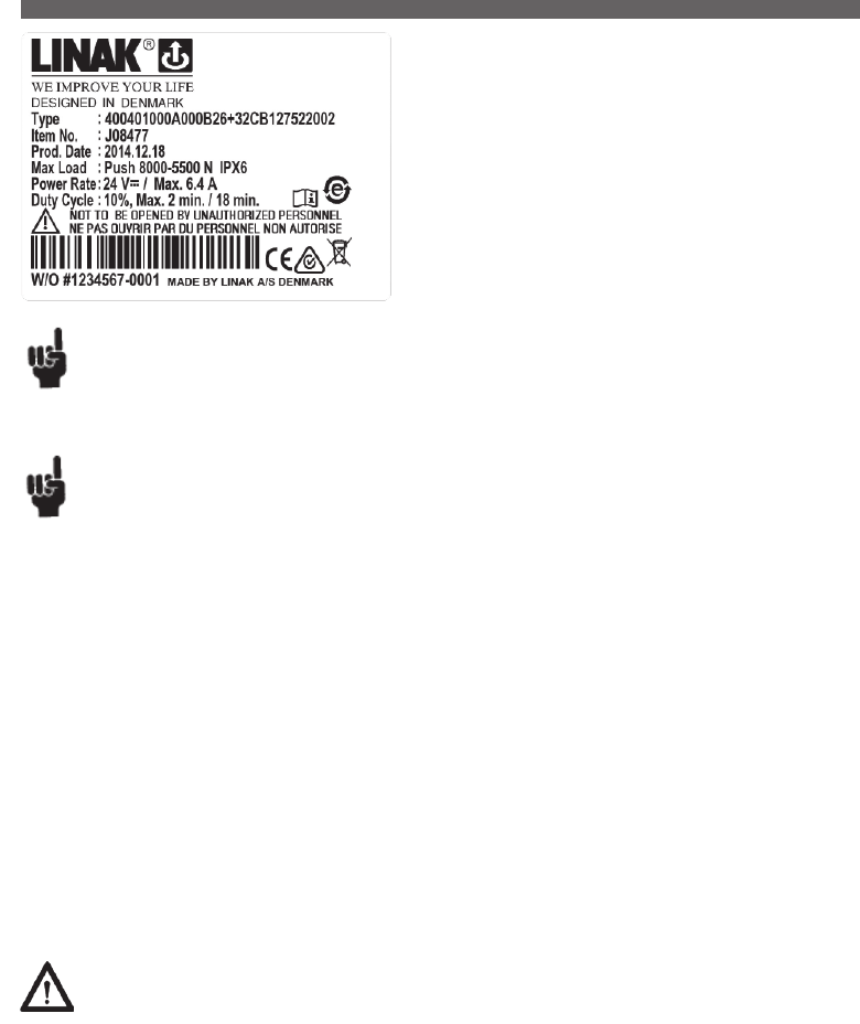
Page 48 of 148
Recommendations
• Power supply without current cut-off can cause serious damage to the actuator if a mechanical stop is encountered or the actuator movement is
blocked in another way.
• Connection bolts must be dimensioned so that they have the necessary strength and tolerance in order to obtain the minimum safety factor
according to the requirements of the authorities.
• The actuator must not be subject to a side load, as this can cause bending/collapse of the actuator. The actuator must never be used as a handle.
• The actuator must not be subject to off centre loading, as this can cause bending/collapse of the actuator.
• The actuator must not be subject to impact, or any form of stress to the casing.
• The actuator must not be subject to overload, as this can reduce the lifetime of the actuator and in the worst case cause damage to the actuator.
• The actuator must never be used in dynamic pull applications, as this can cause collapse.
• Only use the actuator within the specifications.
• Connection bolts and brackets are to be inspected in connection with service, and must be replaced if there are signs of wear.
• Ensure that the cable lock is mounted correctly.
• Ensure that the duty cycle and the usage temperatures for LA40 actuators is respected.
• Ensure that the cable cannot be squeezed, pulled or subjected to any other stress.
• The LA40 is not suitable for use in outdoor applications where it can be exposed to sun and rain.
• LA40 with mechanical endstop - a first failure safe option:
In many applications customers have approvals in accordance with EN 60601-1. The typical applications are beds, massage couches etc.
The norm EN 60601-1 states that the application must be first failure safe.
The manufacturer has the responsibility of carrying out a risk analysis in order to check this. If a risk is identified, the application manufacturer
must ensure that this risk is eliminated. A switch cannot be first failure safe.
The LA40 is a low noise and powerful actuator which is available in a 1500N,
4000N, 6000N and an 8000N version. Based on the extensive knowledge and
experience from previous actuator families, LINAK has developed new gear and
braking principles that improve the efficiency of the new LA40. These innovative
solutions are covered by several patents.
Usage:
• Duty cycle: 10 %, 2 minutes continuous use, followed by 18 minutes not in use
• Usage temperature: 5 oC to 40 oC
• Storage temperature: -10 oC to 50 oC
• Relative humidity: 20 % to 90 % @ 30 oC - not condensing
• Atmospheric pressure: 700 to 1060 hPa
• Approvals: IEC60601-1, 3rd edition, ANSI, AAMI ES60601-1:2008, 3rd edition,
and CAN / CSA 22.2 No 60601-1:2008, ND (National Deciation, AU/NZ)
If electrical endstop fails to function the actuator will continue to retract or extend until mechanical endstop is reached.
The application of the customer must be able to obtain or withstand an actuator with failing electrical endstop.
Minimum length of actuator reaching mechanical endstop: BID - 7 mm.
Maximum length of actuator reaching mechanical endstop: BID + SL + 7 mm.
Warning
• If the actuator does not work as described above, the risk of injury due to squeezing can arise. Therefore, the actuator must immediately be sent
for service at the nearest, authorised LINAK workshop.
• The installation of spline actuators is recommended by LINAK where possible to avoid the squeezing of body parts.
• Activation of a quick release can lead to a risk of squeezing body parts. Installation of a damper may reduce this risk.
• A quick release can accidentally be activated during mounting or maintenance. To avoid this, operators must be warned before service/mounting.
• End of life issue: defective switches - endstop:
If the electrical endstop switch for outward operation fails, it may cause a prolonged actuator stroke and in addition the customer application may
collapse. To avoid this, the manufacturer must take this into account when designing and making a risk analysis.
13. LA40 (MEDLINE® CARELINE® )
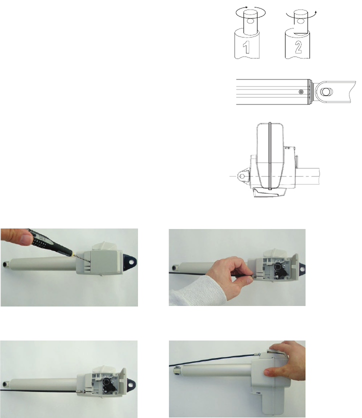
Page 49 of 148
Instruction concerning the turning of the piston rod eye
When mounting and taking into use, it is not permitted to turn the piston rod eye several times.
In cases where the eye is not positioned correctly, the eye must be screwed to its bottom position
(1) and then maximum half a turn outwards again (2).
Mounting of the quick release cable:
Open the quick release lid using a flat-head
screwdriver. Push and twist in release hole.
Mount the cable in one of the assigned cable mounting
holes. For dual release grips, use both holes.
Place cable collar in groove.
Adjust the cable with nut and make sure that the
quick release is functional.
After closing the lid, the quick release is ready to
be used.
Force required to operate the quick release is approximately:
- 35 N at 750 N load
- 60 N at 4000 N load
Travel of cable:
- travel until quick release approx. 15 mm
- maximum travel to endstop approx. 23 mm
The customer application design must ensure that the quick release cable cannot be pulled the full travel-to-end-stop with excessive pull force.
This is to protect the quick release unit.
When operating the quick release function, the quick release must be activated all the way down and not stopped halfway.
Mounting bracket instructions
To avoid damage to the actuator, it is important that the acutator drives to the application endstop
position and continues to operate in the groove until it activates the electric actuator endstop.
To avoid accumulated water inside the quick release lid (see illustration to the right) it is
recommended not to mount the LA40 quick release actuator with the lid in downward position.
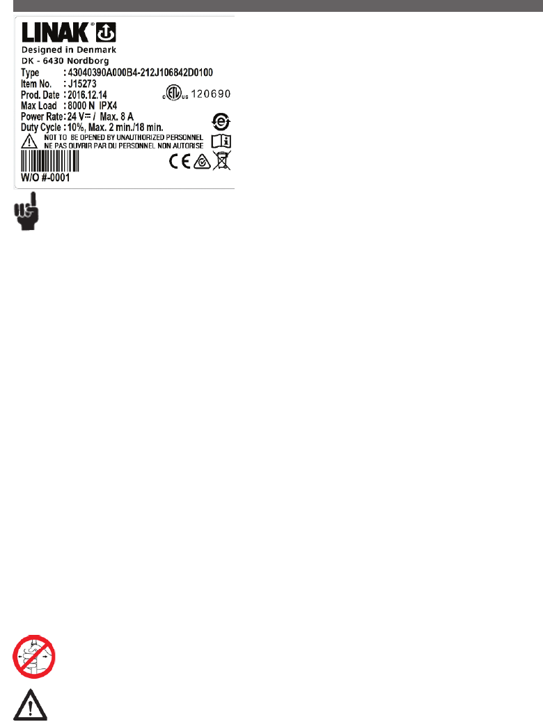
Page 50 of 148
The LA43 is available in a powerful 8,000N version, ensuring safe patient handling.
With the LA43 actuator, LINAK offers a product, which with its wide range of safety
options, low noise level, and outstanding performance is the right choice for medical
applications such as patient lifts, beds, dental chairs etc.
Usage:
• Duty cycle: 10%, 2 minutes continuous use followed by 18 minutes
not in use
• Usage temperature: +5ºC to +40ºC
• Storage temperature: - 10ºC to + 50ºC
• Compatibility: CBJ1/2, CBJ-Home, CBJ-Care, CB6S, CB16, CB20
• Approvals: IEC60601-1:2005 3rd edition
Recommendations
• The actuator is not suitable for outdoor applications
• Power supply without current cut-off can cause serious damage to the actuator if a mechanical stop is encountered or the actuator movement is
blocked in another way.
• If there is a risk of “pull forces” in the application, the actuator must be equipped with electrical spline to avoid damage in pull.
• If the actuator is operated without load (e.g. loose on a table) the electrical spline can activate and the actuator cannot run in an inwards direction.
Push the back fixture and the actuator can be operated again.
• Connection bolts must be dimensioned so that they have the necessary strength in order to obtain the minimum safety factor according to the
requirements of the authorities.
• The actuator must not be subject to a side load, as this can cause bending. It is also for this reason that the actuator should not be used as a handle,
e.g pulling a patient hoist sideways.
• The actuator must not be subject to off centre loading, as this can damage the actuator.
• The actuator must not be subject to impact, or any form of stress to the casing.
• The actuator must not be subject to overload, as this can reduce the lifetime of the actutor and in the worst case cause damage to the actuator.
• The actuator must not be used in pull applications, as this can cause collapse.
• Only use the actuator within the specified working limits.
• It is recommended that the actuator is serviced according to the relevant national norms for the applications in which the actuator is used.
• Connection bolts and brackets are to be inspected in connection with service, and must be replaced if there are signs of wear.
• The safety function: Electrical Spline, should be checked in connection with service. The function is checked by applying a straight pull, of max. 100 N,
to the back fixture. The actuator must not be able to run in an inward direction. Hereafter press the back fixture against the housing and the actuator
can run in an inward direction.
• The actuator should be cleaned regularly, in order to maintain a good hygiene.
• The application must be tested for correct functionality before putting it back into operation.
• Do not step or kick on the actuator as it may damage the housing or the motor.
Patient Lifts and Stand Aids:
• Long installation dimension: Must always be used for patient lifts.
• Do not hold the inner or outer tube while the actuator is running. There can be a risk of squeezing between the Manual Lowering unit and the
outer tube.
• Do always use the electrical spline function for patient lifts
LA43 actuators for patient hoists are marked with a label to ensure the user is aware that it is not permitted to handle the patient hoist
by pulling the actuator or otherwise expose it to side forces.
Warnings
It is not allowed to use tools to adjust the installation dimension of the LA43 actuator as there is a risk that the inner tube may be
unscrewed.
Self-locking ability
• LINAK control boxes are designed so that they will short-circuit the motor terminals (poles) of the actuator(s), when the actuator(s) are not
running. This solution gives the actuator(s) a higher self-locking ability. If the actuator(s) are not connected to a LINAK control box, the terminals of
the motor must be short-circuited to achieve the self-locking ability of the actuator.
14. LA43 (MEDLINE® CARELINE® )
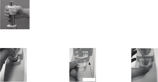
Page 51 of 148
Fig. 1. Manual Lowering
In case of a power failure it is possible to mechanically lower a patient placed in a patient hoist. When turning the manual
lowering handle clockwise the actuator can be moved fully inwards.
Manual lowering:
The following pictures illustrate the manual lowering procedure.
Fitting the plug/smart cable lock
The following pictures illustrate how to fit the plug connection using the smart cable lock manual lowering procedure.
Step 1:
Insert the cable in the socket.
Make sure the O-ring on the
cable is fully inserted..
Step 2:
Attach the cable lock.
Make sure the inclined
surface is facing upwards.
Fig. 2
Step 3:
Push the cable lock inside the slot.
If necessary, the cable can be pushed down at
the same time to ease the cable lock mounting.
Fig. 3Fig. 1
Inclined surface

Page 52 of 148
The LA43 Intelligent Control (IC) enables a simple system consisting of 1 or 2
actuators, a Switch Mode Power Supply and a hand control or a footswitch.
The system is for example an advantage when there is no space for a control box.
Usage:
• Duty cycle: 10%, 2 minutes continuous use followed by 18 minutes not in use
• Usage temperature: + 5º C to + 40º C
• Storage temperature: -10º C to + 50º C
• Compatibility: SMPS30
• Approvals: IEC60601-1:2005 3rd edition
Recommendations
• The actuator is not suitable for outdoor applications
• If there is a risk of “pull forces” in the application, the actuator must be equipped with electrical spline to avoid damage in pull.
• If the actuator is operated without load (e.g. loose on a table) the electrical spline can activate and the actuator cannot run in an inwards direction.
Push the back fixture and the actuator can be operated again.
• Connection bolts must be dimensioned so that they have the necessary strength in order to obtain the minimum safety factor according to the
requirements of the authorities.
• The actuator must not be subject to a side load, as this can cause bending. It is also for this reason that the actuator should not be used as a handle,
e.g pulling a patient hoist sideways.
• The actuator must not be subject to off centre loading, as this can damage the actuator.
• The actuator must not be subject to impact, or any form of stress to the casing.
• The actuator must not be subject to overload, as this can reduce the lifetime of the actutor and in the worst case cause damage to the actuator.
• The actuator must not be used in pull applications, as this can cause collapse.
• Only use the actuator within the specified working limits.
• It is recommended that the actuator is serviced according to the relevant national norms for the applications in which the actuator is used.
• Connection bolts and brackets are to be inspected in connection with service, and must be replaced if there are signs of wear.
The safety function: Electrical Spline, should be checked in connection with service.
The function is checked by applying a straight pull of max. 100 N to the piston rod.
The actuator must not be able to run in an inward direction.
Hereafter press the piston rod and the actuator can run in an inward direction.
• The actuator should be cleaned regularly, in order to maintain a good hygiene.
• The application must be tested for correct functionality before putting it back into operation.
• Do not step or kick on the actuator as it may damage the housing or the motor.
Safety concept:
The user is a part of the safety concept. A light on the SMPS30 is green when a button on the handset is not activated. When a switch is activated the
light changes to orange. Orange indicates that power request is on.
When the light is orange and a button is not activated there is a fault on the system. And the user must call for service.
15. LA43 IC (MEDLINE® CARELINE® )
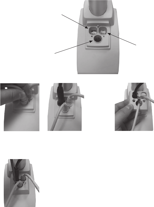
Page 53 of 148
Cable connections:
Handset / FS connection,
10-pole modular jack /
6-wire standard cable.
Second actuator connection,
6-pole minifit plug or blind plug
SMPS connection,
4-pole minifit plug
Step 1:
Insert the cables in the sockets.
Make sure the O-rings on the cables are fully inserted.
Cable connection and cable lock:
Tighten the two screws with approx. 0.4 Nm torque to secure the cable lock. Cable lock and screws to be ordered separately.
Step 2:
Insert the cables into the cable lock.
Make sure that the correct cables are placed
in the corresponding holes.
Step 3:
Attach the cable lock and secure it with screws.
The tightening torque should be 0.4 Nm.
Fig. 2
Fig. 3
Fig. 1
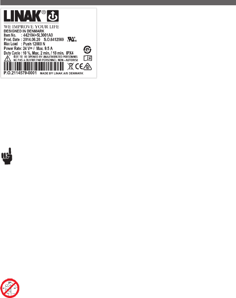
Page 54 of 148
Self-locking ability.
• LINAK control boxes are designed so that they will short-circuit the motor terminals (poles) of the actuator(s), when the actuator(s) are not running.
This solution gives the actuator(s) a higher self-locking ability. If the actuator(s) are not connected to a LINAK control box, the terminals of the motor
must be short-circuited to achieve the selflocking ability of the actuator.
The LA44 is available in powerful 10,000 N and 12,000 N versions, ensuring safe
patient handling.
With the LA44 actuator, LINAK offers a product, which with its wide range of safety
options, low noise level, and outstanding performance is the right choice for medical
applications such as patient lifts, beds, dental chairs etc.
Usage:
• Electrical spline functionality: Electrical spline; can be combined with manual lowering. The Electrical-spline switch is mounted inside LA44.
It activates on a pulling movement of the slightly moveable back fixture. When using the actuator in a vertical
position, the force needed to activate the electric spline is maximum 100 N + the weight of the application.
To reengage the spline function, a force of maximum 100 N is needed.
• Mechanical spline functionality: When using the actuator in a vertical position, the force needed to activate the mechanical spline is maximum
60 N + the weight of the application. To reengage the spline function, a force of maximum 60 N is needed.
• Duty cycle: 10%, 2 minutes continuous use followed by 18 minutes not in use
• Usage temperature: 5ºC to 40ºC
• Storage temperature: - 10ºC to + 50ºC
• Compatibility: CBJ1/2, CBJ-Home, CBJ-Care, CB6s, CB16, CB20
• Approvals: IEC60601-1:2005 3rd edition, ANSI, AAMI ES60601-1:2005, 3rd edition, and CAN / CSA 22.2 No 60601-1:2008.
Recommendations:
• The actuator is not suitable for outdoor applications
• Power supply without current cut-off can cause serious damage to the actuator if a mechanical stop is encountered or the actuator movement is
blocked in another way.
• If there is a risk of “pull forces” in the application, the actuator must be equipped with mechanical or electrical spline to avoid damage in pull.
• If the actuator is operated without load (e.g. loose on a table) the electrical spline can activate and the actuator cannot run in an inwards
direction. Push the back fixture and the actuator can be operated again.
• Connection bolts must be dimensioned so that they have the necessary strength in order to obtain the minimum safety factor according to the
requirements of the authorities.
• The actuator must not be subject to a side load, as this can cause bending. It is also for this reason that the actuator should not be used as a
handle, e.g pulling a patient hoist sideways.
• The actuator must not be subject to off centre loading, as this can damage the actuator.
• The actuator must not be subject to impact, or any form of stress to the casing.
• The actuator must not be subject to overload, as this can reduce the lifetime of the actutor and in the worst case cause damage to the actuator.
• The actuator must not be used in pull applications, as this can cause collapse.
• Only use the actuator within the specified working limits.
• It is recommended that the actuator is serviced according to the relevant national norms for the applications in which the actuator is used.
• Connection bolts and brackets are to be inspected in connection with service, and must be replaced if there are signs of wear.
• The safety function: Electrical Spline, should be checked in connection with service.
The function is checked by applying a straight pull, of max. 100 N, to the back fixture. The actuator must not be able to run in an inward direction.
Hereafter press the back fixture against the housing and the actuator can run in an inward direction.
• The actuator should be cleaned regularly, in order to maintain a good hygiene.
LA44 actuators for patient hoists are marked with a label to ensure the user is aware that it is not permitted to handle the patient
hoist by pulling the actuator or otherwise expose it to side forces.
16. LA44 (MEDLINE® CARELINE® )
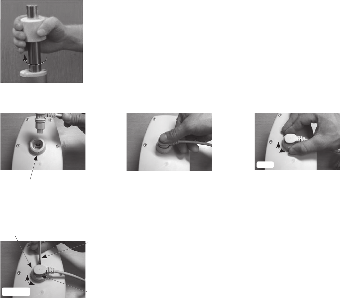
Page 55 of 148
Unlocking the plug/smart cable lock
Using a tool, release the lock (must be from the side shown) by pushing the tap
(through the small slot in the side of the lock).
At the same time, turn the lock 90º in either direction to release the plug connection.
Flanges in locked position
Fig. 1
Press here with tool
No tap on this side
Turn to open
Fitting the plug/smart cable lock
Step 1:
The three flanges in this position
indicate that the “smart cable locking”
device is in the unlocked position.
Step 2:
Position and press the cable plug
into the socket.
Fig. 2
Step 3:
Hold around the lock flanges and turn the lock
either clockwise or anticlockwise.The cable is
fully locked when turned 90°.
Turn 90°
Fig. 3Fig. 1
Fig. 1. Manual Lowering
In case of a power failure it is possible to mechanically lower a patient placed in a patient hoist.
When turning the manual lowering handle clockwise the actuator can be moved fully inwards.
Manual lowering:
The following pictures illustrate a) The manual lowering procedure and
b) How to fit and remove the plug connection using the “Smart cable lock”
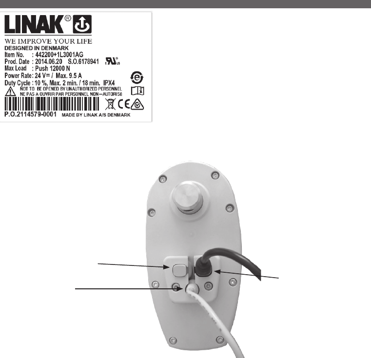
Page 56 of 148
The LA44 Intelligent Control (IC) enables a simple system consisting of 1 or 2 actuators, a
Switch Mode Power Supply and a hand control or footswitch.
The system is for example an advantage when there is no space for a control box.
Usage:
• Duty cycle: 10%, 2 minutes continuous use followed by 18 minutes
not in use
• Usage temperature: + 5º C to + 40º C
• Storage temperature: -10º C to + 50º C
• Compatibility: SMPS30
• Approvals: IEC60601-1:2005 3rd edition, ANSI / AAMI ES60601-
1:2005 3rd edition pending
Cable connections:
Handset / FS connection,
10-pole modular jack /
5 wire standard cable.
SMPS connection,
4-pole minifit plug.
Blind plug or second actuator
connection, 6-pole minifit plug.
Cable connection and cable lock
Tighten the two screws with approx.1.5 Nm torque, to secure the cable lock.
Precautions, Recommendations and Warnings - please see LA44 user manual
17. LA44 IC (MEDLINE® CARELINE® )
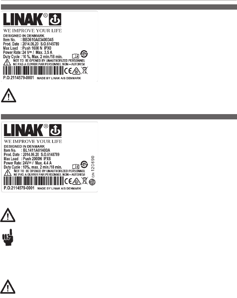
Page 57 of 148
4. Information on specific columns
The BB3 3-part telescopic actuator is the ideal choice for vertical lift of beds where
design and easy integration in the customer’s guidance ensures optimum freedom of
design.
The BB3 is a 3-part telescopic actuator designed to meet EN 1970 for care beds, which
demands an adjustment range from 350 mm up to 750 mm.
Reed-switch:
The Reed-switch gives a number of pulses for each rotation of the motor. These pulses
are used to calculate the piston rod’s position as well as to control several actuators
running in parallel.
Your nearest LINAK dealer can inform you of the number of pulses per stroke length.
Regarding reed-switch connection, see Figure 6.10.
• The columns must be securely mounted before operation, no rotation must be possible
• The motor housing must be mounted uppermost.
Warning
Do only use the column within specified working limits.
The BL1 is a 3-part lifting column designed to be used for example in Hospital beds,
Nursing Home beds, Treatment chairs, Couches and Dental chairs.
The lifting column is compact and has a long stroke length. The 3-part guidance
enables an overlap between the individual profiles, which ensures a high degree of
stability.
The lifting column has an open spindle actuator with a chain drive inside which is
practically noiseless.
Important:
If the actuator(s) are not connected to a LINAK control box, the terminals of the motor must be short circuited to guarantee the self-
locking ability of the actuator.
Usage:
• Duty cycle: 10%, 2 minutes continuous use followed by 18 minutes
not in use
• Usage temperature: + 5°C to + 40°C
• Storage temperature: Max 50°C
• Compatibility: CB6 OBL, CB6 OBF, CB16 and CB20
• Approvals: IEC60601-1:2005 3rd ed., ANSI / AAMI ES60601-1:2005,
3rd edition, CAN / CSA-22.2 No 60601-1:2008
Recommendations
• Please follow the important BL1 mounting guidelines.
• Max. storage temperatures: +50°C.
• BL1 is for use in push applications, cable outlet from smallest profile (top) or biggest profile (bottom). See top and bottom plate dimensions.
• When washing according to IPX6 parameters, it is not allowed to splash water directly onto the plastic frames between the profiles.
Direct splashing is only permitted on the aluminium profiles.
...to be continued
Warnings
• BL1 is heavy (9.8 kg) To avoid personal injury, DO NOT DROP !
• Do not adjust anything during movement, can cause personal injury !
• LINAK recommends using a safety nut in medical applications !
• A broken chain causes a drop of half the length of actual stroke. Therefore do not overload !
• The BL1 is designed for use in push applications, dynamic “Pull forces” can result in damage to the column and cause collapse of the application.
• Do not loosen any screws on the BL1, this can cause collapse of the column !
• LINAK recommends making regular measurement of Class 1 protective ground conductivity in the application to avoid a disconnected grounding cable.
Worn out or defect parts must be replaced.
1. BB3 (MEDLINE® CARELINE®)
2. BL1 (MEDLINE® CARELINE® TECHLINE®)
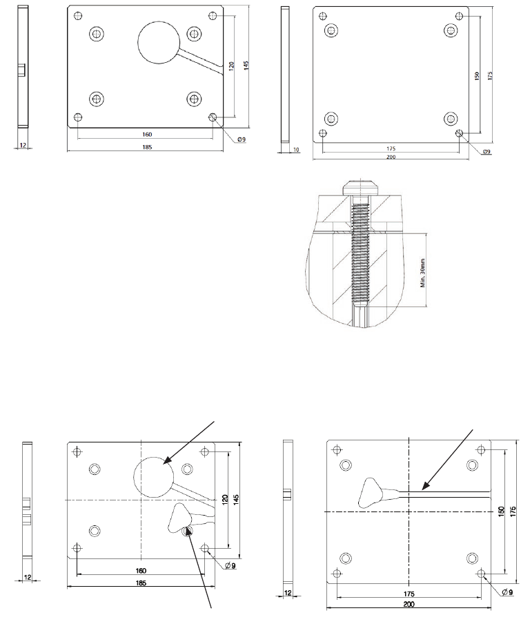
Page 58 of 148
BL1 end plate kit without cable through:
Top plate dimensions: Bottom plate dimensions:
BL1 end plate kit with cable through:
Top plate dimensions: Bottom plate dimensions:
Motor cable
Hand control cable
Hand control cable
Please notice the thickness of the bottom plate is 12 mm. The thickness of the bottom plate without connections is 10 mm.
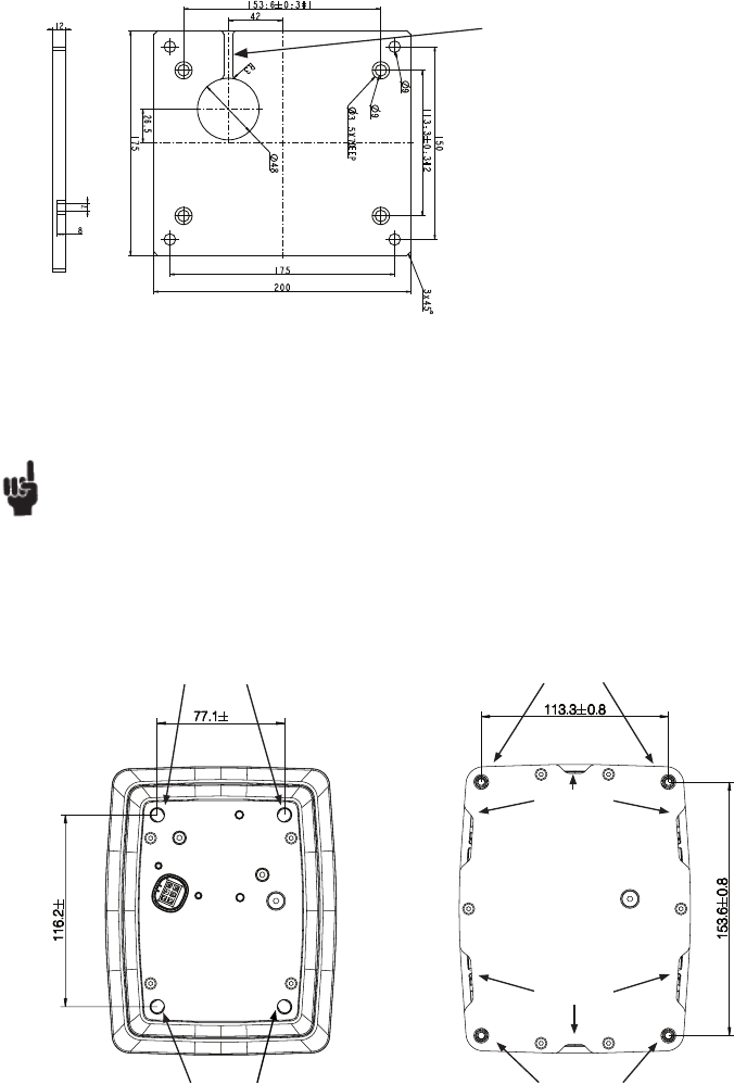
Page 59 of 148
Bottom plate dimensions:
Motor cable
Drawing no.: 0801263-A
BL1 Mounting guidelines:
• BL1 is for use in push applications, and can be mounted in both directions (smallest profile down, or up).
Note: The cable outlet can be positioned at the top (smallest profile). If the option with integrated cable is chosen, the cable outlet can
also be positioned at the bottom (biggest profile).
• It is very simple to mount the BL1 in the application using the 4 mounting holes in both endplates.
• Use 4 self-tapping screws, in each end, for mounting to the application. Use EJOT PT type DG Ø8, screw depth must be min. 30 mm in
aluminium profile. Screw torque: 15 - 17 Nm.
• If the column has been loosened from the application, it is very important that the self-tapping screws are mounted in the same thread,
to ensure the same strength in the thread. Therefore we recommend that the screws are loosened no more than 1 or 2 times.
Drawing no.: 0807000-1
0.6
0.8
Mounting holes
Mounting holes Mounting holes
Drain hole
Mounting holes
Drain hole
Drawing no.: 0807000-1
...to be continued
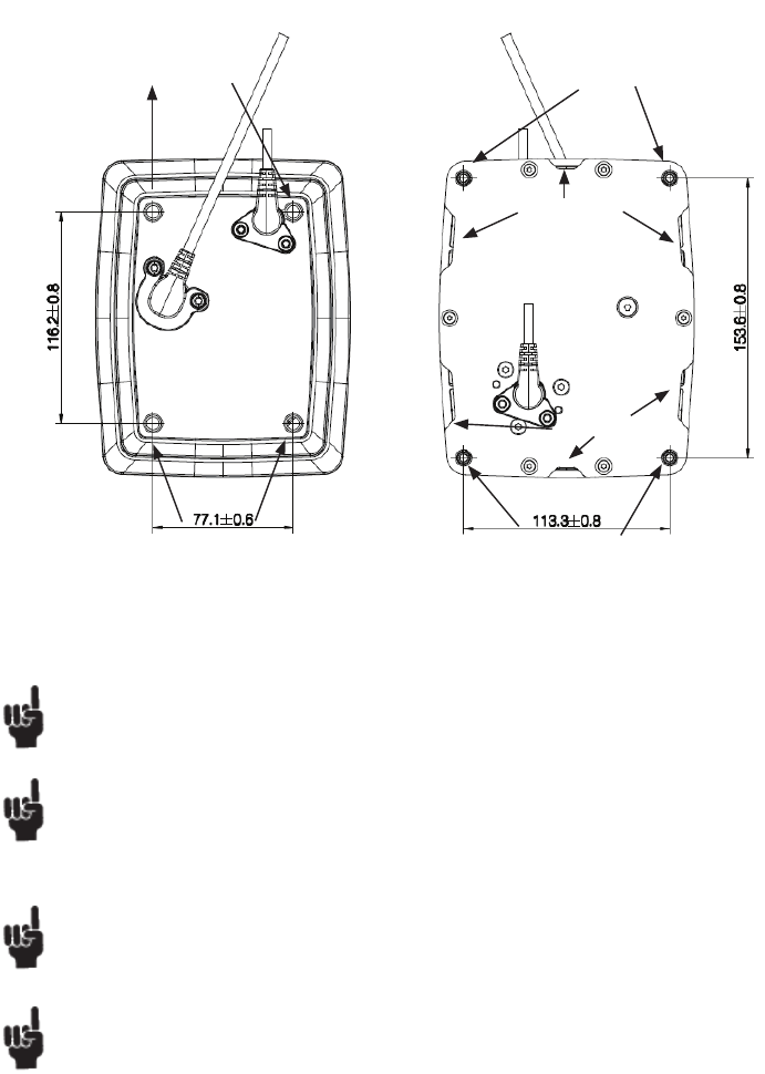
Page 60 of 148
The mounting plate in the application must cover the entire top plate of the BL1 and be strong enough to carry the load.
Remember to secure the cable mounted in the top of the column to the application, so that it cannot be pulled out of the column.
We recommend to use LINAK Cable:
• Lock kit for BL1 with motor cable: 0808040
• Lock kit for BL1 with hand control cable through: 0808046
Use only the screws included in the kit. Screw torque: 2.7 Nm.
Electro Static Discharges!
There is no electrical connection through the length of the BL1 column. Therefore, to avoid ESD issues, consider external potential
alignment between the top and bottom of the bed frame.
To connect for further earth wiring in the application, use an appropriate ø8mm cable shoe under one of the 8mm screws at both the top
plate and the bottom plate.
Remember to mount the blind plugs in the top plate if the motor cable is connected from the bottom plate to ensure the IPX6 protection.
Mounting of BL1 with cable through:
Mounting holes Mounting holes
Mounting holes
Mounting holes
Drain hole
Drain hole
Drawing no.: 0807001-1
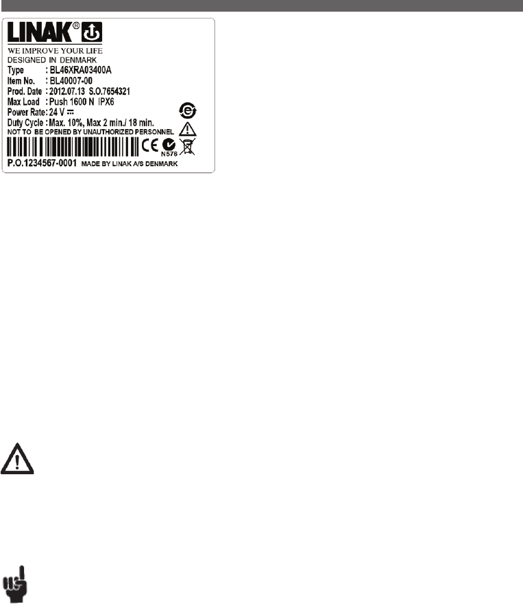
Page 61 of 148
The BL4 is a 4-part lifting column specially designed for hospital and care beds; the
BL4 can of course be used for other applications where a compact lifting column with
a long stroke length is needed.
The lifting column is based on the BB3 actuator, which is practically noiseless. The
specifications comply with the demands to the lifting functions in beds as to load,
speed and stroke length.
Reed-switch:
Reed-switch gives a number of pulses for each rotation of the motor. These pulses
are used to calculate the piston rod’s position as well as to control several actuators
running in parallel.
Your nearest LINAK dealer can inform the number of pulses per stroke length.
Regarding Reed-switch connection, see Figure 6.10.
• There are mounting holes in the endplates and motor housing
• The columns must be securely mounted before operation, no rotation must be possible
• The motor housing must be mounted uppermost
• The mounting bracket tension must be adjusted correctly
Warnings
• Do only use the column within specified working limits.
• The BL4 is heavy (8.2 kg) To avoid personal injury, DO NOT DROP!
• Do not adjust anything during movement, can cause personal injury!
• The BL4 is designed for use in push applications, dynamic “Pull forces” can result in damage to the column and cause collapse of the application.
• Do not loosen any screws on the BL4, this can cause collapse of the column!
• IPX6 washable versions must not be dismantled and then rebuilt again without the motor housing being changed in order to ensure the washability.
• There must be at least 4 hours between each washing cycle to allow the BL4 to resume normal temperature.
Recommendations
• Max. storage temperatures: +50°C.
• BL4 is for use in push applications only and only mounted with the motor housing uppermost.
• Actuators using “buffer” end-stop principle are not compatible with BL4 and CB9 systems.
• If the column is driven in end-position (end-stop switches in the actuator will be activated ) and if the handset is kept activated you will in some cases,
depending on the column load, see that the actuator starts and stops as long as the handset is activated.
Recommendations with washable versions:
• IPX6 Washable versions must not be dismantled and then be rebuilt again without the motor housing being changed in order to ensure the washability.
• There must be at least 4 hours between each washing cycle to allow the BL4 to resume normal temperature.
Technical specification:
Load in push : Max. 1500 N See label
Load in pull (dynamic): 0N
Load in pull (static) : Max. 600 N
Bending moment (static) : Max. 500 Nm
Bending moment (dynamic) : Max. 250 Nm
Duty cycle: 10% Max. 2 min./18 min. See label
Protection classes: IPX4, IPX6 and IPX6 Washable
Usage temperature: +5°C to +40°C
Storage temperature: Max. 50°C
Usage:
• Duty cycle: up to 10% or max. 2/18 min.
• Ambient temperatures: + 5o to + 40o C
• Compatibility: CB9AF, AL, AM, CB12H (special version), CB14 and OpenBus™ control boxes e.g. CB20
...to be continued
3. BL4 (MEDLINE® CARELINE®)
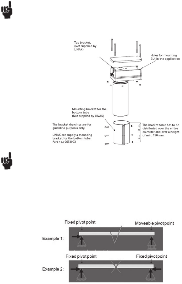
Page 62 of 148
• The mounting plate in the application must cover the entire top plate of the BL1 and be strong enough to carry the load.
• It is recommended that all 4 holes in the motor housing are used to fasten the BL4 to the application.
• The screws must provide a secure fixing e.g. as with self-locking.
• Remember to secure the cable to the housing with a cable tie. Use the fixing eye next to the connector socket.
On the BL4 cables, clip sleeve are mounted, they need to be removed.
• Electro Static Discharges!
Be aware that there is no electrical connection through the length of the BL4 column. Therefore, to avoid ESD issues, consider external
potential alignment between the top and bottom of the bed frame.
BL4 Mounting guidelines:
• The BL4 must always be mounted vertically before operation and always vertical with the motor housing uppermost. (Otherwise, the
internal end-stop switch system can break due to rotation).
• Both the motor housing and the bottom tube (the one with the largest diameter) must be secured in the application in such a way that no
rotation can occur.
• It is recommended to monitor the current consumption in order to determine the necessary tensioning force for the mounting bracket.
If the current consumption rises the BL4 has been tightened too much.
When mounting more than one BL4 you need to consider the fixation:
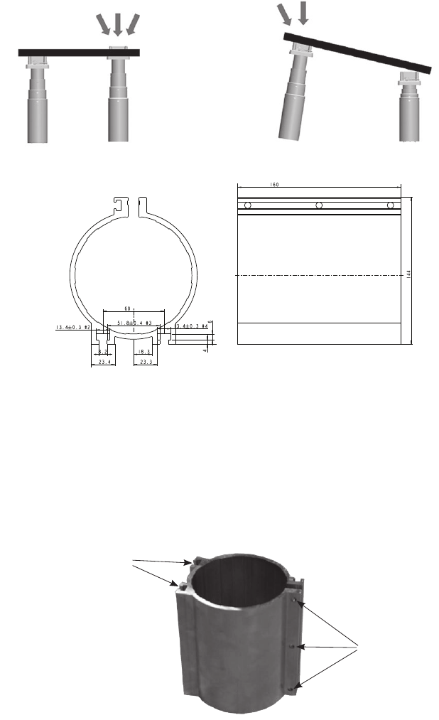
Page 63 of 148
LINAK mounting bracket part no.: 0673003-A
The reason why it is important only to fix one column is that the
columns will not move exactly in parallel – even if you have positioning
such as hall.
If more than one column is fixed, it can lead to dangerous situations.
If you have trend/antitrend function in your application you need to mount
one or more of the BL4s with a slider.
Having sliders prevents the column from bending like illustrated below.
Mounting guidelines for the BL4 bracket, supplied by LINAK, part no. 0673003:
Mounting the bracket in the application:
• The bracket must be mounted to an even abutting plate in the application by using the 2 slits.
• In each slit at least 3 bolts must be mounted. Type M8 8.8.
• Tightening moment must be 22.7 - 26.1 Nm.
• The 3 bolts must be placed in the same height as the 3 holes.
Mounting of the BL4 into the bracket:
• The BL4 must be fi tted in the bracket after mounting the bracket to the application.
• 3 bolts and nuts must be mounted in the 3 holes. Type M6 8.8
• Tightening moment must be 10.3 ± 0.3 Nm
The mounting points must be re-tightened at least once a year with the above specified moments.
3 holes
2 slits
Page 64 of 148
The LC2 column is an update of the LP2 programme. It has an improved
“twisting” stability and end-stop switches as standard.
The column is designed to be used in a vertical position and only for
lifting purposes. It is not possible to use the column in any kind of “pull”
application.
Depending on the application, the LC2 can be operated either as a single column or several columns in a parallel system by choosing a control box
with microprocessor.
It is designed to provide vertical lifting (push only) where simultaneous bending and torsion moments may occur.
Warning
Do only use the column within specified working limits.
The LP2 lifting column is the ideal choice for duties such as height adjustment on computer workstations, work benches, or a wide selection of other duties.
• There are mounting holes in the end plates.
• The largest profile must be mounted uppermost.
The LP2 range of vertical lifting columns is ideal where vertical positioning of
substantial loads is required.
The design allows the LP2 range to be built in a complete motion control system
simply by adding a suitable LINAK control box and handset.
Advanced design and high quality construction allows the column to be operated
either as single or parallel with up to a maximum of four units and/or with a memory
function.
Warning
Do only use the column within specified working limits.
Warning
Ensure a safe connection between column and application
Warning
Side mounting bracket screws: use the correct torque on the side mounting bracket screws.
Warning
The column can not be used in pull
Warning
Max. bending: LP22 = 550 Nm
LP25 = 1000 Nm
4. LC2 (MEDLINE® CARELINE® TECHLINE®)
5. LP2 (DESKLINE® MEDLINE® CARELINE® TECHLINE®)
Page 65 of 148
The LP3 is developed for vertical lifts and can resist a bending moment by virtue of the
effective telescopic system.
The lifting column is designed for applications where a small installation dimension is
requested without compromising the lifting capacity.
The LP3 is characterised by having a lower installation dimension proportional to the
stroke length compared to the LP2. The LP3 can also attain a higher speed than the
LP2.
The telescopic column is compatible with LINAK’s control boxes and can run individually; as 2 x LP3 parallel and/or with memory.
The LP3 is the perfect choice for height adjustment on dental, gynaecologist, and wheelchairs as well as for operating, office and working benches etc.
The column can only be loaded with the maximum bending moment over the first 80% of the stroke. The maximum bending moment will
be reduced to 50%.
The column must be mounted with the largest profile uppermost!
• There are mounting holes in the end plates.
• The largest profile must be mounted uppermost.
Warning
Do only use the column within specified working limits.
Warning
Ensure a safe connection between column and application
Warning
Side mounting bracket screws: use the correct torque on the side mounting bracket screws.
Warning
The column can not be used in pull
Warning
Max. bending: LP3 = 375 Nm
6. LP3 (MEDLINE® CARELINE® TECHLINE®)

Page 66 of 148
5. Information on specific control boxes
Please be aware if the control box is not visible after mounting, all information regarding limitation of use shall be marked on the end product.
Output voltage
On control boxes connected to the mains the voltage of the actuator output is dependent on load, and the no-load voltage can reach 50 V.
Control boxes connected to a battery can reach a voltage of 30 V during charging and no load.
For all control boxes with battery
Prior to first use of LINAK batteries, please make sure that they are being charged 24 hours in order to reach proper function and prolong the lifetime
of the batteries.
Warning
Please observe the following maintenance, replacement, and disposal requirements to ensure a safe and reliable operation.
Maintenance of batteries
The batteries are to be replaced after 4 years at the latest. Perhaps earlier, dependent on the pattern of use. Frequent and high-powered discharges
reduce the battery life. For an optimum lifetime the product must be connected to the mains voltage as often as possible. It is recommended that the
batteries are to be charged at least every 3rd month - otherwise will the batteries have reduced capacity due to self-discharge. It is recommended to
test the battery function at least once every year.
Replacement of batteries
The batteries must only be replaced by the same type of batteries or mechanical and electrical equivalent types.The batteries must be new or
maintained by means of charging at least every 3rd month. The batteries, which make a set, must be supplied with identical production codes.
Mismatching of production codes may lead to a severely reduced life time expectancy.
Before mounting ensure that the battery set is correctly connected, compare with the drawing in the battery room, and check that no connectors are loose.
Warnings
From the factory the battery room is hermatically separated from the electronics room. When replacing the batteries this separation must
not be damaged or modified as this may allow penetration of battery gas into the electronics room with risk of explosion.
When replacing batteries in waterproof products (IPX5 and IPX6) precautions must be taken that the sealing material (silicone ring or joint
filler) is not damaged and that it is correctly placed in the groove. Hereafter the screws in the cover are to be fastened with appox. 1 Nm.
If the seal is damaged it must be replaced by a new silicone string (LINAK article no. 0008004 for a roll of 100 metres).
Disposal
The batteries, which are lead-acid batteries, can be returned to LINAK or disposed in the same way as car batteries.
Warnings
The battery room is supplied with ventilation that ensures correct and necessary airing of the battery room. This airing must not be
blocked or covered as a positive pressure may occur with risk of explosion.
If the product has been exposed to mechanical overload (lost on the floor, collision/squeezing in the application or a powerful stroke) the
product must be sent to an authorised workshop for control of the hermetic separation between the battery and electronics rooms.
Using control boxes with speed control
The common way of carrying out a speed control of the actuators is by using PWM, switching the motor on/off at a high frequency.
In rare cases, while switching the motor on/off, we have experienced that the coupling between the actuators and application frame and ground is
too high, thus generating a slight current noise which exceeds the allowable EMC limits. The current in question is extremely low and is in no way
related to any personal or patient risk.
The coupling is defined by the mechanical layout of the application, and no real guidelines can be given. Using plastic bushings or similar can
improve the application.
If an application faces this issue, it can easily by solved by connecting ground of the CB box to the application frame-, through a cable with built in
serial connection of a resistor and a capacitor.
The EMC test defined in IEC60601-1-2, applicable for all medical products, will show if this is an issue concerning the specific applications.
If you need more information or have any issues on this subject, please contact your LINAK A/S Sales contact.
Design criteria when using a customized CB
When using a customized CB together with a LINAK actuator, the interface connection between the CB vs. Actuator as well as the purpose of the
actuator (with or without feedback) must be considered.
Actuators with feedback
E.g. potentiometer solutions have certain technological characteristics due to the design that might cause quality issues if used outside the
specification range.
The connection interface
The connection interface is not only the compatibility of the plug types used, e.g. male mini-fit to female mini-fit plug type.
It is also considering the contact transition, i.e. the cable as well as the cable connector, the connecting plug, the material surface of the plug PIN, the
soldering of the PCB plug connector etc.
When however using a LINAK Actuator with feedback AND having a bad connection interface towards a Customized CB
– LINAK only guarantees the feedback voltage to be within 500 mV (+/- 250 mV).
Page 67 of 148
The control boxes CA30 and CA40 are
developed as part of a new control box platform
for the care and rehab industry.
The control boxes can be mounted separately
on the application by means of unique slide-on
brackets, but also on several actuator models
using a specially designed actuator bracket.
LED indicator
CA30/CA40 is equipped with a three-colour LED for indication of mains or battery operation.
Connected to MAINS
LED colour Indication of operation
Green On mains, not activated by hand or foot control.
The system is working ok and is ready for normal operation
Yellow On mains, not activated by hand or foot control.
The system is defective and should not be operated.
Yellow On mains, activated by hand or foot control.
The system is working.
Not connected to mains but with BATTERY back-up
LED colour Indication of operation
Orange On battery, activated by hand or foot control.
The system is working
No LED On battery, not activated by hand or foot control.
or CA30/CA40 not connected to mains
...to be continued
1. CA30/CA40 (MEDLINE® CARELINE®)
Usage:
• Duty cycle: 10 % - 2/18 min. on/off continuos use.
Maximum power is 120 W for 80 seconds and 60 W for 40 seconds at 25° C
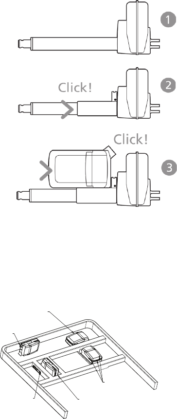
Page 68 of 148
Mounting instructions (Example CA30-CA40 with LA40)
When mounting the control box onto the actuator (1)
Simply slide on the bracket until you hear a clear click (2)
Slide on the control box until you hear a click and the box is mounted (3)
CA30-CA40 - mounted on frame:
Service lid
Integrated hinge
Removable if needed
Release hook
Easy-mount bracket
3-way
cable exit
Very small built-in dimension:
Height: Min. 90 mm (lid can be removed)
Length: +20 mm (locking system)
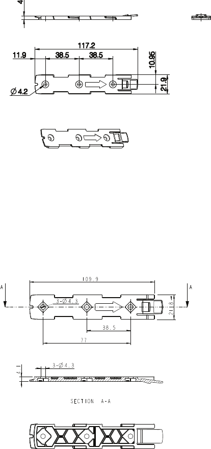
Page 69 of 148 ...to be continued
Mounting bracket (frame flat)
It is recommended that the CA30/CA40 is mounted in a position that allows water to escape.
Recommended torque: 0.6 Nm +/-0.1
The bracket can be mounted to the bed frame or any other application by means of one of the following mounting procedures:
1) M6 nut to be placed in bracket and fixed with M6 bolt from the rear side.
2) M5 machine screw with flat washer to be fixed through bracket with nut on the rear side.
3) Self-tapping screw to be placed through bracket and onto the frame.
Mounting bracket (frame flat) w/M4 nuts
It is recommended to mount the CA30/CA40 in a position that allows water to escape.
Recommended torque: 0.6 Nm +/-0.1
The bracket can be mounted to the bed frame or any other application by means of one of the following mounting procedures:
1) M6 nut to be placed in bracket and fixed with M6 bolt from the rear side.
2) M5 machine screw with flat washer to be fixed through bracket with nut on the rear side.
3) Self-tapping screw to be placed through bracket and onto the frame.
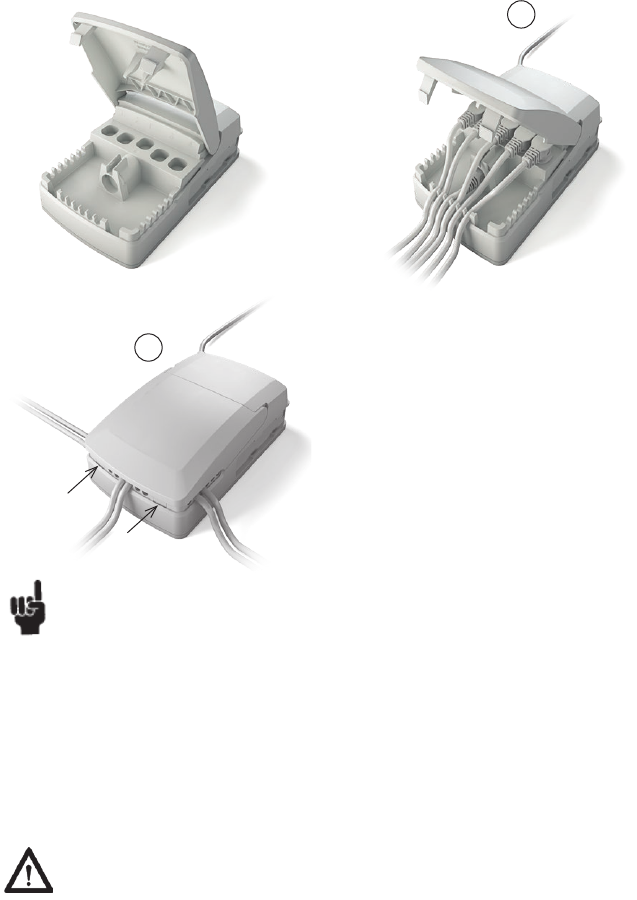
Page 70 of 148
Cable management:
2
Recommendations
• Note that the common current limit on CA30-CA40 is 8 A and may cause overload on certain actuator types.
• Be aware that the channel configuration has been changed compared to existing analogue control boxes.
• To avoid unintended movement like trend or antitrend, LINAK recommends the application manufacturer to instruct the end user to avoid that
multiple keys are pressed simultaneously.
Battery Operation
CA30 and CA40 are only compatible with batteries with built-in charger, BA19 or BA21.
EOP- electronic overload protection
Remark - common/individual current measurement.
As default, the current cut-off is set to 8 A per channel. The total current cut-off default setting is 8 A. If more channels run at the same time, 8 A are
distributed equally.
Warnings
• Due to the half-bridge technology, pressing multiple keys simultaneously might cause an unintended trend or antitrend movement
(application environment 4).
See illustrations:
1
Mounting of cables and cable lock:
The control boxes CA30/CA40 have a uniquely designed cable lid. The lid also works as an integrated cable lock when closed.
1) Mount cable plugs in control box
2) Close lid until lock snaps into place (see arrows)
To allow free access to the cables, the lid has a rest position when completely opened.
It is possible to remove the lid by lifting it a few degrees and pulling it away from the housing under tight mounting conditions.
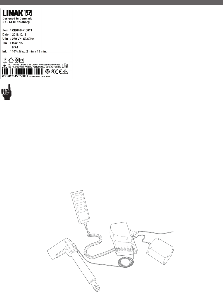
Page 71 of 148
The control box CB6 has been specially developed for use together with LA27/LA40 actuator in
the care and rehab industry.
The control box is designed to be mounted on the actuator LA27/LA40 as with the CB9 and
LA31 system.
The CB6 control box has a LED power ON indicator, detachable mains cable and strain relief for
all cables.
The control box CB6 communicates with the LA27/LA40 actuator by means of the built-in end
stop signal switches in the actuator. Due to the signal switches the power to the motor will be
cut off in the control box and not in the actuator.
Recommendations
• Be aware of the handset configuration (e.g. CH1, 2, 3 should be CH1, 3, 4).
• Same cables variants as for CB9 CARELINE and CB12.
Connecting the system:
• Do not connect the mains cable until all actuators have been connected to the control box.
• Start by connecting the handset to the control box. The connection at the control box is marked with “HB”.
• Connect the different actuators to the different channels on the control box. Each channel is marked with a number (e.g. “1”, “2”, “3”....).
• Check that all plugs are well connected and firm pushed into the connection plug.
Due to the fact that LINAK control boxes are designed for a high IP degree, a firm force can be required.
• CONNECT the mains and turn on the power!
• Finally, connect the battery (BA18) with special T-cable or normal battery cable depending on the specified system.
• The actuators can now be operated by pushing a button on the handset. Use only one button at a time.
If the control box is equipped with special software, an initialising process might be necessary. This process is described in the software specification.
Attention should be paid to the following:
• Control boxes must only be connected to the mains voltage specified on the label.
• The control box must be connected in such a way that the cables are not trapped, exposed to tension or sharp objects, when the application is
moved in different directions.
CB6 system diagram
2. CB6 (MEDLINE® CARELINE®)
Usage:
• Duty cycle: 2/18; 2 minutes continuous use followed by 18 minutes not in use
• CB6 is approved according to EN60601-1 / UL60601-1
• The CB6 can only be combined with LA27/LA40 and HB30 / HB70 / HL70 / HB80 and HL80.
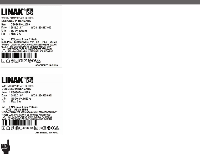
Page 72 of 148
The CB6 OBMe is a powerful control box with switch mode power supply typically used for
applications like hospital beds, couches/tables for treatment and examination and other medical
applications. The universal input voltage makes the control box adaptable to the world-wide market
irrespective of the input voltage.
Approvals:
CB6 OBMe is approved according to UL60601-1 and EN60601-1.
Possible combinations.
CB6 OBMe is meant for use with:
LA27 std. motor (cable type ‘B’),
LA27 std. motor (cable type “A” = encoded) with / without Hall
LA31 std. / fast motor with / without Hall,
LA34 std. / small / fast motor with / without Hall (fast motor not max. load),
LA44 std. / fast motor with / without Hall (fast motor not max. load),
BL1 (only with +35% transformer type) with / without Hall,
HB7x, HL7x, HB8x, FSE/FSL, FS2, MJB, DJB, ACO, ACC, ACK.
CB6 OBMe – with transformer has been approved for CLASS I operation incl. CLASS I cables
(without pigtail for earth).
CB6 OBMe – with SMPS is not approved for CLASS I operation, basically because of the design of
the housing. However the PCB contains 2 x fuses (phase, neutral) as required for CLASS I operation.
If a mains cable with pig tail is applied CLASS I is obtained – however the CB label will indicate
CLASS II! At the end of the day the OEM user applying for an application approval must clarify if
such a solution is accepted by the used testhouse.
Recommendations:
Battery Operation:
• If the battery voltage is at ‘low level’ a battery alarm beeps constantly by activating the HB/ACx.
Low level means that battery charging is necessary to maintain the best possible lifetime.
Low level battery limit corresponds to approx. 19 V (+/- 5%).
• If the battery voltage is at ‘critical level’ the battery alarm function shuts down all operation immediately.
If trying to operate the system anyway, the battery could become deeply drained or the actuator system could be damaged.
When at critical battery level there is a risk that the processor will incorrectly monitor end of stroke. Crashing the actuator could be a result.
Critical level limit corresponds to approx. 17.5 V (+/- 5%).
• If battery back-up is applied it only commences battery charging when it is connected to the mains.
• A battery stored at 25° C has to be recharged every 6 - 7 months.
• Prior to first use of LINAK batteries, please make sure that they are charged for 24 hours in order to reach proper function and prolong
the lifetime of the batteries.
• The longest lifetime is obtained when the battery is fully charged.
If Backlight supported HB is used:
• When CB6 OBMe is powered by mains voltage:
- If an HB button is activated the backlight illuminates fully. When the HB button is released the light is dimmed again after approx. 10 - 15 sec.
Backlight turns completely off after 2 min.
Exception: While charging the HB backlight will stay on dimmed until charging is finished.
• When CB6 OBMe is powered by battery:
- If a HB button is activated the backlight illuminates fully. When the HB button is released the light is dimmed again after approx. 10 - 15 sec.
Backlight turns completely off after 2 min.
1st Failure safe monitoring
Is made in two ways on the OBMe platform. It may be difficult to observe the LED status (hardware) if CB6 OBMe is placed under
a bed, therefore it is now monitored by software as well.
• CB6 OBMe is equipped with a 1st Failure safe indication controlled by HW (power request). At normal operation (no failure observed) the power
LED turns yellow when a HB button is activated.
3. CB6 OBMe (MEDLINE® CARELINE®)

Page 73 of 148
If the LED has turned yellow AND the HB has NOT been activated, it indicates that a failure has occurred (1st Failure).
NOTE: Even though the LED illuminates yellow before the HB is activated it is possible to operate the CB6, however the 1st.
Failure is somehow still in the CB and must be removed to prevent a further failure causing a hazardous failure to happen.
• To meet the safety requirements the device must have a dual switch safety concept. Further information about OpenBus™ safety concepts please
contact your local LINAK.
• The safety function must be monitored and this monitoring is implemented in the SW. In case of a failure (fatal error) any further operation of any
channels are prevented. At a fatal error the CB6 OBMe responds with the following information:
• Failure indication:
all ACO LED’s are blinking
The CB6 OBMe buzzer beeps shortly if a handset is activated
The error can be reset by activating H0 and H1 OR H10 and H11 on a handset.
Compatibility – CB6 OBMe:
• CB6 OBMe supports both digital and analog encoded signals.
The CB6P2 platform is introduced to obtain a powerful and optimised solution to customers looking
for existing analogue input systems. It is based on OpenBus™ technology, but to meet existing
analogue systems it has an analogue input similar to HB40 and therefore OpenBus™ accessories
cannot be connected.
Combination Overview
CB6P2 is meant for use with:
LA27 std. motor with Hall (cable type ‘A’)
LA27 std. motor (cable type ‘B’),
LA31 std. / fast motor with / without Hall,
LA34 std. / small / fast motor with / without Hall (fast motor not max. load),
LA40 std. motor with / without Hall
LA44 std. / fast motor with / without Hall (fast motor not max. load),
BL1 (only with 270W transformer type) with / without Hall, HB7x, HL7x, HB8x, ACL/ACM/ACP
(HB40-like)
Recommendations
Battery Operation:
• If the battery voltage is at ‘low level’, a battery alarm beeps constantly when the HB/ACx is activated.
(Low level means that battery charging is necessary to maintain the best possible life time. Low level battery limit corresponds to approx. 19 V (+/- 5%).
• If the battery voltage is at ‘critical level’ the battery alarm function shuts down all operation immediately.
Critical level limit corresponds to approx. 17.5 V (+/- 5%).
• If battery back-up is applied it only commences battery charging when it is connected to the mains.
• A battery stored at 25° C has to be recharged every 6-7 months.
• Prior to first use of LINAK batteries, please make sure that they are charged for 24 hours in order to reach proper function and prolong the lifetime
of the batteries.
• The longest lifetime is obtained when the battery is fully charged.
4. CB6P2 (MEDLINE® CARELINE®)
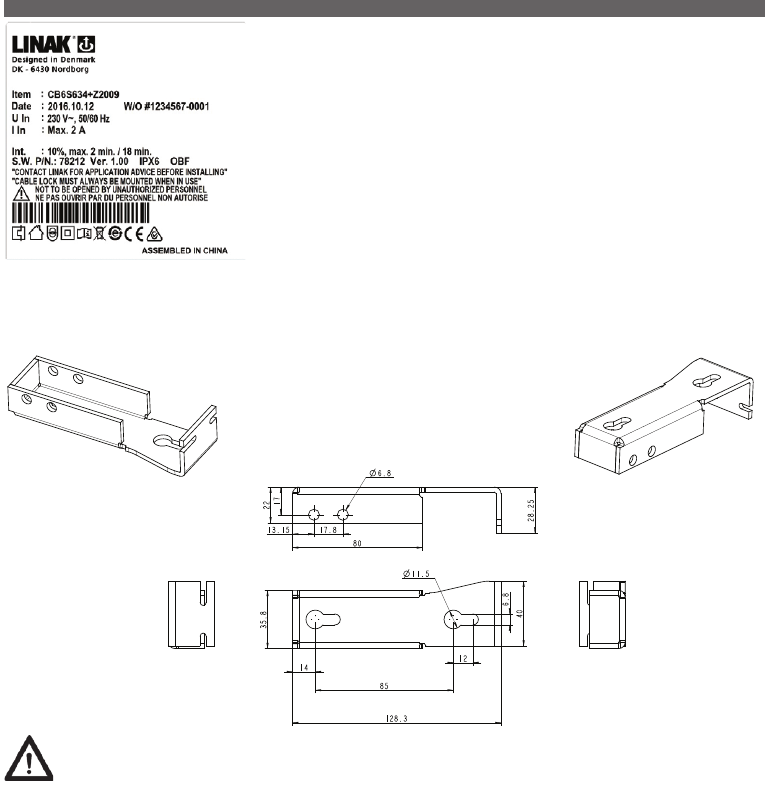
Page 74 of 148
Precautions:
Thermal protection:
OBF only
The CB is equipped with a thermal protection to avoid thermal overload of the FET transistors used to control the acuators.
When triggering the thermal protection all movement of the actuators will stop and the buzzer will sound for 5 seconds constantly. The 5 second
alarm will be reinitiated each time the handset/ACP or similar is activated until the CB is cooled down enough to allow a movement again
The thermal monitoring system monitors a temperature rise and not an absolute temperature. The monitoring system has been designed to operate
up to an ambient temperature of 40 degrees. If the CB is exposed to a temperature higher than 40 degrees for several hours while powered it will
adapt to this temperature. In this case there is a risk of damaging the FET transistors without triggering the thermal protection.
At first power up, after programming a new SW into the CB, the ‘temperature reference value’, used by the thermal monitoring system, will be
automatically initialized. If this is done in a cold area the temperature reference value will be set accordingly and a too early temperature warning
could occur (warning signal is temperature hoot = constant beep)!
After the first power up, the temperature reference value will adapt over time to the surrounding temperature and the adaptation routine happens
every 5 hours (provided the CB is unused and connected to mains). The 5 hour counter (used by the temperature adaptation routine) will be
reinitiated every time a handset/control panel is activated.
We therefore recommend that the CB is resting for min. 5 hours to adapt temperature wise to a ‘normal operating’ temperature, i.e. in the
environment for intended use.
CB6S is part of the LINAK OpenBus™ product range - that provides more flexible solutions no
matter which actuator concept is preferred.
5. CB6S (MEDLINE® CARELINE®)
Mounting of CB6S – article no. 9271233
Apart from LA27 and LA40, it is not possible to mount CB6S onto LINAK actuators. In such case you need a CB6 mounting bracket which can be
welded or likewise to the application.
This bracket is shown below:
14
85
128.3
35.8
40
22
28.25
80
11.5
6.8
12
6.8
17
13.15 17.8

Page 75 of 148
Recommendations
NOTE - HOT PLUGGING
Removing or adding any OpenBus cables is not allowed when the CB is powered by mains supply!
If needed anyway, follow the below procedure:
1. Remove mains and wait 5 sec.
2. Mount or dismount the required cables
If this procedure is NOT followed, it may result in a damaged OpenBus driver circuit.
The risk of a damaged circuit increases if the accessory has a high start current (in rush current).
OBF - hot-plugging protected from January 2016.
Precautions:
BATTERY OPERATION:
OBL and OBF:
• IIf the battery voltage is at ‘low level’ a battery alarm beeps constantly (Low level means that battery charging is necessary to maintain the best
possible lifetime. Low level battery limit corresponds to approx. 19 V (+/- 5%).
• If the battery voltage is at ‘critical level’ the battery alarm function shuts down all operation immediately.
(If trying to operate the system anyway, the battery could become deeply drained or the actuator system could be damaged. When at critical
battery level there is a risk that the processor will incorrectly monitor end of stroke. Crashing the actuator could be a result. Critical level limit
corresponds to approx. 17,5 V (+/- 5%).
• The CB6S with battery back-up only commences battery charging when it is connected to the mains.
• A battery stored at 25° C has to be recharged every 6-7 months.
• Prior to first use of LINAK batteries, please make sure that they are charged 24 for hours in order to reach proper function and prolong the lifetime
of the batteries.
• The longest lifetime is obtained when the battery is fully charged.
IF BACKLIGHT SUPPORTED HB IS USED:
• When CB6S is powered by mains voltage:
- At no operation of the HB the backlight in the HB is dimmed.
- If a HB button is activated the backlight illuminates fully.
When the HB button is released the light is dimmed again after approx. 10-15 sec.
• When CB6S is powered by battery:
- At no operation of the HB there is no backlight in the HB.
- If a HB button is activated the backlight illuminates fully.
When the HB button is released the backlight turns off.
OBF
• More information about “OpenBus SW guidance”, please contact your local LINAK.
Mounting of LA27/LA40 on OBF:
• It is not recommended to mount LA27/LA40 on OBF because of the big toroidal transformer used.
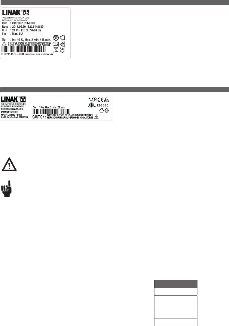
Page 76 of 148
CURRENT CUT-OFF (A)
2 A (2.35 +/- 0.35 Amp)
3 A (3.00 +/- 0.35 Amp)
4 A (4.00 +/- 0.50 Amp)
5 A (5.35 +/- 0.50 Amp)
6 A (5.90 +/- 0.70 Amp)
Values in brackets
show tolerances.
Important: Individual current cut-off:
The current to each actuator is monitored and when this reaches a specified value, the current to that
actuator is cut-off.
As the actuators do not have the same current consumption the cut-off values must also be different.
Therefore it must be specified which actuator is to be connected to which channel:
Warning
In order to avoid injury, the emergency stop should be activated in (all) transport situations.
Recommendations
• Note: max. accumulated power consumption is 10 Amp.
• The measurement is individual for each channel, but if the total current consumption reaches 10 Amp, the CB cuts off the current. The CB and the actuator are
therefore protected via a common measurement.
• External Charger CH01 has to be ordered separately. By use of charger CH01 it is possible to activate the actuators when charging. However, this is not
recommended as it can damage the control box or the charger CH01.
• Battery kit BA0801 has to be ordered separately for versions M, G, H, Q, R (2 channel) and version M (3 channel).
• An external emergency stop device (NC) or short-circuiting connection must be mounted from channel 3 of CB800XXXXN-X0 before connection to allow
proper function and battery charging.
• When using the CB8A with emergency stop button, the stop button must be released before charging batteries.
• Acoustic alarm sounds when batteries are low and recharging should be started. The alarm level corresponds to approx. 17-18 VDC.
• If the CB800XXXXN-X0 option is chosen, An external emergency stop device (NC) or short-circuiting connection must be mounted in channel 3,
before connection to allow proper function and battery charging.
• If the option N for CH3 is chosen, the external emergency stop has to be placed on channel 3, otherwise the CB8A will not work.
The CB8A is a battery powered control box operating up to 3 actuators
individually. One of these channels can be used either as an external
emergency stop device or for battery charging.
Simple design and high quality construction make the CB8A an ideal
control box choice for mains-free operation of beds, chairs, tables and
many other mobile applications.
Usage:
• Duty cycle: Max. 10% or 2 min. in use followed by 18 min. not in use
• Ambient temperatures: + 5o to +4 0o C
• Approvals: IEC60601-1:2005 3rd edition approved ANSI/AAMI, ES60601-1:2005 3rd edition approved.
7. CB8A (MEDLINE® CARELINE® TECHLINE®)
Compared to other LINAK control boxes the CB7 is very small and compact in design.
The CB7 is designed to slide onto an LA31 actuator for easy fitting e.g. in a recliner application
where “mounting” space is limited.
The control box function is divided in two parts. The actual control box CB7, which slides onto the
LA31 actuator and a separate external power supply transformer box TR6 or TR7, which can be wall
mounted or placed on the floor moulding next to the mains.
The control box is only fitted with low voltage electronic components and the connection between
the CB7 and transformer is via a 24 V power cable.
6. CB7 (HOMELINE®)
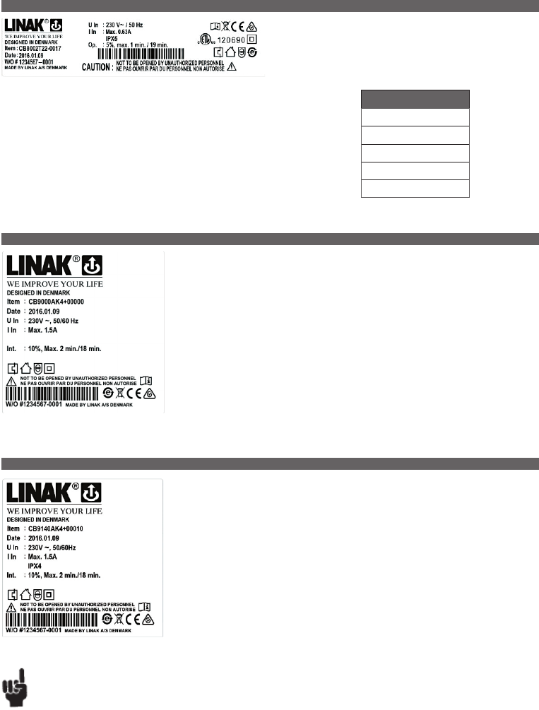
Page 77 of 148
The CB8-T is developed for use with LINAK A/S’ actuators and handsets.
The control box can operate up to 2 actuators individually.
The simple compact design combined with high quality makes the control
box ideal for use with beds, chairs, tables and many other applications.
CURRENT CUT-OFF (A)
2 A (2.35 +/- 0.35 Amp.)
3 A (3.00 +/- 0.35 Amp.)
4 A (4.00 +/- 0.50 Amp.)
5 A (5.35 +/- 0.50 Amp.)
6 A (5.90 +/- 0.70 Amp.)
Values in brackets
show tolerances.
Important: Individual current cut-off:
The current to each actuator is monitored and when this reaches a specified value, the current to that
actuator is cut-off.
As the actuators do not have the same current consumption the cut-off values must also be different.
Therefore it must be specified which actuator is to be connected to which channel:
The CB9 has been developed for Home use. The CB9 and the LA31 can be fully integrated, which saves
mounting and wiring or be installed separately.
The HOMELINE CB9 series is available as either analogue (Ax) or μ-processor based (Px) types.
Recommendations
LA34 fast motor is not compatible with any standard versions of CB9, due to high current consumption. For use of LA34 standard motor and small
motor always use a CB9 with EAS.
Additionally, actuators with reed switch may not be connected to AC, AJ, AK, AF, AL or AM types because of a conflict between the CB-signal wires
and the reed wires !
The CARELINE® CB9 has been developed for use together with LA31/LA31R, LA34/LA34R* in the
Care & Rehab industry. CB9 and LA31 can be fully integrated which saves mounting and wiring or be
installed separately.
Exchangeable mains cables, Electronic Overload Protection (EOP), EAS, earth connection (Class 1) and
exchangeable mains fuse makes CB9 a good choice for the simple hospital and care beds.
Usage:
• Duty cycle: Max. 10% or 2 min. continuous use followed by 18 min. not in use
• Ambient temperature: + 5° to + 40°C
• Compatible with up to 4 actuators, type LA31/LA31R and LA34/LA34R, via 4-pole DIN sockets
• Compatible with BA18
• Medically approved according to EN 60601-1/UL 60601-1
8. CB8-T (MEDLINE® CARELINE® TECHLINE®)
9. CB9 (HOMELINE®)
10. CB9 (MEDLINE® CARELINE®)
...to be continued
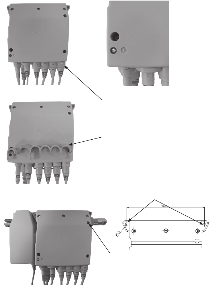
Page 78 of 148
CB9 is equipped with a green LED for indication of mains power connected.
• When th CB9 is connected to mains, the LED is green.
• Connected only to battery, the LED is off.
The cables are locked in position with a locking mechanism.
CB9 can be mounted and fixed together with LA31 with one screw.
The locking mechanism is shownhere (not in position)
CB9 mounted on actuator, LA31. CB9 for mounting on application.
Shows the two holes used for mounting
Screw used for mounting

Page 79 of 148
The CARELINE® Basic CB9 has been developed for use together with LA31 and LA34 in the Care &
Rehab industry.CB9 and LA31 can be fully integrated thus saving mounting and wiring or they can
be installed separately. Exchangeable mains cables, Electronic Overload Protection (EOP) and earth
connection (Class 1) mains fuse makes CB9 a good choice for simple hospital and care beds. The
CARELINE® Basic CB9 series is only available as an analogue (Ax) type.
Microprocessor:
With LINAK software packages the Px types are aimed at applications where parallel drive and/or
memory functions are required. Please consult the ordering example for a detailed description of the
article number.
Internal battery charger:
Compatible with BA18.
If anything other than a LINAK® charger is used, it must conform to the following specifications:
Charging voltage: 27.6 VDC ± 2% Charging current: < 300 mA.
EOP:
AC and AF: Means common measurement on CH1, CH2, CH3 and CH4. If the total current exceeds 5A all channels will be cut off.
AJ and AL: Means a common current measurement on CH1+2. The current will be cut off when the total current on both channels reaches approx.
3.4A and 7A on CH3+4.
Note: CH1+2 = LA31 connection and CH3+4 = LA31/LA34 connection.
AK and AM: Means common measurement on CH1, CH2, CH3 and CH4. If the total current exceeds 7A all channels will be cut off.
AS: Means an individual current measurement on CH1, CH2, CH3 and CH4. The current will be cut off only when the current on one channel reaches
approx. 4A.
Max. current available from the CB9 transformer is approx. 7A.
Px: Means Electronic Overload Protection via a pulse measurement.
Recommendations
The LA34 fast motor is not compatible with any standard versions of the CB9, due to high current consumption. For use of the LA34
standard motor and small motor always use a CB9 with EAS.
Additionally, actuators with reed switch may not be connected to AC, AJ, AK, AF, AL or AM types because of a conflict between the CB-
signal wires and the reed wires !
Usage:
• Duty cycle: Max. 10% or 2 min. continuous use followed by 18 min. not in use
• Ambient temperature: + 5° to + 40°C
• Compatible with up to 4 actuators, type LA31/LA31R and LA34/LA34R, via 4-pole DIN sockets
• Compatible with BA18
• Medically approved according to EN 60601-1/UL 60601-1 3th Edition
The CB12 product range features two standard versions, which are ideal for a vast number of medical
and industrial applications.
In general the CB12 is a transformer operated control unit, which can control up to 4 actuators.
The control box feature a range of built-in safety devices, increased current cut-off, EAS (Electronic
Arc Suppression), and other options such as battery backup, earth outlet, wet alarm etc.
CB12 with battery backup
The CB12 with battery backup has an acoustic alarm, which sounds when the batteries are low,
approx. 17 - 18V. To charge the batteries on a CB12 with internal batteries, just connect the CB12 to
mains. With external batteries, connect the external batteries to an external charger.
External battery charger
If anything other than a LINAK® charger is used, it must conform to the following specifications:
Charging voltage: 27.6 VDC ± 2%
Charging current: < 300 mA.
Warning
In order to avoid injury, a system with control(s) or accessories, a CB12 with battery backup and actuators assembled, must always be
disassembled in transport and service situations.
11. CB9 CARELINE Basic (MEDLINE® CARELINE®)
12. CB12 (MEDLINE® CARELINE®)
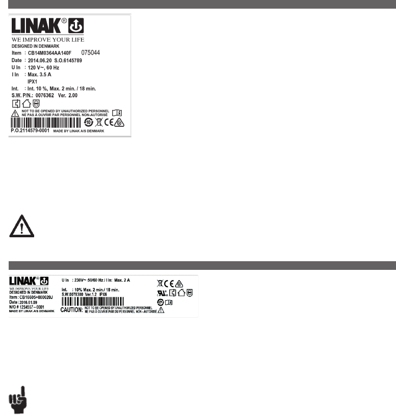
Page 80 of 148
The CB14 with microprocessor is developed for systems with a need to run up to five actuators or
two actuators / lifting columns in parallel and / or with memory function.
The effective toroidal transformer and the many features such as battery backup, earth outlet, wet
alarm makes the control box suitable for a variety of applications.
CB14 with battery backup
The CB14 with battery backup has an acoustic alarm, which sounds when the batteries are low,
approx. 17-18V. To charge the batteries on a CB14 with internal batteries, just connect the CB14 to
mains. With external batteries, connect the external batteries to an external charger.
Memory position on CB14
When storing the memory position on CB14 the actuators must be run to the wanted position and
the “store” button (S) must be pushed. Hereafter, the selected memory button (1, 2, or 3) must be
activated within 2 seconds.
Microprocessor
All control boxes with a microprocessor must be initialized before start-up. A description of the initialisation procedure can be obtained from your
LINAK dealer. If an actuator is replaced, the microprocessor always has to be initialised before use (actuators with reed/hall).
If re-programmed, please ensure that the correct software is used.
External battery charger
If anything other than a LINAK® charger is used, it must conform to the following specifications: Charging voltage: 27.6 VDC ± 2% Charging current:
< 300 mA.
Warning
In order to avoid injury, a system with control(s) or accessories, a CB14 with battery backup and actuators assembled, must always be
disassembled in transport and service situations.
CB16 is part of the LINAK® OpenBus™ product range. It is a powerful
control box with either traditional transformer solution or Switch Mode
Power Supply.The universal Switch Mode Power Supply makes the control
box adaptable to the worldwide market irrespective of the input voltage.
Usage:
• Approvals: CB16OBF/OBL is approved according to IEC60601-1:2005 3rd ed., ANSI / AAMI ES60601-1:2005, 3rd edition,
CAN / CSA-22.2 No 60601-1:2008.
• Compatibility: LA27 (no feedback/encoded feedback), LA31, LA34, LA43, LA44, BL1, and BL4
• Duty cycle: 10%, 2 minutes continuous use followed by 18 minutes not in use
• Usage temperature: 5ºC to 40ºC
• Storage temperature: - 10ºC to 50ºC
Recommendations
NOTE - HOT PLUGGING
Removing or adding any OpenBus cables are not allowed when the CB is powered by mains supply!
If needed anyway follow the below procedure:
1. Remove mains and wait 5 sec.
2. Mount or dismount the required cables
If this procedure is NOT followed it may result in a damaged OpenBus driver circuit.
The risk of a damaged circuit increases if the accessory has a high start current (in rush current).
NOTE - Use of internal mains signal in software or on OpenBus
Please note when using the internal mains signal on control boxes with SMPS that the mains signal may take up to 6 seconds before disappearing
after mains has been removed.
Battery operation:
BATTERY LEVELS
Battery High: > 20 V - normal
Battery Medium: 18-20 V - alarm
Battery Low: < 18 V - critical
13. CB14 (MEDLINE® CARELINE® TECHLINE®)
14. CB16 (MEDLINE® CARELINE®)
Page 81 of 148
• If the battery voltage is at ‘Medium level’ a battery alarm beeps as long as a key is activated. (Medium level means that battery charging is
necessary to maintain the best possible lifetime).
• If the battery voltage is at ‘Low level’, the battery alarm function shuts down all movement immediately. The OpenBus is still active for
approx. 15 seconds. (If trying to operate the system anyway, the battery could get deep drained or the actuator system could get damaged.
When at low battery level (which is critical), there is a risk that the processor will incorrectly monitor the end of stroke.
Crashing the actuator could be a result.
• The CB16 with battery back-up only commences battery charging when it is connected to the mains.
• For more information about the batteries, please contact LINAK.
Before startup of CB16OBF
Due to the microprocessor in CB16OBF the control box has to be initialised before startup.
Initialisation will in most cases be possible pressing H0 and H1 or H10 and H11 on a handset.
Initialisation depends upon the software description so please obtain a description of the initialisation procedure from your local LINAK dealer.
• If an actuator is replaced, the microprocessor always has to be initialised before use (actuators with reed / hall).
• If re-programmed please ensure that the correct software is used.
Precautions
If backlight supported HB is used:
• When CB16 OBL or OBF is powered by mains voltage:
- At no operation of the HB the backlight in the HB is dimmed.
- If an HB button is activated the backlight illuminates fully.
When the HB button is released the light is dimmed again after approx. 10-15 sec.
• When CB16 OBL or OBF is powered by battery:
- At no operation of the HB theres is no backlight in the HB.
- If an HB button is activated the backlight illuminates fully.
When the HB button is released the backlight turns off.
1st failure safe monitoring:
• Failure indication:
- all ACO LED’s are blinking
- The CB16 buzzer is shortly beeping if a handset is activated
- The error can be reset by activating H0 and H1 OR H10 and H11 on a handset.
Compatibility – CB16 OBL:
• Using actuators with feedback on CB16 OBL are not supported. If used anyway it will not work properly. The reason is that feedback signals
(e.g. Hall signals) is positioned at the same PINS as analogue stop signals - when using no feedback.
CB16OBF SMPS - Actuator combinations and/or customized software
• Due to the high power from the CB16OBF SMPS, it is highly recommended to validate the system to guarantee the lifetime of connected actuators.
Especially when using customized software and/or actuator combinations which do not comply with the LINAK compatibility list - for further
questions please contact your local LINAK contact.
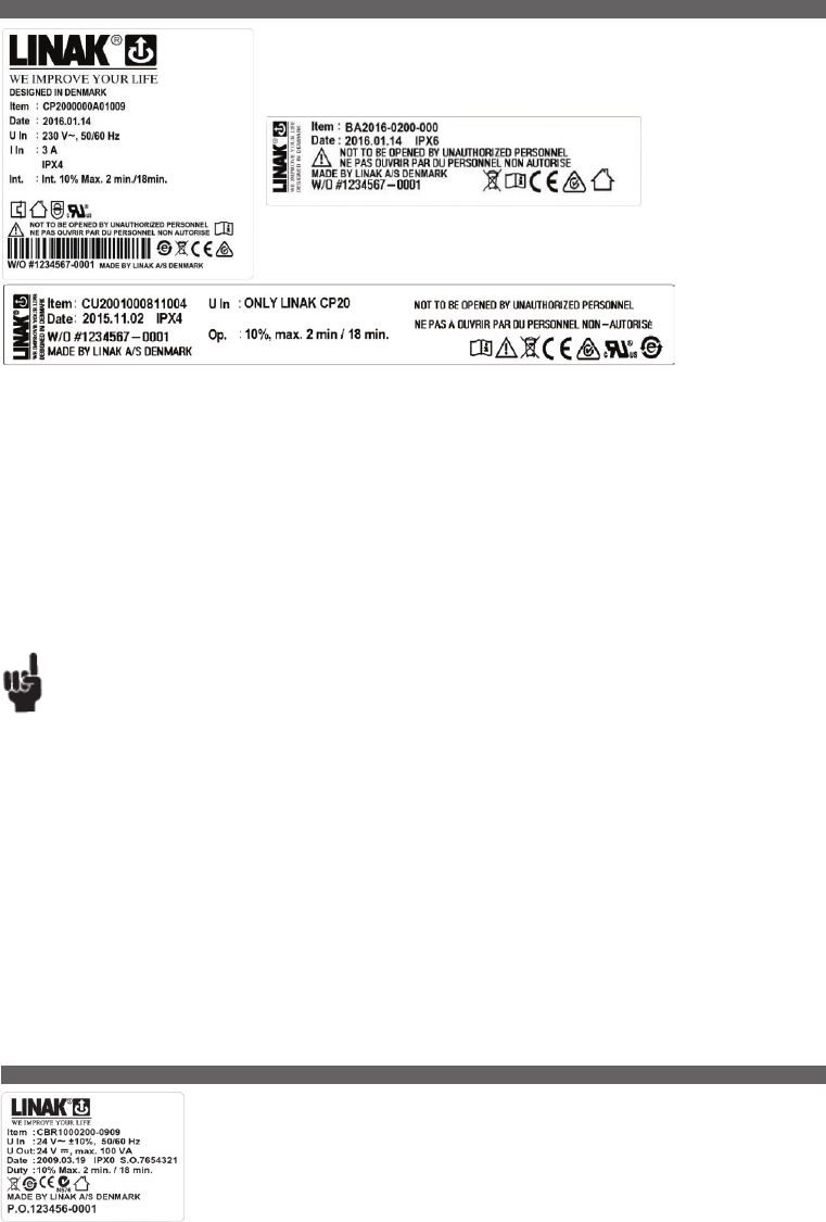
Page 82 of 148
CB20 is a platform which offers a unique safety concept, logging off service data and it is possible to
connect a variety of accessories to the control box.
The CB20 consists of 3 modules :
CP20 = Control Power CU20 = Control Unit BA20 = Battery.
Usage:
• Compatible with specific versions of LA23, LA27C, LA31, LA34, LA40, LA43, LA44 and BL1
• Duty cycle: 10% ˜ max. 2 min. continuous use followed by 18 min. not in use
• Ambient temperature: + 5˚ to + 40˚C
• Approvals: IEC60601-1:2005 3rd ed., ANSI / AAMI ES60601-1:2005, 3rd edition, CAN/CSA-22.2 No 60601-1:2008 approved
Please be aware:
CB20 is delivered in 3 separate units - CU20 + CP20 + BA20. The units are not assembled at LINAK A/S.
Microprocessor
All control boxes with a microprocessor must be initialized before start-up. A description of the initialization procedure can be obtained from your
LINAK dealer. If an actuator is replaced, the microprocessor always has to be initialized before use (actuators with reed/hall). If re-programmed,
please ensure that the correct software is used.
External battery charger
If anything other than a LINAK® charger is used, it must conform to the following specifications: Charging voltage: 28.0 VDC ± 2% Charging current:
< 300 mA.
Recommendations
• Please note mains cable must be ordered separately
HOT PLUGGING
Removing or adding any OpenBus™ cables are not allowed when the CB is powered by mains supply! If necessary anyway follow the below procedure:
1. Remove mains and wait 5 sec.
2. Mount or dismount the required cables
If this procedure is NOT followed it may result in a damaged OpenBus™ driver circuit. The risk of a damaged circuit increases if the accessory has
a high start current (in rush current).
• Please note mains cable must be ordered separately.
Battery running:
• If battery capacity is under 50% a “bip” sound is given for 2 seconds, when a handset key is pressed.
• If the system is activated and the mains plug is pulled out, the system will stop. In the opposite case, if the system is running using battery power
and the mains plug is then plugged in, the system will continue running.
• The charging indicator can blink if the system operates with a high load causing the voltage to drop and because of this the batteries will start to
charge.
• The CB20 with battery back-up only commences battery charging when it is connected to the mains.
• A running battery must be charged for at least 12 hours before use.
• For recommendations on charging cycles and first use of the BA20 battery pack, please refer to chapter 5.
The CBR1 has been developed for use together with the RA40 Rotary actuator. The CBR1 can be installed in the
same profile as the RA40 Rotary actuator thus saving mounting and wiring.
For recommendations on maintenance and storage of the BA20 battery packs,
please refer to chapter 5.
15. CB20 (MEDLINE® CARELINE®)
16. CBR1 (MEDLINE® CARELINE® HOMELINE®)

Page 83 of 148
The LINAK control box CO41 offers a consolidated range of unprecedented features – all utilising
standardised technology, interfaces and compatibility.
The CO41 for LINAK actuators is intended for the control of, for example, hospital bed movement.
Equipped with 120W SMPS, excellent and well thought-out cable management as well as multiple
easy mounting options, this control box opens up a wide range of application possibilities for the
provident hospital and care products manufacturer.
LED indicator
CO41 is equipped with a green LED for indication of mains power connected.
When the CO41 is connected to mains, the LED is green. Connected only to battery, the LED is off.
17. CO41 (MEDLINE® CARELINE® )
Features:
• Duty cycle: 10 % - 2/18 min. on/off continuous use.
Maximum power is 120 W for 80 seconds and 60 W for 40 seconds at 25 °C.
...to be continued
Acoustic signal functionality:
The buzzer will make a warning, when a button on the hand control is pressed, and the battery capacity is low.
The buzzer can also be activated by the control box to signal other conditions. This must be specified in the control box software.
Connected to MAINS
LED colour Indication of operation
Green On mains, not activated by hand or foot control.
The system is working ok and is ready for normal operation.
Yellow On mains, not activated by hand or foot control.
The system is defective and should not be operated.
Yellow On mains, activated by hand or foot control.
The system is working.
Not connected to mains but with BATTERY back-up
LED colour Indication of operation
Orange On battery, activated by hand or foot control.
The system is working.
No LED On battery, not activated by hand or foot control.
or CO41 not connected to mains.
CO41
CO4+09411X09000
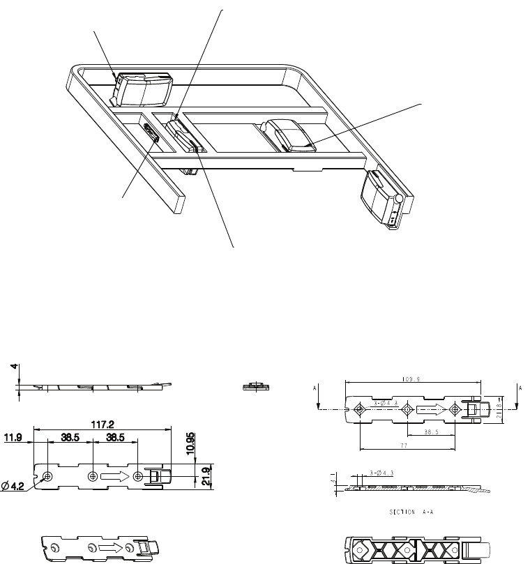
Page 84 of 148
Mounting bracket (frame flat)
- article No. 1015W1001:
Mounting bracket (frame flat) w/M4 nuts
- article No. 1015W1009:
CO41 - mounted on frame:
Release hook
Easy-mount bracket
3-way cable exit
Very small built-in dimension:
Height: min. 80 mm (lid can be removed)
Length: + 20 mm (locking system)
Service lid
Integrated hinge
Removable if needed
...to be continued
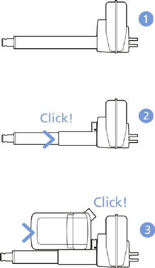
Page 85 of 148
Mounting instructions (Example CO41 with LA40)
When mounting the control box onto the actuator (1)
Simply slide on the bracket until you hear a clear click (2)
Slide on the control box until you hear a click and the box is mounted (3)
It is recommended that the CO41 is mounted in a position that allows water to escape.
Recommended torque: 0.6 Nm +/-0.1
The bracket can be mounted to the bed frame or any other application by following one of the following mounting procedures:
1) M6 nut to be placed in bracket and fixed with M6 bolt from the rear side.
2) M5 machine screw with flat washer to be fixed through bracket with nut on the rear side.
3) Self-tapping screw to be placed through bracket and onto the frame.
...to be continued

Page 86 of 148 ...to be continued
Mounting of cables and cable lock:
CO41 has a uniquely designed cable lid. The lid also works as an integrated cable lock when closed.
1) Mount cable plugs in control box
2) Close lid until lock snaps into place (see arrows)
To allow free access to the cables, the lid has a rest position when completely opened.
It is possible to remove the lid by lifting it a few degrees and pulling it away from the housing under tight mounting conditions.
See illustrations:
1
Cable management:
2

Page 87 of 148
Recommendations
• To avoid that hand control cables short-circuit, LINAK recommends to use an OpenBus system (CO41).
• When the system is overloaded, LINAK recommends to use quick release actuators in the application. These will allow functions to be lowered
manually in case of a CO41 malfunction due to misuse/abuse.
• If the customer has other essential performance than “no unintended movement”, he must consider this in his own risk analysis.
LINAK disclaims any liability.
• If the actuator or the control cable is removed from the control box, the cable lock must be applied. To ensure movement in this case,
LINAK recommends to use quick release actuators in the application.
• If the cable is damaged by pulling, LINAK recommends to make a safe cabling. If movement is an essential performance, LINAK recommends to
apply quick release actuators, for example, to ensure movement.
• If the thermal protection is activated due to current overload when operating multiple actuators and/or excessive duty cycle, the operation must be
kept within the specification. If movement is an essential performance, LINAK recommends to apply quick release actuators, for example,
to ensure movement.
• Sales must request a review of the products according to current cut-off limits.s.
Motor cable
Always use 6-wire cables.
Please note that angled motor cable plugs are required for connection to the control box.
Because of the half-bridge technology used in CO41 there is an interdependence between each half-bridge, CH1 + 2 and CH3 + 4. Half-bridge
connected channels cannot run simultaneously in opposite directions. E.g. running a trend function using CH3 and CH4 will not be possible.
Warnings
• Use EPR or ensure that the user takes care not to squeeze the mains cable.
• Always check correct assembly after mounting and service to ensure that the cable lock is mounted.
(Connectors are usually removed during cleaning)
• Always use approved chemicals with the housing as the plastic may show corrosion caused by some chemicals. As a result water may
accumulate/gather in housing.
• Take special precautions concerning 3rd party interfacing. Please contact LINAK for further information.
• Make a review of all product specifications before system set-up if the current cut-off limit is higher than the maximum allowed
current cut-off for the actuator.
• To avoid cable interruption and actuator defects make a proper cable installation and inspect regularly for wear and damage.
Defective parts must be replaced.
• After service inspection, the application must be tested for correct functionality before it is put into operation to avoid actuator plugs being
mixed during service. Operators must not be inside entrapment area.
• To avoid electrical failure or system disturbance inspect regularly for wear and damage. Defective parts must be replaced.
• Make a proper cable installation to avoid short-circuit cables for handset/controls. Regular inspection must be made for wear and damage.
Defective parts must be replaced.
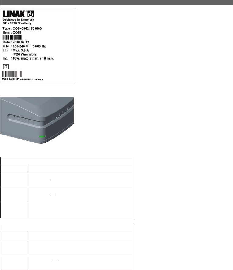
Page 88 of 148
The LINAK control box CO61 offers a consolidated range of unprecedented features – all utilising
standardised technology, interfaces and compatibility.
The CO61 for LINAK actuators is intended for the control of, for example, hospital bed movement.
Equipped with 200W SMPS, excellent and well thought-out cable management as well as multiple
easy mounting options, this control box opens up a wide range of application possibilities for the
provident hospital and care products manufacturer.
LED indicator
CO61 is equipped with a green LED for indication of mains power connected.
When the CO61 is connected to mains, the LED is green. Connected only to battery, the LED is off.
18. CO61 (MEDLINE® CARELINE® )
Features:
• Duty cycle: 10 % - 2/18 min. on/off continuous use.
Maximum power is 200 W for 80 seconds and 100 W for 40 seconds at 25° C.
...to be continued
Acoustic signal functionality:
The buzzer will make a warning, when a button on the hand control is pressed, and the battery capacity is low.
The buzzer can also be activated by the control box to signal other conditions. This must be specified in the control box software.
Connected to MAINS
LED colour Indication of operation
Green On mains, not activated by hand or foot control.
The system is working ok and is ready for normal operation.
Yellow On mains, not activated by hand or foot control.
The system is defective and should not be operated.
Yellow On mains, activated by hand or foot control.
The system is working.
Not connected to mains but with BATTERY back-up
LED colour Indication of operation
Orange On battery, activated by hand or foot control.
The system is working.
No LED On battery, not activated by hand or foot control.
or CO61 not connected to mains.
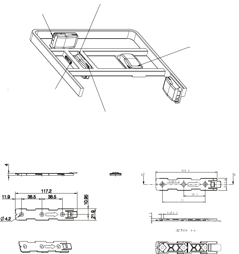
Page 89 of 148
Mounting bracket (frame flat)
- article No. 1015W1001:
Mounting bracket (frame flat) w/M4 nuts
- article No. 1015W1009:
CO61 - mounted on frame:
Release hook
Easy-mount bracket
3-way cable exit
Very small built-in dimension:
Height: min. 80 mm (lid can be removed)
Length: + 20 mm (locking system)
Service lid
Integrated hinge
Removable if needed
...to be continued

Page 90 of 148
Mounting instructions (Example CO61 with LA40)
When mounting the control box onto the actuator (1)
Simply slide on the bracket until you hear a clear click (2)
Slide on the control box until you hear a click and the box is mounted (3)
It is recommended that the CO61 is mounted in a position that allows water to escape.
Recommended torque: 0.6 Nm +/-0.1
The bracket can be mounted to the bed frame or any other application by following one of the following mounting procedures:
1) M6 nut to be placed in bracket and fixed with M6 bolt from the rear side.
2) M5 machine screw with flat washer to be fixed through bracket with nut on the rear side.
3) Self-tapping screw to be placed through bracket and onto the frame.
...to be continued
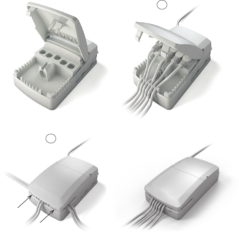
Page 91 of 148 ...to be continued
Mounting of cables and cable lock:
CO61 has a uniquely designed cable lid. The lid also works as an integrated cable lock when closed.
1) Mount cable plugs in control box
2) Close lid until lock snaps into place (see arrows)
To allow free access to the cables, the lid has a rest position when completely opened.
It is possible to remove the lid by lifting it a few degrees and pulling it away from the housing under tight mounting conditions.
See illustrations:
1
Cable management:
2

Page 92 of 148
Recommendations
• To avoid that hand control cables short-circuit, LINAK recommends to use an OpenBus system (CO61).
• When the system is overloaded, LINAK recommends to use quick release actuators in the application. These will allow functions to be lowered
manually in case of a CO61 malfunction due to misuse/abuse.
• If the customer has other essential performance than “no unintended movement”, he must consider this in his own risk analysis. LINAK disclaims
any liability.
• If the actuator or the control cable is removed from the control box, the cable lock must be applied. To ensure movement in this case, LINAK
recommends to use quick release actuators in the application.
• If the cable is damaged by pulling, LINAK recommends to make a safe cabling. If movement is an essential performance, LINAK recommends to
apply quick release actuators, for example, to ensure movement.
• If the thermal protection is activated due to current overload when operating multiple actuators and/or excessive duty cycle, the operation must be
kept within the specification. If movement is an essential performance, LINAK recommends to apply quick release actuators, for example, to ensure
movement.
• Sales must request a review of the products according to current cut-off limits.
Motor cable
Always use 6-wire cables.
Please note that angled motor cable plugs are required for connection to the control box.
Warnings
• Use EPR or ensure that the user takes care not to squeeze the mains cable.
• Always check correct assembly after mounting and service to ensure that the cable lock is mounted. (Connectors are usually removed during cleaning)
• Always use approved chemicals with the housing as the plastic may show corrosion caused by some chemicals.
As a result water may accumulate/gather in housing.
• Take special precautions concerning 3rd party interfacing. Please contact LINAK for further information.
• Make a review of all product specifications before system set-up if the current cut-off limit is higher than the maximum allowed current cut-off for
the actuator.
• To avoid cable interruption and actuator defects make a proper cable installation and inspect regularly for wear and damage.
Defective parts must be replaced.
• After service inspection, the application must be tested for correct functionality before it is put into operation to avoid actuator plugs being mixed
during service. Operators must not be inside entrapment area.
• To avoid electrical failure or system disturbance inspect regularly for wear and damage. Defective parts must be replaced.
• Make a proper cable installation to avoid short-circuit cables for handset/controls. Regular inspection must be made for wear and damage.
Defective parts must be replaced.
• Do nut mount the actuator with the spindle facing downwards to avoid that the actuator slips off the bracket with mounted control box.
The bracket can come loose when exposed to shock or hard vibration, for instance when passing doorsteps.
Regular inspection must be made to ensure proper fixation of control box and bracket on actuator.
Page 93 of 148
The LINAK control box CO71 offers a consolidated range of unprecedented features – all utilising
standardised technology, interfaces and compatibility.
The CO71 for LINAK actuators is intended for the control of, for example, hospital bed movement.
Equipped with 350W SMPS, excellent and well thought-out cable management as well as multiple
easy mounting options, this control box opens up a wide range of application possibilities for the
provident hospital and care products manufacturer.
LED indicator
CO71 is equipped with a green LED for indication of mains power connected.
When the CO71 is connected to mains, the LED is green. Connected only to battery, the LED is off.
19. CO71 (MEDLINE® CARELINE® )
Features:
• Duty cycle: 10 % - 2/18 min. on/off continuous use.
Maximum power is 350 W for 80 seconds and 175 W for 40 seconds at 25 °C.
...to be continued
Acoustic signal functionality:
The buzzer will make a warning, when a button on the hand control is pressed, and the battery capacity is low.
The buzzer can also be activated by the control box to signal other conditions. This must be specified in the control box software.
Connected to MAINS
LED colour Indication of operation
Green On mains, not activated by hand or foot control.
The system is working ok and is ready for normal operation.
Yellow On mains, not activated by hand or foot control.
The system is defective and should not be operated.
Yellow On mains, activated by hand or foot control.
The system is working.
Not connected to mains but with BATTERY back-up
LED colour Indication of operation
Orange On battery, activated by hand or foot control.
The system is working.
No LED On battery, not activated by hand or foot control.
or CO71 not connected to mains.
CO71
CO7+19431X29000

Page 94 of 148
Mounting bracket (frame flat)
- article No. 1015W1001:
Mounting bracket (frame flat) w/M4 nuts
- article No. 1015W1009:
CO71 - mounted on frame:
Release hook
Easy-mount bracket
3-way cable exit
Very small built-in dimension:
Height: min. 80 mm (lid can be removed)
Length: + 20 mm (locking system)
Service lid
Integrated hinge
Removable if needed
...to be continued
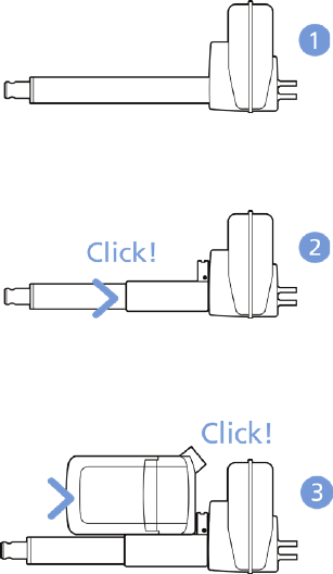
Page 95 of 148
Mounting instructions (Example CO71 with LA40)
When mounting the control box onto the actuator (1)
Simply slide on the bracket until you hear a clear click (2)
Slide on the control box until you hear a click and the box is mounted (3)
It is recommended that the CO71 is mounted in a position that allows water to escape.
Recommended torque: 0.6 Nm +/-0.1
The bracket can be mounted to the bed frame or any other application by following one of the following mounting procedures:
1) M6 nut to be placed in bracket and fixed with M6 bolt from the rear side.
2) M5 machine screw with flat washer to be fixed through bracket with nut on the rear side.
3) Self-tapping screw to be placed through bracket and onto the frame.
...to be continued
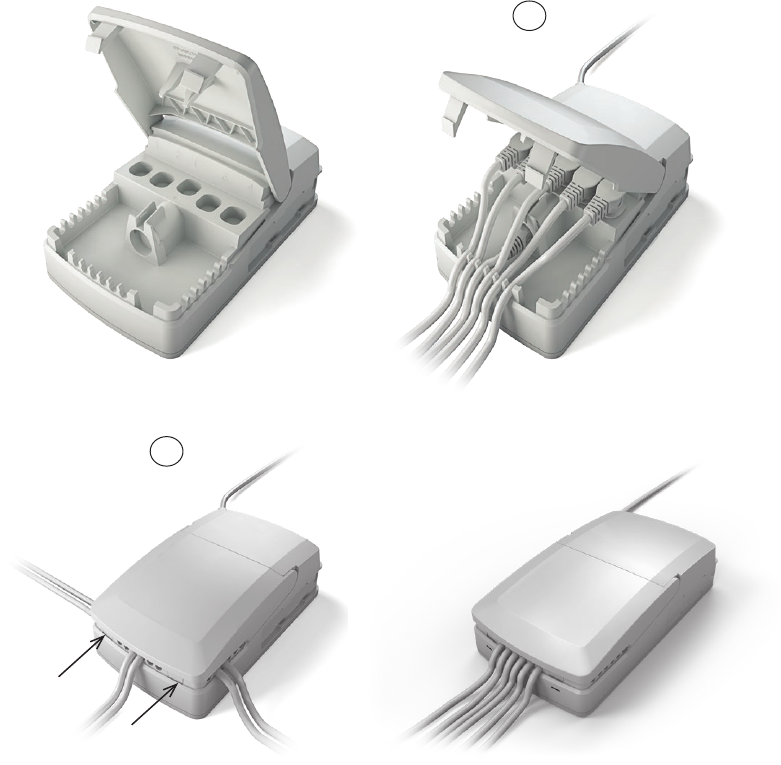
Page 96 of 148 ...to be continued
Mounting of cables and cable lock:
CO71 has a uniquely designed cable lid. The lid also works as an integrated cable lock when closed.
1) Mount cable plugs in control box
2) Close lid until lock snaps into place (see arrows)
To allow free access to the cables, the lid has a rest position when completely opened.
It is possible to remove the lid by lifting it a few degrees and pulling it away from the housing under tight mounting conditions.
See illustrations:
1
Cable management:
2

Page 97 of 148
Recommendations
• To avoid that hand control cables short-circuit, LINAK recommends to use an OpenBusTM system (CO71).
• When the system is overloaded, LINAK recommends to use quick release actuators in the application. These will allow functions to be lowered
manually in case of a CO71 malfunction due to misuse/abuse.
• If the customer has other essential performance than “no unintended movement”, he must consider this in his own risk analysis.
LINAK disclaims any liability.
• If the actuator or the control cable is removed from the control box, the cable lock must be applied. To ensure movement in this case,
LINAK recommends to use quick release actuators in the application.
• If the cable is damaged by pulling, LINAK recommends to make a safe cabling. If movement is an essential performance, LINAK recommends to
apply quick release actuators, for example, to ensure movement.
• If the thermal protection is activated due to current overload when operating multiple actuators and/or excessive duty cycle, the operation must be
kept within the specification. If movement is an essential performance, LINAK recommends to apply quick release actuators, for example, to ensure
movement.
• Sales must request a review of the products according to current cut-off limits.
Motor cable
Always use 6-wire cables.
Please note that angled motor cable plugs are required for connection to the control box.
Warnings
• Use EPR or ensure that the user takes care not to squeeze the mains cable.
• Always check correct assembly after mounting and service to ensure that the cable lock is mounted.
(Connectors are usually removed during cleaning)
• Always use approved chemicals with the housing as the plastic may show corrosion caused by some chemicals. As a result water may
accumulate/gather in housing.
• Take special precautions concerning 3rd party interfacing. Please contact LINAK for further information.
• Make a review of all product specifications before system set-up if the current cut-off limit is higher than the maximum allowed current
cut-off for the actuator.
• To avoid cable interruption and actuator defects make a proper cable installation and inspect regularly for wear and damage.
Defective parts must be replaced.
• After service inspection, the application must be tested for correct functionality before it is put into operation to avoid actuator plugs
being mixed during service. Operators must not be inside entrapment area.
• To avoid electrical failure or system disturbance inspect regularly for wear and damage. Defective parts must be replaced.
• Make a proper cable installation to avoid short-circuit cables for handset/controls.
Regular inspection must be made for wear and damage. Defective parts must be replaced.
• Loss of mains: If the power supply is switched off for a short time (between 1 and approx. 1.5 seconds), the control box will only start up again

Page 98 of 148
6. Information on specific controls
The ACC (Attendant Control Compact) is fitted to advanced hospital and patient care beds for use where
patient positioning must be carefully controlled by medical staff.
With the OpenBusTM system it is possible to use keypads as attendant control or hand controls integrated in the bed side rails.
Features and Options:
• Straight cables: 1250, 1800 or 2500 mm
• The standard ACK colour is grey (RAL 7035)
For LINAK Standard ACK’s, the following is applicable:
• Adhesive for the standard ACK is 3M 468MP
• For information re. suitable and unsuitable surfaces, please see 3M’s webpage
• Standard recommandation for curing time is 72 hours
• The customer is responsible for correct mounting on suitable surfaces
For datasheets and additional informations regarding the adhesives: www.3M.com
For Customised ACK’s, the following is applicable:
Dependant on the customer’s own design, installation, application and test it is possible to improve the IP protection class by the use of a special ACK
introducing an extra sealing ring to avoid ingress. Mounting and curing times depend on the customer application.
Recommendations
• The customer responsibility includes making a proper design of the cable strain relief inside the side rail panel.
• The customer should consider and ensure to use the correct flammability classification when defining and specifying the housing.
According to IEC 60601-1. Minimum HB plastic.
• The customer should consider the existence of vibrations when defining and specifying the housing, i.e. we recommend the customer to carry out a
vibration test on the final product.
• The customer must ensure a proper IP rating/test
• The customer must ensure proper drop testing according to IEC60601-2-52 §201.15.3.4.1. In this clause there is an additional reference to
IEC60601-2-31:2008.
• The customer is responsible for correct mounting of the PCBA. Among other things, it means
- ensuring proper and safe mounting of the PCBA into ex. the side rail
- ensuring proper and correct mounting between key pad connection tails and the ACK PCBA
- ensuring proper and correct mounting of the key pad
- the customer should consider proper precautions against ESD (Electrostatic discharge).
• When handling ESDS (Electrostatic Discharge Sensitive) devices – e.g. during transport, storage, handling, production or mounting in an
application - exposure to harmful ESD must be avoided.
• Consider proper creepage and clearance measures to fulfil IEC 60601. With One MOPP (One Means Of Patient Protection / Secondary side of the
actuator system) requirements are:
- creepage distance = 2 mm / air clearance = 1 mm (Working voltage V d.c. up to and including)
• It is not recommended to dismount the keypad after mounting because it gives a high risk of failing key press.
1. ACC (MEDLINE® CARELINE®)
2. ACK (MEDLINE® CARELINE®)
Usage:
• Operation temperature: +5 °C to +40 °C
• Storage temperature: -10 °C to +50 °C
• Compatibility: LINAK OpenBus™ control boxes
The ACL (Attendant Control Lock) box is a one turn button box fitted to hospital and care beds for use where
the patient positioning must be carefully controlled by the medical staff.
The ACL disconnects all functions on some handsets.
3. ACL (MEDLINE® CARELINE®)
Page 99 of 148
The ACM (Mini Attendant Control) box is fitted to hospital and care beds for use where patient positioning
must be carefully controlled by the medical staff.
The compact design and simple operation makes it easy for the nursing staff to retain direct control over
critical positioning functions whilst giving the patient a limited degree of adjustment.
The ACM must be mounted correctly on a flat surface to ensure IP degree. A short circuit in the cable can
cause movement. To possibly avoid this risk, choose a OpenBus system.
4. ACM (MEDLINE® CARELINE®)
The ACO (Attendant Control OpenBusTM) is a cost optimised and compact unit with up to 15 buttons that can
be used as Handset keys or lock-outs. The lock-out function can be made visable by using yellow LED´s.
The ACO is compatible with control boxes that use an OpenBus interface i.e. CB6S, CB16 and CB20.
Usage:
• Compatible with OpenBus™ e.g. CB20, CB6S and CB16.
• Ambient temperature: +5˚ to + 40˚C
• Approvals: IEC 60601-1 Edition 3.1 (2012)
IEC 60601-1-6:2010 + A1:2013,
ANSI/AAMI ES60601-1: A1:2012, C1:2009/(R) 2012 and A2:2010/(R)2012,
CAN/CSA-C22.2 NO. 60601-1:14
• Current consumption: 15 mA (Standard versions with 5 no. LEDs (5 LEDs x 2 mA = 10 mA)
+ microprocessor 5 mA, total = 15 mA
In order to comply with the norm, the ACO must hang vertically from its hook during the washing process.
5. ACO (MEDLINE® CARELINE®)
Recommendations
• Always use Locking ring and cables with O-rings.
• Locking ring and cables with O-rings must be fitted to ensure IP degree.
• If other front covers than standards are requested, the customer must design them.
N.B.
• Cables are inclusive an O-ring.
ACOM is the obvious control for hospital and nursing home beds where
patient positioning needs careful control by medical staff. ACOM is an
OpenBusTM control.
Usage:
• Operation temperature: +5 °C to + 40 °C
• Storage temperature: -10 °C to + 50 °C
• Relative humidity: 20 % to 80 % at +30° C, non-condensing
• Atmospheric pressure: 700 to 1060 hPa
• Approvals: IEC 60601-1 Edition 3.1 (2012), IEC 60601-1-6:2010 + A1:2013
• Compatibility: Compatible with LINAK OpenBus control boxes, CO-generation
6. ACOM (MEDLINE® CARELINE®)
Recommendations
• Clean the hand control regularly to ensure good hygiene standards.
• When a defective ACOM is replaced, check that the new ACOM has exactly the same specification and functionality.
• Do not submerge the hand control in water.
• Unless otherwise specified or agreed with LINAK, the hand control is only intended to be used for LINAK systems.
• When changing hand controls for OpenBus systems, the power must be switched off.
• It is recommended to check the hand control and cable for damage and holes caused by violent handling before washing the application or at
least once a year.
• It is recommended to have a parking place for the hand control on the application where the customer ensures that the hand control does not fall off.
Warnings:
• Do not sit or lie on the hand control as this can cause unintended movement of the application.
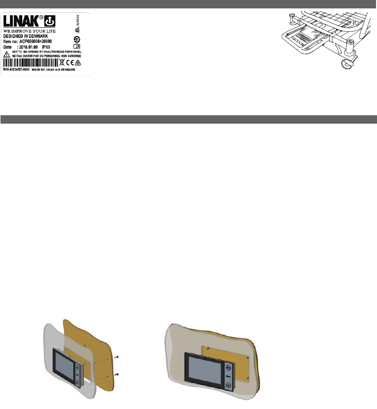
Page 100 of 148
The ACP (Attendant Control Panel) controller is fitted to advanced
hospital and patient care beds for use where patient positioning
must be carefully controlled by medical staff.
The ACP allows nursing staff to retain direct control over critical
positioning functions while giving the patient a limited degree of
adjustment.
It is recommended to clean all surfaces, also surfaces covered by lids and the inside of the lids.
(In the event that the ACP is cleaned in wash tunnels; be aware that surfaces covered by lids and the inside of lids will not be cleaned)
7. ACP (MEDLINE® CARELINE®)
The Attendant Control Touch (ACT) for the hospital and care segment is a control panel with an intuitive, graphical three-level user interface:
1. Care mode for caregivers and relatives (bed operation)
2. Extended care mode for caregivers (locking function, settings etc.)
3. Service mode for technicians (advanced settings)
Usage:
• Operation temperature: +5°C to + 40°C
• Storage temperature: -10°C to + 50°C
• Relative humidity: 20% to 80%
• Atmospheric pressure: 700 to 1060 hPa
• Approvals: IEC60601-1:2005 3rd edition
ANSI/AAMI ES60601-1:2005 3rd edition
CAN/CSA-22.2 No 60601-1:2008
• Compatibility: All OpenBusTM control boxes except CB6OBL
8. ACT (MEDLINE® CARELINE®)
Mounting instructions:
The ACT must be mounted on the bed, for example on the footboard - illustration of the fitting is shown below.
The ACT must be supported on the back of the housing when fastening it to the mounting plate and not only supported on the edge of the housing
front side.
When mounting:
• LINAK recommends to use a self-tapping screw, BN84229, 50x12.
• Please observe that the 1.5 [Nm] screw torque limit is not exceeded.
• Please be aware that the screw holes in the ACT are only 11 mm deep. Use appropriate screws.
• Please ensure that the mounting leaves space (2 mm) between the ACT and the back of the housing. This to avoid that water is trapped.
The space is only necessary where the membrane is placed on the ACT.
• If upward cable exit is used, mount a ferrite core to the cable (see section “Ferrite core”).
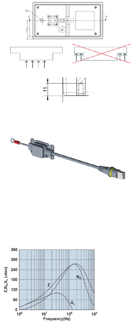
Page 101 of 148
The recommended screw type is self-tapping BN84229 50 x 12.
A grounding cable (article no.: 1009W7004) will be supplied together with the ACT and must be connected to the OpenBusTM system and the other
end to the bed frame to decouple electrical fields.
...to be continued
Ferrite core :
If upward cable exit is used, a ferrite core needs to be added as close as possible to the ACT.
Ferrite core specification:
At the mentioned frequencies, the impedance must be as stated in the table:
Frequency (MHz) 10 25 100 250
Impedance (Ω) 95 156 260 270
Ferrite core graphic characteristics:
Impedance, reactance, resistance vs. frequency

Page 102 of 148
The DPH is a small two button panel for adjustment of different functions. The DPH fits into a MJB with a modular plug and thereby compatible with
OpenBus.
Usage:
• Ambient temperature: +5° to +40°
• DPH is compatible with the OpenBox control boxes via Modular Junction Boxes MJB5061101-00 as follows:
Control Boxes: CB6S OBL, CB6S OBM, CB6S OBF, CB16 OBL, CB16 OBF, CB20
Modular Junction Box: MJB5061101-00
• DPH1K10-210007 combined with MJB5061101-00 creates the OpenBus codes:
Up Arrow: H0
Down Arrow: H1
• Wrong mounting is not an issue with the MJB5061101-00 and the modular jack plug of the DPH cable.
The plug will only fit into the correct ports of the MJB.
9. DPH Medical (MEDLINE® CARELINE®)
Technical recommendations:
• Always use the cable locking mechanism and an O ring.
• Prepare a system/bit overview as the unit may conflict with other OpenBusTM accessories such as HB, ACP etc.
• Avoid large metal parts in the vicinity of the RFID reader (approx. 50 mm).
• When designing the application, be aware of the ACT position in the application to avoid impact to the front glass.
• Allow for a power consumption of max. 200 mA on both V-Bus and Vpermanent when designing a system.
• Use a LINAK magnet or a magnet with a minimum strength of 15 mT measured at a distance of 10 mm.
• Do not bend the cable more than the minimum bending radius of 10 mm when mounting the ACT in side rails or similar
where the cable is repeatedly bent.
• Before first start-up, be aware not to place any magnetic devices or RFID tags in front of the company logo until the ACT
goes into sleep mode to avoid calibration disturbance. (see start-up description under Functionality).
• Be aware that magnetic jewellery or magnets in general can activate care mode and lead to unintended use. LINAK recommends to use RFID tags.
Warnings:
• The application manufacturer must write an end-user manual based on the LINAK user manual which also includes relevant warnings,
information on how to carry out regular inspection and a functionality description. End-users must be trained in all functions.
• Regular system inspections for wear or damage must be made.
• Mains and battery power must be disconnected before servicing.
• The magnet key cannot wake up a system in power-down mode or a system running on battery. The system will wake up when activating a key
and the magnet key can then unlock the system.
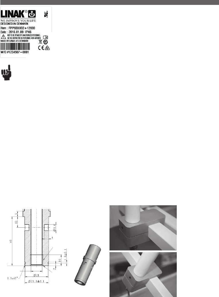
Page 103 of 148
The FPP is for use with a variety of different bed types and is therefore compatible with control boxes that use
an OpenBus™ interface i.e. CB6S, CB16 and CB20.
Recommendations
• The application manufacturer must insure a proper installation of the FPP in the application. The installation must be convenient for the end-user.
• To ensure proper activation, the lock above the housing must be properly locked by turning it clockwise.
• The application manufacturer must ensure the correct torque to the slotted set screw at the bracket, to ensure a stable positioning of the FPP.
• The application manufacturer must consider the bracket location for the FPP: If the FPP is mounted at a moveable part, it will move and might
touch the patient or parts of the application. If mounted at a fixed part, the patient might move out of range to reach the FPP or he might even be
hit by the FPP.
• The end-user must not apply a torque to the FPP housing exceeding 8 Nm between the flexible arm and the panel.
• The end-user must not bend the FPP arm to a radius smaller than 105 mm.
• The FPP must not be useed as a handle at any time when moving the application.
• The end-user must be informed that the FPP must not be used for other purposes (e.g. table, handle) than intended, i.e. as a Flexible Patient Panel (FPP).
• The end-user must ensure the FPP does not hit items or persons when the application is moved.
Usage:
• Ambient temperature: +5° to +40°
• Approvals: LINAK and UL International DEMKO A/S are currently in the process of certifying
FPP re. UL60601 and EN60601-1.
• Current consumption: 15 mA (Standard versions with 5 no. LED’s (5 LED’s x 2 mA = 10 mA) +
microprocessor 5 mA, total = 15 mA
Mounting instructions:
The FPP is intended for mounting at the head end of a bed so the patient is able to see and operate it with an easy push of a button. After use it can
be moved a short distance away with an easy movement.
The FPP comes with a cable attached. The bottom part of the arm is prepared for mounting inside a bracket - fitting the diameter of the arm.
The bracket is not supplied by LINAK but must be designed and made by the customer. It must fit the dimensions shown. A suggestion to a design is
illustrated on below pictures as well as the dimensions of the parts for fixation.
Possible bracket design.Dimensions lIllustration:
The FPP must be mounted in such a manner that it is secured against rotation. For this purpose the bracket end of the arm has 4 x drilled holes - one
of the 4 holes must be secured via the bracket with a slotted set screw with cone point (pointed screw).
Otherwise it may slide away from the user when operated.
10. FPP (MEDLINE® CARELINE®)
...to be continued
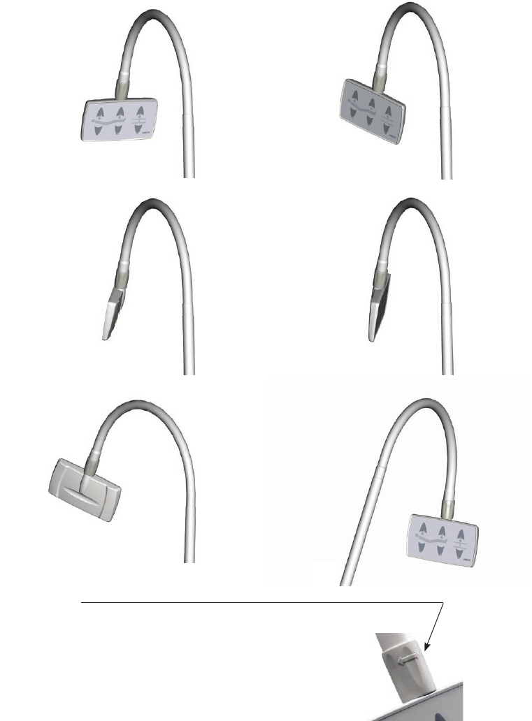
Page 104 of 148
As illustrated from the pictures below the panel itself can be moved and angled in a number of positions. The arm can also be bent to move it closer
to or move it further away from the user.
The lock function
Between the arm and the panel there is a lock/unlock function, (a hose type connection).
It enables the user to turn the panel into a preferred position.
Locking of the Panel:
Turn the panel to a preferred position. With one hand on the panel turn the hose clockwise
with the other hand. The Panel is fully locked when the panel cannot be turned.
Unlocking of the Panel:
With one hand on the panel turn the hose counter clockwise with the other hand until the
panel can be moved freely.
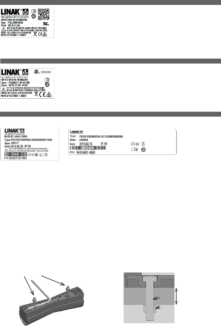
Page 105 of 148
The Foot Switch is a modular system, developed for use together with some of LINAK control boxes.
The LINAK Foot Switch is designed for control of physiotherapeutic beds, hospital beds, dentist chairs,
gynaecologist chairs, computer workstations, and working desks etc. It can also be used as a “stand alone”
item for industrial applications.
Footswitch
Consist of: FS (a pedal unit) and FSE (electronics unit), which can activate one or more actuators. The module
system can max. consist of two pedal units, a FSR (right pedal), a FSL (left pedal), and one electronics box.
The FS2 Foot Switch is developed for use together with some of LINAK control boxes and especially designed
for mounting on a support plate.
The Foot Switch is available in a single and a double version.
The double version can be used on a bed where one Foot Switch will be mounted on each side of the bed
frame, thus enabling operation from both sides.
Bed adaptorFloor adaptor
The Foot Switch FS3 is an ergonomically designed modular system, developed for use together with LINAK control boxes and IC actuators with
Intelligent Control. The LINAK® Foot Switch is designed for easy and improved control of e.g. hospital beds and couches and has been developed in
cooperation with end users. The Foot Switch is therefore very user- and cleaning-friendly and has an aesthetic design.
The FS3 is a robust foot control which is available both as a single and double version as well as a floor and bed model. When mounting the double
version on a bed, the Foot Switch will be placed on each side of the bed frame to enable easy operation from both sides. It is also possible to have
the double floor version for medical applications, e.g. couches, in order to achieve the opportunity to control different motions of the application. The
FS3 is furthermore available in an analogue version and a digital OpenBus™ version.
Usage:
• Usage temperature: + 5º C to + 40º C
• Storage temperature: -10º C to + 50º C
• Relative humidity: 20% to 80% at +30°C
• Atmospheric pressure: 700 to 1060 hPa
• Compatibility: LA27CS, LA43 IC, LA44 IC, analogue control boxes and OpenBusTM control boxes
• Approvals: IEC60601-1:2005 3rd edition, ANSI / AAMI ES60601-1:2005 3rd edition and CAN / CSA-22.2 No 60601-1:2008
Mounting of the FS3 bed model:
To mount the FS3 bed model, you have to use the bolt and the nut which have already been fitted to the FS3 bed model (see picture below).
Bolt and nut for mounting
7 mm
Bolt M5 x 25
Nut M5
11. FS (MEDLINE® CARELINE® TECHLINE®)
12. FS2 (MEDLINE® CARELINE®)
13. FS3 (MEDLINE® CARELINE®)
...to be continued
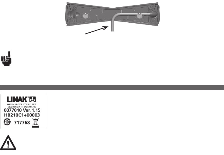
Page 106 of 148
You have to remove the nut before mounting the FS3 on the bed and after mounting the FS3 to the bed, the nut is fastened to secure that the FS3 is
fixed to the bed frame.
Please note that the max. torque on the nut should be 2.0 Nm (20 kg f. cm).
When mounting the FS3 bed model, it is important to run the cable through the hole of the FS3 in order to lead the cable through
(see picture below).
Location of the notch for the cable of the FS3 bed model.
Recommendations
• Do not pull the cable or drop the FS3 on the floor.
• Do not play with the FS3.
The HB20 series combines ergonomic design with a wide range of functionalities such as memory and infrared
communication. The handset series is compatible, via the IRO, with the OpenBus™ product assortment.
Warning
• Inform the customer not to exceed the IP degree and to make regular inspection for correct functionality.
Defective and worn out parts must be replaced.
• Inform the customer that due to the soft material of the soft touch buttons, they can remain activated when released after a forced, any activation.
• Inform the customer that there is no indication for low battery. At low battery, the IR range is reduced and it is recommended to replace the
batteries. After replacing the batteries, the functionality and IR range must be tested.
• Inform the customer that all IROs that receive the HB2x signal will operate. There is no pairing between a unique HB2x and an IRO.
14. HB20 (MEDLINE® CARELINE® HOMELINE®)
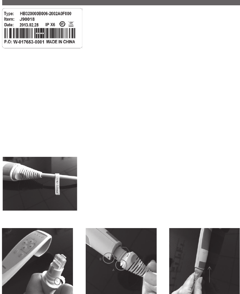
Page 107 of 148
The HB30 hand control is designed for better user experience and ergonomic fit for the hands
of caregivers. The compact size ensures one hand operation. The HB30 is especially suitable for
patient lifts and other MEDLINE® and CARELINE® applications like couches, tables and chairs
for treatment and examination.
Usage:
• Usage temperature: 5° C to 40° C
• Storage temperature: -10° C to +50° C
• Compatibility: Analogue JUMBO Systems
Analogue JUMBO systems with diode and OpenBus
JUMBO versions
All OpenBus control boxes
• Approvals: IEC60601-1:2005 3rd edition approved, ANSI / AAMI
ES60601-1:2005 3rd edition and CAN/CSA-22.2
No 60601-1:2008 pending
The HB30 is biocompatibility tested and approved according to DS/EN ISO 10993-5:2009, biological evaluation of
medical devices - part 5: Tests for in vitro cytotoxicity. It is a demand for hand-held devices for patient lifts.
The HB30 has a compact design and therefore it cannot be approved according to EN IEC60601-2-52
(Application Environment 4 for care beds used in Domestic areas (or EN1970)).
How to identify the cables:
Each cable has a label for easy identification of item number and for which control box it is intended.
How to mount a cable:
Step 1:
Mount the cable lock and fix it to the slot
marked in the picture.
Step 2:
Fix the cable tab on the hand control’s front
side first. Push in and twist a bit to fix the tab
(see picture fit A into B).
Step 3:
Fix the tab on the back as well by pushing.
15. HB30 (MEDLINE® CARELINE® )
...to be continued
Page 108 of 148
Step 1:
Release the cable by pushing e.g. a
screwdriver into the hole on the back
of the hand control. Twist and release.
How to remove a cable:
Recommendations
• Please ensure that you use the right cable type to ensure the wished functionality. In case of lack of functionality of your hand control, check that
the hand control cable is the right one for the intended control box or contact your local LINAK representative.
• Please note that HB3X0L0 version (analogue with diode) is not supported by the CBJC. The diode will light up at all times if used with the CBJC.
• Do not submerge the hand control under water.
• Unless otherwise specified or agreed with LINAK, the hand control is only intended to be used on LINAK systems.
• Do not sit or lie down on the hand control. It can cause unintended movement of the application.
• When changing hand controls for OpenBusTM systems, the power must be switched off.
• The force of the magnet depends on the thickness and the type of the lacquering, stickers, steel thickness etc.
It is the responsibility of the customer to verify that the holding force on the application is acceptable.
• For hand controls with magnets it is the responsibility of the user/operator to evaluate any possible risk caused by use of permanent magnets.
• For hand controls with magnets it is recommended to have a parking place for the hand control on the application, where the customer ensures
that the hand control does not fall off.
Usage:
• Ambient temperature: +5º to +40° C
• HB40 is compatible with CB8-T, CB9..AX(not CH.4) and CB12 (not CH.4)
• HB40A is compatible with CB8-A battery version. Fitted with plug for battery charger CH01.
• HB40E is compatible with CB9Px (except CB9..PM/PN) and CB14
• HB44H is only compatible with CB9..Ax and CB12 (if CH.4) 4 channels
• HB40T is only compatible with CB7 (max. 2 channels)
The HB40 series hand controls are designed for use with LINAK control
boxes.
These sturdy compact units are ergonomically designed and ideal for a
vast range of applications from patient care beds and office furniture to
industrial and agricultural duties.
* only for channels 1, 2 and 3
CB7 CB8 CB8A CB9..Ax CB9..Px
(not CB9..PM/PN
CB12 CB14
HB4xO x x* x
HB4xA x
HB4xE x x
HB4xH x (4ch.) x (4ch.)
HB4xT x
Compatibility:
16. HB40 (MEDLINE® CARELINE® TECHLINE®)
Page 109 of 148
The HB50 is primarily designed for the LINAK JUMBO system and LINAK
control boxes with memory functions.
The HB50 gives the user access to a range of memory functions, allowing
present positions to be stored.
For use in a wide variety of hospital and patient care.
17. HB50 (MEDLINE® CARELINE®)
The HB60 series is exclusively designed to be used together with the LINAK
HOMELINE® system: LA31/LA29 and CB9 with or without memory.
LINAK offers the HB70 with protection class IPX6 as standard and a
range of options such as control of up to 5 actuators, memory, and
simultaneous drive. The HB70 is designed to operate with most LINAK
control boxes.
Usage:
• Compatible with most LINAK control boxes.
• Approved according to: EN 60601-1, EN 60335-1 and UL 60601-1 as part of a LINAK actuator system
Recommendation
• It is not possible to combine HB7x with the binary based CB9..PM/PN.
• The IPX6 Washable version has a special adhesive for the front covers.
• The HB75xE0 used together with CB140 will give trend and anti-trend on channel 1 and 2 of the control box when using the last button row.
• All front covers use the codes W0 (not Washable) and WW (Washable) Memory:
Memory:
• The memory and parallel functions require the control box to have a microprocessor.
• When storing a memory position on the Control Box, the actuators must run to the desired position and the “store” button (S) must be pushed.
Then the desired memory position button (1, 2 or 3) must be activated within 2 seconds.
18. HB60 (HOMELINE®)
Usage:
• Ambient temperature: +5° to +40°
• HB50B is compatible with CBJ2
• HB50E is compatible with CB09P..Px types (except ..PM / PN) and CB14 with memory
• HB50J is compatible with CBJ1
• HB50Y is for Jumbo Home (CBJH)
19. HB70 (MEDLINE® CARELINE®)
Page 110 of 148
The HB80 hand control has an optimised ergonomic design shaped for the hand. The hand control is suitable for
all kinds of MEDLINE and CARELINE applications such as hospital beds, patient lifts, treatment and examination
couches etc.
The HB80 hand control is available in versions with up to 10 or 12 activation buttons.
Usage:
• Usage temperature: 5º C to 40º C
• Storage temperature: -10º C to +50º C
• Compatibility: Compatible with many LINAK control boxes. For further questions, please ask your local LINAK.
• Approvals: IEC60601-1:2005 3rd edition, ANSI/AAMI ES60601-1:2005 3rd edition, and CAN/CSA-22.2 No 60601-1:2008.
The HB86 version has a shorter distance between the buttons and cannot be approved according to EN IEC60601-2-52
Application Environment 4 for care beds used in Domestic area (or EN1970).
HB80 is designed and tested in accordance with EN60601-2-52 cl. 201.11.6.6.101 (Machine washable medical beds).
The HB80 must hang vertically from it’s hook during the washing process.
In order to maintain the flexibility of the cables, it is important that a coiled cable is placed in such a way that the cable’s
own weight does not strain the coil during the washing process.
Recommendations
• Clean the hand control regularly to ensure good hygiene standards.
• When a defective HB80 is replaced, check that the new HB80 has exactly the same specification and functionality.
• Do not submerge the hand control under water.
• Unless otherwise specified or agreed by LINAK - the hand control is only intended to be used on LINAK systems.
• When changing hand controls for OpenBus™ systems, the power must be switched off.
• It is recommended to check the hand control and cable for damage and holes made by violent handling before washing the application or at least
once a year.
• It is recommended to have a parking place for the hand control on the application, where the customer ensures that the hand control does not fall off.
For hand controls with magnets:
• If hand controls with magnet are attached to a smooth surface, a movement or twisting of the cable, for example during transport, can cause the
hand control to move and result in damage if the cable is squeezed.
• The force of the magnet depends on the thickness of the lacquering, the lacquering type, stickers, steel thickness etc. It is the responsibility of the
customer to verify that the holding force on the application is acceptable.
• It is the responsibility of the user/operator to evaluate any possible risk caused by use of permanent magnets.
Warnings
• Do not sit or lie on the hand control. It can cause unintended movement of the application.
• There is a risk that items with internal magnet for mounting instead of hook can disturb function of cardiac pacemaker, implantable cardioverter
defibrillators or magnetic implants!
20. HB80 (MEDLINE® CARELINE®)
Page 111 of 148
Magnet key - article no. 0858008
Warning
• Do not sit or lie on the hand control. It can cause unintended movement of the bed.
• Inform the customer that after loss of mains power, the lock state is reset to the default setting. Be aware of a special setup for a magnet lock of
low power system in case of power down on mains. Also be aware that the lock is reset when running on battery or when powered down.
• Inform the customer that using the magnet key cannot wake up a low power system or a system running on battery. The system will wake up
when activating a key and then the magnet key can unlock the system.
• Inform the customer that a powerful magnetic field may change the lock state.
• Always use O-rings on connectors and cable locks.
• There is a risk that items with internal magnet for mounting instead of hook can disturb function of cardiac pacemaker, implantable cardioverter
defibrillators or magnetic implants!.
Recommendations
• Inform the customer to use only the magnet key supplied by LINAK. We also recommended to make a functional test of the application before putting
it into operation.
• Clean the hand control regularly to ensure good hygiene standards.
• When replacing a defective HD80, check that the new HD80 has exactly the same specification and functionality.
• Do not submerge the hand control under water.
• Unless otherwise specified or agreed by LINAK, the hand control is only intended to be used on LINAK systems.
• When changing hand controls for OpenBus™, the power must be switched off.
• It is recommended to check the hand control and cable for damage and holes made by violent handling before washing the bed or at least once a year.
• In order to maintain the flexibility of the cables, it is important that a coiled cable is placed in such a way that the cable’s own weight does not strain
the coil during the washing process.
For hand controls with magnets:
• If hand controls with magnets are hooked on a smooth surface, a movement or twisting of the cable, for example during transport, can cause the hand
control to move and result in damage if the cable gets squeezed somewhere.
• The force of the magnet depends on the thickness of the lacquering, the lacquering type, stickers, steel thickness etc. It is the responsibility of the
customer to verify that the holding force on the application is acceptable.
• It is the responsibility of the user/operator to evaluate any possible risk caused by use of magnets.
• It is recommended to have a parking place for the hand control on the application where the customer ensures that the hand control does not fall off.
The HD80 makes it possible to have two hand controls in one unit. The hand control
is equipped with a magnet locking function, making it possible to have two levels of
operation – one for the patient and relatives and one for the caregiver staff. The HD80
provides a great overview using LED indication of functions being locked or unlocked.
The hand control is designed to work with OpenBus™ systems.
Usage:
• Usage temperature: 5º C to 40º C
• Storage temperature: -10º C to +50º C
• Compatibility: CB6, CB6S, CB6OBMe, CB16 and CB20 (all OpenBus CBs)
• Relative humidity: 20% to 90% at 30º C - not condensing
• Atmospheric pressure: 700 to 1060 hPa
• Approvals: IEC60601-1:2005 3rd edition, ANSI/AAMI ES60601-1:2005
3rd edition and CAN/CSA-22.2 No 60601-1:2008
The HD80 must hang vertically from it’s hook during the
washing process.
Standard HD80 - HD84C1J0550004-200120012D1C000
Item number J90208
This hand control can be used as a combination of a hand control and the ACO. It has two levels of operation, where the first is a patient mode with
regular operations like hi/lo and trend/anti-trend. Use the magnet key to operate the next level, care mode, where it is possible to lock functions.
The LED lights show which functions are locked and which are not.
21. HD80 (MEDLINE® CARELINE®)
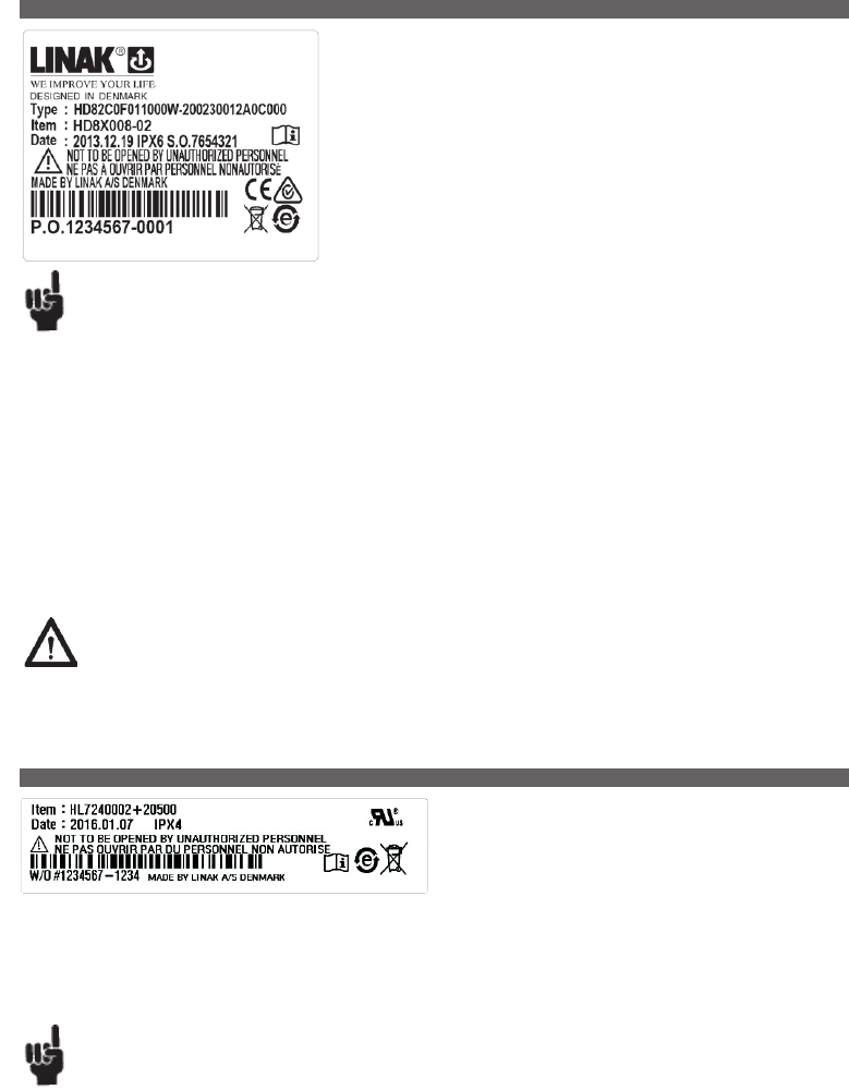
Page 112 of 148
22. HD80 JUMBO (MEDLINE® CARELINE®)
Has an optimised ergonomic design shaped for the hand. The hand control is suitable for
all kinds of MEDLINE and CARELINE applications with OpenBus control system such as
hospital beds, patient lifts, treatment and examination couches etc.
Usage:
• Usage temperature: 5º C to 40º C
• Storage temperature: -10º C to +50º C
• Compatibility: CBJ-C
• Approvals: IEC60601-1:2005 3rd edition, ANSI/AAMI ES60601-1:2005
3rd edition and CAN/CSA-22.2 No 60601-1:2008.
Recommendations
• Unless otherwise specified or agreed by LINAK - the hand control is only intended to be used on LINAK systems.
• When changing hand control for OpenBus™ systems the power must be switched off.
• It is recommended to check the hand control and cable for damage and holes made by violent handling before washing the application or at least
once a year.
• It is recommended to have a parking place for the hand control on the application, where the customer ensures that the hand control does not fall off.
• Clean the hand control regularly to ensure good hygiene standards.
• When a defective HD80 JUMBO is replaced, check that the new HD80 JUMBO has exactly the same specification and functionality.
• Do not submerge the hand control under water.
For hand controls with magnets:
• If hand control with magnet are attached to a smooth surface, a movement or twisting of the cable, for example during transport, can cause the
handset to move and result in damage if the cable is squeezed.
• The force of the magnet depends on the thickness of the lacquering, the lacquering type, stickers, steel thickness etc.
It is the responsibility of the customer to verify that the holding force on the application is acceptable.
• It is the responsibility of the user/operator to evaluate any possible risk caused by use of permanent magnets.
Warnings
• Do not sit or lie on the hand control. It can cause unintended movement of the application.
The HL70 is a handset with integrated locking function, where a selective
locking of the different functions is available by use of a special key.
The HL70 is an alternative to the HB70 combined with an attendant
Control Panel (ACM, ACL, etc.).
23. HL70 (MEDLINE® CARELINE®)
Usage:
• Exchangeable with HB70
• Compatible with many LINAK control boxes
• Approved according to: IEC60601-1:2005 3rd edition, ANSI / AAMI ES60601-1:2005, 3rd edition, and CAN / CSA-22.2 No 60601-1:2008
Recommendations
• To switch between locked and unlocked position a small knob between the two push buttons has to be turned 20° by use of a special key.
The key is for the use of the nursing staff only, there are two types, one is made of plastic the other metal.
• The key has to be ordered separately. Article no. for the plastic key is: 00914516, and the metal key number is: 00914721
• For all types:
Attention should be given to ensure that the channels shown correspond to the channels available on the chosen control box.

Page 113 of 148
Warnings
• When using the locking function on HL80 check that the handset switches are actually locked.
• Locking function on HL80 only locks the actual handset.
• Do not sit or lie on the handset. It can cause unintended movement of the application.
• Locking of a single channel at HL8x do not neccesarily prevent that channel from activation, if the same channel are covered by another handset
button (e.g. at simultaneous drive) or another control unit.
• There is a risk that items with internal magnet for mounting instead of hook can disturb function of cardiac pacemaker, implantable cardioverter
defibrillators or magnetic implants!.
The HL80 handset has an optimised ergonomic design and switch activations.
The HL80 is a lockable handset, which makes it possible to lock or unlock one or several functions.
It is available in several different standard versions with a variation of bed symbols for easy interaction with end-users.
Usage:
• Approved according to: IEC60601-1:2005 3rd edition, ANSI / AAMI ES60601-1:2005, 3rd edition, and
CAN / CSA-22.2 No 60601-1:2008
24. HL80 (MEDLINE® CARELINE®)
Recommendations
• Violent use of the key on HL80 can cause either damage to the keyhole or the key itself.
• If a lock key is missing, then full control over the application could be missing.
• Clean the handset regularly to ensure good hygiene standards.
• When a defective Hx80 is replaced, check that the new Hx80 has exactly the same specification and fuctionality.
• Do not submerge the handset under water.
• Unless otherwise specified or agreed by LINAK, the handset is only intended to be used on LINAK systems.
• When changing handsets for OpenBus™ systems, the power must be switched off.
• It is recommended to check the handset and cable for damage and holes made by violent handling before washing the application or at least
once a year.
• It is recommended to have a parking place for the handset on the application, where the customer ensures that the handset does not fall off.
For handsets with magnet:
• If handsets with magnet are attached to a smooth surface, a movement or twisting of the cable, for example during transport, can cause the
handset to move and result in damage if the cable is squeezed.
• The force of the magnet depends on the thickness of the lacquering, the lacquering type, stickers, steel thickness etc. It is the responsibility of the
customer to verify that the holding force on the application is acceptable.
• It is the responsibility of the user/operator to evaluate any possible risk caused by use of permanent magnets.
Page 114 of 148
The IRO (Infrared Receiver OpenBus™) has been developed as a part of the accessory portfolio to be available
for the CB OpenBus™ family. The receiver is fitted to the bed so that the bed movement can be controlled
with signals received from a remote control (C-type Transmitter).
25. IRO (MEDLINE® CARELINE®)
The LSD type controls the stroke length of the actuator between two fixed end positions by cutting off the current
to the motor.
27. LSD (MEDLINE® CARELINE® TECHLINE®)
There are two types of LINAK limit switches, for actuators type LA22, LA30, LA30S , LS, and LSD.
The LS type gives a signal in two fixed end positions, but requires a control unit to stop the actuator when the
microswitches are activated.
26. LS (MEDLINE® CARELINE® TECHLINE®)
Warnings
• Inform the customer that other handsets/equipment that use a protocol similar to parts of the LINBUS protocol for communication, may have
influence on movement of the application
• Inform the customer that:
- a damaged or a dirty IR window will reduce the receiving sensitivity
- foreign object must not block the visual line from transmitter to the IRO receiver,
- the IRO must be mounted for optimal visual receiving ability
• Inform the customer that interference from other light sources (38 KHz +/- 5 %), e.g. neon light, sunlight or toys may cause a temporary stop in a
movement
• The customer has to mount the IRO at a protected location in the application
• Inform the customer to use the torque 1.5-2.0 Nm for mounting the IRO on the application
Page 115 of 148
The BAJL Li-ion battery pack has been specially developed for use with the JUMBO system for patient lifts and sit to stand lifts. It is a low-weight
battery with reliable and high performance.
Usage:
• Compatibility: CBJ Care, COBO, CHJ2 and CH01
• Duty cycle: BAJL003xxxxxxxx:
10 % (2/18 min.) at max. current draw 10 Amp (ambient temperature ≤ 30 ºC)
10 % (2/18 min.) at max. current draw 8 Amp or
5% (1/19 min.) at max. current draw 10 Amp (ambient temperature > 30 ºC)
BAJL004xxxxxxxx:
10 % (2/18 min.) at max. current draw 10 Amp (standard ambient temperature recommendations)
• Charging: Via JUMBO wall charger CHJ2 or via JUMBO control box with integrated charger
• Charging state: Maximum 30% when shipped from LINAK
•
Recharging during storage: Recharge the battery 6 months at the latest after production date stated on the label
• Operating temperature: +5°C to +40°C
• Charging temperature: +10°C to +40°C
• Charging time: Type 3: 3 to 4 hours - Type 4: 6 to 8 hours
• Storage temperature: -10 °C to +40 °C (+10 °C to +25 °C - recommended)
The batteries must be stored in an applicable storage room without direct sunlight.
• Relative humidity: 20% to 80%
• Atmospheric pressure: 700 to 1060 hPa
• Approvals: IEC60601-1:2005 3rd edition,
ANSI / AAMI ES60601-1:2005, 3rd edition,
CAN / CSA-22.2 No 60601-1:2008,
IEC62133 2nd edition,
UL2054, 2nd edition
PSE (pending)
UN38.8, 6th edition (needed for transport of lithium batteries)
7. Information on specific JUMBOTM
1. BAJ1 & BAJ2 (MEDLINE® CARELINE®)
These battery packs have been specially developed for use with the
JUMBO system.
The battery packs are easy to exchange through an integrated snap system.
The battery packs are easily mounted on the JUMBO mounting brackets.
A customised front cover is possible.
BAJ1 has to be charged with a JUMBO charger CHJ2 or a JUMBO control
box CBJ1 or CBJ2 with integrated charger.
BAJ2 can be charged as BAJ1, but can also be charged through an
integrated DC-plug for use with external charger CH01.
BAJ1 is available in a special edition that can be used in the harsh conditions
in the pool environment both outdoor and indoor.
Usage:
• Duty cycle: 10% or 2 min. continuous use then 18 min. not in use
• Ambient temperatures: +5° to +40 °C
• This battery pack is a part of the JUMBO system. It is compatible with CBJ1/CBJ2 and CHJ2.
• Approvals: IEC60601-1:2005 3rd edition, ANSI/ AAMI ES60601-1:2005 3rd edition and CAN/CSA-22.2 No 60601-1:2008
Warning
Check at regular intervals that the ventilation hole is undamaged and intact. The construction of the ventilation stub permits battery
gasses to get out, but it does not permit penetration of water.
2. BAJL Li-Ion (MEDLINE® CARELINE®)
...to be continued

Page 116 of 148
Mounting
Do not mount the battery upside down.
Please follow the mounting instructions of the control box e.g. CBJ Care or COBO.
Standby mode
When the BAJL Li-Ion is not being used for a longer period - more than a week - or when it is on stock, it enters into a standby mode to save power
and protect the battery from deep discharge.
• Please connect the charger for approx. 15 seconds to exit the standby mode before use.
• There is no audio signal to indicate the standby mode or to indicate exit of standby mode.
After exit of the standby mode
If there is still no power on, the battery needs to be charged.
After charging, the hand control and/or the control box will indicate the battery capacity level again
Deep discharge protection
The BAJL Li-Ion has a deep discharge protection to extend the battery lifetime. The deep discharge protection is activated when the battery is discharged.
• Please connect the charger for approx. 15 seconds to exit the deep discharge mode before use.
If the battery is completely discharged, the charging will be started at a very small rate to protect the battery. This small charging rate is not sufficient
to turn on the light in the charger, and therefore the user may believe that the system has not yet started. Depending on the battery state, it may
take several hours to get to the normal charging state. The orange light of the control box will not be turned on as the operation is analogue. It is
therefore not possible to see that the charging has started, however, only at a low level.
If any of the lithium ion batteries built into LINAK products is found to be defective under warranty, LINAK will provide a new product to the OEM.
LINAK explicitly disclaims all other remedies. LINAK shall not in any event be liable under any circumstances for any special indirect punitive incidental
or consequential damages or losses arising from any incident related to the inherent risk of thermal runaway in the lithium ion cell and any use of
LINAK products. Moreover, LINAK explicitly disclaims lost profits, failure to realise expected savings, any claim against our customer by a third party,
or any other commercial or economic losses of any kind, even if LINAK has been advised of the possibility of such damages or losses.
Transportation
The lithium ion batteries must be packed and transported according to applicable regulations. Always ask your local transportation provider how to
handle the transportation of lithium ion batteries.
Recommendations:
• Do not exceed the storage temperature as it will shorten the lifetime and performance.
• Allow the battery to settle to the temperature specified in the user manual before use or charging.
• Only use correct LINAK charger (CHJ2, CH01 or integrated charger in JUMBO control box).
• Do not exceed the duty cycle as it will shorten the life time and performance.
• BAJL Li-ion is not intended for use in outdoor applications and indoor pool environments.
• If the battery is completely discharged, then recharge the battery before storage.
• Unintentional use of the emergency button, e.g. short activation and deactivation of the emergency button after operating the actuators, can lead
to an error indication of remaining battery capacity. The battery capacity will however be shown correctly approx. 20 seconds after activation of the
emergency button.
• The BAJL goes into sleep mode approximately 20 seconds after the CBJ Care enters into sleep mode. If the CBJ Care is reactivated within this
period, it can lead to a wrong remaining battery capacity indication. The remaining battery capacity will however be shown correctly approx.
20 seconds after the reactivation of the CBJ Care.
Safety feature
BAJL Li-ion contains several mechanisms to protect itself from being damaged due to excessive use.
In case of overheating, the device will activate a thermal protection. No power output will be available until the temperature has returned to normal
operating range. Overheating may occur by extensive use at high temperature or by exceeding the duty cycle.
Battery safety
LINAK li-ion batteries for medical use are designed and manufactured to be safe through the product lifetime. LINAK has performed various tests
of the batteries in normal use, abuse situations and failure situations to verify the design and production methods. These tests have not shown any
unacceptable risks.
The batteries are also UL-tested to have an independent organisation verify the safety of the design and to obtain a safety certificate.
This means that UL regularly inspects the factory to check that standards are complied with.
UL has tested in accordance with the following standards:
UN38.3, 6th edition - Battery Transportation Safety
IEC62133 Battery Safety
UL2054, 2nd edition - Standard for Household and Commercial Batteries
Page 117 of 148
The control boxes CBJ1 and CBJ2 are part of the battery driven JUMBO
system. JUMBO is a modular system combining an actuator, a control box
(CBJ1, CBJ2), a battery (BAJ1) and a charger (CHJ2) in a flexible solution,
specially developed for patient lifts.
The complete system is medically approved and contains a series of
features which meet the patients need for a safe and comfortable lift, e.g.
CBJ1 and CBJ2 are equipped with a soft-start/stop function, emergency
lowering function etc.
CBJ1 and CBJ2 are available in a special edition that can be used in the
harsh conditions in the pool environment both outdoor and indoor.
Usage:
• Duty cycle: max. 10% or 2 min. continuous use then
18 min. without use
• Ambient temperature: +5° to +40°
• For one or two actuators (lift and leg spreader actuator)
• Approvals: IEC60601-1:2005 3rd edition,
ANSI/AAMI ES60601-1:2005
3rd edition,
CAN / CSA-22.2 No 60601-1:2008.
3. CBJ1/CBJ2 (MEDLINE® CARELINE®)
Warnings
Lithium ion batteries differ from the lead acid technology as they have a built-in deep discharge protection.
• Loss of power might happen due to the battery deep discharge protection. This will only happen in case of continuous battery use despite
warnings. In this event, there may be no warning and the application may not be able to move when expected.
• In his risk analysis, the customer must take into consideration how to ensure alternative means to make movement, e.g. quick release or
manual lowering.
• Do not open the battery housing as damaging the cell or circuitry may develop excessive heat.
• Lithium ion batteries that are defective, have been damaged or might produce excessive heat or fire are not allowed for transportation.
• The combination of CBJ1 or CBJ2 with BAJL might not be able to complete a full cycle after the audio signal of low battery warning.
• For safety reasons, please adhere to the indicated charging and operation temperature.
• In case the battery turns hot, disconnect it and evacuate the room and wait for 2 hours before taking further steps.
• The mounting instructions must be followed in order to avoid exposing batteries to water.
• Recharge batteries every 6 months at a minimum.
• Dispose of the batteries in accordance with local regulations.
DO NOT:
• Heat or burn the batteries
• Short circuit the batteries
• Expose the batteries to high impact
• Crush or puncture the batteries
• Use batteries with signs of damage or corrosion
• Charge or store the batteries near combustible material
• Expose the batteries to water or other liquids
• Overcharge or fully discharge the batteries
Compatibility:
Please be aware that BAJL Li-ion is not compatible with:
• CBJ1, CBJ2 – incl. pool lift versions
• COBO20
...to be continued
Page 118 of 148
Warning
• In order to avoid injury, the emergency-stop should be activated in (all) transport and cleaning situations.
• BAJ Li-Ion batteries differ from BAJ1 lead acid as they have built-in discharge protection.
If the user continues to use the battery despite warning signals, loss of power might happen due to the battery deep discharge protection.
In this event, there may be no warning and the application may not be ableto move when expected.
• The combination of CBJ1 or CBJ2 with BAJL might not be able to complete a full cycle after low battery warning.
Recommendations
• The mains cable must always be ordered separately when ordering a CBJ1, CBJ2 with an internal charger.
• Use only original LINAK mains cables to ensure proper connection to internal charger.
• When charging, the CBJ1, CBJ2 will not be able to operate any actuators.
• By use of charger CH01 it is possible to activate the actuators when charging. However, this is not recommended as it can damage the control box
or the charger CH01.
• When the CBJ1, CBJ2 with LCD display option is combined with the battery BAJ Li-Ion, the LCD display can indicate empty battery even if the
battery capacity is not low.
The acoustic alarm will always be activated at low battery capacity independent of display indication.
Special care should be taken when mounting the CBJ1, CBJ2.
As long as the CBJ1, CBJ2 is mounted correctly then the CBJ1, CBJ2 complies to IPX5.
If the CBJ1, CBJ2 is mounted incorrectly, then water will gather around the screw holes resulting in non-compliance with IPX5!
CBJ1, CBJ2 with variable current cut-off: the protection plugs must always be inserted to ensure IP protection after adjustment.
When using the control box with emergency stop, the stop button must be activated in cleaning situations in order to comply with IPX5.
The battery pack BAJ1 must not be removed in cleaning situations, doing so could result in non-compliance with IPX5.
If the CBJ1, CBJ2 is fitted with option B, D and F (DC power connector), the protection plug ex. 00918174 must always be inserted
to ensure IP protection, if the port is not used. IP rating only applies when the battery is connected to the control box.
Mounting the CBJ1, CBJ2
Adjustment instructions for the JUMBO application.
Tool For the adjustment you must use a trimming screwdriver, which can be purchased from LINAK A/S. It is also possible to use other types
of trimming screwdrivers for the adjustment.
Ordinary screwdrivers cannot be used, as they will damage the potentiometer slot.
When you receive the JUMBO from LINAK A/S it is adjusted to min. current cut-off.
1. Connect the JUMBO control box to the actuator.
2. Load the actuator with the required load.
3. Turn the potentiometer completely clockwise.
4. Run the actuator in the loaded direction at the same time turn the potentiometer anticlockwise until the actuator stops.
5. Turn the potentiometer 3 times clockwise.
6. Check JUMBO can lift the loaded actuator.
7. Insert the plugs article no. 0009020 (Light grey (RAL7035) or 0009019 (Dark grey (RAL7016) to ensure IP protection
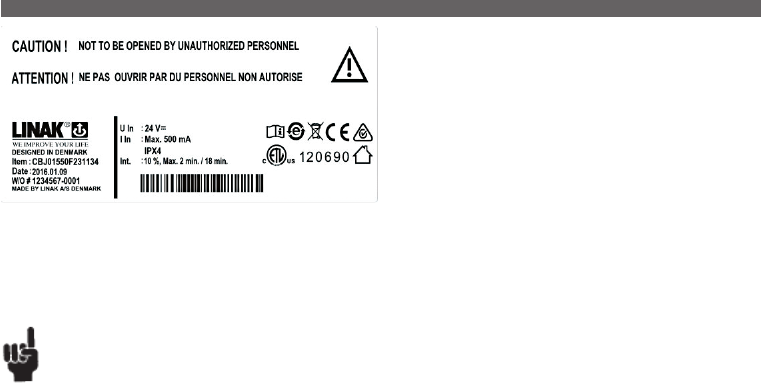
Page 119 of 148
The control boxes CBJ Care is a part of the JUMBO system. JUMBO is a
modular system combining an actuator, a control box (CBJ Care), a battery
(BAJ1 / BAJL), and a charger (CHJ2) / internal charger and a hand control in
a flexible solution, specially developed for patient lifts.
The complete system contains a series of features which meet the patient’s
need for a safe and comfortable lift.
CBJ Care is available in 3 versions, one with diodes, one with a display and
a third without display and diodes.
It is possible to have control buttons on the front cover to have an easy
control option if the hand control is missing. Furthermore it is possible to
have 3 channels via a T-cable in channel 1. The 3rd channel for tilt function
adds value for the patient and the caregiver.
Usage:
• Duty cycle: max. 10% or 2 min.continuous use then18 min. without use
• Ambient temperature: +5° to +40°
• For up to three actuators (lift, leg spreader and tilt of the sling)
• Approvals: IEC60601-1:2005 3rd edition, ANSI / AAMI ES60601-1:2005 3rd edition, CAN/CSA-22.2 No 60601-1:2008
Australia deviation, for one, two or three actuators, (lift, leg spread and tilt actuator), Canadian deviation
Recommendations
• Before start-up we recommend to reset the service counters - days and cycles until next service visit. To reset press the up and down button on the
control box or the hand control for 5 seconds. An audio signal will confirm the resetting.
• When charging, the CBJ Care will not be able to operate any actuators.
• The battery charger, CH01 and/or CHJ2 must always be ordered separately when ordering CBJ Care.
• It is not possible to use other battery types than BAJ1 or BAJL with the JUMBO Care.
• The mains cable must always be ordered separately when ordering a CBJ Care with internal charger.
• Use only original LINAK mains cables to ensure proper connection to internal charger.
• The green battery indicator (100% to 50% capacity remaining) will light up during charging even though the battery is not fully charged.
It is necessary to use the “CHARGE” diode to indicate whether or not the battery is fully charged (when using internal charger).
The CHARGE indicator will light up during charging and turn off when the battery is fully charged.
• Using the Learn Mode function means that:
The lift will never be able to lift more than 1.5 times the max. load. However, the actuator will not stop exactly at the weight it is adjusted to.
This is because the actuator will use less current when its components are run-in. After the max. current value has been registered using the “Learn”
function the control box will be able to use max. current +10%. This ensures that the lift is capable of lifting the promised load but cannot lift more
than 1.5 times this amount. If the below mentioned conditions are fulfilled:
- Learn mode is made on the specific pair of actuator and control box which are going to be used in real life afterwards.
- Ambient temperature should be app. 20 degrees C +/ - 5%.
- Load curve: difference between the highest and lowest load should not be more than approx. max. 10%
• The registration function can only be activated by using a specially produced handset (HB7x235-00). A standard handset cannot activate the function.
• The maximum cut-off value that can be registered (stored) is 11 Amp.
• If an actuator or CBJ Care is exchanged it will be necessary to reset the max. load to ensure the correct cut-off value for the new system as a whole.
• Always use fully charged batteries for learning mode procedures.
• Please note that when you disconnect the service data tool from JUMBO Care it will take 1 hour before the control box will power down.
This means that display indicators will keep lighting up 1 hour after disconnection of the service data tool.
If you want to avoid this battery consumption the emergency stop button can be activated.
• Ensure that you have the Service data tool version 2.5.0 or newer as only these versions support JUMBO Care 2nd generation.
• If the control box is exchanged, the actuator data will be lost. The data is stored in the control box, not the actuator. However, actuator data can be
maintained by using the service data tool for saving actuator data in the new control box.
• Note that the control box has to be “awake” in order to connect to the service data tool. Activate the control box before connecting via the
emergency lowering buttons or the hand control (via T-cable).
• When using the learn mode function, the lift will never be able to lift more than 1.5 times the max. load. The actuator will not stop exactly at the
load it has been adjusted to as the actuator uses less current when its components have been run in. When the max. current value has been
registered using the learn mode function, the control box will be able to use max. current +10 %. This ensures that the lift is capable of lifting the
set load, however it cannot lift more than 1.5 times of the set load.
• When registering current limits, be aware to use a defined set of actuator and control box.
• The ambient temperature must be approx. 20 ºC +/- 5 %.
• The difference between the highest and lowest load must not be more than max. 10 %.
• To activate the learn mode function, use the special hand control (HB7x235-00).
• If an actuator or CBJ Care is exchanged, it is necessary to reset the max. load to ensure the correct cut-off value for the new system.
• Always use fully charged batteries for learn mode procedures.
• A max. cut-off value of 11 Amp can be registered (stored).
• The tolerance for preset current cut-off is: +/- 1 Amp.
• The current cut-off value can be reset by means of the learn mode function, however this is not in accordance with EN10535.
4. CBJ-Care (MEDLINE® CARELINE®)
...to be continued
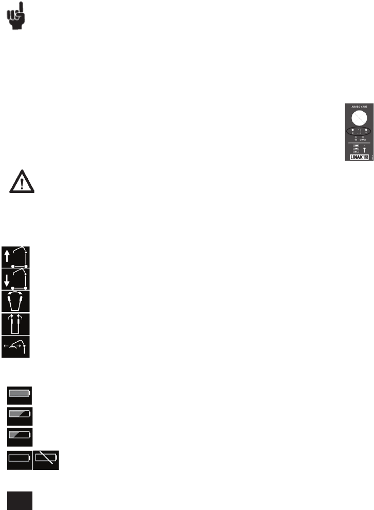
Page 120 of 148
Driving information
As long as a hand control button function is activated driving information will be shown on the display. Either lifting arm up, lifting arm
down, legs in or legs out or tilt of sling.
The only exception to this is when the battery is flat (stage 3 and 4 – see below). At that point the battery information will be shown
instead.
Battery information
The battery discharging will be shown in four stages:
Battery state 1: The battery is ok, no need for charging (100 - 50 %)
Battery state 2: Battery needs charging. (50 - 25 %)
Battery state 3: Battery needs charging. (Less than 25 %)
Buzzer sound is provided when a button is pressed in this battery state.
Battery state 4: The battery needs charging. At this stage some of the functionality of the lift is lost. At this battery stage,
(BAJ1 lead acid) it is not possible to drive the lifting arm up or down. Furthermore, an audio signal will sound when a control
button is activated (17V or lower). The symbol will switch between the two pictures for 10 seconds.
The battery symbol is shown when the box is active until power down (2 minutes after use).
Battery state 4: When using CBJ Care with display together with a BAJL battery, the display will not show the “Battery
(BAJL li-ion) state 4” symbol. The BAJL deep discharge protection overrules the “battery state 4”.
Consequently, the CBJ Care shuts down, and the empty battery symbol is not shown.
• The battery level is measured via voltage level. This means that it is possible to experience e.g. that the battery switches from state 1 to state 2 and
back to state 1.
Warnings
In order to avoid injury, the emergency-stop should be activated in (all) transport situations.
Functionality – JUMBO Care with display
Below you find information about what to read-out on the display version of JUMBO Care. Basically the functionality for the display version is the
same as the diode version, but more information can be read out on the display.
Hot Plugging:
Removing or adding any OpenBus™ cables is not allowed when the control box is on power via mains supply or battery! If necessary anyway, follow
the below procedure:
1. Remove mains or battery and wait 5 sec.
2. Mount or dismount the required cables
If this procedure is NOT followed it may result in a damaged OpenBus™ driver circuit.
The risk of a damaged circuit increases if the accessory has a high start current (in rush current).
Emergency lowering/lifting:
By use of BAJ1, the lifting arm can be lowered by pressing e.g. a pen in the hole or use the control buttons, if present.
This is a permitted method of lowering/lifting.
The emergency lowering/lifting “buttons” work as normal hand control buttons (you do not get extended functionality by
using these when the battery is low).
By use of BAJL, please be aware that loss of power might happen due to the battery deep discharge protection.
This will only happen by continuous use of the battery despite warning.
Recommendations
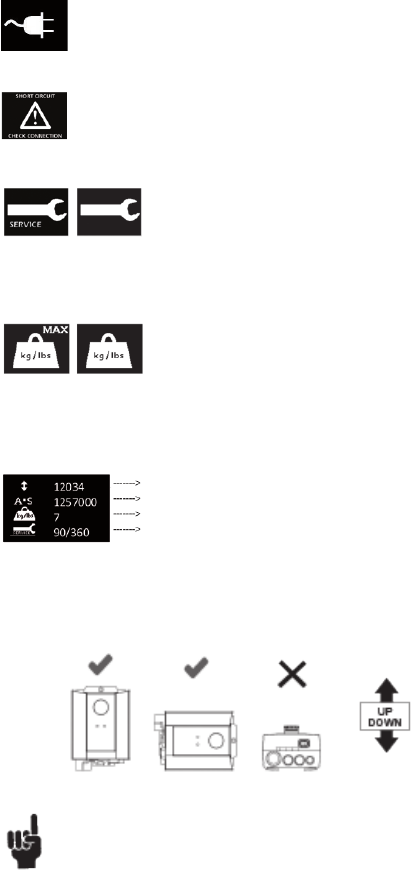
Page 121 of 148
Total cycles done on channel 1
Total work done on channel 1
Total number of overloads (channel 1)
Days since last service/Days between services
If “No days” are chosen for service interval then the display will show Days since last service /-.
Special care should be taken when mounting the CBJ Care.
As long as the the CBJ Care is mounted correctly then the CBJ Care complies to IPX4. If the CBJ Care is mounted incorrectly then water will
gather around the screw holes resulting in non-compliance with IPX4!
If the control box is equipped with emergency stop, the stop button must be activated in cleaning situations in order to comply with IPX4.
The battery pack BAJ1 or BAJL must NOT be removed in cleaning situations, doing so could result in non-compliance with IPX4.
If the CBJ Care is fitted with external charger option (DC power connector), the protection plug ex. 00918174 must always be inserted to
ensure IP protection, if the port is not used.
IP rating only applies when the battery is connected to the control box.
Mounting of CBJ Care
Overload Channel 1 only:
When overload occurs (according to the pre- defined current cut off limit) the overload symbol will be shown on the
display. The ‘MAX’ text will blink 3 times and the overload symbol will be shown for 10 seconds in total.
Service information read-out
Basic service information can be read out on the display. To get the service information on the display please press the lifting arm up button
(only ½ second press). The information will be shown for ½ minute or until other buttons are activated.
Service:
The control box will show the service symbol when it is time for service. The standard setting is after 12 months / 8000
cycles. After each power down, the first time that the service symbol is shown the control box will provide an audio
sound (100 milli seconds) so that the user gets a reminder about checking the display.
The ‘SERVICE’ text will blink 3 times, then a static service symbol will be shown (10 seconds in total). Even though it is time for service the system will
still be functional and work as normal.
Short circuit:
If there is a short circuit the control box will show the short circuit symbol with a recommendation to check the connections.
The symbol will be shown until the short circuit has been repaired.
Charging of battery:
When the mains cable is plugged in and a control button is activated the symbol to the left is shown on the display until power down
2 minutes later. The purpose of the symbol is to tell the user that it is not possible to use the lift when it is plugged in to the mains.
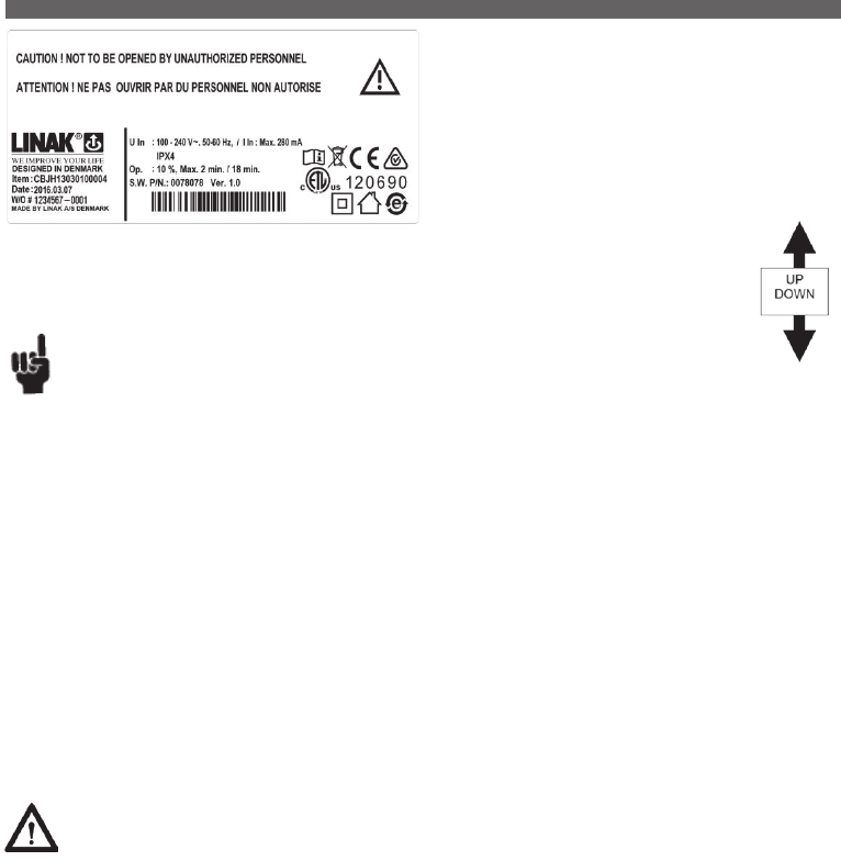
Page 122 of 148
The CBJ-Home is a specially developed solution for patient lifts.
The complete system consists of a control box and a battery enclosed in a
single elegant module.
The system is approved according to medical safety standards and
contains a series of features ensuring a safe comfortable lift, e.g. the
CBJ-Home is equipped with a soft-start function, electrical emergency
lowering, emergency stop etc.
Usage:
• Duty cycle: Max. 10% or 2 min. continuous use then 18 min. without use.
• Ambient temperature: +5˚ to +40˚C.
• Approvals: IEC60601-1:2005 3rd edition,
ANSI/AAMI ES60601-1:2005 3rd edition
Replacement of battery:
Only an authorised LINAK service centre should change a battery in a CBJ-Home. If a CBJ-Home is opened
and a battery changed by an unauthorised personel there is a risk that it may malfunction at a later date.
5. CBJ-Home (MEDLINE® CARELINE®)
Recommendations
• If emergency stop is pressed whilst charging, the batteries will not be charged.
• When charging, the CBJ-Home will not be able to operate any actuators.
• For recharging the batteries, use charger CH01 (charger has to be ordered separately).
• Note: Always mount the CBJ-Home with the channel sockets facing downwards
• The CBJ-Home is not intended for use with “buffer” type actuators such as LA28 and LA32.
• The actuator must always be fitted with an exchangeable cable (mini-fit) socket.
• Actuators on channel 1 must always be with spline.
• The mains cables must always be ordered separately when ordering a CBJ with an internal charger.
• Use only original LINAK mains cables to ensure proper connection to internal charger.
• Always use fully charged batteries for learning mode procedures.
• It cannot be guaranteed that the actuator will stop exactly at the weight that is stored as the motors in the actuators will use less current when
run in. Though it will never reach the 1.5 times max. load as the norm states.
• Tolerance for current cut off is: +/-10%
• The maximum cut-off value that can be registered (stored) is 8 Amp.
• If an actuator or CBJ-Home is exchanged it will be necessary to reset the max. load to ensure the correct cut-off value for the new system as a whole.
• The registration function can only be activated by using a specially produced handset (HB7X161-00). A standard handset cannot activate the function.
• To operate the “Learn mode” function in External charger versions produced before February 2010 press the “R” button when “learning” (the
lifting arm actuator will operate automatically). With all other versions (and future versions with external charger) both the “R” button and the
“lifting arm” button need to be pressed.
Mounting of CBJ-Home
(only vertically)
Warning
In order to avoid injury, the emergency stop should be activated in (all) transport situations.
When using the control box with emergency stop button, the stop button must be released before charging batteries or before the application is put
into operation.
The mounting screws for the control box and the charger must be tightened with a maximum torque of 1 Nm.
Mounting information:
The CBJ-Home is mounted by means of 2 screws:
Type ISO4762-M6x90-8.8 ( not supplied by LINAK )
Spares information:
The cable lock kit consists of the following 3 items:
• 2 x screws
• 1 x blind plug for ch. 2 if not in use
• Cable Lock
All the cable lock items are included when ordering the kit, article number: 0898001-B.
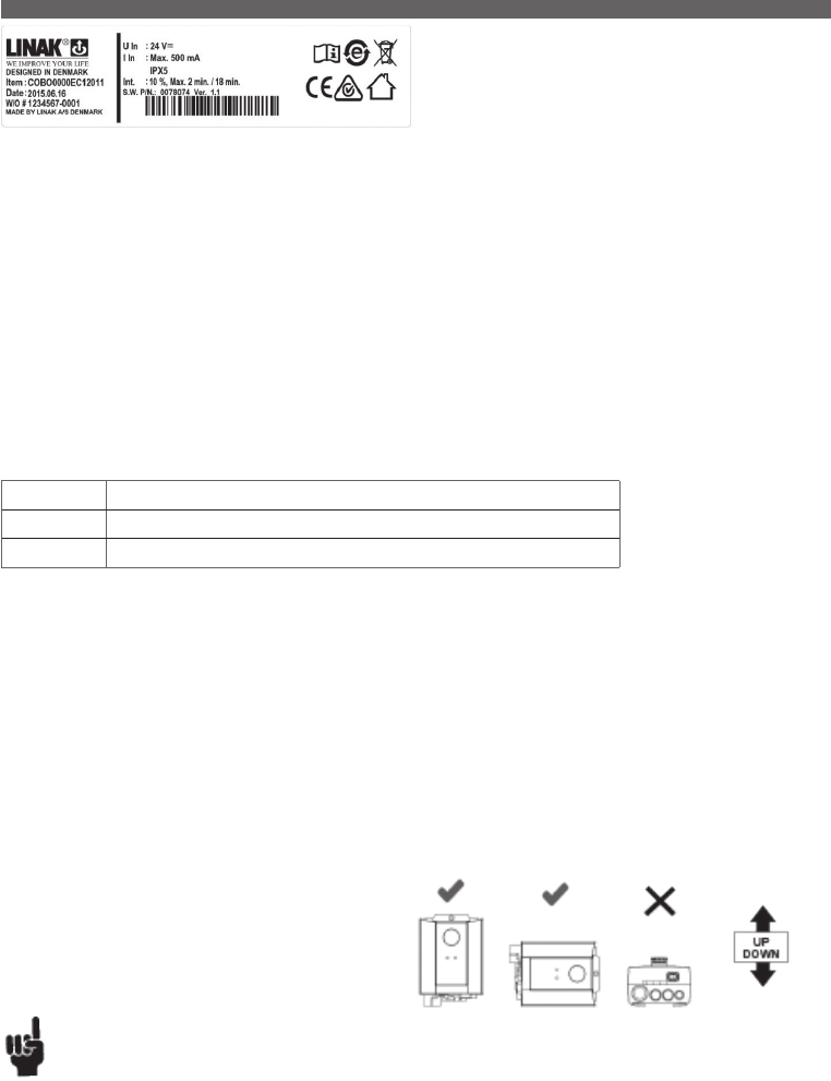
Page 123 of 148
Safety:
The COBO has a monitoring circuit for the FET transistor. If the FET is damaged the CU20 will go into fatal error mode. In this case the COBO is
defective and must be replaced.
Usage:
• Compatibility: LINAK Batteries BAJ1, BAJ2 (24 V, 2.9 AH) or other 26 - 28 V power sources via customer battery connection.
LINAK Lithium Ion battery (BAJL Li-Ion)
• Duty cycle: 10% 2 minutes running and 18 minutes rest
• Operating temperature: +5°C - +40°C
• Storage temperature: -10°C - +50°C
• Relative humidity: 20% to 80%
• Atmospheric pressure: 700 to 1060 hPa
• Approvals: The COBO is EMC approved and designed in accordance with IEC60601-1:2005 3rd edition,
ANSI / AAMI ES60601-1:2005, 3rd edition and CAN / CSA-22.2 No 60601-1:2008
The COBO is an interface box specially developed for use together with
the JUMBO battery pack (BAJ1/BAJ2 and BAJL Li-Ion) and the CU20
control unit. It is also possible to connect other 24V lead acid customer
batteries or fixed power supply.
Recommendations
• Choose CU200XXXXX2XXXX if positioning/memory function is to be used.
• It is recommended that the COBO is serviced according to the relevant national norms for the applications in which it is used, however all
electrical parts must be checked at least once a year.
• The COBO should be cleaned regularly, in order to maintain good hygiene. It is not allowed to use chemicals to clean the box.
• Only use COBO together with CU20.
Functionality:
COBO with internal charger has a green and a yellow light.
Diode colour Functionality
Green is on COBO is connected to mains
Yellow is on COBO is charging. The yellow LED is constantly on until batteries are fully charged.
The CU20 will shut down after 2 minutes to save power.
Accessories depending on V-permanent when the system is inactive will not work.
The CU20 controls whether or not activation should be allowed during charging.
Please note that the CU20 SW must ensure that there is no movement during charging when using COBO with internal charger.
Mounting
Special care should be taken when mounting the COBO.
As long as the COBO is mounted correctly then the COBO complies to IPX5 (IPX4 with internal charger).
If the COBO is mounted incorrectly then water will gather around the screw holes resulting in non-compliance with IPX5 (IPX4 with internal charger).
When using the control box with emergency stop, the stop button must be activated in cleaning situations in order to comply with IPX5.
The battery pack BAJ1 or BAJL must not be removed in cleaning situations, doing so could result in non-compliance with IPX5.
If the COBO is fitted with option EC (DC poser connector), the protection plug ex. 00918174 must always be inserted to ensure IP protection, if the
port is not used.
IP rating only applies when the battery is connected to the control box.
6. COBO (MEDLINE® CARELINE®)
...to be continued
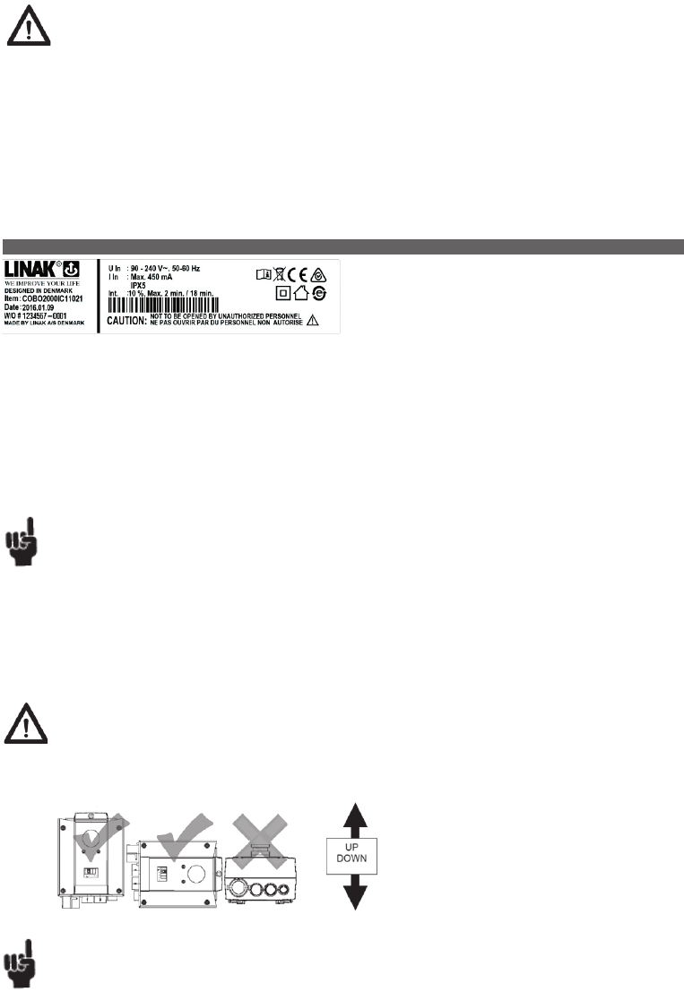
Page 124 of 148
Usage:
• The COBO20 is to be used with CU20 (instead of CP20) for applications that need a large battery capacity.
• Ambient temperatures: +5 to 40°C
• Approvals: The COBO20 is EMC approved.
The COBO20 is designed in accordance with the following standards: 60601-1/ UL2601 and EN60601-1-4.
• When running on batteries CU20 will shut down after 2 minutes to save power.
Recommendations
• Choose CU200XXXXX2XXXX if positioning/memory function is to be used.
• After activation of emergency stop it can take up to 10 seconds before the system can be used again.
• If own battery package is used, a10A fuse must be added.
• It is recommended that the COBO20 is serviced according to the relevant national norms for the applications in which it is used, however all
electrical parts must be checked at least once a year.
• The COBO20 should be cleaned regularly, in order to maintain good hygiene. It is not allowed to use chemicals to clean the box.
• Only use COBO20 together with CU20.
Warning
In order to avoid injury, the emergency stop should be activated in (all) transport situations.
The COBO20 makes increased battery power available (compared to
BA20). It is designed to be used with CU20 together with BAJ1 or BAJ2
(24V, 2.9AH). It is also possible to connect other 24V lead acid or SLA
(Sealed Lead Acid) battery types.
COBO20 with internal charger has a green and a yellow light. Green is ON when the COBO20 is connected to mains. Yellow is ON when charging.
The yellow light shines constantly until batteries are fully charged.
Mounting of COBO20
Special care should be taken when mounting the COBO20:
As long as the COBO is mounted correctly then the COBO20 complies to IPX5. If the COBO is mounted incorrectly then water will gather
around the screw holes resulting in non-compliance with IPX5.
7. COBO20 (MEDLINE® CARELINE®)
Warnings
• Pay attention to the polarity of the customer battery cable - red is positive voltage.
• In order to avoid injury, the emergency stop should be activated in (all) transport situations.
• If 24V lead acid customer batteries or fixed power supply is used, the supply source must comply with “Means Of Patient Protection” and
“Means Of Operator Protection” in accordance with the Medical Safety Standard.
• If 24V lead acid customer batteries or fixed power supply are used, the customer must ensure that EMC values are kept in accordance with
regulations.
• The CU20 power port/channel 7 cannot be used with COBO.
• Max 1 ACT can be connected to the COBO system.
• The COBO is not to be used in agricultural or maritime applications or be connected directly to a vehicle battery.
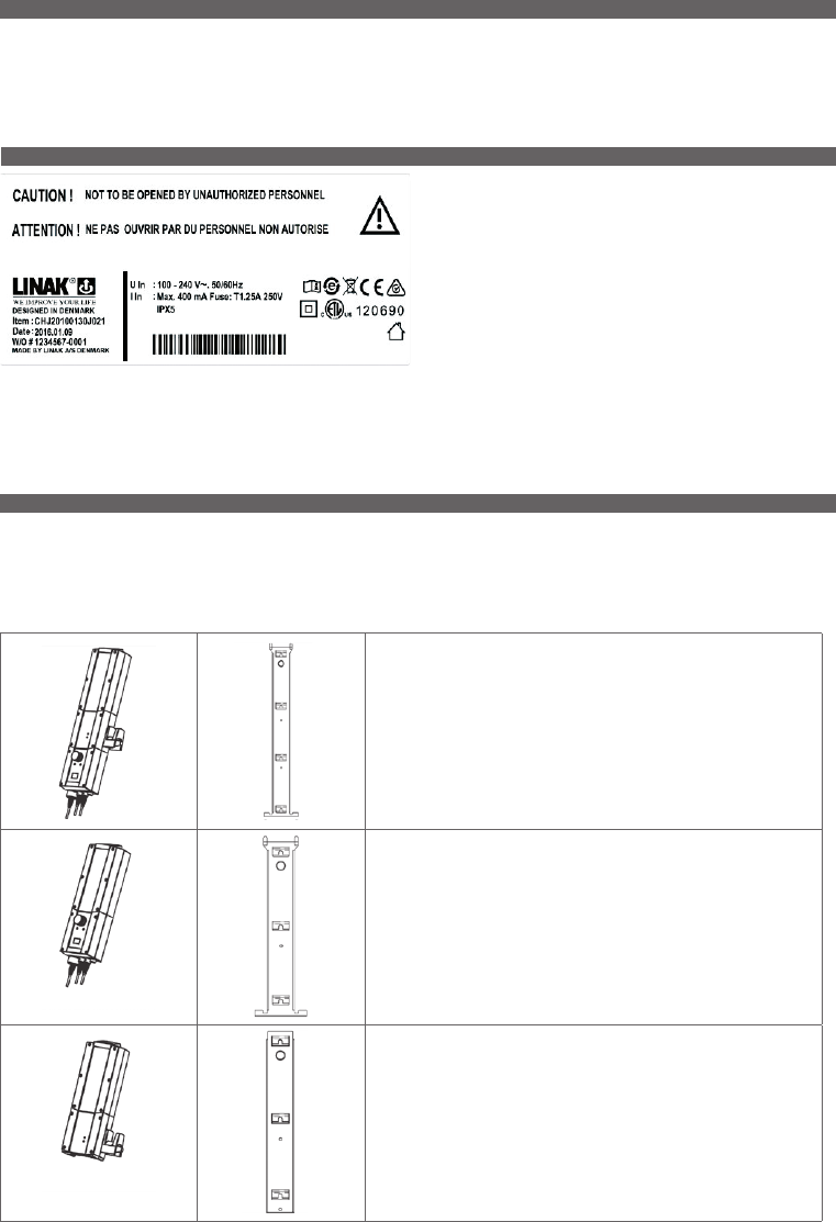
Page 125 of 148
MBJ1
For use together with CBJ1 or CBJ2 or CBJC, CHJ2 and BAJ1 or BAJ2. I. e.
when combining control box, charger and battery pack MBJ1 has to be used.
MBJ2
For use together with CBJ1 or CBJ2 or CBJC, and BAJ1 or BAJ2. I. e. when
combining control box and battery pack MBJ2 has to be used.
MBJ3
For use together with CHJ2 and BAJ1 or BAJ2. I. e. when combining charger
and battery pack MBJ3 has to be used.
Depending on of what your JUMBO system consists you need to use one of the following three mounting brackets. IP protection is only valid when
the JUMBO system is mounted vertically.
All three brackets include matching screws (IPX1, IPXX and IPX5 are delivered with stainless screws). The mounting screws for the control box,
charger must be tightened with a maximum torque of 1 Nm.
9. CHJ2 (MEDLINE® CARELINE®)
The charger CHJ2 has been specially designed for use as a wall-charger for
the JUMBO system.
The CHJ2 charger is a Switch Mode Power Supply (SMPS) version which
makes charging of the batteries more efficient.
The charging time for a BAJ1 or BAJL (standard) battery pack is approx. 4
hours.
Mains voltage from 100 V AC – 240 V AC (50/60 Hz) is possible on same
charger.
The charger indicates whether the charger is connected to the mains
(green LED) or whether the battery is being charged (yellow LED). Medically
approved.
Usage:
• Approvals: IEC60601-1:2005 3rd edition, ANSI/AAMI ES60601:1 2005 3rd edition and CAN / CSA-22.2 No 60601-1:2008
• Ambient temperatures: + 5 to + 40 °C
10. MBJ1/2/3 (MEDLINE® CARELINE®)
8. CH01 (MEDLINE® CARELINE®)
For charging the batteries of CB08-XA and all JUMBO control boxes, directly connected to the control box or via the handset HB40A.
For charging of the batteries in battery box BAJ2 (JUMBO system) and CBJH.
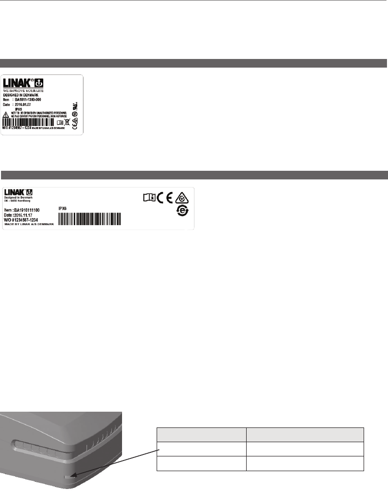
Page 126 of 148
1. BA18 (MEDLINE® CARELINE®)
The BA18 is exchangeable without opening the CB (BA18 is a separate box).
Ventilation of external batteries, BA18 - see Figure 1
Check at regular intervals that the ventilation stub is undamaged and intact. The construction of the ventilation stub
permits battery gasses to get out, but it does not permit penetration of water.
Usage:
• Compatible with CB6, CB6S, CB7, CB9, CB12 / CB14 BT versions
• Ambient temperature: +5°C to +40°C
8. Information on specific accessories
If the actuator is to be equipped with accessories, these must be specified when ordering the actuator from LINAK. There are the following possibilities:
1) TR6/TR7 External transformer
If the TR6 or TR7 fixed cable connection becomes damaged the transformer must be replaced.
2. BA19 lead acid (MEDLINE® CARELINE®)
The BA19 lead acid backup battery has been developed specifically for
use with the new control boxes CA30/CA40 and CO61. It is a compact
and cost-efficient battery with built-in charger and cable management.
Usage:
• Compatibility: Battery backup for CA30/CA40 and CO61
• Duty cycle: 10%, 2 minutes continuous use followed by 18 minutes not in use
• Charging: Via integrated charger
• Charging time: Approx. 6 hours
• Recharging during storage: Battery recharging no later than 6 months after production date stated on the label
• Operating temperature: +5°C to +40°C
• Storage temperature: -5°C to +40°C
The batteries must be stored in an applicable storage room to avoid direct sunlight
• Relative humidity: 20% to 80%, but non-condensing acc. to temp.
• Atmospheric pressure: 700 to 1060 hPa
• Service: Battery cells cannot be replaced as the battery cover cannot be closed properly afterwards
• Approvals (pending): IEC60601-1:2005 3rd edition,
ANSI/AAMI ES60601-1: 2005, 3rd edition
CAN/CSA-22.2 No. 60601-1:2008
LED functionality:
What does the LED indicate?
LED Indication of operation
Solid orange Charging (battery not ready)
No LED light Fully charged (battery ready)
Buzzer functionality:
The buzzer will make a warning when a button on the hand control is pressed and the battery capacity is low.
The buzzer can also be activated by the control box to signal other conditions. This must be specified in the control box software.
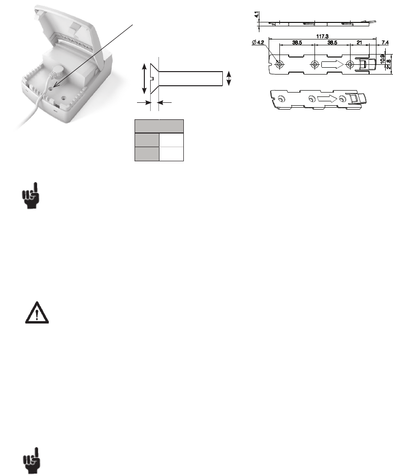
Page 127 of 148
Recommendations:
• Do not exceed the storage temperature as it will shorten the product life and reduce performance.
• Allow the battery to settle to room temperature before use.
• Do not exceed the duty cycle 2/18 as it will shorten the life, reduce performance, and eventually activate overcurrent protection.
• BA19 is not intended for use in outdoor applications.
• If the battery is completely discharged, then recharge the battery before storage.
Safety feature
• BA19 contains overcurrent protection for safety and to protect itself from being damaged due to excessive use.
• When current protection is activated no power output will be available
Warnings
• Loss of power might happen due to activation of overcurrent protection. In this event, there may be no warning and the application may not be
able to move when expected.
• Defective or damaged batteries may leak acid and adequate precautions must be taken during handling and transportation.
• Do not open the battery case as damage to the cell or circuitry may develop excessive heat.
• It is important for users to read the guidelines in the “User Manual Linear Actuators and Electronics”.
• Do not short circuit the battery.
• Use the specified charger only.
• If disposed to fire, the battery may explode.
If product caution is not clearly visible on the final application at low light intensity, the above mentioned warnings must be integrated in the
application manufacturer manual.
The application manufacturer must test the application and ensure that neither intended nor unintended use exceeds the battery specification. The
application manufacturer must assure other means of movement, e.g. quick release or manual lowering in case of battery failure.
Compatibility:
The BA19 has a built-in charger and is therefore not able to operate with control boxes with charger. Be aware that the BA19 is only
compatible with CA30, CA40 and CO61.
Mounting bracket (frame flat) - article no. 1015W1001: Mounting instructions:
BA19 must be mounted with attachment
screw and mounting bracket (see below)
due to the battery weight.
Screw M4 countersunk torque
1.1Nm +/- 0.1Nm.
d M4
dk8.4
k 2.7
According to ISO 2009
dkd
k
45°
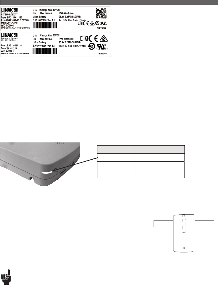
Page 128 of 148
The BA21 Li-Ion back-up battery pack has been specially developed for
use with the new w battery with built-in charger and high performance
and safety.
Features & Options
Weight: 0.7 kg
Housing colour: Light grey (RAL 7035)
Protection class: IPX6 Washable
Packaging: Every battery is packed individually and is fitted with
lithium caution (transportation requirement)
Classification: Internally powered
3. BA21 (MEDLINE® CARELINE®)
Usage:
• Compatibility: Battery back-up for CO61
• Duty cycle: 5%, 1 minute continuous use followed by 19 minutes not in use
• Charging: With integrated charger in battery
• Charging time: Approx. 10 hours
• Recharging during storage: Recharge the battery 12 months at the latest after production date stated on the label
• Operating temperature: +5°C to +30°C
• Storage temperature: -10°C to +40°C
The batteries must be stored in an applicable storage room avoiding direct sunlight
• Relative humidity: 20% to 90%, but non-condensing acc. to temperature
• Atmospheric pressure: 700 to 1060 hPa
• Approvals: IEC60601-1:2005 3rd edition,
ANSI / AAMI ES60601-1:2005, 3rd edition pending CAN / CSA-22.2 No 60601-1:2008 pending
IEC62133 2nd edition, UL2054, UN38.3 (needed for transport of lithium batteries) pending
LED functionality:
LED Indication of operation
Solid yellow Charging
No LED light Fully charged
Error during charging Flashing yellow
Buzzer functionality:
The buzzer will make a warning when a button on the hand control is pressed and the battery capacity is low.
The buzzer can also be activated by the control box to signal other conditions. This must be specified in the control box software.
Mounting:
The Battery Pack BA21 can be mounted in several ways on the bed/the application, either separately
or together with the control box CO61.
It is however not allowed to mount the battery in vertical position with the mounting clip pointing
upwards - see illustration below:
Deep discharge protection
• The BA21 Li-Ion has a deep discharge protection to protect the battery life. The deep discharge protection
is activated when the battery is discharged.
• Charge the battery to exit the deep discharge mode. Ensure that the battery is sufficiently charged before use.
Recommendations:
• Do not exceed the storage temperature as it will shorten the product life and performance.
• Allow the battery to settle to room temperature before use.
• Do not exceed the duty cycle 1/19 as it will shorten the life, reduce performance, and eventually activate excess temperature protection.
• BA21 Li-Ion is not intended for use in outdoor applications.
• If the battery is completely discharged, then recharge the battery before storage.
Page 129 of 148
Safety feature
BA21 Li-Ion contains several mechanisms to protect itself from being damaged due to excessive use.
In case of overheating, the device will activate a thermal protection. No power output will be available until the temperature is back again within
normal operating range.
Extensive use at high temperatures or when exceeding the 1/19 duty cycle may lead to overheating.
Transportation
The lithium ion batteries must be packed and transported according to applicable regulations. Always ask your local transportation provider how to
handle the transportation of lithium ion batteries.
Warnings:
Li-Ion batteries differ from the lead acid technology as they have a built-in deep discharge protection.
• Loss of power might happen due to the battery deep discharge protection and will only happen in case of continuous use of the battery despite
warnings. In this event, there may be no warning and the application may not be able to move when expected.
• Defective or damaged li-ion batteries or li-ion batteries that may produce excessive heat or fire are not allowed for aircraft transportation.
• Do not open the battery case as damage to the cell or circuitry may develop excessive heat.
• If product caution is not clearly visible at low light intensity, read the product label instructions symbol.
A warning must be included in the application manufacturer’s manual for the medical device.
• The application manufacturer must test the application and ensure that intended unintended operations do not exceed the battery specification
limits. The application manufacturer must assure other means of movement, e.g. quick release or manual lowering.
The CS16 electronic limit switch is connected between the LINAK® actuator and a non-LINAK power supply,
where it cuts out the current to the actuator in end position of if an obstacle is encountered. The PCB contains a
variable current limit setting and is available in different versions, depending on the actuator with which it is to
be used.
The CS16 should be connected between the linear actuator and the power supply, where it will switch off the
power when the actuator reaches end position or if the actuator is overloaded.
4. CS16 (TECHLINE®)
As the CS16 are open PCB’s, they have to be installed in an encapsulation to prevent damage. (LINAK® offers one type of encapsulation for CS16).
Adjustment of CS16
The CS16 has a rotary potentiometer for adjusting the value of the cut-off current. To obtain the correct cut-off current, connect the CS16 and turn the
potentiometer as far as it will go/anticlock wise to set the maximum cut-off current.
Then subject the actuator to the maximum load it will be exposed to in the application. At the same time turn the potentiometer clockwise, reducing the
cut-off current, until the actuator stops (not in end position).
Then turn the potentiometer approx. quarter of a turn anti-clockwise and the system is ready for use.
As the CS16 is a open PCB’s, it have to be installed in an encapsulation to prevent damage. (LINAK® offers one type of encapsulation).
The DIN Junction Box is designed for use where there is a need for more than 1 or 2 controls to be connected to a
control box.
The DIN Junction Box is constructed for connection of up to 4 controls with 8-pin DIN plugs. Furthermore, the box is
constructed so that all channels for connetion are placed on the same side of the box.
This gives the box a clean design and makes it easy to mount e.g. in a bed frame.
Usage:
• Possible for connection of LINAK control boxes: CB8, CB9/CB9P, CB12, CB14, CBJ and OpenBus™ control
boxes e.g. CB20, CB6S, CB16.
5. DJB (MEDLINE® CARELINE®)
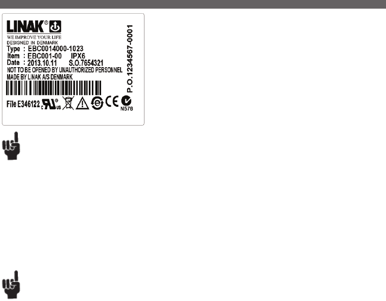
Page 130 of 148
The EBC - Electronic Brake Control - is designed for use together with 3rd party castors
and the control systems CB OpenBusTM, including JUMBO Care. The EBC can replace
traditional (mechanical) central locking systems for castors on healthcare beds or medical
applications. This new system offers an increased freedom of application design as there is
no need for a mechanical connection between the castors.
Usage:
• Operating temperature: 5°C to 40°C
• Storage temperature: - 10°C to 50°C
• Compatibility: CBJC, CB6 OBF, CB6 OBMe, CB16 or CB20
• Fallshaw EBC system approved according to IEC60601-1:2005 3rd edition approved,
ANSI / AAMI ES60601-1:2005, 3rd edition, and CAN / CSA-22.2 No 60601-1:2008
Manner / TENTE approvals are pending
6. EBC - Electronic Brake Control System (MEDLINE® CARELINE®)
Recommendations
• The customer shall ensure proper connection between the EBC and the castors. Missing or interrupting some of the individual wires between the
EBC and the castor may under some circumstances cause damage to the internal circuitry of the EBC.
• Always use locking mechanism and O-ring on cables.
• If any open sockets, they must be fitted with blind plugs to ensure IP degree.
• Removing or adding any OpenBus™ cables is not allowed when the control box is powered (hot plugging).
Before installation/service
• Stop the application.
• Remove battery power cable and OpenBus™ connection then possible castor connection.
• Service system.
After installation/service
• Reconnect castor connection, then OpenBus™ connection, battery power cable, then control box mains.
LINAK A/S only delivers the OpenBus™ system and is not responsible for any products other than LINAK products (i.e. products from 3rd
party suppliers or the compliance of such products with the LINAK OpenBus™ system).
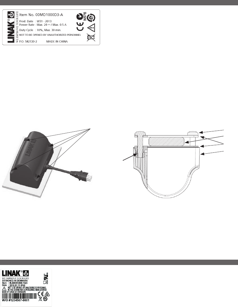
Page 131 of 148
The massage motor can be added to all kinds of couches and tables, chairs or
beds for treatment and examination. It enables comfort, relaxation and tension
release for patients and clients. The massage motors are directly connected to the
actuator port at the control box – no extra wiring at the application, simple and
easy mounting.
Usage:
• Compatibility: CB6S OBMe, CB16 OBF, (CB20 pending) MJB006-0x to be used for OpenBus™ impulse drive
• Duty cycle: 10 %, 30 min. max.
• Operating temperature: +5°C to +40°C
• Storage temperature: -10°C to +50°C
• Relative humidity: 20 % to 80 % at +30°C
• Atmospheric pressure: 700 to 1060 hPa
• Approvals: Medical approvals to be determined
7. Massage Motor Medical (MEDLINE® CARELINE®)
Is mounted
with 4 screws
Mounting:
Massage motor on a plate
Mounting of the screw with max. torque 2 Nm
Mounting of massage motor by using brackets:
Screw
Slat
Bracket
Massage
motor
Nut
The massage unit is mounted with 4 x M6 roundheaded machine screws with flat underside. 15 to 20 mm long + the thickness of the bracket.
Torque max. 2-3 Nm.
2 brackets must be used - one on each side of the slat.
8. MJB (MEDLINE® CARELINE®)
The MJB (Modular Junction Box) is designed for use together with OpenBusTM control boxes.
The MJB makes it possible to connect multiple handsets, attendant controls or it is also possible to use the
MJB as a control unit for 3rd party products such as Out of Bed Detection, USB charger, Under Bed Light etc.
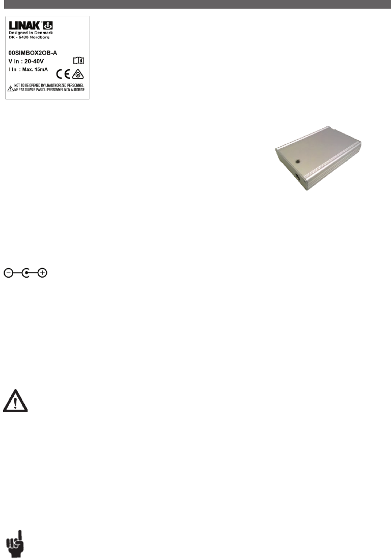
Page 132 of 148
9. Simulator tool (MEDLINE® CARELINE® )
The Simulator Tool is a software that can be used to simulate hand control functions on OpenBus™ and analogue
actuator systems. With the Simulator Tool, sequences of actuator movements can be programmed and repeated in
order to test actuator systems.
USB to OpenBus™ gateway:
The gateway acts as an interface between the Simulator Tool Software and the OpenBus control box.
Together with the Simulator Tool Software, it can be used for test and demo purposes only.
It is not allowed to use the product as a control in any commercial application.
It has a USB B-input connection from the computer/laptop.
As output connection it has an RJ45 jack plug for connection to the control box.
For indication of power supply, the housing has one yellow LED indicator.
Normally, the gateway is powered through the OpenBus connection to the control box. External power supply is only necessary for the control boxes
listed below.
For usage with OpenBus systems which have no permanent voltage (40 V) in the OpenBus connection, it is possible to connect the gateway to an
external power supply. Therefore, the casing is equipped with a 2.5 x 6.6 mm power jack connector.
Warnings:
• The LINAK Simulator Tool is to be used as a test tool or demo tool only. It is not allowed to use the software and accessories as a control in any
commercial application.
• Potentially dangerous situations resulting from automated movement generated by the Simulator Tool Software must be considered and assessed
before starting any action.
• Please note that over time the actual movement of an actuator within a fixed activation time may vary due to changed friction inside the actuator
or especially when a battery-driven system loses power.
Close inspection and required adjustment is necessary to obtain the wanted movement over time and to avoid potentially dangerous situations.
• The generated test report itself is not a legal proof that a system has physically moved the actuators the number of times stated and cannot be
used as such.
The time of activation listed in the report generated is not necessarily the same as the time of actuator movement. It just shows how long the
function has been activated (equal to the time you have pressed the button on the hand control).
The actuator can be in end-of-stroke position or the function can be locked and therefore the actuator itself doesn’t move.
It is recommended to use a physical counter or similar to verify the actual actuator movement.
Recommendations
• See to it that sufficient pauses are kept between activations, so that the duty cycle of each actuator type is respected.
Power input: 20 to 40 V DC, minimum requirements 10 mA
Polarity:
Use LINAK battery charger CH01
Products that require external power:
• Jumbo Care
• COBO
Limitations:
Note that an OpenBus system that has powered down (8 V missing) cannot be woken up by the USB to Openbus gateway!
Although the USB to Openbus gateway sets a keep power bit, it might be neglected by some control boxes that will power down after a period of time.
(Typically 2 minutes).
For cycle testing of such systems (typically battery equipped), that powers down during the cycle, a special control box software that has been stripped for
the power down feature is needed.
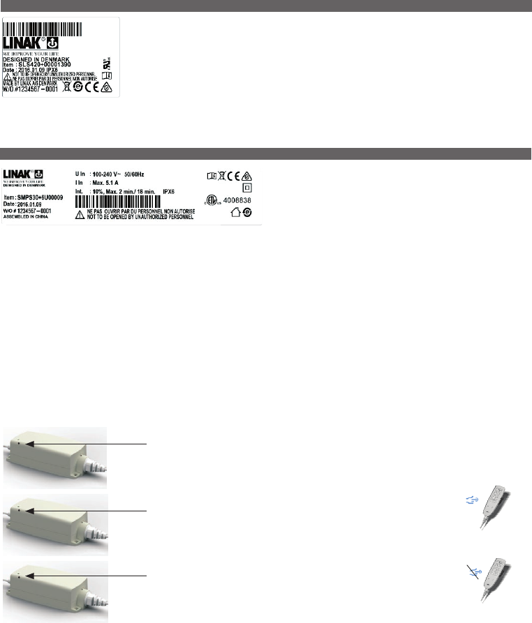
Page 133 of 148
10. SLS (MEDLINE® CARELINE® TECHLINE®)
LINAK has designed a switch that can be mounted in connection with the 24V DC actuators: LA12, LA22, LA28,
LA28S, LA31, LA32, or LA34 and a control box on e.g. a bed frame.
The Safety Limit Switch (SLS). The SLS Switch is primarily used as a Limit Switch in systems consisting of a control
box, LA28/28S and/or LA32.
As an example the SLS can be installed on the actuator cable where it disconnects the actuator in either inward or
outward direction when activated. The SLS can also be used as a signal control directly connected to a control box.
The SMPS30 is a very powerful Switch Mode Power Supply typically used
for Treatment or Examination Couches. The SMPS30 is an eco-friendly
solution due to a low standby power consumption compared to tradi-
tional transformer solutions. The universal input voltage makes the SMPS
adaptable to the worldwide market irrespective of the input voltage.
Usage:
• Compatibility: LA43 IC, LA44 IC
• Duty Cycle*: 10%, 2 minutes continuous use followed by 18 minutes not in use.
• Operating temperature: 5°C to 40°C
• Storage temperature: -10°C to 50°C
• Relative humidity: 20% to 90% @ 30°C – not condensing
• Atmospheric pressure: 700 to 1060 hPa
• Altitude: max. 2000 metres above sea level
• Approvals: IEC60601-1:2005 3rd ed., ANSI / AAMI ES60601-1:2005, 3rd edition, CAN / CSA-22.2 No 60601-1:2008
* AT 10% DUTY CYCLE, MAX. OUTPUT POWER IS POSSIBLE AT AN AMBIENT TEMPERATURE OF 25°C
11. SMPS30 (MEDLINE® CARELINE®)
Safety concept:
DC power is only on the application when needed – when the hand control is activated.
The user is part of a safety concept with light indications showing:
Connected to the mains
Green light when connected to the mains
Power request
Yellow light at power request when the hand control is activated
Check of functionality
Yellow light is turned off when releasing a hand control button – otherwise the
hand control or other components in the application are defective. If so, the user
must call for service.
The SMPS30 is designed for placing on the floor, but it can also be mounted on the wall / application via the bottom base plate
and 4 screws.
If the SMPS30 is mounted on the wall/application, please dismount the SMPS30 to get access to the cable locking mechanism on the mains cable.
...to be continued

Page 134 of 148
Recommendations
Please note
The SMPS30 is only compatible with LA43 IC and the LA44 IC.
The SMPS30 is not suitable for outdoor applications
Before installation, re-installation or troubleshooting
• Stop the application
• Switch off the power supply and pull out the mains plug
• Relieve the application of any loads, which may be released during the work
Before start-up
• Make sure that the system has been installed as instructed in the User Manual
• System connection. The individual parts must be connected before the SMPS30 is connected to the mains.
During operation
• Ensure that the cables are not damaged
• Unplug the SMPS30 before moving the equipment
Device protection:
The SMPS30 contains several mechanisms to protect itself from being damaged due to excessive use.
• In case of overheating, the device will activate a thermal protection. No power output will be available until the temperature is back again within
normal operating range.
• In case of exceeding the current limit / failure in the actuator, the device will activate an overload protection. Immediately after the situation has
been remediated the power output will be available again.
Hot plugging
• It is not allowed to remove or to add the output cable as long as the SMPS is powered by mains.
Maintenance/cleaning
• The SMPS30 must be cleaned at regular intervals to remove dust and dirt and it must be inspected for mechanical damage, wear and breaks
• It is not allowed to spray directly with a high-pressure cleaner on the device
• Interconnecting cables must remain plugged in, correctly fitted with O-rings, during cleaning to prevent ingress of water
• The SMPS30 is resistant to the majority of cleaners and disinfectants used in the hospital and nursing home sector.
However, the detergents must comply with the following basic requirements
- They must not be highly alkaline or acidic (pH value 6-8)
- They must not contain caustic agents
Page 135 of 148
The Under Bed Light (UBL2) provides a powerful light with
a good distribution. The UBL2 is to be used for beds within
hospitals, nursing homes and in homecare.
The Under Bed Light makes it easier for patients and other
people in need of care to find their way at night in the dark
to prevent falling accidents and to make them feel safe.
12. Under Bed Light 2 (MEDLINE® CARELINE®)
Usage:
• Operating temperature: +5°C to +40°C
• Storage temperature: -10°C to +50°C
• Relative humidity: 10% to 80% at +30°C not condensing
• Atmospheric pressure: 700 to 1060hPa
• Approvals: EN62471, IEC60601-1:2005, 3rd edition (approvals are currently pending)
Recommendations and Precautions
• If 2 or more UBL2 products with dimming function are connected to the same application, it is recommended to have a factory reset key to be
able to synchronize the dimming direction and light intensity if one of the UBL2s is replaced.
• Screw holes in application are needed for mounting. Inform the customer to use M4 Ø12 screws with Ø12 washer, when mounting the UBL2.
Max. torque 2.5 Nm.
• Hot-plugging:
Removing or adding any OpenBus™ cables is not allowed when the CB is powered by mains supply!
If needed anyway, follow the below procedure:
1. Remove mains and wait 5 sec.
2. Mount or dismount the required cables
If this procedure is NOT followed, it may result in a damaged OpenBus™ driver circuit. The risk of a damaged circuit increases if the accessory
has a high start current (in rush current).
• There can be a risk of conflict with other OpenBus™ accessories, like HB, ACP, etc. when using the OpenBus™ UBL2, it is therefore
recommended to make a system/bit overview.
• Always use locking mechanism and O-ring
• Sockets not used must be fitted with blind plugs to ensure IP degree
• The UBL2 must be mounted on a plane surface and casing must not be subject to impact or any kind of stress.

Page 136 of 148
9. Repair and disposal
Repair
Only an authorised LINAK service centre should repair the LINAK actuator systems. Systems to be repaired under warranty must be sent to an
authorised LINAK service centre.
In order to avoid the risk of malfunction, all actuator repairs must only be carried out by an authorised LINAK Service shop or repairers, as special
tools and parts must be used.
If a system is opened by unauthorised personel there is a risk that it may malfunction at a later date.
Spare parts
LINAK can supply spindle parts and motor parts as spare parts. Please indicate the designation from the label when ordering spare parts from your
nearest authorised LINAK dealer.
Disposal of LINAK’s products
LINAK’s products may be disposed of, possibly by dividing them into different waste groups for recycling or combustion.
We recommend that our product is disassembled as much as possible at the disposal and that you try to recycle it. As an example of main groups
within sorting of waste we can mention the following.
Metal, plastic, cable scrap, combustible material and collection for recoverable resources.
Some of these main groups can be sub-divided into groups e.g. metal can be divided into steel and aluminum or plastic can be divided into ABS and PP.
At disassembly of batteries, be aware of the chemistry and risk of short-circuiting batteries.
As an example of sorting we show you below, which recycling groups the different components in LINAK’s products should be placed into:
By now nearly all our moulded plastic units are provided with an internal code for plastic types and fibre content, if any.
Product Component Recycling group
Actuator: Spindle and motor Metal scrap
Plastic housing Plastic recycling or combustion
Cable Cable scrap or combustion
Control box: PC-board Electronics scrap
Plastic housing Plastic recycling or combustion
Cable Cable scrap or combustion
Transformer Metal scrap
Batteries Recoverable resources
Control: Plastic housing Plastic recycling or combustion
Cable Cable scrap or combustion
PC-board Electronics scrap

Page 137 of 148
Main groups of disposal
Product main type Metal scrap Cable scrap Electronic scrap Plastic recycling or combustion Remark
ACC X X
ACK X X X
ACL X X X
ACM X X X
ACO X X X
ACOM
ACP X X X
BA18 X Lead battery
BA19 X Lead acid battery
BA20 X X Lead battery
BA21 X X X X Lithium Ion Battery
BADM X X Lead battery
BAJ1 X X X X Lead battery
BAJ2 X X X X Lead battery
BAJL X X X X Lithium Ion battery
BB3 X
BL1 X
BL4 X
CA30 X X X
CA40 X X X
CB12 X X X
CB14 X X X
CB16 X X X
CB20 X X X X
CB6 X X X
CB6P2
CB6S X X X
CB7 X X
CB8-A X
CB8-T X
CB9 X X X X
CBJ1 X
CBJ2 X
CBJC X X
CBJH X
CBR1 X
CHJ2 X
...to be continued

Page 138 of 148
Product main type Metal scrap Cable scrap Electronic scrap Plastic recycling or combustion Remark
CS16 X X
COBO X X
COBO20 X X
CO61 X X X
CP20 X X X
CU20 X X
CUDM X X
DJB X X X
DPH
FS X X X X Metalscrap because of
FSR + FSR
FS2 X X X X
FS3 X X X X
HB20 X X
HB30 X X
HB40 X X X
HB50 X X X
HB60 X X X
HB70 X X X
HB80 X X X
HBDM X X X
HD80 X X X
HD80 JUMBO X X X
HL70 X X X
HL80 X X X
IRO X X
LA12 X X X X
LA22 X X X
LA23
LA27 X X X
LA28 X X X X
LA29 X X X X
LA30 X X X
LA31 X X X X
LA32 X
LA34 X X X X
LA40 HOMELINE
Main groups of disposal

Page 139 of 148
Product main type Metal scrap Cable scrap Electronic scrap Plastic recycling or combustion Remark
LA43 X X X X
LA44 X X X X
LC2 aluminum
extrusions,
spindle, motor,
end plates,
fasteners
power cable,
signal cable
PCB glide pads, retainer clips, top
frame, PCB housing
LP2 X X
LP3 X X
LS X X X
LSD X X X X
Massage Motor
MBJ1/2/3 X
MJB X X
SLS X X X
SMPS30 X X
Main groups of disposal

Page 140 of 148
Product main type Description
ACC Front cover glued together with housing
ACK No housing. Only foil with cable
ACL Cannot be opened as it is welded together.
When the cable has been cut off it is disposed
of as combustible waste
ACM Cannot be opened as it is welded together.
When the cable has been cut off it is disposed
of as combustible waste
ACO Front cover glued together with housing
ACOM
ACP Screwed together
BA18
BA19
BA20 Welded together
BA21 Welded together
BADM Glued and screwed together
BAJ1 Glued and screwed together, symbol of battery
type is marked on the basepart of the housing
BAJ2 Glued and screwed together, symbol of battery
type is marked on the basepart of the housing
BAJL Glued and screwed together, symbol of battery
type is marked on basepart of the housing
BB3 Outer tube (Alu) can be dismounted (screws)
BL1
BL4 Plastic housing and the BB3 inside can be
dismounted (screws)
CA30 Welded together. Cannot be opened
CA40 Welded together. Cannot be opened
CB12 Screwed together
CB14 Screwed together
CB20 Glued and welded together. Cannot be opend
CB6 Glued and screwed together
CB6P2
CB6S Glued and screwed together
CB7
CB8-A Screwed together
CB8-T Screwed together
CB9 Has to be unscrewed with a screw driver
CB16 Glued and screwed together
Practical information
Product main type Description
CBJ1 Glued and screwed together
CBJ2 Glued and screwed together
CBJC Glued and screwed together
CBJH Glued and screwed together
CBR1
CH01 Welded together
CHJ2 Glued and screwed together
CS16 Screw together, cut off can be adjusted
COBO Glued and screwed together
COBO20 Glued and screwed together
CO61 Welded together. Cannot be opened
CP20 Glued and screwed together
CU20 Glued and screwed together
CUDM Glued and screwed together
DJB Cannot be opened as it is welded together.
When the cable has been cut off it is disposed
of as combustible waste
DPH
FPP Foil glued together with housing
FS
FS2
FS3 Ultrasonic welded and screwed together
HB20
HB30 Ultrasonic welded
HB40 Screwed together
HB50 Screwed together
HB60 Screwed together
HB70 Cannot be opened as it is welded together.
When the cable has been cut off it is disposed
of as combustible waste
HL70 Cannot be opened as it is welded together.
When the cable has been cut off it is disposed
of as combustible waste
HB80 Glued together
HD80 Screwed together
HD80 JUMBO Screwed together
HL80 Glued together
HBDM Glued and screwed together
IRO Welded together
LA12

Page 141 of 148
Practical information
Product main type Description
Product main type Description
LA22 Cannot be opened as it is glued together.
When the cable has been cut off it is disposed
of as steel scrap
LA23
LA27 Cannot be opened since it is welded together.
LA28 The outer tube is glued in the motor base, but it
can be unscrewed with a pipe wrench in a vice
LA29
LA30
LA31
LA32 The outer tube is glued in the motor base, but it
may be unscrewed with a pipe wrench in a vice
LA34
LA40 HOMELINE
LA43 Screwed together
LA44 Screwed together
LC2 - LC2-2 uses an LA28 actuator and the LC2-5
uses an LA30 actuator.
- LC2 uses its own limit switch end-stop
technology not the actuator current cut-off
end-stop technology.
- LC2 assemblies should not be repeatedly
disassembled because the screws are self-
tapping and may compromise the fastener
integrity.
Lifting columns with gas spring may only be
opened when they have run out to full stroke.
They can be recognised by the 9th figure,
which is a “G” and by a warning label on
the end plate.
LP2
LP3
LS
LSD
MBJ1/2/3
MJB Cannot be opened since it is welded together.
Massage
Motor
SLS Cannot be opened since it is welded together.
When the cable has been cut-off it is disposed
of as combustible waste
SMPS30 Screwed together (not a repairable product)
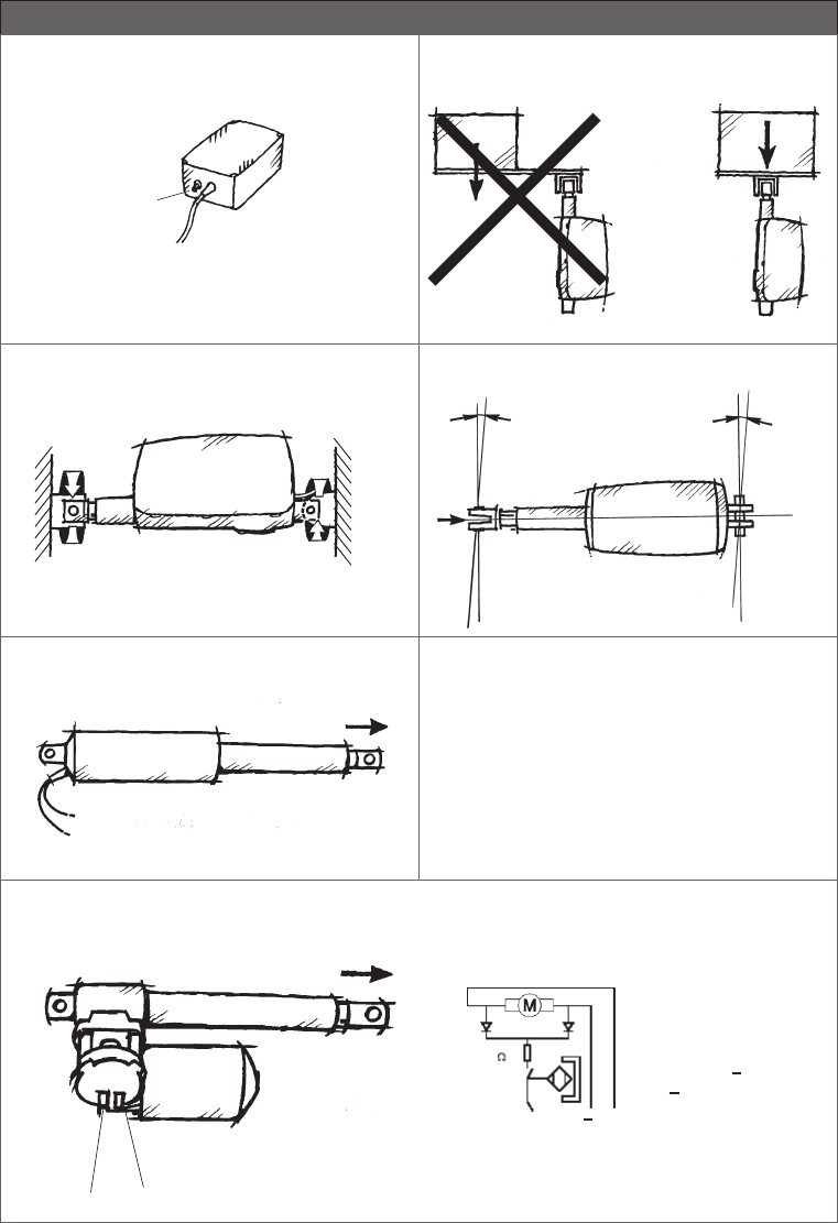
Page 142 of 148
Figure 1
Ventilation of external batteries, BA18
Check at regular intervals that the ventilation stub is undamaged
and intact.
The construction of the ventilation stub permits battery gasses to
get out, but it does not permit penetration of water.
Figure 2
Figure 3 Figure 4
max. ± 1,5omax. ± 1,5o
Drawings
Figure 6
R = ÷
S = +
1) LA22
÷+
+ ÷
3) LA30 and 30S
LA30 Actuator with reed ( only possible with 24V L-motor )
Brown Black
+
+
Out going
In going
Please note that the voltage level og feedback signal depends on the actuator load.
Blue
Black
Brown
Pulse
3.9 k
+
Ventilation stub
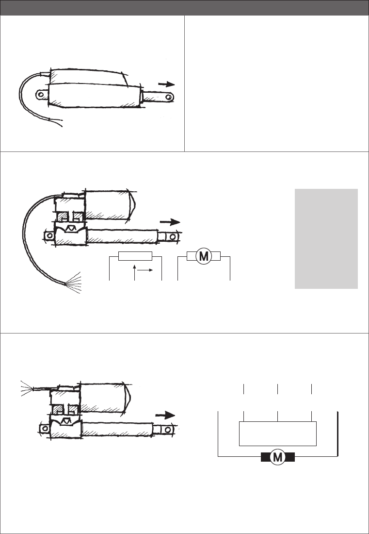
Page 143 of 148
BR = +
BL = ÷
4) LA12
Drawings
Figure 6
Colour codes:
S Black
BR Brown
R Red
O Orange
GU Yellow
G Grey
BL Blue
V Purple
GR Green
HV White
S BL BR R/GU
+
GR.
HV
÷
LA34: GR R GU S B
5) LA30, LA30S, LA32 and LA34 with potentiometer
6) LA30, LA30S and LA32 with optical encoder
Pulses +5V DC
SGU R
OPTIC ENCODER
÷
+
GR BL
Earth
...to be continued
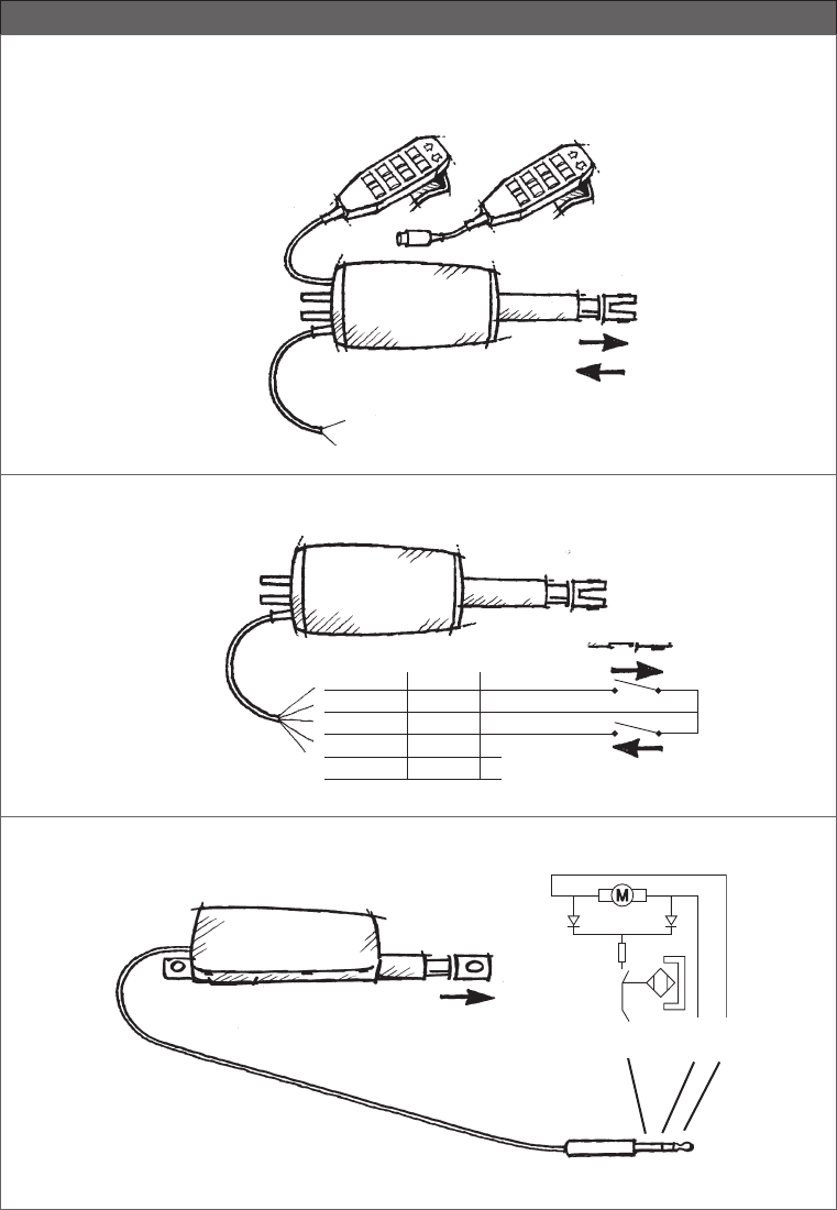
Page 144 of 148
7A-B) LA28/28S/32 with CS28/28S/32 - PC-board version A and B
Version B
LINAK handset HB is
connected with a DIN plug
Version A
LINAK handset HB is connected
with a telephone plug
BR +
BL ÷
24 VDC
Drawings
7C) LA28/28S/32 with CS28/28S/32 - PC-board version C
Version C
GU
S
GR
R
BL
CS28C CS32C
S
GU
GR
R
BL
+
÷24 VDC
Pulse
BL
÷
S
+
BR
3,9 kΩ
8) LA28, LA28S, LA32 with reed-switch and LA34 with pulse system
Figure 6
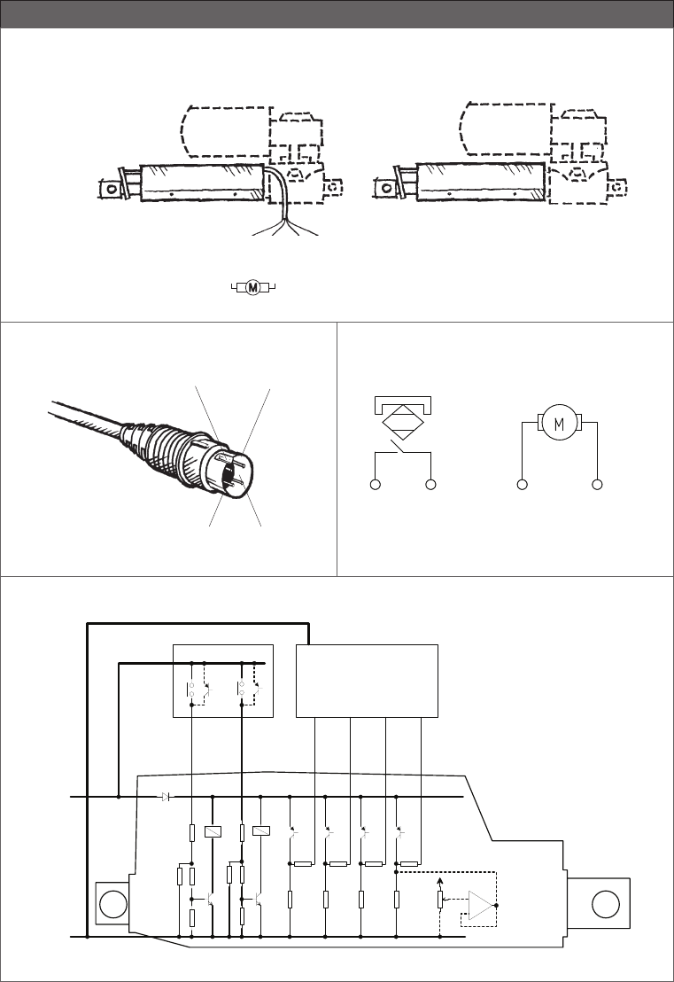
Page 145 of 148
R
+
BL
÷
S
÷
LA22, LA30, LA30S HV
+
9) LSD
Drawings
Figure 6
10) LA31, LA34 with electronic pulse coder (reed-switch)
BL BR
÷ +
R S
11) LA31 TECHLINE
Reed Switch Motor
Black Red Blue +
Blue -
Brown - = Runs outwards
Brown + = Runs inwards
12) LA12 PLC
P L C O U T P U T
B L A C K
B R O W N
-
+ 2 4 V
+ 1 0 V
ORANGE
R E D
I N W A R D S
O U T W A R D S
G R E E N
Y E L L O W
B L U E
V I O L E T
O P E N C O L L E C T O R P N P
O R S W I T C H . / N O R M A L L Y O P E N
P L C I N P U T
I N E N D S W .
O U T E N D S W .
R E A D Y
P U L S E /
P O T E N T I O M E T E R
1 K
1 K 1 K
1 K
1 K
1 0 K 1 0 K
1 0 K
1 K
3 K 3
3 K 3
3 K 3
3 K 3 3 K 3 3 K 3
1 0 K 1 0 K
+
-
...to be continued
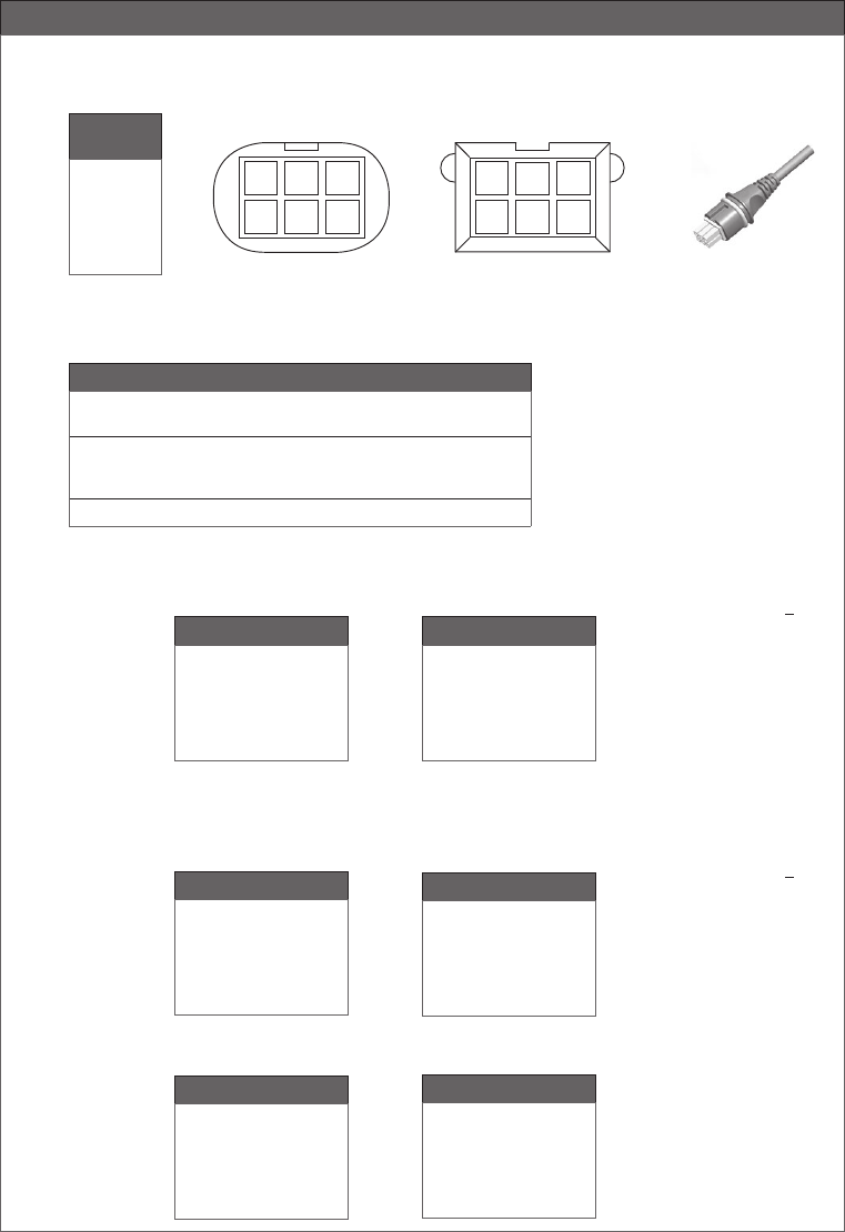
Page 146 of 148
Drawings
Figure 6
LA23/LA31/LA34/BL1/BL4 Mini-fit plug cable
Pin 1
Pin 2
Pin 3
Pin 4
Pin 5
Pin 6
EOS Switch
Switch com. (GND)
Vbus
M+ (Motor/Power)
EOS out
EOD in
M- (Motor/Power)
without Feedback
EOS Switch
Switch com. (GND)
Vbus
M+ (Motor/Power)
EOS wout
EOD in
M- (Motor/Power)
without Feedback
Mini-Fit
Connector
Pin 1
Pin 2
Pin 3
Pin 4
Pin 5
Pin 6
456
1 2 3
Connector front view
65 4
3 2 1
PCBA Header top view
13) Pin-connection for Mini-fit plug (valid for 13 and 14)
Hall
Hall com. (GND)
Vbus
M+ (Motor/Power)
EOS (analog)
Hall
M- (Motor/Power)
with Feedback
Hall
Hall GND
Vbus
M+ (Motor/Power)
Hall A
Hall B
M- (Motor/Power)
with Feedback
Pin 1
Pin 2
Pin 3
Pin 4
Pin 5
Pin 6
CH1-4 MiniFit:
When a channel is operated UP 3: Brown: +
(Motor connections) 6: Yellow: -
5: Orange: UP
End-of-stroke switches 4: Red: DOWN
2: Black: COMMON
Not Used 1: No Connection
(end of stroke = EOS)
WITHOUT FEEDBACK
LA27 Mini-fit plug cable (LA27 standard; Valid for LA27 article numbers = 27xxxxxxxxxxxx0)
LA27 Mini-fit plug cable (Analog encoded without Hall)
Article numbers = 27xxxxxxxxxxxxB
LA23/LA31/LA34/LA44/BL1 Mini-fit plug cable LA27 Mini-fit plug cable
WITH FEEDBACK
Reed
Reed com. (GND)
Vbus
M+ (Motor/Power)
NC
Reed
M- (Motor/Power)
Potentiometer
Pot GND
Vbus
M+ (Motor/Power)
Pot Position
Pot + (3V3)
M- (Motor/Power)
Pin 1
Pin 2
Pin 3
Pin 4
Pin 5
Pin 6
LA34/LA44 Mini-fit plug cable (potentiometer) BL4 Mini-fit plug cable
Article numbers = 27xxxxxxxxxxxxA
0273011 with O-ring
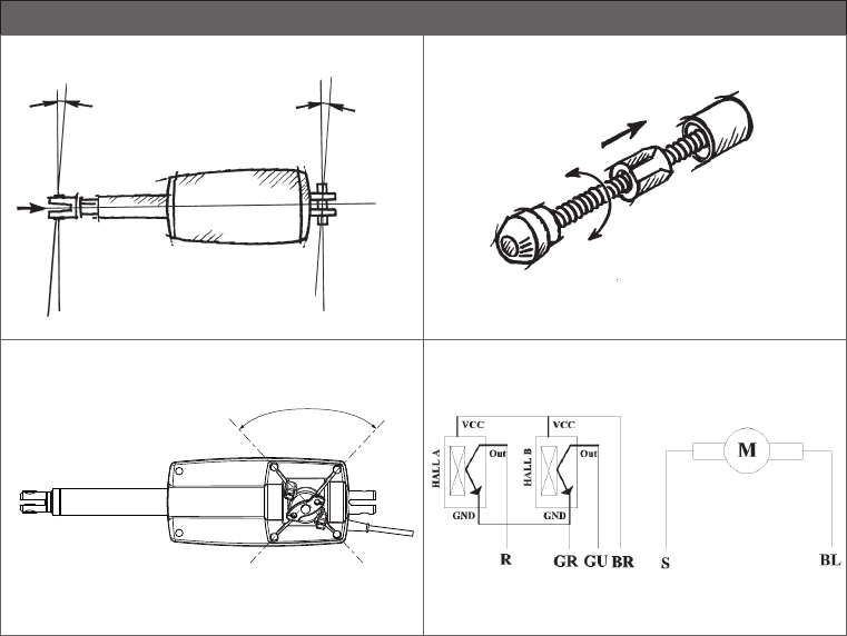
Page 147 of 148
Figure 7
Drawings
max. ± 1,5omax. ± 1,5o
Figure 8
Figure 9
75o
Figure 10

Page 148 of 148
Copyright © LINAK 2018.02 MA-M9-02-196-AM LINAK A/S reserve the right to make technical alterations
Terms of use
The user is responsible for determining the suitability of LINAK products for specific application. LINAK takes great care in providing accurate and
up-to-date information on its products.
However, due to continuous development in order to improve its products, LINAK products are subject to frequent modifications and changes
without prior notice. Therefore, LINAK cannot guarantee the correct and actual status of said information on its products.
While LINAK uses its best efforts to fulfil orders, LINAK cannot, for the same reasons as mentioned above, guarantee the availability of any
particular product. Therefore, LINAK reserves the right to discontinue the sale of any product displayed on its website or listed in its catalogues or
other written material drawn up by LINAK.
All sales are subject to the Standard Terms of Sale and Delivery for LINAK. For a copy hereof, please contact LINAK.
FACTORIES
China
LINAK (Shenzhen) Actuator Systems, Ltd.
Tel: +86 755 8610 6656
Tel: +86 755 8610 6990
E-mail: sales@linak.cn
www.linak.cn
Denmark - Headquarters
LINAK A/S - Group Headquarters
Tel: +45 73 15 15 15
Fax: +45 74 45 80 48
Fax (Sales): +45 73 15 16 13
E-mail: info@linak.com
www.linak.com
USA
LINAK U.S. Inc.
North and South American Headquarters
User support: +1 800 392 7638
Tel: +1 502 253 5595
Fax: +1 502 253 5596
E-mail: info@linak-us.com
www.linak-us.com
SUBSIDIARIES
Australia
LINAK Australia Pty. Ltd
Tel: +61 3 8796 9777
Fax: +61 3 8796 9778
E-mail: sales@linak.com.au
www.linak.com.au
Austria
LINAK Repräsentanz - Österreich (Wien)
Tel: +43 (1) 890 7446
Fax: +43 (1) 890 744615
E-mail: info@linak.de
www.linak.at
Belgium
LINAK Actuator-Systems NV/SA
(Belgium & Luxembourg)
Tel: +32 (0)9 230 01 09
Fax: +32 (0)9 230 88 80
E-mail: beinfo@linak.be
www.linak.be - www.fr.linak.be
Brazil
LINAK DO BRASIL COMÉRCIO DE
ATUADORES LTDA.
Tel: +55 (11) 2832 – 7070
Fax: +55 (11) 2832 – 7060
E-mail: info@linak.com.br
www.linak.com.br
Canada
LINAK Canada Inc.
Tel: +1 502 253 5595
Fax: +1 416-255-7720
E-mail: info@linak.ca
www.linak-us.com
Czech Republic
LINAK C&S S.R.O.
Tel: +420581741814
Fax: +420581702452
E-mail: info@linak.cz
www.linak.cz
Denmark - International
LINAK International
Tel: +45 73 15 15 15
Fax: +45 74 45 90 10
Fax (Sales): +45 73 15 16 13
E-mail: info@linak.com
www.linak.com
Denmark - Sales
LINAK DANMARK A/S
Tel: +45 86 80 36 11
Fax: +45 86 82 90 51
E-mail: linak@linak-silkeborg.dk
www.linak.dk
Finland
LINAK OY
Tel: +358 10 841 8700
E-mail: linak@linak.fi
www.linak.fi
France
LINAK FRANCE E.U.R.L
Tel: +33 (0) 2 41 36 34 34
Fax: +33 (0) 2 41 36 35 00
E-mail: linak@linak.fr
www.linak.fr
Germany
LINAK GmbH
Tel: +49 6043 9655 0
Fax: +49 6043 9655 60
E-mail: info@linak.de
www.linak.de
India
LINAK A/S India Liaison Office
Tel: +91 120 4531797
Fax: +91 120 4786428
E-mail: info@linak.in
www.linak.in
Italy
LINAK ITALIA S.r.l.
Tel: +39 02 48 46 33 66
Fax: +39 02 48 46 82 52
E-mail: info@linak.it
www.linak.it
Japan
LINAK K.K.
Tel: 81-45-533-0802
Fax: 81-45-533-0803
E-mail: linak@linak.jp
www.linak.jp
Malaysia
LINAK Actuators Sdn. Bhd.
Tel: +60 4 210 6500
Fax: +60 4 226 8901
E-mail: info@linak-asia.com
www.linak.my - www.linak.co.id
www.linak.pk - www.linak.ph
Netherlands
LINAK Actuator-Systems B.V.
Tel: +31 76 5 42 44 40
Fax: +31 76 5 42 61 10
E-mail: info@linak.nl
www.linak.nl
New Zealand
LINAK New Zealand Ltd
Tel: +64 9580 2071
Fax: +64 9580 2072
E-mail: nzsales@linak.com.au
www.linak.com.au
Norway
LINAK Norge AS
Tel: +47 32 82 90 90
Fax: +47 32 82 90 98
E-mail: info@linak.no
www.linak.no
DISTRIBUTORS
Argentina
NOVOTEC ARGENTINA SRL
Tel: 011-4303-8989/8900
Fax: 011-4032-0184
E-mail: info@novotecargentina.com
www.novotecargentina.com
Colombia
MEM Ltda
Tel: +[57] (1) 334-7666
Fax: +[57] (1) 282-1684
E-mail: servicioalcliente@memltda.com.co
www.mem.net.co
India
Mechatronics Control Equipments India Pvt Ltd
Tel: +91-44-28558484, 85
E-mail: bala@mechatronicscontrol.com
www.mechatronicscontrol.com
Indonesia
PT. HIMALAYA EVEREST JAYA
Tel: +6 221 544 8956, +6 221 544 8965
Fax: +6 221 619 1925
Fax (Sales): +6 221 619 1925
E-mail: hejplastic-div@centrin.net.id
www.hej.co.id
Iran
Bod Inc.
Tel: +98 2188998635 - 6
Fax: +98 2188954481
E-mail: info@bod.ir
www.bod.ir
Israel
NetivTech LTD
Tel: +972 55-2266-535
Fax: +972 2-9900-560
Email: info@NetivTech.com
www.netivtech.com
Russia
OOO FAM
Tel: +7 812 3319333
Fax: +7 812 3271454
E-mail: purchase@fam-drive.ru
www.fam-drive.ru
Singapore
Servo Dynamics Pte Ltd
Tel: +65 6844 0288
Fax: +65 6844 0070
E-mail: servodynamics@servo.com.sg
www.servo.com.sg
South Africa
Industrial Specialised Applications CC
Tel: +27 011 466 0346
E-mail: gartht@isagroup.co.za
www.isaza.co.za
United Arab Emirates
Mechatronics
Tel: +971 4 267 4311
Fax: +971 4 267 4312
E-mail: mechtron@emirates.net.ae
Poland
LINAK Polska
Tel: +48 22 295 09 70
E-mail: info@linak.pl
www.linak.pl
Republic of Korea
LINAK Korea Ltd.
Tel: +82-(0)2-6231-1515
Fax: +82-(0)2-6231-1516
E-mail: info@linak.kr
www.linak.kr
Russia
OOO LINAK
Tel: +7 495 280 14 26
Fax: +7 495 687 14 26
E-mail: info@linak.ru
www.linak.ru
Spain
LINAK Actuadores, S.L.u
Tel: +34 93 588 27 77
Fax: +34 93 588 27 85
E-mail: esma@linak.es
www.linak.es
Sweden
LINAK Scandinavia AB
Tel: +46 8 732 20 00
Fax: +46 8 732 20 50
E-mail: info@linak.se
www.linak.se
Switzerland
LINAK AG
Tel: +41 43 388 31 88
Fax: +41 43 388 31 87
E-mail: info@linak.ch
www.de.linak.ch - www.fr.linak.ch
www.it.linak.ch
Taiwan
LINAK (Shenzhen) Actuator systems Ltd.
Taiwan Representative office
Tel: +886 2 27290068
Fax: +886 2 27290096
E-mail: sales@linak.com.tw
www.linak.tw
Turkey
LINAK İth. İhr. San. ve Tic. A.Ş.
Tel: + 90 312 4726338
Fax: + 90 312 4726635
E-mail: info@linak.com.tr
www.linak.com.tr
United Kingdom
LINAK UK Limited
Tel: +44 (0)121 544 2211
Fax: +44 (0)121 544 2552
E-mail: sales@linak.co.uk
www.linak.co.uk
