High Speed, Accuracy Laser Displacement Sensor LK G5000 Series User's Manual 96M11282 Lkseries
User Manual: G5000
Open the PDF directly: View PDF ![]() .
.
Page Count: 272 [warning: Documents this large are best viewed by clicking the View PDF Link!]
- Introduction
- Safety Precautions
- Contents
- Chapter 1 Before Use
- Chapter 2 Operations during Measurement and Their Functions
- Chapter 3
Function Settings
- Measurement, Data Flow and Functions
- Setting the sensor head (HEAD)
- List of functions and function Nos.
- List of initial values and setting ranges
- List of the Head settings screens
- Setting ABLE (ABLE)
- Setting the measurement mode according to the target (Measurement mode)
- Specifying the action when measurement becomes impossible (Alarm handling)
- Automatically adjusting the ABLE adjustment range according to the target (ABLE calibration)
- Setting the mounting mode according to the sensor head mounting method (Mounting mode)
- Specifying two points in the measurement range to exclude a certain area from the measurement (Mask setting)
- Preventing measurement fluctuations by ignoring sudden changes in the measured value (Median)
- Grouping the laser control operation (LASER CTRL group)
- Setting the measurement position (Range)
- Setting the reference starting point for peak counting (Base point)
- Setting the measurement value output conditions (OUT)
- List of functions and function Nos.
- List of initial values and setting ranges
- List of the OUT settings screens
- Setting the OUT calculation (Calculation method)
- Calibrating the displayed value based on the measured value (Scaling)
- Apply a filter to ensure stable measurement (Filter)
- Using the Hold function (Measurement mode)
- Setting the trigger condition (Trigger)
- Using offset in the measurement (Offset)
- Setting the unit and minimum display unit (Minimum display unit)
- Scaling the analog output (Analog scaling)
- Setting the type of measurement (Measurement type)
- Setting the Common Function (OPTION)
- List of functions and function Nos.
- List of initial values and setting ranges
- List of the common function settings screens
- Setting the sampling cycle for the measurement (Sampling cycle)
- Setting the mutual interference prevention function (Mutual interference prevention)
- Setting the external synchronous input (Synchronization setting)
- Setting the output form of the tolerance comparator result (Comparator output form)
- Setting the strobe output time (Strobe time)
- Storing the measured values in the memory (Data storage function)
- Assigning OUT to the analog output channel (Analog output)
- Setting the type of alarm output (Alarm output type)
- Setting the Operating Environment settings (ENV)
- List of functions and function Nos.
- List of initial values and setting ranges
- List of the Environment settings screens
- Setting the RS-232C communication parameters (RS-232C)
- Setting the program switching method (Setting selection)
- Copying/initializing the program (Program)
- Preventing erroneous panel operation (Panel lock)
- Specifying the number of OUT to be used (Active OUT count)
- Specifying the number of sensor heads to be used (Active head count)
- Specifying the number of analog output channels (Active analog output channel count)
- Setting the necessary information to connect to a network (LAN setting)
- Chapter 4 I/O terminals
- Chapter 5 RS-232C
- Chapter 6 Specifications
- Appendices
LK-G5000 Series
High-speed, High-accuracy
Laser Displacement Sensor
User's Manual
96M11282
Read this manual before use.
Keep this manual in a safe place for future reference.

2
Introduction
This manual describes the basic operations and hardware functions of the LK-G5000
Series. Before using the LK-G5000 Series, read this manual carefully to ensure complete
understanding so that you can take full advantage of this product’s performance and
functions.
Keep this manual in a safe place for future reference.
Please deliver this manual to the end users of this product.
Symbols
The following symbols alert you to important messages concerning the prevention of
human injury and product damage.
DANGER
Failure to follow the instructions may lead to death or severe injury.
WARNING
Failure to follow the instructions may lead to injury (such as electric shock or burn).
CAUTION
Failure to follow the instructions may lead to property damage or product breakdown.
Provides additional information on proper operation.
Provides reference information or useful information about operation.
NOTE
Reference
3
Safety Precautions
General cautions
•At startup and during operation, be sure to monitor the functions and performance of
the LK-G5000 Series.
•It is recommended that you take substantial safety measures to avoid any damage in
case of product failure.
•Do not modify the LK-G5000 Series or use it in any way other than as described in the
specifications. The warranty will be voided in such cases.
•When the LK-G5000 Series is used in combination with other devices, functions and
performance may be degraded depending on the operating conditions and
surrounding environment.
•Do not use the LK-G5000 Series for the purpose of protecting the human body.
•Do not allow the temperature to change sharply around the LK-G5000 Series, including
the accessories. Otherwise, condensation may lead to a malfunction.
WARNING
Ensuring safe operation
•Use the proper power supply voltage as specified. Failure to do so may cause a fire,
electric shock, or malfunction.
•Do not attempt to disassemble or modify the unit. Doing so may cause a fire, electric
shock or unit malfunction.
Handling abnormal conditions
Turn off the power immediately in the following cases. Using the LK-G5000 Series in an
abnormal condition could cause product breakdown.
Contact your nearest KEYENCE office for repair.
•If liquid or foreign matter enters the unit.
•If the unit is dropped or the housing is damaged.
•If smoke or an abnormal odor is emitted from the controller.
96M11282

4
CAUTION
Ensuring safe operation
•Be sure to turn off the power to the LK-G5000 Series and connected devices when you
connect/disconnect the cable to/from them. Failure to do so may result in product
damage.
•Do not turn off the power while any item is being set. Part or all of the settings may be
lost.
•Do not block the vent holes on the unit. The rise in the internal temperature may cause
product failure.
Installation environment
To use the LK-G5000 Series properly and safely, avoid installing it in the following
locations. Doing so may lead to product breakdown.
•Location that is humid, dusty or poorly ventilated
•Location where the temperature becomes high, such as a place exposed to direct
sunlight
•Location where there are flammable or corrosive gases
•Location where the product may be directly subjected to vibration or impact
•Location where water, oil or chemicals may splash onto the product
•Location where static electricity is readily generated
Noise control
When the LK-G5000 Series is installed near a noise source such as a power source or
high-voltage lines, noise may cause a malfunction or failure of the unit. Take corrective
actions against noise by using noise filters, laying cables in a separate conduit, and/or
providing insulation when installing the controller and sensor head. Use a single core
shielded cable for the analog output cable.
Influence of ambient temperature
Changes in the ambient temperature may cause the measurement to fluctuate. Be sure to
keep the temperature constant at all times. When the ambient temperature changes by
10°C, it takes about 60 minutes until the temperature inside the unit is uniformly
distributed.
Ambient light
Do not use the LK-G5000 Series near a lighting system that repeatedly turns on and off
rapidly. If it is unavoidable to use the unit in such a place, install a light shielding board or
a similar object so that the light will not affect the measurement.
Warming up
After turning on the power, wait approximately 30 minutes before using the LK-G5000
Series. Since the circuit is not stable immediately after the power is turned on, the
measured value may gradually change during this period.

5
Influence of dust or dirt
The measurement may be incorrect when dirt, dust or fluid such as water or oil interferes
with measurement in the following ways.
•Adhesion on the protective glass: Blow the dirt off with clean air. If dirt persists, wipe the
glass surface gently using a soft cloth moistened with alcohol.
•Adhesion on the surface of the measurement target: Blow the dirt off with clean air or
wipe it off.
•Intrusion of floating dust or splash of fluid into the light-axis range: Take corrective
action such as installing a protective cover or air purge.
Other considerations
Influence of vibration
When the measurement target is vibrating, the measured value may fluctuate. In this case,
increase the number of averaging measurements to ensure more accurate measurement.
Measurement target
The measured value may be incorrect if the shape or surface condition of the target varies
with individual targets. In this case, measure a known target and use the calibration
function to correct the error.
Handling
Do not wipe the unit with a wet cloth, benzene, or thinner. This may cause discoloration or
deformation of the housing. If the unit becomes dirty, wipe it off with a cloth moistened with
a mild detergent and then wipe with a soft dry cloth.
Effect of atmospheric motions
Slow atmospheric motions may affect the measurement and result in fluctuation of the
measured value.
In such a case, take the following countermeasures:
•Enclose the sensor head in an appropriate enclosure.

6
Precautions on CE Marking
The LK-G5000 Series conforms to the CE Marking under the conditions that the following
requirements are satisfied. In order to use the LK-G5000 Series be sure that the following
requirements have already been satisfied beforehand.
The applicable standards (EMC Directive) are listed below:
EMI:EN61326-1, Class A
EMS:EN61326-1
Limit the length of the power supply cable and all input/output cables that are connected
to the terminal panel of the controller to 30 m or less.
For the USB cable connected to the terminal panel of the controller, wind two turns of the cable around
the ferrite core of the following model at a distance of 200 mm or less from the USB connector of the
controller.
Model: ZCAT3035-1330 (Manufactured by TDK)
NOTE
7
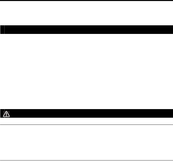
Precautions on wiring
Part of the input/output circuit of the LK-G5000 Series is internally common. Be careful that
no potential difference is generated between the internally common terminals due to the
potential difference between the cables/external devices. Such a potential difference may
cause a breakdown of the product or external devices.
Wiring example
LK-G5001V/LK-G5001 (NPN type)
The 24 VDC (-), COM OUT (COM for output), and COM IN (COM for input) terminals are
common through choke coils respectively. They are also common with COM OUT and
COM IN of the expansion connector through choke coils.
LK-G5001PV/LK-G5001P (PNP type)
The 24 VDC (-) and COM IN terminals are common through choke coils. They are also
common with COM IN of the expansion connector through choke coils.
LK-G5001(V)
COM OUT
COM IN
24 VDC (+)
24 VDC (-)
The power supply terminal (24 VDC) is
short-circuited through the COM terminals,
resulting in product failure.
24 VDC
COM OUT
COM IN
24 VDC (+)
24 VDC (-)
24 VDC
LK-G5001(V)
COM OUT
COM IN
24 VDC (+)
24 VDC (-)
24 VDC
LK-G5001P(V)
The power supply terminal (24 VDC) is
short-circuited through the COM terminals,
resulting in product failure.
COM OUT
COM IN
24 VDC (+)
24 VDC (-)
24 VDC
LK-G5001P(V)
8
Caution for all types
The 24 VDC (-) terminal, SG (GND) of the USB port, and SG (GND) of the RS-232C
connector are common through choke coils. Be careful that no potential difference is
generated between these terminals and the external devices such as a PC or PLC. If any
potential difference exists, isolate the I/O terminals of the LK-G5000 Series except for
those used for the power supply, RS-232C and USB.
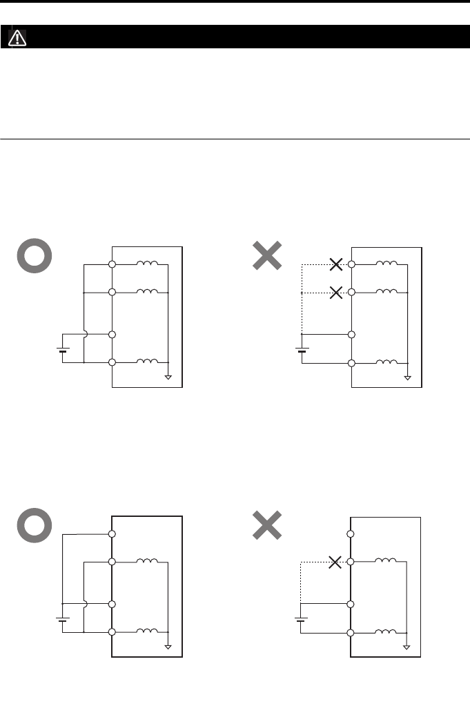
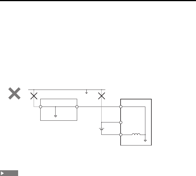
Precautions on use in a positive ground environment
When using the LK-G5000 Series in a positive ground environment, be careful of a short
circuit caused through the COM terminals.
LK-G5001V/LK-G5001 (NPN type)
LK-G5001PV/LK-G5001P (PNP type)
COM OUT
COM IN
24 VDC (+)
24 VDC (-)
24 VDC
LK-G5001(V)
Ground
The power supply terminal (24 VDC) is
short-circuited through the COM terminals,
resulting in product failure.
COM OUT
COM IN
24 VDC (+)
24 VDC (-)
24 VDC
LK-G5001(V)
Ground
COM OUT
COM IN
24 VDC (+)
24 VDC (-)
24 VDC
LK-G5001P(V)
Ground
The power supply terminal (24 VDC) is
short-circuited through the COM terminals,
resulting in product failure.
COM OUT
COM IN
24 VDC (+)
24 VDC (-)
24 VDC
LK-G5001P(V)
Ground
9
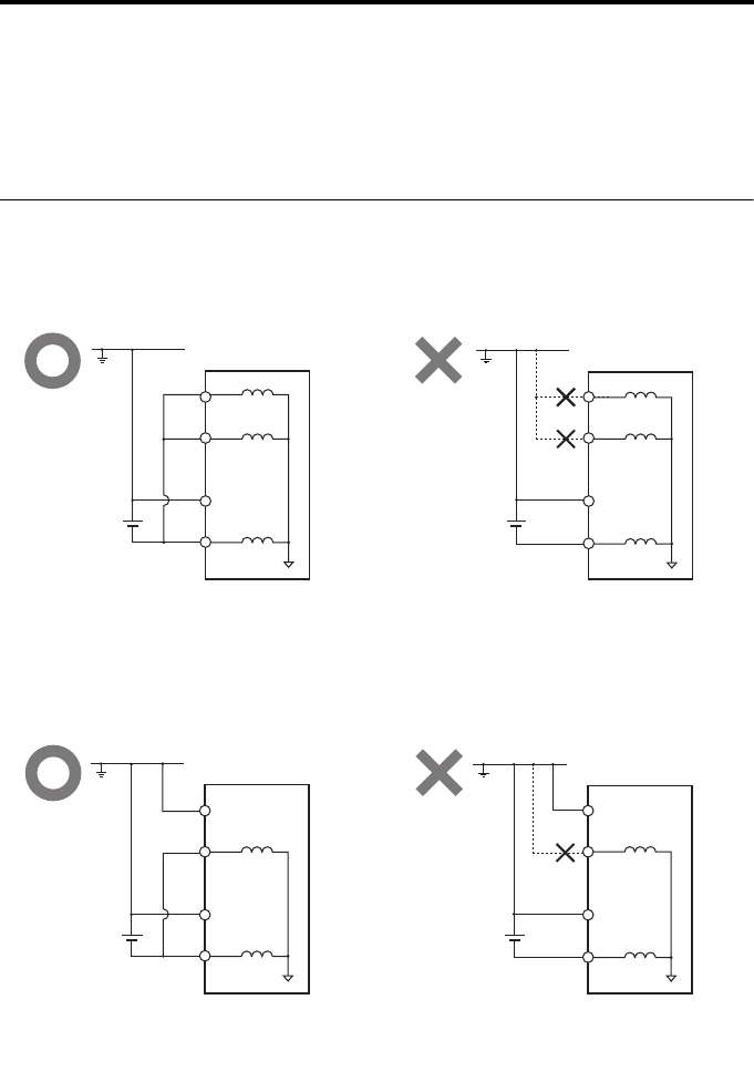
Precautions on connection with a PC or other external device
In a positive ground environment, when the LK-Navigator 2 software is used by
connecting a PC through USB or LAN, or when RS-232C communication is used with a
PC, be careful of a short circuit created between the internal components of the PC and
the SG (GND) terminal of the LK-G5000.
The 24 VDC (-) terminal, SG (GND) of the USB port, SG (GND) and 24 VDC (-) of the RS-
232C connector, and SG (GND) of the Ethernet port are common through choke coils
respectively. Be careful that no potential difference is generated between these terminals
and the external device such as a PC or PLC. If any potential difference exists, isolate the
external device or the I/O terminals of the LK-G5000 Series except for those used for the
power supply, RS-232C, USB and LAN.
If the power supply terminal (24 VDC) is short-circuited through the internal component of the PC and
the SG (GND) terminal of the LK-G5000 Series, a product breakdown may occur. If this is the case,
isolate either the PC (1) or the LK-G5000 Series (2).
The internal wiring of a PC or PLC varies depending on the device. Refer to the instruction manual of
the device for details.
GND for
RS-232C/
USB/LAN
GND for
RS-232C/
USB/LAN
24 VDC(+)
24 VDC(-)
24 VDC
LK-G5001P(V)
GroundPC
Ground
terminal
RS-232C/
USB/LAN
cable
(2)(1)
NOTE
10
Safety precautions on laser products
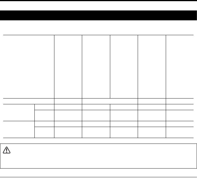
The models of the LK-G5000 Series are classified as follows in terms of laser class:
Precautions on class IIIb/3B laser products
MPE (maximum permissible exposure): 2.5 mW/cm2
NOHD (nominal ocular hazard distance): 68 cm (LK-H023),101 cm (LK-H028),
143 cm (LK-H053), 280 cm (LK-H058) from the transmitter
Follow the instructions mentioned in this manual. Otherwise, injury to the human body
(eyes and skin) may result.
•Do not directly look at or touch the laser beam and its reflection from a mirror-like
surface.
•Do not direct the beam at other people or into areas where other people unconnected
with the laser work might be present.
•Prevent the diffusion of the laser beam.
Make the laser path as short as possible and be sure to terminate it with a diffusion
reflector or diffusion absorber which has proper reflectance and thermal characteristic.
(It is recommended that you install a protective enclosure.)
•Install the laser product carefully so that the laser beam is not unintentionally directed at
mirror-like surfaces.
•Wear protective eye goggles appropriate for the laser beam wavelength.
Model LK-H008/
LK-H008W
LK-H022/
LK-H027/
LK-H022K/
LK-H027K/
LK-H052/
LK-H057/
LK-H052K/
LK-H057K/
LK-H082/
LK-H087/
LK-H152/
LK-H157
LK-H020/
LK-H025/
LK-H050/
LK-H055
LK-H080/
LK-H085/
LK-H150/
LK-H155
LK-H023/
LK-H028/
LK-H053/
LK-H058
Wavelength 655 nm 650 nm 655 nm 690 nm
FDA (CDRH)
Part 1040.10
Output 0.3mW 0.95 mW 4.8 mW 4.8 mW 50 mW
Laser
class
Class II Class II Class IIIa Class IIIa Class IIIb
IEC60825-1 Output 0.3mW 0.95 mW 4.8 mW 4.8 mW 50 mW
Laser
class
Class 1 Class 2 Class 3R Class 3R Class 3B
WARNING
Use of controls or adjustments or performance of procedures other than those specified herein may
result in hazardous radiation exposure.

11
•Do not disassemble this product. Laser emission from this product is not automatically
stopped when it is disassembled.
•Clean the aperture regulary. In addition, stop the emission of the laser beam when
cleaning.
•Use an interlock function to block laser radiation in an emergency.
•Prevent prohibited laser radiation use by providing a key-operated switch or other
control on the control panel.
•Install the products so that the path of the laser beam is not as the same height as that
of human eye.
Precautions on class IIIa/3R laser products
Follow the instructions mentioned in this manual. Otherwise, injury to the human body
(eyes and skin) may result.
•Do not direct the beam at other people or into areas where other people unconnected
with the laser work might be present.
•Never look at the laser beam through optical instruments such as a microscope or a
telescope.
•Prevent the diffusion of the laser beam.
Make the laser path as short as possible and be sure to terminate it with a diffusion
reflector or diffusion absorber which has proper reflectance and thermal characteristic.
(It is recommended that you install a protective enclosure.)
•Install the products so that the path of the laser beam is not as the same height as that
of human eye.
•Install the laser product carefully so that the laser beam is not unintentionally directed at
mirror-like surfaces.
•It is recommended that you wear protective eye goggles.
•Do not disassemble this product. Laser emission from this product is not automatically
stopped when it is disassembled.
•Do not directly look at or touch the laser beam and its reflection from a mirror-like
surface.
Precautions on class II/2 laser products
Follow the instructions mentioned in this manual. Otherwise, injury to the human body
(eyes and skin) may result.
•Do not stare into the beam.
•Do not direct the beam at other people or into areas where other people unconnected
with the laser work might be present.
•Be careful of the path of the laser beam. If there is a danger that the operator may be
exposed to the laser beam reflected by specular or diffuse reflection, block the beam by
installing an enclosure with the appropriate reflectance.
•Install the products so that the path of the laser beam is not as the same height as that
of human eye.
•Do not disassemble this product. Laser emission from this product is not automatically
stopped when it is disassembled.

12
Precautions on Class 1 Laser Products
Follow the instructions mentioned in this manual. Otherwise, injury to the human body
(eyes and skin) may result.
•Do not stare into the beam.
•Do not disassemble this product. Laser emission from this product is not automatically
stopped when it is disassembled.
13
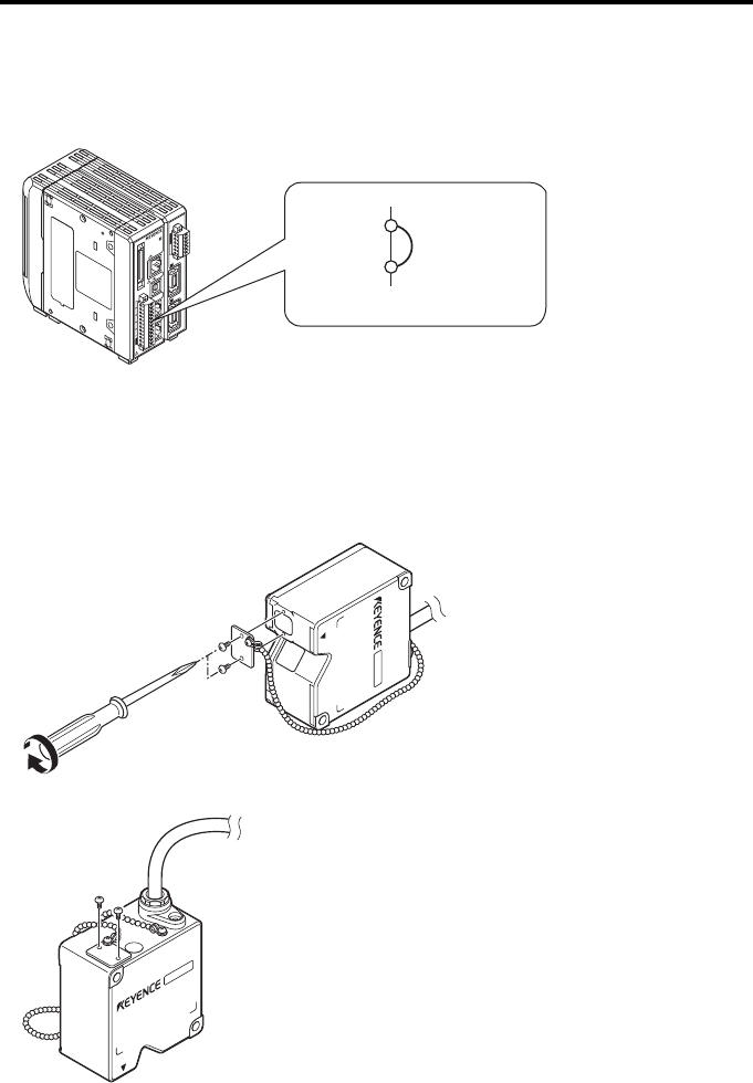
Safety features of the laser product
The LK-G5000 Series is equipped with the following safety features.
Laser radiation emission indicator
Lights or flashes while the LK-G5000 Series is in operation.
Lights or flashes while the LK-G5000 Series is in operation.
Laser emission LED
1
2
3
4
5
6
7
8
9
10
11
12
13
14
15
16
17
18
19
20
2
21
22
23
24
25
26
27
28
29
30
31
32
33
34
35
36
37
38
39
40
LASER ON
ETHERNET
USB
DISPLAY
RS-232C
HEAD
1
OUT(V)
OUT(A)
OUT 0V
OUT(V)
OUT(A)
OUT 0V
COM INZERO 1TIMING 1GOLASER 1DC 24V
1
HEAD
LK-G5000
2
LASER ON (laser emission) lamp
14
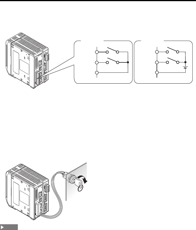
LASER CTRL terminals
The operation is different between the laser class 3B sensor head (LK-H023/LK-H028/LK-
H053/LK-H058) and the laser class 1, 2 or 3R sensor head.
Refer to "12-pin terminal block" (page 4-2) for details about the connecting terminals.
When a laser class 3B sensor head (LK-H023/LK-H028/LK-H053/LK-H058) is used
Provide a key-operated switch between the LASER CTRL1/LASER CTRL2 terminal and the
COM IN terminal. Use a key-operated switch which can be removed only when the laser
emission is off.
•NPN output type:Laser beam emission starts when the key-operated switch is operated
to turn ON (close) the circuit between the LASER CTRL1/LASER CTRL2 terminal and the
COM IN terminal.
•PNP output type:Laser beam emission starts when the key-operated switch is operated
to turn ON (apply voltage to) the circuit between the LASER CTRL1/LASER CTRL2
terminal and the COM IN terminal.
Control with a key-operated switch is required when at least one class 3B sensor head is connected.
Example of applicable key-operated switch
CK-M12BFS1 keylock switch manufactured by Nihon Kaiheiki
Use a key-operated switch which can be removed only when the laser emission is off.
When only a laser class 1, 2 or 3R sensor head is used
•NPN output type: Laser beam emission stops when the circuit between the LASER
CTRL1/LASER CTRL2 terminal and COM IN terminal is short-circuited.
•PNP output type: Laser beam emission stops when voltage is applied to the circuit
between the LASER CTRL1/LASER CTRL2 terminal and COM IN terminal.
1
1
2
3
4
5
6
7
8
9
10
11
12
13
14
15
16
17
18
19
20
2
21
22
23
24
25
26
27
28
29
30
31
32
33
34
35
36
37
38
39
40
LASER ON
ETHERNET
USB
DISPLAY
RS-232C
HEAD
1
(V)
(A)
0V
(V)
(A)
0V
COM INZERO 1TIMING 1GOLASER 1DC 24V
1
HEAD
LK-G5000
2
COM IN
LASER
CTRL 1
LASER
CTRL 2
COM IN
LASER
CTRL 1
LASER
CTRL 2
NPN type PNP type
1
1
2
3
4
5
6
7
8
9
10
11
12
13
14
15
16
17
18
19
20
2
21
22
23
24
25
26
27
28
29
30
31
32
33
34
35
36
37
38
39
40
LASER ON
ETHERNET
USB
DISPLAY
RS-232C
HEAD
1
(V)
(A)
0V
(V)
(A)
0V
COM INZERO 1TIMING 1GOLASER 1DC 24V
1
HEAD
LK-G5000
2
NOTE
15
REMOTE terminal
Laser beam emission can be stopped by opening the circuit between the REMOTE
terminal and COM IN terminal.
Refer to "12-pin terminal block" (page 4-2) for details about the connecting terminals.
Shutter
•You can prevent the laser beam emission by closing the shutter.
•The shutter is provided for the following sensor head models:
LK-H023/LK-H028/LK-H053/LK-H058
•To block the laser beam, attach the shutter to cover the lens surface with the supplied
M1.6 screws.
•When the shutter is unnecessary, secure it next to the warning indicator.
1
1
2
3
4
5
6
7
8
9
10
11
12
13
14
15
16
17
18
19
20
2
21
22
23
24
25
26
27
28
29
30
31
32
33
34
35
36
37
38
39
40
LASER ON
ETHERNET
USB
DISPLAY
RS-232C
HEAD
1
(V)
(A)
0V
(V)
(A)
0V
COM INZERO 1TIMING 1GOLASER 1DC 24V
1
HEAD
LK-G5000
2
COM IN
REMOTE
Illuminates when short-circuited
16
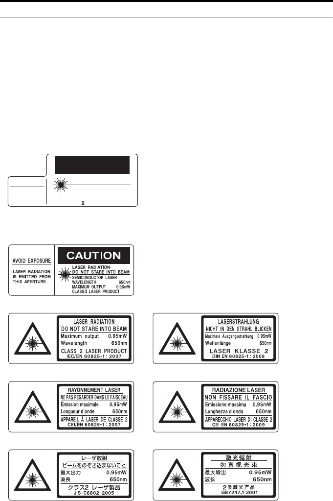
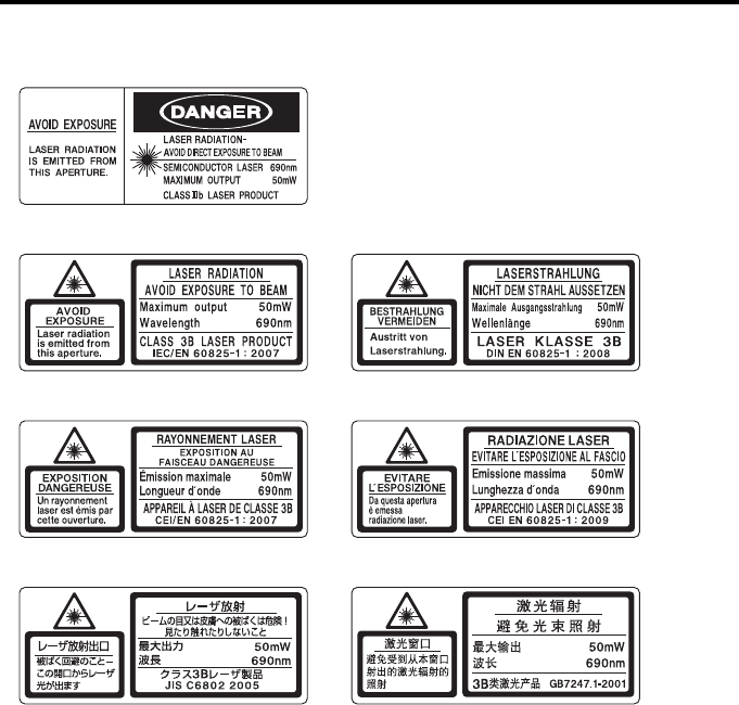
Warning labels
The description on the warning labels attached to the LK-G5000 Series and the label
locations are described below.
The FDA (CDRH) warning labels are attached to the unit when the product is shipped from
the factory. Labels other than the FDA (CDRH) label are supplied with the product. Attach
the other label(s) to the locations as shown in the figures on page 20 according to the
destination of the product. Warning labels are not attached with LK-H008/LK-H008W,
because these models are Laser Class 1 Product according to IEC60825-1.
Label description
LK-H008/LK-H008W
LK-H022/LK-H027/LK-H022K/LK-H027K/LK-H052/LK-H057/LK-H052K/
LK-H057K/LK-H082/LK-H087/LK-H152/LK-H157
FDA(CDRH)
AVOID EXPOSURE
LASER RADIATION
IS EMITTED FROM
THIS APERTURE.
LASER RADIATION-
DO NOT STARE INTO BEAM
CAUTION
SEMICONDUCTOR LASER
WAVELENGTH
MAXIMUM OUTPUT
CLASS LASER PRODUCT
655nm
0.3mW
FDA (CDRH)
IEC (English)
IEC (French)
JIS (Japanese)
DIN (German)
CEI (Italian)
GB (Simplified Chinese)
17
LK-H020/LK-H025/LK-H050/LK-H055
FDA (CDRH)
IEC (English)
IEC (French)
JIS (Japanese)
DIN (German)
CEI (Italian)
GB (Simplified Chinese)
18
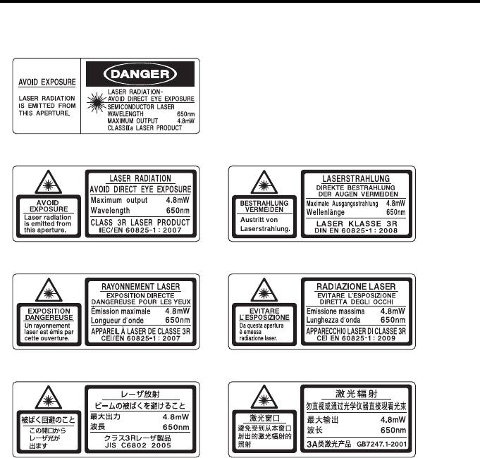
LK-H080/LK-H085/LK-H150/LK-H155
FDA (CDRH)
IEC (English)
IEC (French)
JIS (Japanese)
DIN (German)
CEI (Italian)
GB (Simplified Chinese)
AVOID EXPOSURE
LASER RADIATION
IS EMITTED FROM
THIS APERTURE.
LASER RADIATION-
AVOID DIRECT EYE EXPOSURE
SEMICONDUCTOR LASER
WAVELENGTH
MAXIMUM OUTPUT
CLASS a LASER PRODUCT
655nm
4.8mW
4.8mW
655nm
AVOID
EXPOSURE
Laser radiation
is emitted from
this aperture.
LASER RADIATION
AVOID DIRECT EYE EXPOSURE
Maximum output
Wavelength
CLASS 3R LASER PRODUCT
IEC/EN 60825-1 : 2007
激光窗囗
避免受到从本窗囗
射出的激光辐射的
照射
激光辐射
最大输出
波长
3A
类激光产品
GB7247.1-2001
4.8mW
655nm
DIREKTE BESTRAHLUNG
DER AUGEN VERMEIDEN
DIN EN 60825-1 : 2008
4.8mW
655nm
LASERSTRAHLUNG
LASER KLASSE 3R
Maximale Ausgangsstrahlung
Wellenlange
レーザ放射
ビームの被ばくを避けること
最大出力
波長
4.8mW
655nm
JIS C6802 2005
クラス レーザ製品
3R
被ばく回避のこと
この開口から
レーザ光が
出ます
勿直视或通过光学仪器直接观看光束
BESTRAHLUNG
VERMEIDEN
Austritt von
Laserstrahlung.
EXPOSITION
DANGEREUSE
Un rayonnement
laser est emis par
cette ouverture.
EVITARE
L ESPOSIZIONE
Da questa apertura
e emessa
radiazione laser.
EXPOSITION DIRECTE
DANGEREUSE POUR LES YEUX
CEI/EN 60825-1 : 2007
4.8mW
655nm
RAYONNEMENT LASER
APPAREIL A LASER DE CLASSE 3R
CEI EN 60825-1 : 2009
RADIAZIONE LASER
4.8mW
655nm
APPARECCHI0 LASER DI CLASSE 3R
Emissione massima
Lunghezza d onda
EVITARE L ESPOSIZIONE
DIRETTA DEGLI OCCHI
Emission maximale
Longueur d onde
19
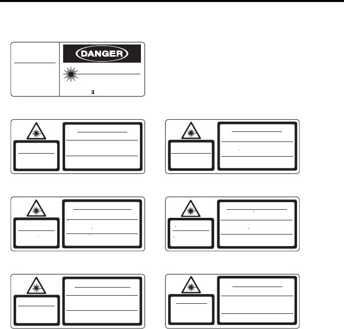
LK-H023/LK-H028/LK-H053/LK-H058
FDA (CDRH)
IEC (English)
IEC (French)
JIS (Japanese)
DIN (German)
CEI (Italian)
GB (Simplified Chinese)
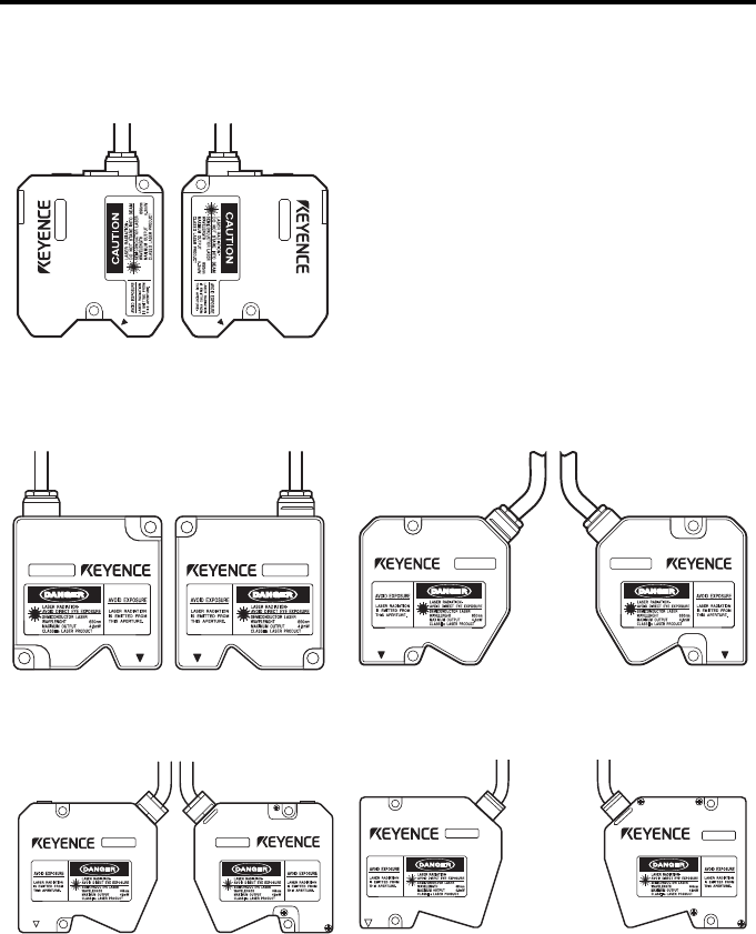
20
Label attachment locations
LK-H008/LK-H008W
LK-H020/LK-H025/LK-H022/
LK-H027/LK-H023/LK-H028/
LK-H022K/LK-H027K
LK-H050/LK-H055/LK-H052/
LK-H057/LK-H053/LK-H058/
LK-H052K/LK-H057K
LK-H080/LK-H085/LK-H082/
LK-H087
LK-H150/LK-H155/LK-H152/
LK-H157

21
Contents
Introduction .............................................2
Safety Precautions ...................................3
General cautions ................................ 3
WARNING........................................... 3
CAUTION............................................ 4
Other considerations..........................5
Precautions on CE Marking................6
Precautions on wiring.........................7
Safety precautions on laser products... 10
Contents ................................................21
Chapter 1 Before Use
System Configuration ...........................1-2
Checking the Package Contents ..........1-3
LK-G5001V/LK-G5001PV
(Single unit type controller)..........1-3
LK-G5001/LK-G5001P
(Separate type controller)............1-3
LK-HA100 (Head expansion unit) ...1-4
LK-HD500 (Separate type display
panel)...........................................1-4
LK-HD1001 (Touch panel) ..............1-4
Sensor head ....................................1-5
CB-A07/CB-A2/CB-A5/CB-A10/
CB-A20/CB-A30...........................1-5
CB-A5E/CB-A10E ............................1-5
Part Names and Functions ...................1-6
Controller .........................................1-6
Sensor head ....................................1-9
Mounting/Connecting the Units ..........1-10
Attaching the ND Filter (Option)....1-10
Mounting the sensor head.............1-10
Mounting the sensor head according
to the measurement target.........1-16
Mounting the controller..................1-17
Connecting the units .....................1-26
Outline of the Measurement and
Settings .........................................1-29
Mode selection..............................1-29
Setting mode .................................1-30
Initializing the LK-G5000 Series to the
Factory Default Settings ...............1-31
Chapter 2 Operations during
Measurement and
Their Functions
Switching the Measurement Value
Displays ..........................................2-2
Setting the Tolerance Comparator Value ..2-4
The function of the tolerance
comparator setting.......................2-4
Hysteresis........................................2-6
Instantaneous Zero Setting (Auto-Zero) ....2-7
Instantaneous Master Adjustment
(Auto-offset) ....................................2-9
Program Function ...............................2-10
Switching Program Nos. .....................2-11
Storing Measured Values in the Memory
(Data Storage Function) ...............2-12
Chapter 3 Function Settings
Measurement, Data Flow and Functions ..3-2
Setting the sensor head (HEAD) ..........3-3
List of functions and function Nos...3-3
List of initial values and
setting ranges ..............................3-4
List of the Head settings screens....3-5
Setting ABLE (ABLE) .......................3-6
Setting the measurement mode
according to the target
(Measurement mode) ..................3-8
Specifying the action when
measurement becomes impossible
(Alarm handling) ........................3-10
Automatically adjusting the ABLE
adjustment range according to the
target (ABLE calibration) ...........3-13
Setting the mounting mode according
to the sensor head mounting method
(Mounting mode) .......................3-15

22
Specifying two points in the
measurement range to exclude a
certain area from the measurement
(Mask setting)............................ 3-16
Preventing measurement fluctuations
by ignoring sudden changes in the
measured value (Median) ......... 3-18
Grouping the laser control operation
(LASER CTRL group) ................ 3-20
Setting the measurement position
(Range) ..................................... 3-21
Setting the reference starting point for
peak counting (Base point)....... 3-22
Setting the measurement value output
conditions (OUT) .......................... 3-24
List of functions and function Nos. 3-24
List of initial values and
setting ranges ........................... 3-26
List of the OUT settings screens... 3-27
Setting the OUT calculation
(Calculation method)................. 3-28
Calibrating the displayed value based on
the measured value (Scaling)........ 3-31
Apply a filter to ensure stable
measurement (Filter) ................. 3-33
Using the Hold function
(Measurement mode)................ 3-37
Setting the trigger condition
(Trigger) ................................... 3-45
Using offset in the measurement
(Offset) ...................................... 3-47
Setting the unit and minimum display
unit (Minimum display unit) ....... 3-48
Scaling the analog output (Analog
scaling)...................................... 3-50
Setting the type of measurement
(Measurement type) .................. 3-53
Setting the Common Function
(OPTION) ..................................... 3-55
List of functions and function Nos. 3-55
List of initial values and
setting ranges ........................... 3-56
List of the common function settings
screens...................................... 3-57
Setting the sampling cycle for the
measurement
(Sampling cycle) ....................... 3-58
Setting the mutual interference
prevention function (Mutual
interference prevention)............ 3-60
Setting the external synchronous input
(Synchronization setting)........... 3-62
Setting the output form of the
tolerance comparator result
(Comparator output form) ......... 3-63
Setting the strobe output time
(Strobe time).............................. 3-64
Storing the measured values in the
memory
(Data storage function).................. 3-65
Assigning OUT to the analog output
channel (Analog output)............ 3-67
Setting the type of alarm output
(Alarm output type) ................... 3-68
Setting the Operating Environment settings
(ENV) ............................................ 3-69
List of functions and function Nos. ... 3-69
List of initial values and
setting ranges .......................... 3-70
List of the Environment
settings screens ........................ 3-71
Setting the RS-232C communication
parameters (RS-232C) .............. 3-72
Setting the program switching method
(Setting selection) ..................... 3-73
Copying/initializing the program
(Program) .................................. 3-74
Preventing erroneous panel operation
(Panel lock) ............................... 3-76
Specifying the number of OUT to be
used (Active OUT count)........... 3-78
Specifying the number of sensor heads
to be used
(Active head count)................... 3-79
Specifying the number of analog output
channels (Active analog output
channel count) .......................... 3-80

23
Setting the necessary information to
connect to a network
(LAN setting)..............................3-81
Chapter 4 I/O terminals
Names and functions of the I/O
terminals .........................................4-2
Function of the I/O terminals ...........4-2
Functions of the I/O Signals ............4-8
Timing diagrams .................................4-15
Chapter 5 RS-232C
Specifications .......................................5-2
Pin assignment................................5-2
Communication parameters ............5-3
Communication operations for the
measuring status and
communication mode ..................5-3
Setting outline according to external
devices ........................................5-3
Measured Value Output and Changing
Settings through Commands ..........5-4
Connecting a PC/PLC link unit ........5-4
Mode change command .................5-7
Measurement control command
format...........................................5-8
Setting change command .............5-14
Setting confirmation command
format.........................................5-25
Timing diagrams............................5-35
Data Storage Function ........................5-36
Environmental settings ..................5-36
Command input/output procedure ...5-36
Measured Value Output through External
Synchronization ............................5-38
Environment settings parameters..5-38
Output type....................................5-38
Timing diagrams............................5-39
Output format ................................5-40
ASCII code table (Reference) .......5-40
Chapter 6 Specifications
Specifications .......................................6-2
Controller .........................................6-2
Sensor head ....................................6-4
Expansion unit .................................6-9
Head-to-controller cable ...............6-11
Head-to-controller extension cable ...6-11
Status table....................................6-12
Response delay time.....................6-14
Dimensions .........................................6-15
Controller .......................................6-15
Sensor head ..................................6-18
Expansion unit ...............................6-22
Characteristics ...................................6-25
Beam spot diameter......................6-25
Mutual interference........................6-27
Optical axis range .........................6-30
Appendices
Troubleshooting ................................... A-2
Error Codes ......................................... A-5
List of Optional Accessories ................ A-7
Type of Measurement and Sampling
frequency.................................... A-9
Relationship Between the Sampling Cycle
and Velocity/Acceleration
Measurement Range ................... A-11
Index .................................................. A-12

24
MEMO

1-1
1
This chapter describes the configuration of the LK-G5000
Series, the operational precautions and the preparations
required before using it. Be sure to read this chapter
thoroughly before using the LK-G5000 Series.
System Configuration ........................................................... 1-2
Checking the Package Contents .......................................... 1-3
Part Names and Functions ................................................... 1-6
Mounting/Connecting the Units .......................................... 1-10
Outline of the Measurement and Settings .......................... 1-29
Initializing the LK-G5000 Series to the Factory Default Settings
.. 1-31
Before Use1
1-2
1
1 Before Use
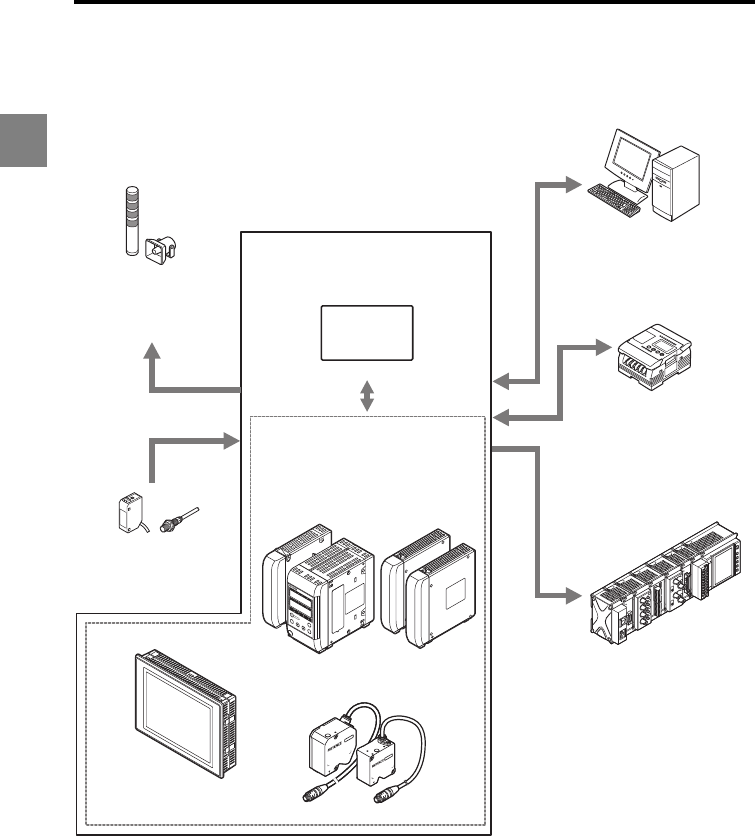
System Configuration
The LK-G5000 Series can be used along with commercially-available devices for various
purposes.
*1: The single unit type controller (LK-G5001V/LK-G5001PV) can be separated into the display panel
and controller unit. They can also be purchased separately.
The single unit type controller is labeled as LK-HD500 on the display panel side and as LK-G5001
or LK-G5001P on the terminal panel side.
*2: For details about the LK-Navigator 2 setup support software (LK-H2), refer to the "LK-Navigator 2
User's Manual" (provided as a PDF file on the CD-ROM).
*3: For details on the dedicated touch panel (LK-HD1000), refer to the LK-HD1000 User's Manual.
*4: For details on the CC-Link communication unit (LK-CC100) and the DeviceNet communication unit
(LK-DN100), refer to the LK-CC100/LK-DN100 User's Manual.
LK Navigator2
LK-HD500
OUT1
HIGOLO TIM
OUT2
HI GO LO TIM
HEAD1
LASER ON STABILITY BRIGHT DARK
HEAD2
LASER ON STABILITYBRIGHT DARK
ZERO
ENT
SET
PROGRAM
Programmable logic
controller (PLC)
Enables synchronization
control of the measurement
and program number
switching as well as reading
of control output and
measured values.
Enables control and
measured value reading
through RS-232C
communication or the parallel
I/O board of the PC.
Recorder
Records the measurement
result.
Indicator, buzzer
Issues an alarm
depending on the
comparator result output.
Photoelectric sensor,
proximity sensor
Transmits a signal to the
synchronous input when
the target is detected.
Dedicated touch panel*3
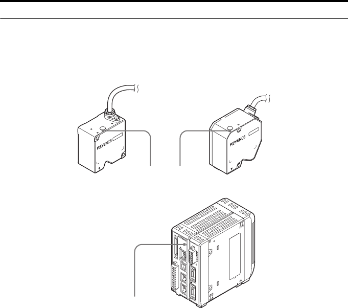
LK-HD1001 Head (12 heads max.)
Setup support software (LK-H2)*2
LK-G5000 Series
USB/RS-232C
Controller*1
LK-G5001/5001P
Head
expansion unit
LK-HA100
CC-Link
communication unit*4
LK-CC100
DeviceNet
communication unit*4
LK-DN100
1-3
1
1 Before Use
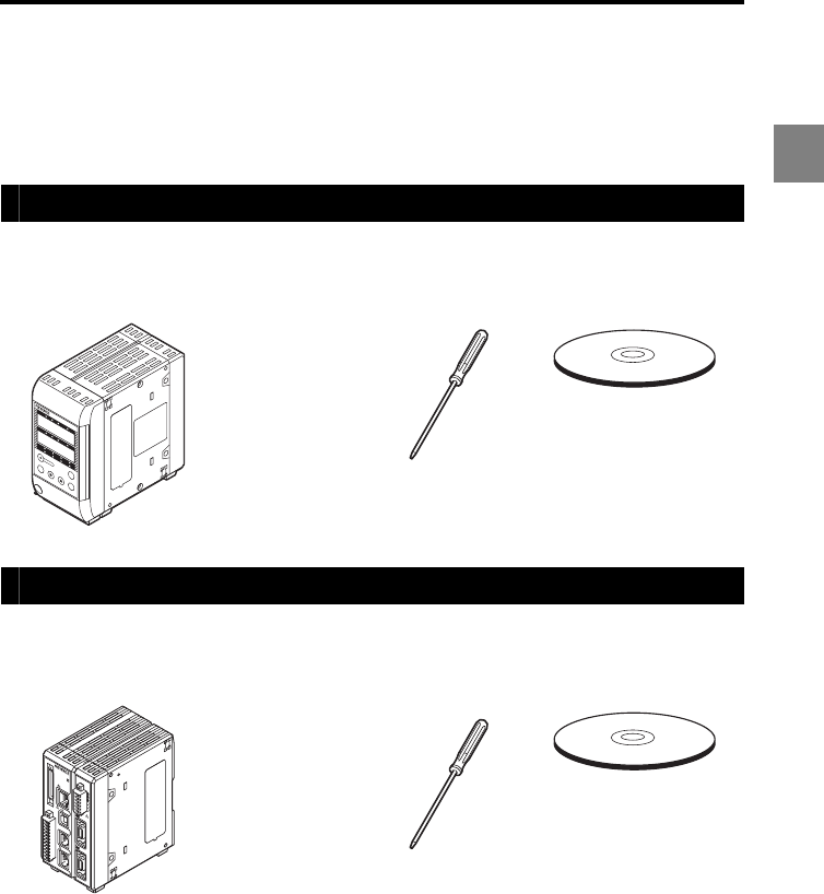
Checking the Package Contents
The LK-G5000 Series consists of the following models. Ensure that all the components
and accessories listed below are included in the package of the model you purchased
before using the unit.
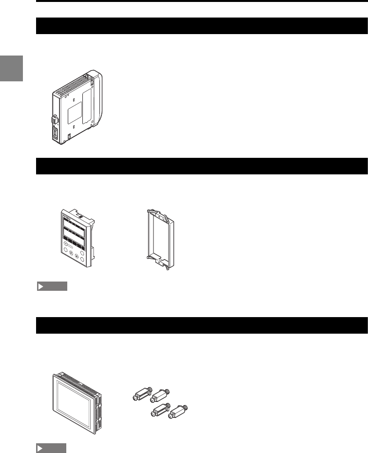
LK-G5001V/LK-G5001PV (Single unit type controller)
LK-G5001/LK-G5001P (Separate type controller)
Controller
LK-G5001V/
LK-G5001PV: 1
User's
Manual
(This manual): 1
Screwdriver: 1 Packaged separately
LK-H2 (CD-ROM)
•Setup support software
LK-Navigator 2
•Setup support software
User's Manual (PDF file)
•USB cable (2 m)
Controller
LK-G5001/
LK-G5001P: 1
User's
Manual
(This manual): 1
Screwdriver: 1 Packaged separately
LK-H2 (CD-ROM)
•Setup support software
LK-Navigator 2
•Setup support software
User's Manual (PDF file)
•USB cable (2 m)
LK-HD500
HI GO LO TIM
HI GO LO TIM
HEAD1
LASER ONSTABILITY BRIGHT DARK
HEAD2
LASER ON STABILITY BRIGHTDARK
ZERO
ENT
SET
PROGRAM
1
2
3
4
5
6
7
8
9
10
11
12
13
14
15
16
17
18
19
20
2
21
22
23
24
25
26
27
28
29
30
31
32
33
34
35
36
37
38
39
40
LASER ON
ETHERNET
USB
DISPLAY
RS-232C
HEAD
1
OUT(V)
OUT(A)
OUT 0V
OUT(V)
OUT(A)
OUT 0V
COM INZERO 1TIMING 1GO
LASER 1
DC 24V
1
HEAD
LK-G5000
2
1-4
1
1 Before Use
LK-HA100 (Head expansion unit)
LK-HD500 (Separate type display panel)
The cable connecting the controller is sold separately (page A-7).
LK-HD1001 (Touch panel)
The cable connecting the controller is sold separately (page A-7).
Head expansion unit
LK-HA100: 1
Instruction
Manual: 1
Display panel
LK-HD500: 1
Display panel
attachment ring: 1
Touch panel
LK-HD1001: 1 Mounting bracket: 4 User's
Manual: 1
POWER
STABILITY
BRIGHT
DARK
HEAD
(V)
(A)
(A)
LK-HA100
LK-HD500
HIGOLO TIM
HI GOLO TIM
HEAD1
LASER ON STABILITY BRIGHT DARK
HEAD2
LASER ON STABILITY BRIGHT DARK
ZERO
ENT
SET
PROGRAM
NOTE
NOTE
1-5
1
1 Before Use
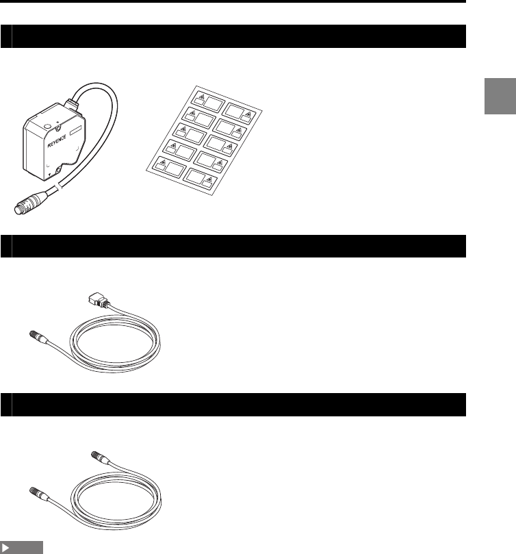
Sensor head
CB-A07/CB-A2/CB-A5/CB-A10/CB-A20/CB-A30
CB-A5E/CB-A10E
•For each sensor head connection, use only one head-to-controller extension cable and limit the
total length to 30 m at maximum.
•You cannot connect the CB-AE to the CB-A30.
•You cannot connect two CB-A10E cables to the CB-A10.
The package contents have been carefully inspected; however, if any component is
defective or damaged, contact your nearest KEYENCE office (address listed at the end of
this manual).
For the optional products, refer to "List of Optional Accessories" (page A-7).
Sensor head: 1 Laser label sheet: 1 The Laser label sheet is not
attached with LK-H008/LK-H008W.
Head-to-controller cable: 1
•CB-A07: 0.7 m cable
•CB-A2: 2 m cable
•CB-A5: 5 m cable
•CB-A10: 10 m cable
•CB-A20: 20 m cable
•CB-A30: 30 m cable
Head-to-controller extension cable: 1
•CB-A5E: 5 m extension cable
•CB-A10E: 10 m extension cable
NOTE
1-6
1
1 Before Use
Part Names and Functions
This section describes the name and functions of each component.
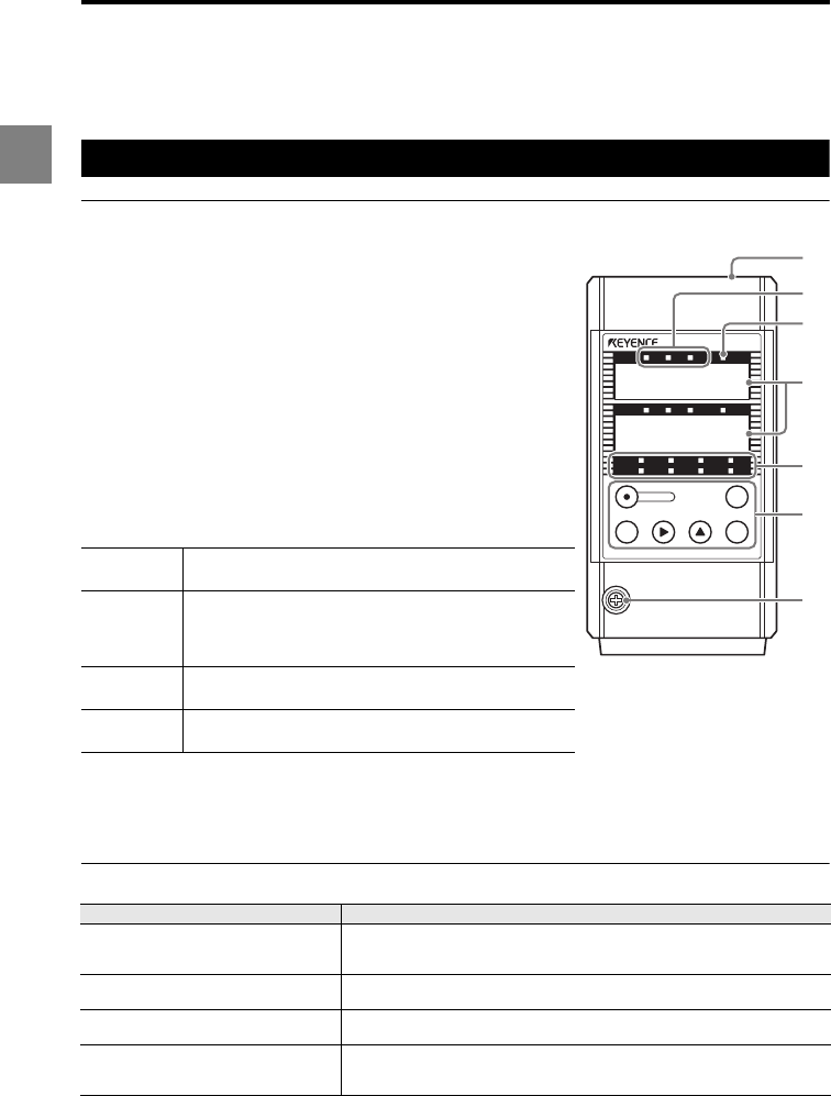
Controller
Display panel
(1) Display panel housing
(2) Comparator output indicators
Lights during the comparator output (HI, GO, or LO).
(3) TIM (synchronous input) indicator
Lights when the synchronous signal is being input.
(4) Measured value display
Displays the measured value, tolerance comparator value,
or the setting items during setting.
Green: Within the tolerance limits Red: Outside the tolerance limits
(5) Sensor head status indicators
Display the laser emission status or the measurement
status.
(6) Operation keys
Refer to "Operation keys" (page 1-7).
(7) Display panel fixing screw
Items shown on the measured value display and their meanings
LASER ON Laser emission LED. Lights while the LK-G5000 Series
is in operation.
STABILITY
Lights in green or orange when the result is within the
measurement range. Lights in red when the result is
outside the measurement range, when an alarm is
issued, or when the laser is off.
BRIGHT Lights when the excessive light intensity alarm is
triggered.
DARK Lights when the insufficient light intensity alarm is
triggered.
Display Description
Numerical value (±999999) The measurement result is displayed as a numerical value. The
display unit, decimal point position, and minimum display unit vary
depending on the settings.
FFFFFF (HI output: ON, Monitor
output: +10.8 V) Displayed when the result exceeds the display range.
-FFFFFF (LO output: ON, Monitor
output: -10.8 V) Displayed when the result is below the display range.
This is also displayed while in alarm status (HI/LO output: ON).
- - - - - -
(HI, GO, and LO output: OFF,
Monitor output: -10.8 V)
Displayed while in comparator standby status.
LK-HD500
HI GO LO TIM
HI GO LO TIM
HEAD1
LASER ON STABILITY BRIGHT DARK
HEAD2
LASER ON STABILITY BRIGHT DARK
ZERO
ENTSET
PROGRAM
88.8888_
88.8888_
(1)
(2)
(3)
(4)
(5)
(6)
(7)
1-7
1
1 Before Use
Operation keys
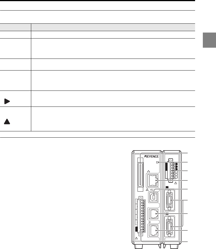
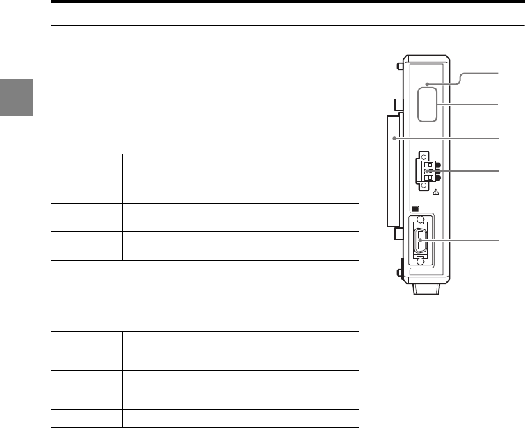
Terminal panel
(1) Expansion connector (page 4-5)
(2) LASER ON (laser emission) lamp
Lights while the LK-G5000 Series is in operation.
(3) 6-pin terminal block (page 4-4)
(4) Ethernet connector
Used to connect a PC through Ethernet. Refer to "LK-
Navigator 2 User's Manual" for details.
(5) USB connector
Used to connect a PC through USB. Refer to "LK-
Navigator 2 User's Manual" for details.
(6) HEAD connector
(7) RS-232C connector (page 5-2)
Used for communication with a PC or PLC.
(8) DISPLAY (display panel) connector
Connects the communication cable to the display panel (LK-HD500) or to the dedicated
touch panel (LK-HD1001).
(9) 12-pin terminal block (page 4-2)
Key Function
PROGRAM • When this key is pressed during measurement, the Program switching mode is invoked.
SET
• When this key is pressed during measurement, the Tolerance setting mode is invoked.
When it is pressed for one second, the Operation setting mode is invoked.
• When this key is pressed during setting, the setting is canceled and the operation
returns to the previous step.
ENT • When this key is pressed during measurement, the OUT display setting mode is invoked.
• When it is pressed during setting, the setting is accepted.
ZERO
• When this key is pressed during measurement, the measured value is set to zero. When
it is pressed for three seconds, the auto-zero setting is canceled.
• When this key is pressed for three seconds during numerical value input, the value and
selected item are initialized.
• When this key is pressed
during setting
, the display is switched to the next setting item.
• When it is pressed during numerical value input, the current digit shifts to the right by
one. When it is pressed for one second or more, the digits shift continuously.
• When this key is pressed during measurement, the display is changed in the order of upper
window only, lower window only, dual display, and repeats.
• When it is pressed during setting, the setting item is changed. When it is pressed during
numerical value input, symbols are switched or a numerical value is set. When it is
pressed for one second or more, the values change continuously.
1
2
3
4
5
6
7
8
9
10
11
12
13
14
15
16
17
18
19
20
2
21
22
23
24
25
26
27
28
29
30
31
32
33
34
35
36
37
38
39
40
LASER ON
ETHERNET
USB
DISPLAY
RS-232C
HEAD
1
(V)
(A)
0V
(V)
(A)
0V
COM INZERO 1TIMING 1GOLASER 1DC 24V
1
HEAD
LK-G5000
2
(9)
(8)
(2)
(1)
(3)
(4)
(5)
(6)
(7)
1-8
1
1 Before Use
LK-HA100 head expansion unit
(1) POWER lamp
Lights when the power is on.
(2) Sensor head status indicator
Displays the laser emission status or the measurement
status.
(3) Connector
(4) Terminal block
Used for analog monitor output.
The 6-pin terminal block of the controller corresponds to analog outputs CH01 and CH02.
The terminal blocks of the head expansion units correspond to analog outputs CH03 to
CH12 respectively from the controller side.
For details about the analog output channel assignment, refer to "Assigning OUT to the
analog output channel (Analog output)" (page 3-67).
(5) HEAD connector
STABILITY
Lights in green or orange when the result is within the
measurement range. Lights in red when the result is
outside the measurement range, when an alarm is
issued, or when the laser is off.
BRIGHT Lights when the excessive light intensity alarm is
triggered.
DARK Lights when the insufficient light intensity alarm is
triggered.
OUT (V)
Analog voltage output
Outputs the displayed value as voltage within the
range of ±10.5 V.
OUT (A)
Analog current output
Outputs the displayed value as a current within the
range of 3.6 mA to 20.4 mA.
OUT 0 V 0 V terminal for OUT
POWER
STABILITY
BRIGHT
DARK
HEAD
(V)
(A)
(A)
LK-HA100 (1)
(2)
(4)
(3)
(5)
1-9
1
1 Before Use
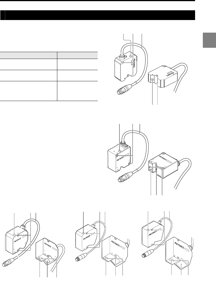
Sensor head
(1) Laser emission LED
Lights or flashes while the LK-G5000 Series is
in operation.
(2) Mounting holes
(3) Connecting cable
Connected to the head-to-controller cable.
(4) Sensor (transmitter)
Emits the laser beam for measurement. This
part is protected with a glass cover.
(5) Sensor (receiver)
Receives the laser beam for measurement.
This part is protected with a glass cover.
(6) Laser attenuator (shutter)
mounting holes
Used to attach the laser attenuator for the
laser class 3B sensor head.
StatusLED
Target is at the center of the
measurement range. Lights in green
Target is within the
measurement range. Lights in orange
Target is outside the
measurement range.
Alarm
Laser off
Flashes in orange
(1) (2) (3)
(4)(5)(6)
(2)(1) (3)
(5)(4)
(1) (2) (3)
(4) (5) (6) (4) (5) (6)
(1) (2) (3) (1) (2) (3)
(4) (5) (6)
1-10
1
1 Before Use
Mounting/Connecting the Units
Attaching the ND Filter (Option)
If the head is installed for specular reflection and the measurement target is a shiny mirror
or glass surface, the received light intensity may saturate. In such a case, by attaching the
ND filter (LK-F2/LK-F3) saturation can be avoided, thus enabling accurate measurements
to be taken.
Mounting the sensor head
Determine the distance between the sensor head and the measurement target, and
secure the head using screws through the two mounting holes.
It is recommended that you provide insulation when the LK-G5000 Series is used in a positive ground
environment.
Ambient temperature for the sensor head
When the sensor head is mounted onto a plastic object, limit the ambient temperature to 45C or lower.
ND filter
LK-F3
• LK-H085/LK-H087 • LK-H155/LK-H157
ND filter
LK-F2
Mounting screw x 2
(M1.6 x 3 countersink-head screw)
Mounting screw x 2
(M1.6 x 3 countersink-head screw)
NOTE
1-11
1
1 Before Use
LK-H008/LK-H008W
Mounting method
Measurement range
•The laser emission LED lights in green within approximately ±0.025 mm of the reference position,
and lights in orange in any other position within the measurement range.
•The following table shows the measurement ranges for the sampling cycle between 2.55 μs and 10
μs.
Range
setting Center Far
2.55 μs ±40 μm -420 to -500 μm
5 μs ±180 μm -140 to -500 μm
10 μs ±460 μm +420 to -500 μm
M4, 35 mm or more
8 mm
0 mm +0.5 mm
-
0.5 mm
Reference
distance Measurement
range
Reference
1-12
1
1 Before Use
LK-H020/LK-H025/LK-H022/LK-H027/LK-H023/LK-H028/LK-H022K/LK-H027K
Mounting method
Measurement range
•For both diffuse reflection mounting and specular reflection mounting, the laser emission LED lights
in green when the target is within approximately ±0.15 mm of the reference position, and lights in
orange when it is in any other position within the measurement range.
•Select the mounting mode according to the mounting method (page 3-15).
•The following table shows the measurement ranges for the sampling cycle between 2.55 μs and 10
μs.
The values in parentheses are for specular reflection mounting.
•Diffuse reflection mounting •Specular reflection mounting
LK-H02x LK-H02xK
Range
setting Center Far Range
setting Center Far
2.55 μs ±0.3 mm
(±0.2 mm)
-2.6 to -3.0 mm
(-2.6 to -2.8 mm) 2.55 μs ±0.2 mm
(±0.2 mm)
-2.6 to -2.8 mm
(-2.6 to -2.8 mm)
5 μs ±1.2 mm
(±1.0 mm)
-0.6 to -3.0 mm
(-0.6 to -2.8 mm) 5 μs ±1.0 mm
(±1.0 mm)
-0.6 to -2.8 mm
(-0.6 to -2.8 mm)
10 μs ±2.5 mm
(±2.2 mm)
2.0 to -3.0 mm
(1.8 to -2.8 mm) 10 μs ±2.2 mm
(±2.2 mm)
1.8 to -2.8 mm
(1.8 to -2.8 mm)
M4, 40 mm or more
20 mm
0 mm +3 mm
-
3 mm
Reference
distance
Measurement
range
16.1 mm
0 mm +2.8 mm
-
2.8 mm
Measurement
range
Reference
distance
Reference
1-13
1
1 Before Use
LK-H050/LK-H055/LK-H052/LK-H057/LK-H053/LK-H058/LK-H052K/LK-H057K
Mounting method
Measurement range
•For both diffuse reflection mounting and specular reflection mounting, the laser emission LED lights
in green when the target is within approximately ±0.5 mm of the reference position, and lights in
orange when it is in any other position within the measurement range.
•Select the mounting mode according to the mounting type (page 3-15).
•The following table shows the measurement ranges for the sampling cycle between 2.55 μs and 10
μs.
The values in parentheses are for specular reflection mounting.
•Diffuse reflection mounting •Specular reflection mounting
LK-H05x LK-H05xK
Range
setting Center Far Range
setting Center Far
2.55 μs ±0.7 mm
(±0.4 mm)
-7.6 to -10.0 mm
(-7.6 to -9.6 mm) 2.55 μs ±0.4 mm
(±0.4 mm)
-4.4 to -5.2 mm
(-4.4 to -5.2 mm)
5 μs ±2.0 mm
(±1.6 mm)
-4.0 to -10.0 mm
(-4.0 to -9.6 mm) 5 μs ±1.6 mm
(±1.6 mm)
-2.0 to -5.2 mm
(-2.0 to -5.2 mm)
10 μs ±4 mm
(±3.6 mm)
2.0 to -10.0 mm
(1.6 to -9.6 mm) 10 μs ±3.6 mm
(±3.6 mm)
3.2 to -5.2 mm
(3.2 to -5.2 mm)
M4, 40 mm or more
50 mm
0 mm
+10 mm
-
10 mm
Reference
distance
Measurement range
46.3 mm
0 mm
+5.2 mm
-
5.2 mm
Measurement range
Reference
distance
Reference
1-14
1
1 Before Use
LK-H080/LK-H085/LK-H082/LK-H087
Mounting method
Measurement range
•For both diffuse reflection mounting and specular reflection mounting, the laser emission LED lights
in green when the target is within approximately ±0.9 mm of the reference position, and lights in
orange when it is in any other position within the measurement range.
•Select the mounting mode according to the mounting type (page 3-15).
•The following table shows the measurement ranges for the sampling cycle between 2.55 μs and 10
μs.
The values in parentheses are for specular reflection mounting.
•Diffuse reflection mounting •Specular reflection mounting
LK-H08x
Range
setting Center Far
2.55 μs ±1.2 mm
±(1.1 mm)
-13.5 to -18.0 mm
(-13.3 to -17.6 mm)
5 μs ±3.5 mm
±(3.4 mm)
-7.3 to -18.0 mm
(-7.2 to -17.6 mm)
10 μs ±7.7 mm
(±7.5 mm)
2.9 to -18.0 mm
(2.8 to -17.6 mm)
M4, 40 mm or more
80 mm
0 mm
+18 mm
-
18 mm
Reference
distance
Measurement range
76.7 mm
0 mm
+17.6 mm
-
17.6 mm
Measurement range
Reference
distance
Reference
1-15
1
1 Before Use
LK-H150/LK-H155/LK-H152/LK-H157
Mounting method
Measurement range
•For both diffuse reflection mounting and specular reflection mounting, the laser emission LED lights
in green when the target is within approximately ±2 mm of the reference position, and lights in
orange when it is in any other position within the measurement range.
•Select the mounting mode according to the mounting type (page 3-15).
•The following table shows the measurement ranges for the sampling cycle between 2.55 μs and 10
μs.
The values in parentheses are for specular reflection mounting.
•Diffuse reflection mounting •Specular reflection mounting
LK-H15x
Range
setting Center Far
2.55 μs ±1.9 mm
±(1.8 mm)
-32.8 to -40.0 mm
(-32.5 to -39.5mm)
5 μs ±7.6 mm
±(7.5 mm)
-16.9 to -40.0 mm
(-16.8 to -39.5 mm)
10 μs ±17.7 mm
(±17.5 mm)
7.2 to -40.0 mm
(7.1 to -17.6 mm)
M4, 40 mm or more
150 mm
0 mm
+40 mm
-
40 mm
Reference
distance
Measurement range
147.5 mm
0 mm
+39.5 mm
-
39.5 mm
Reference
distance
Measurement range
Reference
1-16
1
1 Before Use
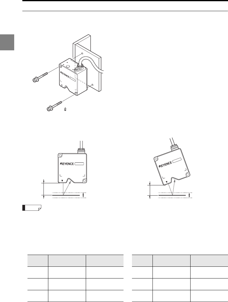
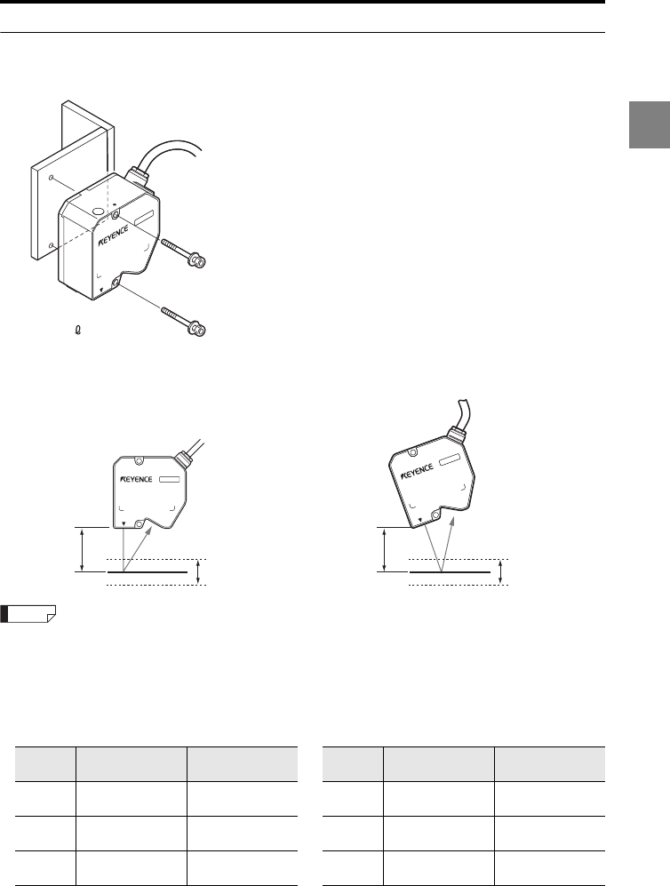
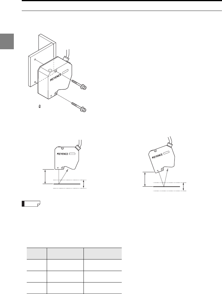
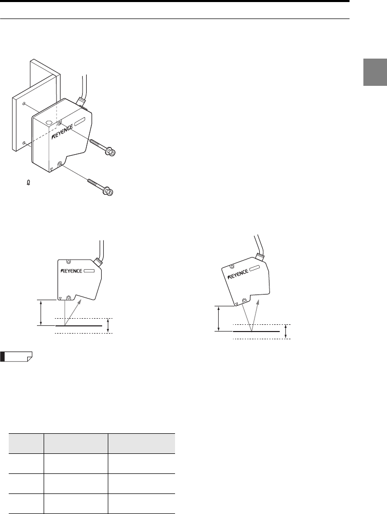
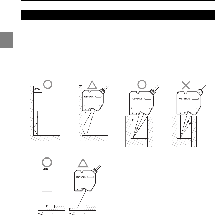
Mounting the sensor head according to the measurement target
Measurement distance
Use the sensor head as close to the reference distance as possible. This ensures the most
stable detection.
Target shape
It is recommended to mount the sensor head in the orientations indicated by the circles in
the figures below.
•Near a wall surface •Displacement in a hole
•Height difference measurement
(a) (b)
1-17
1
1 Before Use
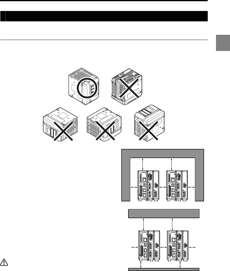
Mounting the controller
Mount the controller to the DIN rail, or secure it with screws.
Caution on the orientation of the controller
Mount the controller only in the orientation shown with a circle in the following figures. Do
not mount it upside down.
To secure the controller with the screws on
the bottom
Provide clearance of 50 mm or more above, 30
mm or more on each side, and 30 mm or more at
the rear of the controller for ventilation.
In addition, for ensuring the safety of the cable
connection work, provide 65 mm or more space in
front of the terminal panel of the controller.
To mount the controller to the DIN rail
Provide clearance of 30 mm or more between the
controllers, 50 mm or more above and 30 mm or
more below the controller.
CAUTION
•Do not block the ventilation holes on the top and
bottom of the controller. The heat may stay inside and
cause a malfunction.
•When the temperature inside the control panel exceeds the specified ambient temperature (50C when
one or less head expansion unit is connected, 40C when two or more head expansion units are
connected), decrease the temperature of the controller bottom to the specified ambient temperature or
lower by using forced air cooling or by providing more clearance around the controller.
POWER
STABILITY
BRIGHT
DARK
HEAD
(V)
(A)
(A)
LK-HA100
1
2
3
4
5
6
7
8
9
10
11
12
13
14
15
16
17
18
19
20
2
21
22
23
24
25
26
27
28
29
30
31
32
33
34
35
36
37
38
39
40
LASER ON
ETHERNET
USB
DISPLAY
RS-232C
HEAD
1
(V)
(A)
0V
(V)
(A)
0V
COM IN
ZERO 1TIMING 1GO
LASER 1
DC 24V
1
HEAD
LK-G5000
2
LK-HD500
OUT1
HI GO LO TIM
OUT2
HI GO LOTIM
HEAD1
LASER ON STABILITY BRIGHT DARK
HEAD2
LASER ONSTABILITY BRIGHT DARK
ZERO
ENT
SET
PROGRAM
LK-HD500
OUT1
HI GO LO TIM
OUT2
HI GO LO TIM
HEAD1
LASER ONSTABILITY BRIGHT DARK
HEAD2
LASER ONSTABILITY BRIGHT DARK
ZERO
ENT
SET
PROGRAM
LK-HD500
OUT1
HI GO LO TIM
OUT2
HI GO LO TIM
HEAD1
LASER ONSTABILITY BRIGHTDARK
HEAD2
LASER ONSTABILITY BRIGHT DARK
ZERO
ENT
SET
PROGRAM
LK-HD500
OUT1
HI GO LO TIM
OUT2
HI GO LO TIM
HEAD1
LASER ON STABILITY BRIGHT DARK
HEAD2
LASER ON STABILITY BRIGHT DARK
ZERO
ENT
SET
PROGRAM
50 mm 50 mm
30
mm
30
mm
30
mm
1
2
3
4
5
6
7
8
9
10
11
12
13
14
15
16
17
18
19
20
2
21
22
23
24
25
26
27
28
29
30
31
32
33
34
35
36
37
38
39
40
LASER ON
ETHERNET
USB
DISPLAY
RS-232C
HEAD
1
(V)
(A)
0V
(V)
(A)
0V
COM INZERO 1TIMING 1GOLASER 1DC 24V
1
HEAD
LK-G5000
2
POWER
STABILITY
BRIGHT
DARK
HEAD
(V)
(A)
(A)
LK-HA100
1
2
3
4
5
6
7
8
9
10
11
12
13
14
15
16
17
18
19
20
2
21
22
23
24
25
26
27
28
29
30
31
32
33
34
35
36
37
38
39
40
LASER ON
ETHERNET
USB
DISPLAY
RS-232C
HEAD
1
(V)
(A)
0V
(V)
(A)
0V
COM INZERO 1TIMING 1GOLASER 1DC 24V
1
HEAD
LK-G5000
2
POWER
STABILITY
BRIGHT
DARK
HEAD
(V)
(A)
(A)
LK-HA100
50 mm
30 mm 30 mm
50 mm
30
mm
30
mm
30
mm
1
2
3
4
5
6
7
8
9
10
11
12
13
14
15
16
17
18
19
20
2
21
22
23
24
25
26
27
28
29
30
31
32
33
34
35
36
37
38
39
40
LASER ON
ETHERNET
USB
DISPLAY
RS-232C
HEAD
1
(V)
(A)
0V
(V)
(A)
0V
COM INZERO 1TIMING 1GOLASER 1DC 24V
1
HEAD
LK-G5000
2
POWER
STABILITY
BRIGHT
DARK
HEAD
(V)
(A)
(A)
LK-HA100
1
2
3
4
5
6
7
8
9
10
11
12
13
14
15
16
17
18
19
20
2
21
22
23
24
25
26
27
28
29
30
31
32
33
34
35
36
37
38
39
40
LASER ON
ETHERNET
USB
DISPLAY
RS-232C
HEAD
1
(V)
(A)
0V
(V)
(A)
0V
COM INZERO 1TIMING 1GOLASER 1DC 24V
1
HEAD
LK-G5000
2
POWER
STABILITY
BRIGHT
DARK
HEAD
(V)
(A)
(A)
LK-HA100
1-18
1
1 Before Use
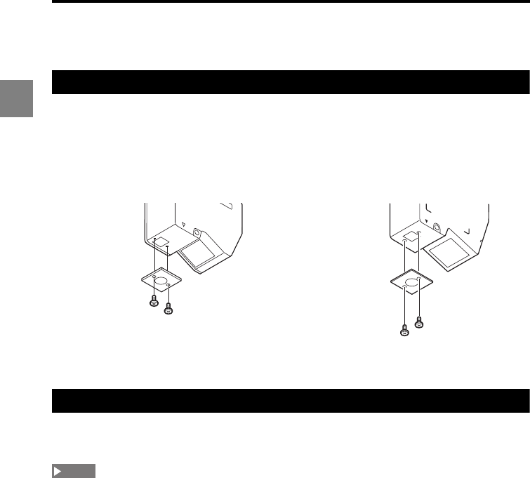
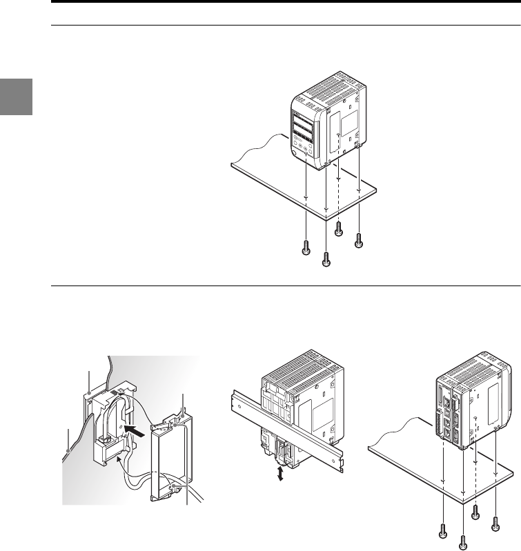
Mounting the LK-G5001V/LK-G5001PV (single unit type controller)
Mount the controller on its bottom surface.
Mounting the LK-G5001/LK-G5001P and LK-HD500 (separate type controller)
Display panel (LK-HD500) Controller (LK-G5001/LK-G5001P)
Insert the display panel
from the front, and secure
it with the display panel
attachment ring from the
rear.
When removing the display
panel, push the two cutouts
of the attachment ring
outward with a flat-blade
screwdriver and then push
out the display panel to the
front.
•DIN-rail mounting •Bottom mounting
LK-HD500
OUT1
HI GO LO TIM
OUT2
HI GO LO TIM
HEAD1
LASER ON STABILITY BRIGHT DARK
HEAD2
LASER ON STABILITY BRIGHT DARK
ZERO
ENT
SET
PROGRAM
M4 screw x 4
(Screw depth: 6 mm)
Two cutouts
Display
panel
attachment
ring
Display
panel
Control
panel
wall
M4 screw x 4
(Screw depth:
6 mm)
1
2
3
4
5
6
7
8
9
10
11
12
13
14
15
16
17
18
19
20
2
21
22
23
24
25
26
27
28
29
30
31
32
33
34
35
36
37
38
39
40
LASER ON
ETHERNET
USB
DISPLAY
RS-232C
HEAD
1
OUT(V)
OUT(A)
OUT 0V
OUT(V)
OUT(A)
OUT 0V
COM INZERO 1TIMING 1GOLASER 1DC 24V
1
HEAD
LK-G5000
2
1-19
1
1 Before Use
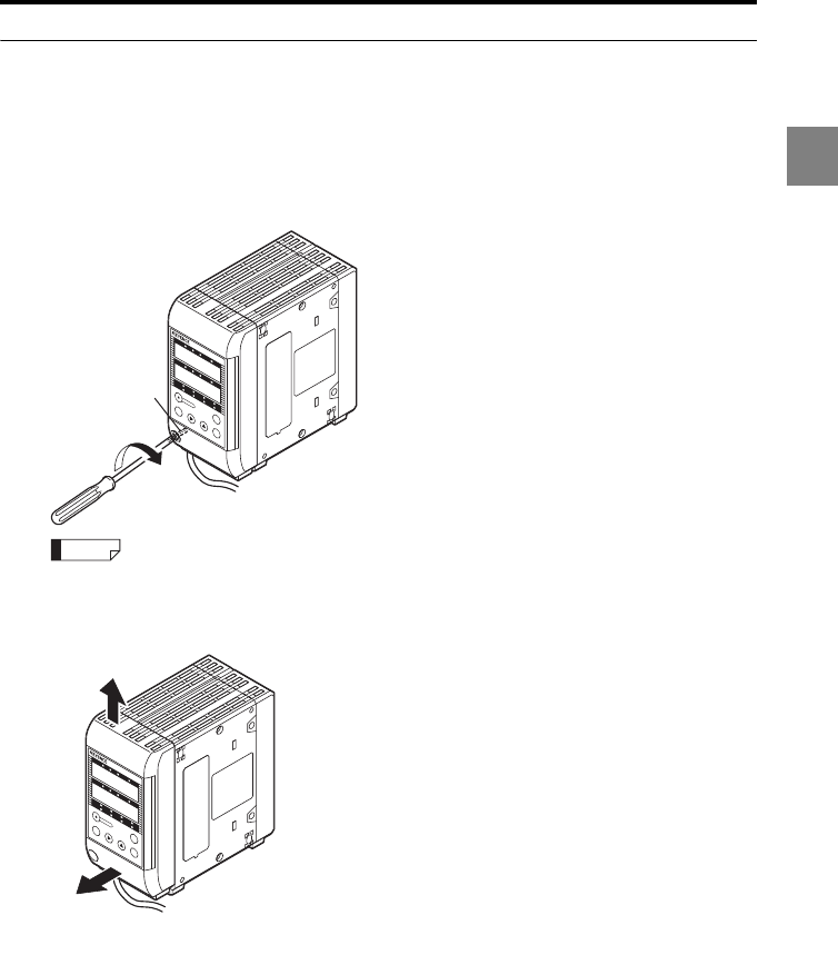
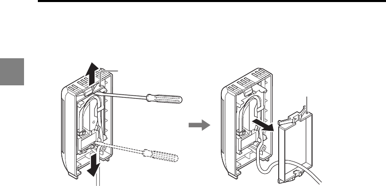
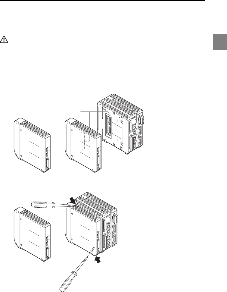
Separating the single unit type controller
1Disconnect the display panel cable from the display panel connector on the
terminal panel of the controller.
Also remove the display panel cable from the guide on the bottom of the controller.
2Loosen the display panel fixing screw.
The display panel fixing screw stays on and does not detach from the display panel housing.
3Remove the display panel housing from the controller.
LK-HD500
OUT1
HI GOLO TIM
OUT2
HI GO LO TIM
HEAD1
LASER ON STABILITY BRIGHT DARK
HEAD2
LASER ON STABILITYBRIGHT DARK
ZERO
ENT
SET
PROGRAM
Display panel
fixing screw
Reference
LK-HD500
OUT1
HI GO LO TIM
OUT2
HI GO LO TIM
HEAD1
LASER ONSTABILITY BRIGHT DARK
HEAD2
LASER ON STABILITY BRIGHT DARK
ZERO
ENT
SET
PROGRAM
(1)
(2) Remove the display panel housing
by pulling it in the directions of the
arrows in the specified order.
1-20
1
1 Before Use
4Push (1) and (2) outward in this order with a flat-blade screwdriver, and then
push the display panel to the front to remove the display panel attachment
ring.
5Remove the display panel from the display panel housing.
(1)
(3)
(2)
Display panel
attachment ring
Display panel
attachment ring
1-21
1
1 Before Use
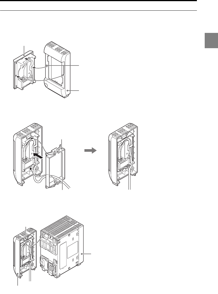
Combining the separate type controller
1Attach the display panel to the display panel housing by aligning the two
protrusions on the housing with the display panel.
2Secure the display panel with the display panel attachment ring, and connect
the 33 cm display panel cable (OP-84427, optional).
3Align the claw of the display panel housing with the controller.
Display panel
Two protrusions
Display panel housing
(OP-84426, optional)
Two cutouts Secure the cable by fitting it
along the guide.
Display panel
attachment ring
Claw
Display panel housing
Controller
1-22
1
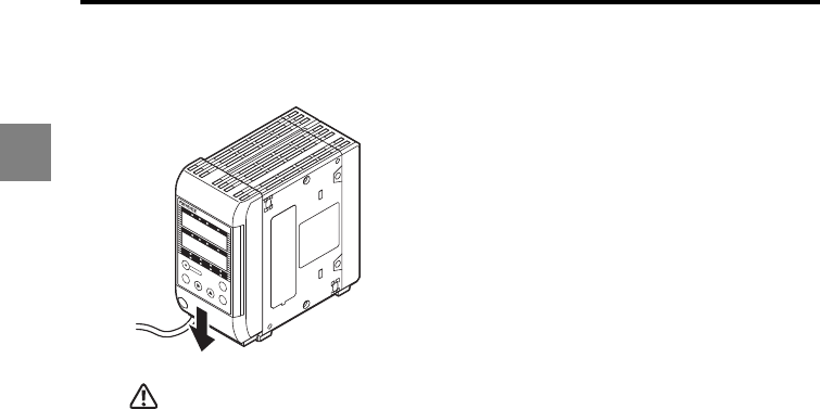
1 Before Use
4Attach the display panel housing by sliding it along the groove on the
controller.
CAUTION
Be sure to check the orientation of the claw on the connector before attaching the display panel
housing. Using the incorrect orientation may break the claw, causing a malfunction.
5 Secure the display panel housing by tightening the display panel fixing screw.
6Route the display panel cable along the guide, and connect it to the display
panel connector on the terminal panel of the controller.
LK-HD500
OUT1
HI GO LO TIM
OUT2
HI GO LO TIM
HEAD1
LASER ONSTABILITY BRIGHT DARK
HEAD2
LASER ON STABILITY BRIGHT DARK
ZERO
ENT
SET
PROGRAM
Slide the front panel in the direction of the arrow.
1-23
1
1 Before Use
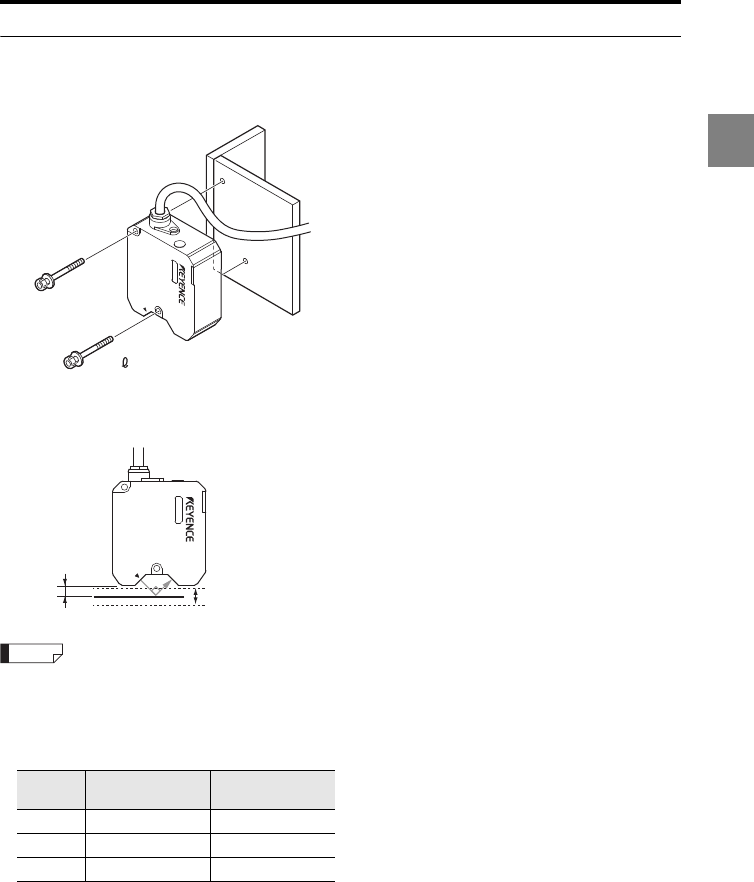
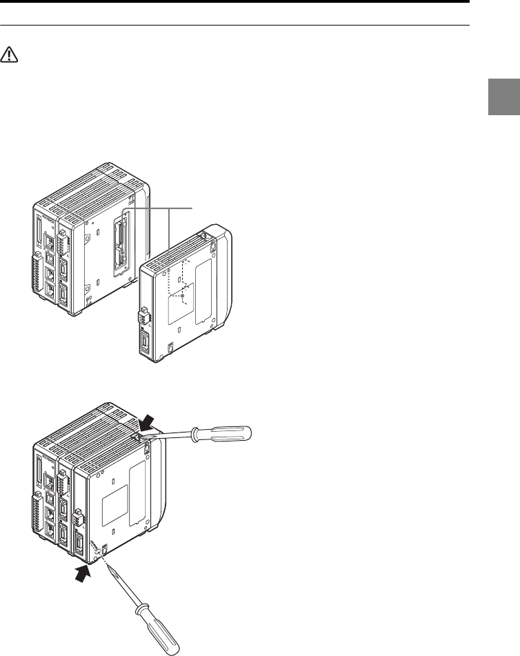
Connecting the head expansion unit
CAUTION
Turn off the power of the LK-G5000 Series before connecting the head expansion unit. Otherwise, you
may suffer a shock or damage the unit.
1Connect the head expansion unit by aligning its connector to the connector on
the left side of the controller.
You need to remove the sticker attached to the left side of the controller beforehand.
2Secure the head expansion unit by tightening the two fixing screws.
Tightening torque
Limit the tightening torque to 0.7 Nm or less.
1
2
3
4
5
6
7
8
9
10
11
12
13
14
15
16
17
18
19
20
2
21
22
23
24
25
26
27
28
29
30
31
32
33
34
35
36
37
38
39
40
LASER ON
ETHERNET
USB
DISPLAY
RS-232C
HEAD
1
OUT(V)
OUT(A)
OUT 0V
OUT(V)
OUT(A)
OUT 0V
COM INZERO 1TIMING 1GOLASER 1DC 24V
1
HEAD
LK-G5000
2
POWER
STABILITY
BRIGHT
DARK
HEAD
(V)
(A)
(A)
LK-HA100
Connector
1
2
3
4
5
6
7
8
9
10
11
12
13
14
15
16
17
18
19
20
2
21
22
23
24
25
26
27
28
29
30
31
32
33
34
35
36
37
38
39
40
LASER ON
ETHERNET
USB
DISPLAY
RS-232C
HEAD
1
OUT(V)
OUT(A)
OUT 0V
OUT(V)
OUT(A)
OUT 0V
COM INZERO 1TIMING 1GOLASER 1DC 24V
1
HEAD
LK-G5000
2
POWER
STABILITY
BRIGHT
DARK
HEAD
(V)
(A)
(A)
LK-HA100
Screw position
Screw position

1-24
1
1 Before Use
3In the Environment settings, specify the active head count and active OUT
count.
Refer to "Setting the Operating Environment settings (ENV)" (page 3-69) for details.
When you change the active head count or active OUT count in the Environment settings, all
the settings of the LK-G5000 Series except for the Environment settings are reset. When you
connect the LK-HA100 head expansion unit(s) and add a sensor head(s), be sure to set the
active head count and active OUT count before changing the other measurement settings.
NOTE
1-25
1
1 Before Use
Connecting the communication unit
Connect the LK-CC100 CC-Link communication unit or the LK-DN100 DeviceNet
communication unit to the controller.
CAUTION
Turn off the power of the LK-G5000 Series before connecting the communication unit. Otherwise, you
may suffer a shock or damage the unit.
1Connect the communication unit by aligning its connector to the connector on
the right side of the controller.
You need to remove the sticker attached to the right side of the connector
beforehand.
2Secure the communication unit by tightening the two fixing screws.
Tightening torque
Limit the tightening torque to 0.7 Nm or less.
1
1
2
3
4
5
6
7
8
9
10
11
12
13
14
15
16
17
18
19
20
2
21
22
23
24
25
26
27
28
29
30
31
32
33
34
35
36
37
38
39
40
LASER ON
ETHERNET
USB
DISPLAY
RS-232C
HEAD
1
(V)
(A)
0V
(V)
(A)
0V
COM INZERO 1TIMING 1GOLASER 1DC 24V
1
HEAD
LK-G500 0
2
MS
NS
10
(FG)
LK-DN100
1
B RATE
V+
CAN H
SHIELD
CAN L
V
-
STATION No.
L RUN
SD
RD
L ERR
10
LK-CC100
1
B RATE
SLD
DG
DB
DA
MODE
STATION No.
(FG)
Connector
LK-CC100
or
LK-DN100
1
1
2
3
4
5
6
7
8
9
10
11
12
13
14
15
16
17
18
19
20
2
21
22
23
24
25
26
27
28
29
30
31
32
33
34
35
36
37
38
39
40
LASER ON
ETHERNET
USB
DISPLAY
RS-232C
HEAD
1
(V)
(A)
0V
(V)
(A)
0V
COM INZERO 1TIMING 1GOLASER 1DC 24V
1
HEAD
LK-G5000
2
MS
NS
10
(FG)
LK-DN100
1
B RA
TE
V+
CAN H
SHIELD
CAN L
V
-
STATION No.
L RUN
SD
RD
L ERR
10
LK-CC100
1
B RA
TE
SLD
DG
DB
DA
MODE
STATION No.
(FG)
Screw position
Screw position
LK-CC100
or
LK-DN100
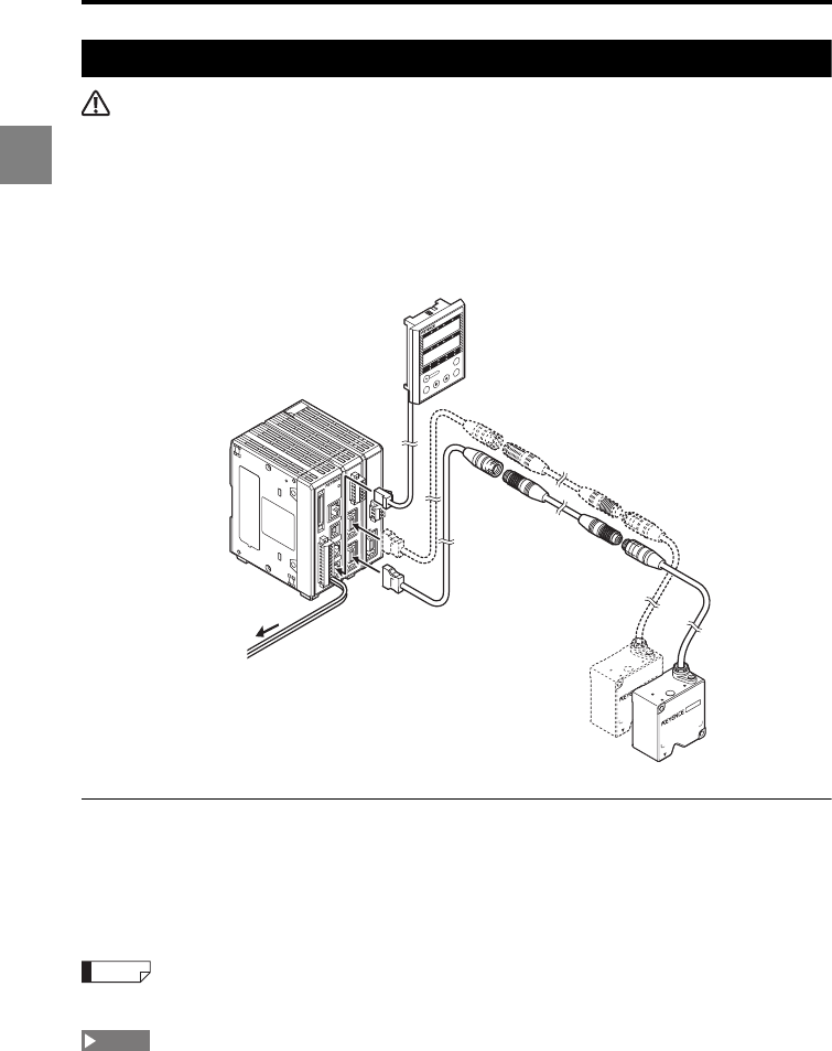
1-26
1
1 Before Use
Connecting the units
CAUTION
•Be sure to turn off the power of the controller before connecting/disconnecting the cables. Failure to
do so may cause product breakdown.
•Check the orientation of the connector before connecting it. Improper connection may break the
connector pins, resulting in product breakdown.
•Part of the input/output circuit of the LK-G5000 Series is internally common. Be careful that no
potential difference is generated between the internally common terminals due to the potential
difference between the cables/external devices.
Refer to "Precautions on wiring" (page 7) for details.
Connecting the sensor head
Connect the connector of the head-to-controller cable to the head connector 1 or 2 on the
terminal panel of the controller. Ensure that a clicking sound is heard which indicates a
secure connection. When disconnecting the cable, pull out the connector while holding
down the buttons on both sides. Up to two sensor heads can be connected to the
controller at the same time.
When the LK-HA100 head expansion units are used, up to 12 sensor heads can be connected.
•For each sensor head connection, use only one head-to-controller extension cable and limit the
total length to 30 m at maximum.
•You cannot connect the CB-AE to the CB-A30.
•You cannot connect two CB-A10E cables to the CB-A10.
POWER
STABILITY
BRIGHT
DARK
HEAD
(V)
(A)
(A)
LK-HA100
1
(V)
(A)
0V
(V)
(A)
0V
LK-HD500
OUT1
HI GO LO TIM
OUT2
HI GO LO TIM
HEAD1
LASER ONSTABILITY BRIGHT DARK
HEAD2
LASER ONSTABILITY BRIGHT DARK
ZERO
ENT
SET
PROGRAM
Head 01
Head 02
Head-to-controller cable
(0.7 m/2 m/5 m/10 m/20 m/30 m)
Head-to-controller
extension cable (5 m/10 m)
Display panel cable
(0.33 m/3 m/10 m)
Display panel
(When the separate type controller is used)
24 VDC power supply
Reference
NOTE
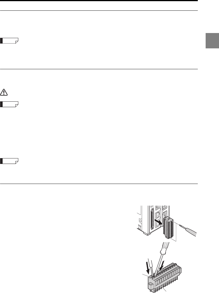
1-27
1
1 Before Use
Connecting the display panel
When using the separate type controller, connect the display panel cable between the
display panel connector of the controller and the display panel.
The LK-G5000 Series can also be operated without the display panel. Moreover, you can use the LK-
Navigator 2 software to operate the LK-G5000 Series from a PC or to display the measured value on a
PC.
Connecting the power supply
Connect the 24 VDC power supply to terminals 1 and 2 of the 12-pin terminal block.
CAUTION
Be sure to observe the following instructions. Otherwise, a connection failure may occur, causing a
malfunction in the LK-G5000.
•For the power supply cable, use lead wires with a nominal cross-section area of 0.8 mm2 to 1.3 mm2
(AWG17 to 18).
•The unsheathed wire length should be approx. 9 mm.
•Do not use soldering (preliminary soldering) to connect the wires.
•Insert the wires into the innermost position of the terminal block securely.
•Connect the wires to the terminal block directly, without using a crimp terminal, etc.
The CA-U3 or MS2 Series manufactured by KEYENCE is recommended for the 24 VDC power supply
unit.
Connection to the terminal block
The procedure to connect electrical wires to the terminal block are as follows:
1Remove the terminal block from the controller.
Loosen the two screws with a screwdriver and pull out
the terminal block.
2Use a screwdriver to push in part (a) and insert a
lead wire into part (b) as indicated.
3Remove the screwdriver once the wire is fully
inserted.
Pull each lead wire gently to confirm that it is properly
secured.
Reference
Reference
Reference
(a)
(b)
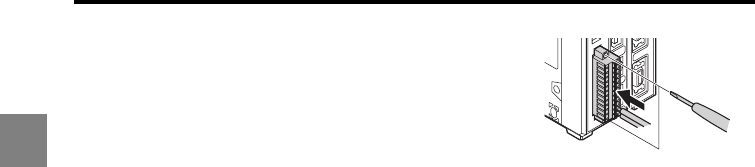
1-28
1
1 Before Use
4Attach the terminal block to the controller.
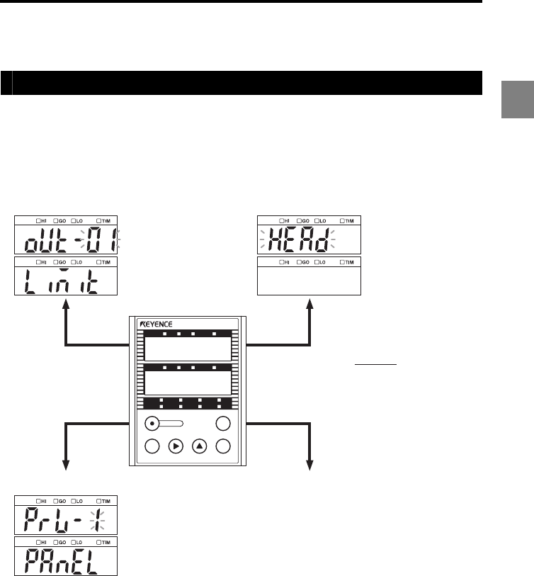
1-29
1
1 Before Use
Outline of the Measurement and Settings
Mode selection
In addition to the measuring mode to perform measurement, the LK-G5000 Series has
three other modes: the program switching mode to switch programs; the tolerance setting
mode to set tolerances; and the setting mode to specify various functions.
LK-HD500
HI GO LO TIM
HI GO LO TIM
HEAD1
LASER ON STABILITY BRIGHT DARK
HEAD2
LASER ON STABILITY BRIGHT DARK
ZERO
ENTSET
PROGRAM
Setting mode
Tolerance setting mode
Program switching mode
Press the SET key for 1 second.
Press the PROGRAM key.
Press the ENT key.
Press the SET key.
Set the upper limit,
lower limit, or
hysteresis for the
tolerance setting.
Call up the program
and change
parameters when
necessary.
See "Program
Function" (page 2-10)
for details.
Set the various functions
including the sensor
head functions and
measurement
processing.
See "Function Settings"
(page 3-1) for details.
To display setting mode (page 2-3)
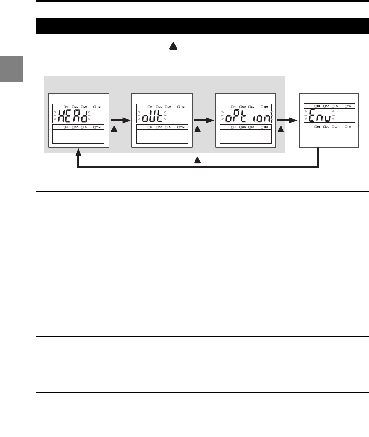
1-30
1
1 Before Use
Setting mode
In the Setting mode, every time the key is pressed, the setting category is switched in
the order of Head Settings -> OUT Settings -> Common Settings -> Environment Settings.
PROG.
0 to 7
The LK-G5000 Series allows switching of eight programs assigned to
Program Nos. 0 to 7. You can register a set of parameters as a program
for a specific measurement process or target. When necessary, you can
call up one of the programs and change the setting easily.
Head settings
(page 3-3)
•Set the functions related to sensing ability to ensure stable detection.
•Setting items:
ABLE, measurement mode, alarm handling, ABLE calibration,
mounting mode, mask setting, median, LASER CTRL group, range,
base point
OUT settings
(page 3-24)
•Set the functions related to data processing.
•Setting items:
Calculation method, scaling, filter, measurement mode, trigger, offset,
minimum display unit, analog scaling, measurement type
Common
settings
(page 3-55)
•Set the functions common to the Head settings and OUT settings.
•Setting items:
Sampling cycle, mutual interference prevention, synchronization,
comparator output form, strobe time, data storage, analog output,
alarm output type
Environment
settings
(page 3-69)
•Set the operating environment of the devices.
•Setting items:
RS-232C, setting selection, program, panel lock, active OUT count,
active head count, active analog channel count, LAN setting
key key
key
key
PROG. 0 to 7
OUT settings
Common settings
Head settings
Environment settings

1-31
1
1 Before Use
Initializing the LK-G5000 Series to the
Factory Default Settings
You can initialize all the specified settings for the LK-G5000 Series back to the default
status when the unit was shipped from the factory.
1Hold down the ENT key and turn on the power.
The measured value display shows " " (INIT).
2When " " (OK) flashes in the lower window, press the ENT key again.
The settings of the LK-G5000 Series are initialized to the factory default settings and
the system enters the measuring status.
Refer to "Function Settings" (page 3-1) for details.

1 Before Use
1-32
1
MEMO

2-1
2
This chapter describes the operations that can be performed
during displacement measurement and their functions.
Switching the Measurement Value Displays......................... 2-2
Setting the Tolerance Comparator Value.............................. 2-4
Instantaneous Zero Setting (Auto-Zero) ............................... 2-7
Instantaneous Master Adjustment (Auto-offset) ................... 2-9
Program Function ............................................................... 2-10
Switching Program Nos. ..................................................... 2-11
Storing Measured Values in the Memory (Data Storage
Function)............................................................................. 2-12
Operations during Measurement
and Their Functions2
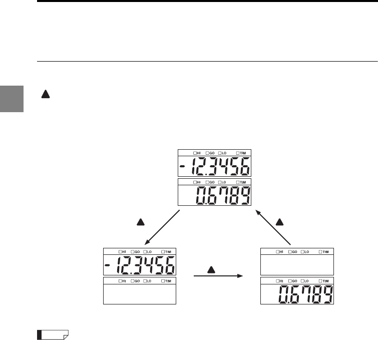
2-2
2
2 Operations during Measurement and Their Functions
Switching the Measurement Value Displays
This section describes how to switch the measurement value displays.
Switching between the upper window display and lower window display
During measurement, you can switch the following three display types by pressing the
key.
•Upper window single display
•Lower window single display
•Dual display
The selected display type is retained for each program No.
key key
key
Dual display (default setting)
Upper window single display Lower window single display
Reference
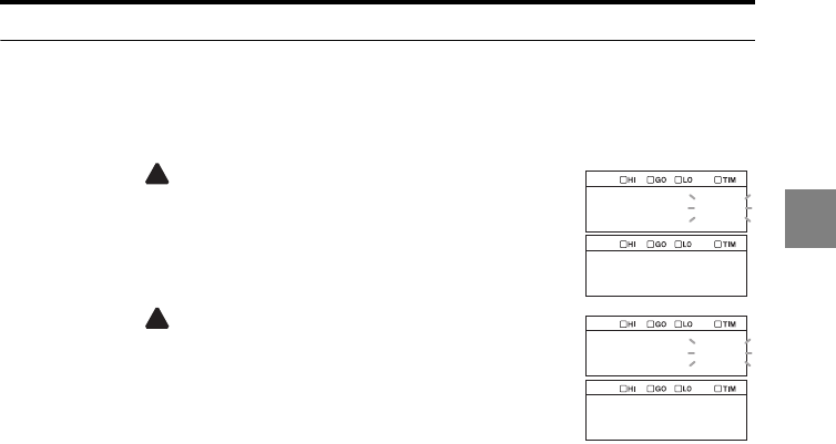
2-3
2
2 Operations during Measurement and Their Functions
Assigning a desired OUT display to the upper/lower window (display setting)
1Press the ENT key.
The system enters the display setting mode.
2Press the key to select the OUT No. to display in the
upper window and then press the ENT key.
3Press the key to select the OUT No. to display in the
lower window and then press the ENT key.
The display assignment is set.
out_01
disp1
out_01
disp2
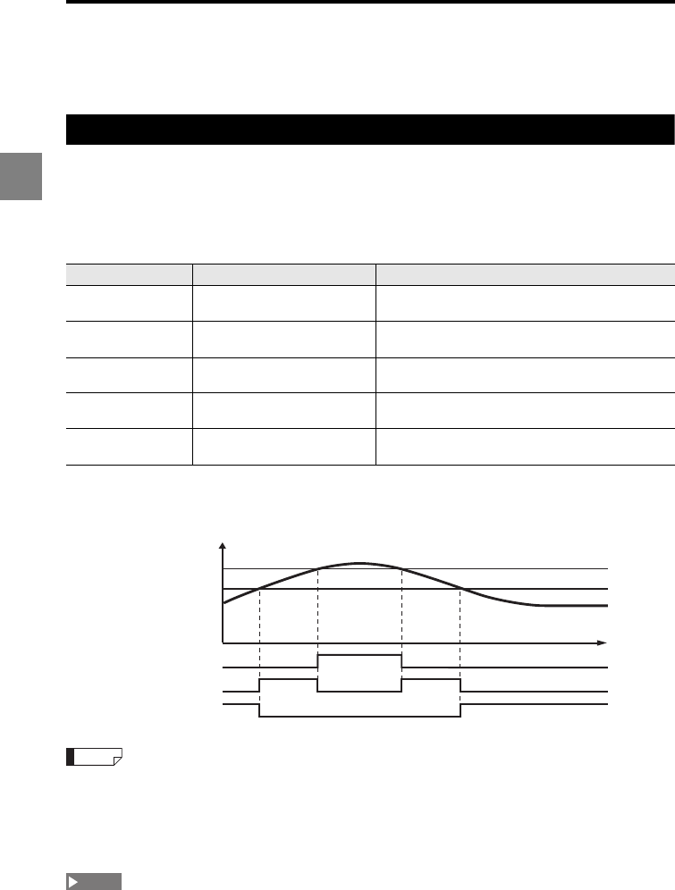
2-4
2
2 Operations during Measurement and Their Functions
Setting the Tolerance Comparator Value
This section describes how to read the tolerance comparator display and how to set it.
The function of the tolerance comparator setting
You can set limit values (tolerance comparator values) used to decide whether the
measured value is within the allowable range. The measured values are classified into
three levels based on the limit: HI when the value exceeds the upper limit, LO when the
value is below the lower limit, and GO when the value is within the allowable range. The
result can be displayed or output.
When the comparator output form (page 3-63) is set to "Normal", the comparator output is
as follows.
•Refer to "Setting the output form of the tolerance comparator result (Comparator output form)" (page
3-63) for details of the comparator output form.
•The tolerance comparator result is output from the 12-pin terminal block and expansion connector
on the terminal panel of the controller. Refer to "Function of the I/O terminals" (page 4-2) for details
of the external output terminals.
Measurement stops during the setting.
Comparator status Range Display
HIGH HI comparator value <
Measured value
The "HI" LED lights and the measured value is
displayed in red.
GO
LO comparator value
Measured
value
HI comparator value
The "GO" LED lights and the measured value is
displayed in green.
LOW Measured value < LO
comparator value
The "LO" LED lights and the measured value is
displayed in red.
Comparator standby
No LED lights and the measured value display shows
"
_______
".
Alarm
The
"HI" and "LO" LEDs light simultaneously
and the
measured value display shows "
_ffffff
".
ON
OFF
ON
OFF
ON
OFF
Displayed value
t
HI comparator
value
LO comparator
value
HI output
GO output
LO output
Reference
NOTE
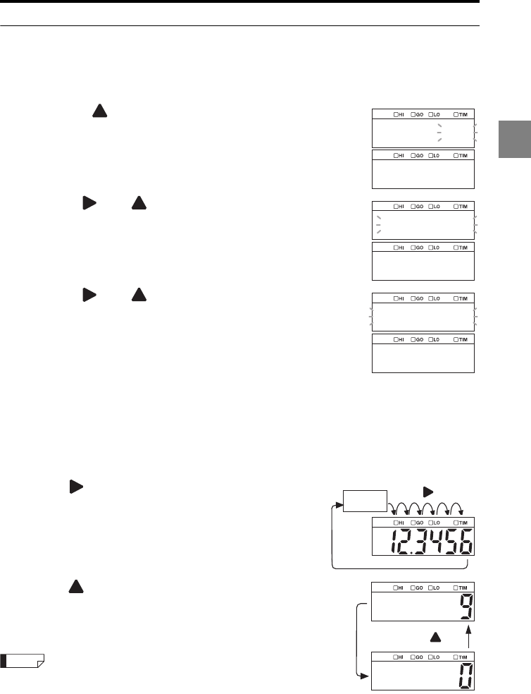
2-5
2
2 Operations during Measurement and Their Functions
Setting the tolerance comparator value
1Press the SET key.
The system enters the tolerance setting mode.
2Press the key to select the OUT No. to set the
tolerance comparator value and then press the ENT key.
3Use the and keys to set the HI comparator value
and then press the ENT key.
In this example, the HI tolerance for OUT01 is set to 4.0000.
4Use the and keys to set the LO comparator value
and then press the ENT key.
In this example, the LO tolerance for OUT01 is set to -4.0000.
The specified tolerance comparator values are set.
5Press the SET key.
The system returns to the measuring status.
Entering numerical values
A numerical value can be set by the following key operations.
•You can set the digit of a flashing number.
•When all digits are flashing, you can set the sign.
•When the key is pressed, the digit that flashes after
all the digits flash shifts to the right. When the key is
pressed for one second or more, digits shift
continuously.
•When the key is pressed, the value increments one
at a time.
When the key is pressed and held for one second or
more, the value increments continuously.
When the ZERO key is pressed and held for three seconds during
the setting, the setting returns to the default value.
out_01
limit
04.0000
01_hi
04.0000_
01_lo
All digits
flash.
key
key
Reference
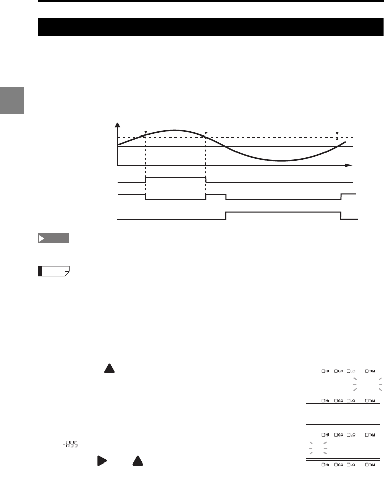
2-6
2
2 Operations during Measurement and Their Functions
Hysteresis
If the measurement value is fluctuating around the tolerance comparator value, the
comparator output may repeatedly turn on and off. By setting a hysteresis, an allowance
can be made between the detected value and the return value of the tolerance
comparator, preventing such a phenomenon. The diagram below shows the comparator
output when the comparator output form is set to Normal. Hysteresis is disabled by
default.
Measurement stops during the setting.
Refer to "Setting the output form of the tolerance comparator result (Comparator output form)" (page 3-
63) for details of the comparator output form.
Setting the hysteresis
1Press the SET key.
The system enters the tolerance setting mode.
2Press the key to select the OUT No. to set the
hysteresis and then press the ENT key.
3Press the ENT key several times until "[Target OUT No.]
" is displayed in the lower window.
4Use the and keys to set the hysteresis and then
press the ENT key.
The specified hysteresis is set.
5Press the SET key.
The system returns to the measuring status.
Recovery Hysteresis
Detection
t
ON
OFF
ON
OFF
ON
OFF
Displayed value
HI comparator
value
LO comparator
value
HI output
GO output
LO output
NOTE
Reference
out_01
limit
000.000
01_hys
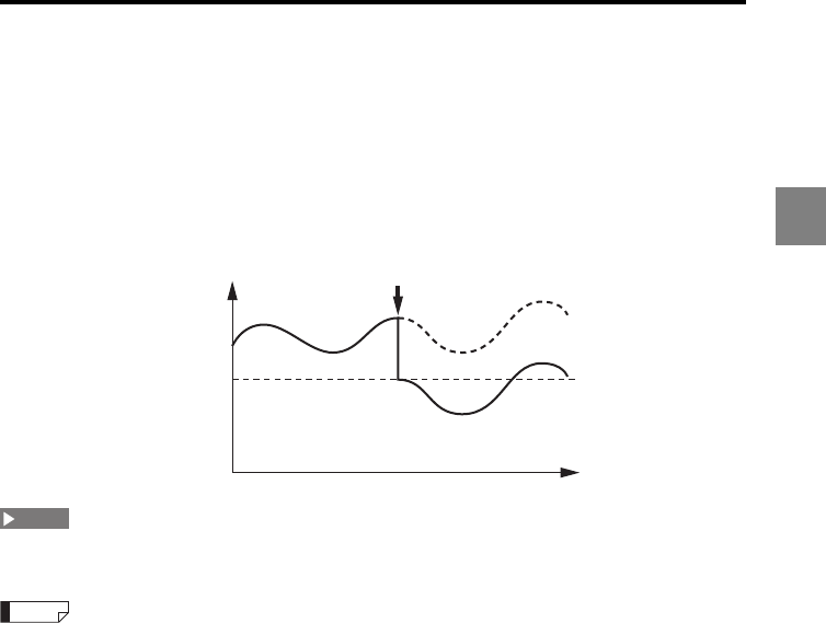
2-7
2
2 Operations during Measurement and Their Functions
Instantaneous Zero Setting (Auto-Zero)
This section describes the auto-zero function which is used for reference zero point
compensation.
The auto-zero function can be used to set a reference point at "0", for example, when the
target is changed. You can instantaneously reset the currently displayed value to "0" by
pressing the [ZERO] key or other operation. An increase or decrease in the displayed
value relative to the zero point (reference point) can be displayed with the "+" or "-".
The auto-zero cannot be set during the comparator standby status ("++++++" is displayed), over
range status, or alarm status. (Canceling auto-zero is possible.)
•The auto-zero value is stored for each program No. and OUT No.
•The auto-zero value is retained even if the power is turned off.
•When the measurement mode is other than Normal, the system enters the comparator standby
status ("------") after auto-zero is set.
•Master target adjustment using the offset function (auto-offset function)
When the offset value has been set to the size of a master target, setting the auto-zero while the
master target is being measured will set the displayed value to the size of the master target (offset
value) (page 3-47).
•The auto-zero is applied to the measured value after it is processed with the measurement mode
operation (page 3-37).
Displayed value
0
t
Auto-zero performed
NOTE
Reference
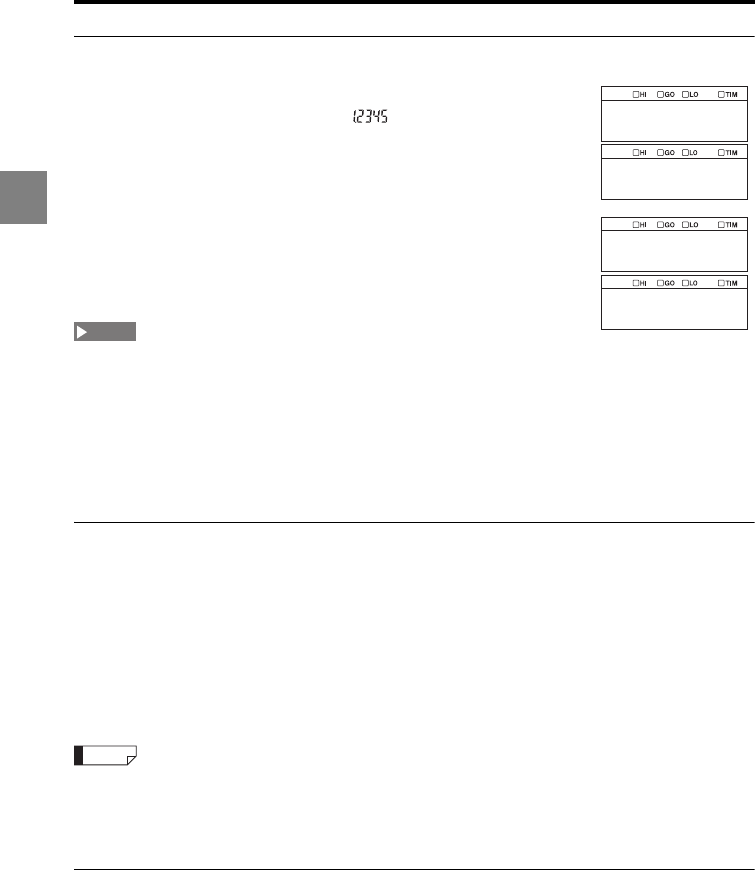
2-8
2
2 Operations during Measurement and Their Functions
Setting the auto-zero from the display panel
1 Measure the target to be used as a reference.
In this example, assume that " " is displayed.
2Press the ZERO key.
The measured value display shows zero.
•To specify the auto-zero setting for either the upper or lower window only, use the up and down
arrows to show only that display.
•To specify the same auto-zero setting for both the upper and lower windows, set the measured
value display mode to the dual display. Refer to "Switching the Measurement Value Displays" (page
2-2) for the procedure for switching the measured value display.
•The auto-zero cannot be set to the OUT No. which is not being displayed.
•The measured value at the moment when the ZERO key is released is set to "0.0000".
•Pressing the ZERO key for three seconds cancels the auto-zero setting.
Auto-zero input from the ZERO terminal
When ZERO1 (Terminal 10) and COM for input (Terminal 12) of the 12-pin terminal block
are turned ON, the auto-zero is set for all of the synchronized OUT.
When ZERO (Terminal 8) and COM for input (Terminal 1) of the expansion connector are
turned ON while DEC_IN (Terminal 16) and COM for input (Terminal 12) of the expansion
connector are turned ON, the auto-zero is set for the OUT selected with the B_IN terminal.
Limit the turn-on time for the terminals to less than two seconds.
•NPN type : OFF when opened/ON when short-circuited
•PNP type : OFF when opened/ON when voltage is applied
•When the synchronization is not set, the auto-zero is set to OUT01 when the ZERO1 terminal is
turned ON.
•The measurement value at the instant when the terminal is turned on is set to "0.0000".
•If the ZERO1 or ZERO2 terminal is turned on for two seconds or more, the auto-zero is canceled.
Auto-zero input using the RS-232C interface
The auto-zero function can be set or canceled with the command sent from the external
devices through the RS-232C interface ("RS-232C" (page 5-1)).
1.2345
0.0000
NOTE
Reference
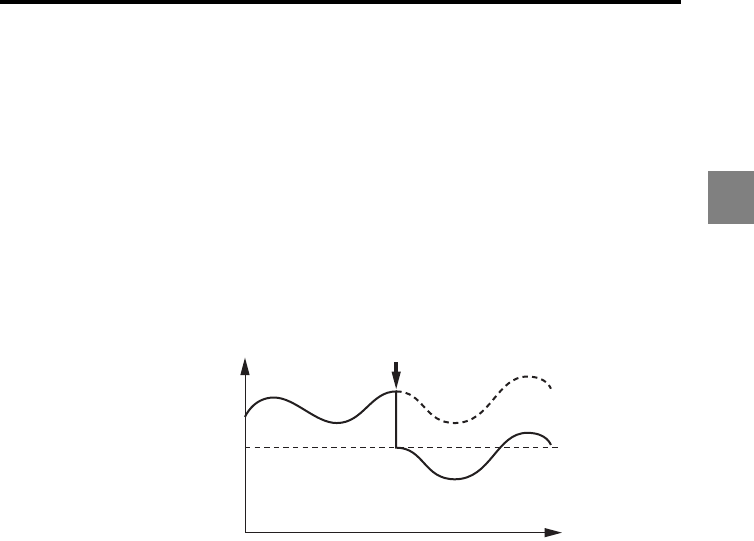
2-9
2
2 Operations during Measurement and Their Functions
Instantaneous Master Adjustment
(Auto-offset)
The auto-offset function can be used for master adjustment, when the target is changed.
Set the size of the master target as the offset value and then use the auto-zero function
while measuring the master target. The size of the master target can be set as the master
value (reference value).
Refer to "Auto-Zero" (page 2-7).
Refer to "Offset" (page 3-47).
Example
To adjust the master target dimension at "10.000", perform the auto-zero function after
setting an offset value of "10.000".
Displayed value
10.000
(Reference value)
t
Auto-zero performed
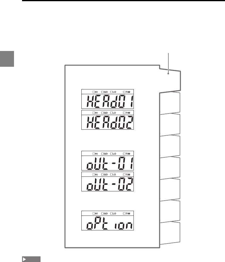
2-10
2
2 Operations during Measurement and Their Functions
Program Function
The LK-G5000 Series allows switching of eight programs assigned to Program Nos. 0 to 7.
You can register a set of parameters as a program for a specific measurement target.
When necessary, you can call up one of the programs and change the setting easily.
The Environment settings are common to all programs. These settings cannot be switched for each
program.
PRG1
PRG0
PRG2
PRG3
PRG4
PRG5
PRG6
PRG7
Program No.
Head settings
OUT settings
Common settings
NOTE
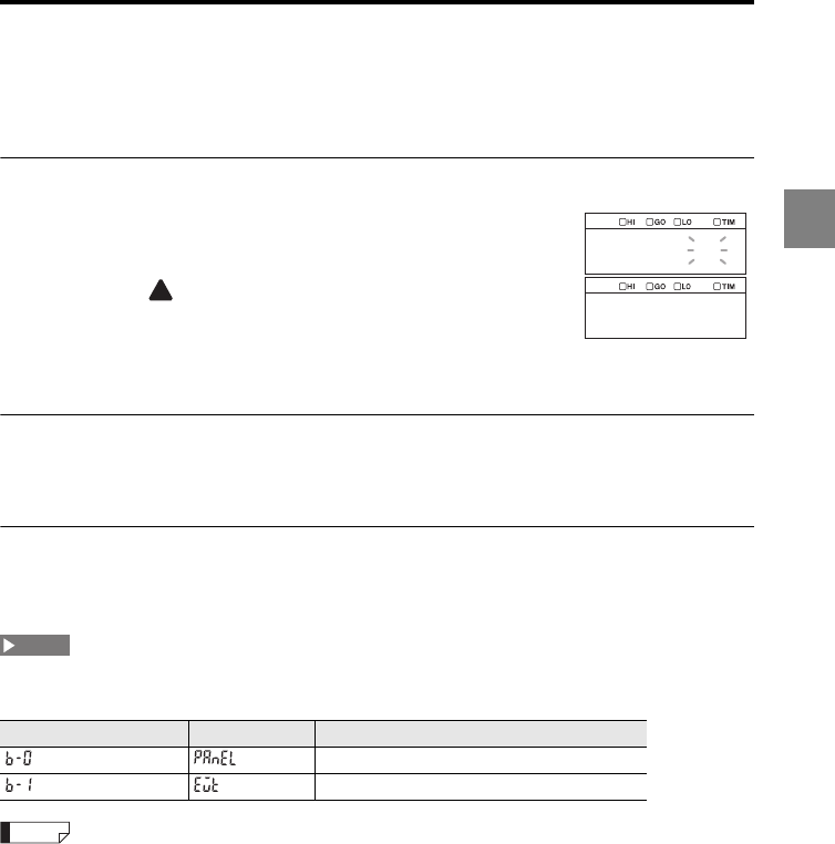
2-11
2
2 Operations during Measurement and Their Functions
Switching Program Nos.
This section describes the Program No. switch function used to easily change the
operation settings.
Using the display panel
1Press the PROGRAM key.
The program selection screen appears.
2Press the key to select the desired program number
and then press the ENT key.
The program is switched and the system returns to the
measuring status.
Using the external input terminal
The program number can be changed using the P1, P2, and P3 terminals of the
expansion connector (page 4-5).
Using the RS-232C interface
The program numbers can be switched with the command sent from the external devices
through the RS-232C interface (page 5-11).
The method for switching the program numbers varies depending on the setting of "Setting the
program switching method (Setting selection)" (page 3-73) in the Environment settings.
It is also possible to switch program numbers by using the LK-HD1001 dedicated touch panel or the
LK-Navigator 2 setup support software.
Function No. Selection item Possible operation
Panel operation/RS-232C interface
External terminal input
prg_0
panel
NOTE
Reference
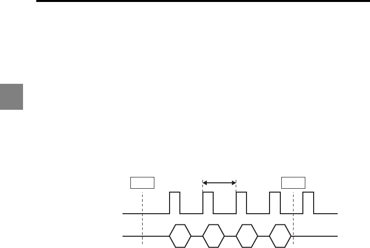
2-12
2
2 Operations during Measurement and Their Functions
Storing Measured Values in the Memory
(Data Storage Function)
This function stores measured values of an arbitrary OUT No. in the controller's internal
memory.
The LK-G5000 series can store data for up to a total of 1,200,000 measured data points in
the internal memory, at each synchronous input, or in a storage cycle.
For the storage timing, "Synchronized with sampling cycle" or "Synchronized with
synchronous input" can be selected.
To start and stop data storage, and to read data, use the RS-232C interface or the LK-
Navigator2. (Refer to LK-Navigator2 User's Manual.)
When storage cycle is "x1"
1. The LK-G5000 starts storing data according to "Conditions to start storing data".
2. The measured value to be stored is determined in each "sampling cycle".
3. The measurement result is stored in the internal memory.
4. The LK-G5000 stops storing data according to "Conditions to stop storing data".
5. While the data storage function is stopped, measured values will not be stored.
Starting/stopping
data storage
Sampling cycle
Start
Storage timing
Storing data into
internal memory
Stop
1. 4.
2. 5.
3.
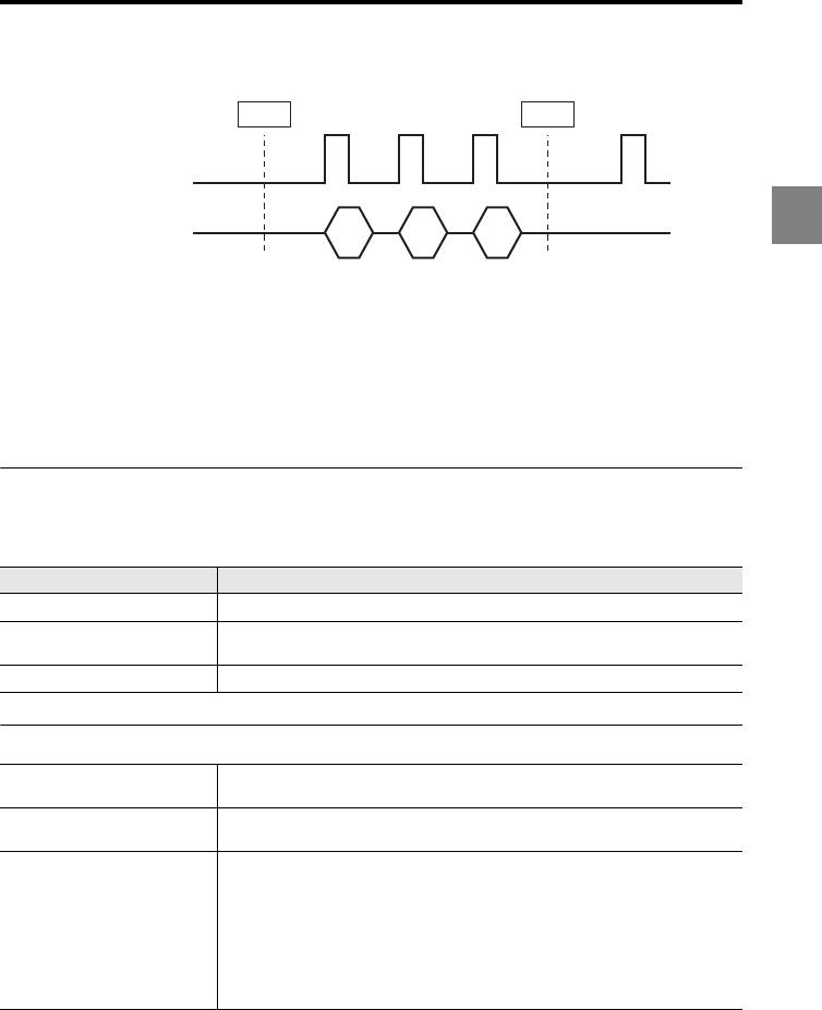
2-13
2
2 Operations during Measurement and Their Functions
When storage cycle is "Synchronization input"
1. The LK-G5000 starts storing data according to "Conditions to start storing data".
2. The measured value to be stored is determined according to "synchronous input".
TIMING1 input, RS-232C interface input and LK-HD1000 timing buttons are
available for "synchronous input".
3. The measurement result is stored in the internal memory.
4. The LK-G5000 stops storing data according to "Conditions to stop storing data".
5. While the data storage function is stopped, measured values will not be stored.
Storage timing
Storage timing is specified with "Storage cycle".
For details on storage cycle, refer to "Storage cycle selection" (page 3-65).
Starting/stopping data storage and clearing data
Storage cycle Storage timing
x1 Stores all measurement data.
x2 to x1000 Samples measurement data, and stores sample data in the sampling cycle
that are a multiple of the specified number.
Synchronization input Stores data determined at each synchronous input.
Conditions to start storing data •Start command from the RS-232C interface
•Operation from the LK-Navigator 2 setup support software
Conditions to stop storing data •Stop command from the RS-232C interface
•Operation from the LK-Navigator 2 setup support software
Conditions to clear the stored
data
Any of the following cases while the storing operation is stopped:
•When the data for the specified number of measured values are stored
•When the setting mode or communication mode is changed to the
measuring mode
•When the initialization command is sent through the RS-232C interface
•When the initialization is ordered from the LK-Navigator 2 setup support
software
•When the power is turned off
•When the program number is changed
Starting/stopping
data storage Start
Synchronous
input
Storing data into
internal memory
Stop
1. 4.
2. 5.
3.


3-1
3
This chapter describes the functions of the LK-G5000 Series and
how to set them.
Measurement, Data Flow and Functions.............................. 3-2
Setting the sensor head (HEAD) .......................................... 3-3
Setting the measurement value output conditions (OUT)... 3-24
Setting the Common Function (OPTION)........................... 3-55
Setting the Operating Environment settings (ENV) ............ 3-69
Function Settings3
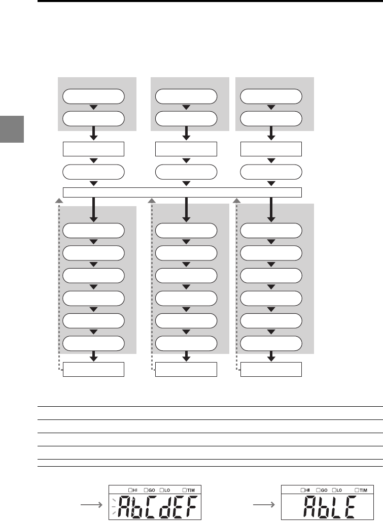
3-2
3
3 Function Settings
Measurement, Data Flow and Functions
The LK-G5000 Series can be connected with two sensor heads (12 heads max. when the
expansion units are used). You can perform measurement using the individual sensor
head or calculate the measurement values between the sensor heads.
The functions of the LK-G5000 Series can be categorized into the following four groups.
Function symbol and function display
Head settings (page 3-3) Set the functions related to sensing ability to ensure stable detection.
OUT settings (page 3-24) Set the functions related to data processing.
Common settings (page 3-55) Set the functions common to the Head settings and OUT settings.
Environment settings (page 3-69) Set the operating environment of the devices.
Measured values of OUT01 through 12 can be used up to three times in the calculation.
Flow of head 01 data
Flow of
OUT01 data
Sampling
…
…
Median
Measured value of
head 01
Measured value of
OUT01
Alarm handling
Filtering
Scaling
Measurement mode
Auto-zero
Offset
Tolerance
comparator
Tolerance
comparator
Tolerance
comparator
Sampling
Median
Measured value of
head 02
Measured value of
OUT02
Alarm handling
OUT calculation
Filtering
Scaling
Measurement mode
Auto-zero
Offset
Sampling
Median
Measured value of
head 12
Measured value of
OUT12
Alarm handling
Filtering
Scaling
Measurement mode
Auto-zero
Offset
Flow of head 02 data
Flow of
OUT02 data
Flow of head 12 data
Flow of
OUT12 data
Function
symbol
display
Function
display
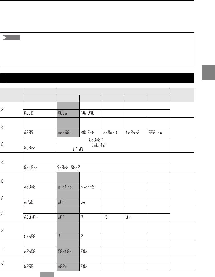
3-3
3
3 Function Settings
Setting the sensor head (HEAD)
This section describes the settings related to sensing ability to ensure stable detection.
List of functions and function Nos.
* The shaded cells ( ) are set by default.
When you change the active head count or active OUT count in the Environment settings, all the
settings of the LK-G5000 Series are reset. When you connect the LK-HA100 head expansion unit(s)
and add a sensor head(s), be sure to specify the active head count and active OUT count before
changing the other measurement settings.
Function
symbol
Function Function No. Reference
page
Function display 0 1 2 3 4
ABLE AUTO MANUAL
page 3-6
Measurement
mode Normal Translucent
object
Transparent
object
Transparent
object 2
Semi
opaque page 3-8
Alarm handling •Process count ( , 0 to 9999, initial value: 8)
•Recovery count ( , 0 to 9999, initial value: 0)
•Level ( , 0 to 9, initial value:4)
page 3-10
ABLE
calibration
START/STOP
page 3-13
/
Mounting mode Diffuse
reflection
Specular
reflection page 3-15
Mask setting OFF ON
page 3-16
Median OFF 7 15 31
page 3-18
LASER CTRL
group
LASER
CTRL1
LASER
CTRL2 page 3-20
Range CENTER FAR
page 3-21
Base point NEAR FAR
page 3-22
NOTE
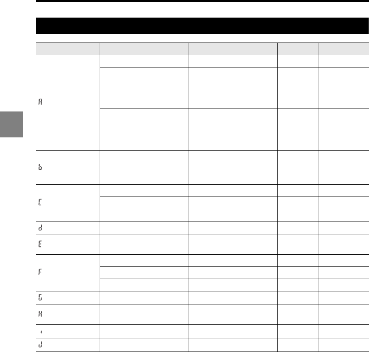
3-4
3
3 Function Settings
List of initial values and setting ranges
Function symbol Item Setting range Initial value Remark
ABLE - AUTO
Upper limit of control 1 to 99 99
Values smaller
than the lower
limit of control
cannot be
selected.
Lower limit of control 1 to 99 1
Values larger
than the upper
limit of control
cannot be
selected.
Measurement mode
Normal/Translucent object/
Transparent object/
Transparent object 2/
Semi opaque
Normal
Process count 0 to 9999 8
Recovery count 0 to 9999 0
Level 0 to 9 4
ABLE calibration START/STOP -
Mounting mode Diffuse reflection/Specular
reflection
Diffuse
reflection
Mask setting OFF/ON OFF
P-1 -9999.99 to 9999.99 0000.00
P-2 -9999.99 to 9999.99 0000.00
Median OFF/7/15/31 OFF
LASER CTRL group LASER CTRL1/LASER
CTRL2
LASER
CTRL1
Range CENTER/FAR CENTER
Base point NEAR/FAR NEAR
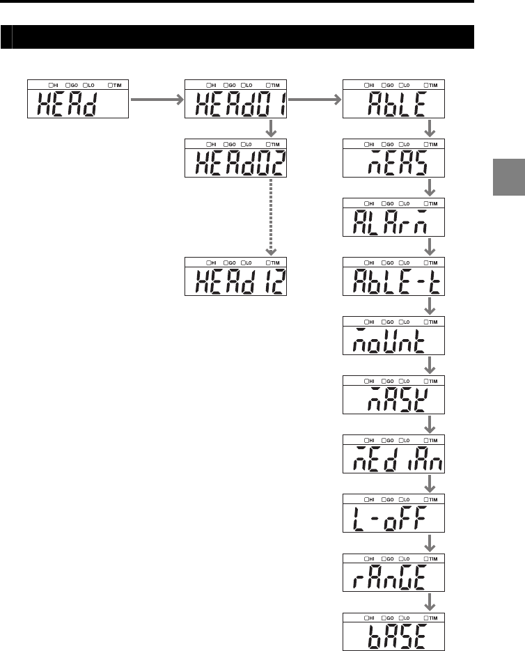
3-5
3
3 Function Settings
List of the Head settings screens
HEAD HEAD 01
HEAD 02
HEAD 12
ABLE
Measurement mode
Alarm handling
ABLE calibration
Mounting mode
Mask
Median
LASER CTRL
group
Range
Base point
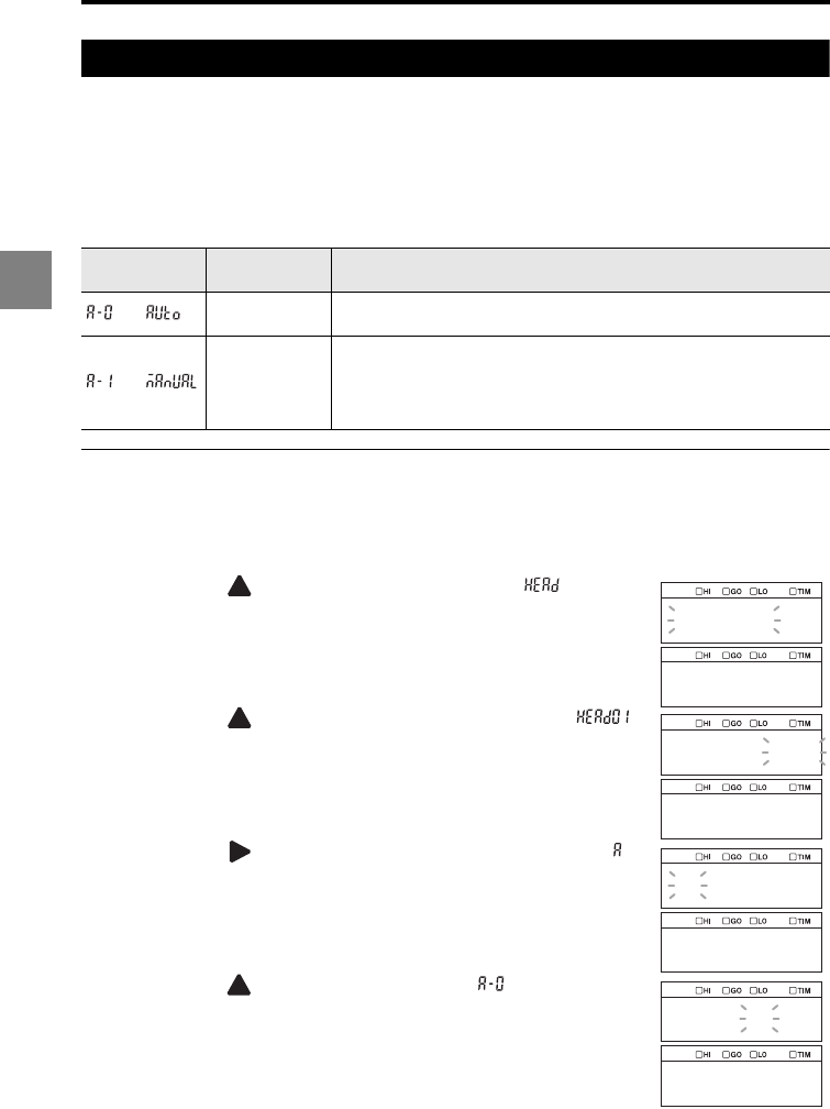
3-6
3
3 Function Settings
Setting ABLE (ABLE)
The LK-G5000 Series measures the displacement of a target by measuring the laser beam
reflected from the surface of the target. The ABLE function automatically adjusts the light
intensity and sensitivity to their optimum levels according to the conditions of the target
surface (color, luster, and material).
The following two types of settings are available for ABLE.
Setting ABLE (AUTO)
The following procedure changes the setting of head 01 as an example.
1
Hold down the SET key.
2Press the
key to select the Head setting ( ) and then
press the ENT key.
3Press the
key to select the target sensor head ( )
and then press the ENT key.
4Press the key
to select
function symbol A (ABLE, )
and then press the ENT key.
5Press the key
to select
A-0 (AUTO, ) and then press
the ENT key.
The setting is saved.
6Press the SET key.
The system returns to the measuring status.
Function No. Light intensity
adjustment Function
Auto The light intensity is automatically adjusted to the optimum level. Select
this option during normal operation.
Manual
The light intensity and sensitivity can be adjusted by limiting the
adjustment range for the light intensity and sensitivity to the desired
range between 1 and 99.
Select this option when the reflectance of the target changes greatly in
a short cycle.
head
head01
head01
abcdef
able
a_0
auto
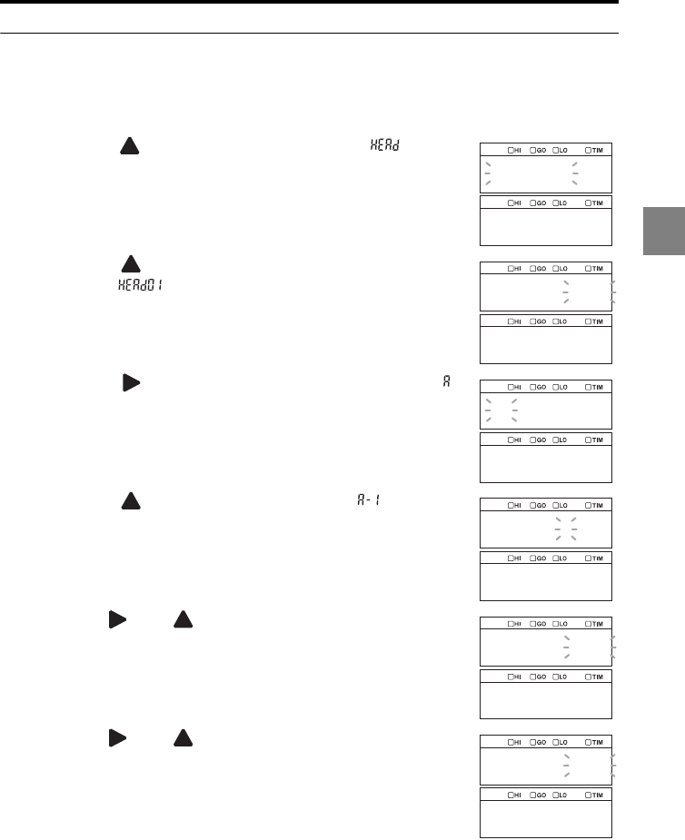
3-7
3
3 Function Settings
Setting ABLE (MANUAL)
The following procedure changes the setting of head 01 as an example.
1
Hold down the SET key.
2Press the key
to select the Head settings ( ) and then
press the ENT key.
3Press the key to select the target sensor head
(HEAD01, ) and then press the ENT key.
4Press the key to select function symbol A (ABLE, )
and then press the ENT key.
5Press the key to select A-1 (MANUAL, ) and then
press the ENT key.
6Use the and keys to set the HI value and then
press the ENT key.
In this example, "60" is set.
7Use the and keys to set the LO value and then
press the ENT key.
In this example, "20" is set.
The setting is saved.
8Press the SET key.
The system returns to the measuring status.
head
head01
head01
abcdef
able
a_1
manual
60
hi
20
lo
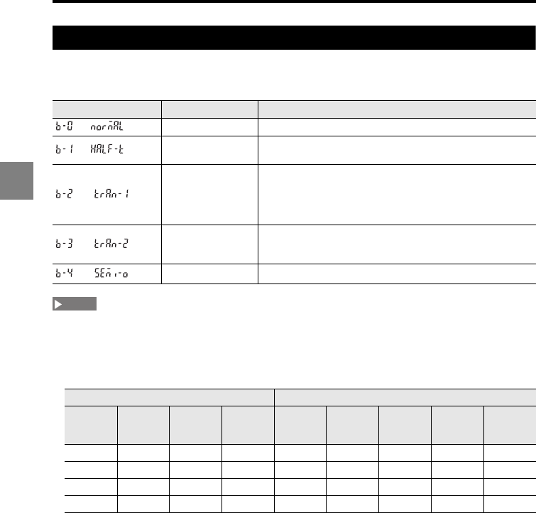
3-8
3
3 Function Settings
Setting the measurement mode according to the target (Measurement mode)
This function is used to ensure more stable detection by specifying the type of
measurement target.
•When "Transparent object 2" is selected, the sampling cycle is quadrupled at maximum in order to
obtain optimum control over the detection of up to four surfaces.
•Using the "Transparent object 2" setting requires the K type sensor head.
•The relationship between the measurement mode of the sensor head, the sampling cycle, and the
active OUT count is shown in the table below.
: When at least one sensor head set to the corresponding measurement mode is connected
: A sensor head set to the corresponding measurement mode can be connected
x : When a sensor head set to the corresponding measurement mode is not used
- : Setting impossible
The values in parentheses are the number of OUT which can be used for the calculation of ADD, SUB,
P-P, MAX, MIN, and AVE among OUT.
Function No. Target Description
Normal Select this option during normal operation.
Translucent object Use this option for a target that absorbs light such as a
translucent plastic.
Transparent object
Use this option to measure the displacement or thickness of a
transparent object.
This option is intended for the case where the reflectance
values of the multiple surfaces of the transparent object are
the same.
Transparent object 2
Use this option when the reflectance values of the multiple
surfaces of the transparent object, such as the front side and
back side, are different (four surfaces maximum).
Semi opaque Use this option for a plastic target with a high gloss surface.
Measurement mode (page 3-8)Sampling cycle (page 3-58)
Semi
opaque
Transparent
object
Transparent
object 2
Normal/
Translucent
object
2.55 µs 5 µs 10 µs 20 to 100
µs
200 µs or
longer
- (-) - (-) - (-) - (-) 12 (12)
x- (-) - (-) 8 (-) 12 (12) 12 (12)
xx- (-) 4 (-) 8 (-) 12 (12) 12 (12)
xxx2 (-) 4 (-) 8 (-) 12 (12) 12 (12)
NOTE
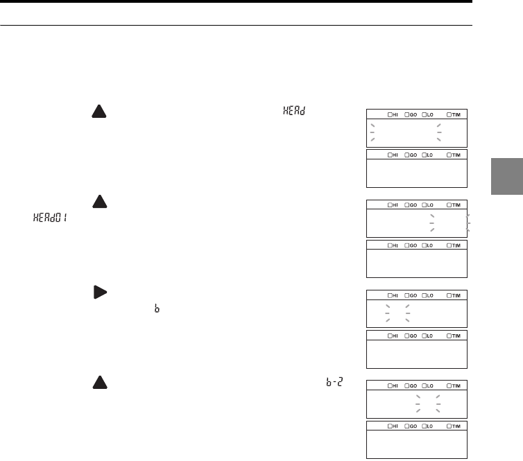
3-9
3
3 Function Settings
Setting the measurement mode
The following procedure changes the setting of head 01 as an example.
1
Hold down the SET key.
2Press the key
to select the Head settings ( ) and then
press the ENT key.
3Press the key
to select the target sensor head (HEAD01
,
) and then press the ENT key.
4Press the key
to select
function symbol B
(Measurement mode, ) and then press the ENT key.
5Press the key
to select
B-2 (Transparent object, )
and then press the ENT key.
The setting is saved.
6Press the SET key.
The system returns to the measuring status.
head
head01
head01
abcdef
meas
b_2
tran_1
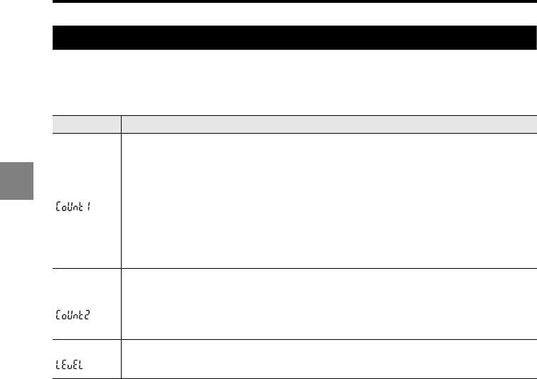
3-10
3
3 Function Settings
Specifying the action when measurement becomes impossible (Alarm handling)
Measurement becomes impossible when the result is out of the measurement range or
when the received light intensity is excessive/insufficient. The alarm handling function is
used to specify how to process data in these situations.
Setting Function
Process count
Specifies the number of sampling times for which the last normal value is held after
measurement becomes impossible.
•Setting range: 0 to 9999
•If measurement is still impossible after the number of sampling times exceeds this value,
the measured value is
displayed as "-FFFFFF".
•Holding is released when the system recovers to the measuring status within the specified
process count.
•When the process count is set to "9999", the normal value is continuously held until
measurement becomes possible.
•If the alarm occurs immediately after the power is turned on and there is no measured
value, "-------" is held.
Recovery
count
After measurement becomes impossible and an alarm is issued (-FFFFFF is displayed), if the
number of valid measured values reaches the specified recovery count, the system recovers
from the alarm.
•Setting range: 0 to 9999
•If another alarm is issued before the number of valid measured values reaches the
specified recovery count, the count is reset.
Level Sets the threshold level of the received light status below which a peak is judged as invalid.
•Setting range: 0 to 9
•"0" is the least sensitive to the alarm and "9" is the most sensitive.
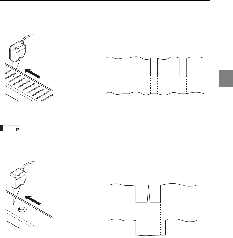
3-11
3
3 Function Settings
Process count and recovery count
Process count
This setting can cancel the status when the measurement becomes impossible
temporarily due to holes or other causes.
This setting does not hold the statuses of the sensor head status indicator on the display
panel and the laser emission LED on the sensor head.
Recovery count
This setting can cancel irregular values resulting from stray light or other causes.
Measurement value with
“Process Count” disabled.
(count set to 0)
Measurement value with
“Process Count” enabled.
-FFFFFF
Reference
Measurement value with
“Recovery Count”
disabled. (count set to 0)
Measurement value
with “Recovery Count”
enabled.
-FFFFF
-FFFFF
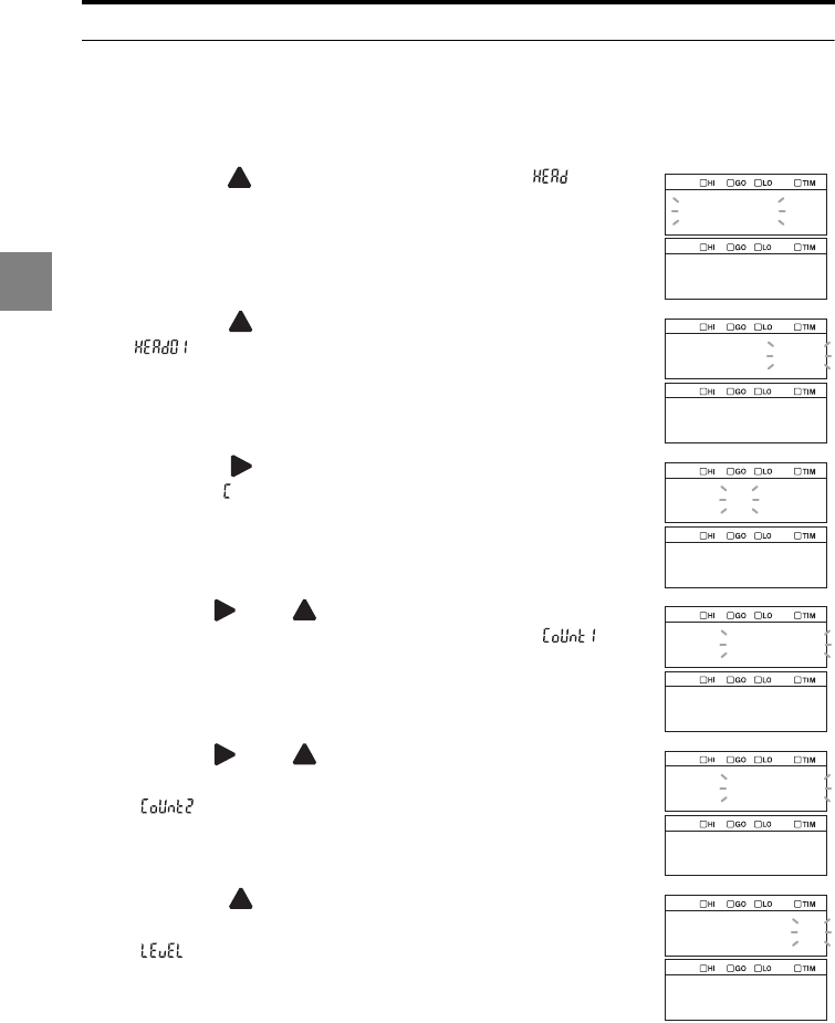
3-12
3
3 Function Settings
Setting the alarm handling
The following procedure changes the setting of head 01 as an example.
1
Hold down the SET key.
2Press the key
to select the Head settings ( ) and then
press the ENT key.
3Press the key
to select the target sensor head (HEAD01
,
) and then press the ENT key.
4Press the key
to select
function symbol C (Alarm
handling, ) and then press the ENT key.
5Use the and keys to specify the number of
sampling times to hold the last normal value ( ) and
then press the ENT key.
In this example, "500" is set.
6Use the and keys to specify the number of
sampling times to count the valid values to recover
( ) and then press the ENT key.
In this example, "500" is set.
7Press the key to specify the level of light-receiving
status to determine that the measurement is impossible
( ) and then press the ENT key.
In this example, "8" is set.
The setting is saved.
8Press the SET key.
The system returns to the measuring status.
head
head01
head01
abcdef
alarm
0500
count1
0500
count2
8
level
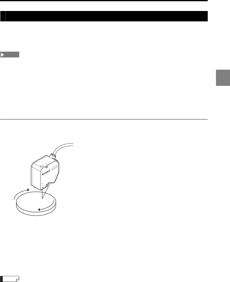
3-13
3
3 Function Settings
Automatically adjusting the ABLE adjustment range according to the target (ABLE calibration)
The ABLE calibration function optimizes the adjustment range for ABLE based on the
actual measurement of the target. This function is useful when the reflectance of the target
changes greatly in a short cycle.
•The ABLE calibration must be conducted after the completion of the OUT settings and Common
settings.
•Note that the ABLE calibration fails in the following cases:
- The target sensor head for the ABLE calibration is not assigned to any OUT.
- The target sensor head for the ABLE calibration is set to "AB-ON" but assigned to
group "C" in the mutual interference prevention setting.
- The input to the REMOTE terminal or LASER CTRL1/LASER CTRL2 terminal for the
target sensor head for the ABLE calibration is turned off.
Operation flow of the ABLE calibration
1Measure an actual target as shown in the figure.
2Start the ABLE calibration (page 3-14).
The data collection starts.
3Move the target slowly.
4Stop the ABLE calibration.
The data collection finishes and the optimum range for ABLE is set.
•When the ABLE calibration is performed, the ABLE setting for function symbol A (page 3-6) is set to
MANUAL, and the upper and lower limits of control are set to the adjusted values.
•By slowly moving the target, you can optimize the adjustment range for ABLE. Such optimization of
the adjustment range improves the response when the reflectance of the target changes greatly in a
short cycle.
NOTE
Reference
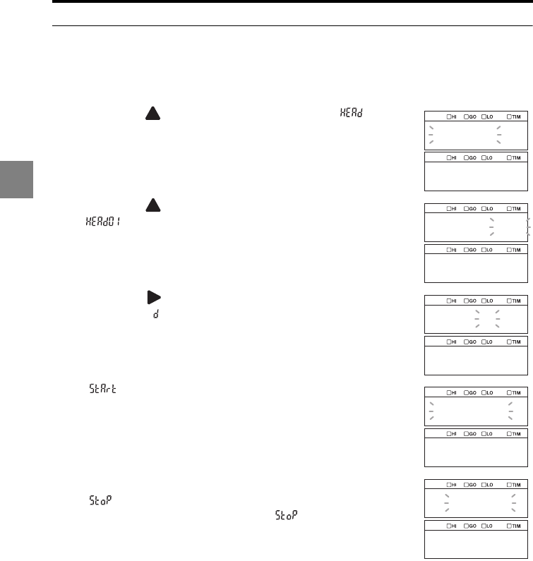
3-14
3
3 Function Settings
Performing the ABLE calibration
The following procedure changes the setting of head 01 as an example.
1
Hold down the SET key.
2Press the key
to select the Head settings ( ) and then
press the ENT key.
3Press the key
to select the target sensor head (
HEAD01,
) and then press the ENT key.
4Press the key
to select
function symbol D (ABLE
calibration, ) and then press the ENT key.
" " is displayed.
5Press the ENT key.
" " is displayed and the measurement starts.
The measurement continues while " " is displayed.
6Press the ENT key.
The setting is saved.
7Press the SET key.
The system returns to the measuring status.
head
head01
head01
abcdef
able_t
start
able_t
stop
able_t
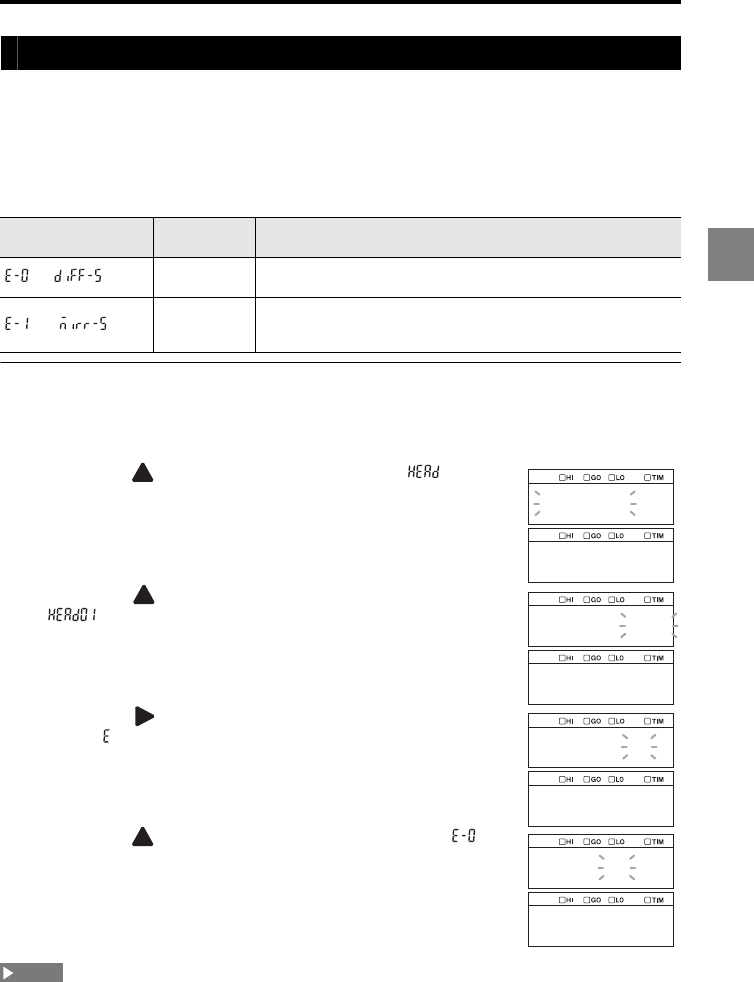
3-15
3
3 Function Settings
Setting the mounting mode according to the sensor head mounting method (Mounting mode)
The LK-G5000 Series measures the displacement of a target by measuring the laser beam
reflected from the surface of the target. When the target surface is flat, such as a mirror or
glass plate, the specular reflection component of the reflected light increases. In such a
case, use the specular reflection mounting so that the sensor head receives the specular
reflection light properly.
The following two types of mounting modes are available.
Setting the mounting mode
The following procedure changes the setting of head 01 as an example.
1
Hold down the SET key.
2Press the key
to select the Head settings ( ) and then
press the ENT key.
3Press the key
to select the target sensor head (HEAD01
,
) and then press the ENT key.
4Press the key
to select
function symbol E (Mounting
mode, ) and then press the ENT key.
5Press the key to select E-0 (Diffuse reflection, ) and
then press the ENT key.
The setting is saved.
6Press the SET key.
The system returns to the measuring status.
The K type sensor head is always set to the specular reflection mode regardless of the mounting mode
setting.
Function No. Mounting
mode Function
Diffuse
reflection
Set the diffuse reflection mounting. Select this option during normal
operation.
Specular
reflection
Set the specular reflection mounting. Select this option when the
target is a mirror, a glass plate, or other similar object. The
displayed value is corrected for the specular reflection mounting.
head
head01
head01
abcdef
mount
e_0
diff_s
NOTE
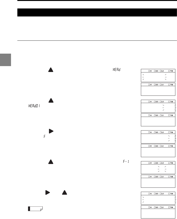
3-16
3
3 Function Settings
Specifying two points in the measurement range to exclude a certain area from the measurement (Mask setting)
The mask setting function is used to specify two points in the measurement range to mask
a certain area. By setting the mask, you can exclude the area within or outside of the area
between the points from the measurement.
Setting the mask
The following procedure changes the setting of head 01 as an example.
1
Hold down the SET key.
2Press the key
to select the Head settings ( ) and then
press the ENT key.
3Press the key
to select the target sensor head (HEAD01
,
) and then press the ENT key.
4Press the key
to select
function symbol F (Mask
setting, ) and then press the ENT key.
5Press the key to select F-1 (Mask setting: ON, ) and
then press the ENT key.
6Use the and keys to set the mask starting point
(P-1) and then press the ENT key.
The starting and ending points for the Mask setting can be specified in
the unit of 0.01 mm.
Values smaller than 0.01 mm are automatically processed inside the system.
head
head01
head01
abcdef
mask
f_1
on
0000.00
pos_1
Reference
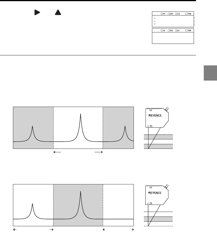
3-17
3
3 Function Settings
7Use the and keys to set the mask ending point (P-
2) and then press the ENT key.
The setting is saved.
8Press the SET key.
The system returns to the measuring status.
Area masked with the mask setting
The area to be masked depends on the values of the starting point (P-1) and ending point
(P-2).
When the starting point (P-1) is larger than the ending point (P-2)
The mask is set to the area outside the area between these points.
When the starting point (P-1) is smaller than the ending point (P-2)
The mask is set to the area inside the area between these points.
When the starting point (P-1) equals the ending point (P-2)
The entire measurement range is measured (no mask is set).
0000.00
pos_2
Measurement
range upper limit
Measurement
range lower limit
P-2P-1
Mask area Area to be measured Mask area
P-1
P-2
Mask area
Area to be measured
Mask area
Measurement
range lower limit
Measurement
range upper limit
P-1P-2
Area to be measured Mask area
Area to be measured
Measurement
range upper limit
Measurement
range lower limit
P-2
P-1
Area to be measured
Mask area
Area to be measured
Measurement
range lower limit
Measurement
range upper limit
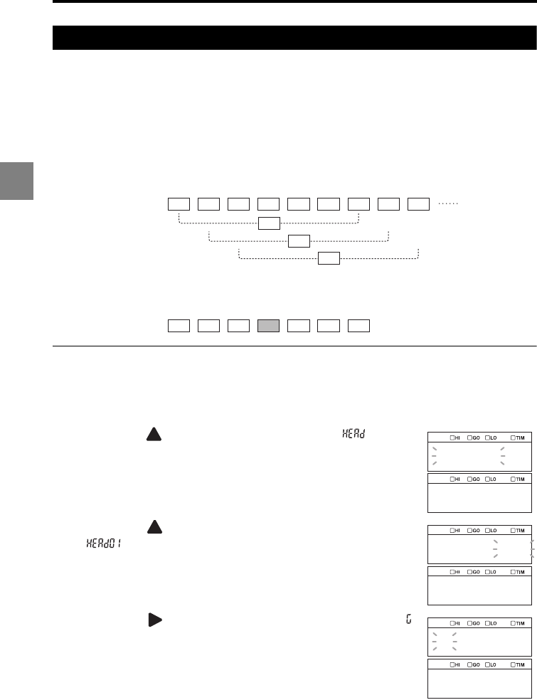
3-18
3
3 Function Settings
Preventing measurement fluctuations by ignoring sudden changes in the measured value (Median)
This function applies a 7-, 15-, or 31-point median filter to prevent measurement
fluctuations by ignoring sudden changes in the measured value. This function is useful
when the target moves fast.
Example when the 7-point median filter is used
Seven measured values are arranged in the order of magnitude and the value at the
center is considered to be the measured value.
Setting the median
The following procedure changes the setting of head 01 as an example.
1
Hold down the SET key.
2Press the key
to select the Head settings ( ) and then
press the ENT key.
3Press the key
to select the target sensor head (HEAD01
,
) and then press the ENT key.
4Press the key
to select
function symbol G (Median, )
and then press the ENT key.
1.1 1.0 1.0
1.0
1.5 0.9 1.0 1.0
1.5 1.1 1.0 1.0 1.0 1.0 0.9
1.0 1.1
Measured value
Measurements count
First median
In the case of the first median, for example, the measured values (1) to (7) are sorted
in the following order.
Consequently, the value at the center, 1.0, is the measured value.
1.0
Second median
Third median
(1) (2) (3) (4) (5) (6) (7) (8) (9)
1.0
head
head01
head01
ghij
median
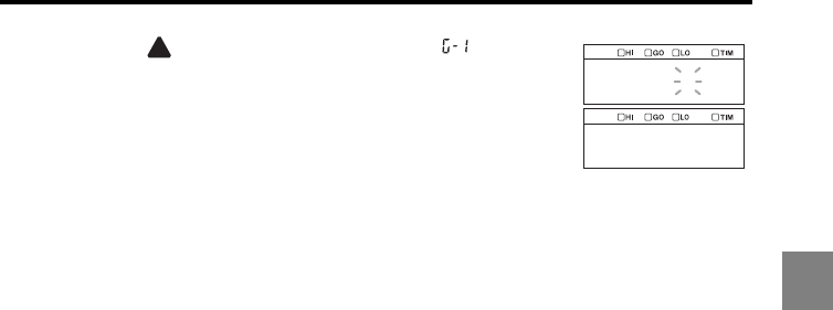
3-19
3
3 Function Settings
5Press the key to select G-1 (Median: 7, ) and then
press the ENT key.
The setting is saved.
6Press the SET key.
The system returns to the measuring status.
G_1
7
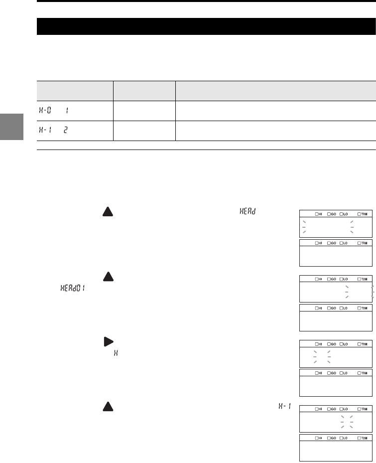
3-20
3
3 Function Settings
Grouping the laser control operation (LASER CTRL group)
This function is used to control laser operation such as turning on/off two or more sensor
heads by grouping them into two groups. It is useful when sensor heads are used in
different production lines.
Setting the LASER CTRL group
The following procedure changes the setting of head 01 as an example.
1
Hold down the SET key.
2Press the key
to select the Head settings ( ) and then
press the ENT key.
3Press the key
to select the target sensor head (HEAD01
,
) and then press the ENT key.
4Press the key
to select
function symbol H (LASER
CTRL group, ) and then press the ENT key.
5Press the key to select H-1 (LASER CTRL group2, )
and then press the ENT key.
The setting is saved.
6Press the SET key.
The system returns to the measuring status.
Function No. LASER CTRL
group Function
LASER CTRL1 Assign the currently selected sensor head to the LASER CTRL1
group.
LASER CTRL2 Assign the currently selected sensor head to the LASER CTRL2
group.
head
head01
head01
ghij
l_off
h_1
2
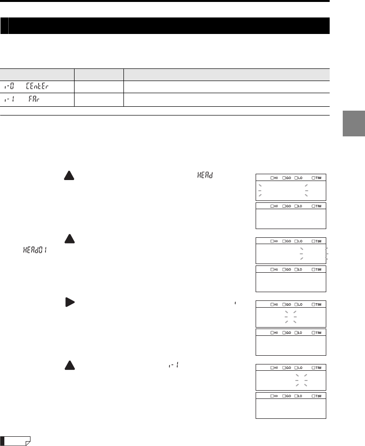
3-21
3
3 Function Settings
Setting the measurement position (Range)
This function is used to set the measurement range to either the reference position or the
FAR side when the sampling cycle is between 2.55 μs and 10 μs.
Setting the range
The following procedure changes the setting of head 01 as an example.
1
Hold down the SET key.
2Press the key
to select the Head settings ( ) and then
press the ENT key.
3Press the key
to select the target sensor head (HEAD01
,
) and then press the ENT key.
4Press the key
to select
function symbol I (Range, )
and then press the ENT key.
5Press the key to select I-1 (FAR, ) and then press
the ENT key.
The setting is saved.
6Press the SET key.
The system returns to the measuring status.
•For details about the relationship between the sampling cycle and measurement range, refer to
page 1-12 (for the 20 mm type sensor head) or page 1-13 (for the 50 mm type sensor head).
•When the sampling cycle is 20 μs to 1 ms, the measurement range in the specification table is used
regardless of the CENTER/FAR setting.
Function No. Range Function
CENTER Set the measurement range at the reference position.
FAR Set the measurement range at the FAR side.
head
head01
head01
ghij
range
i_1
far
Reference
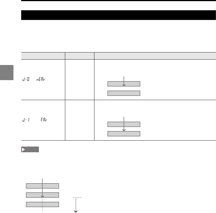
3-22
3
3 Function Settings
Setting the reference starting point for peak counting (Base point)
This function is used when the measurement mode is set to Transparent object and
several peaks are detected within the measurement range. You can specify which peak
will be used as a base point, either the one on the side nearest to the sensor head (NEAR)
or the one on the side farthest from the sensor head (FAR).
•When the Transparent object 2 mode is selected, the counting starts from the nearest peak
regardless of the base point setting.
•Even when the Transparent object mode is selected and the base point is set to FAR, if the number
of peaks exceeds four, the fourth peak from the NEAR side is counted as 1.
Function No. Base point Function
NEAR
Start counting from the peak nearest to the sensor head.
FAR
Start counting from the peak farthest from the sensor head.
Example when the measurement target is the second peak
Peak 2
Peak 1
Peak 4
Peak 3
Example when the measurement target is the second peak
Peak 3
Peak 4
Peak 1
Peak 2
NOTE
These peaks are not counted.
Peak 3
Peak 4
Peak 1
Peak 2
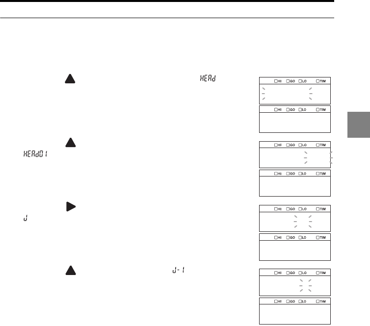
3-23
3
3 Function Settings
Setting the base point
The following procedure changes the setting of head 01 as an example.
1
Hold down the SET key.
2Press the key
to select the Head settings ( ) and then
press the ENT key.
3Press the key
to select the target sensor head (HEAD01
,
) and then press the ENT key.
4Press the key
to select
function symbol J (Base point,
) and then press the ENT key.
5Press the key to select J-1 (FAR, ) and then press
the ENT key.
The setting is saved.
6Press the SET key.
The system returns to the measuring status.
head
head01
head01
ghij
base
j_1
far
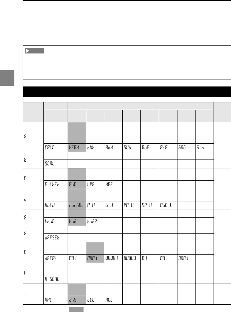
3-24
3
3 Function Settings
Setting the measurement value output
conditions (OUT)
This section describes the settings of the functions related to data processing.
List of functions and function Nos.
* The shaded cells ( ) are set by default.
When you change the active head count or active OUT count in the Environment settings, all the
settings of the LK-G5000 Series except for the Environment settings (ENV) are reset. When you
connect the LK-HA100 head expansion unit(s) and add a sensor head(s), be sure to specify the
active head count and active OUT count before changing the other measurement settings.
Function
symbol
Function Function No.
Reference
page
Function
display 01234567
OUT
calculation
Sensor
head
selection
OUT
selection
Addition
between
OUT
Subtracti
on
between
OUT
Average
of
selected
OUT
Peak-to-
peak of
selected
OUT
Maximum
value of
selected
OUT
Minimum
value of
selected
OUT
page
3-28
Scaling page
3-31
Filter
Averaging
Low-pass
filter
High-
pass filter
page
3-33
Measurement
mode
Normal Peak
hold
Bottom
hold
P-to-P
hold
Sample
hold
Average
hold page
3-37
Trigger
Trigger 1 Trigger 2
page
3-45
Offset page
3-47
Minimum
display unit In mm In mm In mm In mm In μm In μm In μm page
3-48
Analog
scaling page
3-50
Measurement
type
Displace
-ment
Velocity
Acce-
leration
page
3-53
NOTE
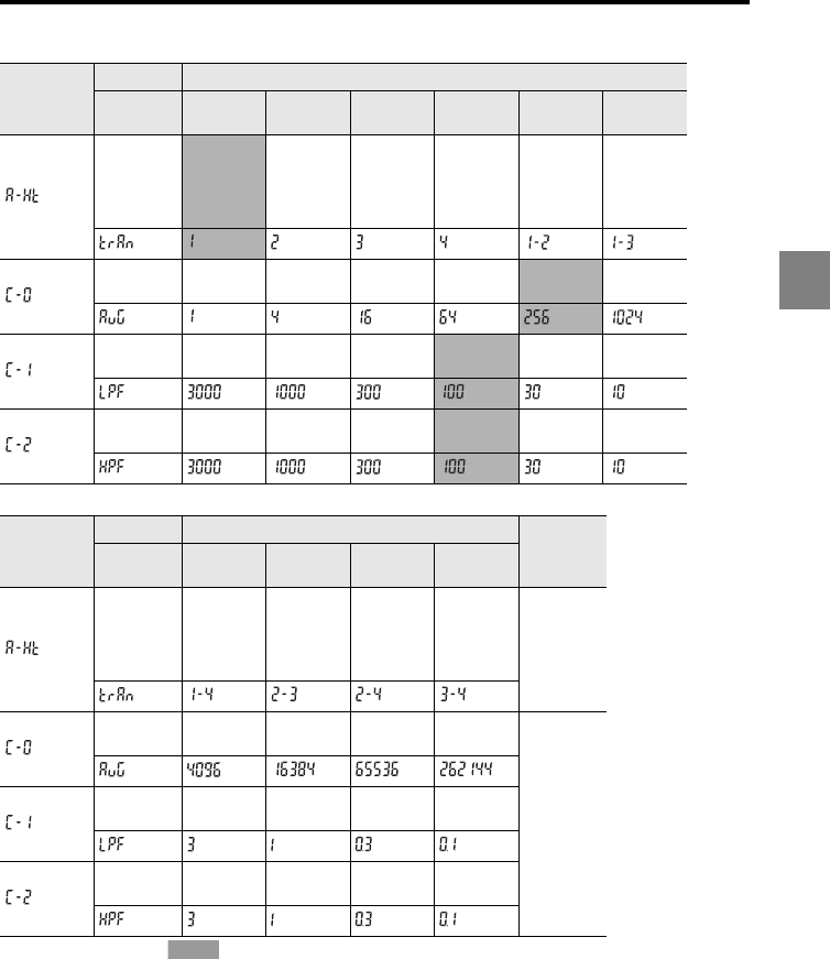
3-25
3
3 Function Settings
Functions A-0 and C require settings for the following sub-functions.
* The shaded cells ( ) are set by default.
Sub-
function
symbol
Function Function No.
Function
display 012345
Sensor
head for
transparent
object
detection
Surface 1 Surface 2 Surface 3 Surface 4 Surface 1 -
2
Surface 1 -
3
Moving
average 1 time 4 times 16 times 64 times 256 times 1024 times
Low-pass
filter 3000 Hz 1000 Hz 300 Hz 100 Hz 30 Hz 10 Hz
High-pass
filter 3000 Hz 1000 Hz 300 Hz 100 Hz 30 Hz 10 Hz
Sub-
function
symbol
Function Function No. Reference
page
Function
display 6789
Sensor
head for
transparent
object
detection
Surface 1 - 4
Surface 2 -
3
Surface 2 -
4
Surface 3 -
4page 3-28
Moving
average 4096 times 16384
times
65536
times
262144
times
page 3-33
Low-pass
filter 3 Hz 1 Hz 0.3 Hz 0.1 Hz
High-pass
filter 3 Hz 1 Hz 0.3 Hz 0.1 Hz
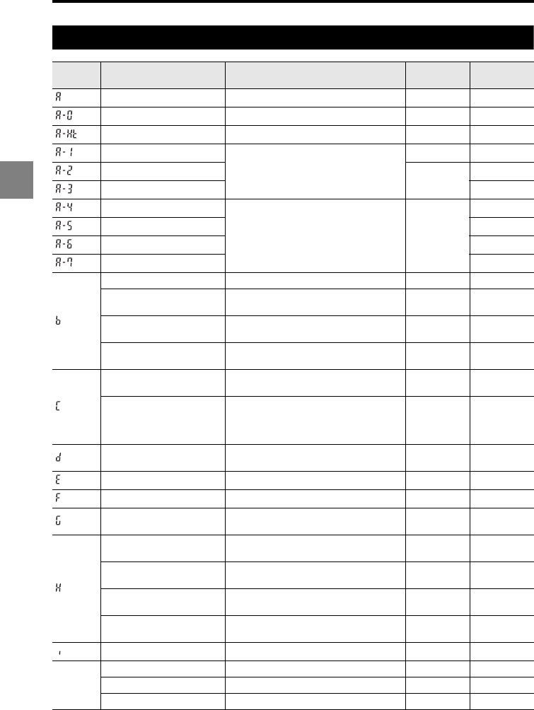
3-26
3
3 Function Settings
List of initial values and setting ranges
Function
symbol Item Setting range Initial value Remark
Calculation method HEAD/OUT/ADD/SUB/AVE/P-P/MAX/MIN HEAD
Sensor head Head 01 to 12 01
Surface to be measured 1, 2, 3, 4, 1-2, 1-3, 1-4, 2-3. 2-4, 3-4 1
OUT
OUT01 to 12
02
ADD 02/02
SUB
AVE
ON/OFF of OUT01 to 12 OFF
P-P
MAX
MIN
Input value for the first point -999999 to +999999 000.000
Display value for the first
point -999999 to +999999 000.000
Input value for the second
point -999999 to +999999 001.000
Display value for the
second point -999999 to +999999 001.000
Number of moving
average operations
1/4/16/64/256/1024/4096/16384/65536/
262144 256
Cutoff frequency 3000/1000/300/100/30/10/3/1/0.3/0.1 100 Hz
Setting range
is the same
for both LPF
and HPF.
Measurement mode Normal/peak hold/bottom hold/peak-to-
peak hold/average hold/sample hold Normal
Trigger Trigger 1/Trigger 2 Trigger 1
Offset -999999 to +999999 000.000
Minimum display unit 0.01 mm/0.001 mm/0.0001 mm/
0.00001 mm/0.1 μm/0.01 μm/0.001 μm 0.001 mm
Display value for the first
point -999999 to +999999 001.000
Output value for the first
point -10.5 V to +10.5 V 01.000
Display value for the
second point -999999 to +999999 -001.000
Output value for the
second point -10.5 V to +10.5 V -01.000
Measurement type Displacement/velocity/acceleration Displacement
Tolerance
Upper tolerance limit -999999 to +999999 005.000
Lower tolerance limit -999999 to +999999 -005.000
Hysteresis width 0 to +999999 000.000
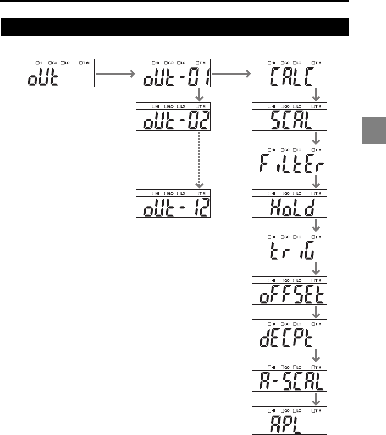
3-27
3
3 Function Settings
List of the OUT settings screens
OUT OUT01
OUT02
OUT12
OUT calculation
Scaling
Filter
Measurement
mode
Trigger
Offset
Minimum display
unit
Analog scaling
Measurement type
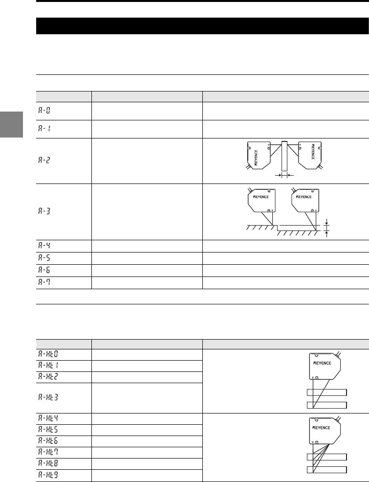
3-28
3
3 Function Settings
Setting the OUT calculation (Calculation method)
This function is used to select the calculation method according to the target, whether to
measure surface displacement, thickness, or height difference, based on the data obtained
with the Head settings.
Function Nos. and measurement examples
*
The auto-zero function is required.
Sub-functions and the surface to be measured
The following settings are used when the Transparent object or Transparent object 2 mode is
selected.
* The values in parentheses indicate the surface to be measured when the Transparent object mode is
selected and the base point is set to FAR.
Function No. Calculation Function
Sensor head Measures surface displacement using the specified
sensor head.
OUT Specifies the measured value of the other sensor
head to be input.
Addition
Measures
thickness
using head
01 and 02.*
Subtraction
Measures
height
difference
using head
01 and 02.
AVE (Average among OUT) Calculates the average of several OUT channels.
P-P (Peak-to-peak value) Calculates the P-P value of several OUT channels.
MAX (Maximum value among OUT)
Calculates the maximum value of several OUT channels.
MIN (Minimum value among OUT)
Calculates the minimum value of several OUT channels.
Sub-function symbol
Surface to be measured Function
1Measures displacement of one
surface.
2
3
4
1-2 Measures and calculates the
relationship between two
surfaces.
When "4" is selected, the
thickness of the first glass plate
is measured.
When "7" is selected, the gap
between the first and second
glass plates is measured.
1-3
1-4
2-3
2-4
3-4
Thickness
measurement
Height
difference
measurement
1(4)*
2(3)
3(2)
4(1)
1(4)*
2(3)
3(2)
4(1)
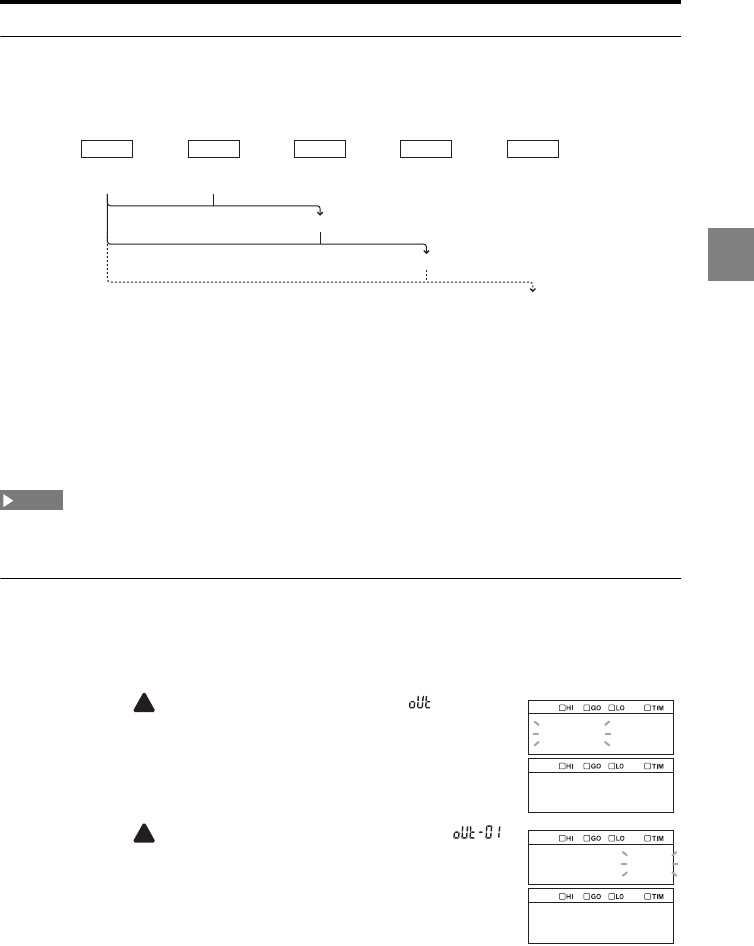
3-29
3
3 Function Settings
Using the output value of OUT in calculations more than once
The output value of OUT can be used in calculations up to two times as shown below.
Example when the output value of OUT01 is used repeatedly in calculations
•Output data of OUT01: Measured value of head 01
•Output data of OUT02: Measured value of head 02
•Output data of OUT03: Sum of OUT01 and OUT02 (Value calculated using the
measured values of head 01 and head 02)
•Output data of OUT04: Sum of OUT03 and OUT01 (Value calculated using the measured
values of head 01 and head 02 as well as using the measured value of head 01)
The measured value of one sensor head cannot be used four times or more. (Refer to the case of the
4th time in the figure above.)
Setting the calculation among OUT
The following procedure changes the setting of OUT01 as an example.
1
Hold down the SET key.
2Press the key
to select the OUT settings ( ) and then
press the ENT key.
3Press the key
to select the target OUT (OUT01
,
)
and then press the ENT key.
OUT01
OUT01 + OUT02
OUT03 + OUT01
OUT04 + OUT01
OUT02 OUT03 OUT04 OUT05
Head 011st time
2nd time
3rd time
4th time
Head 02
×
NOTE
out
out_01
out_01
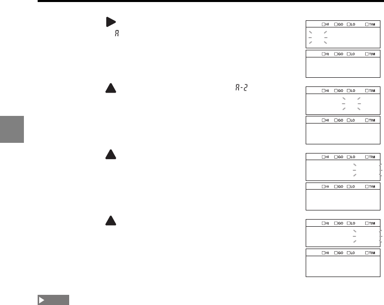
3-30
3
3 Function Settings
4Press the key
to select
function symbol A (Calculation
among OUT, ) and then press the ENT key.
5Press the key to select A-2 (Addition, ) and then
press the ENT key.
6Press the key to select the target OUT to assign as
Add-1 and then press the ENT key.
7Press the key to select the target OUT to assign as
Add-2 and then press the ENT key.
8Press the SET key.
The system returns to the measuring status.
•When the Transparent object 2 mode (page 3-8) is set, select the surface on which the
measurement target actually exists.
•The OUT data obtained with the velocity or acceleration measurement cannot be specified as
calculation data for the other OUT.
abcdef
calc
a_2
add
out_02
add_1
out_02
add_2
NOTE
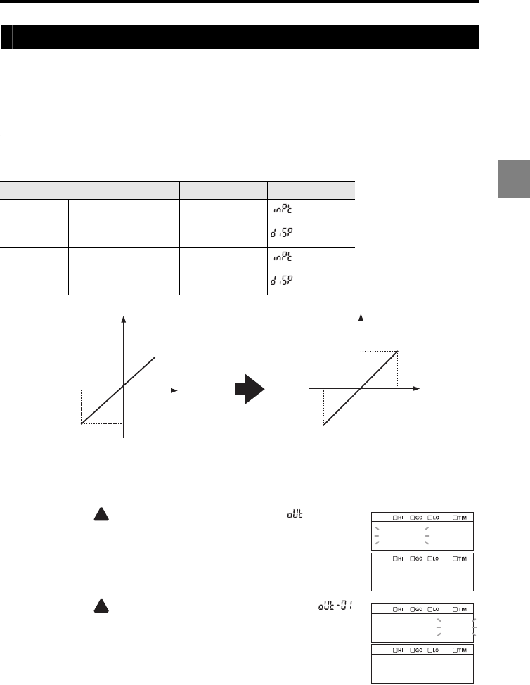
3-31
3
3 Function Settings
Calibrating the displayed value based on the measured value (Scaling)
This function is used to calibrate the value displayed for each OUT based on the
measured value.
You need to select two points and specify values to be displayed for them respectively as
a result of the calibration.
Setting the scaling
This section describes the setting procedure for the following calibration as an example.
The following procedure changes the setting of OUT01 as an example.
1
Hold down the SET key.
2Press the key
to select the OUT settings ( ) and then
press the ENT key.
3Press the key
to select the target OUT (OUT01
,
)
and then press the ENT key.
Setting item Setting value Display
Point 1
Original input value 1 -1.0200
Calibrated displayed
value 1 -1.0000
Point 2
Original input value 2 0.9900
Calibrated displayed
value 2 1.0000
Display
Input
0.99
0.99
-1.02
-1.02
Before
calibration
After
calibration
0.99
1.0000
-1.0000
-1.02
Display
Input
out
out_01
out_01
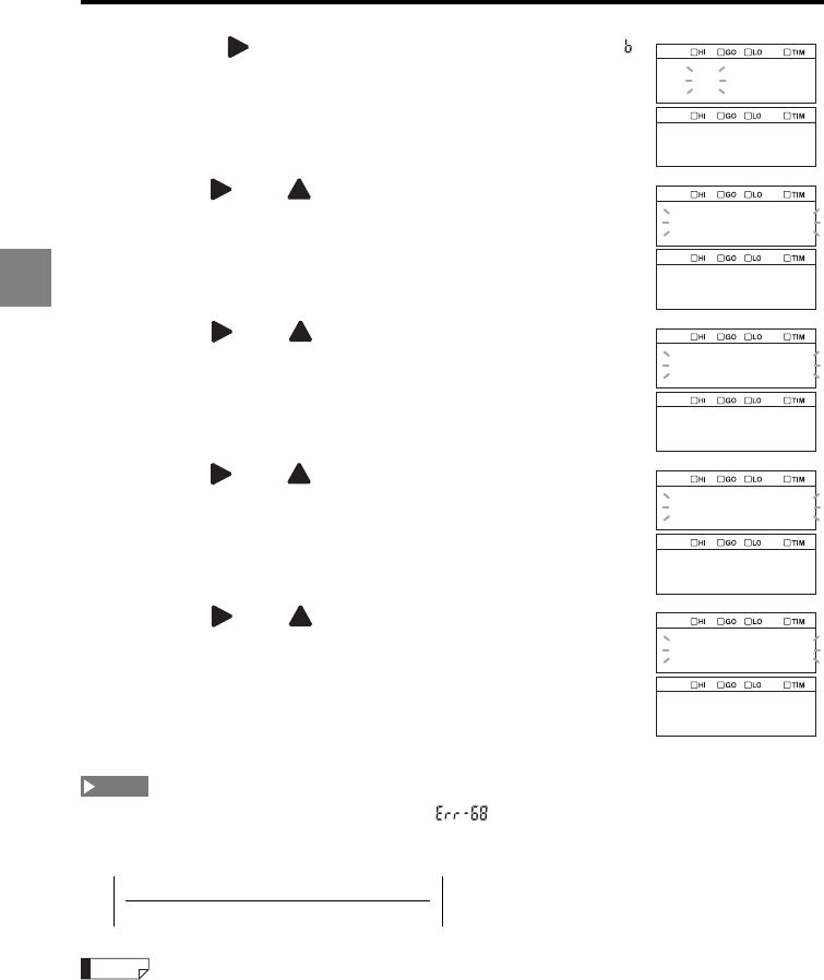
3-32
3
3 Function Settings
4Press the key
to select
function symbol B (Scaling, )
and then press the ENT key.
5Use the and keys to set the input value 1 for point
1 for OUT01 and then press the ENT key.
The current measured value can be loaded by pressing the
ZERO key.
6Use the and keys to set the displayed value 1 for
point 1 for OUT01 and then press the ENT key.
7Use the and keys to set the input value 2 for point
2 for OUT01 and then press the ENT key.
The current measured value can be loaded by pressing the
ZERO key.
8Use the and keys to set the displayed value 2 for
point 2 for OUT01 and then press the ENT key.
The setting is saved.
9Press the SET key.
The system returns to the measuring status.
When the following conditions are not satisfied, " " is displayed and the setting is disabled.
Press the ENT key to cancel the error and then set the scaling again.
(1) Input value 1 - Input value 2 0
(2)
If the ZERO key is pressed during the value input step, the current measured value is used as an input
value. If this key is pressed and held for three seconds, the initial value is input.
abcdef
scal
000.000
inpt1
000.000
disp1
000.000
inpt2
000.000
disp2
NOTE
Displayed value 2 - Displayed value 1 2
Input value 2 - Input value 1
Reference
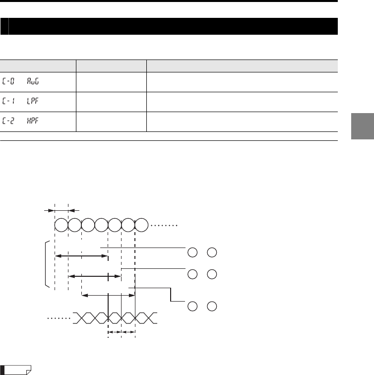
3-33
3
3 Function Settings
Apply a filter to ensure stable measurement (Filter)
The LK-G5000 Series offers the following three types of filter operations.
Setting the averaging filter
The averaging filter calculates the moving average of the measured values within the
range of 1 to 262144 times.
The following is an example of the process when the number of averaging measurements
is set to four.
The sampling cycle, measurement averaging time, and refresh cycle vary depending on the settings.
Refer to "Response delay time" (page 6-14) for details.
Function No. Filter name Function
Averaging The moving average of the measured values is calculated.
Set the number of averaging measurements.
Low-pass filter Abrupt changes are ignored and only moderate changes are
detected. Set the cutoff frequency.
High-pass filter Moderate changes are ignored and only abrupt changes are
detected. Set the cutoff frequency.
Refresh
cycle
A
Refresh
cycle
BC
1
Sampling cycle
Output data
1 4
2 3 4 5 6 7
to .
25
to .
36
to .
Measurement
averaging time
Measurement
averaging time
Measurement
averaging time
Internal data
Outputs data A by averaging data
Outputs data B by averaging data
Outputs data C by averaging data
Reference
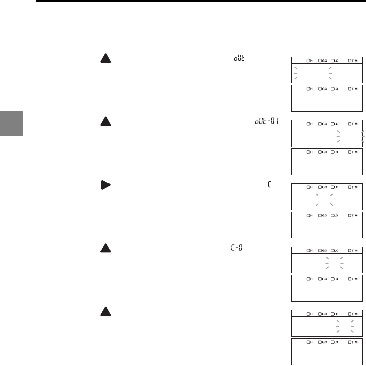
3-34
3
3 Function Settings
The following procedure sets the averaging filter to OUT01 as an example.
1
Hold down the SET key.
2Press the key
to select the OUT settings ( ) and then
press the ENT key.
3Press the key
to select the target OUT (OUT01
,
)
and then press the ENT key.
4Press the key
to select
function symbol C (Filter, )
and then press the ENT key.
5Press the key to select C-0 (Averaging, ) and then
press the ENT key.
6Press the key to set the number of averaging
measurements and then press the ENT key.
In this example, "1024" is set.
The setting is saved.
7Press the SET key.
The system returns to the measuring status.
out
out_01
out_01
abcdef
filter
c_0
avg
c_a5
1024
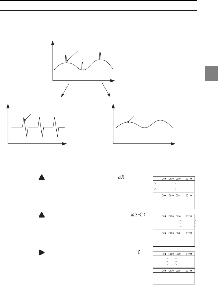
3-35
3
3 Function Settings
Setting the low-pass filter/high-pass filter
Each of these filters requires a cutoff frequency to be set.
When the filter is set, the data is processed as follows:
The following procedure sets the low-pass filter to OUT01 as an example.
1
Hold down the SET key.
2Press the key
to select the OUT settings ( ) and then
press the ENT key.
3Press the key
to select the target OUT (OUT01
,
)
and then press the ENT key.
4Press the key
to select
function symbol C (Filter, )
and then press the ENT key.
Measured value
Time
Measured value
Time
Measured value
Time
Input waveform
Waveform processed with the
high-pass filter Waveform processed with the
low-pass filter
out
out_01
out_01
abcdef
filter
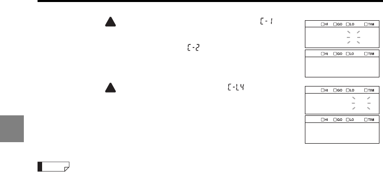
3-36
3
3 Function Settings
5Press the key to select C-1 (Low-pass filter, ) and
then press the ENT key.
To set the high-pass filter, select .
6Press the key to select C-L4 (30 Hz, ) and then
press the ENT key.
The setting is saved.
7Press the SET key.
The system returns to the measuring status.
The cutoff frequency setting is restricted as follows by the sampling cycle (page 3-58) setting.
•When the sampling cycle is set to 1000 μs or 500 μs: Even if the cutoff frequency is set to 3000 Hz,
1000 Hz, or 300 Hz, the setting of 100 Hz is used.
•When the sampling cycle is set to 200 μs: Even if the cutoff frequency is set to 3000 Hz or 1000 Hz,
the setting of 300 Hz is used.
•When the sampling cycle is set to 50 μs or 100 μs: Even if the cutoff frequency is set to 3000 Hz, the
setting of 1000 Hz is used.
•When the sampling cycle is set to 5.0 μs or 10 μs: Even if the cutoff frequency is set to 0.1 Hz, the
setting of 0.3 Hz is used.
•When the sampling cycle is set to 2.55 μs: Even if the cutoff frequency is set to 0.1 Hz or 0.3 Hz, the
setting of 1 Hz is used.
c_1
lpf
c_l4
30
Reference
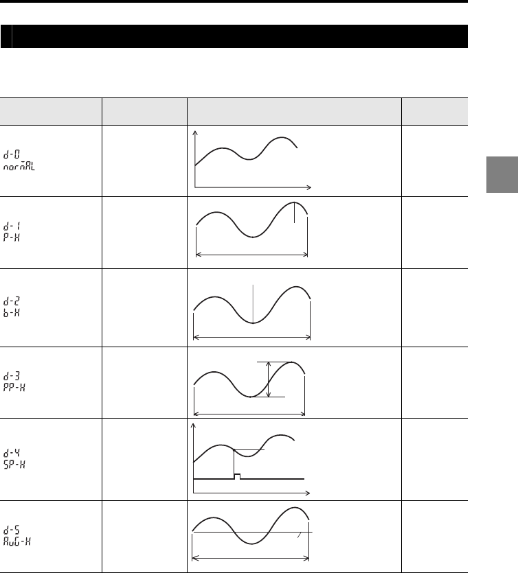
3-37
3
3 Function Settings
Using the Hold function (Measurement mode)
The LK-G5000 Series offers six types of measurement modes.
The following table describes the operations of these measurement modes.
There are two sampling period types which are determined by the trigger condition
settings Trigger 1 and Trigger 2 (page 3-45).
Function No. Mode name Description Reference
page
Normal
The measurement
result can be
displayed/output
constantly. page 3-39
Peak hold
The maximum
value during the
specified period
can be measured. page 3-40
Bottom hold
The minimum
value during the
specified period
can be measured. page 3-40
Peak-to-
peak hold
The "maximum
value - minimum
value" during the
specified period
can be measured.
page 3-40
Sample hold
The value at the
specified
moment
can be
measured.
page 3-42,
page 3-43
Average
hold
The average
value during the
specified period
can be measured. page 3-40
Sampling period
Max.
value
Sampling period
Min. value
Sampling period
Max. value -
Min. value
Synchronous input
Sample hold
value
Sampling period
Average
value
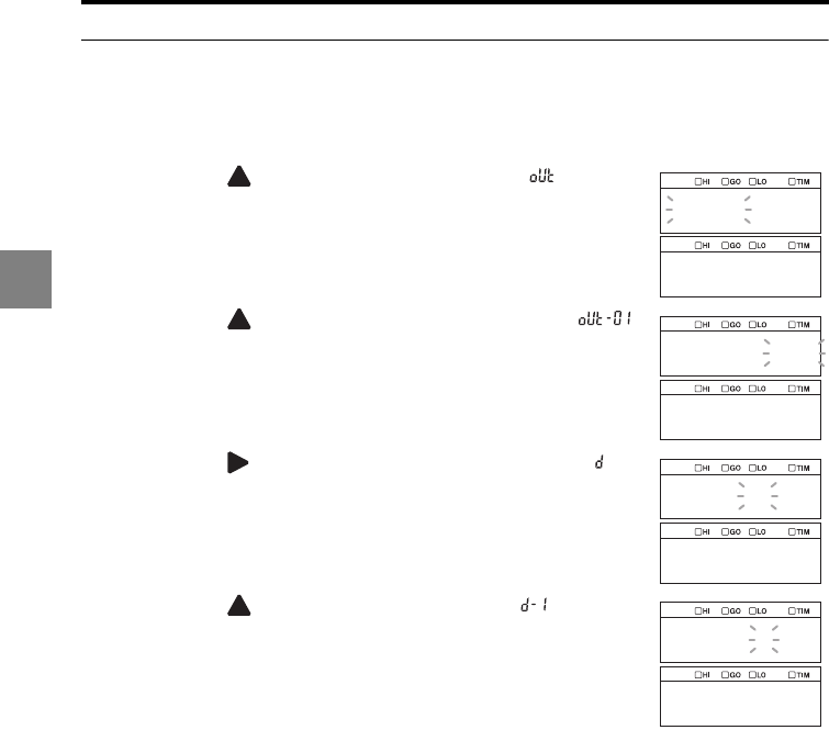
3-38
3
3 Function Settings
Setting the measurement mode
The following procedure sets the peak hold to OUT01 as an example.
1
Hold down the SET key.
2Press the key
to select the OUT settings ( ) and then
press the ENT key.
3Press the key
to select the target OUT (OUT01
,
)
and then press the ENT key.
4Press the key
to select
function symbol D (Hold, ) and
then press the ENT key.
5Press the key to select D-1 (Peak hold, ) and then
press the ENT key.
The setting is saved.
6Press the SET key.
The system returns to the measuring status.
out
out_01
out_01
abcdef
hold
d_1
p_h
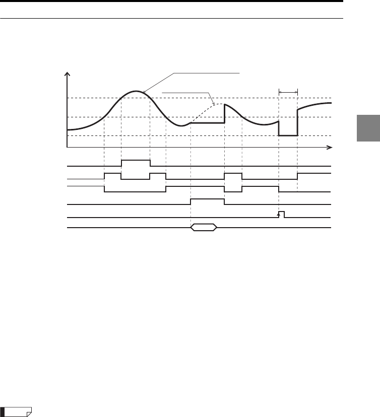
3-39
3
3 Function Settings
Normal
Measurement is performed continuously and the measured value is displayed/output
constantly.
•The ON state of each output indicates that the NPN or PNP open-collector output is
turned on.
•The ON state of each input indicates the following: For NPN type, the corresponding
terminal and the COM terminal are short-circuited; and for PNP type, the voltage is
applied between the corresponding terminal and the COM terminal.
•The RS-232C output is synchronized with the input to the TIMING1 terminal when
"Automatic transmission" in the Environment settings is set to ON (page 3-72).
•Refer to "Functions of the I/O Signals" (page 4-8) for details about binary output.
•If an alarm occurs for the internal measured value during the sampling period, the
measurement result is displayed differently depending on the alarm handling setting as
follows:
Process count set to 9999: The measurement result is output using the last held value.
Process count set to 0 to 9998: When the alarm continues for longer than the specified
process count during the sampling period, an alarm value (-FFFFFF) is output as the
measurement result.
•If the reset input is turned ON while the synchronous input is on, the comparator standby status (the
display shows "______") continues until the synchronous input turns off.
•The synchronous input and reset input can be controlled using the RS-232C (5-9 and page 5-11).
•The operation is the same regardless of the setting of Trigger 1 or Trigger 2.
Measured value in Normal mode
Internal measured value
ON
OFF
HI output
t
Comparator standby
("--------" is displayed)
HI setting value
Measured value
LO setting value
ON
OFF
GO output
ON
OFF
LO output
ON
OFF
Synchronous input
ON
OFF
RESET input
RS-232C output
Measured value
RESET operation
Reference
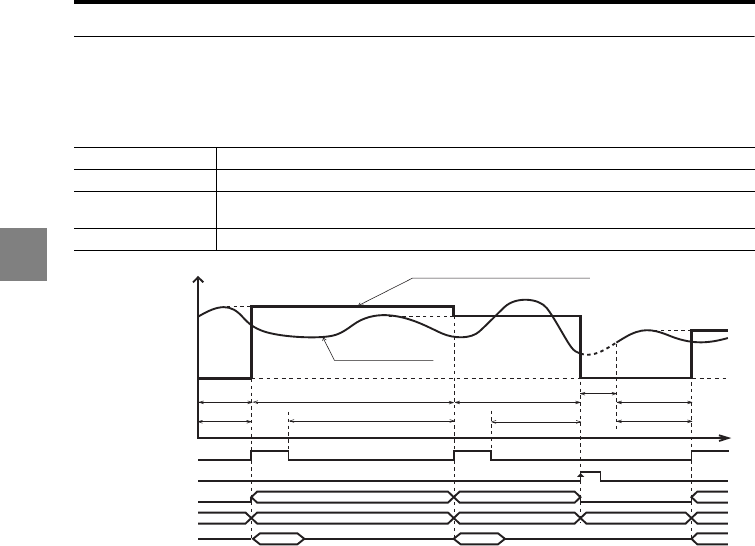
3-40
3
3 Function Settings
Peak hold/bottom hold/peak-to-peak hold/average hold
Measurement is performed within the period of time specified with the external
synchronous input (sampling period), and the displayed/output value is retained. The
sampling period differs between the Trigger 1 and Trigger 2 settings.
•When Trigger 1 is selected (page 3-45), the sampling period is the period between the
instant when the synchronous input turns on and the instant when the next synchronous
input turns on. When the synchronous input turns on, the measured value for the
preceding sampling period is output.
The RESET operation is not performed when the synchronous input is turned on.
•When Trigger 2 is selected (page 3-45), the sampling period is the period when the
synchronous input is turned off. When the synchronous input turns on, the measured
value for the preceding sampling period is output.
The RESET operation for the internal measured value is performed when the
synchronous input turns off.
•In the following cases, the comparator standby status (the display shows "______")
continues until the first measured value is determined:
When the power is turned on, when a setting is changed, when a program number is
changed, when RESET is input, or when auto-zero is input.
•The comparator output is provided according to the measured value.
•The ON state of each output indicates that the NPN or PNP open-collector output is
turned on.
•The ON state of each input indicates the following: For NPN type, the corresponding
terminal and the COM terminal are short-circuited; and for PNP type, the voltage is
applied between the corresponding terminal and the COM terminal.
•The RS-232C output is synchronized with the input to the TIMING1 terminal when
"Automatic transmission" in the Environment settings is set to ON (page 3-72).
Peak hold Measures the maximum value within the specified period of time (sampling period).
Bottom hold Measures the minimum value within the specified period of time (sampling period).
Peak-to-peak hold Measures the "maximum value - minimum value" within the specified period of time
(sampling period).
Average hold Measures the average value within the specified period of time (sampling period).
(Example) Measured value in peak-hold mode
Internal measured value
t
Sampling
period
Sampling period
Sampling period
RESET
operation
Comparator standby
("--------" is displayed)
Measured value
Comparator operation
Measured value Measured value Measured value
Measured value
Measured valueMeasured value
Comparator operation
Comparator operation
ON
OFF
Synchronous input
ON
OFF
RESET input
ON
OFF
Comparator output
Binary output
RS-232C output
Trigger 1
Trigger 2
Sampling
period
Sampling period
Sampling period
Sampling period
Sampling period
-------- --------

3-41
3
3 Function Settings
•Refer to "Functions of the I/O Signals" (page 4-8) for details about binary output.
•If the synchronous input turns on during the RESET operation, the comparator standby
status (the display shows " ") starts.
•If an alarm occurs for the internal measured value during the sampling period, the
measurement result is displayed differently depending on the alarm handling setting as
follows:
Process count set to 9999:The measurement result is output using the last held value.
Process count set to 0 to 9998:When the alarm continues for longer than the specified
process count during the sampling period, an alarm value (-FFFFFF) is output as the
measurement result.
•The synchronous input and reset input can be controlled using the RS-232C (page 5-9 and page 5-
11).
•The strobe output time can also be changed. Refer to "Setting the strobe output time (Strobe time)"
(page 3-64) for details.
When the average hold is selected for the measurement mode, set the filter function to the averaging
filter with the number of averaging measurements set to one.
Reference
NOTE
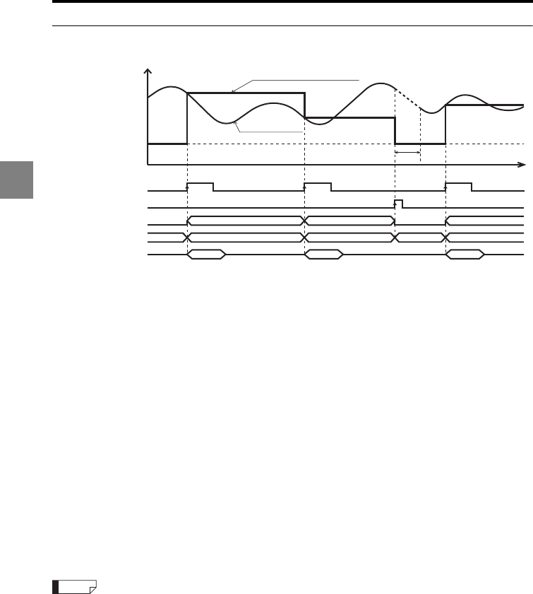
3-42
3
3 Function Settings
Sample hold (Trigger 1)
•The internal measured value when the synchronous input turns on is held and output.
•In the following cases, the comparator standby status (the display shows "______")
continues until the first measured value is determined:
When the power is turned on, when the mode is changed, when a program number is
changed, when RESET is input, or when auto-zero is input.
•The comparator output is provided according to the measured value.
•The ON state of each output indicates that the NPN or PNP open-collector output is
turned on.
•The ON state of each input indicates the following: For NPN type, the corresponding
terminal and the COM terminal are short-circuited; and for PNP type, the voltage is
applied between the corresponding terminal and the COM terminal.
•The RS-232C output is synchronized with the input to the TIMING1 terminal when
"Automatic transmission" in the Environment settings is set to ON (page 3-72).
•If an alarm occurs for the internal measured value during the sampling period, the
measurement result is displayed differently depending on the alarm handling setting as
follows:
Process count set to 9999: The measurement result is output using the last held value.
Process count set to 0 to 9998: When the alarm continues for longer than the specified
process count during the sampling period, an alarm value (-FFFFFF) is output as the
measurement result.
•The synchronous input and reset input can be controlled using the RS-232C (5-9 and page 5-11).
•The strobe output time can also be changed. Refer to "Setting the strobe output time (Strobe time)"
(page 3-64) for details.
Measured value in sample hold mode
Internal measured
value
Comparator operation
Measured value Measured value Measured value
Measured valueMeasured valueMeasured value
Comparator operation Comparator operation
t
RESET
operation
ON
OFF
Synchronous input
Comparator standby
("--------" is displayed)
Measured value
ON
OFF
RESET input
ON
OFF
Comparator output
Binary output
RS-232C output
------- -------
Reference
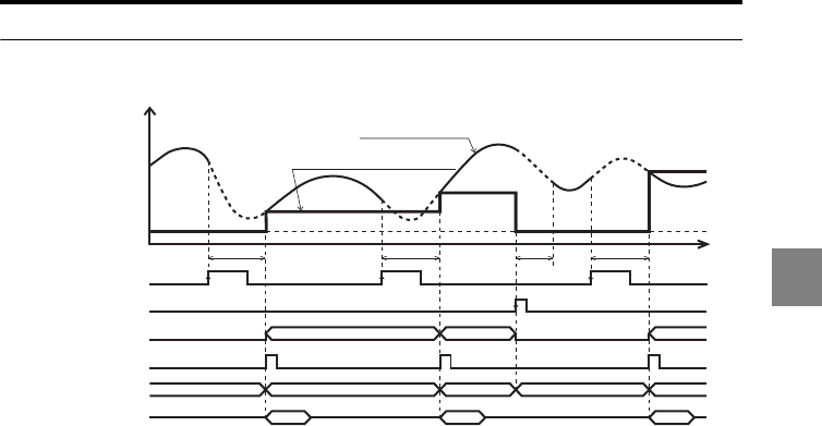
3-43
3
3 Function Settings
Sample hold (Trigger 2)
•When the synchronous input turns on, the internal measurement value, which is
determined by sampling the data from the specified number of averaging
measurements obtained since the synchronous input, is held and output.
•In the following cases, the comparator standby status (the display shows "______")
continues until the first measured value is determined:
When the power is turned on, when the mode is changed, when a program number is
changed, when RESET is input, or when auto-zero is input.
•The comparator output is provided according to the measured value.
•The ON state of each output indicates that the NPN or PNP open-collector output is
turned on.
•The ON state of each input indicates the following: For NPN type, the corresponding
terminal and the COM terminal are short-circuited; and for PNP type, the voltage is
applied between the corresponding terminal and the COM terminal.
•The RS-232C output is synchronized with the input to the TIMING1 terminal when
"Automatic transmission" in the Environment settings is set to ON (page 3-72).
•If the synchronous input turns on during the RESET operation, the system stops the
RESET operation and starts sampling.
•If an alarm occurs for the internal measured value during the sampling period, the
measurement result is displayed differently depending on the alarm handling setting as
follows:
Process count set to 9999: The measurement result is output using the last held value.
Process count set to 0 to 9998: When the alarm continues for longer than the specified
process count during the sampling period, an alarm value (-FFFFFF) is output as the
measurement result.
•If the RESET input or ZERO input is turned on during the sampling period, the sampling
stops and the comparator standby status starts.
Measured value in sample hold mode
Internal measured value
Comparator operation
Measured value
t
RESET
operation
Sampling
period
ON
OFF
Synchronous input
Comparator standby
("--------" is displayed)
Measured value
ON
OFF
RESET input
ON
OFF
Comparator output
ON
OFF
Strobe output
Binary output
RS-232C output
Sampling
period
Sampling
period
Comparator operation
Comparator operation
Measured value
Measured value
Measured value Measured value Measured value
---------- ----------

3-44
3
3 Function Settings
•The synchronous input and reset input can be controlled using the RS-232C (page 5-9 and page 5-
11).
•The strobe output time can be changed. Refer to "Setting the strobe output time (Strobe time)"
(page 3-64) for details.
The filter function should be set to "Averaging" (page 3-33). The number of averaging measurements
can be set as desired.
Reference
NOTE
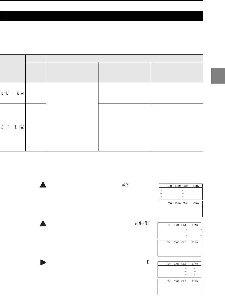
3-45
3
3 Function Settings
Setting the trigger condition (Trigger)
The Trigger 1 and Trigger 2 settings determine the sampling period during which the
measured value is held for the specified measurement mode operation. For the
differences in the timing, refer to "Using the Hold function (Measurement mode)" (page 3-
37).
The following procedure sets Trigger 2 to OUT01 as an example.
1
Hold down the SET key.
2Press the key
to select the OUT settings ( ) and then
press the ENT key.
3Press the key
to select the target OUT (OUT01
,
)
and then press the ENT key.
4Press the key
to select
function symbol E (Trigger, )
and then press the ENT key.
Function
No.
Trigger Function
Normal
Peak hold/
bottom hold/
peak-to-peak hold/
average hold
Sample hold
Trigger 1
Holds the internal
measured value at the
rising edge of the
synchronous signal for the
period while the signal is
turned ON.
Sets the sampling period
from the rising edge of the
synchronous signal to the
next rising edge.
Holds the internal
measured value at the
rising edge of the
synchronous signal.
Trigger 2
Sets the sampling period
from the falling edge of the
synchronous signal to the
next rising edge.
When the synchronous
input rises (turns on), it
holds the internal
measurement value which
is determined by sampling
the data of the specified
number of averaging
measurements obtained
since the synchronous
input.
out
out_01
out_01
abcdef
trig
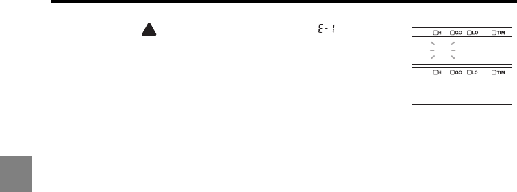
3-46
3
3 Function Settings
5Press the key to select E-1 (Trigger 2, ) and then
press the ENT key.
The setting is saved.
6Press the SET key.
The system returns to the measuring status.
e_1
tim2
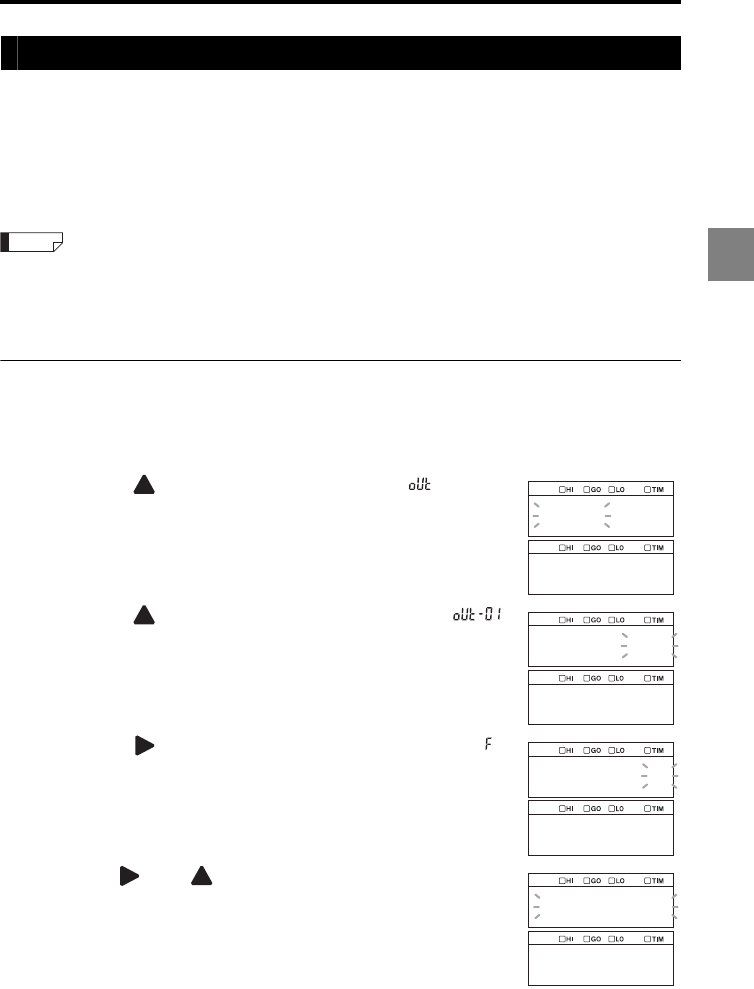
3-47
3
3 Function Settings
Using offset in the measurement (Offset)
The offset function is used to add or subtract a desired value to or from the displayed
value. By setting the offset value in advance, you can display that value when performing
the auto-zero operation.
The offset value is applied to the measured value after it is processed with the specified
measurement mode and auto-zero operations. Refer to "List of initial values and setting
ranges" (page 3-26) for the setting range and restrictions of the offset function.
The offset value can also be used for master adjustment by using the auto-zero function (auto-offset
function).
Set the size of the master target as the offset value and then use the auto-zero function while measuring
the master target. The size of the master target can be set as the master value (reference value).
Setting the offset value
The following procedure sets the offset to OUT01 as an example.
1
Hold down the SET key.
2Press the key
to select the OUT settings ( ) and then
press the ENT key.
3Press the key
to select the target OUT (OUT01
,
)
and then press the ENT key.
4Press the key
to select
function symbol F (Offset, )
and then press the ENT key.
5Use the and keys to set the offset value and then
press the ENT key.
In this example, "0.03" is set.
The setting is saved.
6Press the SET key.
The system returns to the measuring status.
Reference
out
out_01
out_01
abcdef
offset
000.030
offset
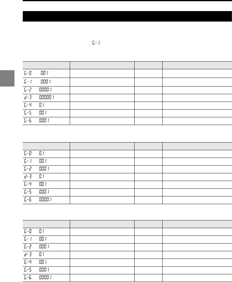
3-48
3
3 Function Settings
Setting the unit and minimum display unit (Minimum display unit)
With the LK-G5000 Series, the display unit and minimum display unit can be selected from
the six options listed in the tables below.
The factory default setting is " ".
When "Displacement" is selected for the measurement type (page 3-53)
When "Velocity" is selected for the measurement type (page 3-53)
When "Acceleration" is selected for the measurement type (page 3-53)
Function No. Minimum display unit Unit Display range
0.01 mm -9999.99 to +9999.99
0.001 mm -999.999 to +999.999
0.0001 mm -99.9999 to +99.9999
0.00001 mm -9.99999 to +9.99999
0.1 μm -99999.9 to +99999.9
0.01 μm -9999.99 to +9999.99
0.001 μm -999.999 to +999.999
Function No. Minimum display unit Unit Display range
0.1 m/s -99999.9 to +99999.9
0.01 m/s -9999.99 to +9999.99
0.001 m/s -999.999 to +999.999
0.1 mm/s -99999.9 to +99999.9
0.01 mm/s -9999.99 to +9999.99
0.001 mm/s -999.999 to +999.999
0.0001 mm/s -99.9999 to +99.9999
Function No. Minimum display unit Unit Display range
0.1 km/s2-99999.9 to +99999.9
0.01 km/s2-9999.99 to +9999.99
0.001 km/s2-999.999 to +999.999
0.1 m/s2-99999.9 to +99999.9
0.01 m/s2-9999.99 to +9999.99
0.001 m/s2-999.999 to +999.999
0.0001 m/s2-99.9999 to +99.9999
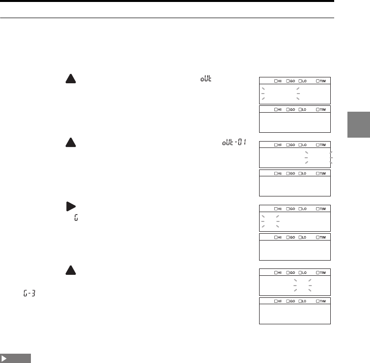
3-49
3
3 Function Settings
Setting the unit and minimum display unit
The following procedure sets OUT01 as an example.
1
Hold down the SET key.
2Press the key
to select the OUT settings ( ) and then
press the ENT key.
3Press the key
to select the target OUT (OUT01
,
)
and then press the ENT key.
4Press the key
to select
function symbol G (Minimum
display unit, ) and then press the ENT key.
5Press the key to select G-3 (Unit: mm, Minimum
display unit: 0.00001,
) and then press the ENT key.
The setting is saved.
6Press the SET key.
The system returns to the measuring status.
If the unit and minimum display unit are changed, the settings related to the numerical value display
for the same OUT of the same program number (tolerance, scaling, offset, and analog output scaling)
as well as the auto-zero setting value are initialized.
out
out_01
out_01
ghi
decpt
g_3
0.00001
NOTE
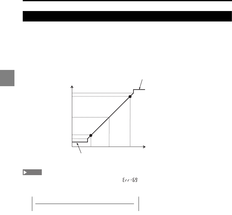
3-50
3
3 Function Settings
Scaling the analog output (Analog scaling)
The analog voltage output can be scaled into a desired output voltage value within the
range of ±10.5 V.
To set the scaling, select two displayed values and specify analog output values
respectively.
To set the scaling of the analog current output (4 to 20 mA), use a voltage value which is
converted from the current value using the following formula:
Voltage value (V) = (Current value [mA] - 12 mA)/0.8
When the following conditions are not satisfied, " " is displayed and the setting is disabled.
Press the ENT key to cancel the error and then set the scaling again.
(1) Displayed value 1 - Displayed value 2 0
(2)
The output voltage is calculated in the unit of 1 mV, and the displayed value is calculated in the
specified unit and minimum display unit.
Displayed value [mm]
0 V (12 mA)
+10.5 V (20.4 mA)
+10 V (20 mA)
Voltage (Current)
–10 V (4 mA)
-5 +50
–10.5 V (3.6 mA)
Over range section on the positive side
+10.8 V (20.64 mA)
Over range section on the negative side
–10.8 V (3.36 mA)
When the scaling is set to:
+10 V: +5 mm
-10 V: -5 mm
Point 1
Point 2
NOTE
Output voltage value 2 - Output voltage value 1 10
Displayed value 2 - Displayed value 1
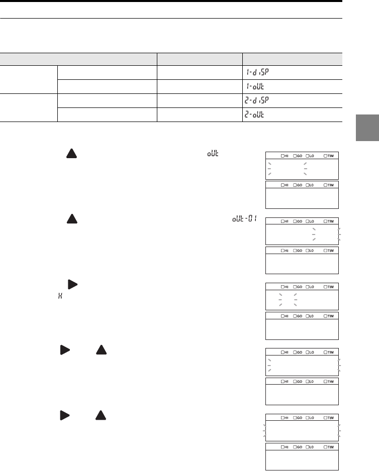
3-51
3
3 Function Settings
Setting the analog output scaling
The following procedure sets the following analog scaling to OUT01 as an example.
1
Hold down the SET key.
2Press the key to select the OUT settings ( ) and then
press the ENT key.
3Press the key to select the target OUT (OUT01, )
and then press the ENT key.
4Press the key
to select
function symbol H (Analog
scaling, ) and then press the ENT key.
5Use the and keys to set the displayed value 1 for
point 1 and then press the ENT key.
6Use the and keys to set the analog output voltage
value 1 for point 1 and then press the ENT key.
Measurement details Measured value Display
Point 1
Displayed value 1 -5.000
Analog output voltage value 1 -10.000
Point 2
Displayed value 2 5.000
Analog output voltage value 2 10.000
out
out_01
out_01
ghi
a_scal
005.000_
1_disp
10.000_
1_out
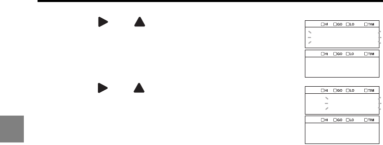
3-52
3
3 Function Settings
7Use the and keys to set the displayed value 2 for
point 2 and then press the ENT key.
8Use the and keys to set the analog output voltage
value 2 for point 2 and then press the ENT key.
The setting is saved.
9Press the SET key.
The system returns to the measuring status.
005.000
2_disp
10.000
2_out
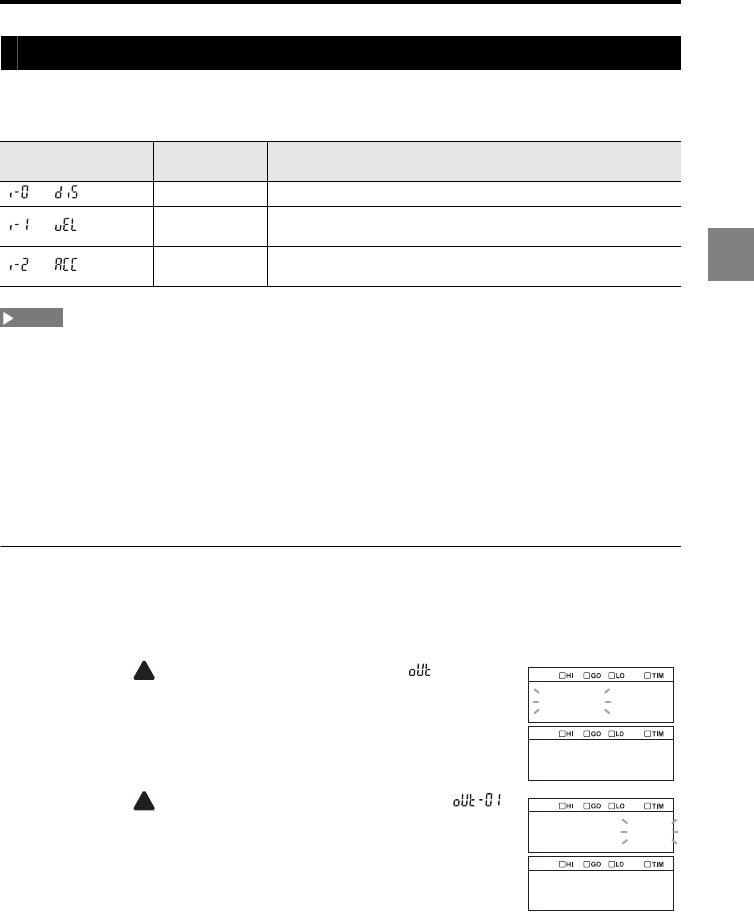
3-53
3
3 Function Settings
Setting the type of measurement (Measurement type)
This function is used to set the measurement type according to the required
measurement.
•The velocity and acceleration which can be calculated vary depending on the sampling cycle.
Refer to "Relationship Between the Sampling Cycle and Velocity/Acceleration Measurement Range"
(page A-11) for details.
•The OUT data obtained with the velocity or acceleration measurement cannot be specified as
calculation data for another OUT.
•The number of OUT which can be set to the velocity/acceleration measurement varies depending
on the sampling cycle as follows: 2.55 μs: 1, 5 μs: 2, 10 μs: 4, and 20 μs or longer: 12. (When the
number of OUT exceeds the limitation, an alarm value is output for the exceeding OUT.)
•When the sensor head measurement mode used for the measurement is Transparent object or
Transparent object 2, the velocity/acceleration is always calculated for the first peak.
Setting the measurement type
The following procedure sets OUT01 as an example.
1
Hold down the SET key.
2Press the key
to select the OUT settings ( ) and then
press the ENT key.
3Press the key
to select the target OUT (OUT01
,
)
and then press the ENT key.
Function No. Measurement
type Measurement
Displacement Measures displacement.
Velocity Calculates the velocity based on the displacement in the
sampling cycle.
Acceleration Calculates the acceleration based on the displacement in the
sampling cycle.
NOTE
out
out_01
out_01
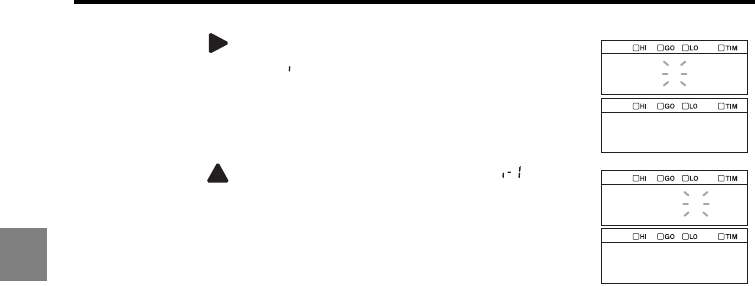
3-54
3
3 Function Settings
4Press the key
to select
function symbol I
(Measurement type, ) and then press the ENT key.
5Press the key to select I-1 (Displacement, ) and
then press the ENT key.
The setting is saved.
6Press the SET key.
The system returns to the measuring status.
ghi
apl
i_1
vel
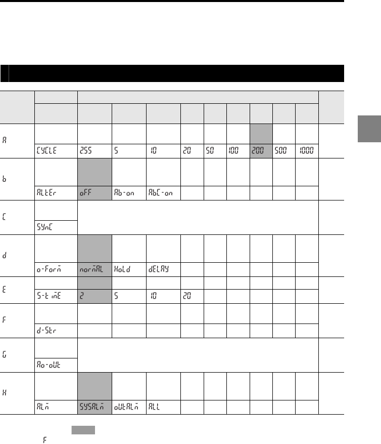
3-55
3
3 Function Settings
Setting the Common Function (OPTION)
This section describes the functions common to all program numbers.
List of functions and function Nos.
•The shaded cells ( ) are set by default.
•Function " " requires the sub-function settings of the number of data and storage cycle (page 3-
65).
Function
symbol
Function Function No.
Reference
page
Function
display 0 1 2 345678
Sampling
cycle 2.55 μs 5 μs 10 μs 20 μs 50 μs 100
μs
200
μs
500
μs
1000
μs page
3-58
Mutual
interference
prevention
OFF 2
groups
3
groups page
3-60
Synchronization
setting
SYNC01 to 12
Set to ON/OFF
page
3-62
Comparator
output
form
Normal Hold Off-
delay page
3-63
Strobe time 2 ms 5 ms 10 ms 20 ms page
3-64
Data
storage page
3-65
Analog
output CH01 to CH12 page
3-67
Alarm
output type
System
alarm
Measured
value
alarm
Both page
3-68
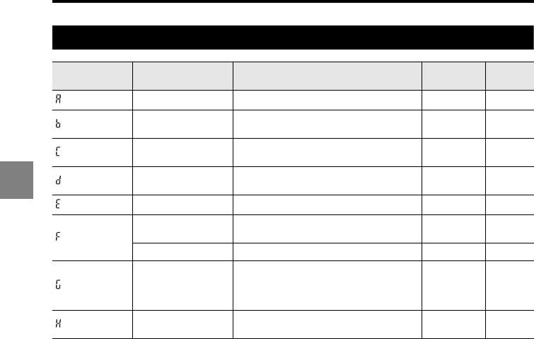
3-56
3
3 Function Settings
List of initial values and setting ranges
Function
symbol Item Setting range Initial value Remark
Sampling cycle 2.55/5/10/20/50/100/200/500/1000 μs 200 μs
Mutual interference
prevention OFF/AB-ON/ABC-ON OFF
Synchronization
setting ON/OFF for OUT01 to 12 All OFF
Comparator output
form Normal/Hold/Off-delay Normal
Strobe time 2/5/10/20 ms 2 ms
Number of data 1 to 1200000 (depends on the number of
OUT for which data is stored) 100000
Storage cycle 1/2/5/10/20/50/100/200/500/1000/TIM 1
Analog output CH01 to 12
CH01 =
OUT01,
CH02 =
OUT02
Alarm output type System alarm/measured value alarm/
both
System
alarm
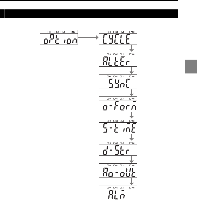
3-57
3
3 Function Settings
List of the common function settings screens
OPTION Sampling cycle
Mutual interference
prevention
Synchronization
setting
Comparator output
form
Strobe time
Data storage
Analog output
Alarm output type
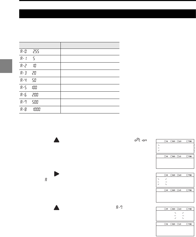
3-58
3
3 Function Settings
Setting the sampling cycle for the measurement (Sampling cycle)
This function is used to set the sampling cycle for the measurement. Use the initial value
during normal operation. If you want the sampling to be performed more quickly, change it
to shorter values. If the received light intensity is extremely low, change it to longer values.
The following procedure sets the sampling cycle to 500 μs as an example.
1Hold down the SET key.
2Press the key
to select the Common settings ( )
and then press the ENT key.
3Press the key
to select
function symbol A (Sampling
cycle, ) and then press the ENT key.
4Press the key to select A-7 (500 µs, ) and then
press the ENT key.
The setting is saved.
5Press the SET key.
The system returns to the measuring status.
Function No. Function (sampling cycle)
2.55 μs
5 μs
10 μs
20 μs
50 μs
100 μs
200 μs
500 μs
1000 μs
option
abcdef
cycle
a_7
500
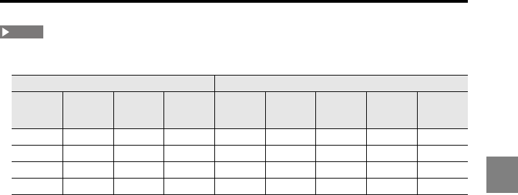
3-59
3
3 Function Settings
•The relationships among the measurement mode of the sensor head, the sampling cycle, and the
active OUT count are shown in the table below.
: When at least one sensor head set to the corresponding measurement mode is connected
: A sensor head set to the corresponding measurement mode can be connected
X : When a sensor head set to the corresponding measurement mode is not used
- : Setting impossible
The values in the parentheses are the number of OUT which can be used for the calculation of ADD,
SUB, P-P, MAX, MIN, and AVE among OUT.
•The number of OUT which can be set to the velocity/acceleration measurement varies depending
on the sampling cycle as follows: 2.55 μs: 1, 5 μs: 2, 10 μs: 4, and 20 μs or longer: 12. (When the
number of OUT exceeds the limitation, an alarm value is output for the exceeding OUT.)
Measurement mode (page 3-8)Sampling cycle (page 3-58)
Semi
opaque
Transparent
object
Transparent
object 2
Normal/
Translucent
object
2.55 µs 5 µs 10 µs 20 to 100
µs
200 µs or
longer
- (-) - (-) - (-) - (-) 12 (12)
x- (-) - (-) 8 (-) 12 (2) 12 (12)
xx- (-) 4 (-) 8 (-) 12 (2) 12 (12)
xxx2 (-) 4 (-) 8 (-) 12 (2) 12 (12)
NOTE
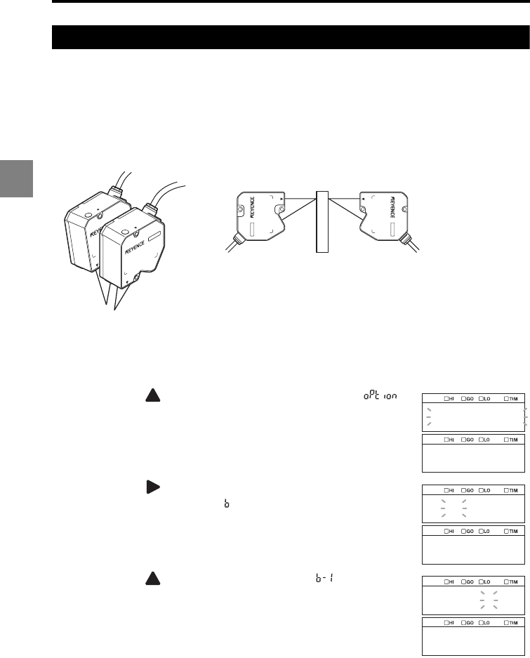
3-60
3
3 Function Settings
Setting the mutual interference prevention function (Mutual interference prevention)
When more than one sensor head are connected and mounted in close proximity, they
may receive the light emitted from the other sensor head, resulting in a measurement error.
The mutual interference prevention function assigns the sensor heads to three groups at
maximum, A to C, to allow these groups to emit light alternately. This prevents interference
with the sensor heads in the other group.
The following procedure enables the mutual interference prevention function for groups A
and B as an example.
1Hold down the SET key.
2Press the key
to select the Common settings ( )
and then press the ENT key.
3Press the key
to select
function symbol B (Mutual
interference prevention, ) and then press the ENT key.
4Press the key to select B-1 (AB-ON, ) and then
press the ENT key.
When the measurement
points are close
When the thickness of a transparent
object is measured
option
abcdef
alter
b_1
ab_on
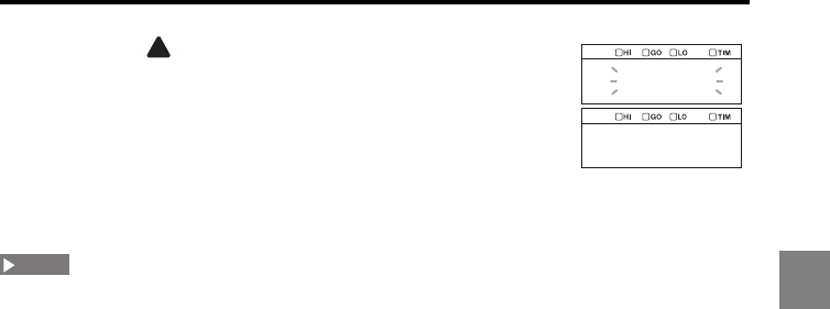
3-61
3
3 Function Settings
5Press the key to select the group to which head 01 is
assigned and then press the ENT key.
The setting is saved.
Repeat this step for all sensor heads specified with the active
head count (page 3-79).
6Press the SET key.
The system returns to the measuring status.
The sampling cycle is double the specified value when the mutual interference prevention function is
set to AB-ON; and is tripled when the function is set to ABC-ON.
gr_a
b_g01
NOTE
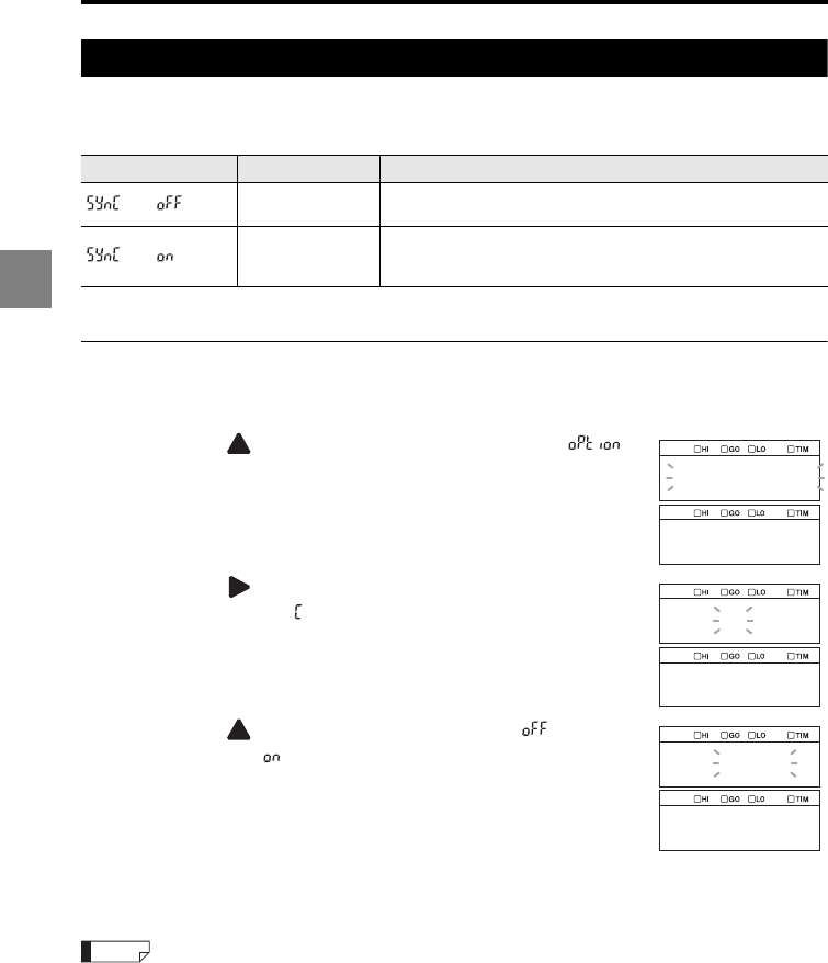
3-62
3
3 Function Settings
Setting the external synchronous input (Synchronization setting)
This function is used to set whether to use synchronous input control for each OUT. The
following two operations can be selected.
* represents OUT No. (01 to 12)
Setting the synchronization
1Hold down the SET key.
2Press the key
to select the Common settings ( )
and then press the ENT key.
3Press the key
to select
function symbol C
(Synchronization, ) and then press the ENT key.
4Press the key to select Asynchronous ( ) or
Synchronous ( ) and then press the ENT key.
The setting is saved.
Repeat this step for all OUT specified with the active OUT
count (page 3-78).
5Press the SET key.
The system returns to the measuring status.
Also refer to "I/O terminals" (page 4-1).
Function No. Synchronization Function
Asynchronous Disables synchronization control using TIMING1, ZERO1, and
RESET1, as well as automatic transmission through RS-232C.
Synchronous
Enables synchronization control using TIMING1, ZERO1, and
RESET1, automatic transmission through RS-232C, and
synchronization of storage operation.
option
abcdef
sync
off
sync01
Reference
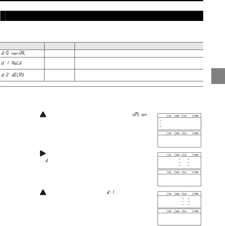
3-63
3
3 Function Settings
Setting the output form of the tolerance comparator result (Comparator output form)
This function is used to set the output form of the tolerance comparator result. The
following three types are available.
Setting the output form of the tolerance comparator result
1Hold down the SET key.
2Press the key
to select the Common settings ( )
and then press the ENT key.
3Press the key
to select
function symbol D (Comparator
output form, ) and then press the ENT key.
4Press the key to select D-1 (Hold, ) and then press
the ENT key.
The setting is saved.
5Press the SET key.
The system returns to the measuring status.
Function No. Output form Function
Normal Produces outputs according to the tolerance comparator result.
Hold Holds the output that is turned on. The hold is released when the
measured value is reset.
Off-delay Applies off-delay of 60 ms to the normal output. The hold is released
when the measured value is reset.
option
abcdef
o_form
d_1
hold
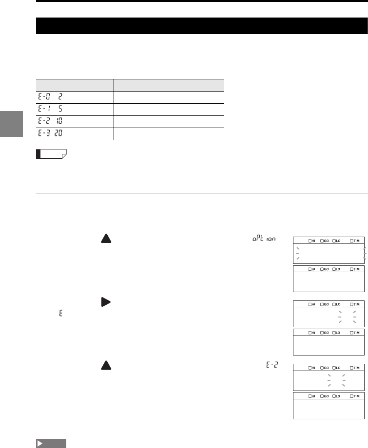
3-64
3
3 Function Settings
Setting the strobe output time (Strobe time)
This function is used to set the period of time for the strobe output to turn ON (one-shot
output time).
The pulse width can be selected from the following four types.
•Refer to "Timing diagrams" (page 4-15) for details about the timing diagram.
•Refer to "Binary output" (page 4-19) for details about binary output timing.
Setting the pulse width of the strobe signal
1Hold down the SET key.
2Press the key
to select the Common settings ( )
and then press the ENT key.
3Press the key
to select
function symbol E (Strobe time,
) and then press the ENT key.
4Press the key to select E-2 (Pulse width: 10 ms, )
and then press the ENT key.
The setting is saved.
5Press the SET key.
The system returns to the measuring status.
This setting is ignored when the measurement mode (page 3-37) is "Normal".
Function No. Function (Strobe output time)
2 ms
5 ms
10 ms
20 ms
Reference
option
abcdef
s_time
e_2
10
NOTE
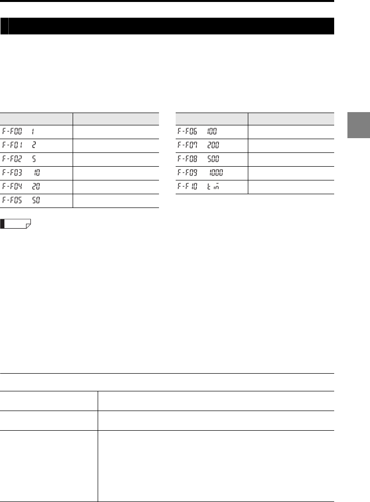
3-65
3
3 Function Settings
Storing the measured values in the memory (Data storage function)
The LK-G5000 Series can store up to 1,200,000 measured values (1,200,000 is a total and
the available number for each Out Channel depends on the number of Out Channels to
store data) in the internal memory using the external synchronous input or in every storage
cycle. The stored data can be read and checked by using the RS-232C interface or the
LK-Navigator 2 software.
The settings of the function numbers and sub-functions are as follows.
•The data to be stored is the measured value of the Out Channel after it is processed with the
specified measurement mode and other operations (page 3-2).
•The "storage cycle" is specified as the multiple of the sampling cycle. When the storage cycle is set
to "Synchronization input", the data is stored in synchronization with the TIMING1 input, the LK-
Navigator 2 operation, or the simultaneous timing button of the LK-HD1001.
•The storing operation stops when the number of stored data exceeds the specified number.
•The storage time can be calculated as "Sampling cycle x Storage cycle x Number of data".
•Even when the refresh cycle, which is determined with the number of averaging measurements, is
longer than the sampling cycle, the data is stored based on the sampling cycle. In this case, the
same measured value is stored until the measured value is updated.
•Even if "auto-zero" or "RESET" is input during data storage operation, the storage continues without
clearing the stored data.
•When this function is started and stopped repeatedly, the new data is stored after the old data.
•From the display panel (HD500), the number of stored data can be set to only 999,999 at maximum.
Starting/stopping data storage and clearing data
Sub-function symbol Storage cycle selection Sub-function symbol Storage cycle selection
x 1 (of the sampling cycle) x 100
x 2 x 200
x 5 x 500
x 10 x 1000
x 20 Synchronization input
x 50
Conditions to start storing data •Start command from the RS-232C interface
•Operation from the LK-Navigator 2 setup support software
Conditions to stop storing data •Stop command from the RS-232C interface
•Operation from the LK-Navigator 2 setup support software
Conditions to clear the stored
data
Any of the following cases while the storing operation is stopped:
•When the data for the specified number of measured values are stored
•When the setting mode or communication mode is changed to the
measuring mode
•When the initialization command is sent through the RS-232C interface
•When the initialization is ordered from the LK-Navigator 2 setup support
software
•When the power is turned off
•When the program number is changed
Reference
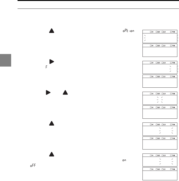
3-66
3
3 Function Settings
Setting the data storage method
1Hold down the SET key.
2Press the key
to select the Common settings ( )
and then press the ENT key.
3Press the key
to select
function symbol F (Data
storage, ) and then press the ENT key.
4Use the and keys to set the number of data to be
stored and then press the ENT key.
In this example, "1000" is set.
5Press the key to select the storage cycle and then
press the ENT key.
In this example, "50x" is set.
6Press the key to select whether to include the
currently displayed OUT value in the stored data ( ) or not
( ) and then press the ENT key.
The setting is saved.
Repeat this step for all OUT specified with the active OUT
count (page 3-78).
7Press the SET key.
The system returns to the measuring status.
option
abcdef
d_str
001000
num
f_f05
50
on
f_o01
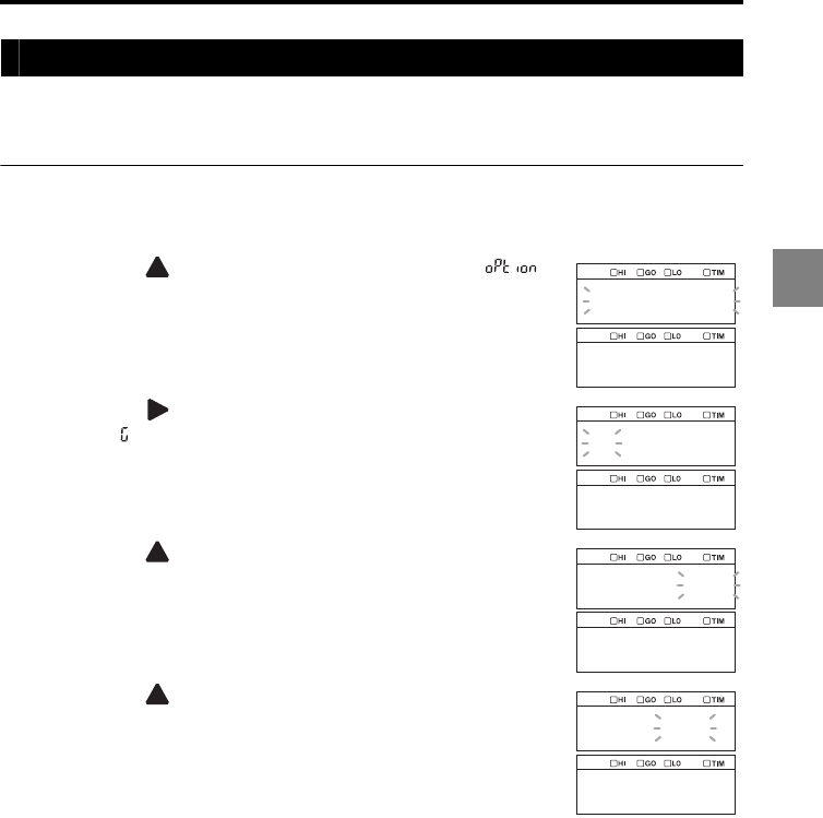
3-67
3
3 Function Settings
Assigning OUT to the analog output channel (Analog output)
Assigning "OUT" as Analog Output Channel. The number of analog outputs which can be
used are two for the controller unit and one for each head expansion unit.
Setting the analog output
1Hold down the SET key.
2Press the key
to select the Common settings ( )
and then press the ENT key.
3Press the key
to select
function symbol G (Analog
output, ) and then press the ENT key.
4Press the key to select the analog output channel to
which OUT is assigned and then press the ENT key.
5Press the to select OUT to be assigned to the analog
output channel selected in step 4 and then press the ENT
key.
The setting is saved.
Repeat steps 4 to 5 for all OUT specified with the active OUT
count (page 3-78).
6Press the SET key.
The system returns to the measuring status.
option
gh
ao_out
ach_01
ao_out
out01
ach_01
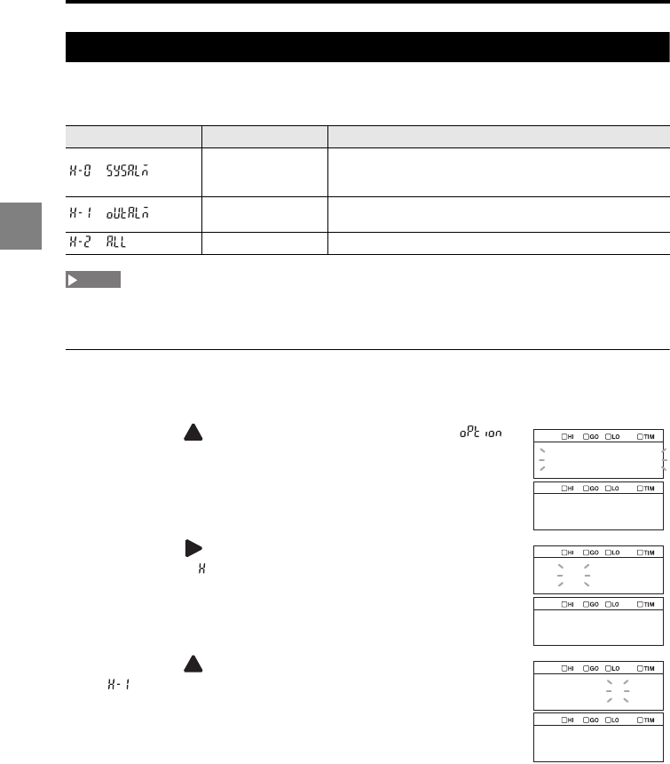
3-68
3
3 Function Settings
Setting the type of alarm output (Alarm output type)
This function is used to select the type of alarm to be output from a system alarm, a
measured value alarm, or both.
The output uses an N.C. (normally closed) contact. The contact is short-circuited when it is OFF and is
open when it is ON.
Setting the alarm output type
1Hold down the SET key.
2Press the key
to select the Common settings ( )
and then press the ENT key.
3Press the key
to select
function symbol H (Alarm
output type, ) and then press the ENT key.
4Press the key to select H-1 (Measured value alarm,
) and then press the ENT key.
The setting is saved.
5Press the SET key.
The system returns to the measuring status.
Function No. Alarm output type Function
System alarm
Outputs an alarm when a system alarm occurred. Once the
alarm is output, the ON state is retained until the power is
turned off.
Measured value
alarm
Outputs an alarm when the received light intensity is
insufficient or excessive.
Both Outputs both system alarm and measured value alarm.
NOTE
option
gh
alm
h_1
outalm
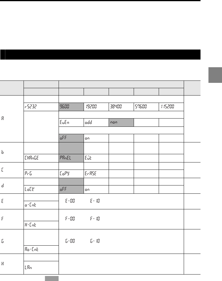
3-69
3
3 Function Settings
Setting the Operating Environment
settings (ENV)
This section describes how to set the device operations.
List of functions and function Nos.
The following five settings are available for the Environment settings. The functions and
setting values are shown below.
* The shaded cells ( ) are set by default.
Function
symbol
Function Function No.
Reference
page
Function display 01234
RS-232C Baud rate
page
3-72
Parity
Automatic transmission
Setting selection Panel Terminal
input page
3-73
Program Copy Initialization page
3-74
Panel lock OFF ON page
3-76
Active OUT count
2 ( ) to 12 ( ) page
3-78
Active head
count 2 ( ) to 12 ( ) page
3-79
Active analog
output
channel count 2 ( ) to 12 ( ) page
3-80
LAN setting The initial values are as follows:
IP address: 192.168.10.10
Subnet mask: 255.255.255.0
Default gateway: 0.0.0.0
page
3-81
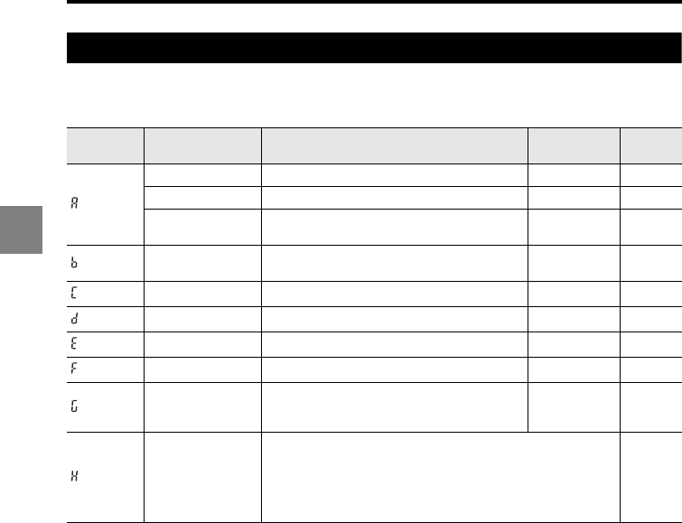
3-70
3
3 Function Settings
List of initial values and setting ranges
The function settings at the time of shipment (initial values) and the available setting
ranges are as follows.
Function
symbol Item Setting range Initial value Remark
Baud rate 9600/19200/38400/57600/115200 bps 9600 bps
Parity NON/EVEN/ODD NON
Automatic
transmission OFF/ON OFF
Setting selection Panel operation/external terminal Panel
operation
Program Copy/initialization
Panel lock ON/OFF OFF
Active OUT count 2 to 12 2
Active head count 2 to 12 2
Active analog
output channel
count
2 to 12 2
LAN setting
Address setting range:
000.000.000.000 to 255.255.255.255
The initial values are as follows:
•IP address:192.168.10.10
•Subnet mask:255.255.255.0
•Default gateway:0.0.0.0
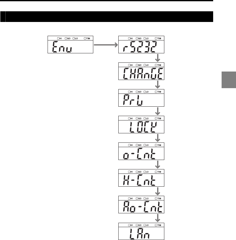
3-71
3
3 Function Settings
List of the Environment settings screens
ENV RS-232C
Setting selection
Program
Panel lock
Active OUT count
Active head count
Active analog output
channel count
LAN setting
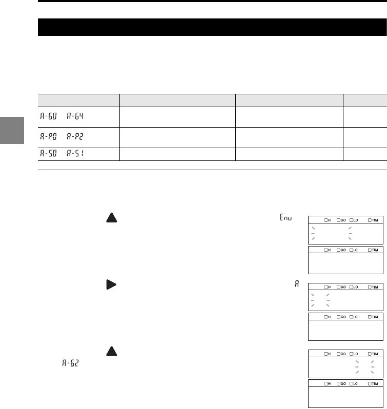
3-72
3
3 Function Settings
Setting the RS-232C communication parameters (RS-232C)
This function is used to set the communication parameters and output operations of the
RS-232C interface.
Refer to "RS-232C" (page 5-1) for details of the RS-232C communication of the LK-G5000
Series.
Changing the RS-232C communication settings
1Hold down the SET key.
2Press the key
to select the Environment settings ( )
and then press the ENT key.
3Press the key
to select
function symbol A (RS-232C, )
and then press the ENT key.
4Press the key to select A-B2 (Baud rate: 38400 bps,
) and then press the ENT key.
The setting is saved.
5Set the parity type and automatic transmission using the
same procedure.
6Press the SET key.
The system returns to the measuring status.
Function No. Setting item Selection item Remark
to Set the data communication
speed.
9600/19200/38400/57600/
115200 Unit: bps
to Set the type of parity. None (NON)/Even (EVEN)/Odd
(ODD)
to Set the automatic transmission. OFF/ON
env
abcdef
rs232
a_b2
38400
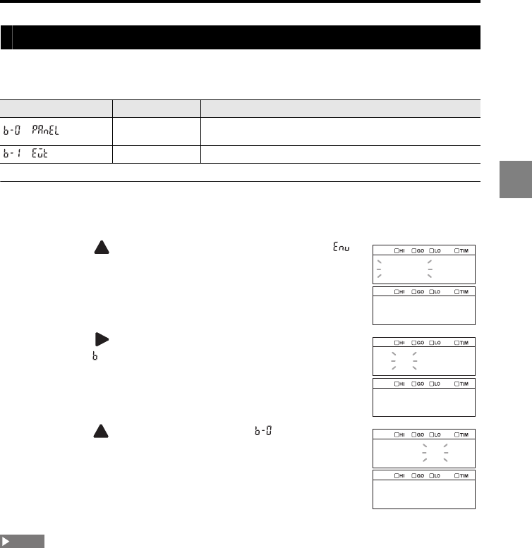
3-73
3
3 Function Settings
Setting the program switching method (Setting selection)
This function is used to select whether to switch program numbers from the display panel
or from an external terminal input.
Setting the program switching method
1Hold down the SET key.
2Press the key
to select the Environment settings ( )
and then press the ENT key.
3Press the key
to select
function symbol B (Setting
selection, ) and then press the ENT key.
4Press the key to select B-0 (Panel, ) and then press
the ENT key.
The setting is saved.
5Press the SET key.
The system returns to the measuring status.
To switch program numbers by using the command for the RS-232C interface, CC-Link, or DeviceNet,
set this setting to "Panel operation".
Function No. Setting selection Function
Panel Panel operation/LK-Navigator 2/RS-232C/
Expansion unit (CC-Link or DeviceNet)
Terminal input External terminal input
env
abcdef
change
b_0
panel
NOTE
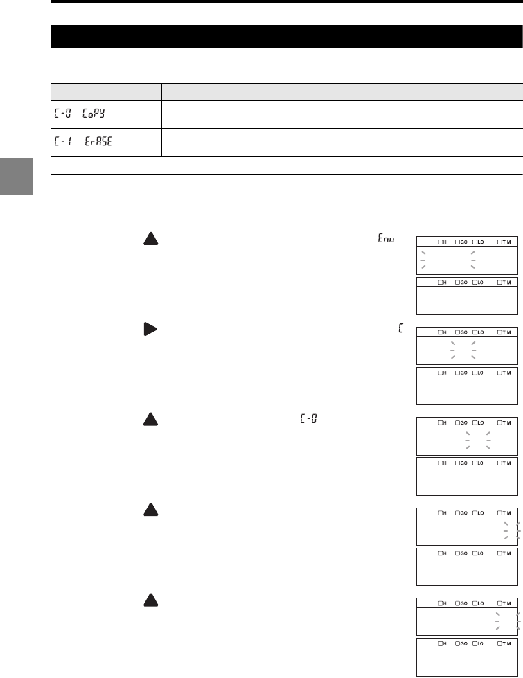
3-74
3
3 Function Settings
Copying/initializing the program (Program)
This function is used to copy or initialize a program.
Copying a program
1Hold down the SET key.
2Press the key
to select the Environment settings ( )
and then press the ENT key.
3Press the key
to select
function symbol C (Program, )
and then press the ENT key.
4Press the key to select C-0 (Copy, ) and then press
the ENT key.
5Press the key to select the source program number
and then press the ENT key.
In this example, Program No. 1 is specified as the source
program.
6Press the key to select the destination program
number and then press the ENT key.
In this example, Program No. 2 is specified as the destination
program.
Function No. Operation Function
Copy Copy a program by specifying the source program number and
destination program number.
Initialization Initialize a program by specifying the program number of the
program.
env
abcdef
prg
c_0
copy
1
from
2
to
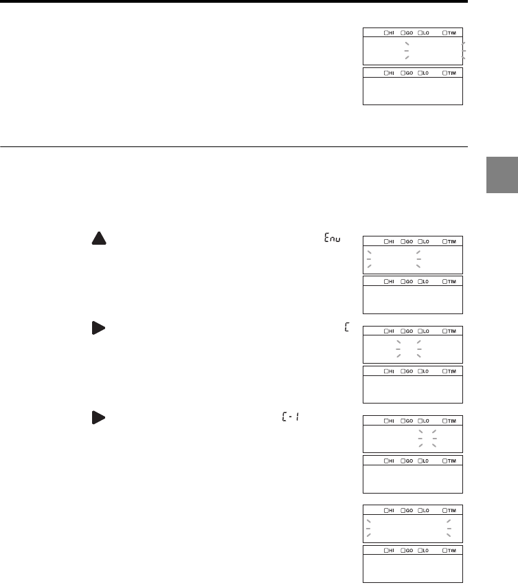
3-75
3
3 Function Settings
7Confirm the source and destination program numbers and
then press the ENT key.
The program is copied.
To cancel copying, press the SET key instead.
8Press the SET key.
The system returns to the measuring status.
Initializing a program
1
Select the program number to be initialized.
2Hold down the SET key.
3Press the key
to select the Environment settings ( )
and then press the ENT key.
4Press the key
to select
function symbol C (Program, )
and then press the ENT key.
5Press the key
to select
C-1 (Initialization, ) and then
press the ENT key.
In this example, Program No. 3 is specified as the program to
be initialized.
6Confirm the program number and then press the ENT key.
The program is initialized.
To cancel the initialization, press the SET key instead.
7Press the SET key.
The system returns to the measuring status.
1_ 2
go
env
abcdef
prg
c_1
erase
prg_3
go
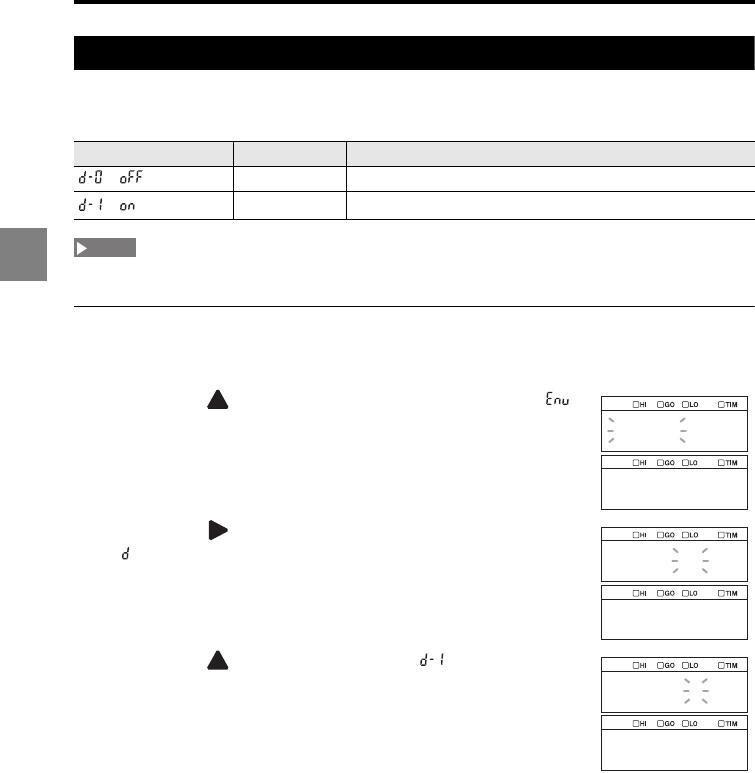
3-76
3
3 Function Settings
Preventing erroneous panel operation (Panel lock)
This function is used to prohibit operations from the display panel. Erroneous operations
can be prevented even if an operation key is accidentally touched.
When the panel is locked, all operations other than canceling the panel lock function are disabled.
Setting the panel lock
1Hold down the SET key.
2Press the key
to select the Environment settings ( )
and then press the ENT key.
3Press the key
to select
function symbol D (Panel lock,
) and then press the ENT key.
4Press the key to select D-1 (ON, ) and then press
the ENT key.
The setting is saved.
Function No. Panel lock Function
OFF Enables key operations from the display panel.
ON Disables key operations from the display panel.
NOTE
env
abcdef
lock
d_1
on
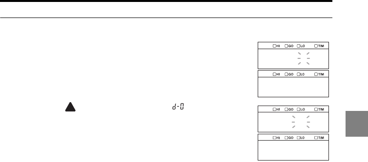
3-77
3
3 Function Settings
Canceling the panel lock
1
Press and hold the SET key for two seconds or more.
The panel lock setting screen is displayed.
2Press the key to select D-0 (OFF, ) and then press
the
ENT key.
3Press the SET key.
The panel lock is canceled and the system returns to the
measuring status.
d_1
on
d_0
off
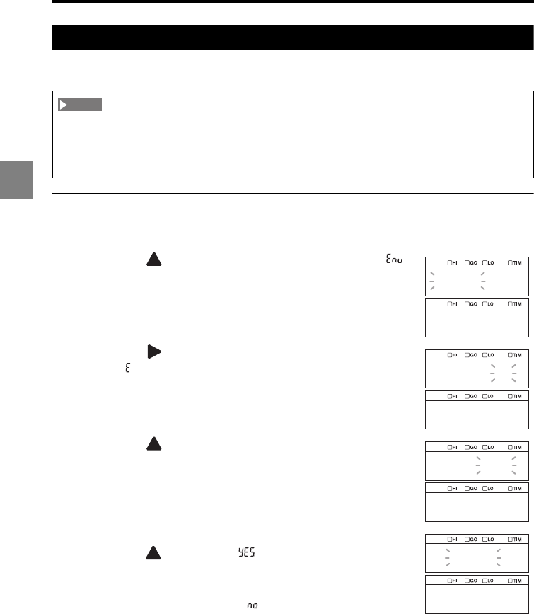
3-78
3
3 Function Settings
Specifying the number of OUT to be used (Active OUT count)
This function is used to set the number of OUT to be used.
Changing the value of the active OUT count
1Hold down the SET key.
2Press the key
to select the Environment settings ( )
and then press the ENT key.
3Press the key
to select
function symbol E (Active OUT
count, ) and then press the ENT key.
4Press the key to select the value of the active OUT
count and then press the ENT key.
A confirmation screen is displayed.
5To change the value of the active OUT count to this value,
press the key, select " ", and then press the ENT
key.
The setting is saved.
To cancel the change, select " ".
6Press the SET key.
The system returns to the measuring status.
When you change the active head count or active OUT count in the Environment settings, all the
settings of the LK-G5000 Series except for the Environment settings are reset. When you connect
the LK-HA100 head expansion unit(s) and add a sensor head(s), be sure to specify the active head
count and active OUT count before changing the other measurement settings.
NOTE
env
abcdef
o_cnt
e_00
2
yes
no
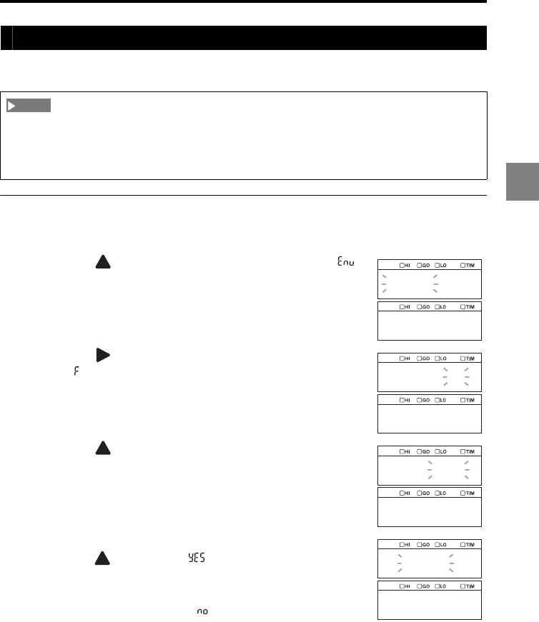
3-79
3
3 Function Settings
Specifying the number of sensor heads to be used (Active head count)
This function is used to set the number of sensor heads to be used.
Changing the value of the active head count
1Hold down the SET key.
2Press the key
to select the Environment settings ( )
and then press the ENT key.
3Press the key
to select
function symbol F (Active head
count, ) and then press the ENT key.
4Press the key to select the value of the active head
count and then press the ENT key.
A confirmation screen is displayed.
5To change the value of the active head count to this value,
press the key, select " ", and then press the ENT
key.
The setting is saved.
To cancel the change, select " ".
6Press the SET key.
The system returns to the measuring status.
When you change the active head count or active OUT count in the Environment settings, all the
settings of the LK-G5000 Series except for the Environment settings are reset. When you connect
the LK-HA100 head expansion unit(s) and add a sensor head(s), be sure to specify the active head
count and active OUT count before changing the other measurement settings.
NOTE
env
abcdef
h_cnt
f_00
2
yes
no
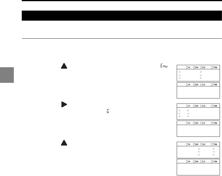
3-80
3
3 Function Settings
Specifying the number of analog output channels (Active analog output channel count)
This function is used to set the number of analog output channels to be used.
Changing the value of the active analog output channel count
1Hold down the SET key.
2Press the key
to select the Environment settings ( )
and then press the ENT key.
3Press the key
to select
function symbol G (Active
analog output channel count, ) and then press the ENT
key.
4Press the key to select the value of the active analog
output channel count and then press the ENT key.
The setting is saved.
5Press the SET key.
The system returns to the measuring status.
env
gh
ao_cnt
g_00
2
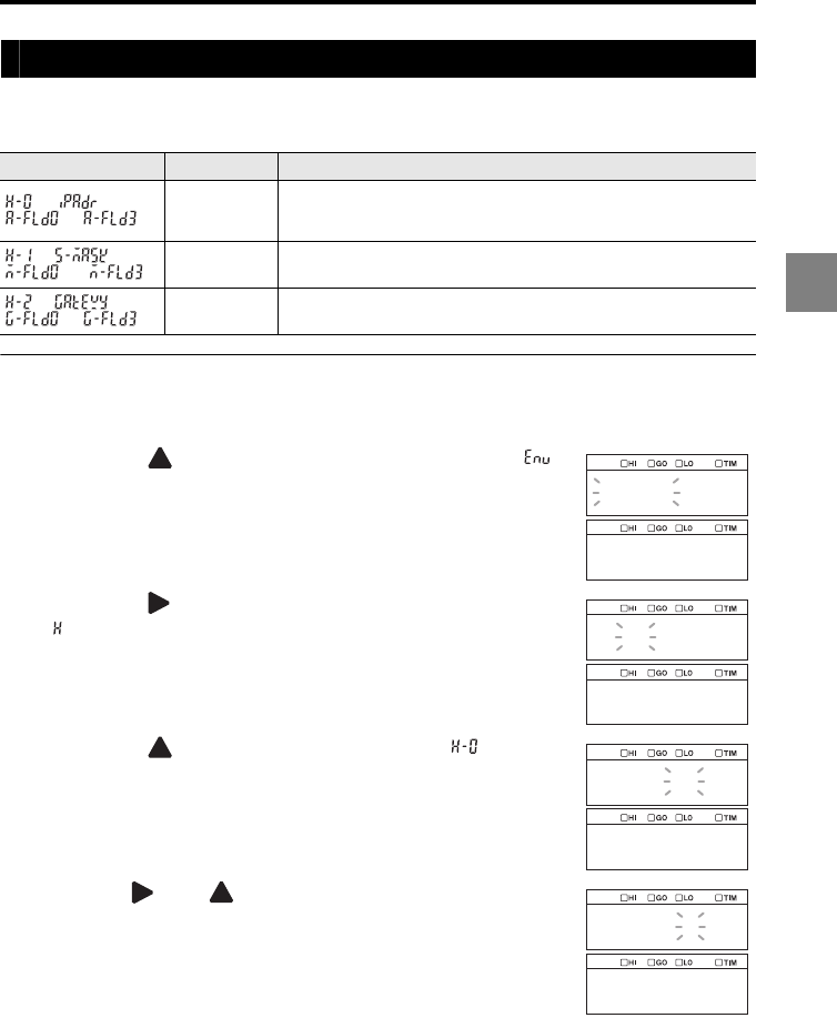
3-81
3
3 Function Settings
Setting the necessary information to connect to a network (LAN setting)
This function is used to set the necessary information to connect to a PC through Ethernet
(such as the IP address, subnet mask, and default gateway of the LK-G5000 Series).
Setting the network information
1Hold down the SET key.
2Press the key
to select the Environment settings ( )
and then press the ENT key.
3Press the key
to select
function symbol H (LAN setting,
) and then press the ENT key.
4Press the key to select H-0 (IP address, ) and then
press the ENT key.
The input screen for field 0 is displayed.
5Use the and keys to set field 0 of the IP address to
be assigned to the LK-G5000 Series and then press the
ENT key.
6Set fields 1 to 3 in the same manner and then press the
ENT key.
The setting is saved.
Function No. LAN setting Function
to IP address
Specify the IP address of the LK-G5000 Series using the four fields
of field 0 to field 3.
The format of "[Field 0].[Field 1].[Field 2].[Field 3]" should be used.
to Subnet
mask
Specify the subnet mask of the LK-G5000 Series using the four
fields of field 0 to field 3.
to
Default
gateway
Specify the default gateway of the LK-G5000 Series using the four
fields of field 0 to field 3.
env
gh
lan
h_0
ipadr
192
a_fld0

3-82
3
3 Function Settings
7Set the subnet mask ( ) and default gateway ( ) in the same manner as in
steps 4 to 6.
8Press the SET key.
The system returns to the measuring status.

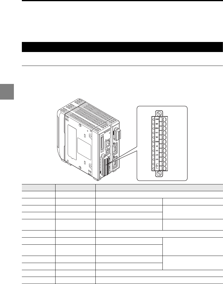
4-2
4
4 I/O terminals
Names and functions of the I/O terminals
This section describes the names and functions of the I/O (input/output) terminals of the LK-G5000
Series provided in the 12-pin terminal block, 6-pin terminal block, and expansion connector.
Function of the I/O terminals
This section includes an overview and functions of the I/O terminals.
12-pin terminal block
The 12-pin terminal block is used for the general comparator output and control input.
Applicable cable specification: AWG 28 to 16, Cable preparation: The cable should be
stripped to 6.5 mm from the end.
*1 When the laser class 3B sensor head is connected, the laser emission is activated when this
terminal is short-circuited. When the laser class 1, 2 or 3R sensor head is connected, the laser
emission is activated when this terminal is opened.
Terminal No. Signal name Description
12 COM_IN COM for input
11 REMOTE Laser remote interlock input Non-voltage input
10 ZERO1 Auto-zero (synchronous) input Non-voltage input (NPN type)
Voltage input (PNP type)
9 RESET1 Reset (synchronous) input
8 TIMING1 TIMING (synchronous) input Non-voltage input 2 (NPN type)
Voltage input 2 (PNP type)
7 COM_OUT COM for output
6 GO General comparator output
NPN open-collector output (NPN type)
PNP open-collector output (PNP type)
5ALARM
System alarm or measured value
alarm
4 LASER_CTRL1 Laser control input 1 Non-voltage input (NPN type)*1
Voltage input (PNP type)*1
3 LASER_CTRL2 Laser control input 2
2 24 VDC (+) 24 VDC input for power supply
1 24 VDC (-) 0 V input for power supply
1
1
2
3
4
5
6
7
8
9
10
11
12
13
14
15
16
17
18
19
20
2
21
22
23
24
25
26
27
28
29
30
31
32
33
34
35
36
37
38
39
40
LASER ON
ETHERNET
USB
DISPLAY
RS-232C
HEAD
1
(V)
(A)
0V
(V)
(A)
0V
COM INZERO 1TIMING 1GOLASER 1DC 24V
1
HEAD
LK-G5000
2
1
2
3
4
5
6
7
8
9
10
11
12

4-3
4
4 I/O terminals
CAUTION
•Precautions on wiring:
Parts of the input/output circuits of the LK-G5000 Series are common internally. Be careful that no
potential difference is generated between the internally common terminals due to the potential
difference between the cables/external devices. Refer to "Precautions on wiring" (page -7) for
details.
•NPN type:
The 24 VDC (-), COM OUT, and COM IN terminals are common through choke coils. They are also
common with 0 V of the 6-pin terminal block and COM of the expansion connector through choke
coils. Be careful of the potential difference being generated among these terminals.
•PNP type:
The 24 VDC (-) and COM IN terminals are common through choke coils. These terminals are also
common with 0 V of the 6-pin terminal block and COM IN of the expansion connector through choke
coils. Be careful of the potential difference being generated among these terminals. The COM OUT
terminals of the 12-pin terminal block and the expansion connector are common.
•The 24 VDC (-) terminal and the SG (GND) terminal of the RS-232C connector are common through
choke coils.
Be careful of the potential difference being generated among these terminals.
•Refer to "Electrical specifications for the NPN type models" (page 4-12) for details about the
electrical specifications.
•Refer to "Timing diagrams" (page 4-15) for details about the timing diagram.
Reference
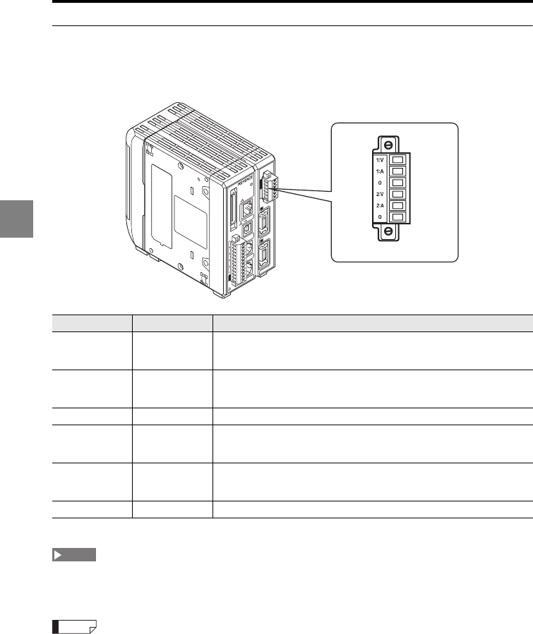
4-4
4
4 I/O terminals
6-pin terminal block
The 6-pin terminal block is used for analog monitor output.
Applicable cable specification: AWG 28 to 16, Cable preparation: The cable should be
stripped to 6.5 mm from the end.
*The 0 V terminals No. 1 and No. 4 are common.
The 0 V terminal of the 6-pin terminal block and 24 VDC (-) terminal of the 12-pin terminal block are
common through choke coils. Be careful of the potential difference being generated among these
terminals.
•Refer to "Electrical specifications for the NPN type models" (page 4-12) for details about the
electrical specifications.
•Refer to "Scaling the analog output (Analog scaling)" (page 3-50) for details about the analog output
scaling.
Terminal No. Signal name Description
6OUT01 (V)
Analog voltage output of OUT01
Voltage output within the range of ±10.5 V proportional to the displayed
value
5OUT01 (A)
Analog current output of OUT01
Current output within the range of 3.6 mA to 20.4 mA proportional to the
displayed value
4 OUT01 0 V 0 V terminal of OUT01
3OUT02 (V)
Analog voltage output of OUT02
Voltage output within the range of ±10.5 V proportional to the displayed
value
2OUT02 (A)
Analog current output of OUT02
Current output within the range of 3.6 mA to 20.4 mA proportional to the
displayed value
1 OUT02 0 V 0 V terminal of OUT02
1
1
2
3
4
5
6
7
8
9
10
11
12
13
14
15
16
17
18
19
20
2
21
22
23
24
25
26
27
28
29
30
31
32
33
34
35
36
37
38
39
40
LASER ON
ETHERNET
USB
DISPLAY
RS-232C
HEAD
1
(V)
(A)
0V
(V)
(A)
0V
COM INZERO 1TIMING 1GOLASER 1DC 24V
1
HEAD
LK-G5000
2
1
2
3
4
5
6
NOTE
Reference
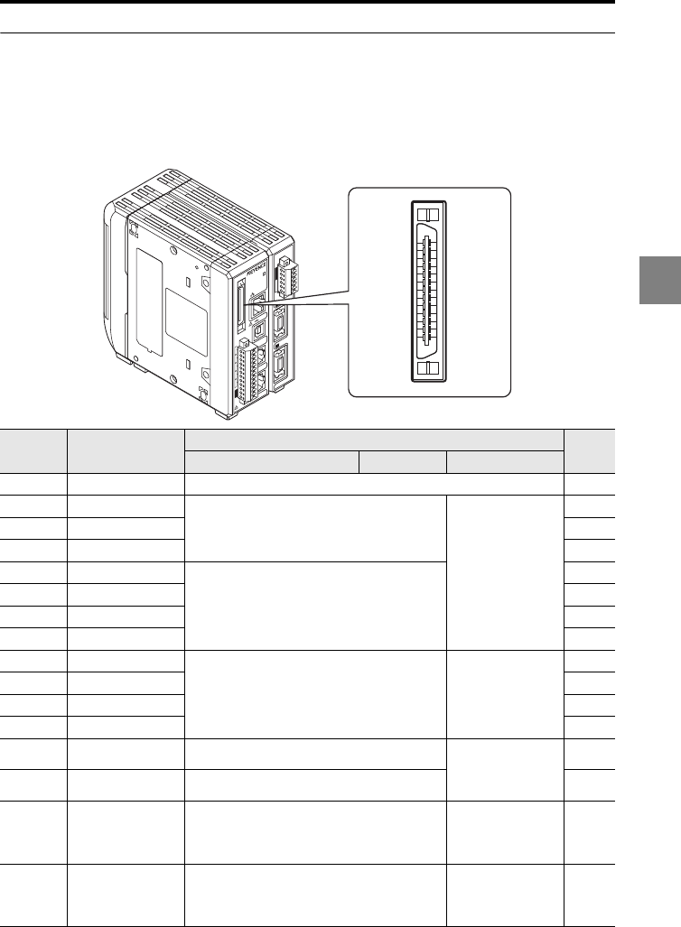
4-5
4
4 I/O terminals
Expansion connector
The expansion connector is used for the comparator output for OUT02, control input, and
binary output.
Applicable connector: FX2B Series (HIROSE Electric Co., Ltd.)
A 3-m expansion connector cable (OP-51657) is available ("List of Optional Accessories"
(page A-7)).
Terminal
No. Signal name Description Cable
color
Comparator output
Binary value output
Circuit (page 4-12)
1 COM_IN COM for input Brown
2P1
Program No. switch input
Non-voltage input
(NPN type)
Voltage input
(PNP type)
Red
3P2 Orange
4P3 Yellow
5B_IN1
Binary selection input
Green
6B_IN2 Blue
7B_IN3 Purple
8B_IN4 Gray
9 B_OUT1
Binary selection output
NPN open-collector
output (NPN type)
PNP open-collector
output (PNP type)
White
10 B_OUT2 Black
11 B_OUT3 Brown
12 B_OUT4 Red
13 ZERO Auto-zero input (binary selection) Non-voltage input
(NPN type)
Voltage input
(PNP type)
Orange
14 RESET RESET input (binary selection) Yellow
15 TIMING TIMING input (binary selection)
Non-voltage input 2
(NPN type)
Voltage input 2
(PNP type)
Green
16 DEC_IN Binary selection confirmation input
Non-voltage input
(NPN type)
Voltage input
(PNP type)
Blue
1
1
2
3
4
5
6
7
8
9
10
11
12
13
14
15
16
17
18
19
20
2
21
22
23
24
25
26
27
28
29
30
31
32
33
34
35
36
37
38
39
40
LASER ON
ETHERNET
USB
DISPLAY
RS-232C
HEAD
1
(V)
(A)
0V
(V)
(A)
0V
COM INZERO 1TIMING 1GOLASER 1DC 24V
1
HEAD
LK-G5000
2
1
20
21
40
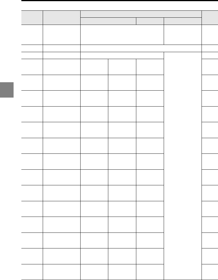
4-6
4
4 I/O terminals
17 DEC_OUT Binary selection confirmation output
NPN open-collector
output (NPN type)
PNP open-collector
output (PNP type)
Purple
18 COM_OUT COM for output Gray
19 STROBE Strobe output NPN open-collector
output (NPN type)
PNP open-collector
output (PNP type)
White
20 OUT1 (8) HI/binary
(0) (LSB)
OUT1
comparator
HI output
OUT8
comparator
HI output
Binary (0)
output (LSB) Black
21 OUT1 (8) GO/
binary (1)
OUT1
comparator
GO output
OUT8
comparator
GO output
Binary (1)
output Brown
22 OUT1 (8) LO/binary
(2)
OUT1
comparator
LO output
OUT8
comparator
LO output
Binary (2)
output Red
23 OUT2 (9) HI/binary
(3)
OUT2
comparator
HI output
OUT9
comparator
HI output
Binary (3)
output Orange
24 OUT2 (9) GO/
binary (4)
OUT2
comparator
GO output
OUT9
comparator
GO output
Binary (4)
output Yellow
25 OUT2 (9) LO/binary
(5)
OUT2
comparator
LO output
OUT9
comparator
LO output
Binary (5)
output Green
26 OUT3 (10) HI/
binary (6)
OUT3
comparator
HI output
OUT10
comparator
HI output
Binary (6)
output Blue
27 OUT3 (10) GO/
binary (7)
OUT3
comparator
GO output
OUT10
comparator
GO output
Binary (7)
output Purple
28 OUT3 (10) LO/
binary (8)
OUT3
comparator
LO output
OUT10
comparator
LO output
Binary (8)
output Gray
29 OUT4 (11) HI/
binary (9)
OUT4
comparator
HI output
OUT11
comparator
HI output
Binary (9)
output White
30 OUT4 (11) GO/
binary (10)
OUT4
comparator
GO output
OUT11
comparator
GO output
Binary (10)
output Black
31 OUT4 (11) LO/
binary (11)
OUT4
comparator
LO output
OUT11
comparator
LO output
Binary (11)
output Brown
32 OUT5 (12) HI/
binary (12)
OUT5
comparator
HI output
OUT12
comparator
HI output
Binary (12)
output Red
33 OUT5 (12) GO/
binary (13)
OUT5
comparator
GO output
OUT12
comparator
GO output
Binary (13)
output Orange
Terminal
No. Signal name Description Cable
color
Comparator output
Binary value output
Circuit (page 4-12)
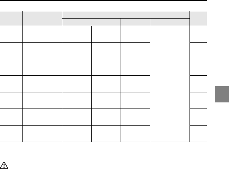
4-7
4
4 I/O terminals
•The cable colors represent the wire colors of the expansion connector cable (OP-51657).
•The signal functions of terminal numbers 20 to 40 vary depending on the binary selection input
through terminal numbers 5 to 8.
CAUTION
•Precautions on wiring:
Parts of the input/output circuits of the LK-G5000 Series are common internally. Be careful that no
potential difference is generated between the internally common terminals due to the potential
difference between the cables/external devices. Refer to "Precautions on wiring" (page -7) for
details.
•NPN type:
The COM OUT and COM IN terminals are common through choke coils. They are also common with
the 24 VDC (-), COM OUT and COM IN terminals of the 12-pin terminal block through choke coils.
Be careful of the potential difference being generated among these terminals.
•PNP type:
The COM IN and 24 VDC (-) terminals are common through choke coils. They are also common with
the 24 VDC (-) and COM IN terminals of the 12-pin terminal block through choke coils. Be careful of
the potential difference being generated among these terminals. The COM OUT terminals of the
expansion connector and 12-pin terminal block are common.
34 OUT5 (12) LO/
binary (14)
OUT5
comparator
LO output
OUT12
comparator
LO output
Binary (14)
output
NPN open-collector
output (NPN type)
PNP open-collector
output (PNP type)
Yellow
35 OUT6 HI/
binary (15)
OUT6
comparator
HI output
Not used
(OFF)
Binary (15)
output Green
36 OUT6 GO/
binary (16)
OUT6
comparator
GO output
Not used
(OFF)
Binary (16)
output Blue
37 OUT6 LO/
binary (17)
OUT6
comparator
LO output
Not used
(OFF)
Binary (17)
output Purple
38 OUT7 HI/
binary (18)
OUT7
comparator
HI output
Not used
(OFF)
Binary (18)
output Gray
39 OUT7 GO/
binary (19)
OUT7
comparator
GO output
Not used
(OFF)
Binary (19)
output White
40 OUT7 LO/
binary (20) (MSB)
OUT7
comparator
LO output
Not used
(OFF)
Binary (20)
output (MSB) Black
Terminal
No. Signal name Description Cable
color
Comparator output
Binary value output
Circuit (page 4-12)
4-8
4
4 I/O terminals
Functions of the I/O Signals
This section describes the functions of the I/O (input/output) signals. Refer to "Names and
functions of the I/O terminals" (page 4-2) for details about the layout of the individual
terminals.
Comparator output
Alarm output
Measurement control input/output
*1 This input is valid when the binary selection input is set to select the binary output and the binary
selection confirmation input is turned on. The input is not accepted when the binary selection input
is set to select the comparator output or the binary selection confirmation input is turned off.
Auto-zero input
*1 This input is valid when the binary selection input is set to select the binary output and the binary
selection confirmation input is turned on. The input is not accepted when the binary selection input
is set to select the comparator output or the binary selection confirmation input is turned off.
Name Description Reference page
Tolerance comparator
output
(OUT HI, OUT GO, OUT
LO)
Outputs the tolerance comparator result of the corresponding
OUT when the binary selection input is set to select the
comparator output.
-
Name Description Reference page
Alarm (N.C.) output
(ALARM)
Outputs an alarm of the type specified with the "Alarm output
type" (system alarm or measured value alarm). page 3-68
Name Description Reference page
TIMING input (TIMING) Inputs a synchronous signal to the OUT selected with the
binary selection input. *1-
RESET input (RESET) Resets the measured value of the OUT selected with the binary
selection input. *1-
TIMING1 input (TIMING1) Inputs a synchronous signal to the synchronized OUT. -
RESET1 input (RESET1) Resets the measured value of the synchronized OUT. -
Name Description Reference page
ZERO input (ZERO) Sets the current measured value of the OUT selected with the
binary selection input to 0 (zero). *1-
ZERO1 input (ZERO1) Sets the current measured value of the synchronized OUT to 0. -
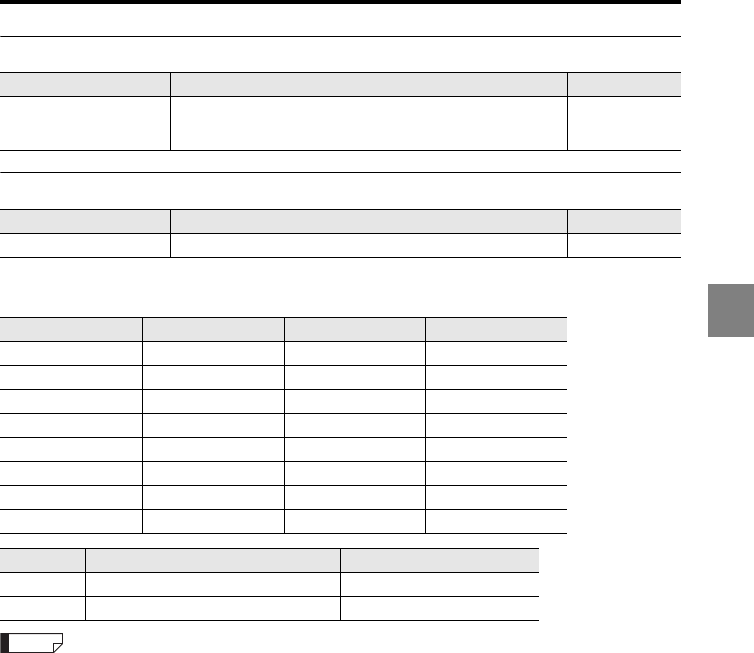
4-9
4
4 I/O terminals
General comparator output
Program No. switch input
The relationship between the program numbers and the statuses of the P1 to P3 terminals
is as follows.
To change the program number with the I/O terminals, you need to change the "Setting selection" of
the Environment settings to "Terminal input" (page 3-73).
Name Description Reference page
General comparator
output (GO)
Outputs a signal when GO output is the result for all OUTs
specified with the available OUT count which are not in the
comparator standby status.
-
Name Description Reference page
P1, P2, P3 Changes the program No. from an external device. page 4-5
Program No. P3 P2 P1
0OFFOFFOFF
1OFFOFFON
2OFFONOFF
3OFFONON
4ONOFFOFF
5ONOFFON
6ONONOFF
7 ONONON
Status NPN type PNP type
ON Short-circuited with the COM terminal Voltage being applied
OFF Open Open
Reference
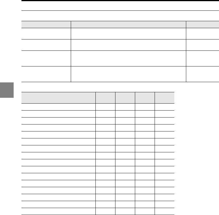
4-10
4
4 I/O terminals
Binary selection input/output
The statuses of the binary selection input/output (B_IN1 to B_IN4) are as follows.
Name Description Reference page
Binary selection input
(B_IN1 to B_IN4)
Changes the range of the comparator output or the OUT No.
for the binary output. -
Binary selection output
(B_OUT1 to B_OUT4)
Outputs the data provided from the comparator/binary output
terminal. -
Binary selection
confirmation input
(DEC_IN)
When turned on, applies the TIMING input, RESET input, and
ZERO input to the selected OUT. -
Binary selection
confirmation output
(DEC_OUT)
Outputs a signal when the binary selection confirmation input
is turned on. -
Output data B_IN4
B_OUT4
B_IN3
B_OUT3
B_IN2
B_OUT2
B_IN1
B_OUT1
Comparator output OUT1 to OUT7 OFF OFF OFF OFF
OUT1 binary output OFF OFF OFF ON
OUT2 binary output OFF OFF ON OFF
OUT3 binary output OFF OFF ON ON
OUT4 binary output OFF ON OFF OFF
OUT5 binary output OFF ON OFF ON
OUT6 binary output OFF ON ON OFF
OUT7 binary output OFF ON ON ON
OUT8 binary output ON OFF OFF OFF
OUT9 binary output ON OFF OFF ON
OUT10 binary output ON OFF ON OFF
OUT11 binary output ON OFF ON ON
OUT12 binary output ON ON OFF OFF
Comparator output OUT1 to OUT7 ON ON OFF ON
Comparator output OUT1 to OUT7 ON ON ON OFF
Comparator output OUT8 to OUT12 ON ON ON ON
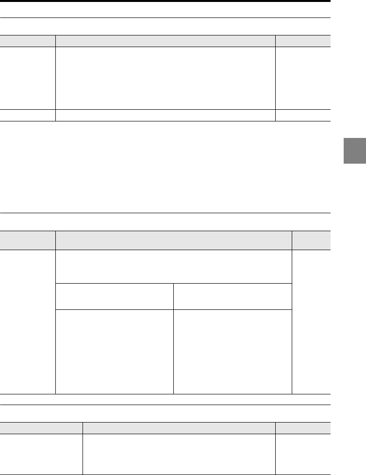
4-11
4
4 I/O terminals
Binary output
Binary output indication
The LK-G5000 Series outputs the measured value as a binary number (two’s complement)
of 21 bits. The decimal point is ignored.
•Example 1: When the measured value is "+134.97"
13497 (decimal) 0 0000 0011 0100 1011 1001 (binary)
•Example 2: When the measured value is "-134.97"
-13497 (decimal) 1 1111 1100 1011 0100 0111 (binary)
LASER CTRL input
Laser remote interlock input
Name Description Reference page
Binary output
Outputs the measured value as binary data (21 bits).
A negative value is represented as a two's complement number.
Negative logic is used ("1" when the NPN or PNP open-collector output
is turned on).
Comparator standby status (All digits are shown with "-"): 0 x 100000
Over range on the positive side: 0 x 0FFFFF
Over range on the negative side: 0 x 100000
Alarm: 0x100000
page 4-5
page 4-12
STROBE output Strobe output for binary output page 4-5
Name Description Reference
page
LASER CTRL
input
Controls the lasers for each group specified as LASER CTRL group. The
operation depends on the laser class of the sensor head.
"LASER CTRL1" controls LASER CTRL group 1, and "LASER CTRL2" controls
LASER CTRL group 2.
page 3-20
page 4-2
page 4-12
page A-11
When only the laser class 1, 2 or 3R
sensor head is used
When the laser class 3B sensor head
(LK-H023/LK-H028/LK-H053/LK-
H058) is used
•NPN output type: The laser beam
emission stops when the LASER
CTRL1/2 and COM IN terminals are
short-circuited.
•PNP output type: The laser beam
emission stops when voltage is
applied to the section between the
LASER CTRL1/2 and COM IN
terminals.
•NPN output type: The laser beam
emission starts when the LASER
CTRL1/2 and COM IN terminals are
short-circuited with the key-
operated switch.
•PNP output type: The laser beam
emission starts when voltage is
applied to the section between the
LASER CTRL1/2 and COM IN
terminals with the key-operated
switch.
Name Description Reference page
REMOTE
This is the laser remote interlock terminal. The laser beam is
emitted when this terminal is short-circuited with COM. The
emission is stopped when this terminal is open. This terminal is
common to sensor heads A and B. This input overrides the
LASER OFF input.
page 4-2
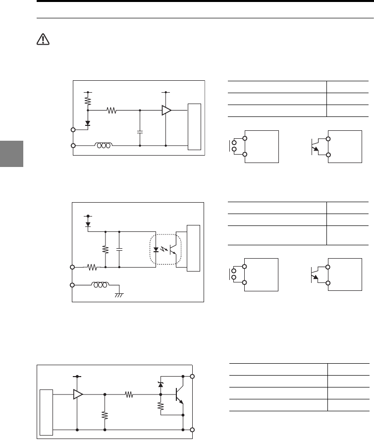
4-12
4
4 I/O terminals
Electrical specifications for the NPN type models
CAUTION
Be sure to read "Precautions on wiring" (page -7) before wiring.
Non-voltage input
Non-voltage input 2 (TIMING/TIMING1)
Compatible with the DC 2-wire model
of the Keyence EV Series proximity
sensor.
NPN open-collector output
ON voltage 1 V max.
OFF current 0.6 mA max.
Short-circuit current (Typical) 2 mA
ON voltage 5 V or less
OFF current 1 mA max.
Short-circuit current
(Typical) 8 mA
Maximum applied voltage 40 V
Maximum sink current 50 mA
Residual voltage 0.5 V max.
Leakage current 0.1 mA max.
Input
+5 V
2.2 kΩ
1 kΩ
COM
for input
+5 V
Internal circuit
Input
or
COM
Input
COM
TIMING
1.6 kΩ
330 Ω
+14 V
COM
for input
Internal circuit
Input
or
COM
Input
COM
Output
4.7 kΩ
10 kΩ
+5 V
1 kΩ
Internal circuit
COM
for output
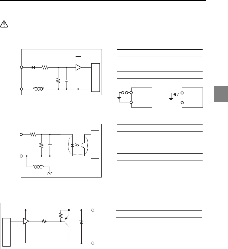
4-13
4
4 I/O terminals
Electrical specifications for the PNP type models
CAUTION
Be sure to read "Precautions on wiring" (page 7) before wiring.
Voltage input
Voltage input 2 (TIMING/TIMING1)
PNP open-collector output
Maximum input voltage rating 26.4 V
ON voltage 10.8 V min.
OFF current 0.6 mA max.
Short-circuit current (Typical) 2 mA
Maximum input voltage rating 26.4 V
ON voltage 10.8 V min.
ON current (Typical) 3 mA
OFF voltage 5 V max.
OFF current 1 mA max.
Maximum applied voltage 30 V
Maximum source current 50 mA
Residual voltage 0.5 V max.
Leakage current 0.1 mA max.
1.5 kΩ
4.7 kΩ
COM
for input
Input
+5 V
Internal circuit
COM COM
Input
or
Input
TIMING
3.9 kΩ
680 Ω
COM
for input
Internal circuit
Output
10 kΩ
+5 V
10 kΩ
COM
for output
Internal circuit
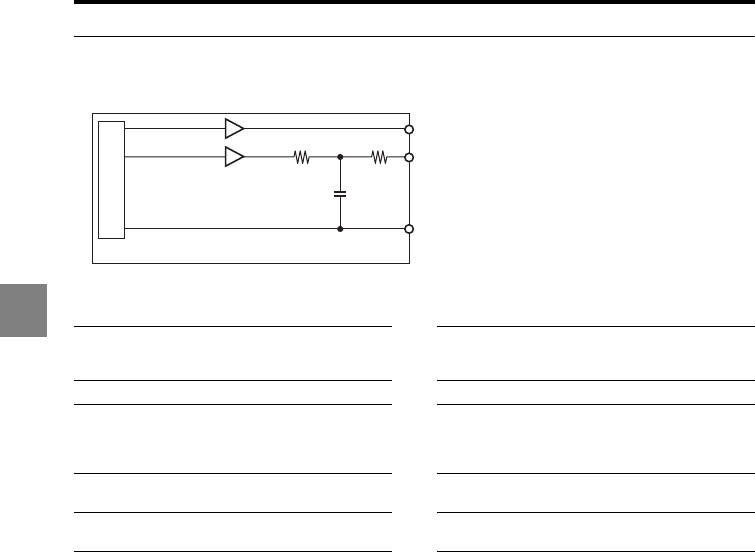
4-14
4
4 I/O terminals
Electrical specifications common to the NPN and PNP type models
Analog voltage output/analog current output
Voltage output Current output
Output range ±10.8 V
(Measured data: ±10.5 V) Output range
3.36 to 20.64 mA
(Measured data: 3.6 to 20.4
mA)
Resolution 2 mV Resolution 40 μA
Accuracy
±0.05% of F.S.
(F.S. = 20 V, accuracy with
reference to
the displayed value)
Accuracy
±0.25% of F.S.
(F.S. = 16 mA, accuracy with
reference to
the displayed value)
Output
impedance Approx. 100 Applicable load 350 max.
Response delay
time
Approx. 1.5 μs (after the
measured value is updated)
Response delay
time
Approx. 10 μs (after the
measured value is updated)
Voltage output
47 Ω47 Ω
0 V
Current output
Internal circuit
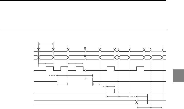
4-15
4
4 I/O terminals
Timing diagrams
This section describes the timing of the I/O signal operations.
Normal
•The minimum input time (T1), input response time (T2), RESET time (T4), refresh cycle
(T5), sampling cycle (T6), and program No. change time (T7) vary depending on the
settings (page 4-26).
•When the sampling cycle (T6) is 20 μs or less, the STROBE output’s T6 is fixed to 20 μs.
•Auto-zero is canceled when the ZERO input is turned on for two seconds or more.
Comparator output ON
OFF
ON
OFF
ON
OFF
ON
OFF
ON
OFF
ON
OFF
Binary output
STROBE output
TIMING/
TIMING1 input
RESET/RESET1/
ZERO/ZERO1 input
P1 to P3 input
T5
T6/2 T6/2
T1 min.
T1 min.
Min
T1 min.
T1 min.
T2 max. T2 max.
T2 max. T4
T4
T1 min.
T1
T7 max.
T6/2 T6/2
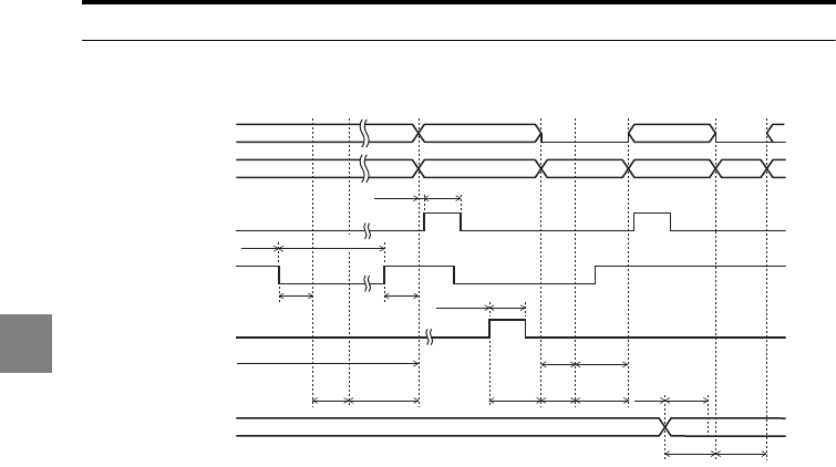
4-16
4
4 I/O terminals
Peak hold/bottom hold/peak-to-peak hold/average hold/sample hold
(Trigger 1)
•The minimum input time (T1), input response time (T2), RESET time (T4), and program
No. change time (T7) vary depending on the settings (page 4-26).
•The STROBE time (T3) can be changed (page 3-64).
•Auto-zero is canceled when the ZERO input is turned on for two seconds or more.
•The internal measured value of the RESET input is determined after the RESET time (T4)
has elapsed.
ON
OFF
ON
OFF
ON
OFF
ON
OFF
ON
OFF
0.2 ms T3
Min
Min
T1 min.
T1 min. T1 min.
T1
T2 max. T2 max.
T2 max.
T7 max.
Sampling
period
Sampling
period
Sampling
period
Sampling period
T4
T4
T4
T1 min.
T1
T4
Comparator output ON
OFF
Binary output
STROBE output
TIMING/
TIMING1 input
RESET/RESET1/
ZERO/ZERO1 input
P1 to P3 input
When Trigger 1
is selected
When Trigger 2
is selected
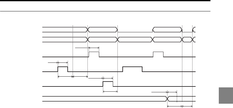
4-17
4
4 I/O terminals
Sample hold (Trigger 2)
•The TIMING input ON signal is used as a trigger and the measured value is determined
after the sampling period (T4) has elapsed.
•The minimum input time (T1), input response time (T2), sampling period (T4), and
program No. change time (T7) vary depending on the settings (page 4-26).
•
The STROBE time (T3) can be changed (
page 3-64
).
•Auto-zero is canceled when the ZERO input is turned on for two seconds or more.
•If the RESET input or ZERO input is turned on during the sampling period, the sampling
stops and the comparator standby status starts.
ON
OFF
ON
OFF
ON
OFF
ON
OFF
ON
OFF
0.2ms
Min
T1 min.
T1 min. T1 min.
T1
T2 max.
T2 max.
T7 max. T4
T1 min.
T1 min.
Sampling
period (T4)
T3
Comparator output ON
OFF
Binary output
STROBE output
TIMING/
TIMING1 input
RESET/RESET1/
ZERO/ZERO1 input
P1 to P3 input
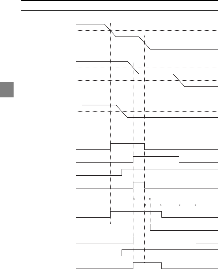
4-18
4
4 I/O terminals
General comparator output GO
•The general comparator output GO turns on when GO outputs are turned ON for all OUTs
which are not in the comparator standby status.
•Since the output is affected by the comparator output form setting, the general comparator
output GO may be output when the HI or LO output is turned on for some OUT (page 3-63).
OUT1
LO
HI
OUT2
LO
HI
OUT3
LO
HI
When the comparator output form is
Normal
GO outputOUT1
ON
OFF
GO outputOUT2
ON
OFF
GO outputOUT3
ON
OFF
GO output
General
comparator
output GO
ON
OFF
When the comparator output form is
Off-delay
GO outputOUT1
ON
OFF
HI outputOUT2
ON
OFF
GO outputOUT2
ON
OFF
GO outputOUT3
ON
OFF
GO output
General
comparator
output GO
ON
OFF
60 ms
60 ms 60 ms
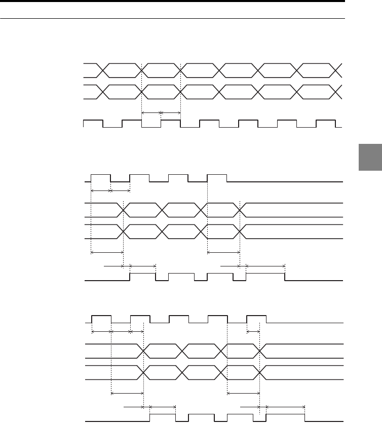
4-19
4
4 I/O terminals
Binary output
BINARY (Normal mode)
•When the sampling cycle (T6) is 20 μs or less, the STROBE output’s T6 is fixed to 20 μs.
BINARY (Measurement mode with Trigger 1 selected)
BINARY (Measurement mode other than the sample hold with Trigger 2 selected)
STROBE output
BINARY
OUT1
Measured value
OFF
ON
T6/2
OUT1 OUT1 OUT1 OUT1 OUT1 OUT1
T6/2
STROBE output
BINARY
TIMING (TIMING 1)
OUT1
Measured value
OFF
ON
OFF
ON
T1 min. T1 min.
T2 max.
Less than T30.2 ms
T2 max.
T30.2 ms
STROBE output
BINARY
TIMING (TIMING1)
OUT1
Measured value
OFF
ON
OFF
ON
T1 min. T1 min.
T2 max. T2 max.
Max. T2 + T4 + Sampling period
Less than T30.2 ms
Max. T2 + T4 + Sampling period
T30.2 ms
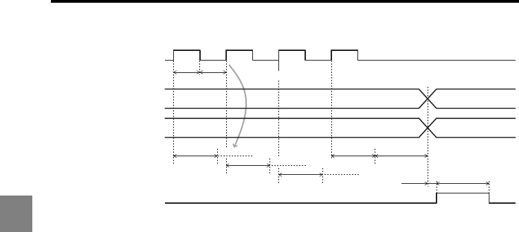
4-20
4
4 I/O terminals
BINARY (Sample hold with Trigger 2 selected)
•After the synchronous signal turns ON and before the strobe output is turned on, if the
synchronous input turns ON again, the internal measured value will be reset, and the
strobe signal will turn ON after a period of "MaxT2 + T4 + 0.2 ms" has elapsed.
STROBE output
BINARY
TIMING (TIMING1)
OUT1
Measured value
Measurement is reset.
OFF
ON
T1 min. T1 min.
T2 max.
T2 max.
T2 max. T4
T30.2 ms
T2 max.
T4
T4
T4
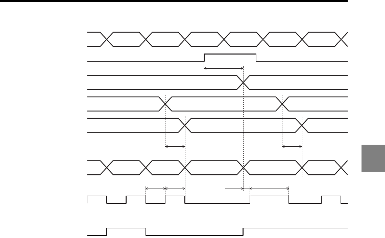
4-21
4
4 I/O terminals
B_IN, B_OUT
•This timing diagram shows an example for settings other than OUT1: Normal, OUT2:
Normal, or Sample hold with Trigger 2 selected.
•The OUT which is set with the B_IN input can be selected for binary output.
•The OUT No. which is providing the current binary output can be checked with the
B_OUT output.
•The binary data should be imported in synchronization with the strobe signal being
turned on.
•The minimum input time (T1), input response time (T2) and refresh cycle (T5) vary
depending on the settings.
•The STROBE time (T3) can be changed.
•When the sampling cycle (T6) is 20 μs or less, the STROBE output’s T6 is fixed to 20 μs.
•In any of the measurement modes, when the BINARY output is switched while strobe
output is turned on, the binary output is turned off even in less than T3.
•In the normal mode, the BINARY output is switched at the timing when strobe output is
turned off.
•The alarm output uses a normally-closed contact.
OUT2
Measured value
TIMING
B_IN
B_OUT
OUT1
Measured value
Alarm output (NC)
When the measured
value alarm is set
OFF
ON
Alarm value
Alarm value
OUT1 OUT2 OUT1
OUT1 OUT2 OUT1
STROBE output
BINARY
OFF
ON
OFF (Output is short-circuited)
ON (Output is open)
T6/2 T30.2ms
OUT1
Alarm value OUT1 OUT2 OUT2 OUT1
T6/2
T1 max. T1 max.
T2 max.
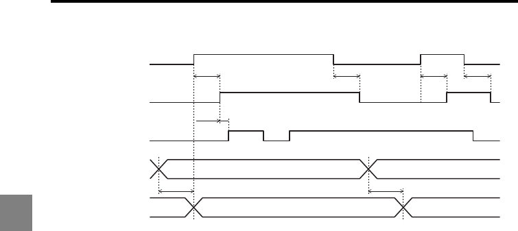
4-22
4
4 I/O terminals
DEC_IN
•When DEC_OUT is off, TIMING/ZERO/RESET is ignored.
•When B_IN specifies the comparator output, TIMING/ZERO/RESET is ignored.
•When synchronized OUT is selected, ZERO/RESET can be input but TIMING is not
accepted.
•To switch the B_IN signal, turn OFF the DEC_IN signal, then switch the B_IN signal, and
then turn DEC_IN ON again after confirming that B_OUT has been switched.
•When DEC_IN is turned on while TIMING (ZERO/RESET) is on, this input is applied to
the OUT specified after DEC_IN is turned on.
DEC_IN OFF
ON
TIMING/
ZERO/RESET OFF
ON
DEC_OUT OFF
ON
B_IN OUT1 OUT2
B_OUT OUT1 OUT2
T1 max. T1 max.T1 max.
T1 max.T1 max.
T1 max.
0 µs min.
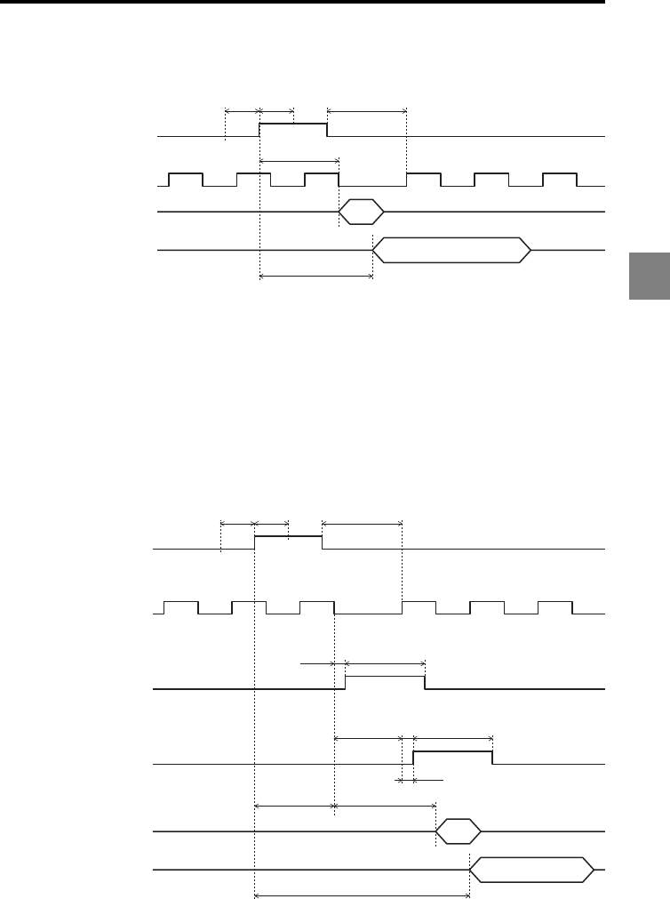
4-23
4
4 I/O terminals
External synchronization for data storage, RS-232C automatic transmission
The STROBE output type depends on the synchronization setting.
•When the measurement mode for synchronized OUT is not sample hold (Trigger 2):
After TIMING1 is input and the input response time (T2) has elapsed, data storage (RS-
232C automatic transmission) is performed.
•When the sample hold (Trigger 2) is selected as the measurement mode for some of the
synchronized OUTs:
– The STROBE output method is decided by the smallest OUT No. among the OUTs
selected for synchronization control. (For example, when all of OUT1 to OUT12 are
set for synchronization control and comparator outputs 8 to 12 are selected with B_IN,
the smallest OUT No. is "OUT1", regardless of the B_IN input.)
– If comparator output is selected with B_IN and synchronization control is not set,
STROBE output is disabled.
Data storage
TIMING1
STROBE
(in Normal mode)
RS-232C
automatic transmission
OFF
ON
OFF
ON
T1 min. T1 min. T2 max.
T2 max.
T2 + 2 ms
Data storage
TIMING1
STROBE
RS-232C
automatic transmission
B_IN set to comparator output:
When OUT of the smallest number is
set to Normal mode
B_IN set to comparator output:
When OUT of the smallest number is
set to measurement mode except for
sample hold (trigger 2)
B_IN set to comparator output:
When OUT of the smallest number is
set to sample hold (trigger 2) and
measurement periods vary among OUTs
OFF
ON
OFF
ON
STROBE OFF
ON
T30.2 ms
0.2 ms
STROBE OFF
ON
T3
T4T2 max.
T4
T1 min. T1 min. T2 max.
T2 + T6 + 2 ms
Measurement period
for OUT of the smallest
number
The longest measurement period
among the synchronized OUTs
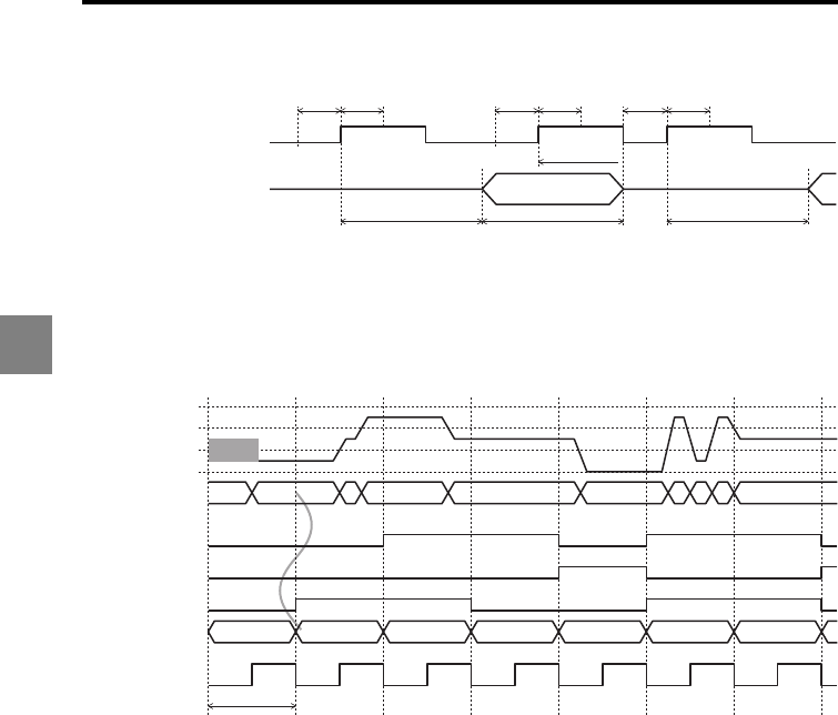
4-24
4
4 I/O terminals
TIMING signal interval for the RS-232C automatic transmission
*This period will be T2 + T4 + 2 ms when the "sample hold (Trigger 2)" is selected as the
measurement mode for some of the synchronized OUTs.
•Even when the next data is determined during the automatic transmission, the data is
not sent.
Refresh timing during high-speed sampling
•The operations when the sampling cycle is shorter than the I/O refresh cycle are as
follows:
•If all comparator results are GO in one refresh cycle, GO turns on at the next refresh.
•If at least one comparator result is HI (LO) in one refresh cycle, HI (LO) turns on at the
next refresh.
•If both HI and LO exist in one refresh cycle, both HI and LO turn on at the next refresh.
•Binary output is updated to the latest value in every refresh cycle.
•The I/O refresh cycle depends on the sampling cycle and mutual interference
prevention setting.
TIMING1
RS-232C
automatic transmission
OFF
ON
T1 min. T1 min.
Transmission periodT2+2ms* T2 + 2 ms*
Data is not sent.
T1 min. T1 min. T1 min. T1 min.
BINARY
Internal tolerance
comparator result
Measured value
STROBE
LO
HI
+FFFFFF
OFF
Comparator standby
LO HI HI HI GO
LOGO
GO
-FFFFFF
Alarm display
GOGOHILO HI
GO
0x100000
Alarm
0 x 100000
Comparator standby
---- display
OFF
ON
HI
OFF
ON
GO
OFF
ON
LO
I/O refresh cycle
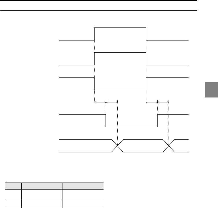
4-25
4
4 I/O terminals
LASER REMOTE/LASER CTRL1/2
•T8 is the laser control emission response time and T9 is the laser control measurement
response time (page 4-26).
•The REMOTE input turns on when opened and turns off when short-circuited.
•The status of LASER CTRL 1/2 is operated as follows:
Status NPN type PNP type
ON Short-circuited with
the COM terminal Voltage applied
OFF Open Open
REMOTE
OFF
ON
T8 T9
LASER CTRL1(2)
When laser class
3B sensor head is
not used
OFF
ON
LASER CTRL1(2)
When laser class
3B sensor head
is used
OFF
ON
Laser emission
Measurement Alarm
Measurement
Stop
Emit
Measured value
T8 T9
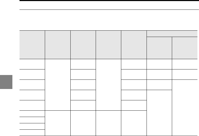
4-26
4
4 I/O terminals
Timing details
Minimum input time (T1), input response time (T2), and refresh cycle (T5)
•The sampling cycle can be changed (15).
•When the sampling cycle is changed, the measurement response time, measurement
averaging time, RESET time, and refresh cycle also change accordingly.
•When the mutual interference prevention function is used, the sampling cycle T6 is
calculated as T6 x 2 (for AB_ON) or T6 x 3 (for ABC_ON).
•When "Velocity" is selected for the measurement type, T4 is calculated as T4 + T6; when
"Acceleration" is selected, T4 is calculated as T4 + 2 x T6.
Sampling
cycle (T6)
Minimum
input time
(T1)
Input
response
time (T2)
Laser control
emission
response
time (T8)
Laser control
measurement
response
time (T9)
I/O refresh cycle
Mutual
interference
prevention
function:
OFF
Mutual
interference
prevention
function: AB-
ON/ABC-ON
2.55 μs
1000 μs
1000 μs +
T6 x 131
1000 μs
T6 x 139
+ 50 μs T6 x 8 T6 x 4
5 μs 1000 μs +
T6 x 67
T6 x 75
+ 50 μs T6 x 4 T6 x 2
10 μs 1000 μs +
T6 x 35
T6 x 43
+ 50 μs T6 x 2
T6 x 1
For the
sampling
cycles longer
than 10 μs:
Same as the
value for 10 μs
20 μs 1000 μs +
T6 x 19
T6 x 27
+ 50 μs
T6 x 1
For the
sampling
cycles longer
than 20 μs:
Same as the
value for 20 μs
50 μs 1000 μs +
T6 x 11
T6 x 19
+ 50 μs
100 μs
1000 μs
+ T6
1000 μs +
T6 x 6
+100 μs
1000 μs
+ T6
T6 x 13
+ 100 μs
200 μs
500 μs
1000 μs

4-27
4
4 I/O terminals
Measurement averaging time and RESET time (T4)
•When the mutual interference prevention function is used, the sampling cycle T6 is
calculated as T6 x 2 (for AB_ON) or T6 x 3 (for ABC_ON).
•When "Velocity" is selected for the measurement type, T4 is calculated as T4 + T6; when
"Acceleration" is selected, T4 is calculated as T4 + 2 x T6.
Program No. change time (T7)
Program No. change time (T7) = Number of sensor heads connected to the controller x 50 ms
+ Number of sensor heads connected to the head
expansion unit x 110 ms + 5 ms
Filter Measurement
averaging time RESET time (T4)
No. of
averaging
measurements
1 T6 x 1 T6 x 1
4 T6 x 4 T6 x 4
16 T6 x 16 T6 x 16
64 T6 x 64 T6 x 64
256 T6 x 256 T6 x 256
1024 T6 x 1024 T6 x 1024
4096 T6 x 4096 T6 x 4096
16384 T6 x 16384 T6 x 16384
65536 T6 x 65536 T6 x 65536
262144 T6 x 262144 T6 x 262144
Low-pass filter T6 x 12 T6 x 12
High-pass filter T6 x 12 T6 x 12

4 I/O terminals
4-28
4
MEMO

5-1
5
5
This chapter describes how to connect external devices and the
communication functions used for external control.
Specifications ....................................................................... 5-2
Measured Value Output and Changing Settings through
Commands ........................................................................... 5-4
Data Storage Function........................................................ 5-36
Measured Value Output through External Synchronization
.... 5-38
RS-232C5
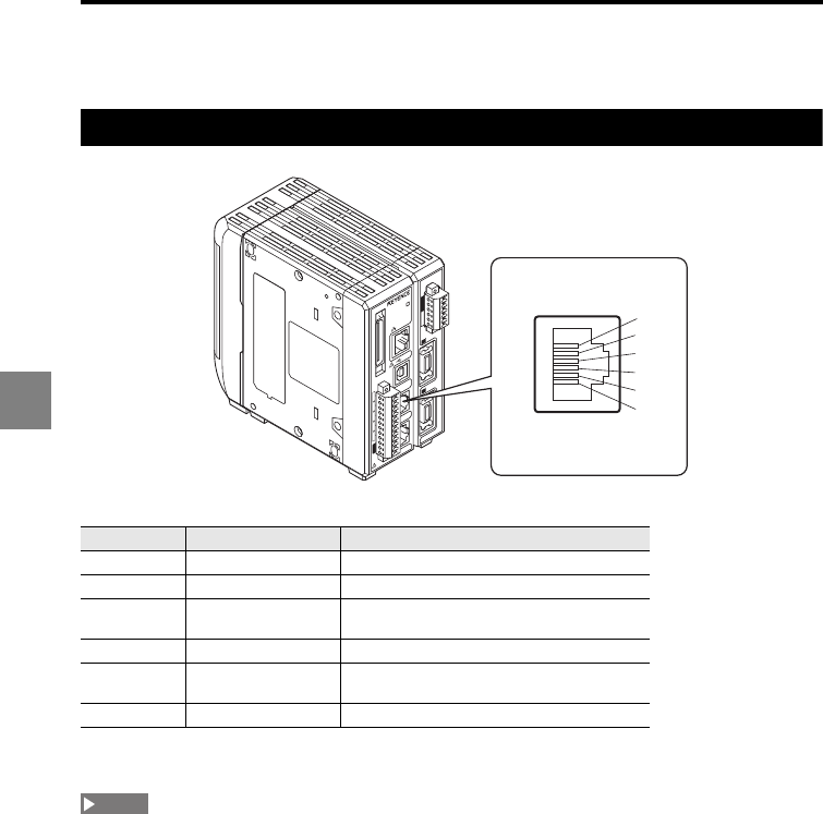
5-2
5
5 RS-232C
Specifications
Pin assignment
Applicable connector specifications: 6-pin modular plug connector
* Do not use the terminals indicated as "Not used". Using these terminals may lead to product
breakdown.
•The SG (GND) and 24 VDC (-) terminals are common through choke coils. Be careful of the potential
difference being generated among these terminals.
•Be sure to read "Precautions on wiring" (page 7) before starting wiring.
Terminal No. Terminal name Description
1 (Not used) -
2 (Not used) -
3SD (TXD)
Signal reception from an external device
(input)
4 SG (GND) GND
5RD (RXD)
Signal transmission to an external device
(output)
6 (Not used) -
1
1
2
3
4
5
6
7
8
9
10
11
12
13
14
15
16
17
18
19
20
2
21
22
23
24
25
26
27
28
29
30
31
32
33
34
35
36
37
38
39
40
LASER ON
ETHERNET
USB
DISPLAY
RS-232C
HEAD
1
(V)
(A)
0V
(V)
(A)
0V
COM INZERO 1TIMING 1GOLASER 1DC 24V
1
HEAD
LK-G5000
2
(1)
(2)
(3)
(4)
(5)
(6)
NOTE
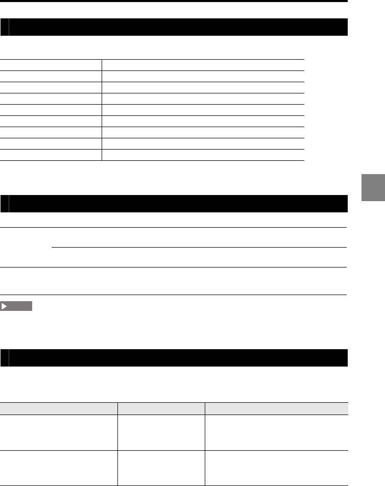
5-3
5
5 RS-232C
Communication parameters
EIA RS-232C compliant (Modem definition)
Refer to "Setting the RS-232C communication parameters (RS-232C)" (page 3-72) for the setting of the
communication parameters.
Communication operations for the measuring status and communication mode
You need to complete a sequence of command inputs/outputs before shifting from the measuring
status to the tolerance/function setting status.
Setting outline according to external devices
Set the automatic transmission function (page 3-72) as described in the table below
according to the external device to be connected.
*The operations described in "Measured Value Output and Changing Settings through Commands" are
also valid when the automatic transmission is set to ON.
Transmission method Full duplex
Synchronization Start-stop
Transmission code ASCII
Data length 8 bits
Stop bit length 1 bit
Parity check* None/even/odd
Baud rate* 9600/19200/38400/57600/115200 bps
Data delimiter CR
Flow control None
General mode
During measurement The measurement control commands are accepted.
Commands such as writing/reading setting values are not accepted.
During tolerance/
function setting
Communication is not accepted.
The measurement stops.
Communication
mode
•When the command "Q" "0" "CR" is received, the mode changes to
the communication mode, and the setting values are written/read.
•The measurement stops during the communication mode.
External device Automatic transmission Reference page
Non-procedure communication with
a PC or a PLC link unit
(Communication commands are
required.)
OFF "Measured Value Output and Changing
Settings through Commands" (page 5-4)
Communication with a PC or a PLC
link unit (Measured values are
output in synchronization with the
external synchronous input.)
ON "Measured Value Output through External
Synchronization" (page 5-38)
NOTE
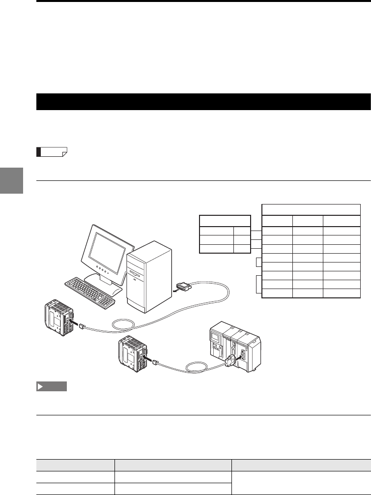
5-4
5
5 RS-232C
Measured Value Output and Changing
Settings through Commands
You can import measured values and change parameter settings by connecting the LK-
G5000 Series to a PC or a PLC link unit.
Connecting a PC/PLC link unit
The connection requires the OP-96368 dedicated cable (2.5-m straight cable) and either
the OP-26401 (D-sub 9-pin) or OP-96369 (D-sub 25-pin) conversion adapter.
Also refer to the instruction manual for the PC or PLC link unit before starting connection.
Connection diagram
Be sure to read "Precautions on wiring" (page 7) before starting wiring.
Environment settings parameters
Change the following parameters according to the PC or PLC link unit to be connected
(page 3-72).
Item Setting value Remark
Baud rate 9600/19200/38400/57600/115200 Set the appropriate parameter according to
the external device to be connected.
Parity check None/even/odd
Reference
1
(V)
(A)
0V
(V)
(A)
0V
LK-G5000
1
(V)
(A)
0V
(V)
(A)
0V
LK-G5000
RD (RXD)
SD (TXD)
(3)(2)
RD (RXD)
(2)(3)
SG (GND)
(5)(7)
(7)(4)
CS (CTS)
RS (RTS)
(8)(5)
DR (DSR)
(6)
(1)
(6)
CD (DCD)
(8)
ER (DTR)
(4)(20)
(5)
SG (GND)
(4)
SD (TXD)
(3)
PC side
LK-G side
Signal name
OP-26401OP-96369
PLC link unit
PC
NOTE
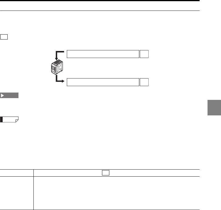
5-5
5
5 RS-232C
Outline of the command format
The LK-G5000 Series controls operation based on the incoming command received from
the external device, and then sends back the response command to the external device.
is used to delimit each piece of data in the incoming/response command format.
When creating a control program, build it so that you confirm the reception of the response command
from the LK-G5000 Series before sending the next command.
Both upper-case and lower-case characters can be used in the command.
The presence or absence of the section enclosed with brackets ([ ]) in the command format depends
on the condition.
Error response command format
The table below lists the major error codes. Refer to "Error Codes" (page A-5) for details.
Response ER, (Issued command), (Error code)
Error code
•50: Command error
•51: Status error
•60: Command length error
•61: Parameter count error
•62: Parameter range error
•88: Timeout error
•99: Other error
CR
Incoming command
Response command
Incoming command format CR
Response command format CR
LK-HD500
OUT1
HIGO LOTIM
OUT2
HI GO LO TIM
HEAD1
LASER ONSTABILITYBRIGHTDARK
HEAD2
LASER ONSTABILITYBRIGHTDARK
ZERO
ENT
SET
PROGRAM
NOTE
Reference
CR
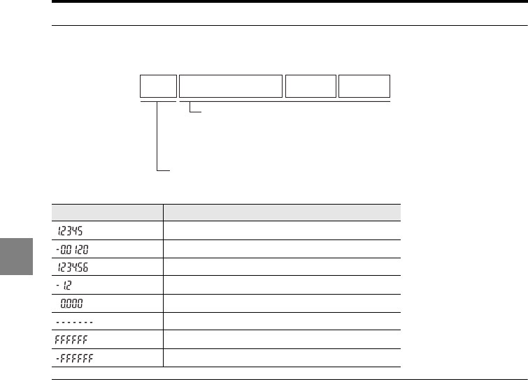
5-6
5
5 RS-232C
Measured value format (hhhhhhh)
A measured value is output in the format shown below.
The following table provides format examples.
Setting value format (fffffff)
Setting change format
Fixed length format that consists of one sign and six-digit numerical values. No decimal
point is included.
Setting confirmation format
Fixed length format that consists of one sign, six-digit numerical value and one decimal
point.
Displayed value Output format
+01.2345
-00.0120
+1234.56
-00001.2
+000.000
XXXXXXXX
+FFFFFFF
-FFFFFFF
Sign Integer portion Decimal
point
Fractional
portion
Fixed length data of one character and the value is "+" or "–".
Fixed length data consisting of seven characters in total.
The decimal point is counted as a single character.
The presence/absence and the position of the decimal
point vary depending on the settings.
The measured value is aligned to the right.
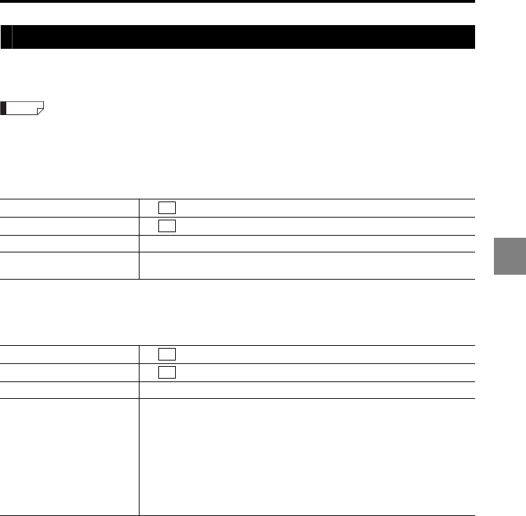
5-7
5
5 RS-232C
Mode change command
This section describes the command format used to switch between the "General mode"
and "Communication mode".
Refer to "Communication operations for the measuring status and communication mode" (page 5-3)
for details about the general mode and communication mode.
Changing to the communication mode
The mode is changed to the communication mode.
Changing to the general mode
The mode is changed to the general mode.
Incoming command Q0
Response command Q0
Parameter description -
Error code Err-51: Command Q0 was sent when the unit was in the communication
mode.
Incoming command R0
Response command R0
Parameter description -
Error code
Err-51: Command R0 was sent when the unit was in the general mode.
Err-63: The repeated use of an OUT value in calculation exceeds the limit.
Err-65: The calculation method parameter does not satisfy the requirements
of the setting list. (OUT for velocity/acceleration was set for OUT calculation;
or an item other than the sensor head was specified for calculation of OUT
for velocity/acceleration.)
Err-66: The calculation method parameter does not satisfy the requirements
of the setting list. (No OUT was specified for AVE, MAX, MIN, or P-P
calculation.)
Reference
CR
CR
CR
CR
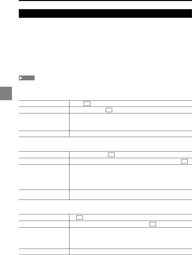
5-8
5
5 RS-232C
Measurement control command format
This section describes the command format used to control the measurement. The
incoming command is a command that the LK-G5000 Series can receive during the
measurement and the response command is a command that is sent after the incoming
command is processed properly.
The following subsections include details about the incoming commands and details
about the response commands that are sent after the incoming commands are processed
properly.
Refer to "Outline of the command format" (page 5-5) for the error response commands and
refer to "Timing diagrams" (page 5-35) for the response delay time.
These commands are accepted only when the controller is in the "General mode".
Measured value output (single)
Measured value output (multiple)
Measured value output (ALL)
Incoming command MS,aa
Response command MS,aa,hhhhhhhh
Parameter description
•Only the measured value for the specified OUT No. is output.
•aa: OUT No. (Numerical value from 01 to 12, 01: OUT1, 02: OUT02,...12:
OUT12)
•hhhhhhhh: Measured value format
Error code -
Incoming command MM,iiiiiiiiiiii
Response command MM,iiiiiiiiiiii,hhhhhhhh[,hhhhhhhh...,hhhhhhhh]
Parameter description
•Any number of OUT can be selected from 12 OUTs to output their
measured values.
•iiiiiiiiiiii: Sequence of numbers specifying 1 (output) or 0 (no output) for
each OUT (Example when OUT02 and OUT05 are specified:
010010000000)
•hhhhhhhh: Measured value format
Error code •Err-62: All OUTs are specified with 0.
•Err-64: An OUT No. which exceeds the active OUT count was specified.
Incoming command MA
Response command MA,hhhhhhhh[,hhhhhhhh...,hhhhhhhh]
Parameter description
•The measured values for all OUT Nos. being used are output according to
"Active OUT count" in the Environment settings. (Example: When the
"active OUT count" is four, the measured values for OUT01 to OUT04 are
output.)
•hhhhhhhh: Measured value format
Error code -
NOTE
CR
CR
CR
CR
CR
CR
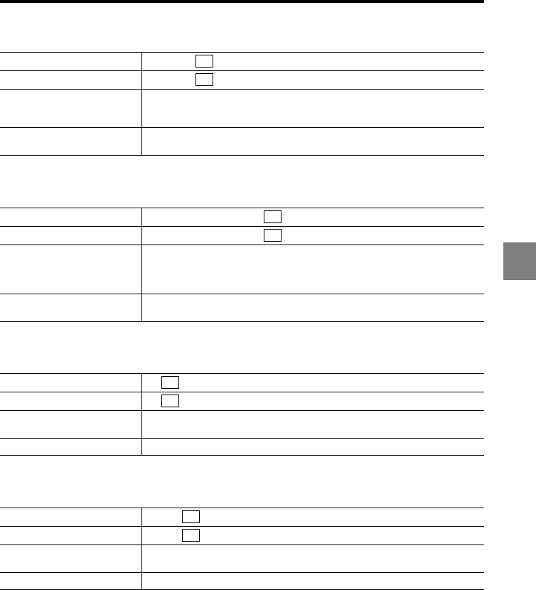
5-9
5
5 RS-232C
Timing ON/OFF (single)
Timing ON/OFF (multiple)
Timing ON/OFF (synchronous)
Auto-zero ON (single)
Incoming command TS,p,aa
Response command TS,p,aa
Parameter description
•p: ON/OFF setting (0: OFF, 1: ON)
•aa: OUT No. (Numerical value from 01 to 12, 01: OUT1, 02: OUT02,...12:
OUT12)
Error code •Err-62: Synchronized OUT was specified.
•Err-64: An OUT No. which exceeds the active OUT count was specified.
Incoming command TM,p,iiiiiiiiiiii
Response command TM,p,iiiiiiiiiiii
Parameter description
•p: ON/OFF setting (0: OFF, 1: ON)
•iiiiiiiiiiii: Sequence of numbers specifying 1 (output) or 0 (no output) for
each OUT (Example when OUT02 and OUT05 are specified:
010010000000)
Error code •Err-62: Synchronized OUT was specified.
•Err-64: An OUT No. which exceeds the active OUT count was specified.
Incoming command TP
Response command TP
Parameter description •This command is applied to all of the synchronized OUT.
•p: ON/OFF setting (0: OFF, 1: ON)
Error code Err-62: Synchronized OUT does not exist.
Incoming command VS,aa
Response command VS,aa
Parameter description aa: OUT No. (Numerical value from 01 to 12, 01: OUT1, 02: OUT02,...12:
OUT12)
Error code Err-64: An OUT No. which exceeds the active OUT count was specified.
CR
CR
CR
CR
CR
CR
CR
CR
5-10
5
5 RS-232C
Auto-zero ON (multiple)
Auto-zero ON (synchronous)
Auto-zero OFF (single)
Auto-zero OFF (multiple)
Auto-zero OFF (synchronous)
Incoming command VM,iiiiiiiiiiii
Response command VM,iiiiiiiiiiii
Parameter description iiiiiiiiiiii: Sequence of numbers specifying 1 (output) or 0 (no output) for each
OUT (Example when OUT02 and OUT05 are specified: 010010000000)
Error code Err-64: An OUT No. which exceeds the active OUT count was specified.
Incoming command VA
Response command VA
Parameter description This command is applied to all of the synchronized OUT.
Error code Err-62: Synchronized OUT does not exist.
Incoming command WS,aa
Response command WS,aa
Parameter description aa: OUT No. (Numerical value from 01 to 12, 01: OUT1, 02: OUT02,...12:
OUT12)
Error code Err-64: An OUT No. which exceeds the active OUT count was specified.
Incoming command WM,iiiiiiiiiiii
Response command WM,iiiiiiiiiiii
Parameter description iiiiiiiiiiii: Sequence of numbers specifying 1 (output) or 0 (no output) for each
OUT (Example when OUT02 and OUT05 are specified: 010010000000)
Error code Err-64: An OUT No. which exceeds the active OUT count was specified.
Incoming command WA
Response command WA
Parameter description This command is applied to all of the synchronized OUT channels.
Error code Err-62: Synchronized OUT does not exist.
CR
CR
CR
CR
CR
CR
CR
CR
CR
CR
5-11
5
5 RS-232C
Reset (single)
Reset (multiple)
Reset (synchronous)
Panel lock
Program switching
Incoming command DS,aa
Response command DS
Parameter description aa: OUT No. (Numerical value from 01 to 12, 01: OUT1, 02: OUT02,...12:
OUT12)
Error code Err-64: An OUT No. which exceeds the active OUT count was specified.
Incoming command DM,iiiiiiiiiiii
Response command DM
Parameter description iiiiiiiiiiii: Sequence of numbers specifying 1 (output) or 0 (no output) for each
OUT (Example when OUT02 and OUT05 are specified: 010010000000)
Error code Err-64: An OUT No. which exceeds the active OUT count was specified.
Incoming command DA
Response command DA
Parameter description This command is applied to all of the synchronized OUT channels.
Error code Err-62: Synchronized OUT does not exist.
Incoming command KL,p
Response command KL
Parameter description p: ON/OFF setting (0: OFF, 1: ON)
Error code Err-62: The specified parameter is out of the parameter definition.
Incoming command PW,o
Response command PW
Parameter description o: Program No. (0 to 7)
Error code Err-62: The specified parameter is out of the parameter definition.
CR
CR
CR
CR
CR
CR
CR
CR
CR
CR
5-12
5
5 RS-232C
Program confirmation
Data storage start
Data storage stop
Data storage initialization
Data storage data output
Incoming command PR
Response command PR,o
Parameter description o: Program No. (0 to 7)
Error code Err-51: Status error
Incoming command AS
Response command AS
Parameter description -
Error code Err-51: The command was executed in a mode other than the Run mode.
Incoming command AP
Response command AP
Parameter description -
Error code Err-51: Status error
Incoming command AQ
Response command AQ
Parameter description -
Error code Err-51: Status error
Incoming command AO,aa
Response command AO,hhhhhhhh...,hhhhhhhh
Parameter description
•aa: OUT No. (Numerical value from 01 to 12, 01: OUT1, 02: OUT02,...12:
OUT12)
•hhhhhhhh: Measured value format
Error code Err-51: The specified OUT was not the OUT for which data is stored.
CR
CR
CR
CR
CR
CR
CR
CR
CR
CR

5-13
5
5 RS-232C
Data storage status output
Incoming command AN
Response command AN,s,ddddddd[,ddddddd...ddddddd]
Parameter description
•s: Storage status (0: Data storage stopped, 1: Data being stored)
•ddddddd: Number of actually stored data (1200000 max. depending on
the number of specified OUT). As many values are output as the number
of OUT being used in the order of OUT01, OUT02, etc.
Error code -
CR
CR
5-14
5
5 RS-232C
Setting change command
The following subsections include details about the incoming commands and details
about the response commands that are sent after the incoming commands are processed
properly.
Refer to "Outline of the command format" (page 5-5) for the error response commands and
refer to "Timing diagrams" (page 5-35) for the response delay time.
These commands are accepted only when the controller is in the "Communication mode".
Measurement display switching
Tolerance setting
Head settings
ABLE
Incoming command DC,bb,bb
Response command DC
Parameter description
bb: OUT No. to display data (01: OUT01, 02: OUT02,...12: OUT12, 00: No
display)
Values should be specified in the order of the upper window and lower
window.
Error code Err-64: An OUT No. which exceeds the active OUT count was specified.
Incoming command SW,LM,aa,fffffff,fffffff,fffffff
Response command SW,LM
Parameter description
•aa: OUT No. (Numerical value from 01 to 12, 01: OUT1, 02: OUT02,...12:
OUT12)
•fffffff: Setting value format (Effective digits: 6).
Values should be specified in the order of the upper limit, lower limit, and
hysteresis. The most significant digit for the hysteresis is not a sign but 0.
Error code Err-64: An OUT No. which exceeds the active OUT count was specified.
Incoming command SW,HA,M,qq,m
Response command SW,HA
Parameter description •qq: Head No. (Numerical value from 01 to 12)
•m: Mode (0: AUTO, 1: MANUAL)
Error code Err-64: A head No. which exceeds the active head count was specified.
NOTE
CR
CR
CR
CR
CR
CR
5-15
5
5 RS-232C
ABLE control range
Measurement mode
Base point
Alarm handling
Incoming command SW,HA,R,qq,xx,xx
Response command SW,HA
Parameter description
•qq: Head No. (Numerical value from 01 to 12)
•xx: Control range data (01 to 99). Values should be specified in the order
of the upper limit and lower limit.
Error code •Err-62: The condition of "Upper limit Lower limit" was not satisfied.
•Err-64: A head No. which exceeds the active head count was specified.
Incoming command SW,HB,M,qq,c
Response command SW,HB
Parameter description
•qq: Head No. (Numerical value from 01 to 12)
•c: Function No. (0: Normal, 1: Translucent object, 2: Transparent object, 3:
Transparent object 2, 4: Semi opaque)
Error code •Err-62: "c" is out of range.
•Err-64: A head No. which exceeds the active head count was specified.
Incoming command SW,HB,B,qq,c
Response command SW,HB
Parameter description •qq: Head No. (Numerical value from 01 to 12)
•c: Function No. (0: NEAR, 1: FAR)
Error code •Err-62: "c" is out of range.
•Err-64: A head No. which exceeds the active head count was specified.
Incoming command SW,HC,N,qq,nnnn,nnnn
Response command SW,HC
Parameter description
•qq: Head No. (Numerical value from 01 to 12)
•nnnn: Numerical value without a sign (0000 to 9999). Values should be
specified in the order of the process count and recovery count.
Error code •Err-62: "nnnn" is out of range.
•Err-64: A head No. which exceeds the active head count was specified.
CR
CR
CR
CR
CR
CR
CR
CR
5-16
5
5 RS-232C
Alarm level
ABLE calibration start
ABLE calibration finish
ABLE calibration stop
Mounting mode
Incoming command SW,HC,L,qq,c
Response command SW,HC
Parameter description •qq: Head No. (Numerical value from 01 to 12)
•c: Alarm level (0 to 9)
Error code •Err-62: "c" is out of range.
•Err-64: A head No. which exceeds the active head count was specified.
Incoming command SW,HD,S,qq
Response command SW,HD
Parameter description qq: Head No. (Numerical value from 01 to 12)
Error code •Err-51: Unconnected sensor head was specified for the ABLE calibration.
•Err-64: A head No. which exceeds the active head count was specified.
Incoming command SW,HD,P
Response command SW,HD
Parameter description -
Error code Err-51: The command was executed when the ABLE calibration was not
being performed.
Incoming command SW,HD,C
Response command SW,HD
Parameter description The sensor head being calibrated is automatically specified.
Error code Err-51: The command was executed when the ABLE calibration was not
being performed.
Incoming command SW,HE,qq,c
Response command SW,HE
Parameter description •qq: Head No. (Numerical value from 01 to 12)
•c: Function No. (0: Diffuse reflection, 1: Specular reflection)
Error code •Err-62: "c" is out of range.
•Err-64: A head No. which exceeds the active head count was specified.
CR
CR
CR
CR
CR
CR
CR
CR
CR
CR
5-17
5
5 RS-232C
Mask setting
Median
LASER CTRL group
Range setting
Incoming command SW,HF,qq,c,fffffff,fffffff
Response command SW,HF
Parameter description
•qq: Head No. (Numerical value from 01 to 12)
•c: Function No. (0: OFF, 1: ON)
•fffffff: Setting value format (Effective digits: 6). Values should be specified
in the order of point 1 and point 2.
Error code •Err-62: "c" or "fffffff" is out of range.
•Err-64: A head No. which exceeds the active head count was specified.
Incoming command SW,HG,qq,c
Response command SW,HG
Parameter description •qq: Head No. (Numerical value from 01 to 12)
•c: Function No. (0: OFF, 1: 7-point, 2: 15-point, 3: 31-point)
Error code •Err-62: "c" is out of range.
•Err-64: A head No. which exceeds the active head count was specified.
Incoming command SW,HH,qq,c
Response command SW,HH,qq
Parameter description •qq: Head No. (Numerical value from 01 to 12)
•c: Function No. (0: LASER_CTRL1, 1: LASER_CTRL2)
Error code •Err-62: "c" is out of range.
•Err-64: A head No. which exceeds the active head count was specified.
Incoming command SW,HI,qq,c
Response command SW,HI
Parameter description •qq: Head No. (Numerical value from 01 to 12)
•c: Function No. (0: CENTER, 1: FAR)
Error code •Err-62: "c" is out of range.
•Err-64: A head No. which exceeds the active head count was specified.
CR
CR
CR
CR
CR
CR
CR
CR
5-18
5
5 RS-232C
Mutual interference prevention group
OUT settings
Calculation method
Surface to be measured
OUT to be calculated (ADD, SUB)
Incoming command SW,HJ,qq,c
Response command SW,HJ
Parameter description •qq: Head No. (Numerical value from 01 to 12)
•c: Function No. (0: OFF, 1: AB-ON, 2: ABC-ON)
Error code •Err-62: "c" is out of range.
•Err-64: A head No. which exceeds the active head count was specified.
Incoming command SW,OA,H,aa,ggg
Response command SW,OA,aa
Parameter description
•aa: OUT No. (Numerical value from 01 to 12, 01: OUT1, 02: OUT02,...12:
OUT12)
•ggg: Head No. (H01 to H12) or OUT No. (O01 to O12), Calculation method
(C01: ADD, C02: SUB, C03: AVE, C04: MAX, C05: MIN, C06: P-P)
Error code
•Err-64: An OUT No. which exceeds the active OUT count was specified.
•Err-66: "ggg" does not conform to the specification described in the setting
list.
Incoming command SW,OA,T,aa,c
Response command SW,OA,aa
Parameter description
•aa: OUT No. (Numerical value from 01 to 12, 01: OUT1, 02: OUT02,...12:
OUT12)
•c: Function No. (0: 1, 1: 2, 2: 3, 3: 4, 4: 1-2, 5: 1-3, 6: 1-4, 7: 2-3, 8: 2-4, 9:
3-4)
Error code •Err-62: "c" is out of range.
•Err-64: An OUT No. which exceeds the active OUT count was specified.
Incoming command SW,OA,C,aa,jj,jj
Response command SW,OA,aa
Parameter description
•The specified values are retained even after the "calculation method" is
changed.
•aa: OUT No. (Numerical value from 01 to 12, 01: OUT1, 02: OUT02,...12:
OUT12)
•jj: OUT to be calculated (Numerical value from 01 to 12).
When the calculation is "OUT01 + OUT02", for example, these two "jj"
values will be "01" and "02".
Error code •Err-64: An OUT No. which exceeds the active OUT count was specified.
CR
CR
CR
CR
CR
CR
CR
CR
5-19
5
5 RS-232C
OUT to be calculated (AVE, MAX, MIN, P-P)
Scaling
Filter
Incoming command SW,OA,M,aa,iiiiiiiiiiii
Response command SW,OA,aa
Parameter description
•This command is used when the selected calculation method is "AVE",
"MAX", "MIN", or "P-P".
•The specified values are retained even after the "calculation method" is
changed.
•iiiiiiiiiiii: Format used to specify multiple OUT, HEAD, or analog output
channel options. This is a sequence of numbers specifying 1 (output) or 0
(no output) for each OUT, HEAD, or analog output channel (Example when
OUT02 and OUT05 are specified: 010010000000)
•aa: OUT No. (Numerical value from 01 to 12, 01: OUT1, 02: OUT02,...12:
OUT12)
Error code
•Err-64: An OUT No. which exceeds the active OUT count was specified.
•Err-66: "iiiiiiiiiiii" does not conform to the specification described in the
setting list.
Incoming command SW,OB,aa,fffffff,fffffff,fffffff,fffffff
Response command SW,OB
Parameter description
•aa: OUT No. (Numerical value from 01 to 12, 01: OUT1, 02: OUT02,...12:
OUT12)
•fffffff: Setting value format (Effective digits: 6). Values should be specified
in the order of the measured value for point 1 (input value), displayed value
for point 1, measured value for point 2 (input value), and displayed value
for point 2.
Error code •Err-64: An OUT No. which exceeds the active OUT count was specified.
•Err-68: "fffffff" does not conform to the specification in the setting list.
Incoming command SW,OC,aa,c,c
Response command SW,OC
Parameter description
•aa: OUT No. (Numerical value from 01 to 12, 01: OUT1, 02: OUT02,...12:
OUT12)
•c: Function No.
First c: Filter mode (0: Averaging, 1: Low-pass filter, 2: High-pass filter)
Second c: Function No. for the filter mode selected with the first c
(0: Averaging 1 time or 3000 Hz, 1: Averaging 4 times or 1000 Hz,
2: Averaging 16 times or 300 Hz, 3: Averaging 64 times or 100 Hz,
4: Averaging 256 times or 30 Hz, 5: Averaging 1024 times or 10 Hz,
6: Averaging 4096 times or 3 Hz, 7: Averaging 16384 times or 1 Hz,
8: Averaging 65536 times or 0.3 Hz, 9: Averaging 262144 times or 0.1 Hz)
Error code •Err-62: "c" is out of range.
•Err-64: An OUT No. which exceeds the active OUT count was specified.
CR
CR
CR
CR
CR
CR
5-20
5
5 RS-232C
Measurement (Hold) mode
Trigger mode
Offset
Minimum display unit
Incoming command SW,OD,aa,c
Response command SW,OD
Parameter description
•aa: OUT No. (Numerical value from 01 to 12, 01: OUT1, 02: OUT02,...12:
OUT12)
•c: Function No. (0: Normal, 1: Peak hold, 2: Bottom hold, 3: Peak-to-peak
hold, 4: Sample hold, 5: Average hold)
Error code •Err-62: "c" is out of range.
•Err-64: An OUT No. which exceeds the active OUT count was specified.
Incoming command SW,OE,M,aa,c
Response command SW,OE
Parameter description
•aa: OUT No. (Numerical value from 01 to 12, 01: OUT1, 02: OUT02,...12:
OUT12)
•c: Function No. (0: Trigger 1, 1: Trigger 2)
Error code •Err-62: "c" is out of range.
•Err-64: An OUT No. which exceeds the active OUT count was specified.
Incoming command SW,OF,aa,fffffff
Response command SW,OF
Parameter description
•aa: OUT No. (Numerical value from 01 to 12, 01: OUT1, 02: OUT02,...12:
OUT12)
•fffffff: Setting value format (Effective digits: 6)
Error code •Err-62: "fffffff" is out of range.
•Err-64: An OUT No. which exceeds the active OUT count was specified.
Incoming command SW,OG,aa,c
Response command SW,OG
Parameter description
•aa: OUT No. (Numerical value from 01 to 12, 01: OUT1, 02: OUT02,...12:
OUT12)
•c: Function No.
When "Displacement" is selected for the measurement type
(0: 0.01 mm, 1: 0.001 mm, 2: 0.0001 mm, 3: 0.00001 mm, 4: 0.1 μm,
5: 0.01 μm, 6: 0.001 μm)
When "Velocity" is selected for the measurement type
(0: 0.1 m/s, 1: 0.01 m/s, 2: 0.001 m/s, 3: 0.1 mm/s, 4: 0.01 mm/s,
5: 0.001 mm/s, 6: 0.0001 mm/s)
When "Acceleration" is selected for the measurement type
(0: 0.1 km/s2, 1: 0.01 km/s2, 2: 0.001 km/s2, 3: 0.1 m/s2, 4: 0.01 m/s2,
5: 0.001 m/s2, 6: 0.0001 m/s2)
Error code •Err-62: "c" is out of range.
•Err-64: An OUT No. which exceeds the active OUT count was specified.
CR
CR
CR
CR
CR
CR
CR
CR
5-21
5
5 RS-232C
Analog output scaling
Measurement type
Synchronization setting
Storage (OUT No. specification)
Incoming command SW,OH,aa,fffffff,fffffff,fffffff,fffffff
Response command SW,OH
Parameter description
•aa: OUT No. (Numerical value from 01 to 12, 01: OUT1, 02: OUT02,...12:
OUT12)
•fffffff: Setting value format (Effective digits: 6). Values should be specified
in the order of the measured value for point 1, output value for point 1,
measured value for point 2, and output value for point 2.
Error code •Err-64: An OUT No. which exceeds the active OUT count was specified.
•Err-69: "fffffff" does not conform to the specification in the setting list.
Incoming command SW,OI,aa,c
Response command SW,OI
Parameter description
•aa: OUT No. (Numerical value from 01 to 12, 01: OUT1, 02: OUT02,...12:
OUT12)
•c: Function No. (0: Displacement, 1: Velocity, 2: Acceleration)
Error code •Err-62: "c" is out of range.
•Err-64: An OUT No. which exceeds the active OUT count was specified.
Incoming command SW,OJ,aa,c
Response command SW,OJ
Parameter description
•aa: OUT No. (Numerical value from 01 to 12, 01: OUT1, 02: OUT02,...12:
OUT12)
•c: Function No. (0: OFF, 1: ON)
Error code •Err-62: "c" is out of range.
•Err-64: An OUT No. which exceeds the active OUT count was specified.
Incoming command SW,OK,aa,c
Response command SW,OK
Parameter description
•aa: OUT No. (Numerical value from 01 to 12, 01: OUT1, 02: OUT02,...12:
OUT12)
•c: Function No. (0: OFF, 1: ON)
Error code •Err-62: "c" is out of range.
•Err-64: An OUT No. which exceeds the active OUT count was specified.
CR
CR
CR
CR
CR
CR
CR
CR

5-22
5
5 RS-232C
Common settings
Sampling cycle
Mutual interference prevention
Comparator output form
Strobe time
Data storage
Incoming command SW,CA,c
Response command SW,CA
Parameter description c: Function No. (0: 2.55 μs, 1: 5 μs, 2: 10 μs, 3: 20 μs, 4: 50 μs, 5: 100 μs, 6:
200 μs, 7: 500 μs, 8: 1000 μs)
Error code Err-62: "c" is out of range.
Incoming command SW,CB,c
Response command SW,CB
Parameter description c: Function No. (0: OFF, 1: AB-ON, 2: ABC-ON)
Error code Err-62: "c" is out of range.
Incoming command SW,CD,c
Response command SW,CD
Parameter description c: Function No. (0: Normal, 1: Hold, 2: Off-delay)
Error code Err-62: "c" is out of range.
Incoming command SW,CE,c
Response command SW,CE
Parameter description c: Function No. (0: 2 ms, 1: 5 ms, 2: 10 ms, 3: 20 ms)
Error code Err-62: "c" is out of range.
Incoming command SW,CF,ddddddd,ll
Response command SW,CF
Parameter description
•ddddddd: Number of data to be stored (0000000 to 1200000)
•ll: Storage cycle (0: 1x, 1: 2x, 2: 5x, 3: 10x, 4: 20x, 5: 50x,
6: 100x, 7: 200x, 8: 500x, 9: 1000x, 10: Synchronous input)
Error code Err-62: "ddddddd" or "ll" is out of range.
CR
CR
CR
CR
CR
CR
CR
CR
CR
CR
5-23
5
5 RS-232C
Analog output channel
Alarm output type
Environment settings
Active OUT count
Active head count
Active analog output channel count
Incoming command SW,CG,ee,bb
Response command SW,CG
Parameter description
•ee: Analog output channel No. (Numerical value from 01 to 12)
•bb: OUT No. to output data (01: OUT01, 02: OUT02,...12: OUT12, 00: No
output)
Error code •Err-62: "ee" exceeds the active analog output channel count.
•Err-64: An OUT No. which exceeds the active OUT count was specified.
Incoming command SW,CH,c
Response command SW,CH
Parameter description c: Function No. (0: System alarm, 1: Measured value alarm, 2: Both)
Error code Err-62: "c" is out of range.
Incoming command SW,EE,yy
Response command SW,EE
Parameter description yy: Active OUT/head count (02 to 12)
Error code Err-62: "yy" is out of range.
Incoming command SW,EF,yy
Response command SW,EF
Parameter description yy: Active OUT/head count (02 to 12)
Error code Err-62: "yy" is out of range.
Incoming command SW,EG,yy
Response command SW,EG
Parameter description yy: Active OUT/head count (02 to 12)
Error code Err-62: "yy" is out of range.
CR
CR
CR
CR
CR
CR
CR
CR
CR
CR
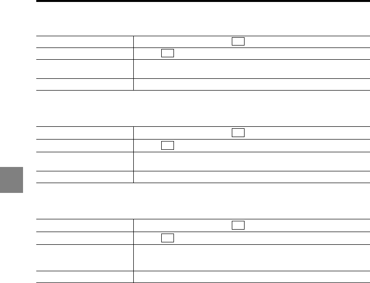
5-24
5
5 RS-232C
IP address
Subnet mask
Default gateway
Incoming command SW,EH,I,zzzzzzzzzzzz
Response command SW,EH
Parameter description zzzzzzzzzzzz: IP address (Numerical values of zzz.zzz.zzz.zzz)
Example: When the IP address is 10.10.1.9, specify "010010001009".
Error code Err-62: "zzzzzzzzzzzz" is out of range.
Incoming command SW,EH,M,zzzzzzzzzzzz
Response command SW,EH
Parameter description zzzzzzzzzzzz: Subnet mask (Numerical values of zzz.zzz.zzz.zzz)
Example: When the subnet mask is 255.255.0.0, specify "255255000000".
Error code Err-62: "zzzzzzzzzzzz" is out of range.
Incoming command SW,EH,G,zzzzzzzzzzzz
Response command SW,EH
Parameter description
zzzzzzzzzzzz: IP address of default gateway (Numerical values of
zzz.zzz.zzz.zzz)
Example: When the IP address is 10.10.1.9, specify "010010001009".
Error code Err-62: "zzzzzzzzzzzz" is out of range.
CR
CR
CR
CR
CR
CR
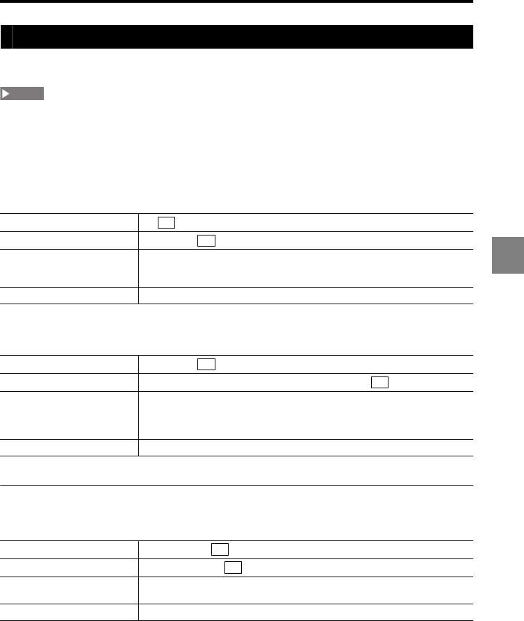
5-25
5
5 RS-232C
Setting confirmation command format
This section describes the format for the commands used to confirm the setting.
These commands are accepted only when the controller is in the "Communication mode".
•The setting value format is returned including a decimal point.
•Refer to "Setting change command" (page 5-14) for details about each command.
Measurement display confirmation
Tolerance setting
Head settings
ABLE
Incoming command DR
Response command DR,bb,bb
Parameter description
bb: OUT No. to display/output data (01: OUT01, 02: OUT02,...12: OUT12,
00: No display/output). Values are returned in the order of the upper window
and lower window.
Error code -
Incoming command SR,LM,aa
Response command SR,LM,aa,ffffffff,ffffffff,fffffff
Parameter description
•aa: OUT (Numerical value from 01 to 12, 01: OUT1, 02: OUT02,...12:
OUT12)
•fffffff: Setting value format (Effective digits: 6). Values are returned in the
order of the upper limit, lower limit, and hysteresis.
Error code Err-64: An OUT No. which exceeds the active OUT count was specified.
Incoming command SR,HA,M,qq
Response command SR,HA,M,qq,m
Parameter description •qq: Head No. (Numerical value from 01 to 12)
•m: Mode (0: AUTO, 1: MANUAL)
Error code Err-64: A head No. which exceeds the active head count was specified.
NOTE
CR
CR
CR
CR
CR
CR
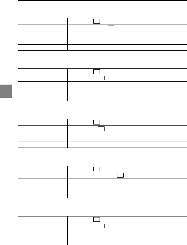
5-26
5
5 RS-232C
ABLE control range
Measurement mode
Base point
Alarm handling
Alarm level
Incoming command SR,HA,R,qq
Response command SR,HA,R,qq,xx,xx
Parameter description
•qq: Head No. (Numerical value from 01 to 12)
•xx: Control range data (01 to 99). Values are returned in the order of the
upper limit and lower limit.
Error code Err-64: A head No. which exceeds the active head count was specified.
Incoming command SR,HB,M,qq
Response command SR,HB,M,qq,c
Parameter description
•qq: Head No. (Numerical value from 01 to 12)
•c: Function No. (0: Normal, 1: Translucent object, 2: Transparent object, 3:
Transparent object 2, 4: Semi opaque)
Error code Err-64: A head No. which exceeds the active head count was specified.
Incoming command SR,HB,B,qq
Response command SR,HB,B,qq,c
Parameter description •qq: Head No. (Numerical value from 01 to 12)
•c: Function No. (0: NEAR, 1: FAR)
Error code Err-64: A head No. which exceeds the active head count was specified.
Incoming command SR,HC,N,qq
Response command SR,HC,N,qq,nnnn,nnnn
Parameter description
•qq: Head No. (Numerical value from 01 to 12)
•nnnn: Numerical value without a sign (0000 to 9999). Values are returned
in the order of the process count and recovery count.
Error code Err-64: A head No. which exceeds the active head count was specified.
Incoming command SR,HC,L,qq
Response command SR,HC,L,qq,c
Parameter description •qq: Head No. (Numerical value from 01 to 12)
•c: Function No. (0 to 9)
Error code Err-64: A head No. which exceeds the active head count was specified.
CR
CR
CR
CR
CR
CR
CR
CR
CR
CR
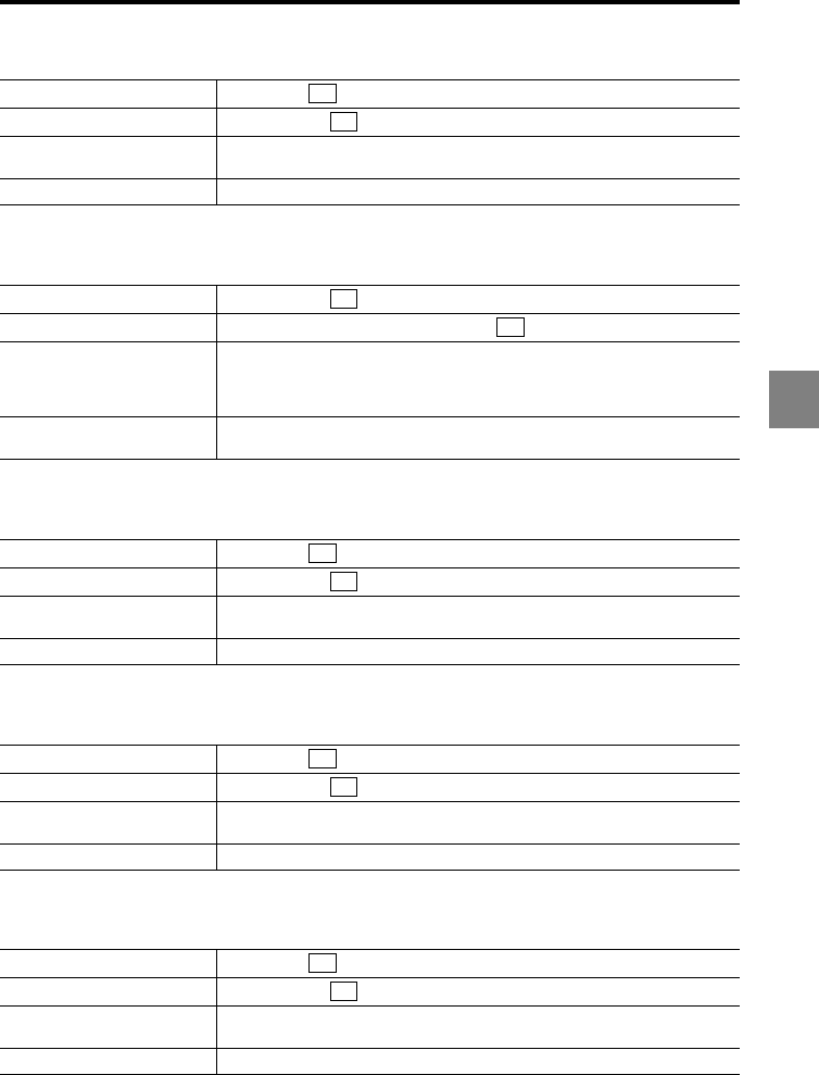
5-27
5
5 RS-232C
Mounting mode
Mask setting
Median
LASER CTRL group
Range setting
Incoming command SR,HE,qq
Response command SR,HE,qq,c
Parameter description •qq: Head No. (Numerical value from 01 to 12)
•c: Function No. (0: Diffuse reflection, 1: Specular reflection)
Error code Err-64: A head No. which exceeds the active head count was specified.
Incoming command SR,HF,qq,c
Response command SR,HF,qq,c,fffffff,fffffff
Parameter description
•qq: Head No. (Numerical value from 01 to 12)
•c: Function No. (0: OFF, 1: ON)
•fffffff: Setting value format (Effective digits: 6). Values are returned in the
order of point 1 and point 2.
Error code •Err-62: "c" is out of range.
•Err-64: A head No. which exceeds the active head count was specified.
Incoming command SR,HG,qq
Response command SR,HG,qq,c
Parameter description •qq: Head No. (Numerical value from 01 to 12)
•c: Function No. (0: OFF, 1: 7-point, 2: 15-point, 3: 31-point)
Error code Err-64: A head No. which exceeds the active head count was specified.
Incoming command SR,HH,qq
Response command SR,HH,qq,c
Parameter description •qq: Head No. (Numerical value from 01 to 12)
•c: Function No. (0: LASER CTRL1, 1: LASER CTRL2)
Error code Err-64: A head No. which exceeds the active head count was specified.
Incoming command SR,HI,qq
Response command SR,HI,qq,c
Parameter description •qq: Head No. (Numerical value from 01 to 12)
•c: Function No. (0: CENTER, 1: FAR)
Error code Err-64: A head No. which exceeds the active head count was specified.
CR
CR
CR
CR
CR
CR
CR
CR
CR
CR
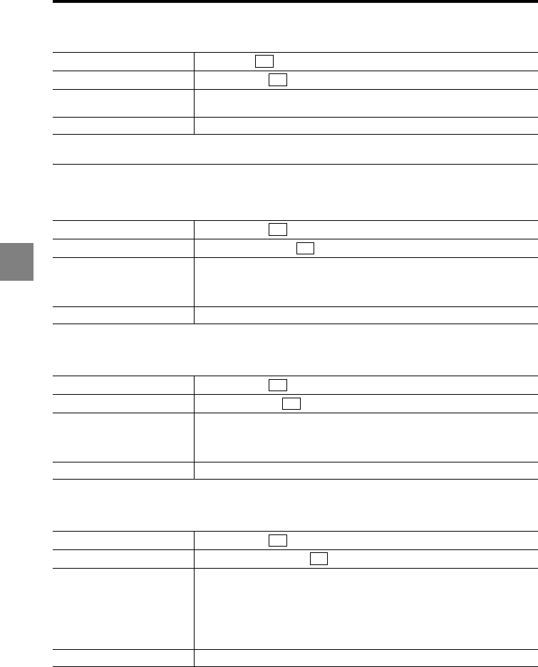
5-28
5
5 RS-232C
Mutual interference prevention group
OUT settings
Calculation method
Surface to be measured
OUT to be calculated (Add, Sub)
Incoming command SR,HJ,qq
Response command SR,HJ,qq,c
Parameter description •qq: Head No. (Numerical value from 01 to 12)
•c: Function No. (0: OFF, 1: AB-ON, 2: ABC-ON)
Error code Err-64: A head No. which exceeds the active head count was specified.
Incoming command SR,OA,H,aa
Response command SR,OA,H,aa,ggg
Parameter description
•aa: OUT/analog output channel No. (Numerical value from 01 to 12, 01:
OUT1, 02: OUT02,...12: OUT12)
•ggg: Head No. (H01 to H12) or OUT No. (O01 to O12), Calculation method
(C01: ADD, C02: SUB, C03: AVE, C04: MAX, C05: MIN, C06: P-P)
Error code Err-64: An OUT No. which exceeds the active OUT count was specified.
Incoming command SR,OA,T,aa
Response command SR,OA,T,aa,c
Parameter description
•aa: OUT No. (Numerical value from 01 to 12, 01: OUT1, 02: OUT02,...12:
OUT12)
•c: Function No. (0: 1, 1: 2, 2: 3, 3: 4, 4: 1-2, 5: 1-3, 6: 1-4, 7: 2-3, 8: 2-4, 9:
3-4)
Error code Err-64: An OUT No. which exceeds the active OUT count was specified.
Incoming command SR,OA,C,aa
Response command SR,OA,C,aa,jj,jj
Parameter description
•The specified values are retained even after the "calculation method" is
changed.
•aa: OUT No. (Numerical value from 01 to 12, 01: OUT1, 02: OUT02,...12:
OUT12)
•jj: OUT to be calculated (Numerical value from 01 to 12).
When the calculation is "OUT01 + OUT02", for example, these two "jj"
values will be "01" and "02".
Error code Err-64: An OUT No. which exceeds the active OUT count was specified.
CR
CR
CR
CR
CR
CR
CR
CR
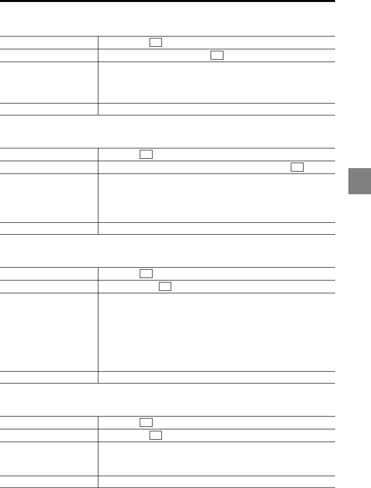
5-29
5
5 RS-232C
OUT to be calculated (AVE, MAX, MIN, P-P)
Scaling
Filter
Measurement mode
Incoming command SR,OA,M,aa
Response command SR,OA,M,aa,iiiiiiiiiiii
Parameter description
•The specified values are retained even after the "calculation method" is
changed.
•aa: OUT No. (Numerical value from 01 to 12, 01: OUT1, 02: OUT02,...12:
OUT12)
•iiiiiiiiiiii: Format used to specify multiple OUT or HEAD.
Error code Err-64: An OUT No. which exceeds the active OUT count was specified.
Incoming command SR,OB,aa
Response command SR,OB,aa,fffffff,fffffff,fffffff,fffffff
Parameter description
•aa: OUT No. (Numerical value from 01 to 12, 01: OUT1, 02: OUT02,...12:
OUT12)
•fffffff: Setting value format (Effective digits: 6). Values are returned in the
order of the measured value for point 1 (input value), displayed value for
point 1, measured value for point 2 (input value), and displayed value for
point 2.
Error code Err-64: An OUT No. which exceeds the active OUT count was specified.
Incoming command SR,OC,aa
Response command SR,OC,aa,c,c
Parameter description
•aa: OUT No. (Numerical value from 01 to 12, 01: OUT1, 02: OUT02,...12:
OUT12)
•c: Function No.
First c: Filter mode (0: Averaging, 1: Low-pass filter, 2: High-pass filter)
Second c: Function No. for the filter mode selected with the first c
(0: Averaging 1 time or 3000 Hz, 1: Averaging 4 times or 1000 Hz,
2: Averaging 16 times or 300 Hz, 3: Averaging 64 times or 100Hz,
4: Averaging 256 times or 30Hz, 5: Averaging 1024 times or 10Hz,
6: Averaging 4096 times or 3 Hz, 7: Averaging 16384 times or 1 Hz,
8: Averaging 65536 times or 0.3 Hz, 9: Averaging 262144 times or 0.1 Hz)
Error code Err-64: An OUT No. which exceeds the active OUT count was specified.
Incoming command SR,OD,aa
Response command SR,OD,aa,c
Parameter description
•aa: OUT No. (Numerical value from 01 to 12, 01: OUT1, 02: OUT02,...12:
OUT12)
•c: Function No. (0: Normal, 1: Peak hold, 2: Bottom hold, 3: Peak-to-peak
hold, 4: Sample hold, 5: Average hold)
Error code Err-64: An OUT No. which exceeds the active OUT count was specified.
CR
CR
CR
CR
CR
CR
CR
CR
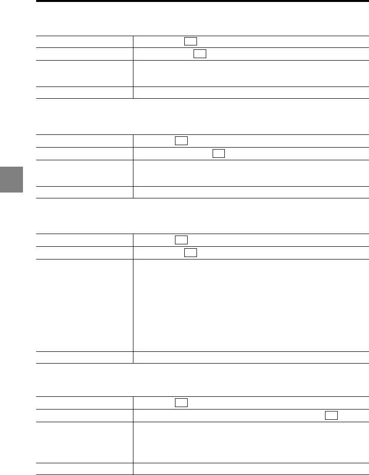
5-30
5
5 RS-232C
Trigger mode
Offset
Minimum display unit
Analog output scaling
Incoming command SR,OE,M,aa
Response command SR,OE,M,aa,c
Parameter description
•aa: OUT No. (Numerical value from 01 to 12, 01: OUT1, 02: OUT02,...12:
OUT12)
•c: Function No. (0: Trigger 1, 1: Trigger 2)
Error code Err-64: An OUT No. which exceeds the active OUT count was specified.
Incoming command SR,OF,aa
Response command SR,OF,aa,fffffff
Parameter description
•aa: OUT No. (Numerical value from 01 to 12, 01: OUT1, 02: OUT02,...12:
OUT12)
•fffffff: Setting value format (Effective digits: 6)
Error code Err-64: An OUT No. which exceeds the active OUT count was specified.
Incoming command SR,OG,aa
Response command SR,OG,aa,c
Parameter description
•aa: OUT No. (Numerical value from 01 to 12, 01: OUT1, 02: OUT02,...12:
OUT12)
•c: Function No.
When "Displacement" is selected for the measurement type
(0: 0.01 mm, 1: 0.001 mm, 2: 0.0001 mm, 3: 0.00001 mm, 4: 0.1 μm,
5: 0.01 μm, 6: 0.001 μm)
When "Velocity" is selected for the measurement type
(0: 0.1 m/s, 1: 0.01 m/s, 2: 0.001 m/s, 3: 0.1 mm/s, 4: 0.01 mm/s,
5: 0.001 mm/s, 6: 0.0001 mm/s)
When "Acceleration" is selected for the measurement type
(0: 0.1 km/s2, 1: 0.01 km/s2, 2: 0.001 km/s2, 3: 0.1 m/s2, 4: 0.01 m/s2,
5: 0.001 m/s2, 6: 0.0001 m/s2)
Error code Err-64: An OUT No. which exceeds the active OUT count was specified.
Incoming command SR,OH,aa
Response command SR,OH,aa,fffffff,fffffff,fffffff,fffffff
Parameter description
•aa: OUT No. (Numerical value from 01 to 12, 01: OUT1, 02: OUT02,...12:
OUT12)
•fffffff: Setting value format (Effective digits: 6). Values are returned in the
order of the measured value for point 1, output value for point 1, measured
value for point 2, and output value for point 2.
Error code Err-64: An OUT No. which exceeds the active OUT count was specified.
CR
CR
CR
CR
CR
CR
CR
CR
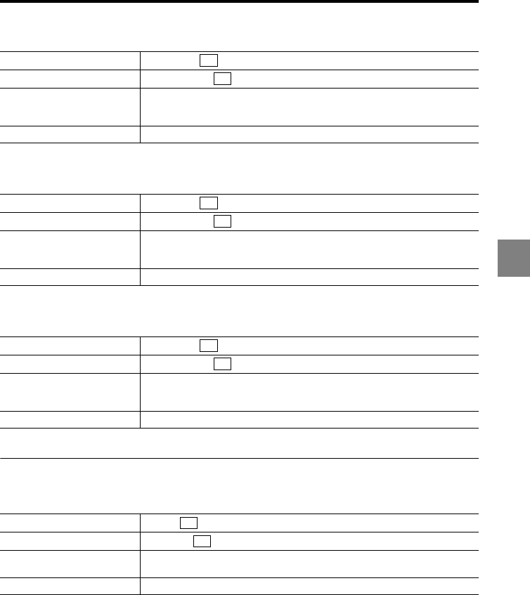
5-31
5
5 RS-232C
Measurement type
Synchronization setting
Storage (OUT No. setting)
Common settings
Sampling cycle
Incoming command SR,OI,aa
Response command SR,OI,aa,c
Parameter description
•aa: OUT No. (Numerical value from 01 to 12, 01: OUT1, 02: OUT02,...12:
OUT12)
•c: Function No. (0: Displacement, 1: Velocity, 2: Acceleration)
Error code Err-64: An OUT No. which exceeds the active OUT count was specified.
Incoming command SR,OJ,aa
Response command SR,OJ,aa,c
Parameter description
•aa: OUT No. (Numerical value from 01 to 12, 01: OUT1, 02: OUT02,...12:
OUT12)
•c: Function No. (0: OFF, 1: ON)
Error code Err-64: An OUT No. which exceeds the active OUT count was specified.
Incoming command SR,OK,aa
Response command SR,OK,aa,c
Parameter description
•aa: OUT No. (Numerical value from 01 to 12, 01: OUT1, 02: OUT02,...12:
OUT12)
•c: Function No. (0: OFF, 1: ON)
Error code Err-64: An OUT No. which exceeds the active OUT count was specified.
Incoming command SR,CA
Response command SR,CA,c
Parameter description c: Function No. (0: 2.55 μs, 1: 5 μs, 2: 10 μs, 3: 20 μs, 4: 50 μs, 5: 100 μs,
6: 200 μs, 7: 500 μs, 8: 1000 μs)
Error code -
CR
CR
CR
CR
CR
CR
CR
CR
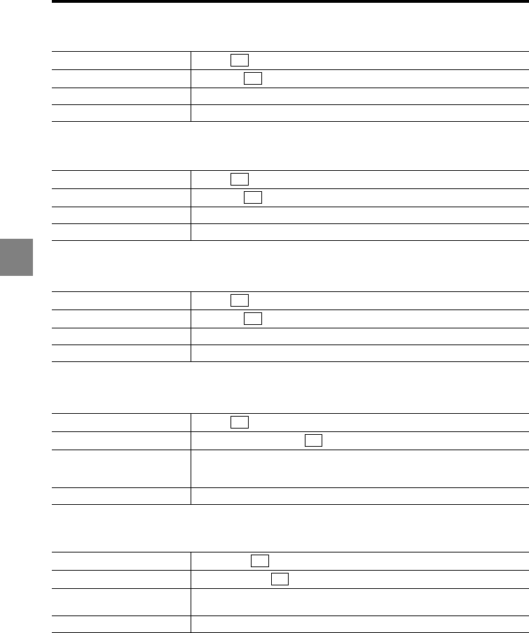
5-32
5
5 RS-232C
Mutual interference prevention
Comparator output form
Strobe time
Data storage
Analog output channel
Incoming command SR,CB
Response command SR,CB,c
Parameter description c: Function No. (0: OFF, 1: AB-ON, 2: ABC-ON)
Error code -
Incoming command SR,CD
Response command SR,CD,c
Parameter description c: Function No. (0: Normal, 1: Hold, 2: Off-delay)
Error code -
Incoming command SR,CE
Response command SR,CE,c
Parameter description c: Function No. (0: 2 ms, 1: 5 ms, 2: 10 ms, 3: 20 ms)
Error code -
Incoming command SR,CF
Response command SR,CF,ddddddd,ll
Parameter description
•ddddddd: Number of data to be stored (0000000 to 1200000)
•ll: Storage cycle (0: 1x, 1: 2x, 2: 5x, 3: 10x, 4: 20x, 5: 50x, 6: 100x, 7: 200x,
8: 500x, 9: 1000x, 10: Synchronous input)
Error code -
Incoming command SR,CG,ee
Response command SR,CG,ee,bb
Parameter description •ee: Analog output channel No. (Numerical value from 01 to 12)
•bb: OUT No. to output data (01: OUT01, 02: OUT02,...12: OUT12)
Error code Err-69: "ee" exceeds the active analog output channel count.
CR
CR
CR
CR
CR
CR
CR
CR
CR
CR
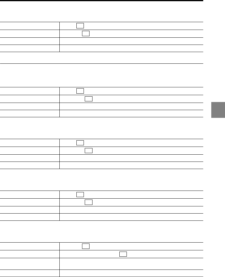
5-33
5
5 RS-232C
Alarm output type
Environment settings
Active OUT count
Active head count
Active analog output channel count
IP address
Incoming command SR,CB
Response command SR,CH,c
Parameter description c: Function No. (0: System alarm, 1: Measured value alarm, 2: Both)
Error code -
Incoming command SR,EE
Response command SR,EE,yy
Parameter description yy: Active OUT/head/analog output channel count (02 to 12)
Error code -
Incoming command SR,EF
Response command SR,EF,yy
Parameter description yy: Active OUT/head/analog output channel count (02 to 12)
Error code -
Incoming command SR,EG
Response command SR,EE,yy
Parameter description yy: Active OUT/head/analog output channel count (02 to 12)
Error code -
Incoming command SR,EH,I
Response command SR,EH,I,zzzzzzzzzzzz
Parameter description zzzzzzzzzzzz: IP address (Numerical values of zzz.zzz.zzz.zzz)
Example: When the IP address is 10.10.1.9, specify "010010001009".
Error code -
CR
CR
CR
CR
CR
CR
CR
CR
CR
CR
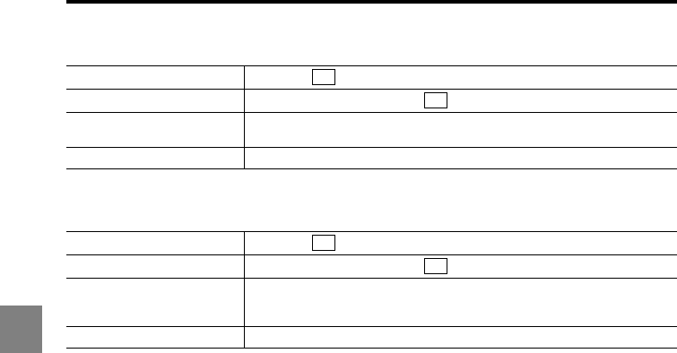
5-34
5
5 RS-232C
Subnet mask
Default gateway
Incoming command SR,EH,M
Response command SR,EH,M,zzzzzzzzzzzz
Parameter description zzzzzzzzzzzz: Subnet mask (Numerical values of zzz.zzz.zzz.zzz)
Example: When the subnet mask is 255.255.0.0, specify "255255000000".
Error code -
Incoming command SR,EH,G
Response command SR,EH,G,zzzzzzzzzzzz
Parameter description
zzzzzzzzzzzz: IP address of default gateway (Numerical values of
zzz.zzz.zzz.zzz)
Example: When the IP address is 10.10.1.9, specify "010010001009".
Error code -
CR
CR
CR
CR
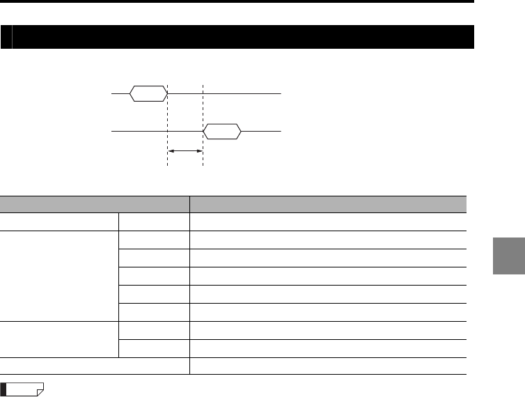
5-35
5
5 RS-232C
Timing diagrams
The timing diagram of the incoming and response commands is as follows.
The following table describes time t for each command.
The response speed becomes slower than the figures in the table during communication with the LK-
Navigator 2 setup support software or when the expansion unit is connected.
Command t
Measurement/control PW 100 ms + Number of head expansion units x 100 ms
Setting/confirmation
SW,HD,S 600 ms + Number of head expansion units x 750 ms
SW,HD,P 100 ms + Number of head expansion units x 10 ms
SW,HD,C 100 ms + Number of head expansion units x 20 ms
SW,EE 100 ms
SW,EF 100 ms
Mode change Q0 5 ms + Number of head expansion units x 10 ms
R0 600 ms + Number of head expansion units x 750 ms
Other 5 ms
Reception
Incoming command
Response
t
Response command
Reference
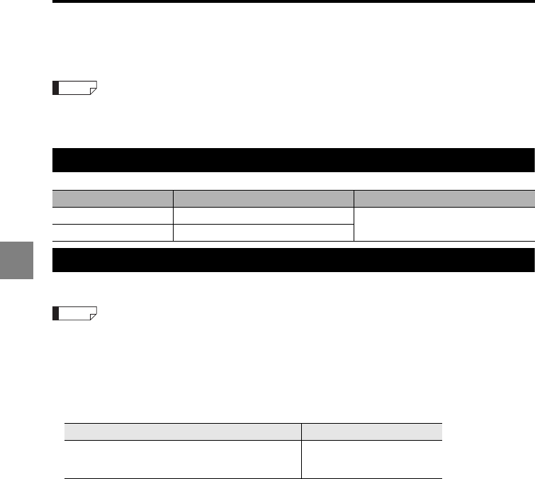
5-36
5
5 RS-232C
Data Storage Function
This section describes the data storage function using the RS-232C interface.
•For details on the data storage function, refer to page 2-11.
•For the procedure of operating the data storage function with LK-Navigator2, refer to LK-Navigator2
User's Manual.
Environmental settings
Command input/output procedure
The procedure for storing and reading measurement data is described below.
•The "data storage setting" and "storage (OUT)" commands can be received only when the controller
is set in "Communication mode".
•The "data storage start", "data storage stop" and "data storage/data output" commands can be
received only when the controller is set in "General mode".
•For switching between the "General mode" and the "Communication mode", refer to "Mode change
command" (page 5-7) in this manual.
•Timing signal input methods are as described below.
Item Setting value Remark
Baud rate 9600/19200/38400/57600/115200bps The settings depend on the external
device connected.
Parity None/Even/Odd
Input method Reference page
External terminal input (TIMING1)
Input via RS-232C interface
Input from dedicated touch panel LK-HD1000
page 4-2
page 5-9
LK-HD1000 User’s Manual
Reference
Reference

5-37
5
5 RS-232C
When the storage cycle is other than "Synchronization input"
1. Specify the number of storage points and the storage cycle with the "data storage
setting" command. (page 5-22)
2. Specify an OUT to be stored to with the "storage (OUT)" command. (page 5-21)
3. Start data storage with the "data storage start" command. (page 5-12)
4. Stop data storage with the "data storage stop" command. (page 5-12)
5. Output stored data with the "data storage/data output" command. (page 5-12)
When storage cycle is "Synchronization input"
1. Select an OUT to be stored to in synchronization with synchronous input in
"Synchronization setting". (page 5-21)
2. Specify the number of storage points and the storage cycle with the "data storage
setting" command. The storage cycle is set in "Synchronization input". (page 5-22)
3. Specify an OUT to be stored to with the "storage (OUT)" command. (page 5-21)
4. Start data storage with the "data storage start" command. (page 5-12)
5. Input a synchronous signal.
6. Stop data storage with the "data storage stop" command. (page 5-12)
7. Output stored data with the "data storage/data output" command. (page 5-12)
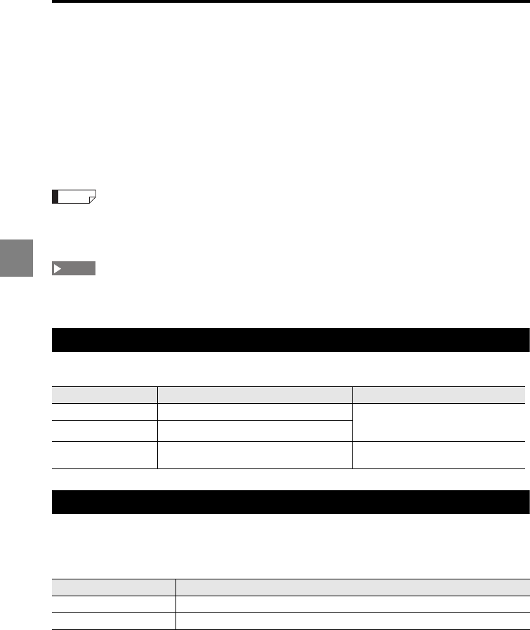
5-38
5
5 RS-232C
Measured Value Output through External
Synchronization
This section describes how to output the measured value through the RS-232C interface
in synchronization with the measurement triggered by the signal from the input terminal
(TIMING1 input). Since no incoming command is used, this method is useful when you
only need to import the measured value or when the LK-G5000 Series is connected to a
device that cannot send commands such as a data logger. The OUT terminals which
output the measured values with this method are the synchronized OUT only.
Commands for measured value output and for changing settings can be used even when the
measured values are being output through the external synchronization (when the external trigger
input is not OFF).
Do not attempt to determine the next measured value while the current measured value is being output
through the RS-232C interface. That next measured value will not be output.
Environment settings parameters
Set the environment settings as follows (page 3-72).
Output type
The measured value to be output is the value determined by the external synchronization
(TIMING1 input).
The output is set as follows depending on the automatic transmission setting.
Item Setting value Remark
Baud rate 9600/19200/38400/57600/115200 bps Set the appropriate parameter
according to the external device to be
connected.
Parity None/even/odd
Automatic
transmission ON/OFF Select ON or OFF according to the
output type.
Automatic transmission Output type
OFF Disables the measured value output through the external synchronization.
ON Enables the measured value output through the external synchronization.
Reference
NOTE
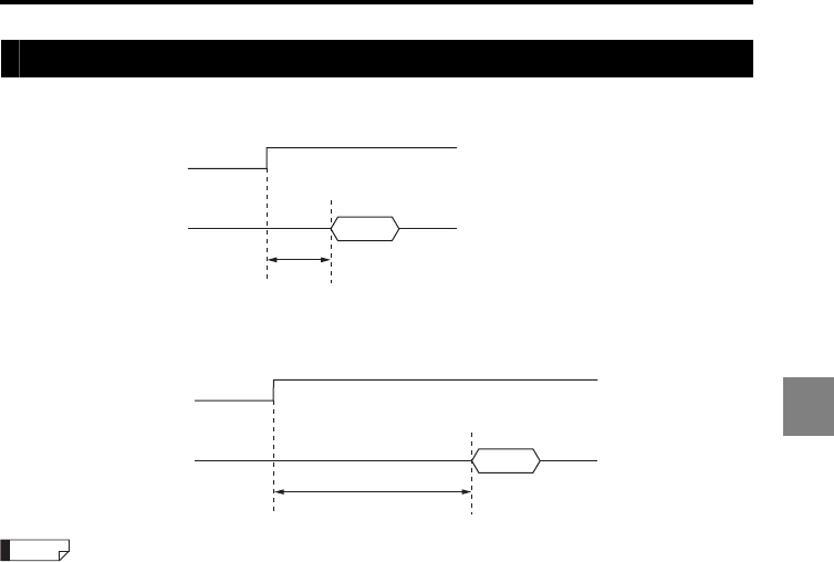
5-39
5
5 RS-232C
Timing diagrams
When the measurement mode is other than the sample hold (Trigger 2)
When the measurement mode is the sample hold (Trigger 2)
For details on T2 (input response time) and T4 (sampling period), refer to "Timing details" (page 4-26).
TIMING input
Measured
value
T2 + 2 ms
RS-232C data output
ON
OFF
T2 + T4 + 2 ms
ON
OFF
TIMING input
Measured
value
RS-232C data output
Reference
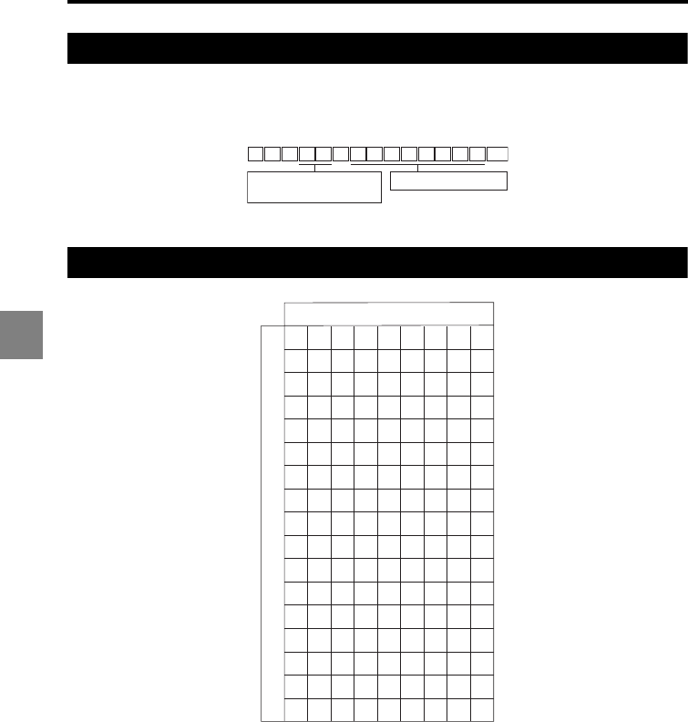
5-40
5
5 RS-232C
Output format
The following command format is used for the measured value output.
Regardless of the synchronization setting (synchronous/asynchronous), the measured
value determined for each OUT No. is output in this format.
ASCII code table (Reference)
T , a a
CR
, f f f f f f f f G
OUT No.
01: OUT01 to 12: OUT12
Measured value format
High-order four bits
Low-order four bits
01234567
NUL
DLESP0@P`p
0
SOH
DC1!1AQaq
1
STX
DC2”2BRbr
2
ETX
DC3#3CScs
3
EOT
DC4$4DTdt
4
ENQ
NAK%5EUeu
5
ACK
SYN&6FV fv
6
BEL
ETB'7GW
gw
7
BSCAN(8HXhx
8
HTEM)9IYiy
9
LFSUB*:JZ jz
A
VTESC+;K[k{
B
FF→,<L¥l|
C
CR←-=M]m}
D
SO↑.>N
^n∼
E
SI↓/ ?O
_oDT
F

6-1
6
6
This chapter includes the specifications of the controller and
sensor head, the outer dimensions, and the characteristics such
as the beam spot diameter.
Specifications ....................................................................... 6-2
Dimensions......................................................................... 6-15
Characteristics.................................................................... 6-25
Specifications6
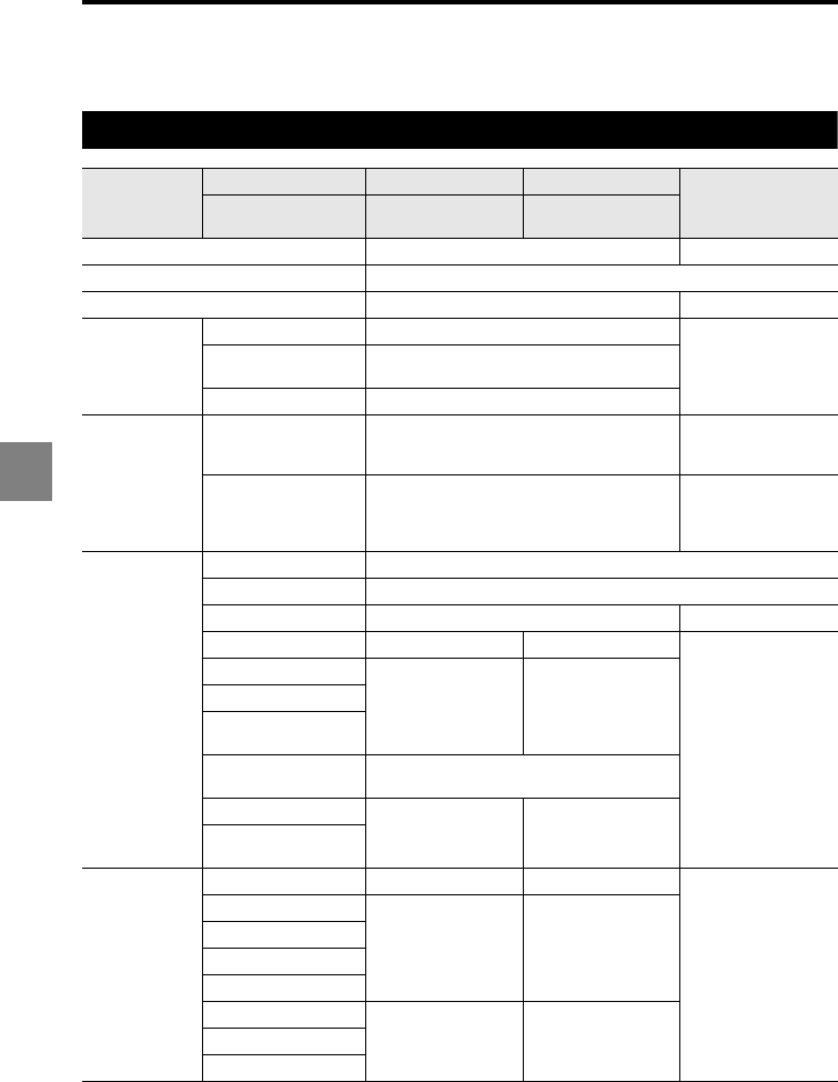
6-2
6
6 Specifications
Specifications
Controller
Model
Single unit type LK-G5001V LK-G5001PV
LK-HA100
Separate type LK-G5001/
LK-HD500
LK-G5001P/
LK-HD500
Designation Main controller Head expansion unit
Sensor head compatibility Compatible
No. of connectable sensor heads 2 1
Display
(LK-HD500)
Minimum display unit 0.001 μm
N/ADisplay range ±999.999 μm to ±9999.99 mm
(7 settings selectable)
Display cycle Approx. 10 times/sec.
Display
interface
DISPLAY port
Either the display unit (LK-HD500) or
dedicated touch panel (LK-HD1001)
can be connected
N/A
LED indicator LASER ON
POWER
STABILITY
BRIGHT
DARK
Terminal block
Analog voltage output ±10 V output, Output impedance: 100
Analog current output 4 to 20 mA, Maximum load resistance: 350
No. of analog outputs 2 1
TIMING1 input*1Non-voltage input Voltage input
N/A
RESET1 input*1
Non-voltage input Voltage input
Auto-zero1 input*1
Laser control
input
Laser remote
input*2Non-voltage input
Alarm output NPN open-collector
output
PNP open-collector
output
General comparator
output
Expansion
connector
TIMING input Non-voltage input Voltage input
N/A
RESET input
Non-voltage input Voltage input
Auto-zero input
Program switch input
Binary selection input
Alarm output
NPN open-collector
output
PNP open-collector
output
Comparator output
Binary output
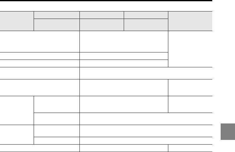
6-3
6
6 Specifications
*7 This input is applied to all of the synchronized OUT.
*8When the laser class 3B sensor head is connected, a key-operated switch must be used for the
input to this terminal. The laser is emitted only when the key-operated switch is set to the ON
position. (Select a key which can be removed only when it is set to the OFF position.) When the
laser class 1, 2/3R sensor head is connected, the laser turns on when this terminal is opened and
turns off when it is short-circuited.
*9 When a PC supporting USB Revision 1.1 or USB Revision 2.0 full speed is connected, the data
refresh cycle and other operations may slow down.
*10The Ethernet connection should be used only for one-to-one connection with a PC or for local
connection including only the PC and the LK-G5000 Series units.
•NPN open-collector output rating: 50 mA max. (40 V max.), Residual voltage: 0.5 V max.
•PNP open-collector output rating: 50 mA max. (30 V max.), Residual voltage: 0.5 V max.
•Non-voltage input rating: ON voltage: 1 V max., OFF current: 0.6 mA max.
•Voltage input rating: Maximum input rating: 26.4 V, ON voltage: 10.2 V, OFF current: 0.6
mA
•Parts of the input/output circuit of the LK-G5000 Series are internally common. Be
careful that no potential difference is generated between the internally common
terminals due to the potential difference between the cables/external devices. For
details, refer to "Precautions on wiring" (page 7).
RS-232C interface
Baud rate: 9600 to 115200 bps
Data length: 8 bits
Stop bit length: 1 bit
Parity: None/even/odd N/A
USB interface USB Revision 2.0 high speed compliant*3
Ethernet interface*4100Base-TX/10Base-T
Head expansion unit connector Up to 10 head expansion units can be connected to one main
controller
Expansion unit connector
Either of the CC-Link unit (LK-CC100) or
DeviceNet unit (LK-DN100) can be
connected
N/A
Power supply
Power supply voltage 24 VDC±10%
24 VDC±10%
(Supplied from
the controller)
Maximum current
consumption
3.5 A (when the maximum number of head expansion units are
connected)
Environment
resistance
Ambient temperature When one or less head expansion unit is connected: 0 to 50C
When two or more head expansion units are connected: 0 to 40C
Relative humidity 35 to 85%RH (No condensation)
Weight 600 g 300 g
Model
Single unit type LK-G5001V LK-G5001PV
LK-HA100
Separate type LK-G5001/
LK-HD500
LK-G5001P/
LK-HD500
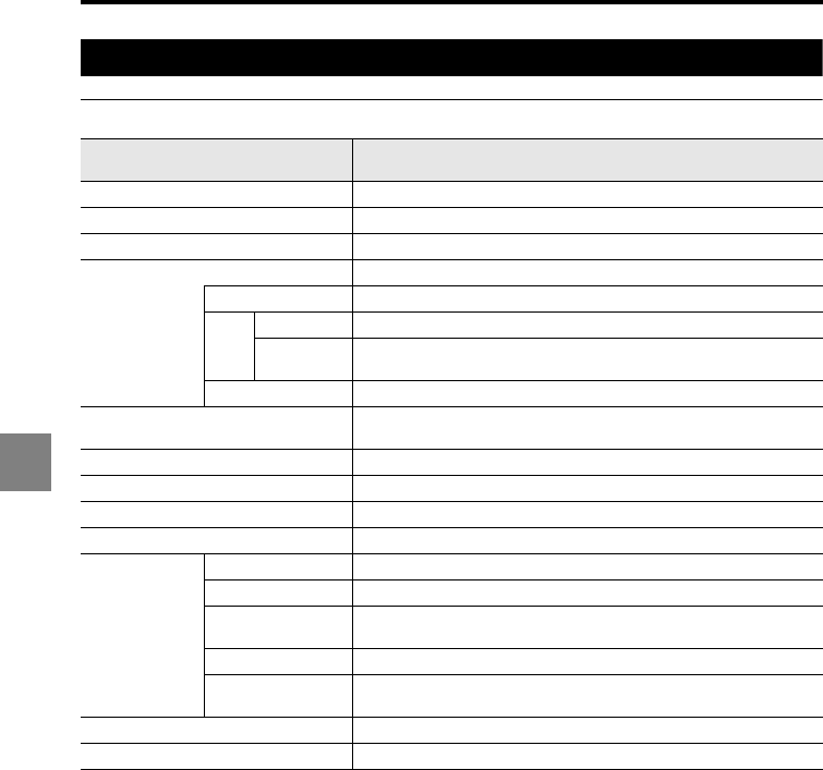
6-4
6
6 Specifications
Sensor head
LK-H008/H008W
*1 Measurement range when the sampling cycle is 20 μs or more.
*2 This value is obtained when the KEYENCE standard target (metal mirror workpiece) is measured in
the normal measurement mode.
*3 This value is obtained when the KEYENCE standard target (metal mirror workpiece) is measured at
the reference distance with the number of averaging measurements set to 16384.
*4 When the ambient temperature rises to 40 C or more, mount this on the metal plate for using.
Model LK-H008/
LK-H008W
Mounting mode Specular reflection
Reference distance 8 mm
Measurement range*1±0.5 mm
Light source
Red semiconductor laser
Wavelength 655 nm
Laser
Class
IEC60825-1 Class II
FDA(CDRH)
Part 1040.10 Class 1
Output 0.3 mW
Beam spot diameter (at reference
distance)
20 μm
20 μm x 550 μm
Linearity*2±0.05% of F.S. (F.S. = 1.0 mm)
Repeatability*30.005 μm (0.001 μm)
Sampling cycle 2.55/5/10/20/50/100/200/500/1000 μs (9 steps selectable)
Temperature fluctuation 0.02% of F.S./C (F.S. = 1.0 mm)
Environment
resistance
Enclosure rating IP67
Ambient light Incandescent lamp or fluorescent lamp: 10000 lx max.
Ambient
temperature*40 to +50C
Relative humidity 35 to 85%RH (No condensation)
Vibration 10 to 55 Hz, 1.5 mm double amplitude in X, Y, and Z directions, 2
hours respectively
Material Aluminum die-cast
Weight (including cable) Approx. 240 g
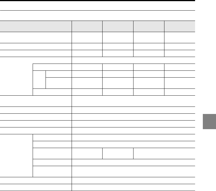
6-5
6
6 Specifications
LK-H020/H025/H023/H028/H022/H027/H022K/H027K
*1 For details about the measurement range, refer to page 1-12 (for the sampling cycles between 2.55
and 10 μs).
*2 This value is obtained when the KEYENCE standard target (light-diffusive white object) is measured
in the normal measurement mode.
*3 This value is obtained when the KEYENCE standard target (light-diffusive white object) is measured
at the reference distance with the number of averaging measurements set to 16384.
The value in parentheses is a typical example of a measurement with the number of averaging
measurements set to 65536.
*4 The LK-H023/H028 must be mounted on a metal plate when the ambient temperature rises to 40C
or more.
Model LK-H020/
LK-H025
LK-H023/
LK-H028
LK-H022/
LK-H027
LK-H022K/
LK-H027K
Mounting mode Diffuse
reflection
Diffuse
reflection
Diffuse
reflection
Specular
reflection
Reference distance 20 mm 20 mm 20 mm 16.1 mm
Measurement range*1±3 mm ±3 mm ±3 mm ±2.8 mm
Light source
Red semiconductor laser
Wavelength 650 nm 690 nm 650 nm 650 nm
Laser
Class
IEC60825-1 Class 3R Class 3B Class 2 Class 2
FDA(CDRH)
Part 1040.10 Class IIIa Class IIIb Class II Class II
Output 4.8 mW 50 mW 0.95 mW 0.95 mW
Beam spot diameter (at reference
distance)
25 μm (LK-H020/H023/H022/H022K)/
25 μm x 1400 μm (LK-H025/H028/H027/H027K)
Linearity*2±0.02% of F.S. (F.S. = 6 mm)
Repeatability*30.02 μm (0.01 μm)
Sampling cycle 2.55/5/10/20/50/100/200/500/1000 μs (9 steps selectable)
Temperature fluctuation 0.01% of F.S./C (F.S. = 6 mm)
Environment
resistance
Enclosure rating IP67
Ambient light Incandescent lamp or fluorescent lamp: 10000 lx max.
Ambient
temperature*40 to +50C0 to +45C 0 to +50C
Relative humidity 35 to 85%RH (No condensation)
Vibration 10 to 55 Hz, 1.5 mm double amplitude in X, Y, and Z directions, 2
hours respectively
Material Aluminum die-cast
Weight (including cable) Approx. 230 g
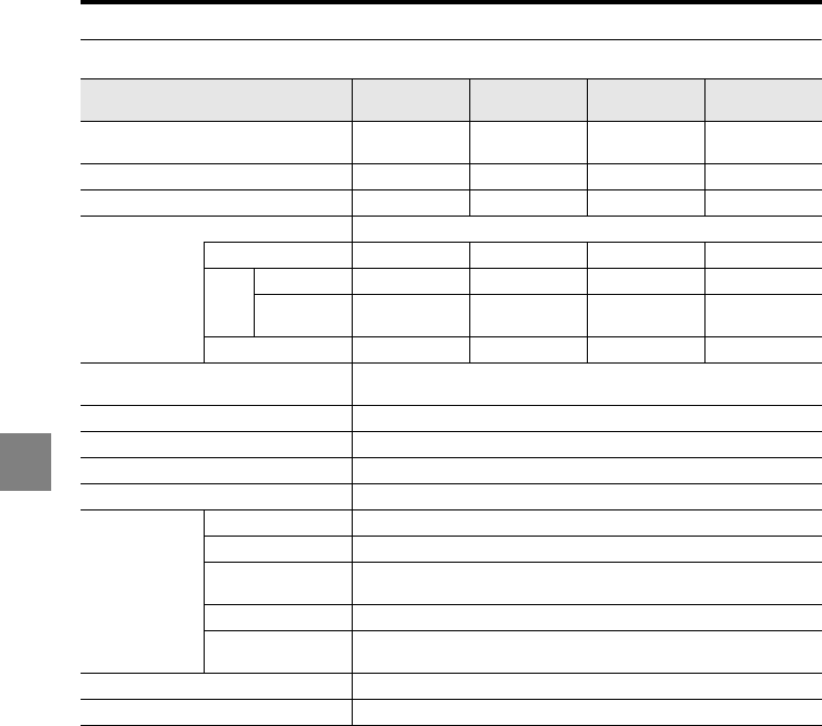
6-6
6
6 Specifications
LK-H050/H055/H053/H058/H052/H057/H052K/H057K
*1 For details about the measurement range, refer to page 1-13 (for the sampling cycles between 2.55
and 10 μs).
*2 This value is obtained when the KEYENCE standard target (light-diffusive white object) is measured
in the normal measurement mode.
*3 This value is obtained when the KEYENCE standard target (light-diffusive white object) is measured
at the reference distance with the number of averaging measurements set to 16384.
Model LK-H050/
LK-H055
LK-H053/
LK-H058
LK-H052/
LK-H057
LK-H052K/
LK-H057K
Mounting mode Diffuse
reflection
Diffuse
reflection
Diffuse
reflection
Specular
reflection
Reference distance 50 mm 50 mm 50 mm 46.3 mm
Measurement range*1±10 mm ±10 mm ±10 mm ±5.2 mm
Light source
Red semiconductor laser
Wavelength 650 nm 690 nm 650 nm 650 nm
Laser
Class
IEC60825-1 Class 3R Class 3B Class 2 Class 2
FDA(CDRH)
Part 1040.10 Class IIIa Class IIIb Class II Class II
Output 4.8 mW 50 mW 0.95 mW 0.95 mW
Beam spot diameter (at reference
distance)
50 μm (LK-H050/H053/H052/H052K)/
50 μm x 2000 μm (LK-H055/H058/H057/H057K)
Linearity*2±0.02% of F.S. (F.S. = 20 mm)
Repeatability*30.025 μm
Sampling cycle 2.55/5/10/20/50/100/200/500/1000 μs (9 steps selectable)
Temperature fluctuation 0.01% of F.S./C (F.S. = 20 mm)
Environment
resistance
Enclosure rating IP67
Ambient light Incandescent lamp or fluorescent lamp: 10000 lx max.
Ambient
temperature 0 to +50C
Relative humidity 35 to 85%RH (No condensation)
Vibration 10 to 55 Hz, 1.5 mm double amplitude in X, Y, and Z directions, 2
hours respectively
Material Aluminum die-cast
Weight (including cable) Approx. 260 g
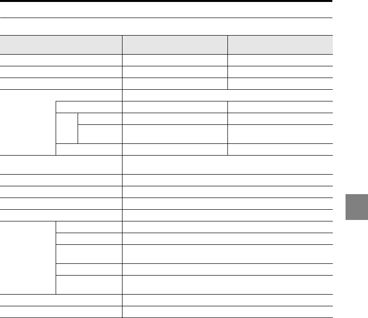
6-7
6
6 Specifications
LK-H080/H085/H082/H087
*1 This measurement range is when the sampling cycle is over 20 μs.
*2 This value is obtained when the KEYENCE standard target (diffusive, white object) is measured
whilst using the standard mode.
*3 This value is obtained when the KEYENCE standard target (light-diffusive white object) is measured
at the reference distance with the number of averaging measurements set to 16384.
*4 Should the ambient temperature be above 40C, a metal plate must be attached before use.
Model LK-H080/
LK-H085
LK-H082/
LK-H087
Mounting mode Diffuse reflection Diffuse reflection
Reference distance 80 mm 80 mm
Measurement range*1±18 mm ±18 mm
Light source
Red semiconductor laser
Wavelength 655 nm 650 nm
Laser
Class
IEC60825-1 Class 3R Class 2
FDA(CDRH)
Part 1040.10 Class IIIa Class II
Output 4.8 mW 0.95 mW
Beam spot diameter (at reference
distance)
70 μm (LK-H080/082)
70 μm x 2500 μm (LK-H085/087)
Linearity*2±0.02% of F.S. (F.S. = 36 mm)
Repeatability*30.10 μm
Sampling cycle 2.55/5/10/20/50/100/200/500/1000 μs (9 steps selectable)
Temperature fluctuation 0.01% of F.S./C (F.S. = 36 mm)
Environment
resistance
Enclosure rating IP67
Ambient light Incandescent lamp or fluorescent lamp: 10000 lx max.
Ambient
temperature*40 to +50C
Relative humidity 35 to 85%RH (No condensation)
Vibration 10 to 55 Hz, 1.5 mm double amplitude in X, Y, and Z directions, 2
hours respectively
Material Aluminum die-cast
Weight (including cable) Approx. 280 g
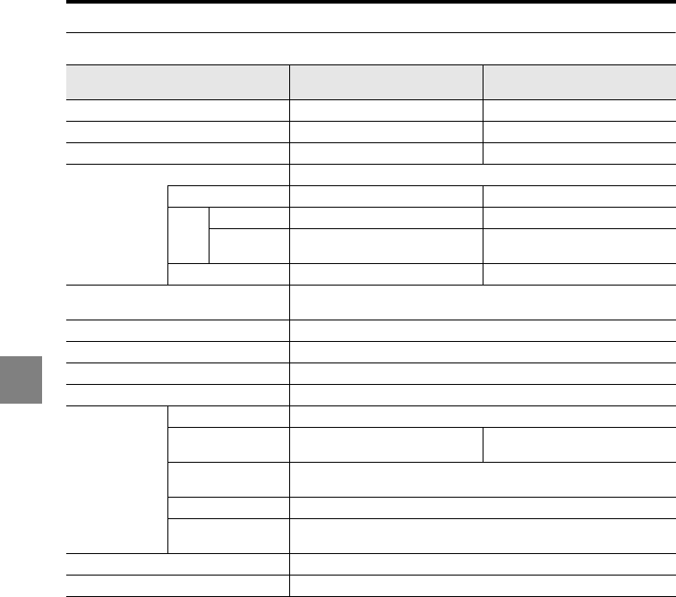
6-8
6
6 Specifications
LK-H150/H155/H152/H157
*1 This measurement range is when the sampling cycle is over 20 μs.
*2 This value is obtained when the KEYENCE standard target (diffusive, white object) is measured
whilst using the standard mode.
*3 This value is obtained when the KEYENCE standard target (light-diffusive white object) is measured
at the reference distance with the number of averaging measurements set to 16384.
*4 Should the ambient temperature be above 40C, a metal plate must be attached before use.
Model LK-H150/
LK-H155
LK-H152/
LK-H157
Mounting mode Diffuse reflection Diffuse reflection
Reference distance 150 mm 150 mm
Measurement range*1±40 mm ±40 mm
Light source
Red semiconductor laser
Wavelength 655 nm 650 nm
Laser
Class
IEC60825-1 Class 3R Class 2
FDA(CDRH)
Part 1040.10 Class IIIa Class II
Output 4.8 mW 0.95 mW
Beam spot diameter (at reference
distance)
120 μm (LK-H150/152)
120 μm x 4200 μm (LK-H155/157)
Linearity*2±0.02% of F.S. (F.S. = 80 mm)
Repeatability*30.25 μm
Sampling cycle 2.55/5/10/20/50/100/200/500/1000 μs (9 steps selectable)
Temperature fluctuation 0.01% of F.S./C (F.S. = 80 mm)
Environment
resistance
Enclosure rating IP67
Ambient light Incandescent lamp or fluorescent
lamp: 10000 lx max.
Incandescent lamp or fluorescent
lamp: 5000 lx max.
Ambient
temperature*40 to +50C
Relative humidity 35 to 85%RH (No condensation)
Vibration 10 to 55 Hz, 1.5 mm double amplitude in X, Y, and Z directions, 2
hours respectively
Material Aluminum die-cast
Weight (including cable) Approx. 300 g
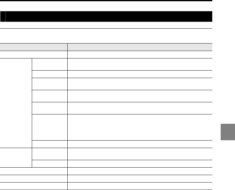
6-9
6
6 Specifications
Expansion unit
LK-CC100 CC-Link unit
*1 CC-Link is a registered trademark of Mitsubishi Electric Corporation.
*2 The LK-G5000 Series supports the "extended cyclic transmission" and "station-to-station cable
length relaxation" of CC-Link Ver. 2.00.
Model LK-CC100
Designation CC-Link communication unit dedicated to LK-G5000 Series
Network
connection
Supported CC-
Link*1 version
Ver. 1.10 (Extended cyclic setting: Single)
Ver. 2.00 (Extended cyclic setting: Double or more)*2
Master unit CLPA-certified master unit (CC-Link Ver. 2.00/Ver. 1.10)
No. of occupied
stations 1 to 4
Communication
speed 156 kbps, 625 kbps, 2.5 Mbps, 5 Mbps, 10 Mbps
Connecting
cable
Dedicated CC-Link cable supporting Ver. 1.10
(Shielded 3-core twisted-pair cable: OP-79426, OP-79427)
Maximum total
cable extension
length
156 kbps: 1200 m
625 kbps: 900 m
2.5 Mbps: 400 m
5 Mbps: 160 m
10 Mbps: 100 m
Station type Remote device station
Environment
resistance
Ambient
temperature
When one or less head expansion unit is connected: 0 to +50C
When two or more head expansion units are connected: 0 to +40C
Relative humidity 35 to 85%RH (No condensation)
Rated voltage 24 VDC±10% (supplied from controller)
Current consumption 200 mA max.
Weight Approx. 300 g
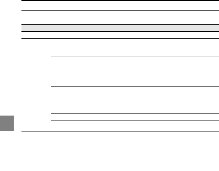
6-10
6
6 Specifications
LK-DN100 DeviceNet unit
*1 DeviceNet is a registered trademark of ODVA (Open DeviceNet Vendor Association).
Model LK-DN100
Designation DeviceNet communication unit dedicated to LK-G5000 Series
Network
connection
Communication
protocol DeviceNet*1 compliant
Master unit ODVA-certified master unit
Transmission
speed 500 kbps, 250 kbps, 125 kbps
Device type Generic
Transmission
medium
Dedicated 5 cables (2 signal cables, 2 power supply cables, 1 shielding
cable)
Maximum trunk
line cable length
Thick cable: 500 m (at transmission speed of 125 kbps)
/250 m (at 250 kbps)/125 m (at 500 kbps)
Thin cable: 100 m (at all transmission speed settings)
Communication
type
I/O communication (Poll)
Explicit message communication
Power supply 11 VDC to 25 VDC
Current
consumption 10 mA max. (when network power supply 24 V is applied)
Environment
resistance
Ambient
temperature
When one or less head expansion unit is connected: 0 to +50C
When two or more head expansion units are connected: 0 to +40C
Relative humidity 35 to 85%RH (No condensation)
Rated voltage 24 VDC±10% (supplied from controller)
Current consumption 200 mA max.
Weight Approx. 300 g
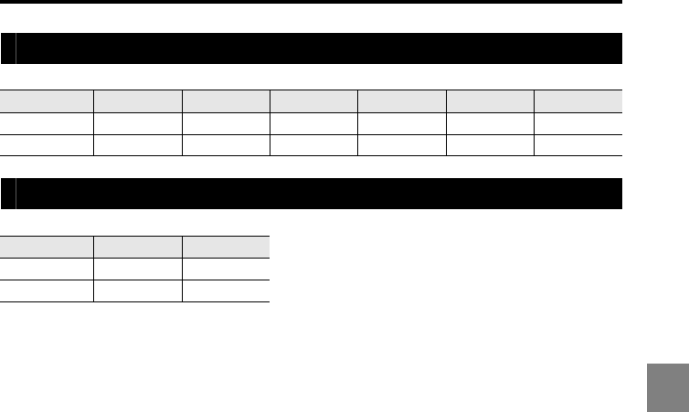
6-11
6
6 Specifications
Head-to-controller cable
Head-to-controller extension cable
Model CB-A07 CB-A2 CB-A5 CB-A10 CB-A20 CB-A30
Cable length 0.7 m 2 m 5 m 10 m 20 m 30 m
Weight
Approx. 100 g Approx. 200 g Approx. 400 g Approx. 750 g Approx. 1400 g Approx. 2000 g
Model CB-A5E CB-A10E
Cable length 5 m 10 m
Weight Approx. 400 g Approx. 750 g
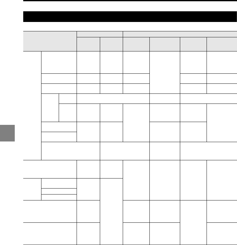
6-12
6
6 Specifications
Status table
•"ON/OFF" indicates the ON/OFF status of the NPN or PNP open-collector output.
•"Hold" represents the status in which the last normal value is being held.
•"Setting mode" represents the setting changes using the display panel keys.
•"Communication mode" means the setting changes using the RS-232C/USB/LAN communication.
•The alarm output turns on when operation is normal and turns off when an error occurs.
•The RESET operation is performed after the mode is changed to the measuring mode, the program
number is changed, the auto-zero operation is completed, and the RESET input is provided.
•If the RS-232C, USB, or LAN communication is used in the measuring mode, the response speed
slows down.
•The RS-232C, USB, and LAN interfaces cannot be used simultaneously.
•When the LK-Navigator 2 setup support software is used, the change to the communication mode
and return to the measuring mode are automatically controlled by the software.
•When the RS-232C communication is used with the LK-Navigator 2, the refresh rate becomes slow
compared with the rate using the USB or LAN communication.
Display panel Output
Measured
value Comparator
Analog
voltage
(current)
ALARM (N.C.) Comparator Binary
Measuring
mode
Normal Measured
value
Comparator
result
Voltage
(current) with
reference to
the measured
value ON
Comparator
result Measured value
Over range
on the positive side FFFFFF HI +10.8 V
(20.64 mA) HI 1048575
(0x0FFFFF)
Over range
on the negative side -FFFFFF LO -10.8 V
(3.36 mA) LO -1048576
(0x100000)
Alarm
During
hold Hold ON Hold
During
alarm -FFFFFF
HI/LO
ON
simultaneou
sly -10.8 V
(3.36 mA)
Varies
depending on
the alarm output
type
HI/LO
ON
simultaneously -1048576
(0x100000)Comparator
standby ------ All OFF ON All OFF
During RESET
operation
Dark/Bright Alarm status
Varies
depending on
the alarm output
type
Alarm status
Setting mode Setting item
Varies
depending
on the
setting item
Hold Hold Hold Hold
Communication
mode
RS-232C
communication --COM--
(Communication
mode indication)
OFF
USB communication
LAN
System error Error
display -10.8 V
(3.36 mA)
Varies
depending on
the alarm output
type
OFF
-1048576
(0x100000)
At power-on
------
(Starting up
process is
being
checked)
Undefined
value until
measurement
starts
OFF 0
(0x000000)
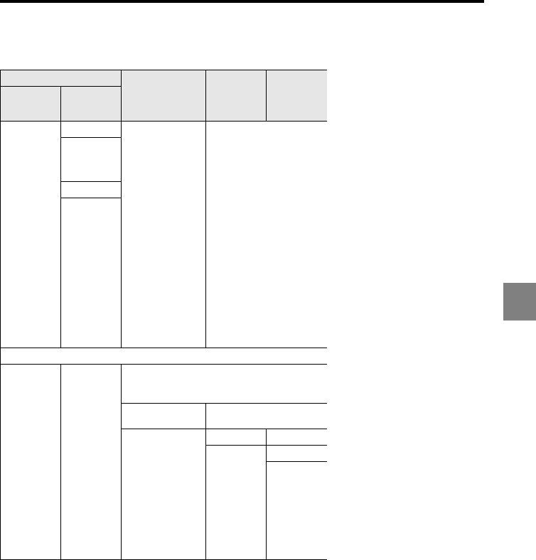
6-13
6
6 Specifications
•"O" and "X" represent the statuses where input is possible and impossible respectively.
•"Setting mode" represents the setting changes using the display panel keys.
•"Communication mode" means the setting changes using the RS-232C/USB/LAN communication.
•The RESET operation is performed after the mode is changed to the measuring mode, the program
number is changed, the auto-zero operation is completed, and the RESET input is provided.
•If the RS-232C, USB, or LAN communication is used in the measuring mode, the response speed
slows down.
•The RS-232C, USB, and LAN interfaces cannot be used simultaneously.
•When the LK-Navigator 2 setup support software is used, the change to the communication mode
and return to the measuring mode are automatically controlled by the software.
•When the RS-232C communication is used with the LK-Navigator 2, the refresh rate becomes slow
compared with the rate using the USB or LAN communication.
Input
RS-232C USB LAN
TIMING/
RESET/
P1/P2/P3
ZERO
Measured value
display, received
light waveform
display, data
storage/
measurement
control commands
controlled by LK-
Navigator 2
Measured value display,
received light waveform
display, data storage
controlled by LK-Navigator
2
X
(Canceling
auto-zero is
possible)
X
(Canceling
auto-zero is
possible)
Alarm status
XX
Error
Setting transmission/
Setting change command
Error
Error
Setting transmission
Error
Error
Setting transmission
Error
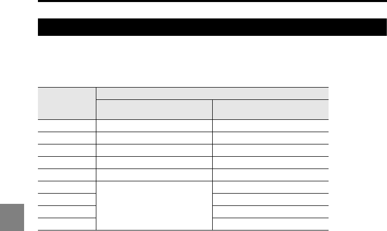
6-14
6
6 Specifications
Response delay time
Measurement response time
This is the period of time until the LK-G5000 Series recognizes the change in the target
and outputs the signal. This is calculated by the following formula.
•For details about the sampling cycle (T6) and reset time (T4), refer to "Timing details"
(page 4-26).
•When the mutual interference prevention function is used, the sampling cycle T6 is
calculated as T6 x 2 (for AB_ON) or T6 x 3 (for ABC_ON).
•When "Velocity" is selected for the measurement type, T4 is calculated as T4 + T6; when
"Acceleration" is selected, T4 is calculated as T4 + 2 x T6.
Power ON reset time
This is the period of time until measurement starts after the LK-G5000 Series is turned on.
•Power ON reset time when only the controller is used: Approx. 7 seconds
•When 10 head expansion units are connected to the controller: Approx. 17 seconds
Sampling cycle
(T6)
Measurement response time
Measurement modes other than
semi opaque
Measurement mode of semi
opaque
2.55 μs T6 x 138 + T4 + 50 μs -
5 μs T6 x 74 + T4 + 50 μs -
10 μs T6 x 41 + T4 + 50 μs -
20 μs T6 x 25 + T4 + 50 μs -
50 μs T6 x 16 + T4 + 50 μs -
100 μs
T6 x 10 + T4 + 100 μs
-
200 μs T6 x 13 + T4 + 100 μs
500 μs T6 x 13 + T4 + 100 μs
1000 μs T6 x 11 + T4 + 100 μs
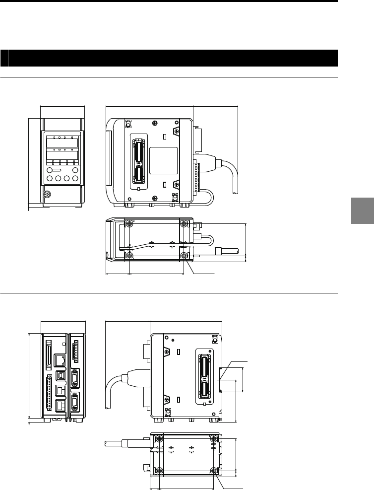
6-15
6
6 Specifications
Dimensions
Controller
LK-G5001V/LK-G5001PV <Unit: mm>
LK-G5001/LK-G5001P <Unit: mm>
65 128 (65)
124
6
34.5 79.5
947
4 × M4
Depth: 6
124
6
65 (65) 105.5
62.1
35.9
47
9
14 79.5
Depth: 6
4 × M4
DIN rail
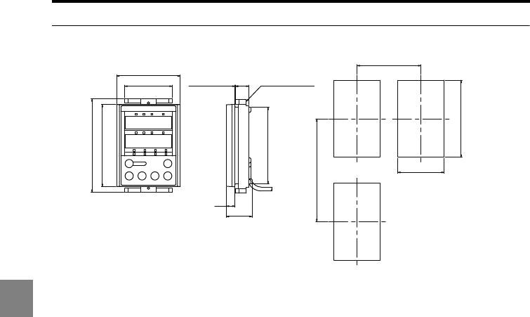
6-16
6
6 Specifications
LK-HD500 <Unit: mm>
62min.
75
45
100min.
+0.6
0
+0.6
0
74.5
8.5
25
13
Display panel
attachment ring
Panel thickness:
0.5 to 5 mm
46
62
80
91
Panel cutout
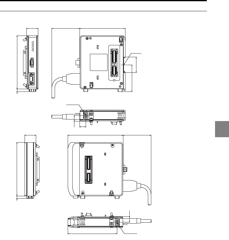
6-17
6
6 Specifications
LK-HA100 <Unit: mm>
26.3
1246
(65) 105.5
35.9
62.1
13.5
14
114
13.5
(65)
12826.3
1246
M4
Depth: 6
M4
Depth: 6
DIN rail
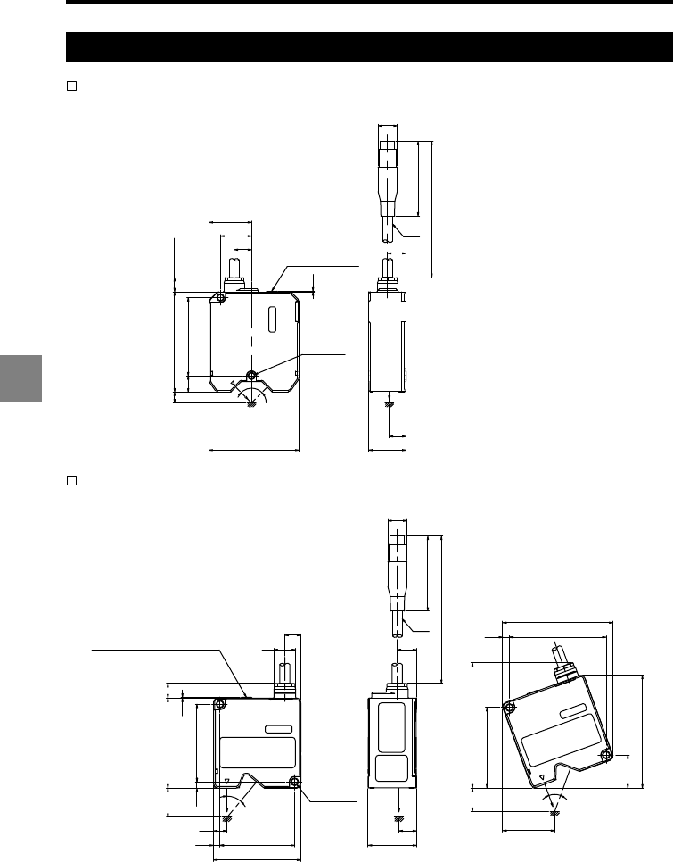
6-18
6
6 Specifications
Sensor head
LK-H008/H008W<Unit: mm>
LK-H020/H025/H023/H028/H022/H027/H022K/H027K <Unit: mm>
12.7
22.8
31.2
57.511.8
8 73.5 13.5 max.
66
0.5
55
500
ø
7
13.5
12.3
27.5
ø
14
90°
(mounting
hole)
2 x
ø
4.4
Laser radiation
warning indicator
15
11
33.44.4 51.4
60
2 x
ø
4.4
4.4 53.4
62
0.5
13 max.
20
Laser radiation warning indicator
(mounting
hole)
55.4
22.8
77.7
66.6
89 max.
16.1
40°
40°
9.2
4.6
75.9
35.8
12.2
13.4
55
500
ø
7
ø
14
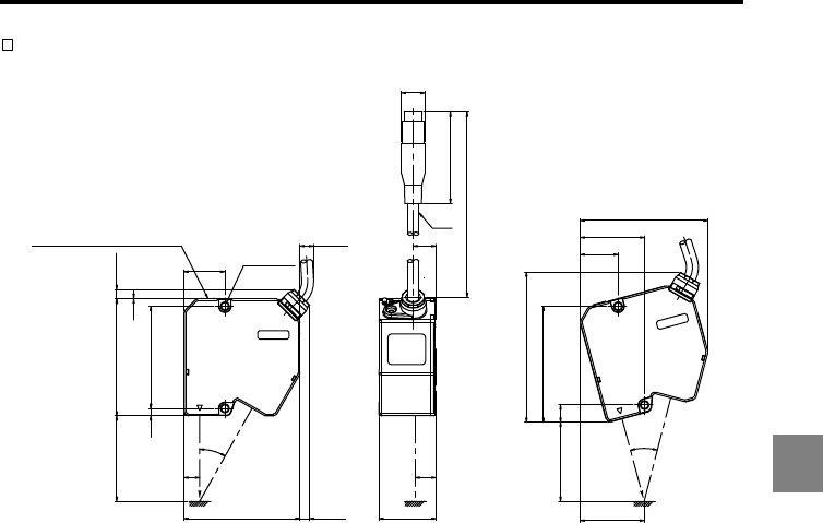
6-19
6
6 Specifications
LK-H050/H055/H053/H058/H052/H057/H052K/H057K <Unit: mm>
2 x
ø
4.4
(mounting
hole)
59.9
4.4
0.5
7.7 max.
68.550
33.4
9.2
30°
68 7.7 max.
24
10.1 max.
10.146.3
37.4
30°
68
89.9 max.
22.1
37.6
74.8
12.2
13.4
Laser radiation warning indicator
55
500
ø
7
ø
14
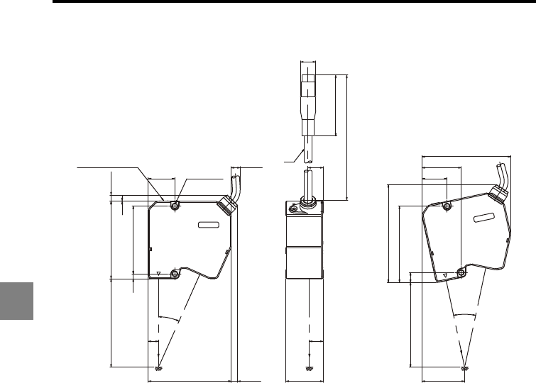
6-20
6
6 Specifications
LK-H080/LK-H085/LK-H082/LK-H087<Unit: mm>
LASER ON/
STABILITY LED φ7
2xφ4.4
(Mounting hole)
φ14
55
500
13.5
12.3
33.5 38.5
24°
9
76.7
69
90.5max.
22.7
35.4
80.3
9.2
75 7.7max.
10.1max.
24
7.7max.
0.5
61.44.4
7080
24°
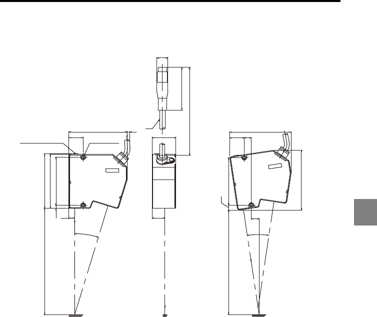
6-21
6
6 Specifications
LK-H150/LK-H155/LK-H152/LK-H157 <Unit: mm>
LASER ON/
STABILITY LED 2xφ4.4
(Mounting hole)
33.3
82.2 4
20.2
18
8.2
17°
17°
68
4.2
76.2
76.8
110 to 190
11
6.8
112.5 to 182.5 67.3
20.6 10.1
86.6
84.3
φ7
φ14
55
500
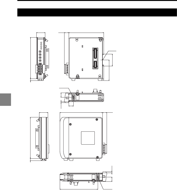
6-22
6
6 Specifications
Expansion unit
LK-CC100 <Unit: mm>
26.3
1246
128 (13.2)
114
13.5
(3.2)
26.3
1246
(13.2) 105.5
35.9
62.1
14
(3.2) 13.5
M4
Depth: 6
M4
Depth: 6
DIN rail
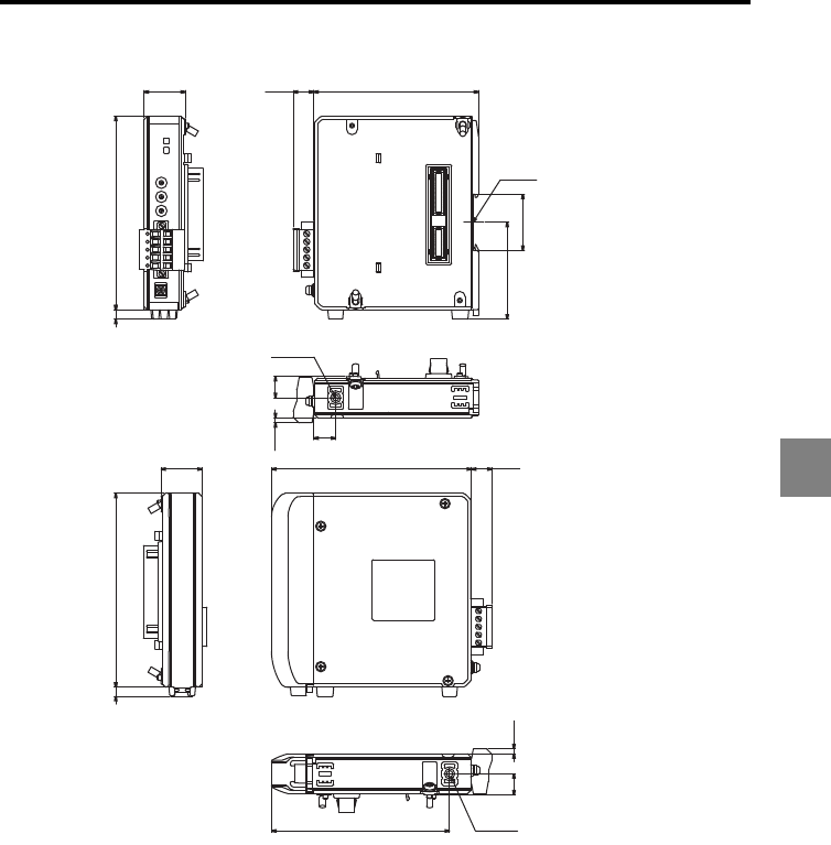
6-23
6
6 Specifications
LK-DN100 <Unit: mm>
26.3 128 (13.2)
1246
114
13.5
(3.2)
26.3
1246
(13.2) 105.5
35.9
62.1
13.5
(3.2)
14
M4
Depth: 6
M4
Depth: 6
DIN rail
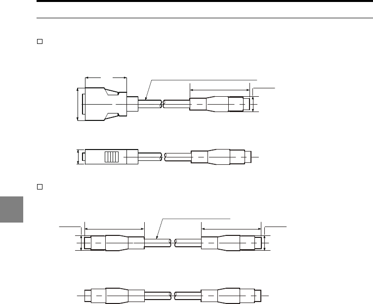
6-24
6
6 Specifications
Other accessory
Head-to-controller cable CB-A07/CB-A2/CB-A5/CB-A10/CB-A20/CB-A30
<Unit: mm>
Head to controller extension cable CB-A5E/CB-A10E
<Unit: mm>
ø7
Cable length: 0.7 m, 2 m, 5 m, 10 m, 20 m, 30 m
11.5
26
33
55 ø14
ø7 Cable length (5 m, 10 m)
5555 ø14ø14
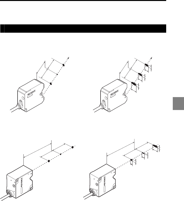
6-25
6
6 Specifications
Characteristics
Beam spot diameter
LK-H008LK-H008W
LK-H020/LK-H023/LK-H022/LK-H022K LK-H025/LK-H027/LK-H027K/LK-H028
Dimensions in ( ) indicate the reference distance
and measurement range for specular reflection
mounting.
Dimensions in ( ) indicate the reference distance
and measurement range for specular reflection
mounting.
0.5mm
0.5mm
8mm
40µm×60µm
ø
20µm
40µm×90µm
0.5mm
0.5mm
8mm
45µm
490µm
20µm
550µm
610µm
45µm
3 mm
(2.8 mm) (2.8 mm)
20 mm
(16.1 mm)
3 mm
ø270 µm
ø270 µm
ø25 µm
3 mm
20 mm
3 mm
1500 µm
1400 µm
1300 µm
270 µm
270 µm
25 µm
(2.8 mm) (2.8 mm)
(16.1 mm)
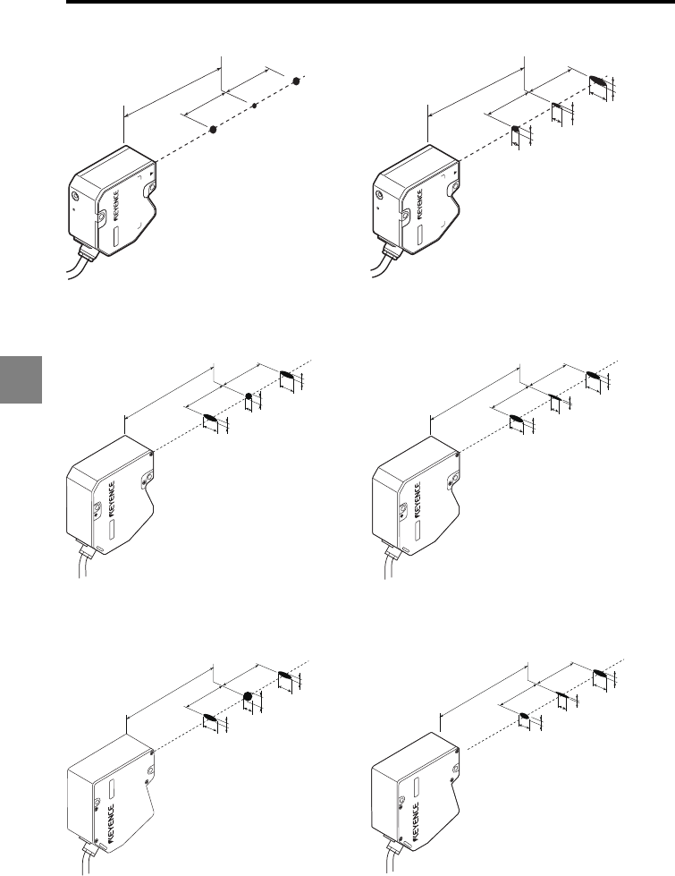
6-26
6
6 Specifications
LK-H050/LK-H052/LK-H053/LK-H052K LK-H055/LK-H057/LK-H058/LK-H057K
Dimensions in ( ) indicate the reference distance and
measurement range for specular reflection mounting.
Dimensions in ( ) indicate the reference distance and
measurement range for specular reflection mounting.
LK-H080/LK-H082LK-H085/LK-H087
Dimensions in ( ) indicate the reference distance and
measurement range for specular reflection mounting.
Dimensions in ( ) indicate the reference distance and
measurement range for specular reflection mounting.
LK-H150/LK-H152 LK-H155/LK-H157
Dimensions in ( ) indicate the reference distance and
measurement range for specular reflection mounting.
Dimensions in ( ) indicate the reference distance and
measurement range for specular reflection mounting.
10 mm
50 mm
10 mm
(5.2 mm)
(46.3 mm)
(5.2 mm)
Ø460 µm
Ø460 µm
Ø50 µm
10 mm
50 mm
10 mm
(5.2 mm)
(46.3 mm)
(5.2 mm)
2100 µm
2000 µm
1900 µm
400 µm
400 µm
50 µm
18mm
18mm
80mm
(76.7mm)
(17.6mm) (17.6mm)
530μm
300μm
220μm
70μm
380μm
70μm
18mm
18mm
80mm
(76.7mm)
(17.6mm) (17.6mm)
2490μm
340μm
340μm
2500μm
2510μm
70μm
40mm
40mm
150mm
(147.5mm)
(39.5mm) (39.5mm)
700μm
400μm
280μm
120μm
480μm
120μm
40mm
40mm
150mm
(147.5mm)
(39.5mm) (39.5mm)
3780μm
400μm
400μm
4200μm
4620μm
70μm
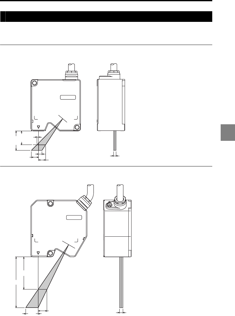
6-27
6
6 Specifications
Mutual interference
No interference occurs if the beam spot of the other sensor is out of the shaded area in the
figures (with white paper target).
LK-H020/LK-H025/LK-H023/LK-H028/LK-H022/LK-H027/LK-H022K/LK-H027K
<Unit: mm>
LK-H050/LK-H055/LK-H053/LK-H058/LK-H052/LK-H057/LK-H052K/LK-H057K
<Unit: mm>
16.7
23.3
2.2
8.8 4.1
8.4
±1.5
39
61
10.7 ±2
15.1
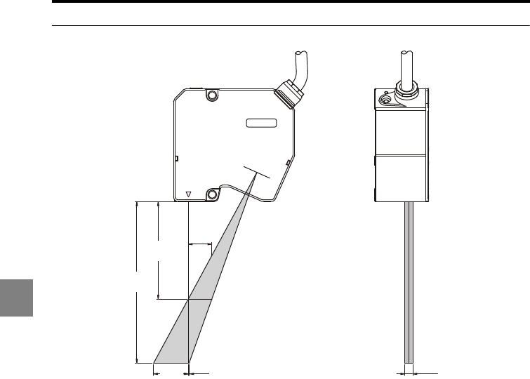
6-28
6
6 Specifications
LK-H080/LK-H085/LK-H082/LK-H087<Unit: mm>
0.5
14.6
±2.5
60.2
99.8
21.4
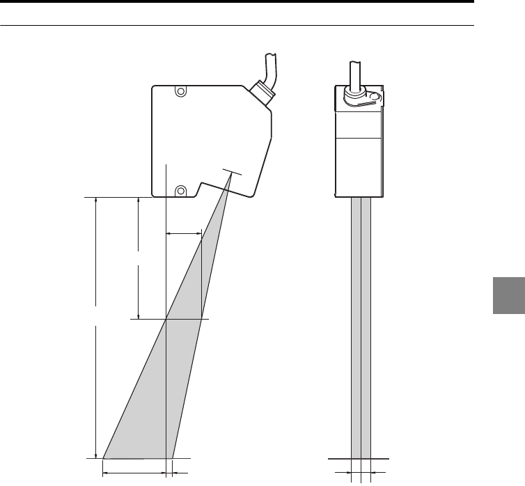
6-29
6
6 Specifications
LK-H150/LK-H155/LK-H152/LK-H157 <Unit: mm>
15.1
39
61
10.7 ±2
27
755
44
92
192
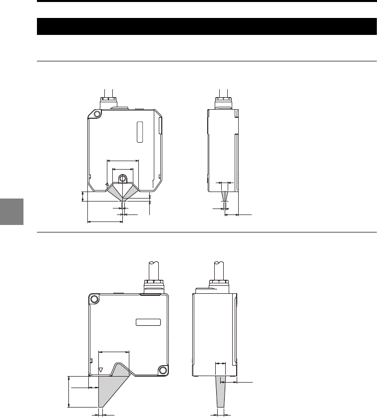
6-30
6
6 Specifications
Optical axis range
The detection is not affected if an interfering object is out of the shaded area in the figures.
LK-H008/LK-H008W
<Unit: mm>
LK-H020/LK-H025/LK-H023/LK-H028/LK-H022/LK-H027/LK-H022K/LK-H027K
<Unit: mm>
12.3
2
5.6
8.5
2.9
1
1.5
31.2
18.4
27.9
22.6
12.2
7.5
53
23.3
7.7
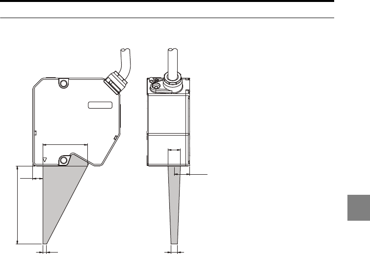
6-31
6
6 Specifications
LK-H050/LK-H055/LK-H053/LK-H058/LK-H052/LK-H057/LK-H052K/LK-H057K
<Unit: mm>
12.2
9.6
53
61
34.9
7.7
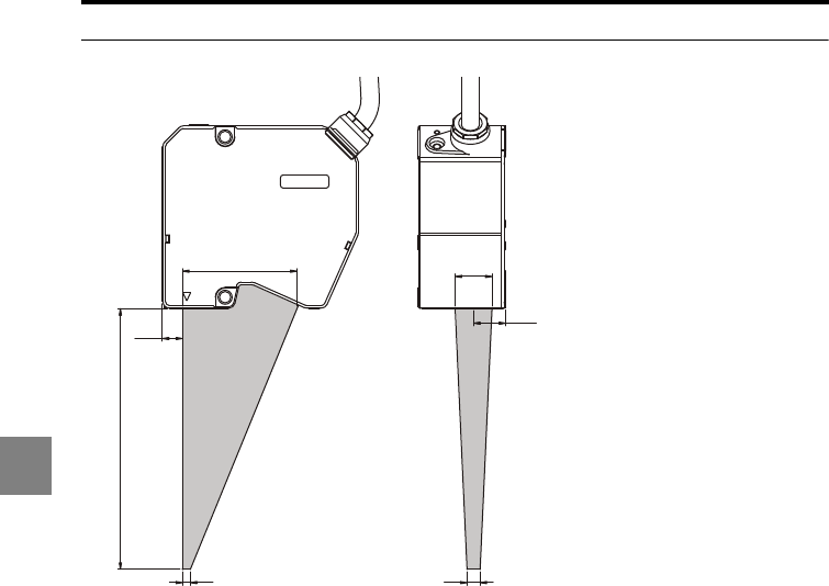
6-32
6
6 Specifications
LK-H080/LK-H085/LK-H082/LK-H087<Unit: mm>
99.8
7.7
12.3
14.1
5
43.8
3
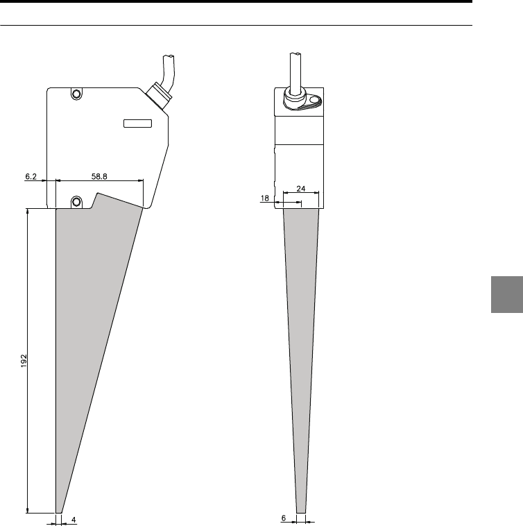
6-33
6
6 Specifications
LK-H150/LK-H155/LK-H152/LK-H157 <Unit: mm>

6 Specifications
6-34
6
MEMO

A-1
A
Tr o ubleshooting .................................................................... A-2
Error Codes .......................................................................... A-5
List of Optional Accessories ................................................. A-7
Relationship Between the Sampling Cycle and Velocity/
Acceleration Measurement Range.................................. A-11
Index .................................................................................. A-12
AppendicesA

A-2
AA
Troubleshooting
This section describes the countermeasures against errors or problems that may occur
during the operation of the LK-G5000 Series.
Problem Possible Cause Countermeasure
Nothing is displayed on the
display panel.
Is the display panel cable properly
connected to the controller?
Is the power supply cable properly
connected?
Connect the power supply cable and display
panel cable properly. (page 1-26)
An error code is displayed. - Address the problem by following the instruction
provided for the displayed error code. (page A-
5)
A measured value is not
displayed.
Is the measurement target placed
within the measurement range?
Place the measurement target properly within
the measurement range.(page 1-12, page 1-13)
Are the head settings properly set? Adjust to the proper settings. (page 3-3)
Is the glass cover dirty? Remove the dust and dirt.
Does the glass cover have any flaws
or cracks?
The glass cover must be replaced. Because this
replacement requires KEYENCE repair service,
contact your nearest KEYENCE office.
Is the synchronization control properly
set according to the measurement
mode?
Set the synchronization control according to the
measurement mode. (page 3-62)
Does condensation occur in the unit? Check the installation environment. (page 1-3)
The laser beam is not
emitted.
Is the head-to-controller cable
properly connected?
Is the power supply cable properly
connected?
Connect the head-to-controller cable and the
power supply cable properly. (page 1-26)
Are the laser remote interlock input
and the laser OFF input provided
properly?
Provide these inputs properly. (page 1-10)
Are the LASER CTRL terminal and
LASER CTRL group set properly?
Adjust to the proper settings. (page 1-10, page
3-20)
Is the active head count set properly? Adjust to the proper setting. (page 3-79)
Is the problematic sensor head
assigned to any OUT?
Assign the sensor head to be used to a certain
OUT. (page 3-28)
The laser beam is not
emitted.
(continued)
Is the problematic sensor head
assigned to group C while the mutual
interference prevention is set to AB-
ON?
Change the setting to ABC-ON or assign the
sensor head to group A or B. (page 3-60)
Is the operation of the specified
measurement mode possible with the
specified sampling cycle setting?
Set the sampling cycle which allows the
operation of the specified measurement mode.
(page 3-58)

A-3
A
The measured value display
fluctuates.
Is the number of averaging
measurements properly set?
Set the number of averaging measurements
properly. (page 3-33)
Is the glass cover dirty? Remove the dust and dirt.
Does the glass cover have any flaws
or cracks?
The glass cover must be replaced. Because this
replacement requires KEYENCE repair service,
contact your nearest KEYENCE office.
Are there any water or oil splashes in
the operating atmosphere?
Use air purge or another method to remove the
splashes.
Does mutual interference occur? Use the mutual interference prevention function
or the laser OFF function. (page 1-10, page 3-
60)
Change the mounting position of the sensor
head.
Is there strong ambient light? Block the ambient light.
Does the measurement target or
sensor head vibrate?
Take appropriate countermeasures such as
vibration isolation.
Are the head settings properly set? Adjust to the proper settings. (page 3-3)
The measured value display
deviates.
Is the measurement target slanted or
displaced?
Place the measurement target properly within
the measurement range. (page 1-12, page 1-13)
Is the LK-G5000 Series calibrated
properly?
Calibrate the unit again. (page 3-31)
Does the temperature in the operating
environment change greatly?
Keep the ambient temperature constant. (page
1-10)
Program No. cannot be
changed.
Is the setting selection properly set? Set the setting selection according to the
method to be used. (page 3-73)
Is the panel lock set to ON? Change the panel lock setting to OFF. (page 3-
76)
Is the LK-G5000 Series in either the
setting mode or the communication
mode?
Change the mode to the measuring mode.
The comparator output is
not output properly.
Is the wiring correct? Check the output circuit and wiring, and ensure
proper connection.
Is the tolerance properly set? Set the tolerance again. (page 2-4)
Is the comparator output form properly
set?
Adjust to the proper setting. (page 3-63)
The analog output is not
output properly.
Is the wiring correct? Check the wiring and ensure proper connection.
Does the voltage exceed +10.8 V or
drop below -10.8 V?
Set the analog scaling properly according to the
measured value. (page 3-50)
Is an oscilloscope or a high-speed A/
D board used?
The resolution may decrease when these
devices are used. Change the analog scaling
setting to minimize the influence.
Problem Possible Cause Countermeasure
A-4
AA
The binary output is not
output properly.
Is the wiring correct? Check the output circuit and wiring, and ensure
proper connection.
Is the logic properly set? The LK-G5000 Series uses negative logic for
output.
Is the import timing properly set? Use strobe output to enable importing with
proper timing. (page 4-15)
Is the binary selection input provided
properly?
Provide the input properly. (page 4-11)
The RS-232C
communication is disabled.
Is the communication cable properly
connected?
Connect the communication cable properly.
(page 5-4)
Is the communication cable
connected according to the
specifications?
Check the connection of the communication
cable. (page 5-4)
Are the communication parameters
properly set?
Set the same communication parameters
between the LK-G5000 Series and the external
device. (page 5-4)
Is the communication program
correct?
Check that the commands and delimiters are
sent and received properly.
(page 5-5)
Is the setting correct for the
communication method and external
device?
Set the automatic transmission properly.
(page 3-72)
Is any item being set? The communication is disabled during setting.
The operation key does not
work.
Is the display panel properly
connected?
Connect the display panel properly.
(page 1-26)
Is the panel lock set to ON? Set the panel lock to OFF. (page 3-76)
The LAN communication is
disabled.
Are the IP address and subnet mask
properly set?
Adjust to the proper settings. (page 3-81)
Is a cross cable used when the LK-
G5000 Series is directly connected
with a PC?
Use a cross cable for direct connection with a
PC.
Is the PC connected using one-to-one
connection or local connection?
To establish LAN connection with a PC, use one-
to-one connection or local connection which
includes only the PC and the LK-G5000 Series
units.
Problem Possible Cause Countermeasure

A-5
A
Error Codes
This section lists the error codes displayed by the LK-G5000 Series and the
countermeasures.
Display System
error
Error description Countermeasure
Err-00
Head connection error Check the sensor head connection.
If there are errors with two or more sensor heads, the
smallest error number among Err-01 to 12 is displayed.
Err-01 to 12
Head 01 to 12 error
Err-13
Controller error Turn off the power once and turn it on again.
If the error continues, contact your nearest KEYENCE
office.
Err-14
Display panel
communication error
Check the connection with the display panel.
Err-15
Controller SRAM error Turn off the power once and turn it on again, or initialize
the settings.
If the error continues, contact your nearest KEYENCE
office.
Err-16
USB communication error Turn off the power once and turn it on again.
If the error continues, contact your nearest KEYENCE
office.
Err-17
Ethernet communication
error
Turn off the power once and turn it on again.
If the error continues, contact your nearest KEYENCE
office.
Err-18
Expansion unit error Turn off the power once, disconnect the expansion unit
and connect it again, and then turn on the power again.
If the error continues, contact your nearest KEYENCE
office.
Err-30 to 39
Head expansion unit error Turn off the power once, disconnect the head expansion
unit and connect it again, and then turn on the power
again.
If the error continues, contact your nearest KEYENCE
office.
Err-50 Command error The received command is not defined for the RS-232C
communication.
Check the command you sent.
Err-51 Status error Operation through the RS-232C communication is not
available (e.g., a measurement control command was
received in the communication mode).
Check the mode and the command you sent.
Err-60 Command length error The command or parameter received through the RS-
232C communication has an insufficient number of
characters. Check the command you sent.
Err-61 Parameter count error The command received through the RS-232C
communication has insufficient parameters. Check the
command you sent.

A-6
AA
* If you cannot resume the LK-G5000 Series after taking the above countermeasures or if you
encounter an error which is not listed in the table, contact your nearest KEYENCE office.
Err-62 Parameter range error The setting value received through the RS-232C
communication is out of the possible setting range.
Check the command you sent.
Err-63 Parameter range error
(OUT calculation count
limitation)
The repeated use of an OUT value in OUT calculation
exceeds the limit. Check the command you sent.
Err-64 Parameter range error
(OUT/Head No.)
The number of sensor heads or OUT being used
exceeds the active head/OUT count.
Check the setting.
Err-65 Parameter range error
(Velocity/acceleration
calculation method)
The OUT set to the measurement type of "Velocity" or
"Acceleration" was set to OUT for another measurement
type or to AVE/P-P/MAX or other calculation between
OUT.
Check the setting.
Err-66 Parameter range error
(OUT specification)
The calculation range set for a certain OUT includes the
OUT itself, or no target OUT has been set for the AVE/P-
P/MIN/MAX calculation.
Err-67 Parameter range error
(Sampling cycle)
The specified sampling cycle is faster than the fastest
sampling cycle available based on the active OUT
count, active head count, measurement mode, and
calculation method. Select a slower sampling cycle or
change other parameters.
Err-68 Parameter range error
(Scaling)
The specified scaling parameters do not satisfy the
following conditions:
•
Input value 1 - Input value 2
0
•
|(Displayed value 2 - Displayed value 1)/(Input value 2
- Input value 1)|
2
Err-69 Parameter range error
(Analog output scaling)
The specified analog output scaling parameters do not
satisfy the following conditions:
•
Input value 1 - Input value 2
0
•
|(Output voltage value 2 - Output voltage value 1)/
(Displayed value 2 - Displayed value 1)|
10
Err-70 Parameter range error
(Number of data to be
stored)
The specified number of data to be stored exceeds the
possible setting range.
Err-71 Parameter range error
(OUT specified for data
storage)
The number of OUT for which data is stored exceeds the
active OUT count.
Err-88 Timeout error No delimiter CR has been received for 30 seconds or
more since the LK-G5000 Series started receiving
commands through the RS-232C communication.
Check the command you sent and the communication
program.
Err-99 Other error Contact your nearest KEYENCE office.
Display System
error
Error description Countermeasure
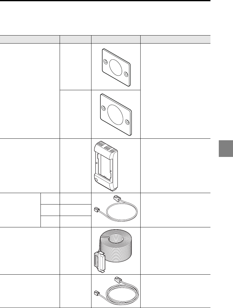
A-7
A
List of Optional Accessories
The following table lists the optional accessories supported by the LK-G5000 series.
Name Model Appearance Description
Display panel housing LK-F2
(LK-H150/155/
152/157)
Used when the mirror surface is
measured at a mirror reflection
setup.
(M1.6 x 3 countersink-head screw
x 2)
LK-F3
(LK-H80/85/
82/87)
Display panel housing OP-84426 Used to combine the display
panel (LK-HD500) and controller
(LK-G5001/LK-G5001P).
Display panel
cable
33 cm OP-84427 A cable used to connect the
display panel (LK-HD500/LK-
HD1001) and controller (LK-
G5001/LK-G5001P).
3 m OP-51655
10 m OP-51656
Expansion connector cable
(3 m)
OP-51657 A cable for the expansion
connector (3 m).
RS-232C cable OP-96368 A communication cable for RS-
232C (2.5 m).
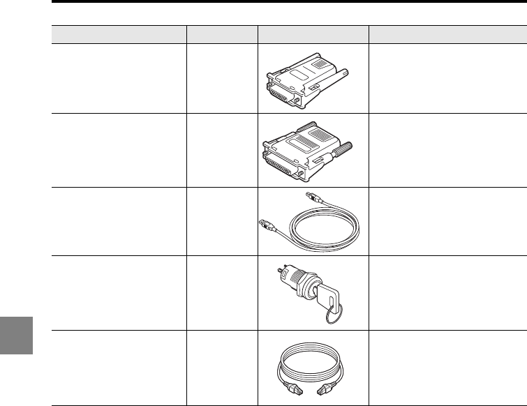
A-8
AA
RS-232C conversion
adapter
OP-26401 A conversion adapter for a D-sub
9-pin connector. This connector
is used in combination with the
OP-96368.
RS-233C conversion
adapter
OP-96369 A conversion adapter for a D-sub
25-pin connector. This connector
is used in combination with the
OP-96368.
USB cable OP-66844 A cable for USB connection (2
m).
Key-operated switch OP-86982 Key-operated switch for laser
emission control
Ethernet cable OP-66843 Cross cable (3m) for Ethernet
communication
Name Model Appearance Description
OP-26401
OP-96369
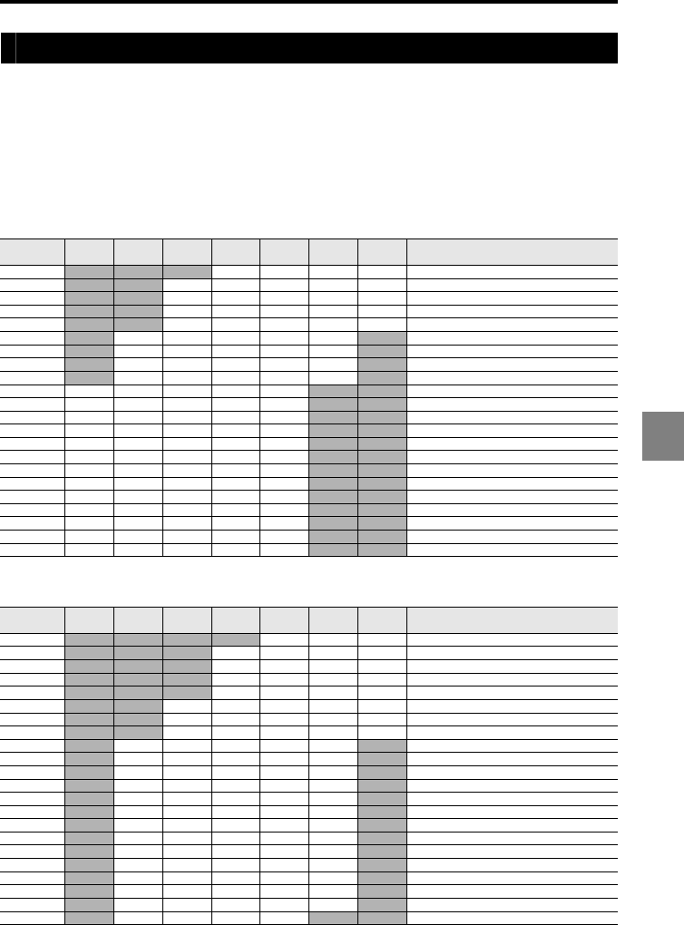
A-9
A
Type of Measurement and Sampling frequency
When the type of measurement is Velocity or Acceleration, the range to display the
measured value is determined according to the settings of minimum display unit,
sampling frequency and mutual intervention prevention function.
: Possible to display measured values
- : Measured value displayed as -FFFFFF
When the Acceleration mode is selected
LK-H008 Series/LK-H02* Series
LK-H05* Series/LK-H08* Series/LK-H15* Series
Sampling
frequency [µs]
±99.9999
[m/s
2
]
±999.999
[m/s
2
]
±9999.99
[m/s
2
]
±99999.9
[m/s
2
]
±999.999
[km/s
2
]
±9999.99
[km/s
2
]
±99999.9
[km/s
2
]
Remark
2.55 - - - 2.55µs Mutal intervention prevension function OFF
5- - 5µs Mutal intervention prevension function OFF
5.1 - -
2.55µs Mutal intervention prevension function AB-ON
7.65 - -
2.55µs Mutal intervention prevension function ABC-ON
10 - - 10
µ
s Mutal intervention prevension function OFF
15 - -5
µ
s Mutal intervention prevension function AB-ON
20 - -20
µ
s Mutal intervention prevension function OFF
30 - -
10µs Mutal intervention prevension function ABC-ON
40 - -20
µ
s Mutal intervention prevension function AB-ON
50 --50
µ
s Mutal intervention prevension function OFF
60 - -
20
µ
s Mutal intervention prevension function ABC-ON
100 --100
µ
s Mutal intervention prevension function OFF
150 - -
50
µ
s Mutal intervention prevension function ABC-ON
200 --200
µ
s Mutal intervention prevension function OFF
300 - -
100µs Mutal intervention prevension function ABC-ON
400 - -
200
µ
s Mutal intervention prevension function AB-ON
500 --500
µ
s Mutal intervention prevension function OFF
600 - -
200µs Mutal intervention prevension function ABC-ON
1000 --1000
µ
s Mutal intervention prevension function OFF
1500 - -
500µs Mutal intervention prevension function ABC-ON
2000 - -
1000µs Mutal intervention prevension function AB-ON
3000 - -
1000µs Mutal intervention prevension function ABC-ON
Sampling
frequency [µs]
±99.9999
[m/s
2
]
±999.999
[m/s
2
]
±9999.99
[m/s
2
]
±99999.9
[m/s
2
]
±999.999
[km/s
2
]
±9999.99
[km/s
2
]
±99999.9
[km/s
2
]
Remark
2.55 - - - - 2.55µs Mutal intervention prevension function OFF
5- - - 5µs Mutal intervention prevension function OFF
5.1 - - -
2.55µs Mutal intervention prevension function AB-ON
7.65 - - -
2.55µs Mutal intervention prevension function ABC-ON
10 - - - 10
µ
s Mutal intervention prevension function OFF
15 - - 5
µ
s Mutal intervention prevension function AB-ON
20 - - 20
µ
s Mutal intervention prevension function OFF
30 - -
10µs Mutal intervention prevension function ABC-ON
40 - -20
µ
s Mutal intervention prevension function AB-ON
50 - -50
µ
s Mutal intervention prevension function OFF
60 - -
20
µ
s Mutal intervention prevension function ABC-ON
100 - -100
µ
s Mutal intervention prevension function OFF
150 - -
50
µ
s Mutal intervention prevension function ABC-ON
200 - -200
µ
s Mutal intervention prevension function OFF
300 - -
100µs Mutal intervention prevension function ABC-ON
400 - -
200
µ
s Mutal intervention prevension function AB-ON
500 - -500
µ
s Mutal intervention prevension function OFF
600 - -
200µs Mutal intervention prevension function ABC-ON
1000 - -1000
µ
s Mutal intervention prevension function OFF
1500 - -
500µs Mutal intervention prevension function ABC-ON
2000 - -
1000µs Mutal intervention prevension function AB-ON
3000 - - -
1000µs Mutal intervention prevension function ABC-ON
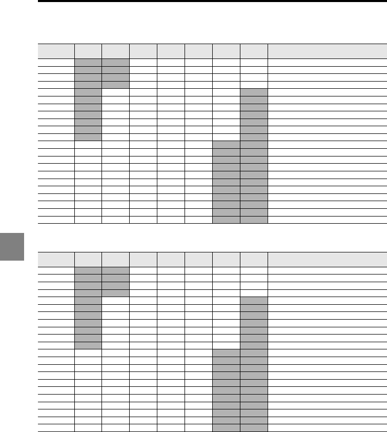
A-10
AA
When the Velocity mode is selected
LK-H008 Series/LK-H02* Series
LK-H05* Series/LK-H08* Series/LK-H15* Series
Sampling
frequency [µs]
±99.9999
[mm/s]
±999.999
[mm/s]
±9999.99
[mm/s]
±99999.9
[mm/s]
±999.999
[m/s]
±9999.99
[m/s]
±99999.9
[m/s]
Remark
2.55 - - 2.55µs Mutal intervention prevension function OFF
5- - 5µs Mutal intervention prevension function OFF
5.1 - -
2.55µs Mutal intervention prevension function AB-ON
7.65 - -
2.55µs Mutal intervention prevension function ABC-ON
10 - -10
µ
s Mutal intervention prevension function OFF
15 - -5
µ
s Mutal intervention prevension function AB-ON
20 - -20
µ
s Mutal intervention prevension function OFF
30 - -
10µs Mutal intervention prevension function ABC-ON
40 - -20
µ
s Mutal intervention prevension function AB-ON
50 - -50
µ
s Mutal intervention prevension function OFF
60 - -
20
µ
s Mutal intervention prevension function ABC-ON
100 -- 100
µ
s Mutal intervention prevension function OFF
150 - -
50
µ
s Mutal intervention prevension function ABC-ON
200 -- 200
µ
s Mutal intervention prevension function OFF
300 - -
100µs Mutal intervention prevension function ABC-ON
400 - -
200
µ
s Mutal intervention prevension function AB-ON
500 -- 500
µ
s Mutal intervention prevension function OFF
600 - -
200µs Mutal intervention prevension function ABC-ON
1000 -- 1000
µ
s Mutal intervention prevension function OFF
1500 - -
500µs Mutal intervention prevension function ABC-ON
2000 - -
1000µs Mutal intervention prevension function AB-ON
3000 - -
1000µs Mutal intervention prevension function ABC-ON
Sampling
frequency [µs]
±99.9999
[mm/s]
±999.999
[mm/s]
±9999.99
[mm/s]
±99999.9
[mm/s]
±999.999
[m/s]
±9999.99
[m/s]
±99999.9
[m/s]
Remark
2.55 - - 2.55µs Mutal intervention prevension function OFF
5- - 5µs Mutal intervention prevension function OFF
5.1 - -
2.55µs Mutal intervention prevension function AB-ON
7.65 - -
2.55µs Mutal intervention prevension function ABC-ON
10 - -10
µ
s Mutal intervention prevension function OFF
15 - -5
µ
s Mutal intervention prevension function AB-ON
20 - -20
µ
s Mutal intervention prevension function OFF
30 - -
10µs Mutal intervention prevension function ABC-ON
40 - -20
µ
s Mutal intervention prevension function AB-ON
50 - -50
µ
s Mutal intervention prevension function OFF
60 - -
20
µ
s Mutal intervention prevension function ABC-ON
100 -- 100
µ
s Mutal intervention prevension function OFF
150 - -
50
µ
s Mutal intervention prevension function ABC-ON
200 -- 200
µ
s Mutal intervention prevension function OFF
300 - -
100µs Mutal intervention prevension function ABC-ON
400 - -
200
µ
s Mutal intervention prevension function AB-ON
500 -- 500
µ
s Mutal intervention prevension function OFF
600 - -
200µs Mutal intervention prevension function ABC-ON
1000 -- 1000
µ
s Mutal intervention prevension function OFF
1500 - -
500µs Mutal intervention prevension function ABC-ON
2000 - -
1000µs Mutal intervention prevension function AB-ON
3000 - -
1000µs Mutal intervention prevension function ABC-ON
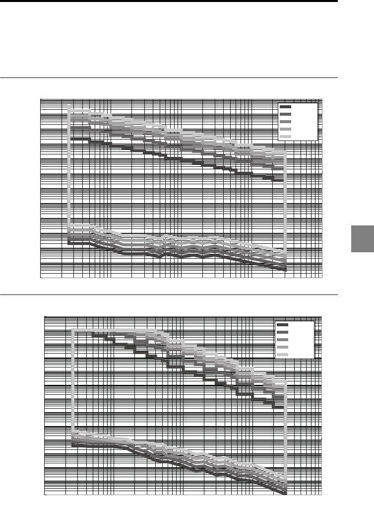
A-11
A
Relationship Between the Sampling Cycle and
Velocity/Acceleration Measurement Range
The following graphs show the relationship between the sampling cycle and velocity/
acceleration in the velocity/acceleration measurement.
Velocity mode
Acceleration mode
0.0000001
0.000001
0.00001
0.0001
0.001
0.01
0.1
1
10
100
1000
10000
100000
1 10 100 1000 10000
LK-H008
LK-H020
LK-H050
LK-H085
LK-H155
Sampling cycle (µs): Doubled when the mutual interference prevention function is set to AB-ON; Tripled when the function is set to ABC-ON
Velocity
(m/s)
0.0001
0.001
0.01
0.1
1
10
100
1000
10000
100000
1000000
10000000
100000000
1000000000
1 10 100 1000 10000
LK-H008
LK-H020
LK-H050
LK-H085
LK-H155
Sampling cycle (µs): Doubled when the mutual interference prevention function is set to AB-ON; Tripled when the function is set to ABC-ON
Acceleration
(m/s2)

A-12
AA
Index
Number
12-pin terminal block..................... 1-7, 4-2
6-pin terminal block....................... 1-7, 4-4
A
ABLE calibration..................................3-13
ABLE function........................................3-6
Acceleration ........................................3-53
Active analog output channel count....3-80
Active head count ...............................3-79
Active OUT count ................................3-78
Alarm handling ....................................3-10
Alarm output ..........................................4-8
Alarm output type ................................3-68
Ambient temperature................................ 4
Analog current output..........................4-14
Analog monitor output...........................4-4
Analog output ......................................3-67
Analog output scaling .........................3-50
Analog scaling.....................................3-50
Analog voltage output .........................4-14
ASCII code ..........................................5-40
Auto-offset function ..................... 2-7, 3-47
Auto-zero function ....................... 2-7, 3-47
Auto-zero input ......................................4-8
Average hold .................... 3-37, 3-40, 4-16
Averaging filter operation ....................3-33
B
Base point ...........................................3-22
Beam spot diameter ............................6-25
Binary output ............................... 4-5, 4-11
Bottom hold ............................... 3-37, 4-16
C
Calculation between the sensor heads
..3-28
Calculation method .............................3-28
CC-Link communication unit ...............1-25
CE Marking............................................... 6
Characteristics ....................................6-25
Combining the separate type controller
............................................. 1-21, 1-23
Command format...................................5-5
Communication parameters ..................5-3
Comparator output ................................4-8
Comparator output form ......................3-63
Comparator standby .............................2-4
Connection
Connecting the display panel .......1-27
Connecting the power supply .......1-27
Connecting the sensor head.........1-26
Connecting to the terminal block ..1-27
Controller specifications........................6-2
D
Data storage function ..........................3-65
DeviceNet communication unit ...........1-25
Diffuse reflection........................ 1-12, 3-15
Dimensions..........................................6-15
Displacement ......................................3-53
Display panel.........................................1-6
Display panel connector .......................1-7
Dual display...........................................2-2
E
ENV......................................................3-69
Environment settings ................. 1-30, 3-69
Error codes........................................... A-5
Ethernet connector................................1-7
External synchronization .....................5-38
External synchronous input.................3-62
F
Filter.....................................................3-33
G
General mode........................................5-3
GO .........................................................2-4

A-13
A
H
Head expansion unit ................... 1-8, 1-23
Head settings .............................. 1-30, 3-3
Height difference measurement..........3-28
HIGH......................................................2-4
High-pass filter operation ....................3-35
Hold function .......................................3-37
Hysteresis..............................................2-6
I
I/O terminals ..........................................4-2
Initializing.............................................1-31
Initializing the settings to the factory
default settings ..............................1-31
Input response time.............................4-26
Installation environment............................4
Insufficient light intensity .....................3-10
K
Key-operated switch ..............................13
L
LAN setting..........................................3-81
LASER CTRL group.............................3-20
LASER CTRL terminals........................... 13
List of functions and function Nos.
(Common function)........................3-55
List of functions and function Nos.
(Environment settings)...................3-69
List of functions and function Nos.
(Head settings)................................3-3
List of functions and function Nos.
(OUT settings) ...............................3-24
List of initial values and setting ranges
(Common function)........................3-56
List of initial values and setting ranges
(Environment settings)...................3-70
List of initial values and setting ranges
(Head settings)................................3-4
List of initial values and setting ranges
(OUT settings) ...............................3-26
List of optional accessories.................. A-7
List of the Environment settings screens
...3-71
List of the Head settings screens..........3-5
List of the OUT settings screens .........3-27
LK-CC100............................................1-25
LK-DN100............................................1-25
LK-HA100 .................................... 1-8, 1-23
LOW.......................................................2-4
Low-pass filter operation .....................3-35
M
Mask setting ........................................3-16
Measured value format..........................5-6
Measurement averaging time..............4-27
Measurement control command format
...5-8
Measurement control input/output ........4-8
Measurement mode ............................3-37
Measurement mode, setting..................3-9
Measurement type...............................3-53
Measurement value output conditions
...3-24
Median.................................................3-18
Minimum display unit...........................3-48
Minimum input time .............................4-26
Mode change command .......................5-7
Mode selection ....................................1-29
Mounting mode ...................................3-15
Mounting the controller........................1-17
Mounting the separate type
controller..................................1-18
Mounting the single unit type
controller..................................1-18
Mounting the sensor head...................1-10
Mutual interference..............................6-27
Mutual interference prevention............3-60
Mutual interference prevention function
..3-60
N
Noise control ............................................4
Non-voltage input ................................4-12
Number of display digits .....................3-48
Numerical value setting procedure.......2-5

A-14
AA
O
Offset ...................................................3-47
Open-collector output .........................4-13
Operation keys ......................................1-6
OPTION ...............................................3-55
OUT .....................................................3-24
OUT settings........................................1-30
Output format ......................................5-40
P
Package contents..................................1-3
Panel lock............................................3-76
Part names and functions......................1-6
Peak hold.......................... 3-37, 3-40, 4-16
Peak-to-peak hold ............ 3-37, 3-40, 4-16
Program...............................................3-74
Program copy and initialization...........3-74
Program No. change time ...................4-27
Program No. switch input ......................4-9
Program switching...............................3-73
R
Range ..................................................3-21
Refresh cycle.......................................4-26
REMOTE terminal ...................................14
RESET time..........................................4-27
Response delay time...........................6-14
RS-232C ...................................... 3-72, 5-1
RS-232C communication parameters
............................................. 3-72, 3-81
S
Sample hold ..................... 3-37, 3-42, 4-16
Sampling cycle....................................3-58
Scaling.................................................3-31
Sensor (receiver) ...................................1-9
Sensor (transmitter)...............................1-9
Sensor head specifications...................6-4
Separate type controller........................1-3
Separate type display panel .................1-4
Separating the single unit type controller
..1-19
Setting change command...................5-14
Setting confirmation command format
...5-25
Setting mode .......................................1-30
Setting selection ..................................3-73
Setting the mounting mode .................3-15
Setting value format...............................5-6
Shutter ....................................................14
Single display ........................................2-2
Single unit type controller......................1-3
Specifications ........................................6-2
Specular reflection ..............................1-12
Status table..........................................6-12
Strobe output time ...............................3-64
Strobe time ..........................................3-64
Switching program Nos.......................2-11
Switching the measurement value
displays ...........................................2-2
Synchronization ...................................3-62
Synchronization setting .......................3-62
System configuration.............................1-2
T
Thickness measurement .....................3-28
Timing diagram ...................................4-15
Tolerance comparator result output form
..3-63
Tolerance comparator setting, function
...2-4
Tolerance comparator value setting......2-4
Translucent object.................................3-8
Transparent object ................................3-8
Transparent object 2 .............................3-8
Trigger .................................................3-45
Trigger condition .................................3-45
Troubleshooting.................................... A-2
U
USB connector ......................................1-7
V
Velocity ................................................3-53
Voltage input .......................................4-13


Revision History
Date of printing Version Revision details
March 2009 First edition 96M00415 0039-2
May 2009 Second edition (96M00604 0059-1)
P.1-24 Addition of notes regarding wiring.
October 2009 Third edition STROBE output was added to pages 4-15, 4-19, and
4-21
November 2009 Second revision,
first edition
LK-H008/H008W added
January 2010 Third revision,
first edition
LK-H085/H087, LK-H155/H157 added
March 2010 Fourth revision,
first edition
LK-H080/H082, LK-H150/H152 added

WARRANTIES AND DISCLAIMERS
(1) KEYENCE warrants the Products to be free of defects in materials and workmanship for a
period of one (1) year from the date of shipment. If any models or samples were shown to
Buyer, such models or samples were used merely to illustrate the general type and quality of
the Products and not to represent that the Products would necessarily conform to said
models or samples. Any Products found to be defective must be shipped to KEYENCE with
all shipping costs paid by Buyer or offered to KEYENCE for inspection and examination.
Upon examination by KEYENCE, KEYENCE, at its sole option, will refund the purchase price
of, or repair or replace at no charge any Products found to be defective. This warranty does
not apply to any defects resulting from any action of Buyer, including but not limited to
improper installation, improper interfacing, improper repair, unauthorized modification,
misapplication and mishandling, such as exposure to excessive current, heat, coldness,
moisture, vibration or outdoors air. Components which wear are not warranted.
(2) KEYENCE is pleased to offer suggestions on the use of its various Products. They are only
suggestions, and it is Buyer's responsibility to ascertain the fitness of the Products for
Buyer's intended use. KEYENCE will not be responsible for any damages that may result
from the use of the Products.
(3) The Products and any samples (Products/Samples) supplied to Buyer are not to be used
internally in humans, for human transportation, as safety devices or fail-safe systems, unless
their written specifications state otherwise. Should any Products/Samples be used in such a
manner or misused in any way, KEYENCE assumes no responsibility, and additionally Buyer
will indemnify KEYENCE and hold KEYENCE harmless from any liability or damage
whatsoever arising out of any misuse of the Products/Samples.
(4) OTHER THAN AS STATED HEREIN, THE PRODUCTS/SAMPLES ARE PROVIDED WITH NO
OTHER WARRANTIES WHATSOEVER. ALL EXPRESS, IMPLIED, AND STATUTORY
WARRANTIES, INCLUDING, WITHOUT LIMITATION, THE WARRANTIES OF
MERCHANTABILITY, FITNESS FOR A PARTICULAR PURPOSE, AND NON-INFRINGEMENT
OF PROPRIETARY RIGHTS, ARE EXPRESSLY DISCLAIMED. IN NO EVENT SHALL
KEYENCE AND ITS AFFILIATED ENTITIES BE LIABLE TO ANY PERSON OR ENTITY FOR
ANY DIRECT, INDIRECT, INCIDENTAL, PUNITIVE, SPECIAL OR CONSEQUENTIAL
DAMAGES (INCLUDING, WITHOUT LIMITATION, ANY DAMAGES RESULTING FROM LOSS
OF USE, BUSINESS INTERRUPTION, LOSS OF INFORMATION, LOSS OR INACCURACY OF
DATA, LOSS OF PROFITS, LOSS OF SAVINGS, THE COST OF PROCUREMENT OF
SUBSTITUTED GOODS, SERVICES OR TECHNOLOGIES, OR FOR ANY MATTER ARISING
OUT OF OR IN CONNECTION WITH THE USE OR INABILITY TO USE THE PRODUCTS,
EVEN IF KEYENCE OR ONE OF ITS AFFILIATED ENTITIES WAS ADVISED OF A POSSIBLE
THIRD PARTY’S CLAIM FOR DAMAGES OR ANY OTHER CLAIM AGAINST BUYER. In some
jurisdictions, some of the foregoing warranty disclaimers or damage limitations may not
apply.
BUYER'S TRANSFER OBLIGATIONS: If the Products/Samples purchased by Buyer are to be
resold or delivered to a third party, Buyer must provide such third party with a copy of this
document, all specifications, manuals, catalogs, leaflets and written information provided to
Buyer pertaining to the Products/Samples.
11281E 1030-1
2010
96M11282
11282 1
