Meinberg LANTIME M300and PZF NTP Time Server User’s Manual M300
User Manual: Meinberg LANTIME M300andPZF NTP Time Server User’s Manual Troubleshoot Meinberg LANTIME M300andPZF NTP Time Server |
Open the PDF directly: View PDF ![]() .
.
Page Count: 122 [warning: Documents this large are best viewed by clicking the View PDF Link!]
- Impressum
- Quick Start
- Network Timeserver with DCF77 synchronized time base
- The Modular System LANTIME
- Network Time Protocol (NTP)
- General information PZF
- DCF77 Antenna
- Booting the PZF receiver
- Booting the Single Board Computer
- Configuration User Interface
- The WEB Interface
- The Command Line Interface
- SNMP Support
- Attachment: Technical Information
- Skilled/Service-Personnel only: Replacing the Lithium Battery
- Technical Specifications M600/300 Multipac
- Safety instructions for building-in equipment
- Rear Panel Connectors
- Pin Assignment: Serial Connectors
- Error Relay
- Technical specifications PZF600
- Technical Specifications LAN CPU
- Time Strings
- Manual VP100/NET Display configuration
- Global Configuration File
- Global Option File
- Third party software
- USB Stick
- Reference
MANUAL
LANTIME M300 PZF
DCF77 NTP Server
Table of Contents
1 Impressum 1
2 Quick Start 2
3 Network Timeserver with DCF77 synchronized time base 3
4 The Modular System LANTIME 4
5 Network Time Protocol (NTP) 7
6 General information PZF 9
7 DCF77 Antenna 11
8 Booting the PZF receiver 12
9 Booting the Single Board Computer 13
10 Configuration User Interface 14
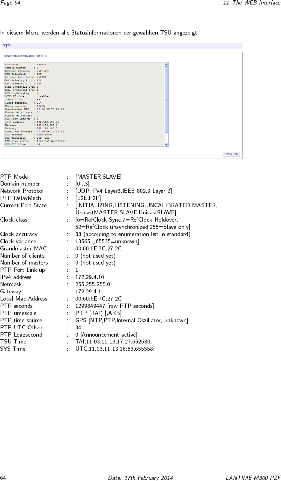
11 The WEB Interface 27
1 Impressum
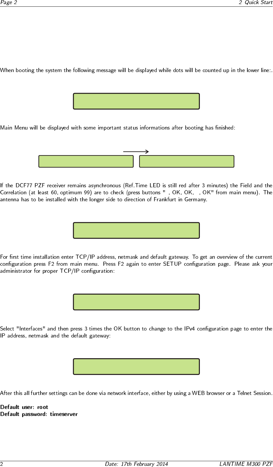
2 Quick Start
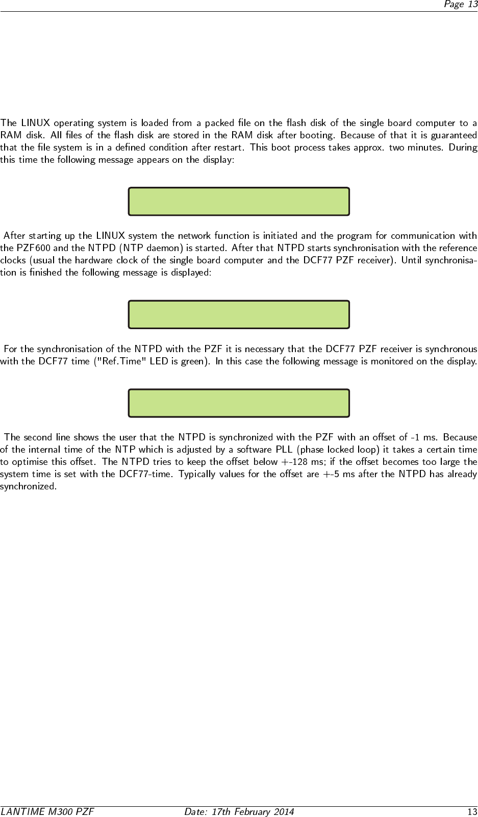
Starting up please wait...
.......
PZF: NORMAL OPERATION Fri, 11.05.2009
NTP: not sync UTC 09:12:11
PZF: NORMAL OPERATION Fri, 11.05.2009
NTP: not sync UTC 09:12:11
↓ ↓
PZF STATE: CORR.: 90 State:fine
FIELD: 94
Global Cfg. Services
Interfaces-> <-
SETUP: Ipv4 LAN Parameter ETH0
Ipv4 ADDRESS: 192.168.10.200
3 Network Timeserver with DCF77 synchronized
time base
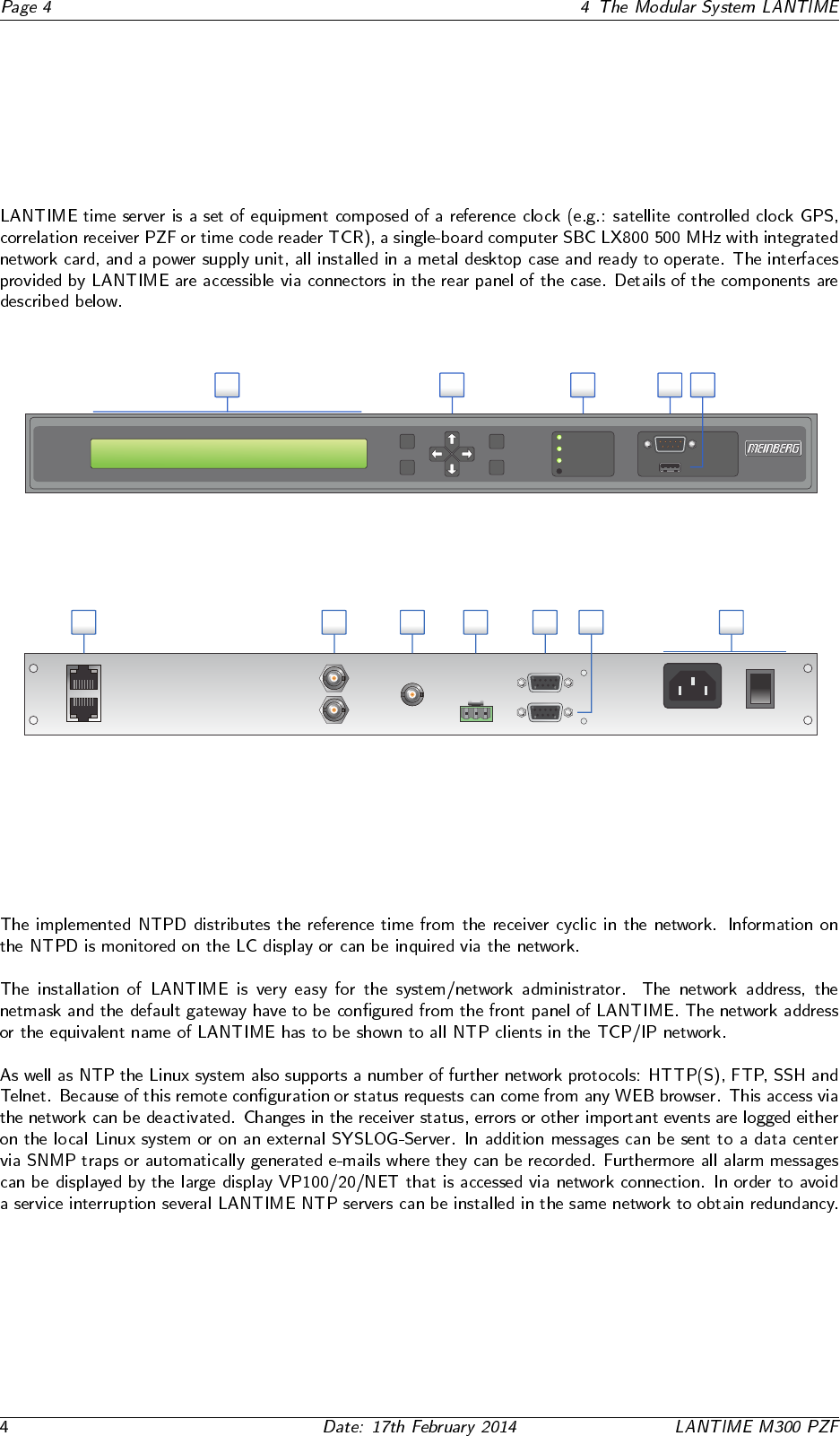
4 The Modular System LANTIME
PZF
Antenna
Error
O
I
100-240V AC
50/60Hz
PPS Out
1
2
34
5
67
ENGLISH
1. Power supply connector
2. Serial Port COM 0, 9pin. D-SUB, female
3. Serial Port TxD 0, 9pin. D-SUB, female
4. Error relay output, 3pin. DFK
5. PZF Antenna, BNC
6. PPS / 10MHz output, BNC
7. Network connectors ETH0 - ETH1, 10/100 Mbit RJ45
DEUTSCH
1. Spannungsversorgung
2. Serielle Schnittstelle COM 0, 9pol. D-SUB Buchse
3. Serielle Schnittstelle TxD 0, 9pol. D-SUB Buchse
4. Störmelderelaisausgang, 3pol. DFK
5. PZF Antenne, BNC
6. PPS / 10MHz Ausgang, BNC
7. Netzwerk Anschlüsse ETH0 - ETH1, 10/100MBit RJ45
TxD 0
COM 0
CO NO NC
10MHz Out
100M 10M
ETH0
ETH1
OK
ESC
Time Service
Ref. Time
Network
Alarm
Terminal
USB
PZF: NORMAL OPERATION
NTP: Offset PPS: -4µs UTC 12: 00 : 00
Mon , dd.mm.yyyy
F1
F2
12345
ENGLISH
1. LC-Display, 2 x 40 characters
2. Function buttons: 4-way navigation; F1, F2, OK, ESC
3. Status LEDs: Ref. Time, Time Service, Network, Alarm
4. Terminal / VT100, 38400 Baud, 8N1, 9pin. D-SUB male
5. USB connector
DEUTSCH
1. LC-Display, 2 x 40 Zeichen
2. Funktionstasten: 4 Wege Navigation; F1, F2; OK, ESC
3. Status LEDs: Ref. Time, Time Service, Network, Alarm
4. Terminal / VT100, 38400 Baud, 8N1, 9pol. D-SUB Stecker
5. USB Anschluss
LANTIME M300
LANTIME M300
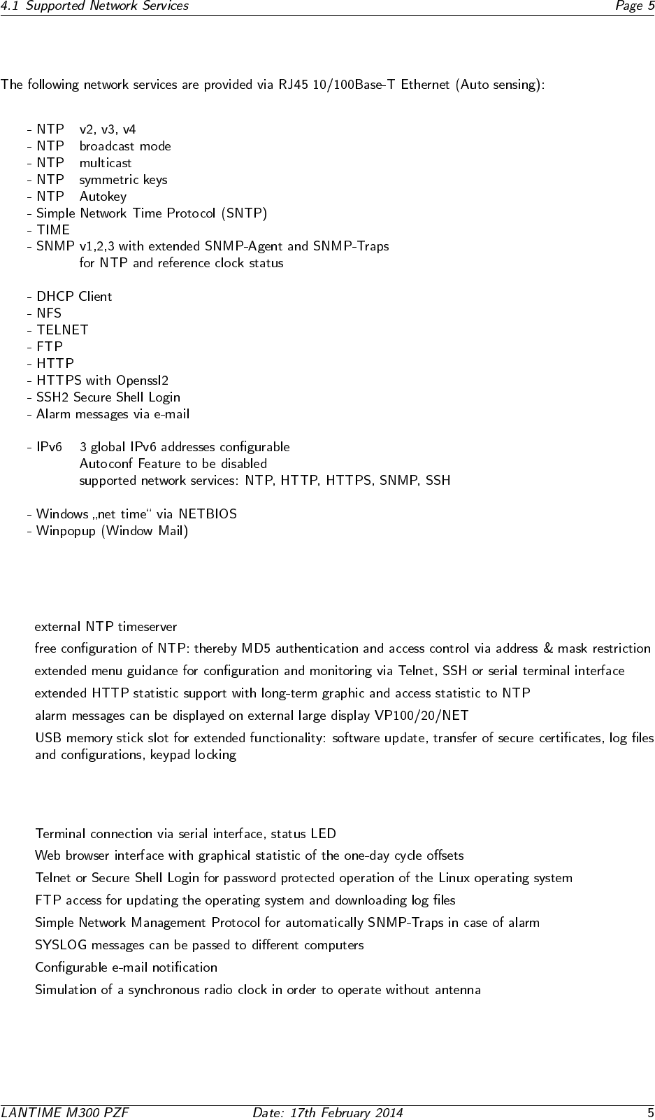
4.1 Supported Network Services
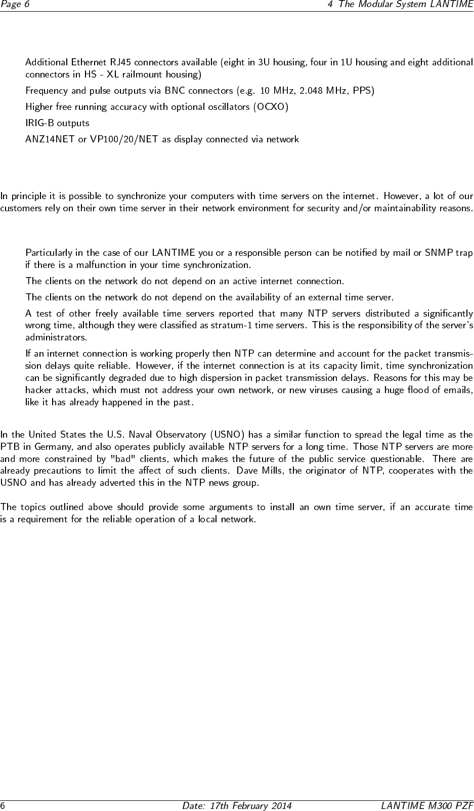
4.2 Additional Features
•
•
•
•
•
•
4.3 User Interface
•
•
•
•
•
•
•
•
4.4 Input and Output Options
•
•
•
•
•
4.5 Why to use a Network Time Server?
•
•
•
•
•
5 Network Time Protocol (NTP)
5.1 NTP Target
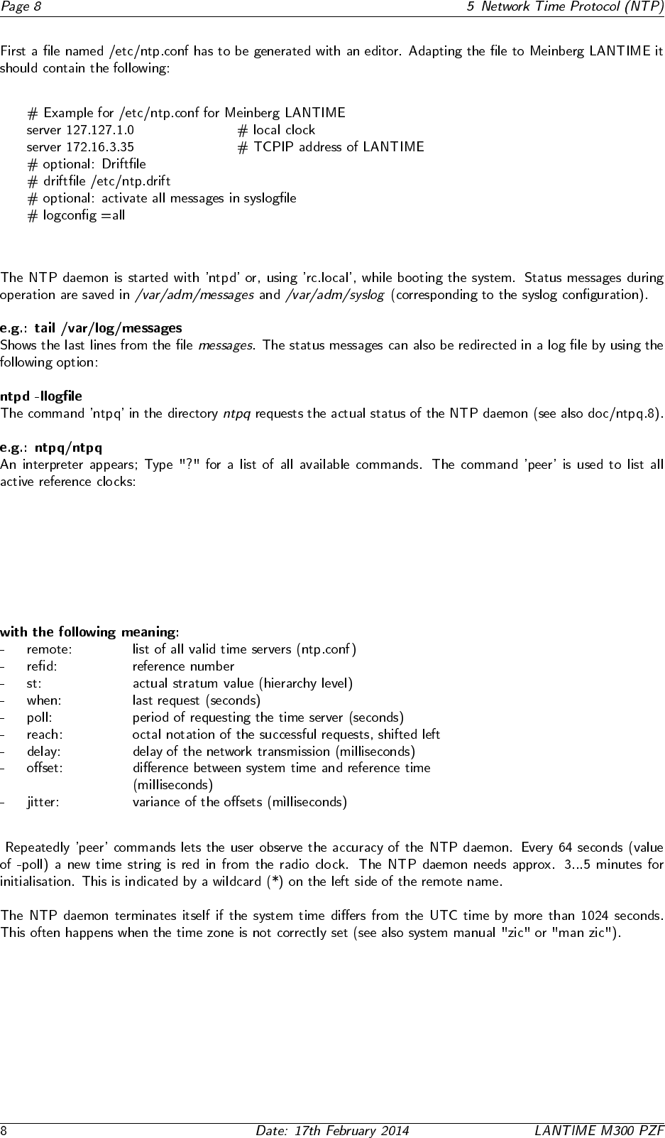
5.2 NTP-Client Installation

6 General information PZF
◦
6.1 Features of PZF
7 DCF77 Antenna
7.1 Assembly of the Antenna
◦

8 Booting the PZF receiver
↓ ↓
PZF STATE: CORR.: 18 State:row
FIELD: 0
PZF STATE: CORR.: 1 State:check
FIELD: 94
PZF STATE: CORR.: 90 State:fine
FIELD: 94
9 Booting the Single Board Computer
Starting up please wait...
.......
PZF: NORMAL OPERATION Fri, 15.12.2005
NTP: not sync UTC 09:12:11
PZF: NORMAL OPERATION Fri, 15.12.2005
NTP: Offset PPS: 1ms UTC 09:14:16
10 Configuration User Interface
10.1 Introduction: Configuration LANTIME
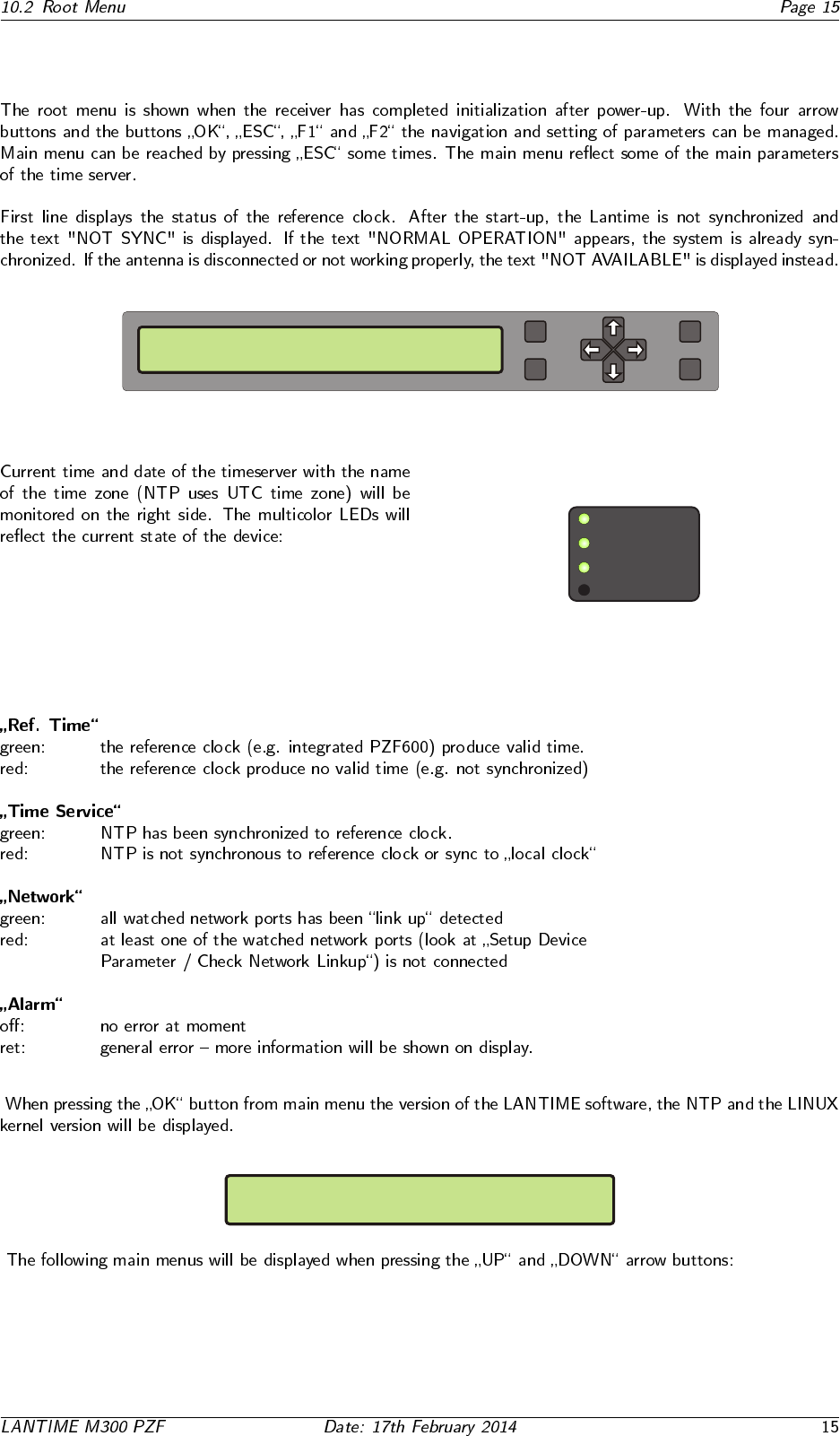
10.2 Root Menu
PZF: NORMAL OPERATION Mon, 28.08.2006
NTP: not sync UTC 14:33:10
OK
ESC
F1
F2
Time Service
Ref. Time
Network
Alarm
TYP:ELX800 PZFXXX M3x VX.xx 2.6.12
SN:030100000000 NTP: 4.2.0
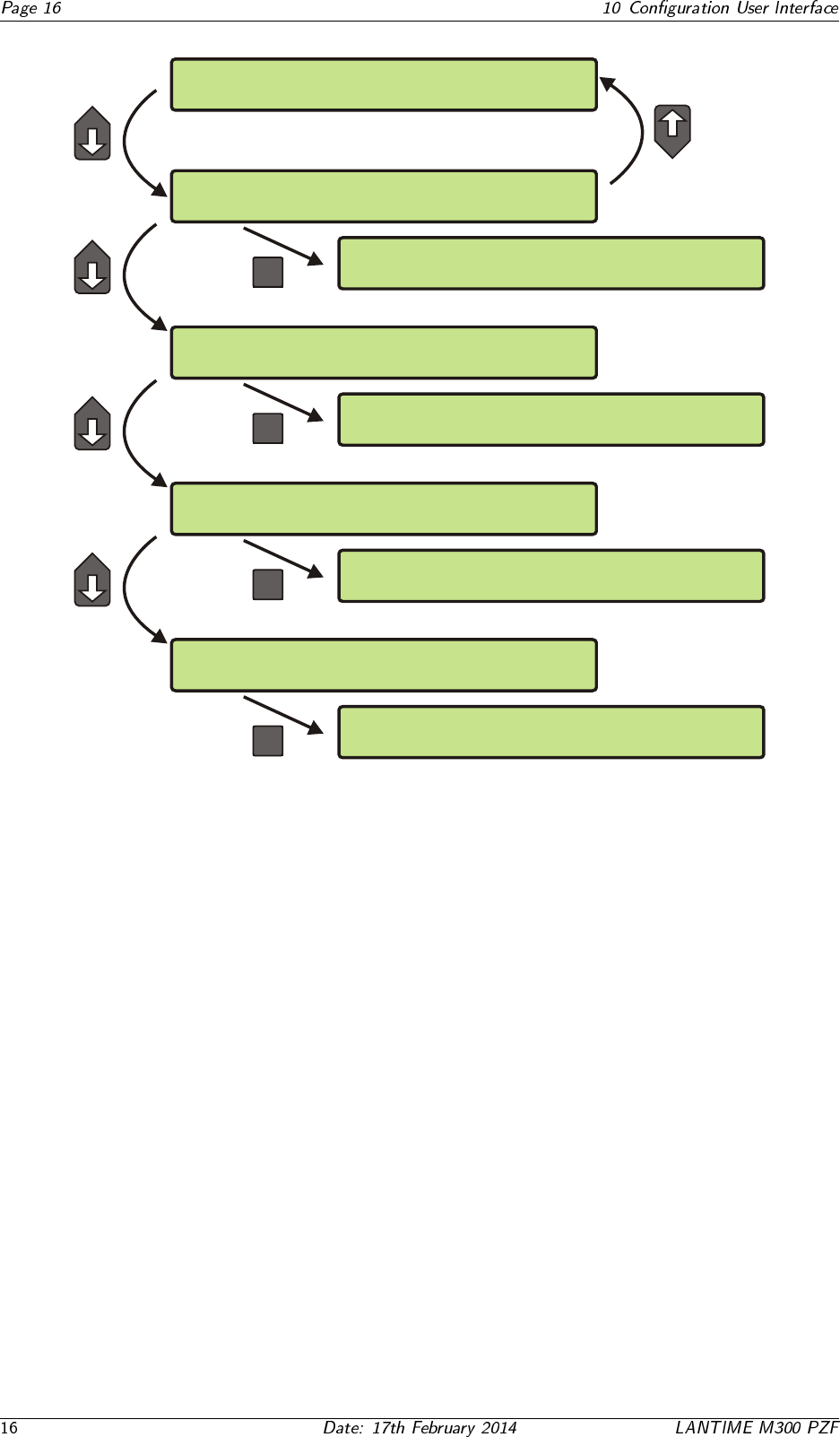
PZF: NORMAL OPERATION Thu, 20.07.2006
NTP: Offest PPS: 1ms UTC 14:02:01
-> Reference Time <- Network
Time Service System
-> Setup PZF <- Setup Serial Out
Info PZF
OK
Reference Time Network
-> Time Service <- System
-> external NTP <- Restart NTP
Local Stratum
OK
Reference Time -> Network <-
Time Service System
-> Global Cfg. <- Services
Interfaces
OK
Reference Time Network
Time Service -> System <-
->Set Time Zone<- Restart NTP
Reboot Server Factory Defaults
OK
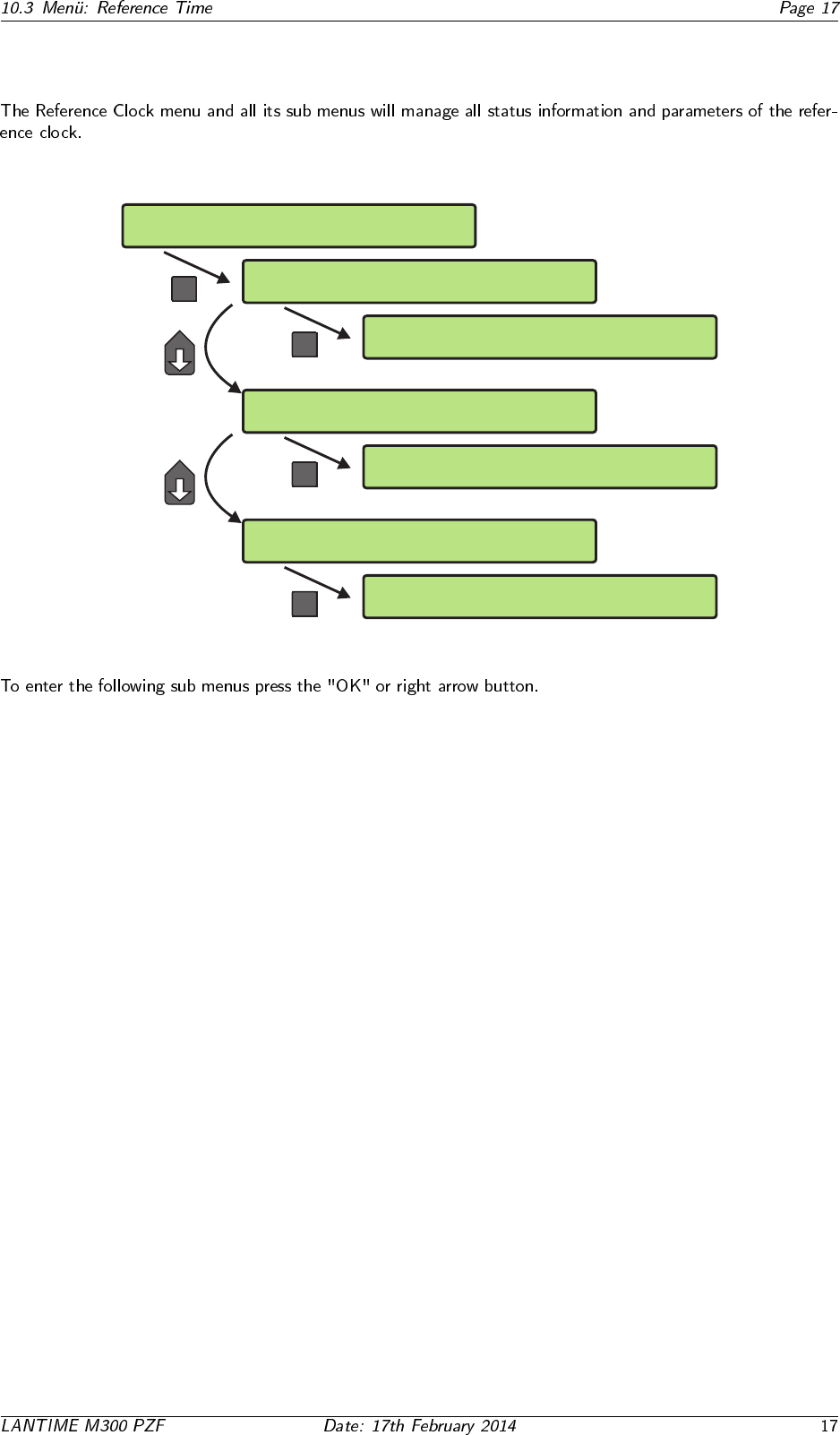
10.3 Men¨
u: Reference Time
-> Reference Time <- Network
Time Service System
-> Info PZF <- Setup Serial Out
Setup PZF
OK
OK
-> Status & Version <-
Correlation & Field
-> Setup PZF <-
Info PZF Setup Serial Out
OK
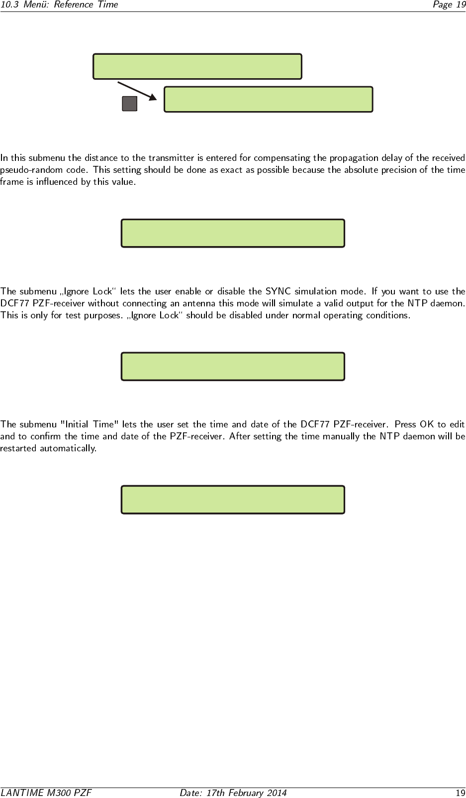
->Transmitter Dist.<- Initial Time
Ignore Lock
-> <-
Setup PZF
Info PZF Setup Serial Out
->Setup COM 0 <- Setup Time Zone
Setup COM 1
OK
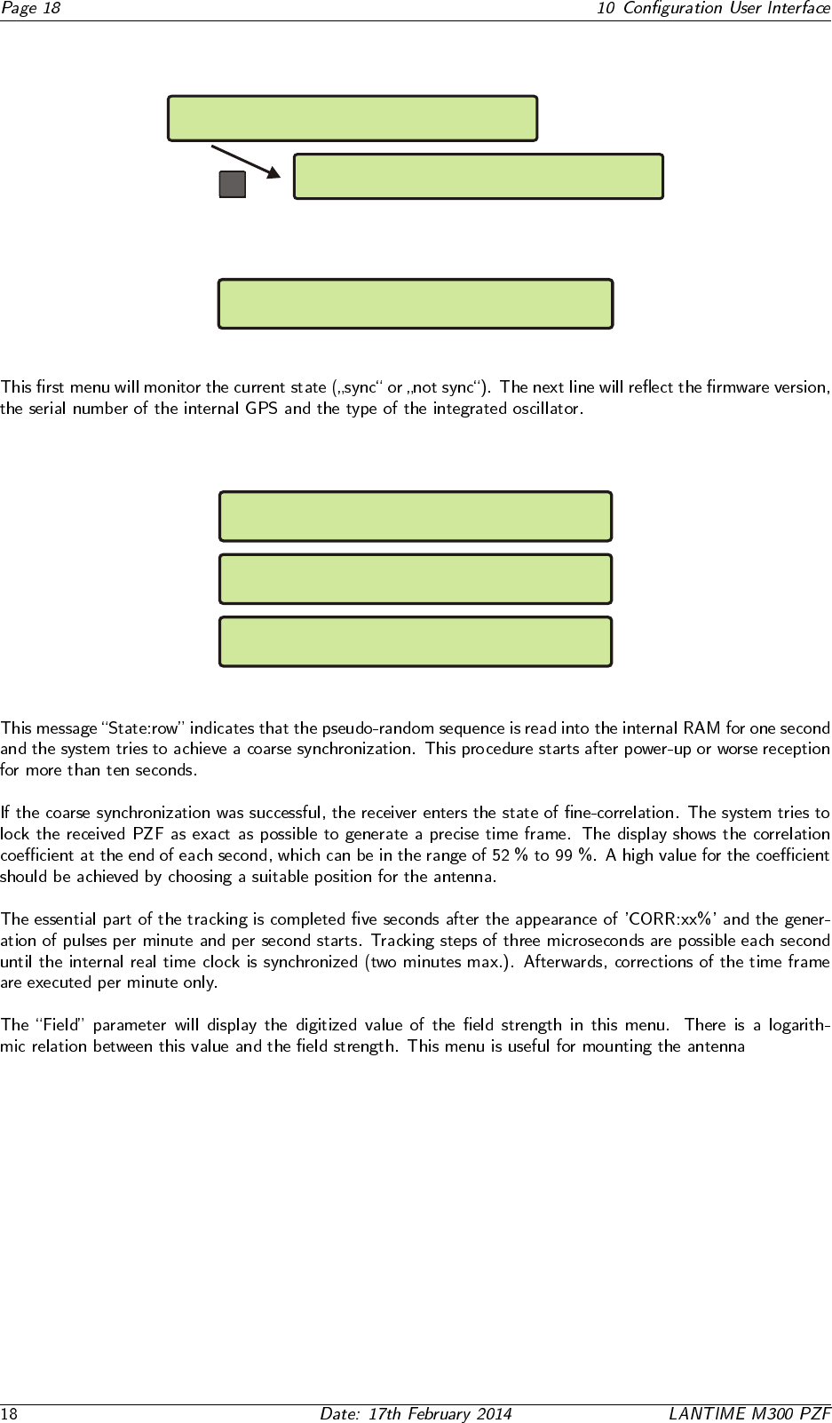
10.3.1 Info PZF
OK
-> Status & Version <-
Correlation & Field
-> Info PZF <- Setup Serial Out
Setup PZF
10.3.2 PZF Status and Version
Reference Clock PZF511 State: SYNC
PZF511 v2.06 S/N:001510000000 TCXO HQ
10.3.3 Correlation and Field
PZF STATE: CORR.: 18 State:row
FIELD: 0
PZF STATE: CORR.: 1 State:check
FIELD: 94
PZF STATE: CORR.: 90 State:fine
FIELD: 94
10.3.4 Setup PZF
OK
-> Transmitter Dist. <- Initial Time
Ignore Lock
Info PZF Setup Serial Out
-> Setup PZF <-
10.3.5 Transmitter Distance
SETUP: PZF Receiver Position
Distance of Transmitter: 0200 km
10.3.6 Ignore Lock (Simulation Mode)
Set Ignore Lock
PZF Receiver Simulation Mode: disabled
10.3.7 Initial Time
Set Initial Time and Date of PZF
UTC 07:58:02 Mon, 27.12.2005
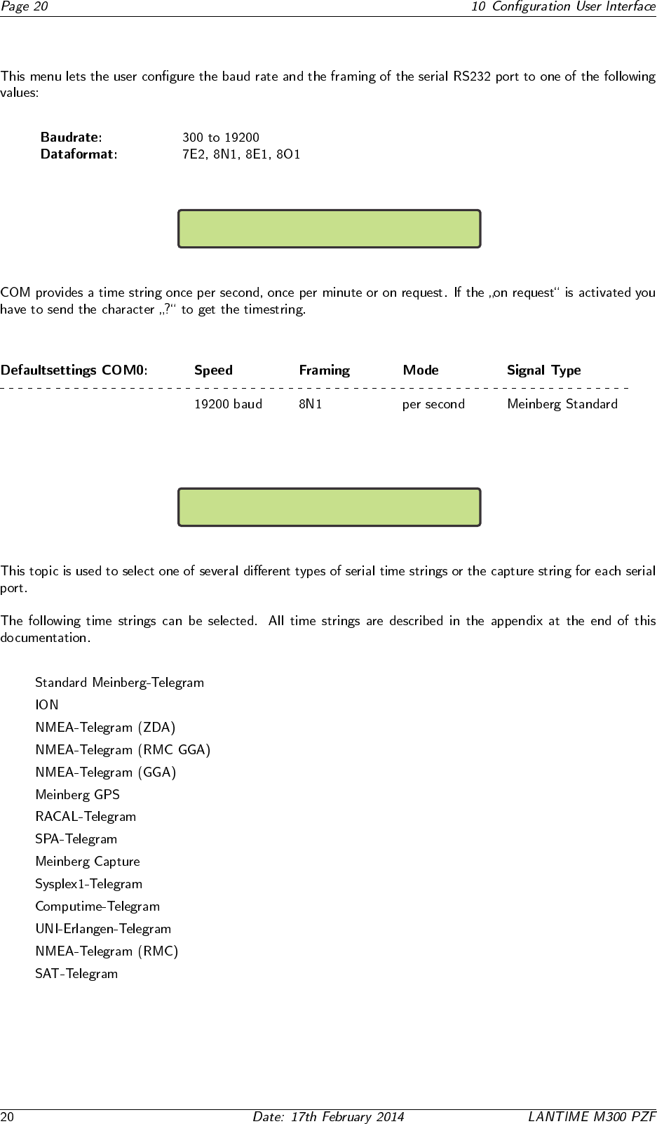
10.3.8 Serial Outputs
->Setup COM 0 <-
Setup COM 1
COM0: 19200 8N1 Mode:per second
String Type: Meinberg Standard
•
•
•
•
•
•
•
•
•
•
•
•
•
•
10.4 Menu: Time Service
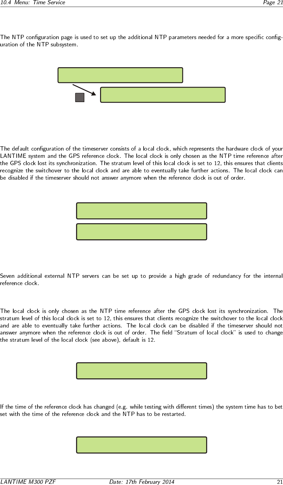
Reference Time Network
-> Time Service <- System
-> external NTP <- Restart NTP
Local Stratum 2nd-Receiver
OK
10.4.1 Menu: external NTP
Ipv4 address of external NTP server 1
000.000.000.000
Ipv4 address of external NTP server 2
000.000.000.000
.
.
.
10.4.2 Menu: Stratum of local clock
Stratum of local clock
12
10.4.3 Menu: Restart NTP
Reset time and restart NTP ?
Press F2 to confirm reset time and NTP
10.5 Menu: Network
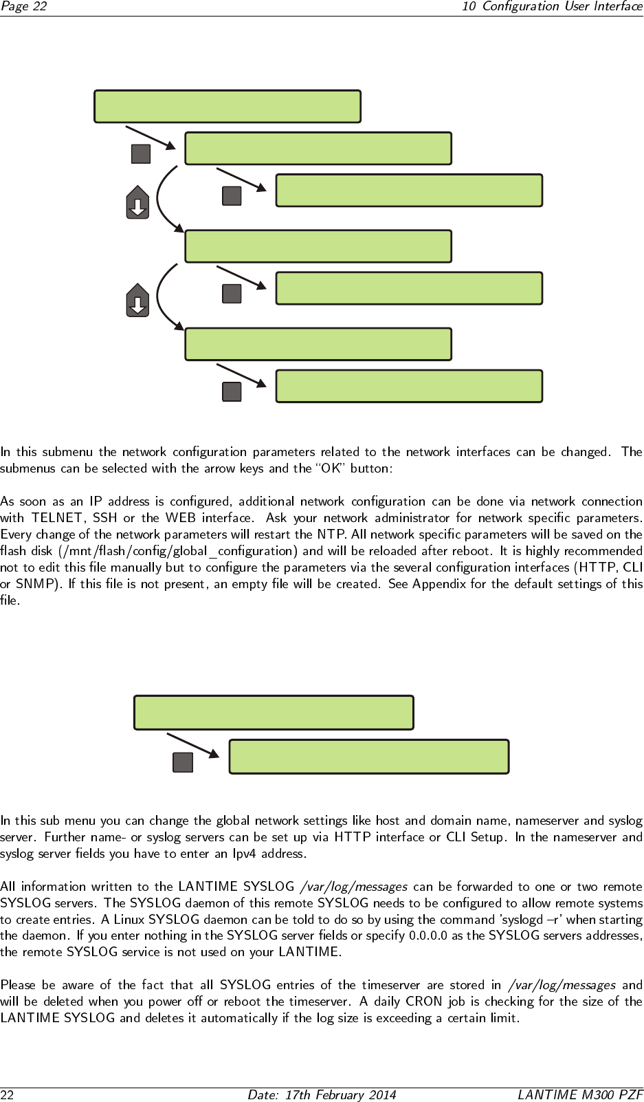
Reference Time -> Network <-
Time Service System
-> Global Cfg. <- Services
Interfaces
OK
OK
->Hostname<- Namesrv. Netw.LED
Domain Syslog
OK
-> Ipv4 Parameter <- Link Mode
Ipv6 Parameter
OK
>SSH:on < TELN:on IPv6:on HTTPS:on
FTP:on SNMP:off HTTP:on NETB:off
Global Cfg. Services
-> Interfaces <-
Global Cfg. -> Services <-
Interfaces
10.5.1 Setup Global Configuration
Services
Interfaces
-> Global Cfg. <-
OK
->Hostname<- Namesrv. Netw.LED
Domain Syslog
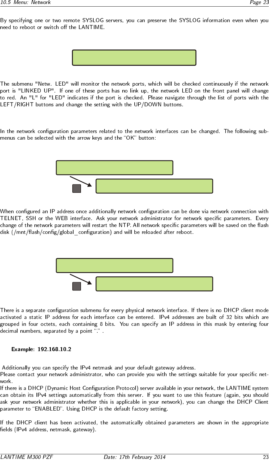
SETUP: Check Network LinkUp on LAN Ports
ETH0:x ETH1: ETH2: ETH3: PTP0:
10.5.2 Setup Network Interfaces
OK
-> Ipv4 Parameter <- Link Mode
Ipv6 Parameter
Global Cfg. Services
-> Interfaces <-
10.5.3 Setup Network Ipv4 Parameter
OK
>DHCP: disabled< ADDR: 192.168.10.2
NETMASK: 255.255.255.0
-> ETH0 <- Def.Gateway
ETH1
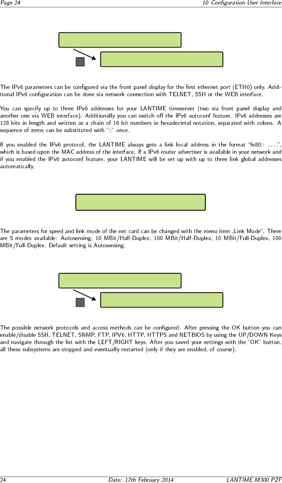
10.5.4 Menu: Setup Ipv6 Parameter
OK
-> Link Local <- glob.Addr 1
Auto Config. glob Addr 2
Ipv4 Parameter Link Mode
-> Ipv6 Parameter <-
10.5.5 Menu: Link Mode
SETUP: ETH0 Device Parameter
Link Speed/Mode: Autosensing
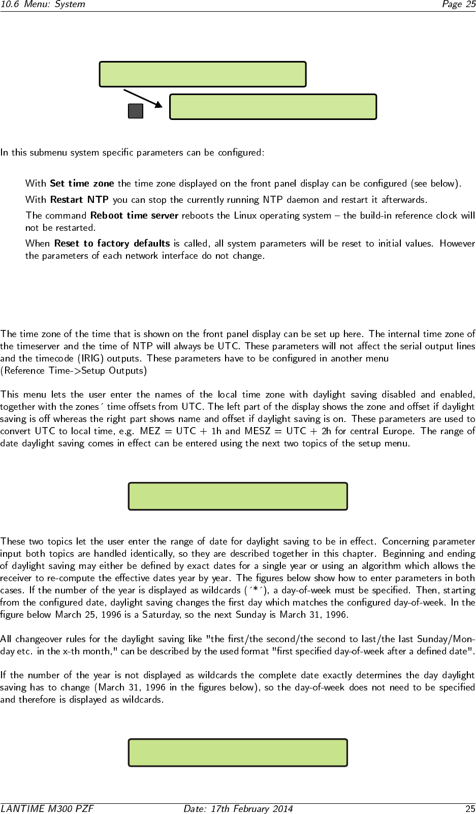
10.5.6 Menu: Setup Network Services
OK
>SSH:on < TELN:on IPv6:on HTTPS:on
FTP:on SNMP:off HTTP:on NETB:off
Global Cfg. -> Services <-
Interfaces
10.6 Menu: System
Reference Time Network
Time Service -> System <-
->Set Time Zone<- Restart NTP
Reboot Server Factory Defaults
OK
•
•
•
•
10.6.1 Set time zone
DAYLIGHT SAVING OFF: |MEZ | +01:00h
DAYLIGHT SAVING ON : |MESZ | +02:00h
DAYLIGHT SAV ON Date: 25.03.****
Day of Week: Sun Time: 02:00:00

DAYLIGHT SAV ON Date: 31.03.1996
Day of Week: *** Time: 02:00:00
DAYLIGHT SAV OFF Date: 25.10.****
Day of Week: Sun Time: 03:00:00
DAYLIGHT SAV OFF Date: 25.03.1996
Day of Week: Sun Time: 03:00:00
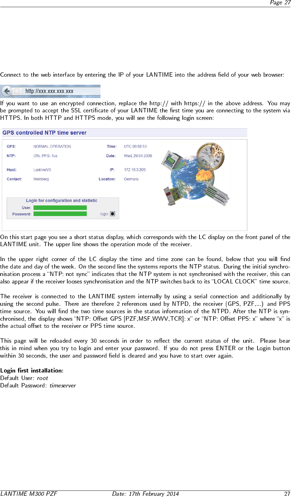
11 The WEB Interface
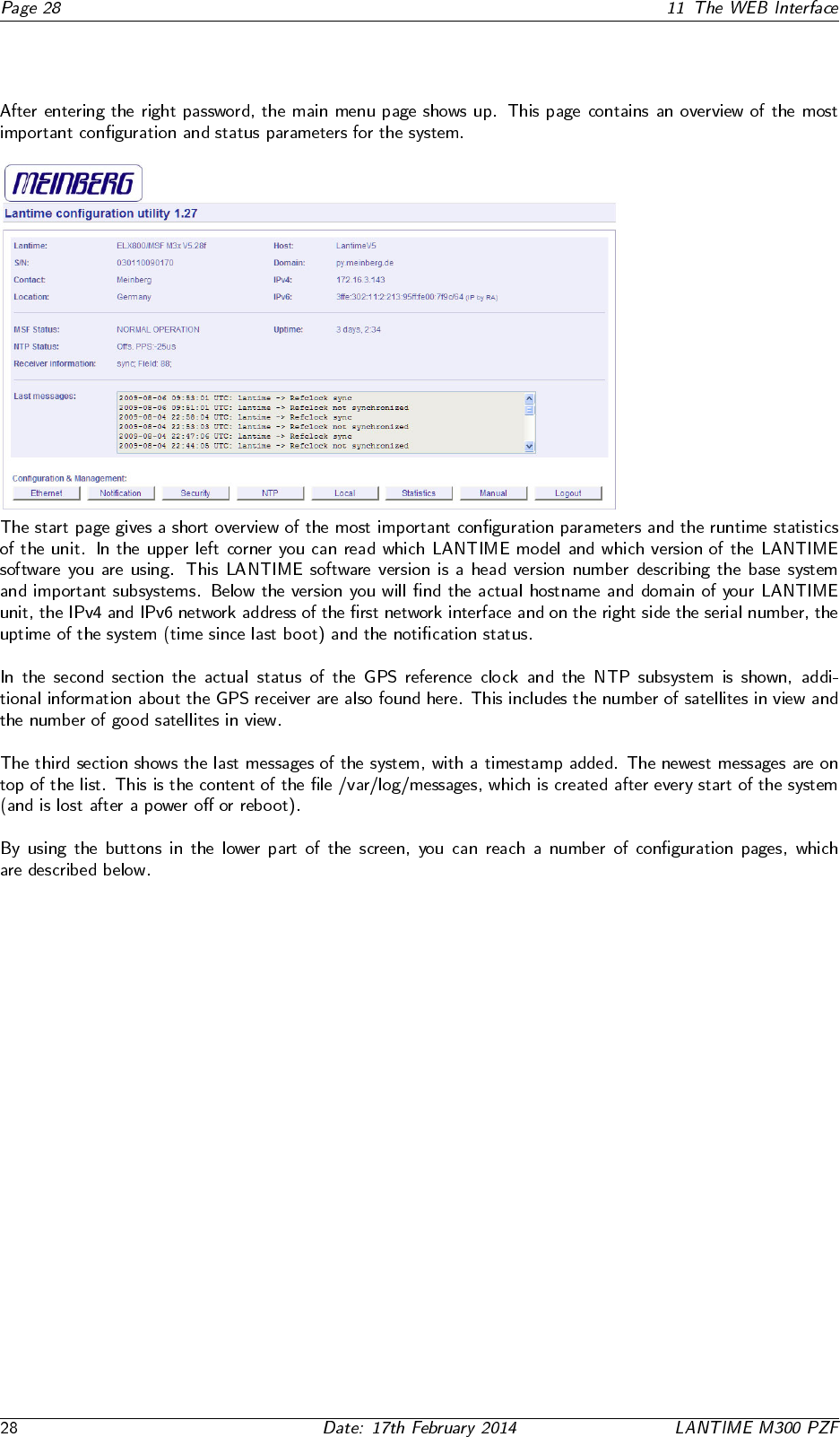
11.1 Configuration: Main Menu
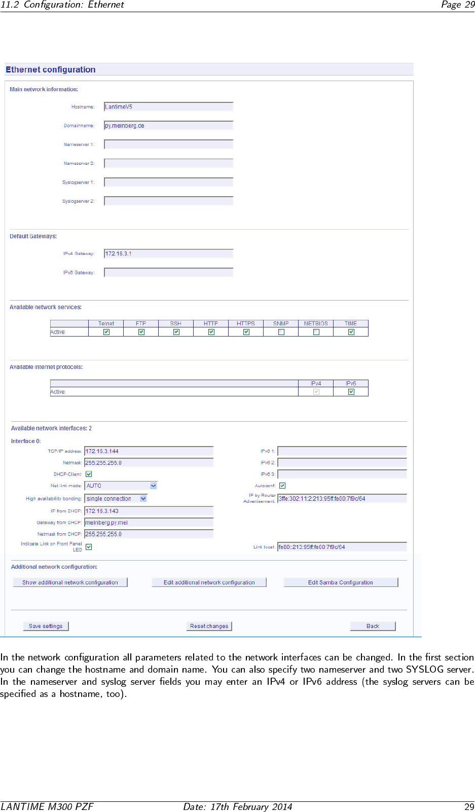
11.2 Configuration: Ethernet
11.2.1 SYSLOG Server

11.3 Network interface specific configuration
11.3.1 IPv4 addresses and DHCP
11.3.2 IPv6 addresses and autoconf

11.3.3 High Availability Bonding
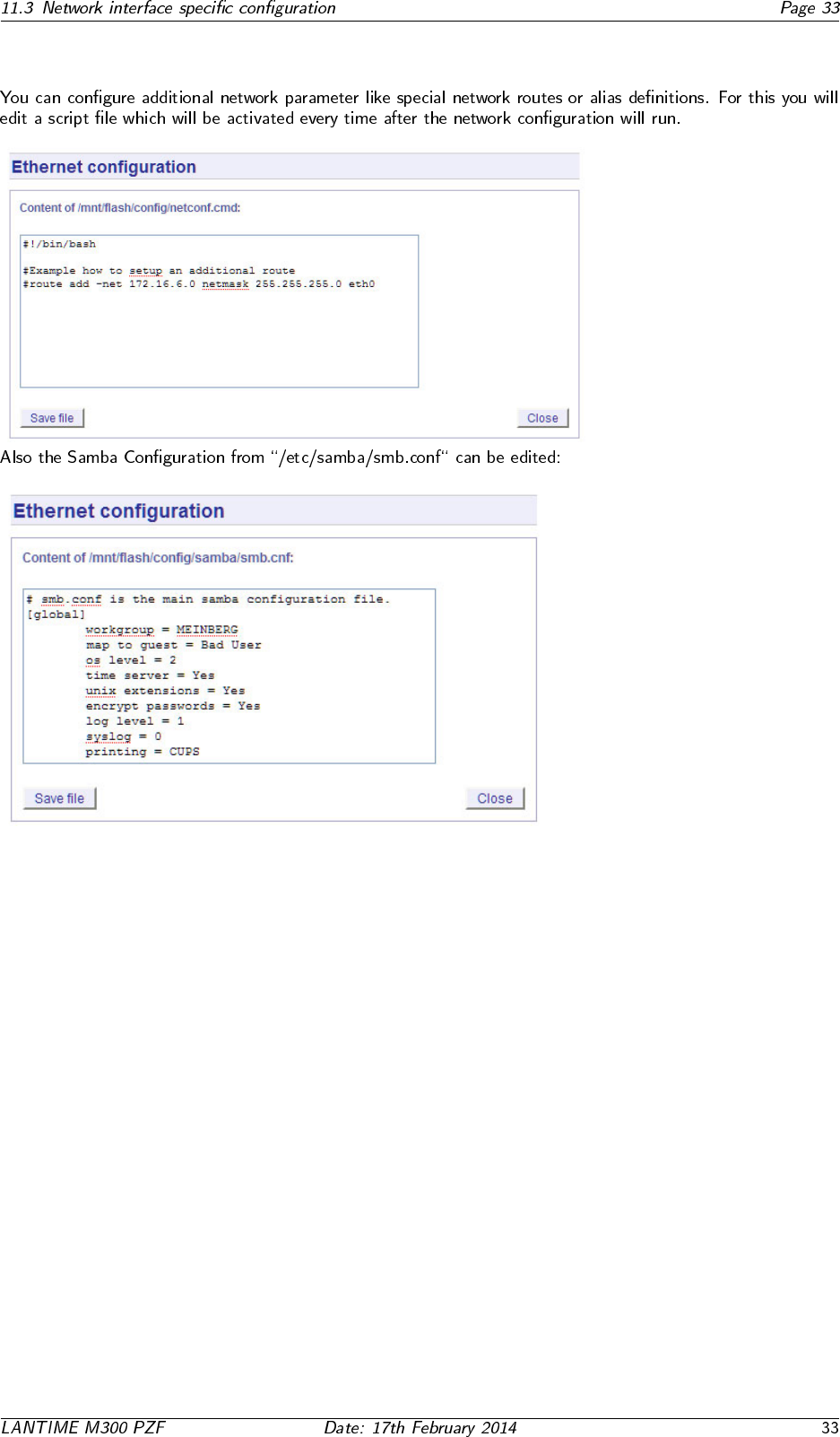
11.3.4 Additional Network Configuration
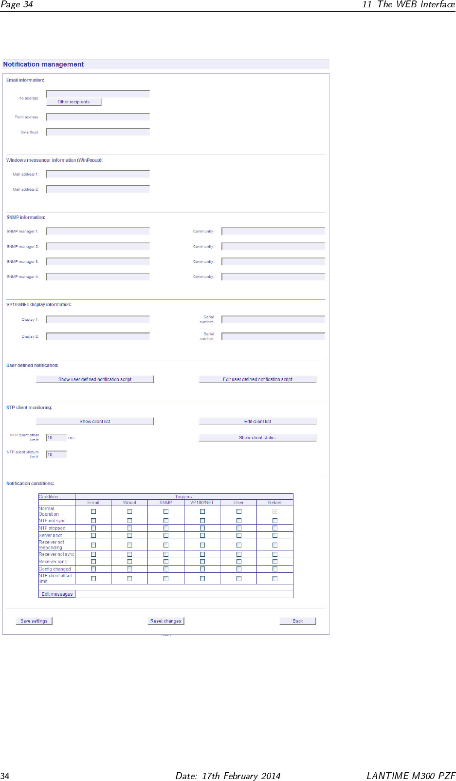
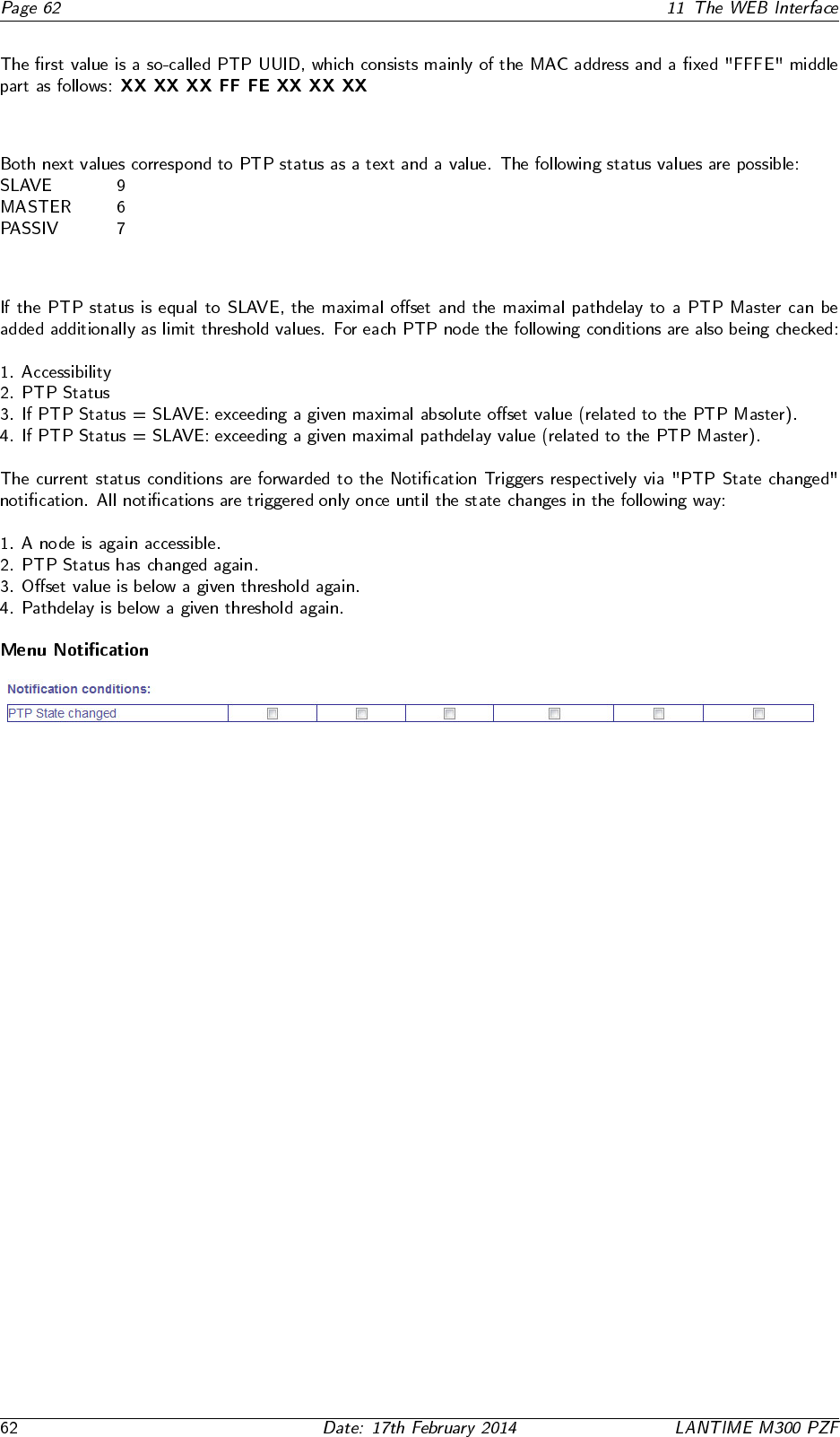
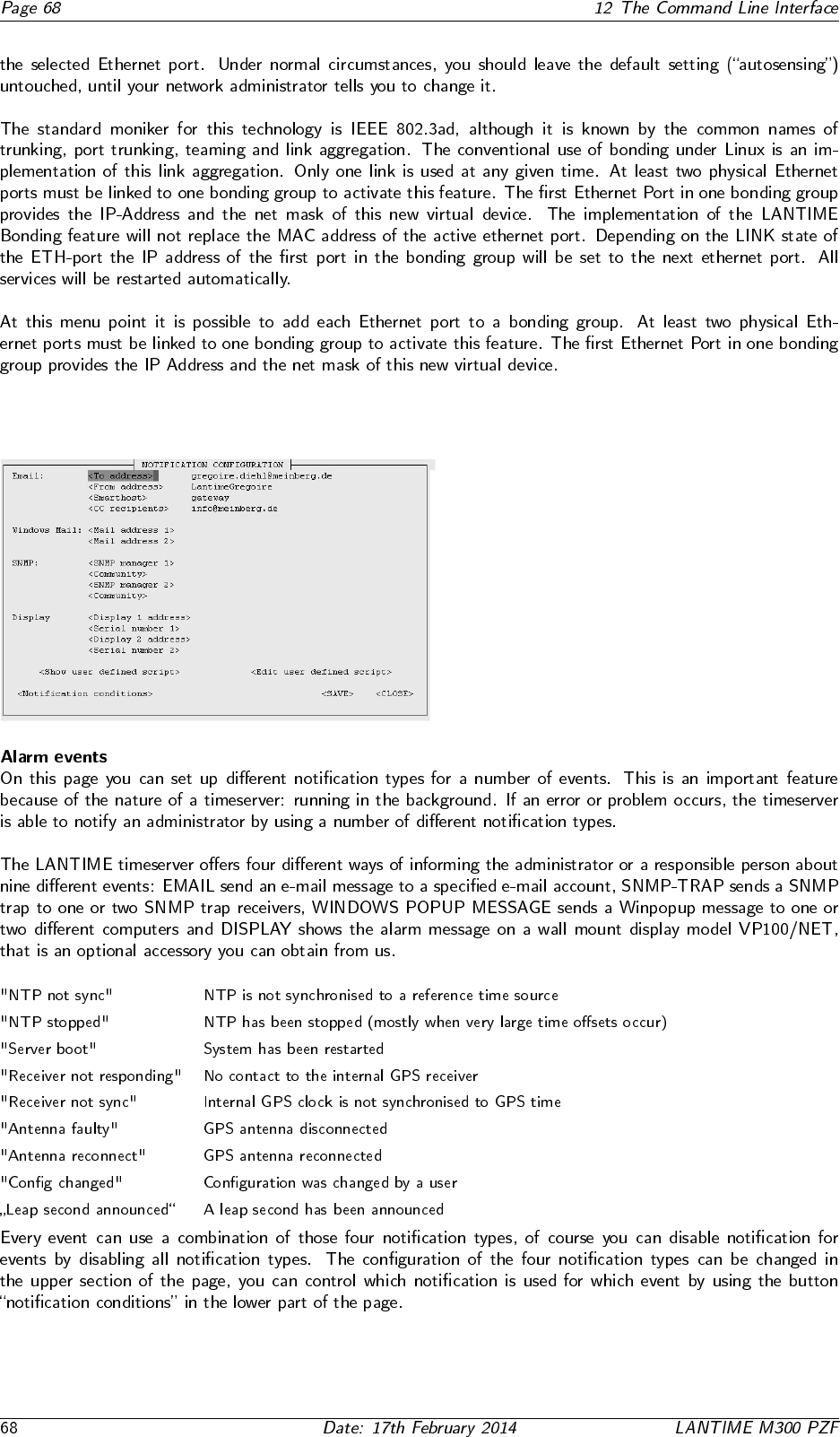
11.4 Configuration: Notification
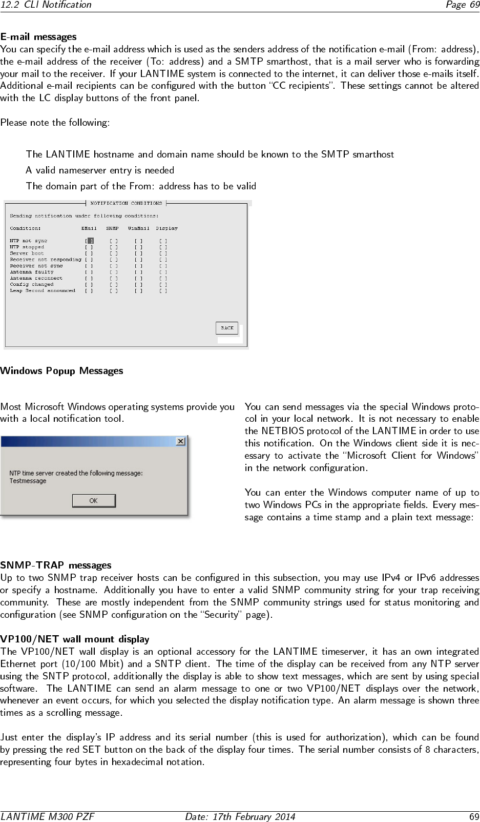
11.4.1 Alarm Events
•
•
•
11.4.2 E-mail messages
•
•
•
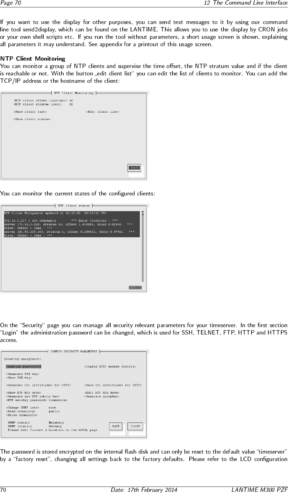
11.4.3 Windows Popup Messages
11.4.4 SNMP-TRAP messages
11.4.5 VP100/NET wall mount display
11.4.6 User defined Alarm scripts
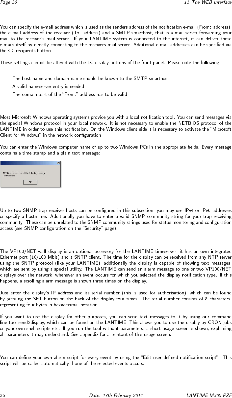
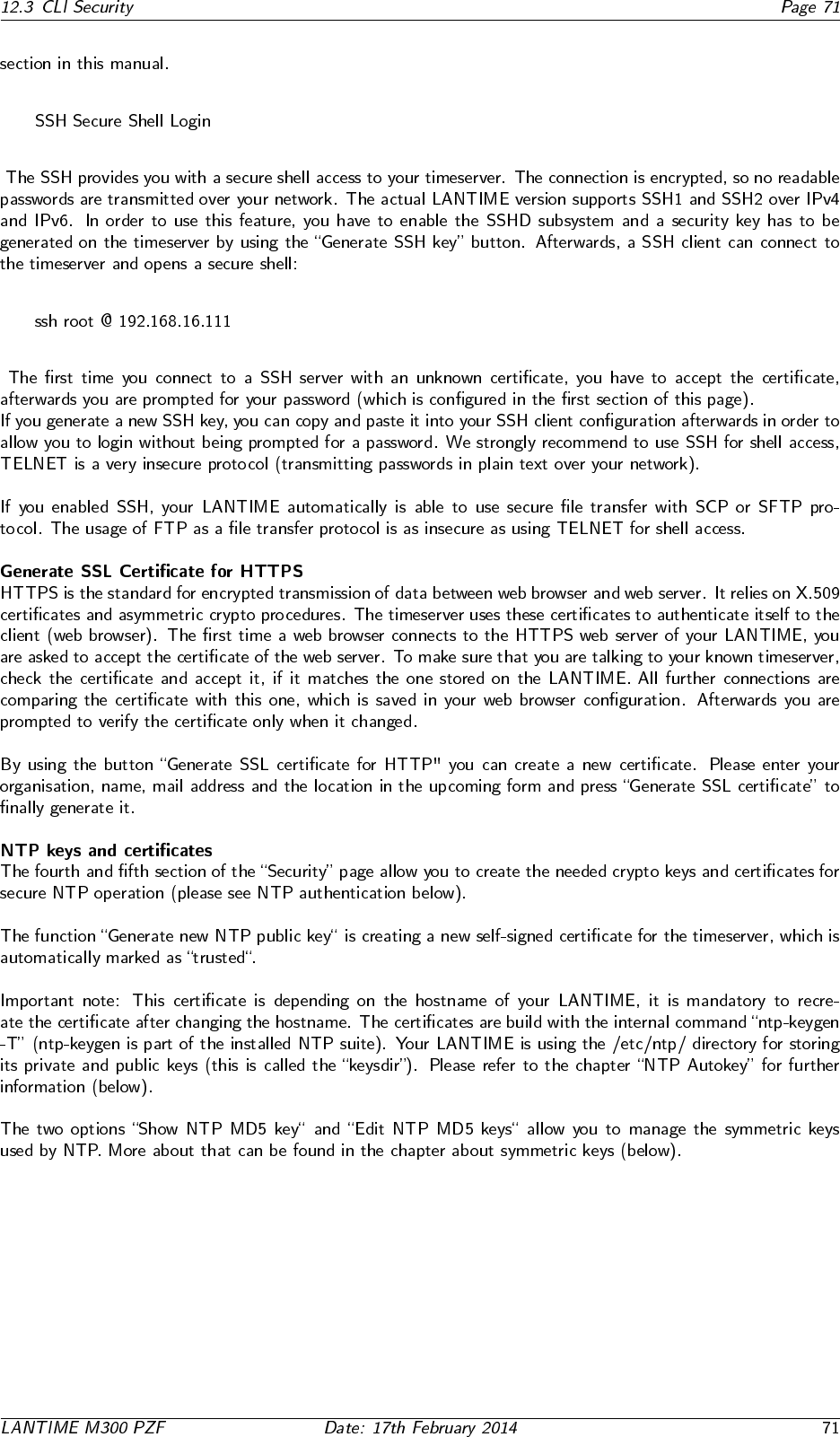
11.4.7 NTP Client Monitoring
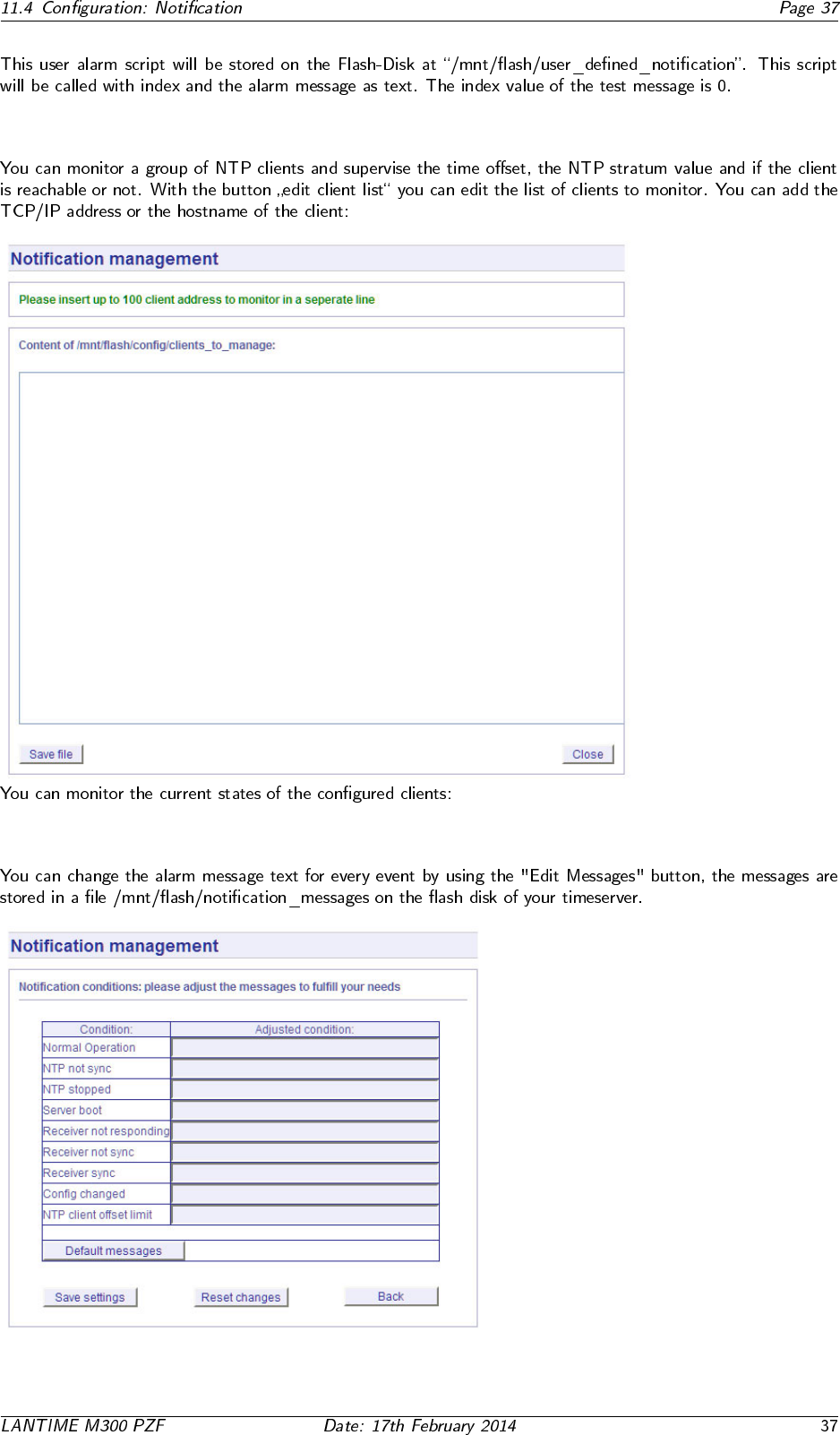
11.4.8 Alarm messages
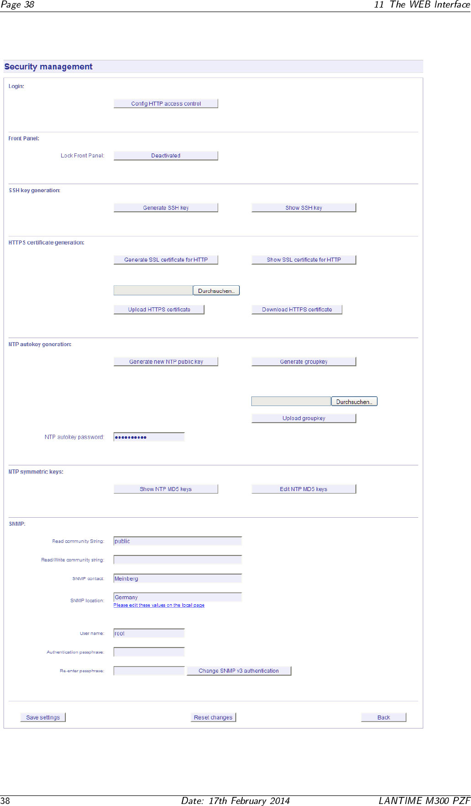
11.5 Configuration: Security
11.5.1 Password
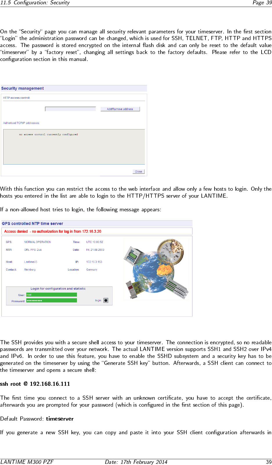
11.5.2 HTTP Access Control
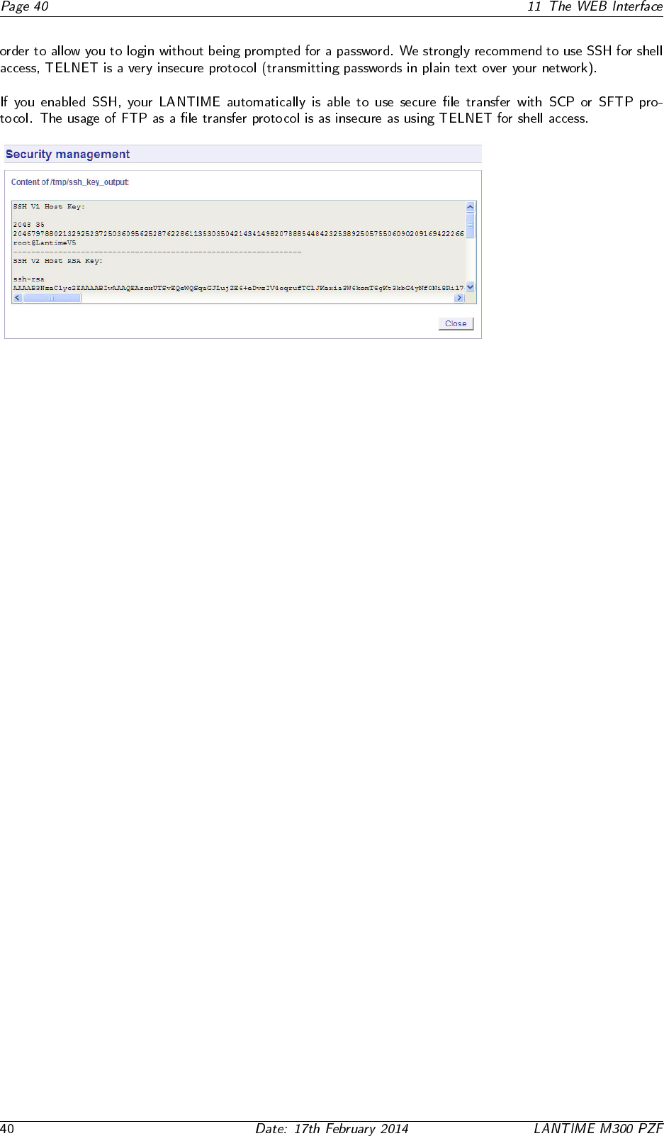
11.5.3 SSH Secure Shell Login
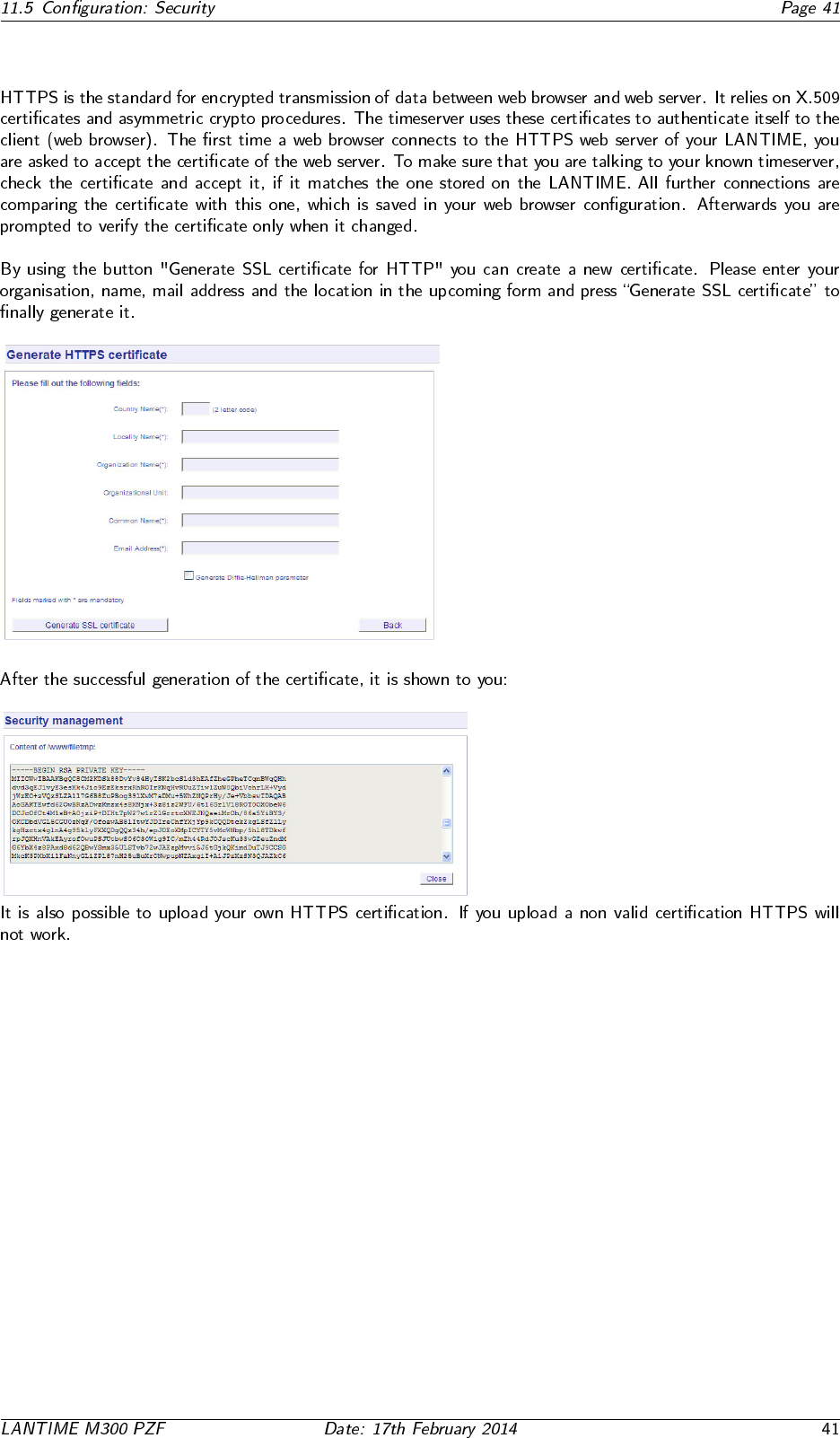
11.5.4 Generate SSL Certificate for HTTPS
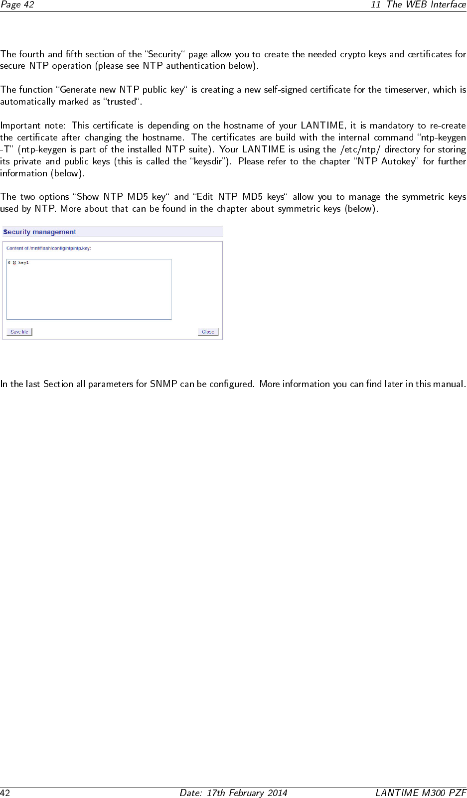
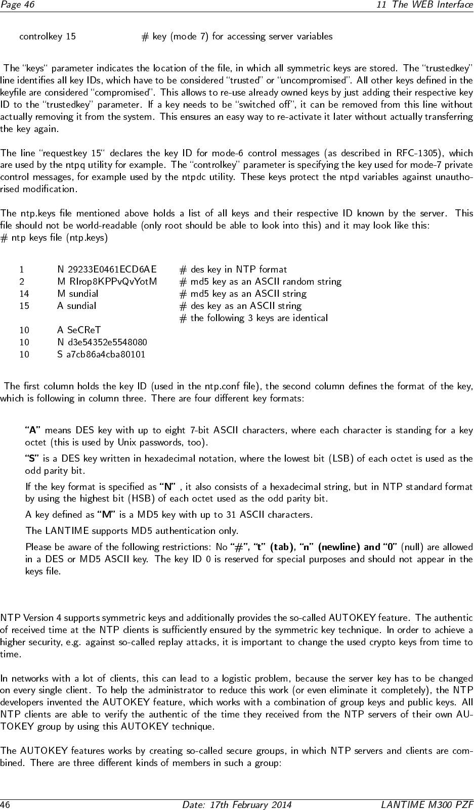
11.5.5 NTP keys and certificates
11.5.6 SNMP Parameter
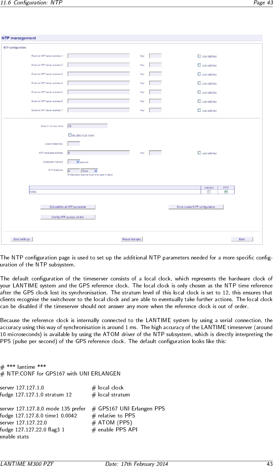
11.6 Configuration: NTP
11.6.1 NTP Authentication
•
•
•
•
•
•
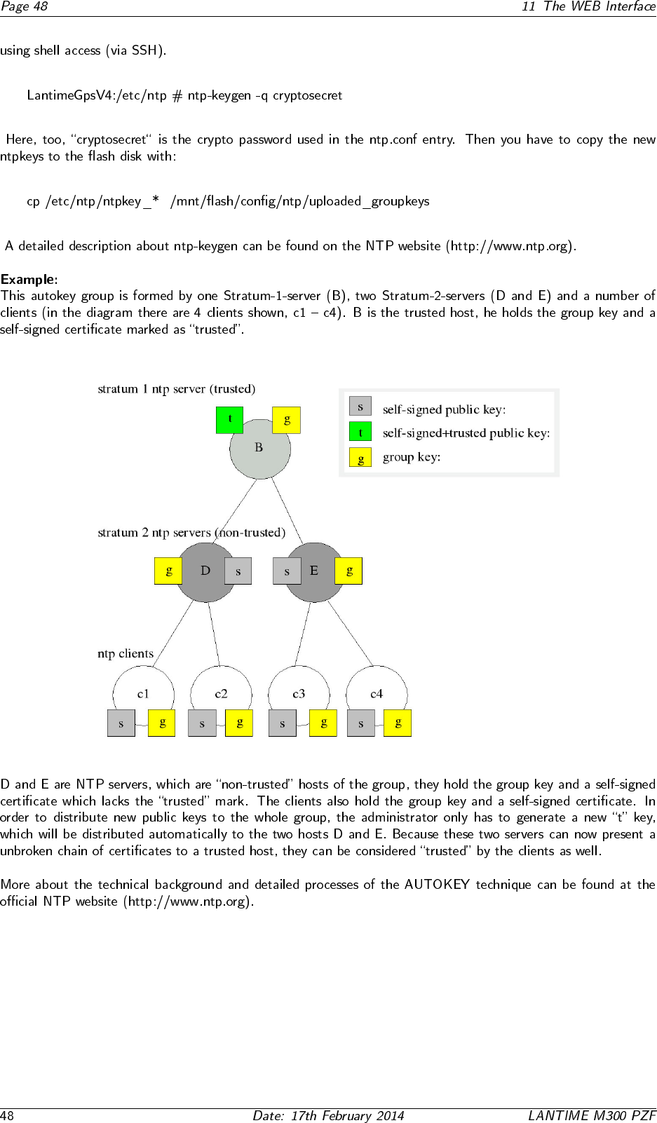
11.6.2 NTP AUTOKEY

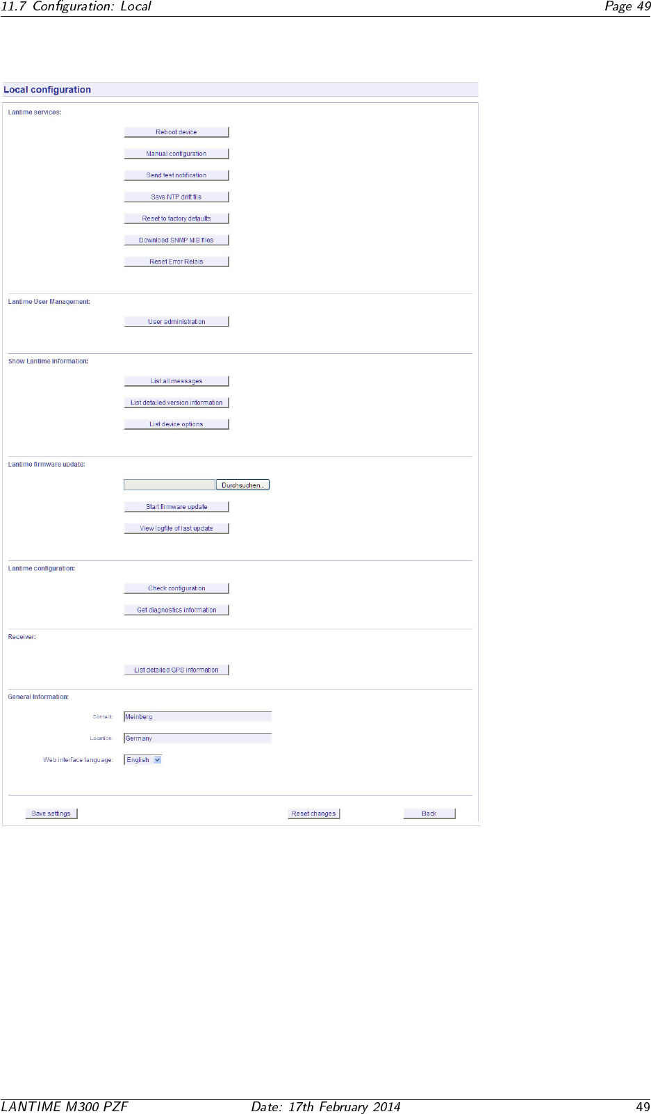
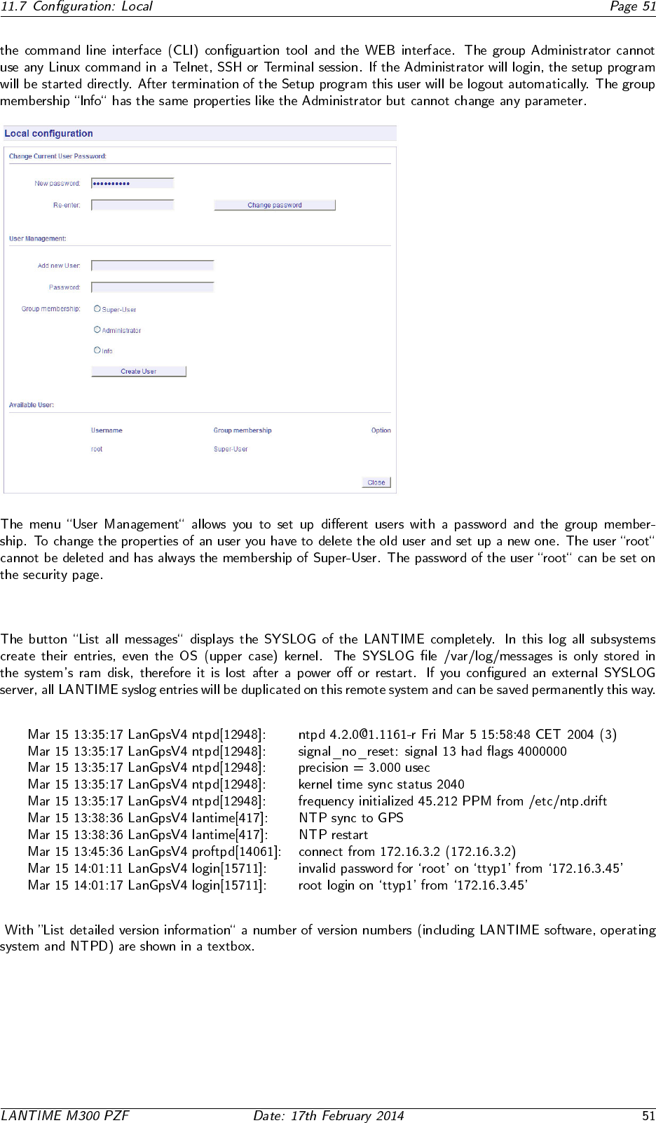
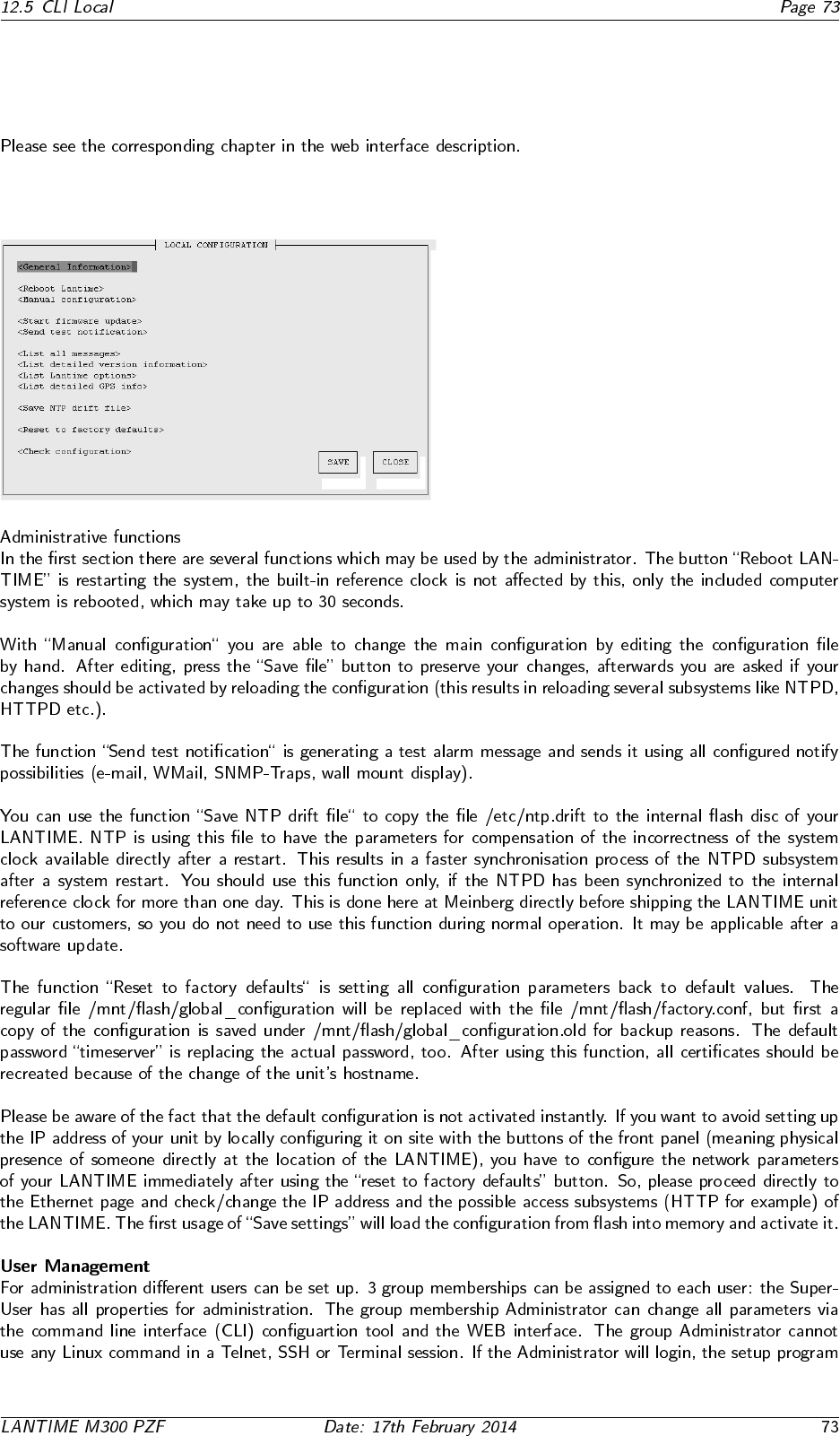
11.7 Configuration: Local
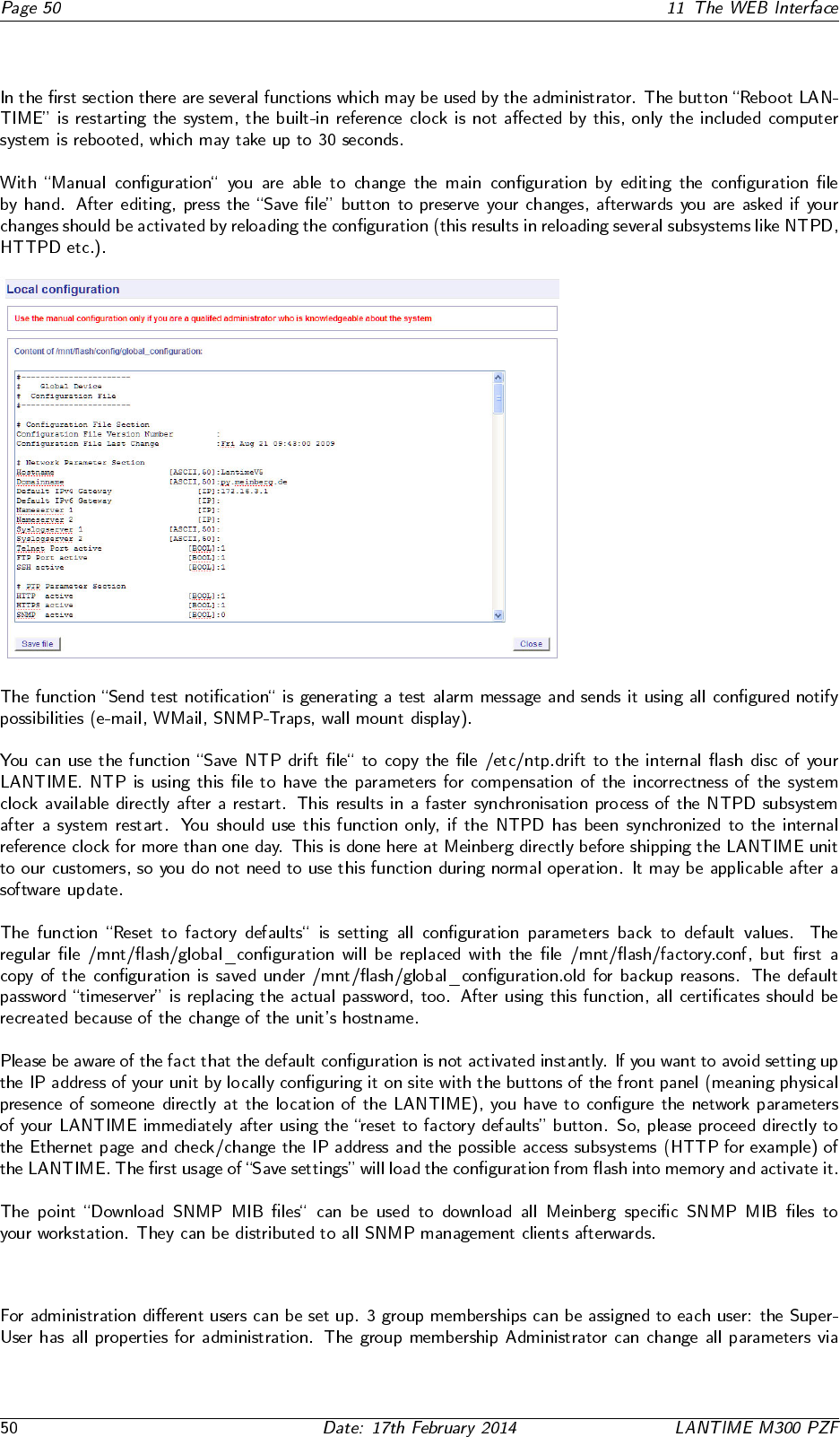
11.7.1 Administrative functions
11.7.2 User Management
11.7.3 Administrative Information

11.7.4 Software Update
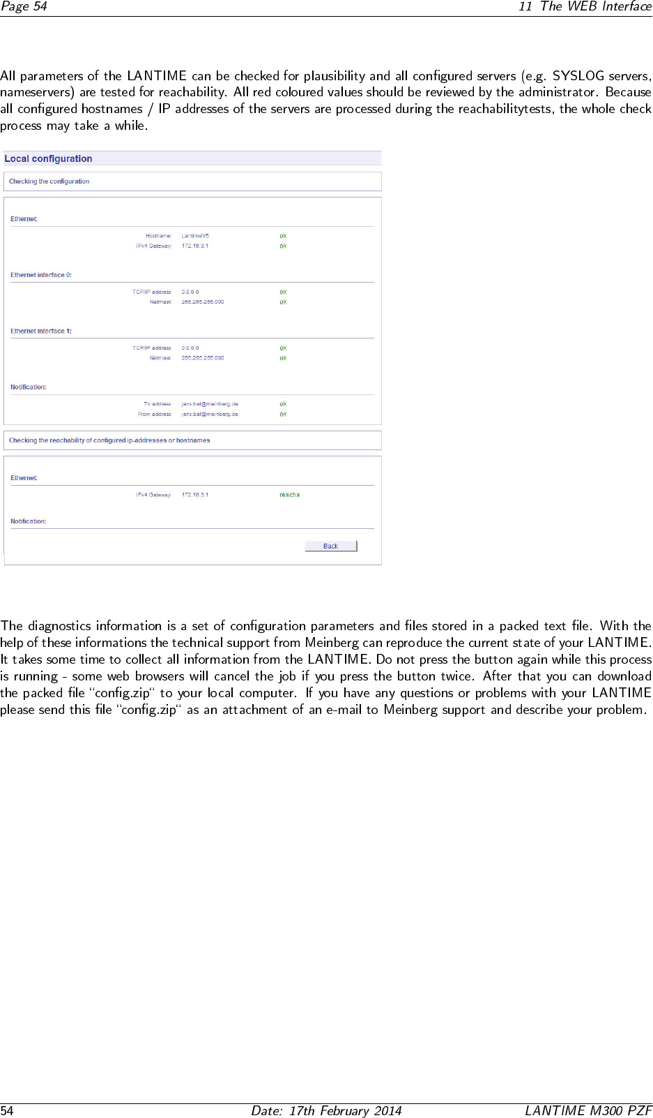
11.7.5 Automatic configuration check
11.7.6 Get Diagnostics Information
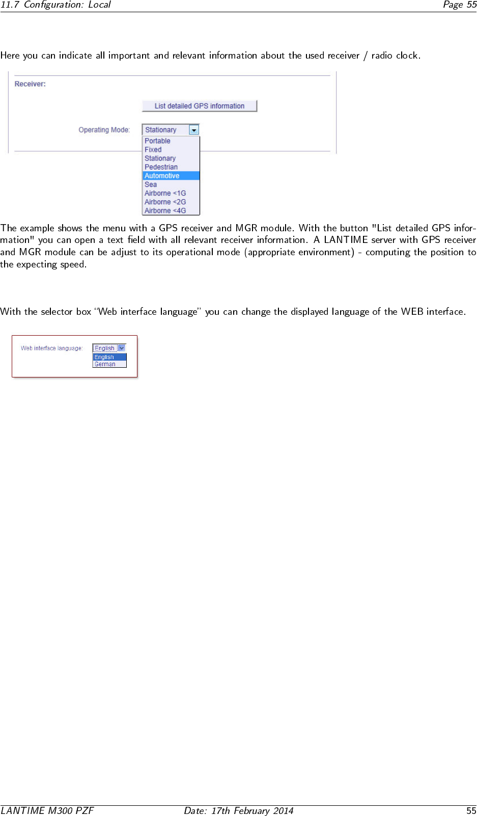
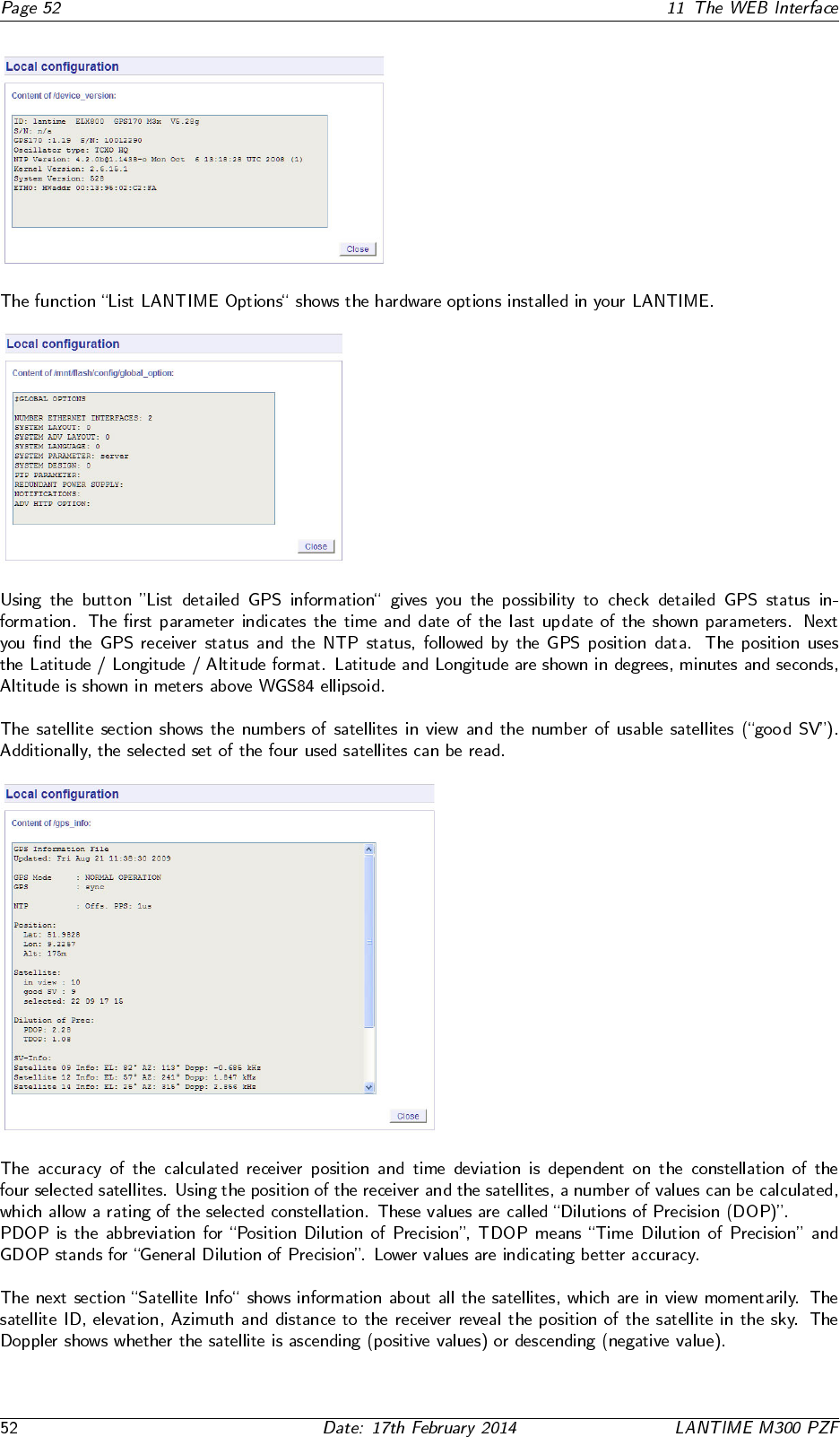
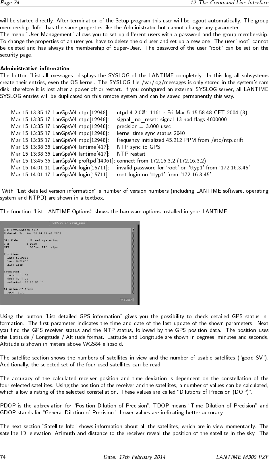
11.7.7 Receiver Information
11.7.8 Web interface language
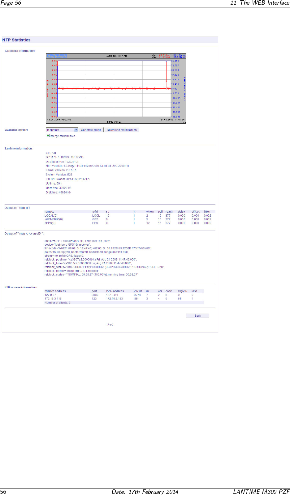
11.8 Configuration: Statistics
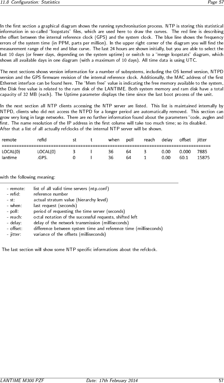
11.8.1 Statistical Information
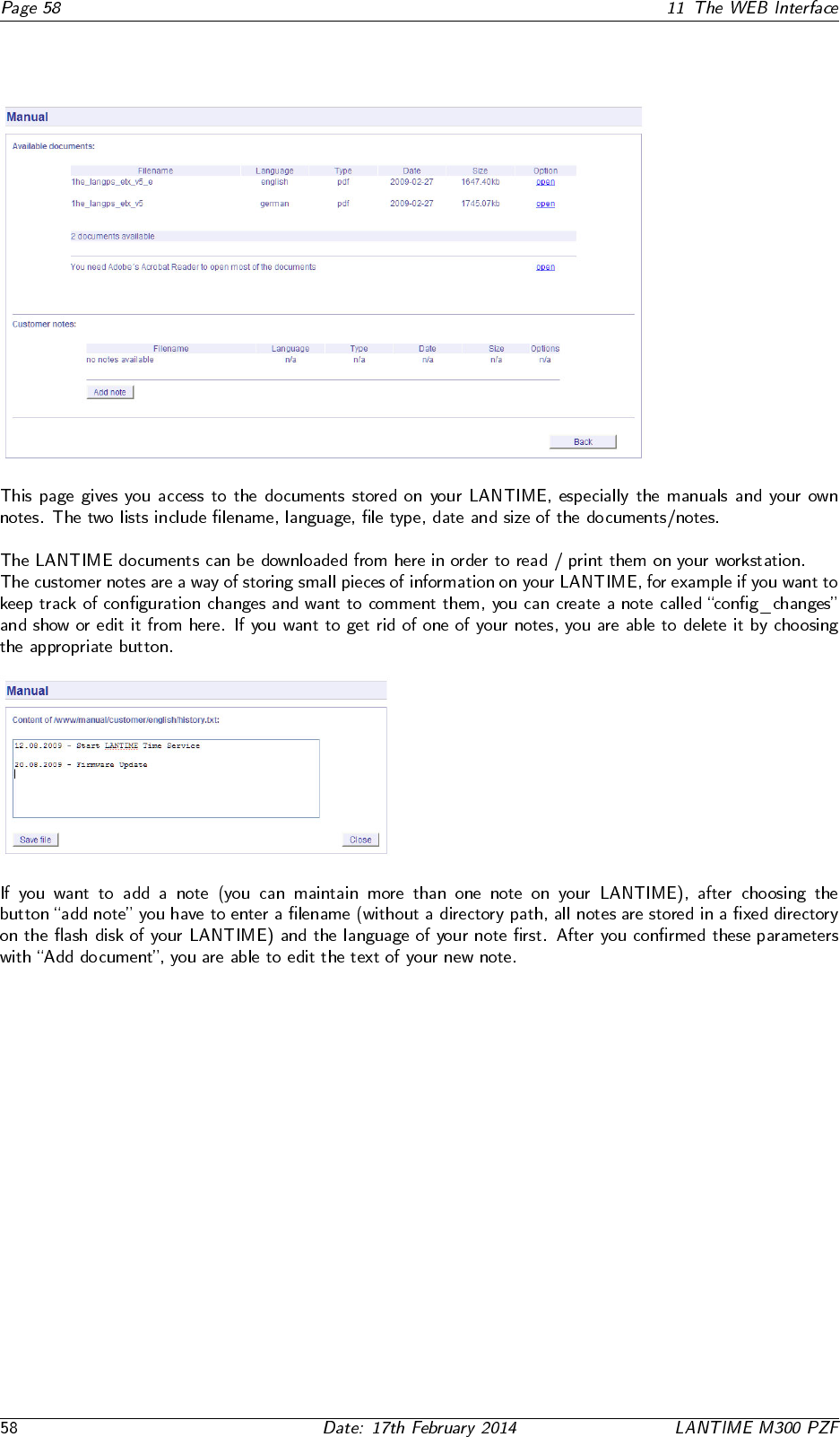
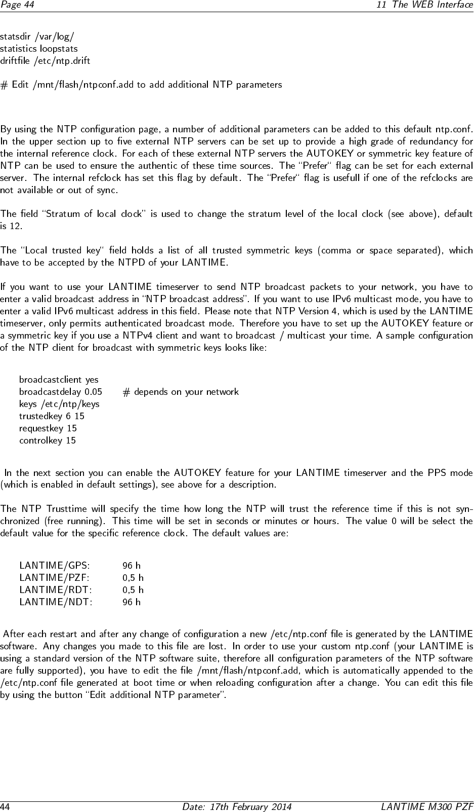
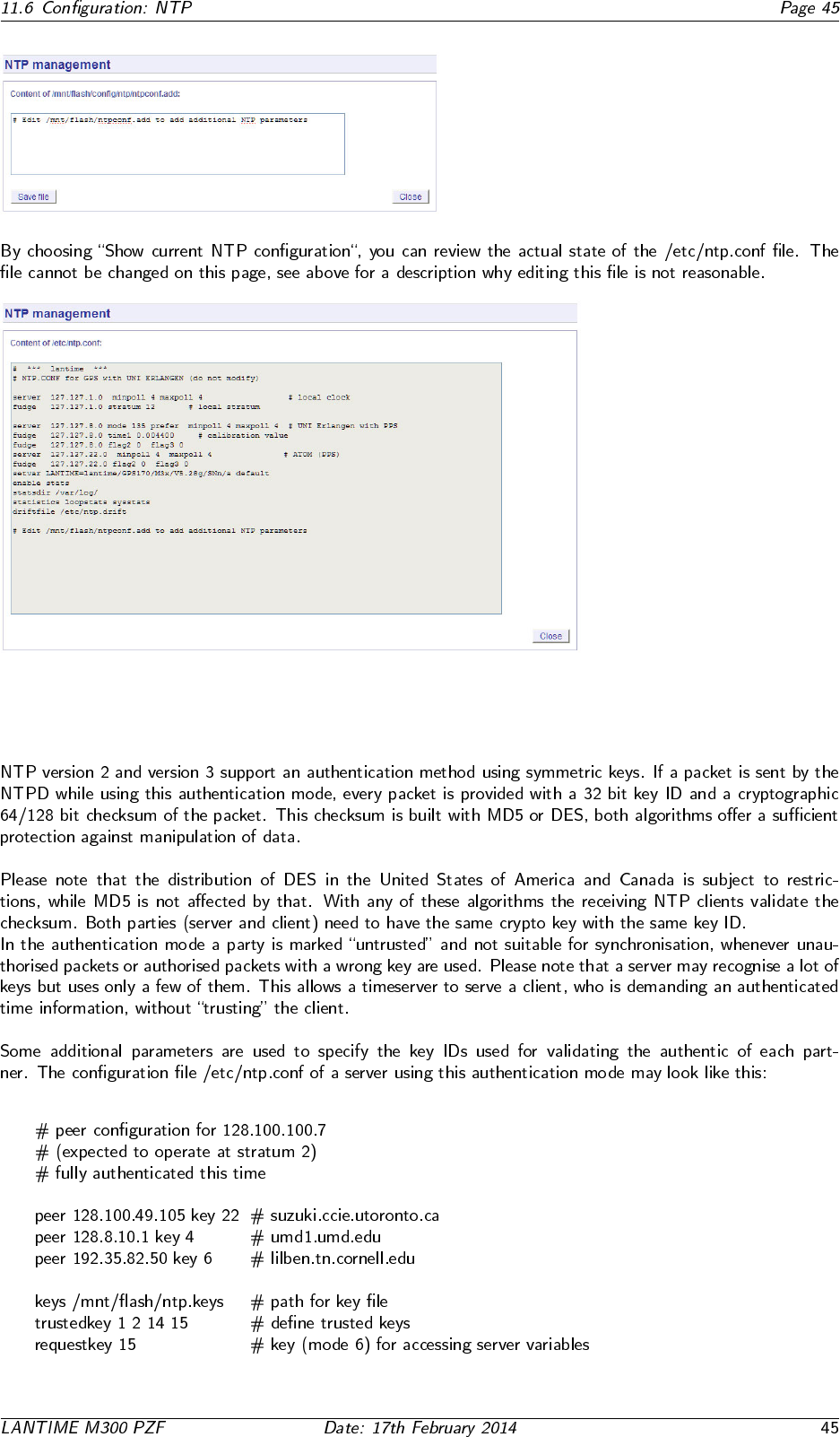
11.9 Configuration: Manual
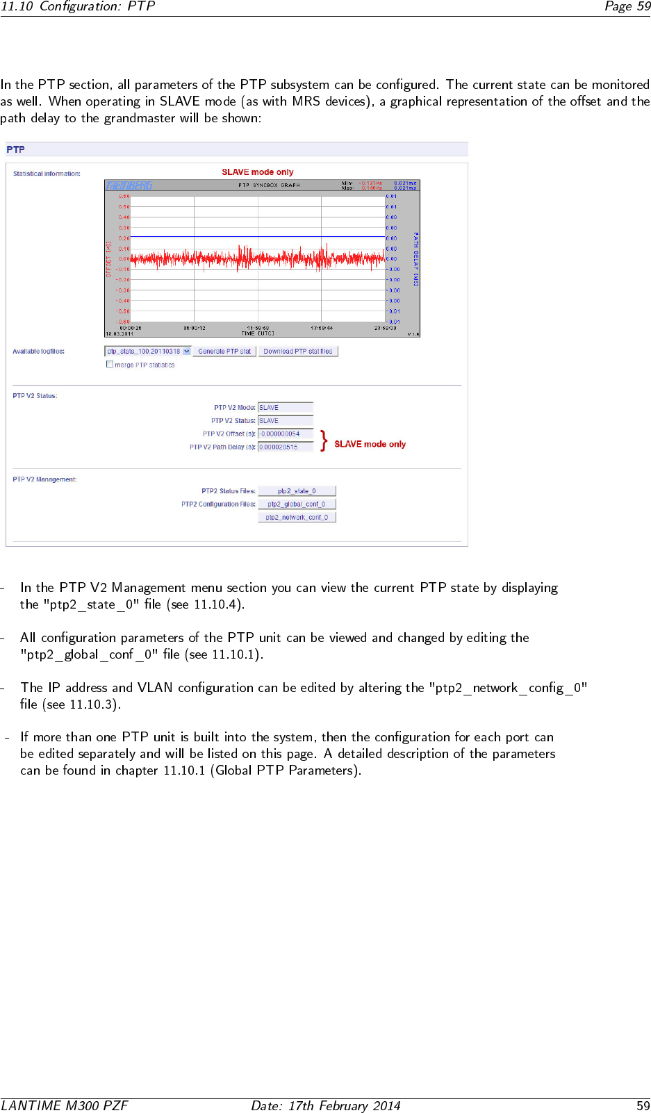
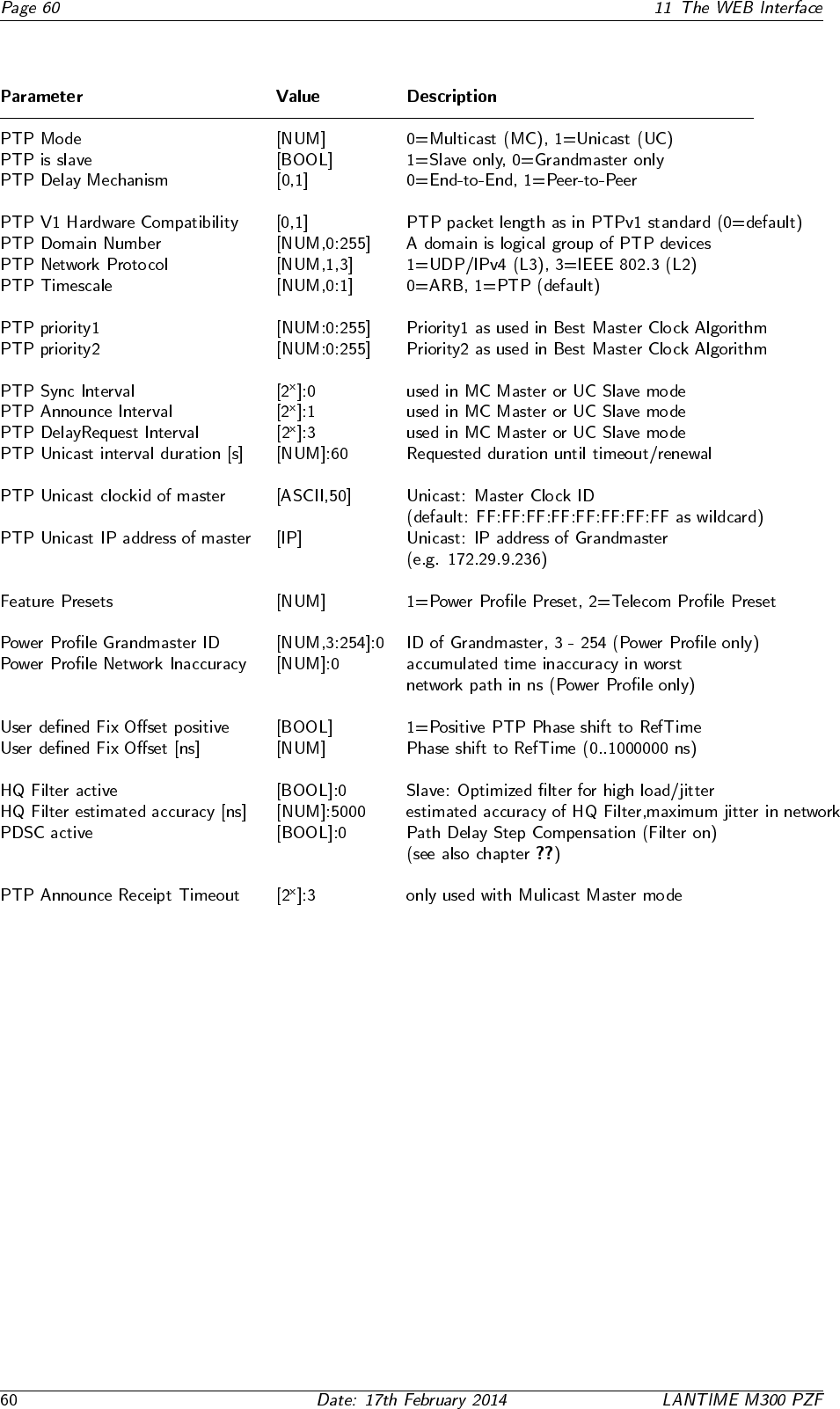
11.10.1 PTPv2 - Global Configuration
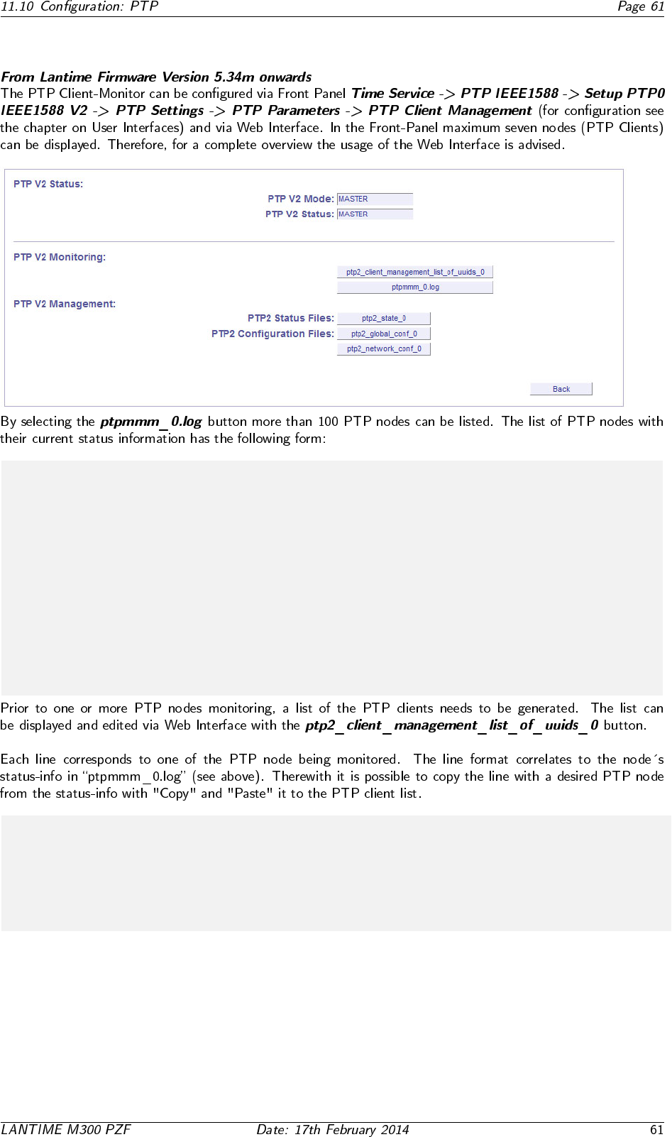
11.10.2 Option: PTP Client Monitoring
# PTP Client Management: found 6 PTP nodes
#
# UUID State-Txt -Val Offset Pathdelay Alias
#-----------------------------------------------------------------------
EC4670FFFE0024CC SLAVE 9 -0.000000015 0.000010420 alias_0
EC4670FFFE002435 MASTER 6 0.000000000 0.000000000
0050C2FFFEB717EA SLAVE 9 0.000000146 0.000020675 alias_2
0050C2FFFED287DE SLAVE 9 0.000000107 0.000020859 alias_3
EC4670FFFE000801 PASSIVE 7 0.000000000 0.000000000
# UUID State text val offset pathdelay Alias
0050C2FFFED287DE Slave 9 0.000000500 0.000025000 alias_name
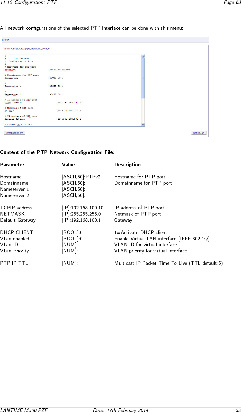
11.10.3 PTP Network Configuration
11.10.4 PTP State Files
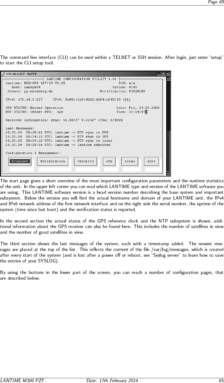
12 The Command Line Interface
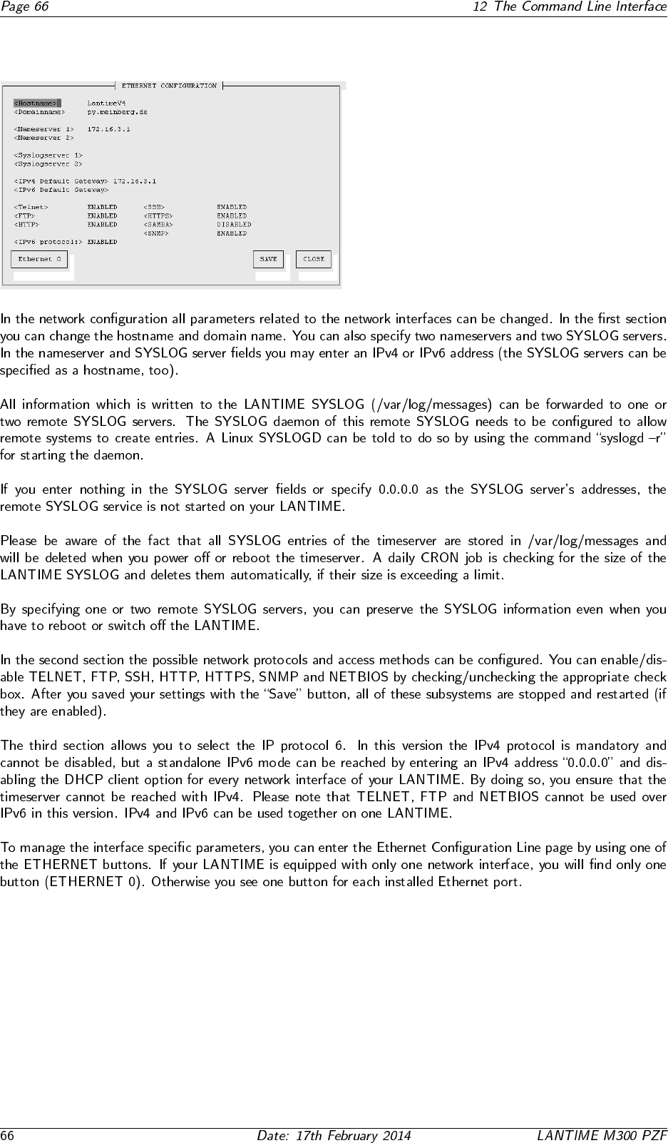
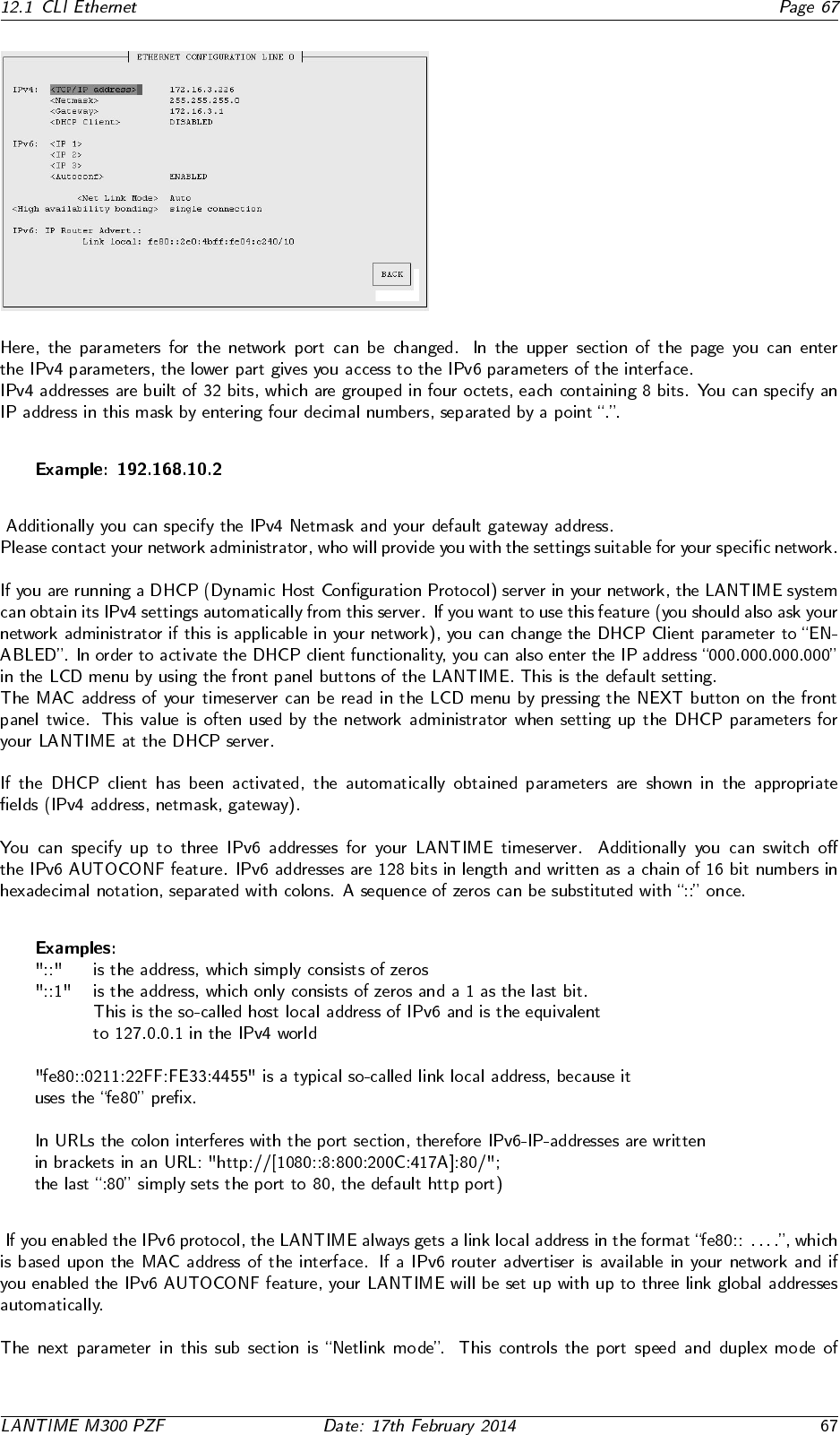
12.1 CLI Ethernet
12.2 CLI Notification
•
•
•
12.3 CLI Security
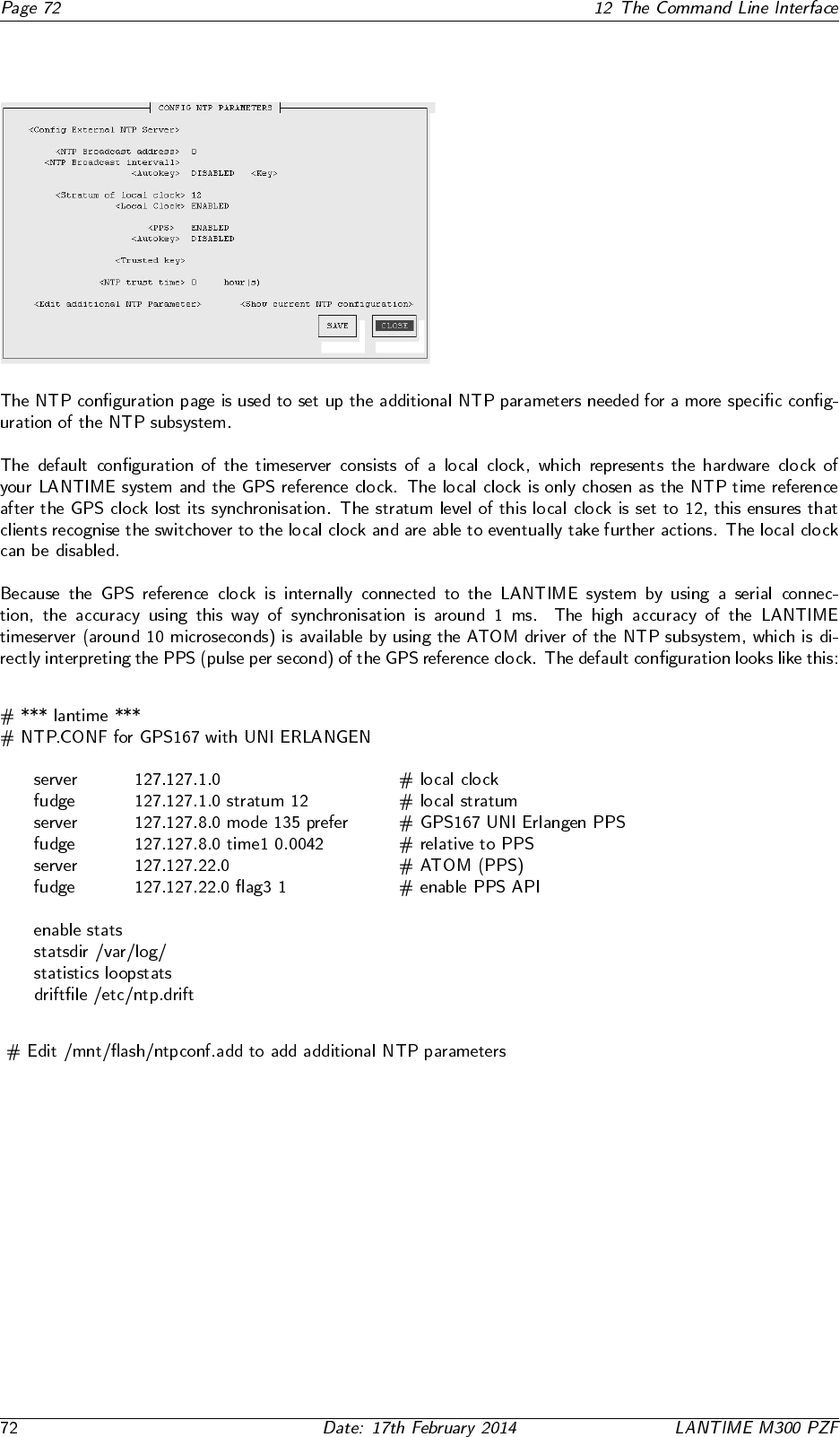
12.4 CLI NTP Parameter
12.4.1 CLI NTP Authentication
12.5 CLI Local

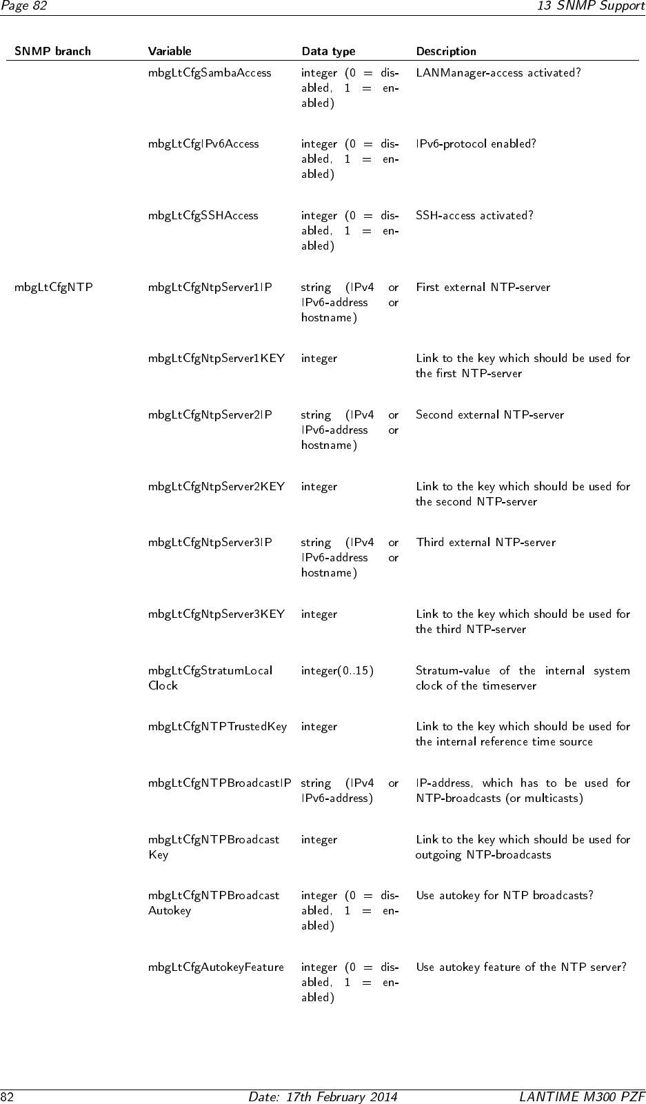
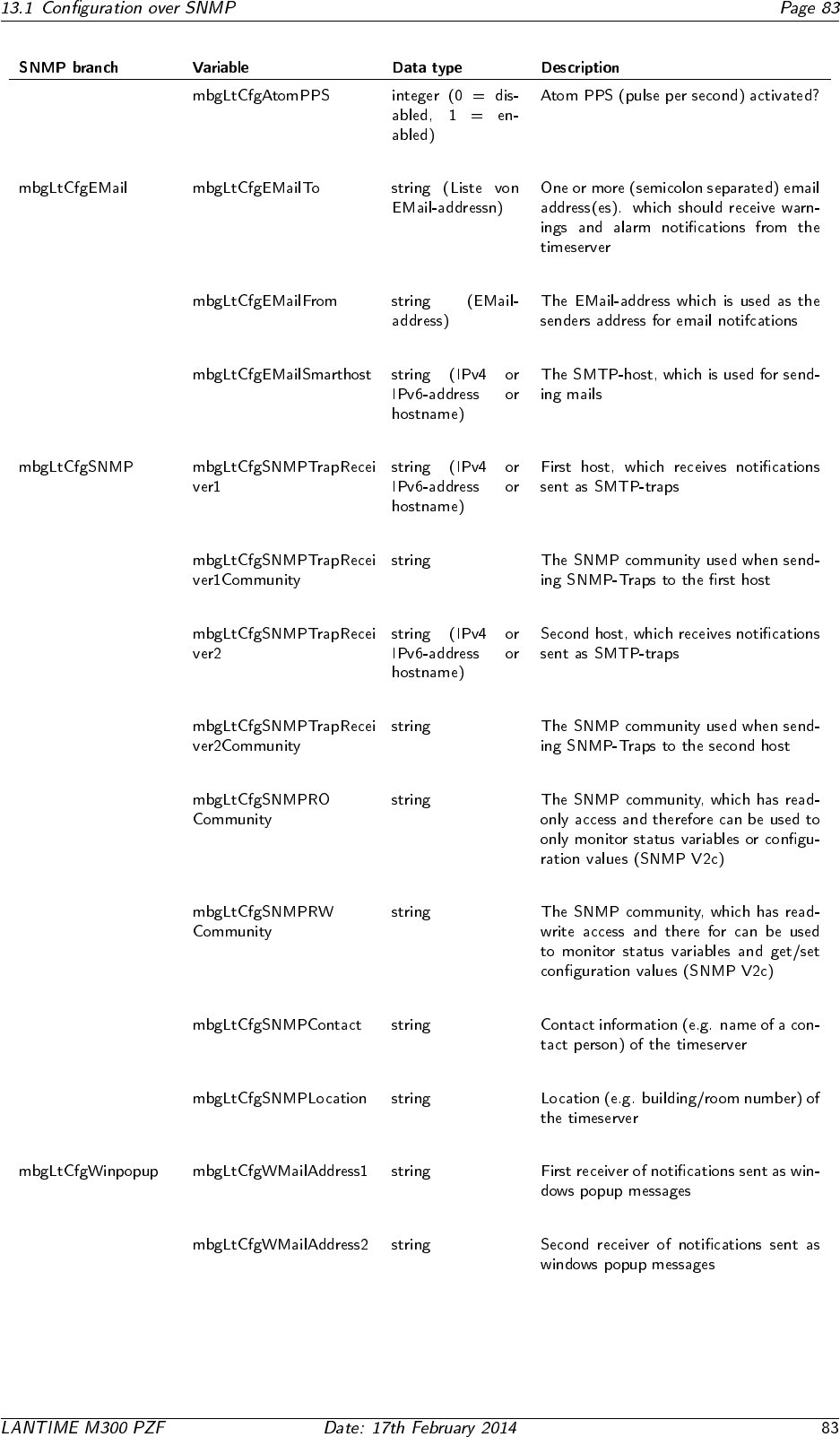
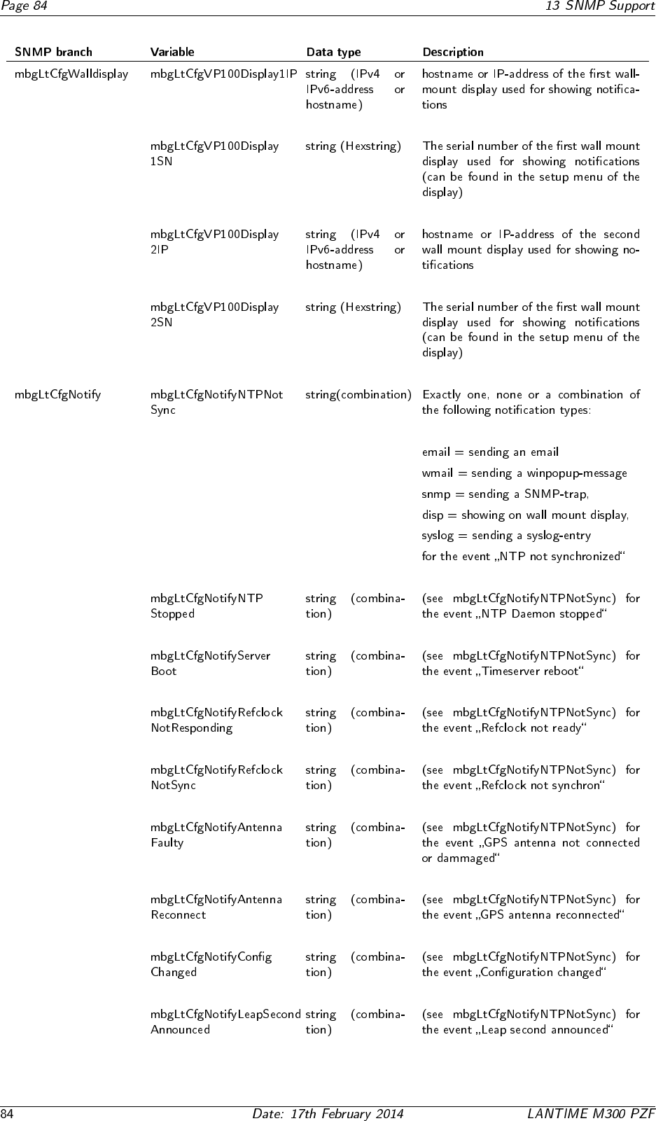
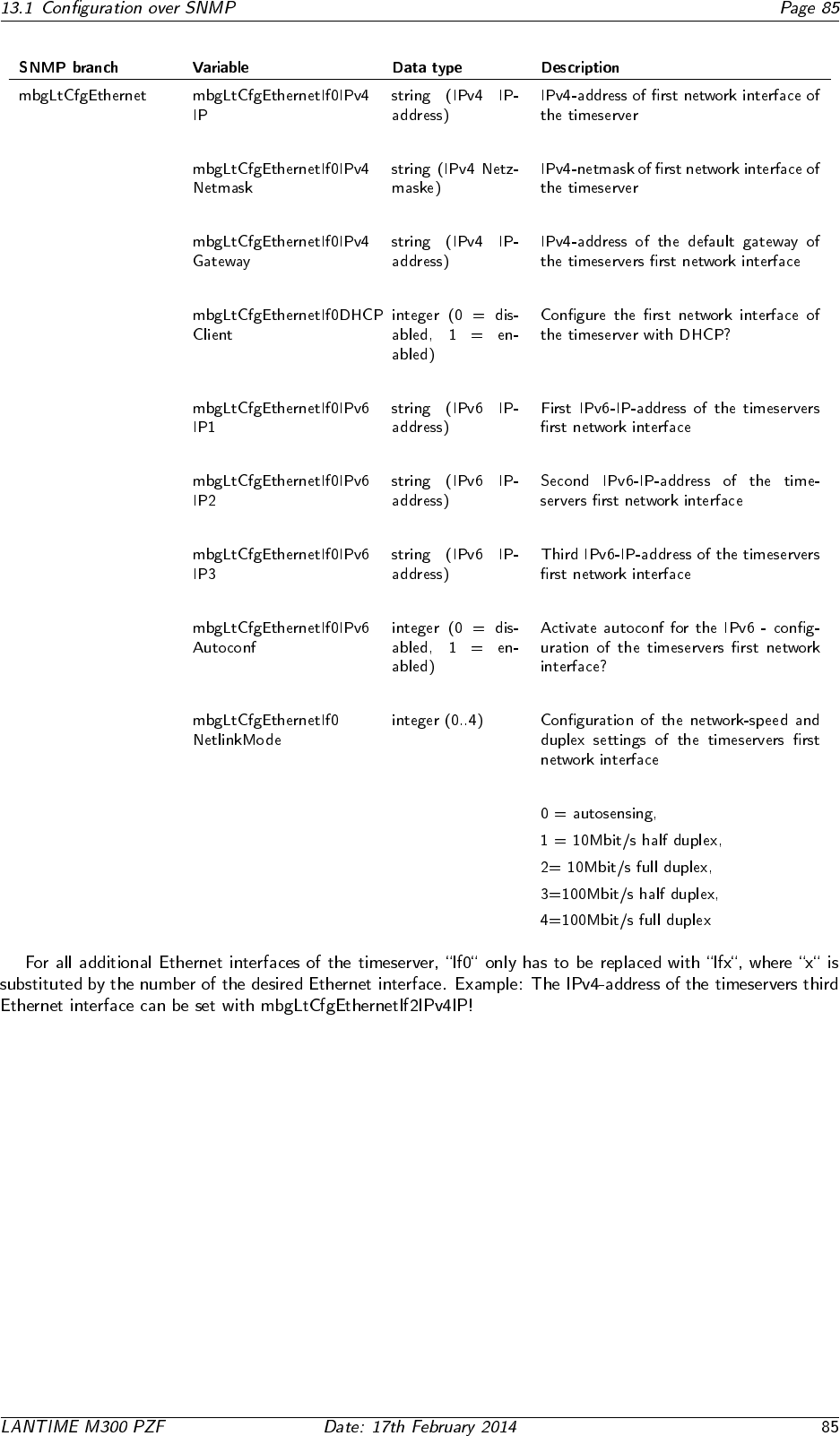
13 SNMP Support
◦ ◦
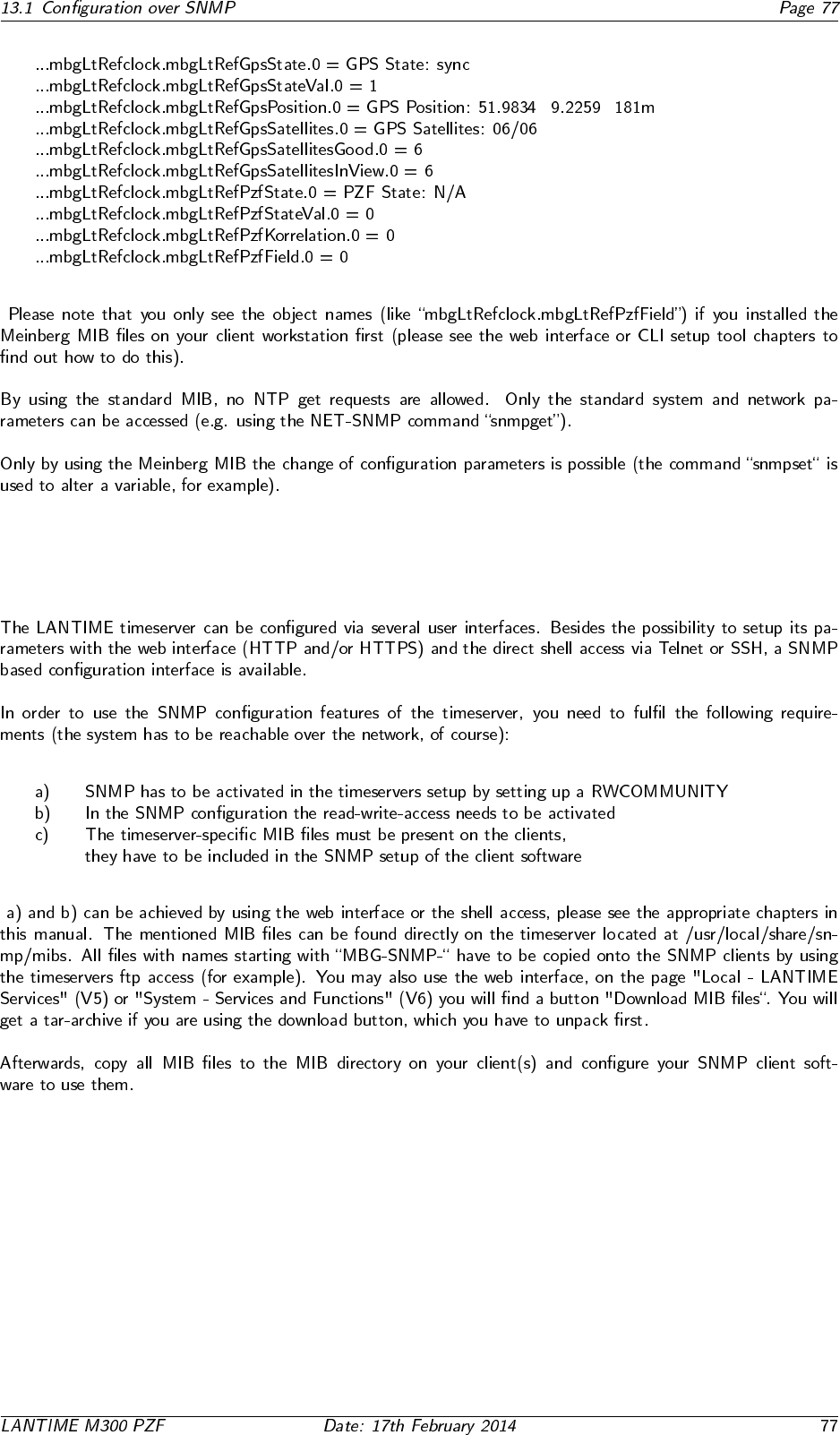
13.1 Configuration over SNMP
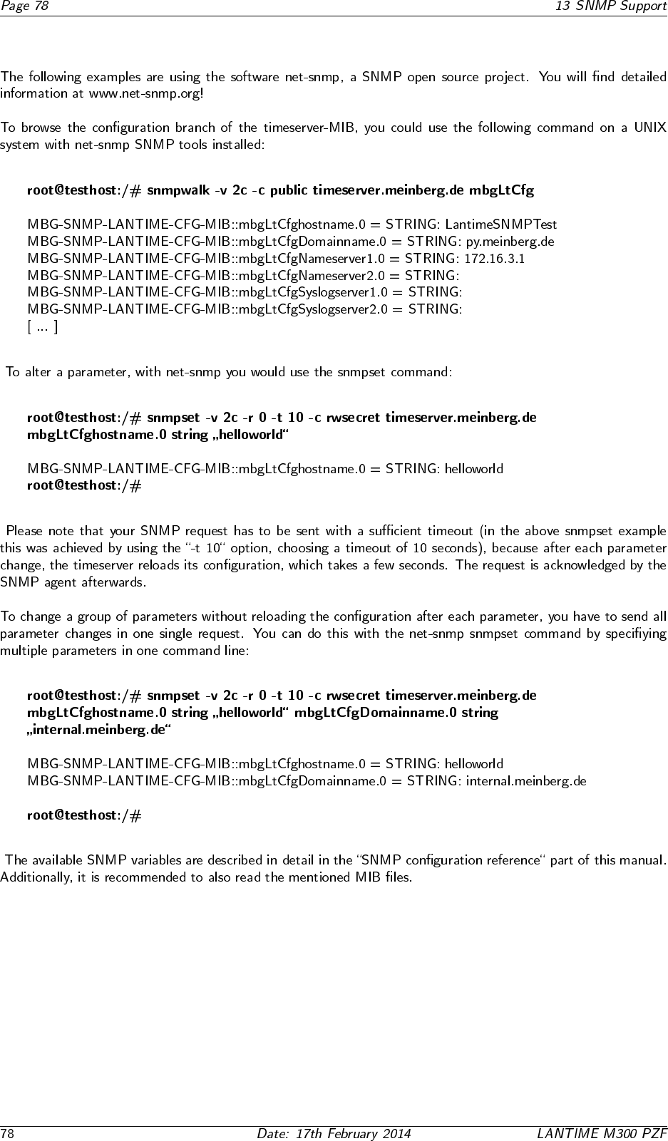
13.1.1 Examples for the usage of the SNMP configuration features

13.1.2 Further configuration possibilities
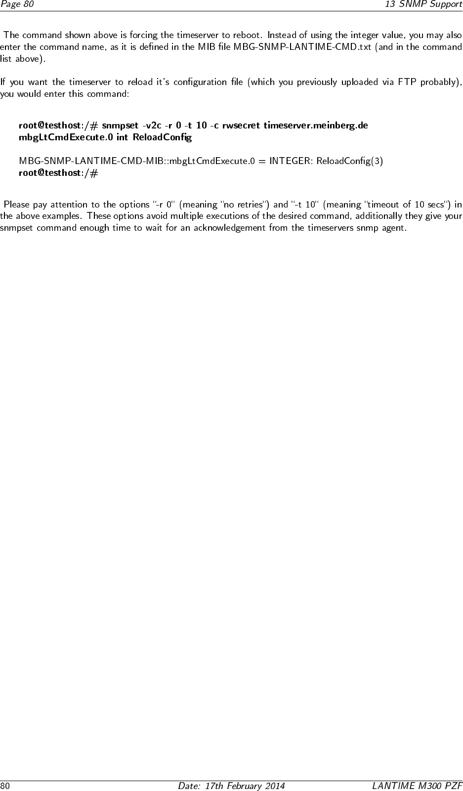
13.1.3 Send special timeserver commands with SNMP
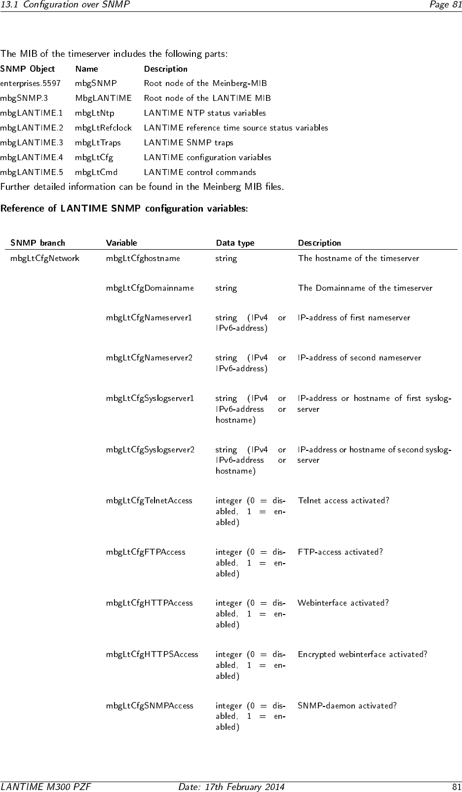
13.1.4 Configuration of the timeserver with SNMP: Reference
13.2 SNMP Traps
13.2.1 SNMP Trap Reference
•
•
•
•
•
•
•
•
•
•

14 Attachment: Technical Information
14.1 Skilled/Service-Personnel only: Replacing the Lithium Battery
14.2 Technical Specifications M600/300 Multipac
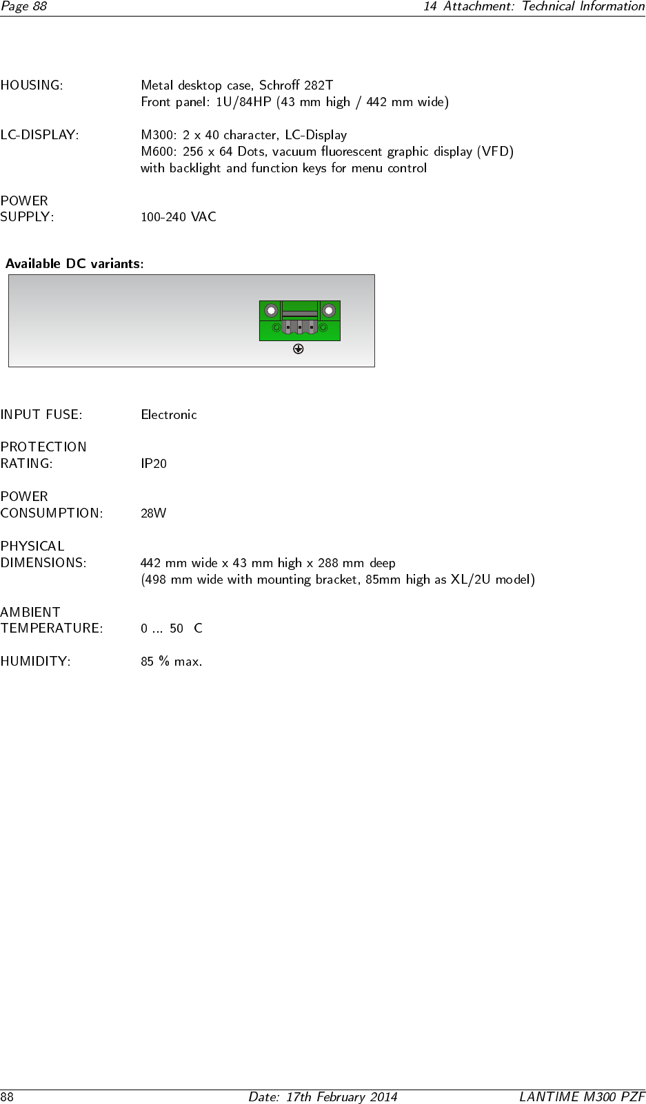
DC Input
+
-
!
!
!
!
100 - 240 VDC
12 VDC
24 VDC
48 VDC
◦

14.3 Safety instructions for building-in equipment
•
•
•
•
•
•◦
•
•
14.3.1 CE-Label
14.4 Rear Panel Connectors
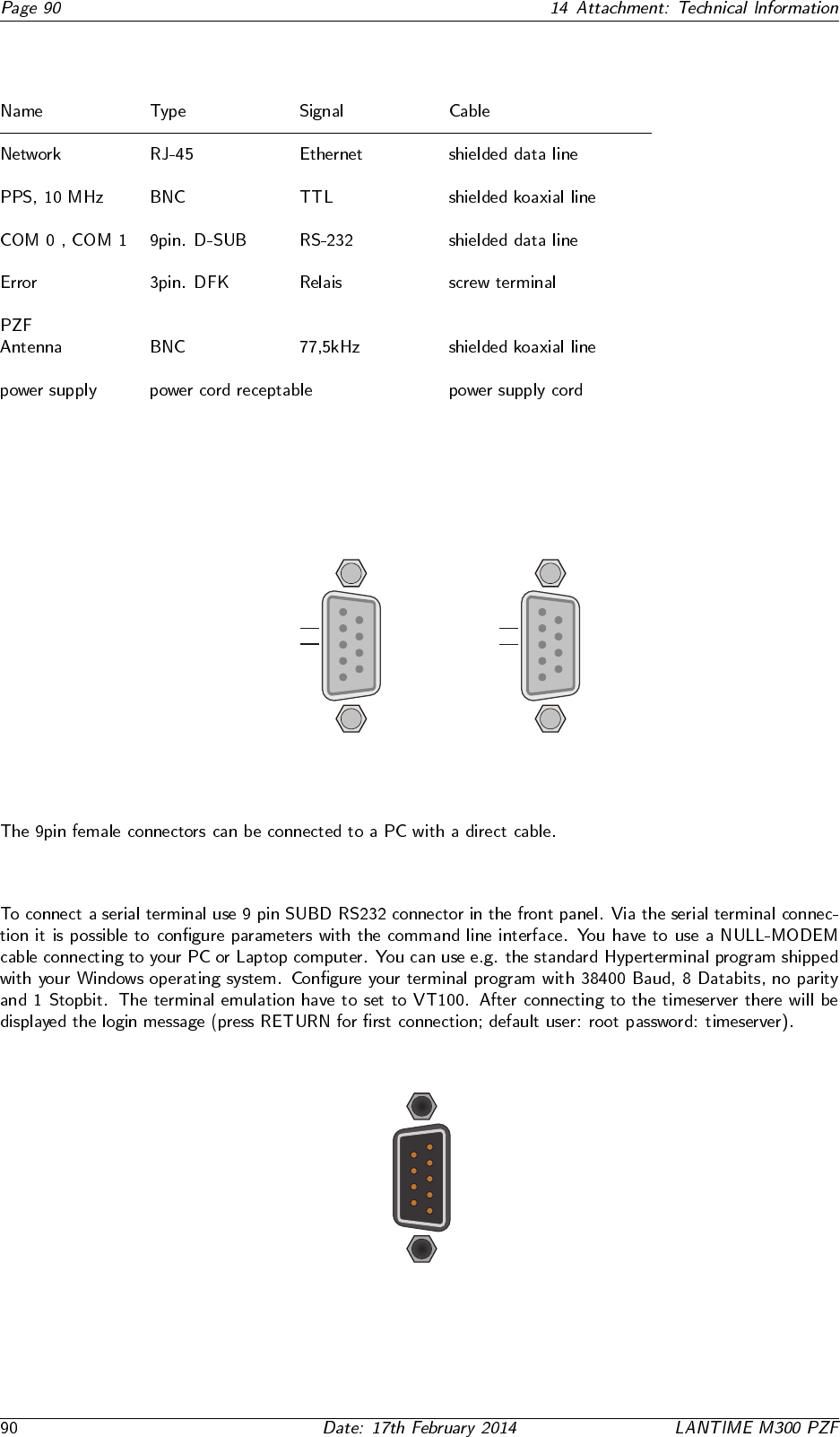
14.5 Pin Assignment: Serial Connectors
14.5.1 Serial Time String
1
6
5
9
TxD1_OUT
RxD1_IN
GND -
COM1
1
6
5
9
TxD0_OUT
RxD0_IN
GND -
COM0
14.5.2 TERMINAL (Console)
RI_IN-
DSR_IN -
CTS_IN-
RTS_OUT-
-DCD_IN
-RXD_IN
-TXD_OUT
-DTR_OUT
-GND
TERM
1
6
5
9
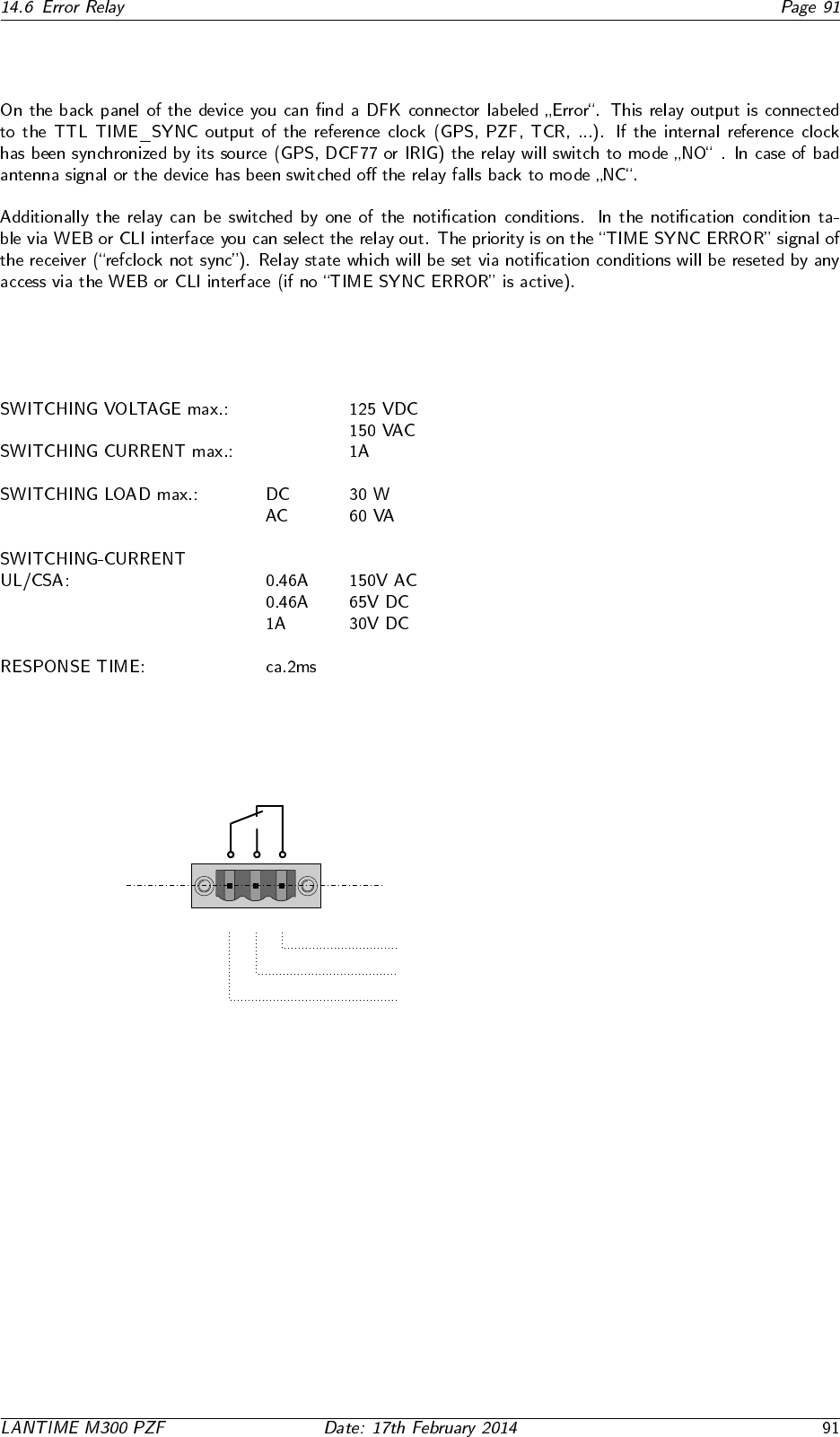
14.6 Error Relay
14.6.1 Technical Specification
Error
CO NO NC
VCC
Error
Normal Operation: CO - NO connected
Error: CO - NC connected
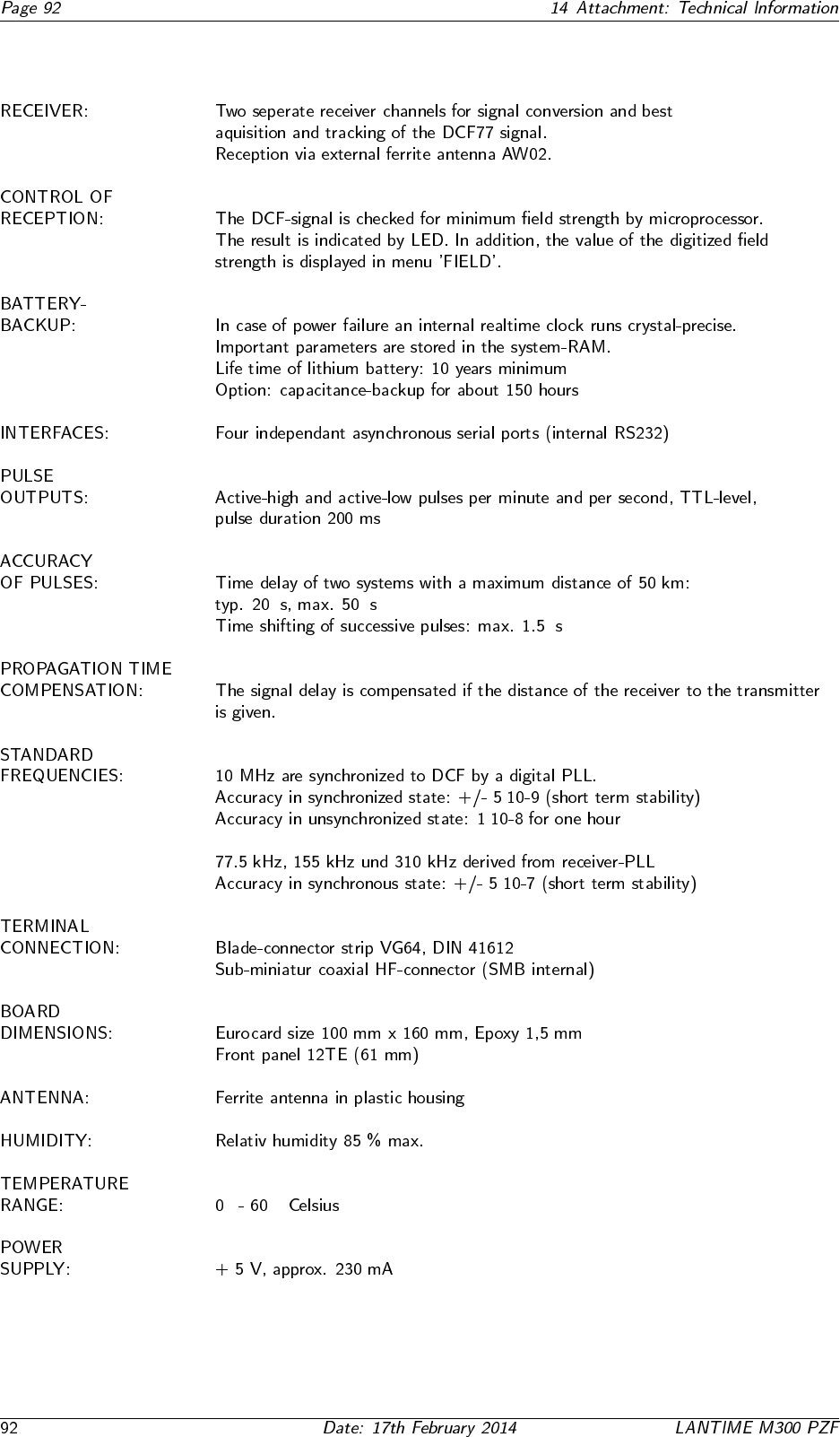
14.7 Technical specifications PZF600
µ µ
µ
·
·
·
◦ ◦
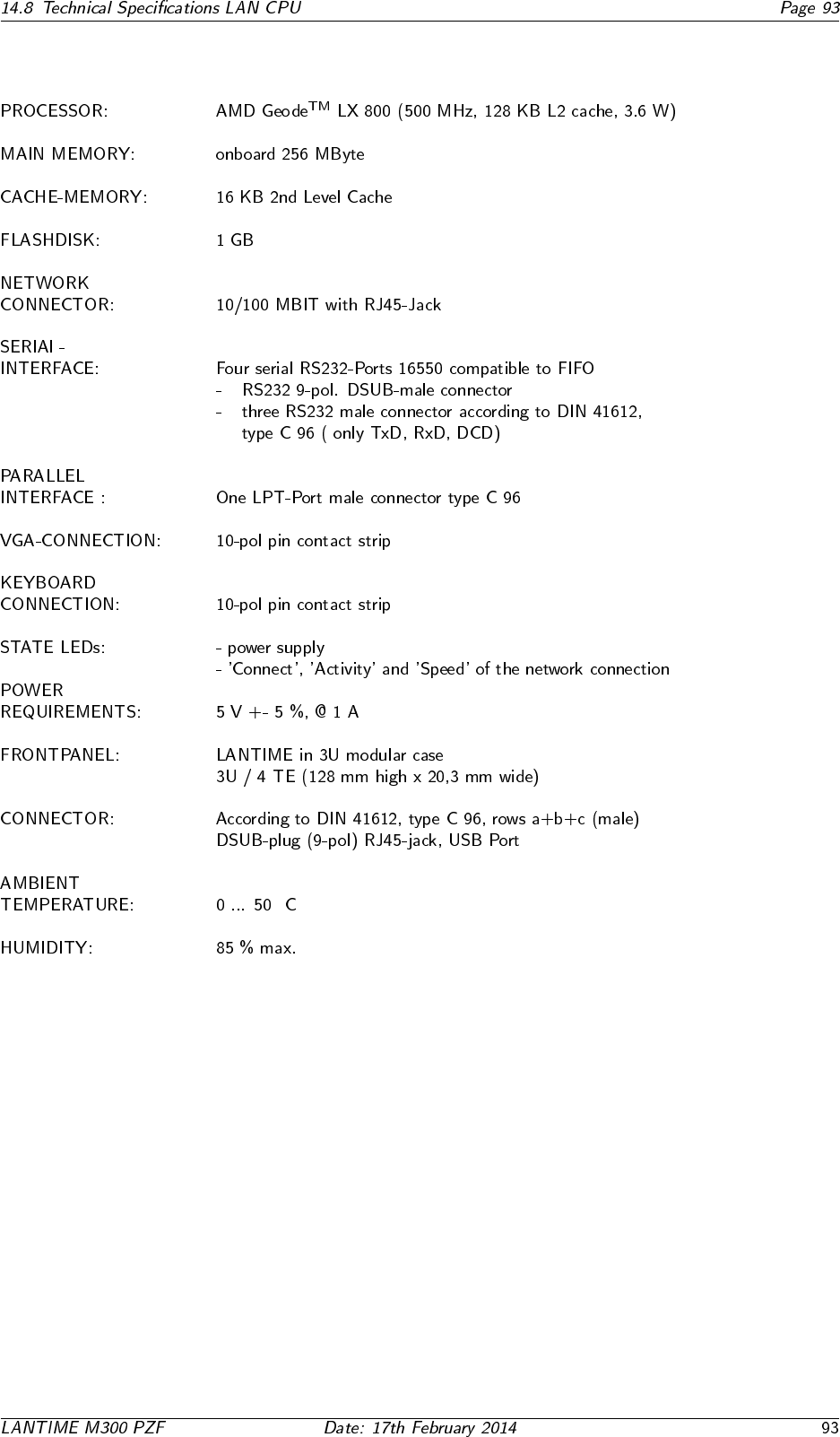
14.8 Technical Specifications LAN CPU
◦
14.9 Time Strings
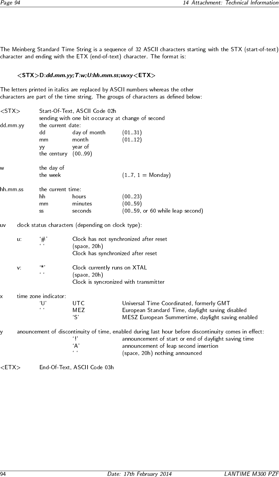
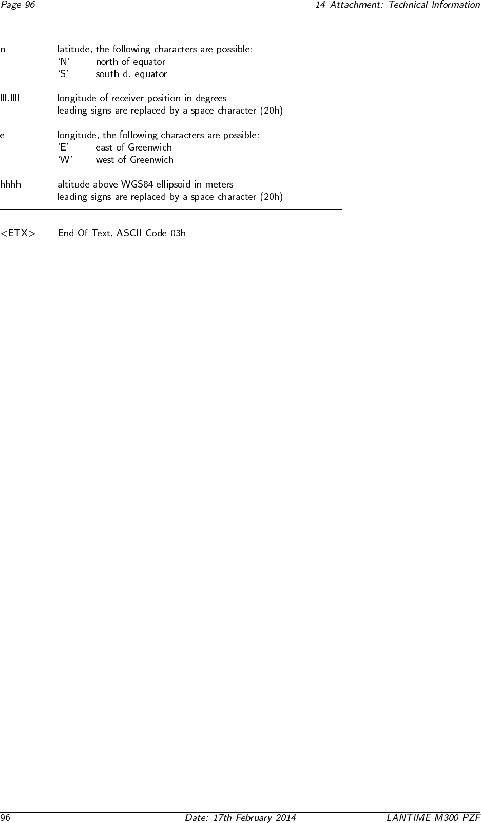
14.9.1 Format of the Meinberg Standard Time String
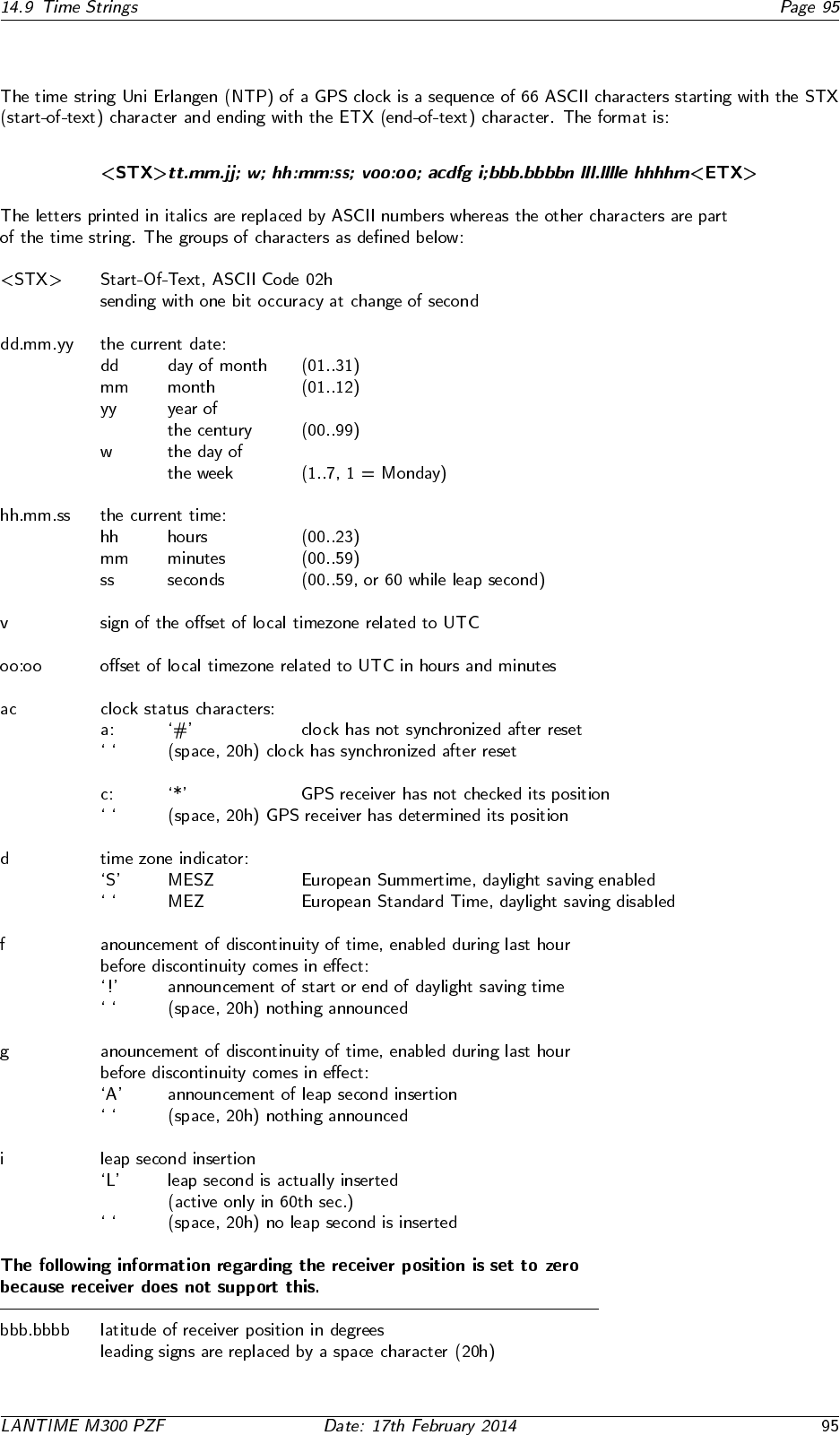
14.9.2 Format of the Uni Erlangen String (NTP)
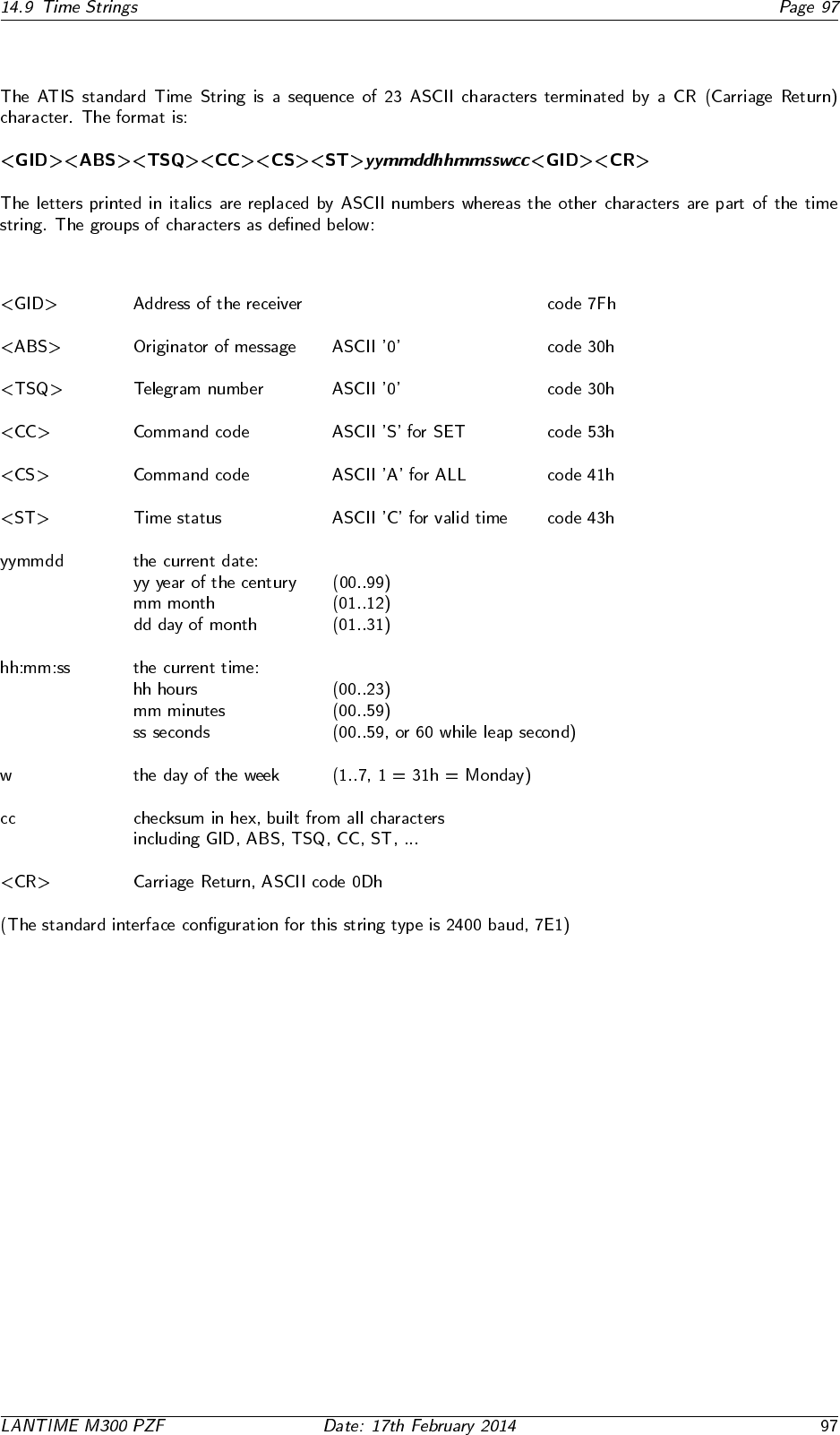
14.9.3 Format of the ATIS standard Time String
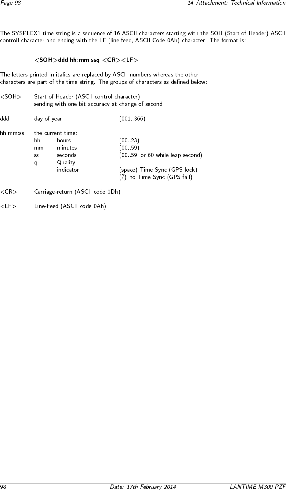
14.9.4 Format of the SYSPLEX-1 Time String
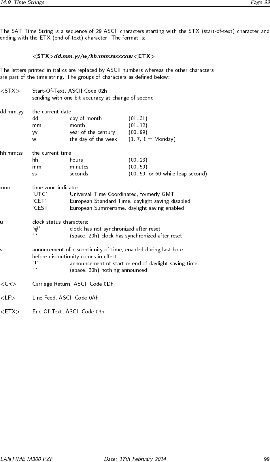
14.9.5 Format of the SAT Time String
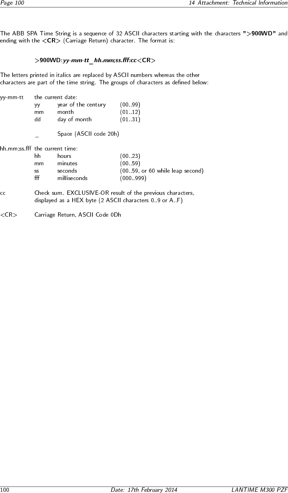
14.9.6 Format of the ABB SPA Time String
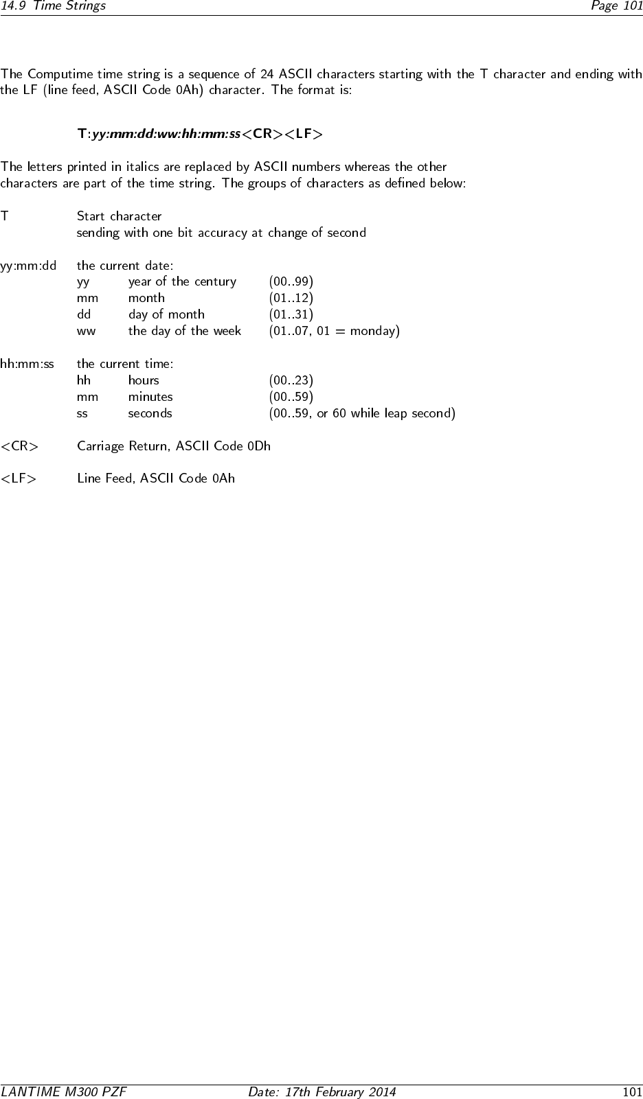
14.9.7 Format of the Computime Time String
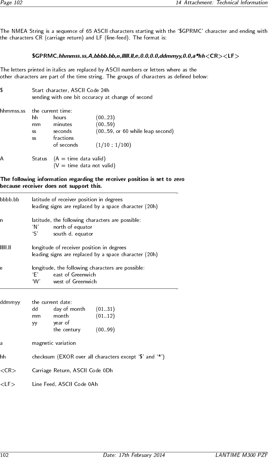
14.9.8 Format of the NMEA 0183 String (RMC)
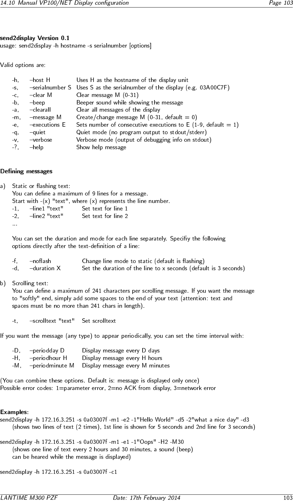
14.10 Manual VP100/NET Display configuration

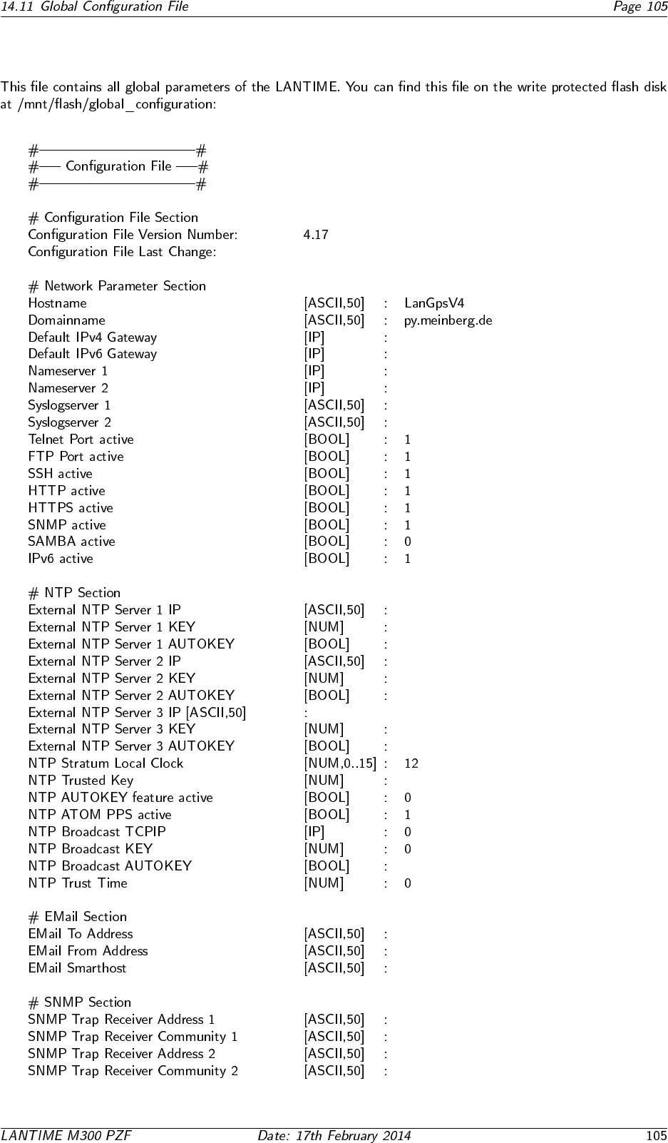
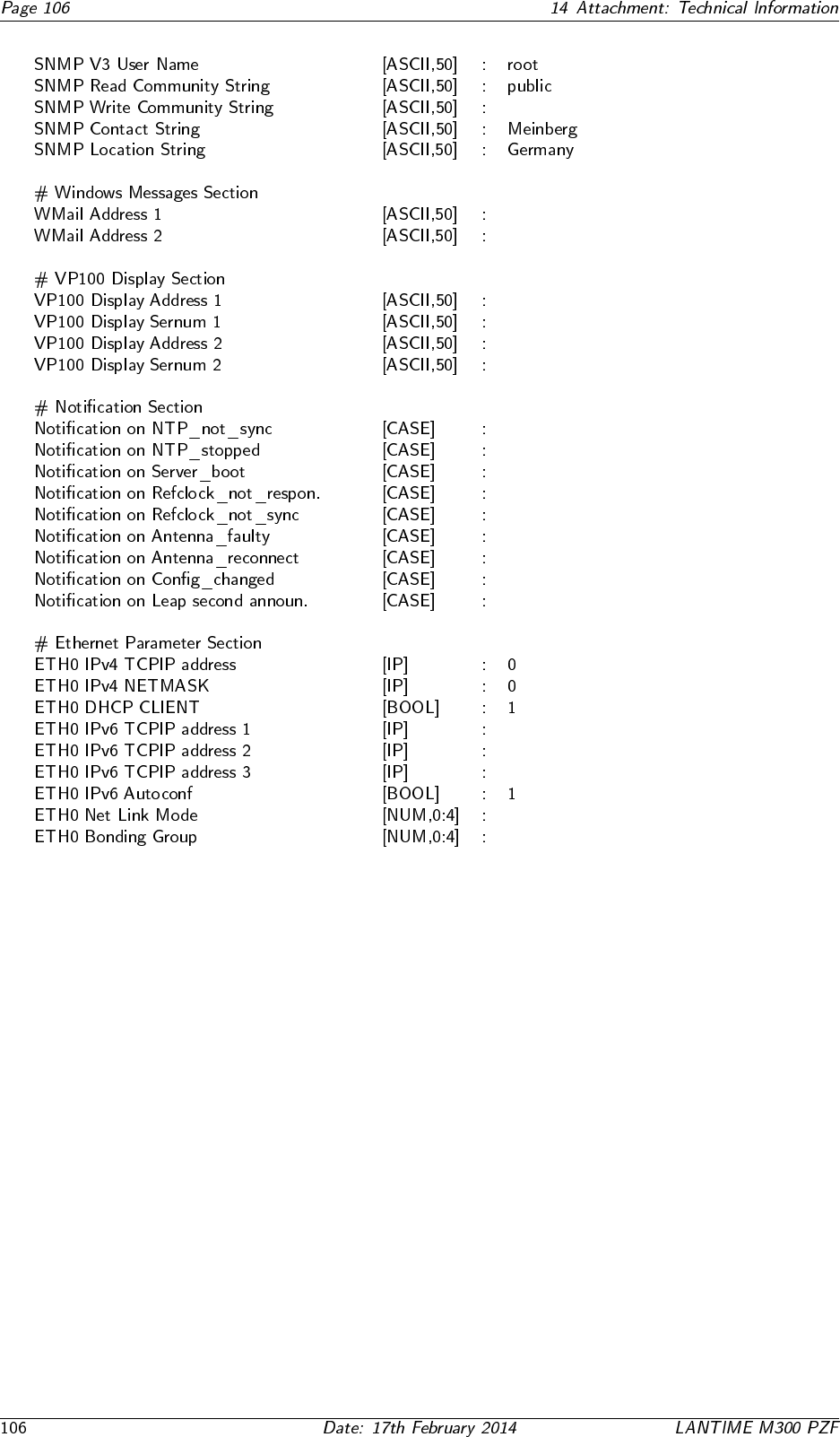
14.11 Global Configuration File

14.12 Global Option File
14.13 Third party software
14.13.1 Operating System GNU/Linux
14.13.2 Samba

14.13.3 Network Time Protocol Version 4 (NTP)

14.13.4 mini httpd

14.13.5 GNU General Public License (GPL)


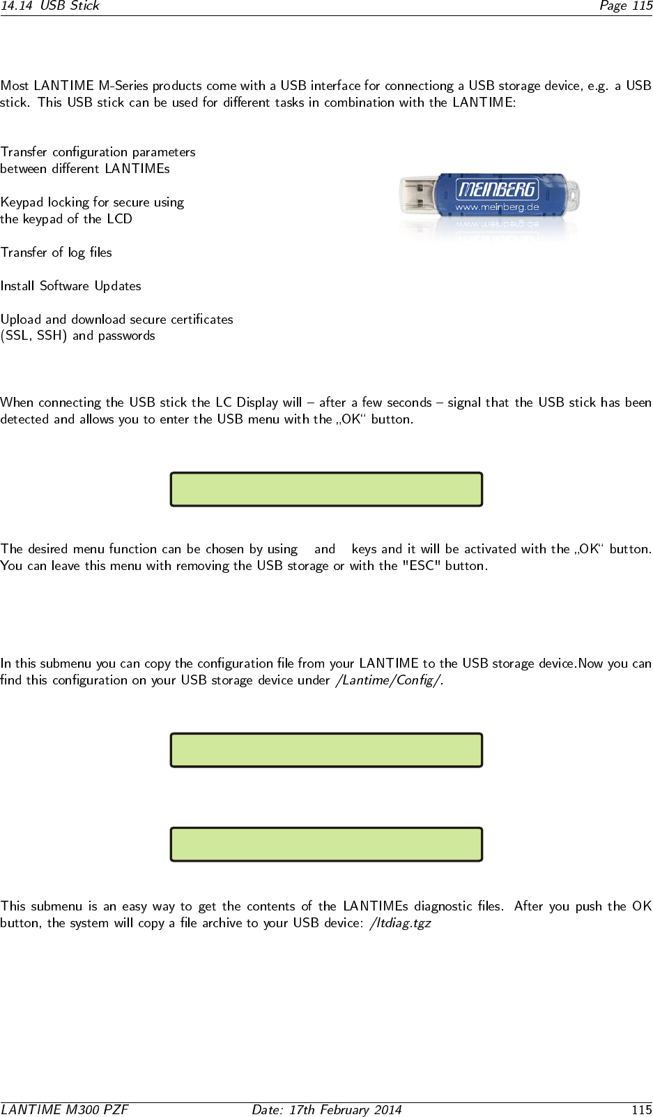
14.14 USB Stick
USB Stick Menu (OK to confirm)
Backup Config. to USB Stick
USB Stick Menu (OK to confirm)
Write Diagn. File to USB Stick
USB Stick Menu (OK to confirm)
Lock Front Panel
USB Stick Menu (OK to confirm)
Unlock Front Panel
USB Stick Menu (OK to confirm)
Restore Config. and REBOOT
USB Memory Stick Main Menu
↑ ↓
14.14.1 Menu Backup Configuration to USB Stick
USB Stick Menu (OK to confirm)
Backup Config. to USB Stick
USB Stick Menu (OK to confirm)
Write Diagn. File to USB Stick
USB Stick Menu (OK to confirm)
Lock Front Panel
USB Stick Menu (OK to confirm)
Unlock Front Panel
USB Stick Menu (OK to confirm)
Restore Config. and REBOOT
USB Memory Stick Main Menu
14.14.2 Menu Write Diagnostic File to USB Stick
USB Stick Menu (OK to confirm)
Backup Config. to USB Stick
USB Stick Menu (OK to confirm)
Write Diagn. File to USB Stick
USB Stick Menu (OK to confirm)
Lock Front Panel
USB Stick Menu (OK to confirm)
Unlock Front Panel
USB Stick Menu (OK to confirm)
Restore Config. and REBOOT
USB Memory Stick Main Menu
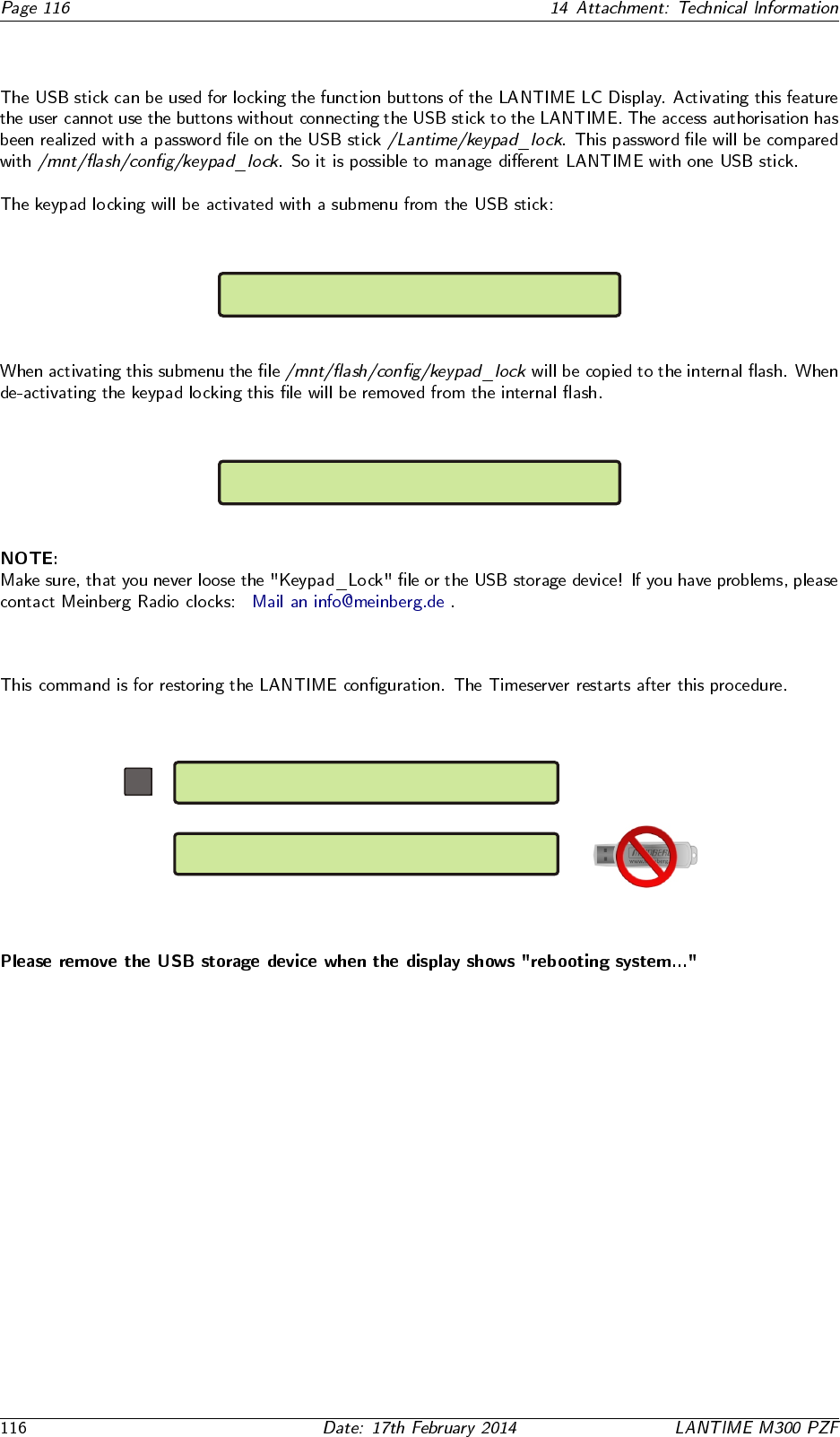
14.14.3 Keypad locking
USB Stick Menu (OK to confirm)
Backup Config. to USB Stick
USB Stick Menu (OK to confirm)
Write Diagn. File to USB Stick
USB Stick Menu (OK to confirm)
Lock Front Panel
USB Stick Menu (OK to confirm)
Unlock Front Panel
USB Stick Menu (OK to confirm)
Restore Config. and REBOOT
USB Memory Stick Main Menu
USB Stick Menu (OK to confirm)
Backup Config. to USB Stick
USB Stick Menu (OK to confirm)
Write Diagn. File to USB Stick
USB Stick Menu (OK to confirm)
Lock Front Panel
USB Stick Menu (OK to confirm)
Unlock Front Panel
USB Stick Menu (OK to confirm)
Restore Config. and REBOOT
USB Memory Stick Main Menu
14.14.4 Menu Restore Configuration
USB Stick Menu (OK to confirm)
Restore Config. and REBOOT
rebooting System...
OK
...

14.15 Reference
