Meinberg LANTIME M600and GPS PTP NTP Time Server User’s Manual M600
User Manual: Meinberg LANTIME M600andGPS PTP NTP Time Server User’s Manual Troubleshoot Meinberg LANTIME M600andGPS PTP NTP Time Server |
Open the PDF directly: View PDF ![]() .
.
Page Count: 146 [warning: Documents this large are best viewed by clicking the View PDF Link!]
- Impressum
- Quick Start
- Network Timeserver with GPS synchronized time base
- The Modular System LANTIME
- Network Time Protocol (NTP)
- Precision Time Protocol (PTP) / IEEE1588
- GPS satellite controlled clock
- Mounting the GPS Antenna
- Booting the GPS receiver
- Booting the Single Board Computer
- Configuration User Interface
- The menus in Detail
- Menu: Reference Time
- Description of the Grafical Menu
- Menu Setup MRS
- Menu IRIG Input Management
- Info GPS Receiver
- GPS Receiver Position
- GPS Satellite Constellation
- GPS Status and Version
- Setup GPS Receiver Parameters
- Init GPS Receiver
- Init Receiver Position
- Init Receiver Time
- Initiate Cold Boot of GPS Receiver
- Initiate Warm Boot of GPS Receiver
- Set Antenna Cable Length
- Set GPS Receiver Simulation Mode
- Setup GPS Outputs
- Enable Outputs
- Setup Serial Outputs
- Setup Time Zone
- TIME CODE (IRIG)
- Synthesizer Frequency Output
- Menu Time Service
- Menu: NTP Configuration
- Programmable pulse (Option)
- Menu: Network
- Menu: System
- The graphical user interfaces
- The WEB Interface
- The Command Line Interface
- SNMP Support
- Attachment: Technical Information
- Skilled/Service-Personnel only: Replacing the Lithium Battery
- Technical Specifications M600/300 Multipac
- Safety instructions for building-in equipment
- Rear Panel Connectors
- Connector Assignments
- TERMINAL (Console)
- Error Relay
- Technical Specifications GPS receiver
- Technical Specifications LAN CPU
- Technical Specifications Power Supply
- Time Code
- Time Strings
- Format of the Meinberg Standard Time String
- Format of the Meinberg Capture String
- Format of the SAT Time String
- Format of the Uni Erlangen String (NTP)
- Format of the NMEA 0183 String (RMC)
- Format of the NMEA 0183 String (GGA)
- Format of the ABB SPA Time String
- Format of the Computime Time String
- Format of the RACAL standard Time String
- Format of the SYSPLEX-1 Time String
- Manual VP100/NET Display configuration
- Global Configuration File
- Global Option File
- Third party software
- Reference
MANUAL
LANTIME M600 GPS PTP
Network Time Server and
PTP Grandmaster Clock
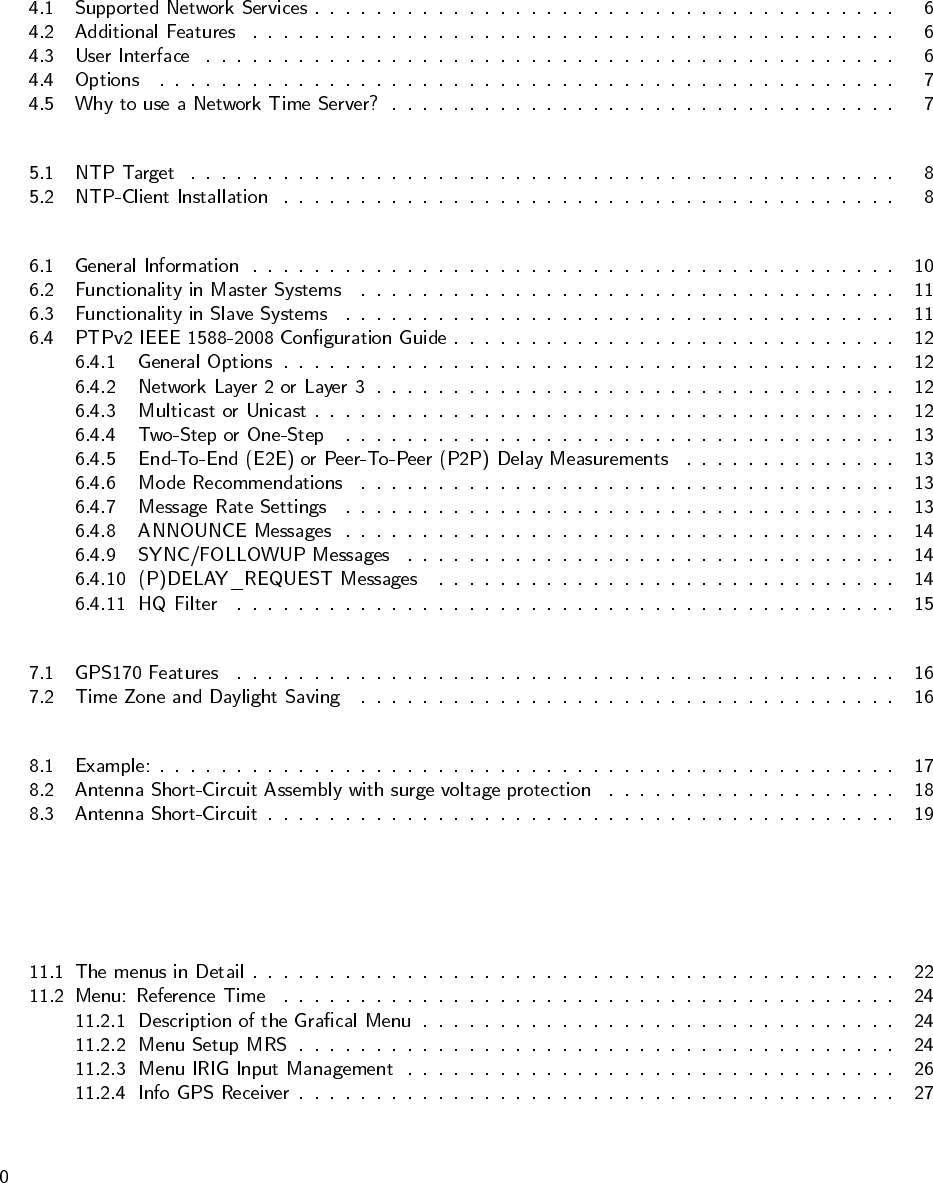
Table of Contents
1 Impressum 1
2 Quick Start 2
3 Network Timeserver with GPS synchronized time base 4
4 The Modular System LANTIME 5
5 Network Time Protocol (NTP) 8
6 Precision Time Protocol (PTP) / IEEE1588 10
7 GPS satellite controlled clock 16
8 Mounting the GPS Antenna 17
9 Booting the GPS receiver 20
10 Booting the Single Board Computer 21
11 Configuration User Interface 22


1 Impressum
2 Quick Start
MEINBERG LANTIME
is booting... please wait...
.......
NTP: Offs. 1ms Stratum: 1
MRS: sync to GPS XTL:SYNC SVs:9/10
PTP: ok PTP_SLAVE GM:00:00:00:00:00:00
Press F1 for help or F2 for setup overview
F1
UTC
Tue, 01.01.2008
12:00:00
MRS Status
-> Setup Input Priorities <-
Setup Fixed Offsets
Setup Precisions
1.GPS is master : -10ns
2.PPS in is available : -20ns
3.IRIG no signal : n/a
4.NTP is available : -30.000us
2.PTP (IEEE1588)is available : -300ns
F1
MRS Input Priorities
GPS Receiver Position
-> Satellite Constellation <-
GPS Status & Version
SATELLITE CONSTELLATION
satellites in view: 5
good satellites : 5
selected set: 04 09 21 17
Global Configuration
->Network Interfaces <-
Network Services
ETH0: -> DHCP:disable <-
ADDRESS: 192.168.10.20
NETMASK: 255.255.255.000
DEF.GATEWAY: 192.168.10.1
3 Network Timeserver with GPS synchronized
time base
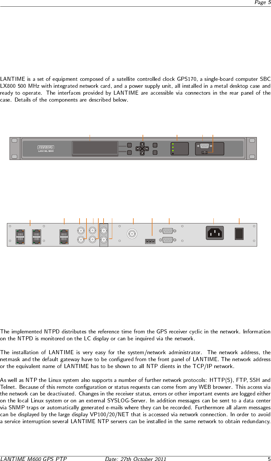
4 The Modular System LANTIME
ENGLISH
1. VF Display
2. Function buttons: 4-way navigation
Button; F1, F2, OK, ESC
3. Status LEDs: Ref. Time, Time Service,
Network, Alarm
4. Terminal port, RS232 Time String output
5. USB connector
6. Brackets for 19” Mounting Rack
1. VF Display
2. Function keys: 4 - way buttons;
F1, F2, OK, ESC
3. Status LEDs: Ref. Time, Time Service,
Network, Alarm
OK
ESC
Time Service
Ref. Time
Network
Alarm
Terminal
USB
5
9
1
6
F1
F2
GPS
NTP
Time
Date
: Normal Operation
: Sync. to PPS
: 16:12:35
: 12.01.2006
(hh:mm:ss)
(dd.mm.yyyy)
1 2 3 4 5 6
4. Terminal port, RS232 timestring output
5. USB connector
6. Bracket for 19” rack mount
ETH0 ETH2
ETH1 ETH3 O
I
100-240V AC
50/60Hz
Synth.
PPM
COM1
COM 0
Error
CO NO NC
16
59
16
59
PPS
TC-DCLS
10MHz
TC-mod
100M 10M100M 10M 100M 10M100M 10M
GPS
Antenna
1. Power supply 85 ... 264 V AC, 47... 63 Hz,
1 A/230 V, 2 A/115 V
2. Mains socket
3. RS232 output, serial interface, time telegram
4. Error relais output
5. GPS antenna, BNC
6. 10MHz output
7. Pulse Per Second output
8. Pulse Per Minute output
9. Frequenzy synthesizer output
10. Time code output - AM (modulated)
11. Time code output - DCLS (unmodulated)
12. IEEE1588 PTPv2, RJ-45 connector
1 x Network connector: ETH4 - 10/100 Mbit, RJ45
13. 4 x Network connectors: ETH0, ETH1,
ETH2, ETH3
10/100 Mbit, RJ45
13 12 11 10 9 8 7 6 5 4 3 2 1
100M 10M100M 10M
PTP0
IEEE1588
ETH4
4.1 Supported Network Services
4.2 Additional Features
•
•
•
•
•
•
4.3 User Interface
•
•
•
•
•
•
•
•
4.4 Options
•
•
•
•
•
4.5 Why to use a Network Time Server?
•
•
•
•
•
5 Network Time Protocol (NTP)
5.1 NTP Target
5.2 NTP-Client Installation
6 Precision Time Protocol (PTP) / IEEE1588
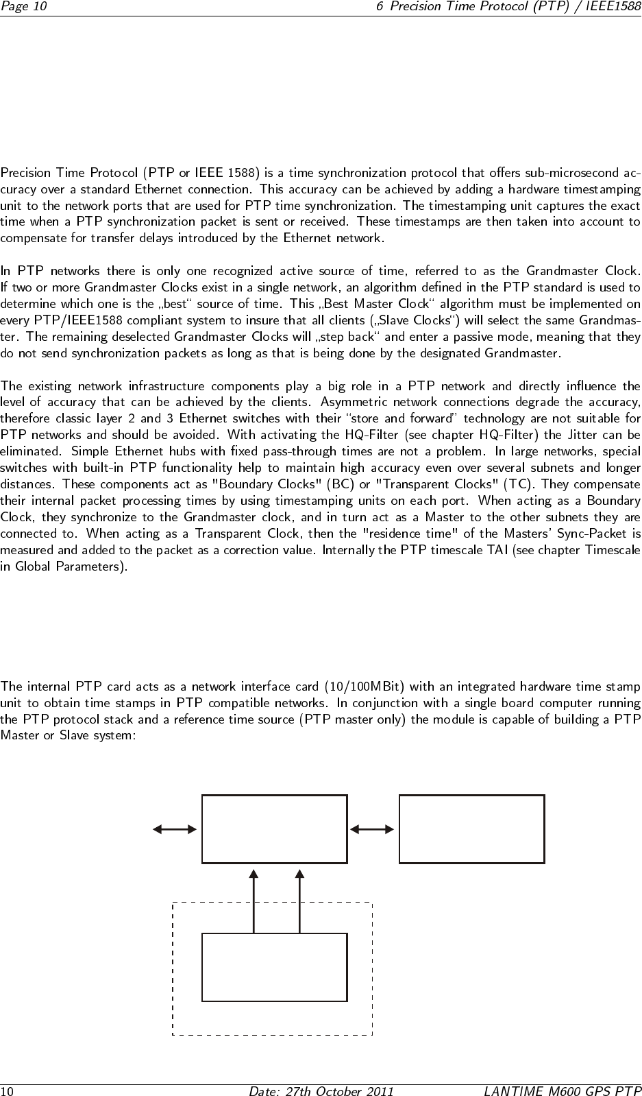
6.1 General Information
10/100MBit
LAN
Network Interface Card
PTP Time Stamp Unit
Single Board Computer
PTP Protocol Stack
Reference Time Source
GPS Receiver
PTP Master System only
USB
PPS10MHz
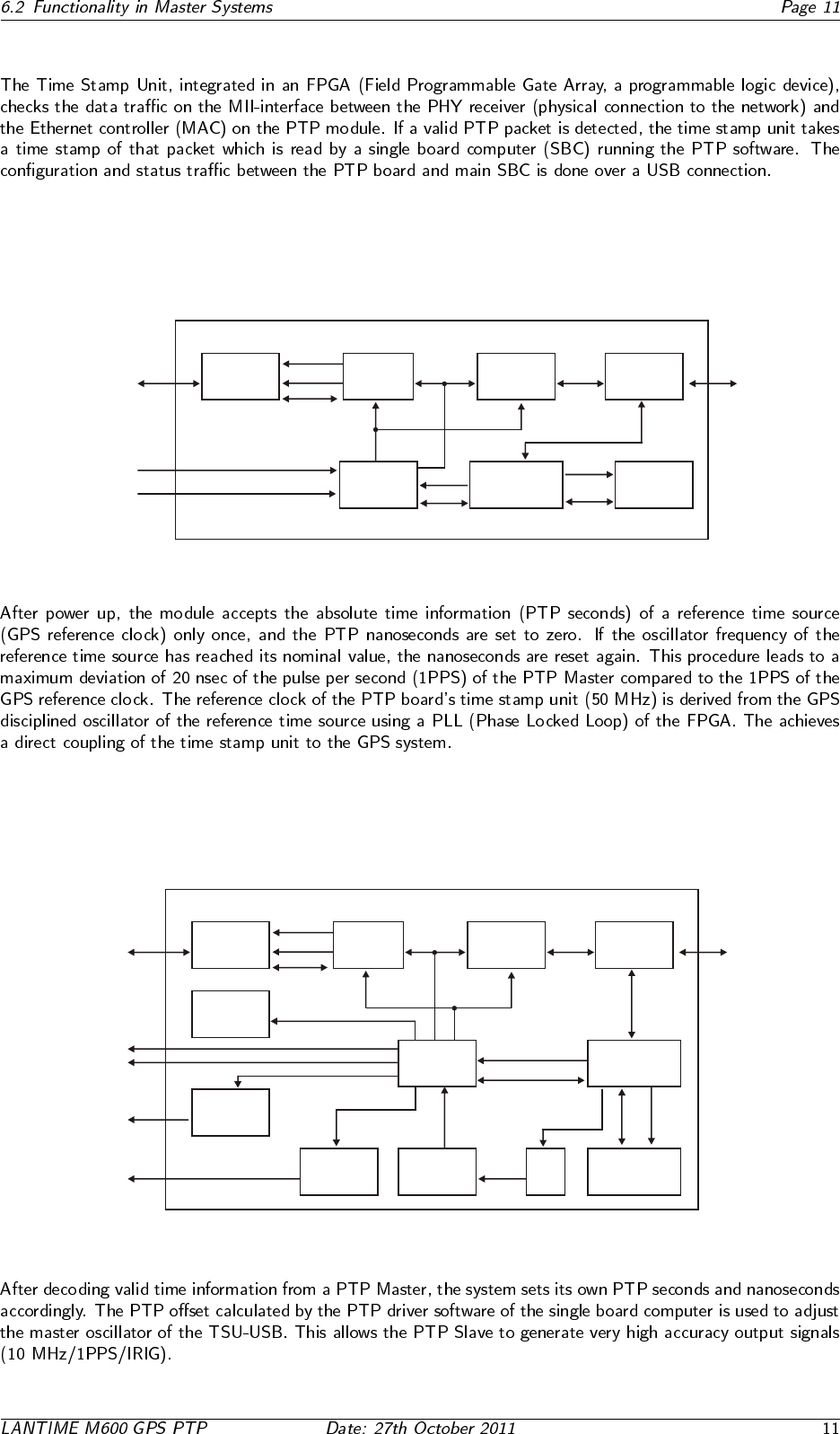
6.2 Functionality in Master Systems
10/100MBit
LAN
10 Mhz from GPS
RJ45 with
magnetics
and LEDs
PHYceiver MAC
controller USB hub
FPGA
microcontroller
with integrated
progr. memory
10M/activity
100M/activity
Rx/Tx
MII interface USB
USB 1.1
to computer
module
Time Stamp Unit PTP Master
FPGA
configuration
memory
PPS from GPS
control
adr/data
control
data
USB
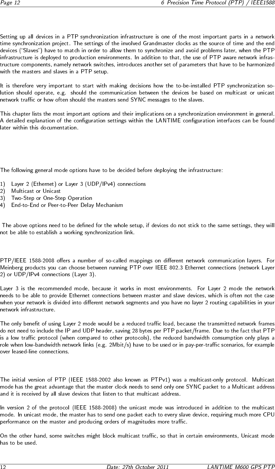
6.3 Functionality in Slave Systems
10/100MBit
LAN
10 MHz
PPS
programmable
outputs
modulated
time code
RJ45 with
magnetics
and LEDs
PHYceiver MAC
controller USB hub
status LEDs
driver
circuits
FPGA
filter and
driver circuit oscillator DAC
microcontroller
with integrated
progr. memory
FPGA
configuration
memory
10M/activity
100M/activity
Rx/Tx
MII interface
USB
USB
data control
control
control
voltage
PWM time code
clock
adr/data
control
USB 1.1
to computer
module
clock
status
Time Stamp Unit PTP Slave
6.4 PTPv2 IEEE 1588-2008 Configuration Guide
6.4.1 General Options
6.4.2 Network Layer 2 or Layer 3
6.4.3 Multicast or Unicast
6.4.4 Two-Step or One-Step
6.4.5 End-To-End (E2E) or Peer-To-Peer (P2P) Delay Measurements
6.4.6 Mode Recommendations
6.4.7 Message Rate Settings
6.4.8 ANNOUNCE Messages
6.4.9 SYNC/FOLLOWUP Messages
6.4.10 (P)DELAY REQUEST Messages
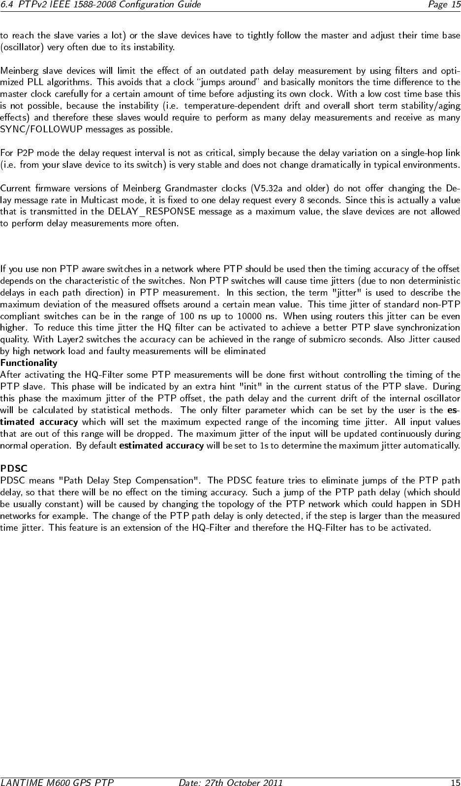
6.4.11 HQ Filter
7 GPS satellite controlled clock
7.1 GPS170 Features
7.2 Time Zone and Daylight Saving
8 Mounting the GPS Antenna
◦
◦ ◦
8.1 Example:
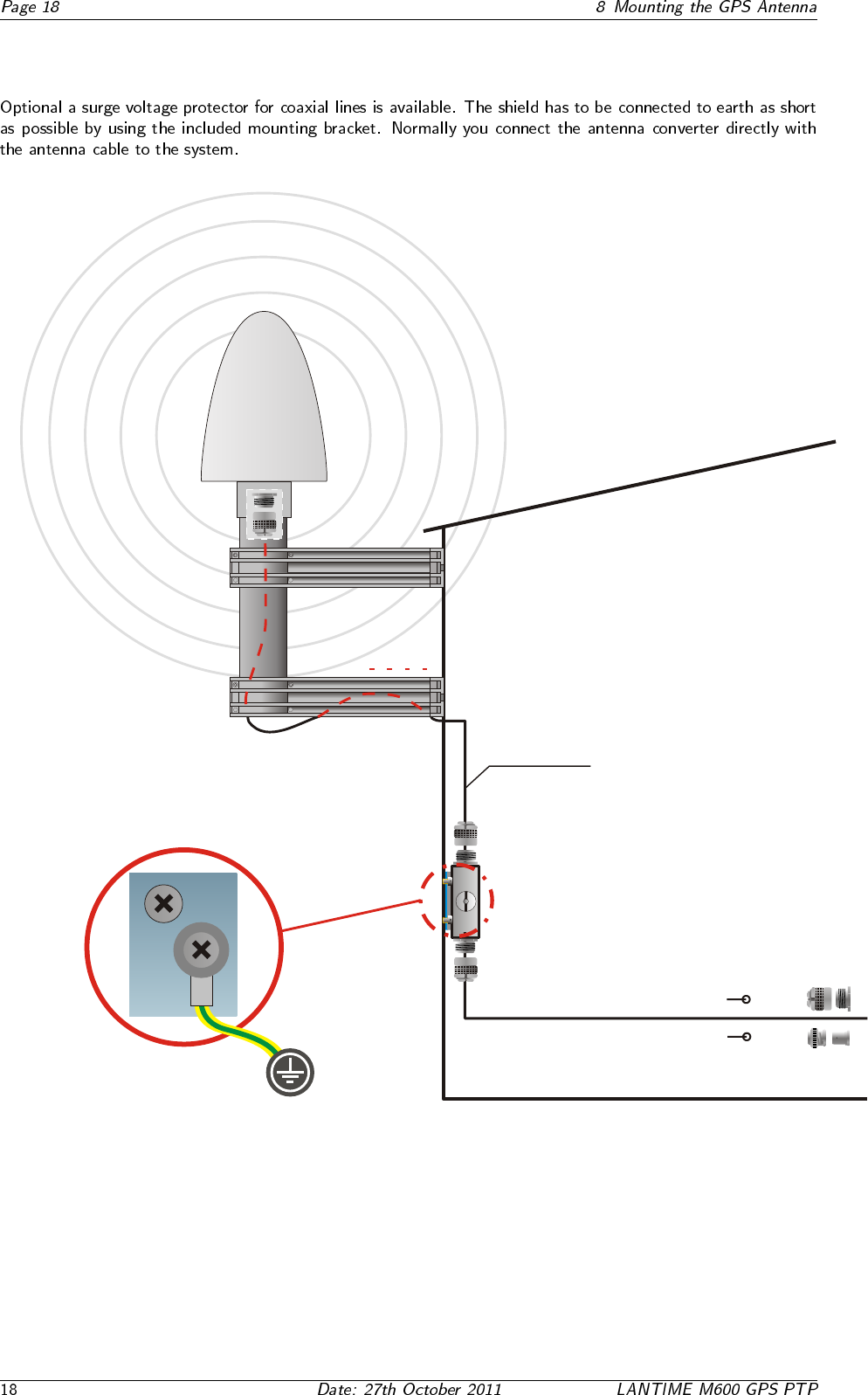
8.2 Antenna Short-Circuit Assembly with surge voltage protection
free view to the sky!
Surge Voltage Protector
connect to earth by using the mounting bracket.
GPS
Antenna
s
S
a
t
P
elli
G
te ante
n
a
n
As short as possible!
cable slot
Ground lead to PE Rail
(Protective Earth)
- fastened
with cable shoe
2
Cable / 16mm
Meinberg GPS
N-Norm male female
or BNC male female
N-Norm male
N-Norm female
N-Norm female
N-Norm male
N-Norm female
N-Norm male

8.3 Antenna Short-Circuit
ANTENNA
SHORT-CIRCUIT
DISCONNECT POWER
! ! !
9 Booting the GPS receiver
10 Booting the Single Board Computer
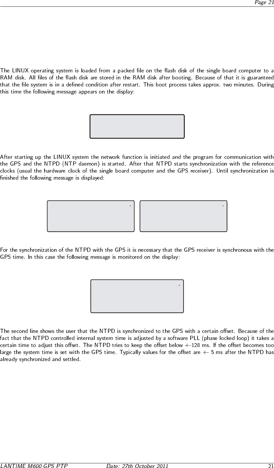
Starting up
please wait...
.....
NTP: Offs. 1ms Stratum: 1
GPS: NORMAL OPERATION Satellites:9/10
PTP: ok PTP_MASTER GM:00:00:00:00:00:00
Press F1 for help or F2 for setup overview
F1
UTC
Tue, 01.01.2008
12:00:00
F1
UTC Tue, 01.01.2008
12:00:00
NTP: Offs. 1ms Stratum: 1
GPS: NORMAL OPERATION Satellites:9/10
Press F1 for help or F2 for setup overview
F1
UTC
Tue, 01.01.2008
12:00:00
11 Configuration User Interface
11.1 The menus in Detail
NTP: Offs. 1ms Stratum: 1
GPS: NORMAL OPERATION Satellites:9/10
PTP: ok PTP_MASTER GM:00:00:00:00:00:00
Press F1 for help or F2 for setup overview
F1
UTC
Tue, 01.01.2008
12:00:00
F1
UTC Tue, 01.01.2008
12:00:00
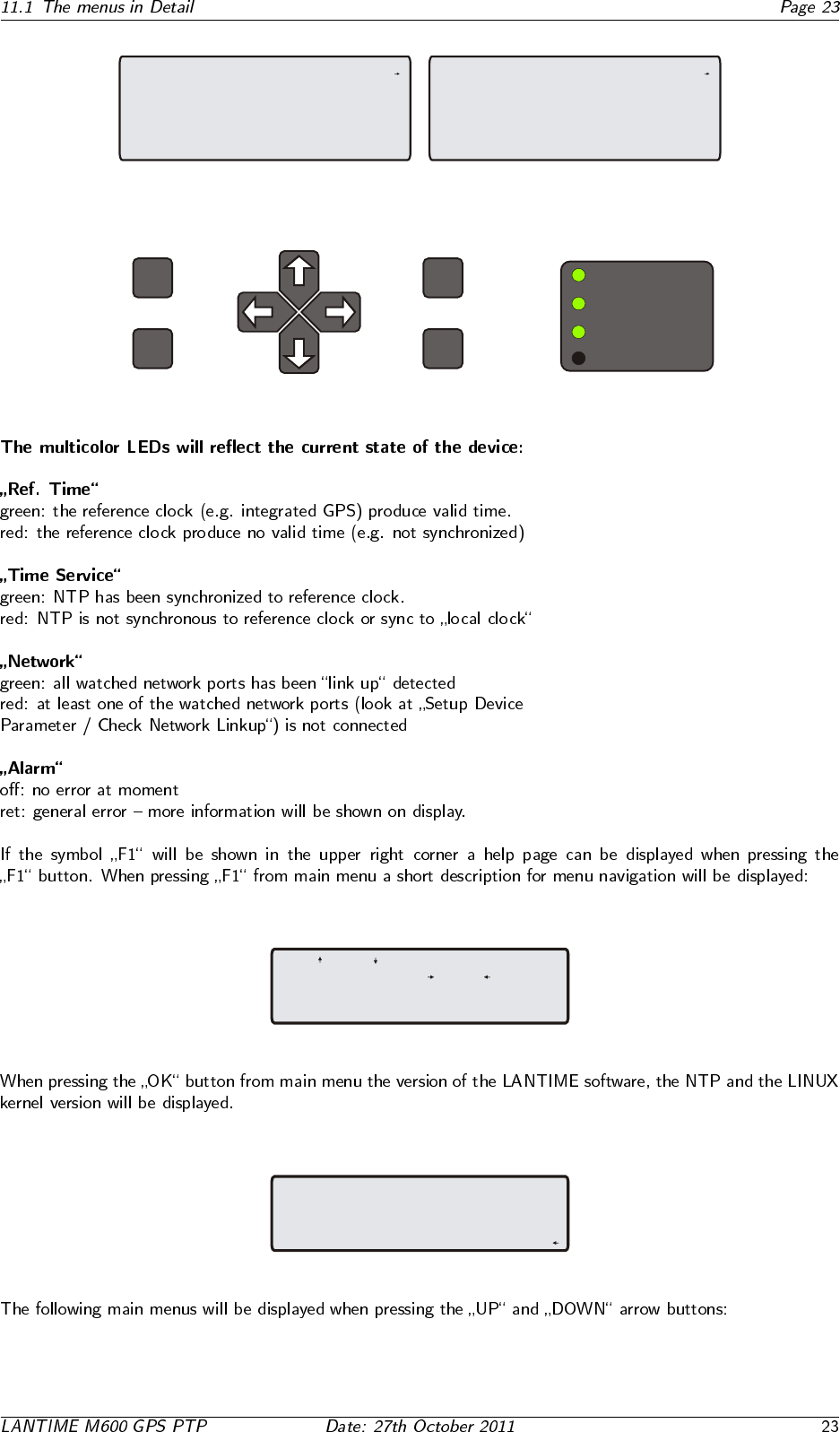
OK
ESC
F1
F2
Time Service
Ref. Time
Network
Alarm
Use and to select different
main menus. Use and to
enter specific submenus. Press
F2 for SETUP overview. [ESC]
TYP: ELX800 GPS170 M6x V5.26
Serial Num.: 000000000000
NTP: 4.2.0@1.1438-o
Kernel: 2.6.12
-> Reference Time <-
Time Service
Network
System
NTP: Offs. 1ms Stratum: 1
GPS: NORMAL OPERATION Satellites:9/10
PTP: ok PTP_MASTER GM:00:00:00:00:00:00
Press F1 for help or F2 for setup overview
F1
UTC
Tue, 01.01.2008
12:00:00
-> Info GPS Receiver <-
Setup GPS Receiver
Setup Outputs
Reference Time
-> Time Service <-
Network
System
-> NTP Current State <-
external NTP servers
Stratum of local clock
PTP IEEE1588
Reference Time
Time Service
-> Network <-
System
-> Global Configuration <-
Network Interfaces
Network Services
Reference Time
Time Service
Network
-> System <-
-> Set time zone <-
Restart NTP
Reset to factory defaults
Reboot time server
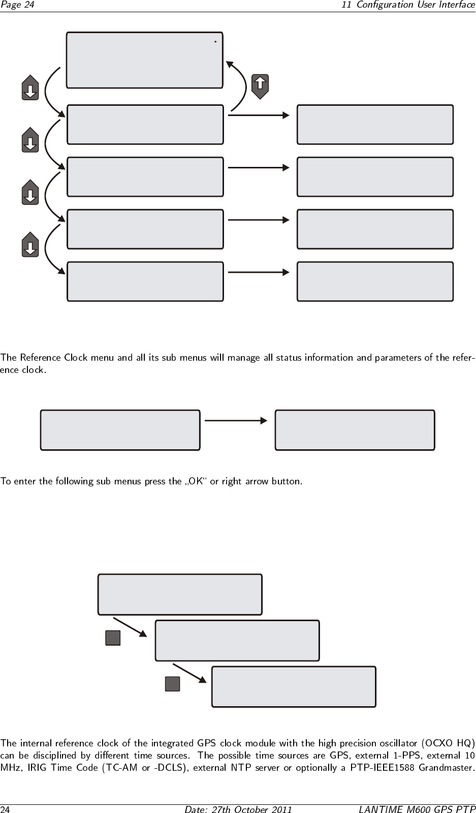
11.2 Menu: Reference Time
-> Reference Time <-
Time Service
Network
System
-> Info GPS Receiver <-
Setup GPS Receiver
Setup Outputs
11.2.1 Description of the Grafical Menu
11.2.2 Menu Setup MRS
OK
-> MRS Management <-
Info GPS Receiver
Setup GPS Receiver
Setup Outputs
-> MRS Status and Setup <-
-> Reference Time <-
Time Service
Network
System
IRIG Input Management
OK
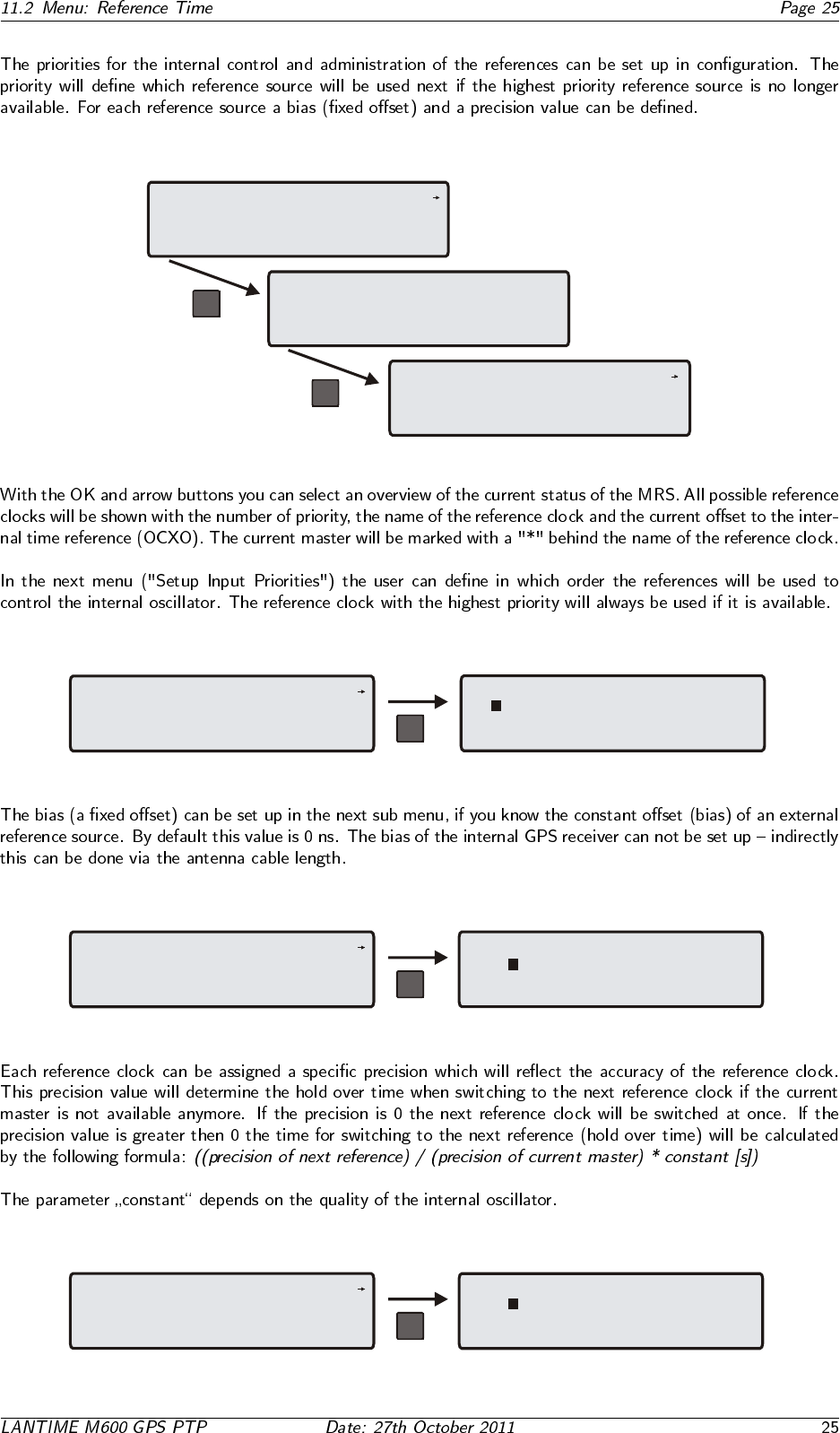
-> Numerical Status <-
Graphical Status
OK
-> MRS Status <-
Setup Input Priorities
Setup Fixed Offsets
Setup Precisions
F1F1
MRS Status F1F1
OK
1.GPS is available : -50.0us
2.PPS is available : -50.0ns
3.FRQ no signal : n/a
4.NTP is available : - 5.0ns
5.PTP is available : -50.0ns
OK
MRS Status
Setup Input Priorities
Setup Fixed Offsets
Setup Precisions
-> <-
F1F1 Setup MRS Input Priorities
1. GPS 2. PPS in
3. TCR in 4. NTP
5. PTP (IEEE158 6. FRQ in
OK
MRS Status
Setup Input Priorities
Setup Fixed Offsets
Setup Precisions
-> <-
F1F1 Set Fixed Offsets in [ns]
PPS: TCR:
NTP: PTP:
FRQ:
OK
MRS Status
Setup Input Priorities
Setup Fixed Offsets
Setup Precisions -> <-
F1F1 Set Precision of Refclocks [ns]
GPS: PPS:
TCR: NTP:
PTP: FRQ:
OK
-> Numerical Status <-
Graphical Status
MRS Status
1.GPS no signal * : (5m19s/19m00s)
2.PPS no signal : n/a
3.TCR no signal : +1.349us [+31.50us]
4.NTP is available : -30.00us
5.PTP is available : -50.0ns
F1F1
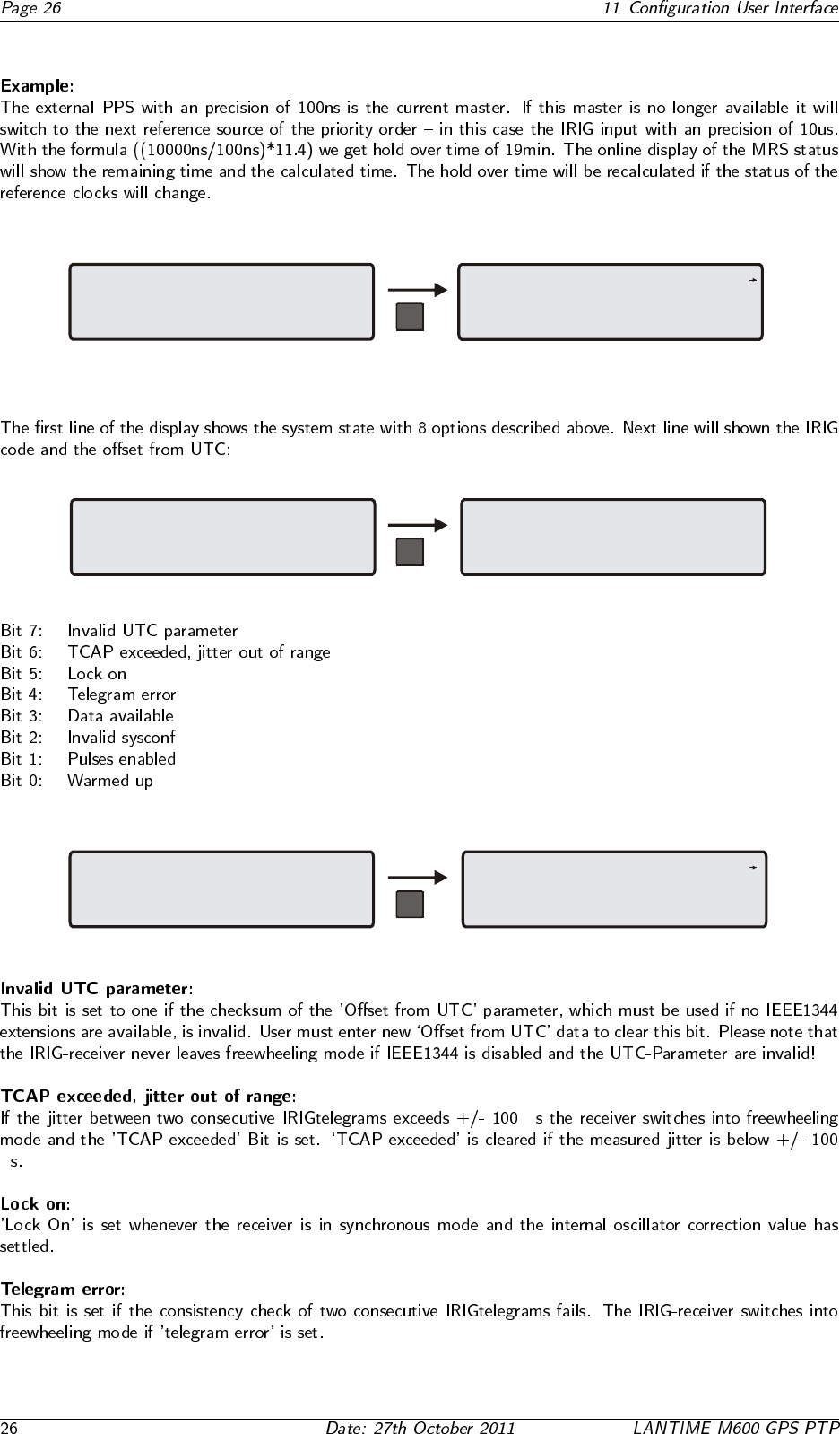
11.2.3 Menu IRIG Input Management
MRS Status and Setup
-> IRIG Input Management <-
OK
-> IRIG Receiver State <-
setup IRIG Receiver
F1F1
Time Code Receiver (IRIG)
IRIG Code: B002/B003 (DC)
IRIG Offset from UTC: +00.00
TCR State: --------
OK
-> IRIG Receiver State <-
setup IRIG Receiver
F1F1
µ
µ
Set IRIG Receiver Parameters
IRIG Code: B002/B003 (DC)
IRIG Offset from UTC (+HH:MM)
+00:00
OK
IRIG Receiver State
etup IRIG Receiver-> S <-
F1F1
11.2.4 Info GPS Receiver
-> GPS Receiver Position <-
Satellite Constellation
GPS Status & Version
SATELLITE CONSTELLATION
satellites in view: 8
good satellites : 8
selected set: 08 12 21 09
GPS Receiver Position
Satellite Constellation
-> GPS Status & Version <-
GPS Receiver Position
-> Satellite Constellation <-
GPS Status & Version
Reference Clock Information
MRS State: SYNC
GPS170 v.1.20 OCXO HQ
S/N: 0290100000680
GPS Receiver Position
LAT: 51.9828 51°58’58” N
LON: 9.2258 09°13’32” E
ALT: 176 m
GPS Receiver Position
x: 3885653 m
y: 631134 m
z: 5001764 m
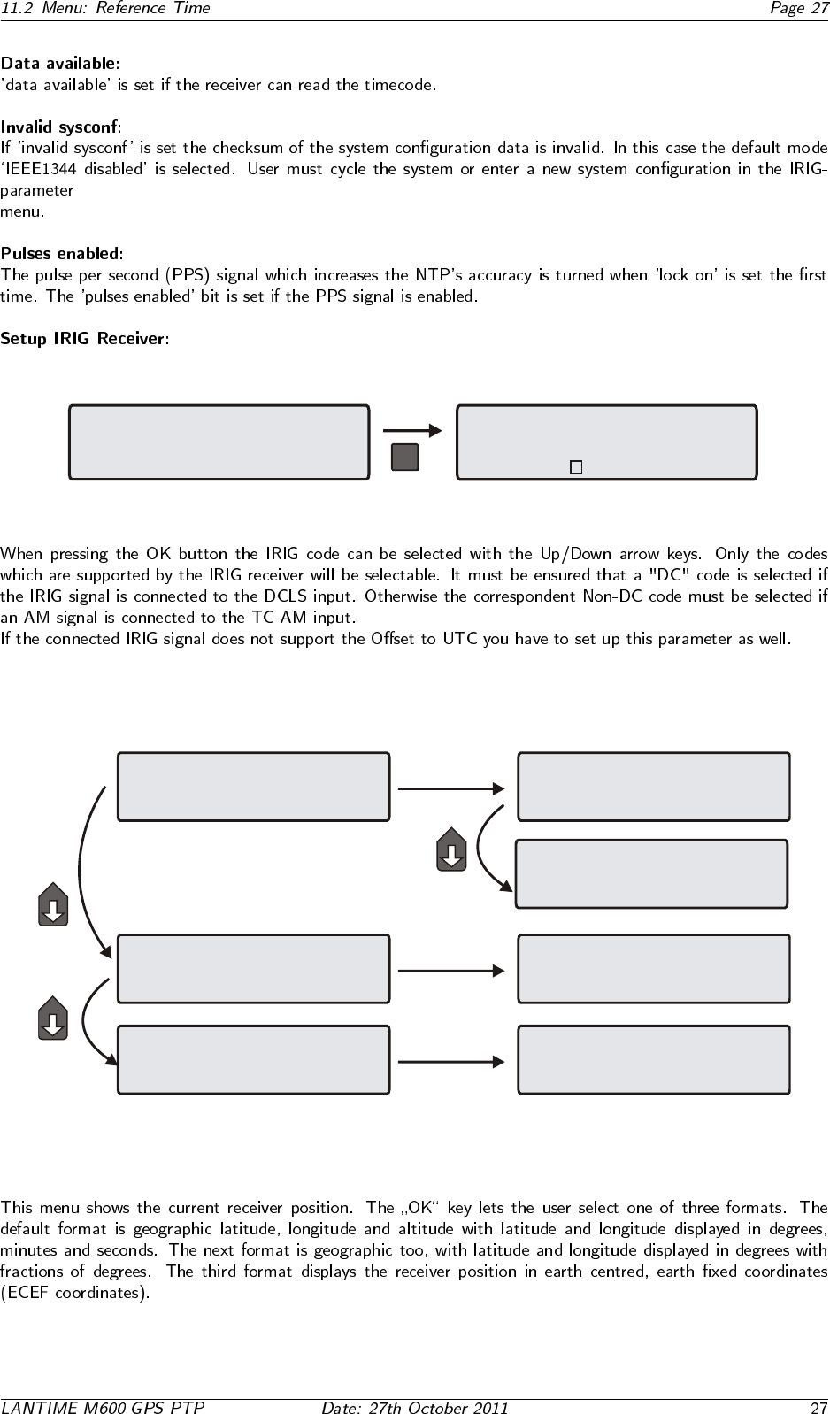
11.2.5 GPS Receiver Position
-> GPS Receiver Position <-
Satellite Constellation
GPS Status & Version
GPS Receiver Position
LAT: 51.9828 51°58’58” N
LON: 9.2258 09°13’32” E
ALT: 176 m
GPS Receiver Position
x: 3885653 m
y: 631134 m
z: 5001764 m
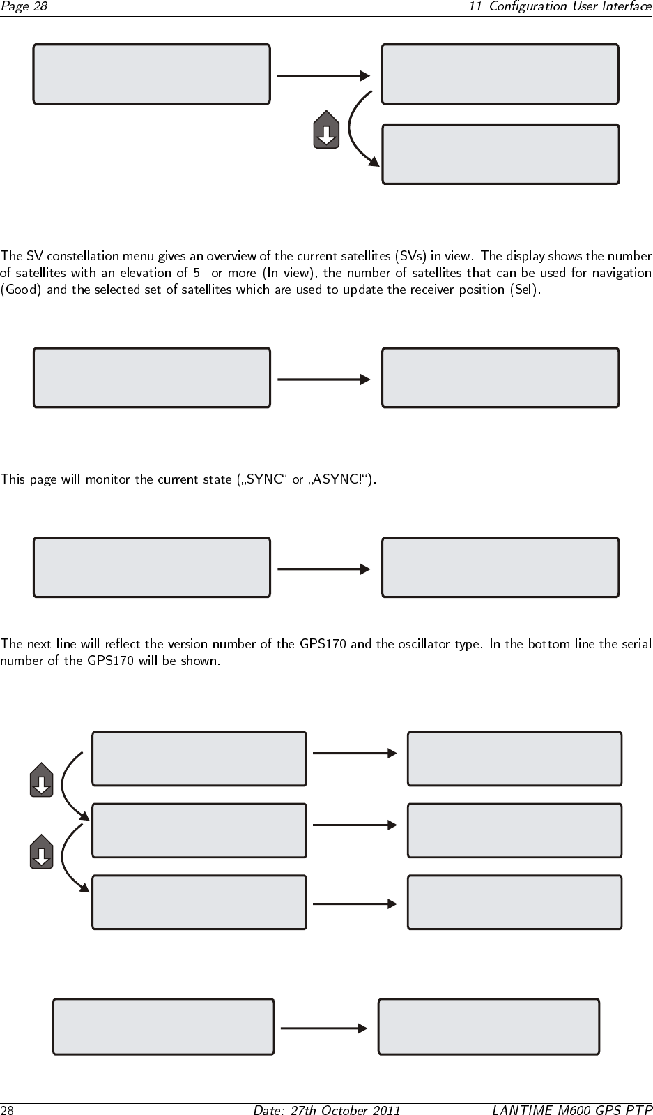
11.2.6 GPS Satellite Constellation
◦
GPS Receiver Position
-> Satellite Constellation <-
GPS Status & Version
SATELLITE CONSTELLATION
satellites in view: 5
good satellites : 5
selected set: 04 09 21 17
11.2.7 GPS Status and Version
GPS Receiver Position
Satellite Constellation
-> GPS Status & Version <-
Reference Clock Information
GPS State: SYNC
GPS170 v1.20 OCXO HQ
S/N: 029010000680
11.2.8 Setup GPS Receiver Parameters
-> Init GPS Receiver <-
Setup Antenna Length
Setup Simulation Mode
-> Init Receiver Position <-
Init Receiver Time
Init COLD Boot
Init WARM Boot
Edit and Set
Antenna Cable Length
of GPS receiver
Length: 020 m
Init GPS Receiver
Setup Antenna Length
-> Setup Simulation Mode <-
Init GPS Receiver
-> Setup Antenna Length <-
Setup Simulation Mode
Edit and Set
GPS Receiver Simulation Mode
Simulation Mode: disabled
11.2.9 Init GPS Receiver
-> Init GPS Receiver <-
Setup Antenna Length
Setup Simulation Mode
-> Init Receiver Position <-
Init Receiver Time
Init COLD Boot
Init WARM Boot
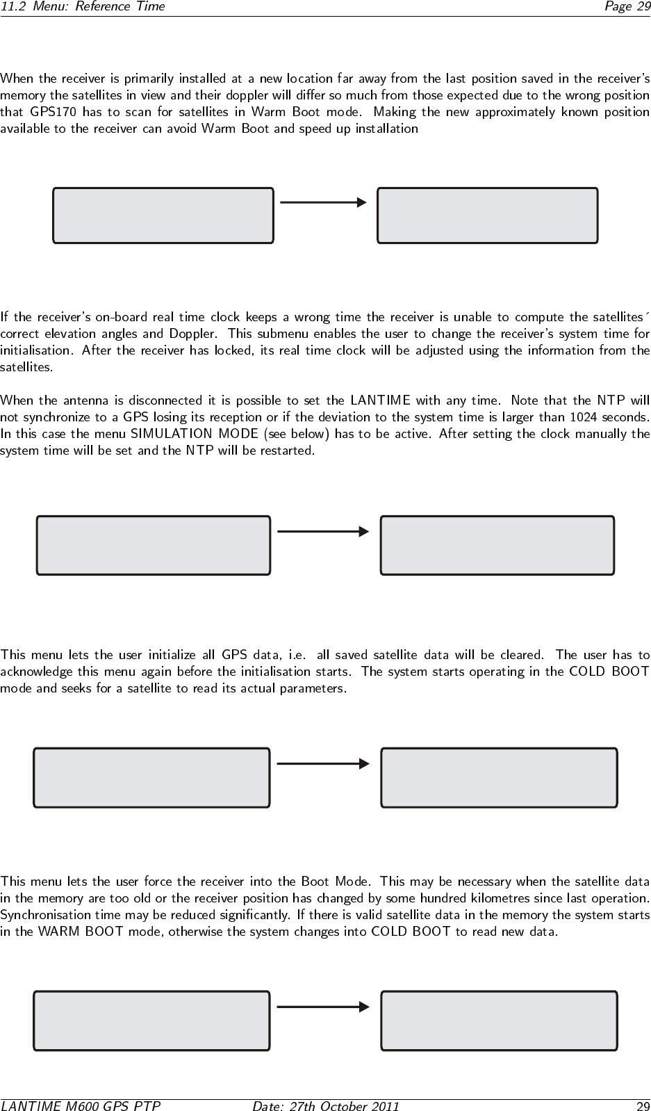
11.2.10 Init Receiver Position
-> Init Receiver Position <-
Init Receiver Time
Init COLD Boot
Init WARM Boot
Init GPS Receiver Position
LAT: 51.58’58” N
LON: 09.13’32” E
ALT: 176 m
11.2.11 Init Receiver Time
Init Receiver Position
-> Init Receiver Time <-
Init COLD Boot
Init WARM Boot
Init GPS Receiver Time
MESZ: 12:48:29
01.07.2008
11.2.12 Initiate Cold Boot of GPS Receiver
Init Receiver Position
Init Receiver Time
-> Init COLD Boot <-
Init WARM Boot
Initiate COLD Boot
of GPS Receiver
Press F2 to confirm
11.2.13 Initiate Warm Boot of GPS Receiver
Init Receiver Position
Init Receiver Time
Init COLD Boot
-> Init WARM Boot <-
Initiate WARM Boot
of GPS Receiver
Press F2 to confirm
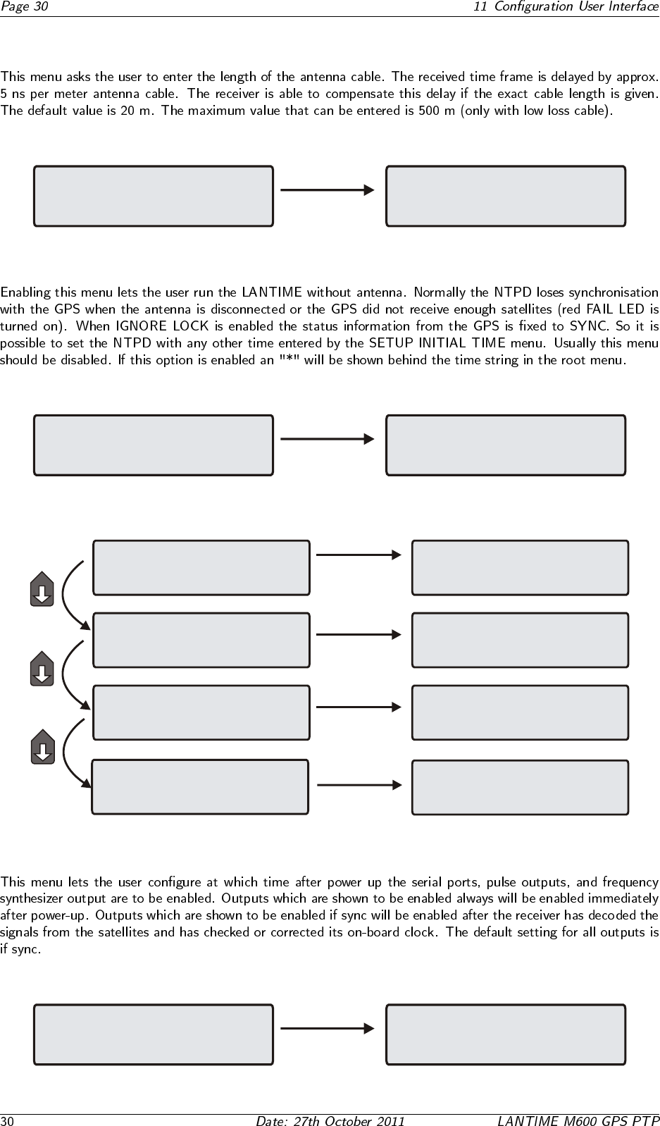
11.2.14 Set Antenna Cable Length
Init GPS Receiver
-> Setup Antenna Length <-
Setup Simulation Mode
Edit and Set
Antenna Cable Length
of GPS receiver
Length: 020 m
11.2.15 Set GPS Receiver Simulation Mode
Init GPS Receiver
Setup Antenna Length
-> Setup Simulation Mode <-
Edit and Set
GPS Receiver Simulation Mode
Simulation Mode: disabled
11.2.16 Setup GPS Outputs
-> Enable Outputs <-
Setup Serial Outputs
Setup IRIG Outputs
Setup Pulse Outputs
Enable Outputs
-> Synthesizer: always <-
Pulses: always
Serial Outputs: always
-> Setup COM 0 <-
Setup COM 1
Setup Time Zone
Enable Outputs
Setup Serial Outputs
-> Setup IRIG Output <-
Setup Pulse Outputs
Enable Outputs
-> Setup Serial Outputs <-
Setup IRIG Outputs
Setup Pulse Outputs
Time Code (IRIG, AFNOR, IEEE)
Output Settings
-> Code: AFNOR NFS-87500 <-
TIME: UTC
Enable Outputs
Setup Serial Outputs
Setup IRIG Output
-> Setup Pulse Outputs <-
-> Setup prg. pulse outputs <-
Setup prg. Synthesizer
11.2.17 Enable Outputs
-> Enable Outputs <-
Setup Serial Outputs
Setup IRIG Output
Setup Pulse Outputs
Enable Outputs
-> Synthesizer: always <-
Pulses: always
Serial Outputs: always
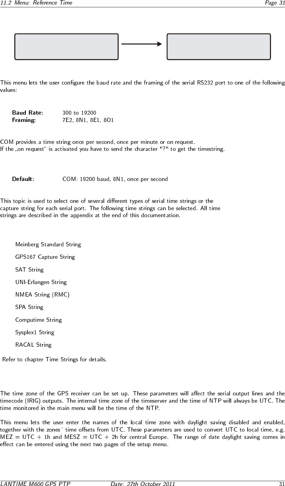
11.2.18 Setup Serial Outputs
Enable Outputs
-> Setup Serial Outputs <-
Setup IRIG Output
Setup Pulse Outputs
-> Setup COM 0 <-
Setup COM 1
Setup Time Zone
•
•
•
•
•
•
•
•
•
11.2.19 Setup Time Zone
Setup COM 0
Setup COM 1
-> Setup Time Zone <-
Time Zone Parameters
of display
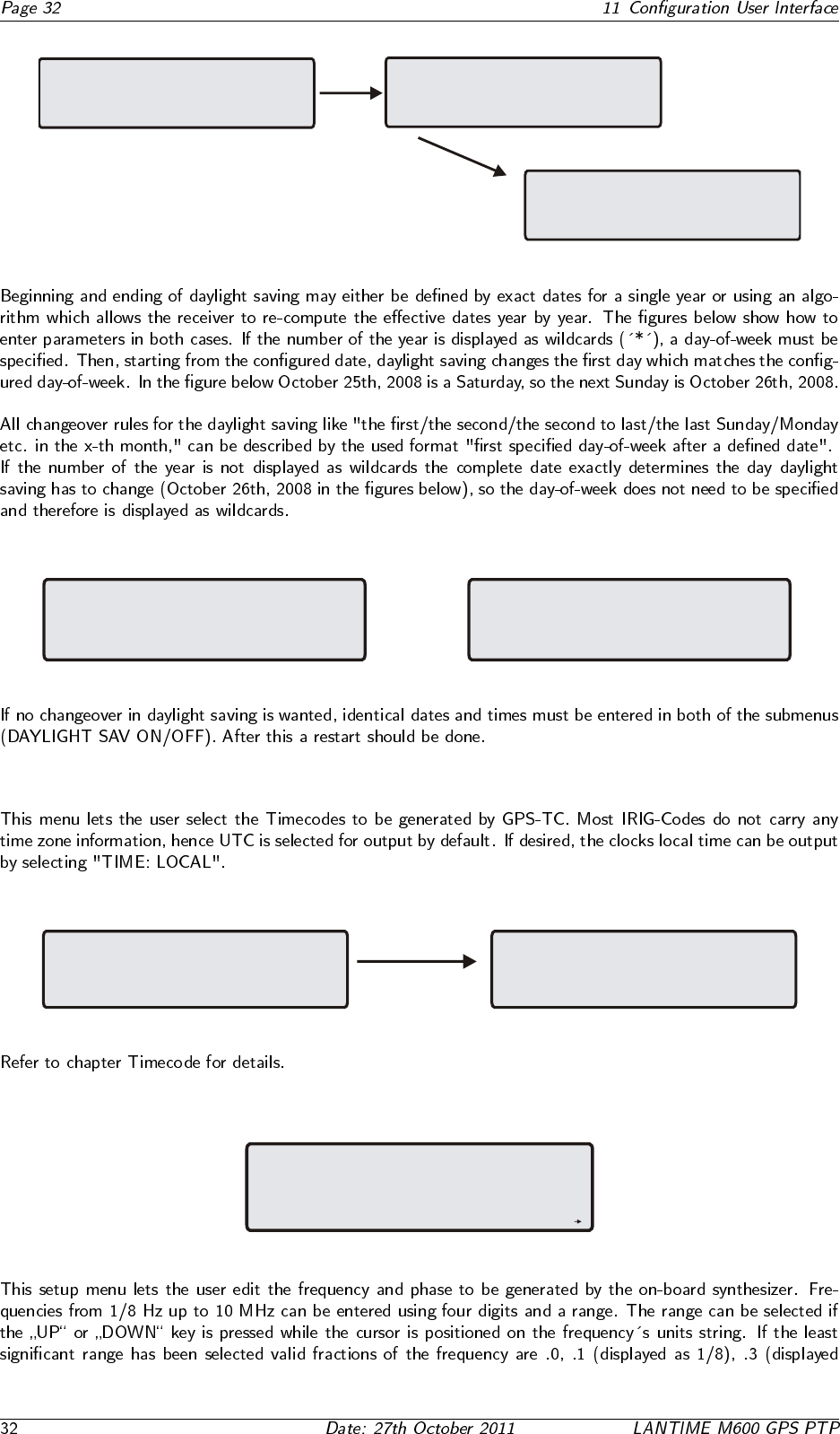
-> Daylight Saving OFF <-
Daylight Saving ON
Daylight Saving OFF
>TZ Name:MEZ < Offs.:+01:00h
Day of Week: Sun
Date:25.10.**** Time:03:00:00
Time Zone Daylight Saving OFF
TZ Name: MEZ Offs.UTC:+01:00h
Day of Week: Sun
Date:25.10.**** Time:03:00:00
Time Zone Daylight Saving OFF
TZ Name: MEZ Offs.UTC:+01:00h
Day of Week: ***
Date:26.10.2008 Time:03:00:00
11.2.20 TIME CODE (IRIG)
Enable Outputs
Setup Serial Outputs
-> Setup IRIG Output <-
Setup Pulse Outputs
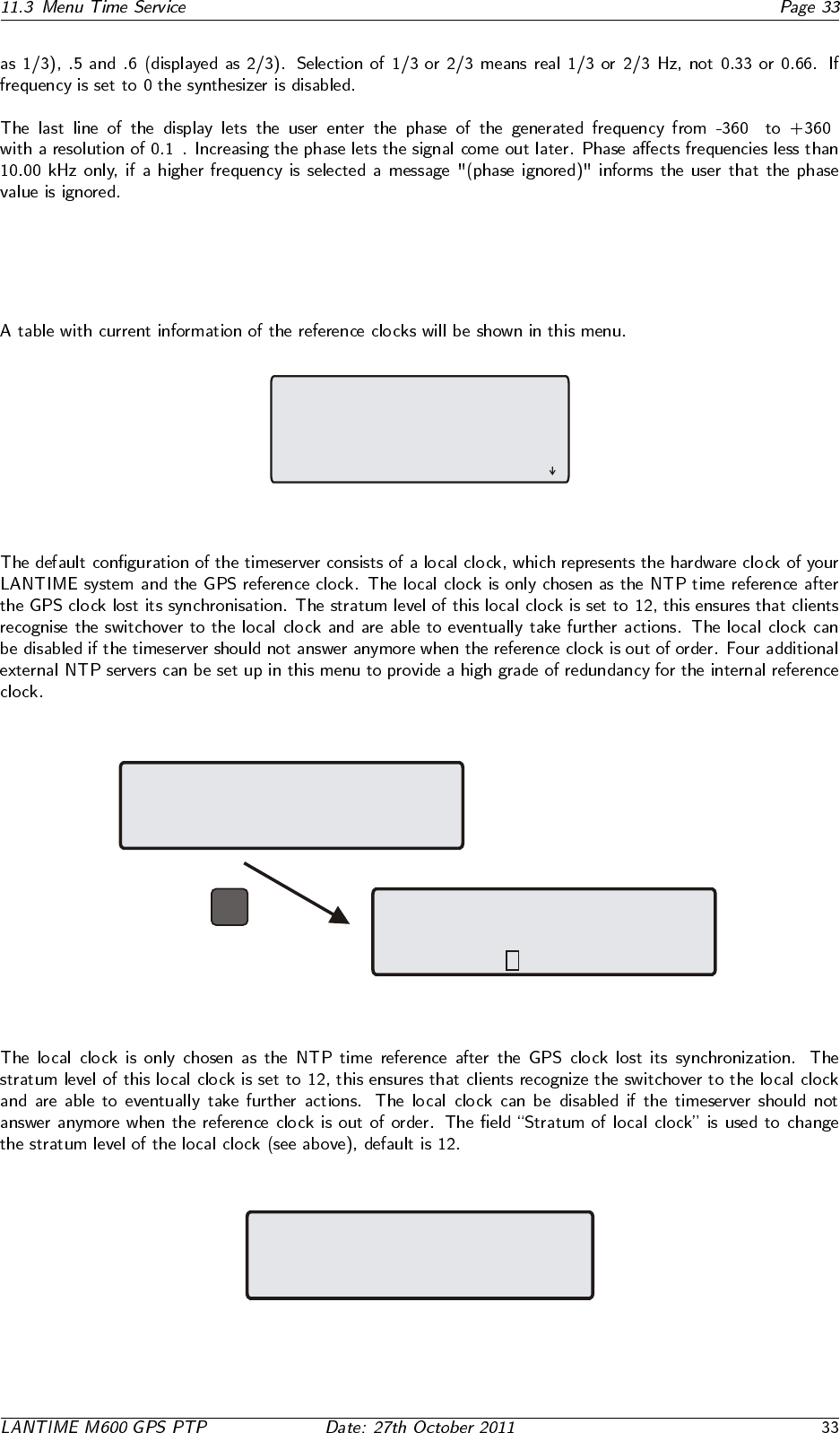
Time Code (IRIG,AFNOR,IEEE)
Output Settings
> Code: B002+B122 <
TIME: UTC
11.2.21 Synthesizer Frequency Output
Synthesizer
Frequency Output
Frequence: 0 Hz
Phase: 0 el
◦ ◦
◦
11.3 Menu Time Service
11.3.1 Menu NTP Current State
Id St wh reach delay offset jitter
0 12 02 377 0.000 0.000 0.000
1 00 08 377 0.000 0.011 0.007
o2 00 11 377 0.000 0.011 0.007
3 01 15 377 0.436 0.043 0.038
*
NTP Query Output
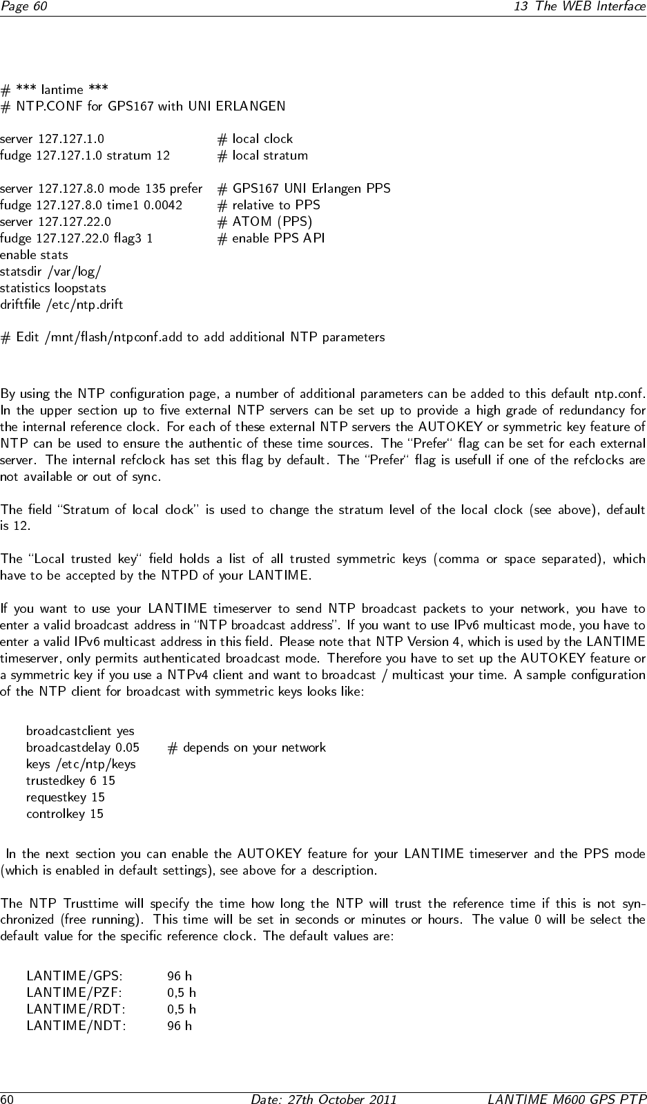
11.3.2 Menu: NTP Configuration
Edit NTP Configuration
external NTP servers
IPv4 address of external NTP
Server1: 192.168.10.12
-> external NTP server 1 <-
external NTP server 2
external NTP server 3
external NTP server 4
OK
11.3.3 Menu: Stratum of local clock
NTP Configuration
Stratum of local clock
new stratum value from 0 to 15
stratum: 12
11.3.4 Menu: PTP State / Setup PTPv1 (Option)
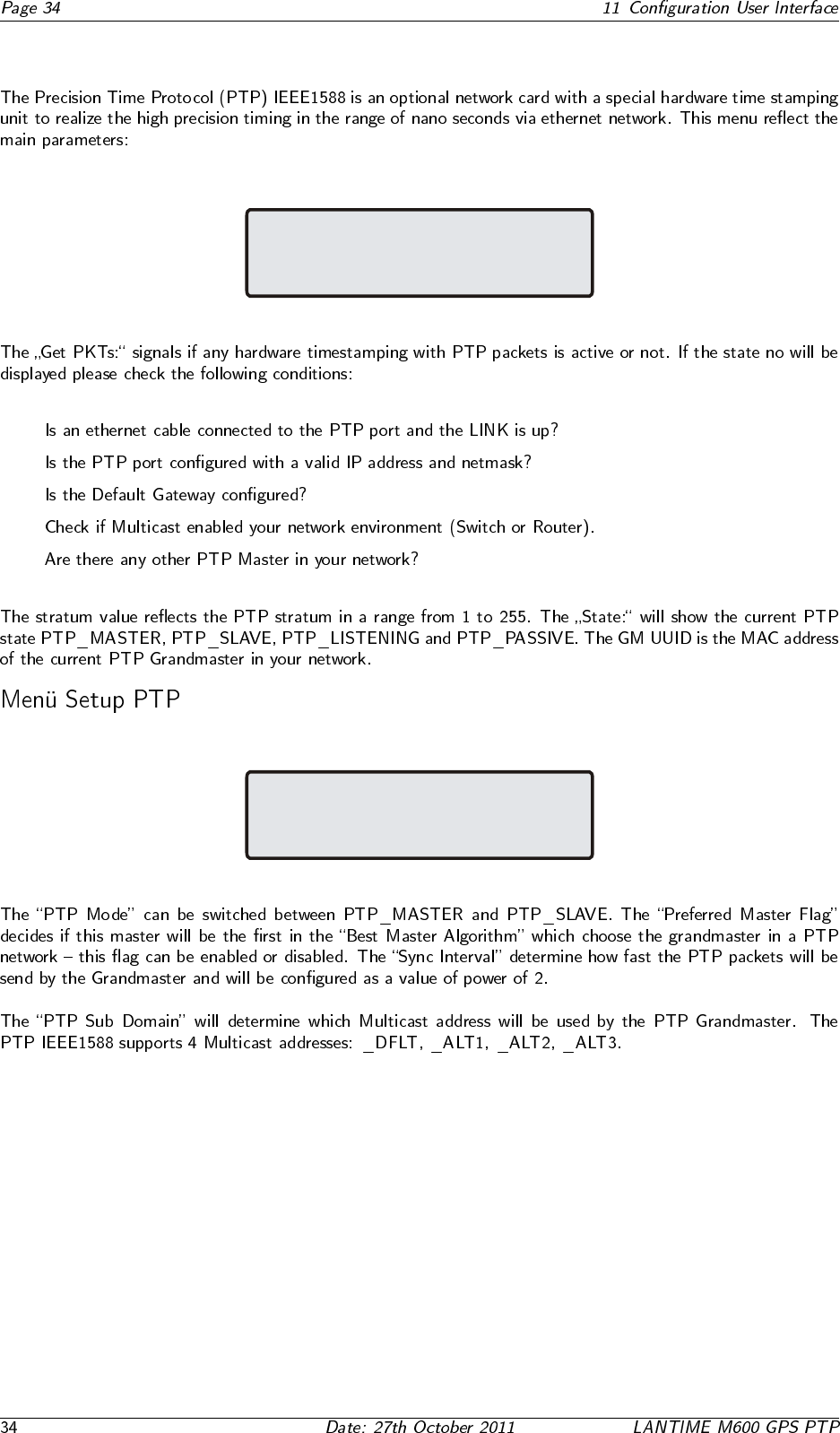
IEEE 1588 PTP State
Get PKTs: ok Stratum: 1 OCX:*
State: PTP_MASTER PFM:
GM UUID: 00:00:00:00:00:00
•
•
•
•
•
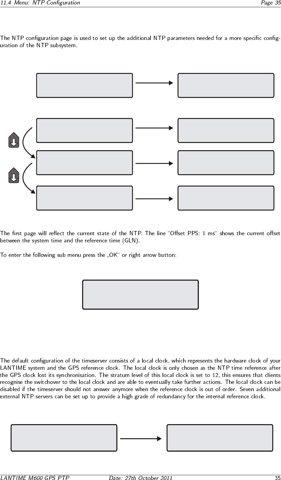
PTP Mode: PTP_MASTER
Prefered Master Flag: disabled
Sync Intervall[2^x]: 1
PTP Sub Domain: _DFLT
11.4 Menu: NTP Configuration
Reference Time
-> Time Service <-
Network
System
-> NTP Current State <-
external NTP servers
Stratum of local clock
NTP Query Output
Id St wh reach delay offset jitter
*0 12 03 377 0.000 0.000 0.002
1 00 00 000 0.000 0.000 0.002
2 00 00 000 0.000 0.000 0.002
-> external NTP server 1 <-
external NTP server 2
external NTP server 3
external NTP server 4
Edit NTP Configuration
Stratum of local clock
new stratum value from 0 to 15
stratum: 12
-> NTP Current State <-
external NTP servers
Stratum of local clock
NTP Current State
-> external NTP servers <-
Stratum of local clock
NTP Current State
external NTP servers
-> Stratum of local clock <-
NTP Configuration
-> external NTP servers <-
Stratum of local clock
Reset time and restart NTP
11.4.1 Menu: External NTP Servers
Edit NTP Configuration
Stratum of local clock
new stratum value from 0 to 15
stratum: 12
NTP Current State
external NTP servers
-> Stratum of local clock <-
11.4.2 Menu: Stratum of local clock
NTP Configuration
Stratum of local clock
new stratum value from 0 to 15
stratum: 12
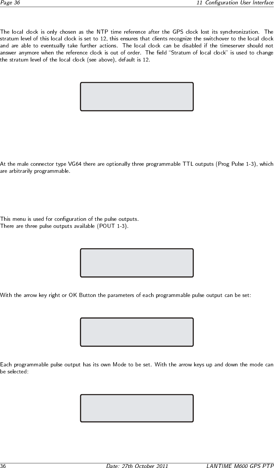
11.5 Programmable pulse (Option)
11.5.1 SETUP POUT X
Programmable Pulses Output
Output 1: TIMER
Output 2: CYCLIC
Output 3: PASSIV
Programmable Pulses Output
---> Output 1 <---
Output 2
Output 3
---> POUT1 Mode PASSIV <---
POUT1 Mode TIMER
POUT1 Mode SINGLE
POUT1 Mode CYCLIC
POUT1 Mode PPS
POUT1 Mode PPM
POUT1 Mode PPH
11.5.2 Mode
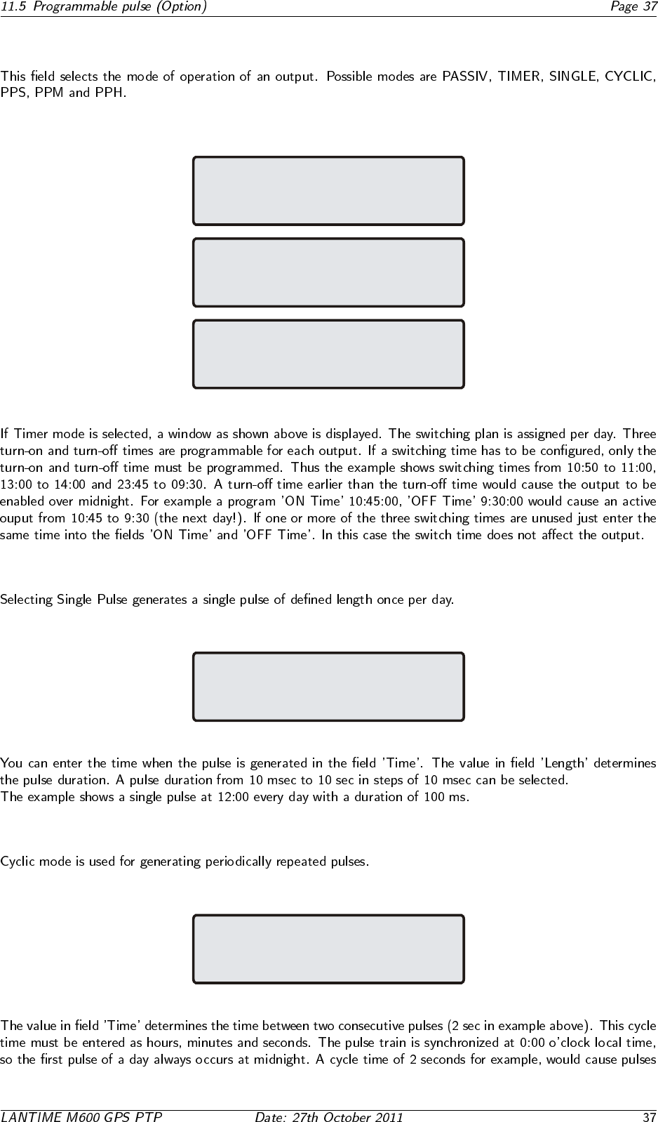
11.5.3 Timer Mode
POUT1 TIMER1
output activ: low
Time ON: 10:50:00
Time OFF: 11:00:00
POUT1 TIMER2
output activ: low
Time ON: 13:00:00
Time OFF: 14:00:00
POUT1 TIMER3
output activ: low
Time ON: 23:45:00
Time OFF: 09:30:00
11.5.4 Single Pulse
POUT1 SINGLE:
output activ: low
Time: 12:00:00
Length: 00.10 sec
11.5.5 Cyclic mode
POUT1 CYCLIC:
output activ: low
Time: 00:00:02
Length: 00.10 sec
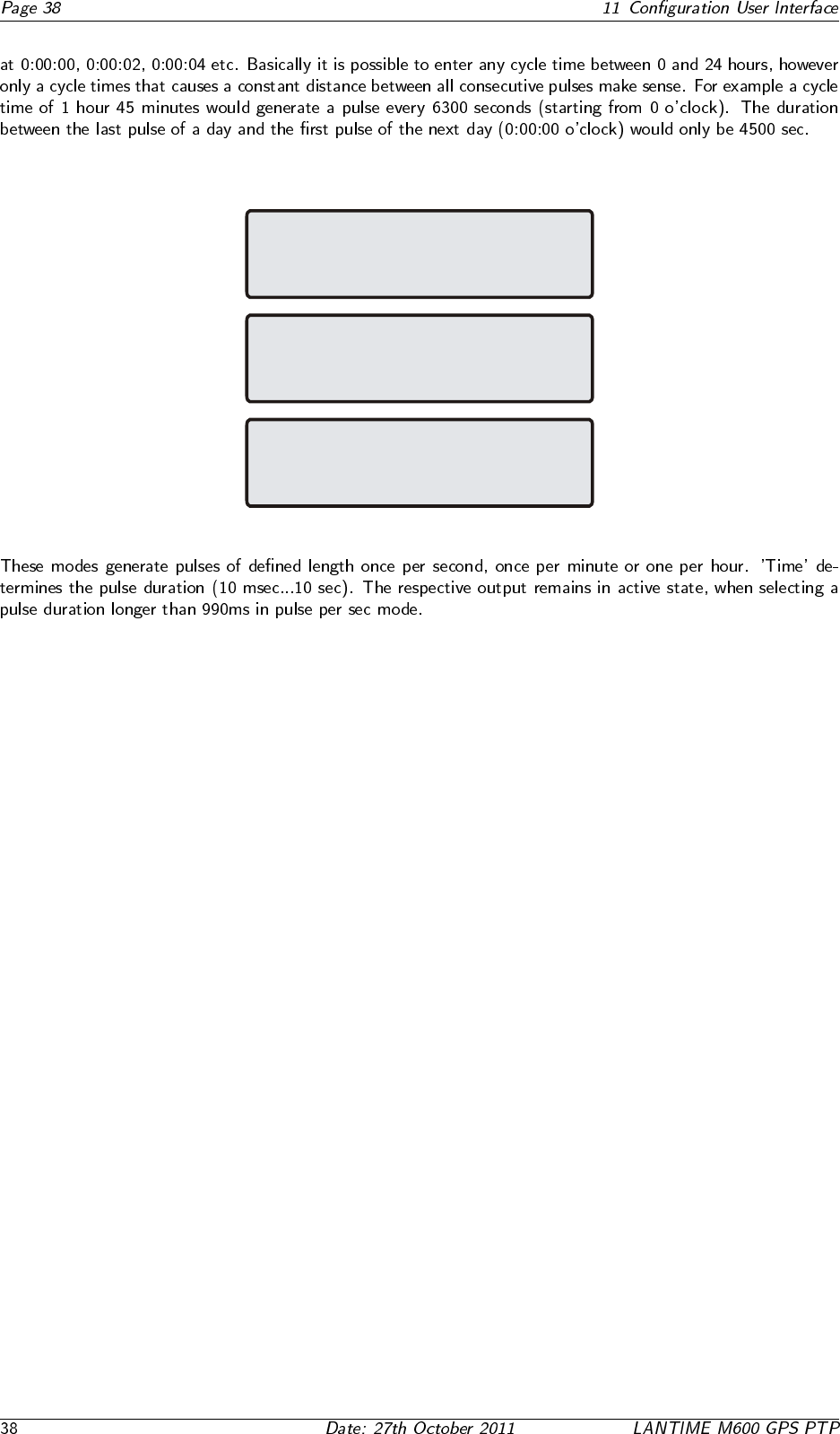
11.5.6 PPS, PPM, PPH Modes
POUT1 Pulse Per Sec (PPS):
output activ: low
Length: 00.10 sec
POUT1 Pulse Per Min (PPM):
output activ: low
Length: 00.10 sec
POUT1 Pulse Per Hour (PPH):
output activ: low
Length: 00.10 sec
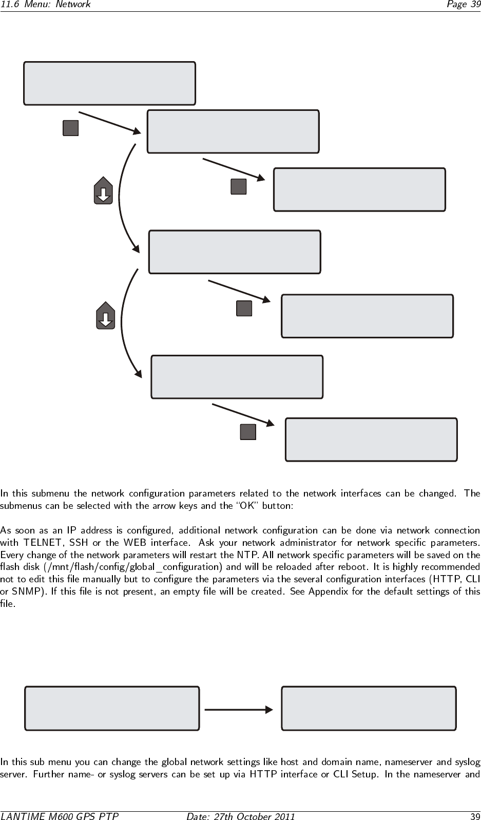
11.6 Menu: Network
Reference Time
Time Service
-> Network <-
System
OK
-> Global Configuration <-
Network Interfaces
Network Services
OK
-> Hostname <- Nameserver
Domainname Syslog Server
Netw. LED
Global Configuration
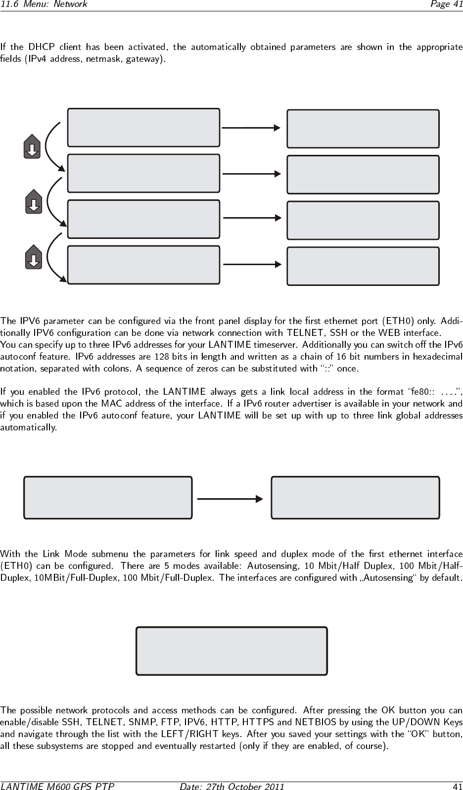
-> Network Interfaces <-
Network Services
-> IPv4 LAN Parameter <-
Ipv6 LAN Parameter
Link Mode
OK
Global Configuration
Network Interfaces
-> Network Services <-
SSH:on IPv6:on
TELN:on HTTP:on
SNMP:off HTTPS:on
FTP:on NetB:off
OK
11.6.1 Menu: Global Configuration
-> Global Configuration <-
Network Interfaces
Network Services
-> Hostname <- Nameserver
Domainname Syslog Server
Netw. LED
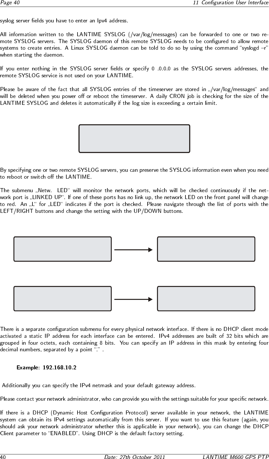
LAN Device Parameter
Check Network LinkUp
on LAN Device Ports
0:L 1: 2: 3: PTP:
11.6.2 Menu: Setup Network Interfaces
Global Configuration
-> Network Interfaces <-
Network Services
-> IPv4 LAN Parameter <-
IPv6 LAN Parameter
Link Mode
11.6.3 Menu: Setup IPv4 LAN Parameter
IPv4 LAN Parameter
-> ETH0 <- ETH1
ETH2 ETH3
PTP0
ETH0: -> DHCP: enabled <-
ADDRESS: 172.16.3.64
NETMASK: 255.255.255.0
DEF.GATEWAY:
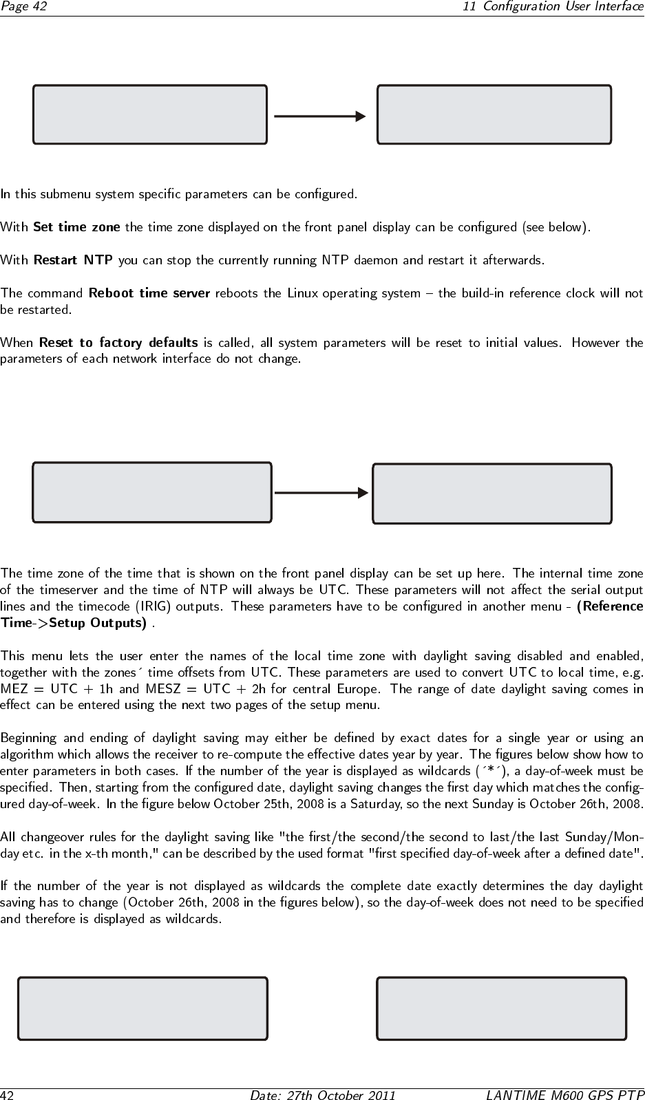
11.6.4 Menu: Setup IPv6 Parameter
IPv6 Link Local Address ETH0
fe80::0213:22FF:FE33:4455/64 Sc
Edit and Set
ETH0 IPv6 Autoconfiguration
Autoconf: enabled
Edit and Set
IPv6 Link Global Address 1 ETH0
0201::feff:8032
Edit and Set
IPv6 Link Global Address 2 ETH0
0201::feff:8032
-> Link Local Address <-
Autoconfiguration Flag
Link Global Address 1
Link Global Address 2
Link Local Address
Autoconfiguration Flag
-> Link Global Address 1 <-
Link Global Address 2
Link Local Address
Autoconfiguration Flag
Link Global Address 1
-> Link Global Address 2 <-
Link Local Address
-> Autoconfiguration Flag <-
Link Global Address 1
Link Global Address 2
11.6.5 Menu: Link Mode
Global Configuration
-> Network Interfaces <-
Network Services
IPv4 LAN Parameter
IPv6 LAN Parameter
-> Link Mode <-
11.6.6 Menu: Network Services
SSH:on IPv6:on
TELN:on HTTP:on
SNMP:off HTTPS:on
FTP:on NetB:off
11.7 Menu: System
Reference Time
Time Service
Network
-> System <-
-> Set time zone <-
Restart NTP
Reset to factory defaults
Reboot time server
11.7.1 Menu: Set time zone
-> Set time zone <-
Restart NTP
Reset to factory defaults
Reboot time server
Time Zone parameters
of display
-> Daylight Saving OFF <-
Daylight Saving ON
Time Zone Daylight Saving OFF
TZ Name: MEZ Offs.UTC:+01:00h
Day of Week: Sun
Date:25.10.**** Time:03:00:00
Time Zone Daylight Saving OFF
TZ Name: MEZ Offs.UTC:+01:00h
Day of Week: ***
Date:26.10.2008 Time:03:00:00
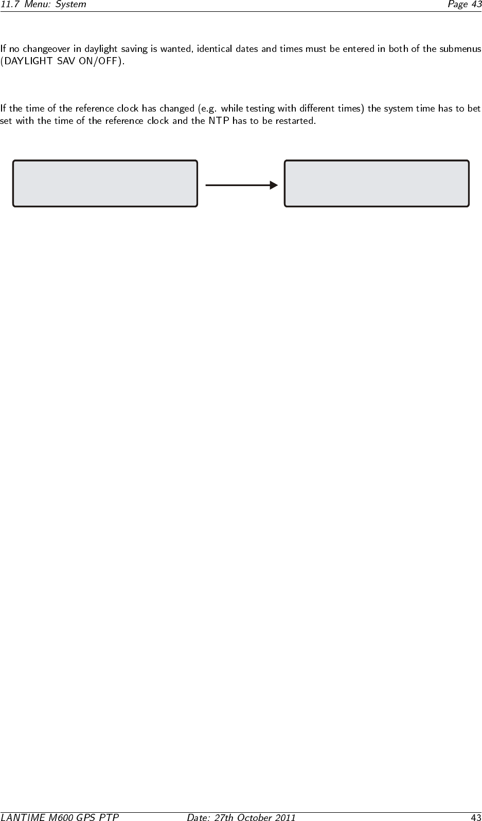
11.7.2 Menu: Restart NTP
Set Time Zone
-> Restart NTP <-
Reset to factory defaults
Reboot time server
Edit NTP Configuration
Set system time with refclock
and restart NTP daemon
Press F2 to confirm reset
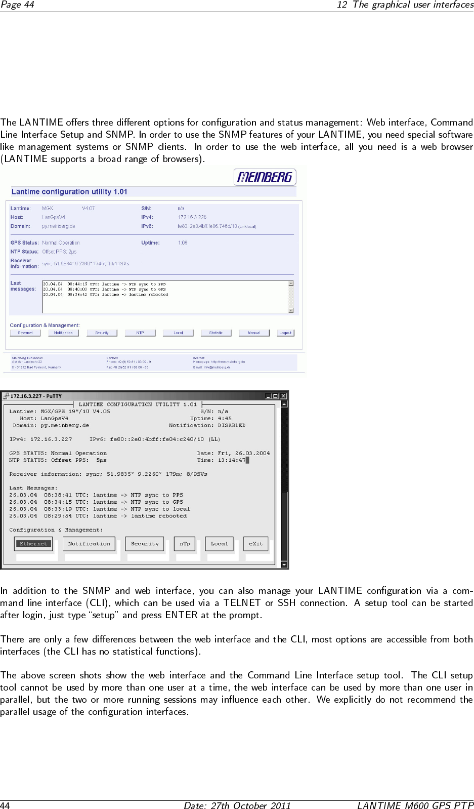
12 The graphical user interfaces
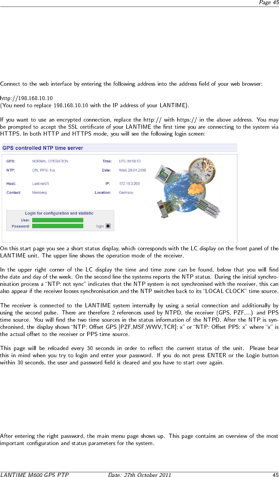
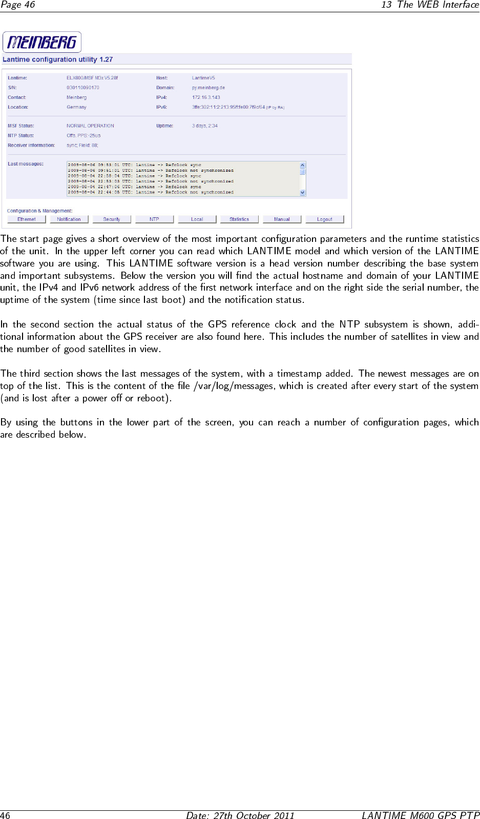
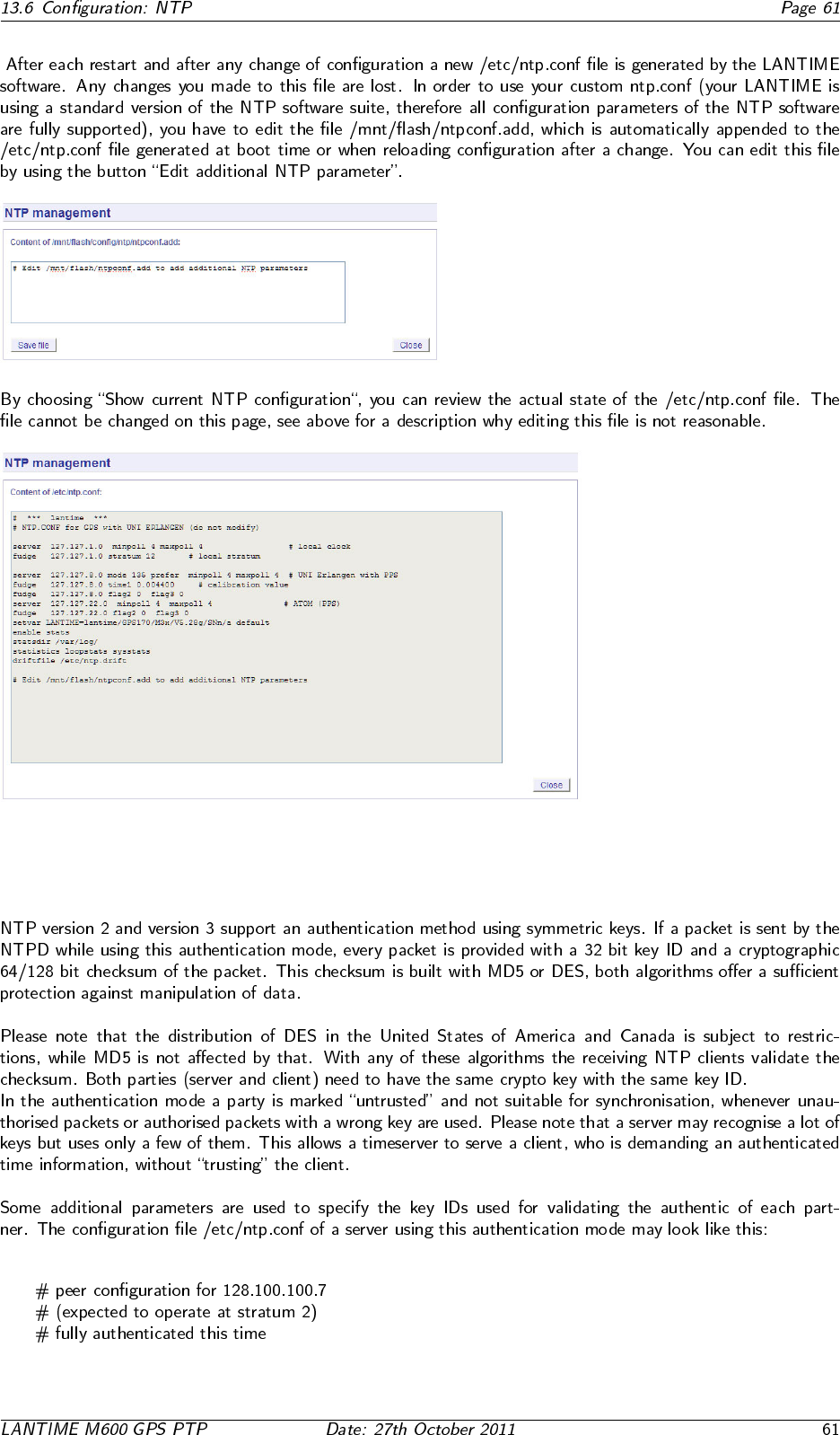
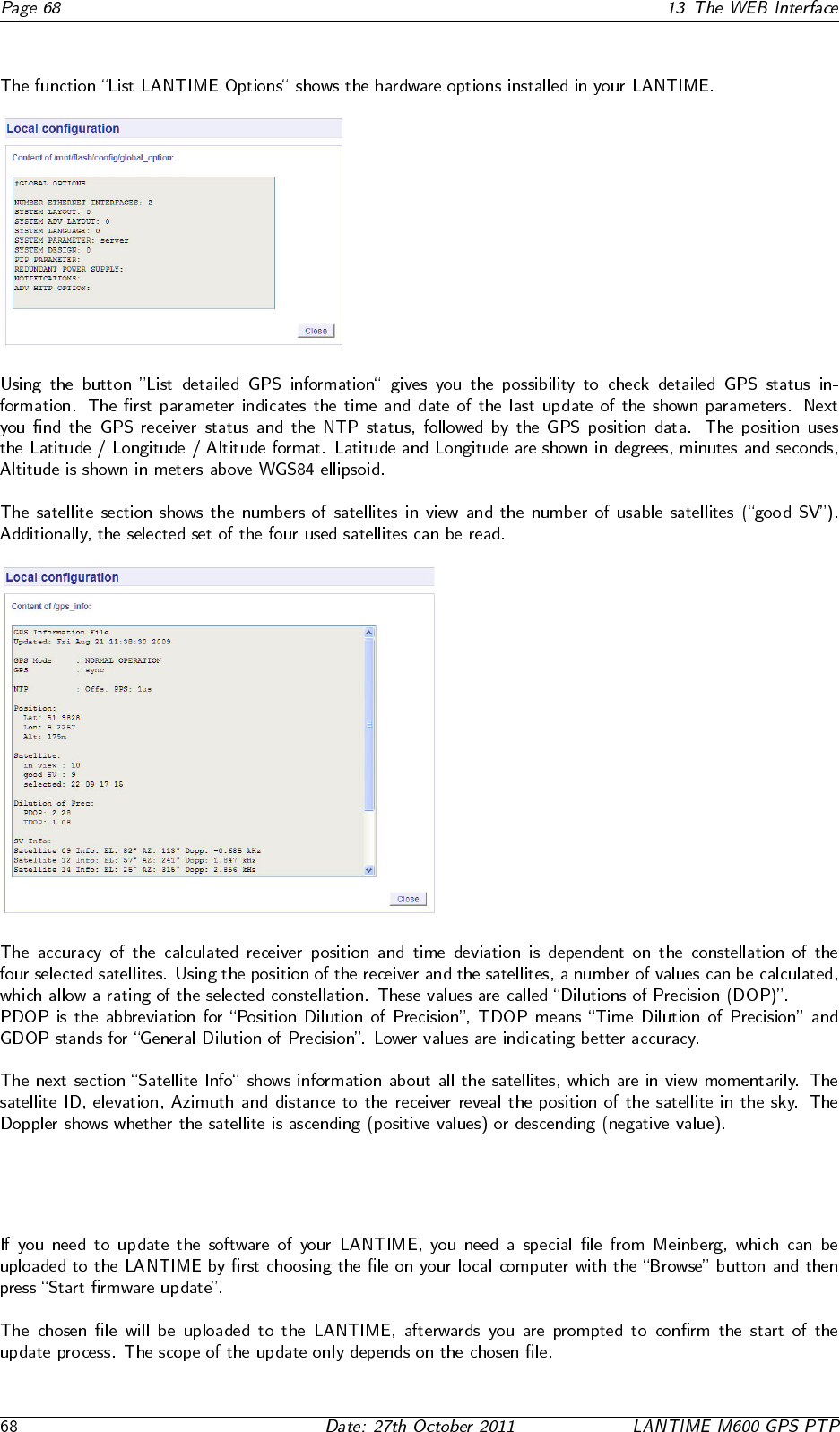
13 The WEB Interface
13.1 Configuration: Main Menu
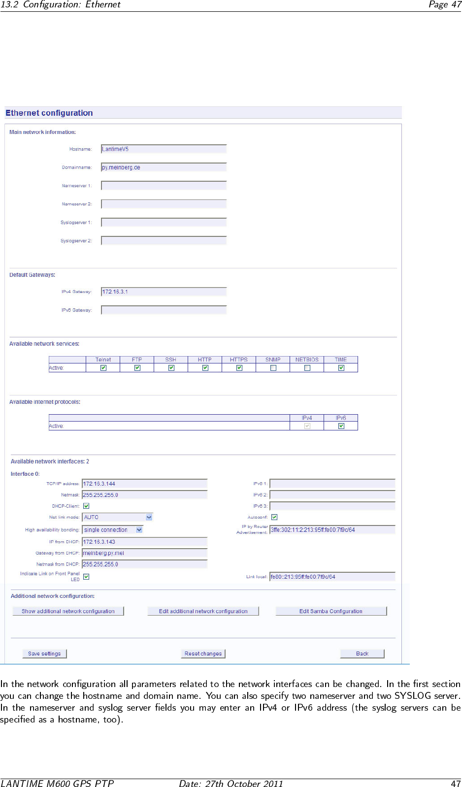
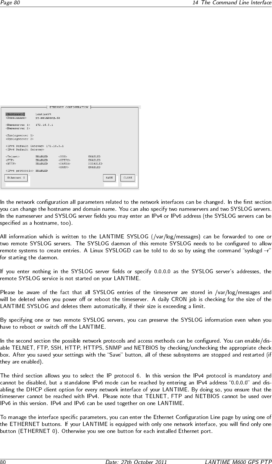
13.2 Configuration: Ethernet
13.2.1 SYSLOG Server
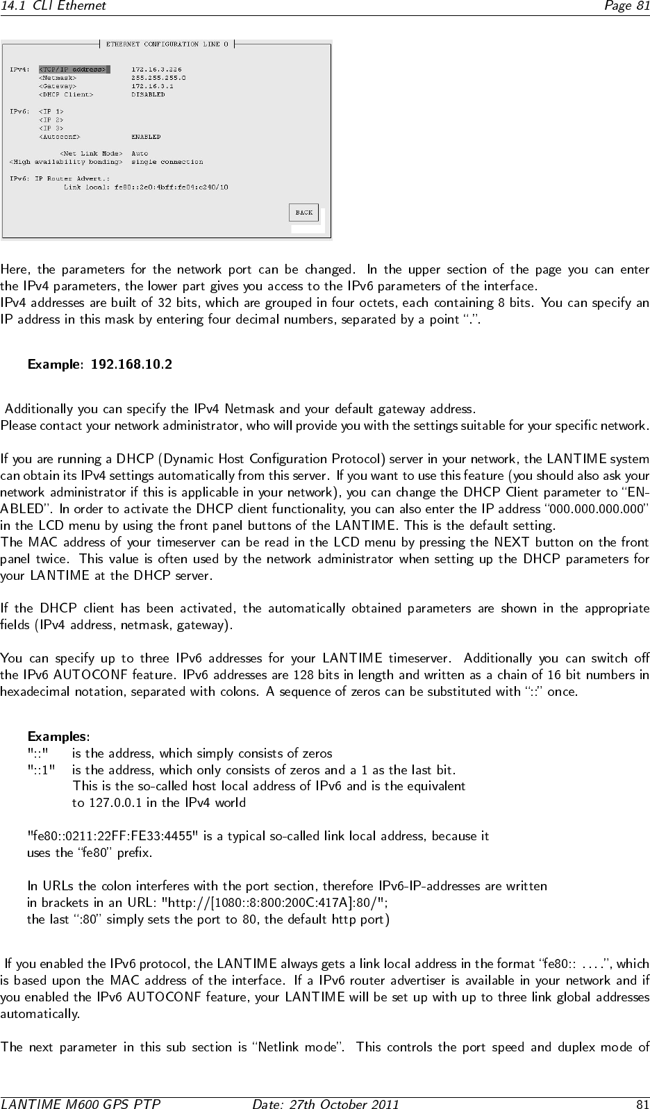
13.3 Network interface specific configuration
13.3.1 IPv4 addresses and DHCP
13.3.2 IPv6 addresses and autoconf
13.3.3 High Availability Bonding
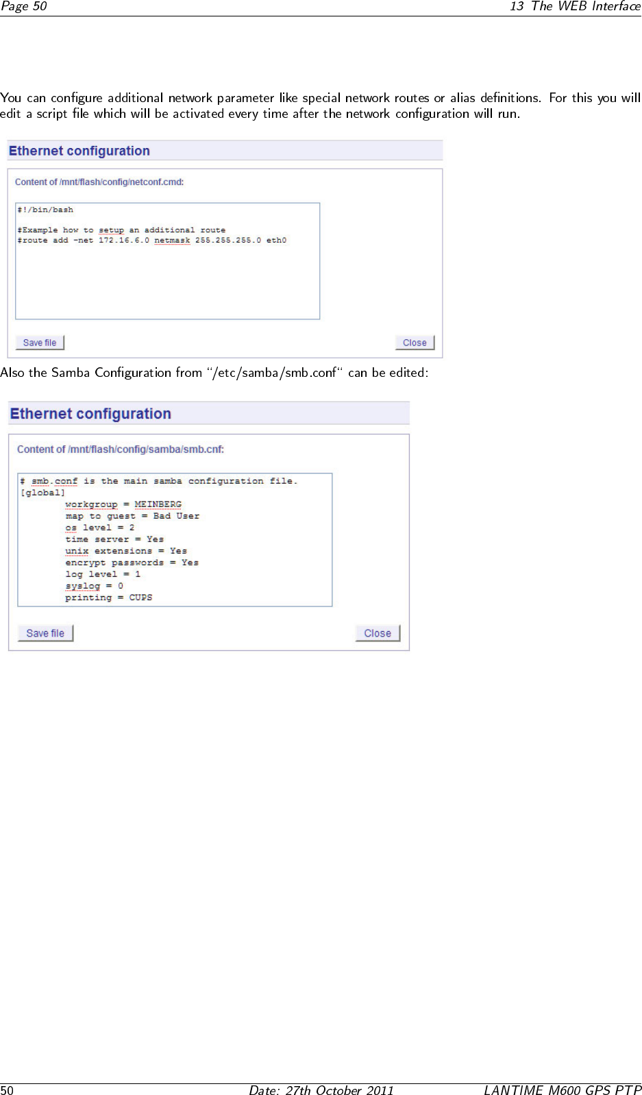
13.3.4 Additional Network Configuration
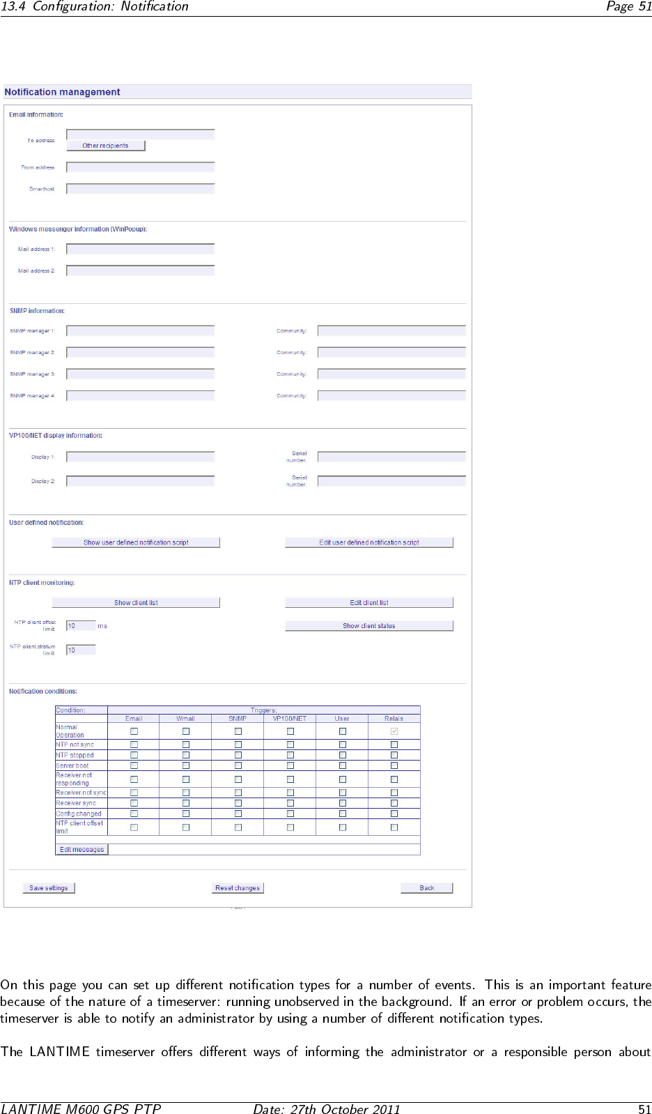
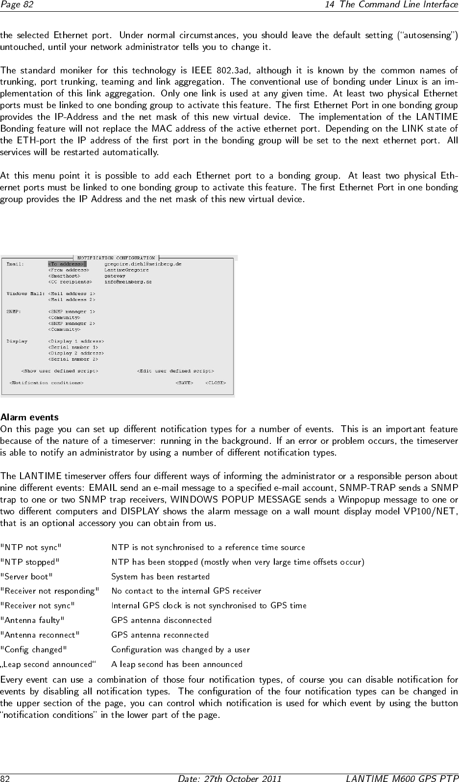
13.4 Configuration: Notification
13.4.1 Alarm events
•
•
•
13.4.2 E-mail messages
•
•
•
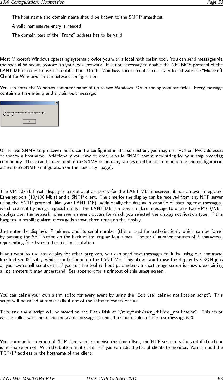
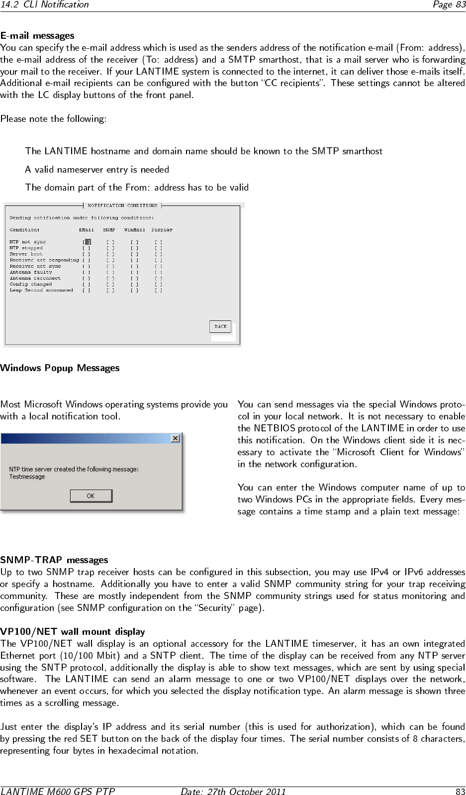
13.4.3 Windows Popup Messages
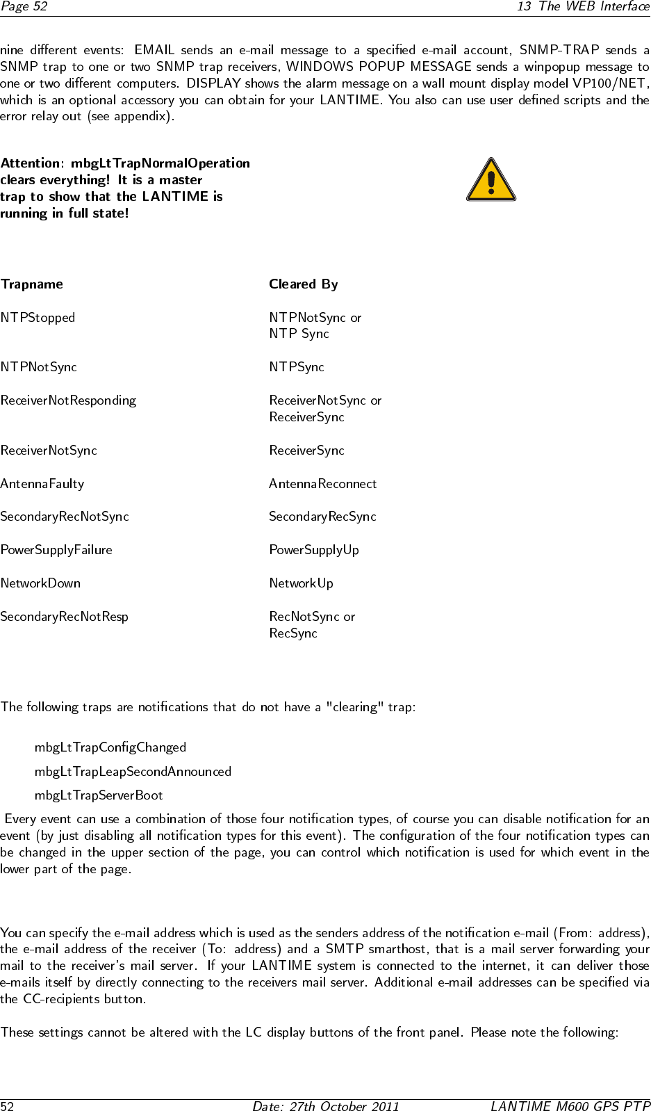
13.4.4 SNMP-TRAP messages
13.4.5 VP100/NET wall mount display
13.4.6 User defined Alarm scripts
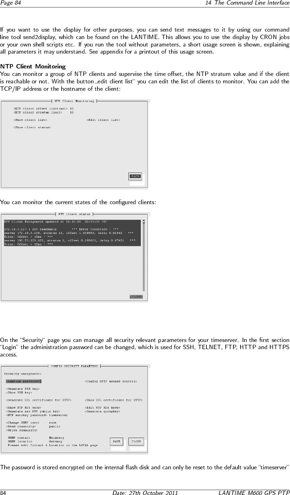
13.4.7 NTP Client Monitoring
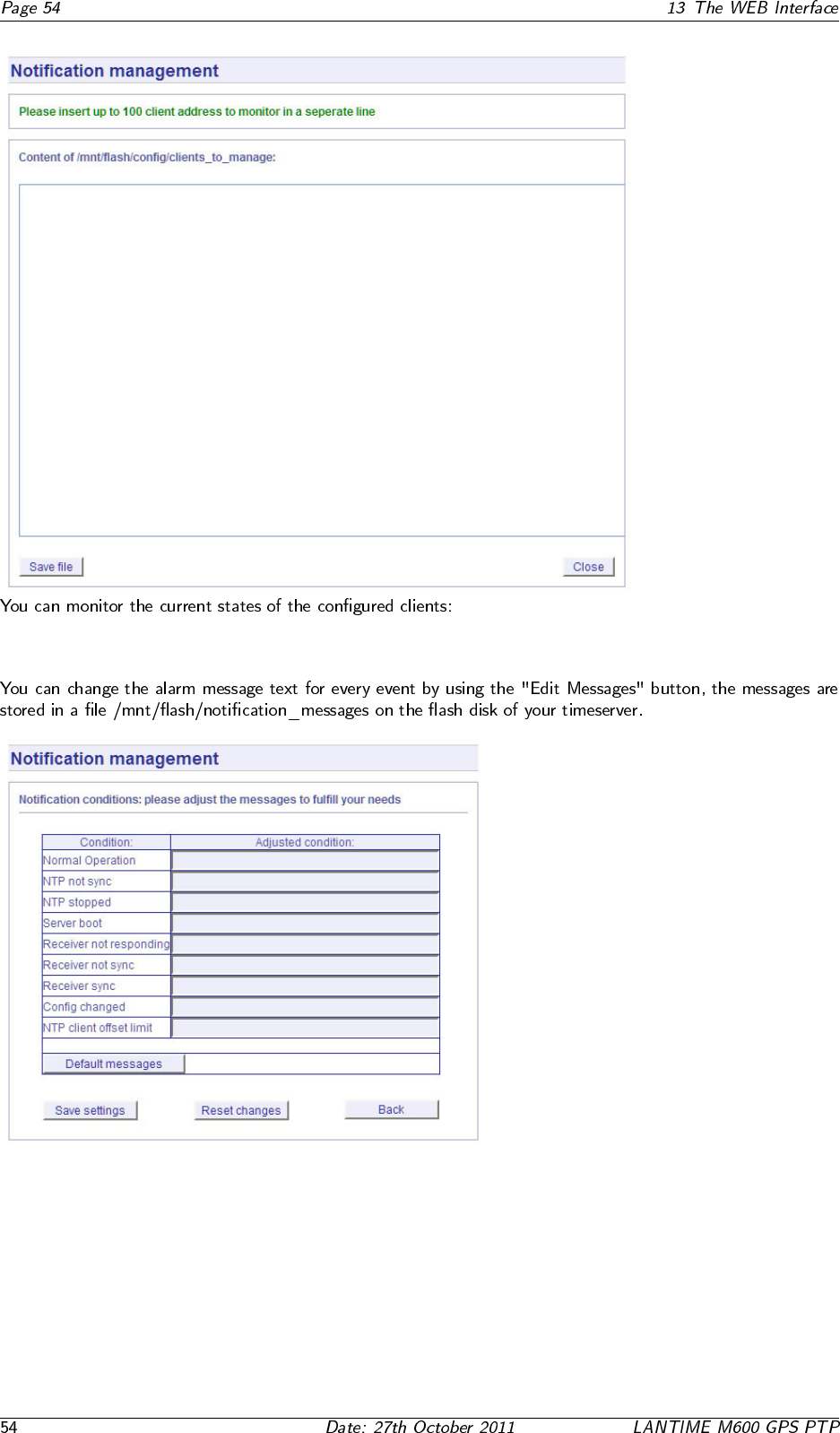
13.4.8 Alarm messages
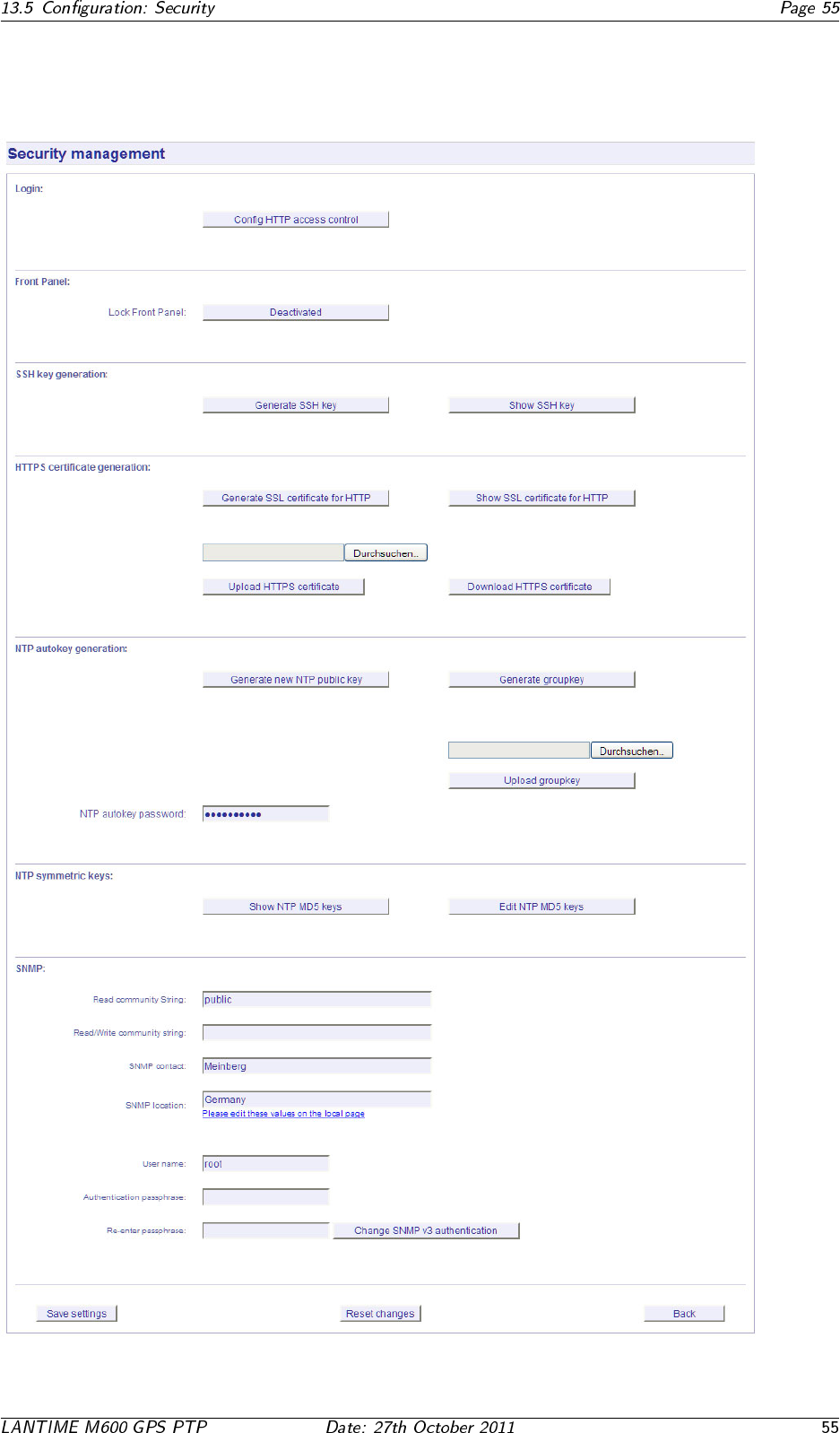
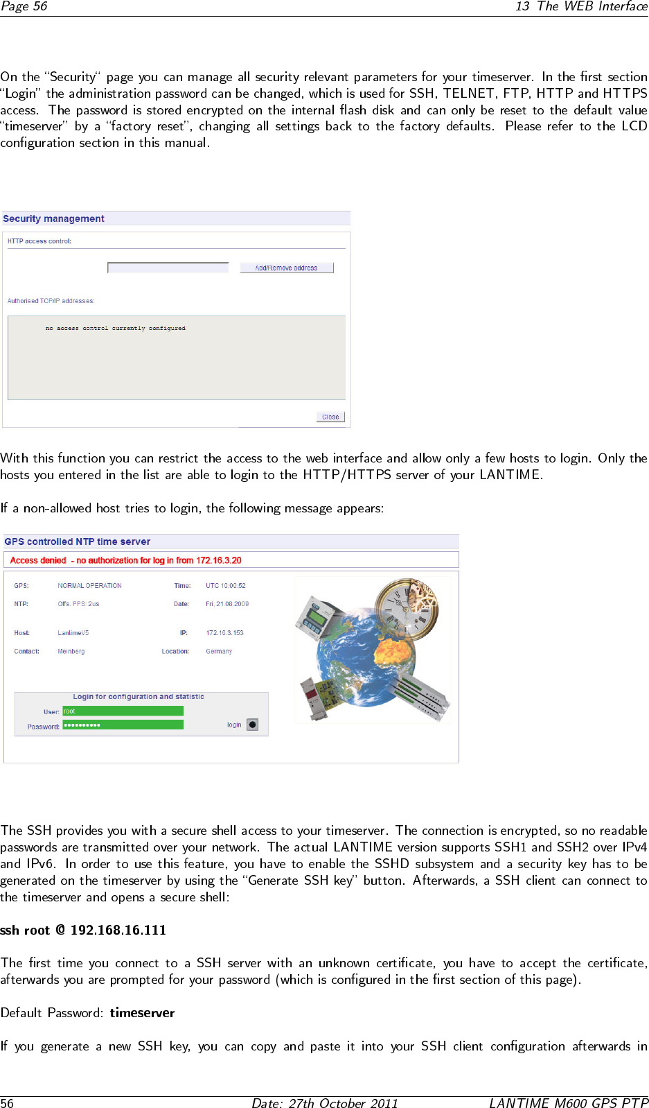
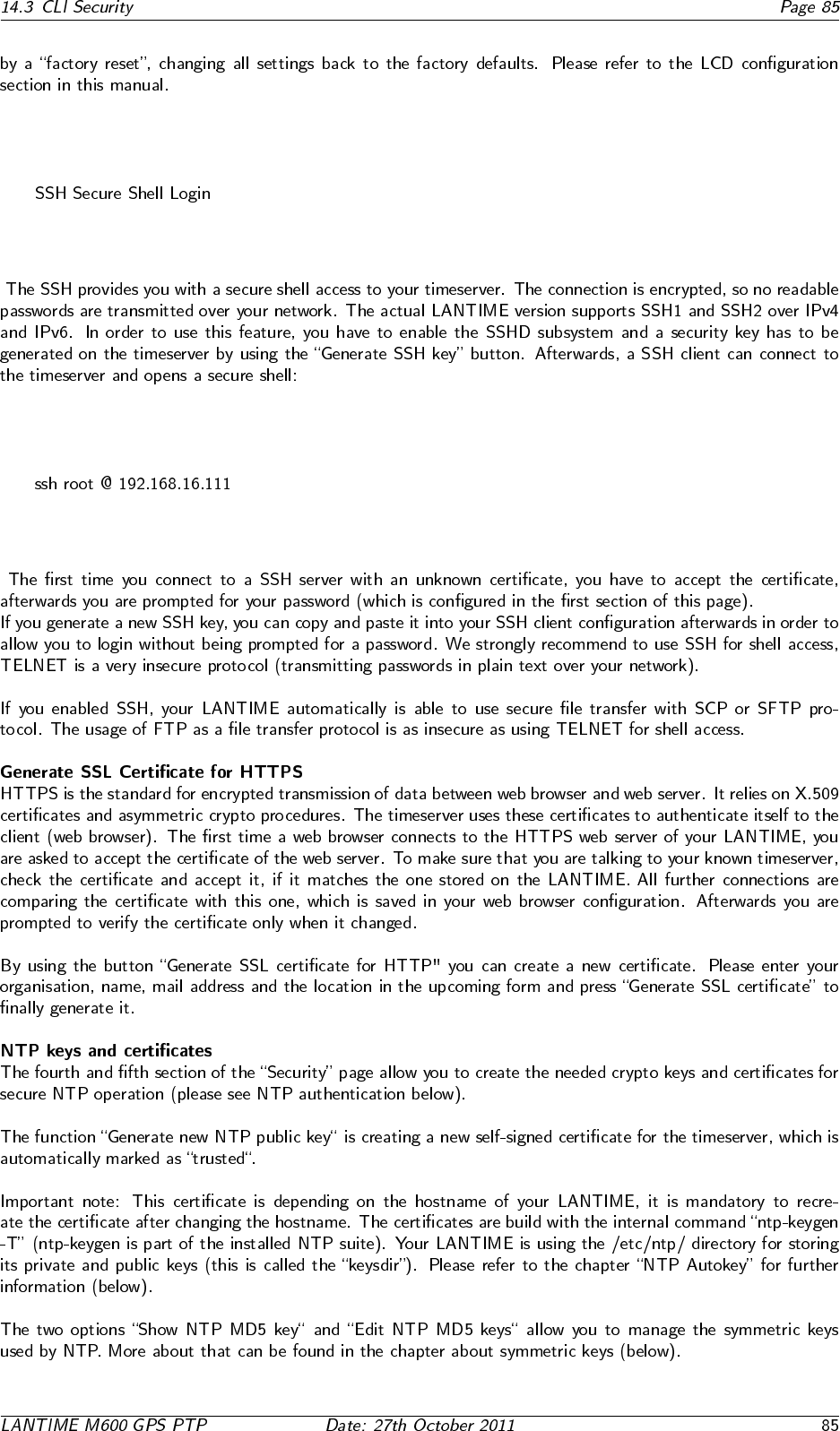
13.5 Configuration: Security
13.5.1 Password
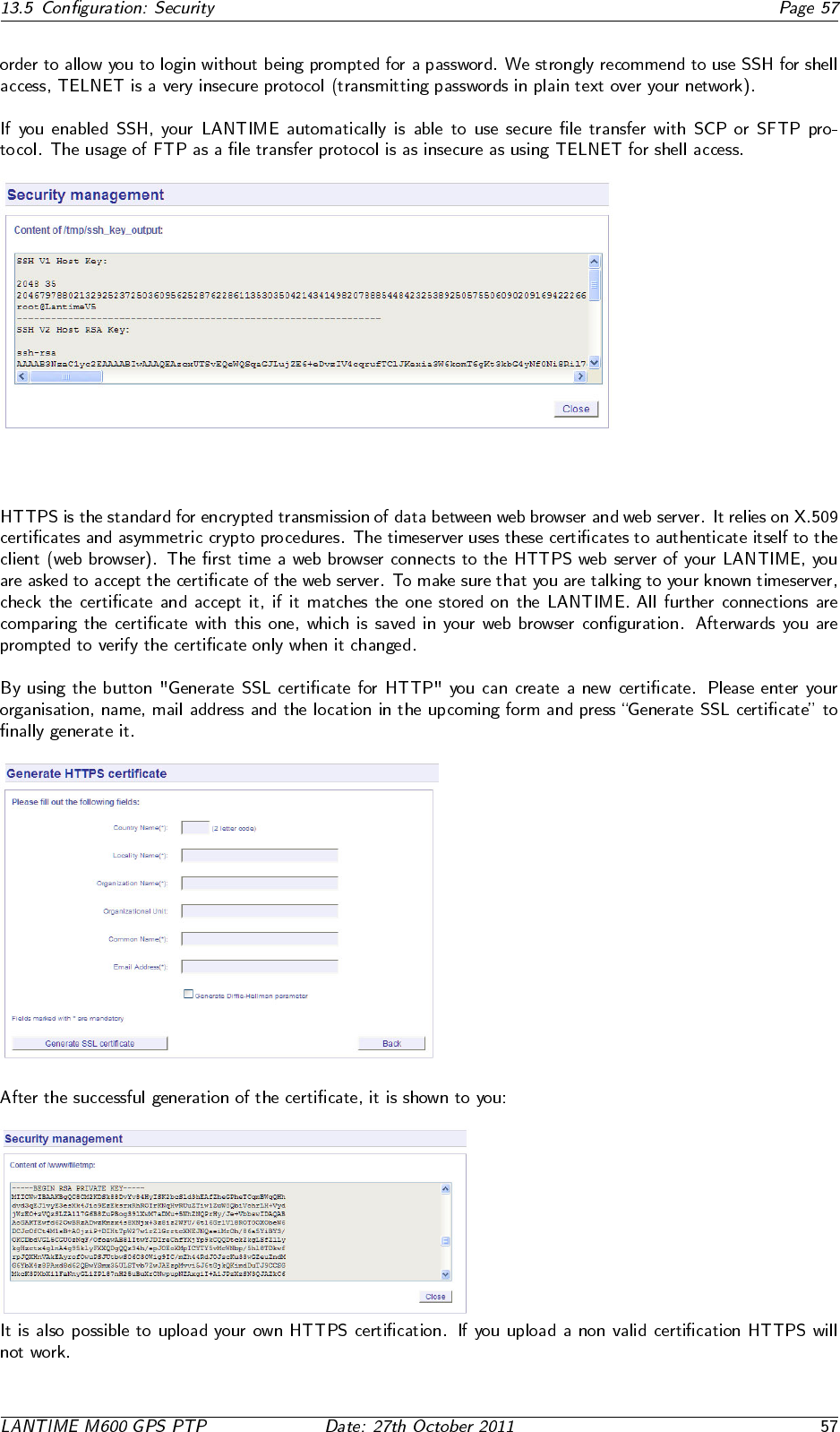
13.5.2 HTTP Access Control
13.5.3 SSH Secure Shell Login
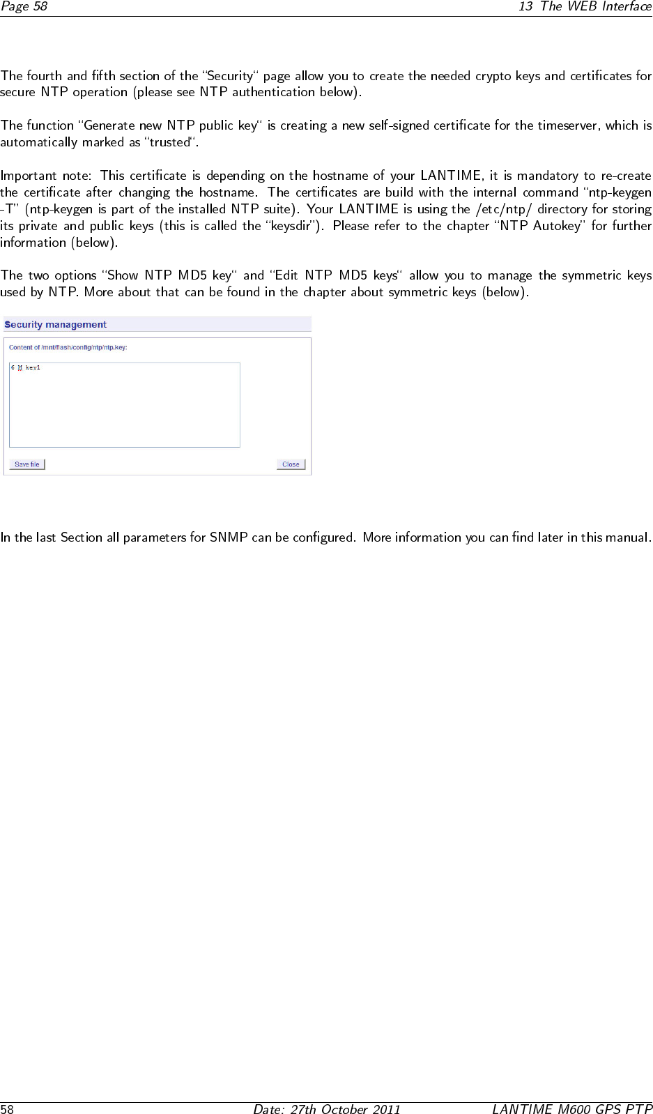
13.5.4 Generate SSL Certificate for HTTPS
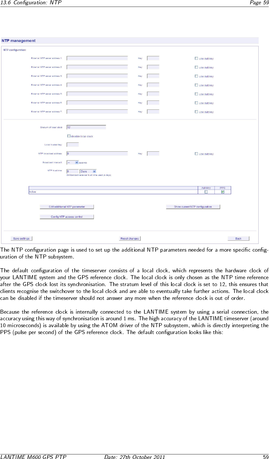
13.5.5 NTP keys and certificates
13.5.6 SNMP Parameter
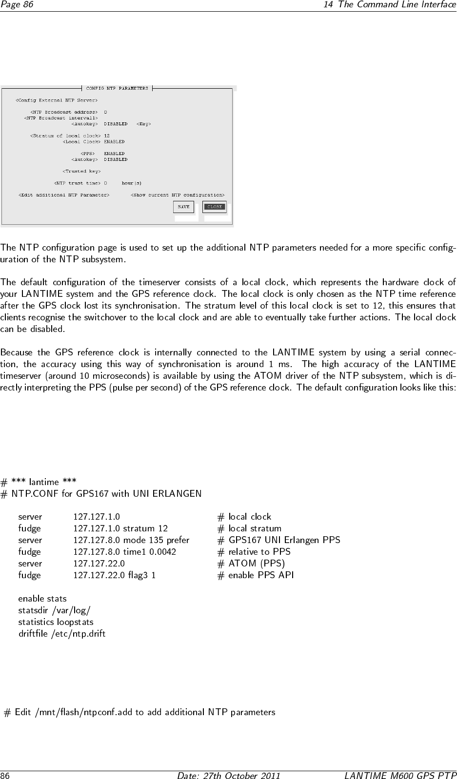
13.6 Configuration: NTP
13.6.1 NTP Authentication
•
•
•
•
•
•
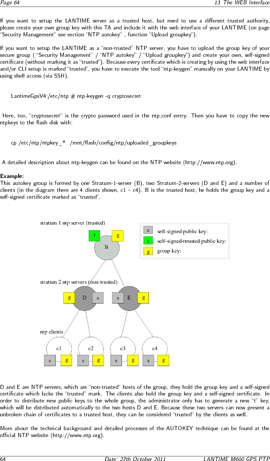
13.6.2 NTP AUTOKEY
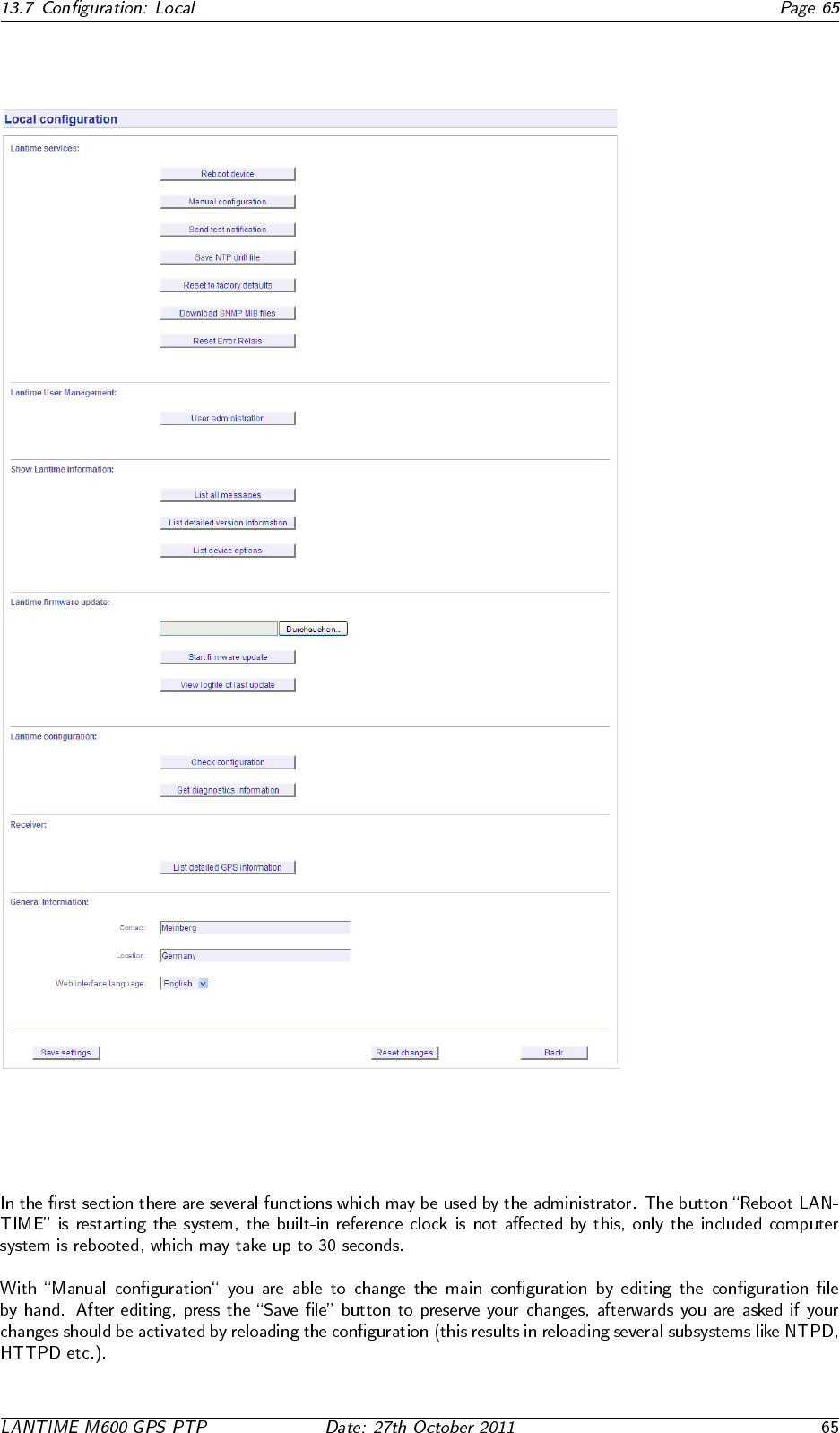
13.7 Configuration: Local
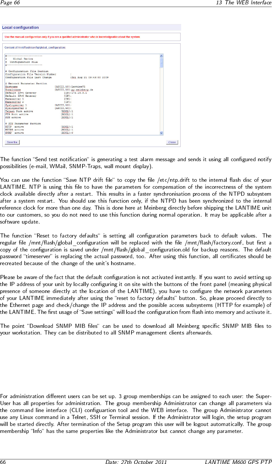
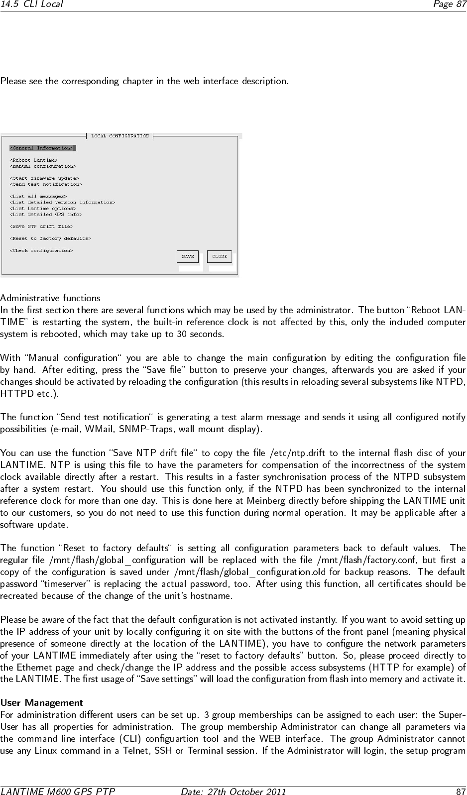
13.7.1 Administrative functions
13.7.2 User Management
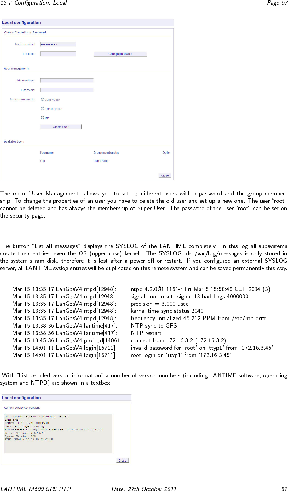
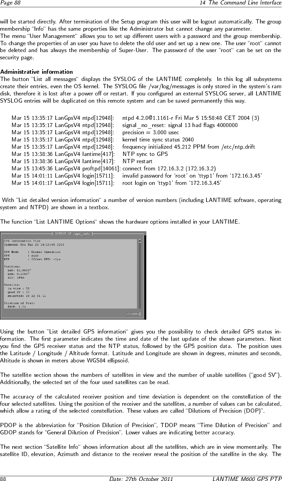
13.7.3 Administrative Information
13.7.4 Software Update
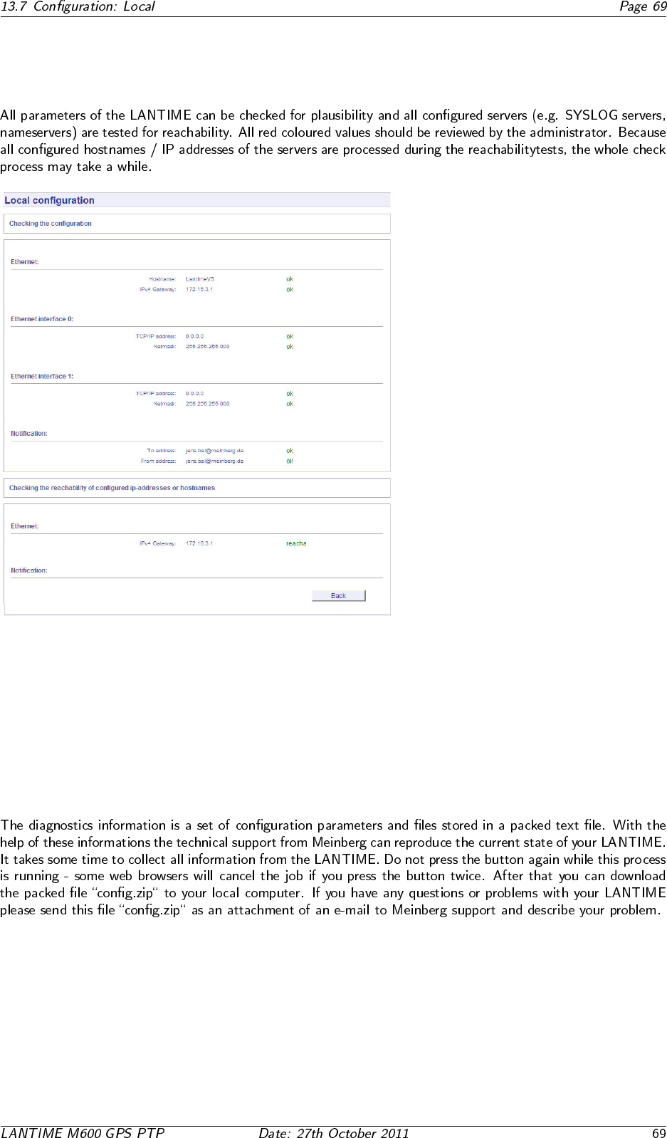
13.7.5 Automatic configuration check
13.7.6 Get Diagnostics Information

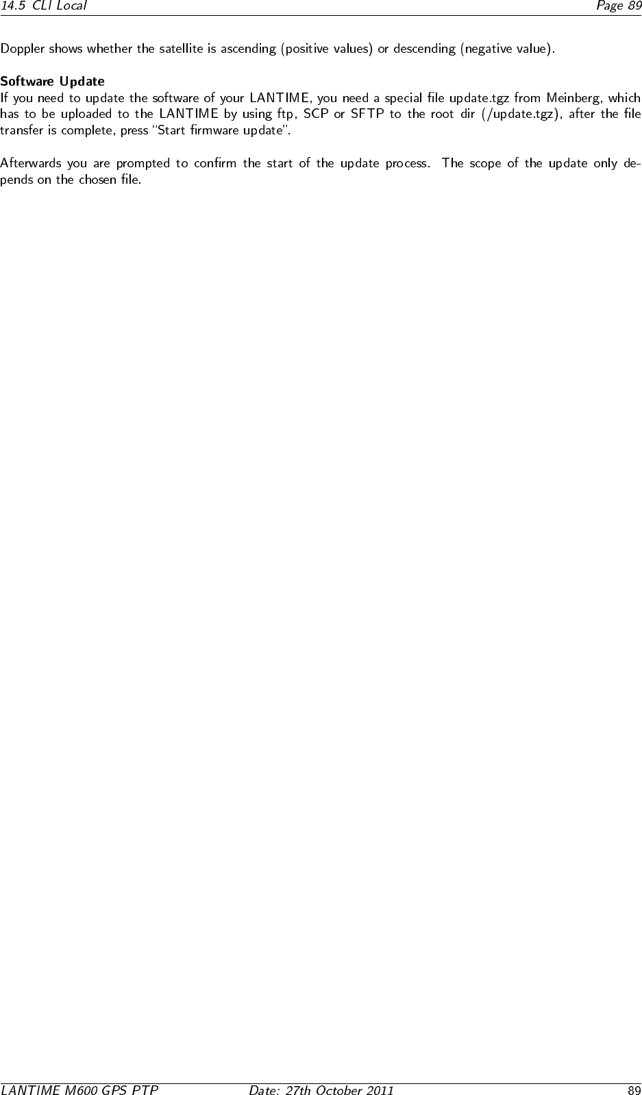
13.7.7 Receiver Information
13.7.8 Web interface language
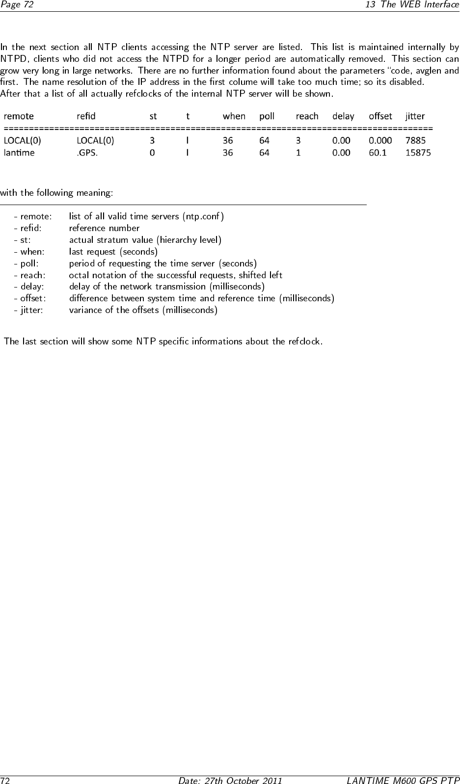
13.8 Configuration: Statistics
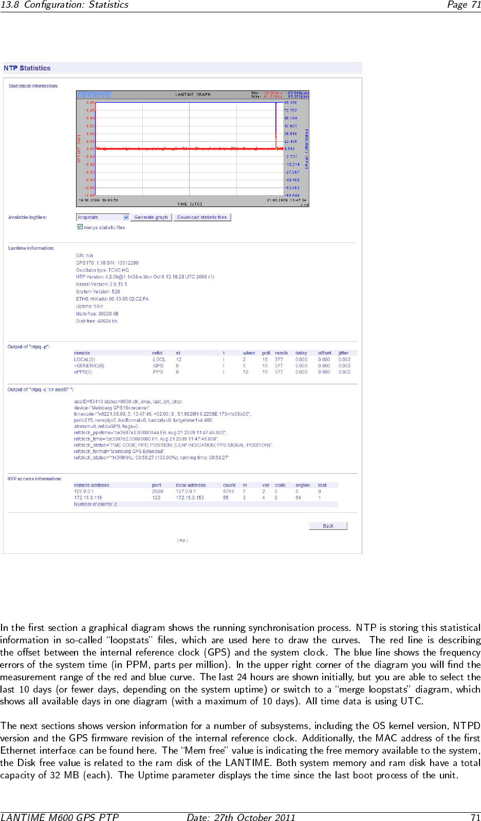
13.8.1 Statistical Information
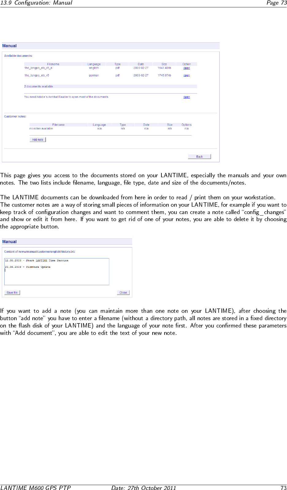
13.9 Configuration: Manual


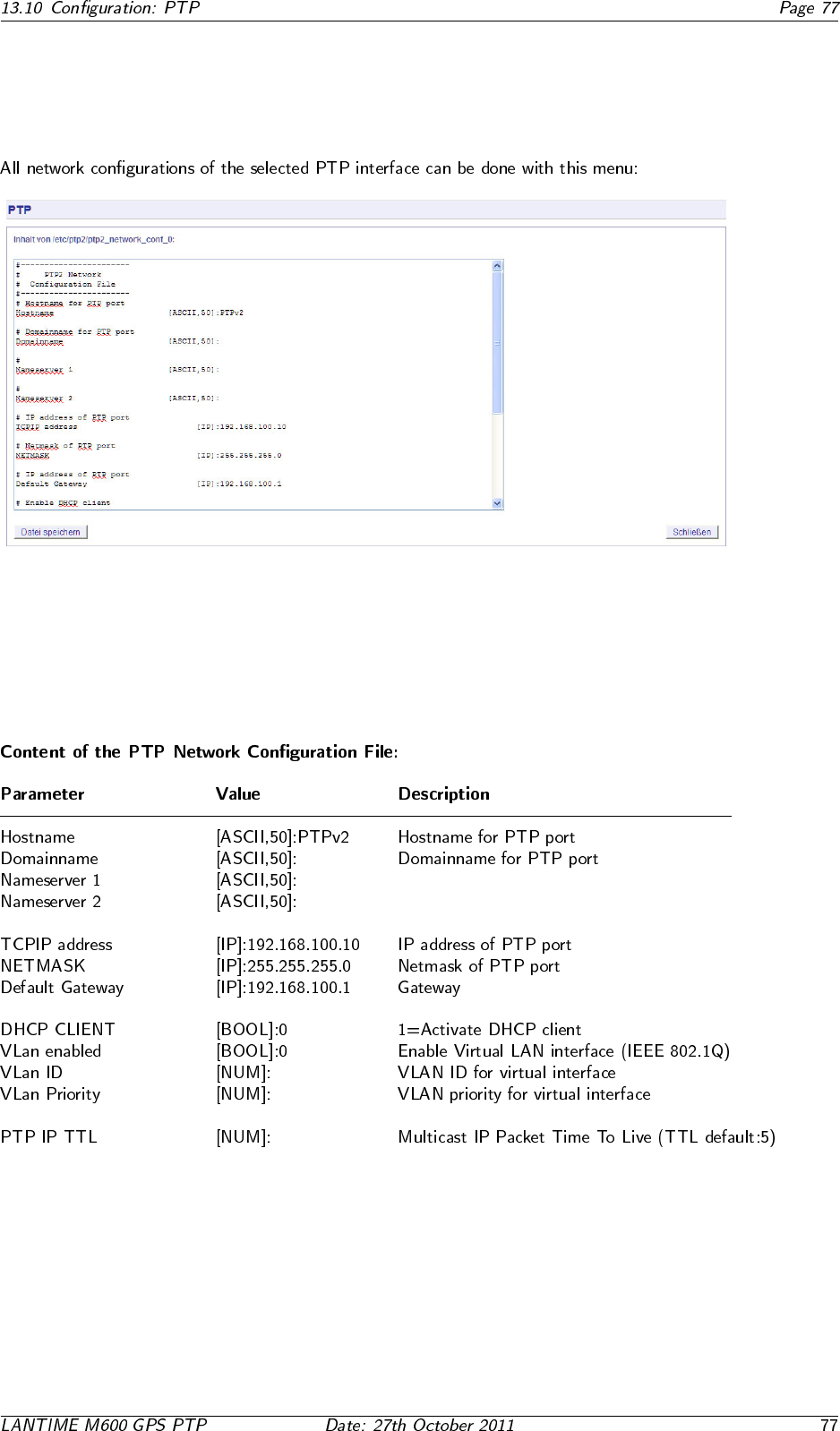
13.10.2 PTP Network Configuration
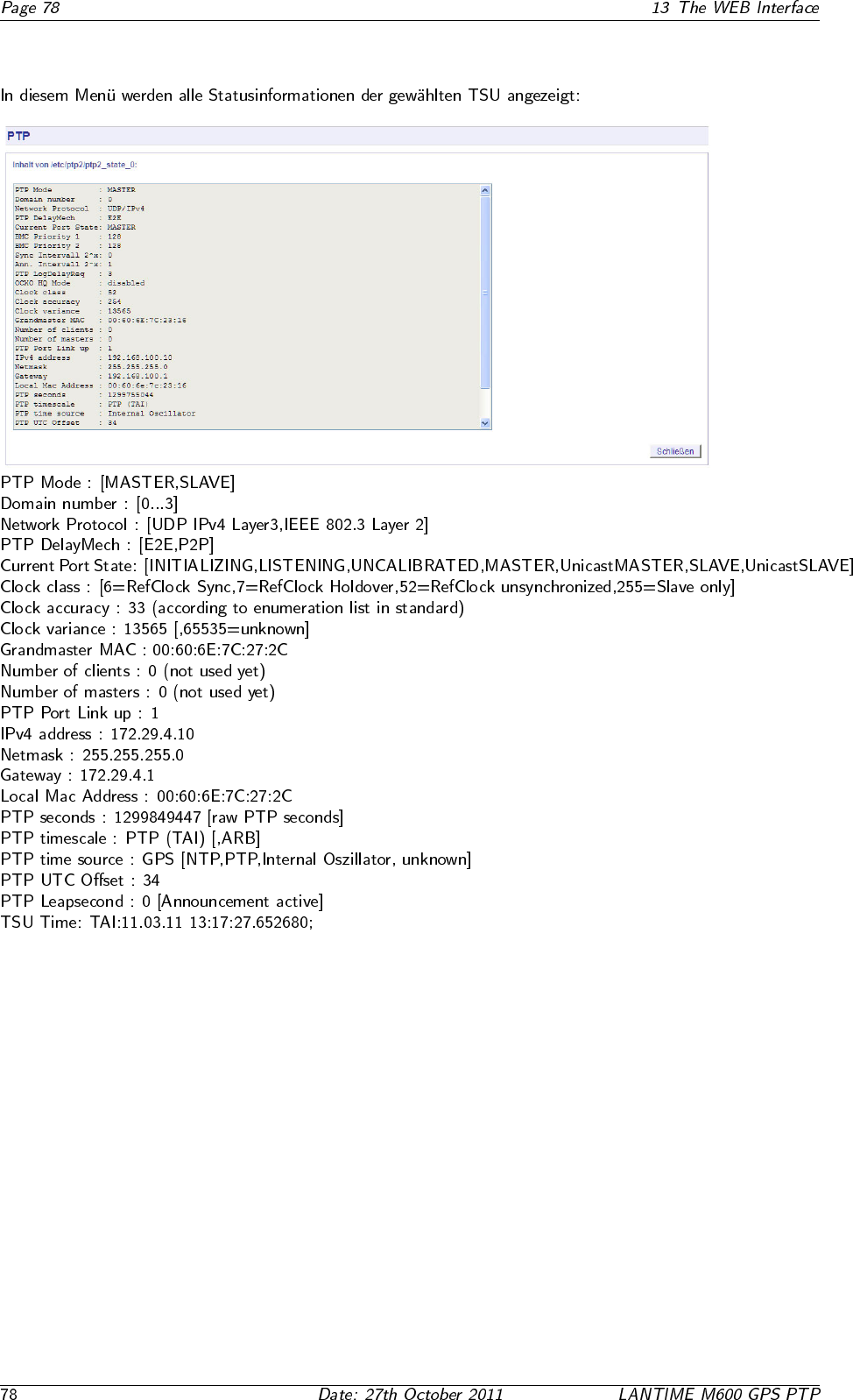
13.10.3 PTP State Files
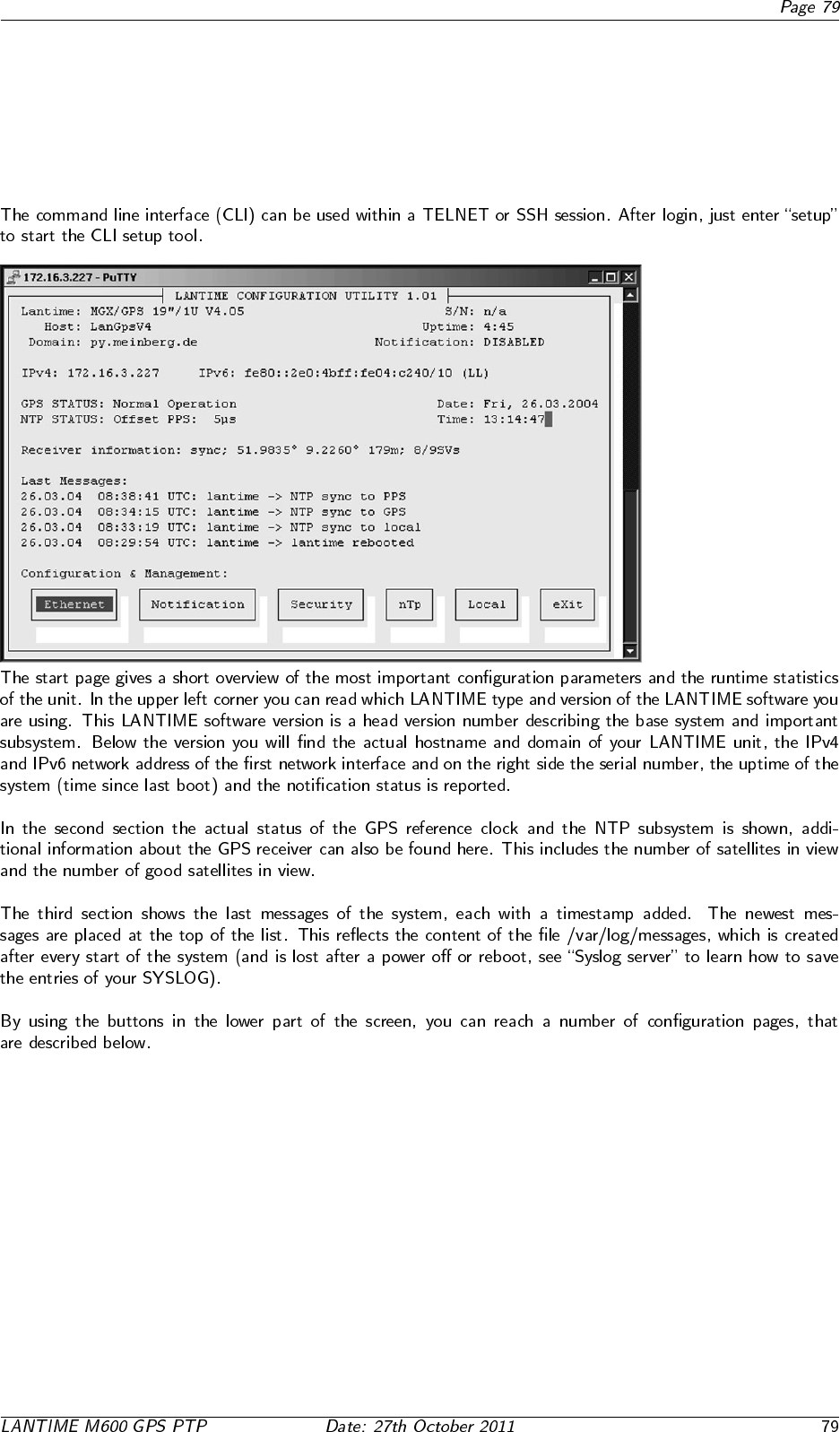
14 The Command Line Interface
14.1 CLI Ethernet
14.2 CLI Notification
•
•
•
14.3 CLI Security
14.4 CLI NTP Parameter
14.4.1 CLI NTP Authentication
14.5 CLI Local
15 SNMP Support
◦ ◦
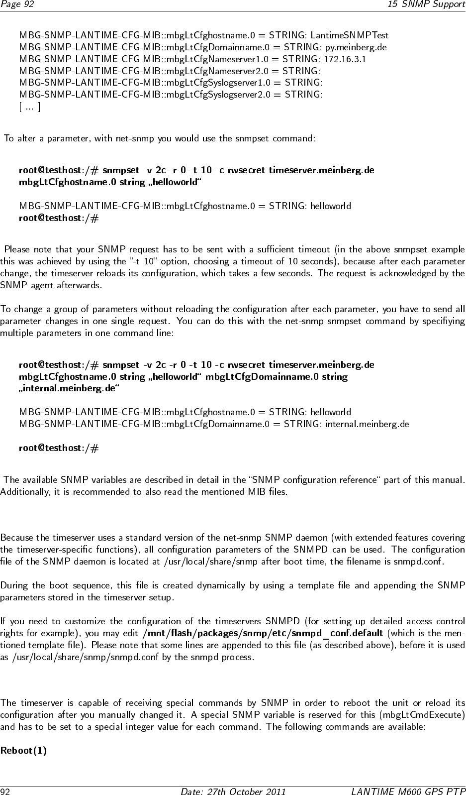
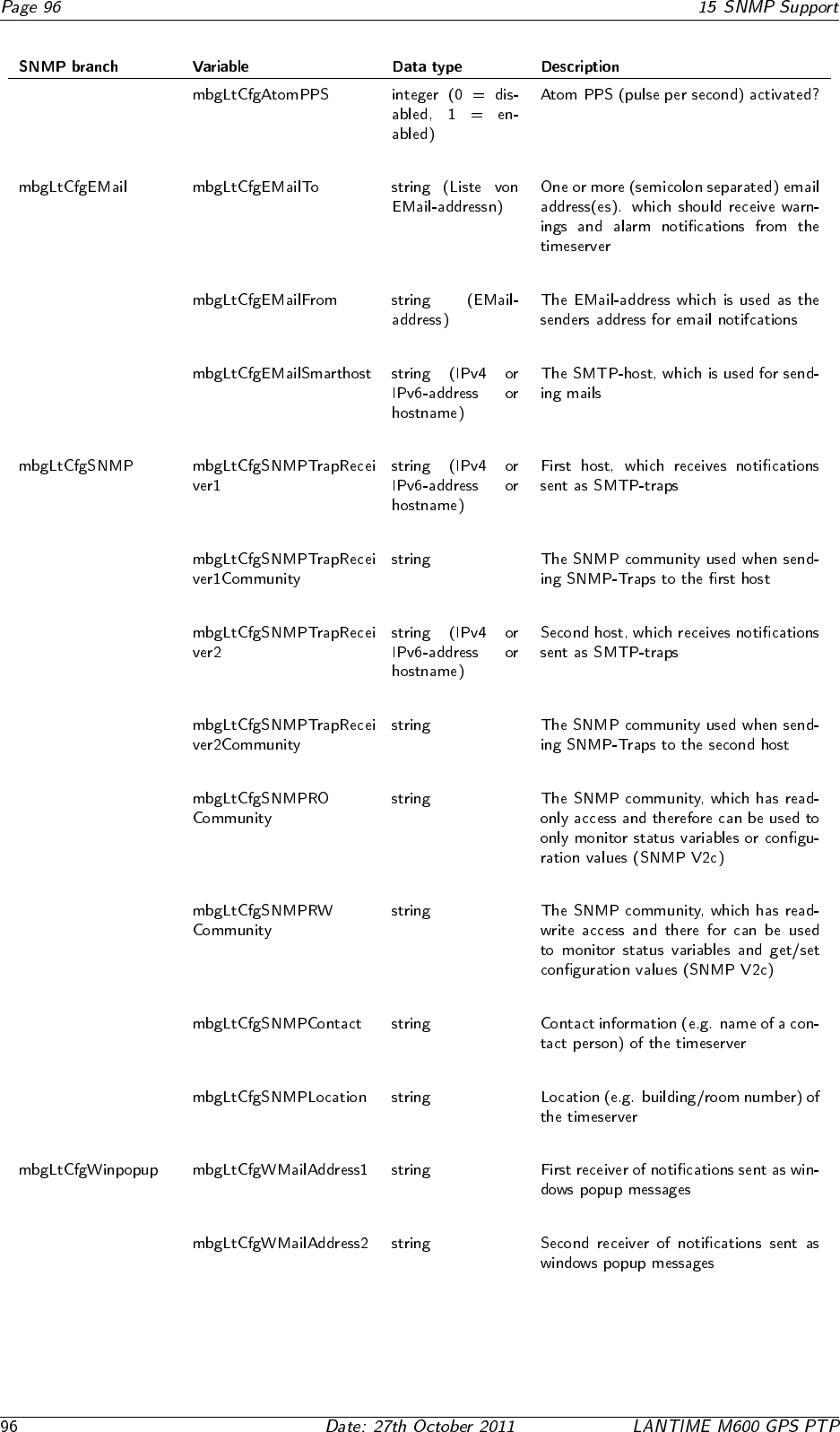
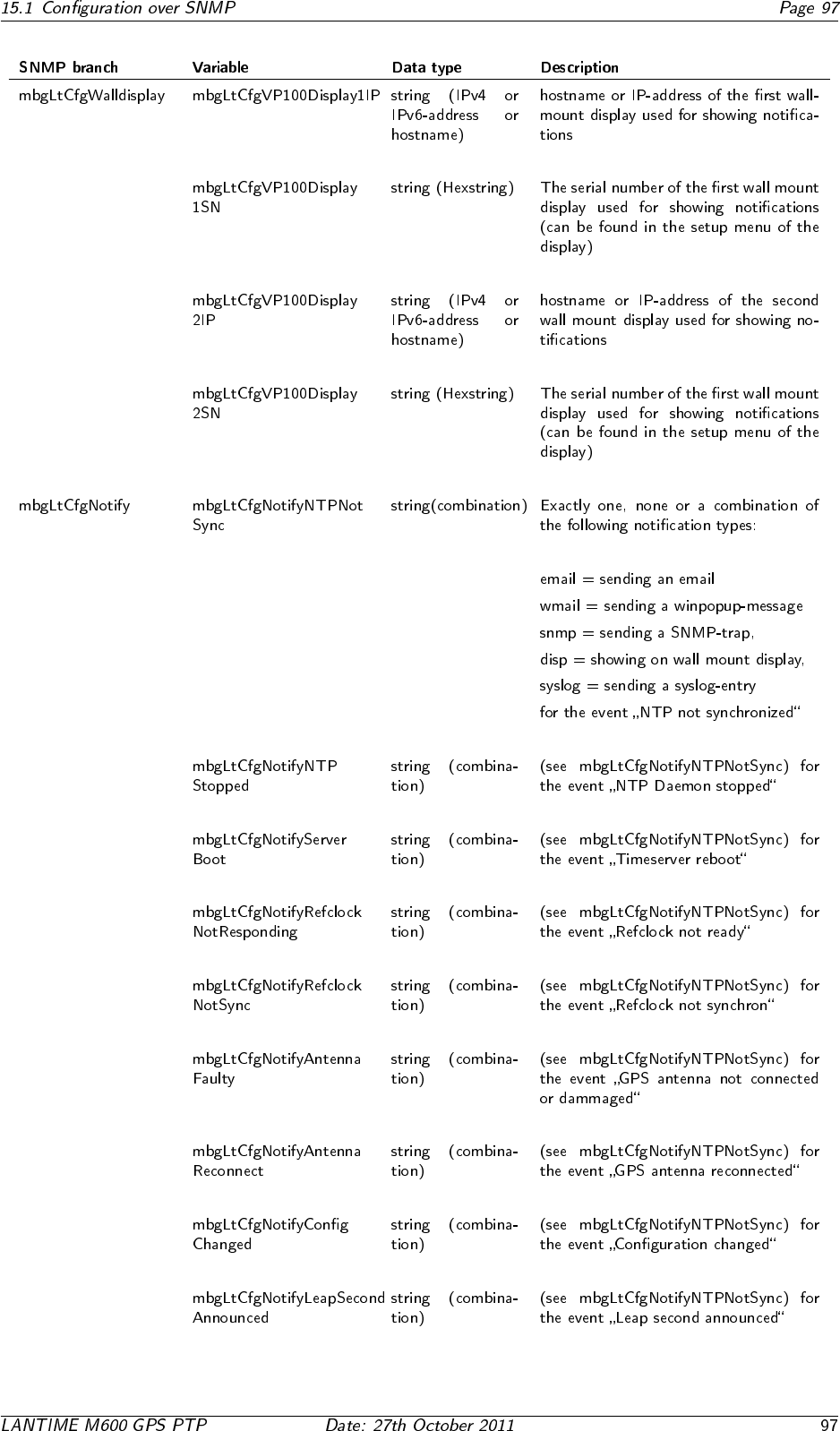
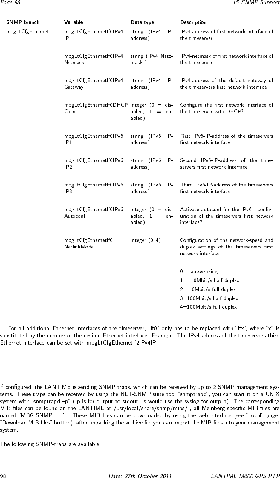
15.1 Configuration over SNMP
15.1.1 Examples for the usage of the SNMP configuration features
15.1.2 Further configuration possibilities
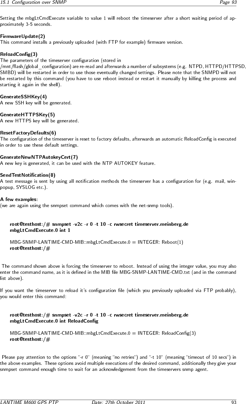
15.1.3 Send special timeserver commands with SNMP
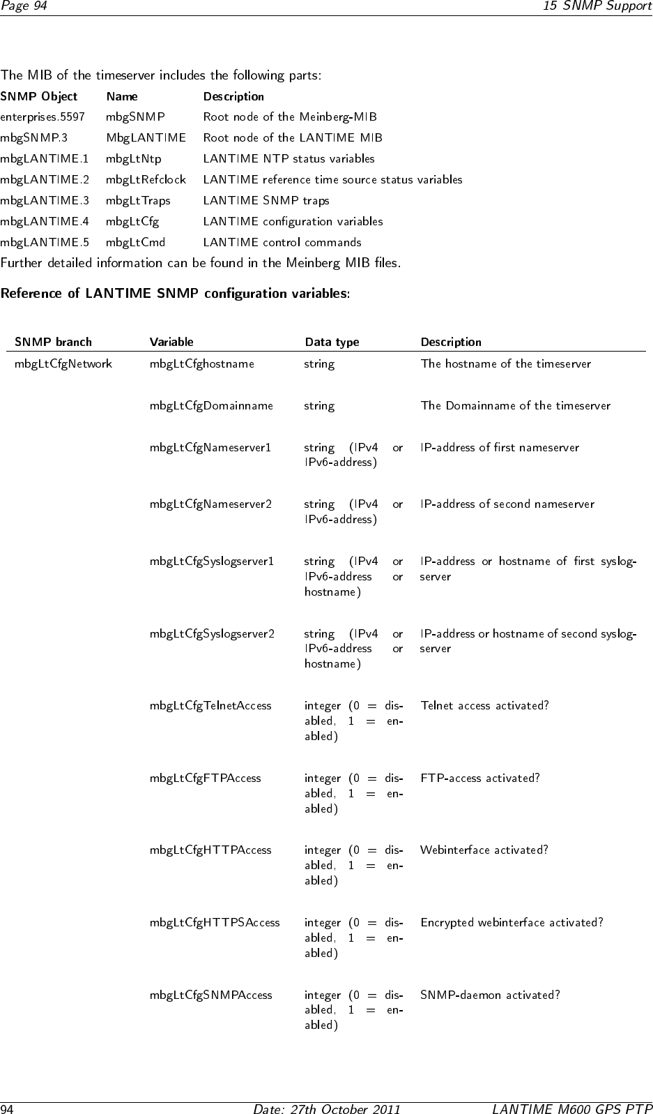
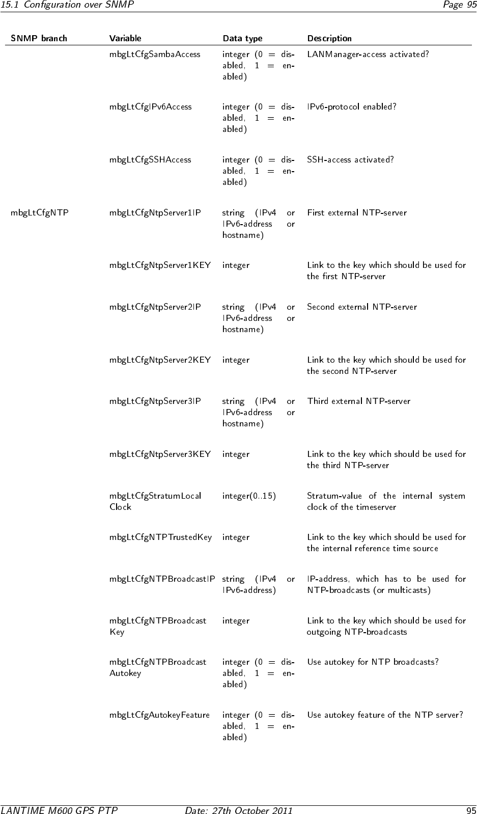
15.1.4 Configuration of the timeserver with SNMP: Reference
15.2 SNMP Traps
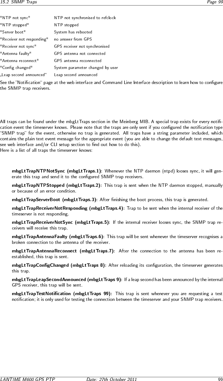
15.2.1 SNMP Trap Reference
•
•
•
•
•
•
•
•
•
•

16 Attachment: Technical Information
16.1 Skilled/Service-Personnel only: Replacing the Lithium Battery
16.2 Technical Specifications M600/300 Multipac
16.3 Safety instructions for building-in equipment
•
•
•
•
•
•◦
•
•
16.3.1 CE-Label
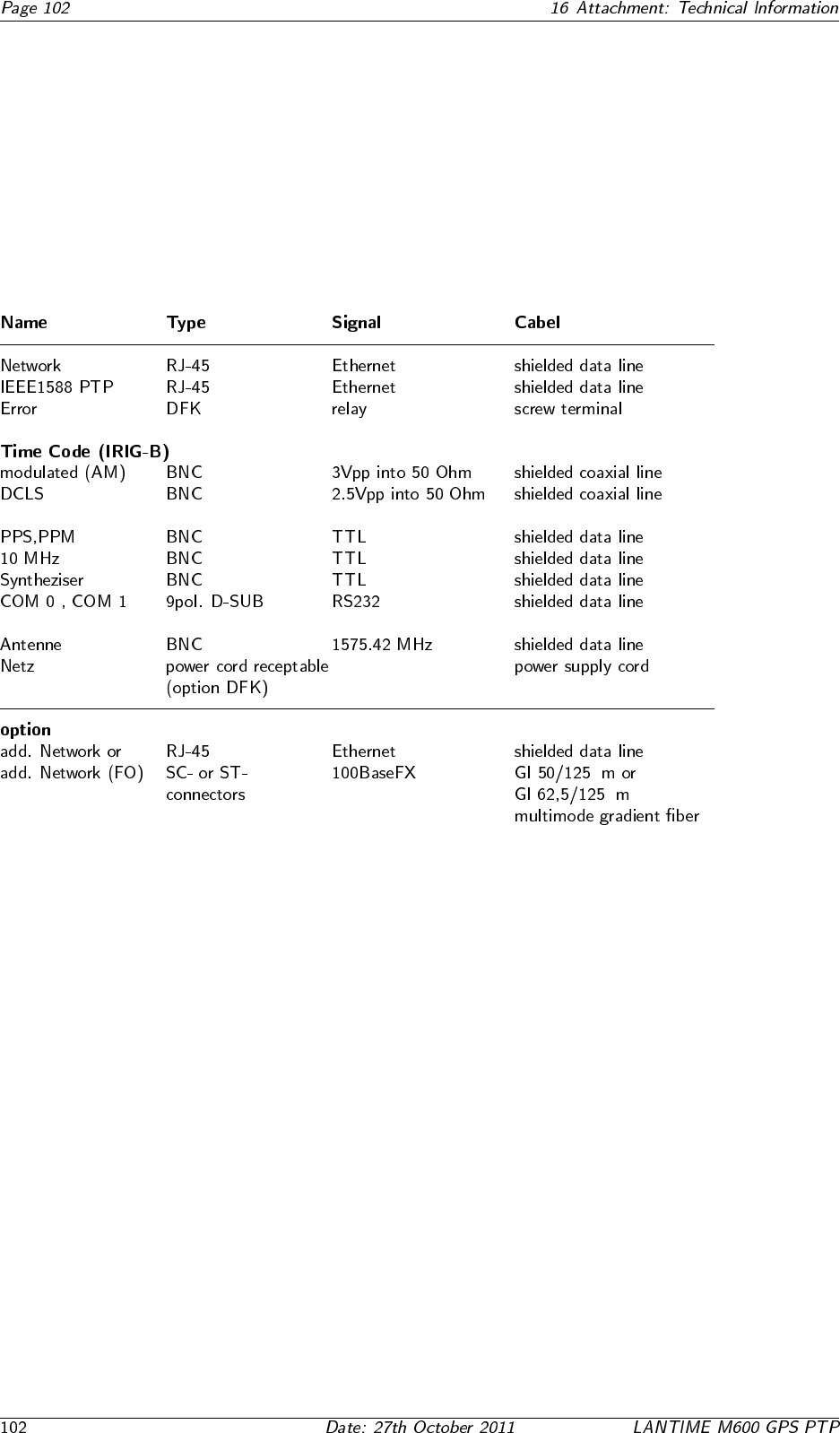
16.4 Rear Panel Connectors
µ
µ
16.5 Connector Assignments
1
6
5
9
TxD1_OUT
RxD1_IN
GND -
COM1
1
6
5
9
TxD0_OUT
RxD0_IN
GND -
COM0
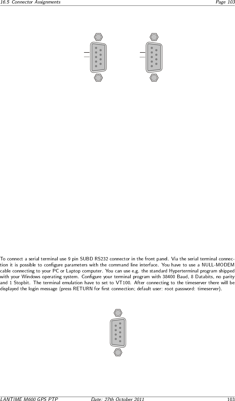
16.6 TERMINAL (Console)
RI_IN-
DSR_IN -
CTS_IN-
1
6
5
9
RTS_OUT-
-DCD_IN
-RXD_IN
-TXD_OUT
-DTR_OUT
-GND
TERM
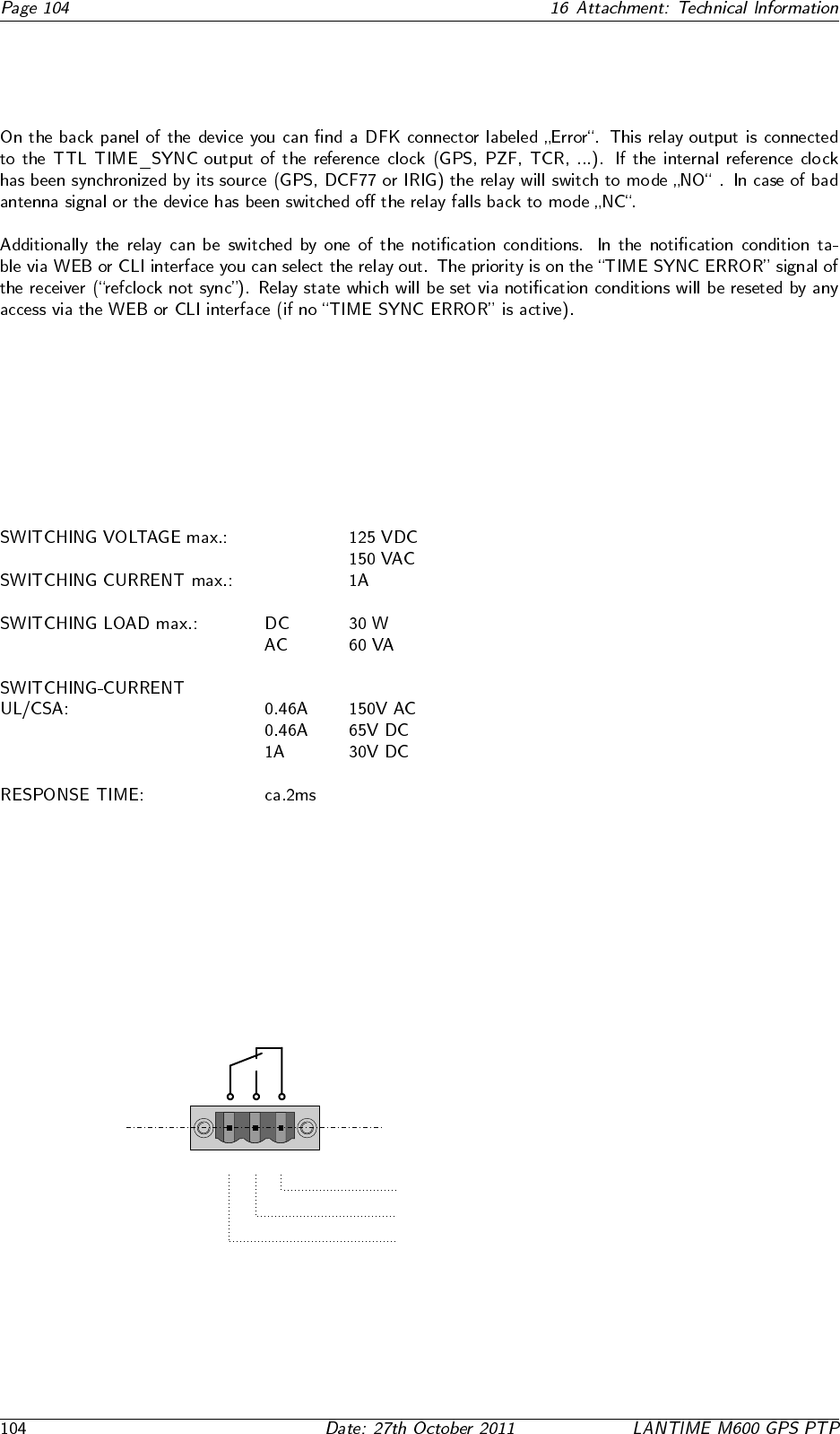
16.7 Error Relay
16.7.1 Technical Specification
Error
CO NO NC
VCC
Error
Normal Operation: CO - NO connected
Error: CO - NC connected
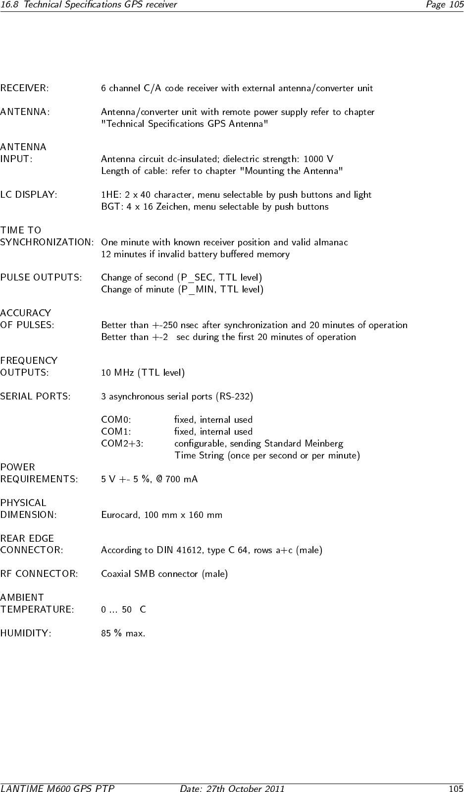
16.8 Technical Specifications GPS receiver
µ
◦
16.8.1 Oscillator specifications
Oscillators available for Meinberg GPS Receivers/Time Servers:
OCXO, TCXO, Rubidium
TCXO OCXO LQ OCXO MQ OCXO HQ OCXO DHQ Rubidium
(only available
for 3U models)
short term stability
(� = 1 sec)
2·10-9 1·10-9 2·10-10 5·10-12 2·10-12 2·10-11
accuracy of PPS
(pulse per sec)
< ±250 ns < ±250 ns < ±100 ns < ±100 ns < ±100 ns < ±100 ns
phase noise 1Hz -60dBc/Hz
10Hz -90dBc/Hz
100Hz -120dBc/Hz
1kHz -130dBc/Hz
1Hz -60dBc/Hz
10Hz -90dBc/Hz
100Hz -120dBc/Hz
1kHz -130dBc/Hz
1Hz -75dBc/Hz
10Hz -110dBc/Hz
100Hz -130dBc/Hz
1kHz -140dBc/Hz
1Hz < -85dBc/Hz
10Hz < -115dBc/Hz
100Hz < -130dBc/Hz
1kHz < -140dBc/Hz
1Hz < -80dBc/Hz
10Hz < -110dBc/Hz
100Hz < -125dBc/Hz
1kHz < -135dBc/Hz
1Hz -75dBc/Hz
10Hz -89dBc/Hz
100Hz -128dBc/Hz
1kHz -140dBc/Hz
accuracy
free run, one day
±1·10-7
±1Hz (Note1)
±2·10-8
±0.2Hz (Note1)
±1.5·10-9
±15mHz (Note1)
±5·10-10
±5mHz (Note1)
±1·10-10
±1mHz (Note1)
±2·10-11
±0.2mHz (Note1)
accuracy,
free run, 1 year
±1·10-6
±10Hz (Note1)
±4·10-7
±4Hz (Note1)
±1·10-7
±1Hz (Note1)
±5·10-8
±0.5Hz (Note1)
±1·10-8
±0.1Hz (Note1)
±5·10-10
±5mHz (Note1)
accuracy
GPS-synchronous,
average 24h
±1·10-11 ±1·10-11 ±5·10-12 ±1·10-12 ±1·10-12 ±1·10-12
accuracy of time
free run, 1 day
± 4.3 ms ± 865 µs ± 65 µs ± 22 µs ± 4.5 µs ± 1.1 µs
accuracy of time
free run, 1 year
± 16 s ± 6.3 s ± 1.6 s ± 788 ms ± 158 ms ± 8 ms
temperature
depandant drift
free run
±1·10-6
(-20...70°C)
±2·10-7
(0...60°C)
±5·10-8
(-20...70°C)
±1·10-8
(5...70°C)
±2·10-10
(5...70°C)
±6·10-10
(-25...70°C)
Note 1: The accuracy in Hertz is based on the standard frequency of 10 MHz.
For example: Accuracy of TCXO (free run one day) is ±1·10-7·10MHz = ± 1 HZ
The given values for the accuracy of frequency and �me (not short term accuracy) are only valid for a constant ambient
temperature! A minimum �me of 24 hours of GPS-syncronicity is required before free run starts.
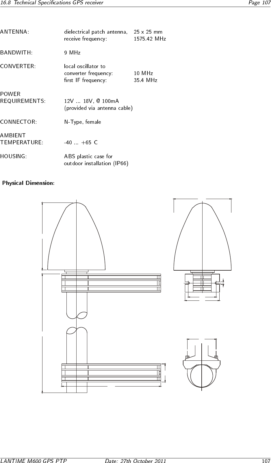
16.8.2 Technical Specifications GPS Antenna
◦
4444
240240
140140
450450
7070
M6M6
180180
6868
8484
66
16.8.3 Signal Description GPS170
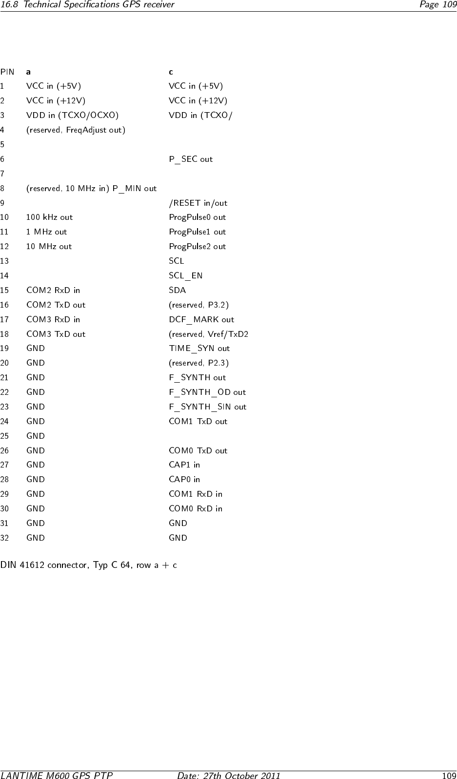
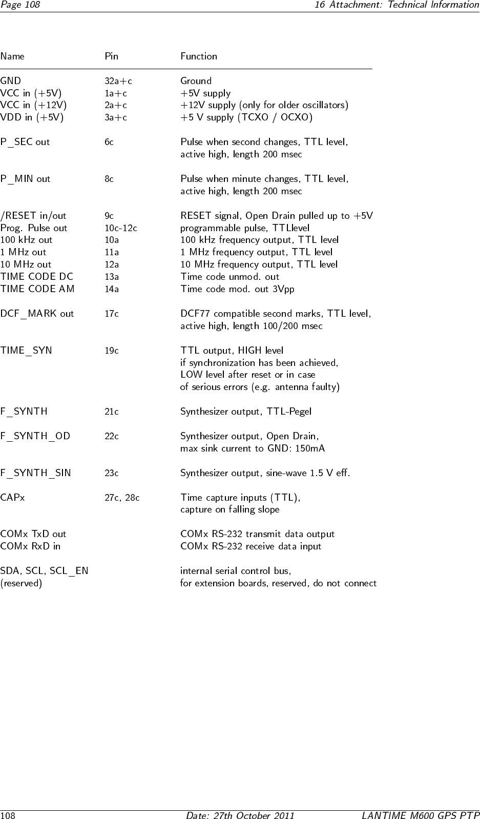
16.8.4 Rear Connector Pin Assignments GPS170
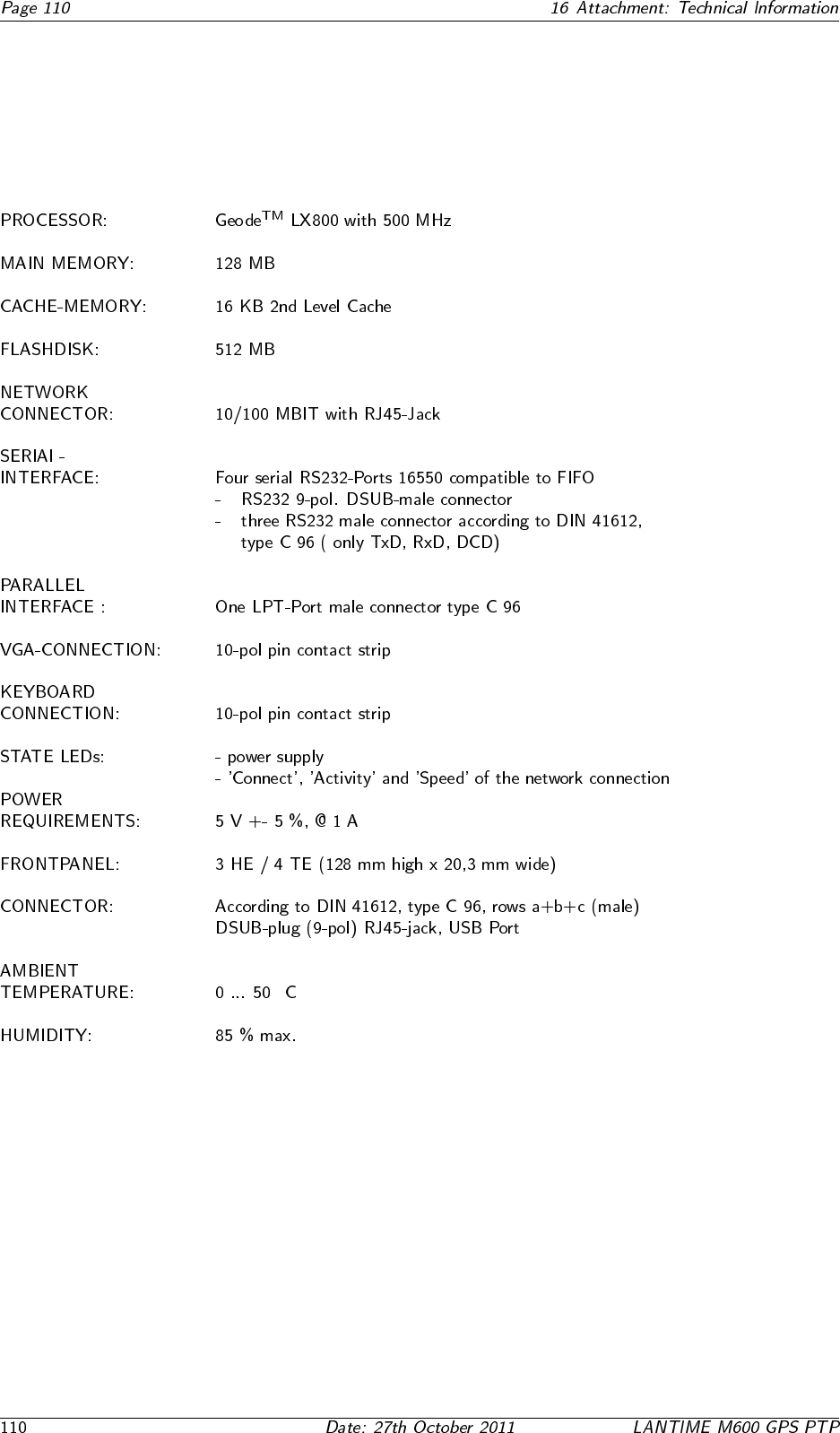
16.9 Technical Specifications LAN CPU
◦
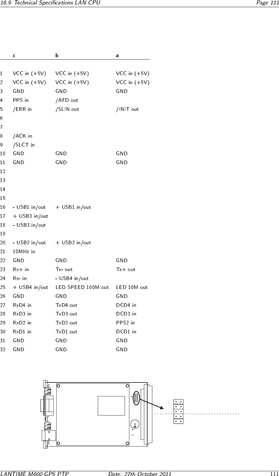
16.9.1 Rear Connector Pin Assignments LAN CPU
16.9.2 VGA, Keyboard Connector Pin Assignments
R
G
B
+5V
KBDAT
HSYNC
VSYNC
GND
GND
KBCLK Tastatur
VGA
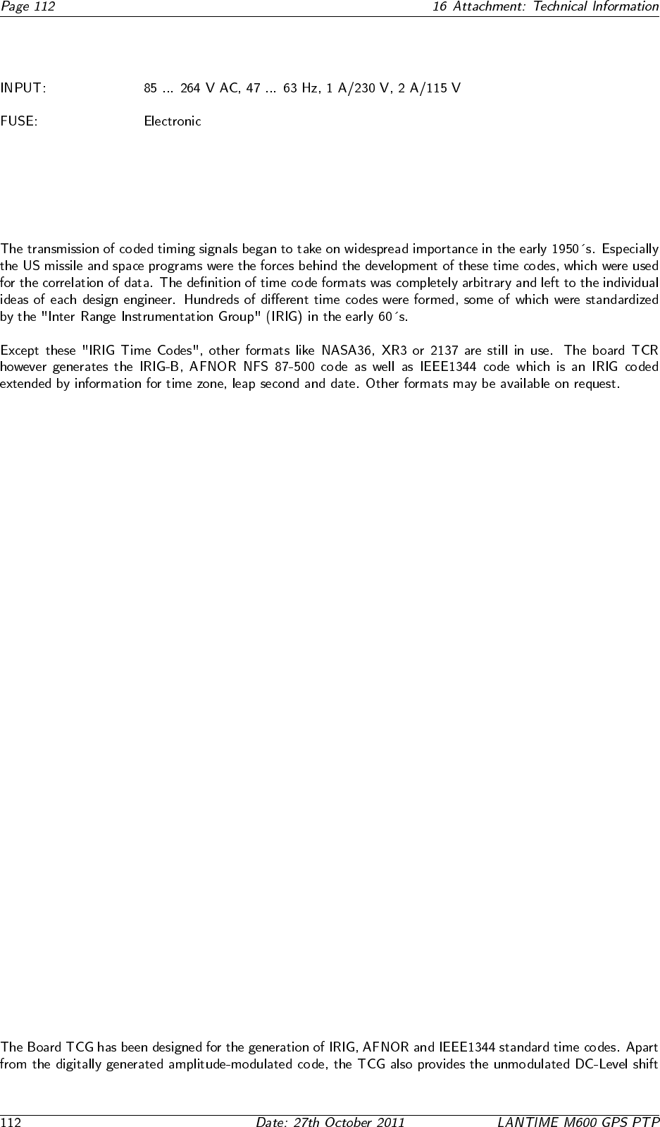
16.10 Technical Specifications Power Supply
16.11 Time Code
16.11.1 Abstract of Time Code
16.11.2 Principle of Operation
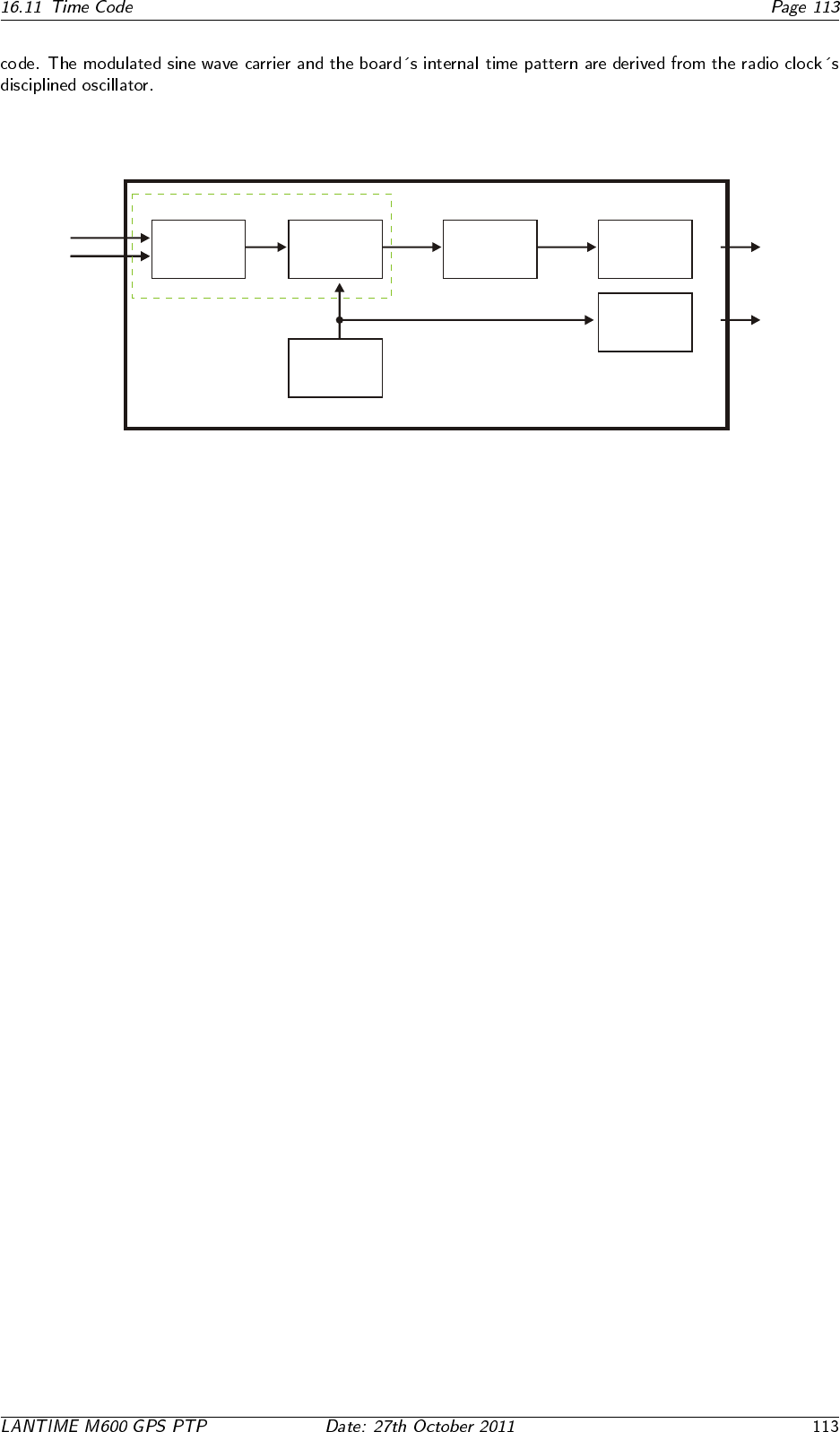
16.11.3 Block Diagram Time Code
10 Mhz
PPS
EPLD
digital
sinewave
generator
modulator D/A converter
microcontroller
timecode
driver
50 Ω
unbalanced
driver
TTL
Time Code AM
Time Code DCLS
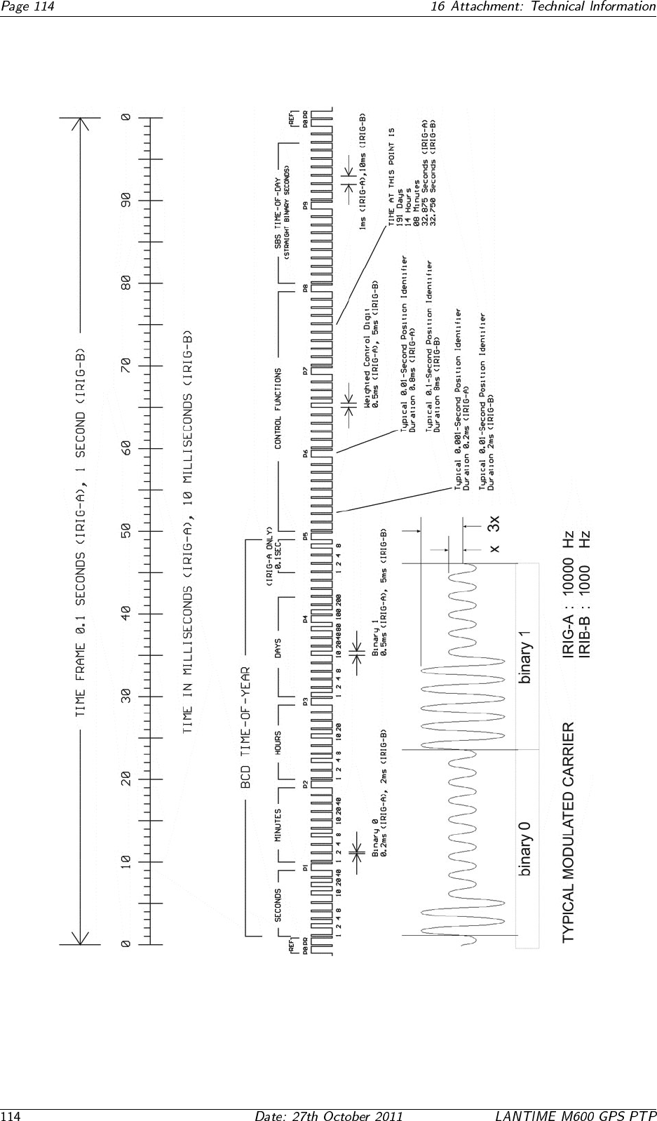
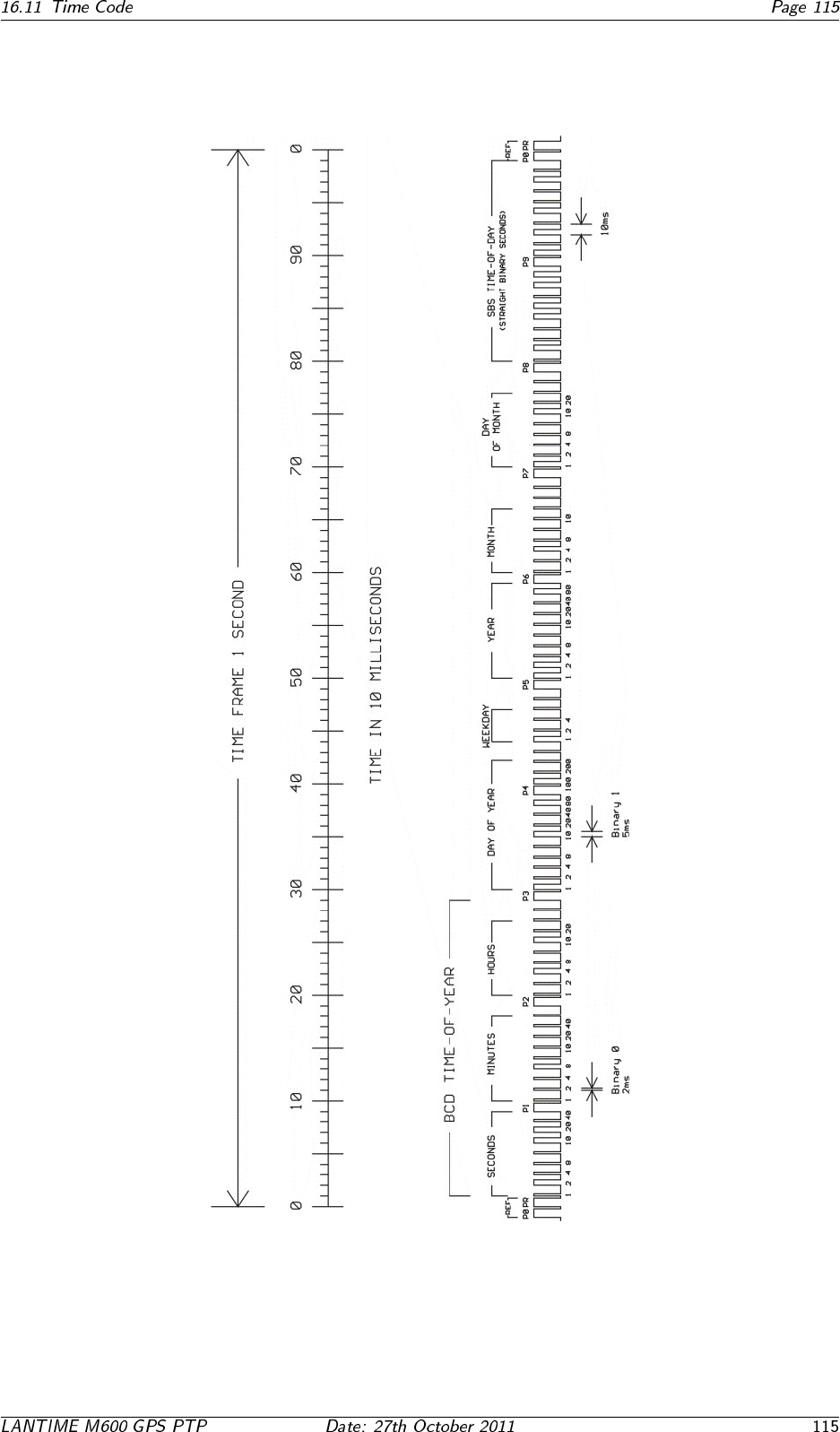
16.11.4 IRIG Standard Format
16.11.5 AFNOR Standard Format
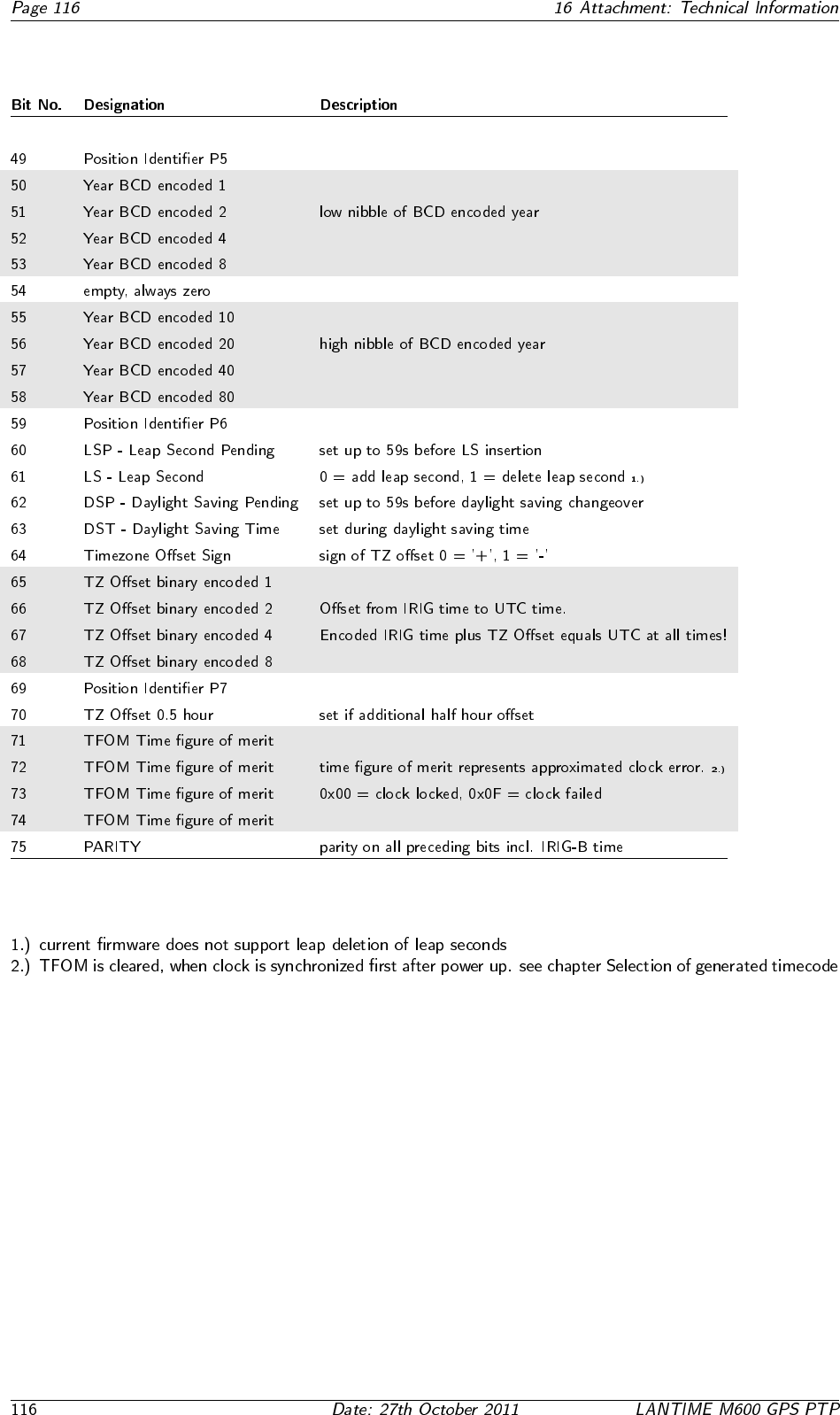
16.11.6 Assignment of CF Segment in IEEE1344 Code
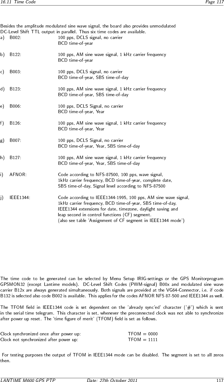
16.11.7 Generated Time Codes
16.11.8 Selection of Generated Time Code
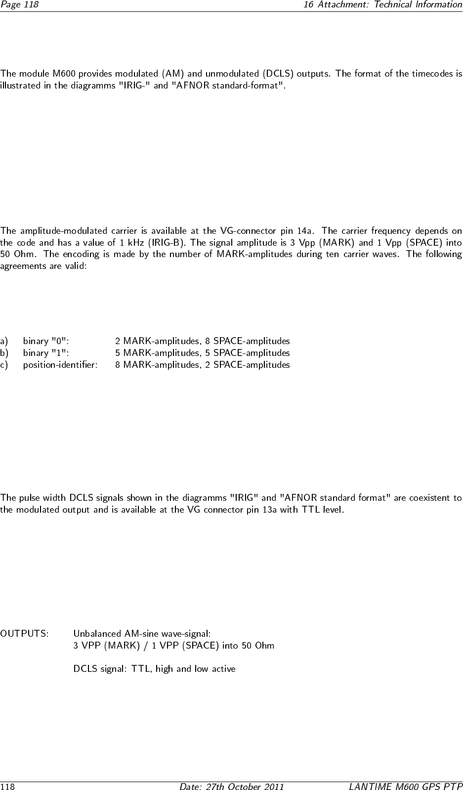
16.11.9 Outputs
AM - Sine Wave Output
DCLS Output
16.11.10 Technical Data
16.12 Time Strings
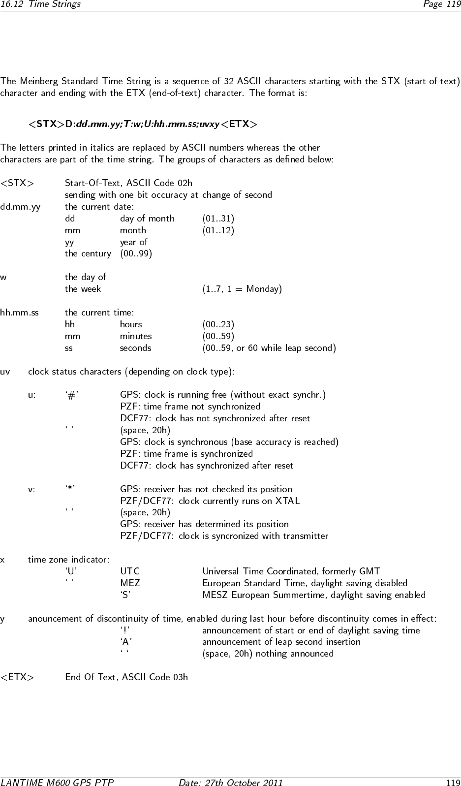
16.12.1 Format of the Meinberg Standard Time String

16.12.2 Format of the Meinberg Capture String
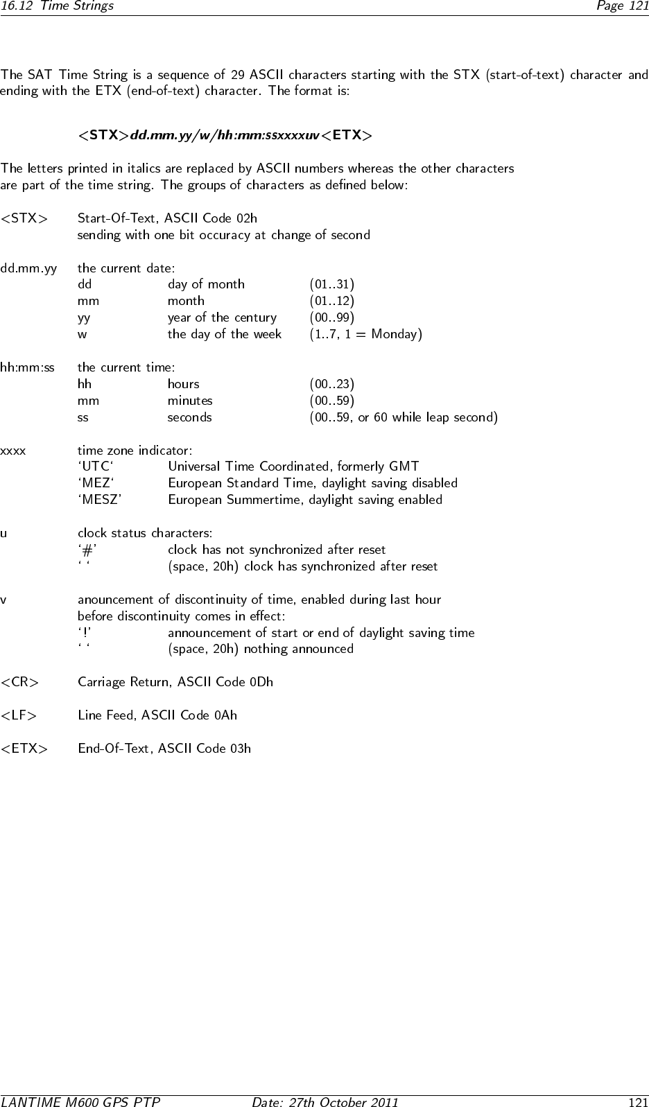
16.12.3 Format of the SAT Time String
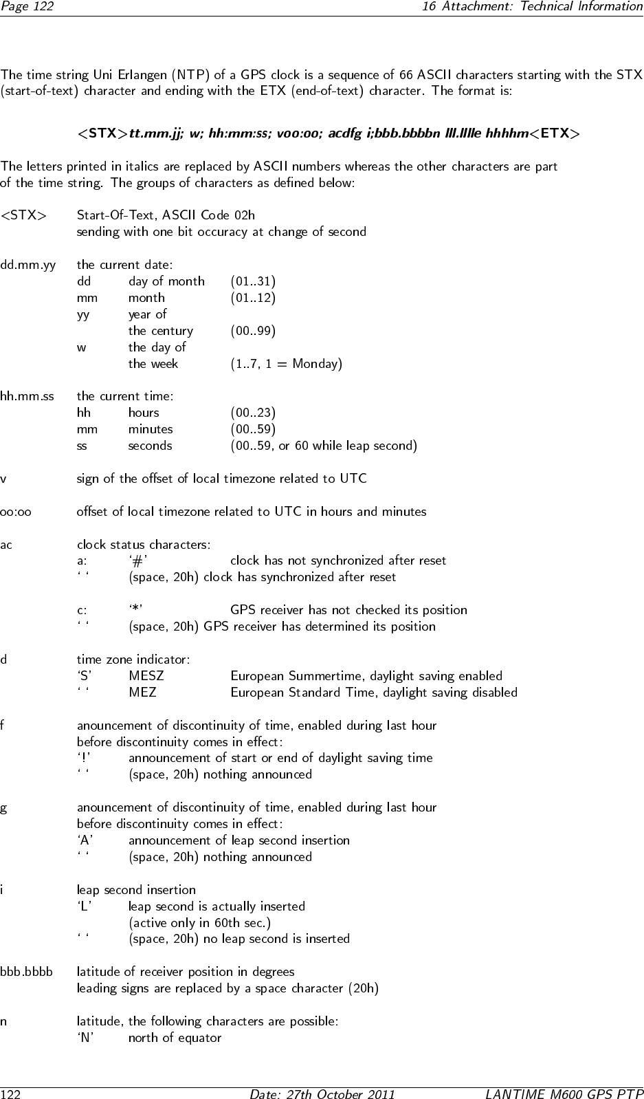
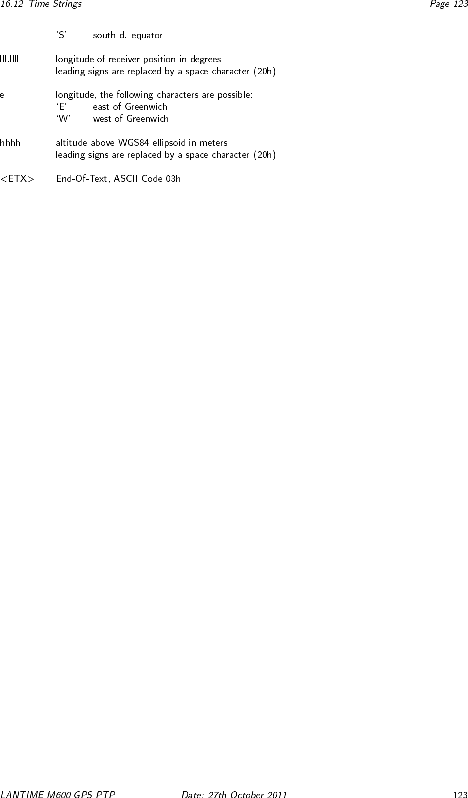
16.12.4 Format of the Uni Erlangen String (NTP)
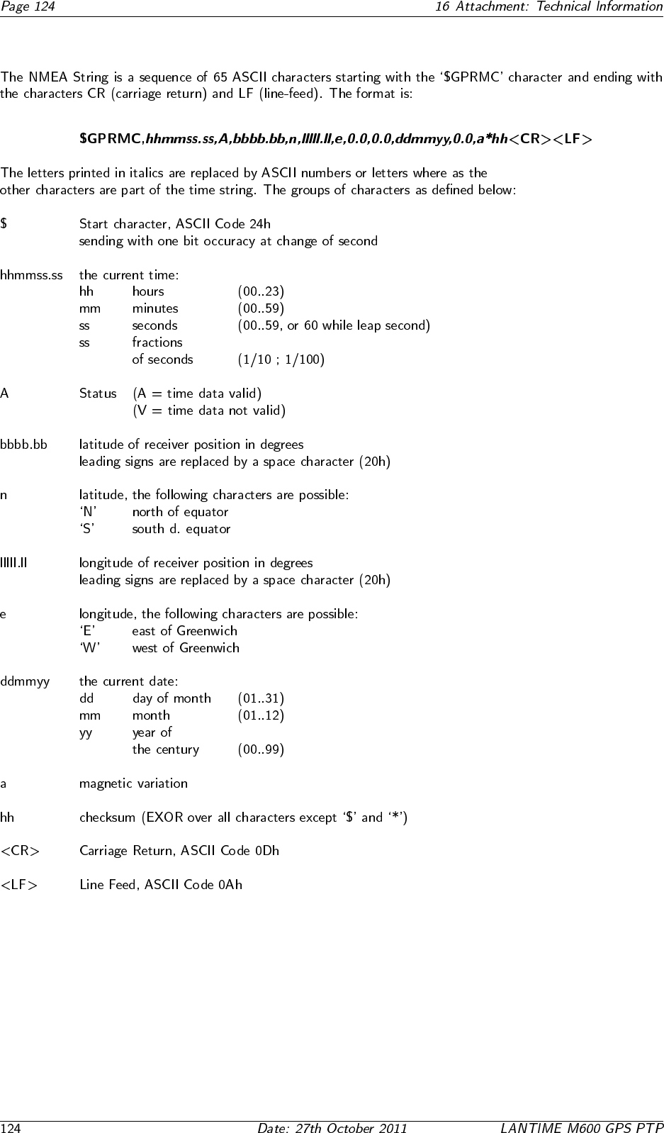
16.12.5 Format of the NMEA 0183 String (RMC)
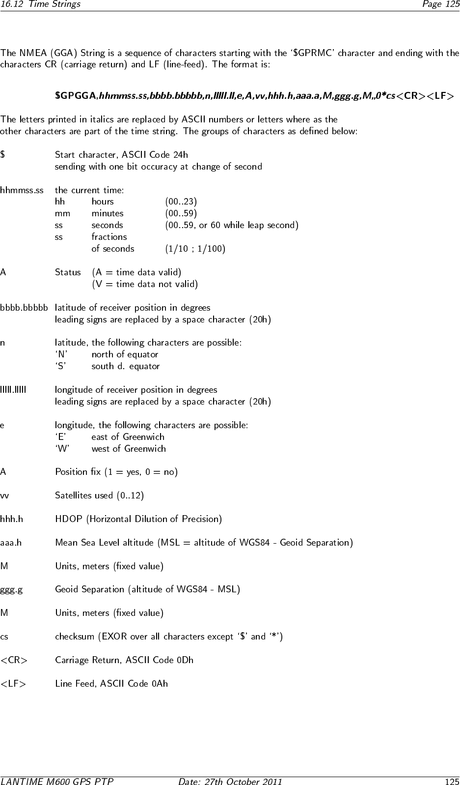
16.12.6 Format of the NMEA 0183 String (GGA)
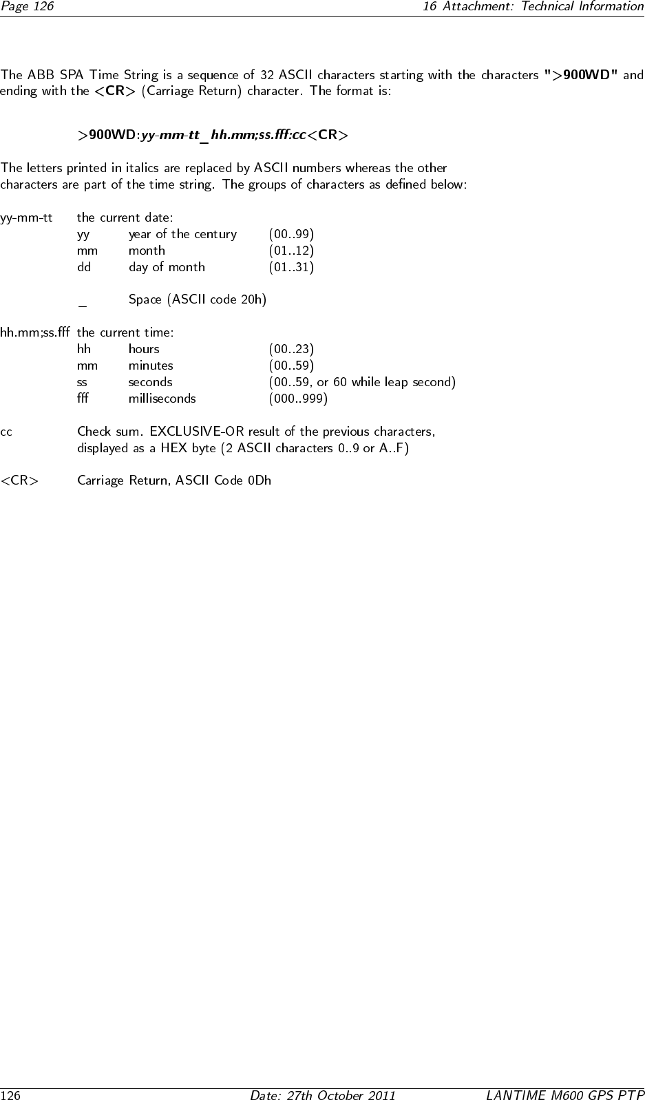
16.12.7 Format of the ABB SPA Time String
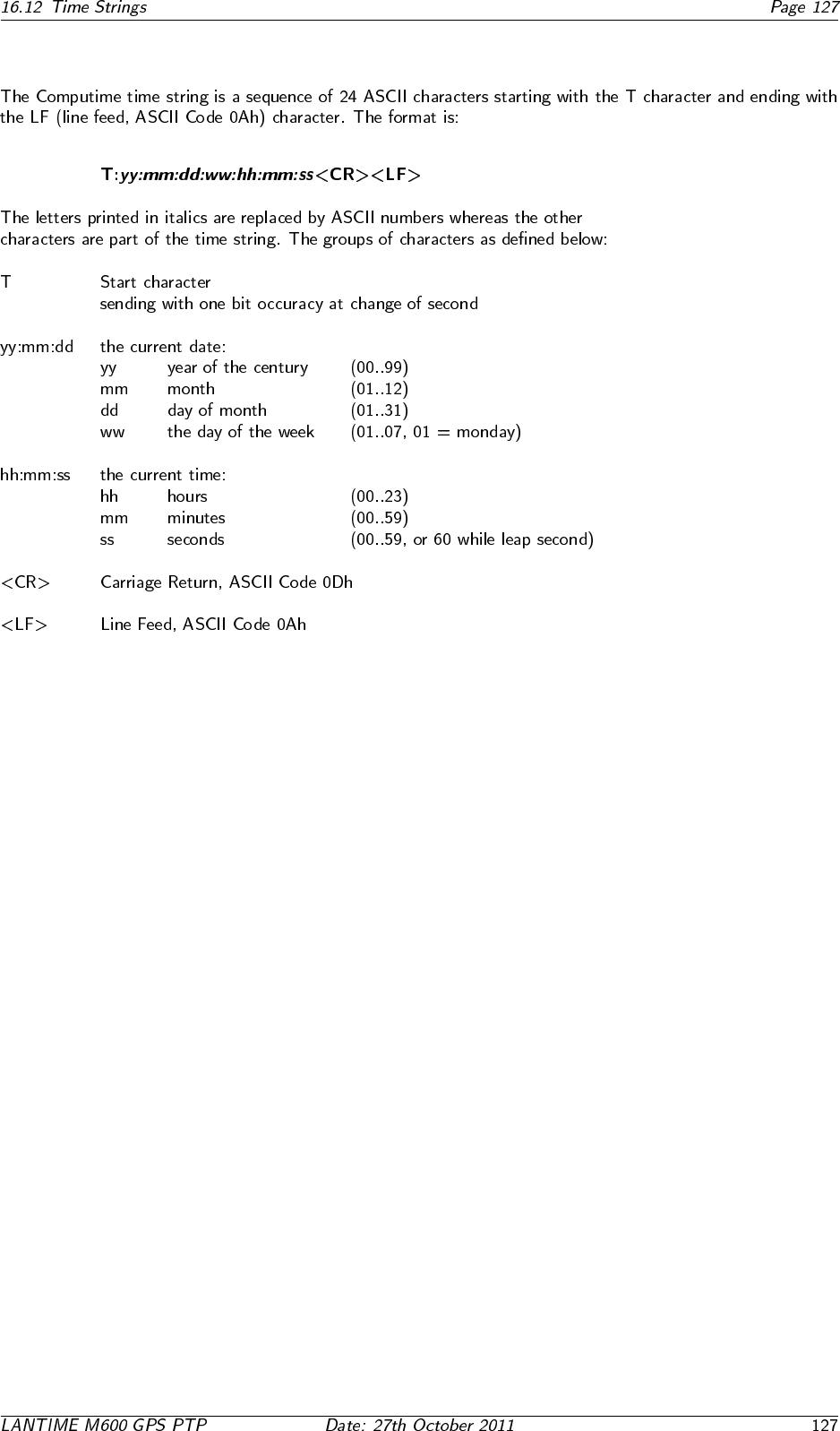
16.12.8 Format of the Computime Time String
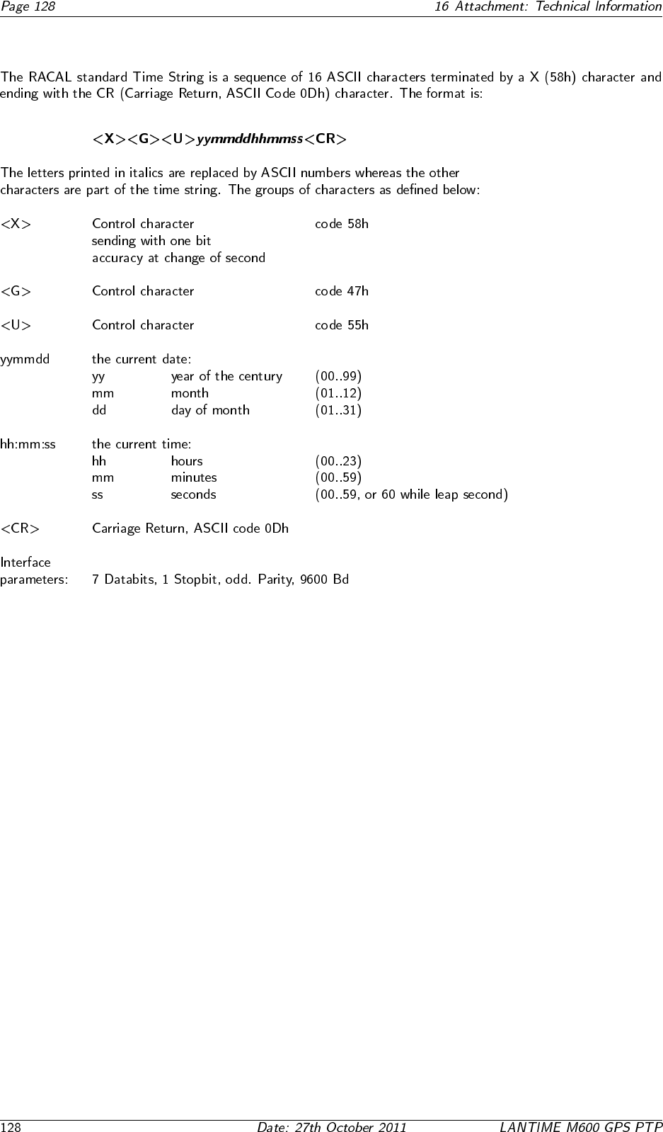
16.12.9 Format of the RACAL standard Time String
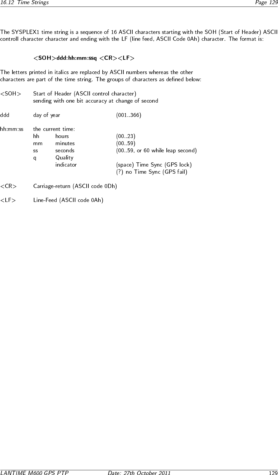
16.12.10 Format of the SYSPLEX-1 Time String
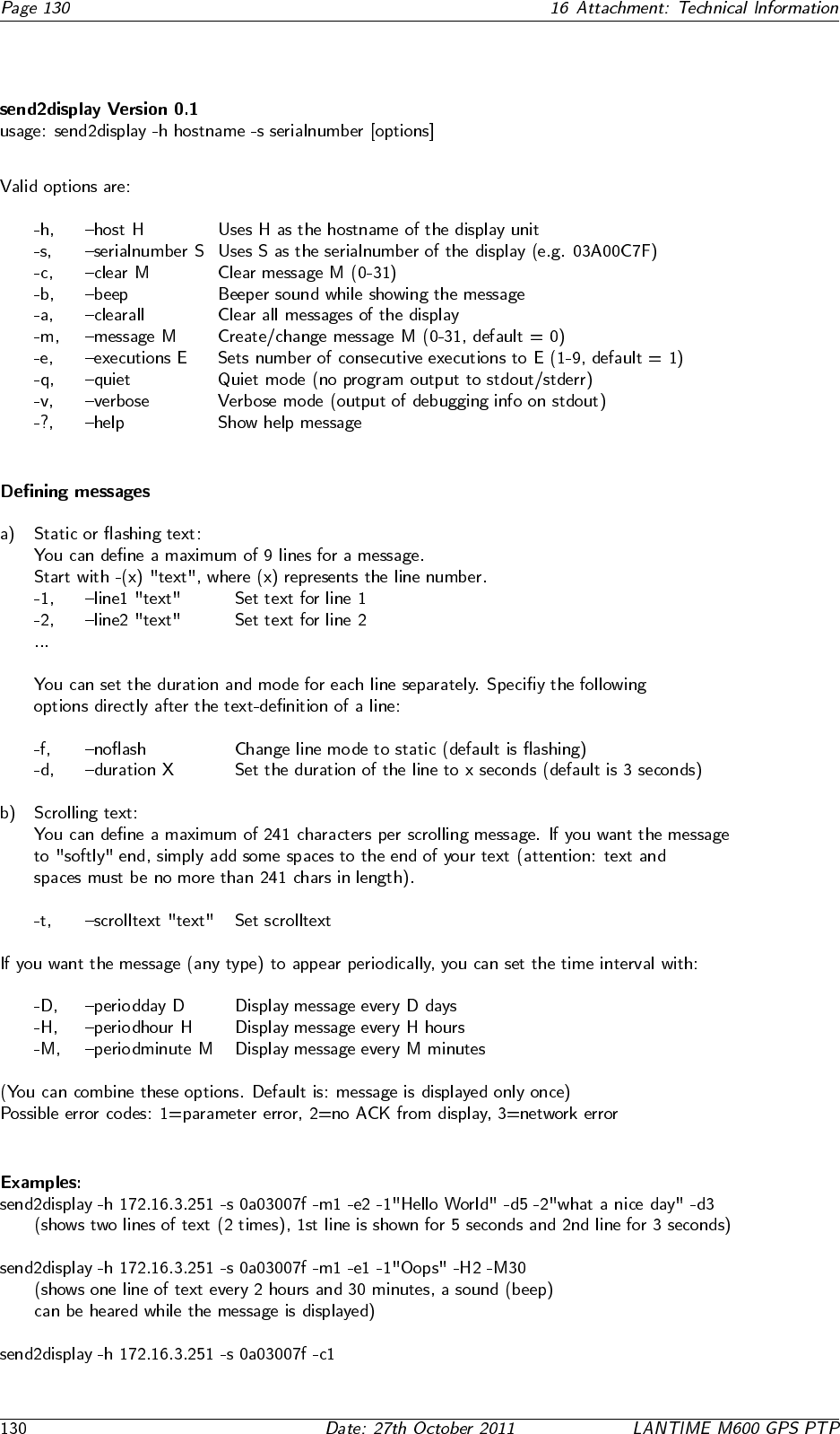
16.13 Manual VP100/NET Display configuration
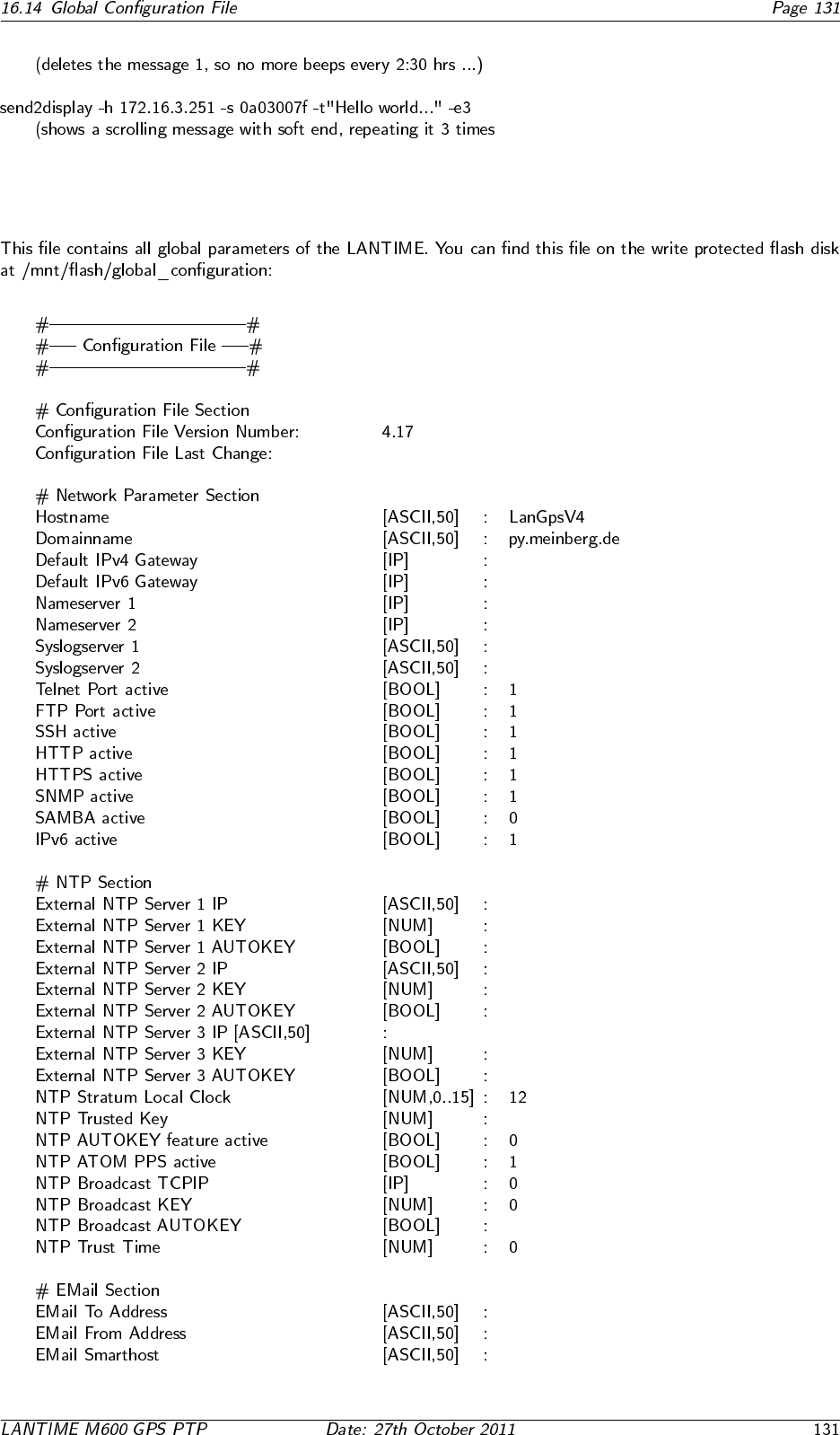
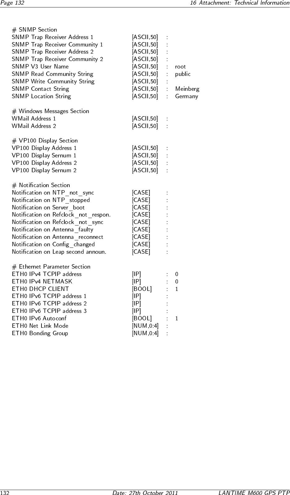
16.14 Global Configuration File
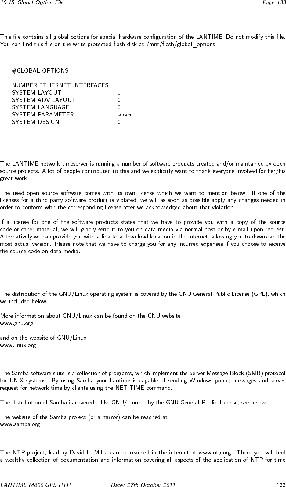
16.15 Global Option File
16.16 Third party software
16.16.1 Operating System GNU/Linux
16.16.2 Samba
16.16.3 Network Time Protocol Version 4 (NTP)
16.16.4 mini httpd
16.16.5 GNU General Public License (GPL)


16.17 Reference

Konformitätserklärung
Declaration of Conformity
Hersteller Meinberg Funkuhren GmbH & Co. KG
Manufacturer Lange Wand 9
D-31812 Bad Pyrmont
erklärt in alleiniger Verantwortung, daß das Produkt
declares under its sole responsibility, that the product
Produktbezeichnung PTP Timeserver
Product Name
Modell / Typ Lantime M600/GPS/PTP
Model Designation
auf das sich diese Erklärung bezieht, mit den folgenden Normen übereinstimmt
to which this declaration relates is in conformity with the following standards
EN55022:1998, Class B Grenzwerte und Meßverfahren für Funkstörungen von
(+A1:2000 +A2:2003) informationstechnischen Einrichtungen
Limits and methods of measurement of radio interference characteristics of
information technology equipment
EN55024:1998 Grenzwerte und Meßverfahren für Störfestigkeit von
(+A1:2001 +A2:2003) informationstechnischen Einrichtungen
Limits and methods of measurement of Immunity characteristics of
information technology equipment
EN 60950-1:2001 Sicherheit von Einrichtungen der Informationstechnik
(+A11:2004) Safety of information technology equipment
gemäß den Richtlinien 2004/108/EG (Elektromagnetische Verträglichkeit), 2006/95/EG (Nieder-
spannungsrichtlinie) und 93/68/EWG (CE Kennzeichnung) sowie deren Ergänzungen.
following the provisions of the directives 2004/108/EC (electromagnetic compatibility), 2006/95/EC (low voltage directive) and
93/68/EEC (CE marking) and its amendments.
Bad Pyrmont, den 03.07.2009
