Magictruck_main Magictruck
User Manual: magictruck
Open the PDF directly: View PDF ![]() .
.
Page Count: 105 [warning: Documents this large are best viewed by clicking the View PDF Link!]

1st PRINTING JAN 99
MANUAL NO. 4201-6447-01
OWNER’S MANUALOWNER’S MANUAL
OWNER’S MANUALOWNER’S MANUAL
OWNER’S MANUAL
SEGA ENTERPRISES, INC. USA

Warranty
Your new Sega Product is covered for a period of 90 days from the date of shipment. This certifies
that the Printed Circuit Boards, Power Supplies and Monitor are to be free of defects in workman-
ship or materials under normal operating conditions. This also certifies that all Interactive Control
Assemblies are to be free from defects in workmanship and materials under normal operating condi-
tions. No other product in this machine is hereby covered.
Sellers sole liability in the event a warranted part described above fails shall be, at its option, to
replace or repair the defective part during the warranty period. For Warranty claims, contact your
Sega Distributor.
Should the Seller determine, by inspection that the product was caused by Accident, Misuse, Ne-
glect, Alteration, Improper Repair, Installation or Testing, the warranty offered will be null and void.
Under no circumstances is the Seller responsible for any loss of profits, loss of use, or other dam-
ages.
This shall be the exclusive written Warranty of the original purchaser expressed in lieu of all other
warranties expressed or implied. Under no circumstance shall it extend beyond the period of time
listed above.
VISIT OUR WEBSITE!

INTRODUCTION OF THE OWNERS MANUAL
GENERAL PRECAUTIONS
1. NAME OF PARTS
2. ACCESSORIES
3. ASSEMBLY AND INSTALLATION
4. PRECAUTIONS TO BE HEEDED WHEN MOVING MACHINE
5. CONTENTS OF GAME
6. EXPLANATION OF TEST AND DATA DISPLAY
6-1 SWITCH UNIT AND COIN METER
6-2 TEST MODE
6-3 MEMORY TEST
6-4 INPUT TEST
6-5 OUTPUT TEST
6-6 SOUND TEST
6-7 C.R.T. TEST
6-8 GAME ASSIGNMENTS
6-9 COIN ASSIGNMENTS
6-10 DEVICE SETTINGS
6-11 BOOKKEEPING
6-12 BACKUP DATA CLEAR
7. CONTROLLER UNITS (LEVERS AND FOOT SW)
7-1 ADJUSTING/REPLACING THE VOLUME
7-2 GREASING
7-3 REPLACING THE STOPPER
7-4 REPLACING THE SHOCK ABSORBER
7-5 REPLACING THE FOOT SW
8. COIN SELECTOR
9. PROJECTOR
9-1 CLEANING THE SCREEN
9-2 MITSUBISHI PROJECTOR
9-3 TOSHIBA PROJECTOR
10. REPLACING THE LAMPS
11. PERIODIC INSPECTION TABLE
12. TROUBLESHOOTING
13. GAME BOARD
13-1 REMOVING THE GAME BOARD
13-2 COMPOSITION OF THE GAME BOARD
14. DESIGN RELATED PARTS
15. PARTS LIST
16. WIRING DIAGRAMS
1
2~4
5
6~7
8~16
17
18~26
27~41
28
29
30
31
31
32
33
34
35~38
39
40
41
42~48
42~44
44
45
46~47
48
49~51
52~65
52
53~54
55~65
66
67
68
69~70
69
70
71~72
73~100
XXX
TABLE OF CONTENTS

1
SEGA ENTERPRISES, LTD., has for more than 30 years been supplying various innovative and
popular amusement products to the world market. This Owners Manual is intended to provide
detailed descriptions together with all the necessary installation, game settings and parts ordering
information related to the MAGICAL TRUCK ADVENTURE, a new SEGA product.
This manual is intended for those who have knowledge of electricity and technical expertise, espe-
cially in ICs, CRTs, microprocessors, and circuit boards. Read this manual carefully to acquire
sufficient knowledge before working on the machine. Should there be a malfunction, non-technical
personnel should under no circumstances touch the interior system. Should the need arise, contact
our main office, or the closest branch office listed below.
SEGA ENTERPRISES, INC. (USA)
Customer Service
45133 Industrial Drive
Fremont, CA 94538
Phone 650-632-7580
Fax 650-632-7594
7:30 am - 4:00 pm, Pacific Standard Time
Monday thru Friday
INTRODUCTION OF THE OWNERS MANUAL
SPECIFICATIONS
Installation space: 95.3 in.(D) x 46.1 in.(W)
Height: 88.4 in.
Weight: Approx. 816 lbs.
Power maximum current: 4.9 Amps (AC 120V 60 Hz AREA)
MONITOR: 50” PROJECTION DISPLAY

2
General Precautions
Follow Instructions: All operating and use instructions should be followed.
Attachments: Do not use attachments not recommended by the product manufacturer as they may cause hazards.
Accessories: Do not place this product on an unstable cart, stand, tripod, bracket, or table. The product may fall,
causing serious injury to a child or adult, and serious damage to the product. Use only with a cart, stand, tripod, bracket, or
table recommended by the manufacturer, or sold with the product. Any mounting of the product should follow the
manufacturer’s instructions, and should use only mounting accessories recommended by the manufacturer.
Moving the Product: This product should be moved with care. Quick stops, excessive force, and uneven surfaces
may cause the product to overturn.
Ventilation: Slots and openings in the cabinet are provided for ventilation, to ensure reliable operation of the product
and to protect it from overheating; these openings must not be blocked or covered. The openings should never be blocked
by placing the product in a built-in installation such as a bookcase or rack unless proper ventilation is provided or the
manufacturer’s instructions have been adhered to.
Power Sources: This product should be operated only from the type of power source indicated on the marking label.
If you are not sure of the type of power supply to your location, consult your local power company. For products intended
to operate from battery power or other sources, refer to the operating instructions.
Grounding or Polarization: This product is equipped with a three-wire grounding-type plug, a plug having a third
(grounding) pin. This plug will only fit into a grounding-type power outlet. This is a safety feature. If you are unable to
insert the plug into the outlet, contact your electrician to replace your obsolete outlet. Do not defeat the safety purpose of the
grounding-type plug.
Power Cord Protection: Power-supply cords should be routed so that they are not likely to be walked on or pinched
by items placed upon or against them, paying particular attention to cords at plugs, convenience receptacles, and the point
where they exit from the product.
Overloading: Do not overload wall outlets, extension cords, or integral convenience receptacles as this can result in
a risk of fire or electric shock.
Object and Liquid Entry: Never push objects of any kind into this product through openings as they may touch
dangerous voltage points or short-out parts that could result in a fire or electric shock. Never spill liquid of any kind on the
product.
Servicing: Do not attempt to service this product yourself as opening or removing covers may expose you to danger-
ous voltage or other hazards. Refer all servicing to qualified service personnel.
Damage Requiring Service: Unplug this product from the wall outlet and refer servicing to qualified service person-
nel under the following conditions:
a) If the power cord or plug is damaged;
b) If liquid has been spilled, or objects have fallen into the product;
c) If the product has been exposed to rain or water;
d) If the product does not operate normally when following the operating instructions. Adjust only those controls that
are explained in the operating instructions. An improper adjustment of other controls may result in damage and will
often require extensive work by a qualified technician to restore the product to its normal operation;
e) If the product has been dropped or damaged in any way;
f) When the product exhibits a distinct change in performance; this indicates a need for service.
Replacement Parts: When replacement parts are required, be sure the service technician has used replacements parts
specified by the manufacturer or that have the same characteristics as the original part. Unauthorized substitutions may
result in fire, electric shock, or other hazards.

3
Safety Check: Upon completion of any service or repairs to this product, ask the service technician to perform safety
checks to determine that the product is in proper operating condition.
Heat: The product should be situated away from heat sources such as radiators, heat registers, stoves, or other prod-
ucts (including amplifiers) that produce heat.
Lithium Battery- Dispose of batteries only in accordance with the battery manufacturer’s recommen-
dations. Do not dispose in an open flame condition, since the battery may explode.
Cleaning: When cleaning the monitor glass, use water or glass cleaner and a soft cloth. Do not apply chemicals such
as benzine, thinner, etc.
Location: This an indoor game machine, DO NOT install it outside. To ensure proper usage, avoid installing indoors
in the places mentioned below:
• Places subject to rain/water leakage, or condensation due to humidity;
• In close proximity to a potential wet area;
• Locations receiving direct sunlight;
• Places close to heating units or hot air;
•In the vicinity of highly inflammable/volatile chemicals or hazardous matter;
• On sloped surfaces;
• In the vicinity of emergency response facilities such as fire exits and fire extinguishers;
• Places subject to any type of violent impact;
• Dusty places.
INSTALLATION PRECAUTIONS
• Verify the amperage of the branch circuit outlet before plugging in the power plug. Do not over-
load the circuit.
• Avoid using an extension cord. If one is required, use an extension cord of type SJT, 16/3 AWG
rated min. 120 VAC, 7A.
• Moving this unit requires a minimum clearance (of doors, etc.) of 32” (W) by 77” (H).
• For the operation of this machine, secure a minimum area of 32” (W) by 42”(D).
REGULATORY APPROVALS
This game has been tested and found to comply with the Federal Communications Commission Rules.
This device complies with Part 15 of the FCC Rules. Operation is subject to the following two conditions: (1) This
device may not cause harmful interference, and (2) this device must accept any interference received, including interference
that may cause undesired operation.
This game has been tested and listed by Underwriters Laboratories, Inc., to ANSI/UL22.
LISTED
UL
®
5K92
AMUSEMENT MACHINE

4
OPERATING PRECAUTIONS
In order to avoid accidents, check the following before starting the operation:
Check if all the adjusters are in contact with the service. If they are not, the cabinet can move
and cause an accident.
Do not put any heavy item on this product. Placing any heavy item on this product can cause
a falling down accident or parts damage.
Do not climb on the product. Climbing on the product can result in falling down accidents.
To avoid electric shock ensure door and cover parts are not damaged or omitted. Alos do not
put the following items ont eh periphery of the product.
Flower vases, flower pots, cups, water tanks, cosmetics, and resceptacles/containers/vessels
containing chemicals and water.
Keep fingers and extranous matter from openings of the product or small openings in or
around the doors.
To avoid injury and accidents, those who fall under the following catagories are not
allowed to play the game.:
Those who need assistance or apparatus while walking.
Those who have high blood pressure or a heart problem.
Those who experience, muscle convulsions or loss of consciousness when playing
video games, etc.
Intoxicated persons.
Pregnant women or those with the likelihood of pregnancy.
Person susceptable to motion sickness.
Those under 140 cm (~54-55 inches)
Those wearing high heels.
In addition please keep small children away from the game during operation to prevent them
from bumping their head on the control levers.
5
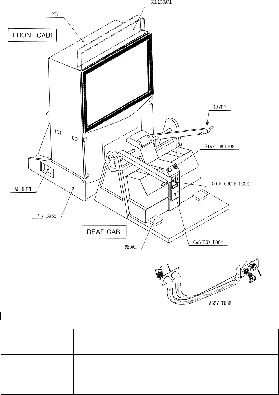
1. NAME OF PARTS
GAME SPECIFICATIONS
BILLBOARD
WIDTH DEPTHHEIGHT WEIGHT
~11 LBS.
46” X 88.5” X 95.5”
45” X 45.5” X 51”
43.5” X 19.5” X 17”
~418 LBS.
~950 LBS.
~825 LBS.
REAR CABINET
DURING SHIPPING
WHEN ASSEMBLED
PTV 45” X 62” X 21” ~243 LBS.
all measurements are rounded up to the nearest 0.5”
PTV BASE 46” X 31” X 40” ~153 LBS.
6
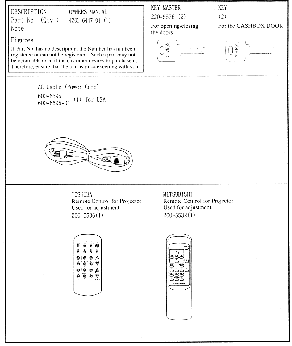
2. ACCESSORIES
7
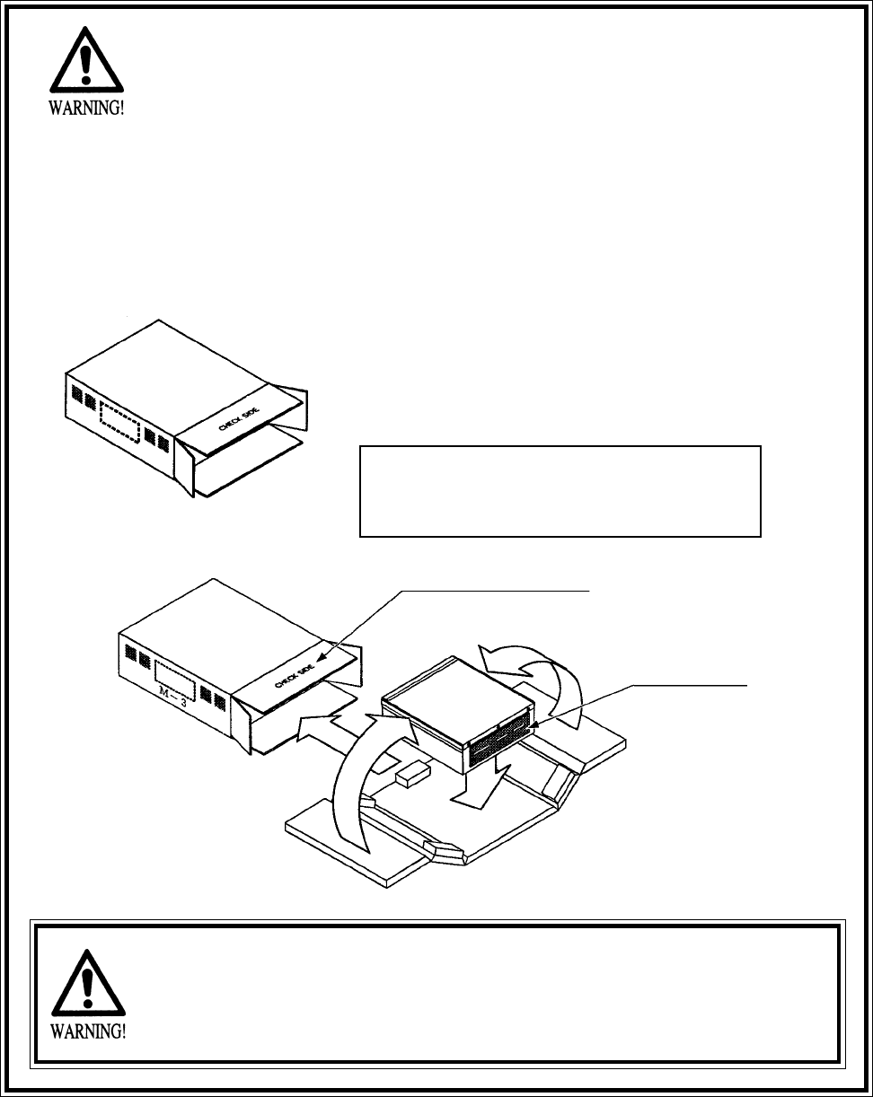
“CHECK SIDE” Display
FILTER BOARD
CARTON BOX
601-8928 (1)
Used for transporting the GAME BOARD.
{SUPPLIED WITH YOUR GAME}
DO NOT SHIP GAME BOARD WITHOUT
THIS BOX AS IT MAY DAMAGE THE GAME
BOARD AND VOID YOUR WARRANTY.
!!NEVER SHIP MODEL 3 GAME BOARDS
!!NEVER SHIP MODEL 3 GAME BOARDS
OUTSIDE OF CAGE!!
OUTSIDE OF CAGE!!
THE SHIPMENT METHOD DESCRIBED BELOW ONLY
APPLIES TO ‘MODEL 3’ BOARDS CONTAINED IN THE
FOLLOWING GAMES:
NO OTHER GAMES BOARDS ARE TO BE SHIPPED IN THE CAGE AS
THEY MAY BE DAMAGED BEYOND REPAIR. PLEASE SHIP THEM
WITHOUT CAGE PROPERLY PROTECTED DURING SHIPPING.
LOST WORLD, VIRTUA FIGHTER 3, SUPER GT, SEGA BASS FISHING, STRIKER 2
HARLEY DAVIDSON, RALLY 2, DAYTONA 2, DIRT DEVILS, THE OCEAN HUNTER,
STAR WARS TRILOGY, MAGIC TRUCK ADVENTURE
8
3. ASSEMBLING AND INSTALLATION
Note that the tools such as a phillips screwdriver and wrench for M16 hexagon bolt w/24 mm width
across flats are required for the assembly work.
When carrying out the assembly work, follow the procedure in the following 4-item sequence:
ASSEMBLING OF THE FRONT CABINET
WIRING CONNECTION BETWEEN PTV AND CABINETS
SECURING IN PLACE
Assembling should be performed as per this manual. Since this is a
complex machine, erroneous assembling may cause damage to the
machine, or malfunctioning to occur.
When assembling, be sure to perform work by plural persons.
Depending on the assembly work, there are some cases in which
performing the work by a single person can cause personal injury or
parts damage.
1
2
3
4
ASSEMBLY CHECK
5
POWER SUPPLY
9
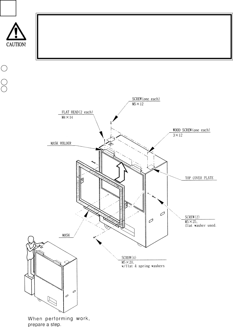
1ASSEMBLING OF PTV
Secure the 2 Top Cover Plates to the PTV ceiling by using one each of the truss screw and wood
screw for each Plate.
Secure the 2 Mask Holders to the PTV with 2 flat head screws for each.
Secure the Mask to the PTV with a total of 6 screws.
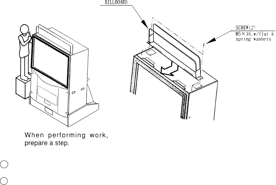
Installing the Billboard by one person is difficult. Be sure to use
plural persons to perform the work safely and accurately.
To perform work safely and securely, be sure to prepare a step
which is in a stable and secure condition. Performing work without
using a step can cause a violent falling down accident.
1
2
3
10
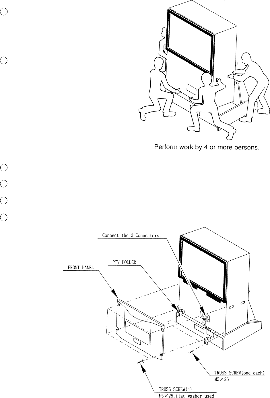
Temporarily fasten the 2 PTV Holders to the PTV Base with the Truss screw for each.
Connect the 2 Wire Connectors of PTV Base to the PTV.
Secure the Front Panel to the front of PTV with 4 truss screws.
Retighten the 2 truss screws whihc temporarily fastened the PTV Holder.
6
7
8
9
4
5
Secure the PTV Base by having the
Adjuster make contact with the surface.
This measure is taken to prevent acci-
dents.
Mount the PTV onto the PTV Base by 4
or more persons.
11
By inserting into the Mask Holder, mount the Billboard to the PTV ceiling.
Fasten with 2 screws.
10
11
12
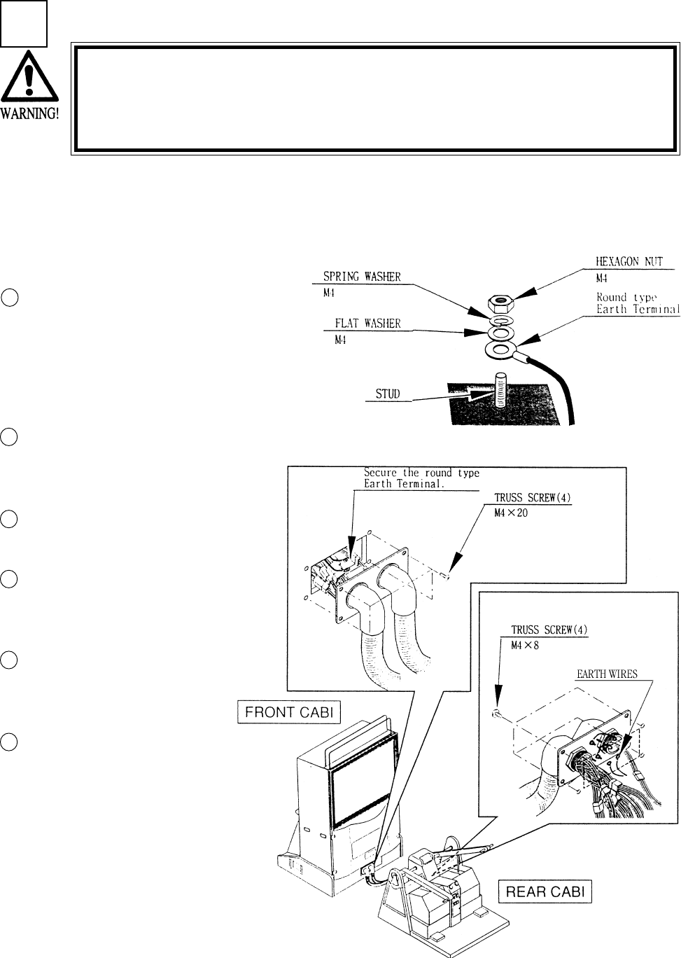
Secure the Earth Wire by fastening the
hexagon nut after installing sequentially in
order of the round type Earth Terminal,
Flat Washer, and Spring Washer to each of
the 2 Studs of the Plate on the side con-
nected to the Front Cabinet.
1
2
3
2WIRING CONNECTIONS BETWEEN PTV AND CABINETS
Be sure to connect connectors securely. Incomplete connector con-
nection can cause electric shock accident.
Use care so as not to damage wirings. Damaged wiring can cause
electric shock or short circuit accident.
4
Connect ASSY TUBE between Front and Rear Cabinets. Either side of the ASSY TUBE can be
connected to Front Cabinet. Each ASSY TUBE Plates at both ends has 4 Studs which secure
Earthwires. the Earth wires which come from the corresponding cabinet with the remaining Studs.
Each Stud secures the Earth Wire.
Connect Connectors which have
identical color and number of
pins.
Secure the Plate with 4 truss
screws.
Secure the Earth Wires to the 2
Studs of the Rear side Plate
similarly as in the Front side.
Connect Connectors which have
identical color and number of
pins.
Secure the Plate with 4 truss
screws.
5
6
13
SECURING IN PLACE (ADJUSTER ADJUSTMENT)
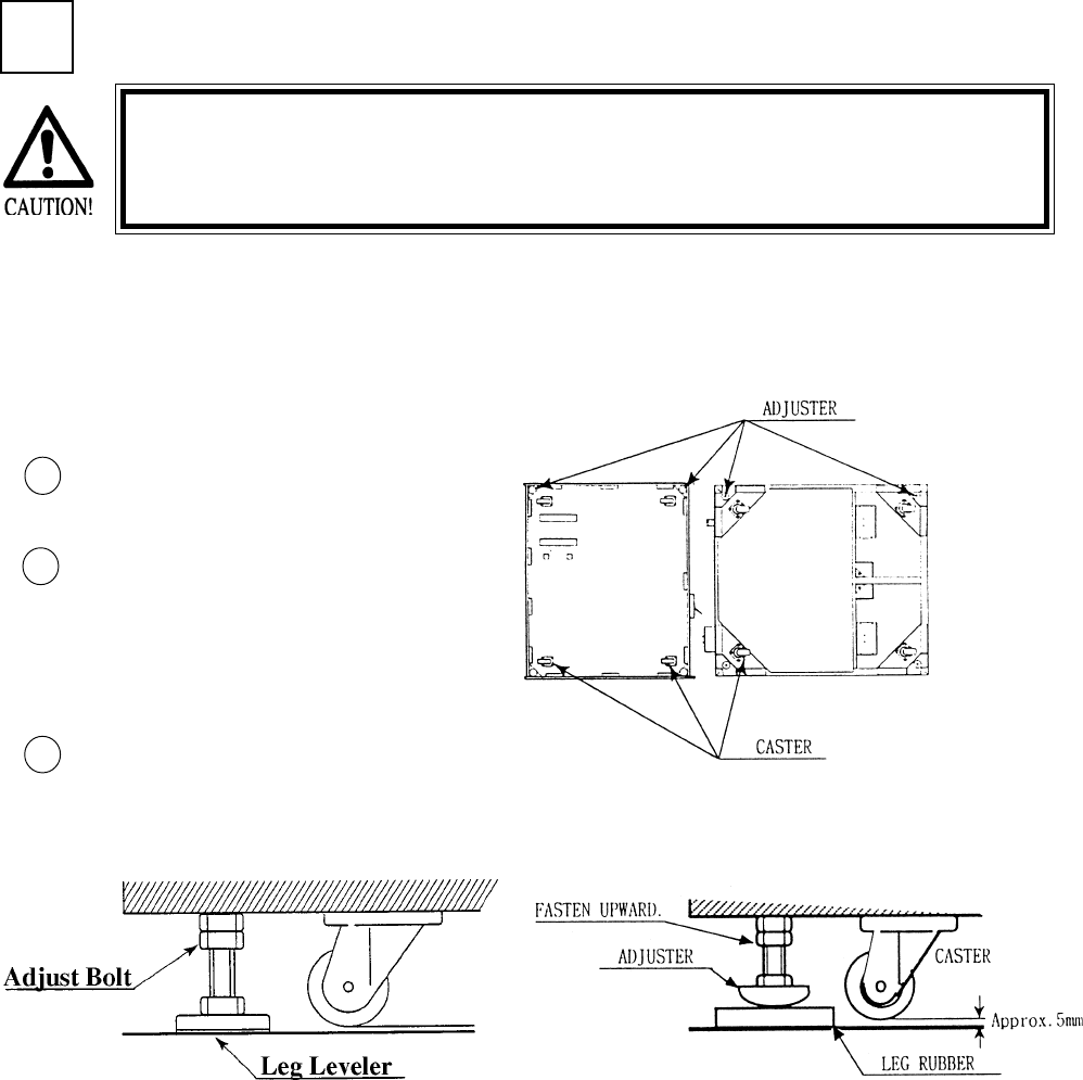
Move the machine to the installation
position.
Cause all of the leg adjusters to make
contact with the floor. By using a
wrench, make adjustments in the height
of the leg adjusters to ensure that the
machine's position is level.
After making adjustments, fasten the
leg adjuster nut upward and secure the
height of the leg adjuster.
This machine has 8 each of casters and adjuster (See Below). When the installation position is
determined, cause the adjusters to come into contact with the floor directly, make adjustments in
a manner so that the casters will be raised approximately 5mm. from the floor and make sure that
the machine position is level.
Be sure to have all the Adjusters make contact with the floor surface.
Unless the Adjusters come into contact with the surface, the Cabinet
can move of itself, causing an accident.
3
3
2
1
FRONT CABI REAR CABI

14
POWER SUPPLY
Ensure that the Main SW is OFF.
The AC unit is located on the left
side of the Cabinet. The Ac unit
incorporates the Main SW, and
power cord.
4
1
CAUTIONS TO BE HEEDED WHEN TURNING THE POWER ON
First make sure that no one is in the periphery of the bike body and turn
the Main SW on. When the power is turned on, the bike body motion
starts automatically. The presence of a person(s) in the periphery of the
bike can cause an accident. Turning the AC Unit’s Main SW on will cause
the machine to start the POWER ON check automatically. In the POWER
ON check, the bike body banks left and right, then returns to the center-
ing position and stops. During this check, do not touch the bike body. If
you do, the body reaction (at the time course-out or crashing) can not be
obtained correctly. The Advertise mode is displayed at the same time the
checking is finished. An ERROR display is indicated if irregularity is found
in the POWER ON check. In case of an irregular reaction during game,
turn power off and turn it back on again to finish the POWER ON check.
The AC unit is mounted on the left side of Front Cabinet DX. The AC Unit incorporates the Main
SW. Firmly insert the Power Plug into the Socket Outlet. Turn the Main SW ON to turn power
ON.
Ensure that the power cord is not exposed on the surface (passage,
etc.). If exposed, they can be caught and are susceptible to damage.
If damaged, the cord can cause an electric shock or short circuit.
Ensure that the wiring position is not in the customer's passage way
or the wiring has protective covering.
2
15
Selecting the INPUT TEST on the test mode
menu screen causes the screen (on which each
switch is tested) to be displayed. Press each
switch. For the coin switch test, insert a coin
into the coin inlet with the coin chute door
being open. If the display beside each switch
indicates "ON," the switch and wiring connec-
tions are satisfactory.
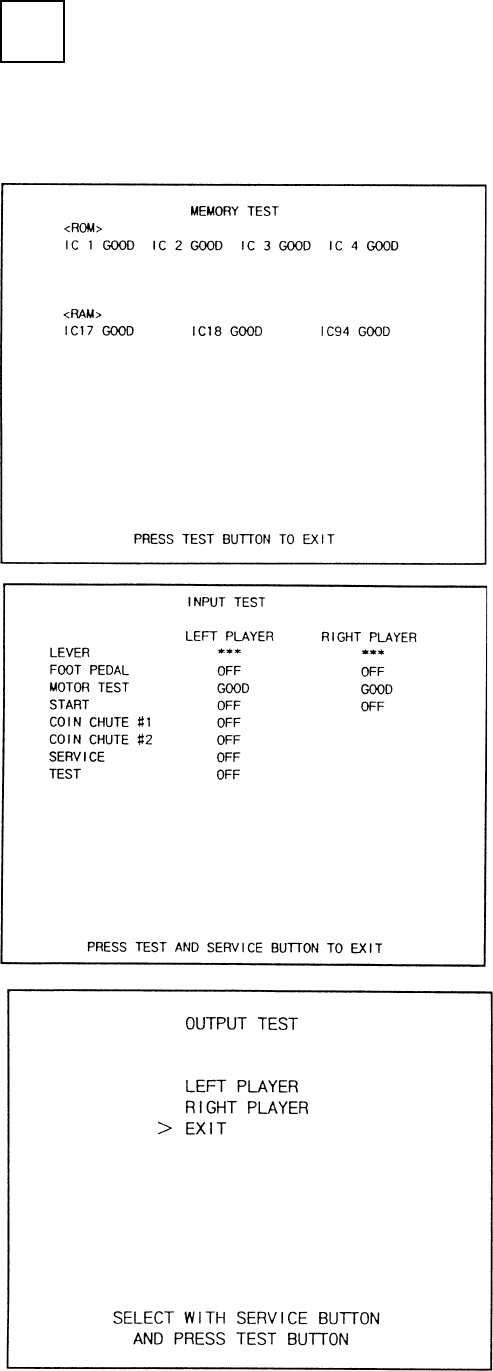
Selecting the MEMORY TEST on the test
mode menu screen causes the on-board
memory to be tested automatically. The game
board is satisfactory if the display beside each
IC No. shows GOOD.
In the TEST MODE, ensure that the assembly has been made correctly and IC BD is satisfactory
(refer to Section 6).
In the test mode, perform the following test:
ASSEMBLING CHECK
5
16
In the TEST mode, selecting SOUND TEST
causes the screen, on which sound related BD
and wiring connections are tested, to be
displayed. be sure to check if the sound is
satisfactorily emitted from each of speaker and
the sound volume is appropriate.
In the TEST mode menu, selecting C.R.T.
TEST allows the screen (on which the monitor
is tested) to be displayed. Although the monitor
adjustments have been made at the same time
of shipment from the factory, color deviation,
etc., may occur due to the effect caused by
geomagnitism, the location building’s steel
frames and other game machines in the periph-
ery.
By watching the test mode screen, make
judgement as to whether an adjustment is
needed. If it is neccessary, adjust the monitor
by refering to Section 9.
17
When moving the machine, be sure to pull out the plug from
the power supply. Moving the machine with the plug as is
inserted can damage the power cord and cause a fire or elec-
tric shock.
When moving the machine on the floor, retract the Adjusters
and ensure that Casters make contact with the floor. During
transportation, pay careful attention so that Casters do not
tread power cords. Damaging the power cords can cause an
electric shock and/or short circuit.
When lifting the cabinet, be sure to hold the catch portions or
bottom part. Lifting the cabinet by holding other portions can
damage parts and installation portions, due to the empty
weight of the cabinet, and cause personal injury.
Since this machine is a heavy structure of approximately 1000+lbs.
its leg adjusters should be retracted when moving the machine over
the floor. When moving the machine on the floor with slanted sur-
faces or step like differences, ensure that the PTV, Front Cabinet
and Rear Base are seperated. Lifting the Cabinet with those items as
is joined can cause the joint portions to be damaged.
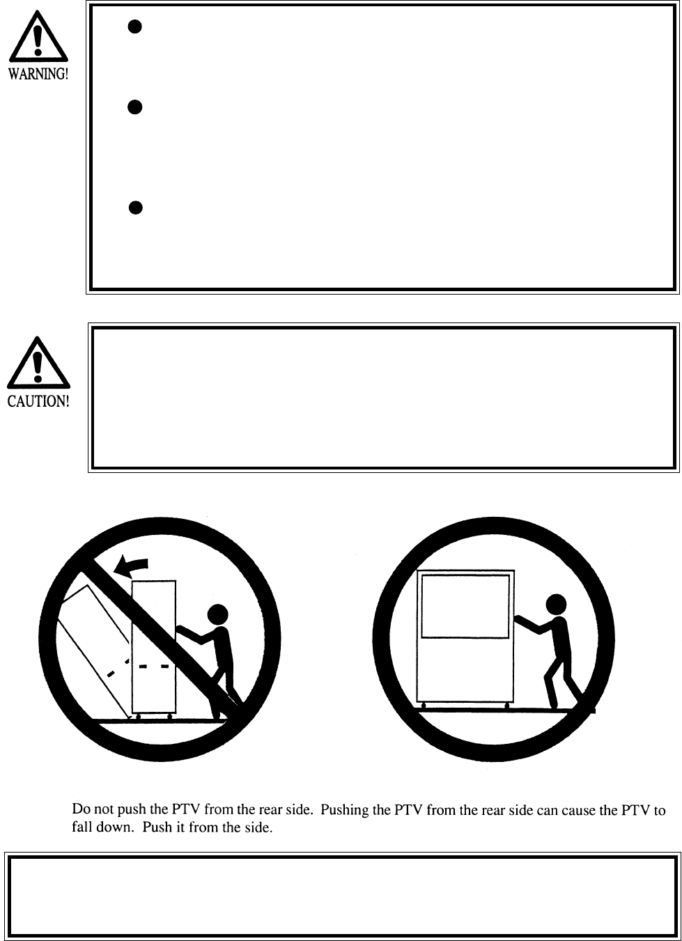
4. PRECATIONS TO BE HEEDED WHEN MOVING THE MACHINE
On a level surface, move the machine by causing all of the casters to make
contact with the floor. Where there are steps (or step like differences in grade),
move machine by seperating into each unit.
18
5. CONTENTS OF GAME
The following explanations apply to the case the product is functioning satisfactoriliy. Should there be any moves
different from the following contents, some sort of faults may have occurred. Immediately look into the cause of the
fault and eliminate the cause thereof to ensure satisfactory operation.
The Control Panel’s START Button blinks if credits allowing for play are available.
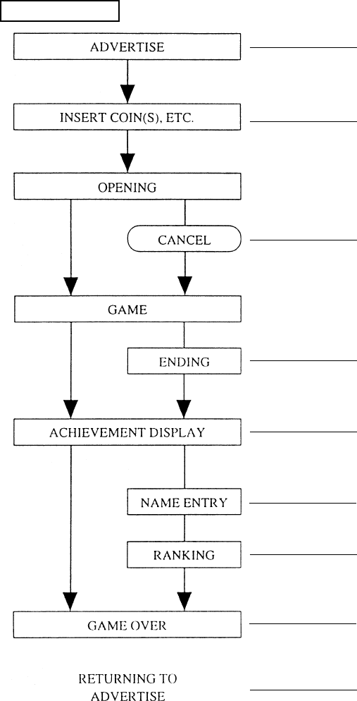
GAME FLOW
While game is not played, the ADVERTISE
mode is always on the screen.
Starting to insert a coin(s) causes the screen to
shift to the INSERT COIN(S) mode.
During the OPENING mode, press the START
Button again to start game immediately.
Finishing the game to the last successfully
allows the player to see the ENDING image.
When the game is finished, acheivements are
displayed.
If acheivements are high, the payer’s name can
be entered.
Displays the player’s ranking place.
Displays GAME OVER.
Returns to ADVERTISE mode.

19
MAGICAL TRUCK ADVENTURE is a simulated action game in which 2 players move the truck
together by using the LEVER in pumping motion evading on-screen obstacles appearing one after
another by jump or dodging left/right.
STORY LINE
In a certain region, there is a girl called Alma who has a mysterious stone. The possessor of the stone
can freely move in time and space dimensions. Once, an evil man Mommy comes to know the
mysterious power of the stone and assualts on Alma together with a giant Marrow, his henchman.
While they are scuffling, the stone’s magical power starts to work suddenly and all of the three
persons are instantaneously moved to a rural town. A boy called Roy happened to be there and
rescues Alma who is knocked down by the two bad guys. Now, Roy and Alma together in the magi-
cal truck start to chase the wicked fellows who robbed her of her stone.
Roy and Alma chase the bad guys to get the stone back by
moving the Lever up/down in pumping motion. The faster you
move the Lever, the faster the truck moves. Move the Lever as
quick as both of you can particularly in the scene the engine
chases you, for example.
Evade on-rail obstacles by jumping or dodging left/right. Use
the Foot Pedal to take these actions.
To cooperate with each other is important to pump the Lever
and evade obstacles. When playing alone, the other (unoccu-
pied) side is operated automatically.
Depending on the results at the end of each stage (whether or
not the stone is recaptured), the next course of stage is deter-
mined.
If all of the stages are cleared, the ending image can be seen.
There are 4 types of Ending applicable on the game results.
When game is finished, ACHEIVEMENT display appears. In
case of high points scored, the name of one or two players can
be entered.
Having a strong sense of justice, he fears nothing and dreams of becoming an
adventurer.
An innocent and affectionate girl having the mission to preserve the stone.
A short higherflier conspiring to conquer the world by using the stone. Brainy and
shrewd.
A man of muscle, rather unintelligent, submissive to his boss.
PUMP THE LEVER AND GO.....
DODGING & JUMP.....................
COOPERATIVE PLAY.................
COURSE OF STAGE...................
MULTI-ENDING..........................
ACHIEVEMENTS........................
ROY...........
ALMA.......
MOMMY...
MARROW.
CHARACTERS
OUTLINE OF GAME
20
ADVERTISE
Before starting game, ADVERTISE mode flows in the following sequential order. This mode contin-
ues until game is started.
During ADVERTISE, moving the Lever shifts to OPERATING INSTRUCTION automatically.
In the latter half of OPERATING INSTRUCTION, rankning is also displayed.
Any time during the ADVERTISE mode, the player can start the game by inserting a coin(s).
Inserting a coin(s) between ENDING and RANKING DISPLAY at the time of previous player’s
play allows the game to start after finishing each display. Press the START button to start game
immediately by cancelling each display.
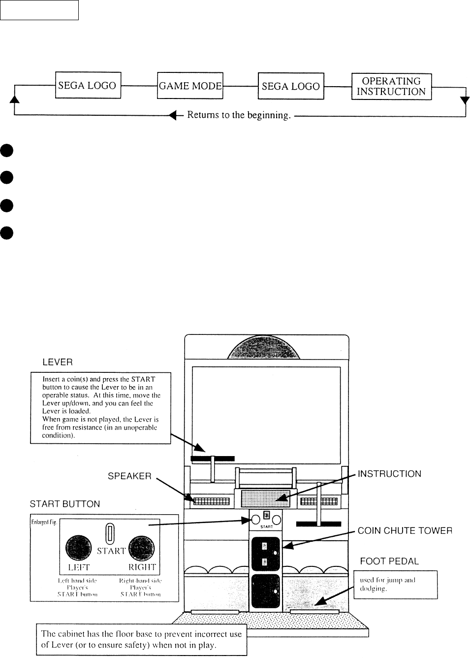
The cabinet of MAGICAL TRUCK ADVENTURE consists of the following as shown.
21
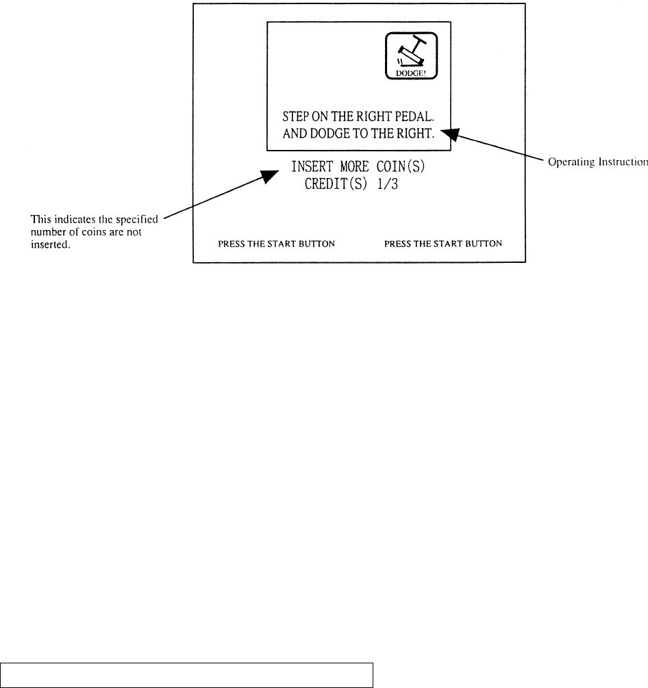
Starting to insert a coin(s) shifts to the folowing screen. Operating instructions is given in this
screen.
Insert the specified number of coins and press START button to start OPENING.
For 2-player play, press left/right START buttons.
For the second player to start while one person is playing, press the other button.
This game isnot continuable.
For 1-player play, use either of left/right seats.
In case of one player play, the other (unoccupied) side is automatically operated.
The screen displays: AUTOMATIC CONTROLLER. JOIN ANYTIME.
Approxiamately 30 seconds after coin insertion (if the START button is pressed), the OPENING
image is displayed on the screen, and game starts. At this time, game playable ont he left-hand side
by one player.
The OPENING image starts immediately after pressing the START button following coin insertion.
Game starts after the OPENING image display.
To start game immediately without watching the OPENING screen, press the START button while
the OPENING image is displayed. Displayng the on-screen image stops and the screen shifts to the
Game Mode.
OPENING AND CANCELLATION OF OPENING
22
Use the Lever and Foot Pedal during game play.
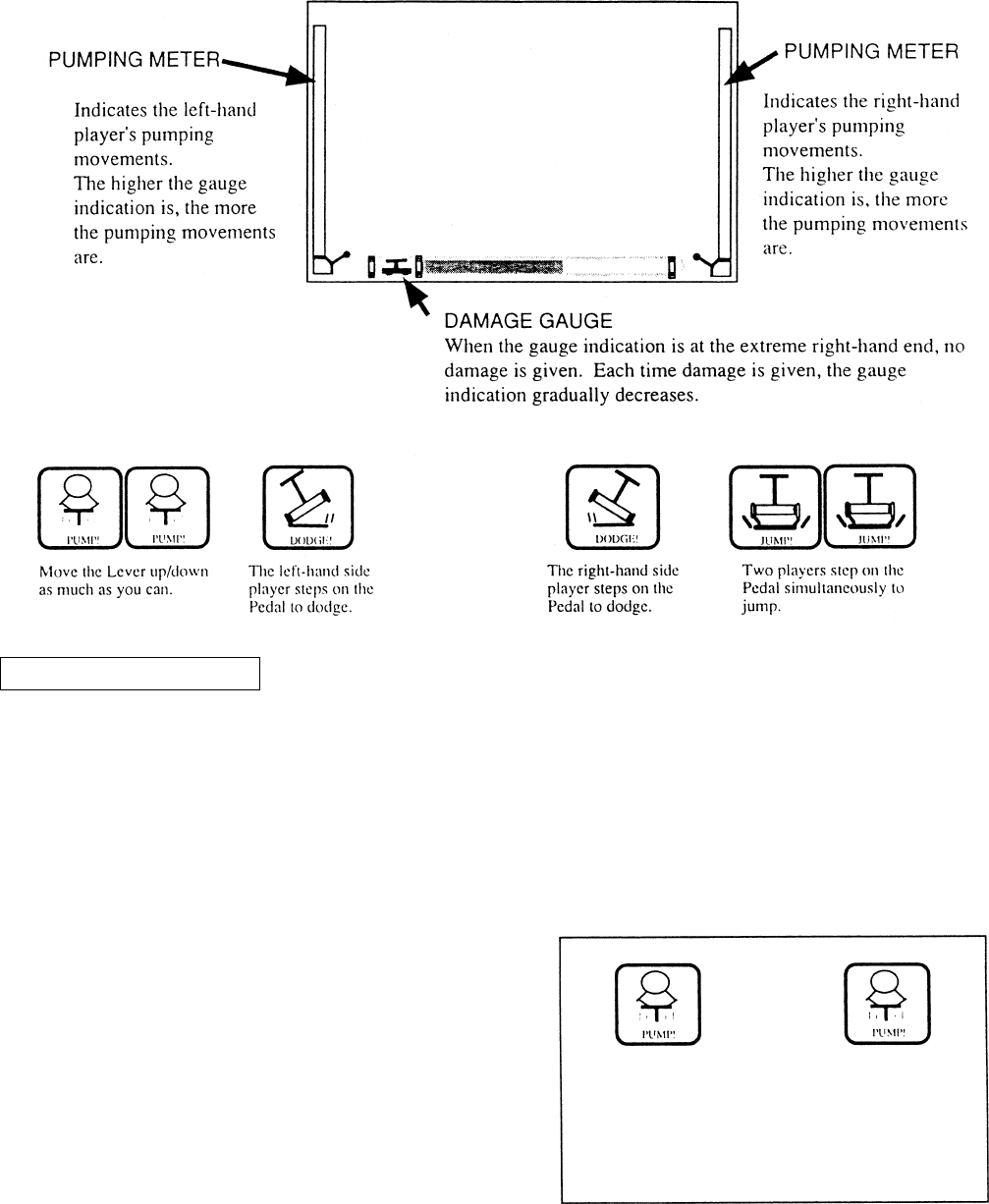
EXPLANATIONS OF ON-SCREEN DISPLAY
The marks shown below appearing on the screen from time to time signify the following:
TO RUN THE TRUCK
Always move the Lever up/down.
Take a firm grip of the Lever to pump.
The truck speed varies depending on the pumping movements of the Lever.
Pump the Lever as fully as possible to move truck faster.
When an engine chases you or when you pursue
the bad guys, if marks shown right appear,
pump as fully and fast as possible to move truck
faster.
Check the Lever pumping movements by
watching the pumping meters at both ends.
23
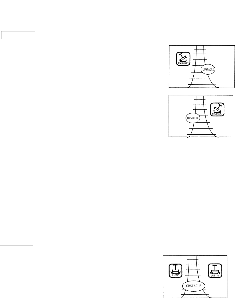
EVADING OBSTACLES
During a game, a number of obstacles will appear. Bumping an obstacle will damage the truck.
To evade the obstacles dodge or jump.
DODGING
Dodge when an obstacle is on one side of the rails and when
selecting the course of stage at the junction.
Dodging left (when the obstacle is on the right-hand side rail)
Only the left player steps on the Pedal. The same applies when
selecting the left-hand side of rails at the junction.
The mark shown in the figure at right can be refered to when the
left-hand side player steps on the Pedal
Dodging right (when the obstacle is onthe left-hand side rail)
Only the right-hand side player steps on the Pedal.
The same applies when selecting the right-hand side or rails at the
junction.
The mark shown in the right-hand side player steps on the Pedal
When you should dodge an obstacle, stepping on both pedal results in a jump.
Once you jump, the truck speeds decreases and also, there are some obstacles you can evade only by
dodging. Be carefu!
At the junction, if both pedals are stepped on by error, this is determined as a failure and in this case
you take the wrong course of the stage.
At the time of dodging or jumping, what is important is to step on the Pedal at just the right moment
rather than increasing the speed by pumping the Lever quickly.
JUMPING
Used to evade the obstacle in the middle of the rails by jump-
ing, and also used inplaces where the rails are discontinued.
To jump, step on the Pedals simultaneously by both players.
The mark shown in the figure at right can be refered to when
both players step on his/her Pedal.
Try to step on Pedals simultaneously (by both players) at just
the right moment, otherwise, the Jump is not succesful.
24
DAMAGE
Failing to evade obstacles by jump or dodging causes damage.
When damaged, the on-screen truck is graudually destroyed.
As regards, how serious damage is, check by watching the damage gauge.
When the truck is completely destroyed, the game is over.
SUCCESS IN “EVENT”
The player(s) is successful in the “EVENT” if he successfully evades a series of obstacles by jump
and dodging without damage to the truck.
For example, if the player skillfully dodges the barrel twice in the first stage, then he is succesful in
the “BARREL EVENT” with the stamp being displayed as shown below. All of the awarded stamps
are displayed at the time of ranking display.
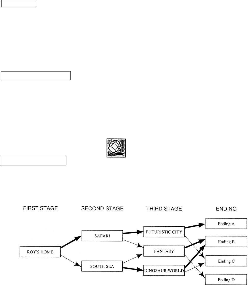
GAME COMPOSITION
In the latter half of the each stage, the hero/heroin chase the bad guys and vice vesra in conection
with the stone. Depending on the results of pursuit, the next stage course differs.
...Refers to the case the player is successful in the pursiut of bad guys and recaptures the stone.
...Refers to the case the player fails in the pursuit of bad guys and had the stone stolen.
25
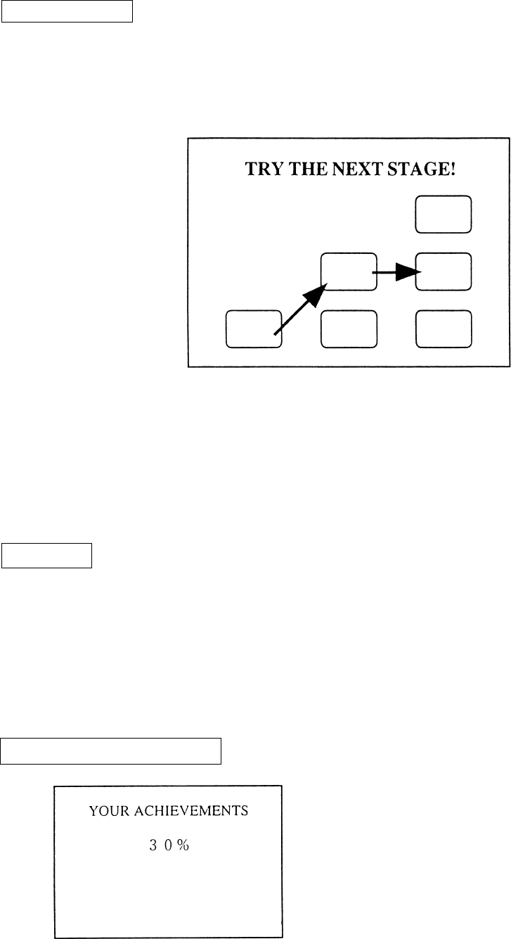
STAGE CLEAR
Finishing one Stage before the truck is completely destroyed results in STAGE CLEAR.
At the time of STAGE CLEAR, the following map is displayed and this informs you of the
next stage the player is going to take.
While repeating a sort of playing tag by chasing and being chased, clearing the 3 stages
allowing you to see the Ending rsults in a GAME CLEAR.
ENDING
Depending on whether or not the player recaptures the stone in the Thrid Stage, which one of
the four Ending Stories the player can see is determined.
When each stage is cleared, the map is displayed so that the player can see which course he
followed.
ACHIEVEMENT DISPLAY
ACHIEVEMENTS are displayed after the ending
or game over.
26
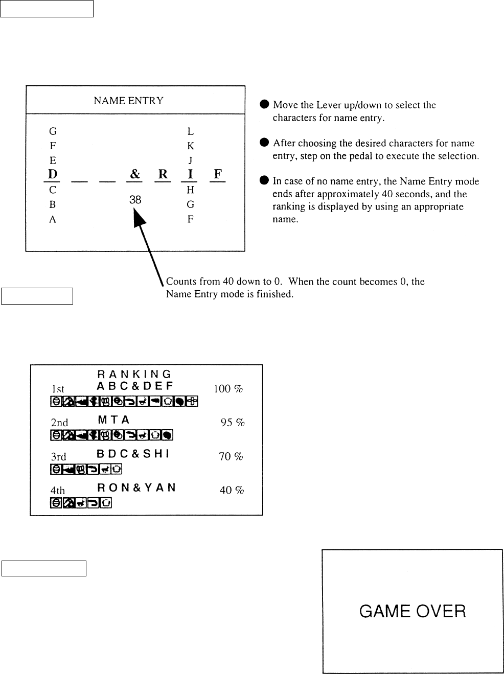
NAME ENTRY
Name of player(s) can be entered if his ACHIEVMENTS are excellent. For the name entry, 3
characteres can be entered. In the case of one player play, the name of one person can be
entered.
RANKING
After Name Entry, RANKING is displayed. Displays up to 10 pairs can be displayed.
GAME OVER
GAME OVER display is indicated. This ends the
game flow series.
After this, the ADVERTISE MODE returns to the
screen.

27
By operating the switch unit, periodically perform the tests and data check. When installing
the machine initially or collecting cash, or when the machine does not function correctly,
perform checking in accordance with the explanations given in this section. The following
shows tests and modes that should be utilized as applicable.
INSTALLATION
OF MACHINE
6 - 4
2. In the INPUT TEST mode, check each SW and VR.
3. In the OUTPUT TEST mode, check each of lamps.
4. In the MEMORY TEST mode, check ICs on the IC Board.
Choose MEMORY TEST in the MENU mode to allow the
MEMORY test to be performed. In this test, PROGRAM
RAMs, ROMs, and ICs on the IC Board are checked.
Periodically perform the following:
1. MEMORY TEST
2. Ascertain each setting.
3. In the INPUT TEST mode, test the CONTROL device
4. In the OUTPUT TEST mode, check each of the lamps.
1. In the INPUT TEST mode, check each SW and VR.
2. Adjust or replace each SW and VR.
3.If the problem hasn’t been solved yet, check the CONTROL’s moves.
In the PROJECTOR ADJUSTMENT mode, check to see if the
PROJECTOR adjustment is appropriately made.
1. MEMORY TEST
2. In the SOUND TEST mode, check the sound related ROMs.
Check such data as game play time and histogram to adjust the
difficulty level, etc
1. Check to see that each setting is as per standard setting made
at the time of shipment.
PERIODIC
SERVICING
MEMORY
PROJECTOR
DATA CHECK
CONTROL
SYSTEM
6 - 8, 6 - 9,
6 - 10
6 - 4
6 - 7
6 - 3
6 - 3
6 - 8, 6 - 9
6 - 7
When the machine is installed, perform the following:
IC BOARD
6 - 4
7
6 - 3
6 - 3
TABLE 6 EXPLANATION OF TEST MODE
9
6 - 5
6 - 11
7
6. EXPLANATION OF TEST AND DATA DISPLAY
ITEMS DESCRIPTION SECTIONS
28
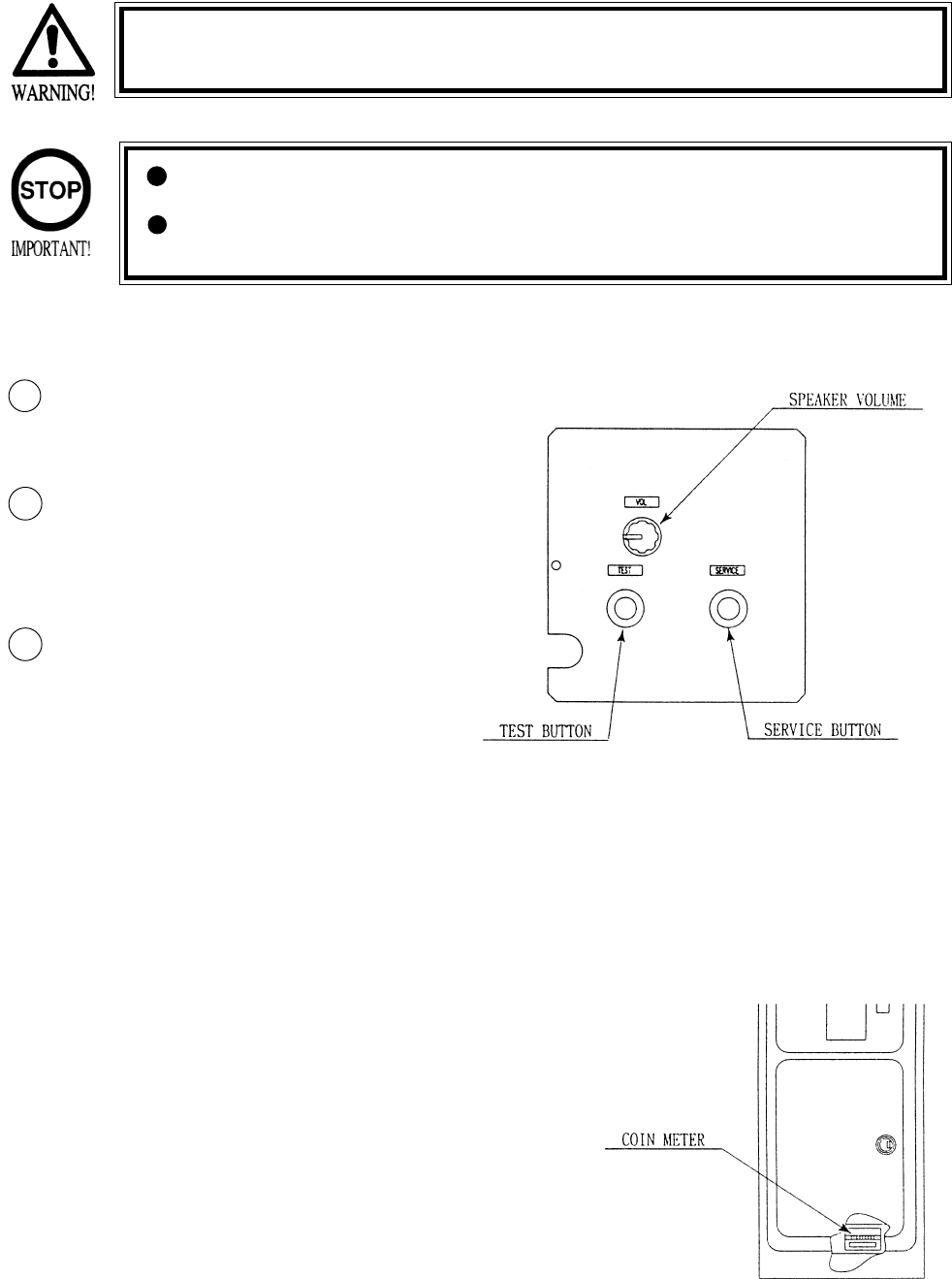
Open COIN CHUTE DOOR, and the switch unit shown appears. The function
of each switch is as follows:
6 - 1 SWITCH UNIT AND COIN METER
Never touch places other than those specified. Touching places not
specified can cause electric shock and short circuit.
Adjust to the optimum sound volume by considering the environmental
requirements of the installation location.
If the COIN METER and the game board are electrically disconnected,
game play is not possible.
TEST BUTTON (TEST SW)
For the handling of the
TEST BUTTON,
refer to the section on test mode.
SERVICE BUTTON
(SERVICESW)
Gives credits without registering
on the coin meter.
2
1
3
SOUND VOLUME SPEAKER
Controls the speaker volume ofall of the machines
speakers.
29
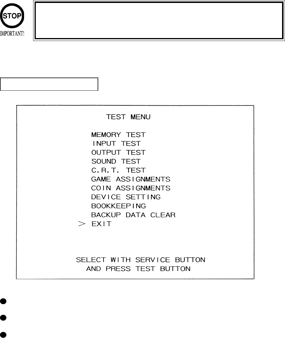
6 - 2 TEST MODE
SELECTION OF TEST ITEMS
In case settings are changed in GAME ASSIGNMENTS, COIN ASSIGNMENT the setting
changes are not effective unless the test mode is exited and the game mode returns
to the screen. The setting changes are ineffective if the power is turned off in the
test mode.
The TEST MODE allows the functioning of each part of the Cabinet to be checked, the monitor to
be adjusted, and the coins and game related various settings to be performed.
Press the TEST BUTTON to have the menu displayed on the screen.
Press the SERVICE BUTTON until the pointer is moved to the desired item to make a selection.
Bring the pointer to the desired item and press the TEST BUTTON to enter the selected item’s
test.
30
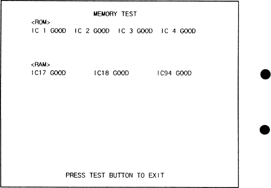
The MEMORY TEST mode is for checking the
on-BD memory IC functioning.
“GOOD” is displayed for normal ICs and
“BAD” is displayed for abnormal ICs
When the test is completed, if the
display is as shown left, it is
satisfactory.
After finishing the test, pressing the
TEST BUTTON allows the
MENU MODE to return on the
screen.
6 -3 MEMORY TEST
31
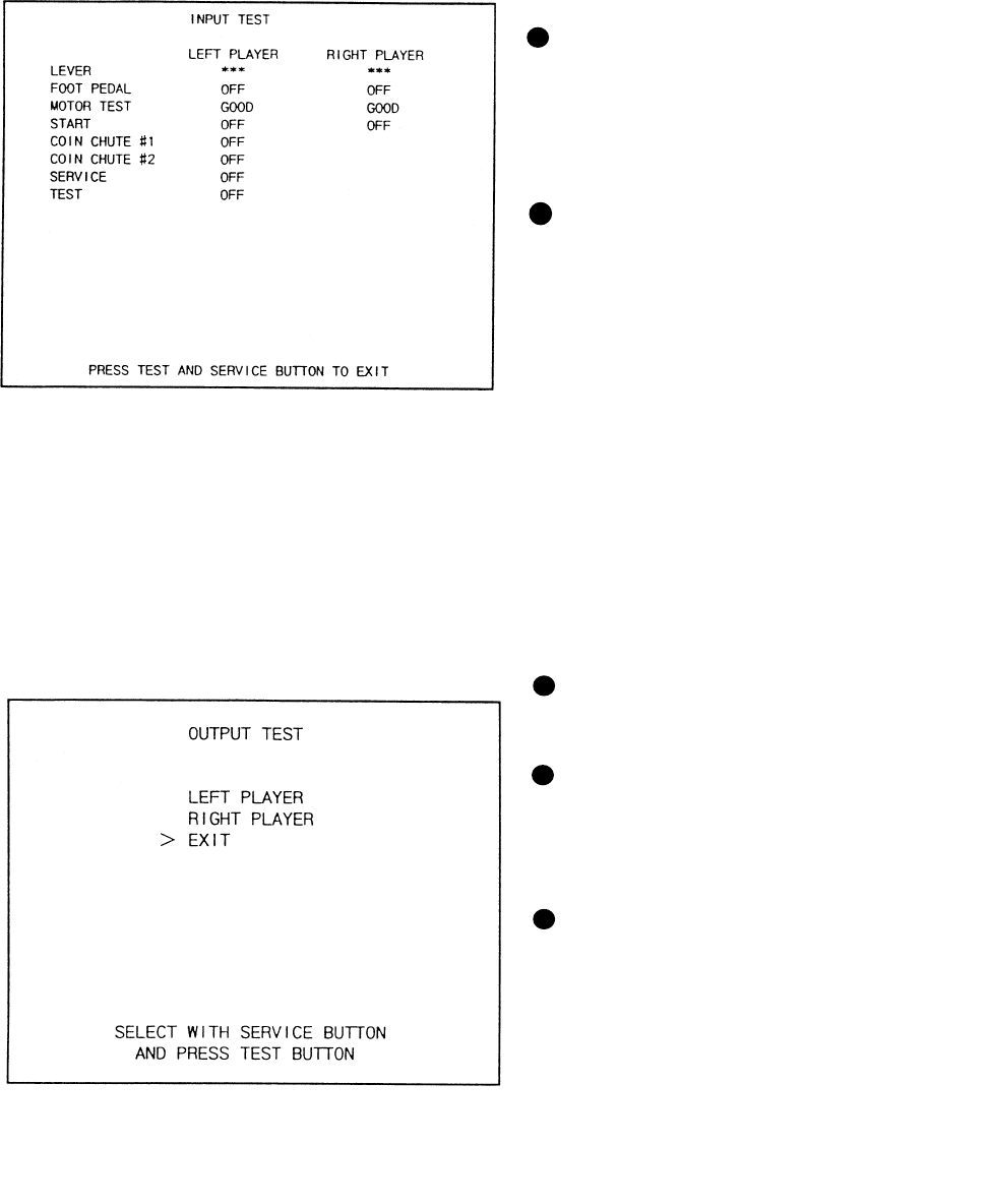
When INPUT TEST is selected, the MONITOR will show the following, allowing you
to watch the status of each switch.
On the screen, periodically check the status of each switch.
6 - 4 INPUT TEST
By pressing each switch, if the display
on the righthand side of the name of
each switch changes to ON from OFF,
the SW and the wiring connections are
satisfactory.
Open the COIN CHUTE DOOR and
insert a coin from the COIN ENRTY to
check the COIN CHUTE SW.
In the INPUT test, pressing the TEST
BUTTON causes the menu to return to
the screen.
Press the SERVICE BUTTON to move
the arrow to the desired lamp test item.
Press the TEST BUTTON. If the display
to the right of the lamp name changes to
ON from OFF, the lamp and wiring
connection are satisfactory.
Choose EXIT and press the TEST BUT-
TON to return to MENU mode (FIG. 6.2).
6 - 5 OUTPUT TEST
Choose OUTPUT TEST to have the MONITOR screen shown left to appear. This screen allows
lamp status to be checked.Periodically check the lamp status in this mode.
32
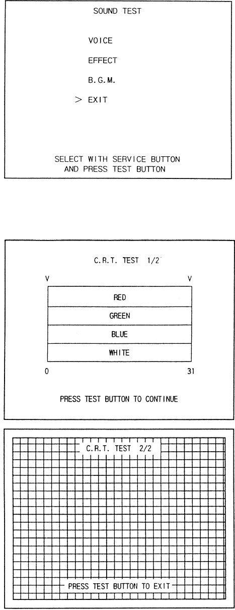
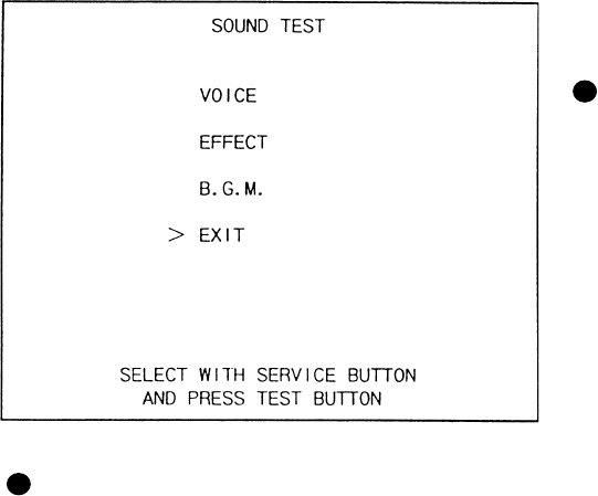
This enables sound used in the game to be
checked. Sound related memory and each
speaker are checked.
SE1/SE2/VOICE/BGM
In these items, sound related memory and each
speaker are checked.
By using the SERVICE button, move the arrow
to the desired item. Every time the TEST button
is pressd, the numeral displayed on the screen
increases and sound is emitted sequentially in
order.
6 - 6 SOUND TEST
BASE SHAKER MUTE TEST
In this test, check if the BASE SHAKER equipped with the cabinet (the vibration device near
where the player stands) satisfactorily functions.
Select this item to start vibrating the Base Shaker at the same time sound is emitted.
When the TEST button is pressed in this status, if only the sound is continuously emitted and
the Shaker vibration is stopped, then, the Base Shaker is functioning satisfactorily.
Being the arrow to EXIT and press the TEST button to return to the Menu mode.
33
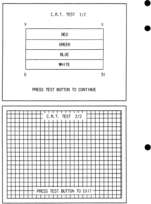
Select C.R.T. TEST to cause the MONI-
TOR to display the screen shown left,
allowing MONITOR adjustment status to
be checked.
Periodically check the MONITOR adjust-
ment status on this screen.
The screen (1/2) enables color adjustment
check to be performed. The color bar of
each of the 4 colors, i.e.,red, green, blue,
and white, is the darkest at the extreme left
and becomes brighter towards the extreme
right.
Press the TEST BUTTON to shift to the
next page (2/2).
The screen (2/2) allows screen size and
distortion to be tested.
Check if the CROSSHATCH FRAME
LINE goes out of the screen and if the
crosshatch lines are distorted.
Press the TEST BUTTON to return to the
MENU mode.
6 - 7 C.R.T. TEST
34
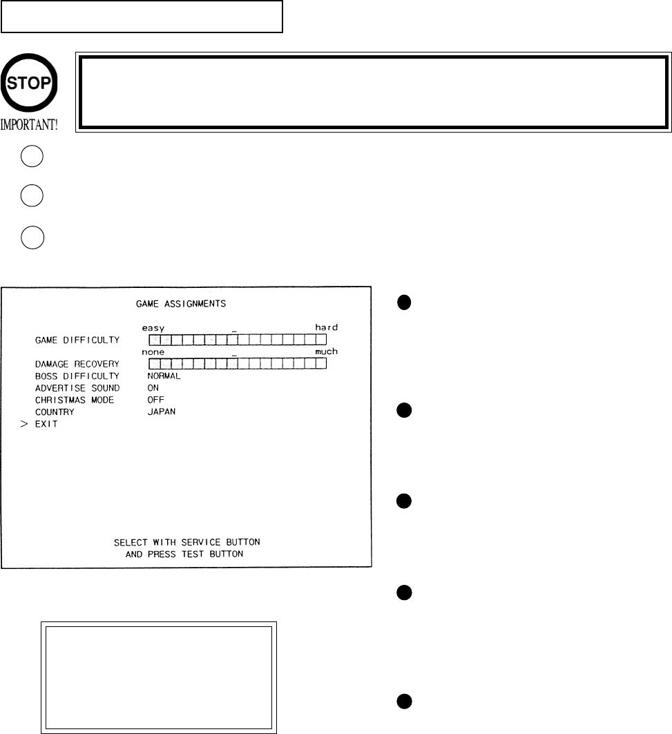
6 - 8 GAME ASSIGNMENTS
Selecting the GAME ASSIGNMENTS in the MENU mode causes the present game settings
to be displayed and also the game settings changes (game difficulty, etc.) can be made. Each
item displays the following content.
SETTING CHANGE PROCEDURE
Press the SERVICE BUTTON to move the arrow to the desired item.
Choose the desired setting change item by using the TEST BUTTON.
To return to the MENU mode, move the arrow to EXIT and press the TEST BUTTON.
1
2
GAME DIFFICULTY
This game allows by-course difficulty
level to be set in 4 levels. Depending
on the difficulty level set, the intial
time varies.
ADVERTISE SOUND
Setting of sound during Advertise.
ON(sound to be emitted), OFF(sound
not to be emitted).
DAMAGE RECOVERY
The degree of DAMAGE RECOV-
ERY after clearing each stage can be
set in 16 levels from none to much.
BOSS DIFFICULTY
The Difficulty Level in each Stage’s
latter half chase scenes can be set in 5
Levels from VERY EASY to VERY
HARD.
CHRISTMAS MODE
Setting to ON causes CHRISTMAS
song for the BGM to be played at the
time of game explanations during
ADVERTISE. While the CHRIST-
MAS song is emitted, “MERRY
CHRISTMAS” is displayed on the
screen.
3
Setting changes cannot be stored unless the TEST BUTTON is pressed
while the arrow is on EXIT.
These FIGURES/These FIGURES/
These FIGURES/These FIGURES/
These FIGURES/
TABLES show theTABLES show the
TABLES show theTABLES show the
TABLES show the
factory recommendedfactory recommended
factory recommendedfactory recommended
factory recommended
settings.settings.
settings.settings.
settings.

35
The “COIN ASSIGNMENTS” mode permits you to set the start number of credits, as well as
the basic numbers of coins and credits. This mode expresses “how many coins correspond to
how many credits.”
SETTING CHANGE PROCEDURE
Press the SERVICE BUTTON to move the arrow to the desired item.
Choose the desired setting change item by using the TEST BUTTON.
To return to the MENU mode, move the arrow to EXIT and press the TEST BUTTON.
COIN CHUTE TYPE
Sets the combination of the number of COIN
CHUTEs and the number of players as appli-
cable. In the case that the COIN CHUTE is
changed, be sure the setting is made in a manner
meeting the replaced coin chute.
COMMON:
Coins are accepted in common for both players.
INDIVIDUAL:
Each player uses a coin chute which accepts coins
independently.
6 - 9 COIN ASSIGNMENTS
CREDIT TO START
Number of credits required for starting game (1~5 credits are selected.)
CREDIT TO CONTINUE
Number of credits required for continuing game (1~5 credits are selected.)
COIN/CREDIT SETTING
Sets the CREDITS increase increment per coin insertion. There are 27 setings from #1 to
#27, expressed in XX CREDIT as against XX COINS inserted. (TABLE 6.10a, 6.10b) #27
refers to FREE PLAY.
When the COIN CHUTE TYPE is set to INDIVIDUAL, there are some setting numbers
not displayed as indicated in TABLE 6.10b.
MANUAL SETTING
This allows credit increase setting as against coin insertion to be further set in the manner
finer than COIN/CREDIT SETTING (refer to TABLE 6.10c).
1
2
3
Setting changes cannot be stored unless the TEST BUTTON is pressed
while the arrow is on EXIT.

36
TABLE 6.9a COIN/CREDIT SETTING (COIN CHUTE COMMON TYPE)
SETTING FUNCTIONING OF CHUTE#1
SETTING #1 1 COIN 1 CREDIT
SETTING #2 1 COIN 2 CREDITS
SETTING #3 1 COIN 3 CREDITS
SETTING #4 1 COIN 4 CREDITS
SETTING #5 1 COIN 5 CREDITS
SETTING #6 1 COIN 2 CREDITS
SETTING #7 1 COIN 5 CREDITS
SETTING #8 1 COIN 3 CREDITS
SETTING #9 1 COIN 4 CREDITS
SETTING #10 1 COIN 5 CREDITS
SETTING #11 1 COIN 6 CREDITS
SETTING #12 2 COINS 1 CREDIT
SETTING #13 1 COIN 1 CREDIT
SETTING #14 1 COIN 2 CREDITS
SETTING #15 1 COIN 1 CREDIT
2 COINS 3 CREDITS
SETTING #16 1 COIN 3 CREDITS
SETTING #17 3 COINS 1 CREDIT
SETTING #18 4 COINS 1 CREDIT
SETTING #19 1 COIN 1 CREDIT
2 COINS 2 CREDITS
3 COINS 3 CREDITS
4 COINS 5 CREDITS
SETTING #20 1 COIN 5 CREDITS
SETTING #21 5 COINS 1 CREDIT
SETTING #22 1 COIN 2 CREDITS
SETTING #23 2 COINS 1 CREDIT
4 COINS 2 CREDITS
5 COINS 3 CREDITS
SETTING #24 1 COIN 3 CREDITS
SETTING #25 1 COIN 1 CREDIT
2 COINS 2 CREDITS
3 COINS 3 CREDITS
4 COINS 4 CREDITS
5 COINS 6 CREDITS
SETTING #26 1 COIN 6 CREDITS
SETTING #27 FREE PLAY

37
SETTING FUNCTIONING OF COIN CHUTE
SETTING #1 1 COIN 1 CREDIT
SETTING #6 1 COIN 2 CREDITS
SETTING #8 1 COIN 3 CREDITS
SETTING #9 1 COIN 4 CREDITS
SETTING #10 1 COIN 5 CREDITS
SETTING #11 1 COIN 6 CREDITS
SETTING #12 2 COINS 1 CREDIT
SETTING #15 1 COIN 1 CREDIT
2 COINS 3 CREDITS
SETTING #17 3 COINS 1 CREDIT
SETTING #18 4 COINS 1 CREDIT
SETTING #19 1 COIN 1 CREDIT
2 COINS 2 CREDITS
3 COINS 3 CREDITS
4 COINS 5 CREDITS
SETTING #21 5 COINS 1 CREDIT
SETTING #22 3 COINS 1 CREDIT
5 COINS 2 CREDITS
SETTING #23 2 COINS 1 CREDIT
4 COINS 2 CREDITS
5 COINS 3 CREDITS
SETTING #25 1 COIN 1 CREDIT
2 COINS 2 CREDITS
3 COINS 3 CREDITS
4 COINS 4 CREDITS
5 COINS 6 CREDITS
SETTING #27 FREE PLAY
TABLE 6.9b COIN/CREDIT SETTING (COIN CHUTE INDIVIDUAL TYPE)
38
MANUAL SETTING
Selecting MANUAL SETTING in the COIN ASSIGNMENTS mode displays the following screen.
FIG. 6.11b MANUAL SETTING
BONUS ADDER NO BONUS ADDER
2 COINS GIVE 1 EXTRA COIN
3 COINS GIVE 1 EXTRA COIN
4 COINS GIVE 1 EXTRA COIN
5 COINS GIVE 1 EXTRA COIN
6 COINS GIVE 1 EXTRA COIN
7 COINS GIVE 1 EXTRA COIN
8 COINS GIVE 1 EXTRA COIN
9 COINS GIVE 1 EXTRA COIN
Table 6.11c MANUAL SETTING
Determines Coin/Credit setting.
This sets how many coins should be inserted to obtain one Service Coin.
This sets how many tokens one coin represents.
COIN TO CREDIT 1 COIN1 CREDIT
2 COINS 1 CREDIT
3 COINS 1 CREDIT
4 COINS 1 CREDIT
5 COINS 1 CREDIT
6 COINS 1 CREDIT
7 COINS 1 CREDIT
8 COINS 1 CREDIT
9 COINS 1 CREDIT
COIN CHUTE MULTIPLIER 1 COIN COUNTS AS 1 COIN
1 COIN COUNTS AS 2 COINS
1 COIN COUNTS AS 3 COINS
1 COIN COUNTS AS 4 COINS
1 COIN COUNTS AS 5 COINS
1 COIN COUNTS AS 6 COINS
1 COIN COUNTS AS 7 COINS
1 COIN COUNTS AS 8 COINS
1 COIN COUNTS AS 9 COINS
MANUAL SETTING
COIN TO CREDIT 1 COIN 1 CREDIT
BONUS ADDER NO BONUS ADDER
COIN CHUTE #1 MULTIPLIER
1 COIN COUNTS AS 1 COIN
COIN 1 2 3 4 5 6 7 8 9
CREDIT 1 2 3 4 5 6 7 8 9
COIN CHUTE #2 MULTIPLIER
1 COIN COUNTS AS 1 COIN
COIN 1 2 3 4 5 6 7 8 9
CREDIT 1 2 3 4 5 6 7 8 9
>EXIT
SELECT WITH SERVICE BUTTON
AND PRESS TEST BUTTON
1
2
3
3
1
2
39
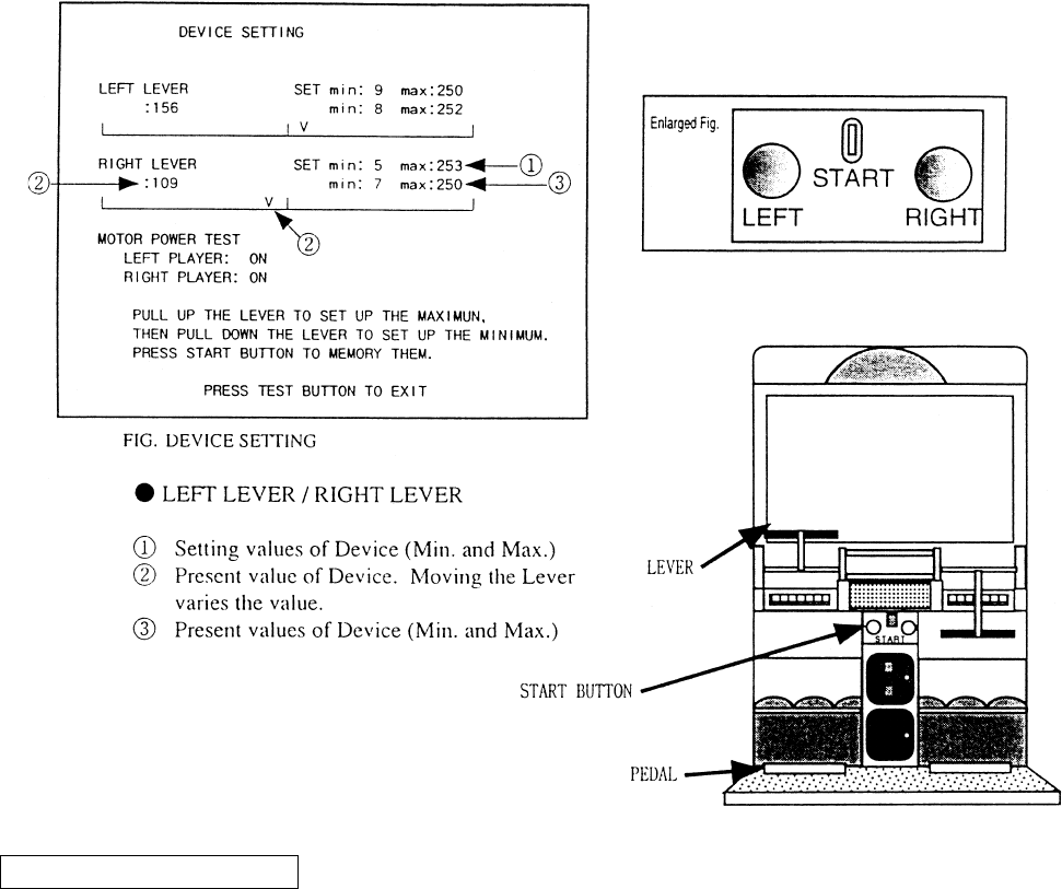
6 - 10 DEVICE SETTING
Performs the setting and checking of DEVICE (Lever V.R. , Motor). Moving the game machine or
repeating play may cause the DEVICE and Mechanism portions to malfunction or to be deviated,
resulting in operability failure. In this mode, periodically check status of DEVICE.
METHOD OF SETTING
For setting the left/right Device, operate each of the left/right LEVERS and START button for each. The setting changes
are not stored unless the Test Mode is exited. The setting change becomes ineffective if power is turned off during test
mode.
a.) Lower the LEVER fully downward. Min is displayed to (3).
b.) Lift the LEVER fully upwards. Max is displayed to (3).
c.) Press the START button. Setting value is changed.
d.) Press the TEST button, return to the MENU mode and EXIT from the Test Mode.
MOTOR POWER TEST
Check the MOTOR which subjects LEVER operation to load. Step on either of the left/right pedals, and both motors are
activated. WHen the Pedal is stepped on, OFF is displayed. When the Pedal is not stepped on, ON is displayed. If the
LEVER is felt lighter when it is moved up and down while OFF is displayed than while ON is displayed, it is satisfac-
tory.
40
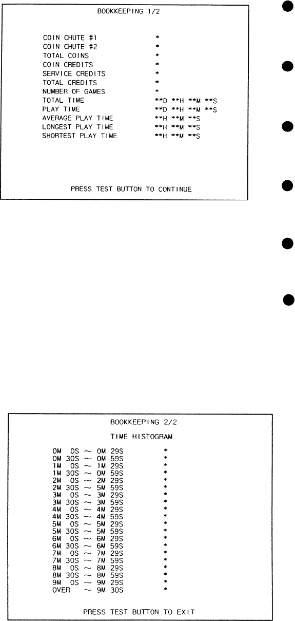
6 - 12 BOOKKEEPING
Choosing BOOKKEEPING in the MENU mode displays the data of operating status up to the
present are shown on 2 pages. Press the TEST BUTTON to proceed to PAGE 2/2.
COIN CHUTE#*:
Number of coins put in each Coin
Chute.
TOTAL COINS:
Total number of activations of Coin
Chutes.
COIN CREDITS:
Number of credits registered by
inserting coins.
SERVICE CREDITS:
Credits registered by the SERVICE
BUTTON.
TOTAL CREDITS:
Total number of credits (COIN
CREDITS+SERVICE CREDITS).
TOTAL TIME:
The total energized time.
41
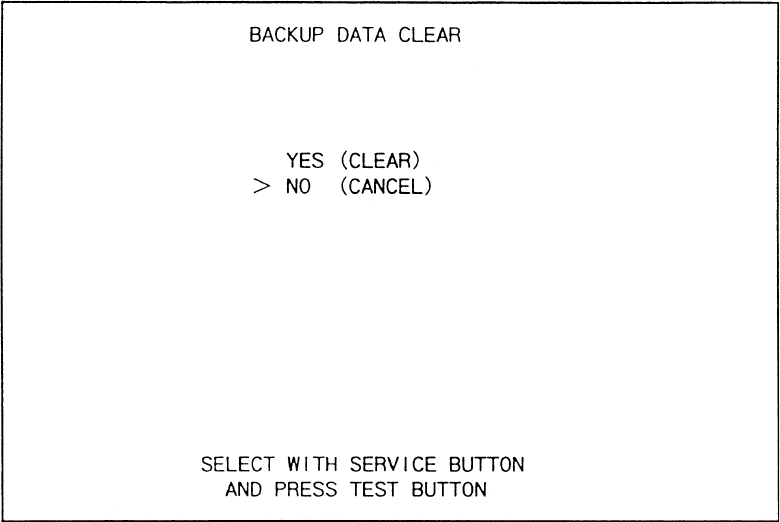
6 - 13 BACKUP DATA CLEAR
Clears the contents of BOOKKEEPING and high score player ranking entry.
When clearing, bring the arrow to “YES” and when not clearing, to “NO”, by using the SER-
VICE BUTTON, and push the TEST BUTTON.
When the data has been cleared, “COMPLETED” will be displayed. Bring the arrow to “NO”
and press the TEST BUTTON to cause the MENU mode to return on to the screen.
Note that the contents of the game setting and sighting adjustment are not affected by BACKUP
DATA CLEAR operation.
42
This work should be performed by the locations Maitenance Man or
Service Man. Performing work by those who do not have the techni-
cal expertise can cause electric shock accident.
7. CONTROLLER’S (LEVERS AND FOOT SWITCH)
Before starting to work, ensure that the power SW is OFF. Failure to
observe this can cause electric shock and short circuit accident.
Use care so as not to damage wirings. Damaged wiring can cause
electric shock and short circuit hazards.
Do not touch undesignated places. Touching places other than those
specified can cause electric shock and short circuit accidents.
7 - 1 ADJUSTING/REPLACING THE VOLUME
In cases the Lever’s operability is poor and adjustment in the DEVICE SETTING of the TEST
MODE is ineffective, the causes may be the Volume Gear’s mesh failure, Volume malfunctioning,
etc. By using the following procedure adjusting position of Volume and gear mesh, or replace the
Volume.
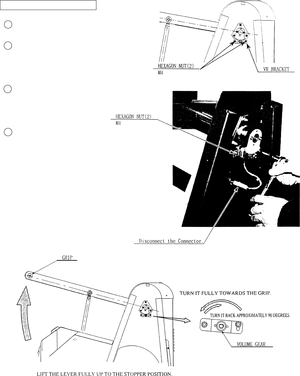
In this product, when the Lever is moved up/down, if the Volume shaft is rotating within the mov-
able range, the Volume is not feared to be damaged. The Volume gear mesh angle is approximately
90 degrees turned in the direction reverse to where the Volume gear angle is approximately 90
degrees turned in the direction reverse to where the Volume gear turned fully to the Lever’s Grip
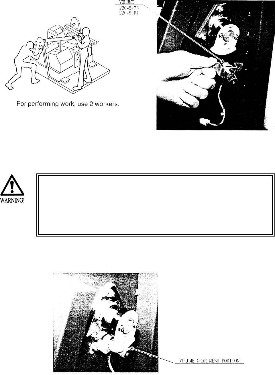
side with the Lever being in the status fully lifted up. To perform the angular adjustment work, safely
and accurately, secure the Lever by one person, and person and perform adjsutment and fastening the
nut by another person.
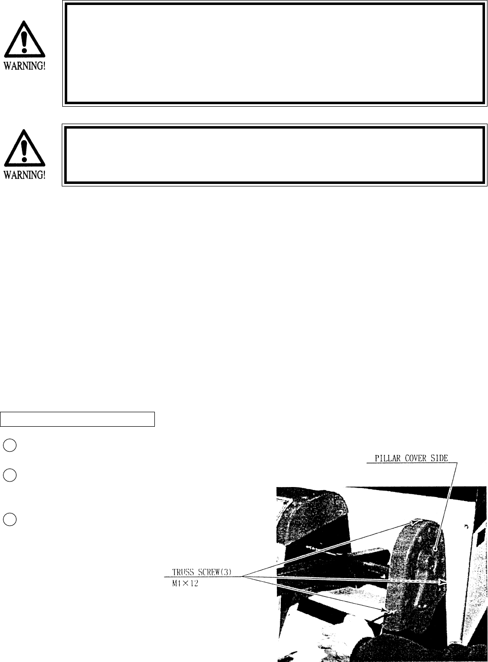
Turn power off.
Take out 3 screws and remove Pillar
Cover Side.
Loosen the 2 Nuts, move the VR
Bracket, and adjsut gear mesh angle
and status.
ADJUSTING THE VOLUME
3
1
2
43
Disconnect Volume Connector.
Take out the 2 hexagon nuts and
remove the Volume together with
VR Bracket.
After replacing the Volume, have the
gear mesh at the angle specified
above, and secure theVR Bracket.
Turn Power ON, and set the Volume
value in DEVICE SETTING of
TEST mode.
REPLACING THE VOLUME
3
2
1
4
44
Before starting to work, ensure that the Power SW is OFF. Failure
to observe this can cause electric shock and short circuit hazards.
Besure to use the designated grease. Using the undesignated
grease can cause parts damage.
Do not apply greasing to undesignated places. Failure to observe
this can cause malfunctioning or quality deterioration of parts.
7 - 2 GREASING
Apply greasing to gear mesh portions once every 3 months. Use GREASEMATE (SEGA PART No.
090-0066).

45
7 - 3 REPLACING THE STOPPER
In case the Lever’s Rubbe Stopper is deteriorated or damaged, replace it by using the following
procedure.
Turn power off.
Take out the 4 truss screws, and remove the Upper Plate.
Take out the 5 truss screws, and remove the Mecha Cover in the manner to pull out towards
you.
Replace the Stopper.
When installing the Mecha Cover, mount the Slide Plate on the Mecha Cover.
3
1
2
4
5
46
7 - 4 REPLACING THE SHOCK ABSORBER.
The following work needs a tool for the C Ring and is rather complicated.
Ask where you purchased your game from or SEGA’s Service Center for assistance.
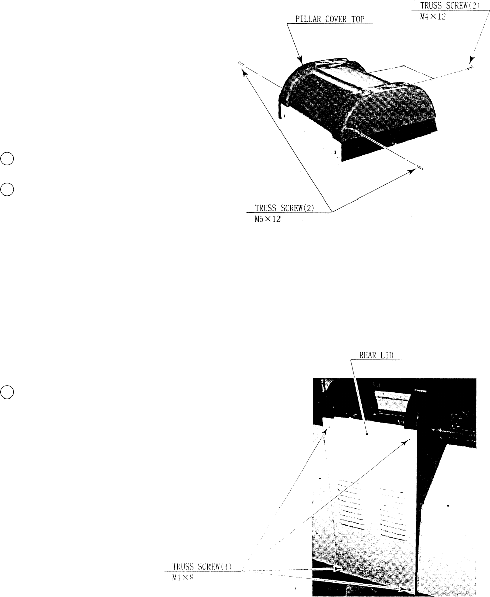
Turn power OFF.
Take out a total of 4 screws and remove Pillar
Cover Top.
Take out 4 screws. and remove Rear Lid.
3
1
2
47
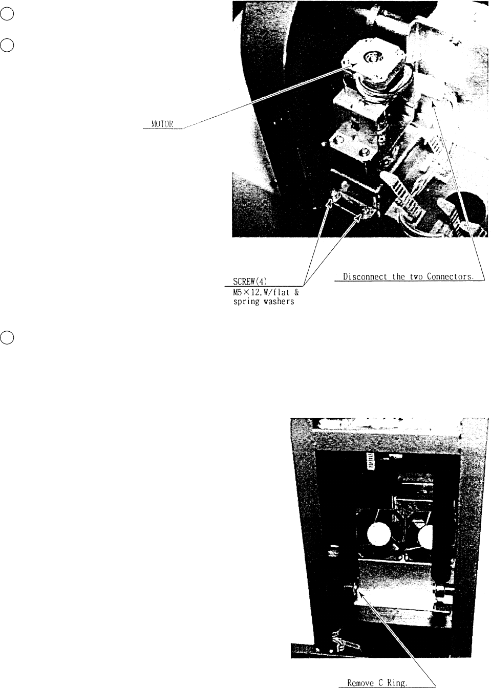
Disconnect the two Connectors.
Take out the 4 screws and remove the
Unit(motor) on the shock absorber.
Remove the C Ring which secures the
bottom part of the Shock Absorber, and
replace Shock Absorber.
3
1
2
48
Before starting to work, ensure that the Power SW is OFF. Failure
to observe this can cause electric shock and short circuit hazards.
Be sure to use the designated grease. Using the undesignated
grease can cause parts damage.
Do not apply greasing to undesignated places. Failure to observe
this can cause malfunctioning or quality deterioration of parts.
This work should be performed by the Location’s Serviceman. Per-
forming work by those who do not have technical expertise can
cause electric shock accidents.
7 - 5 REPLACING THE FOOT SWITCH
Turn Power OFF.
Remove both Mecha Covers.
Remove the Connectors from
the FOOT SW’s, one each on
left/right side.
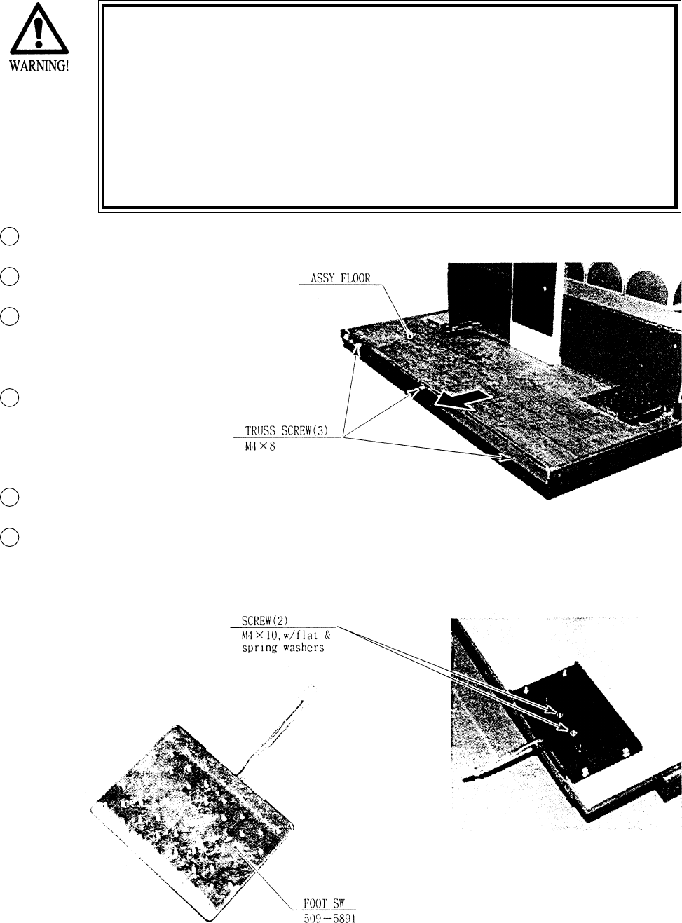
Take out the 3 trus screws
and remove the ASSY
FLOOR.
Turn the ASSY FLOOR over.
Take out the 2 screws and
remove the FOOT SW and
replace.
3
1
2
6
4
5
49
The coin selector should be cleaned
once every 3 months. When cleaning,
follow the procedure below:
Turn the power for the machine OFF.
Open the coin chute door.
Open the gate and dust off by using a
soft brush (made of wool, etc.).
Remove and clean smears by using a
soft cloth dipped in water or diluted
chemical detergent and then squeezed
dry.
Remove the CRADLE.
When removing the retaining ring(E-
ring), be very careful so as not to bend
the shaft.
Remove stain from the shaft and pillow
portions by wiping off with a soft cloth,
etc.
After wiping as per #5 above, further
apply a dry cloth, etc. to cause the coin
selector to dry completely.
Once a month, when performing the COIN SW
TEST, simultaneously check the following:
Does the Coin Meter count satisfactorily?
Does the coin drop into the Cashbox correctly?
Is the coin rejected when inserted while keeping
the REJECT BUTTON pressed down?
If the coin is not rejected when the REJECT BUTTON is pressed, open the coin chute door
and open the selector gate. After removing the jammed coin, put a normal coin in and check
to see that the selector correctly functions.
1
2
3
4
5
6
COIN INSERTION TEST
HANDLING THE COIN JAM
CLEANING THE COIN SELECTOR
8. COIN SELECTOR
Never apply machine oil, etc. to
the coin selector
After cleaning the Coin Selecting,
Insert a regular coin in the normal
working status and ensure that
the Selector correctly functions.
GATE
FIG. 8a
FIG.8b
COIN METER
FIG. 8c
CRADLE
Insert a coin
while keeping
the Reject
Button pressed
down and check
if it is
rejected.
50
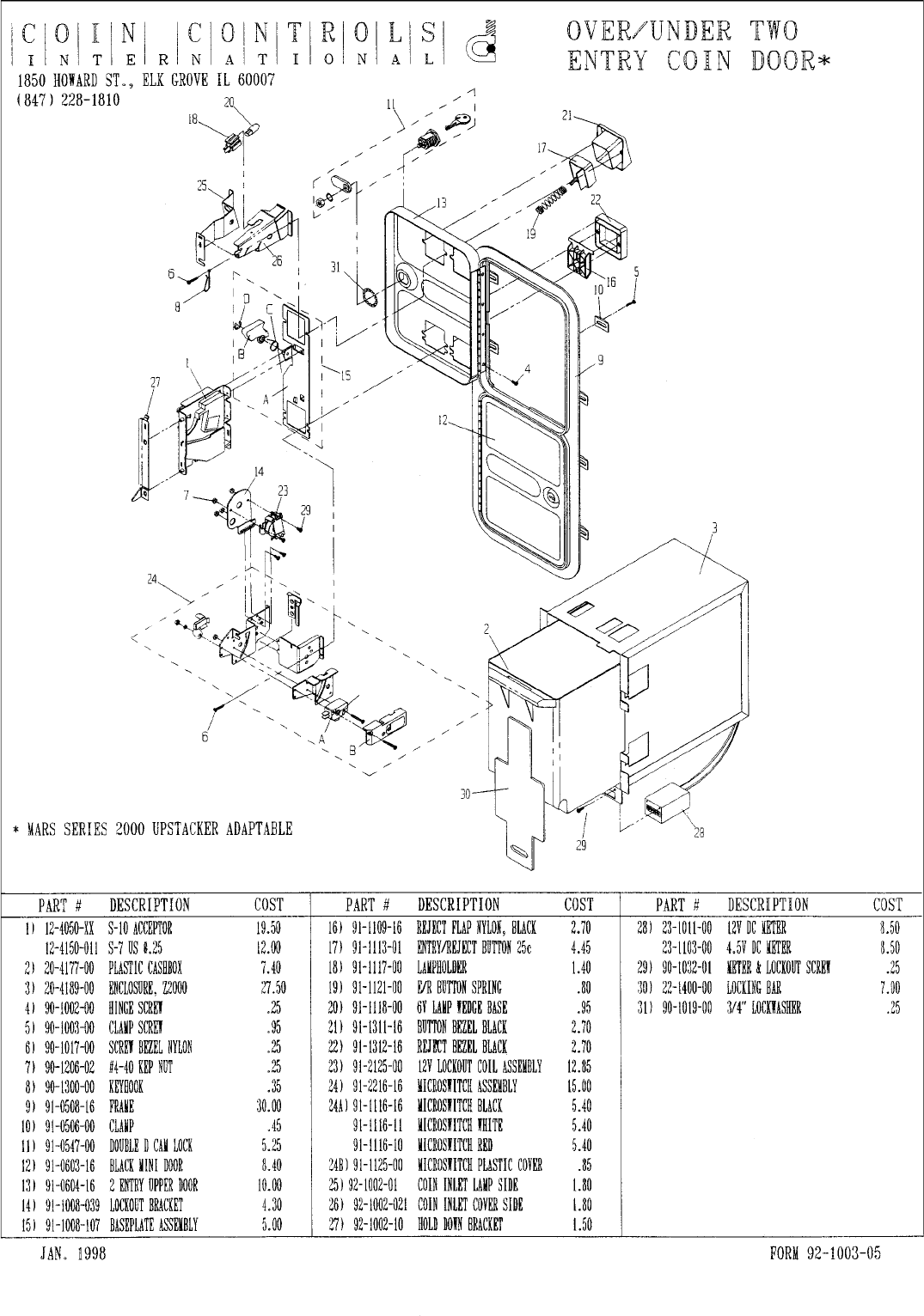
OPTIONAL DOLLAR BILL ACCEPTOR
THE COIN DOOR ASSEMBLY USED ON MAGIC TRUCK ADVENTUREMAGIC TRUCK ADVENTURE
MAGIC TRUCK ADVENTUREMAGIC TRUCK ADVENTURE
MAGIC TRUCK ADVENTURE
COMES EQUIPPED TO ACCEPT A DOLLAR BILL ACCEPTOR. ALL
NEEDED WIRING CONNECTIONS ARE CONVIENENTLY LOCATED INSIDE
THE GAME FOR THIS APPLICATION.
THE COIN DOOR CAN ACCCOMMODATE THE FOLLOWING
VALIDATORS:
HOLE POSITION#1 MARS 2000 SERIES
(FORWARD-MOST POSITION)
HOLE POSITION#2 MARS 2000 SERIES
DBV45 (JCM)
HOLE POSITION #3 CURRENTLY NOT USED
HOLE POSITION #4 DSI01*
*The back flange on the chute can be removed for hole position #4.
If the flange is not removed, it may interfere with the back of the
cabinent.
The frame and cashbox enclosure on this coindoor has been modified to accomodate a Mars 2000
series upstacker. A 2000 series stacker can be added by simply removing the top two entry door and
replacing it with a one entry door with a cut-out for a stacker. This one entry door can be ordered
through Coin Controls or one of Coin Controls authorized distributors. The Part # is 91-4000-01.
The Mars stacker can be obtained through an authorized Mars distributor.
51
52
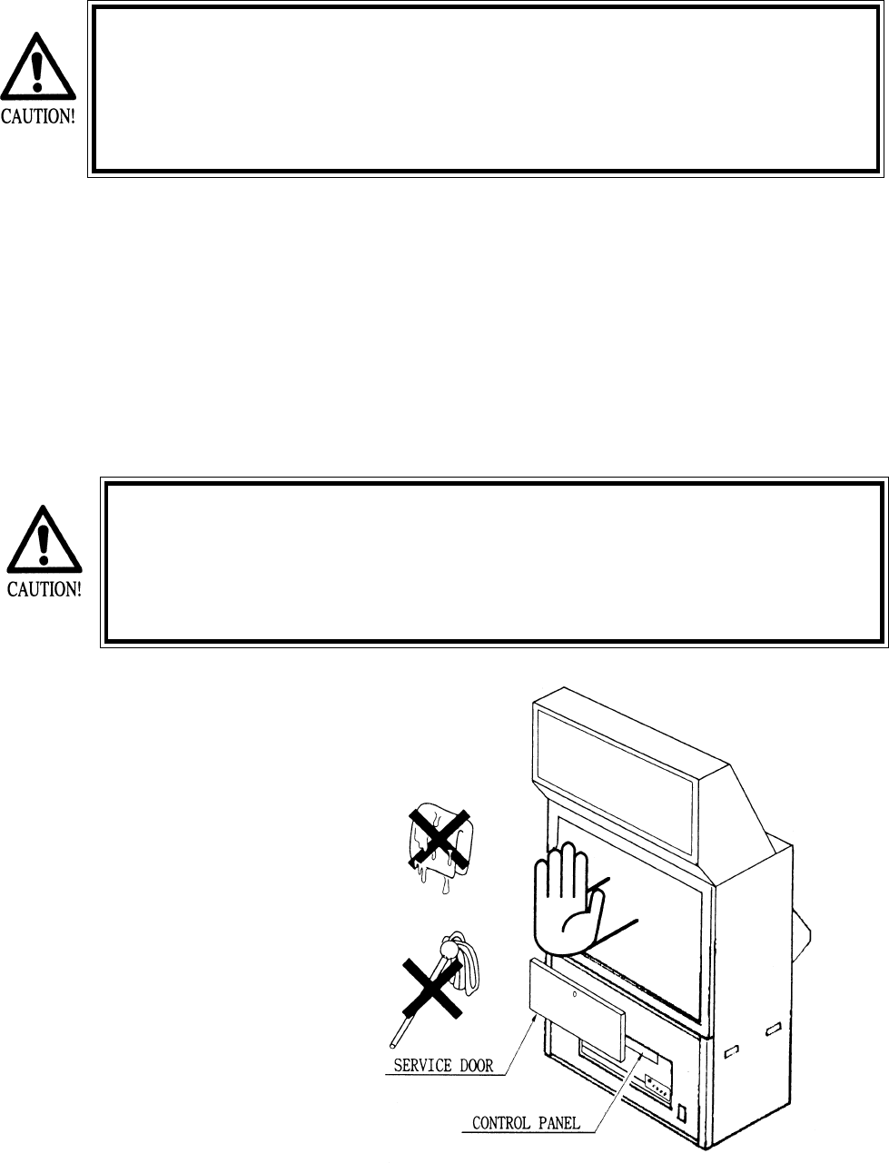
9. PROJECTOR
Since the projector screen is susceptible to damage, pay careful atten-
tion to its handling. When cleaning, freain from using water or volatile
chemicals.
Since the Projector has been adjusted at the time of shipment, avoid
making further adjustments without good reason.
Fine adjustments are stored inthe Projector. Pressing the Fine Adjustment SW (Convergence Adjust-
ment) results in entering the Fine Adjustment mode, and this may cause the stored fine adjustment to
be changed. During work other than for adjustment, should you touch the Fine Adjustment SW by
mistake, immediatley tren power off by using the main SW and then turn it back on again. If any
distortion or color deviation is found in the test mode and adjustments are needed, use the specified
Adjustment Knob, or perform the adjustment by remote control. Note that there are two PROJEC-
TOR makes (HITACHI and MITSUBISHI) and the adjustment method is different between the two.
When checking the Adjustment Control Knob, remove the PTV’s service door. For the HITACHI
PROJECTOR, open the cover in front of the control panel. For the MITSUBISHI PROJECTOR,
remove the cover.
The Projector is subject to color deviation due to Convergence devia-
tion caused by the geomagnitism at the installation location and
peripheral magnetic field. After the installation of machine, and be-
fore commencing operation, check for Convergence deviation and if
deviated, make adjustments.
9 - 1 CLEANING THE SCREEN
When the screen surface
becomes dirty with dust, etc..,
clean it by using a soft cloth
such as gauze. When water and
volatile chemicals such as
benzene and thinnerspill onto
the screen surface, it may be
subject to damage, therefore,
do not use them. Also, since the
surfaces are susceptible to
damage, refrain from rubbing
with a hard material or using a
duster.
53
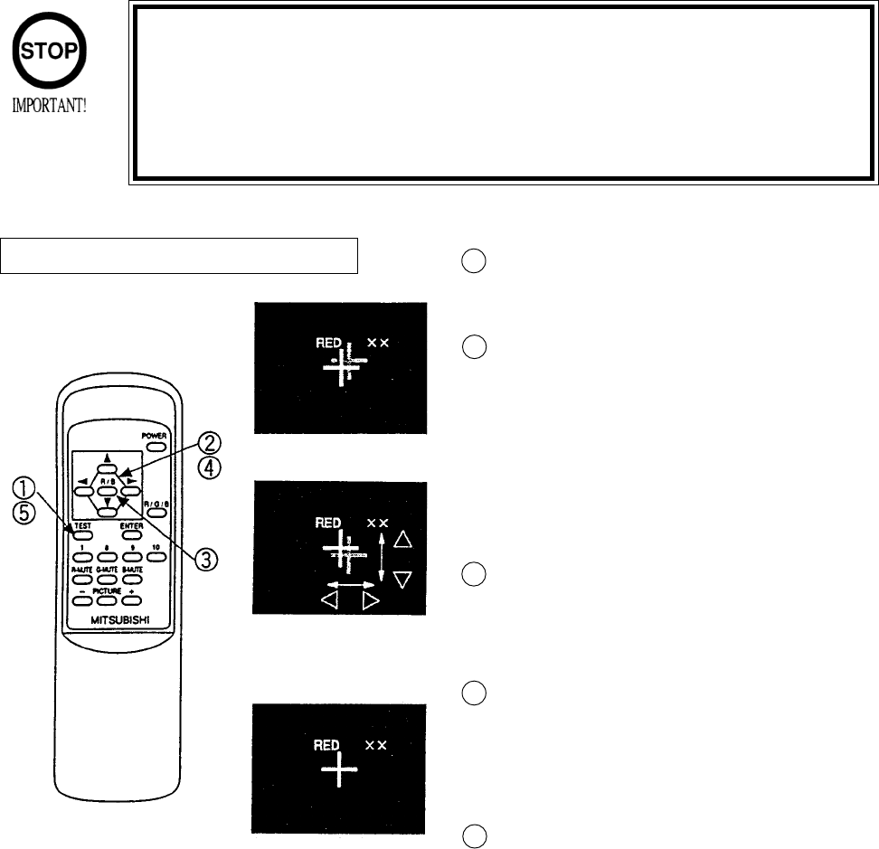
9 - 3 MITSUBISHI PROJECTOR
Press the TEST KEY to have the red line adjust-
ment screen appear.
Superimpose the red cross on the green cross at
the center of the screen.
Move the red cross to the left, right, up, and down
respectively with the corresponding arrow keys of
the remote control.
When the red cross is superimposed on the green
cross, the green cross turns into yellow or white.
Press the R/B Key to have the blue line adjustment
screen appear. Each time R/B Key is pressed, the
red line and blue line will be alternated.
In the manner similar to #2 above, press each key
to superimpose the blue cross on the green cross.
When it is superimposed, the cross in the center
will become white.
Press the TEST KEY to exit from the adjsutment
mode.
During the STATIC CONBVERGENCE ADJUST-
MENT MODE, if no action is taken within 5
minutes, the ADJUSTMENT MODE will be
exited automatically.
STATIC CONVERGENCE ADJUSTMENT
Although Remote Control Buttons other than those specified below do not
function even if pressed during Convergence Adjustment, do not press them
during adjustment work so as to avoid causing malfunctioning.
Operate the Remote Control towards the PTV screen. If directed other than
to the PTV screen, the Remote Control does not function.
Red line Adjustment
Press SHIFT to superimpose
the red line on the green line.
Completion of Adjustment
When adjusting MITSUBISHI PROJECTOR, use the Remote Control.
1
2
3
4
5
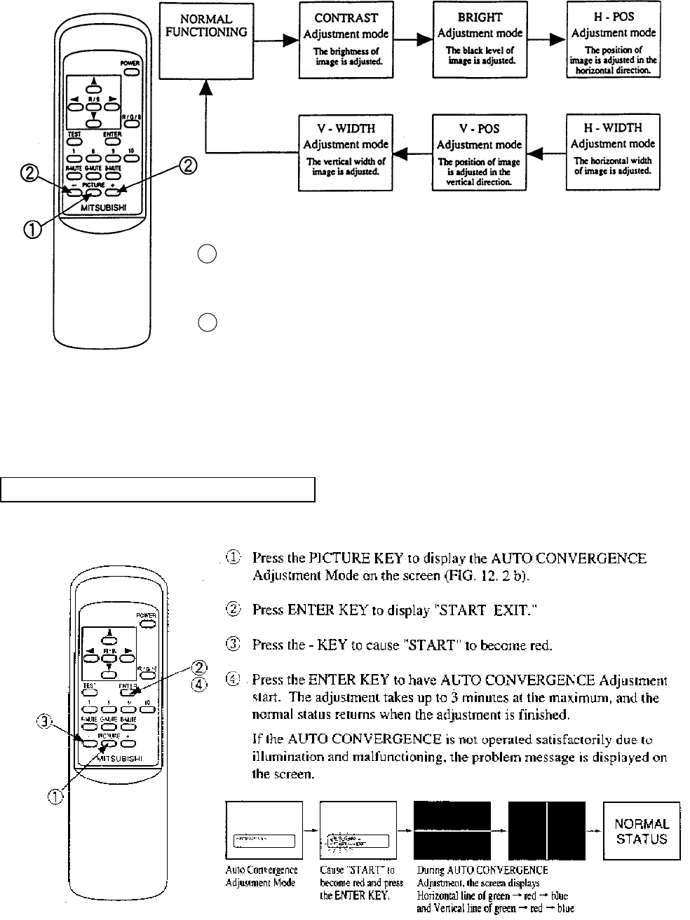
54
Every time the PICTURE Key is pressed, the Adjustment mode proceeds
sequentially in order as above.
In each Adjustment mode, press the + or - key to make adjsutment. In each
Adjustment mode, unless the key input (value or image variation) is effectively
performed within approximately 6 seconds, the Adjustment mode is automati-
cally cancelled and shifts to the normal image. When the horizontal width or
vertical width is adjusted, the convergence is automatically corrected (auto
adjuster functioning).
1
2
AUTO CONVERGENCE ADJUSTMENT
55
9 - 3 TOSHIBA PROJECTOR
Do not touch places other than those specified. Touching places not
specified can cause an electric shock or short circuit accident.
TOSHIBA PROJECTOR has two different types, i.e., one equipped with the Control Panel
and the other without the Control Panel. When adjusting, be sure to confirm the type used.
TOSHIBA PROJECTOR CONTROL PANEL
STATIC CONVERGENCE ADJUSTMENT (With the Control Panel)
Do not press undesignated key. Pressing any undesignated key can
cause malfunction and adjustment fault. Should the key be pressed by
mistake, turn power off and turn it back on again.
During adjustment, should the screen image be abnormally disfigured
due to static electricity and other cuases, do not have adjustment
status stored, and be sure to turn power off.
Operate the Remote Control towards the PTV screen. If directed other
than to the PTV screen, the Remote Control does not function.
Unless the CONV ADJ SW is ON, remote control operation is not
acceptable. At the time of shipment, the SW is set to ON. If remote
control is not accepted, check status of this SW.
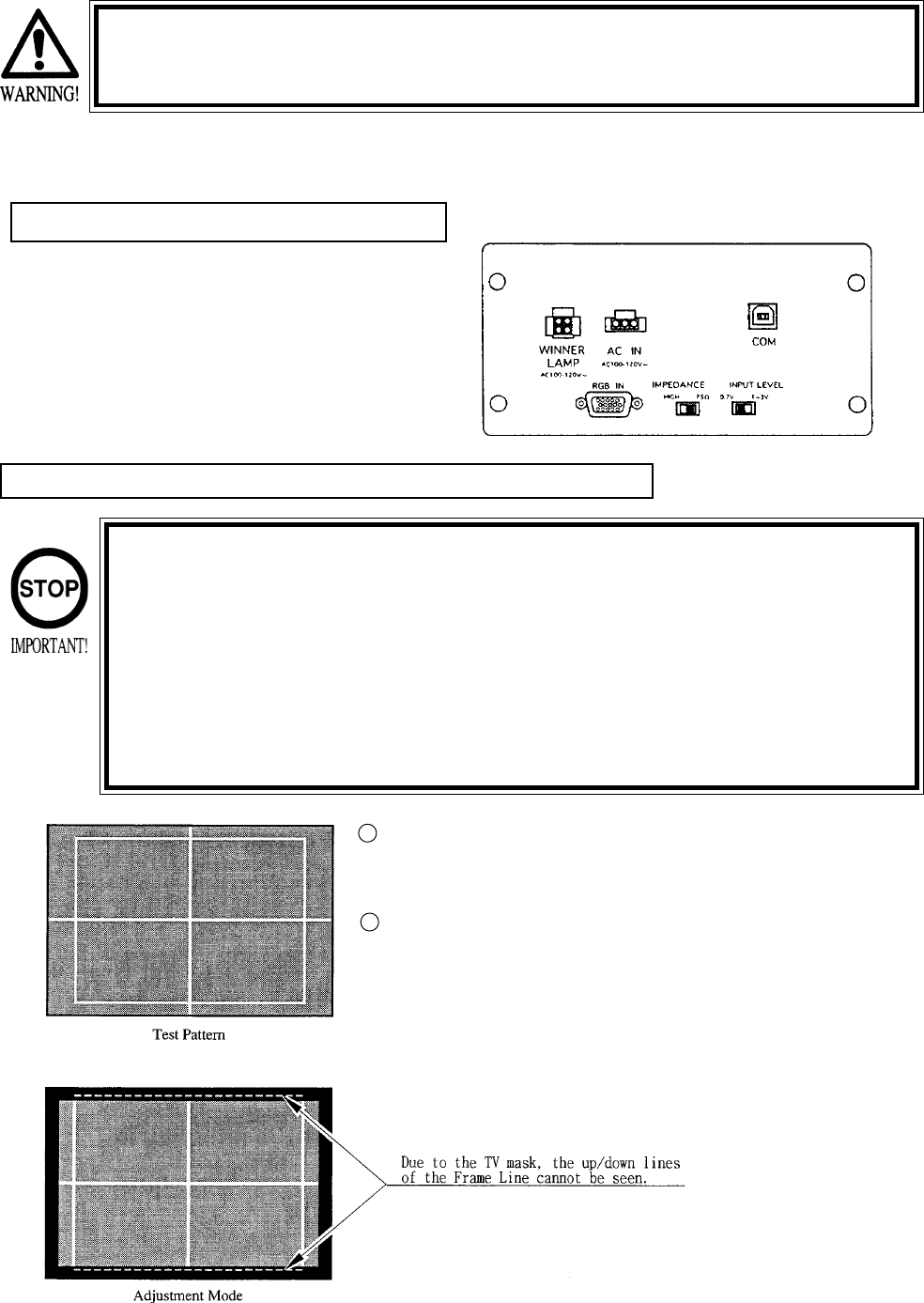
Direct the remote control towards the PTV screen and keep the Test
Key pressed down for approxiamtely 3 seconds. The adjustment
mode should appear on the screen and the screen turns into the green
test pattern.
On the screen, the cross pattern and the square frame line will be
projected. However, due to the TV mask, the up/down lines cannot be
seen.
1
2
56
When intially installing the machine, or when the installa-
tion position is changed, check to see if the Test Pattern is
in the central, well balanced position. If deviated, adjust
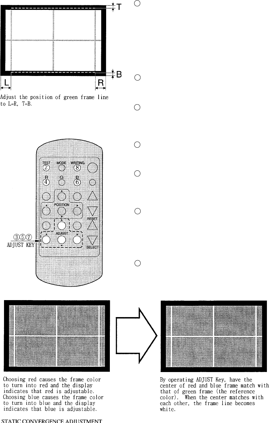
the green position by using the Adjust Key “up/down/left/
right” in the manner so as to improve the balance (L&R,
and T&B are approximately equal as shown).
In the normal usage, with green as reference color, red
and blue are adjusted. Therefore, skip the above proce-
dure.
Press the R Key of the remote control. The red pattern
together with the green pattern are displayed on the
screen. At this time, the frame color turns into red.
By operating the Adjust Key of the remote control “up/
down/left/right”, have the center red match with that of
green. When red color is superimposed on green color, it
seems to be yellow.
Press the B Key of remote control. The blue test pattern is
added to the display on the screen. At this time, the frame
color turns into blue.
By operating the Adjsut key of the remote control “up/
down/left/right”, have the center of the blue match with
that of yellow. When blue color is superimposed on
yellow color, it seems to be white.
By pressing the WRITING KEY, have the adjustment
status stored. After it has been stored, the Adjsutment
Mode is exited automatically, and the noraml mode
returns. If the Test Key is pressed down for approximately
3 seconds without having the adjustment status stored, pre
adjustment status will remain.
The R.G.B. Keys have screen display color change
functions. Pressing the key of the color presently shown
on the screen causes the color to disappear, therefore, for
adjustment, press the key again.
3
4
5
6
7
8
9
57
ADJUSTMENT OF TOSHIBA PROJECTOR (THE TYPE WITHOUT CONTROL PANEL)
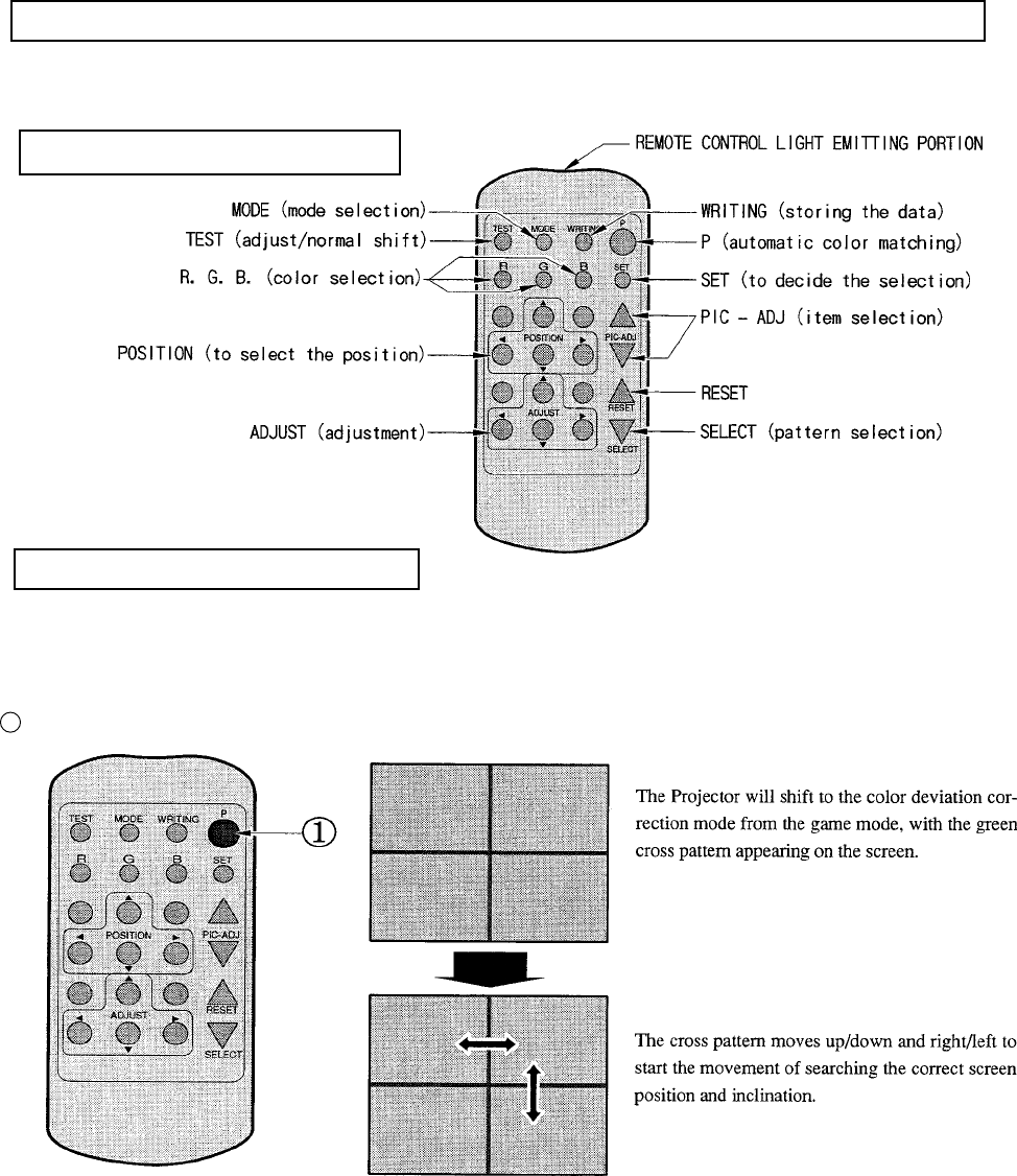
The Remote Control is used for adjustment of the type without Control Panel. When adjsuting the
Projector, direct the Remote Control’s light emitting portion towards the Projector Screen.
REMOTE CONTROL BUTTONS
AUTOMATIC COLOR MATCHING
The Projector may be subject to color deviations affected by earth magnetism, the building’s steel
frames, etc. When the Projector is intially installed of the Projector’s installation position is changed,
have the color matching performed automatically.
Keep pressing the p button (red) for approximately 3 seconds to have the ensuing movements performed automatically.
When the green cross pattern movements are finished, similar detection is performed sequentially in order of red and
then blue cross movements. After detecting by green, red and blue cross movements, the game mode returns with the
color deviation status being corrected
Although very rarely, the TRY AGAIN error display in red may appear. At this time, press the P button (red) for approxi-
mately 3 seconds. Even after the above operation is repeated, if the error condition still exists, then display shifts to
PLEASE ADJ. In this Case, the auto color matching function can not be used. Contact the place of contact herein stated
or where the product was purchased from.
If the automatic color matching indicates an error, color matching can manually be performed. Refer to CONVER-
GENCE ADJUSTMENT (manual color matching).
1
58
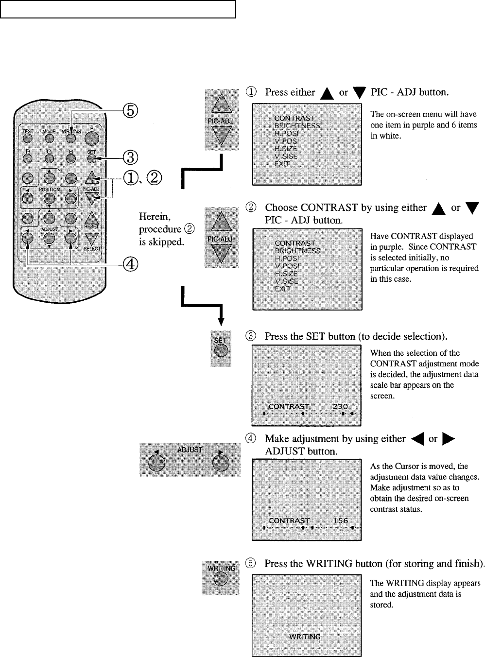
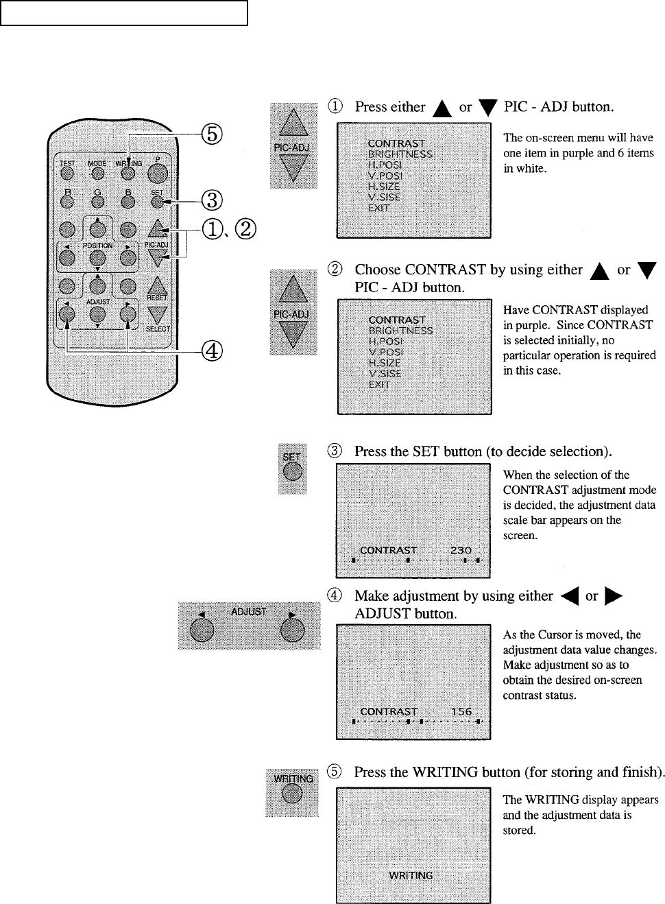
ADJUSTING THE ON-SCREEN CONTRAST
Although the on-screen picture quality has been adjusted at the time of shipment from the factory,
the on-screen contrast can be readjusted if desired. When the Game Board is replaced, readjustment
may be necessary. Changing the CONTRAST causes the light and shade of the on-screen images to
be changed.
When discontinuing the adjustment,
choose EXIT from the menu at the
stage of procedure “2” and press the
SET BUTTON.
To continue adjusting other menu
items, repeat procedure “2~4”
Unless the adjustment data is stored,
the data in the adjusted status will be
erased at the time the power is turned
off and the pre-adjustment status will
prevail when the power is turned ON
the next time.

59
ADJUSTING THE ON-SCREEN BRIGHTNESS
Although the on-screen picture quality has been adjusted at the time of shipment from the factory,
the on-screen contrast can be readjusted if desired. When the Game Board is replaced, readjustment
may be necessary. Changing the BRIGHTNESS causes the light and shade of the on-screen images
to be changed.
When discontinuing the adjustment,
choose EXIT from the menu at the
stage of procedure “2” and press the
SET BUTTON.
To continue adjusting other menu
items, repeat procedure “2~4”
Unless the adjustment data is stored,
the data in the adjusted status will be
erased at the time the power is turned
off and the pre-adjustment status will
prevail when the power is turned ON
the next time.

60
ADJUSTING THE ON-SCREEN CONTRAST
Although the on-screen display position (H. POSI, V. POSI) has been adjusted at the time of ship-
ment from the factory, the on-screen contrast can be readjusted if desired. When the Game Board is
replaced, readjustment may be necessary.
When discontinuing the adjustment,
choose EXIT from the menu at the
stage of procedure ”2” and press the
SET BUTTON.
To continue adjusting other menu
items, repeat procedure “2~4”
Unless the adjustment data is stored,
the data in the adjusted status will be
erased at the time the power is turned
off and the pre-adjustment status will
prevail when the power is turned ON
the next time.
61
ADJUSTING THE SCREEN SIZE
Although the on-screen size (H. SIZE, V. SIZE) has been adjusted at the time of shipment from the
factory, the on-screen contrast can be readjusted if desired. When the Game Board is replaced,
readjustment may be necessary.
When discontinuing the adjustment,
choose EXIT from the menu at the
stage of procedure and press the
SET BUTTON.
To continue adjusting other menu
items, repeat procedure “2~4”
Unless the adjustment data is stored,
the data in the adjusted status will be
erased at the time the power is turned
off and the pre-adjustment status will
prevail when the power is turned ON
the next time.
62
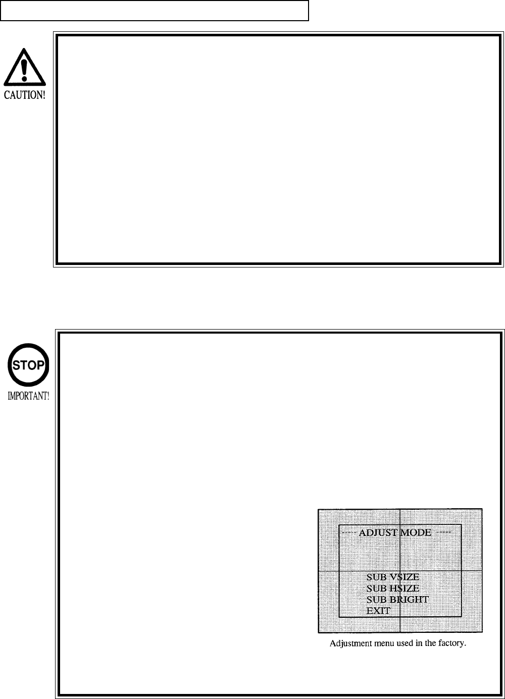
CONVERGENCE ADJUSTMENT (manual color matching)
To avoid circuitry malfunctioning due to electrical load increase, never
utilize CONVERGENCE ADJUSTMENT (Line Convergence Adjustment in
particular) for adjusting screen size changes.
There is no means to restore the Convergence Adjustment data once
stored, to its original state. To avoid changing the screen size by errone-
ously using convergence adjustment, do not perform the green Line
Convergence Adjustment.
As such, be sure to perform the adjustment work from this page onward
by the Technical staff and the location’s maintenance Personnel who are
well versed in such adjustment work. In the Static Convergence
Adjsutments, if satisfactory adjustments can not be performed, do not
make another convergence adjustment inadvetently. Contact the office
herein stated or where the product was purchased from.
To avoid making the adjustment work ineffective, do not press the RE-
SET button during adjustment.
To discontinue adjustment work, keep pressing the TEST button for
approximately 3 seconds at the stage before storing the adjustment
data by pressing the WRITING button.
Should the screen be abnormally disturbed by noise due to static elec-
tricity, etc., turn the power off without storing the adjustment data.
Pressing the “up or down” PIC-ADJ but-
ton in the Convergence Adjustment
Mode status will display the Adjustment
Menu as this is the one applied at the
factory.
Adjusting this menu causes the
Customer’s adjsutment range to be
deviated.
Should the menu shown right be dis-
played by mistake, first choose EXIT by
using either “up or down” PIC-ADJ but-
ton and then press the SET button.

63
STATIC CONVERGENCE ADJUSTMENT
In the static convergence adjustment, each of red and blue images is comprehensively moved to and
superimposed on the green color. If automatic color matching function is not sufficiently satisfactory,
perform this adjustment. Be sure to perform automatic color matching before starting the above
adjustment.
When either of “2” “4” COLOR SELECT
buttons (R,B) is pressed, if the color desired to
be adjusted disappears, press that particular
button again. For example, if the red color
needs to be adjusted again at the stage of “4”
the R button need to be pressed twice.
64
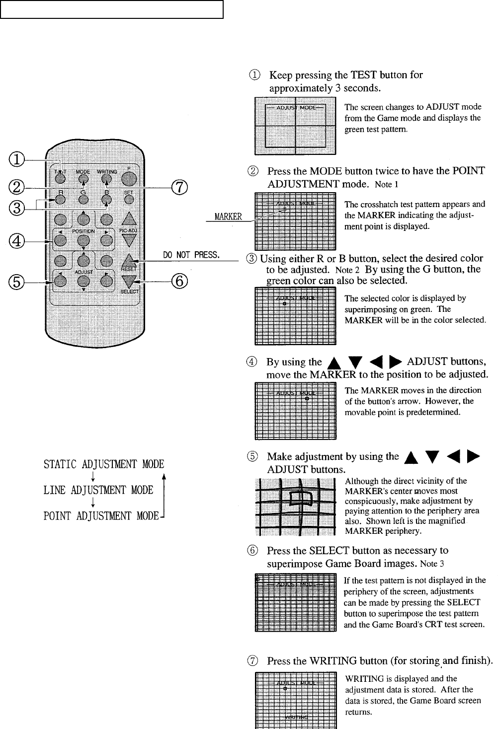
POINT CONVERGENCE ADJUSTMENT
In the POINT CONVERGENCE adjustment, each of red, green, and blue images is partially moved
for color matching. The adjustment may be necessary when the Game Board is replaced or changed,
or screen size is changed. Be sure to perform automatic color matching before starting.
NOTE 1:
When the MODE button is pressed, the adjust-
ment modes will circulate as follows:
NOTE 2:
When either of the COLOR SELECT buttons
(R, B) is pressed, if the desired color to be
adjusted is erased, press that particular button
again.
NOTE 3:
By repeatedly pressing the SELECT button,
only the Projector’s TEST pattern screen and
the screen superimposing the Game Board Test
pattern can be alternately displayed.
65
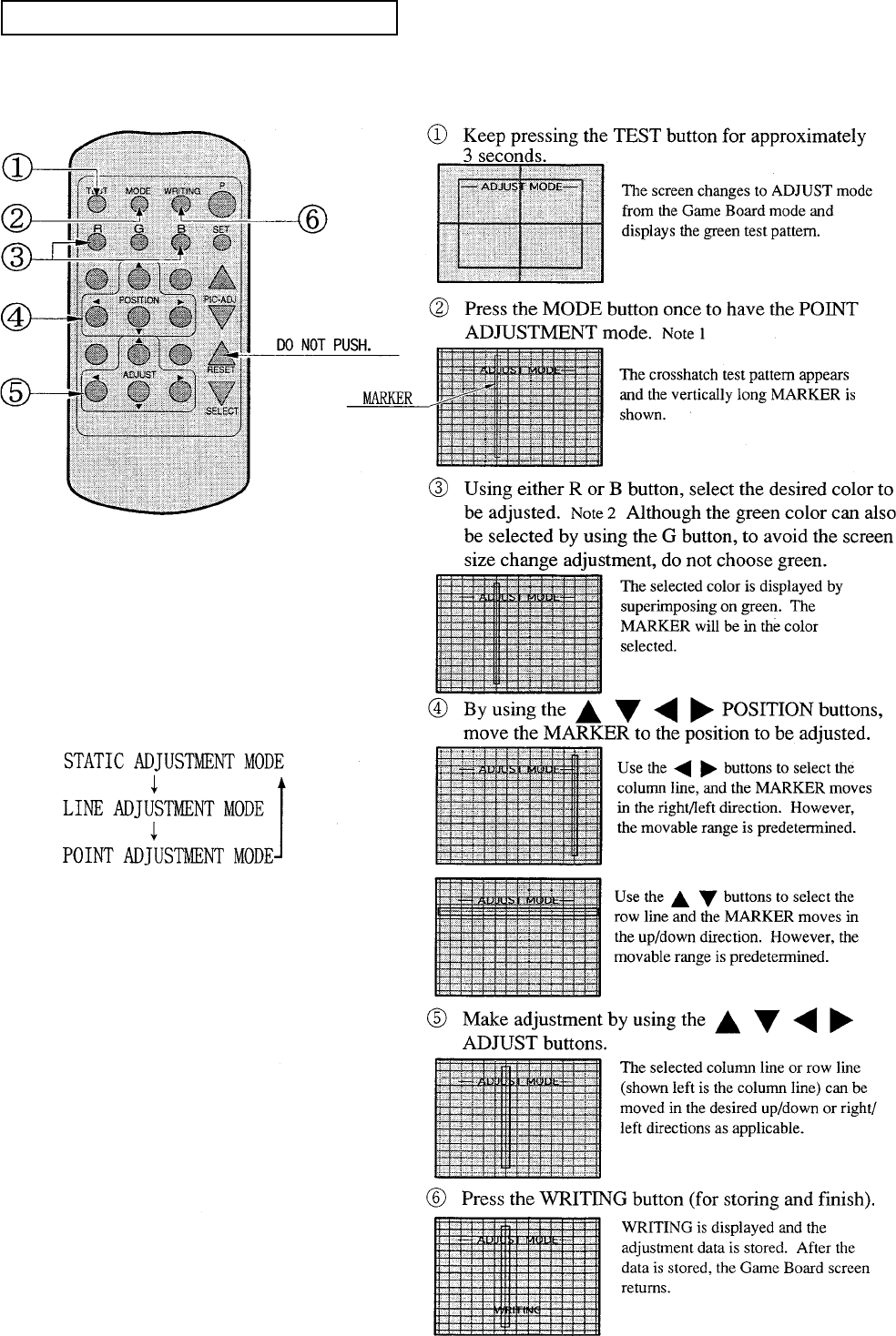
LINE CONVERGENCE ADJUSTMENT
In the LINE CONVERGENCE ADJUSTMENT, the adjustment point of column line (vertical) or
row line (horizontal) is comprehensively moved for color matching. It is convenient to utilize this
adjustment when color of the column line or row is uniformly deviated.
NOTE 1:
When the MODE button is repeatedly pressed,
the adjustment modes will circulate as follows:
NOTE 2:
When either of the COLOR SELECT buttons
(R, B) is pressed, if the desired color to be
adjusted is erased, press that particular button
again.
66
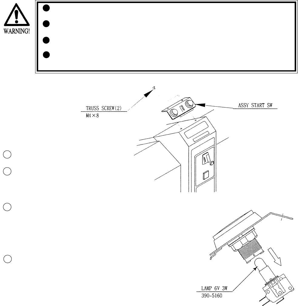
10. REPLACEMENT OF LAMP
When performing the work, be sure to turn power off. Working with
power on can cause an electric shock or short circuit accident.
The Flourescent Lamp, when it gets hot, can cause burns. Be very
careful when replacing the Fluorescent Lamp.
Be sure to use lamps of the designated rating. Using lamps of
undesignated rating can cause a fire or malfunctioning.
Use care so as no to damage wirings. Damaged wiring can cause elec-
tric shock or shortcircuit accidents.
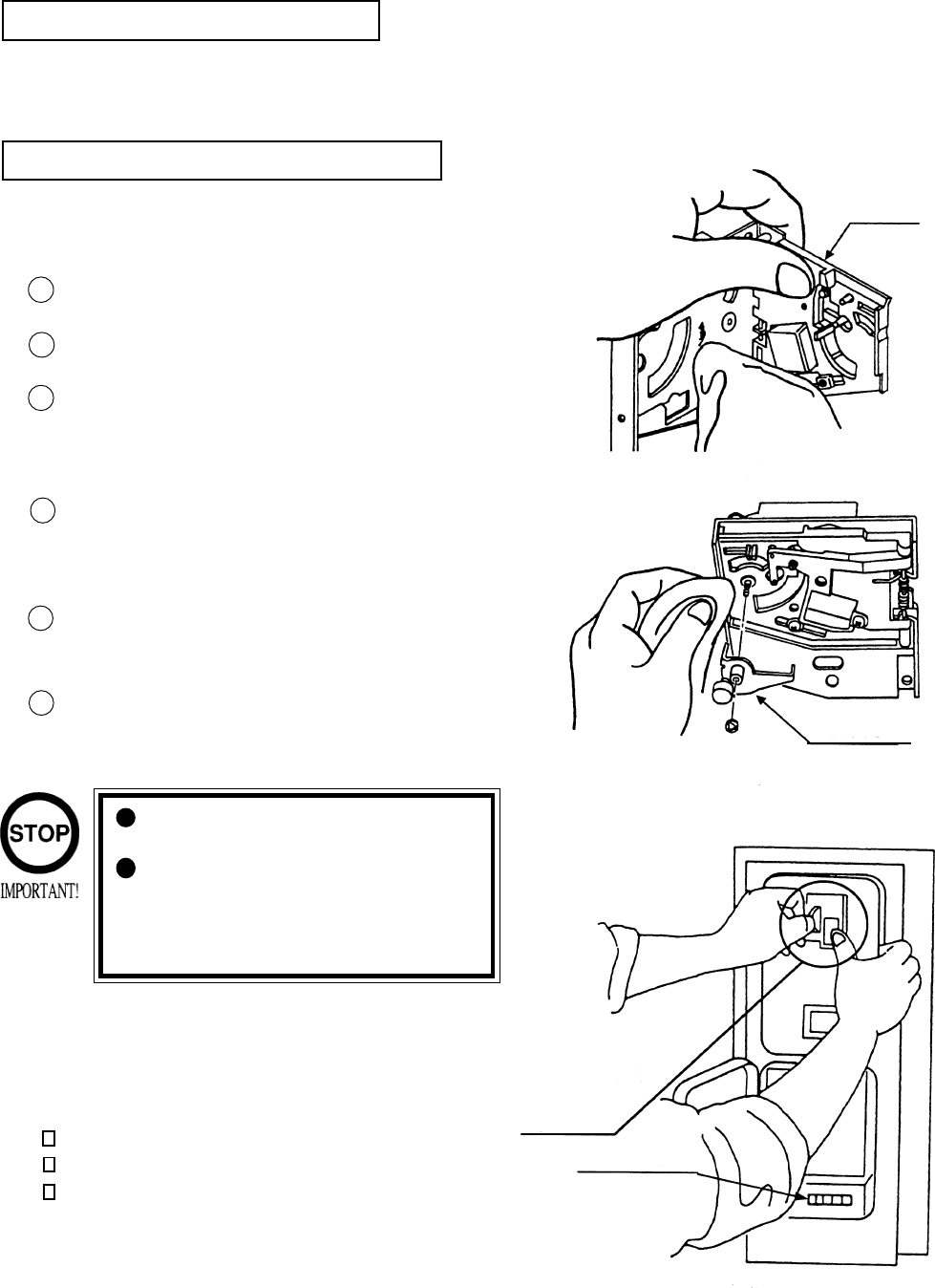
Turn Power OFF.
Take out the 2 truss screws and remove
the ASSY START SW. be careful so as
not to damage the inside wiring.
Hold the SW portion by 2 fingers
tightly and pull out from the button’s
base portion. At this time, be careful so
as not to damage the wiring connected
to the SW.
The Lamp is at the end of the SW
portion. Pull out straight without
turning the lamp.
10 - 1 REPLACING THE LAMP
3
1
2
4
67
The items listed below require periodic check and maintenance to retain the performance of
this machine and ensure safe operation.
When handling the controller, the player will be in direct contact with it. In order to always
allow the player to enjoy the game, be sure to clean it regularly.
11. PERIODIC INSPECTION TABLE
Be sure to check once a year to see if Power Cords are damaged,
the plug is securley inserted, dust is accumulated between the
Socket Outlet and the Power Plug, etc. Using the product with
dust as is accumulated can cause a fire or electrical shock.
Periodically once a year, request the place of contact herin stated
or the Distributer, etc. where the product was purchased from, as
regards the interior cleaning. Using the product with dust as is
accumulated in the interior without cleaning can cause a fire or
accident. Note that cleaning the interior parts can be performed
on a pay-basis.
CLEANING CABINET SURFACES
When the cabinet surfaces are badly soiled, remove stains with a soft cloth dipped in water or
diluted (with water) chemical detergent and squezzed dry. To avoid damaging surface finish,
do not use such solvents as thinner, benzine, etc. other than ethyl alcohol, or abrasives,
bleaching agent and chemical dustcloth.
ITEMS DESCRIPTION PERIOD REFERENCE
CONTROL MECHA Check Volume Value and SW as required
Grease to gear portion Weekly 6
Check Adj. Gear engagement Monthly 6
COIN SELECTOR Check COIN SW Monthly 6
COIN SELECTOR cleaning Trimonthly 8
PROJECTOR SCREEN cleaning Weekly 9
Check adjustments Monthly 3, 6, 9
GAME BD Setting check monthly 6
INTERIOR Cleaning Annually see above.
POWER PLUG Inspection and cleaning
CABINET SURFACE Cleaning As necessary see below
CABINET Ensure that adjusters are
in contact with the floor As necessary 3
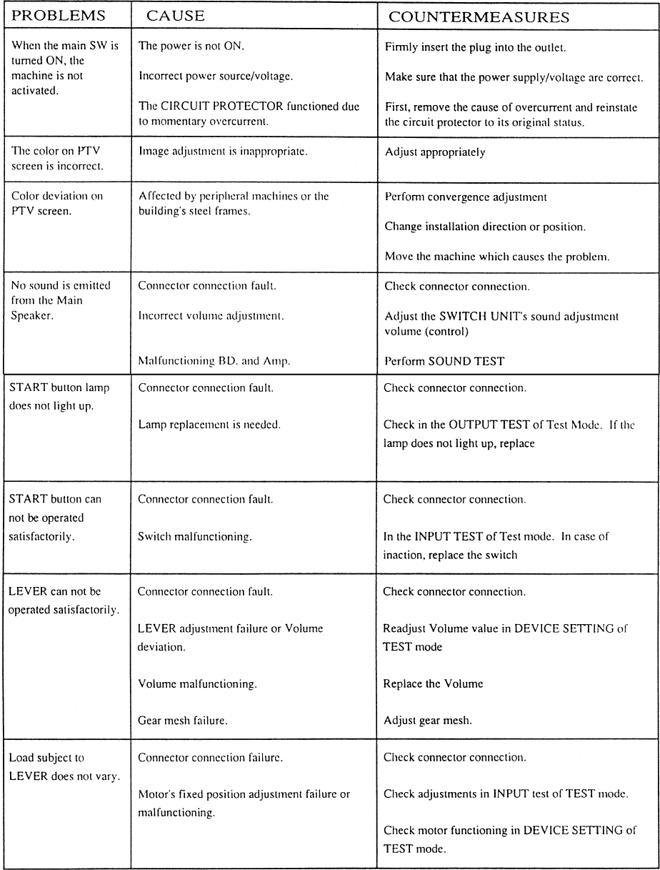
68
12. TROUBLESHOOTING
Should trouble occur, first check connector connections.
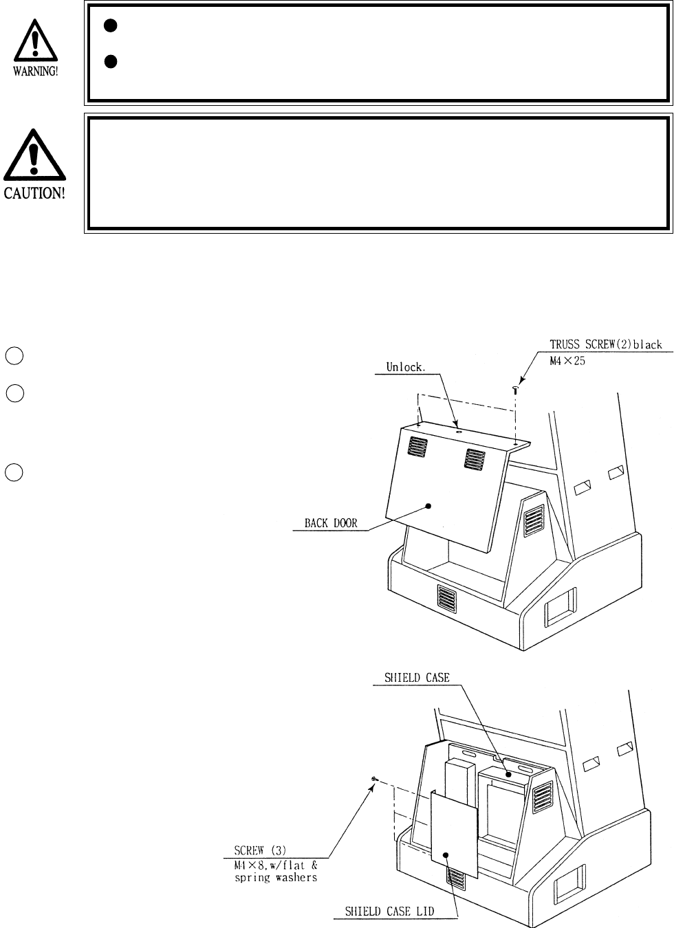
69
13. GAME BOARD
In order to prevent an electrical shock, be sure to turn power off before
performing work by touching the interior parts of the product.
Be careful so as not to damage wirings. Damaged wiring can cause an
electric shock or short circuit accident.
Do not expose the Game BD, etc. without a good reason. In this product,
setting changes are made during the test mode. The Game BD need not be
operated. Use the Game BD, etc. as is with the same setting made at the
time of shipment. The electronic parts on the IC Board could be damaged
due to human static electricity.
13 - 1 GAME BOARD
When replacing or inspecting the Game BD, take out the Game BD by using the following
procedure:
Turn the AC unit’s Main SW OFF.
Take out the 2 truss screws, unlock
and remove the the Back Door.
Take out the 3 screws, remove Shield
Case Lid, and the Game BD appears.
1
2
3
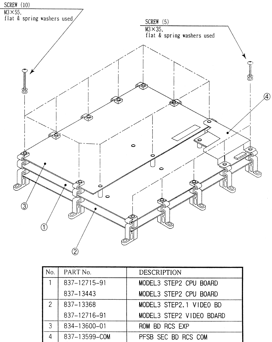
70
13 - 2 COMPOSITION OF GAME BOARD
GAME BD RCS EXP (833-13601-01)
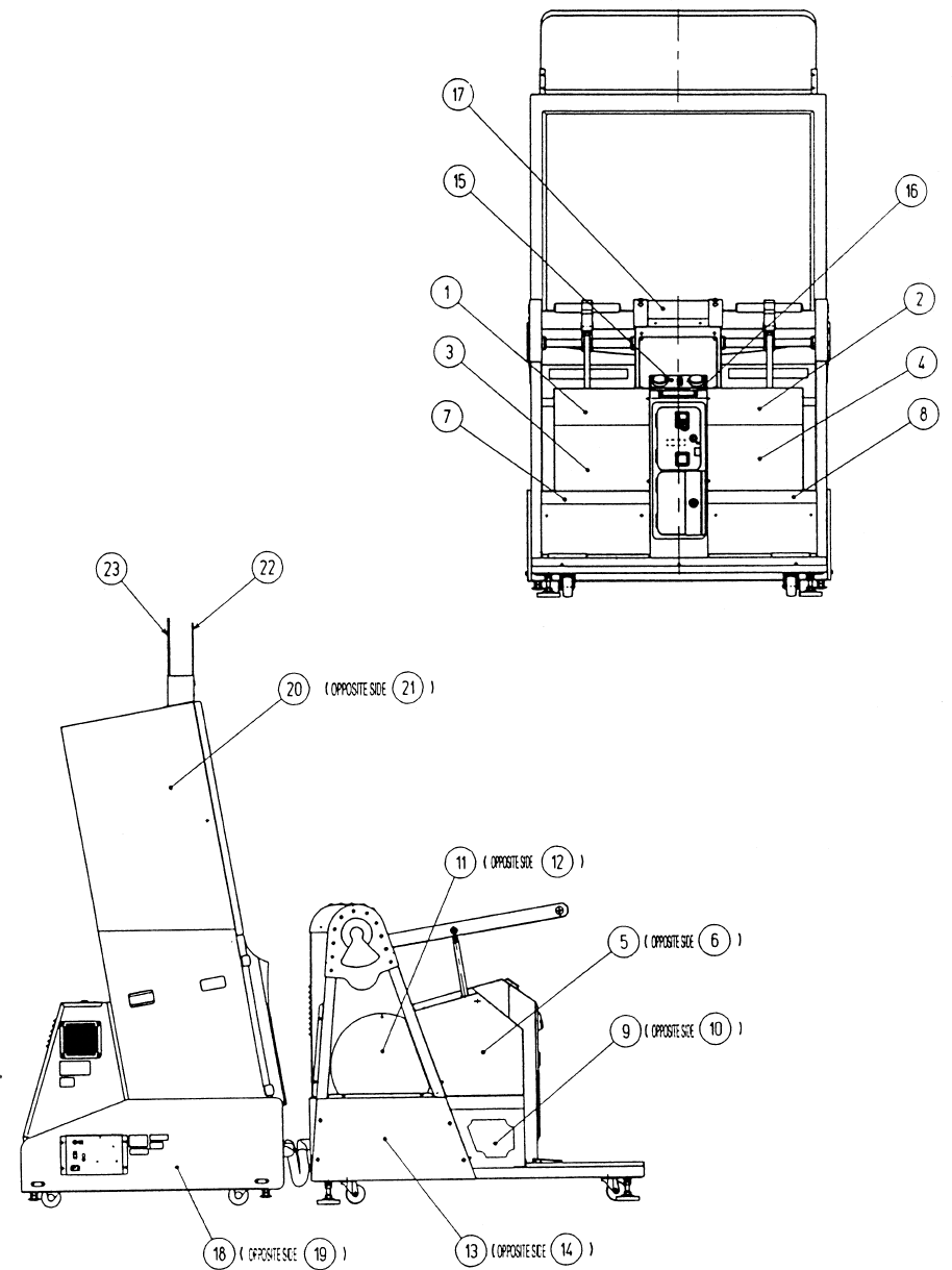
71
14. DESIGN RELATED PARTS
72
ITEM NO. PART NO. DESCRIPTION
1 RCS-3029 STICKER ALMA
2 RCS-3030 STICKER ROY
3 RCS-3031-L STICKER RF900 L
4 RCS-3031-R STICKER RF900 R
5 RCS-3032-L STICKER 518 L
6 RCS-3032-R STICKER 518 R
7 RCS-3033-L STICKER LINE FRONT L
8 RCS-3033-R STICKER LINE FRONT R
9 RCS-3034-L STICKER FRONT L
10 RCS-3034-R STICKER FRONT R
11 RCS-3035-L STICKER MAGICAL L
12 RCS-3035-R STICKER MAGICAL R
13 RCS-3036-L STICKER LINE REAR L
14 RCS-3036-R STICKER LINE REAR R
15 RCS-3421-A STICKER START
16 RCS-0003 STICKER LR
17 RCS-3013-A STICKER TOP COVER
18 RCS-1151-B STICKER BASE L
19 RCS-1151-C STICKER BASE R
20 421-10032 STICKER SIDE RCS L
21 421-10033 STICKER SIDE RCS R
22 RCS-1252 BILLBOARD PANEL FRONT
23 RCS-1253 BILLBOARD PANEL REAR
DESIGN RELATED PARTS
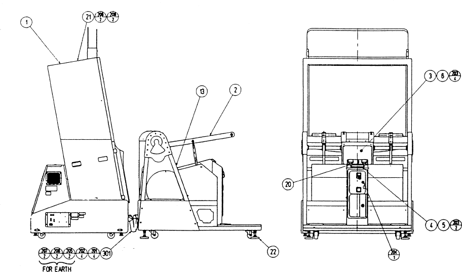
73
15. PARTS LIST
ITEM NO. PART NO. DESCRIPTION
1 RCS-1000 ASSY FRONT CABINET
2 RCS-3000 ASSY REAR CABINET
3 RCS-0001 INST HOLDER
4 RCS-0002 DENOMI PLATE
5 421-7907~ DENOMI SH 1 GAME~
6 422-10041X-01 PLAY INSTR SH RCS ENG
21 RCS-0005 TOP COVER PLATE
22 RCR-0018 LEG RUBBER

74
ITEM NO. PART NO. DESCRIPTION
1 105-5240Y SHIELD CASE MODEL3
2 105-5242X SHIELD CASE LID MODEL3
3 839-0951 FILTER BD MODEL 3 JPT
4 833-13601-01 GAME BD RCS EXP
101 260-0064 FAN MOTOR DC 12V
201 000-P00408-W M SCR PH W/FS M4X8
202 010-P00308-F S-TITE SCR PH W/F M3X8
203 010-P00310-F S-TITE SCR PH W/F M3X10
204 000-P00320-W M SCR PH W/FS M3X20
205 010-P00365-F S-TITE SCR PH W/F M3X65
ASSY SHIELD CASE (RCS-0100)
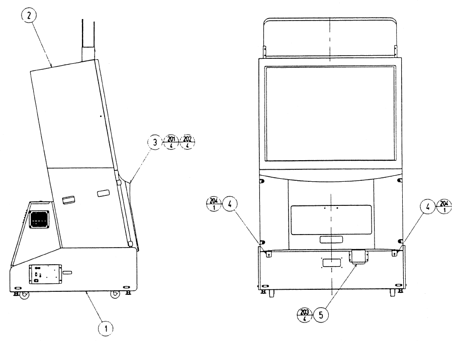
75
ASSY FRONT CABI (RCS-1000)
ITEM NO. PART NO. DESCRIPTION
1 RCS-1100 ASSY BASE CABI
2 RCS-1200 ASSY PTV
3 RCS-1300 ASSY FRONT PANEL
4 JEY-0004 PTV HOLDER
5 JEY-0003 RGB DUCT
201 000-T00525-0C M SCR TH CRM M5X25
202 068-552016-0C FLT WSHR CRM 5.5-20X1.6
203 000-T00416-0B M SCR TH BLK M4X16
204 000-T00525-0B M SCR TH BLK M5X25
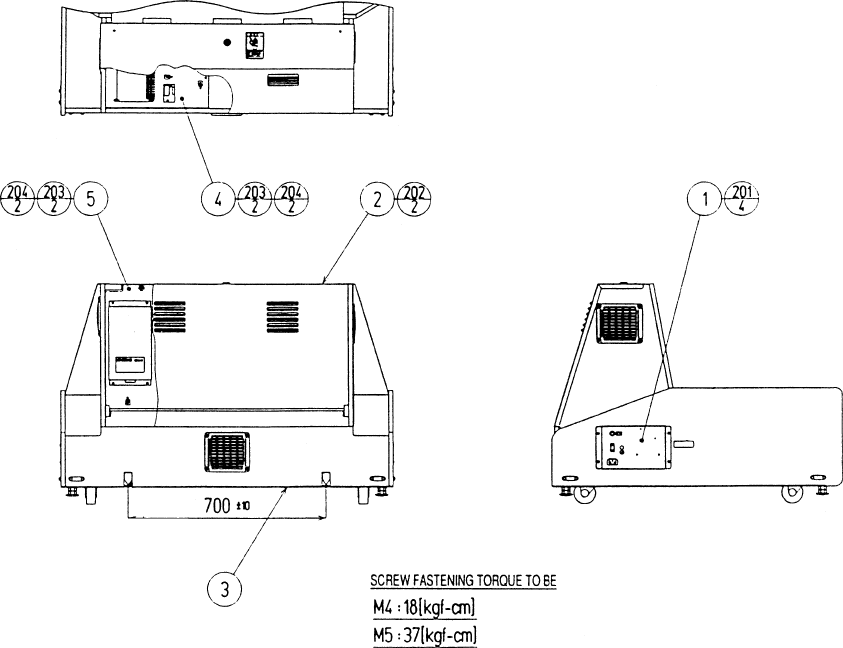
76
ASSY BASE CABI (RCS-1100)
ITEM NO. PART NO. DESCRIPTION
1 RCS-1120 AC UNIT
2 JEY-1170 ASSY BACK DOOR
3 RCS-1150 ASSY SUB BASE CABI
4 RCS-4000 ASSY ELEC
5 RCS-4100 ASSY MAIN BD
201 000-T00416-0B M SCR TH BLK M4X16
202 000-T00425-0B M SCR TH BLK M4X25
203 000-P00530-S M SCR PH W/S M5X30
204 068-552016 FLT WSHR 5.5-20X1.6
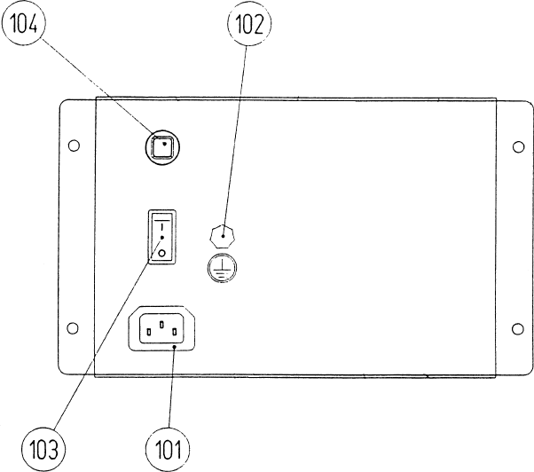
77
AC UNIT (RCS-1120)
ITEM NO. PART NO. DESCRIPTION
1 JEY-1051 AC BRKT
101 214-0202 AC INLET PANEL TYPE
102 280-0417 TERMINAL BINDING POST BLACK
103 509-5453-91-V-B SW ROCKER J8 V-B
104 512-5046-8000 C.P. 8000MA CE UL
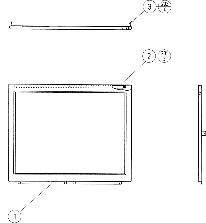
78
ASSY MASK (MGL-1150)
ITEM NO. PART NO. DESCRIPTION
1 MGL-1102 TV MASK
2 MGL-1151 SLIT PLATE
3 MGL-1152 MASK SIDE HOLDER
201 012-F00408-0B TAP SCR FH BLK 4X8
202 000-F00410 M SCR FH M4X10
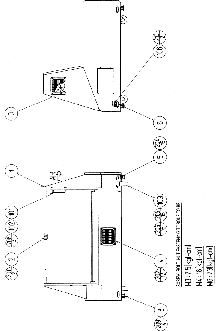
79
ASSY SUB BASE CABI (RCS-1150)
80
ASSY SUB BASE CABI (RCS-1150)
ITEM NO. PART NO. DESCRIPTION
1 RCS-1151 PTV BASE
2 ASK-1152 LOCK BRKT
3 105-5340-01 FAN BRKT LONG
4 253-5460-01 AIR VENT BLACK
5 ARC-1006 LEG BRACKET
6 117-5191 PLATE
8 601-5699X LEG ADJUSTER BOLT M16X75
101 260-0056 AXIAL FLOW FAN AC 115V 50-60Hz
102 601-8543 FAN GUARD
103 601-9377 CASTER FAI-75
106 117-5402-06 EARTH TERMINAL PLATE
201 000-P00416-W M SCR PH W/FS M4X16
202 000-T00416-0B M SCR TH BLK M4X16
203 011-T03512 TAP SCR TH 3.5X12
204 030-000630-SC HEX BLT W/S CRM M6X30
205 030-000630-SC HEX BLT W/S M6X30
206 060-F00600 FLT WSHR M6
207 011-F00310 TAP SCR FH 3X10
208 000-P00312-W M SCR PH W/FS M3X12
209 050-H01600 HEX NUT M16
210 011-F03512 TAP SCR FH 3.5X12
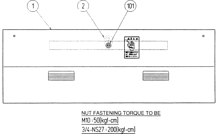
81
ASSY BACK DOOR (JEY-1170)
ITEM NO. PART NO. DESCRIPTION
1 ASK-1141 BACK DOOR
2 TH-1015 LOCKING TONGUE
101 220-5575 CAM LOCK MASTER W/O KEY
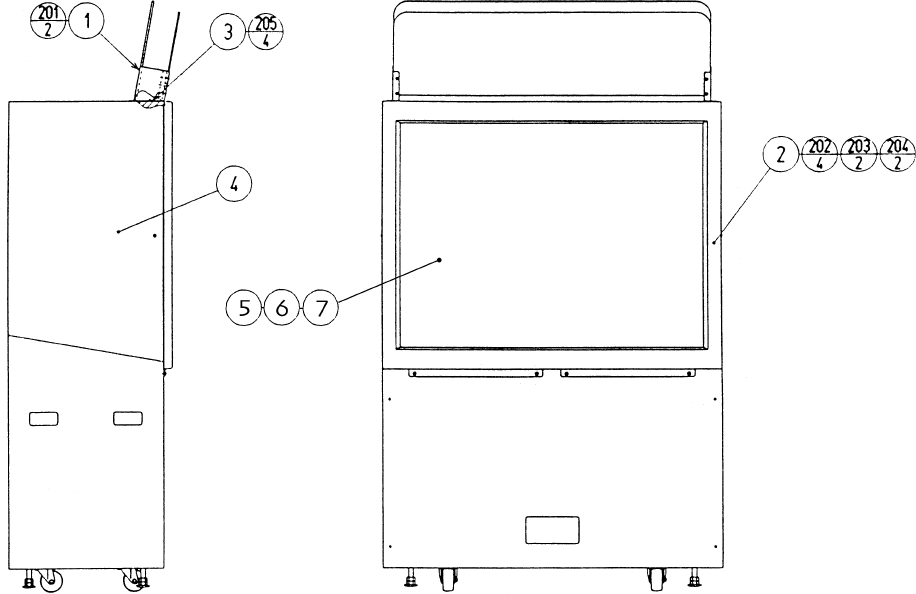
82
ITEM NO. PART NO. DESCRIPTION
1 RCS-1250 ASSY BILLBOARD
2 MGL1-1150 ASSY MASK
3 RCS-1201 MASK HOLDER
4 RCS-1230 PROJ. DSPL T 50 TYPE 24K
5 200-5607 FRESNEL LENS 50"
6 200-5608 LENTICULAR LENS 50"
7 200-5601 MONITOR GLASS 50"
201 000-P00516-WB M SCR PH W/FS BLK M5X16
202 000-P00520-W M SCR PH W/FS M5X20
203 000-T00525-0C M SCR TH CRM M5X25
204 068-552016-0C FLT WSHR CRM 5.5-20X1.6
205 000-F00414 M SCR FH M4X14
ASSY PTV (RCS-1200)
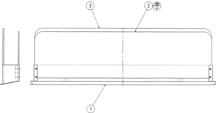
83
ASSY BILLBOARD (RCS-1250)
ITEM NO. PART NO. DESCRIPTION
1 RCS-1251 BILLBOARD BASE
2 RCS-1252 BILLBOARD PANEL FRONT
3 RCS-1253 BILLBOARD PANEL REAR
201 000-T00412-0C M SCR TH CRM M4X12
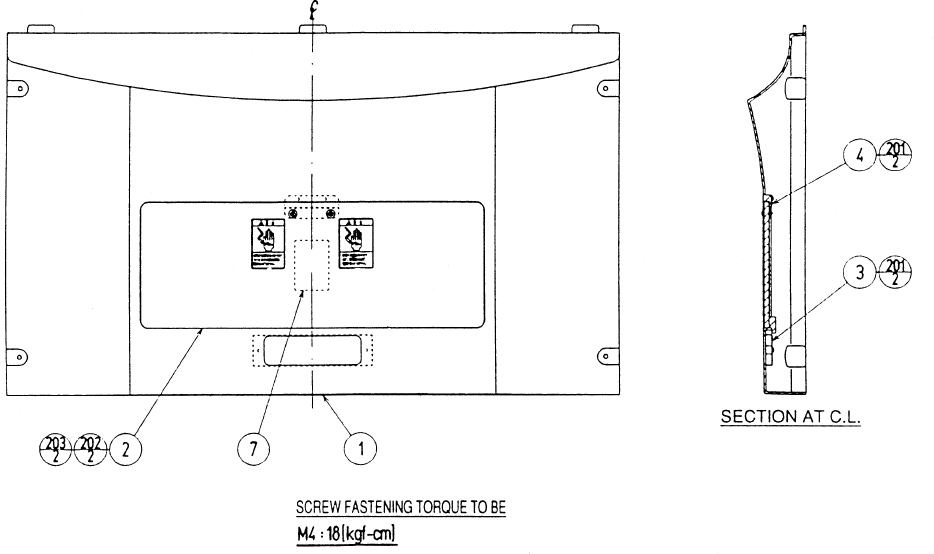
84
ASSY FRONT PANEL (RCS-1300)
ITEM NO. PART NO. DESCRIPTION
1 RCS-1301 FRONT PANEL
2 ASK-1302 PTV LID
3 ASK-1303 HOLE COVER
4 ASK-1304 LID BRKT
201 012-P00410 TAP SCR #2 4X10
202 000-T00416-0C M SCR TH CRM M4X16
203 068-441616-0C FLT WSHR CRM 4.4-16X1.6
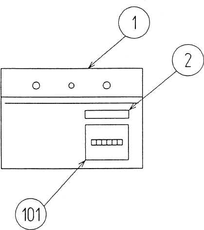
85
METER UNIT (HOD-1590)
ITEM NO. PART NO. DESCRIPTION
1 HOD-1591 METER BRKT
101 220-5643-01 MAG CNTR DC5V 6P WH MZ-674-D04
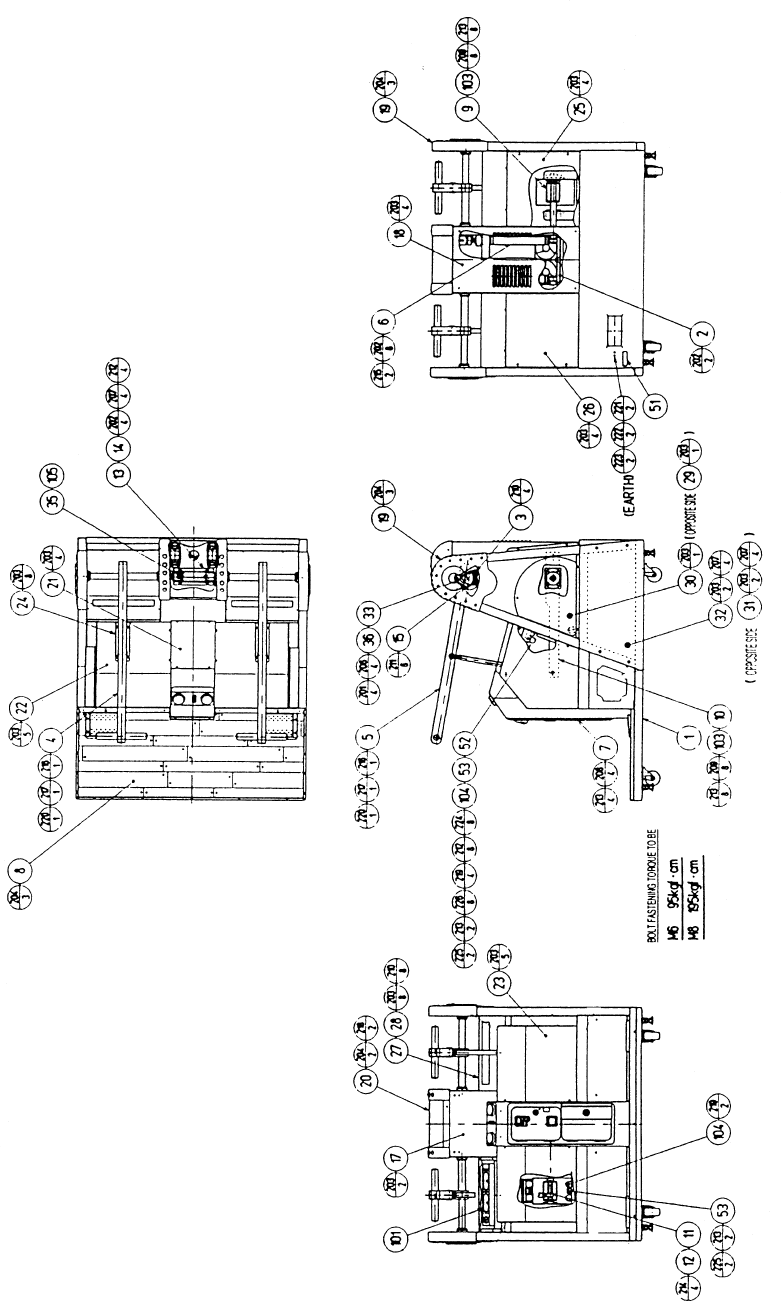
86
ASSY REAR CABI (RCS-3000)
87
ASSY REAR CABI (RCS-3000)
ITEM NO. PART NO. DESCRIPTION
1 RCS-3001Y REAR BASE
2 RCS-3050 ASSY COOLING FAN
3 RCS-3070 ASSY VR
4 RCS-3100 ASSY SWING LEVER L
5 RCS-3200 ASSY SWING LEVER R
6 RCS-3300 ASSY SHOCK ABSORBER
7 RCS-3400 ASSY COIN CHUTE TOWER
8 RCS-3500 ASSY FLOOR
9 RCS-3002Y SWING ARM L
10 RCS-3003Y SWING ARM R
11 RCS-3004 PIN L
12 RCS-3005 COLLAR
13 RCS-3006 RUBBER SPRING BASE
14 RCS-3007 RUBBER SPRING STOPPER
15 RCS-3008 LEVER HOLDER
17 RCS-3010 PILLAR LID F
18 RCS-3011 PILLAR LID R
19 RCS-3012 PILLAR COVER SIDE
20 RCS-3013 PILLAR COVER TOP
21 RCS-3014 MECHA COVER C
22 RCS-3015 MECHA COVER L
23 RCS-3016 MECHA COVER R
24 RCS-3017 UPPER PLATE
25 RCS-3018 BACK COVER L
26 RCS-3019 BACK COVER R
27 RCS-3020 SPEAKER COVER
28 RCS-3021 SPEAKER NET
29 RCS-3022 HOLE LID L
30 RCS-3023 HOLE LID R
31 RCS-3024 SIDE COVER L
32 RCS-3025 SIDE COVER R
33 RCS-3026 GEAR HOLDER
35 RCS-3038 KEY 5X5X40
36 601-6450 GEAR 110
52 RCS-3039 UPPER STOPPER W
53 RCS-3040 BUMP RUBBER
101 130-5146 SPEAKER BOX 80 OHM 20W
102 100-5334 THRUST BUSH25
103 100-5335 BEARING UNIT 20
104 601-8451 STOPPER RI-30
105 601-10480 TORSION RUBBER
CONTINUED NEXT PAGE
88
ITEM NO. PART NO. DESCRIPTION
201 000-P00412-W M SCR PH W/FS M4X12
202 000-P00512-W M SCR PH W/FS M5X12
203 000-T00408-0C M SCR TH CRM M4X8
204 000-T00412-0C M SCR TH CRM M4X12
205 000-T00616-0C M SCT TH CRM M6X16
206 028-A00408-P SET SCR HEX SKT CUP P M4X8
207 030-000616-S HEX BLT W/S M6X16
208 030-000820-S HEX BLT W/S M8X20
209 030-000840-S HEX BLT W/S M8X40
210 050-F00400 FLG NUT M4
211 050-F00500 FLG NUT M5
212 060-F00600 FLT WSHR M6
213 060-F00800 FLT WSHR M8
214 065-S012S0-Z STP RING BLK OZ S12
215 065-S022S0-Z STP RING BLK OZ S22
216 068-552016 FLT WSHR 5.5-22X1.6
217 030-000510 HEX BLT M5X10
218 000-T00512-0C M SCR TH CRM M5X12
219 068-852216 FLT WSHR 8.5-22X1.6
220 060-S00500 SPR WSHR M5
221 050-H00400 HEX NUT M4
222 060-S00400 SPR WSHR M4
223 060-F00400 FLT WSHR M4
224 020-00625-HZ HEX SKT CAP SCR BLK OZ M6X25
225 020-000830-HZ HEX SKT CAP SCR BLK OZ M8X30
226 060-S00600 SPR WSHR M6
ASSY REAR CABI (RCS-3000)
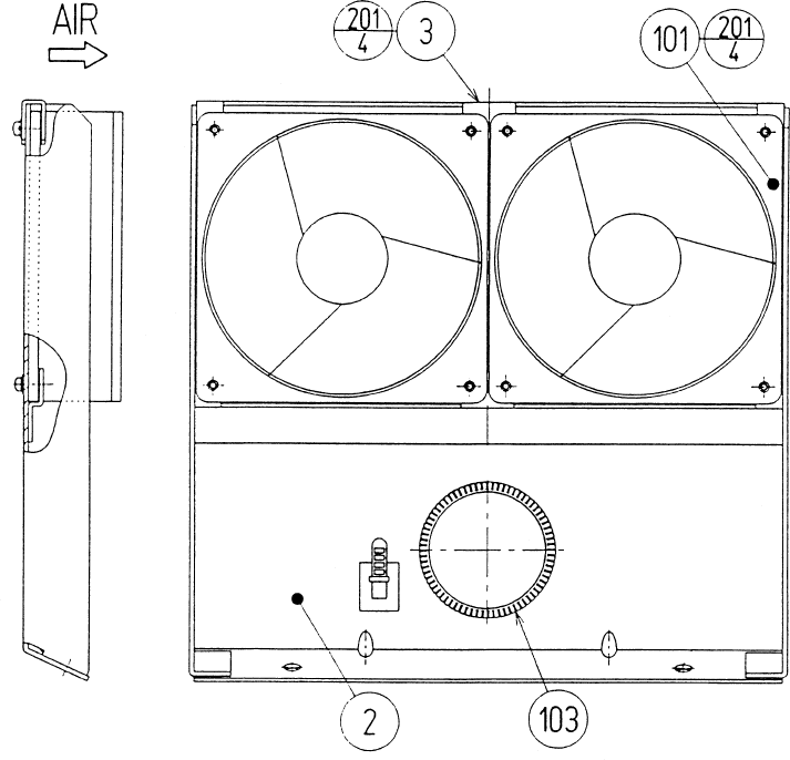
89
ITEM NO. PART NO. DESCRIPTION
2 RCS-3052 FAN BRKT
3 RCS-3053 CLAMP
101 260-0056 AXIAL FLOW FAN AC115V 50-60Hz
103 601-5963-150 BUSH 2.3T(150MM)
201 000-P00316-W M SCR PH W/FS M3X16
ASSY COOLING FAN (RCS-3050)
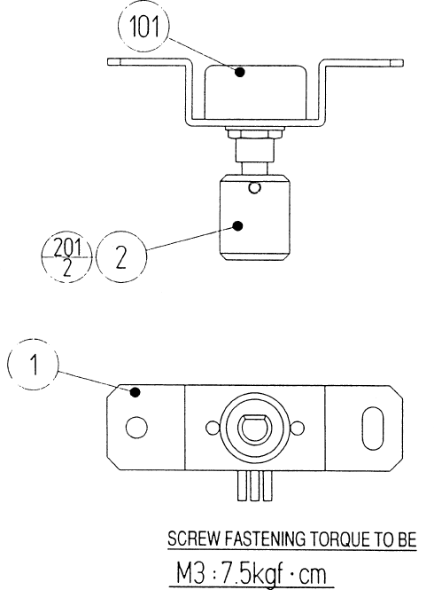
90
ASSY VR (RCS-3070)
ITEM NO. PART NO. DESCRIPTION
1 RCS-3071 VR BRKT
2 601-7945 GEAR 20
101 220-5484 VOL CONT B-5K OHM
201 028-A00304-P SET SCR HEX SKT CUP P M3X4
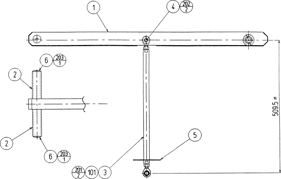
91
ASSY SWING LEVER L (RCS-3100)
ASSY SWING LEVER R (RCS-3200)
ITEM NO. PART NO. DESCRIPTION
1 RCS-3101Y SWING LEVER L
RCS-3201Y SWING LEVER R
2 RCS-3102 GRIP
3 RCS-3103 CONNECTING ROD
4 RCS-3104 PIN S
5 RCS-3105 SLIDE PLATE
6 RCS-3106 GRIP END
101 111-0032 ROD END 12
201 050-H01200-0B HEX NUT BLK M12
202 065-S012S0-Z STP RING BLK OZ S12
203 000-T00412-0C M SCR TH CRM M4X12
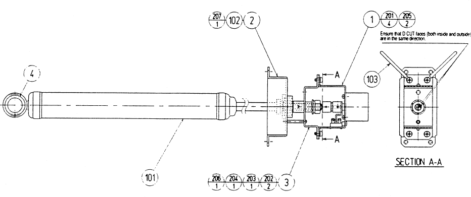
92
ASSY SHOCK ABSORBER (RCS-3300)
ITEM NO. PART NO. DESCRIPTION
1 RCS-3350 ASSY ACTUATOR
2 RCS-3301 UPPER MOUNT
3 RCS-3302 ACTUATOR BASE
4 RCS-3303 BUSH
101 601-10481 SHOCK ABSORBER
102 100-5336 PILLOW BEARING
103 280-0419 HARNESS LUG
201 000-P00408-W M SCR PH W/FS M4X8
202 028-A00408-P SET SCR HEX SKT CUP P M4X8
203 060-F0100 FLT WSHR M10
204 060-S0100 SPR WSHR M10
205 028-A02610-P SET SCR HEX SKT CUP P M2.6X10
206 050-H010S6 HEX NUT P=1.25 M10
207 065-S026H0-Z STP RING BLK OZ H26
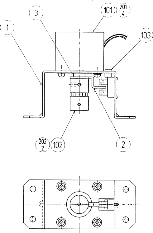
93
ASSY ACTUATOR (RCS-3350)
ITEM NO. PART NO. DESCRIPTION
1 RCS-3351 MOTOR BRKT
2 RCS-3352 SENSOR BLADE
3 RCS-3353 COLLAR
101 350-5550 MOTOR PULSE DC 12V
102 111-0055 COUPLING
103 370-5122 PHOTO INTERRUPTER GP1A73A
201 000-P00308-W M SCR PH W/FS M3X8
202 028-A00306-P SET SCR HEX SKT CUP P M3X6
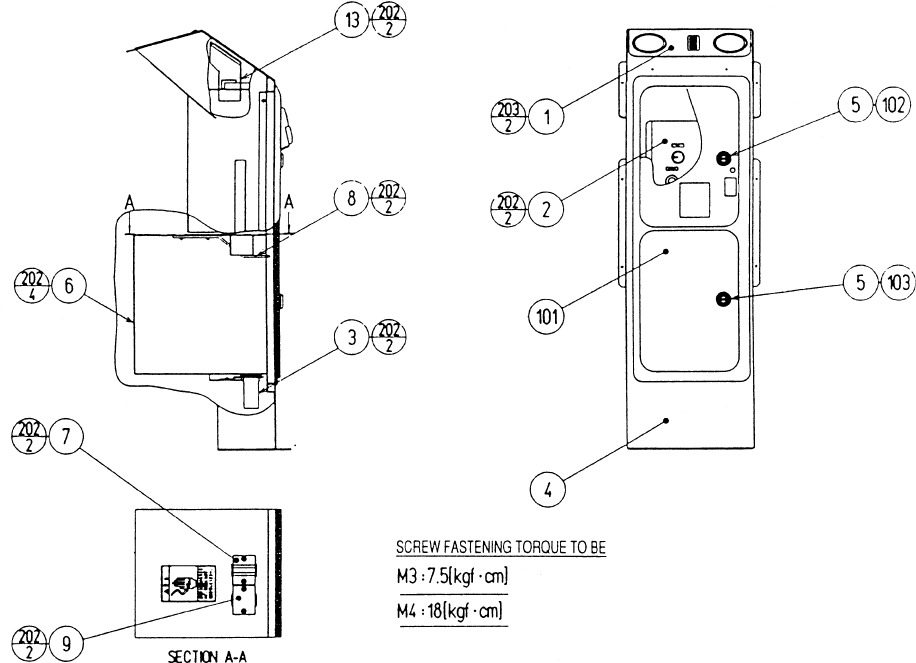
94
ITEM NO. PART NO. DESCRIPTION
1 RCS-3420 ASSY START SW
2 RCS-3430 SW UNIT
3 HOD-1590-01 METER UNIT TWIN
4 RCS-3401 COIN CHUTE TOWER
5 DP-1167 TNG LKG
6 105-5106 CASH BOX COVER
7 105-5107 CHUTE
8 105-5170 LOCK BRACKET S
9 105-5188~ HOLE COVER~
101 220-5237-92~ ASSY C.C 2DR.~
102 220-5575 CAM LOCK MASTER W/O KEY
103 220-5574 CAM LOCK W/KEYS
201 000-P00406-W M SCR PH W/FS M4X6
202 000-P00408-W M SCR PH W/FS M4X8
203 000-T00410-0C M SCR TH CRM M4X10
205 050-H00400 HEX NUT M4
206 060-F00400 FLT WSHR M4
207 060-S00400 SPR WSHR M4
ASSY COIN CHUTE TOWER (RCS-3400)
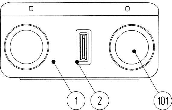
95
ASSY START SW (RCS-3420)
ITEM NO. PART NO. DESCRIPTION
1 RCS-3421-01 SW BASE EXP
2 220-5232-03 COIN ENTRY
101 509-5892-01 SW PB 60M W/L 6V3W YELLOW
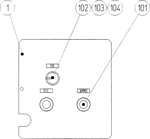
96
SW UNIT (RCS-3430)
ITEM NO. PART NO. DESCRIPTION
1 RCS-3431 SW BRKT
101 509-5028 SW PB 1M
102 220-5179 VOL CONT B-5K OHM
103 601-0042 KNOB 22MM
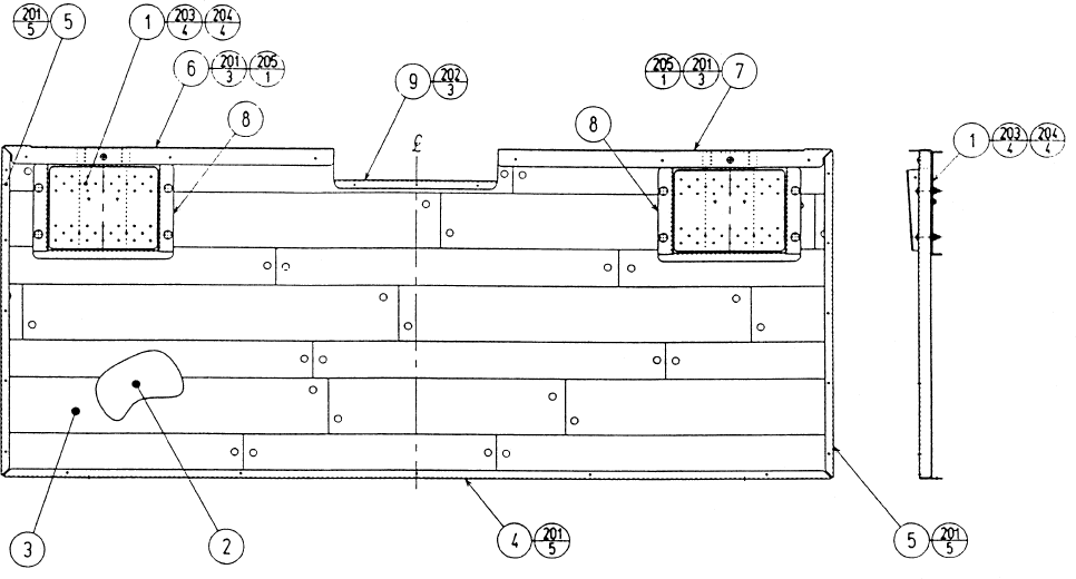
97
ASSY FLOOR (RCS-3500)
ITEM NO. PART NO. DESCRIPTION
1 RCS-3530 ASSY FOOT SW
2 RCS-3501 FLOOR BASE
3 RCS-3502 FLOOR CUSHION
4 RCS-3503 SASH REAR
5 RCS-3504 SASH SIDE
6 RCS-3505 SASH FL
7 RCS-3506 SASH FR
8 RCS-3507 SASH HOLE
9 RCS-3508 SASH FC
201 079-000008 SCR NAIL THH STNLS 1.5X16
202 FAS-790001 NAIL THH STNLS 1.2X13
203 031-000530-0C CRG BLT CRM M5X30
204 050-F00500 FLG NUT M5
205 000-T00406-0C M SCR TH CRM M4X6
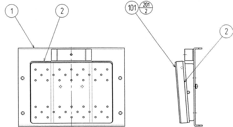
98
ASSY FOOT SW (RCS-35300
ITEM NO. PART NO. DESCRIPTION
1 RCS-3531 FOOT SW BASE
2 RCS-3532 SAFETY CUSHION
101 509-5891 FOOT SW
201 000-P00410-W M SCR PH W/FS M4X10
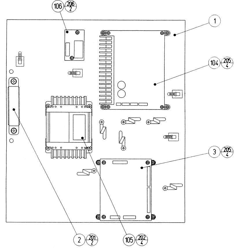
99
ITEM NO. PART NO. DESCRIPTION
1 RCS-4001 WOODEN BASE ELEC
2 GBN-4002 HANDLE
3 837-13677-91 STEP MOTOR CONTROL BD RCS
104 838-12796-01 PWR AMP FOR M3
105 560-5417-H XFMR 100-120V 16.2-0-16.2V2.4A
106 838-11856-UL CONNECT BD UL
201 000-P00516-W M SCR PH W/FS M5X16
202 000-P00416-W M SCR PH W/FS M4X16
203 011-F00310 TAP SCR FH 3X10
204 011-T03512 TAP SCR TH 3.5X12
205 011-T03520 TAP SCR TH 3.5X20
206 011-P00325 TAP SCR PH 3X25
ASSY ELEC (RCS-4000)
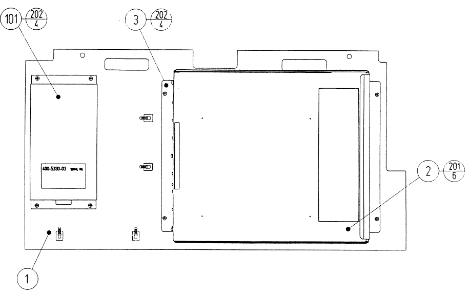
100
ASSY MAIN BD (RCS-4100)
ITEM NO. PART NO. DESCRIPTION
1 JEY-0101 WOODEN BASE MAIN BD
2 RCS-0100-01 ASSY SHIELD CASE EXP
3 105-5241 SHIELD CASE BRKT
101 400-5330-03 SW REGU FOR MODEL 3
201 000-P00408-W M SCR PH W/FS M4X8
202 000-P00412-W M SCR PH W/FS M4X12
203 011-F00310 TAP SCR FH 3X10
204 011-T03512 TAP SCR TH 3.5X12
