12346 MLG 25 Operating Parts (C 6 06).pmd Magnum Manual Mlg25
User Manual: magnum-manual-mlg25-operating-parts Igor's of metalworking and electrical manuals
Open the PDF directly: View PDF ![]() .
.
Page Count: 52
25
www m-p-llc com
DIESEL GENERATOR
MLG 25
OPERATION/PARTS MANUAL

2
This manual provides information and procedures to safely operate and maintain the generator.
For your own safety and protection from physical injury, carefully read, understand, and observe the
safety instructions described in this manual. THE INFORMATION CONTAINED IN THIS MANUAL
IS BASED ON MACHINES IN PRODUCTION AT THE TIME OF PUBLICATION. MAGNUM PROD-
UCTS LLC RESERVES THE RIGHT TO CHANGE ANY PORTION OF THIS INFORMATION WITH-
OUT NOTICE.
An engine operators manual was supplied with the machine at the time of its shipment from the
factory. The manual provides detailed operation and maintenance procedures for the engine. Ad-
ditional copies of this manual are available from the engine manufacturer.
MAGNUM PRODUCTS LLC
215 POWER DRIVE
BERLIN, WI 54923
PHONE: 920-361-4442
FAX: 920-361-4416
TOLL FREE: 1-800-926-9768
www.m-p-llc.com
Engine Make:
Engine Serial #:
Engine Model #:
Generator Make:
Generator Model #:
Generator Serial #:
Unit Model #:
Unit Serial #:
3
TABLE OF CONTENTS
TABLE OF CONTENTS PAGE 3
SAFETY NOTES PAGE 4
UNIT SERIAL PLATE LOCATION PAGE 4
SAFETY NOTES PAGES 5 - 6
SPECIFICATIONS PAGE 7
EXTERIOR LOCATIONS PAGE 8
MAIN CONTROL PANEL PAGE 9
ENGINE CONTROLLER FEATURES PAGES 10 - 11
GENERATOR AND ENGINE MONITORING PAGE 12
GENERATOR OUTPUT CONNECTION LUGS PAGE 13
VOLTAGE SELECTOR SWITCH PAGE 14
AUXILIARY OUTLETS PAGE 15
VOLTAGE REGULATOR PAGE 15
FINE VOLTAGE ADJUSTMENT PAGE 15
EMERGENCY STOP SWITCH PAGE 15
MAIN CIRCUIT BREAKER PAGE 16
REMOTE START TERMINAL BLOCK PAGES 16 - 17
GENERATOR STARTING PAGES 18 - 20
REMOTE STARTING PAGE 20
SHUTTING DOWN PAGE 20
EZ-1 CONTROLLER INFORMATION DISPLAYS PAGE 20
CONTROLLER ALARM LIST WITH DESCRIPTIONS PAGES 21 - 22
TROUBLESHOOTING AUTO SHUTDOWN CONDITIONS PAGES 22 - 23
TOWING THE TRAILER PAGE 23
TRAILER WHEEL BEARINGS PAGE 23
ENGINE AND GENERATOR MAINTENANCE PAGE 24
RELOADING THE TIME TO SERVICE REMINDER PAGE 24
ADJUSTING DISPLAY BACKLIGHTING PAGE 24
DAILY MAINTENANCE CHECKS PAGE 25
DERATING FOR ALTITUDE PAGE 25
FRAME ASSEMBLY PAGES 26 - 27
ENCLOSURE ASSEMBLY PAGES 28 - 29
AUXILIARY OUTLET PANEL ASSEMBLY PAGES 30 - 31
AUXILIARY OUTLET PANEL OPTIONS PAGES 32 - 33
ENGINE COOLING ASSEMBLY PAGES 34 - 35
ENGINE ASSEMBLY PAGES 36 - 37
CONTROL PANEL ASSEMBLY - OLD STYLE PAGES 38 - 39
CONTROL PANEL ASSEMBLY - NEW STYLE PAGES 40 - 41
CONTROL BOX ASSEMBLY - OLD STYLE PAGES 42 - 43
CONTROL BOX ASSEMBLY - NEW STYLE PAGES 44 - 45
LUG DOOR ASSEMBLY PAGE 46
GENERATOR ASSEMBLY PAGE 47
WIRING DIAGRAMS PAGES 48 - 51
4
UNIT SERIAL PLATE LOCATION
SAFETY NOTES
This manual contains NOTES, CAUTIONS and WARNINGS which must be followed to prevent the
possibility of improper service, damage to the equipment, or personal injury. The following formatting options
will apply when calling the readers attention to the NOTES, CAUTIONS and WARNINGS.
Notes: Notes contain additional information important to a procedure. The notes called out in this manual
will be included in the regular text body but the word “Note” will be in BOLD text and the note will be written
in italics to make them more visible. For example: Note: Check the engine oil level before starting.
CAUTION: Cautions provide information important to prevent errors which could damage the equipment.
The cautions called out in this manual will be in BOLD text, in a separate paragraph or sentence from the
regular text body. For example:
CAUTION! Always switch all circuit breakers to “OFF” to prevent the starting of the generator
under load.
WARNINGS: Warnings describe conditions or practices which could lead to serious personal injury or death
to the operator or others around the equipment. Warnings called out in this manual will be in a separate
paragraph, centered and surrounded by a black border, with warning in BOLD text. For example:
25
www m-p-llc com
MANUFACTURED BY/FABRIQUE PAR:
GVWR/PNBV:
DATE OF MFG:
COLD INFL. PRESS./PRESS.
GAWR/PNBE TIRE/PNEU RIM/JANTE KPA(PSI/LPC)
THIS VIEHICLE CONFORS TO ALL APPLICABLE STANDARDS PRESCRIBED UNDER THE CANADIAN MOTOR VIEHICLE SAFETY REGULATIONS
IN ECCEFT ON THE DATE OF MANUFACTURE. / CE VEHICULE EST CONFORME A TOUTES LES NORMES QUI LUI SONT APPLICABLES EN
VERTU DU REGLEMENT SUR LA VEHICULES DES AUTOMOBILES DU CANADA EN VIGUEUR A LA DATE SA FABRICATION.
THIS VIEHICLE CONFORMS TO ALL APPLICABLE U.S. FEDERAL MOTOR VEHICLE SAFETY STANDARDS (FMVSS) IN EFFECT ON THE DATE OF
MANUFACTURE SHOWN ABOVE.
V.I.N./N.I.V.: TYPE/TYPE DE VEHICULE:
kg lbs
rpm hz amb. temp.
Serial Number
V
A
MADE IN USA
REV
Model
RATING: CONT. STAND BY
3 Phase 1 Phase
kVA
Magnum Products LLC
Berlin, WI 54923 USA
(800) 926-9768
R
LR 114630-1
WARNING!
Only a qualified electrician may service or make connections
to the generator. Lethal voltage is present at the connection
lugs when the generator is running!
5
OPERATING SAFETY
Before using the generator be sure you read and understand all instructions! Equipment operated
improperly or by untrained personnel can be dangerous! Read the operating instructions and familiarize
yourself with the location and proper use of all instruments and controls. Inexperienced operators should
receive instruction from someone familiar with the equipment before being allowed to operate or set up the
generator.
The area immediately surrounding the generator should be clean, neat, and free of debris.
Position and operate generator tower on a firm, level surface.
NEVER start a unit in need of repair.
NEVER modify the generator or use it in a manner other than what it was designed for.
ALWAYS keep the generator doors closed when the engine is running. Do not start the generator if any
panels or guards are loose or missing.
ALWAYS connect the generator to a good earthen ground.
Move the generator main circuit breaker to the “OFF” position when servicing or troubleshooting the unit.
The output voltage of the generator can cause a fatal electric shock. Avoid contact with any alternating
current wiring when the engine is running. Make sure any extension cords or equipment connected to
the convenience outlets are in good working condition.
NEVER remove control box cover when the engine is running. Exposed live electrical terminals can
cause a fatal electrical shock.
Check your electrical requirements before installing or starting the generator.
Use a ground fault circuit interrupter (GFCI) in damp or highly conductive areas and construction sites
to prevent electrical shock.
ENGINE SAFETY
Internal combustion engines present special hazards during operation and fueling! Failure to follow the
safety guidelines described below could result in severe injury or death. Also read and follow all safety
warnings described in the Engine Operator's Manual. A copy of this manual was supplied with unit when
it was shipped from the factory.
DO NOT run engine indoors or in an area with poor ventilation unless exhaust hoses are used.
DO NOT fill fuel tank near an open flame, while smoking, or while engine is running.
DO NOT fill tank in an enclosed area with poor ventilation.
DO NOT touch or lean against hot exhaust pipes or engine cylinder.
DO NOT operate with the fuel tank cap loose or missing.
DO NOT remove engine coolant cap while engine is hot.
DO NOT clean air filter with gasoline or other types of low flash point solvents.
Keep area around exhaust pipes and air ducts free of debris to reduce the chance of an accidental fire.
Shut the engine down if any of the following conditions exist during operation:
A. Noticeable change in engine speed.
B. Loss of electrical output.
C. Equipment connected to the generator overheats.
D. Sparking occurs.
E. Engine misfires or there is excessive engine/generator vibration.
TOWING SAFETY
Towing a trailer requires care! Both the trailer and vehicle must be in good condition and securely fastened to
each other to reduce the possibility of an accident. Also, some states require that large trailers be registered
and licensed. Contact your local Department of Transportation office to check on license requirements for your
particular unit.
Check that the hitch and coupling on the towing vehicle are rated equal to, or greater than, the trailer's "gross
vehicle weight rating" (GVWR). Check tires on trailer for tread wear, inflation, and condition.
Inspect the hitch and coupling for wear or damage. DO NOT tow trailer using defective parts!
Make sure the trailer hitch and the coupling are compatible. Make sure the coupling is securely fastened
to the vehicle.
Connect safety chains in a crossing pattern under the tongue and attach the brake away cable TO THE
REAR BUMPER OF THE TOWING VEHICLE.
Make sure directional and brake lights on the trailer are connected and working properly.
Check that lug nuts holding wheels are tight and that none are missing.
Maximum recommended speed for highway towing is 45 m.p.h.. Recommended off-road towing speed
is not to exceed 10 m.p.h. or less depending on terrain.
When towing, maintain extra space between vehicles and avoid soft shoulders, curbs and sudden lane
changes. If you have not pulled a trailer before, practice turning, stopping, and backing up in an area away
from heavy traffic.
A film of grease on the coupler will extend coupler life and eliminate squeaking. Wipe the coupler clean and
apply fresh grease each time the trailer is towed.
REPORTING TRAILER SAFETY DEFECTS
If you believe your trailer has a defect which could cause a crash or could cause injury or death, you should
immediately inform the National Highway Traffic Safety Administration (NHTSA) in addition to notifying
Magnum Products LLC. If NHTSA receives similar complaints, it may open an investigation; and if it finds
that a safety defect exists in a group of vehicles it may order a recall and remedy campaign. However,
NHTSA cannot become involved in individual problem between you, your dealer, or Magnum Products LLC.
To contact NHTSA, you may either call the Auto Safety Hotline toll-free at 1-888-327-4236 or by fax at:
(202)-366-7882. Additional contact information can be found at: www.nhtsa.dot.gov.
SERVICE SAFETY
This unit uses high voltage circuits capable of causing serious injury or death. Only a qualified electrician
should troubleshoot or repair electrical problems occurring in this equipment.
Before servicing the generator, make sure engine start switch is turned to OFF, circuit breakers are open
(off) and the negative terminal on the battery is disconnected. Open main circuit breaker before
disconnecting battery cables. NEVER perform even routine service (oil/filter changes, cleaning, etc.)
unless all electrical components are shut down.
NEVER allow water to accumulate around the base of the generator. If water is present, DO NOT service!
NEVER service electrical components if clothing or skin is wet. If the unit is stored outside, check the engine
and generator for any moisture and dry the unit before use.
NEVER wash the unit with a power washer or high pressure hose.
Keep hands, feet, and loose clothing away from moving parts on generator and engine.
Replace all guards and safety devices immediately after servicing.
Replace all missing and hard-to-read labels. Labels provide important operating instructions and warn of
dangers and hazards.
Make sure slings, chains, hooks, ramps, jacks, and other types of lifting devices are attached securely and
have enough weight-bearing capacity to lift or hold the equipment safely. Always remain aware of the
position of other people around you when lifting the equipment.
6
SPECIFICATIONS
Engine manufacturer ISUZU
Engine model 4LE1-PV 05
Engine type Diesel, 4-cyl, liquid cooled 4-stroke
Engine horsepower (standby) 34.5 hp (25.7 Kw) @1800 RPM
Engine horsepower (primed) 31.5 hp (23.5 Kw) @1800 RPM
Fuel tank capacity 56 gal. (215.8 L)
Fuel consumption 2.1 gph (7.90 Lph)
Generator manufacturer Marathon Electric
Generator model 282NSL1505
Generator output 3O Standby Kw/Kva 20/25
Generator output 1O Standby Kw/Kva 16/16
Generator output 3O Prime Kw/Kva 18/23
Generator output 1O Prime Kw/Kva 15/15
Generator frequency 60 Hz
Generator output voltage 3O 208/220/440/480V
Generator output voltage 1O 120/138/208/220/240/277V
Generator output Amperes 3O (480/208) 30/69
Generator output Amperes 1O (240) 67
Generator power factor 0.8
Generator insulation Class “H1”
Width 67 in. (170.2 cm)
Weight (no fuel) 1570 lbs (710 kg)
Weight with fuel (approx.) 2000 lbs. (910 kg)
Height 56 in. (142.2 cm)
7
25
www m-p-llc com
5
3
7
2
1
4
6
1. FUEL FILLER LOCATION (under door): Use clean DIESEL FUEL ONLY.
2. RADIATOR ACCESS PANEL: Remove this panel for engine coolant service.
3. CONTROL PANEL LOCATION (under door): Engine/generator controls and all circuit breakers.
4. EMERGENCY STOP SWITCH: For emergency shutdown; stops engine and trips main circuit breaker.
5. EQUIPMENT OUTLETS: Circuit breaker protected outlets; 20, 30 and/or 50 amp ratings.
6. GROUND STUDS (2): For grounding generator and equipment connected to the equipment outlets.
7. TONGUE JACK: Used to level generator before starting.
8
EXTERIOR LOCATIONS
2
MAIN CONTROL PANEL
1. MAIN CIRCUIT BREAKER (90A): This breaker will disconnect power to the connection lugs.
2. ENGINE CONTROLLER PANEL: See pages 10 - 11 for additional information.
3. AUXILIARY OUTLET MAIN CIRCUIT BREAKER (100A): This breaker disconnects power to the
auxiliary equipment outlets.
4. PHASE SELECTOR SWITCH: This switch will change the generator output between three phase and
single phase power. See the “VOLTAGE SELECTOR SWITCH” section for more information.
5. REMOTE START TERMINAL BLOCK: Allows for remote starting of the generator.
6. LUG DOOR SAFETY SWITCHES: These switches will shut the generator down if the lug door is
opened when the generator is running.
7. GENERATOR GROUND CONNECTION LUG: This lug is for connecting a good earthen ground per
any local, state or National Electric Code (NEC) guidelines before starting the generator.
8. GENERATOR OUTPUT CONNECTION LUGS: These allow appropriate loads to be wired directly to
the generator.
9
64
1
5
3
7
8
6
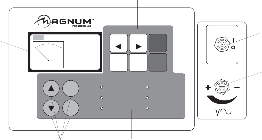
10
1. LCD DISPLAY
This display shows the controller status in, MANUAL and AUTO (remote start) modes.
Should a shut down fault occur, the LCD display will show the condition causing the fault. At the
same time, the engine will shut down and lock out.
The LCD display will also show any possible Engine Sender Failures and Time To Service
information. These conditions will not shut down the engine; they are used to alert the operator.
2. OPERATION KEYS
MANUAL Press to switch from AUTO to MANUAL mode.
AUTO Press to switch from MANUAL to AUTO mode for remote starting of
generator.
ENGINE START Press to start engine.
ALARM CANCEL Press to cancel alarms (visual or audio if equipped).
FAULT RESET Press to clear ALARM LIST fault codes.
ENGINE STOP Press to stop engine.
3. CONTROL POWER SWITCH
This main power switch turns the controller on and off.
4. VOLTAGE ADJUSTMENT RHEOSTAT
This knob allows the end user to fine adjust the output voltage from the generator.
5. OPERATION STATUS LED’S
ALARM / FAULT Indicates active or inactive alarms.
READY / MANUAL Indicates controller is in MANUAL mode, ready to start.
RUNNING Indicates running engine.
WARNING Indicates active or inactive warnings.
READY/AUTO Indicates controller is in AUTO mode, ready for remote start signal.
SUPPLYING LOAD Indicates the genset is running, giving proper voltage and frequency and
is supplying load.
ENGINE CONTROLLER FEATURES
ENGINE
ENGINE
START
START
ENGINE
ENGINE
STOP
STOP
MANUAL AUTO
ALARM
CANCEL
FAULT
RESET
ALARM/FAULT
READY/MANUAL READY/AUTO
WARNING
RUNNING SUPPLYING LOAD
OPERATION
PAGE
SELECT
ENTER
DIAGNOSTICS
STATUS
CONTROL
CONTROL
ON
ON
CONTROL
CONTROL
OFF
OFF
MAN AUT
Ready
PF 0.00
RPM 0
0 kW 0
6
3
5
1
2
4
11
6. DIAGNOSTICS
UP
DOWN Switch between:
POWER SCREEN DISPLAY (DISPLAYS FROM MANUAL TO AUTO MODE)
ALARM SCREEN DISPLAY
HOUR SCREEN DISPLAY
POWER DETAIL SCREEN DISPLAY
Note: Automatically returns to flipping between the ENGINE / GENERATOR DISPLAY SCREENS
after 60 seconds.
PAGE SELECT Provides access to programming and resets.
ENTER Allows access to the next level.
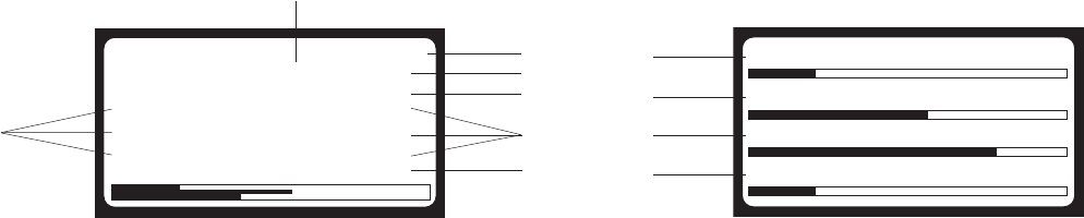
ENGINE MONITORING
Engine information is shown on the LCD display in a repeating manner while the unit is in MANUAL or
AUTO mode. Engine information will show the oil pressure, water temperature, fuel level and battery
voltage.
8. OIL - Displays engine oil pressure. The display registers oil pressure between 0-100 psi. Normal
operating pressure is between 35-80 psi.
9. TEMPERATURE - Displays the temperature of the engine’s coolant. If the coolant temperature
exceeds the Max Water Temp the engine will automatically shut down. Zero “0” will be displayed until a
minimum of 100° F is reached.
10. FUEL - Displays the relative fuel level in the fuel tank in percent (50% = 1/2 tank, 75% - 3/4 tank, etc.).
If the fuel level drops below a programmed Fuel Shutdown Percent the engine will automatically shut
down.
11. BATTERY - Displays the engine battery voltage. A normal reading is 13-14V on 12 volt systems and
24-26V on 24 volt systems.
GENERATOR MONITORING
Generator information is shown on the LCD display in a repeating manner while the unit is running in
MANUAL or AUTO mode. Generator information will show the voltage, amperage and frequency of each
phase.
Additional information can be viewed when the unit is MANUAL or AUTO modes. Pressing “PAGE SE-
LECT” then “UP” or “DOWN” on the key pad will display, Alarm Screen, Hour Screen, and Power Detail
Screen displays.
NOTE: When loading the generator it is important to observe the amperage to determine the load balance
on each line of the generator. Minor load unbalances, usually 5% or less, will not cause any particular
problems. Every effort should be made to distribute the load equally between all lines.
1. PHASE - Indicates generator configuration, 3 phase or single phase.
2. HERTZ - Displays output frequency.
3. NOMINAL VOLTS - Displays generator nominal voltage in current phase switch selection.
4. NOMINAL AMPS - Displays maximum amps in current phase switch selection.
5. GENERATOR OUTPUT VOLTAGE - Line to Line display.
6. AMPS - Displays the AC output amperage produced by the generator.
7. GENERATOR OUTPUT VOLTAGE - Line to Neutral display.
Gen freq 60.0Hz
Gen freq 60.0Hz
NomVolt (3PY)
NomVolt (3PY)
208V
208V
NomAmps 300A
NomAmps 300A
L1N 120V L12 208V
L1N 120V L12 208V
L2N 120V L23 208V
L2N 120V L23 208V
L3N 120V L31 208V
L3N 120V L31 208V
G-Curr 0 0 0 A
G-Curr 0 0 0 A
1
2
3
4
5
6
7
Oil Press 49 psi
Oil Press 49 psi
Water Temp 183°F
Water Temp 183°F
Fuel Level 83%
Fuel Level 83%
Batt Volts 13.4V
Batt Volts 13.4V
8
9
10
11
12

GENERATOR OUTPUT CONNECTION LUGS
The generator is equipped with connection lugs behind a door below the controller face. The lugs provide
connection points for attachment of external loads to the generator. A large decal on the inside of the
connection lug door details the proper connections for selected voltages.
Connections to the lugs should be made by running the power cables through the circular plastic bushing
on the lower right side of the control box. DO NOT make any connections directly to the lug without routing
the cables through this bushing. The connection lug door is equipped with a safety interlock switch that will
automatically trip the main circuit breaker and disable the voltage regulator when the lug door is opened.
Use a 5/16” hex-wrench to tighten the cable connections.
A ground connection is located next to the connection lugs. The unit MUST HAVE this ground lug con-
nected to a good earthen ground for proper operating safety. The ground connection SHOULD BE IN
COMPLIANCE WITH THE NATIONAL ELECTRIC CODE (NEC) AS WELL AS ANY STATE OR LOCAL
GUIDELINES OR CODES.
WARNING!
It is HIGHLY RECOMMENDED that only a trained and licensed electri-
cian perform any wiring and related connections to the generator. Instal-
lation should be in compliance with the NATIONAL ELECTRIC CODE
(NEC) as well as any local or state guidelines as required by law. Failure
to follow proper installation requirements may result in equipment or
property damage, personal injury or death.
WARNING!
Before any connections are made to the generator, make sure that the
main circuit breaker and the control power switch are in the OFF “O”
position. Potentially lethal voltages may be present at the generator
connection lugs.
WARNING!
Improper or incorrect connections to a buildings electrical system can
cause potentially lethal voltages to backfeed onto utility lines. This
may result in injury or electrocution to utility workers nearby. Make
sure the generator is suppling power to an isolated object or building
that is not connected to any utility lines.
13
14
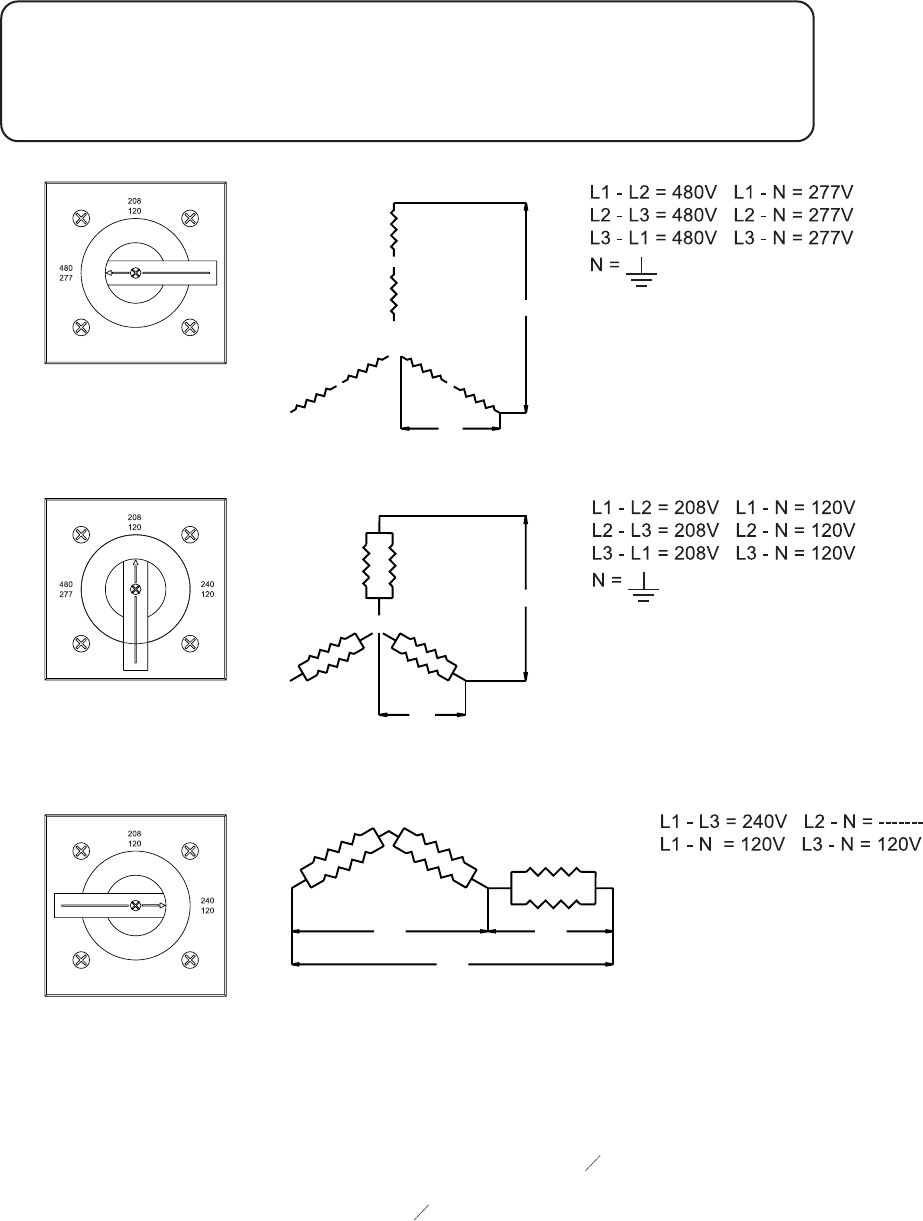
VOLTAGE SELECTOR SWITCH
The voltage selector switch is located on a panel attached to the generator behind the door located next to
the fuel tank filler. The selector switch is a three position switch that mechanically changes the connec-
tions between the generator output leads and the connection lugs on the main control panel. Voltage
ranges are selected by rotating the handle on the switch to the desired voltage.
The voltage switch is equipped with a locking mechanism. Once the proper voltage has been selected,
push the red latch on the inside of the phase switch handle up and insert a padlock through the handle. By
locking the handle in place you will prevent unauthorized personnel from changing the switch settings.
NOTE: When the voltage selector switch is in position for 480/277V 3O, voltage at the two GFCI duplex
convenience outlets is 139 Volts and the voltage at the three twist-lock outlets is 240/139 Volts. When the
voltage selector switch is in position for 208/120V 3O, voltage at the three twist-lock outlets and the two
GFCI outlets is 208/120 volts.
T1
L1
T4
T7
T10
N
T2
L2
T8
T5
T9
T6
T3
L3
T11
T12
L-N
L-L
T4
T7
T10
T1
L1
L2
T8
T2
T9
T3
T6 T11
L3
T5
T12 N
L-N
L-L
T10 T7
T6 T8
T12 T2 T11
T3
T4 T1
T5
T9
L3
N
L1
120V120V
240V
WARNING!
NEVER CHANGE THE VOLTAGE SELECTOR SWITCH WHILE THE ENGINE
IS RUNNING! THIS WILL CAUSE SEVERE ARCING AND DAMAGE TO THE
SWITCH AND GENERATOR WINDINGS.
480/277V
3-PHASE
208/120V
3-PHASE
240/120V
1-PHASE
AUXILIARY OUTLETS
The control panel is equipped with six outlets for
running accessories or tools from the generator.
Power is supplied to the outlets any time the en-
gine is running and the main circuit breaker and
the auxiliary outlet main circuit breaker are switched
on “I”.
Should the main breaker trip, or the auxiliary out-
let main circuit breaker trip, remove some of the
load to the outlets before turning them back on.
Note: To ensure proper grounding, anytime the
generator is providing power to any equipment or
load panels that do not have a grounded plug a
ground wire must be added between the equipment and the grounding stud on the outlet panel per any
local, state or NEC codes and guidelines.
VOLTAGE REGULATION
System stability is the ability of the generator to respond to load transients. Decreasing stability makes the
generator less sluggish and faster to respond to load transients. If the stability of the regulator is de-
creased too much, the generator will tend to hunt under steady state conditions. To adjust the regulation,
see the included manual for the voltage regulator. The regulator is located behind the control panel on the
back of the generator box.
FINE VOLTAGE ADJUSTMENT
The output voltage can be fine adjusted after the generator is running by using the fine voltage adjustment
knob. The switch is located directly below the control power switch next to the control panel. This rheostat
will provide an increase (“+”) or a decrease (”-”) in the output voltage. To adjust the voltage, check the
output voltage on the LCD display. Turn the knob in the desired direction until the required voltage is shown
on the LCD display.
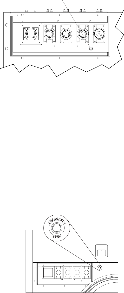
EMERGENCY STOP SWITCH
The generator is equipped with one emergency stop switch,
located on the side panel next to the auxiliary outlet panel.
The switch is clearly labeled with “EMERGENCY STOP” and
is red in color. The switch can be accessed and activated
with all doors closed and locked.
Activate the emergency stop switch by pushing the red but-
ton in until it locks down. This will trip the main circuit breaker
which will open the contact disconnecting the load to the con-
nection lugs. This will also open the fuel pump solenoid, shut-
ting down the engine and the Emergency Stop fault will be
displayed on the LCD. The switch will remain closed until it is
pulled out.
CAUTION! Use the EMERGENCY STOP only when the generator must be shut down immediately.
For any other shut down, follow the detailed shut down procedure.
15
AUXILIARY OUTLET
GROUNDING STUD

MAIN CIRCUIT BREAKER
The main circuit breaker is located on the main control panel. When the breaker is in the off “O” position,
power is interrupted between the customer connection lugs and the generator. Once the connections
have been made to the connection lugs and the generator has been started and allowed to reach normal
operating temperature, the breaker may be switched to the on “I” position.
The main circuit breaker will be tripped, disconnecting power to the connection lugs, if any of the following
items occur while the unit is running:
1. Overload of the generator circuits to the connection lugs.
2. The door covering the customer connection lugs is opened.
3. If the emergency stop switch is activated.
Make sure that any problems that caused the main circuit breaker to trip are corrected before returning the
switch to the on “I” position.
REMOTE START TERMINAL BLOCK
The remote start terminal block is located under the lug box door just below the voltage selector switch. It
provides a connection for installation of a remote start switch which will allow the generator to be started by
a remote dry-contact closure switch.
Before pressing the “AUTO” button, verify that the contacts on any remote switch linked to the generator
are OPEN. If the contacts on a remote switch are closed, the generator will crank and start when AUTO is
selected on the controller. Attach the switch leads to the two unused terminals on the generators remote
start block. For additional information on starting the generator, see GENERATOR START UP section of
this manual.
When the generator is used as a standby power supply, it must be equipped with a transfer switch which
isolates it from the utility’s distribution system. A transfer switch is designed to transfer electrical
loads from the normal power source (utility) to the emergency power source (generator) when normal
voltage falls below a prescribed level. The transfer switch automatically returns the load back to the
normal source when power is restored back to operating levels.
WARNING!
Failure to isolate the generator from the normal power utility can cause
potentially lethal voltage to backfeed into the utility lines. This may result in
injury or electrocution of utility workers nearby. Make sure that the generator
is isolated by a transfer switch from any local utility lines. This also applies if
the generator is being used as a back up to some other type of power supply.
16
WARNING!
THE MAIN CIRCUIT BREAKER INTERRUPTS POWER TO THE CUSTOMER
CONNECTION LUGS ONLY. THE CUSTOMER CONVENIENCE OUTLETS HAVE
POWER EVEN IF THE MAIN CIRCUIT BREAKER IS IN THE OFF “O” POSITION.
The auxiliary outlet main circuit breaker, located next to the main circuit breaker,
will disconnect all power to the auxiliary outlet panel.
Installation of a transfer switch or other type of remote starting device is the responsibility of the generator
user. Installation of such devices must be performed by following all directions supplied by the manufac-
turer of the switch. If attaching generator to a power supply normally serviced by a utility company, notify
the utility company and check local and state regulations. Familiarize yourself with all instructions and
warning labels supplied with the switch.
17
INCOMING
UTILITY
POWER
WHITE = INCOMING UTILITY POWER
GRAY = NORMAL UTILITY POWER CIRCUIT
BLACK = EMERGENCY GENERATOR POWER CIRCUIT
UTILITY
METER
TRANSFER
SWITCH
MAIN DISTRIBUTION
PANEL
(UTILITY POWER)
EMERGENCY
DISTRIBUTION PANEL
(GENERATOR POWER)
POWER FROM
GENERATOR
WARNING!
It is strongly recommended that ONLY a licensed electrician perform any
wiring and any related connections to the generator. Installation should be in
compliance of the National Electric Code as well as any state or local codes or
regulations. Failure to follow these procedures could result in property
damage, personal injury or death. Before any connections are attempted,
make sure the main circuit breaker and the engine start switch are in the
OFF “O” position.
WARNING!
When using the generator as a stand by or substitute power supply, make sure
the output voltage and phase rotation of the generator match those of the
local power utility. Improper voltage or phase rotation may cause equipment
damage or malfunction.
18
OPERATION STATUS
ALARM/FAULT
READY/MANUAL
RUNNING
WARNING
READY/AUTO
SUPPLYING LOAD
65h
65h
ComAp 2005
ComAp 2005
MMG
MMG
IL-MRS17-JD-1.1.1
IL-MRS17-JD-1.1.1
Serial: 11353559
Serial: 11353559
SW vers: 1.1, 1.1
SW vers: 1.1, 1.1
Appl: MRS17
Appl: MRS17
Branch: JD
Branch: JD
GENERATOR START UP
Before starting the generator, carefully read the pre-start check list. Make sure that all of the items are
checked before trying to start the generator. This check list applies for both manual and remote starting
of the generator.
PRE-START CHECK LIST
1. Make sure the control power switch is in the OFF “O” position.
2. Make sure that the circuit breakers (main and convenience) are switched OFF “O”.
3. Check that the generator is properly grounded to a good earthen ground per local and
NEC regulations.
4. Check all electrical connections at the connection lugs. Are they wired correctly?
5. Are the connection lugs tight?
6. Check the voltage selector switch and make sure that it is set to the desired voltage.
7. Is the voltage selector switch locked?
8. Is the generator sitting level?
9. Check for any water inside the unit, on or near the generator. Dry the unit before starting.
10. Check engine oil level, engine coolant level and engine battery connections.
11. Check engine fan belt tension and condition.
12. Check engine fan belt guard.
13. Check engine exhaust system for loose or rusted components.
14. Check radiator and surrounding shroud for debris.
15. Are any of the generator covers loose or missing?
MANUAL STARTING OF THE GENERATOR
1. Move the control power switch to the “CONTROL ON” position.
2. The LCD screen will quickly display system information, all LEDS will flash.
OPERATION STATUS
ALARM/FAULT
READY/MANUAL
RUNNING
WARNING
READY/AUTO
SUPPLYING LOAD
MAN
MAN
AUT
AUT
Ready
Ready
PF 0.00
PF 0.00
RPM 0
RPM 0
0 kW 0
0 kW 0
3. The LCD Screen will indicate MANUAL mode and Ready. Ready/Manual LED will be lit.
4. Press the green ENGINE START key.
NOTE: Unit must be in MAN Mode with READY/MANUAL LED lit.
19
OPERATION STATUS
ALARM/FAULT
READY/MANUAL
RUNNING
WARNING
READY/AUTO
SUPPLYING LOAD
MAN
MAN
AUT L
AUT L
Starting
Starting
PF 1.00L
PF 1.00L
RPM 250
RPM 250
0 kW 0
0 kW 0
OPERATION STATUS
ALARM/FAULT
READY/MANUAL
RUNNING
WARNING
READY/AUTO
SUPPLYING LOAD
MAN
MAN
AUT L
AUT L
Prestart
Prestart
PF 0.00
PF 0.00
RPM 0
RPM 0
Prestart
Prestart
0 kW 5
0 kW 5
9. If the engine does not start after the first cranking attempt the engine will wait for 15 seconds to allow
the starter to cool and the LCD will show “Pause”. The engine will make two more attempts to start for
a total of three crank cycles.
10. Should the engine not start and run the LCD display will show “SD StartFail”. The starting sequence
may be repeated after the starter has had a minimum of two minutes to cool. The FAULT RESET
button needs to be pressed to clear the controller. The unit will start by pressing the ENGINE START
button.
Note: the engine controller may skip the pre-heat acquisition and engine pre-heat steps.
11. Once the engine starts it will slowly begin speeding up to a constant 1800 rpm. On units with isochro-
nous engine governing, the engine may hunt or change speeds until operating temperature is reached.
After a few minutes of operation the engine will be warmed up and the LCD display will show engine
and generator operating parameters. Temperature will be shown as “0” until the engine temperature is
approximately 100 degrees Fahrenheit.
Oil Press 49 psi
Oil Press 49 psi
Water Temp 183°F
Water Temp 183°F
Fuel Level 83%
Fuel Level 83%
Batt Volts 13.4V
Batt Volts 13.4V
Gen freq 60.0Hz
Gen freq 60.0Hz
NomVolt (3PY)
NomVolt (3PY)
208V
208V
NomAmps 300A
NomAmps 300A
L1N 120V L12 208V
L1N 120V L12 208V
L2N 120V L23 208V
L2N 120V L23 208V
L3N 120V L31 208V
L3N 120V L31 208V
G-Curr 0 0 0 A
G-Curr 0 0 0 A
8. The LCD will switch from the POWER SCREEN DISPLAY to:
OPERATION STATUS
ALARM/FAULT
READY/MANUAL
RUNNING
WARNING
READY/AUTO
SUPPLYING LOAD
MAN
MAN
AUT L
AUT L
Running
Running
PF 1.00L
PF 1.00L
RPM 1800
RPM 1800
V Detect
V Detect
4 kW 15
4 kW 15
7. The Running screen will display.
NOTE: It may take a few seconds for the engine to run smoothly and reach its governed operating speed.
6. The Starting screen will display. The engine will crank and start running.
5. The Prestart screen will display (if equipped).
20
Once the generator is at normal operating temperature, check the generator for excessive noise, vibration
and coolant, oil or fuel leaks before applying any loads.
12. Check that the AC output voltage is correct. The output voltage can be fine adjusted by using the fine
voltage adjustment switch, described on page 16.
13. Check that the frequency (Hz) is correct. With no loads connected to the generator, the frequency
should read approximately 60-62 Hz, depending on the type of engine governing used.
14. If all wiring connections have been done correctly, switch the main circuit breaker to the on “I” position
and then add any loads attached to the convenience outlets by switching the respective circuit breaker
to the ON “I” position. You will notice a slight change in engine noise.
AUTO (REMOTE) STARTING OF THE GENERATOR
The AUTO button is used when the generator is started from a location other than the control panel by
using a remote start switch or transfer switch. AUTO (remote start) is the normal setting when the genera-
tor is being used as a standby power supply. Before putting the generator in the AUTO (remote start)
mode, review the PRE-START CHECK LIST and MANUAL STARTING OF THE GENERATOR sections
beginning on page 18. Also follow all safety warnings and information on isolating the generator with a
transfer switch if the unit is to be used as a standby power supply on pages 16 and 17. Then continue with
the steps described below:
1. Perform a manual start of the generator at least once to verify that the engine is operating correctly.
2. If a check of the remote start circuit is desired, press the “AUTO” button. The LCD display should high-
light “AUT” in the upper left corner. Attach a jumper wire (minimum 16 gauge) equipped with two
alligator clips across the two unused terminals on the remote start terminal block. This applies a
ground to the EZ-1 to close the starting circuit. The engine should crank, start and run.
3. Remove the jumper wire from the remote start terminal block, the engine will stop. Connect any nec-
essary wires from the remote start switch.
4. Confirm unit is in “AUTO” mode. The LCD display should have “AUT” hilighted in the upper left corner.
5. Close (set to ON/“I”) the main circuit breaker.
6. Secure the generator by closing and locking all access doors.
7. The generator is now ready for remote starting.
SHUTTING DOWN THE GENERATOR
Check with other personnel using power supplied by the generator and let them know that the power is
going to be turned off. Make sure the power shutdown will not create any hazards by accidentally turning
off equipment that needs to be kept on (pumps, compressors, lights, etc.).
1. Remove all loads from the generator by opening (turn to OFF/“O”) all circuit breakers.
2. Let the engine run for approximately five minutes to allow it to cool down.
3. Push the “ENGINE STOP” button.
4. Move the control power switch to the CONTROL OFF/“O” position.
EZ-1 CONTROLLER INFORMATION DISPLAYS AND FUNCTION
The MAGNUM EZ-1 controller constantly monitors vital generator and engine functions for a number of
operation, alarm and fault conditions. When a fault condition occurs, the engine will shut down automati-
cally and the LCD display will show the fault that has caused the shut down. To resume operation, the fault
condition must be resolved. To reset the EZ-1 and resume operation, press the “FAULT RESET” button.
Operation, alarm and fault conditions and (displayed message) are described in the following table:

21
CONTROLLER ALARM LIST WITH DESCRIPTION
Alarm Display Shutdown
or Alarm Description Possible Cause
Wrn Oil press Alarm Warning level of oil pressure reached Low oil, faulty sender, low engine oil pressure
Sd Oil press Shut Down Shutdown Level of oil pressure reached Low oil, faulty sender, failed engine
Fls Oil Pressure Alarm False Oil Pressure Sender Signal Sending unit / wiring defective
Wrn Wtemp Low Alarm Warning water temp is cold Cold exterior, block heater not functioning
Wrn Water temp Alarm Warning for High water temp Low water level, thermostat, faulty sending unit,
poor radiator performance
Sd Water temp Shut Down Shutdown level for high water temp Low water level, thermostat, faulty sending unit,
poor radiator performance
Fls Water Temp Alarm False Water Temp Sender Signal Sending unit / wiring defective, water temp
outside of sender curve
Wrn Fuel Level Alarm Warning level for Low Fuel Low fuel / faulty sender
Sd Fuel Level Shut Down Shutdown for Low Fuel Level Low fuel, faulty sender
FLS Fuel Level Alarm False Fuel Level Signal Sending unit / wiring defective
Emergency Stop Shut Down E stop mechanism has been activated Emergency Stop has been activated
Wrn Overload Alarm Warning level of kW overload reached Approaching kW overload shutdown
Sd Overload Shut Down Shut down level of kW overload reached kW draw on generator is to high
Sd Underspeed Shut Down Shutdown level for underspeed Reached Fuel, air, generator load
Stop Fail Shut Down Controller expects unit to be shutdown,
but is receiving engine running data Fuel rack stuck
Sd Overspeed Shut Down Shutdown level for Overspeed reached Slow reaction to rapid unload, Engine governor,
incorrect flywheel setting
Wrn Batt Volt Alarm Warning level for high or low battery
voltage Replace alternator, DC voltage regulator, battery
Wrn Vg1 Under Alarm Warning level for Line 1 under voltage
No generator output, Voltage regulator, safety
switch
Wrn Vg2 Under Alarm Warning level for Line 2 under voltage No generator output, Voltage regulator, safety
switch
Wrn Vg3 Under Alarm Warning level for Line 3 under voltage No generator output, Voltage regulator, safety
switch
Sd Vg1 Under Shut down Shutdown level for Line 1 under voltage No generator output, Voltage regulator, safety
switch
Sd Vg2 Under Shut Down Shutdown level for Line 1 under voltage No generator output, Voltage regulator, Safety
switch
Sd Vg3 Under Shut Down Shutdown level for Line 1 under voltage No generator output, Voltage regulator, safety
switch
Wrn Vg1 Over Alarm Warning level for Line 1 over voltage Voltage regulator, voltage adjustment after V-
detect time delay
Wrn Vg2 Over Alarm Warning level for Line 2 over voltage Voltage regulator, voltage adjustment after V-
detect time delay
Wrn Vg3 Over Alarm Warning level for Line 3 over voltage Voltage regulator, voltage adjustment after V-
detect time delay
Sd Vg1 Over Shut Down Shutdown level for line 1 over voltage Voltage regulator, voltage adjustment after V-
detect time delay
Sd Vg2 Over Shut Down Shutdown level for line 2 over voltage Voltage regulator, voltage adjustment after V-
detect time delay
Sd Vg3 Over Shut Down Shutdown level for line 3 over voltage Voltage regulator, voltage adjustment after V-
detect time delay
Sd Igen Unbal Shut Down Shutdown level for Generator current
unbalance condition Generator load is unbalanced, failed equipment
Sd Vgen Unbal Shut Down Shutdown level for generator voltage
unbalanced Generator load is unbalanced, failed equipment
Wrn Fgen Under Alarm Warning for generator under frequency Fuel, air, generator load
Sd Fgen Under Shut Down Shutdown for generator under frequency Fuel, air, generator load
Wrn Fgen Over Alarm Warning level for Generator over
frequency
Slow reaction to rapid unload, Engine governor,
incorrect flywheel setting
Sd Fgen Over Shut Down Shut down level for Generator over
frequency
Slow reaction to rapid unload, Engine governor,
incorrect flywheel setting
Sd IDMT Shut Down Shut down for delayed overcurrent Generator current is higher than setpoint, reduce
load
Sd Short Igen Shut Down Shut down for instantaneous current
overload
Generator is overloaded, possible motor starting
issue, reduce load
Wrn Service Time Alarm Time to service has expired Engine needs service, reset time to service
interval clock

22
TROUBLESHOOTING AUTOMATIC SHUTDOWN CONDITIONS
LOW OIL PRESSURE SHUTDOWN
1. Check the level of the engine oil with the dipstick. The EZ-1 will shut the engine down when the oil
pressure is less than 20 psi. Add oil if required.
2. Visually inspect the engine for oil leaks.
3. If the oil level is good, restart the unit and verify the loss of oil pressure. Shut the engine down
immediately if the oil pressure value does not read 5 PSI within five (5) seconds.
4. Check the oil pressure sender on the engine block and the connecting wiring for damage. To
check for continuity between the sender and the EZ-1, remove the bolts at the top and center of the
control panel and open the panel like a door. Consult the DC wiring diagrams in this manual for the
proper path between the EZ-1 and the pressure sender.
5. If the oil level, pressure sender and wiring are good, the oil loss may be caused by engine failure.
Consult the engine OPERATION AND MAINTENANCE MANUAL for additional information on
excessive oil consumption.
HIGH COOLANT TEMPERATURE SHUTDOWN
1. Check the coolant level in the overflow jug.
2. Restart the engine and read the coolant temperature to verify High Coolant Temperature Shut-
down. Stop the engine immediately if the coolant temperature is 230°F or more.
3. Allow the engine to cool! Add coolant to the overflow jug if it is low and then check the level of
coolant in the radiator. To access the radiator cap, you must remove a small panel on top of the
generator housing directly above the radiator. Add coolant until it is 3/4” below the filler neck. Re
place the radiator cap and access panel.
4. Check the radiator shroud and ducting for blockage and remove any foreign matter.
5. Inspect coolant hoses, engine block and water pump for visible leaks.
6. Check the tension of the serpentine drive belt for the water pump.
7. Check the coolant temperature sender on the engine block and the connecting wiring for damage.
To check for continuity between the sender and the EZ-1, remove the bolts around the control panel
and slowly drop panel down. Consult the DC wiring diagrams in this manual for the proper path
between the EZ-1 and the pressure sender.
8. If the sender and wiring are good and no other problems are found, restart the engine. Observe the
coolant temperature and shut the engine down immediately if it starts to overheat.
9. Reduce the load on the generator and restart the engine. Observe the coolant temperature and
shut the engine down immediately if it starts to overheat. Consult the engine OPERATION AND
MAINTENANCE MANUAL for additional information on engine overheating.
CONTROLLER ALARM LIST WITH DESCRIPTION (CONTINUED)
Alarm Display Shutdown
or Alarm Description Possible Cause
Sd StartFail Shut Down Engine failed to start after 3 attempts Fuel, air, engine, battery issue
Wrn ECU Comm Alarm J1939 Communication failure to the
engine ECU
Com bus wiring issue, Engine ECU issue,
Battery disconnect switch off, blown fuse on
John Deere harness
G ph opposed Alarm Wrong Generator phase sequence (L1,
L2, L3)
Generator phases L1, L2, L3, COM are not
terminated in proper location on controller
Gen L1 neg Alarm Generator phase L1 is inverted
Gen L2 neg Alarm Generator phase L2 is inverted
Gen L3 neg Alarm Generator phase L3 is inverted
Gph + L1 Neg Alarm Wrong generator sequence (L1, L2, L3)
and is inverted
Gph + L2 Neg Alarm Wrong generator sequence (L1, L2, L3)
and is inverted
Gph + L3 Neg Alarm Wrong generator sequence (L1, L2, L3)
and is inverted
ECU Com Fail Controller failed to communicate with
engine computer
ECU alarm Alarm/SD See ECU alarm list John Deere Book for
correct series engine
23
TROUBLESHOOTING AUTOMATIC SHUTDOWN CONDITIONS, CONTINUED
OVERCRANK SHUTDOWN
1. Check the fuel level in tank.
2. Check for proper operation of the fuel pump.
3. If the engine will not start, consult the engine OPERATION AND MAINTENANCE MANUAL for
additional information on troubleshooting starting problems.
OVERSPEED OR UNDERSPEED SHUTDOWN
1. Disconnect all loads and restart the generator. Read the frequency (Hz) on the LCD display.
With no loads on the generator, the frequency should read 60.0 Hz.
2. If the frequency is above or below 60.0 Hz, the engine speed will have to be adjusted. See the
engine manual for throttle adjustments on mechanical governed units and see the electronic
governor manual for electronically controlled units.
TOWING THE TRAILER
1. Use the jack to raise or lower the trailer onto the hitch of the towing vehicle. Lock the hitch coupling
and attach the safety chains or cables to the vehicle. Release the jack locking pin and rotate the jack
into the travel position. Make sure the locking pin snaps into place.
2. Connect any trailer wiring to the tow vehicle. Check for proper operation of the stop and signal lights.
3. Make sure the doors are properly latched.
4. Check for proper inflation of the trailer tires.
5. Check the wheel lugs. Tighten or replace any that are loose or missing. If a tire has been removed for
axle service or replaced, tighten the lugs in the order shown to the following specifications:
A. Start all lug nuts by hand.
B. First pass tighten to 20-25 Ft-Lbs (27-33 Nm).
C. Second pass tighten to 50-60 Ft-Lbs (67-81 Nm).
D. Third pass tighten to 90-120 Ft-Lbs (122-162 Nm).
After the first road use, retorque the lug nuts in sequence.
6. Maximum recommended speed for highway towing is 45 m.p.h..
Recommended off-road towing speed is not to exceed 10 m.p.h. or less
depending on terrain.
TRAILER WHEEL BEARINGS
The generator is equipped with a grease zerk fitting to allow lubrication of the wheel bearings without
the need to disassemble the axle hub. To lubricate the axle bearings, remove the small rubber plug on
the grease cap, attach a standard grease gun fitting to the grease zerk fitting and pump grease into the
fitting until new grease is visible around the nozzle of the grease gun. Use only a high quality grease
made specifically for lubrication of wheel bearings. Wipe any excess grease from the hub with a clean
cloth and replace the rubber plug when finished. The minimum recommended lubrication is every 12
months or 12,000 miles; more frequent lubrication may be required under extremely dusty or damp
operating conditions.
5
2
3
4
1
24
ENGINE AND GENERATOR MAINTENANCE
Poorly maintained equipment can become a safety hazard! In order for the equipment to operate safely
and properly over a long period of time, periodic maintenance and occasional repairs are necessary.
NEVER perform even routine service (oil/filter changes, cleaning, etc.) unless all electrical components
are shut down. When servicing this equipment always follow the instructions listed below.
Before servicing this machine, make sure the control power switch is turned to off “O”, the circuit breakers
are open (off, “O”), the emergency stop switch is activated (pushed in), and the negative (-) terminal on
battery is disconnected. Attach a “DO NOT START” sign to the control panel. This will notify everyone that
the unit is being serviced and will reduce the chance of someone inadvertently trying to start the unit. If the
unit is connected to a remote start or transfer switch, make sure the remote switch is also off and tagged.
Never wash the unit with a high pressure hose or with any kind of power washer. Never wash the engine
block or fuel tank with a power washer or steam cleaner. Water may enter the cabinet and collect in the
generator windings or other electrical parts, causing damage. If the unit is stored outside, check for water
inside the cabinet and generator and dry the unit thoroughly before starting.
RELOADING THE TIME TO SERVICE REMINDER
After scheduled service work has been completed, it is necessary to reload the Time To Service reminder
on the controller. The timer can be reset to count down from 250 hrs. Follow the programming instruc-
tions below:
1. Press PAGE SELECT
2. Press to select > Engine protect
3. Press ENTER
Display reads > NextServTime
4. Press ENTER
5. Press to scroll value to 250
6. Press ENTER
7. Press PAGE SELECT, Press PAGE SELECT again to exit
ADJUSTING DISPLAY BACK LIGHTING
While in any screen except programming:
Press and hold ENTER while pressing
to decrease contrast.
Press and hold ENTER while pressing
to increase contrast.
25
* If equipped, replace primary air cleaner when restriction indicator shows a vacuum of 25 in. H2O.
** Change the oil and oil filter after the first 100 hours, then every 250 hours.
*** If engine manufacturer’s recommended coolant is used, the flushing interval may be extended. See
engine OPERATION AND MAINTENANCE MANUAL.
Use the schedule in the table below as a guide for regular maintenance intervals.
ITEM DAILY 50 HRS. 250 HRS. 500 HRS. 1000 HRS.
Check engine oil level
Check air cleaner and filter minder gauge *
Check engine coolant level
Visual walk around inspection
Check fuel filter
Check all electrical connections and outlets
Service the battery
Change engine oil and replace filter **
Check air intake hoses, connections, and system
Replace fuel filter element
Check automatic belt tensioner and/or belt wear
Check cooling system
Perform coolant solution analysis
Adjust engine droop
Pressure test cooling system
Flush cooling system ***
Check and adjust engine valve clearance
DAILY MAINTENANCE CHECKS
Check the engine oil level daily before starting engine. DO NOT start the generator if the oil level is below
the ADD mark on the dipstick. The normal operating level for the engine oil is anywhere in the crosshatch
pattern between the FULL and ADD markings. Add oil to the engine only if the level is below the ADD mark
on the bottom of the crosshatch pattern. DO NOT OVERFILL the crankcase. Consult the engine OPERA-
TION AND MAINTENANCE MANUAL for the proper grade of oil, including special operating conditions such
as a change in season or climate.
Check the coolant level daily. The coolant is checked by visually inspecting the level in the coolant overflow
jug, located near the radiator. The normal operating level is anywhere between the FULL and ADD mark-
ings on the overflow jug, with the optimum level noted as “NORMAL RANGE”. Coolant may be added
directly to the overflow jug WHEN THE ENGINE IS STOPPED AND COMPLETELY COOL. Consult the
engine OPERATION AND MAINTENANCE MANUAL for coolant recommendations and proper mixture.
Check the condition of the air filter viewing the level of vacuum draw on the filter minder gauge. Replace
the air filter when the yellow center bar reaches the red section on the gauge (20 in. H20).
DERATING FOR ALTITUDE
All generator sets are subject to derating for altitude and temperature; this will reduce the available power
for operating to tools and accessories connected to the auxilliary outlets. Typical reductions in perfor-
mance are 2-4% for every 1000 ft. (305 meters) of elevation and 1% per 10º F (3-5º C) increase in ambient
air temperature over 72º F (22.2º C).
26
5
3
7
14
13
2
1
4
8
6
9
15
11 12
10
16 17
18
20
21
19
36
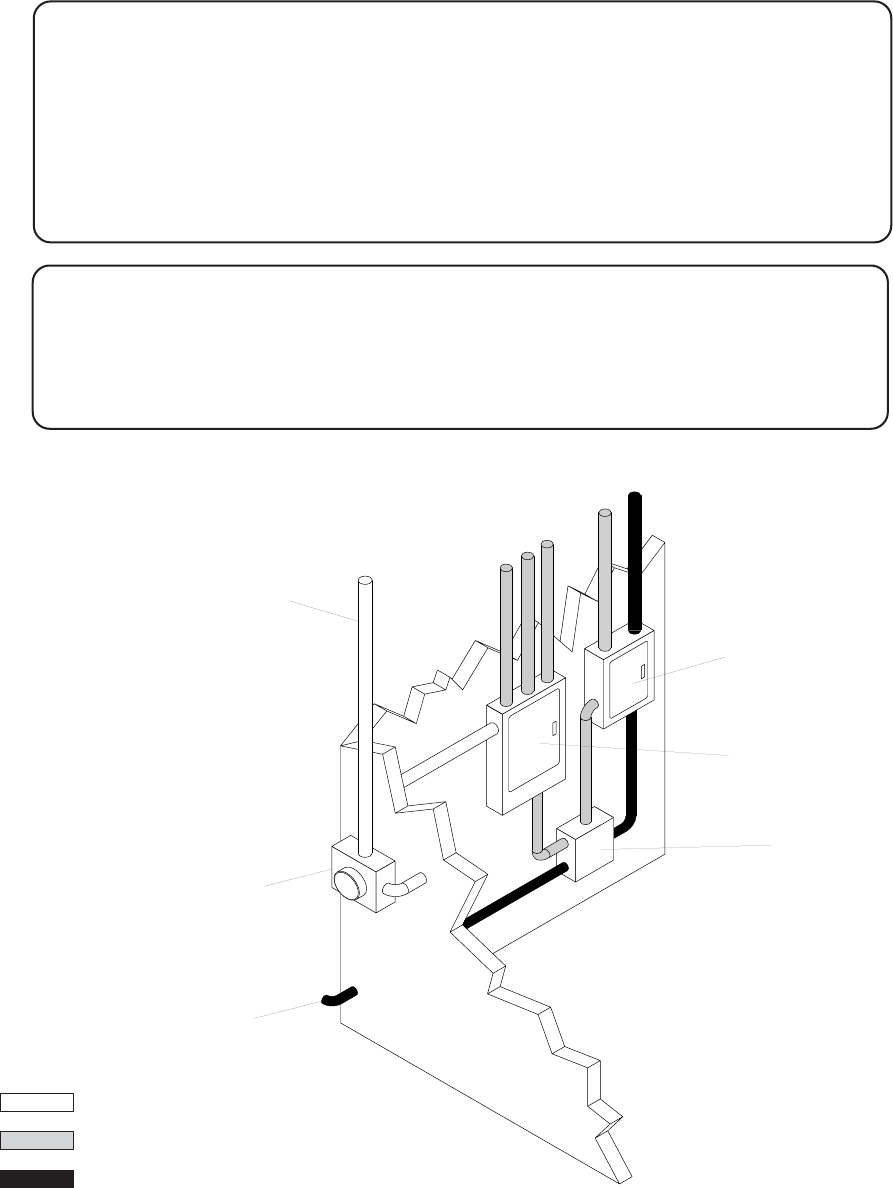
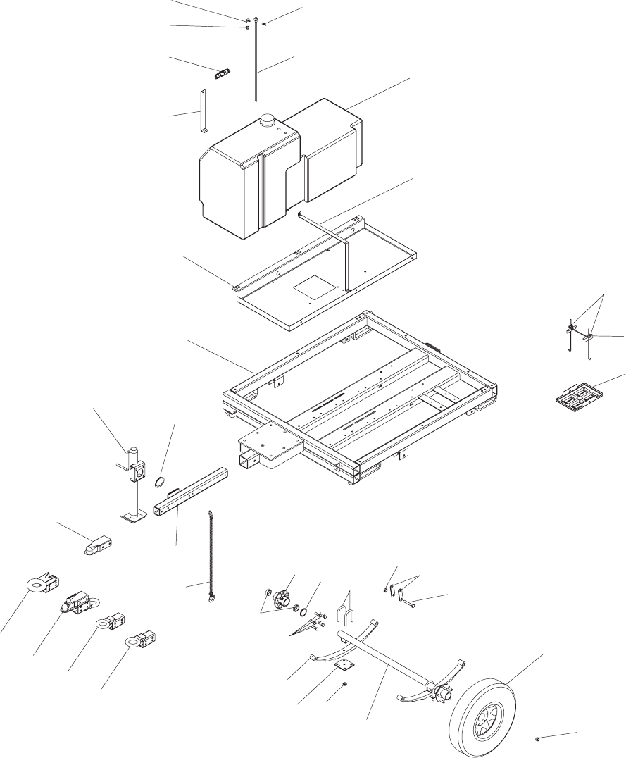
FRAME ASSEMBLY
22
25
31 32
30
33 35
34
24
23 26
27 28
29
ITEM NO. PART NO. QTY DESCRIPTION
1 15142 1 Fitting, .250NPT x .312 hose barb
2 12259 1 Fuel pick-up tube, 24.00 in.
3 12080 1 Cap, fuel tank vented - 3.5 in. green
4 16271 1 Fitting, .250NPT x .188 hose barb
5 12361B 1 Weldment, fuel tank strap (small)
6 16270 1 Fitting, .375MNPT x .250FNPT
7 12162 1 Tank, fuel - 56 gallon poly
8 12359B 1 Weldment, fuel tank strap (LRG)
9 12358B 1 Pan, fuel tank flat frame
10 11563B 1 Weldment, lt/gen chassis
11 14223 1 Jack, sidewind - 2000 lb.
12 14326 1 Ring, retaining
13 16830 1 Coupler, 2 in. ball/2.5 in. channel
14 14521 2 Chain, safety - 44in, w/hook
15 11672B 1 Weldment, hitch - 3.00x1.625 ring/2.50 tube
16 16741B 1 Weldment, combo hitch - 2.5” tongue
17 16835B 1 Weldment, lunette ring - 3.00 ID/ 2.5 tongue
18 16999B 1 Weldment, lunette ring - 2.50 ID/ 2.5 tongue
19 14146 2 Bolt, J - .250-20 x 10 (battery)
20 14682 1 Bracket, battery hold down
21 14145 1 Battery tray
22 11511 4 Axis axle roller bearing
23 11276 2 Axis, axle hub (new) w/races 3500lb.
24 11199 2 Axle bearing seal
25 60674 10 Stud, wheel
26 11277 4 Axle U-bolt 3500 lb.
27 60504 6 Nut, .562-18 hx shackle lock
28 19637 4 Plate, shackle bracket
29 60503 6 Screw, .562-18 hx shackle
30 11280 2 Axis leaf spring, 3500 lb.
31 11278 2 Axle tie plate, 3500 lb.
32 11279 8 Axle nut (u-bolt) 3500 lb.
33 11385 1 Axle, 2200 lb.
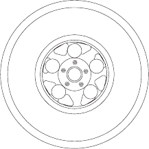
34 15540 2 Wheel, 15” with rim
35 60096 10 Nut, .500-20 wheel lug
36 15828B 1 Weldment, removable tongue
-- 960151 -- Spare tire group - 15" (optional, not shown)
27
FRAME ASSEMBLY
28
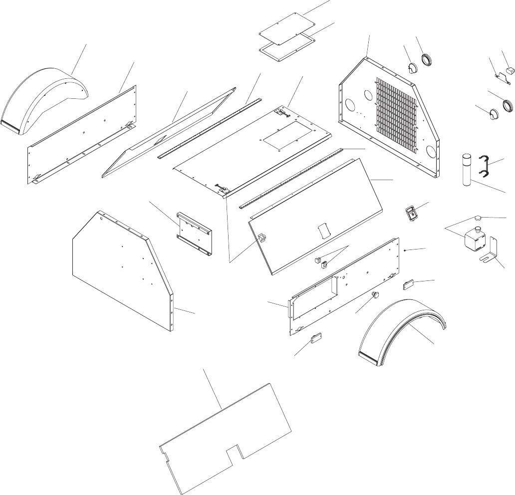
ENCLOSURE ASSEMBLY
4
3
5
6
1
9
8
11
14
7
16
15
10
13
12
24
22
21 19
20 18
17
9
10
5
6
3
25
26
23
21
2
27
ITEM NO. PART NO. QTY DESCRIPTION
1 25333W 1 Panel, back access
2 12195 1 Gasket, radiator access plate
3 11381 2 Fender, plastic
4 11507W 1 Panel, right side sheetmetal
5 16591W 2 Panel, door
6 16598 2 Hinge, door
7 10284W 1 Panel, roof w/access hole
8 10287W 1 Panel, rear 4000 isuzu
9 10220 2 Light, rear tail/turn mlt no grommet
10 10221 2 Grommet, rear light rubber 4.5
10219 2 Assembly, rear tail/turn light (9 & 10)
11 10224 1 Bracket, license plate
12 10225 1 Light, license bracket
10223 1 Assembly, license plate light (11 & 12)
13 11222 1 Bracket, manual holder
14 11121 1 Holder, manual black tube
15 15123 2 Latch, paddle
16 19714 1 Cap, over flow jug
17 14410 1 Assembly, overflow jug
18 22419B 1 Bracket, support overflow jug
19 15215 6 Bumper, rubber
20 65406 2 Light, clearance marker red
21 22550 1 Switch, Estop, 2NO/1NC
22 65407 2 Light, clearance marker amber
23 12257W 1 Panel, left side sheetmetal
24 14651 2 Latch, door
25 11886B 1 Bracket, control box
26 12012W 1 Panel, front sheetmetal
27 11724 2 Foam, door
28 12191 1 Decal, label set (not shown)
29 22545 1 Decal, number set (not shown)
30 10222 - Plug, rear light 3-wire MLT (not shown)
31 10226 - Plug, 2-wire license light (not shown)
29
ENCLOSURE ASSEMBLY
30
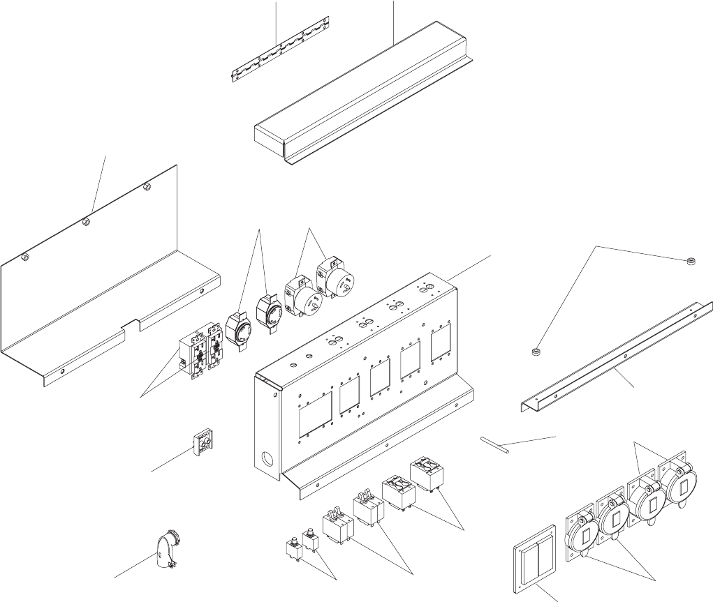
AUXILIARY OUTLET PANEL ASSEMBLY
1
2
8
9
5
4
3
6
710
11
13
12
14
15
17
16
18
31
AUXILIARY OUTLET PANEL ASSEMBLY
ITEM NO. PART NO. QTY DESCRIPTION
1 65535 1 Clamp, 90° 3/4" 2 screw
2 12248B 1 Weldment, outlet cover
3 10081 1 Hinge, continuous - 11.00 in.
4 11484B 1 Cover, breaker
5 14130 2 Receptacle, 120V/20A GFCI
6 65530 2 Block, terminal - 2 pole lug type, 7 pos./pole
7 14137 2 Receptacle, 240V/30A twist lock
8 18089 2 Receptacle,120/ 240V 50A twist lock
9 12246B 1 Weldment, outlet panel
10 15215 2 Rubber bumper
11 11485B 1 Angle, mounting support
12 65492 2 Breaker, 50A, 250V, 2 pole aux contact
13 65387 2 Breaker, 30A, 250V, 2 pole aux contact
14 14156 2 Breaker, 20A, 120V, 1 pole push button
15 15849 1 Cover, receptacle - weather proof
16 65467 2 Cover, receptacle 50A twist lock
17 65460 2 Cover, 20/30A 240V twist lock
18 18992 1 Stud, ground
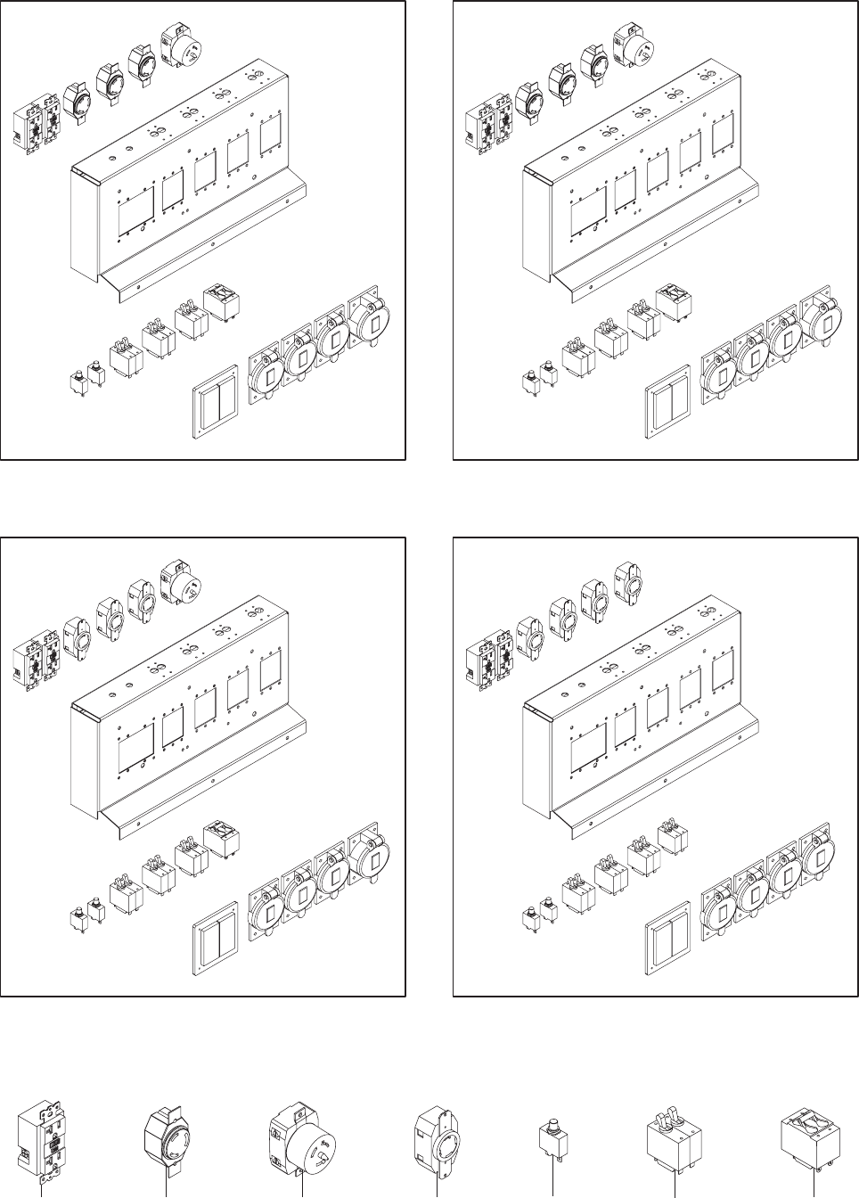
AUXILIARY OUTLET PANEL OPTIONS
32
12345 6 7
PART NUMBER 12399
Receptacle Panel (2x5-20R, 3xL6-30R, 1x50A)
PART NUMBER 12402
Receptacle Panel (2x5-20R, 3xL6-20R, 1x50A)
PART NUMBER 12400
Receptacle Panel (2x5-20R, 3xL14-30R, 1x50A)
PART NUMBER 12401
Receptacle Panel (2x5-20R, 4xL14-30R)
ITEM NO. PART NO. QTY DESCRIPTION
1 14130 2 Receptacle, 120V/20A GFCI
2 14137 - Receptacle, 240V/30A twist lock
3 18089 - Receptacle, 120/240V 50A twist lock
4 65488 - Receptacle, 240V/30A twist lock
5 14156 2 Breaker, 20A, 120V, 1 pole push button
6 65387 - Breaker, 30A, 250V, 2 pole aux contact
7 65492 - Breaker, 50A, 250V, 2 pole aux contact
AUXILIARY OUTLET PANEL OPTIONS
33
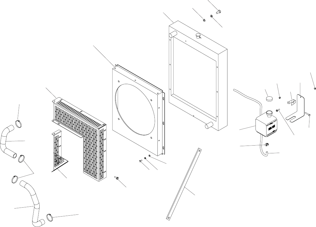
ENGINE COOLING ASSEMBLY
34
123
7
3
12
6
22
4
5
2
1
13
14
15
16
17
8
19 20
9
6
11
18
10
21
6
ITEM NO. PART NO. QTY DESCRIPTION
1 60034 12 Screw, .375-16X.750 hx ser flg ZP
2 60206 12 Washer, split lock .375 ZP
3 60386 12 Washer, flat .375 ZP
4 22238 1 Radiator, engine
5 11626B 1 Weldment, fan shroud
6 15422 4 Clamp, hose SAE 20
7 11760B 1 Panel, fan guard (RHT)
8 60115 8 Screw, M6X1.0X12 hx ser flg ZP
9 11769B 1 Weldment, fan guard (LFT)
10 11596B 1 Strut, radiator support
11 60144 1 Nut, .250-20 nylock ZP
12 22419B 1 Bracket, support overflow jug .5 gal.
13 19726 1 Clamp, overflow bottle
14 60047 1 Nut, M6 hx lock class 6 DIN985 ZP
15 19714 1 Cap, overflow bottle
16 60014 1 Screw, M6X1.0X35 hx GR8.8 DIN933 ZP
17 60135 1 Screw, M6X1.0X20 hx ser flg ZP
18 20287 1 Jug, overflow 2 qt. (.5 gal.)
19 14216 1 Clamp, hose SAE 04
20 19220 1 Hose, overflow
21 12064 1 Hose, radiator upper
22 12356 1 Hose, radiator lower
ENGINE COOLING ASSEMBLY
35
1
10
4
2
14
8
9
5
11
3
718
21
26
17
27
23
6
24 25
10
5
12
13
4
4
17
18
28 29
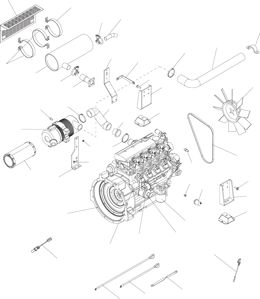
ENGINE ASSEMBLY
36
15 16
519
20
22
36
35
34
32
33 30
31
12
ENGINE ASSEMBLY
ITEM NO. PART NO. QTY DESCRIPTION
1 21505 1 Assembly, air filter
2 60009 4 Screw, M8X1.25X25 hx ser flg ZP
3 12087B 1 Bracket, air filter
4 60018 14 Screw, M10X1.25X20 hx ser flg
5 60316 3 Clamp, hose - SAE 32
6 60342 4 Nut, M8X1.25 hx GR8.8 SS
7 22320 1 Hose, air filter
8 19552 1 Insert, air hose reducer 1.75-2.0
9 12421B 1 Weldment, exhaust flange
10 25455 2 Clamp, 1.5” muffler
11 12608 1 Muffler
12 12606B 3 Bracket, muffler
13 12612B 1 Heat shield
14 12683B 1 Pipe, exhaust
15 12634B 1 Bracket, muffler mounting
16 12635B 1 Bracket, muffler support
17 11471B 2 Weldment, engine mount
18 11524 2 Compression mount, 4.38x4.00x1.50
19 12637 1 Hose, air inlet
20 60821 1 Strap, plastic
21 19258 1 Fan, 15.75 in.
22 22258 1 Belt, fan - 4LE1-PV05
23 19247 1 Sensor, temperature (small)
24 19232 1 Fitting, .125NPTF X .125-28 BSP male
25 18106 1 Sensor, oil pressure
26 18064 1 Engine, 4LE1PV05
27 15074 1 Cable, battery - 4 AWG X 38 in. red
28 15073 1 Cable, battery - 4 AWG X 25 in. blk .38 lug
29 19042 1 Strap, braided ground - 10 in.
30 15183 1 Filter, oil - Isuzu (3LB,3LD,4LE)
31 15331 1 Fuel filter element
32 22893 1 Solenoid, fuel shutdown
33 16205 1 Pump, fuel - ISUZU 4LE1
34 19270 1 Element, air filter
35 18105 1 Sensor, magnetic pickup
36 23899 1 Dipstick, oil, Isuzu 4LEPV05
37 24036 1 Harness, engine (not shown)
38 22430 1 Engine manual, workshop - ISUZU 4LE1
37
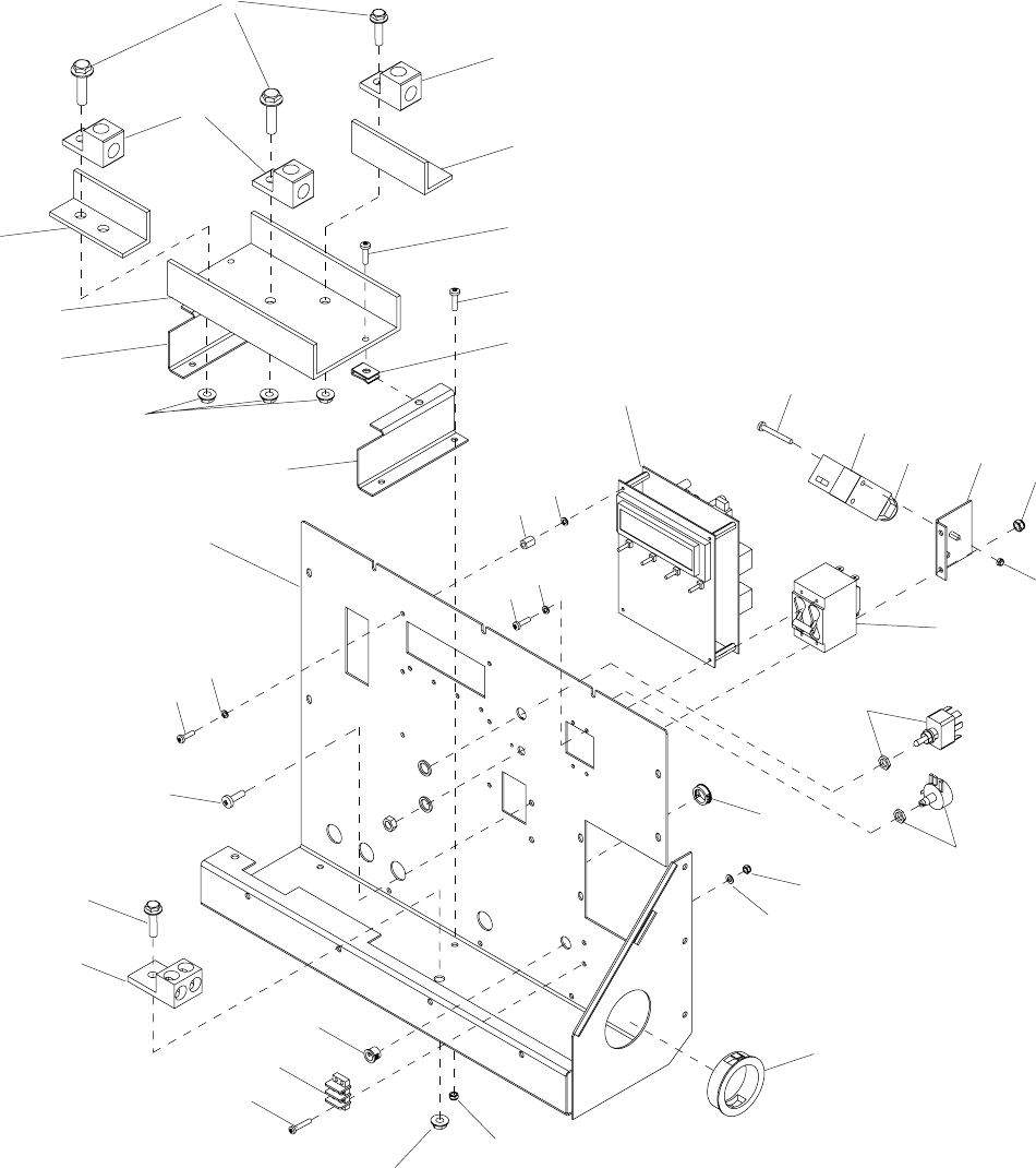
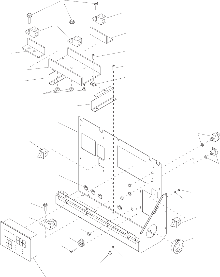
CONTROL PANEL ASSEMBLY
FOR UNITS BUILT PRIOR TO MAY 2006
38
3
7
14
13
2
1
4
610
11
12
8
9
2
4
6
5
20
9
25
23
22 15
16
19
18
17
21 20
28
7
14
27
26
30
29
15
32
24
31
34
39
CONTROL PANEL ASSEMBLY - FOR UNITS BUILT PRIOR TO MAY 2006
ITEM NO. PART NO. QTY DESCRIPTION
1 60160 3 Screw, M8X1.25X30 hx ser flg ZP
2 65225 3 Lug, terminal single #6-250 MCM
3 12065 1 Channel, glastic
4 12066 2 Angle, glastic
5 11695W 1 Panel, control
6 11811W 2 Bracket, glastic plate - MLG 25
7 60020 3 Nut, M8 hx ser flg lock ZP
8 60062 3 Screw, 10-32X.750 pan hd phil ZP
9 60044 2 Screw, M5X0.8X12 pan hd phil ZP
10 60738 2 Nut, 10-32 speed u-type ZP
11 60045 2 Screw, M4X35 pan hd phil ZP
12 18111 1 Switch, lockout (1 NO)(1 NC)
13 11742B 1 Bracket, lockout switch
14 60038 2 Nut, M5 hx nylock DIN985 ZP
15 60057 4 Nut, M4 hx DIN934 - 8 ZP
16 65429 1 Breaker, 100A, 250V, 2 pole, w/aux cont.
17 25078 1 Switch, toggle (auto/off/manual)
18 18113 1 Potentiometer, 2.5K 2 watt
19 25651 1 Board, controller - liquid cooled
20 60058 12 Washer, split lock #6 ZP
21 25657 6 Mount, compression - control board
22 60083 16 Washer, split lock M3 DIN127 ZP
23 60046 4 Screw, 6-32X.750 pan hd phil ZP
24 19227 4 Bushing, .812 OD x .625 ID
25 60190 10 Screw, 6-32X.312 pan hd phil ZP
26 60009 3 Screw, M8X1.25X25 hx ser flg ZP
27 18614 1 Lug, terminal dual #6-250MCM 2 hole
28 19163 1 Bushing, .500 x .375 ID
29 60355 2 Screw, M4X25 pan hd phil
30 18890 1 Terminal block, 2-pos
31 60084 2 Washer, flat M4
32 18496 1 Bushing, 2.50 x 2.00 ID
33 11808W 1 Plate, lug door support
34 15864 1 Strain relief - .50 NPT watertight
35 11987 1 Decal, control panel (not shown)
36 11707 1 Assembly, control panel
CONTROL PANEL ASSEMBLY, NEW STYLE
FOR UNITS BUILT AFTER MAY 2006
40
3
7
2
1
4
610
8
9
2
4
6
5
15
24
21
15
20
7
17
22
23
19
18
13
16
12
14
11
41
CONTROL PANEL ASSEMBLY, NEW STYLE - FOR UNITS BUILT AFTER MAY 2006
ITEM NO. PART NO. QTY DESCRIPTION
1 60160 3 Screw, M8X1.25X30 hx ser flg
2 65287 3 Lug, terminal single #6-350 MCM
3 12065 1 Channel, glastic
4 12066 2 Angle, glastic
5 12629W 1 Panel, control
6 11811W 2 Bracket, glastic plate - MLG 25
7 60020 7 Nut, M8 hx ser flg lock
8 60062 3 Screw, 10-32X.750 pan hd phil
9 60044 2 Screw, M5X0.8X12 pan hd phil
10 60738 2 Nut, 10-32 speed u-type
11 25077 1 Switch, toggle - SPST 20A VAC
12 18113 1 Potentiometer, 2.5K 2 watt
13 60057 4 Nut, M4 HX
14 60084 2 Washer, flat M4
15 12632 2 Switch, trigger safety, N.O. & N.C.
16 18496 1 Bushing, 2.50 x 2.00 ID
17 60038 4 Nut, M5 HX nylock
18 60355 2 Screw, M4X25 pan hd phil
19 18890 1 Terminal block, 2-pos
20 19163 1 Bushing, .500 x .375 ID
21 24129 1 Controller, eng/gen - programmed
22 18614 1 Lug, terminal dual #6-250MCM 2 hole
23 60009 3 Screw, M8X1.25X25 hx ser flg
24 19227 4 Bushing, .812 OD x .625 ID
-- 18934 1 Guard, potentiometer (not shown)
-- 12742 1 Decal, control panel (not shown)
-- 12628 1 Assembly, control panel
1
9
2
10
3
11
4
12
5
67
8
7
7
11
8
8
17
18
13
14
15
16
8
12
19
20
21
22
23
20
19
25 26
24
27
28
29
30
12
7
32
31
32
8
42
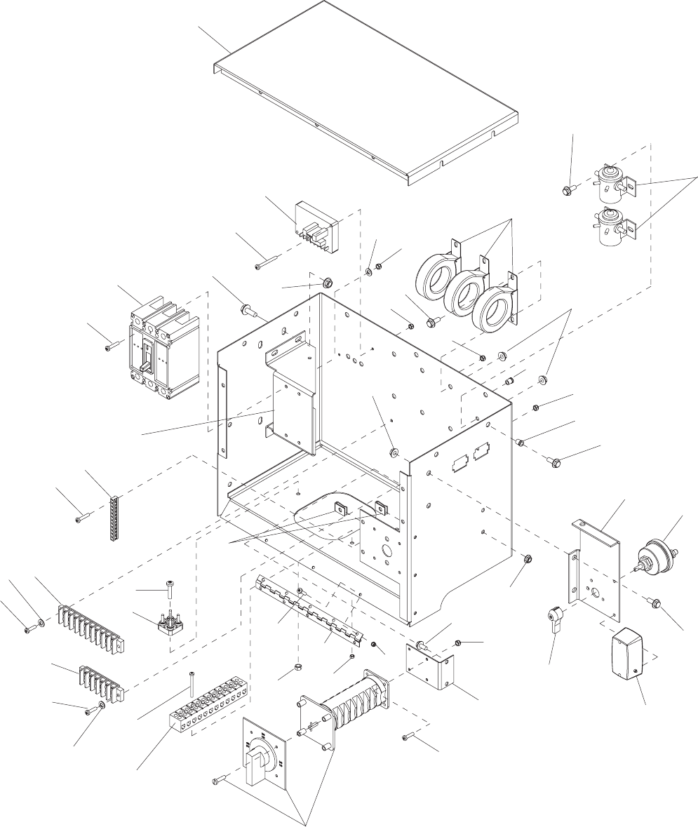
CONTROL BOX ASSEMBLY
FOR UNITS BUILT PRIOR TO MAY 2006
34
33
35
36
37
38
ITEM NO. PART NO. QTY DESCRIPTION
1 11701B 1 Panel, top control box - MLG25
2 18556 1 Regulator, voltage - SE 350
3 60045 2 Screw, M4X35 pan head phil ZP
4 60114 4 Screw, M8X1.25X20 hx ser flg ZP
5 60020 4 Nut, M8 hx ser flg lock ZP
6 60084 6 Washer, flat M4
7 60051 12 Nut, M4 hx nylock
8 60115 12 Screw, M6X1.0X12 hx ser flg ZP
9 60061 4 Nut, 10-32 hx nylock ZP
10 65442 3 Transformer, current - 200:5A
11 60023 7 Insert, threaded M6
12 60036 12 Nut, M6 hx ser flg lock ZP
13 65334 1 Breaker, 90A
14 60159 4 Screw, M4X45 pan head phil ZP
15 11727B 1 Bracket, breaker mounting
16 14204 1 Kit, ground bar
17 60396 2 Screw, 10-32X1.250 pan hd phil ZP
18 14203 1 Block, terminal 10 pos.
19 60041 4 Washer, flat M5
20 60062 10 Screw, 10-32X.750 pan hd phil ZP
21 60738 6 Nut, 10-32 speed u-type ZP
22 60044 6 Screw, M5X0.8X12 pan hd phil ZP
23 10081 1 Hinge, continuous -11 in.
24 18081 2 Relay, ignition soleniod (12V-65 A)
25 65163 1 Block, terminal - 6 pos. fork connection
26 60038 6 Nut, M5 hx nylock DIN985 ZP
27 65456 1 Switch, phase - 63A, 3-pos (Y,y,Z)
28 60091 4 Screw, M4X12 pan hd phil ZP
29 11764B 1 Bracket, phase switch
30 12021B 1 Bracket, control box roof
31 11947 1 Light, interior with switch (optional)
32 65498 1 Switch, disconnect (optional)
33 65519 1 Block, terminal, 4 pole stud
34 60146 1 Screw, M6X1.0X20 pan hd ZP
35 60047 1 Nut, M6 hx lock ZP
36 65590 1 Block, terminal - 12 pos. lug type
37 60045 2 Screw, M4X35 pan hd phil ZP
38 60051 2 Nut, M4 hx nylock
39 19351 1 Seal, generator box (not shown)
40 11688 1 Assembly, control box enclosure
41 11703 1 Assembly, control box complete
43
CONTROL BOX ASSEMBLY - FOR UNITS BUILT PRIOR TO MAY 2006
44
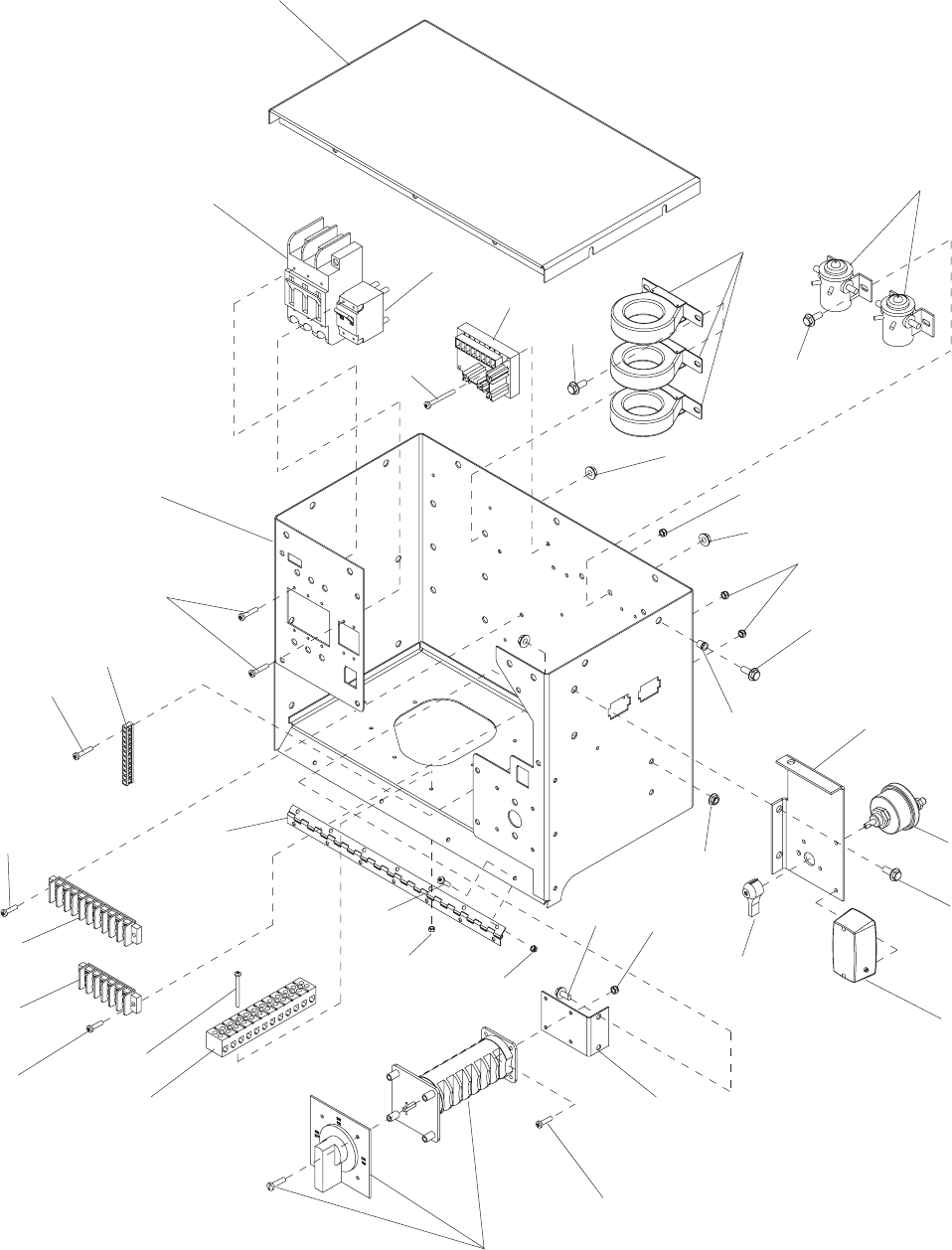
CONTROL BOX ASSEMBLY, NEW STYLE
FOR UNITS BUILT AFTER MAY 2006
1
2
3
4
5
6
7
8
9
11
7
910
12
7
26
27
9
28
27
7
13
14
15
10
7
11
16
17
18
20
10
19
21
22
5
23
24
5
25
ITEM NO. PART NO. QTY DESCRIPTION
1 12694W 1 Panel, top control box - MLG25
2 65619 1 Breaker, 90A, 3 pole
3 65429 1 Breaker, 100A, 250V, 2 pole
4 18556 1 Regulator, voltage - SE 350
5 60355 6 Screw, M4X35 pan head phil
6 65442 3 Transformer, current - 200:5A
7 60115 25 Screw, M6X1.0X12 hx ser flg
8 18081 2 Relay, ignition soleniod (12V-65 A)
9 60036 14 Nut, M6 hx ser flg lock
10 60051 11 Nut, M4 hx nylock
11 60061 6 Nut, 10-32 hx nylock
12 60023 11 Insert, threaded M6
13 11764B 1 Bracket, phase switch
14 60091 4 Screw, M4X12 pan hd phil
15 65456 1 Switch, phase - 63A, 3-pos (Y,y,Z)
16 60044 4 Screw, M5X0.8X12 pan hd phil
17 65590 1 Block, terminal - 12 pos. lug type
18 60045 3 Screw, M4X35 pan hd phil
19 65481 1 Block, terminal - 6 pos.
20 18598 1 Hinge, controller panel - 18.75
21 14203 1 Block, terminal 10 pos.
22 60062 2 Screw, 10-32X.750 pan hd phil
23 14204 1 Kit, ground bar
24 60190 10 Screw, 6-32X.312 pan hd phil
25 12626W 1 Weldment, control box
-- 12625 1 Assembly, control box enclosure
-- 12624 1 Assembly, control box complete
OPTIONAL FEATURES:
26 12021B 1 Bracket, control box roof (optional)
27 65498 1 Switch, disconnect (optional)
28 11947 1 Light, interior with switch (optional)
45
CONTROL BOX ASSEMBLY, NEW STYLE - FOR UNITS BUILT AFTER MAY 2006
46
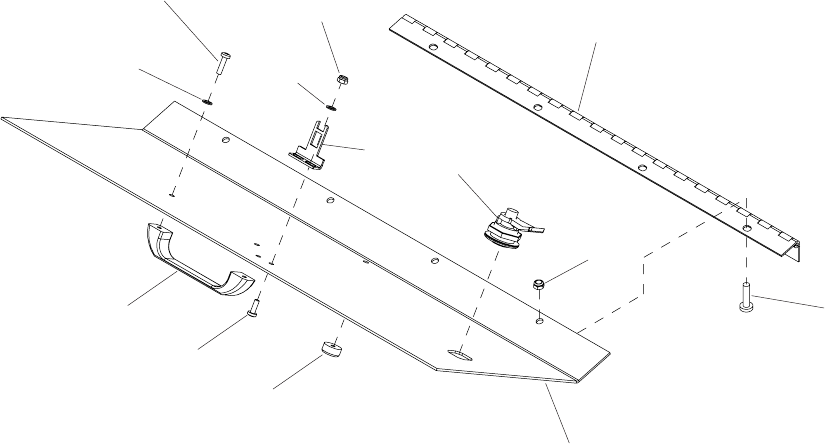
5
6
7
82
4
1
3
9
10
11
13
12
ITEM NO. PART NO. QTY DESCRIPTION
1 18598 1 Hinge, controller panel - 18.75
2 60156 8 Screw, M5X0.8X16 pan hd phil ZP
3 60038 4 Nut, M5 hx nylock DIN985 ZP
4 20762 1 Lock, door - 1/4 turn cam
5 11710W 1 Panel, lug door
12631W 1 Panel, lug door (for units built after May ‘06)
6 15215 1 Bumper, rubber
7 60091 2 Screw, M4X12 pan hd phil ZP
8 18893 1 Handle, lug door
9 18112 1 Key, lockout switch (90 DEG)
11 60084 2 Washer, flat M4 DIN125 ZP
10 60051 2 Nut, M4 hx nylock DIN985
12 60043 2 Washer, split lock M5 DIN127 ZP
13 60068 2 Screw, 10-24X.500 pan phil ZP
14 11809 1 Assembly, lug door
LUG DOOR ASSEMBLY
GENERATOR ASSEMBLY
ITEM NO. PART NO. QTY DESCRIPTION
1 60177 6 Screw, M10X1.25X30 hx hd
2 60206 14 Washer, split lock .375 ZP
3 11000 1 Plate, drive - SAE 7.5
4 11515B 2 Spacer, 2.00 dia x 1.00
5 11524 2 Compression mount, engine
6 22899 1 Generator, 282NSL1505
7 11597B 1 Bracket, gen mount
47
6
4
5
21
3
7
48
ALT EXIT
ALT EXIT
FUEL
FUEL
PUMP
PUMP
MLG 25 DC WIRING
DC WIRING SCHEMATIC, FOR UNITS BUILT PRIOR TO MAY 2006
49
DC WIRING SCHEMATIC, NEW STYLE - FOR UNITS BUILT AFTER MAY 2006
C+
C+
GLOW
GLOW
RELAY
RELAY
B+
B+
BLK
BLK
YEL
YEL
C+
C+
STARTER
STARTER
RELAY
RELAY
B+
B+
BLK
BLK
YEL
YEL
60HZ
60HZ
50HZ
50HZ
WHT
WHT
RED F+
RED F+
F-
F-
F+
F+
4
6
7
BRN/WHT
BRN/WHT
BLK
BLK
BLK F-
BLK F-
BRN
BRN
SE350
SE350
VOLTAGE REGULATOR
VOLTAGE REGULATOR
3
BLK
BLK
BLK
BLK
BLK
BLK
YEL
YEL
YEL
YEL
YEL
YEL
YEL
YEL
GRY
GRY
WT/BU
WT/BU
WT/VI
WT/VI
BRN
BRN
ORG
ORG
BRN
BRN
ORG
ORG
RED
RED
GRY
GRY
ORG
ORG
BLU
BLU
RED
RED
VIO
VIO
RED
RED
GRY
GRY
RED
RED
ORG
ORG
WHT
WHT
RED
RED
BLK
BLK
RED
RED
RED
RED
WHT
WHT
YEL
YEL
BLK
BLK
RED
RED
GRN
GRN
YL/GN
YL/GN
BLK
BLK
BLK
BLK
BLK
BLK
BLK
BLK
WHT
WHT
BLK
BLK
BRN
BRN
GRN
GRN
RED
RED
BLU
BLU
YEL
YEL
ORG
ORG
VIO
VIO
VIO
VIO
VIO
VIO
YEL
YEL
ORG
ORG
WHT
WHT
RED
RED
RED
RED
RED
RED
BLU
BLU
RED
RED
BLK
BLK
WT/VI
WT/VI
YEL
YEL
WT/BU
WT/BU
GRY
GRY
BLK
BLK
VIO
VIO
BLK
BLK
BLK
BLK
RED
RED
WHT
WHT
ORG
ORG
YL/GN
YL/GN
VIO
VIO
GRY
GRY
BLU
BLU
YEL
YEL
BRN
BRN
BR/WT
BR/WT
WHT
WHT
BLK
BLK
GRN
GRN
GRN
GRN
WHT
WHT
BRN
BRN
RED
RED
BLK
BLK
RED
RED
YEL
YEL
RED
RED
GRY
GRY
YEL
YEL
ORG
ORG
WHT
WHT
WHT
WHT
FUSE
FUSE
15 AMP
15 AMP
RED
RED
WHT
WHT
BLK
BLK
VIO
VIO
BLK
BLK
WHT
WHT
YL/GN
YL/GN
GRY
GRY
YEL
YEL
BLK
BLK
RED
RED
ORG
ORG
RED
RED
BLU
BLU
BLU
BLU
BLK
BLK
YEL
YEL
RED
RED
WT/VI
WT/VI
WT/BU
WT/BU
GRY
GRY
BLK
BLK
2 PIN PLUG (RPM)
2 PIN PLUG (RPM)
RPM IN
RPM IN
RPM GND
RPM GND
SMALL 4 PIN ANALOG INPUTS
SMALL 4 PIN ANALOG INPUTS
OIL IN
OIL IN
FUEL IN
FUEL IN
WATER IN
WATER IN
COMMON
COMMON
AI1
AI1
AI2
AI2
AI3
AI3
COM
COM
NEUTRAL
NEUTRAL
COM
COM
4
L1
L1
L2
L2
L3
L3
CT NEUTRAL
CT NEUTRAL
L3
L3
L2
L2
L1
L1
-
+
2 PIN PLUG (POWER)
2 PIN PLUG (POWER)
POWER + DC
POWER + DC
POWER - DC
POWER - DC
REMOTE START
REMOTE START
LOW COOLANT OPTION
LOW COOLANT OPTION
OPEN
OPEN
OPEN
OPEN
OPEN
OPEN
CRANK
CRANK
+ 12 VDC
+ 12 VDC
RUN
RUN
+ 12 VDC
+ 12 VDC
BO1
BO1
COM
COM
BO2
BO2
COM
COM
PREHEAT
PREHEAT
OPEN
OPEN
OPEN
OPEN
OPEN
OPEN
BO3
BO3
BO4
BO4
BO5
BO5
BO6
BO6
BI1
BI1
BI2
BI2
BI3
BI3
B14
B14
BI5
BI5
BI6
BI6
D
BC
"OPTION"
"OPTION"
PLUG LOCATION
PLUG LOCATION
BOTTOM
BOTTOM
BOTTOM
BOTTOM
PLUG LOCATION
PLUG LOCATION
LARGE 4 PIN GENERATOR VOLTAGE
LARGE 4 PIN GENERATOR VOLTAGE
PLUG LOCATION
PLUG LOCATION
TOP
TOP
SMALL 4 PIN GENERATOR CURRENT
SMALL 4 PIN GENERATOR CURRENT
PLUG LOCATION
PLUG LOCATION
TOP
TOP
PLUG LOCATION
PLUG LOCATION
BOTTOM
BOTTOM
6 PIN PLUG (BINARY INPUTS)
6 PIN PLUG (BINARY INPUTS)
PLUG LOCATION
PLUG LOCATION
TOP
TOP
4 PIN PLUG (START / FUEL)
4 PIN PLUG (START / FUEL)
PLUG LOCATION
PLUG LOCATION
BOTTOM
BOTTOM
4 PIN PLUG (BINARY OUTPUTS)
4 PIN PLUG (BINARY OUTPUTS)
PLUG LOCATION
PLUG LOCATION
BOTTOM
BOTTOM
OR
OR
ALTERNATOR
ALTERNATOR
CUT BACK SHEILD
CUT BACK SHEILD
AND TAPE
AND TAPE
SHIELD
SHIELD
BLK
BLK
3NO
3NO
4NO
4NO
4NO
4NO
3NO
3NO
1NC
1NC
2NC
2NC
WHT
WHT
WHT
WHT
WHT
WHT
WHT
WHT
REMOTE START
REMOTE START
BLU
BLU
L1
L1
L2
L2
AUX
AUX
BREAKER
BREAKER
CONTROL POWER
CONTROL POWER
LUG DOOR SW
LUG DOOR SW
VR
VR
WHT
WHT
LUG DOOR SW
LUG DOOR SW
SHUNT
SHUNT
TRIP
TRIP
FUEL
FUEL
SHUTDOWN
SHUTDOWN
SOLENOID
SOLENOID
FUEL
FUEL
PUMP
PUMP
OIL SENDER
OIL SENDER
RED
RED
WHT
WHT
BLK
BLK
90505
90505
WIRING DIAGRAM, MLG25 DC
WIRING DIAGRAM, MLG25 DC
BLOCK
BLOCK
1
L0
9
7
WHT
GROUND
GROUND
TO
TO
FRAME
FRAME
T4
T5
T5
T9
BLOCK
BLOCK
2
34
BLOCK
BLOCK
BLOCK
BLOCK
812
12
2
6
9
7
4 5
1
3
11
11
10
10
1
34
BLOCK
50
AC WIRING SCHEMATIC, FOR UNITS BUILT PRIOR TO MAY 2006
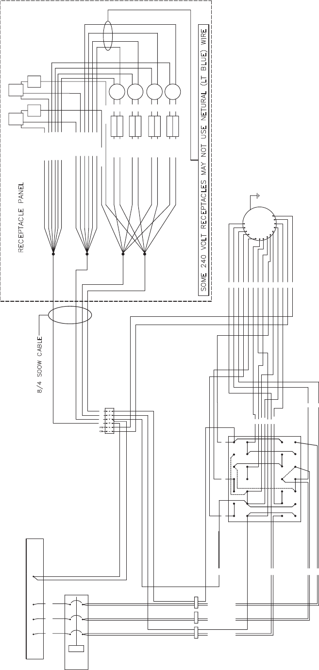
51
AC WIRING SCHEMATIC, NEW STYLE - FOR UNITS BUILT AFTER MAY 2006
BRN 14GA
BRN 14GA
240V
240V
BREAKER
BREAKER
240V
240V
BREAKER
BREAKER
BLK 10GA
BLK 10GA
BLK 10GA
BLK 10GA
BRN 14GA
BRN 14GA
5 9 13
13
610
10
14
14
7
8
11
11
12
12
15
15
16
16
T5
T5
BLK 10GA
BLK 10GA
BLK 10GA
BLK 10GA
125A
125A
GRN/YEL 10GA
GRN/YEL 10GA
CT-3
CT-3
L2
L2
L3
L3
SHUNT
SHUNT
L1
L1
CT-2
CT-2
CT-1
CT-1
BREAKER
BREAKER
PAIR BLK 10GA
PAIR BLK 10GA
PAIR BLK 10GA
PAIR BLK 10GA
PAIR BLK 10GA
PAIR BLK 10GA
GRN/YEL 14GA
GRN/YEL 14GA
GRN/YEL 10GA
GRN/YEL 10GA
1
2
3
4
T4
T4
MECHANICAL LUGS
MECHANICAL LUGS
BLK
BLK
GFCI
GFCI
RECPT
RECPT
120V
120V
17
17
21
21
25
25
18
18
22
22
26
26
19
19
20
20
23
23
24
24
27
27
28
28
T9
T9
RCPT.
RCPT.
240V
240V
RCPT.
RCPT.
240V
240V
BLK
BLK
BLK
BLK
BLK
BLK
T6
T6
T8
T8
T10
T10
T11
T11
T7
T7
T1
T1
T12
T12
T2
T2
T3
T3
120V
120V
BRKER
BRKER
120V
120V
RECPT
RECPT
GFCI
GFCI
6GA
6GA
L3
L3
L2
L2
L1
L1
L0
L0
6GA
6GA
6GA
6GA
12VDC
12VDC
GRN/YEL 14GA
GRN/YEL 14GA
BRKER
BRKER
120V
120V
(3) JUMPER
(3) JUMPER
WIRES (DASHED)
WIRES (DASHED)
ON PHASE SWITCH
ON PHASE SWITCH
10GA
10GA
CIRCUIT
CIRCUIT
LT BLU 14GA
LT BLU 14GA
LT BLU 14GA
LT BLU 14GA
LT BLU 10GA
LT BLU 10GA
LT BLU 10GA
LT BLU 10GA
GROUND
GROUND
TO
TO
FRAME
FRAME
GENERATOR
GENERATOR
F+
F+
F-
F-
T1
T1
T2
T2
T3
T3
T4
T4
T5
T5
T6
T6
T7
T7
T8
T8
T9
T9
T10
T10
T11
T11
T12
T12
F-
F-
F+
F+
GRN
GRN
WHT
WHT
240V
240V
BREAKER
BREAKER
240V
240V
BREAKER
BREAKER
BLK 10GA
BLK 10GA
BLK 10GA
BLK 10GA
BLK 10GA
BLK 10GA
BLK 10GA
BLK 10GA
BLK
BLK
RCPT.
RCPT.
240V
240V
RCPT.
RCPT.
240V
240V
BLK
BLK
BLK
BLK
BLK
BLK
GRN/YEL 10GA
GRN/YEL 10GA
GRN/YEL 10GA
GRN/YEL 10GA
LT BLU 10GA
LT BLU 10GA
LT BLU 10GA
LT BLU 10GA
BLK
BLK
RED
RED
905052
905052
WIRING DIAGRAM, MLG25 AC
WIRING DIAGRAM, MLG25 AC

CALIFORNIA PROPOSITION 65
WARNING
DIESEL ENGINE EXHAUST AND SOME OF ITS CONSTITUENTS ARE
KNOWN TO THE STATE OF CALIFORNIA TO CAUSE CANCER, BIRTH
DEFECTS AND OTHER REPRODUCTIVE HARM.
REV: D PART NO: 12346
7.17.06
