Mainte CR2_E1_5 CR2 E1 5
User Manual: mainteCR2_E1_5
Open the PDF directly: View PDF ![]() .
.
Page Count: 215 [warning: Documents this large are best viewed by clicking the View PDF Link!]
- For safe adjustment and repair
- Index
- Special tool, Measuring equipment, Other
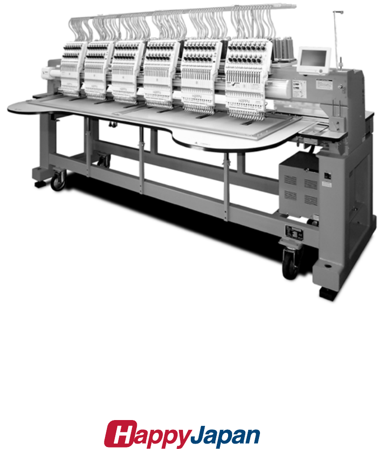
- 1 Placement of key mechanical parts
- 2 Setting up the machine
- 3 Basic maintenance
- 4 Exchange and Setting of mechanical related component
- 4-1 Fixed head
- 4-1-1 Exchange of needle bar driver
- 4-1-2 Adjustment of take-up lever timing
- 4-1-3 Check of height of pressure foot
- 4-1-4 Adjustment of height of pressure foot
- 4-1-5 Exchange of pressure foot
- 4-1-6 Adjustment of thread catcher
- 4-1-7 Exchange of thread catcher guide
- 4-1-8 Exchange of pressure foot cam
- 4-1-9 Adjustment of fixing of jump solenoid
- 4-1-10 Disassembling and Cleaning of jump solenoid
- 4-2- Moving head
- 4-2-1 Assemble and remove moving head (except for 1st head)
- 4-2-2 Assemble and remove moving head (1st Head)
- 4-2-3 Adjustment of needle position (back and front)
- 4-2-4 Adjustment of needle position (Left and Right)
- 4-2-5 Adjustment of needle position (left and right)
- 4-2-6 Adjustment of needle height
- 4-2-7 Adjustment of needle bar lowest point
- 4-2-8 Exchange of needle bar, needle bar spring, cushion and pressure foot block
- 4-2-9 Fixing of needle bar boss check plate
- 4-2-10 Exchange of take-up lever
- 4-2-11 Adjustment of tension of thread adjusting spring
- 4-2-12 Adjustment of stroke of thread adjusting spring
- 4-2-13 Adjustment of thread holder
- 4-2-14 Adjustment of clip-type thread holder
- 4-2-15 Adjustment of clip drive unit
- 4-3 Needle bar change unit
- 4-4 Rotary hook timing
- 4-5 Thread cutting driver
- 4-5-1 Check of thread cutting driver
- 4-5-2 Adjustment of thread cutting driver
- 4-5-3 Exchange of moving knife
- 4-5-4 Exchange of fixed knife
- 4-5-5 Check / Adjustment for position of moving knife
- 4-5-6 Adjustment of moving knife and fixed knife
- 4-5-7 Adjustment of bobbin thread holder
- 4-5-8 Adjustment of position of keeper
- 4-6 Carriage
- 4-7 Transmission unit
- 4-1 Fixed head
- 5 User maintenance mode
- E1 Placement of key electronic parts
- E2 Exchange and Setting of electric related component
- E2-1 Exchange of CONT-R2 board
- E2-2 Exchange Timing Circuit Board
- E2-3 Connection of Detection Circuit Board
- E2-4 Exchange TC7-8 Circuit Board
- E2-5 Exchange needle stop sensor and potentiometer
- E2-6 Exchange Thread trimming sensor
- E2-7 Exchange X-Y Position Sensor
- E2-8 Exchange Brake Unit
- E2-9 Exchange Pulse Motor Driver (Before Rev. A)
- E2-10 Exchange Pulse Motor Driver (Rev. A)
- E2-11 Exchange Switching Power Supply
- E2-12 Adjustment of Voltage for Switching Power Supply
- E2-14 Exchange Cooling Fan
- E2-15 Exchange Inverter
- E2-16 Setting Inverter
- E3 Open and remove control box
- E4 Program update
- E5 Maintenance mode
- E5-1 How to enter maintenance mode
- E5-2 Machine test- Machine Movement
- E5-3 Memory- Initialization of design memory
- E5-4 Record- Operation data display
- E5-5 Setup Machine setting
- E5-6 Position- Registration of coordinates for positioning sensor
- E5-7 Maintenance Register―Registration of machine maintenance date
- E5-8 Machine Setting Navigation after exchanging CONT board (Main program Ver.*1.34~)
- E6 Installation of Option device
- E7 Electric system diagram
- E7-1 Pulse motor driver (PMD) wiring(Before Rev. A)
- E7-1 Pulse motor driver (PMD) wiring (Rev. A)
- E7-2 Inverter wiring
- E7-4 Electrical connection diagram(Before Rev. A)
- E7-5 List of electrical connection diagrams (Before Rev. A)
- E7-6 Electrical connection diagram (Rev. A)
- E7-7 List of electrical connection diagrams (Rev. A)
- E7-8 Explanation of function of circuit board
- E7-4 Electrical connection diagram
- E8 How to respond for some question (As example step)
- E9 Trouble shooting
- E9-1 Electricity doesn t turn on
- E9-2 Thread break
- E9-3 Erroneous thread cut
- E9-4 Off-registration of pattern
- E9-5 Upper thread comes off from needle hole
- E9-6 Upper thread remains
- E9-7 Malfunction of thread break detection
- E9-8 Suspension of upper shaft
- E9-9 Malfunction of needle bar change
- E9-10 Defect on Thread catcher
- E9-11 Others / Mechanical
- E9-12 Others / Electric
- E10-1 Startup error and measure (Main program Ver.*1.37~)
- E10-2 Error and measure
- E11 Tables for timing / adjustment value
Maintenance Manual for Embroidery Machine
HCR2 SERIES
Version 1.5
HappyJapan Inc.

2
# For safe adjustment and repair #
In order to conduct adjustment and repair safely and surely,
please be sure to abide by what is mentioned in this manual to prevent trouble.
1. When you conduct adjustment and repair of this embroidery machine or handle electric related parts,
you are required to take technical lesson in advance.
2. When you conduct adjustment and repair using this manual, please be sure to use together with instruction
with it in hand.
# Please conduct in accordance with work process in this manual.
# In case there are no specific instructions or explanations in work process.
please be sure to unplug cord from receptacle.
# When you exchange parts, please be sure to use genuine parts designated by us.
# Please never remodel the embroidery machine.
When you handle circuit boards:
# In order to prevent troubles from static electricity, please remove earth from human body.
# Please don't touch metal part of circuit board with bare hand as it will short-circuit
and threaten to break circuit boards.
# When you removed circuits boards from the machine or you store or transport them,
please wrap them in static electricity preventive bag and avoid to give shock.

3
Index
Page
For safe adjustment and repair ............................................................................................................. 2
Index ................................................................................................................................ 3
Special tool, Measuring equipment, Other ............................................................................................ 9
1 Placement of key mechanical parts ............................................................................................... 11
2 Setting up the machine
2-1 Machine installation ..................................................................................................... 13
2-2 Assemble the thread guide .............................................................................................. 13
2-3 Removal of stopper ........................................................................................................ 14
2-4 Check of needle position ................................................................................................. 14
2-5 Check of needle height ................................................................................................... 15
2-6 Check of rotary hook timing ............................................................................................. 16
2-7 Oiling ........................................................................................................................... 16
2-8 Check of thread path ...................................................................................................... 17
2-9 Threading .................................................................................................................... 20
2-10 Trial sewing ............................................................................................................... 21
3 Basic maintenance
3-1 Fixing of needle ........................................................................................................... 22
3-2 Selection of thread ...................................................................................................... 23
3-3 Relation between needle and upper thread ................................................................ 24
4 Exchange and Setting of mechanical related component
4-1 Fixed head
4-1-1 Exchange of needle bar driver .................................................................. 25
4-1-2 Adjustment of take-up lever timing ............................................................ 27
4-1-3 Check of height of pressure foot ............................................................... 29
4-1-4 Adjustment of height of pressure foot ....................................................... 30
4-1-5 Exchange of pressure foot ........................................................................ 31
4-1-6 Adjustment of thread catcher .................................................................... 33
4-1-7 Exchange of thread catcher guide ............................................................ 35
4-1-8 Exchange of pressure foot cam ................................................................ 36
4-1-9 Adjustment of fixing of jump solenoid ..................................................... 37a
4-1-10 Disassembling and Cleaning of jump solenoid ..................................... 37b

4
Index
page
4-2 Moving head
4-2-1 Assemble and remove moving head (except for 1st head) ....................... 38
4-2-2 Assemble and remove moving head (1st Head) ........................................ 42
4-2-3 Adjustment of needle position (back and forth) ...................................... 47
4-2-4 Adjustment of needle position (left and right) Adjust for 1st head ........... 48
4-2-5 Adjustment of needle position (left and right) Adjustfor2ndtolasteachhead 50
4-2-6 Adjustment of needle height ..................................................................... 51
4-2-7 Adjustment of needle bar lowest point ...................................................... 53
4-2-8 Exchange of needle bar, needle bar spring, cushion and pressure foot block ................. 55
4-2-9 Fixing of needle bar boss check plate ...................................................... 57
4-2-10 Exchange of take-up lever ...................................................................... 58
4-2-11 Adjustment of tension of thread adjusting spring .................................... 60
4-2-12 Adjustment of stroke of thread adjusting spring ...................................... 61
4-2-13 Adjustment of thread holder .................................................................... 62
4-2-14 Adjustment of
clip-type thread holder ....................................................... 63
4-2-15 Adjustment of
clip drive unit ...................................................................... 64
4-3 Needle bar change unit
4-3-1 Check / Adjustment of needle bar change unit ......................................... 65
4-4 Rotary hook
4-4-1 Adjustment of rotary hook timing .............................................................. 68
4-4-2 Adjustment of retainer on rotary hook ....................................................... 70
4-4-3 Exchange of rotary hook shaft .................................................................. 71
4-5 Thread cut unit
4-5-1 Check of thread cutting driver ................................................................... 74
4-5-2 Adjustment of thread cutting driver ........................................................... 76
4-5-3 Exchange of moving knife ......................................................................... 78
4-5-4 Exchange of fixed knife ............................................................................. 79
4-5-5 Check / Adjustment of position of moving knife ........................................ 80
4-5-6 Adjustment of moving knife and fixed knife .............................................. 82
4-5-7 Adjustment of bobbin thread holder .......................................................... 83
4-5-8 Adjustment of position of keeper .............................................................. 84

5
Index
page
4-6 Carriage unit
4-6-1 Adjustment of X carriage drive belt tension ............................................................. 86
4-6-2 Adjustment of X carriage timing belt tension ............................................................ 88
4-6-3 Adjustment of Y carriage drive belt tension ............................................................. 90
4-6-4 Adjustment of Y carriage timing belt tension ............................................................ 92
4-6-5 Adjustment of
center carriage timing belt tension ..................................................... 94
4-7 Transmission unit
4-7-1 Adjustment of upper shaft timing belt tension .......................................................... 95
4-7-2 Adjustment of
timing detecting unit ............................................................................. 96
5 User maintenance mode
5-1 How to enter user maintenance mode ....................................................................................... 98
5-2 Machine movement .................................................................................................................... 99

6
Index
Page
E1 Placement of key electronic parts ----------------------------------------------------------------------100
E2 Exchange and Setting of electric related component
E2-1 Exchange of CONT-R2 board ------------------------------------------------------- 102
E2-2 Exchange Timing Circuit Board ---------------------------------------------------- 103
E2-3 Connection of Detection Circuit Board ------------------------------------------- 105
E2-4 Exchange TC7-8 Circuit Board ----------------------------------------------------- 106
E2-5 Exchange needle stop sensor and potentiometer ----------------------------- 107
E2-6 Exchange Thread trimming sensor ------------------------------------------------ 109
E2-7 Exchange X-Y Position Sensor ---------------------------------------------------- 110
E2-8 Exchange Brake Unit ----------------------------------------------------------------- 111
E2-9 Exchange Pulse Motor Driver (Before Rev. A) --------------------------------- 112
E2-10 Exchange Pulse Motor Driver (Rev. A) ---------------------------------------- 113
E2-11 Exchange Switching Power Supply ----------------------------------------------- 114
E2-12 Adjustment of Voltage for Switching Power Supply --------------------------- 115
E2-14 Exchange Cooling Fan --------------------------------------------------------------- 116
E2-15 Exchange Inverter --------------------------------------------------------------------- 117
E2-16 Setting Inverter ------------------------------------------------------------------------- 118
E2-16-1 Parameters release the keep off setting and Parameters setting - 118
E2-16-2 Initialize parameters ------------------------------------------------------ 120
E3 Parts Replacement in control box and setting
E3-1 Open and remove control box ------------------------------------------------------ 121
E3-2 Remove LCD-CE board -------------------------------------------------------------- 122
E3-2a 10.4” Remove LCD-CE board ------------------------------------------------------ 124
E3-3 Setting for LCD-CE board ----------------------------------------------------------- 126

7
Index
Page
E4 Program update procedure---------------------------------------------------------------------------- 127
E4-1 Preparation for program update ------------------------------------------------------- 128
E4-2 Machine program update ---------------------------------------------------------------- 129
E4-3 Main program update (Main program 〜Ver.*1.21) ------------------------------- 131
E4-3a Main program update (Main program Ver.*1.22〜) ------------------------------ 131a
E4-4 Setting of revolution ----------------------------------------------------------------------- 132
Re-Initialization of machine system
Initializing of machine speed
E5 Maintenance mode
E5-1 How to enter Maintenance mode ------------------------------------------------------- 133
E5-2 Machine Test - Machine movement ---------------------------------------------------- 134
E5-3 Memory All Clear Initialization of design memory -------------------------------- 136
E5-4 Record- Operation data display --------------------------------------------------------- 137
E5-4-1 Total number of stitch ------------------------------------------------------- 137
E5-4-2 Record of Error occurrence ----------------------------------------------- 138
E5-4-3 Number of occurrence in each error display -------------------------- 139
E5-4-4 Thread break history -------------------------------------------------------- 140
E5-5 Machine setting ----------------------------------------------------------------------------- 141
E5-6 Frame Position Entry - Registration of coordinates for positioning sensor ---- 143
E5-7 Maintenance Register―Registration of machine maintenance date ---------- 144a
E5-8 Machine Setting Navigation after exchanging CONT board (Main program Ver.*1.34~) - 144b
E6 Installment and setting of option unit
E6-2 Installation of laser position marker ----------------------------------------------------- 145
E6-3 Installation of Safety sensor (front)------------------------------------------------------ 147
E6-4 Installation of Safety sensor (rear)------------------------------------------------------- 150
E6-5 Installation of bobbin thread winder ----------------------------------------------------- 153
E6-6 Installation of Upper Thread Holder ----------------------------------------------------- 155
E6-7 Installation of Fulcrum shaft for Cap drive frame ------------------------------------ 157

8
Index
Page
E7 Electric system diagram
E7-1 Pulse motor driver (PMD) wiring (Before Rev. A) ------------------------------------ 158
E7-1 Pulse motor driver (PMD) wiring(Rev. A) ---------------------------------------------- 159
E7-2 Inverter wiring --------------------------------------------------------------------------------- 161
E7-4 Electrical connection diagram (Before Rev. A) --------------------------------------- 162
E7-5 List of electrical connection diagrams (Before Rev. A) --------------------------- 165
E7-6 Electrical connection diagram (Rev. A) ------------------------------------------------- 167
E7-7 List of electrical connection diagrams (Rev. A) --------------------------------------- 170
E7-8 Explanation of function of circuit board ------------------------------------------------- 172
E8 How to respond for some question (As example step) -------------------------------------------- 180
E9 Trouble shooting
E9-1 Electricity doesn’t turn on ------------------------------------------------------------------ 181
E9-2 Thread break ---------------------------------------------------------------------------------- 182
E9-3 Erroneous thread cut ------------------------------------------------------------------------ 187
E9-4 Off-registration of pattern ------------------------------------------------------------------- 189
E9-5 Upper thread comes off from needle hole ---------------------------------------------- 192
E9-6 Upper thread remains ----------------------------------------------------------------------- 194
E9-7 Malfunction of thread break detection --------------------------------------------------- 195
E9-8 Suspension of upper shaft ----------------------------------------------------------------- 196
E9-9 Malfunction of needle bar change -------------------------------------------------------- 197
E9-10 Defect on thread catcher ------------------------------------------------------------------ 198
E9-11 Others (Mechanical)------------------------------------------------------------------------ 199
E9-12 Others (Electronically)---------------------------------------------------------------------- 200
E10-1 Startup error and measure (Main program Ver.*1.37~) ----------------------------------------- 200a
E10-2 Error coping ------------------------------------------------------------------------------------------------- 201
E11 Tables for timing / adjustment value -------------------------------------------------------------------- 206
9
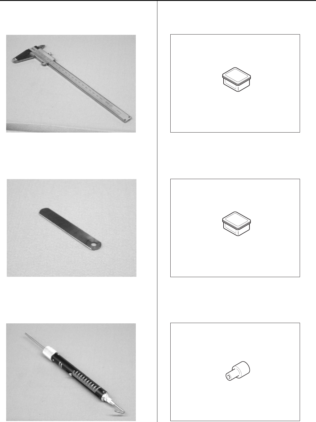
Special tool, Measuring equipment, Other
HSA90030
Keeper positioning gauge (Page 84)
HSA90080
Retainer positioning gauge [0.8mm] (Page 70)
HSA90090
Positioning pin [φ 4] (Page 27)
HSA90131
1.2mm thickness gauge (Page 29, 30)
HSA90230
Tensile gauge (Page 83)
HSA90240
Dial-gauge set (Page 53)
10
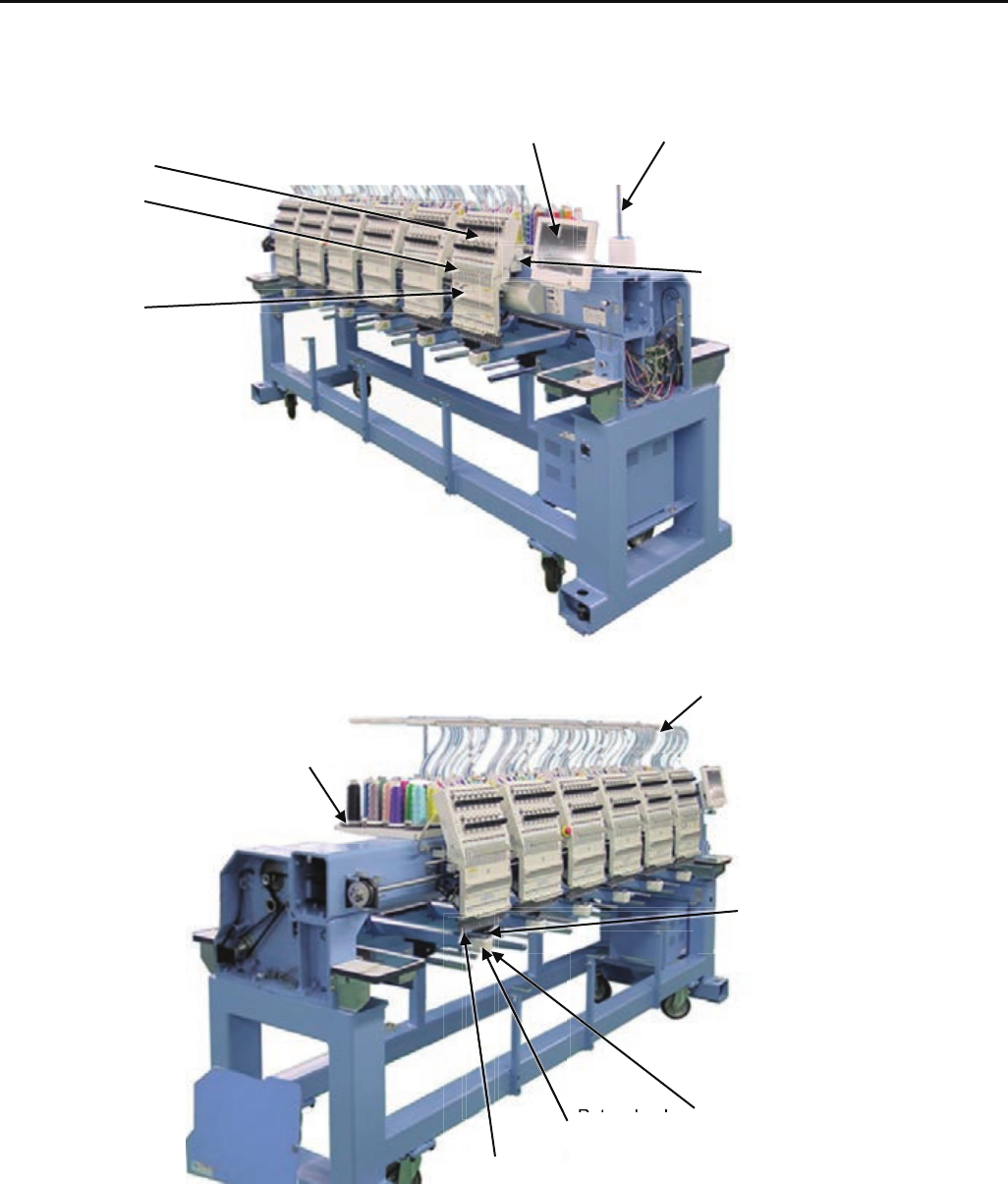
Special tool, Measuring equipment, Other
HSA90270
Vernier calliper gauge [200mm] (Page 37)
HSA90210
0.2mm thickness gauge (Page 59)
HSA90290
Tension gauge 2000Cn(1000g) (Page 88, 90)
HSA90311
Shell alvania EP Grease 100g (Page 72)
HSA90340
Shell Grease7 MIL-G-23827B 50g (Page 37b)
M0404342
Needle height gauge (Page 15, 51)
11
1 Placement of key mechanical parts
Control box Thread guide pillar
Thread tension unit
Take-up lever
Needle bar change unit
Moving head
Thread guide A
Tread stand
Needle plate
Rotary hook Rotary hook cover
Thread holder
Rt h k

12
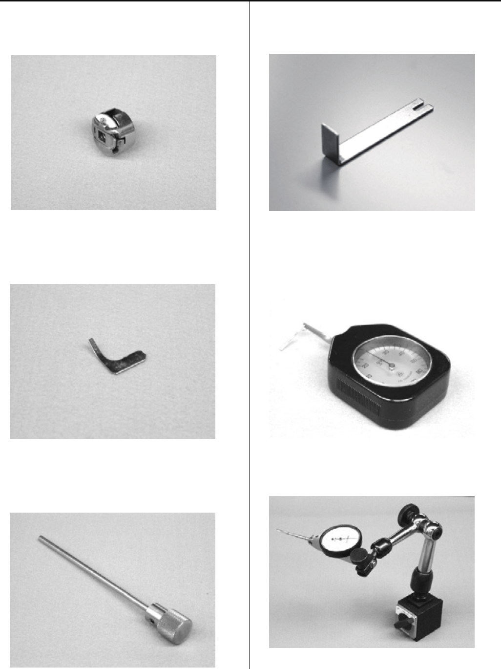
1 Placement of key mechanical parts
Timing detecting unit
Y carriage
Upper shaft
X carriage
Thread cutting driver
13
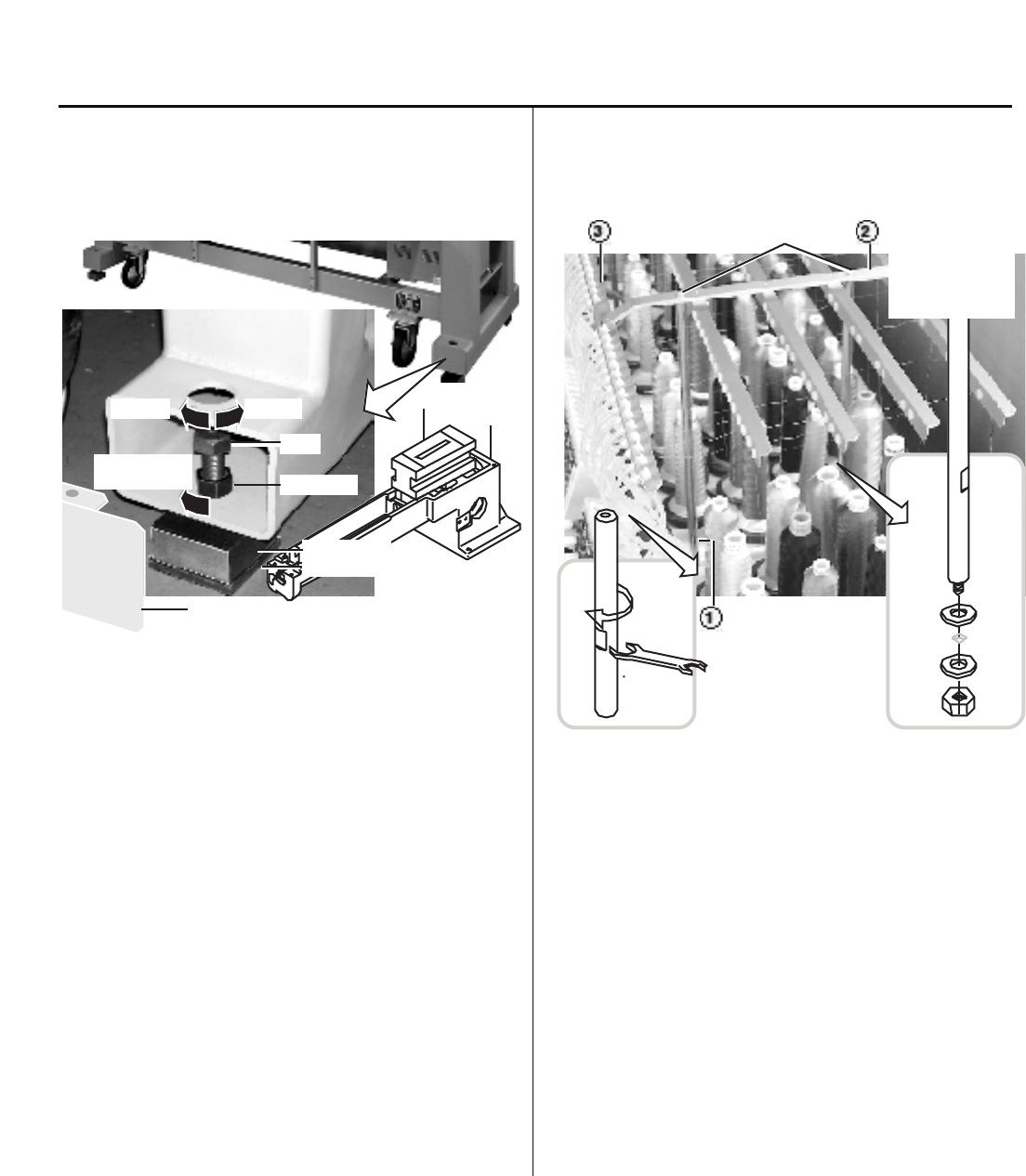
Lock nut
Tighten
the lock nut
LowerHigher
Bolt
Pipe cover
Water level
Head bed
Block base
Rubber mount
Thread guide pillar
ScrewsThread guide A Thread guide
ass'y
2-1, 2-2 Setting up the machine
2-1 Machine installation
(1) place block base and rubber mount under bolts and adjust
bolts so that the machine becomes level.
Block bases and rubber mounts are included in
accessories.
At this moment, get caster slightly risen from the floor.
As shown in Fig., levelers should be placed on both sides
of head bed with upper cover removed.
(2) Fix the lock nut.
(3) Fix the pipe cover.
2-2 Assemble the thread guide
(1) Turn the thread guide pillar (front [long], rear [short])
clockwise with a spanner until tight.
Fix rear thread guide pillar with a washer and a nut (M8).
<Spanner> 10mm, 13mm
(2) Install the thread guide ass'y with supplied screws (M4x8).
(3) Fix thread guide A (with spiral tube) on thread guide ass'y
with screws (M3x8) from lower side.
14
2-3, 2-4 Setting up the machine
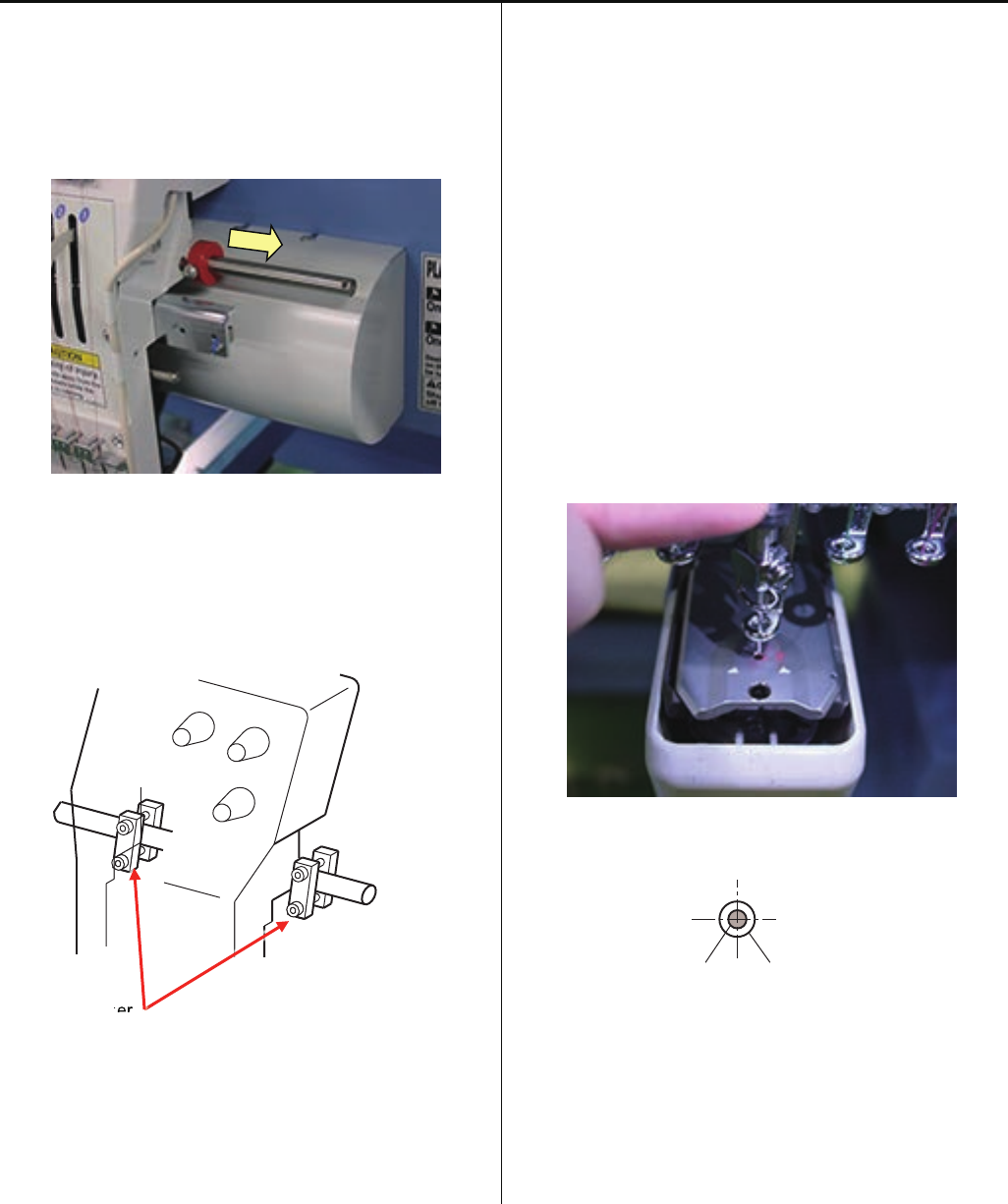
2-3 Removal of stopper
(1) Loosen the screw and remove the red shipping collars that
are equipped on the both side of the guide bar.
(2) Remove head stopper.
< Note > Number of head stopper is depending on model.
Head stopper
2-4 Check of needle position
(1). Turn power switch ON, and enter user maintenance
mode.
Refer to [ 5 User maintenance mode ]
(2) Remove bobbin case.
(3) With help of user maintenance mode, please move needle
bar down and confirm needle position is center of needle
hole on needle plate.
< Note > Please move needle bar slowly
< Note > Please check position of 8th needle, then check
1st and 15th needle.
Needle Needle hole of needle plate
pe
er
er
15
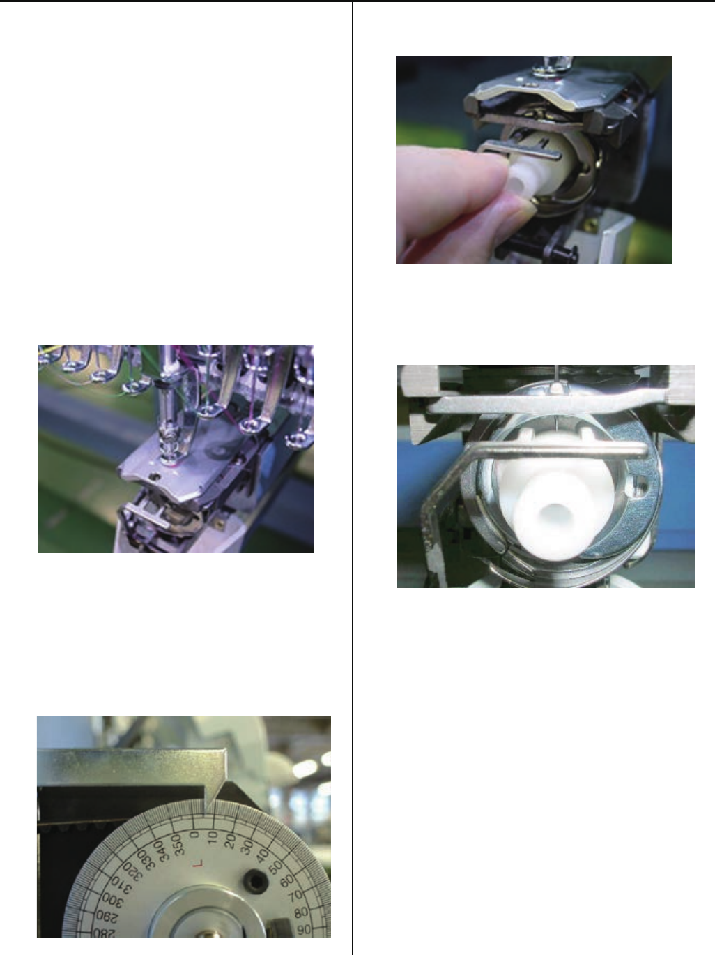
2-5 Setting up the machine
2-5 Check of needle height.
(1) Move moving head to the position which 8th needle is
active.
Remove bobbin case.
(2) Bring needle bar down.
Refer to [ 5 User maintenance mode ]
(3) Turn upper shaft anti-clockwise and set dial disc to [ L + 10
degrees ].
Turn brake switch ON.
(4) Put needle height gauge in rotary hook.
(5) Check if the needle tip touches to the gauge slightly.
(6) Take “Needle height gauge” out from hook.
16
1
3
2
2
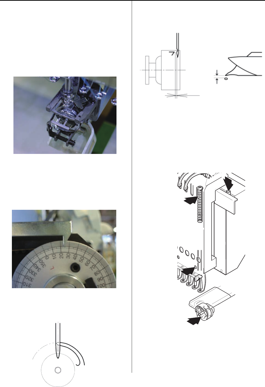
2-6, 2-7 Setting up the machine
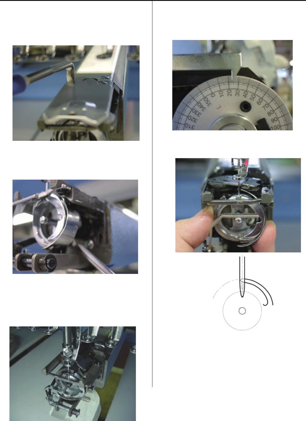
2-6 Check of rotary hook timing
(1) Remove needle plate, Move moving head to the position
which 8th needle.
Turn upper shaft and set to lowest needle position [L]
Refer to [ 5 User maintenance mode ]
(2) Turn upper shaft anti-clockwise and set dial disc to [ 25
degrees ].
Turn brake switch ON.
(3) Check the position of needle and tip of hook as below.
(4) Check the clearance between needle and rotary hook
should be [ 0.1 ~ 0.2mm ].
(5) Fix the needle plate.
2-7. Oiling
Lubricate the specified oil locations.
Oil : #10 Sewing machine oil
1) Rotary hook Between the outer and inner rotary hook
2) Needle bar
3) Head shaft
17
2-8 Setting up the machine
2-8 Check of thread path
To keep stable and high quality stitches, please keep
places where thread contacts in the best condition.
<Note> Pleas confirm that there is no burr and crack at the
position which thread is passing.
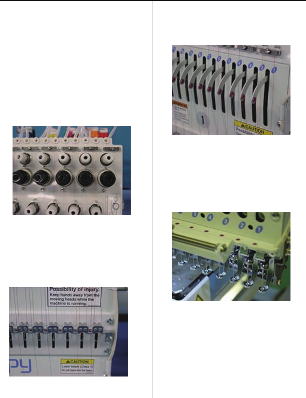
(1) Thread tension, Thread guide, Rectifier
a) Revolution must be smooth
b) No sticking of lint or dust
(2) Thread Adjusting Spring
a) No burr and crack
b) Spring move smoothly
(3) Ceramic and rim of take-up lever
a) No burr and crack
(4) Thread path in lower side and needle holder
a) No burr and crack
18
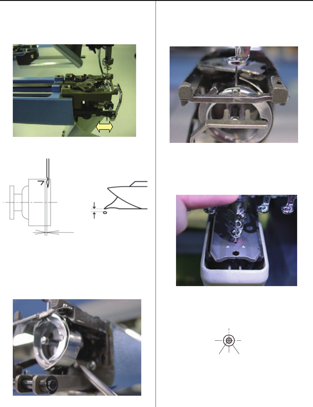
2-8 Setting up the machine
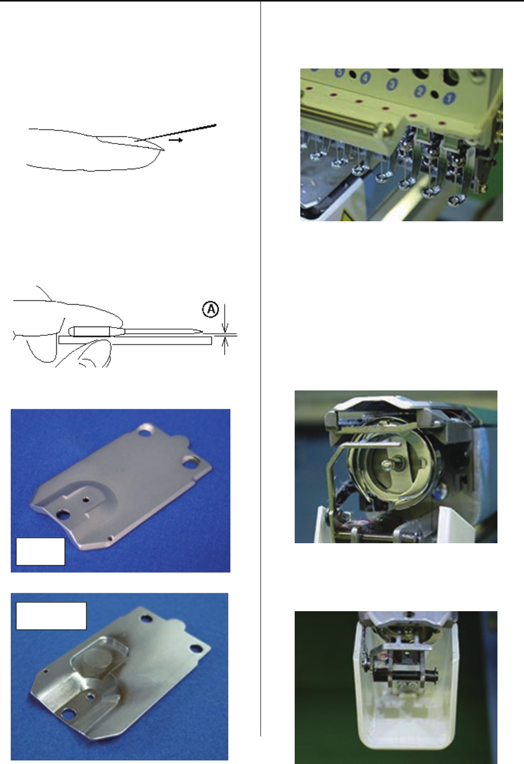
(5) Needle
a) Needle tip shouldn't be warped or bent.
When you slide needle tip on surface of nail and
if the nail gets scratched.
needle tip is warped. Please exchange it with new one.
Please place needle on flat surface and check
clearance (A) from side.
If clearance is not equal, needle is bent.
Please replace it with new one.
(6) Needle plate
a) No burr and crack in needle hole and around it.
(7) Pressure foot
a) No burr and crack inside hole
b) Not bent
(8) Rotary hook
a) No burr and crack.
b) Hook point not warped.
c) Backlash between bobbin case holder and outer hook
should be less.
(9) Keeper
a) No burr and crack in needle hole and around it.
Surface
Two setscrews

19
2-8 Setting up the machine
(10) Rotary hook retainer
a) There is No burr and crack at the position which thread
pass through.
Rotary hook retainer
20
2-9 Setting up the machine
2-9 Threading
- Upper thread
Please adjust minor thread tension
unit that detection rotary is not
slipping and turn smoothly.
< Note > If tension of minor thread
tension unit is too low, detecting
rotary does not turn smoothly and
thread slip on rotary.
Detecting rotary
Please check thread is not disturbed
by spring.
Upper thread tension should be adjusted
depending on type of thread, needle and fabric
etc.
< Standard > 100 ~ 150Cn (gf)
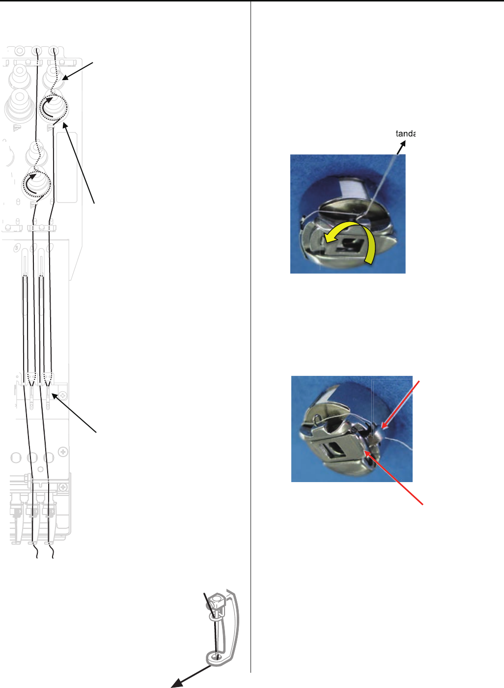
- Bobbin thread
Bobbin thread tension is depending on adjustment of upper
thead.
Please note that bobbin will turn to arrow-marked direction
when you pull bobbin thread.
<Standard> 25 ~ 35cN(gf)
< Note > Please check thread is not disturbed by finger or
latch.
Finger
Latch
Standa
a
tanda

21
2 Setting up the machine
2-10 Trial sewing
(1) Turn thread break detecting switch ON.
(2) Please confirm that thread trimming, thread catcher,
jumping is functioning.
< Important > For a month, please use machine with 70%
of maximum speed.

22
3-1 Fixing of needle
1. In order of (1) - (4), please remove and fix needle.
(1) Loosen screw holding needle.
(2) Remove needle.
(3) Insert needle till it goes to the end.
(4) Tighten screw holding needle.
Fix needle so that needle groove faces front.
Needle holder
Needle
Front

23
3-2 Selection of thread
1. Selection of upper thread.
<Description>
Please select considering cloth, design of pattern and flavor etc.
<Thickness>
Please refer to [Relation between needle and upper thread 3-4].
<Twist>
Z twisted thread is to be used.
(As rotary hook turns left- wise, Z twisted thread can prevent loosening of twist)
Z-twisted S-twisted
(Left - twisted) (Right - twisted)
2. Selection of lower thread.
Basically please use cotton thread (#80-120), #120 is recommendable.
Pay attention to the following in selection.
# Thickness should be equal.
# When it is lightly stretched, it doesn't break easily.
# In process of time, it doesn't get inferior.
Commercially available paper bobbin can be used, but please select thread with
thickness corresponding to cotton thread (#80-120).
24
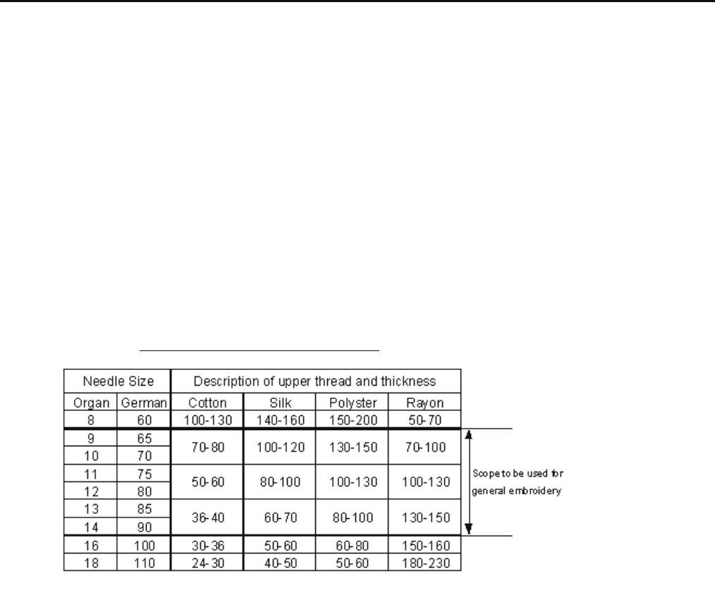
3-3 Relation between needle and upper thread
1. Description of needle
Basically please use [DB X K5] in standard accessory.
If description or thickness of cloth doesn't suit needle size, poor sewing finish / thread break / skipping will occur.
Therefore careful attention is required in selecting needle.
2. Relation between needle and upper thread will be found below. (Representative example is shown.)
Needle - Size is [German 75] in standard accessory.
If necessary, please select in accordance with description of thread and cloth.
Thread - In case needle size is [German 75], if thread is rayon, [#120] is recommendable.
Relation between needle and upper thread
Denier (d)
If needle size and thickness of thread don't match, following problem will be likely to occur.
- Thread break
- Skipping
- Poor sewing finish
25
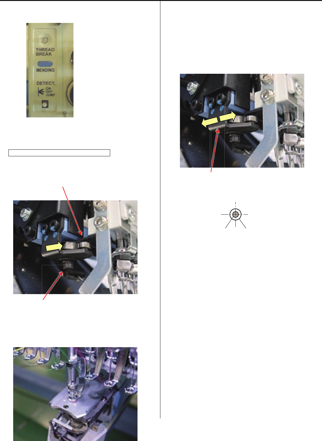
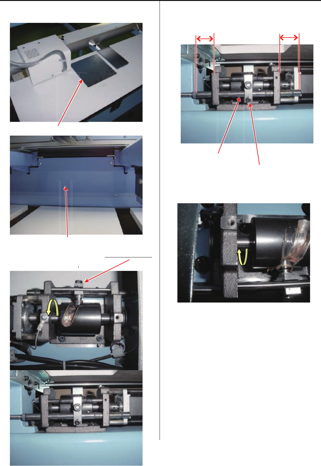
4-1-1 Exchange of needle bar driver
1. Remove moving head.
Please refer to [ 4-2-1, 4-2-2 Assemble and remove
moving head ].
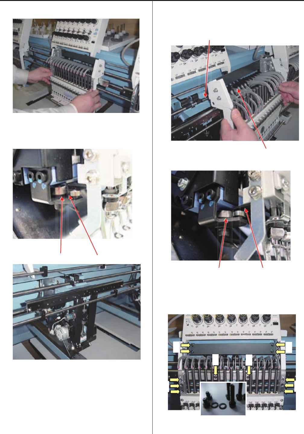
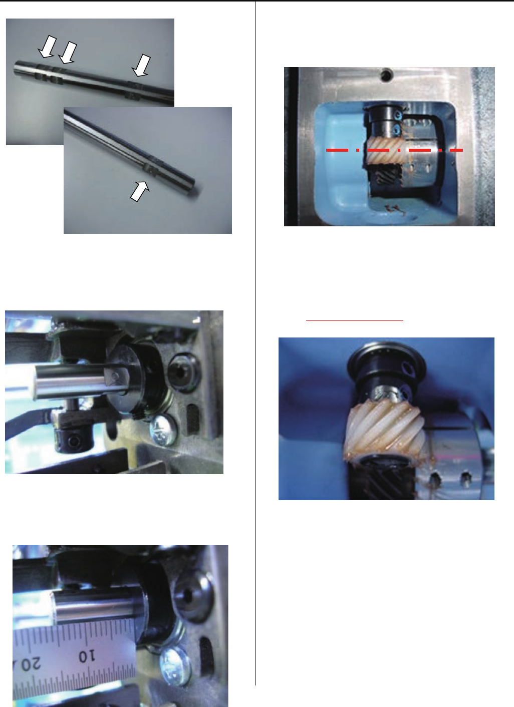
2. Remove needle bar driver.
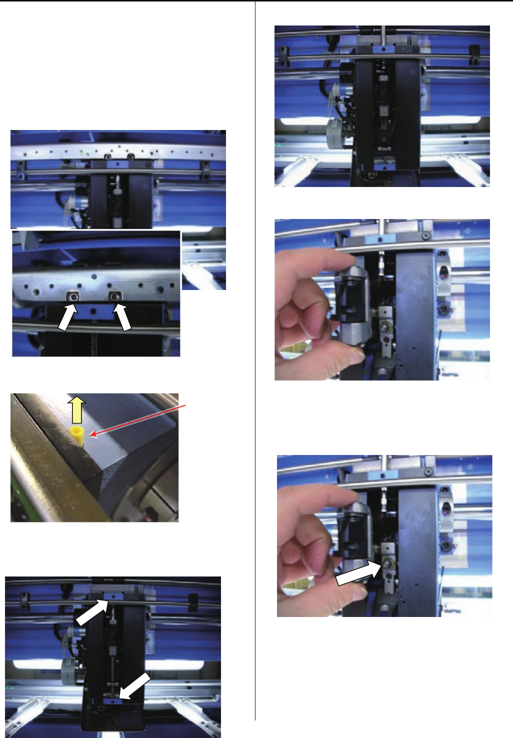
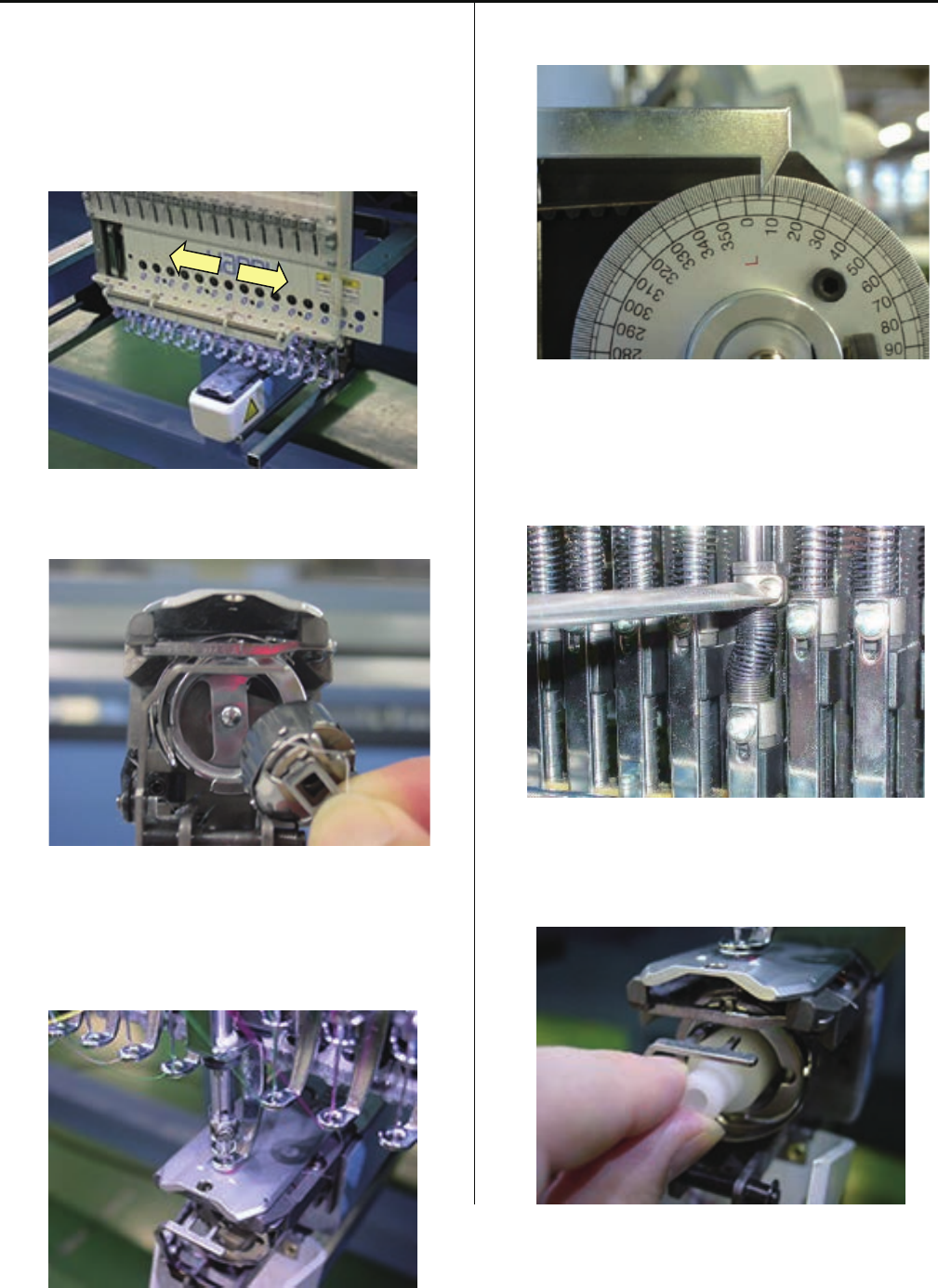
2-1. Slide moving head to 8 th needle. And remove the Slide
unit. (Hexagon socket set screw : M4-10 2 pcs)
2 screws are inside of the position with arrow mark on
above picture.
Oiling pipe
Remove Oiling pipe
2-2. Loose screws for head shaft.
(Hexagon socket set screw : M4-4 2 pcs)
2-3. Slide up the Head shaft.
Take off the broken needle driver.
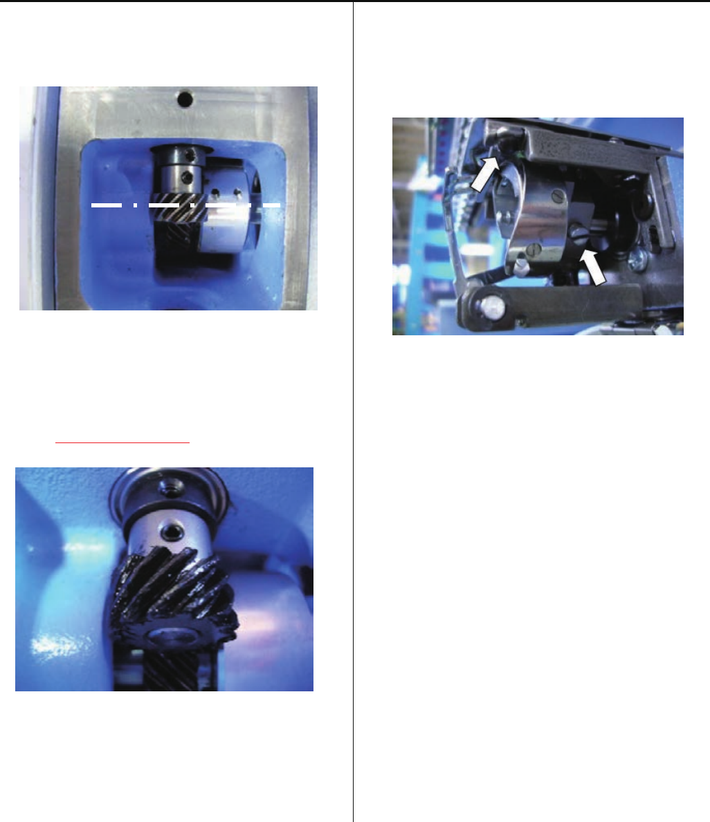
3. Set the new needle bar driver.
Assemble reverse step with step no.2
3-1. Set needle bar driver to block pin.
26
4-1-1 Exchange of needle bar driver
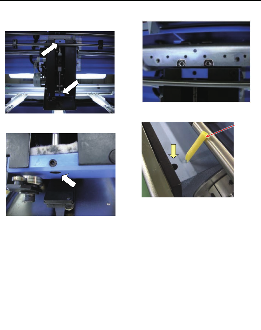
3-2. Set head shaft into the needle driver and tight screws.
(Hexagon socket set screw : M4-4 2 pcs)
Set bottom head shaft face flat with head face.
3-3. Set slide unit.
(Hexagon socket button head screw : M4-10)
< Note > No clearance between head and slide unit.
Oiling pipe
Keeping cut face front and insert oiling pipe into hole.
4. Install moving head.
Please refer to [ 4-2-1, 4-2-2 Assemble and remove
moving head ].
5. Check needle height.
Please refer to [ 2-5 Check of needle height ].
O
27
4-1-2 Adjustment of take-up lever timing
1. Move moving-head to the position which 8st needle is
active.
2. Remove the Upper shaft cover and Detecting cover.
Upper shaft cover
Detecting cover
3. Move moving-head to the position which 1st needle is
active.
Remove the Face plate (right) and Head cover bracket.
Face plate (right)
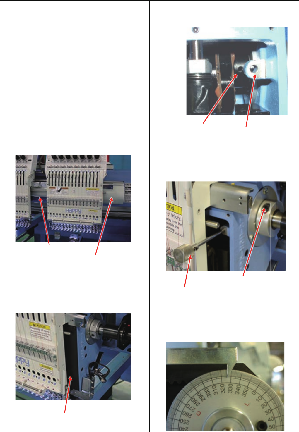
4. Turn upper shaft and insert positioning pin into the hole of
cam through the positioning hole on machine body.
The hole of cam
The positioning hole on machine body
Please note that moving head is removed on
the picture below just for taking photograph.
5. Loosen screw on take up lever cam.
Screw on take up lever cam
The positioning pin
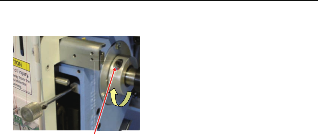
6. Turn upper shaft to the forward direction and set angle
[ 326 degrees ].
Turn brake switch ON.
28
4-1-2 Adjustment of take-up lever timing
7. Fix screw.
Screw on take up lever cam
8. Pull positioning pin out.
9. Turn brake switch OFF.
Turn upper shaft and set angle at [ 270 degrees (C point) ].
10. Set all covers.
29
4-1-3 Check of height of pressure foot
1. Bring needle bar down.
Please refer to [ 5 User maintenance mode ]
2. Turn upper shaft and set dial disc to [ 0 degree ].
Turn brake switch ON
3. Insert [ Gauge I.2mm ] between needle plate and pressure
foot.
Please confirm that there is no gap between gauge and
pressure foot and needle plate.
4. If wrong space ( not 1.2mm ), please adjust height of
pressure foot guide bar.
Please refer to [ 4-1-4 Adjustment of height of pressure
foot ].
30
4-1-4 Adjustment of height of pressure foot
1. Bring needle bar down.
Please refer to [ 5 User maintenance mode ]
2. Turn upper shaft and set dial disc to [ 0 degree ].
Turn brake switch ON.
3. Loosen fixing screw of pressure foot (Fixing screw 1 pcs)
4. Insert [ Gauge I.2mm ] between needle plate and pressure
foot.
1.2 mm is standard, But please adjust depends on
thickness of material.
5. Tighten fixing screw for pressure foot.
(Fixing screw 1 pcs)
At this moment, no gap between gauge and pressure foot
or needle plate.
31
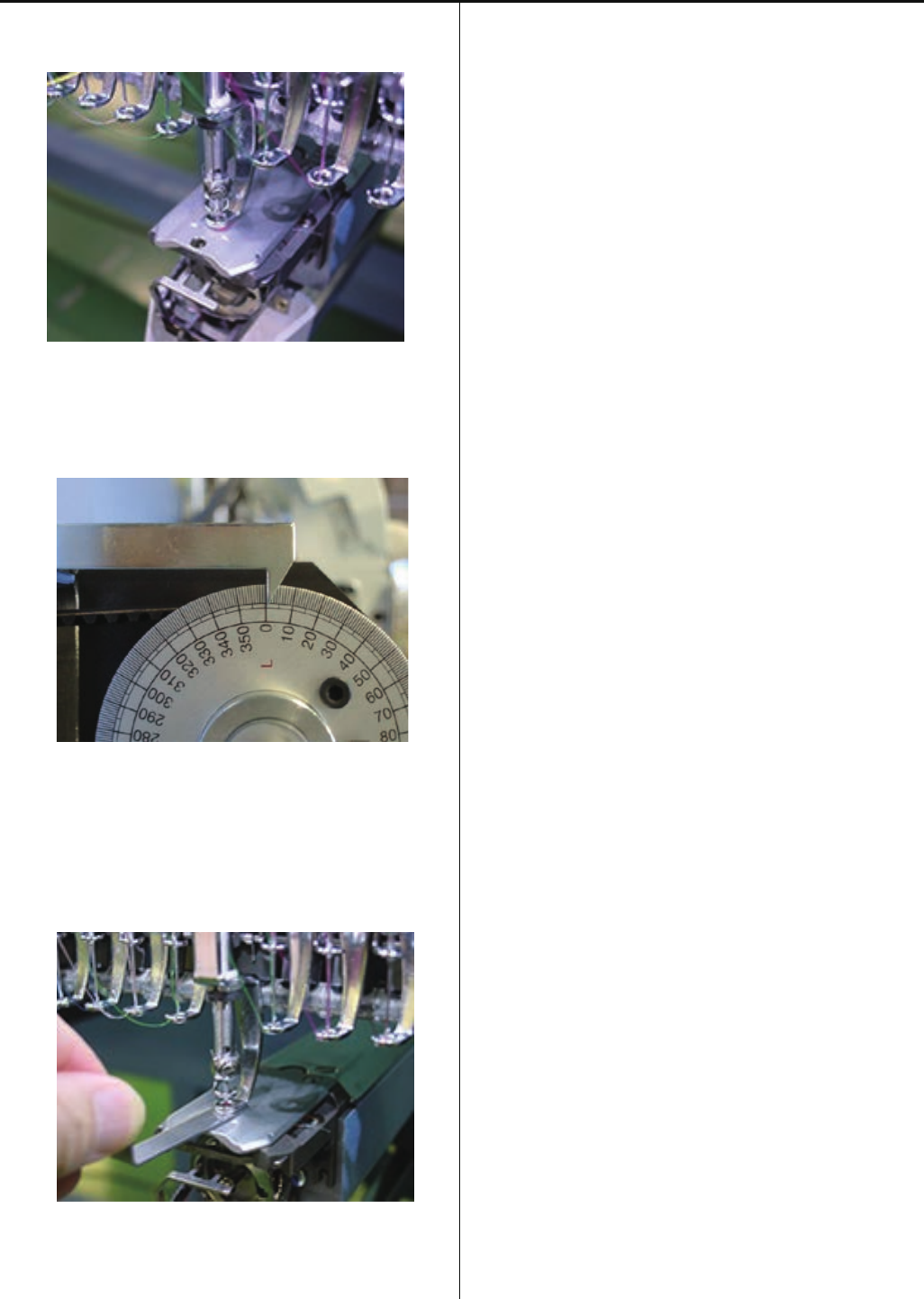
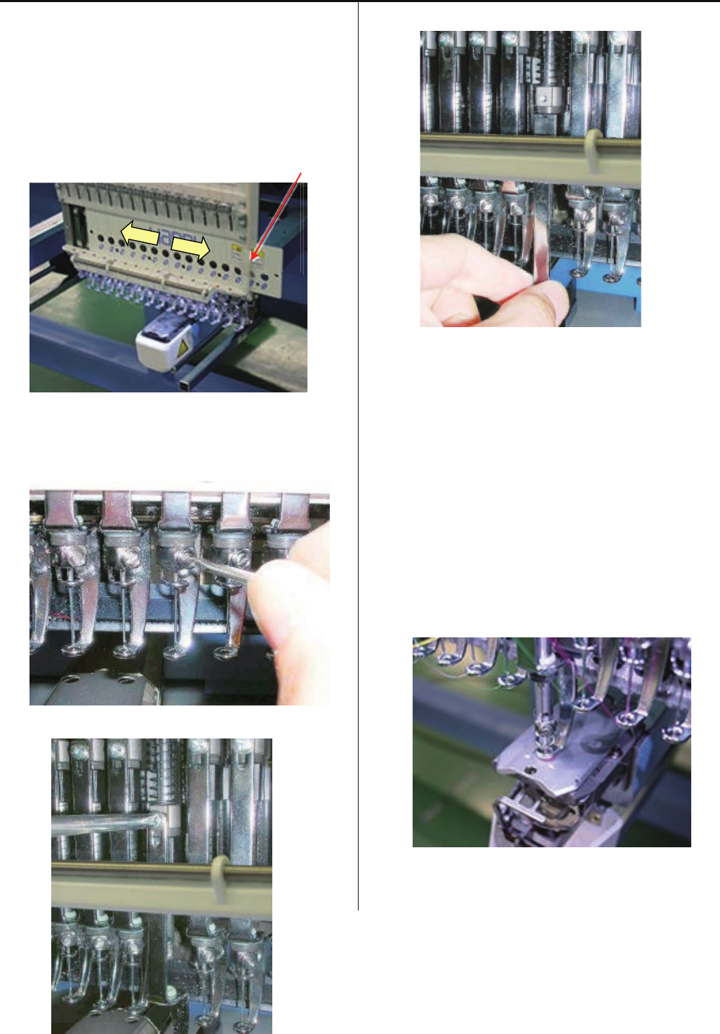
4-1-5 Exchange of pressure foot
1. Loosen fixing screws of front panel (lower) and cord clip.
(Fixing screw 2 pcs)
Slide front panel (lower) to left or right direction up to the
position of pressure foot to be replaced.
In case you need to slide front panel (lower) further, please
slide front panel (lower) on neighbor head
Cord clip
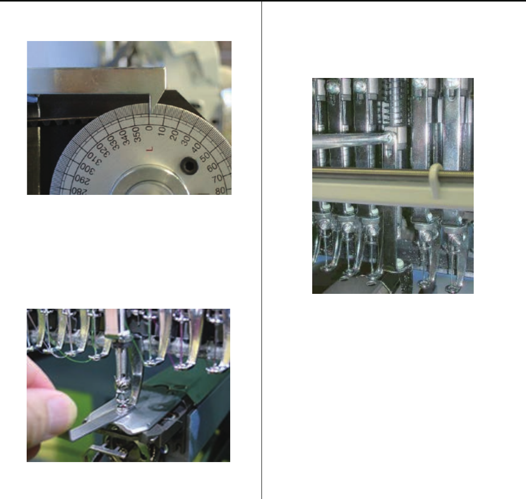
2. Remove needle, needle holder and cushion.
< Note > When needle holder is removed, pressure foot
move down quickly.
3. Remove pressure foot. (Fixing screw 1 pcs)
4. Install good parts.
5. Please set needle and needle clamp.
For set needle, please reference [ 3-1 Fixing of Needle ].
6. Adjust needle height.
Please refer to [ 4-2-6 Adjustment of needle height ].
7. Bring needle bar down.
Please refer to [ 5 User maintenance mode ].
32
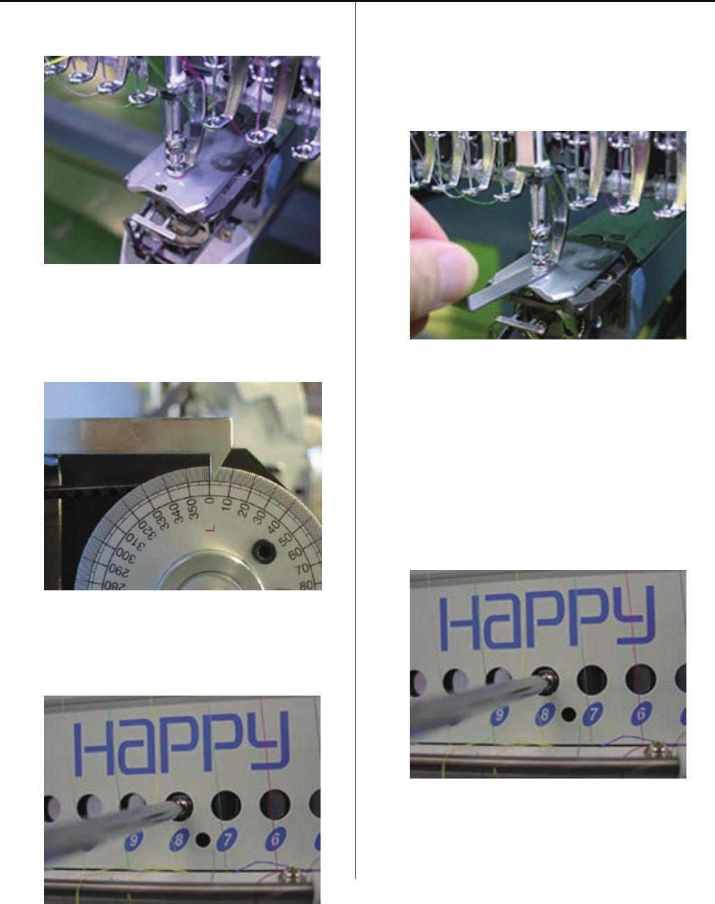
4-1-5 Exchange of pressure foot
8. Turn upper shaft and set dial disc to [ 0 degree ].
Turn brake switch ON.
9. Insert [Gauge I.2mm] between needle plate and pressure
foot.
Please confirm that there is no gap betwen gauge and
pressure foot and needle plate.
10. Tighten fixing screw for pressure foot.
(Fixing screw 1 pcs)
At this moment, no gap between gauge and pressure foot
or needle plate.
11. Return front panel (lower) and cord clip to previous
places to finish.
33
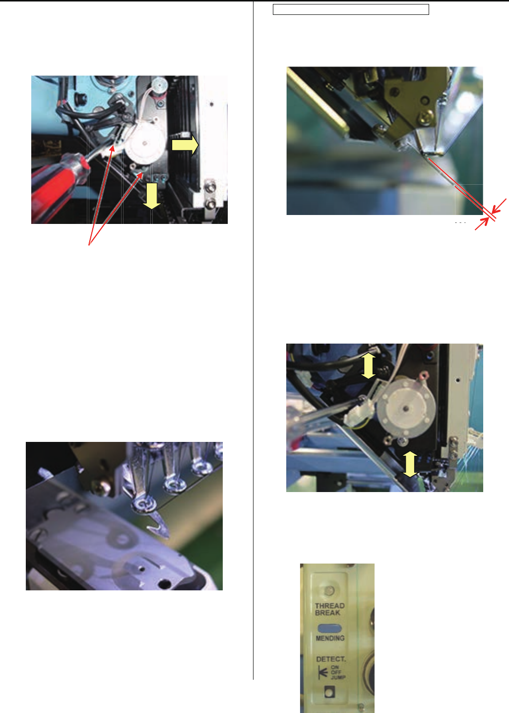
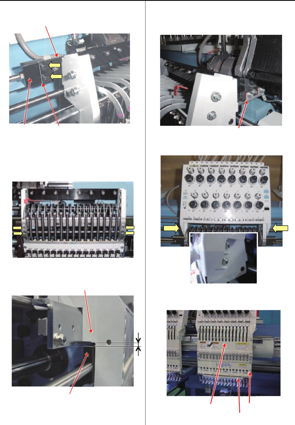
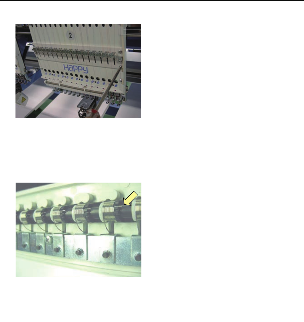
4-1-6 Adjustment of thread catcher
1. Loosen screw of thread catcher, and push thread catcher
to direction as below, and temporary fix screw.
Screw
2. Check position of thread catcher
Move hook in and out by hand and confirm that hook is
moving smoothly.
<Note> Please check at 1st needled and 15th needle
Space between hook and pressure foot
Space between back side of pressure foot and hook is 0.5
~ 1mm.
Space
If space is OK, fix thread catcher
3. In case space is not within allowance, re-adjust position of
thread catcher
4. Turn thread break detecting switch ON
ace
34
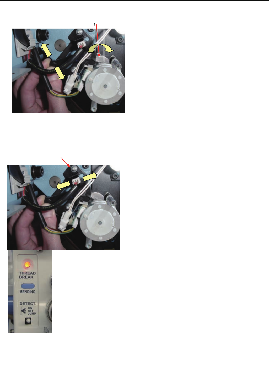
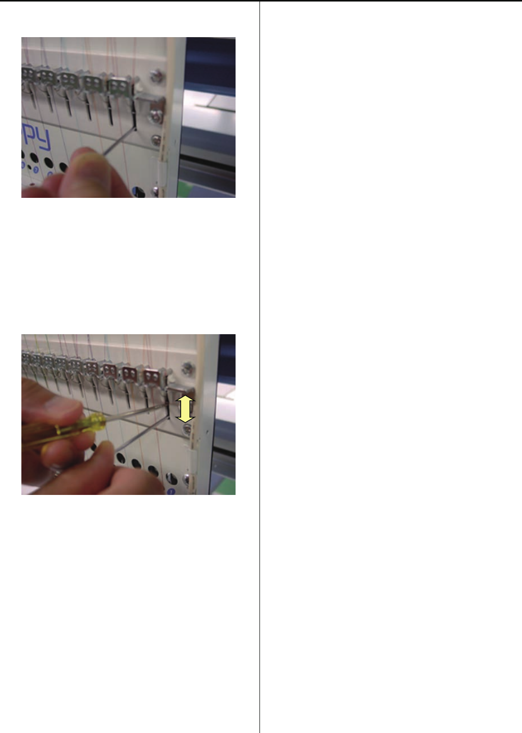
4-1-6 Adjustment of thread catcher
5. Pull hook completely and return to front for movement of 3
pitches of gear.
Gear
6. Loosen screw of photo sensor, and move photo sensor to
the position that thread break lamp becomes RED and fix
photo sensor.
Screw of photo sensor
7. Pull hook completely and return to front for movement of 3
pitches of gear, and confirm that thread break lamp
becomes RED.
r
r
35
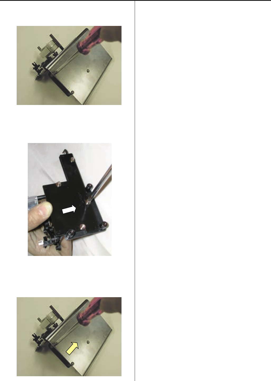
4-1-7 Exchange of thread catcher guide
1. Remove guard plate.
Use the #1 (+) Screw driver.
2. Exchange guide.
Fix the guide after moving it to the right.
3. Install the guard plate.
4. Please refer to [ 4-1-6 Fixing of thread catcher ],
install thread catcher to finish.
36
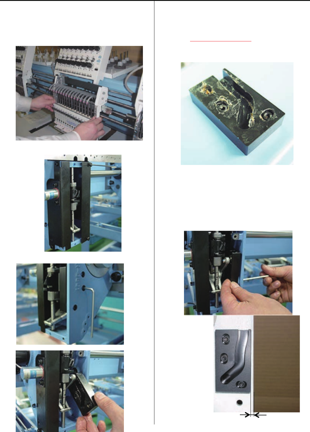
4-1-8 Exchange of pressure foot cam
1. Please refer to [ 4-2-1, 4-2-2 Assemble and remove
moving head ], remove moving head and face plate (right).
Moving head
Face plate (right)
2. Remove pressure foot cam. (Fixing screw 3 pcs)
3. Put on grease to new presser foot cam.
Also, put on grease to fixing nuts, then insert nuts into hole
of pressure foot cam to prevent drop of the nut.
<Grease>Shell alvania EP Grease
(Shell Gudas S2 V220 2)
4. Fix good part as temporally by fixing screw and nut.
Make sure to cover fixing hole with finger to prevent drop of
the nut.
Please check bump 2mm between front of presser foot
cam and front face of fixed head.
37
4-1-8 Exchange of pressure foot cam
5. Set dial disc to [ L + 0 degrees ].
In this time, please check distance between upper face
of presser foot and bottom face of fixed head to
[25.5+/-0.2mm].
6. Set dial disc to [ L + 60 degrees ].
In this time, please check distance between upper face
of presser foot and bottom face of fixed head to
[26.1+/-0.2mm].
7. After check item 5 and 6 then tight screw completely for
fix take-up lever cam.
8. Put each unit back to where it was according to manual.
38
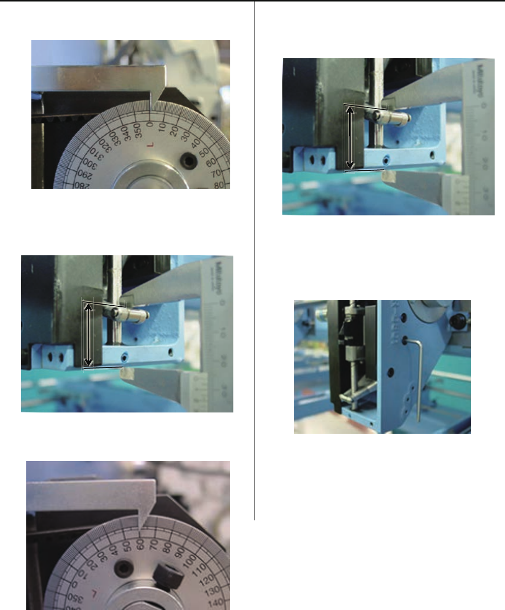
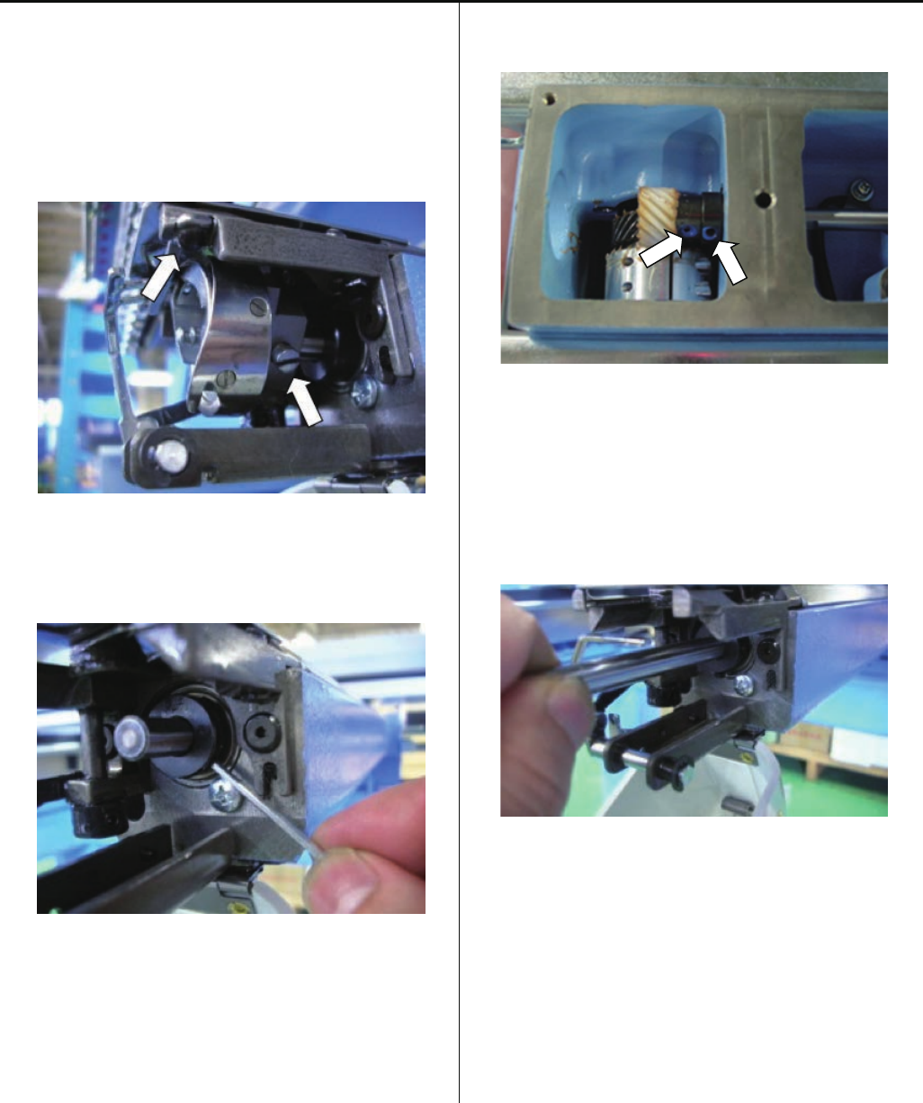
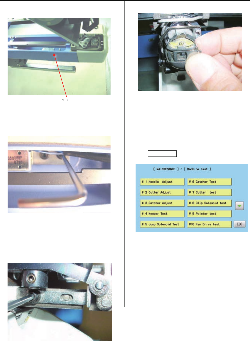
4-1-9 Adjustment of fixing of jump solenoid
1. Please refer to [ 4-2-1, 4-2-2 Assemble and remove
moving head ], remove moving head and face plate (right).
Moving head
2. Remove jump solenoid ass'y. (Fixing screw 2 pcs)
3. Install good parts.
Please check Jump solenoid position.
Turn main shaft till touch plunger of jump solenoid
and needle bar driver and check main shaft indicator.
Should be between 83 to 87 degrees.
Just touched to plunger
<Dubble check> Please double check Jump solenoid
position by following test.
Continually fillip needle bar driver to arrow
direction while main shaft turning and
hearing plunger touch ing noise.
Should change noise between 83 to 87
degrees shaft position.
4. Please put parts back in reverse order to finish.
For adjustment of fixing of each unit, please refer to
process to adjust fixing of each unit.
36b
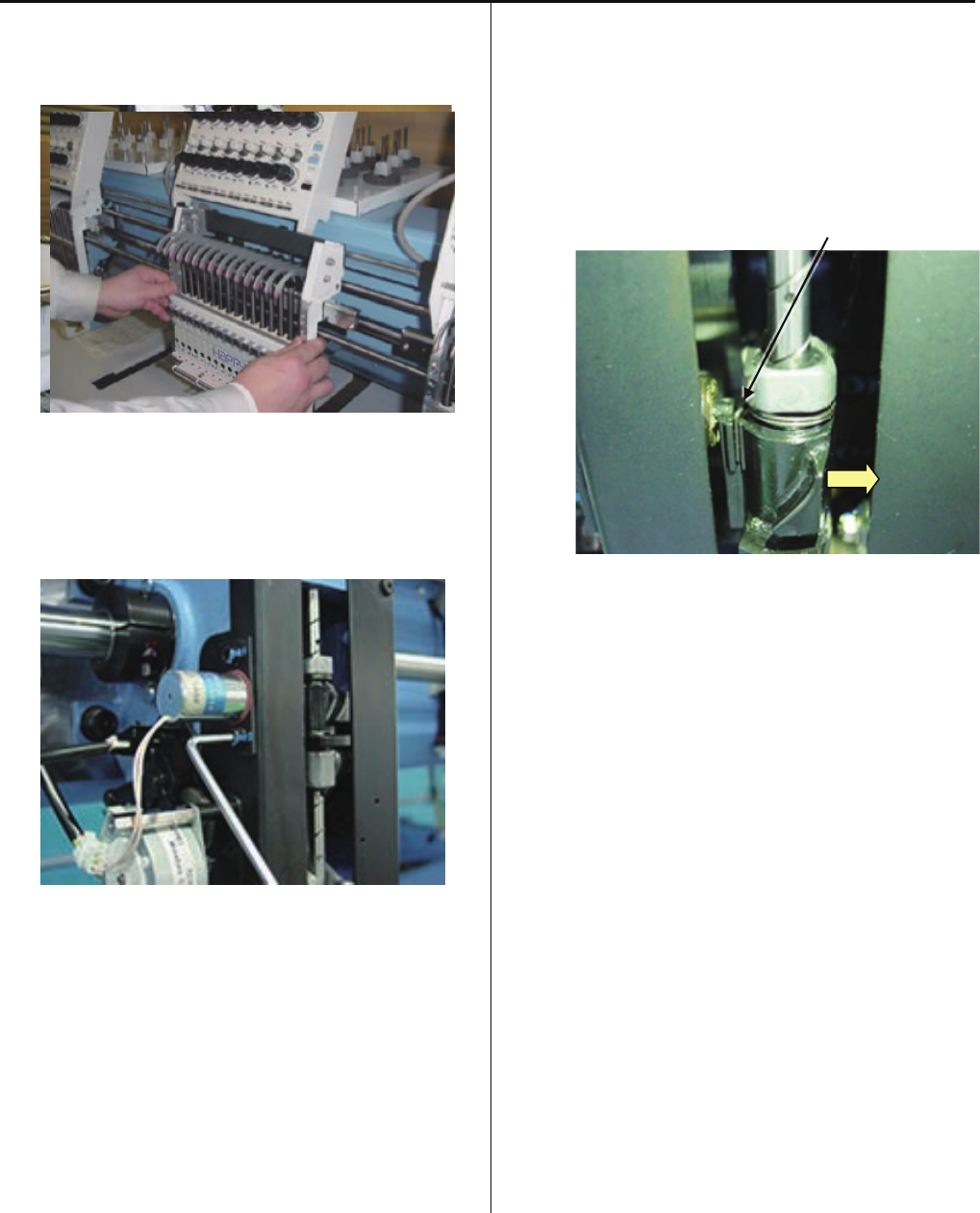
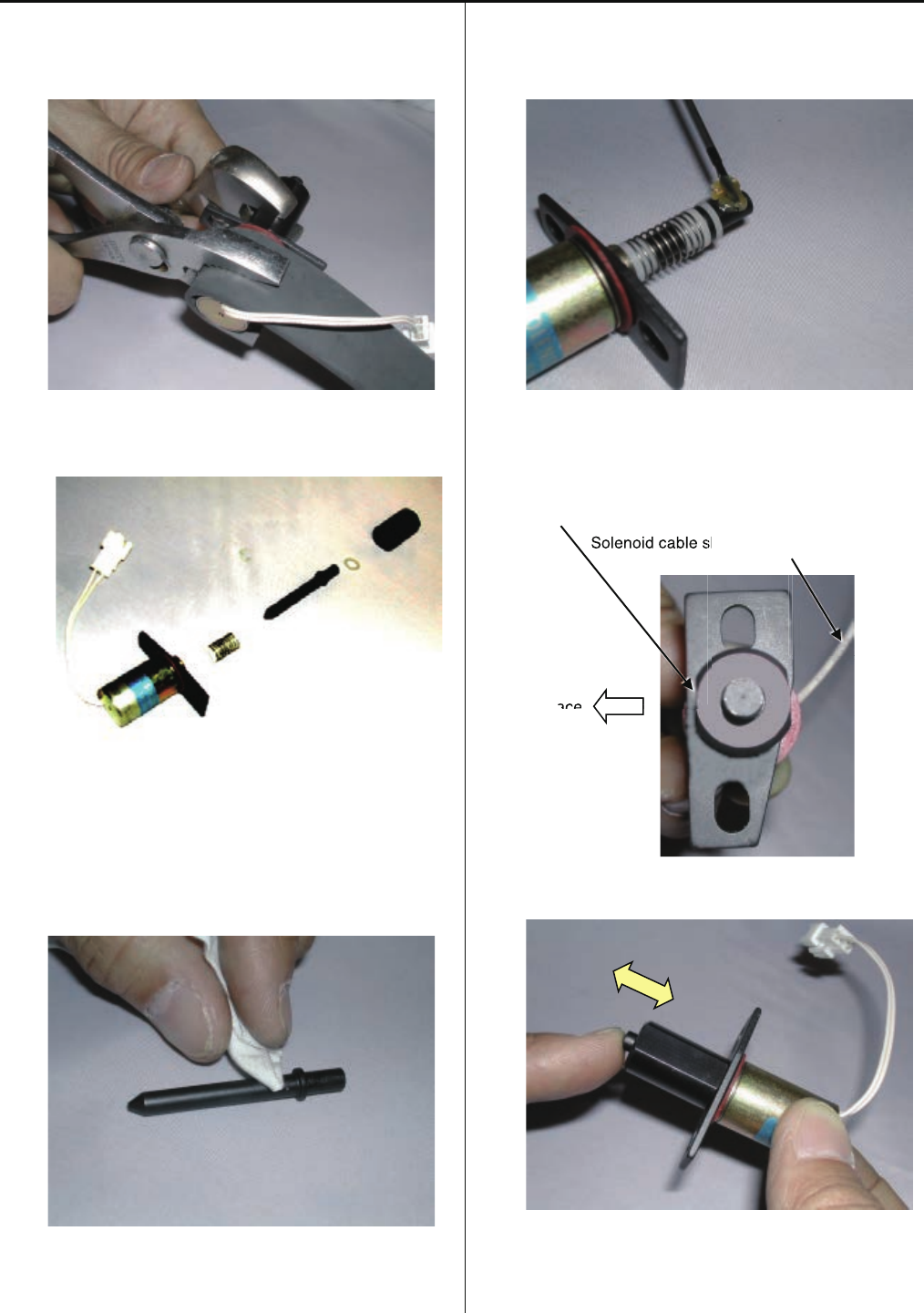
4-1-10 Disassembling and Cleaning of jump solenoid
1. Disassemble the solenoid nut.
Use rubber sheet as safeguard.
2.Clean up the each part of the solenoid.
3. Put the designated grease on plunger part.
<Grease> Shell Grease7 MIL-G-23827B
Equivalent brand
4. Assemble the solenoid to the original position.
The flat surface of the solenoid nut
should come to the front.
Solenoid cable should come to the back side.
Front face
5.Confirm the movement of the plunger is smooth enough.
6.Procedure is done after assembling the Jump solenoid.
Referring to [4-1-9 Adjustment of fixing of jump solenoid].
a
sh
ace
Solenoid cable s
ace
38
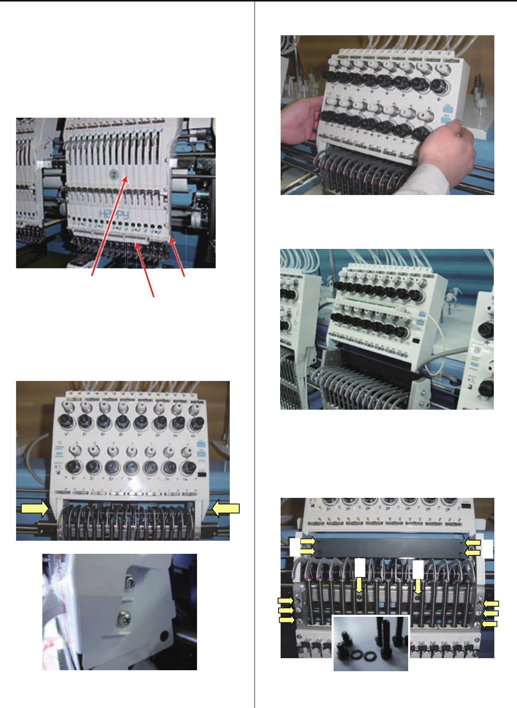
4-2-1 Assemble and remove moving head (except for 1st head)
1. Remove moving head.
1-1. Set moving head at position that 15th needle is active.
Remove the front panel (upper), cord clip and lighting
bracket.
(Truss head screw : M4-6 4 pcs)
Upper shaft cover Cord clip
Lighting bracket
1-2. Loosen screw on thread tension bracket
(Pan head screw : M4-10 4 pcs)
1-3. Remove the thread tension bracket.
(Pull thread tension bracket to front)
Put thread tension bracket and lighting bracket on head
upper cover.
1-4. Remove the set screw.
A (Hexagon socket head cap screw : M4-20 6 pcs)
B (Hexagon socket head cap screw : M4-6 2 pcs)
C (Hexagon socket head cap screw : M4-18 4 pcs)
Hexagon socket head cap screw is a set with plain washer.
Please keep as a set.
B B
C
C
A
A
39
4-2-1 Assemble and remove moving head (except for 1st head)
1-5. Slide moving head to right direction
After rail goes out from positioning roller, take moving head
out.
Positioning roller Rail
2. Install moving head.
2-1. Set moving head at position that 15th needle is active.
Set all take-up lever to guide bar starting from 1st needle
Guide bar
Take-up lever
Insert rail into positioning roller.
Positioning roller Rail
2-2. Temporally tighten screws.
A (Hexagon socket head cap screw : M4-20 6 pcs)
B (Hexagon socket head cap screw : M4-6 2 pcs)
C (Hexagon socket head cap screw : M4-18 4 pcs)
Please put plain washer with hexagon socket head cap
screw.
B B
C
C
A
A
40
4-2-1 Assemble and remove moving head (except for 1st head)
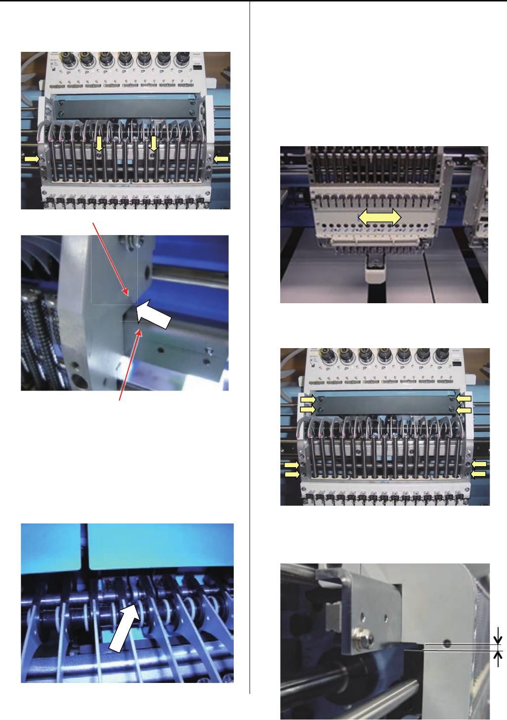
2-3. Move moving head to the position that 8th needle is
active.
Tighten 4 screws on moving head. (see photo below)
Moving head
Rail support
Please confirm that there is no space at the arrow point on
above picture.
2-4. Set take-up lever to lever crank
2-5. Please needle bar of 8th needle down until needle driver
catches needle bar boss. Then turn upper shaft to needle
down and check that needle is center of needle hole on
needle plate. If needle position is not center of needle hole,
please move moving head right or left to fit needle
position.
Please refer to [ 4-2-5 Adjustment of needle position (left
and right) ].
2-6. Tighten 8 screws on moving head. (See photo below)
< Note > Gap between Moving head and Fasten Block
should be 2.5mm.

41
4-2-1 Assemble and remove moving head (except for 1st head)
2-7. Install Thread tension bracket.
(Pan head screw : M4-10 4 pcs)
2-8. Set Front panel (Upper), cord clip and lighting bracket.
(Truss head screw : M4-6 4 pcs)
Upper shaft cover Cord clip
Lighting bracket
3. After installation of moving head, please check following
points;
3-1. Check needle height, please check needle height at 1st ,
8th and 15th needle.
Please refer to [ 2-5 Check of needle height ].
In case needle height is not same for each needle,
installation of moving head was wrong,
Please check step 2-3 again.
3-2. Check of rotary hook timing, please check hook timing
by 8th needle.
Please refer to [ 2-6 Check of rotary hook timing ]
In case hook timing is not correct, installation of moving
head was wrong,
Please check step 2-5 again.
42
4-2-2 Assemble and remove moving head (1st Head)
< Note > When you need to take all moving head out,
please take 1st head at last.
1. Remove moving head.
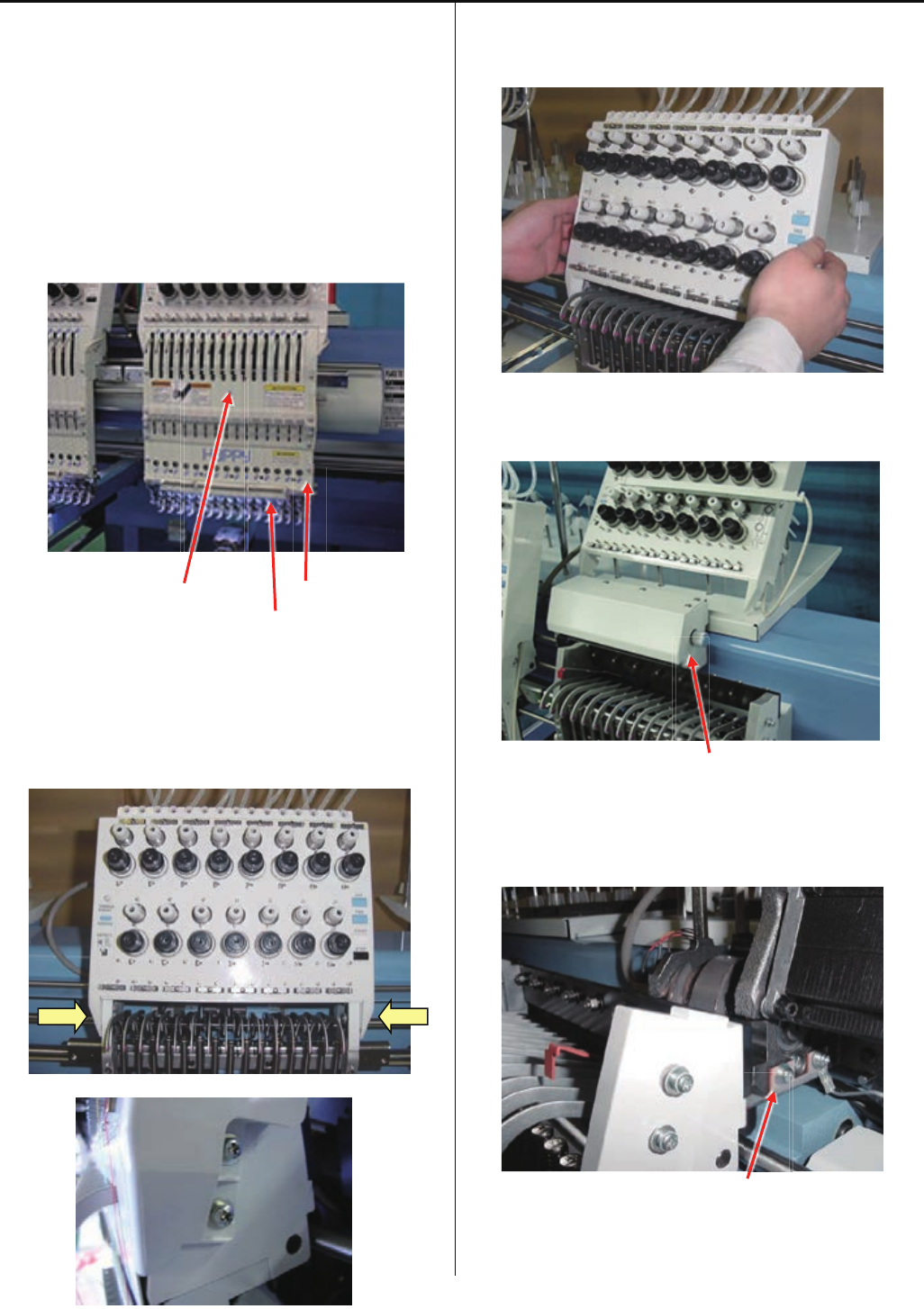
1-1. Remove the front panel (upper), cord clip and lighting
bracket.
(Truss head screw : M4-6 6 pcs)
Upper shaft cover Cord clip
Lighting bracket
1-2. Loosen screw on Thread tension bracket
(Pan head screw : M4-8 4 pcs)
1-3. Remove the thread tension bracket.
(Pull thread tension bracket to front)
Put thread tension bracket and lighting bracket on head
upper cover.
Needle bar change cover
1-4. Remove the Needle bar change cover and needle
position plate.
Needle position plate

43
4-2-2 Assemble and remove moving head (1st Head)
1-5. Move moving head to the position which 8th needle is
active, by knob.
Loosen screw on moving head support.
(Hexagon socket head cap screw : M5-15 2pcs)
1-6. Remove set screw.
(Hexagon socket head cap screw : M4-20 6 pcs)
(Hexagon socket head cap screw : M4-6 2 pcs)
Hexagon socket head cap screw is a set with plain washer.
Please keep as a set.
1-7. Slide moving head to the right direction by knob, and
take moving head out after the rail going out from roller.
Positioning roller Rail
44
4-2-2 Assemble and remove moving head (1st Head)
2. Install moving head.
2-1. When you install moving head, please set the same
position of Needle bar change unit as the position which
you took Moving head out. (slightly moved to the right
position then 15th needle)
< Note > In case you lost the position mentioned above:
Please turn power on and move moving head to 14th
needle by Needle change button, then move to 15th
needle.
After setting to 15th needle, please move slightly to the
right by knob of Needle bar change unit.
Guide bar
Cam follower
With turning knob, set the rail into Positioning Rollers.
Positioning roller Rail
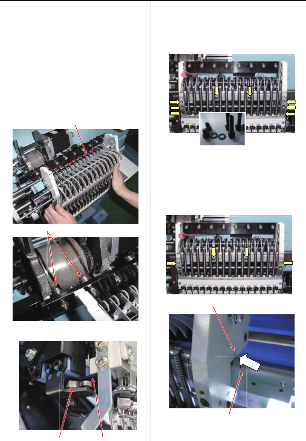
2-2. Set moveing head to 15th needle position and
temporally tighten screws.
(Hexagon socket head cap screw : M4-20 6 pcs)
(Hexagon socket head cap screw : M4-6 2 pcs)
Please put plain washer with hexagon socket head cap
screw.
2-3. Move moving head to the position that 8th needle is
active.
Tighten 4 screws on moving head. (see photo below)
Moving head
Rail support
Please confirm that there is no space at the arrow point on
above picture.
45
4-2-2 Assemble and remove moving head (1st Head)
2-4. Fix Moving head support to Slide Bar by screws.
(Hexagon socket head cap screw : M5-15 2 pcs)
Slide bar
Moving head support Joint point
Please confirm that there is no space at joint point.
2-5. Tighten screw on moving shaft.
< Note > Please confirm "Fasten block" position to make
clearance about [ 2.5mm ] against "Moving head".
Moving head
Fasten block
2-6. Move moving head to the position that 1th needle is
active.
Install the needle position plate.
Needle position plate
2-7. Install Thread tension bracket.
(Pan head screw : M4-10 4pcs)
2-8. Set the front panel (upper), cord clip and lighting bracket.
(Truss head screw : M4-6 4 pcs)
Upper shaft cover Cord clip
Lighting bracket

46
4-2-2 Assemble and remove moving head (1st Head)
2-9. Please adjust Adjustment of needle position (left and
right) Adjust for 1st head ].
Referring to [ 4-2-4 Adjustment of needle position (left
and right) Adjust for 1st head ].
< Note > When you take 1st Moving Head out and
re-install, please check needle positon for all other head
too.
3. After installation of moving head, please check followindg
points;
3-1. Check needle height, please check needle hight at 1st ,
8th and 15th needle.
Please refer to [ 2-5 Check of needle height ].
In case needle height is not same for each needle,
installation of moving head was wrong,
Please check step 2-3 again.
3-2. Check of rotary hook timing, please check hook timing
by 8th needle.
Please refer to [ 2-6 Check of rotary hook timing ]
47
4-2-3 Adjustment of needle position (back and front)
1. Please set Thread break detecting switch to ON for
adjusting head. Other head, please set to JUMP.
2. Push and pull the Moving head and check playing the
moving head.
In case of you find play the moving head
Loose screw of positioning roller and re-tight the screw with
jyointing the Rail.
Rail
Screw
3. Move the Moving head to 8th needle, then down needle till
needle point to face of needle plate.
Please refer to [ 5 User maintenance mode ].
4. Move the Positioning plate to front and back for adjust
needle position against needle hole to center and tight the
screw.
< Note > Insert Lower rail to between the two bearing
deeply.
Positioningplate
Needle Needle hole of needle plate
5. After adjustment, confirm the position by 1st and 15th
needle also.
If you have big different the needle position 8th and 1st and
15th needle, please confirm again after you replate bland
new needle.
6. After adjustment, please be sure to check and adjust
clearance between needle and shuttle hook.
Please refer to [ 4-4-1 Adjustment of rotary hook timing ].
48
4-2-4 Adjustment of needle position (Left and Right)
Adjust for 1st head
If you change 1st head position, you need to confirm head
position other all head.
1. Remove the cover of Needle bar change unit.
Cover
2. Push the Moving head right and left for confirm should not
have a play the Cam. If you have a play the cam, please
refare [ 4-3-1 Check / Adjustment of needle bar change
unit ]. Cam
3. Move the head to 8th needle and remove Detecting Cover
and Thread Detecting Board of 1st head and loose screw
for needle bar change unit.
< Note > Please turn off machine power.
Detecting cover
Thread detecting board
Screw for needle bar change unit inside the beem.
4. Turn the knob and stop at a needle stop position. Then
down needle till needle point to needle plate face. You can
move the Moving head with Needle bar change unit right
and left for adjust needle position to cemter to needle plate
hole.
Needle Needle hole of needle plate

49
4-2-4 Adjustment of needle position (left and right)
5. Please confirm needle position after tight the screw for
needle bar change unit inside the beem.
6. Return Thread Detecting Board, detecting cover and
needle bar change cover to previous places.
7. Turn on the machine and confirm the position at 8th needle
position.
If the needle position is not at center of needle hole, please
refer to [ 4-3-1 Check / Adjustment of needle bar change
unit ].
8. Please confirm 1st and 15th needle also.
9. After adjustment the positon for 1st head, please adjust 2nd
head to last head.
Please refer to [ 4-2-5 Adjustment of needle position (left
and right) Adjust for 2nd to last each head ].
50
4-2-5 Adjustment of needle position (left and right)
Adjust for 2nd to last each head
Please set Thread break detecting switch to ON for
adjusting head. Other head, please set to JUMP.
1. Move the Moving head to 8th needle and remove the Front
panel (Upper) and cord clip.
Upper shaft cover Cord clip
2. Just loose 4 screws showing picture below.
3. Down needle till point of neeld with face of the needle plate.
Please refer to [ 5 User maintenance mode ].
4. You can move Moving head right and left for position
adjustment by hand. Then tight 4 screws.
5. Please confirm 1st and 15th needle also after 8th needle.
If the needle position is not at center of needle hole, please
replace.
6. After adjustment,Please confirm needle height and rotary
hook timing.
Please refer to [ 4-2-6 Adjustment of needle height ]
[ 4-4-1 Adjustment of rotary hook timing ].
7. Set the front panel (upper) and cord clip.
51
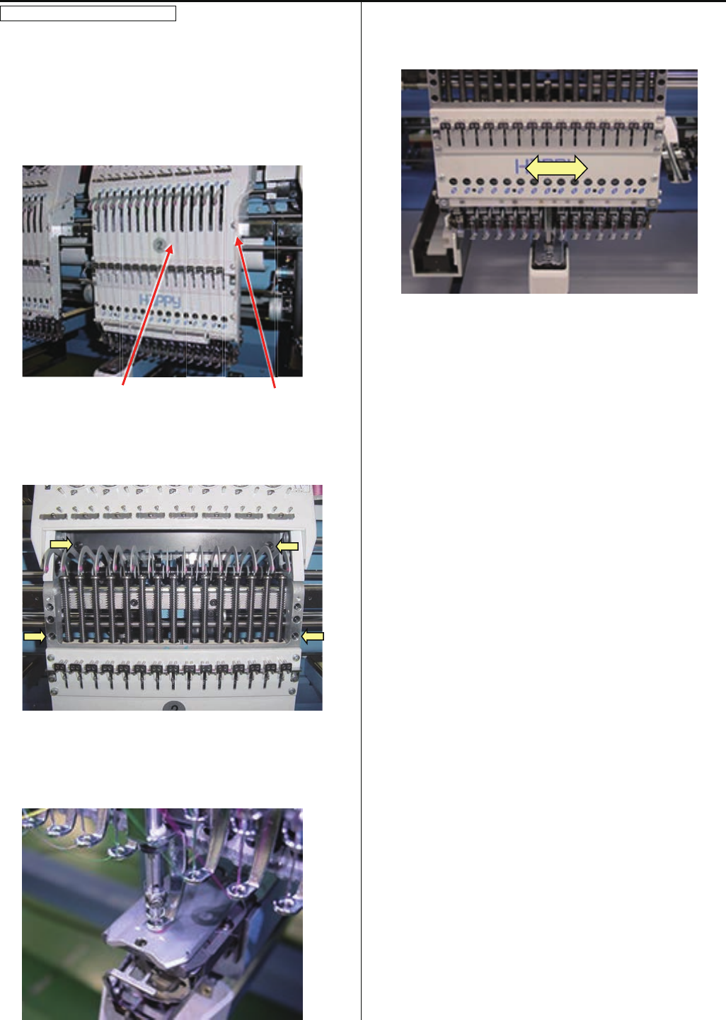
4-2-6 Adjustment of needle height
1. Remove the front panel (upper) and cord clip.
Slide front panel (lower) to left or right direction up to the
position that you can see needle bar to be adjusted.
In case you need to slide front panel (lower) further, please
slide front panel (lower) on neighbor head.
2. Remove bobbin case.
3. Bring needle bar down.
Please refer to [ 5 User maintenance mode ].
4. Turn upper shaft to set dial disc to [ 10 degrees ].
5. Loosen screw on needle bar boss.
6. Put needle height gauge in rotary hook.
52
4-2-6 Adjustment of needle height
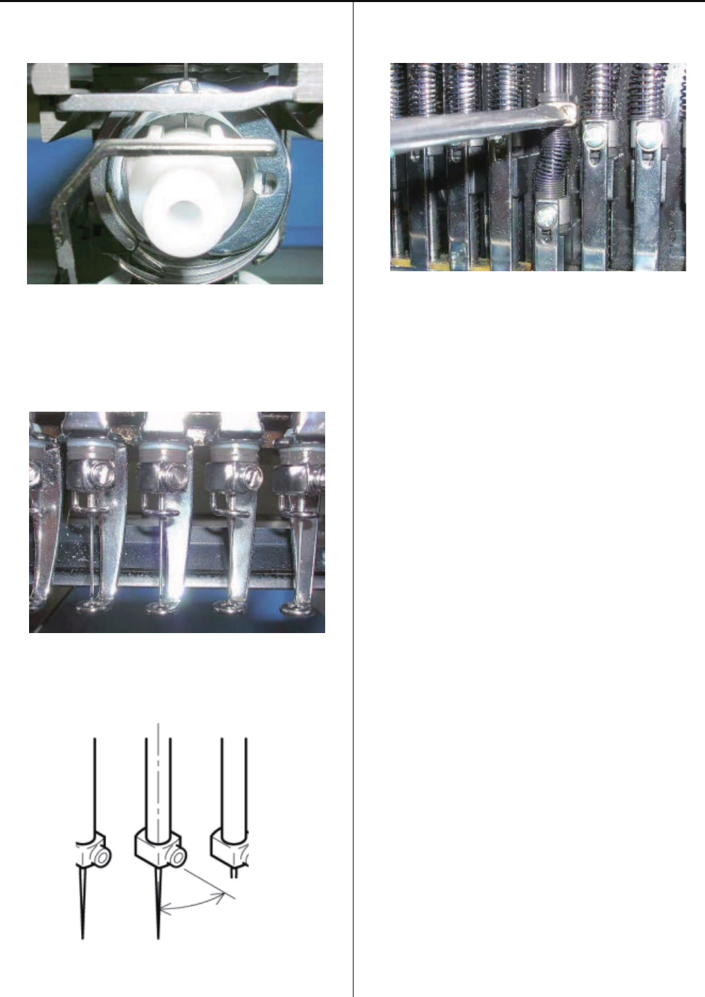
7. Adjust the needle bar height up and down till the needle tip
touches to the gauge slightly.
8. Set direction of needle stop as illustrated below.
About 30 degrees
9. Tighten the screw of needle bar boss.
10. Take Needle height gauge out from Hook.
11. Back main shaft to [ 270 degrees (C point) ] position.
12. Set “front panel (lower)” and cord clip, set “bobbin case”
then end of process.
53
4-2-7 Adjustment of needle bar lowest point
1. Take Upper shaft cover.
Upper shaft cover
2. Move moving head to the position that 14th needle is active.
Take Thread catcher cover.
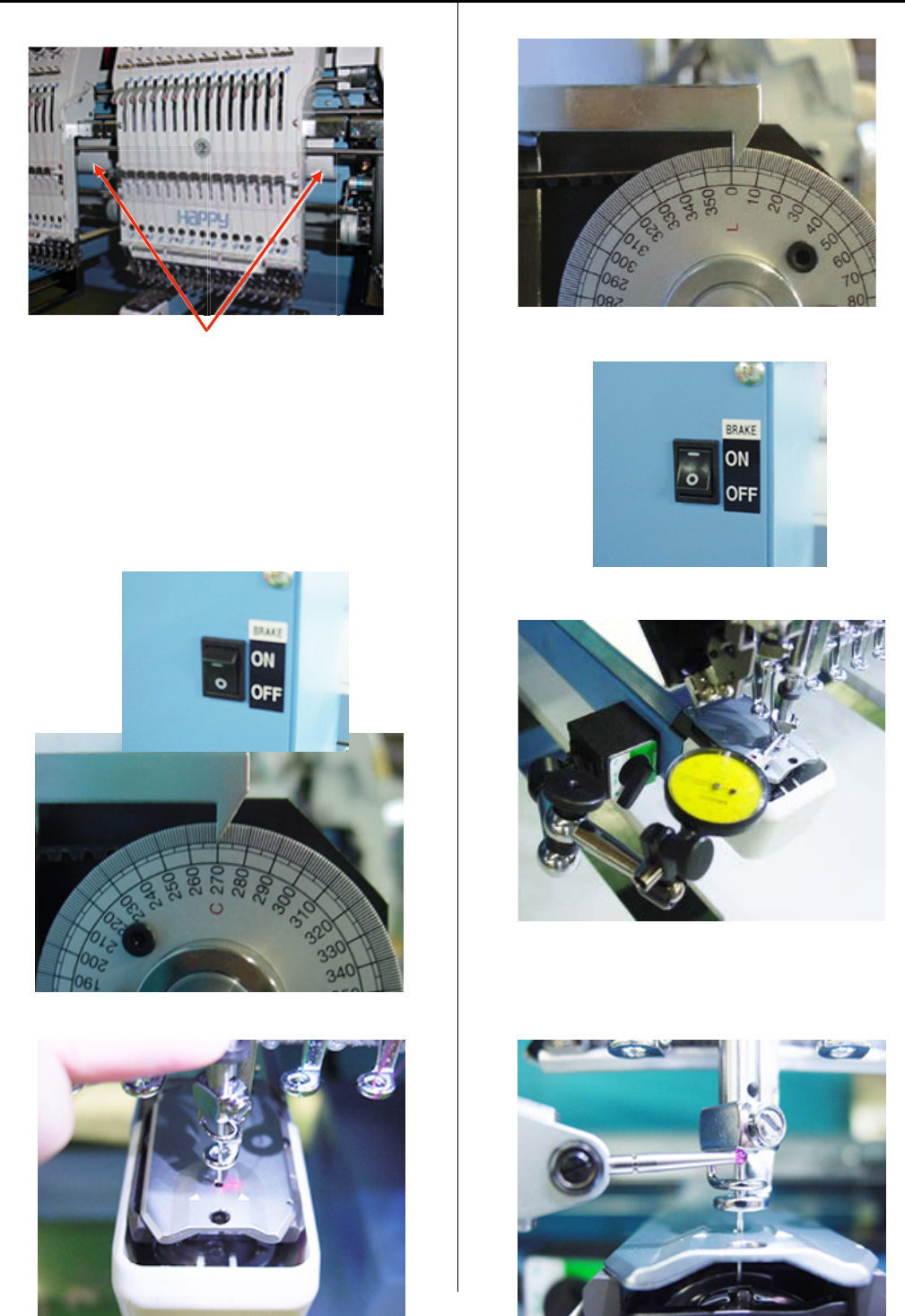
3. Turn off the brake switch.
Turn upper shaft to set dial disc to [ C point (270 degrees) ].
4. Bring needle bar down.
5. Turn upper shaft to set dial disc to [ 0 degrees ].
6. Turn on the brake switch.
7. Fix Dial-gauge set on left side of bed.
8. Set lever of the Dial-gauge at lower surface of needle
holder then, adjust position of the Dial-gauge so as to move
pointer of the Dial-gauge around 1mm.
54
4-2-7 Adjustment of needle bar lowest point
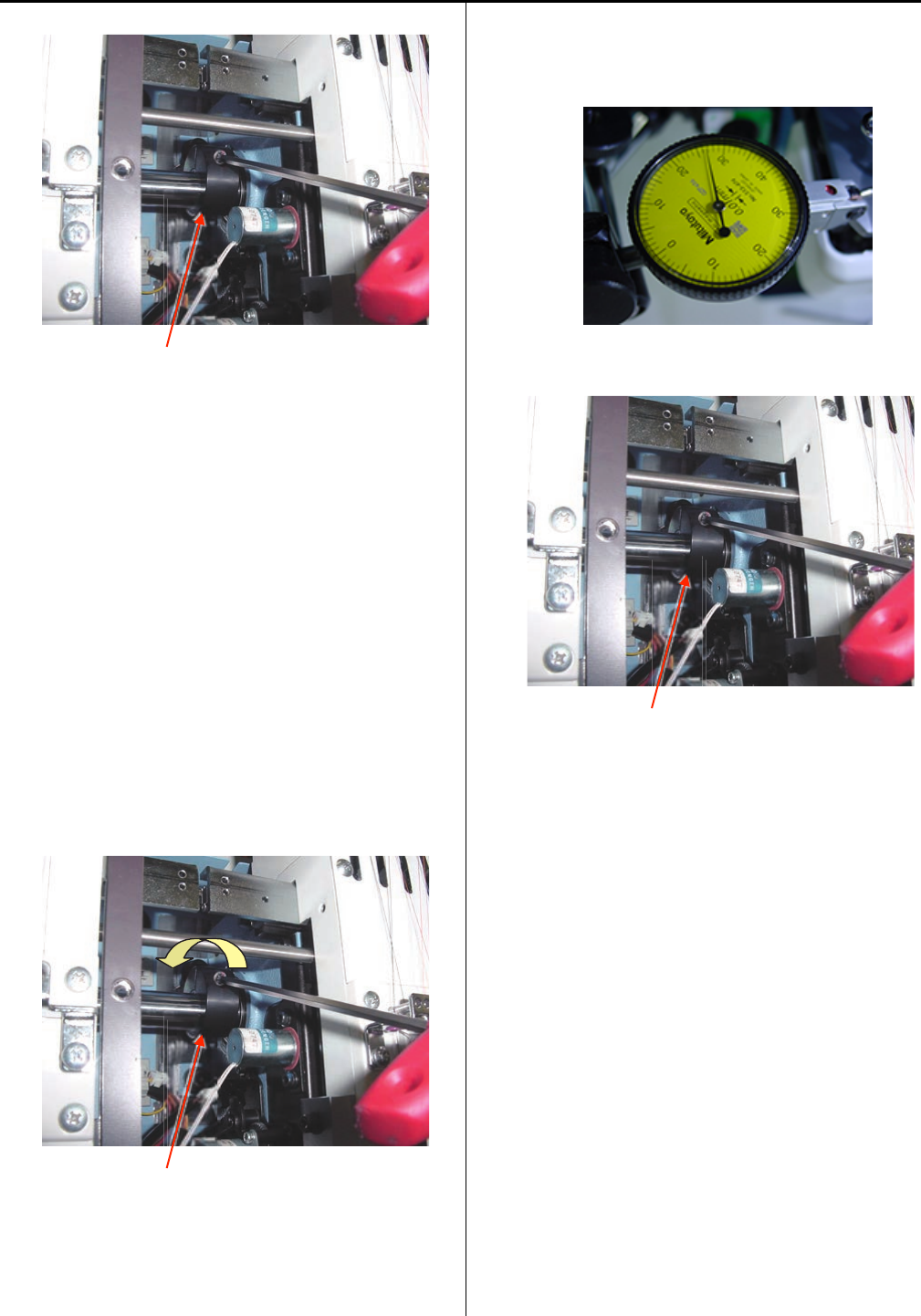
9. Loosen a fixing screw of fasten collar.
Fasten collar
10. Turn Fasten collar to the forward direction and move
needle bar.
< Note > Please do not turn the fasten collar so much,
because the measuring range of the Dial-gauge is limited.
In case needle bar can not be moved,
Fixing screw for Fasten collar is loosen too much.
Tight fixing screw for Fasten collar gradually up to the
position that needle bar can be moved.
< Note > If loosen too much, fasten collar will start slipping
against needle bar cam.
If tight too much, needle bar can not be moved again.
Fasten collar
11. Check movement of the Dial-gauge with turning fasten
collar forward and back ward then, find needle bar lowest
point that the movement of the dial-gauge stops.
12. Tighten fixing screw of fasten collar.
Fasten collar
13. Turn brake switch off.
14. Turn upper shaft to set dial disc to [ 0 degrees ], Turn
main shaft forward and back ward with checking the
Dial-gauge movement then, stop the main shaft at needle
bar lowest point.
Confirm that the dial disk is located at [ 0 degrees ].
If the angle is not correct, repeat steps from 9 to 14.
15. Put removed all parts back to finish.
16. After adjustment, confirm the needle height and rotary
hook timing also.
Please refer to [ 4-2-6 Adjustment of needle height ]
[ 4-4-1 Adjustment of rotary hook timing ].
55
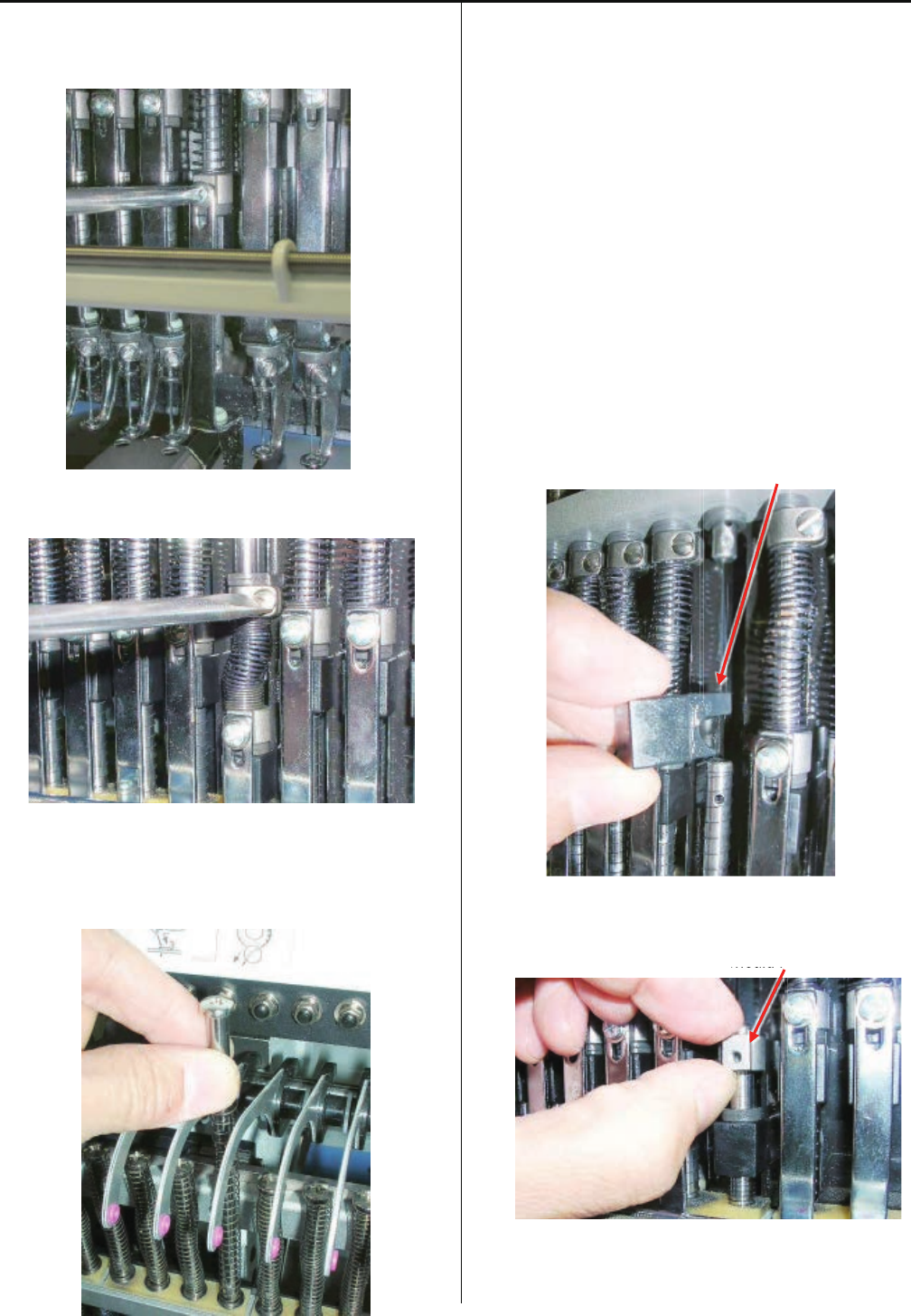
4-2-8 Exchange of needle bar, needle bar spring, cushion and pressure foot block
1. Refering to [ 4-1-5 Exchange of pressure foot ],
remove pressure foot.
2. Loosen screw on needle bar boss.
3. Take off “Needle bar boss”.
At this time, remove pressure foot spring (lower),
pressure foot block, cushion, pressure foot boss and
needle bar boss.
4. Set good parts to needle bar.
At this time, if insert extra needle bar from under, you
can work more easily.
< Note > Care to insert direction for “Pressure foot” and
“Pressure foot boss”.
Pressure foot block
Check shape of direction.
Pressure foot boss
Should hole to under side
Should h
56
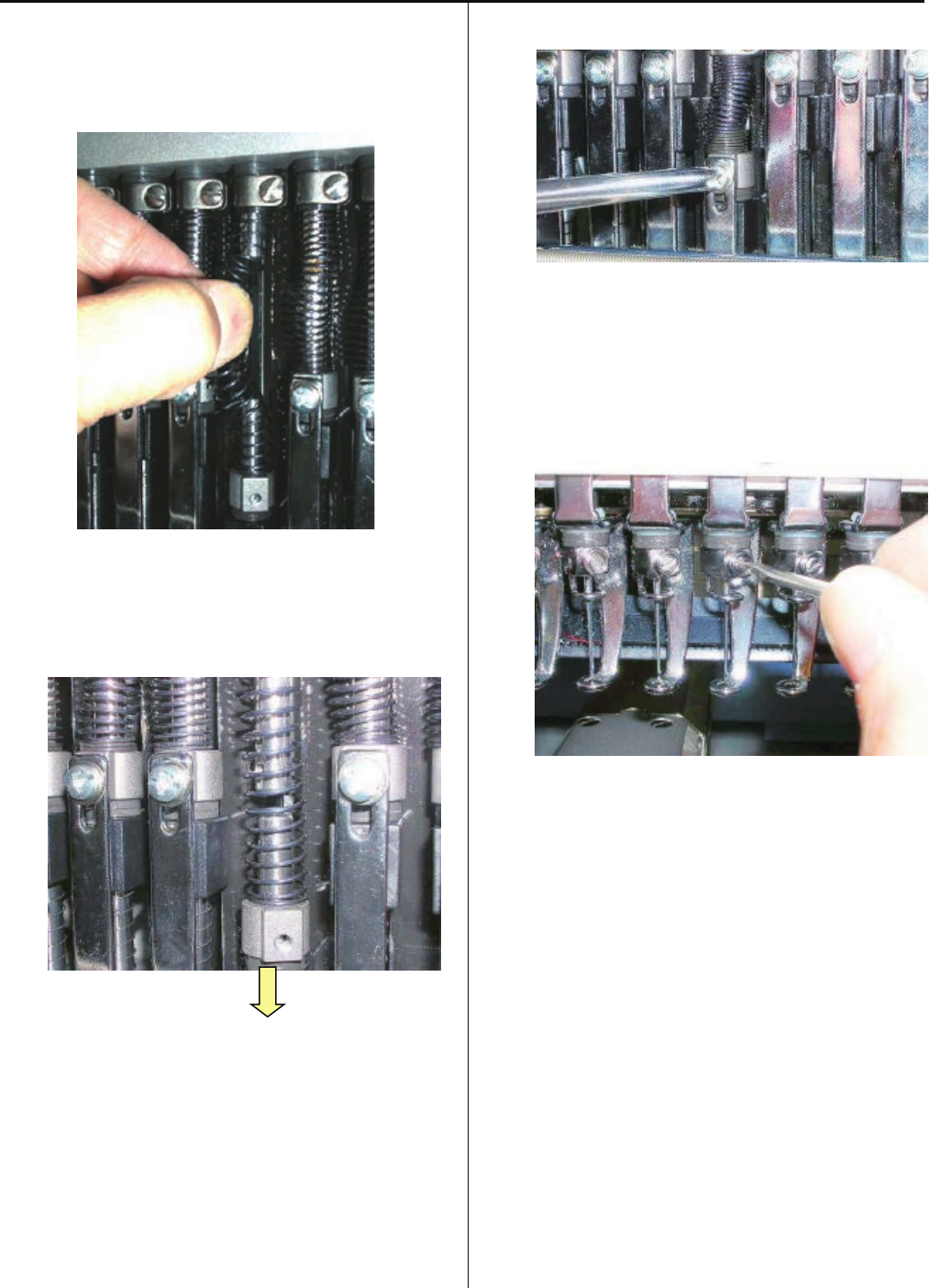
4-2-8 Exchange of needle bar, needle bar spring, cushion and pressure foot block
5. Fix needle bar spring.
Finally, push upper needle bar and string all parts then pull
out lower extra needle bar.
Slide needle bar to lower.
6. Fix pressure foot.
7. Fix needle, needle holder and cushion.
8. Adjust needle height.
Please refer to [ 4-2-6 Adjustment of needle height ].
9. Adjust pressure foot height.
Please refer to [ 4-1-4 Adjustment of height of pressure
foot ].
10. Put removed parts back to finish.
57
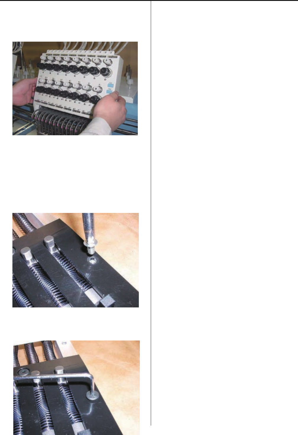
4-2-9 Fixing of needle bar boss check plate
1. Remove moving head.
Please refer to [ 4-2-1, 4-2-2 Assemble and remove
moving head ].
2. Exchange of needle bar boss check plate.
3. Temporarily, use the pan head screw to center the needle
bar boss check plate then fix the screw
4. Fix positioning needle bar boss check plate.
5. Put moving head and other removed parts back to finish.

58
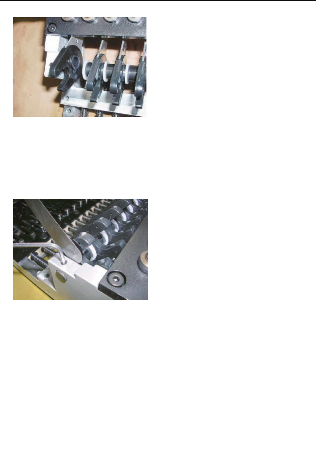
4-2-10 Exchange of take-up lever
1. Remove moving head.
Please refer to [ 4-2-1, 4-2-2 Assemble and remove moving
Head ].
2. Loosen screw on take-up lever shaft. (Fixing screw 2 pcs)
3. Remove the E-ring.
4. Please do not miss “Plastic thrust washer” between E-ring
and Take up lever.
Remove plastic thrust washer. (1 pcs)
5. Remove the take up lever shaft first then remove the take-
up lever.
6. Remove plastic washer.
59
4-2-10 Exchange of take-up lever
7. Install good take-up lever assembly.
8. Leave space of [ 0.2mm ] between take-up lever and
moving head .
Tight screw for “Take up lever shaft”
9. Put moving head in previous position to finish.
60
4-2-11 Adjustment of tension of thread adjusting spring
1. Remove thread adjusting unit ass’y. (Fixing screw 4 pcs)
2. Block has spring groove to be able to adjust in three steps.
Put tip of spring in upper groove.
Strongest tension will be obtained in upper groove.
3. Fix thread adjusting unit ass’y to finish.
61
4-2-12 Adjustment of stroke of thread adjusting spring
1. Loosen screw on adjuster.
2. Move adjuster lower position with small flat-head driver.
When you move adjuster upward, stroke will get small.
When you move it down, stroke will get large.
* The lower position is default setting.
3. After adjustment, tighten screw to finish.
62
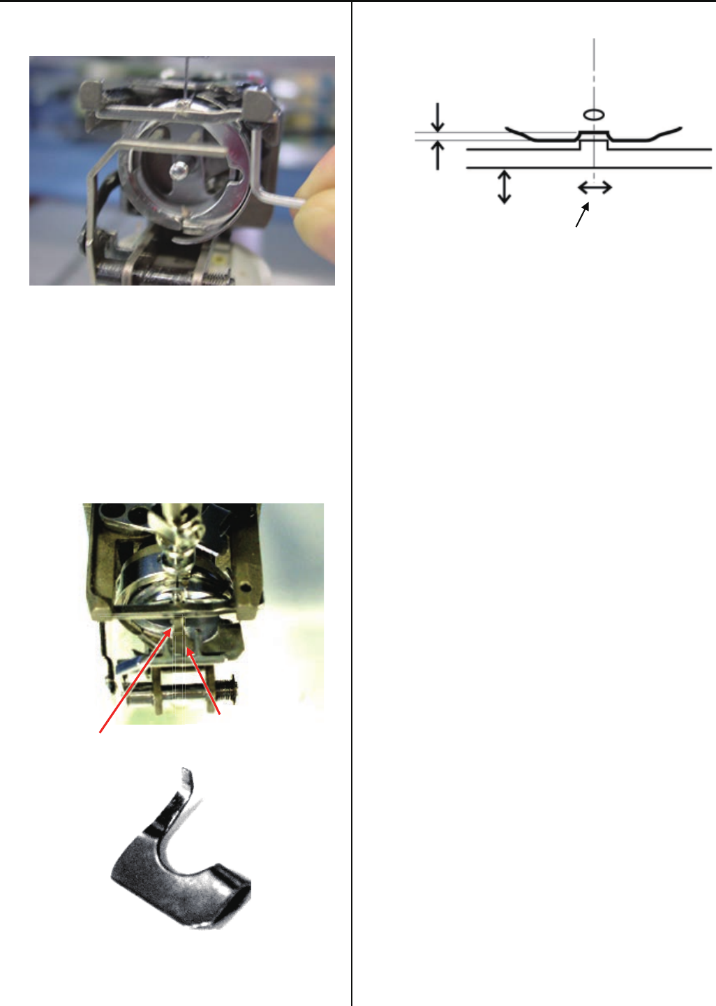
4-2-13 Adjustment of thread holder
1. Loosen screw to the extent that thread hoIder moves.
(Fixing screw 4 pcs)
Screw
2. Please putout and withdraw thread catcher by your finger
and fix holder position at smoothly moving position.
<Note> Please check smoothly moving at 1st and 15th
needle.
Positional relationship between pressure foot and holder
(lower)
When downing the needle, should have gap more than
1 mm between holder and presser foot.
Gap
3. Thread catcher device should be adjusted if above
clearance is not keepable.
4. Press thread trim key and confirm whole thread trim
revolution.
63
4-2-14 Adjustment of clip-type thread holder
1. Loosen screw to the extent that clip-type thread hoIder
moves. (Fixing screw 4 pcs)
Screw
2. Please put out and withdraw thread catcher by your finger
and fix holder position at smoothly moving position.
Hook has to touch surface of clip holder (lower).
< Note > Please check smooth moving at 1st and 15th
needle.
Positional relationship between pressure foot and holder
(lower)
When downing the needle, should have gap more than
1 mm between holder and presser foot.
When is hook pull out, space between hook and bottom of
pressure foot should be more than 1mm.
3. Thread catcher device should be adjusted if above
clearance is not keepable.
4. Space between Clip drive and clip should be 1-2mm.
< Note > Please check at 1st and 15th needle.
Clip drive
Clip
5. Press thread trim key and confirm whole thread trim
revolution.
Gap
64
4-2-15 Adjustment of clip drive unit
1. Move moving head to the position that 1st needle is active.
2. Temporary fix Clip drive unit.
Screw
Clip drive unit
3. Connect cables and bundle by wiring clamp.
Cable
Wiring clamp
4. Space between Clip drive and Clip should be 1-2mm and
push point of Clip Drive should be center of clip(right and
left). Fix Clip drive unit at the position that unit is not
touching to holder.
Clip drive
Clip
5. Turn power switch ON, and move moving head to 15th
needle. Please confirm space between Clip drive and clip
is same as space at 1st needle.
6. If case above space at 1st needle and at 15th needle is not
same, position of clip holder may be incorrect.
Please check position of Clip holder and Clip drive unit.
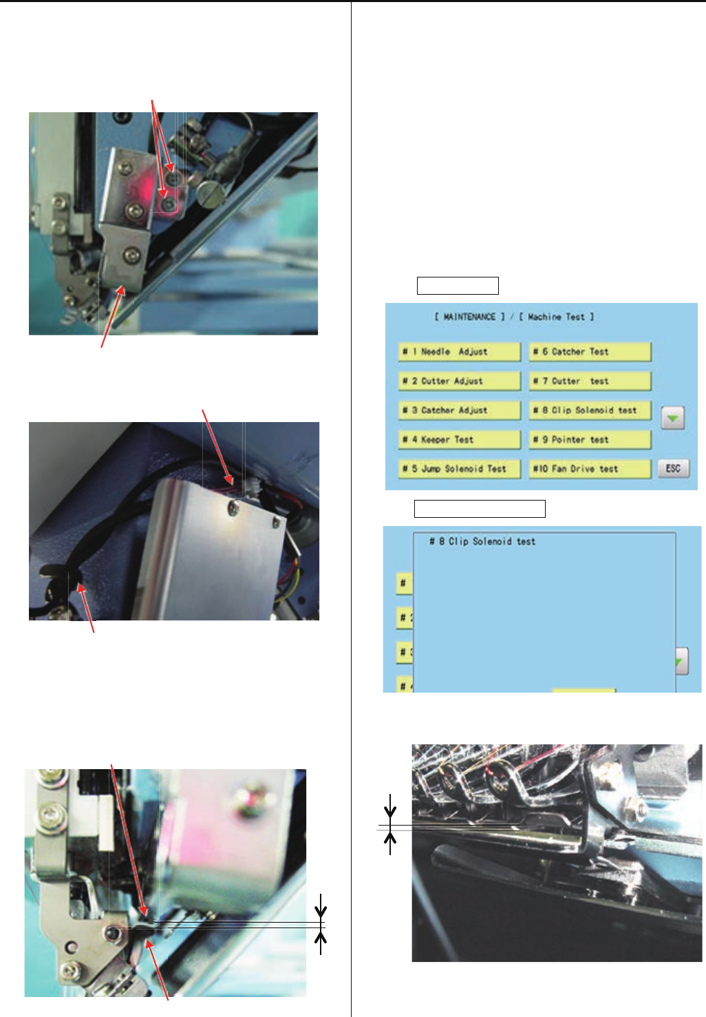
7. Refer to [ E5-1 How to enter maintenance mode ] and
enter maintenance mdoe.
8. Press MachineTest.
9. Press #8ClipSolenoidTest.
Please confirm that clip opens more than 2mm.
< Note > Please check at 1st and 15th needle
10. Press thread trim key and confirm whole thread trim
revolution
65
4-3-1 Check / Adjustment of needle bar change unit
1. Remove cover for needle bar change unit.
Cover
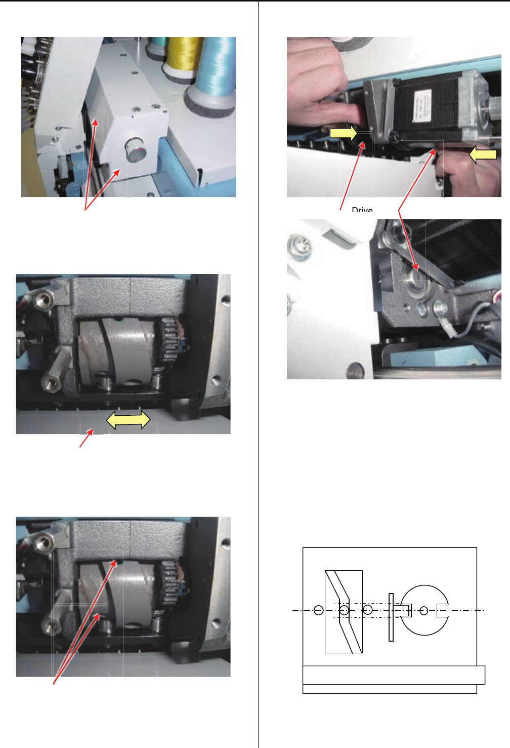
2. Turn the knob to flat position of the cam and push moving
head right and left side for confirm should not have a play
the Cam.
Moving head
2-1. If you had feel a play the cam, please loose the set screw
on cam.
Set screw
Both hole has 2 pcs of set screw.
Inner set screw is "Cup Point" type and outer set screw is
"Flat Point" type.
2-2. Push the Cam to right and push drive shaft to left side
and tight Cam screws.
Cam Drive shaft
2-3. Check the cam should not have play.
After this adjustment, please check and adjust the needle
position.
Please refer to [ 4-2-4 Adjustment of needle position (left
and right) ].
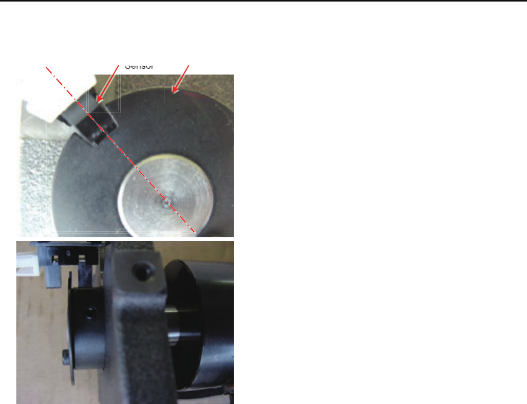
3. Turn the knob and stop at needle stopping point and
confirm Senser and slit position reference following image.
Drive
Drive
Imagine figure of position sensor and cam
66
4-3-1 Check / Adjustment of needle bar change unit
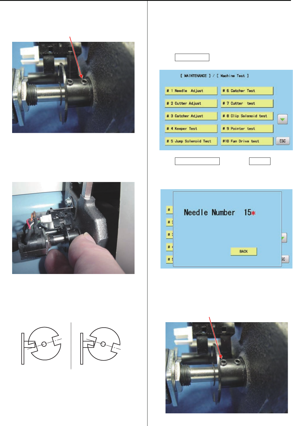
3-1. For adjustment the sensor and slit position, pleaseloose
a screw on the slit.
< Note > Please do NOT loose LEFT side screw.
Set screw
3-2. Please adjust slit position to center of slit gap against
sensor when needle selection cam is middle position on
flat.Then tight screw of slit.
3-3. Turn the knob and confirm position of sensor and slit.
When needle selection cam is position on flat, angle of slit
against sensor should be even like below drawing.
4. Turn the knob and move moving head to 15th needle.
5. Enter maintenance mode, referring to [ E5-1 How to enter
maintenance mode ]
6. Press MachineTest.
7. Press #1NeedleAdjust and press Position.
Should showing [Needle Number 15* ] and has beep
sound.
7-1. If your machine showing different (wrong needle number
or non * mark) message, potentiometer position is not
correct. Please loose left side screw of slit.
< Note > Please do NOT loose right side screw.
Set screw
67
4-3-1 Check / Adjustment of needle bar change unit
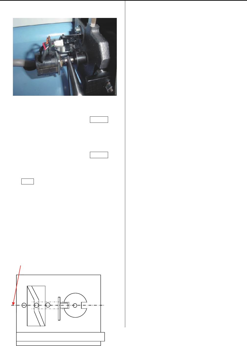
7-2. Turn shaft of Potentiometer and tight screw at middle
position on showing [ * ] mark.
7-3. Move Moving head to 1st head and press Position.
Confirm indication to [Needle Number 1* ].
7-3. Move Moving head to 1st head and press Position.
7-4. Press BACK to complete settings.
8. Please check needle position to needle plate and back on
cover.
< Note > Piositioning image for needle selection Cam, Slit,
Sensor.
Center
Imagine figure of position sensor and cam
68
4-4-1 Adjustment of rotary hook timing
1. Move moving head to the position which 8th needle is
active.
Remove bobbin case and needle plate.
(Fixing screw 2 pcs)
2. Loosen screw on rotary hook. (3 places)
<Note> Please do not loose screws too much.
3. Bring needle down up to the needle lowest position.
Refer to [ 5 User maintenance mode ].
<Note> Please do not loose screws too much.
4. Turn upper shaft and set dial disc to [ 25 degrees ].
< Note > Turn upper shaft anti-clockwise
Turn brake switch ON.
5. Set the position of needle and tip of hook as below.
69
4-4-1 Adjustment of rotary hook timing
6. Clearance between needle and rotary hook should be [ 0.1
~ 0.2mm ]
Clearance
7. Check and adjust with 1st, 8th and 15th needle.
8. Tighten screws on rotary hook
9. For making sure, check position of retainer on bobbin case
holder.
Please refer to [ 4-4-2 Adjustment of retainer on rotary
hook ]
10. Set needle plate keeping needle position is center of
needle hole on needle plate
Needle Needle hole of needle plate
11. Adjustment has finished.
70
4-4-2 Adjustment of retainer on rotary hook
Loosen screw to the extent that retainer moves. ( 1 pcs )
2. Adjust position back and forth, left and right.
Using adjustment gauge and adjust space to be [ 0.8mm ]
for back and forth. ( insert gauge between retainer and
inner hook )
The position for right and left is center of the needle.
Gauge
Center of needle and center of retainer to be adjusted
Gauge
0.8mm
Needle center position
4. Adjustment has finished.
71
4-4-3 Exchange of rotary hook shaft
1. Take hook shaft out
1-1. Take hook retainer out.
(Hexagon socket button head screw : M3-5)
(Plain washer : M3)
1-2. Loosen screw and take hook out.
1-3. Loosen screw of collar.
(Hexagon socket set screw : M4-4 2 pcs)
Please loose screw enough, because shaft has flat face.
1-4. Take cover of bed.
(Screw for needle plate : 2 pcs)
1-5. Lossen screws (see below picture) total 4 pcs.
(Hexagon socket set screw : M4-4 4 pcs)
1-6. Take gear out.
1-7. Pull shaft out.
Take hook shaft out has finished.
72
4-4-3 Exchange of rotary hook shaft
2. Install new shaft.
The parts which has one flat face is for hook side.
2-1. Insert shaft and adjust position of flat face and screw
position.
2-2. Shaft is 15mm out from collar.
Please fix screw
(Hexagon socket set screw : M4-4 2 pcs)
2-3. Put gear and fix.
Set screw position to flat face of shaft, and tighten screw.
(Hexagon socket set screw : M4-4 2 pcs)
Center of gear should be center of shaft.
(please adjust position of gear)
2-4. Please put grease on gear.
<Grease>Shell alvania EP Grease
< Note > Put grease equally.
3-5. Put cover of bed.
( Screw for needle plate : 2 pcs )
.
73
4-4-3 Exchange of rotary hook shaft
2-7. Put gear and fix.
Set screw position to flat face of shaft, and tighten screw.
(Hexagon socket set screw : M4-4 2 pcs)
Center of gear should be center of shaft.
(please adjust position of gear)
2-8. Please put grease on gear.
<Grease>Shell alvania EP Grease
< Note > Put grease equally.
3-9. Put cover of bed.
( Screw for needle plate : 2 pcs )
3. Install hook
3-1. Temporary fix hook and hook retainer.
(Hexagon socket button head screw : M3-5)
(Plain washer : M3)
3-2. Adjust rotary hook timing.
Please refer to [ 4-4-1 Adjustment of rotary hook timing ].
3-3. Adjust retainer on rotary hook.
Please refer to [ 4-4-2 Adjustment of retainer on rotary
hook ].
Exchange has finished.
74
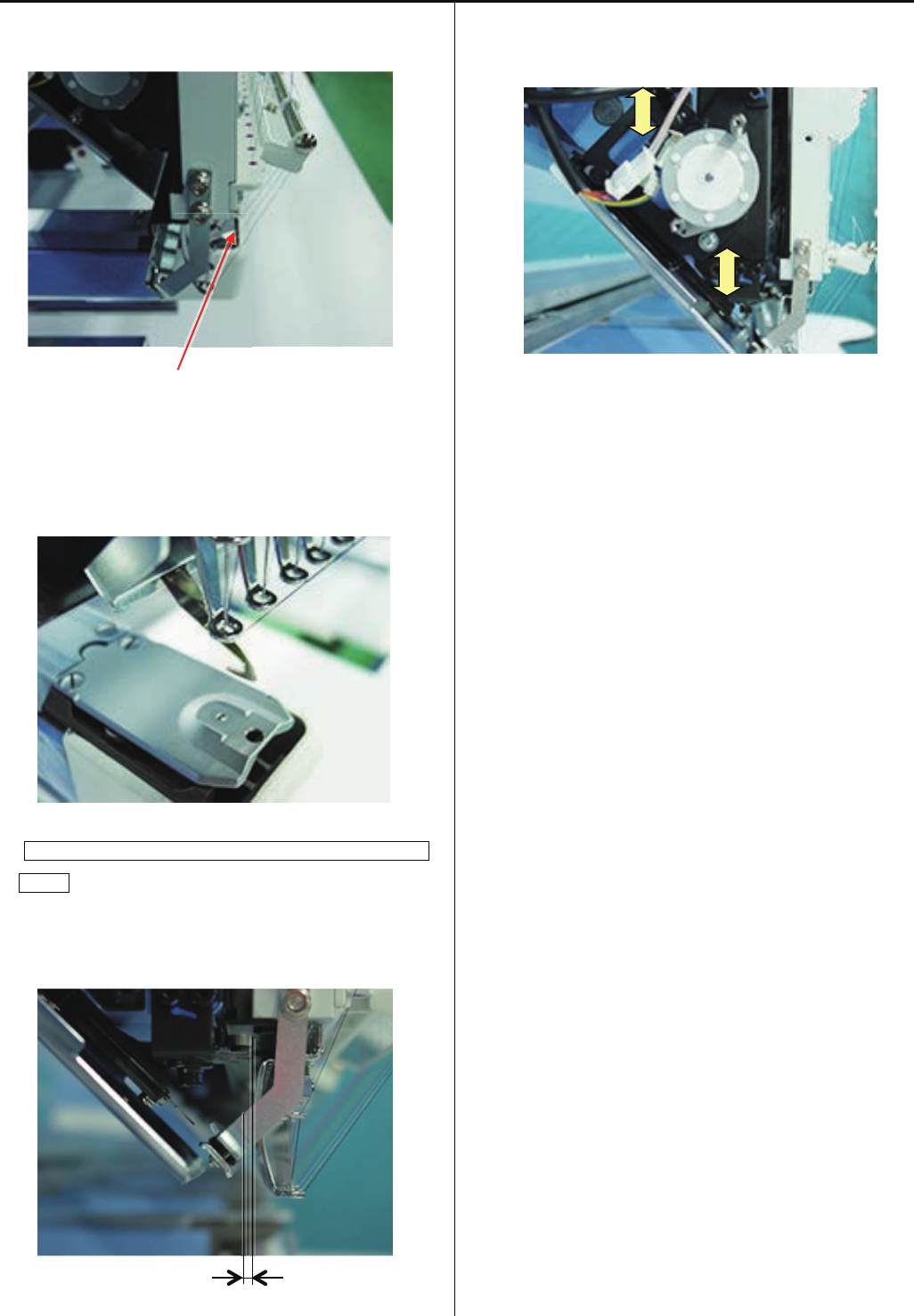
4-5-1 Check of thread cutting driver
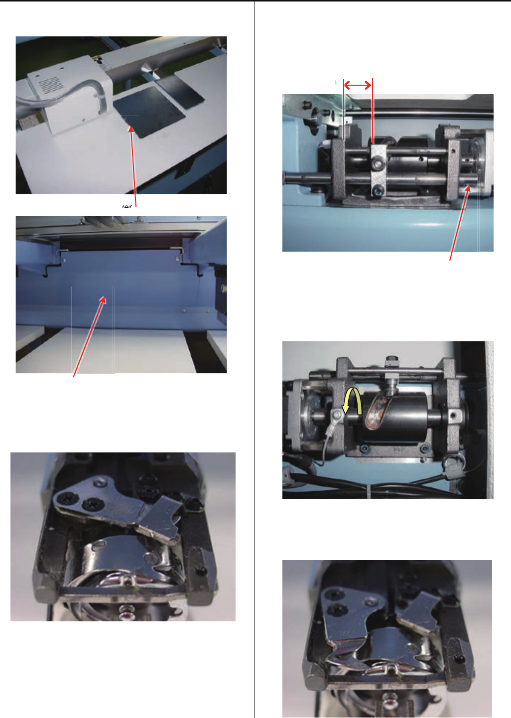
1. remove table support cover, cover for thread cutting driver.
Cover for thread cutting driver
Table support cover
2. Keep Moving knife to closing.
Please refer to [ 5 User maintenance mode ]
3. Check clearance between Driver base and Fasten block for
guide [ 18 ~ 19mm ].
Please confirm bulge right side point of "Slide shaft"
position likefollowing picture.
Clearance
Slide shaft
4. Turn the Cam till stop end. And confirm a ditch of Cam has
allowance.
5. Keep Moving knife to opening.
Please refer to [ 5 User maintenance mode ]
v
ver
ver
e
75
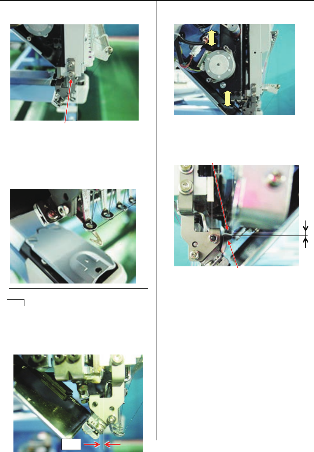
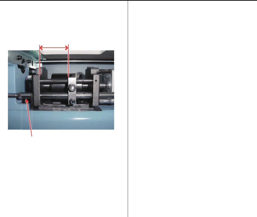
4-5-1 Check of thread cutting driver
6. Check clearance between “Driver base” and “Fasten block
for guide” [ 40 ~ 41mm ].
Please confirm bulge left side point of "Slide shaft" position
likefollowing picture.
Clearance
Slide shaft
- If you have some error in the step 3. ~ 6, please adjust
[ 4-5-2 Adjustment of thread cutting driver ].
7. Please keep Moving knife to closing.
Please refer to [ 5 User maintenance mode ].
Return cover to previous places to finish.
76
4-5-2 Adjustment of thread cutting driver
1. Remove “Table support cover”, and “Cover for thread
cutting driver”.
Cover for thread cutting driver
Table support cover
2. Turn the Thread cutting cam and move Fasten block guide
to center area of the bracket.
3. Loose Fasten screw and adjust slide shaft position to even
protuberance against face of driver base and tight the
screw.
Slide shaft
Fasten screw
4. Turn the Thread cutting cam till end position.
(Please see picture bellow)
Please keep this position for next adjustment.
.
77
4-5-2 Adjustment of thread cutting driver
5. Adjust Slit right position against sensor.
If you off the position, please adjust sensor position by
screw on sensor bracket.
Sensor Slit
6. After it, please adjust [ 4-5-5 Check / Adjustment of
position of moving knife ].
7. Confirm Moving knife position to CLOSE.
Please refer to [ 5 User maintenance mode ].
Back on covers to previous position.
Sensor
Sensor
78
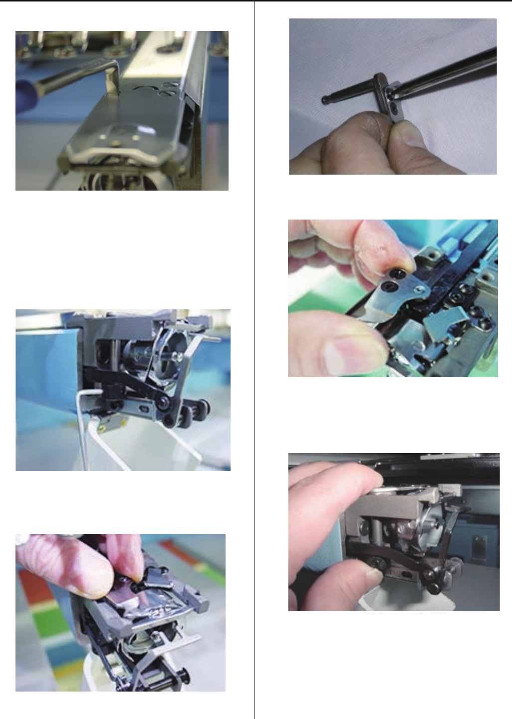
4-5-3 Exchange of moving knife
1. Remove needle plate. (Fixing screw 2 pcs)
2. Open moving knife.
Please refer to [ 5 User maintenance mode ].
3. Remove knife drive shaft retainer.
4. Pull out knife drive shaft ass’y.
5. Exchange moving knife.
6. Setting drive link hole to moving knife, insert knife drive
shaft assembly.
7. Pushing down moving knife and knife drive shaft retainer
like putting them together, fix knife drive shaft retainer.
# Fix so that there is no backlash in upward and downward
direction.
8. Close moving knife.
Please refer to [ 5 User maintenance mode ].
9. Referring to [ 4-5-6 Adjustment of moving knife and
fixed knife ], check how well thread is cut and adjust, then
finish this process.
79
4-5-4 Exchange of fixed knife
1. Remove needle plate.
2. Remove fixed knife.
3. Exchange fixed knife.
4. Tighten fixed knife pushing to forward as full as possible.
< Note > In case moving knife and the left side of fixed knife
overlaps excessively when closing, adjust the position of
fixed knife slightly to the right direction.
5. Referring to [ 4-5-6 Adjustment of moving knife and fixed
knife ], check how well thread is cut and adjust, then finish
this process.
80
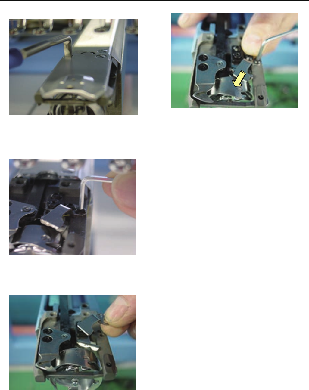
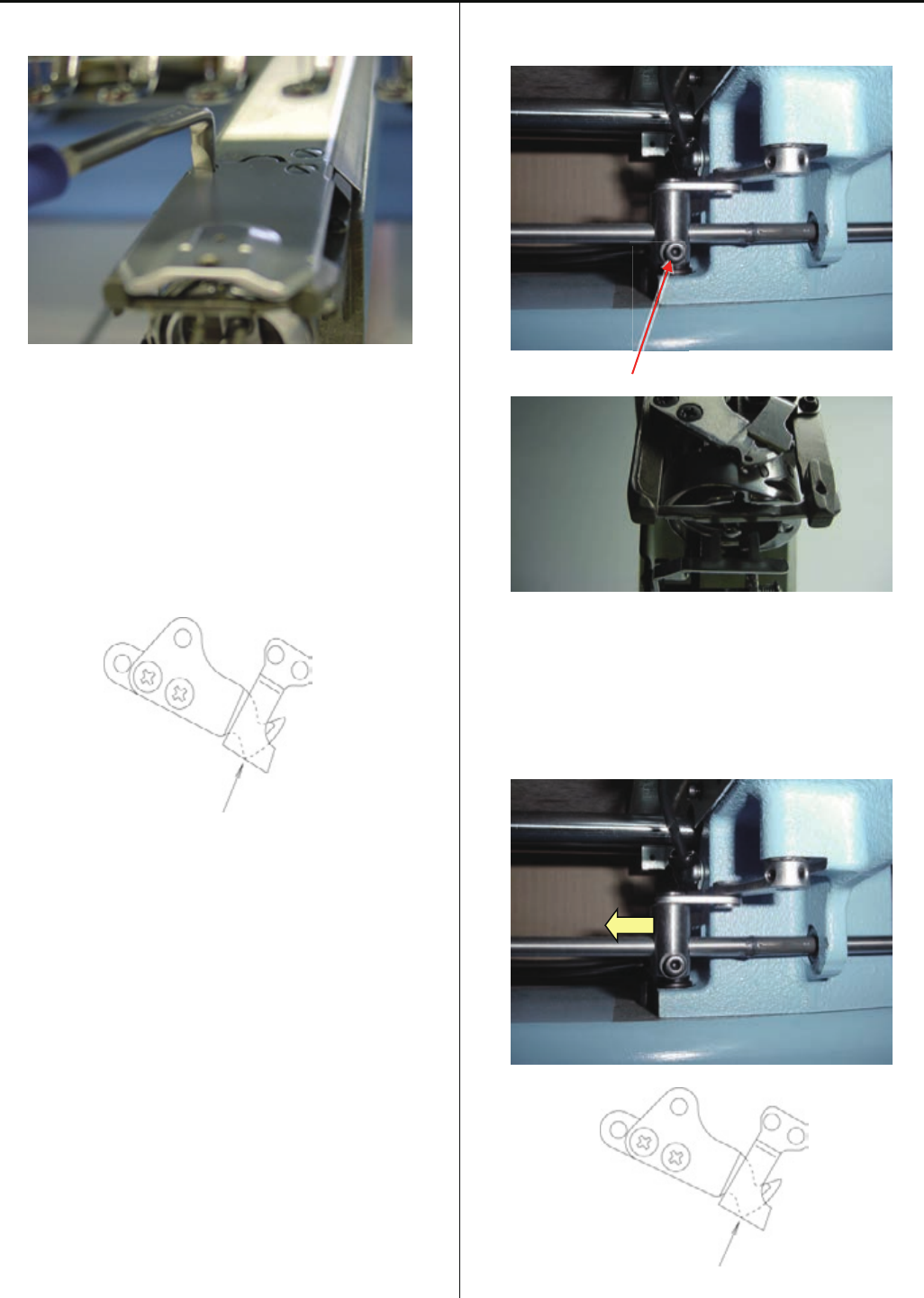
4-5-5 Check / Adjustment for position of moving knife
1.Remove the Needle plate
2. Please check knife closing position to following drawing.
(Point of moving knife same face with fixed knife cutting
line)
Please refer to [ 5 User maintenance mode ] for easy
adjustment for this progress. You can open and close the
knife manually.
“Same face”
3. For this adjustment, remove Table support cover on front
and go to next step.
4. Loosen screw on Thread cutting link and slide the link to
right side for open the moving knife.
Screw
5. Slide the Thread cutting link to left side for close Moving
knife and stop at right position of knife-closed point like
bellow.
“Same face”
81
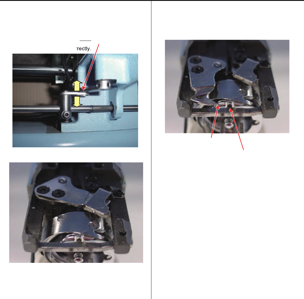
4-5-5 Check / Adjustment of position of moving knife
6. Keep the Thread cutting link position on “Step 5” and tight
screw.
Please confirm play the Link plate.
If you have not playing the plate, possible
moving knife not open correctly.
7. Check Moving knife closing point.
- If the closing position is not right, please back Set 5. and 6.
Please check opening point.
Should open the "Moving knife" to left till "point of Moving
knife" overfrom "Rotary hook retainer".
Point of Moving knife
Rotary hook retainer
- If the position is not right, please check “Thread cutting
driver”.
Referring to [ 4-5-1 Check of thread cutting driver ].
8. After confirm, please back cover and needle plate.
rr
rectly.
82
4-5-6 Adjustment of moving knife and fixed knife
1. Remove needle plate
2. Check if knife drive shaft has no backlash in up and down
direction.
If backlash is found, adjust it referring to [ 4-5-3 Exchange
of moving knife ].
3. Adjust slant of fixed knife with [upper adjustment screw]
and [lower adjustment screw] that fix fixed knife.
< Note> Rub these screws together to the extent that you
don’t feel resistance.
4. Cut thread and check how well it is cut.
Use two polyester threads for checking.
5. Check several times and if no mistakes are found, finish
this process.
83
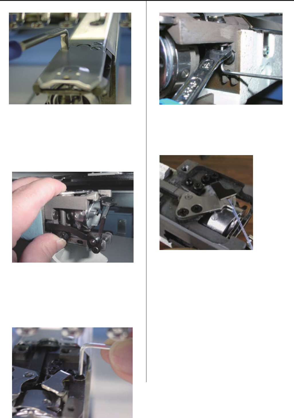
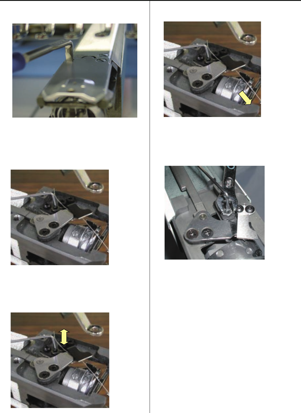
4-5-7 Adjustment of bobbin thread holder
1. Remove needle plate. (Fixing screw 2 pcs)
2. Close moving knife like putting bobbin thread between
moving knife and bobbin thread holder.
3. Adjust height of bobbin thread holder with adjusting screw.
4. Pull bobbin thread toward arrow mark and see that bobbin
thread comes off with tensile gauge [ 20 ~ 25g ].
5. Tighten lock nut. (Don’t move adjusting screw.)
6. Check several times and if OK, finish this process.
84
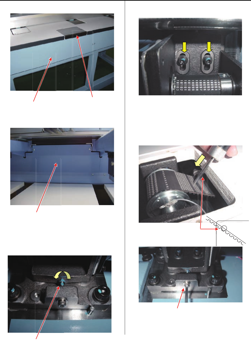
4-5-8 Adjustment of position of keeper
1. Remove needle plate and bed cover.
Solenoid base
2. Loosen screw on solenoid base. ( Fixing screw 2 pcs )
3. Loosen screw for stopper. ( 1 pcs )
4. Insert keeper positioning gauge ( Bobbin ) into rotary hook.
5. Refer to [ E5-1 How to enter maintenance mode ] and
enter maintenance mode.
6. Press MachineTest.
Sl

85
4-5-8 Adjustment of position of keeper
7. Press #4KeeperTest.
Adjust solenoid base where tip of keeper contacts slightly
to the gauge then tighten bracket screw.
Clearance between bobbin and keepr is [ about 1.0mm ].
< View from right>
Keeper positioning gauge
About 1.0mm (Bobbin)
Keeper
8. Adjust position of stopper.
This is the position where tip of keeper contacts to gauge.
9. Adjustment has finished.
86
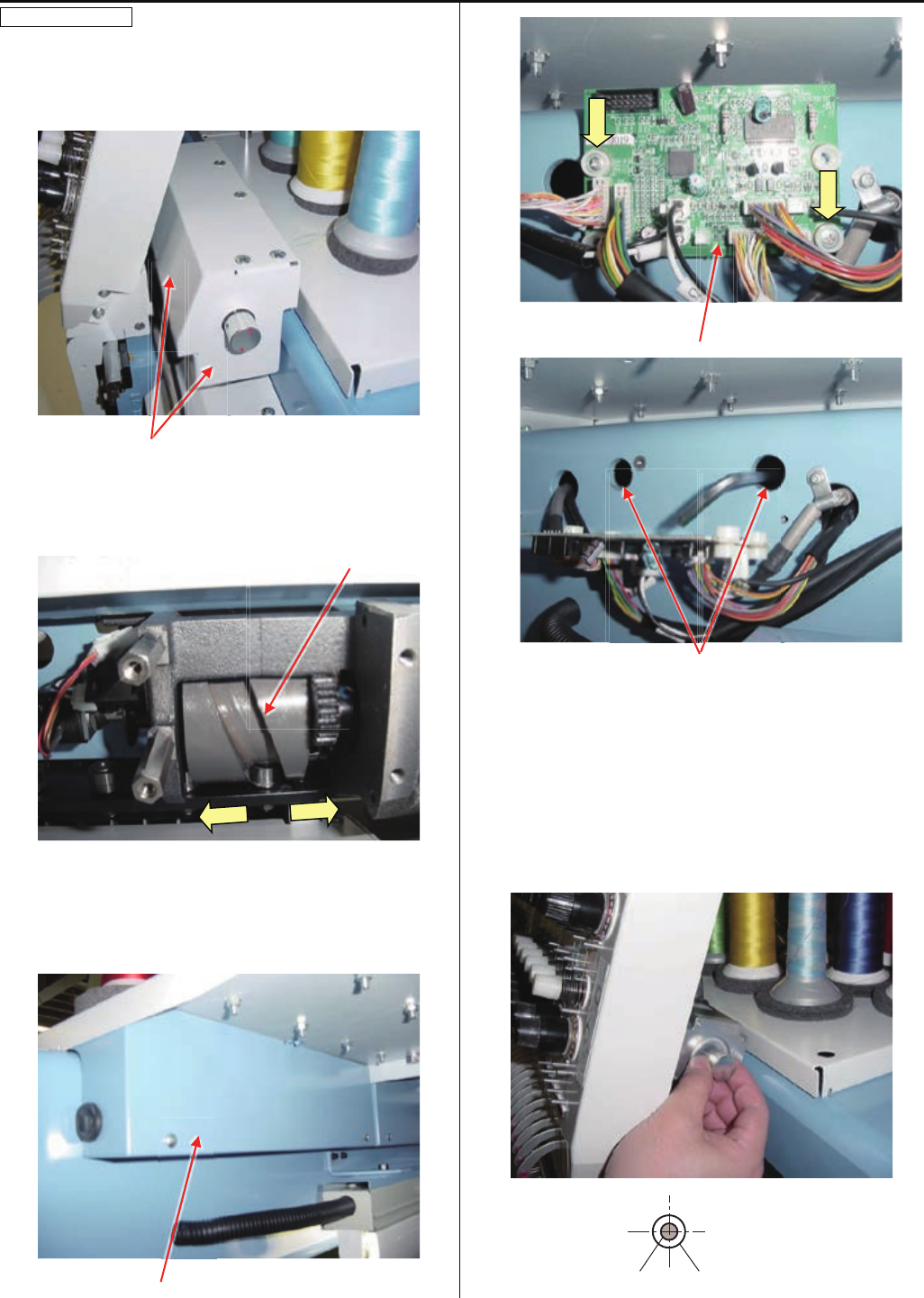
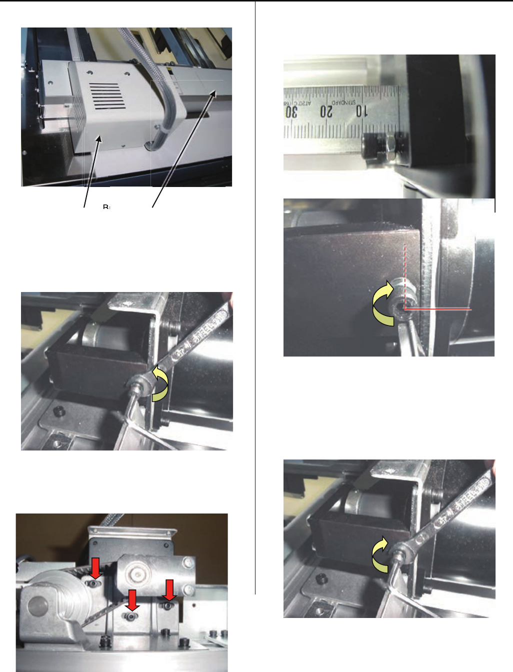
4-6-1 Adjustment of X carriage drive belt tension
1. Remove base cover and drive unit cover.
Drive unit cover Base cover
2. Loosen the adjusting lock nut.
<Spanner> 7mm
3. Loosen screw of Pulse motor bracket half turn
(3 pcs)
4. Set tension adjustment screw position 10mm from face of
bracket of shaft support.
Tighten screw by 1/4 turn.
5. Tighten screw for the pulse motor bracket.
6. Tighten the adjusting lock nut.
B
a
B

87
4-6-1 Adjustment of X carriage drive belt tension
7. Return base cover and drive unit cover to previous places.
8. Please refer to [E5-6 Position- Registration of coordinates
for positioning sensor], register embroidery area and finish
this adjustment.
88
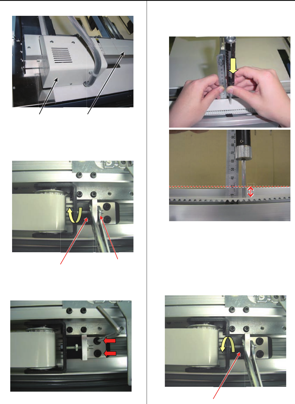
4-6-2 Adjustment of X carriage timing belt tension
1. Take drive unit cover and X carriage base cover out.
Drive unit cover X carriage base cover
2. Loosen lock nut for tension adjusting nut.
<Spanner> 7mm
Lock nut Adjusting nut
3. Loosen screws of tension plate half turn.
( 2 screws )
4. Push belt at center of belt by push gauge with 500gf.
Please adjust tension of belt by adjusting nut that belt
moves 5-6mm.
5~6mm
5. Tighten the screws of tension plate.
6. Tighten the lock nut for tension adjusting nut.
Lock Nut

89
4-6-2 Adjustment of X carriage timing belt tension
7. Return base cover and drive unit cover to previous places.
8. Please refer to [ E5-6 Position- Registration of coordinates
for positioning sensor ], register embroidery area and finish
this adjustment.
90
4-6-3 Adjustment of Y carriage drive belt tension
1. Take middle cover and rear cover out.
Rear cover Middle cover
2. Take out table support cover located front of middle cover.
Table support cover
3. Loosen lock nut of tension adjusting screw.
(you can find this screw under table)
<Spanner> 7mm
4. Loosen screws of Y motor base by half turn.
5. Push belt by push gauge with 500gf.
Belt should hide half of hole for motor fixing screw.
Please adjust tension by tension adjusting screw
< Note > Push gauge should touch belt with 90 degrees
and be close to table edge.
Hole for motor fixing screw
Tension adjusting screw
Lock nut
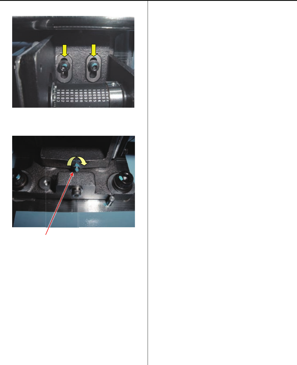
91
4-6-3 Adjustment of Y carriage drive belt tension
6. Tighten screws of Y motor base
7. Tighten lock nut of tension adjusting screw
Lock nut
8. Set table support cover
9. Set rear cover and middle cover
10. Please register frame position
Please refer to [ E5-6 Position- Registration of
coordinates for positioning sensor ].
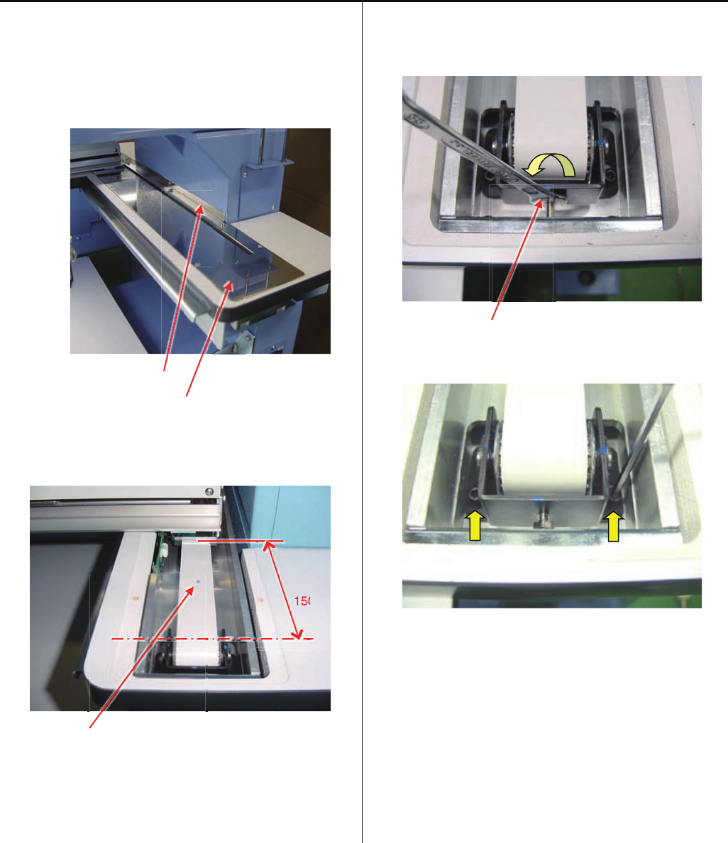
92
4-6-4 Adjustment of Y drive timing belt tension
The way of adjustment of Y drive timing belt is same right side
and left side.
Below explantion is for right side.
1. Take Y cover bracket and Y cover out.
Y cover bracket
Y cover
2. Move X carriage 150mm from center of idler pulley, and put
a mark at 75mm.
150mm
A mark
3. Loosen lock nut for tension adjusting screw.
<Spanner> 7mm
Lock nut
4. Loosen screw for idlerpulley bracketby half turn.
50
15
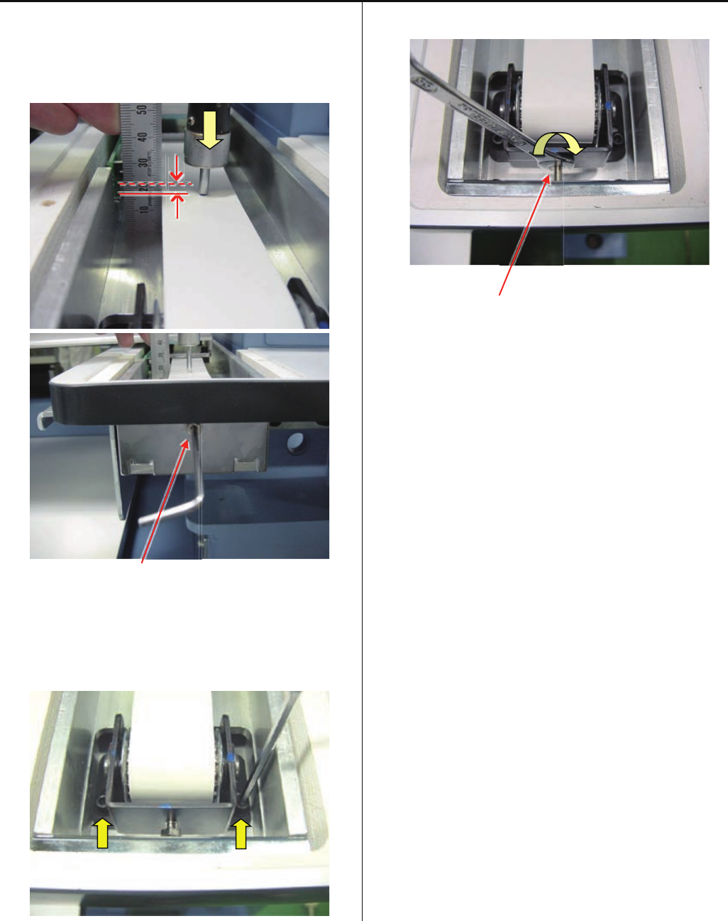
93
4-6-4 Adjustment of Y drive timing belt tension
5. Push belt by push gauge at a mark position.
Belt should move 2.5 ~ 3.0mm by 1kgf of push gauge.
Please adjust tension by tension adjusting screw
Tension adjusting screw
6. Tighten screws of idler pulley bracket
7. Tighten lock nut of tension adjusting screw
Lock nut
8. Set Y cover and Y cover bracket
9. Please register frame position.
Please refer to [ E5-6 Position- Registration of coordinates
for positioning sensor ].
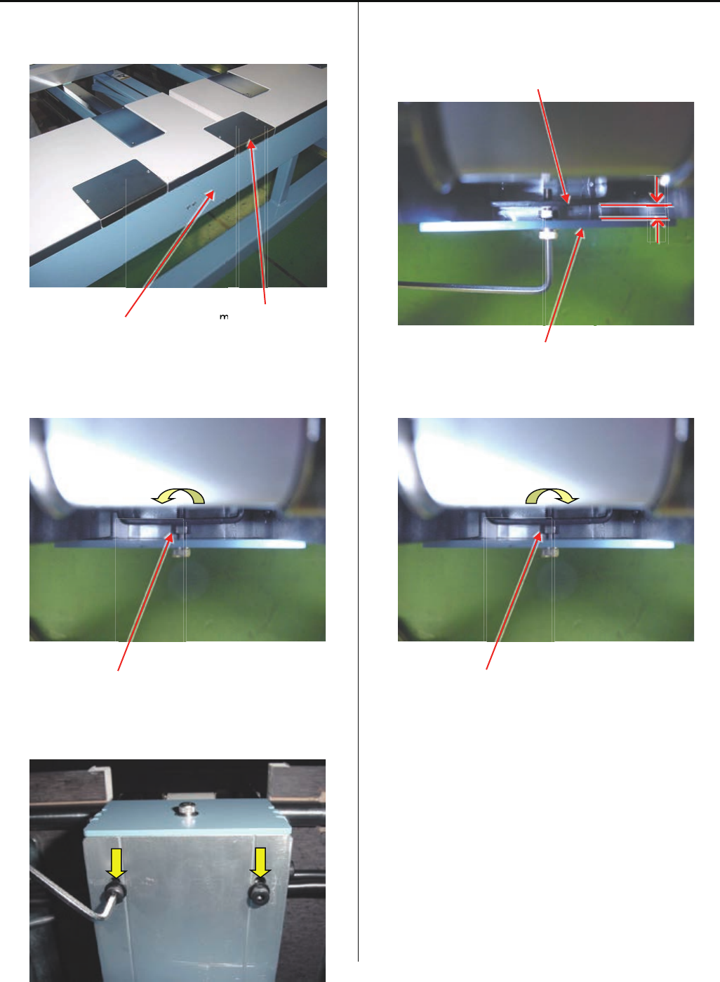
94
4-6-5 Adjustment of center carriage timing belt tension
1. Take middle cover and rear cover out.
Rear cover middle cover
2. Loosen lock nut for tension adjusting screw.
<Spanner> 7mm
Lock nut
3. Loosen screws for idler bracket by half turn.
( 2 pcs )
5. Adjust space between tension plate and idler pulley bracket
5mm by tension adjusting screw.
Idler pulley bracket
Tension plate
6. Tighten lock nut for tension adjusting screw.
Lock nut
7. Set middle cover and rear cover.
8. Please register frame position.
Please refer to [ E5-6 Position- Registration of coordinates
for positioning sensor ].
m
m

95
4-7-1 Adjustment of upper shaft timimg belt tension
1. Take mission cover (left) out
Mission cover(left)
2. Loosen lock nut of tension adjusting screw
<Spanner> 7mm
3. Loosen screws for tension plate by half turn
< Note > Please do not turn main shaft, when screws for
tension plate is loosen. Timing may be changed
4. Adjust space between tension plate and tension plate
(lower) 12.5 ~ 13mm by tension adjustingscrew
< Note > Please Keep tension plate straight.
5. Tighten screws for tension plate.
6. Tighten lock nut of tension adjusting screw.
7. Set mission cover (left).
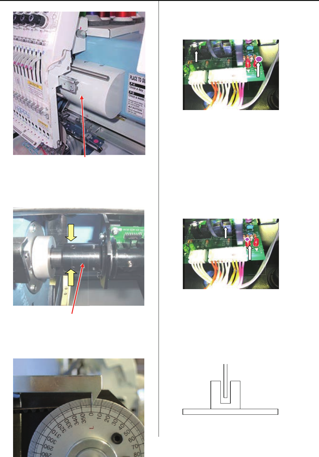
96
4-7-2 Adjustment of timing detecting unit
1. Remove the Head cover and Detecting cover.
Detecting cover
2. Loosen screws on coupling ( 2pcs ).
(Coupling can be turned by hand.)
Coupling
3. Set upper shaft to [ 0 degree ] .
Turn brake switch ON.
4. Turn coupling anti-clockwise to the position which LED4
light goes out, then tighten screws on coupling.
5. After tightening screw, turn brake switch OFF.
Please confirm that LED4 light goes out when angle of
upper shaft is “0 degree”, and LED3 turnes on when angle
of upper shaft is “270 ~ 284degrees (C point)”.
6. Please confirm that should not touch "Slit" and "Sensor".
LED4
L POINT SENSOR
LED3
C POINT SENSOR
Sensor
Slit
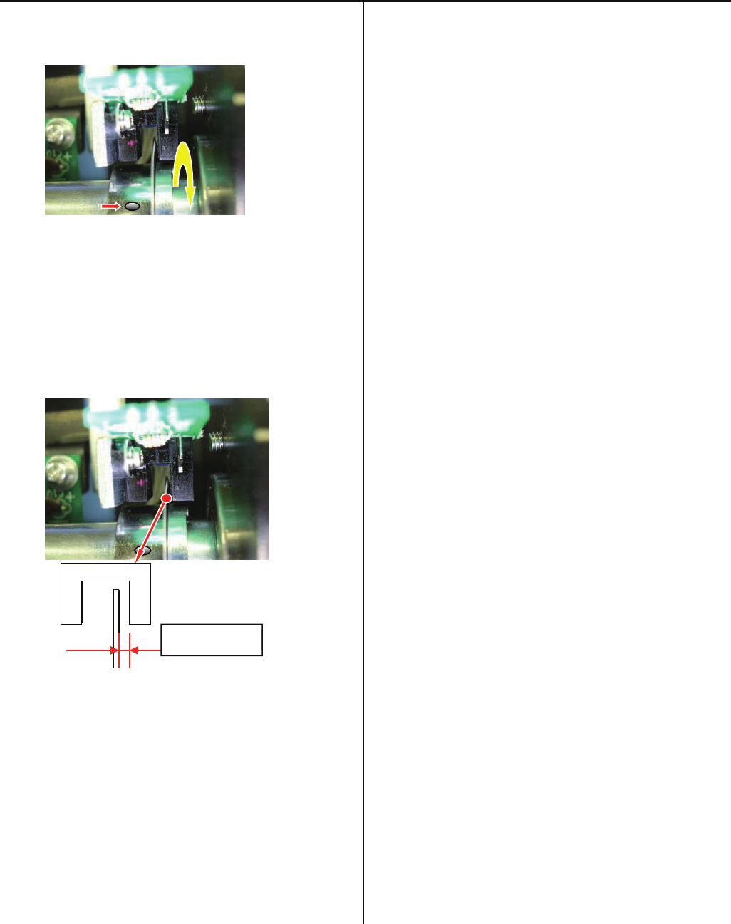
97
4-7-2 Adjustment of timing detecting unit
7. Loosen the screw for fixing timing slit showed as below so
that timing slit can turn itself.
8. Adjust the distance between timing slit and timing board.
As showed below, adjust the distance between timing slit
and timing board to [ 0.7 + / - 0.2mm ] and tighten the
screw.
< Note > Be careful not to bend timing slit, because it is very
thin.
9. Put cover back, finish of procedures.
Space
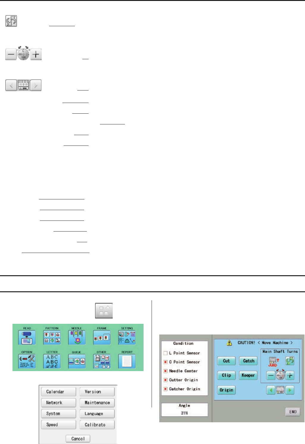
98
5 User maintenance mode
User maintenance mode has the items as below.
Change jump Change the needle bar’s movement.
“JUMP” : Needle Jump, “DRIVE” : Needle Drive
Upper shaft turns Upper shaft turns clockwise and counterclockwise.
When release button, upper shaft stops.
Needle change Move the sewing head to the adjustment needle in the direction of the arrows.
[Cut] Cutter Open/Close Open and close knife of thread trimming
[Catch] Cathcer Open/Close Open and close thread catcher
[Clip] Clip-type thread holder (option) Open and close clip-type thread holder
[Keeper] Keeper Open/Close Open and close keeperr
[Origin] Standby position In case, each equipment position without standby position, as example “Upper shaft is not
at C point, Thread cut blade is not at stop position, Thread Catcher is open position”, this
key work for back to standby position automatically.
Indicates point which sensors are active.
L point sensor The point that indicator becomes RED is L-point, when main shaft is turned.
C point sensor The point that indicator becomes RED is C-point, when main shaft is turned.
Needle sensor The point that indicator becomes RED is needle position, when moving head is moved
Origin point of cutter The point that indicator becomes RED is origin point of cutter
Origin point of thread catcher The point that indicator becomes RED is origin point of thread cacther
Angle Indicate angle of main shaft.
Please use “Dial” on upper shaft, when you need to know precise angle.
5-1 How to enter “User Maintenance Mode”
1. When the machine is stopped, press and
2. Press ”OTHER”.
3. Press ”Maintenance”.
The display shows as below.
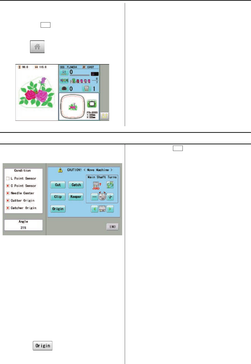
99
4. Please follow instruction of “5-2 Machine Movement”.
5. In case you press END at above display, return to Menu
display.
If you press button once more, return to drive
mode.
5-2 Machine Movement
1. Refer to [ 5-1 How to enter “User Maintenance Mode” ]
and enter to User Maintenance Mode.
2. Press oen of button on control panel and check machine
movement.
< Note > The machine moves quickly.
please be carefull that all head move at once.
machine show following message when you press key.
C point : Upper shaft is not at C point.
Cut blade : Thread cut blade is not at standby
position.
Thread Catcher : Thread Catcher is open position.
Please press for back to standby potion and
repeat step 2 again.
3. When you press END, close user maintenance mode
and return to Menu mode.
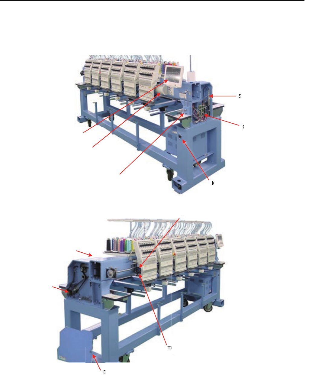
E1 Placement of key electronic parts
Timing Circuit Board
Seiral Port
CONT-R2 board
Bobbin Thread Winder
Control Box
Main Switch
Brake
Main Motor
Brake Release Switch
Thread Catcher
Jump Unit
r
B
J
Th
M
C
S
100
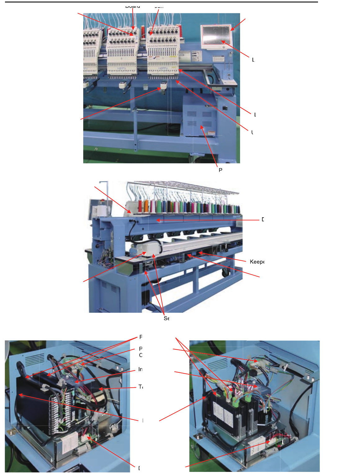
101
Core module
LCD-CE-U board
LCD unit
Keeper Unit
Upper Thread Holder
TC7-8 Circuit Board Jump SW Circuit Board
Head SW Circuit Board
Power Supply Box
Laser Position Marker
Keeper Relay Circuit Board
Needle Bar Changing Unit
X Motor Y Motor
Detection Circuit Board
Sensor Relay Circuit Board
Inverter Unit
PM Driver
DC Power Supply
Transformer
Power Relay
Circuit Board
Keepe
Y
K
D
Se
um
Ju
Board
L
LC
L
L
P
U
Fan
d
D
n
P
T
P
C
T
T
T
n
P
T
P
C
T
T
I
C
I
Tr
F
T
T
T
T
T
Before Rev. A Rev. A
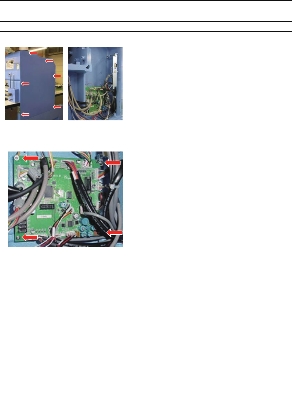
102
E2 Exchange and Setting of electric related component
<note> Please take electric plug, when you exchange electric component.
E2-1 Exchange of CONT-R2 board
1. Take mission cover out.
2. Take all connector out and exchange CONT-R2 board.
3. Fix screws and connect all cable which are taken.
4. Make adjustment from step 1 to 5 as below, or follow
the instruction [E5-8 Machine Setting Navigation after
exchanging CONT board (Main program Ver.*1.34~)],
then the procedure of Exchange of CONT-R2 board is
complete.
(1)E5-5Machine setting
(2)E4-2Machine program update
(3)E4-3,E4-3aMain program update
(4)E5-6Frame Position Entry-Registration of
coordinates for positioning sensor
(5)E4-4Initializing of machine speed
CONT-R2
BOARD
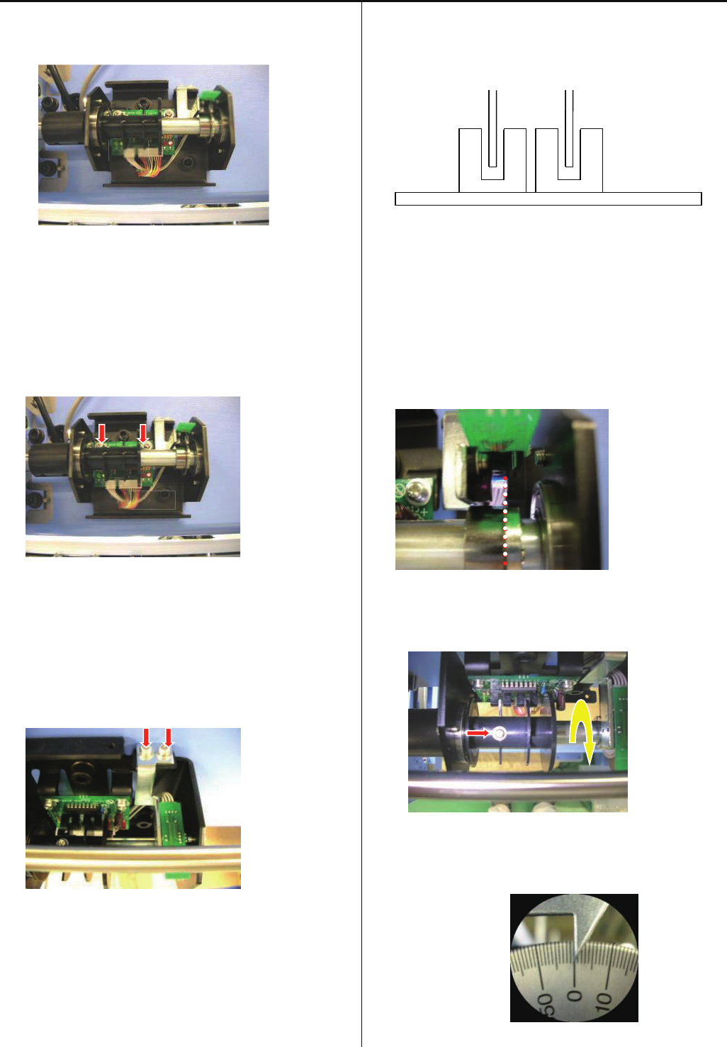
103
E2- Exchange Timing Circuit Board
1.Timing Circuit Board consist with two part(A and B).
2.Take A part out
Unscrew 2 screws, then take C cable and D harness out
3.Take B part out
Unscrew 2 screws
4.Replace A part
Fix by screws, and set cable and haeness
<note> Slit should be set between sensor
5.Replace B part
Fix by screws
<note> Slit should be between sensor. Be careful for
handling of slit, because slit is thin and soft.
6.Loosen screw for Slit and make it free from shaft
7.Turn main shaft and set [0 degree(L point)]
A
B
D C
SLIT
SENSOR
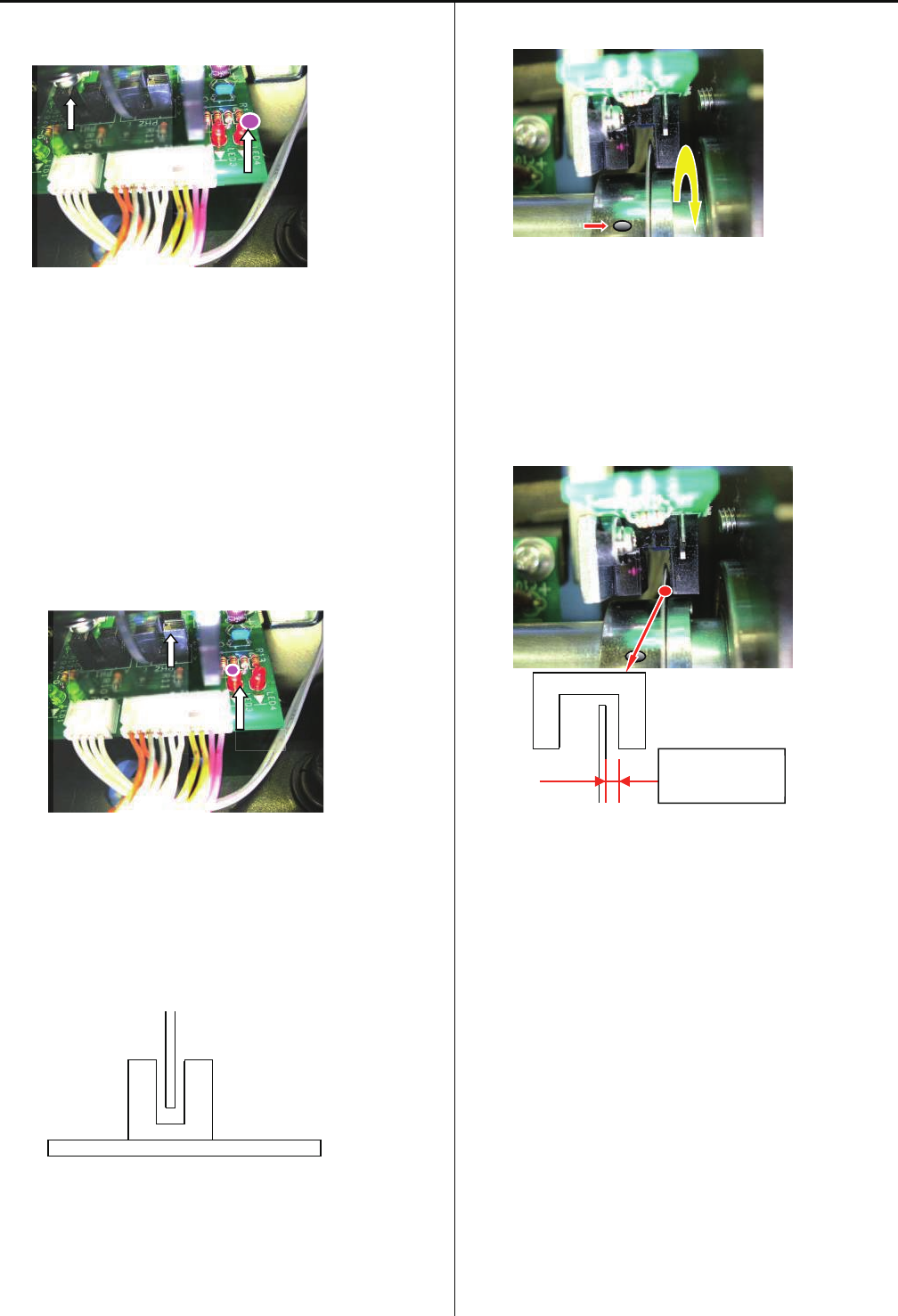
104
8.Turn Slit clock-wise(see from scale side) and fix by screw at
the point which LED 4 is turned off.
9.After fixing Timing Circuit Board, Turn Main shaft and check
if LED 4 is turned off at 0 dgree of main shaft
10.Turn main shaft counterclockclock wise(see from scale
side), and confirm LED 3 is turned on at the C
Point(270-284 degree)
11.Control that slit does not touch sensor
12.Loosen screw and make Timing Slit free to turn
13.Keep space 0.7+ -0.2mm between Timing Slit and Sensor,
and fix
<note> Be careful for handling of slit, because slit is thin and
soft.
LED3
C POINT SENSOR
0.7(+ -0.2)mm
LED4
L POINT SENSOR
Sensor
SLIT

105
E2-3 Connection of Detection Circuit Board
CN6 on Detection Circuit Board has different way of
connection for each head.
Please attention to following information.
1.For Head with emergency stop SW->TC-EMG harness
2.For Head without emergency SW->white loop harness
3.For last Head->Red loop harness
After connect all, please check if emergency SW works
correctly.
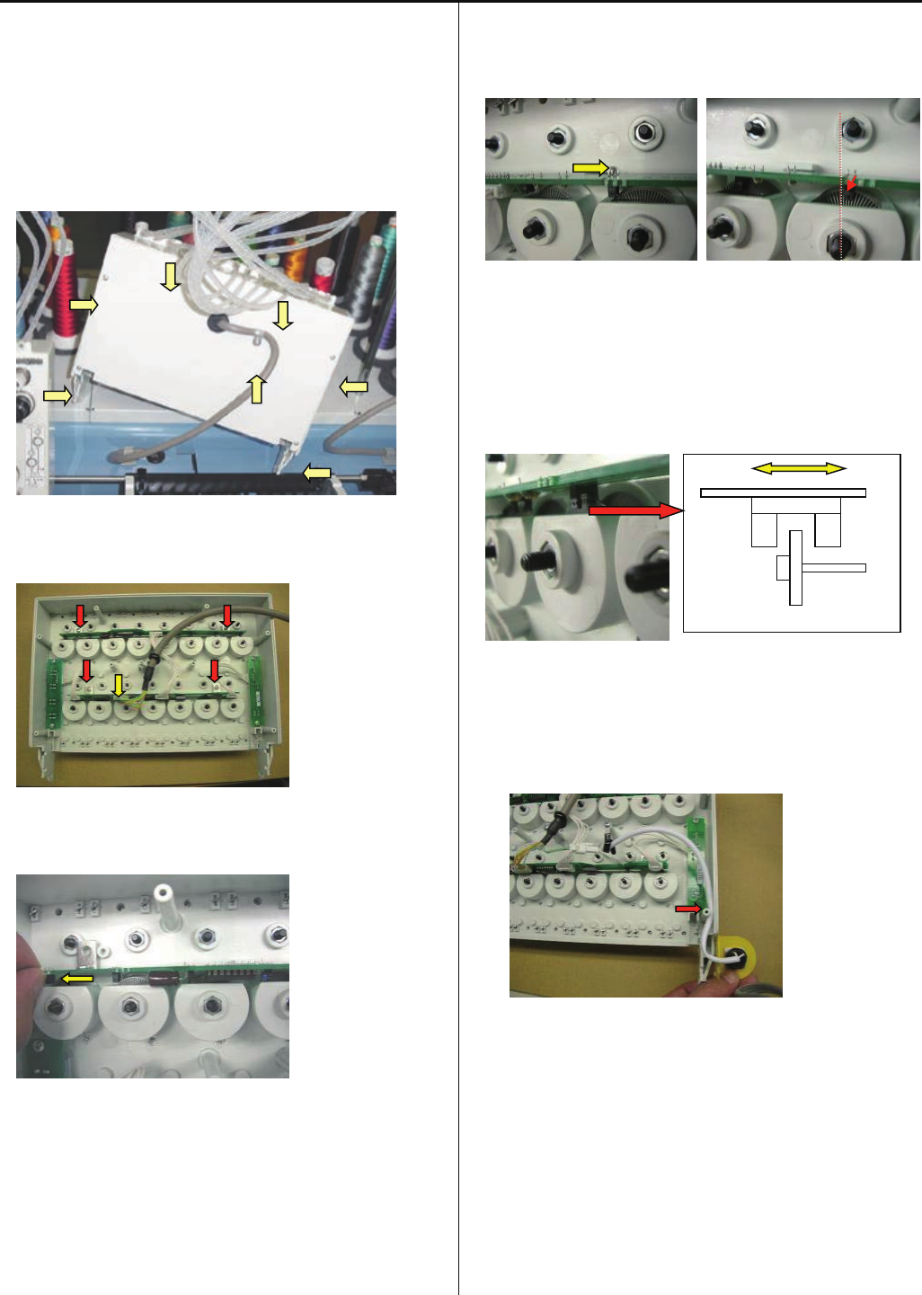
106
E2- Exchange TC7-8 Circuit Board
1. Remove the thread tension bracket.
Please refer to [ 4-2-1, 4-2-2 Assemble and remove
moving head ].
2. Take cover out from moving head by unscrew 7 screws.
3. Take harness and screws out.
4.Slide board and take out.
<note> Do not pull without sliding, Sensor may be broken.
5. Insert Board into guide and slide and adjust sensor position
to be center of slit.
6. Check that sensor is not touching to slit.
Fix by screw and connect harness.
<note> The Front led cord and cable for emergency sw has
to pass as below photo.
7. Set cover and Install Thread tension bracket.
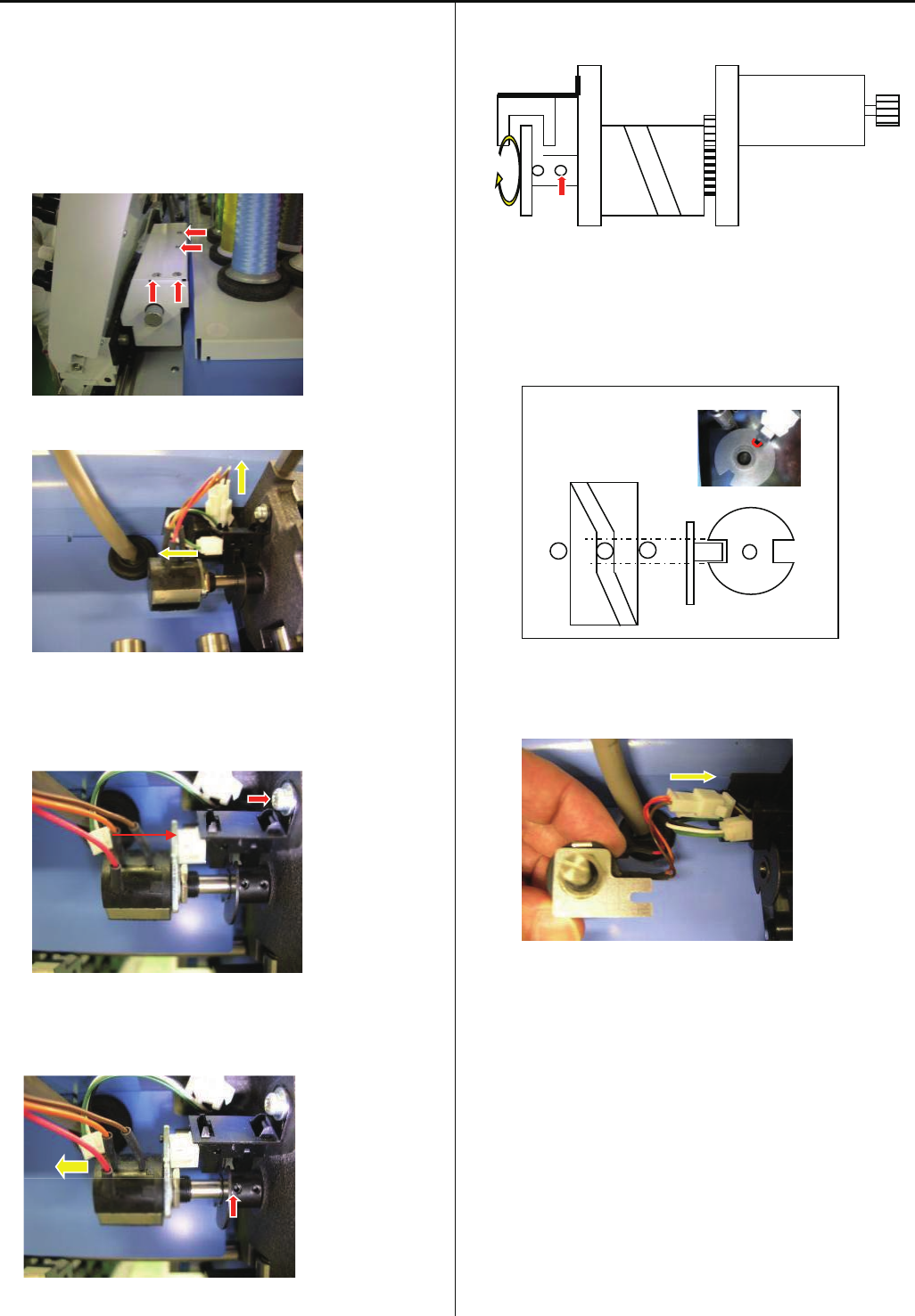
107
E2- Exchange needle stop sensor and potentiometer
1. Move head position to needle no.15 by head moving knob
2.Unscrew and take cover out
3. Take 2 connectors out
4. Unscrew and take Sensor
Set new sensor and fix by screw and connector
5.Loosen screw and pull potentiometer out
6.Loosen slit collar fixing screw and make slit collar free to
turn
7.Adjust notch position of slit collar to be sensor, and cam
position where moving head does not move
8.Connect harness of potentiometer
9. Enter maintenance mode, referring to [ E5-1 How to enter
maintenance mode ]
Sensor
Potentiometer
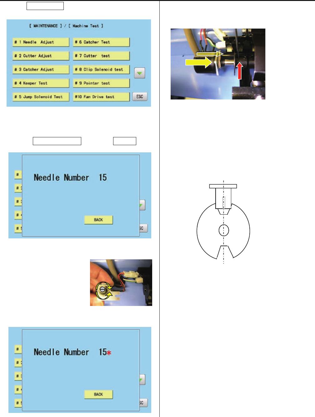
108
10. Press MachineTest.
11. 7. Press #1NeedleAdjust and press Position.
12. Turn shaft of potentiometer
and set position where * mark
and needle number (15)
appear on screeen with
sound.
13.Set potentiometer and fix
<check>
Sensor is located at notch center of slit collar and * mark
is shown on creen
The position of sensor is not lacated at notch of slit collar,
re-adjust again
14. Turn knob and move head to 1st needle position
<check>
* mark appears, when notch center of slit collar comes
sensor position. If position is not matching, please re-adjust
again
Sensor
Slit
Center
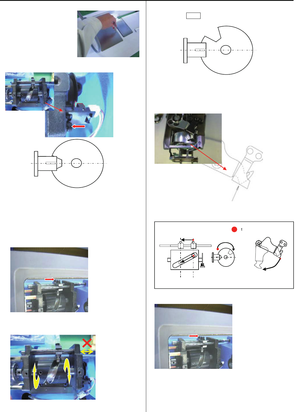
109
E2-6 Exchange Thread trimming sensor
1.Take table cover out
2.Exchange sensor and connect haeness
<note> Sensor should place at center of slit
3.Loosen Cap screw (1pc)
4.Turn CAM and confirm that shaft is not moving
5.Turn CAM and set sensor position is out from slit. Power on
and press NEXT on control box
6.CAM turns and stops at stopping position automatically.
Check postion of moving knife
Position of Moving knife and fixed knife
7. Fix Cap screw
Set cover
Sensor
Slit
Sensor
Slit
Sensor
CAM
stopping position
s
Relation of CAM and Knife
SENSOR&SLIT KNIFE ASS’Y
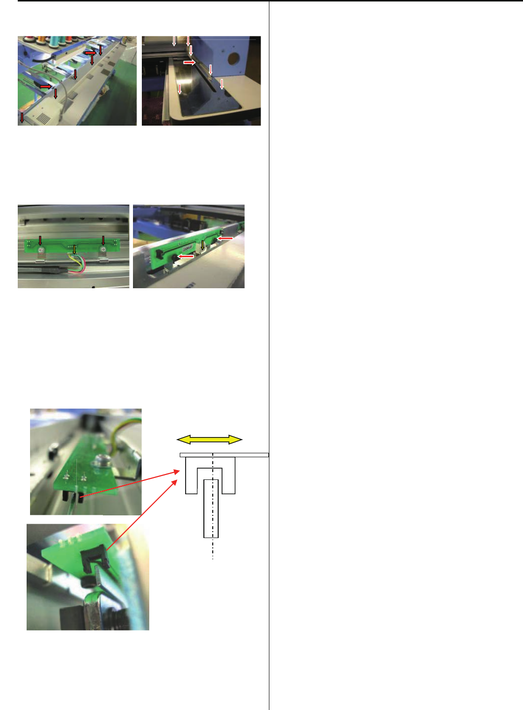
110
E2- Exchange X-Y Position Sensor
1.Unscrew and take cover out
2.Unscrew and take Position Sensor Circuit Board. Then take
harness out
3.Replace Board and set harness, and fix by screw
<note> Adjust postion of detecting plate to be center of
sensor
4.Set cover
5.Set coordintes
Refer [E5-6 Position- Registration of coordinates for
positioning sensor]
X Sensor
X Sensor
Y Sensor
Y Sensor
X Sensor
Y Sensor
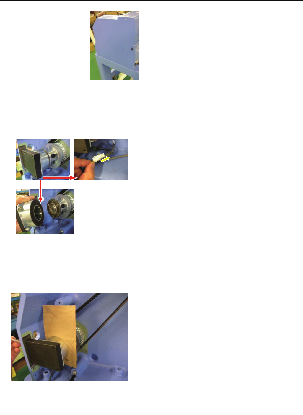
111
E2- Exchange Brake Unit
1. Take reft rear table.
Take mission cover (left side)
out.
2.Take connector out
Unscrew and take brake solenoid
3. Put 0.1-0.15mm paper between brake solenoid and brake
disk, and fix brake solenoid by screw
4.Take paper out and set cover, set reft rear table.
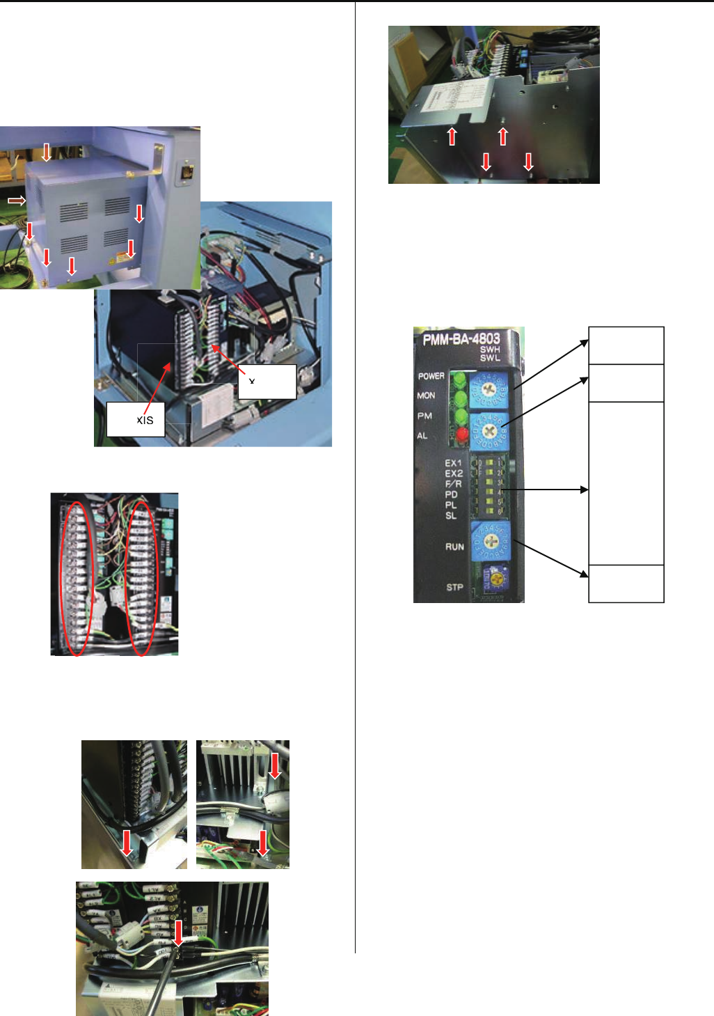
112
E2-9 Exchange Pulse Motor Driver (Before Rev. A)
<note>
Before starting the following work, please take electric power
cable out
1.Take box cover out
2.Take harnesses out from driver
3. Take AC100V connector out.
Unscrew 4 screws on base plate.
4. Unscrew from reverse side of base plate
5. Check setting of new driver(same setting for X and Y)
<note> Driver is same as one for HCR, but setting is different
6. Fix driver by screws and connect harnesses, and put cover.
Detail information about harnesses conenction is mentioned
in [E7-1 Pulse motor driver (PMD) wiring]
SWH 1
SWL E
RUN 0
EX1 ON
EX2 ON
F/R OFF
PD ON
PL OFF
SL ON
Y-AXIS
X-AXIS
XIS
X
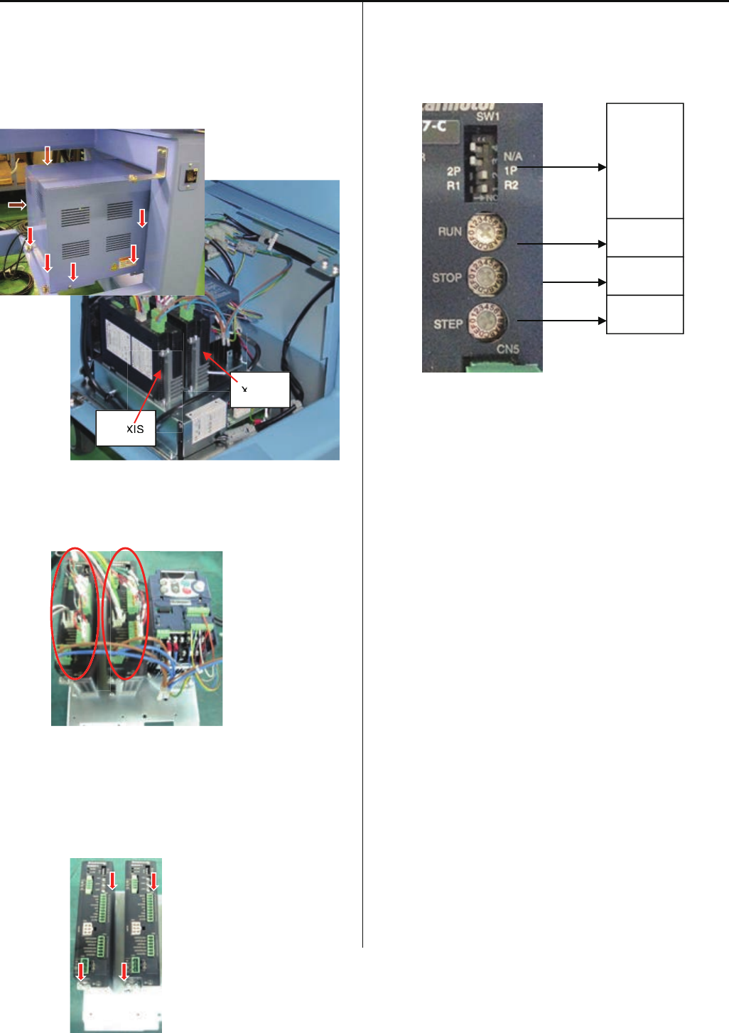
113
E2-10 Exchange Pulse Motor Driver (Rev. A)
<note>
Before starting the following work, please take electric power
cable out
1. Take box cover out
2. Take harnesses out from driver.
3. Unscrew 4 screws on base plate
4. Check setting of new driver. (same setting for X and Y)
5. Fix driver by screws and connect harnesses, and put
cover.
Detail information about harnesses conenction is
mentioned in [E7-1 Pulse motor driver (PMD) wiring]
Y-AXIS
X-AXIS
XIS
X
RUN A
STOP 2
STEP 5
4 OFF
3 OFF
2 ON
1 ON
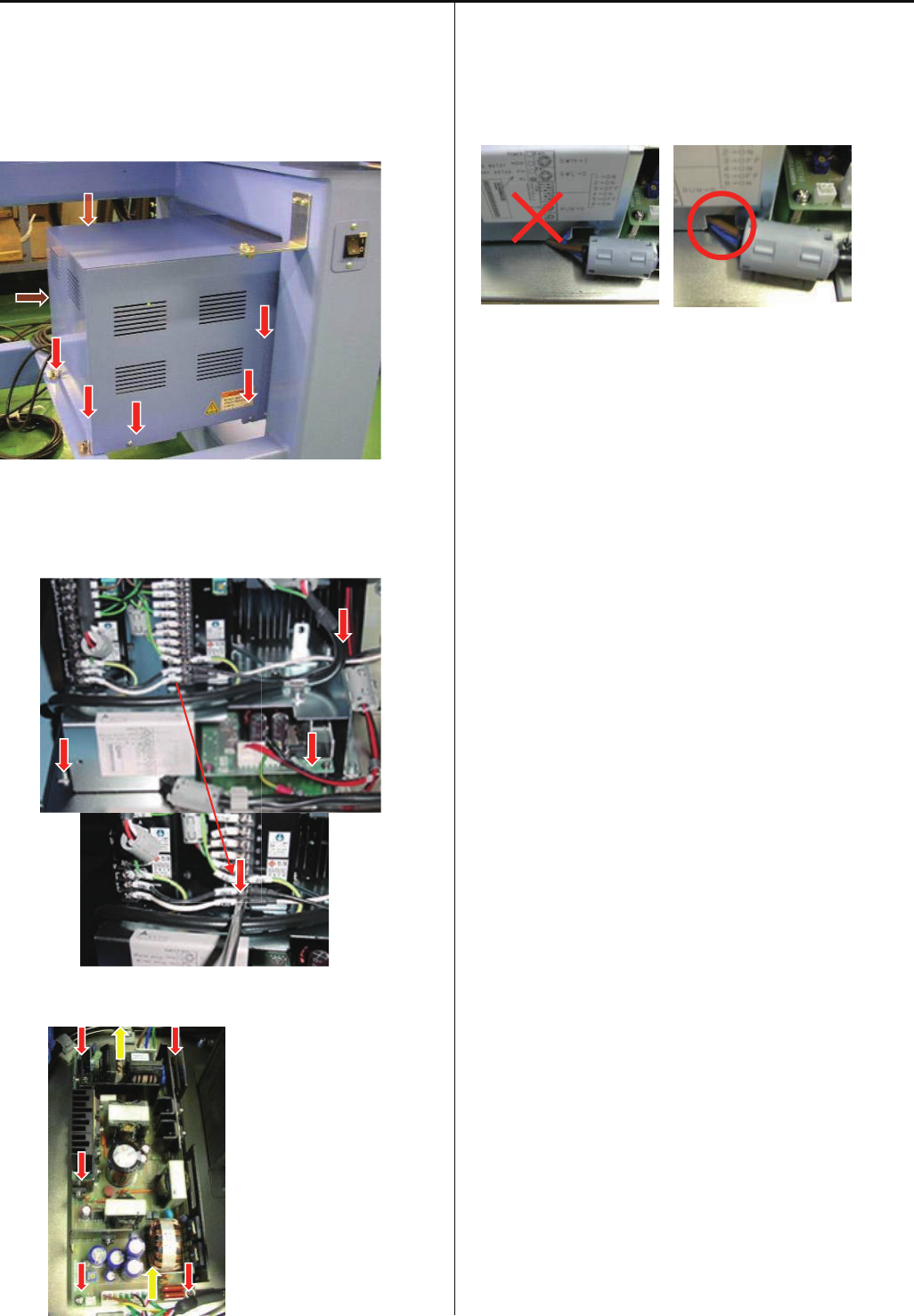
114
E2-11 Exchange Switching Power Supply
<note>
Before starting the following work, please take electric power
cable out
1. Take box cover out
2. Take AC100V connector out. (Before Rev. A)
Unscrew 4 screws on base plate.
3.Switching Power Supply locates under base plate
Unscrew and teke connector out
4.Replace Swicthing Power Supply and fix screw and
connector
<note> Harness should not get caught
5.Refer [E2-12 Adjustment of Voltage for Switching Power
Supply] and adjust voltage setting
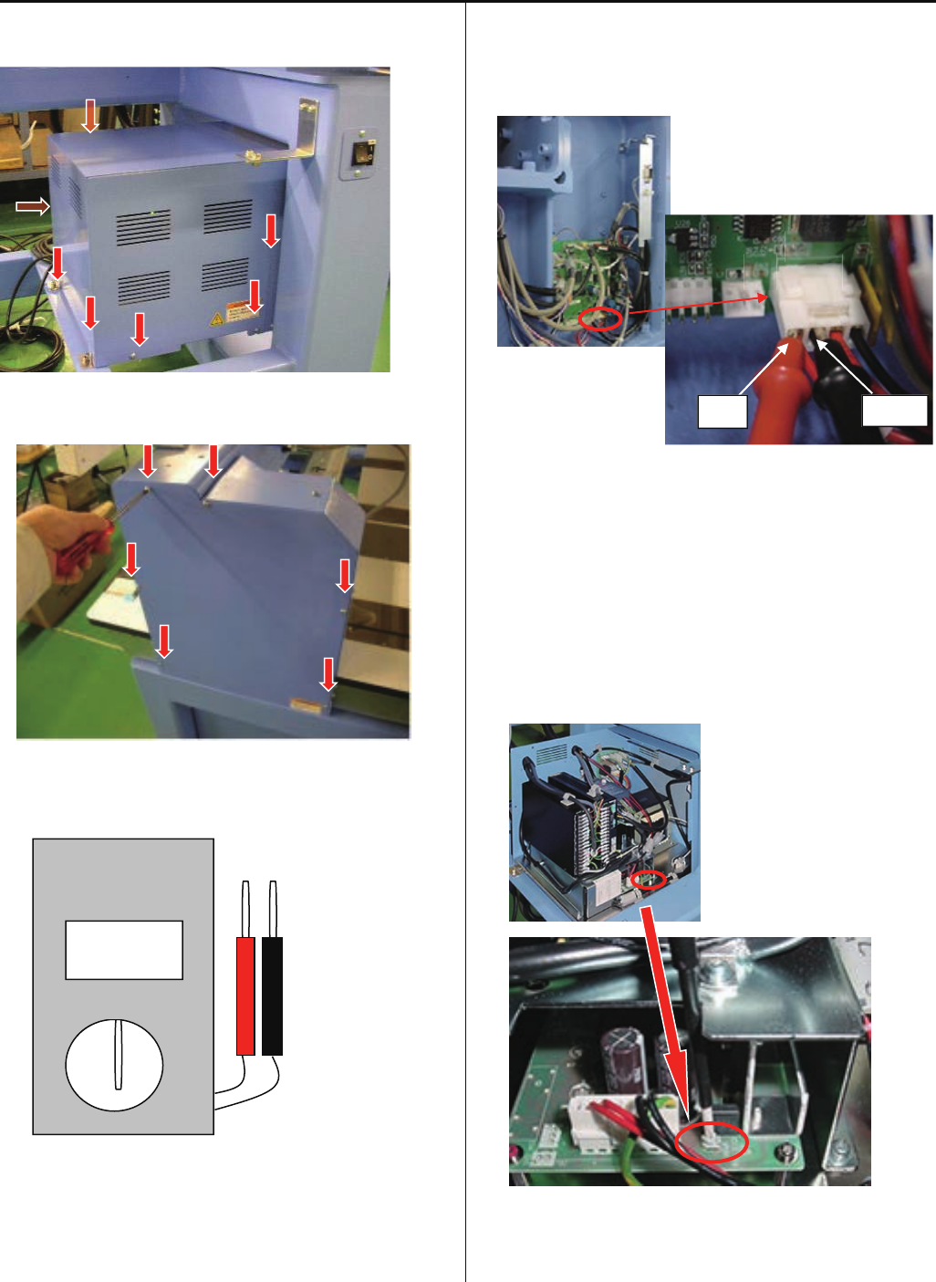
115
E2-12 Adjustment of Voltage for Switching Power Supply
1. Take box cover out.
2. Take mission cover(right side) out.
3.Set [DC] of degital tester.
4. Put tester into CN28 of Drive B board.
<note>
*Tester(red) to be put into no.1 of CN28
*Tester(black) to be put into no.2 of CN28
5. Power main switch on, and turn VR(volume) on Switching
Power Supply and set [24.0V+-0.1V] .
Set cover
0V
DC
AC
DIGITAL
MULTIMETER
RED BLACK
CN28
1 4
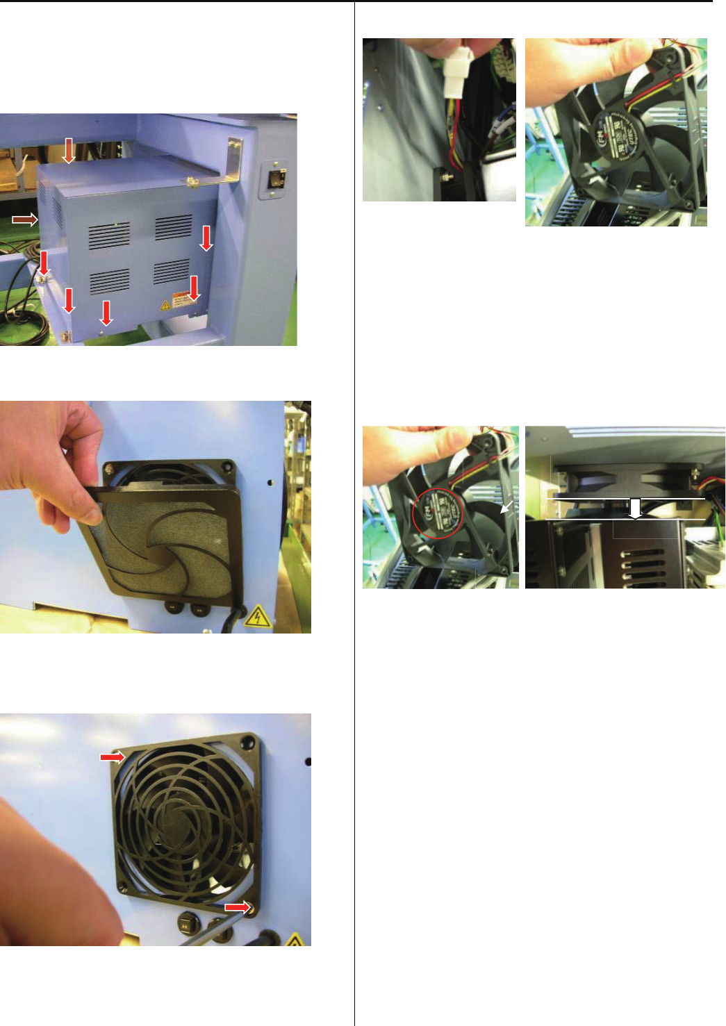
116
E2-14 Exchange Cooling Fan
<note> Before starting the following work, please take electric
power cable out
1. Take box cover out
2. Take filter out
3. Unscrew fan cover (note: nut is on reverse side)
4. Take connector out, then take fan out from box
5. Replcae fan and connect all connector and fix
<note1> Direcetion of fan: Label side is front
<note2> Check that fan is not touching to any other part
<note1> <note2>
6 .Put cover
AIR
FRONT
BACK
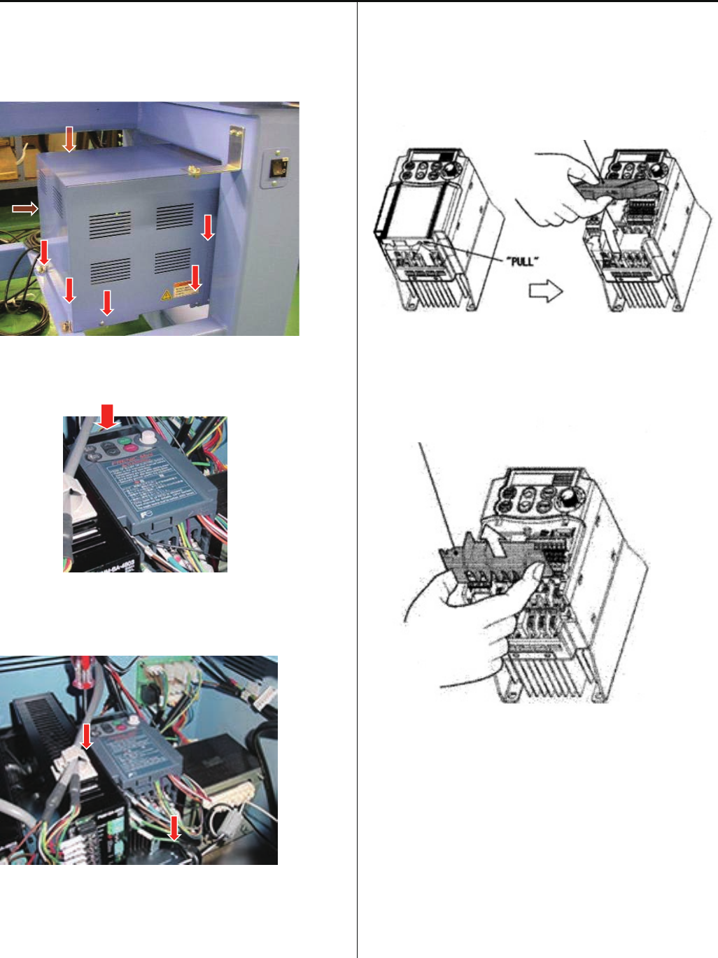
117
E2-15 Exchange Inverter
<note> Before starting the following work, please take electric
power cable out
1. Take box cover out
<check>Display is off
2. Take all harnes out, take inverter out.
3. Remove control terminal cover.
Insert fingers in a gap (under the “PULL” indication) on the
underside of control terminal cover, and pull the cover
toward yourself and remove it.
4. Remove main terminal cover
Hold both left and right ends of main terminal cover with
fingers and slide the cover toward yourself and remove it.
5. Set new inverter and connect harness, and fix
Pefer [E7-2 Inverter wiring] for detail information of
harness connection
6. Put cover
7. Referring to [E4-4 Setting of revolution],
Perform[Initializingofmachinespeed].
Control terminal cover
Main terminal cover
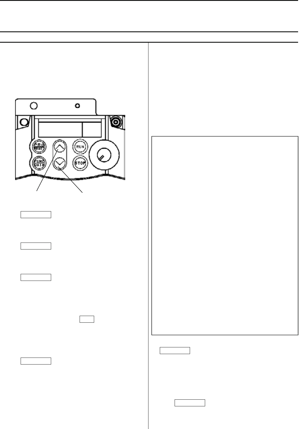
118
E2-16 Setting Inverter
In case of spare parts supply, parameter is preset. Please contact HAPPY, when you need to change it.
Parameter cannot be set while machine is running . Pay attention to electric wires as setting is done with power is on.
E2-16-1 Parameters release the keep off setting and Parameters setting
How to release the setting change prohibition
Release the prohibition by following the procedures below
since parameter is set as setting change prohibition.
1. Press PRG/RESET.
[ I.F _ _ ] is displayed.
2. Press FUNC/DATA.
[ F 0 0 ] is displayed.
3. Press FUNC/DATA again.
[ 1 ] is blinking.
(This means setting change is prohibited.)
4. Press Down key while pressing STOP.
[ 0 ] is blinking.
(This means you can change settings.)
5. Press FUNC/DATA.
After [SAVE] is indicated,
[ F 0 1 ] is displayed.
By above process, you will be able to set parameters.
Next, change each setting.
6. Press Up key and function code is displayed. Select the
function code whose parameter you would like to change.
(Press Down key and the function code returns to the
previous code.)
The following table shows function codes, setting details, and
factory default setting. Functions other than described below
are initial setting of inverter.
Refer to the next clause for the method of initial setting.
7. Select the code you would like to change and press
FUNK/DATA.
Parameter of the function is displayed.
8. Change parameter by pressing Up or Down key.
9. Press FUNK/DATA.
After [SAVE] is displayed, the next function code is displayed.
This means change of the function code is made.
Up key
Down key
Code Function
→
Setting
F00 Prohibition of change→ 1 (Protect)
F01 Frequency set mode→ 1
F02 Drive / Operation → 1
F03 Maxmum frequency → 100.0
F05 Base frequency voltage→ 200
F07 Acceletion time 1 → 1.2
F08 Deceletration time 1 → 0.7
F09 Torque booost → 11.0
F11 Motor thermal protection→ 2.30
F15 Upper limit freq. limter→ 100.0
F20 DC brake. Starting freq.→ 1.5
F21 DC braking current → 20
F22 DC braking time → 1.0
F23 Start frequency → 0.5
F26 Carrier frequency → 6
F27 Tone → 1
F37 Load selection → 1
C05 Multi stage frequency 1→ 2.6
C33 Analog input filter → 0.05
C34 Analog input adjustment→ 50.0
C50 Bias frequency → 3.0
P02 Motot capacity → 0.40
P03 Motor rated current → 2.30

119
How to set the prohibition setting
10. After each setting is done, select [ F 0 0 ] by pressing
Up or Down key to return to setting change prohibition.
11. Press FUNC/DATA.
[ 0 ] is blinking.
12. Press Up key while pressing STOP.
[ 1 ] is blinking.
13. Press FUNC/DATA.
After [ S A V E ] is displayed,
[ F 0 1 ] is displayed.
14. Press PRG/RESET.
[ I.F _ _ ] is displayed.
15. PRG/RESET again.
Return to normal mode.

120
E2-16-2 Initialize parameters
P lease note that you are unable to make this setting while the machine is running.
When setting is mistakenly made in mid way, the setting will return to parameter in normal standard in one action.
Thereafter please change to parameter you want to set.
1. Enable parameter to be changed by referring in [E2-16-1
Parameters release the keep off setting and Parameters
settin].
2. Press PRG/RESET.
[ I.F _ _ ] is displayed.
3. Select [ I.H _ _ ] by pressing Down key 3 times.
4. Press FUNC/DATA.
[ H 0 3 ] is displayed.
5. Press FUNC/DATA again.
[ 0 ] is displayed.
6 Press Up key while pressing STOP.
[ 1 ] is displayed.
7. Press FUNC/DATA.
After [ S A V E ] is displayed,
[0.00 ] is displayed.
The settings of inverter become initial settings.
Then, change parameter and return to prohibition setting by
referring to the previous clause.

121
E3 Open and remove control box
E3-1 Remove control box
<Check> Be sure to turn power switch OFF before work.
1. Take mission cover out.
2. Disconnect the connectors indicated by the arrows in
the figure below. Remove the screw that fixes cables.
3. Remove Clamp filter.
Remove three setscrews on bracket A as shown in
the figure below.
4. Remove control box.
Please reverse procedure when installing control box.
Clamp filter
Standard
10.4”
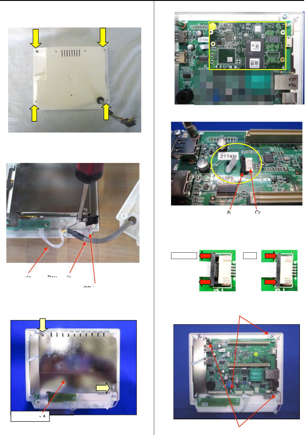
E3-2 Remove LCD-CE board
1. Remove four setscrews as shown in the figure below
and remove rear cover.
2. Remove connectors for SW cable, Box cable, cable for
LCD inverter (red/white).
SW cable Box cable
Cable for LCD inverter (red/white)
3. Remove set screw and sealed case A.
4. Remove core module.
5. Remove narrow flat cable for LCD unit.
Latch Connector
When you pull the latch to cord side, the cord release.
When you push the latch to connector side, the cord
fixed.
Release Fix
6. Remove two sets screws and two studs.
Setscrew
Stud
ble Box
ble
LCD i
Sealed case A
e A
ch
Co
122
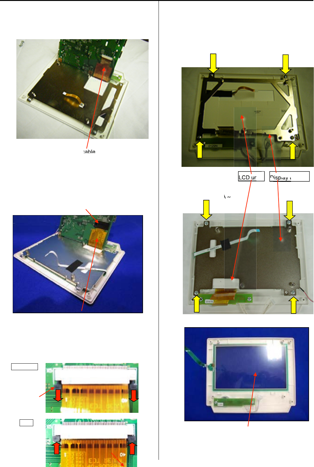
123
7. Lift LCD-CE board as shown in the figure below.
Remove wide flat cable for LCD unit.
Mac. No. ~1011003A
Wide flat cable
Mac. No. 1011007A ~
(
(
When the tape for fixing is stuck on connector, please
peel off.)
)
Connector
Wide flat cable
When you pull the latch to cord side, the cord release.
When you push the latch to connector side, the cord
fixed.
Release
Latch
Fix
8. Remove four setscrews and LCD unit.
Mac. No. ~1011003A
Mac. No. 1011007A ~
Remove touch panel.
Please reverse procedure when installing LCD-CE board.
Display bracket
LCD unit
cable
Disp
LCD un
Display b
A
~
LCD un
LCD un
Touch panel
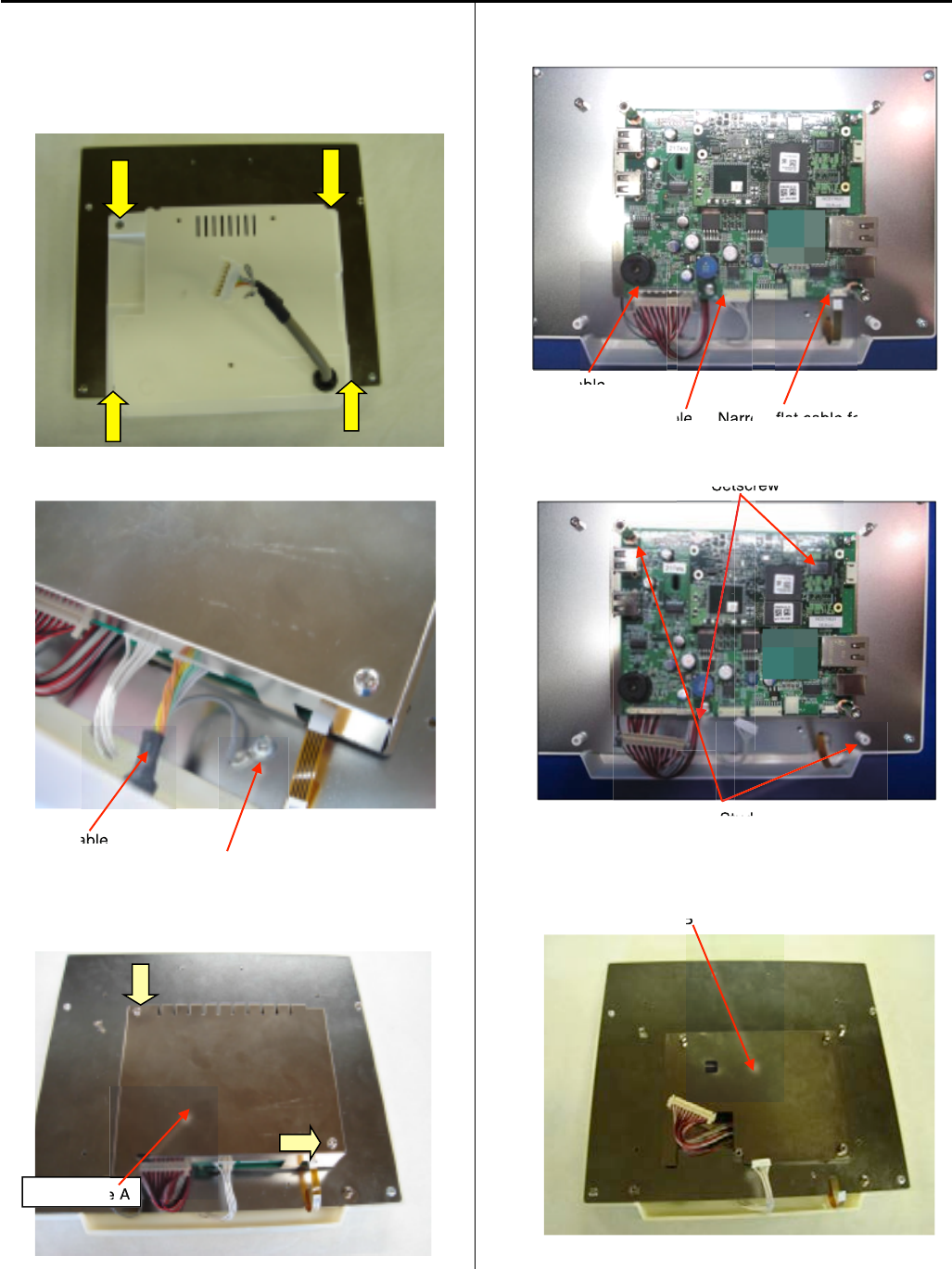
124
E3-2a 10.4” Remove LCD-CE board
1.Remove emergency stop blacket.
Remove four setscrews as shown in the figure below
and remove rear cover.
2.Remove connectors for SW cable, Box cable.
Box cable
Screwforground
3.Remove set screw and sealed case A.
4.Remove connectors.
LVDS cable
SWcable Narrow flat cable for LCD unit
5.Remove two sets screws and two studs.
Setscrew
Stud
6.Remove sealed case B.
Sealed case B
Sealed case A
e A
B
able
able
ble
N
arro
flat cable fo
Set
tscrew
tscr
Stud
St
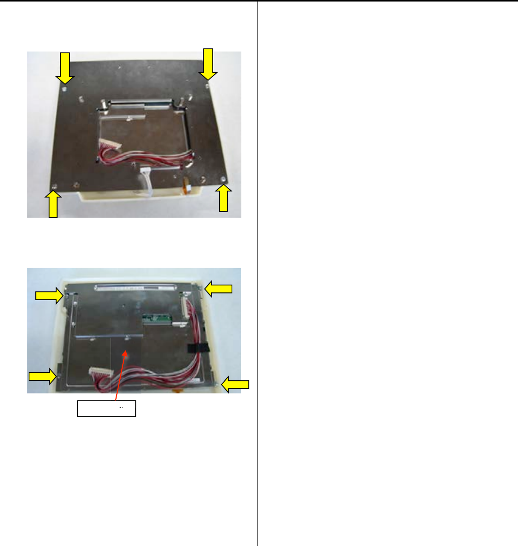
125
7.Remove set screw and rear cover.
8. Remove set screw and LCD unit.
Please reverse procedure when installing LCD-CE board.
LCD unit
it
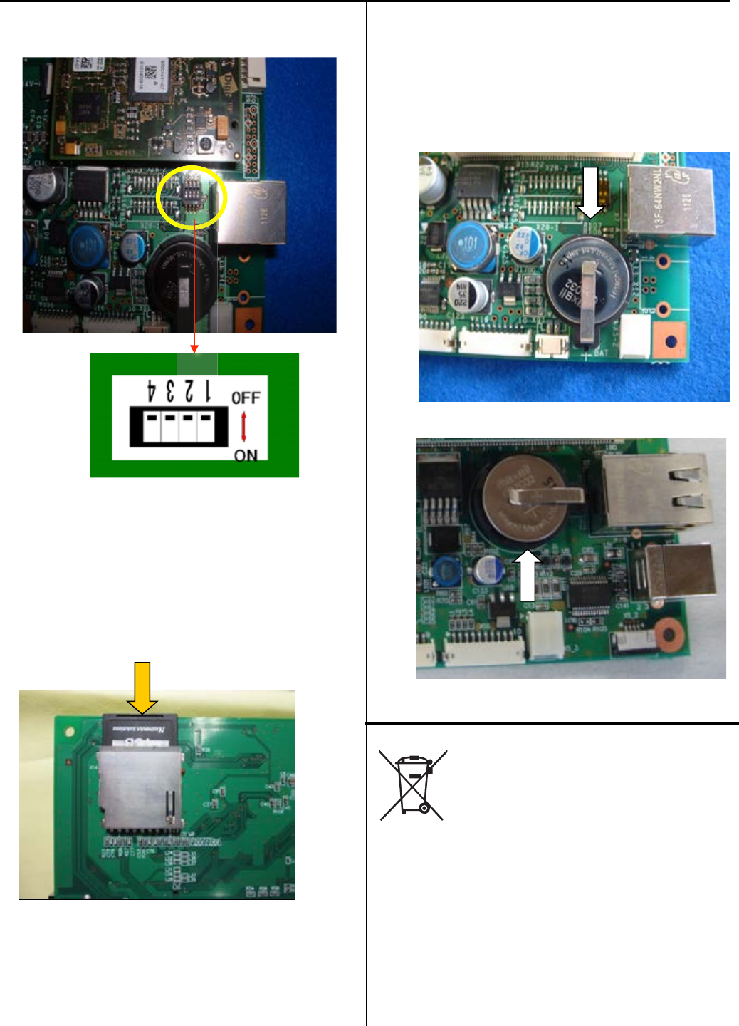
126
E3-3 Setting for LCD-CE board
2DIP switch (LCD-CE-U)
Switch to OFF on all the settings for DIP switch.
Memory card
Insert our official memory card (EPZ01220). Refer to
the latest parts list for the parts number.
This memory card contains programs and data for an
embroidery machine.
<Notice> Please contact us if you need to use third party’s
memory card from local market.
The necessary information will be provided.
Coin battery
Insert our official coin battery (EPZ01190).
Refer to the latest parts list for the parts number.
The battery is used for back-up power source of real-time
clock on an embroidery machine.
Replace new battery if clock dose not indicate the correct
time after setting a clock and turning power switch OFF.
LCD-CE-U
LCD-CE-MX (Mac. No. 〜
〜
1036002A)
Disposal of coin battery of LCD-CE board
Dispose of a coin battery by following the method
specified by each country or each region.

127
E4 Program update procedure
* The sequence of procedures of program update is described below..
If you need more details, please refer to each manual.
1. Insert the updated program downloaded USB memory to the USB port of the machine
with its power turned “OFF”.
Press NEXT while pressing START/STOP button of the control box at the screen after
the machine is booted.
2. Enter maintenance mode and update machine program and main program from the menu.
3. [Replacement of CONT-S2 board]
Register frame position in Maintenance Mode.
4. Press [MENU] button and select [System] in menu of [OTHER] for initialization of system.
5. Press [MENU] button and select [Speed] in menu of [OTHER] for automatic speed setting.
6. [Replacement of LCD-CE board]
Calender setting
7. end of process
E4-2 Machine program update
E4-3 Main program update
E4-4 Setting of revolution
E5-6 Position Registration
of coordinates for
positioning sensor
Initializing of machine
speed

128
E4-1 Preparation for program update
* Download updated program file and decompress the file.
Program
for HCD2, HCS2, HCH, HCR2 " "MainProgramA**** "
*Copy the decompressed file(s) or the folder that contains decompressed file to USB memory.
File names on your PC are shown below:
Program for HCD2, HCS2, HCH, HCR2 " UpDateFile"
<NOTE 1>
・Copy the program to the root folder of USB memory.
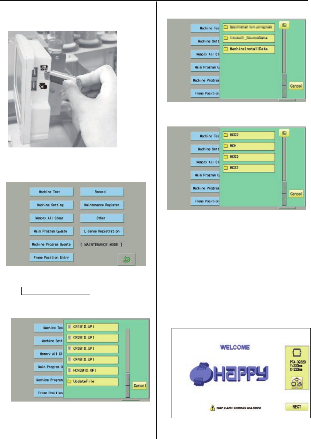
129
E4-2 Machine program update
1. Insert USB memory that contains data for version up into
insertion slot on the control box.
2. Refer to [ E5-1 How to enter maintenance mode]
and enter maintenance mode. The screen shows below:
3. Press Machine Program Update.
The screen shows contents of the USB memory.
4. Select [UpdateFile].
5. Select [MachineInstallData].
6. Select the machine model.
Installation of program begins.
After successful installation, the display will return to step
no.2.
<NOTE>
* Please do not take out USB memory during installation.
* Please do not turn off the power during installation (it will
take for a while for completion of installation).
7. Turn OFF the power and then turn ON the power.

130
8. Press NEXT.
9. Referring to [E4-4 Setting of revolution],
Perform[Re-Initializationofmachinesystem]
And[Initializingofmachinespeed].
・* End of process.
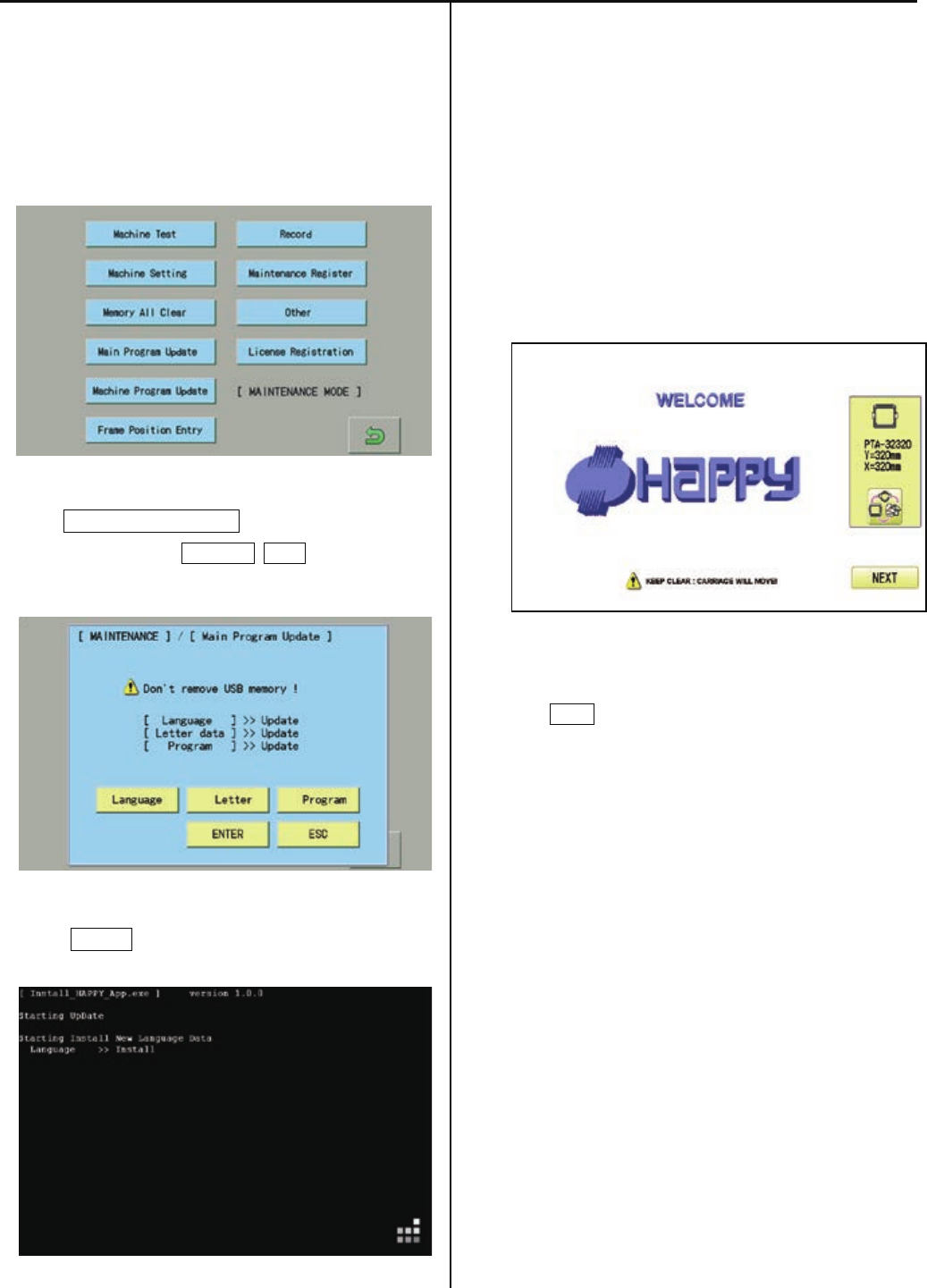
131
E4-3 Main program update (Main program 〜Ver.*1.21)
1. Insert USB memory that contains data for version up into
insertion slot on the control box.
2. Refer to [ E5-1 How to enter maintenance mode ] and enter
maintenance mode. Display comes as below.
3. Press Main Program Update.
Select 3 items such as Language, Letter and and make
the screen show “Update” on each item.
4. Press ENTER.
Installation of program begins.
<NOTE>
* Please do not take out USB memory during installation.
* Please do not turn off the power during installation (it will
take for a while for completion of installation).
Retry updating when the screen shows “Error” due to
writing error.
Once update id complete, the machine will be rebooted
automatically.
5. Press NEXT button.
6. Referring to [E4-4 Setting of revolution],
Perform[Re-Initializationofmachinesystem]
And[Initializingofmachinespeed].
* End of process.
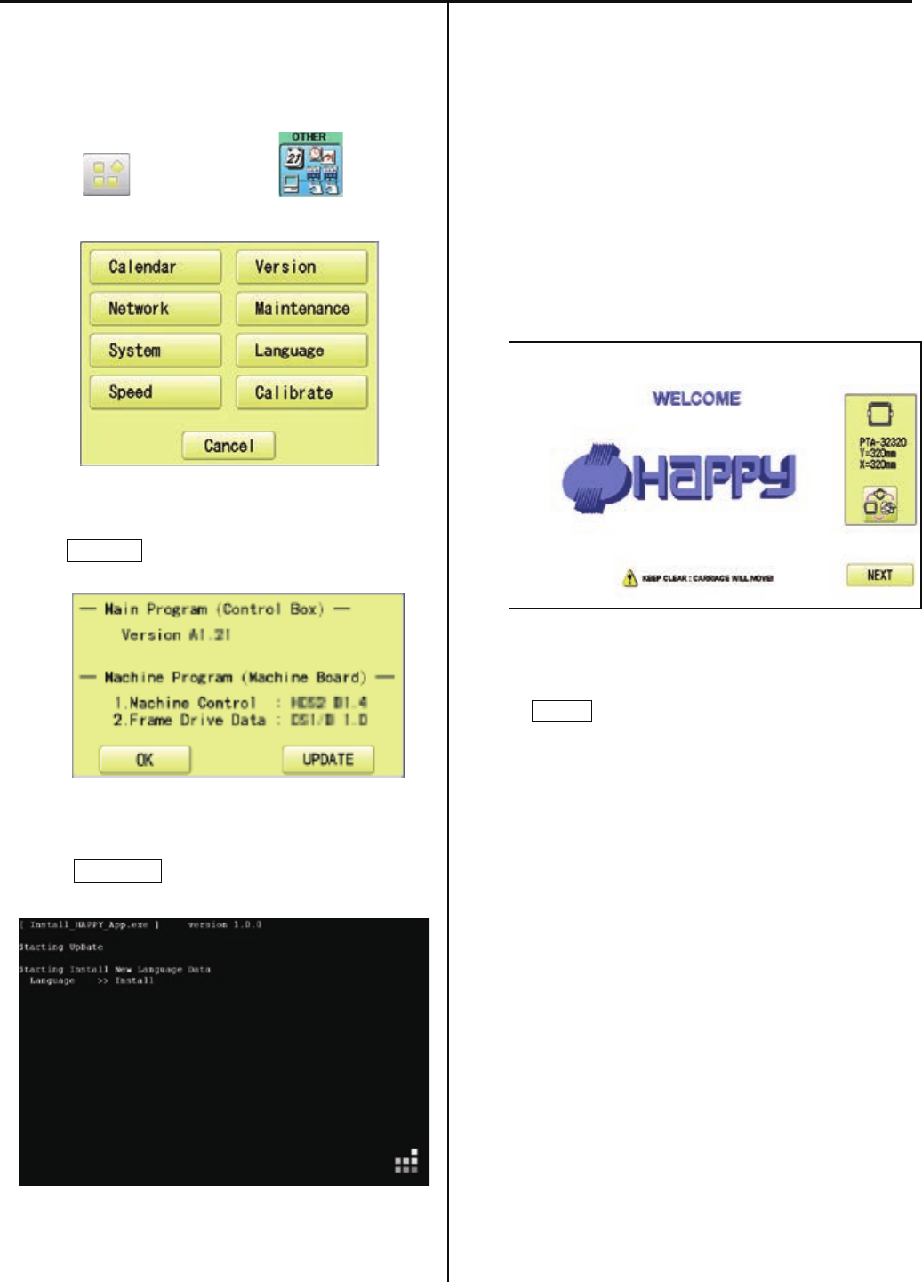
131a
E4-3 Main program update (Main program Ver.*1.22〜)
1. Insert USB memory that contains data for
version up into insertion slot on the control box.
2. Press (MENU) and press (OTHER).
3. Press Version .
4. Press UPDATE .
Installation of program begins.
<NOTE>
* Please do not take out USB memory during installation.
* Please do not turn off the power during installation (it will
take for a while for completion of installation).
Retry updating when the screen shows “Error” due to
writing error.
Once update id complete, the machine will be rebooted
automatically.
* Press NEXT button.
10. Referring to [E4-4 Setting of revolution],
Perform[Re-Initializationofmachinesystem]
And[Initializingofmachinespeed].
* End of process.
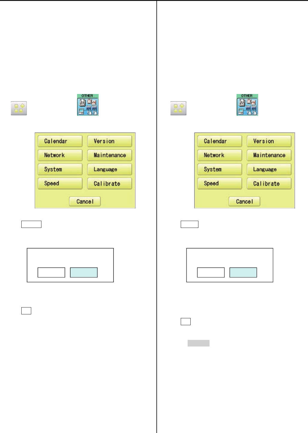
132
E4-4 Setting of revolution
Re-Initialization of machine system
Perform this function only to fix problems with the machine.
When performed, all settings in the “OPTION” menu are lost.
Be sure to reset the “OPTION” menu after performing this
function.
1. Turn on the power. After the program start up, press
(MENU) and press (OTHER).
2. Press System .
3. Press OK .
Formatting of the machines systems are carried out.
Indicate HAPPY logo in screen.
End of process.
Initializing of machine speed
Setting of revolution of main shaft, which is suitable to the
machine is required.
If setting is not done, the revolution may not speed up.
1. Turn on the power. After the program start up, press
(MENU) and press (OTHER).
2. Press Speed .
3. Press OK .
Main shaft adjusts its revolution speed automatically.
Message complete will be displayed when setting is
finished and it goes back to drive mode.
End of process.
System initialize OK?
Cancel OK
Speed setting OK?
CAUTION! <Main shaft turns>
Cancel OK

133
E5 Maintenance mode
Maintenance mode consists of items as shown below.
Machine Test Movement test, maintenance, and adjustment
Machine Setting Machine control setting
Memory All Clear Initialization of design memory.
Main Program Update Update of operation program and language data
Machine Program Update Update of control program and frame move data
Frame Position Entry Registration of coordinates for positioning sensor
Record Total number of stitches, Error occurrence record, Occurrence record by error type.
Maintenance Register Registration of machine maintenance date(Normally not used at maintenance)
Other Other (This item is neither configured nor used.)
License Registration Limited usable period
Replaced CONT Board Machine Setting Navigation after exchanging CONT board (Main program Ver.*1.34~)
E5-1 How to enter maintenance mode
1. Turn on machine.
2. Press NEXT while pressing START/STOP button at
the screen of the control box after booting the machine.
Main program Ver.*1.34~
3. Press .
You can enter maintenance mode again by long key press
of (Menu) at the Drive screen after maintenance mode
is finished.
However, you cannot use the reentry method above once
the machine is turned off and rebooted.
Ver
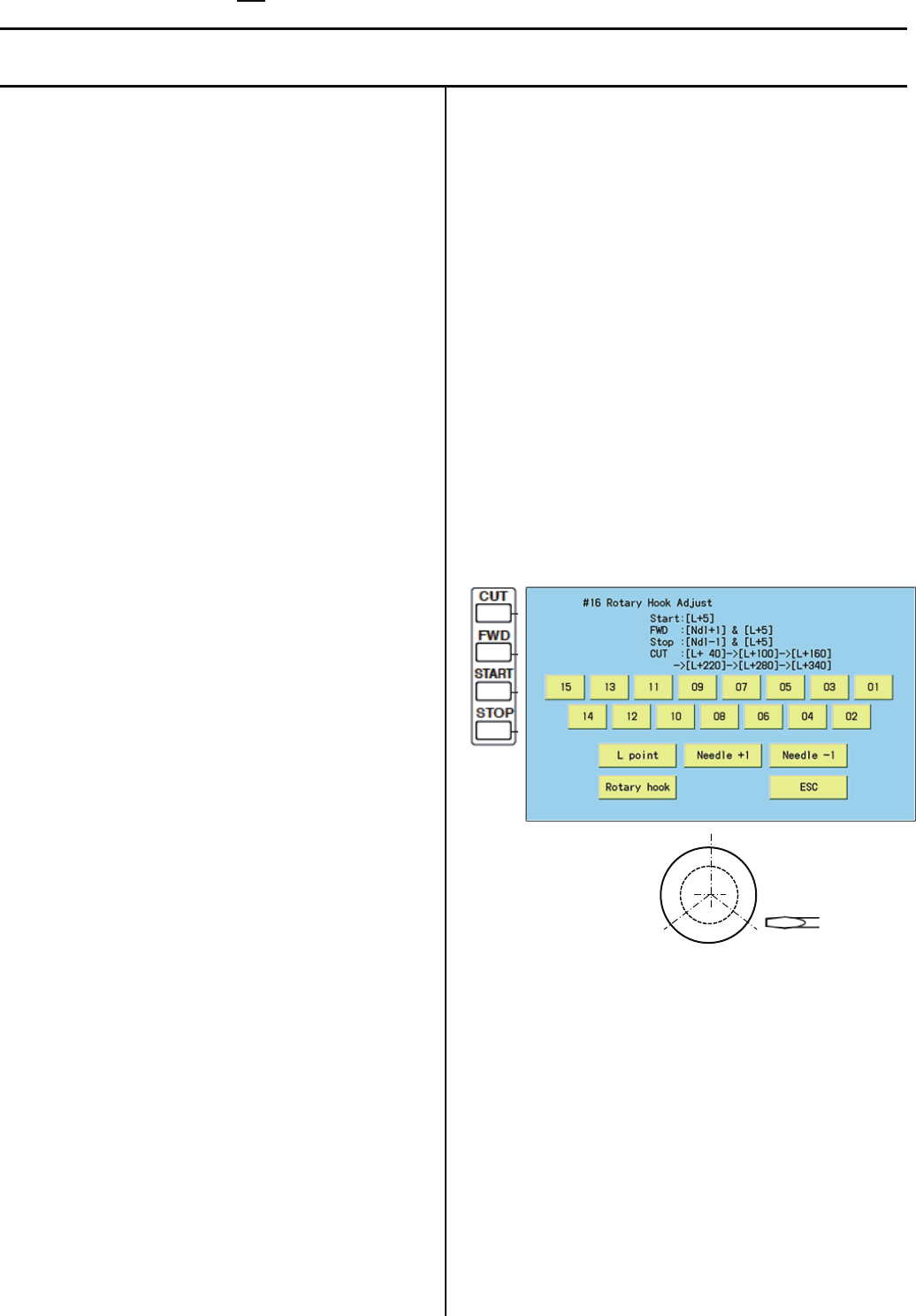
134
E5-2 Machine Test Machine movement
Below operation will be moved solely. In some operations, actuator of motor will be moved, Keep hands and face away during
movement for your own safety.
#1 Needle Adjust : Input of Needle bar detect Potentiometer
At section of [Setting to detect needle position], this
function can be used to set position of Potentiometer.
#2 Cutter Adjust : Action test of moving knife Open-Close
Use this function to adjust stop position of Moving knife.
#3 Catcher Adjust : Action test of Thread catch hook
This test is used to adjust stop position of Thread catch
hook.
#4 Keeper Test : Action test of Keeper solenoid ON-OFF
This test is used to check action of Keeper.
#5 Jump Solenoid Test : Movement test of jump device
ON-OFF.
This test is used to check movement of Jump device.
#6 Catcher Test : Movement test of thread catch hook
IN-OUT
Use this test to check movement of Thread catch hook.
#7 Cutter Test : Action test of moving knife Open-Close
Use this function to check opening-closing action of
Moving knife.
#8 Clip Solenoid : Action test of clip type thread holder
(Option)
This test is used to check movement of clip type thread
holder.
#9 Pointer Test : Action test of laser pointer (Option)
This test is used to check action of Laser pointer.
#10 Fan Drive Test : Action test of cooling fan ON-OFF
Use this function to check movement of cooling fan.
#11 Encoder Check : Input test of L point / C point timing
With turning main shaft, you can use this function to
check if L point signal, C point signal, and timing signal
are correct or not.
#12 Position Data Entry : Position Data Entry Confirm frame
moving sensor
This test is used to check action of Frame moving
sensor.
From Main program Ver.*1.34~, the Pulse motor will be
un-locked when you activate the test, then you can
move the embroidery frame to your desire position.
#13 Position Data Entry : Confirm registration of frame
position data
You can use this function to check if Frame position data
are entered correctly.
#14 Shaft Drive Test : Main shaft control test
You can turn main shaft with pushing “Start” or “Jump”
key of Needle bar section.
This function can be used for test run after maintenance
work.
#15 Sequin test (Option)
This test is used to check or adjust of Sequin device.
#16 Rotary Hook Adjust
Thisfunctioncanbeusedfor[Adjustmentofneedle
height]or[Adjustmentofrotaryhooktiming].
Youcanalsousethefunctionthroughoperationpanel
aswell.
40,220degrees
160,340degrees100,280degrees
[01]–[15]: Needlechange (Main program Ver.*1.37~)
[START]or[Lpoint]:MainshaftwillturnandsetNeedle
barpositionfor[Adjustmentofneedleheight](L+10
degree).
[CUT]or[Rotaryhook]: Rotaryhookwillturnandstop
every120degreestoaccess3fixingscrewseasier.
[FWD]or[Ndl+1],
[STOP]or[Ndl-1]:Needlebarmovestotheleftorright,
thensetsNeedlebarpositionfor[Adjustmentof
needleheight](L+10degree).
#17 Needle Posi. Adjust (for factory production)
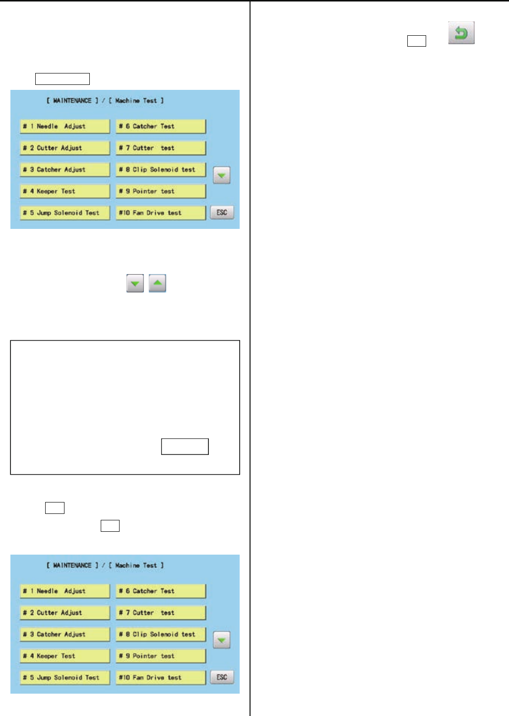
135
1. Enter maintenance mode in reference to [E5-1 How to
enter maintenance mode].
2. Press Machine Test .
3. Select desired number to be confirmed.
Page is switched by pressing .
Selected item will be executed.
# * ***************
4. The screen returns to the [MACHINE TEST] screen by
pressing ESC .
(Unnecessary to press ESC if the item completes
automatically.)
5. Return to drive mode by pressing ESC and .
ESC
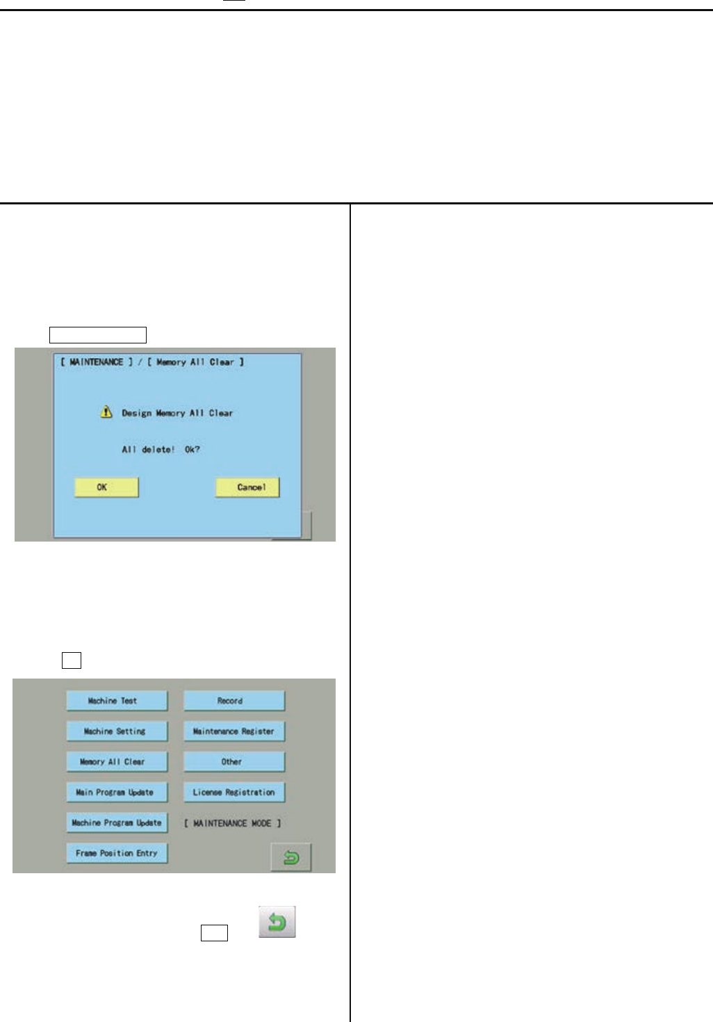
136
E5-3 Memory All Clear Initialization of design memory
Delete all the design memory.
Execute this function when occurring design breakage or impossibility of design input.
If abnormality is found after deleting all the data, replace LCD-CE board (or Core module) since the board might be broken.
<NOTE>
All the internal design memory will be deleted by initialization of design memory.
You have to be careful when initializing design memory.
1. Enter maintenance mode in reference to [E5-1 How to
enter maintenance mode ]
2. Press Memory All Clear .
3. Confirmation of free area and all delete will be started after
pressing OK .
4. Return to drive mode by pressing ESC and .
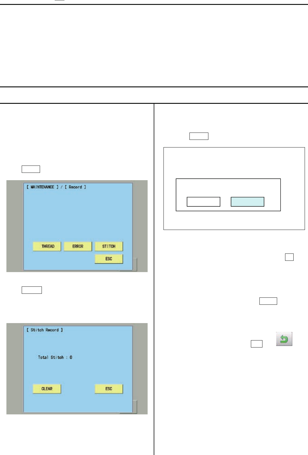
137
E5-4 Record Operation data display
You can confirm history of operation.
Total number of stitch : Total number of stitch used for embroidery so far
Error occurrence record : Type of errors and its occurrence date
Occurrence record by error type : Accumulated number of each error occurrence
Thread break history : The number of thread break by needle bar
E5-4-1 Total number of stitch
1. Enter maintenance mode in reference to [ E5-1 How to
enter maintenance mode ]
2. Press Record.
3. Press STITCH.
The screen shows total number stitches used for
embroidery so far.
4. Selection menu of Clear Total Stitch will be opened when
pressing CLEAR at Procedure 3.
* Total number of stitch is cleared after pressing OK and
the screen shows one in the procedure 3. Total number of
stitch is 0.
* If you do not prefer to clear it, press Cancel and
the screen shows of the procedure 3 is shown
5. Return to drive mode by pressing ESC and .
Clear Total Stitch ?
Cancel
OK

138
E5-4-2 Record of Error occurrence
1. Enter maintenance mode in reference to [ E5-1 How to
enter maintenance mode ]
2. Press Record .
3. Press ERROR.
Enable to confirm Record of error occurrence
* Enable to confirm Occurrence date and error number
with button.
Selection menu of Clear Error Record will be opened when
pressing CLEAR.
*Error record is cleared by pressing OK and the screen of
the procedure 3 is displayed.
* If you do not prefer to clear it, press Cancel and
the screen of the procedure 3 is displayed..
Clear Error Recode ?
Cancel
OK
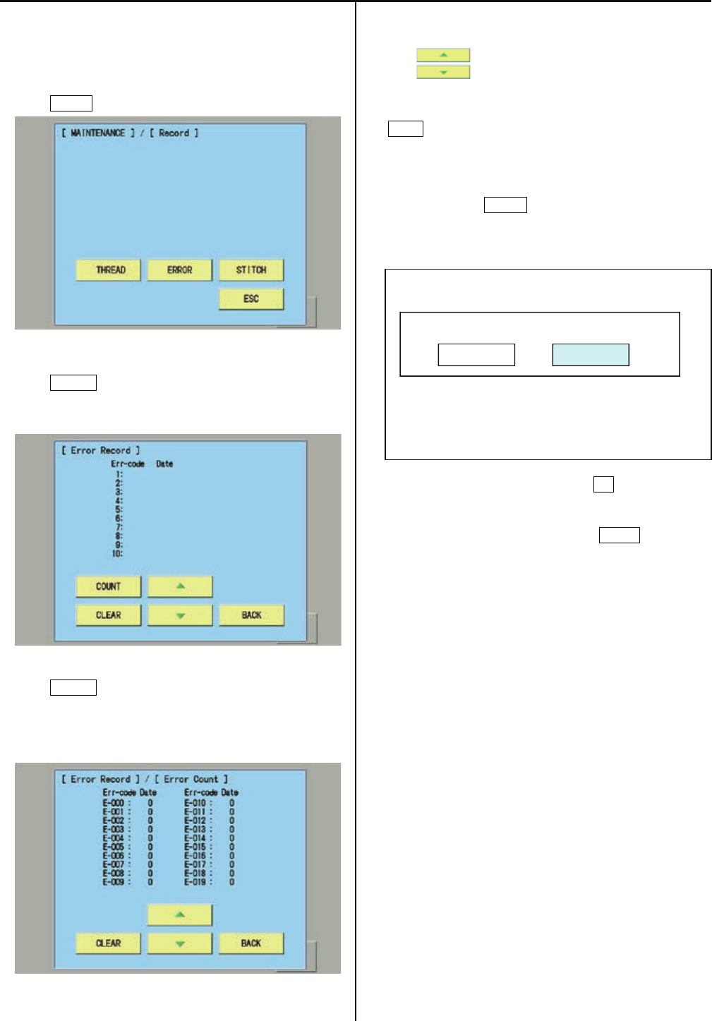
139
E5-4-3 Number of occurrence in each error display
1. Enter maintenance mode in reference to [ E5-1 How to
enter maintenance mode ]
2. Press Record .
3. Press ERROR.
You can confirm record of error occurrence.
4. Press COUNT .
You can confirm total number of occurrence in each error.
(E-000 to E-255 will be displayed )
* You can confirm accumulated number for E-000 to E-255
with .
* The screen returns to the previous screen by pressing
BACK.
5. Selection menu of Clear Error Total Count will be opened
when pressing CLEAR and the screen of procedure 4
is displayed.
* Error record is cleared by pressing OK and the screen of
the procedure 4 is displayed.
* If you do not prefer to clear it, press Cancel and
the screen of the procedure 4 is displayed.
Clear Error Total Count ?
Cancel OK
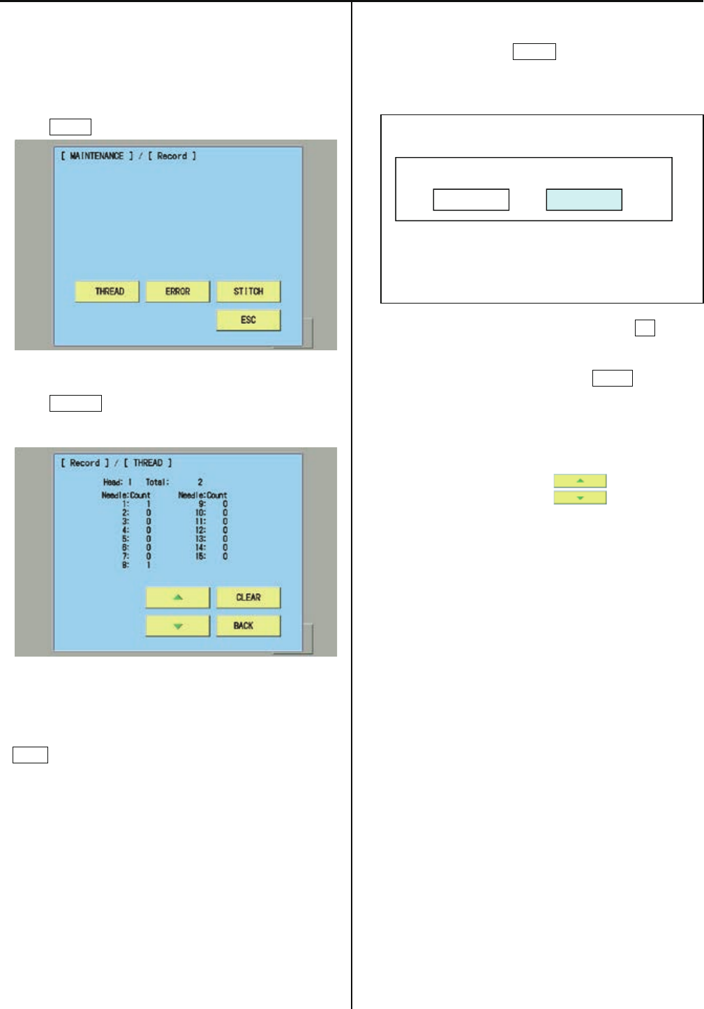
140
E5-4-4 Thread break history
1. Enter maintenance mode in reference to [ E5-1
How to enter maintenance mode ]
2. Press Record .
3. Press THREAD.
You can confirm thread break history by needle bar.
・*The screen returns to the previous screen by pressing
BACK.
・
5. Selection menu of Clear Thread Break Count will be
opened when pressing CLEAR at the screen of procedure
3.
* Thread break history is cleared by pressing OK and
the screen of the procedure 3 is displayed.
* If you do not prefer to clear it, press Cancel and
the screen of the procedure 3 is displayed.
6. Head is switched by pressing .
Clear Thread Break Count ?
Cancel OK

141
E5-5 Setup Machine setting
<NOTE> ( *: Setting is for each indivisual machine, so prohibit to change setting. When you need to chage it, please contact us in
advance)
( $ : Setting is different for each model type. Please check before changing data)
( # : Setting is depending on options installed. Please check before changing data)
Contents
*1 Machine Type : HCR2
*2 Max Needle Number : 15 (1-15) : Number of Needle
$ 3 Max Head Number : □ (1-30) : Number of Head
$ 4 Machine Max Speed : □□□ (500-2000) : Maximum rotation
$ 5 Machine Max Area X : □□□ (0-15000) : Maximum embroidery area at X axis
*6 Machine Max Area Y : 4500 (0-15000) : Maximum embroidery area at Y axis
$ 7 X Position Sensor : □ (0-12) : Number of position sensor at X axis
* 8 Y Position Sensor : 6 (0-12) : Number of position sensor at Y axis
# 9 LED Needle Pointer : No : Use of LED Pointer Yes or No
#10 Safety Sensor : No. : Use of safety sensor ( rear )Yes or No ( To be determined )
#11 N.Safety Sensor : No. : Use of safety sensor (front) Yes or No
#12 Clip Holder Device :No : Use of Clip holder device YES or NO
*13 Borer Device : No. : Use of Borer device Yes or No
*14 Cutter Unit Type : PulseMtr : Thread cutting unit type
*15 X Start Base Angle : 60 (20-90) : Starting angle of frame movement on X axis
*16 Y Start Base Angle : 60 (20-90) : Starting angle of frame movement on Y axis
*17 X Start Angle(CAP) :40 (20-90) Starting angle of frame movement on X axis for cap frame
*18 Y Start Angle(CAP) :40 (20-90) Starting angle of frame movement on Y axis for cap frame
$19 Color Change Speed :Slow1 (Normal / Slow1 ~ Slow4) Speed of needle bar change
*20 Brush Data [*0.1mm]:200 (0-250) Distance of thread brush (mm) after thread cut
(1:0.1mm , 200:20.0mm … 250:25.0mm)
# 21 Clip Close Timing :250 (0-1000) Close timing of Clip when Thread trim (ms)
Set to 250 when the Clip holder device is Yes.
*22 Border Overlap :8 (0-8) Overlap of between heads for border frame
*23 Trace Needle No. :1 (1-15) Needle Number for Trace
*24 Device Com. Speed :19200bps (2400-115200) Communication speed for Sequin device and Cording device
# 25 Sequin Dev. Left :No Use of left side Sequin device Yes or No
# 26 Sequin Dev. Right :No Use of right side Sequin device Yes or No
# 27 Sequin Dev. Type :Other (Happy) Type of Sequin device
# 28 Number of 3-Needle :0 (0-15) Needle number of 3-Needle device
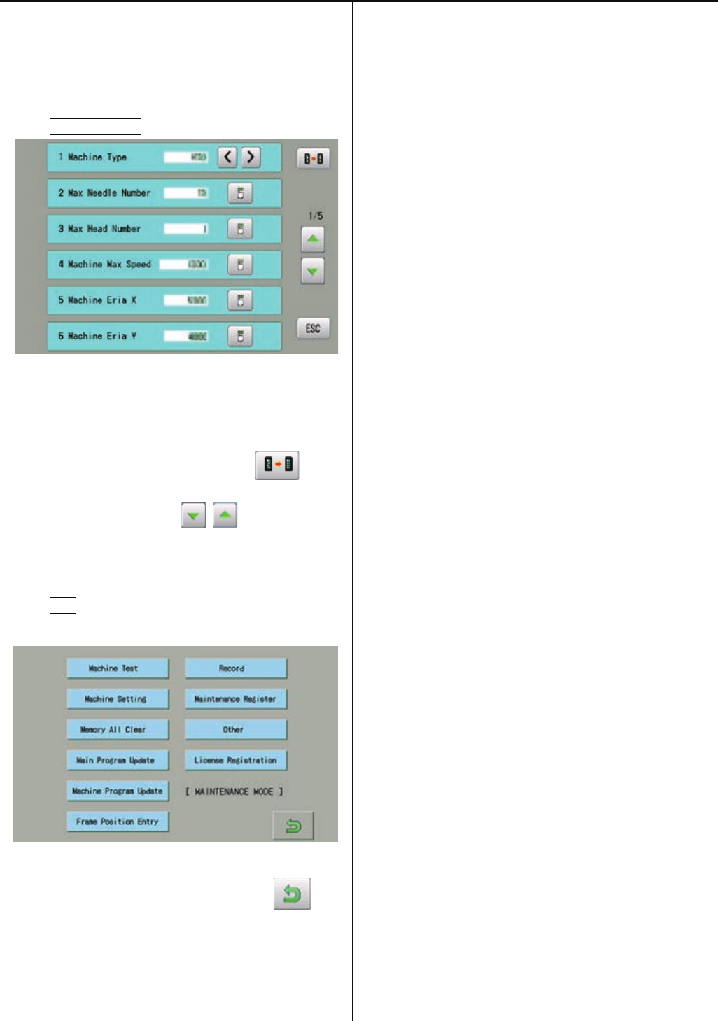
142
1. Enter maintenance mode in reference to [E5-1 How to
enter maintenance mode ].
2. Press Machine Setting.
3. Select desired number and modify setting.
・Setting values become default by pressing .
・Page is switched by pressing .
4. Press ESC button after modifying of setting
number.
5. The screen returns to drive mode by pressing .
6. Turn off power and on again before use a machine.
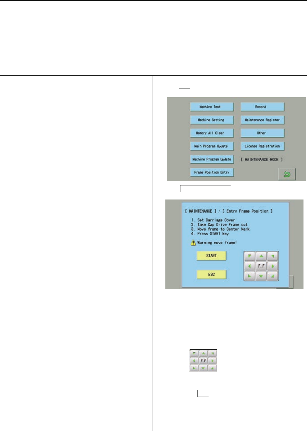
143
E5-6 Position- Registration of coordinates for positioning sensor
This procedure is to memorize embroidery area into the machine.
*This procedure has to be done after exchange of CONT-R2 board position sensor board.
(Machine will display error [ E-67 Position data ] without the registration of coordinates of position sensor.
<note> Registeraion should be done with cover installed. Correct position may not be registered, if the registration is done with
cover off.
As frame moves at maximum embroidery area, be surenot to have anything around the machine.
1.Refer to [E5-5 Setup- Machine setting] and confirm the
following setting
5 Machine Eria X
HCR2-1502: 5000
HCR2-1504: 3600
HCR2-X1504: 5000
HCR2-1506: 3600
HCR2-X1506: 5000
HCR2-1508: 3600
6 Machine Eria Y
HCR2-1502: 4500
HCR2-1504: 4500
HCR2-X1504: 4500
HCR2-1506: 4500
HCR2-X1506: 4500
HCR2-1508: 4500
7 X Position Sensor
HCR2-1502: 6
HCR2-1504: 4
HCR2-X1504: 6
HCR2-1506: 4
HCR2-X1506: 6
HCR2-1508: 4
7 Y Position Sensor
HCR2-1502: 6
HCR2-1504: 6
HCR2-X1504: 6
HCR2-1506: 6
HCR2-X1506: 6
HCR2-1508: 6
2.Press ESC button.
3. Press Frame Position Entry .
Operate according to displayed below message.
(1). Fix carriage cover
(2). Remove cap frame
(3). Move carriage to center mark position by
. (Refer to below display)
(4). Press START button
(Press ESC button in case of cancellation)
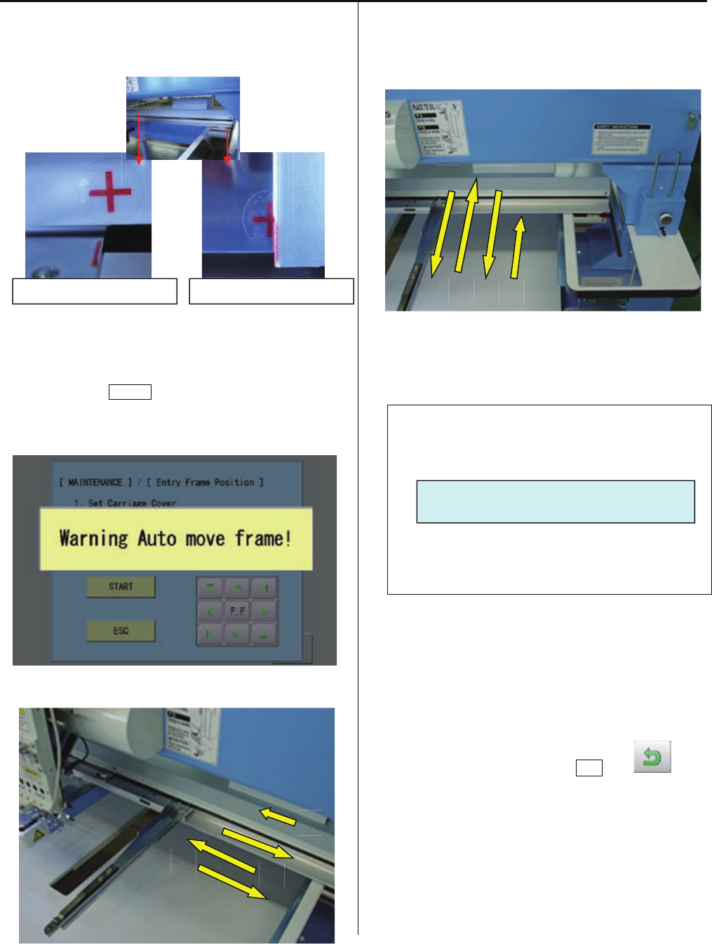
144
4. When you press STARTbutton, registration of X axis
direction will start. Frame moves as below.
5.Then registration of Y axis direction will start. Frame moves
as below.
6.Bellow message will be displayed with successful completion.
Retry from step 3, if [Error] occurs
Frame position registration is finished.
7. Return to drive mode by pressing ESC and .
Center mark position of X axis
Center mark position of Y axis
- - - - Complete - - - -
1 2
3 4
1
2
3
4
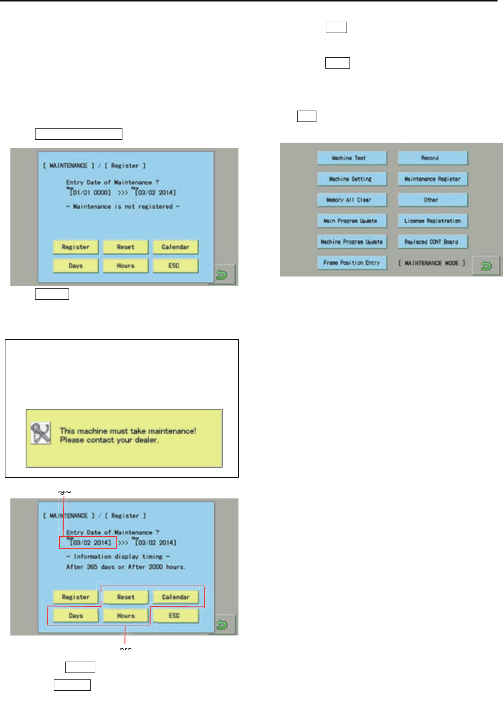
144a
E5-7 Maintenance Register―Registration of machine maintenance date
Registration of machine maintenance date
When last maintenance date is registered, next regular
maintenance date will be set automatically.
1. Enter maintenance mode in reference to [ E5-1 How to
enter maintenance mode].
2. Press Maintenance Register.
3. Press Register.
The current date will be registered as last maintenance
date.
When the machine runs more than 2000 hours (default
setting) or 365 days are passed after last maintenance,
the machine will display the message to have regular
maintenance.
Registered date
Main program Ver.*1.34~
・Pressing the RESET button delete the registered date.
・When the Calender button is pressed, you can set
calendar of the machine.
・By pressing Days button, you can change the number of
days for regular maintenance. (1 ~ 3,650 dsys)
・By pressing Hours button, you can change the number of
running time for regular maintenance. (1 ~ 50,000 hours)
4. Press ESC.
Return to maintenance mode.
・End of process.
egis
pro
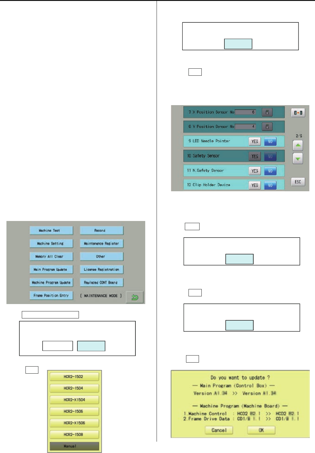
144b
E5-8 Machine Setting Navigation after exchanging CONT board (Main program Ver.*1.34~)
After exchange CONT board, please activate [Machine
Setting Navigation after exchanging CONT board] function.
Then you can set necessary machine setting with one
process.
E5-5 Setup Machine setting
E4-2 Machine program update
E4-3a Main program update
E5-6 Position Registration of coordinates for
positioning sensor
E4-4 Initializing of machine speed
・Refer to [E4-1 Preparation for program update] and
prepare latest update programs.
1.Insert USB memory that contains data for version
up into insertion slot on the control box.
2. Refer to [E5-1 How to enter Maintenance mode] and
enter maintenance mode. The screen shows below:
3. Press Replaced CONT Board.
4.Press OK .
5.Select model name of your embroidery machine.
6.Press OK .
Machine setting menu will be opened and all items which
are required to set will be highlighted.
7. Press ESC after setting of necessary items.
8.Press OK .
9. Press OK .
Start Setup-Navigation?
CancelOK
2nd Step: Program Update
OK
Save the latest program to USB memory
And set USB to USB slot on panel.
OK
1st Step: Option Selection
OK

144c
10. When the current machine program is older than latest
version, press OK .
The installation will be started.
If the current machine program is same or newer version,
press Cancel .
11.Press OK .
12. Enter the corresponding machine number.
13. Press OK .
14. Press START .
[Position Registration of coordinates for positioning
sensor] begins.
Refer to [E5-6 Position Registration of coordinates
for positioning sensor] for more details.
15. Press ESC.
16.Press OK .
17.Press OK .
[Initializing of machine speed] will be started.
Refer to [Initializing of machine speed] of [E4-4 Setting
of revolution] for more details.
18.Press OK .
The screen returns to the maintenance mode。
・End of process.
3rd Step: Select machine serial No.
(for auto-machine setting)
OK
Final Step: Speed setting
OK
Setup is completed.
OK
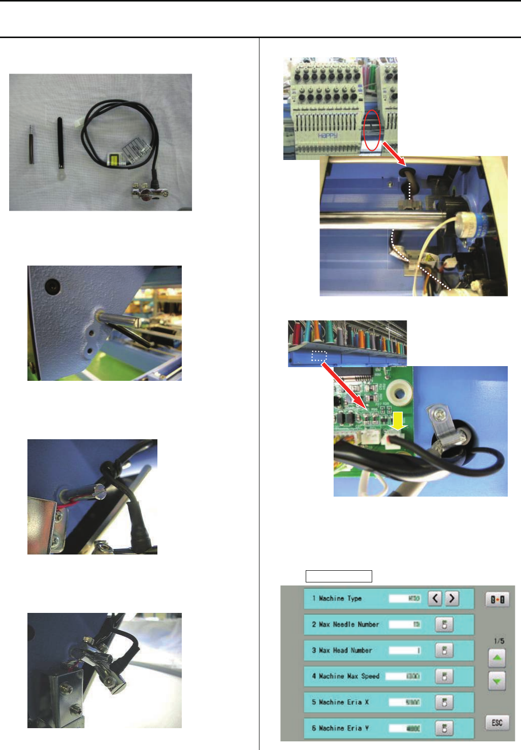
145
E6-2 Installation of laser position marker
<note> laser position marker is factory option and installed at factory. In case you need to install later at your side, trained
engineer has to install
ESHCRU28010 Laser position marker set
1.Set bandage(B) with stud(A) on right side of moving head
2.Bind harness of pointer unit (C) with bandage(B)
3.Set pointer unit (C) on stud (A)
4.Pass harness through hole at left side of moving head
5.Put harness to CN11 on detection circuit board
6. Enter maintenance mode in reference to [ E5-1 How to
enter maintenance mode ].
7. Press Machine Setting.
B
A
C
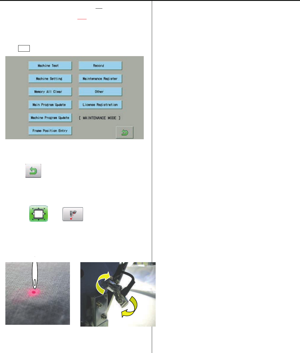
146
8. Change [ 9 LED Needle Pointer No] to
[ 9 LED Needle Pointer Yes].
9. Prss ESC button.
10. Press , return to running menu.
11. Press and .
12.Adjust angle of pointer unit to point needle position
<note> Position may be changed depend on thickness of
fabric
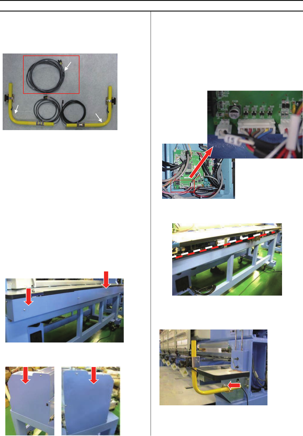
147
E6-3 Installation of Safety sensor (front)
<note>Safety sensor (front) is factory option but sensor is not set on machine. Please install sensor according to this instruction.
HCR2-FS2-4 Safety sensor (front)(for 2 and 4 haeds)
HCR2-FSX4-6 Safety sensor (front)(for X4 and 6 haeds)
HCR2-FSX6-8 Safety sensor (front)(for X6 and 8 haeds)
HCRU28C1x Safety sensor (front) (without Harness A)
<note> Harness A is installed on machine, if sensor is
ordered with machine
<Check>If you would like to order safety sensor separately,
please check the machine if harness A is already installed or
not. For some high-demand countries, harness A is installed
beforehand at factory. In this case, you need to order only
Safety sensor (front) (without Harness A).
B=Sensor(emission part)
C=Sencer(receiving part)
1.Take cover out at behind of machine
2.Take mission covers (right and left) out
3.Connect harness
<note> Harness A is installed on machine, if sensor is
ordered with machine or If harness A is already
installed on the machine, you can skip this step.
Connect harness A into CN15 on CONT-R2 board in
mission (right)
Extend harness to mission (left)
<note> harness should not touch to rotation parts and belts
4.Install sensor(C) at right side
A
B
C CN15
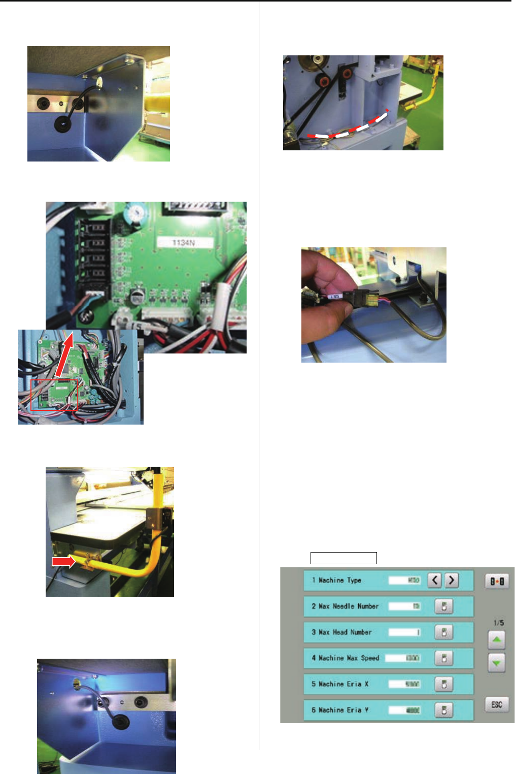
148
5. Cut center part of grommet and pass harness through
grommet as photo below.
6.Connect harnessinto CN13 on Drive circuit board
7. Install sensor(B) at left side
8. Cut center part of grommet and pass harness through
grommet as photo below.
9.Pass harness through missin (left) and bring to front
<note> harness should not touch to belt
10. Connect harness to extension harness(LS5) at lower
part of Y carriage
<note> put cable in order for avoiding to touch to shaft
11.Set cover
<note> harness should not get caught in the cover
12. Enter maintenance mode in reference to [ E5-1 How to
enter maintenance mode ].
13. Press Machine Setting.
CN13
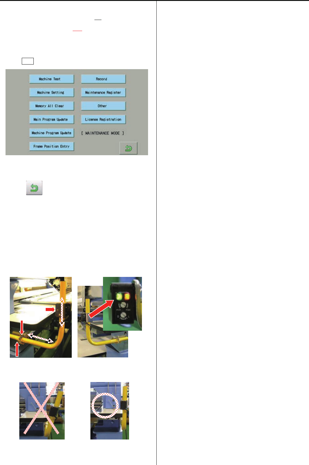
149
14. Change [11 N.Safety Sensor No] to
[11 N.Safety Sensor Yes].
15. Prss ESC button.
16. Press , return to running menu.
After these setting, Sencor becomes effective
17.Adjust position of sensors. Confirm both LED (green and
Orange) is lighting
<note> Sencor should be finxed vertical
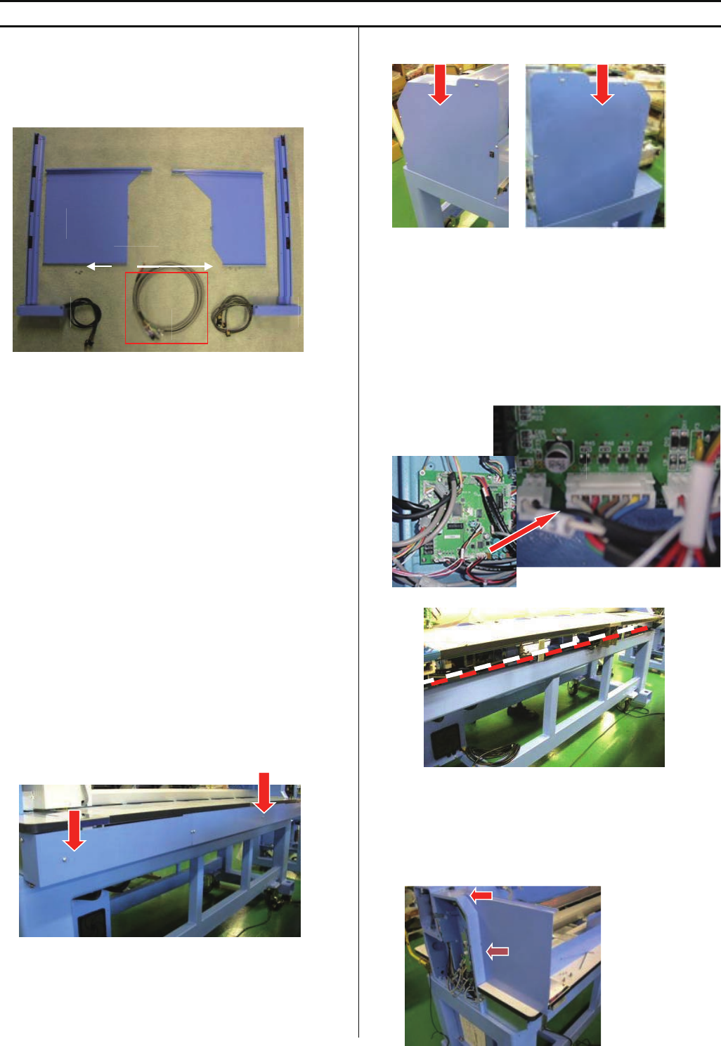
150
E6-4 Installation of Safety sensor (rear)
<note> Safety sensor (rear) is factory option but sensor is not set on machine. Please install sensor according to this instruction
HCR2-RS2-4 Safety sensor (rear)(for 2 and 4 haeds)
HCR2-RSX4-6 Safety sensor (rear)(for X4 and 6 haeds)
HCR2-RSX6-8 Safety sensor (rear)(for X6 and 8 haeds)
HCRU28D10 Safety sensor (rear)(without Harness A)
<note> Harness A is installed on machine, if sensor is
ordered with machine
<Check>If you would like to order safety sensor separately,
please check the machine if harness A is already installed or
not. For some high-demand countries, harness A is installed
beforehand at factory. In this case, you need to order only
Safety sensor (rear) (without Harness A).
B=Safety Guard (right)
C=Sensor (receiving part)
D=Safety Guard (left)
E=Sencer (emission part)
F=M3X6 screws (6 pcs)
1. Take cover out at behind of machine
2. Take mission covers (right and left) out
3.Connect harness
<note> Harness A is installed on machine, if sensor is
ordered with machine or If harness A is already
installed on the machine, you can skip this step.
Connect harness A into CN12 on CONT-R2 board in
mission(right)
Extend harness to mission (left)
<note> harness should not touch to rotation parts and belts
4. Remove screw of rmission (right), Install Safety Guard on
missin (right)
A
B
C
D
E
F
CN12
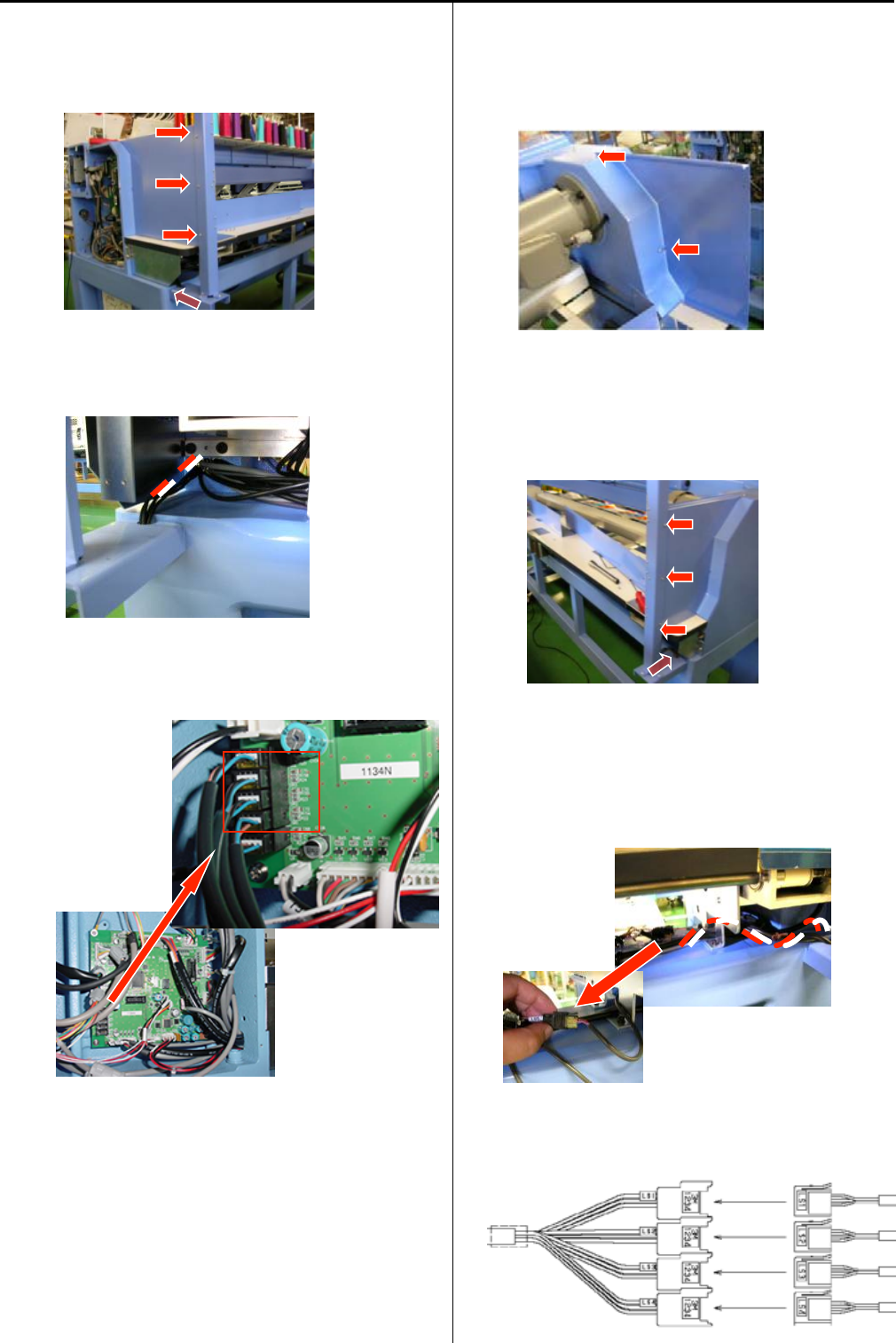
151
5. Remove screw of body, Fix Sencor (C) on body and fix to
Sefety Guard(B) by screws(F)
6.Pass harness into mission box
7. Connect harnessinto CN14 on Drive circuit board
RS4 -> CN14-RS4
RS3 -> CN14-RS3
RS2 -> CN14-RS2
RS1 -> CN14-RS1
8. Remove screw of rmission (left), Set Safety Guard (D) on
mission (left)
9. Remove screw of body, Fix Sencor (E) on body and fix to
Sefety Guard(D) by screws(F)
10. Connect harness to extension harness(LS*) at side of Y
carriage
<note> put cable in order for avoiding to touch to shaft
LS1 <- LS1
LS2 <- LS2
LS3 <- LS3
LS4 <- LS4
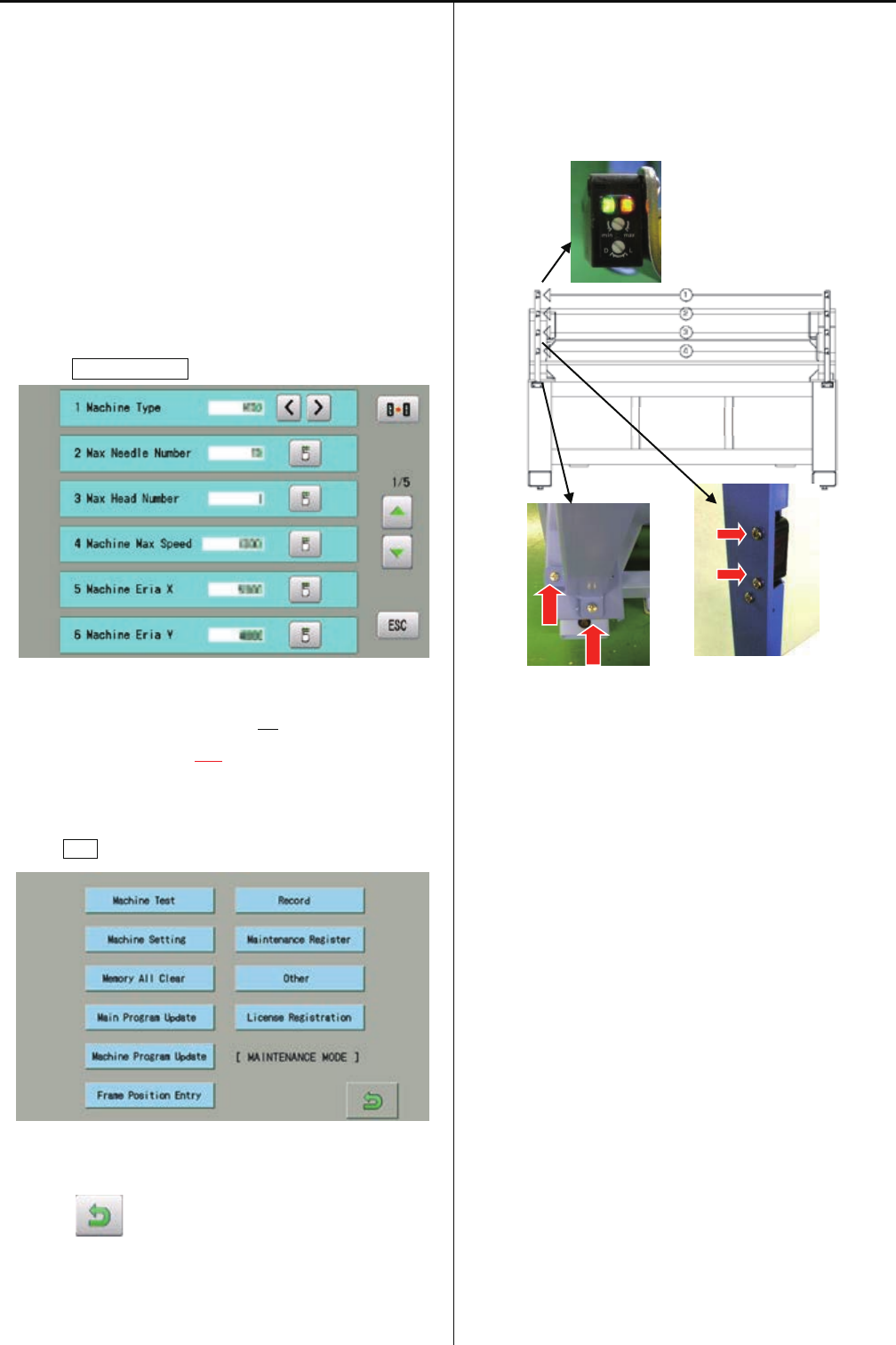
152
11.Set cover
<note> harness should not get caught in the cover
12. Enter maintenance mode in reference to [ E5-1 How to
enter maintenance mode ].
<note> This setting is done already, if sensor is ordered with
machine. You can skip this step
13. Press Machine Setting.
14. Change [10 Safety Sensor No] to
[10 Safety Sensor Yes].
15. Prss ESC button.
16. Press , return to running menu.
After these setting, Sencor becomes effective
17.In case error occurs during operation:
Please adjust position of sensor where both LED (green
and Orange) light stable by screws below.
<note> Please do not press sensor, when you need to move
machine. The position of sensor may be changed.
BACK
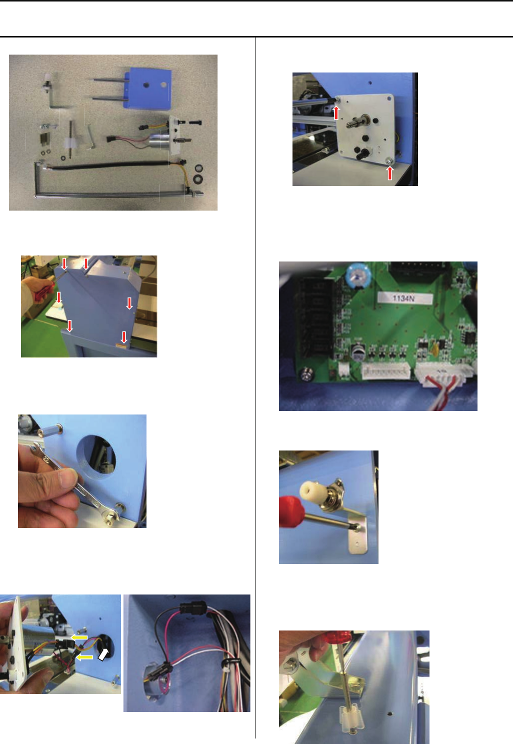
153
E6-5 Installation of bobbin thread winder
<note> Bobbin thread winder is factory option and installed at factory. In case you need to install later at your side, trained
engineer has to install
ESHCRU36010 Bobbin thread winder set.
1.Take mission cover (right) out.
2.Set stud (H) with M4 washer.
<Spanner> 7mm
3.Connect harness (C) to harness of motor (A) with limit
switch, and put harness into mission.
4.Fix winder(A). (Screw M4x8)
5.Connect harness (C) into CN24 on CONT-R2 board.
6.Set Thread tension device (D) on Body. (Screw M4x8)
7.Set thread stand (E) with M4 washer.
B
C
D
E
F
G
H A

154
8. Set thread guide (G) with M8 washer and spring washer.
Adjust a position of eyelet on bobbin thread guide to
a position above of thread standpin (E), and fix nut.
Thread stand pin (E)
9.Set stop switch (F).
10.Set cover and power on.
11. Put thread and start to wind bobbin thread.
Adjust position bobbin stand and thread tension (E) for
winding thread equally.
Thread tension (E)
12. Take stop switch (F) out and put cover (B).
13. Set stop switch (F) and adjust position where stop switch
(F) will open , when bobbin wilnd thread full.
NG OK
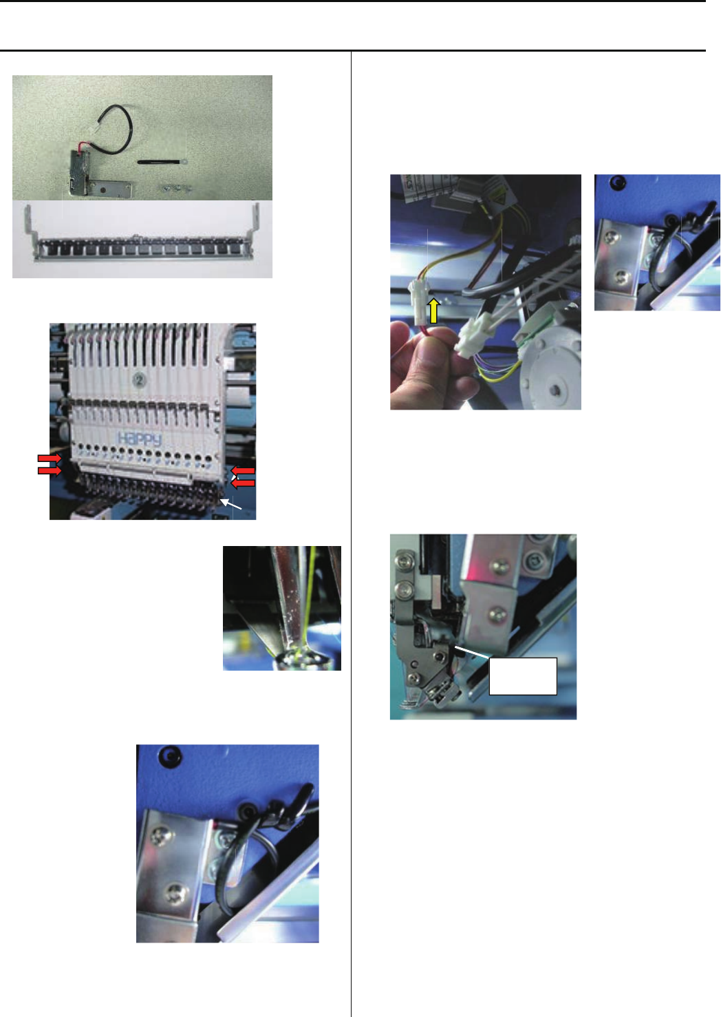
155
E6-6 Installation of Upper Thread Holder
<note> Upper Thread Holder is factory option and installed at factory. In case you need to install later at your side, trained
engineer has to install
ESHCRU15010 Upper Thread Holder set
1.Set thread holder(A) under moving head
2.Check smooth movement of thread
catcher at 1st and 15th needle
3.Set Clip drive unit (B) with bandage (C) by screw (D) at right
side of moving head.
(bandage is common used for laser pointer and thread
holder)
4.Connect harness to connector (2P) at left side of moving
head, and bind cable with bandage.
<note> Cable should not touch to any moving part
5.Adjust space around 1~2mm between clip dirve unit (B) and
thread holder
6. Enter maintenance mode in reference to [ E5-1 How to
enter maintenance mode ].
<note> This setting is done already, if Upper Thread Holder is
ordered with machine. You can skip this step
B
C
D
D
ORANGE
YELLOW
C
A
A
B
C
D
1~2mm
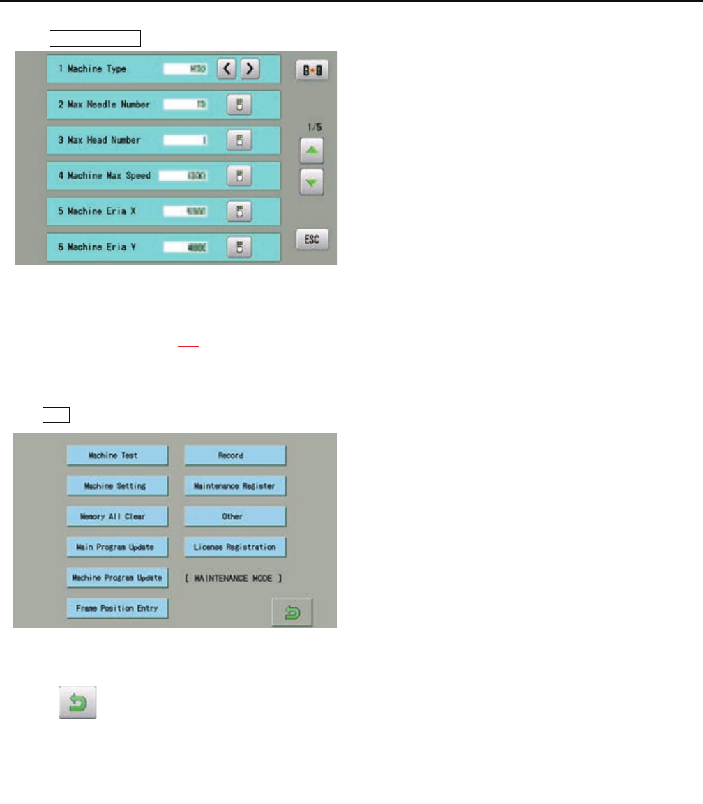
156
7. Press Machine Setting.
8. Change [12 Clip Holder Device No] to
[12 Clip Holder Device Yes].
9. Prss ESC button.
10. Press , return to running menu.
After these setting, Upper Thread Holder becomes
effective.
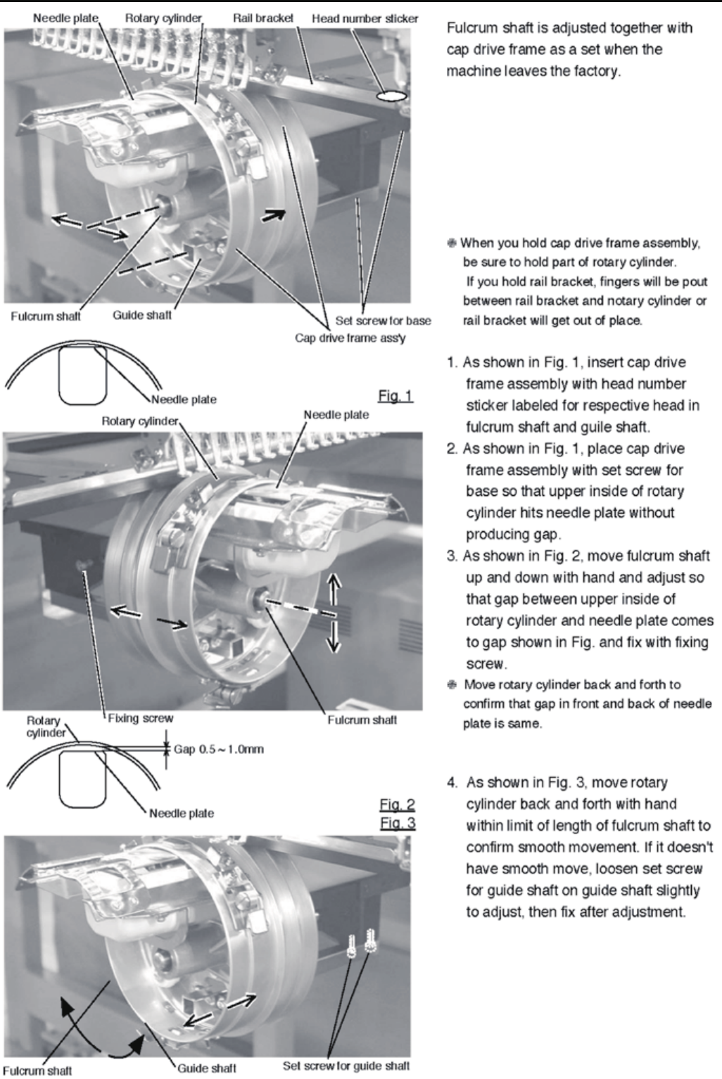
157
E6-7 Installation of Fulcrum shaft for Cap drive frame

158
E7 Electric system diagram
E7-1 Pulse motor driver (PMD) wiring (Before Rev. A)

159
E7-1 Pulse motor driver (PMD) wiring (Rev. A)
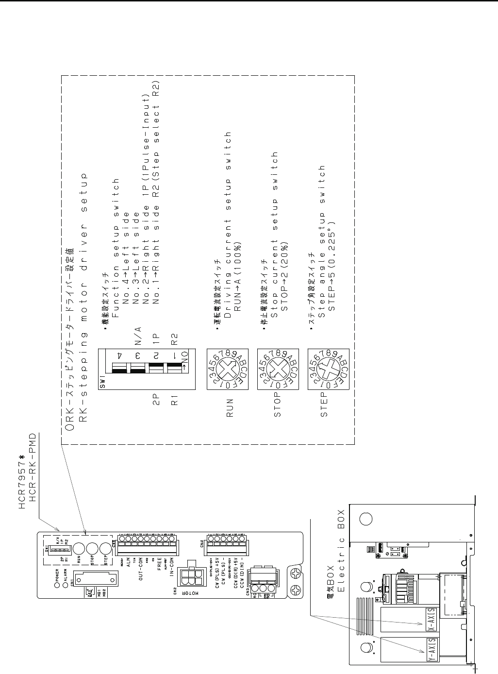
160
E7-1 Pulse motor driver (PMD) setup (Rev. A)

161
E7-2 Inverter wiring
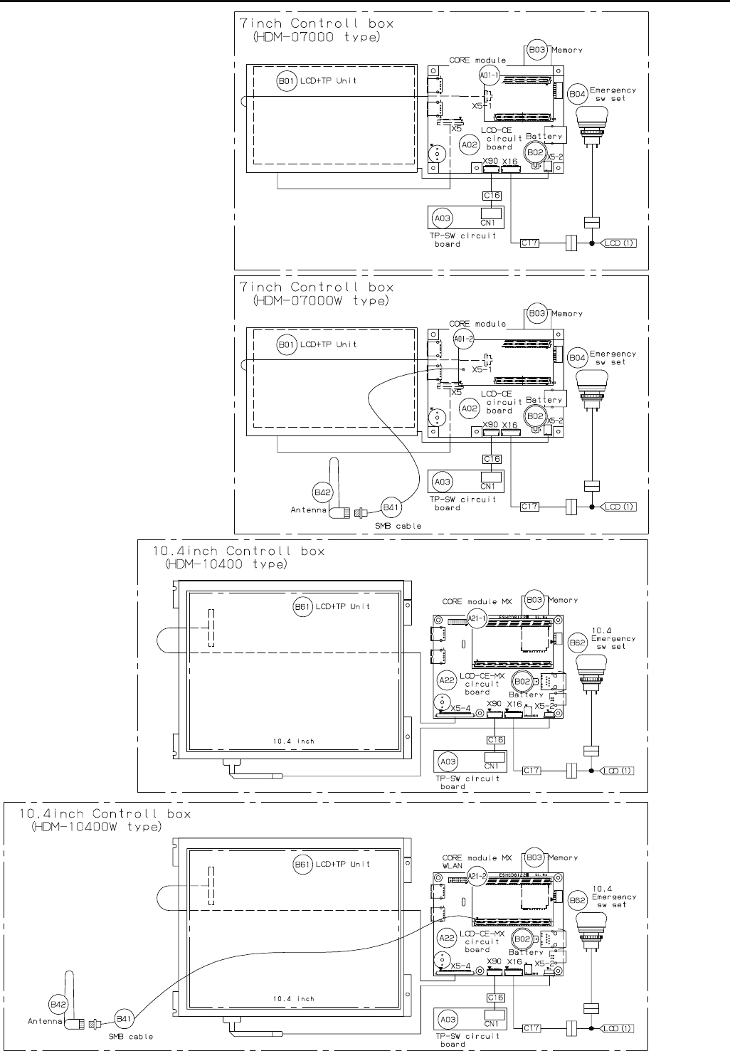
162
E7-4 Electrical connection diagram (Before Rev. A)

163
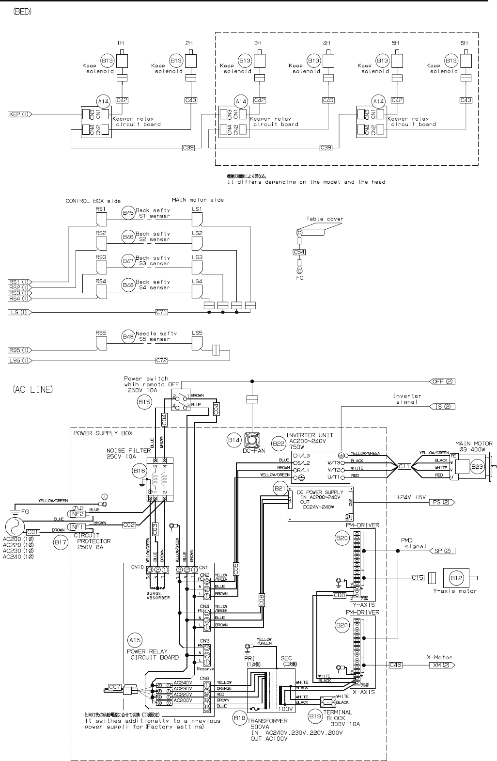
164
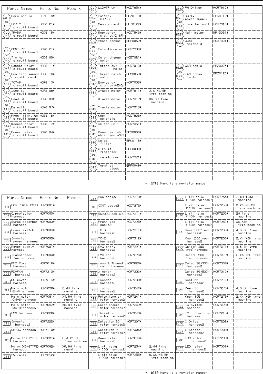
165
E7-5 List of electrical connection diagrams (Before Rev. A)
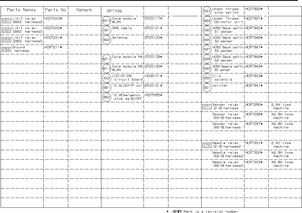
166
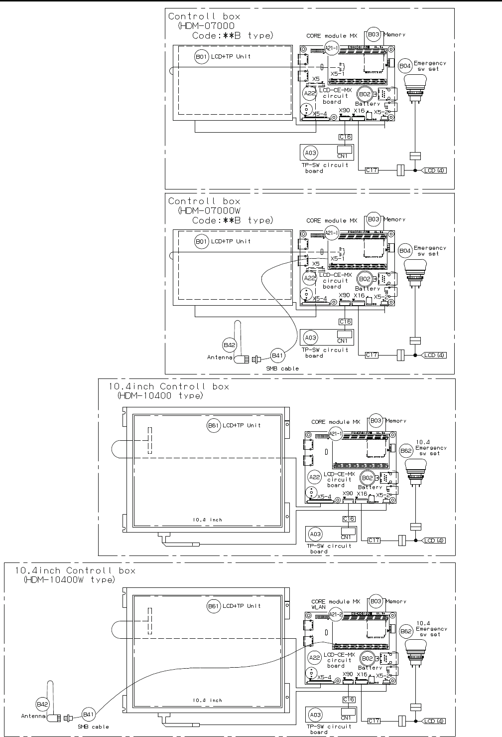
167
E7-6 Electrical connection diagram (Rev. A)
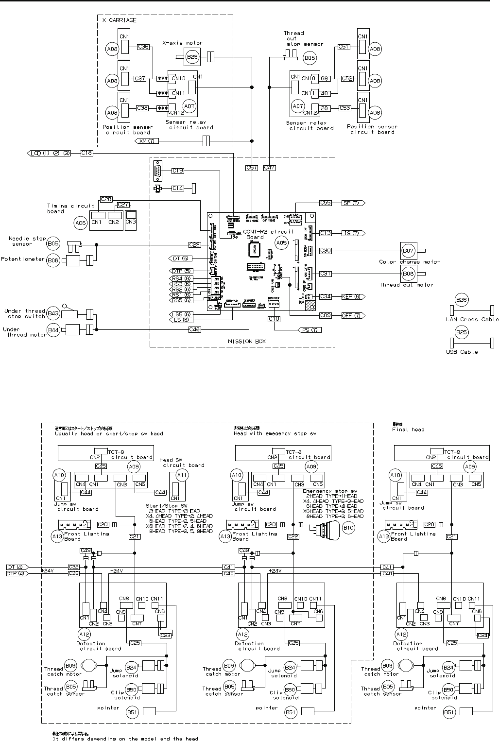
168
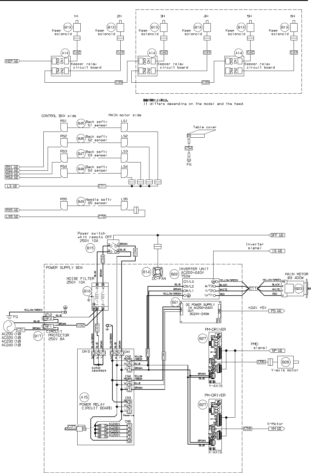
169
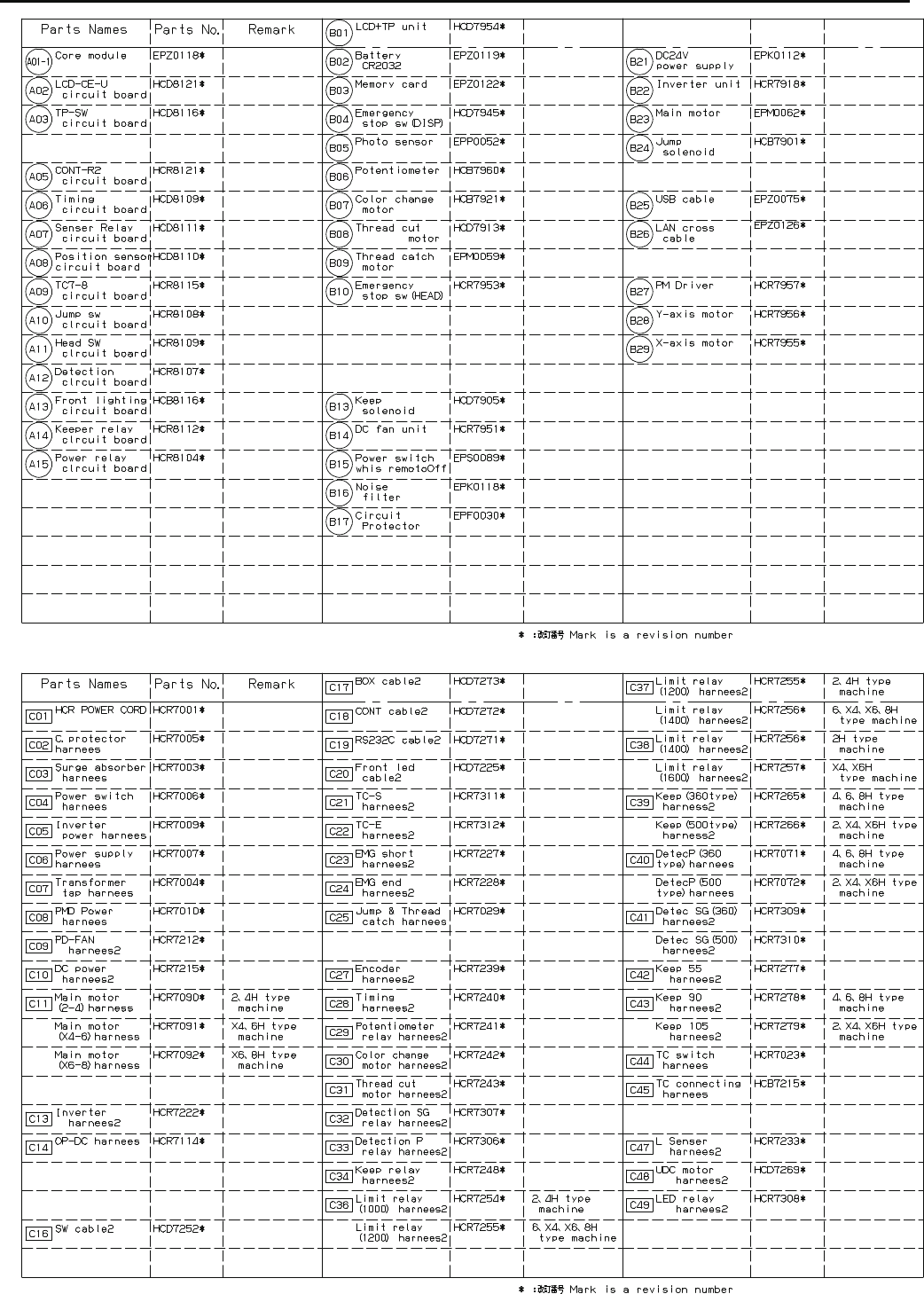
170
E7-7 List of electrical connection diagrams (Rev. A)

171
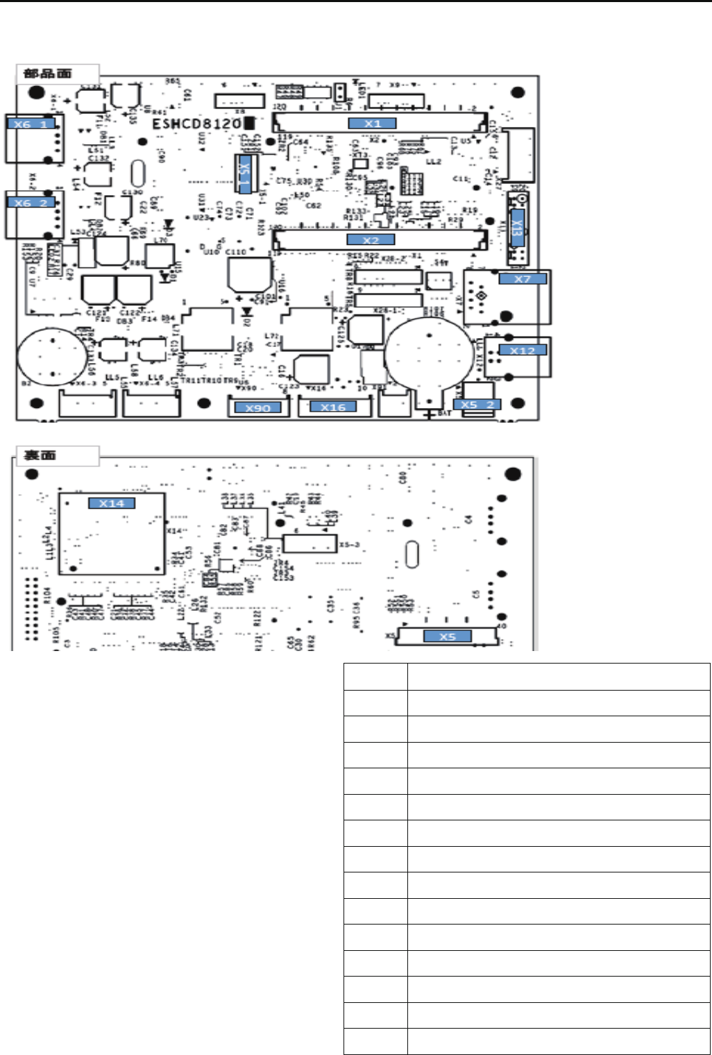
172
E7-8 Explanation of function of circuit board
HCD8121*
LCD-CE-U Circuit Board Ass'y
9>8.=498
)9;079/>60
)9;079/>60
D 48
D+48=9>.3:,80648:>=
)+48-,.56423=9>=:>=
D+&$.9880.=9;
D+&$.9880.=9;
D
D&$.9880.=9;
D&)
D$.,;/
)%"$( -9,;/
)! %-9,;/
!=30;
#0<0;?0/

173
HCD8122*
LCD-CE-MX Circuit Board Ass'y
9>8.=498
)9;079/>60
)9;079/>60
D 48
D+48=9>.3:,80648:>=
)+48=9>.3:,80648:>=
)+48-,.56423=9>=:>=
)+48
D+&$.9880.=9;
D+&$.9880.=9;
D
D&$.9880.=9;
D&)
D$.,;/
)%"$( -9,;/
)! %-9,;/
!!=30;=30;
!=30; #0<0;?0/
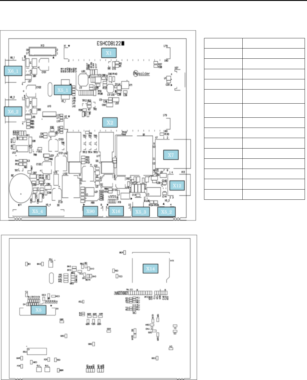
173a
HCD81222
LCD-CE-MX Circuit board Ass'y
CN No. Function
X1 Core module I/F
X2 Core module I/F
X5 7in LCD I/F
X5_1 7in touch panel input
X5_2
10.4in touch panel
input
X5_3
7in LCD backlight
output
X5_4 10.4in LCD I/F
X6_1 USB-A connector 1
X6_2 USB-A connector 2
X7 LAN
X12 USB-B connector
X14 SD card
X16 TP-SW board I/F
X90 CONT-** board I/F
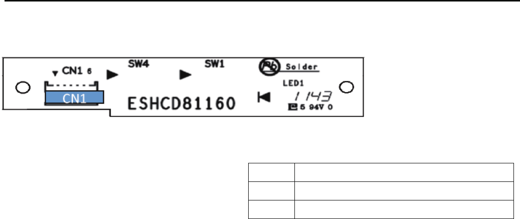
174
HCR8116*
TP-SW Circuit Board Ass'y
9>8.=498
$@4=.39>=:>=48:>=
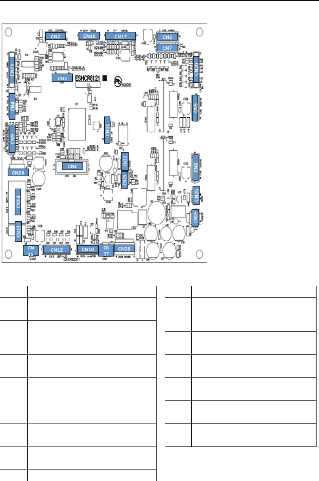
175
HCR8121*
CONT-R2 Circuit Board Ass'y
9>8.=498
98=;96-9A
!:=498
00/60-,;.3,820:9=08<49870=0; 00/60-,;
.3,8209;42:948=<08<9;48:>=
00/60-,;.3,82079=9;9>=:>=
)79=9;
*79=9;
%3;0,/.>==48279=9;9>=:>=
%3;0,//0=0.=482-9,;/9>=:>=
;98=
9--48@48/0;79=9;9>=:>=
&)
,.5<01=B<08<9;9>=:>=
00/60<01=B<08<9;48:>=
,.5<01=B<08<9;48:>=
00/60<01=B<08<9;9>=:>=
):9<4=498<08<9;
*:9<4=498<08<9;
%3;0,/.>==4829;42<08<9;48:>=
00:0;<960894/9>=:>=
8?0;=0;
%47482/0=0.=482
,48<@4=.3;079=09>=:>=
,48-9A1,89>=:>=
,48<3,1=-;,50
':9@0;<9>;.019;%3;0,//0=0.=482-9,;/
&)
8:>=91':9@0;<9>;.0
#0<0;?0/
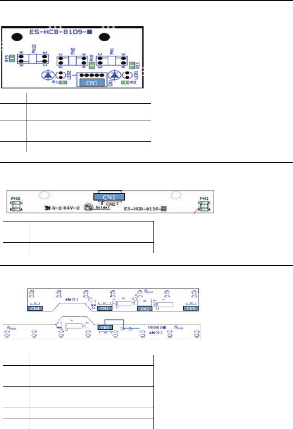
176
HCD8109*
TIMING Circuit Board Ass'y
9>8.=498
!>=:>=91:948=:948= ,8260<08<9;
HCD8110*
POSITION SENSER Circuit Board Ass'y
HCR8115*
TC7-8 Circuit Board Ass'y
9>8.=498
$08<9;9>=:>=
9>8.=498
!>=:>==90?088>7-0;<08<9;
8:>=910?088>7-0;<08<9;
0=0.=482-9,;/,<<B
>7:$(-9,;/
$=,;=$=9:-9,;/
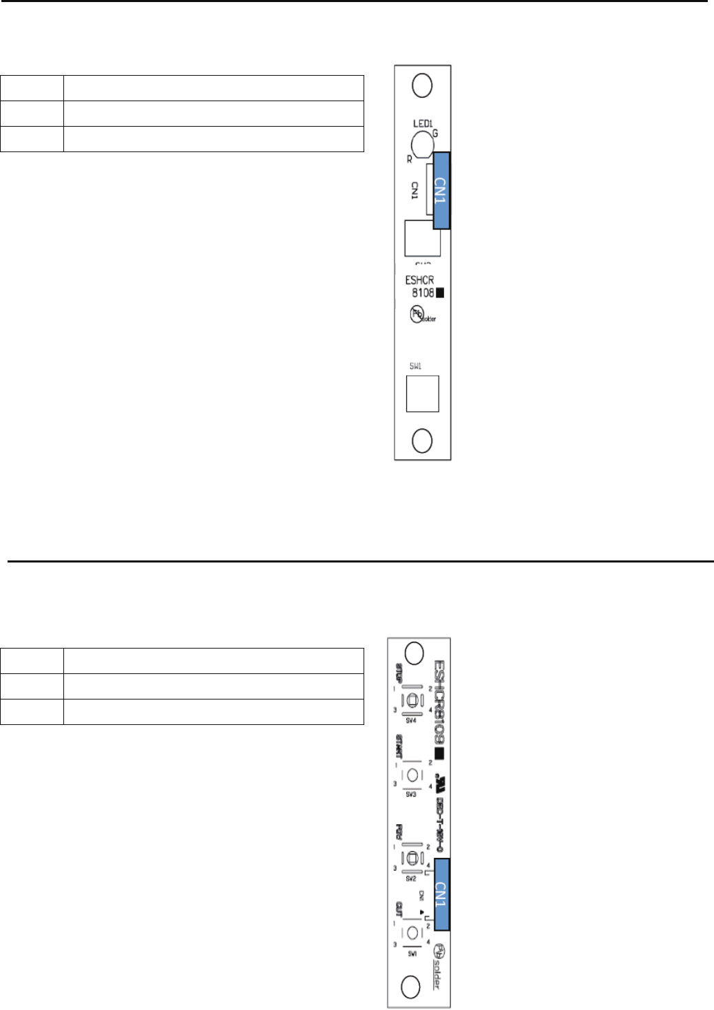
177
HCR8108*
JUMP SW Circuit Board Ass'y
9>8.=498
%-9,;/
HCR8109*
START/STOP Circuit Board Ass'y
9>8.=498
%-9,;/
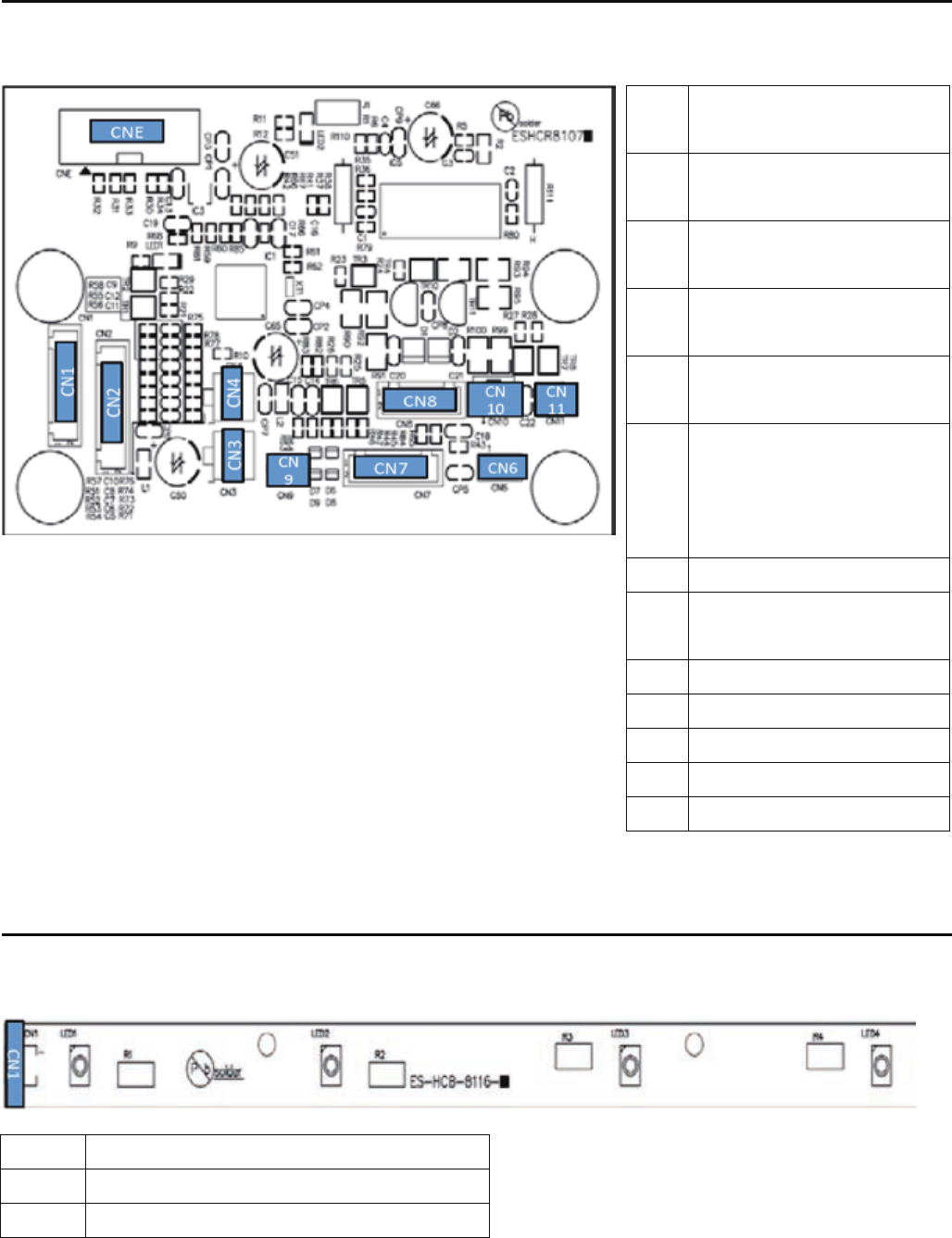
178
HCR8107*
DETEC Circuit Board Ass'y
HCB8116*
FRONT LED Circuit Board Ass'y
9>8.=498
':9@0;<9>;.048:>=
9
>8.=498
8:>=91;06,B.98=;96<428,6
C=9! %#-9,;/
!>=:>=91;06,B.98=;96<428,6
C=980A=/0=0.=482-9,;/
':9@0;<9>;.019;%3;0,/
/0=0.=482-9,;/
':9@0;<9>;.019;%3;0,/
/0=0.=482-9,;/
70;208.B<=9:
C9880.=;06,B.,-60@308=30
070;208.B->==984<89=14A0/
@4=330,/
%-9,;/
!>=:>=91%3;0,/.,=.379=9;
>7:<960894/64:<960894/
!:=498
&8><0/
,<0;:948=0;9>=:>=
#0<0;?0/19;1,.=9;B
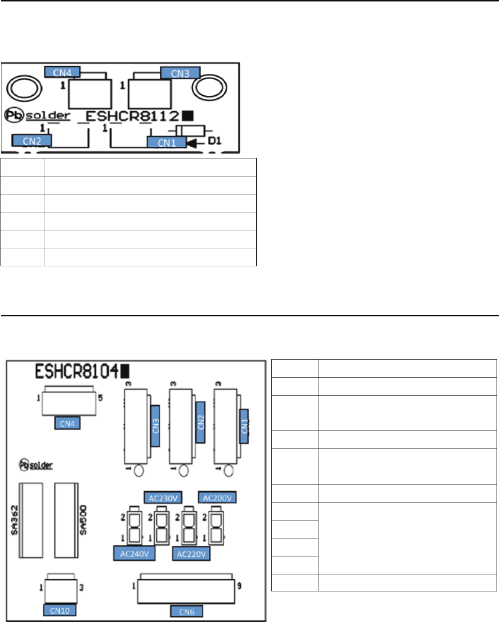
179
HCR8112*
KEEPER RELAY Circuit Board Ass'y
).(-$)(
* +
* +( 1-#
(*.-)!% * ++ &2
.-*.-)!% * ++ &2
HCR8104*
POWER RELAY Circuit Board Ass'y
).(-$)(
*)0 +,).+ $(*.-
*)0 +,).+ + &2(/ +- +
/+$/ +
*)0 +,).+ + &2!)+*-$)(+
*)0 +,).+ + &2
0$-#$("*)0 +,.**&2
+(,!)+' +$(*.- /()(( -
#("$(")!-*!)+-+(,!)+' +
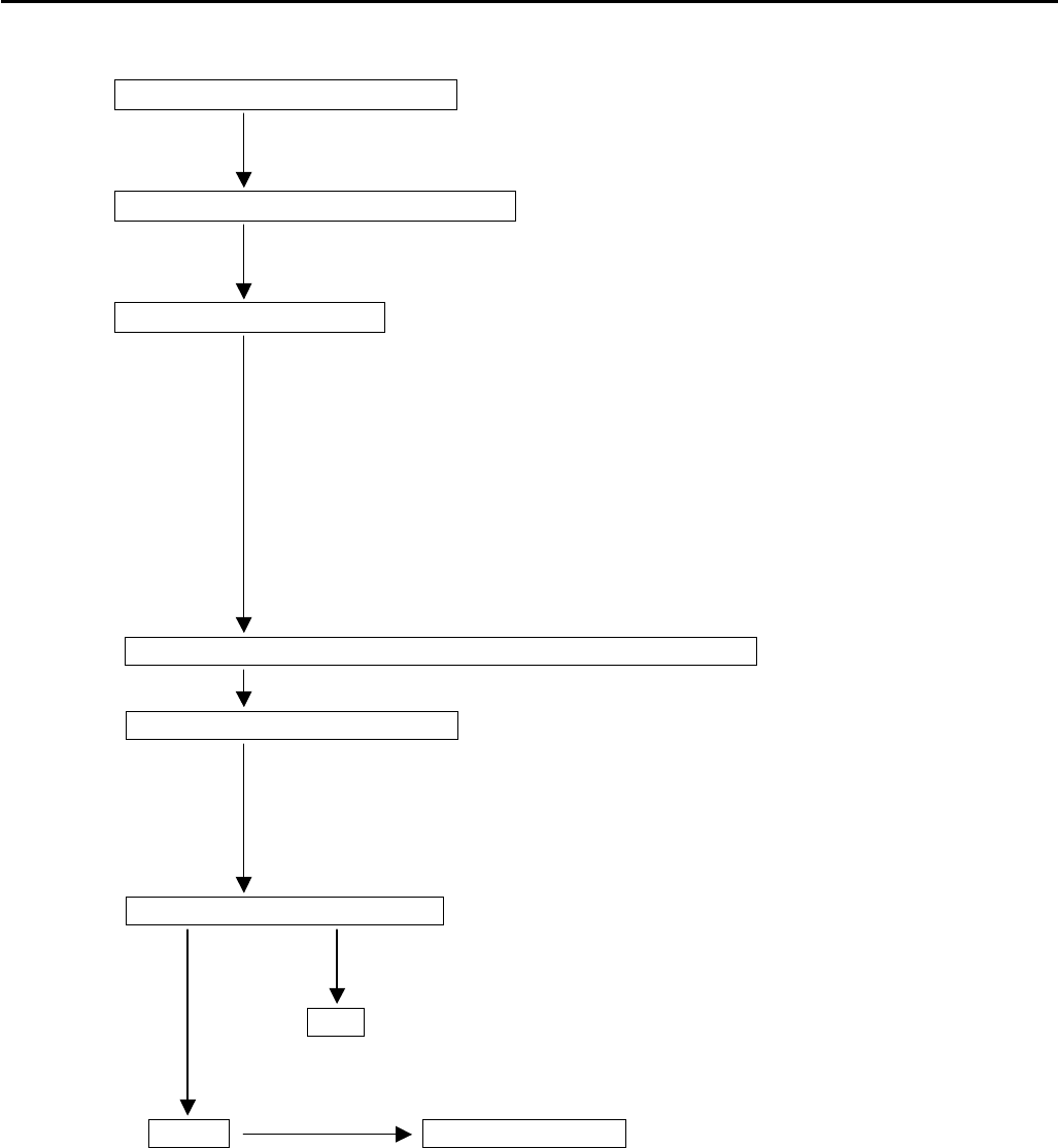
180
E8 How to respond for some question (As example step)
*When you receive some question from customer, please use this step for sold problem as sample.
Receive contact from customer
Ask machine type and serial number
Ask contents of question
*Circumstance of machine (Windy, Dusty, Floor condition and etc)
*Embroidery condition (Frame, Fabric, Thread, Pattern)
*Machine creations. (Create menu)
*Version of machine program.
*Version of Happylinf software.
*About connecting PC.
*etc.
You may prepare instruction book and parts book by customer.
Respond for customer’s question
*Advice by Instruction book and Parts book.
*Advice referencing maintenance manual.
*If you can not immediate, contact again after more detail check.
Ask customer’s contact number
*Phone, Fax and E-mail
OK
*If you find case of respond, contact customer kindly.
NG Visit your technician
*Ask schedule for visit

181
E9 Trouble shooting
E9-1 Electricity doesn’t turn on
Trouble Factor Cause of trouble and measure Page
Electricity Mechanical 1. Did fuse blow?
doesn't turn on 1-1 If it did, replace it.
2. Check of defect on board.
2-1 Replace of LCD-CE board. E3-2
2-2 Replace of LCD unit. E3-2
2-3 Replace of CONT-R2 board E2-1
3. No problem in power supply?
3-1 Check and adjust the correct voltage. E2-12
3-2 Try to replace power supply. E2-11
4. Check of Cable catching causes short-circuit.
4-1 Please insulate the cable after removing outer cover.
4-2 Replace of cable. E2-5
5. Confirm not getting power supply from same outlet with other embroidery
machine or other machines which contains motor.
5-1 Preferably only 1 embroidery machine should be connected with 1 outlet.
(Maximum 2-3machines)
Operator 1. Didn't press emergency switch?
1-1 Release lock.
Environment 1. Is electricity in receptacle?
1-1 Supply power.
( ) ----- Reference instruction book

182
E9-2 Thread break
Trouble Factor Cause of trouble and measure Page
Thread break Mechanical 1. Is needle drop unstable by vibration? 2-1
1-1 Reconsider where to install the machine.
1-2 Move the machine to floor fully reinforced.
2. No burr or scratch in thread guide hole? 2-8
2-1 Remove burr and scratch.
2-2 Replace of thread guide.
3. No problem in thread adjusting spring? 2-8
3-1 Replace spring if it doesn't spring.
3-2 If weak or broken, replace it.
4. Does detecting roller make smooth turn?
4-1 Clean inside hole of bearing.
4-2 Correct so as for slit disc not to touch sensor. E2-4
4-3 Correct so as for cable not to touch slit disc.
4-4 Check cable of TC 12 Board is unconnected
5. No problem in thread guide unit and thread tension ass’y? 2-8
5-1 Remove burr and scratch if appeared.
5-2 Remove lints and clean.
6. Does disc on thread tension ass’y. turn smoothly? 2-8
6-1 Remove lints and clean.
6-2 Replace
7. Is backlash between take-up lever and take-up crank roller not bigger? 4-2-10
7-1 Replace of take-up lever.
8. No problem in needle holder?
8-1 Remove burr and scratch.
8-2 Make proper fixing. (direction) 3-1
8-3 Replace if thread guide is bent. 2-8
9. No burr and scratch on needle plate? 2-8
9-1 Remove burr and scratch in needle hole.
9-2 Remove burr and scratch around needle hole on back of needle plate.
9-3 Replace it if not furbished.
9-4 If furbishing made needle hole wider, replace it.
10. No problem in pressure foot?
10-1 Remove burr and scratch. 2-8
10-2 Correct bent. 2-8
10-3 Adjust height. 4-1-4
10-4 Replace of pressure foot. 4-1-5
10-5 Replace of pressure foot drive cam.
( ) ----- Reference instruction book

183
Trouble Factor Cause of trouble and measure Page
Thread break Mechanical 11. No problem in rotary hook? 2-8
11-1 Clean it to remove lints. ( 23-2 )
11-2 Furbish scratch.
11-3 If backlash of bobbin case holder and outer hook grows bigger, replace them.
11-4 Replace.
12. No problem in rotary hook retainer?
12-1 Remove burr and scratch.
12-2 Adjust position. 4-4-2
13. No problem in needle?
13-1 Fix it properly . 3-1
13-2 Select proper size of needle to match thread thickness. 3-3
13-3 If tip of needle is warped or bent, replace. 2-8
13-4 Replace.
14. No problem in bobbin case?
14-1 Remove rust and scratch.
14-2 If thread guide spring is off, replace it.
15. No problem in bobbin?
15-1 Remove scratch (iron bobbin).
15-2 If distorted. replace it.
16. Is needle bar spring not broken?
16-1 Replace it. 4-2-8
17. Does needle bar make smooth movement?
17-1 If bent, replace it. 4-2-8
18. Needle doesn't drop in the center of needle hole.
18-1 Adjust positioning plate and adjust needle drop back and forth. 4-2-3
18-2 Adjust position of needle selection unit, then adjust needle drop right and left. 4-2-4, -5
19. Is the lowest needle position proper?
19-1 Adjust mechanical lowest needle position.
19-2 Adjust electric lowest needle position. E2-2
20. Is needle height proper?
20-1 Adjust as specified. 4-2-6
21. Is rotary hook timing proper?
21-1 Adjust as specified. 4-4-1
22. Is clearance between needle and rotary hook proper?
22-1 Adjust as specified. 4-4-1
( ) ----- Reference instruction book

184
Trouble Factor Cause of trouble and measure Page
Thread break Mechanical 23. Check tip of keeper hit the bobbin case.
23-1 Adjust it regularly. 4-5-8
24. ls take-up lever timing proper ?
24-1 Adjust as specified. 4-1-2
25. No problem in timing belt?
25-1 Adjust tension. 4-7-1
25-2 If scratched or damaged, replace it.
26. Is revolution setting proper?
26-1 Make automatic speed setting. E4-4
27. Is inverter setting proper ?
27-1 Make setting. E2-16
Operator 1. Operation is wrong (no proper [Machine settings] setting for sewing?)
1-1 Tell how to operate. ( 5-1 )
2.Is pattern dwindled too much by pattern adjustment?
2-1 Adjust size so as to produce less thread break.
2-2 Use pattern edited again (density_ change).
3. Is thread tension properly set?
3-1 <Upper thread> Considering sewing finish, set tension. 2-9
3-2 <Bobbin thread> Considering upper thread tension, set tension. 2-9
4. Is bobbin winding proper?
4-1 Adjusting bobbin winding tension, wind with proper strength. E6-5
5. Is bobbin put in bobbin case properly?
5-1 Viewing from front of bobbin case, set so that bobbin turns left-wise. 2-9
6. Does thread cone stand properly? (4-6)
6-1 Keep thread from hitting felt.
6-2 Stand vertically.
7. Is passing of thread proper? ( 4-6, 4-7 )
7-1 Pass thread properly. 2-9
8. Is cloth properly stretched? ( 6-2, 7-6 )
8-1 No loosening and no too much tightening. Even tension in depth and width.
8-2 Texture should be even in direction of X and Y.
9. Is frame properly set? ( 6-3, 7-6 )
9-1 Frame should be put in positioning hole on tubular-frame.
9-2 No loosening of screw.
( ) ----- Reference instruction book

185
Trouble Factor Cause of trouble and measure Page
Thread break Operator 10. Is frame used to suit pattern size? ( 2-10 )
10-1 Use frame to suit pattern size.
11. When you dispose of thread (thread remains around rotary hook),
didn't you damage rotary hook, needle plate with scissors?
11-1 Tell to dispose of thread carefully.
11-2 Open needle plate to dispose of thread. ( 23-2 )
12. Didn't you neglect cleaning and oiling?
12-1 Tell to always clean and use cleanly. ( 23-2 )
12-2 Tell to oil regularly. ( 23-1b )2-7
Thread & 1. Is thread used to suit needle size?
cloth 1-1 Use thread to suit needle size. 3-3
2. Is thread used to suit embroidery? (thread twist, tender thread). 3-2
2-1 Don't use too strongly twisted thread.
2-2 Twist of thread is to be left-wise.
2-3 Use tender thread.
2-4 Don't use thread with knot or uneven size.
3. Is thread properly wound aginst cone?
3-1 Use thread to be wound smoothly.
4. Isn't tip of cone warped or isn't thread caught in scratch?
4-1 Remove warp and scratch.
5. Don't use thread left for a long period? (inferior thread).
5-1 Don't buy thread more than you use.
5-2 Tell not to store thread for a long period.
5-3 Tell how to store. (direct sunshine. humidity dust etc.)
6. Isn't poor unwoven cloth used? Is number of sheets used proper?
Environment 1. Is strength of table and floor enough? 2-1
1-1 Reconsider place to install the machine.
1-2 Move the machine to place where floor is strong enough.
2 Are room temperature and humidity proper against thread? ( 23-1 )
2-1 It is desirable to install air conditioner to keep temperature and humidity
in a certain level.
3. Doesn't embroidery machine receive direct sunlight? (cause of inferior thread)
3-1 See not to expose to sunlight (spread curtain)
( ) ----- Reference instruction book

186
Trouble Factor Cause of trouble and measure Page
Thread break Environment 4. Is there something that produce steam, wasted cotton, dust around.
the embroidery machine?
4-1 Keep the embroidery machine off those things.
5. Does thread go out of control by taking wind from outside or heater etc.?
5-1 Keep the embroidery machine off such wind.
5-2 Move the embroidery machine to proper place.
Pattern 1. Does thread break occur repeatedly at same place in design?
1-1 Check pattern to modify punching.
2. Is it too narrow between stitches?
2-1 Check pattern to modify punching.
2-2 Setting of [Reading] menu. (Stitch sweeper) (14-4 )
3. Too many empty stitches?
3-1 Make [Reading] setting. (Skip null stitches) ( 14-4 )
Others 1. Using spray paste (adhesive material)
1-1 Clean around rotary hook. ( 23-2 )
1-2 Replace or clean needle. 3-1
1-3 Use this paste at a given place and never use in front or back of
the embroidery machine.
( ) ----- Reference instruction book

187
E9-3 Erroneous thread cut
Trouble Factor Cause of trouble and measure Page
Erroneous Mechanical 1. Is thread cut timing proper?
thread cut 1-1 Set timing to specified value. 4-5-2
(E-190) 2. Isn't rubbing of fixed knife and moving knife weak?
(E-193) 2-1 Adjust to be able to rub properly. 4-5-6
3. Does moving knife make smooth move?
3-1 Check if rubbing of moving knife and fixed knife is not too strong. 4-5-6
3-2 Check no loosening of screw on moving knife. 4-5-3
3-3 Check no damage or scratch on face of moving knife.
4. Check Displace of moving knife.
4-1 Adjust of moving knife position. 4-5-5
5. Check defacement of moving knife or fixed knife.
5-1 If possible, furnish with file. 4-5-6
5-2 Replace 4-5-3
6. No backlash in up and down direction of knife drive shaft? 4-5-3
6-1 Check no loosening of screw on moving knife.
6-2 Check no loosening of screw on knife drive shaft.
7. No backlash in fixed knife? 4-5-6
7-1 Check no loosening of screw on fixed knife.
8. Does thread cut pulse motor work properly?
8-1 Check cable.
8-2 If trouble found in LCD-CE board or CONT-R2 board, replace. E3-2, E2-1
8-3 If trouble found in thread cut pulse motor, replace.
8-4 Adjust of thread cut sensor position. E2-6
9. Is number of revolution proper at time of thread cut?
9-1 Make automatic speed setting. E4-4
9-2 If trouble in LCD-CE board or CONT-R2 board, replace. E3-2, E2-1
10. Is there no skipped stitch?
10-1 Adjust needle depth. 4-2-6
10-2 Adjust clearance between needle and rotary hook. 4-4-1
10-3 Is height of pressure foot proper? 4-1-4
10-4 Is rotary hook timing proper? 4-4-1
10-5 Is relation between needle and thread proper? 3-3
( ) ----- Reference instruction book

188
Trouble Factor Cause of trouble and measure Page
Erroneous Mechanical 11. Check the needle bar moves up and down during thread cut.
thread cut 11-1 Replace needle bar cushion. 4-2-8
(E-190) 11-2 Replace needle bar driver. 4-1-1
(E-193) 12. Is position of keeper proper?
12-1 Adjust the fixed position regularly. 4-5-8
13. Check the movement of keeper goes smoothly.
13-1 Readjust if it is not smooth. 4-5-8
Operator 1. No negligence in cleaning thread cut device? ( 23-2 )
1-1 Tell to clean regularly.
# It's desirable to prepare brush with soft hair and air gun.
2. Is timing of thread tension proper? 2-9
2-1 <Upper thread> Considering sewing finish, set tension. *
2-2 <Bobbin thread> Considering upper thread tension, set tension. *
Environment 1. Are power and voltage rated and stable?
1-1 Supply rated voltage. ( 23-1 )
Thread & 1. Is twist of thread too strong?
cloth 1-1 Use thread with proper twist. 3-2
2. No skipping by use of lots of paste?
2-1 Use small amount of paste.
2-2 Remove paste stuck to needle.
( ) ----- Reference instruction book

189
E9-4 Off-registration of pattern
Trouble Factor Cause of trouble and measure Page
Off-registration Mechanical 1. Does frame move smoothly?
of pattern 1-1 Avoid curling of thread and cloth.
1-2 Reinstall of outer cover in case of touch with outer cover.
2. Is carriage belt tension proper? 4-6-1
2-1 Adjust all belts as specified. 4-6-3
3. No loosening of screws on carriage drive?
3-1 Check screw. If loosened, tighten firmly.
4. No lints or dust around idler pulley on carriage?
4-1 Clean
5. No damage in carriage belt?
5-1 If damaged, replace.
6. No backlash of back and forth in moving head?
6-1 Adjust positioning roller shaft to remove backlash back and forth. 4-2-3
7. Is height of pressure foot proper?
7-1 Adjust as specified. 4-1-4
8. No problem in motion of pulse motor?
8-1 Check wiring. If screw got loosened, tighten more.
8-2 After 9-1, still problem, then replace.
9. No problem in motion of PMD ?
9-1 Check wiring. If screw got loosened, tighten more.
9-2 After 10-1, still problem, then replace. E2-8, 10
10. Does't other frame than Happy's genuine one used?
10-1 If frame is too heavy, don't use it.
10-2 If setting is not proper, set it so as not to move.
11. No problem in LCD-CE board or CONT-R2 boaer ?
11-1 Try to initialize. E4-4
11-2 Replace of CPU board. E3-2, E2-1
12. Is number of revolution proper? E4-4
12-1 Make automatic speed setting.
13. Not affected by noise?
13-1 Don't use the machine near where noise is generated.
( ) ----- Reference instruction book

190
E9-4 Off-registration of pattern
Trouble Factor Cause of trouble and measure Page
Off-registration Mechanical 14. No problem in timing sensor unit?
of pattern 14-1 Test the Machine-Test Machine movement #11 (Test of timing sensor E5-2
unit) of Maintenance mode, Check timing sensor unit.
If trouble found, error number and messages will be displayed.
If measure doesn't solve the trouble, replace of timing circuit board
or cable.
E-18 Problem in detecting angle of main shaft.
Check timing slit.
Adjust timing slit. 4-7-2
Turn main shaft once by hand.
If LED4 (L point) lights two times or more, Adjust detecting slit.
E-51 L point sensor doesn't detect.
E-52 C point sensor doesn't detect.
Clean dust attached to sensor.
Check detecting slit.
If trouble found, Adjust detecting slit. 4-7-2
Operator 1. Is setting of frame correct? ( 6-3, 7-6 )
1-1 Frame should be put in positioning hole on tubular frame.
1-2 Set so as for screw not to loosen.
( ) ----- Reference instruction book

191
Trouble Factor Cause of trouble and measure Page
Off-registration Operator 2. Is cloth properly stretched. ( 6-3, 7-6 )
of pattern 2-1 Stretch properly.
3. Is thread tension proper? 2-9
3-1 Observing sewing rhythm, set thread tension properly.
4. Was the machine left for a long time in middle of sewing?
4-1 Try to finish sewing as soon as possible.
Environment 1. Is strength of table and floor enough? 2-1
1-1 Check where to place the machine again.
1-2 Move to where floor is strong enough.
2. No problem in pulse motor driver by low power and voltage (variation)?
2-1 Supply rated voltage. ( 23-1 )
2-2 Use transformer.
2-3 Use stabilizer.
3. Is there no place where noise is generated near the machine?
3-1 Don't use the machine near where noise is generated.
4. Doesn't drive frame hit obstacle?
4-1 Remove obstacle.
Thread & 1. Not using shrinkable cloth? ( 4-3 )
cloth 1-1 Use backing paper (consider number of sheets to use).
2. Isn't breakable cloth is used by thread tightening? ( 4-3 )
2-1 Use backing paper (consider number of sheets to use).
3. Is proper backing paper used? ( 4-3 )
3-1 Use backing paper to match cloth.
4. Isn't cloth (embroidery) too heavy?
4-1 Don't use extremely heavy cloth.
Pattern 1. Pattern data may be destroyed. ( 5-5, 5-6 )
1-1 Read again.
1-2 Let new pattern read.
2. Memory pattern was destroyed.
2-1 Let new pattern read. ( 5-5, 5-6 )
3. No problem in memory media ?
3-1 Initialize and read again.
3-2 Prepare new memory media. ( 5-5 )
( ) ----- Reference instruction book

192
E9-5 Upper thread comes off from needle hole
Trouble Factor Cause of trouble and measure Page
Upper thread Mechanical 1. Is keeper in motion?
comes off 1-1 Check if cable was cut or there is something unusual.
from needle 1-2 In case solenoid is in trouble, replace.
hole 1-3 In case LCD-CE board is in trouble, replace. E3-2
1-4 In case CONT-R2 board is in trouble, replace. E2-1
2. Is keeper put in right place?
2-1 Put it as specified. 4-5-8
2-2 Modify bent of keeper.
2-3 Adjust it again if movement is not smooth. 4-5-8
3. When thread trim action, please check upper thread wind keeper or not.
3-1 If dose not wind, please adjust keeper position again.
4. Is magic-tape on thread catch holder not worn?
4-1 Replace magic-tape.
5. Does bobbin thread holder hold bobbin thread?
5-1 Adjust pressure when contacting moving knife. 4-5-7
5-2 In case bobbin thread holder is in trouble, replace.
5-3 Clean bobbin thread holder.
6. No error in thread cut (2 threads cut)?
6-1 Check and adjust thread cut timing. 4-5-2
6-2 Position moving knife as specified. 4-5-5
6-3 Check and polish burr or scratch on moving knife.
6-4 In case moving knife is in trouble, replace. 4-5-3
7. Are clearance between needle and rotary point and needle height are proper?
7-1 Adjust clearance between needle and rotary hook as specified. 4-4-1
7-2 Adjust needle depth. 4-2-6
8. Doesn't thread catch hook cut upper thread?
8-1 Polish burr on hook.
8-2 In case hook is in trouble, replace.
9. Does thread catch hook hold upper thread?
9-1 Check if cable was cut or there is something unusual.
9-2 In case pulse motor is in trouble, replace.
9-3 Adjust fixing position. 4-1-6
9-4 If hook is bent, modify.
9-5 In case hook is in trouble, replace.
9-6 In case LCD-CE board is in trouble, replace. E3-2
9-7 In case CONT-R2 board is in trouble, replace. E2-1
( ) ----- Reference instruction book

193
Trouble Factor Cause of trouble and measure Page
Upper thread Mechanical 10.Check the needle bar moves when start sewing.
comes off 12-1 Adjust position to fix jump solenoid.
from needle 12-2 Replace needle bar driver. 4-1-1
hole 11. Is number of revolution proper when sewing started?
13-1 Make automatic speed setting. E4-4
12.Is height of pressure foot proper?
14-1 Adjust as specified. 4-1-4
Operator 1. Isn't thread tension too strong?
1-1 Weaken tension not to cause trouble in sewing rhythm. 2-9
2. Keen in cleaning thread cut device?
2-1 Clean bobbin thread holder regularly. ( 23-2 )
3. Is setting of bobbin thread proper? *
3-1 Pass thread on bobbin thread guide surely. 2-9
4. Is bobbin thread properly wound? *
4-1 Adjust tensile strength of bobbin winder and check holding plate. ( 4-4 )
4-2 Pull out bobbin thread to check if it comes out smoothly. 2-9
5. Is upper thread properly passed? ( 4-6, 4-7 )
5-1 Pass properly again. 2-9
6. Does thread cone stand properly? ( 4-6 )
6-1 Keep thread from hitting felt.
6-2 Stand vertically.
7. Is [Machine settings] properly set? ( 5-1 )
7-1 Select setting of length of TRD. Cut [Long].
7-2 Select setting of Quick start mode [No].
7-3 Select setting of STR. Lock stitch [Yes].
Thread & 1. Is thread used to suit embroidery? (thread twist, tender thread). 3-3
Cloth 1-1 Don't use too strongly twisted thread.
1-2 Twist of thread is to be left-wise.
1-3 Use tender thread.
1-4 Don't use thread with knot or uneven size.
Environment 1. Does wind let thread go beyond control? (outside wind, heater, and fan etc.)
1-1 Keep the embroidery machine off from wind.
Pattern 1. Is there stop sewing stitch for start sewing?
1-1 Modify pattern.
( ) ----- Reference instruction book

194
E9-6 Upper thread remains
Trouble Factor Cause of trouble and measure Page
Upper thread Mechanical 1. Upper thread is difficult to come out of keeper at time of thread cut (bent or warp etc.).
remains 1-1 Modify bent or warp.
1-2 Replace keeper.
2. Keeper doesn't return properly at time of thread cut.
2-1 Modify bent of keeper.
2-2 Adjust position to fix. 4-5-8
2-3 Adjust it again if movement is not smooth.
3. Upper thread does not come off from magic tape of thread holder.
3-1 Insert something(Thickness 0.1-0.2mm) into holder then move it right and
left to put magic tape in order.
3-2 Replacement of magic tape.
4. Doesn't thread catch hook cut upper thread?
4-1 Polish burr on hook.
4-2 In case hook is in trouble, replace.
Operator 1. Setting of thread tension is weak.
1-1 Strengthen so as not to cause trouble in sewing rhythm. 2-9
2. Is [Machine settings] properly set? ( 5-1 )
2-1 Select setting of length of TRD. cut [Normal].
Thread & 1. Using hard cloth make thread difficult to go through.
cloth 1-1 Select needle and thread. 3-3
2. Using thick cloth make thread difficult to go through.
2-1 Select needle and thread. 3-3
3. Is thread used to suit embroidery? (thread twist, tender thread). 3-2
3-1 Don't use too strongly twisted thread.
3-2 Twist of thread is to be left-wise.
3-3 Use tender thread.
3-4 Don't use thread with knot or uneven size.
( ) ----- Reference instruction book

195
E9-7 Malfunction of thread break detection
Trouble Factor Cause of trouble and measure Page
Malfunction of Mechanical 1. Trouble in turning detection roller.
thread break 1-1 Clean roller shaft holder.
detection 1-2 Check if slit disc doesn't contacts sensor. E2-4
(empty 1-3 Clean sensor if dust gets stuck.
detection) 1-4 Check if cord doesn't contacts slit disc.
1-5 Check Disconnection of cable.
1-6 Check clog of thread detection roller. Roller shaft should haveclearance.
2. Check circuit board.
2-1 Replace of LCD-CE board. E3-2
2-2 Replace of TC 12 board. E2-4
2-3 Replace of Detection board E2-3
2-4 Replace of CONT-R2 board E2-1
3. Sometimes needle bar doesn’t work when start sewing.
3-1 Replace of needle bar driver. 4-1-1
3-2 Adjust of jump solenoid position.
3-3 Clean and overhaul of Jump solenoid.
3-4 Replace of Jump solenoid.
Operator 1. No thread is passed through detecting roller.
1-1 Pass thread properly. 2-9
2. Is thread tension proper?
2-1 Observing sewing rhythm, adjust thread tension properly. 2-9
3. Is proper detection sensitivity of thread cut selected? ( 5-1 )
3-1 Select detection sensitivity according to sewing condition of thread and cloth etc.
3-2 Please check [TRD. break detect] in setting menu to except [Off].
4. Is thread tension proper?
4-1 Observing sewing rhythm, adjust to proper thread tension. 2-9
(Adjust it little bits stronger.)
Environment 1. Is there any device to yield lints etc. around the embroidery.
1-1 Keep it off the embroidery machine.
1-2 Move the embroidery machine to other place.
2. Doesn't thread go beyond control by wind? (thread comes off from needle hole by loosing)
2-1 Keep thread off wind.
2-2 Move the embroidery machine to other place.
Thread & 1. Isn't silicone agent used on thread?
Cloth (Thread slips at detecting roller part due to adhere of silicone.)
1-1 Clean silicone agent attached to detecting roller groove.
( ) ----- Reference instruction book

196
E9-8 Suspension of upper shaft
Trouble Factor Cause of trouble and measure Page
Suspension Mechanical 1. Upper thread twine round rotary hook or rotary hook retainer.
of main shaft 1-1 Get rid of it. ( 23-2 )
(E-18) 2. Check return of keeper goes smooth. (when start sewing, thread cutting.
(E-51) 2-1Adjust it regularly. 4-5-8
(E-52) 3. Check upper thread is sticking at thread guide part of bobbin case.
3-1 Get rid of it. ( 23-2 )
3-2 Do not use of bobbin case in which thread guide is coiled type.
(use standard type)
4. Effect by breakage of parts.
4-1 Repair broken place.
5. No damage in electric parts ?
5-1 Replace of LCD-CE board. E3-2
5-2 Replace of Timing Board. E2-2
5-3 Replace of inverter. E2-15
5-4 Replace of CONT-R2 board. E2-1
6. Trouble of software in LCD-CE circuit board. E4-3
6-1 Initialize, then make automatic speed setting. E4-4
7. Trouble in control of number of revolution.
7-1 Make automatic speed setting. E4-4
Operator 1. Isn't foreign stuff such as thread or cloth caught in where revolution is driven.
1-1 Get rid of foreign stuff.
1-2 Stretch properly. ( 6-3, 7-6 )
2. Isn't thread tension too strong (stop at time of action of thread cut)? 2-9
2-1 Weaken tension so as not to cause trouble in sewing rhythm.
3. Check condition of lubrication. 2-7
3-1 Lubricate (refer to message) ( 23-1b )
Environment 1. Check adequate level of voltage (refer to trip of inverter).
1-1 Supply rated voltage. ( 23-1 )
200V:220V:230V:240V (It varies in the specifications.)
( ) ----- Reference instruction book

197
E9-9 Malfunction of needle bar change
Trouble Factor Cause of trouble and measure Page
Head does not Mechanical 1. Check lint or cloth is seized between Lower Moving rail and Bearing.
move 1-1 Remove seized lint or cloth.
(E-021) 2. Check lint or waste is seized in gap of Moving Cam.
(E-022) 2-1 Remove seized lint or waste.
3. Effect by breakage of parts.
3-1 Repair broken place.
4. No problem in CONT-R2 board.
4-1 Replace of CONT-R2 board. E2-1
Operator 1. Check Stopper of Moving Head is removed.
1-1 Remove Stopper. 2-3
Uncontrollable Mechanical 1. No problem in sensor circuit board ?
Move 1-1 Clean dust attached to sensor.
(E-024) 1-2 Replace sensor circuit board. E2-5
(E-025) 2. Trouble in potentiometer.
2-1 Replace E2-5
3. Needle number is not exactly recognized.
3-1 Recognize needle number with maintenance mode. E2-5
4. Breakage of Pulse Motor.
4-1 Replace Pulse Motor.
( ) ----- Reference instruction book

198
E9-10 Defect on Thread catcher
Trouble Factor Cause of trouble and measure Page
does not catch Mechanical 1. Thead catcher does not extend hook sufficiently.
thread 1-1 Adjust position of Thread catcher 4-1-6
1-2 Adjust position of Thread holder. 4-2-13, -14
2. Excessive distance between Hook and tip of Needle.
2-1 Adjust position of Thread catcher. 4-1-6
2-2 Adjust position of Thread holder. 4-2-13, -14
Hook of Thread Mechanical 1. Check Hook of Thread catcher bent or not.
catcher does not 1-1 Repair bent Hook.
extend 1-2 Replace Hook.
2. Check position of Thread catcher is proper.
2-1 Adjust 4-1-6
3. Check position of Thread holder is proper.
3-1 Adjust 4-2-13, -14
4. Check Thread catcher.
4-1 Check cable is securely connected.
4-2 Replace Pulse Motor with trouble.
5. No damage in electric parts?
5-1 Replace LCD-CE Board. E3-2
5-2 Replace of CONT-R2 board. E2-1
5-3 Replace of Detection board E2-3
Hook hits or Mechanical 1. Check Hook is bent or not.
catches Needle 1-1 Repair bent Hook.
(E-193) 1-2 Replace Hook.
2. Check position of Thread catcher is proper.
2-1 Adjust 4-1-6
3. Check position of Thread holder is proper.
3-1 Adjust 4-2-13, -14
Operator 1. Check if Needle is securely set.
1-1 Set Needle properly. 3-1
Constant display Mechanical 1. Trouble of Photo sensor.
of E-193 1-1 Replace Photo sensor. 4-1-6
( ) ----- Reference instruction book

199
E9-11 Others / Mechanical
Trouble Factor Cause of trouble and measure Page
Needle Breakage Mechanical 1. Check Needle is not bent. 2-8
1-1 Replace bent Needle. 3-1
2. Check Moving Head set securely.
2-1 Adjust Positioning Roller Shaft. 4-2-3
3. Secure adequate distance between Needle and Rotary Hook.
3-1 Adjust distance properly. 4-4-1
Operator 1. Is thread method in proper way?
1-1 Threading again in a proper way. 2-9
2. Check upper thread comes in a smooth way.
(Thread stand, Thread tension point, double back etc)
2-1 Adjust place be caught in. ( 4-7 )
3. Check whether fabric is fixed firmly or not.
3-1 Hooping fabric firmly again. ( 6-3, 7-6)
Defect of pressure Mechanical 1. Check whether pressure foot and thread catcher holder touch each other or not.
foot movement 1-1 Adjust installment position of thread catch holder. 4-2-13, -14
1-2 In case pressure foot is fixed at an angle, fix it vertically again. 4-1-4
Abnormal noise Mechanical 1. By defect of cover installation. (Pressure foot drive, Carriage etc)
1-1 Take care of insert condition, clearance etc and fix again.
2. By lack of oil inside rotary hook.
2-1 Refuel 2-7,( 23-1 )
2-2 Replace of rotary hook 4-4-1
Big noise Mechanical 1. Bearing gap of take up crank ass’y.
1-1 Adjust roller shaft ass’y.
1-2 Replace of roller shaft ass’y.
2. Gap between take up lever ass’y and take up clank ass’y.
2-1 Replace of take up lever ass’y.
2-2 Replace of take up lever crank ass’y
3. Needle bar driver gap of needle bar driver ass’y.
3-1 Replace of needle bar driver ass’y. 4-1-1
4. Big gap pressure foot cam
4-1 Replace of take-up lever cam. 4-1-8
( ) ----- Reference instruction book

200
E9-12 Others / Electric
Trouble Factor Cause of trouble and measure Page
Frame overrun Mechanical 1. Interference between censor circuit board and douser. E2-7
1-1 Position adjustment of douser.
1-2 Replace of censor circuit board.
2. Check whether cable has problem or not. E2-7
2-1 Replace in case damage exists.
2-2 Insert connector again.
3. No damage in electric parts?
3-1 Replace LCD-CE Board. E3-2
3-2 Replace of CONT-R2 board. E2-1
Key on control box Mechanical 1. When removing panel in replacing circuit board , due to poor cable bundling,
can not be pressed circuit board being pushed from inside.
down and returned 1-1 Bundle cable again
Defect of LCD Mechanical 1. Check LCD .
1-1 Replace of LCD E3-2
2. Inadequate condition of cable insertion
2-1 Insert to the back firmly
3. Check whether LCD-CE board is out of order or not.
3-1 Replace of LCD-CE board E3-2
Defect of data Mechanical 1. Check whether PC has problem or not.
communication 1-1 Affirm whether there is problem or not.
(E-90) 2. Check LCD-CE board is out of order or not.
(E-91) 2-1 Replace of LCD-CE board. E3-2
Operator 1. Baud rate does not fit between machine side and PC side.
1-1 Make setting of baud rate ( 5-1 )
Watch doesn't Mechanical 1. Trouble in back-up battery
indicate time 1-1 Replace board. E3-3
( ) ----- Reference instruction book
P**-P** --- Refer to Happy Link instruction book

200a
E10-1 Startup error and measure (Main program Ver.*1.37~)
Error message will be displayed if error occurs during machine startup.
After confirming contents, press button [OK] on control box to release error, then restore in accordance with measure in this list.
Message Error Measure
Exchanged control
box or CONT board
does not match for
the installed data of
[Machine setting].
When only control box has been exchanged, open
the menu of [E5-5 Setup — Machine setting] and
just close without any amendment.
When CONT board has been exchanged, follow
the procedure of [E5-8 Machine Setting Navigation
after exchanging CONT board].
Installed frame drive
data in the machine
does not match.
Check setting contents of [Machine setting] by
referring [E5-5 Setup—Machine setting], then
follow the procedure [E4-
2 Machine program
update].

E 109
E10-2 Error and measure
When trouble occurred while the machine is running, error number and error item will be displayed. After confirming contents,
press button [OK] on control box to release error, then restore in accordance with measure in this list.
No. Message Error Measure Page
001 Circuit board Trouble detected in control circuit board. (1)Turn power off once and turn on again.
(2)If recurred, replace LCD-CE board. E3-2
002 Power source Power failure or abnormal voltage
004 System memory Trouble in system memory. Replace LCD-CE board. E3-2
014 Fan Alarm Cooling fan fault (1)Clean dust attached to fan.
(2)Replace fan. E2-14
015 Inverter trip Trouble in drive unit on main shaft. (1)Turn power off, turn main shaft by hand and
Overload on main shaft motor, if no trouble found, turn power on again.
damage in drive unit on main shaft. (2)If trouble found, repair where damaged.
(3)If inverter in trouble, replace. E2-15
(4)Check if voltage high or not. If high,check
origin of power source of factory.
Or use stabilizer, transformer to set to
rated voltage.
016 Alarm X unit X-motor-related trouble, i.e. x-motor (1)Power off machine, test pantograph
overload, short circuit, problem with movement manually. Check for any
motor drive unit, voltage drop abnormality throughout full range of motion.
(momentary) If none found, power on again.
017 Alarm X unit Y-motor-related trouble, i.e. y-motor (2)Check related harnes.
overload, short circuit, problem with (3)Replace of PMD. E2-9, 10
motor drive unit, voltage drop
(momentary)
018 Main shaft Suspension of main shaft in mid way. (1)Check if trouble found between main shaft
and drive. If trouble found, restore.
(2)If recurred, find cause and fix.
(3)Make automatic speed setting again. E4-4
(4)If inverter in trouble, replace. E2-15
020 Needle detect Needle position not detected. (1)Turn needle selection cam by hand to set to
Trouble in stop position of needle regular position.
selection unit. (2)Fix needle selection related mechanical trouble.
(3) Replace sensor circuit board or potentiometer. E2-5
021 Needle move Suspension of needle selection motor (1)Turn needle selection cam by hand to set to
022 in mid way. regular position.
Trouble in take-up lever hinders. (2)Fix needle selection related and take up lever
Trouble in position detecting circuit related troubles.
board. (3)Replace sensor circuit board or potentiometer. E2-5
( ) ----- Reference instruction book

202
No. message Error measure page
024 Needle center Stop position of needle bar is off center (1)Turn needle selection cam by hand to set to
regular position.
(2)If trouble occurs repeatedly, fix mechanical
trouble in needle selection & its vicinity.
025 Needle over Specified needle number went beyond Adjust position of needle selection cam (poten-
needle number of the machine. tiometer) and needle number of moving head. E2-5
026 Needle differ As needle number differed from memory (1)Turn power off once and turn on again.
when power turned on, it was renewed. (2)Let the machine recognize needle number. E2-5
030 Slow mismatch Inadequate adjustment of number of (1)Make automatic speed setting. E4-4
low speed revolution. (2)If not solved even after speed adjustment, E3-2
Low speed revolution doesn't come replace LCD-CE board.
below 100rpm.
050 C point Main shaft stops off its position. (1)Turn main shaft to plus direction to set to C point. ( 24-5 )
051 L sensor Poor lowest needle position sensor (1)If photo sensor is stained, clean. E2-2
on timing detecting circuit board. (2)Adjust timing.
Damage in timing detecting circuit (3)Replace main shaft timing circuit board.
board, stained photo sensor, poor
adjustment of slit disc.
052 C sensor Damage in color change point
sensor on timing circuit board.
Damage in timing detecting circuit
board, stained photo sensor, poor
adjustment of slit disc.
060 X limit Drive frame went beyond limits in X direction. (1) Move drive frame back to limits with move key.
061 Y limit Drive frame went beyond limits in Y direction. (2) Correct pattern size and setting contents.
063 Drive Setup During embroidery, preparation for (1) Malfunction of "Lowest needle position" E2-2
frame movement did not complete sensor on detection circuit board, Improper
within predetermined time. adjustment.
(2)Make automatic speed setting. E4-4
064 X Center sens. Trouble in embroidery frame sensor (1) Check if position sensor is dirty. E2-7
Turn off power source, then turn on again.
065 Y Center sens. (2) Setup mistake of the machine parameter E5-5,-6
(3) Replace position sensor circuit board. E2-7
066 Frame drive Frame movement did not complete (1) Dirt L point sensor [PH1] or wrong position E2-2
during origin point movement. of slit.
(2) Dirt timing slit, position adjustment E2-2
(3) Replace timing circuit board. E2-2
067 L sensor Consumption of embroidery frame Adjust position sensor position on carriage. E2-7
coordinate data. Then register frame position again.
( ) ----- Reference instruction book

203
No. message Error measure page
068 Position set Failure to read embroidery frame (1) Check if position sensor is dirty. E2-7
sensor signal. (Return) Turn off power source, then turn on again.
069 Position Entry Failure to read embroidery frame (2) Setup mistake of the machine parameter E5-5,-6
sensor signal. (Entry) (3) Replace position sensor circuit board. E2-7
070 Safety sensor Safety sensor has been tripped. (1)Clear area around safety sensor.
(2)Check material dose not shut out safety
sensor beam.
(3) Adjust safety sensor position. E6-3, E6-4
090 Miss reception Error has occurred during data transfer (1)Let the machine read pattern data from first. ( 5-5 )
(via cable) between machine and PC. (2)Set transmitting speed of the machine and ( 5-1 )
personal computer.
091 No send Data is not put in for over 10 seconds. Let the machine read data from first. ( 5-5 )
103 Data format Machine unable to determine format of (1)Check format of pattern data. ( 14-5 )
pattern data. (2)By setting reading of pattern data, ( 14-4 )
104 Miss function Timing to read pattern data doesn't Read pattern data again from the first. ( 5-5 )
conform.
105 Dual function One stitch data has more than 2 (1)Read pattern data again from the first. ( 5-5 )
functions. (2)Check and modify the design data if there is wrong.
106 No function Interval between start read time and Read pattern data again from the first ( 5-5 )
time of reception of actual pattern data
108 Improper read While reading pattern data, there Read pattern data again from the first. ( 5-5 )
accrued error in internal processing.
110 Memory full While reading pattern data, memory (1)Delete unnecessary patterns and read from ( 5-B )
exceeded its capacity. the outset.
111 Change over While reading pattern data, the (1)Modify pattern data and reduce frequency of color
frequency of color change (color No.) change of one pattern to less than 250 times.
exceeded 250 times. (2)Divide pattern data and reduce frequency of color
change of one pattern to less than 250 times.
112 Data error Pattern data of pattern to be (1)Read pattern data again from the first. ( 5-B )
embroidered is damaged. (2)Read pattern data again if you have
a backup data.
114 Id over The number of pattern in memory has Delete unnecessary patterns and read. ( 5-B )
reached maximum of 250.
116 Not found Id Specified pattern does not exist. (1)Check setting.
(2)Re-initialize machine system. E4-4
118 Trace data over The stitch number counts over 1024 Set Embroidery area of pattern data within
stitches during preparing Trace data. 2m(X) x 2m(Y).
( ) ----- Reference instruction book

204
No. message Error measure page
120 Memory error It became impossible to retain contents (1) Turn power off once and turn on again.
of memory. (2) If problem recurs frequently, replace
LCD-CE board. E3-2
130 Disk error Unable to communicate continuously (1)Turn off power source once and turn it on again.
with memory media. (2)Memory media reading processor may defective.
Replace the LCD-CE board. E3-2
131 Device no ready Memory media is not set. Check if memory media is properly set. ( 5-5 )
133 Bad disk Improper or faulty memory media. (1)Memory media might be not eadable with ( 5-5)
the machine. Prepare readable memory
media for the machine.
(2)Memory media might be defective.
Prepare another memory card or data
disk which is not defective.
(3)Initialize the memory media
if it is not initialized.
141 Not found name Designated pattern is not found. Memory media might be not readable with ( 5-5 )
the machine.
Prepare readable memory media for the machine.
142 Disk full Memory media is full to capacity. Clear unnecessary patterns or use a different
memory media.
143 Multi name Another pattern with same name has Change name, use a different memory media,
been detected while attempting to or overwrite existing pattern.
write to memory media.
190 Cut blade Thread cut knife is not at stop position. (1)Restore the moving knife to stop position. ( 24-6 )
(2) Check dirt of trim sensor or position of slit.
(3)Modify the adjustment if the problem repeats.
(4) Adjust sensor position.
193 Catcher Thread catch hook is not in its (1)Check if mistake is found in thread cut. ( 24-8 )
stop position. If found, cut thread and move thread catch
hook to proper position.
(2)Adjust and correct trouble that hinders
motion of thread catch hook.
( ) ----- Reference instruction book

2
205
No. message Error measure page
203 Install data Error has occurred during update Check an update program. E4-1
of program.
215 Frm. drive err Frame movement did not complete. (1) Check timing sensor unit and slit. E2-2
during normal movement. (Time over) (2) Install updated program. E4-3
217 Frm.drive data Frm.drive data Install updated program. E4-3
255 Default Error During embroidery, frame movement Re-initialize machine speed setting. E4-4
did not complete until main shaft reach Check adjustment of upper shaft timing.
“Lowest needle position". (C point / L point)
( ) ----- Reference instruction book

206
E11 Tables for timing / adjustment value
Tables for Timing/Adjustment value
MachineNo. -1008009
1
008010-1017013A
(2014.1)
1018001A~(2014.11)
Take-up lever timing326°← ←
Rotary hook timing23°← 25°
Needle height5°← 10°
Needle bar lowest point0°355°0°
Main shaft timing
L LED4 light out at 0 degrees
(Clockwise)
← ←
C LED3 light on at 270-284 degrees
(Clockwise)
← ←
Jump solenoid85° ← ←

2017 / 8
HappyJapan Inc.
9-5. TAITO 2-CHOME,TAITO-KU,TOKYO,JAPAN
TEL +81-3-3834-0711
FAX +81-3-3835-8917
