Manual
manual
User Manual:
Open the PDF directly: View PDF ![]() .
.
Page Count: 40

UbikSim 2.0 Developers Manual
University of Murcia
Juan A. Bot´ıa - juanbot [at] um.es
Pablo Campillo - pablocampillo [at] um.es
Francisco Campuzano - fjcampuzano [at] um.es
Emilio Serrano - emilioserra [at] dit.upm.es
November 20, 2014
1
Copyright c
2013 Juan A. Bot´ıa (juanbot [at] um.es), Pablo Campillo (pablocampillo [at] um.es),
Francisco Campuzano (fjcampuzano [at] um.es), Emilio Serrano (emilioserra [at] dit.upm.es). Per-
mission is granted to copy, distribute and/or modify this document under the terms of the GNU Free
Documentation License, Version 1.3 or any later version published by the Free Software Foundation;
with no Invariant Sections, no Front-Cover Texts, and no Back-Cover Texts. A copy of the license
is included in the section entitled “GNU Free Documentation License”.
2
Listings
1 UsageoftheConfigurationclass. .................................... 16
2 MyExperimentclass ........................................... 17
3 Launching a controlled experiment without graphical user interface. . . . . . . . . . . . . . . . . 18
4 Launching a controlled experiment with default graphical user interface. . . . . . . . . . . . . . . 18
5 MyUbikSimWithUIclass. ........................................ 19
6 Launching the experiment with a customized GUI. . . . . . . . . . . . . . . . . . . . . . . . . . . 19
7 EscapeSimclass. ............................................. 19
8 EscapeSimWithGUIclass......................................... 21
9 Action to launch simulation form UbikSimIDE. . . . . . . . . . . . . . . . . . . . . . . . . . . . . 22
3
Contents
1 Basic controls 5
1.1 Installing and executing UbikSimIDE . . . . . . . . . . . . . . . . . . . . . . . . . . . . . . . . . 5
1.2 UbikSimdemos.............................................. 5
1.3 Somenotesaboutnavigation ...................................... 6
1.4 How to use Ubik Editor to create a simulation . . . . . . . . . . . . . . . . . . . . . . . . . . . . 6
1.5 How to launch a simulation within the editor . . . . . . . . . . . . . . . . . . . . . . . . . . . . . 8
2 How to create environments with UbikSimIDE 11
2.1 Creatingtheenvironment ........................................ 11
2.2 Doorscreation .............................................. 12
2.2.1 Some notes about the doors and the simulation . . . . . . . . . . . . . . . . . . . . . . . . 15
2.3 Doorsensor................................................ 15
2.4 Floortilewithpressuresensor...................................... 15
3 How to extend UbikSimIDE to develop your own simulation. 16
3.1 MyExperiment .............................................. 17
3.2 MyUbikSimWithUI............................................ 18
3.3 Launching our experiment using UbikSimIDE . . . . . . . . . . . . . . . . . . . . . . . . . . . . . 22
4 Navigation in the environment 24
4.1 Navigationwithouttools......................................... 24
4.2 Automaticnavigationgraph....................................... 24
4.3 Navigatingusingthegraph ....................................... 25
5 Batch experiments, logging data, and conducting statistic operations 26
6 Modelling people in UbikSim 30
6.1 Creating crowds in the simulator . . . . . . . . . . . . . . . . . . . . . . . . . . . . . . . . . . . . 30
6.1.1 Recovering the initial position of persons added in runtime . . . . . . . . . . . . . . . . . 30
6.2 UsingtheAutomatonclass ....................................... 30
6.2.1 IntroductiontoAutomaton ................................... 30
6.2.2 Creating your Automaton instance . . . . . . . . . . . . . . . . . . . . . . . . . . . . . . . 33
6.2.3 DebuggingyourAutomaton................................... 35
7 GNU Free Documentation License 37
4

Figure 1: UbikSim presentation GUI
1 Basic controls
This section describes how to create a simple example of simulation with UbikSimIDE.
1.1 Installing and executing UbikSimIDE
•Install the Java Runtime Environment, Apache ant and Java 3D.
•Download and uncompress the current github UbikSim code from this link https://github.com/emilioserra/
UbikSim/archive/master.zip
•The folder is both a NetBeans and Eclipse project, so, optionally, you can import UbikSim in your favorite
IDE to use it or extend it.
•Go to the UbikSim folder and click on “run.bat” or open a new console and input “ant run”. The
presentation GUI should show up (figure 1).
1.2 UbikSim demos
These demos code offers information about the essentials of UbikSim and are recommended as baseline to start
new developments. A presentation video is available at: https://www.youtube.com/watch?v=1i1-a81dAdE.
Of course, scenarios can be changed or created from scratch with UbikEditor, see section 1.4.
The first demo shows a floor of a building at the Technical University of Madrid and a number of agents.
After starting, each agent chooses a random exit to get out of the building. From the console, model tab, a
signal can be sent to make all agents use a specific exit. Agents are marked in red when they have not been able
to follow their path at some point. The second demo shows a floor at the University of Murcia. Here, agents
choose 5 random goals in the floor, try to reach them, and are marked in blue when finished. The 2D display
may be used to interact with specific agents, indicating new destinies to be achieved.
The classes involved in these demos are:
•SimExampleWithGUI. Simulation GUI, based on SimExample class.
•SimExample. Simulation without GUI.
•Worker. Agent behaviour for demo 1. Actually, the scenario of this demo, “mapExample.ubiksim”,
contains an agent of this type, and it is loading this scenario what makes this agent involved in the demo.
•Teacher. Agent behaviour for demo 2. Actually, the scenario of this demo, “primeraPlantaUMU DIIC.ubiksim”,
contains several agents of this type, and it is loading this scenario what makes these agents involved in
the demo.
5
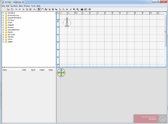
Figure 2: UbikSim Editor
•Pathfinder. It uses A* to calculate paths in the environments. Each cell is considered a node in the graph.
•PathfinderThread. Same as Pathfinder but the calculation does not stop the simulation execution. This
makes execution smoother, but simulation reproducibility is lost. In general, Pathfinder is a better option
since, even if the simulation is slowly executed, agents time depends on the timestamp.
•BooleanPathfindingMap. Used by Pathfinder to know fixed obstacles in the scenario and detect mobile
obstacles.
1.3 Some notes about navigation
The demos basically show the use of navigation in UbikSim. Each cell in the environment is considered a graph
node, A* is applied to detect a destiny, agents follow the path, and A* is executed again if some mobile objects
are in the middle of the path to avoid them. The PathfinderDemo class contains all you need to know about
this approach.
This always gets a path if there is one. However, it is computationally costly, specially when cell size is
very small. On the other hand, the time needed is very reasonable since A* uses heuristic algorithms to avoid
exploring all the grid/graph. Moreover, the time from agents’ view point is not affected if the pathfinding takes
a few extra seconds since is the “timestep” what makes them age.
An alternative is to use navigation meshes. Slick2D. a video game engine used in UbikSim, provides them.
However, this involves including an extra layer of complexity (and bugs) to build the mesh and deciding what
to do when nodes in the mesh are not reachable. Another option is the use of more advanced algorithms such as
D* lite, which does not have repeat all operations to find a path when a mobile obstacle is detected. However,
this involves using a lot of memory to store network information for each agent so it is not usually employed in
videogames and simulations where there are a large number of mobile agents.
1.4 How to use Ubik Editor to create a simulation
A tutorial to create a basic simulation follows. This tutorial is concerned to learn only the basic controls. If
you are interested in create more complex models, it is recommended to study the section 2 of this document.
Ubik Editor is an indoor environments editor integrated in UbikSimIDE. This editor allows the users to
create buildings over a 2D plan, and also offers a navigable 3D view of the model. There exists the possibility
of including a wide range of furniture, domotic devices and persons. Figure 2(b) shows an screenshot of the
editor which is divided in four resizable panes.
•The part 1 is the objects palette. It contains all the available furniture, domotic devices, persons, doors,
etc. you may add to your model, they are classified in folders. Every object of this palette must have an
associated JAVA class if it is going to manifest behaviours during the simulation.
•The part 2 is the 2D view. Over this plan viewed from top, the user can draw the rooms and walls of
the environment with the mouse and layout the objects. The objects to be included in the model can be
dragged & dropped to the plan directly from the palette. The position of the objects can be modified at
every moment. A magnetism function allows to put the objects fixed to other objects, e.g. a clock fixed
6
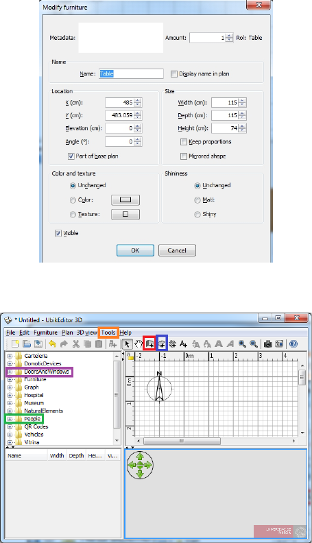
Figure 3: Object properties window
Figure 4: UbikSim editor details
to a wall. Doing double click on an object, it is possible to define some configuration properties as the
size or the elevation from the floor. Figure 3 shows the object properties that can be modified. The field
metadata allow the users to create specific properties for every object.
•The part 3 is a list which contains all the objects introduced in the model. Their name, size and other
characteristics may be displayed. It may be sorted by clicking on each column title. Double-clicking on
them it is possible to modify all their properties in a menu as the one shown in figure 3.
•The part 4 is a 3D view of the model. It shows a preview of the model and it is updated in real time
when the user modifies the model. Every time a new object is added to the 2D plan or the environment
is modified, the preview is updated. The 3D preview has visualization capacities as zoom, rotation and
first person view.
From now on, we offer an step by step example of how to create a simple environment. Firstly, for creating
the walls click on the button boxed in red in figure 4. A window showing tips about the wall creation will
appear (figure 5(a)).
Create two squares with the walls. Then, you can create the rooms clicking on the button boxed in blue in
figure 4. A window showing tips about the room creation will appear (figure 5(b)). You can draw the contour
of two rooms in this model, one room per every wall square previously created. After that, put a door in
7
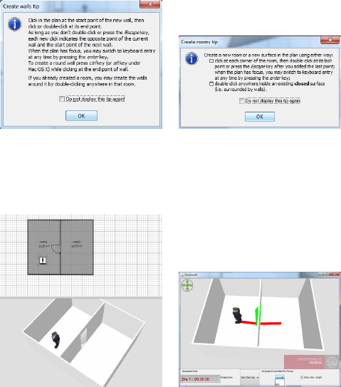
(a) (b)
Figure 5: (a) Wall creation tips, (b) Room creation tips
(a) (b)
Figure 6: (a) Result for a simple environment creation, (b) UbikSim 3D Display
the wall positioned between the two rooms. You can select the object “opened door” situated into the folder
DoorsAndWindows of the palette (purple box in figure 4).
The next step is to include a person in the model. It is recommended to use the object “Teacher 2” from
the folder People (green box in figure 4) and put it in any of the rooms.
Finally, doing double click on the rooms and the person, you can assign them names. These names are
useful for reference them in the JAVA code. For example, assigns room1 and room2 to the rooms and Bob to
the person. The final result must be similar to this one shown in figure 6(a).
Save the environment as “experiment.ubiksim” (File, save as).
1.5 How to launch a simulation within the editor
This section explains how to launch simple simulations within the editor. To know more about how to execute
UbikSim with more advanced features, it is recommended to take a look to the section 3 of this document.
Once your simulation file is saved, go to the menu Tools (orange box in figure 4) and choose the option
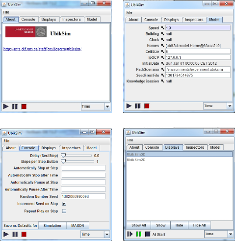
Simulate. Then, the UbikSim console will appear, see figure 7(a). It is based on the original console of MASON.
The MASON console offers different options. For example, the tab Model (see figure 7(b)) allows to configure
some simulation parameters, as the random seed or the cell size or the initial date of the simulation. In the tab
Console it is possible to configure some console parameters, e.g., a delay that establishes the simulation speed
(recommended between 0.5 and 1), see figure 7(c). It is possible to show the visualization of the simulation in
a new window, in 2D or 3D, selecting the option in the tab Displays (figure 7(d)). Finally, you can start the
simulation clicking the play button.
UbikSim2D display can be used watch the simulation but its main functionality is to inspect properties
of entities in the simulation such as agents and devices. By double-left click on a entity, its properties are
presented in the Inspectors tab, see Figure 7. More details about how to use inspector tab at http://cs.gmu.
edu/~eclab/projects/mason/docs/tutorial0/index.html.
UbikSim3D display offers some functionalities, see Figure 6(b):
8
(a) (b)
(c) (d)
Figure 7: (a) UbikSim console based in MASON, (b) Model configuration tab, (c) Console configuration tab,
(d) Display configuration tab
•Change perspective of the camera between “View from top” and “View from observer”. Use WSAD keys
to control de camera in ”View from observer” mode.
•Any character can be controlled using keyboard and mouse. The display offer a list with the names of the
people, once one is selected, click the 3D frame. Keys to control the character are presented in 1.
•Last option (“Show Nav. Graph”), displays in the scenario the navigation graph, i.e., the paths that
agents follow. It is useful to debug scenarios and detect isolated areas.
9

’j’ - turn left
’l’ - turn right
’i’ - go ahead
’k’ - 180◦turn
’o’ - open or close a nearby door
’u’ - start or stop person activity
(useful for detecting activity with presence sensor
although the person is not moving)
’+’ - increase speed by 2
’-’ - decrease speed by 2
’0’ - set state of the person to 0
’1’ - set state of the person to 1
’2’ - set state of the person to 2
’3’ - set state of the person to 3
’4’ - set state of the person to 4
’5’ - set state of the person to 5
’6’ - set state of the person to 6
’7’ - set state of the person to 7
’8’ - set state of the person to 8
’9’ - set state of the person to 9
Table 1: Keys to control a person.
10
(a) (b)
(c) (d)
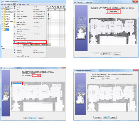
Figure 8: (a) How to import a background image, (b) Wizard to import background image: how to choose an
image, (c) How to establish the image scale, (d) How to put the image as background
2 How to create environments with UbikSimIDE
This section explains how to create an environment model with UbikSimIDE and some tips to ease that purpose.
2.1 Creating the environment
In order to facilitate the environment creation, UbikSimIDE allows the user to import the blueprint of the
environment to create. It can be established as the background of the 2D plan window choosing the option
Plan →Import Background Image..., as it is shown in figure 8 (a).
A wizard that helps you to choose and scale an image file will appear. Then, click on Choose Image and
choose the image file that contains your blueprint in the file dialog. BMP, JPEG, GIF or PNG formats are
supported. Once the image is loaded, click on Continue>, see figure 8 (b).
The next step is defining the image scale. It is recommendable to enlarge the window to have more precision.
Define the scale of the image by moving the end points of the coloured line drawn in the image, in such a way
that this line matches a known length. We recommend to choose a distance as large as possible. Once the line
is correctly positioned on the image, type the real length of this line in the Length of the drawn line field, and
click on Continue. See figure 8 (c) to see an example.
The last step consists in establishing the origin of the image. Define the origin of the image in the plan, i.e.
the point in the image matching the point (0, 0) in the home plan. See figure 8 (d). Click on the button Finish.
Once the wizard is closed, your image will appear behind the home plan grid at the chosen scale, as shown in
figure 9 (a). If you chose a wrong scale or location, edit them by choosing Plan →Modify background image...
out of the menu.
The next step is the wall creation. Click on the button Create walls, as in figure 10 (a). Then click on
the home plan at the start point of the new wall, then click or double-click on the plan at its end point.
As long as you don’t double-click or press the Escape key, each new click indicates the opposite point of the
current wall and the start point of the next wall. It is recommendable to use the zoom tool, with combination
Ctrl+<mouse scroll>, in order to achieve more precision. The walls are straight lines, so you can click at
every room corner to create them. The wall layout has some predefined angles, probably not enough sufficient
in complex environments like this one. To create a wall with any angle hold pushed the Shift key. It is also
recommendable to do wall layouts as large as possible, e.g. if you are modelling a house, draw first the external
walls and later the internals. When the walls are created, it is possible to see in the 3D view the wall creation
11
(a) (b)
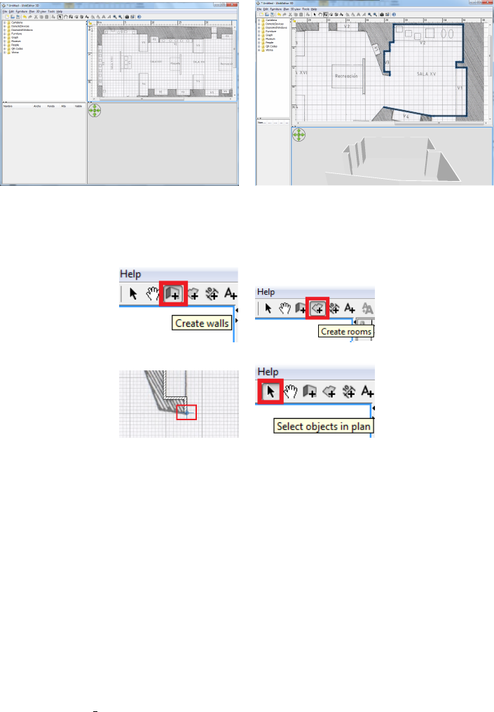
Figure 9: (a) Background image loaded, (b) 3D view with the walls successfully created
(a) (b)
(c) (d)
Figure 10: (a) Tool for wall creation, (b) Tool for room creation, (c) Blue circle that eases the room creation,
(d) Tool for object selection
in real time, see figure 9 (b).
Once the walls are created, the next step is the room creation. For that purpose, click on the button of
figure 10 (b). To create the rooms click at each corner of the walls and draw the room shape. Then double-click
at its last point or press the Escape key after you added the last point. Note that if you situate the cursor
near to the wall corners, a blue circle appears, see figure 10 (c). After the creation of the room, employ the
objects selection tool, as it is shown in figure 10 (d). Doing double click on the room it is possible to edit its
properties (figure 11). In this case, edit the room name, Room1, and the room type, Room. The room type
can be chosen from a combo box that shows all the room types which are implemented in the simulator. It is
possible to edit the room type but you must assure that this type is implemented and its name is added to the
space handler, handlers/space areas.txt. Note that every room must be completely delimited by walls. If you
are interested in not showing a wall, it is recommended to put a frame door whose size was the same as the
wall. More information about this type of doors in the next section.
Once the walls and the rooms are created, the next step is the door creation.
2.2 Doors creation
Doors are objects situated at the object palette, in the folder DoorsAndWindows, see figure 12 (a). To add
furniture (e.g. doors) to your home, drag and drop the corresponding object from catalog to the home plan.
Situate them on the walls, you will see how the door recognize the wall and adapts to it. As an example, we
will use two type of doors. A Frame door is a door without door, only the frame. It is useful to use this object
to connect rooms when there is not a door between them in the reality. The second door is the most common,
Opened door. Once it is situated on a wall, it is necessary to adjust the door width, especially if you are using
a frame door and you want to occupy all the wall. It is easy to do this clicking on the object (every object
12
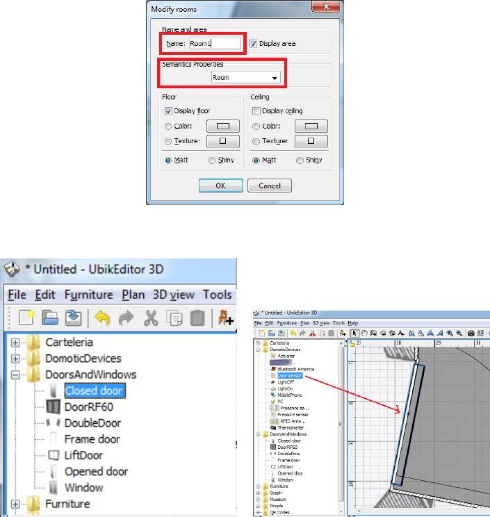
Figure 11: Room properties menu.
(a) (b)
Figure 12: (a) Palette folder containing doors and windows, (b) How to situate a door sensor in a door
in UbikSimIDE has some icons at each corner of the selected piece, you can use these icons to modify some
properties of the object as its size, elevation and angle). See figure 13 for an example of how to make the door
wider.
Note that the doors always must connect two rooms. The doors that connect the building with the exterior,
are special cases. You must create a room that represents the street for a correct performance of the simulator.
Optionally, the properties of the door can be modified double-clicking on the object, see figure 14 (a). By
default, all the doors in the simulator (not in the editor) which are opened are coloured in green. If you want
to create closed doors or any other state, you can indicate this at the field Metadata. The possible door states
are the following, use exactly these names in the field Metadata to achieve this kind of door.
•opened: opened door (default state), these doors are coloured in green during the simulation.
•closed: closed without key, these doors are coloured in yellow during the simulation.
•locked: closed with key, these doors are coloured in red during the simulation.
Figure 14 (a) shows an example of how to indicate the door is initially closed, by writing the word “closed”.
13
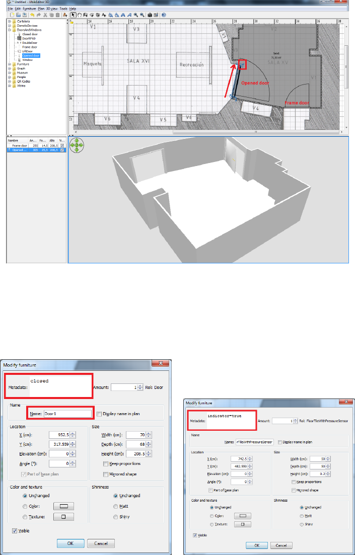
Figure 13: Resizing a door.
(a) (b)
Figure 14: (a) How to edit the door type (opened, closed or locked), (b) Floor tile with press sensor properties
14
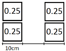
Figure 15: Person weight distribution model.
2.2.1 Some notes about the doors and the simulation
•When during a simulation, an agent calculates routes of how to go from one place to another, the routes
that cross a door locked will be ignored.
•Doors can be opened, closed or locked during the simulation using the methods: open(),close(),lock()
and unlock() of the class sim.app.ubik.building.connectionSpace.Door.
•The code to obtain the closest door, it is written in a class that heritages from Person, an example of use
follows:
SpaceArea sa = ubik.getBuilding().getFloor(floor).getSpaceAreaHandler().
getSpaceArea(getPosition().x, getPosition().y, Room.class);
Room room = (Room) sa;
ConnectionSpaceInABuilding c =
room.getConnectionSpaceNearerTo(getPosition().x, getPosition().y);
Door door = (Door)c;
door.lock();
door.open();
door.close();
door.unlock();
2.3 Door sensor
The door sensor indicates if a door is closed (state closed or locked) or opened (state opened). The door sensor
is situated in the objects palette, at the folder DomoticDevices. To associate a door with a sensor situate it
over the door in the plain. It is very important that the sensor be contained into the door area. This area is
the rectangle which illuminates when the door is selected. Figure 12 (b) shows how a sensor is contained into
the door area. If it is necessary, resize the sensor and do it lesser.
2.4 Floor tile with pressure sensor
This element is located at the folder DomoticDevices with the name FloorTileWithPressureSensor. It consists
in a tile of 50x50cm with an associate pressure sensor which detects the weight of persons that step on the floor
tile. It is possible to define in the field metadata “indicator=true” (figure 14 (b)). In this case, when the tile
is pressed during the simulation, it will be coloured in green. If you do not want this feature, you can indicate
“indicator=false” instead. To fill a room with tiles of this type it is recommended to select a set of them and
(while holding the key SHIFT ), copy and paste them.
To detect the weight of a person, they must have this property in the field metadata. By default, the weight
of all the persons in the simulator is 70Kg, represented by the property “weight=70”. This weight is distributed
in a model as the figure 15 shows. At a distance of 10 cm, the weight is distributed in two spaces of 10cm
(simulating the foot). Every space corresponds to a point where the 0.25 of the total weight of the person falls.
15
Ubik
- seedFromFile: long
- cellSize: int
- initialDate: Date
- pathScenario: String
- speed: double
- clock: UbikClock
- void start()
- void finish()
SimState
- void start()
- void finish()
GUIState
- void start()
- void quit()
- void init(Controller)
UbikSimWithUI
- void start()
- void quit()
- void init(Controller)
UbikSimDisplay3D
UbikSimDisplay2D
state
config.props
Configuration
Console
controller
MyExperiment
- int: numberOfWorkers
- void start()
- void finish()
MyUbikSimWithUI
- void start()
- void quit()
- void init(Controller)
MyDisplay
JFrame
UbikSimIDE
Mason
MySimulation
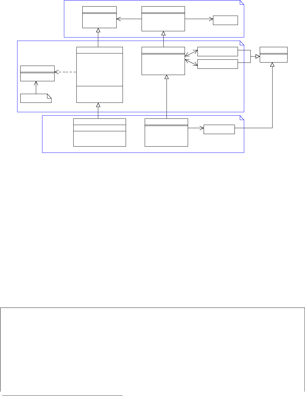
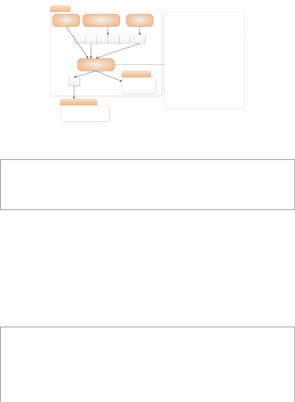
Figure 16: Diagram of the main classes.
3 How to extend UbikSimIDE to develop your own simulation.
This section is an overview of the main classes of UbikSimIDE and it explains how to extend these classes in
order to perform our simulations properly.
UbikSimIDE is based on MASON1, and most of its facilities are available from UbikSimIDE. So, it is
recommended to read sections 1 and 2 of the MASON manual2. Take in mind that UbikSimIDE visualization
(2D and 3D) is not performed using MASON.
Figure 16 shows how UbikSimIDE extends SimState and GUIState. SimState represents a simulation and
GUIState is the interface used to control and display the simulation. Ubik extends SimState since it is a basic
simulation which has a seed, a cellSize (granularity of space), a initial date of the simulation, a path where the
scenario (.ubiksim) is located. All these attributes can be loaded from a file using Configuration class. This class
has get and set methods in order to make easier their management. By default, the file is called “config.props”
but you can specify any other in the constructor method (new Configuration(”file path”)). If you do not pass
a configuration object to Ubik class, it creates one using “config.props”.
Listing 1 shows how to run UbikSim using the Configuration class.
1 public s tatic void main ( String [] ar gs ) {
2 Con fig ur ati on co nf igu ra tio n = new C on fi gur at ion (" m yconf ig . props " );
3 conf igu ra t ion . se tPa th Sce nar io ( " my Scenr io . ubik s im ") ;
4 conf igu rat ion . setSeed (0123 456) ;
5 conf igu rati on . se t Ini tia l Dat e ( new Date ( System . c u rre ntT ime Mil lis () )) ;
6
7 Ubik ubik = new Ubik ( co nfi gura tion ) ;
8 Ubik Sim With UI vid = new UbikS imW i thU I ( ubik ) ;
9 Co ns ol e c = ne w C ons ole ( vid ) ;
10 c. set In cr em en tSee dO nS to p ( fal se );
11 c. se tVisi ble ( true );
12 }
1MASON website: http://cs.gmu.edu/~eclab/projects/mason/
2MASON Manual: http://cs.gmu.edu/~eclab/projects/mason/manual.pdf
16
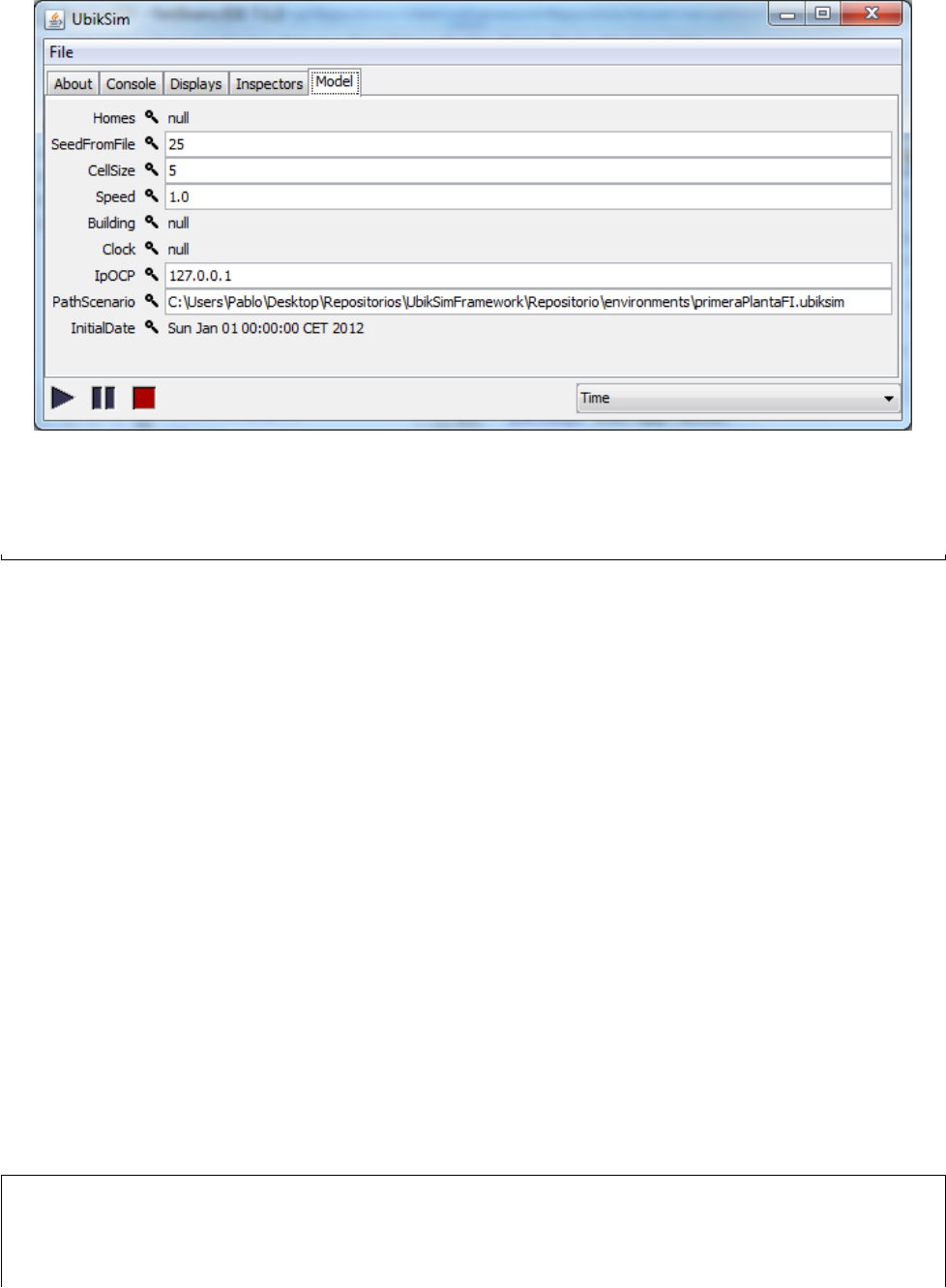
Figure 17: Model tab of the console with simulation parameters.
Listing 1: Usage of the Configuration class.
Ubik class initializes its attributes using configuration class. The initialization is carried out in the con-
structor method in order to be able to change these attributes from Model tab of the console. It is explained
below.
UbikSimWithUI class extends GUIState and offers two displays. UbikSimDisplay3D is used to watch the
simulation in 3D and allow you to control a character of the simulation. UbikSimDisplay2D is used to inspect
the properties of the entities of the simultation on the Inspector tab. By double-click on an entity in the
UbikSimDisplay2D, their properties are shown in the tab. Every display should extend JFrame class.
Next two subsections explain how to extends Ubik and UbikSimWithUI classes to customize simulations.
3.1 MyExperiment
Every experiment (or simulation) must extend Ubik class (such as MyExperiment). This class has attributes
related with our simulation. If we create get and set methods for each attribute, they will could be edit in the
Model tab of the console, see Figure 17. Fields are not editable since they had not defined their set methods. It
is recommended to define a method that has a seed as a parameter and/or one that has a Configuration class
as parameter. Both constructors must call to their parent constructor, see listing 2.
The start() method should call super method and initialize variables related with the scenario. The scenario
is created in Ubik.start() method. It is important, because in the constructor, the environment is not created
yet.
In MyExperiment, it duplicates an agent whose name is “Agent” and it is moved to a random position.
The agent must exists in the scenario. Then, the name of each agent is changed to “Agent-x”, i.e., “Agent-1”,
“Agent-2”, etcetera.
The finish() method should be redefined in order to release resources created in the class. In this case it is
not necessary.
1 public class MyE x per i men t exte nds Ubik {
2
3 int numberOfAgents = 100;
4
5 pu blic MyE xp eri me nt ( long seed ) {
17

6 super ( seed ) ;
7 }
8
9 @Over ride
10 publ i c void start () {
11 super . start () ;
12
13 Autom aton . setEcho ( false ) ;
14
15 Pe rson pa ttern = P os iti onT oo ls . getPe rso n (this , " Agent " );
16 P er so n Ha nd le r p h = g et Bu il di ng () . g et Fl oo r (0) . g et Pe rs on H an dl er () ;
17 ph . ad dPers ons ( ge tNu mb e rO f Ag ent s () , true , pat tern );
18 ph . cha ng eN ame Of Ag en ts (" Agent " );
19 }
20
21 publ i c int getN umb erO fAg ent s () {
22 return numberOfAgents;
23 }
24
25 pu bli c void s et Nu mb erO fA ge nts ( int n um ber Of Ag ent s ) {
26 this.numberOfAgents = numberOfAgents;
27 }
28 }
Listing 2: MyExperiment class
The experiment can be launched without graphical user interface and with total control of each step with
the code in listing 3. In the example the experiment is run until step number 5000.
1 public s tatic void main ( String [] ar gs ) {
2 Sim St at e s tate = new St ud en ts ( S ys te m . c u rr en tT i me Mi ll i s () ) ;
3 state . start () ;
4 do
5 if (! state . sche dule . step ( sta te )) br eak ;
6 while ( state . sc hedul e . get Steps () < 500 0) ;
7 st at e . f in is h () ;
8 Sy ste m . exit (0) ;
9 }
Listing 3: Launching a controlled experiment without graphical user interface.
In order to monitoring the simulation with a graphical interface, the experiment has to be launched using
UbikSimWithUI class, see listing 4.
1 public s tatic void main ( String [] ar gs ) {
2 Ubik ubik = new My Exp er im en t (0) ;
3 Ubik Sim With UI vid = new UbikS imW i thU I ( ubik ) ;
4 Co ns ol e c = ne w C ons ole ( vid ) ;
5 c. set In cr em en tSee dO nS to p ( fal se );
6 c. se tVisi ble ( true );
7 }
Listing 4: Launching a controlled experiment with default graphical user interface.
3.2 MyUbikSimWithUI
In order to add windows to control any element of the simulation, such as console to send commands to the
agents, UbikSimWithUI class should be extended, such as MyUbikSimWithUI, see Figure 16. UbikSimWithUI
already has to displays. 2D display is used to inspect properties of every element of the scenario by double
clicking on it. The properties are presented in Inspector tab of the console. 3D display is used to watch the 3D
simulation.
18

The display should extend JFrame class.
Displays must be created and registered to the console in the start() method, see listing 5. Displays can
be set visible or not by default. Anyway, displays can be shown or hidden using Displays tab of the console.
finish() method should be redefined to unregister every display registered in start() method.
1 public class MyU bik Sim W ith UI extends Ubi kSi mWit hUI {
2
3 pr ivate MyDisp lay myDis p lay ;
4
5 @Over ride
6 publ i c void start () {
7 super . start () ;
8
9 myDi spla y = new M yDi spl ay ( this ) ;
10 myDisp lay . set Visib le ( true );
11 contr oller . r egis ter Fram e ( ubi kSi m Dis pla y2D ) ;
12 }
13
14 @Over ride
15 publ i c void finish () {
16 su pe r . f in is h () ;
17
18 contr olle r . unr egi s te r Fra me ( m y Displ ay );
19 }
20 }
Listing 5: MyUbikSimWithUI class.
To launch our customized console, UbikSimWithUI is replazed by MYUbikSimWithUI, see listing 6.
1 public s tatic void main ( String [] ar gs ) {
2 Ubik ubik = new My Exp er im en t (0) ;
3 Ubik Sim With UI vid = new MyUb ikSi mWi thU I ( ubik ) ;
4 Co ns ol e c = ne w C ons ole ( vid ) ;
5 c. set In cr em en tSee dO nS to p ( fal se );
6 c. se tVisi ble ( true );
7 }
Listing 6: Launching the experiment with a customized GUI.
The UbikSimclass project available on-line (visit UbikSim site) model a test person escaping from a building
and offer an example of batch experiments in EscapeSimBatch (see Section 5). Hereinafter the code of this
project will be used as example. In this project, EscapeSim class (see Listings 7) extends Ubik class and
EscapeSimWithGUI (see Listings 8) extends UbikSimWithUI.
1 public class Escap eSim extends Ubik {
2
3 static int max Tim eFo rE x ec u ti o n =1500;
4
5/* *
6* Object with in form atio n about ex ecutio n and , if needed ,
7* to finish the e x ecuti o n
8*/
9 Es cap eMo nit orA gen t ema ;
10 Fire fire;
11
12 /* *
13 * Passing a random seed
14 * @param seed
15 */
16 pu blic Escap eSi m ( long seed ) {
17 super ( seed ) ;
19

18
19 }
20
21 /* *
22 * Passing a random seed and time to make Es ca p eM o ni t orA gen t to f i ni sh sim ulat i on
23 * This time must be less than m axT ime For Exe cut ion
24 * @param seed
25 */
26 pu blic Escap eSim ( long seed , int t im eFo rSi m ) {
27 super ( seed ) ;
28 Esc ape Mo n it orA gen t . set Step ToSt op ( ti m eFor Sim ) ;
29
30 }
31
32
33 /* *
34 * Using seed from config . pros file
35 */
36 public Es capeS i m () {
37 sup er () ;
38 s et Se ed ( g et Se ed Fr om Fi le () ) ;
39 }
40
41 /* *
42 *
43 * Adding things bef o r e running s imula tion .
44 * Method called after pre s sing pause ( the buildin g varia bles are in stan tiat ed )
but before exec uting si mulat ion .
45
46 */
47 public void start () {
48 super . start () ;
49 ema = new E sca pe Mo ni to rA gen t ( thi s );
50 fire = new Fire ( th is );
51 Autom aton . setEcho ( false ) ;
52 // add more peo p le
53 P er so n Ha nd le r p h = g et Bu il di ng () . g et Fl oo r (0) . g et Pe rs on H an dl er () ;
54 // ph . ad dP er so ns (20 , true , ph . g et Pe rs on s () . get (0 ) ) ;
55 // change their name
56 ph . ch ang eNa meO fAg ent s (" a" );
57 }
58
59
60 /* *
61 * Defa u lt exe cution witho u t GUI . It execu ted the sim ulat i on for m axT ime For Exe cut ion
st eps .
62 * @param args
63 */
64 pu blic st atic void main ( String [] args ) {
65
66 E sc ap eS im s ta te = n ew E sc ap eS im ( System . c ur r en tT im e Mi ll is () ) ;
67 state . start () ;
68 do {
69 if (! state . sc hedu le . step ( state ) ) break ;
70 } whi le ( stat e . sch edule . getSt eps () < m axTi me Fo rE xe cu ti on ); //
71 st at e . f in is h () ;
72
73
74 }
75
20

76 /* *
77 * Get the Fire object from the s imula tion object
78 * @return
79 */
80
81 pu bl ic Fi re g et Fi re () {
82 re turn f ir e ;
83 }
84 /* *
85 * Get the mon itor agent ( agent logging data ) from the sim ulati on object
86 * @return
87 */
88 pu bl ic E sc a pe M on i to rA ge n t g et M on it or A ge nt ( ) {
89 re tur n ema ;
90 }
91
92
93
94
95 }
Listing 7: EscapeSim class.
1/* *
2* Start the sim with a GUI , d isplays show 3 d and 2 d views
3* @ auth or Em ilio S er ra no , Ph .d .; e se rr ano @g si . dit . upm . es
4*/
5 public class Esc ape Sim Wit h GUI exte nds Ubik S imW ithU I {
6
7 pu blic Esc ap eS im Wi thG UI ( Ubik ubik ) {
8 super ( ubik ) ;
9 }
10
11 /* *
12 * Method called after pre s sing pause ( the buildin g varia bles are in stan tiat ed )
but before exec uting si mulat ion .
13 * Any JFrame can be reg ister ed to be shown in the d i splay menu
14 */
15 @Over ride
16 publ i c void start () {
17 super . start () ;
18 (( E sca peSi m ) state ). fire . in se rt InD is pl ay () ;
19
20 }
21
22 /* *
23 * Execu ting simu latio n with GUI , it d e legat es to EscapeSim , simul ation witho ut GUI
24 * @param args
25 */
26 pu blic st atic void main ( String [] args ) {
27 Es ca pe Si m e s ca pe si m = new Es ca pe Si m ( Sy st em . c u rr en tT i me Mi ll i s () ) ;
28 Esc ape Sim Wit hGU I vid = new Esca peS im W it h GU I ( escap esim ) ;
29 Co ns ol e c = ne w C ons ole ( vid ) ;
30 c. set In cr em en tSee dO nS to p ( fal se );
31 c. se tVisi ble ( true );
32 }
33
34
35
36
21

37
38
39
40
41
42 }
Listing 8: EscapeSimWithGUI class.
3.3 Launching our experiment using UbikSimIDE
An experiment can be launched from the UbikSimIDE. By default, UbikSimIDE launch Ubik class, see method
execute of SimulationAction in listing 9. Note that Configuration class is used and the path of the scenario is
that which is opened. If we want to launch our experiment by pressing Tools →Simulation form UbikSimIDE,
Ubik class has to be replaced by MyExperiment such as was explained before.
1 public class Ubi kSim Plug in extends Plugin {
2
3 private static Plugin plugin;
4
5 @Over ride
6 publ i c P lugi nAct ion [] getAct ions () {
7 setP lugi n ( this ) ;
8// TODO Auto - ge nerat e d m e th o d stub
9 re turn new Plu gin Act io n []{ new Simu la ti on Ac tio n () };
10 }
11
12 publ i c st a ti c Pl u gi n getPl ugin () {
13 return plugin;
14 }
15
16 publ i c st a ti c void setPl ugin ( Plugin plugin ) {
17 Ubi kSi mPl ugi n . plugin = plugin ;
18
19 }
20
21 publ i c class Sim ula tio nAc tion exte nds Plugi nAct ion {
22
23 publ i c S imu lat ion Acti on () {
24 put Pro per ty V al ue ( Prop erty . NAME , " S imul ation " );
25 put Pr op er ty Val ue ( Prope rty . MENU , " Tools " );
26 // Enable s the action by default
27 setE nab le d ( true );
28 }
29
30 @Over ride
31 publ i c boo l ean is Enabl ed () {
32 retur n getHom e () != null && g etHome () . ge tRooms () != null && g e tHome () .
ge tR oo ms () . si ze () > 0;
33 }
34
35 @Over ride
36 publ i c void execute () {
37 C on fi g ur at io n c o nf ig u ra ti on = ne w C o nf ig ur at io n () ;
38 St ri ng ho me = g et Hom e () . get Na me () ;
39 conf igu r ati on . set Pat hSce nar io ( home );
40
41 Ubik ubik = new Ubik ( co nfi gura tion ) ;
42 Ubik Sim W ith UI vid = new UbikS imW i thU I ( ubik ) ;
43 Co ns ol e c = ne w C onso le ( vid ) ;
22

44 c. set In cr em en tSee dO nS to p ( fal se );
45 c. se tVisi ble ( true );
46 }
47 }
48 }
Listing 9: Action to launch simulation form UbikSimIDE.
23

4 Navigation in the environment
See new navigation system in UbikSim 2.0 in section 1.3.
UbikSim offers realistic environments, see section 2, while other simulation tools may offer a simple grid to
represent the world. This makes the simulation more descriptive, but also more complex. Specifically, agents
have to be able to recover information from the environment and to move through it. The navigation problem
consists of making an agent go from one point (x1, y1) to another point (x1, y1) avoiding obstacles such as walls
and other agents.
The UbikSim class project available on-line (visit UbikSim site) models a test person escaping from a
building. In this example, as section 6 explains, agents move through a complex environment by simply using
a class called “Move”. However, if it does not work correctly or according to the requirements of the specific
simulation, this section offers insights into the navigation given by UbikSim.
4.1 Navigation without tools
The readers used to other tools such as MASON, NetLogo or Repast; may want to program their navigation by
only coordinates in the space. For that purpose, assuming an object ubik which extends the class Ubik (which
represents a simulation, see section refextending), the following method returns an object SparseGrid2D (see
MASON documentation) with the space of a floor:
1 ub ik . ge tB ui l di ng () . g etF lo or ( 0) . g et Sp a ce Ar ea H an dl er () . g etGr id () ;
However, UbikSim offers more abstract tools for the navigation. Specifically, the environment created by
UbikEditor is covered automatically by a number of nodes which form a graph that developers could use for
minimum paths algorithms.
4.2 Automatic navigation graph
The class BuildingToGraph deals with the construction of a graph when the environment is built. More con-
cretely, its method createRooms introduces a number of nodes automatically in each room:
•A node in the center of the room (to move to a room).
•A node for each piece of furniture (to move to them inside a room). The kind of furniture must be
registered in the file “/handlers/furnitures.txt”.
•A node for each “connection space” in the room, such as doors or stairs. These objects are instances of
ConnectionSpaceInABuilding and allow the graph to connect different rooms.
Besides, this method, createRooms, generates the edges inside a room if there is no obstacle between the
nodes (it uses getSpaceAreaHandler().isObstacles(...) for this). The edges are weighted with the distance
between the nodes connected.
After creating the navigation graph for each room, rooms have to be connected. For that purpose, Building-
ToGraph calls the method createConnectionSpace which connect edges between the nodes created for doors and
stairs (objects of ConnectionSpaceInABuilding) in different rooms. The weight given to these edges is stated
by ConnectionSpaceWeighted to give, for example, an infinite weight for close doors.
Warning!. A very important note is that the environment should include “node graphs” manually intro-
duced by the user in UbikEditor (see section 2) for large rooms such as corridors (a node graph in front of
each door is recommended) or rooms which non-rectangular shapes (for example, a room with L-shape should
include a node graph at the corner).
At this point, the developer can choose to use the graph generated by UbikSim directly (possibly after
modifying its generation, for example to add name for special nodes considered in the simulation). This graph
is available in the graph attribute of the class RoadMap. On the other hand, next section gives methods which
automatically obtain paths from the graph.
1 ub ik . ge tB ui l di ng () . ge t Bu il di n gT oG ra p h ( ) . g et Ro ad M ap () . ge tG ra ph ()
24

4.3 Navigating using the graph
The class RoadMap takes the graph generated in the above section and uses Dijkstra’s algorithm provides
several methods to obtain a path from two points in the space and returning it as (1) a list of graph nodes
(getGraphPath); or, (2) a list of positions of the grid (getRoute).
1 ub ik . ge tB ui l di ng () . ge t Bu il di n gT oG ra p h ( ) . g et Ro ad M ap () . ge tG ra p hP at h ( In t2 D ori , Int2D
dest)
Note that these methods stored the routes previously calculated, so if the environment is supposed to change
dynamically (for example, doors are opened and closed during the execution) this feature should be removed.
The method getGraphPath checks these routes already calculated in the matrix routes[p][q].
25

5 Batch experiments, logging data, and conducting statistic opera-
tions
When working with UbikSim, developers probably are interested in executing not only one simulation but
hundreds of them to learn about the model. For that purpose, batch experiments must be conducted. The
ubikSim class project available on-line (visit UbikSim site) models a test person escaping from a
building and offers an example of batch experiments in EscapeSimBatch. Hereinafter the code
of this project will be used as example.
A batch class must:
•Iterates over the different parameters of the simulation experimentsForDifferentParameters()
•Executes a batch of experiments for those parameters batchOfExperiments()
•Executes one experiment for each element of the batch oneExperiment(int seed). The series of seeds must
be repeated for each different combination of parameters.
•Performs statistical operations on results and prints them in files. The example assumes 2 operations
(in 2 files): mean and standard deviation for the metrics logged. It can be easily extended with more
operations.
The EscapeSimBatch example is shown below:
1/* *
2*
3* Batch of exp erim ents for Es capeSi m
4* @ auth or Em ilio S er ra no , Ph .d .; e se rr ano @g si . dit . upm . es
5*/
6 public class Esc ape S imB atc h {
7 stat i c int exp eri men ts Per Par am ete rs = 3;
8/* *
9* Time for each experiment , E s ca p eM o ni t orA gen t will end simula tion at this step
10 */
11 stat i c int t ime For Exp eri men t = 1000;
12 /* *
13 * Extra hea ding added for each param eters co nfi g ura tion in the data lo g ge d by
Esc ape Mon ito rAg ent
14 */
15 st ati c A rra yList < Str ing > e xt ra He ad in gs Per Pa ra me ter ;
16 /* *
17 * name with ou t p ut
18 */
19 stat i c String fileN ame ;
20
21 public s tatic void main ( String [] ar gs ) throws IOE xc ept io n {
22 // name of the batch file
23 String d ate = ( new Da te () ) . t oSt ri ng () . re pl ac e ( ’ : ’, ’. ’ );
24 fileNa me = " B atcho utpu t " + date ;
25 ArrayList < Gen er icLogger > r = e xp er ime nt sFo rD iff er ent Pa ram et er s () ;
26 prin tInFi le (r );
27 Sy ste m . exit (0) ;
28
29 }
30
31 /* *
32 * Expe rime n ts for di fferen t pa rame t ers of the con fi guration , example : number of
agents
33 * @return
34 * @throws IOE xcept ion
35 */
26

36 private static ArrayList < Gene r icLogger > ex pe ri me nt sF or Di ff er en tP ar am et er s () throws
IOException {
37 ArrayList < GenericLogg e r > r = new ArrayList < GenericLogger >() ;
38 e xt ra He ad ing sP er Pa ram et er = new ArrayLis t < Stri ng >() ;
39 r . ad dAl l ( b a tc h Of Ex pe r im en ts () ) ;
40 /* if needed , add a loop with an i ntera tion for parameter , change the
simu l atio n parameters ,
41 * and add an extra heading per con figu rati on to d istin guis h the d i ffere nt
ba tch in the outpu t file
42 */
43 extraHeadingsPerParameter.add("");// no extra h eading for mean
44 extraHeadingsPerParameter.add("");// no extra h eading for de viat ion
45 d el et eT em pF il es () ;
46
47 retu r n r;
48 }
49
50 /* *
51 * A batch of exp erim ents .
52 * Mean and dev iation of exp erim e nts are re giste red in the list of result
53 *
54 * @retur n gene ric l o ggers with the r e sults regis tered ( mean and deviat i on )
55 */
56 pr ivate static ArrayList < GenericLog ger > b atc hO fE x pe ri men ts () {
57 ArrayList < GenericLogg e r > l ist OfR esu lts = new ArrayList < GenericLogg e r >() ;
58 for ( int i = 0; i < expe ri men tsP er Par ame te r s ; i ++) {
59 G en er i cL og g er gl1 = o ne Ex pe ri me n t ( i * 1 00 0) ; // seed shoud be equal for
diffe r ent par amet e rs
60 li st Of Re su lts . add ( g l1 ) ;
61 }
62 ArrayList < GenericLogg e r > r = new ArrayList < GenericLogger >() ;
63 r. add ( Ge ner icLo gger . get M ean ( list OfR esul ts )) ;
64 r. add ( Ge ner icLo gger . g et Sta nda rdD evi ati on ( li stO fRes ults ) );
65 retu r n r;
66
67 }
68 /* *
69 * A si m pl e ex p erim e nt , code based on the main me th o d of Escap eSim
70 * @param seed
71 * @return
72 */
73 pu bli c s tat ic Gen er ic Lo gg er one Ex pe ri men t ( int seed ) {
74
75 Es ca pe Si m s ta te = new Es ca pe Si m ( se ed , t i me Fo rE x pe ri me nt ) ;
76 state . start () ;
77 do {
78 if (! state . sc hedu le . step ( state ) ) break ;
79 } whi le ( stat e . sch edule . getSt eps () < t im eF or Ex pe ri me nt *2) ; // the
Esc ape Mon ito rAg ent will finish before
80 st at e . f in is h () ;
81 re tur n s tate . ema . ge tG en eri cL og ge r () ;
82 }
83
84 /* *
85 * Print results from the gen e ric logger of each e xecuti on assu ming that mean and
devia tion has been logg e d
86 * @param r
87 * @throws IOE xcept ion
88 */
89 pr ivate static void pr in tIn Fi le ( ArrayList < Generi cLogger > r ) throws IOEx cep tio n {
27

90
91 ...
As seen, batch experiments in this example deal with genericLogger objects which are filled by an Escape-
MonitorAgent. This is a logger agent which is created in the start method of the simulation without GUI (so
it is also present in batches and experiments with GUIs). Logger agents are very simple MASON agents which
extends from MonitorService, requiring to define:
•register(): To be included in the schedule.
•step(SimState ss): To perform actions which basically are: (1) fill a generic logger (or your favorite data
structure), (2) check if the simulation has to finish to kill it.
The EscapeMonitorAgent code is given below:
1 public class Es c ap e Mo n ito rAg ent i m plem ents Mo nito rSe rvic e {
2/* * T hi s a ge nt s to ps si mu la ti on in t his st ep */
3 protec ted st a ti c long maxS tep T oSt op =1000;
4
5/* *
6* Data struct u re to log data and co nduct stat istic al oper a tion s
7*/
8 protec ted Gen eric Logg er gen eric Log g er ;
9 prot ecte d U bi k ubik ;
10 /* *
11 * Counter with peo p le who have touch fire
12 */
13 protec ted int peo ple C los eTo Fir e =0;
14
15
16
17 pu blic Esc ap eM on ito rA ge nt ( Ubik u ) {
18 this . ub ik = u ;
19 St ri ng l og He ad in gs [] ={ " P eo pl eI nB ui ld in g " , " P eo pl e Wh oR ea ch Fi r e " };
20 gene ric Logg er = new Ge ner icLo gge r ( log Head i ngs ) ;
21 reg is te r () ;
22 }
23
24 /* *
25 * Set the nu m be r of the step to stop s imul ation
26 * @param s
27 */
28 pu blic st atic void se tS te pT oS to p ( long s ){
29 maxS tep ToSt op =s ;
30 }
31 /* *
32 * Get the gene ricL ogge r with the data of the si mulat ion
33 * @return
34 */
35 pu bl ic G e ne ri c Lo gg er g e tG en er i cL og ge r () {
36 re t ur n g ene r icL ogge r ;
37 }
38
39 /* *
40 * Regist e r the fire in the sc hedule ( to make the simu latio n call the step method in
fire for each step).
41 */
42
43 publ i c void regist er () {
44 ubik . sc hedule . sch ed ule Rep ea tin g ( this , 1) ;
45 }
28

46 /* *
47 * Method with the act i ons to be p erform ed by this agent in each step : adding data in
gene ric L ogg er and che cking if the simul atio n has to finish
48 *
49 * @param ss
50 */
51 pu bl ic vo id s tep ( S im St at e ss ) {
52 List < Pe rson > p eople = ub ik . g et Buil di ng () . ge tF lo or (0) . g et Pe rs on Ha nd le r () .
ge tP er so ns () ;
53 do uble [] t oLo gI nSt ep ={ people . size () , pe op le Cl os eT oF ire };
54 gene ric Logg er . addStep ( t o LogI nSte p );
55
56 if (ubik . schedul e . getSte ps () >= max Ste pToS top ) {// end s imula tion from agent
monitor
57 ub ik . ki ll () ;
58 }
59
60 }
61
62 publ i c void stop () {
63 throw new U ns upp or t ed Op e ra tio nE xce pt ion (" Not supp orted yet . " ) ;
64 }
65
66
67
68 }
29

6 Modelling people in UbikSim
The example of person given in the simulator is TestPerson. It extends the Person class and has a method step
as any MASON agent to implement its behaviour.
6.1 Creating crowds in the simulator
The simplest way to model a group of people is using the field “amount” of a person inserted from the editor.
Putting a value of x, x copies of the aforementioned agent are distributed at random positions in the environment.
Only positions in rooms with name are considered.
Groups of agents can also be created and deleted dynamically from the code (even during a simulation).
For that purpose, methods of the PersonHandler class which are useful are: addPersons and removePersons.
Another useful method is changeNameOfAgents that gives each agent x a name “a x”. These methods are
usually called in the method start of the simulation without GUI extending the Ubik class.
Sometimes, it is also interesting to model agents who exit of the graphical representation without occupying
any space or losing their execution turn, for example when modelling a room where agents can come in and
out without modelling what is outside of the room. Subsequently, this agent must be introduced again in the
environment. For these cases, the PositionTools class provides developers with the following methods: isInSpace,
putInSpace, and getOutOfSpace.
6.1.1 Recovering the initial position of persons added in runtime
The following code can be used in the step method of a person to make sure that the initial position is available
when needed:
1 if ( i ni ti al Po si ti on == n ul l ) {
2 Sp ac eA re a sa = ( S pa ce Ar ea ) ubi k . g e tB ui l di ng () . g et Fl oo r (0) . ge tS p ac eA re a Ha n dl er () .
getS pac eAr e a ( posi tion .x , posi tion . y) ;
3 if ( sa i ns t an ce of Roo m ) {
4 i ni t ia lP os it io n = ( Roo m ) sa ;
5 } els e if ( sa i ns ta nc eo f D oor ) {
6 Do or d oor = ( Do or ) sa ;
7 In t2D point = do or . ge tA cc es sP oi nt s () [0];
8 i ni t ia lP os it io n = ( Roo m ) ubi k . ge tB ui ld in g () . g et Fl oo r (0) . g et Sp a ce A re aH an d le r () .
get Spa ceA rea ( poin t .x , point . y) ;
9 }
10 }
6.2 Using the Automaton class
6.2.1 Introduction to Automaton
As said, there is a step method in TestPerson (and Person) to implement any behaviour. However, UbikSim
gives a top-down approach for modelling complex agents by using the class Automaton. This approach involves
the breaking down of a human behaviour to gain insight into its compositional sub-behaviours.
Automaton is a hierarchical automaton of behaviours (HAB). Each state is another automaton (with sub
states which also are automata). There is a main automaton (the one connected directly with the Person),
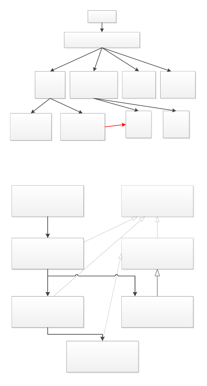
father automata and subordinate automata. Maybe you see it better as a tree of behaviours. Figure 18 offers
an example to illustrate the idea of Automaton. A baby delegates to babyAutomaton (extending Automaton)
to implement baby’s behaviour. This automaton can generate transitions to the states: play, be hungry, sleep,
and so on. Some of these states are complex enough to be further detailed. Actually these states are also
instances of Automaton, so they have more subordinate automaton/states (Play can generate transitions to use
toy and break toy). The idea of the tree is useful, but it is not a tree (break toy can delegate to cry). The
UbikSim class project available on-line (visit UbikSim site) models a test person escaping from a
building with the classes described in figure 19. Hereinafter the code of this project will be used
as example. The following code shows the person creating and delegating to the automaton:
30
Baby
AutomatonBaby
Play Sleep Relieve
BeHungry
Cry Eat
UseToy BreakToy
Figure 18: Classes with the behaviour of a baby
TestPerson
AutomatonTe
stPerson
Move Disappear
Automaton
SimpleState
SimpleMove
Figure 19: Classes with the behaviour of a test person in the ubikSim class project
31
Automaton
Automaton Father
Automaton subordinate
S1S1
S2 S3 S4 ... Sn
Create new
transitions
Ds
Current state
Pending transitions Default state
Get default
state
Interpreter
(next state)
Is finished
-New pending transitions are generated
-If cs==null (current state) ||
cs.isFinished(), cs= state in list with
more priority
-If cs==null, cs= get default state
-If cs==null || this.isFinished() return
control to automaton father
-If there is a state (sx) in pending
transitions with more priority than cs,
cs=sx;
-Give control to cs: cs.nextState()
(which can be another automaton or a
simple state)
Figure 20: Automaton components and interpreter
1 public void step ( Si mSta te s tate ) {
2 ...
3 if ( au to ma to n == nul l ) {
4 aut oma to n = new sim . app . u bik . b eha vi or s . escape . Au to mat on Tes tP er so n ( th is ) ;
5 }
6 automa ton . nex tStat e ( state );
7 }
How does automaton decides what transition is taken in each moment, when to delegate to a subordinate
automaton/state, when to return control to the father automaton? Automaton has an interpreter which decides
these actions based on the implementation of several methods that developers have to fill when an instance of
Automaton is created. Figure 20 illustrates the components of an Automaton. In essence, an Automaton is
composed of: a list of pending transitions ordered by priority, a method for creating new transitions (adding
them to the list), a current state (state with the control) and a default state (state that takes control of the
automaton when the list of pending transitions is empty).
An interpreter [1] makes the automaton advance every step of the simulation. The main actions of the
interpreter are described below. (1) Firstly, new pending transitions are generated from the current state to
another. (2) Then, the interpreter checks whether the current state is completed (or still empty) to undertake
the next transition in the list, the one with higher priority. (3) If the list is empty, the default state is taken as
current state. (4) If the current state is not finished but there is a transition with highest priority in the list, the
interpreter gives the control to the latter. Finally, (5) the current state takes control to undertake an action.
The Automaton control is performed transparently to the developer. The complete code of the interpreter is in
the GitHub repository of UbikSim (nextState method in Automaton) and shown here:
1 public void n extSt ate ( Sim State simSta te ) {
2// ignore if the state is paus e d
3 if ( pau se ) return ;
4// gene ratin g new tr ansi tion s and includ e them in the p en ding t ransi tion list
5 ArrayList < Automaton > n e wT r an s it i ons = cr ea teN ewT ra nsi ti ons ( simSt ate );
6 if ( n ew Tr an si ti on s != nu ll && ! ne w Tr an s it io ns . i sE mp ty () ) {
7 for ( A ut om at on ps : n ew Tr an s it io ns ) {
8 this . addTr ans i tio n ( ps );
9 }
10 }
11 // check if current state is fini shed and make tran sitio n or r eturni ng co n trol to
32

autom a ton father
12 if ( cu rre n tSt ate == null || c urre ntSt ate . is Fini shed ( s i mStat e ) ) {
13 if ( cu rr en t St at e != nu ll ) { // curren t state is f inished
14 curr entS tate . s etFi nishe d (true ); // set it as f inished
15 }
16 if (! p e nd i ng Tr an s it io ns . i sE mp ty () ) { // next p ending trans itio n
17 curr entS tate = g et T ra nsi ti onA cc ord in gTo Pr ior it y ( null , simS t ate );
18 }
19 el se { // go to de fault state
20 curr ent Sta t e = g etDe fau ltS ta t e ( sim S tate ) ;
21 }
22 if ( cu rr en t St at e == nu ll ) { // retu r ning control to auto maton father (no pending
tran sit ion s or def ault state )
23 this . s et Fin is hed ( true ) ;
24 return;
25 }
26 }
27 // stop curre n t state to start make a tran s itio n to a state with more priori ty
28 if (( ! pe n di n gT ra ns i ti on s . is Em pt y () ) && p en di ng T ra ns it i on s . ge tF ir st () . pri or it y >
curr ent Sta t e . prio rity ) {
29 cur ren t Sta te = get Tr an si ti on Ac cor di ng To Pri or it y ( currentState , simS t ate ) ;
30 }
31 // give control to sub ordi nate aut omaton
32 cur ren t Sta te . ne x tSta te ( simSta te );
33 // redu cing time for the cu rrent state
34 if ( cu rre n tSt ate . d u ration != -1) {
35 c ur re n tS ta t e . de c re as eT i me Le ft () ;
36 }
37 }
Note that the interpreter assumes that an automaton ends and returns the control when there is no default
state given and no transitions pending.
Very important, if you do not like or understand Automaton, forget it and just use the step
in person to implement your behaviour as in MASON!.
6.2.2 Creating your Automaton instance
The first thing to decide is if it is a main automaton (a person delegates to it), a subordinate automata (another
automaton delegates to it) or a simple state (it does not have to delegate to other automata because it is very
simple). The first two cases are instances of Automaton and they basically differ in:
•The constructor. A main automaton does not have to compete against other automata, so they do not
need priority. The following code shows the constructor of a main Automaton for Test Person.
1 public Aut oma to nT es tPe rs on ( P erson per so nI mp le me nt in gA ut om at on ) {
2 super(personImplementingAutomaton);
3 }
And the following code shows the constructor for a subordinate automaton which needs a priority, a
name, a maximum time given to execute the behaviour, and extra information for the behaviour (such as
a destiny if it is a move behaviour):
1 public Move ToC los est Exi t ( Person pers onIm ple ment ing A uto mato n , int priority , int
du ra ti on , Str ing name ) {
2 super ( pe rson Imp leme nti n gAu toma ton , priority , duration , name ) ;
3 }
•The final condition. Note also that the main automaton (level 0), the highest in the hierarchy, never ends
if a cyclic behaviour wants to be modelled (and therefore a default state must be given). Besides, no
implementation is given for isFinished and no maximum time is given in the constructor.
33

Explained these differences between a main automaton and a subordinate automata, the tasks to be im-
plemented by the developer to create an Automaton are: (1) creating new transitions, (2) getting the default
state, and (3) including an ending condition for the automaton if needed.
The following code shows the methods (1) and (2) for the main automaton TestPersonAutomaton:
1
2 public class Au t om ato nTe stP ers on extends Auto maton {
3 ...
4 @Over ride
5 public Au tomat on get Def aul tSt ate ( SimSt ate si mState ) {
6 retu r n new Do Nothin g (p ,0 ,1 , " d oNot h ing " );
7 }
8
9
10 @Over ride
11 public ArrayList < Automaton > c rea teN ew Tra ns iti on s ( SimSt ate simStat e ) {
12 ArrayList < Automaton > r= null ;
13 if (! this . is Tra nsi tio nPl an n ed (" go ToExit " )) {
14 r = new ArrayLis t < Auto maton >( ) ;
15 Room exit = Pos itio nTo o ls . cl osest Room (p , STAIRS );
16 r . add ( new M ove (p ,10 , -1 , " go To Ex it " ,exit )) ;
17 r. add ( new D i sappe ar ( p , " es caped " , p . get Name () + " e scaped using " + exit .
get Na me () ) ) ;
18 }
19
20
21 if (! p . ha s Be e nC lo se T oF ir e () ) {
22 if ( sim . g et Fi re () . t au ch ing Fi re ( p er so nI mp le men ti ng Au tom at on )) {
23 p.setCloseToFire(true);
24 sim . g et M on it or Ag en t () . pe o pl e Cl os eT o Fi re ++ ;
25 }
26 }
27
28 retu r n r;
29 }
The code returns to the default state DoNothing for one step if the pending transitions are empty. In
createNewTransitions, if the agent has not planned to go to an exit (this is done to avoid planning things which
are already planned, in other words, to avoid that the pending transition list grows in each step) a transition is
planned to go to the closest exit (priority 10) and another to make the agent disappear after reaching the exit.
Sometimes, an automaton must include extra actions at each step besides passing the control to the next level.
In that case, those actions or behaviours should be implemented in the methods to generate the new transitions
or the default state. The generation of new transitions is called at each step while obtaining the default state
occurs only when the list of transitions is empty. Some typical behaviours included in automatons are: checking
that the agent has a specific identification to generate a transition only for that agent (when the same Automaton
is used for a number of agents), using a probability distribution function to generate a probabilistic transition,
checking the content of the list of pending transitions, checking a flag to generate transitions only once, etc. In
the example shown above, some treatment has been included in createNewTransitions: checking if the person
is close to a fire.
The following code shows the methods (1) and (2) for the subordinate automaton MoveToClosestExit:
1 public class Mov eTo Clo ses tEx it extends Auto maton {
2 ...
3 @Over ride
4 publi c A ut om at on g e tD ef a ul tS ta t e ( S im St at e ss ) {
5 re turn n ul l ;
6 }
7
8 @Over ride
9 public ArrayList < Automaton > c r ea teN ewT ran sit ion s ( SimS t ate ss ) {
34

10 < Aut om at on > r = n ul l ;
11 if (! this . i sTr ans iti on Pla nne d (" goToExi t ") ){
12 r = new ArrayLis t < Auto maton >( ) ;
13 Room exit = Pos itio nTo o ls . cl osest Room (p , STAIRS );
14 r . add ( new M ove (p ,10 , -1 , " go To Ex it " ,exit )) ;
15 r. add ( new D i sappe ar ( p , " es caped " , p . get Name () + " e scaped using " + exit .
get Na me () ) ) ;
16 }
17 retu r n r;
18 }
No default state is given to finish when transitions are performed. In this case, isFinished has not be
redefined, but in Move (for example) it is extended to tell the automaton to finish if the destiny has been
reached (besides if no more transitions are planned and the time given in the constructor is over).
Explained main automata and subordinate automata, the states at the bottom of the hierarchy (with no
subordinate automata) must be explained. These automata implement simple behaviours. The developer must
create one of these simple states when defining an action which will be performed in one step to immediately
return control to the automaton father. The class that defines simple states in UbikSim is SimpleState. (1),
(2), and (3), needed in the definition of Automaton instances, are not necessary for simple states because they
do not have: transitions, a default state, or a final condition. These states requires redefining only a method
nextState which carries out an “atomic” action (in the sense that modelling an automaton is not necessary due
to its simplicity).
Disappear is an example of such a simple state:
1 public class Disap pear extends Sim pleS t ate {
2 ...
3 pu blic void n ext Stat e ( Si mSta te s tate ) {
4 if (! pe rs o nI m pl e me n ti n gA u to m at o n . isS to pp ed () ) {
5 if ( message != null ) S ystem . out . print ln ( message ) ;
6 personImplementingAutomaton.stop();
7 }
8 }
6.2.3 Debugging your Automaton
The method Automaton.setEcho(true) makes automata to print information about the transitions undertaken.
Here is an example of the ubikSim class project available on-line. If no output is shown, your agent probably
is not connected properly to the automaton defining its behaviour.
1 a1 , MA INAU TOMA TON pen d ing tran siti ons exte nded [ goToExit , escap ed ]
2
3 a1 , M AIN A UTO MATO N automa t on ch a nges to state goToExi t
4
5 a1 , go ToExit pending tr a nsit ions exte nded [ SimpleMove , simple move to (698 ,157) [
editor f ormat : 3490 ,785] , SimpleMove , simple move to (727 ,102) [ editor forma t :
3635 ,510] , SimpleMove , simple move to (731 ,99) [ ed it o r format : 3655 ,495] ,
Si mpleMove , simple move to (744 ,63) [ edit o r format : 3720 ,315] , SimpleMo ve , simpl e
move to (744 ,63) [ e di t or format : 3720 ,315]]
6
7 a1 , goToE xit autom aton change s to state SimpleMove , simple move to (698 ,157) [ edit or
format : 3490 ,785]
8
9 a1 , goToE xit auto maton fi nished SimpleMove , simple move to (698 ,157) [ e d it or format :
3490,785]
10
11 a1 , goToE xit autom aton change s to state SimpleMove , simple move to (727 ,102) [ edito r
format : 3635 ,510]
12
13 . . .
35

14
15 a1 , M AIN A UTO MATO N automa t on fi nished goTo E xit
16
17 a1 , M AIN A UTO MATO N automa t on ch a nges to state escape d
36
7 GNU Free Documentation License
Version 1.3, 3 November 2008
Copyright c
2000, 2001, 2002, 2007, 2008 Free Software Foundation, Inc.
<http://fsf.org/>
Everyone is permitted to copy and distribute verbatim copies of this license document, but changing it is not allowed.
Preamble
The purpose of this License is to make a manual, textbook, or other functional and useful document “free” in the sense of freedom: to assure everyone the
effective freedom to copy and redistribute it, with or without modifying it, either commercially or noncommercially. Secondarily, this License preserves for the
author and publisher a way to get credit for their work, while not being considered responsible for modifications made by others.
This License is a kind of “copyleft”, which means that derivative works of the document must themselves be free in the same sense. It complements the GNU
General Public License, which is a copyleft license designed for free software.
We have designed this License in order to use it for manuals for free software, because free software needs free documentation: a free program should come
with manuals providing the same freedoms that the software does. But this License is not limited to software manuals; it can be used for any textual work,
regardless of subject matter or whether it is published as a printed book. We recommend this License principally for works whose purpose is instruction or
reference.
1. APPLICABILITY AND DEFINITIONS
This License applies to any manual or other work, in any medium, that contains a notice placed by the copyright holder saying it can be distributed under
the terms of this License. Such a notice grants a world-wide, royalty-free license, unlimited in duration, to use that work under the conditions stated herein. The
“Document”, below, refers to any such manual or work. Any member of the public is a licensee, and is addressed as “you”. You accept the license if you copy,
modify or distribute the work in a way requiring permission under copyright law.
A “Modified Version” of the Document means any work containing the Document or a portion of it, either copied verbatim, or with modifications and/or
translated into another language.
A “Secondary Section” is a named appendix or a front-matter section of the Document that deals exclusively with the relationship of the publishers or
authors of the Document to the Document’s overall subject (or to related matters) and contains nothing that could fall directly within that overall subject. (Thus,
if the Document is in part a textbook of mathematics, a Secondary Section may not explain any mathematics.) The relationship could be a matter of historical
connection with the subject or with related matters, or of legal, commercial, philosophical, ethical or political position regarding them.
The “Invariant Sections” are certain Secondary Sections whose titles are designated, as being those of Invariant Sections, in the notice that says that the
Document is released under this License. If a section does not fit the above definition of Secondary then it is not allowed to be designated as Invariant. The
Document may contain zero Invariant Sections. If the Document does not identify any Invariant Sections then there are none.
The “Cover Texts” are certain short passages of text that are listed, as Front-Cover Texts or Back-Cover Texts, in the notice that says that the Document
is released under this License. A Front-Cover Text may be at most 5 words, and a Back-Cover Text may be at most 25 words.
A “Transparent” copy of the Document means a machine-readable copy, represented in a format whose specification is available to the general public, that
is suitable for revising the document straightforwardly with generic text editors or (for images composed of pixels) generic paint programs or (for drawings) some
widely available drawing editor, and that is suitable for input to text formatters or for automatic translation to a variety of formats suitable for input to text
formatters. A copy made in an otherwise Transparent file format whose markup, or absence of markup, has been arranged to thwart or discourage subsequent
modification by readers is not Transparent. An image format is not Transparent if used for any substantial amount of text. A copy that is not “Transparent” is
called “Opaque”.
Examples of suitable formats for Transparent copies include plain ASCII without markup, Texinfo input format, LaTeX input format, SGML or XML using
a publicly available DTD, and standard-conforming simple HTML, PostScript or PDF designed for human modification. Examples of transparent image formats
include PNG, XCF and JPG. Opaque formats include proprietary formats that can be read and edited only by proprietary word processors, SGML or XML for
which the DTD and/or processing tools are not generally available, and the machine-generated HTML, PostScript or PDF produced by some word processors for
output purposes only.
The “Title Page” means, for a printed book, the title page itself, plus such following pages as are needed to hold, legibly, the material this License requires
to appear in the title page. For works in formats which do not have any title page as such, “Title Page” means the text near the most prominent appearance of
the work’s title, preceding the beginning of the body of the text.
The “publisher” means any person or entity that distributes copies of the Document to the public.
A section “Entitled XYZ” means a named subunit of the Document whose title either is precisely XYZ or contains XYZ in parentheses following text
that translates XYZ in another language. (Here XYZ stands for a specific section name mentioned below, such as “Acknowledgements”, “Dedications”,
“Endorsements”, or “History”.) To “Preserve the Title” of such a section when you modify the Document means that it remains a section “Entitled XYZ”
according to this definition.
The Document may include Warranty Disclaimers next to the notice which states that this License applies to the Document. These Warranty Disclaimers
are considered to be included by reference in this License, but only as regards disclaiming warranties: any other implication that these Warranty Disclaimers may
have is void and has no effect on the meaning of this License.
2. VERBATIM COPYING
You may copy and distribute the Document in any medium, either commercially or noncommercially, provided that this License, the copyright notices, and
the license notice saying this License applies to the Document are reproduced in all copies, and that you add no other conditions whatsoever to those of this
License. You may not use technical measures to obstruct or control the reading or further copying of the copies you make or distribute. However, you may accept
compensation in exchange for copies. If you distribute a large enough number of copies you must also follow the conditions in section 3.
You may also lend copies, under the same conditions stated above, and you may publicly display copies.
3. COPYING IN QUANTITY
If you publish printed copies (or copies in media that commonly have printed covers) of the Document, numbering more than 100, and the Document’s license
notice requires Cover Texts, you must enclose the copies in covers that carry, clearly and legibly, all these Cover Texts: Front-Cover Texts on the front cover, and
Back-Cover Texts on the back cover. Both covers must also clearly and legibly identify you as the publisher of these copies. The front cover must present the full
title with all words of the title equally prominent and visible. You may add other material on the covers in addition. Copying with changes limited to the covers,
as long as they preserve the title of the Document and satisfy these conditions, can be treated as verbatim copying in other respects.
If the required texts for either cover are too voluminous to fit legibly, you should put the first ones listed (as many as fit reasonably) on the actual cover,
and continue the rest onto adjacent pages.
If you publish or distribute Opaque copies of the Document numbering more than 100, you must either include a machine-readable Transparent copy along
with each Opaque copy, or state in or with each Opaque copy a computer-network location from which the general network-using public has access to download
using public-standard network protocols a complete Transparent copy of the Document, free of added material. If you use the latter option, you must take
reasonably prudent steps, when you begin distribution of Opaque copies in quantity, to ensure that this Transparent copy will remain thus accessible at the stated
location until at least one year after the last time you distribute an Opaque copy (directly or through your agents or retailers) of that edition to the public.
It is requested, but not required, that you contact the authors of the Document well before redistributing any large number of copies, to give them a chance
to provide you with an updated version of the Document.
4. MODIFICATIONS
You may copy and distribute a Modified Version of the Document under the conditions of sections 2 and 3 above, provided that you release the Modified
Version under precisely this License, with the Modified Version filling the role of the Document, thus licensing distribution and modification of the Modified
Version to whoever possesses a copy of it. In addition, you must do these things in the Modified Version:
37
A. Use in the Title Page (and on the covers, if any) a title distinct from that of the Document, and from those of previous versions (which should, if there
were any, be listed in the History section of the Document). You may use the same title as a previous version if the original publisher of that version
gives permission.
B. List on the Title Page, as authors, one or more persons or entities responsible for authorship of the modifications in the Modified Version, together with
at least five of the principal authors of the Document (all of its principal authors, if it has fewer than five), unless they release you from this requirement.
C. State on the Title page the name of the publisher of the Modified Version, as the publisher.
D. Preserve all the copyright notices of the Document.
E. Add an appropriate copyright notice for your modifications adjacent to the other copyright notices.
F. Include, immediately after the copyright notices, a license notice giving the public permission to use the Modified Version under the terms of this License,
in the form shown in the Addendum below.
G. Preserve in that license notice the full lists of Invariant Sections and required Cover Texts given in the Document’s license notice.
H. Include an unaltered copy of this License.
I. Preserve the section Entitled “History”, Preserve its Title, and add to it an item stating at least the title, year, new authors, and publisher of the Modified
Version as given on the Title Page. If there is no section Entitled “History” in the Document, create one stating the title, year, authors, and publisher
of the Document as given on its Title Page, then add an item describing the Modified Version as stated in the previous sentence.
J. Preserve the network location, if any, given in the Document for public access to a Transparent copy of the Document, and likewise the network locations
given in the Document for previous versions it was based on. These may be placed in the “History” section. You may omit a network location for a work
that was published at least four years before the Document itself, or if the original publisher of the version it refers to gives permission.
K. For any section Entitled “Acknowledgements” or “Dedications”, Preserve the Title of the section, and preserve in the section all the substance and tone
of each of the contributor acknowledgements and/or dedications given therein.
L. Preserve all the Invariant Sections of the Document, unaltered in their text and in their titles. Section numbers or the equivalent are not considered part
of the section titles.
M. Delete any section Entitled “Endorsements”. Such a section may not be included in the Modified Version.
N. Do not retitle any existing section to be Entitled “Endorsements” or to conflict in title with any Invariant Section.
O. Preserve any Warranty Disclaimers.
If the Modified Version includes new front-matter sections or appendices that qualify as Secondary Sections and contain no material copied from the Document,
you may at your option designate some or all of these sections as invariant. To do this, add their titles to the list of Invariant Sections in the Modified Version’s
license notice. These titles must be distinct from any other section titles.
You may add a section Entitled “Endorsements”, provided it contains nothing but endorsements of your Modified Version by various parties—for example,
statements of peer review or that the text has been approved by an organization as the authoritative definition of a standard.
You may add a passage of up to five words as a Front-Cover Text, and a passage of up to 25 words as a Back-Cover Text, to the end of the list of Cover
Texts in the Modified Version. Only one passage of Front-Cover Text and one of Back-Cover Text may be added by (or through arrangements made by) any one
entity. If the Document already includes a cover text for the same cover, previously added by you or by arrangement made by the same entity you are acting on
behalf of, you may not add another; but you may replace the old one, on explicit permission from the previous publisher that added the old one.
The author(s) and publisher(s) of the Document do not by this License give permission to use their names for publicity for or to assert or imply endorsement
of any Modified Version.
5. COMBINING DOCUMENTS
You may combine the Document with other documents released under this License, under the terms defined in section 4 above for modified versions, provided
that you include in the combination all of the Invariant Sections of all of the original documents, unmodified, and list them all as Invariant Sections of your
combined work in its license notice, and that you preserve all their Warranty Disclaimers.
The combined work need only contain one copy of this License, and multiple identical Invariant Sections may be replaced with a single copy. If there are
multiple Invariant Sections with the same name but different contents, make the title of each such section unique by adding at the end of it, in parentheses, the
name of the original author or publisher of that section if known, or else a unique number. Make the same adjustment to the section titles in the list of Invariant
Sections in the license notice of the combined work.
In the combination, you must combine any sections Entitled “History” in the various original documents, forming one section Entitled “History”; likewise
combine any sections Entitled “Acknowledgements”, and any sections Entitled “Dedications”. You must delete all sections Entitled “Endorsements”.
6. COLLECTIONS OF DOCUMENTS
You may make a collection consisting of the Document and other documents released under this License, and replace the individual copies of this License in
the various documents with a single copy that is included in the collection, provided that you follow the rules of this License for verbatim copying of each of the
documents in all other respects.
You may extract a single document from such a collection, and distribute it individually under this License, provided you insert a copy of this License into
the extracted document, and follow this License in all other respects regarding verbatim copying of that document.
7. AGGREGATION WITH INDEPENDENT WORKS
A compilation of the Document or its derivatives with other separate and independent documents or works, in or on a volume of a storage or distribution
medium, is called an “aggregate” if the copyright resulting from the compilation is not used to limit the legal rights of the compilation’s users beyond what
the individual works permit. When the Document is included in an aggregate, this License does not apply to the other works in the aggregate which are not
themselves derivative works of the Document.
If the Cover Text requirement of section 3 is applicable to these copies of the Document, then if the Document is less than one half of the entire aggregate,
the Document’s Cover Texts may be placed on covers that bracket the Document within the aggregate, or the electronic equivalent of covers if the Document is
in electronic form. Otherwise they must appear on printed covers that bracket the whole aggregate.
8. TRANSLATION
Translation is considered a kind of modification, so you may distribute translations of the Document under the terms of section 4. Replacing Invariant
Sections with translations requires special permission from their copyright holders, but you may include translations of some or all Invariant Sections in addition
to the original versions of these Invariant Sections. You may include a translation of this License, and all the license notices in the Document, and any Warranty
Disclaimers, provided that you also include the original English version of this License and the original versions of those notices and disclaimers. In case of a
disagreement between the translation and the original version of this License or a notice or disclaimer, the original version will prevail.
If a section in the Document is Entitled “Acknowledgements”, “Dedications”, or “History”, the requirement (section 4) to Preserve its Title (section 1) will
typically require changing the actual title.
38
9. TERMINATION
You may not copy, modify, sublicense, or distribute the Document except as expressly provided under this License. Any attempt otherwise to copy, modify,
sublicense, or distribute it is void, and will automatically terminate your rights under this License.
However, if you cease all violation of this License, then your license from a particular copyright holder is reinstated (a) provisionally, unless and until the
copyright holder explicitly and finally terminates your license, and (b) permanently, if the copyright holder fails to notify you of the violation by some reasonable
means prior to 60 days after the cessation.
Moreover, your license from a particular copyright holder is reinstated permanently if the copyright holder notifies you of the violation by some reasonable
means, this is the first time you have received notice of violation of this License (for any work) from that copyright holder, and you cure the violation prior to 30
days after your receipt of the notice.
Termination of your rights under this section does not terminate the licenses of parties who have received copies or rights from you under this License. If
your rights have been terminated and not permanently reinstated, receipt of a copy of some or all of the same material does not give you any rights to use it.
10. FUTURE REVISIONS OF THIS LICENSE
The Free Software Foundation may publish new, revised versions of the GNU Free Documentation License from time to time. Such new versions will be
similar in spirit to the present version, but may differ in detail to address new problems or concerns. See http://www.gnu.org/copyleft/.
Each version of the License is given a distinguishing version number. If the Document specifies that a particular numbered version of this License “or any
later version” applies to it, you have the option of following the terms and conditions either of that specified version or of any later version that has been published
(not as a draft) by the Free Software Foundation. If the Document does not specify a version number of this License, you may choose any version ever published
(not as a draft) by the Free Software Foundation. If the Document specifies that a proxy can decide which future versions of this License can be used, that proxy’s
public statement of acceptance of a version permanently authorizes you to choose that version for the Document.
11. RELICENSING
“Massive Multiauthor Collaboration Site” (or “MMC Site”) means any World Wide Web server that publishes copyrightable works and also provides prominent
facilities for anybody to edit those works. A public wiki that anybody can edit is an example of such a server. A “Massive Multiauthor Collaboration” (or “MMC”)
contained in the site means any set of copyrightable works thus published on the MMC site.
“CC-BY-SA” means the Creative Commons Attribution-Share Alike 3.0 license published by Creative Commons Corporation, a not-for-profit corporation
with a principal place of business in San Francisco, California, as well as future copyleft versions of that license published by that same organization.
“Incorporate” means to publish or republish a Document, in whole or in part, as part of another Document.
An MMC is “eligible for relicensing” if it is licensed under this License, and if all works that were first published under this License somewhere other than
this MMC, and subsequently incorporated in whole or in part into the MMC, (1) had no cover texts or invariant sections, and (2) were thus incorporated prior
to November 1, 2008.
The operator of an MMC Site may republish an MMC contained in the site under CC-BY-SA on the same site at any time before August 1, 2009, provided
the MMC is eligible for relicensing.
39
References
[1] F. Campuzano, E. Serrano, and J. A. Bot´ıa. Towards socio-chronobiological computational human models.
In Advances in Artificial Intelligence–IBERAMIA 2012, pages 392–401. Springer, 2012.
40
