FIRST Robotics Competition 2017 Game And Season Manual
User Manual:
Open the PDF directly: View PDF ![]() .
.
Page Count: 135 [warning: Documents this large are best viewed by clicking the View PDF Link!]

2017 Game & Season Manual

FIRST®, the FIRST® logo, FIRST® Robotics Competition, Coopertition®, FIRST STEAMWORKS℠, Gracious Professionalism®,
and Sport for the Mind™ are trademarks of For Inspiration and Recognition of Science and Technology (FIRST®). © 2016-2017
FIRST. All rights reserved.
Official FIRST® Robotics Competition teams and Partners are permitted to make reproductions of this manual for team and
Partner use only. Any use, reproduction, or duplication of this manual for purposes other than directly by the team or Partner as
part of FIRST® Robotics Competition participation is strictly prohibited without specific written permission from FIRST.

Contents
iii
Contents
1 Introduction ............................................................................................................................. 7
1.1 About FIRST® .............................................................................................................................................7
1.2 FIRST® Robotics Competition ....................................................................................................................7
1.3 Gracious Professionalism®, a FIRST® Credo................................................................................................7
1.4 Coopertition® ............................................................................................................................................... 8
1.5 This Document and its Conventions ............................................................................................................. 9
1.6 Translations & Other Versions ................................................................................................................... 10
1.7 Team Updates ............................................................................................................................................ 10
1.8 Question and Answer System ....................................................................................................................... 11
2 FIRST® STEAMWORKSSM Overview .................................................................................. 13
3 ARENA .................................................................................................................................. 15
3.1 Zones and Markings ................................................................................................................................... 16
3.2 FIELD ....................................................................................................................................................... 18
3.3 GUARDRAIL ............................................................................................................................................ 18
3.4 AIRSHIP ................................................................................................................................................... 19
3.4.1 ROTORS ...................................................................................................................................................... 20
3.4.2 GEAR Sets .................................................................................................................................................... 22
3.5 LIFTS ...................................................................................................................................................... 24
3.6 STEAM TANK ......................................................................................................................................... 25
3.7 DAVIT ....................................................................................................................................................... 26
3.8 ROPE ......................................................................................................................................................... 27
3.9 TOUCHPAD ............................................................................................................................................. 27
3.10 HOPPERS ................................................................................................................................................. 29
3.11 ALLIANCE WALL ................................................................................................................................... 31
3.11.1 PLAYER STATION ................................................................................................................................... 31
3.11.2 Overflow LOADING STATION................................................................................................................ 33
3.11.3 Return LOADING STATIONS ................................................................................................................ 34
3.11.4 BOILER ........................................................................................................................................................ 35
3.11.5 RETURN & OVERFLOW BINS .............................................................................................................. 36
3.11.6 STEAM PIPE .............................................................................................................................................. 36
3.12 GAME PIECES ......................................................................................................................................... 37
3.12.1 FUEL ............................................................................................................................................................ 37
3.12.2 GEARS .......................................................................................................................................................... 37

Contents
iv
3.13 Vision Targets ............................................................................................................................................ 38
3.14 The Field Management System .................................................................................................................. 38
4 MATCH Play ......................................................................................................................... 41
4.1 Periods ........................................................................................................................................................ 41
4.2 MATCH Setup ........................................................................................................................................... 41
4.3 Scoring ....................................................................................................................................................... 43
4.4 Rule Violations .......................................................................................................................................... 45
4.5 DRIVE TEAM ......................................................................................................................................... 45
4.6 Logistics .................................................................................................................................................... 46
5 Safety Rules ............................................................................................................................ 47
6 Conduct Rules ........................................................................................................................ 50
7 Game Rules ............................................................................................................................ 54
7.1 Before the MATCH .................................................................................................................................. 54
7.2 ROBOT Restrictions .................................................................................................................................. 55
7.3 ROBOT to ROBOT Interaction ................................................................................................................ 56
7.4 FIELD Interaction .................................................................................................................................... 58
7.5 GAME PIECE Interaction ....................................................................................................................... 60
7.6 AUTO Period Rules ................................................................................................................................... 62
7.7 Human Action Rules .................................................................................................................................. 62
8 ROBOT Rules ........................................................................................................................ 66
8.1 Overview .................................................................................................................................................... 66
8.2 General ROBOT Design............................................................................................................................. 68
8.3 Robot Safety & Damage Prevention ........................................................................................................... 69
8.4 Budget Constraints & Fabrication Schedule ............................................................................................... 71
8.5 BUMPER Rules ........................................................................................................................................ 77
8.6 Motors & Actuators ................................................................................................................................... 84
8.7 Power Distribution ......................................................................................................................................87
8.8 Control, Command & Signals System ......................................................................................................... 93
8.9 Pneumatic System .......................................................................................................................................97
8.10 OPERATOR CONSOLE ........................................................................................................................ 102
9 Inspection & Eligibility Rules.............................................................................................. 104
10 Tournaments ......................................................................................................................... 109
10.1 MATCH Schedules .................................................................................................................................. 109

Contents
v
10.2 Practice MATCHES ................................................................................................................................ 109
10.2.1 Filler Line .............................................................................................................................................. 109
10.3 Measurement ............................................................................................................................................. 110
10.4 Qualification Matches................................................................................................................................ 110
10.4.1 Schedule .................................................................................................................................................. 110
10.4.2 MATCH Assignment ............................................................................................................................. 110
10.4.3 Qualification Ranking ............................................................................................................................. 111
10.5 Playoff MATCHES .................................................................................................................................. 111
10.5.1 ALLIANCE Selection Process ............................................................................................................. 112
10.5.2 BACKUP TEAMS .................................................................................................................................. 113
10.5.3 Playoff MATCH Bracket ....................................................................................................................... 113
10.6 REFEREE Interaction ............................................................................................................................. 115
10.7 YELLOW and RED CARDS ................................................................................................................... 116
10.8 MATCH Replays ...................................................................................................................................... 117
10.9 TIMEOUTS and BACKUP TEAMS ...................................................................................................... 118
10.10 Pit Crews ................................................................................................................................................... 119
10.11 FIRST® Championship Additions and Exceptions ................................................................................... 120
10.11.1 Four ROBOT ALLIANCES ................................................................................................................120
10.11.2 FIRST Championship Pit Crews ........................................................................................................... 121
10.11.3 FIRST Championship Playoffs ............................................................................................................. 121
10.11.4 FIRST Championship TIMEOUTS .................................................................................................... 122
10.12 Advancement Between Tournaments ........................................................................................................ 122
10.12.1 Regional Events ...................................................................................................................................... 123
10.12.2 Wild Cards .............................................................................................................................................. 123
10.12.3 District Events ....................................................................................................................................... 124
11 Glossary ................................................................................................................................. 131

Section 1 Introduction
V0
7 of 135
1 Introduction
1.1 About FIRST®
FIRST® (For Inspiration and Recognition of Science and Technology) was founded by inventor Dean
Kamen to inspire young people’s interest in science and technology. Based in Manchester, New
Hampshire, FIRST is a 501(c)(3) not-for-profit public charity.
FIRST provides four programs:
FIRST® Robotics Competition for grades 9-12, ages 14-18
FIRST® Tech Challenge for grades 7-12, ages 12-18
FIRST® LEGO® League for grades 4-8, ages 9-14 (ages 9-16 outside of North America)
FIRST® LEGO® League Jr. for grades K-4, ages 6-10
Please visit our website: www.firstinspires.org for more information about FIRST programs.
1.2 FIRST® Robotics Competition
FIRST Robotics Competition pairs high school students with adult mentors (primarily engineers and
teachers) to design and build ROBOTS that compete against one another in a high energy environment.
This varsity Sport for the Mind™ combines the excitement of sport with the rigors of science and
technology. Under strict rules, limited resources and time limits, teams of students are challenged to raise
funds, design a team “brand”, hone teamwork skills, and build and program ROBOTS to perform
prescribed tasks against a field of competitors. It’s as close to “real-world” engineering as a student can
get.
Each January at the Kickoff, a new, challenging game is introduced. These exciting competitions combine
the practical application of science and technology with the fun, intense energy and excitement of a
championship-style sporting event. Teams are encouraged to display Gracious Professionalism® and to
help other teams and cooperate while competing. This is known as Coopertition®.
In 2017, FIRST Robotics Competition will reach 85,000 high-school students representing approximately
3,400 teams. Teams come from nearly every state in the United States, as well as many other countries.
FIRST Robotics Competition teams will participate in 55 Regional Competitions, 80 District Competitions,
and 10 District Championships. In addition, approximately 800 teams will qualify to go to one of the two
FIRST Championships at the end of April, 2017.
This year’s game was presented at the 2017 FIRST Robotics Competition Kickoff on Saturday, January
7, 2017.
At the Kickoff, all teams:
saw the 2017 game, FIRST® STEAMWORKSSM, for the first time
learned about the 2017 game rules and regulations
received a Kickoff Kit that provides a starting point for robot build
1.3 Gracious Professionalism®, a FIRST® Credo
Gracious Professionalism® is part of the ethos of FIRST. It’s a way of doing things that encourages high
quality work, emphasizes the value of others, and respects individuals and the community.
Section 1 Introduction
V0
8 of 135
Gracious Professionalism is not clearly defined for a reason. It can and should mean different things to
everyone.
Some possible meanings of Gracious Professionalism include:
Gracious attitudes and behaviors are win-win
Gracious folks respect others and let that respect show in their actions
Professionals possess special knowledge and are trusted by society to use that knowledge
responsibly
Gracious Professionals make a valued contribution in a manner pleasing to others and to
themselves
In the context of FIRST, this means that all teams and participants should:
Learn to be strong competitors, but also treat one another with respect and kindness in the
process
Avoid leaving anyone feeling as if they are excluded or unappreciated
Knowledge, pride and empathy should be comfortably and genuinely blended.
In the end, Gracious Professionalism is part of pursuing a meaningful life. When professionals use
knowledge in a gracious manner and individuals act with integrity and sensitivity, everyone wins and
society benefits.
“The FIRST spirit encourages doing high-quality, well-
informed work in a manner that leaves everyone feeling
valued. Gracious Professionalism seems to be a good
descriptor for part of the ethos of FIRST. It is part of what
makes FIRST different and wonderful.”
- Dr. Woodie Flowers, National Advisor for FIRST
It is a good idea to spend time going over this concept with your team and reinforcing it regularly. We
recommend providing your team with real-life examples of Gracious Professionalism in practice, such as
when a team loans valuable materials or expertise to another team that they will later face as an
opponent in competition. Routinely highlight opportunities to display Gracious Professionalism at events,
and encourage team members to suggest ways in which they can demonstrate this quality themselves
and through outreach activities.
1.4 Coopertition®
At FIRST, Coopertition® is displaying unqualified kindness and respect in the face of fierce competition.
Coopertition is founded on the concept and philosophy that teams can and should help and cooperate
with one another even as they compete. Coopertition involves learning from teammates and mentors.
Coopertition means competing always, but assisting and enabling others when you can.
A Message from Woodie Flowers Award Recipients
The Woodie Flowers Award is the most prestigious mentoring award in FIRST. The award recipients as of
the 2015 FIRST Championship created an important message for all FIRST Robotics Competition teams
to consider as we tackle each season.
“Performing at your best is important. Winning is important. This is a competition.
However, winning the right way and being proud of what you have accomplished and how you have
accomplished it is more important. FIRST could create rules and penalties to cover almost any scenario

Section 1 Introduction
V0
9 of 135
or situation, but we prefer an understandable game with simpler rules that allow us to think and be
creative in our designs.
We want to know that our partners and opponents are playing at their best in every match. We want to
know they are playing with integrity and not using strategies based on questionable behaviors.
As you create your robots and award presentations, prepare for competition and match play, create and
implement game strategies, and live your daily lives, remember what Woodie has said time and time
again, and let’s ‘Make your Grandmother proud.’”
Woodie Flowers
Liz Calef (88)
Mike Bastoni (23)
Ken Patton (51, 65)
Kyle Hughes (27)
Bill Beatty (71)
Dave Verbrugge (5110, 67)
Andy Baker (3940, 45)
Dave Kelso (131)
Paul Copioli (3310, 217)
Rob Mainieri (2735, 812, 64)
Dan Green (111)
Mark Breadner (188)
John Novak (16)
Chris Fultz (234)
John Larock (365)
Earl Scime (2614)
Fredi Lajvardi (842)
Lane Matheson (932)
Mark Lawrence (1816)
Eric Stokely (258, 360, &
2557)
1.5 This Document and its Conventions
The 2017 Game and Season Manual is a resource for all FIRST Robotics Competition teams for
information specific to the 2017 season and the FIRST® STEAMWORKSSM game. Its audience will find
the following detail:
A general overview of the FIRST STEAMWORKS game
Detail about the FIRST STEAMWORKS playing field
Description of how to play the FIRST STEAMWORKS game
All season rules (e.g. safety, conduct, game play, inspection, etc.)
Description of how teams advance at 2017 tournaments and throughout the season
The intent of this manual is that the text means exactly, and only, what it says. Please avoid interpreting
the text based on assumptions about intent, implementation of past rules, or how a situation might be in
“real life.” There are no hidden requirements or restrictions. If you’ve read everything, you know
everything.
Specific methods are used throughout this section to highlight warnings, cautions, key words and
phrases. These conventions are used to alert the reader to important information and are intended help
teams in constructing a ROBOT that complies with the rules in a safe manner.
Links to other section headings in this manual and external articles appear in green underlined text.
Key words that have a particular meaning within the context of the FIRST Robotics Competition and
FIRST STEAMWORKS are defined in Section 11 Glossary, and indicated in ALL CAPS throughout this
document.
The rule numbering scheme uses an indication of the section in which the rule is stated plus a serial
numbering system (e.g. safety rules begin with “S,” game rules begin with “G,” etc.). References to
specific rules use this scheme (e.g. “S01” is the first rule in Section 5 Safety Rules).

Section 1 Introduction
V0
10 of 135
Warnings, cautions and notes appear in blue boxes. Pay close attention
to their contents as they’re intended to provide insight into the reasoning
behind a rule, helpful information on understanding or interpreting a rule,
and/or possible “best practices” for use when implementing systems
affected by a rule.
While blue boxes are part of the manual, they do not carry the weight of
the actual rule (if there is an inadvertent conflict between a rule and its
blue box, the rule supersedes the language in the blue box).
With the exception of nominal dimensions, imperial dimensions are followed by comparable metric
dimensions in parentheses to provide metric users with the approximate size, weight, etc. Metric
conversions for non-rules (e.g. FIELD dimensions) round to the nearest whole unit e.g. "17 in. (~43 cm)”
and “6 ft. 4 in. (~193 cm).” Metric conversions in rules round such that the metric dimension is compliant
with the rule (i.e. maximums round down, minimums round up). The metric conversions are offered for
convenient reference only and do not overrule or take the place of the imperial dimensions presented in
this manual and the field drawings (i.e. FIELD dimensions and rules will always defer to measurements
using imperial units).
Some sections and rules include colloquial language, also called headlines, in an effort to convey the
intent of the rule or rule set. This language is differentiated using bold brown text. Any disagreement
between the specific language used in the rules and the colloquial language is an error, and the specific
rule language is the ultimate authority. If you discover a disparity, please let us know and we will correct
it.
Team resources that aren’t generally season specific (e.g. what to expect at an event, communication
resources, team organization recommendations, ROBOT transportation procedures, and award
descriptions) can be found on the FIRST Robotics Competition website.
1.6 Translations & Other Versions
The FIRST® STEAMWORKSSM manual is originally and officially written in English, but is occasionally
translated into other languages for the benefit of FIRST Robotics Competition Teams whose native
language may not be English.
A text-based version can be provided only for use with assistive devices for visually and hearing impaired
persons, and not for redistribution. For more information, please contact
frcteamadvocate@firstinspires.org.
In the event that a rule or description is a modified in an alternate version of this manual, the English pdf
version as published on the FIRST website is the commanding version.
1.7 Team Updates
Team updates are used to notify the FIRST Robotics Competition community of revisions to the official
season documentation (e.g. the manual, drawings, etc.) or important season news. Between Kickoff and
Stop Build Day, Team Updates are posted each Tuesday and Friday. Between Stop Build Day and the
week before FIRST Championship Houston, Team Updates are posted each Tuesday. Team updates are
posted on the FIRST STEAMWORKS Game and Season Materials website and generally posted before
5 pm, Eastern Time.
Generally, Team Updates follow the following convention:
Additions are highlighted in yellow. This is an example.
Section 1 Introduction
V0
11 of 135
Deletions are indicated with a strikethrough. This is an example.
Notes that are added for clarity or explanation for the change but are not retained as part of
the manual appear in bold. This is an example.
1.8 Question and Answer System
Questions about any 2017 Game and Season Manual content may be asked to FIRST using the
official Question and Answer System (i.e. “the Q&A”), which opens on January 11, 2017, noon Eastern.
Details on the Q&A can be found on the FIRST STEAMWORKS Game and Season Materials website.
The Q&A is intended to help clarify rules, and sometimes the responses result in revisions to the text in
the official document (which is communicated using Team Updates).
The Q&A is not a resource for rulings on hypothetical strategies or situations or a design review of a
ROBOT system for legality. The responses in the Q&A do not supersede the text in the manual, although
every effort will be made to eliminate inconsistencies between the two. While responses provided in the
Q&A may be used to aid discussion at each event, per Section 10.6 REFEREE Interaction and Section 9
Inspection & Eligibility Rules, REFEREES and Inspectors are the ultimate authority on rules. If you have
concerns about enforcement trends by volunteer authorities, please notify FIRST at
firstroboticscompetition@firstinspires.org.
Technical questions, e.g. an inquiry about how to check the image version on the roboRIO should be
posted to the FIRST Robotics Competition section of the FIRST Forums (any technical questions
submitted to the Q&A will be redirected there).
Section 2 Overview
V1
13 of 135
2
FIRST®
STEAMWORKSSM Overview
FIRST® STEAMWORKSSM, the 2017 FIRST® Robotics Competition game, invites two adventurers’ clubs,
in an era where steam power reigns, to prepare their airships for a long distance race.
Each three-team alliance prepares in three ways:
1. Build steam pressure. Robots collect fuel (balls) and score it in their boiler via high and
low efficiency goals. Boilers turn fuel into steam pressure which is stored in the steam tank
on their airship – but it takes more fuel in the low efficiency goal to build steam than the
high efficiency goal.
2. Start rotors. Robots deliver gears to pilots on their airship for installation. Once the gear
train is complete, they turn the crank to start the rotor.
3. Prepare for flight. Robots must latch on to their airship before launch (the end of the
match) by ascending their ropes to signal that they’re ready for takeoff.
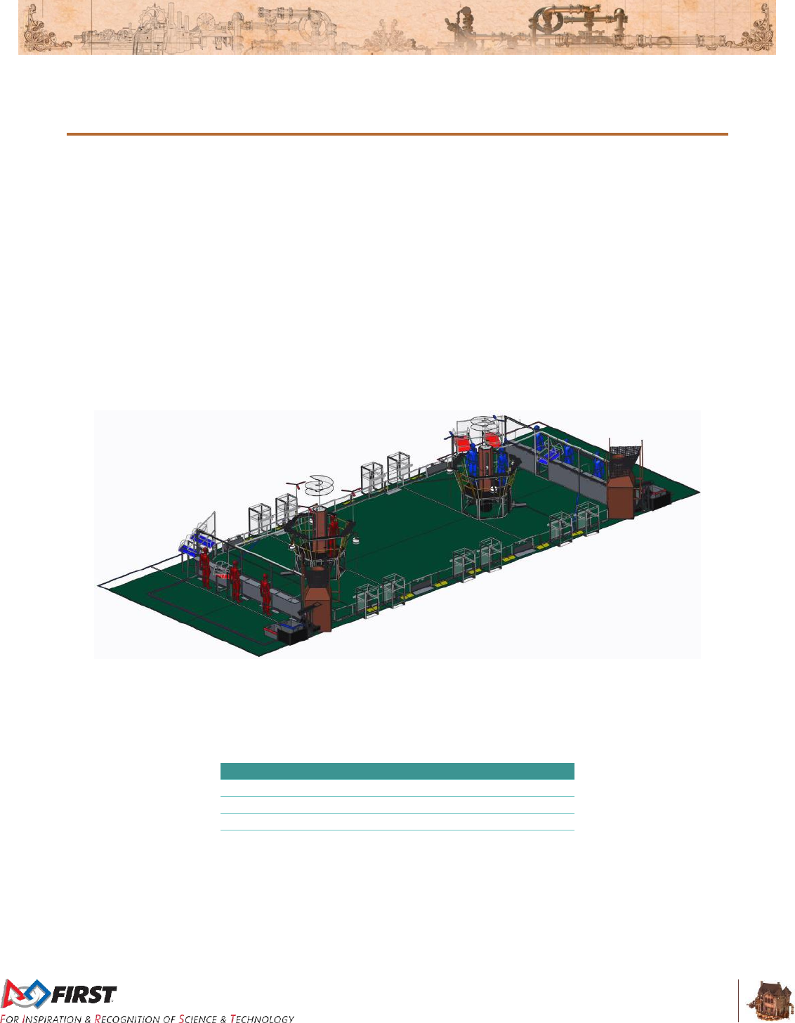
Figure 2-1: FIRST STEAMWORKS playing area
Each match begins with a 15-second autonomous period in which robots operate only on pre-
programmed instructions. During this period, robots work to support the three efforts listed above and
also get points for crossing their baseline.
Table 2-1: Auto Point Values
Action
Value
Cross the baseline
5 match points
1 fuel in high efficiency goal
1 match point, 1 kPa
3 fuel in low efficiency goal
1 match point, 1 kPa
Rotor turning
60 match points
During the remaining 2 minutes and 15 seconds of the match, the teleoperated period, student drivers
control robots. Teams on an alliance work together to build as much pressure and start as many rotors as
possible – but they have to be sure they leave enough time to latch on to their airship before the end of
the match. Points for these efforts are awarded as shown in Table 2-2.

Section 2 Overview
V1
14 of 135
Table 2-2: Teleop Point Values
Action
Value
3 fuel in high efficiency goal
1 match point, 1 kPa
9 fuel in low efficiency goal
1 match point, 1 kPa
Rotor turning
40 match points
Ready for takeoff
50 match points
Alliances are seeded in the Qualification tournament using ranking points which are awarded based on a
combination of their Win-Loss-Tie record (2 points for a win, 1 point for a tie), the number of times they
reach a 40 kiloPascal (kPa) pressure threshold (1 point), and the number of times they start all rotors (1
point).
For full details, read on!
Section 3 ARENA
V12
15 of 135
3 ARENA
The ARENA includes all elements and areas of the game infrastructure that are required to play FIRST
STEAMWORKSSM: the FIELD, AIRSHIPS, carpet, scoring elements, and all equipment and areas needed
for FIELD control, ROBOT control, and scorekeeping.
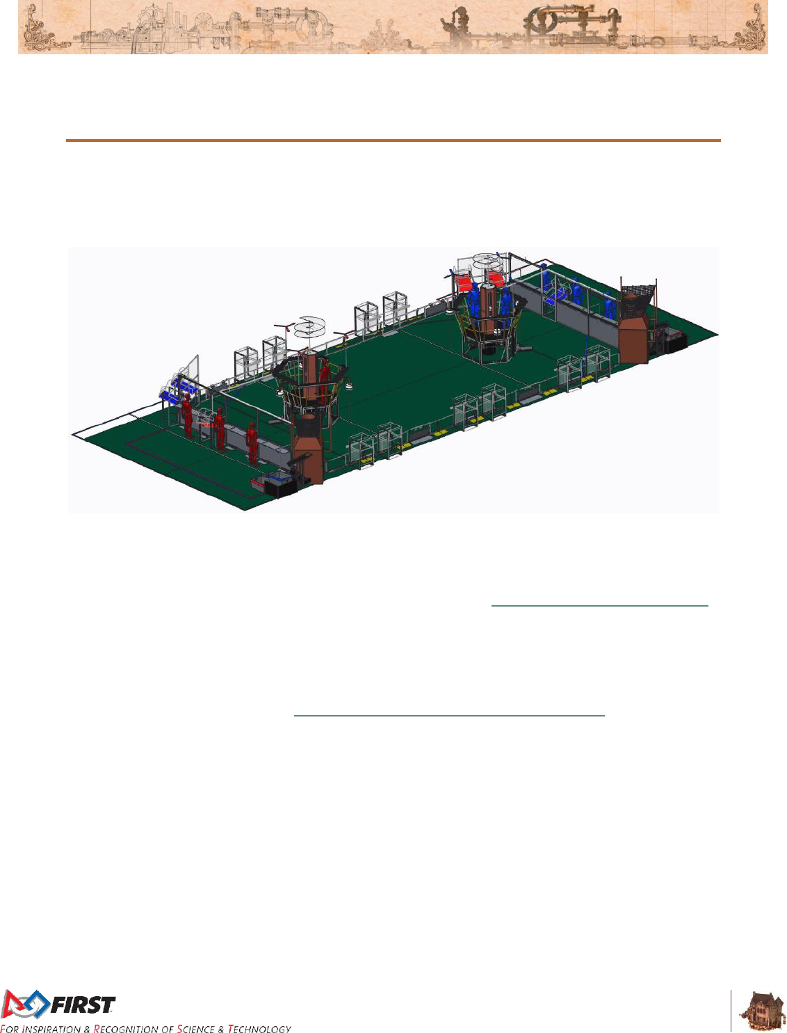
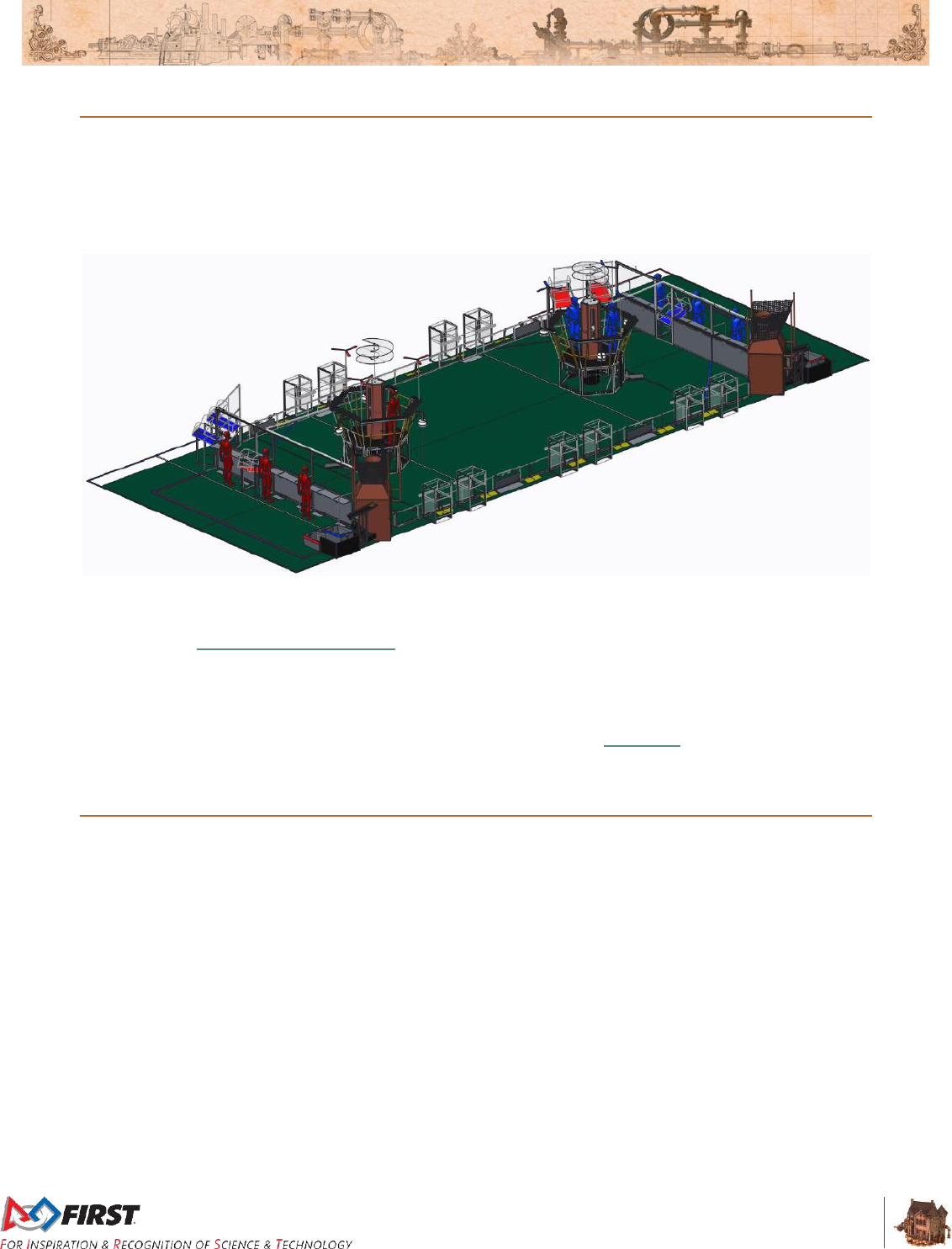
Figure 3-1: FIRST STEAMWORKS playing area
The competition ARENA is modular and assembled, used, disassembled, and shipped many times during
the competition season. It will undergo wear and tear. The ARENA is designed to withstand rigorous play
and frequent shipping. Every effort is made to ensure that ARENAS are consistent from event to event.
However, ARENAS are assembled in different venues by different event staff and some small variations
occur. For details regarding assembly tolerances, please refer to the 2017 FRC Field Assembly Drawing.
Successful Teams will design ROBOTS that are insensitive to these variations.
Illustrations included in this section are for a general visual understanding of the FIRST STEAMWORKS
ARENA, and dimensions included in the manual are nominal. Please refer to the official drawings for
exact dimensions, tolerances, and construction details. The official drawings, CAD models, and drawings
for low-cost versions of important elements of the FIRST STEAMWORKS FIELD are posted in the
“Playing Field Details” section of the FIRST STEAMWORKS Game & Season Materials web page.
Section 3 ARENA
V12
16 of 135
3.1 Zones and Markings
There are several areas on the FIELD relevant to game play and rules. Such spaces are described
below. All lines are marked using 2-in. (nominal) gaffers tape.
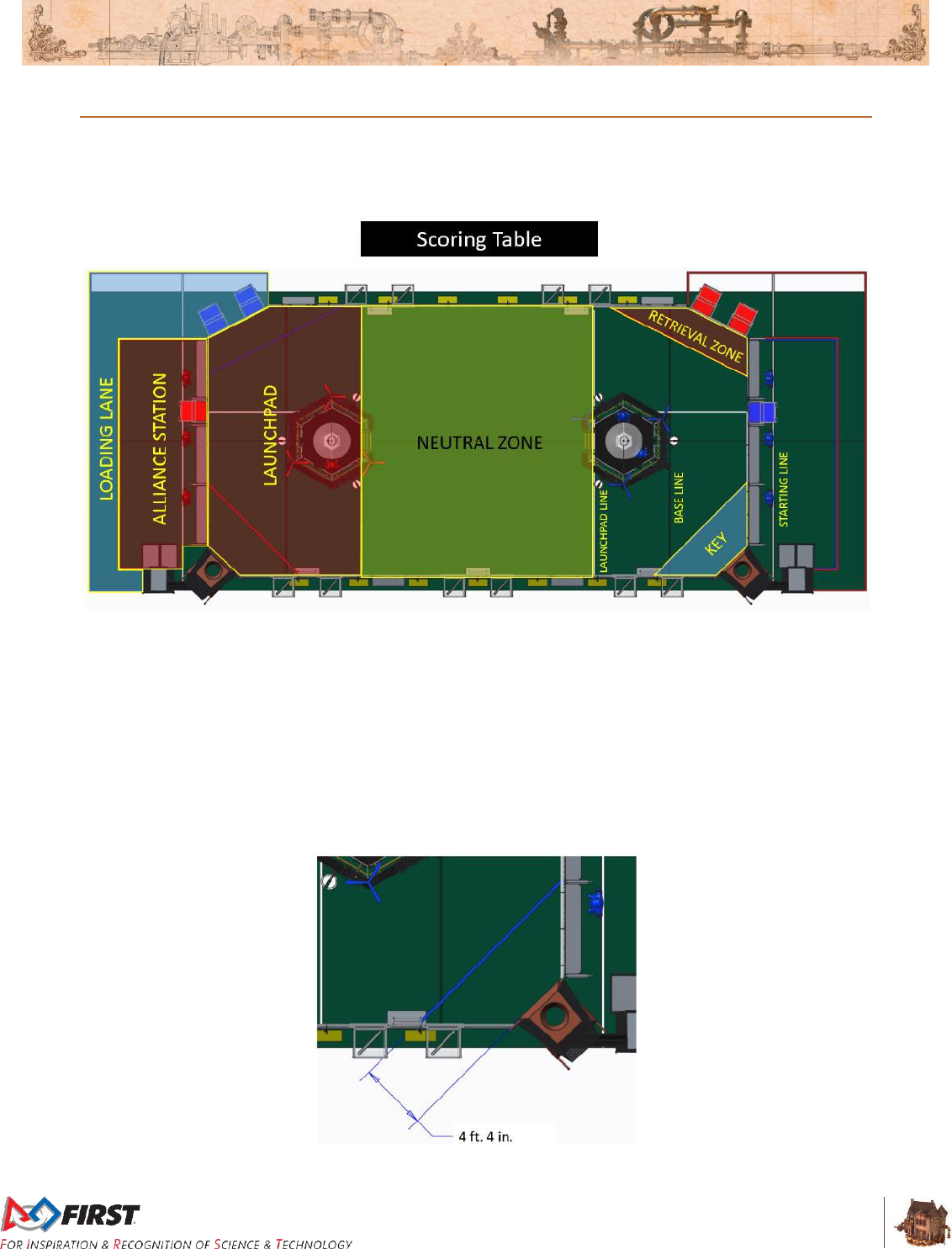
Figure 3-2: Zones and Markings
ALLIANCE STATION: an 8 ft. 9¾ in. (~269 cm) by 23 ft. 1½ in. (~705 cm) infinitely tall
volume bounded by the ALLIANCE WALL and ALLIANCE colored tape. The volume above
the tape is part of the ALLIANCE STATION.
BASE LINE: a green line that spans the width of the FIELD and is 7 ft. 9¼ in. (~237 cm) from
the ALLIANCE WALL diamond plate.
KEY: an infinitely tall volume in the ALLIANCE’S LAUNCHPAD bounded by the ALLIANCE
WALL, GUARDRAIL, and ALLIANCE colored tape. The KEY includes the volume above the
tape. The far edge of the tape is parallel to and 4 ft. 4 in. (~132 cm) from the front face of the
BOILER.
Figure 3-3: KEY
Section 3 ARENA
V12
17 of 135
LAUNCHPAD: an infinitely tall volume in the FIELD bounded by the GUARDRAILS, the
ALLIANCE WALL, and the LAUNCHPAD LINE. The volume above the LAUNCHPAD LINE is
part of the LAUNCHPAD.
LAUNCHPAD LINE: a tape line that is the width of the FIELD and collinear with the edge of
the AIRSHIP deck that is closest to the center of the FIELD.
LOADING LANE: an area bounded by and including ALLIANCE colored tape, edge of the
carpet, the RETURN BIN Table, and the opponent’s ALLIANCE WALL.
NEUTRAL ZONE: an infinitely tall volume on the FIELD bounded by the GUARDRAILS and
the LAUNCHPAD LINES. The volume above the LAUNCHPAD LINES is not part of the
NEUTRAL ZONE.
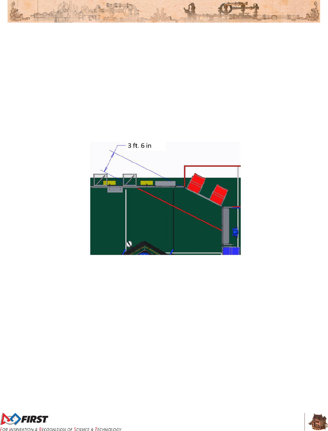
RETRIEVAL ZONE: an infinitely tall volume inside the FIELD bounded by the ALLIANCE
WALL, GUARDRAIL and ALLIANCE colored tape. The RETRIEVAL ZONE includes the
volume above the tape. The far edge of the tape is parallel to and 3 ft. 6 in. (~107 cm) from
the front face of the LOADING STATION.
Figure 3-4: RETRIEVAL ZONE
STARTING LINE: a white tape line that runs the width of the carpet and is 2 ft. 6 in. (~76 cm)
behind the ALLIANCE WALL diamond plate.
Section 3 ARENA
V12
18 of 135
3.2 FIELD
The FIELD for FIRST STEAMWORKS is a 27 ft. by 54 ft. 4 in. (~823 cm by ~1656 cm) area, bounded by
and including the upward- and inward-facing surfaces of the GUARDRAILS and ALLIANCE WALLS. The
carpet used for the FIELD is green (Shaw Floors, Philadelphia Commercial, Neyland II 20, 30352,
“Scotch Pine”).
Figure 3-5: FIRST STEAMWORKS playing area
There are two versions of GUARDRAILS and PLAYER STATIONS (i.e. the FIELD perimeter) used for
competitions. One design has been used at FIRST Robotics Competition events for several years and is
depicted in the 2017 Basic Field Drawings and FIRST provided CAD models. The other is designed and
sold by AndyMark. While the designs are slightly different, the critical dimensions, performance, and
expected user experience between the two is the same. All Regional and Championship assemblies will
use the traditional FIRST design (except for Shenzhen Regional and all FIRST Championship practice
fields). Teams may contact their local District leadership for details on which assembly is used by their
District. Detailed drawings for the AndyMark design are posted on the AndyMark website. All illustrations
in this document depict the traditional FIELD design.
3.3 GUARDRAIL
The GUARDRAIL is a system that consists of transparent polycarbonate supported on the top and bottom
by aluminum extrusion. The GUARDRAIL prevents ROBOTS from inadvertently exiting the FIELD during
a MATCH.
There are four (4) gates in the GUARDRAIL that allow access to the FIELD for placement and removal of
ROBOTS. The gates are 3 ft. 2 in. (~97 cm) wide and closed and shielded during the MATCH.
Section 3 ARENA
V12
19 of 135
Figure 3-6: Gate locations
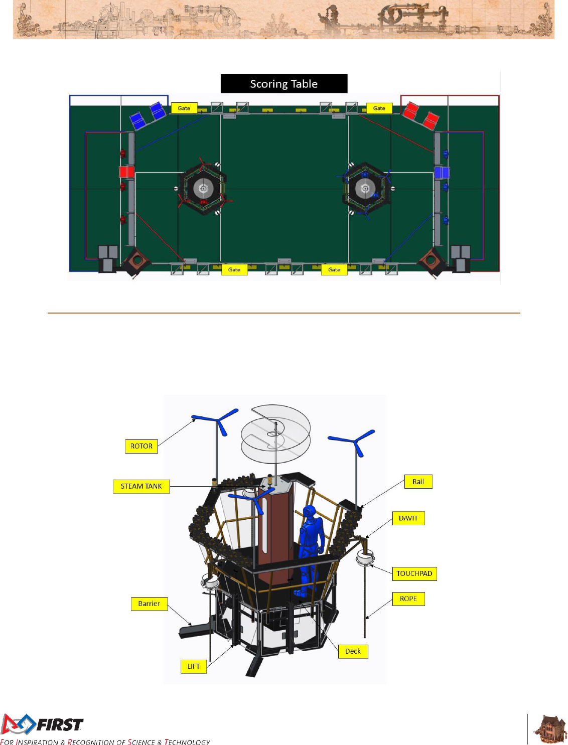
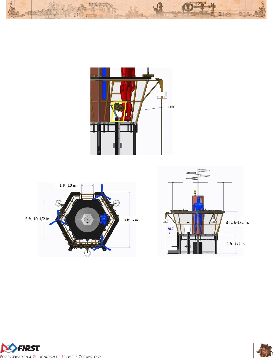
3.4 AIRSHIP
The AIRSHIP is a structure that features an elevated hexagonal deck, slanted walls, rails with AXLES to
mount GEARS, four (4) ROTORS, three (3) LIFTS, a STEAM TANK, and three (3) ROPES attached to
DAVITS. There is one AIRSHIP at the edge of each LAUNCHPAD. The AIRSHIP is positioned such that
the three (3) LIFTS face the ALLIANCE wall. The maximum capacity of the AIRSHIP is two (2) people.
Figure 3-7: AIRSHIP elements
Section 3 ARENA
V12
20 of 135
The hexagonal deck is 5 ft. 10½ in. (~179 cm) wide and 3 ft. ½ in. (~93 cm) above the FIELD carpet. The
rail forms an 8 ft. 5 in. (~257 cm) wide hexagon that is 3 ft. 6½ in. (~108 cm) above the deck.
Polycarbonate walls connect the deck and rail and angle out from the deck at a 75 deg. angle. PORTS,
13 in. (~33 cm) wide by 19½ in. (~50 cm) holes next to each LIFT, are cut in the three walls facing the
ALLIANCE WALL.
Figure 3-8: PORT
Figure 3-9: AIRSHIP geometry
The deck is accessed by a step ladder. The step ladder is 1 ft. 10 in. (~56 cm) wide. Before MATCH play,
it is rotated upward and latched to the rail.
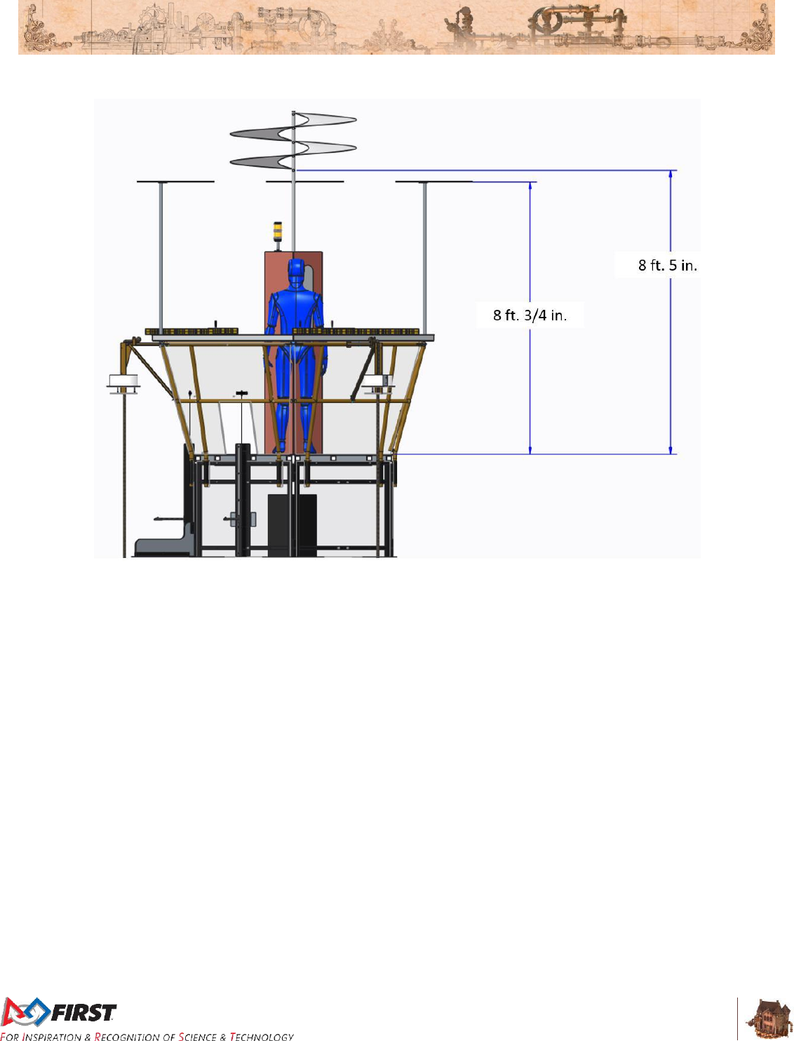
3.4.1 ROTORS
A ROTOR is one of four (4) rotating airfoils mounted to each AIRSHIP. There is one (1) central ROTOR
(modeled after the Da Vinci Aerial Screw) that protrudes from the center of the STEAM TANK. It starts 8
ft. 5 in. (~257 cm) above the deck. Three (3) smaller ROTORS are mounted to the rail, 8 ft. ¾ in. (~246
cm) above the deck, and evenly spaced around the rail.
Section 3 ARENA
V12
21 of 135
Figure 3-10: ROTOR heights
Section 3 ARENA
V12
22 of 135
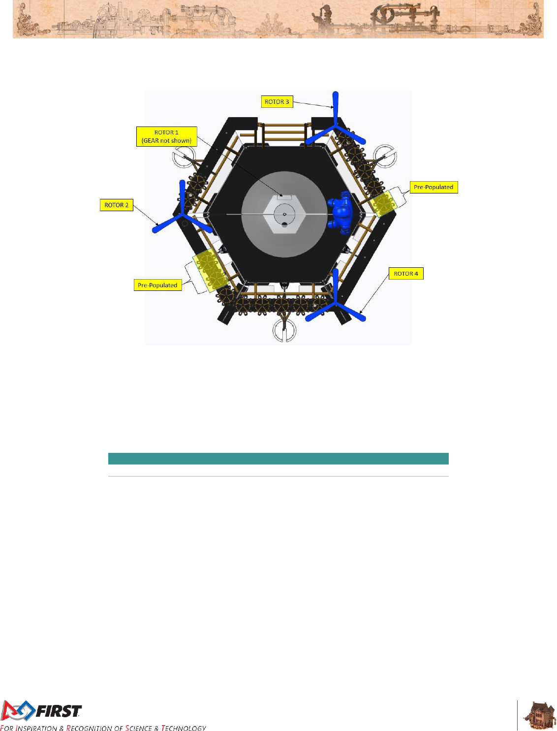
3.4.2 GEAR Sets
Figure 3-11: GEAR placement
A GEAR set is a series of meshed GEARS that correspond to a specific ROTOR. GEAR sets are installed
on AXLES mounted to the rail. An AXLE is a ⅞-in. diameter (~2 cm), 2-in. (~5 cm) long shaft which fits
the central hub of a GEAR. The number of AXLES for each GEAR set depends on the ROTOR. Some
AXLES are prepopulated with GEARS and indicated in Table 3-1. Prepopulated GEARS are marked with
ALLIANCE color gaff tape. The number of pre-populated GEARS may change for District Championships
or the FIRST Championship.
Table 3-1: GEAR set population.
ROTOR 1
ROTOR 2
ROTOR 3
ROTOR 4
Pre-populated GEARS
0
0
1
2
PILOT placed GEARS
1
2
4
6
One GEAR, the Reserve GEAR, is staged on the AIRSHIP at the start of the MATCH at the base of the
STEAM TANK, as shown in Figure 3-12.
Section 3 ARENA
V12
23 of 135
Figure 3-12: Reserve GEAR location
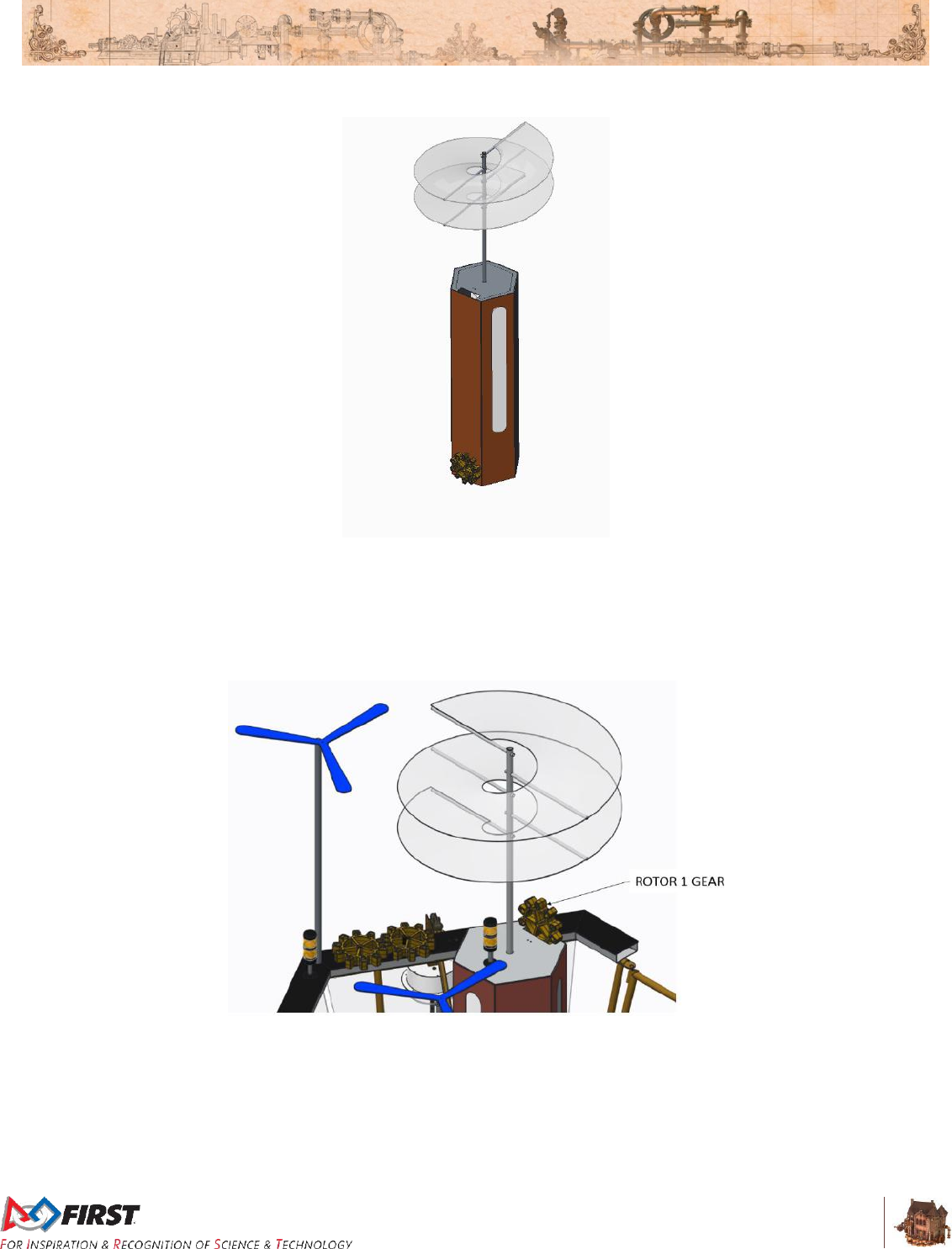
Once a ROTOR is started, it remains turning for the duration of the MATCH. ROTORS only start in order:
1, 2, 3, and then 4. The order of GEAR placement within a GEAR set is not important. To start ROTOR 1,
the PILOT places the GEAR in the GEAR slot at the top of the STEAM TANK, opposite the stack light for
ROTOR 1.
Figure 3-13: GEAR placement to start ROTOR 1
When a GEAR set for ROTORS 2, 3, or 4 is complete, a CRANK, a handle located with the first GEAR in
the set, can be turned which engages the corresponding ROTOR. It takes three (3) full rotations to
engage the ROTOR. If a GEAR set corresponding to the next sequential unengaged ROTOR remains idle
for more than ten (10) seconds, the rotation count resets to zero (0).
A yellow stack light is installed next to ROTORS 1 and 2 and illuminates if its corresponding ROTOR is
engaged during AUTO.
Section 3 ARENA
V12
24 of 135
Figure 3-14: AUTO stack light indicators
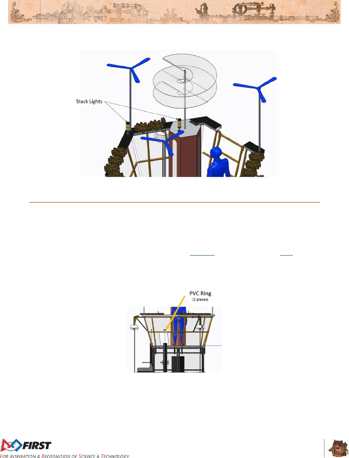
3.5 LIFTS
LIFTS are used to transfer GEARS from the ROBOTS to the PILOTS. One (1) LIFT is mounted to each of
the three (3) sides of the deck that face the PLAYER STATIONS. Each LIFT consists of a peg, steel
guide frame, carriage assembly, and cable. The cable is pulled by the PILOT to raise the carriage to a
PORT where the GEAR can be safely accessed. Each carriage has a peg designed to hold the GEAR
during the transition. The peg is 1 ft. 1 in. (~33 cm) from the FIELD carpet when the carriage is all the
way down, protrudes 10½ in. (~27 cm) from the carriage and is 1⅜ in. (~3 cm) wide. It is constructed from
⅞-in. (nominal) diameter extension spring (McMaster P/N: 9664K68 or Century Spring P/N: E-41). A PVC
ring, centered on and mounted to the lower rung of the AIRSHIP rail as show in Figure 3-15, loosely holds
the pull cord and prevents the LIFT handle from falling out the PORT.
Figure 3-15: Reserve GEAR location
Section 3 ARENA
V12
25 of 135
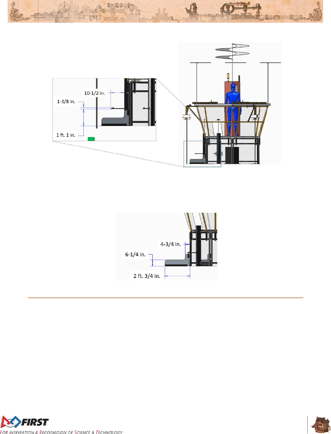
Figure 3-16: LIFT geometry
The center LIFT is flanked by two ½-in. (nominal) thick HDPE barriers that radiate out from the adjacent
AIRSHIP corners. Barriers are 6¼ in. (~16 cm) tall and extend 2 ft. ¾ in. (~63 cm) out from the leg of the
AIRSHIP.
Figure 3-17: Barrier geometry
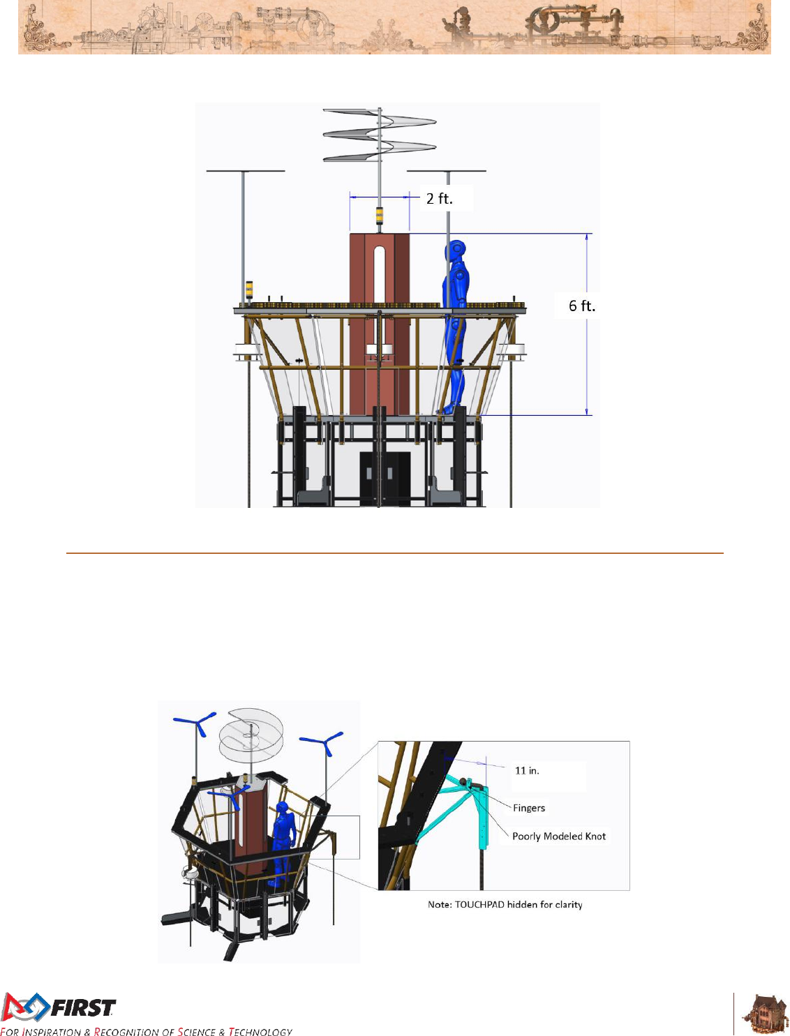
3.6 STEAM TANK
The STEAM TANK is a 6-ft. (~183 cm) tall hexagonal container with a diagonal dimension of 2 ft. (~61
cm) centrally mounted on the deck. It is “filled” via a STEAM PIPE that originates at the BOILERS. Lights
indicate the pressure, in kiloPascals (kPa), that’s been generated by the ALLIANCE and stored in the
STEAM TANK.
Three windows in the STEAM TANK contain Philips Color Kinetics LED Light Strips used to indicate the
amount of steam pressure generated by the BOILER and transmitted to the AIRSHIP. Each window
displays the same information. For every five (5) kPa of pressure generated, a row of LEDs illuminates in
the ALLIANCE’S color. For example, if the Red ALLIANCE has generated forty (40) kPa, the bottom eight
(8) rows of LEDs are red. If the Blue ALLIANCE generates ten (10) kPa, the bottom two (2) rows are blue.
Section 3 ARENA
V12
26 of 135
Figure 3-18: STEAM TANK geometry
3.7 DAVIT
A DAVIT is one of three steel frames that attaches a ROPE to the AIRSHIP. Each DAVIT extends 11 in.
(~28 cm) from the railing of the AIRSHIP. Each DAVIT has a 2-in. (~5 cm) wide by 2-in. (~5 cm) deep
vertical steel channel used to cradle the ROPE and to mount the TOUCHPAD. There are two (2) steel
fingers at the top of each DAVIT used to secure the ROPE. These fingers are 1 in. (~3 cm) apart and
have a hole for a wire locking retaining pin (McMaster P/N: 98416A009 or similar). The ROPE passes
through the fingers with the top knot on the AIRSHIP side of the fingers.
Figure 3-19: DAVIT location and geometry
Section 3 ARENA
V12
27 of 135
3.8 ROPE
A ROPE is a strong, thick string composed of twisted or braided strands of manila, hemp, flax, or the like,
secured to the AIRSHIP, and used to secure ROBOTS for flight at the end of the MATCH. As described in
Section 4.2 Match Setup, Teams are invited to bring and install their own ROPE. If they don’t, they can
expect default FIELD ROPES installed. These default ROPES are three (3), 1 in. (nominal) thick by 7 ft. 2
in. (~218 cm) long polypropylene “Manila” style ROPES from Knot and Rope Supply, SKU 0162. Each
default ROPE is knotted at the top, such that there’s at least 7 ft. 2 in. (~218 cm) below the knot (see
Figure 3-19), fused at the bottom, suspended from a notch at the end of each DAVIT, and stowed using
the ROPE retention strap and loop pad (as described in GE-17025) on the outside of the AIRSHIP. The
ROPE passes through the center of the TOUCHPAD and hangs down to the FIELD carpet. The PILOT
pulls the ROPE’S retention strap to deploy the ROPE.
Figure 3-20: FIELD ROPE Anatomy
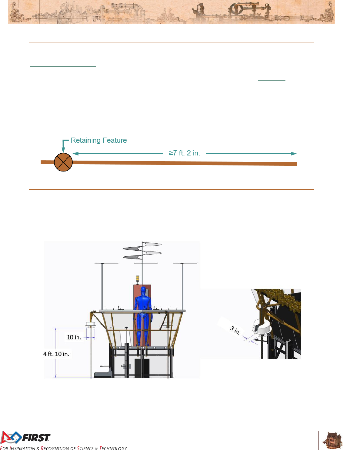
3.9 TOUCHPAD
Each TOUCHPAD is a 10 in. (~25 cm) polycarbonate plate mounted 4 ft. 10 in. (~147 cm) above the
carpet and used to determine if a ROBOT has successfully latched on to the AIRSHIP (i.e. ready for
takeoff) at the end of the MATCH. The plate has a 3 in. (~8 cm) wide by 6 in. (~15 cm) deep rectangular
cut-out to aid in assembly and ROPE mounting.
Figure 3-21: TOUCHPAD geometry
The TOUCHPAD plate must be pressed such that the following conditions are met for the ROBOT to be
credited with being ready for takeoff at the end of the MATCH:
A. it’s minimally displaced by ½ in. (~1 cm),
Section 3 ARENA
V12
28 of 135
B. it’s pressed for a duration of at least one (1) sec, and
C. it’s pressed when the Teleop Period ends at T = 0
The force required to activate the TOUCHPAD (i.e. push the TOUCHPAD plate up by approximately ½ in.
(~1.3 cm), causing activation of one or more of its microswitches) is no more than 1 lb. (~½ kg).
The force required to move the TOUCHPAD throughout its full range of travel (i.e. cause the TOUCHPAD
plate to travel the full 1½ in. (~4 cm)) is no more than 2 lbs. (~1 kg).
While a force less than 75 lbs (~34 kg) applied to the TOUCHPAD plate once it’s fully pressed is not likely
to damage the TOUCHPAD, be aware that any damage, even if a result of less than 75 lbs of force, is a
violation of G15.
Teams may wish to consider a reasonable “safety factor” for
TOUCHPAD activation and assume that no more than 3 lbs. (~1.4 kg) of
vertical force is required to guarantee activation to account for
tolerances, assembly variations, temperature/humidity differences, and
other variances.
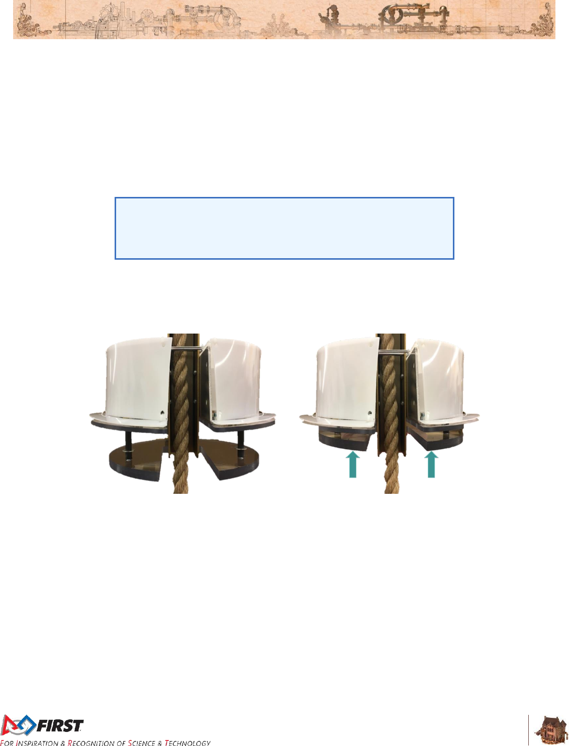
Figure 3-22 shows the two extreme states of the TOUCHPAD plate. The image on the left shows the
TOUCHPAD unactuated and the figure on the right shows one example of an actuated TOUCHPAD (with
the plate pressed all the way up). The DAVIT’S steel channel does not move with the TOUCHPAD plate.
Figure 3-22 Unactuated TOUCHPAD (left) and fully displaced TOUCHPAD plate (right)
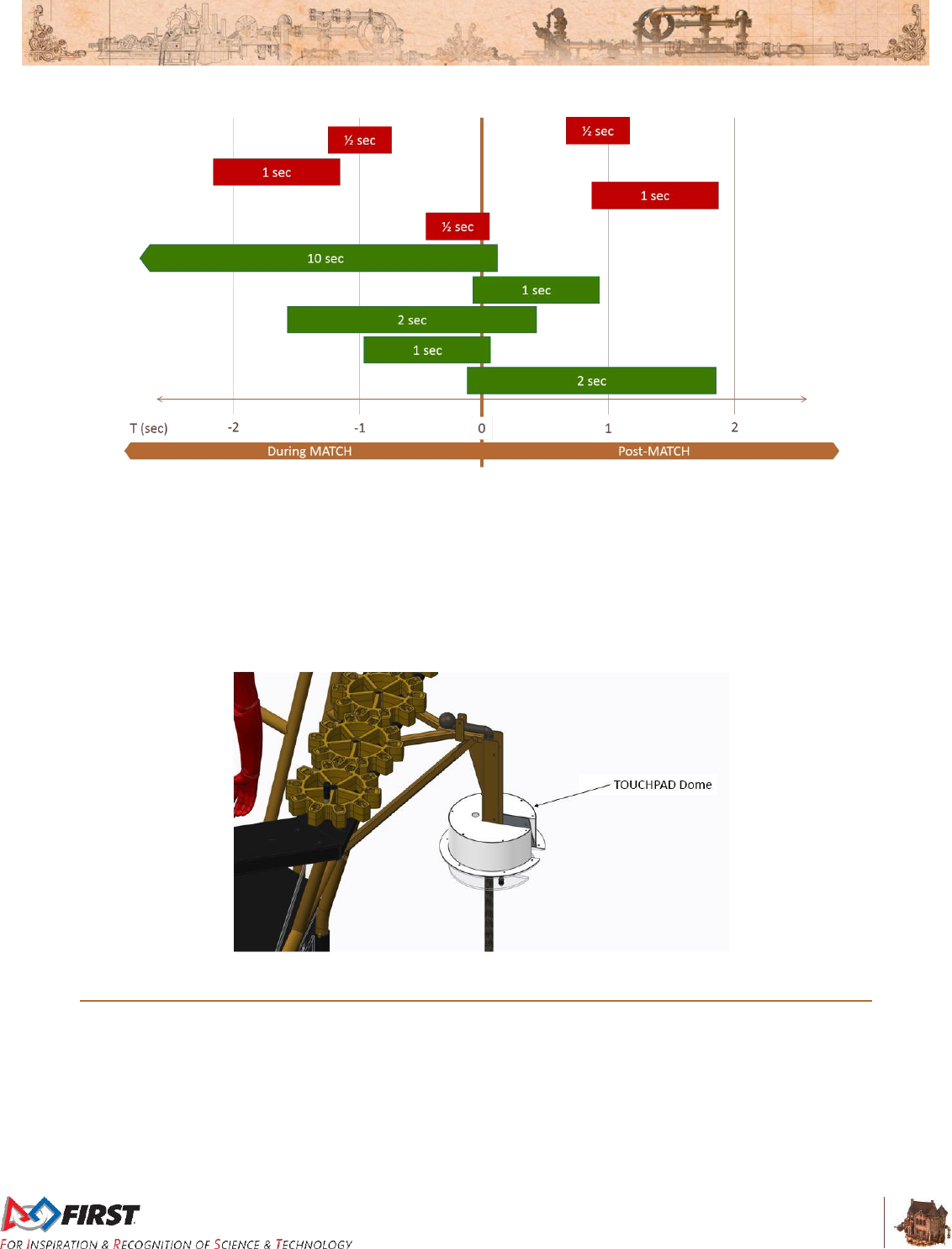
Figure 3-23 shows examples where the TOUCHPAD has been sufficiently displaced, but timing varies.
Activations in red indicate that the requirements were not met, and the ROBOT was not credited with
“ready for takeoff” points defined in Table 4-1. Activations in green meet all criteria and credit the
ALLIANCE with associated points.
Section 3 ARENA
V12
29 of 135
Figure 3-23: TOUCHPAD activation examples.
A plastic dome is mounted above each TOUCHPAD and indicates if the associated ROBOT is ready for
takeoff. When thirty (30) seconds remain in TELEOP, all six (6) domes briefly animate to indicate that
they are active. If a TOUCHPAD is pressed by a ROBOT prior to this, the dome remains off. If a
TOUCHPAD is pressed during the final thirty (30) seconds of the MATCH and for the minimal duration
described in part B above, the dome illuminates in the ALLIANCE’S color and the associated points are
added to the real-time score. If a ROBOT causes a dome to illuminate, but disengages from the
TOUCHPAD, the dome turns off and the associated points are removed from the real-time score.
Figure 3-24: TOUCHPAD dome
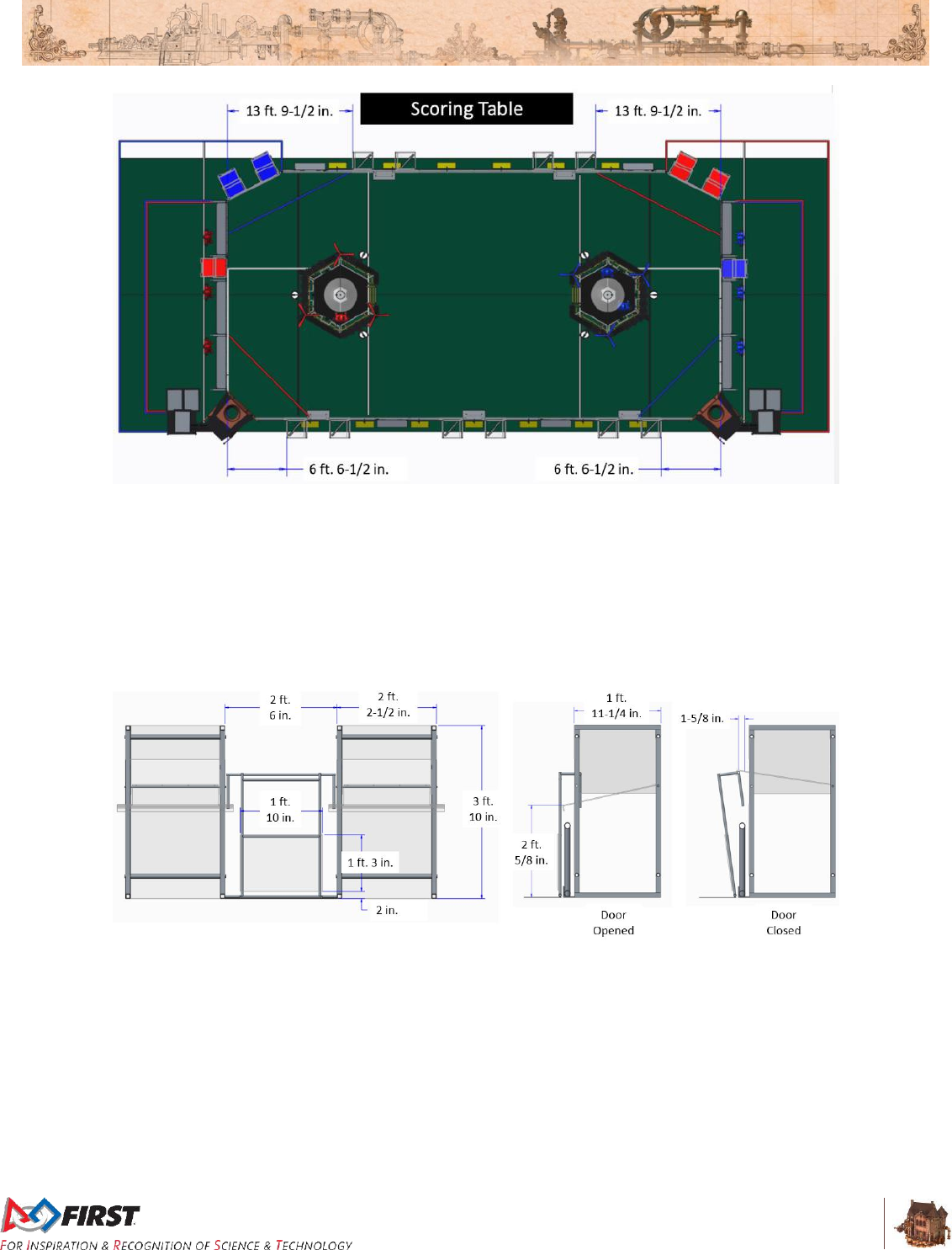
3.10 HOPPERS
A HOPPER is a pair of containers located just outside the FIELD and used to store FUEL at the start of
the MATCH. There are five (5) HOPPERS located alongside and outside the GUARDRAIL. Two (2) are
positioned on the scoring table side of the FIELD and are each 13 ft. 9½ in. (~420 cm) from the
ALLIANCE WALLS. Two (2) are positioned opposite the scoring table side of the FIELD and are each 6
ft. 6½ in. (~199 cm) from the ALLIANCE WALLS. The fifth HOPPER is positioned opposite the scoring
table side of the FIELD and centered on the GUARDRAIL.
Figure 3-25: HOPPER locations
Section 3 ARENA
V12
30 of 135
Each HOPPER container is an aluminum framed polycarbonate box that is 2 ft. 2½ in. (~67 cm) wide by 1
ft. 11¼ in. (~59 cm) deep by 3 ft. 10 in. (~117 cm) high. There is an opening that faces the FIELD at the
top of each HOPPER container. Once a polycarbonate panel is pushed, the floor of the box pivots down,
causing FUEL to roll onto the FIELD. When depositing FUEL onto the FIELD, the floor of the HOPPER is
2 ft. ⅝ in. (~63 cm) from the carpet. The polycarbonate panel is 1 ft. 3 in. (~38 cm) high, 1 ft. 10 in. (~56
cm) long and 2 in. (~5 cm) above the FIELD carpet, and requires approximately 25 lbs. (~11 kg) applied 6
in. from the carpet over 1⅝ in. (~4 cm) toward the HOPPER (until flush with the guardrail) to fully engage.
Figure 3-26: HOPPER geometry
Section 3 ARENA
V12
31 of 135
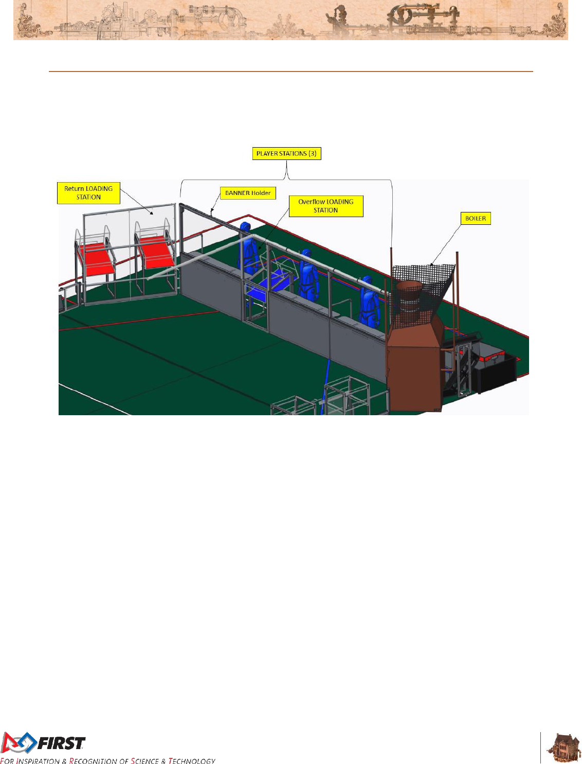
3.11 ALLIANCE WALL
The ALLIANCE WALL is the physical structure that separates ROBOTS from DRIVE TEAMS (except the
PILOT) and consists of a BOILER, three (3) PLAYER STATIONS, an Overflow LOADING STATION and
a Return LOADING STATION.
Figure 3-27: ALLIANCE WALL COMPONENTS
3.11.1 PLAYER STATION
A PLAYER STATION is one (1) of three (3) assigned positions in an ALLIANCE WALL from where a
DRIVE TEAM operates their ROBOT. Each PLAYER STATION is made from a 3 ft. (~91 cm) tall diamond
plate panel base topped with a 3 ft. 6 in. (~107 cm) tall transparent plastic panel. An aluminum shelf is
attached to each PLAYER STATION to support the DRIVE TEAM’S OPERATOR CONSOLE. The shelf is
5 ft. 9 in. (~175 cm) wide and 1 ft. (~30 cm) deep. There is a 4 ft. 6 in. (~137 cm) long by 2 in. (nominal)
wide strip of hook-and-loop tape (“loop” side) along the center of the support shelf that may be used to
secure the OPERATOR CONSOLE to the shelf.
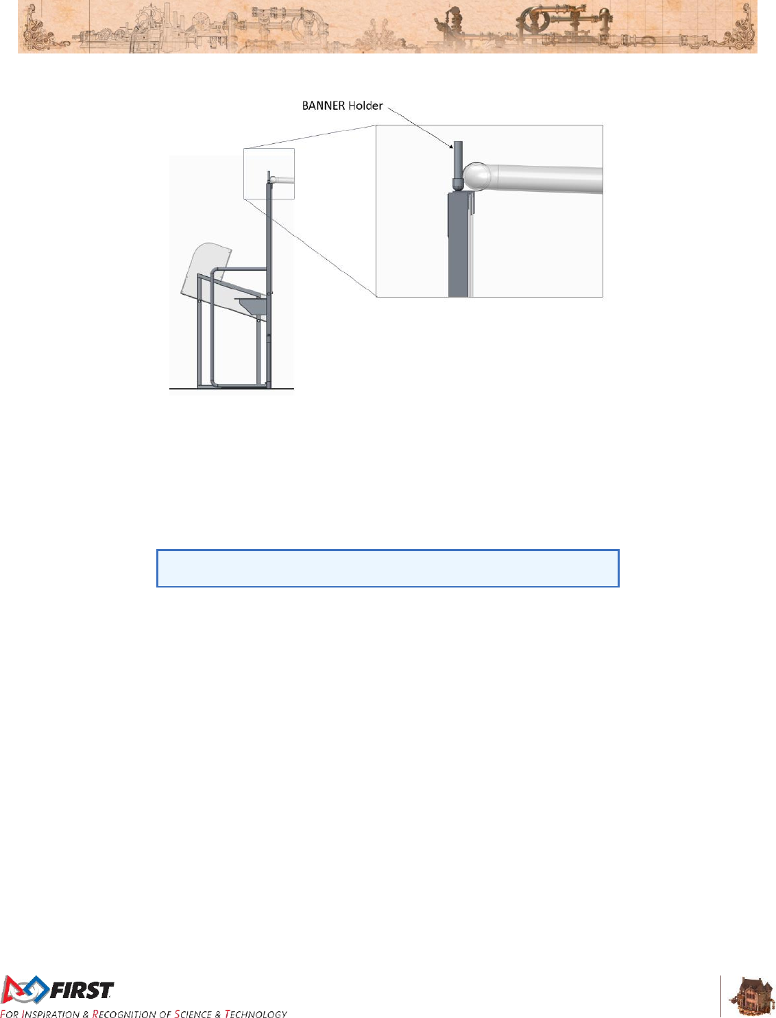
Each PLAYER STATION supports one (1) BANNER Holder. The BANNER Holder features a receptacle
designed to hold a ½-in. (nominal) diameter rod and is mounted above the team sign and behind the
STEAM PIPE.
Section 3 ARENA
V12
32 of 135
Figure 3-28: BANNER holder
Each PLAYER STATION contains the following electronic components for Teams:
One Ethernet Cable: attaches to the Ethernet port of the OPERATOR CONSOLE and
provides connectivity to the ARENA network.
One 120VAC NEMA 5-15R power outlet: located on the right side of each PLAYER STATION
shelf and protected by its own 2-Amp circuit breaker. It can be used to power the
OPERATOR CONSOLE. DRIVE TEAMS are responsible for monitoring their power
consumption as a tripped breaker in the outlet does not constitute an ARENA fault.
Note: The power outlet circuit breaker has been reduced from a 3A
breaker to a 2A breaker (used in 2015 and 2016).
One Emergency Stop (E-Stop) button: located on the left side of the PLAYER STATION shelf
and should be used to deactivate a ROBOT in an emergency.
One Team sign: displays the Team number and located at the top of each PLAYER
STATION.
One Team LED: indicates ALLIANCE color, ROBOT status, and E-Stop status and centered
at the top of each PLAYER STATION. Team LED states include:
Solid: indicates that the ROBOT is connected and enabled. This will only happen during a
MATCH.
Blinking: indicates that either the Field Management System (FMS) is preset for the MATCH
or it’s during a MATCH and the corresponding ROBOT has lost connectivity.
Off: indicates that the MATCH has not started yet, but the ROBOT is linked and disabled.
If the amber LED is on, the E-stop button has been pressed.
One Timer: displays the official time remaining in AUTO, TELEOP, and TIMEOUTS and
marked with white tape along the bottom edge. A Timer is positioned at the top of each
Return LOADING STATION.
Competition ARENA hardware and wiring: mostly located below the center PLAYER
STATION shelf.
Section 3 ARENA
V12
33 of 135
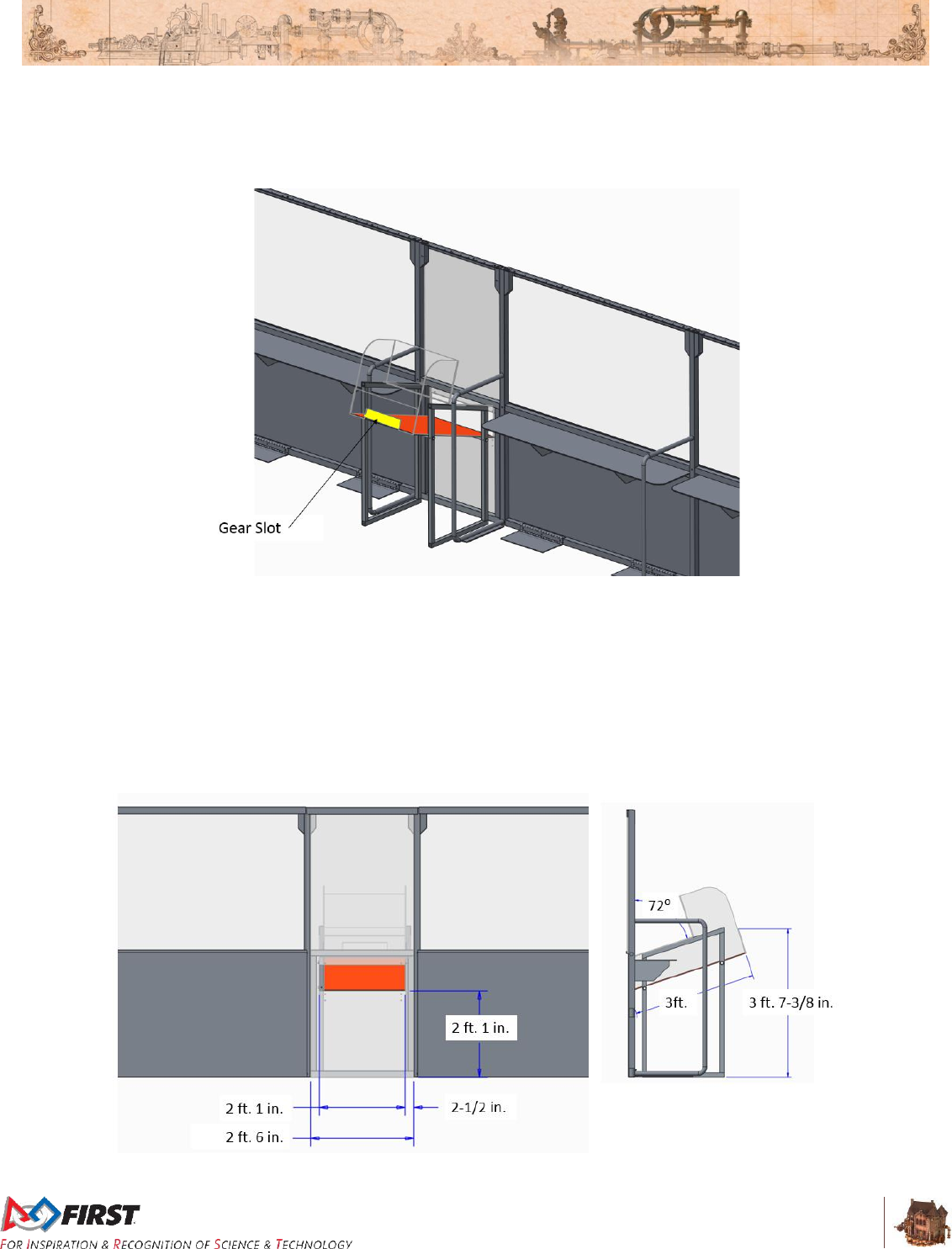
3.11.2 Overflow LOADING STATION
An Overflow LOADING STATION is located two (2) PLAYER STATIONS away from each BOILER.
Figure 3-29: Overflow LOADING STATION
An Overflow LOADING STATION is used to feed FUEL from the OVERFLOW BIN on to the FIELD. Each
Overflow LOADING STATION includes a 6 ft. 6 in. (~198 cm) in. tall and 2 ft. 6 in. (~76 cm) wide
polycarbonate panel with an opening, aluminum frame, and shelf with backboard. The opening is 2½ in.
(~6 cm) from each edge of the loading station, 2 ft. 1 in. (~64 cm) wide, 7½ in. tall (~19 cm), and 2 ft. 1 in.
(~64 cm) above the carpet.
The Overflow LOADING STATION shelf is 2 ft. (~61 cm) wide, 3 ft. (~91 cm) long, and mounted at a 72
deg. angle. The top of the shelf is 3 ft. 7⅜ in. (~110 cm) from the carpet.
Figure 3-30: Overflow LOADING STATION geometry
Section 3 ARENA
V12
34 of 135
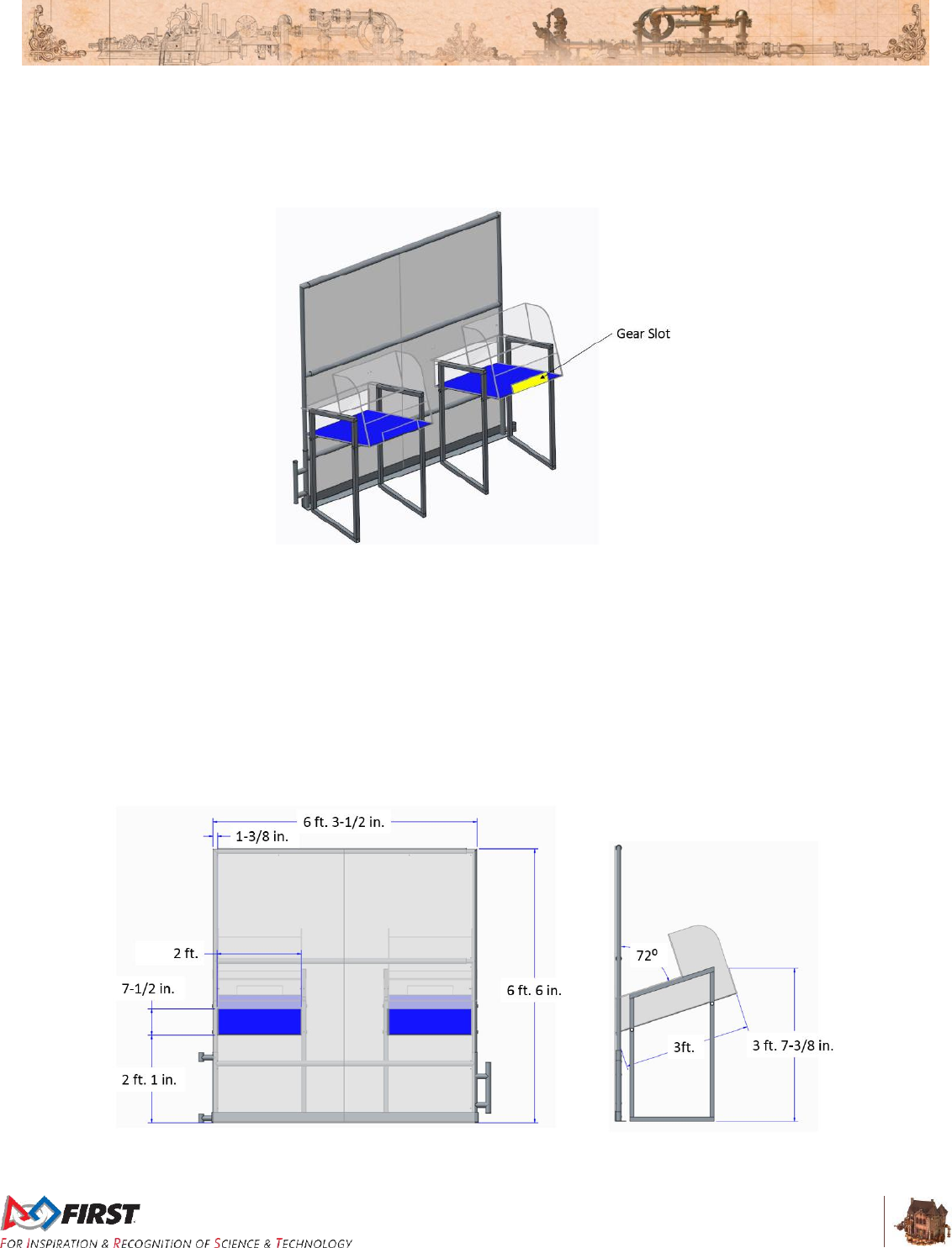
3.11.3 Return LOADING STATIONS
Return LOADING STATIONS are located in each of the two (2) corners of the FIELD opposite the
BOILERS.
Figure 3-31: Return LOADING STATIONS
A Return LOADING STATION is used to feed FUEL and GEARS on to the FIELD. Each Return
LOADING STATION includes a 6 ft. 6 in. (~198 cm) in. tall and 6 ft. 3½ in. (~192 cm) wide polycarbonate
panel with two (2) openings, aluminum frame, and shelves with backboards. The openings are side by
side, 1⅜ in. (~3 cm) from each edge of the loading station, 2 ft. (~61 cm) wide, 7½ in. tall (~19 cm), and 2
ft. 1 in. (~64 cm) above the carpet.
There are two (2) shelves, 2 ft. (~61 cm) wide by 3 ft. (~91 cm) long, mounted at a 72 deg. angle. The
tops of the shelves are 3 ft. 7⅜ in. (~110 cm) from the carpet. Each shelf has a slot through which to pass
GEARS.
Figure 3-32: Return LOADING STATION geometry
Section 3 ARENA
V12
35 of 135
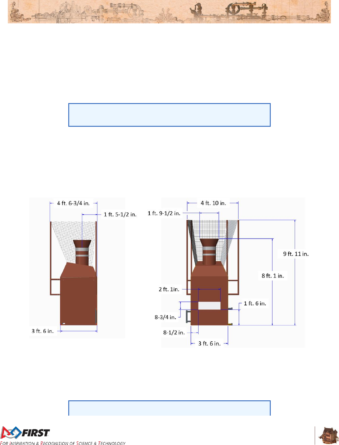
3.11.4 BOILER
A BOILER is a FIELD element which converts FUEL to steam. There is a BOILER on each corner of the
FIELD opposite the scoring table. The base of each BOILER is 3 ft. 6 in. wide (~107 cm) by 3 ft. 6 in.
(~107 cm) deep by 8 ft. 1 in. (~246 cm) tall. There are two (2) openings, or GOALS, for loading FUEL into
the BOILER: the High Efficiency GOAL and the Low Efficiency GOAL.
The High Efficiency GOAL is a 1 ft. 9½ in. (~55 cm) diameter vertical cylinder. The opening is 8 ft. 1in.
(~246 cm) from the carpet. The horizontal offset between the face of the BOILER and the center of the
High Efficiency Goal opening is 1 ft. 5½ in. (~44 cm).
The High Efficiency GOAL geometry can be simulated using six (6) 2015
Recycle Rush™ totes and one (1) 2015 Recycle Rush recycling
container.
The Low Efficiency GOAL is 2 ft. 1 in. (~64 cm) wide by 8¾ in. (~22 cm) tall. The bottom edge of the
GOAL is 1 ft. 6 in. (46 cm) above the carpet.
A series of nets is installed behind the BOILER which redirects missed shots back in to the FIELD. The
net is approximately 4 ft.10 in. (147 cm) wide by 9 ft. 11 in. (302 cm) tall and is set 4 ft. 6¾ in. (139 cm)
behind the GOAL opening. Nets are used to retain GAME PIECES in the FIELD and not intended to
behave consistently.
Figure 3-33: BOILER geometry
The capacity of the Low Efficiency GOAL is seventy (70) FUEL. The capacity of the High Efficiency GOAL
is one-hundred and fifty (150) FUEL. FUEL that exceeds GOAL capacities will fall back on to the FIELD.
A BOILER processes FUEL in to steam at an average rate of five (5) FUEL per second per GOAL, but
actual rate is dependent on the amount and packing of FUEL in the GOALS (i.e. the tighter the packing in
a GOAL, the faster the FUEL processing rate).
FIRST instructs FTAs to test BOILER counting by dumping forty (40)
FUEL into each High and Low Efficiency GOAL and noting the count
Section 3 ARENA
V12
36 of 135
logged by the FMS three times before MATCHES begin each day. The
BOILER is operating as expected if the counts in each batch are 40 +/-1.
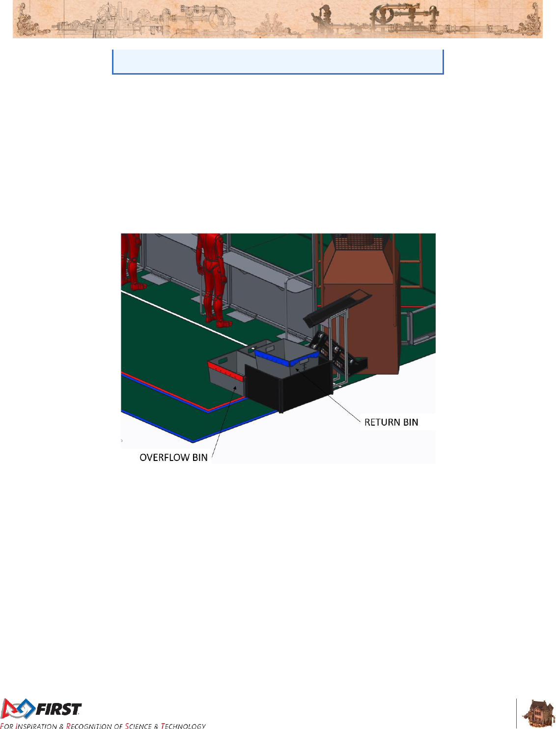
3.11.5 RETURN & OVERFLOW BINS
RETURN and OVERFLOW BINS are used to store and transport FUEL that has exited a BOILER. They
are plastic open-topped containers, 2 ft. 9½ in. (~85 cm) wide by 1 ft. 6 in. (~46 cm) deep by 1 ft. 1 in.
(~33 cm) tall, and each has a capacity of approximately fifty to sixty (50-60) FUEL.
Once FUEL is processed, it exits the BOILER into a RETURN BIN. Each LOADING LANE has three (3)
RETURN BINS. To prevent a RETURN BIN from overflowing, HUMAN PLAYERS may replace it with an
empty RETURN BIN.
Should a RETURN BIN overflow, the FUEL collects in either of the (2) OVERFLOW BINS.
Figure 3-34: RETURN and OVERFLOW BINS
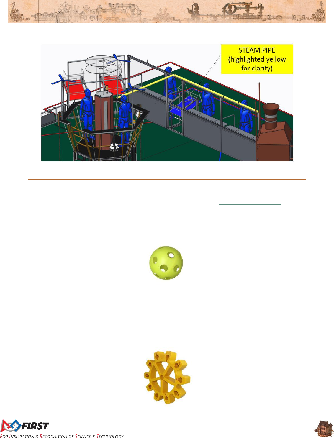
3.11.6 STEAM PIPE
The STEAM PIPE is a clear PVC pipe that transfers steam from the BOILER to the STEAM TANK on the
AIRSHIP. It is constructed from 2⅜ in. (nominal) diameter clear plastic pipe and exits out the side of the
BOILER net support pipe closest to the PLAYER STATION. It is mounted flush to the top of the
ALLIANCE WALL and when it reaches the middle of the Overflow LOADING STATION, it turns and
extends to the AIRSHIP.
The pipe contains strips of Philips Color Kinetics Lights which display the transfer of steam. A pattern of
colored LEDs flow from the BOILER to the AIRSHIP as FUEL is scored by the BOILER. As the rate of
FUEL being scored inside the BOILER increases, the animation become faster. If the scoring rate
decreases, the animation slows down. If an ALLIANCE stops scoring FUEL in their BOILER, the lights will
come to a stop at their current position, indicating that FUEL is not being scored.
Section 3 ARENA
V12
37 of 135
Figure 3-35: STEAM PIPE
3.12 GAME PIECES
3.12.1 FUEL
FUEL is used to generate steam for the AIRSHIP and is represented by “Screamin’ Yellow,” 5 in.
(nominal) diameter Gopher ResisDent™ polyethylene balls (Item Number 42-555). Each FUEL weighs
2.6 oz. (~74 g.). FUEL may be purchased from AndyMark (am-3376), and a six (6) pack of balls may be
purchased directly from Gopher Sports.
Figure 3-36: FUEL
3.12.2 GEARS
A GEAR is a toothed wheel used to start ROTORS on the AIRSHIP. Each GEAR is made from gold
(Pantone PMC 124C) polypropylene, has 10 teeth, an 11 in. (~28 cm) diameter, 10 in. (~25 cm) pitch
diameter, and is 2 in. (~5 cm) thick. Each GEAR weighs 18.4 oz. (~0.5 kg.) GEARS may be purchased
from AndyMark (am-3302).
Figure 3-37: GEAR
Section 3 ARENA
V12
38 of 135
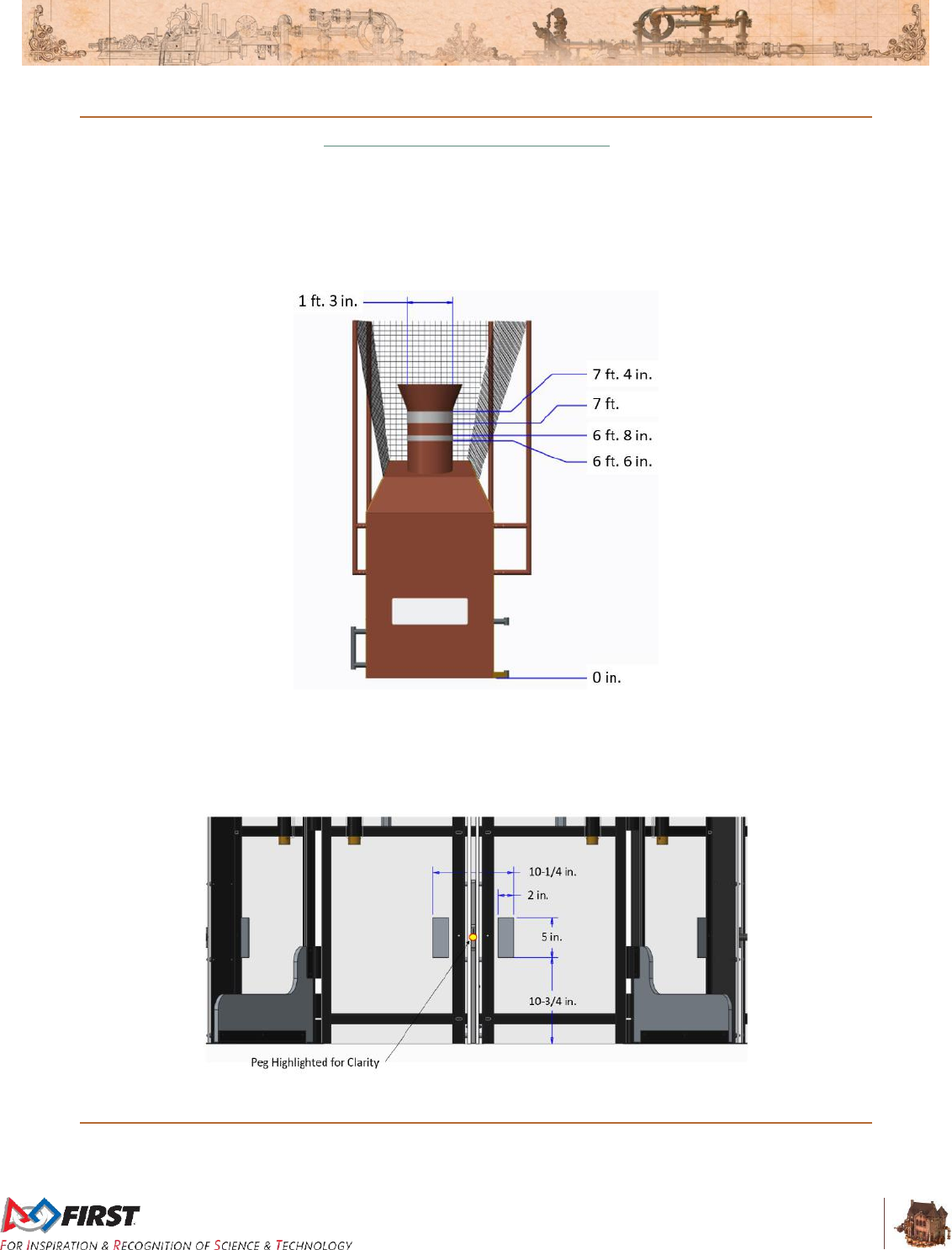
3.13 Vision Targets
Vision targets are marked using 3M 8830 Scotchlite Reflective Material and highlight the locations of High
GOALS and LIFT pegs.
The vision target on the High GOAL consists of two horizontal rings. The first ring is 4 in. (~10 cm) wide,
with the upper edge located 7 ft. 4 in. (~224 cm) from the carpet. The second ring is 2 in. (~5 cm) wide
with the upper edge 6 ft. 8 in. (~203 cm) off the carpet.
Figure 3-38: BOILER vision target measurements
There are also vision targets on both sides of each LIFT peg. The peg targets are 2 in. (~5 cm) wide by 5
in. (~13 cm) tall rectangles located 10¾ in. (~27 cm) from the carpet and spaced 10¼ in. (~26 cm) apart
(outside dimensions).
Figure 3-39: LIFT peg vision target dimensions
3.14 The Field Management System
When a DRIVE TEAM connects the Ethernet cable from their assigned PLAYER STATION to their
OPERATOR CONSOLE, the Driver Station software on the OPERATOR CONSOLE computer will begin
Section 3 ARENA
V12
39 of 135
to communicate with the Field Management System (FMS). Once connected to FMS, the only open ports
available are described in Table 3-2.
Table 3-2: Open FMS Ports
Port
Designation
Bi-directional?
UDP/TCP 1180-1190
Camera data from the roboRIO to the Driver
Station (DS) when the camera is connected
the roboRIO via USB
Yes
TCP 1735
SmartDashboard
Yes
UDP 1130
Dashboard-to-ROBOT control data
Yes
UDP 1140
ROBOT-to-Dashboard status data
Yes
HTTP 80
Camera connected via switch on the ROBOT
Yes
HTTP 443
Camera connected via switch on the ROBOT
Yes
UDP/TCP 554
Real-Time Streaming Protocol for h.264
camera streaming
Yes
UDP/TCP 5800-5810
Team Use
Yes
Teams may use these ports as they wish if they do not employ them as outlined above (e.g. TCP 1180
can be used to pass data back and forth between the ROBOT and the Driver Station software if the Team
chooses not to use the camera on USB). Note that ROBOT code cannot be deployed while connected to
the FMS. Additional information about the FMS may be found in the FMS Whitepaper.

Section 4 MATCH Play
V4
41 of 135
4 MATCH Play
During each FIRST® STEAMWORKSSM MATCH, two ALLIANCES (an ALLIANCE is a cooperative of up
to four (4) FIRST® Robotics Competition Teams) rush to best prepare their AIRSHIPS for a long distance
race. Well prepared AIRSHIPS have as much steam pressure stored in the STEAM TANK and as many
ROTORS on the AIRSHIP activated as possible.
STEAM Pressure: ROBOTS collect FUEL and use the FUEL to stoke their BOILERS and
make STEAM Pressure (as measured in kilopascals, kPa). Each ALLIANCE has one High
Efficiency BOILER and one Low Efficiency BOILER. As FUEL is loaded in to BOILERS,
pressure is built at rates defined in Table 4-1, and added to the ALLIANCE’S score.
ROTORS: ROBOTS collect GEARS from their HUMAN PLAYER stationed on the opposite
end of the FIELD. ROBOTS then deliver GEARS to PILOTS on their AIRSHIP, who then
install them. GEARS installed properly complete the GEAR sets used to drive ROTORS on
the AIRSHIP. ALLIANCES earn extra points for any ROTOR started during AUTO.
Bonus points are awarded for ROBOTS that signify that they’re ready for takeoff by latching on to their
AIRSHIP via the ROPES.
4.1 Periods
Each MATCH is divided in to two periods. The first period, called AUTO, is the first fifteen (15) seconds of
a MATCH in which ROBOTS operate without any DRIVE TEAM control or input. During this period,
ROBOTS attempt to deliver preloaded GAME PIECES (and PILOTS race to install delivered GEARS),
retrieve additional GAME PIECES, and cross their BASE LINE before the start of the next period.
TELEOP is the second period in a MATCH and is two minutes and fifteen seconds (2:15) long. During
this period, DRIVERS may operate ROBOTS remotely to retrieve and deliver GAME PIECES, defend
against their opponents, and climb their ROPES to prepare for the impending departure of their AIRSHIP
after the MATCH.
4.2 MATCH Setup
Each MATCH consists of two (2) minutes and thirty (30) seconds of game play, as well as pre- and post-
MATCH time for setup and reset of the ARENA. During ARENA Reset, the ARENA is cleared of ROBOTS
and OPERATOR CONSOLES from the MATCH that just ended. The ROBOTS and OPERATOR
CONSOLES for the following MATCH must be placed in position and ready to operate before the start of
the next MATCH. FIELD STAFF reset the ARENA elements during this time.
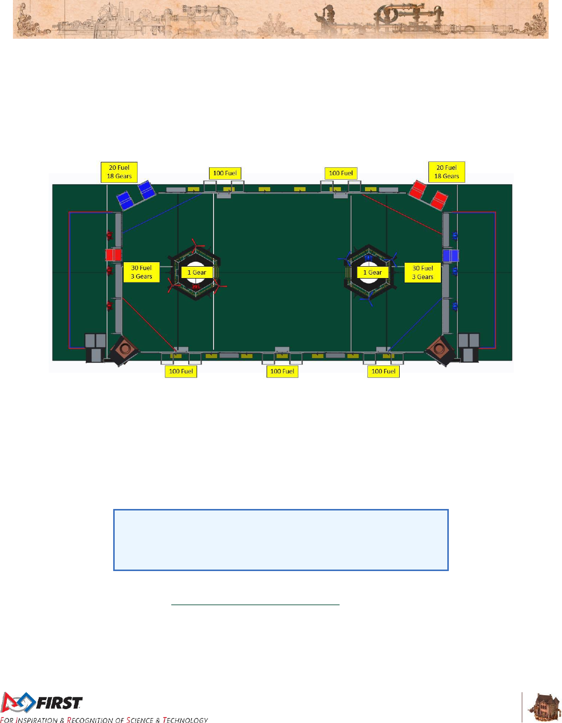
Each MATCH begins with GAME PIECES, elements used to score points, staged as shown in Figure 4-1.
Staging details are as follows:
FUEL
A. Ten (10) available for each TEAM to preload in their ROBOT (any not preloaded are
staged in the bin referenced in the next bullet, B)
B. Twenty (20) in each LOADING LANE (in a bin staged between the LOADING
STATION and the STARTING LINE)
C. One hundred (100) plus or minus four (4) in each HOPPER (i.e. fifty (50) plus or
minus two (2) in each HOPPER container)
Section 4 MATCH Play
V4
42 of 135
GEARS
D. One (1) available to each team to preload in their ROBOT (any not preloaded are
staged with GEARS in E)
E. Eighteen (18) in each LOADING LANE (staged on the carpet between the LOADING
STATION and the STARTING LINE)
F. One (1) in each AIRSHIP (as described in Section 3.4.2)
Figure 4-1: GAME PIECE staging
When a DRIVE TEAM loads their ROBOT onto the FIELD for a MATCH they may elect to:
A. pre-load one (1) GEAR in or on their ROBOT such that it is fully and only supported
by the ROBOT. Any GEARS not preloaded in a ROBOT are transferred to their
LOADING LANE.
and
B. pre-load up to ten (10) FUEL in or on their ROBOT such that they are fully and only
supported by the ROBOT. Any FUEL not preloaded in a ROBOT is transferred to a
RETURN BIN in their LOADING LANE.
“Support”, in reference to pre-loaded GAME PIECES, is transitive
through other GAME PIECES. For example, a FUEL is “fully supported
by the ROBOT” if it is resting on top of a GEAR that is in turn on a
ROBOT (and thus both GAME PIECES are “fully supported” by the
ROBOT).
A DRIVE TEAM may elect to switch one of the ROPES on their AIRSHIP for their own ROPE that meets
the criteria defined in I04 of Section 9 Inspection & Eligibility Rules and has a serialized Inspection tag.
Once the DRIVE TEAM has installed their ROPE on the AIRSHIP, it is part of the FIELD, but any issues
with it will not result in an ARENA FAULT.
If order placement of ROBOTS or ROPES matters to either or both ALLIANCES, the ALLIANCE must
notify the Head REFEREE during setup for that MATCH. Upon notification, the Head REFEREE will
require ALLIANCES alternate placement of all ROBOTS and then all ROPES, starting with the Red

Section 4 MATCH Play
V4
43 of 135
ALLIANCE and in order of PLAYER STATION assigned (i.e. Red Station 1 ROBOT, Blue Station 1
ROBOT, Red Station 2 ROBOT, Blue Station 2 ROBOT…Red Station 1 ROPE, Blue Station 1 ROPE,
Red Station 2 ROPE…).
4.3 Scoring
ALLIANCES are rewarded for accomplishing various actions including autonomous movement, pressure
accumulation, ROTOR engagement, getting a ROBOT ready for takeoff, and winning and tying
MATCHES. Rewards are granted either via MATCH points (which contribute to the ALLIANCE’S MATCH
score) or Ranking Points (which increases the measure used to rank teams in the Qualification
tournament). Such actions, their criteria for completion, and their point values are listed in Table 4-1.
Scores are assessed and updated throughout the MATCH.
Fractions of kilopascals accumulate as an ALLIANCE stokes the BOILER with FUEL in the High and Low
Efficiency GOALS. For example, during TELEOP, an ALLIANCE scores twelve (12) FUEL in the Low
Efficiency GOAL and five (5) FUEL in the High Efficiency GOAL. As a result, the ALLIANCE has
generated three (3) kPa of pressure (= 12/9 + 5/3).
MATCH points increment as whole unit kilopascals are achieved. For example, during TELEOP, an
ALLIANCE scores fourteen (14) FUEL in the Low Efficiency GOAL and five (5) FUEL in the High
Efficiency GOAL. As a result, they have generated 32/9 kPa of pressure (= 14/9 + 5/3), and their MATCH
points increment by three (3) points. They do not receive a fourth MATCH point unless and until they
score enough FUEL in the high and Low Efficiency GOAL to generate four (4) kPa of pressure.
Fractions of kilopascals generated in AUTO carry over and contribute to the TELEOP pressure. For
example, if an ALLIANCE scores seventeen (17) FUEL in the Low Efficiency GOAL in AUTO, the
ALLIANCE receives five (5) MATCH points and has generated 5⅔ kPa of pressure. Once TELEOP
begins, the ALLIANCE scores another three (3) FUEL in the Low Efficiency GOAL. Their pressure is now
six (6) kPa and they’re awarded a sixth MATCH point.

Section 4 MATCH Play
V4
44 of 135
Table 4-1: FIRST STEAMWORKS rewards
Action
Criteria
MATCH Points
Ranking
Points
AUTO
TELEOP
AUTO
mobility
For each ROBOT that breaks the BASE LINE
vertical plane with their BUMPER by T=0
5
-
-
Pressure
accumulation
For every three (3) FUEL counted in the Low
Efficiency GOAL by T=0
1
+ 1 kPa
For every one (1) FUEL counted in the High
Efficiency GOAL by T=0
For every nine (9) FUEL counted in the Low
Efficiency GOAL by T=0
-
1
+ 1 kPa
For every three (3) FUEL counted in the High
Efficiency GOAL by T=0
If ALLIANCE meets or exceeds a threshold
pressure of 40 kPa
20
(Playoffs
only)
1
(Quals
only)
ROTOR
engagement
For each ROTOR turning by period’s T=0,
that’s not previously been scored
60
40
-
If all four (4) ROTORS turning by T=0
100
(Playoffs
only)
1
(Quals
only)
Ready for
Takeoff
For each TOUCHPAD triggered by a ROBOT
at T=0
50
-
Win
ALLIANCE’s final score exceeds their
opponents’
-
2
(Quals
only)
Tie
ALLIANCE’s final score equals their
opponents’
1
(Quals
only)
Although the STEAM TANK lights as described in Section 3.6 STEAM TANK have an upper limit to the
amount of Pressure they can display, there is no limit on the Pressure an ALLIANCE can accumulate.
FUEL contributes to an ALLIANCE’S pressure and MATCH score only
once it is counted, which occurs after it’s loaded in a BOILER. The
BOILER’S rate of processing FUEL is detailed in Section 3.11.4 BOILER
and should be taken in to consideration when loading FUEL in the final
seconds of AUTO and TELEOP. The BOILER counters shut off at T=0,
and any uncounted FUEL (i.e. FUEL that has not passed by the sensors)
does not contribute to pressure accumulation or MATCH points.
Like the reduction of prepopulated GEARS for Championships described
in Section 3.4.2 GEAR Sets, the threshold pressure may also increase
for District Championships or FIRST® Championship.

Section 4 MATCH Play
V4
45 of 135
4.4 Rule Violations
Upon a rule violation, one or more of the penalties listed in Table 4-2 will be assessed.
Table 4-2: Penalty Table
Action
Penalty
FOUL
5 points credited towards the opponent’s total score.
TECH FOUL
25 points credited towards the opponent’s total score.
YELLOW
CARD
a warning issued by the Head REFEREE for egregious ROBOT or Team
member behavior or rule violations. A subsequent YELLOW CARD
within the same tournament phase will lead to a RED CARD.
RED CARD
a penalty assessed for egregious ROBOT or Team member behavior, or
rule violations, which results in a Team being DISQUALIFIED for the
MATCH.
DISABLED
ROBOT will be commanded to deactivate all outputs, rendering the
ROBOT inoperable for the remainder of the MATCH.
DISQUALIFIED
the status of a Team, as determined by the Head REFEREE, in which
their Team receives zero (0) MATCH points in a qualification MATCH or
causes their ALLIANCE to receive zero (0) MATCH points in a Playoff
MATCH
In addition to rule violations explicitly listed in this manual and witnessed by a REFEREE, the Head
REFEREE may assign a YELLOW or RED CARD as a result of egregious ROBOT actions or Team
member behavior at the event. Please see Section 10.7 YELLOW and RED CARDS for additional detail.
4.5 DRIVE TEAM
A DRIVE TEAM is a set of up to five (5) people from the same FIRST Robotics Competition Team
responsible for Team performance during a MATCH. There are four (4) specific roles on a DRIVE TEAM
which ALLIANCES can use to assist ROBOTS with race preparation.
Table 4-3: DRIVE TEAM roles
Role
Description
Max./
DRIVE TEAM
Criteria
COACH
responsible for acting as
a guide or advisor
1
Pre-college student or adult mentor
Must wear “Coach” button
DRIVER
responsible for operating
and controlling the
ROBOT
4
Pre-college student
Must wear one (1) of the four (4) “Drive
Team” buttons
HUMAN
PLAYER
responsible for managing
GAME PIECES
4
PILOT
responsible for installing
GEARS, starting
ROTORS, and deploying
ROPES
1
There may be up to two (2) PILOTS per ALLIANCE per MATCH. During Qualification MATCHES, PILOTS
may come from the DRIVE TEAMS assigned to Stations 1 and 2. A Team is permitted to cede their
PILOT position to a PILOT from the DRIVE TEAM assigned to Station 3. During Playoff MATCHES, the
ALLIANCE CAPTAIN has the authority on which two separate teams provide the ALLIANCE’S PILOTS.
Section 4 MATCH Play
V4
46 of 135
PILOTS are strongly encouraged to make sure safety glasses fit
properly, secure them with eyewear retainers, avoid loose fitting clothing
and jewelry, and tie back long hair.
4.6 Logistics
Any GAME PIECES that leave the FIELD will not be returned to MATCH play. GAME PIECES that
inadvertently bounce back in to the FIELD will be considered fair game.
Note that ROBOTS may not deliberately cause GAME PIECES to leave
the FIELD (see G22).
GAME PIECES that roll, slide, or otherwise transfer from a LOADING LANE to an ALLIANCE STATION
(or vice versa) are considered “owned” by the ALLIANCE in the space now occupied by the GAME
PIECE.
There will not be an ARENA FAULT called for MATCHES that accidentally begin with an incorrect number
of GAME PIECES, damaged GAME PIECES, or experience the failure of a Team provided ROPE.
Once the MATCH is over, if the Head REFEREE determines that the FIELD is safe for FIELD Staff but
not safe for everyone (e.g. the FIELD is littered with FUEL that may cause a tripping hazard for a DRIVE
TEAM carrying a ROBOT), they will turn the LED strings purple. Once the FIELD is ready for regular
traffic, the Head REFEREE will change the LED strings to green and DRIVE TEAMS may retrieve their
ROBOT in accordance with S04.

Section 5 Safety Rules
V6
47 of 135
5 Safety Rules
Safety is paramount at all times during any Tournament, and each rule below is intended to establish
norms at each event that will mitigate injury risk to all participants.
Event staff have the final decision authority for all safety-related issues within a venue.
S01. Safety glasses: required. All event attendees must wear ANSI-approved, UL Listed, CE EN166
rated, AS/NZS, or CSA rated non-shaded safety glasses while in the ARENA. Lightly tinted
lenses are permitted provided eyes are clearly visible to others, but reflective lenses are
prohibited.
Violation: Attendee must immediately remedy or leave the ARENA.
S02. Closed-toed shoes: required. All event attendees must wear closed-toed shoes while in the
ARENA.
Violation: Attendee must immediately remedy or leave the ARENA.
S03. Dangerous ROBOTS: not allowed. ROBOTS whose operation or design is dangerous or unsafe
are not permitted.
Examples include, but are not limited to:
A. Uncontrolled motion that cannot be stopped by the DRIVE TEAM
B. ROBOT parts “flailing” outside of the FIELD
C. ROBOTS dragging their battery
D. ROBOTS that consistently extend beyond the FIELD
Violation: If before the MATCH, the offending ROBOT will not be allowed to participate in the
MATCH. If during the MATCH, the offending ROBOT will be DISABLED.
S04. Wait for the green lights. DRIVE TEAMS may only enter the FIELD if the LED strings are green,
unless explicitly instructed by a REFEREE or an FTA, and PILOTS may only exit the AIRSHIP if
the LED strings are green, unless explicitly instructed by a REFEREE or an FTA.
Violation: YELLOW CARD.
S05. ROBOTS, stay on the FIELD during the MATCH. ROBOTS and anything they control, e.g. a
GEAR, may not contact anything outside the FIELD with the exception of brief incursions into the
GOALS.
Please be conscious of REFEREES, and FIELD STAFF working around
the ARENA who may be in close proximity to your ROBOT.
Violation: Offending ROBOT will be DISABLED.
S06. Humans, stay off the FIELD during the MATCH. DRIVE TEAMS (except for PILOTS, see S07)
may not extend any body part into the FIELD during the MATCH.
Examples of egregious violations that are likely to escalate the Violation
to a RED CARD include, but are not limited to, walking onto the FIELD
during a MATCH or intentionally reaching into the FIELD and grabbing a
ROBOT during a MATCH.

Section 5 Safety Rules
V6
48 of 135
Violation: YELLOW CARD
S07. Keep your limbs safe at all times. During the MATCH, the PILOT may neither
A. contact ROTORS,
B. contact DAVITS,
C. reach outside any PORT (except for incidental and brief excursions outside the port
and above the deck, required to manipulate the carriage assembly), nor
D. contact any part of a deployed (i.e. any part of the ROPE is below the deck of the
AIRSHIP) ROPE.
Reaching outside a port to retrieve a GEAR is a violation of S07-C, as
retrieving a GEAR is not manipulating the carriage assembly.
Reaching outside a port to untangle a pull handle or pull cord is not a
violation of S07-C, as those elements are part of the carriage assembly.
Violation: YELLOW CARD
S08. Stay out of the chute. DRIVE TEAMS may not contact the inside surfaces of the chute nor any
part of a GAME PIECE that is within the volume of the chute. Momentary contact while feeding
GAME PIECES into the chute is an exception to this rule.
Violation: FOUL.
S09. Never step/jump over the GUARDRAIL. DRIVE TEAMS may only enter or exit the FIELD
through open gates.
Violation: YELLOW CARD.
S10. Wireless operation: on FIELD and Practice Field only. Wireless ROBOT control is only
permitted on the FIELD or Practice FIELD. ROBOTS must be operated by tether when outside
the FIELD or Practice FIELD.
Violation: Verbal warning. Re peated violations will be addressed by the H ead REFEREE, the Lead
ROBOT Inspector and/or Event Management.
S11. If wireless on Practice Field, use FIRST’s radio. If operating wirelessly on the Practice FIELD,
ROBOTS must use the provided Practice Field radio for communication.
Violation: Verbal warning. Repeated violations will be addressed by the H ead REFEREE, the Lead
ROBOT Inspector and/or Event Management.
S12. Climb facing the ladder, but don’t operate it. PILOTS may only enter and exit the AIRSHIP
under the following criteria:
A. a member of the FIELD STAFF has released the ladder,
B. one rung at a time (though bottom rung may be skipped), and
C. facing your AIRSHIP.
Note that PILOTS exiting the AIRSHIP if the LED strings are purple is a
violation of S04.
Violation: Verbal warning. If jumped off AIRSHIP, YELLOW CARD. Repeated violations will be
addressed by the Head REFEREE, the Lead ROBOT Inspector and/or Event Management.

Section 5 Safety Rules
V6
49 of 135

Section 6 Conduct Rules
V1
50 of 135
6 Conduct Rules
C01. Be a good person. All Teams must be civil towards their own Team members, other Teams,
competition personnel, FIELD STAFF, and event attendees while at a FIRST® Robotics
Competition event.
Violation: Behavior will be discussed with Team or individual. Viol ations of this rule are likely to
escalate to YELLOW or RED CARDS rapidly (i.e. the threshold for egregious or repeated
violations is relatively low.)
Examples of egregious behavior include, but are not limited to,
inappropriate behavior such as repeated use of offensive language or
other uncivil conduct.
C02. Asking other Teams to throw a MATCH – not cool. A Team may not encourage an ALLIANCE,
of which it is not a member, to play beneath its ability.
NOTE: This rule is not intended to prevent an ALLIANCE from planning and/or executing its own
strategy in a specific MATCH in which all the Teams are members of the ALLIANCE.
Example #1: A MATCH is being played by Teams A, B, and C, in which
Team C is encouraged by Team D to not deliver GEARS, resulting in
Teams A, B, and C not earning a Ranking Point for the ROTOR
achievement. Team D’s motivation for this behavior is to prevent Team A
from rising in the Tournament rankings and negatively affecting Team
D’s ranking.
Example #2: A MATCH is being played by Teams A, B, and C, in which
Team A is assigned to participate as a SURROGATE. Team D
encourages Team A to not participate in the MATCH so that Team D
gains ranking position over Teams B and C.
FIRST® considers the action of a Team influencing another Team to
throw a MATCH, to deliberately miss Ranking Points, etc. incompatible
with FIRST values and not a strategy any team should employ.
Violation: Behavior will be discussed with Team or individual. Violations of this rule are likely to
escalate rapidly to YELLOW or RED CARDS, and may lead to dismissal from the event (i.e. the
threshold for egregious or repeated violations is relatively low.)
C03. Letting someone coerce you in to throwing a MATCH – also not cool. A Team, as the result
of encouragement by a Team not on their ALLIANCE, may not play beneath its ability.
NOTE: This rule is not intended to prevent an ALLIANCE from planning and/ or executing its own
strategy in a specific MATCH in which all the ALLIANCE members are participants.
Example #1: A MATCH is being played by Teams A, B, and C. Team D
requests Team C to not deliver GEARS resulting in Teams A, B, and C
not earning a Ranking Point for the ROTOR achievement. Team C
accepts this request from Team D. Team D’s motivation for this behavior
is to prevent Team A from rising in the Tournament rankings negatively
affecting Team D’s ranking.

Section 6 Conduct Rules
V1
51 of 135
Example #2: A MATCH is being played by Teams A, B, and C, in which
Team A is assigned to participate as a SURROGATE. Team A accepts
Team D’s request to not participate in the MATCH so that Team D gains
ranking position over Teams B and C.
FIRST considers the action of a Team influencing another Team to throw
a MATCH, to deliberately miss Ranking Points, etc. incompatible with
FIRST values and not a strategy any team should employ.
Violation: Behavior will be discussed with Team or individual. Violations of this rule are likely to
escalate rapidly to YELLOW or RED CARDS, and may lead to dismissal from the event (i.e. the
threshold for egregious or repeated violations is relatively low.)
C04. Compete with only one (1) ROBOT. Each registered FIRST Robotics Competition team may
enter only one (1) ROBOT (or ‘Robot’, which to a reasonably astute observer, is a ROBOT built to
play FIRST STEAMWORKS) into the 2017 FIRST Robotics Competition.
“Entering” a ROBOT (or Robot) in to a FIRST Robotics Competition
means bringing it to the event such that it’s an aid to your Team (e.g. for
spare parts, judging material, or for practice). Spare FABRICATED
ITEMS may be brought to the event in a bag or part of a WITHHOLDING
ALLOWANCE.
This rule does not prohibit teams from bringing in robots from other
FIRST programs for the purposes of awards presentations or pit
displays.
Violation: Verbal warning. Repeated violations will be addressed by the H ead REFEREE, the Lead
ROBOT Inspector and/or Event Management.
C05. Don’t set up wireless networks. Teams may not set up their own 802.11a/b/g/n/ac (2.4GHz or
5GHz) wireless communication (e.g. access points or ad-hoc networks) in the venue.
A wireless hot spot created by a cellular device is considered an access
point.
Violation: Verbal warning. Repeated violations will be addressed by the H ead REFEREE, the Lead
ROBOT Inspector and/or Event Management.
C06. Don’t try to hack networks. No Team or Team member shall interfere or attempt to interfere
with any other Team’s or FIRST wireless communication. Except as expressly allowed for
purposes of communicating with the Team’s own ROBOT on the FIELD or a Practice FIELD, no
Team or Team member shall connect or attempt to connect to any other Team’s or FIRST’s
wireless network.
Teams are encouraged to report suspected wireless security
vulnerabilities to the FIRST Technical Advisor (FTA) if at the event or to
FIRST via the Wireless Security Feedback Form.
Violation: Behavior will be discussed with Team or individual. Violations of this rule are likely to
escalate rapidly to YELLOW or RED CARDS, and may lead to dismissal from the event (i.e. the
threshold for egregious or repeated violations is relatively low.) Legal action may also be pursued
based on applicable law.
C07. Show up to your MATCHES. Each Team must send at least one (1) member of its DRIVE
TEAM to the FIELD and participate in each of the Team’s assigned Qualification and Playoff
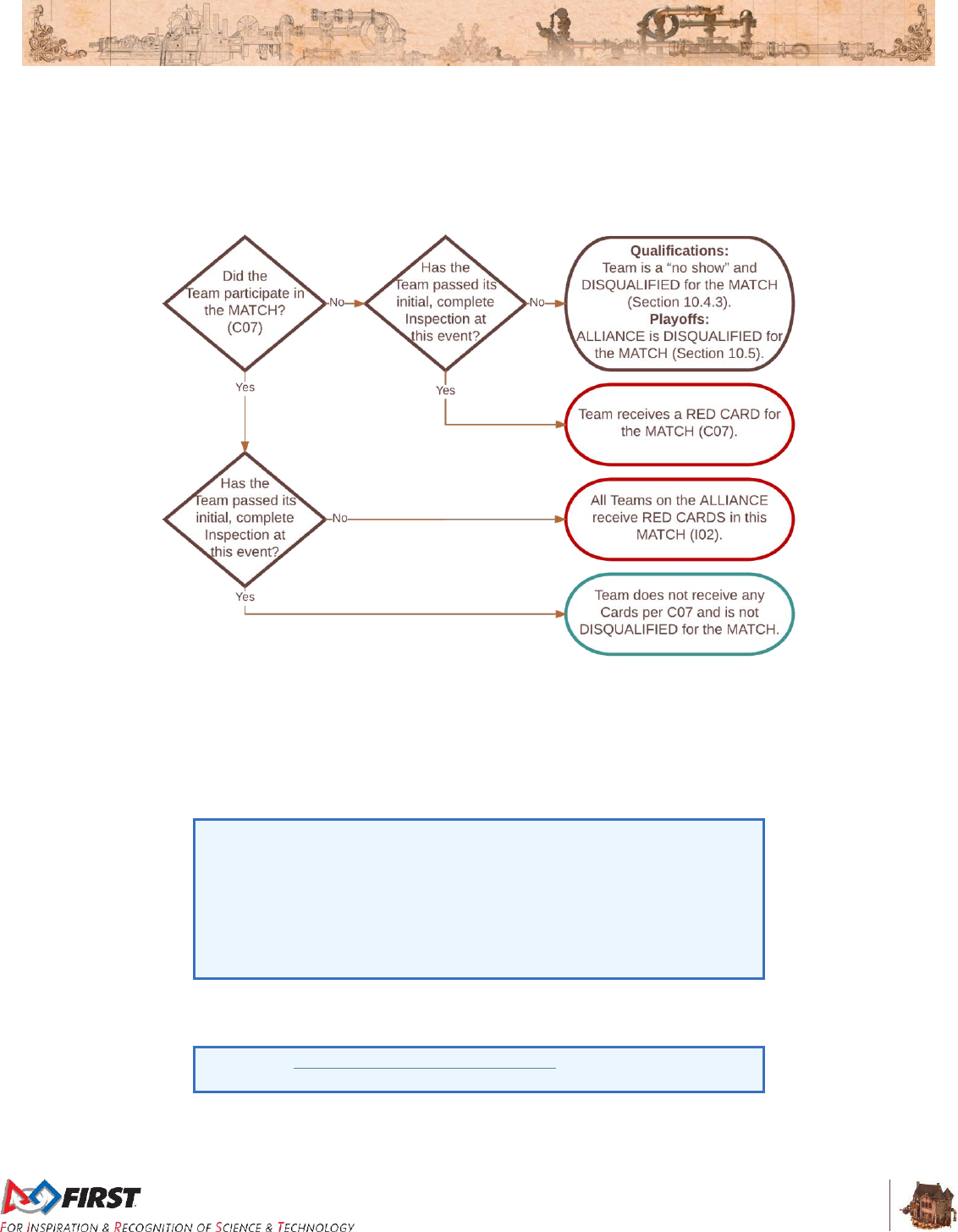
Section 6 Conduct Rules
V1
52 of 135
MATCHES. The Team should inform the Lead Queuer if the Team’s ROBOT is not able to
participate.
Violation: If ROBOT has passed an initial, complete Inspection, RED CARD. If ROBOT has not
passed an initial, complete Inspection, DISQUALIFIED per I02.
Figure 6-1: Match participation flowchart
C08. Don’t expect to gain by doing others harm. Strategies aimed solely at forcing the opposing
ALLIANCE to violate a rule are not in the spirit of FIRST Robotics Competition and not allowed.
Rule violations forced in this manner will not result in an assignment of a penalty to the targeted
ALLIANCE.
Violation: FOUL. If egregious or repeated, YELLOW CARD.
C08 does not apply for strategies consistent with standard gameplay,
e.g. contacting an opponent while in your RETRIEVAL ZONE to retrieve
GAME PIECES.
C08 requires an intentional act with limited or no opportunity for the
TEAM being acted on to avoid the penalty, e.g. placing a GEAR on/in an
opponent who’s already controlling a GEAR such that they cannot help
but violate G27.
C09. One student, one Head REFEREE. A Team may only send one (1) pre-college student from its
DRIVE TEAM to address the Head REFEREE.
Please see Section 10.6 REFEREE Interaction for more information
about process and expectations.
Violation: The Head REFEREE will not address additional, non -compliant Team members or
peripheral conversations.

Section 6 Conduct Rules
V1
53 of 135
C10. Even BANNERS have standards. If brought to the ARENA, the Team BANNER must be
constructed to the Team Banner Specification and installed such that
A. its vertical support is in the BANNER holder in the PLAYER STATION to which the
Team is assigned, as indicated on the Team sign and,
B. oriented with its horizontal support piece parallel to the ALLIANCE WALL.
Violation: The MATCH will not start until the situation is corrected or the Team banner is removed
from the ARENA.
C11. Keep your hands off your BANNER. During a MATCH, the Team BANNER may not be touched
by any member of the ALLIANCE
Violation: FOUL, an exception is given for a Team BANNER which is damaged and/or dangling in
front of a DRIVE TEAM.
C12. Plug in to/be in your PLAYER STATION. The OPERATOR CONSOLE must be used in the
PLAYER STATION to which the Team is assigned, as indicated on the Team sign.
Violation: The MATCH will not start until the situation is corrected. If during a MATCH, YELLOW
CARD.
One intent of C12 is to prevent unsafe situations where long tethers to
OPERATOR CONSOLE devices increase tripping hazards as the
operator moves about the ALLIANCE STATION. In the interest of
avoiding nuisance penalties associated with an operator stepping outside
of a prescribed area, we prefer to offer a general guideline as to what it
means to use the OPERATOR CONSOLE in the ALLIANCE STATION.
Provided the operator is within close proximity of their PLAYER
STATION, there will be no repercussions. However, if an operator is
located more than approximately ½ PLAYER STATION width away from
their own PLAYER STATION, that would be considered a violation of
C12.
C13. No work outside your pit. Throughout the event, from load-in to load-out, Teams may only
produce FABRICATED ITEMS in their pit area, other Teams’ pit areas with permission from that
Team, or as permitted at provided machine shops.
Violation: Verbal warning. Repeated or egregious violations will be addressed by the H ead
REFEREE, the Lead ROBOT Inspector and/or Event Management.

Section 7 Game Rules
V12
54 of 135
7 Game Rules
7.1 Before the MATCH
G01. Know your ROBOT setup. When placed on the FIELD for a MATCH, each ROBOT must be:
A. in compliance with all ROBOT rules, i.e. has passed Inspection (for exceptions
regarding Practice MATCHES, see Section 9 Inspection & Eligibility Rules),
B. the only item left on the FIELD by the DRIVE TEAM,
C. confined to its STARTING CONFIGURATION,
D. set on the carpet,
E. in contact with its ALLIANCE WALL diamond plate, and
F. supporting not more than 10 FUEL and 1 GEAR (as described in Section 4.2 MATCH
Setup).
Violation: If fix is a quick remedy, the MATCH won’t start until all requirements are met. If it is not
a quick remedy the offending ROBOT will be DISABLED and, at the discretion of the Head
REFEREE, must be re-inspected.
If a ROBOT is BYPASSED prior to the start of the MATCH, the DRIVE
TEAM may not remove the ROBOT from the FIELD without permission
from the Head REFEREE or the FIRST® Technical Advisor (FTA).
G01-1. Know your ROPE setup. If a Team is using their own ROPE, it must be stowed using the ROPE
retention strap and/or loop pad such that it is not deployed.
Violation: If fix is a quick remedy, the MATCH won’t start until all requirements are met. If it is not
a quick remedy the FI ELD STAFF will install a default ROPE.
G02. Be prompt/safe when coming to and going from the FIELD. DRIVE TEAMS may not cause
significant or repeated delays to the start of a MATCH and/or to the FIELD reset at the conclusion
of the MATCH.
Violation: If prior to the MATCH, the offending DRIVE TEAM’S ROBOT will be DISABLED. If after
the MATCH, YELLOW CARD.
DRIVE TEAMS are expected to stage their ROBOTS for a MATCH, and
remove it from the FIELD afterwards, safely and swiftly. Examples
include, but are not limited to:
E. late arrival to the FIELD
F. failing to exit the FIELD once the LED strings have turned off
(indicating MATCH ready)
G. installing BUMPERs, charging pneumatic systems, or any other
ROBOT maintenance, once on the FIELD
H. use of alignment devices that are external to the ROBOT
I. failing to remove OPERATING CONSOLES from the PLAYER
STATIONS in a timely manner
J. convoluted installation and removal of TEAM supplied ROPE
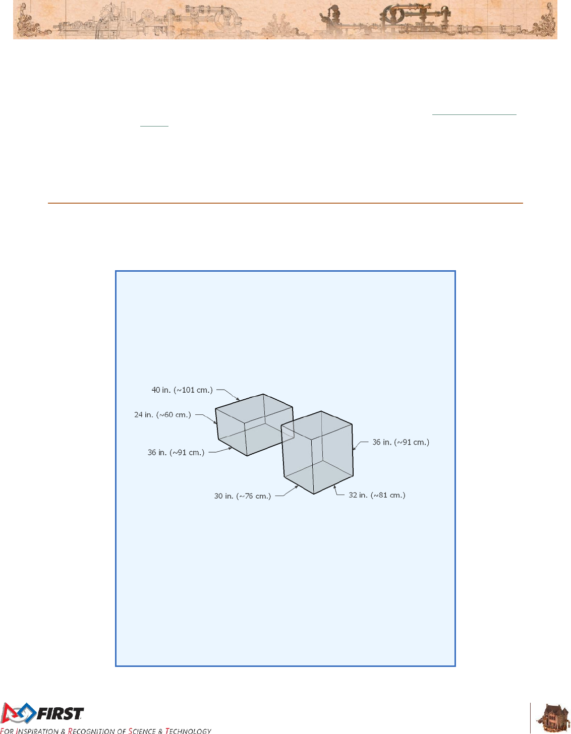
Section 7 Game Rules
V12
55 of 135
G03. Know your DRIVE TEAM positions. Prior to the start of the MATCH, DRIVE TEAMS must be
positioned as follows:
A. DRIVERS and COACHES must be in their ALLIANCE STATION and behind the
STARTING LINE
B. At least one (1) PILOT must be on their AIRSHIP (please refer to Section 4.5 DRIVE
TEAM for details regarding which DRIVE TEAMS provide the PILOT(S))
C. HUMAN PLAYERS (that are not PILOTS) must be behind the STARTING LINE and
in their ALLIANCE STATION or LOADING LANE
Violation: MATCH will not start until the situation is corrected .
7.2 ROBOT Restrictions
G04. Don’t overextend yourself. A ROBOT may not exceed the volume for which it passed
Inspection during the MATCH.
Violation: FOUL. If strategic, (e.g. expansion results in the TOUCHPAD being triggered), RED
CARD.
The two (2) distinct ROBOT volumes permitted are defined in R03 and
included below for reference:
A. 36 in. by 40 in. by 24 in. tall (~91 cm by 101 cm by 60 cm tall)
B. 30 in. by 32 in. by 36 in. tall (~76 cm by 81 cm by 91 cm tall)
Figure 7-1: Permitted ROBOT volumes
These measurements are intended to be made as if the ROBOT is
resting on a flat floor, not relative to the height of the ROBOT from the
FIELD carpet.
As a result, a ROBOT that fits in one of the permitted volumes and has
climbed a ROPE such that its highest point is 4 ft. (~122 cm) from the
floor has not violated G04 as it is not considered 4 ft. (~122 cm) tall.
Additionally, a ROBOT that is angled as it climbs a rope (such that a
diagonal of length that exceeds the volume’s height restriction becomes
vertical), does not violate G04, assuming that if it’s virtually transposed to
a flat floor without changing configuration, it’s within its permitted volume.
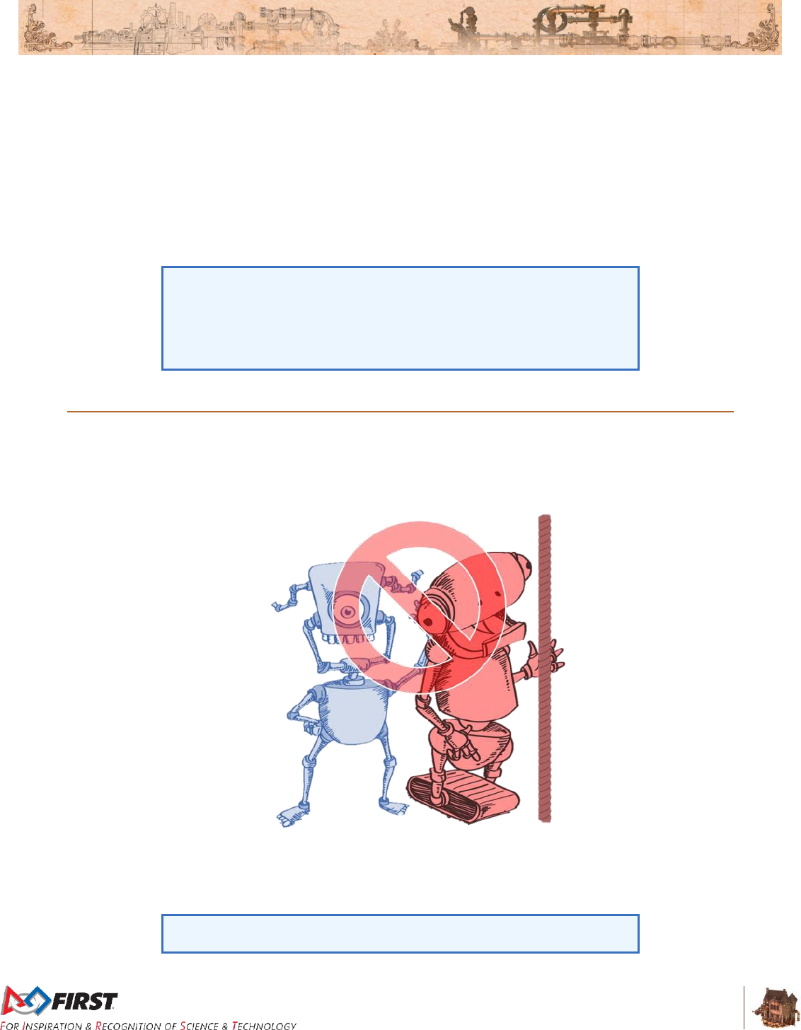
Section 7 Game Rules
V12
56 of 135
G05. Keep your BUMPERS together. ROBOTS must be in compliance with BUMPER Rules
throughout the MATCH.
Violation: FOUL. DISABLED if any BUMPER segment becomes completely detached or the Team
number or ALLIANCE color becomes indeterminate.
G06. ROBOTS must be removed from the FIELD by hand (i.e. no enabling, power, etc.). ROBOTS
will not be re-enabled after the conclusion of the MATCH, nor will Teams be permitted to tether to
the ROBOT except in special circumstances (e.g. during TIMEOUTS, after Opening Ceremonies,
before an immediate MATCH replay, etc.) and with the express permission from the FTA or a
REFEREE.
Violation: YELLOW CARD.
Tethering includes any wired or wireless connection used to electrically
energize and/or control elements on the ROBOT. The safety of Teams
and Volunteers in close proximity to ROBOTS and ARENA elements on
the FIELD is of the utmost importance, therefore ROBOTS or ROBOT
COMPONENTS may not be energized or powered in any way on the
FIELD once the MATCH has concluded.
7.3 ROBOT to ROBOT Interaction
G07. Opponent touching their ROPE: don’t touch them. ROBOTS may not contact an opposing
ROBOT, regardless of who initiates the contact, if the opposing ROBOT is in contact with one of
its own ALLIANCE'S ROPES.
Figure 7-2: Don’t touch opponents touching their ROPES.
Violation: The opposing ROBOT is considered to have triggered an un -triggered TOUCHPAD at the
end of the MATCH.
Teams are encouraged to consider rule C08 when developing their
strategies, such as attempting to draw violations of this rule.

Section 7 Game Rules
V12
57 of 135
G08. Don’t tear others down to lift yourself up. Strategies aimed at the destruction or inhibition of
ROBOTS via attachment, damage, tipping, entanglements, or deliberately putting a GEAR on an
opponent’s ROBOT are not allowed.
Violation: FOUL and YELLOW CARD. If harm or incapacitation occurs as a result of the strategy,
RED CARD
G09. Stay out of other ROBOTS. Initiating deliberate or damaging contact with an opponent ROBOT
on or inside the vertical extension of its FRAME PERIMETER is not allowed.
Violation: FOUL and YELLOW CARD.
G10. Don’t collude with your partners to shut down major parts of game play. Two or more
ROBOTS may not isolate or close off any major facet of MATCH play, e.g. block all three
opponent LIFTS, shut down all access to GAME PIECES, quarantine all opponents to a small
area of the FIELD, etc.
Violation: YELLOW CARD for the ALLIANCE.
A single ROBOT blocking access to a particular area of the FIELD is not
a violation of G10.
G11. There’s a 5-count on pins. ROBOTS may not pin an opponent’s ROBOT for more than five (5)
seconds. A ROBOT will be considered pinned until the ROBOTS have separated by at least six
(6) feet. The pinning ROBOT(s) must then wait for at least three (3) seconds before attempting to
pin the same ROBOT again. Pinning is transitive through other objects. If the pinned ROBOT
chases the pinning ROBOT upon retreat, the pinning ROBOT will not be penalized, and the pin
will be considered complete.
Violation: If pinning ROBOT is not in the opponent’s KEY, FOUL, plus an additional FOUL for every
five (5) seconds in which the situation is not corrected. If pinning ROBOT is in the opponent’s
KEY, TECH FOUL, plus an additional TECH FOUL for every five (5) seconds in which the situation
is not corrected. In either scenario, if e xtended and egregious, RED CARD.
There is no FIRST® Robotics Competition specific definition of pin, so a
general definition applies; “to prevent or stop something from moving.”
As a result, contact is not required for pinning to occur. For example, a
ROBOT parked right behind an opponent that is between dividers could
be considered pinning because the dividers and the parked ROBOT
prevent the opponent from moving.
Generally, pins that exceed fifteen (15) seconds are considered
extended and egregious, regardless of a pinning ROBOT’s mobility,
however circumstances vary and the assessment is open to REFEREE
discretion.
G12. If an opponent’s down, back off. Fallen (i.e. tipped over) ROBOTS attempting to right
themselves (either by themselves or with assistance from a partner ROBOT) have one ten (10)
second grace period in which they may not be contacted by an opponent ROBOT. This protection
lasts for either ten (10) seconds or until the protected ROBOT has completed the righting
operation, whichever comes first.
Violation: FOUL. If intentional, YELLOW CARD.
G13. Don’t mess with a ROBOT in their RETRIEVAL ZONE. A ROBOT with any part inside its
opponent’s RETRIEVAL ZONE may not contact an opposing ROBOT, regardless of who initiates
the contact.
Violation: TECH FOUL.

Section 7 Game Rules
V12
58 of 135
TEAMS should take note that they are putting themselves at great risk
for FOULS if they choose to enter their opponent’s RETRIEVAL ZONE.
G14. Don’t climb on each other. Unless attempting to right a fallen (i.e. tipped over) ALLIANCE
partner, ROBOTS may neither fully nor partially support the weight of other ROBOTS on the
same ALLIANCE strategically or repeatedly.
Violation: RED CARD.
7.4 FIELD Interaction
G15. Be careful about what you grab on to. DRIVE TEAMS, ROBOTS, and OPERATOR
CONSOLES are prohibited from the following actions with regards to interaction with ARENA
elements.
Items A and B exclude DRIVE TEAM interaction with FIELD elements in their areas.
Item C excludes use of the PLAYER STATION hook-and-loop tape, plugging in to the provided
power outlet, and plugging the provided Ethernet cable in to the OPERATOR CONSOLE.
Items A-E exclude GAME PIECES.
Items A-G exclude ROPES installed on an ALLIANCE’S AIRSHIP.
Items A-H exclude a ROBOT'S interaction with a Team supplied ROPE that doesn’t litter the
FIELD. A. Grabbing
B. Grasping
C. Attaching to (including the use of hook-and-loop tape against the FIELD carpet)
D. Grappling
E. Hanging
F. Deforming
G. Becoming entangled
H. Damaging
Violation: If prior to MATCH, and situation can be corrected quickly, it must be remedied before
the MATCH will start. If during a MATCH, FOUL. If during a MATCH and extended or repeated,
YELLOW CARD. If offense is via a ROBOT and the Head REFEREE determines that further
damage is likely to occur, offending ROBOT will be DISABLED. Corrective action (such as
eliminating sharp edges, removing the damaging MECHANISM, and/or re-Inspection) may be
required before the ROBOT will be allowed to compete in subsequent MATCHES.
GAME PIECES are expected to undergo a reasonable amount of wear
and tear as they are handled by ROBOTS, such as scratching or
marking. Gouging, tearing off pieces, or routinely marking GAME
PIECES are violations of this rule. Humans causing GAME PIECE wear
and tear, e.g. flattening FUEL, are subject to a CARD per Section 10.7
YELLOW and RED CARDS.
A ROBOT that has only unseated the TOUCHPAD dome has not
damaged the FIELD.
GEARS placed in a BOILER will damage the BOILER internal elements
and such an action is considered an egregious violation of G15.
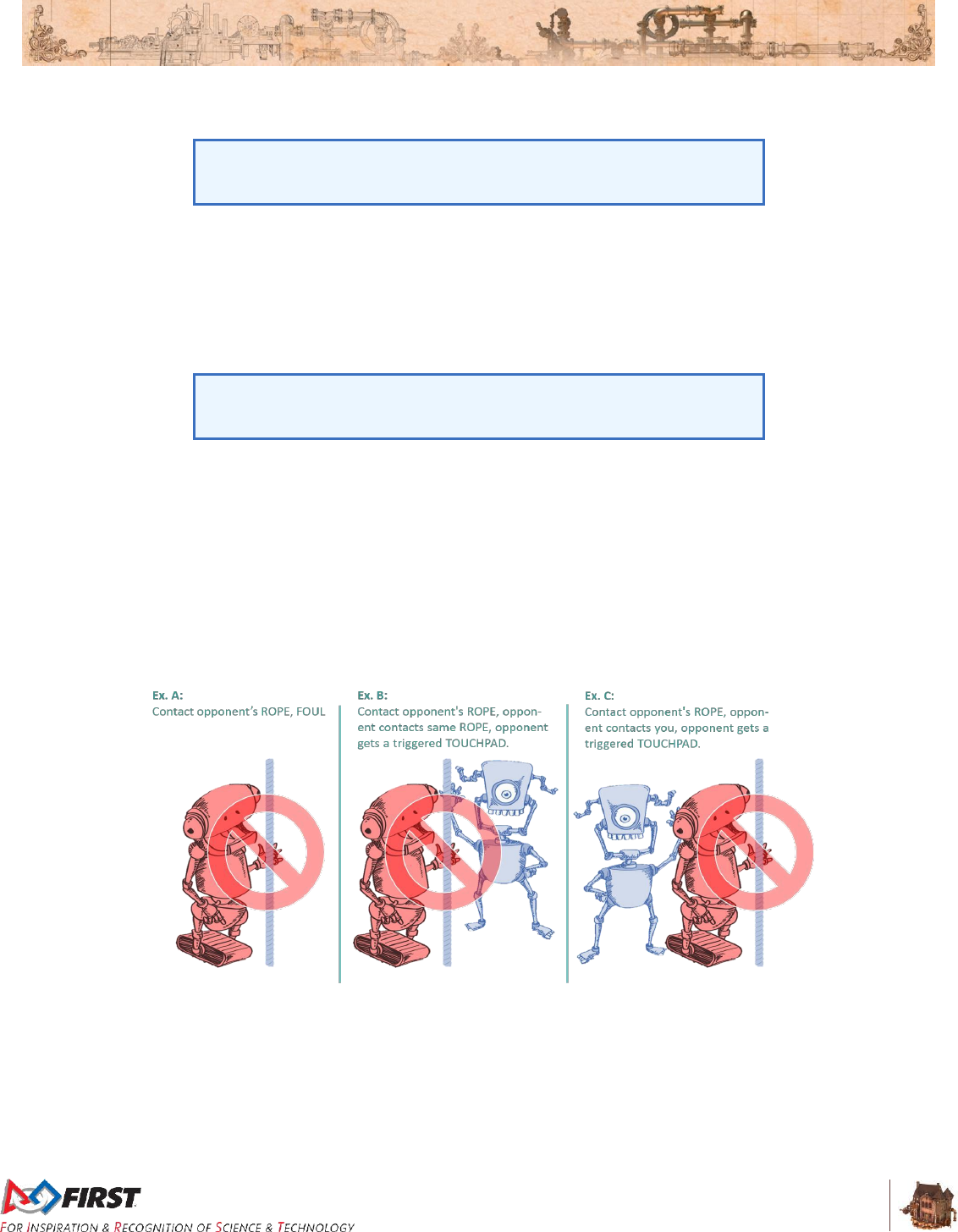
Section 7 Game Rules
V12
59 of 135
G16. Keep it together. ROBOTS may not intentionally detach or leave parts on the FIELD.
Violation: RED CARD
This rule is not intended to penalize ROBOTS that encounter accidental
breakage (e.g. a failed MECHANISM that falls off), as those actions are
not intentional.
G17. Opponent’s KEY: a no parking zone. A ROBOT may not be in their opponent’s KEY for more
than five (5) seconds (if the ROBOT is breaking the plane of the line with BUMPERS, it is
considered in the KEY).
A ROBOT that is being pinned is exempt from G17. Once the pin is over, the G17 5-second count
begins.
Violation: FOUL. For every five (5) seconds in which the situation is not corrected, FOUL.
In a scenario where a ROBOT is pinning (per G11) and in the opponent’s
KEY, REFEREES are instructed to disregard G17 so they can focus on
the pinning.
G18. One ROBOT per ROPE. No more than one (1) ROBOT may be fully supported by a ROPE.
Violation: RED CARD.
G19. Only climb on deployed ROPES. A ROBOT may only pull on a ROPE if/once the ROPE is
supported only by the DAVIT, the carpet, the ROBOT, or any combination thereof.
Violation: RED CARD.
G20. Let ‘em climb: don’t touch their ROPES. During the final thirty (30) seconds of a MATCH,
ROBOTS may not contact an opposing ALLIANCE’S ROPE.
Figure 7-3: Don't touch opponents' ROPES in the final thirty (30) seconds of the MATCH.
Violation: FOUL. If an opposing ROBOT contacts the offending ROBOT or the ROPE, the opposing
ROBOT is considered to have triggered an un -triggered TOUCHPAD at the end of the MATCH .
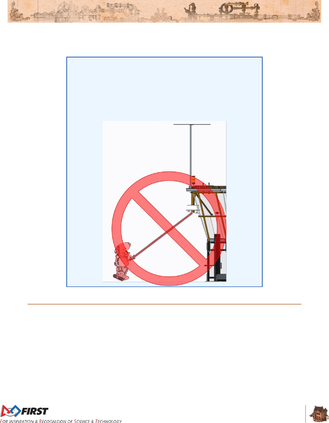
Section 7 Game Rules
V12
60 of 135
G20-1. ROBOTS gotta climb. A ROBOT may only signal they’re “Ready for Takeoff” by climbing a
ROPE.
Violation: RED CARD
‘Climbing a ROPE’ means ascending using a ROPE.
A ROBOT may supplement the climbing action by using an extension
that reaches out to trigger a TOUCHPAD (assuming, of course, ROBOT
size restrictions are still met), but climbing must be part of the triggering
action.
Figure 7-4: Use of FIELD geometry to signal a ROBOT is “Ready for Takeoff”
without climbing the ROPE is an example of a violation of G20-1.
7.5 GAME PIECE Interaction
G21. GAME PIECES: use as directed. ROBOTS may not deliberately use GAME PIECES, e.g.
GEARS, in an attempt to ease or amplify the challenge associated with other FIELD elements,
e.g. BOILERS, HOPPERS, or ROPES.
Violation: YELLOW CARD.
G22. Keep GAME PIECES in bounds. ROBOTS may not intentionally eject GAME PIECES from the
FIELD other than through BOILERS.
Violation: FOUL. Repeated or extended violations of this rule are likely to escalate rapidly to
YELLOW or RED CARDS.
G23. Shoot FUEL from your own LAUNCHPAD. A ROBOT may only LAUNCH FUEL while in their
LAUNCHPAD (i.e. at least breaking the plane of the line with BUMPERS).

Section 7 Game Rules
V12
61 of 135
For the purposes of FIRST® STEAMWORKSSM, LAUNCHING is defined
as shooting in the air, kicking or rolling across the floor with an active
mechanism, or throwing in a forceful way.
A ROBOT that has bumped FUEL has not LAUNCHED it.
Violation: FOUL. Repeated or extended violations of this rule are likely to escalate rapidly to
YELLOW or RED CARDS.
G24. Don’t throw GEARS at all. A ROBOT may not LAUNCH a GEAR.
Violation: YELLOW CARD.
G25. AIRSHIPS run on steam, not FUEL. ROBOTS may not intentionally put FUEL in an AIRSHIP.
Violation: YELLOW CARD.
G26. If you’re going to deliver GEARS, you have to use a LIFT. Any GEAR transferred from a
ROBOT to a PILOT during the MATCH must be done so via a LIFT.
Violation: TECH FOUL and a YELLOW CARD.
G27. One-GEAR limit. ROBOTS may not control more than one GEAR at a time.
Violation: FOUL. If strategic, TECH FOUL and YELLOW CARD.
Moving or positioning a GEAR to gain advantage is considered “control.”
Examples include, but are not limited to:
A. “carrying” (holding a GEAR inside a ROBOT)
B. “herding” (intentionally pushing a GEAR to a desired location or
direction)
C. “trapping” (holding a GEAR against a FIELD element in an attempt to
shield or guard it)
Examples of interaction with GEARS that are not “control” include, but
are not limited to:
A. “bulldozing” (inadvertent contact with GEARS while in the path of the
ROBOT moving about the FIELD)
B. “deflecting” (being hit by a GEAR that bounces into or off of a
ROBOT).
If a GEAR becomes lodged in or on a ROBOT, it will be considered
controlled by the ROBOT. It is important to design your ROBOT so that it
is impossible to inadvertently or unintentionally control more than the
allowed maximum.
G28. Don’t use air to direct/redirect FUEL. ROBOTS may not use forced air to affect the movement
of FUEL that is outside the volume of the ROBOT.
Violation: RED CARD.
Section 7 Game Rules
V12
62 of 135
7.6 AUTO Period Rules
A01. Behind the lines. During AUTO, DRIVE TEAM members in ALLIANCE STATIONS and
LOADING LANES may not contact anything in front of the STARTING LINES, unless for personal
or equipment safety.
Violation: FOUL.
Pointing, gesturing or otherwise extending across the STARTING LINE
such that contact is not made with carpet or other ARENA elements is
not a violation of this rule.
One example of an exception for equipment safety is if an OPERATOR
CONSOLE starts to slide from the PLAYER STATION shelf. In that
circumstance, DRIVE TEAM members may step forward to catch it and
return it. However, if an OPERATOR CONSOLE has already hit the
ground, the damage has already been done, and touching it before
TELEOP starts is not an exception for equipment safety.
A02. During AUTO, let the ROBOT do its thing. During AUTO, DRIVE TEAMS may not directly or
indirectly interact with ROBOTS or OPERATOR CONSOLES unless for personal safety,
OPERATOR CONSOLE safety, or pressing an E-Stop for ROBOT safety.
Violation: FOUL and YELLOW CARD.
A03. Disconnect or set down controllers. During AUTO, any control devices worn or held by the
DRIVERS and/or HUMAN PLAYERS must be disconnected from the OPERATOR CONSOLE.
Violation: FOUL.
A04. Stay out of your opponent’s LAUNCHPAD. During AUTO, no part of a ROBOT’S BUMPERS
may enter their opponent’s LAUNCHPAD.
Violation: FOUL. If contact is made with an opponent ROBOT in their LAUNCHPAD (either direct
contact or transitive contact through anoth er object), TECH FOUL.
A05. PILOTS: don’t take the “free” GEAR yet. During AUTO, PILOTS may not remove the reserve
GEAR from the starting position in which it begins the MATCH.
Violation: TECH FOUL.
7.7 Human Action Rules
H01. COACHES and other Teams: hands off the controls. A ROBOT shall be operated solely by
the DRIVERS and/or HUMAN PLAYERS of that Team.
Violation: Offending ROBOT will be DISABLED.
Exceptions may be made before a MATCH for major conflicts, e.g.
religious holidays, major testing, transportation issues, etc.
H02. Wireless devices not allowed. During a MATCH, DRIVE TEAMS may not use electronic
devices which have the capability of receiving communications from persons outside of the
ARENA (e.g. cell phones or wearable technology).
Violation: YELLOW CARD.
H03. Leave FIELD scoring elements alone. Teams may not interfere with any automated scoring
hardware.

Section 7 Game Rules
V12
63 of 135
Violation: RED CARD for the ALLIANCE.
Examples of violations of this rule include, but are not limited to,
tampering with the sensors, putting anything but a GEAR in the GEAR
slot for ROTOR 1, blocking FUEL from exiting the BOILER, or attempting
to feed FUEL backwards through a BOILER.
H04. By invitation only. Only DRIVE TEAMS for the current MATCH are allowed in their respective
ALLIANCE STATIONS, LOADING LANES, and AIRSHIPS.
Violation: MATCH will not start until the situation is corrected.
H05. Identify yourself. DRIVE TEAMS must wear proper identification while in the ARENA. Proper
identification consists of:
A. All DRIVE TEAM members wearing their designated buttons above the waist in a
clearly visible location at all times while in the ARENA.
The COACH wearing the "Coach" labeled drive team button
The DRIVERS and HUMAN PLAYERS each wearing a DRIVE TEAM button
B. During a Playoff MATCH, the ALLIANCE CAPTAIN clearly displaying the designated
ALLIANCE CAPTAIN identifier (e.g. hat or armband).
Violation: MATCH will not start until the situation is correcte d. Those not displaying identification
must leave the ARENA.
H06. COACHES, no GAME PIECES. COACHES may not touch GEARS or FUEL unless for safety
purposes.
Violation: FOUL.
H07. No wandering. DRIVE TEAM members may not contact anything outside the zone in which they
started the MATCH (e.g. the AIRSHIP, LOADING LANE, or ALLIANCE STATION) during the
MATCH. Exceptions will be granted for inadvertent, momentary, and inconsequential infractions
and in cases concerning safety.
Violation: FOUL. If strategic, RED CARD.
H08. GAME PIECES through LOADING STATIONS only. ALLIANCES may only deliberately cause
GAME PIECES to leave an ALLIANCE STATION or LOADING LANE
A. during TELEOP,
B. by a HUMAN PLAYER or DRIVER, and
C. through a LOADING STATION slot.
Violation: FOUL per GAME PIECE. If strategic, RED CARD.
H09. PILOTS, keep the GEARS. PILOTS may not throw GEARS from the AIRSHIP.
Violation: RED CARD.
Accidently dropping a GEAR is not a violation of H09.
H10. GEARS stay installed. Once a ROTOR is started, the PILOT may not remove any GEARS used
to start it.
Violation: RED CARD.
H11. Don’t release ROPES early. PILOTS may not deploy ROPES (i.e. cause a ROPE to extend
below the deck of the AIRSHIP) until there are 30 or fewer seconds left in the MATCH.

Section 7 Game Rules
V12
64 of 135
Violation: FOUL. If deployed with more than 35 seconds left in the match, TECH FOUL.
The ARENA will sound an alert when thirty (30) seconds remain in
TELEOP.
H12. You can’t bring/use anything you want. The only equipment that may be brought to the
ARENA and used by DRIVE TEAMS during a MATCH is listed below. Regardless if equipment
fits criteria below, it may not be employed in a way that breaks any other rules, introduces a
safety hazard (e.g. a step stool or large signaling device in the confined space of the AIRSHIP
are safety concerns), blocks visibility for FIELD STAFF or audience members, or jams or
interferes with the remote sensing capabilities of another Team, including vision systems,
acoustic range finders, sonars, infrared proximity detectors, etc. (e.g. including imagery that, to a
reasonably astute observer, mimics the Vision Guides).
A. the OPERATOR CONSOLE,
B. BANNERS and devices, if needed, to assist placement in the BANNER Holder,
C. non-powered signaling devices,
D. reasonable decorative items,
E. special clothing and/or equipment required due to a disability
F. devices used solely for the purpose of planning or tracking strategy or devices used
solely to record gameplay, provided they meet all of the following conditions:
do not connect or attach to the OPERATOR CONSOLE
do not connect or attach to the FIELD or ARENA
do not connect or attach to another ALLIANCE member
do not communicate with anything or anyone outside of the ARENA.
do not include any form of enabled wireless electronic communication (e.g.
radios, walkie-talkies, cell phones, Bluetooth communications, Wi-Fi, etc.)
do not in any way affect the outcome of a MATCH, other than by allowing
PLAYERS to plan or track strategy for the purposes of communication of that
strategy to other ALLIANCE members.
G. non-powered Personal Protective Equipment (examples include, but aren’t limited to,
gloves, eye protection, and hearing protection)
Violation: MATCH will not start until situation remedied. If discovered or used inappropriately
during a MATCH, TECH FOUL.
H13. FUEL overboard? Only out the PORT. In a circumstance where FUEL gets in an AIRSHIP, the
only way a PILOT may remove it is by dropping it through the PORT.
Violation: FOUL per FUEL.
H14. You have to use the CRANK. PILOTS may only start ROTORS 2, 3, and 4 by turning the
CRANK installed in the first GEAR in the set.
Violation: YELLOW CARD.

Section 7 Game Rules
V12
65 of 135
H15. Seriously, GEARS stay installed. A pre-populated GEAR may not be removed from its AXLE.
Violation: RED CARD.

Section 8 ROBOT Rules
V10
66 of 135
8 ROBOT Rules
This section of the 2017 FIRST® Robotics Competition Game Manual presents legislation relevant to the
construction of a 2017 FIRST Robotics Competition ROBOT. ROBOTS must pass Inspection at each
FIRST Robotics Competition event to confirm compliance before being allowed to compete, per Section 9
Eligibility & Inspection.
8.1 Overview
The rules listed below explicitly address legal parts and materials and how those parts and materials may
be used on a 2017 ROBOT. There are many reasons for the structure of the rules, including safety,
reliability, parity, creation of a reasonable design challenge, adherence to professional standards, impact
on the competition, and compatibility with the Kit of Parts (KOP), which is the collection of items listed on
any Kickoff Kit Checklists, distributed via FIRST® Choice, or paid for completely, except shipping, with a
Product Donation Voucher (PDV).
Another intent of these rules is to have all energy sources and active actuation systems on the ROBOT
(e.g. batteries, compressors, motors, servos, cylinders, and their controllers) drawn from a well-defined
set of options. This is to ensure that all Teams have access to the same actuation resources and that the
Inspectors are able to accurately assess the legality of a given part.
ROBOTS are made up of COMPONENTS and MECHANISMS. A COMPONENT is any part in its most
basic configuration, which cannot be disassembled without damaging or destroying the part or altering its
fundamental function. A MECHANISM is a COTS or custom assembly of COMPONENTS that provide
specific functionality on the ROBOT. A MECHANISM can be disassembled (and then reassembled) into
individual COMPONENTS without damage to the parts.
Many rules in this section reference Commercial-Off-The-Shelf (COTS) items. A COTS item must be a
standard (i.e. not custom order) part commonly available from a VENDOR for all Teams for purchase. To
be a COTS item, the COMPONENT or MECHANISM must be in an unaltered, unmodified state (with the
exception of installation or modification of any software). Items that are no longer commercially available
but are functionally equivalent to the original condition as delivered from the VENDOR are considered
COTS and may be used.
Example 1: A Team orders two (2) ROBOT grippers from
RoboHands Corp. and receives both items. They put one in their
storeroom and plan to use it later. Into the other, they drill “lightening
holes” to reduce weight. The first gripper is still classified as a COTS
item, but the second gripper is now a FABRICATED ITEM, as it has
been modified.
Example 2: A Team obtains openly available blueprints of a drive
module commonly available from Wheels-R-Us Inc. and has local
machine shop “We-Make-It, Inc.” manufacture a copy of the part for
them. The produced part is NOT a COTS item, because it is not
commonly carried as part of the standard stock of We-Make-It, Inc.
Example 3: A Team obtains openly available design drawings from a
professional publication during the pre-season, and uses them to
fabricate a gearbox for their ROBOT during the build period following
Kickoff. The design drawings are considered a COTS item, and may

Section 8 ROBOT Rules
V10
67 of 135
be used as “raw material” to fabricate the gearbox. The finished
gearbox itself would be a FABRICATED ITEM, and not a COTS item.
Example 4: A COTS part that has non-functional label markings
added would still be considered a COTS part, but a COTS part that
has device-specific mounting holes added is a FABRICATED ITEM.
Example 5: A team has a COTS single-board processor version 1.0,
which can no longer be purchased. Only the COTS single-board
processor version 2.0 may be purchased. If the COTS single-board
processor version 1.0 is functionally equivalent to its original
condition, it may be used.
Example 6: A team has a COTS gearbox which has been
discontinued. If the COTS gearbox is functionally equivalent to its
original condition, it may be used.
A VENDOR is a legitimate business source for COTS items that satisfies all of the following criteria:
A. has a Federal Tax Identification number. In cases where the VENDOR is outside of
the United States, they must possess an equivalent form of registration or license
with the government of their home nation that establishes and validates their status
as a legitimate business licensed to operate within that country.
B. is not a “wholly owned subsidiary” of a FIRST Robotics Competition Team or
collection of Teams. While there may be some individuals affiliated with both a Team
and the VENDOR, the business and activities of the Team and VENDOR must be
completely separable.
C. must be able to ship any general (i.e., non-FIRST unique) product within five
business days of receiving a valid purchase request. It is recognized that certain
unusual circumstances (such as 1,000 FIRST Teams all ordering the same part at
once from the same VENDOR) may cause atypical delays in shipping due to
backorders for even the largest VENDORs. Such delays due to higher-than-normal
order rates are excused.
D. should maintain sufficient stock or production capability to fill Teams’ orders within a
reasonable period during the season (less than 1 week). (Note that this criterion may
not apply to custom-built items from a source that is both a VENDOR and a
fabricator. For example, a VENDOR may sell flexible belting that the Team wishes to
procure to use as treads on their drive system. The VENDOR cuts the belting to a
custom length from standard shelf stock that is typically available, welds it into a loop
to make a tread, and ships it to a Team. The fabrication of the tread takes the
VENDOR two weeks. This would be considered a FABRICATED ITEM, and the two-
week ship time is acceptable.) Alternately, the Team may decide to fabricate the
treads themselves. To satisfy this criterion, the VENDOR would just have to ship a
length of belting from shelf stock (i.e. a COTS item) to the Team within five business
days and leave the welding of the cuts to the Team.)
E. makes their products available to all FIRST Robotics Competition Teams. VENDOR
must not limit supply or make a product available to just a limited number of FIRST
Robotics Competition Teams.
The intent of this definition it to be as inclusive as possible to permit
access to all legitimate sources, while preventing ad hoc organizations
from providing special-purpose products to a limited subset of Teams in
an attempt to circumvent the cost accounting rules.

Section 8 ROBOT Rules
V10
68 of 135
FIRST desires to permit Teams to have the broadest choice of legitimate
sources possible, and to obtain COTS items from the sources that
provide them with the best prices and level of service available. Teams
also need to protect against long delays in availability of parts that will
impact their ability to complete their ROBOT. The build season is brief,
so the VENDOR must be able to get their product, particularly FIRST
unique items, to a Team in a timely manner.
Ideally, chosen VENDORS should have national distributors (e.g. Home
Depot, Lowes, MSC, Radio Shack, McMaster-Carr, etc.). Remember,
FIRST Robotics Competition events are not always near home – when
parts fail, local access to replacement materials is often critical.
A FABRICATED ITEM is any COMPONENT or MECHANISM that has been altered, built, cast,
constructed, concocted, created, cut, heat treated, machined, manufactured, modified, painted, produced,
surface coated, or conjured partially or completely into the final form in which it will be used on the
ROBOT.
Note that it is possible for an item (typically raw materials) to be neither
COTS nor a FABRICATED ITEM. For example, a 20 ft. length of
aluminum which has been cut into 5 ft. (~152 cm) pieces by the Team for
storage or transport is neither COTS (it’s not in the state received from
the VENDOR), nor a FABRICATED ITEM (the cuts were not made to
advance the part towards its final form on the ROBOT).
Teams may be asked to provide documentation proving legality of non-2017 KOP items during Inspection
where a Rule specifies limits for a legal part (e.g. pneumatic items, current limits, COTS electronics, etc.).
Some of these rules make use of English unit requirements for parts. If your team has a question about a
metric-equivalent part’s legality, please e-mail your question to frcparts@firstinspires.org for an official
ruling. To seek approval for alternate devices for inclusion in future FIRST Robotic Competition seasons,
please contact frcparts@firstinspires.org with item specifications.
Teams should acknowledge the support provided by the corporate Sponsors and Mentors with an
appropriate display of their school and Sponsors names and/or logos (or the name of the supporting
youth organization, if appropriate).
FIRST Robotics Competition can be a full-contact competition and may include rigorous game play. While
the rules aim to limit severe damage to ROBOTS, Teams should design their ROBOTS to be robust.
8.2 General ROBOT Design
R01. The ROBOT (excluding BUMPERS) must have a FRAME PERIMETER, contained within the
BUMPER ZONE, that is comprised of fixed, non-articulated structural elements of the ROBOT.
Minor protrusions no greater than ¼ in. (~6.3 mm) such as bolt heads, fastener ends, weld
beads, and rivets are not considered part of the FRAME PERIMETER.
To determine the FRAME PERIMETER, wrap a piece of string around
the ROBOT (excluding BUMPERS) at the BUMPER ZONE described in
R23 and pull it taut. The string describes this polygon.
Example: A ROBOT’s chassis is shaped like the letter ‘V’, with a large
gap between chassis elements on the front of the ROBOT. When
wrapping a taut string around this chassis, the string extends across the
gap and the resulting FRAME PERIMETER is a triangle with three sides.

Section 8 ROBOT Rules
V10
69 of 135
Note: to permit a simplified definition of the FRAME PERIMETER and
encourage a tight, robust connection between the BUMPERS and the
FRAME PERIMETER, minor protrusions such as bolt heads, fastener
ends, rivets, etc. are excluded from the determination of the FRAME
PERIMETER.
R02. In the STARTING CONFIGURATION (the physical configuration in which a ROBOT starts a
MATCH), no part of the ROBOT shall extend outside the vertical projection of the FRAME
PERIMETER, with the exception of its BUMPERS and minor protrusions such as bolt heads,
fastener ends, rivets, etc.
If a ROBOT is designed as intended and each side is pushed up against
a vertical wall (in STARTING CONFIGURATION and with BUMPERS
removed), only the FRAME PERIMETER (or minor protrusions) will be in
contact with the wall.
The allowance for minor protrusions in R02 is intended to allow
protrusions that are both minor in extension from the FRAME
PERIMETER and cross sectional area.
R03. Maximum ROBOT size, including BUMPERS and all extensions, must be constrained to one of
two volumes:
A. 36 in. by 40 in. by 24 in. tall (~91 cm by 101 cm by 60 cm tall).
B. 30 in. by 32 in. by 36 in. tall (~76 cm by 81 cm by 91 cm tall).
The ROBOT must remain constrained to the maximum inspected volume at all times during the
MATCH (i.e. A ROBOT may not switch between volume A and volume B without being re-
inspected).
Expect to have to demonstrate a ROBOT’S ability to constrain itself per
above during Inspection. Constraints may be implemented with either
hardware or software.
Be sure to consider the size of the ROBOT on its cart to make sure it will
fit through doors. Also consider the size of the ROBOT to ensure that it
will fit into a shipping crate, bag, vehicle, etc.
R04. The ROBOT weight must not exceed 120 lbs. When determining weight, the basic ROBOT
structure and all elements of all additional MECHANISMS that might be used in different
configurations of the ROBOT shall be weighed together.
For the purposes of determining compliance with the weight limitations, the following items are
excluded:
A. ROBOT BUMPERS
B. ROBOT battery and its associated half of the Anderson cable quick
connect/disconnect pair (including no more than 12 in. (~30 cm) of cable per leg, the
associated cable lugs, connecting bolts, and insulation)
8.3 ROBOT Safety & Damage Prevention
R05. Traction devices must not have surface features such as metal, sandpaper, hard plastic studs,
cleats, hook-loop fasteners or similar attachments that could damage the ARENA. Traction
devices include all parts of the ROBOT that are designed to transmit any propulsive and/or
braking forces between the ROBOT and FIELD carpet.

Section 8 ROBOT Rules
V10
70 of 135
R06. Protrusions from the ROBOT and exposed surfaces on the ROBOT shall not pose hazards to the
ARENA elements (including the GAME PIECES and excluding a Team supplied ROPE) or
people.
If the ROBOT includes protrusions that form the “leading edge” of the
ROBOT as it drives and have a surface area of less than 1 in.2 (~6 cm2),
it will invite detailed Inspection. For example, forklifts, lifting arms, or
grapplers may be carefully Inspected for these hazards.
R07. ROBOT parts shall not be made from hazardous materials, be unsafe, cause an unsafe condition,
or interfere with the operation of other ROBOTS.
Examples of items that will violate R07 include (but are not limited to):
A. Shields, curtains, or any other devices or materials designed or used
to obstruct or limit the vision of any DRIVERS and/or COACHES
and/or interfere with their ability to safely control their ROBOT
B. Speakers, sirens, air horns, or other audio devices that generate
sound at a level sufficient to be a distraction
C. Any devices or decorations specifically intended to jam or interfere
with the remote sensing capabilities of another ROBOT, including
vision systems, acoustic range finders, sonars, infrared proximity
detectors, etc. (e.g. including imagery on your ROBOT that, to a
reasonably astute observer, mimics the retro-reflective features of
vision targets described in Section 3.13 Vision Targets)
D. Exposed lasers other than Class I.
E. Flammable gasses
F. Any device intended to produce flames or pyrotechnics
G. Hydraulic fluids or hydraulic items
H. Switches or contacts containing liquid mercury
I. Circuitry used to create voltages in excess of 24 Volts
J. Any ballast not secured sufficiently, including loose ballast e.g. sand,
ball bearings, etc., such that it may become loose during a MATCH.
K. Exposed, untreated hazardous materials (e.g. lead weights) used on
the ROBOT. These materials may be permitted if painted,
encapsulated or otherwise sealed to prevent contact. These
materials may not be machined in any way at an event.
L. Tire sealant
M. High intensity light sources used on the ROBOT (e.g. super bright
LED sources marketed as ‘military grade’ or ‘self-defense’) may only
be illuminated for a brief time while targeting and may need to be
shrouded to prevent any exposure to participants. Complaints about
the use of such light sources will be followed by re-inspection and
possible disablement of the device.
Teams should provide MSD Sheets for any materials they use that might
be considered questionable during ROBOT Inspection.
R08. ROBOTS must allow removal of GAME PIECES from the ROBOT and the ROBOT from FIELD
elements while DISABLED and powered off.

Section 8 ROBOT Rules
V10
71 of 135
ROBOTS will not be re-enabled after the MATCH, so Teams must be
sure that GAME PIECES and ROBOTS can be quickly, simply, and
safely removed. Note that a Team provided ROPE may be removed from
the FIELD and is no longer considered a FIELD element once removed
from the DAVIT.
R09. Lubricants may be used only to reduce friction within the ROBOT. Lubricants must not
contaminate the ARENA or other ROBOTS.
8.4 Budget Constraints & Fabrication Schedule
R10. The total cost of all items on the ROBOT shall not exceed $4000 USD. All costs are to be
determined as explained in Section 8.4 Budget Constraints & Fabrication Schedule. Exceptions
are as follows:
A. individual COTS items that are less than $5 USD each and
B. KOP items
Teams should be prepared to disclose to Inspectors the cost of any non-
KOP item and the total cost of the ROBOT.
Per I07, Teams must be prepared to display a Cost Accounting
Worksheet (CAW) to Inspectors during Inspection. The CAW may be
displayed in either printed or electronic form.
If the item is a KOP item, it does not need to be on the CAW.
Individual COMPONENTS or MECHANISMS, not excluded in R10, that
are retrieved from previous ROBOTS and used on 2017 ROBOTS must
have their undepreciated cost included in the 2017 CAW and applied to
the overall cost assessment.
R11. No individual, non-KOP item shall have a value that exceeds $400 USD. The total cost of
COMPONENTS purchased in bulk may exceed $400 USD as long as the cost of an individual
COMPONENT does not exceed $400 USD.
If a COTS item is part of a modular system that can be assembled in
several possible configurations, then each individual module must fit
within the price constraints defined in R11.
If the modules are designed to assemble into a single configuration, and
the assembly is functional in only that configuration, then the total cost of
the complete assembly including all modules must fit within the price
constraints defined in R11.
In summary, if a VENDOR sells a system or a kit, a team must use the
entire system/kit Fair Market Value and not the value of its
COMPONENT pieces.
Example 1: VENDOR A sells a gearbox that can be used with a number
of different gear sets, and can mate with two different motors they sell. A
team purchases the gearbox, a gear set, and a motor (which are not
offered together as an assembly or kit), then assembles them together.
Each part is treated separately for the purpose of CAW costing, since the
purchased pieces can each be used in various configurations.

Section 8 ROBOT Rules
V10
72 of 135
Example 2: VENDOR B sells a robotic arm assembly that the team
wants to use. However, it costs $700 USD, so they cannot use it. The
VENDOR sells the “hand”, “wrist”, and “arm” as separate assemblies, for
$200 USD each. A team wishes to purchase the three items separately,
then reassemble them. This would not be legal, as they are really buying
and using the entire assembly, which has a Fair Market Value of $700
USD.
Example 3: VENDOR C sells a set of wheels or wheel modules that are
often used in groups of four. The wheels or modules can be used in
other quantities or configurations. A team purchases four and uses them
in the most common configuration. Each part is treated separately for the
purpose of CAW costing, since the purchased pieces can be used in
various configurations.
R12. The CAW cost of each non-KOP item must be calculated based on the unit fair market value for
the material and/or labor, except for labor provided by Team members (including sponsor
employees who are members of the team), members of other Teams, event provided Machine
Shops and shipping.
Example 1: A Team orders a custom bracket made by a company to the
Team's specification. The company’s material cost and normally charged
labor rate apply.
Example 2: A Team receives a donated sensor. The company would
normally sell this item for $52 USD, which is therefore its fair market
value.
Example 3: Special price discounts from National Instruments and other
FIRST Suppliers are being offered to Teams. The discounted purchase
price of items from these sources may be used in the additional parts
accounting calculations.
Example 4: A Team purchases steel bar stock for $10 USD and has it
machined by a local machine shop. The machine shop is not considered
a team Sponsor, but donates two (2) hours of expended labor anyway.
The Team must include the estimated normal cost of the labor as if it
were paid to the machine shop, and add it to the $10 USD.
Example 5: A Team purchases steel bar stock for $10 USD and has it
machined by a local machine shop that is a recognized Sponsor of the
Team. If the machinists are considered members of the Team, their labor
costs do not apply. The total applicable cost for the part would be $10
USD.
It is in the best interests of the Teams and FIRST to form relationships
with as many organizations as possible. Teams are encouraged to be
expansive in recruiting and including organizations in their team, as that
exposes more people and organizations to FIRST. Recognizing
supporting companies as Sponsors of, and members in, the Team is
encouraged, even if the involvement of the Sponsor is solely through the
donation of fabrication labor.
Example 6: A Team purchases steel bar stock for $10 USD and has it
machined by another Team. The total applicable cost for the part would
be $10 USD.

Section 8 ROBOT Rules
V10
73 of 135
Example 7: A Team purchases a 4 ft. by 4 ft. (~122 cm by 122 cm) sheet
of aluminum, but only uses a piece 10 in. by 10 in. (~24 cm by 25 cm) on
their ROBOT. The Team identifies a source that sells aluminum sheet in
1 by 1 ft. pieces. The Team may cost their part on the basis of a 1 by 1 ft.
piece, even though they cut the piece from a larger bulk purchase. They
do not have to account for the entire 4 by 4 ft. bulk purchase item.
R13. Physical ROBOT elements created before Kickoff are not permitted. Exceptions are:
A. OPERATOR CONSOLE,
B. BUMPERS (a protective assembly designed to attach to the exterior of the ROBOT
and constructed as specified in Section 8.5 Bumper Rules),
C. battery assemblies per R04-B,
D. FABRICATED ITEMS consisting of one COTS electrical device (e.g. a motor or
motor controller), connectors, and any materials used to secure and insulate those
connectors
Please note that this means that FABRICATED ITEMS from ROBOTS
entered in previous FIRST competitions may not be used on ROBOTS in
the 2017 FIRST® Robotics Competition (other than those allowed per
R13-C and R13-D). Before the formal start of the Build Season, Teams
are encouraged to think as much as they please about their ROBOTS.
They may develop prototypes, create proof-of-concept models, and
conduct design exercises. Teams may gather all the raw stock materials
and COTS COMPONENTS they want.
Example 1: A Team designs and builds a two-speed shifting
transmission during the fall as a training exercise. After Kickoff, they
utilize all the design principles they learned in the fall to design their
ROBOT. To optimize the transmission design for their ROBOT, they
improve the transmission gear ratios and reduce the size, and build two
new transmissions, and place them on the ROBOT. All parts of this
process are permitted activities.
Example 2: A Team re-uses a 2017-legal motor from a previous ROBOT
which has had connectors added to the wires. This is permitted, per
exception D, because the motor is a COTS electrical COMPONENT.
R14. Software and mechanical/electrical designs created before Kickoff are only permitted if the source
files (complete information sufficient to produce the design) are available publicly prior to Kickoff.
Example 1: A Team realizes that the transmission designed and built in
the fall perfectly fits their need for a transmission to drive the ROBOT
arm. They build an exact copy of the transmission from the original
design plans, and bolt it to the ROBOT. This would be prohibited, as the
transmission – although made during the competition season – was built
from detailed designs developed prior to Kickoff.
Example 2: A Team developed an omni-directional drive system for the
2011 competition. Over the summer of 2011 they refined and improved
the control software (written in C++) to add more precision and
capabilities. They decided to use a similar system for the 2017
competition. They copied large sections of unmodified code over into the
control software of the new ROBOT (also written in C++). This would be
a violation of the schedule constraint, and would not be allowed.

Section 8 ROBOT Rules
V10
74 of 135
Example 3: The same Team decides to use LabVIEW as their software
environment for 2017. Following Kickoff, they use the previously-
developed C++ code as a reference for the algorithms and calculations
required to implement their omni-directional control solution. Because
they developed new LabVIEW code as they ported over their algorithms,
this would be permitted.
Example 4: A different Team develops a similar solution during the fall,
and plans to use the developed software on their competition ROBOT.
After completing the software, they post it in a generally accessible
public forum and make the code available to all Teams. Because they
have made their software publicly available before Kickoff, they can use
it on their ROBOT.
Example 5: A Team develops a transmission during the fall. After
completing the project, they publish the CAD files on a generally
accessible public forum and make them available to all Teams. Because
they have made the design publicly available before Kickoff, they can
use the design to create an identical transmission, fabricated after
Kickoff, for use on their 2017 ROBOT.
R15. All ROBOT elements (including items intended for use during the competition in alternative
configurations of the ROBOT), with the exception of the WITHHOLDING ALLOWANCE per R21,
BUMPERS, and COTS items, must be bagged and sealed, by 04:59 UTC on Stop Build Day,
Wednesday, February 22, 2017.
To bag your ROBOT:
Locate the “Bag and Tag” kit from your Kickoff Kit which contains two
plastic bags large enough to contain your ROBOT and at least ten
tags with individual serial numbers.
Set the bag on the floor, leaving room for the ROBOT in the center.
Place the ROBOT in the center of the bag and pull the bag up
around the ROBOT. Be careful not to catch the bag on the corners or
sharp edges.
Tightly seal the bag with your next numbered tag.
Complete the ROBOT Lock-up Form to verify the date and time that
the bag was sealed. The ROBOT Lock-up Form must be signed by
an adult, 18 years old or older, who is not a student on the team.
This form must be brought with you to the event.
R16. For convenience, Teams may disassemble their ROBOT and use two (2) bags to “Bag and Tag”
the pieces. However, no more than two (2) bags may be used and each bag must have its own
numbered tag and entry on the ROBOT Lock-up Form.
When transporting their ROBOT, Teams may use any transportation
method they wish (at their own risk and expense), as long as the ROBOT
remains sealed in the bag.
R17. If you are attending another event, such as the FIRST Championship or another Regional or
District event, you must re-seal your ROBOT in the bag with a new tag and enter the new tag
number on the ROBOT Lock-up Form prior to leaving the event.
Section 8 ROBOT Rules
V10
75 of 135
R18. Teams must stay “hands-off” their bagged ROBOT elements during the following time periods:
A. between Stop Build Day and their first event,
B. during the period(s) between their events, and
C. outside of Pit hours while attending events.
Modifying parts at night offsite (e.g. pits have closed and you bring a
MECHANISM back to the hotel to fix it) is a violation of R18-C.
Additional time is allowed as follows:
D. After Kickoff, there are no restrictions on when software may be developed.
E. On days a team is not attending an event, they may continue development of any
items permitted per R21, including items listed as exempt from R21, but must do so
without interfacing with the ROBOT.
F. ROBOTS may be unbagged and operated briefly after “Stop Build Day” for brief
display purposes only provided the following requirements are met:
The ROBOT Lock-up Form must be used to track the unbagging and
rebagging of the ROBOT during this period. In the “Explanation” column of
the form, enter “Robot Display”.
No activity that could be considered “work on” or “practice with” the ROBOT
is allowed.
Brief displays of robot functions, driving for example, are allowed, but not to
the extent that they could be considered practice
The intent of this option is to allow Teams to briefly show their ROBOT to
their community, sponsors, or potential sponsors after “Stop Build Day”.
The intent is not to allow 'exhibition matches', or other similar activities, as
this would be considered practice.
Unbagging a ROBOT and putting it on display for many hours (i.e., more
than four (4)) at a time is not considered a “brief” display.
A good way to avoid turning a ROBOT display period in to a practice
session is to have non-DRIVE TEAM members operate the ROBOT, and
only for as short a time as necessary to show the ROBOT’S capabilities.
If you have any questions about the ROBOT Display option, please email
frcparts@firstinspires.org.
G. Teams attending 2-day events may access their ROBOTS using the ROBOT Access
Period.
Teams attending 2-day events will not have as much time to work on
their ROBOTS at events as Teams attending traditional 3-day Regional
events. Due to this, teams are granted an additional “Robot Access
Period” to un-bag their ROBOT between the “Stop Build Day” and their
2-day district events. 2-day events for the 2017 season include District
Qualifier events for the following areas:
FIRST Chesapeake District (DC, MD, VA)
FIRST in Michigan District (MI)

Section 8 ROBOT Rules
V10
76 of 135
FIRST Ontario District (ON)
Indiana FIRST District (IN)
Israel District (IS)
Mid-Atlantic Robotics District (DE, NJ, Eastern PA)
New England FIRST District (CT, MA, ME, NH, RI, VT)
FIRST North Carolina District (NC)
Pacific Northwest (AK, OR, WA)
Peachtree District (GA)
R19. Teams permitted to use the ROBOT Access Period per R18-G may only unlock their ROBOT for
a total of six (6) hours during the 7-day period preceding any 2-day event in which their Team will
be competing with their ROBOT.
The six hours may be broken up in any way the team wishes, with the exception that no single
access period may be shorter than two (2) hours.
The ROBOT must be locked up between sessions which must be documented on the ROBOT
Lock-up Form.
R20. If the ROBOT is accessed before the event, the unbagging must be noted on the ROBOT Lock-
up form and the ROBOT must be rebagged. The ROBOT must remain in the bag until:
A. Your ROBOT Lock-up Form has been checked and approved by an Inspector and
B. The pits have officially been opened for ROBOT work.
R21. At an Event, Teams may have access to a WITHHOLDING ALLOWANCE. The WITHHOLDING
ALLOWANCE is a static set of FABRICATED ITEMS that shall not exceed 30 lbs. (~13 kg.),
brought to an event (or ROBOT Access Period) in addition to the bagged items, to be used to
repair and/or upgrade their ROBOT. With permission from another Team, Teams may also have
access to FABRICATED ITEMS that are part of that other Team’s WITHOLDING ALLOWANCE
to repair and/or upgrade their ROBOT. The WITHHOLDING ALLOWANCE may only be brought
into the Venue when the Team initially loads in at the Event. Items made at an Event do not count
towards this weight limit.
Teams should be prepared to show their WITHOLDING ALLOWANCE
items, and potentially have them weighed, during load-in.
This means teams may not store FABRICATED ITEMS outside the pits
to be brought to the event at a later time. This set may be changed
between events (i.e. a Team may leave a different set of items out of the
bag and/or fabricate new items to bring to their next event) provided the
total weight of FABRICATED ITEMS brought to the next event does not
exceed thirty (30) lbs. (~13 kg.).
There is no restriction on the quantity of COTS items or items which do
not meet the definitions of COTS or FABRICATED ITEMS (e.g. raw
materials) that may be accessed by a Team at an Event.
For Teams attending 2-Day Events, these FABRICATED ITEMS may be used during the ROBOT
Access Period and/or brought to the Event, but the total weight may not exceed 30 lbs. (~13 kg.)
FABRICATED ITEMS constructed during the ROBOT Access Period and bagged with the
ROBOT are exempt from this limit.

Section 8 ROBOT Rules
V10
77 of 135
Example 1: A team creates 10 lbs (~4 kg.) of FABRICATED ITEMS after
Stop Build Day. During their first ROBOT Access Period before their first
event, they install these items on the ROBOT and bag them with the
ROBOT. The team may bring up to 20 lbs. (~9 kg.) of FABRICATED
ITEMS (which may be items removed from the ROBOT before bagging
at the end of the ROBOT Access Period) with them to the event.
Example 2: A team creates 30 lbs (~13 kg.) of FABRICATED ITEMS
after Stop Build Day. During their first ROBOT Access Period before their
first event, they install these items on the ROBOT and bag them with the
ROBOT. The team may not bring any FABRICATED ITEMS (including
any initially bagged on Stop Build Day and removed during the ROBOT
Access Period) with them to the event.
Items exempt from this limit are:
A. the OPERATOR CONSOLE,
B. any ROBOT battery assemblies (as described in R04-B).
C. BUMPERS
8.5 BUMPER Rules
A BUMPER is a required assembly which attaches to the ROBOT frame. BUMPERS are important
because they protect ROBOTS from damaging/being damaged by other ROBOTS and FIELD elements.
Criteria used in writing these rules included the following:
A. Minimize variety of BUMPERS so teams can expect consistency
B. Minimize the amount of design challenge in creating BUMPERS
C. Minimize cost of BUMPER materials
D. Maximize use of relatively ubiquitous materials
R22. ROBOTS are required to use BUMPERS to protect all outside corners of the FRAME
PERIMETER. For adequate protection, at least 6 in. (~16 cm) of BUMPER must be placed on
each side of each outside corner (see Figure 8-1). If a FRAME PERIMETER side is shorter than
6 in. (~16 cm), that entire side must be protected by BUMPER (see Figure 8-2). A round or
circular FRAME PERIMETER, or segment of the FRAME PERIMETER, is considered to have an
infinite number of corners, therefore the entire frame or frame segment must be completely
protected by BUMPER(S).
The dimension defined in R22 is measured along the FRAME
PERIMETER. The portion of the BUMPER that extends beyond the
corner of the FRAME PERIMETER is not included in the 6 in. (~16 cm)
requirement. See Figure 8-1 below.
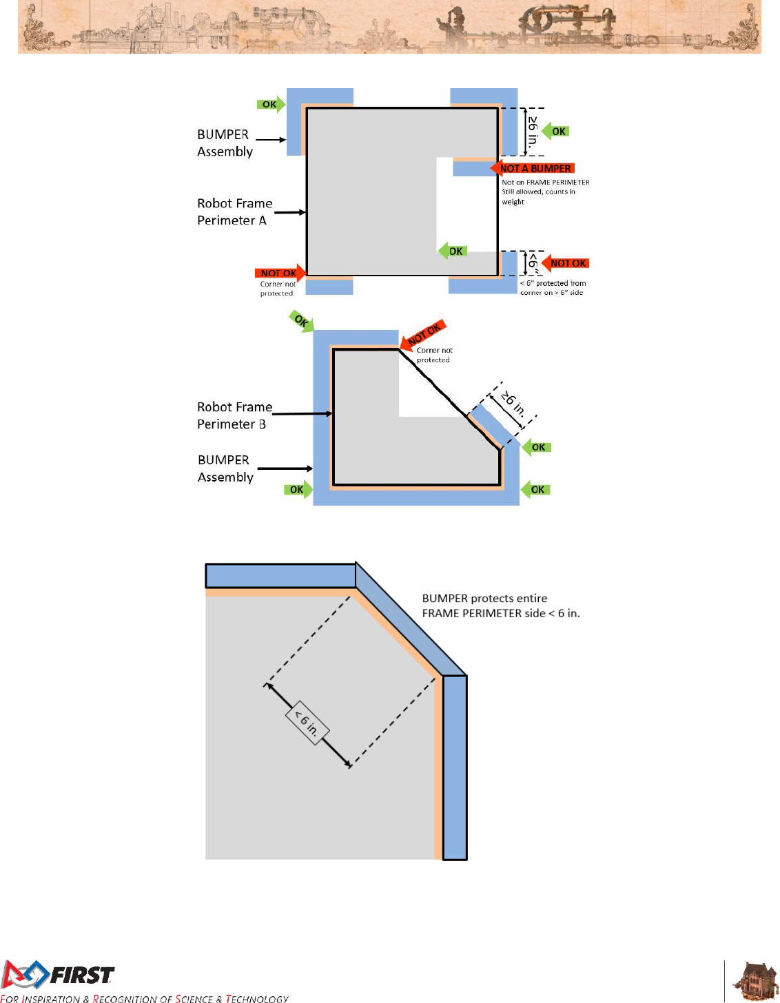
Section 8 ROBOT Rules
V10
78 of 135
Figure 8-1: BUMPER corner examples
Figure 8-2: BUMPER around full side/corner.

Section 8 ROBOT Rules
V10
79 of 135
R23. BUMPERS must be located entirely within the BUMPER ZONE, which is the volume contained
between the floor and a virtual horizontal plane 7 in. (~17 cm) above the floor in reference to the
ROBOT standing normally on a flat floor. BUMPERS do not have to be parallel to the floor.
This measurement is intended to be made as if the ROBOT is resting on
a flat floor (without changing the ROBOT configuration), not relative to
the height of the ROBOT from the FIELD carpet. Examples include:
Example 1: A ROBOT that is at an angle while navigating a ROPE has
its BUMPERS outside the BUMPER ZONE. If this ROBOT were virtually
transposed onto a flat floor, and its BUMPERS are in the BUMPER
ZONE, it meets the requirements of R23.
Example 2: A ROBOT deploys a MECHANISM which LIFTS the
BUMPERS outside the BUMPER ZONE (when virtually transposed onto
a flat floor). This violates R23.
R24. BUMPERS must not be articulated (relative to the FRAME PERIMETER).
R25. BUMPERS (the entire BUMPER, not just the cover) must be designed for quick and easy
installation and removal to facilitate inspection and weighing.
As a guideline, BUMPERS should be able to be installed or removed by
two (2) people in fewer than five (5) minutes.
R26. Each ROBOT must be able to display Red or Blue BUMPERS to MATCH their ALLIANCE color,
as assigned in the MATCH schedule distributed at the event (as described in Section 10.4.1
Schedule). BUMPER Markings visible when installed on the ROBOT, other than the following, are
prohibited:
A. those required per R27,
B. hook-and-loop fastener backed by the hard parts of the BUMPER, and
C. solid white FIRST logos between 4¾ in. (~13 cm) and 5¼ in. wide (~13 cm) (i.e.
comparable to those distributed in the 2017 Kickoff Kit).
R27. Team numbers must be displayed and positioned on the BUMPERS such that an observer
walking around the perimeter of the ROBOT can unambiguously tell the Team’s number from any
point of view and meet the following additional criteria:
A. consist of numerals at least 4 in. (~11 cm) high, at least ½ in. (~12.7 mm) in stroke
width, and be either white in color or outlined in white
B. must not wrap around sharp corners (less than 160 degrees) of the FRAME
PERIMETER
C. may not substitute logos or icons for numerals
There is no prohibition against splitting Team numbers onto different
sections of BUMPER. The intent is that the Team’s number is clearly
visible and unambiguous so that Judges, REFEREES, Announcers, and
other Teams can easily identify competing ROBOTS.
R28. Each set of BUMPERS (including any fasteners and/or structures that attach them to the
ROBOT) must weigh no more than 20 lbs (~9 kg).
If a multi-part attachment system is utilized (e.g. interlocking brackets on
the ROBOT and the BUMPER), then the elements permanently attached
to the ROBOT will be considered part of the ROBOT, and the elements
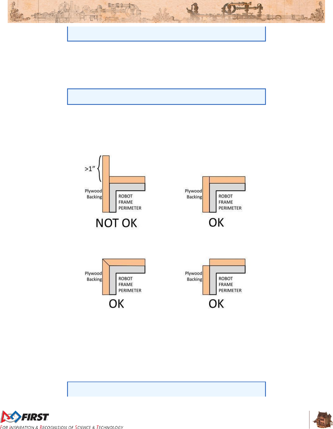
Section 8 ROBOT Rules
V10
80 of 135
attached to the BUMPERS will be considered part of the BUMPER.
Each element must satisfy all applicable rules for the relevant system.
R29. BUMPERS must be constructed as follows (see Figure 8-5):
A. be backed by ¾ in. (nominal) thick (~19mm) by 5 in. ± ½ in. (~127 mm ± 12.7 mm)
tall plywood or solid, robust wood. Small clearance pockets and/or access holes in
the plywood backing are permitted, as long as they do not significantly affect the
structural integrity of the BUMPER.
Particle board or chipboard is not likely to survive the rigors of FIRST
Robotics Competition gameplay and thus not compliant with R29-A.
B. hard BUMPER parts allowed per R29-A, R29-E, R29-F, and R29-G must not extend
more than 1 in. (~25 mm) beyond the FRAME PERIMETER with the exception of
minor protrusions such as bolt heads, fastener ends, rivets, etc. (Figure 8-3 and
Figure 8-5).
Figure 8-3: Hard Parts of BUMPER Corners
C. use a stacked pair of approximately 2½ in. (nominal) round, petal, or hex “pool
noodles” (solid or hollow) as the BUMPER cushion material (see Figure 8-5). All pool
noodles used in a BUMPER set (e.g. Red set of BUMPERS) may not be deformed
and must be the same diameter, cross-section, and density (e.g. all round hollow or
all hex solid). Cushion material may extend up to 2½ in. (~63 mm) beyond the end of
the plywood (see Figure 8-6). To assist in applying the fabric covering, soft fasteners
may be used to attach the pool noodles to the wood backing, so long as the cross
section in Figure 8-5 is not significantly altered (e.g. tape compressing the pool
noodles).
All pool noodles used on a ROBOT must be the same in order to
maintain the desired interaction between ROBOTS in the cases of
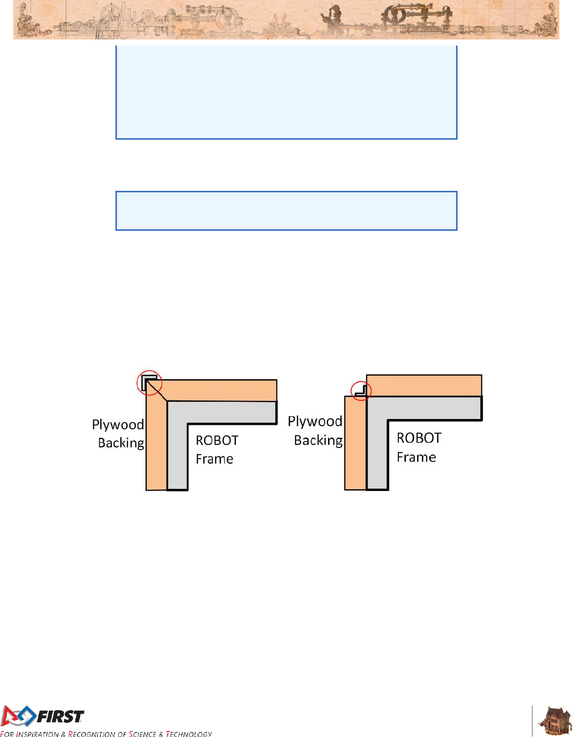
Section 8 ROBOT Rules
V10
81 of 135
BUMPER-to-BUMPER contact. BUMPERS containing pool noodles of
vastly different construction may cause a “ramp” effect when interacting
with other BUMPERS.
Noodle compression as a result of smoothing BUMPER fabric is not
considered deformed. Any compression beyond that, e.g. for the
purposes of flattening the noodle, is deformation and a violation of R29-
C.
D. be covered with a rugged, smooth cloth. (multiple layers of cloth and seams are
permitted if needed to accommodate R26, provided the cross section in Figure 8-5 is
not significantly altered).
Silk and bedding are not considered rugged materials, however 1000D
Cordura is. Tape (e.g. gaffer’s tape) matching the BUMPER color is
allowed to patch small holes on a temporary basis.
The cloth must completely enclose all exterior surfaces of the wood and pool noodle
material when the BUMPER is installed on the ROBOT. The fabric covering the
BUMPERS must be solid in color.
E. optionally use aluminum angle, as shown in Figure 8-5 or other fasteners (e.g.
staples, screws, etc.) to clamp cloth.
F. optionally use aluminum brackets (i.e. angle or sheet metal) to attach BUMPER
segments to each other (see Figure 8-4).
Figure 8-4: Hard Parts of BUMPER Corners
G. must attach to the FRAME PERIMETER of the ROBOT with a rigid fastening system
to form a tight, robust connection to the main structure/frame (e.g. not attached with
hook-and-loop, tape, or tie-wraps). The attachment system must be designed to
withstand vigorous game play. All removable fasteners (e.g. bolts, locking pins, pip-
pins, etc.) will be considered part of the BUMPERS.
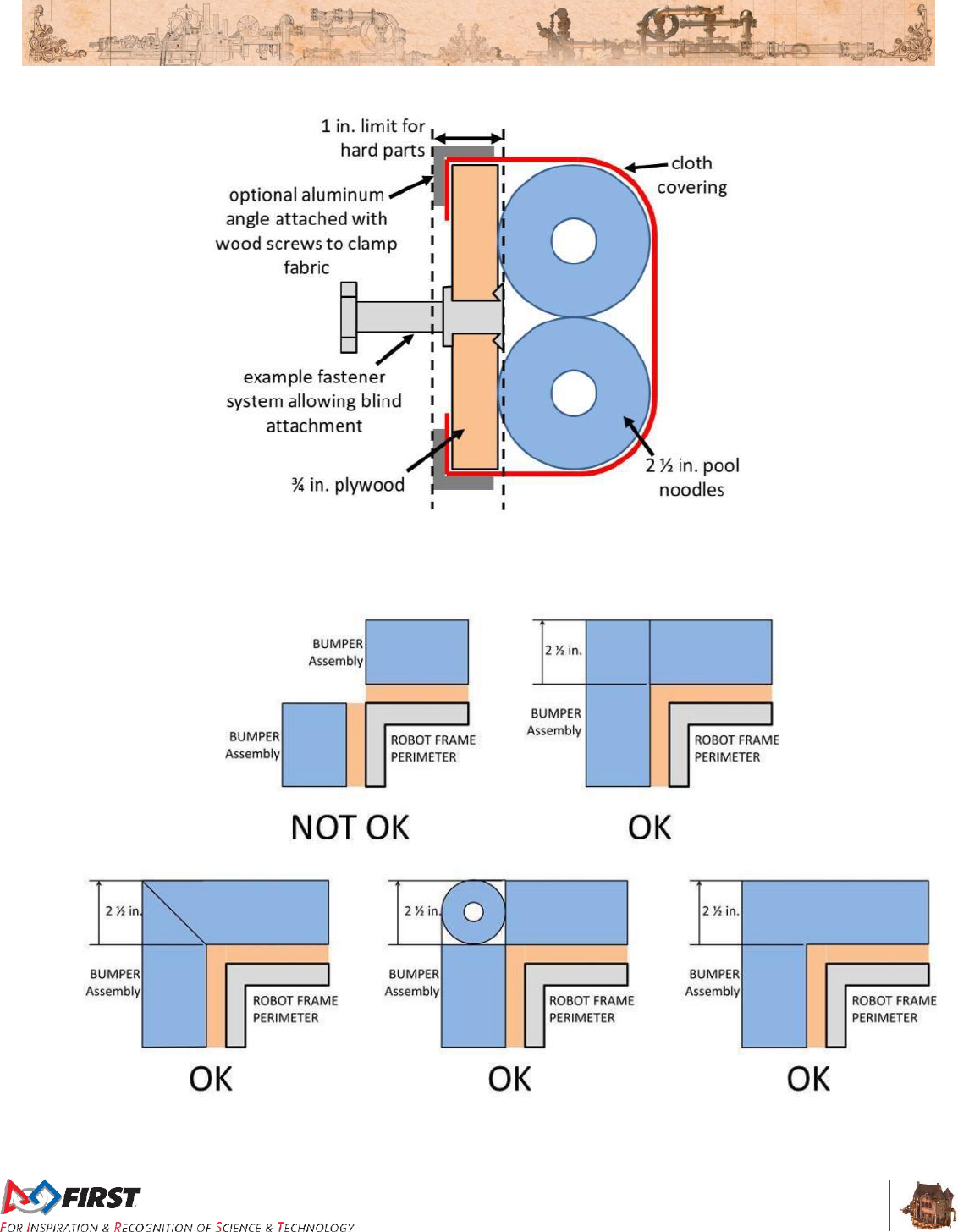
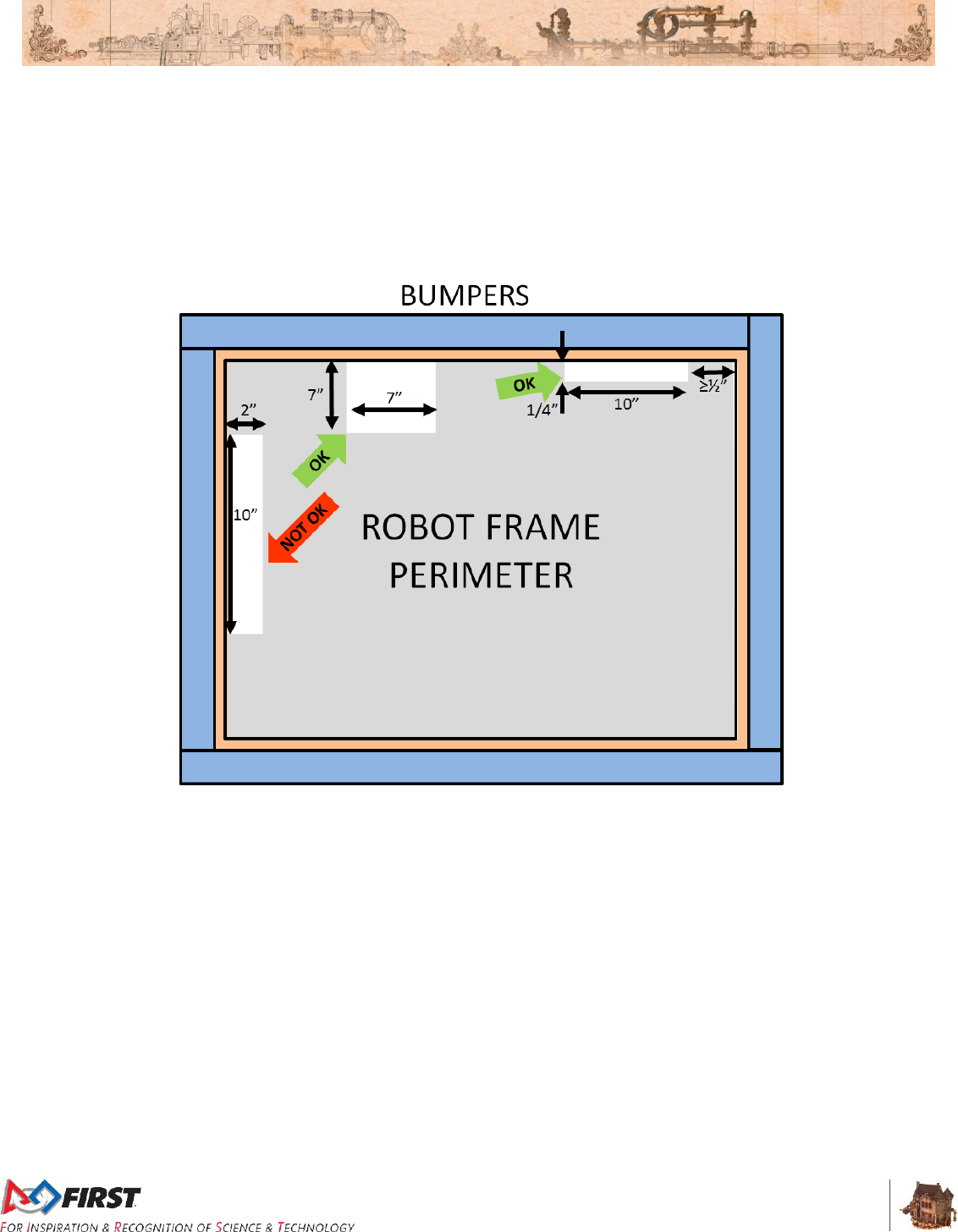
Section 8 ROBOT Rules
V10
83 of 135
R31. BUMPERS must be supported by the structure/frame of the ROBOT (see Figure 8-7). To be
considered supported, a minimum of ½ in. (~12.7 mm) at each end of each BUMPER wood
segment must be backed by the FRAME PERMIETER. “Ends” exclude hard BUMPER parts
which extend past the FRAME PERIMETER permitted by R29, part B. Additionally, any gap
between the backing material and the frame:
A. must not be greater than ¼ in. (~6 mm) deep, or
B. not more than 8 in. (~20 cm) wide
Figure 8-7: BUMPER support examples

Section 8 ROBOT Rules
V10
84 of 135
8.6 Motors & Actuators
R32. The only motors and actuators permitted on 2017 ROBOTS include the following:
Table 8-1: Motor allowances
Motor Name
Part Numbers Available
Max Qty
Allowed
CIM
FR801-001
M4-R0062-12
AM802-001A
217-2000
PM25R-44F-1005
PM25R-45F-1004
PM25R-45F-1003
PMR25R-45F-1003
PMR25R-44F-1005
6
West Coast Products RS775 Pro
217-4347
Unlimited
Banebots
M7-RS775-18
RS775WC-8514
M5 – RS550-12
RS550VC-7527
RS550
AndyMark 9015
am-0912
VEX BAG
217-3351
VEX mini-CIM
217-3371
AndyMark PG
am-2161 (alt. PN am-2765)
am-2194 (alt. PN am-2766)
Select Automotive Motors
(Window, Door, Windshield wiper,
Seat, Throttle)
Various
Snow Blower Motor
am-2235
AndyMark NeveRest
am-3104
Electrical solenoid actuators, no greater than 1 in. (nominal) stroke and rated
electrical input power no greater than 10 watts (W) continuous duty at 12 volts
(VDC)
Hard drive motors or fans that are: included in any Kickoff Kit, distributed via
FIRST Choice, part of a legal motor controller (including manufacturer
provided accessories), or part of a legal COTS computing device
Factory installed vibration and autofocus motors resident in COTS computing
devices (e.g. rumble motor in a smartphone).
PWM COTS servos with a retail cost < $75.
Motors integral to a COTS sensor (e.g. LIDAR, scanning sonar, etc.),
provided the device is not modified except to facilitate mounting
For servos, note that the roboRIO is limited to a max current output of
2.2A on the 6V rail (12.4W of electrical input power). Teams should
make sure that their total servo power usage remains below this limit at
all times.
This is the total number of each motor a Team may use on their ROBOT,
not the quantity per part number. For example, each team may use up to
six (6) CIM motors on their ROBOT, regardless of the quantity or
combination of each individual part number used.

Section 8 ROBOT Rules
V10
85 of 135
Given the extensive amount of motors allowed on the ROBOT, Teams
are encouraged to consider the total power available from the ROBOT
battery during the design and build of the ROBOT. Drawing large
amounts of current from many motors at the same time could lead to
drops in ROBOT battery voltage that may result in tripping the main
breaker or trigger the brownout protection of the roboRIO. For more
information about the roboRIO brownout protection and measuring
current draw using the PDP, see RoboRIO Brownout and Understanding
Current Draw.
R33. The integral mechanical and electrical system of any motor must not be modified. Motors, servos,
and electric solenoids used on the ROBOT shall not be modified in any way, except as follows:
A. The mounting brackets and/or output shaft/interface may be modified to facilitate the
physical connection of the motor to the ROBOT and actuated part.
B. The electrical input leads may be trimmed to length as necessary and connectors or
splices to additional wiring may be added.
C. The locking pins on the window motors (P/N: 262100-3030 and 262100-3040) may
be removed.
D. The connector housings on window, door, windshield wiper or seat motors and Bosch
motors (P/N: 6004 RA3 353-01) may be modified to facilitate lead connections.
E. Servos may be modified as specified by the manufacturer (e.g. re-programming or
modification for continuous rotation).
The intent of this rule is to allow teams to modify mounting tabs and the
like, not to gain a weight reduction by potentially compromising the
structural integrity of any motor. The integral mechanical and electrical
system of the motor is not to be modified.
Note that for the previous KOP Window motors and the Bosch motor, the
gearbox is considered integral to the motor, thus the motor may not be
used without the gearbox.
R34. With the exception of servos, fans, or motors integral to sensors of COTS computing devices
permitted in R32, each actuator must be controlled by a power regulating device. The only power
regulating devices for actuators permitted on the ROBOT include:
A. Motor Controllers
DMC 60 Motor Controller (P/N: 410-334-1)
Jaguar Motor Controller (P/N: MDL-BDC, MDL-BDC24, and 217-3367)
SD540 Motor Controller (P/N: SD540x1, SD540x2, SD540x4, SD540Bx1,
SD540Bx2, SD540Bx4, SD540C)
Spark Motor Controller (P/N: REV-11-1200)
Talon Motor Controller (P/N: CTRE_Talon, CTRE_Talon_SR, and am-2195)
Talon SRX Motor Controller (P/N: 217-8080, am-2854, 14-838288), equipped
with firmware version 0.28 or newer if using via PWM. See R75 if using via
CAN.
Victor 884 Motor Controller (P/N: VICTOR-884-12/12)
Victor 888 Motor Controller (P/N: 217-2769)
Section 8 ROBOT Rules
V10
86 of 135
Victor SP Motor Controller (P/N: 217-9090, am-2855, 14-868380)
B. Relay Modules
Spike H-Bridge Relay (P/N: 217-0220 and SPIKE-RELAY-H)
C. Pneumatics controllers
Pneumatics Control Module (P/N: am-2858, 217-4243)
Please see the Talon SRX User Guide for more information about the
Talon SRX firmware update, determining the firmware on your Talon
SRX, and instructions on how install.
R35. Each power regulating device may control electrical loads per Table 8-2. Unless otherwise noted,
each power regulating device shall control one and only one electrical load.
Table 8-2: Power regulating device allotments
Electrical Load
Motor Controller
Relay Module
Pneumatics
Controller
CIM
AndyMark 9015
WCP RS775 Pro
VEX BAG/MiniCIM
Banebots
Yes
No
No
Automotive
Window/Door/Windshield
Wiper/Seat/Throttle
Motors
AndyMark PG
Snow-Blower Motor
NeverRest
Yes
(up to 2 per
controller)
Yes
No
Compressor
No
Yes
Yes
Pneumatic Solenoid
Valves
No
Yes*
Yes (1 per
channel)
Electric Solenoids
No
Yes*
Yes (1 per
channel
CUSTOM CIRCUITSª
Yes
Yes*
Yes (1 per
channel)
* Multiple low-load, pneumatic solenoid valves, electric solenoids or CUSTOM CIRCUITS may be
connected to a single relay module. This would allow one (1) relay module to drive multiple
pneumatic actions or multiple CUSTOM CIRCUITS. No other electrical load can be connected to
a relay module used in this manner.
ª A CUSTOM CIRCUIT is any electrical COMPONENT of the ROBOT other than motors,
pneumatic solenoids, roboRIO, PDP, PCM, VRM, RSL, 120A breaker, motor controllers, relay
modules (per R34-B), wireless bridge, or batteries.
R36. Servos must be connected to, and only to, one of the following:
A. PWM ports on the roboRIO
B. PWM ports on a WCP Spartan Sensor Board (P/N: WCP-0045)
C. REV Servo Power Module (P/N: REV-11-1144)

Section 8 ROBOT Rules
V10
87 of 135
8.7 Power Distribution
R37. The only legal source of electrical energy for the ROBOT during the competition, the ROBOT
battery, must be a non-spillable sealed lead acid (SLA) battery with the following specifications:
A. Nominal voltage: 12V
B. Nominal capacity at 20-hour discharge rate: minimum 17Ah, maximum 18.2Ah
C. Shape: Rectangular
D. Nominal Dimensions:7.1 in. x 3 in. x 6.6 in., +/- .1 in. for each dimension (~ 180 mm x
76mm x 168 mm, +/- 2.5 mm for each dimension)
E. Nominal weight: 11lbs. to 14.5 lbs. (~5 kg. to 6.5 kg.)
F. Terminals: Nut and bolt style
Examples of batteries which meet these criteria include:
A. Enersys (P/N: NP18-12, NP18-12B, NP18-12BFR)
B. MK Battery (P/N: ES17-12)
C. Battery Mart (P/N: SLA-12V18)
D. Sigma (P/N: SP12-18)
E. Universal Battery (P/N: UB12180)
F. Power Patrol (P/N: SLA1116)
G. Werker Battery (P/N: WKA12-18NB)
H. Power Sonic (P/N: PS-12180NB)
I. Yuasa (P/N: NP18-12B)
J. Panasonic (P/N: LC-RD-1217)
K. Interstate Batteries (P/N: BSL1116)
L. Duracell Ultra Battery (P/N: DURA12-18NB)
Teams should be aware that they may be asked to provide
documentation of the specifications of any battery not listed above.
Batteries should be charged in accordance with manufacturer’s
specification. (Please see the FIRST Safety Manual for additional
information.)
Additionally, batteries integral to and part of a COTS computing device or self-contained camera
are also permitted (e.g. laptop batteries, GoPro style camera, etc.), provided they’re only used to
power the COTS computing device and any peripheral COTS USB input devices connected to
the COTS computing device and they are securely fastened to the ROBOT.
R38. Any battery charger used to charge a ROBOT battery must have the corresponding Anderson SB
connector installed.
R39. Any battery charger used to charge a ROBOT battery may not be used such that it exceeds 6-
Amp charge current.
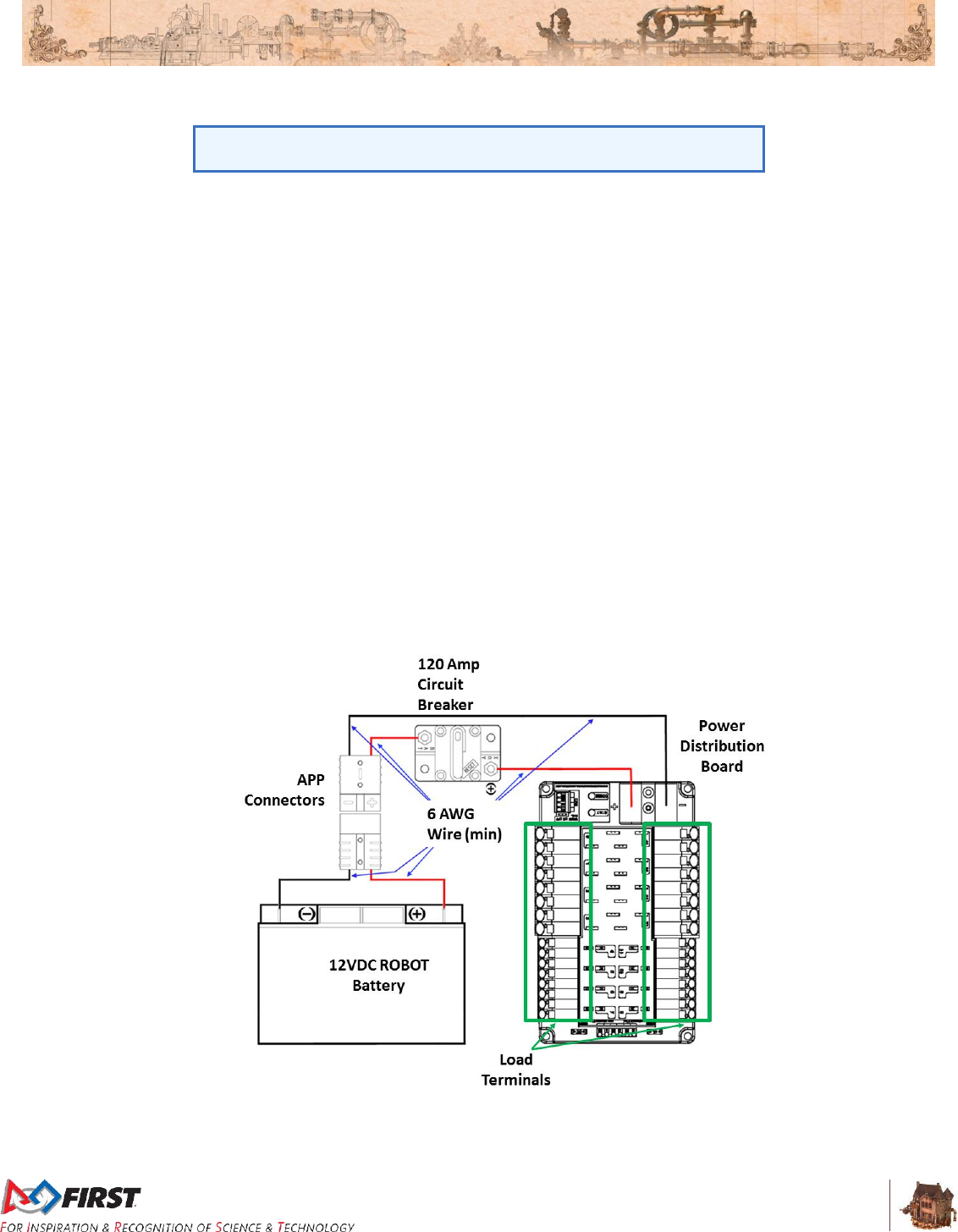
Section 8 ROBOT Rules
V10
88 of 135
R40. No batteries other than those allowed per R37 are allowed on the ROBOT, whether or not they
are being used to supply power.
This means teams may not use additional batteries as extra weight on
their ROBOTS, for example.
R41. The ROBOT battery must be secured such that it will not dislodge should the ROBOT be turned
over or placed in any arbitrary orientation.
R42. Each electrical terminal on the ROBOT battery, main breaker, and their connections (lugs,
stripped wire ends, etc.) to the wire must be fully insulated at all times.
R43. Non-electrical sources of energy used by the ROBOT, (i.e., stored at the start of a MATCH), shall
come only from the following sources:
A. compressed air stored in the pneumatic system that has been charged in compliance
with R84 and R85,
B. a change in the altitude of the ROBOT center of gravity,
C. storage achieved by deformation of ROBOT parts,
D. closed-loop COTS pneumatic (gas) shocks, and
E. air-filled (pneumatic) wheels.
R44. The one (1) ROBOT battery, a single pair of Anderson Power Products (or APP) 2-pole SB type
connectors, the one (1) main 120-amp (120A) surface mount circuit breaker (Cooper Bussman
P/N: CB185-120 or CB185F-120), and the one (1) CTR Electronics Power Distribution Panel
(PDP, P/N: am-2856, 217-4244, 14-806880) shall be connected with 6 AWG (7 SWG or 16 mm2)
wire or larger, with no additional devices or modifications, as shown in Figure 8-8.
Figure 8-8: Electrical connection diagram

Section 8 ROBOT Rules
V10
89 of 135
“SB type” refers to SB type only (e.g. SB-50, SB-120, etc.), not SBS or
any other part type beginning with SB. All batteries supplied by FIRST
(such as Spare Parts and international batteries) will have a Red or Pink
SB50 connector installed which may not be removed.
The pink connectors included in the 2017 KOP mate with the Red SB50
connector.
R45. All circuits, with the exceptions of those listed in R50 and R52, must connect to, and have power
sourced solely by, a single protected 12VDC WAGO connector pair (i.e. the Load Terminals, as
shown in Figure 8-8) of the one (1) CTR Electronics Power Distribution Panel, not the M6 cap
screws.
R46. All wiring and electrical devices, including all Control System COMPONENTS, shall be electrically
isolated from the ROBOT frame. The ROBOT frame must not be used to carry electrical current.
R46 is checked by observing a >3kΩ resistance between either the (+) or
(-) post within the APP connector that is attached to the PDP and any
point on the ROBOT.
The Victor-SP and Talon-SRX motor controller cases are electrically
isolated. They may be mounted directly to ROBOT frame
COMPONENTS.
Note that some cameras and sensors (e.g. the Axis 206 camera) have
grounded enclosures. These devices must be electrically isolated from
the ROBOT frame to ensure compliance with R46.
R47. The 120A circuit breaker must be quickly and safely accessible from the exterior of the ROBOT.
This is the only 120A circuit breaker allowed on the ROBOT.
Examples considered not “quickly and safely accessible” include
breakers covered by an access panel or door, or mounted on,
underneath or immediately adjacent to moving components.
It is strongly recommended that the 120A circuit breaker location be
clearly and obviously labeled so it can be easily found by FIELD STAFF
during a MATCH.
R48. The PDP, associated wiring, and all circuit breakers must be easily visible for Inspection.
R49. Any active electrical item that is not an actuator (specified in R32) or core Control System item
(specified in R71) is considered a CUSTOM CIRCUIT. CUSTOM CIRCUITS shall not produce
voltages exceeding 24V.
R50. The roboRIO power input must be connected to the dedicated supply terminals on the PDP
shown in Figure 8-9. No other electrical load shall be connected to these terminals.
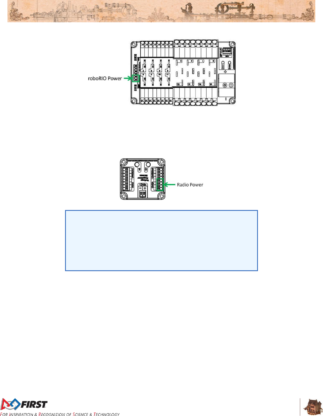
Section 8 ROBOT Rules
V10
90 of 135
Figure 8-9: roboRIO power source
R51. The Wireless Bridge power must be supplied directly by the 12V 2A output of a CTR Electronics
Voltage Regulator Module (VRM) (P/N: am-2857, 217-4245) and must be the only load
connected to those terminals.
Figure 8-10: Radio power source
Note that this wiring is different from the wiring for the radio used in
2015, but is identical to the wiring from 2016. When using a 2015 VRM
with the OM5P-AN or OM5P-AC radio, the radio should be connected as
described above, not to the terminals labeled “Radio”.
Note that this prohibits using any active POE Injector device to power the
radio, but does not prohibit using any PASSIVE CONDUCTORS to inject
the VRM power into an Ethernet cable plugged into the radio port labeled
“18-24v POE”.
R52. The VRM supplying power to the Wireless Bridge per R51 must be connected to the designated
supply terminals at the end of the PDP, and not the main WAGO connectors along the sides of
the PDP as shown in Figure 8-11. With the exception of a single CTR Electronics Pneumatics
Control Module (PCM, P/N: am-2858), no other electrical load shall be connected to these PDP
terminals.
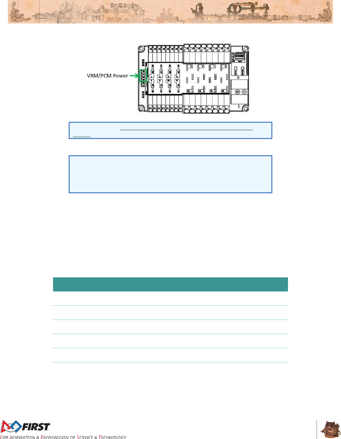
Section 8 ROBOT Rules
V10
91 of 135
Figure 8-11: VRM and PCM power source
Please reference Wiring the 2016 FRC Control System for Wireless
Bridge wiring information.
R53. Only one wire shall be connected to each WAGO connector on the PDP.
If multi-point distribution of circuit power is needed (e.g. to provide power
to multiple PCMs and/or VRMs from one 20A circuit), then all incoming
wires may be appropriately spliced into the main lead (e.g. using an
insulated terminal block, crimped splice or soldered wire splice), and the
single main lead inserted into the WAGO connector to power the circuit.
R54. The only circuit breakers permitted for use in the PDP are:
A. Snap Action VB3-A Series, terminal style F57
B. Snap Action MX5-A Series, 40A rating or lower
R55. The fuses in the PDP shall only be replaced with functionally identical fuses (mini automotive
blade fuses with values matching those printed on the PDP)
R56. Each branch circuit must be protected by one and only one circuit breaker on the PDP per Table
8-3. No other electrical load can be connected to the breaker supplying this circuit.
Table 8-3: Branch circuit protection requirements
Branch Circuit
Circuit Breaker
Value
Quantity Allowed
Per Breaker
Motor Controller
Up to 40A
1
CUSTOM CIRCUIT
Up to 40A
1
Fans permitted per Table 8-1 and not
already part of COTS computing devices
Up to 20A
No limit
Relay Module
Up to 20A
1
PCM – with compressor
20A
1
Additional VRM (non-radio)/Additional
PCM (non-compressor)
20A
3 total

Section 8 ROBOT Rules
V10
92 of 135
R56 does not prohibit the use of smaller value breakers in the PDP or
any fuses or breakers within CUSTOM CIRCUITS for additional
protection.
R57. All circuits shall be wired with appropriately sized insulated wire:
Table 8-4: Wire sizes
Application
Minimum Wire Size
31 – 40A protected circuit
12 AWG
(13 SWG or 4 mm2)
21 – 30A protected circuit
14 AWG
(16 SWG or 2.5 mm2)
6 – 20A protected circuit
18 AWG
(19 SWG or 1 mm2)
Between the PDP dedicated terminals and the VRM or PCM
Compressor outputs from the PCM
Between the PDP and the roboRIO
22 AWG
(22 SWG or 0.5 mm2)
≤5A protected circuit
VRM 2A circuits
24 AWG
(24 SWG or .25mm2)
roboRIO PWM port outputs
26 AWG
(27 SWG or 0.14 mm2)
SIGNAL LEVEL circuits (i.e. circuits which draw ≤1A continuous
and have a source incapable of delivering >1A, including but not
limited to roboRIO non-PWM outputs, CAN signals, PCM
Solenoid outputs, VRM 500mA outputs and Arduino outputs)
28 AWG
(29 SWG or .08 mm2)
Wires that are recommended by the device manufacturer or originally attached to legal devices
are considered part of the device and by default legal. Such wires are exempt from R57.
R58. Branch circuits may include intermediate elements such as COTS connectors, splices, COTS
flexible/rolling/sliding contacts, and COTS slip rings, as long as the entire electrical pathway is via
appropriately gauged/rated elements.
R59. All non-SIGNAL LEVEL wiring with a constant polarity (i.e., except for outputs of relay modules,
motor controllers, or sensors) shall be color-coded along their entire length from the manufacturer
as follows:
A. Red, yellow, white, brown, or black-with-stripe on the positive (e.g. +24VDC,
+12VDC, +5VDC, etc.) connections
B. Black or blue for the common or negative side (-) of the connections.
Wires that are originally attached to legal devices are considered part of the device and by default
legal. Such wires are exempt from R59.
R60. CUSTOM CIRCUITS shall not directly alter the power pathways between the ROBOT battery,
PDP, motor controllers, relays (per R34-B), motors and actuators (per R32), pneumatic solenoid
valves, or other elements of the ROBOT control system (items explicitly mentioned in R71).
Custom high impedance voltage monitoring or low impedance current monitoring circuitry
connected to the ROBOT’S electrical system is acceptable, if the effect on the ROBOT outputs is
inconsequential.
A noise filter may be wired across motor leads or PWM leads. Such
filters will not be considered CUSTOM CIRCUITS and will not be
considered a violation of R60 or R77.
Section 8 ROBOT Rules
V10
93 of 135
Acceptable signal filters must be fully insulated and must be one of the
following:
A one microfarad (1 µF) or less, non-polarized, capacitor may be applied across the power leads
of any motor on your ROBOT (as close to the actual motor leads as reasonably possible).
A resistor may be used as a shunt load for the PWM control signal feeding a servo.
8.8 Control, Command & Signals System
R61. ROBOTS must be controlled via one (1) programmable National Instruments roboRIO (P/N:
am3000), with image version FRC_2017_v8.
There are no rules that prohibit co-processors, provided commands
originate from the roboRIO to configure, enable, and specify all operating
points for all power regulating devices. This includes motor controllers
legally wired to the CAN-bus.
R62. One (1) OpenMesh Wireless Bridge (P/N: OM5P-AN or OM5P-AC), that has been configured with
the appropriate encryption key for your team number at each event, is the only permitted device
for communicating to and from the ROBOT during the MATCH.
R63. The roboRIO Ethernet port must be connected to the Wireless Bridge port labeled “18-24 vPOE,”
closest to the power connector (either directly, via a switch, or via a CAT5 Ethernet pigtail).
Note: Placing a switch between the roboRIO and radio may impede the
ability for FIELD STAFF to troubleshoot roboRIO connection issues on
the FIELD. Teams may be asked to try directly connecting from the radio
to roboRIO as part of troubleshooting efforts.
R64. Ethernet-connected COTS devices or CUSTOM CIRCUITS may connect to any remaining
Ethernet port on the Wireless Bridge but must not transmit or receive UDP packets using ports
1100-1200 with the exception of ports 1130 and 1140.
R65. Communication between the ROBOT and the OPERATOR CONSOLE is restricted as follows:
A. Network Ports:
UDP/TCP 1180-1190: Camera data from the roboRIO to the Driver Station
(DS) when the camera is connected the roboRIO via USB, bi-directional.
TCP 1735: SmartDashboard, bi-directional
UDP 1130: Dashboard-to-ROBOT control data, uni-directional
UDP 1140: ROBOT-to-Dashboard status data, uni-directional
HTTP 80: Camera connected via switch on the ROBOT, bi-directional
HTTP 443: Camera connected via switch on the ROBOT, bi-directional
UDP/TCP 554: Real-Time Streaming Protocol for h.264 camera streaming,
bi-directional
UDP/TCP 5800-5810: Team Use, bi-directional
Teams may use these ports as they wish if they do not employ them as outlined
above (i.e. TCP 1180 can be used to pass data back and forth between the ROBOT
and the DS if the Team chooses not to use the camera on USB).
B. Bandwidth: no more than 7 Mbits/second.
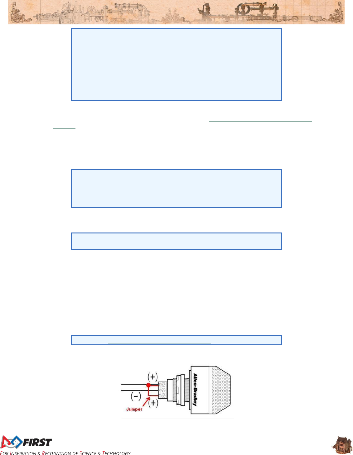
Section 8 ROBOT Rules
V10
94 of 135
Note that, for 2017, the 7 Mbit limit will be strictly enforced by the
Wireless Bridge.
The FMS Whitepaper has more details on how to check and optimize
bandwidth usage.
While FIRST® makes every effort to provide a wireless environment that
allows teams access to a full 7 Mbits/second data rate (with about 100
Kbit used for ROBOT control and status), at some events wireless
conditions may not accommodate this.
R66. The roboRIO, Driver Station software, and Wireless Bridge must be configured to correspond to
the correct Team number, per the procedures defined in Getting Started with the 2017 Control
System.
R67. All signals must originate from the OPERATOR CONSOLE and be transmitted to the ROBOT via
the ARENA Ethernet network.
R68. No form of wireless communication shall be used to communicate to, from, or within the ROBOT,
except those required per R62 and R67.
Devices that employ signals in the visual spectrum (e.g. cameras) and
non-RF sensors that don’t receive human-originated commands (e.g.
“beam break” sensors or IR sensors on the ROBOT used to detect
FIELD elements) aren’t wireless communication devices and thus R68
doesn’t apply.
R69. The Wireless Bridge must be mounted on the ROBOT such that the diagnostic lights are visible to
ARENA personnel.
Teams are encouraged to mount the wireless bridge away from noise
generating devices such as motors, PCM(s), and VRM(s).
R70. ROBOTS must use at least one (1), but no more than two (2), diagnostic Robot Signal Lights
(RSL) (P/N: 855PB-B12ME522).
Any RSL must be:
A. mounted on the ROBOT such that it is easily visible while standing three 3 ft. (~ 100
cm) in front of the ROBOT,
B. connected to the “RSL” supply terminals on the roboRIO,
C. wired for solid light operation, by placing a jumper between the “La” and “Lb”
terminals on the light per Figure 8-12.
Please see Wiring the 2017 FRC Control System for connection details.
Figure 8-12: RSL jumper wiring

Section 8 ROBOT Rules
V10
95 of 135
R71. The Driver Station software, roboRIO, Power Distribution Panel, Pneumatics Control Modules,
Voltage Regulator Modules, RSL, 120A breaker, motor controllers, relay modules (per R34-B),
Wireless Bridge, and batteries shall not be tampered with, modified, or adjusted in any way
(tampering includes drilling, cutting, machining, rewiring, disassembling, etc.), with the following
exceptions:
Please note that the Driver Station application is a separate application
from the Dashboard. The Driver Station software may not be modified,
while teams are expected to customize their Dashboard code.
A. User programmable code in the roboRIO may be customized.
B. Motor controllers may be calibrated as described in owner's manuals.
C. Fans may be attached to motor controllers and may be powered from the power input
terminals.
D. If powering the compressor, the fuse on a Spike H-Bridge Relay may be replaced
with a 20A Snap-Action circuit breaker.
E. Wires, cables, and signal lines may be connected via the standard connection points
provided on the devices.
F. Fasteners (including adhesives) may be used to attach the device to the OPERATOR
CONSOLE or ROBOT or to secure cables to the device.
G. Thermal interface material may be used to improve heat conduction.
H. Labeling may be applied to indicate device purpose, connectivity, functional
performance, etc.
I. Jumpers may be changed from their default location.
J. Limit switch jumpers may be removed from a Jaguar motor controller and a custom
limit switch circuit may be substituted.
K. Device firmware may be updated with manufacturer supplied firmware.
L. Integral wires on the Victor SP or Talon SRX may be cut, stripped, and/or
connectorized.
M. Devices may be repaired, provided the performance and specifications of the device
after the repair are identical to those before the repair.
N. The cover may be removed from the Talon SRX data port.
Please note that while repairs are permitted, the allowance is
independent of any manufacturer’s warranty. Teams make repairs at
their own risk and should assume that any warranty or RMA options are
forfeited. Be aware that diagnosing and repairing COMPONENTS such
as these can be difficult.
R72. Neither 12VDC power nor relay module or motor controller outputs shall be directly connected to
the roboRIO (with the exception of the designated 12VDC input).
R73. Every relay module (per R34-B), servo controller, and PWM motor controller shall be connected
to a corresponding port (relays to Relay ports, servo controllers and PWM controllers to PWM
ports) on the roboRIO (either directly or through a WCP Spartan Sensor Board) or via a legal
MXP connection (per R74). They shall not be controlled by signals from any other source.
R74. If a motor is controlled via the MXP, its power regulating device must be connected by one of the
following methods:
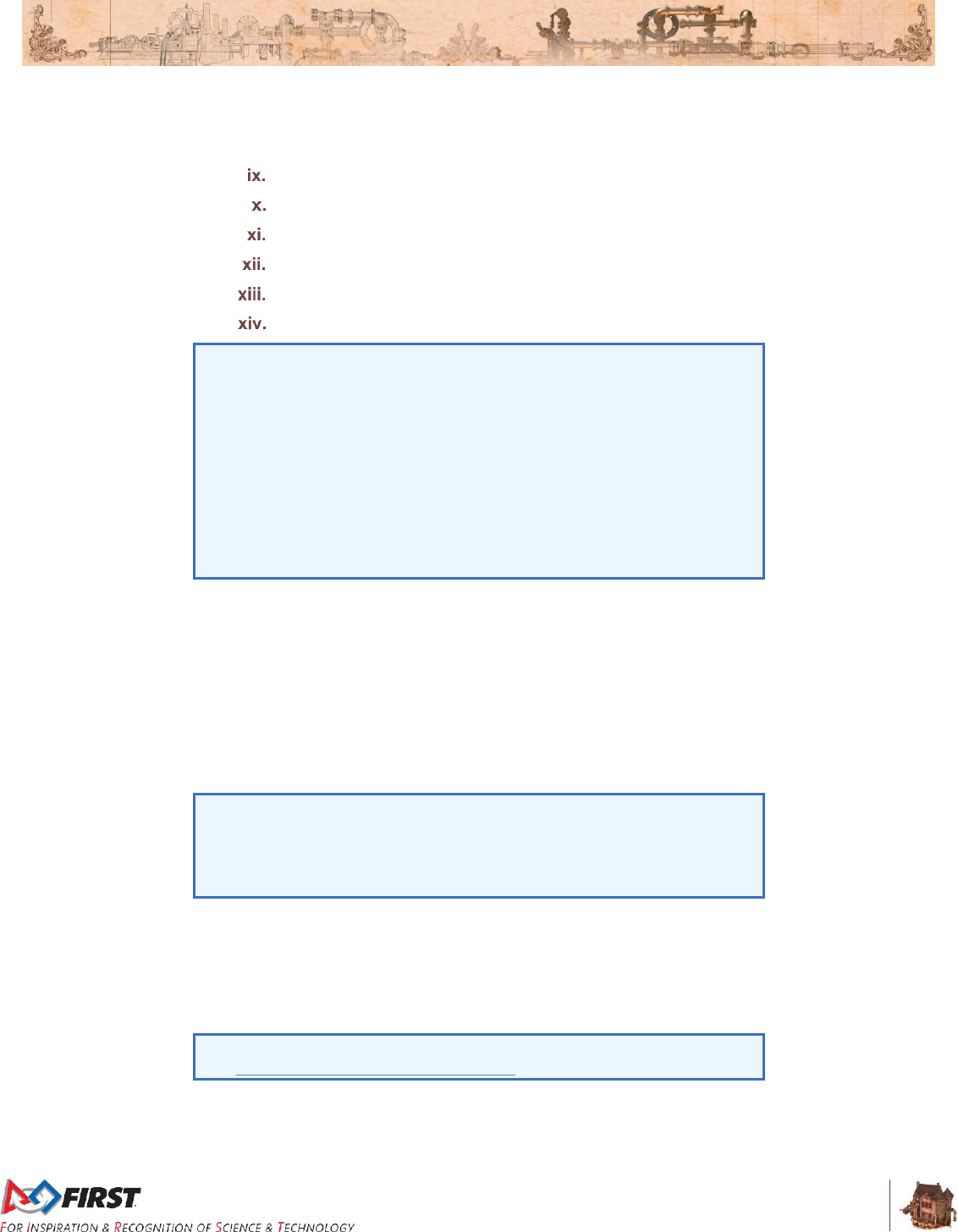
Section 8 ROBOT Rules
V10
96 of 135
A. directly to any PWM pins,
B. via a network of PASSIVE CONDUCTORS used to extend the PWM pins, or
C. via one approved ACTIVE DEVICE:
Kauai Labs navX MXP
RCAL MXP Daughterboard
REV Robotics RIOduino
REV Robotics Digit Board
WCP Spartan Sensor Board
Huskie Robotics HUSKIE 2.0 Board
A PASSIVE CONDUCTOR is any device or circuit whose capability is
limited to the conduction and/or static regulation of the electrical energy
applied to it (e.g. wire, splices, connectors, printed wiring board, etc.).
An ACTIVE DEVICE is any device capable of dynamically controlling
and/or converting a source of electrical energy by the application of
external electrical stimulus.
The “network of PASSIVE CONDUCTORS” only applies to the pins
being used for PWM output to motors or servos. This means that
connecting an ACTIVE DEVICE, such as a sensor to one MXP pin does
not prevent other MXP pins from being used in accordance with R74-B.
R75. Each Jaguar or Talon SRX must be controlled with signal inputs sourced from the roboRIO and
passed via either a PWM (wired per R73) or CAN-bus (either directly or daisy-chained via another
CAN-bus device) signal, but both shall not be wired simultaneously on the same device. If the
CAN-bus configuration is used, the firmware on the device must be updated to at least the
following versions:
A. Grey Jaguars – v109
B. Black Jaguars – v109
C. Talon SRX – v1.01.
As long as the CAN bus is wired legally so that the heartbeat from the
roboRIO is maintained, all closed loop control features of the Jaguar or
Talon SRX motor controller may be used. (That is, commands originating
from the roboRIO to configure, enable, and specify an operating point for
all Jaguar or Talon SRX closed loop modes fit the intent of R61.)
R76. Each PCM must be controlled with signal inputs sourced from the roboRIO and passed via a
CAN-bus connection from the roboRIO (either directly or daisy-chained via another CAN-bus
device). The firmware on each PCM must be updated to at least version 1.62.
R77. The PDP CAN interface must be connected to the CAN-bus on the roboRIO (either directly or
daisy-chained via another CAN-bus device).
For documentation on how to wire the CAN-bus connections of the PDP
see Wiring the 2017 FRC Control System.
R78. The CAN-bus must be connected to the roboRIO CAN port.

Section 8 ROBOT Rules
V10
97 of 135
A. Additional switches, sensor modules, CUSTOM CIRCUITS, third-party modules, etc.
may also be placed on the CAN-bus.
B. No device that interferes with, alters, or blocks communications among the roboRIO
and the Jaguars, PDP, PCMs, and/or Talon-SRXs on the bus will be permitted.
Only one wire should be inserted into each Weidmuller CAN connector
terminal. For documentation on how to wire the CAN-bus connections of
the roboRIO, PCM, PDP and CAN motor controllers, see Wiring the 2017
FRC Control System.
8.9 Pneumatic System
R79. To satisfy multiple constraints associated with safety, consistency, Inspection, and constructive
innovation, no pneumatic parts other than those explicitly permitted in Section 8.9 Pneumatic
System shall be used on the ROBOT.
R80. All pneumatic items must be COTS pneumatic devices rated by their manufacturers for burst or
maximum pressure of at least 125psi (~862 kPa).
It is recommended that all pneumatic items be rated by their
manufacturers for a working pressure of at least 60 psi (~414 kPa).
R81. All pneumatic COMPONENTS must be used in their original, unaltered condition. Exceptions are
as follows:
A. tubing may be cut,
B. wiring for pneumatic devices may be modified to interface with the control system,
C. assembling and connecting pneumatic COMPONENTS using the pre-existing
threads, mounting brackets, quick-connect fittings, etc.,
D. removing the mounting pin from a pneumatic cylinder, provided the cylinder itself is
not modified,
E. labeling applied to indicate device purpose, connectivity, functional performance, etc.
Do not, for example, paint, file, machine, or abrasively remove any part
of a pneumatic COMPONENT – this would cause the part to become a
prohibited item. Consider pneumatic COMPONENTS sacred.
R82. The only pneumatic system items permitted on ROBOTS include the items listed below.
A. Items available in the KOP (except as noted in K),
B. Pneumatic pressure vent plug valves functionally equivalent to those provided in the
KOP,
Parker valves PV609-2 or MV709-2 are recommended.
C. Pressure relief valves functionally equivalent to those provided in the KOP,
Norgren 16-004-011, 16-004-003 or McMaster-Carr 48435K714
recommended.
To be considered functionally equivalent the valve must be preset or
adjustable to 125 psi (~862 kPA) and capable of relieving at least 1 scfm
(~472 cm3/s).

Section 8 ROBOT Rules
V10
98 of 135
D. Solenoid valves with a maximum ⅛ in. (nominal) NPT, BSPP, or BSPT port diameter,
E. Additional pneumatic tubing, with a maximum 0.165 in. (nominal) inside diameter,
functionally equivalent to that provided in the KOP,
F. Pressure transducers, pressure gauges, passive flow control valves (specifically
“needle valve”), manifolds, and connecting fittings,
G. Check and quick exhaust valves, provided that the requirements of R94 are still met.
H. Shutoff valves which relieve downstream pressure to atmosphere when closed (may
also be known as 3-way or 3-way exhausting valves).
I. Pressure regulators with the maximum outlet pressure adjusted to no more than 60
psi (~413 kPa),
J. Pneumatic cylinders, pneumatic linear actuators, and rotary actuators,
K. Pneumatic storage tanks (with the exception of White Clippard tanks P/N: AVT-PP-
41), and
L. Compressors compliant with R84.
The following devices are not considered pneumatic devices and are not
subject to pneumatic rules (though they must satisfy all other rules):
A. a device that creates a vacuum
B. closed-loop COTS pneumatic (gas) shocks
C. air-filled (pneumatic) wheels
R83. If pneumatic COMPONENTS are used, the following items are required as part of the pneumatic
circuit and must be used in accordance with this section, as illustrated in Figure 8-13.
A. Compressor
B. Pressure relief valve (per R82-C) connected via legal rigid fittings (e.g. brass, nylon,
etc.)
C. Nason pressure switch, P/N SM-2B-115R/443
D. At least one Pressure vent plug
E. “Stored” pressure gauge (upstream from Primary Regulator, must show psi)
F. “Working” pressure gauge (downstream from Primary Regulator, must show psi)
G. “Working” pressure regulator
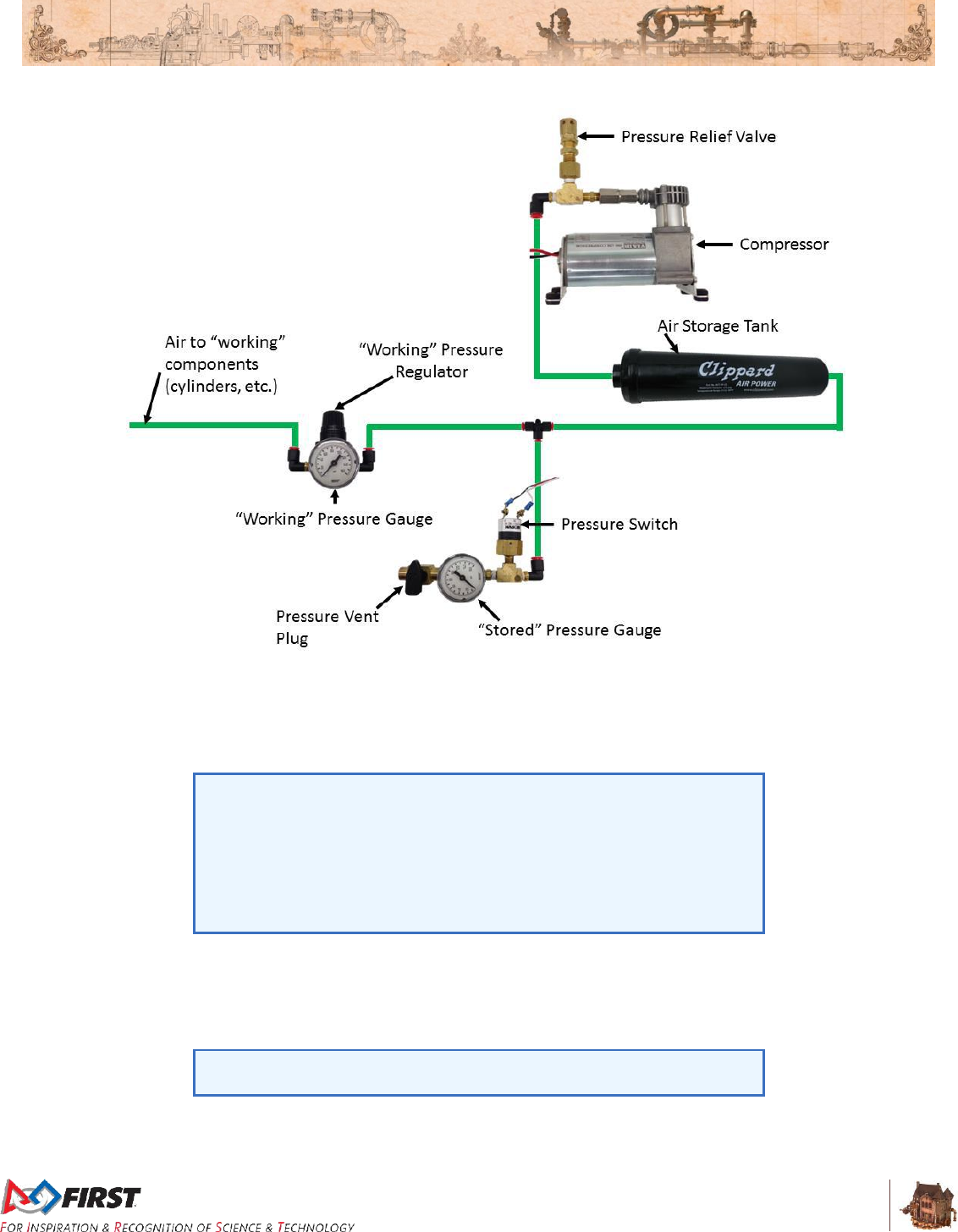
Section 8 ROBOT Rules
V10
99 of 135
Figure 8-13: Pneumatic circuitry
R84. Compressed air on the ROBOT must be provided by one and only one compressor. Compressor
specifications must not exceed nominal 1.10 cfm (~519 cm3/s) flow rate @ 12VDC.
R85. The compressor (permitted per R84) may be located off-board the ROBOT, however the
compressor must still be controlled and powered by the ROBOT when used.
The compressor may be mounted on the ROBOT, or it may be left off the
ROBOT and used to pre-charge compressed air in storage tanks on the
ROBOT provided the additional restrictions of R90 are met.
The intent of this rule is to permit teams to take advantage of the weight
savings associated with keeping the compressor off-board. However,
using the compressor off-board of the ROBOT does NOT permit non-
compliance with any other applicable rules.
R86. “Stored” air pressure on the ROBOT must be no greater than 120 psi (~827 kPa). No stored air
pressure intended for the ROBOT may be located off-board the ROBOT.
R87. “Working” air pressure on the ROBOT must be no greater than 60 psi (~413 kPa) and must be
provided through a single primary adjustable, relieving, pressure regulator.
Norgren regulator P/N: R07-100-RNEA or Monnier P/N: 101-3002-1
recommended.
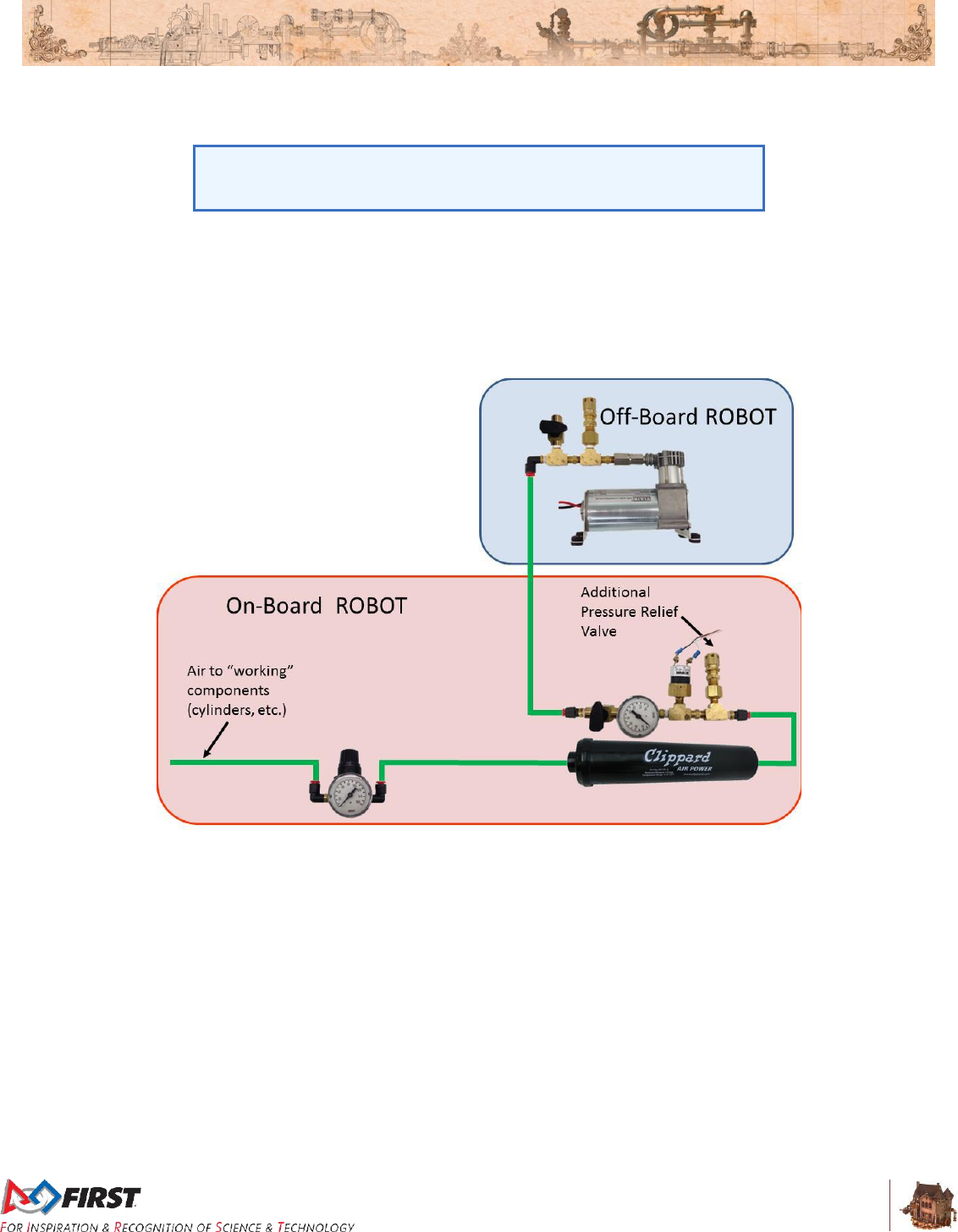
Section 8 ROBOT Rules
V10
100 of 135
R88. Only the compressor, relief valve (P/N: 16-004-011 or 16-004-003), pressure switch, pressure
vent plug, pressure gauge, storage tanks, tubing, pressure transducers, and connecting fittings
may be in the high-pressure pneumatic circuit upstream from the regulator.
It is recommended that all COMPONENTS in the high-pressure
pneumatic circuit upstream from the regulator be rated for at least 115
psi (~793 kPa) working pressure.
R89. Pressure gauges must be placed in easily visible locations upstream and downstream of the
regulator to display the “stored” and “working” pressures.
R90. If the compressor is not included on the ROBOT (under the provisions of R85) the “stored”
pressure gauge and pressure switch may be located on-board (Figure 8-14) or off-board (Figure
8-15) (but must be together), provided all other pneumatic rules are satisfied.
Figure 8-14: Off board compressor with stored pressure gauge and pressure switch on the ROBOT
R91. If the stored pressure gauge is kept off-board the ROBOT with the compressor, then only low-
pressure (60 psi (~413 kPa) or less) “working” air can be stored on the ROBOT. The “working”
pressure gauge must be installed on-board the ROBOT at all times (Figure 8-15).
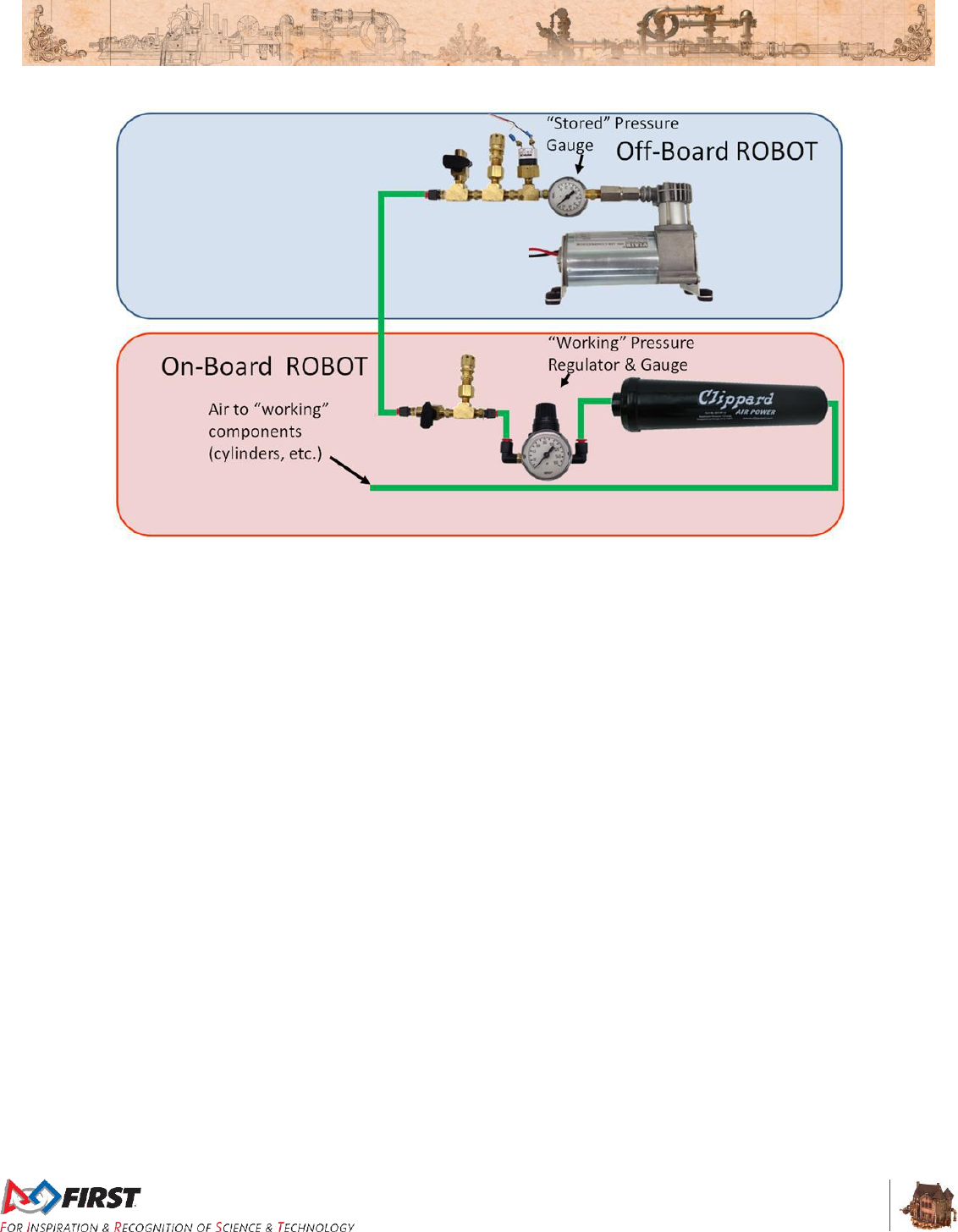
Section 8 ROBOT Rules
V10
101 of 135
Figure 8-15: Off board compressor with stored pressure gauge and pressure switch off the ROBOT
R92. The relief valve must be attached directly to the compressor or attached by legal hard fittings (e.g.
brass, nylon, etc.) connected to the compressor output port. If using an off-board compressor, an
additional relief valve must be included on the ROBOT.
If necessary, Teams are required to adjust the relief valve to release air at 125 psi (~861 kPa).
The valve may or may not have been calibrated prior to being supplied to Teams.
R93. The pressure switch requirements are:
A. It must be Nason P/N: SM-2B-115R/443
B. It must be connected to the high-pressure side of the pneumatic circuit (i.e. prior to
the pressure regulator) to sense the “stored” pressure of the circuit.
C. The two wires from the pressure switch must be connected directly to the pressure
switch input of the PCM controlling the compressor or, if controlled using the roboRIO
and a Spike relay, to the roboRIO.
D. If connected to the roboRIO, the roboRIO must be programmed to sense the state of
the switch and operate the relay module that powers the compressor to prevent over-
pressuring the system.
R94. Any pressure vent plug must be:
A. connected to the pneumatic circuit such that, when manually operated, it will vent to
the atmosphere to relieve all stored pressure in a reasonable amount of time, and
B. placed on the ROBOT so that it is visible and easily accessible.
If the compressor is not used on the ROBOT, then an additional pressure vent plug must be
connected to the high-pressure portion of the pneumatic circuit off-board the ROBOT with the
compressor (see R85).
R95. The outputs from multiple solenoid valves must not be plumbed together.

Section 8 ROBOT Rules
V10
102 of 135
8.10 OPERATOR CONSOLE
R96. The Driver Station software provided on the National Instruments website is the only application
permitted to specify and communicate the operating mode (i.e. Autonomous/Teleop) and
operating state (Enable/Disable) to the ROBOT. The DRIVER Station software must be revision
17.0.1 or newer.
Teams are permitted to use a portable computing device of their choice
(laptop computer, tablet, etc.) to host the DRIVER Station software while
participating in competition MATCHES.
R97. The OPERATOR CONSOLE, the set of COMPONENTS and MECHANISMS used by the
DRIVERS and/or HUMAN PLAYER to relay commands to the ROBOT, must include a graphic
display to present the Driver Station diagnostic information. It must be positioned within the
OPERATOR CONSOLE so that the screen display can be clearly seen during Inspection and in a
MATCH.
R98. Devices hosting the Driver Station software must only interface with the Field Management
System (FMS) via the Ethernet cable provided at the PLAYER STATION (e.g. not through a
switch). Teams may connect the FMS Ethernet cable to their Driver Station device directly via an
Ethernet pigtail, or with a single-port Ethernet converter (e.g. docking station, USB-Ethernet
converter, Thunderbolt-Ethernet converter, etc.). The Ethernet port on the OPERATOR
CONSOLE must be easily and quickly accessible.
Teams are strongly encouraged to use pigtails on the Ethernet port used
to connect to the FMS. Such pigtails will reduce wear and tear on the
device’s port and, with proper strain relief employed, will protect the port
from accidental damage.
R99. The OPERATOR CONSOLE must not
A. be longer than 60 in. (~152 cm)
B. be deeper than 14 in. (~35 cm) (excluding any items that are held or worn by the
DRIVERS during the MATCH)
C. extend more than 6 ft. 6 in. (~198 cm) above the floor
D. attach to the FIELD (except as permitted by G15)
There is a 54 in. (~137 cm) long by 2 in. (nominal) wide strip of hook-
and-loop tape (“loop” side) along the center of the PLAYER STATION
support shelf that may be used to secure the OPERATOR CONSOLE to
the shelf, per G15. See Section 3.11.1 PLAYER STATION for details.
Please note that while there is no hard weight limit, OPERATOR
CONSOLES that weigh more than 30 lbs. (~13 kg.) will invite extra
scrutiny as they are likely to present unsafe circumstances.
R100. Other than the system provided by the ARENA, no other form of wireless communications shall
be used to communicate to, from, or within the OPERATOR CONSOLE.
Examples of prohibited wireless systems include, but are not limited to,
active wireless network cards and Bluetooth devices. For the case of the
FIRST Robotics Competition, a motion sensing input device (e.g.
Microsoft Kinect) is not considered wireless communication and is
allowed.

Section 8 ROBOT Rules
V10
103 of 135
R101. OPERATOR CONSOLES shall not be made using hazardous materials, be unsafe, cause an
unsafe condition, or interfere with other DRIVE TEAMS or the operation of other ROBOTS.

Section 9 Inspection & Eligibility
Rules
V7
104 of 135
9 Inspection & Eligibility Rules
This section describes the rules governing MATCH participation. A Team has participated in a MATCH if
any member of their DRIVE TEAM is in the ALLIANCE STATION, with or without the ROBOT on the
FIELD, at the start of the MATCH.
At each event, the Lead Robot Inspector (LRI) has final authority on the legality of any COMPONENT,
MECHANISM, or ROBOT. Inspectors may re-Inspect ROBOTS to ensure compliance with the rules.
ROBOTS are permitted to participate in scheduled Practice MATCHES prior to passing Inspection.
However, the FIRST Technical Advisor (FTA), LRI, or Head REFEREE may determine at any time that
the ROBOT is unsafe, per safety rules, and may prohibit further participation in Practice MATCHES until
the condition is corrected and/or the ROBOT passes Inspection.
Prior to the start of a MATCH, any ROBOT which is unable or ineligible to participate in that MATCH as
determined by the FTA, LRI, or Head REFEREE is declared to be BYPASSED and is DISABLED. A
Team whose ROBOT is BYPASSED remains eligible to receive Qualification Ranking Points or Playoff
MATCH points provided that its ROBOT has passed Inspection, per I02.
I01. The ROBOT must be built by the Team and to play this year’s game. The ROBOT is an
electromechanical assembly built by the FIRST® Robotics Competition Team to perform specific
tasks when competing in FIRST® STEAMWORKSSM. The ROBOT must include all of the basic
systems required to be an active participant in the game – power, communications, control,
BUMPERS, and movement. The ROBOT implementation must obviously follow a design
approach intended to play FIRST STEAMWORKS (e.g. a box of unassembled parts placed on
the FIELD, or a ROBOT designed to play a different game does not satisfy this definition).
I01 requires that the ROBOT a Team uses in competition was built by
that Team, but isn’t intended to prohibit assistance from other Teams
(e.g. fabricating elements, supporting construction, writing software,
developing game strategy, contributing COMPONENTS and/or
MECHANISMS, etc.).
I02. Get inspected before playing a Qualification/Playoff MATCH. A Team is only permitted to
participate in a Qualification or Playoff MATCH and receive Ranking or MATCH Points
respectively if their ROBOT has passed an initial, complete Inspection.
Violation: If prior to the start of the MATCH, the Team is not eligible to participate in the MATCH.
If after the start of the MATCH, the entire ALLIANCE receives a RED CARD for that MATCH.
Please take note of this rule. It is important that FIRST Robotics
Competition Teams ensure their ALLIANCE partners have passed
Inspection. Allowing a partner that has not passed Inspection to play puts
the ALLIANCE at risk of RED CARDS. Teams should check with their
ALLIANCE partners early, and help them pass Inspection before
competing.
I03. Bring it all to Inspection. At the time of Inspection, the ROBOT must be presented with all
MECHANISMS (including all COMPONENTS of each MECHANISM), configurations, and
decorations that will be used on the ROBOT during the competition event. It is acceptable,
however, for a ROBOT to play MATCHES with a subset of the MECHANISMS that were present
during Inspection. Only MECHANISMS that were present during the Inspection may be added,

Section 9 Inspection & Eligibility
Rules
V7
105 of 135
removed or reconfigured between MATCHES. If MECHANISMS are changed between
MATCHES, the reconfigured ROBOT must still meet all Inspection criteria.
I04. ROPES have to be inspected. A Team must submit any ROPE they intend to use in a MATCH
for Inspection. A ROPE must meet the following criteria (see Figure 9-2 for letter references):
A. have a maximum width (W) of 1 in. (nominal) (e.g. exclusive of any knot widths)
B. be designed/configured to be at least 5 ft. 3 in. (~160 cm) long measured from the
side of the ROPE’S retaining feature (per I04-E) that abuts the DAVIT fingers (L), to
the farthest point on the ROPE from this feature.
C. be designed/configured to not exceed a length of 8 ft. (~244 cm) measured from the
side of the ROPE’S retaining feature (per I04-E) that abuts the DAVIT fingers (L), to
the farthest point on the ROPE from this feature.
D. consist entirely of (except for dye or adhesive applied by the VENDOR as part of the
normal manufacturing process for a COTS item and no longer tacky, e.g. a “binder
coat”) flexible, non-metallic fibers sewn, twisted, tied, woven, knitted, crocheted,
intertwined, or braided together except for the last 4 in. (~10 cm) of any cut end (E)
which may be whipped (with material that is flexible and non-metallic) or fused only to
prevent fraying.
Figure 9-1 ROPE examples
E. be configured such that it engages securely with the FIELD with a Retaining Feature
(RF) that does not extend more than 2 in. (~5 cm) below the DAVIT fingers.
To interface with the field a ROPE must have a retaining feature (e.g. a
knot) greater than 1 in. (~25.4 mm) in diameter to interface with the
DAVITS (RF).
The DAVIT's retaining pins are not designed to hold the weight of a
ROBOT and therefore attachment to them would not be considered
engaging "securely with the FIELD" per I04-D.
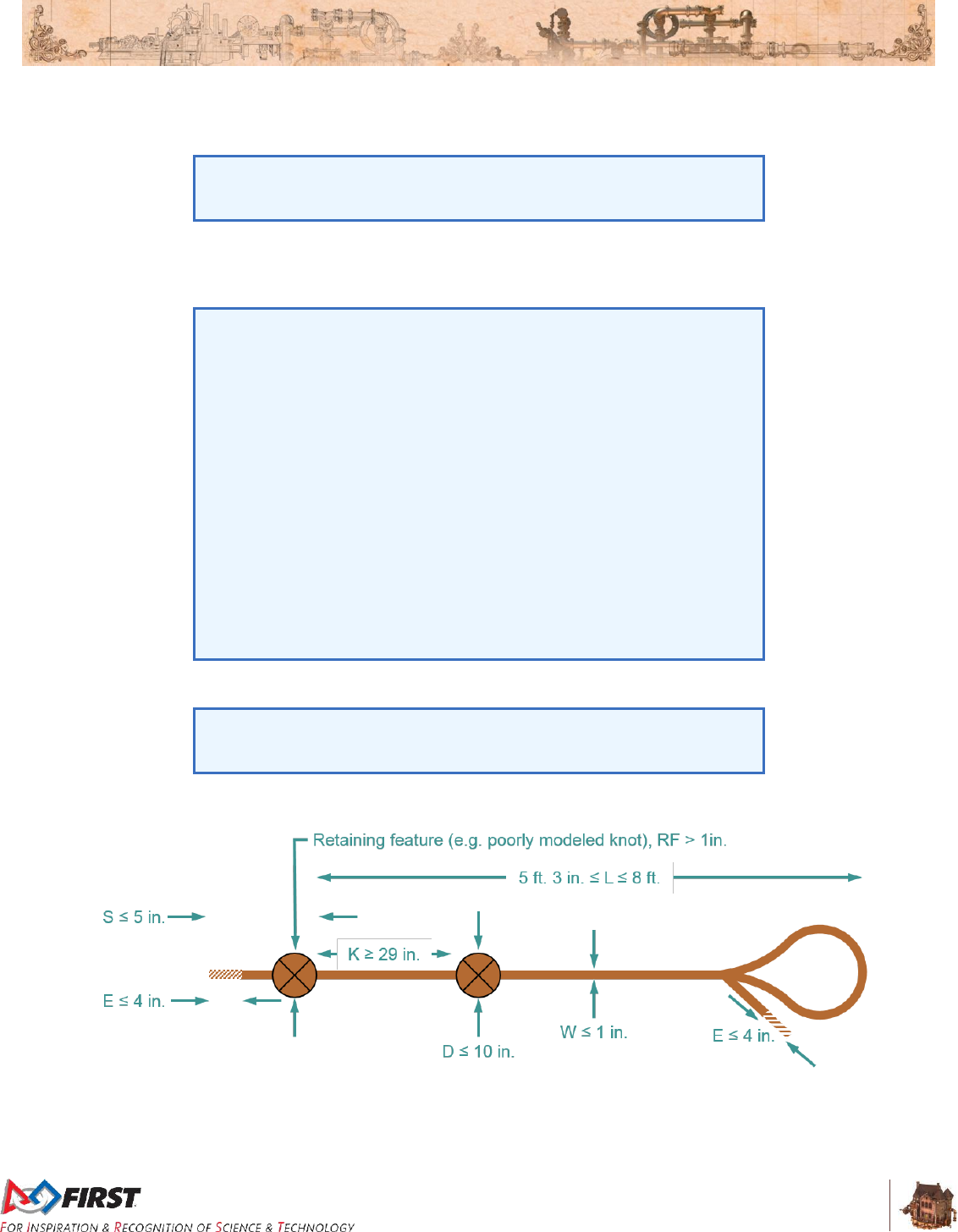
Section 9 Inspection & Eligibility
Rules
V7
106 of 135
F. if knotted, the top knot must be at least 29 in. (~74 cm) below the retaining
knot/feature (K)
G. if frayed, knotted or looped, the total diameter does not exceed 10 in. (~25 cm) (D)
If the ROPE has a loose loop such that, uncompressed it’s 12 in. (~30
cm) in diameter, but it can be easily compressed by hand to less than 10
in., that ROPE has met the requirement of part I04-G.
H. be designed/configured to not exceed a length of 5 in. (~12 cm) measured from the
side of the ROPE’S retaining feature (per I04-E) that abuts the DAVIT fingers, to the
closest end on the ROPE from this feature (S).
The intent of I04 is to allow Teams the convenience of bringing their own
ROPE for reliability and predictability purposes, as well as accommodate
some modifications to ease the challenge associated with accessing the
TOUCHPAD (e.g. tying knots).
The modifications allowed are limited, however. For example, consider
the limitation of the purpose of whipping or fusing to prevent fraying in
I04-D and that FIRST Robotics Community members are innovative and
may discover a way to fuse the end of the ROPE in a way that can be
leveraged for competitive advantage. This “superfusion” extends the
fusing’s purpose beyond only preventing fraying.
We acknowledge that this could result in temptation to implement the
superfusion method anyway and hope an Inspector doesn’t notice, or
that you will be able to convince them the superfusion method really is
"only to prevent fraying." Please don’t do this. It will likely lead to a bad
experience both for you and the volunteer who really does want you to
participate in the event, but with a 100% legal ROBOT.
I. be flexible such that it’s not capable of being pushed to activate the TOUCHPAD.
Flexible means that if the ROPE is held at any point, it should not extend
more than 12 in. (~30 cm) above the point where it is held. ROPES are
meant to be pulled, not pushed.
Figure 9-2 ROPE anatomy
I05. Unless the change is listed below, any change to a ROBOT must get re-inspected. If a
ROBOT is modified after it has passed its most recent Inspection, that ROBOT must be re-
Inspected before the ROBOT is eligible to participate in a MATCH. Exceptions are listed in A

Section 9 Inspection & Eligibility
Rules
V7
107 of 135
through F (unless they result in a significant change to the ROBOT’S size, weight, legality, or
safety).
A. addition, relocation, or removal of fasteners (e.g. cable ties, tape, and rivets)
B. addition, relocation, or removal of labeling or marking
C. revision of ROBOT code
D. replacement of a COTS COMPONENT with an identical COTS COMPONENT
E. replacement of a MECHANISM with an identical MECHANISM (size, weight,
material)
F. additions, removals, or reconfiguration of ROBOT with a subset of MECHANISMS
already inspected per I02.
When in doubt, the Team should ask to be re-Inspected.
Inspectors prioritize ROBOTS that have not yet completed initial
inspection over ROBOT changes and ROPES.
While every effort will be made to re-inspect Teams in a timely manner,
Teams need to consider that they may need to play with the previously
inspected configuration if re-inspection cannot be completed before a
MATCH. Teams should work with Inspectors when making changes to
minimize the chance of this occurring.
Example 1: Team A’s ROBOT has passed Inspection, but burns out a
motor controller during a MATCH. Team A replaces it with an identical
motor controller. Team A does not have to get their ROBOT re-
Inspected per exception I05-D.
Example 2: Team B would like to add weight to their ROBOT to lower
their center of gravity. Team B adds a large amount of fasteners to their
ROBOT as ballast. Team B must get their ROBOT re-Inspected because
they have significantly changed their weight per I05.
Example 3: Team D has decided to move their motor controller to a
different location on their ROBOT, and must use a different length wire to
make the proper connections. Team D must get their ROBOT re-
Inspected because rewiring is not an exception in I05.
Example 4: Team E decides to relocate their battery on their ROBOT to
change their center of gravity. Team E must be re-Inspected as the
relocation of COMPONENTS or MECHANISMS is not an exception I05.
Example 5: Team F realizes they can gain necessary functionality by
building a new MECHANISM at an event and adding it to their ROBOT.
Their ROBOT must be re-Inspected.
If an observation is made that another Team’s ROBOT may be in
violation of the ROBOT rules, please approach FIRST officials to review
the matter in question. This is an area where Gracious Professionalism®
is very important.
I06. Changes to a ROPE need re-inspection. If a ROPE is modified after it has passed its most
recent Inspection, that ROPE must be re-Inspected before the ROPE is eligible for a MATCH.
Section 9 Inspection & Eligibility
Rules
V7
108 of 135
I07. Document your costs. A Cost Accounting Worksheet (CAW), listing all items on the ROBOT
except those listed in R10 and their relevant costs per Section 8.4 Budget Constraints &
Fabrication Schedule, must be presented at the time of Inspection.
Teams are encouraged to use the CAW Template posted on the FIRST
website. Please note that while CAWs must be shown to Inspectors,
Teams are not required to submit their CAWs to the Inspectors.
I08. ROBOTS are off for Inspection, mostly. For the safety of all those involved, Inspections must
take place with the ROBOT powered off, pneumatics unpressurized, and springs or other stored
energy devices in their lowest potential energy states (e.g. battery removed).
Power and air pressure should only be enabled on the ROBOT during those portions of the
Inspection process where it is absolutely required to validate certain system functionality and
compliance with specific rules (firmware check, etc.). Inspectors may allow the ROBOT to be
powered up beyond the parameters above if both criteria below are met.
A. The ROBOT design requires power or a charged stored energy device in order to
confirm that the ROBOT meets volume requirements, and
B. The Team has included safety interlocks that mitigate unexpected release of such
stored energy.
The Team may be asked to demonstrate these interlocks during the
inspection process.
I09. No student, no Inspection. At least one student Team member must accompany the ROBOT for
any Inspection efforts.
Exceptions may be made for major conflicts, e.g. religious holidays,
major testing, transportation issues, etc.
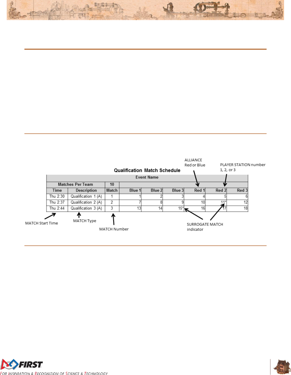
Section 10 Tournaments
V10
109 of 135
10 Tournaments
Each 2017 FIRST Robotics Competition event is played in a tournament format. Each tournament
consists of three sets of MATCHES called Practice MATCHES (not necessarily at all District Events),
Qualification MATCHES, and Playoff MATCHES.
Practice MATCHES provide each Team with an opportunity to operate its ROBOT on the FIELD prior to
the start of the Qualification MATCHES.
Qualification MATCHES allow each Team to earn a seeding position that may qualify them for
participation in the Playoff MATCHES.
Playoff MATCHES determine the event Champions.
10.1 MATCH Schedules
A MATCH schedule is used to coordinate MATCHES at an Event. Figure 10-1 details information shown
on each Schedule. Figure 10-1: Sample MATCH Schedule
10.2 Practice MATCHES
Practice MATCHES are played on the first day of each event. The Practice MATCH schedule is available
as soon as possible, but no later than the start of Practice MATCHES. Practice MATCHES are randomly
assigned, and teams may not switch scheduled Practice MATCHES. Each Team is assigned an equal
number of Practice MATCHES unless the number of Teams multiplied by number of Practice MATCHES
is not divisible by six. In this case, the FIELD Management System (FMS) randomly selects some Teams
to play an extra Practice MATCH.
Practice MATCHES are not guaranteed at District Events.
10.2.1 Filler Line
A Filler Line is used to fill open slots at events that employ scheduled Practice MATCHES, or all slots at
events with an open Practice MATCH schedule. Teams from the Filler Line are used on a first come, first
served basis to fill empty spots in Practice MATCHES left by other Teams that do not report to Queueing.
The number of Teams in the Filler Line is dependent upon space at venues

Section 10 Tournaments
V10
110 of 135
T01. Teams wanting additional Practice MATCHES may not join the Filler Line unless all criteria listed
below are met:
A. ROBOTS in the Filler Line must have passed Inspection (this requirement may be waived
for events with open Practice MATCH schedules);
B. DRIVE TEAMS must join the Filler Line with their ROBOT;
C. Teams may not work on their ROBOT while in the Filler Line;
D. Teams may not occupy more than one spot in the Filler Line; and
E. If a Team is queued for their Practice MATCH, they may not also join the Filler Line.
10.3 Measurement
The ARENA will be open for at least thirty (30) minutes prior to the start of Qualification MATCHES,
during which time Teams may survey and/or measure the FIELD and bring ROBOTS on the FIELD to
perform sensor calibration. The specific time that the FIELD is open will be communicated to Teams at
the event. Teams may bring specific questions or comments to the FTA.
T02. During the period when the ARENA is open for measurement, ROBOTS can be enabled, but
cannot move, nor can they interact (e.g. shoot, push, pickup, etc.) with GAME PIECES or the
AIRSHIP.
Violation: YELLOW CARD.
10.4 Qualification MATCHES
10.4.1 Schedule
The Qualification MATCH schedule is made available as soon as possible, but no later than one (1) hour
before Qualification MATCHES are scheduled to begin. Each Qualification schedule consists of a series
of rounds in which each team plays one (1) MATCH per round.
10.4.2 MATCH Assignment
FMS assigns each Team two (2) ALLIANCE partners for each Qualification MATCH using a predefined
algorithm, and teams may not switch Qualification MATCH assignments. The algorithm employs the
following criteria, listed in order of priority:
1. Maximize time between each MATCH played for all Teams
2. Minimize the number of times a Team plays opposite any Team
3. Minimize the number of times a Team is allied with any Team
4. Minimize the use of SURROGATES (Teams randomly assigned by the FMS to play an
extra Qualification MATCH)
5. Provide even distribution of MATCHES played on Blue and Red ALLIANCE
6. Balance assigned PLAYER STATION proximity to a BOILER.
All Teams are assigned the same number of Qualification MATCHES, equal to the number of rounds,
unless the number of Teams multiplied by number of MATCHES is not divisible by six. In this case, the
FMS randomly selects some Teams to play an extra MATCH. For the purpose of seeding calculations,
those Teams are designated as SURROGATES for the extra MATCH. If a Team plays a MATCH as a
SURROGATE, it is indicated on the MATCH schedule, it is always their third Qualification MATCH, and
the outcome of the MATCH has no effect on the Team’s ranking. YELLOW and RED CARDS assigned to
SURROGATES do carry forward to subsequent MATCHES.

Section 10 Tournaments
V10
111 of 135
10.4.3 Qualification Ranking
Ranking Points (RP) are units credited to a Team based on their ALLIANCE’S performance in
Qualification MATCHES. Ranking Points are awarded to each eligible Team at the completion of each
Qualification MATCH:
A. Each Team on the winning ALLIANCE receives two (2) Ranking Points.
B. Each Team on the losing ALLIANCE receives zero (0) Ranking Points.
C. In the event of a tied score, all Teams receive one (1) Ranking Point.
D. Each Team on an ALLIANCE that achieves at least 40 kPa receives one (1) Ranking
Point.
E. Each Team on an ALLIANCE that engages all four (4) ROTORS by the end of the
MATCH receives one (1) Ranking Point.
Exceptions to A-E are as follows:
A. A SURROGATE receives zero (0) Ranking Points.
B. A DISQUALIFIED Team, as determined by the Head REFEREE, receives zero (0)
Ranking Points in a Qualification MATCH or causes their ALLIANCE to receive zero
(0) MATCH points in a Playoff MATCH.
C. A “no-show” Team is either DISQUALIFIED from or issued a RED CARD for that
MATCH (see C07). A Team is declared a no-show if no member of the DRIVE TEAM
is in the ALLIANCE STATION, AIRSHIP, or LOADING LANE at the start of the
MATCH.
The total number of Ranking Points earned by a Team throughout their Qualification MATCHES divided
by the number of MATCHES they’ve been scheduled to play (minus any SURROGATE MATCH), then
truncated to two (2) decimal places, is their Ranking Score (RS).
All Teams participating in Qualification MATCHES are ranked by Ranking Score. If the number of Teams
in attendance is ‘n’, they are ranked ‘1’ through ‘n’, with ‘1’ being the highest ranked Team and ‘n’ being
the lowest ranked Team.
Teams are ranked in order, using the sorting criteria defined in Table 10-1.
Table 10-1: Qualification MATCH Ranking Criteria
Order Sort
Criteria
1st
Ranking Score
2nd
Cumulative sum of MATCH points
3rd
Cumulative sum of AUTO points
4th
Cumulative ROTOR engagement score (AUTO and TELEOP)
5th
Cumulative TOUCHPAD score
6th
Total accumulated pressure
7th
Random sorting by the FMS
10.5 Playoff MATCHES
In Playoff MATCHES, Teams do not earn Ranking Points; they earn a Win, Loss or Tie. Within each
series of the Playoff MATCH bracket, the first ALLIANCE to win two (2) MATCHES will advance.
Section 10 Tournaments
V10
112 of 135
In the case where the Quarterfinal or Semifinal MATCH scores for both ALLIANCES are equal, the Win is
awarded to the ALLIANCE per criteria listed in Table 10-2. A DISQUALIFIED Team, as determined by the
Head REFEREE, causes their ALLIANCE to receive zero (0) MATCH points in a Playoff MATCH.
In Finals MATCHES, the Champion ALLIANCE is the first ALLIANCE to win two (2) MATCHES. In the
case where an ALLIANCE hasn’t won two (2) MATCHES after three (3) MATCHES, the Playoffs proceed
with up to three (3) additional Finals MATCHES, called Overtime MATCHES, until an ALLIANCE has won
two (2) Finals MATCHES. In the case where the Overtime MATCH scores for both ALLIANCES are
equal, the win for that Overtime MATCH is awarded based on the criteria listed in Table 10-2.
Table 10-2: Quarterfinal, Semifinal, and Overtime Tiebreaker Criteria
Order Sort
Criteria
1st
Fewer FOUL points
2nd
Cumulative sum of AUTO points
3rd
Cumulative ROTOR engagement score (AUTO and TELEOP)
4th
Cumulative TOUCHPAD score
5th
Total accumulated pressure
6th
MATCH is replayed
10.5.1 ALLIANCE Selection Process
At the end of the Qualification MATCHES, the top eight (8) seeded Teams become the ALLIANCE Leads.
The seeded ALLIANCES are designated, in order, ALLIANCE One, ALLIANCE Two, etc., down to
ALLIANCE Eight. Using the ALLIANCE selection process described in this section, each ALLIANCE Lead
chooses two (2) other Teams to join their ALLIANCE.
If a Team declines the ALLIANCE Lead position or doesn’t send a student representative for ALLIANCE
selection, they are ineligible to participate in the Playoff Tournament. If the declining/absent Team would
have been an ALLIANCE Lead, all lower ranked ALLIANCE Leads are promoted one spot. The next
highest-ranked Team moves up to become the ALLIANCE Eight Lead.
Each Team chooses a student Team representative who proceeds to the ARENA at the designated time
(typically before the lunch break on the final day of the event) to represent their Team. The designated
student representative from each ALLIANCE in a Playoff MATCH is called the ALLIANCE CAPTAIN.
The ALLIANCE selection process consists of two (2) rounds during which each ALLIANCE CAPTAIN
invites a Team seeded below them in the standings to join their ALLIANCE. The invited Team must not
already have declined an invitation.
Round 1: In descending order (ALLIANCE One to ALLIANCE Eight), each ALLIANCE CAPTAIN invites a
single Team. The invited Team’s representative steps forward and either accepts or declines the
invitation.
If the Team accepts, it becomes a member of that ALLIANCE. If an invitation from a top eight ALLIANCE
to another ALLIANCE Lead is accepted, all lower ALLIANCE Leads are promoted one spot. The next
highest-seeded, unselected Team moves up to become the ALLIANCE Eight Lead.
If the Team declines, that Team is not eligible to be picked again or to be a BACKUP TEAM (see Section
10.5.2 BACKUP TEAMS), and the ALLIANCE CAPTAIN extends another invitation to a different Team. If
an invitation from a top eight ALLIANCE to another ALLIANCE Lead is declined, the declining Team may
still invite Teams to join their ALLIANCE; however, it cannot accept invitations from other ALLIANCES.
The process continues until ALLIANCE Eight makes a successful invitation.

Section 10 Tournaments
V10
113 of 135
Round 2: The same method is used for each ALLIANCE CAPTAIN’S second choice except the selection
order is reversed, with ALLIANCE Eight picking first and ALLIANCE One picking last. This process results
in eight (8) ALLIANCES of three (3) Teams each.
Of the remaining eligible Teams, the highest seeded Teams must either accept or decline to be included
in a pool of available Teams until there are up to eight (8) Teams that accept to be added into the pool.
FIELD STAFF will coordinate the assembly of this BACKUP pool immediately after the top ranked
ALLIANCE has made their final pick. If a Team is not available to accept inclusion in the BACKUP pool, it
will be assumed they have declined the invitation.
10.5.2 BACKUP TEAMS
In the Playoff MATCHES, it may be necessary for an ALLIANCE to replace one of its members due to a
faulty ROBOT. ROBOT faults include but are not limited to:
1. mechanical damage,
2. electrical issues, or
3. software problems.
In this situation, the ALLIANCE CAPTAIN has the option to bring in only the highest seeded Team from
the pool of available Teams to join its ALLIANCE. The Team whose ROBOT and DRIVE TEAM replaces
another ROBOT and DRIVE TEAM on an ALLIANCE during the Playoff MATCHES is called the BACKUP
TEAM.
The resulting ALLIANCE is then composed of four (4) Teams. The replaced Team remains a member of
the ALLIANCE for awards, but cannot return to play, even if their ROBOT is repaired.
Each ALLIANCE is allotted one (1) BACKUP TEAM Coupon during the Playoff MATCHES. If a second
ROBOT from the ALLIANCE becomes inoperable, then the ALLIANCE must play the following MATCHES
with only two (2) (or even one (1)) ROBOTS.
Example: Three (3) Teams, A, B and C, form an ALLIANCE going into
the Playoff MATCHES. The highest seeded Team not on one of the eight
(8) ALLIANCES is Team D. During one of the Playoff MATCHES, Team
C’s ROBOT suffers damage to its mechanical arm. The ALLIANCE
CAPTAIN decides to bring in Team D to replace Team C. Team C and
their ROBOT are not eligible to play in any subsequent Playoff
MATCHES. The new ALLIANCE of Teams A, B, and D are successful in
advancing to the Finals and win the event. Teams A, B, C, and D are all
recognized as members of the Winning ALLIANCE and receive awards
In the case where a BACKUP TEAM is part of the Winning or Finalist ALLIANCE, there will be a four (4)-
Team Winning or Finalist ALLIANCE.
10.5.3 Playoff MATCH Bracket
The Playoff MATCHES take place following the completion of the Qualification MATCHES and the
ALLIANCE selection process. Playoff MATCHES are played in a bracket format as shown in Figure 10-2.
ALLIANCE Leads are assigned to PLAYER STATION 2, the first picks are assigned to the PLAYER
STATIONS closer to the BOILER, and second picks are assigned to the PLAYER STATIONS closer to
the opponent’s LOADING STATION. If a BACKUP TEAM is in play, they will be assigned to the PLAYER
STATION that was assigned to the DRIVE TEAM they’re replacing.
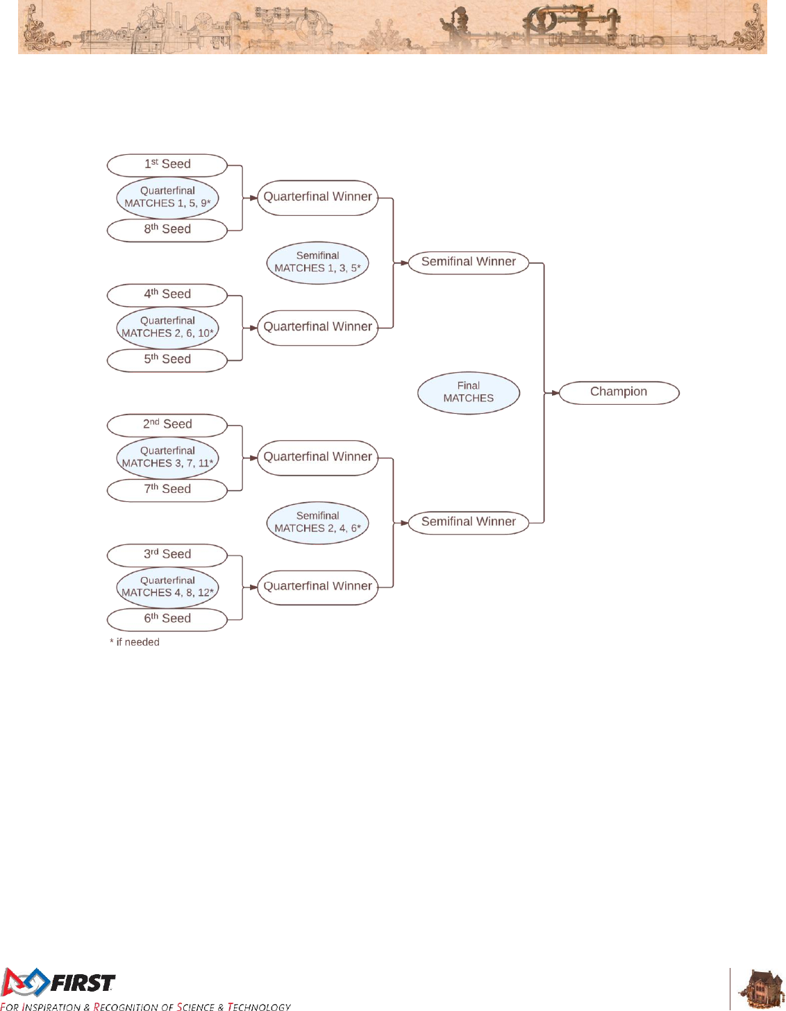
Section 10 Tournaments
V10
114 of 135
For Quarterfinal MATCHES, the higher seeded ALLIANCE is assigned to the Red ALLIANCE. Beyond the
Quarterfinal MATCHES, the ALLIANCE on the top of each MATCH in Figure 10-2 are assigned to the
Red ALLIANCE, regardless of whether they are the higher seeded ALLIANCE in that particular MATCH.
Figure 10-2: Playoff MATCH Bracket
Section 10 Tournaments
V10
115 of 135
In order to allow time between MATCHES for all ALLIANCES, the order of play is as follows:
Table 10-3: Playoff Order
Quarterfinal
Round 1
Quarterfinal
Round 2
Quarterfinal
Round 3
Semifinals
Finals
Quarterfinal 1
(1 vs.8)
Quarterfinal 5
(1 vs.8)
Quarterfinal
Tiebreaker 11
Semifinal 1
Final 1
Quarterfinal 2
(4 vs.5)
Quarterfinal 6
(4 vs.5)
Quarterfinal
Tiebreaker 21
Semifinal 2
FIELD
TIMEOUT
Quarterfinal 3
(2 vs.7)
Quarterfinal 7
(2 vs.7)
Quarterfinal
Tiebreaker 31
Semifinal 3
Final 2
Quarterfinal 4
(3 vs.6)
Quarterfinal 8
(3 vs.6)
Quarterfinal
Tiebreaker 41
Semifinal 4
FIELD
TIMEOUT
FIELD
TIMEOUT1
FIELD
TIMEOUT1
FIELD
TIMEOUT1
Semifinal
Tiebreaker 11
Final
Tiebreakers
(Overtime) 1
Any Replays
due to ties1
Semifinal
Tiebreaker 21
FIELD
TIMEOUT1
Any Replays
due to ties1
Any Replays
due to ties1
1 - if required
10.6 REFEREE Interaction
The Head REFEREE has the ultimate authority in the ARENA during the event, but may receive input
from additional sources, e.g. Game Designers, FIRST personnel, FTA, and technical staff. The Head
REFEREE rulings are final. No event personnel, including the Head REFEREE, will review video, photos,
artistic renderings, etc. of any MATCH, from any source, under any circumstances.
If a DRIVE TEAM needs clarification on a ruling or score, per C09, one (1) pre-college student from that
DRIVE TEAM should address the Head REFEREE after the ARENA Reset Signal (e.g. LED lights turn
green). A DRIVE TEAM member signals their desire to speak with the Head REFEREE by standing in the
corresponding Red or Blue Question Box, which are located on the floor near each end of the scoring
table. Depending on timing, the Head REFEREE may postpone any requested discussion until the end of
the subsequent MATCH.
While FMS tracks quantities of FOULS and TECH FOULS, FIRST instructs REFEREES to not self-track
details about FOULS and TECHNICAL FOULS; as a result, we don’t expect REFEREES to recall details
about what FOULS or TECHNICAL FOULS were made, when they occurred, and against whom.
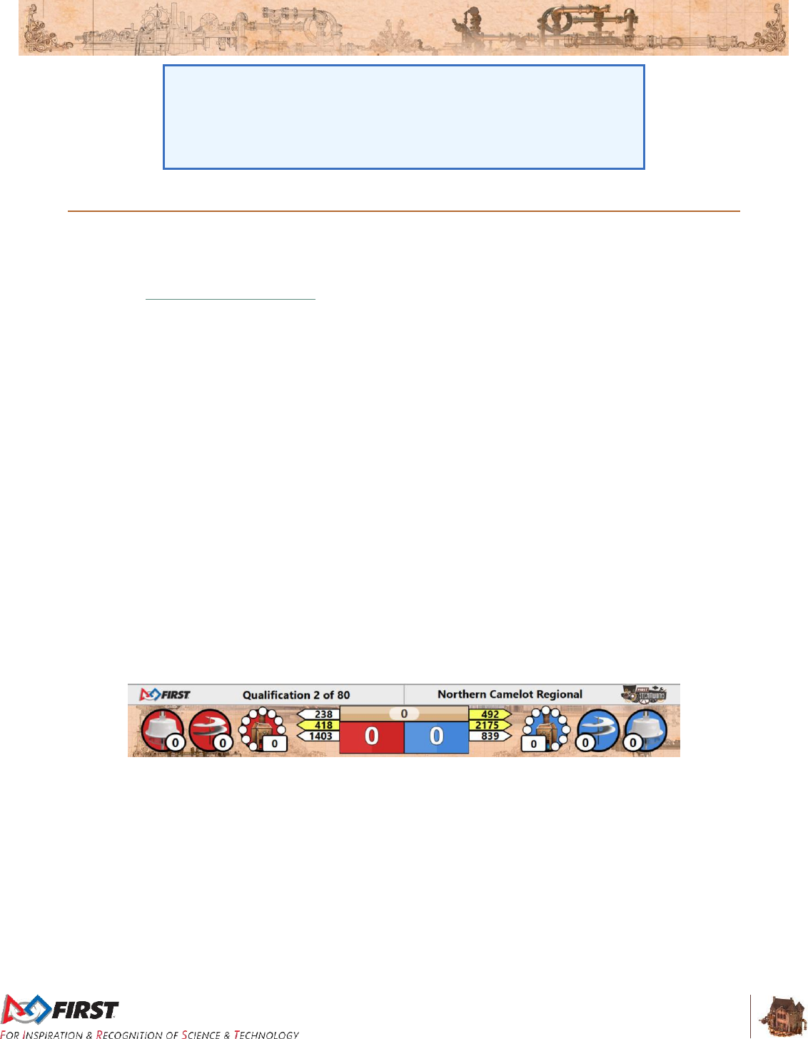
Section 10 Tournaments
V10
116 of 135
Any reasonable question is fair game in the Question Box, and Head
REFEREES will do good faith efforts to provide helpful feedback (e.g.
how/why certain FOULS are being called, why a particular ROBOT may
be susceptible to certain FOULS based on its design or game play, how
specific rules are being called or interpreted), but please know that they
will likely not be able to supply specific details
10.7 YELLOW and RED CARDS
In addition to rule violations explicitly listed throughout the 2017 Game and Season Manual, YELLOW
CARDS and RED CARDS are used in FIRST® Robotics Competition to address Team and ROBOT
behavior that does not align with the mission of FIRST®.
As noted in Section 4.4 Rule Violations and C01, the Head REFEREE may assign a YELLOW CARD as
a warning, or a RED CARD for DISQUALIFICATION in MATCH for egregious behavior inappropriate at a
FIRST Robotics Competition event.
T03. Egregious or repeated violations of any rule or procedure is prohibited.
Violation: The Head REFEREE may assign a YELLOW CARD as a warning, or a RED CARD for
DISQUALIFICATION in MATCH.
A YELLOW or RED CARD is indicated by the Head REFEREE standing in front of the Team’s PLAYER
STATION and holding a YELLOW and/or RED CARD in the air.
YELLOW CARDS are additive, meaning that a second YELLOW CARD is automatically converted to a
RED CARD. A Team is issued a RED CARD for any subsequent incident in which they receive an
additional YELLOW CARD, including earning a second YELLOW CARD during a single MATCH. A
second YELLOW CARD is indicated by the Head REFEREE standing in front of the Team’s PLAYER
STATION and holding a YELLOW CARD and RED CARD in the air simultaneously after the completion of
the MATCH. A Team that has received either a YELLOW CARD or a RED CARD carries a YELLOW
CARD into subsequent MATCHES, except as noted below. A RED CARD results in DISQUALIFICATION.
Once a Team receives a YELLOW or RED CARD, its Team number will be presented with a yellow
background on the audience screen at the beginning of all subsequent MATCHES, including any replays,
as a reminder to the Team, the REFEREES, and the audience that they carry a YELLOW CARD.
Figure 10-3: Audience Screen Graphic Showing YELLOW and RED CARD Indicators
All YELLOW CARDS are cleared at the conclusion of Qualification MATCHES, providing teams a clean
slate at the beginning of Playoff MATCHES.
During the Playoff MATCHES, if a Team receives a YELLOW or RED CARD, it results in the entire
ALLIANCE receiving the YELLOW or RED CARD for that MATCH. If two different Teams on the same
ALLIANCE are issued YELLOW CARDS, the entire ALLIANCE is issued a RED CARD. A RED CARD
results in zero (0) points for that MATCH, and the ALLIANCE loses the MATCH. If both ALLIANCES
receive RED CARDS, the ALLIANCE which committed the action earning the RED CARD first
chronologically loses the MATCH.
Section 10 Tournaments
V10
117 of 135
YELLOW and RED CARDS are applied based on the following:
Table 10-4: YELLOW and RED CARD application
Time YELLOW or RED CARD earned:
MATCH to which CARD is applied:
prior to the start of Qualification MATCHES
Team’s first Qualification MATCH
during the Qualification MATCHES
Team’s current (or just-completed) MATCH. In the
case where the Team participated as a
SURROGATE in the current (or just completed)
MATCH, the card is applied to the Team’s
previous MATCH (i.e. the Team’s second
Qualification MATCH.)
between the end of Qualification MATCHES and
the start of Playoff MATCHES
ALLIANCE’S first Playoff MATCH
during the Playoff MATCHES
ALLIANCE’S current (or just-completed) MATCH.
10.8 MATCH Replays
Over the course of the Tournament, ARENA FAULTS may occur. An ARENA FAULT is an error in
ARENA operation that includes, but is not limited to:
A. broken FIELD elements due to
normal, expected game play or
ROBOT abuse of FIELD elements that affects the outcome of the MATCH for
their opponents.
A broken FIELD element caused by ROBOT abuse that affects the
outcome of the MATCH for their ALLIANCE is not an ARENA FAULT.
For example, a ROBOT that slams into their own LIFT (which has been
constructed and assembled per the manual) so hard that the peg breaks,
is not considered an ARENA FAULT.
B. power failure to a portion of the FIELD (tripping the circuit breaker in the PLAYER
STATION is not considered a power failure)
C. improper activation by the FMS
D. errors by FIELD STAFF
E. a Team BANNER falling into the FIELD
If, in the judgment of the Head REFEREE, an ARENA FAULT occurs that affects the outcome of the
MATCH and any team on the affected ALLIANCE desires a replay, the MATCH will be replayed.
All reasonable effort is made to create the same conditions when replaying a MATCH. This means, for
example, that a Team which was BYPASSED during the MATCH which is to be replayed, is BYPASSED
for the replay MATCH.
Note that an ARENA FAULT that does not affect MATCH outcome in the
judgement of the Head REFEREE does not lead to a MATCH replay.
Examples include, but are not limited to:
A. a piece of FIELD plastic falls into the FIELD in the last 5 seconds of
a MATCH, far away from any human or ROBOT activity, and in such
a way that it does not affect MATCH outcome
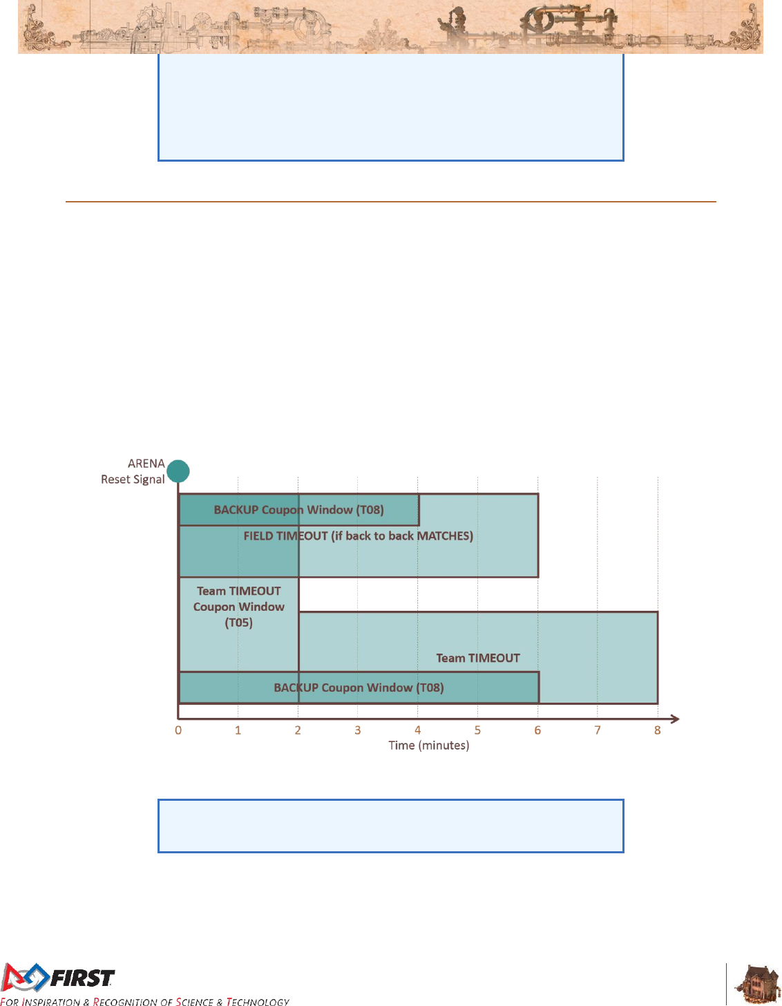
Section 10 Tournaments
V10
118 of 135
B. delay in the playing of an ARENA sound
C. mismatch between the timer on the Audience Screen and the FIELD
Timer
D. any adjustment or delay in assignment of a penalty (including those
made after the MATCH)
10.9 TIMEOUTS and BACKUP TEAMS
A TIMEOUT is a period of up to six (6) minutes between MATCHES which is used to pause Playoff
MATCH progression.
During a TIMEOUT, the ARENA Timer will display the time remaining in the TIMEOUT. Both ALLIANCES
will enjoy the complete six (6) minute window. If an ALLIANCE completes their repairs before the ARENA
Timer expires, the ALLIANCE CAPTAIN is encouraged to inform the Head REFEREE that they are ready
to play. If both ALLIANCES are ready to play before the TIMEOUT expires, the next MATCH will start.
There are no TIMEOUTS in the Practice or Qualification MATCHES.
If circumstances require an ALLIANCE to play in back-to-back MATCHES during the Playoff MATCHES,
the Head REFEREE will issue a FIELD TIMEOUT to allow Teams to prepare for the next MATCH. FIELD
TIMEOUTS are the same time duration as TIMEOUTS.
Figure 10-4: TIMEOUT Timeline
T04. An ALLIANCE may not call more than one (1) TIMEOUT during the Playoff MATCHES.
Teams are expected to have their ROBOTS staged on the FIELD by the
end of the TIMEOUT. Teams that cause a significant delay to the start of
a MATCH after a TIMEOUT are subject to 0.
T05. If an ALLIANCE wishes to call a TIMEOUT, the ALLIANCE CAPTAIN must submit their
TIMEOUT coupon to the Head REFEREE within two (2) minutes of the ARENA reset signal
preceding their MATCH. If there is no preceding MATCH, the TIMEOUT coupon must be
submitted no later than two (2) minutes before the scheduled MATCH time. The TIMEOUT will
Section 10 Tournaments
V10
119 of 135
begin two (2) minutes after the ARENA reset signal (i.e. at the end of the TEAM TIMEOUT
Coupon Window depicted in Figure 10-4)
T06. There are no cascading TIMEOUTS. If an ALLIANCE calls a TIMEOUT during a FIELD
TIMEOUT, the FIELD TIMEOUT will expire two (2) minutes after the ARENA reset signal and the
ALLIANCE’S TIMEOUT will begin.
If an ALLIANCE wishes to call a TIMEOUT during a FIELD TIMEOUT, it
must still do so within two (2) minutes of the ARENA reset signal
preceding their MATCH, per T05.
T07. TIMEOUTS are not transferrable between ALLIANCES.
While TIMEOUTS are not transferrable between ALLIANCES, meaning
an ALLIANCE cannot hand their designated TIMEOUT coupon to
another ALLIANCE to use, an ALLIANCE may use their own coupon for
any purpose they wish.
T08. If during a TIMEOUT an ALLIANCE CAPTAIN determines that they need to call up a BACKUP
TEAM, they must submit their BACKUP TEAM coupon to the Head REFEREE while there are still
at least two (2) minutes remaining on the ARENA Timer. After that point, they will not be allowed
to utilize the BACKUP TEAM.
Alternatively, an ALLIANCE CAPTAIN may choose to call up a BACKUP TEAM without using
their TIMEOUT by informing the Head REFEREE directly within two (2) minutes of the Head
REFEREE issuing the ARENA reset signal preceding their MATCH. If there is no preceding
MATCH, the BACKUP TEAM coupon must be submitted no later than two (2) minutes before the
scheduled MATCH time.
In the case where the ALLIANCE CAPTAIN’S ROBOT is replaced by a BACKUP TEAM, the
ALLIANCE CAPTAIN is allowed as a sixteenth ALLIANCE member.
The Head REFEREE will not accept the BACKUP TEAM coupon unless it lists the number of the
Team whose ROBOT is being replaced, and is initialed by the ALLIANCE CAPTAIN. Once a
BACKUP TEAM coupon is submitted and accepted by the Head REFEREE, the BACKUP TEAM
coupon may not be withdrawn by the ALLIANCE.
T09. An ALLIANCE may request neither a TIMEOUT nor a BACKUP TEAM after a Playoff MATCH is
stopped by the Head REFEREE (e.g. due to an ARENA FAULT or a safety issue). The sole
exception is if the replay is due to an ARENA FAULT that rendered a ROBOT inoperable.
If a Playoff MATCH is replayed per T09, the Head REFEREE has the
option of calling a FIELD TIMEOUT.
10.10 Pit Crews
During the Playoff MATCHES, extra Team members may be needed to maintain the ROBOT between
MATCHES because of the distance between the FIELD and the pit area. Each Team is permitted to have
three (3) additional pit crew members who can also help with needed ROBOT repairs/maintenance
T10. Pit Crew members may not be in the ALLIANCE STATION during a MATCH.
Violation: MATCH will not start until the situation is corrected. Those not displaying identification
must leave the ARENA.

Section 10 Tournaments
V10
120 of 135
10.11 FIRST® Championship Additions and Exceptions
At the 2017 FIRST Championship, Teams are split into six (6) Subdivisions. Each Subdivision plays a
standard Tournament as described in Section 10 Tournaments to produce the Subdivision Champions.
Those six (6) Subdivision Champions proceed to the Championship Playoffs, on the Einstein FIELD, to
determine the 2017 FIRST® Robotics Competition Champions.
There is no provision for BACKUP TEAMS at the Championship.
10.11.1 Four ROBOT ALLIANCES
Before each Subdivision Playoff Tournament, ALLIANCES will be selected per the process as described
in Section 10.5.1 ALLIANCE Selection Process, however the process will continue with a 3rd round of
selection as follows.
Round 3: The same method is used for each ALLIANCE CAPTAIN’S third choice except the selection
order is reversed again, with ALLIANCE One picking first and ALLIANCE Eight picking last. This process
results in eight (8) ALLIANCES of four (4) Teams each.
ALLIANCES may start with any three (3) of the four (4) ROBOTS on their ALLIANCE during Subdivision
Playoff MATCHES and during the Championship Playoffs. The list of three (3) Teams participating in the
MATCH and their selected PLAYER STATIONS is called the LINEUP. One representative from the Team
not on the LINEUP is allowed as a sixteenth ALLIANCE member.
T11. The ALLIANCE CAPTAIN must report the LINEUP to the Head REFEREE, or their designee, in
writing prior to end of the preceding MATCH (e.g. the LINEUPS for Quarterfinal 2 must be
submitted before the end of Quarterfinal 1). If there is no preceding MATCH, the LINEUP is due
no later than two (2) minutes before the scheduled MATCH time.
Violation: The LINEUP is the same as the ALLIANCE’S previous MATCH. If any of these three (3)
ROBOTS are unable to play, the ALLIANCE must play the MATCH with only two (2) (or even one
(1)) ROBOTS
If an ALLIANCE fails to submit a LINEUP per the process defined in T11
and the MATCH is their first of the Subdivision Playoffs or the
Championship Playoffs, the LINEUP will be the ALLIANCE Lead, first
ALLIANCE selection, and second ALLIANCE selection. If any of these
three (3) ROBOTS are unable to play, the ALLIANCE must play the
MATCH with only two (2) (or even one (1)) ROBOTS.
The LINEUP will be kept confidential until the FIELD is set for the MATCH, at which point each
ALLIANCE’S LINEUP will appear on the Team Signs.
T12. Once the LINEUP has been declared, it cannot be changed unless there is a TIMEOUT. If there
is a TIMEOUT, the ALLIANCE CAPTAIN may submit a different LINEUP, but must do so while
there are still more than two (2) minutes remaining in the TIMEOUT.
Example: Four (4) Teams, A, B, C and D, form an ALLIANCE going into
the Playoff MATCHES on their Subdivision FIELD. During one of the
Playoff MATCHES, Team C’s ROBOT becomes inoperable. The
ALLIANCE decides to bring in Team D to replace Team C. Team C
repairs their ROBOT and may play in any subsequent Playoff MATCHES
replacing Teams A, B, or D. All four (4) ALLIANCE members are also
eligible to play MATCHES during the Championship Playoffs should the
ALLIANCE win the Subdivision Tournament.
Section 10 Tournaments
V10
121 of 135
T13. If a MATCH must be replayed due to an ARENA FAULT, the LINEUP for the replayed MATCH is
the same as the original MATCH. The sole exception is if the ARENA FAULT rendered a ROBOT
inoperable, in which case the LINEUP can be changed.
10.11.2 FIRST Championship Pit Crews
FIRST will distribute badges to the ALLIANCE CAPTAINS during the ALLIANCE CAPTAIN meeting,
which takes place on the Subdivision FIELDS. These badges will provide the necessary access to the
ARENA for pit crew members.
T14. Only Team members wearing proper badges are allowed on the ARENA floor during Subdivision
and Championship Playoff MATCHES
Violation: MATCH will not start until the situation is corrected. Those not displaying identification
must leave the ARENA.
Teams should assume they may be chosen for an ALLIANCE and think
about the logistics of badge distribution and set a plan prior to the
ALLIANCE selection process. It is each ALLIANCE CAPTAIN’S
responsibility to get the Team’s badges to the pit crew members.
10.11.3 FIRST Championship Playoffs
The six (6) Subdivision Champions play a round-robin style tournament to determine the 2017 FIRST
Robotics Competition Champions. In this format, each Subdivision Champion plays one MATCH against
each of the other Subdivision Champions. The order of MATCHES is shown in Table 10-5.
Table 10-5: Championship MATCH order
T15. In the Championship Playoffs, ALLIANCES do not earn Ranking Points; they earn Championship
Points. Championship Points are units credited to an ALLIANCE based on their performance in
each MATCH and are awarded at the completion of each Round Robin tournament MATCH.
MATCH
Houston
St. Louis
Round 1
1
Carver v Turing
Archimedes v. Tesla
2
Galileo v Roebling
Carson v. Darwin
3
Hopper v Newton
Curie v. Daly
Round 2
4
Carver v Roebling
Archimedes v. Darwin
5
Turing v Newton
Tesla v Daly
6
Galileo v Hopper
Carson v Curie
Round 3
7
Carver v Newton
Archimedes v. Daly
8
Roebling v Hopper
Darwin v Curie
9
Turing v Galileo
Tesla v. Carson
Round 4
10
Carver v Hopper
Archimedes v. Curie
11
Newton v Galileo
Daly v. Carson
12
Roebling v Turing
Darwin v. Tesla
Round 5
13
Carver v Galileo
Archimedes v Carson
14
Hopper v Turing
Curie v Tesla
15
Newton v Roebling
Daly v. Darwin
Section 10 Tournaments
V10
122 of 135
A. The winning ALLIANCE receives two (2) Championship Points
B. The losing ALLIANCE receives zero (0) Championship Points
C. In the event of a tied score, each ALLIANCE receives one (1) Championship Point
Exceptions to A-C are as follows:
D. A DISQUALIFIED Team, as determined by the Head REFEREE, causes their
ALLIANCE to receive zero (0) Championship points.
The total number of Championship Points earned by a Team throughout the round robin MATCHES
divided by the number of round robin Matches in which they’ve been scheduled is their Championship
Score (CS).
All Teams participating in round robin Matches are ranked by Championship Score. If the number of
Teams in attendance is ‘n’, they are ranked ‘1’ through ‘n’, with ‘1’ being the highest ranked Team and
‘n’ being the lowest ranked Team.
Table 10-6: Einstein Tournament Ranking Criteria
Order Sort
Criteria
1st
Championship Score
2nd
Cumulative sum of MATCH points
3rd
Cumulative sum of ROTOR and pressure bonuses
4th
Cumulative sum of AUTO points
5th
Cumulative ROTOR engagement score (AUTO and TELEOP)
6th
Cumulative TOUCHPAD score
7th
If tie affects which ALLIANCES advance to Playoffs, a tiebreaker
MATCH is played between the affected ALLIANCES.
If tie is between ALLIANCES advancing to Playoffs, FMS randomly
seeds tied alliances to determine ALLIANCE color.
The two ALLIANCES with the highest Championship Scores at the conclusion of the round robin
tournament advance to the Einstein Finals. In the Einstein Finals, ALLIANCES do not earn points, they
earn a Win, Loss or Tie. The first ALLIANCE to win two (2) MATCHES is declared the 2017 FIRST
Robotics Competition Champions.
T16. During the Einstein Finals, if the MATCH score of each ALLIANCE is equal, the MATCH is
replayed.
10.11.4 FIRST Championship TIMEOUTS
There are no TIMEOUTS for teams in the Einstein tournament.
T17. Deleted.
10.12 Advancement Between Tournaments
Teams advance through the season depending on the events at which they compete: Regional or District.
This section details how teams advance from Regional events to the FIRST Championship, or from
District qualifying events, to their District Championship, to the FIRST Championship.
T18. A team is considered to have already earned a FIRST Championship invitation prior to the
District, Regional, or District Championship if they are:
A. pre-qualified or

Section 10 Tournaments
V10
123 of 135
A FIRST® Robotics Competition Team listed in the Championship
Eligibility Criteria document is pre-qualified for the FIRST Championship
if the Team meets one of the following criteria:
A. member of the FIRST® Hall of Fame
B. an original and sustaining team since 1992
C. a 2016 FIRST Championship winner
D. a 2016 FIRST Championship Engineering Inspiration Award winner
B. met the criteria outlined in T19 at a prior event.
10.12.1 Regional Events
T19. A Team competing at a Regional Event qualifies for the FIRST Championship by meeting one of
the following criteria:
A. Winning a qualifying award:
Regional Chairman’s Award
Engineering Inspiration Award
Rookie All-Star Award
B. A member of the Winning ALLIANCE
C. Earning a Wild Card
10.12.2 Wild Cards
Wild cards are used to qualify additional teams for the FIRST Championship from Regional events.
T20. All Regional events have a minimum of one (1) Wild Card slot. Additional Wild Cards are
generated as follows:
A. Any team competing at a Regional event that has already qualified for the FIRST
Championship prior to the Regional, per T18, and earns an additional spot, per T19,
generates one (1) Wild Card.
B. Any team earning two (2) qualifying spots at a single Regional per T19 (e.g. by being
on the Winning Alliance and earning the Chairman’s Award) generates one (1) Wild
Card.
C. A team who has already earned a spot at FIRST Championship prior to their current
Regional, per T18, and earns two qualifying spots, per T19, will generate two Wild
Card slots.
Wild Card slots are distributed to the Finalist ALLIANCE, in the order of team selection per
Section 10.5.1 ALLIANCE Selection Process, until either all Wild Card slots generated at that
event are distributed or the Finalist ALLIANCE is out of teams, whichever comes first.
T21. If a member of the Finalist ALLIANCE has already qualified for the FIRST Championship, per
T18, they are skipped and the next member of the ALLIANCE is awarded the available Wild Card.
T22. Unused Wild Card slots will not be backfilled or replaced.
A Team may decline a Wild Card, but this does not pass the Wild Card
slot down to the next available Team. The Wild Card goes unused.
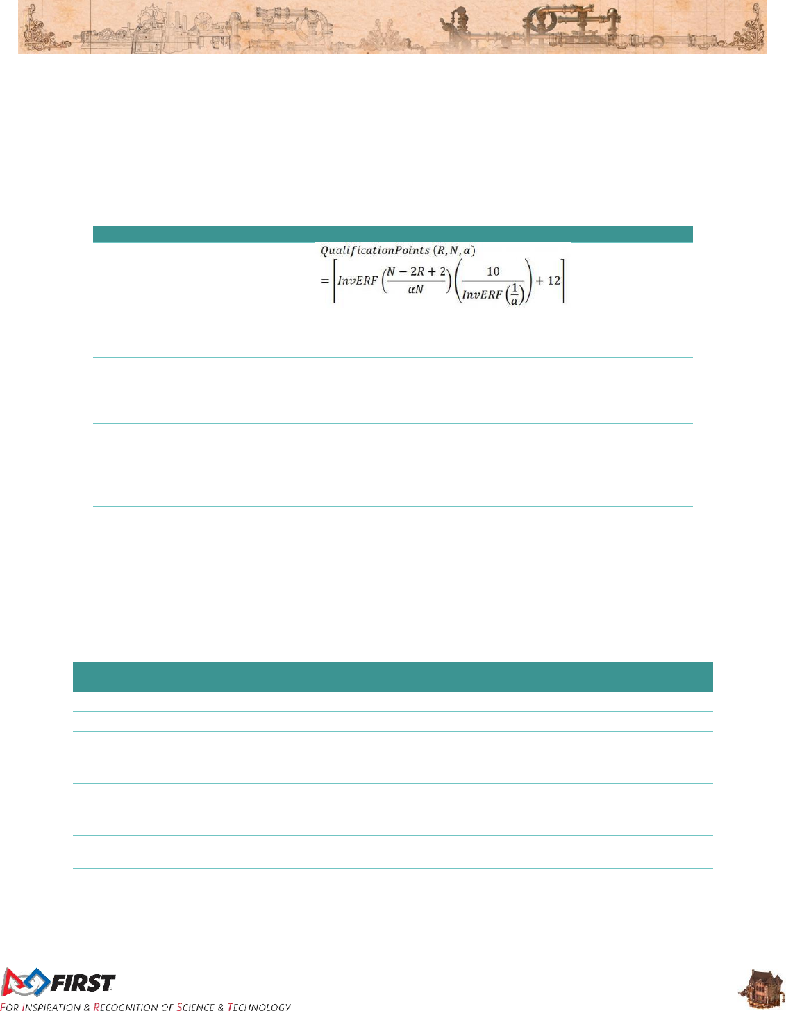
Section 10 Tournaments
V10
124 of 135
T23. Teams selected from the FIRST Championship Waitlist to participate at the FIRST Championship
do not generate Wild Cards.
10.12.3 District Events
District teams are ranked throughout the season based on the points they earn at their first two home
District events they attend, as well as at their District Championship. Points are awarded to teams as
follows:
Table 10-7: District point assignment
Category
Points
Qualification
Round
Performance
(For a typically sized District event, this will result in a minimum of four (4)
points being awards for Qualification round performance. For events of all
sizes, a maximum of twenty-two (22) points will be awarded.)
ALLIANCE
CAPTAINS
Equal to 17 minus the ALLIANCE CAPTAIN number
(e.g. 14 points for ALLIANCE #3 Captain)
Draft Order
Acceptance
Equal to 17 minus the Draft Order Acceptance Number
(e.g. 12 points for the Team that is 5th to accept an invitation)
Playoff
Advancement
Points awarded based on team participation in individual playoff rounds, and
whether or not the ALLIANCE advances. See details below.
Judged Team
Awards
10 points for Chairman’s Award
8 points each for Engineering Inspiration and Rookie All Star Awards
5 points each for all other judged Team awards
Team Age
10 points for Rookie Teams
5 points for second-year Teams
Points earned at District Championships are multiplied by three (3) and then added to points earned at
District events, to determine the final season point total for the Team
If there is a tie in the season point total between teams, those items are broken using the following sorting
criteria: Table 10-8: District Team sort criteria
Order Sort
Criteria
1st
Total Playoff Round Performance Points
2nd
Best Playoff Round Finish at a single event
3rd
Total ALLIANCE Selection Results Points
4th
Highest Qualification Round Seed or Draft Order Acceptance (i.e. Highest ALLIANCE
Selection points at a single event)
5th
Total Qualification Round Performance Points
6th
Highest Individual MATCH Score, regardless of whether that score occurred in a
Qualification or Playoff MATCH
7th
Second Highest Individual MATCH Score, regardless of whether that score occurred in
a Qualification or Playoff MATCH
8th
Third Highest Individual MATCH Score, regardless of whether that score occurred in a
Qualification or Playoff MATCH
9th
Random Selection
Qualification Round Performance

Section 10 Tournaments
V10
125 of 135
The calculation of Qualification performance points is done using the equation (an inverse error function)
in the table above. The equation utilizes the following variables:
R – the qualification rank of the team at the event at the conclusion of Qualification
MATCHES (as reported by FMS)
N – the number of FIRST Robotics Competition teams participating in the Qualification
rounds at the event
Alpha (α) – a static value (1.07) used to standardize the distribution of points at events
This formula generates an approximately normal distribution of Qualification Round Performance points at
an event, based on rank, with most teams getting a moderate number of points, and fewer teams getting
the highest or lowest numbers of points available.
Table 10-9 displays sample Qualification Round Performance points for variously ranked teams at a forty
(40) team event. The system will automatically generate the appropriate points for each team based on
their rank and the number of teams at the event.
Table 10-9 Sample Qualification Round Point assignments
Rank
1
2
3
4
…
19
20
21
…
37
38
39
40
Points
22
21
20
19
…
13
13
12
…
6
6
5
4
10.12.3.1 ALLIANCE Selection Results
This attribute measures both individual Team qualification round seeding performance and recognition by
peers.
ALLIANCE CAPTAINS are recognized based on their qualification round seeding rank. This rank is a
result of the rules of the game, which typically incorporate several team performance attributes, and are
designed to eliminate ties in rank. Non-ALLIANCE CAPTAINS are rewarded based on peer recognition.
To be invited to join an ALLIANCE, a Team’s peers have decided that the Team has attributes that are
desirable. Giving points for ALLIANCE selection also supports come-from-behind Teams. A Team taking
several MATCHES to optimize their performance may be recognized as a late bloomer by a top seeded
Team, even if that performance isn’t reflected in the rankings because of poor performance in early
MATCHES. These points also have the potential to recognize Teams employing a minority strategy with
their ROBOT. Teams with unique or divergent ROBOT capabilities that complement the strengths of other
ALLIANCE members may be selected to fill a strategic niche.
Note also that ALLIANCE CAPTAINS are given the same number of points as the Team drafted in the
same sequence. For example, the third ALLIANCE CAPTAIN gets the same number of points as the third
draft. Numerical analysis supports the idea that ALLIANCE CAPTAINS are about as strong in ROBOT
performance as equivalently drafted Teams. As an additional minor benefit, awarding the same points for
ALLIANCE CAPTAINS and equivalent drafts lubricates the acceptance of draft offers between ALLIANCE
CAPTAINS, which gives Teams out of the top eight the chance to experience being ALLIANCE
CAPTAINS themselves.
10.12.3.2 Playoff Round Performance
This attribute measures Team performance as part of an ALLIANCE.
All Teams on the ALLIANCE winning a particular playoff series, who participate in MATCHES with their
ROBOTS, receive five (5) points per MATCH won. In most cases, Teams receive ten (10) points at each
of the Quarterfinal, Semifinal, and Final levels, unless a BACKUP ROBOT is called in to play.
10.12.3.3 Awards
This attribute measures Team performance with respect to Team awards judged at the event.

Section 10 Tournaments
V10
126 of 135
The points earned for Team awards in this system are not intended to capture the full value of the award
to the Team winning the award, or to represent the full value of the award to FIRST. In many ways, the
Team’s experience in being selected for awards, especially the Chairman’s Award, the Engineering
Inspiration Award, and the Rookie All Star Award, is beyond measure, and could not be fully captured in
its entirety by any points-based system. Points are being assigned to awards in this system only to help
Teams recognize that FIRST® continues to be “More than Robots®,” with the emphasis on our cultural
awards, and to assist in elevating award-winning Teams above non-award winning Teams in the ranking
system.
Teams only get points for Team awards judged at the event. If an award is not judged, e.g. Rookie
Highest Seed, is not for a Team, e.g. the Dean’s List Award, or is not judged at the event, e.g. Safety
Animation Award, sponsored by UL, no points are earned.
10.12.3.4 Team Age
This attribute recognizes the difficulty in being a Rookie or second-year Team.
Points are awarded to Rookie and second year Teams in recognition of the unique challenges Teams
face in those early years, and to increase the chance that they will make it to the District Championship to
compete with their ROBOTS. Like our dedicated Rookie awards, these additional points are intended to
recognize and motivate newer participants in FIRST® Robotics Competition. These points are awarded
once at the beginning of the season. Rookie year is calculated based on the year in which FIRST
recognizes the Team as a Rookie.
10.12.3.5 Regional Participation
District Teams do not earn points for their actions at any Regionals they may attend, nor are eligible for
FIRST Championship qualifying judged awards at those events. However, if a District Team does earn a
slot at the FIRST Championship while attending a Regional event, that slot does count as part of the total
Championship allocation the District is receiving for the season.
10.12.3.6 District Championship Eligibility
T24. A Team competing in a District qualifies for their District Championship by meeting one of the
following criteria:
A. District Chairman’s Award winner
B. District Ranking; based on total points earned at their first two home District events
as detailed in Section 10.12.3 District Events.
Teams do not earn points at third or subsequent District events, nor at
any inter-district or Regional events at which they compete during the
2017 season.
If a team declines an invitation to the District Championship, the next
highest uninvited team on the list is invited, and so on, until the event
capacity is filled.
C. District Engineering Inspiration winner (qualifies to compete for the award only)
D. District Rookie All Star winner (qualifies to compete for the award only)
The capacity of each District Championship is shown in Table 10-10. Each District determines the number
of teams which qualify for their District Championship. These limits are based on factors including but not
limited to the total number of teams in the District, available venue capacity, etc.

Section 10 Tournaments
V10
127 of 135
Table 10-10: 2017 District Championship Capacities
District Championship
2017 Team Capacity
Chesapeake District Championship
58
Indiana State Championship
32
Israel
45
Michigan State Championship
160
Mid-Atlantic Robotics District Championship
60
New England District Championship
64
FIRST North Carolina State Championship
32
FIRST Ontario Provincial Championship
60
Pacific Northwest District Championship
64
Peachtree District State Championship
45
10.12.3.7 FIRST® Championship Eligibility for District Teams
Districts receive the percentage of 'available slots' at their assigned FIRST Championship location,
rounded up to the nearest whole slot, equal to the percentage of teams they have in their District
compared to the total of all FIRST Robotics Competition teams in the current season who would normally
be assigned to their FIRST Championship location. 'Available slots' are calculated by taking the total
number of slots at each FIRST Championship location, subtracting the number of pre-qualified teams
assigned to that location, and also subtracting a 10% allowance for waitlisted teams, as Districts are still
allowed to send waitlisted teams to the FIRST Championship. Further, this overall calculation uses a
‘snapshot’ of teams that have registered and paid as of a specific day a week or so after season payment
due.
These slots are guaranteed to the Districts and populated with the following teams:
qualifying award winners from the District Championship (Chairman’s Award, Engineering
Award, and Rookie All Star winners),
teams on the Winning Alliance from the District Championship (including any Back-Up teams
participating),
qualifying award winners among district teams who traveled to Regionals,
teams on the final District ranking list, as deep in the ranking list as the District needs to go to
fill their allocation.
If a District team earns a slot to the FIRST Championship within the season, but is not able to attend, the
top ranked team who has not yet been offered a slot is given the opportunity, and so on, until all slots are
filled. Slots for pre-qualified teams will not be backfilled.
Districts determine the number of Dean’s List, Chairman’s, Rookie All Star, and Engineering Inspiration
Awards to present at their Championship, within a range established by FIRST and shown in Table 10-11.

Section 10 Tournaments
V10
128 of 135
Table 10-11: District slot allocations for FIRST Championship
Chairman’s
Award
Dean’s List
Award
Engineering
Inspiration
Award
Rookie All
Star Award
FIRST Championship
Slots
FIRST Championship
Normalized Slots
Max Ratio
Min Ratio
District Selection
Max Ratio
Min Ratio
District Selection
Min
Max
District Selection
Min
Max
District Selection
18
9
9
6
FIRST Championship St. Louis
FIRST Chesapeake
23
1
3
2
3
4
4
1
2
2
1
2
1
FIRST in Michigan
82
5
9
5
9
14
14
1
2
1
1
2
2
Indiana FIRST
10
1
1
1
2
2
2
1
2
1
1
2
1
Mid-Atlantic Robotics
22
1
2
2
2
4
4
1
2
2
1
2
1
New England
37
2
4
4
4
6
6
1
2
2
1
2
2
Ontario
29
2
3
3
3
5
5
1
2
1
1
2
1
FIRST Championship Houston
FIRST Israel
16
13
1
1
1
2
2
2
1
2
2
1
2
1
FIRST North Carolina
15
12
1
1
1
2
2
2
1
2
2
1
2
1
Pacific Northwest
39
32
2
4
3
4
5
5
1
2
2
1
2
2
Peachtree
18
15
1
2
1
2
3
3
1
2
2
1
2
1
All Districts, regardless of Championship Slot allocation, may award one (1) or two (2) Engineering
Inspiration and Rookie All-Star Awards.
Chairman’s Award and Dean’s List Award maximums and minimums are determined by ratios applied to
a given District’s Championship Slot allocations. However, Districts assigned to Houston have relatively
larger Championship slot allocations for a given team count compared to Districts assigned to St Louis,
and we did not want these larger allocations to skew award allocations. So, for the purposes of award
allocations only, Championship slots for Houston Districts were ‘normalized’, as shown in the table,
reducing the slots allocated to what they would have been if both Championship geographies had the
same total number of FIRST Robotics Competition teams. This ‘normalized’ slot allocation was then used
to determine award minimums and maximums. As noted, these normalized slot values are used only for
award allocations. The Houston-assigned Districts still retain the full Championship Slots Allocated (the
larger number) shown in the table.
10.13 Festival of Champions Additions & Exceptions
At the 2017 Festival of Champions, ALLIANCES representing FIRST Championship Houston and FIRST
Championship St. Louis will meet in competition.
The ALLIANCE first winning three (3) MATCHES will be declared the winner of the event. If the MATCH
score of each ALLIANCE is equal in any given MATCH, the MATCH is replayed.
ALLIANCES for the 2017 Festival of Champions will consist of the winning ALLIANCE at FIRST
Championship Houston and the winning ALLIANCE at FIRST Championship St. Louis (all four (4) TEAMS
from each).

Section 10 Tournaments
V10
129 of 135
Should a team from a winning ALLIANCE at a FIRST Championship location not be able to attend the
2017 Festival of Champions, the ALLIANCE CAPTAIN of that ALLIANCE may invite a team per Figure
10-5.
Figure 10-5 : Festival of Champions Backfill Process
All relevant rules under Section 10.11.1 Four ROBOT ALLIANCES, four-ROBOT ALLIANCES, will
continue to be followed at the 2017 Festival of Champions.
As a practical matter, we will not be able to inspect for every modification TEAMS may have made to their
ROBOTS after their participation on Einstein. However, the intent of these rules is to help make sure the
ROBOTS that participate in the Festival of Champions are reasonably similar to the ROBOTS that
participated in Einstein, with allowances for improvements in software. As with many FIRST Robotics
Competition rules, we are relying on our TEAMS’ Gracious Professionalism in making the Festival of
Champions a fun and fair competition.
Who can't
make it?
Captain
•1st Pick becomes ALLIANCE CAPTAIN, then
•ALLIANCE CAPTAIN can invite any Team from the Finalist ALLIANCE. If each Finalist Team
declines, then
•ALLIANCE CAPTAIN can invite any Team from the 3rd place ALLIANCE. If each 3rd place ALLIANCE
Team declines, repeat with 4th, 5th, and 6th ALLIANCES as needed. If no Teams accept the invite,
then
•ALLIANCE plays without backfilling the Captain.
1st Pick
•ALLIANCE CAPTAIN can invite any Team from the Finalist ALLIANCE. If each Finalist Team
declines, then
•ALLIANCE CAPTAIN can invite any Team from the 3rd place ALLIANCE. If each 3rd place ALLIANCE
Team declines, repeat with 4th, 5th, and 6th ALLIANCES as needed. If no Teams accept the invite,
then
•ALLIANCE plays without backfilling the 1st Pick.
2nd Pick
•ALLIANCE CAPTAIN can invite the 2nd or 3rd Pick from the Finalist ALLIANCE. If each Finalist Team
declines, then
•ALLIANCE CAPTAIN can invite the 2nd or 3rd pick from the 3rd place ALLIANCE. If both 3rd place
ALLIANCE Teams decline, repeat with 4th, 5th, and 6th ALLIANCES as needed. If no Teams accept
the invite, then
•ALLIANCE plays without backfilling the 2nd Pick.
3rd Pick
•ALLIANCE CAPTAIN can invite the 3rd Pick from the Finalist ALLIANCE. If they decline, then
•ALLIANCE CAPTAIN can invite the 3rd pick from the 3rd place ALLIANCE. If they decline, repeat
with 4th, 5th, and 6th ALLIANCES as needed. If no Teams accept the invite, then
•ALLIANCE plays without backfilling the 3rd Pick.
Section 10 Tournaments
V10
130 of 135
All rules in Section 9 Inspection & Eligibility Rules apply, except there is no ‘bagging’ requirement for the
ROBOTS used in competition at the Festival of Champions. Additionally, the following rules apply:
T25. TEAMS must compete in each MATCH with the same ROBOT they competed with at FIRST
Championship, as configured for their ALLIANCE’S final MATCH. In other words, TEAMS may
not add mechanical or sensor functionality to their ROBOTS for or during the Festival of
Champions, including, but not limited to:
E. New functionality
F. Redesigned/enhanced mechanisms
G. New sensors
T25 does not prohibit changes to or additions of software, the OPERATOR CONSOLE, or non-
functional decorations. It also does not restrict any activities including off-season event
participation, outreach, demonstrations, or practice.
TEAMS may make any necessary repairs to their ROBOTS. This
includes the repair or replacement of damaged or non-functioning parts.
Teams may modify their ROBOT in any way they wish for non-Festival of
Champions activities, but any changes not compliant with this section
must be undone prior to participation in the Festival.
TEAMS may collaborate on the allowed activities above with any other
TEAMS or resources they choose.
T26. ROBOTS used at the Festival of Champions must remain compliant with all ROBOT rules except
R17.
Teams participating in the Festival of Champions that have any
questions on these rules should email frcteamadvocate@firstinspires.org
If you are unsure whether or not an action you are considering with your
Einstein ROBOT is legal, please ask.

Section 11 Glossary
V4
131 of 135
11 Glossary
Term
Definition
AIRSHIP
a structure that features an elevated hexagonal deck, slanted walls, rails with
AXLES to mount GEARS, four (4) ROTORS, three (3) LIFTS, a STEAM TANK,
and three (3) ROPES attached to DAVITS
ALLIANCE
a cooperative of up to four (4) FIRST® Robotics Competition Teams
ALLIANCE
CAPTAIN
The designated student representative from each ALLIANCE in a Playoff
MATCH
ALLIANCE
STATION
an 8 ft. 9¾ in. (~269 cm) by 23 ft. 1½ in. (~705 cm) infinitely tall volume
bounded by the ALLIANCE WALL and ALLIANCE colored tape
ALLIANCE WALL
the physical structure that separates ROBOTS from DRIVE TEAMS (except the
PILOT) and consists of a BOILER, three (3) PLAYER STATIONS, an Overflow
LOADING STATION and a Return LOADING STATION.
ARENA
all elements and areas of the game infrastructure that are required to play
FIRST STEAMWORKSSM: the FIELD, AIRSHIPS, carpet, scoring elements,
and all equipment and areas needed for FIELD control, ROBOT control, and
scorekeeping
ARENA FAULT
an error in ARENA operation that includes, but aren’t limited to those listed in
Section 10.8 MATCH Replays.
AUTO
the first fifteen (15) seconds of a MATCH in which ROBOTS operate without
any DRIVE TEAM control or input
AXLE
a ⅞-in. diameter (~2 cm), 2-in. (~5 cm) long shaft which fits the central hub of a
GEAR. AXLES are installed on the RAIL of the AIRSHIP.
BACKUP TEAM
The Team whose ROBOT and DRIVE TEAM replaces another ROBOT and
DRIVE TEAM on an ALLIANCE during the Playoff MATCHES
BANNER
a Team’s flag to be displayed on their PLAYER STATION during MATCHES
(see specifications here)
BASE LINE
a green line that spans the width of the FIELD and is 7 ft. 9¼ in. (~237 cm) from
the ALLIANCE WALL diamond plate
BOILER
a FIELD element which converts FUEL to steam. There is a BOILER on each
corner of the FIELD opposite the scoring table. The base of each BOILER is 3
ft. 6 in. wide (~107 cm) by 3 ft. 6 in. (~107 cm) deep by 8 ft. 1 in. (~246 cm) tall.
There are two (2) openings, or GOALS, for loading FUEL into the BOILER: the
High Efficiency GOAL and the Low Efficiency
BUMPER
a required assembly which attaches to the ROBOT frame. BUMPERS are
important because they protect ROBOTS from damaging/being damaged by
other ROBOTS and FIELD elements
BUMPER ZONE
the volume contained between the floor and a virtual horizontal plane 7 in. (~17
cm) above the floor in reference to the ROBOT standing normally on a flat floor
BYPASSED
any ROBOT which is unable or ineligible to participate in that MATCH as
determined by the FTA, LRI, or Head REFEREE resulting in a ROBOT which is
disabled)
COACH
a precollege student or adult mentor member of the DRIVE TEAM responsible
for acting as a guide or advisor
COMPONENT
any part in its most basic configuration, which cannot be disassembled without
damaging or destroying the part or altering its fundamental function

Section 11 Glossary
V4
132 of 135
Term
Definition
COTS
a standard (i.e. not custom order) part commonly available from a VENDOR for
all Teams for purchase. To be a COTS item, the COMPONENT or
MECHANISM must be in an unaltered, unmodified state (with the exception of
installation or modification of any software).
CRANK
a handle located with the first GEAR in the set
CUSTOM CIRCUIT
any electrical component of the robot other than motors, pneumatic solenoids,
roboRIO, PDP, PCM, VRM, RSL, 120A breaker, motor controllers, relay
modules (per R34-B), wireless bridge, or batteries.
DAVIT
one of three steel frames that attaches a ROPE to the AIRSHIP
DISABLED
a state in which a ROBOT is commanded to deactivate all outputs, rendering
the ROBOT inoperable for the remainder of the MATCH
DISQUALIFIED
the status of a Team, as determined by the Head REFEREE, in which their
Team receives zero (0) Match points in a qualification MATCH or causes their
ALLIANCE to receive zero (0) Match points in a Playoff MATCH
DRIVER
a precollege student member of the DRIVE TEAM responsible for operating
and controlling the ROBOT
DRIVE TEAM
a set of up to five (5) people from the same FIRST Robotics Competition Team
responsible for Team performance during a MATCH
FABRICATED ITEM
any COMPONENT or MECHANISM that has been altered, built, cast,
constructed, concocted, created, cut, heat treated, machined, manufactured,
modified, painted, produced, surface coated, or conjured partially or completely
into the final form in which it will be used on the ROBOT
FIELD
a 27 ft. by 54 ft. 4 in. (~823 cm by ~1656 cm) area, bounded by and including
the upward- and inward-facing surfaces of the GUARDRAILS and ALLIANCE
WALLS
FIELD STAFF
REFEREES, FTAs, or other staff working around the FIELD
FMS
the Field Management System (FMS)
FOUL
a penalty assessed by a REFEREE upon a rule violation resulting in 5 points
credited towards the opponent’s total score
FRAME
PERIMETER
the polygon contained within the BUMPER ZONE, that is comprised of fixed,
non-articulated structural elements of the ROBOT
FTA
a FIRST Technical Advisor
FUEL
a GAME PIECE used to generate steam for the AIRSHIP and is represented by
“Screamin’ Yellow,” 5 in. (nominal) diameter Gopher ResisDent™ polyethylene
balls
GAME PIECE
GEAR or FUEL
GEAR
a GAME PIECE that is a toothed wheel used to start ROTORS on the AIRSHIP.
Each GEAR is made from gold (Pantone PMC 124C) polypropylene, has 10
teeth, an 11 in. (~28 cm) diameter, 10 in. (~25 cm) pitch diameter, and is 2 in.
(~5 cm) thick
GOAL
an opening for loading FUEL into the BOILER
GUARDRAIL
a system that consists of transparent polycarbonate supported on the top and
bottom by aluminum extrusion. The GUARDRAIL prevents ROBOTS from
inadvertently exiting the FIELD during a MATCH.
HOPPER
a pair of containers located just outside the FIELD and used to store FUEL at
the start of the MATCH
HUMAN PLAYER
a pre-college student DRIVE TEAM member responsible for managing GAME
PIECES
KEY
an infinitely tall volume in the ALLIANCE’S LAUNCHPAD bounded by the
ALLIANCE WALL, GUARDRAIL, and ALLIANCE colored tape
KOP
Kit of Parts, the collection of items listed on any Kickoff Kit Checklists,
distributed via FIRST® Choice, or paid for completely, except shipping, with a
Product Donation Voucher (PDV).

Section 11 Glossary
V4
133 of 135
Term
Definition
LAUNCHING
shooting in the air, kicking or rolling across the floor with an active mechanism,
or throwing in a forceful way
LAUNCHPAD
an infinitely tall volume in the FIELD bounded by the GUARDRAILS, the
ALLIANCE WALL, and the LAUNCHPAD LINE. The volume above the
LAUNCHPAD LINE is part of the LAUNCHPAD.
LAUNCHPAD LINE
a tape line that is the width of the FIELD and collinear with the edge of the
AIRSHIP deck that is closest to the center of the FIELD
LIFT
an assembly used to transfer GEARS from the ROBOTS to the PILOTS
LINEUP
The list of three (3) Teams participating in the MATCH and their selected
PLAYER STATIONS
LOADING LANE
an area bounded by and including ALLIANCE colored tape, edge of the carpet,
the RETURN BIN Table, and the opponent’s ALLIANCE WALL
LOADING STATION
an assembly used to feed FUEL and GEARS on to the FIELD. Each Return
LOADING STATION includes a 6 ft. 6 in. (~198 cm) in. tall and 6 ft. 3½ in.
(~192 cm) wide polycarbonate panel with two (2) openings, aluminum frame.
RETRIEVAL ZONE
an infinitely tall volume inside the FIELD bounded by the ALLIANCE WALL,
GUARDRAIL and ALLIANCE colored tape. The RETRIEVAL ZONE includes
the volume above the tape.
MATCH
a two (2) minute and thirty (30) second period of time in which ALLIANCES play
FIRST STEAMWORKS
MECHANISM
a COTS or custom assembly of COMPONENTS that provide specific
functionality on the ROBOT. A MECHANISM can be disassembled (and then
reassembled) into individual COMPONENTS without damage to the parts
MXP
MyRIO eXpansion Port, the expansion port on the roboRIO
NEUTRAL ZONE
an infinitely tall volume on the FIELD bounded by the GUARDRAILS and the
LAUNCHPAD LINES. The volume above the LAUNCHPAD LINES is not part of
the NEUTRAL ZONE
OPERATOR
CONSOLE
the set of COMPONENTS and MECHANISMS used by the DRIVERS and/or
HUMAN PLAYER to relay commands to the ROBOT
OVERFLOW BIN
one of the plastic open-topped containers, 2 ft. 9½ in. (~85 cm) wide by 1 ft. 6
in. (~46 cm) deep by 1 ft. 1 in. (~33 cm) tall, and each has a capacity of
approximately fifty to sixty (50-60) FUEL
PASSIVE
CONDUCTORS
any device or circuit whose capability is limited to the conduction and/or static
regulation of the electrical energy applied to it (e.g. wire, splices, connectors,
printed wiring board, etc.)
PCM
Pneumatic Control Module
PDP
Power Distribution Panel
PILOT
a pre-college student DRIVE TEAM member responsible for installing GEARS,
starting ROTORS, and deploying ROPES
PLAYER STATION
one (1) of three (3) assigned positions in an ALLIANCE WALL from where a
DRIVE TEAM operates their ROBOT
PORT
a 13 in. (~33 cm) wide by 19½ in. (~50 cm) hole next to each LIFT cut in each
of the three walls facing the ALLIANCE WALL
RED CARD
a penalty assessed for egregious ROBOT or Team member behavior, or rule
violations, which results in a Team being DISQUALIFIED for the MATCH
REFEREE
an official who is certified by FIRST to enforce the rules of FIRST
STEAMWORKS
RETURN BIN
one of the plastic open-topped containers, 2 ft. 9½ in. (~85 cm) wide by 1 ft. 6
in. (~46 cm) deep by 1 ft. 1 in. (~33 cm) tall, and each has a capacity of
approximately fifty to sixty (50-60) FUEL

Section 11 Glossary
V4
134 of 135
Term
Definition
ROBOT
an electromechanical assembly built by the FIRST® Robotics Competition
Team to perform specific tasks when competing in FIRST®
STEAMWORKSSM. The ROBOT must include all of the basic systems required
to be an active participant in the game – power, communications, control,
BUMPERS, and movement. The ROBOT implementation must obviously follow
a design approach intended to play FIRST STEAMWORKS
ROPE
a strong, thick string composed of twisted or braided strands of manila, hemp,
flax, or the like, secured to the airship, and used to secure robots for flight at the
end of the match
ROTOR
one of four (4) rotating airfoils
RP
Ranking Point, a unit credited to a Team based on their ALLIANCE’S
performance in Qualification MATCHES
RS
Ranking Score, the total number of Ranking Points earned by a Team
throughout their Qualification MATCHES divided by the number of MATCHES
they’ve been scheduled to play (minus any SURROGATE MATCH), then
truncated to two (2) decimal places
STARTING
CONFIGURATION
the physical configuration and orientation of the ROBOT at the beginning of the
MATCH where no part of the ROBOT shall extend outside the vertical
projection of the FRAME PERIMETER, with the exception of its BUMPERS and
minor protrusions such as bolt heads, fastener ends, rivets, etc.
STARTING LINE
a white tape line that runs the width of the carpet and is 2 ft. 6 in. (~76 cm)
behind the ALLIANCE WALL diamond plate
STEAMACRIT
one who complains about non-working gears being used while coating a Nerf
gun with paint and calling it a raygun. (courtesy “TimeTinker” on The
Steampunk Forum at Brass Goggles)
STEAM PIPE
a clear PVC pipe that transfers steam from the BOILER to the STEAM TANK
on the AIRSHIP
STEAM TANK
a 6-ft. (~183 cm) tall hexagonal container with a diagonal dimension of 2 ft.
(~61 cm) centrally mounted on the deck. It is “filled” via a STEAM PIPE that
originates at the BOILERS.
SURROGATE
a Team randomly assigned by the FIELD Management System to play an extra
Qualification MATCH
TECH FOUL
25 points credited towards the opponent’s total score
TELEOP
the second period in a MATCH and is two minutes and fifteen seconds (2:15)
long
TIMEOUT
a period of up to six (6) minutes between MATCHES which is used to pause
Playoff MATCH progression
TOUCHPAD
a 10 in. (~25 cm) polycarbonate plate mounted 4 ft. 10 in. (~147 cm) above the
carpet and used to determine if a ROBOT has successfully latched on to the
AIRSHIP
VRM
Voltage Regulator Module
WITHHOLDING
ALLOWANCE
a static set of FABRICATED ITEMS that shall not exceed 30 lbs. (~13 kg.),
brought to an event (or Robot Access Period) in addition to the bagged items,
to be used to repair and/or upgrade their ROBOT
YELLOW CARD
a warning issued by the Head REFEREE for egregious ROBOT or Team
member behavior or rule violations. A subsequent YELLOW CARD within the
same tournament phase will lead to a RED CARD.

Section 11 Glossary
V4
135 of 135
