Manual
User Manual: manual manual pdf - FTP File Search (17/20)
Open the PDF directly: View PDF ![]() .
.
Page Count: 10
24/12/2013 G&S Smith Chart Manual 2.1beta 1/10
Gorik Stevens
G&S Smith Chart Calculator Manual
What is new in version 2.1
Solved some minor issues like unable to adjust the Z0 in some cases.
But the incompatibility with MAC concerning the copy to clipboard and saving files might still be an
issue.
Manual
The program has 2 parts the control side and the Smith Chart.
The Smith Chart
Verify which version you have.
Starting from 1.2beta a build is added so the user can verify whether he has the latest version. This
can be done by using the menu Help > About
Exiting this window is done by clicking on the window containing the build info.
Actions
Select a point: Single click. Useful to set SWR circle or Cursors and other actions depending on the
selected point.
Zoom and drag: Since version 1.4beta one can zoom in or out by scrolling the mouse and move/drag
the smith chart by dragging with the mouse. To reset your zoom press the “Reset Zoom” button.
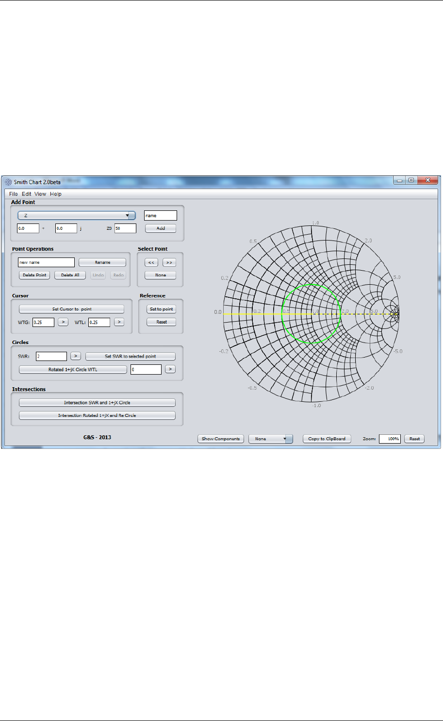
The Control panel
24/12/2013 G&S Smith Chart Manual 2.1beta 2/10
Gorik Stevens
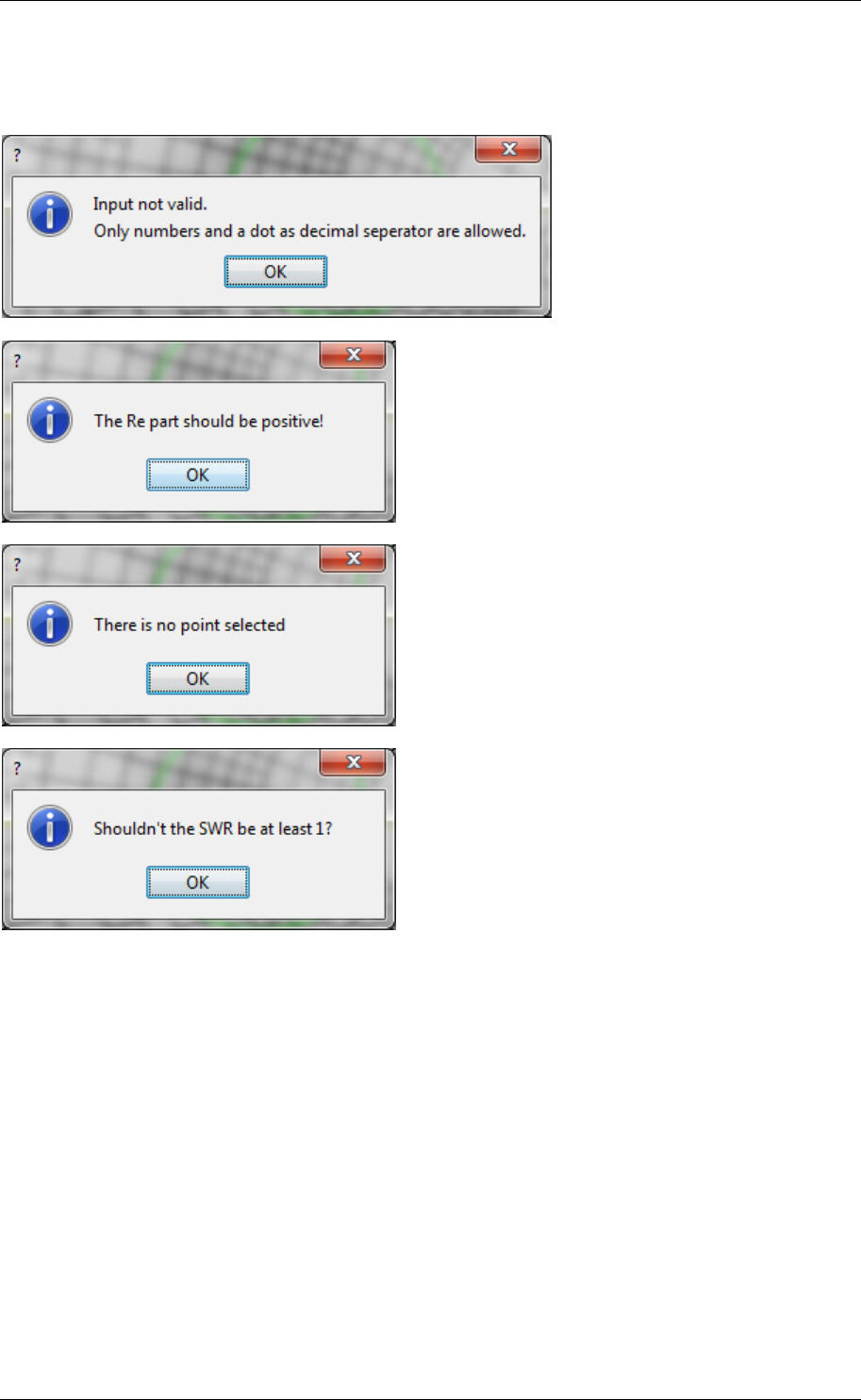
Note: All values should be entered with a “.” as decimal separator and all numbers.
If there is something wrong one of the following messages could appear:
Add a point
Note: A capital Z/Y stands for a not normalized impedance/admittance. A small z/y stands for a
normalized impedance/admittance.
Adding a point is possible via various options:
* Adding a given point
Select the type of impedance/admittance/reflection combination you want to use form the Add
Point dropdown menu.
Enter a name in the name field
Enter your desired values
Press “Add”

24/12/2013 G&S Smith Chart Manual 2.1beta 3/10
Gorik Stevens
Note: the options to add a Z/Y to the selected point, give you the possibility to combine parallel
admittances and series impedances.
* Adding a point when you know the SWR and the angle.
Set the Cursor at the right angle (see Cursors)
Set the SWR to the desired value.
Choose the “Z Cursor and SWR” or “Y Cursor and SWR” form the Add Point dropdown menu.
Enter a the desired name.
Press "Add"
* Adding a point by inverting an impedance to an admittance and vice versa.
A point can also be created when you desire the Y of a Z or the other way around.
Select the desired point and select the “Z <=> Y” from the Add Point dropdown menu.
The name is automatically set to the selected point and can only be altered afterwards with rename.
Press Add.
* Adding a point with a different characteristic impedance.
Select the point which needs to be altered.
Select "Change Z0" from the Add Point dropdown menu and fill in the new characteristic impedance.
The name is automatically set to the selected point and can only be altered afterwards with rename.
Press Add.
Note: this is required when you have 2different characteristic impedances connected together. e.g.
quarter wave transformer.
Point operations
Rename Point: Select the point you would like to rename, enter the new name and press “Rename
Point”
Delete point: select the point you would like to remove and then press “Delete Point”. This can also
be done by pressing the Delete button. Note that the chart needs to be active to do so. If this button
doesn't work, select the point prior to pressing the delete button.
“Delete All Points” deletes all points.
Undo: Undo last action. You can maximally undo 5 actions.
Redo: Redo last action. This is actually the undo of the undo. You can only redo 2 actions.
Next point (>>) and previous point (<<)
When you are unable to select the right point by clicking the on the smith chart these buttons could
be helpful.
Selects the next and previous point. This could be useful when points are laying on top of each other.
You can also select no point by pressing none.
Starting from version2.0, one can also use the keyboard arrows to navigate between points.
Cursors
The cursors will show you how many wavelengths you need to travel and allow you to enter the
amount of wavelengths you want to travel.

24/12/2013 G&S Smith Chart Manual 2.1beta 4/10
Gorik Stevens
The yellow dashed cursor is the “reference cursor” (point of 0 WTG), the solid line is the “cursor”.
Set Reference to Point: Select a point and afterwards press this button. This will set the reference
cursor to the selected point.
Reset: Sets the Reference cursor to its default position.
Set Cursor to Point: Select a point and afterwards press this button. This will set the reference (point
of 0 WTG) to the selected point. You can read the values in the WTG (Wavelengths Towards
Generator) and WTL (Wavelengths Towards Load) fields.
Setting the cursor at a certain WTG or WTL is possible by just entering the value in a WTG or WTL
field. Update by pressing the ENTER or RETURN key or use the update button.
Note: The values will be simplified to the range 0 to 0.5.
Circles
SWR: Set the SWR circle to a desired value OR read the SWR value of the current SWR circle.
Set SWR to Selected Point: Sets the SWR circle to the selected point.
Rotated 1+jX circle: Used for the double stub method. Enter the desired value at the input field and
enable the rotated circle by clicking the “Rotated Circle WTL” button.
Intersections
Intersection SWR and 1+jX: Used in the single stub method and double stub method. It will give you
the 2 options.
Intersection Rotated 1+jX and Re: Used in the double stub method. It will give you the 2 options or an
error message when there are no intersections or infinite solutions.
Reset Zoom
To reset the zoom of the smith chart.
Since build 27 the zoom setting is bidirectional. You can also type the desired value.
Show Components
This will show you the relationships between the forward the reflected/backward and total
voltage/current. (Voltage when the point is an impedance, current when the point is an admittance)
Show Angle
Gives you the option to show an arc which represents the amount of wavelengths between the
cursors.
FILE MENU
Export data
Generates a “.gnssc” file which can be imported into a spread sheet editor. Don't forget to select the
"." as decimal separator.
Import data
This allows you to import an original 1.5beta “.gnssc” file. Once the layout of your gnssc-file has been
tampered the import functions will not work. In the student edition, it will be verified that you are

24/12/2013 G&S Smith Chart Manual 2.1beta 5/10
Gorik Stevens
the same user on the same PC as previously.
Note: older dat files are no longer compatible with the gnssc file structure.
Export PNG
Export an image.
Export PNG settings
One can choose the option to add a watermark. This feature is not longer possible to enable in the
normal edition. The Student edition has this option enabled automatically.
You can also choose to enable or disable the SWR, rotated 1+jX and Cursors. (default: enable)
EDIT MENU
Undo
Same functionality as the Undo button
Redo
Same functionality as the Redo button
HELP MENU
Help
Will direct you to the online PDF.
About
Will give you an overview of the version, build and contact info.
VIEW MENU
Re and Im coordinates
Allows you to enable/disable the markers of the Re and Im circles.
SWR Circle
Allows you to enable/disable the SWR circle.
Example 1: Single stub
Use a single parallel open stub to match a load impedance of 15+10j Ω to a 50Ω transmission line.
Find the distance and length of the open stub circuit.
24/12/2013 G&S Smith Chart Manual 2.1beta 6/10
Gorik Stevens
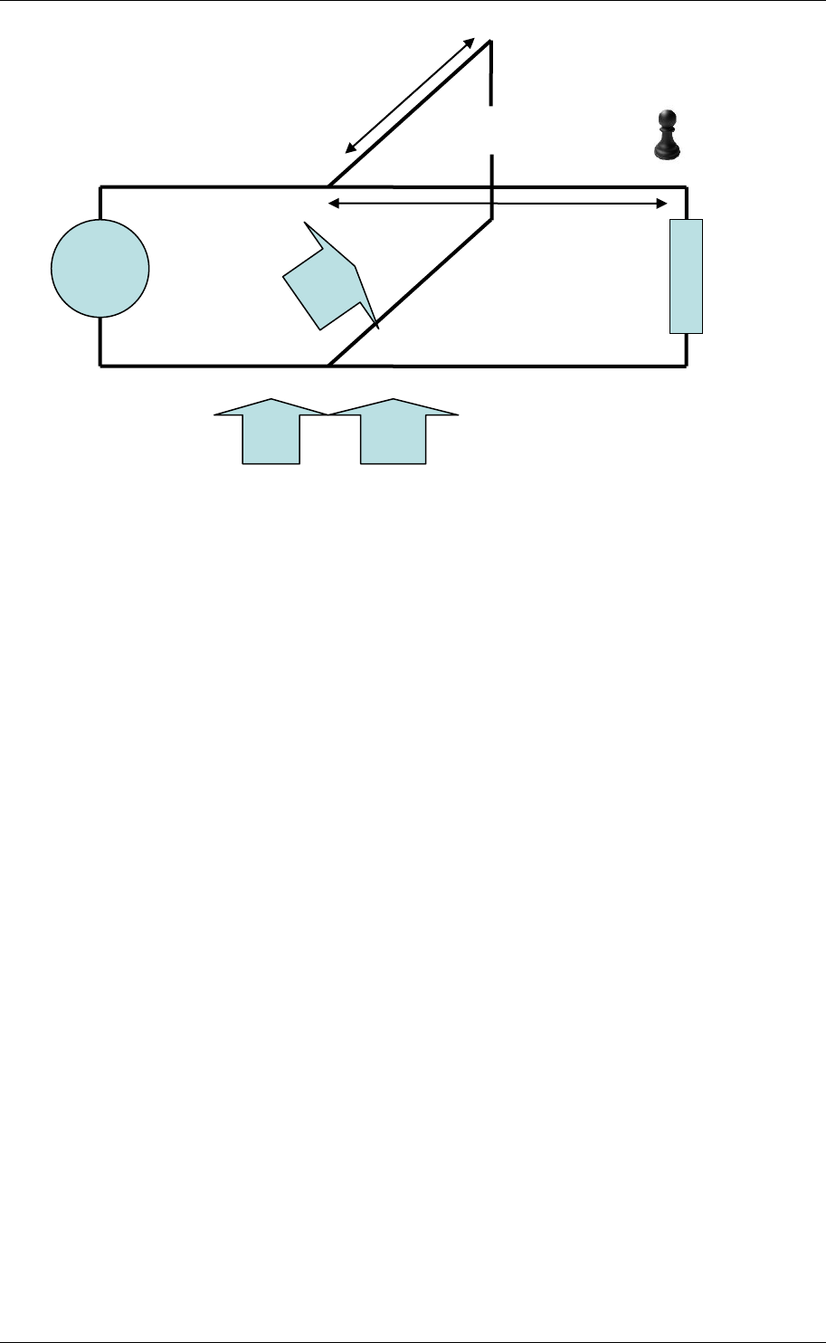
To solve any exercise you should first draw the schematic and add a (imaginary) pawn to know where
you are at that moment. Here @ ZL
Select Z from the add point drop down box.
Since ZL = 15 +10j, type your desired name (L) and type 15, 10 and 50 in the respective text fields.
Press Add
Since this is a parallel stub we need to go to admittances. Select Z<=Y from the Add point drop down
box and make sure that ZL is selected/highlighted. A new point YL is generated
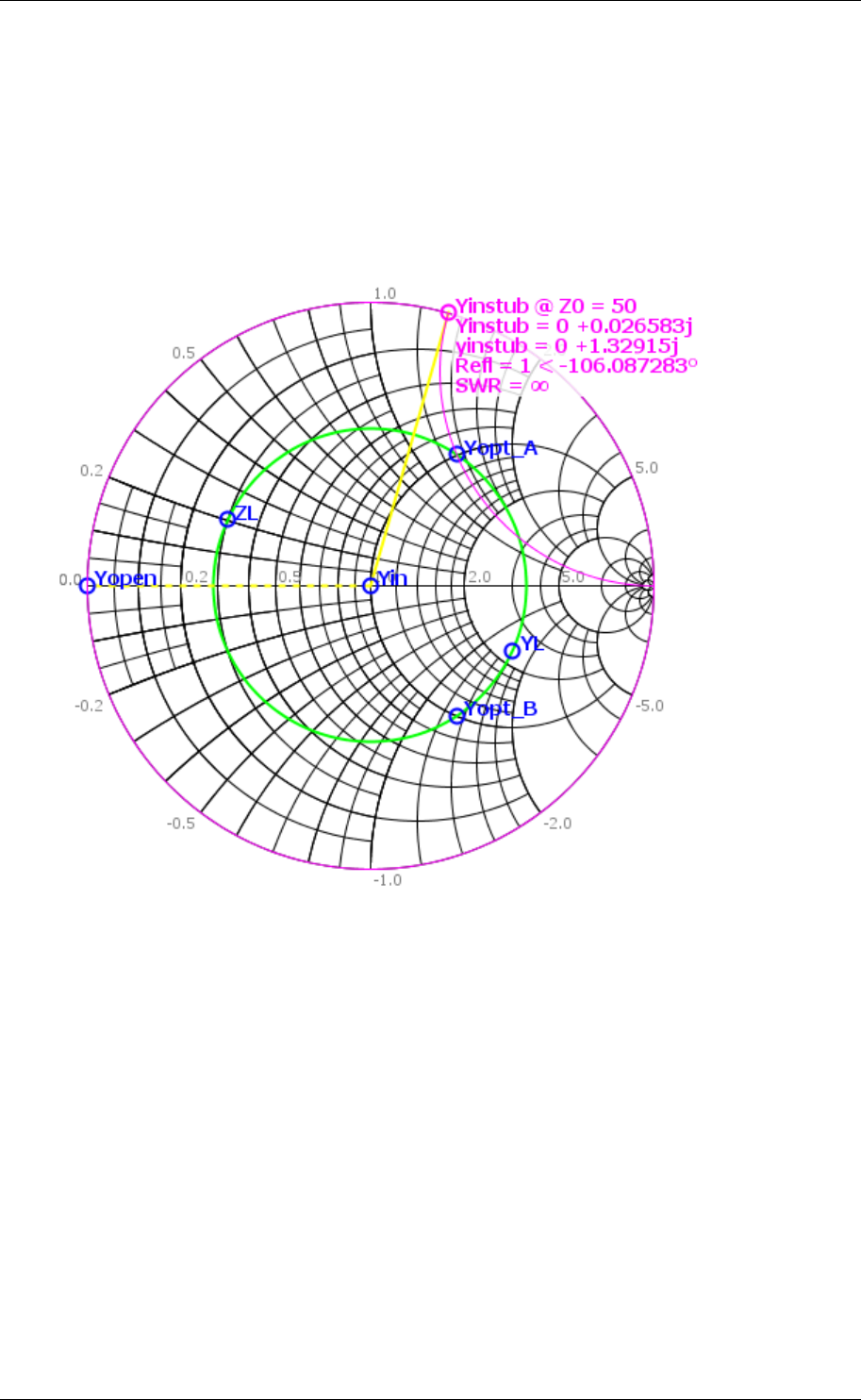
Know we need to know the place on the cable where we have 1+jX so that by adding a stub with
input admittance -jX we get 1+0j. There is a button for this option. Press intersection SWR and 1+jX.
The 2 valid options will appear. Let us take option B.
To know the distance between the load and the stub we need to use the cursors.
Select the YL and click Set reference Select Yopt_B and click Set cursor to point.
Read the value from the WTG text field: 0.044029 λ
Why WTG? take a look at the schematic your pawn should move from ZL to the spot where the stub
will be put.
yopt_B normalised is 1-1.32916j if we add a stub of ynormalised = 1.32916j the sum will be nicely 1.
(this point is Yin)
If you would like to do this select Add normalised z/y to selected form the dropdown box and
complete with the desired values (0, 1.32916,50).
OK back to the length of the stub:
Choose y normalised from the drop down menu. Type the name "instub" and the values 0, 1.32916
and 50. To know the length we will put our pawn at the open. Add the admittance of an open on the
smith chart. Choose (normalised) admittance from the dropdown menu and type "open", 0, 0 and
50. Press Add.
1+jX
1
ZL
dstub
lstub
-jX
24/12/2013 G&S Smith Chart Manual 2.1beta 7/10
Gorik Stevens
Press reference set to point (Yopen is selected)
Select Yinstub and press set cursor to point.
Read the value from WTG: 0.147343 λ
SOLUTION: The stub needs to be at a distance of 0.044029 λ and has a length of 0.147343 λ.
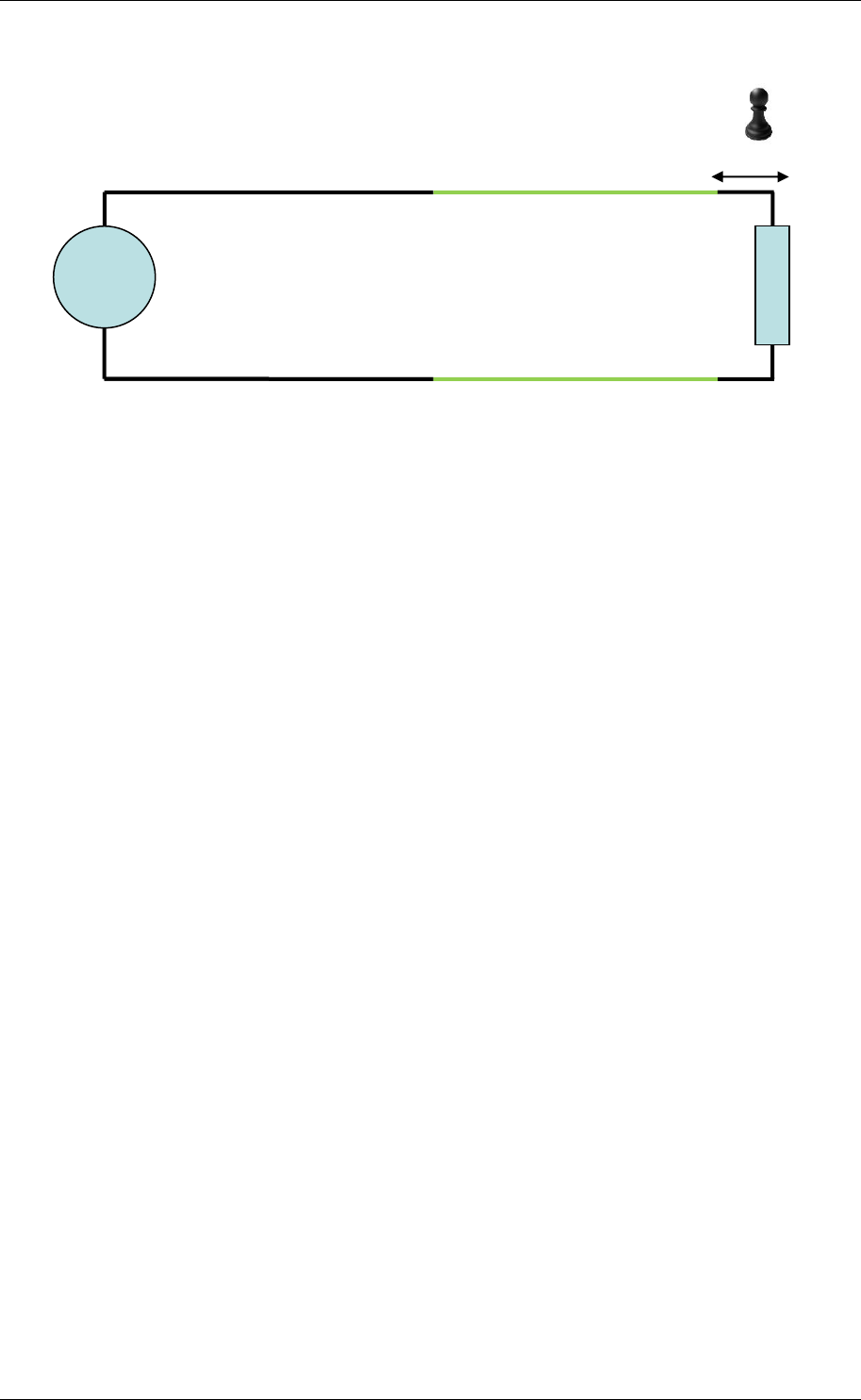
Example 2: Quarter wave transformer
A 50Ohm transmission line has a load of 100+0j Ohm. Match this circuit using a quarter wave
transformer.
24/12/2013 G&S Smith Chart Manual 2.1beta 8/10
Gorik Stevens
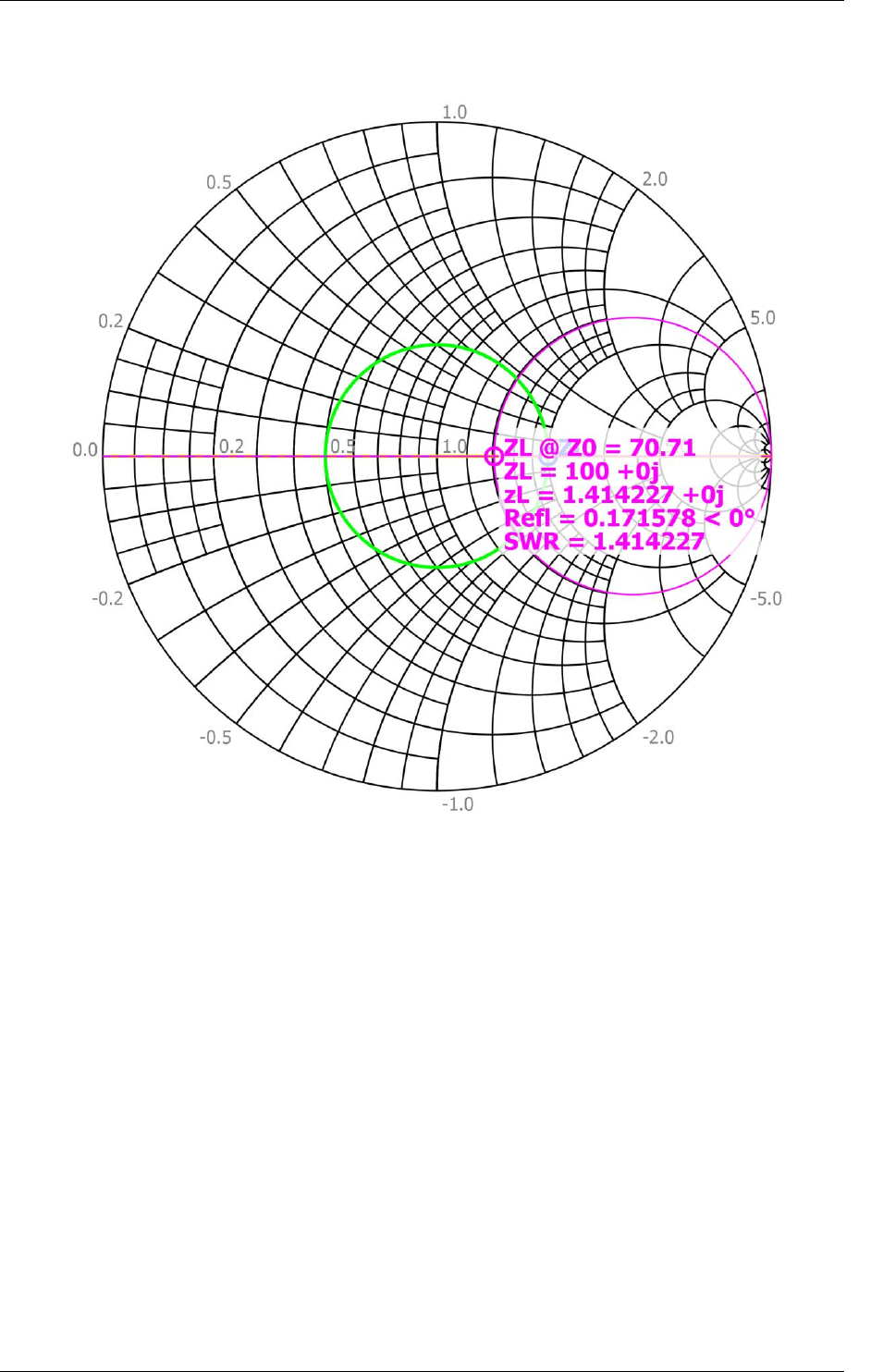
To solve this question we will first plot ZL. Select Z from the add point drop down box.
Since ZL = 100, type your desired name (L) and type 100, 0 and 50 in the respective text fields.
Press Add
Next we need to look for a maximum or a minimum. ZL is already at a maximum. So this is where we
will insert the transformer. De distance to the transformer is 0.
Calculate the characteristic impedance of the transformer. Since Z0,λ/4 is the square root of Zin at the
maximum and Z0 of the original cable this gives us 70.71.
Now we will move to the point at the beginning of the cable. Select change Z0 from the drop down
box in the add menu and make sure the ZL point is selected.
Fill in 70.71 and press Add.
Z0,λ/4; length = λ/4
distance to max or min
ZL
24/12/2013 G&S Smith Chart Manual 2.1beta 9/10
Gorik Stevens
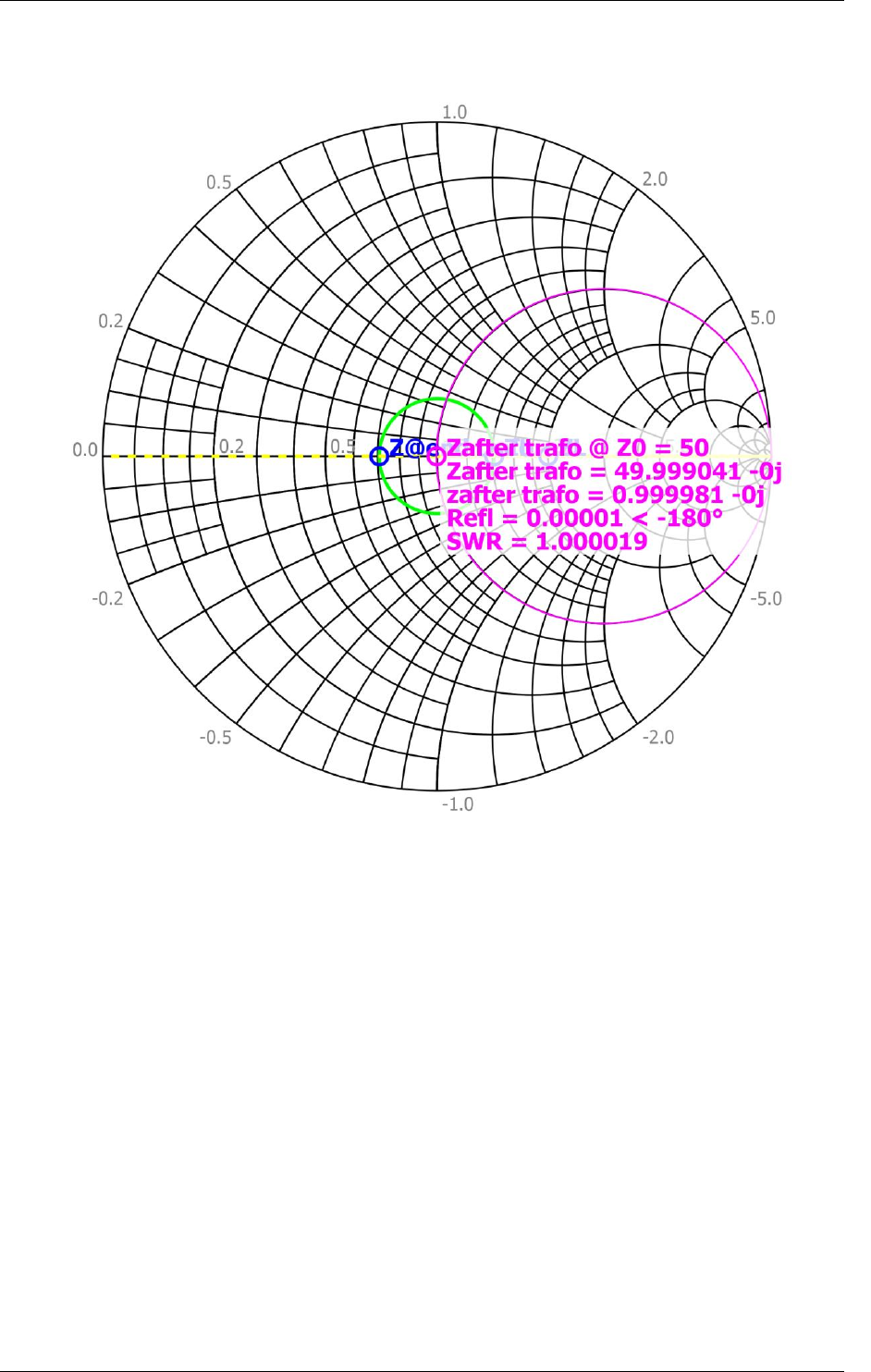
Now we need to move to this point to the end of the transformer. Select Move selected WTG along
SWR and fill in 0.25. Use e.g. “@end trafo” as name and press Add.
Now we need to go back to the original cable. Select change Z0 and fill in 50. Give this point the
name “after trafo”
24/12/2013 G&S Smith Chart Manual 2.1beta 10/10
Gorik Stevens
