Brown Manual D1204 79422
User Manual: D1204
Open the PDF directly: View PDF ![]() .
.
Page Count: 32

INSTRUCTION
MANUAL
FOR SPEEDOTRON
BROWN LINE
EQUIPMENT
2
WELCOME TO SPEEDOTRON
Thank you for purchasing Speedotron Brown Line equipment. The name
Speedotron is synonymous with professional workmanship and the production
of the finest electronic flash equipment you’ll find anywhere. Backed by years
of experience, our engineers have developed the Brown Line system to
economically handle tough lighting situations through a wide range of power
demands.
Speedotron’s business has grown over the years without much fanfare or
advertising. This success is the result of making satisfied users our best
salesmen. Keeping with this tradition, we are determined to serve you well and
to offer the most efficient, competent and courteous service anywhere. We
have prepared this manual to acquaint you with the operational aspects of
your new equipment and to assist you in getting the most from it.
Because this manual is a guide to the proper use of your equipment and not a
photographic handbook, only information pertinent to the basic operation of
Speedotron Brown Line is given.
The equipment you have purchased is durable and will stand up to the rigors
of daily use either on location or in the studio. However, there are certain
operating techniques that should be adhered to in order to obtain maximum
performance. Treated with a reasonable amount of care, your Brown Line
system will provide you with very dependable, consistent and long-lasting
service.
Please help us to get to know you and fulfill our obligations to you. Return the
enclosed warranty registration form to us immediately. Sending in this form will
validate your warranty and put your name on our mailing list, enabling us to
send you up-to-date information on new accessories and new applications for
your present equipment.
Speedotron Corporation
info@speedotron.com
www.speedotron.com
310 South Racine Avenue
Chicago, Illinois 60607
312/421-4050
Fax 312/421-5079
3
TABLE OF CONTENTS
Power Supplies
General Information – Read This First . . . . . . . . . . . . . . . . . . . 4
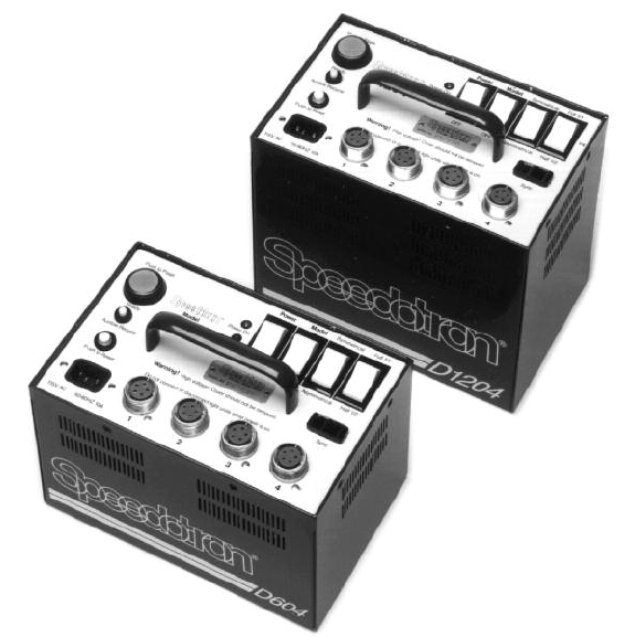
Models D604, D1204, D1604
Description of Controls . . . . . . . . . . . . . . . . . . . . . . . . . . . . . 6
Operating Instructions . . . . . . . . . . . . . . . . . . . . . . . . . . . . . . 7
Power Distribution Tables . . . . . . . . . . . . . . . . . . . . . . . . . . . . 9
Technical Specifications . . . . . . . . . . . . . . . . . . . . . . . . . . . . .12
Models D402, D802B
Description of Controls . . . . . . . . . . . . . . . . . . . . . . . . . . . . .14
Operating Instructions . . . . . . . . . . . . . . . . . . . . . . . . . . . . . .15
Power Distribution Tables . . . . . . . . . . . . . . . . . . . . . . . . . . . .16
Technical Specifications . . . . . . . . . . . . . . . . . . . . . . . . . . . . .18
Model D202
Description of Controls . . . . . . . . . . . . . . . . . . . . . . . . . . . . .19
Operating Instructions . . . . . . . . . . . . . . . . . . . . . . . . . . . . . .20
Technical Specifications . . . . . . . . . . . . . . . . . . . . . . . . . . . . .21
Light Units
General Information – Read This First . . . . . . . . . . . . . . . . . . .22
Models MW3R, MW3R/CC, MW3U, MW3U/CC,
MW3UQ, MW3UQ/CC,M90,M90/CC, M90Q, M90Q/CC
Fixed Reflector Light Units . . . . . . . . . . . . . . . . . . . . . . . . . . .24
Models M11, M11/CC, M11Q, M11Q/CC
UniversalLightUnits ................................26
General Maintenance and Care . . . . . 28
Trouble Shooting . . . . . . . . . . . . . . . . 29
GuideNumbers .................30

4
GENERAL POWER SUPPLY
INSTRUCTIONS
For maximum equipment life and for safe, dependable operation of power
supplies we advise you to follow these general rules.
Unpack equipment carefully. Examine all packing material. Should you notice any
breakage or defect, notify the dealer and carrier (if shipped to you) immediately. Then
please read all instructions before assembling your flash system in order to avoid
damage to your equipment or injury to yourself.
Before doing anything with the power supply make sure that the Model and Power
switches are in the off position.
Connect light head cable(s) to the Light Unit Outlet(s) on the power supply, selecting
the appropriate outlets for the desired power level.
All Brown Line light units can handle at least 400 watt-seconds, and specific units are
designed for a maximum of 1200 or 1600 watt-seconds. For power supplies that can
produce more than 400Ws of power, you must be very careful that the flash tube you are
using in your light unit can handle all the available power. Never subject a flash tube to
more watt-seconds than it is designed to handle. If you are not sure that your flash
tube can handle the power provided by the set-up you are using, check pages 25 and 26
in addition to the Power Distribution Chart on the side of your power supply. We
recommend that you purchase at least one light unit that will accept the full output of
the power supply.
To connect light units, align the light unit plug with the power supply outlet and apply
even pressure while pushing. Black colored light unit connectors are of the “quick
release” type that only require pushing the connector firmly until it is fully seated. Silvery
colored light unit connectors must be threaded until they are fully seated. Both types
prevent accidental cable removal. Make sure all light unit cables are firmly seated to
prevent connector damage. Tape all cables to the floor and keep them out of the
pathways to prevent accidents.
Never install light units while the power supply is turned on. Never insert or remove
flash tubes while the light unit is connected to the power supply. Be sure flash tubes
are fully seated into light unit sockets. (Read instructions in the Light Units section of
this manual for more information on light unit assembly and operation.)
In order to maximize the life of the power supply it is recommended that
the capacitors be "formed" when a pack is not in use for 30 days or more.
All that is required of the user is to turn on the power supply for about 10
to 20 minutes each month. This simple procedure prevents premature
failure by maintaining the "elasticity" of the capacitors.
5
Speedotron power supplies are equipped with arc-protected outlets. However, as with
any electrical equipment, arc-over (an electrical discharge between two physically
disconnected electrical terminals) is a possibility. When light cables, flash tubes or power
cords are improperly seated, arc-over may occur. Also, if your light unit or power supply
malfunctions, or the power cord or the internal wiring in the studio is improperly
terminated or defective, there is a chance of arc-over when connecting or disconnecting
light units. Severe power supply damage and operator injury may result if arc-over
occurs. That is why in spite of the arc-protection feature of Speedotron power supplies,
you should always make sure your Model and Power switches are off when
disconnecting or connecting light units. Plug sync extension into Sync socket and
connect the other end to a PC cord designed for your camera or lens. The sync
extension supplied with the power supply accepts the standard AC twin-blade type sync
connector. A standard AC to PC sync cord will be required to connect the camera to the
power supply's sync
extension.
A slave tripper (Speedotron #23510) may be installed in the Sync socket (in place of the
sync extension) to fire the power supply. If the power supply fails to flash when exposed
to another light source with the slave installed in the Sync socket, remove the slave,
rotate it 180° and reinstall it in the socket.
Connect AC power cord into Power Input on power supply. A 3-terminal ground power
plug is utilized on Brown Line power supplies. For maximum performance and safety, it is
strongly suggested that the 3-terminal cord supplied with the power supply be properly
utilized and properly terminated at the main source of incoming power. Always use a
three-wire ground power cord and a properly grounded wall outlet with all Speedotron
power supplies. Failure to do so may cause the power supply to intermittently misfire.
We do not recommend using an adapter and installing into a 2-blade
outlet.
Once the light units are properly assembled and installed, the power cord is installed
and the sync extension is connected, turn the Power switch on.
Now refer to the Operating Instructions section of this manual for information regarding
the proper use of your particular power supply.
Never attempt to make repairs to your Speedotron equipment. All electronic flash
systems operate on high voltage and high power. It is very dangerous to open a
power supply.

6
GENERAL DESCRIPTION OF CONTROLS
Power – turns power supply on and off (flashes light units when turning off).
Model – turns model lamp(s) on and off.
Symmetrical/Asymmetrical – controls power distribution. In the symmetrical position,
power is split equally between all lights. In the asymmetrical position, power is
distributed unequally and modeling lamp brightness on light units in outlets 3 and 4
is reduced.
Full/Half (on D604) or Full/Half/1/4 (on D1204 and D1604) – controls the total amount
of power delivered to light unit outlets.
Ready/Push to Flash – combination ready light and test flash button. Illuminates in
green to indicate when power supply has recycled to 85%. Pressing the button
when illuminated triggers the flash for testing or open flash applications.
Audible Recycle – controls audible ready tone (on/off).
Power On – green LED illuminates when power switch is turned on.
Hi-Temp – red LED lights, alarm tone sounds, when internal heat becomes excessive.
Sync – socket for sync extension or slave.
Push to Reset – resets circuit breaker. Circuit breaker disables power supply in case of
malfunction.
Power Input – socket for AC power cord.
Light Unit Outlets (4) – sockets for connecting from one to four light units to power
supply.
Ready/Push to flash button
Power on LED
Hi-temp LED
Symmetrical/Asymmetrical
Power Model Full/Half/Quarter
Power input Push to reset Sync
Light unit outlets
Audible recycle
7
OPERATING INSTRUCTIONS
Operation of the D604, D1204 and D1604 power supplies is simple and straight
forward. This sequence of operation is suggested for maximum life and
dependability.
Make sure that the Model and Power switches are in the off position and the Push to
Reset button is fully depressed into its socket. Connect light head cable(s) to the Light
Unit Outlet(s) on the power supply. The outlets are wired in parallel so it does not
matter in what sequence light head cables are connected.
Never connect or disconnect light units while power is on. Do not insert or remove
flash tubes while power is on. Your Brown Line power supply is equipped with arc-
protection, but should your light unit or power supply malfunction, or the power cord, or
even the internal wiring in the studio be improperly terminated or defective, the chance
of arc-over when connecting or disconnecting light units is greatly increased. Severe
power supply damage and operator injury may result if arc-over occurs when light units
are being disconnected or connected. To prevent this, you should always turn the power
supply off when disconnecting or connecting light heads.
Never subject a flash tube to more watt-seconds than it is designed to handle.
MW3 and M90 series (non-”Q”) light units have a maximum rating of 400Ws, while “Q”
versions are rated at 1200Ws. M11 light units are rated at 1200Ws* (with new MW9H
flashtubes) and M11Q light units are rated at 2400Ws. We strongly recommend that at
least one light unit in your system is capable of handling the maximum output of your
power supply. If you are not sure if your flash tube and light unit can handle the power
provided by the set up you are using, check pages 25 and 26 and the Power Distribution
Chart on the side of your power supply.
Connect AC power cord into Power Input on power supply, then plug into a properly
grounded outlet. Use proper 3-conductor grounded cord for operator safety and to
reduce self-firing and misfiring caused by static electricity. Set Full/Half/1/4 switch as
desired (Full/Half switch on D604). This switch reduces the total output of the power
supply. Do not switch the Full/Half/1/4 switch until ready light is illuminated. Failure to
follow this procedure may result in damage to the switch.
Plug sync connector into Sync socket and connect the other end to PC cord for camera.
Once the camera is connected, tripping the shutter will automatically trigger the flash.
A slave tripper (Speedotron #23510), may be inserted into the Sync socket in place of
the PC cord. In this mode of operation, the slave will activate the power supply when it
senses a bright flash of light from another light source. If the power supply fails to flash
when exposed to another light source with the slave installed in the sync socket, it may
be necessary to remove the slave, rotate it 180° and reinstall it into the Sync socket.
*New MW9H flashtubes supplied with M11 light units handle up to 1200Ws.
The MW9M flashtubes have a maximum capacity of 1000Ws.

8
Turn on Power and Model switches. Wait until the green Ready/Push to Flash
illuminates and press to check if the unit is operational. The light unit(s) should flash
instantly when this button is pressed. If you wish to check the function of each individual
light unit, we recommend that you turn off the Model switch and hold your hand in front
of (not inside) the light unit to be tested. When you fire the unit you will feel the heat of
the flash. This method is suggested because it is often difficult to determine by sight if
one of the lights has failed to flash.
The D604, D1204 and D1604 power supplies are equipped with an audible ready
signal (may be turned off) and high temperature alarm. A short audible tone along with
a green Ready/Push to Flash light indicates that the power supply has recycled to 85
percent (ANSI standard). For very critical exposures, waiting several seconds after the
green Ready/Push to Flash light illuminates will ensure that the power supply is at 100
percent power. If the beep should prove distracting, depress the Audible Recycle switch
to eliminate this short tone. The green Ready/Push to Flash light will still continue to
illuminate.
Prolonged rapid flashing or storage in a high temperature environment (like the trunk of
a car) or extended use in extremely warm environments may eventually produce enough
heat to set off a steady alarm tone and red Hi-Temp LED indicator. The power supply
should be turned off at the Power switch because continued use may cause severe
damage. When the power supply has sufficiently cooled, normal operation may be
resumed. (If the power supply is not turned off, the alarm will not clear.)
When the power supply has been exposed to extreme cold weather for an extended
period of time, it is suggested that the unit be allowed to warm up to room temperature
before connecting it to an AC power line.
When disassembling the system, turn off Power and Model switches first. When the
Power switch is turned off, the power supply will discharge by flashing all light units.
Placing the Full/Half/1/4 switch into the full position before turning off Power will
ensure that all capacitors are discharged. If the power supply should be inadvertently
switched off at a lower power setting, DO NOT immediately switch to full power!
Damage to the switch may result. Wait at least 10 seconds before operating the
Full/Half/1/4 switch. Unplug the power cord and disconnect the light head cable(s).

9
One light: Symmetrical mode in any outlet, will receive 600Ws.
Asymmetrical mode in outlets 1 or 2, will receive
600Ws; when using outlets 3 or 4 output is 450Ws.
Two lights: Symmetrical mode, all outlets share an equal amount of
power. Two lights each receive 300Ws (600Ws divided by 2).
Asymmetrical mode
Combination 1: one light in outlet 1 or 2 receives 300Ws;
the second light in outlet 3 or 4 receives 150Ws.
Combination 2: in outlets 1 and 2 receive 300Ws each.
Combination 3: in outlets 3 and 4 will receive 150Ws each.
Following the table will quickly illustrate other combinations that are possible with up to
four light units on the D604.
Divide watt-seconds by 2 when using half power.
600
450
300 150
300 300
150 150
75 75300
210 210 105
180 180 45 45
POWER DISTRIBUTION TABLES
On the side of the D604, D1204 & D1604 power supplies there is a Power Distribution
Table based on the full power setting. These tables should be used as guides for
determining various lighting possibilities, guide numbers & exposures when using
consistent flash tubes & reflectors. When different flash tubes and/or reflectors are used
actual light output will vary, producing as much as a full f/stop discrepancy with the
table.
Brown Line '04 power supplies, feature symmetrical and asymmetrical operation.
Symmetrical output means all light units share equal output. To determine power levels,
divide the maximum output by the number of light units to be used. In asymmetrical
mode, outlets 1 and 2 receive a greater portion of the total output than outlets 3 and 4.
(For specific power distribution refer to the charts below for the number and
configuration of the lights to be used.)
D604 Power Distribution Table
Symmetrical
Any socket(s)
Asymmetrical
1 or 2 3 or 4
1 Light 600Ws
2 Lights
3 Lights
4 Lights
300Ws
200Ws
150Ws
2:1
1:1
4:1:1
2:2:1
4:4:1:1
1:1

10
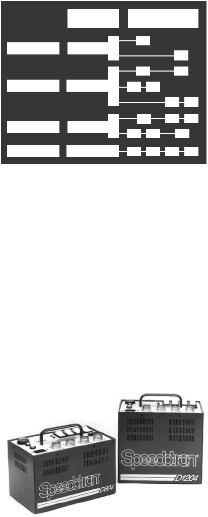
D1204 Power Distribution Table
One light: Symmetrical mode in any outlet, will receive 1200Ws.
Asymmetrical mode in outlets 1 or 2, will receive
1200Ws; when using outlets 3 or 4 output is 900Ws.
Two lights: Symmetrical mode, all outlets share an equal amount
of power. Two lights each receive 600Ws (1200Ws
divided by 2).
Asymmetrical mode
Combination 1: one light in outlet 1 or 2 receives
600Ws; the second light in outlet 3 or 4 receives 300Ws.
Combination 2: in outlets 1 and 2 receive 600Ws each.
Combination 3: in outlets 3 and 4 will receive 300Ws each.
Following the table above will quickly illustrate other combinations that are
possible with up to four light units on the D1204.
Divide Watt-seconds by 2 when using half power.
Divide Watt-seconds by 4 when using quarter power.
1200
900
600 300
600 600
300 300
150 150600
420 420 210
360 360 90 90
Symmetrical
Any socket(s)
Asymmetrical
1 or 2 3 or 4
1 Light 1200Ws
2Lights
3 Lights
4 Lights
600Ws
400Ws
300Ws
2:1
1:1
4:1:1
2:2:1
4:4:1:1
1:1
11
One light: Symmetrical mode in any outlet will, receive 1600Ws.
Asymmetrical mode in outlets 1 or 2, will receive 1600Ws;
when using outlets 3 or 4 output is 1200Ws.
Two lights: Symmetrical mode, all outlets share an equal amount of power.
Two lights each receive 800Ws (1600Ws divided by 2).
Asymmetrical mode
Combination 1: one light in outlet 1 or 2 receives 800Ws;
the second light in outlet 3 or 4 receives 400Ws.
Combination 2: in outlets 1 and 2 receive 800Ws each.
Combination 3: in outlets 3 and 4 will receive 400Ws each.
Following the above table will quickly illustrate other combinations that are possible with
up to four light units on the D1604.
D1604 Power Distribution Table
Divide Watt-seconds by 2 when using half power.
Divide Watt-seconds by 4 when using quarter power.
1600
1200
800 400
800 800
400 400
200 200800
560 560 280
480 480 120 120
Symmetrical
Any socket(s)
Asymmetrical
1or 2 3 or 4
1Light 1600Ws
2 Lights
3 Lights
4 Lights
800Ws
532Ws
400Ws
2:1
1:1
4:1:1
2:2:1
4:4:1:1
1:1
TECHNICAL SPECIFICATIONS
D604 Power Supply
Maximumpower: .....................600Ws
Number of light unit outlets: . . . . . . . . . . . .4
Recycle time: watt-seconds seconds
(to 85% voltage, ANSI standard) .............600 2.3
300 1.3
Flash duration . . . . . . . . . . . . . . . . . . . . . . . .1/590 sec. (1.7 milliseconds)
(at full power w/one M11Q light unit measured 1/2 to 1/2 peak as per ANSI PH3.40)
Maximum power into one light unit: . . . . . . .600Ws
Minimum power into one light unit: . . . . . . .225Ws
Minimum power per light with 4 light units: .22.5Ws
Power input requirements: . . . . . . . . . . . . . .105-120VAC 50-60Hz. 10 amps peak
Size: . . . . . . . . . . . . . . . . . . . . . . . . . . . . . . . .5.9 x 9.1" (foot print) x 5.9" (case height)
Weight: .............................11.2lbs.
Systemvoltage:.......................900V
Triggervoltage:.......................70V
Trigger current: . . . . . . . . . . . . . . . . . . . . . . .0.000043A (43 micro-amps)
Guidenumber .......................250
(at ISO 100 w/M11Q fitted with 11-1/2" reflector measured at 10 feet, on axis with MW9QC flash tube)
12
13
D1204 Power Supply
Maximum power: . . . . . . . . . . . . . . . . . . . . .1200Ws
Number of light unit outlets: . . . . . . . . . . . .4
Recycle time: watt-seconds seconds
(to 85% voltage, ANSI standard) 1200 4.1
600 2.0
300 1.0
Flash duration : . . . . . . . . . . . . . . . . . . . . . . .1/370 sec. (2.7 milliseconds)
(at full power w/one M11Q light unit measured 1/2 to 1/2 peak as per ANSI PH3.40)
Maximum power into one light unit: . . . . . . .1200Ws
Minimum power into one light unit: . . . . . . .225Ws
Minimum power per light with 4 light units: .22.5Ws
Power input requirements: . . . . . . . . . . . . . .105-120VAC 50-60Hz. 10 amps peak
Size: . . . . . . . . . . . . . . . . . . . . . . . . . . . . . . . .5.9 x 9.1" (foot print) x 7.9" (case height)
Weight: .............................14.4lbs
Systemvoltage:.......................900V
Triggervoltage:.......................70V
Trigger current: . . . . . . . . . . . . . . . . . . . . . . .0.000043A (43 micro-amps)
Guidenumber: .......................455
(at ISO 100 w/M11Q fitted 11-1/2" reflector measured at 10 feet, on axis with MW9QC flash tube)
D1604 Power Supply
Maximum power: . . . . . . . . . . . . . . . . . . . . .1600Ws
Number of light unit outlets: . . . . . . . . . . . .4
Recycle time: watt-seconds seconds
(to 85% voltage, ANSI standard) 1600 6.0
800 2.8
400 1.3
Flash duration : . . . . . . . . . . . . . . . . . . . . . . .1/350 sec. (2.9 milliseconds)
(at full power w/one M11Q light unit measured 1/2 to 1/2 peak as per ANSI PH3.40)
Maximum power into one light unit: . . . . . . .1600Ws
Minimum power into one light unit: . . . . . . .300Ws
Minimum power per light with
4lightunits:..........................30Ws
Power input requirements: . . . . . . . . . . . . . .105-120VAC 50-60Hz. 10 amps peak
Size: . . . . . . . . . . . . . . . . . . . . . . . . . . . . . . . .6.4 x 9.5" (foot print) x 8.2" (case height)
Weight: .............................16.2lbs
Systemvoltage:.......................900V
Triggervoltage:.......................70V
Trigger current: . . . . . . . . . . . . . . . . . . . . . . .0.000043A (43 micro-amps)
Guidenumber: .......................540
(at ISO 100 w/M11Q fitted 11-1/2" reflector measured at 10 feet, on axis with MW9QC flash tube)
14
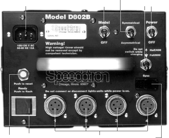
DESCRIPTION OF CONTROLS
Power – turns power supply on and off (flashes units when turning off D802 or D402).
Model – turns model lamp(s) on and off.
Symmetrical/Asymmetrical – controls power distribution. In the symmetrical position,
power is split equally between all lights. In the asymmetrical position, power is
distributed unequally and model lamp brightness on light units in outlets 3 and 4 is
reduced.
Full/Half – controls amount of power delivered to light unit outlets.
Ready/Push to Flash – a combination ready light and test flash button. Illuminates to
indicate when power supply has recycled to 85%. Pressing the button when
illuminated triggers the flash for testing or open flash applications.
Sync – socket for sync extension or slave.
Push to Reset – resets circuit breaker. Circuit breaker disables power supply in case of
malfunction.
Power Input – socket for AC power cord.
Light Unit Outlets (4) – sockets for connecting from one to four light units to power
supply.
Ready/Push to flash
Symmetrical/Asymmetrical
Power
Model Full/Half
Power input
Push to reset Sync
Light unit outlets
15
*New MW9H flashtubes supplied with M11 light units handle up to 1200Ws.
The MW9M flashtubes have a maximum capacity of 1000Ws.
OPERATING INSTRUCTIONS
Operation of Brown Line power supplies is simple and straight forward. It is
suggested that this sequence of operation be utilized for maximum life and
dependability.
Make sure that the Model and Power switches are in the off position and the Push to
Reset buttons are fully depressed into their sockets. Connect light head cable(s) to the
Light Unit Outlet(s) on the power supply. The outlets are wired in parallel so it does not
matter in what sequence light head cables are connected.
Never connect or disconnect light units while power is on. Do not insert or remove
flash tubes while power is on. Your Brown Line power supply is equipped with
arc-protection, but should your light unit or power supply malfunction, or the power
cord, or even the internal wiring in the studio be improperly terminated or defective, the
chance of arc-over when connecting or disconnecting light units is greatly increased.
Severe power supply damage and operator injury may result if arc-over occurs when
light units are being disconnected or connected. To prevent this, you should always turn
the power supply off when disconnecting or connecting light heads.
Never subject a flash tube to more watt-seconds than it is designed to handle. MW3
and M90 series (non-”Q”) light units have a maximum rating of 400Ws, while “Q”
versions are rated at 1200Ws. M11 light units are rated at 1200Ws* (with new MW9H
flashtube) and M11Q light units are rated at 2400Ws. We strongly recommend that at
least one light unit in your system is capable of handling the maximum output of your
power supply. If you are not sure if your flash tube and light unit can handle the power
provided by the set up you are using, check pages 25 and 26 and the Power Distribution
Chart on the side of your power supply.
Connect AC power cord into Power Input on power supply, then plug into a properly
grounded outlet. Use proper 3-conductor grounded cord for operator safety and to
reduce self-firing caused by static electricity. Set Full/Half switch as desired. This switch
reduces the total output of the power supply. The difference between the “full” and
“half” settings is one f-stop. After flashing, do not switch the Full/Half switch until ready
light is illuminated, or until at least ten seconds after turning off unit. Failure to follow
this procedure may result in damage to the switch.
Plug sync connector into Sync socket and connect the other end to PC cord for camera.
Once the camera is connected, tripping the shutter will automatically trigger the flash.
A slave tripper (Speedotron #23510), may be inserted into the Sync socket in place of
the PC cord. In this mode of operation, the slave will activate the power supply when it
senses a bright flash of light from another light source. If the power supply fails to flash
when exposed to another light source with the slave installed in the sync socket, it may
be necessary to remove the slave, rotate it 180° and reinstall it into the Sync socket.

16
Turn on Power and Model switches. Wait until the Ready/Push to Flash illuminates and
press the button to check if the unit is operational. The light unit(s) should flash instantly
when this button is pressed. If you wish to check the function of each individual light unit,
we recommend that you turn off the Model switch and hold your hand in front of (not
inside) the light unit to be tested. When you fire the unit you will feel the heat of the
flash. This method is suggested because it is often difficult to determine by sight if one
of the lights has failed to flash.
When disassembling the system or changing the position of a light unit connector in any
outlet, it is a good habit to set the Full/Half switch to full first, then turn off Model and
Power switches prior to disconnecting light units. If this procedure is not followed, allow
10 seconds between turning the Power switch off and adjusting the Full/Half switch.
DO NOT immediately switch to full power! Damage to the switch may result.
The D402 and D802B power supplies will flash their light units when turned off. Placing
the Full/Half switch on the D402 and D802B into the full position before turning off
Power will ensure that all capacitors are discharged.
POWER DISTRIBUTION TABLES
On the side of the D202, D402 and D802B power supplies, there is a Power Distribution
Table based on the full power setting. These tables should be used as guides for
determining various lighting possibilities, guide numbers and exposures when using
consistent flash tubes and reflectors. When different flash tubes and/or reflectors are
used actual light output will vary producing as much as a full f/stop discrepancy with
the table.
The ’02 Series feature symmetrical and asymmetrical operation. Symmetrical output
means all light units share equal output. To determine power levels, divide the total
watt-seconds by the number of light units to be used. In asymmetrical mode, outlets 1
and 2 receive a greater portion of the total output than outlets 3 and 4. (For specific
power distribution refer to the charts below for the number and configuration of the
lights to be used.)
D402 Power Distribution Table
Divide watt-seconds by 2 when using half power.
400
300
200 100
200 200
100 100
50 50200
140 140 70
120 120 30 30
Symmetrical
Any socket(s)
Asymmetrical
1 or 2 3 or 4
1 Light 400Ws
2 Lights
3 Lights
4 Lights
200Ws
133Ws
100Ws
2:1
1:1
4:1:1
2:2:1
4:4:1:1
1:1

17
One light: Symmetrical mode in any outlet, will receive 800Ws.
Asymmetrical mode in outlets 1 or 2, will receive 800Ws;
when using outlets 3 or 4 output is 600Ws.
Two lights: Symmetrical mode, all outlets share an equal amount of power.
Two lights each receive 400Ws (800Ws divided by 2).
Asymmetrical mode
Combination 1: one light in outlet 1 or 2 receives 400W;
the second light in outlet 3 or 4 receives 200Ws.
Combination 2: in outlets 1 and 2 receive 400Ws each.
Combination 3: in outlets 3 and 4 will receive 200Ws each.
Following the table will quickly illustrate other combinations that are possible with
up to four light units on the D802B.
D802B Power Distribution Table
One light: Symmetrical mode in any outlet, will receive 400Ws.
Asymmetrical mode in outlets 1 or 2, will receive 400Ws;
when using outlets 3 or 4 output is 300Ws.
Two lights: Symmetrical mode, all outlets share an equal amount of power.
Two lights each receive 200Ws (400Ws divided by 2).
Asymmetrical mode
Combination 1: one light in outlet 1 or 2 receives 200Ws;
the second light in outlet 3 or 4 receives 100Ws.
Combination 2: in outlets 1 and 2 receive 200Ws each.
Combination 3: in outlets 3 and 4 will receive 100Ws each.
Following the table will quickly illustrate other combinations that are possible with
up to four light units on the D402.
Divide watt-seconds by 2 when using half power.
800
600
400 200
400 400
200 200
100 100400
280 280 140
240 240 60 60
Symmetrical
Any socket(s)
Asymmetrical
1 or 2 3 or 4
1 Light 800Ws
2 Lights
3 Lights
4 Lights
400Ws
266Ws
200Ws
2:1
1:1
4:1:1
2:2:1
4:4:1:1
1:1
18
TECHNICAL SPECIFICATIONS
D402 Power Supply
Maximumpower: .....................400Ws
Number of light unit outlets: . . . . . . . . . . . .4
Recycle time: watt-seconds seconds
(to 85% voltage, ANSI standard) .............400 1.75
200 0.9
Flash duration : . . . . . . . . . . . . . . . . . . . . . . .1/1200 sec. (.8 milliseconds)
(at full power w/one M11Q light unit measured 1/2 to 1/2 peak as per ANSI PH3.40)
Maximum power into one light unit: . . . . . . .400Ws
Minimum power into one light unit: . . . . . . .150Ws
Minimum power per light with 4 light units: .15Ws
Power input requirements: . . . . . . . . . . . . . .105-120VAC 50-60Hz. 10 amps peak
Size: . . . . . . . . . . . . . . . . . . . . . . . . . . . . . . . .5.5 x 7.9" (foot print) x 7.2" (case height)
Weight: .............................11.5lbs
Systemvoltage:.......................900V
Triggervoltage:.......................70V
Trigger current: . . . . . . . . . . . . . . . . . . . . . . .0.000043A (43 micro-amps)
Guidenumber: .......................270
(at ISO 100 w/M11Q fitted 11-1/2" reflector measured at 10 feet, on axis with MW9QC flash tube)
D802 Power Supply
Maximumpower: .....................800Ws
Number of light unit outlets: . . . . . . . . . . . .4
Recycle time: watt-seconds seconds
(to 85% voltage, ANSI standard) .............800 3.2
400 2
Flash duration : . . . . . . . . . . . . . . . . . . . . . . .1/830 sec. (2.9 milliseconds)
(at full power w/one M11Q light unit measured 1/2 to 1/2 peak as per ANSI PH3.40)
Maximum power into one light unit: . . . . . . .800Ws
Minimum power into one light unit: . . . . . . .150Ws
Minimum power per light with 4 light units: .30Ws
Power input requirements: . . . . . . . . . . . . . .105-120VAC 50-60Hz. 10 amps peak
Size: . . . . . . . . . . . . . . . . . . . . . . . . . . . . . . . .5.5 x 7.9" (foot print) x 7.2" (case height)
Weight: .............................12lbs
Systemvoltage:.......................900V
Triggervoltage:.......................70V
Trigger current: . . . . . . . . . . . . . . . . . . . . . . .0.000043A (43 micro-amps)
Guidenumber: .......................380
(at ISO 100 w/M11Q fitted 11-1/2" reflector measured at 10 feet, on axis with MW9QC flash tube)
19
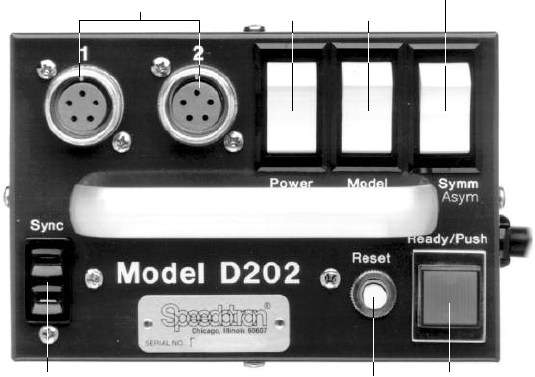
DESCRIPTION OF CONTROLS
Power – turns power supply on and off. (Flashes light units when turning off.)
Model – turns model lamps on and off.
Symmetrical/Asymmetrical – controls power distribution. In the symmetrical position,
power is split equally between all lights. In the asymmetrical position power is
distributed unequally and the model lamp brightness/flash tube output of a light
in outlet #2 is reduced.
Ready/Push to Flash – a combination ready light and test flash button. Illuminates to
indicate when power supply has recycled to 85%. Pressing the button when
illuminated triggers the flash for testing or open flash applications.
Sync – socket for sync extension or slave.
Circuit Breaker/Reset – resets circuit breaker. Circuit breaker disables power supply in
case of malfunction. Does not affect model lamp circuit.
Light Unit Outlets (2) – sockets for connecting one or two light units to power supply.
Ready/Push to flash
Symmetrical/Asymmetrical
Power Model
Push to reset
Sync
Light unit outlets
20
OPERATING INSTRUCTIONS
Make sure that the Model and Power switches are in the off position and the Push to
Reset button is fully depressed into its socket. Connect light head cable(s) to the Light
Unit Outlet(s) on the power supply. The outlets are wired in parallel so it does not
matter in what sequence light head cables are connected.
Never connect or disconnect light units while power is on. Do not insert or remove
flash tubes while power is on. Your Brown Line power supply is equipped with arc-
protection, but should your light unit or power supply malfunction, or the power cord, or
even the internal wiring in the studio be improperly terminated or defective, the chance
of arc-over when connecting or disconnecting light units is greatly increased. Severe
power supply damage and operator injury may result if arc-over occurs when light units
are being disconnected or connected. To prevent this, you should always turn the power
supply off when disconnecting or connecting light heads.
The D202 is fully compatible with all Speedotron Brown Line light units and flash
tubes.
Connect power supply cord into a 3-wire grounded AC outlet. This reduces misfires and
self-firing caused by static electricity.
Plug sync connector into Sync socket and connect the other end to PC cord for
camera. Once the camera is connected, tripping the shutter will automatically trigger
the flash.
A slave tripper (Speedotron #23510), may be inserted into the Sync socket in place of
the PC cord. In this mode of operation, the slave will activate the power supply when it
senses a bright flash of light from another light source. If the power supply fails to flash
when exposed to another light source with the slave installed in the sync socket, it may
be necessary to remove the slave, rotate it 180° and reinstall it into the Sync socket.
Turn on Power and Model switches. Wait until the amber Ready/Push to Flash
illuminates and press the button to check if the unit is operational. The light unit(s)
should flash instantly when this button is pressed. If you wish to check the function of
each individual light unit, we recommend that you turn off the Model switch and hold
your hand in front of (not inside) the light unit to be tested. When you fire the unit you
will feel the heat of the flash. This method is suggested because it is often difficult to
determine by sight if one of the lights has failed to flash.
The D202 has symmetrical and asymmetrical power distribution. The two light units are
connected in parallel when the symmetrical/asymmetrical switch is in the symmetrical
position. With the switch in the asymmetrical position power will be distributed as shown
by the power distribution table on the next page or on the side of the power pack.

21
200
100 50
150
TECHNICAL SPECIFICATIONS
D202 Power Supply
Maximumpower: .....................200Ws
Number of light unit outlets: . . . . . . . . . . . .2
Recycle time: watt-seconds seconds
(to 85% voltage, ANSI standard) 200 3.25
Flash duration . . . . . . . . . . . . . . . . . . . . . . . .1/1200 sec. (.85 milliseconds)
(at full power w/one M11Q light unit measured 1/2 to 1/2 peak as per ANSI PH3.40)
Maximum power into one light unit: . . . . . . .200Ws
Minimum power into one light unit: . . . . . . .150Ws
Minimum power per light with 2 light units: .50Ws
Power input requirements: . . . . . . . . . . . . . .105-120VAC 50-60Hz. 4 amps peak
Size: . . . . . . . . . . . . . . . . . . . . . . . . . . . . . . . .4.4 x 6.5" (foot print) x 6.2" (case height)
Weight: .............................6.5lbs.
Systemvoltage:.......................900V
Triggervoltage:.......................70V
Trigger current: . . . . . . . . . . . . . . . . . . . . . . .0.000043A (43 micro-amps)
Guidenumber .......................190
(at ISO 100 w/M11Q fitted with 11-1/2" reflector measured at 10 feet, on axis with MW9QC flash tube)
D202 Power Distribution Table
Symmetrical
Any socket(s)
Asymmetrical
1 or 2 3 or 4
1 Light
2 Lights
One light: Symmetrical mode in any outlet, will receive 200Ws.
Asymmetrical mode: outlet 1 will receive 200Ws;
outlet 2 outputs 150Ws.
Two lights: Symmetrical mode, both outlets share an equal amount of power.
Two lights each receive 100Ws (200Ws divided by 2).
Asymmetrical mode: light in outlet 1 receives 100Ws;
the light in outlet 2 receives 50Ws.
Following the table will quickly illustrate other combinations that are possible with up
to four light units on the D202
200Ws
100Ws
22
*New MW9H flashtubes supplied with M11 light units handle up to 1200Ws.
The MW9M flashtubes have a maximum capacity of 1000Ws.
BROWN LINE LIGHT UNITS
General Instructions and Information
The Speedotron Brown Line light units described here may be used with any Speedotron
Brown Line power supply using the five-pin MS outlet. All light units are supplied with a
20' wired-in cable.
Unpack and examine all equipment carefully. Should you notice any breakage or defect,
notify your dealer (and the carrier if it was shipped to you) immediately. The flash tube(s)
and model lamp(s) are packed in their original cartons. This affords sufficient protection
and reduces the incidence of breakage during shipping. Make sure all packing materials
are removed before using. This includes the pipe cleaners (used as packing material)
inside some flash tubes.
Install flash tubes first. Always handle lamps and flash tubes with care. Because they can
break if put under stress, handle them cautiously. Don’t touch glass surfaces with your bare
hands. If your fingers come in contact with the glass of the model lamp, wipe off carefully
with alcohol. When removing or replacing lamps and tubes, always disconnect light units
from power supply. Allow lamps to cool before handling. For instructions on how to insert
model lamps into specific units, see the unit descriptions on the following pages.
Flash tubes must be inserted into the sockets all the way. Flash tube pins must align with
the flash tube socket to be inserted. Apply gentle pressure. A slight rocking motion may
be necessary when installing larger flash tubes. New flash tubes and sockets fit very
tightly. Be sure all flash tubes and model lamps are fully seated into light unit sockets.
It is important to observe the maximum watt-seconds rating of these light units. Never
subject a flash tube to more watt-seconds than it is designed to handle. MW3 and
M90 series (non-”Q”) light units have a maximum rating of 400Ws, while “Q”
versions are rated at 1200Ws. M11 light units are rated at 1200Ws* (with new MW9H
flashtubes) and M11Q light units are rated at 2400Ws. We strongly recommend that at
least one light unit in your system should be capable of handling the maximum output of
your power supply. If you are not sure that the flash tube in your light unit can
handle the power provided by the set up you are using, check the following pages and
the Power Distribution Chart on the side of your power supply. Failure to observe this
precaution could drastically shorten the life of your flash tubes.
Connect light cable(s) to the Light Unit Outlet(s) on the power supply. Never connect or
disconnect light units while Power is on. Do not insert or remove flash tubes or model
lamps while Power is on.
23
To connect light units, align the light unit plug with the power supply outlet and apply
even pressure while pushing. Black colored light unit connectors are of the “quick
release” type that only require pushing the connector firmly until it is fully seated. Silvery
colored light unit connectors must be threaded until they are fully seated. Both types
prevent accidental cable removal. Make sure all light unit cables are firmly seated to
prevent connector damage. Tape all cables to the floor and keep them out of the
pathways to prevent accidents.
Speedotron power supplies are equipped with arc-protected outlets. However, as with
any electrical equipment, arc-over (an electrical discharge between two physically
disconnected electrical terminals) is a possibility. When light cables or flash tubes are
improperly seated, arc-over may occur. Also, if your light unit or power supply
malfunctions, or the power cord or the internal wiring in the studio is improperly
terminated or defective, there is a chance of arc-over when connecting or disconnecting
light units. Severe power supply damage and operator injury may result if arc-over
occurs. That is why, in spite of the arc-protection feature of Speedotron units, you should
always make sure Power is off when connecting or disconnecting light units.
All Brown Line light units fit on top of 5/8" light stands. MW3U and MW3UCC accept
umbrellas with shafts up to 3/8". MW3R and MW3RCC light units include an adaptor to
fit onto 3/8" light stands.
Turn on power supply, wait for Ready light, then press Push to Flash button to verify
proper operation. The model lamp may be turned on or off by the switch located on the
top of the light unit assembly (insure that the Model switch at power supply is on).
For maximum performance and life, the model lamp should be used only when
necessary and turned off after initial set-up or focusing is done. Although convection
cooling is more than ample for normal usage, turning off the model lamp will eliminate
heat and enable the light unit to run cooler, extending the life of all components.
After extended use or after transporting your system, inspect flash tubes for cracks and
any unusual darkening (arc-over) around the tube sockets. If cracks or darkening are
noted the flash tube is, most likely, near the end of its duty cycle. Cracked tubes will
probably misfire. The normal duty cycle is 100,000 flashes for the majority of Speedotron
Brown Line flash tubes.
Be sure replacement flash tubes are designed for the watt-second output requirements
of Speedotron light units. Applying too much power severely shortens the life of flash
tubes, may cause fine cracks to develop in the tube that may cause tube failure or, in the
most extreme case, may cause the tube to shatter. For this reason, we suggest you
always use Speedotron flash tubes and model lamps to insure safe and dependable
operation.
24
FIXED REFLECTOR LIGHT UNITS
MW3R and MW3R/CC
The MW3R series light units share a common base, but are differentiated by the type of
flash tube each contains. They feature 5-1/2" fixed reflector and are functional as
background or hair lights. When installing flash tubes and model lights be sure that the
unit is disconnected from the power supply. To assemble, first insert the flash tube
according to the General Instructions, then insert the model lamp, using the packing
material to hold the lamp. The 60W candelabra base model lamp threads into the
reflector-mounted socket. The flash tubes are the MW3 (for MW3R) and MW3C (for
MW3R/CC). Again, follow the General Instructions to attach the light unit to the power
supply. It accepts several accessories listed below including snoots, barn doors and
diffusers. The MW3R converts to the MW3R/CC by changing to the color corrected flash
tube.
MW3U, MW3U/CC, MW3UQ and MW3UQ/CC
MW3U series light units share a common base, but are differentiated by the type of flash
tube each contains. They feature 5-1/2" fixed reflectors for use with umbrellas. When
installing flash tubes and model lamps be sure that the unit is disconnected from the
power supply. To assemble, first insert the flash tube according to the General
Instructions, then insert the model lamp, using the packing material to hold the lamp.
The 150W candelabra base model lamp inserts into the reflector-mounted socket. Align
the locking pins to the model lamp socket and use gentle pressure to insert and gently
twist the lamp 1/4 turn. The flash tubes are the MW3 (for MW3U), MW3C (for
MW3U/CC), MW3Q (for MW3UQ), and MW3QC (for MW3UQ/CC). Again, follow the
General Instructions to attach the light unit to the power supply. The light units accept
accessories listed below, including barn doors. It is recommended that snoots not be
used with the MW3U series because of heat from the model lamp.
M90, M90/CC, M90Q and M90Q/CC
The M90 series light units share a common base, but are differentiated by the type of
flash tube each contains. They feature 8-1/2" fixed reflector light units for use with
umbrellas or as key and fill lights. When installing flash tubes and model lamps be sure
that the unit is disconnected from the power supply. To assemble, first insert the flash
tube according to the General Instructions, then insert the model lamps using the
packing material to hold the lamps. The three 25W model lamps insert into the reflector-
mounted sockets around the flash tube. Align the locking pins to the model lamp
sockets and use gentle pressure to insert and gently twist the lamp 1/4 turn. The flash
tubes are the MW3 (for M90), MW3C (for M90/CC), MW3Q (for M90Q), and MW3QC
(for M90Q/CC). Again, follow the General Instructions to attach the light unit to the
power supply. The light units accept several accessories listed below including snoots,
barn doors and diffusers.
25
Technical Specifications
Maximum power:
MW3 (for MW3R, MW3U, M90) . . . . . . . . . . . . . .400Ws
MW3C (for MW3R/CC, MW3U/CC, M90/CC) . . .400Ws
MW3Q (for MW3UQ, M90Q) . . . . . . . . . . . . . . . .1200Ws
MW3QC (for MW3UQ/CC, M90Q/CC) . . . . . . . .1200Ws
Flash duration (MW3 and MW3C):
at400Ws ................................1/830sec.
at200Ws ................................1/1300sec.
Flash duration (MW3Q and MW3QC):
at1200Ws ...............................1/500sec.
at800Ws ................................1/600sec.
at600Ws ................................1/830sec.
at400Ws ................................1/1200sec.
Flash tube, standard . . . . . . . . . . . . . . . . . . . . . . . . . . .MW3 — 900V, 400Ws
Flash tube, 5500°K color corrected . . . . . . . . . . . . . . .MW3C — 900V, 400Ws
Flash tube, quartz standard . . . . . . . . . . . . . . . . . . . . .MW3Q — 900V, 1200Ws
Flash tube, quartz 5500°K color corrected . . . . . . . . . .MW3C — 900V, 1200Ws
Model lamp
MW3R series . . . . . . . . . . . . . . . . . . . . . . . . . . . . .60W candelabra base
MW3U series . . . . . . . . . . . . . . . . . . . . . . . . . . . . .150W quartz halogen
M90series ...............................Three25Wlockingbase
ACCESSORIES FOR LIGHT UNITS
WITH FIXED REFLECTORS
14218 barn doors for 5.5" reflectors (2 leaf)
14216 barn doors for 8.5" reflectors (2 leaf)
25519 diffuser, 5.5” mylar clip-on
25526 diffuser, 8.5” mylar clip-on
25211 gel holder, 5.5”
25213 gel holder. 8.5”
24206 snoot for MW3R light unit, 2" opening; used to provide rim
lighting on hair and shoulders or other small objects.
24210 snoot for MW3R light unit, 3" opening; used to provide rim
lighting on hair and shoulders or other small objects.
24213 snoot for M90 light unit; used to provide rim lighting on hair
and shoulders or other small objects.
25210 flood adapter for M90 light unit; increases angle of coverage to
110° when inserted between tube and socket.
26
UNIVERSAL LIGHT UNITS (REMOVABLE
REFLECTORS)
M11, M11/CC, M11Q and M11Q/CC
The M11 series universal light units share a common base, but are differentiated by the
type of flash tube each contains. They are supplied with a removable 11-1/2" reflector
when purchased individually or include a 7" umbrella reflector when purchased in an
umbrella kit or flash systems. When installing flash tubes and model lamps be sure that
the unit is disconnected from the power supply. To assemble, first insert the flash tube
according to the General Instructions, then insert the model lamp, using the packing
material to hold the lamp. The 150W quartz model lamp inserts into the center of the
flash tube ring. Align the locking pins to the model lamp socket and use gentle pressure
to insert and gently twist the lamp 1/4 turn. The flash tubes are the MW9M (for M11),
MW9MC (for M11/CC), MW9Q (for M11Q), and MW9QC (for M11Q/CC). Again, follow
the General Instructions to attach the light unit to the power supply. Universal light units
accept a full range of quick-disconnect bayonet mount reflectors, snoots, barn doors,
diffusers and a tube protector.
Technical Specifications
Maximum power:
M11andM11/CC .........................1200Ws
M11Q and M11Q/CC . . . . . . . . . . . . . . . . . . . . .2400Ws
Flash tubes:
M11, standard . . . . . . . . . . . . . . . . . . . . . . . . . . . .MW9H — 900V, 1200Ws
M11/CC, 5500°K color-corrected . . . . . . . . . . . . .MW9HC— 900V, 1200Ws
M11Q, quartz standard . . . . . . . . . . . . . . . . . . . . .MW9Q — 900V, 2400Ws
M11Q/CC, quartz 5500°K
color corrected . . . . . . . . . . . . . . . . . . . . . . . . . . .MW9QC— 900V, 2400Ws
M11, M11/CC Flash duration
at800Ws ................................1/740sec.
at600Ws ................................1/1100sec.
at400Ws ................................1/1500sec.
at200Ws ................................1/250sec.
M11Q, M11Q/CC Flash duration
at1600Ws ...............................1/500sec.
at1200Ws ...............................1/625sec.
at800Ws ................................1/830sec.
at600Ws ................................1/1000sec.
at300Ws ................................1/1500sec.
Modellamp ..................................150Wquartzhalogen
27
UNIVERSAL LIGHT ACCESSORIES
Reflectors
24226 grid reflector, 11.5” for M11 series light units
24227 grid reflector, 16” - 50° for M11 series light units
24235 grid reflector, 20” - 50° for M11 series light units
24236 grid reflector, 22” for M11 series light units
24219 reflector, 7” for M11 series light units
14221 reflector for snoots, 7” black
14209 snoot for 7” reflector, 2.5” opening
Barn doors
14217 barn doors for 7" reflectors (2 leaf)
14540 barn doors for 11.5" reflectors (2 leaf)
14542 barn doors for 16" reflectors (2 leaf)
24215 NEW! 4-way barn door system for 7” reflector
24501 NEW! Cookaloris for 4-way system
24502 NEW! Diffused Glass filter for 4-way system
24503 NEW! Half Scrim for 4-way system
24504 NEW! Graduated Scrim for 4-way system
24505 NEW! Full Scrim for 4-way system
Diffusers
24511 NEW! Lightsox diffuser for 11” reflector
24512 NEW! Lightsox diffuser for 20/16” reflector
24510 NEW! Lightsox diffuser for 22” reflector
25525 diffuser, 7” mylar clip-on
25527 diffuser, 11.5" mylar clip-on
25528 diffuser, 16" mylar clip-on
25529 diffuser, 20" mylar clip-on
Gel holders
25212 gel holder, 7”
25214 gel holder, 11.5”
25215 gel holder, 16"
25216 gel holder, 20"
Grids (for M11 & M11Q)
14611 grid, 7” - 3°
14612 grid, 7” - 10°
14613 grid, 7” - 20°
14614 grid, 7” - 30°
14615 grid, 7” - 40°
14619 grids, set of four 7” (10°, 20°, 30°, 40°)
14601 grid, 11.5” - 10°
14602 grid, 11.5” - 20°
14603 grid, 11.5” - 35°
14608 grids, set of two 11.5” (20° & 35°)
14621 grid, 16” - 20°
14625 grid, 20” - 20°
14630 grid, 22”
28
GENERAL MAINTENANCE AND CARE
All Speedotron Brown Line equipment is ruggedly built. Nevertheless, it should be
treated with the same care given to other pieces of quality photographic
equipment. To protect the user, all Speedotron equipment is designed to be safe
when used in accordance with instructions. To assure the maximum in safe,
dependable service, the following guidelines should be carefully observed.
• Avoid kinking or pulling cables. Disconnect cables by pulling on the plug only. Never
pull plugs out by the cable. Light cables as well as sync cords and AC power cords
should be occasionally checked for wear, cracks, separation between cable and plug, and
for indications of arc-over.
• Do not wrap the light unit cables around the light units. Coiling cables tightly stresses
the internal wires and may lead to premature cable failure. If possible, keep the coil
diameter at least 10 inches.
• If a cable becomes frayed, the insulation damaged, or the connectors bent or broken,
have them repaired immediately.
• Keep all connectors, plugs and sockets free of dust, moisture and corrosion.
• Do not connect or disconnect light units or insert or remove flash tubes while the
power supply is on.
• When using your equipment, be sure all cable, sync, power and flash tube connections
are completely and properly installed.
• Do not attempt to make repairs to your Speedotron equipment yourself. It is very
dangerous, and will void your warranty. Consult your dealer regarding authorized
service in your area, or return the equipment to Speedotron.
• When you are not using your equipment, it is recommended that you store it in a dry
place. Equipment should be charged up and flashed a few times at least once a month.
This will keep your equipment in top working condition for many years.
• With your light unit disconnected, occasionally clean the interior surface of the
reflector. Carefully remove the flash tube, and clean the glass cover. Only in this way will
you conserve a consistent color temperature and light output. Dirt and dust deposits on
the tube and reflector act like a filter to alter color.
• Never handle the quartz halogen model lamps with your bare hands. Use tissue or
packing materials when installing and removing. The natural oils from your skin may
cause the glass surface to heat unevenly and cause early failure. When removing these
lamps allow sufficient cooling time before touching.
• To extend their life, the model lamp circuit should be turned off after set-up and
focusing.
29
TROUBLE-SHOOTING
System will not work at all; no flash.
Check that sync cable, AC power cord and light unit cables are firmly and properly
attached. Check that the flash tube is firmly seated. Check that Power switch is on.
With metal camera bodies, you may be required to polarize the camera sync cable and
the power supply sync extension in order to avoid possible misfires resulting from a
build-up of static electricity. This is done by touching any unpainted metal part of the
power supply with the unpainted part of the camera, or better still, with the outer shell
or the grounded part of the sync cable with all sync cords attached. If the unit flashes,
the plug on the sync cable should be reversed and then marked for future reference.
Test fire the camera after reversing the sync extension cable (PC to power supply). If the
unit still does not fire, reverse the PC to camera connection and try again. The trigger
current is very low and is measured in microamperes, so it is impossible to even feel any
shock when touching these contacts.
Occasional failure of all light units to flash.
Check sync cable and light unit cable connections. Make sure that the Ready indicator is
illuminated before attempting to fire unit.
Occasional failure of one light unit only.
Check light unit cable connection. Inspect the cable. Check flash tube. Make sure that
the Ready/Push to Flash indicator is illuminated before attempting to fire unit.
Reduced light output.
Check to see if Full/Half/Low or Full/Half/1/4 switch is in right position. Check flash tube;
check power supply by comparing to similar pack with same light units if possible.
Flash tube glows after firing (afterglow); will not flash again until glow is gone.
If confined to one light unit, check flash tube by substitution. If it continues or all heads
afterglow, power supply is at fault. If this is the case, turn power supply off immediately!
Power supply needs repair.
Full/Half/Low or Full/Half/1/4 switch has no effect on recycle time or light output.
Power supply needs repair.
Circuit breaker on power supply pops.
Check that all cables on power supply and light units are properly connected. Also check
for afterglow. If a circuit breaker blows, it is an indication that something is wrong.
Normal operation will not blow circuit breakers.
Circuit breaker or fuse in studio blows.
Be sure AC line is rated for a minimum of 10 amperes and that high amperage
electrical equipment is not operating on the same AC line.
Important: When checking power supplies, light units and cables, be sure that Power is
off. Look for blackened, discolored or burned pins and sockets. If a Light Unit Outlet on
the power supply is burned, blackened or discolored, it must be replaced before it is
used. It could damage light units that are connected to it. Check that cables are not
loose or frayed.

30
Ws per flash tube M90 M90 w/flood adapter M11 w/7" reflector M11 w/11" reflector
100Ws 123 80 68 135
200Ws 175 115 95 190
400Ws 245 160 135 270
800Ws 320* 220* 190 380
1200Ws 385* 265* 230 455
1600Ws --270* 540*
GUIDE NUMBERS
Guide numbers provide a starting point in calculating the proper exposure for pictures
taken with flash. A guide number is a constant numerical value (for a given film
speed/ISO) determined by multiplying the light source-to-subject distance by the f-stop
in use on the lens. Consequently, dividing a given (known) guide number by the light
source-to-subject distance will yeld the proper f-stop. For example, if the given guide
number is 110 and the light source to subject distance is 10 feet, the f-stop required for
proper exposure is f/11.
The formula is as follows:
guide number = G G = D x F
light source-to-subject distance = D D = G/F
f-stop = F F = G/D
Important note: Guide number values provide a general starting point for exposure
determination and vary depending on a myriad of factors such as power supply
differences, surrounding area reflectance, flash tube differences, etc. In some instances
such as extreme close-up and macro applications guide numbers will not provide
accurate exposure information. All guide numbers are approximations and we
recommend that test shots be produced to insure exposure accuracy.
The guide numbers bellow are based on exposure from one light only, on axis with an
exposure index of ISO 100 in feet. The information supplied in the chart bellow is most
accurate for use in small, light colored rooms. For large or dark colored rooms it may be
necessary to open the lens 1/2 f-stop. For rooms which are both large and dark colored
it may be necessary to open up as much as one full f-stop.
Guide Numbers at ISO 100/feet
*use quartz flash tube only
31
Ws per flash tube MW3-1 MW3Q MW9H MW9Q
100Ws 1/1500 1/1500 1/3000 1/3000
200Ws 1/1200 1/1200 1/2200 1/2200
400Ws 1/750 1/750 1/1400 1/1400
600Ws - 1/580 1/1000 1/1000
800Ws - 1/450 1/700 1/700
1200Ws - 1/330 1/500 1/500
1600Ws ---1/400
FLASH DURATION
Flash duration of a Speedotron Brown Line system will vary with the type of flash tube,
the amount of power outputted and the number of light units connected to the power
supply. For example, a D402 system with two M90 light units and two MW3R light units
will have four MW3-1 flash tubes and a 400Ws power supply. When set to full power
each flash tube will output 100 Ws with a flash duration of 1/1500 second.
Flash Duration in fractions of a second
M11 w/16" reflector M11 w/20" reflector MW3R MW3U w/o umbrella
105 113 95 95
150 160 135 135
210 225 190 190
295 320 255* 255*
355 380 305* 305*
420* 450 --
Light will continue to be produced for about five times the flash duration but will add
little to the exposure. This will not affect action stopping abilities for most normal
contrast subjects.
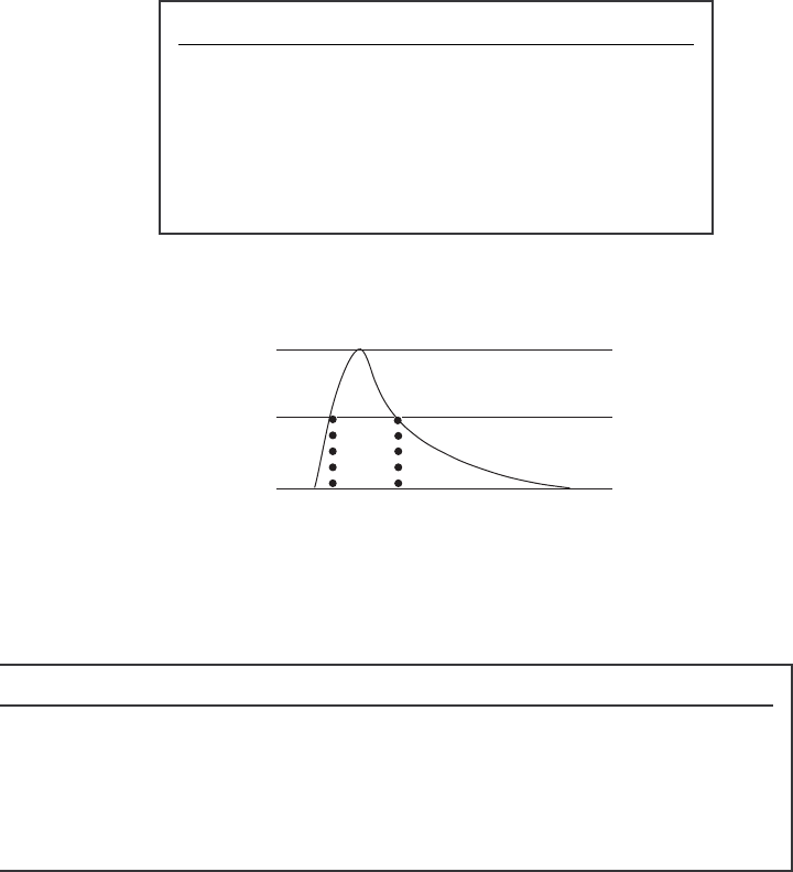
Flash duration is measured from 1/2 peak light output to 1/2 light peak output as
illustrated below:
Peak
1/2
0
flash duration
©2009 Speedotron Corporation
SPEEDOTRON’S LIMITED WARRANTY
Speedotron guarantees to repair or replace, free of charge, any part or parts (except for flash tubes
and modeling lamps) found by factory inspection to be defective due to faulty material or
workmanship, provided the equipment is returned to our factory prepaid. The period of warranty is
two years from the date of original purchase. Flash tubes, which are warrantied by independent
manufacturers, are covered for a period of one year only, and the length of manufacturer warranties
on modeling lamps varies. The manufacturers’ warranties covering flash tubes and modeling lamps
are for defective merchandise only, and do not cover tubes that are cracked or broken.
The Speedotron two-year warranty does not apply to equipment which has been abused, cracked
or broken in shipping, resold or rented (without written permission from Speedotron Corporation),
which has the serial number removed or defaced, which has been modified or repaired by an
unauthorized person, or which has been purchased from any source other than an authorized
Speedotron dealer. A copy of the original sales receipt from an authorized Speedotron dealer is
required at the time of warranty service.
Speedotron shall not be liable for any injury, loss or damage, direct or consequential, arising from
the use or inability to use the product. Prior to use, the purchaser shall determine the suitability of
the product for the intended use and assume all risks and liabilities.
The obligation of Speedotron Corporation is limited to repair or replacement only and no one is
authorized to assume any obligation not in accordance with the above.
Do not attempt to make repairs to your Speedotron equipment. All electronic flash systems operate
on high voltage and high power. There is a high risk of severe electrical shock when opening a
power supply or light unit. Leave service to qualified and authorized electrical service personnel.
Authorized service personnel are familiar with the procedure to fully discharge a live unit (flashing
the unit is not enough to drain stored power even when the unit is unplugged). Repairs by
unauthorized service personnel or by the user will void the Speedotron warranty.
Although we do have several service stations, we encourage you to send all repairs, under warranty
or otherwise, to our factory to ensure the best possible service. Not only will your unit be properly
repaired, but it will be given a routine updating of all circuitry that has been revised since your unit
was manufactured.
Should service be necessary under this warranty, return the item to us, prepaid (we do not accept
collect shipments). We, in turn, will expedite repairs and return the item to you, prepaid, via
whatever means of transportation you used to ship it to us (applies to continental U.S.A. only).
This warranty is not valid unless you fill out and return your warranty registration card. Equipment
should be registered within 10 days of purchase.
Speedotron Corporation
info@speedotron.com
www.speedotron.com
310 South Racine Avenue
Chicago, Illinois 60607
312/421-4050
Fax 312/421-5079
