Manual_VTS V1.8.0 Manual VTS
User Manual: manual_VTS-v1.8.0
Open the PDF directly: View PDF ![]() .
.
Page Count: 198 [warning: Documents this large are best viewed by clicking the View PDF Link!]
- 1: Introduction
- 2: Getting Started
- 3: Network Configuration
- 4: Serial Port Configuration
- 5: Clustering Configuration
- 6: Power Controller
- 7: PC Card Configuration
- 8: System Status and Log
- 9: System Administration
- 10: System Statistics
- 11: CLI guide
- Appendix A: Connections
- Appendix B: PC card supported by VTS
- Appendix C: VTS Configuration files
- Appendix D: Well-known port numbers
- Appendix E: Guide to the Bootloader menu program
- Appendix F: Guide to use Encrypted NFS feature
- APPENDIX G: VTS management using SNMP
- APPENDIX H: Virtual KVM Tool
1
Versatile Console Management Server
VTS series
User Guide
Version 1.8.0
2005-11-08

2
User Guide for the VTS Series
Version 1.8.0
Firmware version 1.8.0
Printed in Korea
Copyright Information
Copyright 2005, Sena Technologies, Inc. All rights reserved.
Sena Technologies reserves the right to make any changes and improvements to its product without
providing prior notice.
Trademark Information
HelloDevice™is a trademark of Sena Technologies, Inc.
Windows® is a registered trademark of Microsoft Corporation.
Ethernet® is a registered trademark of XEROX Corporation.
Notice to Users
Proper back-up systems and necessary safety devices should be utilized to protect against injury,
death or property damage due to system failure. Such protection is the responsibility of the user.
This device is not approved for use as a life-support or medical system.
Any changes or modifications made to this device without the explicit approval or consent of Sena
Technologies will void Sena Technologies of any liability or responsibility of injury or loss caused by
any malfunction.
Technical Support
Sena Technologies, Inc.
210 Yangjae-dong, Seocho-gu
Seoul 137-130, Korea
Tel: (+82-2) 573-5422
Fax: (+82-2) 573-7710
E-Mail: support@sena.com
Website: http://www.sena.com

3
Revision history
Revision Date Name Description
V1.1.0 2003-06-11 J.W. Woo Firmware v1.1.0 update reflected
V1.2.0 2003-08-28 O.J. Jung Firmware v1.2.0 update reflected
V1.3.2 2003-10-07 H.R. Joe Firmware v1.3.2 update reflected
V1.4.1 2003-12-16 H.R. Joe Firmware v1.4.1 update reflected
V1.5.1 2004-06-03 H.R. Joe Firmware v1.5.1 update reflected
V1.5.3 2004-07-15 H.R. Joe Firmware v1.5.3 update reflected
V1.6.0 2004-10-01 H.R. Joe Firmware v1.6.0 update reflected
V1.6.1 2004-12-01 Kumar Updates in the package checklist in this manual
V1.6.5 2005-02-24 K.T.Lee Firmware v1.6.5 update reflected
V1.7.0 2005-05-25 H.R. Joe Firmware v1.7.0 update reflected
V1.8.0 2005-11-08 H.R. Joe
Hunn Lee
Firmware v1.8.0 update reflected.
Temperature and Humidity update
4
Contents
1: Introduction 9
1.1 Overview .....................................................................................................................................9
1.2 Package Check List ..................................................................................................................10
1.3 Product Specification................................................................................................................. 11
1.4 Terminologies and acronyms ....................................................................................................12
2: Getting Started 14
2.1 Panel Layout .............................................................................................................................14
2.1.1 VTS3200 Panel Layout ...................................................................................................14
2.1.2 VTS1600 Panel Layout ...................................................................................................15
2.1.3 VTS800 Panel Layout .....................................................................................................15
2.1.4 VTS400 Panel Layout .....................................................................................................15
2.1.5 VTS4800 Panel Layout ...................................................................................................15
2.2 Connecting the Hardware .........................................................................................................16
2.2.1 Connecting the power .....................................................................................................16
2.2.2 Connecting to the network ..............................................................................................17
2.2.3 Connecting to the device ................................................................................................17
2.3 Accessing the System Console.................................................................................................18
2.3.1 Using the System console ..............................................................................................18
2.3.2 Using Remote console....................................................................................................20
2.4 Accessing the Web Browser Management Interface ................................................................21
3: Network Configuration 24
3.1 IP Configuration.........................................................................................................................24
3.1.1 Using a Static IP Address................................................................................................25
3.1.2 Using DHCP....................................................................................................................26
3.1.3 Using PPPoE ..................................................................................................................27
3.2 SNMP Configuration..................................................................................................................28
3.2.1 MIB-II System objects Configuration............................................................................... 29
3.2.2 Access Control Settings..................................................................................................29
3.2.3 Trap Receiver Settings....................................................................................................30
3.2.4 Management using SNMP ..............................................................................................30
3.3 Dynamic DNS Configuration .....................................................................................................31
3.4 SMTP Configuration .................................................................................................................. 32
3.5 IP Filtering .................................................................................................................................33
3.6 SYSLOG server configuration ...................................................................................................36
3.7 NFS server configuration ..........................................................................................................36
3.8 Web server configuration ..........................................................................................................39
5
3.9 Ethernet configuration ............................................................................................................... 40
3.10 TCP service configuration .......................................................................................................41
4: Serial Port Configuration 43
4.1 Overview ...................................................................................................................................43
4.2 Port Access Menu Configuration ............................................................................................... 48
4.2.1 Overview .........................................................................................................................48
4.2.2 Authentication for the port access menu.........................................................................50
4.2.3 Protocol of the port access menu ................................................................................... 50
4.2.4 Port access menu options...............................................................................................51
4.2.5 Port access menu in clustering ....................................................................................... 51
4.3 Individual Port Configuration .....................................................................................................52
4.3.1 Port Enable/Disable ........................................................................................................53
4.3.2 Port Title ..........................................................................................................................53
4.3.3 Apply All Port Settings.....................................................................................................55
4.3.4 Host Mode Configuration ................................................................................................56
4.3.5 Virtual KVM configuration ...............................................................................................63
4.3.6 Serial port parameters / Remote port parameters ..........................................................65
4.3.7 Port Logging....................................................................................................................68
4.3.8 Port event handling .........................................................................................................71
4.3.9 Port IP filtering configuration ........................................................................................... 73
4.3.10 Authentication configuration..........................................................................................74
4.3.11 User access control configuration.................................................................................77
4.3.12 Alert configuration .........................................................................................................80
4.3.13 Power control configuration ..........................................................................................83
4.4 All Port Configurations ............................................................................................................... 84
4.5 Serial port connection ............................................................................................................... 86
5: Clustering Configuration 93
5.1 Overview ...................................................................................................................................93
5.2 Clustering configuration ............................................................................................................94
6: Power Controller 103
6.1 Overview .................................................................................................................................103
6.2 Power controller configuration.................................................................................................103
6.2.1 Add / remove power controller ......................................................................................103
6.2.2 Edit power controller – Power controller tab.................................................................104
6.2.3 Edit power controller – Alarms & thresholds tab ...........................................................105
6.2.4 Edit power controller – Outlets tab................................................................................106
6.2.5 Edit power control configuration of the serial port configuration ...................................108
6.3 Power controller management ................................................................................................109
6
6.3.1 Power controller management – Power controller list ..................................................109
6.3.2 Power controller unit management – Power controller tab........................................... 110
6.3.3 Power controller unit management – Outlets tab..........................................................110
6.3.4 Power controller unit management - Serial port connection......................................... 111
6.3.5 Power controller unit management – Serial port power control.................................... 112
7: PC Card Configuration 113
7.1 LAN Card Configuration ..........................................................................................................114
7.2 Wireless LAN Card Configuration ........................................................................................... 115
7.3 Serial Modem Card Configuration...........................................................................................116
7.4 ATA/IDE Fixed Disk Card Configuration ..................................................................................117
8: System Status and Log 119
8.1 System Status ......................................................................................................................... 119
8.2 System Log Configuration ....................................................................................................... 119
8.3 User logged on list...................................................................................................................121
9: System Administration 122
9.1 User Administration .................................................................................................................122
9.2 Access Lists.............................................................................................................................126
9.3 Change Password ...................................................................................................................127
9.4 Device Name Configuration ....................................................................................................128
9.5 Date and Time Settings ...........................................................................................................128
9.6 Configuration management .....................................................................................................129
9.7 Security Profile ........................................................................................................................131
9.7.1 System security.............................................................................................................132
9.7.2 Password Security ........................................................................................................135
9.8 Firmware Upgrade...................................................................................................................136
9.9 CLI Configuration ....................................................................................................................141
10: System Statistics 142
10.1 Network Interfaces Statistics .................................................................................................142
10.2 Serial Ports Statistics.............................................................................................................142
10.3 IP Statistics............................................................................................................................143
10.4 ICMP Statistics ......................................................................................................................145
10.5 TCP Statistics........................................................................................................................147
10.6 UDP Statistics........................................................................................................................149
11: CLI guide 150
11.1. Introduction...........................................................................................................................150
11.2. Flash partition .......................................................................................................................150
11.3. Supported Linux Utilities.......................................................................................................151
11.3.1 Shell & shell utilities:....................................................................................................151
7
11.3.2 File and disk utils:........................................................................................................151
11.3.3 System utilities: ...........................................................................................................151
11.3.4 Network utilities: ..........................................................................................................151
11.4. Accessing CLI .......................................................................................................................151
11.4.1 Accessing CLI as root .................................................................................................151
11.4.2 Accessing CLI as a system administrator ...................................................................152
11.5. Editing VTS configuration in CLI ..........................................................................................152
11.5.1 Configuration file save/load mechanism: ....................................................................152
11.5.2 To change configuration in CLI:...................................................................................152
11.6. Running user defined scripts................................................................................................153
11.7. File transmission...................................................................................................................153
11.8. Serial console access using modem ....................................................................................154
11.9. Examples ..............................................................................................................................154
11.9.1 Disabling the Telnet Port of the Unit ............................................................................154
11.9.2 Enabling the RADIUS Authentication for the CLI log-in..............................................155
11.9.3 Enabling the TACACS+ Authentication for the CLI log-in ...........................................160
Appendix A: Connections 164
A.1 Ethernet Pin outs ....................................................................................................................164
A.2 Console and Serial port pin-outs ............................................................................................164
A.3 Cable diagram.........................................................................................................................165
Appendix B: PC card supported by VTS 168
Appendix C: VTS Configuration files 170
C.1 System.cnf ..............................................................................................................................170
C.2 Redirect.cnf.............................................................................................................................173
Appendix D: Well-known port numbers 177
Appendix E: Guide to the Bootloader menu program 178
E.1 Overview .................................................................................................................................178
E.2 Main menu ..............................................................................................................................178
E.3 RTC configuration menu .........................................................................................................179
E.4 Hardware test menu ...............................................................................................................179
E.5 Firmware upgrade menu.........................................................................................................184
Appendix F: Guide to use Encrypted NFS feature 186
F.1 Overview..................................................................................................................................186
F.2 Installing the NFS server .........................................................................................................186
F.3 Installing the OpenSSH Package ............................................................................................187
F.4 Configuring Encrypted NFS feature in VTS ............................................................................188
APPENDIX G: VTS management using SNMP 189
G.1 Overview .................................................................................................................................189
8
G.2 Query a device for information................................................................................................190
G.3 Changes to information...........................................................................................................190
G.4 Attention ..................................................................................................................................191
APPENDIX H: Virtual KVM Tool 192
H.1 Overview.................................................................................................................................192
H.2 Installation...............................................................................................................................192
H.3 Running ..................................................................................................................................192
H.4 Operations and Functions ......................................................................................................195
9
1: Introduction
1.1 Overview
The VTS is an embedded Linux-based console management server. It gives the user increased
flexibility by supporting simultaneous and multi-system configurations through the use of advanced
protocols and a single-slot PC card interface.
The VTS allows IT (Information Technology) professionals, network administrators and utility
managers to remotely manage IT/Telco equipment, such as servers, routers, switches and other rack
systems that have a serial console port via the network.
The VTS3200 and VTS1600 have 32 and 16 serial ports respectively for console port access. The
VTS supports RS232 on each serial port allowing virtually any asynchronous serial device to be
accessed over a network.
As for the network connectivity, the VTS supports open network protocols such as TCP/IP, UDP
and PPPoE (PPP-over-Ethernet), allowing simultaneous equipment management over either a DSL-
based broadband Internet connection, or a conventional LAN (Local Area Network) environment.
In-Band management is provided using a 10/100 Base-TX Ethernet network, whereas the Out-
of-Band management is done through either dial-in or broadband access. A separate protocol is
provided for floating IP environments (Broadband or Dynamic DNS) to allow access to the VTS via a
domain name.
The VTS provides the following management functions:
Status monitoring
Remote reset
Error log monitor
Firmware upgrades accessible over the Web, Telnet or a system console port with
password protection support.
User-level management functions for port access
IP address filtering function for transmission protection from unintentional data streams
SSH (Secure Shell) to assure secure data communication.
Please note that this manual assumes user knowledge of Internetworking protocols and
serial communications.
10
1.2 Package Check List
- VTS external box
- Power cable
- 19 in. rack mounting kit
- Console/Ethernet cable (RJ45-RJ45 Straight, 2m) 1 set
- Cable kit
Includes
Serial RJ45 loop-back connector 1 set
RJ45-DB9 female adapter (Cross-Over) 1 set
RJ45-DB25 female adapter (Cross-Over) 1 set
RJ45-DB25 male adapter (Cross-Over) 1 set
RJ45-DB25 male adapter (Straight) 1 set
- A hardcopy of the Quick Start Guide
- CD-ROM, including the HelloDevice-IDE, HelloDevice Manager and manuals

11
1.3 Product Specification
VTS400 VTS800 VTS1600 VTS3200 VTS4800
4-port 8-port 16-port 32-port 48-port
RS232 with RJ45 connector
Serial speeds 1200bps to 230Kbps
Flow Control:
None, Hardware RTS/CTS, Software Xon/Xoff
Signals:
RS232 Rx, Tx, RTS, CTS, DTR, DSR, DCD, GND
Serial Interface
Modem controls: DTR/DSR and RTS/CTS
10/100 Base Ethernet with RJ45 Ethernet connector
Network Interface
Supports static and dynamic IP address
Protocols ARP, IP/ICMP, TCP, Telnet, SSH v1 & v2,
DNS, Dynamic DNS, HTTP, HTTPS,
SMTP, SMTP with Authentication, pop-before SMTP,
DHCP client, NTP, PPPoE,
SNMP v1 & v2 (MIB II), RIP, Static routing
PC card interface Supports one of the following PC cards:
ATA/IDE fixed disk card
LAN card
802.11b Wireless LAN card
PSTN/CDMA Modem card
Host mode
Console server, Terminal server, Dial-in modem, Dial-in Terminal server
Port buffering and logging
To RAM disk or ATA memory card or NFS server or syslog server
Port function
Email notification according to the equipment alarm messages
User ID & Password
Secure terminal interface: SSH with public key
User-level management & user-access management for ports
RADIUS, TACACS+, LDAP authentication
Security
IP address filtering
Supports NAT-based efficient and secure clusteringClustering
Access up to 16 slave units
Serial console port, Telnet, Web, HelloDevice Manager
System logging
Automatic email delivery of system log
To RAM disk or ATA memory card or NFS server or syslog server
System statistics
Full-featured system status display
Management
Firmware
Downloadable via Telnet, serial console or Web interface
Environmental Operating temperature: 0 ~ 50 oC
Storage temperature: -20 ~ 66 oC
Humidity: 90% Non-condensing
Power 5VDC 110 ~ 240VAC 110 ~ 240VAC
Dual Power
(option)
245 x 153 x 30 432 x 193 x 44.5 443 x 253 x 44Dimension
L x W x H (mm) 19 in. rack mountable
Weight (kg) 1.5 2.8 3.0(Single Power)
3.1(Dual Power)

12
Certification FCC, CE, MIC
Warranty 5-year limited warranty
1.4 Terminologies and acronyms
This section will define commonly used terms in this manual. These terms are related to
Internetworking, and defined in regards to their use with VTS.
MAC address
On a local area network or other network, the MAC (Media Access Control) address is the computer's
unique hardware number. (On an Ethernet LAN, it is the same as the Ethernet address.)
It is a unique 12-digit hardware number, which is composed of 6-digit OUI (Organization Unique
Identifier) number and 6-digit hardware identifier number. The VTS has the following MAC address
template: 00-01-95-xx-xx-xx. The MAC address can be found on the bottom of the original package.
Host
A user’s computer connected to the network
Internet protocol specifications define "host" as any computer that has full two-way access to other
computers on the Internet. A host will have a specific "local” or “host number" that, together with the
network number, forms its unique IP address.
Session
A series of interactions between two communication end points that occur during the span of a single
connection
Typically, one end point requests a connection with another specified end point. If that end point
replies, agreeing to the connection, the end points take turns exchanging commands and data ("talking
to each other"). The session begins when the connection is established at both ends and terminates
when the connection is ended.
Client/Server
Client/server describes the relationship between two computer programs in which one program, the
client, makes a service request from another program, the server, which fulfills the request.
A server is a computer program that provides services to other computer programs on one or many
computers. The client is the requesting program or user in a client/server relationship. For example,
the user of a Web browser is effectively making client requests for pages from servers all over the
Web. The browser itself is a client in its relationship with the computer that is getting and returning the
requested HTML file. The computer handling the request and sending back the HTML file is a server.

13
Table 1-1 Acronym Table
ISP Internet Service Provider
PC Personal Computer
NIC Network Interface Card
MAC Media Access Control
LAN Local Area Network
UTP Unshielded Twisted Pair
ADSL Asymmetric Digital Subscriber Line
ARP Address Resolution Protocol
IP Internet Protocol
ICMP Internet Control Message Protocol
UDP User Datagram Protocol
TCP Transmission Control Protocol
DHCP Dynamic Host Configuration Protocol
SMTP Simple Mail Transfer Protocol
FTP File Transfer Protocol
PPP Point-To-Point Protocol
PPPoE Point-To-Point Protocol over Ethernet
HTTP HyperText Transfer Protocol
DNS Domain Name Service
DDNS Dynamic Domain Name Service
SNMP Simple Network Management Protocol
RADIUS Remote Access for Dial-In User Service
SSH Secure Shell
NTP Network Time Protocol
UART Universal Asynchronous Receiver/Transmitter
Bps Bits per second (baud rate)
DCE Data Communications Equipment
DTE Data Terminal Equipment
CTS Clear to Send
DSR Data Set Ready
DTR Data Terminal Ready
RTS Request To Send
DCD Data Carrier Detect
14
2: Getting Started
This chapter describes how to set up and configure the VTS.
-2.1 Panel Layout explains the layout of the panel and LED indicators.
-2.2 Connecting the Hardware describes how to connect the power, the network, and the
equipment to the VTS.
-2.3 Accessing System Console describes how to access the console port using a serial console
or a Telnet or Web menu from remote location.
The following items are required to get started.
- One power cable (included in the package)
- One console/Ethernet cables (included in the package)
- Cable kit (included in the package)
- One PC with Network Interface Card (hereafter, NIC) and/or one RS232 serial port.
2.1 Panel Layout
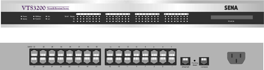
2.1.1 VTS3200 Panel Layout
The VTS3200 has three groups of LED indicator lamps to display the status, as shown in Figure
2-1 (i.e. System, Ethernet and Serial ports). The first three lamps on the left side indicate Power,
Ready and PCMCIA interface. The next three lamps are for Ethernet 100Mbps, Link and Act. Next
lamps indicate InUse, Receive and Transmit of the serial ports. Table 2-1 describes the function of
each LED indicator lamp. The rear panel shows the serial ports with RJ45 connector, Ethernet port,
the VTS3200 console port and the power socket.
Figure 2-1. The panel layout of the VTS3200

15
Table 2-1. LED indicator lamps of the VTS3200
Lamps Function
Power Turned on if power is supplied
Ready Turned on if system is ready to run
System
PCMCIA Turned on if a PCMCIA device is running
100Mbps Turned on if 100Base-TX connection is detected
LINK Turned on if connected to Ethernet network
Ethernet
Act Blink whenever there is any activities such as incoming or outgoing packets
through the VTS Ethernet port
InUse Turned on if the serial port is in use
(Port buffering enabled or port access in use)
Serial port
Rx/Tx Blink whenever there is any incoming or outgoing data stream through the
serial port of the VTS
2.1.2 VTS1600 Panel Layout
The front panel of the VTS1600 is nearly identical to the VTS3200. The VTS1600 has 16 serial
port indicators, while the VTS3200 has 32. For further information, refer to the chapter, 2.1.1.
VTS3200 Panel Layout.
2.1.3 VTS800 Panel Layout
The front panel of the VTS800 is nearly identical to the VTS3200. The VTS800 has 8 serial port
indicators, while the VTS3200 has 32. For further information, refer to the chapter, 2.1.1. VTS3200
Panel Layout.
2.1.4 VTS400 Panel Layout
The front panel of the VTS400 is nearly identical to the VTS3200. The VTS800 has 4 serial port
indicators, while the VTS3200 has 32. For further information, refer to the chapter, 2.1.1. VTS3200
Panel Layout.
2.1.5 VTS4800 Panel Layout
The VTS4800 has two groups of LED indicator lamps to display the status, as shown in Figure 2-
2 (i.e. System and Ethernet). The first four(five) lamps on the left side indicate Power 1(/2), Ready,
PCMCIA interface and Find-Me Function. The next three lamps are for Ethernet 100Mbps, Link and
Act. There is no lamp for serial ports in VTS4800 model. Table 2-2 describes the function of each LED
indicator lamp. The rear panel shows the serial ports with RJ45 connector, Ethernet port, the VTS4800
console port and the power socket.

16
(Front panel of Dual Power Model)
(Front panel of Single Power Model)
(Rear Panel)
Figure 2-2. The panel layout of the VTS4800
Table 2-2. LED indicator lamps of the VTS4800
Lamps Function
Power 1/2 Turned on if power is supplied
Ready Turned on if system is ready to run
PCMCIA Turned on if a PCMCIA device is running
System
Find Me Blinking if user select probing function through HD manager
100Mbps Turned on if 100Base-TX connection is detected
LINK Turned on if connected to Ethernet network
Ethernet
Act Blink whenever there is any activities such as incoming or outgoing packets
through the VTS Ethernet port
2.2 Connecting the Hardware
This section describes how to connect the VTS to the equipment for initial testing.
- Connect a power source to the VTS
- Connect the VTS to an Ethernet hub or switch
- Connect the device
2.2.1 Connecting the power
Connect the power cable to the VTS. If the power is properly supplied, the [Power] lamp will light
up green.
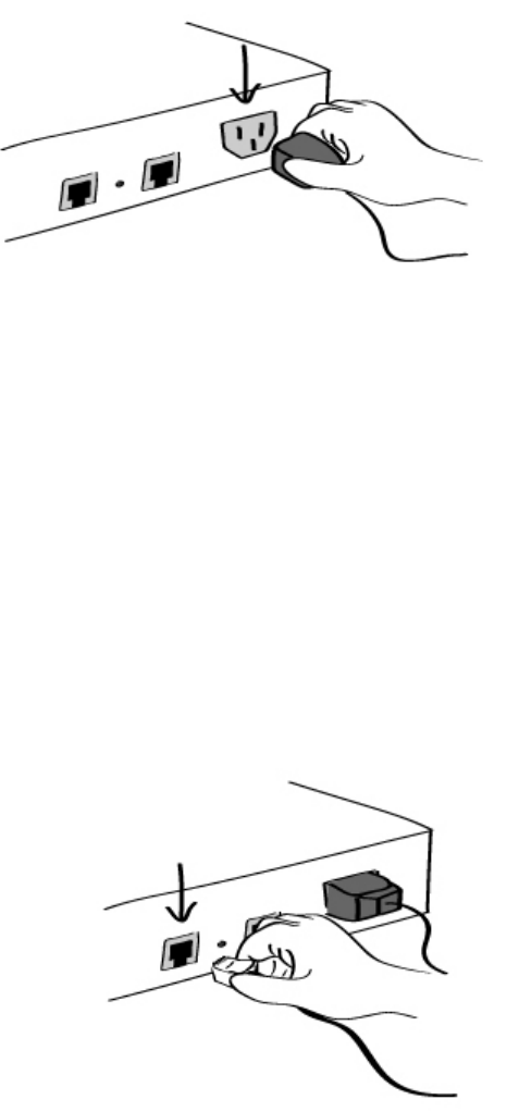
17
Figure 2-3. Connecting the power to the VTS
2.2.2 Connecting to the network
Plug one end of the Ethernet cable to the VTS Ethernet port. The other end of the Ethernet
cable should be connected to a network port. If the cable is properly connected, the VTS will have a
valid connection to the Ethernet network. This will be indicated by:
The [Link] lamp will light up green.
The [Act] lamp will blink to indicate incoming/outgoing Ethernet packets
The [100Mbps] lamp will light up green if the VTS is connected to 100Base-TX network
The [100Mbps] lamp will not turn on if the current network connection is 10Base-T.
Figure 2-4. Connecting a network cable to the VTS
2.2.3 Connecting to the device
Connect the console cable to the VTS serial port. To connect to the console port of the device,
the user needs to consider the type of console port provided by the device itself. In the VTS cable kit
package, plug-in adapters are provided for the easier connectivity to the user’s devices. Please refer
to the Appendix, A.3 Cabling diagram for details.
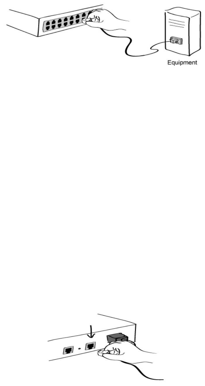
18
Figure 2-5. Connecting a equipment to the VTS
2.3 Accessing the System Console
There are several ways to access the VTS. These methods are dependent on whether the user is
located at a local site or a remote site, or whether s/he requires a menu-driven interface, graphic menu
system or CLI (Command Line Interface).
- System console:
Local users can connect directly to the system console port of the VTS using the console/Ethernet
cable with the corresponding adapter.
- Remote console:
Remote users who require a menu-driven interface can utilize Telnet (port 23) or SSH (port 22)
connections to the VTS using terminal emulator.
- Web:
Remote users who want to use a web browser to configure the VTS can connect to the VTS using
conventional web browsers, such as Internet Explorer or Netscape Navigator.
The above methods require the user authentication by the VTS system.
2.3.1 Using the System console
1) Connect one end of the console/Ethernet cable to the console port on the VTS.
Figure 2-6. Connecting a system console cable to the VTS

19
2) Connect to the user’s computer with the RJ45-DB9 female adapter.
3) Connect the other end of the cable to the serial port of the user’s computer.
4) Run a terminal emulator program (i.e. HyperTerminal). Set up the serial configuration
parameters of the terminal emulation program as follows:
9600 Baud rate
Data bits 8
Parity None
Stop bits 1
No flow control
5) Press the [ENTER] key.
6) Enter your user name and password to log into the VTS. The factory default user settings
are as follows.
Login: root Password: root
Login: admin Password: admin
192.168.161.5 login: root
Password:****
root@192.168.161.5:~#
192.168.161.5 login: admin
Password:
Welcome to VTS-3200 Configuration
Press Enter
7) Upon authentication, the corresponding user interface is displayed. Either the text-menu
driven interface or the CLI are initially provided for configuration. Please refer to the chapter
9.1. User Administration for details on the default user interfaces available for each user
role. For details on the CLI, refer to the chapter 11. CLI guide.
If the default interface is set up as text menu, the menu screen in Figure 2-7 is displayed.
192.168.161.5 login: admin
Password:
-------------------------------------------------------------------------------
Welcome to VTS-1600 configuration page
Current time : 02/25/2003 16:46:34 F/W REV. : v1.0.0
Serial No. : vts32000302-00001 MAC Address : 00-01-95-a1-89-b7
IP mode : Static IP IP Address : 192.168.161.5
-------------------------------------------------------------------------------
Select menu
1. Network Configuration
2. Serial Port Configuration
3. Clustering Configuration
4. Power Controller
5. PC Card Configuration

20
6. System Status & Log
7. System Administration
8. Save Changes
9. Exit without Saving
a. Exit and Apply Changes
b. Exit and Reboot
<ENTER> Refresh
----->
Figure 2-7. The main menu screen (VTS 3200)
From the main menu screen, the user may select the menu item for the configuration of the VTS
parameters by typing the menu number and pressing the [ENTER] key. In the submenu screen, users
can configure the required parameters guided by online comments. All the parameters are stored into
the non-volatile memory space of the VTS, and it will not be stored until users select menu 8.Save
Changes. All the configuration change will be effective after selecting the menu a. Exit and Apply
Changes or b. Exit and Reboot.
2.3.2 Using Remote console
The IP address of the VTS must be known before users can access the VTS using the Remote
console (see chapter 3. Network Configuration for details). The default VTS IP address is
192.168.161.5.
The Remote console access function can be disabled in the remote host access option (See IP
filtering in section 3.5 for details). The VTS supports both Telnet and SSH protocol for remote
consoles.
The following instructions will assist in setting up the Remote Console functionality:
1) Run either a Telnet (or SSH) program or a program that supports Telnet (or SSH) functions
(i.e. TeraTerm-Pro or HyperTerminal). The target IP address and the port number must
match the VTS. If required, specify the port number as 23 (or 22). Type the following
command in the command line interface of user’s computer.
telnet 192.168.161.5 (or ssh admin@192.168.161.5 )
Or run a Telnet program with the following parameters:
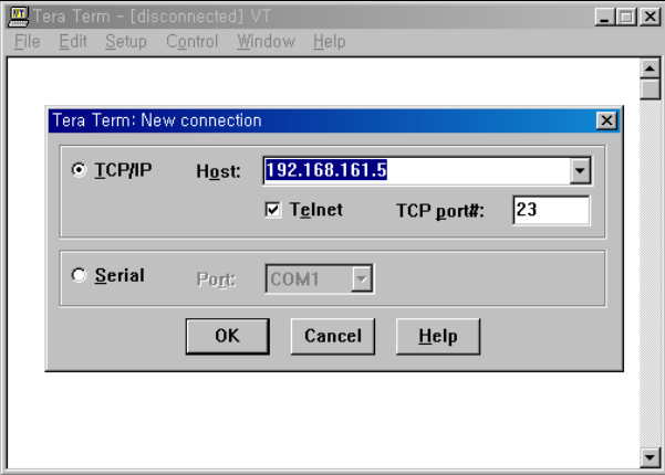
21
Figure 2-8. Telnet program set up example (TeraTerm Pro)
2) The user must log into the VTS. Type the user name and password. A factory default setting
of the user name and password are both root for the system root and admin for the system
administrator (See the section, 9.1. User Administration).
3) Upon authentication by the VTS, one of the CLI prompts or text menu screens are shown to
the user according to the default shell configuration of the user’s account. (Refer to Chapter
11. CLI guide for details if the user is logged into the CLI prompt.) The menu-driven
interface allows the user to select a menu item by typing the menu number and then pressing
[ENTER]. The corresponding screen allows user configuration of the required parameters.
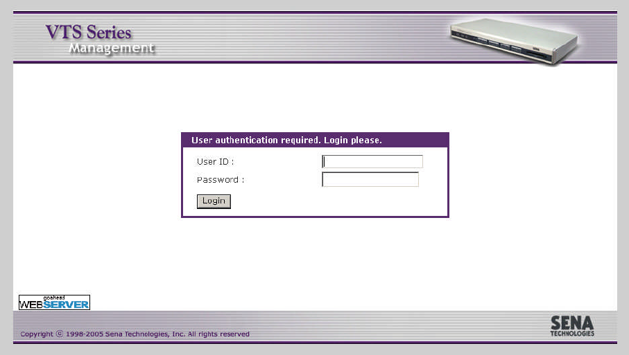
2.4 Accessing the Web Browser Management Interface
The VTS supports both HTTP and HTTPS (HTTP over SSL) protocols. The VTS also provides
has its own Web management pages. To access the VTS Web management page, enter the VTS’s IP
address or resolvable hostname into the web browser’s URL/Location field. This will direct the user to
the VTS login screen. The user must authenticate themselves by logging into they system with a
correct user name and password. The factory default settings are:
Login: root Password: root
Login: admin Password: admin
Note: Before accessing the VTS Web management page, the user must check the VTS’s IP address
(or resolvable Hostname) and Subnet mask settings.
22
Figure 2-9. Login screen of the VTS Web Management
Figure 2-10 shows the user homepage of the VTS Web management interface. A menu bar is
provided on the left side of the screen. The menu bar includes the uppermost configuration menu
groups. Selecting an item on the menu bar opens a tree view of all the submenus available under
each grouping. Selecting a submenu item will allow the user to modify parameter settings for that
item. Every page will allow the user to [Save to flash], [Save & apply] or [Cancel] their actions. After
changing the configuration parameter values, the users must select [Save to flash] to save the
changed parameter values to the non-volatile memory. To apply all changes made, the user must
select [Apply Changes]. This option is available on the bottom of the menu bar. Only when the user
selects [Apply changes] will the new parameter values be applied to the VTS configuration. The user
also can select [Save & apply] to save parameters and apply changes in one step.
If the user does not want to save the new parameter values, the user must opt to [Cancel]. All
changes made will be lost and the previous values restored.
23
Figure 2-10. The VTS Web Management screen

24
3: Network Configuration
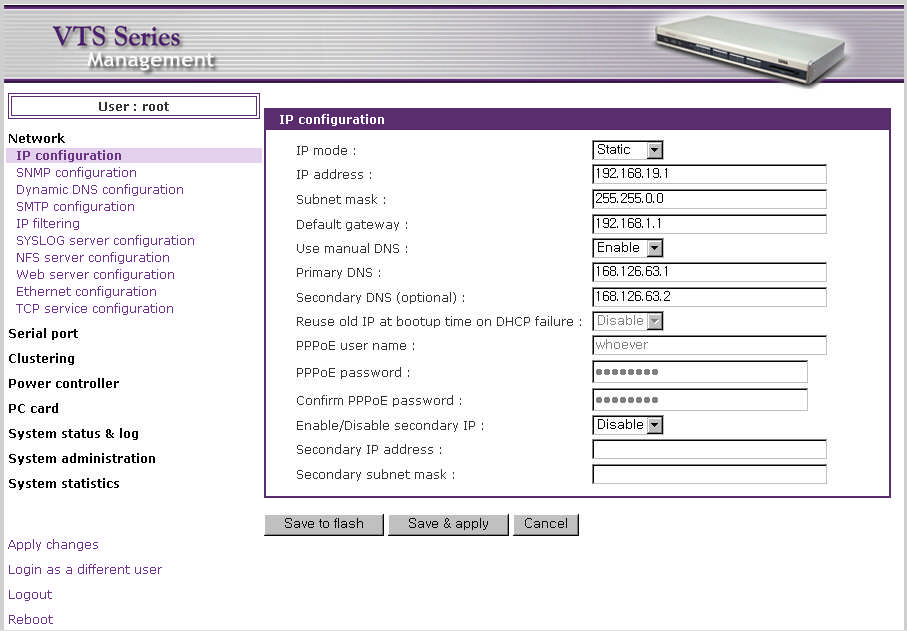
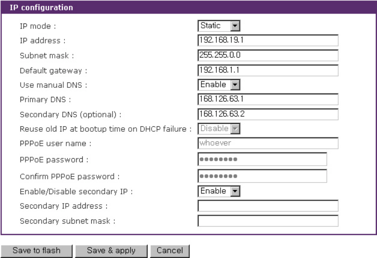
3.1 IP Configuration
The VTS requires a valid IP address to operate within the user’s network environment. If the IP
address is not readily available, contact the system administrator to obtain a valid IP address for the
VTS. Please note that the VTS requires a unique IP address to connect to the user’s network.
The users may choose one of three Internet protocols in setting up the VTS IP address: i.e.,
Static IP
DHCP (Dynamic Host Configuration Protocol)
PPPoE (Point-to-Point Protocol over Ethernet)
The VTS is initially defaulted to Static IP mode, with a static IP address of 192.168.161.5. Table
3-1 shows the configuration parameters for all three IP configurations. Figure 3-1 shows the actual
web-based GUI to change the user’s IP configuration.
Table 3-1. IP Configuration Parameters
IP address
Subnet mask
Default gateway
Use manual DNS(Enable only) / Primary DNS / Secondary DNS(Optional)
Static IP
Enable/Disable secondary IP /Secondary IP address /Secondary subnet mask
Use manual DNS / Primary DNS / Secondary DNS (Optional)
Reuse old IP at bootup time on DHCP failure
DHCP
Enable/Disable secondary IP /Secondary IP address /Secondary subnet mask
PPPoE Username
PPPoE Password
Use manual DNS / Primary DNS / Secondary DNS (Optional)
PPPoE
Enable/Disable secondary IP /Secondary IP address /Secondary subnet mask
The users can make the VTS not connected to the network by setting IP mode as Disable.
Users can also access to the VTS through the secondary IP address as long as Enable/Disable
secondary IP address is enabled and secondary IP address and subnet mask is set available in static
IP protocol. Refer to 3.1.1 Using a Static IP Address to enable and configure the secondary IP
address.
25
Figure 3-1. IP Configuration
3.1.1 Using a Static IP Address
When using a Static IP address, the user must manually specify all the configuration parameters
associated with the VTS’s IP address. These include the IP address, the network subnet mask, the
gateway computer and the domain name server computers. This section will look at each of these in
more detail.
Note: The VTS will attempt to locate all this information every time it is turned on. .
IP address
AStatic IP address acts as a “static” or permanent identification number. This number is
assigned to a computer to act as its location address on the network. Computers use these IP
addresses to identify and talk to each other on a network. Therefore, it is imperative that the selected
IP address be both unique and valid in a network environment.
Note: 192.168.1.x will never be assigned by and ISP (Internet Service Provider). IP addresses using
this form are considered private. Actual application of the VTS Series may require access to public
network, such as the Internet. If so, a valid public IP address must be assigned to the user’s computer.
A public IP address is usually purchased or leased from a local ISP.
Subnet mask
A subnet represents all the network hosts in one geographic location, such as a building or local
area network (LAN). The VTS will use the subnet mask setting to verify the origin of all packets. If the
desired TCP/IP host specified in the packet is in the same geographic location (on the local network
26
segment) as defined by the subnet mask, the VTS will establish a direct connection. If the desired
TCP/IP host specified in the packet is not identified as belonging on the local network segment, a
connection is established through the given default gateway.
Default gateway
A gateway is a network point that acts as a portal to another network. This point is usually the
computer or computers that control traffic within a network or a local ISP (Internet service provider).
The VTS uses the IP address of the default gateway computer to communicate with hosts outside the
local network environment. Refer to the network administrator for a valid gateway IP address.
Primary and Secondary DNS
The DNS (Domain Name System) server is used to locate and translate the correct IP address for
a requested web site address. A domain name is the web address (i.e. www.yahoo.com) and is
usually easier to remember. The DNS server is the host that can translate such text-based domain
names into the numeric IP addresses for a TCP/IP connection.
The IP address of the DNS server must be able to access the host site with the provided domain
name. The VTS provides the ability to configure the required IP addresses of both the Primary and
Secondary DNS servers addresses. (The secondary DNS server is specified for use when the
primary DNS server is unavailable.)
3.1.2 Using DHCP
Dynamic Host Configuration Protocol (DHCP) is a communications protocol that lets network
administrators manage and automate the assignment of IP addresses centrally in an organization's
network. DHCP allows the network administrator the ability to supervise and distribute IP addresses
from a central point and automatically send a new IP address when a computer is plugged into a
different network location.
When in static IP mode, the IP address must be entered manually at each computer. If a
computer is moved to another network location, a new IP address must be assigned. DHCP allows all
the parameters, including the IP address, subnet mask, gateway and DNS servers to be automatically
configured when the IP address is assigned. DHCP uses a “lease” concept in assigning IP
addresses to a computer. It limits the amount of time a given IP address will be valid for a computer.
All the parameters required to assign an IP address are automatically configured on the DHCP server
side, and each DHCP client computer receives this information when the IP address is provided at its
boot-up.
Each time a VTS is reset, the VTS broadcasts a DHCP request over the network. The reply
generated by the DHCP server contains the IP address, as well as the subnet mask, gateway address,
DNS servers and the “lease” time. The VTS immediately places this information in its memory. Once
the “lease” expires, the VTS will request a renewal of the “lease” time from the DHCP server. If the
27
DHCP server approves the request for renewal, the VTS can continue to work with the current IP
address. If the DHCP server denies the request for renewal, the VTS will start the procedure to
request a new IP address from the DHCP server.
Note: While in DHCP mode, all network-related parameters for the VTS are to be configured
automatically, including the DNS servers. If the DNS server is not automatically configured, the user
may manually configure the settings by entering the primary and secondary DNS IP addresses. To
force an automatic configuration of the DNS address, set the primary and secondary DNS IP
addresses to 0.0.0.0 (recommended).
A DHCP sever assigns IP addresses dynamically from an IP address pool, which is managed by
the network administrator. This means that the DHCP client, i.e. the VTS, receives a different IP
address each time it boots up. The IP address should be reserved on the DHCP server side to assure
that the user always knows the newly assigned VTS address. In order to reserve the IP address in
the DHCP network, the administrator needs the MAC address of the VTS found on the label sticker at
the bottom of the VTS.
Setting Reuse old IP at bootup time on DHCP failure as Enable, if the VTS fails to receive an
IP address from the DHCP server on booting up, the users can set the IP configurations of the VTS
with the previous IP configurations and connect it to the network. When the “lease” expires, the VTS
requests a renewal.
3.1.3 Using PPPoE
PPPoE (Point-to-Point Protocol over Ethernet) is a specification for connecting multiple computer
users on an Ethernet LAN (local area network) to a remote site through a modem or similar device.
PPPoE can be used to multiple users the ability to share ADSL, cable modem, or wireless connection
to the Internet.
To use the VTS in PPPoE mode, users require a PPPoE account and the necessary equipment
for PPPoE access (i.e. an ADSL modem). Since the VTS provides a PPPoE protocol, it can access
the remote host on the Internet over an ADSL connection. The user will have to set up the user name
and password of the PPPoE account for the VTS.
The VTS negotiates the PPPoE connection with the PPPoE server whenever it boots up. During
the negotiation, the VTS receives the information required for an Internet connection, such as the IP
address, gateway, subnet mask and DNS servers. If the connection is established, the VTS will
maintain the connection for as long as possible. If the connection is terminated, the VTS will attempt to
make a new PPPoE connection by requesting a new connection.
Note: While in PPPoE mode, all network-related parameters for the VTS are to be configured
automatically, including the DNS servers. If the DNS server is not automatically configured, the user
may manually configure the settings by entering the primary and secondary DNS IP addresses. To
28
force an automatic configuration of the DNS address, set the primary and secondary DNS IP
addresses to 0.0.0.0 (recommended).
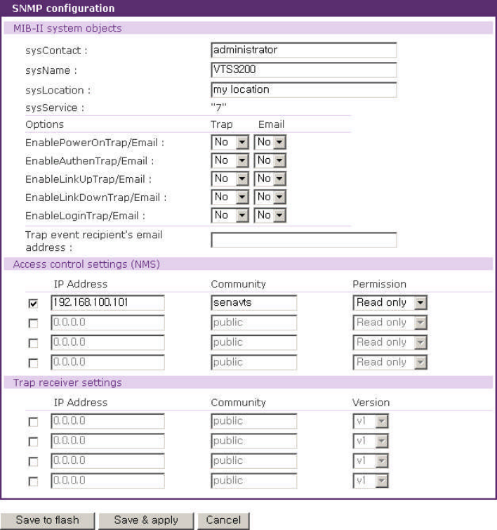
3.2 SNMP Configuration
The VTS has the SNMP (Simple Network Management Protocol) agent supporting SNMP v1 and
v2 protocols. Network managers like NMS or SNMP Browser can exchange information with VTS, as
well as access required functionality.
SNMP protocols include GET, SET, GET–Next, and TRAPs. With these functions, a manager can
be notified of significant events (TRAPs), query a device for more information (GET), and make
changes to the device state (SET). SNMPv2 adds a GET–Bulk function for retrieving tables of
information and security functions.
With the SNMP configuration panel, the user can configure MIB-II System objects, access control
settings and TRAP receiver settings. The manager configured in this menu can perform both
information exchange and action control. Figure 3-2 shows a SNMP configuration screen via a web
interface.
Figure 3-2. SNMP configuration
29
3.2.1 MIB-II System objects Configuration
MIB–II System objects configuration sets the System Contact, Name, Location, and
Authentication-failure traps used by the SNMP agent of the VTS. These settings provide the values
used for the MIB-II sysName, sysContact, sysLocation, snmpEnableAuthenTraps, snmpEnable-
PowerOnTrap, snmpEnableAuthenTrap, snmpEnableLinkUpTrap, snmpEnableLinkDownTrap and
snmpEnableLoginTrap Object Identifications (OIDs). The VTS can be set to send the emails to the
Trap event recipient’s email address when snmpEnableAuthenTraps, snmpEnable- PowerOnTrap,
snmpEnableAuthenTrap, snmpEnableLinkUpTrap, snmpEnableLinkDownTrap and snmpEnable
LoginTrap are generated.
Brief descriptions of each OIDs are as follows,
-sysContact: Identification of the contact person for the managed system (VTS), and a
description of how to contact the person.
-sysName: Name used to identify the system. By convention, this is the fully qualified domain
name of the node.
-sysLocation: The physical location of the system (e.g., Room 384, Operations Lab, etc.).
-sysService(Read Only) : A series of values, separated by commas, that indicate the set of
services that the system provides. By default, VTS only supports an Application(7) service level.
-EnablePowerOnTrap: Indicates whether the SNMP agent process is permitted to generate
power-on traps.
-EnableAuthenTrap: Indicates whether the SNMP agent process is permitted to generate
authentication-failure traps. The value of this object overrides any configuration information; as
such, it provides a means whereby all authentication-failure traps may be disabled..
-EnableLinkUpTrap: Indicates whether the SNMP agent process is permitted to generate
Ethernet-link traps
-EnableLinkDownTrap: Indicates whether the SNMP agent process is permitted to generate
Ethernet-link-down traps
-EnableLoginTrap: Indicates whether the SNMP agent process is permitted to generate system
login traps.
If users need support for adding or modifying MIBs, please contact Sena technical support.
For more information about the MIBs and SNMP, see the RFCs 1066, 1067, 1098, 1317, 1318
and 1213.
3.2.2 Access Control Settings
Access Control defines accessibility of managers to the VTS SNMP agent. Only the manager set
in this menu can access VTS SNMP agent to exchange information and control actions. If there is no
specified IP address (all IP address are defaulted to 0.0.0.0), a manager from any host can access the

30
VTS SNMP agent.
3.2.3 Trap Receiver Settings
The Trap receiver defines managers, which can be notified of significant events(TRAP) from the
VTS SNMP agent.
3.2.4 Management using SNMP
The VTS can be managed through the SNMP protocol using NMS (Network Management
System) or SNMP Browser. Before using the NMS or SNMP Browser, the user must set the access
control configuration properly so that the VTS permits host access where the NMS or SNMP Browser
is executed. Figure 3-3 shows a screen shot of a typical SNMP browser with MIB-II OIDs of the VTS
SNMP agent.
Figure 3-3. Browsing MIB-II OIDs of VTS SNMP agent using SNMP Browser
(AdventNet MibBrowser)

31
3.3 Dynamic DNS Configuration
When users connect the VTS to a DSL line or use a DHCP configuration, the IP address might be
changed whenever it reconnects to the network. It can therefore be very difficult to post all related
contacts for each new IP address. In addition, if the administrator only has access through the remote
console, there is no way to know if an IP address has changed, or what the new IP address is.
A Dynamic DNS service is provided by various ISPs or organizations to deal with the above issue.
By using the Dynamic DNS service, users can access the VTS through the hostname registered in the
Dynamic DNS Server regardless of any IP address change.
By default, the VTS only supports Dynamic DNS service offered at Dynamic DNS Network
Services, LLC (www.dyndns.org). Contact Sena technical support for issues regarding other Dynamic
DNS service providers.
To use the Dynamic DNS service provided by Dynamic DNS Network Services, the user must set
up an account in their Members' NIC (Network Information Center - http://members.dyndns. org). The
user may then add a new Dynamic DNS Host link after logging in to their Dynamic DNS Network
Services Members NIC.
After enabling the Dynamic DNS service in the Dynamic DNS Configuration menu, the user must
enter the registered Domain Name, User Name, and Password. After applying the configuration
change, users can access the VTS using only the Domain Name.
Figure 3-4 shows the Dynamic DNS configuration web interface.
Figure 3-4. Dynamic DNS configuration
32
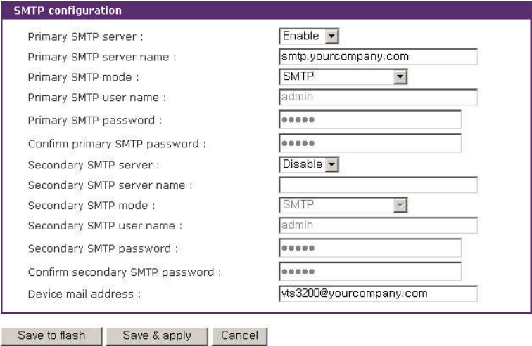
3.4 SMTP Configuration
The VTS can send an email notification when the number of system log messages reaches to
certain value and/or when an alarm message is created due to an issue with serial port data. The user
must configure a valid SMTP server to send these automatically generated emails. The VTS supports
three SMTP server types:
SMTP without authentication
SMTP with authentication
POP-before-SMTP
Figure 3.6 shows these examples. Required parameters for each SMTP configuration include:
Primary / Secondary SMTP server name
Primary / Secondary SMTP mode
Primary / Secondary SMTP user name
Primary / Secondary SMTP user password
Device mail address
Figure 3-5. SMTP configuration
33
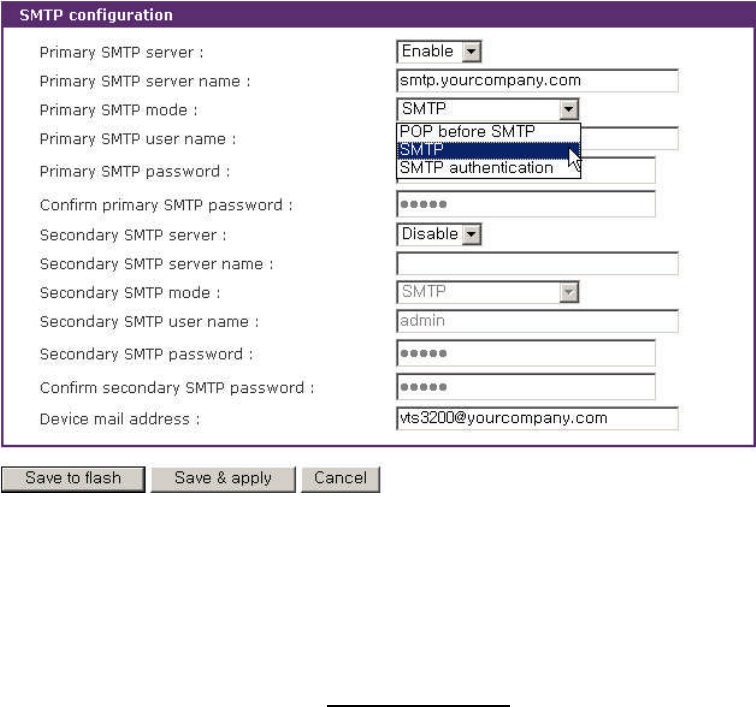
Figure 3-6. SMTP mode selection in SMTP configuration
The device mail address specifies the sender’s email address for all log and alarm delivery emails.
SMTP servers often check only the sender’s host domain name of the email address for validity. .
Consequently, the email address set for the device can use an arbitrary username with a registered
hostname (i.e. arbitrary_user@yahoo.com or anybody@sena.com).
The SMTP user name and SMTP user password are required when either SMTP with
authentication or POP-before-SMTP mode is selected.
Secondary SMTP configuration is also provided so that mail can be delivered even when the
primary SMTP server fails. Only when the primary SMTP server fails, the secondary SMTP server will
be tried for mail delivery.
3.5 IP Filtering
The VTS keeps unauthorized hosts from accessing to the VTS by specifying IP filtering rules. An
IP filtering rule consists of Interface,Option,IP address/Mask, Protocol, Port and Chain rule.
Interface
The Interface is the optional name of the network interface via which a packet is received. It can
be one of these three values:
eth0 : the VTS default interface
eth1 : the interface added by network PC card or wireless network PC card

34
all : both of eth0 and eth1
Option
The Option determines that this rule will be applied to the hosts included or excluded in hosts
range specified by the IP address/Mask. It can be one of these two values:
Normal : applied to the hosts included
Invert : applied to the hosts excluded
IP address/Mask
The IP address/Mask specifies the host range by entering base host IP address followed by “/”
and subnet mask. The host range can be one of the following scenarios by changing the value:
Only one host of a specific IP address
Hosts on a specific subnet
Any host
Table 3-2. Input examples of IP address/Mask
Input format
Specified host range Base Host IP address Subnet mask
Any host 0.0.0.0 0.0.0.0
192.168.1.120 192.168.1.120 255.255.255.255
192.168.1.1 ~ 192.168.1.254 192.168.1.0 255.255.255.0
192.168.0.1 ~ 192.168.255.254 192.168.0.0 255.255.0.0
192.168.1.1 ~ 192.168.1.126 192.168.1.0 255.255.255.128
192.168.1.129 ~ 192.168.1.254 192.168.1.128 255.255.255.128
Protocol
The Protocol determines which protocol the host uses to communicate with the VTS. It can be
one of three values such as TCP, UDP and ICMP.
Port
The Port is a port or port range of the VTS which hosts try to access to. The port range can be
specified by entering port1:port2 where the port range starts with port1 and ends with port2.
Chain rule
The Chain rule determines whether the access of the hosts is allowed or not. It can be one of the
these two values :
ACCEPT : access allowed
DROP : access not allowed
35
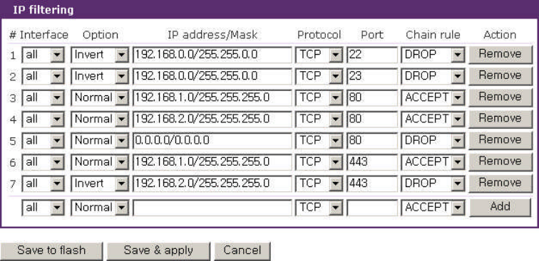
Figure 3-7 shows IP filtering configuration.
Figure 3-7. IP filtering configuration
The #1 IP filtering rule at Figure 3-7 means the hosts which is not included (Option : invert) in the
host range from 192.168.0.1 to 192.168.255.254(IP address/Mask : 192.168.0.0/255.255.0.0) are not
allowed (Chain rule : DROP) to connect to SSH (port : 22) of the VTS via both of eth0 and eth1
(Interface : all). The #1 allows only the hosts whose subnet is 192.168.x.x to access to the VTS
through SSH. The #2 IP filtering rule allows those which belongs to the subnet 192.168.x.x to connect
to the VTS through the telnet via both eth0 and eth1.
No host is allowed to connect to the VTS through http (port 80) by the #5 rule but the hosts whose
subnet is 192.168.1.x is allowed by the #3 rule and 192.168.2.x by the rule #4. So, only the hosts
which belong to the subnet 192.168.1.x or 192.168.2.x can access to the VTS through http by the #3,
#4 and #5 rules.
No host except the hosts whose subnet is 192.168.1.x is allowed to connect to the VTS through
https (port 443) by the #7 rule. But, hosts included in the subnet 192.168.1.x are allowed by the #6 rule.
So, only the hosts which belong to the subnet 192.168.1.x or 192.168.2.x can access to the VTS
through https by the #6 and #7 rules.
Users can add a new IP filtering rule by setting the properties at adding line and then clicking the
Add button. User can remove a rule by clicking the Remove button. Users can also edit the rules if
they set the rule properties and click the Save to flash or the Save & apply button. The VTS will not
filter the access of the hosts according to the IP filtering rules before users apply the changes by
clicking the Save & apply button or selecting Apply changes at menu.
36
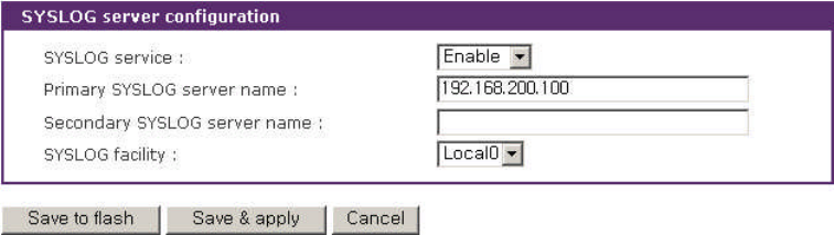
3.6 SYSLOG server configuration
The VTS supports a remote message logging service, SYSLOG service for the system and port
data logging. To use the remote SYSLOG service, the user must specify the SYSLOG server’s IP
address or domain name and the facility to be used. Figure 3-8 shows the SYSLOG server
configuration page of the supplied Web interface. The VTS provides a maximum of two SYSLOG
servers. If the secondary SYSLOG server is configured, the VTS will send the same SYSLOG
messages to both servers.
Figure 3-8. SYSLOG server configuration
To receive log messages from the VTS, the SYSLOG server specified in the VTS’s configuration
must be configured as “remote reception allowed”. If there is a firewall between the VTS and the
SYSLOG server, the user must add a rule that will allow all outgoing and incoming UDP packets the
ability to travel across.
The VTS supports SYSLOG facilities from local0 to local7. The user can employ these facilities to
save messages from the VTS separately from the SYSLOG server.
If the SYSLOG service is enabled and the SYSLOG server configuration is properly set up, the
user can specify the storage location for the VTS’s system log or port data log as SYSLOG server. For
more information about the configuration of port/system log storage location, please refer to section,
4.3.7 Port Logging and 8.2 System Log Configuration.
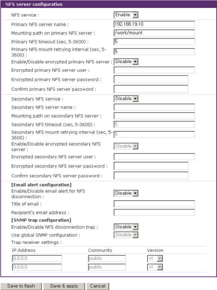
3.7 NFS server configuration
The VTS supports NFS (Network File System) service for system or port data logging functions.
The user must specify the NFS server’s IP address and the mounting path on the NFS server to use it.
Figure 3-9 shows the web based NFS server configuration page.
To store the VTS log data to the NFS server, the NFS server specified in the VTS’s configuration
must be configured as “read and write allowed”. If there is a firewall between the VTS and NFS
server, the user must add a rule that will allow all outgoing and incoming packets to travel across.
37
If the NFS service is enabled and the NFS server configuration is properly set up, the user can
specify the storage location for the VTS’s system log or port data log as the NFS server. If secondary
NFS server is configured, the same VTS log messages are stored also in the secondary NFS server.
For more information about the configuration of the port/system log storage location, please refer to
section, 4.3.7 Port Logging and 8.2 System Log Configuration.
Figure 3-9. NFS server configuration
Required parameters for each NFS server configuration include:
Primary / Secondary NFS server IP address
38
Mounting path on primary / secondary NFS server
Primary / Secondary NFS timeout
Primary / Secondary NFS mount retrying interval
Enable/Disable encrypted primary / secondary NFS server
Encrypted primary / secondary NFS server user
Encrypted primary / secondary NFS server password
Email alert configuration
SNMP trap configuration
NFS timeout specifies time out value for VTS to check how long it will wait the response from the
NFS server if NFS server is not responding for some time. If there is no response form NFS server
during the NFS timeout interval, VTS releases (unmount) a local directory which is mounted to the
directory of NFS server(mounting path on NFS server) and changes data logging location to memory
automatically if it is needed.
NFS mount retrying interval specifies time intervals for VTS to check whether connecting to
NFS server is possible. VTS check whether connecting to NFS server is possible for every NFS
mount retrying interval. And if connection to NFS server is possible, VTS remounts mounting path
on NFS server on its local directory again and changes data logging location to NFS server
automatically if it is needed.
Whereas NFS is a wide spread protocol for sharing files through network, it has following security
problem because it uses UDP protocol in general.
- Data between NFS server and client cannot be encrypted.
- There is no authentication method for the user who tries to connect NFS server.
- It is very difficult to use NFS if there is Firewall between NFS server and client.
But Encrypted NFS feature in VTS solves above problems by using SSH tunneling. To use Encrypted
NFS feature, user must use NFS server that support TCP protocol. Most NFS servers for Microsoft
Windows support TCP protocol. And also SSH daemon must be installed and run on the same host
which be used as an Encrypted NFS server for VTS. And finally a utility program, pause.exe, which is
included CR ROM accompanied with VTS products must be copied to the directory where SSH
daemon program is located. For more detail procedures about using Encrypted NFS, please see
Appendix F. Guide to use Encrypted NFS feature section.
If Enable/Disable email alert for NFS disconnection is set as Enable, the VTS will send an
email according to the Email alert configuration on NFS server disconnection. If user configures
39
Enable/Disable NFS disconnection trap as Enable and IP address at trap receiver settings as trap
receiver, the VTS will transfer the NFS disconnection trap according to the Trap receiver settings
whenever NFS server is down. If Use global SNMP configuration is set as Enable, trap receiver
settings configured at SNMP configuration are used as the destination of the SNMP trap. For details
of SNMP trap configurations and descriptions, please refer to section 3.2 SNMP Configuration.
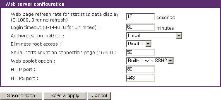
3.8 Web server configuration
The VTS’Web server supports both HTTP and HTTPS (HTTP over SSL) services simultaneously.
The user can opt to enable or disable each individually at security profile. For details of security profile ,
please refer to section 9.7 Security Profile. Figure 3-10 shows the Web based server configuration
page.
Figure 3-10. Web server configurations
The Web page refresh rate can be also adjusted in this configuration page. The refresh rate is
only applicable to the serial port connection page, system statistics pages such as network interfaces,
serial ports, IP, ICMP, TCP and UDP and power controller management pages. Other pages in the
Web interface are not refreshed automatically. For more information about the serial port connection,
please refer to section 4.5 Serial port connection.And for more information about the system
statistics, please refer to section 10. System Statistics.
If Login timeout is set, the VTS will prompt to login when user tries to use web interface again
after login timeout without using it. If it is set 0, login will not be prompted.
Users can select Authentication method for the VTS web pages login. The VTS currently
provides authentication methods of Local, RADIUS server, RADISU down - Local, TACACS+ server,
LDAP server, Kerberos Server and Custom PAM. Please refer to section 4.3.10 Authentication
40
configuration for details in authentication methods.
The VTS Root user can be limited to access the VTS web interface by selecting Enabled at
Eliminate root access. To keep the VTS Root user from access the remote or serial console of the
telnet or SSH protocol, please refer to section 11. CLI Guide 11.1 Introduction.
Notes: Differently with serial ports user authentication, the VTS always refers to the local database for
the web server login user authentication. Even when the user authentication method is configured as
RDAIUS, TACAS+, LDAP, Kerberos, the authentication will be failed if local database has no record for
the corresponding user. However, in this case, the password in the remote authentication server will
be utilized instead of the password in the local database. Please refer to the section 4.3.10
Authentication configuration for the serial port authentication details. Also, please refer to the
section 9.1 User Administration for the user administration of local database.
The Serial ports count on connection page determines how many ports are displayed a page
at the serial port connection page. If there are more ports to display than it, the list box which helps to
move to some other pages is shown up. For more information about the serial port connection, please
refer to section 4.5 Serial port connection.
The Web applet option determines what kind of Java applet is used on accessing to the
serial/remote port or the serial port of the clustering slave unit. For built-in applet such as Built-in with
SSH1 and Built-in with SSH2, there is no difference for telnet protocol. But the Built-in with SSH1
option means SSH version 1 is used and Built-in with SSH2 option means SSH version 2 is used for
SSH protocol. If Built-in with SSH1 is selected for the Web applet option and SSHV1 is disabled at
security profile, the port with SSH protocol may not be accessible through java applet. User defined
java applet is available. After copying the user defined java applet to /usr2/jta.jar, the User
defined option is added to the list box of the Web applet option. Selecting the User defined makes it
possible to use the customized java applet.
The HTTP port and the HTTPS port determine the port of the VTS web services.
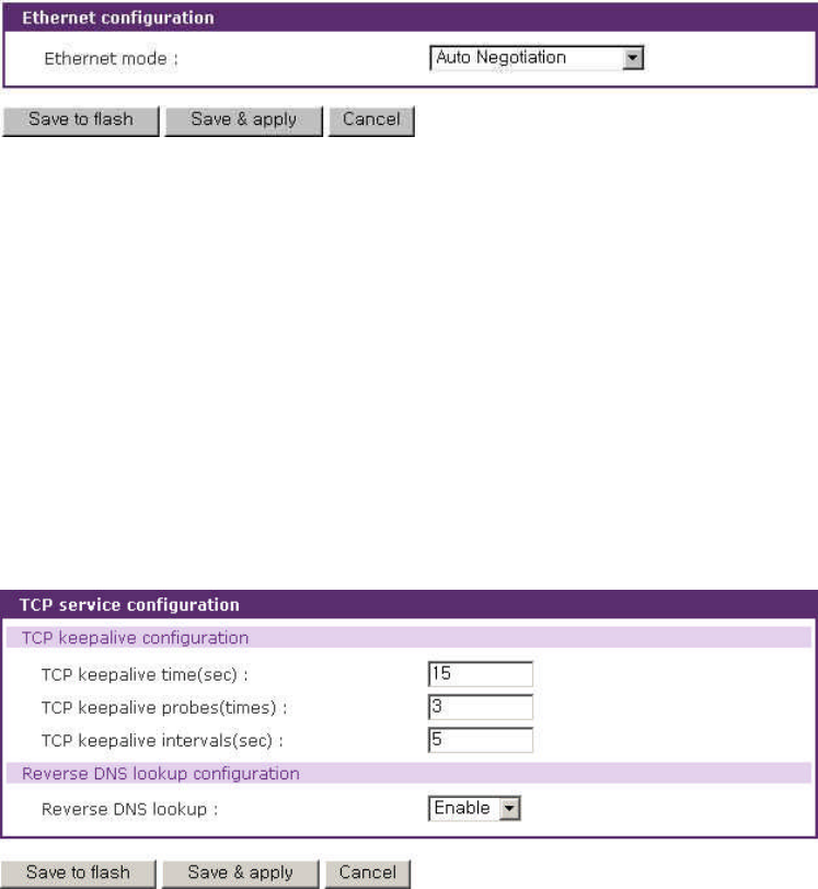
3.9 Ethernet configuration
The VTS supports several types of Ethernet modes:
- Auto Negotiation
- 100 BaseT Half Duplex
- 100 BaseT Full Duplex
- 10 BaseT Half Duplex
41
- 10 BaseT Full Duplex
After changing the Ethernet mode, the user must reboot the system. The factory default value of
the Ethernet mode is Auto Negotiation. With most network environments, Auto Negotiation mode
should work fine and recommended. Invalid Ethernet mode settings will not make the VTS work in the
network environment.
Figure 3-11. Ethernet mode configuration
3.10 TCP service configuration
If a TCP session is established between two hosts, it should be closed (normally or abnormally)
by either of the hosts to prevent the lock-up of the corresponding TCP port. To prevent this type of
lock-up situation, the VTS provides a TCP “keep-alive”feature. The VTS will send packets back and
forth through the network periodically to confirm that the network is still alive. The corresponding TCP
session is automatically closed if there’s no response from the remote host.
Figure 3-12. TCP service configuration
To use the TCP “keep-alive”feature with the VTS, the users should configure three parameters
as follows:
-TCP keep-alive time :
42
This represents the interval of time between packet submissions by the VTS. These “keep-
alive”messages are sent to the remote host after the TCP session is open to confirm that the
session is still open. The default time value is 15 sec.
-TCP “keep-alive”probes :
This represents how many “keep-alive”probes the VTS will send to the remote host, until it
decides that the connection is dead. Multiplied with the “TCP ‘keep-alive’intervals”, this gives
the time that a link is forced to close after a “keep-alive”packet has been sent for the first time.
The default is 3 times
-TCP keep-alive intervals :
This represents the interval of time before a “keep-alive”packets is retransmitted, due to no
acknowledgement by the original Chinatown. The default value is 5 seconds.
By default, the VTS will send the keep-alive packets 3 times with 5 seconds interval after 15
seconds have elapsed since the time when there’s no data transferred back and forth.
To convert the IP addresses of the form xxx.xxx.xxx.xxx to the domain names and to display the
domain names, the users should set the Reverse DNS lookup enabled.
43
4: Serial Port Configuration
4.1 Overview
The serial port configuration capability allows the user to configure the host mode of each port,
serial communication parameters, port logging parameters and other related parameters.
The serial port’s host mode can be set as any of the following:
Console server mode: Connection requests are sent from the remote host. This is to
allow access to the serial port from the remote host.
Terminal server mode: Connection requests are sent from the serial port. This is to allow
access to the remote host on the network or execute a shell program of VTS.
Dial-in modem mode : Allows access to the VTS from a remote site via an analog
modem connection.
Dial-in terminal server mode: Allows access to the remote host on the network via an
analog modem connection.
The VTS supports remote ports where connection requests are sent from the remote host like the
console server mode of the serial port but it allows access to the remote host on the network unlike
the console server mode. So, remote ports have not serial port parameters configuration but remote
port parameters configuration where the properties of the remote host to access is set.
The VTS also provides a port access menu. This menu displays all the serial ports via the web
for easier access to the serial ports. The user is able to access any serial port by simply clicking the
hyperlink for the port.
With the port-logging feature while in console server mode, the data sent through the serial port
is transferred to MEMORY, SYSLOG server, NFS server’s storage or an ATA/IDE fixed disk card
using a PC Card slot. The user can also define keywords for each serial port that will trigger an email
or SNMP trap notification. This will enable the user to monitor the data from the attached device.
Using MEMORY to store data will result in loss of all information when the VTS is turned off.
Use the NFS server or ATA/IDE fixed disk card to preserve the serial port log data.
One of the useful features provided is the “port sniffing” function. By using “port sniffing”
function, users can access a serial port concurrently. But maximum number of sniff user is limited up
to 15 users per port. This safeguard prevents unexpected memory shortages due to the increase of
TCP sessions.

44
If the host which is connected to a serial port on console server mode or is connected through
network on remote port provide a KVM function, VTS helps the users to connect to the server with the
KVM client program.
The serial ports and the remote ports can be configured individually or all at once. Table 4-1
summarizes the configuration parameters related to the serial port configuration.
Table 4-1. Serial port configuration parameters
Port access menu Enable/Disable
Port access menu port number (listening TCP port)
Port access menu protocol (Telnet or SSH)
Port access menu inactivity timeout (seconds)
Port access menu local IP
Port access menu quick connect via (Web applet or Local client)
Port access menu web applet encoding – Web applet only (English (latin1), Korean
(KSC5601), Japanese (eucjp), Unicode (UTF8))
Login on port access Enable/Disable
Port access menu authentication method (Local, RADIUS, TACAS+, LDAP)
Enable/Disable email alert for port login
Title of email
Recipient’s email address
Enable/Disable port login trap
User global SNMP configuration
IP Address
Community
Port Access
Menu
First / Second
Trap receiver
settings Version
Enable/Disable port
Reset port (except all ports setting)
Port
Enable/Disable Set port as factory default (except all ports setting)
Automatic detection Enable/Disable
Use detected port title Enable/Disable
Port title
Probe string
Detected OS (Read only)
Device detection method (Active or Passive)
Detection initiation (Periodically, If new device is detected)
Port title
Detection delay
Apply all port settings (except all ports setting)
Enable/Disable assigned IP
Assigned IP
Listening TCP port
Protocol (Telnet/SSH/RawTCP)
Inactivity timeout (0 for unlimited)
Enable/Disable port escape sequence
Port escape sequence
Port break sequence
Use comment
Quick connect via
Console
server
Web applet encoding (same as Port access
menu web applet encoding)
Terminal server option (Remote connection /
Shell program)
All ports
setting
Or
Individual
serial port
setting
#1~#4
(8, 16, 32, 48)
Or
Remote port Host mode
configuration
Terminal
server
(except
remote port)
Terminal server shell program path

45
Destination IP
Destination port
Protocol (Telnet/SSH/RawTCP)
remote port)
Inactivity timeout (0 for unlimited)
Modem init string
Enable/Disable dial-in modem callback
Dial-in modem callback phone number
Enable/Disable dial-in modem test
Dial-in modem test phone number
Dial-in modem
(except
remote port)
Dial-in modem test interval
Destination IP
Destination port
Protocol (Telnet/SSH/ RawTCP)
Inactivity timeout (0 for unlimited)
Dial-in
terminal
server
(except
remote port) Modem init string
Virtual KVM connection Enable/Disable
Automatic IP detection
IP address
Client program
Virtual KVM
configuration
Client program path
Baud rate
Data bits
Parity
Stop bits
Flow control
DTR behavior (except Dial-in modem / Dial-in terminal server)
Enable/Disable delimiter (RawTCP only)
Delimiter (RawTCP only)
Delimiter option (with / without delimiter) (RawTCP only)
Serial Port
Parameters
(except remote
port)
Inter-character timeout (ms) (RawTCP only)
IP address
Port
Remote Port
Parameters
(remote port only) Protocol
Port logging Enable/Disable
Logging direction (Server output / User input / Both with arrows /
Both without arrows)
Port log storage location (Memory / CF card / NFS server )
Port log to SYSLOG server Enable/Disable
Port log buffer size
Port log file name (User port title / Specify below + file name)
Time stamp to port log Enable/Disable
Show last 10 lines of a log upon connect Enable /Disable
Strip the ^M from SYSLOG (Port log SYSLOG server enable
only)
Automatic backup on mounting
Port logging
(only provided in
console server
mode)
Monitoring interval (sec.)
Key word
Case sensitive
Email notification Enable/Disable
Title of email
Recipient’s email address
SNMP trap notificatin Enable/Disable
Title of SNMP trap
Use global SNMP configuration
IP Address
Community
Port event
handling (only
provided on port
logging enabled)
First / Second
Trap receiver
settings Version
Port IP filtering
Allowed base hosts IP

46
(console server
mode only) Subnet mask to be applied
None
Local
First RADIUS authentication server
Second RADIUS authentication server
First RADIUS accounting server
Second RADIUS accounting server
RADIUS timeout (0-300 sec.)
RADIUS secret
RADIUS
server
RADIUS retries (0-50 times)
First TACAS+ authentication server
Second TACAS+ authentication server
First TACAS+ accounting server
Second TACAS+ accounting server
TACAS+
server
TACAS+ secret
First LDAP authentication server
Second LDAP authentication server
LDAP search base
LDAP server
Domain name for active directory
First Kerberos authentication server
Second Kerberos authentication server
Realm for first Kerberos server
Kerberos
server
Realm for second Kerberos server
Authentication
Custom PAM
Port
Monitor
<<Everyone>>
or individual
user’s or
access list’s
access Power
Enable/Disable sniff mode
Sniff session display mode (Server output /
User input / Both)
Display data direction arrows Enable/Disable
User access
control
Sniff session
Permit monitoring only mode Enable/Disable
Email alert for port login
Title of email
Recipient’s email address
Email alert for device connection
Title of email
Recipient’s email address
Email alert for active detection
Title of email
Recipient’s email address
Port login trap
Device connection trap
Active detection trap
Use global SNMP configuration
IP Address
Community
Console
server
First / Second
Trap receiver
settings Version
Email alert for dial-in modem test
Title of email
Recipient’s email address
Dial-in modem test trap
Use global SNMP configuration
IP Address
Alert
configuration
Dial-in modem
(Dial-in
modem test
enabled)
First / Second
Trap receiver
settin
gs
Community
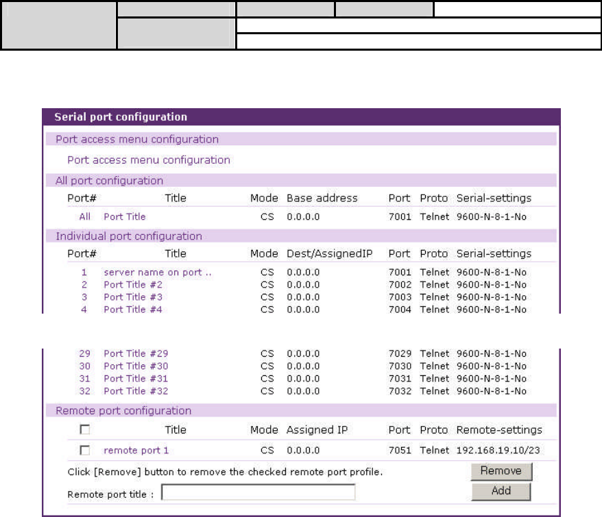
47
settings Version
Power controllerPower control
configuration Outlet
Figure 4-1 shows the web-based serial port configuration screen.
…
Figure 4-1. Serial port configurations main screen
To select and configure a serial port or a remote port individually, click the port number or title. To
configure all of the serial ports and the remote ports at once, click [All] or [Port Title], located below the
[All port configuration] label.
The user can add a remote port by providing remote port title and clicking the [Add] button at the
Remote port configuration tab. The user can remove the checked remote ports by clicking the
[Remove] button.
The user also has the ability to connect to each serial port or remote port and port access menu
from the configuration Web page using the terminal emulation Java applet. To access each port and
port access menu through the Web
1. The user must select the serial port connection link on the left menu bar
2. The user must select a terminal icon in the Individual port connection.
3. The user may now use the serial port link provided in the port access menu connection.
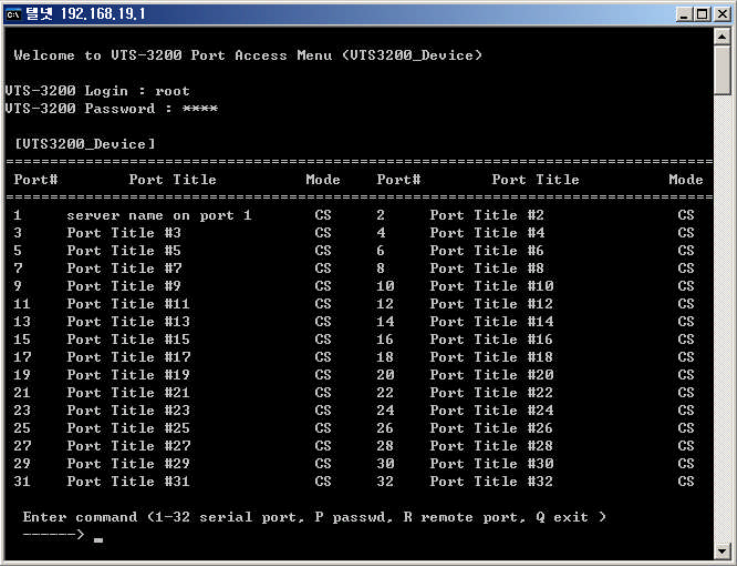
48
Notes: For serial port connections details, please refer to the section 4.5 Serial port connection
4.2 Port Access Menu Configuration
4.2.1 Overview
With the port access menu, the VTS will confirm connection to a specified virtual port via a
Telnet/SSH client connection. Once connected, the VTS will display the connection route to all serial
ports and remote ports on the port access menu. This will also include the port number, the port title
and the serial port mode. The VTS allows users to access a serial port configured as a console
server by selecting the corresponding port number at the menu. There is R menu for listing the remote
ports at the menu. After clicking it and moving to the list of the remote ports, users can access to a
remote port by selecting the remote port number.
Figure 4-2 shows the port access menu screen using the Windows Telnet program.
Figure 4-2. Accessing port access menu using Windows Telnet
The VTS connects to the virtual port by:
- Using the VTS IP address with the user-defined TCP port number as the port access menu
- Using the IP address of the virtual port with a pre-defined TCP port number
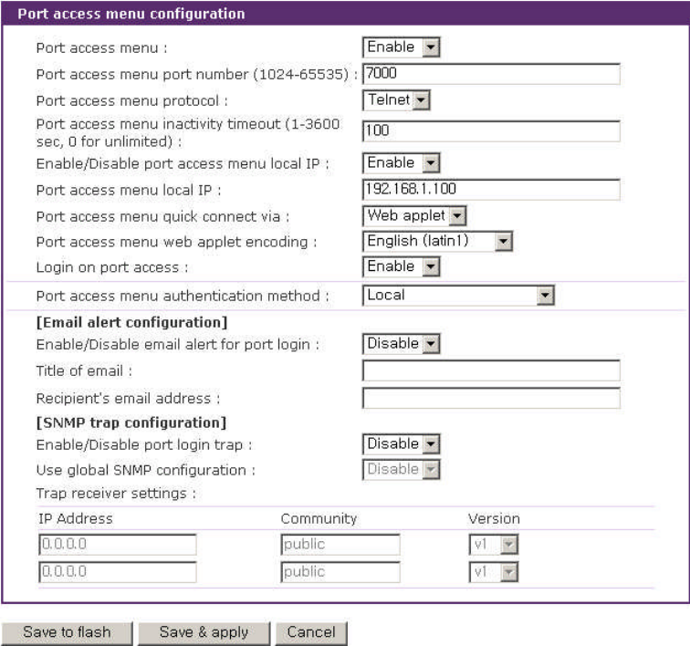
49
For example, if the VTS IP address is 192.168.1.100 and the TCP port number of the virtual port
is 6000, the user would enter the following command at the Windows Command Prompt:
telnet 192.168.1.100 6000 <ENTER>
If the IP address of this virtual port is 192.168.1.132, the user can also connect to the port without
using the port number by entering the following command at the Windows Command Prompt:
telnet 192.168.1.132 <ENTER>
Figure 4-3 shows the Port access menu configuration screen.
Figure 4-3 Port Access Menu Configuration
If Login on port access is set as Disable, the serial port connected through port access menu
does not prompt user authentication.
If Enable/Disable email alert for port login is set as Enable, an email is sent to the specified
address with the specified title when users login or logout port access menu. If Enable/Disable port
login trap is set as Enable, a SNMP trap is transferred to an administrator depending on trap receiver
50
settings.
Note: When assigning the IP address of the port access menu, the user must be sure not to conflict
with other host IP addresses. If there is a conflict, the IP address of the port access menu will be
disabled. If the user disables local IP or assigns 0.0.0.0 for the local IP, the VTS does not assign local
IP address for port access menu and the user should access the port access menu using the VTS IP
address and the VTS port number.
4.2.2 Authentication for the port access menu
The VTS provides a dual authentication procedure to access the port access menu. The user
must first be authenticated by the “port access menu authentication” method to access the port
access menu. The user must then be authenticated by the “serial port authentication” method to
access the serial port display.
If the “port access menu authentication”method is configured to [none], all users will have access
to the serial ports in the port access menu.
If the “serial port authentication” method is configured to [None], users will have no access into
the port.
If the “port access menu authentication” method is set to [Local] or another method (i.e.
RADIUS, LDAP, TACACS+ or Kerberos) is identified, the user can access the serial ports in the port
access menu when the following conditions are satisfied:
- The user is authenticated and gains access to the port access menu
- The user is authenticated and gains access to the serial port in the port access menu.
- The user is registered in the port’s user access list.
Once authenticated, the user can access only the “console server mode” serial ports. All other
serial ports are inaccessible.
Once authenticated, the user accessing the port access menu also has priority over all other
connections. If the user requests a connection currently in use, that connection is closed and a new
session is opened for the authenticated user.
Please refer to section 4.3.10 Authentication configuration for details in authentication methods.
4.2.3 Protocol of the port access menu
The port access menu protocol can be configured to use either Telnet or SSH. It may not be
coincident with that of each port. Because the protocol for the serial port is specifies the way to
connect to the VTS from remote hosts, it is meaningless if the users are already login to the VTS using
port access menu. Although it may seem to the users that the protocol configured for port access

51
menu overrides that for each serial port, the protocol selected for the port access menu has
precedence over that of the serial port.
4.2.4 Port access menu options
Users can assign which client program will be used for connection menu of the web page by
configuring Port access menu quick connect via option. If user configures Port access menu
quick connect via option as Web applet, the web applet will use Port access menu web applet
encoding option to encode the received data to the string to display. If Enable/Disable email alert for
port login is set as Enable, the VTS will send an email according to the Email alert configuration on
user’s login to or logout from the port access menu. If user configures Enable/Disable port login trap
as Enable and IP address at trap receiver settings as trap receiver, the VTS will transfer the port login
trap according to the Trap receiver settings whenever users log in to or log out from the port access
menu. If Use global SNMP configuration is set as Enable, trap receiver settings configured at SNMP
configuration are used as the destination of the SNMP trap. For details of SNMP trap configurations
and descriptions, please refer to section 3.2 SNMP Configuration.
4.2.5 Port access menu in clustering
In clustering mode (chapter 5), slave units can be accessed via port access menu of the master
unit. Users can select a slave unit by entering S key for slave unit menu and then selecting A~P key at
slave unit menu in the port access menu of the master unit. Once a slave unit is accessed, users can
see a port access menu of the slave unit, and access to a desired serial port within the port access
menu of the slave unit. The IP address at the top of the screen shows the IP address of the unit
currently being accessed.
[VTS3200_Device]
================================================================================
Port# Port Title Mode Port# Port Title Mode
================================================================================
1 Port Title #1 CS 2 Port Title #2 CS
3 Port Title #3 CS 4 Port Title #4 CS
5 Port Title #5 CS 6 Port Title #6 CS
7 Port Title #7 CS 8 Port Title #8 CS
9 Port Title #9 CS 10 Port Title #10 CS
11 Port Title #11 CS 12 Port Title #12 CS
13 Port Title #13 CS 14 Port Title #14 CS
15 Port Title #15 CS 16 Port Title #16 CS
17 Port Title #17 CS 18 Port Title #18 CS
19 Port Title #19 CS 20 Port Title #20 CS
21 Port Title #21 CS 22 Port Title #22 CS
23 Port Title #23 CS 24 Port Title #24 CS
25 Port Title #25 CS 26 Port Title #26 CS
27 Port Title #27 CS 28 Port Title #28 CS

52
29 Port Title #29 CS 30 Port Title #30 CS
31 Port Title #31 CS 32 Port Title #32 CS
Enter command ( 1-32 serial port, P passwd, S slave unit
R remote port, Q exit )
------> S
[VTS3200_Device]
==============================================================================
Unit # IP Unit # IP
==============================================================================
A 192.168.19.3 B ----------
C ---------- D ----------
E ---------- F ----------
G ---------- H ----------
I ---------- J ----------
K ---------- L ----------
M ---------- N ----------
O ---------- P ----------
Enter command ( A-P slave unit, L serial port, R remote port, Q exit )
------>
4.3 Individual Port Configuration
The VTS allows serial ports and remote ports to be configured either individually or all at once.
The parameters for both individual and all port configurations are similar.
Individual Port Configurations are classified into 12 groups:
1. Port enable/disable
2. Port title
3. Apply all port settings
4. Host mode configuration
5. Virtual KVM configuration: Only available if the host is set to Console Server Mode.
6. Serial port parameters: Only available for serial ports
7. Port logging: Only available if the host is set to Console Server Mode.
8. Port event handling: Only available if the host is set to Console Server Mode and Port
logging is enabled.
9. Port IP filtering: Only available if the host is set to Console Server Mode.
10. Authentication
11. User access control: Only available if the host is set to Console Server Mode.
12. Alert configuration: Only available if the host is set to Console Server Mode.
13. Power control configuration: Only available if a power controller is added.
Users can switch to another serial port configuration screen conveniently using the [--- Move to ---
] list box at the right upper side of the individual port configuration screen.
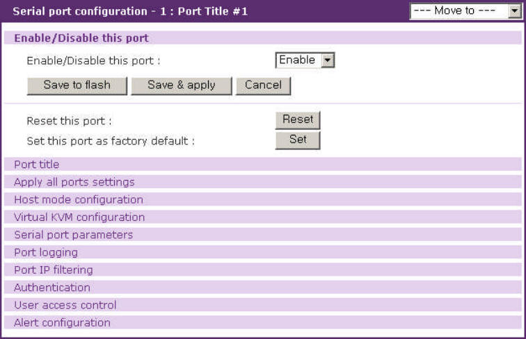
53
4.3.1 Port Enable/Disable
Each serial port and remote port can be enabled or disabled. If a serial port is disabled, users
cannot access the serial port or remote port. Figure 4-4 shows the port enable/disable screen.
Each stuck port can be reset by clicking the [Reset] button at the [Reset this port] part and set as
factory default by clicking the [Set] button at the [Set this port as factory default] part.
Figure 4-4. Port enable/disable
4.3.2 Port Title
Users can enter descriptive information for each port based on the device attached to it. This
can include the device type, vendor, and/or location. The port title is not only helpful in the
configuration process, but can also be utilized as descriptive information for the serial port
connection and port access menu.
The configuration parameters for port title are as follows:
Automatic detection
Use detected port title
Port title
Probe string
Device detection method
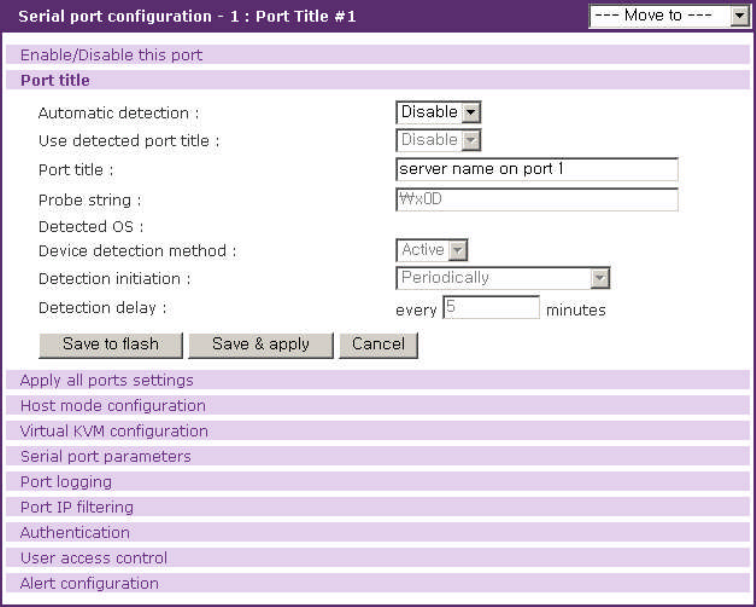
54
Detection initiation
Detection delay
Figure 4-5. Port title configuration
Automatic detection
This parameter determines whether the information of the device connected to serial port such as
operating system (OS) and host name is collected automatically. If host mode is console server
mode and the device connected to serial port is not a power controller, options can be
Enable/Disable. Otherwise, Disable is default. In the case of remote port, it is Disable and not
configurable.
Use detected port title
This parameter defines whether the device information detected automatically is used as the port
title. Only if Automatic detection is Enable, it is selective.
Port title
Only ff the device information is gathered automatically and used as port title – Automatic
detection is set Enable and Use detected port title is set Enable, this parameter is not configurable.
Otherwise, this parameter is used as the port title.
55
Probe string
Only if Automatic detection is set Enable, this parameter is configurable. It configures the
command that the VTS sends to the connected device to require the device information.
Device detection method
Only if Automatic detection is set Enable, this parameter is selective. Options are Active and
Passive.Active means that the VTS sends the command and parses the data received from the
device to get the device information such as OS and host name. Passive means that the VTS gets the
device information from the port log. Therefore, Passive can be selective only if Port logging is set
Enable. The way the VTS parses the data from the device into OS and host name can be customized
by modifying the /etc/active_detect or /etc/passive_detect script file. OS is logged /var
/run/OSPortxx at file and host name /var/run/HostnamePortxx where xx is port number.
Detection initiation
If Device detection method is set Active, options are Periodically and If new device is
detected but if Passive,Periodically is default. Periodically means that the VTS parses the device
data every Detection delay minutes. If new device is detected means that the VTS do it whenever
the event that a new device is connected to serial port occurs.
If Automatic detection is set Enable,Device detection method is Active and Detection
initiation is Periodically, VTS sends email or SNMP trap about the result of parsing device
information according to the properties of alert configuration page. Please refer to section 4.3.12 Alert
configuration for details.
Detection delay
If Detection initiation is set Periodically, this parameter is configurable. It determines how often
the VTS parses the device data.
4.3.3 Apply All Port Settings
To prevent the possibility of the user inadvertently selecting to change all port settings at the same
time, the VTS provides the ability to enable or disable this function at an individual serial port level.
Changes made when using the “change all port parameters at once”function will not be applied to an
individual serial port if the function has been disabled (See Figure 4-6. This shows the apply all port
setting configuration screen.
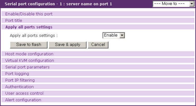
56
Figure 4-6. Apply all port setting configuration
4.3.4 Host Mode Configuration
The VTS operating mode is called the “host mode.”Four host modes are available:
Console Server Mode
Terminal Server Mode
Dial-in Modem Mode
Dial-in Terminal Sever.
Console Server Mode
This mode utilizes a TCP server socket , which listens for a Telnet or SSH client connection.
Once a Telnet or SSH client session is opened, the data stream can be sent back and forth to the
device connected to the serial port. Remote ports can have only this mode. Remote ports access to
the remote host configured at remote port configuration through the protocol configured at remote port
configuration in contrast with serial port.
Terminal Server Mode
This mode uses the VTS to capture data from the device connected to the serial port. The VTS
makes a TCP connection as a Telnet or SSH client to a pre-defined remote host to send incoming
data from the serial port or executes a shell program of the VTS according to the configuration of the
terminal server option. It is not available for remote port.
Dial-in Modem Mode
The VTS also supports out-of-band access with an external modems. When a serial port is
configured as dial-in modem mode, the VTS assumes that the serial port is connected with an
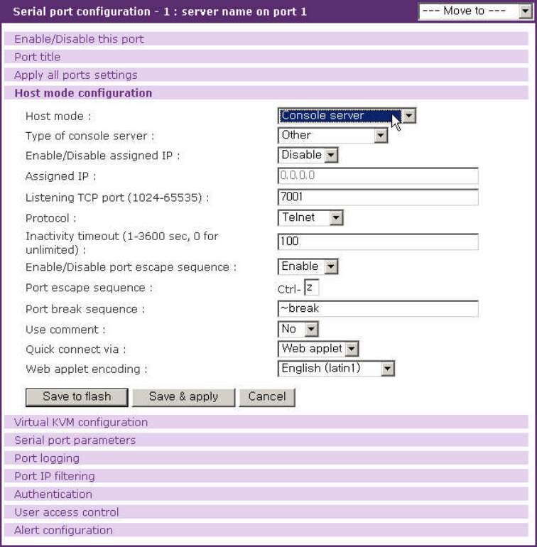
57
external modem, and waits for a dial-in connection from a remote site. Using a terminal emulation
program to access the VTS will prompt to login for authentication. It is not available for remote port.
Dial-in Terminal Server
The Dial-in terminal server mode is a combination of both the terminal server mode and dial-in
modem mode. When the users configures a serial port(s) as a Dial-in terminal server, the VTS
assumes that the serial port is connected to an external modem, and waits for dial-in connection from
a remote site. Once the user dials into the VTS using a terminal emulation program, it accepts the
connection and makes a TCP connection as a Telnet or SSH client to a pre-defined remote host. It is
not available for remote port.
Figures from Figure 4-7 to Figure 4-10 show the main workspace screen for the host mode
configuration for each host mode.
Figure 4-7. Host mode configuration -
console server mode
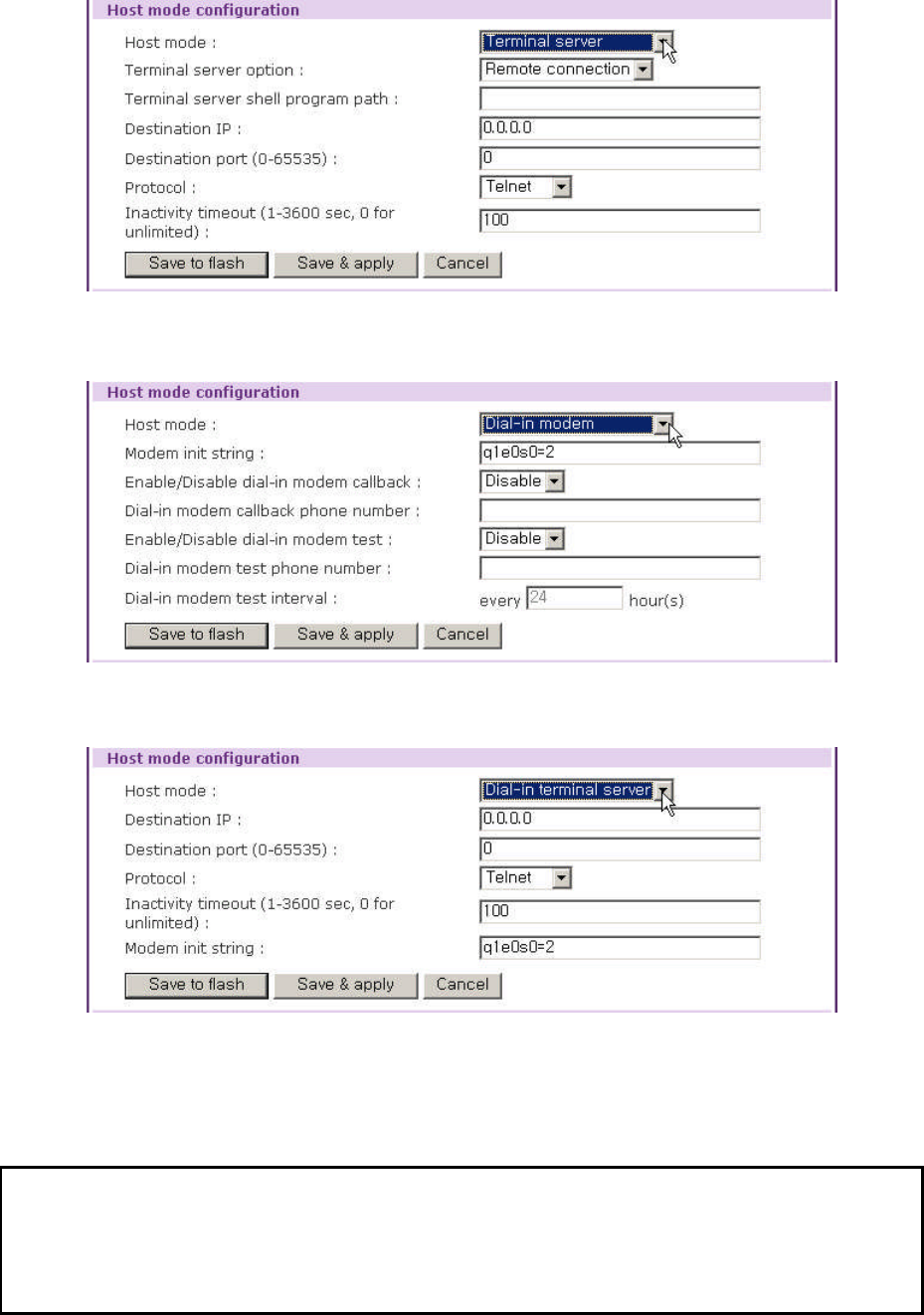
58
Figure 4-8. Host mode configuration - terminal server mode
Figure 4-9. Host mode configuration - dial-in modem mode
Figure 4-10. Host mode configuration - dial-in terminal server mode
Console server mode configuration
For console server mode, the user can configure the following parameters:
Type of console server
Enable/Disable assigned IP

59
Assigned IP address
Listening TCP port number
Protocol
Inactivity timeout
Enable/Disable port escape sequence
Port escape sequence
Port break sequence
Use comment
Quick connect via
Web applet encoding
Type of console server
This parameter determines whether the type of console server is MS SAC console or not.
Enable/Disable assigned IP
This parameter determines whether assigned IP address is used or not.
Assigned IP address
If the users assign an IP address to a serial or remote port of the console server, the user can
access the serial or remote port directly through the IP address of the configured port. The user may
set this parameter by using the Telnet or SSH client program with the standard TCP port number of
telnet (23) or SSH (22).
If the IP address of the serial port is assigned as 192.168.1.101, the users can connect to the port
as follows:
telnet 192.168.1.101
The assigned IP address may not conflict with the existing IP address. If a conflict is detected, the
IP address of the serial or remote port will be disabled. If the user wants not to assign an IP address to
a serial port, select disable at the Enable/Disable assigned IP menu, or assign 0.0.0.0 to the assigned
IP.
Listening TCP port number
The user can also access a serial or remote port through the IP address of the VTS and the
listening TCP port number of the serial port. The user must use the TCP port number as well as the
VTS IP address to the Telnet/SSH client.
If the IP address of the VTS and the serial port are assigned as 192.168.1.100 and

60
192.168.1.101, the user can connect to the port as follows:
telnet 192.168.1.100 6001
Protocol
Select Telnet, SSH or Raw TCP as the protocol. If the users are using a Telnet client program,
select Telnet. If the users are using an SSH client program, select SSH. When Raw TCP is selected,
direct TCP socket communication is available between the VTS and the remote host.
Inactivity timeout
The purpose of the inactivity timeout parameter settings is to maintain the TCP connection state
as either Closed or Listen. If there is no activity between the VTS and the Telnet/SSH client during the
specified inactivity timeout interval, the existing session will automatically be closed. If the user wants
to maintain the connection indefinitely, configure the inactivity timeout period to 0. Although the
inactivity timeout is disabled, the VTS will continue to check the connection status between the
Telnet/SSH client and the VTS by sending “keep alive” packets periodically. If the Telnet/SSH client
does not answer the packets, system will assume that the connection is down unintentionally. The
VTS will close the existing Telnet/SSH connection, regardless of the inactivity setting.
Enable/Disable port escape sequence
This parameter determines whether port escape sequence is used or not.
Port escape sequence
When users connects to a port, they will get the port escape menu by entering the port escape
sequence. The port escape menu contains [show last 100 lines of log buffer], [send message to port
user], [close current connection to port] for all users, [enter as a slave session] for sniff users, [send
break] for main session user, [take over main session] for sniff users having both port and monitor
access control and [disconnect a sniff session] for users having both port and monitor access control.
If the serial or remote port device is powered by a power controller and the user logged on has the
power access control, the port escape menu also contains [power device on], [power device off] and
[reboot device using power-switch].
In order to send port escape sequence, enter the port escape sequence character twice or enter
the port escape sequence character at the port escape menu.
Port break sequence
The user can send a break signal to the serial port by entering the break sequence that is
configured as the port break sequence in the configuration menu.

61
Use comment
The user can input comments when a port user accesses a serial port if
Use comment
is
configured to
Yes
. To use this feature, protocol should be configured as Telnet or SSH.
Comments input will be displayed in Comments item of individual port connection, which is in
the serial port connection page. Please refer to the section
4.5 Serial port connection
for details.
Quick connect via
The user can select a client program that is used for the VTS web connection page by configuring
Quick connect via if the protocol is configured as Telnet or SSH. If the user wants to launch the java
applet for a telnet or SSH client when the user selects the connection icon in the serial port connection
page, select Web applet. If the user wants to use Telnet or SSH client provided by an OS, select
Local client. With Windows OS, Hyper Terminal is launched for telnet protocol in this case.
Web applet encoding
This option is used to display the data from device through a serial port that are encoded in
various way.
Terminal server mode configuration
For terminal server mode, the user can configure the following parameters:
Terminal server option
Terminal server shell program path
Destination IP address
Destination TCP port number
Protocol
Inactivity timeout.
Terminal server option
The VTS makes a TCP connection as a Telnet, SSH or TCP client to a pre-defined remote host to
send incoming data from the serial port when terminal server option is set remote connection. On
shell program, the VTS executes the shell program specified at terminal server shell program path
when the serial port of the VTS is connected.
Terminal server shell program path
The terminal server shell program path specifies the shell program that the VTS executes on

62
connection to the serial port of the VTS when terminal server option is set shell program.
Destination IP address and Destination TCP port number
The destination IP address and destination TCP port numbers identify the Telnet/SSH server
information needed for the VTS to capture any incoming data from an attached device when the
terminal server option is remote connection.
Protocol
The protocol can be either Telnet, SSH or Raw TCP. If the user wants to connect to either a Telnet
or SSH server, the user must select Telnet or SSH. It is enabled on shell program.
Inactivity timeout
If there is no data transfer between the VTS and the Telnet/SSH server for the during the inactivity
timeout interval, the current Telnet or SSH connection will be closed. If the user wants to maintain the
connection indefinitely, configure the inactivity timeout period to 0. It is enabled on shell program.
Dial-in modem mode configuration
For dial-in modem mode, the users can configure the following parameters:
Modem init string.
Enable/Disable dial-in modem callback
Dial-in modem callback phone number
Enable/Disable dial-in modem test
Dial-in modem test phone number
Dial-in modem test interval
Modem init string
The modem init string is used to initialize an external modem attached to a serial port. If the user
does not specify any init string, the default init command is used. The default modem init command is
‘q1e0s0=2’. For more information about the modem init string, please refer to the modem manual.
Enable/Disable dial-in modem callback
If dial-in modem callback is enabled, the VTS disconnects the connection from a remote site and
then calls the phone number specified at the dial-in modem callback phone number.
Dial-in modem callback phone number

63
It is the phone number which the VTS calls with dial-in modem callback enabled.
Enable/Disable dial-in modem test
If dial-in modem test is enabled, the VTS tests whether the modem works well. If dial-in modem
test is enabled, user can configure whether VTS will send email and/or SNMP trap about the modem
test result at alert configuration page. Please refer to section 4.3.12 Alert configuration for details.
Dial-in modem test phone number
It is the phone number which the VTS calls to check whether the modem works well.
Dial-in modem test interval
It specifies how often the VTS take a dial-in modem test.
Dial-in terminal server mode configuration
For dial-in terminal server mode, the user can configure the following parameters:
Destination IP address: (Please refer to the Terminal Server Mode section)
Destination TCP port number: (Please refer to the Terminal Server Mode section)
Protocol: (Please refer to the Terminal Server Mode section)
Inactivity timeout: (Please refer to the Dial-in Modem Mode section)
Modem init string: (Please refer to the Dial-in Modem Mode section)
4.3.5 Virtual KVM configuration
When the Virtual KVM connection is enabled at console server mode, the users can connect to
the server through the specified KVM client program and manage it at its screen with keyboard and
mouse operation.
The configuration parameters for virtual KVM connection are as follows:
Enable/Disable Virtual KVM connection
Automatic IP detection
IP address
Client program
Socket/Screen number for VNC connection
Client program path
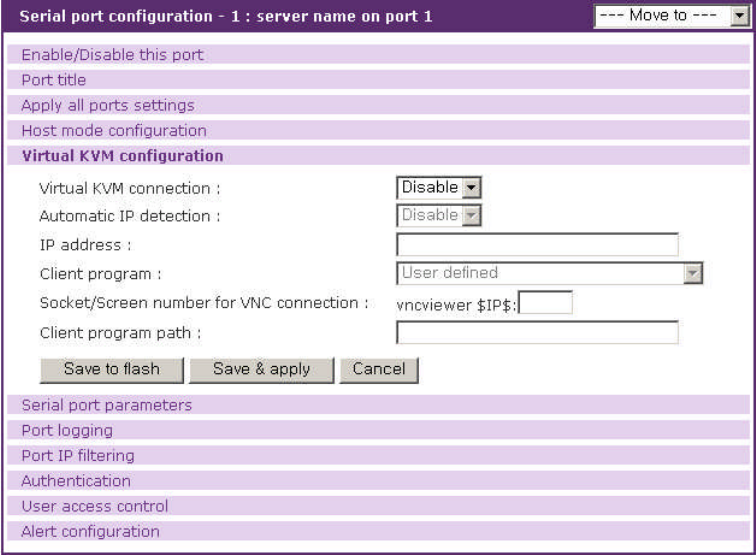
64
Figure 4-11. Virtual KVM configuration
Enable/Disable Virtual KVM connection
This parameter defines whether to enable or disable the virtual KVM feature. The factory default
setting is [disable].
Automatic IP detection
This parameter defines whether VTS automatically detects through serial port or remote port the
IP address to which the KVM client program tries to connect. It is available when the Type of console
server at Host mode configuration page is set as MS SAC console.
IP address
This parameter specifies the IP address where the KVM client program tries to connect.
Client program
This list provides a list of KVM client program to help users set the Client program path easily. If
users select Windows remote desktop connection, VNC, Radmin or Xmanager, the Client program
path will be filled with the corresponding client program path. Otherwise, users have to fill it manually.
Socket/Screen number for VNC connection
This parameter helps users set the Client program path of VNC connection easily. If users edit,
the Client program path will be filled with the VNC client program path with screen or TCP port number.
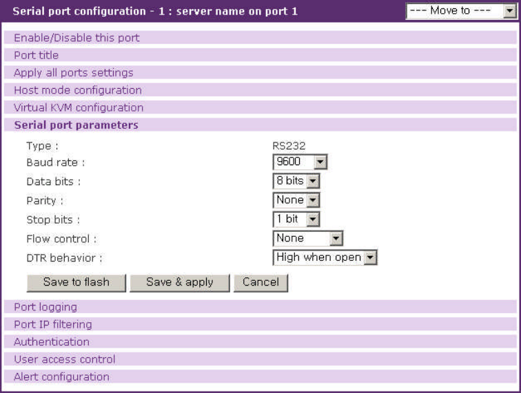
65
Client program path
This parameter specifies the client program through which users can open a KVM session to the
server connected to the serial port or the remote port. $IP$ means the server IP address to which the
client program connects.
4.3.6 Serial port parameters / Remote port parameters
To connect the serial device to the VTS serial port, the serial port parameters of the VTS should
match exactly to that of the serial device attached. The serial port parameters are required to match
this serial communication.
The parameters required for the serial communication are:
Baud rate
Data bits
Parity
Stop bits
Flow control
DTR behavior
Enable/Disable delimiter (only for RawTCP protocol)
Delimiter (only for RawTCP protocol)
Delimiter option (only for RawTCP protocol)
Inter character time-out (only for RawTCP protocol)
Figure 4-12. Serial port parameters configuration
66
Baud rate
The valid baud rate for the VTS is as follows:
1200, 2400, 4800, 9600, 14400, 19200, 38400, 57600, 115200, and 230400
The factory default setting is 9600.
Data bits
Data bits can be between 7 bits and 8 bits. The factory default setting is 8 bits.
Parity
Parity can be none, even or odd. The factory default setting is none.
Stop bits
Stop bits can be between 1 bit and 2 bits. The factory default setting is 1 bit.
Flow control
Flow control can be none,software(Xon/Xoff) or hardware(RTS/CTS). The factory default
setting is none.
DTR behavior
The DTR output behavior of a serial port can be configured as: always high, always low or High
when open. If the DTR behavior is set to High when open, the state of the DTR pin will be
maintained high as long as the TCP connection is established. When the host mode is configured as
either “dial-in modem mode”or “dial-in terminal server mode”, the user cannot set the DTR behavior.
Enable/Disable delimiter
This parameter is available only for RawTCP protocol. If enable, data from serial port is divided
into packets by delimiter sent to client. If disabled, data from serial port is sent without data from serial
port for Inter character time-out.
Delimiter
This parameter is available when Enable/Disable delimiter is enabled. Data is separated by this
parameter and sent to client.
Delimiter option
This parameter is available when Enable/Disable delimiter is enabled. This parameter
determines whether delimiter is sent together when data is sent to client.
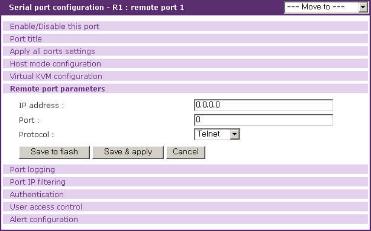
67
Inter character time-out
This parameter is available when Enable/Disable delimiter is disabled. Data is separated and
sent to client if no data is received from serial port during this parameter.
Users can enable dial-in modem support on console port by using rc.user script. Please add
following line to rc.user,
echo 57600 > /var/run/mgetty.console
where 57600 is the baudrate of modem to be connected on console port.
Please, note that dial-in modem support on console port is effective after rebooting the system with
above rc.user file.
In the case of remote port, information of remote host such as IP address, port and protocol is
required to access to remote host when client requests to connect.
The parameters required for the remote host connection are:
IP address
Port
Protocol
Figure 4-13. Remote port parameters configuration
IP address
It specifies IP address of remote host to access to.
68
Port
It specifies TCP port number of remote host to access to.
Protocol
It specifies protocol which is used to access to the remote host.
4.3.7 Port Logging
With the port-logging feature while in console server mode, the data sent through the serial or
remote port is stored to MEMORY, an ATA/IDE fixed disk card or a mounting point on an NFS server.
It can also be stored to a SYSLOG server at the same time.
The user can also define keywords for each serial port that will trigger an email/SNMP notification
at port event handling configuration. This will enable the user to monitor the data from the attached
device. For more information about the port event handling, please refer to section 4.3.8 Port event
handling.
The port-logging feature is valid and visible only if the host mode of the serial or remote port is
configured to console server mode. The port-logging feature will not be accessible if the serial port is
configured to terminal server or dial-in modem mode.
The configuration parameters for port logging are as follows:
Enable/Disable port logging
Logging direction
Port log storage location
Port log to SYSLOG server
Port log buffer size
Port log file name
Time stamp to port log
Show last 10 lines of a log upon connect
Strip the ^M from SYSLOG
Automatic backup on mounting
Monitoring interval
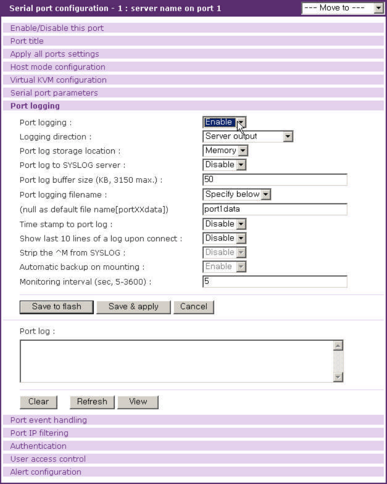
69
Figure 4-14. Port logging configuration
Enable/disable port logging
This parameter defines whether to enable or disable the port-logging feature. The factory default
setting is [disable].
Logging direction
This parameter defines whether the incoming and the outgoing data are logged with direction
arrows or not. The factory default setting is [Server output].
70
Port log storage location
The port log data can be stored to the VTS internal memory, an ATA/IDE fixed disk card inserted
in PCMCIA slot or the mounting point on an NFS server. If the internal memory is used to store port
log data, the port log data will be cleared when the VTS is turned off. To preserve the serial port log
data, set the storage location to be the ATA/IDE fixed disk card or NFS server or enable the port log to
SYSLOG server. To do this, the user must configure the corresponding media in advance. Unless the
media is properly set up, the user will not be able to select a storage location from the interface.
Port log to SYSLOG server
The port log data can be stored to the SYSLOG server in addition to the port log storage location
at the same time.
Port log buffer size
This parameter defines the maximum amount of port log data to be logged. When using internal
memory to store the log data, the total size of the port buffer cannot exceed 3200 Kbytes (i.e. sum of
all port buffer size of each serial port should be smaller than or equal to 3200 Kbytes). The factory
default setting is 4 Kbytes.
When using an ATA/IDE fixed disk card to store log data, the maximum port buffer size is
dependent upon the card capacity.
When using an NFS server to store log data, the maximum port buffer size is unlimited. The user
should configure the NFS server to ensure that the port logging system works properly.
Port log filename
Port log filename defines a port log file name to be logged. If Port logging file name is set as Use
port title, the port title is used as logging file name. If Specify below, the file name specified below is
used and if this parameter is not configured, port log file name of portXXdata will be used instead
where XX denotes corresponding serial port number.
Time stamp to port log
If Time stamp to port log is enabled, every line of log data includes time stamp. Factory default
setting of this parameter is disable.
Show last 10 lines of a log upon connect
If Show last 10 lines of a log upon connect is enabled, the last 10 lines of log will be disaplayed
when a user connects the port. Factory default setting of this parameter is disable.
Strip the ^M from SYSLOG
If Strip the ^M from SYSLOG is enabled, 0x0D in port log data that is displayed as ^M at
71
SYSLOG server is replaced with space so port log data is sent to SYSLOG server without 0x0D.
Monitoring interval
If port-logging option is enabled and port event handling (see section 4.3.8 Port event handling) is
configured, the VTS will search a defined key word presence to make a corresponding reaction. Within
this condition, Monitoring interval defines the interval whenever the VTS searches a key word from
the buffered port log. The smaller value of this parameter will result in immediate keyword search and
heavy usage of system resources. The largest value accepted is recommended to prevent system
resource usage minimization.
Automatic backup on mounting
This parameter is available when Port log storage location is set as CF card or NFS server. It
determines whether the backup file for port logging is created on remounting the logging storage.
4.3.8 Port event handling
If port-logging option is enabled, the user can let the VTS to search a defined keyword from the
port logging data and send an email or SNMP trap to an administrator by Port event handling
configurations. Each reaction can be configured individually upon each keyword. Reaction can be an
email delivery, SNMP trap sending or both.
The configuration parameters for port event handling are as follows:
Key word
Case sensitive
Email notification
Title of email
Recipient’s email address
SNMP trap notification
Title of SNMP trap
Use global SNMP configuration
First/Second SNMP trap receiver IP address
First/Second SNMP trap community
First/Second SNMP trap version
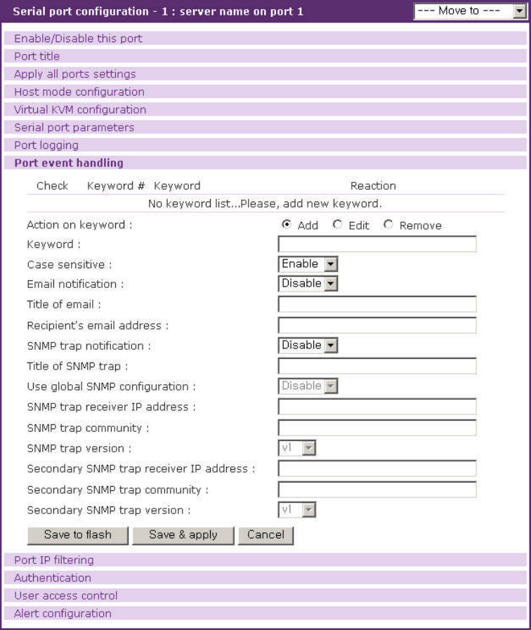
72
Figure 4-15. Port event handling configuration
Case sensitive
If this parameter is disabled, the VTS will search a defined key word presence ignoring the case
of the keyword.
Email notification configurations
If the user wants an email notification for the reaction, set Email notification parameter to enable,
and configure a recipient’s mail address and the email title..
SNMP trap notification configurations
If SNMP trap notification is enabled, A SNMP trap is transferred if a keyword is found from port log
data. For details of SNMP trap configurations and descriptions, please refer to section 3.2 SNMP
Configuration.
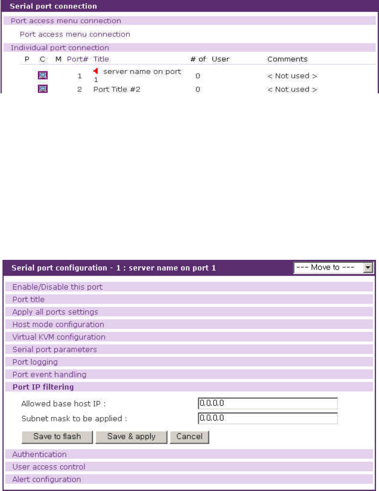
73
Use global SNMP configuration
This parameter defines whether the trap receiver setting of the SNMP configuration at network
configuration is used as trap receiver.
After a keyword is added to the port event handling configuration, the VTS monitors it is detected.
And if it is detected and no user connects to the port, the alerting icon will be displayed by the port title
at serial port connection page till any user connects to the port. Figure 4-16 shows the serial port
connection page showing the alerting icon at port 1 named server name on port 1.
Figure 4-16. Serial port connection page showing the alerting icon
4.3.9 Port IP filtering configuration
The remote hosts that are allowed to access the VTS serial or remote ports can be specified
based on the IP address filtering rules. The user may allow specific hosts to access the VTS serial or
remote ports by providing a valid IP address or network address and its subnet mask. Please refer to
section 3.5 for more details.
Figure 4-17. Port IP filtering
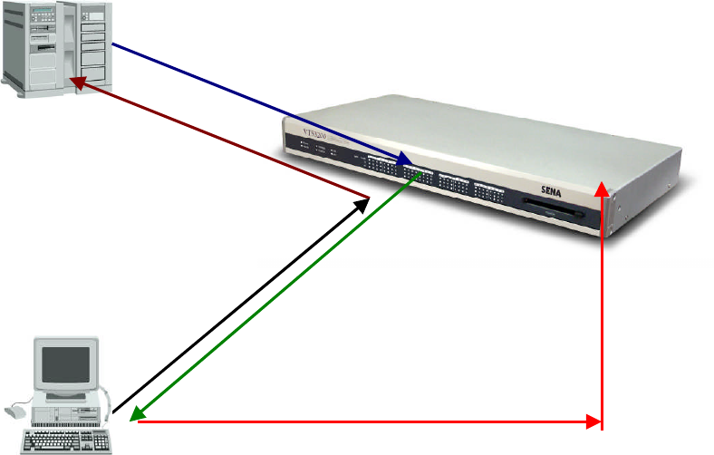
74
4.3.10 Authentication configuration
Authentication is the process of identifying an individual, usually based on a username and
password. The VTS supports various authentication options, such as None,Local, RADIUS,
TACACS+, Kerberos and LDAP to authenticate the users who access the serial port.
When the authentication is set to None, the users can access to the serial port without
authentication. The VTS can supports the Linux-PAM (Pluggable Authentication Modules for Linux)
using Custom PAM option. When the authentication is set to Local, the VTS will use its own user list
to authenticate a user. If configured otherwise, the VTS will request authentication from the external
authentication servers (i.e. RADIUS, Kerberos, TACACS+ and LDAP servers). Figure 4-18 shows
conceptually the user authentication process when using an external authentication server.
The user may also select to combine authentication methods. This method will instruct the VTS
attempt authentication with the first method. If this fails, the VTS is instructed to attempt
authentication with the second selected method. For example, RADIUS authentication can be
combined with local authentication. If the user selects the “RADIUS server – Local” authentication
method, the VTS will try to authenticate using RADIUS first and then try with the VTS local database if
the RADIUS authentication process fails.
In the case of “RADIUS down – Local”, the VTS will try to authenticate using RADIUS first and
then try with the VTS local database if the RADIUS server is down.
1) Users’logging into the Port 1
With user ID & password
2) Query the user
Request user authentication
to the authentication server
3) Response from
the authentication server (accept or reject)
4) Allow users’access to the Port 1
5) Access the device attached to the port 1
Figure 4-18. Concept of the user authentication by the external servers
75
NOTE :
1. It is necessary to copy kinit binary to /usr2 folder to use Kerberos authentication at VTS
v1.7.0 or later
2. Custom PAM option supports Linux-PAM. It is necessary to create /etc/pam.d/custom file.
Please refer to the section 11.9.2 Enabling the RADIUS Authentication for the CLI log-in
and 11.9.3 Enabling the TACACS+ Authentication for the CLI log-in for details on Linux-
PAM.
The following is all the authentication options that the VTS provides for each serial port:
None
Local
RADIUS server
RADIUS server - Local
Local - RADIUS server
RADIUS down - Local
TACACS+ server
TACACS+ server - Local
Local - TACACS+ server
LDAP server
LDAP server - Local
Local - LDAP server
Kerberos server
Kerberos server - Local
Local - Kerberos server
Custom PAM

76
Figure 4-19. The VTS authentication options for the serial port
Figure 4-20. Authentication configuration for the RADIUS server – Local
77
4.3.11 User access control configuration
The user access control configuration can be used for restricting or permitting users who try to
connect to or sniff a serial / remote port of the VTS and manage power of a serial port. How to manage
sniff session is also configured at sniff session part.
Port access control is used to permit or restrict to connect to a serial port. Monitor access control
is used to permit or restrict to sniff a serial / remote port. Power access control is used to permit or
restrict to manage the power of a serial port that is connected to a power controller outlet.
The access controls of <<Everyone>> specify the access control of all the users except the users
who are added in the user list or access list of user access control. Users whose access controls are
different from those of <<Everyone>> should be added in the user list or access list of user access
control.
If a port is disabled to be sniffed, the monitor access control does not affect. If a port is not
connected to a power controller outlet, the power access control does not affect.
In the case of sniff mode, users who can connect to a port are divided to three groups – users
who have both of the port and the monitor access control, users who have only port access control
and users who have only monitor access control.
Users having port and monitor access control can open the serial port as main session and
access to it as sniff session. They can disconnect sniff sessions at main session and sniff session and
take over main session at sniff session.
User having just port access control can open the serial port as main session and connect to it as
sniff session but they can neither disconnect sniff session nor take over main session at sniff session.
Users having just monitor access control can connect to it just at sniff session and they can
neither disconnect sniff session nor take over main session.
Users should be not only identified by VTS or authentication server according to authentication
configuration but also permitted by VTS according user access control in order that they may connect
to a serial port. For further details about authentication configuration, please refer to section 4.3.10.
Authentication configuration.
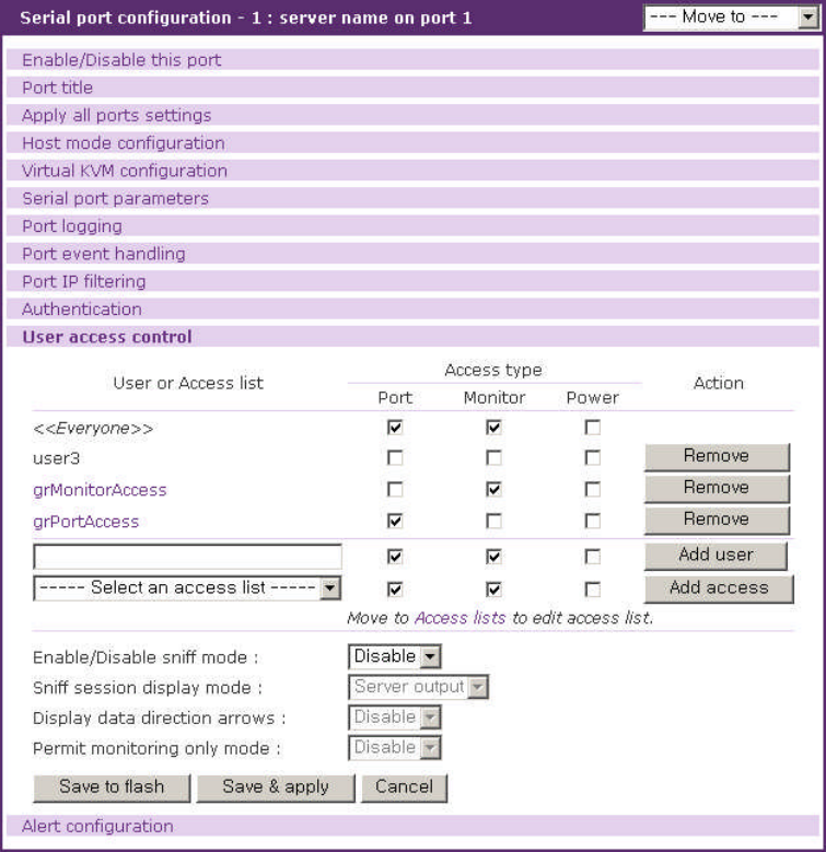
78
Figure 4-21. User Access Control configuration for serial ports
User access control
Access type consists of port , monitor and power access control. The port access control
specifies if user may connect to the port as main session. The monitor access control specifies if user
may connect to it as sniff session. The power access control specifies if user may manage the power
of the port.
The access controls of <<Everyone>> are applied to all the users who are not added to user list
or access list of user access control. The users should be added to user list or access list if their
access controls do not match <<Everyone>> access controls. For further details about access lists,
please refer to section 9.2. Access Lists.
If the administrator wants to specify users who must be restricted from accessing a specific serial
port, the administrator may check <<Everyone>> access control and add them to user list with option
unchecked. If the administrator wants to specify the users who are allowed to access a specific serial
port, he may uncheck <<Everyone>> access control and add them to user list with option checked.

79
Sniff session
The sniff session enables multiple users to access a single serial/remote port. Users having the
port access control or the monitor access control can access the serial/remote port even if another
user is using it at the time. Number of simultaneous Sniff users allowed to access is limited to 15 and
also limited by system resource.
Enable/Disable sniff mode should be set as [Enable] to allow users to sniff.
The sniff session display mode has three settings: User input,Server output and both. If set
to User input mode, the sniff user can see only the incoming user data for a serial/remote port from a
remote host. If set to Server output mode, the sniff user can only see the outgoing data from the
serial/remote port to the remote host. If set to Both mode, the sniff user can see all the data sent back
and forth through the serial/remote port.
Display data direction arrows determines whether the incoming and the outgoing data are
shown with direction arrows or not.
If a sniff user access to a serial port that is in use by a user already, the sniff user has a screen as
in Figure 4-22. Then the sniff user gets the port menu by typing the port escape sequence. A sniff user
having both the port and the monitor access control has a higher level of authority than a regular user
having either the port or the monitor access control and is able to take over main session that is in
connection currently and disconnect another sniff session. By selecting a menu shown in Figure 4-22,
a sniff user can enter as the main session by killing a current main session, or take over a main
session and switch a current main session to a sniff session. Besides these functions, a sniff user can
terminate the other sniff session by selecting disconnect a sniff session or send messages to other
users by selecting send message to port user or display logs by selecting show last 100 lines of
log buffer or close current connection by selecting close current connection to port.
A sniff user cannot access to a serial port through sniff session without main session and the sniff
sessions are closed when the main session is closed. That is, there is no sniff session without the
main session. But if Permit monitoring only mode is set to Enable, these limitations are come over.
Sniff session is connected without main session and sniff sessions are still alive and keep monitoring
when main session is closed.
Welcome to VTS-1600 Console Server
VTS-1600 Login : admin
VTS-1600 Password : *****
Entering server port, ..... type ^z for port menu.
New sniff session started ...

80
After typing the port escape sequence
Port menu:
(server name on port 1) (Port 1) is being used by (sena)
The (admin) is connected in monitoring mode.
m take over main session
s enter as a slave session
l show last 100 lines of log buffer
d disconnect a sniff session
a send message to port user
x close current connection to port
Figure 4-22. Sniff user interface screen
4.3.12 Alert configuration
Email agent process sends email depending on email alert configurations and SNMP agent
process transfers a SNMP trap to an administrator depending on SNMP trap configurations when the
events related to the serial port such as port login and serial port connection occur at console server
mode. If Automatic detection is set Enable, Device detection method is Active and Device
initiation is Periodically at Port Title page, Email and SNMP trap about device information detected
periodically is sent depending on configurations. Remote ports support just port login event.
The configuration parameters for alert configuration are as follows:
Enable/Disable email alert for port login
Enable/Disable email alert for device connection
Enable/Disable email alert for active detection
Title of email
Recipient’s email address
Enable/Disable port login trap
Enable/Disable device connection trap
Enable/Disable active detection trap
Use global SNMP configuration
Trap receiver settings
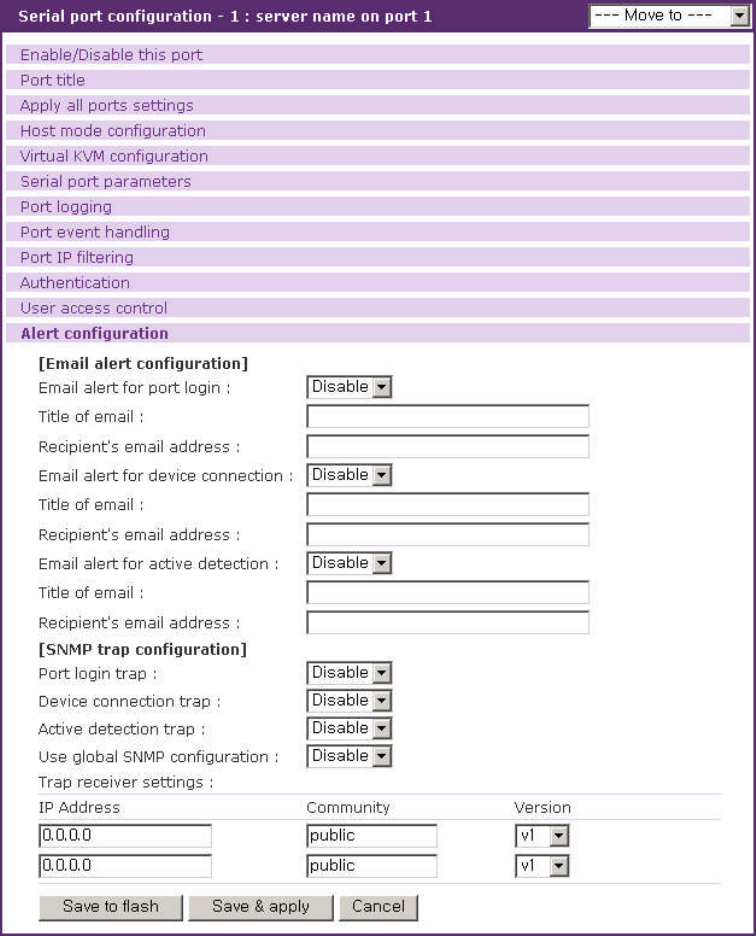
81
Figure 4-23. Alert configuration at console server mode
Enable/Disable email alert for port login
This parameter defines whether the email is sent when a user logs in and out the serial/remote
port.
Enable/Disable email alert for device connection
This parameter defines whether the email is sent when the serial port is connected or
disconnected to a device.
Enable/Disable email alert for active detection
This parameter is configurable when Automatic detection is set Enable, Device detection
82
method is Active and Device initiation is Periodically at Port Title page. This parameter defines
whether the email about device information detected periodically by VTS is sent.
Title of email
This parameter defines the title of email.
Recipient’s email address
This parameter defines to whom the email is sent
Enable/Disable port login trap
This parameter defines whether the SNMP trap is transferred when a user logs in and out the
serial/remote port.
Enable/Disable device connection trap
This parameter defines whether the SNMP trap is transferred when the serial port is connected or
disconnected to a device.
Enable/Disable active detection trap
This parameter is configurable when Automatic detection is set Enable, Device detection
method is Active and Device initiation is Periodically at Port Title page. This parameter defines
whether the SNMP trap about device information detected periodically by VTS is transferred.
Use global SNMP configuration
This parameter defines whether the trap receiver setting of the SNMP configuration at network
configuration is used as trap receiver.
Trap receiver settings
For details of SNMP trap configurations and descriptions, please refer to section 3.2 SNMP
Configuration.
Email agent process sends email depending on email alert configurations and SNMP agent
process transfers a SNMP trap to an administrator depending on SNMP trap configurations when the
dial-in modem test is enabled and the events related to dial-in modem test occur at dial-in modem
mode.
The configuration parameters for alert configuration are as follows:
Enable/Disable email alert for dial-in modem test
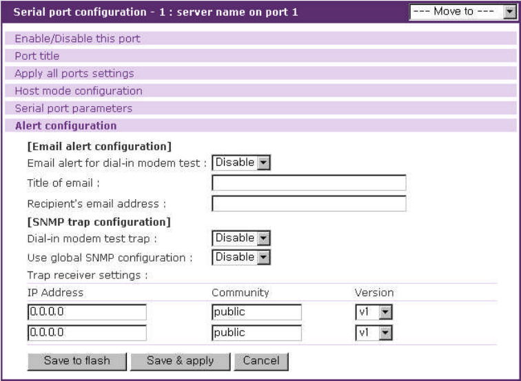
83
Title of email
Recipient’s email address
Enable/Disable dial-in modem test trap
Use global SNMP configuration
Trap receiver settings
Figure 4-24. Alert configuration at dial-in modem mode
Enable/Disable email alert for dial-in modem test
This parameter defines whether the email is sent when an event related to dial-in modem test
occurs.
.Enable/Disable dial-in modem test trap
This parameter defines whether the SNMP trap is transferred when when an event related to dial-
in modem test occurs.
4.3.13 Power control configuration
If a power controller is connected to VTS, user can configure which power controller outlets a
serial port is connected to at this page. The power of the serial port is managed using this
configuration.
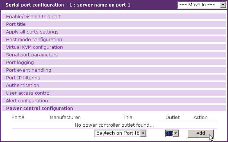
84
Figure 4-25. Power control configuration
4.4 All Port Configurations
If modifications are being made to all serial ports are similar or the same, changes can be made
to the serial port configuration for all serial ports simultaneously. With the all port configuration
function, the configuration will be applied to all the serial ports; unless an individual ports “apply all
port setting” option is disabled.
“All port configuration”parameters can be grouped into the following groups:
1. Port enable/disable
2. Port title
3. Host mode configuration
4. Virtual KVM configuration: Only available if the host is set to Console Server Mode.
5. Serial port parameters: Invalid for remote port
6. Port logging: Only valid and visible if host mode set to Console Server Mode.
7. Port event handling: Only available if the host is set to Console Server Mode and Port
logging is enabled.
8. Port IP filtering: Only available if the host is set to Console Server Mode.
9. Authentication
10. User access control: Only available if the host is set to Console Server Mode.
11. Alert configuration: Only available if the host is set to Console Server Mode.
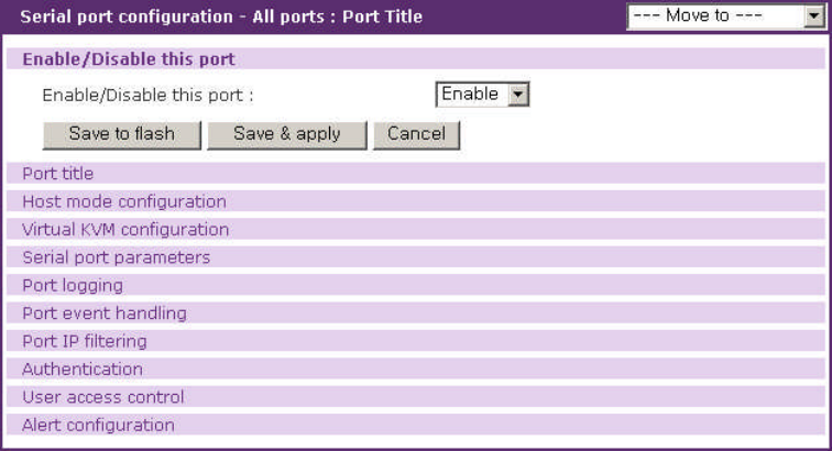
85
Figure 4-26. All port configuration
Port enable/disable
This parameter enables or disables port function.
Port title
If this parameter is set with a certain string, the port title of each serial/remote port will be set with
a combination of this string and the port number. For example, if the port title is set with “my server”,
the port title of port 1 will be set with “my server #1”, the port title of port#2 will be “my server #2”, and
so on. The port title of remote port 1 will be set with “my server #R1”.
Host mode
If the host mode is set to console server mode, the assigned IP address of each serial port
allowed will be the following equation:
(IP address assigned + serial port number – 1) for serial port and
(IP address assigned + remote port number – 1 + serial port count) for remote port
For example, if the IP address assigned is 192.168.1.1 in all port configuration, the IP address of
port 1 will be 192.168.1.1, that of port 2 is 192.168.1.2, and so on. If the count of serial port is 32, that
of remote port 2 is 192.168.1.33. Similarly, the listening TCP port number will be also set with the
following equation:
(listening TCP port number + serial port number – 1) for serial port and
(listening TCP port number + remote port number – 1 + serial port count) for remote port
If the host mode is set to terminal server mode, the destination IP address of each serial port will
be assigned incrementally to the case of the console server mode. However, the destination TCP port
number will be the same regardless of the serial port number. For example, if the destination IP
address and the TCP port number are set as 192.168.1.1:8001, the destination IP address and TCP
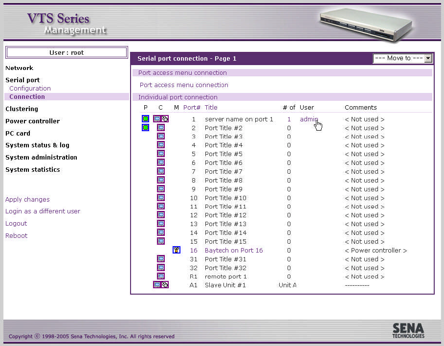
86
port number of port 1 is 192.168.1.1:8001 and 192.168.1.2:8001 for port 2.
Virtual KVM configuration, Serial port parameters, Port logging, Port event handling, Port IP
filtering, Authentication, User access control, Alert configuration
For the parameters of the groups above, the values set in an “all port configuration” will be set
identically for all of the serial/remote ports except serial port parameters. The changes of serial port
parameters are not reflected on remote ports.
4.5 Serial port connection
The VTS Web configuration interface provides a web-based serial port connection which enables
the user to access the serial ports without using the telnet or SSH client program. If the users select
the Serial port - connection menu item in the menu bar, the screen in Figure 4-27 is displayed.
Figure 4-27. Serial port connection page
87
This provides the means for the connection to the port access menu, the serial/remote ports,
and the serial ports of clustered slave device.
If the count of the ports to display at this page exceeds to the count displayed a page which is
configured at web server configuration, all the ports are divided into pages which contain as many as
configured and one of them is displayed. (refer to section 3.8 Web server configuration). The [---
Move to ---] list box helps to move to other pages.
Clicking the column name of Port # sorts all the ports by port number at ascending. Clicking it
again reverse the order of sorting. Each page of the [--- Move to ---] list box has the port number of the
first port. The port number of the remote ports consists of Rand the remote port number. The port
number of the ports of the clustered slave device has the slave unit number and the port number.
Users can sorts the ports by port title at ascending or descending by clicking the column name of
Title. The items at the [--- Move to ---] list box have the port title of the first port of each page.
The user may access the serial port by clicking the terminal icon at Ccolumn. The terminal
emulation pop-up window will be opened to grant user access to the port.
Note: If the protocol of the serial port is configured as Telnet of SSH, pop-up terminal emulation
program will be either a java telnet/SSH client or a telnet/SSH client provided by the OS used
depending on the Quick connect via parameter configuration. Please refer to the section 4.3.4 Host
Mode Configuration for details.
When the server connected to the port supports KVM connection and the Virtual KVM
configuration of the port is set properly, this page displays the KVM connection icon. The user can
open a KVM session to the server and manage the server by clicking the KVM connection icon.
A Java applet is used to provide the text-based user interface to access the serial/remote port or
the serial port of the slave unit. This Java applet supports only Telnet or SSH connection. The user
cannot access the port via the web when the host mode of the port is set to Raw TCP connection. The
user is asked to enter his/her user ID and password to access the port. Once authenticated, the user
now has access to the port. The title bar of the pop-up window and the Java applet shows the
information regarding the connection, i.e. Telnet or SSH, connection status, the port number and the
port title. On the bottom of the screen, there are hot key buttons accessible to connect, disconnect or
send break.
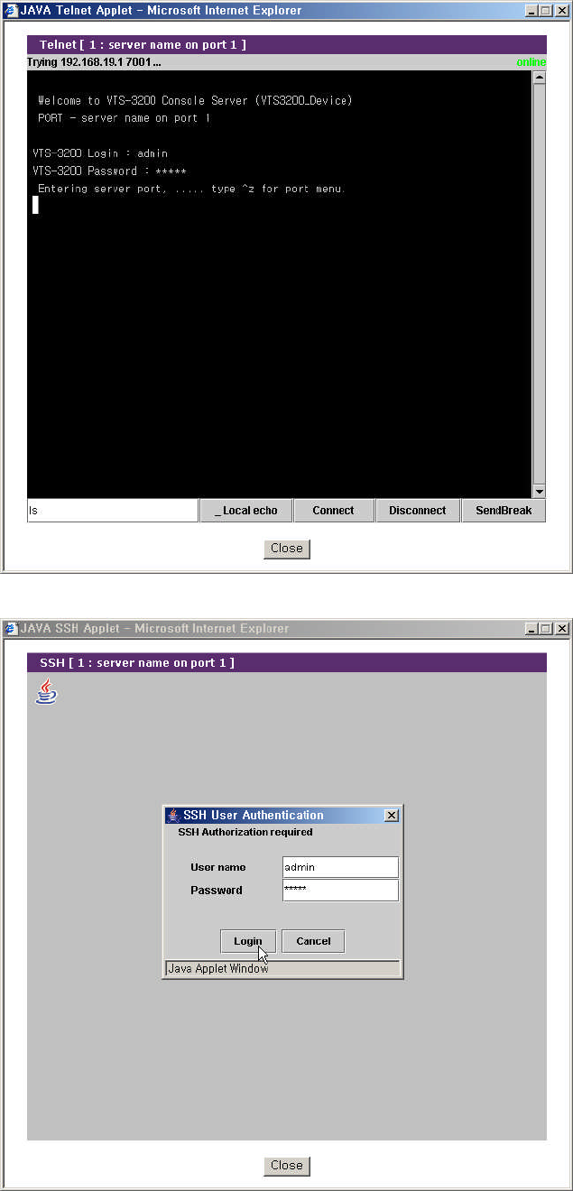
88
Figure 4-28. JTA window for Telnet
Figure 4-29. JTA window for SSH
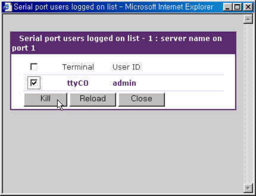
89
The SSH V1 property at the Security Profile page determines whether VTS supports SSH version
1 or not. (refer to section 9.7 Security profile). The Web applet option property at the Web server
configuration page configures which SSH version is used when a port is connected through java
applet for SSH. (refer to section 3.8 Web server configuration).
Note: The users registered with their SSH public key cannot access the port through the web
because the Java applet does not provide an SSH public key authentication.
It also provides the serial port power control. The user may be able to move to the serial port
power control page and control the power of a serial/remote port by clicking the on / off state icon at P
column if a power controller is added to the VTS and the serial/remote port device is linked to the
power controller outlet. It also provides the short cut to the power controller management page to
control the power controller added to VTS. Clicking the management icon in M column, the user can
move to the power controller management page and deal with the power controller. (refer to 6.3.4
Power controller unit management - Serial port connection)
In addition, serial port connections page displays current port connection status including the
number of connected users, port user IDs and comments input by a port user for each serial port.
The VTS allows users to monitor the users connecting to the VTS serial port besides the main
session user and disconnect the current connections to the VTS serial port. Users can open Serial
port users logged on list (refer to Figure 4-30) by clicking the # or user link of the VTS serial port to
commit.
Users can disconnect the connection to the VTS serial port of the some users by checking and
clicking the Kill button at the serial port users logged on list window.
Figure 4-30. Serial port users logged on list
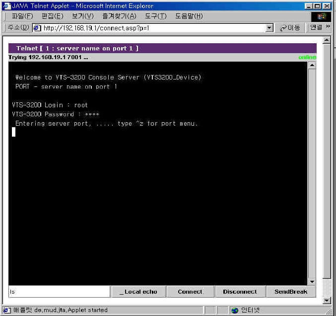
90
The VTS also provides users with the direct access to the serial/remote port or to the serial port of
the clustered slave unit without login to the Web management interface. Users can connect to the port
by entering URL at address text field of the Web browser such as
http://<IP>/connect.asp?p=<port number>
or
http://<IP>/connect.asp?t=<port title>
where <IP> is the IP address or domain name of the VTS, <port number> is the number of the port
and <port title> is the title of the port. Users can access to the port whose port number is same as
<port number> or whose title contains <port title>. Figure 4-31 and Figure 4-32 shows the JTA applet
directly connected to the port matching <port number> or <port title>.
Figure 4-31. Direct access to serial port through port number
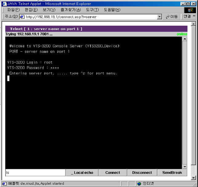
91
Figure 4-32. Direct access to serial port through port title
The VTS allows users to access to the serial/remote port or the serial port of the clustered slave
unit through the remote SSH serial console specifying the user as
<user>:p=<port number>
or
<user>:t=<port title>
or
<user>:<tcp port number >
where <user> is user ID, <port number> is the number of the port and <port title> is the title of the port.
Users can access to the port whose port number is same as <port number> or whose title is same as
<port title>. <tcp port number> is the TCP port number of the port. Users can access to the port whose
TCP port number is same as <tcp port number>. Figure 4-33 and Figure 4-34 shows the SSH client
directly connected to the port matching <port number> or <port title> on linux. Figure 4-35 shows the
SSH client directly connected to the port matching <tcp port number> on linux.

92
[root@loclahost ~] ssh root:p=1@192.168.19.1
root:p=1@192.168.19.1’s password:
Entering server port, ..... type ^z for port menu.
Figure 4-33. Direct access to a port using the remote SSH serial console through port number
[root@loclahost ~] ssh ‘root:t=server name on port 1@192.168.19.1’
root:t=server name on port 1@192.168.19.1’s password:
Entering server port, ..... type ^z for port menu.
Figure 4-34. Direct access to a port using the remote SSH serial console through port title
[root@loclahost ~] ssh root:7001@192.168.19.1
root:p=1@192.168.19.1’s password:
Entering server port, ..... type ^z for port menu.
Figure 4-35. Direct access to a port using the remote SSH serial console through tcp port number
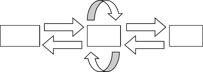
93
5: Clustering Configuration
5.1 Overview
The VTS provides centralized management of other VTS serial ports with its clustering feature.
The user may access up to 816 serial ports (=48 ports * 16 slave units + 48 ports for master unit)
through one master unit.
The VTS uses NAT (Network Address Translation) based methodology to access the slave unit
serial ports. Using a kernel-based simple IP forwarding mechanism, the VTS provides an efficient,
flexible, fast and secure method of access. It can also manage other terminal servers if the users
manually set up the IP forwarding rule to reflect the current environment.
The incoming data stream to the master unit’s TCP port is forwarded to the (IP address: TCP port)
of the slave units. Therefore, the only thing that the user has to set up for the master unit’s
configuration is the IP forwarding rule for the slave units. No additional sets up for the slave units are
required for the application.
Let’s assume that the user is trying to connect to the slave unit’s serial port by way of the master
unit. The environment for the clustering is as follows.
-User’s computer has the IP address: 192.168.0.100
-The IP address of the master: 192.168.0.2
-The IP address of the slave: 192.168.0.3.
-The TCP port, 6033 of the master is reserved for the serial port 1 (TCP port, 6001) of the
slave unit.
-
Figure 5-1 shows the operation concept of the VTS clustering feature under this condition.
VTS
Master
192.168.0.2
VTS
Slave
192.168.0.3
1 1’
From: 192.168.0.100:34567
To: 192.168.0.2:6033
NAT:IP forwarding
From: 192.168.0.2:45678
To: 192.168.0.3:6001
2’ 2
User
192.168.0.100
NAT:IP forwarding
From: 192.168.0.3:6001
To: 192.168.0.2:45678
From: 192.168.0.2:6033
To: 192.168.0.100:34567
Figure 5-1. VTS clustering operation concept
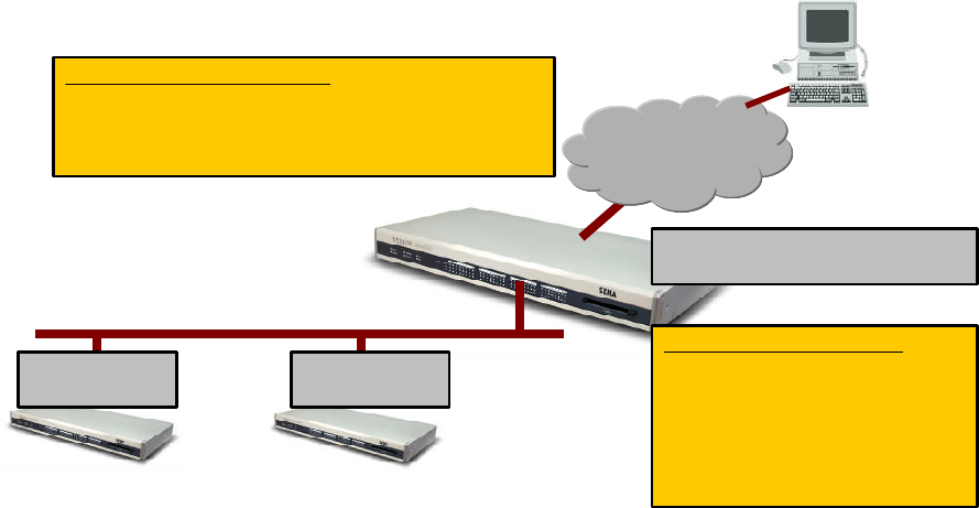
94
Figure 5-2 illustrates an application diagram how the user may connect to the VTS slave units
through the broadband Internet.
Master
Slave 1 Slave 2
Network
InternetInternet
Remote
User PC
192.168.1.101
(211.112.67.34)
192.168.1.102 192.168.1.103
Users’ access over the VTS
Master VTS: 211.112.67.34 (public IP)
Master serial ports: 211.112.67.34: 6000~6031
Slave 1 serial ports : 211.112.67.34:8000~8031
Slave 2 serial ports: 211.112.67.34:9000~9031
Clustering configuration
Master’s TCP port 8000~8031
Slave 1’s TCP port 6000~6031
-------------------------------------
Master’s TCP port 9000~9031
Slave 2’s TCP port 6000~6031
Master’s TCP port forwarding:
8000~8031, 9000~9031
TCP ports
6000~6031
TCP ports
6000~6031
Figure 5-2. VTS clustering example
5.2 Clustering configuration
Only the master unit configuration is required to apply the clustering features except
Authentication mode and Update master on changes.Authentication mode defines whether user
will be authenticated at clustering slave unit or clustering master unit when a port of clustering slave
unit is connected through master unit and its authentication mode is set as Local.Update master on
changes defines whether the changes of the slave unit are updated on the master unit when the
configuration of the slave unit is changed and applied. Authentication mode and Update master on
changes are disabled when Clustering mode is set as Master.
If a user wants to configure the VTS as the master, they should do it in the Clustering
configuration workspace. Figure 5-3 shows the Clustering configuration workspace. If user selects
Master at Clustering mode and save it, the clustering configuration screen for the master unit will be
displayed. Figure 5-4 shows the clustering configuration screen for the master unit.
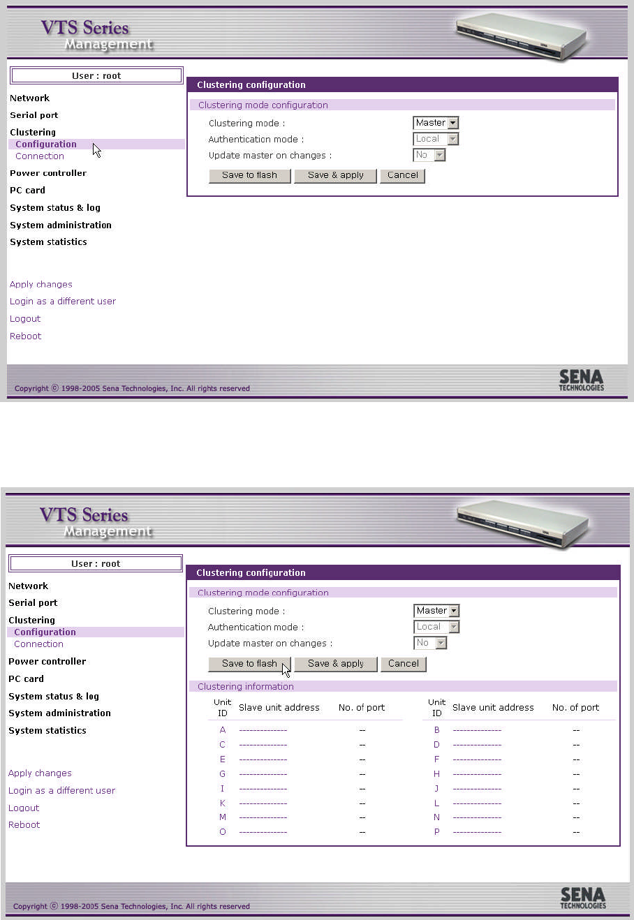
95
Figure 5-3. VTS clustering configuration as a master
Figure 5-4. VTS clustering configuration for the master unit
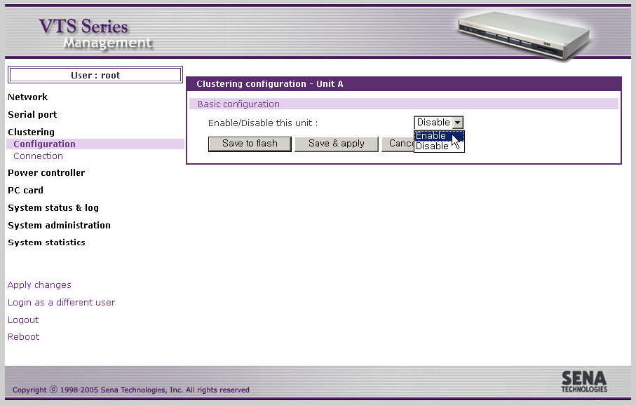
96
In order to add the slave in this workspace, the user selects the slave number displayed. Then,
the screen for the configuration of the slave unit will be shown up. Figure 5-5 shows the screen for the
configuration of the slave unit. The user then enables the slave configuration. The screen will then
guide them to the IP forwarding table screen for access of the specified slave unit. Figure 5-6 shows
IP forwarding table for the clustering configuration of the salve unit.
Figure 5-5. Enabling the configuration of the salve unit
The users may either manually set up the IP forwarding table or automatically import the serial
port configurations of the slave units. Access to the Port access menu and to the individual serial port
is provided. The Source port is the TCP port number of the master unit that will be forwarded to the
Destination port of the slave port.
To automatically configure the port-forwarding table, enter the IP address or domain name of the
slave unit, and then click the [Auto Config] button. The master unit automatically imports the port
information of the slave unit and reserves the source port for them. Figure 5-7 shows the result after
running the auto configuration. The automatic configuration imports the configuration only if the unit is
configured as a slave and only for the slave ports set to console server mode. The user can configure
the port title by setting up the base title. The user may change the source port number or the
destination port number by setting up the base port number for either one. Web management interface
provides users with link to web interface for clustering slave unit configuration. The user can determine
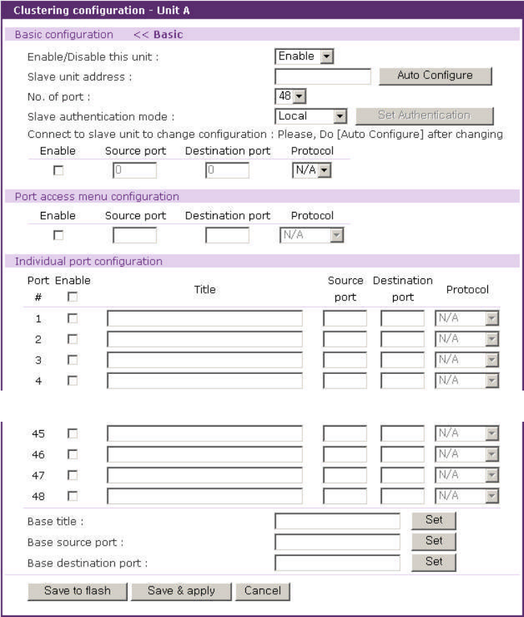
97
which protocol of HTTP and HTTPS is used to connect to it by selecting Protocol at Connect to
slave unit to change configuration part.
Note: The source port number may not conflict with the existing configuration of the master’s serial
ports. If there is conflict detected, the clustering feature is disabled.
…
Figure 5-6. IP forwarding table for the clustering configuration of the salve unit
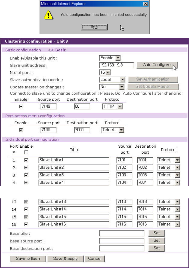
98
…
Figure 5-7. VTS automatic clustering configuration result
If the automatic configuration process fails, an error message will appear. The most common
error is entry of an incorrect IP address or network problem (i.e. network down).
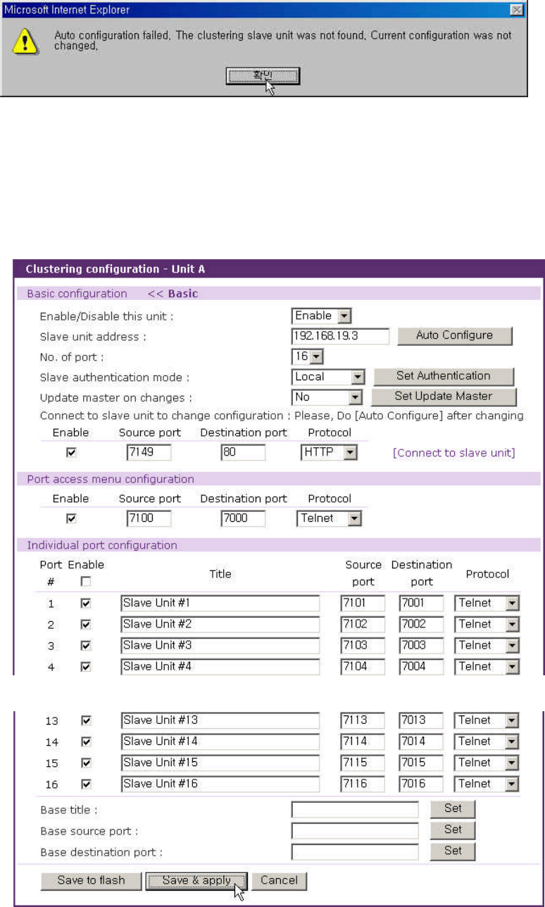
99
Figure 5-8. VTS clustering configuration error message
Please check whether the port information of the slave unit is correctly set up. Then select the
[Save to flash] and [Apply changes] buttons in order to complete the clustering configuration for the
slave units. Figure 5-9 shows the result after saving and applying the clustering configuration.
…
Figure 5-9. VTS clustering configuration after saving and applying
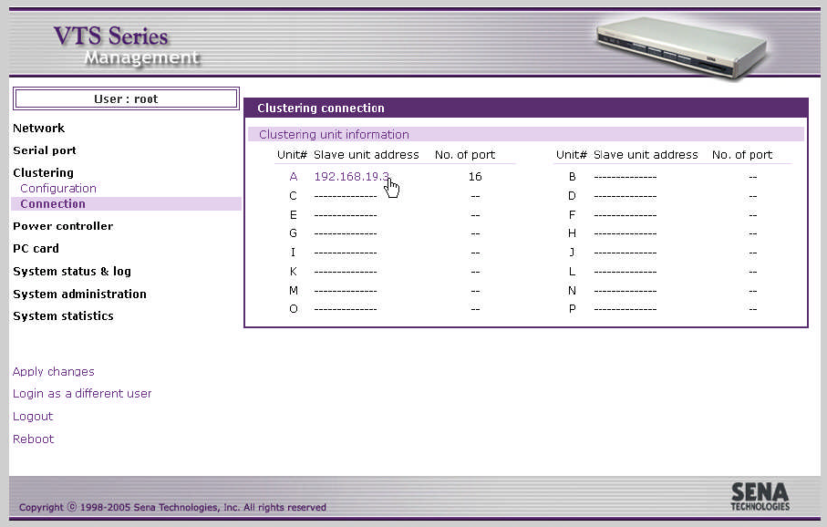
100
User can change the clustering authentication mode of the clustering slave unit by selecting
Slave authentication mode and clicking Set Authentication button. Users can change the Update
master on changes value by selecting Update master on changes and clicking Set Update Master
button. User can also access to the web interface of the clustering slave unit where user can configure
the clustering slave unit by clicking the link named [Connect to slave unit]. After user changes the
configuration of the clustering slave unit, user needs to click Auto Configure button to reflect the
changes of the clustering slave unit to the clustering configurations of the clustering master unit. But,
the slave unit reflects the changed configuration of the slave unit on the master unit if Update master
on changes of the slave unit is set as Yes.
Upon completing the clustering configuration, the user may try to connect to the ports of the slave
unit by selecting [Clustering – Connection] menu item on the menu bar. Figure 5-10 shows the screen
for clustering connection. The user may connect the slave ports by selecting the unit number or the IP
address of the slave in the clustering connection workspace. Then the workspace displaying all the
serial ports available in the slave’s serial port will be shown up.
Figure 5-10. VTS clustering connection page – slave information
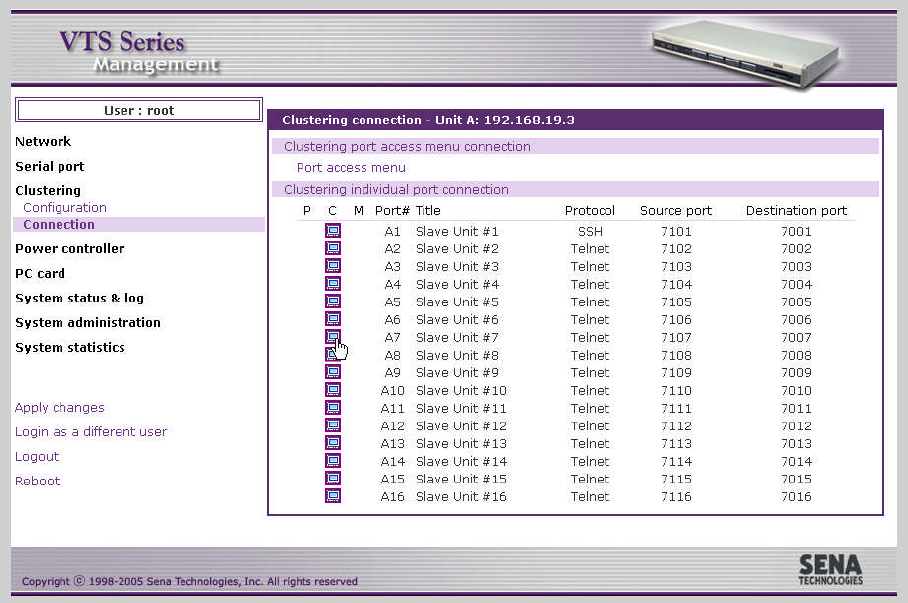
101
Figure 5-11. VTS clustering connection page – slave unit
Figure 5-11 shows the workspace displaying all the serial ports available in the slave’s serial port.
This is similar to the serial port connection. The user may now select the terminal icon at C column to
access the serial port of the slave unit by using the Java applet window. The serial port connection
page has not only the serial/remote ports of the master unit but also the serial ports of the slave unit.
Users can connect to the serial port of the slave unit as same way as users access to the
serial/remote port of the master unit. (refer to section 4.5 Serial port connection)
The user may use their own terminal emulation program, such as telnet or an SSH client program
to access the source port of the master unit to connect to the destination port of the slave.
As well as the serial/remote ports, the VTS provides users with the direct access to the serial port
of the clustered slave unit without login to the Web management interface and with the access to seial
port through the remote SSH serial console. (refer to section 4.5 Serial port connection)
Figure 5-12 shows the access to the serial port of the slave unit through the Java Applet Window
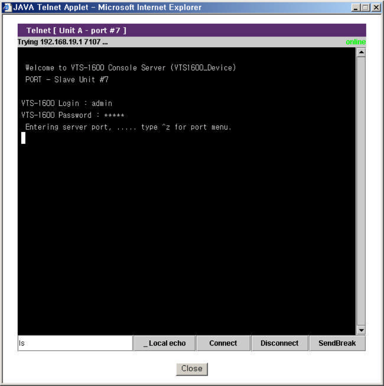
102
Figure 5-12. Connection to the serial port of slave unit
103
6: Power Controller
6.1 Overview
The VTS allows users to add, configure and manage remote power controller such as SENA PM
series and Baytech RPC series. When users add a power controller to the VTS and plug a device
which is connected to the VTS serial port into the outlet of the power controller, users can configure it
at the power controller configuration page or the power control configuration page of the Serial
port configuration. For further details about power control configuration, please refer to section 4.3.13
Power control configuration. Users can also manage it at the power controller management page
or the serial port power control page from serial port connection.
The power controller features of the VTS help users manage the power of the device connected
to the VTS serial port. Users can not only turn on / off and reboot the device but also monitor the state
of the power controller. The properties to set or to monitor depends on the power controller.
Available power controllers
- SENA PM series
- Baytech RPC series
6.2 Power controller configuration
Users add / remove a power controller, configure the count of the outlet, the title and the alarms
and thresholds of the power controller and link an outlet to a certain device or a serial port of the VTS.
Users can also link a serial port of the VTS to an outlet of the power controller at the power control
configuration page of the serial port configuration.
6.2.1 Add / remove power controller
If the users select the Power controller - Configuration menu item in the menu bar, the power
controller configuration page (refer to Figure 6-1 Power controller configuration) is displayed.
Clicking Add controller button after selecting the port where a power controller is connected,
manufacturer and the number of cascaded units in the case of SENA PM at Add power controller
part, user can add the power controller. After the power controller is add, the power controller unit
configuration page is displayed. And then users can configure the power controller added.
Users can remove the power controller by clicking the Remove button of the power controller at
Power controllers part.
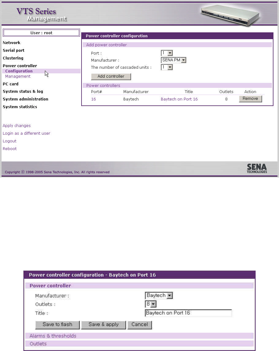
104
Figure 6-1. Power controller configuration
6.2.2 Edit power controller – Power controller tab
When a power controller is added or a power controller in power controller list of power controllers
part at the power controller configuration page(refer to Figure 6-1 Power controller configuration) is
selected, the power controller tab of power controller configuration (refer to Figure 6-2 Power controller
configuration – power controller tab) is displayed.
Figure 6-2. Power controller configuration – power controller tab
User may configure the manufacturer, the count of outlets and the title of the power controller. If
more than a power controllers are added, users may be able to identify each power controllers by the
title of the power controllers, so they will easily access to the power controller that they want to
configure or manage.
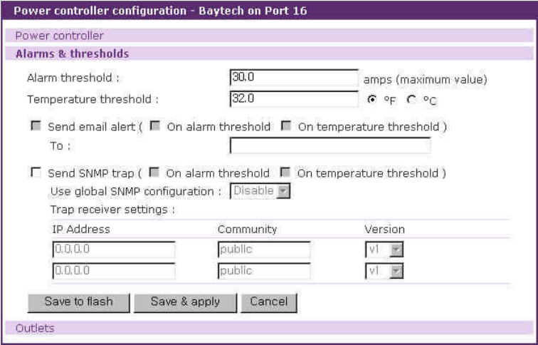
105
6.2.3 Edit power controller – Alarms & thresholds tab
When users select a power controller in power controller list of power controllers part at the power
controller configuration page (refer to Figure 6-1 Power controller configuration) and then the Alarms &
thresholds tab link at power controller unit configuration page, users can access to the alarms &
thresholds tab of power controller configuration (refer to Figure 6-3 Power controller configuration –
alarms & thresholds tab). These properties may not be supported depending on the power controllers.
Figure 6-3. Power controller configuration – alarms & thresholds tab
The configuration parameters for power controller alarms & thresholds are as follows:
Alarm threshold
Temperature threshold
Send email alert
Send SNMP trap
Alarm threshold
This parameter defines the threshold to be set on the current that sets off an audible alarm when
exceeded. When this threshold is reached, email alerts or SNMP traps can also be sent according to
Send email alert and Send SNMP trap parameters.
Temperature threshold
This parameter defines the threshold to be set on the internal temperature of the power controller.
When this threshold is reached, email alerts or SNMP traps can also be sent according to Send email
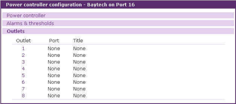
106
alert and Send SNMP trap parameters.
Send email alert
Send email alert : determines whether email is sent.
On alarm threshold : determines whether email is sent when alarm threshold is reached.
On temperature threshold : determines whether email is sent when temperature threshold is
reached.
To : determines to whom email is sent
Send SNMP trap
Send SNMP trap : determines whether SNMP trap is sent.
On alarm threshold : determines whether email is sent when alarm threshold is reached.
On temperature threshold : determines whether email is sent when temperature threshold is
reached.
Use global SNMP configuration : determines whether the trap receiver setting of the SNMP
configuration at network configuration is used as trap receiver.
Trap receiver settings : For details of SNMP trap configurations and descriptions, please refer to
section 3.2 SNMP Configuration.
6.2.4 Edit power controller – Outlets tab
When users select a power controller in power controller list of power controllers part at the power
controller configuration page(refer to Figure 6-1 Power controller configuration) and then the Outlets
tab link at power controller unit configuration page, users can access to the outlets tab of power
controller configuration (refer to Figure 6-4 Power controller configuration – outlets tab).
Figure 6-4. Power controller configuration – outlets tab
Users can unfold outlet configuration part by clicking the outlet number link and fold it by clicking
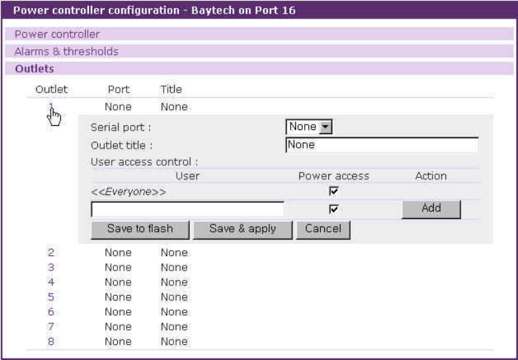
107
the number of the unfolded outlet. Figure 6-5 shows the folded outlet configuration part.
Figure 6-5. Power controller configuration – outlet configuration
The configuration parameters for outlet configuration are as follows:
Serial port
Outlet title
User access control
Serial port
This parameter defines this outlet supplies the device of this serial port of the VTS with the power.
None means this outlet serves a device that is not connected to any serial port of the VTS. If it is set to
a serial port number of the VTS, the outlet title is set to the title of the serial port configuration, the
user access control of power is set to the power access of the user access control of the serial port
configuration and they are not editable. (refer to Figure 6-6 Power controller configuration – outlet
configuration with serial port)
Outlet title
This parameter is descriptive to the outlet. When users configure or manage a outlet, it helps
them to identify it from others. If the serial port is set to a serial port, this column is not editable, set as
the serial port title and just link to the port title page of the serial port configuration is provided. (refer to
Figure 6-6 Power controller configuration – outlet configuration with serial port)
User access control

108
This parameter defines whether user can access to the outlet or not. If a user has the power
access control, he can monitor the power state at the serial port connection page (refer to 6.3.4 Power
controller unit management - Serial port connection) and manage the power controller outlet at the
power controller unit management page (refer to 6.3.3 Power controller unit management – Outlets
tab) or the serial port power control page linked from the P column of the serial port connection page
(refer to 6.3.5 Power controller unit management – Serial port power control).
If <<Everyone>> is checked, all the user except the users who is in the user list of the user
access control part can access to it. Unless, they are not allowed to access to it. The users in the user
list depend on their own access control.
If the serial port is set to a serial port, this column is not editable, set as the power access control
of the user access control of the serial port configuration and just link to the user access control page
of the serial port configuration is provided. (refer to Figure 6-6 Power controller configuration – outlet
configuration with serial port)
Figure 6-6. Power controller configuration – outlet configuration with serial port
6.2.5 Edit power control configuration of the serial port configuration
The power control configuration page is one of the serial port configuration. If a power controller is
added to the VTS, the serial port configuration of each port has this tab. (refer to 4.3.13 Power control
configuration).
This page is designed to link the device of a serial port of the VTS to outlets of the power
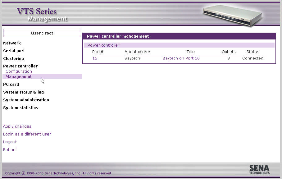
109
controllers in contrast to the outlet configuration page which is used to link a outlet to a device that is
connected to a serial port of the VTS or not. (refer to 6.2.4 Edit power controller – Outlets tab).
6.3 Power controller management
Users monitor / manage a power controller and its outlets at the power controller management
pages, the serial port connection page and serial port power control page linked from the serial port
connection page.
6.3.1 Power controller management – Power controller list
If the users select the Power controller - Management menu item in the menu bar, the power
controller mangement page (refer to Figure 6-7 Power controller management – power controller list)
is displayed. It shows the list of power controllers added to the VTS. It contains the information of the
power controller such as the connected serial port of the VTS, the manufacturer, the title, the count of
outlets and the status of the power controller. If the status of power controller is [Connected], the link to
power controller management of the power controller unit on the port number and title column is
provided.
Figure 6-7. Power controller management – power controller list
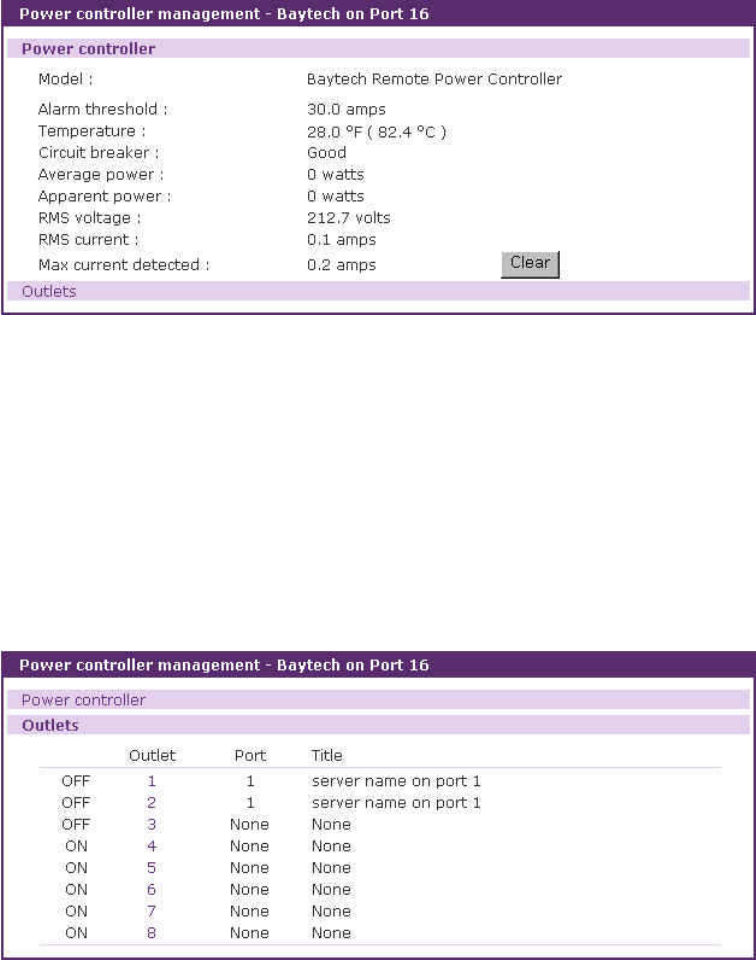
110
6.3.2 Power controller unit management – Power controller tab
When a power controller in power controller list of the power controller management page(refer to
Figure 6-7 Power controller management – power controller list) is selected, the power controller tab of
power controller management (refer to Figure 6-8 Power controller unit management – power
controller tab) is displayed. This page can be accessed by clicking the icon on M column at the serial
port connection page, too.
It shows the information and the status of the power controllers. Users can reset such value as
[Max current detected] by clicking clear button. It is varied as to the power controller model.
Figure 6-8. Power controller unit management – power controller tab
6.3.3 Power controller unit management – Outlets tab
When users select a power controller in power controller list at the power controller management
page(refer to Figure 6-7 Power controller management – power controller list) and then the Outlets tab
link at power controller unit management page, users can access to the outlets tab of power controller
unit management (refer to Figure 6-9 Power controller unit management – outlets tab).
Figure 6-9. Power controller unit management – outlets tab
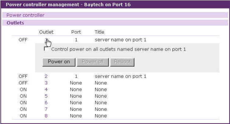
111
It shows such information as the number of the serial port where the outlet linked, the title and
the status of the outlet. It provides the outlet management part to manage the power of the device
linked to the outlet. Users can turn on / off and reboot the outlet.
Users can unfold outlet management part by clicking the outlet number link and fold it by clicking
the number of the unfolded outlet. Figure 6-10 shows the folded outlet management part.
Figure 6-10. Power controller unit management – outlet management
Users can also turn on all the outlets which is linked to the same serial port by checking the
[Control power on all outlets named … ] check box and pressing the [Power on] button if the serial port
is linked to more than one outlet. If users turn off or reboot this outlet in this case, all the outlets are
turned off or rebooted.
6.3.4 Power controller unit management - Serial port connection
The serial port connection page linked from the Serial port - Connection menu item also shows
the status of the power controller. (refer to Figure 6-11 Power controller unit management – serial port
connection). In the contrast that the power controller unit management shows it in the view of outlets,
the serial port connection page focuses on the power of the device connected to the VTS serial port.
It not only shows the status of the power but also contains the link to the serial port power control
page where users can monitor and control the power of the serial port. Only if the status is on (green)
or off (red), users can move to the serial port power control page by clicking the status icon at P
column. On trasition (yellow) status, the icon has no link.
The serial port where the power controller is attached has the icon at M column. It is linked to the
power controller unit management page. So are the port number and the title of the serial port.
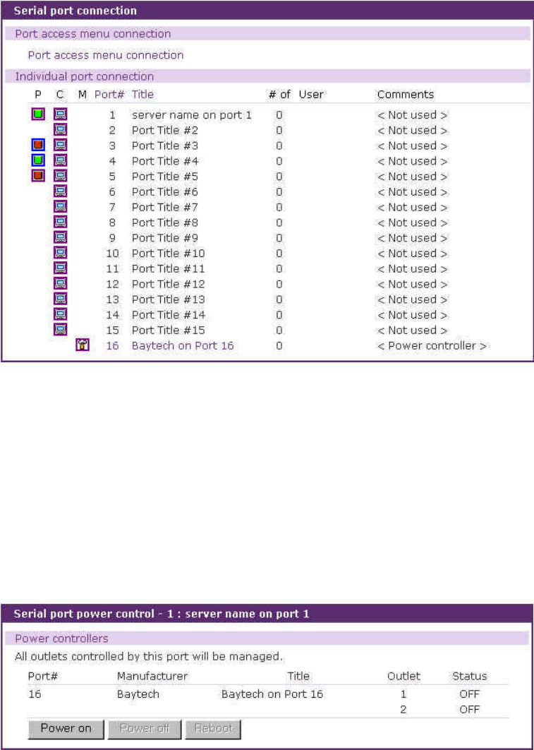
112
Figure 6-11. Power controller unit management – serial port connection
6.3.5 Power controller unit management – Serial port power control
Users can access to the serial port power control page by clicking the on / off status icon at P
column of the serial port connection page. (refer to Figure 6-12 Power controller unit management –
serial port power control). If the outlet management page controls a outlet of the power controller, this
page manages the power of the device connected to the serial port.
Figure 6-12. Power controller unit management – serial port power control
It shows the information of the outlets where the device of the VTS serial port is linked and the
power status of the device. It helps to turn on / off and reboot the device. All the outlets are affected at
the same time.
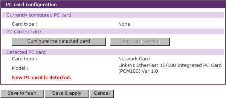
113
7: PC Card Configuration
The VTS has one extra PC card slot for increased expandability. It supports four types of PC
cards:
-LAN card
-Wireless LAN card
-Modem card
-ATA/IDE fixed disk card
The user can allow access via another network connection with either a LAN or wireless LAN card.
The ATA/IDE fixed disk card allows the user the ability to store and carry system and serial port log
data. Using the card slot for a modem card allows the user out-of-band access to the VTS without a
serial port to connect to an external modem.
Figure 7-1. Initial PC card configuration menu screen on detecting a new PC card
To use the PC card slot, the users must complete the following steps.
Step 1. Insert the PC card into the PC card slot.
Step 2. Select the Configure the detected card button on the PC card configuration page.
Step 3. The VTS will use its plug and play functionality to discover the card type. It will then
display the configuration menu screens. The user can now set card’s operation
parameters.
Step 4. Save the configuration settings by selecting the Save to flash button.
Step 5. Select [Apply changes] from the menu to apply the newly configured settings.
If VTS fail to discover the PC card, the following error message will be displayed on the menu screen.
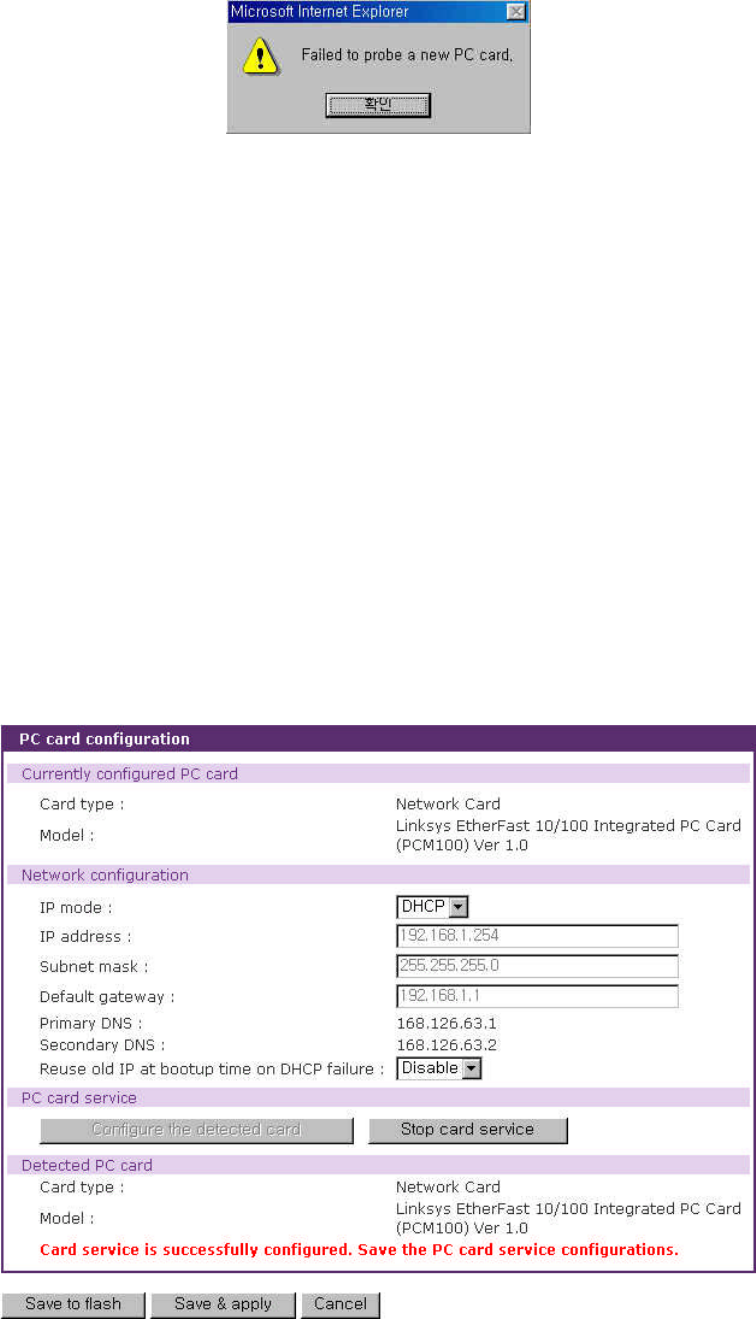
114
Figure 7-2. Failure to detect error message
Refer to Appendix B.PC Card supported by VTS to view a list of PC cards support by the VTS.
To stop or remove the PC card, user must complete the following steps.
Step 1. Select [(Ban- show the actual button) Stop card service].
Step 2. Save the configuration changes by selecting [Save to flash].
Step 3. Apply changes by selecting [Apply changes] from the menu.
Step 4. Remove the PC card from the PC card slot.
Note: Removing the PC card from the slot without following the above instructions may cause a
system malfunction.
7.1 LAN Card Configuration
A LAN card will create two network interfaces and two IP addresses. The users can assign a valid
IP address to each serial port . The IP address must be valid in the VTS built-in network interface or
the environment of VTS PC card LAN interface environment.
Figure 7-3. PC LAN card configuration
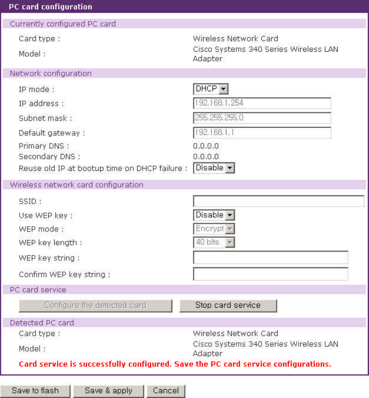
115
All the configuration steps are the same as detailed in Section 3.1. IP Configuration.
Refer to Appendix B.PC Card supported by VTS to view a list of LAN PC cards supported by
the VTS.
7.2 Wireless LAN Card Configuration
A wireless LAN card will result in two network interfaces and two IP addresses. The user can
assign a valid IP address to each serial port. The IP address must valid in the VTS built-in network
interface or in the wireless LAN interface environment.
Figure 7-4. PC wireless LAN card configuration
116
All the configuration steps are the same as detailed in Section 3.1. IP Configuration.
The VTS supports SSID(Service Set Identifier) and WEP(Wired Equivalent Privacy) key features
for the wireless LAN configuration. The user may configure the SSID to specify an AP (Access Point).
The user may also configure the WEP mode as either encrypted or shared. The WEP key length must
be either 40 or 128 bits. The 40-bit WEP key length requires the user to enter 5 hexadecimal code
sets without the separator of colon (:). The 128 bits WEP key length requires the user to enter 13
hexadecimal code sets without the separator of colon (:).
For example, to use the 128 bits WEP key length option, the user must enter 13 hexadecimal
code sets as follows:
000F25E4C2000F25E4C2000F24
Refer to Appendix B.PC Card supported by VTS to view a list of wireless LAN cards supported
by the VTS.
7.3 Serial Modem Card Configuration
Using the extra PC card slot as a modem will allow the user on-line access without tying up a
serial port with an external modem. Most 56Kbps PC serial modem cards are compatible with the PC
card slot. A complete catalog of modem cards supported by the VTS is listed in Appendix B.PC
Card supported by VTS
The default modem init string is “q1e0s0=2”. This allows the modem to operate in quiet mode
(‘q1’), echo off mode (‘e0’) and the number of rings on which to answer in Auto Answer mode equaling
two (“s0=2”). For more detailed information on the command sets, please refer to the modem manual.
For details on the callback, modem test and alert configuration, please refer to the dial-in modem
part of 4.3.4 Host Mode Configuration and 4.3.12 Alert Configuration.
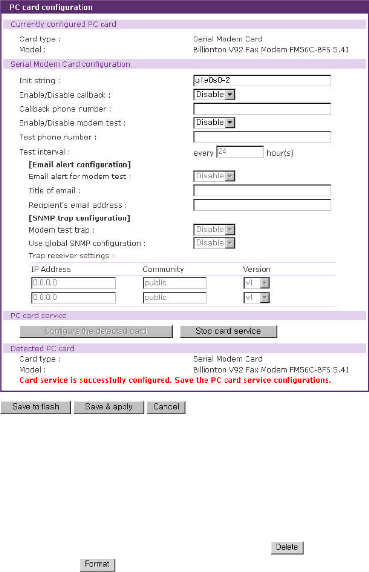
117
Figure 7-5. PC serial modem card configuration
7.4 ATA/IDE Fixed Disk Card Configuration
The user must configure the total data size required to use the PC ATA/IDE fixed disk card to
store the system and serial port log. The VTS will automatically locate the total storage size and the
disk space available on the disk.
The user may delete all the files currently on the card by selecting .
The user may select to format the card. The VTS supports both EXT2 and VFAT file
systems for the disk card.
The user may store or retrieve the VTS configuration files to/from the disk by exporting/importing
the VTS configuration.
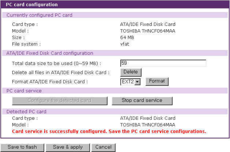
118
Figure 7-6. PC ATA/IDE fixed disk card configuration
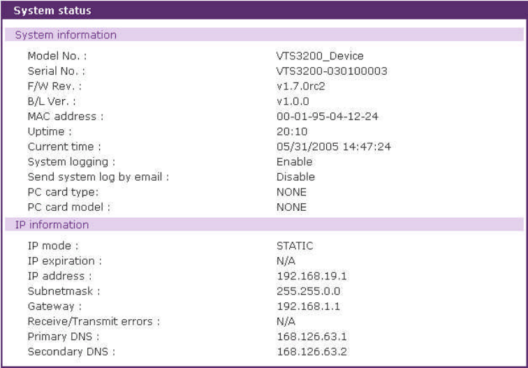
119
8: System Status and Log
The VTS display the system status and the log data via a Status Display Screen. This screen is
to be used for management purposes. System status data includes the model name, serial number,
firmware version, bootloader version and the network configuration of the VTS. The VTS can also be
configured to deliver log data automatically via email to a specified recipient with the system-logging
feature.
8.1 System Status
Figure 8-1. System status display
8.2 System Log Configuration
The VTS provides both the system logging feature and the system log status display. The user
may configure the VTS to enable or disable the system logging process and select the system log
buffer size as well as the log storage location.
Enable/disable system logging
This parameter defines whether to enable or disable the system logging feature.
120
System log storage location
The system log can be stored in the VTS internal memory, the ATA/IDE fixed disk card inserted
in PCMCIA slot or the mounting point on an NFS server. If the internal memory is used to store
system log data, the log data will be cleared when the VTS is turned off. To preserve the system log
data, set the storage location to be the ATA/IDE fixed disk card or NFS server or enable the system
log to SYSLOG server. To do this, the user must configure the corresponding media in advance.
Unless the media is properly set up, the user will not be able to select a storage location from the
interface.
System log to SYSLOG server
The system log data can be stored to the SYSLOG server in addition to the system log storage
location at the same time.
System log buffer size
This parameter defines the maximum amount of system log data that can be logged. When using
internal memory to store data, the total size of the system log cannot exceed 300 Kbytes.
When using an ATA/IDE fixed disk card to store log data, the maximum buffer size is dependent
upon the card capacity.
When using an NFS server to store logs data, the maximum buffer size is unlimited. The user
should configure the NFS server to ensure that the port logging system works properly.
System log filename
System log filename defines a log file to be logged. The factory default filename is logs.
Automatic backup on mounting
This parameter is available when System log storage location is set as CF card or NFS server.
It determines whether the backup file for system logging is created on remounting the logging storage.
Send system log by Email
The VTS can also be configured to send log data automatically if the number of logs unsent
reaches a pre-defined number. If enabled, the user must set parameters to initiate the creation of an
email. These parameters would include the number of logs required to trigger an email, the recipient
email address, etc.
Figure 8-2 shows the configuration and system log view screen.
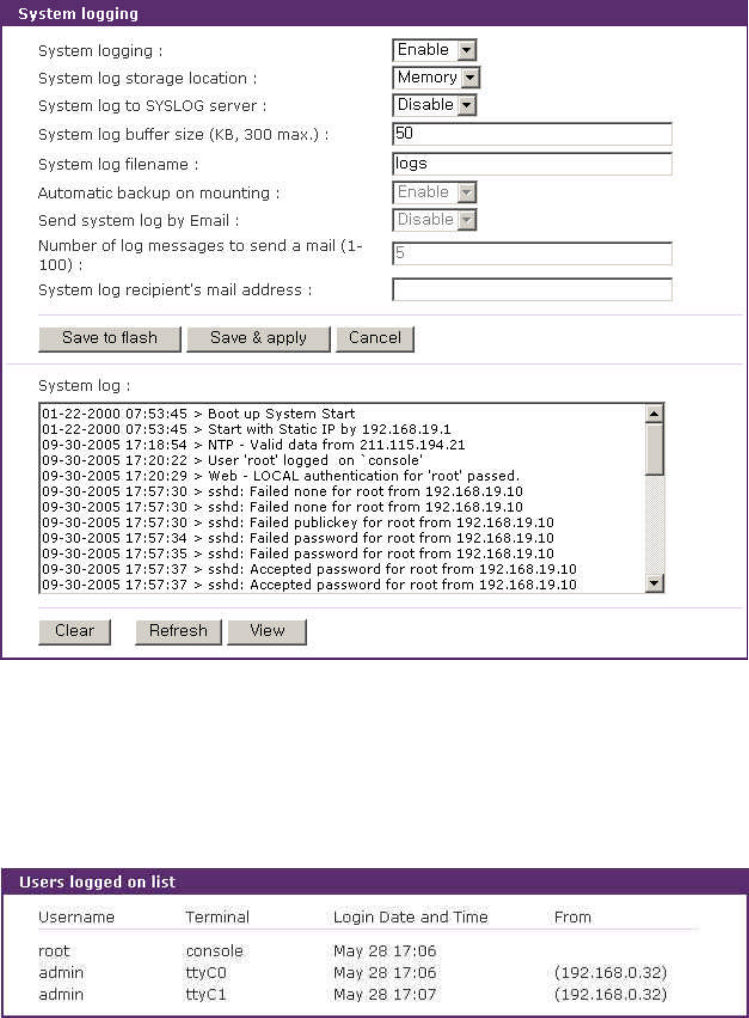
121
Figure 8-2. System log configuration and view
8.3 User logged on list
This function allows a user to view current and historical user activity on the system.
Figure 8-3. User logged on list
The list displays the following information for users who have logged into the system:
User name
Terminal type for the session
Time connected
IP address of the remote host
Note: Users access via the web will not appear on the list. Connections are not always made
using HTTP/HTTPS protocol.
122
9: System Administration
The VTS utilizes three user profile types to manage accessibility to different functions. These
three levels of user types include: system admin, port admin and user.
The system admin group has full read/write access of the VTS configuration. The system admin
can view or edit all VTS configurations, as well as use the VTS without any limitations.
The port admin group has full read/write access to the serial port configuration parameters and
power controller outlet configuration parameters. The port admin group are only provided read
access to the other VTS configuration settings. The port admin group also has access to the port
access menu.
The user group has no right to modify any of the VTS configurations. The user may access the
serial port connection screen and the power controller management screen on the web interface to
connect to the VTS serial ports or access the port access menu and to manage the power controller if
allowed.
In addition to the local authentication method, the VTS also supports an authentication server
based method for user authentication. If a remote authentication method (i.e. RADIUS, TACAS+,
LDAP) is enabled, the VTS will confirm the username and password with the remote authentication
server and check the response from the server. The users can also use the cascaded authentication
method such as remote authentication first and then local authentication if the remote authentication
fails, or vice versa.
The users can configure the VTS’s device name, date and time settings, the current user’s
password, and import / export configurations in this menu group. The users can also upgrade the
firmware of the VTS using the web interface, remote consoles or serial console.
9.1 User Administration
The VTS manages four user-level groups. Access of the configuration interfaces and of the
serial ports is based on the user’s group level.
-User: General Port User Group
-Users who belong to this group can access each serial port of which the port access control
they have, if the serial port is disabled to sniff.
-Users who belong to this group can access each serial port of which the port or monitor
123
access control they have, if the serial port is enabled to sniff.
-Users who belong to this group can manage the power of the outlet of which the power
access control they have.
Note:
The user access control is introduced to support user grouping of serial ports and power controller.
-Users in this group can also access the port access menu.
-Users in this group can use the serial port connection menu and power controller
management menu on Web interface.
-Users in this group cannot access any configuration menu or CLI.
-Port Administrator: Serial Port Administrator Group
-The Serial Port Administrator group has the all privileges that the User group has when
connected to the serial port and to the power controller.
-The Serial Port Administrator group can access the configuration menu through the Web
interface or console. The group can only change the configuration parameters provided for
the serial port, the clustering and power controller outlet. However, this group cannot change
the configuration parameters of system itself (i.e. network configuration, PC card and system
administration).
-The users who belong to this group cannot access CLI.
-System Administrator: System Administrator group
-The System Administrator group has all the privileges that users in the Port Administrator
group have when connected to the serial port.
-The System Administrator group can access the configuration menu through the Web
interface or console. They can change all the configuration parameters of the system itself.
-The System Administrator group can access the CLI, as well as execute the program. The
CLI allows the group access to the configuration and port access menu.
-root : System Super User
-ASystem Super User has all the privileges that users in the System Administrator group
have when connected to the serial port.
-ASystem Super User can access the Linux CLI. A System Super User has full access to
modify the CLI system.
-Only one user can be identified as the A System Super User. The user name cannot be
changed.
The factory default user names and the passwords are:
System Super User

124
Login: root Password: root
System Administrator
Login: admin Password: admin.
The user groups and their VTS access privileges are summarized in the Table 9-1.
Table 9-1. User groups and their privileges
Group Super user System
Administrator Port
Administrator Users
Default User name Root Admin - -
Default config
User interface CLI Text menu - -
Interface Program
CLI
Text menu
Port access menu
CLI
Text menu
Port access menu
Text menu
Port access menu
Port access menu
SSH public key
upload O O X X
CLI access O O X X
Configuration
text menu access O O ᇫ** X
Port Access Menu
Access O O O O
Web UI Access O O ᇫ** ᇫ***
System parameter
Change O O ᇫ** X
User parameter
Change O O X X
User Edit/Removal O O X X
Note:
1) ** Only the serial port/clustering and power controller outlet related configuration settings are
accessible. Read-only privilege is provided for all other fields.
2) *** The user may access only the connection workspace for the serial port / the clustering and
the power controller management.
Figure 9-1 shows the initial user administration web interface.
Figure 9-1. User administration
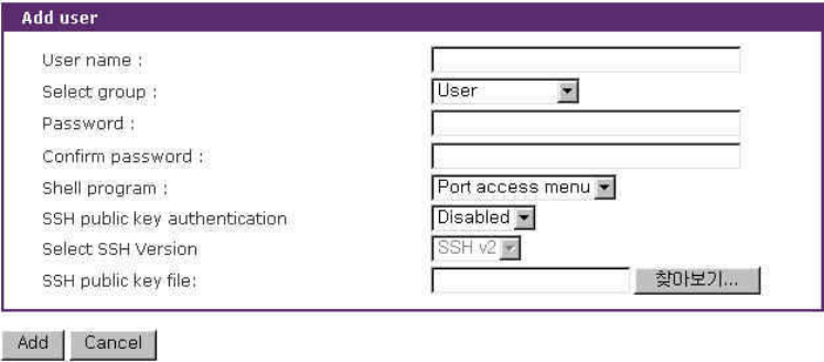
125
User list can be restricted to searching condition by specifying user name, user group or both of
them. If user name is empty, all users are listed. If user name specified, users whose name starts with
specified user name are listed. If user group is selected, users who belong to it are listed. The
default condition is empty in user name and [All group] in user group.
To add a user, Open add user screen by clicking the [Add] button, type the username, group and
password at the add user screen, and then click the [Add] button. Figure 9-2 shows the Add User
screen.
The following parameters should be properly set up to create a user’s account:
User Name
User Group: One of User, Port admin, System admin
User Password
Shell program: One of CLI, Configuration menu, Port access menu
SSH public key authentication: One of Enabled or Disabled
SSH version: One of v1 or v2
SSH public key file
If the SSH public key is uploaded into the VTS, the users who connect to the VTS using the SSH
client program will be automatically authenticated using this key file. Otherwise, a password-based
authentication will be done.
Notes:
User ID and password should be at least 3 characters or more for user add and change. There will be
an error message if they are shorter than or equal to 2 characters.
Figure 9-2. Adding a user
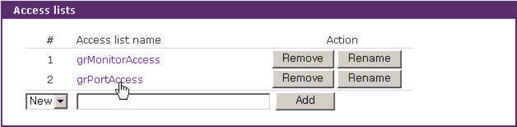
126
To remove a user,
Check the users at the User administration screen
Click the [Remove] button
To change the parameters of the user account, open the edit user screen by selecting the user
name at the User administration screen and then edit the parameters of user account like adding
user.
9.2 Access Lists
The VTS supports the access lists function to facilitate to configure the user access control. Users
can specify the access control of users at a time, after adding an access list, assigning users to it and
specifying its access control at user access control configuration page.
Figure 9-3. Access lists – access list management
Figure 9-3 shows access list management screen. There is a list of the added access lists.
To add an access list:
1. Select [New] item of the access list number list box.
2. Type the access list name.
3. Click the [Add] button.
Users can copy an existing access list to a new access list including user lists.
To copy an access list:
1. Select the number of source access list at the access list number list box.
( [Add] button changed to [Copy] button)
2. Type the new access list name.
3. Click the [Copy] button.
Users can remove an access list using [Remove] button and rename an access list by
clicking [Rename] button. Even if users remove or rename an access list, it is not reflected to the
access list used at user access control configuration. Please, be careful of referring to removed
access list at user access control.
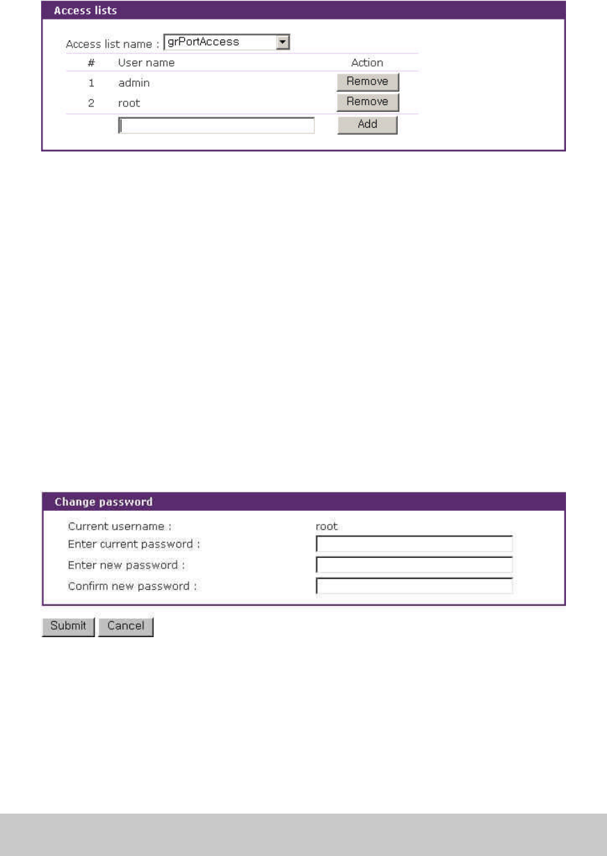
127
Users can open the user management screen of the access list by clicking an access list
name.
Figure 9-4. Access lists – user management
Figure 9-4 shows user management screen of the access list. It displays users list belonging to
the access list. Users can add a user to access list by typing a user name and clicking the [Add] button
and remove the user by clicking the [Remove] button.
Selecting [--- Access list ---] item of the [Access list name] list box leads to the access list
management screen and selecting another access list name to its user management screen.
9.3 Change Password
Figure 9-5 shows the change password screen. To change the current user’s password, type the
current password and a new password and then confirm the new password.
Figure 9-5. Change password
A user who can access only the port access menu can change the password at the port access
menu page. When connecting to the port access menu, the page below will be displayed. Please,
enter P at command input column and new password and confirm the new password and the
password will be changed.
[VTS3200_Device]
================================================================================
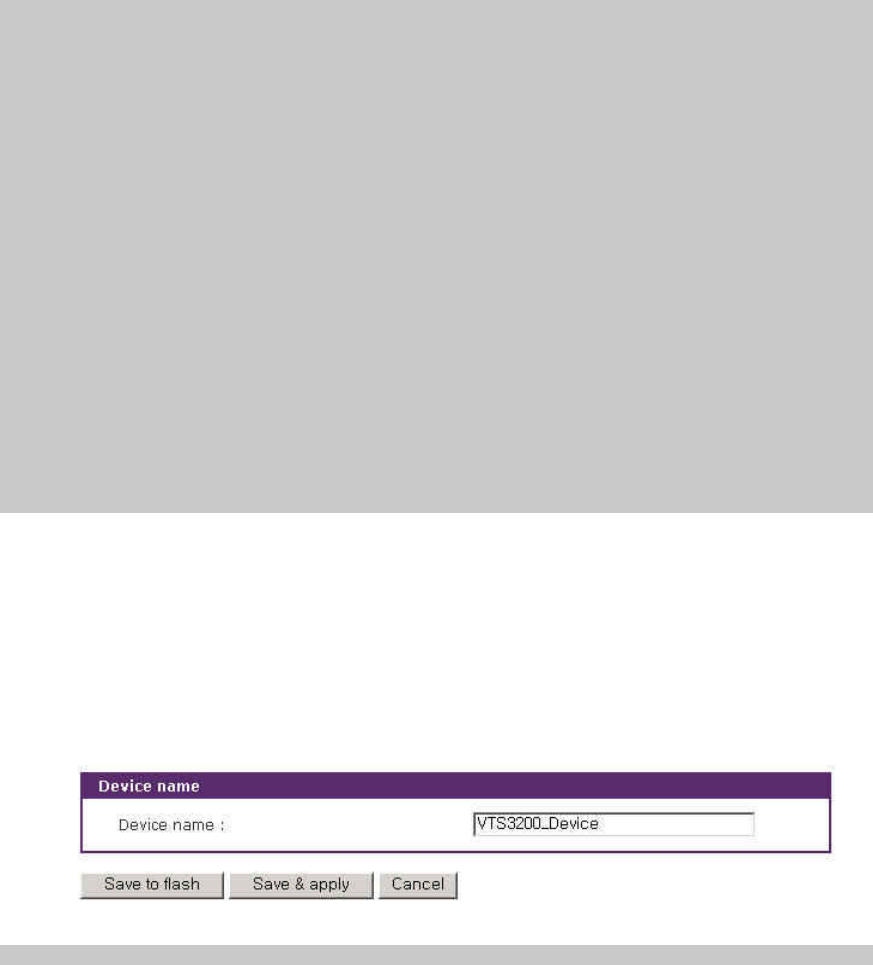
128
Port# Port Title Mode Port# Port Title Mode
================================================================================
1 Port Title #1 CS 2 Port Title #2 CS
3 Port Title #3 CS 4 Port Title #4 CS
5 Port Title #5 CS 6 Port Title #6 CS
7 Port Title #7 CS 8 Port Title #8 CS
9 Port Title #9 CS 10 Port Title #10 CS
11 Port Title #11 CS 12 Port Title #12 CS
13 Port Title #13 CS 14 Port Title #14 CS
15 Port Title #15 CS 16 Port Title #16 CS
17 Port Title #17 CS 18 Port Title #18 CS
19 Port Title #19 CS 20 Port Title #20 CS
21 Port Title #21 CS 22 Port Title #22 CS
23 Port Title #23 CS 24 Port Title #24 CS
25 Port Title #25 CS 26 Port Title #26 CS
27 Port Title #27 CS 28 Port Title #28 CS
29 Port Title #29 CS 30 Port Title #30 CS
31 Port Title #31 CS 32 Port Title #32 CS
Enter command ( 1-32 serial port, P passwd, S slave unit
R remote port, Q exit )
------> P
Enter new password : *****
Retype new password : *****
Password was changed.
9.4 Device Name Configuration
The VTS has its own name for administrative purposes. Figure 9-6 shows the device name
configuration screen. When user changes Device name, hostname of VTS shall be changed and then
prompt on CLI also shall be changed to the corresponding one as follows,
root@VTS3200_Device:~#
Figure 9-6. Device name configuration and Prompt on CLI
Please note that user cannot set space character as one of device name. And If user sets blank
as Device name then hostname is set as IP address of VTS automatically.
And also the device name is mainly utilized for management program, HelloDevice Manager.
9.5 Date and Time Settings
The VTS maintains current date and time information. The VTS clock and calendar settings are
backed up by internal battery power. The user can change the current date and time, as shown in
Figure 9-7.
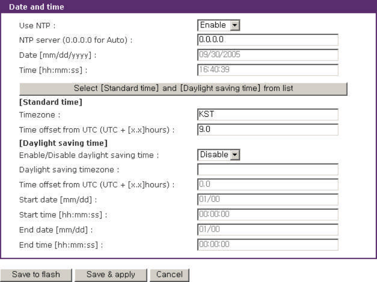
129
Figure 9-7. Date and time configuration
There are two date and time settings. The first is to use the NTP server to maintain the date and
time settings. If the NTP feature is enabled, the VTS will obtain the date and time information from the
NTP server at each reboot. If the NTP server is set to 0.0.0.0, the VTS will use the default NTP
servers. In this case, the VTS should be connected from the network to the Internet. The second
method is to set date and time manually without using the NTP server. This will allow the date and
time information to be kept maintained by the internal battery backup.
The user may also need to set the timezone and the time offset from UTC depending on the
users’location to set system date and time exactly. If the user uses daylight saving time, the user may
need to set the daylight saving time properties such as the daylight saving timezone, the time offset
from UTC, start data and time, end date and time. It allows the VTS to calculate the exact system time.
The user can open the window to help to set these properties easily by clicking the Select [Standard
time] and [Daylight saving time] from list button.
9.6 Configuration management
The user may export the current configurations to a file at such locations as CF card, NFS server,
user space or local machine and import the exported configurations as current configurations from CF
card, NFS server, user space or local machine.
The user may restore the factory default settings at any time by selecting “Factory default” at
location property at the import part or by pushing the factory default reset switch on the back panel of
the VTS.
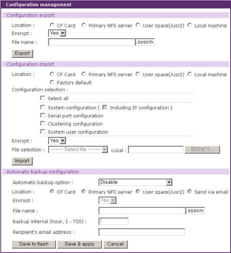
130
The VTS provides the function to backup the configuration automatically. Configuring the
Automatic backup configuration, the user can store the configuration in specified way on specified
time.
Figure 9-8 shows the configuration management screen.
Figure 9-8. Configuration management
The following parameters should be properly set up to export / import configurations or to backup
the configuration automatically:
Configuration export
Location : Location to export to.
Encrypt : One of Yes or No.
File name
131
Configuration import
Location : Location to import from. By selecting Factory default, the user may restore the
factory settings.
Configuration selection : Determines what kinds of configurations are imported.
Encrypt : One of Yes or No. If location is Factory default, it does not affect.
File selection : List all the exported files satisfying the encrypting option at the selected location
which is one of CF card, NFS server and user space.
Local : Helps to browse the exported file at local machine if location is local machine.
Automatic backup configuration
Automatic backup option : One of Disable,Periodically or 10 minutes after last change
Location : Location to backup
Encrypt : One of Yes or No
File name
Backup interval : Determines how often stored on Periodically option
Recipient’s email address : Email address where email is sent on Send via email optiin
To export the current configurations:
4. Select the location to export to.
5. Select the encrypting option
6. Type the file name.
7. Click the [Export] button.
To import the exported configurations:
1. Select the location to import from.
2. Select the configurations to import.
3. Select the encrypting option.
4. Select the file to import from the file selection list box if location is not local machine nor
factory default.
5. Select the file to import by clicking browse button if location is local machine.
6. Click the [Import] button.
9.7 Security Profile
The policy of the security for VTS management is configured. It contains the system security such
as the security of VTS services, the security for network and the security of each port connection and
the security through password management. Security Profiles are classified into 2 groups:
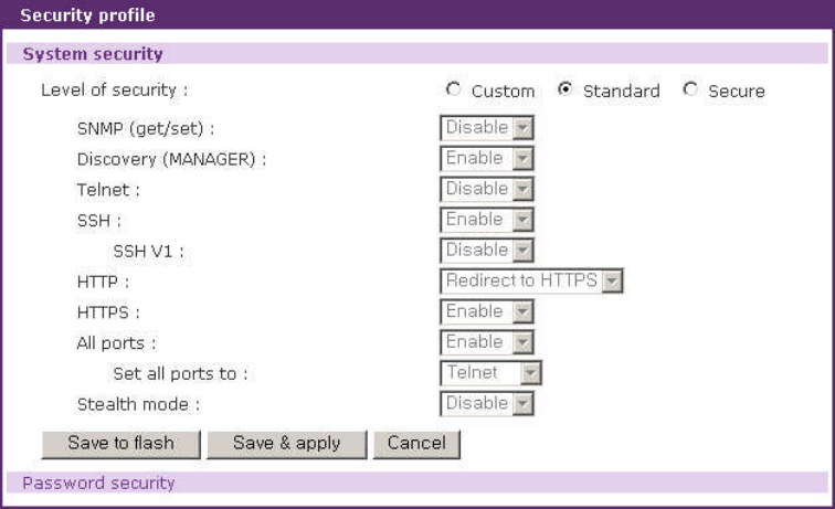
132
1. System security
2. Password security
9.7.1 System security
The policy of the system security such as the VTS services, network and port connections is
configured. Figure 9-9 shows the system security of the security profile.
Figure 9-9. Security profile – System security
The configuration parameters for services are as follows:
Level of security
SNMP (get/set)
Discovery (MANAGER)
Telnet
SSH
SSH V1
HTTP
HTTPS
All ports
Set all ports to
Stealth mode
Level of security
This parameter determines the level of security policy. It can be one of custom, standard and

133
secure. User can configure any security item in the case of custom. Otherwise, each security item is
configured corresponding to the security level as follows:
Security Item Custom Standard Secure
SNMP (get/set) Configurable Disable Disable
Discovery (MANAGER) Configurable Enable Disable
Telnet Configurable Disable Disable
SSH Configurable Enable Enable
SSH V1 Configurable Disable Disable
HTTP Configurable Redirect to HTTPS Disable
HTTPS Configurable Enable Enable
All ports Configurable Any Any
Set all ports to Configurable Any SSH
Stealth mode Configurable Disable Enable
SNMP (get/set)
This parameter determines whether the service to get or set the status of the VTS is enabled or
not.
Discovery (MANAGER)
This parameter determines whether the VTS reply to the request for VTS Manager to probe the
VTS.
Telnet
This parameter determines whether the telnet console service is enabled or not. It is implemented
by adding or changing the IP filtering rule as follows:
Status Interface Option IP address/Mask Port Chain rule
Disable all Normal 0.0.0.0/0.0.0.0 23 DROP
Enable all Normal 0.0.0.0/0.0.0.0 23 ACCEPT
Please refer to section 3.5 IP Filtering for details.
SSH
This parameter determines whether the SSH console service is enabled or not. It is implemented
by adding or changing the IP filtering rule as follows:
Status Interface Option IP address/Mask Port Chain rule
Disable all Normal 0.0.0.0/0.0.0.0 22 DROP
Enable all Normal 0.0.0.0/0.0.0.0 22 ACCEPT
Please refer to section 3.5 IP Filtering for details.

134
SSH V1
This parameter determines whether SSH version1 protocol is allowed or not. If it is set as Disable,
the VTS supports only SSH V2 protocol.
HTTP
This parameter determines whether Web service through HTTP is enabled or not. It is
implemented by adding or changing the IP filtering rule as follows:
Status Interface Option IP address/Mask Port Chain
rule
Disable all Normal 0.0.0.0/0.0.0.0 HTTP port DROP
Enable or
Redirect to HTTPS all Normal 0.0.0.0/0.0.0.0 HTTP port ACCEPT
Please refer to section 3.5 IP Filtering for details. If it is set as the Redirect to HTTPS, the
request of web interface through HTTP is lead to the request through HTTPS.
HTTPS
This parameter determines whether Web service through HTTPS is enabled or not. It is
implemented by adding or modifying the IP filtering rule as follows:
Status Interface Option IP address/Mask Port Chain
rule
Disable All Normal 0.0.0.0/0.0.0.0 HTTPS port DROP
Enable All Normal 0.0.0.0/0.0.0.0 HTTPS port ACCEPT
Please refer to section 3.5 IP Filtering for details.
All ports
This parameter determines whether all the serial and the remote ports are connected or not. It is
implemented by changing the configuration of port access menu and modifying the Port IP filtering
configuration of all the ports as follows:
상태 Allowed base host IP Subnet mask to be applied
Disable 255.255.255.255 255.255.255.255
Enable 0.0.0.0 0.0.0.0
Please refer to section 4.3.9 Port IP filtering configuration for details.
Switch all ports to SSH
If this parameter is set as Telnet or SSH, user can access to the port access menu and the
serial/remote ports only via Telnet or SSH protocol. It is implemented by setting the Port access
menu protocol parameter of the port access menu configuration as Telnet or SSH and the Protocol
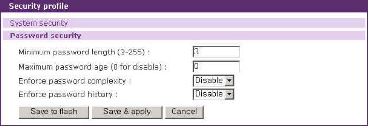
135
parameter of the host mode configuration of the serial/remote as Telnet or SSH. If as RawTCP, the
protocol of serial / remote port is changed to RawTCP but not applied to port access menu. Please
refer to section 4.2 Port Access Menu Configuration and 4.3.4 Host Mode Configuration for details.
Stealth mode
If this parameter is set as Enable, the VTS does not reply to the request instead of refusing when
a client tries to connect to the port which it does not listen to.
9.7.2 Password Security
Users can guarantee the security through password management. It configures the policy of the
password security. Figure 9-10 shows the password security of the security profile.
Figure 9-10. Security profile – Password security
The configuration parameters for password security are as follows:
Minimum password length
Maximum password age
Enforce password complexity
Enforce password history
Minimum password length
The length of the password is not to be less than this parameter.
Maximum password age
This parameter configures the valid term by day. User cannot manage the VTS until his/her
password is changed after the valid term has expired.
Note : A series of three failures in log-in causes the user account expired at any condition.
The user account is not valid until the Administrator recovers it.
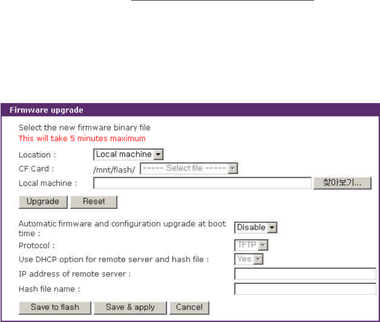
136
Enforce password complexity
This parameter keeps user from using a simple password. If it is set as Enable, password is
required to have the following characteristics:
1. Password must be at least eight characters in length.
2. Password must contain at least one of each of the following: uppercase, lowercase,
number, and special character.
3. Password must contain at least six characters which only occur once.
4. Password must have no consecutive numbers or letters.
5. Password must not contain the user name.
Enforce password history
If this parameter is set as Enable, the password same as one of the 10 old passwords is
forbidden.
9.8 Firmware Upgrade
Firmware upgrades are available via serial, remote console or web interface. The latest upgrades
are available on the Sena web site at http://www.sena.com/support/downloads/. The VTS supports the
automatic firmware and configuration upgrade at booting. If users set the properties related to the
automatic firmware and configuration, the VTS will check whether the firmware and configuration are
newly updated and upgrade the new firmware and configuration if needed.
Figure 9-11 shows the firmware upgrade web interface.
Figure 9-11 Firmware upgrade

137
To upgrade firmware via the web:
1. Select “Local machine”from “Location”list box.
2. Select the latest firmware binary by clicking browse button.
3. Select and upload the selected version.
4. Once the upgrade has been completed, the system will reboot to apply the changes.
To upgrade firmware via CF card:
1. Select “CF card”from “Location”list box.
2. Select the latest firmware from “------ Select file -----“list box.
3. Select and upload the selected version.
4. Once the upgrade has been completed, the system will reboot to apply the changes.
To use either a remote or serial console to upgrade your firmware, the TELNET/SSH or terminal
emulation program must support Zmodem transfer protocol. After the firmware upgrade, the previous
settings will be reset to the factory default settings, except the IP configuration settings.
To upgrade firmware via a remote console:
1. Obtain the latest firmware.
2. Connect either TELNET/SSH or a serial console port using the terminal emulation
program.
(TELNET or SSH is recommended since the process of firmware upgrade by serial
console requires extremely long time.)
3. Select from the firmware upgrade menu as shown in Figure 9-12.
4. Follow the online directions and transfer the firmware binary file using the Zmodem
protocol as shown in Figure 9-13. Select “CF Card” for “Location” and enter file name to
upgrade via CF card.
5. Once the upgrade has been completed, the system will reboot to apply the changes
6. If the firmware upgrade fails, the VTS will display error messages as shown in Figure 9-14.
It will also maintain the current firmware version.
Login : admin
Password : *****
-------------------------------------------------------------------------------
Welcome to VTS-3200 configuration page
Current time : 0000/00/00 00:00:00 F/W REV. :
Serial No. : MAC Address : 00-01-95-04-1b-2e
IP mode : DHCP IP Address : 192.168.0.129
-------------------------------------------------------------------------------

138
Select menu
1. Network Configuration
2. Serial Port Configuration
3. Clustering Configuration
4. Power Controller
5. PC Card Configuration
6. System Status & Log
7. System Administration
8. Save Changes
9. Exit without Saving
a. Exit and Apply Changes
b. Exit and Reboot
<ENTER> Refresh
-----> 7
-------------------------------------------------------------------------------
System Administration
-------------------------------------------------------------------------------
Select menu
1. User Administration
2. Access Lists
3. Device Name : VTS3200 Device
4. Date and Time
5. Configuration Management
6. Security Profile
7. Firmware Upgrade
8. CLI Configuration
<ESC> Back, <ENTER> Refresh
-----> 7
-------------------------------------------------------------------------------
System Administration --> Firmware Upgrade
-------------------------------------------------------------------------------
Select menu
1. Firmware Upgrade
2. Automatic firmware and configuration upgrade at boot time : Disable
<ESC> Back, <ENTER> Refresh
-----> 1
Select the location of the firmware
( 1 = Local Machine, 2 = CF Card )
-----> 1
----------------------------------
Location : Local Machine
----------------------------------
*** Firmware upgrade will RESTART your device. ***
Do you want to start firmware upgrade ? (y/n) : y
Preparing for firmware upgrade. Wait a moment...
Transfer firmware by zmodem using your terminal application.
** B0ff000005b157
Figure 9-12. Firmware upgrade using remote/serial console
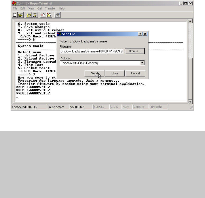
139
Figure 9-13. Transfer binary file by Zmodem (HyperTerminal)
-----> 5
*** Firmware upgrade will RESTART your device. ***
Do you want to start firmware upgrade ? (y/n) : y
Preparing for firmware upgrade. Wait a moment...
Transfer firmware by zmodem using your terminal application.
** B0ff000005b157
** B0ff000005b157
** B0ff000005b157
** B0ff000005b157
Firmware upgrade failed !
Now reboot ...
Figure 9-14. Firmware upgrade failure message
To use the function to upgrade the firmware and configuration or to upload a user file or to run a
user command at boot time, users have to set the following properties:
Automatic firmware and configuration upgrade at boot time
It determines whether the VTS upgrade at boot time or not.
Protocol
It determines which protocol the VTS uses to communicate with the remote host on upgrading.
Use DHCP option for remote server and hash file
It determines where the properties such as IP address of remote server and Hash file name
that are required to upgrade firmware automatically can be found. If it is set Yes, they are found at the
140
response of the DHCP server for the DHCP request of the VTS. Otherwise, they are specified at the IP
address of remote server and the Hash file name fields.
IP address of remote server
It determines to which host the VTS connects to get the hash file, firmware image and
configuration file.
Hash file name
It determines the name of hash file that is used to specify the firmware image file and
configuration file to upgrade. The VTS checks if the VTS needs to upgrade or not by comparing the
model name and version at hash file with the VTS model name and firmware version. Hash file format
is below :
<TYPE>,<NAME>,<MODEL>,<VERSION>
or
<TYPE>,<NAME>,<Options for file uploading>,<Path to upload>
or
<TYPE><COMMAND>
Where <TYPE> - 1:firmware image 2:configuration (1 byte)
<NAME> - the name of firmware image file or configuration file
<MODEL> - the model name of VTS such as VTS800, VTS1600 and VTS3200
<VERSION> - version of firmware or configuration
In case of firmware update, this field should be the same version number
that the firmware has. In case of configuration update, this field is a user
assigned version number with the similar format of firmware version
or <TYPE> - 3: User file upload
<NAME> - Name of the target file
<Options for file uploading> - [F][X][Z]U
F : forced copy(remove if there is same file already)
X : uncompress the file to the specified location
Z : unzip the file to the specified location
U : default option for file uploading
<Path to upload> - Directory path where the specified file will be uploaded
or <TYPE> - 4:User command run
<COMMAND> - Command to run
Hash file example is below:
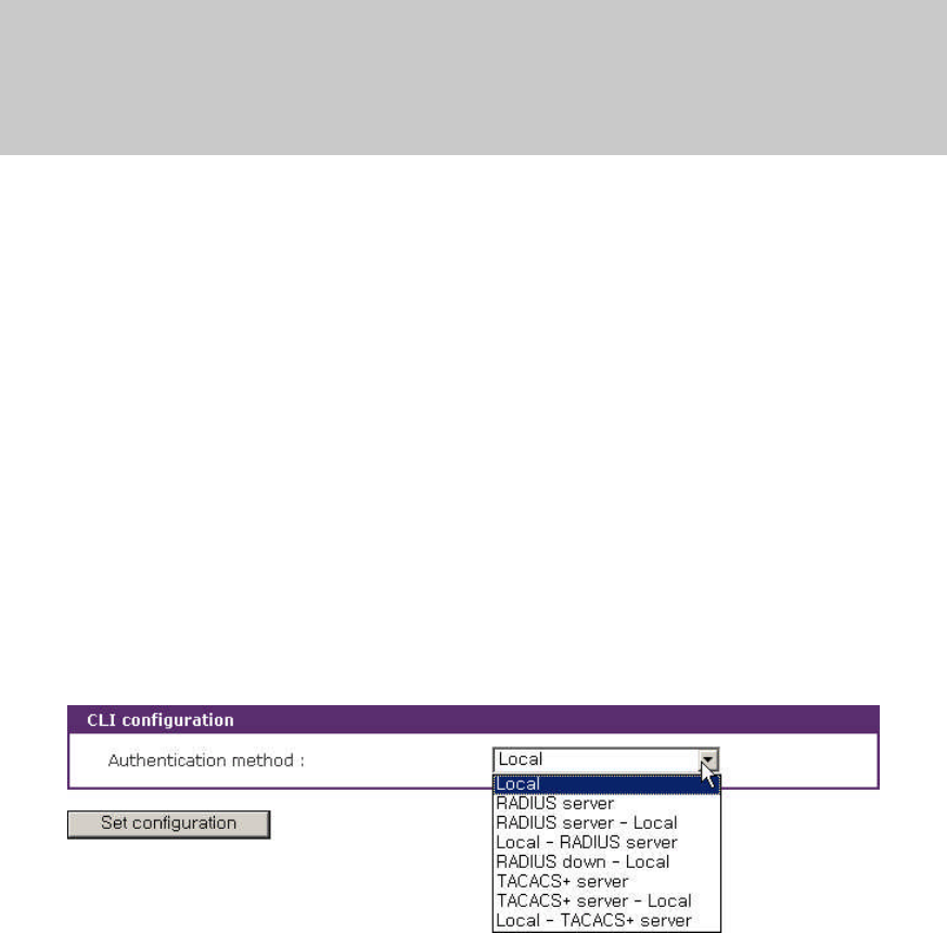
141
1,vts48.img,VTS3200,v1.5.0
2,vts48.syscm,VTS3200,v1.0.0
3,test_hash.tar,FXU,/mnt/flash
3,active_detect.tar.gz,FXZU,/mnt/flash
4,mkdir /tmp/test
9.9 CLI Configuration
Users can select an Authentication method for CLI login via serial console and telnet/SSH
remote console. The VTS currently provides authentication methods of Local, RADIUS server,
RADIUS server – Local, Local – RADIUS server, RADIUS down – Local, TACACS+ server, TACACS+
server – Local, Local – TACACS+ server using Linux-PAM (Pluggable Authentication Modules for
Linux).
Please refer to section 4.3.10 Authentication configuration for details in authentication methods
and section 11.9.2 Enabling the RADIUS Authentication for the CLI log-in and 11.9.3 Enabling the
TACACS+ Authentication for the CLI log-in for details on Linux-PAM.
Figure 9-15 shows the CLI configuration web interface.
Figure 9-15. CLI configuration
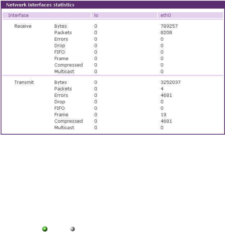
142
10: System Statistics
The VTS Web interface provides system statistics menus. The user can use the menus to access
statistical data and tables stored in the VTS memory. Network interfaces statistics and serial ports
statistics display statistical usage of the link layer, lo,eth and serial ports. IP, ICMP, TCP and UDP
statistics display usages of four primary components in the TCP/IP protocol suite.
10.1 Network Interfaces Statistics
Network interfaces statistics display basic network interfaces usage of the VTS, lo and eth0.lo is
a local loop back interface and eth0 is a default network interface of VTS.
Figure 10-1. Network interfaces statistics
10.2 Serial Ports Statistics
Serial ports statistics display the usage history of 32 serial ports, baud rate configurations and
each port’s pin status. ( : On : Off )
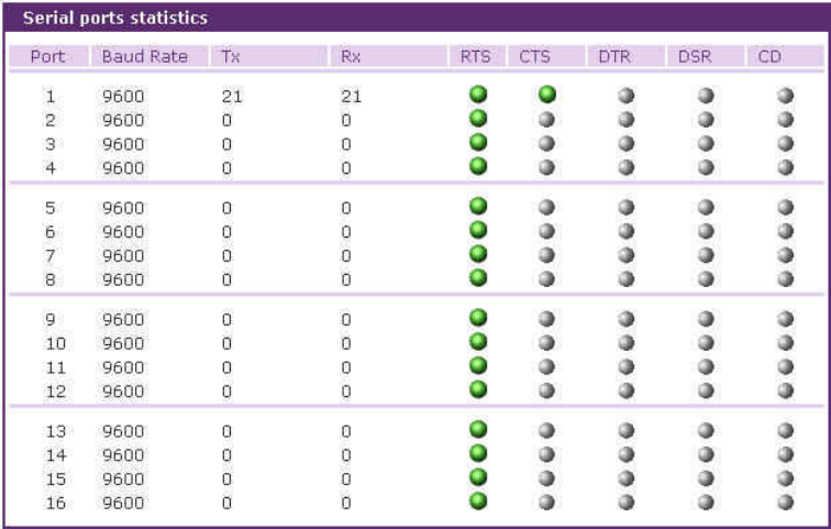
143
Figure 10-2. Serial ports status
10.3 IP Statistics
The IP Statistics screen provides statistical information about packets/connections using an IP
protocol. Definitions and descriptions of each parameter are described below:
Forwarding :
Specifies whether IP forwarding is enabled or disabled.
DefaultTTL :
Specifies the default initial time to live (TTL) for datagrams originating on a particular computer.
InReceives :
Shows the number of datagrams received.
InHdrErrors :
Shows the number of datagrams received that have header errors. Datagrams Received Header
Errors is the number of input datagrams discarded due to errors in their IP headers, including bad
checksums, version number mismatch, other format errors, time-to-live exceeded, errors
discovered in processing their IP options, etc.
InAddrErrors :
Specifies the number of datagrams received that have address errors. These datagrams are
discarded because the IP address in their IP header's destination field was not a valid address to
be received at this entity. This count includes invalid addresses (for example, 0.0.0.0) and
144
addresses of unsupported Classes (for example, Class E).
ForwDatagrams :
Specifies the number of datagrams forwarded.
InUnknownProtos :
Specifies the number of locally addressed datagrams received successfully but discarded
because of an unknown or unsupported protocol.
InDiscard :
Specifies the number of input IP datagrams for which no problems were encountered to prevent
their continued processing, but which were discarded (for example, for lack of buffer space). This
counter does not include any datagrams discarded while awaiting reassembly.
InDelivers :
Specifies the number of received datagrams delivered.
OutRequests :
Specifies the number of outgoing datagrams that an IP is requested to transmit. This number
does not include forwarded datagrams.
OutDiscards :
Specifies the number of outgoing datagrams discarded.
OutNoRoutes :
Specifies the number of transmitted datagrams discarded. These are datagrams for which no
problems were encountered to prevent their transmission to their destination, but which were
discarded (for example, for lack of buffer space.) This counter would include datagrams counted
in Datagrams Forwarded if any such packets met this (discretionary) discard criterion.
OutNoRoutes :
Specifies the number of datagrams for which no route could be found to transmit them to the
destination IP address. These datagrams were discarded. This counter includes any packets
counted in Datagrams Forwarded that meet this "no route" criterion.
ReasmTimeout :
Specifies the amount of time allowed for all pieces of a fragmented datagram to arrive. If all
pieces do not arrive within this time, the datagram is discarded.
ReasmReqds :
Specifies the number of datagrams that require reassembly.
ReasmOKs :
Specifies the number of datagrams that were successfully reassembled.
ReasmFails :
Specifies the number of datagrams that cannot be reassembled.
FragOKs :
Specifies the number of datagrams that were fragmented successfully.
FragFails :
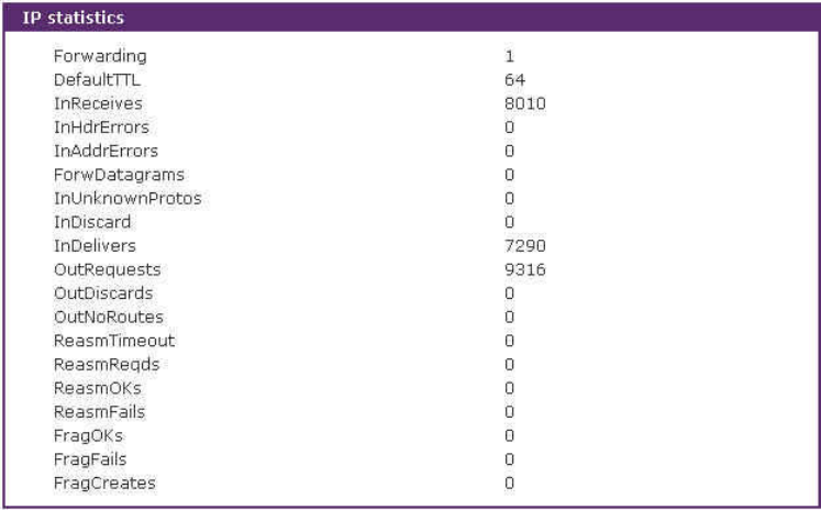
145
Specifies the number of datagrams that need to be fragmented but couldn't be because the IP
header specifies no fragmentation. For example, if the datagrams "Don't Fragment" flag was set,
the datagram would not be fragmented. These datagrams are discarded.
FragCreates :
Specifies the number of fragments created.
Figure 10-3. IP statistics
10.4 ICMP Statistics
The ICMP Statistics screen provides statistical information about packets/connections using an
ICMP protocol. Definitions and descriptions of each parameter are described below:
InMsgs, OutMsgs :
Specifies the number of messages received or sent.
InErrors, OutErrors :
Specifies the number of errors received or sent.
InDestUnreachs, OutDestUnreachs :
Specifies the number of destination-unreachable messages received or sent. A destination-
unreachable message is sent to the originating computer when a datagram fails to reach its
intended destination.
InTimeExcds, OutTimeExcds :
146
Specifies the number of time-to-live (TTL) exceeded messages received or sent. A time-to-live
exceeded message is sent to the originating computer when a datagram is discarded because the
number of routers it has passed through exceeds its time-to-live value.
InParmProbs, OutParmProbs :
Specifies the number of parameter-problem messages received or sent. A parameter-problem
message is sent to the originating computer when a router or host detects an error in a
datagram's IP header.
InSrcQuenchs, OutSrcQuenchs :
Specifies the number of source quench messages received or sent. A source quench request is
sent to a computer to request that it reduces its rate of packet transmission.
InRedirects, OutRedirects :
Specifies the number of redirect messages received or sent. A redirect message is sent to the
originating computer when a better route is discovered for a datagram sent by that computer.
InEchos, OutEchos :
Specifies the number of echo requests received or sent. An echo request causes the receiving
computer to send an echo reply message back to the originating computer.
NEchoReps, OutEchoReps :
Specifies the number of echo replies received or sent. A computer sends an echo reply in
response to receiving an echo request message.
InTimestamps, OutTimestamps :
Specifies the number of time-stamp requests received or sent. A time-stamp request causes the
receiving computer to send a time-stamp reply back to the originating computer.
InTimestampReps, OutTimestampReps :
Specifies the number of time-stamp replies received or sent. A computer sends a time-stamp
reply in response to receiving a time-stamp request. Routers can use time-stamp requests and
replies to measure the transmission speed of datagrams on a network.
InAddrMasks, OutAddrMasks :
Specifies the number of address mask requests received or sent. A computer sends an address
mask request to determine the number of bits in the subnet mask for its local subnet.
InAddrMaskReps, OutAddrMaskReps :
Specifies the number of address mask responses received or sent. A computer sends an address
mask response in response to an address mask request.
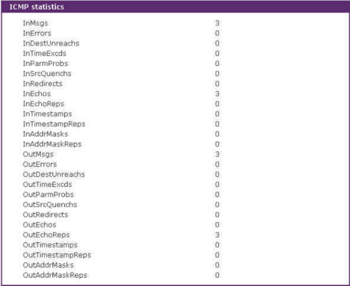
147
Figure 10-4. ICMP statistics
10.5 TCP Statistics
The TCP Statistics screen provides statistical information about packets/connections using a TCP
protocol. Definitions and descriptions of each parameter are described below:
RtoAlgorithm :
Specifies the retransmission time-out (RTO) algorithm in use. The Retransmission Algorithm can
have one of the following values.
0 : CONSTANT - Constant Time-out
1: RSRE - MIL-STD-1778 Appendix B
2: VANJ - Van Jacobson's Algorithm
3: OTHER - Other
RtoMin :
Specifies the minimum retransmission time-out value in milliseconds.
RtoMax :
Specifies the maximum retransmission time-out value in milliseconds.
MaxConn :
Specifies the maximum number of connections. If is the maximum number is set to -1, the
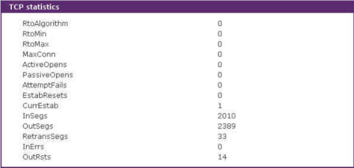
148
maximum number of connections are dynamic.
ActiveOpens :
Specifies the number of active opens. In an active open, the client is initiating a connection with
the server.
PassiveOpens :
Specifies the number of passive opens. In a passive open, the server is listening for a connection
request from a client.
AttemptFails :
Specifies the number of failed connection attempts.
EstabResets :
Specifies the number of established connections that have been reset.
CurrEstab :
Specifies the number of currently established connections.
InSegs :
Specifies the number of segments received.
OutSegs :
Specifies the number of segments transmitted. This number does not include retransmitted
segments.
RetransSegs :
Specifies the number of segments retransmitted.
RetransSegs :
Specifies the number of errors received.
OutRsts :
Specifies the number of segments transmitted with the reset flag set.
Figure 10-5. TCP statistics
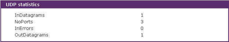
149
10.6 UDP Statistics
The UDP Statistics screen provides statistical information about packets/connections using a
UDP protocol. Definitions and descriptions of each parameter are described below:
InDatagrams :
Specifies the number of datagrams received.
NoPorts :
Specifies the number of received datagrams that were discarded because the specified port was
invalid.
InErrors :
Specifies the number of erroneous datagrams that were received. Datagrams Received Errors is
the number of received UDP datagrams that could not be delivered for reasons other than the
lack of an application at the destination port.
OutDatagrams :
Specifies the number of datagrams transmitted.
Figure 10-6. UDP statistics

150
11: CLI guide
11.1. Introduction
The VTS Root or System Administrator can access the Linux console command line interface
(CLI) of the VTS via the serial console or Telnet/SSH. In the CLI, the authorized user can perform
standard Linux commands to view the status of the VTS, edit the configuration, apply configuration
changes, define user scripts and transmit files between the VTS and remote hosts.
The VTS provides 1024 KB user space mounted in /usr2 for read/write capabilities in its internal
flash memory. Using the user space, the user can create their own scripts or executable binaries to
customize the VTS.
ARoot user will always have access to the CLI through the serial console on the VTS back panel
or by using a Telnet/SSH client from their workstation. A System Administrator user can also access
to the CLI but with limited rights.
The Root user will not be able to access the telnet remote / serial console by removing remark
character of following line in /etc/pam.d/login file.
auth requisite pam_securetty.so
The Root user will not be able to access the SSH remote / serial console by changing configuration
in /etc/ssh/sshd_config file
#PermitRootLogin yes => PermitRootLogin no.
To apply the configuration changes above, the command as below is to be executed
[root@loclahost ~] killall –HUP sshd
The user can access the CLI through modem connection by connecting dial-in modem to serial
console. To user this function requires to add a new line as below to the rc.user file and reboot the
system to apply the changes.
echo 57600 > /var/run/mgetty.console
where 57600 is baud rate of the dial-in modem and the serial port.
11.2. Flash partition
The VTS internal flash is partitioned as shown in the table below. The users can freely access the
Mtdblock5 which is mounted on /usr2 for their own needs. The user can also access files at /etc,
/var, and /temp at their own risk. Simply accessing these files will not affect the VTS after rebooting.
However, if the user invokes the command saveconf, the changes in the configuration file will be
committed to the internal flash memory area of the VTS. This will result in the changes being kept

151
after the reboot sequence. Invalid configuration changes can effect the VTS behavior. At worst, it
may cause the VTS to be inoperable.
Block Type Mount point Size (KB)
Mtdblock0 Bootloader None 128
Mtdblock1 Kernel None 768
Mtdblock2 CRAMFS (Read only) / 6080
Mtdblock3 Ram disk image (4MB) /etc, /var, /tmp 64
Mtdblock4 EXT2 (R/W) /cnf (normally unmounted) 64
Mtdblock5 JFFS2 (R/W) /usr2 1024
Mtdblock6 Reserved None 64
Total 8192
Note : Do not access each mtdblock using mount or dd command in the CLI.
This may make the VTS inoperable.
11.3. Supported Linux Utilities
11.3.1 Shell & shell utilities:
sh, ash, bash, echo, env, false, grep, more, sed, which, pwd
11.3.2 File and disk utils:
ls, cp, mv, rm, mkdir, rmdir, ln, mknod, chmod, touch, sync,
gunzip, gzip, zcat, tar, dd, df, du, find, cat, vi, tail,
mkdosfs, mke2fs, e2fsck, fsck, mount, umount, scp
11.3.3 System utilities:
date, free, hostname, sleep, stty, uname, reset,
insmod, rmmod, lsmod, modprobe,
kill, killall, ps, halt, shutdown, poweroff, reboot, telinit, init,
useradd, userdel, usermod, whoami, who, passwd, id, su, who
11.3.4 Network utilities:
ifconfig, iptables, route, telnet, ftp, ssh, ping
11.4. Accessing CLI
11.4.1 Accessing CLI as root
Serial console:

152
1) Connect the console port of the VTS with the PC serial port
2) Run the PC terminal emulation program
3) Configure the PC serial port to: 9600-8-N-1 No flow control
4) Press <enter>
5) Login with the VTS root account
Telnet/SSH console:
1) telnet VTS_ip_address or
2) ssh root@VTS_ip_address
11.4.2 Accessing CLI as a system administrator
System administrator configuration
1) Access web: System administration -> Users administration
2) [Add user] or [Edit user]
3) Select group = System admin
4) Shell program = CLI
5) [Add] or [Submit]
6) Access serial console or telnet console as with System admin login
11.5. Editing VTS configuration in CLI
11.5.1 Configuration file save/load mechanism:
1) While booting, the VTS uncompresses /cnf/cnf.tar.gz to /tmp/cnf/* and unmounts
/cnf
2) When changing the configuration, the VTS changes the contents of the files in /tmp/cnf
3) When the user saves the configuration, the VTS mounts /cnf and compresses /tmp/cnf/*
to /cnf/cnf.tar.gz (Web [Save to flash], or “saveconf”in CLI)
11.5.2 To change configuration in CLI:
To change the VTS configuration in the CLI, run the menu-driven configuration utility
“configmenu”, or configure manually as follows:
1) Edit the configuration file manually using vi command
(Please see Appendix C. VTS Configuration files for detail descriptions of each parameter
in the configuration files)
2) Save the configuration file to flash using the “saveconf”utility
3) Apply all changes using “applyconf”utility
root@192.168.0.117:~# configmenu

153
or
root@192.168.0.117:~# cd /tmp/cnf
root@192.168.0.117:/tmp/cnf# vi redirect.cnf
root@192.168.0.117:/tmp/cnf# saveconf
root@192.168.0.117:/tmp/cnf# applyconf
11.6. Running user defined scripts
Shell script /usr2/rc.user is automatically called when the VTS is booting. Users can modify the
rc.user file to run user defined script or binaries
#!/bin/bash
#
# rc.user : Sample script file for running user programs at boot time
#
#PATH=/bin:/usr/bin:/sbin:/usr/sbin
# Add shell command to execute from here
echo ‘This is the welcome message defined by users’exit 0
11.7. File transmission
The users can use an ftp client for file transmission and use /usr2 directory for data read/write
root@192.168.0.117:~# cd /usr2
root@192.168.0.117:/usr2# ftp 192.168.2.3
Connected to 192.168.2.3.
220 lxtoo.senalab.co.kr FTP server (Version wu-2.6.1-16) ready.
Name (192.168.2.3:root): sena
331 Password required for sena.
Password:
230 User sena logged in.
Remote system type is UNIX.
Using binary mode to transfer files.
ftp> get test.tgz
local: test.tgz remote: test.tgz
200 PORT command successful.
150 Opening BINARY mode data connection for test.tgz (350 bytes).
226 Transfer complete.
350 bytes received in 0.04 secs (9.6 kB/s)
ftp> bye
In addition to a regular FTP client, the user can copy files securely as encrypted using scp client
program. If the user wants to copy a file from the VTS(192.168.0.120) to user’s PC, type a
command on the user’s PC as shown below:
[root@localhost work]# scp root@192.168.0.120:/usr2/rc.user /work
The authenticity of host '192.168.0.120 (192.168.0.120)' can't be established.
RSA key fingerprint is c1:70:ab:52:48:ab:e5:dc:47:9c:94:ed:99:6f:94:4f.
Are you sure you want to continue connecting (yes/no)? yes
Warning: Permanently added '192.168.0.120' (RSA) to the list of known hosts.
root@192.168.0.120's password:
rc.user 100% |*****************************| 173 00:00
[root@localhost work]#

154
11.8. Serial console access using modem
The VTS unit supports to access to the serial port through modem by adding a script as below to
/usr2/rc.user and rebooting
echo 9600 > /var/run/mgetty.console
where 9600 is baud rate between serial port and modem.
For some modem such as US Robotics,
echo “9600 &F&B1”> /var/run/mgetty.console
11.9. Examples
11.9.1 Disabling the Telnet Port of the Unit
The VTS unit does not support disabling the remote console port individually (port 22 for SSH or
port 23 for Telnet to the box)
Currently, the user can only disable or enable all remote consoles together. This must be done
using the UI or console configuration menu.
The user may bypass this and disable only one (Telnet or SSH) remote console by modifying the
script 'rc.user'. Below are two examples of how this could be done.
Example1. Modify 'inetd.conf'
Step 1 Modify /etc/inetd.conf (comment out or delete telnet service)
Step 2 Copy inetd.conf to /usr2/inetd.conf
Step 3 Edit usr2/rc.user script as follows:
#!/bin/bash
#
# rc.user : Sample script file for running user programs at boot time
#
#PATH=/bin:/usr/bin:/sbin:/usr/sbin
# Add shell command to execute from here
# Add shell command to execute from here
cp -a /usr2/inetd.conf /etc/inetd.conf
ps -ef
while killall inetd 2>/dev/null;
do sleep 1;
ps -ef
done
/usr/sbin/inetd
ps -ef
exit 0

155
The user may now disable the telnet service every time the system boots up.
Example 2. Run iptables rule
Step 1 Modify 'usr2/rc.user script as follows:
#!/bin/bash
#
# rc.user : Sample script file for running user programs at boot time
#
#!/bin/bash
#
# rc.user : Sample script file for running user programs at boot time
#
#PATH=/bin:/usr/bin:/sbin:/usr/sbin
# Add shell command to execute from here
# if user wants to disable telnet service from all host
iptables -A INPUT -p tcp -s --dport 23 -j DROP
# if user wants to enable telnet service only from specific hosts(192.168.0.0 ~
192.168.0.255)
#iptables -A INPUT -p tcp -s ! 192.168.0.1/255.255.255.0 --dport 23 -j DROP
exit 0
The user may now disable the telnet service every time the system boots up.
If the user resets the VTS to the factory defaults, /usr2/rc.user script file will be renamed to
/usr2/rc.user.old# file, and the default rc.user file will be restored.
11.9.2 Enabling the RADIUS Authentication for the CLI log-in
The CLI of the VTS unit supports Linux-PAM (Pluggable Authentication Modules for Linux). With
this feature, the user can add RADIUS authentication for the CLI login. Please note that there should
be local users on VTS with the same name as in radius server so that login process can assign the
user proper shell program after remote authentication.
Example1. Serial/Telnet console
Step 1 Add the user account to the RADIUS server (192.168.0.135)
Step 2 Add the user account to the VTS unit
Step 3 Create the server file, which contains the RADIUS server IP address, secret and time-
out values, under /usr2/ directory.
# vi /usr2/server
192.168.0.135 testing123 10

156
Step 4 Create the login file, which is a PAM configuration file for checking whether the user is
allowed to login to a machine, under /usr2/ directory.
# vi /usr2/login
For Radius only authentication,
auth required pam_securetty.so
auth required pam_radius_auth.so
account required pam_unix.so
password required pam_unix.so
session required pam_unix.so
For Radius and Local authentication,
(First Radius and then local authentication if Radius authentication is succeeded.
User should enter his passwords twice.)
auth required pam_securetty.so
auth required pam_radius_auth.so
auth required pam_unix_auth.so
account required pam_unix.so
password required pam_unix.so
session required pam_unix.so
For Radius or Local authentication,
(First Radius and then local authentication if Radius authentication is failed.)
auth required pam_securetty.so
auth sufficient pam_radius_auth.so
auth required pam_unix_auth.so
account required pam_unix.so
password required pam_unix.so
session required pam_unix.so
For Radius down – Local authentication
(First Radius and then local authentication only if Radius server is down)
auth required pam_securetty.so
auth [success=done new_authtok_reqd=done authinfo_unavail=ignore default=die] pam_radius_auth.so
auth [success=done new_authtok_reqd=done authinfo_unavail=ignore default=die] pam_unix_auth.so
account required pam_unix.so
password required pam_unix.so
session required pam_unix.so
Step 5 Create securetty which permits root login as follows,
# vi /usr2/securetty
console
ttyS0
pts/0
Step 6 Copy server,login and securetty files to the corresponding directory as follows,
# cp /usr2/server /etc/raddb
# cp /usr2/login /etc/pam.d
# cp /usr2/securetty /etc/securetty

157
Step 7 Reflect above changes to /usr2/rc.user script so that it can be effected on every
system reboot as follows,
#!/bin/bash
#
# rc.user : Sample script file for running user programs at boot time
#
#PATH=/bin:/usr/bin:/sbin:/usr/sbin
# Add shell command to execute from here
# Add shell command to execute from here
cp –f /usr2/server /etc/raddb/
cp –f /usr2/login /etc/pam.d/
cp –f /usr2/securetty /etc/
exit 0
The user now use the RADIUS authentication method for CLI login through telnet client.
Please note that the user must successfully complete the steps described above to enable the
RADIUS authentication for CLI login. If an error occurs, the user will need to reset the system back to
the factory defaults to be able to access the system.
To permit multiple root access, user should add pts logins to securetty file as follows,
console
ttyS0
pts/0
pts/1
...
pts/9
If the user resets the VTS to factory defaults, /usr2/rc.user script file will be renamed to
/usr2/rc.user.old# file, and default rc.user file will be restored.
Example2. SSH console
Step 1 Add the user account to the RADIUS server (192.168.0.135)
Step 2 Add the user account to the VTS unit
Step 3 Create the server file, which contains the RADIUS server IP address, secret and time-
out values, under /usr2/ directory.
# vi /usr2/server
192.168.0.135 testing123 10
Step 4 Create the sshd file, which is a PAM ssh configuration file for checking whether the user
is allowed to login to a machine, under /usr2/ directory.
# vi /usr2/sshd
For Radius only authentication,

158
auth required pam_radius_auth.so
auth required pam_nologin.so
session required pam_unix.so
For Radius and Local authentication,
(First Radius and then local authentication if Radius authentication is succeeded.
User should enter his passwords twice.)
auth required pam_radius_auth.so
auth required pam_unix_auth.so
session required pam_unix.so
For Radius or Local authentication,
(First Radius and then local authentication if Radius authentication is failed.)
auth sufficient pam_radius_auth.so
auth required pam_unix_auth.so
session required pam_unix.so
For Radius down – Local authentication
(First Radius and then local authentication only if Radius server is down)
auth [success=done new_authtok_reqd=done authinfo_unavail=ignore default=die] pam_radius_auth.so
retry=2
auth [success=done new_authtok_reqd=done authinfo_unavail=ignore default=die] pam_unix_auth.so
session required pam_unix.so
Step 5 Change UsePAM equals yes and PasswordAuthentication equals no in sshd_config file
# cp /etc/ssh/sshd_config /usr2/
# vi /usr2/sshd_config
...
PasswordAuthentication no
...
UsePAM yes
Step 6 Modify inetd.conf to run SSHD with modified configuration file as follows,
# cp /etc/inetd.conf /usr2/
# vi /usr2/inetd.conf
...
ssh stream tcp nowait root /usr/sbin/tcpd sshd –i -f /usr2/sshd_config
...
Step 7 Copy server, sshd and inetd.conf files to the corresponding directory as follows,
# cp /usr2/server /etc/raddb/
# cp /usr2/sshd /etc/pam.d/
# cp /usr2/inetd.conf /etc/
Step 8 Restart inetd process to apply changed configuration,
# killall inetd

159
# /usr/sbin/inetd
The user now use the RADIUS authentication for CLI login through SSH client.
Step 9 Reflect above changes to /usr2/rc.user script so that it can be applied to every
system reboot as follows,
#!/bin/bash
#
# rc.user : Sample script file for running user programs at boot time
#
#PATH=/bin:/usr/bin:/sbin:/usr/sbin
# Add shell command to execute from here
# Add shell command to execute from here
cp –f /usr2/server /etc/raddb/
cp –f /usr2/sshd /etc/pam.d/
cp –f /usr2/inetd.conf /etc/
while killall inetd 2>/dev/null;
do sleep 1;
done
/usr/sbin/inetd
exit 0
Step 10 Configure SSH client program as below
For TeraTerm Pro SSH client - Use challenge/response(TIS) to login
Note : In case of Radius Down – Local, you cannot use TeraTermPro
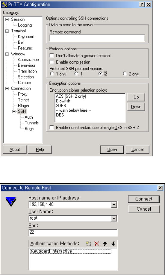
160
For Putty SSH client - Select Preferred SSH protocol version as 2
For F-secure SSH client - Add “Keyboard interactive” to Authentication Methods
11.9.3 Enabling the TACACS+ Authentication for the CLI log-in
The CLI of the VTS unit supports Linux-PAM (Pluggable Authentication Modules for Linux). With
this feature, the user can add TACACS+ authentication for the CLI login. Please note that there should
be local users on VTS with the same name as in TACACS+ server so that login process can assign
the user proper shell program after remote authentication.
Example1. Serial/Telnet console
Step 1 Add the user account to the TACACS+ server (192.168.0.135). And run TACACS+ server,

161
(# /usr/local/sbin/tac_plus –C /etc/tac_plus.cfg –d 4088)
Step 2 Add the user account to the VTS unit
Step 3 Create the login file, which is a PAM configuration file for checking whether the user is
allowed to login to a machine, under /usr2/ directory,
# vi /usr2/login
For TACACS+ only authentication,
auth required pam_securetty.so
auth required pam_tacplus.so encrypt service=ppp protocol=lcp
server= 192.168.0.135 secret=vts123
#account required pam_unix.so
#password required pam_unix.so
#session required pam_unix.so
For TACACS+ and Local authentication,
(First TACACS+ and then local authentication if TACACS+ authentication is succeeded.
User should enter his passwords twice.)
auth required pam_securetty.so
auth required pam_tacplus.so encrypt service=ppp protocol=lcp server=
192.168.0.135 secret=vts123
auth required pam_unix_auth.so
account required pam_unix.so
password required pam_unix.so
session required pam_unix.so
For TACACS+ or Local authentication,
(First TACACS+ and then local authentication if TACACS+ authentication is failed.)
auth required pam_securetty.so
auth sufficient pam_tacplus.so encrypt service=ppp protocol=lcp
server= 192.168.0.135 secret=vts123
auth required pam_unix_auth.so
account required pam_unix.so
password required pam_unix.so
session required pam_unix.so
Step 4 Create securetty which permits root login as follows,
# vi /usr2/securetty
console
ttyS0
pts/0
Step 5 Copy login and securetty files to the corresponding directory as follows,
# cp /usr2/login /etc/pam.d
# cp /usr2/securetty /etc/securetty
Step 6 Reflect above changes to /usr2/rc.user script so that it can be effected on every
system reboot as follows,
#!/bin/bash

162
#
# rc.user : Sample script file for running user programs at boot time
#
#PATH=/bin:/usr/bin:/sbin:/usr/sbin
# Add shell command to execute from here
# Add shell command to execute from here
cp –f /usr2/login /etc/pam.d/
cp –f /usr2/securetty /etc/
exit 0
The user may now use the TACACS+ authentication method for CLI login.
Please note that the user must successfully complete the steps described above to enable the
TACACS+ authentication for CLI login. If an error occurs, the user will need to reset the system back
to the factory defaults to be able to access the system.
To permit multiple root access, user should add pts logins to securetty file as follows,
console
ttyS0
pts/0
pts/1
...
pts/9
If the user resets the VTS to factory defaults, /usr2/rc.user script file will be renamed to
/usr2/rc.user.old# file, and default rc.user file will be restored.
Example2. SSH console
Step 1 Add the user account to the TACACS+ server (e.g. 192.168.0.135),
Step 2 Add the user account to the VTS unit,
Step 3 Create the sshd file, which is a PAM ssh configuration file for checking whether the user
is allowed to login to a machine, under /usr2/ directory,
# vi /usr2/sshd
For TACACS+ only authentication,
auth required pam_tacplus.so encrypt server=192.168.0.135
secret=vts123
auth required pam_nologin.so
session required pam_unix.so
For TACACS+ only authentication and accounting,
auth required pam_tacplus.so encrypt server=192.168.0.135
secret=vts123
auth required pam_nologin.so
session required pam_tacplus.so encrypt service=ppp protocol=lcp
server= 192.168.0.135 secret=vts123

163
For TACACS+ and Local authentication,
(First TACACS+ and then local authentication if TACACS+ authentication is succeeded.
User should enter his passwords twice.)
auth required pam_tacplus.so encrypt server=192.168.0.135
secret=vts123
auth required pam_unix_auth.so
session required pam_unix.so
For TACACS+ or Local authentication,
(First TACACS+ and then local authentication if TACACS+ authentication is failed.)
auth sufficient pam_radius_auth.so
auth required pam_unix_auth.so
session required pam_unix.so
Step 4 Change USEPAM equals yes and PasswordAuthentication equals in sshd_config file
# cp /etc/ssh/sshd_config /usr2/
# vi /usr2/sshd_config
...
PasswordAuthentication no
...
UsePAM yes
Step 5 Copy sshd and sshd_config files to the corresponding directory as follows,
# cp /usr2/sshd /etc/pam.d/
# cp /usr2/sshd_config /etc/ssh/
Step 6 Reflect above changes to /usr2/rc.user script so that it can be effected on every
system reboot as follows,
#!/bin/bash
#
# rc.user : Sample script file for running user programs at boot time
#
#PATH=/bin:/usr/bin:/sbin:/usr/sbin
# Add shell command to execute from here
# Add shell command to execute from here
cp –f /usr2/sshd /etc/pam.d/
cp –f /usr2/sshd_config /etc/ssh/
exit 0
The user may now use the TACACS+ authentication for CLI login through SSH client.
Step 7 Configure SSH client program like Step 10 at Example 2. SSH console of 11.9.2 Enabling
the RADIUS Authentication for the CLI log-in.

164
Appendix A: Connections
A.1 Ethernet Pin outs
The VTS uses the standard Ethernet connector that is shielded connector compliant with
AT&T258 specifications. Table A-1 shows the pin assignment and wire color.
Figure A-1. Pin layout of the RJ45 connector
Table A-1. Pin assignment of the RJ45 connector for Ethernet
Pin Description Color
1 Tx+ White with orange
2 Tx- Orange
3 Rx+ White with green
4 NC Blue
5 NC White with blue
6 Rx- Green
7 NC White with brown
8 NC Brown
A.2 Console and Serial port pin-outs
The VTS uses an RJ45 connector for console and serial ports. The pin assignment of the RJ45
connector for console and serial ports is summarized in Table A-2. Each pin has a function according
to the serial communication type configuration.
Table A-2. Pin assignment of RJ45 connector for console and serial ports
Pin Description
1 CTS
2 DSR
3 RxD
4 GND
5 DCD
6 TxD
7 DTR
8 RTS

165
A.3 Cable diagram
Devices Serial port type Use
Cisco equipments
Sun Netra servers
RJ45
Console/Ethernet cable
Nortel equipments
Other DB9 DTE devices
DB9 male Console/Ethernet cable
+ RJ45-DB9F cross-over adapter
Sun Sparc servers
Other DB25 DTE devices
DB25 female
Console/Ethernet cable
+ RJ45-DB25M cross-over adapter
Serial printers
DB25 DTE devices
DB25 male Console/Ethernet cable
+ RJ45-DB25F cross-over adapter
Modem
ISDN terminal adapters
DB25 male Console/Ethernet cable
+ RJ45-DB25M straight adapter

166
RJ45-DB9 female adapter
Using RJ45 to DB9(Female) Cross-over Cable
Description (RJ45) Internal Cable Color RJ45 Pin No. DB9 Pin No. Description (DB9)
CTS Blue 1 7 RTS
DSR Orange 2 4 DTR
RXD Black 3 3 TXD
GND Red 4 5 GND
DCD Green 5 1 DCD
TXD Yellow 6 2 RXD
DTR Brown 7 6 DSR
RTS White 8 8 CTS
Console cable + RJ45-DB9F adapter
RJ45-DB25 female adapter
Using RJ45 to DB25(Female) Cross-over Cable
Description (RJ45) Internal Cable Color RJ45 Pin No. DB25 Pin No. Description (DB25)
CTS Blue 1 4 RTS
DSR Orange 2 20 DTR
RXD Black 3 2 TXD
GND Red 4 7 GND
DCD Green 5 8 DCD
TXD Yellow 6 3 RXD
DTR Brown 7 6 DSR
RTS White 8 5 CTS
RJ45-DB25 male adapter
Using RJ45 to DB25(Male) Cross-over Cable
Description (RJ45) Internal Cable Color RJ45 Pin No. DB25 Pin No. Description (DB25)
CTS Blue 1 4 RTS
DSR Orange 2 20 DTR
RXD Black 3 2 TXD
GND Red 4 7 GND
DCD Green 5 8 DCD
TXD Yellow 6 3 RXD
DTR Brown 7 6 DSR
RTS White 8 5 CTS

167
RJ45-DB25 male adapter
Using RJ45 to DB25(Male) Straight Cable
Description (RJ45) Internal Cable Color RJ45 Pin No. DB25 Pin No. Description (DB25)
CTS Blue 1 5 CTS
DSR Orange 2 6 DSR
RXD Black 3 3 RXD
GND Red 4 7 GND
DCD Green 5 8 DCD
TXD Yellow 6 2 TXD
DTR Brown 7 20 DTR
RTS White 8 4 RTS
Console cable + RJ45-DB25F/M adapter

168
Appendix B: PC card supported by VTS
The following PC cards are supported by VTS series:
Table B-1. Network card
Manufacturer Model/Name VTS probed Model name Specification
3COM 3CXE589ET-AP 3Com Megahertz 589E
TP/BNC LAN PC Card 10 Mbps LAN card
Linksys Linksys EtherFast 10/100
Integrated PC Card
(PCM100)
Linksys EtherFast 10/100
Integrated PC Card
(PCM100) Ver 1.0
10/100 Mbps LAN card
Corega FetherII PCC-TXD corega K.K. corega FEtherII
PCC-TXD 10/100 Mbps LAN card
Netgear 16bit PCMCIA Notebook Adapter
FA411 NETGEAR FA411 Fast
Ethernet 10/100 Mbps LAN card
Table B-2. Wireless Network card
Manufacturer Model/Name VTS probed Model name Specification
Cisco Systems AIR-PCM340/Aironet 340 Cisco Systems 340 Series
Wireless LANAdapter 11 Mbps Wireless LAN
Adapter
Cisco Systems AIR-PCM350/Aironet 350 Cisco Systems 350 Series
Wireless LANAdapter 11 Mbps Wireless LAN
Adapter
Lucent
Technologies PC24E-H-FC/Orinoco Silver Lucent Technologies
WaveLAN/IEEE Version
01.01
11 Mbps Wireless LAN
Adapter
Agere Systems
(Lucent
Technologies)
Orinoco Classic Gold
(PC24E-H-FC/Orinoco Gold) Lucent Technologies
WaveLAN/IEEE Version
01.01
11 Mbps Wireless LAN
Adapter
Buffalo AirStation
(WLI-PCM-L11GP) MELCO WLI-PCM-L11
Version 01.01 11 Mbps Wireless LAN
Adapter
Table B-3. ATA/IDE Fixed Disk Card
Manufacturer Model/Name VTS probed Model name Specification
Advantech CompactFlash CF 48M 48 MB Storage card
SanDisk SDP series SunDisk SDP 5/3 0.6 64 MB Storage card
SanDisk SDP series SanDisk SDP 5/3 0.6 256 MB Storage card
Kingston CompactFlash Storage Card TOSHIBA THNCF064MAA 64 MB Storage card
Viking CompactFlash TOSHIBA THNCF064MBA 64 MB Storage card

169
Table B-4. Serial Modem Card
Manufacturer Model/Name VTS probed Model name Specification
Billionton
Systems Inc. FM56C series PCMCIA CARD
56KFaxModem FM56C-NFS
5.41
Ambient (Intel) V.90
FAX/MODEM PC Card
Viking PC Card Modem 56K Viking V.90 K56flex 021 A MODEM PC Card
KINGMAX KIT PCMCIA 56K
Fax/Modem Card
CIRRUS LOGIC
56K MODEM CL-MD56XX
5.41 V.90 FAX/MODEM PC Card
TDK TDK DH6400 TDK DH6400 1.0 64Kbps
NTT
DoCoMo Mobile Card Triplex N NTT DoCoMo Mobile
Card Triplex N 64Kbps

170
Appendix C: VTS Configuration files
C.1 System.cnf
#
# system.cnf
#
# system configuration which exist only one place on this file.
#
# kind of IP configuration mode
# 1 - static ip , 2 - dhcp , 3 - pppoe
ipmode = 1
# system ip addres
ipaddr = 192.168.161.5
# system subnet mask
subnet = 255.255.0.0
# system gateway
gateway = 192.168.1.1
# dns configuration
# 'p_dns' is a primary dns ip address and 's_dns' is a secondary dns ip address
# if you want to set dns authmatically in case of dhcp or pppoe,
# you can set 'bmanual_dns' to 0.
p_dns = 168.126.63.1
s_dns = 168.126.63.2
bmanual_dns = 1
# pppoe configuration
# 'ppp_usr' is pppoe account name and 'ppp_pwd" is a password for that account
ppp_usr = whoever
ppp_pwd = pppoepwd
# Email logging configuration
# if you want to send log via E-mail, set 'emaillog' to 1
# 'emaillog_num' trigger sending email.
# The number of logs are greater than 'emaillog_num", then send it.
emaillog = 0
emaillog_num = 5
# SMTP configuration
# 'smtpsvr' is a SMTP server .
# 'sysmailaddr' is a sender address.
# 'recvmailaddr' is a receiver address.
# 'smtp_mode' means a SMTP server authentication mode.
# 1 - smtp w/o authentication , 2 - pop before smtp , 3 - smtp w/
authentication
# If 'smtp_mode" is 2 or 3, you need SMTP account information.
# 'smtp_user' is a SMTP account name and 'smtp_pwd" is a password.
smtpsvr = smtp.yourcompany.com
sysmailaddr = vts1600@yourcompany.com
recvmailaddr = admin@yourcompany.com
smtp_mode = 1
smtp_user = admin
smtp_pwd = admin
# 'device_name' mean a unit name assigned. A unit name will be a identifier
among PS products.
device_name = VTS Device

171
# IP filtering configuration
# By setting 'btelnet' to 1, you can use remote console.
# Similarly by setting 'bweb' to 1, you can use remote console.
# 0 means that protect any access.
# 'enable_ip', 'enable_netmask' pair is a source rule specification for remote
console filtering.
# 'enable_webip', 'enable_webnetmask' pair is for web filtering.
btelnet = 1
bweb = 1
enable_ip = 0.0.0.0
enable_netmask = 0.0.0.0
enable_webip = 0.0.0.0
enable_webnetmask = 0.0.0.0
# dynamic DNS(DDNS) configuration
# dynamic dns can be enabled by setting 'bdyndns' to 1. 0 for disable.
# 'dyn_dn' is a domain name for your DDNS.
# 'dyn_user' is a account name for DDNS and 'dyn_pwd" is a password for it.
bdyndns = 0
dyn_dn = vts1600.dyndns.biz
dyn_user = vts1600-user
dyn_pwd = vts1600-pwd
# NTP configuration
# 'ntp_enable' set to 1 for using NTP or set to 0.
# 'ntp_serverip' is the IP address of NTP server and 'ntp_offset' is a your
offset from UTC.
# If you don't know any NTP server IP, then set 'ntp_auto_conf' to 1.
ntp_enable = 0
ntp_auto_conf = 1
ntp_offset = 0.0
ntp_serverip = 192.168.200.100
# Log configuration
# system logging is enabled by 'log_enable' to 1.
# 'logbuf_size' is a variable for representing log buffer size by KB.
# 'log_stoloc' is a location to save log.
# 1 = memory 2 = CF card 3 = NFS 4 = SYSLOGD
# If you choose log location to SYSLOGD, 'logbuf_size' you've set will loose his
role - limiting log file size.
log_enable = 1
logbuf_size = 4
log_stoloc = 1
# Port access menu(PAM) configuration
# Enable or disable port access menu by setting 'master_enb' 1 or 0.
# 'master_port' is a listening port for PAM.
# 'master_proto' means a protocol .
# 1 = Telnet , 2 = SSH , 3 = RawTCP
# To set inactivity time-out, set 'master_inactivity'. A unit is second.
# 'master_localip' means a assigned ip for PAM.
# 'master_authmethod' means a authentication method for PAM.
# 0 = None
# 1 = radius 2 = local 3 = radius/local 4 = local/radius
# 5 = TACACS+ 6 = TACACS+/local 7 = local/TACACS+
# 8 = LDAP 9 = LDAP/local 10 = local/LDAP
# If your authenticatio method is not None or Local, then you have to specify
other parameters
# 'master_p_radius_auth' and 'master_s_radius_auth' is a authentication server
ip address.
# One is a primary server and the other is secondary one.
# 'master_p_radius_acct' and 'master_s_radius_acct' is for accounting server.
# Accounting server parameters isn't needed in case of LDAP.
# 'master_radius_secret' is a shared secret only for RADIUS and TACACS+.
# In RADIUS case, you have two more parameters, 'master_radius_timeout' and
'master_radius_retries'.

172
# One is for the timeout and the other is for the count of retries.
# 'master_ldap_search_base' parameter - ldap base string - is ONLY FOR LDAP.
master_enb = 1
master_port = 7000
master_proto = 1
master_inactivity = 100
master_localip = 192.168.1.100
master_authmethod = 2
master_radius_timeout = 10
master_radius_retries = 3
master_ldap_search_base = "dn=yourcomapy,dn=com"
# syslog configuration
# You can run or kill syslogd by setting 'bsyslog_service' to 1 or 0.
# 'syslog_ip' is a IP addresss of a remote syslog server.
# 'syslog_2ndip' is a IP address of a secondary syslogd server which will get
the same logs.
# 'syslog_facility' specify what type of program is logging. 0 ~ 7 for LOCAL0 to
LOCAL7
bsyslog_service = 0
syslog_ip = 192.168.200.100
syslog_facility = 0
# NFS configuration
# You can mount or unmount NFS by setting 'bnfs_service' to 1 or 0.
# 'nfs_ip' is a NFS server IP addresss and 'nfs_path' is a mount path.
bnfs_service = 0
nfs_ip = 192.168.200.100
nfs_path = /
# WEB configuration
# If you want to support HTTP, then set 'bweb_http' to 1. If not, set tot 0.
# 'bweb_https' is for HTTPS.
# 'web_refresh_rate' is for refresh the changing page when you see the system
status page.
bweb_http = 1
bweb_https = 1
web_refresh_rate = 10
# TCP configuration
# 'keepalive_time' is a time before keep alive takes place.
# 'keepalive_probes' is the number of allowed keep alive probes.
# 'keepalive_intvl' is a time interval between keep alive probes.
keepalive_time = 15
keepalive_probes = 3
keepalive_intvl = 5
# Ethernet configuration
# 'ethernet_mode' is a ethernet mode.
# 0 = Auto Negotiation, 1 = 100BaseT Half Duplex, 2 = 100BaseT Full Duplex,
# 3 = 10BaseT Half Duplex, 4 = 10BaseT Full Duplex
ethernet_mode = 0
# PCMCIA configuration
# 'pcmcia_card_type' shows a pcmcia card type.
# 0 for empty , -1 for unsupported card, 1 for CF card, 2 for Network card,
# 3 for Wireless Network card, 4 for Serial Modem card
pcmcia_card_type = 0
# PCMCIA ipconfiguration
# same with system ip configuration
pcmcia_ipmode = 2
pcmcia_ip = 192.168.1.254
pcmcia_subnet = 255.255.255.0
pcmcia_gateway = 192.168.1.1
pcmcia_ppp_usr = whoever
pcmcia_ppp_pwd = pppoepwd

173
pcmcia_bmanual_dns = 0
# In case of serial modem card, 'pcmcia_modem_initstr' means a modem init string.
pcmcia_modem_initstr = q1e0s0=2
# Wireless network card configuration
# To enable or disable Wired Equivalent Privacy(WEP), set 'pcmcia_wep_enb' to 1
or 0.
# 'pcmcia_web_mode' is a WEP mdoe. 1 for encrypted, 2 for shared
# 'pcmcia_wep_length' is a length for WEP. 1 for 40 bits, 2 for 128 bits
# 'pcmcia_wep_key_str' is a key string for WEP.
pcmcia_wep_enb = 0
pcmcia_wep_mode = 1
pcmcia_wep_length = 1
# 'pcmcia_cf_conf_max' is a maximum size to use in case of CF card.
pcmcia_cf_conf_max = 0
C.2 Redirect.cnf
#
# redirect.cnf
#
# Port configuration except port access menu place on this file.
# Basically keys followed by 'port' key are data for those port.
# Port number is zero-by-index and the maximum value for port is used as all
port configuration
# Data followed by all port are default values and will NOT be applied.
# 'port' key notify the port data follow.
# If you want to activate the port, set 'benable' to 1. If not, set to 0.
# If you set 'bmanset' to 1, you don't want to change the port data by changing
all port configuration.
# If you want to change the port data by changing all port configuration, set to
0.
port = 0
benable = 0
bmanset = 0
port = 1
benable = 0
bmanset = 0
port = 2
benable = 0
bmanset = 0
port = 3
benable = 0
bmanset = 0
port = 4
benable = 0
bmanset = 0
port = 5
benable = 0
bmanset = 0
benable = 0
port = 6
bmanset = 0
benable = 0
port = 7
bmanset = 0
benable = 0
port = 8
benable = 0

174
bmanset = 0
port = 9
benable = 0
bmanset = 0
port = 10
benable = 0
bmanset = 0
port = 11
benable = 0
bmanset = 0
port = 12
benable = 0
bmanset = 0
port = 13
benable = 0
bmanset = 0
port = 14
benable = 0
bmanset = 0
port = 15
benable = 0
bmanset = 0
# As refered, maximum port (in case 16 port machine ,16) represents the defaults
values for
# all port configuration.
port = 16
benable = 0
bmanset = 0
# Serial parameter configuration
# 'uarttype' is for UART type. But PS only support RS232.
# So set 'uarttype' to 0 and DO NOT CHANGE.
# 'baudrate' is for baudrate. From 1200 to 230400 is available.
# 'stopbits' is for stop bits. 1 for 1 bit, 2 for 2 bits
# 'databits' is for data bits. 7 for 7 bits, 8 for 8 bits.
# 'parity' is for parity. 0 for none, 1 for even , 2 for odd parity.
# 'flowcontrol" is for flow contorl. 0 for none, 1 for XON/XOFF, 2 for hardware
flow control
# 'dtropt' is for dtr option.
# 1 = Always HIGH, 2 = Always LOW, 3 = High when open
# 'interchartimeout' is for inter-character timeout. It works ONLY FOR RAWTCP
mode.
uarttype = 0
baudrate = 9600
stopbits = 1
databits = 8
parity = 0
flowcontrol = 0
dtropt = 0
interchartimeout = 100
# Host mode configuration
# 'protocol' means a host mode.
# 0 = Terminal Server, 1 = Console Server, 2 = Dial-in modem, 3 = Dial-In
Termimal Server
protocol = 1
# In Terminal Server mode, 'destip' and 'destport' is destination IP and port to
connect.
destip = 0.0.0.0
destport = 0
# In Console Server mode, 'localip' is a assigned IP to the port and 'localport'
is a listenning port.
local_ip = 0.0.0.0
localport = 0
# 'inactivitytimeout' is a inactivity timeout in seconds.
inactivitytimeout = 100

175
# 'run_proto' is a ethernet protocol for this port. This key is useless for
Dial-In modem mode.
# 1 = Telnet , 2 = SSH , 3 = RawTCP
run_proto = 1
# 'ssh_break_string' is a string for send a break in case of Console server mode
and 'run_proto' is SSH.
ssh_break_string = ~break
# IP filtering configuration
# 'allow_ip', 'allow_netmask' pair is a source rule specification for serial
port access filtering.
allow_ip = 0.0.0.0
allow_netmask = 0.0.0.0
# 'porttitle' is a port title.
porttitle = Port Title
# Email notification configuration
# Enable of disable e-mail notification by setting 'en_enable' to 1 or 0.
# 'en_minsnddelay' is a minimum delay of sending email notification.
# A unit is second and minimum value is 5.
# 'en_msgtitle' is a message title of email.
# 'en_mailto' is reciever addresss.
# 'en_keywords' is a keyword to monitor. 'en_keyword' key can occur serveral
times.
# But the maximum number of keywords is 30.
en_enable = 0
en_minsnddelay = 5
en_msgtitle = Email Alarm Notification
en_mailto = admin@yourcompany.com
# Port buffering configuration
# Enable of disable port buffering by setting 'pb_enable' to 1 or 0.
# 'pb_size' is a maximum port buffering size. Maximum value are different by
location.
# 'pb_loc' is a location to store port buffer data.
# 1 = memory 2 = CF card 3 = NFS 4 = SYSLOGD
pb_enable = 0
pb_size = 4
pb_loc = 1
# In Dial-In Modem or Dial-in Terminal Server mode, you can set modem initstring
by setting 'modem_initstr'.
modem_initstr = q1e0s0=2
# Authentication configuration
# 'authmethod' means a authentication method for port log-in.
# 0 = None
# 1 = radius 2 = local 3 = radius/local 4 = local/radius
# 5 = TACACS+ 6 = TACACS+/local 7 = local/TACACS+
# 8 = LDAP 9 = LDAP/local 10 = local/LDAP
# If your authenticatio method is not None nor Local, then you have to specify
other parameters
# 'p_radius_auth' and 's_radius_auth' is a authentication server ip address.
# One is a primary server and the other is secondary one.
# 'p_radius_acct' and 's_radius_acct' is for accounting server.
# Accounting server parameters isn't needed in case of LDAP.
# 'radius_secret' is a shared secret only for RADIUS and TACACS+.
# In RADIUS case, you have two more parameters, 'radius_timeout' and
'radius_retries'.
# One is for the timeout and the other is for the count of retries.
# 'ldap_search_base' parameter - ldap base string - is ONLY FOR LDAP.
authmethod = 2
radius_timeout = 10
radius_retries = 3
ldap_search_base = "dn=yourcomapy,dn=com"

176
# 'user_ctrl_mode' is user access control mode.
# 0 = disable, 1 = restriction , 2 = permission
# 'restricted_user_list' is a string shows a restricted user list
# 'permitted_user_list' is a string shows a permitted user list
# in user list string, user IDs must be seperated by comma(,).
user_ctrl_mode = 0
# 'sniff_mode' is a sniffing mode option.
# 0 = disable, 1 = input , 2 = output , 3 = Both
# 'sniff_user_list' is a sniff user list. Like above user list, user name should
be seperated by comma.
sniff_mode = 0

177
Appendix D: Well-known port numbers
Port numbers are divided into three ranges: Well Known Ports, Registered Ports, and Dynamic
and/or Private Ports. Well Known Ports are those from 0 through 1023. Registered Ports are those
from 1024 through 49151. Dynamic and/or Private Ports are those from 49152 through 65535.
Well Known Ports are assigned by IANA, and on most systems, can only be used by system
processes or by programs executed by privileged users. Table D-1 shows some of the well-known
port numbers. For more details, please visit the IANA website:
http://www.iana.org/assignments/port-numbers
Table D-1. Well-known port numbers
Port number Protocol TCP/UDP
21 FTP (File Transfer Protocol) TCP
22 SSH (Secure SHell) TCP
23 Telnet TCP
25 SMTP (Simple Mail Transfer Protocol) TCP
37 Time TCP, UDP
39 RLP (Resource Location Protocol) UDP
49 TACACS, TACACS+ UDP
53 DNS UDP
67 BOOTP server UDP
68 BOOTP client UDP
69 TFTP UDP
70 Gopher TCP
79 Finger TCP
80 HTTP TCP
110 POP3 TCP
119 NNTP (Network News Transfer Protocol) TCP
161/162 SNMP UDP
443 HTTPS TCP

178
Appendix E: Guide to the Bootloader menu program
E.1 Overview
The bootloader menu provides a way to recover the VTS unit using BOOTP/TFTP as a disaster
recovery option and to diagnose the system hardware. If the user presses the <ESC> key within 3
seconds after the VTS unit is powered up, he will enter the bootloader menu program. From this menu
program, the user can set various system parameters, test system hardware, and perform firmware
upgrades.
E.2 Main menu
After entering the bootloader menu program, the user will see following main menu page:
Bootloader 0.3.0 (Feb 14 2003 - 10:49:27)
CPU : XPC855xxZPnnD4 (50 MHz)
DRAM : 64 MB
FLASH : 8 MB
PC CARD : No card
EEPROM : A Type exist
Ethernet : AUTO-NEGOTIATION
Autoboot Start: 0
-----------------------------------------------------------------------------
Welcome to Boot Loader Configuration page
-----------------------------------------------------------------------------
Select menu
1. RTC configuration [ Feb 14 2003 - 11:00:26 ]
2. Hardware test
3. Firmware upgrade [S/W Version : v0.6.11]
4. Exit and boot from flash
5. Exit and reboot
<ESC> Back, <ENTER> Refresh
----->
Figure E-1. Main Menu Page of Bootloader Menu Program

179
E.3 RTC configuration menu
Using the RTC configuration menu, the user can set the system time of the VTS.
-----------------------------------------------------------------------------
RTC configuration
-----------------------------------------------------------------------------
Select menu
1. Date(mm/dd/yy) : 02/14/03
2. Time(hh:mm:ss) : 13:27:12
<ESC> Back, <ENTER> Refresh
-----> 1
Enter Current Date (mm/dd/yy) : 02/15/03
press the ENTER key to continue
-----------------------------------------------------------------------------
RTC configuration
-----------------------------------------------------------------------------
Select menu
1. Date(mm/dd/yy) : 02/15/03
2. Time(hh:mm:ss) : 13:27:20
<ESC> Back, <ENTER> Refresh
-----> 2
Enter Current Time (hh:mm:ss) : 13:25:00
press the ENTER key to continue
-----------------------------------------------------------------------------
RTC configuration
-----------------------------------------------------------------------------
Select menu
1. Date(mm/dd/yy) : 02/15/03
2. Time(hh:mm:ss) : 13:25:01
<ESC> Back, <ENTER> Refresh
----->
Figure E-2. RTC configuration within Bootloader Menu Program
E.4 Hardware test menu
Using the Hardware test menu, the user can test hardware components. There are three
hardware test modes:
-One time
-Looping (without External test in Auto test)
-Looping (with External test in Auto test)
If the user selects One time, an auto test or each component test is performed just once. In this
mode, the ping test to the remote host (server IP address) and UART test are also performed once.
If the user selects Looping (without External test in Auto test), the auto test is performed repeatedly
until the user presses the <ctrl-c> keys. In this mode, the ping test to the remote host (server IP
address) and UART test are not performed.

180
If the user selects Looping (with External test in Auto test)’, auto test is performed repeatedly until
the user presses the <ctrl-c> keys. And, the ping test to the remote host (server IP address) and
UART test are also performed repeatedly.
Note:
To perform the test on the Ethernet and UART properly, the user must connect an Ethernet cable
to the Ethernet port of the VTS and must plug the loopback connector to all the serial ports of the VTS.
There must exist a remote host with a valid IP address. The default server IP address is 192.168.0.128
and it can be changed using the [Firmware Upgrade] menu. Otherwise, the test may not be performed
properly.
-----------------------------------------------------------------------------
Hardware Test
-----------------------------------------------------------------------------
Select menu
0. Test Mode - One time
1. Auto test
2. DRAM test
3. FLASH test
4. FAN test
5. LED test
6. EEPROM test
7. UART test
8. PC card test
9. Ethernet test
<ESC> Back, <ENTER> Refresh
-----> 0
-----------------------------------------------------------------------------
Hardware Test
-----------------------------------------------------------------------------
Select menu
0. Test Mode - Looping(without External test in Auto test)
1. Auto test
2. DRAM test
3. FLASH test
4. FAN test
5. LED test
6. EEPROM test
7. UART test
8. PC card test
9. Ethernet test
<ESC> Back, <ENTER> Refresh
----->0
-----------------------------------------------------------------------------
Hardware Test
-----------------------------------------------------------------------------
Select menu
0. Test Mode - Looping(with External test in Auto test)
1. Auto test
2. DRAM test
3. FLASH test
4. FAN test
5. LED test
6. EEPROM test

181
7. UART test
8. PC card test
9. Ethernet test
<ESC> Back, <ENTER> Refresh
----->0
-----------------------------------------------------------------------------
Hardware Test
-----------------------------------------------------------------------------
Select menu
0. Test Mode - One time
1. Auto test
2. DRAM test
3. FLASH test
4. FAN test
5. LED test
6. EEPROM test
7. UART test
8. PC card test
9. Ethernet test
<ESC> Back, <ENTER> Refresh
----->
Figure E-3. Hardware test menu within Bootloader Menu Program
When the user selects [Auto test], a test of all the hardware components is performed automatically.
-----------------------------------------------------------------------------
Hardware Test
-----------------------------------------------------------------------------
Select menu
0. Test Mode - One time
1. Auto test
2. DRAM test
3. FLASH test
4. FAN test
5. LED test
6. EEPROM test
7. UART test
8. PC card test
9. Ethernet test
<ESC> Back, <ENTER> Refresh
----->1
******* Hardware auto-detect and auto-test *******
[DRAM]
DRAM Test in progress ----------------------------------------[65536KB]
DRAM Test ----------------------------------------------------[SUCCESS]
[FLASH]
Flash Test Status---------------------------------------------[ 100 %]
Flash Test ---------------------------------------------------[SUCCESS]
[FAN]
Fan Status --------------------------------------------------[7020 RPM]
[LED]
SERIAL READY LED ON/OFF---------------------------------------3 time(s)
[EEPROM]
EEPROM : A Type exist
EEPROM Test ------------------------------------------------- [SUCCESS]

182
[UART]
<--Internal loop test-->
Port # 1 test in progressing(Read/Write)----------[SUCCESS]
Port # 2 test in progressing(Read/Write)----------[SUCCESS]
Port # 3 test in progressing(Read/Write)----------[SUCCESS]
Port # 4 test in progressing(Read/Write)----------[SUCCESS]
.
.
.
Port #30 test in progressing(Read/Write)----------[SUCCESS]
Port #31 test in progressing(Read/Write)----------[SUCCESS]
Port #32 test in progressing(Read/Write)----------[SUCCESS]
<--External loop test-->
Port # 1 test in progressing(Read/Write)----------[SUCCESS]
(RTS/CTS)-------------[SUCCESS]
(DTR/DSR)-------------[SUCCESS]
Port # 2 test in progressing(Read/Write)----------[SUCCESS]
(RTS/CTS)-------------[SUCCESS]
(DTR/DSR)-------------[SUCCESS]
Port # 3 test in progressing(Read/Write)----------[SUCCESS]
(RTS/CTS)-------------[SUCCESS]
(DTR/DSR)-------------[SUCCESS]
Port # 4 test in progressing(Read/Write)----------[SUCCESS]
(RTS/CTS)-------------[SUCCESS]
(DTR/DSR)-------------[SUCCESS]
.
.
.
Port #31 test in progressing(Read/Write)----------[SUCCESS]
(RTS/CTS)-------------[SUCCESS]
(DTR/DSR)-------------[SUCCESS]
Port #32 test in progressing(Read/Write)----------[SUCCESS]
(RTS/CTS)-------------[SUCCESS]
(DTR/DSR)-------------[SUCCESS]
[PCMCIA]
5V CARD
5.0V card found: Lucent Technologies WaveLAN/IEEE Version 01.01
Network Adapter Card
[Ethernet]
Ethernet chip test--------------------------------------------[SUCCESS]
PING 192.168.0.135 from 192.168.161.5 : 64 bytes of ethernet packet.
64 bytes from 192.168.0.135 : seq=0 ttl=255 timestamp=11172879 (ms)
64 bytes from 192.168.0.135 : seq=1 ttl=255 timestamp=11173874 (ms)
64 bytes from 192.168.0.135 : seq=2 ttl=255 timestamp=11174875 (ms)
64 bytes from 192.168.0.135 : seq=3 ttl=255 timestamp=11175876 (ms)
******* Hardware auto-detect and auto-test SUMMARY *******
1. DRAM Test -----------------------------------------------[SUCCESS]
2. FLASH Test -----------------------------------------------[SUCCESS]
3. FAN Test -----------------------------------------------[SUCCESS]
4. EEPROM Test-----------------------------------------------[SUCCESS]
5. UART Test Summary
Port NO | exist status | exist status | exist status | exist status
-----------------------------------------------------------------------------
--
Port 01-04| YES SUCCESS | YES SUCCESS | YES SUCCESS | YES SUCCESS
Port 05-08| YES SUCCESS | YES SUCCESS | YES SUCCESS | YES SUCCESS
Port 09-12| YES SUCCESS | YES SUCCESS | YES SUCCESS | YES SUCCESS
Port 13-16| YES SUCCESS | YES SUCCESS | YES SUCCESS | YES SUCCESS
Port 17-20| YES SUCCESS | YES SUCCESS | YES SUCCESS | YES SUCCESS
Port 21-24| YES SUCCESS | YES SUCCESS | YES SUCCESS | YES SUCCESS
Port 25-28| YES SUCCESS | YES SUCCESS | YES SUCCESS | YES SUCCESS
Port 29-32| YES SUCCESS | YES SUCCESS | YES SUCCESS | YES SUCCESS

183
6.PC CARD Test Summary
5V CARD
5.0V card found: Lucent Technologies WaveLAN/IEEE Version 01.01
Network Adapter Card
7. PING Test -----------------------------------------------[SUCCESS]
PRESS any key to continue!!
Figure E-4. Hardware test screen within Bootloader Menu Program
For each hardware component test, the user can skip a test by pressing the <ESC> key.
-------------------------------------------------------------------------------
Hardware Test
-------------------------------------------------------------------------------
Select menu
0. Test Mode - One time
1. Auto test
2. DRAM test
3. FLASH test
4. FAN test
5. LED test
6. EEPROM test
7. UART test
8. PC card test
9. Ethernet test
<ESC> Back, <ENTER> Refresh
-----> 1
******* Hardware auto-detect and auto-test *******
[DRAM]
DRAM Test in progress ----------------------------------------[ 640KB]
DRAM Test ----------------------------------------------------[SKIPPED]
[FLASH]
Flash Test Status---------------------------------------------[ 2 %]
FLASH Test ---------------------------------------------------[SKIPPED]
Figure E-5. Skip the specific test using ESC key
If a failure occurs while Auto Test with looping mode is being performed, the test will stop and the
serial InUse LEDs blink to indicate the hardware test has failed. In this case, the user must press the
<ctrl-c> keys to return to the menu page.

184
E.5 Firmware upgrade menu
By using the ‘Firmware upgrade’ menu, the user can upgrade the firmware of the unit. Before
firmware upgrade, the user can check the current firmware version by selecting menu item 3 from the
Main menu page.The firmware upgrade menu program supports two protocols for remote firmware
download: BOOTP and TFTP. The default protocol is BOOTP for DHCP environments. If the user
selects TFTP, he must also set the IP address for the unit properly. The default IP address for the unit
is 192.168.161.5.
For firmware upgrade, a firmware file configured as [Firmware File Name] on the server configured
as [Server’s IP address] must exist.
-----------------------------------------------------------------------------
Firmware upgrade
-----------------------------------------------------------------------------
Select menu
1. Protocol [BOOTP]
2. IP address assigned to Ethernet interface [192.168.161.5]
3. Server's IP address [192.168.0.128]
4. Firmware File Name [vts3200.bin]
5. Start firmware upgrade
<ESC> Back, <ENTER> Refresh
-----> 1
Select protocol ( 1 = BOOTP, 2 = TFTP) : 2
-----------------------------------------------------------------------------
Firmware upgrade
-----------------------------------------------------------------------------
Select menu
1. Protocol [TFTP]
2. IP address assigned to Ethernet interface [192.168.161.5]
3. Server's IP address [192.168.0.128]
4. Firmware File Name [vts3200.bin]
5. Start firmware upgrade
<ESC> Back, <ENTER> Refresh
----->
Figure E-6. Firmware upgrade menu within Bootloader Menu Program
If the user selects [Start firmware upgrade], a confirm message will be displayed on the screen. If
the user enters ‘y’, the firmware upgrade process will start. This process cannot be stopped until it is
finished.
-----------------------------------------------------------------------------
Firmware upgrade
-----------------------------------------------------------------------------
Select menu
1. Protocol [BOOTP]
2. IP address assigned to Ethernet interface [192.168.161.5]

185
3. Server's IP address [192.168.0.128]
4. Firmware File Name [vts3200.bin]
5. Start firmware upgrade
-----> 5
Firmware upgrade cannot be stopped until finished.
And all configuration parameters are restored to default values.
Do you really want to start firmware upgrade(y/n)?y
BOOTP broadcast 1
ARP broadcast 1
TFTP from server 192.168.0.128; our IP address is 192.168.161.5
Filename 'vts3200.bin'.
Load address: 0x100000
Loading: #################################################################
#################################################################
#################################################################
#################################################################
#################################################################
#################################################################
#################################################################
#################################################################
#################################################################
#################################################################
#################################################################
#################################################################
#################################################################
#################################################################
#################################################################
#################################################################
#################################################################
####################################
done
Bytes transferred = 5838194 (591572 hex)
Erase Flash Sectors 9-20 in Bank # 1
BLOCK 1 : Copy to Flash... done
Erase Flash Sectors 21-115 in Bank # 1
BLOCK 2 : Copy to Flash... done
Erase Flash Sectors 116-116 in Bank # 1
BLOCK 3 : Copy to Flash... done
BLOCK 4 : Erase Flash Sectors 117-117 in Bank # 1
Firmware upgrade is finished successfully.
-----------------------------------------------------------------------------
Firmware upgrade
-----------------------------------------------------------------------------
Select menu
1. Protocol [BOOTP]
2. IP address assigned to Ethernet interface [192.168.161.5]
3. Server's IP address [192.168.0.128]
4. Firmware File Name [vts3200.bin]
5. Start firmware upgrade
<ESC> Back, <ENTER> Refresh
----->
Figure E-7. Firmware upgrade process
After finishing the firmware upgrade process, the program will display the menu again along with a
success message.
186
Appendix F: Guide to use Encrypted NFS feature
F.1 Overview
NFS is a wide spread protocol for sharing files through network, but it has following security
problem because it uses UDP protocol in general.
- Data between NFS server and client cannot be encrypted.
- There is no authentication method for the user who tries to connect NFS server.
- It is very difficult to use NFS if there is Firewall between NFS server and client.
To complement these security problems in native NFS protocol, Encrypted NFS (or Secure NFS)
is used for secure file sharing. Encrypted NFS feature in VTS is implemented by using SSH tunneling.
This section describes how to make Encrypted NFS server in user’s own host where Microsoft
Windows is installed.
F.2 Installing the NFS server
To use Encrypted NFS feature, user must use NFS server that support TCP protocol. Most NFS
servers for Microsoft Windows support TCP protocol. In this section, Omni-NFS server v4.2 from Xlink
Technology Inc. is used for illustration. User can download evaluation version of Omni-NFS server
from their web site. (http://www.xlink.com/eval.htm)
To install Omni-NFS server on user’s Windows host, please complete following steps.
Step 1. Get the Omni-NFS server v4.2
Step 2. Run "nfserver.exe" and follow the instructions
Step 3. After finishing installation of Onmi-NFS server, select NFS server under "Start -> Program
-> Omni-NFS Server V4.2"
Step 4. On the XLink NFS Server windows, select New Entry under Action menu
Step 5. Click Browse button on the NFS Server Export window and select folder to be mounted.
NOTE : 1. User should remember "Exported Alias" of exported folder,
this will be used as a Mounting Path on VTS configuration.
2. In general Linux does not support NTFS file system(and VTS also),
so user should select folder on FAT or FAT32 file system.
Step 6. On the Directory Access Rights section of NFS Server Export window, check "Read/Write"
to permit data logging from VTS

187
F.3 Installing the OpenSSH Package
Encrypted NFS feature in VTS is implemented by using SSH tunneling. So user should also install
SSH daemon on the same host where NFS server is installed. In this section, OpenSSH for Windows
v3.6.1 is used for illustration. OpenSSH for Windows is a free package and user can download it from
following URL,
http://lexa.mckenna.edu/sshwindows/download/releases/
To install OpenSSH for Windows on user’s Windows host, please complete following steps.
Step 1. Get the OpenSSH for Windows package.
Step 2. Run "setupssh361-20030512.exe" and follow the instructions
Step 3. Open a command prompt and change to the installation directory (Program
Files\OpenSSH is the default)
Step 4. Change directory into the bin directory.
Step 5. Use mkgroup to create a group permissions file.
C:\Program Files\OpenSSH\bin> mkgroup -l >> ..\etc\group
Step 6. Use mkpasswd to add authorized users into the passwd file. To add ALL users on the
Windows, do not type '-u username' options.
C:\Program Files\OpenSSH\bin> mkpasswd -l >> ..\etc\passwd
Step 7. Start the OpenSSH server.
C:\Program Files\OpenSSH\bin> net start opensshd
Step 8. Copy “pause.exe”to "Program Files\OpenSSH\bin" directory.
NOTE : 1. “pause.exe”is a proprietary utility program of SENA for VTS.
2. This utility is used to maintain Encrypted TCP connection between
server(Windows NFS server host) and clients(VTS).
3. This utility is included in CR ROM accompanied with VTS products.
Please contact SENA Technical support if there is no this utility.
188
F.4 Configuring Encrypted NFS feature in VTS
After installing NFS server and OpenSSH successfully, user can use Encrypted NFS feature in
VTS. To configure Encrypted NFS feature in VTS, please complete following steps.
Step 1. Login to Web UI
Step 2. Go to NFS server configuration page.
Step 3. Set each parameters as follows,
NFS service : Enabled
Primary NFS server IP address : write IP address of Encrypted NFS server here
Mounting path on primary NFS server : write "Exported Alias" here
Primary NFS timeout (sec, 5-3600) : write any value you want (default is 5)
Enable/Disable encrypted primary NFS server : Enabled
Encrypted primary NFS server user : write account name of Encrypted NFS server here
Encrypted primary NFS server password : write password of account here
Confirm primary NFS server password : write password of account here again
Step 4. Save & apply.
Step 5. Set the log location of system log or port log as NFS server.
Step 6. Test
To test encrypted NFS, user can use ethernet packet capture program like LanExplorer or
EtherReal. In normal NFS(not encrypted NFS) case, user can capture all data tramsmission between
VTS and NFS server in the form of clean text. But for encrypted NFS case, user can also capture all
data tramsmission between CM and NFS server, user cannot decode it because it is encrypted.
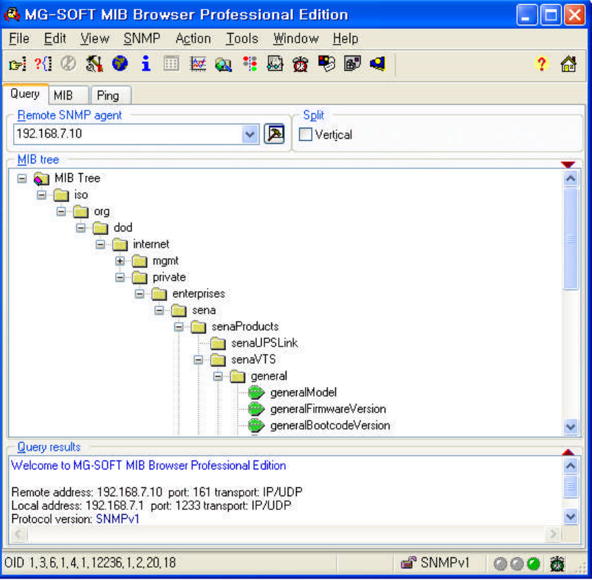
189
APPENDIX G: VTS management using SNMP
G.1 Overview
The VTS can be managed through the SNMP protocol using NMS (Network Management
System) or SNMP Browser. Before using the NMS or SNMP Browser, the user must set the access
control configuration properly so that the VTS permits host access where the NMS or SNMP Browser
is executed. Figure G-1 shows a screen shot of a typical SNMP browser with MIB-II OIDs of the VTS
SNMP agent.
Figure G-1. SNMP Browser
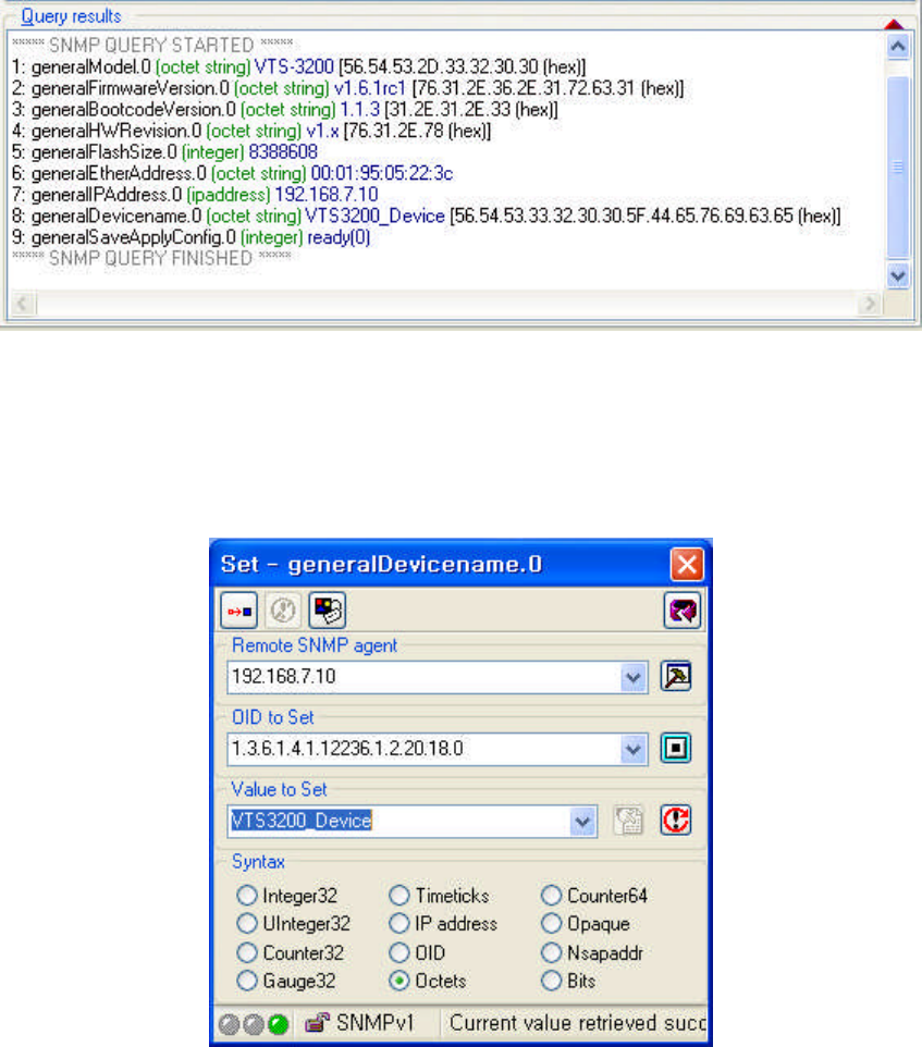
190
G.2 Query a device for information
A manager can get information from Get/Get-Next of SNMP protocol.
Figure G-2. Get information from Get/Get-Next of SNMP protocol.
G.3 Changes to information
A manager can changes to information using Set of SNMP protocol.
Figure G-3. Changes to information using SNMP

191
G.4 Attention
-When you're changing information, you have to change the value to 'save' or 'saveApply'.
-When you are first time to add keyword to port, using addRow to add it at default-keyword.
-Adding another keyword to port which has keyword, using addRow to add it at same keyword
of port.
-If the index of the port was changed after having executed "addRow" at some port, a keyword
cannot be added to that port, since there be made duplicate keywords with the same index of
the same port.
-Excuteing information like ‘portsResetFactoryDefault’has to be one by one.
Figure G-4. Setting ‘excute’
192
APPENDIX H: Virtual KVM Tool
H.1 Overview
The Virtual KVM Tool is a utility program used to manage efficiently the server which is connected
through the virtual KVM connection of VTS. It has such functions as connecting to the serial/remote
port, viewing the port logs and moving to another KVM client program.
H.2 Installation
To use the Virtual KVM Tool, Users have to install the program at their PC and add it to system
path to run it at VTS web interface. Users can get this program from Sena technical support.
To install the Virtual KVM Tool on user’s Windows host, please complete following steps.
Step 1. Copy the program file to user’s host.
Step 2. Add the folder containing the program file to system path.
To install the Virtual KVM Tool on user’s Linux host, please complete following stepsl
Step 1. Uncompress the installation file.
Step 2. Check the uncompressed files
connect.xpm (Connect button image)
log.xpm (View logs button image)
exit.xpm (Close button image)
RDCTool.config (configuration file)
RDCTool (binary file)
Step 3. Copy the binary file to /usr/local/bin.
Step 4. Make RDCTool directory at /usr/local/etc/.
Step 5. Copy all the files except the binary file to /usr/local/etc/RDCTool.
H.3 Running
Users have to configure the virtual KVM configuration at the port to which the server supporting
KVM connection is connected. Clicking the KVM connection icon in C(Connection) column of the port
at the serial port connection page results in launching the Virtual KVM Tool, which runs the KVM client
program specified at the Virtual KVM configuration.
Below is an example of running the Virtual KVM Tool.
Step 1. Connect the server running on Windows 2003 and supporting the remote desktop
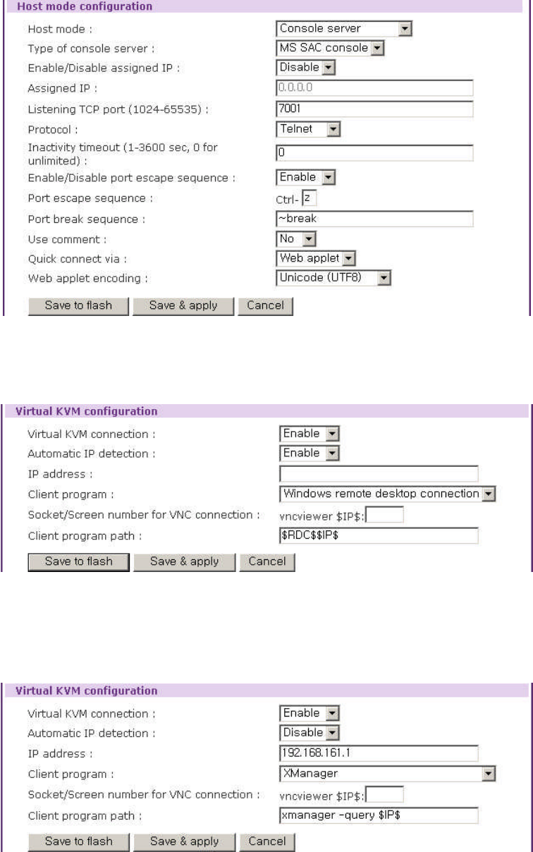
193
connection to Port #1 and configure the host mode configuration as below:
Figure H-1. Host mode configuration of Windows2003 Remote desktop connection
Step 2. Configure the Virtual KVM configuration of Port #1 as below:
Figure H-2. Virtual KVM configuration of Windows2003 Remote desktop connection
Step 3. Connect the server running on Linux and running the X window server to Port #2 and
configure the Virtual KVM configuration as below:
Figure H-3. Virtual KVM configuration of Linux X window server
Step 4. Open the Serial port connection page by selecting the Serial port - connection menu
item in the menu bar.
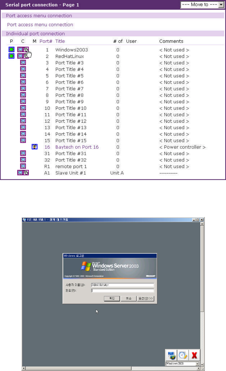
194
Figure H-4. Serial port connection page
Step 5. Run the Virtual KVM Tool by clicking the KVM connection icon of C(Connect) column of
the Port #1.
Figure H-5. Virtual KVM Tool – Remote desktop connection
The Virtual KVM Tool runs the remote desktop connection client program – mstsc.exe
and open the remote desktop session to the Windows 2003 server. It adds the port title –
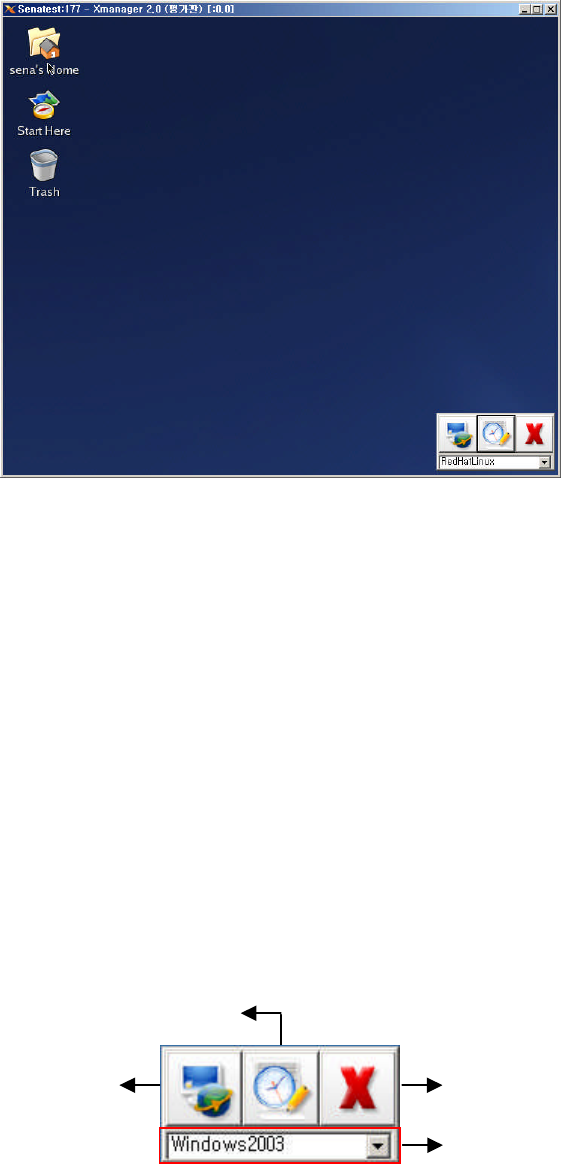
195
Window2003 to the its port list.
Step 6. Click the KVM connection icon of C(Connect) column of the Port #2 and make the Virtual
KVM Tool run the Xmanager client program to connect to X window server. It adds the
port title – RedHatLinux to its port list.
Figure H-6. Virtual KVM Tool – X window server
H.4 Operations and Functions
The functions of the Virtual KVM Tool are as below:
1. Connect to the serial port or the remote port
2. View the port logs
3. Move to another the KVM client program which opens through the serial port connection
page of the VTS web interface.
Note : Operations and functions are supported at the Virtual KVM Tool for Windows. All the
operations and functions are not available at that for Linux. Please contact to Sena
technical support for more information.
Figure H-7 is the screen of the Virtual KVM Tool activated.
Figure H-7. Virtual KVM Tool Activated
Port list
Connect to
serial / remote port
Close
View logs
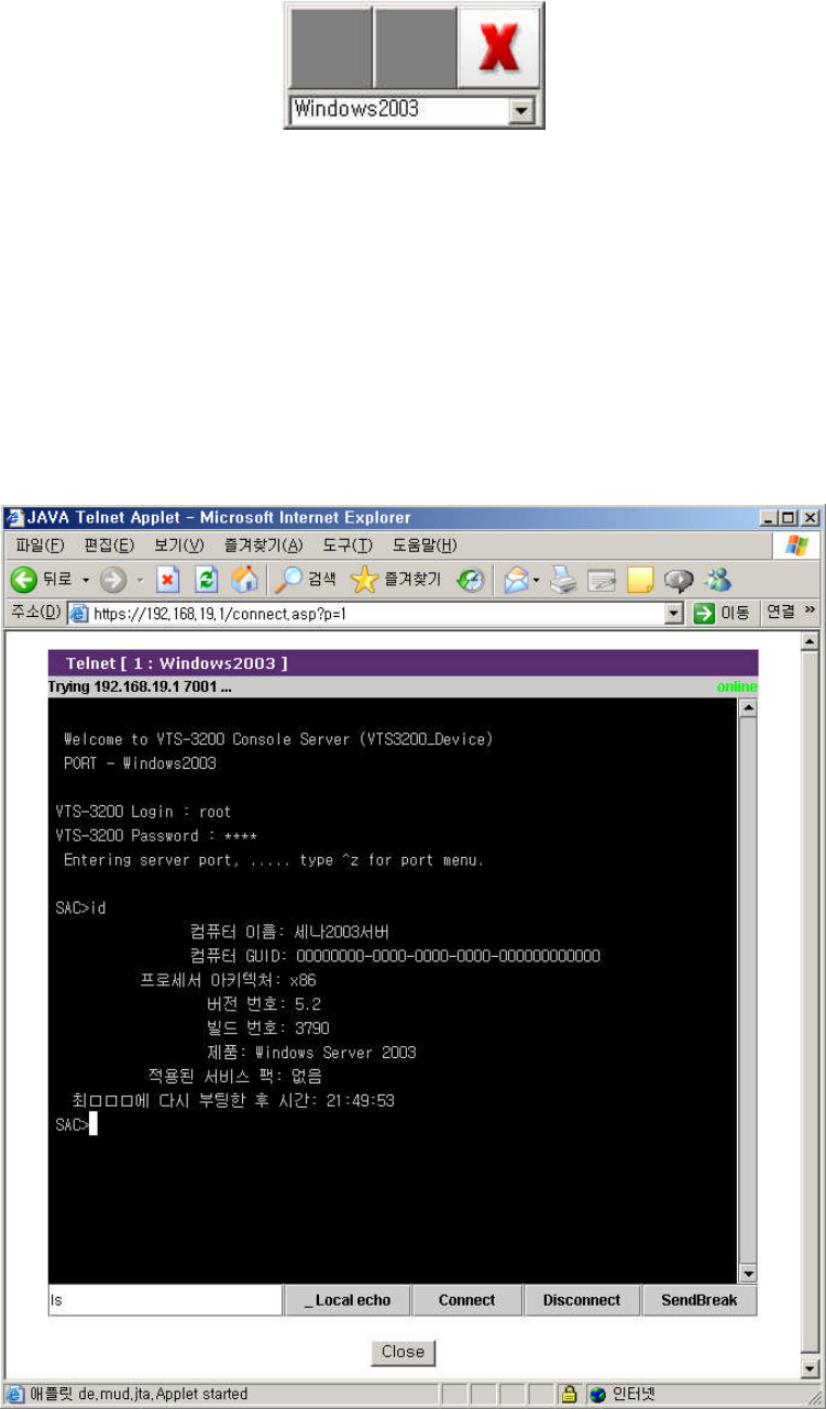
196
Figure H-8 is the screen of the Virtual KVM Tool deactivated.
Figure H-8. Virtual KVM Tool Deactivated
When one of the KVM client programs run through the serial port connection page gets focused,
the Virtual KVM Tool is activated. When the Virtual KVM Tool is activated and its Connect button and
View logs button are enabled, users can connect to the serial port or the remote port with the Connect
button and view the port logs with the View logs button. When a program other than the KVM client
has the focus, the Virtual KVM Tool is deactivated and its Connect button and View logs button are
disabled.
When the Virtual KVM Tool is activated, clicking the Connect button makes the VTS connect to
the serial port or the remote port. Figure H-9 shows the screen of connection to Port #1.
Figure H-9. Connect to serial port

197
When the Virtual KVM Tool is activated, clicking the View logs button results in viewing the port
logs. Figure H-10 shows the screen of viewing the log of Port #1 after clicking the View log button.
Figure H-10.View port logs
Whenever users open a KVM client program by clicking a KVM connection icon at the serial port
connection page, the Virtual KVM Tool adds the port title to its port list. Users can move to the KVM
client program by selecting a port title at the port list of the Virtual KVM Tool. Figure H-11 shows the
port list resulted from the example at H.3.
Figure H-11. Port list
198
To move the Virtual KVM Tool, users need to drag to the position clicking the mouse right button
on the Virtual KVM Tool.
The Close button of the Virtual KVM Tool leads to close the Virtual KVM Tool.
