Manual Folding Door June 2017
User Manual:
Open the PDF directly: View PDF ![]() .
.
Page Count: 28
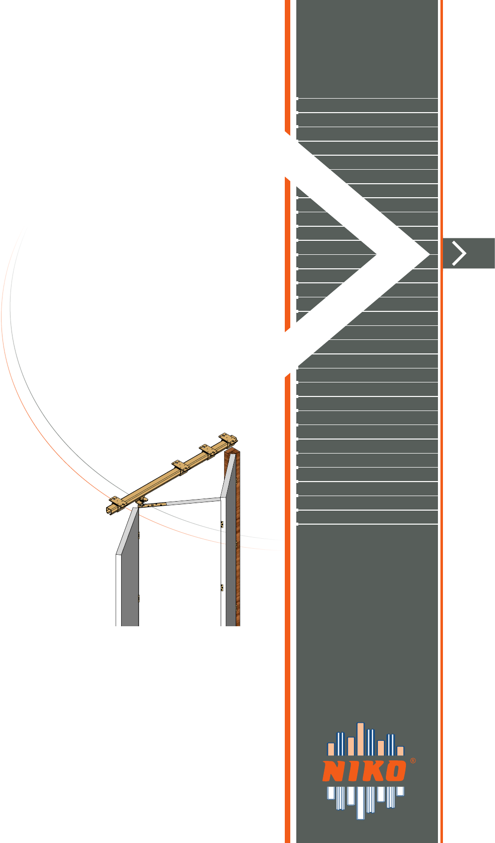
INSTALLATION
OPERATION &
MAINTENANCE
MANUAL
for folding door
systems

Version June 2017
index INSTALLATION, OPERATION &
MAINTENANCE MANUAL
for folding door systems
1. TECHNICAL DESCRIPTION OF NIKO FOLDING DOOR SYSTEMS
1.1 General description
1.2 Component specifications for a typical folding door system
1.2.1 General details for track profiles
1.2.2 General detail for guide track profiles
1.3 Technical specifications
1.3.1 Chart with allowed loads for wheel hangers
1.3.2 Supporting options
2. INSTALLATION INSTRUCTIONS FOR A TYPICAL FOLDING DOOR
2.1 Installation of track, brackets & guide track
2.2 Installation of door panels
2.2.1 Calculation of panels width
2.2.2 Preparation of panels
2.2.3 Installation of panels
3. MULTIPLE PANEL FOLDING DOOR
4. FOLDING DOOR - HARMONICA TYPE
5. BASIC RULES FOR SAFETY - OPERATION
6. INSPECTION AND MAINTENANCE SCHEDULE

3
Version June 2017 Version June 2017
INSTALLATION, OPERATION & MAINTENANCE MANUAL
for folding door systems
Prologue:
Thank you for selecting our products.
To ensure correct installation, please read this manual thoroughly.
In the first chapter, a general description of system components is presented with the technical
specifications. Installation instructions for a typical folding door with three panels come next as well as
calculations in order to determine the track length and the panels width. An example of multiple panel
folding door is also described, including the steps for installing the splice joint .B49. Chapter 4 presents
an example of a folding door, harmonica type.
On the instructions:
The information on this form have been checked carefully for their accuracy. However, there is not given
guarantee for the correctness of the contents. The information on this form may change without notice.
Copyright:
This document contains information protected by the laws of copyright and includes patents. All the
rights of this document belong to the maker company. No part of this document can be published with
any mechanical, electronic or any other way, without the previous consent of NIKO.
Brands:
All brands (and their logos) are property of their owners.
NIKO is a brand name of Helm Hellas SA and will be used from herein to describe the company.
Official manufacturer:
HELM HELLAS S.A.
82 Km Athens – Korinthos
P.O. Box 209 GR 20100 Korinthos, Greece
Tel: 0030 (0) 2741076800
Fax: 0030 (0) 2741025368
e-mail: info@niko.eu.com
www.niko.eu.com
4
INSTALLATION, OPERATION & MAINTENANCE MANUAL
for folding door systems
Version June 2017
1TECHNICAL DESCRIPTION
of NIKO folding door systems
Key design characteristics of Niko folding door
fittings:
1. We have achieved the highest EN 1527
certification ranking
2. Five different track profiles.
3. All our products are zinc plated, which allows
smoother running of our wheels in the
track profiles and uniform color among our
components.
4. Our track profiles have an unrivaled compact
construction and therefore require less space.
5. Simple installation and adjustment.
6. Our wheels and bearings are custom
made and are significantly more durable
under load than standard bearings.
7. The NIKO enclosed track tapered design enables
self-alignment of the wheel hangers and reduces
the possibility of dust build up.
8. Greater aesthetic appeal as the guide track is
recessed (concealed) to the floor.
9. Quiet and effortless operation.
10. Flat folding for easier access and space saving.
11. Technical data:
Min/Max door panel width: 600mm - 900mm
Max door panel weight: 300kg
Max door panels: 9 - NIKO recommends 7 panels
for optimal operation
1.1 General description
NIKO®” provides a wide range of zinc plated products for sliding and folding door applications in
order to meet the high demands of door hardware market for domestic, commercial and industrial
applications. Our products are also available in stainless steel series 304/316.
5
Version June 2017 Version June 2017
INSTALLATION, OPERATION & MAINTENANCE MANUAL
for folding door systems
1
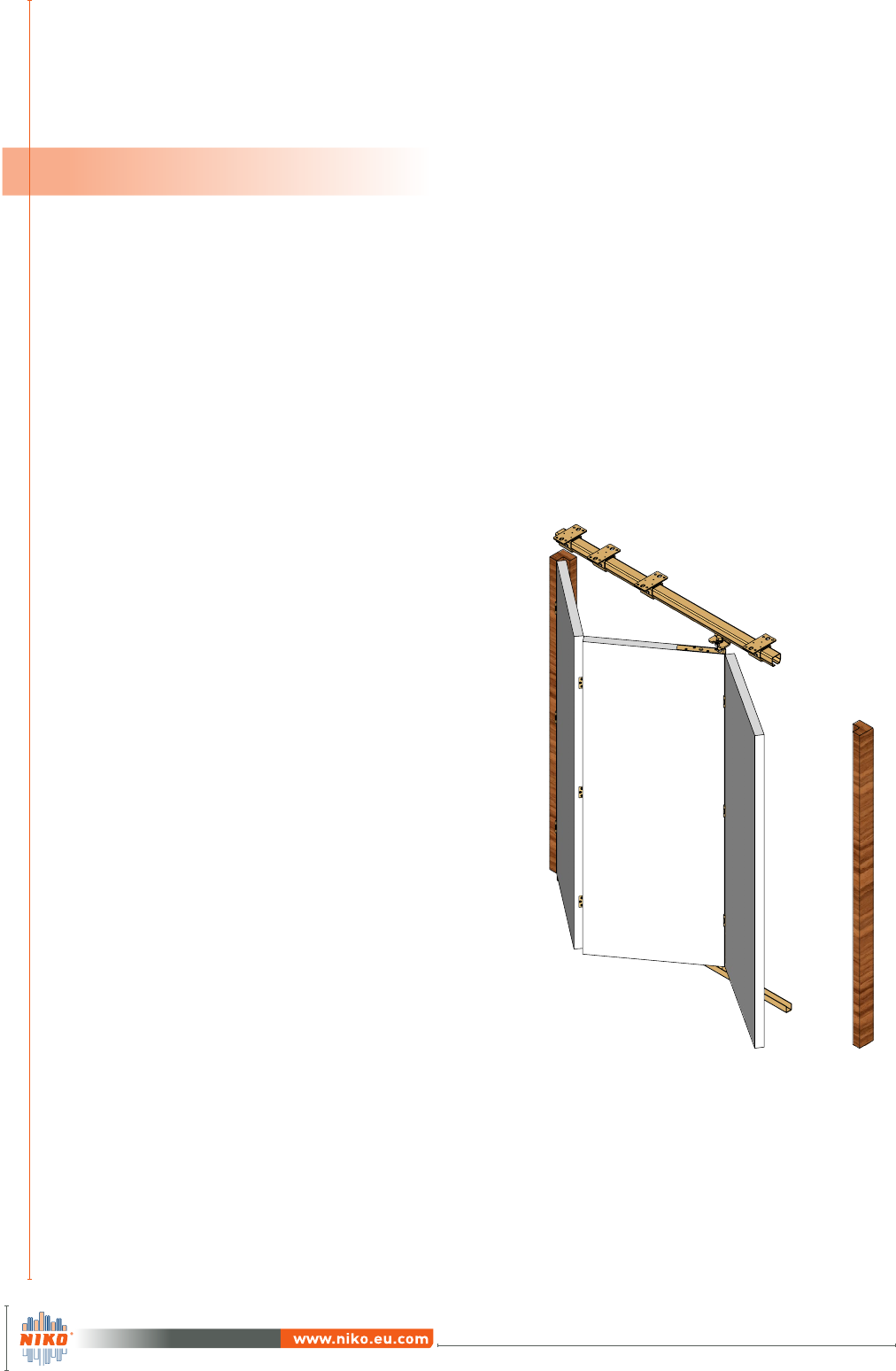
The system includes the following components:
For more details, please refer to Technical Catalogue B1.
1. Track .000
The total length of the track profile should
be 2 times the width of the wider panel plus
10cm. See page 11.
2. Ceiling support bracket .B02
The right selection of support bracket’s type
depends on the construction on which the
track will be fixed.
3. Guide track 3X.000
For selecting the right guide track profile,
please advise our
Technical Catalogue B1.
4. Top corner bracket .F94
Install one top corner bracket every second
door panel.
1.2 Component specifications
for a typical folding door system with wooden panels
1 2 22 4 5 63 2
5. Double wheel hanger .R86
Install one hanger every second door panel.
The right selection of the wheel hanger pro-
file depends on the weight of the panel.
6. Bottom corner guide with roller .N94
Install one bottom corner guide roller every
second panel.
All components must be of the same NIKO profile. For example, should you be using hanger 23.R86,
then track 23.000, support bracket 23.B.., wheel hanger 23.R.. and so on, are required.
6
INSTALLATION, OPERATION & MAINTENANCE MANUAL
for folding door systems
Version June 2017
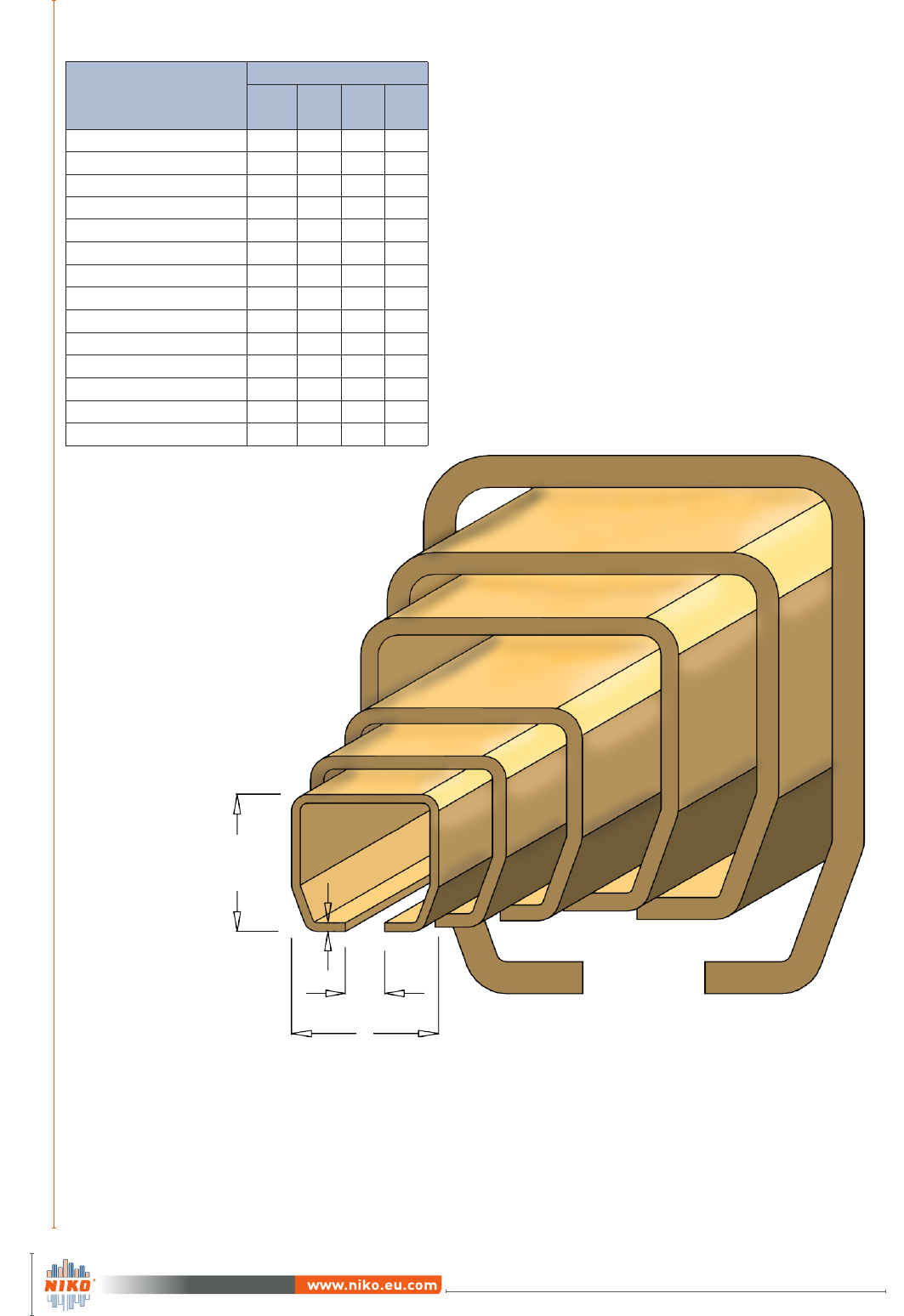
NIKO Profile No.
Dimensions
h
(mm)
b
(mm)
d
(mm)
s
(mm)
21.000 28,00 30,00 8,00 1,75
21.050 Stainless steel (304) 28,00 30,00 8,00 1,75
21.070 Stainless steel (316) 28,00 30,00 8,00 1,75
23.000 35,00 40,00 11,00 2,75
23.050 Stainless steel (304) 35,00 40,00 11,00 2,75
23.070 Stainless steel (316) 35,00 40,00 11,00 2,75
24.000 43,50 48,50 15,00 3,20
24.050 Stainless steel (304) 43,50 48,50 15,00 3,20
24.070 Stainless steel (316) 43,50 48,50 15,00 3,00
25.000 60,00 65,00 18,00 3,60
25.050 Stainless steel (304) 60,00 65,00 18,00 3,60
25.070 Stainless steel (316) 60,00 65,00 18,00 4,00
26.000 75,00 80,00 22,00 4,50
27.000 110,00 90,00 25,00 6,50
1.2.1 General details for track profiles
1
h
b
d
Scale 1:1
s
7
Version June 2017 Version June 2017
INSTALLATION, OPERATION & MAINTENANCE MANUAL
for folding door systems
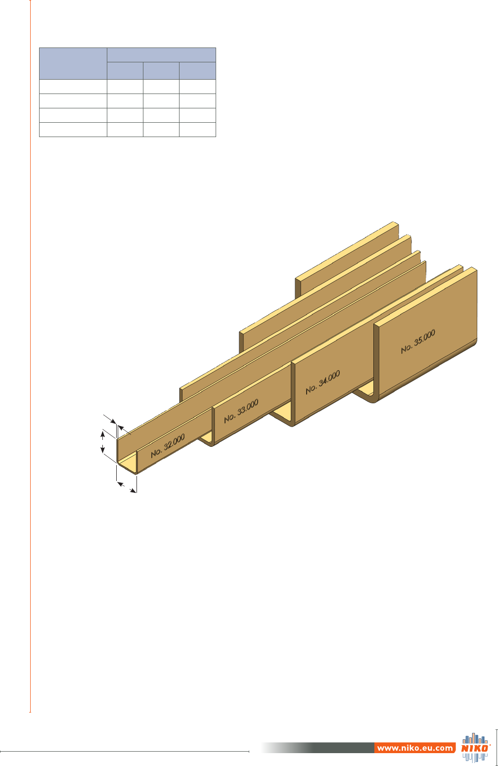
NIKO Guide
track No.
Dimensions
h (mm) B (mm) s (mm)
32.000 15 15 1
33.000 25 25 2
34.000 40 40 3
35.000 50 60 4
1.2.2 General details for guide track profiles
1
s
B
h

8
INSTALLATION, OPERATION & MAINTENANCE MANUAL
for folding door systems
Version June 2017
1.3.1 Chart with allowed loads for wheel hangers
4-wheel hanger
NIKO Profile No.
Folding and
Harmonica doors
Load capacity / kg /
Door panel
21.000 22
23.000 42
24.000 75
25.000 150
26.000 300
NIKO Profile No.
Folding and
Harmonica doors
Load capacity / kg /
Door panel
21.000 15
23.000 32
24.000 50
25.000 100
26.000 200
2-wheel hanger
Select the track size according to the weight and dimensions of the door.
Take into consideration that each wheel hanger has to hold the weight of two panels.
1
1.3 Technical specifications
Before installing the system, determine:
The number of panels
The weight of panels
Door material
Clear passage height
Clear opening width
Total width
Total height
Once you have specified the above data, calculate the number of concealed hinges
(not provided) per door.
For door panel height up to 280cm,
use 3 hinges per panel.
For panels heighter than 280cm,
use 4 hinges per panel.
9
Version June 2017 Version June 2017
INSTALLATION, OPERATION & MAINTENANCE MANUAL
for folding door systems
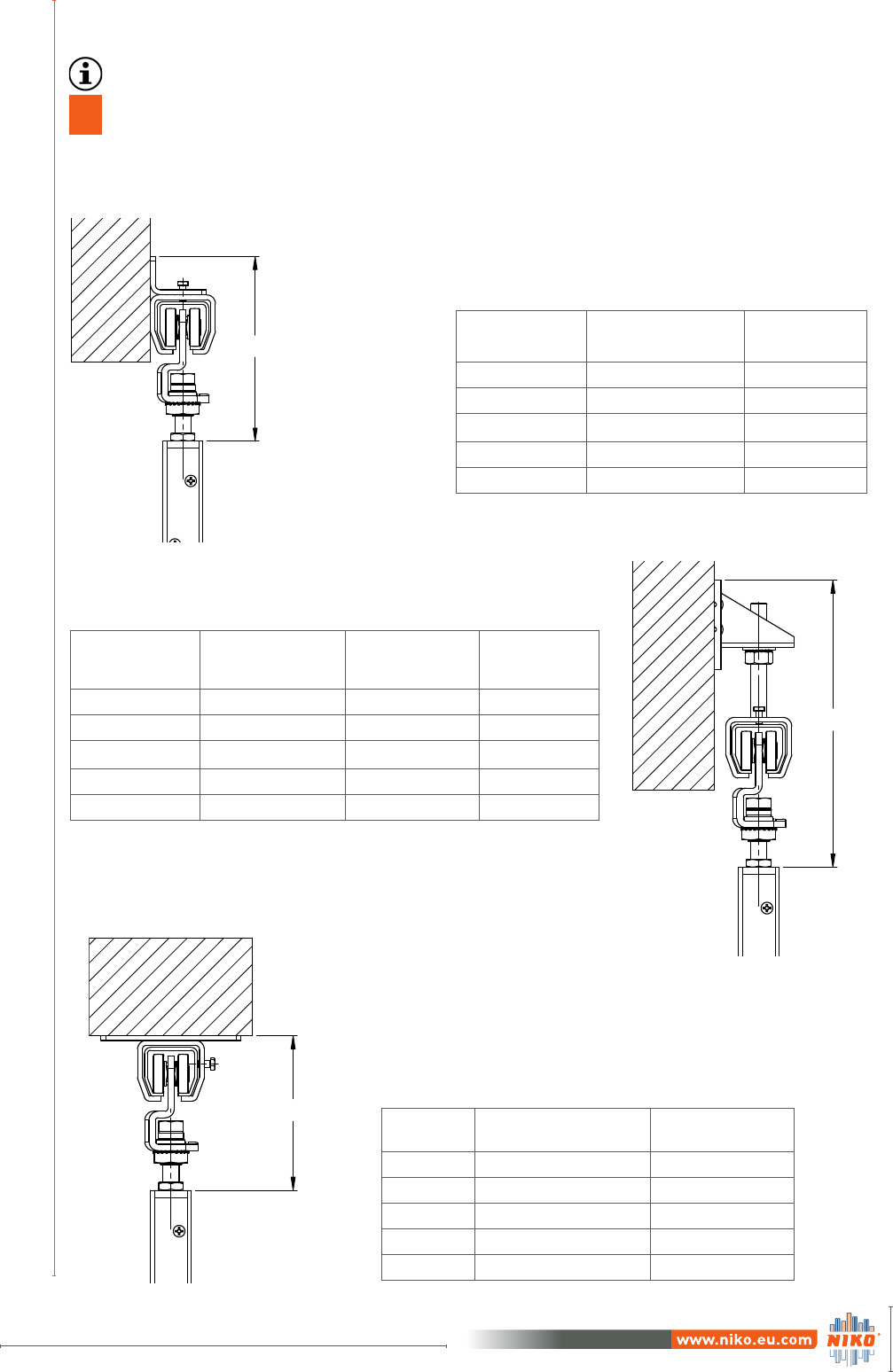
11.3.2 Supporting options
NIKO
Profile No.
Ceiling
support bracket
Dimension H
max. / min.
21.000 21.B02 101/84
23.000 23.B02 128/103
24.000 24.B02 152/135
25.000 25.B02 198/160
26.000 26.B02 316/203
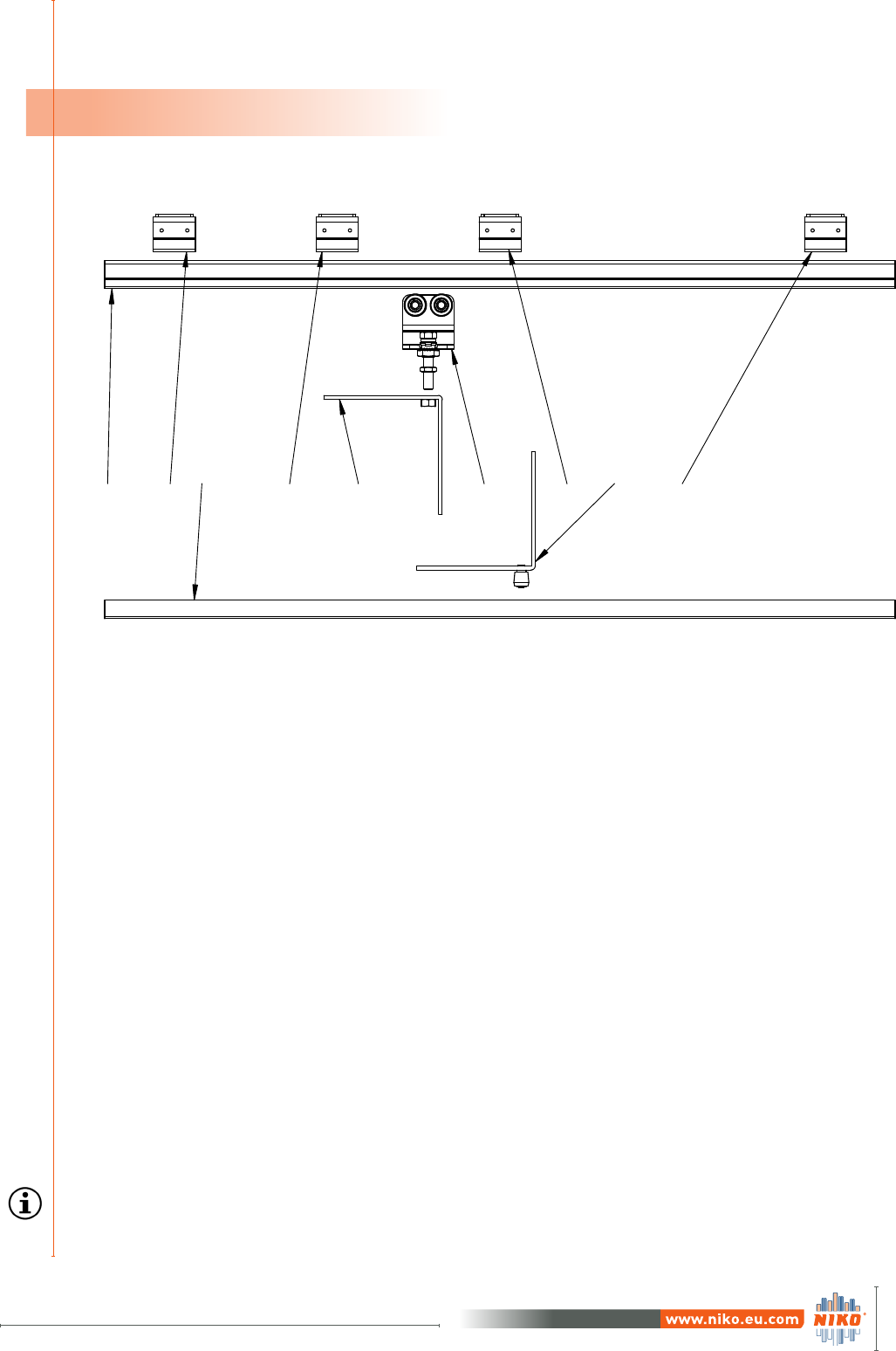
Ceiling support bracket with wheel hangers for
folding doors
H
Wall support bracket with wheel
hangers for folding doors
NIKO
Profile No.
Wall support
bracket
Dimension H
max. / min.
21.000 21.B01 123/106
23.000 23.B01 157/132
24.000 24.B01 187/170
25.000 25.B01 240/202
26.000 26.B01 368/255
H
NIKO
Profile No.
Adjustable wall
bracket
Height adjustable
bracket
Dimension H
max. / min.
21.000 21.B05 21.B04 183/140
23.000 24.B05 23.B04 252/197
24.000 24.B05 24.B04 271/182
25.000 26.B05 25.B04 373/265
26.000 26.B05 26.B04 530/302
H
Adjustable wall bracket with height adjustable
bracket and wheel hanger for folding doors
The right selection of support bracket type depends on the construction
on which the track will be fixed.
ii) Ceiling support option
i) Wall support options
10
INSTALLATION, OPERATION & MAINTENANCE MANUAL
for folding door systems
Version June 2017
2INSTALLATION INSTRUCTIONS
for a typical folding door
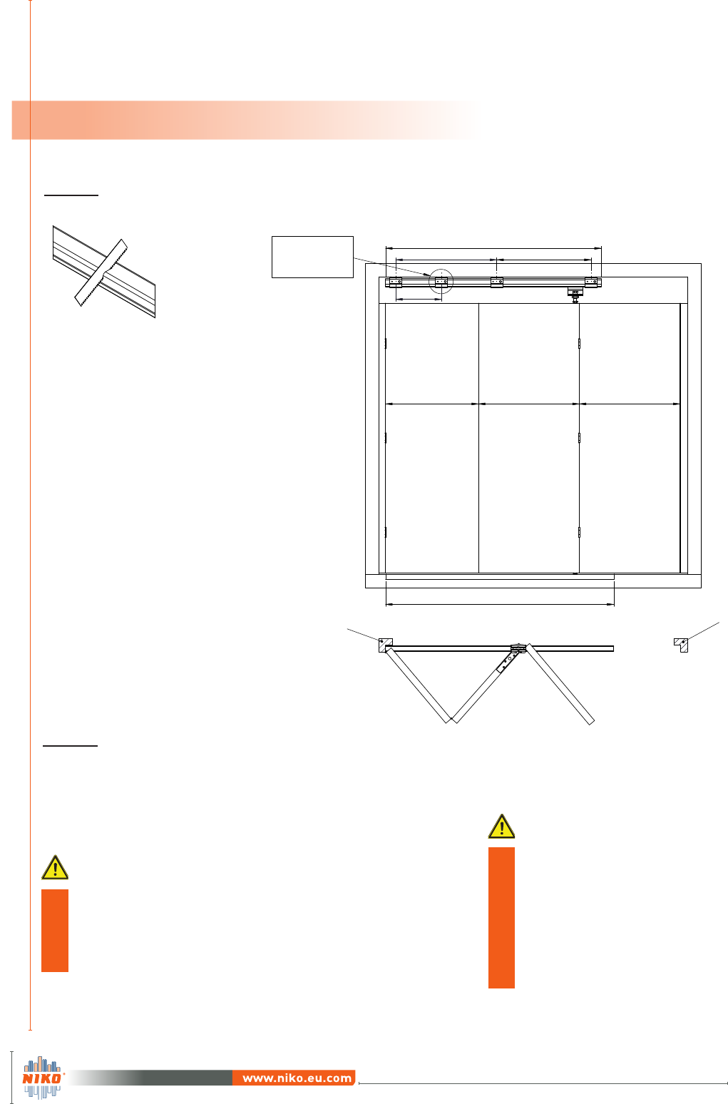
2.1 Installation of track, brackets & guide track
Door
frame Door
frame
max 75 cm
35 cm
X Z
max 75 cm
L=2*X+10 cm
X
L
An additional
support bracket
should be fitted on
folding area
Fixed
Panel
Center
Panel
End
Panel
Calculate the track length using the
equations below:
1. Odd number of panels - «n» (e.x. 3,5,7)
L = (n-1)*X+10cm
2. Even number of panels - «m» (e.x. 2,4,6)
L = m*X+10cm
For a folding door with 3 panels,
track length should be twice the wider
panel width plus 10cm.
L=2*X+10cm
See page 15
STEP 2:
Calculate the number of ceiling support
brackets according to the length of the
track.
Maximum distance between ceiling support
brackets is 75cm.
In the folding area an additional support bracket is
required.
Make sure to remove any
chips or dirt from inside
the track after cutting
process as they will
damage the wheel
hangers and cause noise
during operation.
STEP 1:
Cut the track at the required length.
11
Version June 2017 Version June 2017
INSTALLATION, OPERATION & MAINTENANCE MANUAL
for folding door systems
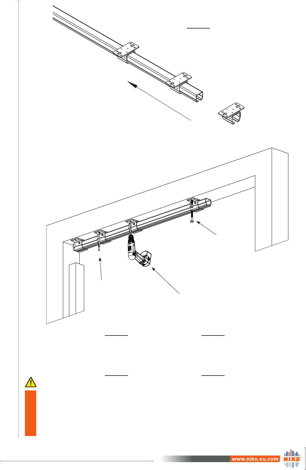
2STEP 3:
Gradually insert ceiling support
brackets onto the track.
STEP 4:
Place the set ‘‘track-support
brackets’’ on the construction
frame.
STEP 5:
Mark the points where the
holes need to be done.
STEP 6:
Lift down the set
«track-support brackets» and
drill holes at the marks.
STEP 7:
Choose hardware and fasten-
ers according to construction
type.
Place back the set and fix sup-
port brackets on the existing
construction.
Step 6.
Step 7.
Step 5.
It is very important
to achieve hori-
zontal alignment
because this will
result in smooth
running.
12
INSTALLATION, OPERATION & MAINTENANCE MANUAL
for folding door systems
Version June 2017
2
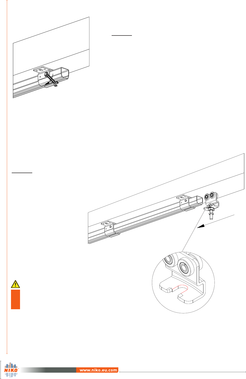
STEP 8:
Tighten the side bolts to fix the track in
place.
Bracket slot
should face the
outside.
STEP 9:
Slide double wheel hangers (.R86)
into the track in correct orientation.
Bracket slot
13
Version June 2017 Version June 2017
INSTALLATION, OPERATION & MAINTENANCE MANUAL
for folding door systems
2
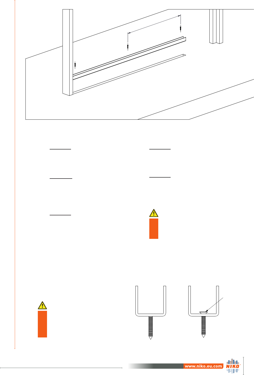
STEP 10: Cut the guide
track to the required length.
STEP 11: Cut a notch in the
floor with appropriate tool
according to guide track
dimensions.
100 cm
STEP 12: Drill holes in
guide track 100cm apart.
STEP 13: Fit guide track in
the floor notch.
STEP 14: Fix the guide
track with chipboard
screws.
Guide track and top
track must have the
same length
Countersink holes to
the guide track for
preventing protrusion
of head screws
Protrusion
Guide tracks

14
INSTALLATION, OPERATION & MAINTENANCE MANUAL
for folding door systems
Version June 2017
2
Opening Width
d
c
c/2
l
z x x
z x
STEP 15: The fixed panel (z)
must be narrower in width
than the other leaves by
l+c/2+d/2
d
l
c: Panel thickness
2.2 Installation of door panels
2.2.1 Calculation of panels width
Dividing
(opening width + l + c/2+ d/2) by
the total number of panels, normal
panels width (x) is calculated.
To calculate the fixed panel width (z)
subtract (l + c/2 + d/2) from x.
Example:
3 - leaf end folding door
Clear opening width = 2200mm
Panel thickness (c) = 40mm
Hinge diameter (d) = 8mm
Dimension (l) =20mm
Calculation:
2200 + 20 + 20 + 4 = 2243mm
Normal Panel width (x) : 2243 ÷ 3 = 748mm
Fixed panel width (z) : 748-44 = 704mm
15
Version June 2017 Version June 2017
INSTALLATION, OPERATION & MAINTENANCE MANUAL
for folding door systems
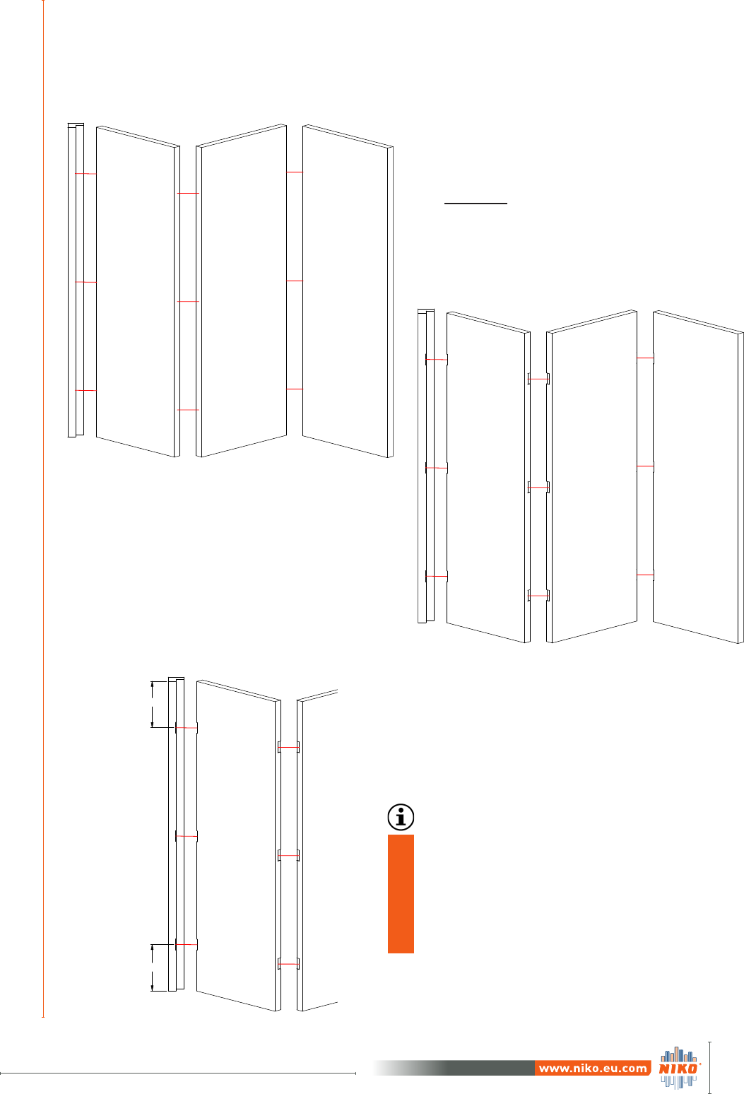
22.2.2 Preparation of panels
f
f
STEP 16:
Make the cut outs in each panel for the
hinges to be attached.
1.
2.
According to the type of hinges (not
provided) and the dimensions of top
corner bracket (.F94) and guide cor-
ner bracket (.N94) , leave a distance
from top and bottom edge of the
panels.
16
INSTALLATION, OPERATION & MAINTENANCE MANUAL
for folding door systems
Version June 2017
2
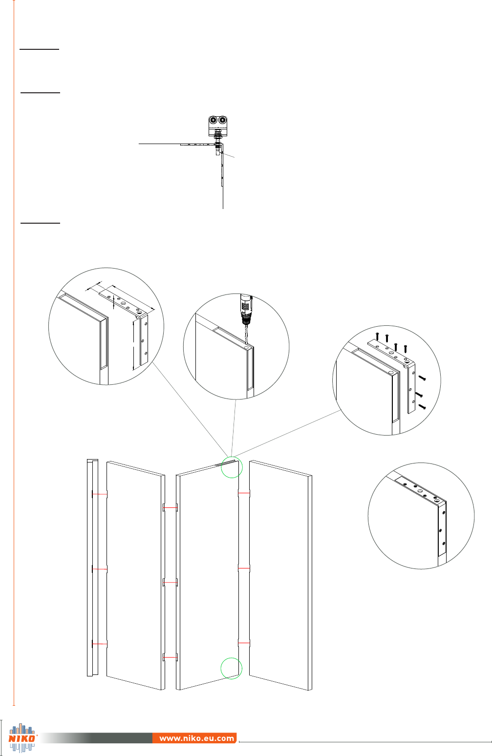
2.
3.
Step 17:
Make a cut out at the top of the center panel for fixing the top bracket,
ensuring its dimensions are equivalent to the bracket’s dimensions. (1.)
Step 18:
Drill a hole in the cut out for adjusting the bolt of the wheel hanger in
following steps. (2.)
Step 19:
Fix the top bracket with countersunk wood screws. (3.)
2.2.2 Preparation of panels
L
B
H
s
1.
Hole for Bolt
See page 20
17
Version June 2017 Version June 2017
INSTALLATION, OPERATION & MAINTENANCE MANUAL
for folding door systems
L
B
h
s
4.
5.
Step 20:
Make a cut out at the bottom of the center panel for fixing the guide corner bracket ensuring its
dimensions are equivalent to the bracket’s dimensions. (4.)
Step 21:
Fix the guide corner bracket with countersunk wood screws. (5.)
22.2.2 Preparation of panels
18
INSTALLATION, OPERATION & MAINTENANCE MANUAL
for folding door systems
Version June 2017
2
l
l
.F94
.F06
Depending on the panel type (metal
frame and bracket .F06)
a welding process may be required.
The distance from the center of hole
to the edge of panel must be the
same (dimension l).
See Table 2 below.
2.2.2 Preparation of panels
NIKO
Profile No.
Bracket for steel
constructions
.F06
Top corner
bracket
.F94
Dimension
l (mm)
21.000 21.F06 21.F94 15
23.000 23.F06 23.F94 20
24.000 24.F06 24.F94 20
25.000 25.F06 25.F94 30
26.000 26.F06 26.F94 44
In case of metal frame select the ap-
propriate bracket (.F06) according to
guide roller (.N49/.M49) thread. The
distance from the center of roller to
the edge of panel must be the same
(dimension l).
See Table 2 below.
l
l
.N94
.F06
.N49/.M49
Table 2.
metal panel
wooden panel
metal panel
wooden panel
19
Version June 2017 Version June 2017
INSTALLATION, OPERATION & MAINTENANCE MANUAL
for folding door systems
2
Cut-outs
Spirit level
JambFixed panel
4 5
6
B
A
C
DD
C
A
B
ΕΠΟΜΕΝΟ ΣΧΕΔΙΟ
NEXT ASSY
-
ΤΕΛΙΚΗ ΕΠΕΞΕΡΓΑΣΙΑ - FINISH
ΕΠΕΞΕΡΓΑΣΙΑ - TREATMENT
ΥΛΙΚΟ - MATERIAL
ΚΩΔΙΚΟΣ - PART NUMBERΜΕΓΕΘΟΣ
SIZE
ΑΝΑΘΕΩΡΗΣΗ
REVISION
SHEET
ΣΕΛΙΔΑ
1/1
SCALE
ΚΛΙΜΑΚΑ
1:1
METRIC
ΣΧΕΔΙΑΣΗ
DESIGN
ΕΛΕΓΧΟΣ
CHECK
ΕΓΚΡΙΣΗ
APPROVAL
NAME
ΟΝΟΜΑ
DATE
ΗΜΕΡ.
ΑΝΟΧΕΣ - TOLERANCES
ΕΚΤΟΣ ΑΝ ΟΡΙΖΕΤΑΙ ΔΙΑΦΟΡΕΤΙΚΑ
UNLESS OTHERWISE SPECIFIED
ISO 2768mk
ΠΕΡΙΓΡΑΦΗ - DESCRIPTION
ΠΙΝΑΚΑΣ ΕΚΔΟΣΕΩΝ - REVISION STATUS
ΑΝΑΘ.
REV.
E.C.N. No
ΑΡΙΘΜΟΣ Ε.Α.Σ.
DATE
ΗΜΕΡ.
APPROVED
ΕΓΚΡΙΘΗΚΕ
A3
Α
R
82o Km. ATHENS-KORINTHOS 201 OO KORINTH P.O. BOX 209 GREECE
HELM HELLAS
AND CONVEYOR SYSTEMS
MANUFACTURERS OF SLIDING DOOR FITTINGS
S.A.
82o Km. ATHENS-KORINTHOS 201 OO KORINTH P.O. BOX 209 GREECE
HELM HELLAS
AND CONVEYOR SYSTEMS
MANUFACTURERS OF SLIDING DOOR FITTINGS
S.A.
ΠΕΡΙΓΡΑΦΗ
ΠΕΡΙΓΡΑΦΗ
P.PSIL
-
-
-
26.06.13
1
2 3
4 5 632
1
P.PSIL
P.PSIL
P.MAL.
26.06.13
-
26.06.13
26.06.13
THIS DRAWING IS PROPERTY OF HELM HELLAS S.A. IT MAY NOT BE REPRODUCED OR USED, IN ANY FORM OR BY ANY MEANS WITHOUT PRIOR PERMISSION.
ΤΟ ΣΧΕΔΙΟ ΑΥΤΟ ΕΙΝΑΙ ΙΔΙΟΚΤΗΣΙΑ ΤΗΣ HELM ΕΛΛΑΣ Α.Β.Ε.Ε. ΝΑ ΜΗΝ ΑΝΑΠΑΡΑΧΘEI Η ΧΡΗΣΙΜΟΠΟΙΗΘEI
ΣΕ ΚΑΜΙΑ ΜΟΡΦΗ ΚΑΙ ΜΕ ΚΑΝΕΝΑ ΤΡΟΠΟ ΧΩΡΙΣ ΠΡΟΗΓΟΥΜΕΝΗ ΕΓΚΡΙΣΗ.
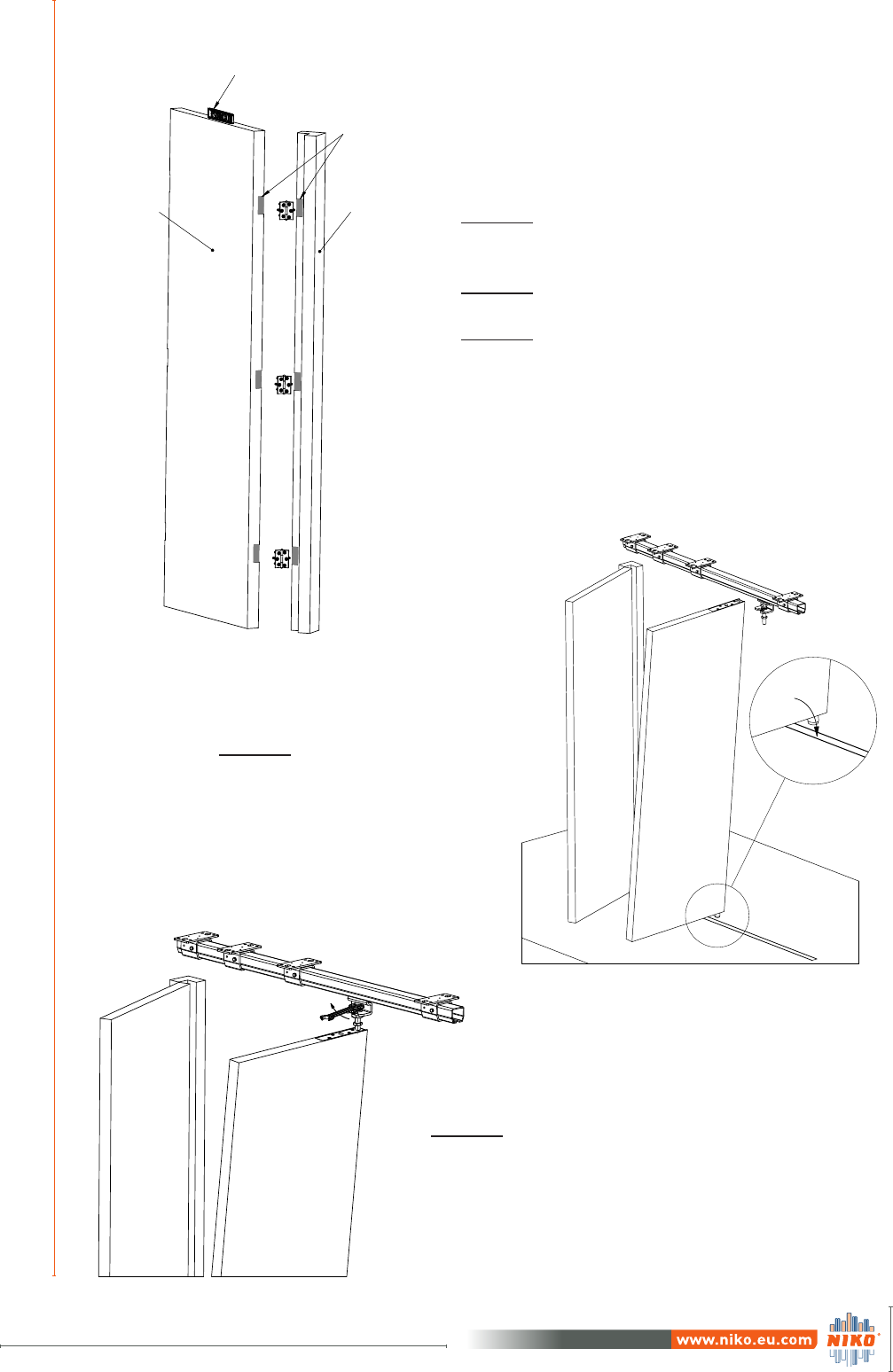
Raise panel
2.2.3 Installation of panels
Step 22:
Fix the first panel to the frame of
the construction.
Step 23:
Align the panel with a spirit level.
Step 24:
Attach the hinges to the cut outs in
both fixed panel and frame.
Step 25:
Fit the roller of the bottom guide
roller into the guide track.
Step 26:
Screw bolt of wheel hanger to adjust
the panel.
20
INSTALLATION, OPERATION & MAINTENANCE MANUAL
for folding door systems
Version June 2017
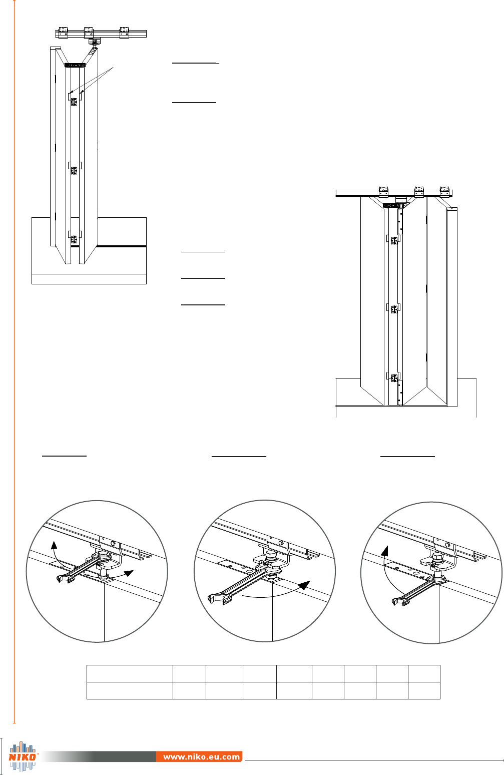
Cut-outs
2.2.3 Installation of panels
STEP 27:
Align the panel with a spirit level
STEP 28:
Attach the hinges to the cut outs in
both fixed and center panel.
STEP 29:
Fix the end panel.
STEP 30:
Align the panel with a spirit level.
STEP 31:
Attach the hinges to the cut outs in
both center and end panel.
STEP 32.B:
Tighten jam nut so that
nut and bracket lock
together.
2
Down
Raise
STEP 32:
Adjust panels height if
required. Screw bolt to
adjust the panel.
STEP 32.A:
Tighten the nut with
appropriate tightening
torque. See Table 1
Bolt (Class 8.8) M6 M8 M16 M12 M16 M20 M24 M30
Torque 10 25 50 87 210 412 711 1422
Table 1.
21
Version June 2017 Version June 2017
INSTALLATION, OPERATION & MAINTENANCE MANUAL
for folding door systems
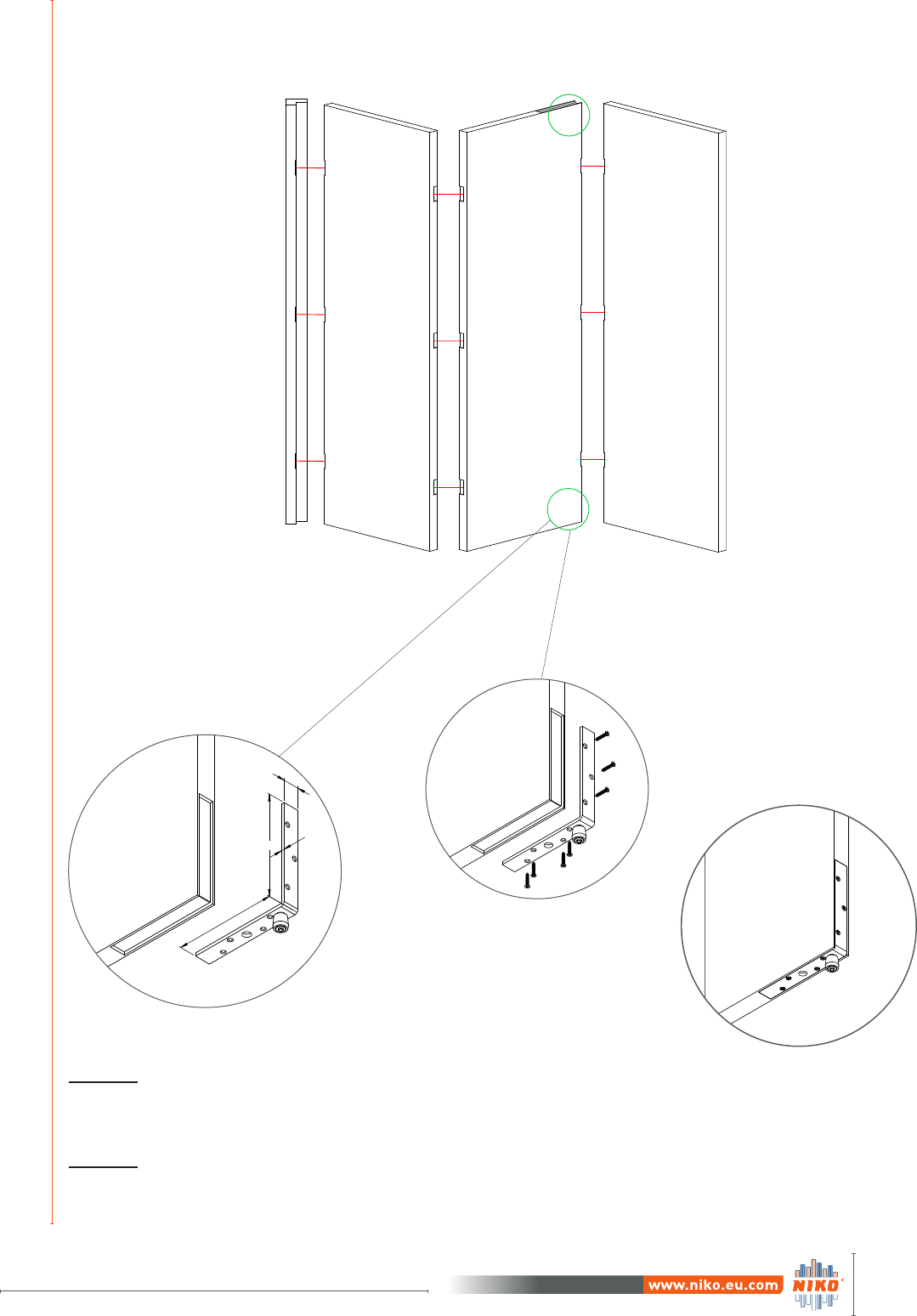
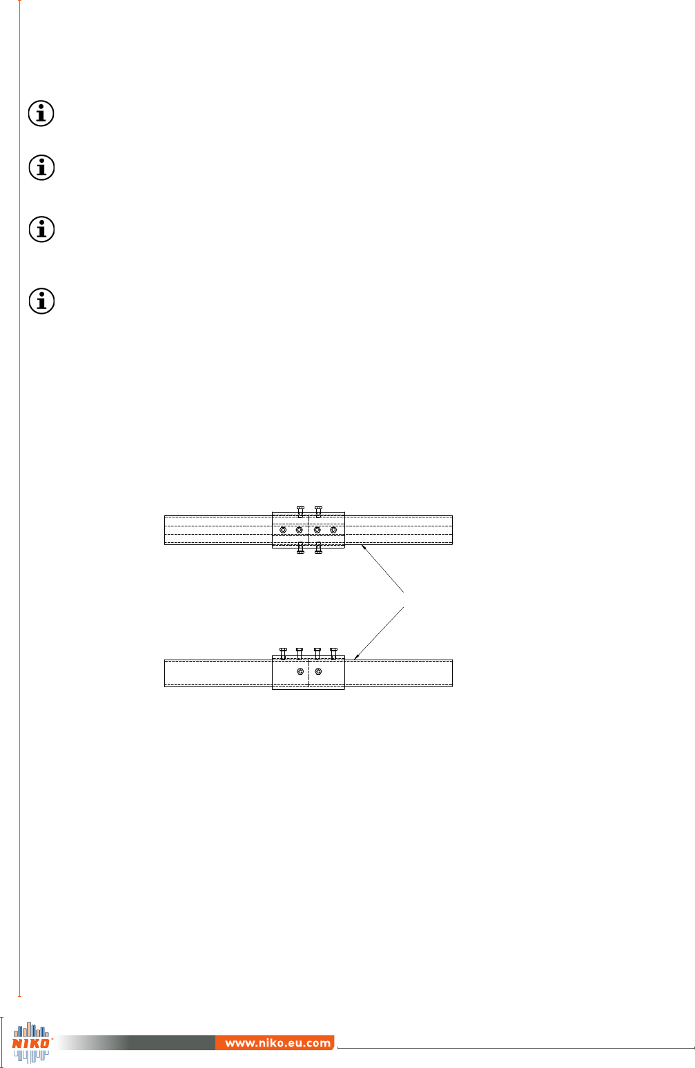
STEP 1: The edges of each track enter
the joint and meet in the centre.
STEP 2: The four bolts at the top of the
joint have to be bolted so that the track
has tight contact with the joint, creating
a flat running surface through the joint.
STEP 3: The four side bolts are used to
achieve horizontal alignment within the
joint.
B49: Installer should follow the next steps:
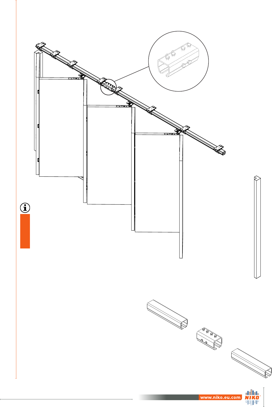
3MULTIPLE PANEL FOLDING DOOR
.B49
When using more than one piece of
track profiles (due to many panels
or group of panels) a splice joint
(.B49) is required in order to join
the tracks.
22
INSTALLATION, OPERATION & MAINTENANCE MANUAL
for folding door systems
Version June 2017
3
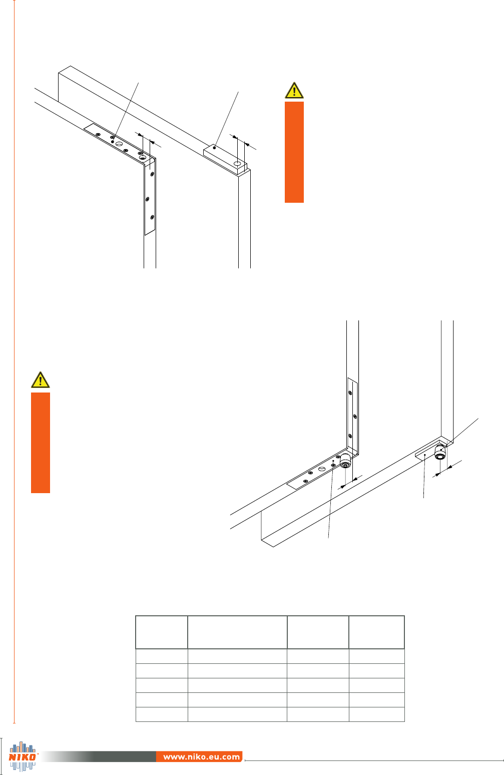
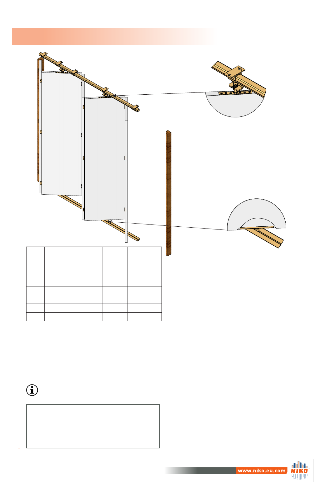
Care must be taken with the following:
Alignment of the two parts both to horizontal and vertical level is absolutely necessary in order to
avoid any problem to trolleys rolling inside the tracks. The gap between the two parts of track must
be as small as possible.
Track Profiles should be
vertical and horizontal aligned
Pay particular attention when supports are used around a splice joint. The joint is used only for
connection and does not support any load. The joint must be supported either side by additional
support brackets. These supports must not be omitted.
Important information for multiple panel folding door system
When you are using splice joint it is necessary to place support brackets at the right and
left side of the splice joints with the minimum distance between the joint and the bracket.
An odd number of panels indicates that the last panel will operate as an opening door.
At the bottom of previous panel a stabilization latch must be installed.
An application with 2 group of panels, requires that at least the one of them has to have
odd number of panels so when groups meet in the middle, the wheel hangers won’t hit
each other.
For wide door openings, NIKO recommends two groups of panels (one group folds at the
right side and the other at the left). For optimal operation, when having one group of pan-
els, do not use more than 7 panels.
Multiple panel folding door
23
Version June 2017 Version June 2017
INSTALLATION, OPERATION & MAINTENANCE MANUAL
for folding door systems
FOLDING DOOR - HARMONICA TYPE
4
Dividing (opening width + c/2* + d/2**) by the total number of half panels, the width of the half
normal panel is calculated. Multiply by 2 (x2) to calculate normal panel width.
To calculate the fixed panel width, subtract (c/2+d/2) from the half normal panel width.
Example: 4 and 1/2 folding door panels
Clear opening width = 3000mm
Panel thickness (c) = 40mm
Hinge diameter (d) = 8mm
Calculation:
3000 + 20 + 4 = 3024mm
Half Normal Panel width (x/2) : 3024 ÷ 9 = 336mm
Normal panel width (x) : 336 x 2 = 672mm
Fixed panel width (z) : 336 - 24 = 312mm
.F00
One normal panel (x) is 2 half panels.
.N00
4.1 Example of folding door with four and half panels
NIKO
Item Description
Quantity
(pcs)
B1 Technical
Catalogue
page
Track 1 23
.B02 Ceiling support bracket 5 27
.R86 Wheel hanger 2 43
.F00 Bracket 2 56
.N00 Guide with roller 2 68
.000 Guide track 1 62
Features:
Hangers are suspended at the
centre of the door panel
Floor guidance is optional
Half width panel at beginning
See
Table 2
for system components
Table 2
4.1.1 Calculation of panels width
*c: Panel thickness (See page 14)
**d: Hinge diameter (See page 14)
24
INSTALLATION, OPERATION & MAINTENANCE MANUAL
for folding door systems
Version June 2017
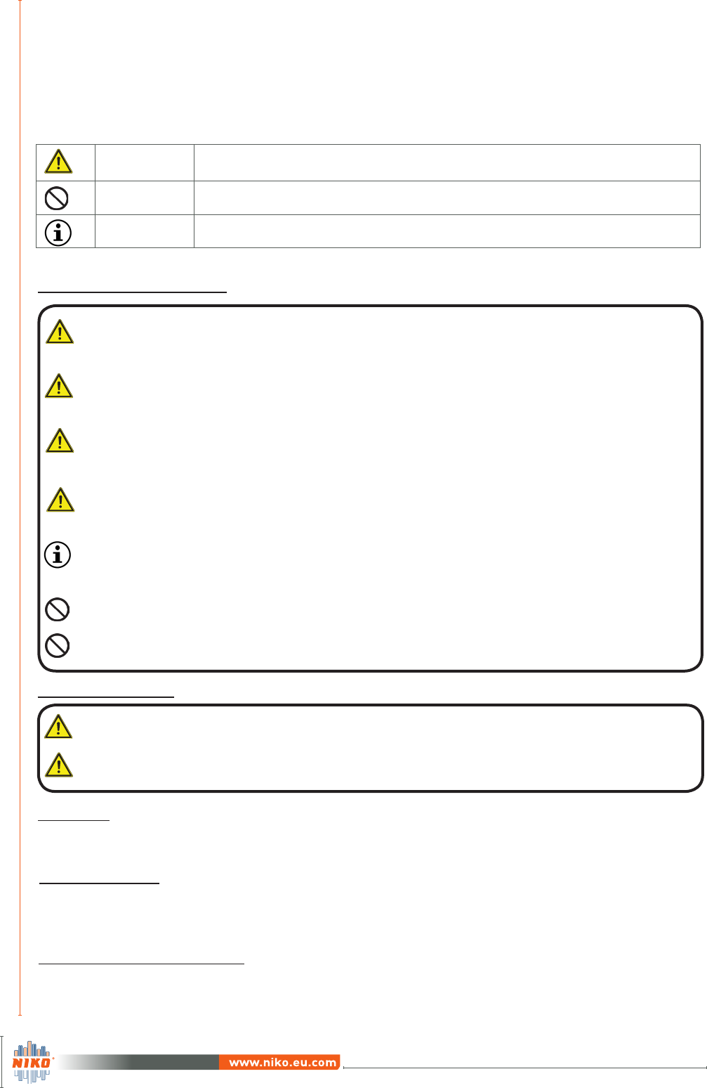
WARNING
CAUTION
Warns you about the health and indicates possible risks of injury or risks to the machine/other
objects
PROHIBITED Indicates an action that is not permitted
NOTE Highlights tips and information for you
Do not try to use this product for any other purposes than the one described in this manual.
Do not use the parts for applications that are out of specification.
Once the installation has been completed, make sure to check that the finished product
is safe and well-functioning.
Wall requirements and fixings:
The substructure /wall must be level and vertical and able to bear permanent loads.
Depending on the door weight and the substructure/wall , fixings must be sufficiently
dimensioned.
BASIC RULES
for safety - operation
FOLDING DOOR ELEMENTS
The panel weight must not exceed the maximum lifting capacity of wheel hangers.
Every second panel, a wheel hanger must be installed.
No change should be made nor intervention in the basic elements of folding door system
by unauthorised personnel.
PERSONAL SAFETY
Only trained personnel must be involved with installation and operation. If the system is
not installed correctly, the door will not operate smoothly, and or may cause injury.
It is recommended that the folding system should be installed by at least two people. One
person could handle the door panel while the other adjust and install the folding system
hardware.
People involved in the installation process should always wear protective clothing.
Never put your hand inside the track during operation.
DISPOSAL
Dispose in accordance with local, state and national regulations.
GENERAL RULES
Meaning of symbols
Ensure that the frame (casing) can endure the weight of the door. A frame without suf-
ficient strength may result in improper and slower movement of the system or it may
cause the door to drop down.
5

25
Version June 2017 Version June 2017
INSTALLATION, OPERATION & MAINTENANCE MANUAL
for folding door systems
INSPECTION AND MAINTENANCE
Schedule
DOOR ELEMENT EVERY 3 MONTHS EVERY 6 MONTHS ANNUALLY
TRACK VISUAL INSPECTION
(OPERATOR)
CHECK FOR CORROSION
OR SIGNS OF DEFORMITY.
CLEAN INSIDE THE TRACK
(MAINTENANCE
PERSONNEL)
SPLICE JOINT
VISUAL INSPECTION
FOR HORIZONTAL AND
VERTICAL ALIGNMENT
(OPERATOR)
CHECK ALL BOLTS ARE
TIGHTENED PROPERLY
(MAINTENANCE
PERSONNEL)
SUPPORT
BRACKETS
VISUAL INSPECTION
FOR ANY MOVEMENT
(OPERATOR)
CHECK ALL BOLTS ARE
TIGHTENED PROPERLY
(MAINTENANCE
PERSONNEL)
WHEEL HANGERS
CHECK FOR SMOOTH
OPERATION AND
MOVEMENT. CHECK
ALL THE BOLTS AND
NUTS ARE TIGHTENED
PROPERLY. (OPERATOR)
1) CHECK FOR
CORROSION IN ALL
MOVING PARTS
2) CHECK ALL THE
BOLTS AND NUTS ARE
TIGHTENED
PROPERLY
(MAINTENANCE
PERSONNEL)
UNINSTALL ALL THE
WHEEL HANGERS. CHECK
FOR UNUSUAL WEAR OR
CORROSION. ESPECIALLY
CHECK THE SMOOTH
OPERATION OF THE
BEARINGS AND THAT THE
BOLTS AND THE NUTS ARE
PROPERLY TIGHTENED.
(MAINTENANCE
PERSONNEL)
Make sure to test the screws for slack at regular inervals.
(1 month after first usage, half year and then one time every year is recommended).
The first inspection should be done one month after the folding door’s installation.
At that time, the following should be checked:
Horizontal and vertical alignment of the track profile must be checked.
All the elements of the folding door have to be inspected for any unusual wear-out.
All the bolts and nuts should be properly tightened.
All splice joints have to be aligned correctly.
All the wheel hangers have to roll smoothly.
Even though “NIKO®” folding door systems do not require any special maintenance, periodic checks
should be done. These checks combined with proper installation increase the system’s lifetime.
A check and maintenance table appears below:
6

26
INSTALLATION, OPERATION & MAINTENANCE MANUAL
for folding door systems
Version June 2017
Notes

Version June 2017
§ 1.Preamble
1.These Standard Terms and Conditions for the sale of export Goods shall exclusively apply, save as varied by express agreement accepted in writing by both parties. 2.The offer, order acknowledgement,
order acceptance or sale of any products covered herein is conditioned upon the terms contained in this instrument. Any conditional or different terms proposed by the buyer are objected to and will not
be binding upon the seller unless assented in writing by the seller. Our Terms and Conditions apply exclusively also in the case of goods being delivered without reservation to the buyer despite our full
awareness of contradicting or varying terms and conditions of the buyer.3.These conditions shall govern any future indivudual contract of sale between the seller and the buyer to the exclusion of any other
terms and conditions subject to which any such quotation is accepted or purported to be accepted, or any such order is made or purported to be made, by the buyer. 4.Any typographical, clerical or other
error or omission in any sales literature, quotation, price list, acceptance of offer, invoice or other document of information issued by the seller shall be subject to correction without any liability on the part
of the seller. 5.The provisions of these Standard Terms and Conditions extend to standard contract conditions which are used in a contract with a merchant in the course of business only and apply only to
companies, legal persons under public law or public special assets.
§ 2.Orders and Specifications
1.No order submitted by the buyer shall be deemed to be accepted by the seller unless and until confirmed in writing by the seller or the seller’s representative within 2 weeks after submittal.2.The quantity
and description of and any specification for the goods shall be those set out in the seller’s quotation or the buyer’s order.3.Any such specification, sales literature, quotation etc. shall be strictly confidential
and must not be made available to third parties. 4.The buyer shall be responsible for the seller for ensuring the accuracy of the terms of any order submitted by the buyer, and for giving the seller any neces-
sary information relating to the goods within a sufficient time to enable the seller to perform the contract in accordance with its terms.5.If the goods are to be manufactured or any process is to be applied
to the goods by the seller in accordance with the specification submitted by the buyer, the buyer shall indemnify the seller against all loss, damages, costs and expenses awarded against or incurred by the
seller in connection with infringement of any patent, copyright, design, trade mark or other industrial or intellectual property rights of any other person which results from the seller’s use of the buyer’s
specification.6.The seller reserves the right to make any changes in the specification of the goods which are required to conform with any applicable statutory requirements or, where the goods are to be
supplied to the seller’s specification, which do not materially affect their quality or performance.
§ 3.Price of the Goods
1.The price of the goods shall be the seller’s quoted price or, where no price has been quoted the price listed in the seller’s published price list current at the date of acceptance of the order. 2.The seller
reserves the right, by giving notice to the buyer at any time before delivery, to increase the price of the goods to reflect increase in the cost to the seller which is due to any factor beyond the control of the
seller (such as foreign exchange fluctuation, currency regulation, alteration of duties, significant increase in the cost of materials or other costs of manufacture) or any change in delivery dates. 3.Except
as otherwise stated under the terms of any quotation or in any price list of the seller, and unless otherwise agreed in writing between the buyer and the seller, all prices are given by the seller on an ex
works basis, and where the seller agrees to deliver the goods otherwise than at the seller’s premisses, the buyer shall be liable to pay sellers charges for transport.4.The seller bears the cost of the usual
packaging; charges for special packaging will be borne by the buyer 5.On buyers request, the seller will insure the goods at the expense of the buyer.6.Prices are exclusive of VAT, which must then be paid
to the seller additionally.
§ 4.Terms of Payment / Prepayments
1.The buyer shall pay the price of the goods immediately upon receipt of invoice, unless a payment deadline is granted in the invoice.2.Payment shall be effected by inter bank payment transaction only; no
cheque or bill of exchange will be considered as fulfillment of the payment obligation.3.It may be agreed between the parties that the buyer has to deliver a letter of credit issued by his bank (or any bank ac-
ceptable to the seller). In this individual case it is assumed that any letter of credit will be issued in accordance with the Uniform Customs and Practice for Documentary Credits, 1993 Revision; ICC Publication
No. 500. 4.If the buyer fails to make any payment on the due date then, without any prejuce to any other right or remedy available to the seller, the seller shall at his discretion be entitled to:
◦cancel the contract or suspend any further deliveries to the purchaser; or
◦charge the buyer interest on the amount unpaid, at the rate of 4 per cent per annum above Federal Reserve Bank Rate/Bundesbank Discount Rate from then being valid, until payment in full is made. The
buyer shall be entitled to prove that the delay of payment caused no or little damage only.
5.Advancements, prepayments and installments paid by the buyer to the seller regarding customized goods or goods which empirically have a rare demand are not refundable by the seller . 6.Payments will
first be applied to accumulated costs, then to interest and then to the oldest main demand.
§ 5.Delivery
1.Delivery of the goods shall be made by the buyer collecting the goods at the seller’s premises at any time after the seller has notified the buyer that the goods are ready for collection or, if some other place
for delivery is agreed by the seller, by the seller delivering the goods to that place.2.If a fixed time for delivery is provided for in the contract, and the seller fails to deliver within such time or any extension
thereof granted, the buyer shall be entitled, on giving notice in writing to the seller within a reasonable time, to claim a reduction of 0,5 % per week (and up to a maximum of 5%) of the price payable under
the contract, unless it can be reasonably concluded from the circumstances of the particular case that the buyer has suffered no loss. This limit shall not apply if the business had to be settled on a fixed
date or if the delay was caused negligently or intentionally by the seller, his agents or representatives or if there is any future breach of any essential contractual obligation.3.If for any reason whatever the
seller fails within such time to effect delivery, the buyer shall be entitled by notice in writing to the seller to fix a deadline after the expiry of which the buyer shall be entitled to terminate the contract. After
the expiry of the above mentioned fix deadline the buyer may also recover from the seller any loss suffered by the buyer by reason of the failure of the seller.4.If the buyer fails to accept delivery on due date,
he shall nevertheless make any payment conditional on delivery as if the goods had been delivered. The seller shall arrange for the storage of the goods at the risk and cost of the buyer. If required by the
buyer the seller shall insure the goods at the cost of the buyer.
§ 6.Transfer of Risk
Risk of damage to or loss of the goods shall pass to the purchaser as follows:
•in the case of goods to be delivered otherwise than at the seller’s premises, at the time of the delivery or, if the buyer wrongfully fails to take delivery of the goods, the time when the seller has tendered
delivery of the goods;
•in the case of goods to be delivered at the seller’s premises (“ex works”, Incoterms 2000) at that time when the seller notifies the purchaser that the goods are available for collection.
§ 7.Risk of damage to or loss of the goods shall pass to the purchaser as follows:
•in the case of goods to be delivered otherwise than at the seller’s premises, at the time of the delivery or, if the buyer wrongfully fails to take delivery of the goods, the time when the seller has tendered
delivery of the goods;
•in the case of goods to be delivered at the seller’s premises (“ex works”, Incoterms 2000) at that time when the seller notifies the purchaser that the goods are available for collection.
1.Notwithstanding delivery and the passing of risk in the Goods, or any other provision of these conditions, the property in the goods shall not pass to the buyer until the seller has received payment in full
of the price of the goods and all other goods agreed to be sold by the seller to the buyer for which payment is then due.2.After termination of the contract the seller shall have absolute authority to retake,
sell or otherwise deal with or dispose of all or any part of the goods.3.Until such time as the property in the goods passes to the buyer, the buyer shall hold the goods as the seller’s fiduciary agent, and shall
keep the goods properly stored, protected and insured.Until that time the buyer shall be entitled to resell or use the goods in the ordinary course of business, but shall account to the seller for the proceeds
of sale or otherwise of the goods including insurance proceeds, and shall keep all such proceeds separate from any moneys or properties of the buyer and third parties.4.The buyer is only entitled to further
disposal or processing in consideration of the following conditions:
•The buyer may only dispose of or process the reserved merchandise in a proper business office and only if there is no lasting decline in his financial circumstances.
•The buyer herewith transfers the demand with all secondary rights resulting from sales of the reserved merchandise -including possible balance demands- to the seller.
•If the goods are processed or reshaped by the buyer and if processing is done with goods that the seller has no property in, the seller shall become co-owner of the goods. The same shall apply if the seller’s
goods are completely reshaped and mixed with other goods.
•If the buyer has sold the demand within the bounds of a real factoring, he will transfer the newly resulting demand of the factor to the retailer and will forward him a share of his sales proceeds amounting to
the value of the seller’s right on the merchandise. The buyer is obligated to reveal the transfer to the factor if he is more than 10 days overdue with the payment of an invoice or if his financial circumstances
decline substantially. The seller accepts this transfer.
5.If third parties take up steps to pledge or otherwise dispose of the goods, the buyer shall immediately notify the seller in order to enable the seller to seek a court injunction. If the buyer fails to do so in
due time he will be held liable for any damages caused.6.The seller shall on demand of the buyer release any part of the collateral if the value of the collateral held in favour of the seller’s decision to release
those parts of the collateral suitable for him.
§ 8.Warranties, exclusion clauses and limitation period
1.The buyer shall examine the goods as required and raise any objections within 8 days after receiving the goods. 2.The seller warrants that all items delivered under this agreement will be free from defects
in material and workmanship, conform to applicable specifications, and, to the extent that detailed designs have not been furnished by the buyer, will be free from design defects and suitable for the purposes
intended by the buyer.3.The seller shall not be liable for the normal process of wearing down during use of the goods and goods being fit for a particular purpose unless otherwise agreed upon, to which the
buyer intends to put them. 4.The above warranty is given by the seller subject to the following conditions:
◦the seller shall not be liable in respect of any defect in the goods arising from any design or specification supplied by the buyer;
◦the seller shall not be liable under the above warranty if the total price for the goods has not been paid by the due date for payment;
◦the above warranty does not extent to parts, materials or equipment manufactured by or on behalf of the buyer unless such warranty is given by the manufacturer to the seller.
5.This warranty does not cover defects in or damage to the products which are due to improper installation or maintenance, misuse, neglect or any cause other than ordinary application.6.Any discharge from
liability will be void if a defect results from negligent or intentional breach of contract on the part of the seller. The same applies if the seller may be held responsible for the breach of any further essential
contractual obligation.7.The buyer is entitled to demand the delivery of any substitute goods, or repair.8.Where any valid claim in respect of any goods which is based on any defect in the quality or condition
of the goods or their failure to meet specification is notified to the seller in accordance with these conditions, the seller shall be entitled at the seller’s sole discretion to either replace the goods free of charge
or repair the goods. If the seller is neither ready nor able to either repair or replace the goods the buyer shall be entitled at the buyer’s sole discretion to claim for a reduction of price or a cancellation of the
contract.9.All the purchaser’s demands concerning defects will lapse within a limitation period of 1 year as of the legal lapse beginning.
§ 9.Miscellaneous clauses
1.The seller reserves the right to improve or modify any of the products without prior notice, provided that such improvement or modification shall not affect the form and function of the product. 2.This agree-
ment supersedes and invalidates all other commitments and warranties relating to the subject matter hereof which may have been made by the parties either orally or in writing prior to the date hereof, and
which shall become null and void from the date of the agreement is signed.3.This agreement shall not be assigned or transferred by either party except with written consent of the other. 4.Each party shall
be responsible for all ist legal, accountancy or other costs and expenses incurred in the performance of ist obligation hereunder.
§ 10.Choice of law: Place of jurisdiction
1.This agreement is subject to the law applicable in the country in which the seller has its registered office. Both parties consent to the exclusive jurisdiction of the court at the registered office of the seller.
2.The seller has the right to sue at the court of competent jurisdiction for the buyer or any other court which may have jurisdiction under national or international law.
TERMS AND CONDITIONS FOR THE SALE OF GOODS
GREECE-Helm Hellas S.A.
82nd Km Athens-Korinthos
P.O. Box 209
201 00 KORINTHOS
Tel. 0030 (0) 27410 85803-6
Fax 0030 (0) 27410 25368
info@niko.eu.com
www.niko.eu.com
H
e
l
m
m
H
e
e
l
l
l
a
a
s
s
S
S
S
S
.
A
A
A
A
A
A
A
.
.
.
E
E
E
E
N
N
N
1
5
5
2
2
7
7

H
e
l
m
m
H
e
e
l
l
l
a
a
s
s
S
S
S
S
.
A
A
A
A
A
A
A
.
.
.
E
E
E
E
N
N
N
1
5
5
2
2
7
7
NIKO
Locations
NIKO
Representatives
Global
LOCATIONS
AUSTRIA-NIKO Vertriebs GmbH
Hainfelder Straße 48
A - 2560 Berndorf
Tel. 0043 2672 21201
Fax 0043 2672-21201-13
office.at@niko.eu.com
www.niko.world
CHINA-NIKO TRADING
(SHANGHAI) Co., Ltd
Room 605, Building #13, No.354
Linghe Road, Pudong District,
P.R.China - 200120 Shanghai
Tel. 0086 139 1814 5645
info.cn@niko.eu.com
GERMANY-NIKO Technik GmbH
Robert-Bosch-Str. 14
DE – 42489 Wülfrath
Tel. 0049 (0) 2058 9093603
Fax 0049 (0) 2058 9093604
office.de@niko.eu.com
GREECE-Helm Hellas S.A.
82nd Km Athens-Korinthos
P.O. Box 209
GR - 201 00 KORINTHOS
Tel. 0030 27410 76800
Fax 0030 27410 25368
info@niko.eu.com
POLAND- NIKO Polska
Wojska Polskiego 65A
PL - Wielun 98-300
Tel. 0048 504 00 35 56
info.pl@niko.eu.com
UNITED KINGDOM-NIKO Ltd
Units 15-21, Insight Park
Welsh Road East, Southam
Warwickshire, CV47 1NE - UK
Tel. 0044 (0) 1926 813111
Fax 0044 (0) 1926 815599
Sales@niko.co.uk
www.niko.co.uk
USA-NIKO Track
300 Highpoint Ave
USA - Portsmouth, RI. 02871
Tel. 001 (0) 401 683 7525
Fax 001 (0) 401 293 3848
info@nikotrack.com
www.nikotrack.com
Copyright NIKO ( Version June 2017)
We take no obligation for layout, composition, technical modifications as well as misprints.
Subject to technical modifications / Images can be differ from original.
