Manual II Ii_administration Guide For Qx Gateways Administration
manual-ii_administration guide for qx gateways manual-ii_administration guide for qx gateways Alloy Computer Products - Australia - s
manual-ii_administration guide for qx gateways manual-ii_administration guide for qx gateways Alloy Computer Products - Australia - s
manual-ii_administration guide for qx gateways manual-ii_administration guide for qx gateways Alloy Computer Products - Australia - s
User Manual: manual-ii_administration guide for qx gateways Alloy Computer Products - Australia - s
Open the PDF directly: View PDF ![]() .
.
Page Count: 218 [warning: Documents this large are best viewed by clicking the View PDF Link!]
- 1 About Administration Guide
- 2 Conventions Used in this Guide
- 3 QX’s Graphical Interface
- 4 Dashboard
- 5 Setup Menu
- 6 Extensions Menu
- 7 Interfaces Menu
- 8 Telephony Menu
- 9 Firewall Menu
- 10 Network Menu
- 11 Status Menu
- 12 Maintenance Menu
- 13 User Extension's Menu
- 14 Appendix: Needed Bandwidth for IP Calls
- 15 Appendix: Feature Codes
- 16 Appendix: System Default Values
- 17 References
- 18 Appendix: Software License Agreement
Please Note: This document contains confidential and proprietary information owned by Epygi Technologies, LTD. Any copying, use or disclosure of
the document or the information contained herein without the written permission of Epygi Technologies, LTD. is strictly prohibited.
Copyright © 2003-2017 Epygi Technologies, LTD. All Rights Reserved.
Manual-II: Administration Guide for
QX Gateways
This manual is effective for all QX Gateways: QXFXO4, QXISDN4,
QXE1T1 and QXFXS24.

Manual-II: Administration Guide for QX Gateways
Edition 2 (FW Version 6.1.17 and higher) 2
Notice to Users
This document, in whole or in part, may not be reproduced, translated or reduced to any machine-readable form without prior written approval.
Epygi provides no warranty with regard to this document or other information contained herein and hereby expressly disclaims any implied warranties of
merchantability or fitness for any particular purpose in regard to this document or such information. In no event shall Epygi be liable for any incidental,
consequential or special damages, whether based on tort, contract or otherwise, arising out of or in connection with this document or other information
contained herein or the use thereof.
Copyright and Trademarks
Copyright © 2003-2017 Epygi Technologies, LTD. All Rights Reserved. Quadro and QX are registered trademarks of Epygi Technologies, LTD. Microsoft,
Windows and the Windows logo are registered trademarks of Microsoft Corporation. All other trademarks and brand names are the property of their
respective proprietors.
Emergency 911 Calls
YOU EXPRESSLY ACKNOWLEDGE THAT EMERGENCY 911 CALLS MAY NOT FUNCTION WHEN USING QUADRO OR QX AND THAT EPYGI TECHNOLOGIES,
LTD. OR ANY AFFILIATES (AGENTS) SUBSIDIARIES, PARTNERS OR EMPLOYEES ARE NOT LIABLE FOR SUCH CALLS.
Limited Warranty
Epygi Technologies, LTD. (‘Epygi’) warrants to the original end-user purchaser every Quadro and QX to be free from physical defects in material and
workmanship under normal use for a period of one (1) year from the date of purchase (proof of purchase required) or two (2) years from the date of
purchase (proof of purchase required) for products purchased in the European Union (EU). If Epygi receives notice of such defects, Epygi will, at its
discretion, either repair or replace products that prove to be defective.
This warranty shall not apply to defects caused by (i) failure to follow Epygi’s installation, operation or maintenance instructions; (ii) external power
sources such as a power line, telephone line or connected equipment; (iii) products that have been serviced or modified by a party other than Epygi or an
authorized Epygi service center; (iv) products that have had their original manufacturer’s serial numbers altered, defaced or deleted; (v) damage due to
lightning, fire, flood or other acts of nature.
In no event shall Epygi’s liability exceed the price paid for the product from direct, indirect, special, incidental or consequential damages resulting from the
use of the product, its accompanying software or its documentation. Epygi offers no refunds for its products. Epygi makes no warranty or representation,
expressed, implied or statutory with respect to its products or the contents or use of this documentation and all accompanying software, and specifically
disclaims its quality, performance, merchantability or fitness for any particular purpose.
Return Policy
If the product proves to be defective during this warranty period, please contact the establishment where the unit was purchased. The Integrator will
provide guidance on how to return the unit in accordance with its established procedures. Epygi will provide the Return Merchandise Authorization
Number to your retailer.
Please provide a copy of your original proof of purchase. Upon receiving the defective unit, Epygi, or its service center, will use commercially reasonable
efforts to ship the repaired or a replacement unit within ten business days after receipt of the returned product. Actual delivery times may vary depending
on customer location. The Distributor is responsible for shipping and handling charges when shipping to Epygi.
European Limited Warranty
The European Limited Warranty is the same as the Limited Warranty above, except the warranty period is for two years from the date of purchase.
Extended Warranty
Extended Warranty Option
Epygi offers an extended warranty program available for purchase by end users. This option is available at the time of purchase, extending the users
original warranty for an additional three (3) years. Combined with the original warranty, the extended warranty would offer a total of five (5) years
protection for European end users and four (4) years protection for non-European end users.
Extended Warranty Statement
Epygi Technologies, LTD. extends its Limited Warranty for an additional period of three (3) years from the date of the termination of the original Limited
Warranty period (proof of purchase required).
Epygi reserves the right to revise or update its products, pricing, software, or documentation without obligation to notify any individual or entity. Please
direct all inquiries to:
Epygi Technologies, LTD.
2233 Lee Road Suite 201 Winter Park, Florida 32789

Manual-II: Administration Guide for QX Gateways
Edition 2 (FW Version 6.1.17 and higher) 3
Administrative Council for Terminal Attachments (ACTA) Customer Information
This equipment complies with Part 68 of the FCC rules and the requirements adopted by the ACTA. Located on the equipment is a label that contains,
among other information, the ACTA registration number and ringer equivalence number (REN). If requested, this information must be provided to the
telephone company.
The REN is used to determine the quantity of devices which may be connected to the telephone line. Excessive REN’s on the telephone line may result in
the devices not ringing in response to an incoming call. In most, but not all areas, the sum of the REN’s should not exceed five (5.0). To be certain of the
number of devices that may be connected to the line, as determined by the total REN’s contact the telephone company to determine the maximum REN for
the calling area.
This equipment cannot be used on the telephone company-provided coin service. Connection to Party Line Service is subject to State Tariffs.
If this equipment causes harm to the telephone network, the telephone company will notify you in advance that temporary discontinuance of service may
be required. If advance notice isn’t practical, the telephone company will notify the customer as soon as possible. Also, you will be advised of your right the
file a complaint with the FCC if you believe it is necessary.
The telephone company may make changes in its facilities, equipment, operations, or procedures that could affect the operation of the equipment. If this
happens, the telephone company will provide advance notice in order for you to make the necessary modifications in order to maintain uninterrupted
service.
If trouble is experienced with this equipment, please contact EPYGI TECHNOLOGIES, LTD.
If the trouble is causing harm to the telephone network, the telephone company may request you to remove the equipment from the network until the
problem is resolved.
Electrical Safety Advisory
To reduce the risk of damaging power surges, we recommend you install an AC surge arrestor in the AC outlet from which the Quadro or QX is powered.
Industry Canada Statement
This product meets the applicable Industry Canada technical specifications.
Safety Information
Before using the Quadro or QX, please review and ensure the following safety instructions are adhered to:
•To prevent fire or shock hazard, do not expose your Quadro or QX to rain or moisture.
•To avoid electrical shock, do not open the Quadro or QX. Refer servicing to qualified personnel only.
•Never install wiring during a lightning storm.
•Never install telephone jacks in wet locations unless the jack is specified for wet locations.
•Never touch non-insulated telephone wire or terminals unless the telephone line has been disconnected at the network interface.
•Use caution when installing or modifying cable or telephone lines.
•Avoid using your Quadro or QX during an electrical storm.
•Do not use your Quadro, QX or telephone to report a gas leak in the vicinity of the leak.
•An electrical outlet should be as close as possible to the unit and easily accessible.
Emergency Services
The use of VoIP telephony is made available through IP networks such as the Internet and is dependent upon a constant source of electricity, network
availability and proper operation of the equipment. If a power outage, network disruption or equipment failure occurs, the VoIP telephony service could
be disabled. User understands that in any of those events the Quadro or QX may not be able to support 911 emergency services, and further, such services
may only be available via the user's regular telephone line or mobile lines that are not connected to the Quadro or QX. User further acknowledges that any
interruption in the supply or delivery of electricity, network availability or equipment failure is beyond Epygi's control and Epygi shall have no
responsibility for losses arising from such interruption.
Music on Hold Copyright
The default Music on Hold on the Quadro or QX is a 22 second fragment from Chopin's Nocturne Op.9 #2 performed by Marina Vardanyan and kindly
provided to Epygi Technologies, LTD. The recording is royalty free.
Compliance with Laws
You may not use the Epygi Materials for any illegal purpose or in any manner that violates applicable domestic or foreign law. You are responsible for
compliance with all domestic and foreign laws governing Voice over Internet Protocol (VoIP) calls.

Manual-II: Administration Guide for QX Gateways
Edition 2 (FW Version 6.1.17 and higher) 4
Document Edition History
Edition Date Description Valid for FW Valid for
Models
1 27-May-16 Initial Release 6.1.17 and higher QX Gateways
2 24-Mar-17 Updated 6.1.17 and higher
QXFXO4,
QXISDN4,
QXE1T1
6.1.40 and higher QXFXS24

Manual-II: Administration Guide for QX Gateways
Edition 2 (FW Version 6.1.17 and higher) 5
Table of Contents
1 About Administration Guide .......................................................................... 7
2 Conventions Used in this Guide .................................................................... 8
3 QX’s Graphical Interface ............................................................................... 9
4 Dashboard .................................................................................................. 10
5 Setup Menu ................................................................................................. 11
5.1 Basic Setup .............................................................................................................. 12
5.2 System Security ........................................................................................................ 22
5.3 Licensed Features .................................................................................................... 23
5.4 Language Pack ......................................................................................................... 25
6 Extensions Menu ......................................................................................... 26
6.1 Extensions ................................................................................................................ 27
6.2 Extension Codecs ..................................................................................................... 40
6.3 Dialing Directories ..................................................................................................... 41
6.4 Recordings ............................................................................................................... 42
6.5 Authorized Phones ................................................................................................... 42
7 Interfaces Menu ........................................................................................... 45
7.1 FXS ........................................................................................................................... 46
7.2 IP Lines ..................................................................................................................... 50
7.3 The Hosted PBX Survivability feature on QX ............................................................. 52
7.4 FXO Settings ............................................................................................................. 54
7.5 E1/T1 Trunk Settings ................................................................................................ 55
7.6 ISDN Settings ........................................................................................................... 72
7.7 PSTN Gateway Operation Mode ............................................................................... 80
7.8 PSTN Lines Sharing .................................................................................................. 80
8 Telephony Menu .......................................................................................... 82
8.1 VoIP Carrier Wizard ................................................................................................... 83
8.2 Call Routing Table ..................................................................................................... 85
8.3 Call Routing .............................................................................................................. 97
8.4 Local AAA Table ....................................................................................................... 98
8.5 SIP Tunnel ................................................................................................................ 103
8.6 NAT Traversal ........................................................................................................... 103
8.7 RTP Settings ............................................................................................................. 107
8.8 SIP ............................................................................................................................ 108
8.9 Advanced Settings .................................................................................................... 110
9 Firewall Menu .............................................................................................. 117
9.1 Firewall ..................................................................................................................... 118
9.2 Filtering Rules ........................................................................................................... 120
9.3 Custom Services....................................................................................................... 123
9.4 IP Groups ................................................................................................................. 124
9.5 SIP IDS Settings ....................................................................................................... 125

Manual-II: Administration Guide for QX Gateways
Edition 2 (FW Version 6.1.17 and higher) 6
10 Network Menu ............................................................................................. 127
10.1 IP Routing ................................................................................................................. 128
10.2 DHCP ....................................................................................................................... 130
10.3 DNS Settings ............................................................................................................ 134
10.4 PPP/ PPTP Settings ................................................................................................. 137
10.5 SNMP Settings ......................................................................................................... 139
10.6 VLAN Settings .......................................................................................................... 141
10.7 VPN Configuration .................................................................................................... 142
10.8 Local Client Configuration ......................................................................................... 153
11 Status Menu ................................................................................................ 154
11.1 System Status .......................................................................................................... 155
11.2 Events....................................................................................................................... 159
11.3 Call History ............................................................................................................... 161
11.4 Network Interfaces .................................................................................................... 167
11.5 Statistics ................................................................................................................... 168
12 Maintenance Menu ...................................................................................... 172
12.1 Diagnostics ............................................................................................................... 173
12.2 System Logs ............................................................................................................. 177
12.3 User Rights Management ......................................................................................... 179
12.4 Backup/Restore ........................................................................................................ 181
12.5 Auto Provisioning ...................................................................................................... 185
12.6 Firmware Update ...................................................................................................... 185
12.7 Reboot...................................................................................................................... 190
12.8 Registration Form ..................................................................................................... 190
13 User Extension's Menu ................................................................................ 191
13.1 Call History ............................................................................................................... 191
13.2 General Information .................................................................................................. 192
13.3 Account Settings ...................................................................................................... 192
13.4 Basic Services .......................................................................................................... 194
13.5 Caller ID Services ...................................................................................................... 195
14 Appendix: Needed Bandwidth for IP Calls ..................................................... 200
15 Appendix: Feature Codes ............................................................................. 201
15.1 PBX Services Accessible at the Dial Tone ................................................................. 201
15.2 Administrator Login ................................................................................................... 204
15.3 Auto Attendant ......................................................................................................... 205
16 Appendix: System Default Values.................................................................. 208
16.1 System Settings ........................................................................................................ 208
16.2 Extension Settings .................................................................................................... 215
17 References .................................................................................................. 216
18 Appendix: Software License Agreement ........................................................ 217

Manual-II: Administration Guide for QX Gateways
Edition 2 (FW Version 6.1.17 and higher) 7
1 About Administration Guide
This guide is intended for administrators who need to prepare for install, configure and operate QX Gateways
(herein QX). In this guide, we describe the functionality and configuration of QX Gateways with reference to
other guides, manuals and complementary resources.
This guide contains many example screen illustrations. Since QXs offer a wide variety of features and
functionality, the example screenshots shown may not appear exactly the same for your particular QX as they
appear in this manual. The example screenshots are for illustrative and explanatory purposes, and should not
be construed to represent your own unique environment.
Administration Guide consists of the following parts:
•Conventions Used in this Guide – lists all conventions used in this guide and provides their descriptions.
•QX’s Graphical Interface – describes all available Main Menus and explains all recurrent buttons.
•Appendix: Administrator Login – is used to review and modify the Auto Attendant greeting and recurring
prompt, as well as the universal extension messages.
•Appendix: System Default Values – lists all factory default values.
•Appendix: Software License Agreement – includes the contract for using QX's hardware and software.

Manual-II: Administration Guide for QX Gateways
Edition 2 (FW Version 6.1.17 and higher) 8
2 Conventions Used in this Guide
Following conventions are used in this guide:
•Add – this button is used to create and add new entry.
•Edit – this button is used to modify the selected entry(s).
•Delete – this button is used to remove the selected entry(s).
•Save – this button is used to apply changes.
•Start – this button is used to start a service, connection, etc.
•Stop – this button is used to start a service, connection, etc.
•Generate Password – this button is used to generate a system defined strong password.
•Show Hot Desking Settings/Hide Hot Desking Settings – these links are used to show/hide the Hot
Desking settings respectively.
•Hide extensions attached to disabled IP lines / Show all extensions – these links are used to hide
extensions which are attached to disabled IP lines or show all created extensions respectively.
•Call Type – lists the available call types:
PBX – local calls to QX extensions.
SIP – calls via SIP.
PSTN – calls to a legacy telephone network (N/A for QXFXS24)
Auto – calls to a destination resolved by the Call Routing Table.
•Address (Redirect Address or Call to) – this field is used to define the destination address the call will be
addressed to. The address strictly depends on the call type. Thus, define an extension number for
the PBX calls, SIP address for the SIP calls, phone number for the PSTN calls, and, finally, define a
routing pattern for the Auto type calls. The Wildcards are allowed in this field.
•Description – this field is used to insert any optional information about the entry.
•Wildcard supported – used to mention that wildcards are allowed for the field. Go to the Allowed
Characters and Wildcards section to see the complete list of the supported characters and wildcards.
•The following options are available on the QX to select the way custom voice message will be provided:
File – is used to upload/record the file for the message.
RTP Channel – is used to stream the massage (hold music, ringing announcements, queue
messages, etc.) through the RTP Channels.
•Upload File – show the available methods in case if File is selected from the options mentioned above:
Click Choose File next to the Upload file field to open a file chooser window to upload the file.
Note:
•The uploaded file should be either in (*.wav) format.
•The maximum duration of the uploaded file is limited to 5 minutes.
•The maximum size of the uploaded file is limited to 7.5 MB.
Once the message has been uploaded/recorded the following links will appear:
Download … message – used to download the uploaded message.
Remove … message – used to remove the uploaded message or restore the default one.

Manual-II: Administration Guide for QX Gateways
Edition 2 (FW Version 6.1.17 and higher) 9
3 QX’s Graphical Interface
The following top menus and links are available on the QX Management page when logged in as an
administrator:
•Dashboard
•Setup
•Extensions
•Interfaces
•Telephony
•Firewall
•Network
•Status
•Maintenance
•Pending Events – allows quick access to the system events and event settings.
•Language – available when a custom Language Pack has been installed. Is used to enable the custom
language for GUI or revert back to the default English.
•Renew WAN IP Address – will be shown if the WAN IP address for QX assigned dynamically via DHCP.
Manual-II: Administration Guide for QX Gateways
Edition 2 (FW Version 6.1.17 and higher) 10
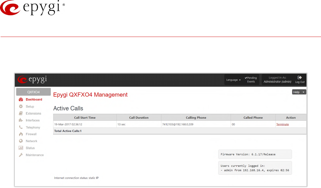
4 Dashboard
If you are logged in as an administrator (users: admin or localadmin), you will see the number of calls currently
active on QX. The Active Calls table includes information about the calling/called parties, call start time and
duration.
Figure 1: Dashboard menu
•The Terminate link is used to terminate the corresponding call.
•The list of users currently logged into the system appears in the lower right corner of the page. The IP
address of the user, the time until the next automatic logout and the current version of the QX's
firmware are presented as well. The idle session timeout is set at 10 minutes. If no action is performed
within 10 minutes, the user will be automatically logged out.
Manual-II: Administration Guide for QX Gateways
Edition 2 (FW Version 6.1.17 and higher) 11
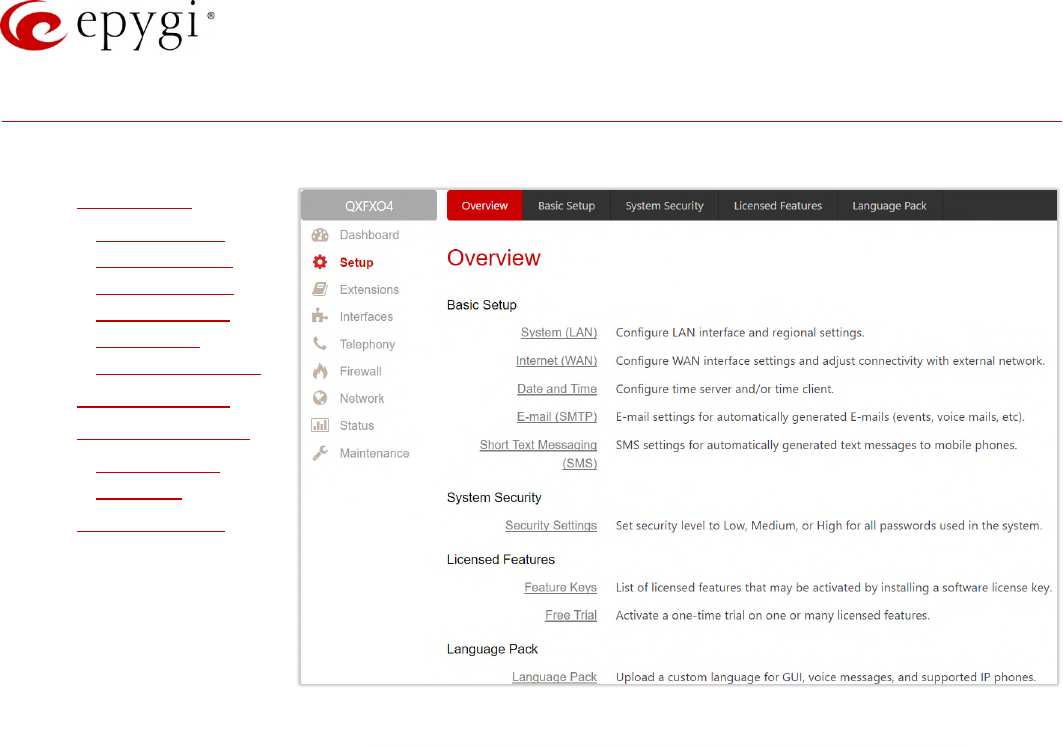
5 Setup Menu
The Setup menu consists of the following sections:
•Basic Setup
System (LAN)
Internet (WAN)
Date and Time
E-mail (SMTP)
Short Text
Messaging (SMS)
•System Security
•Licensed Features
Feature Keys
Free Trial
•Language Pack
Figure 2: Setup Menu overview
Manual-II: Administration Guide for QX Gateways
Edition 2 (FW Version 6.1.17 and higher) 12
5.1 Basic Setup
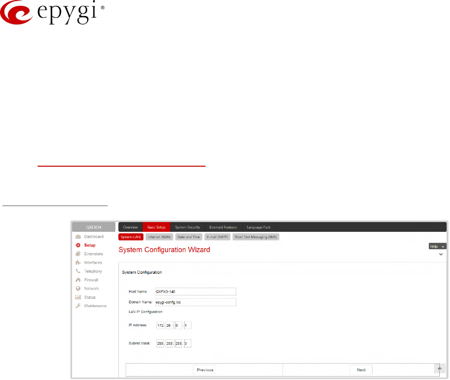
5.1.1 System (LAN)
You can login the QX WEB GUI through the LAN interface using the default IP address, which is 172.28.0.1. Go
to the SetupBasic SetupSystem (LAN) to adjust the network parameters for the LAN interface. The System
Configuration Wizard navigate you through the following parameters and settings:
•System Configuration
•DHCP Settings for the LAN Interface
•Regional Settings and Preferences
System Configuration
Figure 3: System Configuration section
•Host Name – set the host name for QX.
•Domain Name – set domain name which the QX belongs to.
•IP Address – set the LAN IP address.
•Subnet Mask – set the subnet mask.
Manual-II: Administration Guide for QX Gateways
Edition 2 (FW Version 6.1.17 and higher) 13
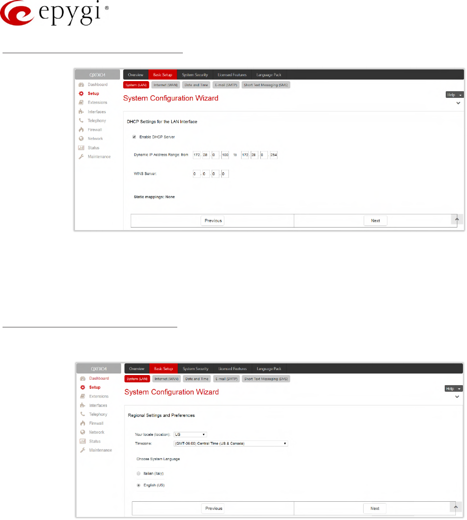
DHCP Settings for the LAN Interface
Figure 4: DHCP Settings for the LAN Interface section
•Enable DHCP Server – enable/disable DHCP server capability on the QX.
•Dynamic IP Address Range: (from - to) – set the IP address pool.
•WINS Server – set the IP address for the WINS server.
Regional Settings and Preferences
The regional settings are important for the functionality of the QX voice subsystem.
Figure 5: Regional Settings and Preferences section
•Your Locale (location) – select the location and timezone of QX.
•Timezone – select the proper time zone so the QX can display correct time accordingly. TIP: The QX
supports Daylight Savings (DST) correction if it is available for the selected time zone.
•Choose System Language – select the language for system voice messages: custom or default English.
TIP: This selection is available when a custom Language Pack has been uploaded.
Manual-II: Administration Guide for QX Gateways
Edition 2 (FW Version 6.1.17 and higher) 14
Note:
Finish the wizard and click "OK" to apply the changes made in any section of the wizard. You must
confirm the settings within 20 minutes. Otherwise the device will return back to the previous
configuration and reboot.
It is strongly recommended to not change the factory default settings if their meanings are not fully
clear to you.
5.1.2 Internet (WAN) – Internet Configuration Wizard
Go to the SetupBasic SetupInternet (WAN) to configure or adjust the network parameters for the QX WAN
interface. The Internet Configuration Wizard navigates through the following basic configuration parameters and
settings:
•Uplink Configuration
•WAN Interface Protocol
•WAN Interface Configuration
•DNS Settings
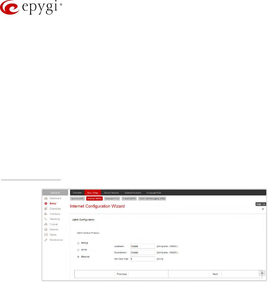
Uplink Configuration
Figure 6: Uplink Configuration section
•WAN Interface Protocol – select the protocol for the WAN interface. Based on this selection the wizard's
configuration pages may differ. The following connection protocols are available:
PPPoE
PPTP
Ethernet
Vlan
Note: Vlan option becomes available only when VLAN is configured on the QX.
WAN interface bandwidth settings specify the upstream and downstream speeds in Kbit/s, helping to
assure the quality of IP calls. IP call loses the voice quality if there is no available bandwidth. When
approaching the limits of a bandwidth capacity, another IP call will be declined.
Min Data Rate – set the amount of upstream bandwidth that ought to remain for data traffic even if
voice applications use the entire available upstream bandwidth. The value selected here needs to be
smaller than the upstream bandwidth.

Manual-II: Administration Guide for QX Gateways
Edition 2 (FW Version 6.1.17 and higher) 15
WAN Interface protocol – PPPoE
•Authentication Settings – insert the authentication parameters (Username and Password) to register on
the ISP server.
•Dial manually – if selected, a button will be displayed in the top WEB management window to switch the
connection on/off.
•Always connected – if selected, the QX will always stay connected.
•IP Address Assignment – select the IP address assignment for the PPPoE interface:
Dynamic IP Address – with this option QX will get an IP address dynamically.
Fixed IP Address – enter the IP address manually for this option.
•Keep connection alive – keeps the connection alive by sending control packets for the link state
verification.
Click Next to continue WAN Interface configuration.
WAN Interface protocol – PPTP
•Assign automatically via DHCP – with this option selected, QX will use DHCP to get an available IP
address from your local network or ISP.
•Assign Manually – if selected, manually provide the settings for the WAN interface.
IP Address – enter the IP address.
Subnet Mask – enter the subnet mask.
Default Gateway – enter the IP address for default gateway.
Click Next to continue the configuration of the PPP/ PPTP settings:
•PPTP Server – enter the IP address of the PPTP server.
•Encryption – select the encryption for the traffic over the PPTP interface.
•Authentication Settings – insert the authentication parameters (Username and Password) to register on
the ISP server.
•Dial manually – if selected, a button will be displayed in the top WEB management page for switching
the connection on/off.
•Always connected – if selected, then the QX will always stay connected.
•IP Address Assignment – select the IP address assignment for the PPP interface:
Dynamic IP Address – with this option, QX will dynamically get an IP address.
Fixed IP Address – when this option is selected, manually enter the IP address.
•Keep connection alive – keeps the connection alive by sending control packets for the link state
verification.
Click Next to continue WAN Interface configuration.
Manual-II: Administration Guide for QX Gateways
Edition 2 (FW Version 6.1.17 and higher) 16
WAN Interface protocol – Ethernet
•Assign automatically via DHCP – with this option selected, QX will use DHCP to get an available IP
address from local network or ISP.
•Assign Manually – with this option selected, manually provide IP settings for the WAN interface.
IP Address – enter the IP address.
Subnet Mask – enter the subnet mask.
Default Gateway – enter the IP address for default gateway.
Click Next to continue WAN Interface configuration.
WAN Interface protocol – Vlan
•VLAN ID – select VLAN ID from the configured VLAN list.
Click Next to continue the configuration of the VLAN IP Configuration settings.
•Assign automatically via DHCP – with this option selected, QX will use DHCP to get an available IP
address from local network or ISP.
•Assign Manually – if selected, manually provide IP settings for the WAN interface.
IP Address – the IP address of the selected VLAN.
Subnet Mask – the subnet mask of the selected VLAN.
Default Gateway – the IP address for default gateway.
Click Next to continue WAN Interface configuration.
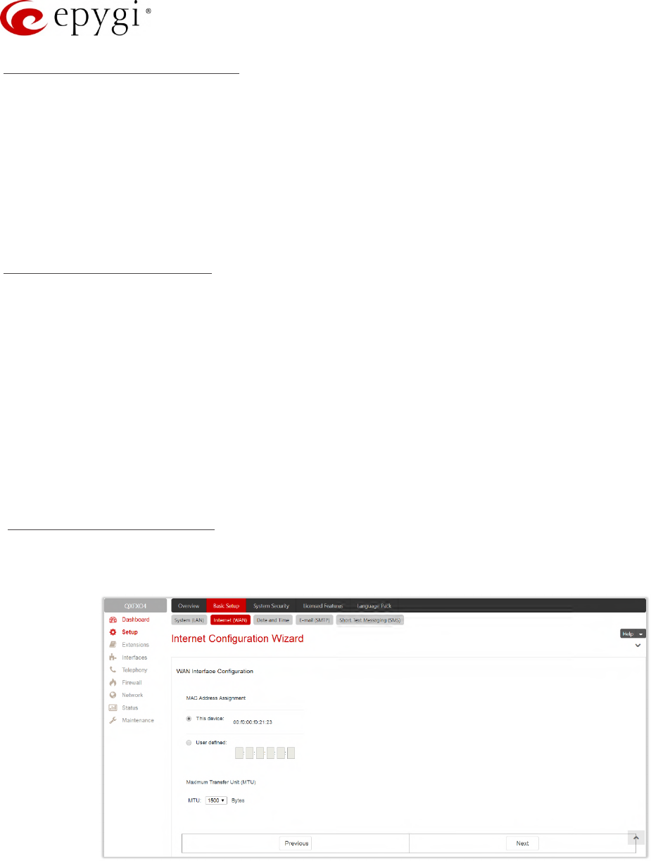
WAN Interface Configuration
This section is used to modify the MAC address of the QX. This might be necessary if the ISP requires a
specified MAC address (e.g. for authentication).
Figure 7: WAN Interface Configuration section
•This Device – selects the default MAC address of the WAN interface.
•User Defined – enter the MAC Address manually.
•MTU – select the maximum size of packet that can be sent in a packet or frame-based network such as
the Internet. QX supports packet fragmentation. TIP: The default MTU size is 1500 Bytes for Ethernet
protocol and 1400 Bytes for PPPoE.
Manual-II: Administration Guide for QX Gateways
Edition 2 (FW Version 6.1.17 and higher) 17
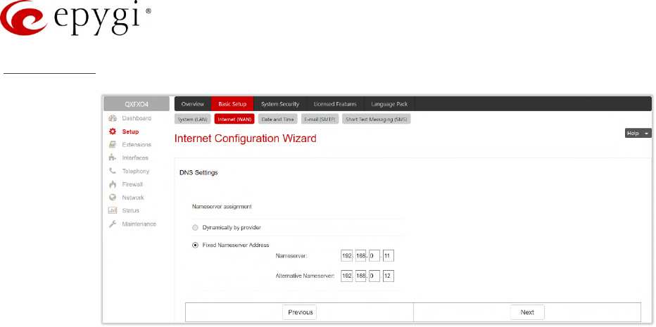
DNS Settings
Figure 8: DNS Settings section
•Dynamically by provider – with this option selected, QX will get an available IP address of DNS from local
network or ISP.
•Fixed Nameserver Address – if selected, manually provide DNS Server settings:
Nameserver – IP address of the primary DNS.
Alternative Nameserver – IP address of the secondary DNS.
Note:
Finish the wizard and click "OK" to apply the changes made in any section of the wizard. You must
confirm the settings within 20 minutes. Otherwise the device will return back to the previous
configuration and reboot.
It is strongly recommended to not change the factory default settings if their meanings are not fully
clear to you.
Manual-II: Administration Guide for QX Gateways
Edition 2 (FW Version 6.1.17 and higher) 18
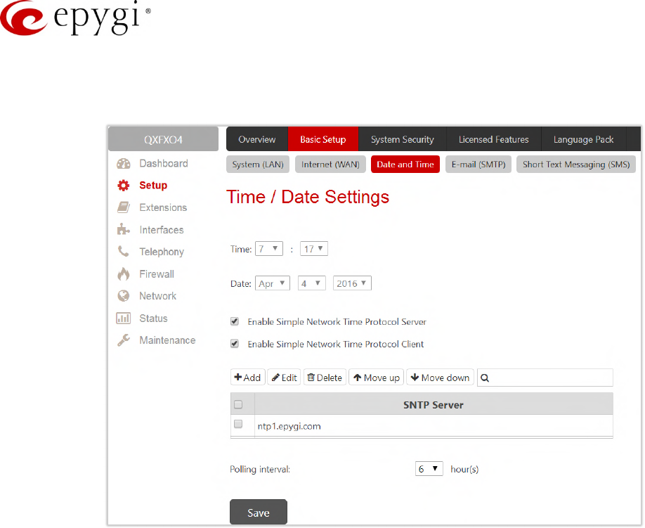
5.1.3 Date and Time
The QX Date and Time settings may be updated through the international time servers.
Figure 9: Time/Date Settings page
•Time, Date – displays the current system time.
•Enable Simple Network Time Protocol Server – enable or disable SNTP server capability on the QX.
•Enable Simple Network Time Protocol Client – enable or disable SNTP client on the QX. If not selected,
the current system time can be configured manually.
•Polling interval – select the time interval for the periodical synchronization between the timeserver and
QX.
The SNTP Servers table lists all defined SNTP servers. To add a new SNTP server:
1. Click Add. Define new server parameters:
manual – enter the SNTP server’s FQDN (Full Qualified Domain Name) or IP address.
predefined – select the SNTP server’s host address from the drop-down list.
2. Click Save to add the new SNTP server in the SNTP Servers table.
Note: Move Up/Move Down – are used to sort NTP servers in the order they need to be accessed. If the NTP
server in the first position of the SNTP Servers table does not answer, NTP server in the next position will be
attempted to reach.
Manual-II: Administration Guide for QX Gateways
Edition 2 (FW Version 6.1.17 and higher) 19
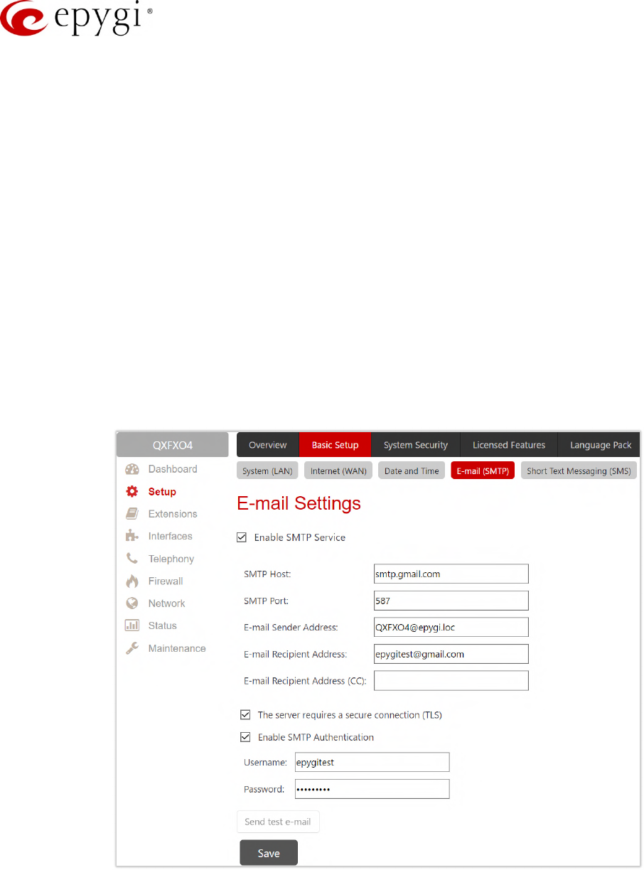
5.1.4 E-mail (SMTP)
Simple Mail Transfer Protocol (SMTP) service allows QX to automatically generate and send alert and
notification e-mails as specified in the Event Settings.
•Enable SMTP Service – activates the SMTP service.
•SMTP Host – IP address or hostname of the SMTP server.
•E-mail Sender Address – e-mail address that is either registered on the selected SMTP server or has
permission to use the SMTP server for e-mail transmissions.
•E-mail Recipient Address – an active address to send e-mails to.
•E-mail Recipient Address (CC) – an active address to deliver e-mails’ carbon copy (CC) to.
•The server requires a secure connection (TLS) – select if the specified SMTP server requires secure
connection using TLS. If the specified SMTP server allows to use both secure and unsecure
connections, then this selection forces to establish the secure connection.
•Enable SMTP Authentication – select if the specified SMTP server requires authentication. Then enter
the Username and Password configured on the SMTP server.
Shown below is a sample e-mail settings on the QX, assuming the e-mail is using smtp.gmail.com as the SMTP
server.
Figure 10: E-mail Settings page
Once the configuration is finished, click "Send test e-mail" to send a test e-mail to the defined e-mail address to
verify the settings.

Manual-II: Administration Guide for QX Gateways
Edition 2 (FW Version 6.1.17 and higher) 20
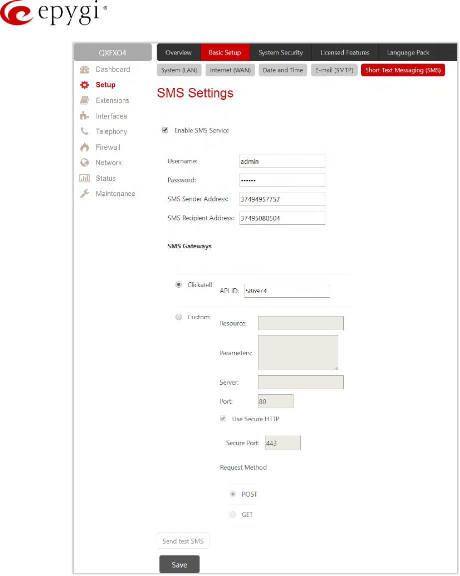
5.1.5 Short Text Messaging (SMS)
The SMS service allows QX to automatically generate and send alert and notification events via SMS.
•Enable SMS Service – activates SMS service.
•Username and Password – authentication parameters configured on the SMS server.
•SMS Sender Address – sms sender's address.
•SMS Recipient Address – sms recipient's address. TIP: Use a space, semicolon or a comma to
separate mobile numbers in case of multiple recipients.
You may either use predefined SMS gateway (Clickatell) or define a custom service.
•Clickatell – select to use the predefined SMS gateway. Then insert the Clickatell specific parameter
provided by the server in the activated API ID field. This parameter must be identical on both sides.
•Custom – select to define a custom gateway as follows:
Resource – enter the HTTP resource name on the SMS gateway.
Parameters – enter parameters to be submitted to the resource address. The value of this field
represents a string with tokens (separated by percent (%) symbols) inside. Each token indicates a
value of the certain field on this page. The value depends on the SMS gateway requirements. The
tokens are the strings that have the following dependencies from the field in this page:
%username% – indicates the username defined in the field Username.
%password% – indicates the password defined in the field Password.
%to% – indicates the password defined in the field SMS Recipient Address.
%from% – indicates the password defined in the field SMS Sender Address.
%text% – indicates the SMS text generated by QX (voice mail notification, event notification, etc.).
For example: user=%username%&password=%password%&to=%to%&from=%from%&text=%text%
Server – IP address or hostname of the SMS gateway.
Port – port number of the SMS gateway.
Use Secure HTTP to access the SMS server via HTTPS. Then define the port number for HTTPS
traffic in the activated Secure Port field.
•Select one of the HTTP request’s methods (POST or GET) through the Request Method buttons. The
QX uses one of methods to access to the SMS gateway.
Manual-II: Administration Guide for QX Gateways
Edition 2 (FW Version 6.1.17 and higher) 21
Figure 11: SMS Settings page
Once the configuration is finished, click "Send test SMS" to send a test sms to the defined mobile number to
verify the settings.
Manual-II: Administration Guide for QX Gateways
Edition 2 (FW Version 6.1.17 and higher) 22
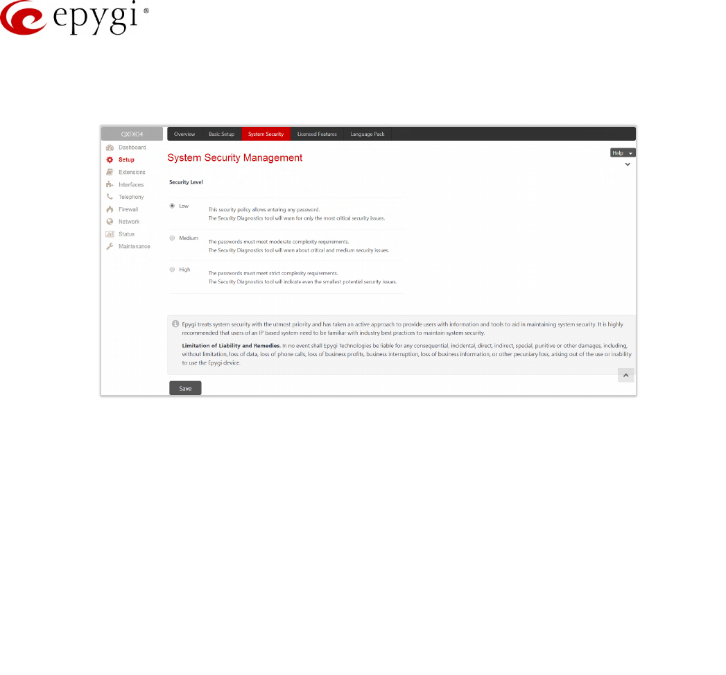
5.2 System Security
The System Security Management is used to manage the QX’s global security.
Figure 12: System Security Management page
QX treats the selected security level when checking the passwords strength and when running the security
audit to get security reports. The security levels are the following:
•Low – there are no specific restrictions on the strength of the saved password. Only the critical
warnings on the Call Routing Rules to PSTN and IP-PSTN, disabled Firewall and IDS will be generated
in Security Report.
•Medium – the minimum strength of the passwords must be "moderate". The Security Report will
generate warnings on all unsecured Call Routing rules, IP Line and extension passwords, Firewall level
(if it is set below "Medium"), disabled IDS, default administrator passwords.
•High – the minimum strength of the passwords must be "strong". The Security Report will generate
warnings on the IP Line and extension passwords, disabled IDS, all unsecured Call Routing rules,
Firewall level (if it is set below "High"), default administrator passwords etc.
Manual-II: Administration Guide for QX Gateways
Edition 2 (FW Version 6.1.17 and higher) 23
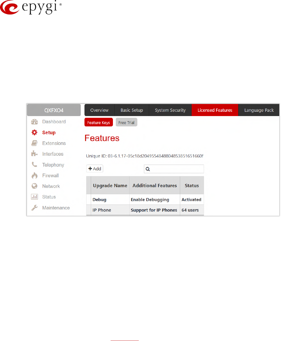
5.3 Licensed Features
5.3.1 Feature Keys
Two types of licensable feature keys are available on the QX:
•Permanent keys – activate licensable features on QX permanently, without time limitation.
•Time limited keys – activate or extend the operation for already activated licensable features temporarily,
for the specified period. The feature will be no longer functional after the period expiration date. The
Time Limited keys are available for all licensable features.
Figure 13: Features page
•Debug – enable SSH connection towards the QX for debugging purposes.
•IP Phone Support – enables IP phones support on the QXE1T1/QXFXO4. This feature key allows
activating up to 200 IP lines.
To receive a Feature Key, register the QX device and send a corresponding request to Epygi Technical Support.
This request must include the Unique ID that is displayed in the Features page above the features list.
Enter a Feature Key as follows:
1. Click Add to open the Features page.
2. Enter the key in the Feature Key field.
3. Click Save. The status of the selected feature will turn to "Reboot needed".
4. Reboot QX to complete the installation. The status of the feature will turn to "Activated".
Note: Please make sure to have correct Date/Time on the device before adding the license key, otherwise you
may have issues with the applied key.
Manual-II: Administration Guide for QX Gateways
Edition 2 (FW Version 6.1.17 and higher) 24
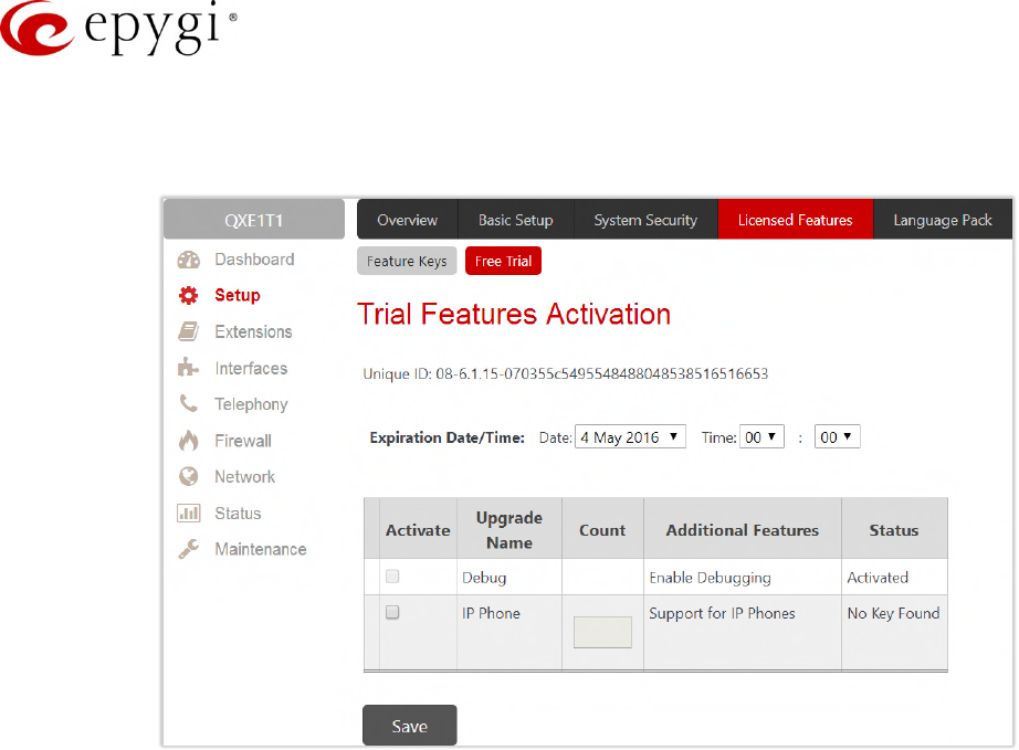
5.3.2 Free Trial
This page lists all QX features that may be activated for a trial period.
Figure 14: Trial Features Activation page
Expiration Date/Time – is used to specify the trial period. Upon expiring the specified period, the QX will reboot
and trial feature(s) will disable. TIP: The trial option can be activated on the QX only once. You cannot activate
the trial for the same or any other feature again after the first activation.
To activate trial feature:
1. Select the checkbox next to the feature.
2. Specify the needed count under the Count column (depending on the selected feature).
3. Click Save. The QX will reboot and activate the selected trial feature(s).
Manual-II: Administration Guide for QX Gateways
Edition 2 (FW Version 6.1.17 and higher) 25
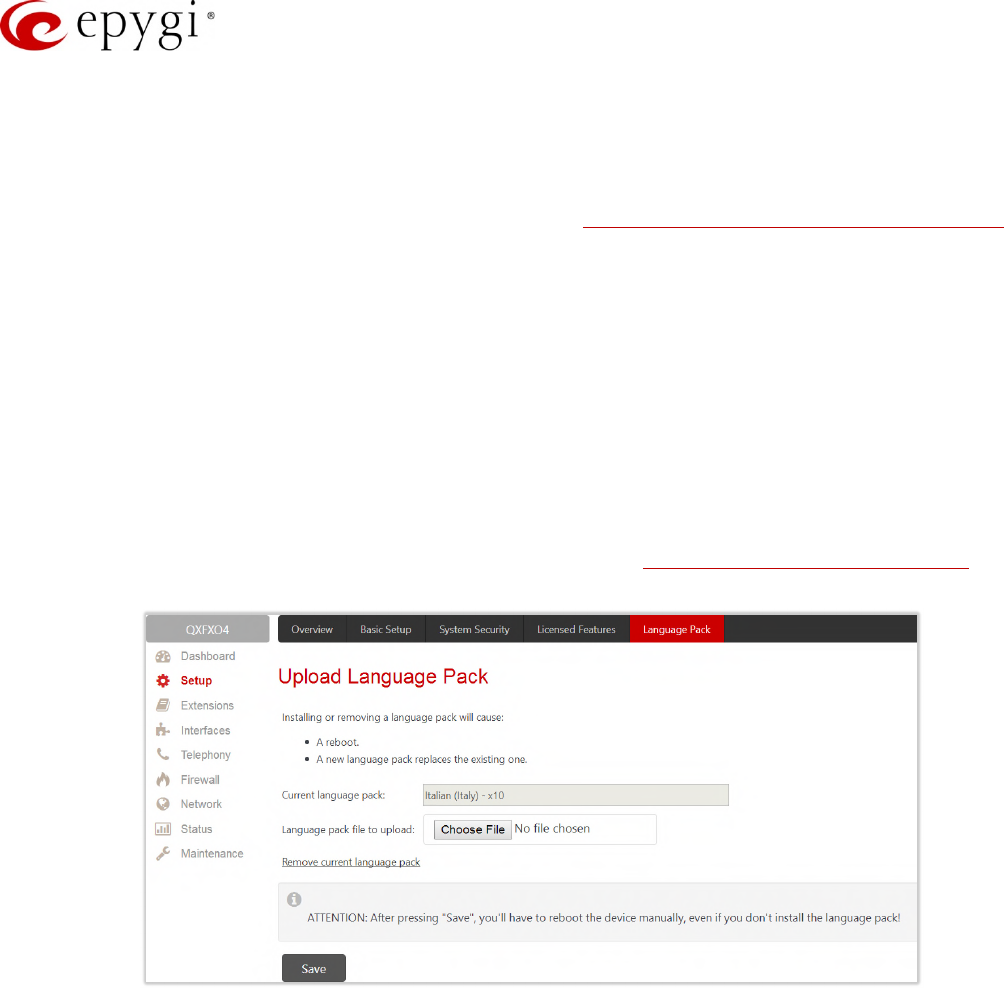
5.4 Language Pack
All Epygi supported LPs will change the system voice messages to the custom language, some of LPs will
change the device GUI interface as well.
For more information on Language Packs, please refer to the Language Packs Overview for Epygi QX Line
guide.
To upload a language pack:
1. Click Choose File to browse and select the file for the language pack.
2. Click Save to start uploading the language pack. Clicking Save will stop some vital processes on the
QX, therefore it is required to manually reboot the device even if you have cancelled the LP update
procedure on the following steps.
3. Click Yes to proceed the upload. The QX will be rebooted automatically.
4. Uploaded LP will appear in the Current language pack field. After successful upload, you will be able to:
Change the language of the GUI session from the GUI Login page or from main menu.
Switch the system voice messages to the custom language and change the GUI interface of some
supported IP phones. TIP: Choose the language from the Regional Settings and Preferences section
of the System Configuration Wizard to change the system voice messages.
Figure 15: Language Pack page
Remove current language pack – is used to remove the uploaded LP. This link appears only if there is an
uploaded LP.
Note: Only one custom Language Pack can be uploaded at a time. Thus, the new LP will remove the existing
one and reboot the QX.
Manual-II: Administration Guide for QX Gateways
Edition 2 (FW Version 6.1.17 and higher) 26
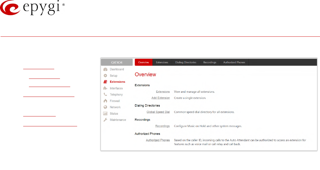
6 Extensions Menu
The Extensions menu consists of the following sections:
•Extensions
Extensions
Add Extension
•Dialing Directories
Global Speed Dial
•Recordings
•Authorized Phones
Figure 16: Extensions Menu overview
Manual-II: Administration Guide for QX Gateways
Edition 2 (FW Version 6.1.17 and higher) 27
6.1 Extensions
6.1.1 Extensions
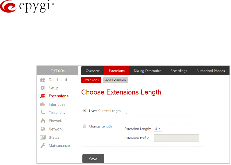
Navigating to the Extensions Management page for the first time after the QX initial start or configuration restore
you will be prompted to choose the extensions length applicable to all QX default extensions.
Figure 17: Choose Extensions Length page
The following options are available:
•Leave Current Length – keep the current length of QX extensions unchanged. By default, the
extension’s length is 3 on the QXFXO4, QXE1T1 and is 2 on QXISDN4 and QXFXS24. In front of this
selection, the actual configured length of extensions is displayed.
•Change Length – change the length of extensions as follows:
Extension Length – select the length of extensions. It will be applied for all existing extensions on the
QX. The length of the extension can be 2, 3, 4.
Extension Prefix – define the prefix the existing extensions as well as the newly created extensions
should start with. The prefix cannot start with the digits 0 or 9.
Attention:
•By saving the settings on the Choose Extensions Length page, all existing extensions will lose the
custom voice messages. The device will be rebooted. The Choose Extensions Length page will not
appear again unless the default configuration settings will not be restored on the QX.
•The Choose Extensions Length page will not display in case if a feature key for IP phone support is
installed and activated on the QX.
•QXFXS24 is limited to 100, QXISDN4, QXFXO4 and QXE1T1+ to 400 extensions in total.

Manual-II: Administration Guide for QX Gateways
Edition 2 (FW Version 6.1.17 and higher) 28
Figure 18: Extensions Management page
The Extensions Management table consists of the following components:
•Extension – list the numbers for extensions on the QX. These numbers are used for calling the
extensions internally.
•Display Name – is an optional name given to extension mainly to identify the extension’s owner at the
called side.
•Attached Line – indicate the IP line (FXS for QXFXS24) a corresponding extension is attached to. TIP: R
is displayed in this column when Remote Extension service is enabled on the extension. None is
displayed when no FXS or IP line is attached to the extension.
•SIP Address – display the full SIP address of extension, (i.e., username@sipserver:port) when the
Registration on SIP Server is enabled. If registration is disabled, the SIP address will be displayed in the
following format: "username, Proxy: sipserver:port". If no SIP registration server or SIP server port is
defined, corresponding information will not be included in this column. If no username is defined, the
extension number will be displayed instead.
•Percentage of System Memory – indicate the memory size assigned to extension in percentage
regarding the total system memory. The actual available duration for the extension’s voice mails,
uploaded/recorded greetings and blocking messages is also displayed here.
•External Access – indicate whether the GUI Login or Call Relay options are enabled on the extension.
•Codecs – list the short information about extension specific voice Codecs. Extension codec’s can be
accessed and modified by clicking on the link of the corresponding extension’s Codecs. The link leads
to the Extension Codecs page.
Manual-II: Administration Guide for QX Gateways
Edition 2 (FW Version 6.1.17 and higher) 29
6.1.2 Add Extension
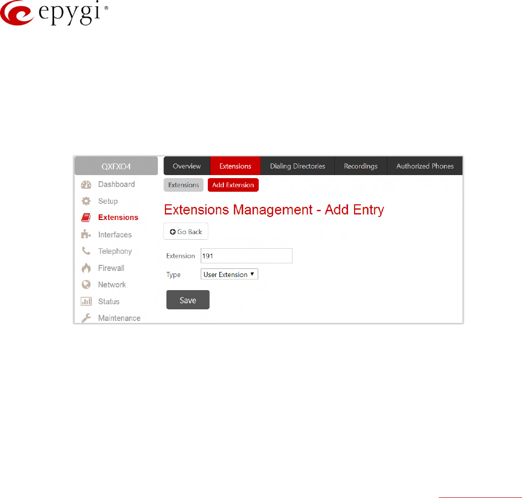
To add a new extension:
1. Click "Add Extension".
2. Enter the extension number.
3. Select the extension type. The following types are available: Attendant and User Extension.
4. Click Save to add the new extension to the Extension Management table.
Figure 19: Extensions Management – Add Entry page
Two types of user extensions, active and inactive, can be created on the QX.
•Active extensions are those that are attached to a line, can place and receive calls and use available
telephony services.
•Inactive extensions are those that are not attached to the line. They can use some available telephony
services, but cannot place and receive calls.
Auto Attendant extension is dedicated to the IVR system on the QX Gateway. This extension is used by external
callers to reach QX’s extensions and the call relay services.
Note:
•Adjust the routing rules for calling extensions with custom length manually since the call routing rule(s)
for calling PBX extensions will not be adjusted automatically.
•A maximum extension length is 20 digits.
•Auto Attendant extension type is NOT available on QXFXS24.
Manual-II: Administration Guide for QX Gateways
Edition 2 (FW Version 6.1.17 and higher) 30
6.1.3 Edit Extension
The Edit leads to the Extensions Management – Edit Entry page to editing an extension(s). When editing multiple
extensions, fields that cannot be edited for multiple records have Multiple values in the Edit Entry page. When
editing user and attendant extensions together, the Edit Entry page displays only common fields. Additionally,
"Select to modify fields" checkbox to submit changes of the corresponding settings (options), otherwise the
changes won’t be applied.
Figure 20: Extensions Management – Edit Entry page for multiple edit operation
6.1.4 User Extension
The following sections are available for configuration:
•General Settings
•SIP Settings
•SIP Advanced Settings
•Remote Settings
General Settings
This section is used to uniquely identify an extension through below described parameters:
•Display Name – is the caller ID that will be displayed on the callee’s phone.
•Password – assign a password to the extension. TIP: This password will be used for GUI login and Call
Relay.
•Attached Line (N/A for QXISDN4) – list all free lines an extension can be attached to. Extension should
be attached to a line (either IP or FXS) to be able to make and receive calls. If there is no line attached to
an extension, then it is called Virtual Extension (herein VE). VEs can’t place/receive calls, but allowed to
use a limited number of QX telephony services, such as the call forwarding service or the voice mail
service to store and manage the messages from callers. Any VE can easily become a real extension
after attaching a line and vice versa. Extensions cannot be detached from the line if the Remote
Extension feature is enabled on. To detach the extension from the line, disable the Remote Extension
service on the extension first.

Manual-II: Administration Guide for QX Gateways
Edition 2 (FW Version 6.1.17 and higher) 31
Figure 21: User Extension – General Settings section
•Allow Call Relay (N/A for QXFXS24) – enable the extension to be used to access the Call Relay service in
the QX Auto Attendant. It is recommended to define a proper and non-empty password when enabling
this feature in order to protect the Call Relay service from an unauthorized access.
•GUI Login Allowed (N/A for QXFXS24) – enable GUI access (by extension name and password) for the
current extension.
•Show on Public Directory (N/A for QXFXS24) – if selected, allows to display the extension (Display
Name, number) on the General Information page.
•Edit Call Intercept Access List (available for QXFXS24) – leads to the Call Intercept Access List page to
define extension(s) allowed to intercept calls.
•Edit Watch Access List (N/A for QXISDN4) – leads to the page to define the extensions allowed to watch
calls.
Call Intercept Access List
This page is used to define a list of extensions that are capable to Barge-In/Intercept the current extension’s
calls and defines the appropriate permissions. The Call Barge-In / Intercept Access List page is available only if
the Barge-In is activated.
Manual-II: Administration Guide for QX Gateways
Edition 2 (FW Version 6.1.17 and higher) 32
Figure 22: Call Intercept Access List
To add a new extension:
1. Click Add.
2. Enter the extension number(s) allowed to Intercept the current extension’s calls.
3. Select Allow Intercept option, to allow the call interception.
4. Click Save, the new entry will be added to the Call Intercept Access List table.
Note: Intercepted calls neither will be displayed in the Active Calls table on the Dashboard nor will be registered
in the Call History table.
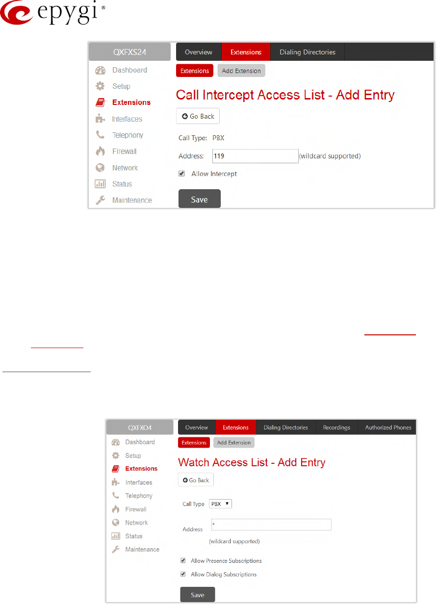
Watch Access List
This page is used to define a list of extensions that are capable to watch the current extension calls and defines
the appropriate permissions.
Figure 23: Watch Access List – Add Entry page
Manual-II: Administration Guide for QX Gateways
Edition 2 (FW Version 6.1.17 and higher) 33
To add a new extension:
1. Click Add.
2. Enter the extension number(s).
3. Select the "Allow Presence Subscriptions" and "Allow Dialog Subscriptions" to allow subscriptions to the
current extension.
4. Click Save, the new entry will be added to the Watch Access List table.
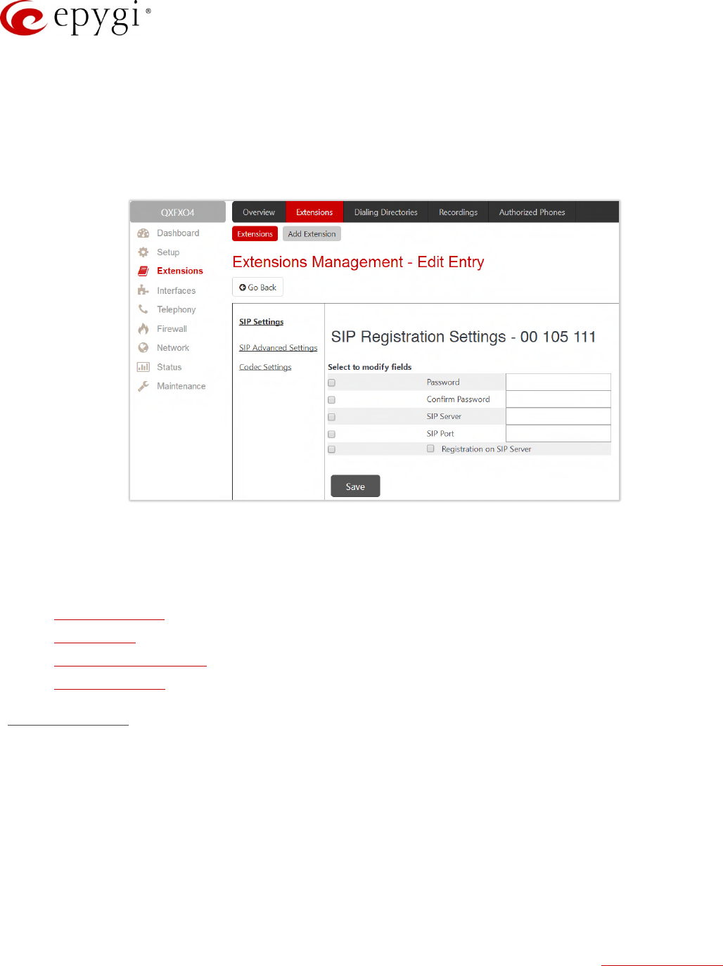
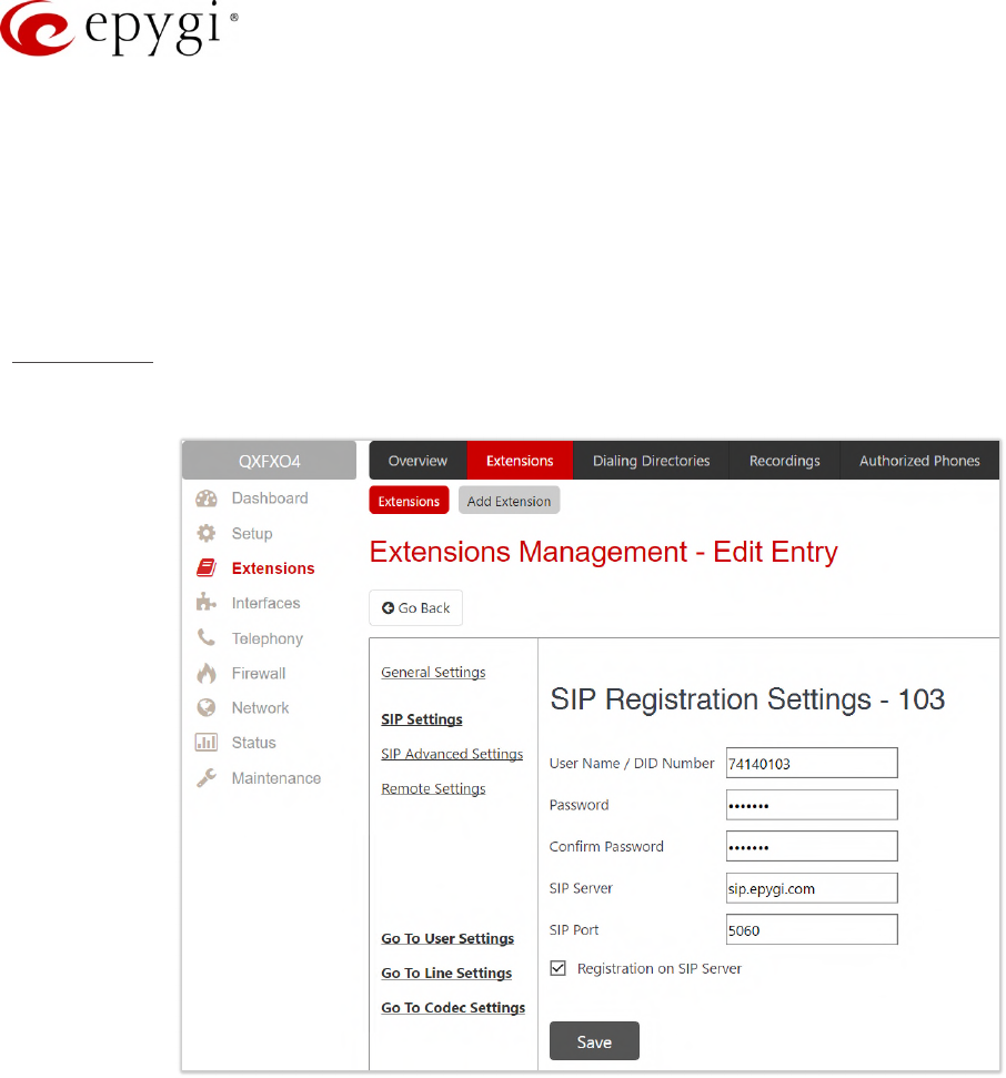
SIP Settings
This section describes how to register the QX extension on a SIP server to receive external SIP calls.
Figure 24: SIP Settings section
•User Name/DID Number – is the registration username or the DID number on the external server. TIP: A
maximum SIP Username length is 32 characters. The SIP Username can consist of lowercase and
uppercase alphabetic characters, digits and symbols.
•Password – is the registration password on the SIP server.
•SIP Server – is the address of the SIP server. It can be either an IP address, such as 192.168.0.26 or a
host name, such as sip.epygi.com. TIP: A maximum SIP Server length is 32 characters. The SIP Server
can consist of lowercase and uppercase alphabetic characters, digits and symbols.
•SIP Port – is the port number used to connect to the SIP server. TIP: If the SIP port is not specified, QX
will access the SIP server through the default 5060.
•Registration on SIP Server – is used to register the current extension on the SIP server.
How it works: Upon receiving a SIP Invite message from an external server, the QX will look to match the called
number in the Username/DID Number field. If the ITSP does not require each DID to uniquely register on an
external SIP server, then only insert the DID number in the Username/DID Number field and keep the other fields
empty.
Manual-II: Administration Guide for QX Gateways
Edition 2 (FW Version 6.1.17 and higher) 34
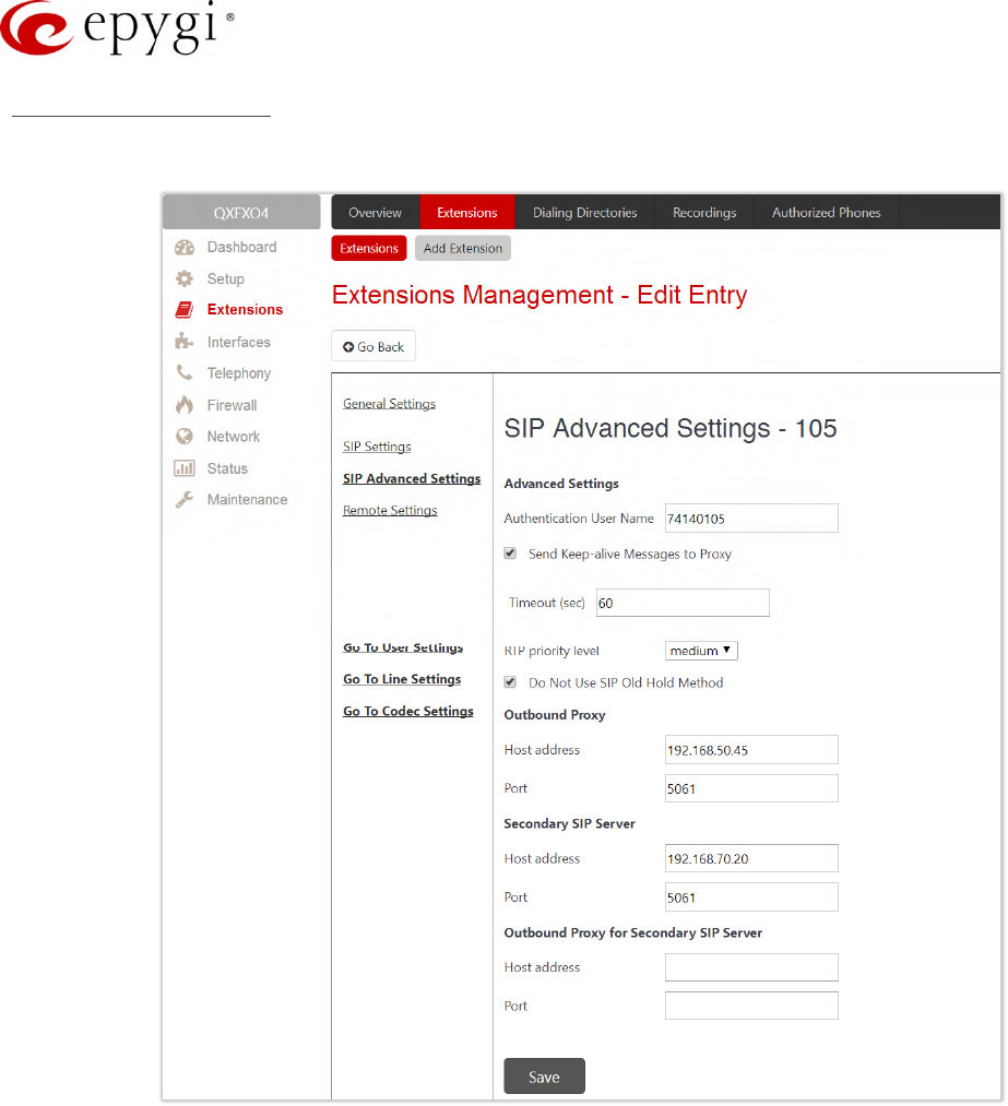
SIP Advanced Settings
This section describes how to configure advanced and specific SIP settings for QX extension.
Figure 25: SIP Advanced Settings section
•Authentication User Name – enter an identification parameter. It should be provided by the SIP service
provider and can be requested for some SIP servers only. For others, the field should be left empty.
•Send keep alive Messages to Proxy – enable the SIP registration server accessibility to the verification
mechanism.
•Timeout – define the timeout between two attempts for the SIP registration server accessibility
verification. If no reply is received from the primary SIP server within this timeout, the Secondary SIP
server will be contacted. When the primary SIP server recovers, SIP packets will resume being sent to it.
•RTP priority level – select the level of priority (low, medium or high) of the RTP packets sent from the
extension. RTP packets with higher priority will be sent first in case of heavy traffic.
•Do Not Use SIP Old Hold Method – if selected, a new recommended method of call hold in SIP (the call
hold request is indicated with the "a=sendonly" media attribute, rather than with the IP address of
0.0.0.0) will be used. This checkbox must be enabled if the remote party does not recognize hold
requests initiated from the QX.
Manual-II: Administration Guide for QX Gateways
Edition 2 (FW Version 6.1.17 and higher) 35
•Outbound Proxy – is the SIP server where all SIP requests and SIP messages are transferred to. Some
SIP servers use an outbound proxy to escape restrictions of NAT. If an outbound proxy is specified for
an extension then all SIP calls originating from that extension will go through that outbound proxy, i.e.,
all requests will be sent to that outbound proxy.
•Secondary SIP Server – act as an alternative SIP registration server when the primary SIP Registration
Server becomes inaccessible. If the connection with the primary SIP server fails, the QX will
automatically start sending SIP messages to the Secondary SIP Server. It will switch back to the
primary SIP server as soon as the connection is reestablished.
•Host address and Port – specify the host address and SIP port of the Outbound Proxy, Secondary SIP
Server and the Outbound Proxy for the Secondary SIP Server respectively. These settings are provided
by the SIP server providers and are used by QX to reach the selected SIP servers.
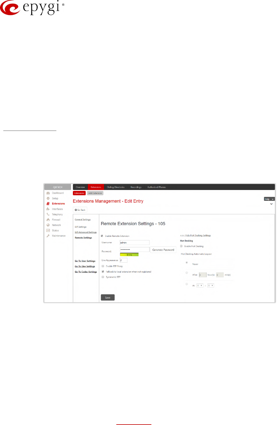
Remote Settings
This section (N/A for QXFXS24 and QXISDN4) describes how to configure Remote Extension settings for QX
extension. This is an advanced telephony feature that allows users to connect phone to the QX remotely. User
needs to register an IP phone or softphone on the QX by defining the QX global IP address and an appropriate
Username/ Password. The registered phone can act fully as a phone connected locally to the QX, i.e. you can
use all QX telephony features, place and receive calls, etc.
Figure 26: Remote Settings section
•Enable Remote Extension – activates the Remote Extension’s service.
•Username and Password enter the identification parameters used by the remote phone to register it on
the QX. TIP: The Username and Password must match on both QX and IP phone for successful
registration.
•Line Appearance – define a number of simultaneous calls supported by the remote phone.
•Enable RTP Proxy – if selected, the incoming and outgoing RTP streams to/from the remote IP phone
will be routed through the QX, otherwise RTP packets will move directly between peers.
•Fallback to local extension when not registered – if selected, the incoming calls to the local extension will
be forwarded to the remote IP phone only if it is registered. Otherwise, when the remote IP phone is
unregistered, incoming calls will be routed to the local extension it is attached to.
•Symmetric RTP – must be selected when the remote extension is located behind the NAT router.
•Enable Hot Desking – enable the Hot Desking feature on the current remote extension.
Manual-II: Administration Guide for QX Gateways
Edition 2 (FW Version 6.1.17 and higher) 36
•Hot Desking Automatic Logout – is used to configure the Hot Desking functionality expiration on the
current extension. Following options are available:
Never – the extension will never expire and will remain logged into the public phone.
After – the extension will be automatically logged out from the public phone after a specified period of
time.
At – the extension will be automatically logged out from the public phone at the specified moment
(hour and minute).
6.1.5 Auto Attendant Extension
The Auto Attendant is an IVR system (N/A for QXFXS24) that replaces a receptionist and allows to distribute
calls to the QX’s extensions or services through prerecorded audio prompts. Remote access to the QX’s
attendant is possible through IP/PSTN/IP-PSTN calls, by dialing Attendant's SIP or PSTN number.
Note: The SIP Settings, SIP Advanced Settings and Go To Codec Settings sections are the same as for user
extensions.
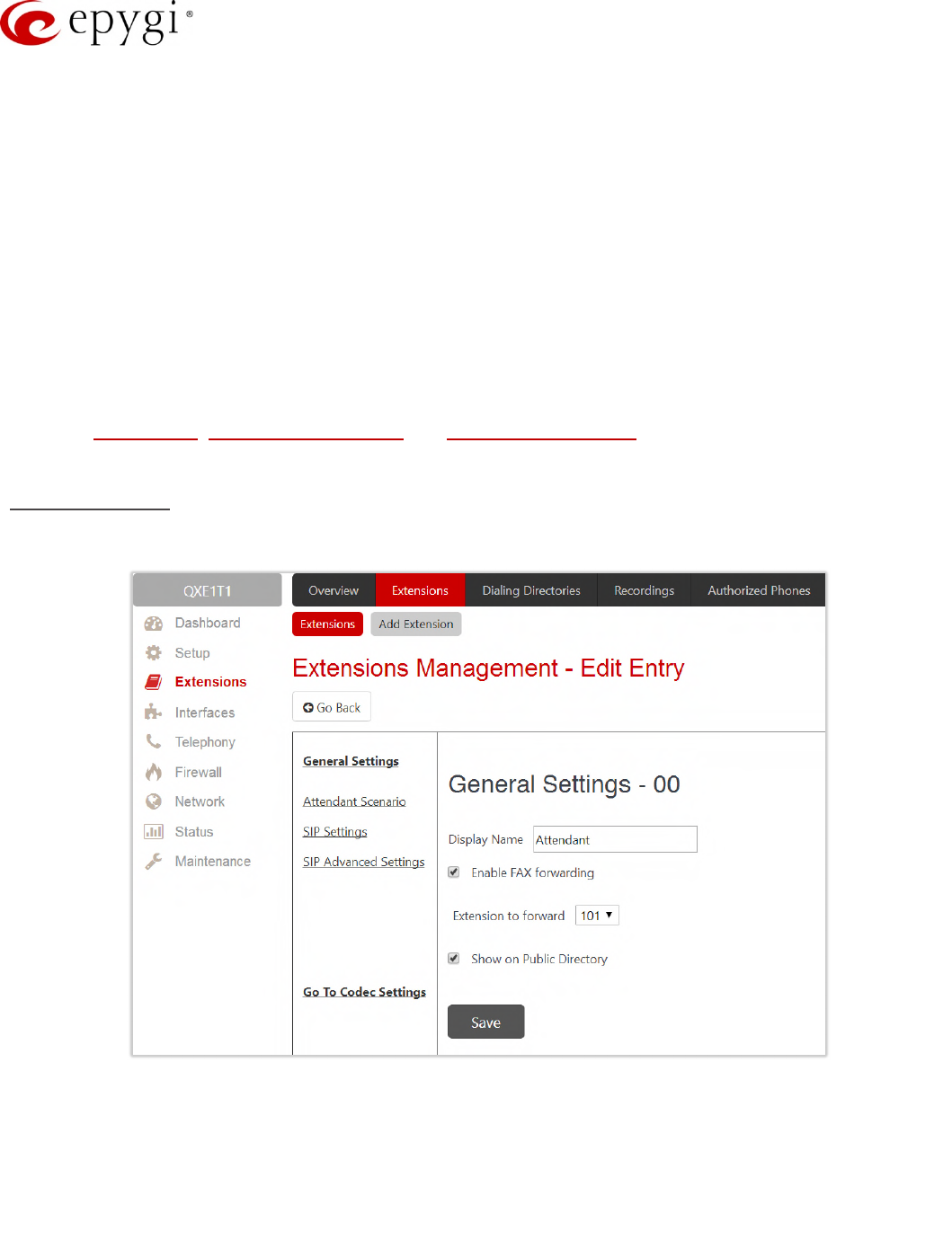
General Settings
This section describes how to configure general settings of the Attendant:
Figure 27: Attendant – General Settings section
•Display Name – is the caller ID that will be displayed on the phone when making call to attendant or
from attendant (e.g. when using callback service).
•Enable FAX forwarding – if selected, the system forwards the FAX messages to the selected extension if
incoming calls are routed to the Attendant and FAX tone is detected on the Attendant.
•Extension to forward – select the extension where the incoming FAX addressed to the Attendant will be
forwarded. The list contains only those extensions that have FAX support enabled. FAX support can be

Manual-II: Administration Guide for QX Gateways
Edition 2 (FW Version 6.1.17 and higher) 37
enabled from the Extension Codecs page. TIP: FAX forwarding is applicable only for incoming calls from
PSTN and SIP.
•Show on Public Directory – if selected, allows to display the extension (Display Name, number) on the
General Information page.
•Percentage of Total Memory – defines the memory space allocated to AA extension for custom voice
messages.
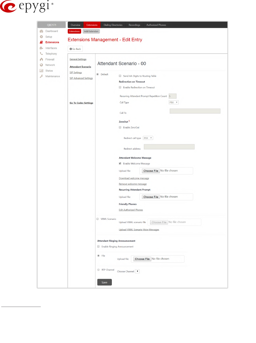
Attendant Scenario
This section describes how to manage the attendant scenario (Figure 28). The following scenarios are available:
•Default scenario – available and active on the 00 attendant and newly created attendant extensions by
default.
•VXML scenario – allows to upload custom scenario file in VXML format.
Manual-II: Administration Guide for QX Gateways
Edition 2 (FW Version 6.1.17 and higher) 38
Figure 28: Attendant Scenario section
Default scenario
The following options are available for the Default scenario:
•Send AA Digits to Routing Table – if selected, sends the dialed numbers to the Call Routing Table.
•Enable Redirection on Timeout – if activated and configured, callers will be redirected to the specified
address in case if no action by caller on the Recurring Attendant Prompt(s). Prompt Repetition is used to
define the number of prompts to be played before redirection.
Manual-II: Administration Guide for QX Gateways
Edition 2 (FW Version 6.1.17 and higher) 39
•Enable ZeroOut – if activated and configured, callers dialing during welcome message or recurring
prompt will be redirected to the specified address.
•Call Type, Call To – (identical for both Call Redirection and ZeroOut Redirection) – allow to redirect the
call to the specified destination.
Note: The routing patterns in the Call Routing Table starting with digit will not work for incoming calls to
attendant if both the ZeroOut and Send AA Digits to Routing Table options are enabled. The ZeroOut feature
has a higher priority. If enabled, the system will redirect calls to the specified destination. As a result, calls
prefixed with will never reach call routing.
•Enable Welcome Message – activates/deactivates the welcome message (default or custom).
•Recurring Attendant Prompt – is used to change the active recurring prompt (played after the Welcome
Message and then periodically repeated while being in the Attendant).
•Edit Authorized Phones – leads to the Authorized Phones page. If the external SIP or PSTN caller added
to the Authorized Phones, he/she allowed to access the attendant services bypassing the authorization
procedure and use the Callback service as well.
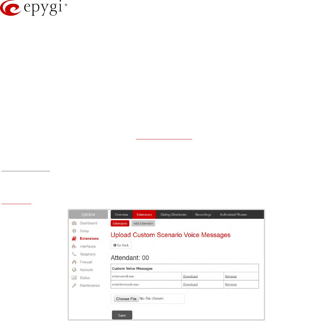
VXML scenario
The VXML scenario allows to upload custom scenario file and voice messages. Following options are available:
Upload VXML scenario file – is used to upload a new scenario file. TIP: The uploaded file needs to be in
EpygiXML format and is restricted to 20 KB file size.
Figure 29: Upload Custom Voice Messages page
•Upload VXML Scenario Voice Messages – leads to the Upload Custom Scenario Voice Messages page
to manage voice messages used in scenario. TIP: It is allowed to upload all voice messages at once. To
do this, create an archive file of the (*.tar.gz) type containing all the necessary files and upload it from the
Upload VXML Scenario Voice Messages page.
•View/Download VXML scenario – view or download the scenario file.
•Remove VXML scenario – remove the custom scenario file.
Manual-II: Administration Guide for QX Gateways
Edition 2 (FW Version 6.1.17 and higher) 40
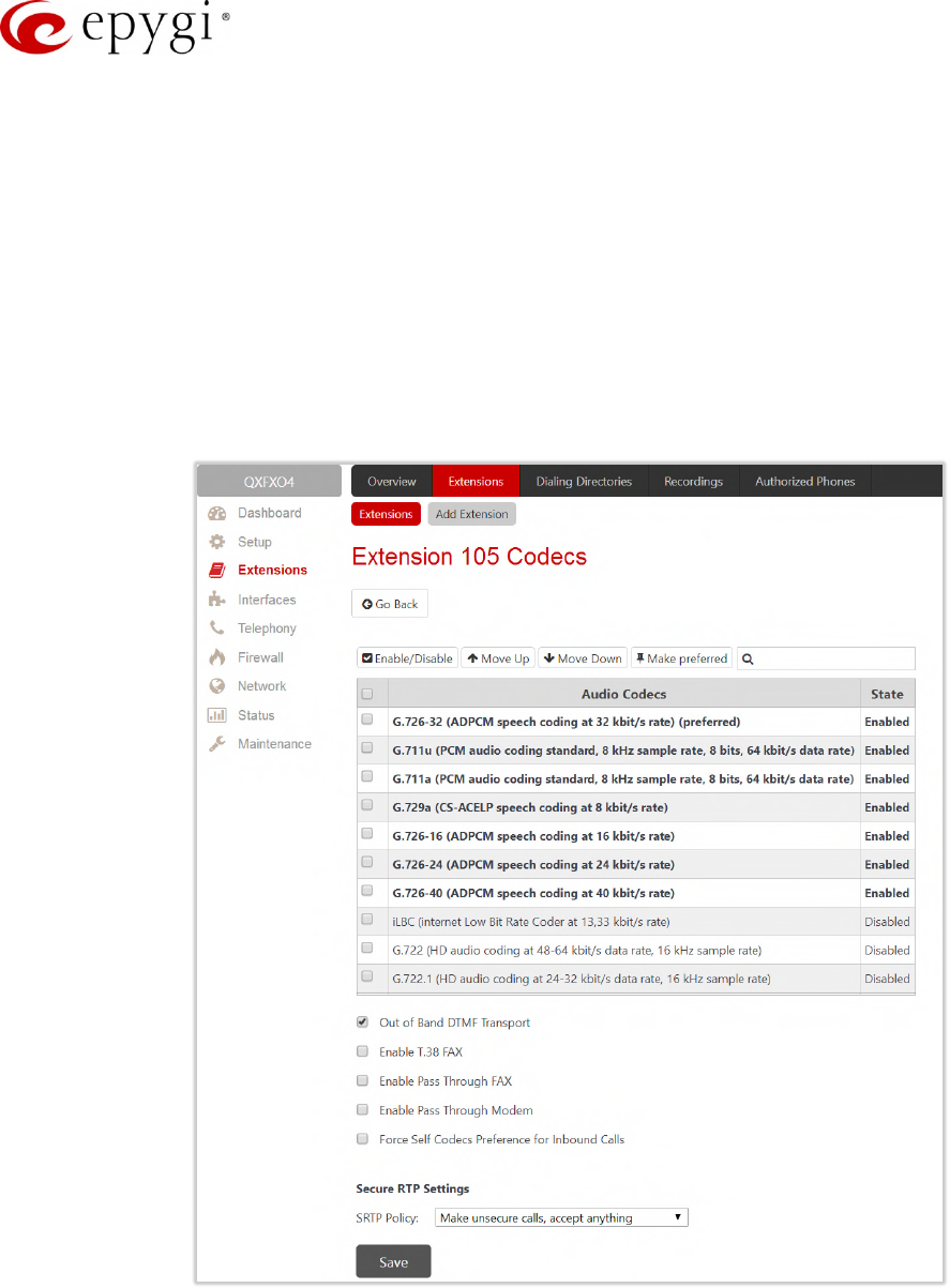
6.2 Extension Codecs
To establish an IP voice communication, call participants have to use the same codec. When establishing a
communication line, this codec is negotiated. If the caller does not find an appropriate codec, the
communication does not take place. To allow communication with all IP callers, it is helpful to support as many
codecs as possible. In this case, all codecs that the system offers should be enabled in the Codecs table. On
the other hand, some codecs require quite a high transfer rate of up to 64 kbit/s. If you definitely do not want to
use these codecs, make sure they are disabled in the Codecs table.
The enabled codecs participate in codec negotiation at the call setup. The order of the enabled codecs is very
important. A codec placed at the top of the table is used as the preferred codec. When establishing a call, the
system will try this codec first. If the remote party does not support the preferred codec, the following codecs
will be tried out strictly in the order given in the Codecs table.
Figure 30: Extension Codecs list
•Enable/Disable – is used to enable/disable the selected codec. Disabled codecs do not participate in
the codec negotiation, i.e. they will be never used for call setup. At least one codec must be enabled,
otherwise voice communication with an extension/attendant will be impossible.
•Move Up/Down – moves the selected codec one level up/down to increase/decrease the codec's
priority.

Manual-II: Administration Guide for QX Gateways
Edition 2 (FW Version 6.1.17 and higher) 41
•Make preferred – moves the selected codec to the top of the table, setting its priority to the highest.
Pressing Make preferred for a disabled codec will first enable the codec and then move it to the top.
•Out of Band DTMF Transport – enables the DTMF code transmission in parallel with the voice stream.
Destination received the DTMF code will play it locally if it supports the feature as well. This helps avoid
DTMFs loss in case of heavy traffic. The feature is valuable for all codecs but it is especially
recommended for low bit rate codecs, such as G.729, G.726/16, etc.
•Enable T.38 FAX – enables the T.38 codec support of FAX transmission for incoming unified FAX
messages (fax to mailbox) and remote IP devices connected to the QX via routing rules that use the
target extension user settings (UES).
•Enable Pass Through FAX – enables the G.711 codec support for incoming unified FAX messages and
IP devices connected to the attached IP line. TIP: If both of the above checkboxes are enabled, the
T.38 codec will be used as a preferred codec for FAX transmission. If it is not supported by the peer,
the G.711 codec will be used instead.
•Enable Pass Through Modem – enables the modem tone detection and G.711 codec support for the
data transmission from/to the modem attached to the line. During data transmission, Silence
Suppression and Echo Cancellation are automatically disabled on the line. The checkbox is available for
the Auto Attendant extensions. TIP: If the user extension or attendant is intended to accept modem
connections, disable the Enable T.38 FAX checkbox to allow the system to identify the modem tones
correctly, otherwise the modem connection may fail.
•Force Self Codecs Preference for Inbound Calls – allows to use your own preferred codecs (if available
on both peers).
•Secure RTP Settings – are used to configure secure voice over IP communication on the QX.
•SRTP Policy – is used to select the secure IP connection policy.
Make and accept only secure calls – only secure calls will be generated and accepted.
Make and accept only unsecure calls – only unsecure calls will be generated and accepted.
Try to establish secure calls, accept anything – system will try first to establish secure call, but will fall
back to unsecure call if party doesn't accept secure calls. Both secure and unsecure incoming calls
will be accepted, as requested by remote party, with the preference given to establishing secure call.
Make unsecure calls, accept anything – system will establish unsecure outgoing calls, but both secure
and unsecure incoming calls will be accepted as requested by remote party.
Note:
•Pay attention when configuring Auto Attendant codecs as they are used by virtual extensions for
redirecting the incoming calls.
•For bandwidth used by secure calls, see Needed Bandwidth for IP Calls.
6.3 Dialing Directories
The Global Speed Dial service allows multiple speed dial rules assigned to specific destinations to be composed
in a file and imported to the QX. To use these codes, the QX extension should simply dial the code on the
phone. The call will pass through the Call Routing Table.
For information on how to configure and use Global Speed Dial service, please refer to the Dialing Directories on
QX IP PBXs guide.
Manual-II: Administration Guide for QX Gateways
Edition 2 (FW Version 6.1.17 and higher) 42
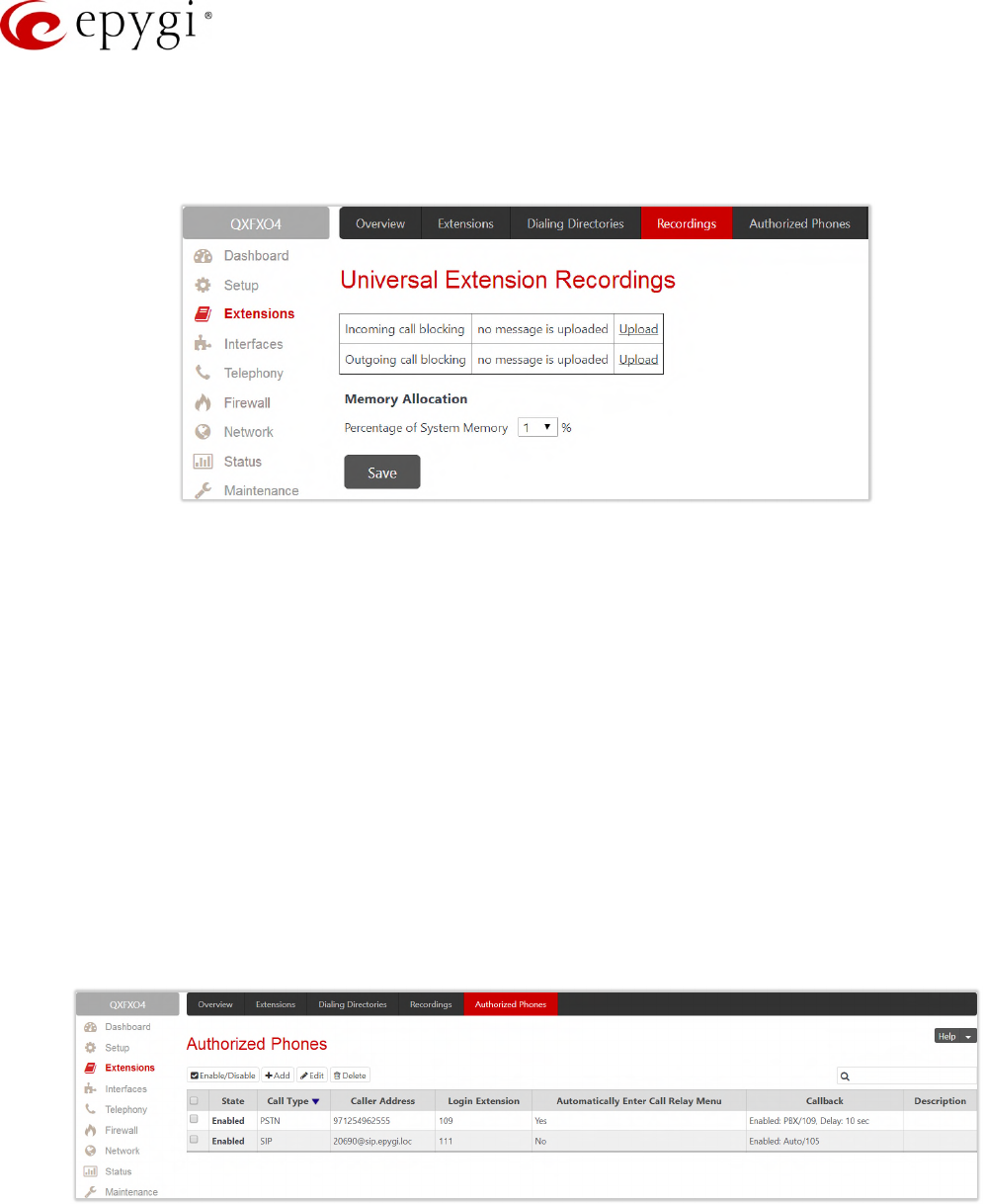
6.4 Recordings
The Universal Extension Recordings (N/A for QXFXS24) is used to define the voice messages universal for all
extensions on QX. The defined messages become applicable by default to all extensions on QX.
Figure 31: Universal Extension Recordings page
•Incoming call blocking – message played when calling to the blocked extension.
•Outgoing call blocking – message played when calling from the blocked extension.
The Universal Extension Recordings page consists of a table where the universal voice messages are listed.
•Upload – is used to upload a custom system message.
•Download and Remove – are used to download and/or remove the uploaded system message.
•Memory Allocation – is used to select a Percentage of System Memory that can be used for universal
extension recordings.
Note: Changing the Percentage of System Memory on this page will stop any recordings of universal extension
voice messages from the handset.
6.5 Authorized Phones
The Authorized Phones (N/A for QXFXS24) is used to create the list of trusted external users allowed to access
the QX Auto Attendant services without authentication.
Figure 32: Authorized Phones
Manual-II: Administration Guide for QX Gateways
Edition 2 (FW Version 6.1.17 and higher) 43
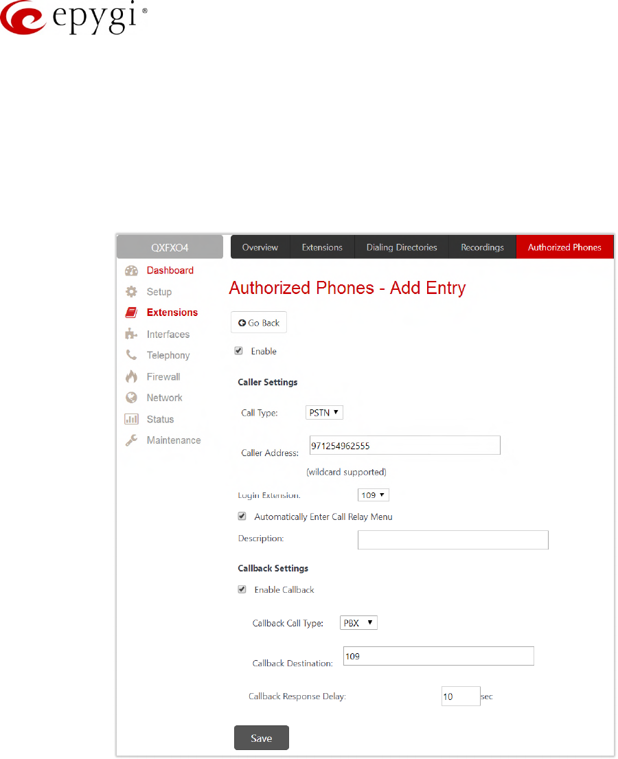
To add a new entry:
1. Click Add. The Authorized Phones – Add Entry page will be opened.
2. Select "Enable" to activate service for the created entry.
3. Enter the caller's SIP address or PSTN number.
4. Select the Login Extension. When calling the QX’s Auto Attendant, a trusted user will automatically be
logged in as the selected extension, i.e., the extension number and password will be automatically
submitted by the system and the trusted user will directly access to the Auto Attendant services. The
SIP settings of the logged in extension will be used for making IP calls.
Figure 33: Authorized Phones – Add Entry page
5. Select the Automatically Enter Call Relay Menu checkbox. If selected allows direct access for the trusted
user to Auto Attendant Call Relay menu. If not selected, a trusted caller will be directed to the Auto
Attendant's main menu, but still will be able to reach Call Relay services without authentication.
6. Configure Callback Settings (optional).
Select Enable Callback checkbox to allow the specified caller to use the Callback service.
Specify the Call Back Destination. TIP: If the Callback Destination is left empty, the trusted caller
address will be implied as a Callback destination.
Define Callback Response Delay (in seconds) before the Callback will be started.

Manual-II: Administration Guide for QX Gateways
Edition 2 (FW Version 6.1.17 and higher) 44
How it works: When the trusted user call the Auto Attendant, he/she will be able to use QX services as if a PBX
extension. If the CallBack service is activated the trusted user will get a call back from Auto Attendant.
Note:
•Authorized Phones will only work when the trusted caller connects to the Auto Attendant running the
Standard scenario configured.
•For more information how to configure and use Callback service, please refer to the Callback Service on
Epygi QXs guide.
Manual-II: Administration Guide for QX Gateways
Edition 2 (FW Version 6.1.17 and higher) 45
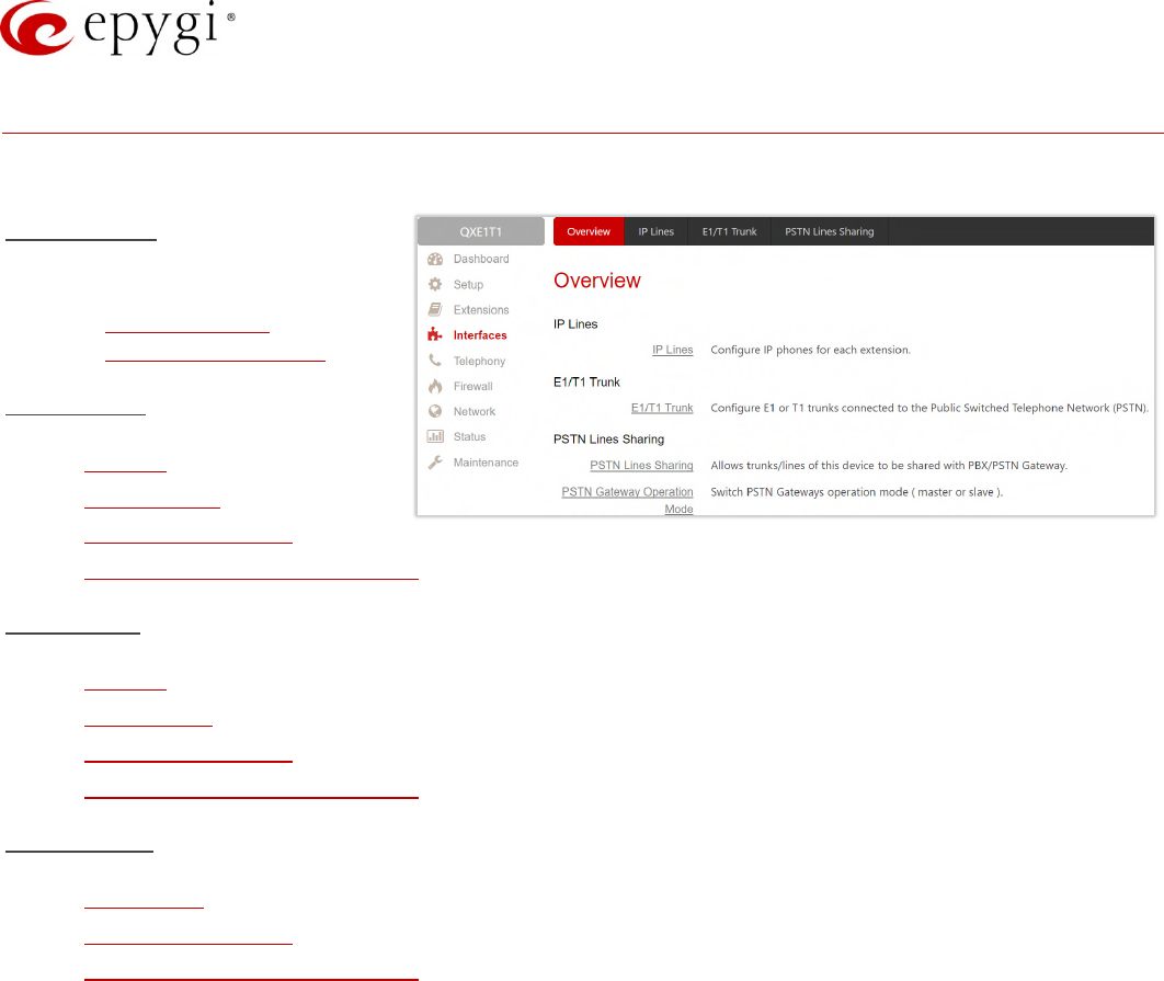
7 Interfaces Menu
The Interfaces menu consists of the following sections:
For QXFXS24
•FXS
FXS (On–board)
Diagnostic Loopback
For QXFXO4
•IP Lines
•FXO Settings
•PSTN Lines Sharing
•PSTN Gateway Operation Mode
For QXE1T1
•IP Lines
•E1/T1 Trunk
•PSTN Lines Sharing
•PSTN Gateway Operation Mode
For QXISDN4
•ISDN Trunk
•PSTN Lines Sharing
•PSTN Gateway Operation Mode
Figure 34: Interfaces Menu overview
Manual-II: Administration Guide for QX Gateways
Edition 2 (FW Version 6.1.17 and higher) 46
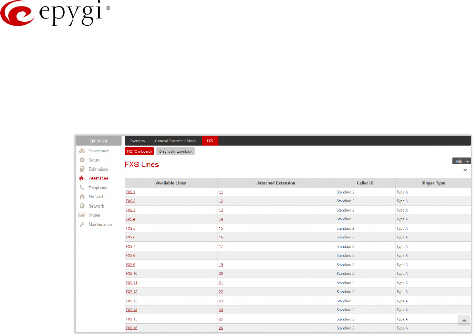
7.1 FXS
7.1.1 FXS (On–board)
The FXS (On-board) Line Settings are used to configure on-board FXS lines, define the caller ID detection type,
configure remote party disconnect indication and select the ringer type on each of them.
Figure 35: FXS Lines page
•Available Lines – displays all FXS lines available on the QXFXS24. Press a hyperlinked FXS line to go to
the Line Settings page (Figure 36) to configure settings of the selected FXS line.
•Attached Extension – displays the extension attached to the corresponding FXS line. Nothing will be
displayed if there is no extension attached to that line. Press the hyperlinked extension number to go to
the Extensions Management – Edit Entry page to configure the extension’s settings.
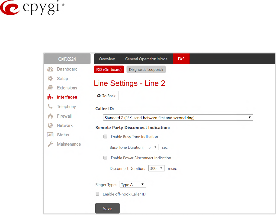
Manual-II: Administration Guide for QX Gateways
Edition 2 (FW Version 6.1.17 and higher) 47
Line Settings – Line #
The Line Settings – Line # page is used to configure specific settings for the selected FXS line.
Figure 36: Line Settings – Line# page
•Caller ID Type – is used to send the calling party's information to the phone attached to the selected
line:
No Caller ID
FSK, send prior to the first ring
FSK, send between the first and second ring
FSK, send both prior to a ring and between the first and second ring
DTMF, send prior to the first ring
DTMF, send between the first and the second ring
Combined, send both DTMF prior to the first ring and FSK between the first and the second rings.
Note: The caller ID detection method is different for various types of phones and can be found in the phone
manual.
•Enable off–hook Caller ID – is used to enable Caller ID transmission to the phone in the off–hook state
attached to a certain line. Service is applicable to the phones supporting the Call Waiting Caller ID
feature.
•Remote Party Disconnect Indication parameters are used to configure the private PBX attached to the
QX FXS port.
•Enable Busy Tone Indication – is used to enable a busy tone transmission to the FXS port when the
remote party being called is disconnected.
Busy Tone Duration – is used to select the period (in seconds) when a busy tone will be transmitted to
the FXS port.
•Enable Power Disconnect Indication – is used to enable the power cycling on the FXS line when the
remote party being called is disconnected. Power Disconnect is applied after the busy tone transmission
on the FXS line.

Manual-II: Administration Guide for QX Gateways
Edition 2 (FW Version 6.1.17 and higher) 48
Disconnect Duration – is used to select the period (in milliseconds) when the FXS line power will be
down.
•Ringer Type – is used to select the frequency of the ringer supported by the phone attached to the line.
Information can be found on the phone enclosure or in the phone's manual. Problems with the ringer
might occur if the ringer type selected here does not correspond to the one supported by the phone.
TIP: The supported ringer type can be found on the bottom of the phone, in the "Ren:x.xN" value where
N is the ringer type supported by the phone. For example, if N=A, the TypeA ringer type should be
selected, if N=B, the TypeB&Z ringer type should be selected.
Information on the Caller ID system
Caller ID service is used to identify the caller (when performing a call or sending a voice mail) and notify the
called party about the identity of the caller. The Caller ID service is available only for phones with a display to
show that information. Two types of Caller ID notification are available on QX: FSK and DTMF.
FSK Standard
The FSK standard supports caller ID indication either with the phone handset on–hook or if the called party is
already busy with another call or operation (handset is off–hook). For internal calls, caller ID notification in FSK
can show up to two lines of identifiable parameters on the called phone’s display. The first line shows the
caller’s extension number. The second line shows the caller’s nickname (if indicated in the configuration). For
external IP calls, caller ID notification in FSK can also show up to two lines of identifiable parameters on the
called phone’s display. The first line shows the caller’s user name. The second line shows the caller’s nickname
(if indicated in configuration). If the nickname is not available and there is a display name, provided by the caller
party, the second line will display it, otherwise the URL in the format: username@host will be displayed. For calls
from the PSTN network, the entire caller ID message will be shown.
DTMF Standard
The DTMF standard supports caller ID indication only if the phone handset is on-hook (phone is free and ready
to accept calls). This standard also has caller ID notification conditions but they are non-configurable. Caller ID
notification in DTMF can show only one line of identifiable parameters on the called phone’s display. For internal
calls, it is the caller’s extension number. For external IP calls, it is the caller’s user name. For calls from the
PSTN network, caller ID will only display the caller’s phone number. TIP: DTMF supports only parameters
consisting of digits. If any letter symbol has been used in the external caller user name, DTMF will not display
caller ID.
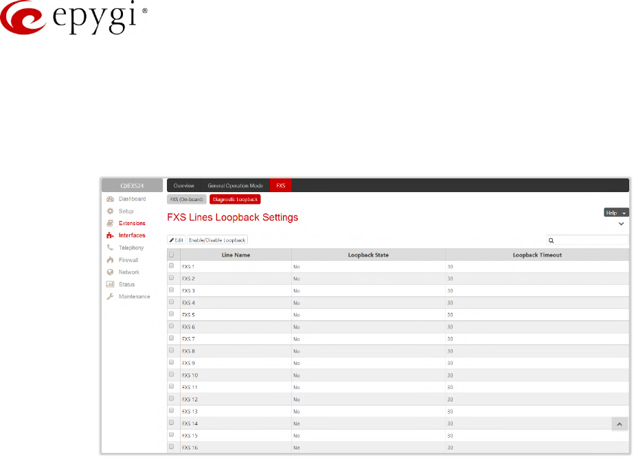
Manual-II: Administration Guide for QX Gateways
Edition 2 (FW Version 6.1.17 and higher) 49
7.1.2 Diagnostic Loopback
The FXS Lines Loopback Settings page is used to configure the lines for voice loopback diagnostics. When
loopback is enabled on the line, any incoming calls to the corresponding line will automatically pick up on the
first ring and any voice towards the line will automatically be sent back to the caller (the caller will hear
themselves in the handset).
Figure 37: FXS Lines Diagnostic Loopback page
•Edit – leads to FXS Lines Loopback Settings – Edit Entry page to configure the Loopback Timeout (in
seconds) for the selected FXS line(s).
Loopback Timeout – is used to put a limit the voice loopback diagnostics duration, i.e. the caller will
be disconnected from the QX when the Loopback Timeout expires.
•Enable/Disable Loopback – is used to enable/disable the loopback service on the selected FXS line(s).
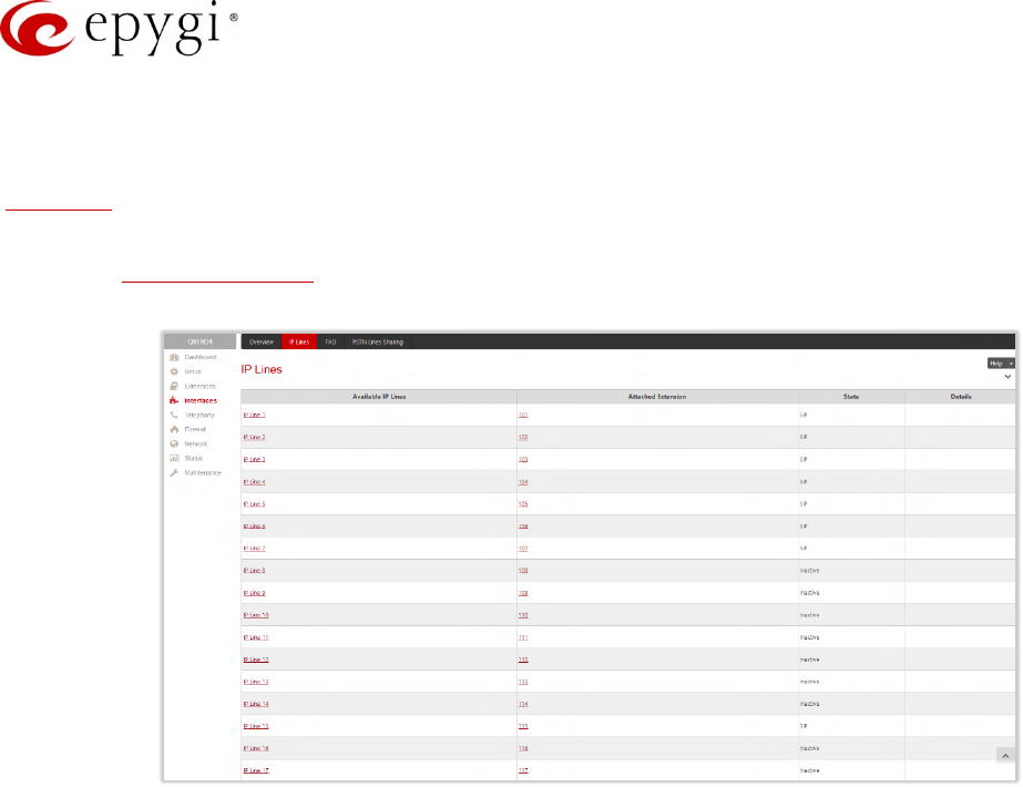
Manual-II: Administration Guide for QX Gateways
Edition 2 (FW Version 6.1.17 and higher) 50
7.2 IP Lines
The IP Lines page is available on the QXFXO4 and QXE1T1 GWs and used to configure the IP lines to connect
IP phones to QX.
Attention: The IP phone support is a licensable feature for QXFXO4 and QXE1T1, so enter an IP phone license
key on the Licensed Features page to enable the IP phones support on the QX. The total number of IP lines
available is 200.
Figure 38: IP Lines page
The IP Lines table lists all IP lines available on QX with specific details for each:
•Available IP Lines – shows all IP lines available on the QX. Click an IP line to go the IP Line Settings page
(Figure 39).
•Attached Extension – shows the QX extension attached to the IP line. TIP: "None" is displayed if there is
no extension attached to that line.
•State – displays whether the IP line is configured with an IP phone (SIP) or not (Inactive).
•Details – displays the settings for the IP phone configured on the corresponding line, such as the
authorization credentials.
•Hide disabled IP lines/Show disabled IP lines – are used to show or hide the IP lines not activated with a
feature key.
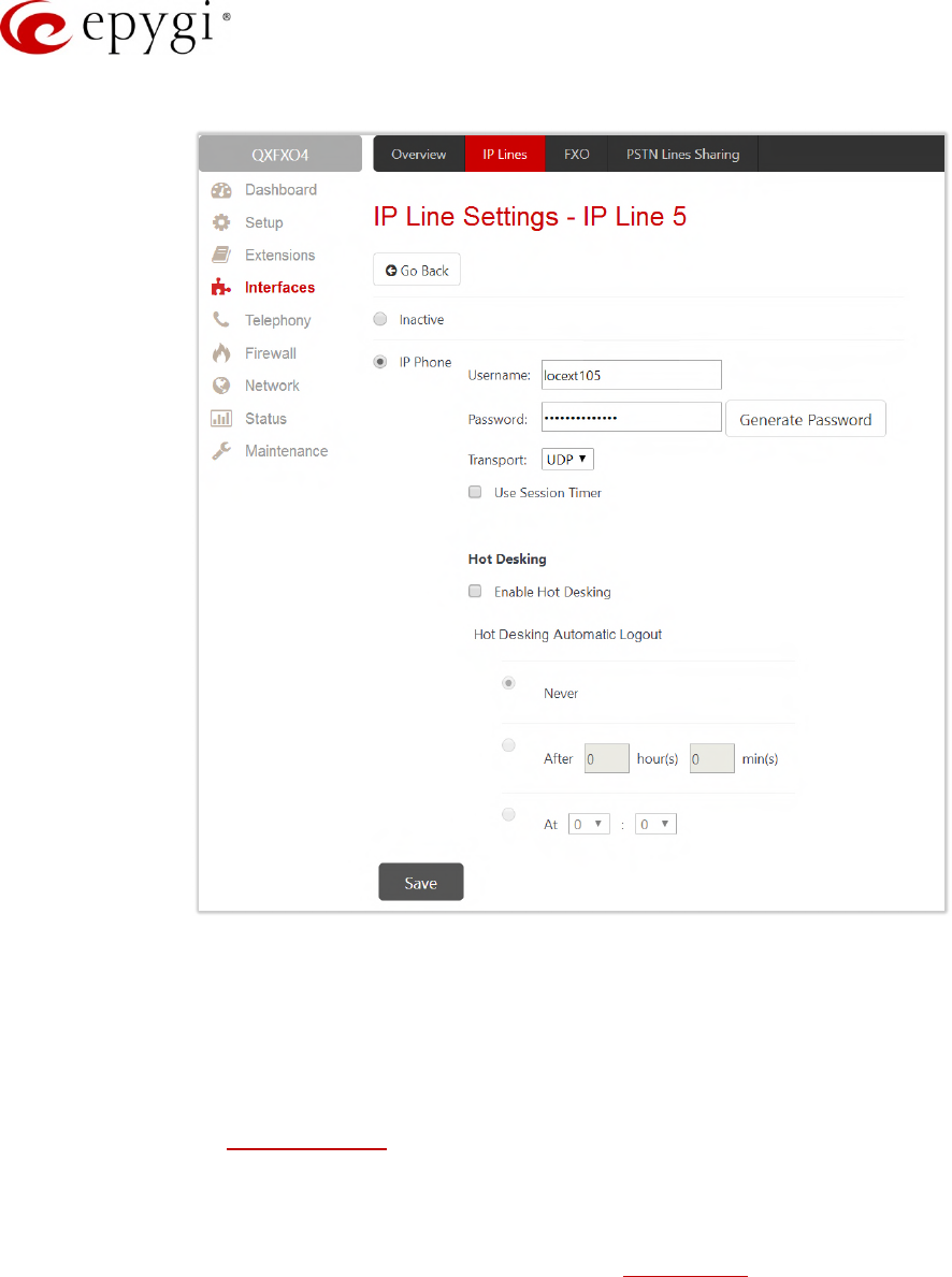
Manual-II: Administration Guide for QX Gateways
Edition 2 (FW Version 6.1.17 and higher) 51
IP Line Settings – IP Line # page is used to configure the IP Line with a phone.
Figure 39: IP Line Settings – IP Line # page
•Inactive – if selected, turns the IP line state to inactive.
•IP Phone – if selected, activates the IP line to configure with the IP phone as follows:
Username and Password – define the authentication parameters to register the IP phone on the QX.
TIP: The same parameters should be manually configured on the phone using the phone GUI.
Transport – select the transport protocol for SIP messages – UDP, TCP or TLS. For TLS, you may
activate the TLS Certificates update mechanism from an IP Phone to obtain the latest certificate
generated by the QX.
Use Session Timer – enable the SIP session timer for the corresponding IP line. This option allows
both user agents and proxies to check and determine if the SIP session is still active.
The Hot Desking section is used to enable and configure the Hot Desking service on the IP Line as follows:
•Enable Hot Desking – enable the Hot Desking on the corresponding IP line.
•Hot Desking Automatic Logout – with this option enabled, QX will control the extension login timeout.
Once the predefined expiration time arrives, the currently logged in extension will automatically log out
and make available the public phone for other extensions. The following options are available:
Never – if selected, the Hot Desking will never expire for the extension.
After – if selected, extension will automatically log out from the public phone after the defined period.
At – if selected, extension will automatically log out from the public phone at the defined moment
(hour and minute).

Manual-II: Administration Guide for QX Gateways
Edition 2 (FW Version 6.1.17 and higher) 52
7.3 The Hosted PBX Survivability feature on QX
QXE1T1 and QXFXO4 gateways support the Hosted PBX Survivability (HS). This feature can be helpful in the
scenario when using a Hosted PBX, but cannot make calls due to loss of the broadband connection. Using
QXE1T1 and QXFXO4 gateways with HS allow IP phones to work, even when the broadband link or Hosted
PBX are down. Users can also use the HS feature to provide access to remote phones in a branch office.
Attention: HS support is available for the firmware version 6.1.17 and higher.
Generally, IP phones register on the Hosted PBX, where they make and receive calls, as a primary SIP proxy
server. Additionally, IP phones register on the QX Gateway as a secondary SIP proxy server. When the
broadband link or Hosted PBX fail, the QX Gateway takes control of the IP phone calls, connecting them to the
PSTN. Transition from the Hosted PBX to the QX via the HS is transparent to users. This list of IP phones
configured and tested to work properly with QXE1T1 and QXFXO4, supporting most of Epygi telephony
features and HS, is provided in the table below.
Vendor Model SW/FW Version
Aastra 6757iCT(57iCT) 3.3.1.2256–SIP
Aastra 9480iCT(35iCT) 3.3.1.2256–SIP
Grandstream GXP1100 1.0.8.6
Grandstream GXP1105 1.0.8.6
Grandstream GXP1160 1.0.8.6
Grandstream GXP1165 1.0.8.6
Grandstream GXP1400 1.0.8.6
Grandstream GXP1405 1.0.8.6
Grandstream GXP1450 1.0.8.6
Grandstream GXP1610 1.0.2.27
Grandstream GXP1620/GXP1625 1.0.2.27
Grandstream GXP2100 1.0.8.6
Grandstream GXP2110 1.0.8.6
Grandstream GXP2120 1.0.8.6
Grandstream GXP2124 1.0.8.6
Grandstream GXP2130 1.0.5.23
Grandstream GXP2140 1.0.5.23
Grandstream GXP2160 1.0.5.23
Grandstream GXP2200 1.0.3.27
Grandstream GXV3140 1.0.7.80
Grandstream GXV3175 1.0.3.76
Grandstream GXV3240 1.0.3.62
Grandstream GXV3275 1.0.3.62
Mitel (Aastra) 6730 3.3.1.4305-SIP
Mitel (Aastra) 6731 3.3.1.4305-SIP
Mitel (Aastra) 6735 3.3.1.8140-SIP
Mitel (Aastra) 6737 3.3.1.8140-SIP
Mitel (Aastra) 6739 3.3.1.4305-SIP
Mitel (Aastra) 6753 3.3.1.4305-SIP
Mitel (Aastra) 6755 3.3.1.4305-SIP
Mitel (Aastra) 6757 3.3.1.4305-SIP
Mitel (Aastra) 6863 4.0.0.92-SIP
Mitel 6865 4.0.0.92-SIP
Mitel 6867 4.0.0.92-SIP

Manual-II: Administration Guide for QX Gateways
Edition 2 (FW Version 6.1.17 and higher) 53
Vendor Model SW/FW Version
Mitel 9143 3.3.1.4305-SIP
Mitel 9480 3.3.1.4305-SIP
Polycom SoundPoint IP 330SIP 3.3.5.0247
Polycom SoundPoint IP 331SIP 3.3.5.0247
Polycom SoundPoint IP 335SIP 3.3.5.0247
Polycom SoundPoint IP 450SIP 3.3.5.0247
Polycom SoundPoint IP 550SIP 3.3.5.0247
Polycom SoundPoint IP 650SIP 3.3.5.0247
Polycom SoundPoint IP 670SIP 3.3.5.0247
Polycom SoundStation IP 5000 3.3.5.0247
Polycom SoundStation IP 6000 3.3.5.0247
Polycom VVX 1500 3.3.5.0247
Polycom VVX 300/310 4.1.7.1210
Polycom VVX 400/410 4.1.7.1210
Polycom VVX 500 4.1.7.1210
Polycom VVX 600 4.1.7.1210
Yealink CP860 37.80.0.10
Yealink SIP-T19P 31.72.0.1
Yealink SIP-T19P E2 53.80.0.130
Yealink SIP-T20P 9.72.0.1
Yealink SIP-T21P 34.72.0.1
Yealink SIP-T21P E2 52.80.0.130
Yealink SIP-T22P 7.72.0.1
Yealink SIP-T23G(P) 44.80.0.130
Yealink SIP-T26P 6.72.0.1
Yealink SIP-T27G 69.81.0.25
Yealink SIP-T27P 45.80.0.130
Yealink SIP-T28P 2.72.0.1
Yealink SIP-T29G 46.80.0.130
Yealink SIP-T32G 32.70.0.130
Yealink SIP-T38G 38.70.0.125
Yealink SIP-T40P 54.80.0.130
Yealink SIP-T41P 36.80.0.130
Yealink SIP-T41S 66.81.0.25
Yealink SIP-T42G 29.80.0.130
Yealink SIP-T42S 66.81.0.25
Yealink SIP-T46G 28.80.0.130
Yealink SIP-T46S 66.81.0.25
Yealink SIP-T48G 35.80.0.130
Yealink SIP-T48S 66.81.0.25
Yealink SIP VP-T49G 51.80.0.100
Yealink VP-530 23.70.0.40
Yealink W52P 25.30.0.20
Table 1: Tested IP Phones
The feature codes supported on the IP phones configured with QX E1T1 and QXFXO4 Gateways are described
in the appendix.
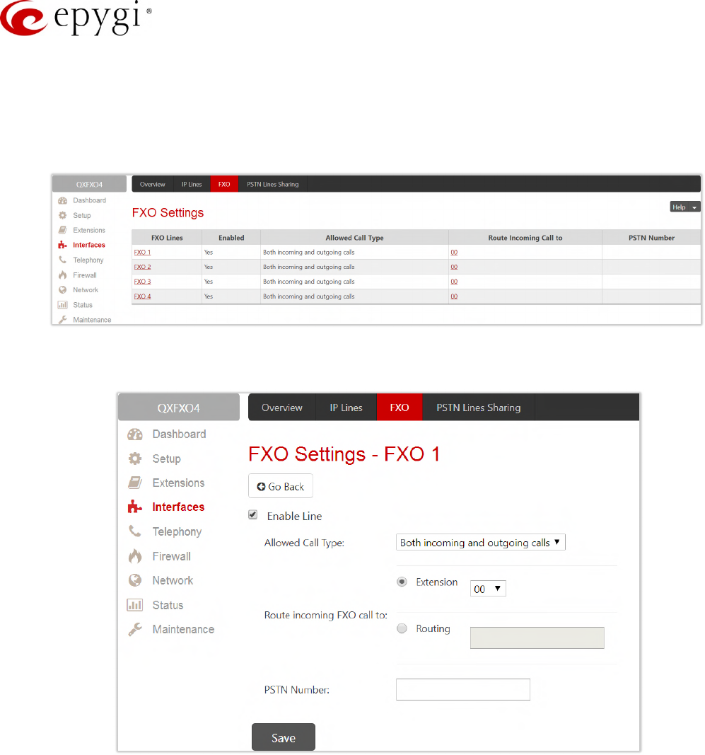
Manual-II: Administration Guide for QX Gateways
Edition 2 (FW Version 6.1.17 and higher) 54
7.4 FXO Settings
The FXO Settings is used to configure the QX's on-board FXO Lines to make PSTN calls through the on-board
FXO ports.
Note: FXO ports are available on QXFXO4 (4 ports).
Figure 40: FXO Settings page
Click a hyperlinked FXO line to go to the FXO Settings – FXO# page to modify the settings of the selected line.
Figure 41: FXO Settings – FXO# page
•Enable Line – activate the selected FXO line.
•Allowed Call Type – select the allowed call directions for the FXO line. The following options are
available:
Both incoming and outgoing calls will be enabled for the selected FXO line.
Incoming calls only (prohibiting outgoing calls) will be enabled for the selected FXO line.
Outgoing calls only (prohibiting incoming calls) will be enabled for the selected FXO line.
•Route incoming FXO Call to – define the destination where the incoming calls will be forwarded to.
Extension – is used to forward the calls to either PBX user or auto attendant extension.
Routing – is used to forward the calls to the destination defined through the Call Routing Table. Insert
the routing pattern that will be used for forwarding purposes.
•Insert a PSTN Number for the current FXO line if needed for information.
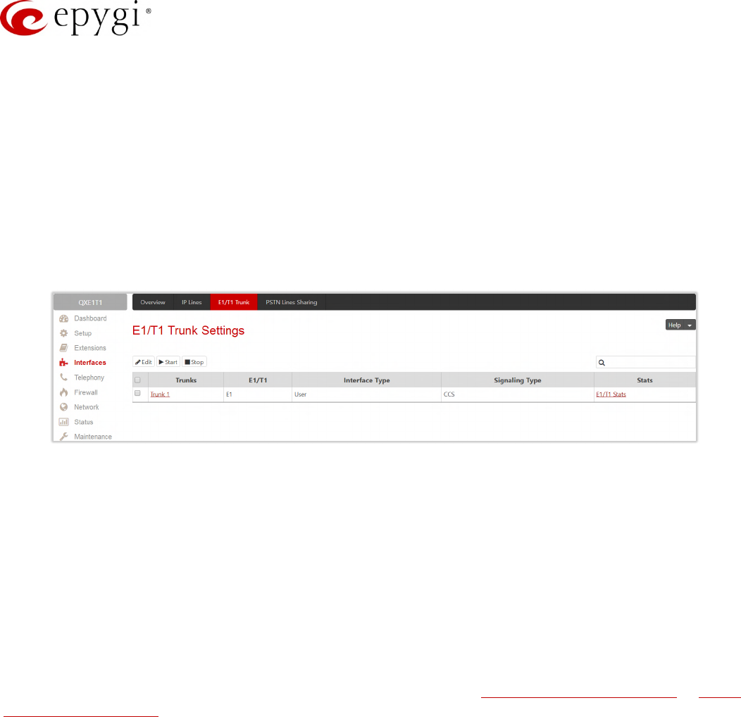
Manual-II: Administration Guide for QX Gateways
Edition 2 (FW Version 6.1.17 and higher) 55
Note: The same settings and options are available for shared FXO lines.
7.5 E1/T1 Trunk Settings
The E1/T1 Trunk Settings allows QXE1T1 to be connected to a PBX or to a CO (Central Office) via E1/T1
trunks, using E1/T1 CAS/CCS signaling. QXE1T1 may act as a user or as network. If connected to a private
PBX, the QXE1T1 should be configured in the network mode. If an E1/T1 trunk from the CO is connected to
the QXE1T1, it should be configured as a user. The QXE1T1 has one E1/T1 trunk available.
The E1/T1Trunk Settings are used to configure the E1/T1 trunks allowing to make PSTN calls through E1/T1
trunks.
Figure 42: E1/T1 Trunk Settings page
The Trunk Settings table lists the available E1/T1 trunks on the QX and their settings (Trunk name, E1/T1 mode,
interface, signaling types).
E1/T1 Trunk Settings page includes the following buttons:
•Start and Stop are used to start/shutdown the selected E1/T1 trunk(s). When E1/T1 trunk is in a
shutdown state, no E1/T1 calls could be placed and received.
•E1/T1 Stats – appears for every active trunk on the board and leads to the page where E1/T1 trunk and
traffic statistics can be viewed.
•Edit leads to Trunk – 1@ – Edit Entry page where the trunk type (E1 or T1) and signaling (CAS or CCS)
can be selected.
Note: According to the selected signaling type, you will either go to the Trunk CAS Signaling Settings or Trunk
CCS Signaling Settings page by pressing the hyperlinked trunk.
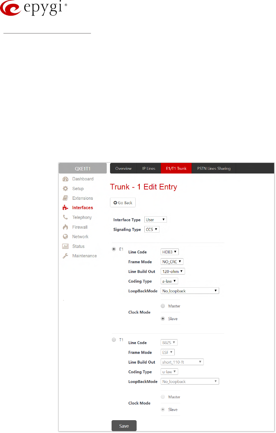
Manual-II: Administration Guide for QX Gateways
Edition 2 (FW Version 6.1.17 and higher) 56
Trunk–1@–Edit Entry page
The Trunk – 1@ – Edit Entry page consists of the following components:
•Interface Type – is used to select the interface configuration (User or Network).
•Signaling Type – is used to select the signaling type for the trunk. The CAS (Channel Associated
Signaling) and CCS (Common Channel Signaling) signaling types are available.
Up to 30 timeslots will be available for placing E1 calls regardless the trunk signaling type. The
timeslot TS0 is reserved for framing and the timeslot TS16 for signaling purposes.
Up to 23 timeslots will be available for placing T1 calls if the trunk signaling type is CCS. The timeslot
TS24 is reserved for signaling purposes.
Up to 24 timeslots will be available for placing T1 calls if the trunk signaling type is CAS. Each timeslot
is used both for voice and signaling purposes.
•The E1 and T1 radio buttons are used to select the mode for the trunks. Both selections allow to
configure the Line Code, Frame mode, Line Build Out, Coding Type, LoopBackMode and Clock Mode
settings to match the E1/T1 settings for ITSP’s.
Figure 43: E1/T1 Settings – Edit Entry page
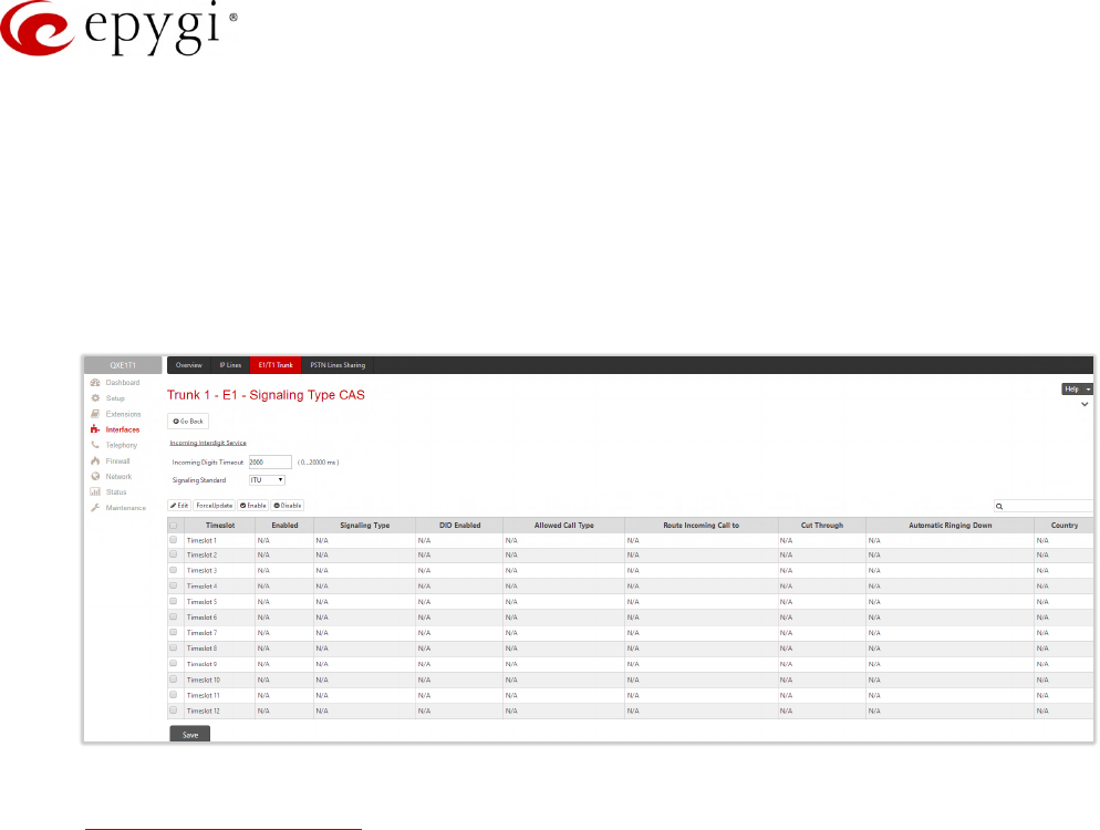
Manual-II: Administration Guide for QX Gateways
Edition 2 (FW Version 6.1.17 and higher) 57
Attention: The E1/T1 trunk settings sometimes can lead to invalid routes in the Call Routing Table. Check and
reconfigure the E1/T1 trunk settings and the routing rules accordingly.
Click Trunk 1@ link to open the Trunk 1@ – Signaling Type page. Different settings and options are available for
configuration depending on the selected signaling type (CAS or CCS).
7.5.2 Signaling Type – CAS
The following settings are available when the signaling type for the trunk is selected as CAS:
Figure 44: Trunk 1 CAS Signaling Settings page
•Incoming Interdigit Service – leads to the page to configure the dial plan for incoming E1/T1 calls from
CO/PBX to the QX can be configured.
•Incoming Digits Timeout – is used to define the timeout during which incoming digits from the
destination party will be collected before being applied as an incoming called number.
•Signaling Standard – is used to select the signaling standard for connection (N/A for T1 interface).
The Trunk CAS Signaling Settings page lists the available timeslots of the trunk with CAS signaling and their
settings.
•Force Update – is used to apply immediately the new settings on the selected timeslot(s). This will force
the timeslot(s) to be restarted and any active connection on the selected timeslot(s) will be interrupted.
•Edit – leads to the CAS Signaling Wizard where the key configuration parameters specific to the selected
timeslot(s) can be configured
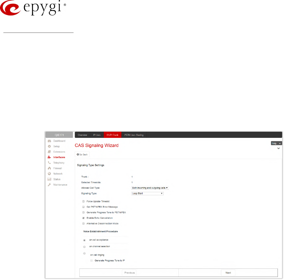
Manual-II: Administration Guide for QX Gateways
Edition 2 (FW Version 6.1.17 and higher) 58
CAS Signaling Wizard
The CAS Signaling Wizard consists of the following sections:
•Signaling Type Settings – to configure the signaling type settings:
Allowed Call Type – to select the call directions: incoming, outgoing or both.
Signaling Type – to select the CAS signaling type. R2 signaling (compelled and non-compelled) can be
used with an E1 interface both in User and Network modes. QX with E1 interface in the CAS mode
detects the busy tone only in case of R2 compelled and non-compelled (both with and without ANI)
signaling types. QX does not support the Forward Digit selected on the CO when acting in the User
mode with CAS Loop Start signaling type.
Force Update Timeslot – is used to apply new settings immediately. This will force the timeslot(s) to be
restarted and any active connection on the selected timeslot(s) will be interrupted.
Figure 45: Signaling Type Settings section
Get PSTN/PBX Error Message – if selected, a notification message will be played when the outgoing
call is not established (destination unreachable, incorrect or non-existent number), otherwise the call
will be disconnected.
Generate Progress Tone to PSTN/PBX – if selected, QX generates ring tones to incoming callers
during E1/T1 call dialing. This feature is mainly applicable to 2-stage dialing mode.
Enable Echo Cancellation – enables the echo cancellation mechanism on the selected timeslot(s).
Alternative Disconnection Mode – if selected, the QX will play a busy tone towards the PBX/CO when
the call is failed. After 60 second timeout, the QX will stop playing the busy tone and the call will be
disconnected.
Voice Establishment Procedure – is used to select a method of voice establishment on the trunk:
On call acceptance – the voice will be established after call is being accepted.
On channel selection – the call will be accepted during channel selection. This selection is not
allowed for R2 signaling.
On call ringing – the voice will be established after call is being ringing. The Generate Progress Tone
checkbox which is used to enable the progress tone generation upon voice establishment.
•DID Service Settings – this section becomes available only if the Signaling Type is set to any of the E&M
types or to R2 DTMF in Signaling Type Settings section.
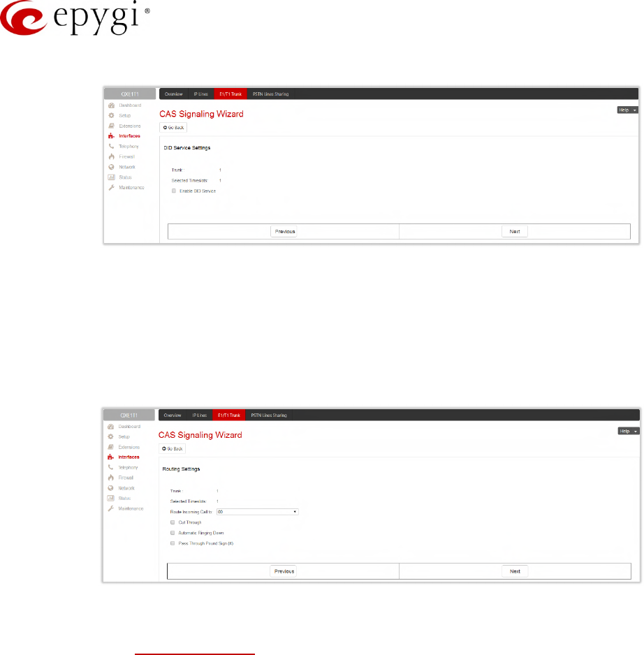
Manual-II: Administration Guide for QX Gateways
Edition 2 (FW Version 6.1.17 and higher) 59
Enable DID Service – is used to enable DID (Direct Inward Dialing) service for the selected timeslot(s).
Figure 46: DID Service Settings section
•Routing Settings – is used to set the destination for incoming calls to be routed to and to enable Cut
Through and Automat Ringing Down services for signaling different from R2 (all types).
Route Incoming Call to – is used to define the destination where the incoming calls will be forwarded
to.
The call can be forwarded to user or auto attendant extension. The call will be forwarded to Voice
Mailbox if the selected extension is inactive (not attached to a line).
Figure 47: Routing Settings section
Routing with inbound destination number – is used to forward the calls to the destination defined
through Call Routing Table. It will automatically use the initially dialed number to connect the
destination without any additional dialing.
Cut Through – is available when the Enable DID Service checkbox not selected from the previous
section. The Cut Through option is used to reconnect the call (terminated by some reason, e.g. user
error, network problems, etc.) by going on-hook and off-hook again even if the call partner is off-hook
and not involved in the call.
Automat Ringing Down – is available when the Enable DID Service checkbox not selected from the
previous section. The Automatic Ringing Down option allows an E1/T1 device connected to the QX to
establish a hot-line call (automatic call without any digits dialed).
Pass Through Pound Sign # – is not available when selected Signaling Type on the Signaling Type
Settings section is R2 Compelled, R2 Non-Compelled, R2 Compelled with ANI or R2 Non-Compelled
with ANI. When this checkbox is selected, the pound sign detected in the dialed number will be
passed through and will be considered as a part of the dialed number. When this checkbox is not
selected, the detected pound sign will be considered as a call acceleration digit.
•Country Settings – this section becomes available only for E1 interface and the Signaling Type is set to
any of the R2 types in Signaling Type Settings section.
Country – is used to set the location where QX is located to support the correct functionality of R2
signaling. For the locations missing in the list, use the ITU option.
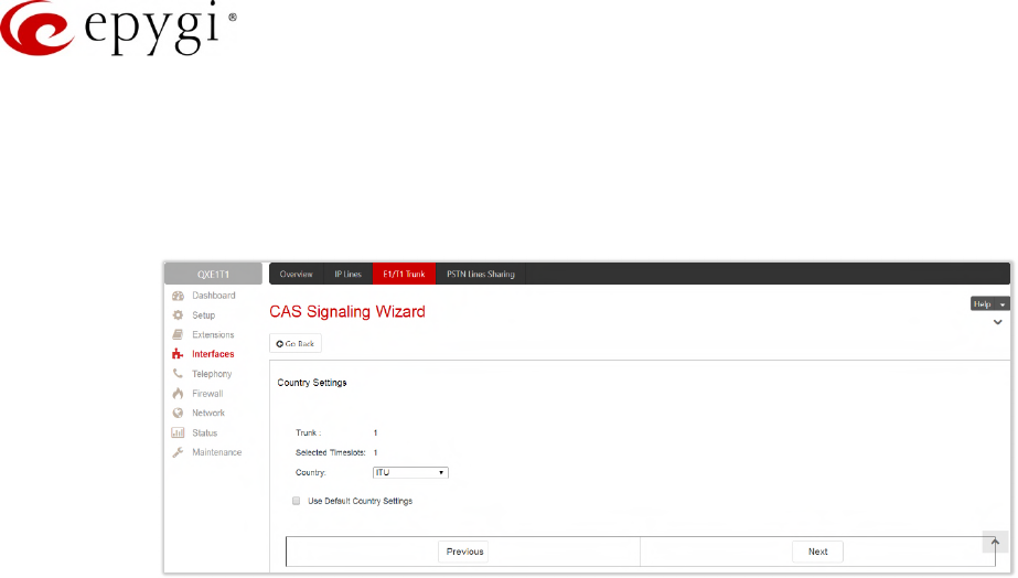
Manual-II: Administration Guide for QX Gateways
Edition 2 (FW Version 6.1.17 and higher) 60
Use Default Country Settings – is used to restore default advanced settings for the selected location.
You can manually configure Advanced Country Settings in the next section if the checkbox is not
selected.
•Advanced Country Settings – this section becomes available only if the Use Default Country Settings
checkbox is not selected in Country Settings section.
Figure 48:Country Settings section
ANI Category – is used to select the calling party priority depending on the call originator’s location
specifics (N/A for R2 DTMF Signaling Type).
ANI Request Transmit and ANI Request Receive – is used to select the Caller ID request R2 tones for
transmit and receive.
Seize Acknowledge Timeout – is used to define a timeout (in a range from 2 to 2000 milliseconds)
between incoming seize signal and the corresponding feedback.
Answer Guard Timeout – is used to define a wait timeout (in a range from 0 to 1000 milliseconds)
Group-B Answer Signal and Line Answer.
Release Guard Timeout – is used to define an idle timeout (in a range from 0 to 120000 milliseconds)
between the disconnect signal receipt and call disconnection.
Dialing Delay Timeout – is used to define a timeout (in a range from 0 to 2000 milliseconds) before
injecting dialed digits. Timeout specially refers to R2 DTMF signaling.
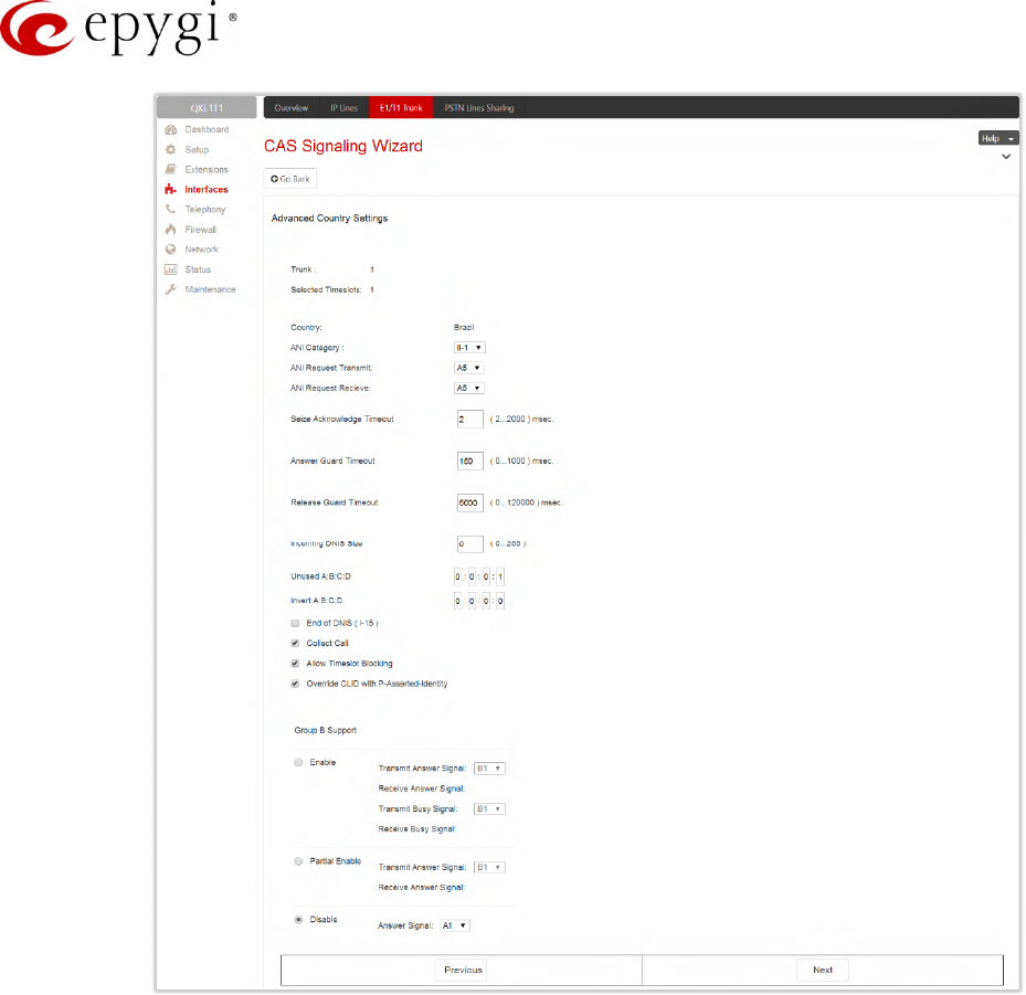
Manual-II: Administration Guide for QX Gateways
Edition 2 (FW Version 6.1.17 and higher) 61
Figure 49:Advanced Country Settings section
Incoming DNIS Size – indicates the number of received digits (in a range from 0 to 255) required to
establish a call. When field has 0 value, system uses either timeout defined in the Incoming digits
timeout field or the End of Address messages to establish a call. Independent on the value in this field,
the message End of Address always causes the call establishment.
Unused A:B:C:D – is used to configure unused C and D bits of E1/T1 CAS signaling (A and B bits are
predefined). Fields may have either 0 or 1 values.
Invert A:B:C:D – is used to invert the ABCD status bits in time-slot 16 before TX and after RX. If bit is
set to 1, the router inverts it before transmission and after the receipt.
End of DNIS (I-15) checkbox is used to enable End of DNIS service.
Collect Call – if selected, then in case of incoming calls, always the called destination will pay for the
call (applicable only for Brazil country). Option is particularly applicable when calling from the mobile
phone. Checkbox should be selected when the appropriate feature is enabled on the legacy PBX.
Allow Timeslot Blocking – indicates whether the system should use blocked timeslots to make
outgoing PSTN calls. If this checkbox is selected, the system will NOT use timeslots blocked by the
carrier, otherwise the system will try to unblock the timeslots and will make outgoing calls if
succeeded.
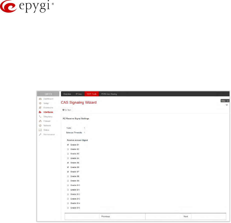
Manual-II: Administration Guide for QX Gateways
Edition 2 (FW Version 6.1.17 and higher) 62
Group B Support – enables/disables the Group B Support. This section becomes available only for E1
interface and the Signaling Type is set to any of the R2 types (except R2 DTMF) in Signaling Type
Settings section. The Group B Support manipulation radio button group offers following selections:
Enable – this selection enables Group B Support both for answer and busy recognitions of transmit
and receive signals. This selection requires you to define transmit and receive signals. The Transmit
Answer Signal and Transmit Busy Signal parameters are defined from the drop-down lists on this
page. When the "transmit" signals are selected, press Next on this section to access the R2 Receive
Signal Settings section where Receive Answer Signal and Receive Busy Signal should be defined
(Figure 49). Use the checkboxes to select the Receive Answer Signal and Receive Busy Signal
values. Multiple values are allowed for each signal.
Figure 50: R2 Receive Signal Settings section
Partial Enable – selection partially enables Group B Support with for answer recognition only. This
selection requires you to define transmit and receive signals. The Transmit Answer Signal parameter
is defined from the drop-down list on this page. When the "transmit" signal is selected, press Next
on this section to access the R2 Receive Signal Settings section where Receive Answer Signal
should be defined. Use the checkboxes to select the Receive Answer Signal value. Multiple values
are allowed for each signal.
Disable – selection disables Group B Support and requires defining the Answer Signal parameter.
•Summary results of CAS Settings – this section displays all configured settings for the CAS signaling
(Figure 51).
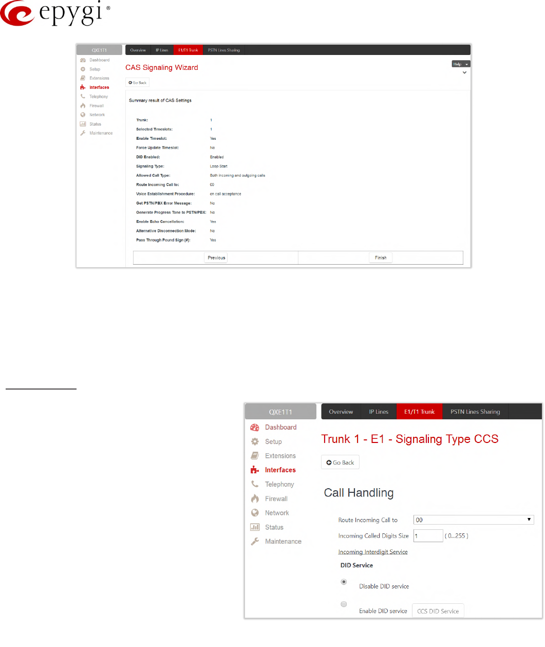
Manual-II: Administration Guide for QX Gateways
Edition 2 (FW Version 6.1.17 and higher) 63
Figure 51: Summery results of CAS Settings section
7.5.3 Signaling Type – CCS
The Trunk CCS Signaling Settings page allows configuring CCS signaling settings and gives a possibility to
select timeslots for signaling data transfer/receive and voice transfer. The page consists of the following
components:
Call Handling
•Route Incoming Call to – is used to
define the destination where the
incoming calls will be forwarded to. The
following options are available:
The calls can be forwarded to either
user extension or auto attendant. The
calls will be forwarded to Voice
Mailbox if an inactive extension is
chosen.
Routing with inbound destination
number – is used to forward the calls
to the destination defined through
Call Routing Table. It will automatically
use the initially dialed number to
connect the destination without any
additional dialing.
•Incoming Called Digits Size – indicates
the number of received digits (in a
range from 0 to 255) required to establish a call. When field has 0 value, system uses either timeout
defined in the T302 field or the Sending Complete Information element messages to establish a call.
Independent on the value in this field, Sending Complete Information element and pound sign always
cause the call establishment.
Figure 52: Trunk 1 CCS Signaling Settings – Call Handling
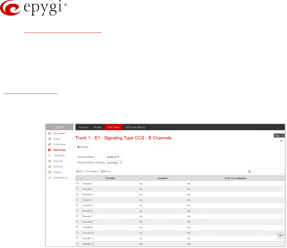
Manual-II: Administration Guide for QX Gateways
Edition 2 (FW Version 6.1.17 and higher) 64
•Incoming Interdigit Service – link leads to the page where the dial plan for incoming E1/T1 calls from
CO/PBX to the QX can be configured.
•DID Service – is available for User interface only:
Disable DID Service – disables the DID service.
Enable DID Service – enables the DID service.
CCS DID Service – leads to the CCS DID Service page to configure the CCS DID number(s).
ISDN L3 Settings
•B Channel link leads to the Signaling Type CCS – B Channel Settings page where available timeslots
may be enabled/disabled for the voice transfer and echo cancellation feature may be configured.
Figure 53: Signaling Type CCS – B Channels page
The Signaling Type CCS – B Channels page lists the available timeslots of the trunk and their settings.
•Channel Selection – is used to select between the Preferred and Exclusive B channel selection methods.
For Preferred channel selection, the CO answers to the call request by the first available timeslot, while
for Exclusive channel selection CO should feedback only by the timeslot used for the call request.
•Channel Selection Ordering – is used to choose the B channels selection order.
•Force Update – is used to apply immediately the new settings on the selected timeslot(s). This will force
the selected timeslot(s) to be restarted and any active connection on the selected timeslot(s) will be
interrupted.
•Restart – is used to bring timeslot(s) to the initial idle state on the both sides.
•Edit – leads to the Signaling Type CCS – B Channels – Edit Entry page where the key parameters
specific to the selected timeslot(s) can be configured. The following options are available:
Enable Timeslot – enables/disables the selected timeslot(s).
Force Update Timeslot – applies new settings immediately by restarting the timeslot(s).
Enable Echo Cancellation – enables/disables the echo cancellation on the selected timeslot(s).
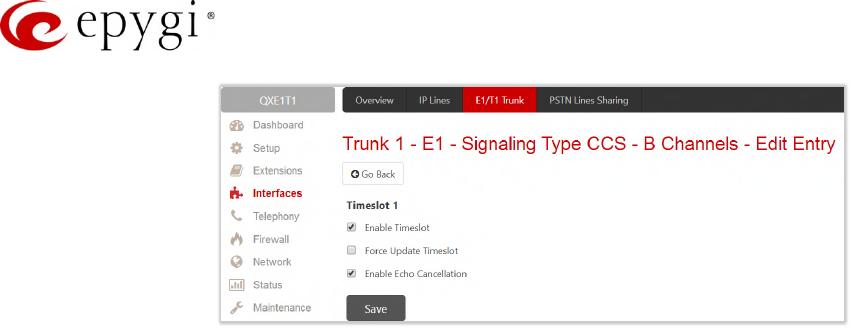
Manual-II: Administration Guide for QX Gateways
Edition 2 (FW Version 6.1.17 and higher) 65
Figure 54: Signaling Type CCS – B Channels – Edit Entry page
Note: A timeslot can be used either for voice or data transfer. Timeslot selected for the D Channel
receive/transmit is missing in the list of B channels.
•Switch Type – this configuration parameter depends on the Service Provider when acting in the User
mode and the legacy PBX capabilities when acting in the Network mode.
•Bearer Establishment Procedure – allows to select the session initiation method on the B channels. One
of the following possibilities of the transmission path completion prior to receipt of a call acceptance
indication can be selected:
on channel negotiation at the destination interface.
on progress indication with in-band information.
on call acceptance.
•Generate Progress Tone to PSTN/PBX – contains the options for sending progress (ring-back) tone to
callers from the PSTN/PBX. The following options are available in the list:
None – configures the system to send ALERT messages without the Progress Indicator Information
Element (IE).
Unconditional – configures the system to send ALERT/PROGRESS messages with the Progress
Indicator IE. With this option, the system will send its own progress tone.
Conditional – configures the system to send ALERT/PROGRESS messages with Progress Indicator IE.
With this option, the system will send its own progress tone only if there is no early media (180/183
with SDP) from the called party.
•T302 Timer – insert the value for the T302 timer in milliseconds (digit values from 0 to 15000). The time
frame system will wait for digit to be dialed and when timer expires, it initiates the call. Timer is not
applicable for DMS-100 switch types.
•T309 Timer – insert the value for the T309 timer in milliseconds (digit values from 0 to 90000). This
option is responsible for call steadiness during link disconnection within the period equal to this timer
value. If the value in this field is 0, T309 timer will be disabled.
•T310 Timer – insert the value for the T310 timer in milliseconds (digit values from 1000 to 120000). This
option is responsible for the outgoing call steadiness when CALL PROCEEDING is already received from
the destination but call confirmation (ALERT, CONNECT, DISC or PROGRESS) is not yet arrived.
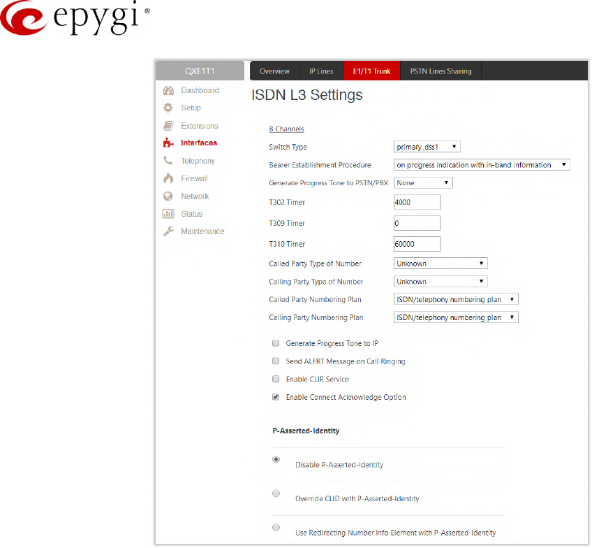
Manual-II: Administration Guide for QX Gateways
Edition 2 (FW Version 6.1.17 and higher) 66
Figure 55: Signaling Type CCS – ISDN L3 Settings part
•No Answer Disconnect Timer – insert the value for the No Answer Disconnect Timer (digit values from 0
to 200000) which is used in certain types of legacy PBXs. The value 0 indicates that the timer is
disabled. When time expires, QX will play a busy tone towards the legacy PBX if the call has been
disconnected by the peer. This option is available only in Network mode.
•Calling Party Type of Number – allows to select the type identifying the origin of call.
•Called Party Type of Number – allows to select the type identifying the sub address of the called party.
•Called Party Numbering Plan and Calling Party Numbering Plan – indicate correspondingly the
numbering plan of the called party and calling party.
•Generate Progress tone on IP – if selected, the progress tone to IP (SIP) will be generated.
•Send ALERT Message on Call Ringing – if selected, the system will send ALERT messages to callers
from the PSTN/PBX on call ringing, otherwise the system will send a PROGRESS message on receiving
early media from the called party if the Unconditional or Conditional options are selected for Generate
Progress Tone to PSTN/PBX.
•Enable CLIR Service – if selected, Calling Line Identification Restriction (CLIR) service will be activated
and this will display the incoming caller ID only in case if Presentation Indication is allowed on the
remote side, otherwise, if CLIR service is disabled, caller ID will be unconditionally displayed.
•Enable Connect Acknowledge Option – if selected, QX will stop the T303 and T310 timers upon
receiving the CONNECT message, will send a CONNECT ACKNOWLEDGE message to the remote side
and enter the active state, otherwise QX will stop the T303 and T310 timers upon receiving the
CONNECT message and will enter the active state without sending the CONNECT ACKNOWLEDGE
message to the remote side.

Manual-II: Administration Guide for QX Gateways
Edition 2 (FW Version 6.1.17 and higher) 67
•P-Asserted-Identity – is used to configure P-Asserted-Identity for the calls from SIP to E1/T1 and vice-
versa.
Disable P-Asserted-Identity – disables the P-Asserted-Identity for both incoming and outgoing calls.
Override CLID with P-Asserted-Identity – enables the SIP P-Asserted-Identity support. For the calls
from SIP to E1/T1 if the Invite SIP message contains a P-Asserted-Identity or a P-Preferred-Identity or
a Remote-Party-ID, then the CallerID on E1/T1 is sent with the original Caller ID which comes from the
identity field. SIP user agent should check for the existence of the P-Asserted-Identity, then the P-
Preferred-Identity, then the Remote-Party-ID to fill the identity field. For the calls from E1/T1 to SIP
with restricted Caller ID, the SIP Invite message contains P-Asserted-Identity field with the value from
the Caller ID on E1/T1. The "SIP From" field contains anonymous.
Use Redirecting Number Info Element with P-Asserted-Identity radio button selection enables full
support of the SIP P-Asserted-Identity. For the calls from SIP to E1/T1, if the SIP Invite message
contains a P-Asserted-Identity or a P-Preferred-Identity or a Remote-Party-ID, then the CallerID on
E1/T1 contains the number from the user name field and the Redirecting Number IE contains the
original number from the identity field. SIP user agent should check for the existence of the P-
Asserted-Identity, then the P-Preferred-Identity, then the Remote-Party-ID to fill the identity field. For
the calls from E1/T1 to SIP with Caller ID, the SIP Invite message contains P-Asserted-Identity field
with the original number value from the Redirecting Number IE on E1/T1. The "SIP From" field
contains the value from the user name.
ISDN L2 Settings
•Non Automat – if selected, the non-automatic Terminal Endpoint Identifier (TEI) searching will be
activated.
TEI Address – insert a TEI number (digit values from 0 to 63) for connection establishment between
CO and E1/T1 client. In automatic mode, an E1/T1 connection will be established on the first available
TEI, while in non-automatic mode a specific TEI may be reserved for the connection. In this case, both
call partners need to specify the same TEI in their settings.
SAPI Value – insert an additional Service Access Point Identifier (SAPI) value (digit values from 1 to 62)
that is used to support additional interface between ISDN Layer 2 and Layer 3. Leaving this field
empty (default value), only Call Control and Layer 2 management procedures will be activated.
•Alternative Disconnection Mode – if not selected, QX will disconnect the call as soon as disconnect
message has been received from the peer, otherwise, QX's user may hear a busy tone when peer has
been disconnected.
•Excessive Ack. Delay T200 – is used to configure the period in milliseconds (digit values from 500 to
9999) between the transmitted signaling packet and its acknowledgement received.
•Idle Timer T203 – is used to configure the period in milliseconds (digit values from 1000 to 99999) for
E1/T1 client idle timeout.
•D Channel Timeslot For Transmit/Receive – is used to select the timeslot for signaling data
transmit/receive.
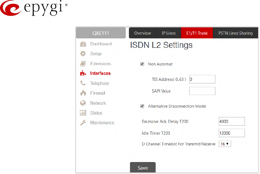
Manual-II: Administration Guide for QX Gateways
Edition 2 (FW Version 6.1.17 and higher) 68
Figure 56: Signaling Type CCS – ISDN L2 Settings part
Note:
In the Network Mode (PBX connected):
•If Non Automat mode is selected, the same TEI address should be specified on both sides (QX and
legacy PBX).
•If Automat mode is selected, the user on PBX side will have the opportunity to set any mode related to
TEI assignment in PBX configuration. This will allow PBX connection to the QX without providing the TEI
address from QX.
In the User Mode (CO connected) the TEI assignment is dependent on CO settings:
•Select Non Automat mode and insert the same TEI address provided by CO.
•Select any mode related to TEI assignment if automat TEI searching mode is selected on CO side.
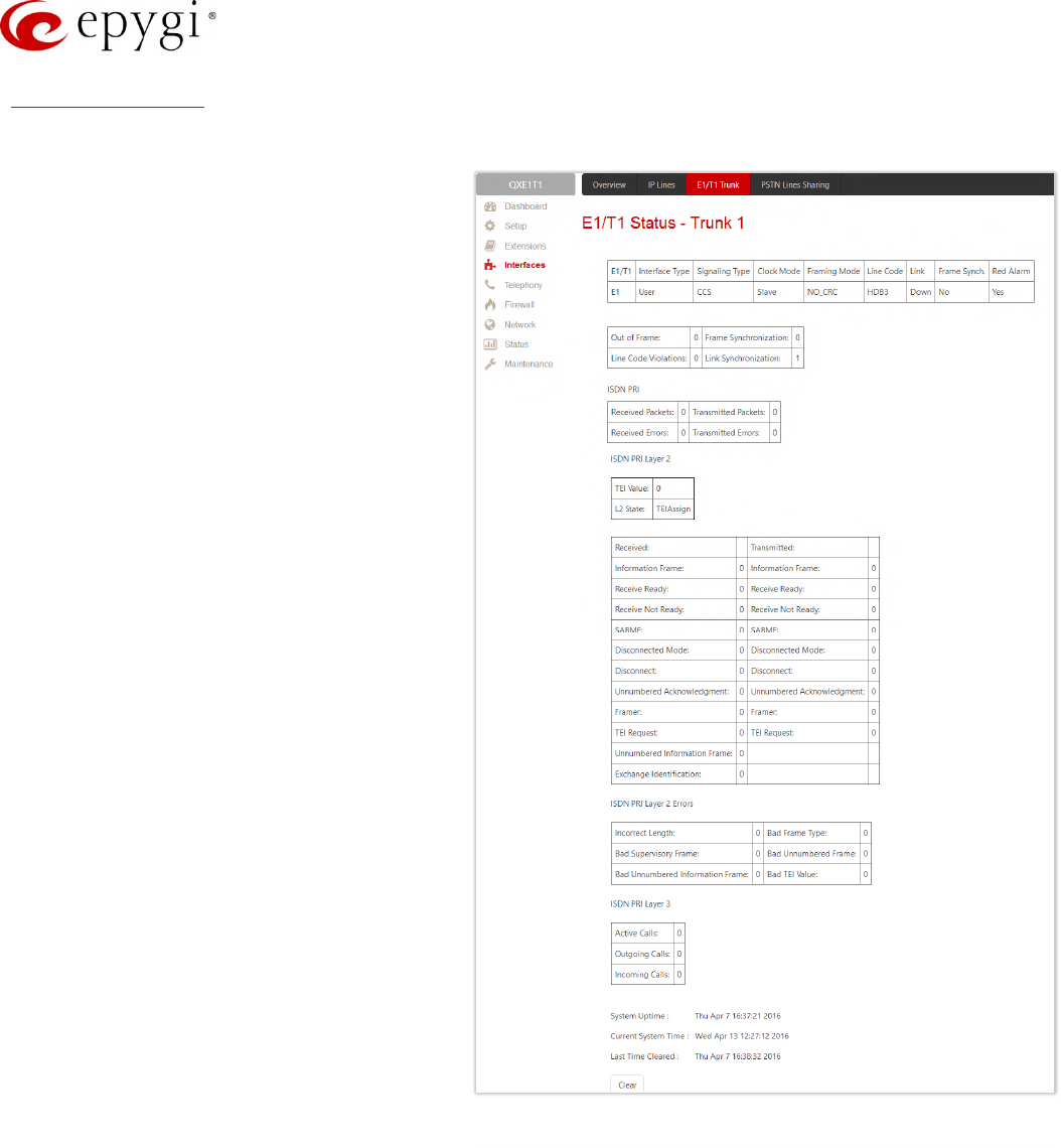
Manual-II: Administration Guide for QX Gateways
Edition 2 (FW Version 6.1.17 and higher) 69
E1T1 Status page
This page displays information about the selected trunk state.
•E1/T1 – displays the selected mode
(E1 or T1).
•Interface Type – displays the selected
interface type (User or Network).
•Signaling Type – displays the selected
signaling type: CAS or CCS.
•Clock Mode – displays the selected
clock mode (Master or Slave).
•Framing mode – displays the selected
framing mode.
•Link – displays the E1/T1 link state (up
or down).
•Frame Synchronization – displays the
signal synchronization state in the trunk
(Yes or No).
•Red Alarm – indicates that the receive
frame alignment for the line has been
lost and the data cannot be properly
extracted. The red alarm is indicated
by the loss of frame condition for the
various framing formats.
•Out of Frame – displays the number of
Out of Frame errors.
•Line Code Violation – displays the
number of Line Code Violation errors.
•Frame Synchronization – displays
number of Frame Synchronization
errors.
•Link Synchronization – displays the
number of Link Synchronization errors.
Following statistics are available, if CAS
Signaling is selected:
•Active Calls – displays the number of
currently active calls in the selected
trunk.
•Outgoing Calls – displays the number of total outgoing calls in the selected trunk.
•Incoming Calls – displays the number of total incoming calls in the selected trunk.
Following statistics is available when CCS Signaling is selected:
•Received Packets – displays the number of received packets.
•Received Errors – displays the number of received erroneous packets.
•Transmitted Packets – displays the number of transmitted packets.
•Transmitted Errors – displays the number of transmitted erroneous packets.
Figure 57: E1/T1 Trunk Stats page

Manual-II: Administration Guide for QX Gateways
Edition 2 (FW Version 6.1.17 and higher) 70
ISDN PRI Layer 2 statistics is displayed for actual TEI value and the received and transmitted packets:
•TEI Value – the actual TEI assigned.
•L2 State – the state of the TEI assignment.
•Information Frame – signaling packets for call initiation and termination.
•Receive Ready – controlling packets during E1/T1 link is up.
•Receive Not Ready – controlling packets in case of inability to accept calls by destination.
•SABME – packets upon connection establishment.
•Disconnected Mode – packets when connection is being disconnected.
•Disconnect – packets upon connection termination.
•Unnumbered Acknowledgement – packets upon accepting connection establishment/termination.
•Framer – packets as a report of an error condition.
•TEI – packets containing TEI (Terminal Endpoint Identifier) to initiate subscription of the device in the
network.
•Unnumbered Information Frame – broadcast signaling packets received for call initiation and termination.
•Exchange Identification – received packets containing connection management settings.
ISDN PRI Layer 2 Errors statistics:
Incorrect Length – packets with incorrect length.
•Bad Supervisory Frame – packets with incorrect supervisory header.
•Bad Unnumbered Information Frame – packets with incorrect unnumbered information frame header.
•Bad Frame Type – packets with bad frame type.
•Bad Unnumbered Frame – packets incorrect unnumbered acknowledgement frame header.
•Bad TEI Value – packets with bad TEI (Terminal Endpoint Identifier) value.
ISDN PRI Layer 3 statistics displays the same information as for CAS signaling.
No E1/T1 trunk statistics is displayed on this page at first, but page is getting automatically refreshed every 10
minutes. Statistics collected since that time and the last resetting of the counter will be displayed here.
•Blocked Timeslots – lists the timeslots blocked by the carrier. Available for E1/T1 CAS R2 signaling type
only.
•Current System Time – displays the actual time on the QXE1T1.
•Last Time Cleared – displays the exact date and time when the QXE1/T1 Stats has been manually
cleared last time.
•System Uptime – displays the period the QXE1T1 is on since the last reboot.
•Clean – is used to reset the statistics counters.
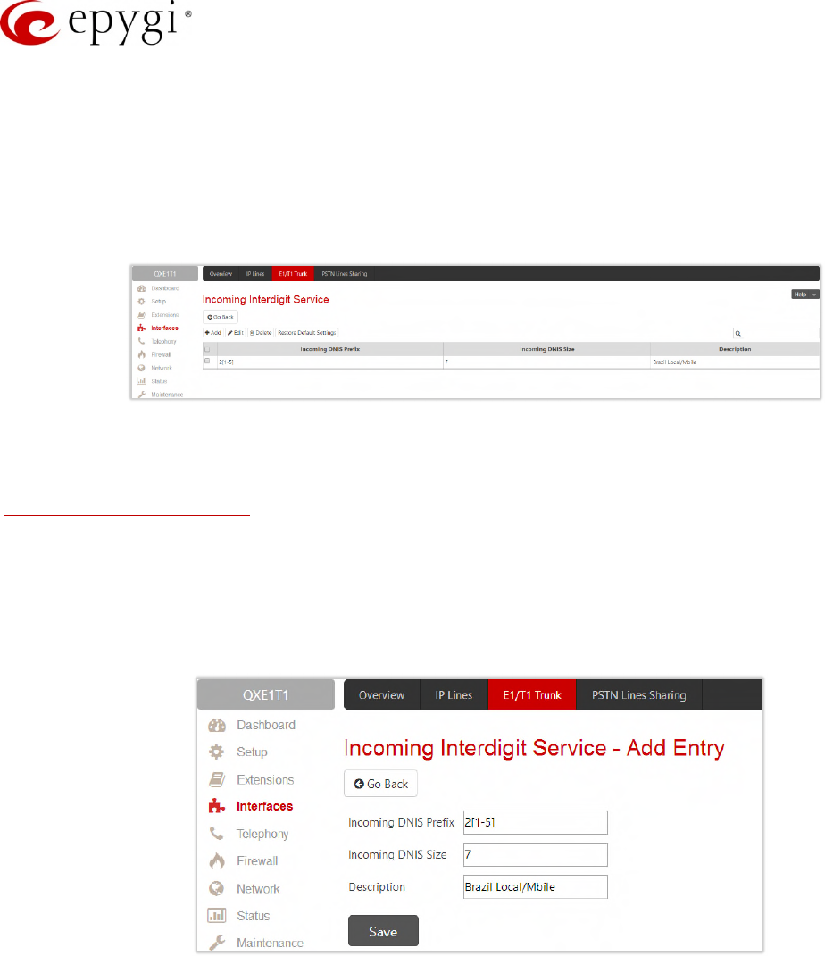
Manual-II: Administration Guide for QX Gateways
Edition 2 (FW Version 6.1.17 and higher) 71
7.5.4 Incoming Interdigit Service
The Incoming Interdigit Service allows to speed up the call procedure by detecting the prefix according to the
time set in the Incoming Digits Timeout field.
When the system detects incoming dialed number starting with any of the prefixes listed in the Incoming
Interdigit Service table, it will wait for the rest of the digits, as specified for the corresponding prefix in the
Incoming DNIS Size. Once all digits are received, the system will route the call to the destination.
Figure 58: Incoming Interdigit Service page
The Incoming Interdigit Service page lists a table with existing E1/T1 dial plan entries and allows you to manage
them. By default, the table on the Incoming Interdigit Service page lists the local specific (selected from the
System Configuration Wizard) E1/T1 dial plan settings. For some countries, this table may however be empty.
The Incoming Interdigit Service page includes the following buttons:
•Add – leads to the Incoming Interdigit Service – Add Entry page where a new E1/T1 dial plan entry can
be configured. The following options are available:
Incoming DNIS Prefix – insert the prefix of the incoming dialed number. The Incoming DNIS Prefix may
contain wildcards.
Figure 59: Incoming Interdigit Service – Add Entry page
Incoming DNIS Size – insert the total length of the dialed number, including the prefix digits. The
number defined here should be greater than the longest prefix defined in the Incoming DNIS Prefix.
•Restore Default Settings – is used to restore the locale specific E1/T1 dial plan entries.
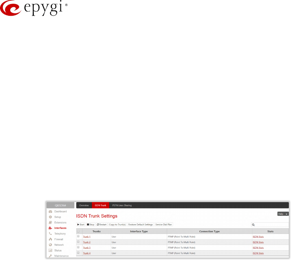
Manual-II: Administration Guide for QX Gateways
Edition 2 (FW Version 6.1.17 and higher) 72
7.6 ISDN Settings
The Integrated Services Digital Network (ISDN) is distinguished by digital telephony and data–transport services
offered by regional telephone carriers. ISDN involves the digitization of the telephone network, which permits
voice, data, text, graphics, music, video, and other source material to be transmitted over existing telephone
wires. The ISDN Basic Rate Interface (BRI) service offers two B channels (voice transfer) and one D channel
(signaling data transfer). The BRI B-channel service operates at 64 kbit/s and is meant to carry user data. The
BRI D-channel service operates at 16 kbit/s and is meant to carry control and signaling information, although it
can support user data transmission under certain circumstances.
The ISDN service allows QXISDN4 gateway act as:
•network – if connected to a private PBX
•user – if connected to the ISDN trunk from the CO (Central Office). The QXISDN4 supports the MSN
(Multiple Subscriber Number) service, i.e., thus it can be subscribed to multiple numbers from the CO
allowing to place two simultaneous calls at a time.
The ISDN Trunk Settings page is used to configure the ISDN trunk and their signaling. There are 4 ISDN trunks
available on the QXISDN4 gateway.
The Trunk Settings table lists the available ISDN trunks on the QXISDN4 and their settings (trunk name and
interface types).
Figure 60: ISDN Trunk Settings page
ISDN Trunk Settings page includes the following buttons:
•Start and Stop are used to start/shutdown the selected ISDN trunk(s). When an ISDN trunk is in a
shutdown state, ISDN calls cannot be placed or received.
•Restart is used to bring channel(s) to the initial idle state on both sides, any active traffic on the
channel(s) will be terminated.
•Copy to Trunk(s) – is used to copy the settings of the selected trunk to another trunk(s).
•Restore Default Settings – restores the default settings of the selected ISDN trunk(s).
•Service Dial Plan – is used to select a trunk and configure dial plan for incoming ISDN calls from
CO/PBX to the QX.
Clicking on the Trunk # @ link will lead to the ISDN wizard for the selected trunk, where the ISDN settings can
be configured.
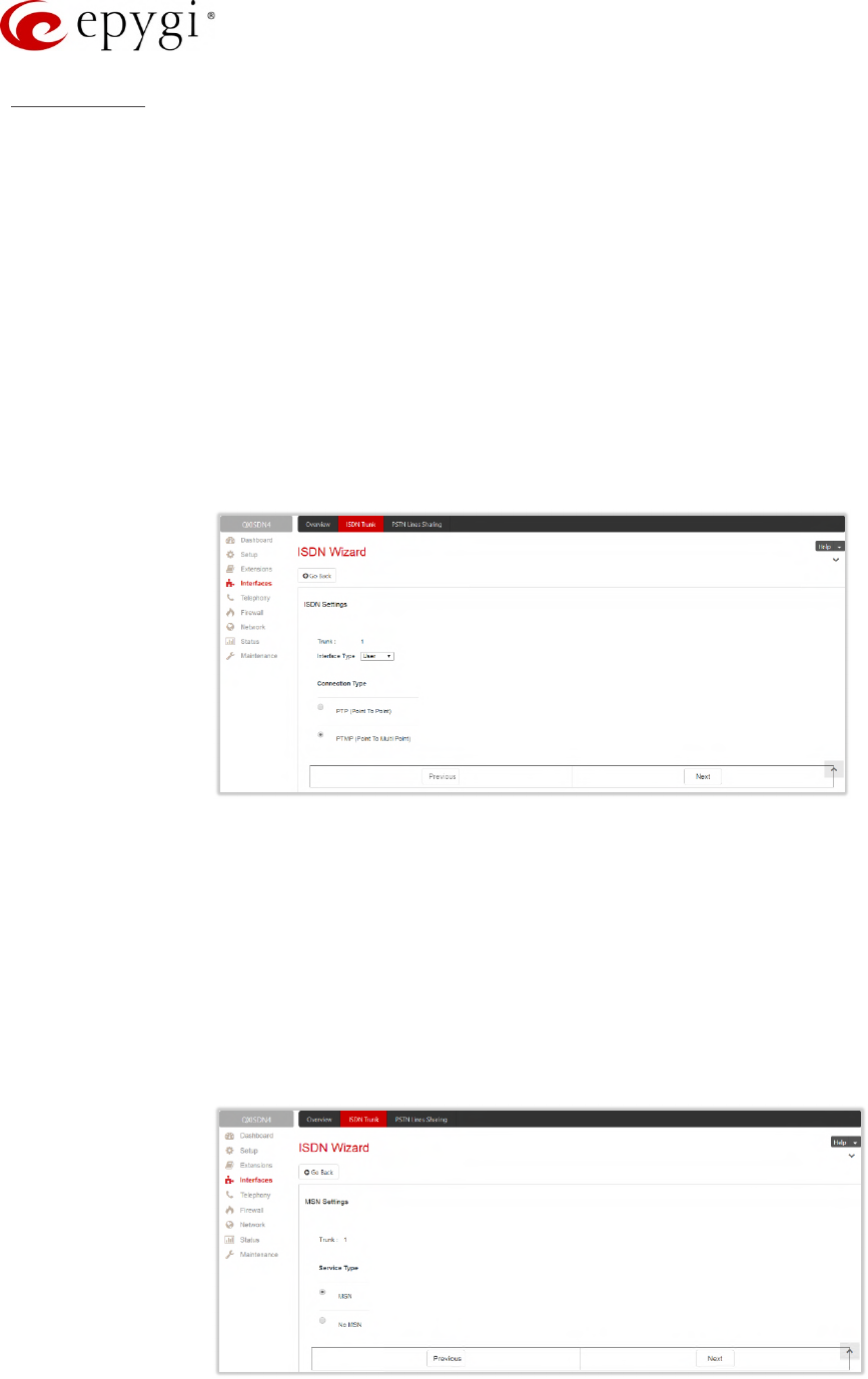
Manual-II: Administration Guide for QX Gateways
Edition 2 (FW Version 6.1.17 and higher) 73
ISDN Wizard
The ISDN Wizard consists of the following sections:
•ISDN Settings – is used to select the interface type and the connection type of the selected trunk.
Interface Type – allows to choose between the User and the Network options. If the ISDN trunk is
connected to the CO, then the User option should be selected. If the trunk is connected to legacy
PBX, then Network option should be selected.
Connection Type – allows to choose between the PTP and PTMP connection types.
PTP (Point to Point) – In case of connection to the CO (User interface type is selected) choose this
option if only QX is connected to the ISDN trunk from CO (no other ISDN devices are connected to
the particular ISDN trunk from CO besides the QX). In case of connection to the legacy PBX
(Network interface type is selected) choose this option if only the legacy PBX is connected to the
ISDN trunk from the QX (no other ISDN devices are connected to the particular ISDN trunk). In both
cases, with this selection, QX sets the TEI to manually mode assigning the default value of 0. If
needed, that value can be changed later in the Advanced Settings section of ISDN Wizard.
Figure 61: ISDN Settings section
PTMP (Point to Multi Point) – In case of connection to the CO (User interface type is selected)
choose this option if there can be other devices connected to the same ISDN trunk from CO except
the QX. In case of connection to legacy PBX (Network interface type is selected) choose this option
if there can be other devices connected to the same ISDN trunk except for the legacy PBX. In both
cases, with this selection QX sets the TEI to automatic mode.
•MSN Settings – is used to turn on the MSN configuration (Figure 62). This section becomes available
only if the interface type is User. It is recommended to enable the MSN when there are multiple ISDN
devices connected to the same ISDN bus. If the MSN is enabled the next section will require the MSN
table configuration.
Figure 62: MSN Settings section
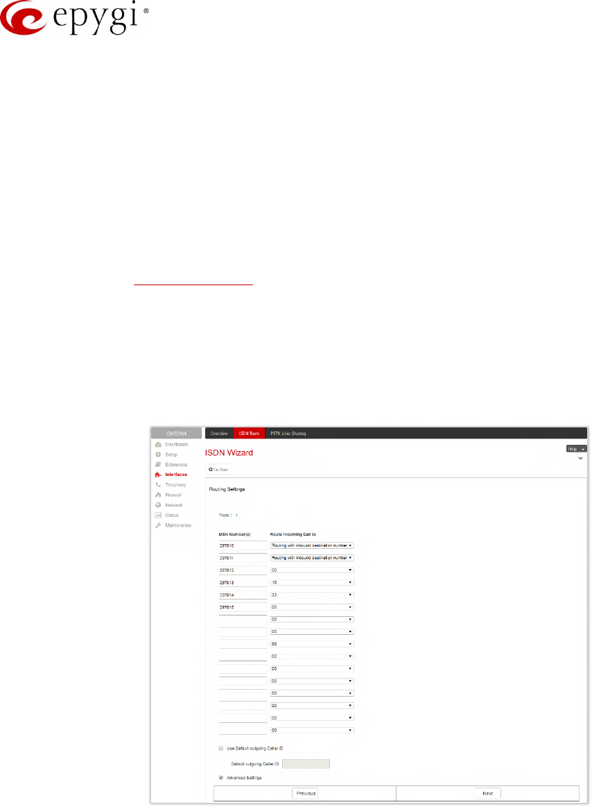
Manual-II: Administration Guide for QX Gateways
Edition 2 (FW Version 6.1.17 and higher) 74
The Routing Settings section content is dependent on the interface type and service selected on the previous
sections of ISDN Wizard.
•Routing Settings – if MSN service is enabled, this section is used to assign MSN numbers to the certain
destinations on the QX.
The fields in the MSN Number column require the MSN numbers allocated to the QX. At least one
MSN number should be defined.
Route Incoming Call to – is used to define the destination where the incoming calls addressed to the
certain MSN number will be forwarded. The following options are available:
The calls can be forwarded to either user extension or auto attendant. The calls will be forwarded to
Voice Mailbox if an inactive extension is chosen.
Routing with inbound destination number – is used to forward the calls to the destination defined
through Call Routing Table. Routing Settings – if MSN service is disabled or selected interface type
is Network, this section contains only one Route Incoming Call to option.
Use Default outgoing Caller ID – allows to overwrite the source caller information with the one specified
in the Default outgoing Caller ID field when placing outgoing calls toward the CO. Insert the caller ID
for the outgoing calls from the QX through the ISDN trunk in the Default outgoing Caller ID field. That
number should be registered at the CO and can be one of the MSNs provided by the CO. If the
checkbox selected but no value is defined in the Default outgoing Caller ID, empty caller information
will be sent to the CO. If not selected, the source caller information will be forwarded to the CO.
Figure 63: Routing Settings section
Advanced Settings – select this if you want to adjust trunk’s L2 and L3 Settings manually in the next
section, otherwise leave it unselected to use the system default values.
•ISDN Low Level Settings – section is used to enable Power Source option. This section becomes
available only if the selected interface type is Network.
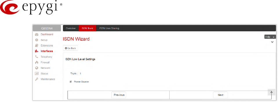
Manual-II: Administration Guide for QX Gateways
Edition 2 (FW Version 6.1.17 and higher) 75
Figure 64: ISDN Low Level Settings section
Power Source – if selected, the QX will supply power for the connected ISDN phones, otherwise ISDN
phones should have their own power supplies. TIP: Power Source option should be always disabled
when a legacy PBX or Telecom connected to the QX.
•L2&L3 Settings – is used for advanced configuration of ISDN L2&L3 settings. This section becomes
available only if the Advanced Settings checkbox is selected on the previous section. This section
contains the following components:
Excessive Ack. Delay T200 – is used to configure the period in milliseconds (digit values from 500 to
9999) between the transmitted signaling packet and its acknowledgement received.
Idle Timer T203 – is used to configure the period in milliseconds (digit values from 1000 to 99999) for
the ISDN client idle timeout.
T302 Timer – insert the value for the T302 timer in milliseconds (digit values from 0 to 15000). The
time frame system will wait for digits to be dialed and when timer expires, it initiates the call.
T309 Timer – insert the value for the T309 timer in milliseconds (digit values from 0 to 90000). This
option is responsible for call steadiness during link disconnection within the period equal to this timer
value. If the value in this field is 0, T309 timer will be disabled.
T310 Timer – insert the value for the T310 timer in milliseconds (digit values from 1000 to 120000).
This option is responsible for the outgoing call steadiness when CALL PROCEEDING is already
received from the destination but call confirmation (ALERT, CONNECT, DISC or PROGRESS) is not yet
arrived.
Alert Guard Timeout – insert the value for the Alert Guard Timer in milliseconds (digit values from 0 to
500) between CALL PROC and ALERT messages. Alert Guard Timer is used when QX is connected
to a slow legacy PBX. Recommended values are:
fast connection (0ms).
normal (150ms), default.
slow ISDN-PBX (350ms).
very slow ISDN-PBX (500ms).
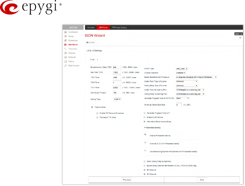
Manual-II: Administration Guide for QX Gateways
Edition 2 (FW Version 6.1.17 and higher) 76
Figure 65: ISDN Low Level Settings section
Coding Type – is used to select between a-law and mu-law coding types.
Passive Mode – is used to leave the ISDN Layer1 connection in the Slave mode. If selected, Layer1
remains idle when calls are not available, otherwise QX keeps its Layer1 always active. This checkbox
enables the Enable TEI Remove Procedure and Permanent TEI Value options.
Enable TEI Remove Procedure – if selected, the trunk will lose the assigned TEI when entering into
passive mode on the Layer 2.
Permanent TEI Value – if selected, the trunk will keep the assigned TEI when entering into passive
mode on the Layer 2 or when QX detected ISDN link DOWN signal from carrier.
Note: These options are available only for PTMP (Point to Multi Point) connection type. If PTP (Point to Point)
connection type is selected, these two options are replaced with a TEI Address option which requires the
channel number (digit values from 0 to 63) for connection establishment between the CO and the ISDN client.
Switch Type – this configuration parameter depends on the Service Provider when acting in the User
mode and the legacy PBX capabilities when acting in the Network mode.
Channel Selection – is used to select between the Preferred and Exclusive B channel selection
methods. For Preferred channel selection, the CO answers to the call request by the first available
timeslot. With the Exclusive channel selection, the CO should feedback only by the timeslot asked in
the call request.
Bearer Establishment Procedure – allows to select the session initiation method on the B channels.
One of the following possibilities of the transmission path completion prior to receipt of a call
acceptance indication can be selected:
on channel negotiation at the destination interface.
on progress indication with in-band information.
on call acceptance.
Called Party Type of Number – allows to select the type identifying the sub address of the called party.
Calling Party Type of Number – allows to select the type identifying the origin of call.
Called Party Numbering Plan and Calling Party Numbering Plan – indicate correspondingly the
numbering plan of the called party and calling party.

Manual-II: Administration Guide for QX Gateways
Edition 2 (FW Version 6.1.17 and higher) 77
Generate Progress Tone to PSTN/PBX – contains the options for sending progress (ring-back) tone to
callers from the PSTN/PBX. The following options are available in the list:
None – configures the system to send ALERT messages without the Progress Indicator Information
Element (IE).
Unconditional – configures the system to send ALERT/PROGRESS messages with the Progress
Indicator IE. With this option, the system will send its own progress tone.
Conditional – configures the system to send ALERT/PROGRESS messages with Progress Indicator
IE. With this option, the system will send its own progress tone only if there is no early media
(180/183 with SDP) from the called party.
Incoming Called Digits Size – indicates the number of received digits (in a range from 0 to 255)
required to establish a call. When this field has 0 value, system uses either the timeout defined in the
T302 field or the Sending Complete Information element messages to establish a call. Independent on
the value in this field, Sending Complete Information element and # always cause the call
establishment.
Generate Progress tone on IP – if selected, the progress tone to IP (SIP) will be generated.
Enable CLIR Service – if selected, Calling Line Identification Restriction (CLIR) service will be activated
and this will display the incoming caller ID only in case if Presentation Indication is allowed on the
remote side, otherwise, if CLIR service is disabled, caller ID will be unconditionally displayed.
Alternative Disconnection Mode – if not selected, QX will disconnect the call as soon as disconnect
message has been received from the peer, otherwise, QX's user may hear a busy tone when the peer
has been disconnected.
P-Asserted-Identity – is used to configure P-Asserted-Identity for the calls from SIP to ISDN and vice-
versa.
Disable P-Asserted-Identity – disables the P-Asserted-Identity for both incoming and outgoing calls.
Override CLID with P-Asserted-Identity – enables the SIP P-Asserted-Identity support. For the calls
from SIP to ISDN if the Invite SIP message contains a P-Asserted-Identity or a P-Preferred-Identity
or a Remote-Party-ID, then the Caller ID on ISDN is sent with the original Caller ID which comes
from the identity field. SIP user agent should check for the existence of the P-Asserted-Identity, then
the P-Preferred-Identity, then the Remote-Party-ID to fill the identity field. For the calls from ISDN to
SIP with restricted Caller ID, the SIP Invite message contains P-Asserted-Identity field with the value
from the Caller ID on ISDN. The "SIP From" field contains anonymous.
Use Redirecting Number Info Element with P-Asserted-Identity radio button selection enables full
support of the SIP P-Asserted-Identity. For the calls from SIP to ISDN, if the SIP Invite message
contains a P-Asserted-Identity or a P-Preferred-Identity or a Remote-Party-ID, then the Caller ID on
ISDN contains the number from the user name field and the Redirecting Number IE contains the
original number from the identity field. SIP user agent should check for the existence of the P-
Asserted-Identity, then the P-Preferred-Identity, then the Remote-Party-ID to fill the identity field. For
the calls from ISDN to SIP with Caller ID, the SIP Invite message contains P-Asserted-Identity field
with the original number value from the Redirecting Number IE on ISDN. The "SIP From" field
contains the value from the user name.
Send Calling Party Subaddress – if selected, QX will send the extension number as sub address and
the value defined in the Default outgoing Caller ID field as caller ID on the outgoing call. Otherwise no
sub address information will be sent and the caller ID will be defined according to the selection of the
Use Default Outgoing Caller ID checkbox (see above). Caller ID information, along with the
Subaddress, can be displayed on the phone display depending on the phone and PBX settings and
capabilities.
Ignore Empty Channel Identification in CALL PROCEEDING Msg. – if selected, QX will ignore the empty
ISDN L3 Channel Identification information element in CALL PROCEEDING message and will not
response with STATUS message, otherwise QX will response with STATUS message on empty
Channel Identification information element.
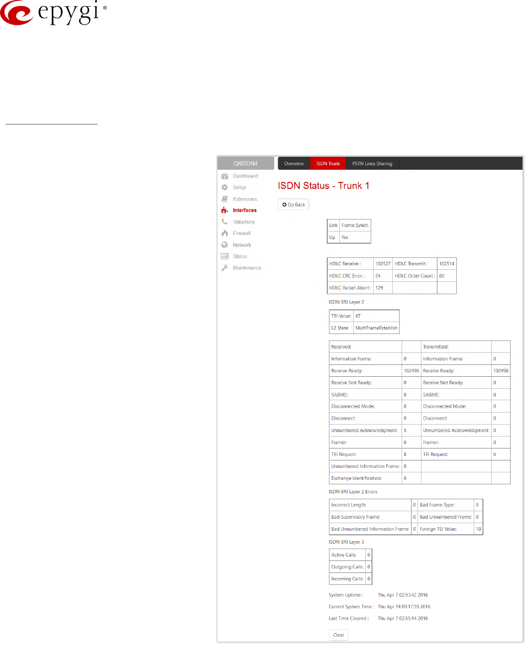
Manual-II: Administration Guide for QX Gateways
Edition 2 (FW Version 6.1.17 and higher) 78
B1 Channel and B2 Channel enable/disable timeslots for voice transfer. Disabling the timeslot will
prevent both incoming and outgoing calls.
•Summary of ISDN Settings – this section displays all configured settings for the ISDN trunk.
ISDN Status page
This page displays information about the selected trunk state.
•Link – displays the ISDN link state
(up or down).
•Frame Synchronization – displays
the signal synchronization state in
the trunk (Yes or No).
•HDLC Receive – displays the
number of packets received in
HDLC (High–level Data Link
Control) format.
•HDLC CRC Error – displays the
number of packets received with
CRC (Cyclical Redundancy Check)
errors.
•HDLC Packet Abort – displays the
number of received aborted
packets.
•HDLC Transmit – displays the
number of packets transmitted in
HDLC format.
•HDLC Octet Count – displays the
number of error packets received in
HDLC format.
•TEI value – displays the actual TEI
value.
•L2 State – displays the actual BRI
L2 state.
•Information Frame – displays the
number of signaling packets for call
initiation and termination.
•Receive Ready – displays the
number of controlling packets while
the ISDN link is up.
•Receive Not Ready – displays the
number of controlling packets in
case of inability to accept calls by
destination.
•SABME – displays the number of
packets upon connection establishment.
•Disconnected Mode – displays the number of packets when the connection is being disconnected.
Figure 66: ISDN Trunk Status page

Manual-II: Administration Guide for QX Gateways
Edition 2 (FW Version 6.1.17 and higher) 79
•Disconnect – displays the number of packets upon connection termination.
•Unnumbered Acknowledgement – displays the number of packets upon accepting connection
establishment/termination.
•Framer – displays the number of packets as a result of an error condition.
•TEI Request – displays the number of packets containing TEI (Terminal Endpoint Identifier) to initiate
subscription of the device in the network.
•Unnumbered Information Frame – displays the number of broadcast signaling packets received for call
initiation and termination.
•Exchange Identification – displays the number of received packets containing connection management
settings.
•Incorrect Length – displays the number of packets with an incorrect length.
•Bad Supervisory Frame – displays the number of packets with an incorrect supervisory header.
•Bad Unnumbered Information Frame shows the number of packets with an incorrect unnumbered
information frame header.
•Bad Frame Type – displays the number of packets with a bad frame type.
•Bad Unnumbered Frame shows the number of packets with an incorrect unnumbered
acknowledgement frame header.
•Foreign TEI Value – displays the number of packets with a bad or foreign TEI (Terminal Endpoint
Identifier) value.
•Active Calls – displays the number of currently active calls in the selected trunk.
•Outgoing Calls – displays the number of all outgoing calls in the selected trunk.
•Incoming Calls – displays the number of all incoming calls in the selected trunk.
ISDN trunk statistics are not displayed on this page at first, but the page is automatically refreshed every 10
minutes. Statistics collected from that time, as well as the last resetting of the counter, will be displayed there.
System Uptime, Current System Time and Last Time Cleared (last time ISDN statistics has been cleared) are
displayed at the bottom of the page.
•Clear – click to reset the statistics counters.
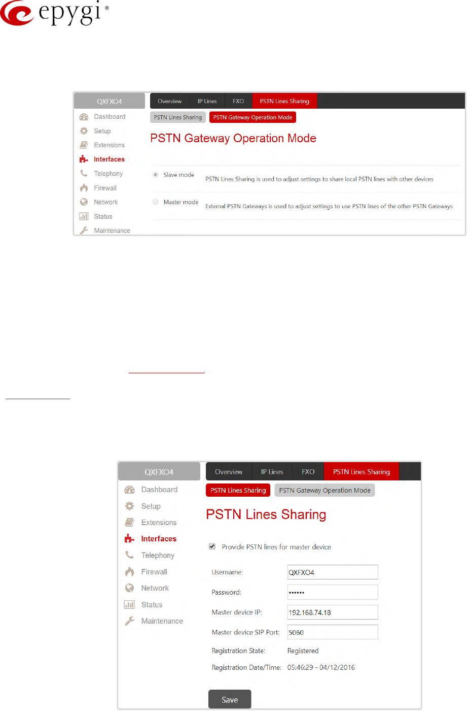
Manual-II: Administration Guide for QX Gateways
Edition 2 (FW Version 6.1.17 and higher) 80
7.7 PSTN Gateway Operation Mode
The PSTN Gateway Operation page is used to define the PSTN Gateway operational mode.
Figure 67: PSTN Gateway Operation Mode page
•Slave Mode – is used to adjust settings to share local PSTN lines with other devices.
•Master Mode – is used to adjust settings to use PSTN lines of the other PSTN Gateways.
7.8 PSTN Lines Sharing
The PSTN Lines Sharing page is used to allow the QX Gateway either share its PSTN lines (FXO lines, E1T1
and/or ISDN trunks) with another QX Gateway or QX IP PBX.
According to the selected operation mode, different configuration parameters will appear on this page.
Share Mode
The PSTN Lines Sharing page is used to configure the slave QX Gateway with the master QX device. The
master QX device (IP PBX or Gateway) will be allowed to make PSTN calls through shared FXO lines, E1T1 or
ISDN trunks.
Figure 68: PSTN Lines Sharing page
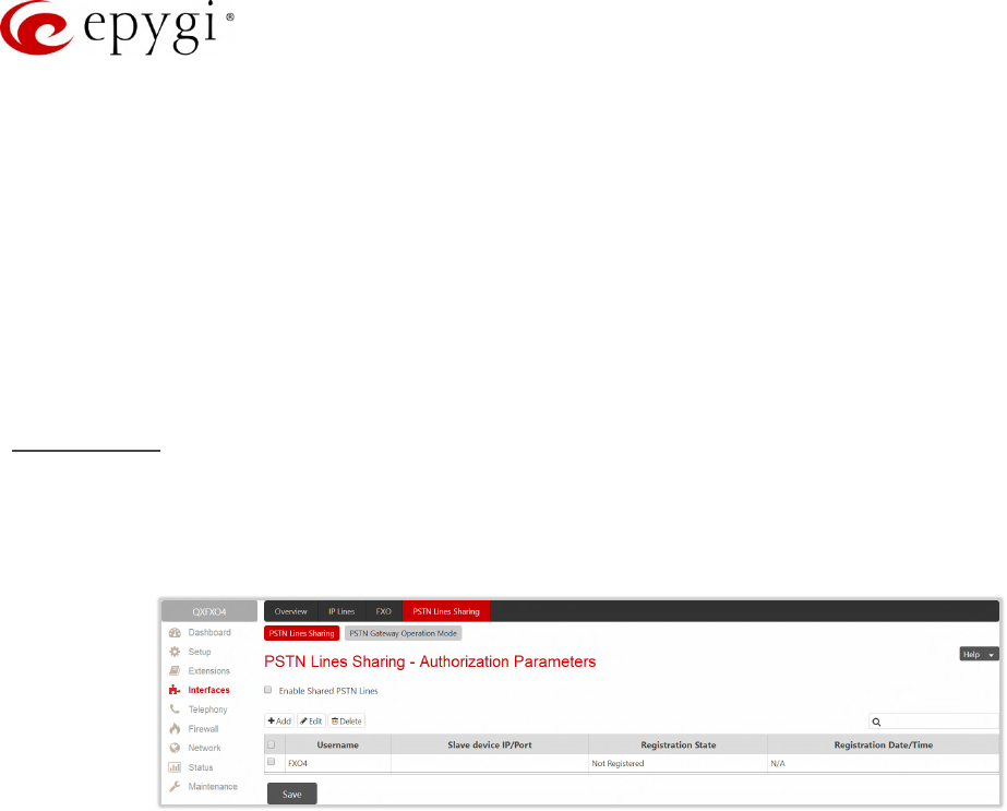
Manual-II: Administration Guide for QX Gateways
Edition 2 (FW Version 6.1.17 and higher) 81
•Provide PSTN lines for master device – is used to share the PSTN lines to the master device.
•Username and Password – are used to define the authentication parameters. TIP: The Username and
Password should match on both master and slave for the successful PSTN Lines sharing.
•Master device IP – is used to define the IP address of the master device.
•Master device SIP port – is used to define the port number of the master device.
•Registration State – displays whether the slave device is registered on the master device or not.
•Registration Date/Time – displays the time since the QX is registered on the master device.
After the master–slave configuration, appropriate routing rules will be created on the Call Routing Table for both
devices to allow to support PSTN line sharing.
Master Mode
The PSTN Gateways – Authorization Parameters page is used to create accounts for the slave QX Gateway(s) to
connect it to the master QX Gateway for PSTN lines (FXO lines, E1/T1 and/or ISDN trunks) sharing.
Attention: Master gateway can be configured in sharing mode only with the same model of slave gateway(s).
Figure 69: PSTN Gateways – Authorization Parameters page
•Enable Shared PSTN Lines – allows the master device to use shared PSTN lines (FXO lines, E1/T1
and/or ISDN trunks) of the QX Gateway.
•Add – leads to the PSTN Gateways – Authorization Parameters – Add Entry page to configure account(s)
for the slave QX Gateway by defining the Username and Password. TIP: The Username and Password
should match on both master and slave for the successful PSTN Lines sharing.
The newly added slave gateway will be displayed on the Authorization Parameters table.
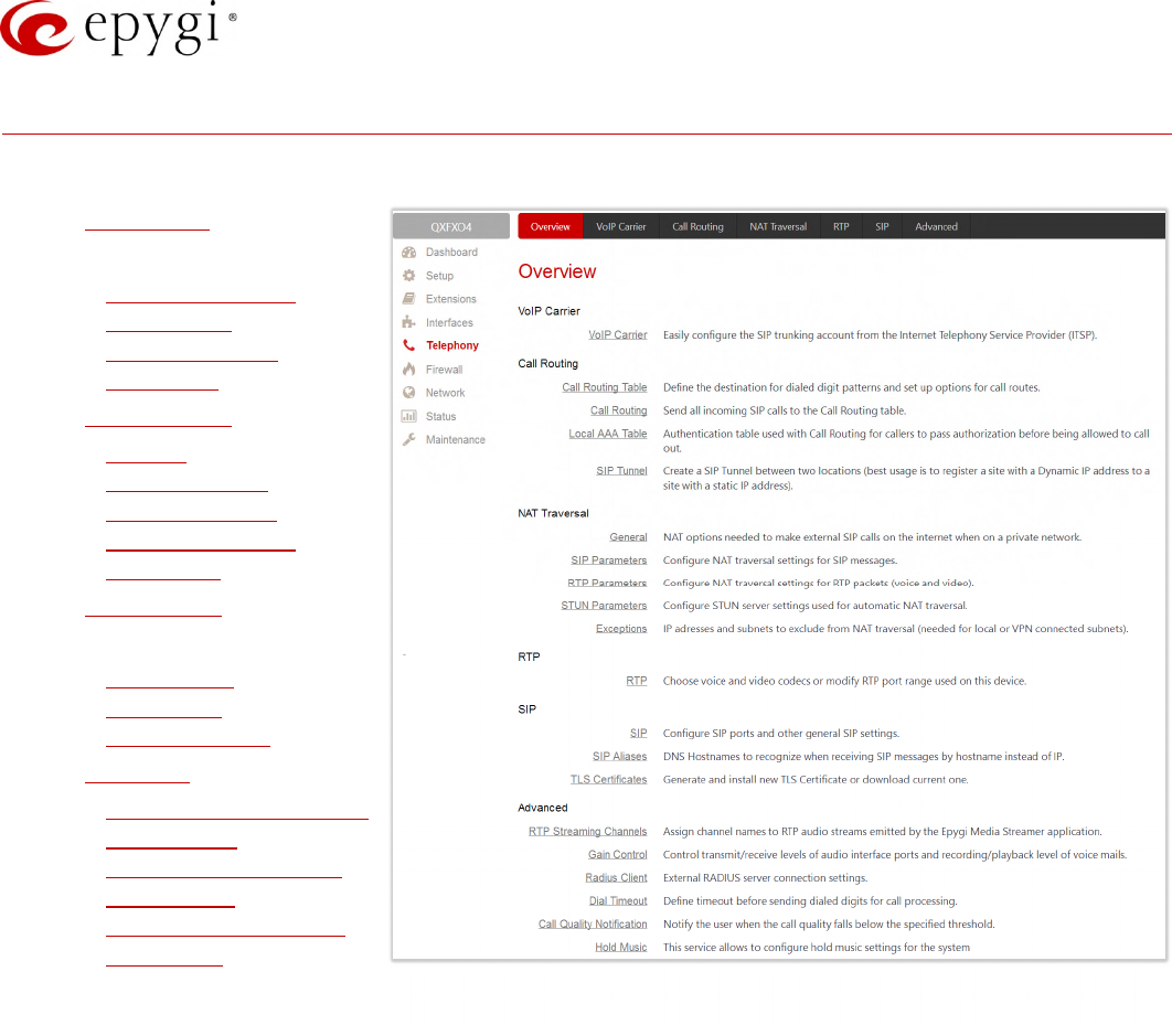
Manual-II: Administration Guide for QX Gateways
Edition 2 (FW Version 6.1.17 and higher) 82
8 Telephony Menu
The Telephony menu consists of the following sections:
•VoIP Carrier
•Call Routing
Call Routing Table
Call Routing
Local AAA Table
SIP Tunnel
•NAT Traversal
General
SIP Parameters
RTP Parameters
STUN Parameters
Exceptions
•RTP Settings
•SIP
SIP Settings
SIP Aliases
TLS Certificates
•Advanced
RTP Streaming Channels
Gain Control
Radius Client Settings
Dial Timeout
Call Quality Notification
Hold Music
Figure 70: Telephony Menu overview
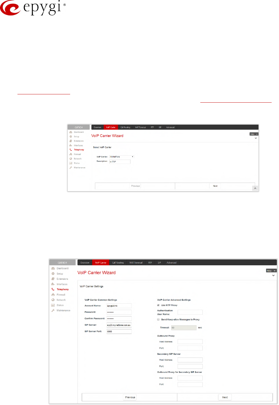
Manual-II: Administration Guide for QX Gateways
Edition 2 (FW Version 6.1.17 and higher) 83
8.1 VoIP Carrier Wizard
The VoIP Carrier Wizard simplifies the configuration of the QXs with different VoIP SIP trunking services.
The wizard is for collecting the data and generating the configuration for each specific VoIP SIP trunking service
on the QX. After finishing the wizard, the extensions on the QX will be able to receive calls from the VoIP carrier
SIP trunks, as well as to place calls to the PSTN using the carrier SIP trunks.
For each configured VoIP SIP trunking service, the wizard creates a specific IP-PSTN type routing rule in the
QX’s Call Routing Table. By default, only PBX users can make calls through the corresponding VoIP carrier.
Additionally, a virtual extension will be automatically generated in the Extensions Management table and
registered on the VoIP Carrier's SIP server. The settings of that extension will be used to make calls towards
the created VoIP Carrier SIP Trunks.
Figure 71: Select VoIP Carrier section
The wizard composed of the following sections:
•Select VoIP Carrier section is used to select a carrier from the VoIP Carrier list. Once a carrier is found
and selected, the carrier's SIP Server and SIP Port will automatically appear on the next section of the
wizard. The Manual option selection allows to configure the VoIP Carrier settings manually from scratch.
•VoIP Carrier Settings section is used to define and configure the account from provider.
Figure 72: VoIP Carrier Settings section
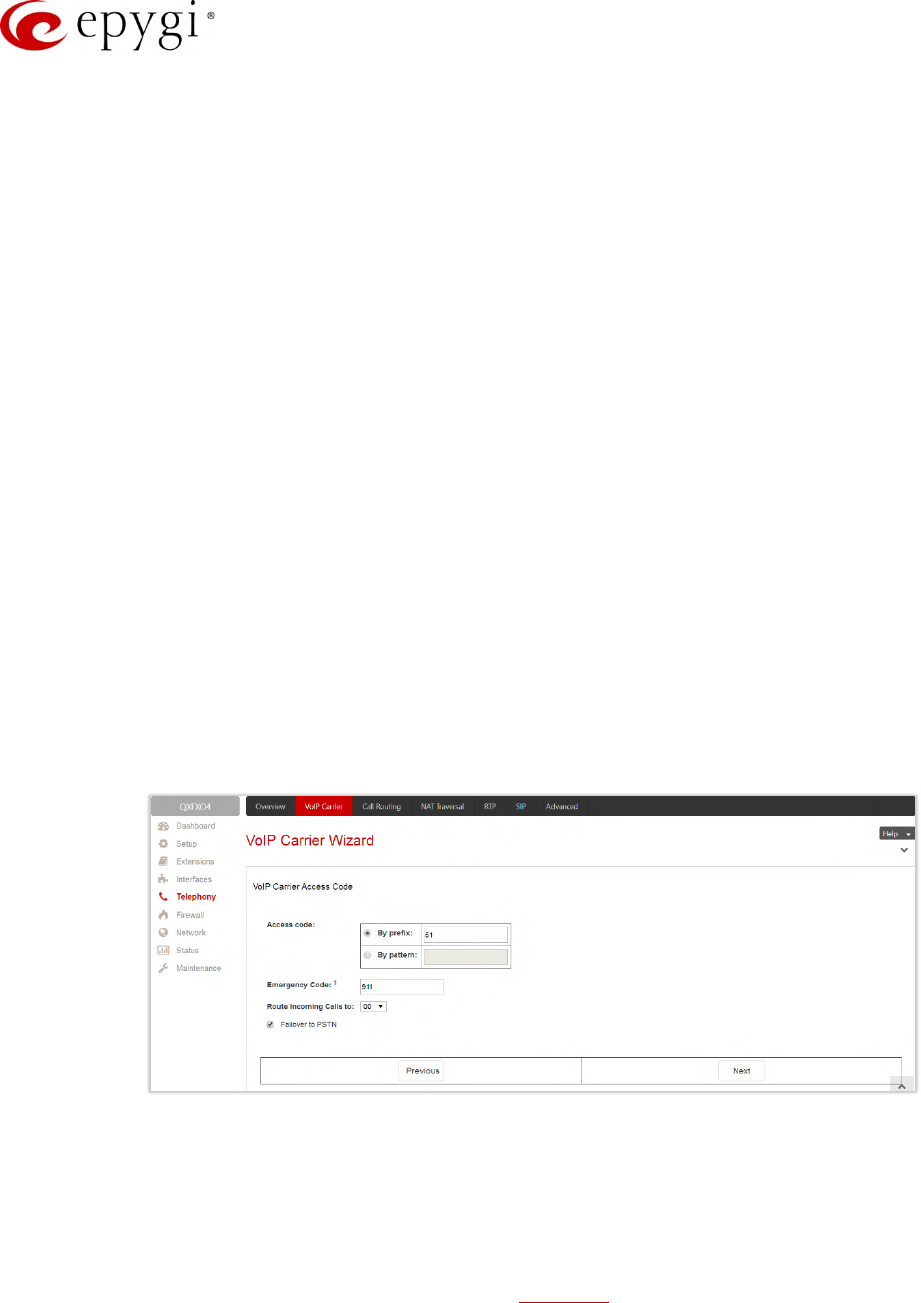
Manual-II: Administration Guide for QX Gateways
Edition 2 (FW Version 6.1.17 and higher) 84
Authentication by IP Address – if selected, deactivates the Account Name and Password fields, thus
allow skipping the IP address authentication settings. This option is intended for VoIP carriers
requiring IP address authentication instead of account authentication and will be available if Manual
has been selected in the previous section.
Account Name – insert the username for authentication on the carrier’s SIP server.
Password – insert the password for authentication on the carrier’s SIP server and confirm it in the
Confirm Password field.
SIP Server – insert the IP address or hostname for the carrier’s SIP server.
SIP Server Port – insert the SIP server port for the carrier’s SIP server.
Use RTP Proxy – if selected, the RTP streams between external users will be routed through the QX,
otherwise RTP packets will move directly between peers. This option is applicable only when a route
is used for calls towards a configured VoIP Carrier from a peer located outside the QX.
Authentication User Name – insert an identification parameter to reach the SIP server. It should be
provided by the SIP trunking service provider and can be requested only for certain SIP servers. For
others, the field should be left empty.
Send Keep-alive Messages to Proxy – enables the SIP registration server accessibility to the
verification mechanism.
Timeout – define the timeout between two attempts of SIP registration server accessibility
verification. If a reply is not received from the primary SIP server within this timeout, the secondary
SIP server will be contacted. When the primary SIP server recovers, SIP packets will continue to be
sent to the server.
Define the Outbound Proxy, Secondary SIP Server and Outbound Proxy for Secondary SIP Server by
inserting the Host Address and Port for each of them respectively. These settings are provided by the
provider and are used by the QX to reach to the selected SIP servers.
•VoIP Carrier Access Code section is used to define the routing rules for outbound/inbound calls through
VoIP carrier SIP trunks.
Figure 73: VoIP Carrier Access Code section
Access code – defines the routing rule for outbound calls.
By prefix – is used for entering the numeric prefix that should be dialed to route call through carriers
SIP trunks. The system will route all digits matching this prefix to the carriers SIP trunks.
By pattern – is used to specify the pattern that should be applied to dialed digits. If an outbound call
has a destination number that matches the specified pattern, it will be completed according to the
current rule. A routing pattern may contain wildcards.
Emergency Code – insert the emergency code supported by the specified VoIP provider. In case your
system has both local PSTN emergency codes and IP-PSTN codes configured, when dialing the
certain emergency code, QX will first try to reach the local PSTN allocated emergency, and if failed will
dial the IP-PSTN emergency. TIP: If the defined VoIP service is 911 compliant then you have to bind
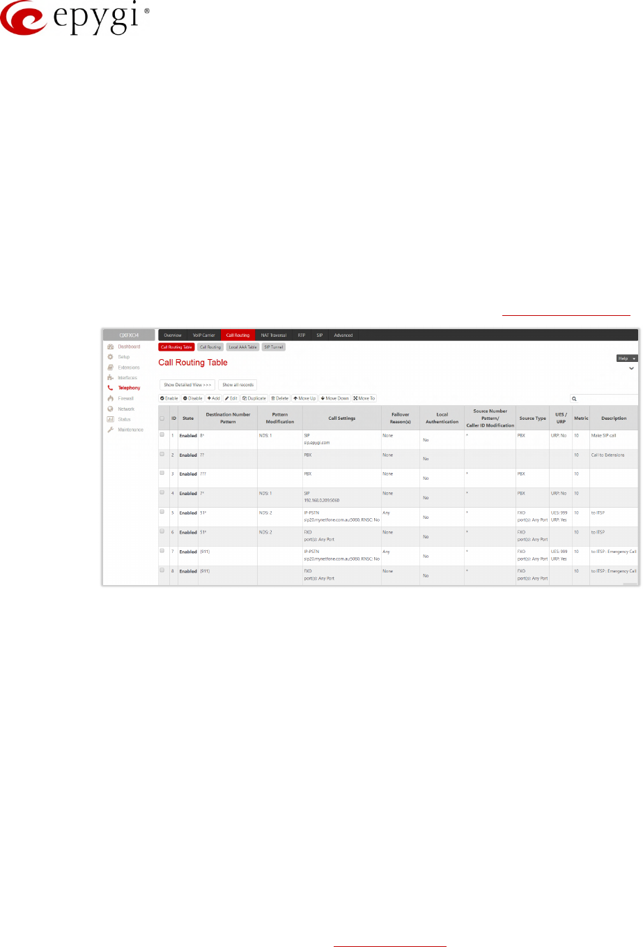
Manual-II: Administration Guide for QX Gateways
Edition 2 (FW Version 6.1.17 and higher) 85
this account with the geographical address of your device. If the provider is not 911 compliant, then
the public safety agency will not be able to determine the address automatically.
Route Incoming Calls to – select an extension (user extension or Auto Attendant) on the QX where the
incoming calls from the configured VoIP Carrier should be routed to. There will be an unconditional
forwarding set up automatically which will care for incoming calls forwarding from the VoIP carrier to
the selected extension.
Failover to PSTN – if selected, an additional entry will be added to the Call Routing Table to route calls
to the PSTN network through the QX on-board PSTN lines in case if the VoIP Carrier SIP trunks are
not available.
8.2 Call Routing Table
The Call Routing Table lists the settings of all call routing records (rules) either generated by default, or added
automatically with one of the QX's system wizards: Call Routing Wizard and VoIP Carrier Wizard.
Figure 74: Call Routing Table – brief view
The following components are available:
•Show Brief View – if pressed, displays the most important settings of the entries in the Call Routing
Table.
•Show Detailed View – if pressed, displays all settings of the entries in the Call Routing Table.
•Hide disabled records/Show all records – are used to hide/show disabled records respectively.
•Enable – enables (activate) the selected route(s).
•Disable – disables (deactivate) the selected route(s).
•Add – leads to the Call Routing Wizard – Add Entry page to configure a new routing pattern.
•Duplicate – creates a routing pattern with the settings duplicated from the selected one.
•Move Up/Move Down – moves call routing patterns one level up/down. The sequence of the routing
patterns is important when making routing calls because the Call Routing table is parsed from the top to
down and routing will take place according to the first pattern that matches the dialed number.
•Move To – moves the selected entry to a different position. This will increase or decrease the selected
routing pattern's priority.
•Local Authentication – if selected, displays Authorized Users link for the selected routing rule.
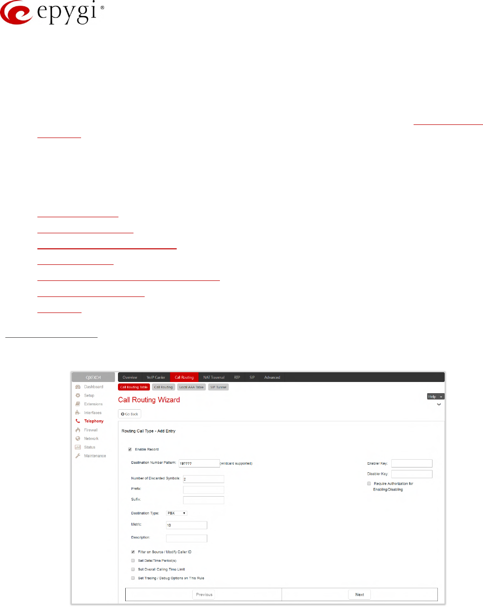
Manual-II: Administration Guide for QX Gateways
Edition 2 (FW Version 6.1.17 and higher) 86
All calls from QX extensions, as well as some calls from external sources, are being routed in QX according to
call routing rules (records) that specify the destination based on the dialed number. When a user dials a
number, the QX matches the dialed number against the destination number patterns in call routing records.
1. If the dialed number matches only with a single pattern, then the record with respective pattern will be
used to set up the call.
2. If multiple patterns have been found to match the dialed number, the QX uses the Best Matching
Algorithm to prioritize the matching patterns.
3. Once the patterns are prioritized, the record having pattern of the highest priority will be used as a
preferred route for call setup.
The Add button starts the Call Routing Wizard for configuring a new call routing record. In general, the Wizard
passes through the following sections:
•Routing Call Type
•Routing Call Settings
•Source Filter / Modify Caller ID
•Date/Time Rules
•Routing Overall Calls Limitation Settings
•Tracing/Debug Options
•Summary
Routing Call Type
In this section of the Wizard user configures the following settings:
Figure 75: Routing Call Type section
•Enable Record – is used to disable/enable the newly created routing rule. This option is checked off by
default.
•Destination Number Pattern – specifies a template for filtering out the calls that can be routed via
respective call routing record. If destination number of the call matches with specified pattern, then the

Manual-II: Administration Guide for QX Gateways
Edition 2 (FW Version 6.1.17 and higher) 87
call can be completed via respective call routing record. The Destination Number Pattern may contain
wildcards.
•Number of Discarded Symbols – specifies the number of symbols/digits/characters that shall be
removed from the beginning of the destination number after matching it against the destination number
pattern. The field should be empty if no symbols need to be discarded.
•Prefix – specifies the symbols/digits/characters that will be added in front of the destination number
after discarding the symbols as described above. Except for single characters or character strings, the
following tags can be used for this field:
<callerid:range> – allows to use the caller ID or its part as a prefix. For example, <callerid:1-3>
indicates that the first 3 digits of the caller ID will be considered as a prefix, <callerid:3-end> indicates
that the caller ID from its 3rd digit and up to the end will be assigned to prefix.
<dialednum:range> – allows to use the dialed number or its part as a prefix. For example, <dialnum:1-
3> indicates that the first 3 digits of the dialed number will be as assigned to the prefix, <dialnum:1-
end> indicates that the dialed number from its 3rd digit and up to the end will be assigned to prefix.
aaa,,,bbb – allows two-stage dialing. The aaa and bbb are the numbers to call; bbb can also be a
series of digits to inject; a comma indicates a delay of one second. For example, 11,,,11018 will call
to 11, wait until the call is established, wait for three seconds and then dial/inject 11018. The two-
stage dialing is available for FXO, ISDN, and E1/T1destination types.
•Suffix – specifies the characters that will be added to destination number from the end after discarding
the symbols and adding the prefix as described above.
•Destination Type – is used to select the call destination type. The following destination types are
available:
PBX (N/A for QXFXS24) – local call to QX’s extension.
SIP – calls through a SIP server.
SIP_Tunnel – calls through an established SIP tunnel.
IP-PSTN (N/A for QXFXS24) – calls through the IP-PSTN provider to the global PSTN network.
FXO – calls to the PSTN network through FXO lines (available only for QXFXO4).
ISDN – calls to the PSTN network through ISDN trunks (available only for QXISDN4).
E1/T1 – calls to the PSTN network through E1/T1trunk(s) (available only for QXE1T1).
•Metric – is used to enter a rating for the selected route in a range from 0 to 20. If no value is inserted
into this field, 10 will be used as the default. If two route entries match a user’s dial string, the route with
the lower metric will be chosen.
•Enabler Key and Disabler Key (N/A for QXFXS24)– is a digital code which should be dialed from handset
or the Auto Attendant to enable or disable the routing rule. You can set the same Enabler/Disabler key
for multiple routing rules (the same key may be used as enabler for one routing rule, and as disabler for
another one) – this will allow managing several routing rules with the single key.
Require Authorization for Enabling/Disabling – is used to enable administrator’s password (Phone
Access Password) authentication when enabler/disabler keys are configured for a certain routing rule.
The service can be used locally from the handset or remotely on the Auto Attendant. When this
checkbox is selected, the password will be requested to enable/disable the certain routing rule(s). TIP:
If the password has been inserted incorrectly for 3 times, no status changes will be applied to any of
the routing record(s), even to those which have no authorization enabled.
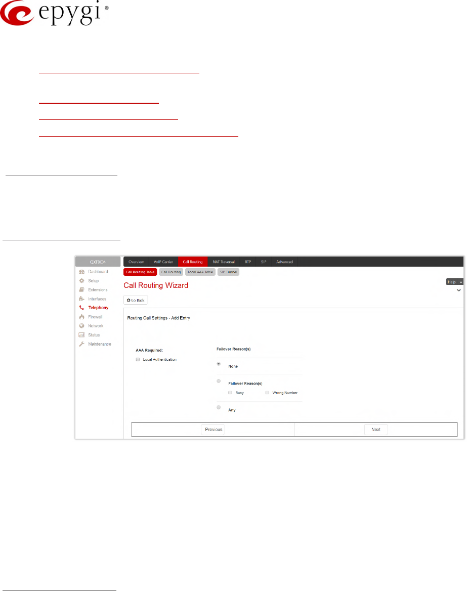
Manual-II: Administration Guide for QX Gateways
Edition 2 (FW Version 6.1.17 and higher) 88
The following four options give additional configuration possibilities:
•Filter on Source / Modify Caller ID – selection allows to limit the routing pattern availability for selected
caller(s) or to modify the caller ID. This option is enabled by default.
•Set Date / Time Period(s) – is used to define a validity period(s) for the routing pattern.
•Set Overall Calling Time Limit – is used to control and limit the total calls duration for the routing pattern.
•Set Tracing / Debug Options on This Rule – allows to enable/disable generating event notifications on
the result of using the routing rule.
Routing Call Settings
This section offers different components depending on the call Destination Type selected on the previous
section.
Destination Type – PBX
Figure 76: Routing Call Settings section for PBX destination type
•Local Authentication – if selected, the caller(s) will need to pass an authorization to make PBX calls.
•Failover Reason(s) – the system will use next matching pattern(s) to establish the call if the call setup fails
due to below presented failover reasons:
None – the system will not use next matching pattern(s) regardless of the failover.
Busy – the system will use next matching pattern(s) if the dialed destination is busy.
Wrong Number – the system will use next matching pattern(s) if the dialed number is wrong.
Any – the system will use next matching pattern(s) regardless the failover reason.
Destination Type – SIP
•Use Extension Settings – is used to select the extension (also Auto Attendant) on behalf of which the call
will be placed. The SIP settings of the selected extension will be used as the caller information. If
nothing is selected from the list, the original caller information will be kept.
•Keep Original Caller ID – if selected, the called destination will receive the original caller’s information.
•Add Remote Party ID – if selected, the Remote Party ID parameter will be added in the outgoing Invite
message.

Manual-II: Administration Guide for QX Gateways
Edition 2 (FW Version 6.1.17 and higher) 89
•Destination Host – is the IP address or hostname of the destination (for a direct call) or SIP server (for
calls through the SIP server). TIP: This field renamed to Modified Destination Host if the Destination
Number Pattern field (in the wizard’s first page) contains "@" symbol.
•Destination Port – is the port number of the destination or the SIP server. TIP: This field renamed
Modified Destination Port if the Destination Number Pattern field (in the wizard’s first page) contains "@"
symbol.
•Username and Password – is used to define the authentication parameters for the SIP server if needed.
•Use RTP Proxy – if selected, the RTP streams between peers will be routed through the QX. This is
applicable when the peers are both located outside the QX. If not selected, the RTP streams will move
directly between peers.
•Single Call Duration Limit – is used to limit the duration of the call placed through the routing rule. The
single call duration will be unlimited If the checkbox is not selected. Maximum Duration is used to define
the maximum duration of the call (in seconds). The call will be disconnected without prior notice if the
maximum duration is reached.
•Local Authentication – if selected, the caller(s) will need to pass an authorization to make SIP calls.
•Voice Transcoding – if selected, the RTP stream will converted to different codec before transmitting to
the destination system.
•Failover Reason(s) – the system will use next matching pattern(s) to establish the call if the call setup fails
due to below presented failover reasons:
None – the system will not use next matching pattern(s) regardless of the failover.
Busy – the system will use next matching pattern(s) if the dialed destination is busy.
Wrong Number – the system will use next matching pattern(s) if the dialed number is wrong.
Network Failure – the system will use next matching pattern(s) when system overload, network failure
or timeout expiration occurred.
System Failure – the system will use next matching pattern(s) if indicates one of cases in the Network
Failure or Other fail reason groups.
Other – the system will use next matching pattern(s) if indicates cases when authorization, negotiation,
not supported, request rejected or other unknown errors occur.
Any – stands for all failure reasons mentioned in the Failover Reason(s) group.
•Enable Failover Timeout – is used to define the period after which the call could be considered as failed
(SIP response message isn’t received). The Failover Timeout is used to define the timeout duration (in
the range from 1 to 180 seconds). The call will be established through next matching pattern(s) after the
timeout expired if the failover reason is enabled for the routing rule.
•SIP Privacy – is used to select the security level of the SIP route by means of hiding or replacing
(depending on the configuration of the SIP server) the key headers of the SIP messages used to
establish the call.
Default Privacy – if selected, no QX specific SIP privacy will be applied, and all privacy will be relied on
the configuration of the SIP Server.
Disable Privacy – if selected, SIP call security will be disabled, all headers of the SIP message will be
transparently visible to the destination.
Enable Privacy – if selected, QX specific SIP privacy will be applied for the corresponding route.
Selection enables a group of checkboxes to choose the key headers to be fully or partly hidden or
replaced. Require Privacy checkbox is used to restrict the delivery of the SIP message if either of the
selected headers cannot be hidden (or replaced, depending on the configuration of the SIP server)
before being sent to the destination.
•Transport Protocol for SIP messages – is used to select the transport protocol (UDP, TCP or TLS) for
transmitting the SIP messages.

Manual-II: Administration Guide for QX Gateways
Edition 2 (FW Version 6.1.17 and higher) 90
Destination Type – SIP_Tunnel
•Use Extension Settings – is used to select the extension (also Auto Attendant) on behalf of which the call
will be placed. The SIP settings of the selected extension will be used as the caller information. If an
entry is not selected from this list, the original caller information will be kept.
•Keep Original Caller ID – if selected, the called destination will receive the original caller’s information.
•Add Remote Party ID – if selected, the Remote Party ID parameter will be added in the outgoing Invite
message.
•SIP Tunnel – is used to select the previously configured SIP tunnel to route the calls through tunnel to
the remote QX device (QX IP PBXs and QX Gateways).
•Use RTP Proxy – is applicable when a route is used for calls through QX between peers that are both
located outside the QX. RTP streams between the peers will be routed through QX if the checkbox
selected, otherwise the RTP packets will move directly between peers.
•Single Call Duration Limit – is used to limit the duration of the call placed through the routing rule. The
single call duration will be unlimited if the checkbox is not selected. Maximum Duration is used to define
the maximum duration of the call (in seconds). The call will be disconnected without prior notice if the
maximum duration is reached.
•Local Authentication – if the checkbox selected, the caller(s) will need to pass authorization to make SIP
call through the tunnel.
•Voice Transcoding – if selected, the RTP stream will converted to different codec before transmitting to
the destination system.
•Failover Reason(s) – the system will use next matching pattern(s) to establish the call if the call setup fails
due to below presented failover reasons:
None – the system will not use next matching pattern(s) regardless of the failover.
Busy – the system will use next matching pattern(s) if the dialed destination is busy.
Wrong Number – the system will use next matching pattern(s) if the dialed number is wrong.
Network Failure – the system will use next matching pattern(s) if the system overload, network failure
or timeout expiration occurred.
System Failure – the system will use next matching pattern(s) if indicates one of cases in the Network
Failure or Other fail reason groups.
Other – the system will use next matching pattern(s) if the authorization request rejected or other
unknown errors occur.
Any – the system will use next matching pattern(s) regardless the failover reason.
•Enable Failover Timeout – is used to define the period after which the call could be considered as failed
(SIP response message isn’t received). The Failover Timeout is used to define the timeout duration (in
the range from 1 to 180 seconds). The call will be established through next matching pattern(s) after the
timeout expired if the failover reason is enabled for the routing rule.
•SIP Privacy – is used to select the security level of the SIP route by means of hiding or replacing
(depending on the configuration of the SIP server) the key headers of the SIP messages.
Default Privacy – if selected, QX specific SIP privacy will not be applied and all privacy will rely on the
configuration of the SIP Server.
Disable Privacy – if selected, SIP call security will be disabled and all headers of the SIP message will
be transparently visible to the destination.
Enable Privacy – if selected, QX specific SIP privacy will be specified for the corresponding route.
Selection enables a group of checkboxes to choose the key headers to be fully or partly hidden or
replaced. Require Privacy is used to restrict the delivery of the SIP message if either of the selected
headers cannot be hidden (or replaced, depending on the configuration of the SIP server) before
being sent to the destination.

Manual-II: Administration Guide for QX Gateways
Edition 2 (FW Version 6.1.17 and higher) 91
•Transport Protocol for SIP messages – is used to select the transport protocol (UDP, TCP or TLS) for
transmitting the SIP messages.
Destination Type – IP-PSTN
•Use Extension Settings – is used to select the extension (or Auto Attendant) on behalf of which the call
will be placed. The SIP settings of the selected extension will be used as the caller information. If an
entry is not selected from this list, the original caller information will be kept.
•Keep Original Caller ID – if selected, the called destination will receive the original caller’s information.
•Add Remote Party ID – if selected, the Remote Party ID parameter will be added in the outgoing Invite
message.
•Destination Host – is the IP address or the hostname of the destination (for a direct call) or the SIP
server (for calls through the SIP server). TIP: This field renamed to Modified Destination Host if the
Destination Number Pattern field (in the wizard’s first page) contains "@" symbol.
•Destination Port – is the port number of the destination or the SIP server. TIP: This field renamed
Modified Destination Port if the Destination Number Pattern field (in the wizard’s first page) contains "@"
symbol.
•Username and Password – is used to define the authentication parameters for SIP server if needed.
•Restrict the Number of Simultaneous Calls – is used to restrict the number of simultaneous calls to the
SIP server with the same username. Allowed Call Count is used to define the number of simultaneous
calls.
•Enable Failover Timeout – is used to define the period after which the call could be considered as failed
(SIP response message isn’t received). Failover Timeout is used to define the timeout duration (in the
range from 1 to 180 seconds). The call will be established through next matching pattern(s) after the
timeout expired if the failover reason is enabled for the routing rule.
•Use RTP Proxy – if selected, the RTP streams between peers will be routed through the QX. This is
applicable when the peers are both located outside the QX. If not selected, the RTP streams will move
directly between peers.
•Single Call Duration Limit – is used to limit the duration of the call placed through the routing rule. The
single call duration will be unlimited If the checkbox is not selected. Maximum Duration is used to define
the maximum duration of the call (in seconds). The call will be disconnected without prior notice if the
maximum duration is reached.
•Local Authentication – if selected, the caller(s) will need to pass an authorization to make calls.
•Failover Reason(s) – the system will use next matching pattern(s) to establish the call if the call setup fails
due to below presented failover reasons:
None – the system will not use next matching pattern(s) regardless of the failover.
Busy – the system will use next matching pattern(s) if the dialed destination is busy.
Wrong Number – the system will use next matching pattern(s) if the dialed number is wrong.
Network Failure – the system will use next matching pattern(s) if the system overload, network failure
or timeout expiration occurred.
System Failure – the system will use next matching pattern(s) if indicates one of cases in the Network
Failure or Other fail reason groups.
Other – the system will use next matching pattern(s) if the authorization request rejected or other
unknown errors occur.
Any – the system will use next matching pattern(s) regardless the failover reason.
•SIP Privacy – is used to select the security level of the SIP route by means of hiding or replacing
(depending on the configuration of the SIP server) the key headers of the SIP messages.

Manual-II: Administration Guide for QX Gateways
Edition 2 (FW Version 6.1.17 and higher) 92
Default Privacy – if selected, QX specific SIP privacy will not be applied and all privacy will rely on the
configuration of the SIP Server.
Disable Privacy – if selected, SIP call security will be disabled and all headers of the SIP message will
be transparently visible to the destination.
Enable Privacy – if selected, QX specific SIP privacy will be specified for the corresponding route.
Selection enables a group of checkboxes to choose the key headers to be fully or partly hidden or
replaced. Require Privacy checkbox is used to restrict the delivery of the SIP message if either of the
selected headers cannot be hidden (or replaced, depending on the configuration of the SIP server)
before being sent to the destination.
•Transport Protocol for SIP messages – is used to select the transport protocol (UDP, TCP or TLS) for
transmitting the SIP messages.
Destination Type – FXO
•Port ID – is used to select a specific or any of the available FXO line to route the calls. The following
options are available:
None – selection means no local (On-board) FXO lines will be used to route the call.
Any Port – the call will be established through the first available local FXO line.
Specific Port – the call will be established only through the selected local FXO line.
If another QXFXO4 GW is connected to the QXFXO4 in share mode, the following additional options will be
available:
Any@Any – the calls will be established through the first available on-board FXO lines then through
shared FXO lines.
Any Port@ – the call will be established through the first available shared FXO line.
Specific Port@ – the call will be established only through the selected shared FXO line.
•FXO Lines Load Balancing – is used to enable load balancing mechanism on the FXO lines.
None – the system will not apply load balancing mechanism and the call will be routed through the
first available FXO line (among the selected ones).
Round Robin – the system will apply load balancing mechanism according to an internally gained
statistics of most used FXO lines, the call will be routed to the less used and currently available FXO
line (among the selected ones).
•Local Authentication – if selected, caller(s) will need to pass an authorization to make FXO calls.
•Failover Reason(s) – the system will use next matching pattern(s) to establish the call if the call setup fails
due to below presented failover reasons:
None – the system will not use next matching pattern(s) regardless of the failover.
Cannot Establish Connection – the system will use next matching pattern(s) if the connection cannot
be established.
Any – the system will use next matching pattern(s) regardless the failover reason.
Destination Type – ISDN
•Keep Original Caller ID – if selected, the called party will receive the original caller’s information (mobile
number, PSTN/SIP number, etc.) instead of extension’s information when the call(s) are forwarded.
•Port ID – is used to select a specific or any of the available trunk to route the calls. The following options
are available:
Any Port (User) – the calls will be established through any ISDN trunks running in User mode.
Any Port (Network) – the calls will be established through any ISDN trunks running in Network mode.
ISDN Trunk # – the calls will be established through the selected ISDN trunk.

Manual-II: Administration Guide for QX Gateways
Edition 2 (FW Version 6.1.17 and higher) 93
If another QXISDN4 GW is connected to the QX in share mode, the following additional options will be available:
Any Port (User)@Any – the calls will be established through the first available on-board ISDN trunks
running in User mode then through shared ISDN trunks running in User mode.
Any Port (Network)@Any – the calls will be established through the first available on-board ISDN trunks
running in Network mode then through shared ISDN trunks running in Network mode.
ISDN Trunk # @ – the call will be established through the selected shared ISDN trunk.
Any Port (User)@ – the calls will be established through the first available shared ISDN trunks running
in User mode.
Any Port (Network)@ – the calls will be established through the first available shared ISDN trunks
running in Network mode.
•Collect Call – is used when the calling party wants to place a call at the called party's expense. This
service is applicable only if the Collect Call service is enabled on both calling and called party's.
•Local Authentication – if selected, the caller(s) will need to pass an authorization to make ISDN calls.
•Failover Reason(s) – the system will use next matching pattern(s) to establish the call if the call setup fails
due to below presented failover reasons:
None – the system will not use next matching pattern(s) regardless of the failover.
Cannot Establish Connection – the system will use next matching pattern(s) if the connection cannot
be established.
Any – the system will use next matching pattern(s) regardless the failover reason.
Attention: An additional wizard page will be available for ISDN type calls for configuring trunk timeslots.
•Select Timeslots – is used to select timeslot(s) which will be used for placing ISDN calls.
Destination Type – E1/T1
•Keep Original Caller ID – if selected, the called party will receive the original caller’s information (mobile
number, PSTN/SIP number, etc.) instead of extension’s information when the call(s) are forwarded.
•Port ID – is used to select a specific shared E1/T1 trunk to route the call(s). The following option is
available:
E1/T1 Trunk1 @ – the call will be established through the selected shared E1/T1 trunk.
•Collect Call – is used when the calling party wants to place a call at the called party's expense. This
service is applicable only if the Collect Call service is enabled on both calling and called party's.
•Single Call Duration Limit – if selected, puts a limit on the duration of the call placed through the routing
rule, otherwise the call duration will be unlimited. Maximum Duration is used to define the maximum
duration of the call (in seconds).
•Local Authentication – if selected, the caller(s) will need to pass authorization to make E1/T1 call.
•Failover Reason(s) – the system will use next matching pattern(s) to establish the call if the call setup fails
due to below presented failover reasons:
None – the system will not use next matching pattern(s) regardless of the failover.
Cannot Establish Connection – the system will use next matching pattern(s) if the connection cannot
be established.
Any – the system will use next matching pattern(s) regardless the failover reason.
Attention: An additional wizard page will be available for E1/T1 type calls for configuring trunk timeslots.
•Select Timeslots – is used to select timeslot(s) which will be used for placing E1/T1 calls.
Up to 30 timeslots will be available for placing E1 calls regardless the trunk signaling type.
Up to 23 timeslots will be available for placing T1 calls if the trunk signaling type is CCS.
Up to 24 timeslots will be available for placing T1 calls if the trunk signaling type is CAS.
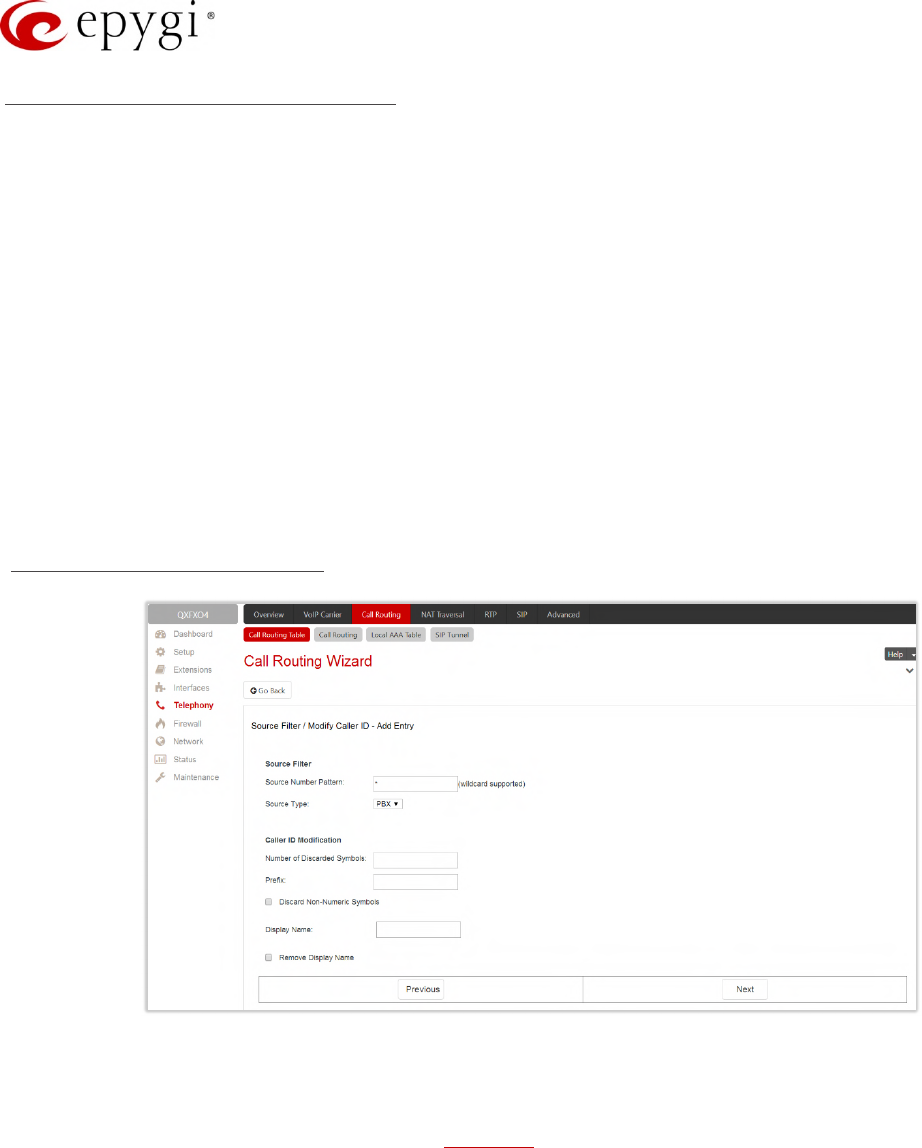
Manual-II: Administration Guide for QX Gateways
Edition 2 (FW Version 6.1.17 and higher) 94
Radius Authentication and Authorization
RADIUS Authentication and Authorization options are available for the routing pattern regardless destination call
type if a RADIUS client is enabled.
•RADIUS Authentication and Authorization – is used to make the caller(s) pass the authorization through
the RADIUS server to make calls.
•RADIUS Accounting – if selected, no authentication will take place, except for CDRs (call detail reports)
of the calls made through this routing record will be sent to the RADIUS server. This checkbox selection
enables the Client Code Identification checkbox. If the authentication is configured based on the caller’s
address, callers will pass the authentication automatically; otherwise they will be required to identify
themselves by a username and password.
•Client Code Identification – activate the code identification feature: a caller, after dialing the destination
phone number, may optionally enter "*" and then an Identity Code. An Identity Code is an arbitrary digit
string entered by the user to identify a specific call or call group. The Identity Code is sent with a CDR to
the RADIUS server and might be used by a billing program for grouping the calls having the same
Identity Code.
Source Filter / Modify Caller ID
Figure 77: Source Filter / Modify Caller ID section
•Source Filter – is used to limit the routing pattern availability for selected caller(s).
Source Number Pattern – insert the caller address for which the routing pattern will be available. The
Source Number Pattern may contain wildcards.
Source Type – is used to select the caller source type. The following options are available:
Any – any caller will be able to make calls regardless caller source type.
PBX – only PBX extension(s) will be able to make calls.
SIP – only inbound SIP caller(s) will be able to make calls. To configure Source Host address (IP
address or hostname) for SIP call type, an additional wizard page will be available.
SIP_Tunnel – only inbound callers from the selected SIP_Tunnel will be able to make calls. To select
Inbound SIP Tunnel, an additional wizard page will be available.
FXO – only inbound FXO caller(s) will be able to make calls. To select Port ID for FXO call type, an
additional wizard page will be available.
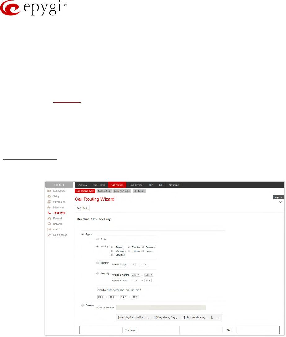
Manual-II: Administration Guide for QX Gateways
Edition 2 (FW Version 6.1.17 and higher) 95
ISDN – only inbound ISDN caller(s) will be able to make calls. To select Port ID for ISDN call type, an
additional wizard page will be available.
E1/T1 – only inbound E1/T1 caller(s) will be able to make calls. To select Port ID for E1/T1 call type,
an additional wizard page will be available.
•Caller ID Modification – is used to modify the Caller ID before sending them to remote party.
Number of Discarded Symbols – insert the number of digits that should be discarded from the
beginning of the Source Number Pattern. Left the field empty if no need to discard the digits.
Prefix – insert the symbols that will be placed in front of the Source Number Pattern. The Prefix may
contain wildcards.
Discard Non-Numeric Symbols – is used to discard any non-numeric symbols from the Source
Number Pattern.
Display Name – is used to replace an original caller’s ID with the custom display name. This option is
not applicable for the PBX-Voicemail destination type routing rule.
Remove Display Name – is used to remove caller IDs.
Date/Time Rules
The Date/Time Rules section is used to define a validity period(s) for the routing pattern.
Figure 78: Date/Time Rules section
•Typical – is used to select one of the below presented validity periods:
Daily – the routing pattern will be available for each day.
Weekly – the routing pattern will be available for the selected weekday(s).
Monthly – the routing pattern will be available for the selected day(s) in each month.
Annually – the routing pattern will be available for the selected day(s) and month(s) for each year.
•Custom – is used to manually define the validity period(s).
TIP: The inserted values needs to be in this [Month, Month-Month] [Day, Day-Day] [hh:mm-hh:mm] format.
•Available Time Period – is used to define the validation time range for the routing pattern. The defined
time here will be checked against QX’s time.
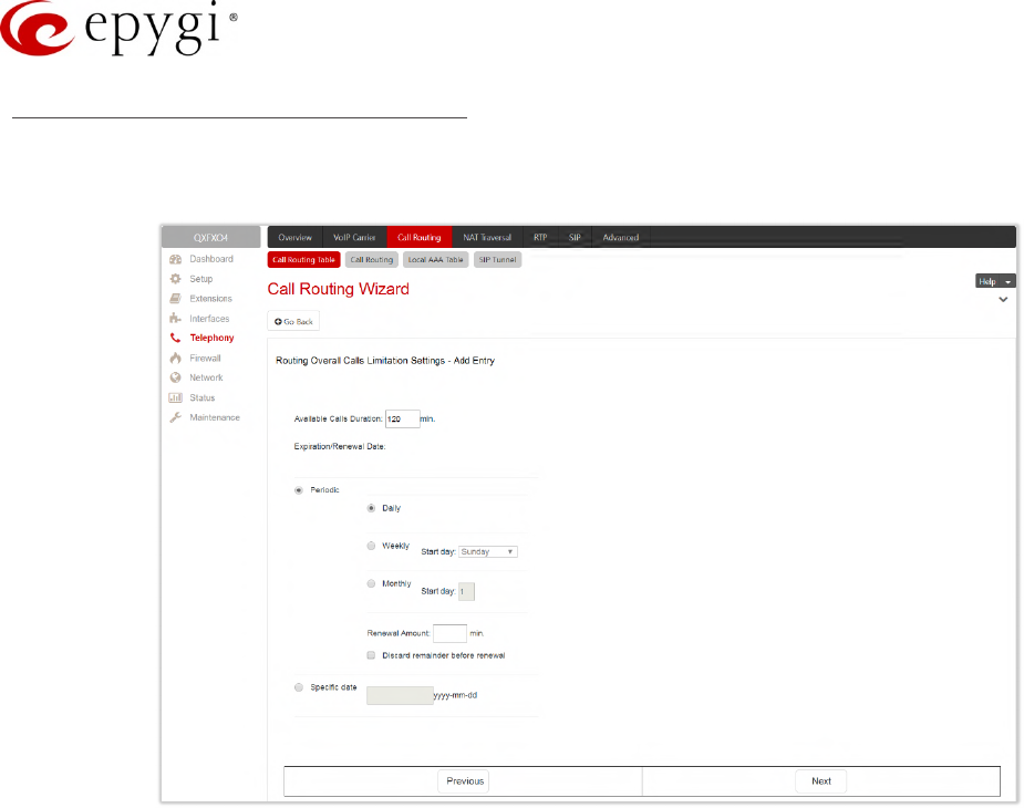
Manual-II: Administration Guide for QX Gateways
Edition 2 (FW Version 6.1.17 and higher) 96
Routing Overall Calls Limitation Settings
The Routing Overall Calls Limitation Settings are used to control the total duration for all calls through the
specific routing rule for defined period(s).
Figure 79: Routing Overall Calls Limitation Setting section
•Available Calls Duration – the total duration for all calls (in minutes) through the selected routing pattern.
Once the Available Calls Duration expires, the current call will be disconnected without prior notice and
no new call will be possible until the Available Calls Duration is updated manually or automatically by
specified Renewal Date/Amount.
The settings under the Expiration/Renewal Date section are used to configure the Expiration Date, Renewal
Date and Renewal Amount of the Available Calls Duration.
•Periodic – is used to select one of the below presented Renewal Date options:
Daily – the defined Available Calls Duration will be renewed each day.
Weekly – the defined Available Calls Duration will be renewed each week.
Monthly – the defined Available Calls Duration will be renewed each month.
Renewal Amount – insert the renewal amount (in minutes) to be added to the available calls duration
when the expiration date of the Available Calls Duration is reached. Leave the Renewal Amount empty,
if you don’t need to renew the Available Calls Duration.
Discard remainder before renewal – is used to discard the remainder of Available Calls Duration
before renewal and set the Renewal Amount as the new Available Calls Duration.
•Specific Date – is used to manually define the expiration date for the Available Calls Duration. When the
Specific Date expires, the routing rule becomes unavailable automatically and no new call will be
possible until this field is updated.
Note: The Overall Calling Time Limitation is not applicable for "PBX", type routing rules.
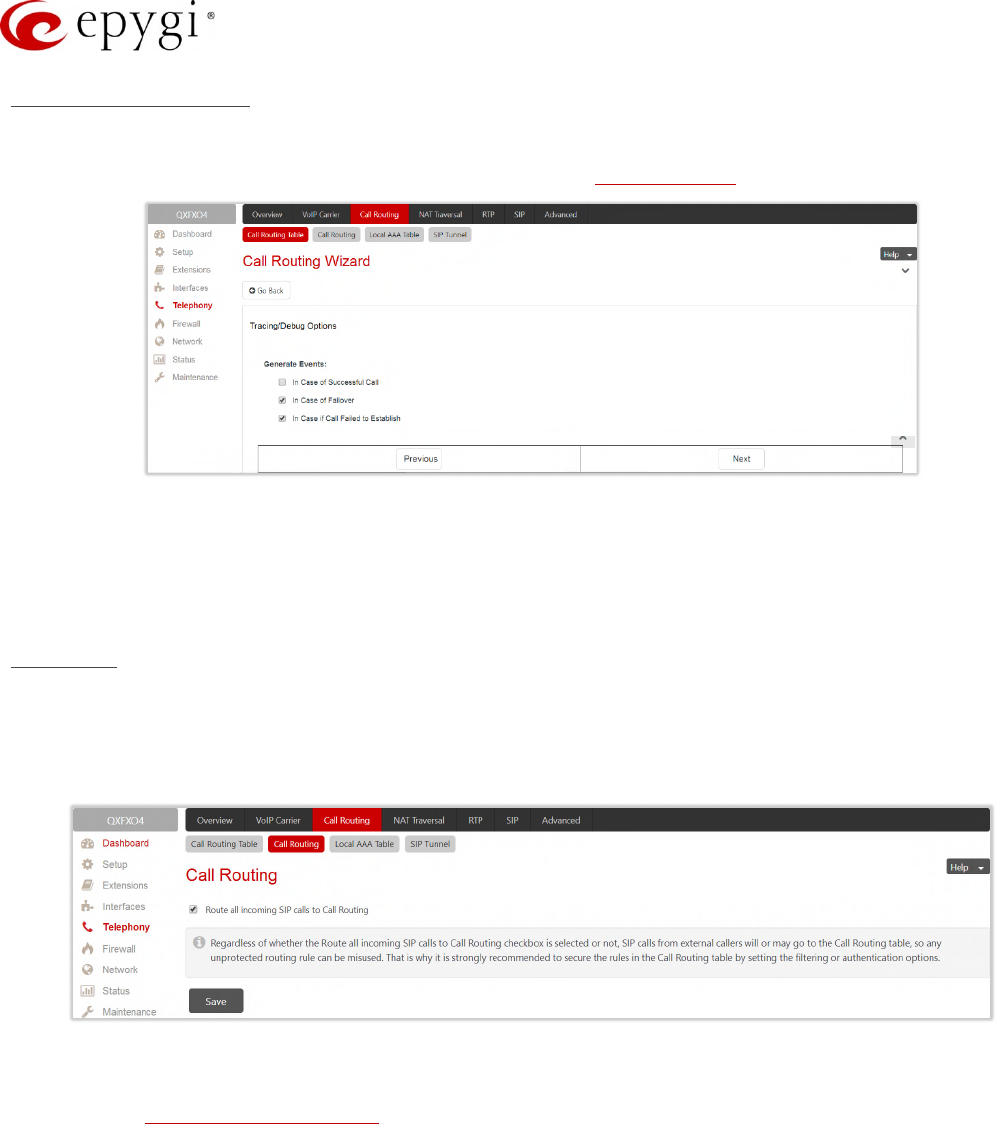
Manual-II: Administration Guide for QX Gateways
Edition 2 (FW Version 6.1.17 and higher) 97
Tracing/Debug Options
The Set Tracing/Debug Options are used to generate event notifications on the certain execution result for the
routing rule. The events will be generated and displayed in the System Events for the following cases:
Figure 80: Tracing/Debug Options section
•In Case of Successful Call – when a call was successful established with the routing rule.
•In Case of Failover – when the call ends up due to one of the selected failover reasons.
•In Case if Call Failed to Establish – when the call executed through the routing rule failed.
Summary
The Summary section displays all configured settings for the routing pattern before applying them.
8.3 Call Routing
Figure 81: Call Routing page
Route all incoming SIP calls to Call Routing – if not selected, the system will first search the incoming SIP
address in the Extensions Management table. If matching the incoming SIP call will ring on the corresponding
extension, otherwise the system will look for a matching routing rule in the Call Routing Table. If this option is
selected, the system will directly look for a matching routing rule in the Call Routing Table and ignore the
possible matches in the Extensions Management table.
Attention: Regardless of whether Route all incoming SIP calls to Call Routing is selected or not, SIP calls from
external callers will or may go to the Call Routing Table, so any unprotected routing rule can be misused. That is
why it is strongly recommended to secure the rules in the Call Routing Table by setting the filtering or
authentication options.
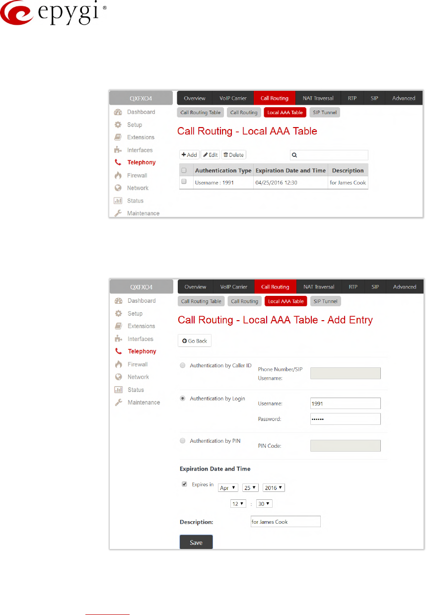
Manual-II: Administration Guide for QX Gateways
Edition 2 (FW Version 6.1.17 and higher) 98
8.4 Local AAA Table
The Call Routing – Local AAA Table is used to configure and manage the local authentication database.
Figure 82: Call Routing – Local AAA Table page
•Add – leads to the Call Routing – Local AAA Table - Add Entry page to create a new local AAA entry as
follows:
Figure 83: Call Routing - Local AAA Table - Add Entry page
Authentication by Caller ID – set the authentication based on the caller's phone number or SIP
username (which is considered to be automatically detected). The Phone Number/SIP Username may
contain wildcards.
Authentication by Login – set the authentication based on the Username and Password provided by
the user upon login.
Authentication by PIN – set the authentication based on the PIN Code provided by the user upon
login.
Expires in – select to enable the Expiration Date and Time option and define the expiration date for the
configured local AAA entry.
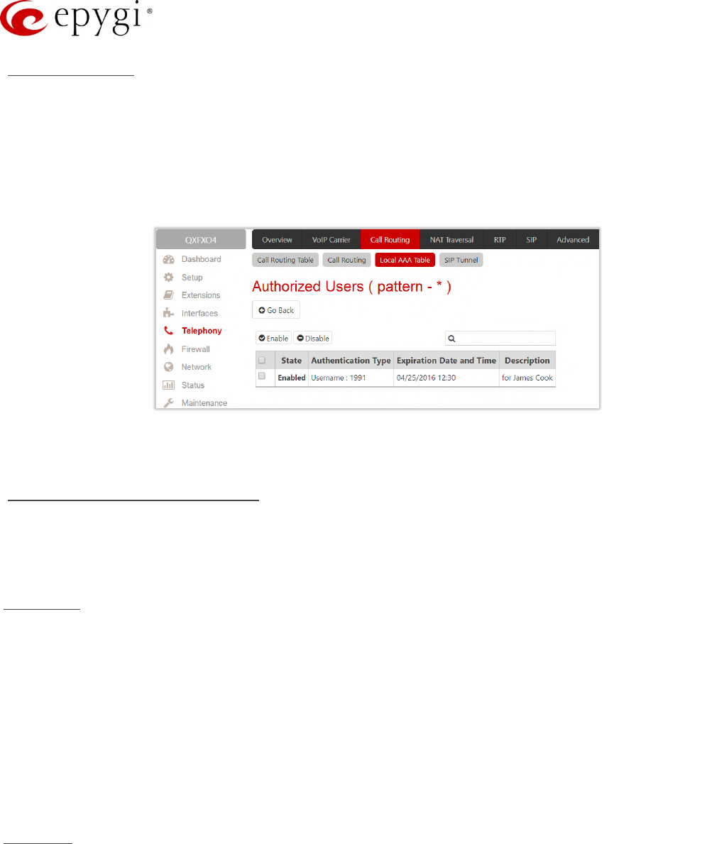
Manual-II: Administration Guide for QX Gateways
Edition 2 (FW Version 6.1.17 and higher) 99
Authorized Users
Caller(s) have to pass an authorization if the AAA option is enabled on the routing pattern. The Authorized Users
link leads to the Authorized Users page to enable or disable the configured authentication entry(s) for the
corresponding routing rule.
The caller will automatically pass the authorization if the caller's phone number or SIP username is enabled in
the Authorized Users table, otherwise will be asked to login (enter username and password) or enter the PIN
Code.
Figure 84: Authorized Users page
Note: Authentication by Login cannot be combined with Authentication by PIN on the same routing rule.
Allowed Characters and Wildcards
The following is the complete list of the characters and wildcards supported in the QX system.
Not all characters and wildcards are supported for all QX options and settings. Thus, depending on the
meaning of the option some limitations can be applied.
Characters
•Numbers – 0…9
•Letters – A…Z, a…z
•Special symbols – =; +; -; $ ; / ; ~ ; _ ; – ; . ; & ; ( ) ; ' ; ! ; * ; ? ; {} ; [ ]
Note:
•The symbols (*, ?, -, ! and ,) should be prefixed with a slash (\) symbol if they are used as ordinary
characters; otherwise the system will interpret them as wildcards.
•The symbols !; { }; [ ]; – and , are used to define a range of characters and cannot be used as ordinary
characters.
Wildcards
•* – any number of any characters
•? – any single character
•{} – a character or a string from the specified set of characters and strings
•[] – a character from the specified set of characters and strings
Note: You can use the wildcard ? within the braces, but not *.
The following control symbols are used to specify a set:
•Use a comma (,) to separate the elements of a set.

Manual-II: Administration Guide for QX Gateways
Edition 2 (FW Version 6.1.17 and higher) 100
Example: The pattern is: 9{1,3,11,a}
Numbers matching the pattern will be: 91, 93, 911, 9a
Note: No spaces are allowed within braces.
•Use a minus sign (-) to specify a range of characters. Each successive element of the range is obtained
by increasing the previous element (the element code) by one.
Example: The pattern is: 2{11-15,a-d}5
Numbers matching the pattern will be: 2115, 2125, 2135, 2145, 2155, 2a5, 2b5, 2c5, 2d5
•Use an exclamation point (!) to exclude a character or a string from a set.
Example: The pattern is: 2{11-15,a-d,!14,!c}5
Numbers matching the pattern will be: 2115, 2125, 2135, 2145, 2155, 2a5, 2b5, 2d5
Note: The exclamation point (!) cannot be used to exclude a range of symbols.
•Use a slash (\) before control symbols (*, ?, -, ! and ,) to use them as an ordinary character.
Example: The pattern is: 1\*[1–3]
Numbers matching the pattern will be: 1*1, 1*2, 1*3
•Use an at sign (@) to indicate full SIP address (for example: 20233@sip.epygi.com). This pattern is
mainly used to call back users registered on the SIP server different from the one where the called party
is registered.
Note: Patterns containing @ symbol will not be parsed among those that do not have @ symbol in the Call
Routing Table. When calling from local extensions (the calling number for PBX extension is
sip_number@ip_address_of_QX, e.g. 20233@192.168.35.25), only the sip number part of the pattern will be
parsed among other entries with @ symbol in the Call Routing Table.
Best Matching Algorithm
Each call through and within a QX are made according to call routing patterns that specify a destination based
on a dialed number. When a user dials a number, the QX matches the dialed number against the existing
routing patterns.
1. If the dialed number matches only to a single pattern, this pattern will be used to set up the call.
2. If multiple patterns have been found to match the number, the QX uses the Best Matching Algorithm to
prioritize the matching patterns.
3. Once the patterns are prioritized, the pattern with the highest priority will be used as a preferred route
for call setup.
Attention: The subsequent prioritized pattern will be used only if the destination specified by a pattern with
higher priority is unreachable and the corresponding Failover(s) configured.
To prioritize the matching patterns, the following criteria are sequentially applied to matching patterns. The
criteria are ordered by their priorities: Each consecutive criterion is calculated only for the patterns that take the
same value for the preceding criterion: that is Criterion 3 is calculated only for patterns that take the same value
for Criterion 1 and Criterion 2.

Manual-II: Administration Guide for QX Gateways
Edition 2 (FW Version 6.1.17 and higher) 101
Criteria list
•Criterion 1 – is the presence of asterisks (*) in a pattern. The patterns without (*) have a higher priority.
•Criterion 2 – is the total number of matching digits/symbols inside and outside the braces/brackets. The
more matching digits a pattern contains, the higher its priority.
•Criterion 3 – is the number of matching digits/symbols outside the braces/brackets. The more matching
digits outside braces/brackets a pattern contains, the higher its priority. TIP: This criterion is used only if
several patterns take an equal but non-zero value for Criterion 2.
•Criterion 4 – is the total number of question marks (?) inside and outside the braces/brackets. The more
question marks a pattern contains, the higher its priority.
•Criterion 5 – is the number of question marks (?) outside braces/brackets. The more question marks
outside braces/brackets a pattern contains, the higher its priority. TIP: This criterion is used only if
several patterns take an equal but non-zero value for Criterion 4.
•Criterion 6 – is the number of square brackets ([]). The more brackets a pattern contains, the higher its
priority.
•Criterion 7 – is the number of braces ({}). The more braces a pattern contains, the higher its priority.
•Criterion 8 – is the number of asterisks (*). The fewer asterisks a pattern contains, the higher its priority.
•Criterion 9 – is the value of the metric. The lower the metric of a pattern is, the higher its priority.
•Criterion 10 – is the position in the routing table. The higher the position of a pattern in the routing table
is, the higher its priority.
Example: The user dials 1231, the following matching patterns are found in the Call Routing Table.
Pattern Position Routing Pattern
1 *1*
2 123*
3 {11–15}3*
4 ?2?1
5 [1–3]*
6 {100–150, asd, \*\?}1
7 1[1–3]3[0–8]
8 123?
9 *2*1
10 *
Table 2: Example – The list of Patterns
Step 1: The list is sorted and the patterns with asterisks (*) are pushed back to the end of the list, due to lower
priority (Criterion 1).
Position after
Step1 Routing Pattern
1 ?2?1
2 {100–150, asd, \*\?}1
3 1[1–3]3[0–8]
4 123?
5 *1*
6 123*
7 {11–15}3*
8 [1–3]*
9 *2*1
Manual-II: Administration Guide for QX Gateways
Edition 2 (FW Version 6.1.17 and higher) 102
Position after
Step1 Routing Pattern
10 *
Table 3: Example – The list of Patterns after the Step 1
Step 2: The list is sorted and the patterns with the fewer number of matching digits inside and outside the
braces/brackets are pushed back to the end of the list, due to lower priority (Criterion 2). The patterns that
contain the same number of matching digits are grouped into sub-lists.
Position after
Step2 Routing Pattern Matching Digits
1 1[1–3]3[0–8] 4
2 {100–150, asd, \*\?}1 4
3 123? 3
4 {11–15}3* 3
5 123* 3
6 ?2?1 2
7 *2*1 2
8 [1–3]* 1
9 *1* 1
10 * 0
Table 4: Example – The list of Patterns after the Step 2
Step 3: Each consecutive criterion is calculated only for the patterns that take the same value for the preceding
criterion: that is Criterion 3 is calculated only for patterns that take the same value for Criterion 1 and Criterion 2.
The list is sorted and the patterns with the fewer number of matching digits outside the braces/brackets are
pushed back to the end of the list, due to lower priority (Criterion 3).
Position after
Step2 Routing Pattern Matching Digits
1 1[1–3]3[0–8] 2
2 {100–150, asd, \*\?}1 1
Table 5: Example – The list of the Patterns after Step 3
The Best Matching Algorithm will stop after executing Step 3 and the dialed number 1231 will pass through 1[1-
3]3[0-8] routing pattern.
Allowed SIP Addresses
Calls over IP are implemented based on Session Initiating Protocol (SIP) on the QX. When making a call to a
destination that is somewhere on the Internet, a SIP address must be provided.
SIP address needs to be inserted in one of the following formats:
•"display name" <username@ipaddress:port>
•"display name" <username@ipaddress>
•username@ipaddress:port
•username@ipaddress
•username
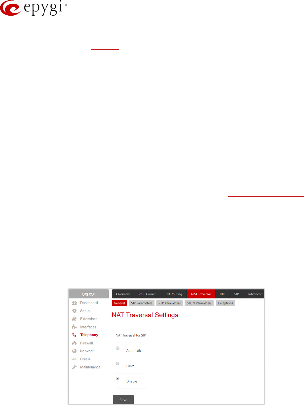
Manual-II: Administration Guide for QX Gateways
Edition 2 (FW Version 6.1.17 and higher) 103
The display name and port number are optional parameters in the SIP address. If a port is not specified, 5060
will be set up as the default one. The range of valid ports is between 1024 and 65536.
The SIP Address may contain wildcards. The following combinations can be used:
•*@ipaddress – any user from the specified SIP server
•username@* – a specified user from any SIP server
•*@* – any user from any SIP server
Note: Wildcards are allowed for called party addresses. Exceptions are addresses in the Supplementary
Addresses table that are used by Outgoing Call Blocking and Hiding Caller Information Settings services.
8.5 SIP Tunnel
The SIP Tunneling service is used to build a tunnel between QXs (QX IP PBXs and QX Gateways) to use that
tunnel for routing the SIP calls through the remote QX device. When this service is enabled, slave QXs should
be registered on the master QX with the corresponding username/password. With the appropriate configuration
done on the master QX, the master device can use the slave device(s) for routing the SIP calls through them
and accessing peers located behind the slave device or recognized by it. This enables the master device to
locate the slave, even when the network settings, like IP address, SIP port and other settings are changed on
the slave device.
For information on how to configure and use SIP Tunnels, please refer to the QX SIP Tunneling Feature guide
8.6 NAT Traversal
The NAT Traversal is divided into separate pages used to configure the General NAT Traversal Settings, SIP,
RTP and STUN parameters for NAT and the page where the NAT Exclusion table may be filled.
8.6.1 General Settings
The General Settings page is used to select the mode NAT Traversal will be used for the SIP traffic.
Figure 85: NAT traversal Settings page
•Automatic – If selected, the system will analyze the QX WAN IP address. If the address is in the IP range
specified for private networks (according to RFC), the SIP traffic will be routed through NAT, otherwise
no SIP traffic will be routed through NAT router.
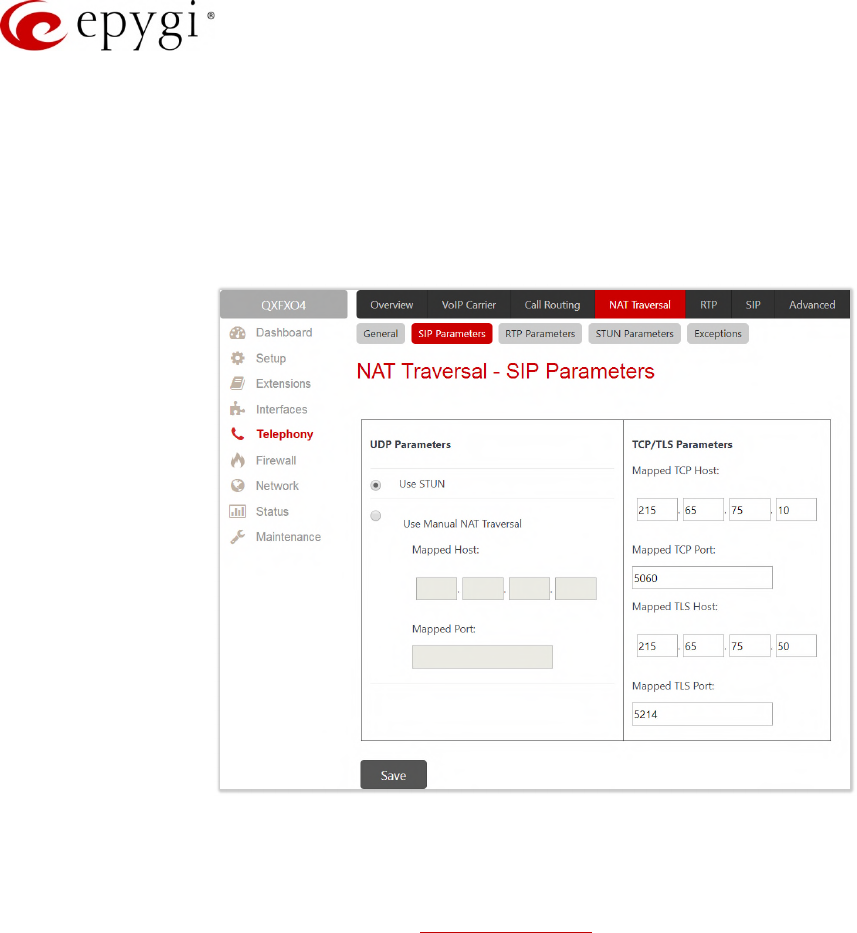
Manual-II: Administration Guide for QX Gateways
Edition 2 (FW Version 6.1.17 and higher) 104
•Force – if selected, all SIP traffic will be routed through the NAT router.
•Disable – if selected, no SIP traffic will be routed through the NAT router.
8.6.2 SIP Parameters
The SIP Parameters page is used to configure NAT specific settings for SIP and offers two independent groups
of settings:
Figure 86: NAT Traversal – SIP Parameters page
The UDP Parameters section allows to select the type of connection over NAT as follows:
•Use STUN – select to automatically discover the mapped settings for the SIP UDP traffic over NAT.
STUN settings are configured in the STUN Parameters page.
•Use Manual NAT Traversal – select to manually define the mapped settings for the SIP UDP traffic over
NAT:
Mapped Host – insert the IP address of the mapped host for SIP UDP traffic over NAT.
Mapped Port – insert the port number on the mapped host for the SIP UDP traffic over NAT.
TCP/TLS Parameters:
•Mapped TCP Host – insert the IP address of the mapped host for SIP TCP traffic over NAT.
•Mapped TCP Port – insert the port number on the mapped host for the SIP TCP traffic over NAT.
•Mapped TLS Host – insert the IP address of the mapped host for SIP TLS traffic over NAT.
•Mapped TLS Port – insert the port number on the mapped host for the SIP TLS traffic over NAT.
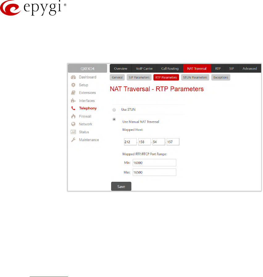
Manual-II: Administration Guide for QX Gateways
Edition 2 (FW Version 6.1.17 and higher) 105
8.6.3 RTP Parameters
The RTP Parameters page is used to select between the STUN and Manual NAT traversal connection for the
RTP traffic and define the RTP/RTCP ports for the connection over NAT.
Figure 87: NAT Traversal – RTP Parameters page
•Use STUN – is used to automatically discover the mapped settings for the RTP UDP traffic over NAT.
STUN settings are configured on the STUN Parameters page.
•Use Manual NAT Traversal – is used to manually define the RTP/RTCP port ranges for the RTP traffic
over NAT:
Mapped Host – is used to define the mapped host IP address for RTP traffic over NAT.
Min and Max – insert the port numbers on the mapped host for RTP and RTSP traffic. TIP: RTP/RTCP
Mapped Port ranges should be greater than or equal to the RTP/RTCP port ranges defined on the
RTP Settings page.
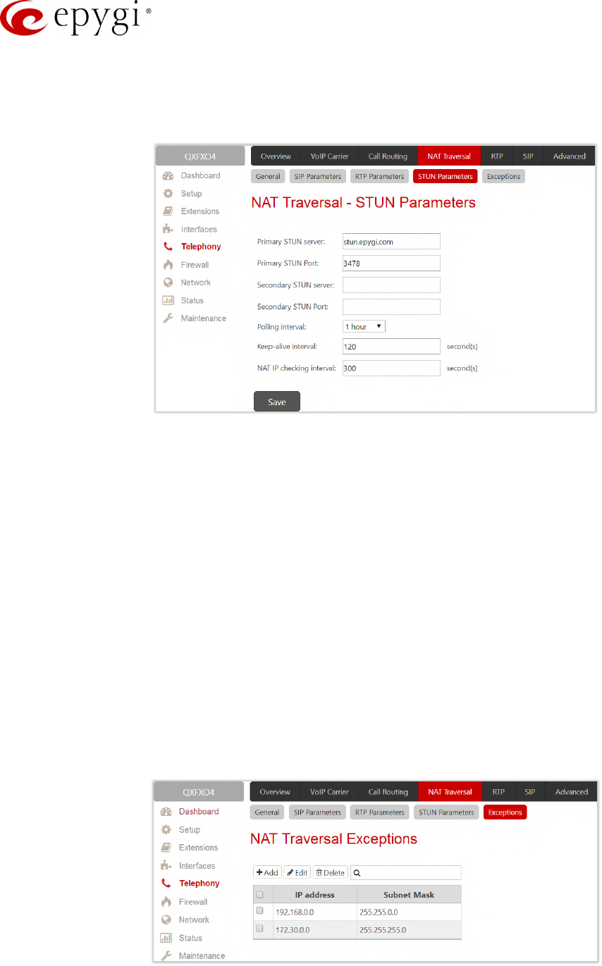
Manual-II: Administration Guide for QX Gateways
Edition 2 (FW Version 6.1.17 and higher) 106
8.6.4 STUN Parameters
The STUN Parameters page is used to enable automatic NAT configuration through the STUN server and is
used to configure the STUN (Simple Traversal of UDP over NAT) client on the QX as follows:
Figure 88: NAT Traversal – STUN Parameters page
•Primary STUN Server – insert the STUN server’s hostname or IP address.
•Primary STUN Port – insert the STUN server port number.
•Secondary STUN Server and Secondary STUN Port – insert the respective parameters of the secondary
STUN server.
•Polling Interval – select the possible time intervals between referrals to the STUN server.
•Keep-alive interval – define the time interval (in seconds) for keeping NAT mapping alive.
•NAT IP checking interval – define the interval (in seconds) between the NAT IP checking attempts (used
to distinguish the possible NAT IP address changes and perform registration on the new host).
8.6.5 Exceptions
The NAT Exclusion Table displays all possible IP ranges that are not included in the NAT process, but can be
accessed directly. IP addresses that are not listed in the NAT Exclusion Table are accessed over NAT. For
example, if a QX user needs to make SIP calls within the local network as well as outside of that network, all
local IP addresses are required to be excluded from NAT traversal settings by being listed in this table.
Otherwise, a malfunction may occur in SIP operations.
Figure 89: NAT Traversal Exceptions page
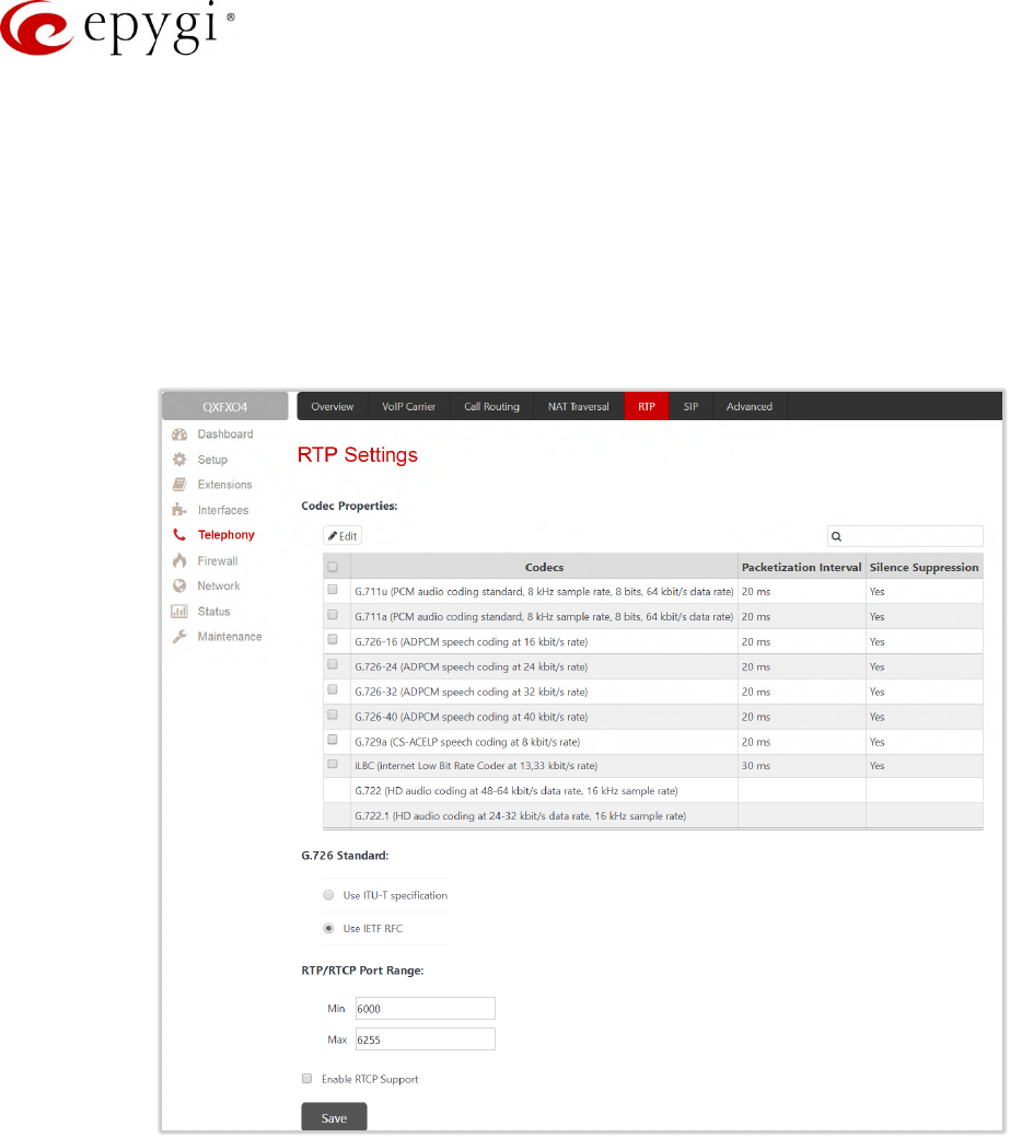
Manual-II: Administration Guide for QX Gateways
Edition 2 (FW Version 6.1.17 and higher) 107
•Add – leads to the NAT Traversal Exceptions – Add Entry page to add a new IP range as follows:
IP address – insert the IP address that is placed behind NAT within the local network.
Subnet Mask – insert the subnet mask corresponding to the specified IP address.
8.7 RTP Settings
The RTP Settings page is used to configure the packet size and silence suppression for each voice codec.
The Codec Properties table lists all codecs with the packetization ranges and information about silence
suppression.
Figure 90: RTP Settings page
•Edit – leads to the RTP Settings – Edit Entry page to modify the selected codec settings.
Packetization Interval – is the time interval between two RTP packets of the same stream. If this
interval is increased, the overhead is decreased, but the voice quality may deteriorate as a result. If
the interval is decreased, the network load is increased and the delay is reduced.
Enable Silence Suppression – is used to stop RTP packet transmission in case of no voice activity.
This option helps to avoid extra traffic if the RTP stream contains no voice activity. It is activated after
two seconds of silence and restarted immediately if any audio appears.
•G.726 Standard - is used to select between packaging method of the G.726 code words into octets. If
you are experiencing problems with the voice quality when using G.726 with one of these options
selected, try switching to the next one.
Use ITU_T specification – if selected, the ITU I.366.2 ("AAL2 type 2 service specific convergence
sublayer for narrow-band services") type packaging of code words is used, where packing code
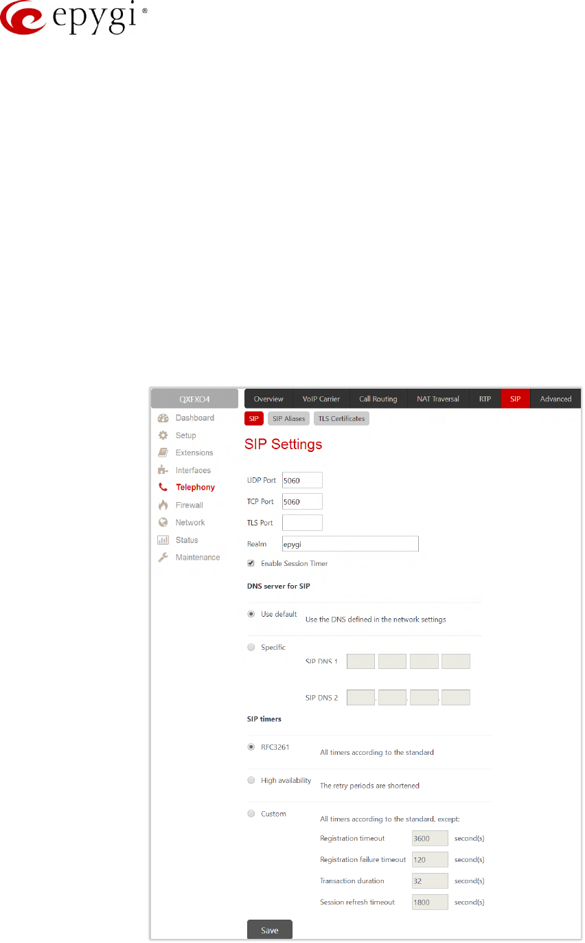
Manual-II: Administration Guide for QX Gateways
Edition 2 (FW Version 6.1.17 and higher) 108
words into octets starts from the most significant rather than the least significant positions in the
octet.
Use IETF RFC – if selected, the IETF RFC ("RTP Profile for Audio and Video Conferences with Minimal
Control") type packaging of code words is used, where packing code words starts from the least
significant positions in the octet.
•Min and Max – is used to insert the port numbers for RTP and RTSP traffic. TIP: RTP/RTCP Port ranges
cannot include the defined SIP UDP ports.
•Enable RTCP Support – enables Real Time Control Protocol support and allows the RTCP packets
transmission. RTCP is used for monitoring the RTP streams and changing RTP characteristics
depending on Network conditions.
8.8 SIP
8.8.1 SIP Settings
The SIP Settings page is used to select the SIP receive UDP and TCP ports, the DNS server configurations for
SIP and the SIP timers scheme.
Figure 91: SIP Settings page
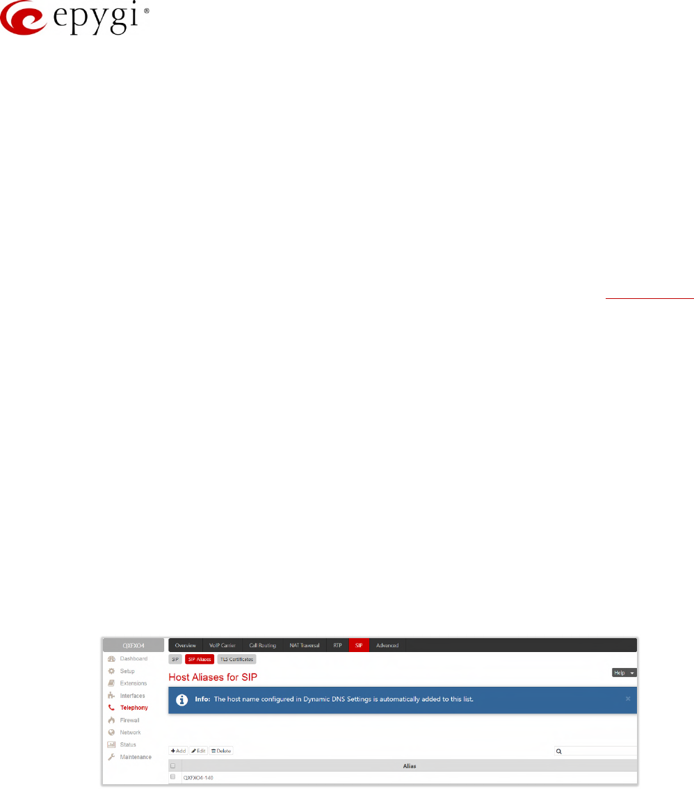
Manual-II: Administration Guide for QX Gateways
Edition 2 (FW Version 6.1.17 and higher) 109
•UDP Port – indicates the SIP UDP (User Datagram Protocol) receive port. By default, 5060 is selected
and used. TIP: The SIP UDP port cannot be in the selected RTP/RTCP port range for FXS and IP lines.
•TCP Port – indicates the SIP TCP (Transmission Control Protocol) receive port. By default, 5060 is
selected and used. QX will not use TCP protocol as a transport for SIP messages if the TCP Port field is
left empty.
•TLS Port – indicates the SIP TLS (Transport Layer Security) receive port number. By default, TLS port is
not used. TLS port number should be different from the TCP Port number.
•Realm – is used to define the messaging level information to be included in SIP messages sent by the
QX. This information might be used by remote side for authentication purposes.
•Enable Session Timer – enables advanced mechanisms for connection activity checking. This option
allows both user agents and proxies to determine if the SIP session is still active.
•DNS server for SIP allows to choose between regular DNS servers configured in the DNS Settings page
and specific DNS servers for SIP traffic.
Use default – is used to apply regular DNS servers for SIP traffic.
Specific – is used to enable SIP specific DNS servers. For this selection, both primary and secondary
SIP DNS servers should be defined in the SIP DNS 1 and SIP DNS 2 text fields.
•SIP Timers is used to define the timeouts of the SIP messages retransmission.
RFC 3261 – is used to apply standard SIP timers described in the corresponding specification.
High availability – is used to apply SIP timers to shorten the call establishment, registration
confirmation and registration failure procedures. This selection provides more firmness to the SIP
connection but increases the network traffic on the QX.
Custom – is used to manually define the Registration Timeout, Registration Failure Timeout,
Transaction Duration and Session refresh timeout SIP timers (in seconds).
8.8.2 SIP Aliases
The Host Aliases for SIP page is used to add the hostname(s) registered on remote DNS server to the Host
Aliases for SIP list. This list will be used to identify SIP packets received from remote servers where the QX is
registered with different names.
Figure 92: Host aliases for SIP page
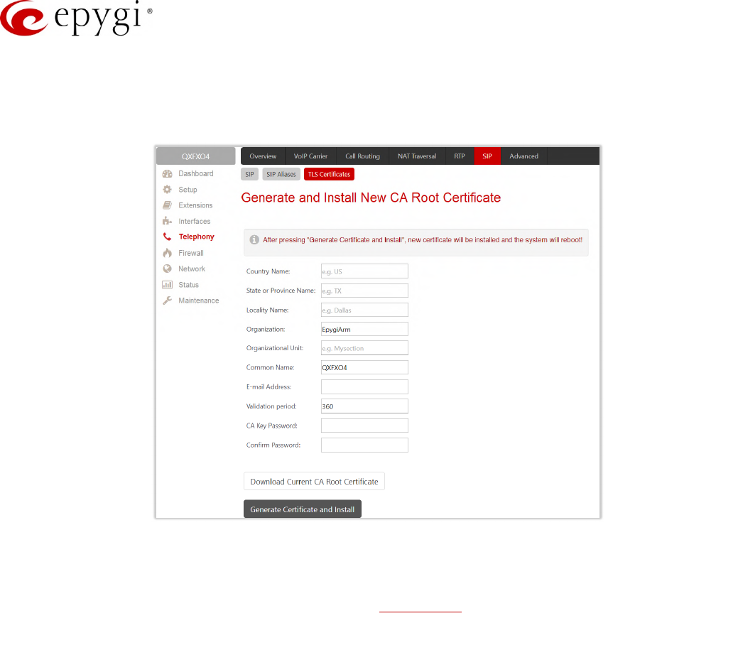
Manual-II: Administration Guide for QX Gateways
Edition 2 (FW Version 6.1.17 and higher) 110
8.8.3 TLS Certificates
The Generate and Install New CA Root Certificate page is used to define, generate and install a new CA root
certificate for SIP TLS traffic. All fields in this page require root certificate specific information.
Figure 93: Generate and Install New CA Root Certificate page
•Generate Certificate and Install – generates a new CA root certificate based on the defined data and
installs it on the QX. The QX will reboot automatically once the new certificate is installed. You may
download the actual copy of the certificate from SIP Settings page.
•Download Current CA Root Certificate – is used to download the actual CA root certificate in the (*.crt)
format.
To ensure a secure TLS connection with the QX's defined CA root certificate, both sides should have the same
certificate installed. If the end user is an IP phone, you may activate the TLS certificate update mechanism from
it to obtain the latest certificate generated by the QX. If the end user is a server or other device, you may
download the certificate from the QX and apply it manually on the remote side.
8.9 Advanced Settings
8.9.1 RTP Streaming Channels
The RTP Streaming Channels page (N/A for QXFXS24) is used to define the channels for the broadcast RTP
streaming. These channels may be then used for configuring RTP channel streaming for any type of music
/announcement to be played to the caller.
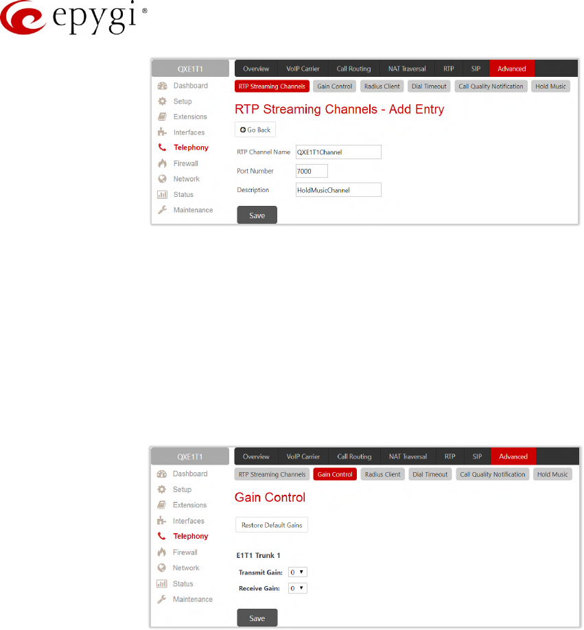
Manual-II: Administration Guide for QX Gateways
Edition 2 (FW Version 6.1.17 and higher) 111
Figure 94: RTP Streaming Channel page
•Add – leads to the RTP Streaming Channels – Add Entry page to add a new RTP channel as follows:
RTP Channel Name – insert the name of the RTP channel.
Port Number – insert the broadcasting RTP port number.
8.9.2 Gain Control
The Gain Control settings are used to define the Transmit and Receive gains.
The Gain Control page consists of Transmit Gain and Receive Gain drop down lists for each line that contains
allowed gain values, which can be set up for every line.
Figure 95: Gain Control page on QXE1T1
•Restore Default Gains – is used to restore the default values.
•For FXS lines (available for QXFXS24):
Transmit Gain defines the phone speaker volume on the call.
Receive Gain defines the volume of the phone microphone on the call.
•For FXO lines (available for QXFXO4):
Transmit Gain defines the level of voice transmitted from QX to the FXO network.
Receive Gain defines the volume of voice received by QX from the FXO network.
•For ISDN trunks (available for QXISDN4):
Transmit Gain defines the level of voice transmitted from QX to the ISDN network.
Receive Gain defines the volume of voice received by QX from the ISDN network.
•For E1/T1 trunks (available for QXE1T1):
Transmit Gain defines the level of voice transmitted from QX to the E1/T1 network.
Receive Gain defines the volume of voice received by QX from the E1/T1 network.

Manual-II: Administration Guide for QX Gateways
Edition 2 (FW Version 6.1.17 and higher) 112
8.9.3 RADIUS Client Settings
Remote Authentication Dial in User Service (RADIUS) specifies the RADIUS protocol used for authentication,
authorization and accounting, to differentiate, to secure and to account for the users. The RADIUS Server
provides the option for a caller from/through QX to pass authentication and to be able to dial a specific number.
When a RADIUS client is enabled on the QX, and according to the configuration of AAA Required option Call
Routing Table, the RADIUS server will be used to authenticate user and/or to account for the call. This can be
accomplished by automatic detection of the caller’s number or a customized login prompt where the caller is
expected to enter a username and password.
Transactions between the client and the RADIUS server are authenticated through the use of a shared Secret
Key, which is never sent over the network. In addition, user passwords are encrypted when sent between the
client and RADIUS server to eliminate the possibility of a party viewing an unsecured network where they could
determine a user's password. If no response from the RADIUS Server is returned after the Receive Timeout
expires, the request is resent numerous times as defined in the Retry Count list. The client can also forward
requests to an alternate server(s) if the primary server is down or unreachable. An alternate server can be used
after a number of failed tries to the primary server.
Once the RADIUS server receives the request, it determines if the sending client is valid. A request from a client
that the RADIUS server does not recognize must be silently discarded. If the client is valid, the RADIUS server
consults a database of users to find the user whose name matches the request. The user entry in the database
contains a list of requirements (username, password, etc.) that must be met to give access to the user. If all
conditions are met, the user gets access to the QX Network.
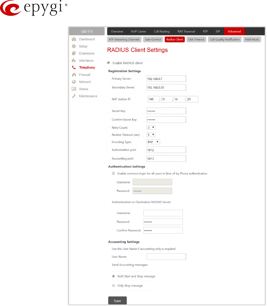
Manual-II: Administration Guide for QX Gateways
Edition 2 (FW Version 6.1.17 and higher) 113
Figure 96: Radius Client Settings page
•Enable RADIUS Client – is used to enable RADIUS client on the QX. TIP: The RADIUS Client cannot be
disabled if there is at least one route with RADIUS Authentication and Authorization or RADIUS
Accounting values configured in the AAA Required drop down list on the Call Routing Table. In order to
disable the RADIUS Client on the QX, the configured routes should be removed first.
•Primary Server – insert the IP address of the primary Radius Server.
•Secondary Server – insert the IP address of the secondary Radius Server
•NAT Station IP – insert the WAN IP address for the NAT station. If no NAT Station is specified here,
QX’s IP address will be sent to the RADIUS server.
•Secret Key – insert the secret key between the Radius client and server. Confirm the inserted key in the
Confirm Secret Key field.
•Retry Count – select the number of attempts authorized before canceling the registration.
•Receive Timeout – select the timeout (in seconds) between two attempts to register.
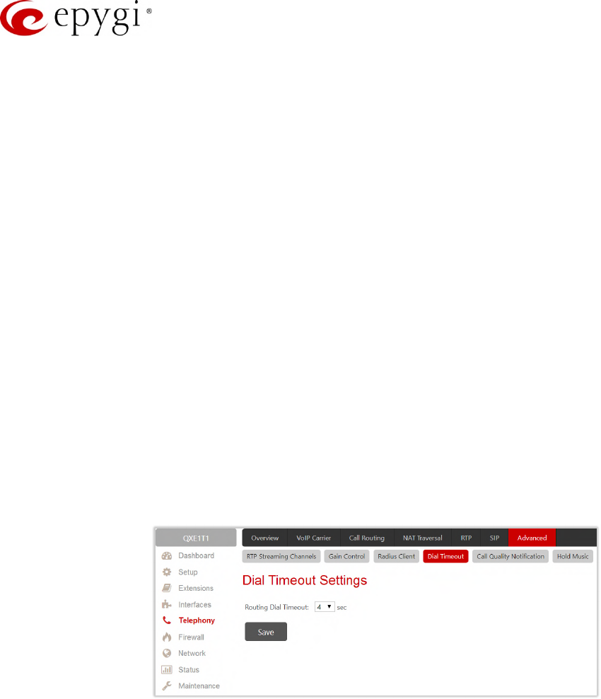
Manual-II: Administration Guide for QX Gateways
Edition 2 (FW Version 6.1.17 and higher) 114
•Encoding Type – select the encoding type (PAP or CHAP) that should be unique on both the client and
the server sides for the establishment of a successful connection. Encoding type should also be
requested from the Radius Server administrator.
•Authorization Port – insert the port number on the RADIUS server where QX is to send the
authentication requests.
•Accounting Port – insert the port number on the RADIUS server where QX is to send the accounting
messages.
•Enable common login for all users in time of by Phone authentication – enable custom settings for the
callers who passed an authorization by phone on the QX. This checkbox enables Username and
Password fields to insert the custom settings that will stand instead of the source caller’s settings when
being delivered to the RADIUS server.
•Authentication on Destination RADIUS Server – insert Username and Password to pass authentication on
the RADIUS Server of the destination QX. If these fields are left empty, the original authentication
settings that users enter for authentication will be used.
•Username – insert an identification username for accounting purposes. When no username is specified
in this field, the source username will be used for accounting. This field is dedicated for accounting
services only.
•Send Accounting messages – select sending both Start and Stop accounting messages or only Stop
accounting message.
8.9.4 Dial Timeout
The Dial Timeout Settings are used to adjust the timeout setting when dialing on the phone.
Figure 97: Dial Plan Settings page
•Routing Dial Timeout – is used to specify a period of time after the last dialed digit that the system
identifies as a completion of dialing. If the user does not press any key within the specified timeout, the
system assumes that the dialing is completed and starts processing the dialed number.
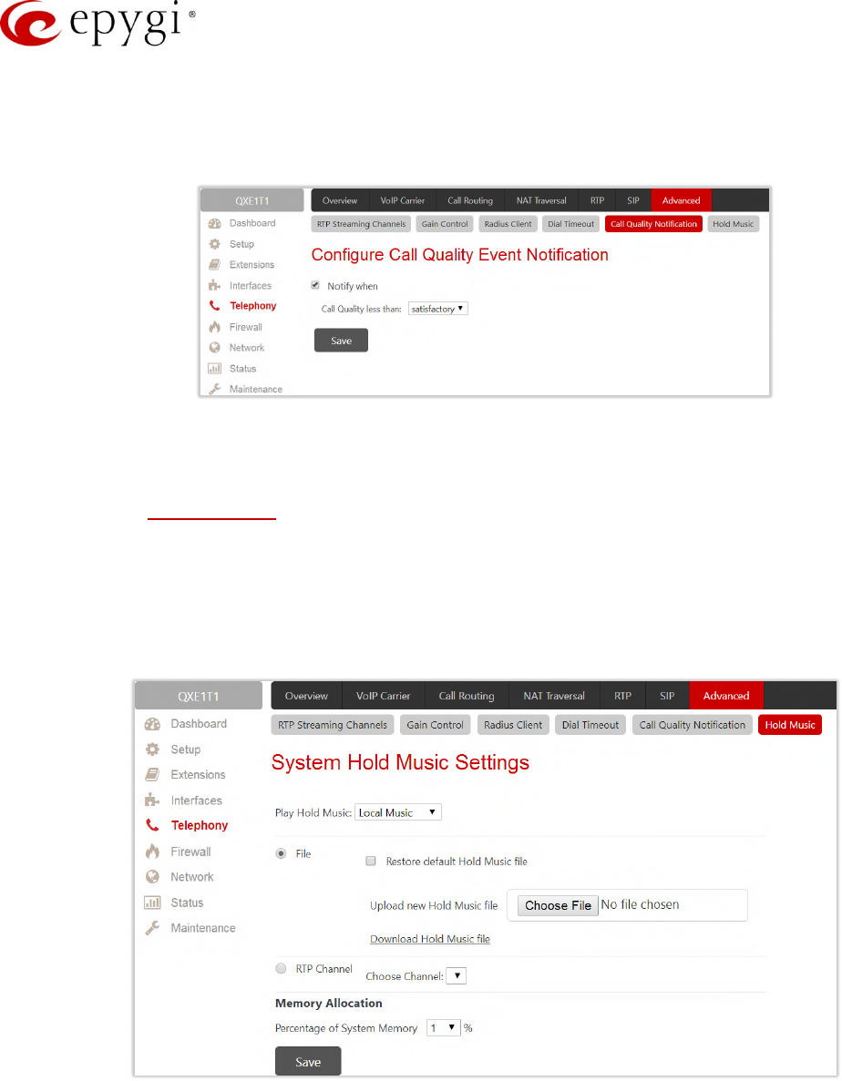
Manual-II: Administration Guide for QX Gateways
Edition 2 (FW Version 6.1.17 and higher) 115
8.9.5 Call Quality Notification
The Configure Call Quality Event Notification page is used to configure the policy for event notification when the
call quality is lower than the allowed level.
Figure 98: Configure Call Quality Event Notification page
•Notify when – is used to enable the call quality monitoring mechanism.
Call Quality less than – is used to select the minimum satisfactory call quality. Notification will appear
on the System Events about the call with lower quality.
8.9.6 Hold Music
The System Hold Music Settings allows you to define the hold music played to the PSTN party when it is held
by the IP user. This page also allows you to define the percentage of system memory dedicated to the
uploaded hold music file. This page contains following components:
Figure 99: Hold Music Settings page
•The Play Hold Music drop down list specifies the music played to the PSTN party when it is held by
remote IP user. It offers the following options:
Off – no music will be played.
Local Music –the music configured on the QX will be sent to the remote PSTN party while it is on hold.
Remote Music – the music sent by the IP party will be transparently passed to the PSTN user while it
is held by the IP party.

Manual-II: Administration Guide for QX Gateways
Edition 2 (FW Version 6.1.17 and higher) 116
•Restore default Hold Music file – is used to enable the default hold music. If selected, the Upload new
Hold Music file field will be deactivated.
•Upload new Hold Music file – is used to upload a new hold music file. Click Choose File to browse the
hold music file. TIP: The music file needs to be in PCMU (CCITT u–law, 8 kHz, 16-bit Mono) wave
format.
•Download Hold Music file – is used to download the uploaded file to the PC. This link won’t appear if
there is not uploaded file.
•RTP Channel – is used to Choose Channel for the broadcast streaming (RTP Streaming Channels).
•Percentage of System Memory – is used to select the memory for uploading the hold music file.
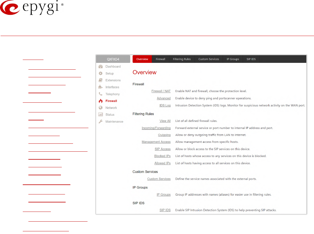
Manual-II: Administration Guide for QX Gateways
Edition 2 (FW Version 6.1.17 and higher) 117
9 Firewall Menu
The Firewall menu consists of the following sections:
•Firewall
Firewall and NAT
Advanced Firewall
Configuration
IDS Log
•Filtering Rules
View All Filtering
Rules
Incoming Traffic/Port
Forwarding
Outgoing Traffic
Management Access
SIP Access
Blocked IPs
Allowed IPs
•Custom Services
Service Pool
Configuration
•IP Groups
IP Pool Configuration
•SIP IDS Settings Figure 100: Firewall Menu overview

Manual-II: Administration Guide for QX Gateways
Edition 2 (FW Version 6.1.17 and higher) 118
9.1 Firewall
The Firewall Configuration page allows setting up the Firewall, configuring the security level and enabling the
Network Address Translation (NAT) and Intrusion Detection System (IDS services on the QXs.
Firewall is a security service configurable through various criteria. It has three level of security policies: low,
medium and high. The Firewall allows or blocks traffic based on the policies, services and/or IP addresses.
Filtering rules will take effect only if the Firewall has been enabled and are independent from the selected firewall
security level. Additional service-based rules can be added as well.
NAT is used to connect the QX LAN members to the Internet using QX WAN IP address. NAT also forwards
incoming packets from the WAN to the PCs or devices in the QX’s LAN.
IDS is a type of firewall. It deletes dangerous packets or packets containing intrusion attacks, also generates a
log file containing information about the dropped packets and senders responsible for those packets. The log
can be viewed on the IDS Log page. Users can be notified about the generated logs through an email, flashing
LED display notification, etc.
9.1.1 Firewall and NAT
The Firewall Configuration page offers the following components:
•Enable IDS – enables the Intrusion Detection System.
•Enable NAT – enables the Network Address Translation.
•Enable Firewall – enables the firewall security service. The firewall security level has to be selected,
otherwise the firewall cannot be enabled.
The Firewall Security levels are the following:
•Low Security – everything that is not explicitly forbidden will be allowed. This security level doesn't block
anything by default. It is recommended if the device is already located behind another firewall or if every
filter has been configured correctly.
•Medium Security – traffic originating from the LAN side may pass and traffic from the WAN side will be
blocked by default. This is the recommended security level.
•High Security – everything that is not explicitly allowed will be blocked, including traffic from the LAN
side.
Figure 101: Firewall Configuration page
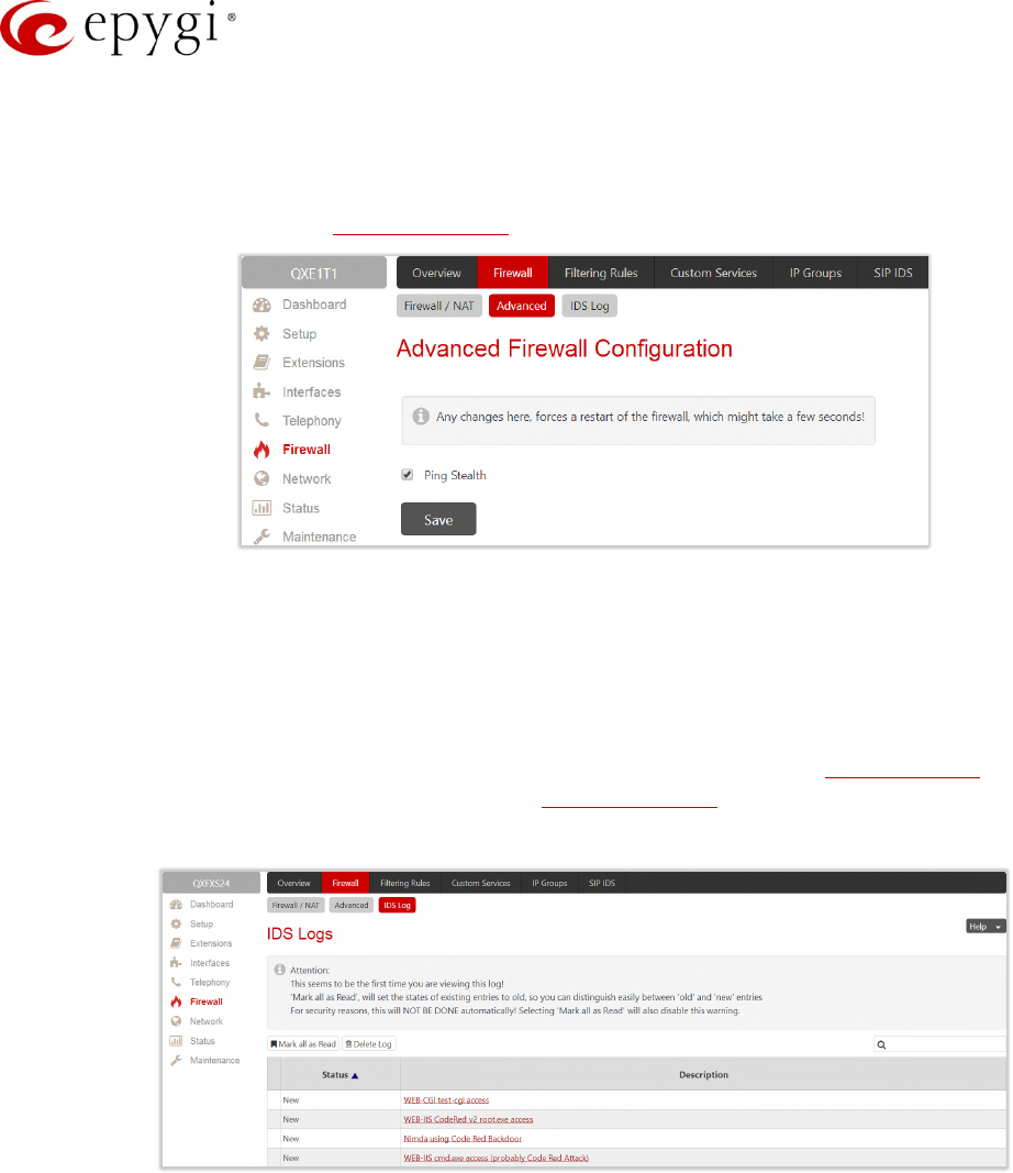
Manual-II: Administration Guide for QX Gateways
Edition 2 (FW Version 6.1.17 and higher) 119
9.1.2 Advanced Firewall Configuration
The Advanced Firewall Settings are used to deny Ping operation addressed towards the device. With this
feature enabled the QX will answer with irritating message to the Ping. The Ping operation will be denied when
the Firewall is enabled from the Firewall and NAT page.
Figure 102: Advanced Firewall Settings page
9.1.3 IDS Log
The IDS log page (N/A for QXE1T1 gateway) contains information about dropped packets and the senders
responsible for those packets. The IDS discards dangerous packets or packets including intrusion attacks. It
generates a table with the IDS log report. The administrator can be notified about newly logged entries in
various ways (e-mail, display notification, etc.) depending on the settings in the System Events page. IDS logs
will be reported as soon as IDS is enabled from the Firewall and NAT page
The IDS Logs table is a list of new or read IDS entries and descriptions referring to them.
Figure 103: IDS Log page
Click on the desired entry to see it's detailed log in the IDS Detailed Logs table.
The IDS Logs detailed page has a following preview:
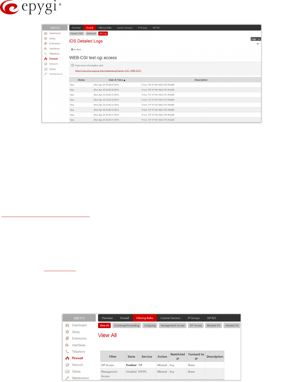
Manual-II: Administration Guide for QX Gateways
Edition 2 (FW Version 6.1.17 and higher) 120
Figure 104: IDS issue detailed preview
The IDS Logs table is a detailed log that shows additional information about the access protocol, IP address
and port number as well as date and time of the event.
9.2 Filtering Rules
The Filtering Rules page is used to configure the filters for incoming and outgoing traffic.
It is allowed to create only one rule per service to prevent inaccurate configuration. You may use IP groups to
include several IP addresses for any rule. Since the filtering rules specify the operation mode of the firewall, they
only take effect if the firewall has been enabled (also NAT is enabled to use the Port Forwarding function in the
Incoming Traffic/Port Forwarding filtering rules). The filtering rules are independent from the security level, so
they will work regardless the type of selected security level.
Note:
•Applying firewall rules will prevent the establishment of new connections that violate the rules. Applying
rules does not kill existing connections that violate the rule.
•The newly created blocking filtering rules will take effect immediately only if the IP address(es) added
into the Blocked IPs.
9.2.1 View All Filtering Rules
View All table presents all configured filters, specified by their State (enabled or disabled), selected Service, type
of Action (allowed or blocked), displays Restricted IP addresses and destination of port forwarding.
Figure 105: Filtering Rules page
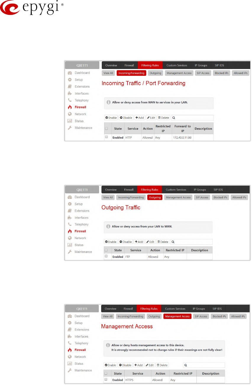
Manual-II: Administration Guide for QX Gateways
Edition 2 (FW Version 6.1.17 and higher) 121
9.2.2 Incoming Traffic/Port Forwarding
Incoming Traffic/Port Forwarding filtering rules are used to allow or deny incoming traffic to reach to the QX
LAN. Enable the NAT service on the QX to allow Port Forwarding in the Incoming/Forwarding filtering rules.
Figure 106: Incoming Traffic/Port Forwarding page
9.2.3 Outgoing Traffic
Outgoing Traffic filtering rules allow or deny access to the external services for QX LAN users.
Figure 107: Outgoing Traffic page
9.2.4 Management Access
Management Access filtering rules are used to allow or deny hosts management access to the QX.
Figure 108: Management Access page
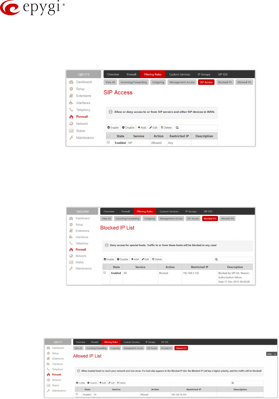
Manual-II: Administration Guide for QX Gateways
Edition 2 (FW Version 6.1.17 and higher) 122
9.2.5 SIP Access
SIP Access filtering rules are used to allow or deny access to or from SIP servers and other SIP devices in the
WAN. This filtering rule will prevent or allow incoming/outgoing SIP calls from/to specified SIP server(s) or
host(s).
Figure 109: SIP Access page
9.2.6 Blocked IPs
Blocked IP List entries are used to deny access for special hosts. Traffic to or from these hosts will be blocked
in any case, no matter what services are configured in other filters. The Blocked IP List service has a higher
priority than the Allowed IP List: if the same host is listed in both tables, it will be blocked.
Figure 110: Blocked IP List page
9.2.7 Allowed IPs
Allowed IP List entries are used to allow trusted hosts to reach your network and vice versa. If a host also
appears in the Blocked IP List, the Blocked IP List has a higher priority, and the traffic will be blocked.
Figure 111: Allowed IP List page

Manual-II: Administration Guide for QX Gateways
Edition 2 (FW Version 6.1.17 and higher) 123
To Add a Filtering Rule
1. Navigate to the Filtering Rules (Incoming Traffic/Port Forwarding, Outgoing Traffic, Management Access,
SIP Access, Blocked IP List or Allowed IP List) page to add a rule.
2. Click Add on the corresponding filtering rules page.
3. Select the Service to configure a rule for it.
4. Select an Action to setup the rule.
5. Insert the destination IP address in the Forward to IP where traffic should be transferred to if it comes
from the restricted host (Incoming Traffic/Port Forwarding rule).
6. Insert a port number in the Port Translation field which will stand instead of the original port number
when incoming packet is being forwarded (Incoming Traffic/Port Forwarding rule).
7. Choose the restriction type by selecting Any, Single IP, IP/Mask or Single URL and enter the required
information in the text fields or select a group.
8. Insert a Description, if needed.
9. Click Save to create a rule with given parameters. The newly created filtering rule will be shown in the
corresponding Filtering Rule table and in the View All page.
10. Click Enable to activate the newly created filtering rule from the corresponding table.
9.3 Custom Services
9.3.1 Service Pool Configuration
The Service Pool Configuration page is used to create new services with the appropriate settings (protocol type
and port range). New services can be used to add a restriction or allowance upon creating a new filtering rule.
To Add a Service
1. Click Add on the Service Pool Configuration page.
2. Insert a Service Name.
3. Select a Protocol type.
4. Define the Port Range.
5. Click Save to add the service with given parameters. The newly created service will be displayed on the
Service Pool Configuration table.
Figure 112: Service Pool Configuration – Add page

Manual-II: Administration Guide for QX Gateways
Edition 2 (FW Version 6.1.17 and higher) 124
9.4 IP Groups
9.4.1 IP Pool Configuration
The IP Pool Configuration page is used to add groups of IP addresses that have the same restriction criteria.
When adding a new filtering rule, a group can be used instead of several IP addresses. TIP: Changing a group
name will also change the references to this group, including filtering rules and member relations to the other
groups. Deleting a group will also delete any reference to the corresponding group, including filtering rules and
member relations to the other groups.
The IP Pool Group Configuration page displays a list of all the added member IP addresses for the selected
group as well as allows adding/modifying members.
Figure 113: IP Pool Configuration page
Click Group name link to display an IP Pool Group Configuration page with the Members list for the current
group.
To Add a new Group with Members
1. Click Add on the IP Pool Configuration page.
2. Insert a Group Name and fill in the Group Description, if needed.
3. Click Save to add the group. The newly added group will be displayed on the IP Pool Configuration
table.
4. Open the IP Pool Group Configuration page by clicking on the group name.
5. Click Add on the IP Pool Group Configuration page. A page opens where new members may be added
to the group.
6. Choose the member addition type by selecting IP Address, IP Subnet and enter the required information
in the text fields or select A user-defined Group.
7. Insert a Member description, if needed.
8. Click Save to add the member. The newly added member will be shown in Current Group table.
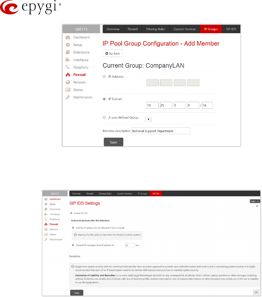
Manual-II: Administration Guide for QX Gateways
Edition 2 (FW Version 6.1.17 and higher) 125
Figure 114: IP Pool Group Configuration – Add Member page
9.5 SIP IDS Settings
The SIP IDS Settings page includes the following components:
Figure 115: SIP IDS Settings page
•Enable SIP IDS – enables SIP attack prevention.
•Add the IP address into the Blocked IP List in Firewall – if selected, the system will block the SIP
attacker's IP address by adding it to the Blocked IP List of Firewall. This action will take effect if Firewall
is enabled on the QX.
•Discard SIP messages from IP address for – if selected, the system will ignore the SIP messages from
attackers IP address for the specified time period after attack detection (default period is 32 seconds).
•Exceptions – link leads to the Exceptions for SIP IDS page where you can specify the trusted IP
address(es) that shouldn’t be blocked.
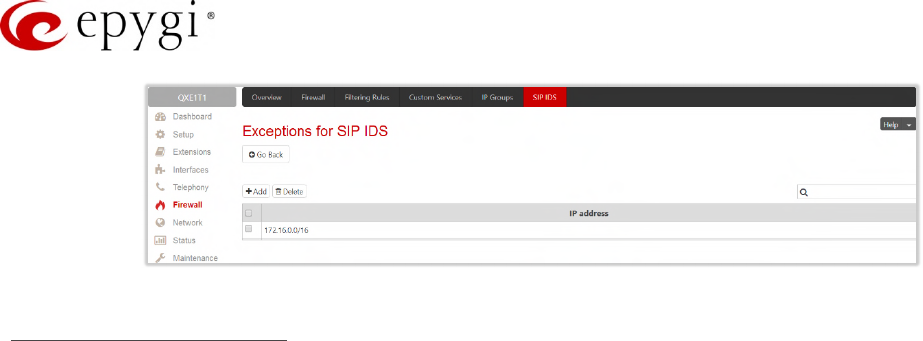
Manual-II: Administration Guide for QX Gateways
Edition 2 (FW Version 6.1.17 and higher) 126
Figure 116: Exceptions for SIP IDS Table
The Bad IP detection logic
The Bad IP detection logic is the following:
•2 failures of SIP authorization/authentication from the same IP during 250 milliseconds.
•2 messages causing Non-self-Request-URI from the same IP during 250 milliseconds.
•If there are 10 failures in a row during any period of time from the same IP, then the IP will be blocked.
Note: Any successful registration attempt from that IP will reset the counter. For example, if IP=xxx.xxx.xxx.xxx
failed to register 9 times and then successfully registered on the 10th attempt, then it resets the counter to 0.
Next time the same IP can make another 9 unsuccessful attempts before being blocked.
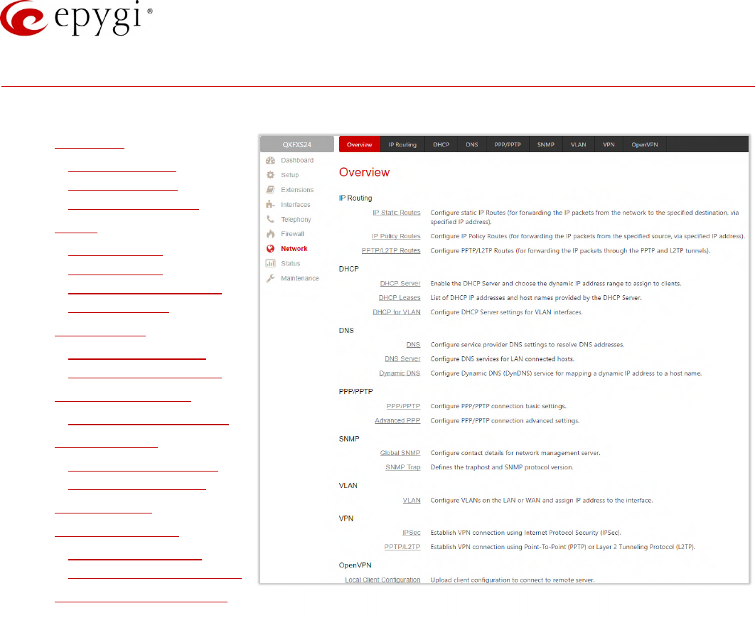
Manual-II: Administration Guide for QX Gateways
Edition 2 (FW Version 6.1.17 and higher) 127
10 Network Menu
The Network menu consists of the following sections:
•IP Routing
IP Static Routes
IP Policy Routes
PPTP/L2TP Routes
•DHCP
DHCP Server
DHCP Leases
DHCP Settings for the
VLAN Interface
•DNS Settings
DNS Server Settings
Dynamic DNS Settings
•PPP/ PPTP Settings
Advanced PPP Settings
•SNMP Settings
Global SNMP Settings
SNMP Trap Settings
•VLAN Settings
•VPN Configuration
IPSec Configuration
PPTP/L2TP Configuration
•Local Client Configuration Figure 117: Network Menu overview
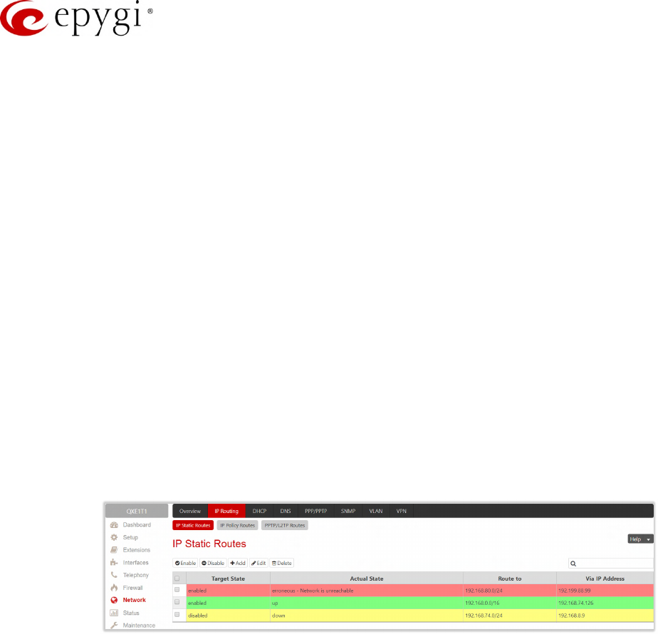
Manual-II: Administration Guide for QX Gateways
Edition 2 (FW Version 6.1.17 and higher) 128
10.1IP Routing
Routing is used to relay information across the Internet from a source to a destination. Along the way, at least
one intermediate node is typically encountered. Routing differs from the bridging. The main difference between
bridging and routing is that bridging operates at the OSI Data Link Layer (Level Two Media Access Control
Layer) and routing operates at OSI Network Layer (Level Three).
QX IP Routing service allows to route IP packets from one destination to another (or to a specified router)
through the QX or QX’s VPN.
The IP Routing is used to make IP Static, IP Policy and PPTP/L2TP routes for IP packets routing. This page
consists of three tables. Entries in the tables are color coded according to the state of the route. For example,
yellow indicates disabled routes, green indicates successful routes and the red indicates routes with an error.
10.1.1 IP Static Routes
IP Static Routes are used to forward IP packets from the Network, the QX is connected, to the specified
destination.
The IP Static Routes table displays all established IP static routes with their parameters:
Target State – state of the route (enabled or disabled)
Actual State – state of the route connection (up, down or erroneous)
Route To – subnet the incoming packets should be routed to
Via IP Address – router IP address incoming packets should be routed through.
Figure 118: IP Static Routes page
•Add – leads to the Add IP Static Route page to establish a new static route. Add a new static route as
follows:
Route to – insert the IP address and subnet mask of the destination the IP packet will be routed to.
Via IP Address – insert the IP address of the router that will forward the IP packet to the specified
destination.
•Enable/Disable – activates/deactivates a selected route(s). At least one route should be selected in order
to use these functions.
Note: The rule with the longest subnet (smallest IP range) will take effect when having two or more IP Static
routing rules with the coinciding subnets.
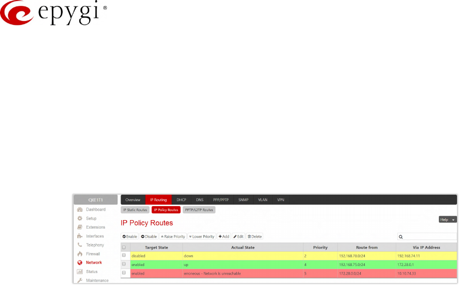
Manual-II: Administration Guide for QX Gateways
Edition 2 (FW Version 6.1.17 and higher) 129
10.1.2 IP Policy Routes
IP Policy Routes allow IP packets forwarding to the specified router depending on the source IP address as well
as defining the priority for the current routing rule.
The IP Policy Routes table displays all specified IP policy routes with their parameters:
Target State – state of the route (enabled or disabled)
Actual State – state of the route connection (up, down or erroneous)
Priority – route priority
Route from – is where the subnet, routed packets come from
Via IP Address – is where the router IP address incoming packets should be routed through.
Figure 119: IP Policy Routes table
•Add – leads to the Add IP Policy Route page to establish a new policy route. Add a new policy rule as
follows:
Priority – define a priority of the routing rule. Insert any numeric value from the 1-252 range. The lower
the number, the sooner the routing rule will take effect (higher priority).
From – insert the packet source IP address and subnet mask of the specified destination to match
with the rule.
Via IP Address – insert the IP address of the subsequent router to forward the IP packet to.
•Enable/Disable – activates/deactivates the selected route(s).
•Raise Priority/Lower Priority – increases/decreases the priority of the selected policy route(s) by one. At
least one route should be selected to use these functions.
10.1.3 PPTP/L2TP Routes
PPTP/L2TP Routes allow IP packets forwarding through the PPTP and L2TP tunnels of the QX. VPN routes
cannot be generated if PPTP/L2TP connections do not exist on the QX.
The PPTP/L2TP Routes table displays all generated VPN routes with their parameters:
Target State – state of the route (enabled or disabled)
Actual State – state of the route connection (up, down or erroneous)
Route to – subnet where the incoming packets should be routed
Via Tunnel – VPN tunnel incoming packets should be routed through
Tunnel State – actual state of the route tunnel (up or down).
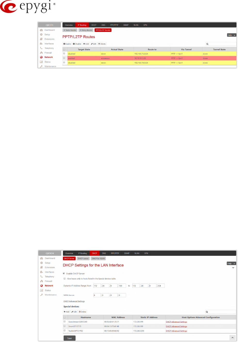
Manual-II: Administration Guide for QX Gateways
Edition 2 (FW Version 6.1.17 and higher) 130
Figure 120: PPTP/L2TP Route page
•Add leads to the Add PPTP/L2TP Route page to add a new VPN route. Add a new VPN as follows:
Route via – lists the available PPTP and L2TP connections on the QX. A connection selected from this
list will be used to route the IP packet from the QX’s LAN to the peer behind the PPTP/L2TP tunnel.
Route to – insert the IP address range of the possible peers behind the PPTP/L2TP tunnel the IP
packets should be routed to.
•Enable/Disable – activates/deactivates the selected route(s). At least one route should be selected to
use these functions.
10.2DHCP
The DHCP Settings are used to enable a DHCP server and controlling the QX user’s LAN settings. Therefore,
QX LAN users will automatically be provided with the following settings using the configured parameters:
•IP addresses
•NTP (corresponds to the QX’s IP address
•WINS server
•Nameserver (corresponds to the QX’s IP address
•Domain name
10.2.1 DHCP Server
The DHCP Settings for the LAN Interface page offers the following input options:
Figure 121: DHCP Settings page for the LAN interface page
•Enable DHCP Server – activates the DHCP server on the QX. If selected, QX will be able to assign
dynamic IP addresses to its LAN devices.
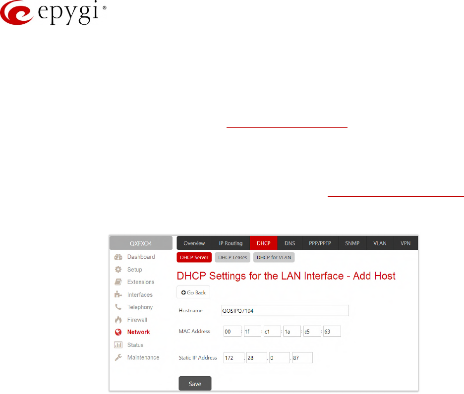
Manual-II: Administration Guide for QX Gateways
Edition 2 (FW Version 6.1.17 and higher) 131
•Give leases only to hosts listed in the Special devices table – if selected, then the DHCP services will be
provided only to the devices listed in the Special Devices table.
•Dynamic IP Address Range (from to) – defines a range of IP addresses that will be assigned to the QX
LAN users.
•WINS Server – defines a WINS server IP address for the QX LAN users.
•DHCP Advanced Settings – leads to the DHCP Advanced Settings page to configure the advanced
options of the QX’s DHCP server.
•Special devices – allows to set a static IP address binding on the MAC address of the device in the QX
LAN. When this table is configured, the devices with defined hostnames and MAC addresses will
always get the same LAN IP address from the DHCP server. Devices, not listed in this table, will get
dynamic LAN IP addresses. This table is also displayed in the System Configuration Wizard.
•Add – leads to the Add Host page to assign a new static MAC address to the QX LAN device as
follows:
Figure 122: DHCP Settings for the LAN Interface – Add Host page
Hostname – insert the hostname of the device.
MAC Address – insert the MAC address of the device.
Static IP Address – insert a fixed IP address of the device.
Note: If you leave this field empty, the device will get the first available IP address from range the defined in the
DHCP Settings page (Figure 121).
10.2.2 DHCP Advanced Settings
The DHCP Advanced Settings page is used to add new advanced options of the QX server and modify the
existing ones. The DHCP Advanced Settings table lists DHCP server default options. All options will be sent to
the DHCP clients.
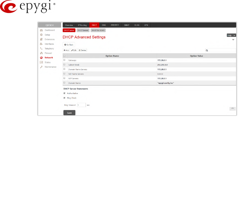
Manual-II: Administration Guide for QX Gateways
Edition 2 (FW Version 6.1.17 and higher) 132
Figure 123: DHCP Advanced Settings page
•Add – leads to the Add Entry page to define a new DHCP server option as follows:
Predefined Options – select one of the predefined DHCP server options.
Option Name – select DHCP server option.
Option Value – insert the value for the selected option. Type and format of the inserted value
depends on the option selected from the Option Name list.
Custom Options – define a new DHCP server option. The following parameters must be inserted for a
new option:
Option Code – insert a code for the option. It may have values in a range from 0 to 255.
Option Value Type – select the type of the option value. It may be an IP address, a Boolean or
integer value, etc.
Option Value – insert the value of the option. This value depends on the selected Option Value Type.
•Authoritative – enables/disables authoritative mode on the QX DHCP server. TIP: If several DHCP
servers are used on the network and the QX has to provide network parameters to IP phones only then
disable the Authoritative mode.
•Ping Check – if selected, verifies the availability of an IP address on the network before providing it to a
client. The QX will first ping an IP address retrieved from the IP pool and wait for a reply. If no reply is
received within a timeout specified in the Ping Timeout field (by default 1 sec), the retrieved IP address
will be provided to the client. Otherwise, a new IP address will be retrieved from the IP pool and the
procedure will be repeated. If not selected, the QX will provide an IP address immediately when
requested.
Note:
•If there are two or more values inserted, they must be separated by commas.
•The changes made through the System Configuration Wizard regarding the DHCP server options will not
immediately reflect on the DHCP Advanced Settings if DHCP sever option parameters are modified, so
user will have to reconfigure changes in the DHCP Advanced Settings manually. The settings will be
changed automatically if the parameters in DHCP server options are in "bold". In this case, the DHCP
Advanced Settings will be changed automatically if you make changes through the System Configuration
Wizard.
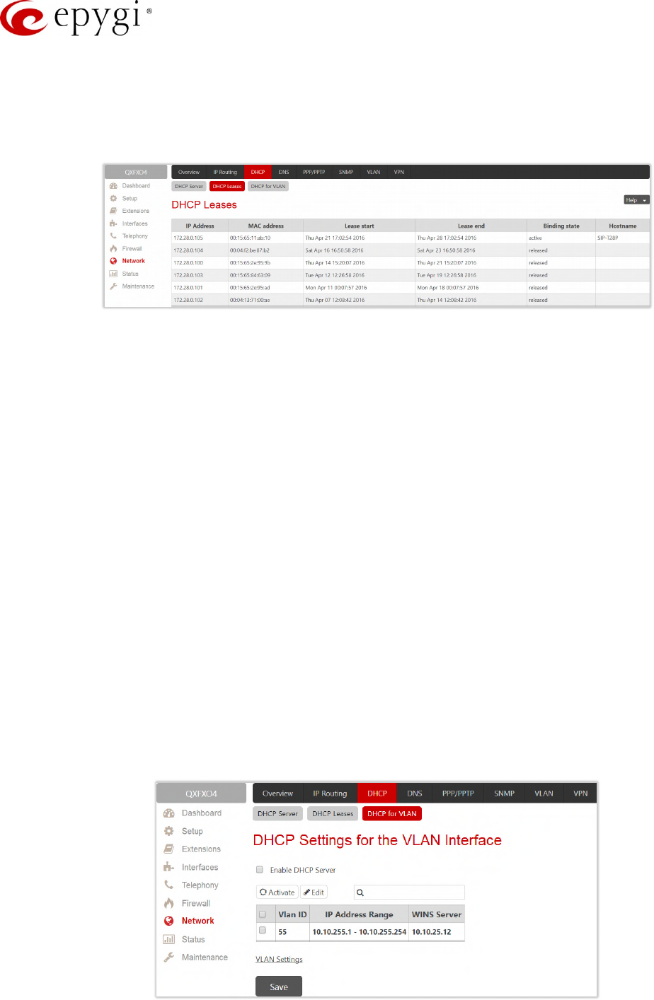
Manual-II: Administration Guide for QX Gateways
Edition 2 (FW Version 6.1.17 and higher) 133
10.2.3 DHCP Leases
The DHCP Leases page includes a list of the leased host addresses that are part of the QX LAN. For these
hosts, QX acts as a server supplying them with a unique IP address. It displays a read–only table describing all
the leased IP hosts and their parameters.
Figure 124: DHCP Leases page for LAN interface
•IP Address – host IP address, assigned by the QX.
•MAC address – host MAC address, provided by the host itself.
•Lease start – date and time when the leased IP address has been activated.
•Lease end – date and time when the leased IP address has been or will be deactivated.
•Binding state – indicates the state of the DHCP lease.
•Hostname – hostname, provided by the host itself.
10.2.4 DHCP Settings for the VLAN Interface
The DHCP Settings for the VLAN Interface page is used to establish virtual networks in the QX LAN or to
integrate the QX into the corporate network’s virtual LAN/WAN. DHCP service can be activated both on LAN or
WAN interfaces. VLAN is useful in corporate companies to divide large networks into subgroups and to have
devices like QXs and IP phones in each network separated (for example, to separate networks for data and
voice transmission). Priorities may be assigned to the interfaces for packets prioritization.
With VLAN configuration, each virtual network will be characterized with a VLAN ID (tag). Packets addressed to
that network will be checked towards the ID and if the ID number defined in the incoming packets matched the
corresponding network’s ID, the packets will be accepted. Otherwise, the packets will be dropped. In the same
way, if the QX is integrated into the network that uses VLAN technology, outgoing packets should have the ID
number of the corresponding virtual network, for the remote party to accept those packets.
The DHCP Settings for the VLAN Interface table lists all enabled VLAN interfaces created in the VLAN Settings
page and corresponding parameters (VLAN ID, IP Address Range and WINS Server).
Figure 125: DHCP Settings page for VLAN interface
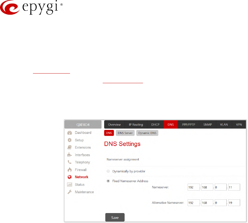
Manual-II: Administration Guide for QX Gateways
Edition 2 (FW Version 6.1.17 and higher) 134
•Enable DHCP Server – activates the DHCP server on QX for VLAN. If selected, the QX will be able to
assign dynamic IP addresses to the devices in its VLAN.
•Activate – activates the DHCP service on one of the VLAN interfaces in the list. Only one VLAN interface
can have DHCP service activated.
•Edit – is used to modify the selected VLAN interface. This page contains all the same components as
the DHCP Server page.
•VLAN Settings – leads to the VLAN Settings page to create virtual LAN/WAN interfaces.
10.3DNS Settings
The DNS Settings page provides the option of setting up a name server for the QX.
Figure 126: DNS Settings page
Nameserver Assignment options are as follows:
•Dynamically by provider – automatically configures the assignment of the name server address from the
provider party.
•Fixed Nameserver address – is used to manually assign a name server as follows:
Nameserver – insert the IP address of an external name server.
Alternative Nameserver – insert the IP address of the secondary name server that will be used if the
main name server cannot be accessed.
10.3.1 DNS Server Settings
The DNS Server provides the services to the hosts in the QX LAN. With this service, QX returns the correct IP
address to the requested domain name, so that any device in the LAN can be accessed by its hostname or
alternative alias name.
The DNS Server Settings page is used to configure DNS server settings on the QX and define a list of aliases for
the devices in the QX's LAN.
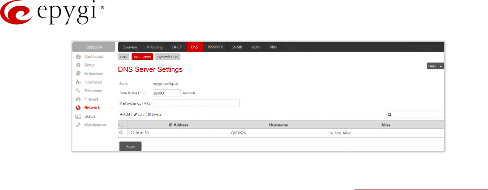
Manual-II: Administration Guide for QX Gateways
Edition 2 (FW Version 6.1.17 and higher) 135
Figure 127: DNS Server Settings page
•Zone – displays the QX’s host domain name as it is configured in the System Configuration Wizard.
•Time to live (TTL) – indicates the time (in seconds) during which the DNS server will keep the resolved
names in its cache. During this time, the same address will be resolved from the cache of the DNS
server. When this timeout expires, the requested address will be resolved newly.
•Mail Exchange (MX) – indicates the mail server’s hostname. When resolving the email address, the
reference will go to the mail server defined in this field, before being sent out to the external network.
The value in this field will be used in the MX record in the DNS server on the QX.
The table on this page lists aliases for each of the device in the QX’s LAN to be resolves through the DNS
server.
•Add – leads to the Add Host page to define a list of aliases for the certain device in the QX LAN as
follows:
IP Address – insert the IP address of the device.
Hostname – insert the hostname of the device.
Alias – insert up to 5 alias names by which the device will be resolved.
10.3.2 Dynamic DNS Settings
The Dynamic DNS (DynDNS) service is used to map a dynamic IP address to a host name. This service is used
if you are connected to the Internet with a dynamic IP address (and PPP, DHCP client) and want to allow
access from the Internet to a device behind the firewall. For example, if you want to run your own WEB server.
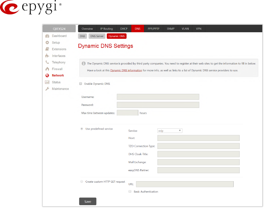
Manual-II: Administration Guide for QX Gateways
Edition 2 (FW Version 6.1.17 and higher) 136
Figure 128: Dynamic DNS Settings page
•Enable Dynamic DNS – enables the dynamic DNS service. To enable the DynDNS service on QX
gateway, you first have to choose a DynDNS provider and register at their website.
•Username and Password – is used to define the authentication parameters specified during the
registration at the DynDNS provider.
•Max time between updates – is used to define the period between two updates (in hours). The values
entered in these fields should be greater than 24. Normally, whenever you set up a connection to the
Internet the DynDNS is updated at least once in the period indicated in this field.
•Use predefined service – enables the manual configuration of the DynDNS service.
Service – select the provider to be subscribed to.
Host – insert the name of the host on the Internet.
TZO Connection Type – insert a special parameter required by the DynDNS provider TZO.
DHS Cloak-Title – insert a special parameter required by the DynDNS provider DHS.
Mail Exchange – insert the address of the email server the DynDNS service provider will relay emails
to. If this service is used, ensure that there is port forwarding configured for SMTP (port 25) to the
internal email server.
•easyDNS Partner – insert a special parameter required by the DynDNS provider easyDNS.
•Create Custom HTTP GET Request – is used to switch to the custom settings of the DynDNS service.
Normally, the DynDNS provider uses HTTP get requests to map dynamic IP addresses to host names.
If the HTTP receive request is known to you, press Create Custom HTTP GET Request and enter the
appropriate value into the URL text field.
URL – is used to define the complete request to be sent to the DynDNS server.
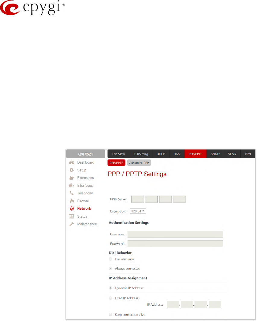
Manual-II: Administration Guide for QX Gateways
Edition 2 (FW Version 6.1.17 and higher) 137
The request modifies the nameserver database so that the hostname will be resolved to the new IP address.
Basic Authentication – enables the encoding of the username and password entered in the text fields
above, and then uses the Basic Authentication method to notify the provider about the user
authentication settings.
Most of the DynDNS providers require an authentication for security. Authentication parameters can be
provided in the URL text field to be used for the HTTP get request. The Basic Authentication checkbox can be
selected if no authentication parameters to be provided.
10.4PPP/ PPTP Settings
The PPP/PPTP Settings are used to establish a connection over the DSL link, or any other type of uplink, to the
ISP. A connection is needed to set up and make or receive calls through PPP over Ethernet. The connection
may be configured for manual setup or always up. Once a connection has been established between the QX
and the provider, QX users will be able to make and receive calls at any time.
Figure 129: PPP/PPTP Settings page
•PPTP Server – is used to define the IP address of the PPTP server.
•Encryption – is used to select the encryption for the traffic over the PPTP interface.
•Authentication Settings – are used to insert the authentication parameters (Username and Password) to
register on the ISP server.
•Dial manually – if selected, a button will be displayed in the main management window that serves to
switch the Internet connection on/off. When accessing the Internet, every station of the connected LAN
has to connect to the QX first.
•Always connected – if selected then the QX will always stay in the connected mode.
•IP Address Assignment – is used to define the IP address assignment for the PPP interface with the
following options:
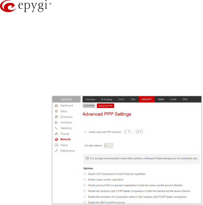
Manual-II: Administration Guide for QX Gateways
Edition 2 (FW Version 6.1.17 and higher) 138
Dynamic IP Address – dynamically assigns an IP address to the PPP interface by the DHCP server.
Fixed IP Address – assigns an IP address to the PPP interface.
Keep connection alive – keeps the connection alive by sending control packets dedicated to the link
state verification.
10.4.1 Advanced PPP Settings
The Advanced PPP Settings are used to enable/disable certain parts of the negotiation process during
connection establishment. These settings are available only if QX has a PPPoE WAN interface.
Attention: It is strongly recommended to leave these switches unchanged if their meanings are not completely
clear.
Figure 130: Advanced PPP Settings page
•Enable automatic PPP restart – is used to select the time when the PPP connection will automatically be
restarted.
LCP echo failures – displays the number of the LCP echo failure packets received before the PPP
connection will be considered as dead and will be restarted.
•Disable CCP (Compression Control Protocol) negotiation – select if the peer system is not working
properly. For example, if it is not accepting the requests from the PPPD (Point-to-Point Daemon) for
CCP negotiation.
•Disable magic number negotiation – select if the peer system is not working properly. If selected, PPPD
cannot detect a looped–back line.
•Disable protocol field compression negotiation in both the receive and the transmit direction – if selected,
no protocol field compression will take place.
•Disable Van Jacobson style TCP/IP header compression in both the transmit and the receive direction – if
selected, no negotiation of TCP/IP header compression will take place and the header will always be
sent uncompressed.
•Disable the connection-ID compression option in Van Jacobson style TCP/IP header compression – if
selected, PPPD will not compress the connection-ID byte from Van Jacobson and will not ask the peer
to do so.
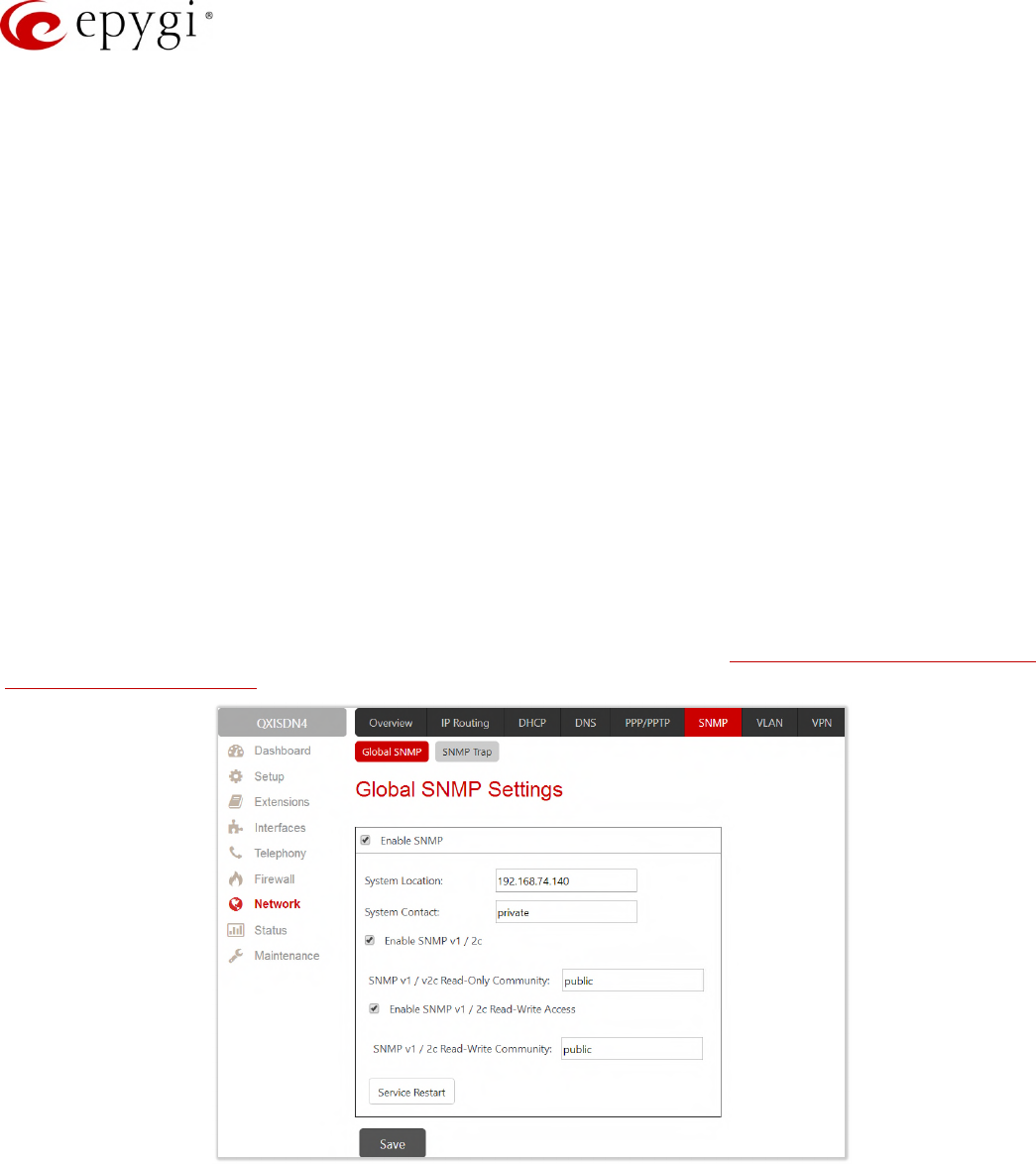
Manual-II: Administration Guide for QX Gateways
Edition 2 (FW Version 6.1.17 and higher) 139
•Disable the IPXCP and IPX protocols – select if the peer is not working properly and cannot handle
requests from PPPD for IPXCP negotiation.
10.5SNMP Settings
The Simple Network Management Protocol (SNMP) is an application layer protocol that facilitates the exchange
of management information between network devices and is used by network administrators to manage
network performance, find and solve network problems, and plan for network growth.
The SNMP agent is running to allow administrators to remotely manage QX’s network and the device’s
configuration. Remote administration is being performed by means of special SNMP monitoring programs
(SNMP Manager), which can automatically feedback by the certainly configured actions on some events on the
QX or remotely modify QX settings.
10.5.1 Global SNMP Settings
The Simple Network Management Protocol (SNMP) is an application layer protocol that facilitates the exchange
of management information between network devices and is used by network administrators to manage
network performance, find and solve network problems, and plan for network growth. The SNMP agent is
running to allow administrators to remotely manage QX’s network and the device’s configuration.
For more information on how to configure and use SNMP, please refer to the Configuring SNMP Agent on QX
IP PBXs and QX Gateways guide.
Figure 131: Global SNMP Settings page
Configure global SNMP settings as follows:
•Enable SNMP – enable SNMP agent on the QX gateway.
•System Location – define the network where the SNMP management will be performed if required.
•System Contact – insert the contact person’s name, e-mail address, phone number or other contact
information if required. This contact person will be responsible for the SNMP management in the
defined network.
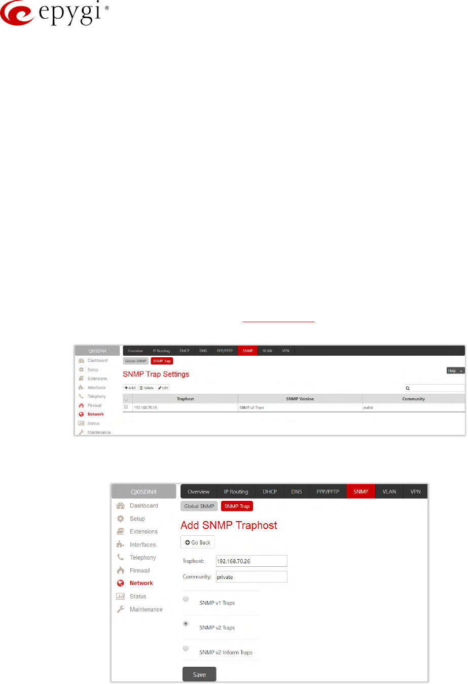
Manual-II: Administration Guide for QX Gateways
Edition 2 (FW Version 6.1.17 and higher) 140
•Enable SNMP v1/2c – enable SNMP v1/2c protocol version for the messaging between the SNMP
agent and administrating application. If not selected, SNMP v1 will be implied.
•SNMP v1/v2c Read-Only Community – insert the community description (public, private, etc.) for the
read–only management (like gathering events, statistics, other information about QXs). Field may
contain some kind of password which should be matching both on the QX and on the administrating
application for successful SNMP management.
•Enable SNMP v1/2c Read-Write Access – enable a read-write access on the QX for the SNMP
monitoring application. If selected, the administrator will be able to remotely configure the QX via SNMP
administrating program.
•SNMP v1/v2c Read-Write Community – insert the community description (public, private, etc.) for the
read-write management (like gathering events, statistics, other information about the QX and remotely
changing its configuration). Field may contain some kind of password which should be matching both
on the QX and on the administrating application for successful SNMP management.
•Service Restart – restart the SNMP sub-system on the QX. Restarting the SNMP sub-system is
recommended if it does not respond to a SNMP manager's requests.
10.5.2 SNMP Trap Settings
SNMP Trap Settings are used to define the traphosts that should be informed when certain events occur on the
QX. Configure the Send SNMP Trap action on the System Events page to inform the listed traphosts about the
events on the QX.
Figure 132: SNMP Trap Settings page
SNMP Trap Settings table lists all configured traphosts with the referring information.
Figure 133: Add SNMP Traphost page
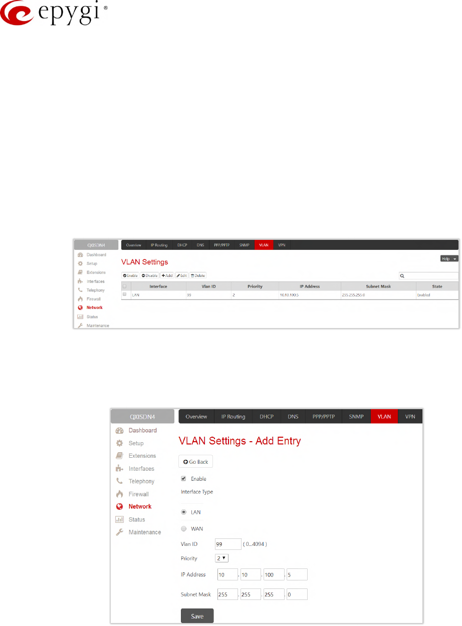
Manual-II: Administration Guide for QX Gateways
Edition 2 (FW Version 6.1.17 and higher) 141
•Add – leads to the Add SNMP Traphost page to define a new traphost as follows:
Traphost – insert an IP address or host name of the traphost. Administrating application’s host
address should be inserted here.
Community – insert a community description (public, private, etc.) for the administrating application to
accept the notifications about the certain events on the QX. Field may contain some kind of password
which should be the same on both QX and administrating application for successful SNMP
management.
Select one of the presented SNMP protocol versions used for events notifications delivered by the QX
to the application.
10.6VLAN Settings
The VLAN Settings page is used to create a new interface(s). The VLAN Settings table lists all existing virtual
interfaces on the QX.
Figure 134: VLAN Settings page
•Enable – enables the selected virtual interface(s).
•Disable – disables the selected virtual interface(s).
•Add – leads to the Add Entry page to define a new virtual network.
Figure 135: VLAN Settings – Add Entry page
Enable – select to enable current virtual interface after creating it.
Interface Type – select whether the virtual interface will be LAN or WAN.
VLAN ID – insert the virtual network ID from the range of 0 to 4094.
Priority – select the priority of packets in the corresponding interface. Packets with the lower priority
(0) will be delivered first.

Manual-II: Administration Guide for QX Gateways
Edition 2 (FW Version 6.1.17 and higher) 142
IP Address – insert the IP address of the virtual interface.
Subnet Mask – insert the subnet of the virtual interface.
10.7VPN Configuration
The Virtual Private Network (VPN) is established to connect two local networks (intranets) securely over the
Internet. The VPN routers manage authentication between servers and clients and handle data encryption for
the connection. Only authorized users may access the network and the data exchange cannot be intercepted.
In general, the VPN connection is similar to the Internet connection, both of them are based on the IP detection.
The VPN gateway must authenticate the IP addresses of its partners’ VPN gateways. Each time a specific VPN
is to be established, usually the same IP addresses are expected. This will not create problems if both VPN
partners have fixed WAN IP addresses. There may be circumstances reasons to prefer dynamically allocated IP
addresses. To enable devices that use a variable IP address as part of a VPN, they are turned into "Road
Warriors". For example, at this point they are able to reach their corporate network via authentication at the
company's VPN gateway device. This VPN gateway device must have a fixed IP address for Internet access.
Every VPN needs at least one VPN gateway with a fixed IP address.
The partner devices of a VPN must have different WAN IP addresses, and if they are connected to local area
networks, these LAN’s must have different IP addresses. As all QX devices have the same default IP addresses
on delivery, at least one of them must be reconfigured in order to set a new IP address.
The QX supports several types of VPN connections such as IPSec and PPTP/L2TP.
Note: It is strongly recommended not to run different types of VPN tunnels between the same endpoints
simultaneously.
10.7.1 IPSec Configuration
An IPSec connection includes authentication and encryption to protect data integrity and confidentiality. VPNs
are "virtual" in the sense that individuals can use the public Internet as a means of securely accessing an
internal network. Once the IPSec connection is established, users have access to the same network resources,
addresses, and so forth as if they were connected locally. VPNs are "private" because the data is encrypted
between two VPN gateways. Encryption makes it very difficult for anyone to intercept data and capture
sensitive information such as passwords. The QX can be set up to act as a VPN router when connected to the
Internet with a fixed IP address or as an IPSec connection Road Warrior when using dynamic IP addresses.
To establish an IPSec connection, it is required to have an operational VPN gateway on each side of the
communication line. QXs, PCs and workstations can be equipped with VPN gateways. Home offices typically
prefer dynamically allocated IP addresses.
When the QX is connected to the Internet with a fixed IP address, it will be set up to act as a VPN gateway. QX
is then prepared to establish an IPSec connection with another VPN gateway device, but also allows access to
Road Warriors. A notebook /laptop used by a traveling employee could also be a Road Warrior. Access to their
company’s intranet via an IPSec connection can be obtained regardless of their location.
The QX can also be set up to act as a Road Warrior. If a home office is connected to the Internet via QX with
Point to Point Protocol over Ethernet (PPPoE) and dynamic IP addressing, setting up the QX as a Road Warrior
will allow an IPSec connection to the corporate network.
You need to use a key to encrypt and decrypt the data transmitted via the IPSec connection. RSA is an
asymmetric key system used by the QX. It has to be available on both sides of the IPSec connection and will
generate a different pair of keys on each side, a private key and a public key. During the connection
establishment, some data is encrypted with the remote party’s public key. They can be decrypting the data
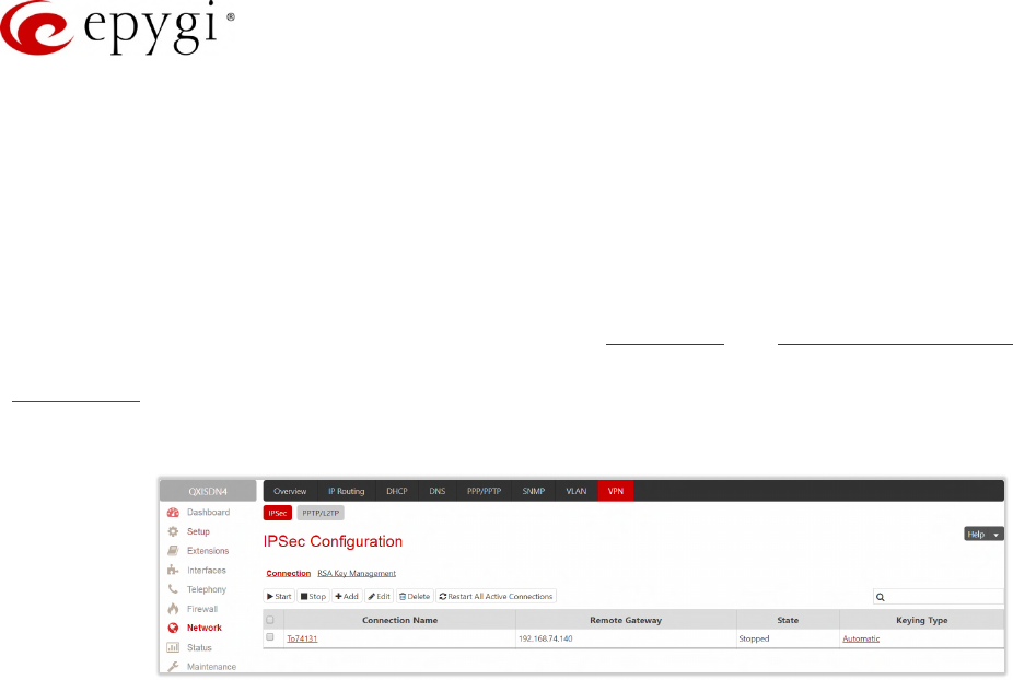
Manual-II: Administration Guide for QX Gateways
Edition 2 (FW Version 6.1.17 and higher) 143
with their private key and the data encrypted there with QX’s public key can be decrypted with QX’s private
key. Since the private key is never transmitted, it stays completely unknown to everyone, thus the system
remains safe. Even if someone gets the public key, decryption cannot be possible without the private key. The
QX generates such a pair of keys automatically when it is set up. The user cannot see the private key, but must
know the public key because their IPSec connection partner will need it.
Note: A pair of keys will always be generated, a public one and a private one. The previously generated pair of
keys will become invalid as well as all existing IPSec connections that use RSA keying.
The IPSec Configuration page consists of two sub-pages: Connection and RSA Key Management.
Connection
The Connection sub-page is used to create a new IPSec connection or manage the existing ones.
Figure 136: IPSec Configuration – Connection Settings page
The following buttons are available:
•Start – activates the selected IP Sec connection. The State will be changed to
Activated
or
Connected
depending on the IPSec connection type.
•Stop – disconnects the selected IPSec connection. The state of the IPSec connection will be changed
to
Stopped
.
•Edit – leads to the IPSec Configuration Wizard to modify the parameters of the selected IPSec
connection.
•Delete – removes the selected IPSec connection(s) from the table.
•Restart All Active Connections – restarts all active IPSec connections. The State of these IPSec
connections will turn into Connected or Activated if the restart procedure has been successfully
completed.
•Add – leads to the Add IPSec Connection wizard to define a new IPSec connection.
The IPSec Configuration wizard composed of the following sections:
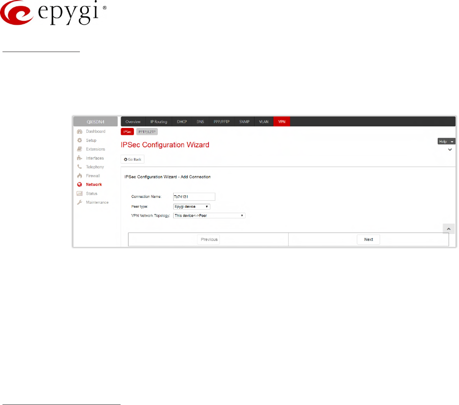
Manual-II: Administration Guide for QX Gateways
Edition 2 (FW Version 6.1.17 and higher) 144
Add Connection
•Connection Name – insert the name of a new IPSec connection.
•Peer type – select the remote machine type for the IPSec Connection to be established. If the list does
not include the required type of machine, choose Other.
Figure 137: Add IPSec Connection section
•VPN Network Topology – select the location of the peers participating to the VPN connection. The
following options are available:
This device<>Peer – direct connection between the QX and peer.
This device<>[Internet]<>Peer – connection between the QX and peer over Internet.
This device<>NAT<>[Internet]<>Peer – connection between the QX and peer over Internet through QX
provider’s NAT.
This device<>[Internet]<>NAT<>Peer – connection between the QX and peer over Internet through
peer provider’s NAT.
IPSec Keying Properties
The Internet Key Exchange (IKE) and Encapsulated Security Payload (ESP) parameters are used to define the
security of your IPSec tunnel.
The IKE parameters group is used to set up security association (SA) in the IPsec protocol suite.
•Encryption – is used to select encryption standard. The following standards are available:
Triple DES – uses three DES encryptions on a single data block with three different keys to achieve a
higher security than is available from a single DES pass (block cipher algorithm with 64-bit blocks and
a 56-bit key).
AES (128 bit) cryptography scheme is a symmetric block cipher, which encrypts and decrypts 128-bit
blocks of data.
AES (192 bit) cryptography scheme is a symmetric block cipher, which encrypts and decrypts 192-bit
blocks of data.
AES (256 bit) cryptography scheme is a symmetric block cipher, which encrypts and decrypts 256-bit
blocks of data.
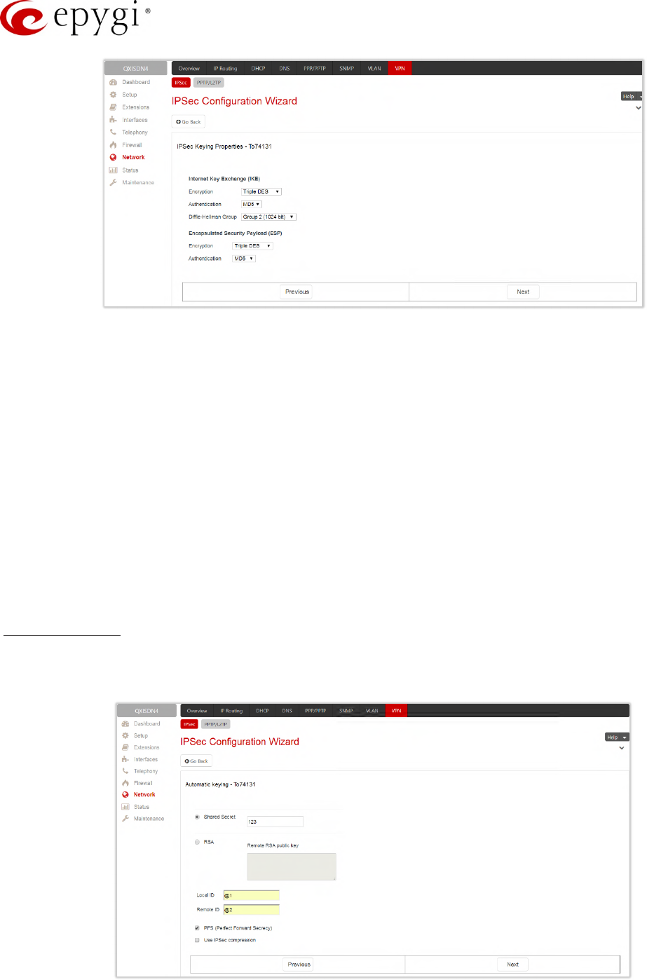
Manual-II: Administration Guide for QX Gateways
Edition 2 (FW Version 6.1.17 and higher) 145
Figure 138: IPSec Keying Properties section
•Authentication – is used to select authentication type:
SHA/SHA1 (Secure Hash Algorithm) is a strong digest algorithm proposed by the US NIST (National
Institute of Standards and Technology) agency as a standard digest algorithm and is used in the
Digital Signature standard, FIPS number 186 from NIST. SHA is an improved variant of MD4
producing a 160-bit hash. SHA and MD5 are the message digest algorithms available in IPSEC.
MD5 (Message Digest) is a hash algorithm that makes a checksum over the messages. The
checksum is sent with the data and enables the receiver to notice whether the data has been altered.
•Diffie-Hellman Group – is used to determine the length of the base prime numbers used during the key
exchange process. The cryptographic strength of any key derived depends, in part, on the strength of
the Diffie-Hellman group, which is based upon the prime numbers. The higher is the group bit rate, the
better is encryption. If mismatched groups are specified on each peer, negotiation fails.
The ESP parameters group is used to provide origin authenticity, integrity and confidentiality protection of
packets. The same IKE encryption and authentication parameters are used.
Automatic keying
The Automatic keying section is used to specify a Shared Secret password or RSA public key to secure the
IPSec Connection.
Figure 139: Automatic Keying Settings section

Manual-II: Administration Guide for QX Gateways
Edition 2 (FW Version 6.1.17 and higher) 146
•Shared Secret – is a type of password that both of the IPSec connection partners must know. The
authentication will be done with this shared secret. All encryption functions below will remain concealed.
•RSA – is used to define the public RSA key of your IPSec Connection partner.
•Local ID – is used to define the QX FQDN (Fully Qualified Domain Name) that is resolved to an IP
address, or any @-ed string that is used in the same way.
•Remote ID – is used to define the IPSec Connection partner’s FQDN (Fully Qualified Domain Name) that
is resolved to an IP address, or any @-ed string that is used in the same way.
The Local ID and Remote ID text fields may have the values in one of the formats presented below:
IP address – example: 10.1.19.32.
Host name – example: vpn.epygi.com. This form requires additional resources to resolve the host
name, therefore it is not recommended to use this format.
@FQDN – example: @vpn.epygi.com. This form is considered as a string, and is not being resolved.
It is recommended to use this form for most applications.
user@FQDN – example: qx@vpn.epygi.com. This form is also considered as a string, and is not
being resolved. It has no advantages over the previous form.
•PFS (Perfect Forward Secrecy) – is a procedure of system key exchange, which uses a long-term key
and generates short-term keys as is required. Thus, an attacker who acquires the long-term key can
neither read previous messages that they may have captured nor read future ones.
•Use IPSec Compression – enables IPSec data compression. This option is displayed only if the IPSec-
VPN partner supports it.
Note:
•It is not recommended to start multiple road warrior connections with the Shared Secret automatic
keying selected. For multiple road warriors to be started at the same time, it is recommended to use
RSA keying with Local ID and Remote ID fields configured.
•QX will prevent to start a connection with Shared Secret automatic keying selected if there is already a
connection with RSA automatic keying started, and vice versa.
•The Local ID and Remote ID values are mandatory for the RSA selection and are optional for Shared
Secret selection. However, it is recommended to define the Local ID and Remote ID values for multiple
road-warrior connections.
IPSec Connection Properties
Dynamic IP/Road Warrior and Static IP/ Remote Gateway buttons are used to select whether the remote QX (or
another VPN gateway device) is connected to the Internet with a dynamic IP address and is acting as a Road
Warrior, or is connected to the Internet with a fixed IP address and is acting as a VPN Gateway.
The following options is used to configure IPSec connection:
•Dynamic IP/RoadWarrior – if selected, then the Remote Gateway IP Address field will automatically
generate the value "any", to allow access independent from the sending IP address.
•Static IP/Remote Gateway – is used to enter the IP address or hostname of the remote QX (or another
VPN gateway device) in the Remote Gateway field.
•This device<>Remote Gateway – allows access from the local QX to the remote VPN gateway (local
subnet and remote subnet are not included). This includes management access. The checkbox is
disabled if the This device<>NAT<>[Internet]<>Peer or This device<>[Internet]<>NAT<>Peer option is
selected from the VPN Network Topology drop-down list on the first page of the IPSec Connection
Wizard.
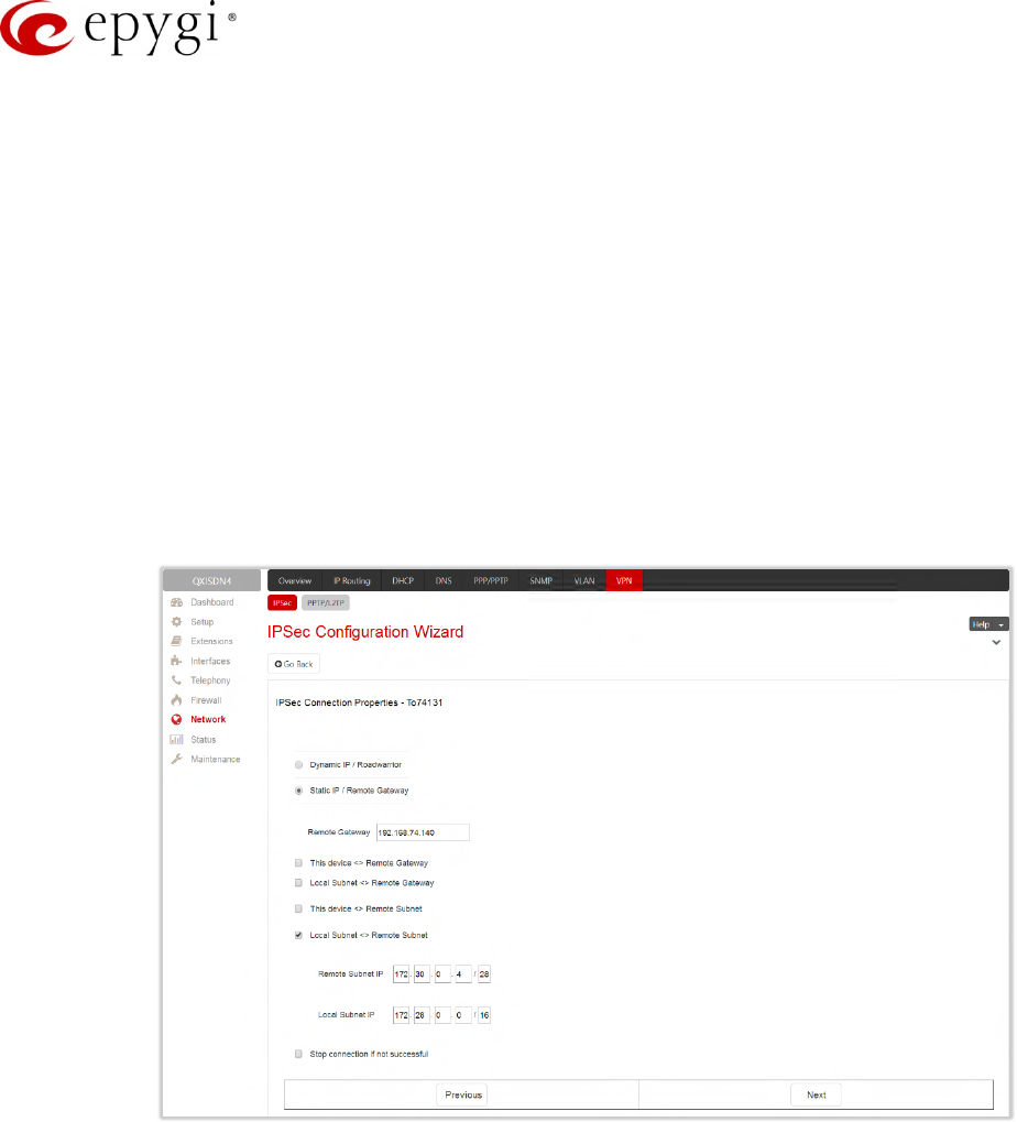
Manual-II: Administration Guide for QX Gateways
Edition 2 (FW Version 6.1.17 and higher) 147
•Local Subnet<>Remote Gateway – allows access from all stations connected to the local network to the
remote VPN gateway device (local QX and remote subnet are not included). The checkbox is disabled
when the This device<>[Internet]<>NAT<>Peer option is selected from the VPN Network Topology drop-
down list on the first page of the IPSec Connection Wizard.
•This device<>Remote Subnet – allows access from the local QX to all stations of the remote LAN (local
subnet and remote VPN gateway devices are not included). The checkbox is disabled when the This
device<>NAT<>[Internet]<>Peer option is selected from the VPN Network Topology drop-down list on
the first page of the IPSec Connection Wizard.
•Local Subnet<>Remote Subnet – allows access from all stations of the local network to all stations of
the remote LAN (VPN gateway devices are not included). In this case, the local and remote subnet IP
addresses and subnet masks have to be entered in the corresponding fields Local Subnet IP and
Remote Subnet IP.
•Stop connection if not successful – allows to stop the IPSec connection attempts if the partner remains
unreachable after the timeout period. If not selected, then the system will continue to try to reach the
IPSec connection partner.
Figure 140: IPSec Connection Properties section
Note:
•It is not recommended to simultaneously start a static and a dynamic connection configured to use the
same secret key. A dynamic connection may capture the static connection peer and vice versa,
depending on which connection established first.
•The Static IP/ Remote Gateway selection is not possible if the Gateway is positioned behind NAT, since
the IP address of the remote gateway is not reachable directly in this case.
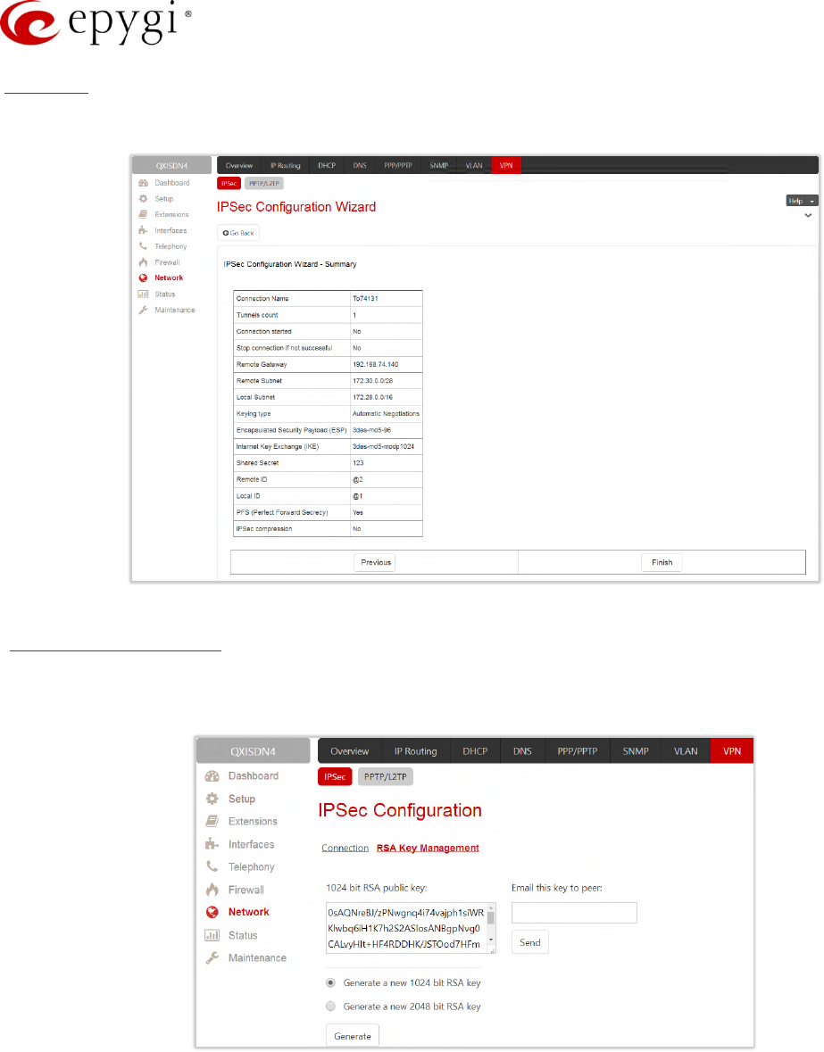
Manual-II: Administration Guide for QX Gateways
Edition 2 (FW Version 6.1.17 and higher) 148
Summary
The Summary section displays all configured settings for the IPSec connection.
Figure 141: Summary section
RSA Key Management
The RSA Key Management sub-page is used to generate a new RSA Key. Also, this page displays the current
public RSA key and allows to send it to the IPSec connection partner.
Figure 142: RSA Key Management page
•RSA Public Key – displays the generated public key.
•Generate a new 1024bit RSA Key/Generate a new 2048bit RSA Key – allows to generate a new pair of
keys by specifying the key length.
•Email this key to peer – is used to enter the email of an IPSec connection partner.
•Send – sends the public RSA key via e-mail.
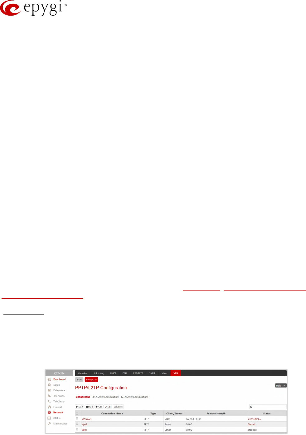
Manual-II: Administration Guide for QX Gateways
Edition 2 (FW Version 6.1.17 and higher) 149
10.7.2 PPTP/L2TP Configuration
Point-to-Point Tunneling Protocol (PPTP) is used to establish a VPN over the Internet. Remote users can
access their corporate networks via any ISP that supports PPTP on its servers. PPTP encapsulates any type of
network protocol (IP, IPX, etc.) and transports it over IP. Therefore, if IP is the original protocol, IP packets ride
as encrypted messages inside PPTP packets running over the IP. PPTP is based on the Point-to-Point Protocol
(PPP) and Generic Routing Encapsulation (GRE) protocol. Encryption is performed by Microsoft's Point-to-Point
Encryption (MPPE), which is based on RC4.
Layer 2 Tunneling Protocol (L2TP) is a protocol from the IETF, which allows a PPP session to run over the
Internet, ATM, or frame relay network. L2TP does not include encryption (as does PPTP), but defaults to using
IPSec in order to provide virtual private network (VPN) connections from remote users to the corporate LAN.
Derived from Microsoft's Point-to-Point Tunneling Protocol (MPPTP) and Cisco's Layer 2 Forwarding (L2F)
technology, L2TP encapsulates PPP frames into IP packets either at the remote user's PC or at an ISP that has
an L2TP remote access concentrator (LAC). The LAC transmits the L2TP packets over the network to the L2TP
network server (LNS) at the corporate side. Large carriers also may use L2TP to offer remote POPs to smaller
ISPs. Users at the remote locations dial into the modem pool of an L2TP access concentrator, which forwards
the L2TP traffic over the Internet or private network to the L2TP servers at the ISP side, which then sends them
on to the Internet.
For PPTP and L2TP connections, two parties are required: Client and Server. The client is responsible for
establishing the connection. The server is waiting for clients; it is not able to initiate the connection itself.
Servers define the range of IP addresses that are assigned to the Server and Client hosts participating in a
connection.
Each side is specified by the Host Name and Password. The client should know the server’s name and
password (the QX server has no password) and the server should set the client’s host name and a password.
The client and server settings have to match on both sides for successful connection establishment.
Attention:
•L2TP tunnels have no data encryption mechanism.
•Only one client can be connected to the server in the same network.
The PPTP/L2TP Configuration page consists of 3 sub-pages: Connections, PPTP Server Configurations and
L2TP Server Configurations.
Connections
The Connections sub-page lists all existing connections characterized by their Connection Name, Type (PPTP or
L2TP), Client/Server mode, State, Remote Hostname IP (IP address or hostname of the connection peer) and
Status. The state of the PPTP and L2TP Connections, except for the "Stopped" state, is established as a link
that refers to the page where login/logout information about the connection status is displayed. Logs can be
useful to determine problems on PPTP or L2TP connections failure.
Figure 143: PPTP/L2TP Configuration – Connections page
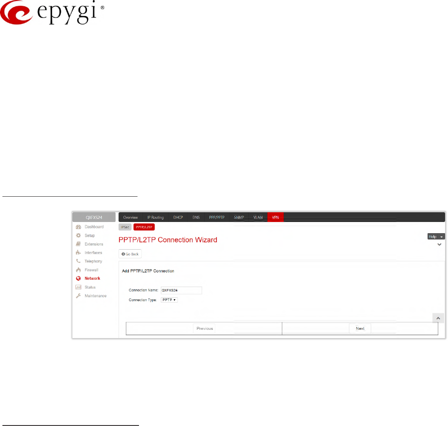
Manual-II: Administration Guide for QX Gateways
Edition 2 (FW Version 6.1.17 and higher) 150
•Start – initiates the selected connection(s). If it is a client connection, then this button initiates a client
activity of reaching the server.
•Stop – stops the selected connection(s). Stopping the server connection will disconnect all connected
clients and close the PPTP/L2TP tunnel.
•Add – leads to the PPTP/L2TP Connection Wizard to establish a new connection.
Note: After creating a PPTP server connection, PPTP connections between devices placed on the QX LAN
and external devices will no longer be possible. The PPTP pass-through service for incoming and outgoing
traffic will be automatically disallowed once a PPTP server connection is created.
The PPTP/L2TP Connection Wizard composed of the following sections:
Add PPTP/L2TP Connection
Figure 144: Add PPTP/L2TP Connection section
Connection Name – insert connection name. The name cannot start with a digit symbol; however, it
can contain digits further in the name.
Connection Type – select the type of the connection (PPTP or L2TP).
PPTP Connection Properties
Peer Name – insert the connection peer name. TIP: The Peer Name must be written with Latin characters.
When creating a connection with a Windows Server, ensure that a user with the QX’s host name and Dial-in
access exists on the server. When creating a connection with a Windows Client, ensure that the Peer Name
specified on this page matches the Dial-in connection’s username.
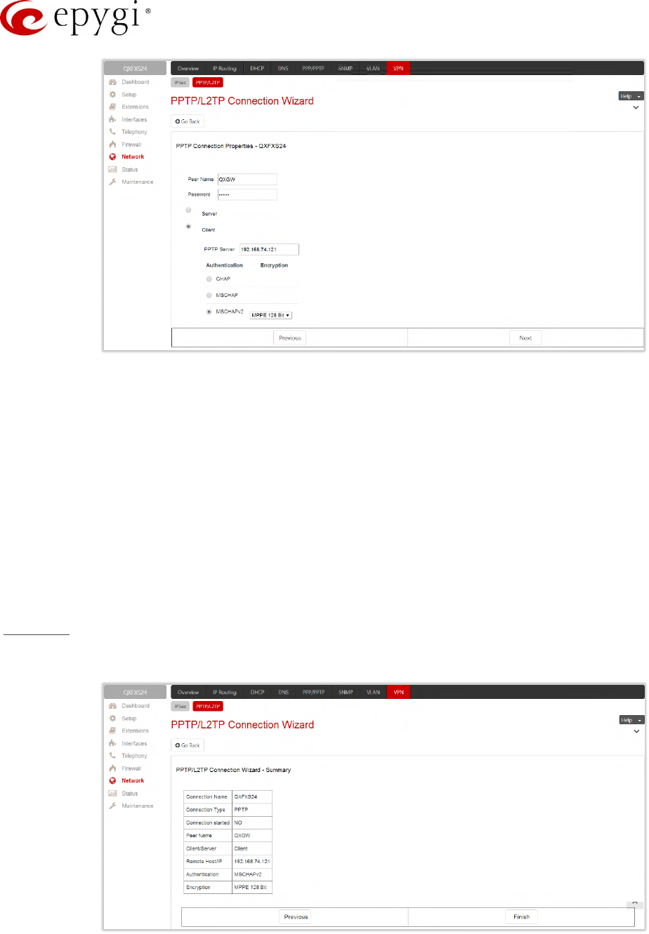
Manual-II: Administration Guide for QX Gateways
Edition 2 (FW Version 6.1.17 and higher) 151
Figure 145: PPTP/L2TP Connection Wizard for PPTP connection
•Password – insert the password.
•Server/Client – select whether the new connection will be a server or client. For the Client radio button
selection following information needs to be provided:
PPTP Server (if the PPTP connection type is selected) – insert an IP address or a host name of the
PPTP server.
L2TP Server (if the L2TP connection type is selected) – insert an IP address of the L2TP server.
Authentication – select the authentication protocol through which the client will communicate with the
server. This section is available only if the PPTP connection type is selected on the previous section.
The MSCHAPv2 selection enables the Encryption drop-down list where the encryption method can be
selected. TIP: These authentication settings should be identically configured on both peers for the
successful connection establishment.
Summary
The Summary section displays all configured settings for the PPTP/L2TP connection.
Figure 146: Summary section
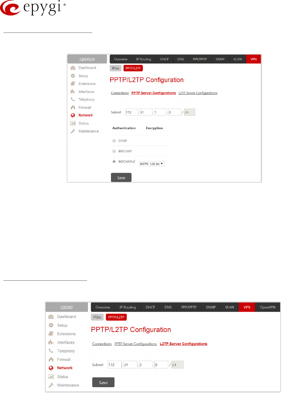
Manual-II: Administration Guide for QX Gateways
Edition 2 (FW Version 6.1.17 and higher) 152
PPTP Server Configurations
The PPTP Server Configuration sub-page is used to configure the PPTP server settings.
Figure 147: PPTP Server Configuration page
•Subnet – is used to enter the IP address range for the PPTP server and clients within the PPTP tunnel.
The value specified for the subnet mask is fixed to 24 to restrict the possible number of clients for the
PPTP connection. TIP: The first address specified in the PPTP Subnet will be assigned to the PPTP
server, others will be assigned to the clients. The PPTP server subnet must be different from the L2TP
server subnet.
•Authentication – is used to select the corresponding authentication protocol through which the client will
communicate with the server. TIP: The MSCHAPv2 selection enables Encryption drop-down list where
the encryption method can be selected.
L2TP Server Configuration
The L2TP Server Configuration sub-page is used to configure the L2TP server settings.
Figure 148: L2TP Server Configuration page
•L2TP Subnet – is used to enter the IP address range for the L2TP server and clients within the L2TP
tunnel. The value specified for the subnet mask is fixed to 24 to restrict the possible number of clients
for the L2TP connection. TIP: The first address specified in the L2TP Subnet will be assigned to the

Manual-II: Administration Guide for QX Gateways
Edition 2 (FW Version 6.1.17 and higher) 153
L2TP server, others will be assigned to the clients. The L2TP server subnet must be different from the
PPTP server subnet.
10.8Local Client Configuration
The Local Client Configuration page (available only for QXFXS24) is used to upload the OpenVPN configuration
file allowing to act QXFXS24 as an OpenVPN client. The OpenVPN configuration file should be uploaded on the
QXFXS24 without any changes.
For information on how to configure and use OpenVPN, please refer to the OpenVPN Service on QX IP PBXs
and Auto Configuration of Epygi Supported IP Phones using OpenVPN guides.
This page contains the following buttons:
•Add – leads to the Add Entry page to upload the new client configuration.
•Edit – is used to modify the configuration parameters (Server IP and Port).
•Start – activates the selected connection. The State will be changed from Stopped to Connected.
•Stop – disconnects the selected connection. The State will be changed from Connected to Stopped.
•Delete – is used to delete the selected configuration.
•View – is used to display the uploaded configuration file settings.
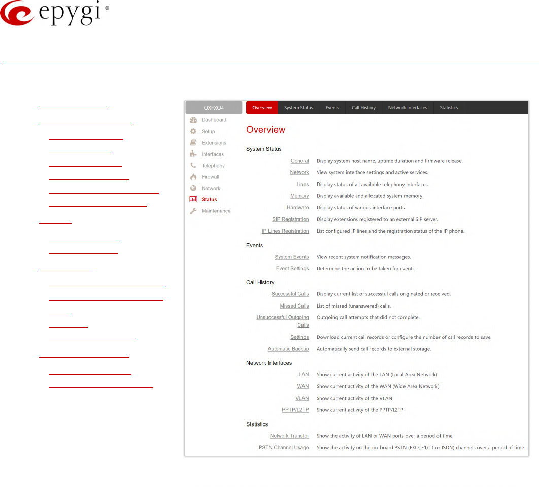
Manual-II: Administration Guide for QX Gateways
Edition 2 (FW Version 6.1.17 and higher) 154
11 Status Menu
The System Status menu consists of the following sections:
•System Status
•General Information
Network Status
Lines Status
Memory Status
Hardware Status
SIP Registration Status
IP Lines Registration
•Events
System Events
Event Settings
•Call History
Successful, Missed and
Unsuccessful Outgoing
Calls
Settings
Automatic Backup
•Network Interfaces
Network Transfer
PSTN Channel Usage
Figure 149: Status Menu overview
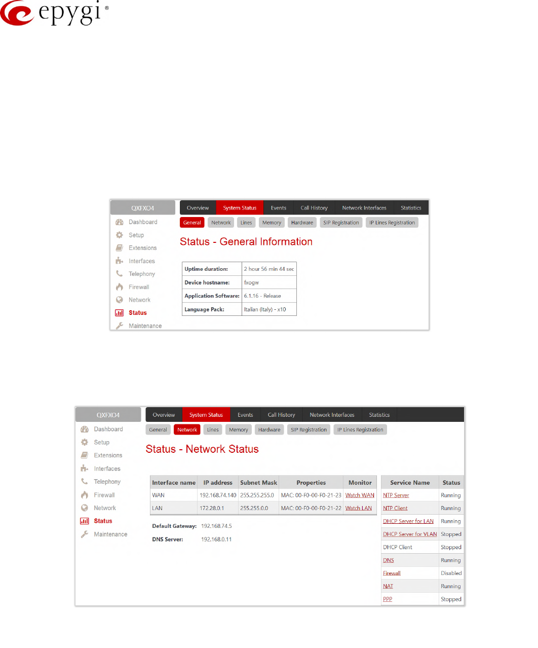
Manual-II: Administration Guide for QX Gateways
Edition 2 (FW Version 6.1.17 and higher) 155
11.1System Status
11.1.1 General Information
The General Information page provides the following information:
•Uptime duration – time period the QX is running since last reboot.
•Device hostname – displays the QX device host name.
•Firmware version – the version of the QX's firmware and the file system.
•Language Pack – this information is presented only when a custom language pack is uploaded and
indicates the version of language pack.
Figure 150: Status – General Information page
11.1.2 Network Status
The Network Status page provides information on available network interfaces and services on the QX.
Figure 151: Status – Network Status page
The Network Status table displays the following information:
•Interface Name – network interfaces (LAN, WAN, VLAN and etc.) available and configured on the QX.
•IP Address – IP address for the network interface.
•Subnet Mask – subnet mask for the network interface.
•Properties – MAC address for the network interface or additional information about the interface.
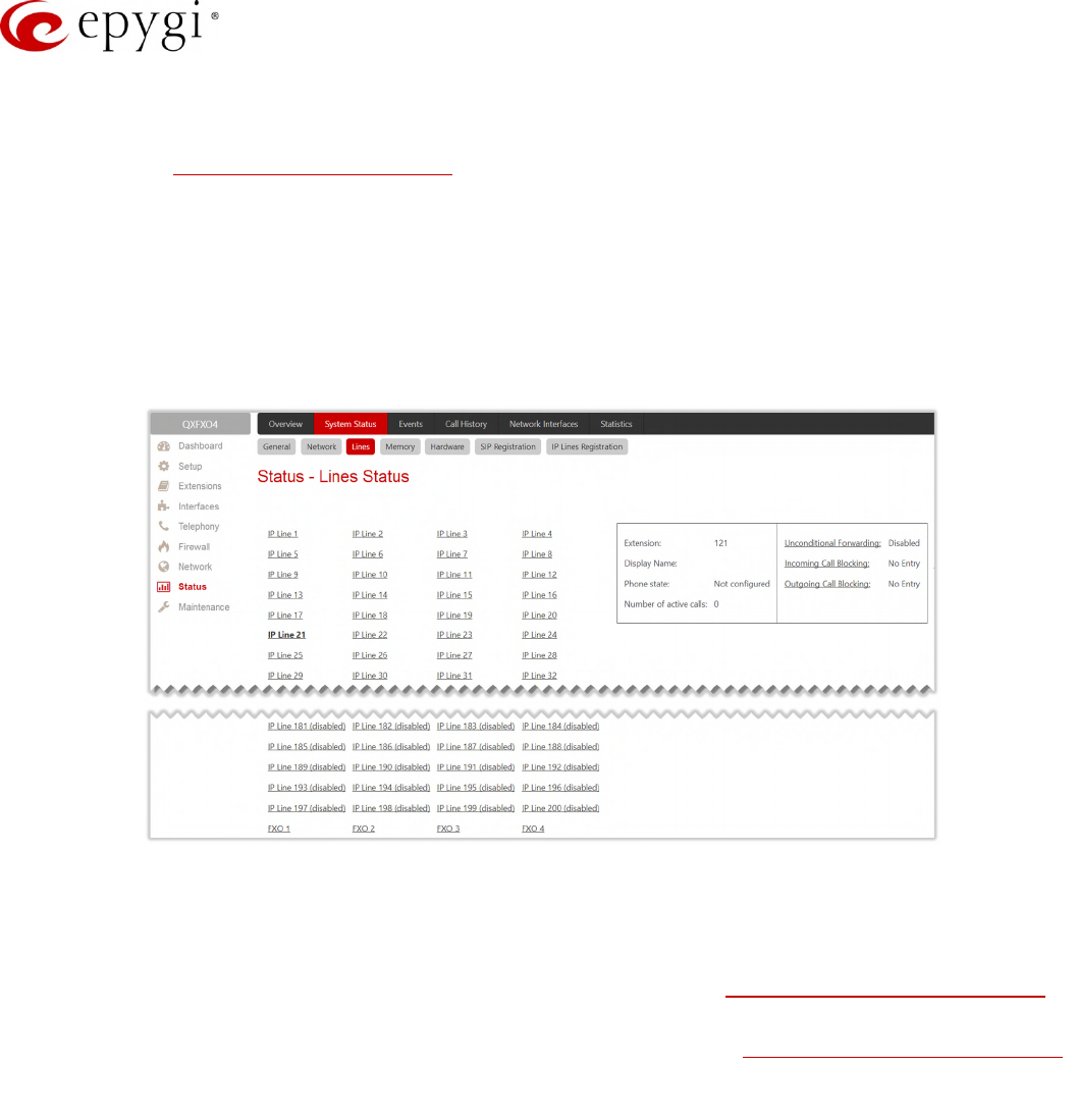
Manual-II: Administration Guide for QX Gateways
Edition 2 (FW Version 6.1.17 and higher) 156
•Monitor – allows to watch and monitor the interface.
The DNS Server, Alternative DNS Server and Default Gateway display the corresponding settings of QX,
configured in the Internet Configuration Wizard.
The Services table displays the available services (NTP Server and Client, DHCP Server and Client, DNS,
Firewall, NAT, PPP) with their current statuses.
11.1.3 Lines Status
The Status – Lines Status page displays the current status of an IP line, FXO line, FXS line, ISDN trunk or E1T1
trunk (depending on the QX model).
Figure 152: Status – Lines Status page
Attention: Only one line/trunk information can be displayed at a time.
Press the desired IP Lines, FXO, FXS, ISDN Trunk or E1T1 Trunk link to get information about its status.
•FXO Channel Usage Statistics (available for QXFXO4) – leads to the Statistics – PSTN Channel Usage to
get FXO lines usage information. Not available for shared FXO lines.
•ISDN Channel Usage Statistics (available for QXISDN4) – leads to the Statistics – PSTN Channel Usage
to get ISDN trunks usage information. Not available for shared ISDN trunks.
•E1/T1 Channel Usage Statistics (available for QXE1T1) – leads to the Statistics – PSTN Channel Usage
page to get E1/T1 trunks usage information. Not available for shared E1/T1 trunks.
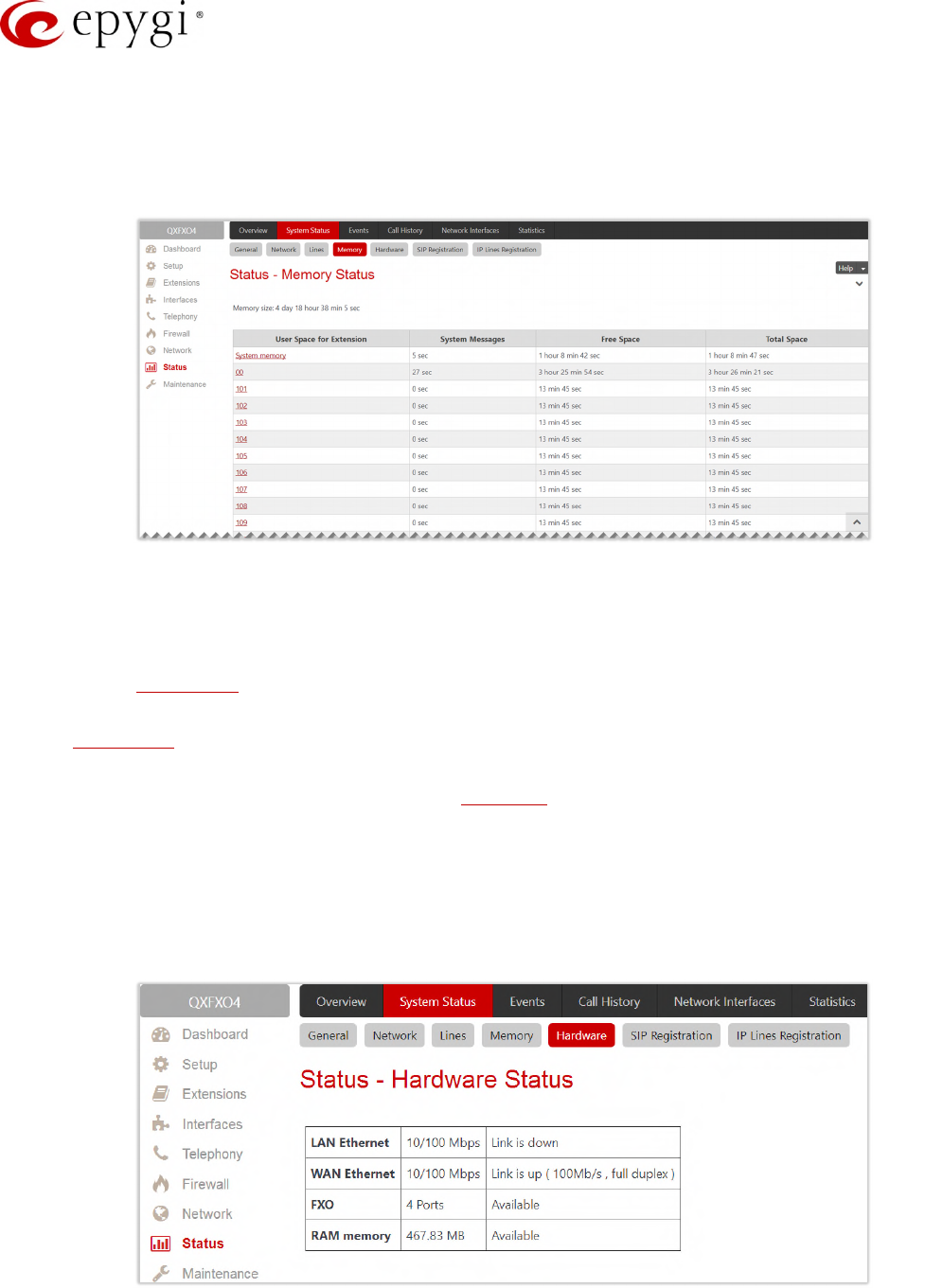
Manual-II: Administration Guide for QX Gateways
Edition 2 (FW Version 6.1.17 and higher) 157
11.1.4 Memory Status
The Memory Status page displays User Space information for each extension. Particularly, memory space used
by uploaded/recorded system greetings, free and total space (in minutes/seconds) information is available on
this page.
Figure 153: Status – Memory Status page
•Memory Size – displays the total memory space (in minutes/seconds) available on the QX and assigned
to all extensions.
•System Memory – displays the space occupied by the universal extension recordings. Press the link to
go the Recordings page to upload universal extension system messages and adjust the percentage of
system memory.
•Call History – displays the current number of calls (successful, unsuccessful outgoing calls, missed) with
recorded statistic entries.
•Hyperlinked extension number leads to the extension.
11.1.5 Hardware Status
The Hardware Status table shows the list of network interfaces, on-board and external devices and parts
currently available on the QX with their parameters and statuses.
Figure 154: Status – Hardware Status page
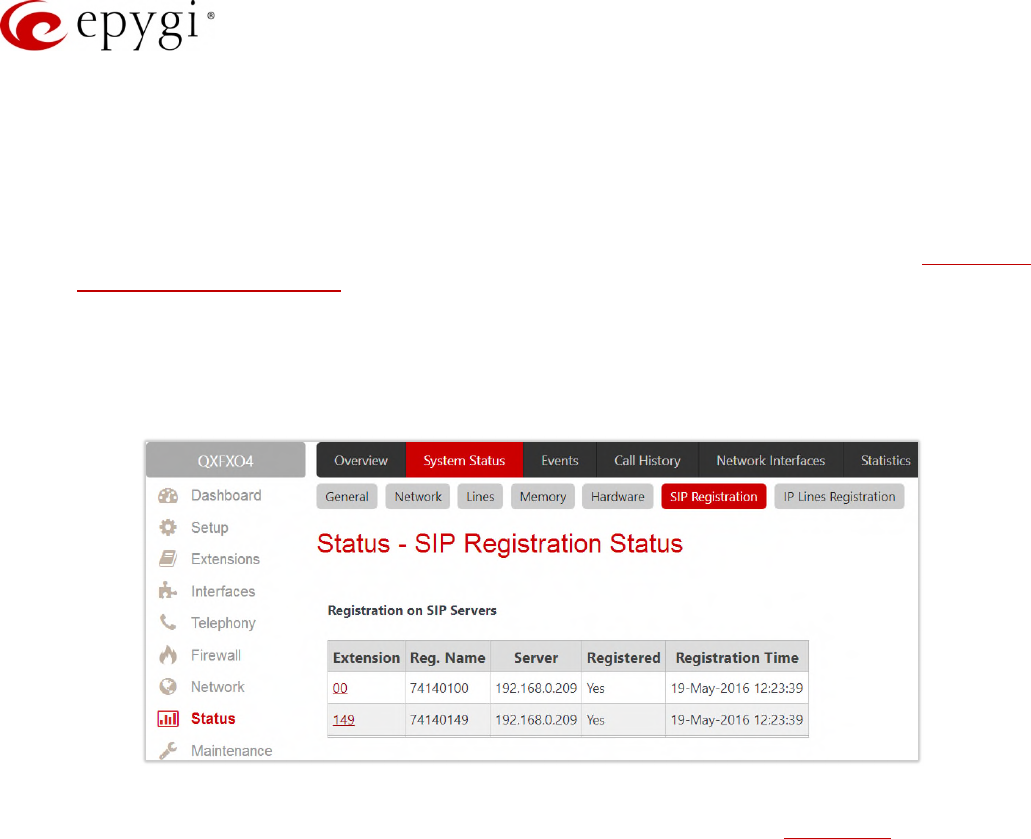
Manual-II: Administration Guide for QX Gateways
Edition 2 (FW Version 6.1.17 and higher) 158
11.1.6 SIP Registration Status
The SIP Registration Status page displays information about the QX extensions registration on SIP servers.
Information about the configured SIP Tunnels between Epygi devices is displayed here as well.
The Registration on SIP Servers table shows the following information:
•Extension – shows the extension number. The hyperlinked Extension number leads to the Extensions
Management – SIP Settings section where the SIP registration settings can be modified.
•Username/DID Number – is the registration username or the DID number on the server.
•SIP Server – indicates the address of the SIP server. It can be either an IP address or a host name.
•Registered – shows the registration status.
•Registration Time – shows the registration time.
Figure 155: Status – SIP Registration Status page
The SIP Tunnels to Slave Devices and SIP Tunnels to Master Devices tables list the SIP tunnels between local
and the remote Epygi devices. The SIP Tunnels to Slave Devices table lists those tunnels where local QX acts as
a master. The SIP Tunnels to Master Devices table lists those tunnels where local QX acts as a slave.
11.1.7 IP Lines Registration
The IP Lines Registration Status (N/A for QXISDN4 and QXFXS24) page provides information on IP Lines
registration on the QX.
The IP Lines Registration table lists the IP lines and remote extensions registered on the QX. The following
information is available:
•Line – shows the number of IP line. The hyperlinked Line number leads to the IP Line Settings page
where the IP Line settings can be modified.
•Extension – shows the extension number attached to the IP line.
•Username – indicates the registration username.
•Registered – shows the registration status.
•Binding IP Address – indicates the IP address of the registered device (IP phone, softphone or etc.).
•Registration Time – shows the registration time.
•Registration Expires in – shows when the registration will expire for the device.
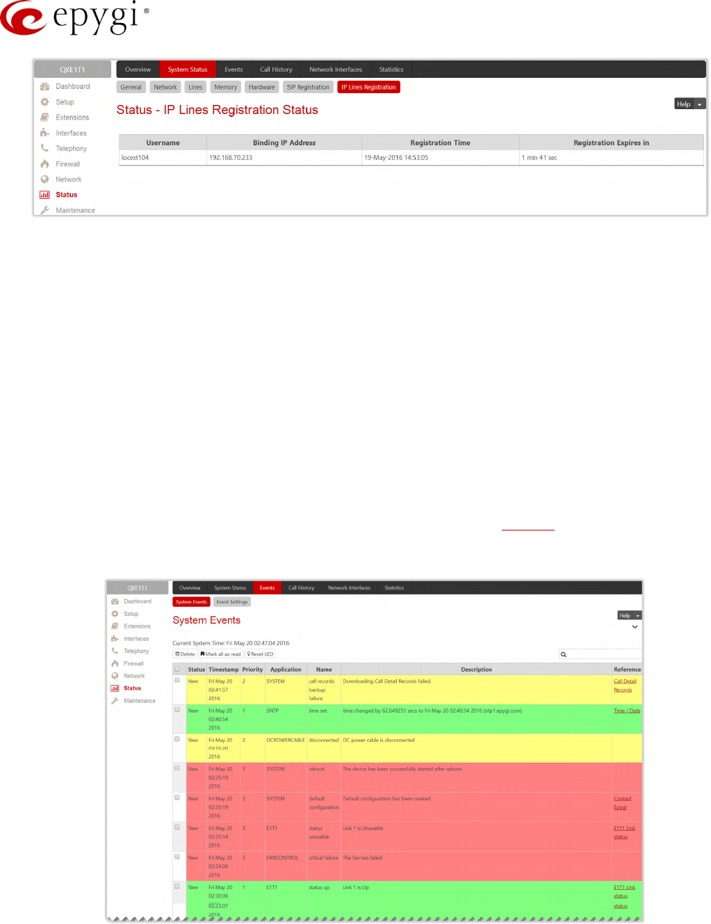
Manual-II: Administration Guide for QX Gateways
Edition 2 (FW Version 6.1.17 and higher) 159
Figure 156: Status – IP Lines Registration Status page
11.2Events
11.2.1 System Events
The System Events page lists information about system events that have occurred on the QX. When a new
event takes place, a record is added to the System Event table. Numerous circumstances may cause a certain
application on the QX to flag an event. TIP: The warning link that leads directly to the System Events page will
disappear from the management pages if the administrator has marked all new events as "read".
The System Events table is the list of new and read system events. System events have corresponding coloring
depending on the nature of the event: success (priority 1, color green), low importance failure (priority 2, color
yellow), critical failure (priority 3, color red).
The table shows the Status of the event (new or read) as well as the name of the application the event refers to,
event description, and the date when the event was received. For example, if the event was caused by the IDS
service, the Check IDS link appears in the reference row that will lead to the IDS Log page, or if the event has
occurred due to incorrect mail sending or SIP registration, the corresponding links will be seen in the Reference
column of the table.
Figure 157:System Events page
•Current System Time – displays the local date and time on the QX.
•Mark all as read – marks newly occurred events as "read".
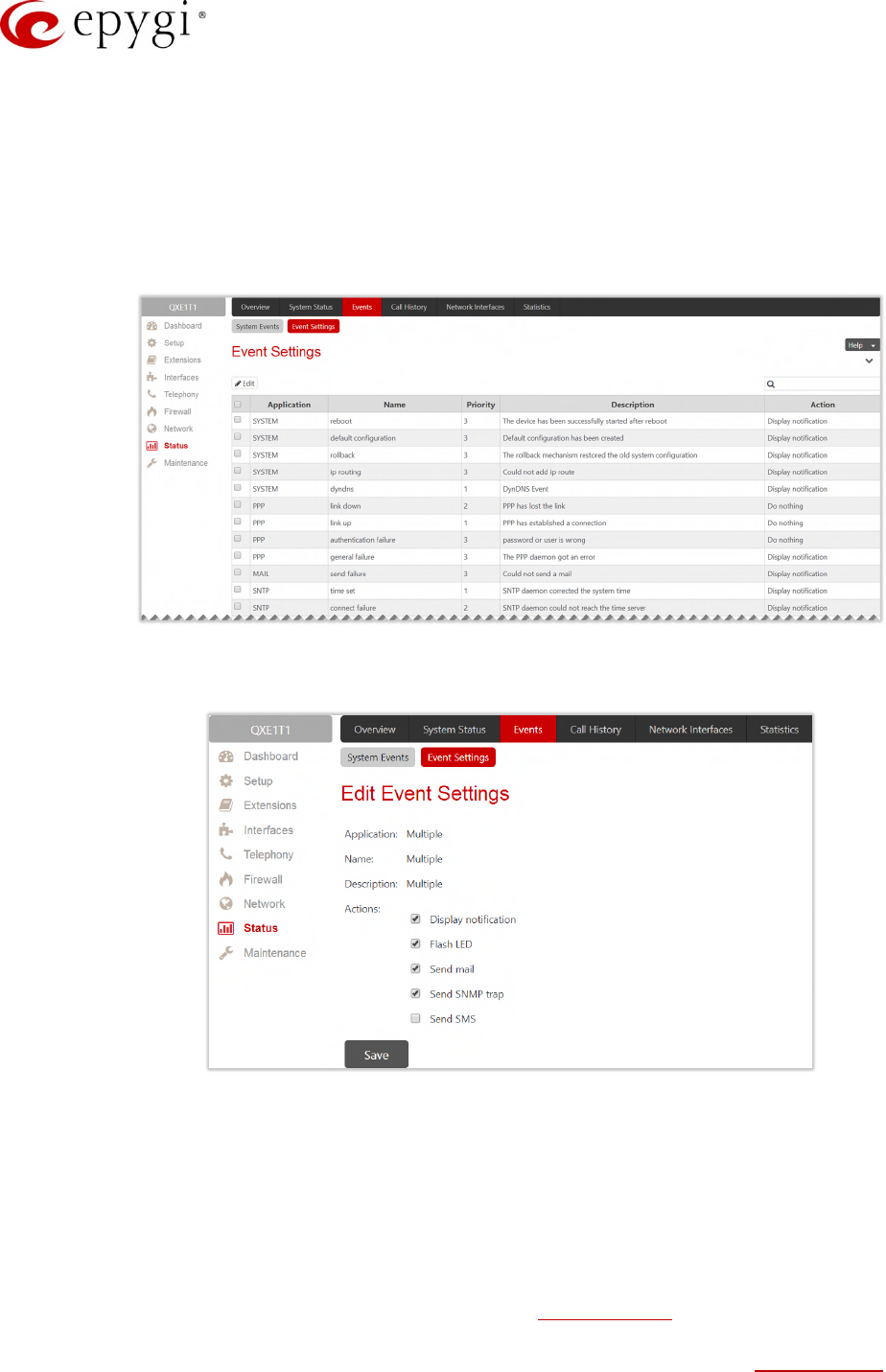
Manual-II: Administration Guide for QX Gateways
Edition 2 (FW Version 6.1.17 and higher) 160
•Reset LED – switches off the flashing LED (if applicable) on the board. The LED notification may appear
(depending on the notification type given) in the Event Settings page when a new event occurs.
11.2.2 Event Settings
The Event Settings page lists all possible events on the QX and allows controlling notification (action) when an
event takes place. Each entry in the events’ table has a checkbox assigned to each row. You can modify
multiple events by selecting two or more events.
Figure 158: Event Settings page
•Edit – leads to the Edit Event Settings page to modify the event action.
Figure 159: Edit Event Settings page
Application – displays the application the event refers to. Multiple is shown here if more than one event
has been selected for the action assignment.
Name – displays the name of the event. Multiple is shown here if more than one event has been
selected for the action assignment.
Description – displays additional information about the event. Multiple is shown here if more than one
event has been selected for the action assignment.
Action – is used to select event notification method:
Display Notification – displays notification in the System Events page.
Flash LED – LED flashes every second. For some events the LED will start flashing after a delay.
Send Mail – an e-mail will be sent to the e-mail address specified in the E-mail (SMTP) page.
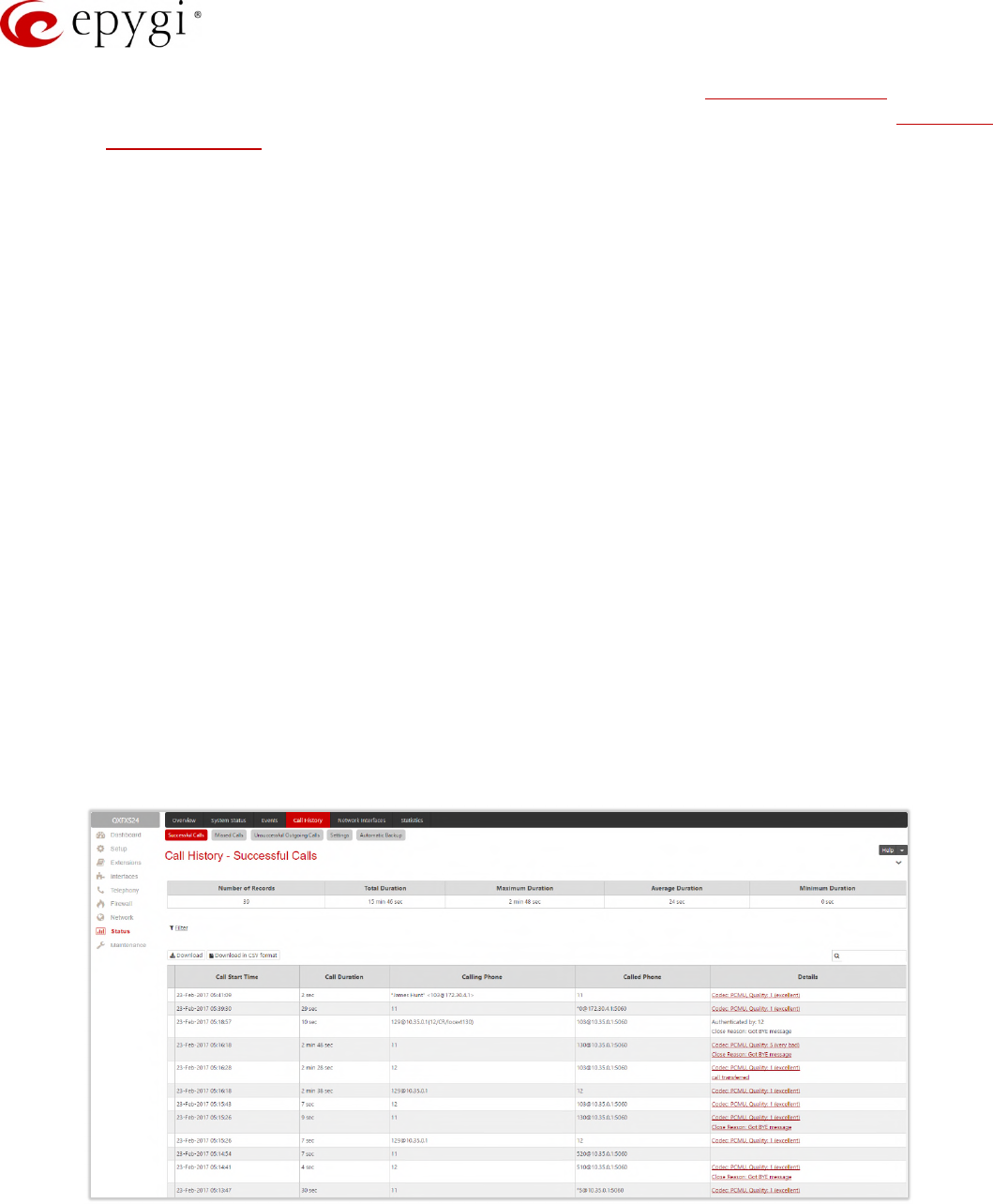
Manual-II: Administration Guide for QX Gateways
Edition 2 (FW Version 6.1.17 and higher) 161
Send SNMP Trap – a trap will be sent to the traphost(s) listed in the SNMP Trap Settings table.
Send SMS (N/A for QXFXS24) – a SMS will be sent to the mobile number specified in the Short Text
Messaging (SMS) page.
Note:
•Actions that are not allowed for the selected event (like mail notification if the PPP link is down or the
mail server has been configured improperly) are hidden. For multiple events editing, actions that are not
appropriate for least one of the selected events will also be hidden.
•In case of an IDS intrusion alert, only the first possible intrusion in each 10-minute period will initiate an
event. If the QX cannot receive an IP address from the DHCP or PPP servers, or cannot register an
extension on the SIP or Routing servers, or cannot reach an NTP server, it raises only one event for the
entire period the action has failed, but will continue to try. When the required action is successful, the
QX raises an appropriate message.
11.3Call History
The Call History allows to track and report the call detail records (CDR) for calls originated and terminated on
QX, as well as for calls passed through QX.
11.3.1 Successful, Missed and Unsuccessful Outgoing Calls
The Successful Calls, Missed Calls and Unsuccessful Outgoing Calls pages lists successful, missed and
unsuccessful outgoing calls and their parameters. The following components are available:
•Filter – allows searching for call records based on at least one of the criteria: Call Start Time, Call
Duration, Caller and Called parties.
•Clear Filter – is used to remove the filter.
•The Download / Download in CSV format buttons are used to download the displayed CDRs for each
page (Successful, Missed and Unsuccessful Outgoing) in the (*.log) and (*.csv) formats respectively.
Figure 160: Call History – Successful Calls page

Manual-II: Administration Guide for QX Gateways
Edition 2 (FW Version 6.1.17 and higher) 162
CDRs listed in the Call History tables are characterized by the following parameters:
•Call Start Time – shows the start date and time of the call.
•Call Duration – shows the duration of the call.
•Calling Phone – shows the caller's number and display name (if available).
•Called Phone – shows the callee's number and display name (if available).
•Details – provides the following additional information:
Details on the call quality, audio codec used to receive and transmit packets and the call close
reason. The call close reason appears to provide more information about the call termination, such as
a network problem, call termination by one of the parties, voice mail service activation, etc. The Details
information link leads to the RTP Statistics page where all RTP parameters of the call are shown.
Authenticated By – shows the authentication parameters in the Local AAA Table, such as login or PIN
code used to pass the authentication when making call. Information about FAX statistics for the calls
that have a FAX transmission handled. It only appears when there was a FAX transmission during the
call. The FAX link leads to the FAX Statistics page.
11.3.2 Settings
The Call History – Settings page (Figure 161) is used to configure specific parameters for displaying Call History.
The following options are available:
•Enable Call Reporting – enables/disables the CDR reporting and allows to select the maximal numbers
of CDR entries to be displayed in the Call History tables respectively.
Maximal Number of Successful/Missed/Unsuccessful Call Records – these are used to select the
maximal number of Successful, Missed and Unsuccessful Outgoing CDR entries to be displayed in the
respective Call History tables. TIP: When the number of CDRs exceeds the numbers specified in the
Call History – Settings page, the oldest entries are being automatically deleted. To keep the call history
entries safe, configure and use the Automatic Backup service of the QX.
•The Download All Call Detail Records / Download All Call Detail Records in CSV format links are used to
download the displayed Call History in the (*.log) and (*.csv) formats respectively.
•Clear all Records – is used to remove all CDRs.
•CDR Parameters section provides the full list for CDR parameters on QX. You can select the specific
parameters to be excluded from the downloaded/archived call history files to make the CDR files more
compact, thus more readable. For the detailed information about the CDR parameters listed in this
page, please refer to the Call Detail Records on the QX IP PBXs guide.
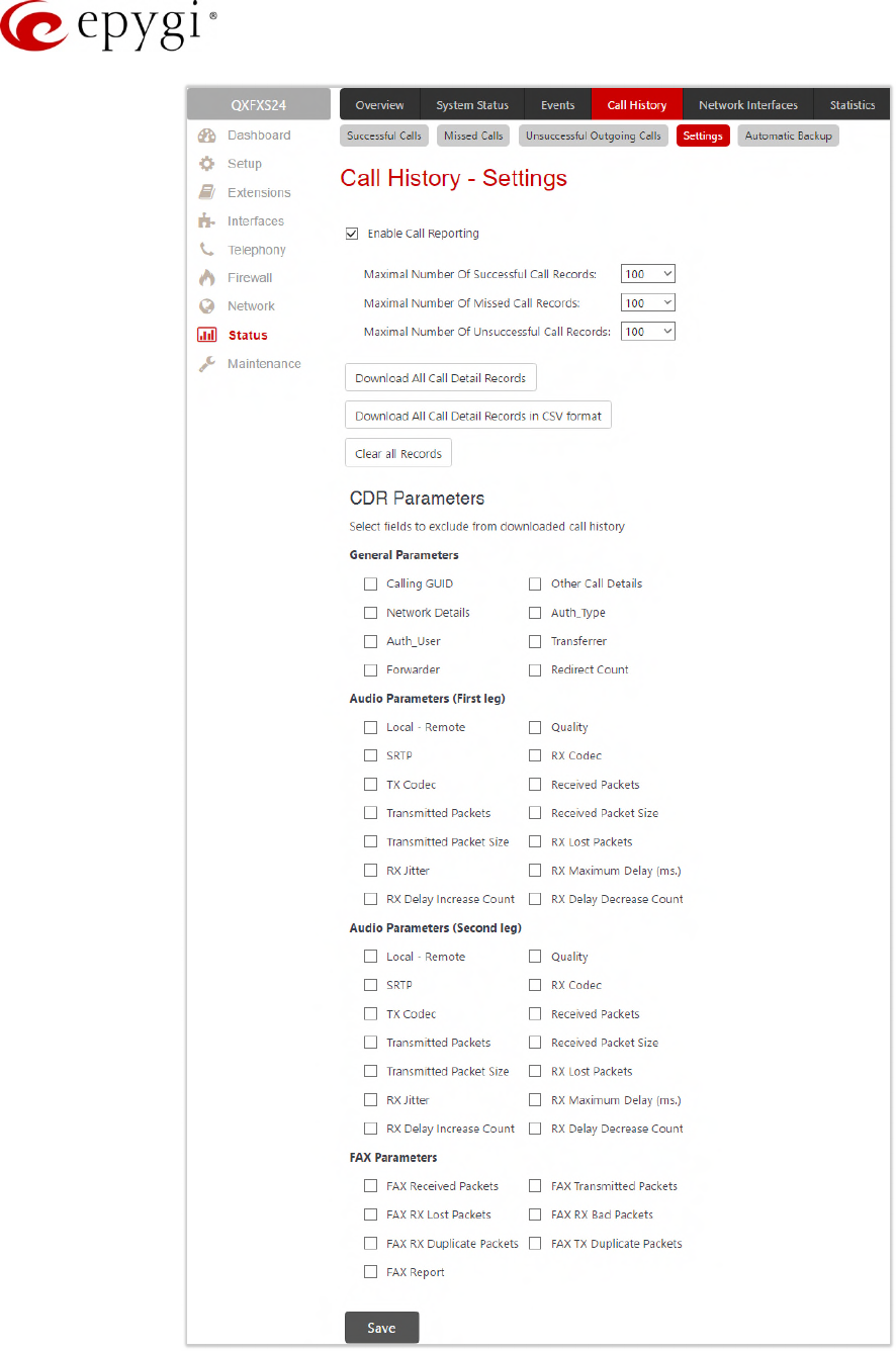
Manual-II: Administration Guide for QX Gateways
Edition 2 (FW Version 6.1.17 and higher) 163
Figure 161: Call History – Settings page
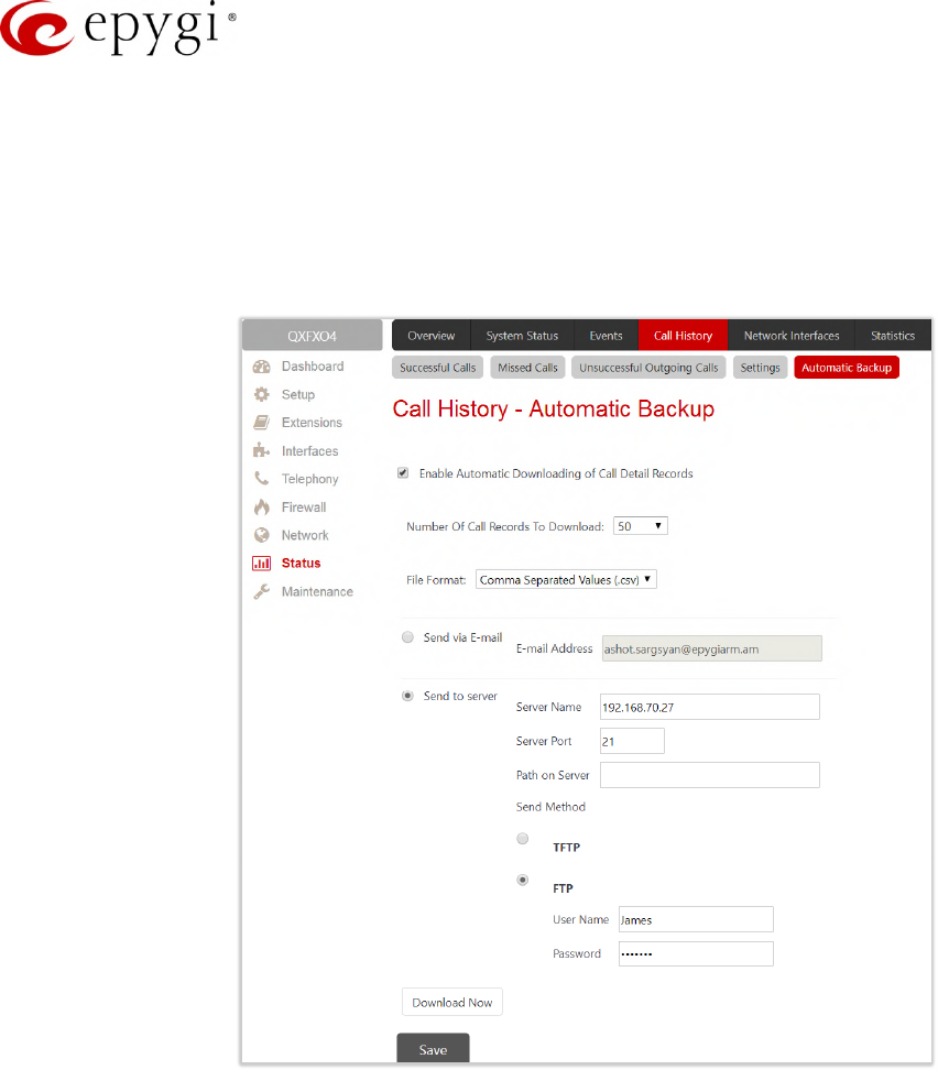
Manual-II: Administration Guide for QX Gateways
Edition 2 (FW Version 6.1.17 and higher) 164
11.3.3 Automatic Backup
The Automatic Backup page is used to configure the automatic downloading of the call history.
Two options are available:
•Upload the call history file to the server.
•Send the call history file to the mailing address.
Figure 162: Call Statistics – Automatically Download page
•Enable Automatic Downloading of Call Detail Records – enables automatic downloading mechanism of
the call history file. TIP: This service refers only to the statistics collected from the moment of enabling.
Any previously generated statistics will not be downloaded.
•Number of Call Records to Download – is used to select the portion size of the call history (including all
types of call statistic, i.e. successful, missed and unsuccessful outgoing call history, in the timing order)
which will be downloaded to the server or send per email. The number selected in this drop-down list
indicates the number of entries in the single downloaded call history file. If there are no enough entries in
the call history table on the QX, the system will wait until the necessary number of entries will be
collected and then will upload the statistics file to the server or send it to the email address.
•File Format – is used to select the archive file format as Tab Delimited Text (.log) and Comma Separated
Values (.csv).
Send via Email – is used to send the call history files via email. You need to define the Email Address
of the receipt.
Send to Server – is used to store the call history files on a remote server. This selection enables the
following fields to be inserted:
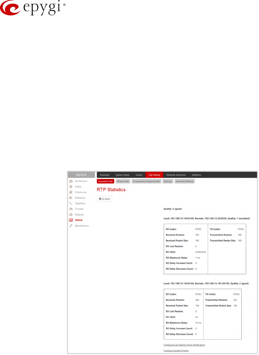
Manual-II: Administration Guide for QX Gateways
Edition 2 (FW Version 6.1.17 and higher) 165
Server Name – is the IP address or host name of the remote server.
Server Port – is the port number of the remote server.
Path on Server – is the path on the server to store the call history files in.
Send Method – is used to select the remote server type: TFTP or FTP. In case of FTP selection, the
authentication username and the password need to be inserted. If these fields are left empty,
anonymous authentication will be used.
•Download Now – is used to manually download of the call history.
11.3.4 RTP Statistics
The RTP Statistics page provides detailed information about the established call. When QX serves as an RTP
proxy, this page displays two groups (legs) of RTP statistics. For example, when calling from an IP Phone
attached to the QX IP line to an external SIP destination or from one external SIP destination to another through
the QX Auto Attendant. Each group of parameters describes characteristics of a piece of RTP stream
composing an overall SIP session. Normally, one leg describes the RTP stream from caller to the QX gateway
and the other leg describes the RTP stream from the QX to the destination.
Figure 163: RTP Statistics page
•Quality – indicates the call quality, which depends on RTP statistic. Below is the legend for Call Quality
definitions on the displayed RTP Statistics:
excellent – RX Lost Packets < 1% & RX Jitter < 20
good – RX Lost Packets < 5% & RX Jitter < 80
satisfactory – RX Lost Packets < 10% & RX Jitter < 150
bad – RX Lost Packets < 20% & RX Jitter < 200
very bad – RX Lost Packets > 20% or RX Jitter > 200
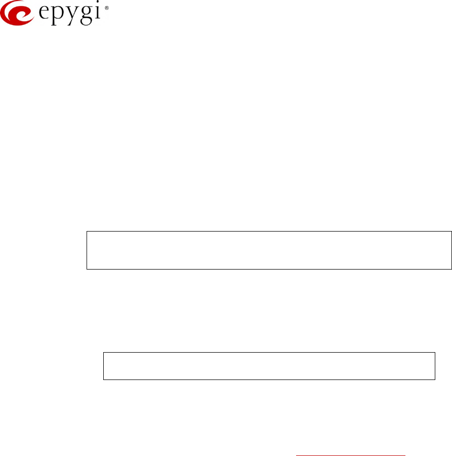
Manual-II: Administration Guide for QX Gateways
Edition 2 (FW Version 6.1.17 and higher) 166
•Local and Remote – indicate the two peers between which the RTP stream is transmitted. The
characteristics in the table below describes to the piece of RTP stream between these peers.
•Rx/Tx Codec – codec for received and transmitted RTP stream respectively.
•Rx/Tx Packets – is the number of RTP packets received and transmitted respectively.
•Rx/Tx Packet Size – is the size of RTP packets (payload) received and transmitted respectively.
•Rx Lost Packets – is the number of lost RTP packets for received stream.
•Rx Jitter – inter-arrival jitter is an estimate of the statistical variance of the RTP data packet inter-arrival
time, measured in timestamp units.
The inter-arrival jitter is defined to be the mean deviation (smoothed absolute value) of the difference D in packet
spacing at the receiver compared to the sender for a pair of packets. If Si is the RTP timestamp from packet i,
and Ri is the time of arrival in RTP timestamp units for packet i, then for two packets i and j, D may be
expressed as:
D(i,j) = (Rj - Ri) - (Sj - Si) = (Rj - Sj) - (Ri - Si)
J(i) = J(i-1) + (|D(i-1,i)| - J(i-1))/16, where J(i) is Rx Jitter for packet i.
For more details about Jitter calculations, please refer to the RFC1889.
•Rx Maximum Delay – is the maximum variance (absolute value) of actual arrival time of the RTP data
packet compared to estimated arrival time, measured in milliseconds. If Si is the RTP timestamp from
packet i, and Ri is the time of arrival in RTP timestamp units for packet i, then variance for packet i may
be expressed as following:
V(i) = |(Ri - R1) - (Si - S1)| = |(Ri - Si) - (R1 - S1)|
Rx Maximum Delay = max V(i) / 8
•RX Delay Increase Count – indicates the number of times the delay in jitter buffer is increased during the
call.
•RX Delay Decrease Count – indicates the number of times the delay in jitter buffer is decreased during
the call.
•Configure Call Quality Event Notification – leads to the Call Quality Notification page to configure call
quality control notification specifics.
•Configure System Events – leads to the Event Settings page to configure the methods of notification for
each system event.
RTP Statistics is logged only when at least one of the call endpoints is located on the QX. For example, it will
not be logged when:
•Calls incoming from or addressed to the IP lines or remote extension.
•Calls from an external user are routed to another external user through QX’s routing rules.
In the first case, RTP statistics will be logged if remote extension or IP line user is calling locally to the QX’s
extension or auto attendant.
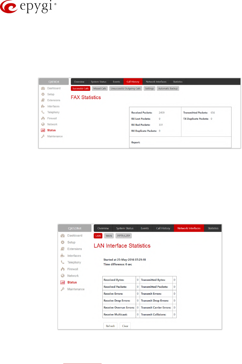
Manual-II: Administration Guide for QX Gateways
Edition 2 (FW Version 6.1.17 and higher) 167
11.3.5 FAX Statistics
The FAX statistics page is accessed from the Call History page by clicking on the FAX details link in the Details
column for the calls that contain T.38 FAX transmission.
The FAX statistics page provides information about received and transmitted packets, lost, bad and duplicated
packets. These statistics refers only to the T.38 FAX transmission. The FAX statistics is not available for the FAX
transmitted with other protocols.
Figure 164: FAX Statistics page
11.4Network Interfaces
The Network Interface Statistics pages display the corresponding statistics.
•LAN – current activity of the LAN (Local Area Network).
•WAN – current activity of the WAN (Wide Area Network).
•VLAN – current activity of the VLAN.
•PPTP/L2TP – current activity of the PPTP/L2TP.
Figure 165: LAN Interface Statistics page
The table displayed here shows the number of receive and transmit events that occurred since the last resetting
of the counters by clicking the Clear button. Depending on the Watch LAN, Watch WAN, Watch VLAN, Watch
PPP link selected on the Network Status page, the LAN Interface Statistics, WAN Interface Statistics, VLAN
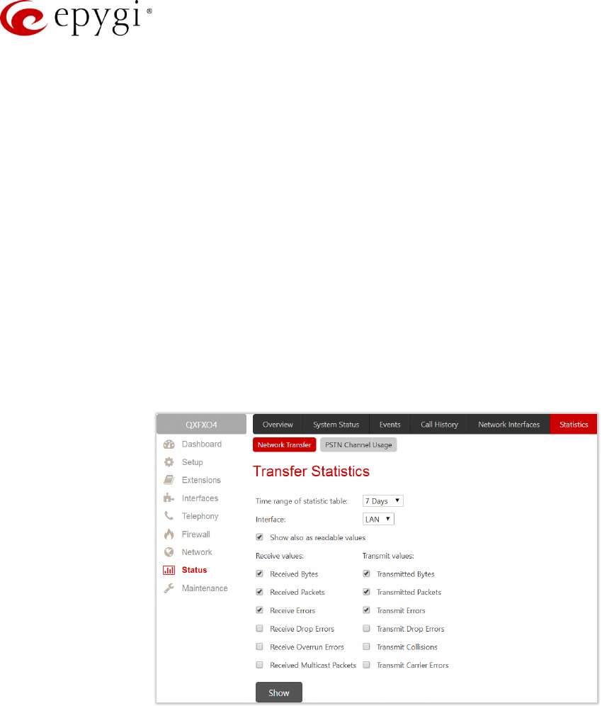
Manual-II: Administration Guide for QX Gateways
Edition 2 (FW Version 6.1.17 and higher) 168
Interface Statistics, PPTP or L2TP statistics page will be displayed. The page is automatically refreshed every
minute. Additionally, Refresh allows to initiate manual.
11.5Statistics
11.5.1 Network Transfer
The Transfer Statistics page shows a user-defined statistics table with the transmit/receive value (criteria),
interface type and time period. It contains the following components:
•Time range of statistic table – includes the period (in days) statistics data that is to be collected and the
corresponding diagram charts that are to be built.
•Interface drop-down list offer the values:
LAN – Show current activity of the LAN (Local Area Network).
WAN – Current activity of the WAN (Wide Area Network).
VLAN – Show current activity of the VLAN.
PPTP/L2TP – Show current activity of the PPTP/L2TP.
Figure 166: Transfer Statistics page
•Show also as readable values – if selected, an additional table with statistics values will be displayed on
the next page.
•Receive Values provides the following:
Receive Bytes – number of received bytes.
Receive Packets – number of received Ethernet packets.
Receive Errors – number of received packets containing errors.
Receive Drop Errors – number of received packets that have been discarded.
Receive Overrun Errors – number of received overrun errors that occur when the receive buffer is not
large enough to hold all incoming packets. This error usually appears due to a slow receiving system.
Receive MultiCast Packets – number of received broadcast packets.
•Transmit Values provides the following:
Transmit Bytes – number of transmitted bytes
Transmit Packets – number of transmitted Ethernet packets.
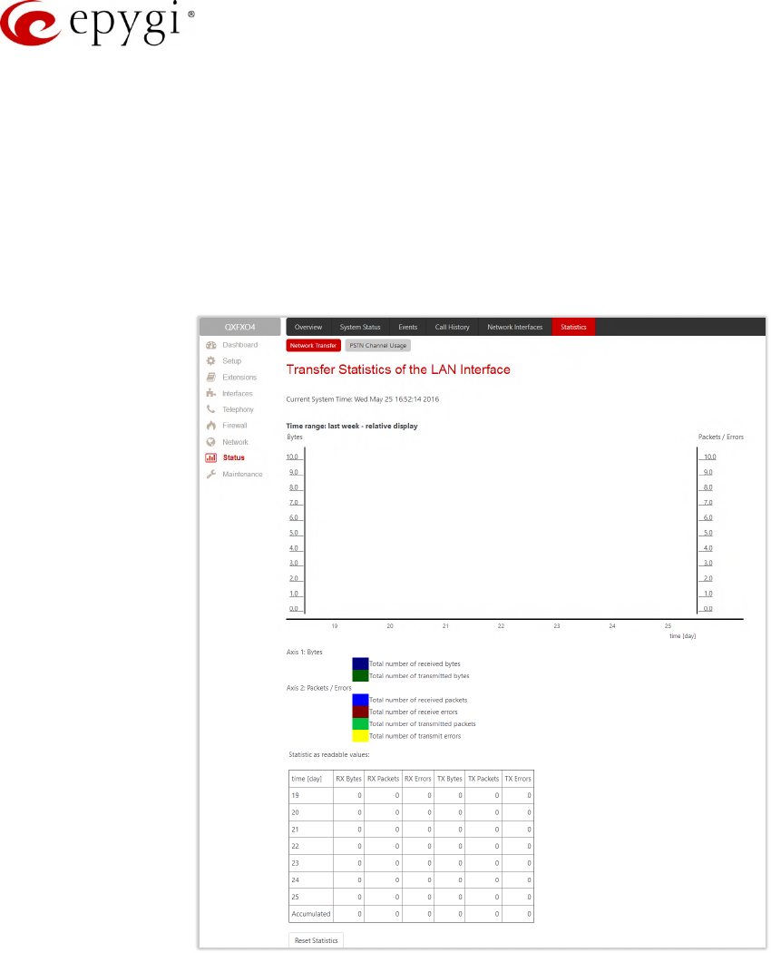
Manual-II: Administration Guide for QX Gateways
Edition 2 (FW Version 6.1.17 and higher) 169
Transmit Errors – number of transmitted packets containing errors.
Transmit Drop Errors – number of transmitted packets that have been discarded.
Transmit Carrier Errors – number of transmit carrier errors that occur due to a defective or lost
connection on the Ethernet link.
Transmit Collisions – number of transfer errors that occurred during a simultaneous packet
transmission from both sides.
To see the Transfer Statistics Diagram Charts, select the desired criteria and click Save to generate the
corresponding chart and the table showing the transfer statistics values (if enabled). The letters M (millions) and
K (thousands) used in the legend of the displayed diagrams show the total number of specified criteria.
Figure 167: Transfer Statistics Diagram Chart
•Reset Statistics – is used to reset the chart and the table (if enabled).
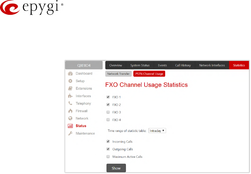
Manual-II: Administration Guide for QX Gateways
Edition 2 (FW Version 6.1.17 and higher) 170
11.5.2 PSTN Channel Usage
The trunk checkboxes are used to select the port number(s) over which the FXO, ISDN or E1/T1 (depending on
QX gateway model) traffic chart will be built. At least one Trunk should be selected.
Figure 168: FXO Channel Usage Statistics page
•Time range of statistic table – lists the period (in days) statistics data that is to be collected and the
corresponding diagram chart that is to be built.
•Incoming Calls and Outgoing Calls – are used to select whether the FXO, ISDN or E1/T1 (depending on
the QX model) traffic statistics for only incoming or outgoing or for both type of calls should be displayed
in the diagram chart.
•Maximum Active Calls – is used to have the number of maximum active calls displayed in the diagram
chart. At least one of these checkboxes should be selected.
•Show – is used to generate an FXO, ISDN or E1/T1 (depending on the QX model) channels usage
diagram chart over the parameters selected above.
When this button is pressed, FXO, ISDN or E1/T1 (depending on the QX model) Channel Usage Statistics chart
appears. It represents dependency between the time frame and the number of calls performed during that
period. Additionally, it may display the maximum number of calls performed in the selected time frame.
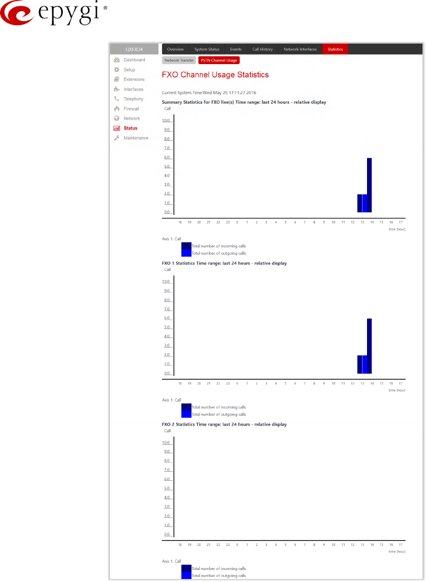
Manual-II: Administration Guide for QX Gateways
Edition 2 (FW Version 6.1.17 and higher) 171
Figure 169: QXISDN4 gateway – ISDN Channel Usage Statistics chart
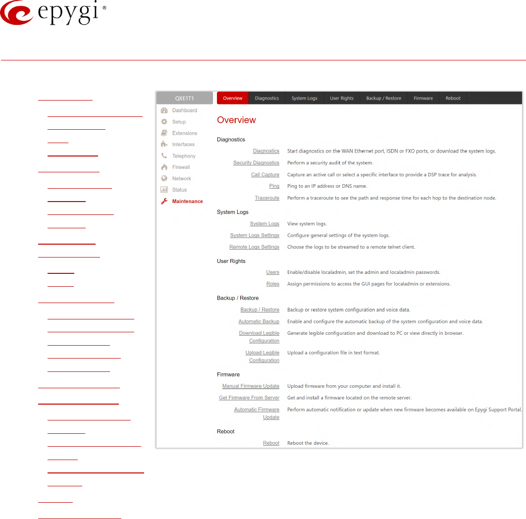
Manual-II: Administration Guide for QX Gateways
Edition 2 (FW Version 6.1.17 and higher) 172
12 Maintenance Menu
The Maintenance menu consists of the following sections:
•Diagnostics
Security Diagnostics
Call Capture
Ping
Traceroute
•System Logs
System Logs
Settings
Remote Logs
Settings
•User Rights
Management
Users
Roles
•Backup/Restore
Automatic Backup
Download Legible
Configuration
Upload Legible
Configuration
•Auto Provisioning
•Firmware Update
Manual Firmware
Update
Get Firmware From
Server
Automatic Firmware
Update
•Reboot
•Registration Form
Figure 170: Maintenance Menu overview
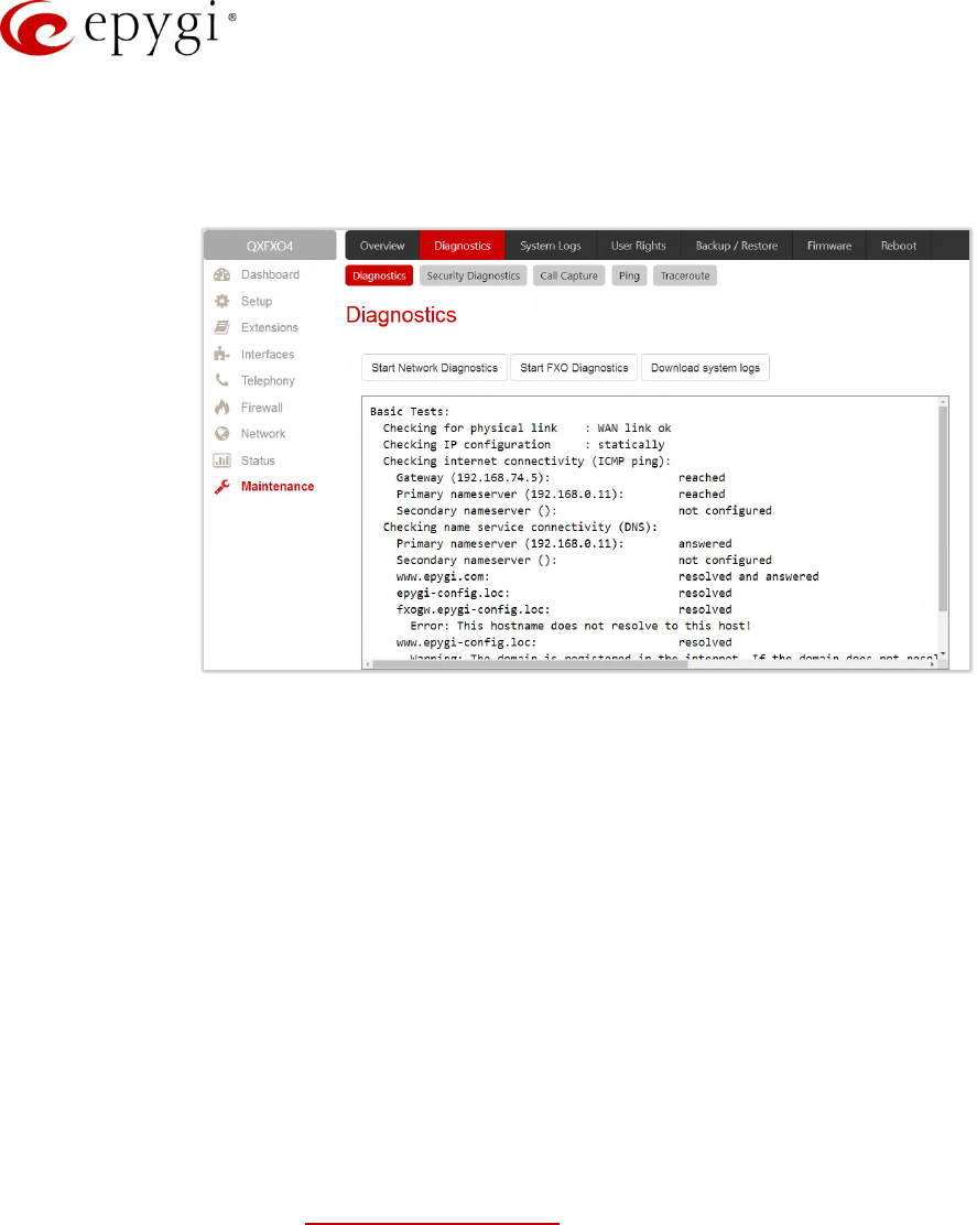
Manual-II: Administration Guide for QX Gateways
Edition 2 (FW Version 6.1.17 and higher) 173
12.1Diagnostics
The Diagnostics page is used to run Network protocol diagnostics to verify QX's connectivity and download all
system logs for possible problems recovery.
Figure 171: Diagnostics page
•Start Network Diagnostics – initiates network diagnostics, i.e., to check the WAN link and IP
configuration, to verify gateway, DNS primary and secondary (if configured) servers' accessibilities.
•Start FXO Diagnostics (available for QXFXO4) – runs FXO diagnostic tests to determine the optimal value
for the FXO country specific regional setting (CSRS) appropriate to your PSTN provider. Once the FXO
diagnostic is complete, the recommended value should be set manually on the "fxocfg.cgi" hidden
page. Setting this value may resolve echo or poor audio quality issues on FXO lines.
•Start ISDN Diagnostics (available for QXISDN4) – runs ISDN diagnostics test to initiate ISDN BRI low
level diagnostic. With these tests the ISDN physical link is checked and the Frame Synchronization is
verified.
•Start E1/T1 Diagnostics (available for QXE1T1) – initiate E1/T1 Link Diagnostic and Diagnostic Loopback.
With these tests E1/T1 physical link is checked, Frame Synchronization and Red Alarm states are
verified. For successful Link Diagnostic, remote side should have Line_loopback or Payload_loopback
settings configured or a loopback terminator should be plugged to the QX gateway's E1/T1 port.
Diagnostic Loopback will be initiated if Link Diagnostic is failed or E1/T1 link is down.
•Download system logs – is used to download all logs to the local PC as a (*.tar) archive file. These logs
can then be used by Epygi Technical Support to determine the problem that has occurred on your QX.
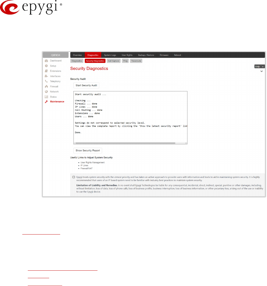
Manual-II: Administration Guide for QX Gateways
Edition 2 (FW Version 6.1.17 and higher) 174
12.1.1 Security Diagnostics
The Security Diagnostics page allows running the security audit and getting the security reports.
Figure 172: Security Diagnostics page
•Start Security Audit – is used for running the security audit. The QX Security Audit is a security reporting
system, which generates the warnings regarding the QX gateway's weaknesses relative to the selected
Security Level. Based on the selected global Security Level the warnings may vary. The Security Audit
will detect the security related configuration issues in Firewall, IDS, Call Routing and extension settings.
•Show Security Report – displays the last security audit report.
•Following useful links are available to adjust the system security:
User Rights Management
IP Lines
Firewall/NAT
12.1.2 Call Capture
The Call Capture page is used to capture the voice streams on the active calls and the available interfaces on
the QX (FXS, FXO, E1/T1 or ISDN – depending on QX gateway model). This page consists of two sub-pages:
The Active Calls sub-page lists all FXO, FXS, ISDN or E1/T1 (depending on QX gateway model) active calls on
the QX gateway for the certain moment.
•Capture Timeout – is used to define the time period (in seconds) during which the call will be captured.
•Start – is used to start the active call capture. Select the active call on the table and click Start to
capture that call. Only one call can be captured at the same time.
•Stop – is used to stop the capturing process. This button appears when the call capturing is in progress
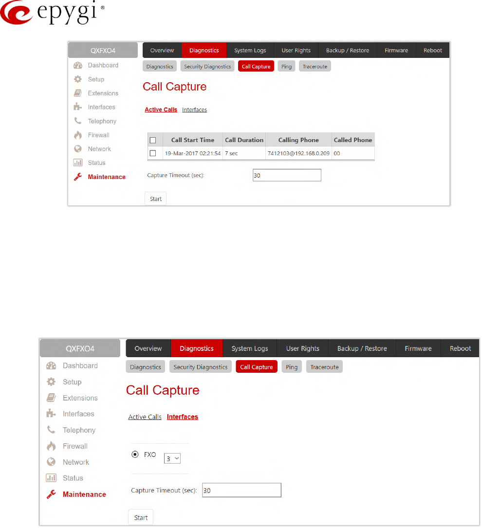
Manual-II: Administration Guide for QX Gateways
Edition 2 (FW Version 6.1.17 and higher) 175
Figure 173: Call Capture – Active Calls page
•Download Capture and Remove Capture links appear once the call has been captured.
Download Capture – is used to download the captured call as an archived (*.tar) file which contains
two streams (receive and transmit) of the corresponding call. The files can be then played with an
audio application.
Remove Capture – is used to remove the captured audio stream.
The Interfaces sub-page lists all available interfaces on the QX. Manipulation radio-buttons allow you to select
the needed line or trunk to be captured.
Figure 174: Call Capture – Interfaces page
•Capture Timeout – is used to define the time period (in seconds) during which the selected interface will
be captured.
•Start – is used to start the capture of the selected interface. The Stop button appears when the
interface capture procedure is in progress and is used to stop the capture procedure.
•Download Capture and Remove Capture links appear once the selected interface has been captured.
Download Capture – is used to download the captured stream as an archived (*.tar) file which
contains two streams (receive and transmit) of the corresponding stream. The files can be then played
with an audio application.
Remove Capture – is used to remove the captured audio stream.
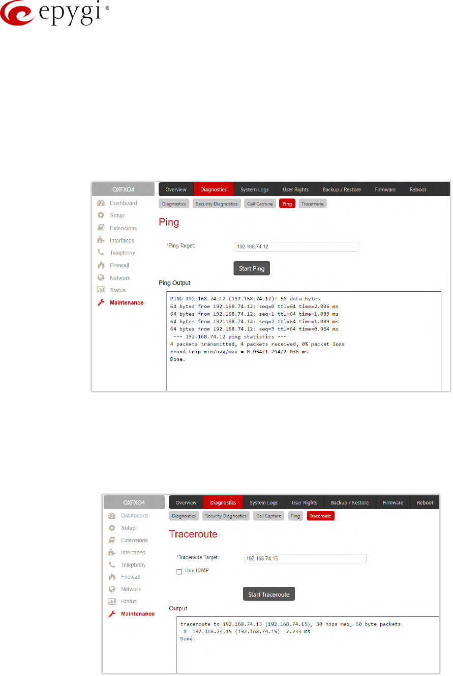
Manual-II: Administration Guide for QX Gateways
Edition 2 (FW Version 6.1.17 and higher) 176
12.1.3 Ping
Ping sends four ICMP (Internet Control Message Protocol) requests with a default size of 64 bytes to the
destination (IP address or host name) specified in the text field Ping Target. The response times are logged, and
the round-trip time (the time required from being sent until being received again) is measured. The minimum
and maximum round trip time and its average as well as the percentage of lost and of received frames results
are displayed in the lower area of the page.
•Ping Target – is used to define the destination (IP address or host name) for the ping request.
•Start Ping – is used to start pinging the specified ping target.
Figure 175: System Diagnostic – Ping page
12.1.4 Traceroute
Traceroute checks the Internet connection by triggering the routers (hops) that are passed to reach to the
defined. Trace routing gives feedback on the routers passed by packets on the way toward the destination and
the round-trip delay of packets to these routers.
Figure 176: Diagnostics – Traceroute page
•Traceroute Target – is used to enter the IP address or host name of the destination to be trace routed.
•Start Traceroute – is used to process the router triggering to check the Internet connection.
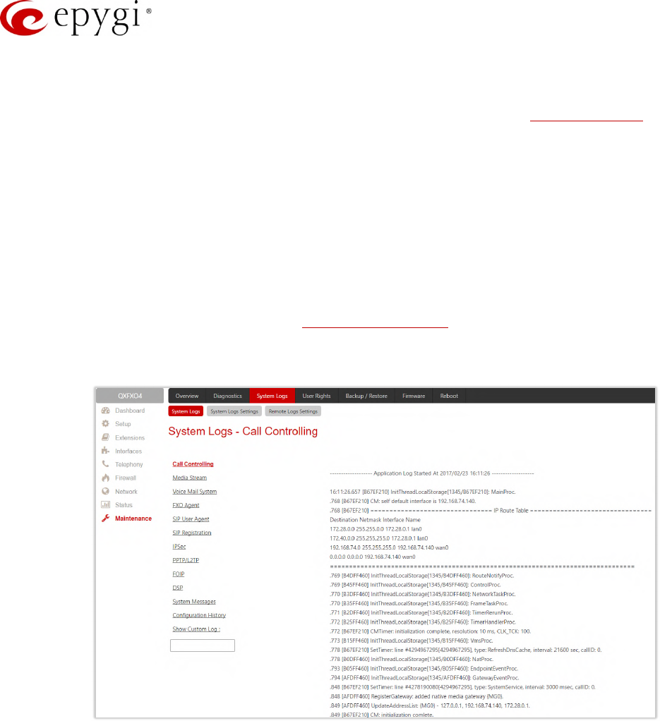
Manual-II: Administration Guide for QX Gateways
Edition 2 (FW Version 6.1.17 and higher) 177
•Use ICMP – if selected, an ICMP request will be send to the ping destination (MS Windows standard),
otherwise a UDP request will be send (Linux standard).
Attention: No Traceroute is possible if a high priority Firewall has been enabled (Firewall and NAT). For the
purpose of tracerouting, several IP packets are sent out. UDP (User Datagram Protocol) is used to send
packets and ICMP (Internet Control Message Protocol) is used to receive information about the routers. In their
headers, the TTL value increases from 1 to 30. When the first IP frame is received by the first router, its IP
address will be returned in its acknowledgement.
12.2System Logs
The System Logs page displays the generated logs on the QX. System logs are useful to determine any king of
problems on the QX as well as to monitor the user’s access and the usage of it. On the left side of the page, a
list of main logs is displayed. Clicking on the needed link will display the most recent log lines. The number of
log lines displayed on this page is set on the System Logs Settings page.
The text field on the left side is dedicated for support personnel only and is used to search a custom log not
listed on this page. To do so, insert a required log name to the text field and click Show Custom Log.
Figure 177: System Logs page
If the user has used Logs Collection feature code after or during (from another phone connected to the
same QX) the call, a special log file will be generated containing the details of that call and few last calls done in
the system. This log file will be internally kept in the system until the next time someone used the Logs
Collection feature code again. The collected logs will be a part of the System Logs when user downloads them
next time, so it can be reviewed by appropriate support staff. This could be used to collect the logs at the exact
moment when a problem has happened.
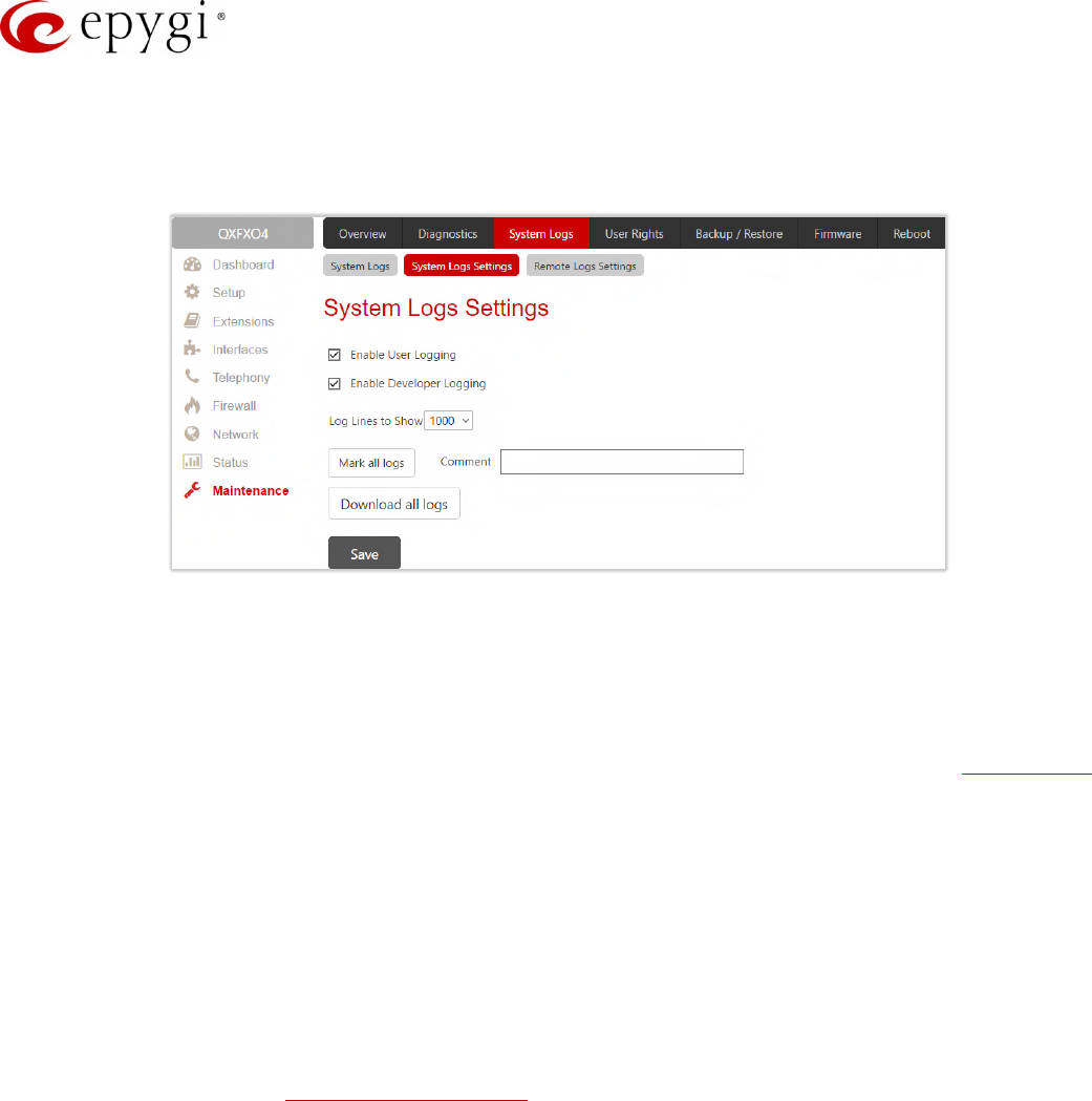
Manual-II: Administration Guide for QX Gateways
Edition 2 (FW Version 6.1.17 and higher) 178
12.2.1 System Logs Settings
The System Logs Settings page is used to adjust system logging settings, view system logs directly in your
browser or download them locally to your PC.
Figure 178: System Logs Settings page
•Enable User Logging – enables user level logging. This logging contains brief information about events
on the QX.
•Enable Developer Logging – enables developer high level logging. This logging contains detailed
information about events on the QX.
•Log Lines to Show – is used to select the maximum number of log lines to display on the System Logs
page.
•Mark all Logs – is used to set a line marker in the logs. If you need to follow a certain piece of log, push
this button to set a starting mark in all logs and then perform the needed actions over the QX. When the
actions are done, push this button again to set an ending mark in all logs. This way you shall clearly see
a piece of log between the starting and ending marks generated during the certain actions taken over
the QX.
•Comment – is used to insert some text information which will be displayed next to the marks inserted in
the logs. This comment may describe the problem captured in the following logs and may be useful for
the Technical Support.
•Download all Logs – is used to download all logs to the local PC as a (*.tar) archive file. These logs can
then be used by the Epygi Technical Support to determine the problem that has occurred on your QX.
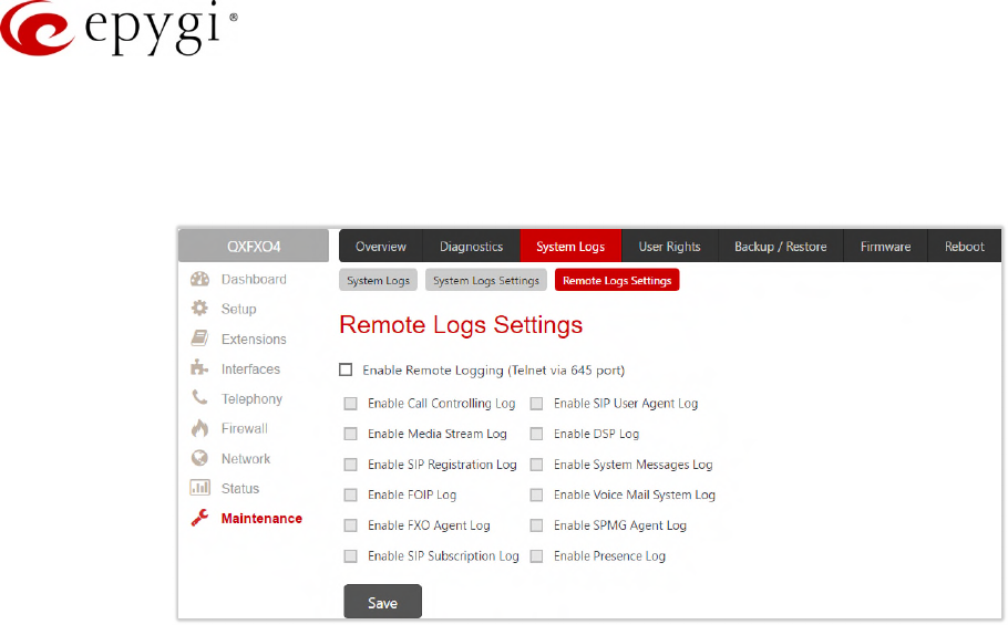
Manual-II: Administration Guide for QX Gateways
Edition 2 (FW Version 6.1.17 and higher) 179
12.2.2 Remote Logs Settings
The Remote Logs Settings page is used to adjust the system logging settings and contains the following
components.
Figure 179: Remote Logs Settings page
•Enable Remote Logging – enables remote monitoring of the QX’s logs. When this option is selected,
remote administrators may connect the QX with Telnet protocol (port number 645) and access the logs
selected on this page. This is done for remote the QX’s diagnostics and is mainly used by Epygi’s
Technical Support. To make the QX’s logs open for remote access, appropriate Firewall level or Filtering
Rules must be created. The options below are used to select those log types that should be accessible
remotely. Select only those logs that you wish to have monitored remotely.
12.3User Rights Management
The User Rights service sets restrictions on the GUI access for various users, permits or denies the access to
certain Web GUI configuration pages and creates multilevel user management of the QX.
12.3.1 Users
The Users page contains a table where the Administrator and Local Administrator accounts are listed. This
page allows to modify the passwords of Administrator and Local Administrator accounts.
Two levels of QX GUI administration are available:
•admin – this is the Administrator’s account. The administrator has access to all Web GUI pages and no
one else has configuration permission to adjust this account. The administrator is responsible for
granting access to all other user groups. By default, as well as after factory reset of QX, the admin
password is set to 19.
•localadmin – this is a common sub-administrator’s account. Local Administrator has permission to
access and adjust each GUI management page. But the account of Local Administrator is disables by
default and after each factory reset. By default, as well as after factory reset of QX, the localadmin
password is set to 19.
•The Change Password functional button is used to change the password of the Administrator and Local
Administrator user’s account. Select one of the available users in the table by toggling the
corresponding checkbox and press Change Password to open the corresponding page.
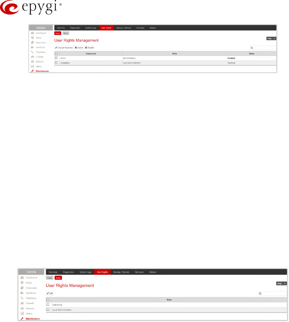
Manual-II: Administration Guide for QX Gateways
Edition 2 (FW Version 6.1.17 and higher) 180
Figure 180: User Rights Management – Users page
The following buttons are available on this page:
•Change Password – is used to change the GUI and Phone access passwords of the admin and
localadmin. Select one of the available accounts in the table by toggling the corresponding checkbox
and click Change Password to open the Change Password page.
•The GUI Access Password offers the following components:
Old Password – appears only for modifying the Administrator account password and requires the
current password of the admin.
New Password and Confirm New Password are used to insert a new GUI access password for the
admin or localadmin.
•The Phone Access Password offers the following components:
New Password and Confirm New Password are used to insert a new Phone access password for the
admin.
•Enable and Disable buttons are used to enable or disable the Local Administrator’s account.
12.3.2 Roles
The Roles page contains a table where the Local Administrator and Extensions role are listed. This page allows
you to set the permissions to the GUI pages for each role in the table.
•Local Administrators – this role can have permissions to adjust each GUI page.
•Extension (N/A for QXFXS24) – this role refers to all extensions created on the QX. Permissions for an
extension to access each GUI page can be adjusted.
Figure 181: User Rights Management – Roles page
•Edit – leads to the Access Rights page where a list of user specific GUI pages is displayed. Select the
role in the table and click Edit to manage the permissions.
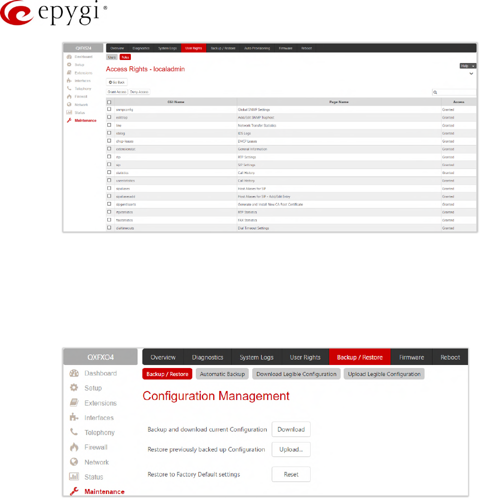
Manual-II: Administration Guide for QX Gateways
Edition 2 (FW Version 6.1.17 and higher) 181
Figure 182: User Rights Management – Edit Roles page
12.4Backup/Restore
The Configuration Management page assists the administrator with managing the system configuration settings
and voice data. For example, the administrator is able to back up and download the settings to a PC and then
upload and restore them back to the QX. Additionally, this page provides the possibility of restoring the factory
default configuration settings.
Figure 183: Configuration Management page
•Backup and download current Configuration – generates a backup file with all configuration settings and
user uploaded greeting messages. It opens a file chooser window for immediate download to the user’s
PC.
•Restore previously backed up Configuration – opens a page that has a Choose File button, (which opens
a file chooser to select a backed-up file) and a Configuration to Upload field requiring the file path to
upload and to restore it immediately. Clicking Save will restore the selected backup file, and delete all
current user defined greetings and replace configuration settings.
•Restore to Factory Default settings – resets all configuration settings and restores the board’s factory
default configuration. By restoring the default configuration, you will replace your current configuration,
lose all voice mails and reboot the device. You will not be automatically redirected to the GUI start page.
After the successful reboot, you will need to enter into the management page and login again to access
the QX’s configuration. A warning message will ask you to confirm your selection before restoring the
default configuration.
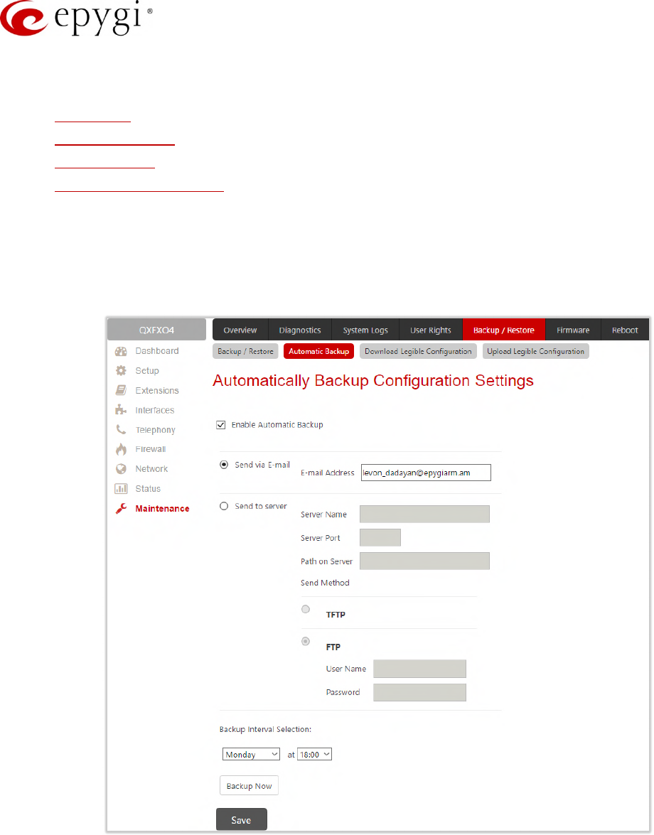
Manual-II: Administration Guide for QX Gateways
Edition 2 (FW Version 6.1.17 and higher) 182
Note: Unlike the factory default settings restore procedure initialized from the Reset button on the QX device,
will keep the following data:
•Call History
•Transfer Statistics
•System Events
•Device Registration State
12.4.1 Automatic Backup
The Automatic Backup page allows you to enable the automatic backup of the system configuration and the
voice data on the QX. With this service, QX will automatically backup the system configuration and the voice
data and store it in the specified location.
Figure 184: Automatic Backup page
•Enable Automatic Backup – enables automatic backup mechanism on the QX.
•Send via Email – is used to send the automatically backed up files via email. The selection enables Email
Address field that requires the email address of the administrating person to receive the automatically
backup files.
•Send to Server – is used to store the automatically backup files on a remote server as follows:
Server Name – insert the IP address or the host name of the remote server.
Server Port – insert the port number of the remote server.
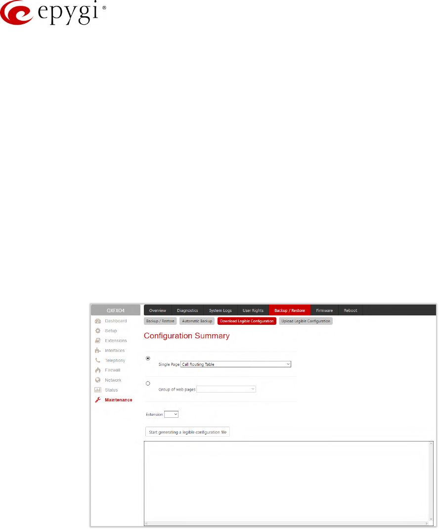
Manual-II: Administration Guide for QX Gateways
Edition 2 (FW Version 6.1.17 and higher) 183
Path on Server – define the path on the server to store the backup files in.
Send Method – is used to select the remote server type: TFTP or FTP. In case of FTP selection, the
authentication username and the password need to be inserted. In case these fields are left empty,
anonymous authentication will be used.
•Backup Interval Selection – is used to select the frequency and the time when the automatic backup of
the QX's system configuration and the voice data will take place.
•Backup Now – is used to perform a manually immediate backup of the system configuration and the
voice data.
12.4.2 Download Legible Configuration
The Legible Configuration Management page is used to manually manage the configuration on the QX. This will
allow you to download a piece of configuration from the QX in the way of legible file, to make necessary
changes in that file and upload it back to the same or different QX(s). With this service, some pieces of
configuration (like extension settings, NAT settings, etc.) of one QX can be used on another QX. This also helps
to apply the same group of settings to the several instances (for example, to apply the same SIP settings to
multiple extensions on the QX) on the same or different QXs avoiding manual configuration of each of those
instances (i.e. extension) from the web management on each of the QXs. The QX reseller, distributor, ISP or
carrier usually uses this service.
Figure 185: Download Legible Configuration page
•Single Page selection – is used to select a certain page from the list of QX’s Web management pages
for which the legible configuration can be manually managed. For example, selecting "RTP Settings" will
generate a legible configuration file with parameters present on the RTP Settings page.
•Group of web pages – is used to choose among the four predefined groups: Internet Connection
Settings, LAN Configuration Settings, Telephony General Settings and Extension Settings. Each of these
groups refer to all pages characterized by the selected criteria, e.g. Internet Connection Settings group
contains all parameters on the pages related to the networking and WAN configuration.
•Extension – is used select the settings in the generated legible configuration file to one specific
extension. For example, each of the extensions on the QX have own SIP settings or Codecs. To
download the settings for a particular extension only, you need to choose the corresponding extension
from the list. The drop-down may also have a blank selection. In that case, the legible configuration file
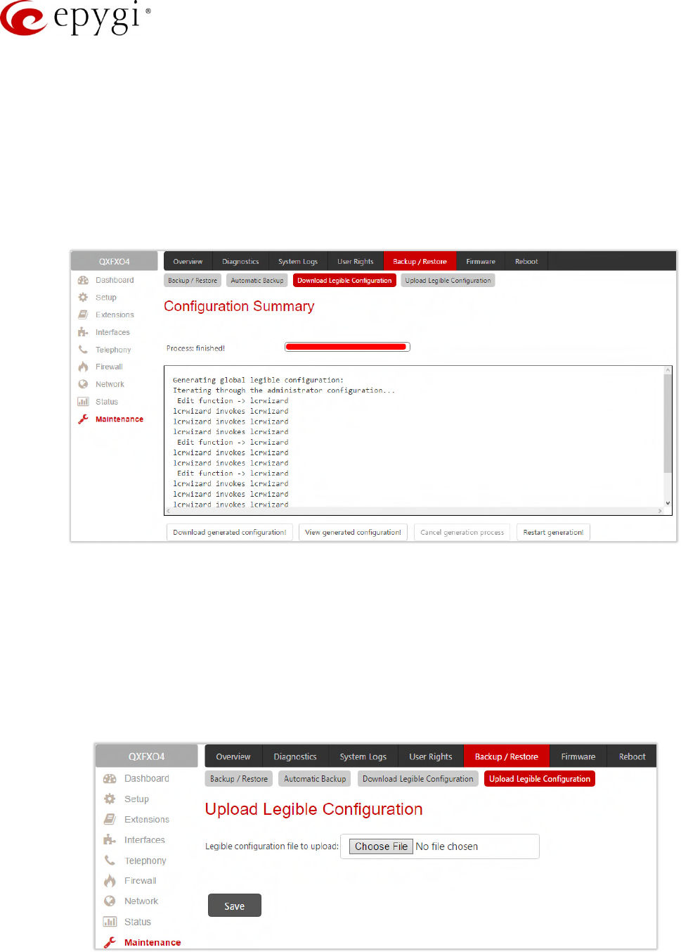
Manual-II: Administration Guide for QX Gateways
Edition 2 (FW Version 6.1.17 and higher) 184
will contain the parameter of all available extensions on the QX (if the selected parameter applies to the
extension and not to the overall system, like RTP settings).
•Start generate a legible configuration file – starts parsing the configuration structure of the device for the
defined parameters. The progress will be displayed in the area below.
•Cancel generation process – stops the generation procedure. This button appears once the
configuration generation procedure has been started.
•Download generated configuration! – is used to download the generated file to the PC in a plain text
format. This button appears when the legible configuration generation is finished. Necessary changes
can be made in the downloaded configuration file and then uploaded back to the system.
Figure 186: Download Legible Configuration page
•View generated configuration! – is used to view the generated file directly in the browser. This button
appears when the legible configuration generation is finished.
•Restart generation! – is used to cancel the generated configuration file and start over. This button
appears when the legible configuration generation is finished.
12.4.3 Upload Legible Configuration
The Upload Legible Configuration page is used to upload a configuration file in the (*.txt) format.
Figure 187: Upload Legible Configuration page
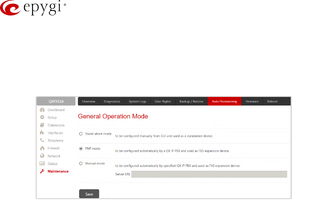
Manual-II: Administration Guide for QX Gateways
Edition 2 (FW Version 6.1.17 and higher) 185
•Choose File – is used to browse certain legible configuration file to be uploaded and updated into the
system. The configuration files should be in the (*.txt) format, otherwise a system error occurs.
Configuration file upload progress will be displayed in the area below.
12.5Auto Provisioning
The General Operation Mode page is used to select one of options for QXFXS24 operational mode. The
following modes are available:
Figure 188: Auto Provisioning page
•Stand-alone mode – select this option to configure the QXFXS24 manually from GUI and use it as
stand-alone VoIP getaway. You have to configure the device manually using the management GUI.
•PNP mode – select this option to configure the QXFXS24 automatically with any available in network QX
IP PBX and use it as FXS expansion device. Some extra adjustment in configuration can be done
manually, if needed.
•Manual mode – select this option to configure the QXFXS24 automatically with the specified QX IP PBX
and use it as FXS expansion device. Some extra adjustment in configuration can be done manually, if
needed. TIP: The Server URL needs to be in http://xxx.xxx.xxx.xxx format.
12.6Firmware Update
The Firmware section is used to update the firmware of QXs. Following options are available for updating the
current firmware:
•Manual installation of a new firmware.
•Manual downloading and updating a new firmware from the server.
•Automatic firmware update.
Users registered at Epygi will be notified as soon as a new firmware will be available on the Epygi Technical
Support WEB page.
Attention:
•It is recommended to back up the configuration for emergency purposes prior to upgrading the
firmware. You can do that by clicking the Download Configuration link in the Manual Firmware Update
page. The current configuration will remain after the firmware update. Moreover, all custom messages
and call history will be saved during the upgrade.
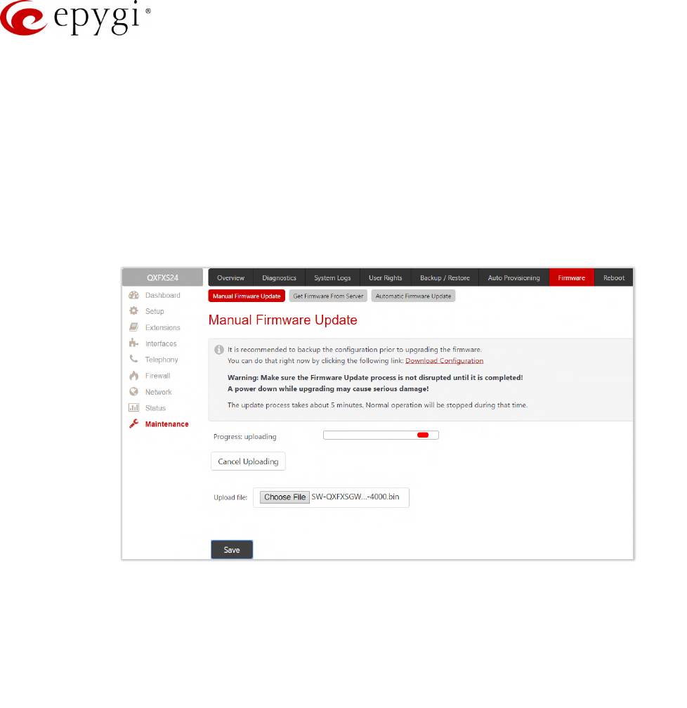
Manual-II: Administration Guide for QX Gateways
Edition 2 (FW Version 6.1.17 and higher) 186
•Firmware installation will take about 5 minutes. During that time, QXs will be in non-operational
condition, neither telephony nor Internet access is possible.
•You will not be automatically redirected to the Login page. To access the QX’s Web GUI, connect to an
QX again and login.
•The QX will factory reset and the system configuration will be lost while downgrading the firmware.
• After the firmware update, all IP phones attached to the QX will be restarted.
12.6.1 Manual Firmware Update
The Manual Firmware Update page is used to manually update the QX firmware by installing a new one.
Figure 189: Manual Firmware Update page
•Choose file – is used to browse the firmware file.
•Save – starts uploading.
•Cancel Uploading – is used to cancel the firmware upload. This button becomes activated once the
uploading starts.
Following firmware validity information will appear after the upload:
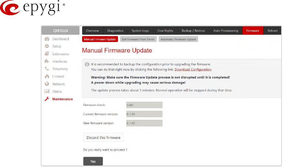
Manual-II: Administration Guide for QX Gateways
Edition 2 (FW Version 6.1.17 and higher) 187
Figure 190: Manual Firmware Update page
•Firmware check – displays the uploaded firmware is valid or not. Invalid will be displayed if the firmware
does not correspond to the hardware version.
•Current Firmware Version/New Firmware Version – displays the current/new uploaded firmware versions.
•Click Yes to proceed the update or click Discard this firmware to close the message without updating
the device.
Note: The Burning Image window will appear right after proceeding the firmware update. This window does not
contain any button and intends only for informing about the firmware update procedure.
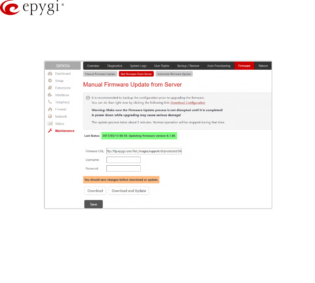
Manual-II: Administration Guide for QX Gateways
Edition 2 (FW Version 6.1.17 and higher) 188
12.6.2 Get Firmware From Server
The Manual Firmware Update from Server page is used to manually download and update the QX firmware from
the FTP Server.
Figure 191: Manual Firmware Update from Server page
•Last Status – displays when and with which version the updated process is completed.
•Firmware URL – is used to define the firmware URL to get the new firmware located in the FTP server.
•Username and Password – are used to define the FTP server authentication parameters.
•Save – if pressed, keeps the changes before Download or Download and Update.
•Download – if pressed, starts firmware download from FTP Server.
Information about firmware validity will be displayed after successful upload.
•Firmware check shows the uploaded firmware is valid or not. Invalid will be displayed if the firmware
does not correspond to the hardware version.
•Current Firmware Version/New Firmware Version – displays the current/new uploaded firmware versions.
•Update – is used to proceed the update or click Discard to close the warning message without updating
the device.
•Download and Update – is used to automatically download and update the firmware from the FTP
server.
Note: The Burning Image window will appear right after proceeding the firmware update. This window does not
contain any functional button and intends only for informing about the firmware update procedure.
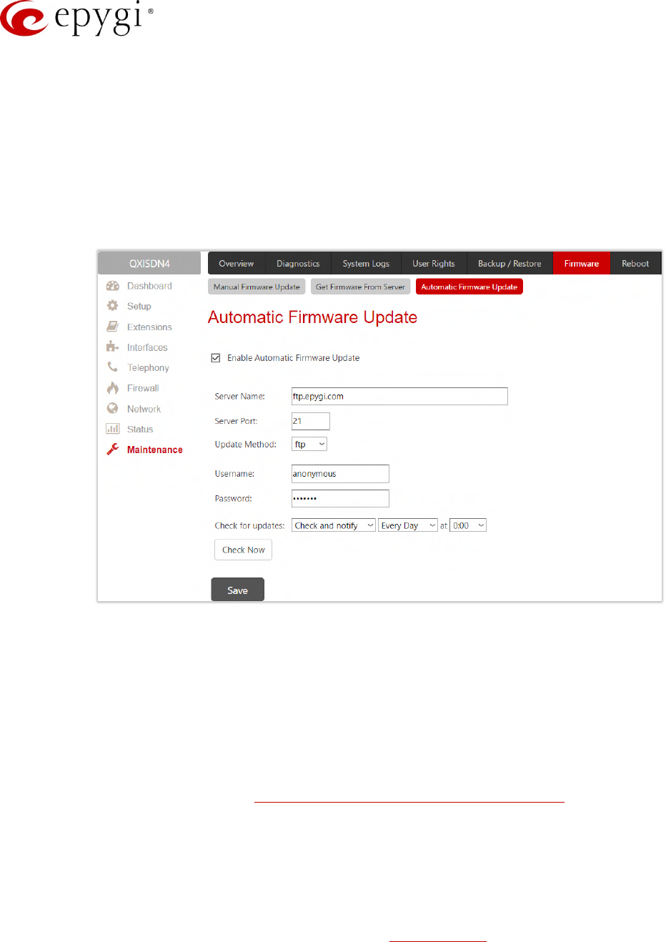
Manual-II: Administration Guide for QX Gateways
Edition 2 (FW Version 6.1.17 and higher) 189
12.6.3 Automatic Firmware Update
The Automatic Firmware Update page is used to enable the automatic firmware update on the QX as a new
firmware (software image) becomes available in the server. When this service is enabled, on the scheduled time
the QX will automatically check for a new firmware on the server then, based on the configured settings, will
either notify or update the firmware immediately. The server configuration can be done manually.
Note: Regardless of the server type, there must be an "auto-update" folder in the root directory of the server.
The QX will check for any new firmware in that specific folder only. Besides the firmware (*.bin) file, the "auto-
update" folder must contain supplementary file(s) to point to the correct firmware file.
Figure 192: Automatic Firmware Update page
Enable automatic firmware update and define the configuration settings on the QX as follows:
•Check off the Enable Automatic Firmware Update checkbox.
•Enter the IP address or hostname of FTP, HTTP or HTTPS in the Server Name field.
•Enter the Server Port of the remote server.
•Select the desired update method (FTP, HTTP or HTTPS) from the Update Method drop-down list.
•Enter the Username and Password authentication parameters.
For more information, please refer to Automatic Firmware Update on the Epygi QXs guide.
Note: Leave the Server Name, Server Port, Update Method, Username and Password text fields to their default
values (ftp.epygi.com, 21, ftp and anonymous respectively, use blank for password) to use Epygi's public ftp
server.
Check for updates based on one of the following options:
•Select the Check and notify option to configure the QX to check for a new firmware in the server at the
scheduled time. Define notification settings in the Event Settings page.
•Select Check and update to configure the QX to check for a new firmware, automatically download and
install it on a scheduled time.
•Click Check Now to manually initiate the action selected from the Check for updates drop-down list.
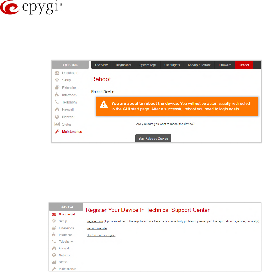
Manual-II: Administration Guide for QX Gateways
Edition 2 (FW Version 6.1.17 and higher) 190
12.7Reboot
The Yes, Reboot Device button is used to reboot the QX. TIP: The session with the QX will be closed, i.e., the
QX's GUI should be newly opened and a new login will be required afterwards.
Figure 193: Reboot Device page
12.8Registration Form
The Register Your Device in Technical Support Center page appears when administrating an unregistered QX,
and it has been created for customer support purposes. The page requires customer registration at the Epygi
Technical Support Center. It provides several links offering the following registration options:
Figure 194: Device Registration page
•Register now – leads to the Epygi Technical Support System Registration page and requires customer’s
information to submit the QX registration form.
•Remind me later – hides the registration notification in the QX until the next administrating activities.
•Don’t remind me again – hides the registration notification forever.
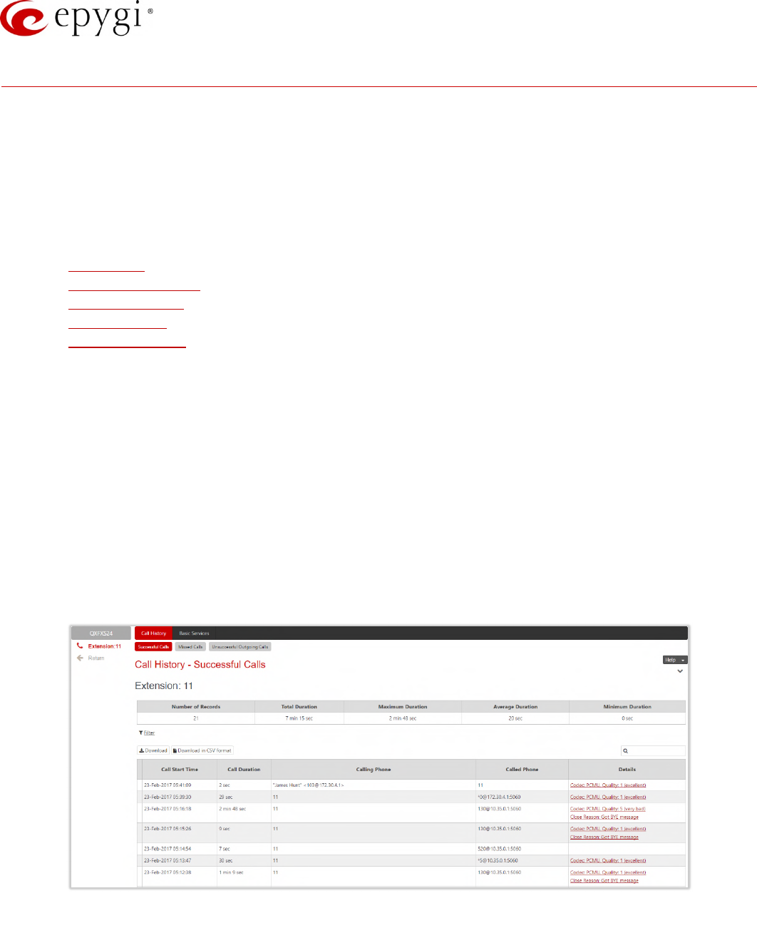
Manual-II: Administration Guide for QX Gateways
Edition 2 (FW Version 6.1.17 and higher) 191
13 User Extension's Menu
QX configuration management may be accessed by users (extensions) and administrators. If you are a user, log
in with the extension number and the password (if any) you received from your system administrator.
•Log Out – is used to close the session between the PC and QX and to leave the Extension
Management.
•Return – this link is used to return back to Extensions Management page.
•Extension # menu allows you to access the following settings to operate and perform actions that are
private for each user.
Call History
General Information
Account Settings
Basic Services
Caller ID Services
13.1Call History
The Call History allows to track and report the call detail records (CDR) for concerning the inbound/outbound
calls, for the current extension.
The Successful Calls, Missed Calls and Unsuccessful Outgoing Calls pages lists successful, missed and
unsuccessful outgoing calls and their parameters. The following components are available:
•Filter – allows searching for call records based on at least one of the criteria: Call Start Time, Call
Duration, Caller and Called parties.
•Clear Filter – is used to remove the filter.
•The Download / Download in CSV format buttons are used to download the displayed CDRs for each
page (Successful, Missed and Unsuccessful Outgoing) in the (*.log) or (*.csv) formats respectively.
Figure 195: Call History – Successful Calls page
CDRs listed in the Call History tables are characterized by the following parameters:
•Call Start Time – shows the start date and time of the call.
•Call Duration – shows the duration of the call.
•Calling Phone – shows the caller's number and display name (if available).
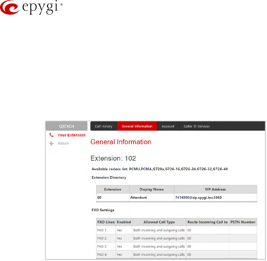
Manual-II: Administration Guide for QX Gateways
Edition 2 (FW Version 6.1.17 and higher) 192
•Called Phone – shows the callee's number and display name (if available).
The Download Call Detail Records / Download Call Detail Records in CSV format links are used to download the
displayed CDRs for each page (Successful, Missed and Unsuccessful Outgoing) in the (*.log) or (*.csv) formats
respectively.
13.2General Information
The General Information page (N/A for QXFXS24) provides read-only information about the extension codecs,
other existing extensions and available PSTN lines on the QX.
The General Information displays a list of available codecs for the extension, the list of extensions on the QX
Extensions Directory. Any available FXO lines, E1/T1 and ISDN trunks are also visible here.
Figure 196: General Information page
13.3Account Settings
The Account Settings page (N/A for QXFXS24) allows changing the extension display name, the user password
and uploading the files with the user-defined messages. This page consists of the following components:
•Extension – displays the current extension number.
•Display Name – allows to modify the extension’s display name. The display name appears on the called
phone display.
•Enable Remote Extension (N/A for QXISDN4) – this option is only visible when the Remote Extension
service has been activated on the extension. With this option, the user can enable/disable the Remote
Extension functionality.
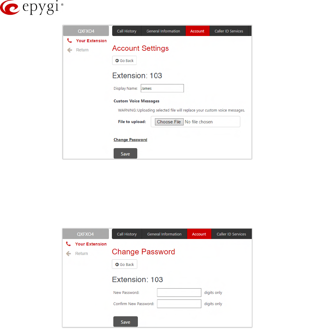
Manual-II: Administration Guide for QX Gateways
Edition 2 (FW Version 6.1.17 and higher) 193
Figure 197: Extension Account Settings page
•Custom Voice Messages – is used to upload custom voice messages for the extension. Uploading
selected file will replace your custom voice messages. Uploading custom messages downloaded from
the other QX will overwrite messages that have not been configured by the user with the current device
default ones. This means that if some default messages were used on one QX, they may be completely
different on another QX after uploading the voice data.
•The Change Password link leads to Change Password page where you can change your password.
Figure 198: Change Password page
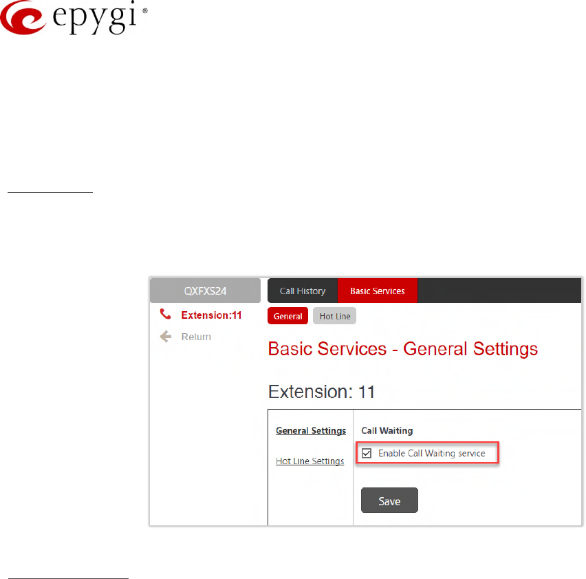
Manual-II: Administration Guide for QX Gateways
Edition 2 (FW Version 6.1.17 and higher) 194
13.4Basic Services
The Basic Services page (available only for QXFXS24 gateway) allows you to configure the basic telephony
features of QXFXS24 gateway, such as Call Waiting and Hot Line service.
Note: Remember to save changes before moving between the configuration sections.
Call Waiting
The Call Waiting service allows to receive a call when you are currently on a call. The QX user will hear a special
beeping on the phone when call arrives. For analog phones, to switch between the current and the new arrived
call, use the appropriate calling code.
Figure 199: Basic Services – General Settings page
Hot Line Settings
The Hot Line service (available only for QXFXS24) is used to call automatically the preconfigured number in case
if no action for a predefined period after lifting the phone handset. This service is commonly used for
emergency calls.
The Hot Line Settings page consists of the following components:
•Enable Hot Line Service – activates the Hot Line service on the current extension.
Timeout – is used to select the delay before the defined number will be dialed automatically.
Call Type, Called Address – is used to define destination address.
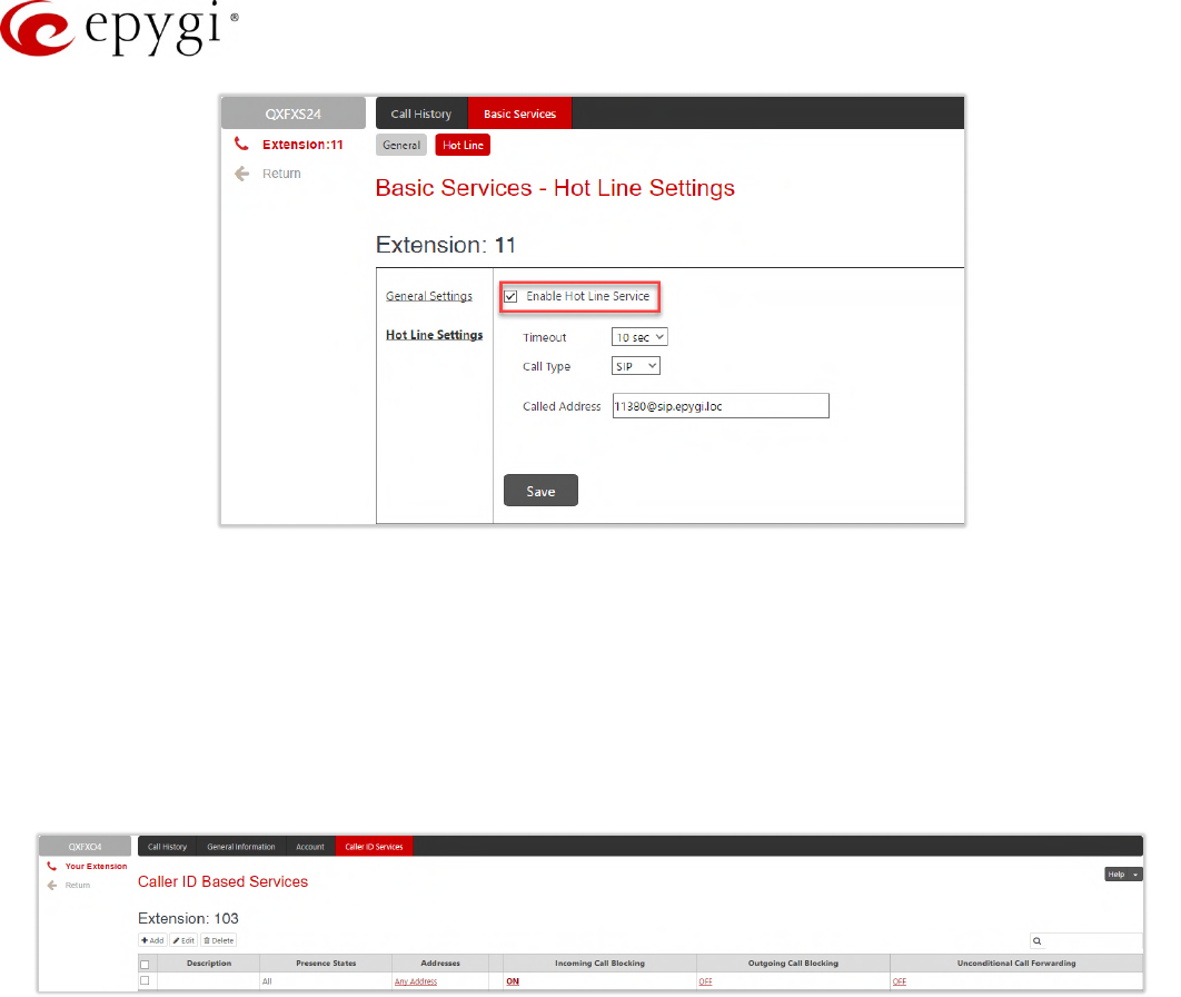
Manual-II: Administration Guide for QX Gateways
Edition 2 (FW Version 6.1.17 and higher) 195
Figure 200: Hotline Settings section
13.5 Caller ID Services
The Caller ID Based Services page (N/A for QXFXS24) provides interface(s) to configure the telephony services
for the extension. The configuration settings for Unconditional Call Forwarding, Incoming and Outgoing Call
Blocking services are accessible from this page.
The Caller ID Based Services page lists all manually or automatically configured caller and called addresses with
the ON/OFF status of their telephony services.
Figure 201: Caller ID Based Services for Any Address page
Note:
•Any Address – the Any Address entry in this page is undeletable. It is used to configure the Caller ID
Based services for all addresses. Adding a new entry changes the Any Address to Other Addresses.
•Remember to save changes before moving between the caller ID based services configuration pages.
Add leads to the Caller ID Based Services – Add Entry page where a new address and presence states can be
defined. The following settings are available:
•Insert a description about the address owner.
•Presence State allows to set the Presence State of an extension.
All States – is used to select and enable all states for the extension.
Specific States – is used to select the specified state(s) for the extension.
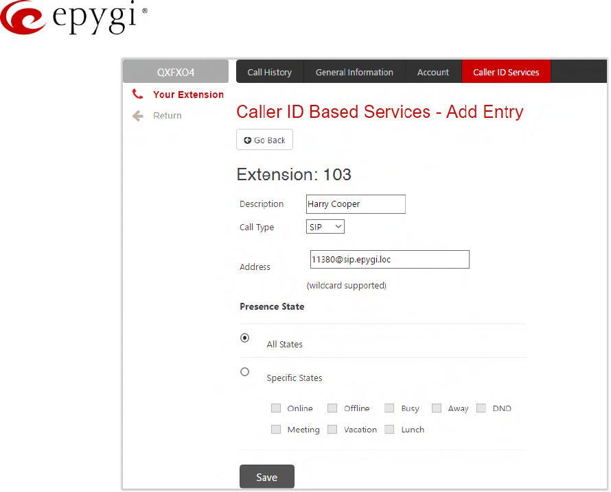
Manual-II: Administration Guide for QX Gateways
Edition 2 (FW Version 6.1.17 and higher) 196
Figure 202: Caller ID Based Services – Add Entry page
To configure Caller ID Based Services for a specific address, follow the steps:
1. Click the Add button on the Caller ID Based Services page. The Caller ID Based Services – Add Entry
page will open, where the address can be defined.
1. Define an optional Description for the address.
2. Select the call type from the Call Type drop down list.
3. Enter the SIP address, extension or PSTN number (depends on the chosen call type) in the Address
text field according to the entering rules.
4. Select the Presence State of an extension.
5. To add an address to the Caller ID Based Services table, click Save.
6. Click on the newly created Address in the Caller ID Based Services table to open the Caller ID Based
Services for Address page.
7. From the left frame, choose a Caller ID Based Services. From the right frame, enable, configure and
adjust the corresponding service. Do this for each service.
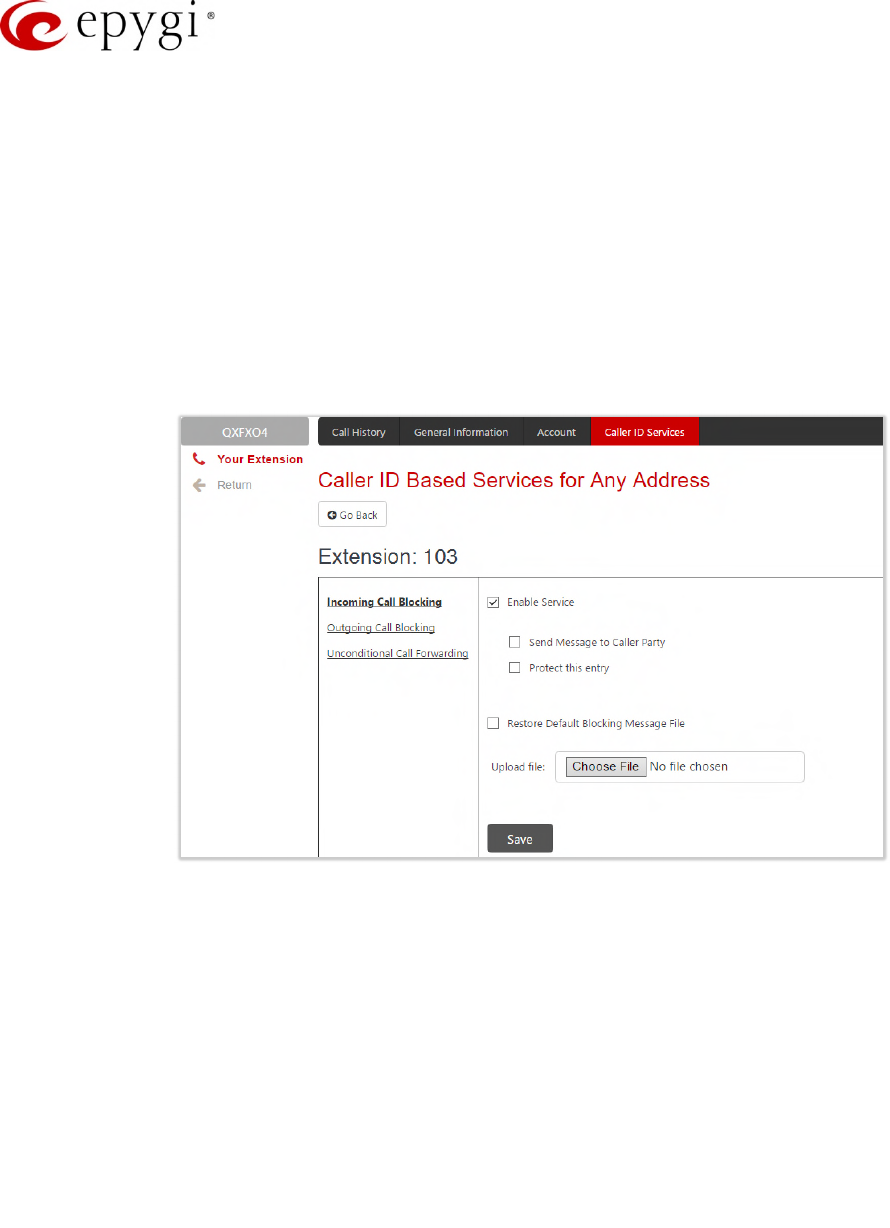
Manual-II: Administration Guide for QX Gateways
Edition 2 (FW Version 6.1.17 and higher) 197
13.5.1 Incoming Call Blocking
Incoming Call Blocking section allows blocking unwanted caller and informing the caller that the call is blocked.
•Enable Service – blocks the incoming calls to the current extension for any or for a specific address.
Send Message to Caller Party – if selected, announced the caller that his number is blocked,
otherwise the calling party will be disconnected without notification.
Protect this entry – if selected, the user will not be able to deactivate the Incoming Call Blocking
service for the corresponding caller. This option is available only for administrators and is used to
protect Incoming Call Blocking service from being disabled by the user.
•Incoming Call Blocking Message – is used to upload a new incoming call blocking message, download
the message to the PC, as well as restore the default one.
Figure 203: Incoming Call Blocking section
13.5.1 Outgoing Call Blocking
Outgoing Call Blocking section allows blocking the calls to unwanted numbers and informing the caller that the
number is blocked (Figure 204).
•Enable Service – blocks the outgoing calls to any or to specific address.
Send Message to Caller Party – if selected, initiates a message to inform the caller that the called
number is blocked, otherwise the caller will hear a busy tone.
Protect this entry – if selected, the extension user will not be able to deactivate the Outgoing Call
Blocking. This option is available only for administrators and is used to protect Outgoing Call Blocking
service from being disabled by the user.
•Upload new blocking message file – is used to upload a new outgoing call blocking message, download
the message to the PC or restore the default one. This message will be played to the user while making
calls to the unwanted address.
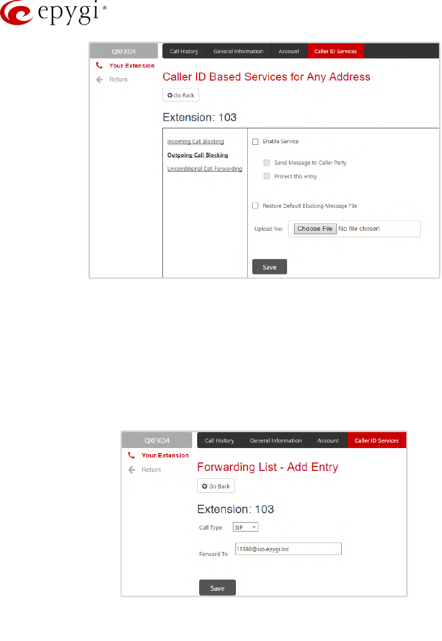
Manual-II: Administration Guide for QX Gateways
Edition 2 (FW Version 6.1.17 and higher) 198
Figure 204: Outgoing Call Blocking section
13.5.2 Unconditional Call Forwarding
The Unconditional Call Forwarding section allows to forward all incoming calls to the defined destination(s). The
Forward to table displays the list of destinations with the associated settings (Figure 206):
•Enable Service – activates the service for the current extension.
•Enable/Disable – is used to enable/disable the forwarding destinations in the Forwarding table.
•Add leads to the Forwarding List – Add Entry page where you can add forwarding destinations may be
specified:
Figure 205: Forwarding List – Add Entry page
External Party – is used to call external number with options available:
Call Type, Calling Address – is used to define the forwarding destination.
Note: The QX allows to forward incoming calls through local PSTN lines. To do so, select PSTN from the Call
Type drop down list and type pstn (capital and lower case letters allowed) in the Calling Address field. Caller will
connect to the available PSTN line, get the dial tone and be free to dial a number.
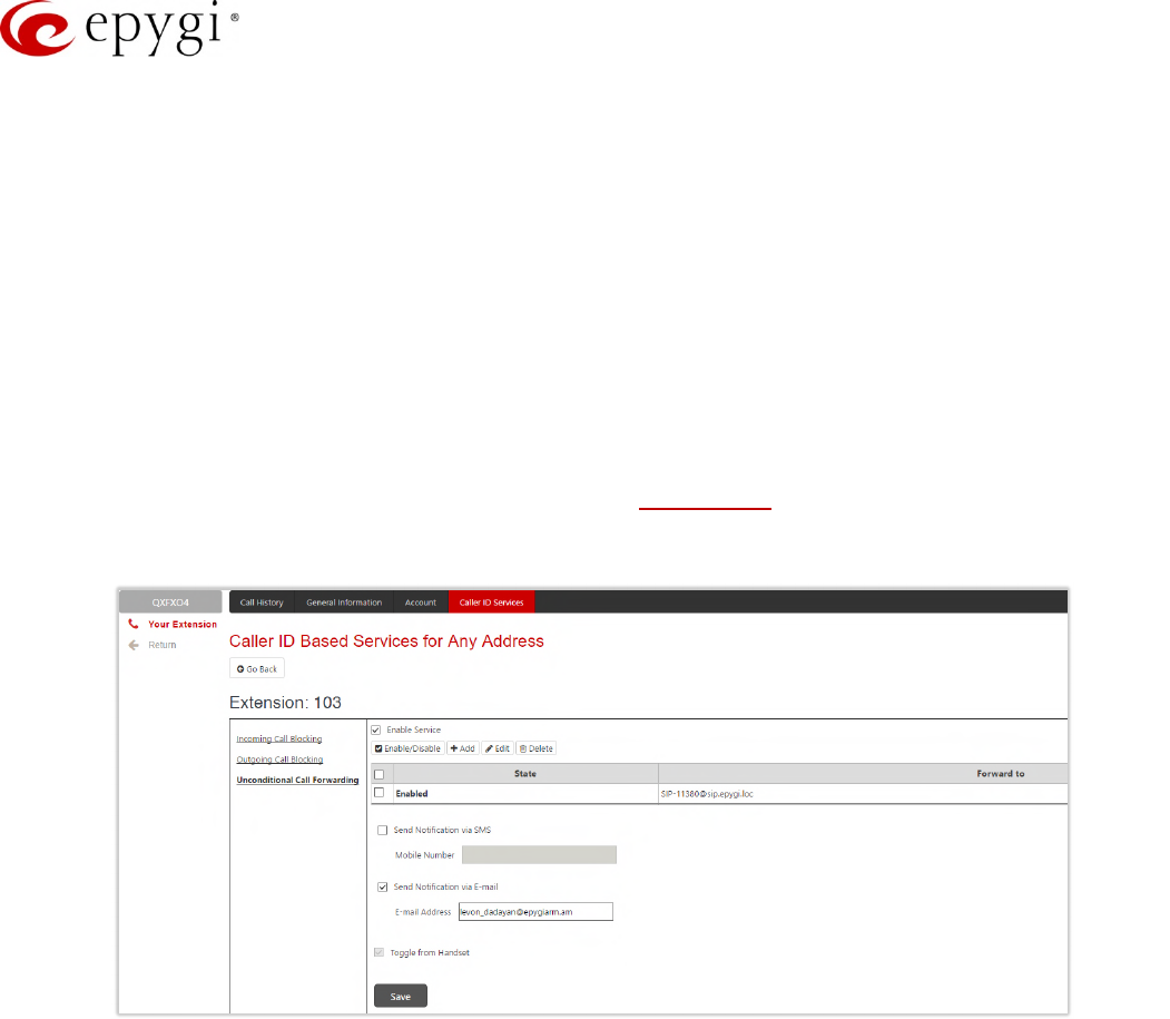
Manual-II: Administration Guide for QX Gateways
Edition 2 (FW Version 6.1.17 and higher) 199
Extension – is used to call QX extension.
•Send Notification via SMS – is used to enable sending SMS notification to the specified mobile number
when call forwarding takes place. If selected, the following options become available:
Mobile Number – insert the mobile number of the recipient. Use a space, semicolon or a comma to
separate numbers in case of multiple recipients. TIP: This option will work when SMS Service is
enabled on the QX.
•Send Notification via E-mail – is used to enable sending e-mail notification when call forwarding takes
place. If selected, the following options become available:
E-mail Address – insert the e-mail address of the recipient. Use a space, semicolon or a comma to
separate mailing addresses in case of multiple recipients. TIP: This option will work when SMTP
Service is enabled on the QX.
•Toggle from Handset – is used to enable toggling the Unconditional Call Forwarding for a selected entry
ON/OFF from the phone handset by the appropriate feature code. Dialing the will toggle the
Unconditional Call Forwarding for all entries in the Caller ID Based Services table that have the Toggle
from Handset option enabled.
Figure 206: Unconditional Call Forwarding section
Attention: The Forwarding has higher priority over other Caller ID based services, except for Incoming and
Outgoing Call Blocking. If the Incoming or Outgoing Call Blocking services are configured on the extension,
these services will take effect.
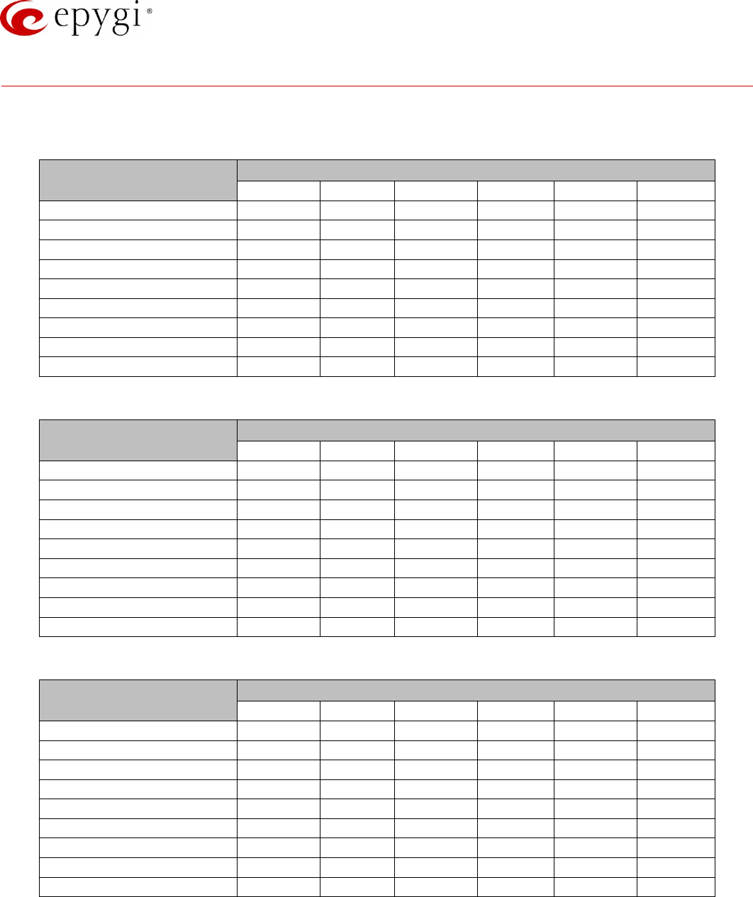
Manual-II: Administration Guide for QX Gateways
Edition 2 (FW Version 6.1.17 and higher) 200
14 Appendix: Needed Bandwidth for IP Calls
The bandwidth required by an IP call depends on the codecs used and these specifications are listed in the
tables below.
Codecs Packet Size in msec
10 20 30 40 50 60
G.711u/G.711a 105 84 76 74 71 67
G.726–16 58 37 30 27 25 22
G.726–24 66 45 38 34 32 30
G.726–32 74 53 45 42 40 37
G.726–40 82 61 53 50 48 45
G.729a 50 29 22 19 17 15
iLBC–13.33 – – 27 – – 20
G.722 105 84 76 74 71 67
G.722.1 74 53 45 42 40 37
Table 6: Required Bandwidth for Standard Packets
Codecs Packet Size in msec
10 20 30 40 50 60
G.711u/G.711a 114 89 81 76 74 72
G.726–16 66 41 33 28 26 24
G.726–24 74 49 41 36 34 32
G.726–32 82 57 49 44 42 40
G.726–40 90 65 57 52 50 48
G.729a 58 33 26 20 18 16
iLBC–13.33 – – 31 – – 22
G.722 114 89 81 76 74 72
G.722.1 82 57 49 44 42 40
Table 7: Required Bandwidth for Encrypted Packets when using a SRTP
Codecs Packet Size in msec
10 20 30 40 50 60
G.711u/G.711a 148 105 90 85 80 74
G.726–16 95 59 43 38 34 29
G.726–24 108 65 52 45 41 37
G.726–32 118 74 60 53 48 45
G.726–40 124 81 66 61 56 52
G.729a 92 49 35 30 26 22
iLBC–13.33 – – 41 – – 26
G.722 148 105 90 85 80 74
G.722.1 118 74 60 53 48 45
Table 8: Required Bandwidth for Encrypted Packets when using a VPN

Manual-II: Administration Guide for QX Gateways
Edition 2 (FW Version 6.1.17 and higher) 201
15 Appendix: Feature Codes
15.1PBX Services Accessible at the Dial Tone
This chapter describes the feature codes to navigate through the QX telephony services with the phone
handset. These services are characterized by starting with the key :
Automatic Redial
•Dial to redial the last dialed number.
•If the called number is busy after dialing keep the handset lifted to activate the auto redialing of the
last called number. The connection will be established immediately when the called destination answers
the call.
Note:
This service is functional for SIP and PBX calls only. For PSTN calls, this feature works as a single
redial (with no multiple attempts to reach the called destination).
This service is not available on QXISDN4 and QXFXS24.
Call Back
Dial to call back the last caller.
Unconditional Call Forwarding
Dial to configure Unconditional Call Forwarding:
1. Press to add a forwarding number.
2. Press to toggle (enable or disable) the forwarding service.
After successful configuration, dial to activate/deactivate the service.
Note:
•Using the "Change the Forwarding Number" option will update the first entry in the Unconditional Call
Forwarding table with Auto call type. Any other entries with Auto call type, as well as with other call
types will not be modified.
•Besides Any Address/Other Addresses entry of the Unconditional Call Forwarding table this toggling also
affects all those entries that have Toggle from Handset option selected. The states of those entries will
be set to the same as the state of Any Address/Other Addresses entry after toggling.
•This service is not available on QXFXS24.
Block Last Caller
•Dial to block the last caller. The last caller will be blocked and added to the Caller ID Services
table.
•To unblock the caller, go to the Incoming Call Blocking section and disable the Incoming Call Blocking
service for the blocked address.

Manual-II: Administration Guide for QX Gateways
Edition 2 (FW Version 6.1.17 and higher) 202
Note:
This service can be activated within 10 seconds after the call termination.
This service is not available on QXISDN4 and QXFXS24.
Line Information
Dial to get information about the IP line, attached Extension number and SIP username. TIP: This
service is not available on QXISDN4 and QXFXS24.
Call Routing Management
The Call Routing Management is used to manage the routing entries in the Call Routing table, i.e. to
enable/disable certain routing rule(s) by dialing key combinations pre-configured on each rule.
1. Dial to enable the routing rule.
2. Enter the activation code and press .
After successful activation, the state of the routing rule will be modified (enabled).
1. Dial again to disable the routing rule.
2. Enter the deactivation code and press .
After successful deactivation, the state of the routing rule will be modified (disabled).
Note:
•If the routing record has an authorization enabled on the enabler/disabler key, administrator’s password
(Phone Access Password) should be inserted after the key. Once the password is entered, system
plays a confirmation about the accepted configuration and the state of the certain routing rule(s) is
getting modified. If the password has been inserted incorrectly for 3 times, no status changes will be
applied to any of the routing rule(s), even to those which have no authorization enabled.
•This service is not available on QXFXS24.
Hot Desking
If QX has limited number of IP phones connected, but much more users wishing to make and receive calls
through the QX, some of the connected phones can be announced as public. Public phones have no static
owners; they are just connected to the IP lines. Each user that accesses the public phone should first login with
personal settings, such as the extension’s number and password of previously configured and dedicated him
virtual extension. TIP: This service is not available on QXISDN4 and QXFXS24.
To access the public phone:
1. Dial to login.
2. Enter the extension number and press .
3. Enter the extension password and press .
After successful login, the phone becomes a full featured phone connected to the QX. You can place and
receive calls and use all supplementary PBX services of the QX.
When having finished using the phone, logout.
1. Dial to logout.
2. Enter the password of the current logged in extension and press .

Manual-II: Administration Guide for QX Gateways
Edition 2 (FW Version 6.1.17 and higher) 203
When logged out, the public phone becomes available for other users.
Outgoing Call Blocking
Dial to configure Outgoing Call Blocking:
1. Enter the extension's password and press .
2. Press to block a destination.
3. Enter the number to be blocked and press .
After successful configuration, the service will be applied.
Dial to unblock the destination:
1. Press to unblock a destination.
2. Enter the number to be unblocked and press .
TIP: This service is not available on QXISDN4 and QXFXS24.
Mark the Last Call as Bad
You can mark the last call as Bad in the system logs, this can be used for diagnostics purposes only.
Dial after terminating the call. TIP: This service is not available on QXISDN4 and QXFXS24.
Logs Collecting
You can collect system logs (user’s failure log) from handset, this can be used for diagnostics purposes only.
Dial to collect the logs. TIP: This service is not available on QXISDN4 and QXFXS24.
Call Codes available for QXFXS24
The table below presents the feature codes for PBX services accessible at the dial tone.
PBX Services Keys
Call Hold (used both for call waiting
and for switching from one line to
another)
Flash 0
Call Blind Transfer and Call
Transfer with Consultation Flash
Call Conference Flash 3
To terminate the call Flash 4
Table 9: Feature Keys available on QXFXS24
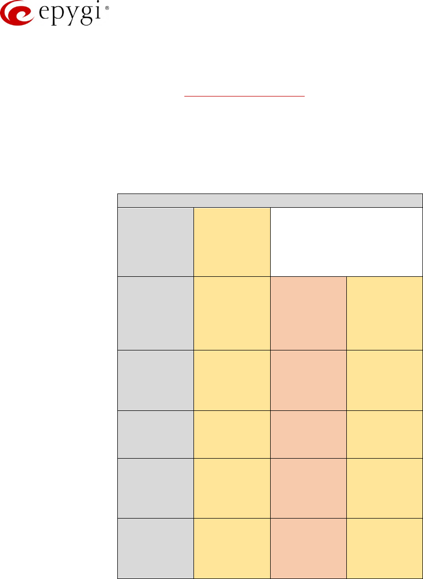
Manual-II: Administration Guide for QX Gateways
Edition 2 (FW Version 6.1.17 and higher) 204
15.2Administrator Login
The Administrator Login is used to review and modify the Auto Attendant greeting and recurring prompt, as well
as the universal extension messages. Phone Access Password will be required for login.
1. Dial to login.
2. Insert the Phone access password.
3. Follow the voice prompts to review and change system messages.
4. Press or hang up to logout.
System will notify about the messages that can be reviewed and modified.
Administrator Login menu
Review
Attendant
Greeting
Review
Attendant
Recurring
Prompt
Review Universal Extension
Messages
Enter the
Attendant
Number
(in case of
multiple AAs)
Enter the
Attendant
Number
(in case of
multiple AAs)
Incoming Call
Blocking
message
Outgoing Call
Blocking
message
Listen to the
current
greeting
Listen to the
current
prompt
Listen to the
current
message
Listen to the
current
message
Record a new
greeting
Record a new
prompt
Record a new
message
Record a new
message
Restore
system default
greeting
Restore
system default
prompt
Restore
system default
message
Restore
system default
message
Stop recording
or playback
Stop recording
or playback
Stop recording
or playback
Stop recording
or playback
Table 10: Administrator Login menu

Manual-II: Administration Guide for QX Gateways
Edition 2 (FW Version 6.1.17 and higher) 205
15.3Auto Attendant
Auto Attendant can be accessed locally, remotely from the IP network (by dialing Auto Attendant’s SIP address)
and from the PSTN network if the calls from PSTN are routed to the Auto Attendant. TIP: Auto Attendant is not
available on QXFXS24.
The following services are accessible from Auto Attendant by using appropriate feature codes:
Call Relay
When dialing on the IP phone connected to QX, the dialed digits are send directly to be processed by Call
Routing Table. But when remote callers are dialing on the Auto Attendant prompt, the dialed digits are not send
to Call Routing Table by default. This is done to prevent unauthorized calls. To send the Auto Attendant digits
to Call Routing Table either the Auto Attendant "Send AA Digits to Routing Table" option should be enabled or
the Auto Attendant Call Relay service should be used. Using Call Relay gives privileges of PBX extensions to call
directly to remote destinations.
The Call Relay service is accessible by feature code on Auto Attendant prompt. After dialing an
authentication will be required (an extension number and password). Once successfully entered, the caller can
use the routes available in the Call Routing.
Note: The Call Relay service cannot be used, if it is not enabled on at least one of the extensions on the QX.
The Allow Call Relay option is enabled/disabled on a per extension basis. By default, this option is disabled on
all extensions.
Call Relay allows the external user to make multiple calls to different destinations without the necessity of
hanging up after each call and dialing the auto attendant again. To make a call to the new destination without
disconnecting from QX, the external user has to enter rather than hang up. Upon receiving this service
code, the QX terminates the current call to destination and sends the invitation to dial the new destination
number.
Note:
•The service code is applicable at ringing and connected call stages.
•This service can only be used when accessing from PSTN to the external SIP destination through QX’s
AA or vice versa.
•This service is not available on the second QX Auto Attendant (calling from one Attendant to another).
Call Back
With the QX's Call Back service callers can save the call charge when calling to/through the QX to the remote
destinations. The QX allows configuring a list of trusted callers that are allowed to make free of charge calls.
Two types of Call Back configurations are available: Pre-configured Call Back and Remote Call Back
Configuration.
Pre-configured Call Back
For Pre-configured Call Back, a list of trusted callers must be configured in the QX's Authorized Phones using
the Web Management. The Call Back service should be enabled and a valid callback destination should be
specified for each caller.
To use Pre-configured Call Back, the caller registered in the Authorized Phones should simply call to the QX’s
Auto Attendant through SIP or PSTN, let the call to ring during the preconfigured timeout and then hang up.

Manual-II: Administration Guide for QX Gateways
Edition 2 (FW Version 6.1.17 and higher) 206
Call Back will be instantly activated, and QX will call back to the defined Call Back destination. By answering the
incoming call caller will be connected to the Auto Attendant menu.
Remote Call Back Configuration
The Remote Call Back Configuration service is used by authorized callers to configure or reconfigure existing
call back configuration on the QX. Remote Call Back Configuration is divided into two modes accessible from
the QX's Auto Attendant:
•Permanent Call Back
•Non-Permanent (Instant) Call Back
Note: Remote Call Back Configuration services are only available when the Automatically Enter Call Relay Menu
option is disabled in the Call Back settings for the trusted user.
Permanent Call Back
Permanent Call Back service allows callers registered in the Authorized Phones to create a new trusted caller
with Call Back enabled. They can also modify the Call Back destination of existing callers in the Authorized
Phones. By calling QX's Auto Attendant and entering the Auto Attendant menu, the caller can use the
code to create a new trusted caller as well as to modify the Call Back destination for the already registered
callers in the Authorized Phones.
By entering Permanent Call Back reconfiguration menu, system asks caller to login by dialing the number and
an appropriate password for the QX's extension that is used as login extension in the Call Back settings. After
passing the login, callers should follow the voice instructions for configuring a new entry or reconfiguring
existing entries in the Authorized Phones.
When system accepts the inserted settings, the corresponding entry will be logged to the Authorized Phones.
The caller will then be disconnected from the QX's Auto Attendant and the defined Call Back destination will
receive a call from the QX within the next few seconds. Answering the incoming call, the caller will be
reconnected to the QX's Auto Attendant.
Note: The detected caller number must correspond to the one applied by the caller. In case of PSTN call back
at least one PSTN line must be available on the QX. There must be network connectivity and the destination
must be reachable.
Non-Permanent Call Back
Non-Permanent Call Back configuration service allows trusted caller to organize one-time Call Back to the
defined destination. In this situation, no entry will be logged to the Authorized Phones. By calling QX's Auto
Attendant and entering the Auto Attendant menu, the caller can use code to modify the Call Back
destination for already registered callers in the Authorized Phones.
The system will ask to login by dialing the number and an appropriate password for the QX's extension that is
used as login extension in the Call Back settings. After login, caller should follow the voice instructions for
reconfiguring the existing entry in Authorized Phone. The caller will then be disconnected from the QX's Auto
Attendant and the defined Call Back destination will receive a call from the QX within the next few seconds.
Answering the incoming call, the caller will be reconnected to the QX's Auto Attendant.
Note: For both Permanent Call Back and Non-Permanent Call Back, the detected caller number must
correspond to the one configured for trusted caller. In case of PSTN call back at least one PSTN line must be
available on the QX. There must be network connectivity and the destination must be reachable.

Manual-II: Administration Guide for QX Gateways
Edition 2 (FW Version 6.1.17 and higher) 207
Other Services
You can also remotely access some QX telephony services through Auto Attendant after passing the
authentication. The following services are accessible from Auto Attendant:
•Unconditional Call Forwarding
•Administrator Login
•Call Routing Management

Manual-II: Administration Guide for QX Gateways
Edition 2 (FW Version 6.1.17 and higher) 208
16 Appendix: System Default Values
16.1System Settings
Parameter System Default Value QX Model
Admin Settings Login name – admin
Password – 19 All
Host Name
e1t1gw QXE1T1
fxogw QXFXO4
isdngw QXISDN4
fxsgw QXFXS24
Domain Name epygi-config.loc All
LAN IP Address 172.28.0.1 All
LAN Subnet Mask 255.255.0.0 All
DHCP Server Enabled All
Regional Settings and
Preferences
Locale – US
TimeZone – Central Time (US&Canada) All
WAN Interface Protocol Ethernet All
WAN Interface Bandwidth
Upstream – 100000
Downstream – 100000
Min Data Rate – 0
All
WAN IP Configuration Assign automatically via DHCP All
WAN Interface
Configuration
MAC Address – Assigned by device
MTU –1500 Bytes All
DNS Settings Dynamically by provider All
Date and Time Settings
SNTP Server and Client – enabled
SNTP Server – ntp1.epygi.com
Polling interval – 6
All
E-mail(SMTP) Settings SMTP Service – disabled All
Short Text Messaging
(SMS) Settings Enable SMS Service – disabled All
System Security Security Level – Medium All
Licensed Features No feature is activated. QXFXO4,
QXE1T1
Language Pack Default – English
Current Language Pack – none All
Extensions Management
Extension Length – 2 QXISDN,
QXFXS24
Extension Length – 3 QXE1T1,
QXFXO4
User Extension – General
Settings
Display name – none
Password – empty
11-34 extensions attached to the FXS lines 1-24
QXFXS24
Display name – none
Password – empty
Call Relay – disabled
GUI Login Allowed – disabled
Show on Public Directory – disabled
QXE1T1,
QXFXO4,
QXISDN4

Manual-II: Administration Guide for QX Gateways
Edition 2 (FW Version 6.1.17 and higher) 209
Parameter System Default Value QX Model
User Extension – SIP
Settings
Username / DID Number – same as extension
number
Password – empty
SIP Server – empty
SIP Port – 5060
SIP Registration Transport – UDP
Registration on SIP Server – disabled
All
User Extension – SIP
Advanced Settings
Authentication Username – undefined
Send Keep-alive Messages to Proxy – disabled
RTP Priority Level – medium
Do Not use SIP Old Hold Method – disabled
Outbound Proxy, Secondary SIP Server and
Outbound Proxy for Secondary SIP Server –
undefined
All
User Extension – Remote
Settings Enable Remote Extension – disabled QXFXO4,
QXE1T1
User Extension – Codecs
Codecs:
G711u (preferred), G711a, G729a – enabled
G726/16, G726/24, G726/32, G726/40, iLBC
Out of Band DTMF Transport – enabled
T.38 FAX – enabled
Pass Through FAX – enabled
Pass Through Modem – disabled
Force Self Codecs Preference for Inbound Calls –
disabled
SRTP Policy – Make unsecure calls, accept anything
QXFXS24
Codecs:
G711u (preferred), G711a, G729a – enabled
G726/16, G726/24, G726/32, G726/40, iLBC,
G.722, G.722.1
Out of Band DTMF Transport – enabled
T.38 FAX – enabled
Pass Through FAX – enabled
Pass Through Modem – disabled
Force Self Codecs Preference for Inbound Calls –
disabled
SRTP Policy – Make unsecure calls, accept anything
QXE1T1,
QXFXO4,
QXISDN4
Attendant 00 General
Settings
Display name – empty
Enable FAX forwarding – disabled
Show on Public Directory – enabled
QXFXO4,
QXE1T1,
QXISDN4
Attendant 00 Attendant
Scenario
Scenario – default
Send AA digits to Routing Table – disabled
Redirection on Timeout – disabled
ZeroOut – disabled
Welcome Message – enabled
Ringing Announcement – disabled
Welcome Message, Recurring Attendant Prompt and
Attendant Ringing Announcement – default
QXFXO4,
QXE1T1,
QXISDN4
Attendant 00 SIP Settings
Registration Username/DID Number – empty
Registration password – empty
SIP server – empty
SIP Server port – 5060
SIP Server Registration – disabled
QXFXO4,
QXE1T1,
QXISDN4

Manual-II: Administration Guide for QX Gateways
Edition 2 (FW Version 6.1.17 and higher) 210
Parameter System Default Value QX Model
Attendant 00 SIP
Advanced
Settings
Authentication Username – undefined
Send Keep-alive Messages to Proxy – disabled
RTP Priority Level – medium
Do Not use SIP Old Hold Method – disabled
Outbound Proxy, Secondary SIP Server and
Outbound Proxy for Secondary SIP Server –
undefined
QXFXO4,
QXE1T1,
QXISDN4
Attendant 00 Codecs
Codecs:
G711u (preferred), G711a, G729a – enabled
G726/16, G726/24, G726/32, G726/40, iLBC
Out of Band DTMF Transport – enabled
T.38 FAX – enabled
Pass Through FAX – enabled
Pass Through Modem – disabled
Force Self Codecs Preference for Inbound Calls
– disabled
SRTP Policy – Make unsecure calls, accept
anything
QXFXO4,
QXE1T1,
QXISDN4
Global Speed Dial No file imported All
Universal Extension
Recordings Percentage of System Memory – 1%
QXFXO4,
QXE1T1,
QXISDN4
Authorized Phones No entries
QXFXO4,
QXE1T1,
QXISDN4
General Operation Mode PNP mode QXFXS24
FXS (On-board) settings
Caller ID Type – Standard 2
Enable off-hook Caller ID – disabled
Busy Tone and Power Disconnect indications:
disabled
Ringer type: Type A
Hot Desking – disabled
QXFXS24
FXO Settings
4 FXO lines exists on QXFXO4
All lines enabled, incoming and outgoing calls
allowed and routed to 00 Attendant on all lines
QXFXO4

Manual-II: Administration Guide for QX Gateways
Edition 2 (FW Version 6.1.17 and higher) 211
Parameter System Default Value QX Model
E1/T1 Settings
Trunk 1 exists on QXE1T1
Trunk mode – E1
Interface Type – User
Signaling – CCS
Line Code – HDB3
Frame Mode – NO_CRC
Line Build Out – 120–ohm
Coding – a–law
LoopBack Mode – No_loopback
Clock Mode – Slave
TEI mode – non automat, TEI address –0
SAPI Value – undefined
Alternative Disconnect Mode – enabled
Excessive Ack. Delay T200 – 4000
Idle Timer T203 – 12000
T302 timer – 4000
T309 timer – 0
T309 timer – 60000
D Channel Timeslot for Transmit/Receive – 16
B channels – 1–31 timeslots are enabled
Echo Cancellation – enabled for all B channels
Channels Selection – preferred
Channels Selection Ordering – ascending
Bearer Establishment Procedure – on progress
indication with in–band information,
Called Party Type of Number and Calling Party Type
of Number – Unknown,
Called Party Numbering Plan and Calling Party
Numbering Plan – ISDN/telephony numbering plan
Route Incoming Call to – 00
Switch Type – primary_dss1
Generate Progress Tone to PSTN/PBX – None
Incoming Called Digits Size – 1
Generate Progress Tone to IP – disabled
Send ALERT Message on Call Routing – disabled
Enable CLIR Service – disabled
Enable Connect Acknowledge Option – enabled
Override CLID with P–Asserted–Identity –disabled
QXE1T1
ISDN Settings
ISDN Trunks – 4 trunks exist on QXISDN4.
Settings for all available Trunks:
State – started
Interface Type – User
Connection Type – PTMP (Point To Multi Point)
Service Type – No MSN
Route Incoming Call to – 00
Use Default Outgoing Caller ID – enabled
Default outgoing Caller ID – undefined
Advanced Settings – disabled
QXISDN4
PSTN Lines Sharing Provide PSTN lines for master device – disabled
QXFXO4,
QXE1T1,
QXISDN4
PSTN Gateway Operation
Mode Slave mode
QXFXO4,
QXE1T1,
QXISDN4

Manual-II: Administration Guide for QX Gateways
Edition 2 (FW Version 6.1.17 and higher) 212
Parameter System Default Value QX Model
VoIP Carrier VoIP Carrier – Manual
Description – undefined
QXFXO4,
QXE1T1,
QXISDN4
Call Routing Table
2 entries defined for a call – calls to extensions and
calls to SIP
QXFXO4,
QXE1T1,
QXISDN4
1 entry defined for a SIP call QXFXS24
Call Routing Route all incoming SIP calls to Call Routing –
disabled All
Local AAA Table No entries All
SIP Tunnel Settings
Enable Tunnels to Slave Devices – disabled
Tunnels to Slave Devices – no entries
Enable Tunnels to Master Devices – disabled
Tunnels to Master Devices – no entries
All
NAT Traversal Settings
NAT Traversal for SIP – Automatic
SIP and RTP Parameters – Use STUN
SIP TCP Port – 5060
STUN Parameters:
•Primary STUN Server – stun.epygi.com
•Primary STUN Port – 3478
•Secondary STUN Server – undefined
•Secondary STUN Port – undefined
•Polling Interval: 1 hour
•Keep-alive interval: 120 seconds
•NAT IP checking interval: 300 seconds
NAT Traversal Exceptions – No entries
All
RTP Settings
Properties for all Codecs except iLBC, G.722,
G.722.1:
•Packetization – 20ms
•Silence Suppression – yes
iLBC properties:
•Packetization – 30ms
•Silence Suppression – yes
G.722, G.722.1 properties – undefined
G.726 Standard – Use ITU-T specification
RTP/RTCP port range – 6000-6255
RTCP Support – disabled
All
SIP Settings
UDP and TCP Port – 5060
TLS Port – empty
Realm – epygi
Session Timer – disabled
DNS Server for SIP – default
SIP timers – RFC 3261
Host Aliases for SIP – undefined
All
RTP Streaming Channels No entries
QXFXO4,
QXE1T1,
QXISDN4

Manual-II: Administration Guide for QX Gateways
Edition 2 (FW Version 6.1.17 and higher) 213
Parameter System Default Value QX Model
Gain Control Settings
FXS lines:
•Transmit Gain: – 6
•Receive Gain: 0
QXFXS24
FXO lines:
•Transmit Gain: 0
•Receive Gain: 0
QXFXO4
E1/T1 trunk:
•Transmit Gain: 0
•Receive Gain: 0
QXE1T1
ISDN trunks:
•Transmit Gain: 0
•Receive Gain: 0
QXISDN4
RADIUS Client Settings RADIUS client – disabled All
Dial Timeout 4 seconds All
Call Quality Notification Disabled All
Hold Music Play Hold Music – Local Music
Percentage of system memory – 1%
QXFXO4,
QXE1T1,
QXISDN4
Firewall
Enable NAT – enabled
Enable Firewall – disabled
Enable IDS – disabled
Ping Stealth – enabled
Fool Portscanner (for QXFXS24) – disabled
All
Filtering Rules
SIP Access (Allowed for Any IP)
Management Access – HTTPS (Allowed for Any IP)
No user defined services and IP pool groups
All
SIP IDS Settings
Enable SIP IDS – enabled
Add the IP address into the Blocked IP List in
Firewall – enabled
Discard SIP messages from IP address – enabled
(32 seconds)
Exceptions for SIP IDS – no entries
All
IP Routing No entries All
DHCP Advanced Settings
DHCP Options:
•Gateways – 172.28.0.1
•Subnet mask – 255.255.0.0
•Domain name servers – 172.28.0.1
•NBT name servers – 0.0.0.0
•NTP servers – 172.28.0.1
•Domain name – "epygi-config.loc"
•Overload TFTP Server Name – 172.28.01
DHCP Server Statements:
•Authoritative – enabled
•Ping Check – enabled
•Ping timeout – 1 sec
All

Manual-II: Administration Guide for QX Gateways
Edition 2 (FW Version 6.1.17 and higher) 214
Parameter System Default Value QX Model
DNS Server Settings
Zone – epygi-config.loc
Time to live (TTL) – 86400 seconds
Mail Exchange (MX) – undefined
No aliases defined
All
Dynamic DNS Disabled All
SNMP Settings SNMP – disabled All
VLAN Settings Undefined All
IPSec, PPTP and L2TP
No connections:
•RSA Key Management – 1024-bit key
defined
PPTP Server Configuration:
•Subnet – 172.31.1.0/24
•Authentication – MSCHAPv2, MPEE 128 bit
L2TP Server Configuration:
•Subnet – 172.31.2.0/24
All
OpenVPN No file imported QXFXS24
Event Settings
"Display notification" for all events except Login and
Firmware Update events. Those events have a "Do
nothing" action assigned. Additionally, Fan Control
critical and major failures have a Flash LED action
assigned.
All
Call History
Enable Call Reporting – enabled, 100 entries for all
type of calls
Enable Automatic Downloading of Call Detail
Records – disabled
All
System Logs Settings
Enable User Logging – enabled
Enable Developer Logging – enabled
Log Lines to Show – 50
Comment – undefined
All
Remote Logs Settings Disabled All
User Rights Management
Users – admin (enabled), localadmin (disabled)
GUI Access Password –19,
Phone Access Password – 19,
Roles – Extension (N/A for QXFXS24), Local
Administrators (all accessible pages for localadmin)
All
Automatic Backup Disabled All
Automatic Firmware
Update
Enabled
Server Configuration – Assign manually
Server Name – ftp.epygi.com
Server Port – 21
Update Method – ftp
Username – anonymous
Password – empty
Check and notify – Every day at 0:00
All
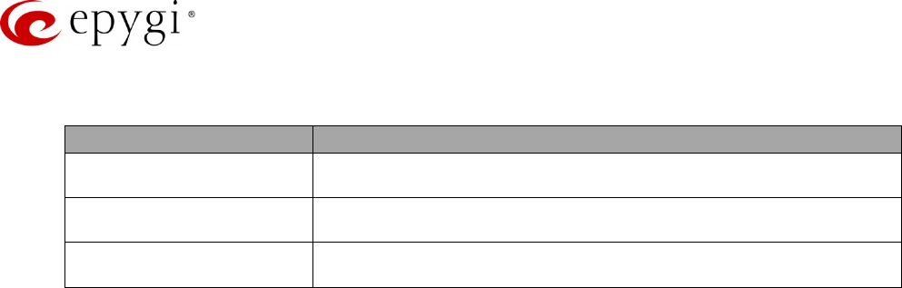
Manual-II: Administration Guide for QX Gateways
Edition 2 (FW Version 6.1.17 and higher) 215
16.2Extension Settings
Parameter System Default Value
Account Settings Display Name – undefined
Custom Voice Messages – default
Basic Services – General
(for QXFXS24 only)
Enable Call Waiting Service – enabled
Hot Line – disabled
Caller ID Services
(N/A for QXFXS24)
For Any Callers – all services are disabled
Call Blocking messages – default

Manual-II: Administration Guide for QX Gateways
Edition 2 (FW Version 6.1.17 and higher) 216
17 References
Refer to the below listed recourses to get more details about the configurations described in this guide:
•Manual-I: Installation Guide for QX Gateways
•Licensable Features on QX IP PBXs
•Language Packs Overview for Epygi QX Line
•Auto Configuration of Epygi Supported IP Phones using OpenVPN
•OpenVPN Service on QX IP PBXs
•Call Detail Records on the QX IP PBXs
•Automatic Firmware Update on the Epygi QXs
Find the above listed documents on Epygi Support Portal.
Manual-II: Administration Guide for QX Gateways
Edition 2 (FW Version 6.1.17 and higher) 217
18 Appendix: Software License Agreement
EPYGI TECHNOLOGIES, LTD.
Software License Agreement
THIS IS A CONTRACT.
CAREFULLY READ ALL THE TERMS AND CONDITIONS CONTAINED IN
THIS AGREEMENT. USE OF THE QUADRO HARDWARE AND
OPERATIONAL SOFTWARE PROGRAM INDICATES YOUR ACCEPTANCE
OF THESE TERMS AND CONDITIONS. IF YOU DO NOT AGREE TO THESE
TERMS AND CONDITIONS, YOU MAY NOT USE THE HARDWARE OR
SOFTWARE.
1. License.Epygi Technologies, LTD. (the "Licensor"), hereby grants to you a non–exclusive right to use the Quadro or QX Operational Software
program, the documentation for the software and such revisions for the software and documentation as the Licensor may make available to you from
time to time (collectively, the "Licensed Materials"). You may use the Licensed Materials only in connection with your operation of your Quadro or
QX. You may not use, copy, modify or transfer the Licensed Materials, in whole or in part, except as expressly provided for by this Agreement.
2. Ownership. By paying the purchase price for the Licensed Materials, you are entitled to use the Licensed Materials according to the terms of this
Agreement. The Licensor, however, retains sole and exclusive title to, and ownership of, the Licensed Materials, regardless of the form or media in or
on which the original Licensed Materials and other copies may exist. You acknowledge that the Licensed Materials are not your property and
understand that any and all use and/or the transfer of the Licensed Materials is subject to the terms of this Agreement.
3. Term. This license is effective until terminated. This license will terminate if you fail to comply with any terms or conditions of this Agreement or
you transfer possession of the Licensed Materials to a third party in violation of this Agreement. You agree that upon such termination, you will
return the Licensed Materials to the Licensor, at its request.
4. No Unauthorized Copying or Modification. The Licensed Materials are copyrighted and contain proprietary information and trade secrets of the
Licensor. Unauthorized copying, modification or reproduction of the Licensed Materials is expressly forbidden. Further, you may not reverse
engineer, decompile, disassemble or electronically transfer the Licensed Materials, or translate the Licensed Materials into another language under
penalty of law.
5. Transfer. You may sell your license rights in the Licensed Materials to another party that also acquires your Quadro or QX product. If you sell your
license rights in the Licensed Materials, you must at the same time transfer the documentation to the acquirer. Also, you cannot sell your license
rights in the Licensed Materials to another party unless that party also agrees to the terms and conditions of this Agreement. Except as expressly
permitted by this section, you may not transfer the Licensed Materials to a third party.
6. Protection And Security. Except as permitted under Section 5 of this Agreement, you agree not to deliver or otherwise make available the Licensed
Materials or any part thereof to any person other than the Licensor or its employees, without the prior written consent of the Licensor. You agree to
use your best efforts and take all reasonable steps to safeguard the Licensed Materials to ensure that no unauthorized person shall have access
thereto and that no unauthorized copy, publication, disclosure or distribution thereof, in whole or in part, in any form, shall be made.
7. Limited Warranty. The only warranty the Licensor makes to you in connection with this license is that the media on which the Licensed Materials
are recorded will be free from defects in materials and workmanship under normal use for a period of one (1) year from the date of purchase (the
"Warranty Period"). If you determine within the Warranty Period that the media on which the Licensed Materials are recorded are defective, the
Licensor will replace the media without charge, as long as the original media are returned to the Licensor, with satisfactory proof of purchase and
date of purchase, within the Warranty Period. This warranty is limited to you as the licensee and is not transferable. The foregoing warranty does not
extend to any Licensed Materials that have been damaged as a result of accident, misuse or abuse.
EXCEPT FOR THE LIMITED WARRANTY DESCRIBED ABOVE, THE LICENSED MATERIALS ARE PROVIDED ON AN "AS IS" BASIS. EXCEPT AS
DESCRIBED ABOVE, THE LICENSOR MAKES NO REPRESENTATIONS OR WARRANTIES THAT THE LICENSED MATERIALS ARE, OR WILL BE, FREE
FROM ERRORS, DEFECTS, OMISSIONS, INACCURACIES, FAILURES, DELAYS OR INTERRUPTIONS INCLUDING, WITHOUT LIMITATION, TO ANY
IMPLIED WARRANTIES OF MERCHANTABILITY, FITNESS FOR A PARTICULAR PURPOSE, LACK OF VIRUSES AND ACCURACY OR COMPLETENESS OF
RESPONSES, CORRESPONDENCE TO DESCRIPTION OR NON–INFRINGEMENT. THE ENTIRE RISK ARISING OUT OF THE USE OR PERFORMANCE OF
THE LICENSED MATERIALS REMAINS WITH YOU.
8. LIMITATION OF LIABILITY AND REMEDIES. IN NO EVENT SHALL THE LICENSOR OR ANY OTHER PARTY WHO HAS BEEN INVOLVED IN THE
CREATION, PRODUCTION OR DELIVERY OF THE LICENSED MATERIALS BE LIABLE FOR ANY CONSEQUENTIAL, INCIDENTAL, DIRECT, INDIRECT,
SPECIAL, PUNITIVE OR OTHER DAMAGES, INCLUDING, WITHOUT LIMITATION, LOSS OF DATA, LOSS OF BUSINESS PROFITS, BUSINESS
INTERRUPTION, LOSS OF BUSINESS INFORMATION, OR OTHER PECUNIARY LOSS, ARISING OUT OF THE USE OF OR INABILITY TO USE THE
LICENSED MATERIALS, EVEN IF THE LICENSOR OR SUCH OTHER PARTY HAS BEEN ADVISED OF THE POSSIBILITY OF SUCH DAMAGES. YOU AGREE
THAT YOUR EXCLUSIVE REMEDIES, AND THE LICENSOR'S OR SUCH OTHER PARTY'S ENTIRE LIABILITY WITH RESPECT TO THE LICENSED
MATERIALS, SHALL BE AS SET FORTH HEREIN, AND IN NO EVENT SHALL THE LICENSOR'S OR SUCH OTHER PARTY'S LIABILITY FOR ANY
DAMAGES OR LOSS TO YOU EXCEED THE LICENSE FEE PAID FOR THE LICENSE MATERIALS.
The foregoing limitation, exclusion and disclaimers apply to the maximum extent permitted by applicable law.

Manual-II: Administration Guide for QX Gateways
Edition 2 (FW Version 6.1.17 and higher) 218
9. Compliance With Laws. You may not use the Licensed Materials for any illegal purpose or in any manner that violates applicable domestic or
foreign law. You are responsible for compliance with all domestic and foreign laws governing Voice over Internet Protocol (VoIP) calls.
10. U.S. Government Restricted Rights. The Licensed Materials are provided with RESTRICTED RIGHTS. Use, duplication or disclosure by the
Government is subject to restrictions as set forth in subparagraphs (c)(1) and (2) of the Commercial Computer Software—Restricted Rights clause at
48 C.F.R. section 52.227–19, or subparagraph (c)(1)(ii) of the Rights in Technical Data and Computer Software clause at DFARS 252.227.7013, as
applicable.
11. Entire Agreement. It is understood that this Agreement, along with the Quadro or QX installation and administration manuals, constitute the
complete and exclusive agreement between you and the Licensor and supersede any proposal or prior agreement or license, oral or written, and any
other communications related to the subject matter hereof. If one or more of the provisions of this Agreement is found to be illegal or unenforceable,
this Agreement shall not be rendered inoperative but the remaining provisions shall continue in full force and effect.
12. No Waiver. Failure by either you or the Licensor to enforce any of the provisions of this Agreement or any rights with respect hereto shall in no way
be considered to be a waiver of such provisions or rights, or to in any way affect the validity of this Agreement. If one or more of the provisions
contained in this Agreement are found to be invalid or unenforceable in any respect, the validity and enforceability of the remaining provisions shall
not be affected.
13. Governing Law. This Agreement shall be governed by and construed in accordance with the laws of the state of Texas, without regard to choice of
law provisions that would cause the application of the law of another jurisdiction.
14. Attorneys' Fees. In the event of any litigation or other dispute arising as a result of or by reason of this Agreement, the prevailing party in any such
litigation or other dispute shall be entitled to, in addition to any other damages assessed, its reasonable attorneys’ fees, and all other costs and
expenses incurred in connection with settling or resolving such dispute.
If you have any questions about this Agreement, please write to Epygi at 1400 Preston Road, Suite 300, Plano, Texas 75093 or call Epygi at (972)
692–1166.
15. Free Software.Certain software utilized in the Epygi products is free software in its original form or in its modified form. Both types of free software
are available to you free of charge for redistribution or modification under certain conditions. Permission is granted to copy, distribute and or/modify
any free software you wish to download, whether in its original or modified forms, under the GNU General Public License or Free Documentation
License, Version 1.1 or any later version published by the Free Software Foundation. BECAUSE THE FREE SOFTWARE IS LICENSED FREE OF CHARGE,
THERE IS ABSOLUTELY NO WARRANTY. Please make sure you download the GNU license from www.gnu.org . For a list of free software go to
http://www.epygi.com/about/free–software–list.
