MESU 200 Mount Quick Guide To Installation
User Manual:
Open the PDF directly: View PDF ![]() .
.
Page Count: 23
MESU 200 Mount
A Quick Guide to Installation
V1.0
August, 2014 Steve Richards

1
0 CHAPTER INDEX
Chapter Page
1 Foreword 2
2 Mounting 3
3 Software Installation 6
4 Connecting to your PC 8
5 Software Configuration 9
6 Balancing the Mount 13
7 Polar Alignment 15
8 Mount Control 17
9 Further Reading 20
10 Mount Specification 22

Foreword
2
1 FOREWORD
Congratulations on the purchase of your Mesu-Mount 200.
The Mesu-Mount 200 is an equatorial mount with some special features.
1.
A backlash-free drive mechanism that is very stiff and tracks extreme smoothly and accurately.
These properties are especially important for astrophotography but they are desirable for other
applications as well.
2.
A 90 degree rotatable altitude setting makes it possible to set the mount for any latitude on
Earth.
3.
Its very simple and rugged design enhances the reliability and the ease of use in darkness.
4.
Its 27kg upper head has a huge carrying capacity so it will be possible to use heavy telescopes
with this mount.
5.
After passing the meridian it will still be possible to continue tracking an object for an
additional 3 hours before a meridian flip has to be carried out.
6.
The SiTech Servo II controller included with the mount is an industry leading servo controlled
system manufactured by Sidereal Technology.
In short, this is a purchase that you will enjoy for many years to come.
Lucas Mesu
Mounting
3
2 MOUNTING
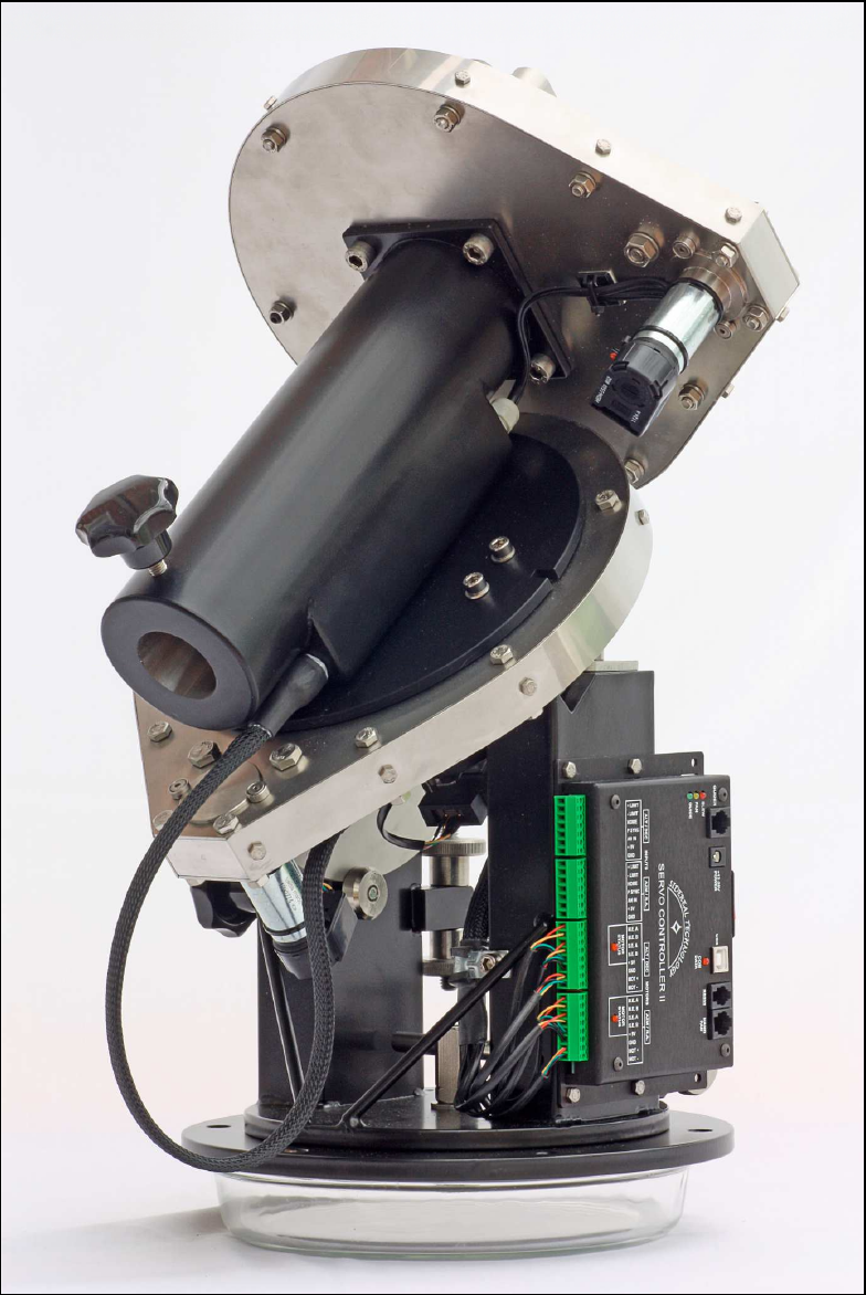
The Mesu 200 mount should be attached to a pier via the Mesu mounting plate. Ensure that the
azimuth post hole is orientated to the South if you are located in the Northern Hemisphere or to the
North if you are located in the Southern Hemisphere.
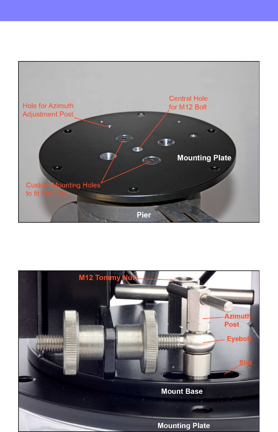
Carefully place the mount on top of the mounting plate and attach it using an M12 bolt, Tommy
nut and a washer, through the hole in the centre of the mount’s base. Align the centre of the slotted
hole at the rear of the base over the azimuth hole in the mounting plate and insert the M8 azimuth
post through the azimuth adjustment eyebolt and nip the two Tommy nuts.
Mounting
4
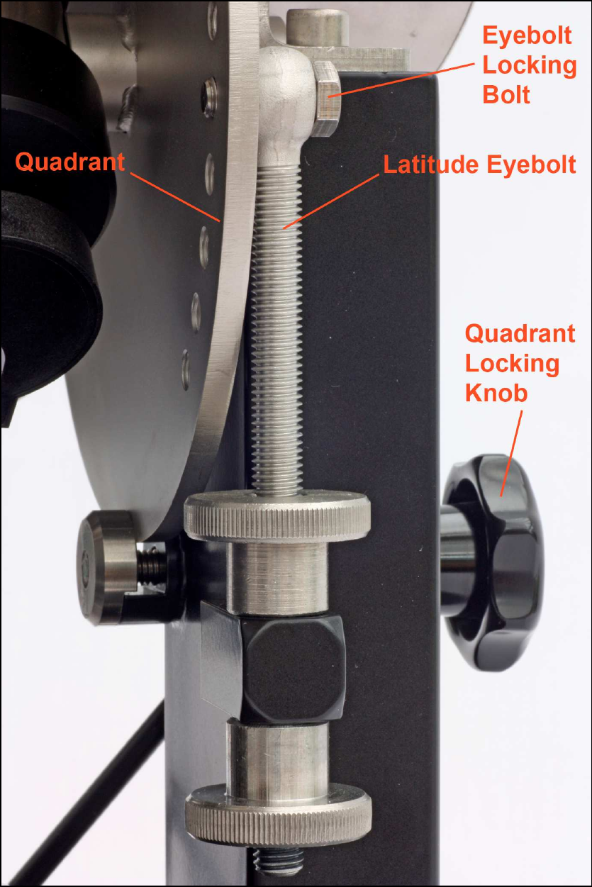
Roughly set the RA axis to your local latitude. The quadrant that sets the mount’s polar axis has
locating holes for the adjustment eyebolt, in increments of 10 degrees. Choose the hole closest to
your latitude, release the locking knob on the side of the mount, undo the eyebolt retaining bolt and
move the eyebolt to the chosen hole while carefully supporting the mount head to ensure that it
doesn’t fall. Final adjustment will be carried out later in chapter 7.
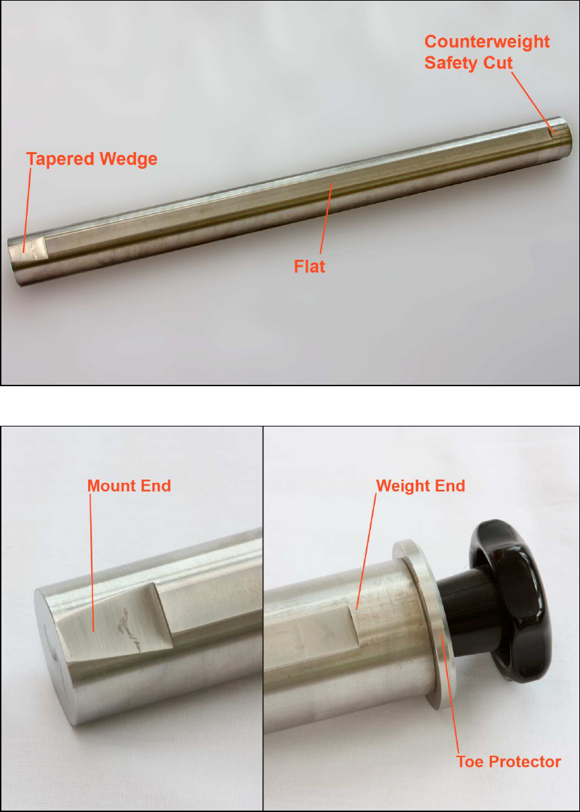
To complete the basic assembly of the mount, insert the tapered wedge-shaped cut-out end of the
counterbalance bar into the declination housing and carefully tighten the locking knob ensuring
that the bolt is aligned with the flat milled in the cut-out.
Mounting
5
The Full Bar
Close-up of bar ends

Software Installation
6
3 SOFTWARE INSTALLATION
DOWNLOADING THE REQUIRED SOFTWARE
Various pieces of software must be downloaded from the Sidereal Technology website at the
following URL:- http://siderealtechnology.com/page9.html
1. MICROSOFT .NET FRAMEWORK 4
You must be running version 4 of the Dot Net framework. This framework provides a software
environment that allows for a range of different program languages to operate together.
2. ASCOM PLATFORM V 6.1
The SiTech II controller is operated within the ASCOM platform (in version 6.1 at the time of
writing this manual). More information about ASCOM can be found at http://ascom-standards.org
3. ASCOM VERSION OF SITECHEXE 0.90P
This software installs the following programs:-
a) SiTechExe The SiTech ServoII control software
b) PlateSolve2 An excellent plate solving program
c) CalPointsXP An excellent sky modelling system
d) Interop.MaxIm.dll An interface to the popular image capture software MaxIm DL
e) ServoConfig The configuration management system for the SiTech ServoII software
4. CDM20830_SETUP
The USB driver for the USB to Serial chip virtual COM port for connecting the SiTech ServoII
controller to your PC’s USB port. You may well not need this driver as your operating system
should identify the serial connection on the SiTech ServoII controller but it makes sense to have it
to hand just in case.
5. SITECH V0.90 RELEASE NOTES PDF FILE
This document gives details of the latest software version with instructions on how to install the
software components. The PDF file can be downloaded from the following URL:-
http://siderealtechnology.com/SiTechExeReleaseNotesVersion0.90.pdf
6. UCAC3PS zip file
This 411Mb file comprises The Third US Naval Observatory CCD Astrograph Catalog (UCAC3)
which is required for use with the PlateSolve2 and CalPoints XP software above. This extensive
data file can be downloaded from the following URL:-
http://old.planewave.com/files/software/platesolve/UCAC3PS.zip

Software Installation
7
7. OPERATIONSMANUAL1-1.PDF
The SiTech ServoII operation manual. This PDF file includes a huge amount of information about
the SiTech.exe software but a lot of it is not relevant to the Mesu 200 mount. However, it is a very
useful reference work that we will be pointing to from time to time where appropriate. The PDF
file can be downloaded from the following URL:-
http://www.sitechservo.info/controller-manual/OperationsManual1-1.pdf?attredirects=0&d=1
8. QUICK START SITECH EQU OPERATIONS REV J.PDF
This is a quick start guide to the general use of an equatorial mount with the SiTech Servo II
controller. Again, some of it is relevant and some of it can be ignored and in particular, ignore the
information regarding the encoders as this information will already have been entered into the
firmware at the Mesu-Optics factory. The PDF file can be downloaded from the following URL:-
http://www.sitechservo.info/controller-
manual/Quick%20Start%20SiTech%20EQU%20Operations%20rev%20J.pdf?attredirects=0&d=1
9. CARTES DU CIEL
This software is a very competent planetarium program that can be used to locate a huge number of
celestial objects then issue GoTo or Sync commands to your mount to make mount control
intuitive and fun within a graphical user interface (GUI). The software can be downloaded from the
following URL:-
http://sourceforge.net/projects/skychart
INSTALLING THE REQUIRED SOFTWARE
Only software items 1 to 3 inclusive must be installed to have the mount up and running, all the
other items are optional although we would recommend downloading the Operations Manual (item
7) for reference.
It is very important that the software is installed in the following sequence.
1. MICROSOFT .NET FRAMEWORK 4
Install this software in accordance with the instructions on the Microsoft website.
2. ASCOM PLATFORM V 6.1
Install the ASCOM platform version 6.1 or higher in accordance with the instructions on the
ASCOM website.
3. ASCOM VERSION OF SITECHEXE 0.90P
Double click on the executable file SiTechSetup090P.exe to automatically install all the controller
software. SiTechExe.exe, PlateSolve2.exe, CalPointsXP.exe and Interop.MaxIm.dll will all be
installed in the folder C:\Program Files\SiTech\SiTechExe for 32bit versions of Windows XP,
Vista and W7 or C:\Program Files (x86)\SiTech\SiTechExe for 64bit versions. The configuration
program ServoConfig.exe will be installed with all its resource files in the directory
C:\ServoConfig for all software versions.
We recommend setting shortcuts on your desktop screen to both SiTechExe.exe and
ServoConfig.exe.
Connecting to your PC
8
4 CONNECTING TO YOUR PC
Connect the mount to a regulated 13.8 volt supply via the ‘+12V – 28V POWER’ socket on the
front of the controller – the inner pin is the positive terminal. Connect the supplied hand-controller
to the socket marked ‘HAND PAD’.
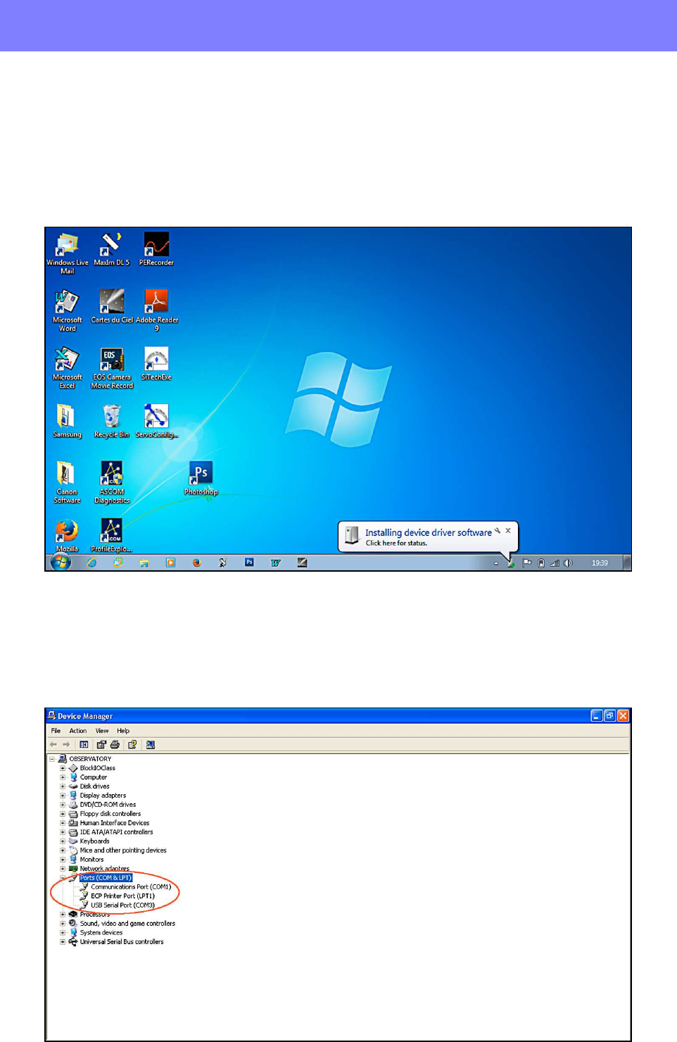
Turn on your PC and when the operating system has finished loading, plug the USB cable into
the USB socket on the controller and a spare USB 2.0 socket on your PC. Your operating system
should identify the USB device and load the drivers for it. If the USB device is not recognised, run
the device installer CDM20830_Setup.exe.
When the USB driver has completed installation, click on Start - Control Panel - Device Manager
and examine the available ports by clicking on the ‘+’ sign next to ‘Ports (COM & LPT)’. One of
the ports will be labelled as a ‘USB Serial Port (COM *)’, thus identifying the USB to Serial Port
converter built into the SiTech ServoII. Make a note of the COM port number that has been
assigned to it (COM3 in the example below) as you will need it for the next step.
Software Configuration
9
5 SOFTWARE CONFIGURATION
There are two sets of configuration files that need to be managed with this system. The SiTech
ServoII controller is very versatile and can be used with a wide range of different mounts so it
needs to know various attributes regarding the specific mount it is connected to.
The program ServoConfig manages this information and the data is stored in the SiTech ServoII
contoller. Mesu-Optics have already inserted the required information into your controller at the
factory but for your security, you should make a local copy on your PC’s hard drive.
The second set of configuration data tells the controller how it should perform and this is
managed within the program SiTechExe.
CONFIGURING SERVOCONFIG
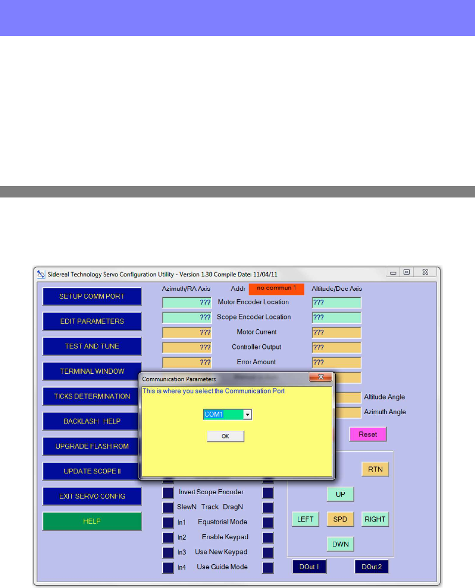
Turn on the mount using the panel switch on the right hand side of the controller box and then
double click on the shortcut to ServoConfig.exe. Click on the [SETUP COMM PORT] button and
select the COM port number that you noted above.
Setting the COM port in ServoConfig
Click on the [EDIT PARAMETERS] button and select the [Get Data From Controller] button
to download the data from the controller into the configuration manager. Under no circumstances
should you change any of the parameters under the Motors/Encoder tab as these have already been
set up at the Mesu-Optics factory for your specific mount. Click on the Auto Tracking tab and
enter your latitude in decimal degrees in the fifth box down as shown overleaf.
Now select the Misc. and Action tab and enable Use New Handpad by clicking in the box to its
left. These are the only changes to this configuration data that you will be required to make so click
on the [Send Configuration to Controller] button and then click on the [Save Controller
Configuration to Flash Rom] button to update the SiTech Servo II controller. When this action is
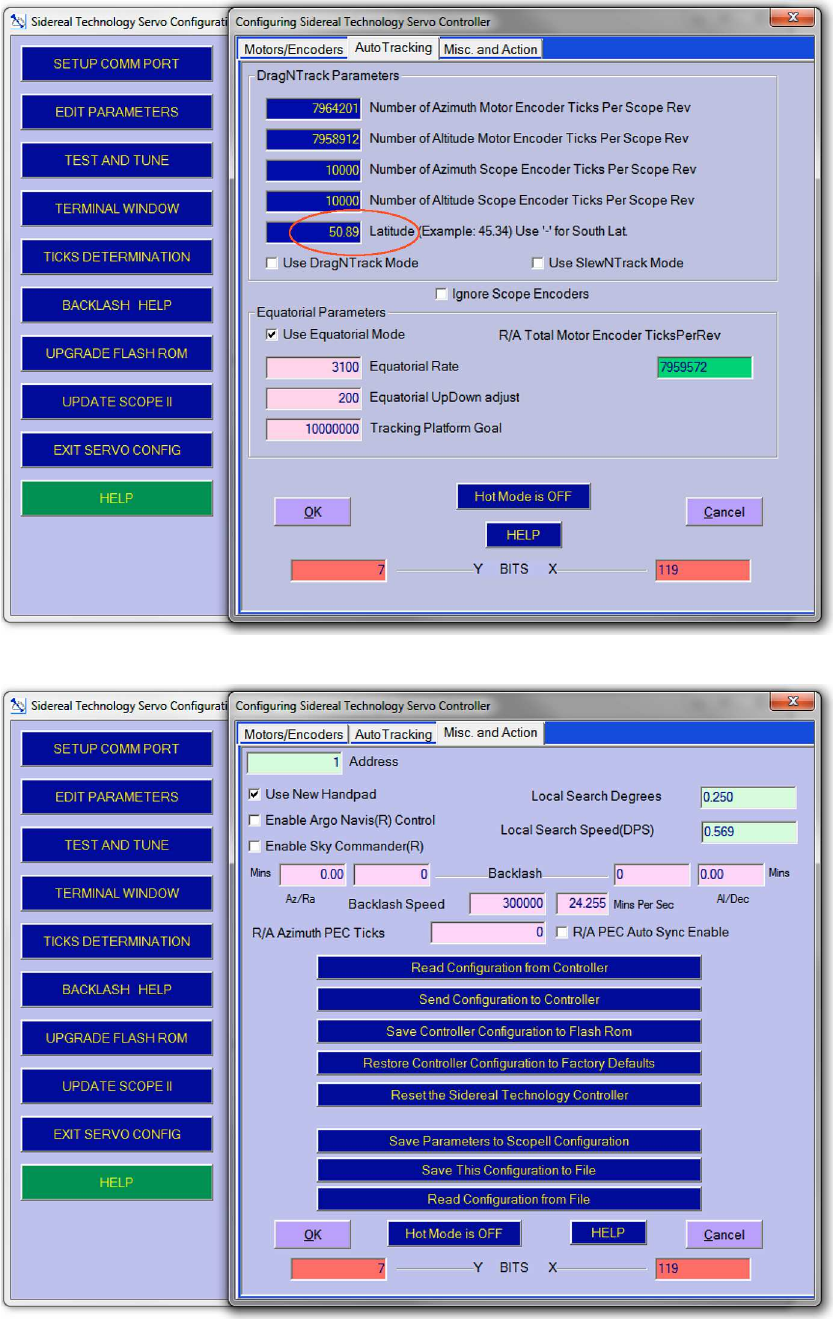
Software Configuration
10
completed, click on the [Save This Configuration to File] button to save a security copy of the
data to your hard drive and choose a suitable filename like Mesu_config_13-08-2014.car (the
‘.car’ file extension will automatically be appended to your chosen file name).
Click on the [EXIT SERVO CONFIG] button to close the program because you cannot have
both ServoConfig and SiTechExe running at the same time and that is where we’re going next.
Setting Your Latitude in ServoConfig
Saving your updated your configuration files
Software Configuration
11
CONFIGURING SITECHEXE
Ensure that ServoConfig is not running and then double click on the shortcut to SiTechExe. You
will note a ‘Bad Scope Commun’ error message will appear which is to be expected at this stage.
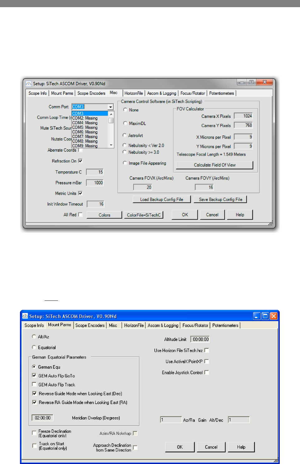
Select the Config tab and click on the [Change Config!] button to load the Setup panel for the
SiTech ASCOM driver. Select the Misc tab and choose the COM port number that you noted
above. You will now be able to communicate with the SiTech ServoII controller using the
SiTechExe software and with other software via ASCOM.
Click on the Scope Info tab, give your mount a suitable name, enter your longitude and latitude
in the relevant boxes using the 99:99:99 format, enter your height above sea level in the Elevation
box and then add the optical information.
Click on the Mount Parms tab. The Mesu 200 mount is a German Equatorial Mount (GEM) so
it is vital that the correct parameters are entered here to ensure predictable operation. The first two
radio buttons (Alt/Az and Equatorial) should be deselected. In the ‘German Equatorial Parameters’
section, select only the following parameters by clicking on them:-
Software Configuration
12
German Equ
GEM Auto Flip GoTo
Reverse Guide Mode when Looking East (Dec)
Reverse RA Guide Mode when Looking East (RA)
Deselect all the other tick boxes on this screen.
Note:
Later, you may start using a ‘horizon map’ to automate sky modelling and to warn you that chosen
objects are below your local accessible horizon. If you do want to use a horizon map then tick the
‘Use Horizon File Sitech.hrz’ box.
Click on the Scope Encoders tab. The Mesu 200 mount has two encoders on each axis, a motor
encoder and a shaft encoder and these work in unison to ensure extremely accurate GoTos and
tracking. It is recommended that you select ‘Polite Mode’ for both the RA and Dec axes and set a
Supervisory Threshold of 10:00:00 degrees. In Polite Mode, both motor and shaft encoders are in
operation for GoTo slews in excess of the supervisory threshold that you set, while slews of less
than the supervisory threshold use only the much higher resolution motor encoders.
Return to the Misc tab and enable the following parameters by clicking on them:-
Nutate Coords
Aberrate Coords
Refraction On
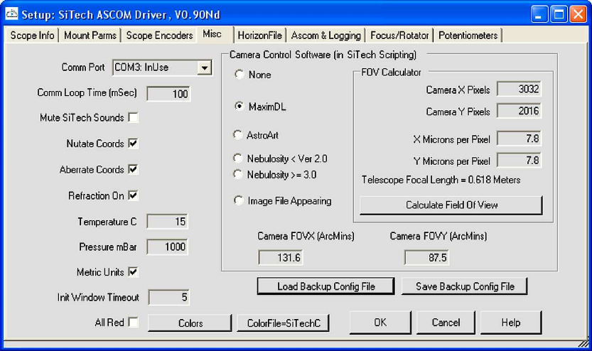
In the ‘Camera Control Software (in SiTech Scripting)’ section enable relevant camera control
software or select ‘None’ if your software isn’t listed. If your software is listed, enter your
camera’s Pixel information in the FOV Calculator and click on the [Calculate Field Of View]
button. This information is used when running a script to produce an automated sky model (see
chapter 9 - Further Reading).
For security, click on the [Save Backup Config File] button to save this configuration data to
your hard drive and choose a suitable filename like Mesu_config_13-08-2014.cfg (the ‘.cfg’ file
extension will automatically be appended to your chosen file name).
This and the work already carried out by Mesu-Optics concludes the basic software configuration
and your mount is now ready to be set up for an observing or imaging session.
Balancing the Mount
13
6 BALANCING THE MOUNT
Just like any equatorial mount, the Mesu 200 mount must be carefully balanced to ensure accurate
GoTos, tracking and the minimum of stress being placed on any of the components.
Counterbalance weights are not supplied as standard with the mount but these are available from
your retailer. The Geoptik chrome plated steel counterweights in 10Kg and 5Kg versions are
highly recommended and compatible with the Mesu 200’s 40mm counterweight bar.
As a basic guide, you will require counterbalance weights of a similar weight to that of the
telescope and other equipment you intend mounting. Please note that the counterbalance bar
and counterbalance weights are very heavy so must be handled and installed with extreme
care to avoid any accidents – Mesu-Optics will not accept any liability in the event of any
accident involving the installation and use of the counterbalance bar and/or weights.
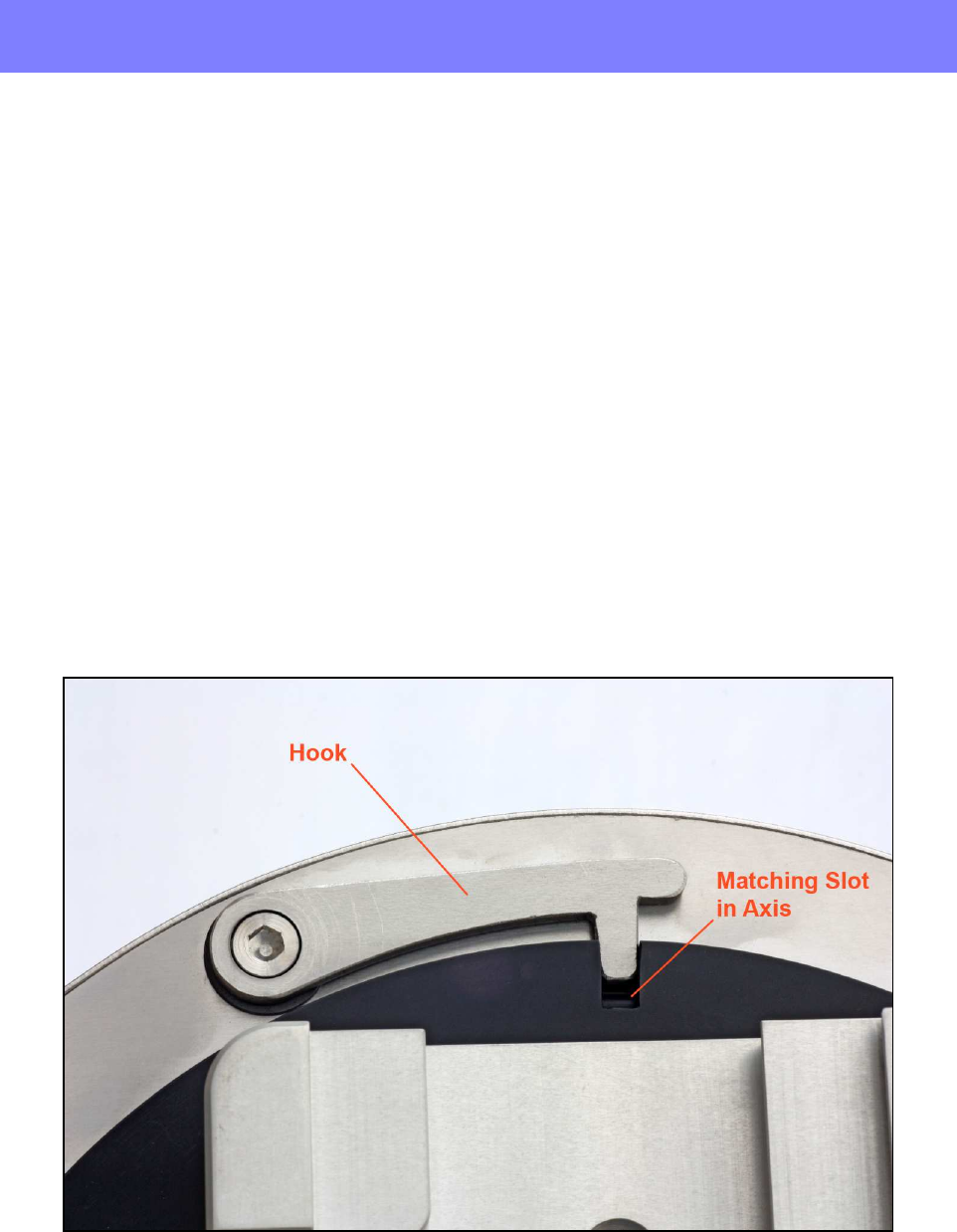
Turn off the mount and check that the counterbalance bar has been correctly installed as
described in chapter 2 – Mounting. Rotate the mount around the RA axis until the counterbalance
bar is pointing downwards and then adjust the RA axis carefully until you can engage the hook that
retains the RA axis in a locked position. Install the counterweight(s) one at a time by slipping them
over the counterbalance bar and securing them firmly with the locking bolt aligned with the flat
machined in the length of the counterbalance bar. Securely attach the ‘toe protector’ to the end of
the counterbalance bar.
Rotate the Dec axis until it is in a suitable orientation to install your telescope and then adjust the
Dec axis carefully until you can engage the hook in one the nearest slots that retain the Dec axis in
a locked position.
Install the dovetail bar attached to your telescope to the saddle clamp on the top of the Dec axis
and tighten the saddle clamp firmly. Attach your ancillary equipment to the telescope (star
diagonal/eyepiece or camera/autoguider) in accordance with the manufacturer’s instructions.
While holding firmly onto the telescope, release the Dec hook gently and check for rotation of
the Dec axis. Rotate the Dec axis until the telescope is horizontal. Loosen the saddle clamp a little
and slide the telescope in the saddle clamp horizontally until it is perfectly balanced in the Dec axis
and then re-tighten the saddle clamp – you can feel when the balance is correct by gently rocking
the Dec axis backwards and forwards.
Balancing the Mount
14
While holding firmly onto the telescope, release the RA hook gently and check for rotation of the
RA axis. Rotate the RA axis until it is horizontal and adjust the position of the counterbalance
weight(s) until the RA axis is perfectly balanced – you can feel when the balance is correct by
gently rocking the RA axis backwards and forwards.
Make a final check that the saddle clamp, counterbalance bar and counterbalance weights are all
securely locked in position.
Equatorial mounts with conventional worm and gear drives require the ‘rising’ side of the RA axis
to be heavier to counteract backlash when autoguiding. Because the Mesu 200 mount has zero
backlash, it will not be necessary to bias the balance of the mount when autoguiding.
Polar Alignment
15
7 POLAR ALIGNMENT
In common with all equatorial mounts, you must ensure that the mount is accurately Polar Aligned.
The most accurate method for doing this is to carry out a drift alignment - a Google search will
find numerous resources describing how to do a drift alignment. However, the SiTech ServoII
system can help you to achieve a very good Polar Alignment with software assistance.
Full details on how to do this can be found on page 90, section 5.2.1 Polar Align in the
Operationsmanual1-1.pdf manual downloaded in chapter 3. You will be required to download
and install the UCAC3PS zip file also discussed in chapter 3, to carry out this software assisted
procedure but this data file will have other uses as well.
We would recommend that you also read page 51, section 4.7 Init Point Window of the
Operationsmanual1-1.pdf manual to familiarise yourself with the meaning of the terms Offset
Init and Calstar Init.
For casual observing, the optional external polar scope supplied by Mesu-Optics can also be
used to achieve a very basic Polar Alignment.
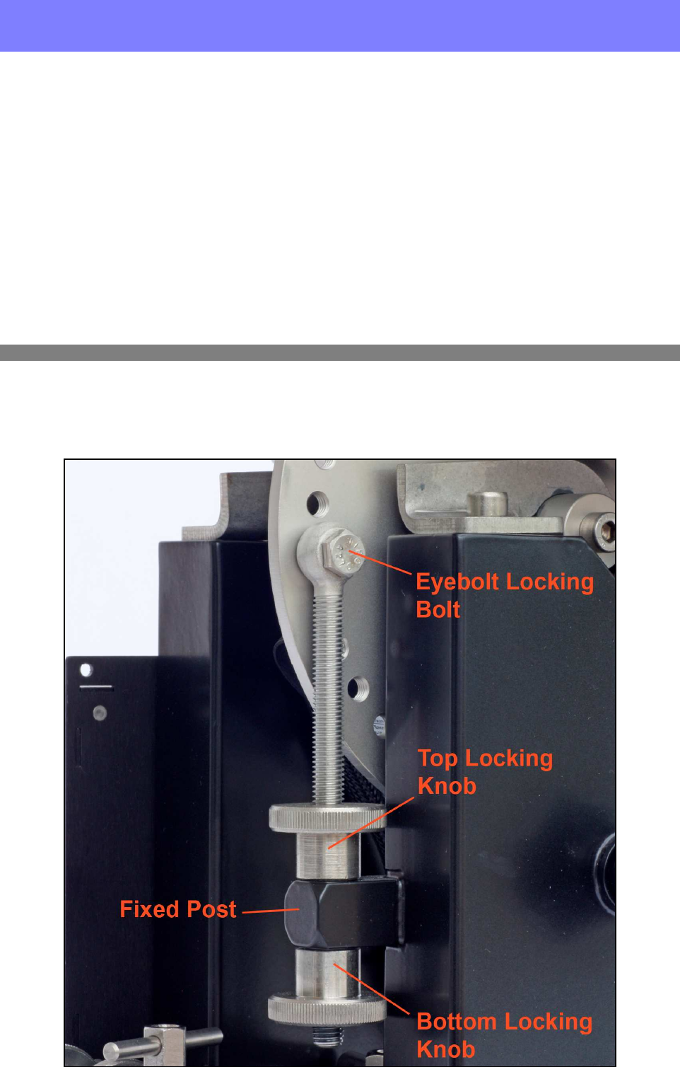
Adjusting the mount in elevation
The mount’s altitude has already been set to within 5 degrees of your latitude during the mounting
stage in chapter 2 but final much more accurate adjustment must now be carried out to correct any
error revealed by the Polar Alignment method you have used.
Polar Alignment
16
Start by unlocking the quadrant locking knob and slackening the eyebolt locking bolt slightly.
To decrease the elevation, unscrew the bottom locking knob and tighten the top locking knob
against the fixed post at the same time.
To increase the elevation, unscrew the top locking knob and tighten the bottom locking knob
against the fixed post at the same time.
When the elevation is correct, lock the quadrant locking knob and tighten the eyebolt locking bolt
then nip the top and bottom locking knobs against the fixed post.
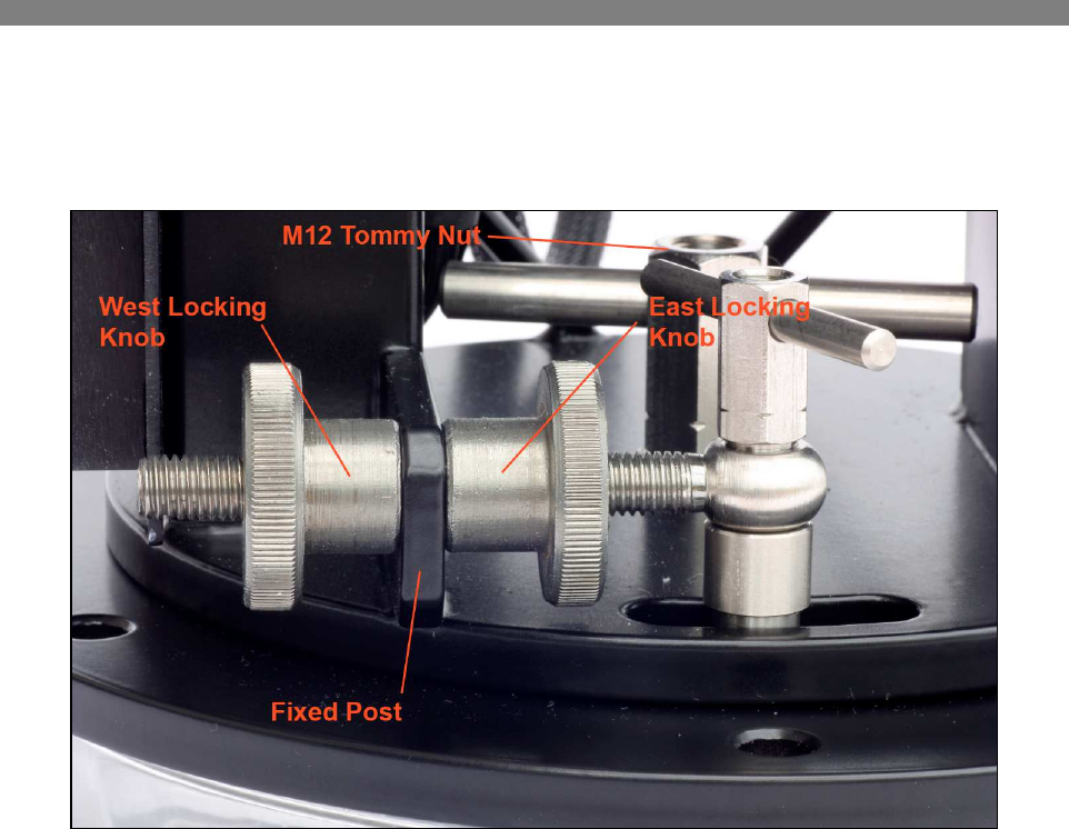
Adjusting the mount in azimuth
The mount’s azimuth has already been set to approximately North during the mounting stage in
chapter 2 but final much more accurate adjustment must now be carried out to correct any error
revealed by the Polar Alignment method you have used. Start by slackening the M12 Tommy nut a
little to allow the base of the mount to rotate on the mounting plate.
To correct for the mount pointing too far to the East, unscrew the East locking knob and
tighten the West locking knob at the same time.
To correct for the mount pointing too far to the West, unscrew the West locking knob and
tighten the East locking knob at the same time.
When the azimuth is correct, lock the Tommy nut then nip the East and West locking knobs against
the fixed post.
Mount Control
17
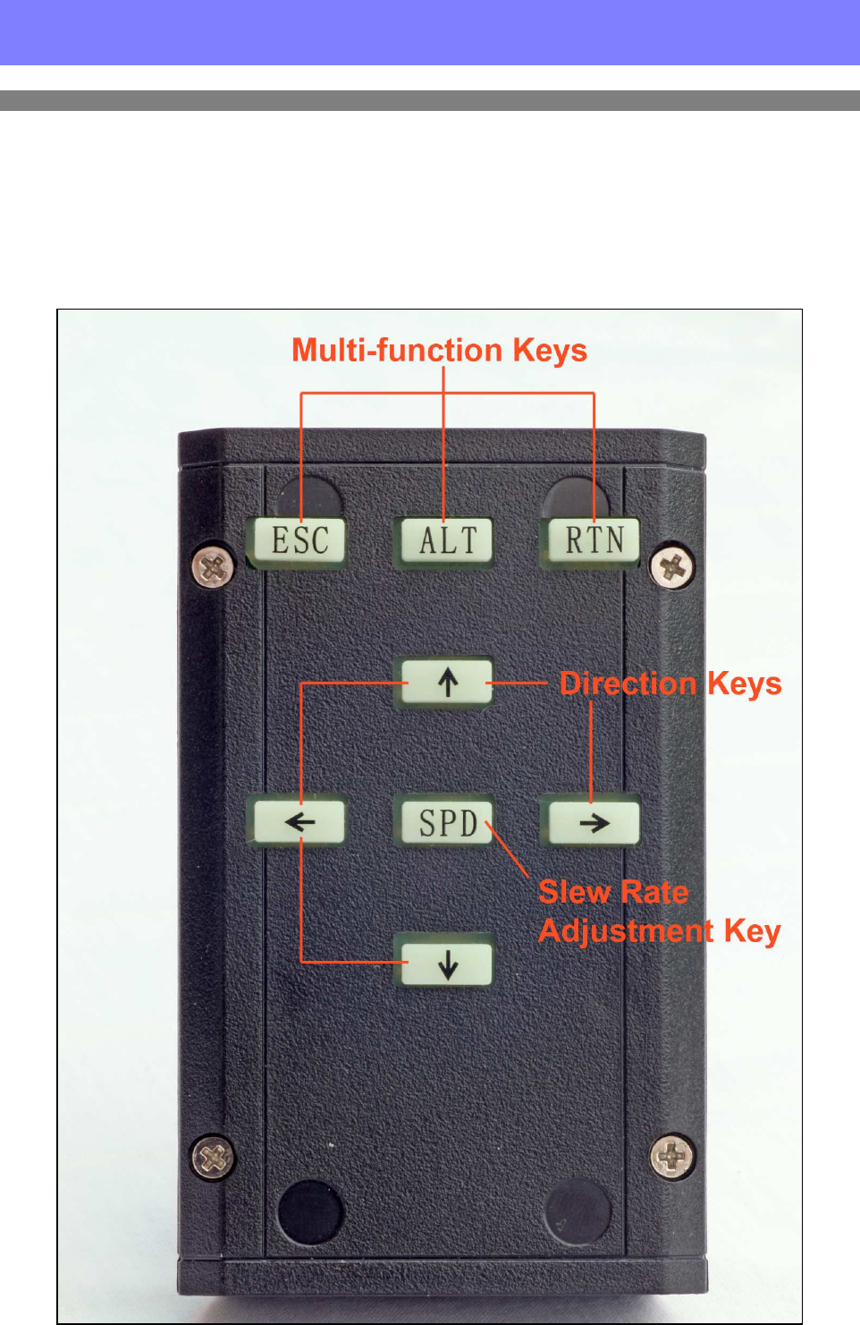
8 MOUNT CONTROL
Operating the mount without a PC
The Mesu 200 mount ships with a basic hand controller allowing adjustment of the mount’s
pointing and slew speed. The mount can be configured to start moving at sidereal rate as soon as it
is turned on. The direction keys can then be pressed to slew the telescope manually at high speed to
the object you wish to observe and then fine adjustments can be made by pressing the centre key
once to slow down to ‘scan’ speed and a second time to reduce to ‘guide’ speed. Pressing the
centre button again will return you to full slew speed.
Mount Control
18
Operating the mount using a PC and Planetarium software
Operating the Mesu 200 mount using your PC and suitable software will release the full potential
of the mount and reveal its many advanced features.
We recommend that you download and install the planetarium software, Cartes du Ciel (item 9
on page 7) as this software is proven to work very well with the SiTech ServoII controller and
Mesu 200 mount.
Full instructions are available with the Cartes du Ciel software regarding how to configure the
software for your location so we will concentrate on getting it working with the Mesu 200 mount.
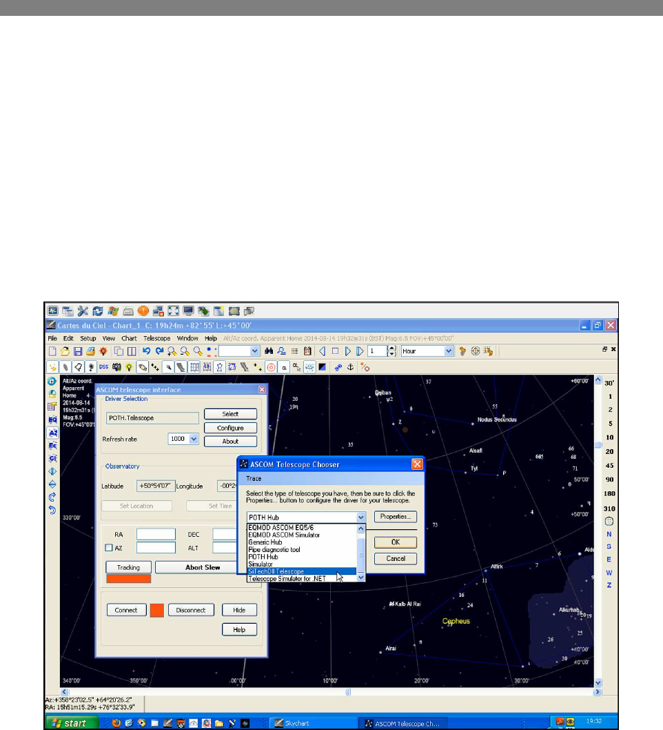
Start by associating the planetarium software with the SiTechEXE ASCOM driver. Select
Telescope – Telescope Settings, click on the Telescope tab and choose ‘ASCOM’ then click on the
[APPLY] button followed by the [OK] button. Select Telescope – Control Panel then click on the
[Select] button to enter the ASCOM chooser dialogue. Select ‘SiTechDII Telescope’ and click on
the [OK] button.
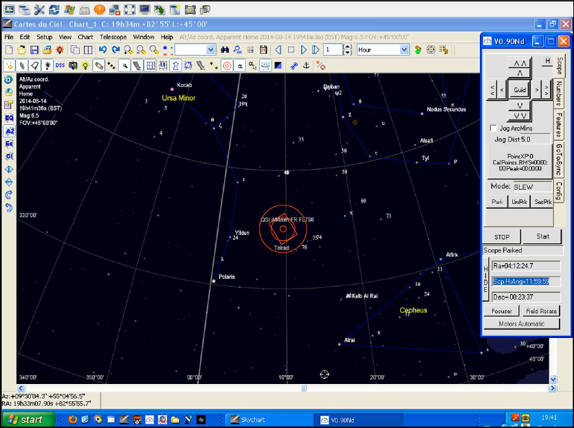
Turn on the Mesu 200 mount then click on the [Connect] button and the SiTechEXE virtual hand
controller will appear (see overleaf). Click on the [UnPrk] button (ignore any error message about
not being parked) followed by clicking on the [Start] button. The mount will start tracking at
sidereal rate.
Manually slew the telescope to point at a known object in the sky using the hand controller
supplied with the Mesu 200 mount and centre the object in your eyepiece. Locate the object in
Cartes du Ciel and then right click on the object to bring up an option menu. Click on ‘Telescope’
then click on ‘Sync’ to synchronise the mount with the planetarium software and the actual sky.
You can now choose other objects from Cartes du Ciel, right click on them, select ‘Telescope’
then click on ‘Slew’ to command the telescope to ‘GoTo’ each one.
At the end of the session, manually move the mount to a convenient ‘Park’ position (usually
with the counterbalance bar pointing downwards and the telescope pointing North) and click on the
[STOP] button to stop the mount from tracking. Now, click on the [SetPrk] button, followed by
the [Park] button to set the Park position and Park the mount (see overleaf). Finally, open the
telescope control panel from Cartes du Ciel again, click on the [Disconnect] button, close down
SiTechEXE and turn off the Mesu 200 mount.
Mount Control
19
Cartes du Ciel with the SiTech Virtual Handcontroller
Congratulations, you have now completed your first observing session!

Further Reading
20
9 FURTHER READING
This short manual is purely aimed at getting you up and running quickly without you having to
wade through the huge SiTech ServoII operation manual which contains a wealth of information
but much of it doesn’t pertain to the Mesu 200 mount. However, there are some sections that we
would recommend you should read to get the most out of the enormously rich feature set of the
Mesu 200/SiTech ServoII combination.
More information about the SiTechEXE software
The SiTechEXE controller is much more than just a virtual handcontroller – it has a
comprehensive set of features. We thoroughly recommend that you read the introduction to the
SiTechEXE controller software in its entirety by reading section 4 starting on page 35 of the
operation manual.
Parking and UnParking the Mount
Parking and unparking the mount are very important functions for starting and ending an observing
session. See page 40 section 4.3.4 of the operation manual.
Sky Modelling
Sky modelling takes the normal 1, 2 or 3 star alignment of most GoTo mounts to a new level
allowing numerous points all over the sky to be mapped using ‘CalStar Inits’.
There are two types of ‘Sync’ procedures that your mount can perform - ‘Offset Inits’ and
‘CalStar Inits’. Offset Inits are transient and CalStar Inits are semi-permanent. Think of CalStar
Inits as being a set of corrections for mount pointing placed strategically all over the sky so that the
mount makes specific corrections to its pointing when it is in each region covered by a CalStar Init.
These CalStar Init corrections define the overall map of the sky. An Offset Init tells the mount
where on that overall map the telescope is currently pointing.
With that in mind, turn to page 74 of the operation manual. It would also make sense to build a
‘Horizon File’ as described on page 82.
Autoguiding
The Mesu 200 mount is the perfect mount for long-exposure deep sky imaging but even with its
incredibly low periodic error (4 arcseconds peak to peak), autoguiding should still be used to
ensure the best quality images. Although there is an industry standard ST4 port built into the
SiTech ServoII controller, we would recommend that you use pulse-guiding. See section 6 on page
108 of the operation manual.
Other Planetarium Software
Although we have used and tested Cartes du Ciel with the Mesu 200 mount ourselves, there are, of
course, other software options. See Appendix B on page 158 for more information.
Troubleshooting
A useful troubleshooting section is included in the manual. See Appendix F on page 182.
Cue Cards
A Cue Card is a shorthand version of a checklist and you will find a set of these in the manual. See
Appendix H on page 195.

Further Reading
21
Platesolving
Included in the SiTech suite of software and used during an automatic sky modelling scripted run,
is an excellent standalone platesolving program called PlateSolveXP. See Appendix I on page 206
for more information.
Yahoo Mesu 200 User Group
There is an active user group supporting the Mesu 200 and we would encourage you to join in.
https://groups.yahoo.com/neo/groups/Mesu_Mount_200/info
Yahoo SiTech Servo User Group
There is an active user group supporting the SiTech ServoII Controller and we would encourage
you to join in.
https://groups.yahoo.com/neo/groups/SiTechservo/info

Mount Specification
22
10 MOUNT SPECIFICATION
Drive system Friction wheels driven by Servo motors
Gear ratio 1 to 2000
Payload Up to 100kg
Meridian flip required Yes
Backlash No
Latitude range 0 - 90 degrees
Pointing accuracy < 2.5arcminutes
Guide accuracy 0.1arcseconds with autoguiding
Periodic error 4arcseconds peak-to-peak
GOTO speed 6 - 8 degrees/sec.
Mount control SiTech Controller (needs a PC running SiTech Software)
Guiding protocol ST4 port and Pulse-Guiding
Power consumption Average is 400mA (when the mount guides for 90% of the time)
Diameter counterweight bar 40mm
Please note that due to our policy of continuous development, some of the items shown in the
photographs in this manual may not exactly match the appearance of your own mount.
MESU-OPTICS
Lucas Mesu
Jasmijnstraat 14
5492 JT Sint-Oedenrode
Tel: +31 (0) 413-479981
E-mail: info@mesu-optics.nl
August, 2014 Steve Richards
