Description Of The CP 343 1 Lean SIMATIC NET Mn Cp343 76
User Manual: SIMATIC NET CP 343-1
Open the PDF directly: View PDF ![]() .
.
Page Count: 23
S
IMATIC NET
S
7-CPs for Industrial Ethernet
Manual Part B8
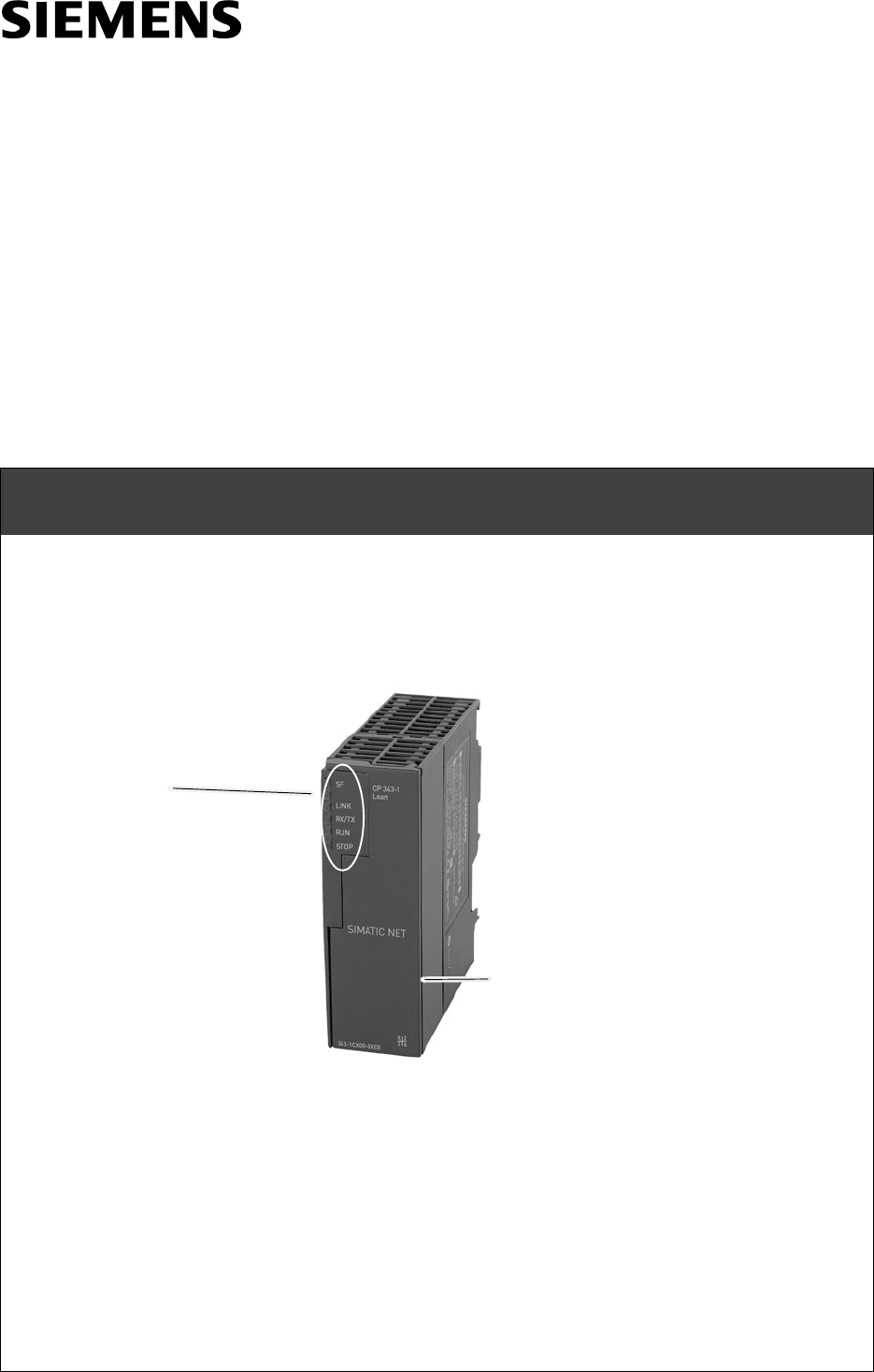
LED displays
CP 343-1 Lean
6GK7 343-1CX00-0XE0 Version 1 or higher (Firmware Version V1.0)
for SIMATIC S7-300 / C7-300
TP port:
8-pin RJ-45 jack
(behind the hinged front panel)

Notes on the Product
B8-2 CP 343-1 Lean / Manual Part B8
Release 08/2004
C79000-G8976-C198-01
Notes on the Product
Product Names
This description contains information on the following product
SCP 343-1 Lean
Printed Product Information Supplied with the Product
Note
All the notices in the Product Information Bulletin shipped with this device are
valid and must be adhered to.
Address label with unique MAC address preset for the CP
The CP 343-1 Lean is supplied with a MAC address preset in the factory. The
MAC address is not changed during configuration.

Contents
B8-3
CP 343-1 Lean / Manual Part B8
Release 08/2004
C79000-G8976-C198-01
Contents
Contents - Part A
Ethernet CPs - General Information See General Part. . . . . . . . . . . . . . . . . . .
Note
Please remember that Part A of the manual also belongs to the description of the
CP. Among other things, it contains explanations of the safety notices, the
references to literature, and general information that applies to all S7 CPs for
Industrial Ethernet.
You can also obtain the current Part A from the Internet:
http://www4.ad.siemens.de/view/cs/en/8777865
Contents - Part B7
1 Properties / Services B8-4. . . . . . . . . . . . . . . . . . . . . . . . . . . . . . . . . . . . . . . . . . . . . . . . . . .
2 Requirements for Use B8-6. . . . . . . . . . . . . . . . . . . . . . . . . . . . . . . . . . . . . . . . . . . . . . . . . .
3 Installation and Commissioning B8-8. . . . . . . . . . . . . . . . . . . . . . . . . . . . . . . . . . . . . . . . .
4 Displays B8-11. . . . . . . . . . . . . . . . . . . . . . . . . . . . . . . . . . . . . . . . . . . . . . . . . . . . . . . . . . . . . . .
5 Performance Data B8-13. . . . . . . . . . . . . . . . . . . . . . . . . . . . . . . . . . . . . . . . . . . . . . . . . . . . . .
5.1 General Characteristics B8-13. . . . . . . . . . . . . . . . . . . . . . . . . . . . . . . . . . . . . . .
5.2 Characteristics of S7 Communication B8-13. . . . . . . . . . . . . . . . . . . . . . . . . . .
5.3 Characteristics of the SEND/RECEIVE Interface B8-14. . . . . . . . . . . . . . . . .
6 Further Notes on Operation B8-15. . . . . . . . . . . . . . . . . . . . . . . . . . . . . . . . . . . . . . . . . . . . .
6.1 Memory Reset B8-15. . . . . . . . . . . . . . . . . . . . . . . . . . . . . . . . . . . . . . . . . . . . . . .
6.2 Working with Fast Ethernet - automatic switchover B8-16. . . . . . . . . . . . . . .
6.3 FC Call Interface B8-18. . . . . . . . . . . . . . . . . . . . . . . . . . . . . . . . . . . . . . . . . . . . .
6.4 SNMP Agent B8-19. . . . . . . . . . . . . . . . . . . . . . . . . . . . . . . . . . . . . . . . . . . . . . . .
6.5 Possible Security Gaps on Standard IT Interfaces /
Preventing Illegal Access B8-20. . . . . . . . . . . . . . . . . . . . . . . . . . . . . . . . . . . . . .
6.6 Influence of MPI on Connections via Industrial Ethernet B8-20. . . . . . . . . . .
6.7 Other Information Available about the CP B8-21. . . . . . . . . . . . . . . . . . . . . . . .
7 How to Load New Firmware B8-22. . . . . . . . . . . . . . . . . . . . . . . . . . . . . . . . . . . . . . . . . . . . .
8 Technical Specifications B8-23. . . . . . . . . . . . . . . . . . . . . . . . . . . . . . . . . . . . . . . . . . . . . . . .

1 Properties / Services
B8-4 CP 343-1 Lean / Manual Part B8
Release 08/2004
C79000-G8976-C198-01
1 Properties / Services
Application
The CP 343-1 Lean communications processor is designed for operation in an
S7-300 programmable logic controller. It allows the S7-300 to be attached to
Industrial Ethernet.
Services
The CP 343-1 Lean supports the following communication services:
SS7 communication and PG/OP communication
- PG functions (including routing)
- Operator control and monitoring functions (HMI)
- Server for data exchange on S7 connections configured at one end only
without communication blocks on the S7-300 / C7-300 station
SS5 compatible communication with
- SEND/RECEIVE interface over ISO-on-TCP, TCP and UDP connections
- Multicast over UDP connection
The multicast mode is made possible by selecting a suitable IP address
when configuring connections.
- FETCH/WRITE services (server; corresponding to S5 protocol) over
ISO-on-TCP connections and TCP connections;
The addressing mode can be configured for FETCH/WRITE access as the
S7 or S5 addressing mode.
- LOCK/UNLOCK with FETCH/WRITE services;
SInternal time of day
If a time master exists (using the NTP or SIMATIC mode), the time for
CP-internal diagnostic buffer is synchronized over the LAN.
SCan be addressed using a factory-set MAC address
The CP can be reached over the preset MAC address to allow the IP address
to be assigned.
SSNMP Agent
The CP supports data queries over SNMP version V1 (Simple Network
Management Protocol) according to the MIB II standard.

1 Properties / Services
B8-5
CP 343-1 Lean / Manual Part B8
Release 08/2004
C79000-G8976-C198-01
SIP configuration
You can configure how and with which method the CP is assigned the IP
address, the subnet mask and the address of a gateway.
It is also possible, as an alternative, to assign the connection configuration to
the CP using STEP 7 or using a block interface in the user program (FB55:
CP_CONFIG) (see /Part A/).
Note: Does not apply to S7 connections.
Configuration
You can configure the CP 343-1 Lean over MPI or LAN/Industrial Ethernet. You
require STEP 7 with NCM S7 for Industrial Ethernet (abbreviated to “NCM IE”
below) with the following version:
Table 10-1
Version STEP 7 *) Function of the CP 343-1 Lean / CP 343-1EX20
V5.3 SP1 or higher Requirement for the configuration of the full functionality of the
CP 343-1 Lean
*) As of V5.3, NCM is automatically part of the basic installation, as of this version no distinction between
Ethernet and PROFIBUS is made.
Programming - Using Blocks
For some communications services, there are pre-programmed blocks (FCs/FBs)
available as the interface in your STEP 7 user program.
You will find a detailed description of these blocks in the NCM S7 for Ethernet
manuals.
Notice
We recommend that you always use the latest block versions for all module types.
You will find information on the latest block version and links to download the
current blocks in our Customer Support on the Internet:
http://www4.ad.siemens.de/view/cs/de/8797900
If you are using older block types, this recommendation only applies if you also
have the latest firmware version.
You will find further information and Internet addresses in the Preface of the
General Part of this manual.

2 Requirements for Use
B8-6 CP 343-1 Lean / Manual Part B8
Release 08/2004
C79000-G8976-C198-01
2 Requirements for Use
General Operation
The following table shows the S7-300 CPUs with which the CP 343-1 can be
operated with this range of functions:
Notice
The table lists the CPUs approved at the time of printing this product information
bulletin. S7-300 CPUs approved later and not listed in the table also support the
range of functions described here.
Table 11-1
CPU Order Number
CPU 312 IFM 6ES7 312-5AC02-0AB0
CPU 312 (T) 6ES7 312-5AC82-0AB0
CPU 312 6ES7 312-1AD10-0AB0
CPU 313 6ES7 313-1AD03-0AB0
CPU 314 6ES7 314-6CF01-0AB0
CPU 314 6ES7 314-1AF10-0AB0
CPU 314 6ES7 314-1AE04-0AB0
CPU 314 (T) 6ES7 314-1AE84-0AB0
CPU 314 IFM 6ES7 314-5AE03-0AB0
CPU 314 IFM (T) 6ES7 314-5AE83-0AB0
CPU 315 6ES7 315-2AF03-0AB0
CPU 315 6ES7 315-2AG10-0AB0
CPU 315 6ES7 315-6FF01-0AB0
CPU 315 6ES7 315-1AF03-0AB0
CPU 315-2 DP 6ES7 315-2AF03-0AB0
CPU 315-2 DP (T) 6ES7 315-2AF83-0AB0
CPU 316-2 DP 6ES7 316-2AG00-0AB0
CPU 318-2 6ES7 318-2AJ00-0AB0
CPU 614 6ES7 614-1AH03-0AB3
CPU 614-Z 6ES7 614-1AH03-0AB3-Z
CPU 312C 6ES7 312-5BD00-0AB0
CPU 313C 6ES7 313-5BE00-0AB0
CPU 313C-2 DP 6ES7 313-6CE00-0AB0
CPU 313C-2 PtP 6ES7 313-6BE00-0AB0


3 Installation and Commissioning
B8-8 CP 343-1 Lean / Manual Part B8
Release 08/2004
C79000-G8976-C198-01
3 Installation and Commissioning
Procedure / Steps
Table 12-1
Step Explanation / Meaning
1. Install the CP on the S7 standard rail.
2. Establish the connection via the enclosed bus
connector to the backplane bus.
Slots 4 to 11 are permitted for the CP in racks 0 to 3
(connected by IM 360/361).
Proceed as in the sections dealing with setup and
wiring, described in detail in /1/.
Note
The CP cannot be used in an extension rack that is connected via the IM 365! Reason: The required
communication bus is not connected to the extension rack via the IM 365.
3. Connect the CP to the power supply. Follow the steps as described in detail in /1/ when
wiring between the power supply and the CPU.
Notes
SThe CPU, CP and IM (if one exists) must be connected to the same power supply.
SOnly wire up the S7-300 / C7-300 with the power switched off!
4. Attach the CP to Industrial Ethernet.
5. The remaining steps in commissioning involve
downloading the configuration data. You can connect the PG when configuring the CP
as follows:
Svia MPI
Svia Industrial Ethernet
For further details, refer to the general Part A of
this manual:
- addressing the first time (IP address
assignment / node initialization);
- downloading the defined configuration
The PG/PC requires a LAN attachment, for
example via a CP 1613 or CP 1411 and must have
the necessary software (for example the S7 1613
package or SOFTNET IE). The TCP/IP protocol
must be installed. The protocol used must then be
applied to the S7ONLINE access point.

3 Installation and Commissioning
B8-9
CP 343-1 Lean / Manual Part B8
Release 08/2004
C79000-G8976-C198-01
Slider for setting the
chassis ground contact Attachment to Industrial
Ethernet:
8-pin RJ-45 jack
Figure 12-1
Ground/Chassis Ground Concept
Notice
Please keep to the instructions on the grounding and chassis concept in the
installation instructions for the SIMATIC S7-300/S7-400; see installation manual
SIMATIC S7 Programmable Controller S7-300 - Hardware and Installation:/1/.
Behind the hinged panel on the left of the device, you will see a slider with
which you can connect or disconnect the chassis ground of the 24 V power
supply with reference ground.
- Slider pushed in: chassis and reference ground connected (note: the slider
must be felt to lock in place).
- Slider pulled out: No connection between chassis and reference ground
When shipped: Slider pushed in
Use a screwdriver to set the slider.
Note
You can connect to Ethernet and PROFIBUS even with the power switched on.

3 Installation and Commissioning
B8-10 CP 343-1 Lean / Manual Part B8
Release 08/2004
C79000-G8976-C198-01
Note
The hinged front panel must be kept closed during operation.
The module must be installed so that its upper and lower ventilation slits are not
covered, allowing adequate ventilation.
4 Displays
B8-11
CP 343-1 Lean / Manual Part B8
Release 08/2004
C79000-G8976-C198-01
4 Displays
The display on the front panel consists of 5 LEDs that indicate the operating mode
and display the communication status.
Front
panel: SF
LINK
RX/TX
RUN
STOP
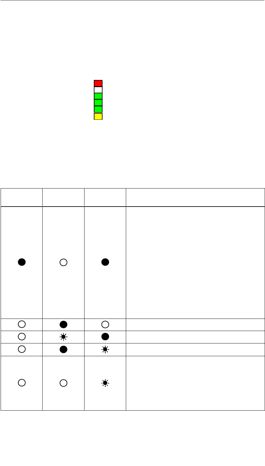
LEDs Displaying the CP Operating Mode
The different combinations of the LEDs on the front panel indicate the operating
mode:
Table 13-1
SF(red) RUN(green) STOP
(yellow) CP Operating Mode
SStarting up after power up
The startup behavior differs depending on the
configuration as follows:
- Ethernet cable inserted
After a few seconds, the CP also signals the
existing connection to ITP/TP with the LINK
LED. The CP then changes to RUN mode.
- Ethernet cable not inserted
After 10 seconds, the CP changes to the
“Ready to begin firmware download” status.
or
SStopped (STOP) with errors
In this state, the CPU or intelligent modules in the
rack remain accessible using PG functions.
Running (RUN)
Starting up (STOP->RUN)
Stopping (RUN->STOP)
Ready to begin firmware download (this mode is
active for approximately 15 seconds)
This mode is activated after the “Starting up after
power on” mode if the Ethernet cable was previously
removed.
During this phase, the Ethernet cable must be inserted
again and the firmware download started.

4 Displays
B8-12 CP 343-1 Lean / Manual Part B8
Release 08/2004
C79000-G8976-C198-01
Table 13-1 , continued
SF(red) CP Operating ModeSTOP
(yellow)
RUN(green)
Waiting for firmware update (CP currently has an
incomplete or incorrect firmware version)
Stopped (STOP)
In the STOP mode configuring and performing
diagnostics on the CP remain possible.
Legend: on off flashing
LED Display of the CP Communication status
In addition to the LEDs that signal the CP mode, the front panel also includes
LEDs that provide information about the status of the CP interface to Industrial
Ethernet.
Table 13-2
LED Meaning
LINK LED (green) On: Indicates an established connection to TP
RX/TX LED (green) Flashing: CP sending/receiving via TP

5 Performance Data
B8-13
CP 343-1 Lean / Manual Part B8
Release 08/2004
C79000-G8976-C198-01
5 Performance Data
5.1 General Characteristics
Table 14-1
Characteristic Explanation / Values
Number of simultaneous connections in total over
Industrial Ethernet Maximum 12
Example of Maximum Load
You can operate:
4 S7 connections
4 ISO-on-TCP connections
2 TCP connections
2 UDP connections
5.2 Characteristics of S7 Communication
Table 14-2
Characteristic Explanation / Values
Number of connections for S7 communication on
Industrial Ethernet in each case, up to
S4 Operator control and monitoring functions
(HMI)
S4 S7 connections configured at one end
The number depends on the CPU type being used.
Please refer to /1/ for the values for your CPU.
LAN interface - data record length per PDU
SSending
SReceiving 240 bytes / PDU
240 bytes / PDU

5 Performance Data
B8-14 CP 343-1 Lean / Manual Part B8
Release 08/2004
C79000-G8976-C198-01
5.3 Characteristics of the SEND/RECEIVE Interface
Table 14-3
Characteristic Explanation / Values
Total number of ISO-on-TCP connections + TCP
connections Maximum 8
Total number of UDP connections Maximum 8
Notes:
SAll UDP connections are also possible in the
multicast mode
SFree UDP connections (program-controlled
addressing of the communication partner) are
not supported by the CP.
Maximum data length for blocks AG_SEND (V4.2
and higher) and AG_RECV (V4.7 and higher) AG_SEND and AG_RECV allow the transfer of
data fields of between 1 and 240 bytes.
S1 to 8192 bytes for
ISO-on-TCP, TCP;
S1 to 2048 bytes for UDP
Restrictions for UDP
STransfer is not confirmed The transmission of UDP frames is unconfirmed, in
other words the loss of messages is not detected
or displayed by the send blocks (AG_SEND).
SData field length The maximum length of the data fields is 2048
bytes.
SNo reception of UDP broadcast To avoid overload resulting from a high broadcast
load, the CP does not permit reception of UDP
broadcast.
Reaction Times of ISO-on-TCP and TCP Connections
The calculation of the reaction times with ISO-on-TCP or TCP connections is
determined by the run time of the function blocks required on the S7-300 CPU
(AG_SEND, AG_RECV).
Table 14-4
Component Explanation / Values
Run time in the CPU 314-1 per block
AG_SEND, AG_RECV:
2.5 ms to 5 ms

6 Further Notes on Operation
B8-15
CP 343-1 Lean / Manual Part B8
Release 08/2004
C79000-G8976-C198-01
6 Further Notes on Operation
6.1 Memory Reset
Available Functions
The CP has a two-level function available for resetting memory:
SClear / reset
Following this memory reset, the CP retains the preset MAC address and the
retentive parameters. The CP is therefore immediately ready for downloads
using the IP address.
The retentive parameters include:
- IP address and IP parameters
- LAN settings
SResetting to factory settings
After this memory reset, the CP retains only the factory-set MAC address (as
shipped).
Note
Using the functions described here to reset the memory, you do not modify the
configuration data on the CPU!
If you subsequently upload the configuration data from the CPU to a PG you will
always obtain the configuration data that were previously on the CP (with
parameters, connections, IP address).
How to Use the Function
You can start the memory reset functions in STEP 7.
SClear / reset
In STEP 7/HW Config with PLC " Clear/Reset
or
In STEP 7 / NCM Diagnostics with Operating Mode " Clear/Reset Module
SFactory defaults reset
In STEP 7 / NCM Diagnostics with Operating Mode " Reset to Factory
Defaults

6 Further Notes on Operation
B8-16 CP 343-1 Lean / Manual Part B8
Release 08/2004
C79000-G8976-C198-01
Behavior after Memory Reset
The CPU in the S7 station does not recognize that the CP memory was reset. The
CP therefore changes to the “stopped with error” state (see Chapter 4).
The configuration data must then be reloaded.
if the configuration data are stored on the CPU, you can start a download with
power down/up.
6.2 Working with Fast Ethernet - automatic switchover
How Autosensing and Autonegotiation Work
The CP has a 10/100 Mbps full duplex interface with autosensing and
autonegotiation of the network settings. After turning on the CP, these functions
work as explained below:
The CP attempts to detect the transmission rate used by the partner.
If detection is possible, the CP attempts to negotiate an optimum duplex mode
with the partner.
If no negotiation is possible, the CP uses the previously detected transmission
rate and half duplex.
Time required: 2 seconds
Automatic Setting or Individual Network Settings
As default, the CP is configured for automatic detection. As soon as you define a
configuration manually when configuring the CP with STEP 7/HW Config (in the
properties dialog of the CP - ”Options” tab), the automatic switchover is no longer
effective.
Further Notes:
S10/100 Mbps network components without “Autonegotiation”
If you use 10/100 Mbps network components that do not support
“Autonegotiation”, you may have to set the mode manually during CP
configuration using STEP 7 / HW Config (in the properties dialog of the CP). As
default, the CP is configured for automatic detection.
SForcing a specific mode instead of “Autonegotiation”
If your application requires a fixed mode instead of “Autonegotiation”, you will
need to match up the partner devices.
SNo reaction to Autonegotiation query with manual configuration
Remember that if you configure the CP manually, it will not react to an

6 Further Notes on Operation
B8-17
CP 343-1 Lean / Manual Part B8
Release 08/2004
C79000-G8976-C198-01
autonegotiation query! As a result, a connected partner will not be able to set
the required mode and communication will not be ideal.
Example:
If, for example, the CP is set to “100 Mbps - full duplex”, a CP connected as
partner will set “100 Mbps - half duplex”. Reason: Due to the fixed setting, no
autonegotiation response is possible; the connected partner recognizes the 100
Mbps with autosensing but nevertheless remains in half duplex.
SRecommendation: Change “Individual network settings” only over MPI
If you modify the LAN settings using the “Individual network settings” option of
the CP, these changes will be adopted by the CP and activated when the
configuration data is downloaded to the CP.
We therefore recommend that you download configuration data to the S7
station over an MPI connection if you change this setting.
If you download the configuration data over the LAN interface, depending on
the selected setting, it is possible that the current download will not be
completed due to the changes to the configuration taking immediate effect.
NCM Diagnostics displays the operating mode
You will find more information about the currently used network settings in NCM
diagnostics in the diagnostic object “Industrial Ethernet” in the Section “Network
Attachment”.

6 Further Notes on Operation
B8-18 CP 343-1 Lean / Manual Part B8
Release 08/2004
C79000-G8976-C198-01
6.3 FC Call Interface
Status of the FC Call Interface; special situation with FC versions *)
With the FCs AG_SEND (FC5) and AG_RECV (FC6), the following situations
SThe CP is in the STOP mode.
SThe connection is not configured.
SThe connection is not established
SThe connection was aborted;
are indicated by the following codes:
SAG_SEND:
DONE=0; ERROR=0; Status=8181H
or
DONE=0; ERROR=1; Status=8183H
SAG_RECV:
DONE=0; ERROR=0; Status=8180H
or
DONE=0; ERROR=1; Status=8183H
*) valid for FCs with version 4.0 and higher
Calling Communications Blocks for S7-300
Notice
Calling communications blocks for S7-300 (SIMATIC NET block libraries for
S7-300 in STEP 7) in several priority classes is not permitted! If, for example, you
call a communications block in OB1 and in OB35, the block execution could be
interrupted by the higher-priority OB.
If you call the blocks in several OBs, you must write your program so that an
executing communication block cannot be interrupted by another communication
block (for example, by disabling/enabling SFC alarms).
Changing Call Parameters only after Job Confirmation
Notice
After a job has been triggered, you may only change the call parameters on the
FC call interface of the FCs AG_SEND or AG_RECV again after the FC has
confirmed job execution with DONE=1 or ERROR=1.
If you do not keep to this, it is possible that the job will be aborted with an error.

6 Further Notes on Operation
B8-19
CP 343-1 Lean / Manual Part B8
Release 08/2004
C79000-G8976-C198-01
6.4 SNMP Agent
SNMP (Simple Network Management Protocol)
The CP supports data queries over SNMP in version 1.
SNMP is protocol language for managing networks and is easy to handle. To
transmit data, SNMP uses the connectionless UDP protocol.
The information on the properties of SNMP-compliant devices is entered in MIB
files (MIB = Managed Information Base). For more detailed information on working
with MIB files, refer to the documentation of the SNMP client you are using
(example of an SNMP client: SNMP OPC Server from SIMATIC NET).
Supported MIB Objects
The CP supports all MIB objects of the standard MIB according to MIB II (RFC
1213).
Exceptions / restrictions:
SWrite access is permitted only for the following MIB objects:
sysContact, sysLocation and sysName;
For security reasons, only read access is permitted for all other MIB objects.
STraps are not supported by the CP.
Access Permissions using Community Name
The CP uses the following community names for assigning permissions:
SFor read access: “public”
Sfor read and write access: “private”
(note the use of lower-case letters!)

6 Further Notes on Operation
B8-20 CP 343-1 Lean / Manual Part B8
Release 08/2004
C79000-G8976-C198-01
6.5 Possible Security Gaps on Standard IT Interfaces /
Preventing Illegal Access
With various SIMATIC NET components, such as OSMs/ESMs, a wide range of
parameter assignment and diagnostic functions (for example, Web servers,
network management) are available over open protocols and interfaces. The
possibility of unauthorized misuse of these open protocols and interfaces by third
parties, for example to manipulate data, cannot be entirely excluded.
When using the functions listed above and these open interfaces and protocols (for
example, SNMP, HTTP, Telnet), you should take suitable security measures to
prevent unauthorized access to the components and the network particularly from
within the WAN/Internet.
Notice
We expressly point out that automation networks must be isolated from the rest of
the company network by suitable gateways (for example using tried and tested
firewall systems). We do not accept any liability whatsoever, whatever the legal
justification, for damage resulting from non-adherence to this notice.
If you have questions on the use of firewall systems and IT security, please contact
your local Siemens office or representative. You will find the address in the
SIMATIC NET Catalog IK PI or on the Internet at
http://www.siemens.de/automation/partner
6.6 Influence of MPI on Connections via Industrial Ethernet
If a station on MPI is added or removed, for example because a service PG has
been connected or disconnected, it is possible that all the connections on the
communications bus are aborted. This has the following effects on the
communication connections on Industrial Ethernet:
SAll S7 connections are temporarily aborted.
SThe connections on which a job on the communication bus with a data length >
240 bytes is being processed are aborted temporarily.
SFETCH/WRITE connections are temporarily aborted.
The return values must be handled accordingly on the FC interface in the user
program.

6 Further Notes on Operation
B8-21
CP 343-1 Lean / Manual Part B8
Release 08/2004
C79000-G8976-C198-01
6.7 Other Information Available about the CP
You will find detailed information (FAQs) on using the CP described here on the
Internet under the following entry number:
http://www4.ad.siemens.de/view/cs/en/10806025

7 How to Load New Firmware
B8-22 CP 343-1 Lean / Manual Part B8
Release 08/2004
C79000-G8976-C198-01
7 How to Load New Firmware
Requirements
You download new firmware to a SIMATIC NET CP using the firmware loader
shipped with STEP 7 / NCM S7.
Requirements for Downloading
STo download firmware, you require an Industrial Ethernet CP module in the
PG/PC (for example, CP 1613) or other Ethernet module with the “Softnet”
software package.
SThe S7-ONLINE interface must be set to the ”ISO - Industrial Ethernet”
protocol. It is not possible to download using TCP/IP (and therefore not to other
networks).
How to Download New Firmware
You must always run the download using the MAC address of the CP!
What to do if a Download is Interrupted
Disturbances or collisions on the network can lead to packets being lost. In such
cases, this can lead to an interruption of the firmware download. The firmware
loader then signals a timeout or negative response from the module being loaded.
In this case, repeat the download.
If you cannot start the download again with the preset MAC address following an
aborted attempt, follow the steps below:
1. Remove the Ethernet cable from the device.
2. Turn the entire rack off and on again.
The LEDs of the CP now indicate ”Starting up after power up” for 10 seconds.
Following this, the LED display ”Ready for start of firmware download” is
displayed for a further 15 seconds. During this time, take the following two
actions:
3. Connect the CP to Industrial Ethernet again.
4. Restart the firmware download.

8 Technical Specifications
B8-23
CP 343-1 Lean / Manual Part B8
Release 08/2004
C79000-G8976-C198-01
8 Technical Specifications
Table 17-1 Technical Specifications
Transmission rate 10 Mbps and 100 Mbps
Interfaces
Attachment to Twisted Pair RJ-45 jack
Power supply DC +24 V (permitted range: +20.4 V to +28.8 V)
Current consumption
Sfrom backplane bus
Sfrom external 24 V DC
200 mA maximum
TP: approx. 0.2 A maximum
Power loss approx. 5.8 W
Permitted ambient conditions
SOperating temperature
STransportation/storage
temperature
SRelative humidity max.
SAltitude
0 °C to +60 °C
-40 °C to +70 °C
95% at +25 °C
up to 2000 m above sea level
Design
SModule format
SDimensions (W x H x D) in mm
SWeight approx.
Compact module S7-300; single width
40 x 125 x 120
220 g
In addition to this, all the information in the S7-300 reference manual /1/ ”Module
Data” in the section ”General Technical Specification” on the topics listed below
applies to the CP:
SElectromagnetic compatibility
STransportation and storage conditions
SMechanical and climatic ambient conditions
SInsulation tests, class of protection and degree of protection
