M_S2567_101 If Not Then M S2567 101
User Manual: If not then Manual: ftp://ftp.tyan.com/manuals/m_s2567_101
Open the PDF directly: View PDF ![]() .
.
Page Count: 60

Thunder HEsl
S2567
Motherboard User’s Manual
Revision 1.01
Copyright © Tyan Computer Corporation, 2001. All rights reserved. No part of this
manual may be reproduced or translated without prior written consent from Tyan
Computer Corp.
All registered and unregistered trademarks and company names contained in this
manual are property of their respective owners including, but not limited to the fol-
lowing.
Tyan, Thunder HEsl S2567 are trademarks of Tyan Computer Corporation.
AMI BIOS is a trademark of American Megatrends, Inc.
Windows is a trademark of Microsoft Corporation.
IBM, PC, AT, PS/2 are trademarks of IBM Corporation.
Intel, Pentium III are registered trademarks of Intel Corporation.
ServerWorks, ServerSet HE-SL are trademarks of ServerWorks Corporation.
LSI, Symbios are trademarks of LSI Logic Corporation.
Creative Labs is a trademark of Creative Technology Ltd.
SST is a trademark of Silicon Storage Technology, Inc.
Information contained in this document is furnished by Tyan Computer Corpora-
tion and has been reviewed for accuracy and reliability prior to printing. Tyan
assumes no liability whatsoever, and disclaims any express or implied warranty,
relating to sale and/or use of Tyan products including liability or warranties relating
to fitness for a particular purpose or merchantability. Tyan retains the right to make
changes to product descriptions and/or specifications at any time, without notice.
In no event will Tyan be held liable for any direct or indirect, incidental or conse-
quential damage, loss of use, loss of data or other malady resulting from errors or
inaccuracies of information contained in this document.
TM

http://www.tyan.com
2
Overview ....................................................................................................................4
Hardware Specifications ............................................................................................5
Software Specifications ..............................................................................................6
Technical Support ......................................................................................................7
Returning Merchandise for Service ............................................................................7
Chapter 1: Introduction
Chapter 2: Board Installation
Chapter 3: BIOS Setup
Front Panel Connector .............................................................................................12
CMOS Reset ............................................................................................................12
CPU Front Side Bus .................................................................................................13
Cooling Fans ............................................................................................................13
LAN Enable/Disable .................................................................................................13
Wake on LAN* ..........................................................................................................13
Wake on Modem/Ring* ............................................................................................13
Chassis Intrusion* ....................................................................................................13
Internal USB** ..........................................................................................................13
Spread Spectrum .....................................................................................................14
Speaker Connector ..................................................................................................14
CD, Video, Mono, and MPEG Input Connectors** ...................................................14
Server Management Connector** ............................................................................14
Reserved Serial Connector ......................................................................................14
External SCSI LED ...................................................................................................14
Soft Power Connector ..............................................................................................14
Hardware Reset Switch Connector Installation ........................................................14
Flash Utility ..............................................................................................................14
Unpacking ..................................................................................................................8
Installation ..................................................................................................................8
How to install our products right... the first time ..........................................................8
Quick Reference for Jumpers ..................................................................................10
Map of Motherboard Jumpers ..................................................................................11
Setting Jumpers .......................................................................................................12
Introduction to the BIOS Setup .................................................................................27
Starting Setup ..........................................................................................................27
Setup Keys ...............................................................................................................28
Getting Help .............................................................................................................28
In Case of Problems .................................................................................................28
Setup Variations .......................................................................................................28
Mounting the Motherboard in the Chassis ................................................................15
Installing Memory .....................................................................................................16
Installing the CPU and Cooling Fan .........................................................................18
Connecting IDE and Floppy Drives ..........................................................................20
Installing Add-on Cards ............................................................................................22
Connecting PS/2, USB, Serial and Parallel Ports .....................................................24
Connecting the Power Supply ..................................................................................25
Frequently Asked Questions (FAQ) .........................................................................26
.............................................................
.............................................................
....................................................................
Page 4
8
2.1
2.2
2.3
2.4
2.5
2.6
1.1
1.2
1.3
1.4
1.5
2.6-A
2.6-B
2.6-C
2.6-D
2.6-E
2.6-F
2.6-G
2.6-H
2.6-I
2.6-J
2.6-K
2.6-L
2.6-M
2.6-N
2.6-O
2.6-P
2.6-Q
2.6-R
2.7
2.8
2.9
2.10
2.11
2.12
2.13
2.14
27
Table of Contents
Main Setup ...............................................................................................................293.1
3.2-A
3.2-B
3.2-C
3.2-D
3.2-E
Configure SuperIO Configuration .............................................................................30
IDE Configuration .....................................................................................................30
Floppy Configuration ................................................................................................31
Boot Setting Configuration .......................................................................................32
Event Log Configuration* .........................................................................................33
Advanced Setup .......................................................................................................293.2
3.1-A
3.1-B System Date/Time ...................................................................................................29
General Help ............................................................................................................29

Thunder HEsl S2567 3
Chapter 4: System Resources
Beep Codes .............................................................................................................39
Displayed Error Messages .......................................................................................39
.......................................................
Appendix II: Glossary
39
41.......................................................................
4.1
4.2
3.3
3.4
3.5
3.6
3.7
3.8
3.9
Chipset Setup ..........................................................................................................34
PCI/PnP Menu .........................................................................................................35
Power Menu .............................................................................................................36
Boot Menu ................................................................................................................37
Security Menu ..........................................................................................................37
Exit Menu .................................................................................................................37
Flash Utility ..............................................................................................................38
Appendix I: SCSI Installation and LAN Information 42......................
Introduction ..............................................................................................................42
Features of the LSI Symbios SCSI BIOS .................................................................42
Legacy Support for non-Ultra160 SCSI devices .......................................................42
Setting up internal SCSI peripherals ........................................................................42
Checking SCSI IDs ..................................................................................................42
Terminating SCSI devices ........................................................................................42
Connecting SCSI Peripherals ..................................................................................42
Connecting internal cables for Ultra160 LVD SCSI devices .....................................42
Information on the LSI Symbios 53C1010 SCSI BIOS .............................................44
Boot Initialization with BIOS Boot Specification (BBS) .............................................44
CD-ROM Boot Initialization ......................................................................................44
Starting the SCSI BIOS Configuration Utility ............................................................44
Error Messages ........................................................................................................45
Using the Configuration Utility ..................................................................................45
Main Menu ...............................................................................................................46
Boot Adapter List ......................................................................................................47
Global Properties .....................................................................................................48
Adapter Properties ...................................................................................................49
Device Properties .....................................................................................................51
Quitting the SCSI BIOS Configuration Utility ............................................................52
LAN Information .......................................................................................................53
3.2-F
3.2-G Peripheral Device Configuration ..............................................................................33
Remote Access Configuration ..................................................................................33
* not verified at time of print, check Tyan website for updates: http://www.tyan.com
** optional feature available on some Thunder HEsl models

http://www.tyan.com
4
Chapter 1: Introduction
1.1 Overview
The Thunder HEsl™ is designed for mission critical applications that require the power of dual Intel®
Pentium® III FC-PGA processors*. This motherboard utilizes the ServerWorks ServerSet HE-SL chipset
and can support CPU speeds of 500 MHz through 1 GHz and front side bus speeds* of 100 MHz or 133
MHz. Please see Tyan’s website for updates and information concerning CPU information and support:
http://www.tyan.com
This integrated performance board is supported in an ATX form factor. Some of the features included are
onboard UltraDMA-compatible** support, and hardware monitoring.
With I/O and drive controller support onboard, the one 2x mode AGP Pro slot, two 64-bit/66MHz^ 3.3V
slots, four 64-bit/32-bit 33MHz 5.0V PCI slots, and one ISA slot (shared with a PCI slot) are free for
numerous types of add-on expansion cards. The four 168-pin DIMM sockets can support up to 4GB of
PC133 Registered SDRAM, with the option of ECC support.
Remember to visit Tyan’s website at http://www.tyan.com. There you can find information on all of
Tyan’s products with FAQs, distributors list, and BIOS settings explanations.
** UltraDMA-33/66 devices are supported although UDMA-33/66 transfer speeds are not reachable at this
time
* 66 MHz FSB is NOT SUPPORTED due to its technological limitations. For CPU compatibility updates
and information check the Tyan website: http://www.tyan.com
^ if 100MHz FSB CPU and/or 33MHz PCI card is used, the PCI bus will not run at 66MHz

Thunder HEsl S2567 5
1.2 Hardware Specifications
Dual ZIF PGA370 Socket
Intel Pentium III FC-PGA*
Two onboard VRMs
Front side bus support* for 100 or 133MHz
One 2x mode AGP Pro slot
Two fully independent 64-bit PCI buses
Two 64-bit/66MHz 3.3V PCI slots^^
Four 64-bit/32-bit 33MHz 5.0V PCI slots
One ISA slot (shared w/ a PCI slot)
ServerWorks ServerSet HE-SL chipset
Integrated IOAPIC supports full 32-APIC entries
SMC FDC37B787 Super I/O chip
3-pin fan monitoring headers
2-pin chassis intrusion header
CPU temperature and voltage monitoring
3-pin Wake on Modem header***
3-pin Wake on LAN header***
One floppy connector supports up to two drives
Two 9-pin 16550UART serial ports
One 25-pin SPP/ECP/EPP parallel port
Two USB ports
PS/2 mouse and keyboard ports
Four 168-pin 3.3V DIMM sockets
Supports up to 4GB PC100/133 Registered SDRAM
Supports ECC (72-bit) type memory modules
Expansion Slots^^
Chipset Information
System Management
Memory
Integrated I/O
Processor Information
Integrated PCI IDE Two channel master mode
Supports up to four Enhanced IDE devices
Support for UltraDMA-compatible** IDE devices and
ATAPI compliant devices
** UltraDMA-33/66 devices are supported although UDMA-33/66 transfer speeds are not reachable at
this time
Intel 82559 LAN controller
10/100Mbps data transfer rate
Integrated LAN
Controller
LSI Symbios 53C1010 chipset
Dual-channel Ultra160 SCSI support
160Mbps maximum data transfer rate
Supports up to 15 LVD SCSI devices per channel
Channel A: 68-pin connector
Channel B: 68-pin connector
Integrated SCSI
Controller^
* 66 MHz FSB is NOT SUPPORTED due to its technological limitations. For CPU compatibility updates
and information check the Tyan website: http://www.tyan.com
*** not verified at time of print, check Tyan website for updates: http://www.tyan.com
^ SCSI limited to 33MHz
^^ if 100MHz FSB CPU and/or 33MHz PCI card is used, the PCI bus will not run at 66MHz
INTRO

http://www.tyan.com
6
1.3 Software Specifications
Windows NT/2000OS
Extended ATX 2.03 12” x 13” (304.8 x 330.2 mm)
Dual 20-pin ATX power connectors
Stacked mouse & keyboard ports
Stacked two USB ports & one RJ-45 LAN port w/ LEDs
Stacked two serial ports & one parallel port
Stacked Line-in/Line-out/Mic-in ports & Game/MIDI port
FCC Class B (Declaration of Conformity)
European Community CE (Declaration of Conformity)
Form Factor
Regulatory
AMI BIOS 4 Mbit Flash
Auto-detection of memory size
Auto-configuration of IDE hard disk types
User settings of hardware monitoring
Multiple boot options
DMI 2.0 compliant
BIOS
Creative Labs PCI ES1373 sound
AC’97 codec
Line-in, Line-out, Mic-in, and Game/MIDI ports
4-pin CD-ROM audio header (ATAPI)
Integrated Audio
(manufacturing option)

Thunder HEsl S2567 7
1.4 Technical Support
If a problem arises with your system, you should turn to your dealer for help first. Your system has most
likely been configured by them, and they should have the best idea of what hardware and software your
system contains. Hence, they should be of the most assistance. Furthermore, if you purchased your sys-
tem from a dealer near you, you can actually bring your system to them to have it serviced, instead of
attempting to do so yourself (which can have expensive consequences).
Help Resources:
1.5 Returning Merchandise for Service
During the warranty period, contact your distributor or system vendor FIRST for any product problems.
This warranty only covers normal customer use and does not cover damages incurred during shipping or
failure due to the alteration, misuse, abuse, or improper maintenance of products.
NOTE: A receipt or copy of your invoice marked with the date of purchase is required before any
warranty service can be rendered. You may obtain service by calling the manufacturer for a
Return Merchandise Authorization (RMA) number. The RMA number should be prominently dis-
played on the outside of the shipping carton and the package should be mailed prepaid. Tyan will
pay to have the board shipped back to you.
1. See the FAQ and beep codes section of this manual.
2. See the Tyan website for FAQ, bulletins, driver updates, and other
information: http://www.tyan.com
3. Contact your dealer for help BEFORE calling Tyan.
4. Check the Tyan user group: alt.comp.periphs.mainboard.tyan
INTRO
http://www.tyan.com
8
Chapter 2: Board Installation
2.1 Unpacking
The retail motherboard package should contain the following:
2.2 Installation
You are now ready to install your motherboard. The mounting hole pattern of the motherboard matches
the ATX board specifications, so your chassis must be capable of supporting an Extended ATX board
(check the motherboard dimensions provided on p. 6).
2.3 How to install our products right.. the first time.
Question: what’s the first thing I should do?
The first thing you should do is read the user’s manual. It contains important information which will make
configuration and setup much easier, as well as provide information on device installation and component
set up.. By reading through the manual completely before installing your motherboard, you will have a
complete overview on the installation.
Thunder HEsl motherboard
34-pin floppy cable
Thunder HEsl user’s manual
Tyan driver CD
UDMA IDE cable
* if you require a different I/O shield solution, please contact your chassis vendor
I/O shield*
68-pin Ultra160 LVD SCSI cable (optional)
(2) LSI SYM1010 SCSI Driver Disks

Thunder HEsl S2567 9
Here are some safety tips:
(1) Ground yourself properly before removing your motherboard from the antistatic bag. Unplug
the power from your computer power supply and touch any metal part on the computer case. (You
might also want to wear a grounded wrist strap.)
(2) Hold the motherboard by its edges and do not touch the bottom of the board.
(3) Avoid touching motherboard components, IC chips, connectors, and leads.
(4) Avoid touching pins of memory modules and chips.
(5) Place motherboard on a grounded antistatic surface or on the antistatic bag.
Having reviewed the precautions above, the next step is to take the motherboard out of the cardboard box
and static bag, hold it by its edges, and place it on a grounded antistatic surface, component side up.
Inspect the board for damage.
Press down on any of the socketed ICs if it appears that they are not properly seated (the board should
still be on an antistatic mat). Do not touch the bottom of the board. Remember, don’t take any electronic
device out of its protective bag until you are ready to actually install it into the computer case. If you do not
ground yourself, you risk zapping the motherboard or adapter card. Subsequent problems may not arise
immediately because electrostatic discharge, unlike physical damage, causes the device to fail over time.
Installation Steps
1. Set jumpers (if necessary)
2. Mount motherboard in chassis
3. Install memory
4. Install CPU and cooling fan(s)
5. Connect IDE and floppy drives
6. Install add-on cards
7. Connect PS/2, USB, and serial devices
NOTE: DO NOT APPLY POWER TO THE BOARD IF IT HAS BEEN DAMAGED!
INSTALL
http://www.tyan.com
10
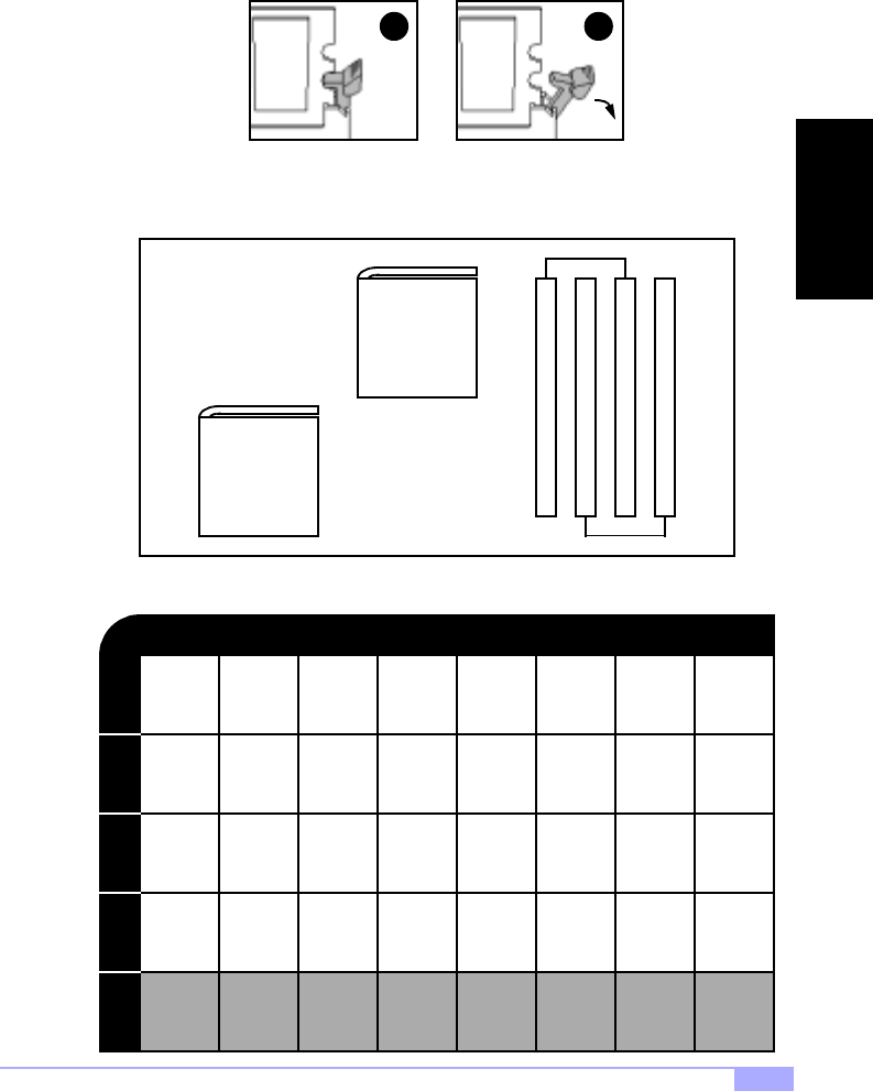
2.4 Quick References for Jumpers
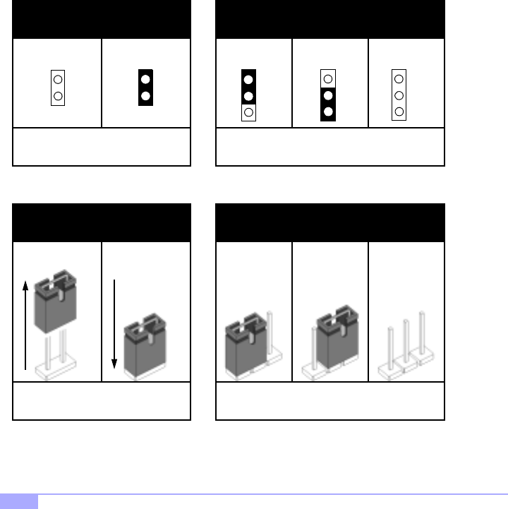
In this manual, the term “closed” and “on” are used when referring to jumpers (or jumper pins) that are
active; “open” and “off” are used when referring to jumpers (or jumper pins) that are inactive. See Figure
2.0a and Figure 2.0c for examples of “on” and “off” pins and jumpers.
Jumpers and pins are connected by slipping the plastic jumper connector over the top of two adjacent
jumper pins (indicated by 1-2 or 2-3). The metal rod inside the plastic shell bridges the gap between the
two pins, completing the circuit. See Figure 2.0b and Figure 2.0d for more examples of 3-pin jumper
connections. NOTE: The small number “1” indicates pin 1.
The tables and maps on the following pages will help you set the jumpers for CPU speed, infrared, and
external connector pin assignments, among others. The miniature motherboard maps will help you locate
the jumpers on your board. Full page maps of the motherboard can be found on the next two pages.
2-pin jumpers
Figure 2.0a
(overhead view)
3-pin jumpers
Figure 2.0b
(overhead view)
off on 1-2 2-3 open
1
2
3
1
2
3
1
2
3
Figure 2.0c
(front angle view) Figure 2.0d
(front angle view)
1-2 2-3 openoff on
2-pin jumpers 3-pin jumpers
11
Thunder HEsl S2567 11
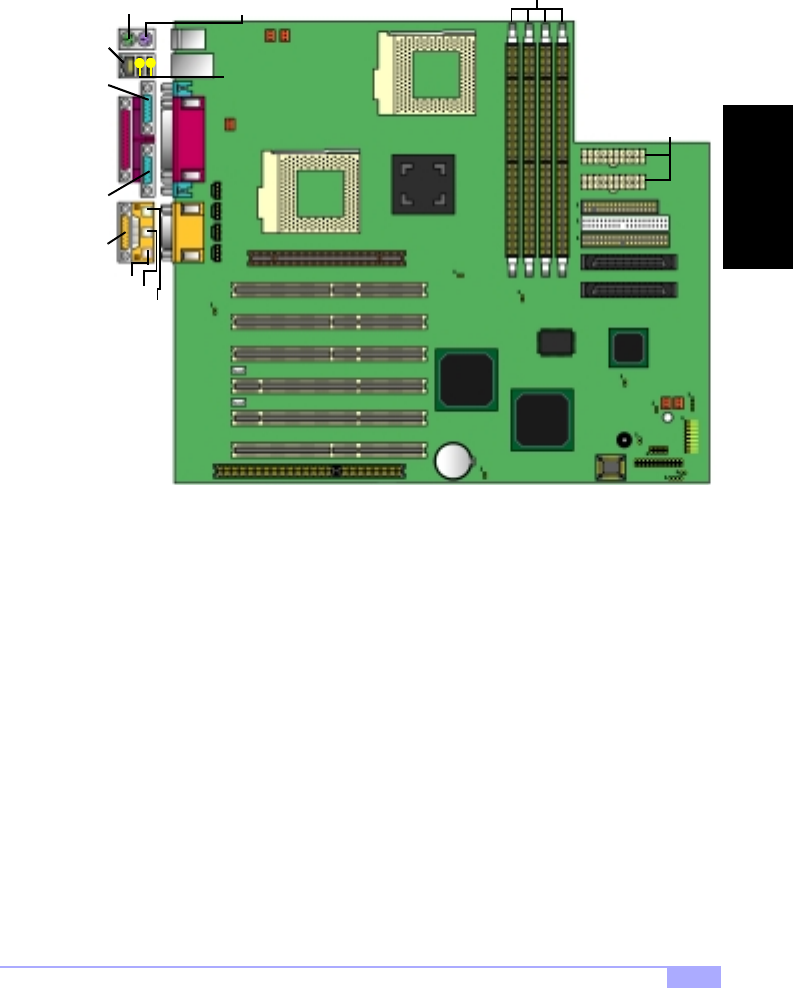
2.5 Map of Motherboard Jumpers
Serial
port
Serial
port
Keyboard port
(lower port) Mouse port
(upper port)
ServerWorks
ServerSet
HE-SL
FAN2
FDD
ATX Power
Connectors
Battery
USB
Ports
WOR**
2x AGP Pro slot
J22**
Buzzer
FAN4
WOL**
Parallel
port
CPU1
CPU2
LAN
port
Game/
Midi port*
Mic-in*
Line-in*
Line-out*
MPEG IN*
FAN3
FAN5
SIDE
PIDE
CH A
CH B
FAN1
USB4^
JP20^
J29
JP12
J27
J32
JP13
ISA Slot
JP9
JP3
JP1
(4) DIMM
Sockets
J25
CD IN*
Video
IN*
Mono IN*
J24
AMI
4Mbit
BIOS
* optional feature available on some Thunder HEsl models
Creative Labs
ES1373*
** not verified at time of print, check Tyan website for updates: http://www.tyan.com
^ reserved feature
INSTALL
http://www.tyan.com
12
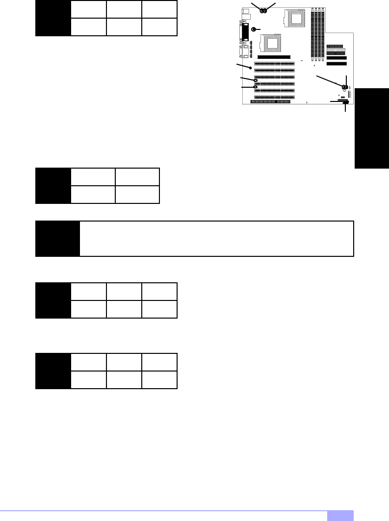
2.6 Setting Jumpers
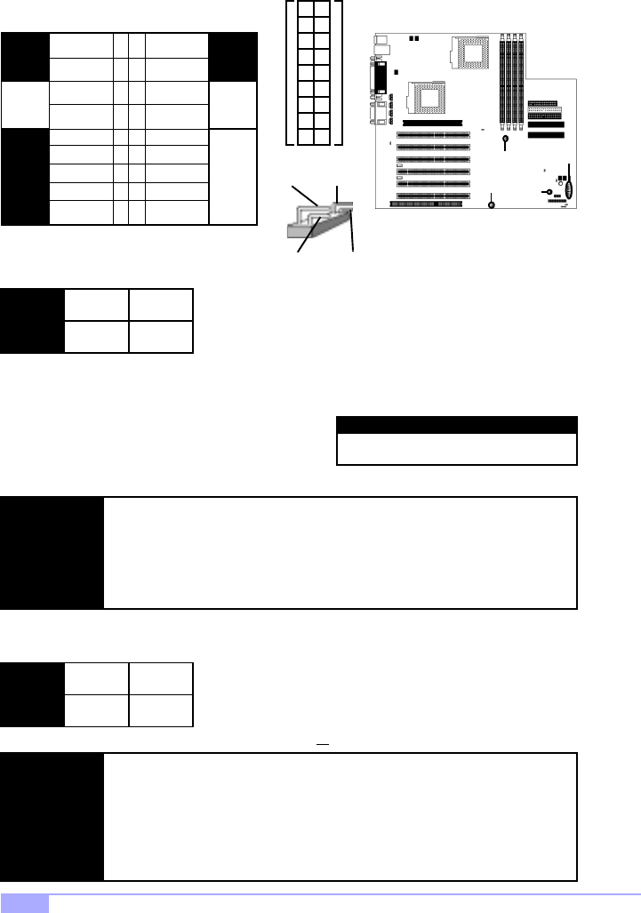
2.6-A. Front Panel Connector (J24)
2.6-B. CMOS Reset (JP13)
If you have been locked out of your system because you forgot your password or set the CMOS incor-
rectly, or have just finished flashing your BIOS follow the instructions below.
By following this procedure, you will erase your password and reset the CMOS.
2.6-C. CPU Front Side Bus Jumper (JP1)
With this jumper, the CPU’s FSB can be set to either 100 or 133MHz.
1. Power off the system, and disconnect the power supply
2. Close JP13 (see mini-map for location of JP13)
3. Wait about three seconds
4. Open JP13, then power on the system again
JP13 open
Normal
closed
Clear
HDD
LED
LED
Reset
Switch
Infrered
Pwr/Slp
LEDs
Power
Switch
VCC
Switch
Ground Switch
Ground
Pwr LED+
Slp LED+
IR +5V
IR RX
Ground
no connect
+5VCC
no connect
IR TX
CHIN2
no connect
no connect
34
56
11 12
78
910
13 14
15 16
17 18
12
J24
JP13
JP1
NOTE:
If you have a non-retail/engineering sample CPU, you will also need to close J29
(see mini-map for location of J29) as well as JP13.
Tyan takes no reponsibility and will not be held liable for damage related to opera-
tion of the CPU using different settings from those of the CPU manfacturer’s spec-
ified default settings
NOTE:
Only non-retail/engineering sample CPUs are affected by this jumper. Retail
CPUs have their FSB locked in. If your CPU can only run at 100MHz, opening
JP1 will not make the CPU run at 133MHz.
Tyan takes no reponsibility and will not be held liable for damage related to opera-
tion of the CPU using different settings from those of the CPU manfacturer’s spec-
ified default settings
JP1 close
100MHz
open
133MHz
Pin 17
(top pin)
Pin 18
(bottom
pin)
Pin 1
Pin 2
12
34
56
78
910
11
13
12
14
15 16
17 18
top set of pins
bottom set of pins
J29
IMPORTANT! Check the Flash section
on p.38 for update regarding flashing
NOTE:
Thunder HEsl S2567 13
2.6-D. Cooling Fans (FAN1, FAN2, FAN3, FAN4, FAN5)
In addition to installing your CPU, Tyan highly recommends
that you install a CPU fan/heatsink combination, and if
needed, additional chassis fans. To this end Tyan has
provided several connectors to power the fan(s), as well as
the fan pinout (shown above). Here is some information you
may find useful:
2.6-E. LAN Enable/Disable (JP9)
With this jumper, you can enable or disable the onboard LAN.
2.6-F. Wake on LAN (optional) (WOL)*
This is the connector for the Wake on LAN function.
2.6-G. Wake on Modem/Ring (optional) (WOR)*
This is the connector for the Wake on Modem/Ring function.
2.6-H. Chassis Intrusion (optional) (J22)*
If your chassis supports a feature for chassis intrusion, you can use this connector to use that feature. If
the chassis is opened while this feature is enabled, the user will be notified, depending on how the system
is setup.
2.6-I. Internal USB (reserved) (USB4)
This is a reserved connector for USB functions.
WOR*
USB4
WOL*
J22*
JP9
FAN 1
Ground
2
+12V
3
Speed
- We recommend you use FAN4 for CPU1 and FAN3 for CPU2
- All other fan connectors are left to the user’s discretion
NOTE: Tyan strongly recommends that you disable onboard LAN through the BIOS, rather
than using this jumper.
JP9 close
disable LAN
open
enable LAN
WOL 1
+5VSB
2
Ground
3
WOL
WOR 1
+5VSB
2
Ground
3
WOR
FAN4
FAN5FAN3
FAN2FAN1
* not verified at time of print, check Tyan website for updates: http://www.tyan.com
INSTALL
http://www.tyan.com
14
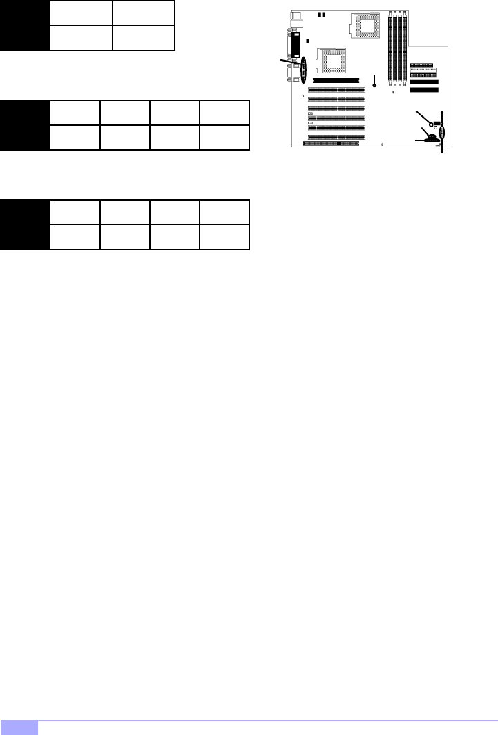
2.6-J. Spread Spectrum (JP3)
This jumper is for EMI-related functions.
2.6-K. Speaker Connector (J27)
This connector allows for connection of an external buzzer.
2.6-L. CD*, Video*, Mono*, and MPEG Input Connectors* (CD IN, Video IN, Mono IN, MPEG IN)
These four pin connectors are reserved for multimedia functions.
2.6-M. Server Management Connector (optional) (J32)*
This is a reserved connector for server management functions.
2.6-N. Reserved Serial Connector (reserved, may or may not be available) (JP20)
2.6-O. External SCSI LED (J25)
Connecting an peripheral to J25 will cause its activity to be displayed on the front panel LED(s).
2.6-P. Soft Power Connector
The soft power connector is part of jumper block J24 (pins 6 to 8). This board uses the chipset for power
management, including turning on and off the system. If the power button function option in the BIOS
Power Management menu is set to “On/Off” (which is the default), pressing the power button once after
the BIOS has booted up will turn the system on and off. If the power button function is set to Suspend,
pressing the power button once will wake up the system or send it to Suspend mode. In this case, you
cannot turn the system off unless you shut down through the Windows operating system or you hold the
power button down for four seconds (BIOS-dependent feature).
2.6-Q. Hardware Reset Switch Connector Installation
The reset switch on your chassis case provides you with the Hardware Reset function, which is the same
as power on/off, except that the system will immediately execute a cold start after the reset button is
pushed. The reset switch needs to be connected to jumper block J24 (pins 5 to 7).
2.6-R. Flash Utility
You can upgrade the BIOS of this motherboard by using the Flash Utility (see p. 38). Check the Tyan web-
site for details: http://www.tyan.com
JP3 close
disable
open
enable
SPK 1
+12V
2
no connect
3
no connect
4
speaker
J24
JP3
J27
INPUT 1
L
2
Ground
3
Ground
4
R
CD IN*
Video IN*
Mono IN*
MPEG IN*
* optional feature available on some Thunder HEsl models
J32
JP20
J25
Thunder HEsl S2567 15
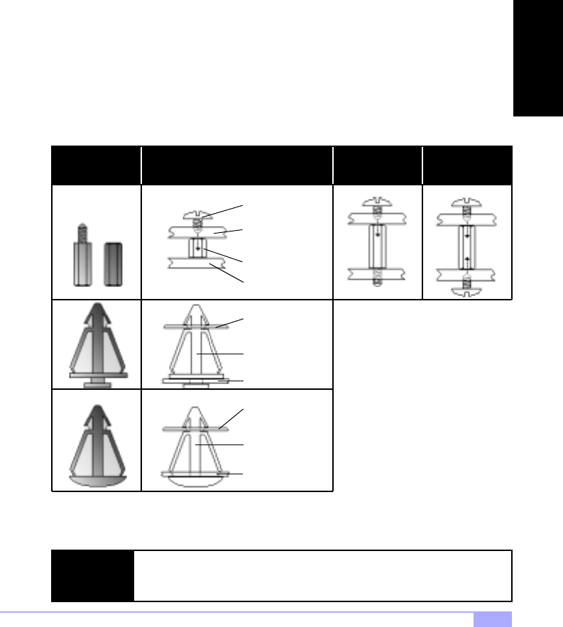
2.7 Mounting the Motherboard into the Chassis
Your chassis may include mounting hardware. If mounting hardware was included, you can use the fol-
lowing examples to help you in installing your motherboard into the chassis.
The chassis may have come with the studs integrated into the chassis wall, so in those cases you would
only need to use screws (possibly included with your chassis) to install the motherboard. See the exam-
ples (Figure 2.0, shown below) for more details.
If the chassis includes mounting hardware without the studs pre-installed, then you will need to install the
motherboard using the mounting hardware as shown in the examples below. Remember not to over-
tighten any of the screws, or you might risk breaking internal traces in the surrounding area, or damage
the motherboard in some other way.
Other examples of how to install your motherboard using other hardware (that may or may not have been
included with your chassis) are shown below.
NOTE: The diagrams above are only representative of a few solutions for installing a
motherboard into the chassis. The installation procedure for installing your moth-
erboard may differ.
chassis wall
stud
screw
motherboard
base
One solution for installing motherboardType of hardware Another solution Another solution
chassis wall
standoff
motherboard
base
chassis wall
standoff
motherboard
base
Figure 2.0
INSTALL
http://www.tyan.com
16
2.8 Installing Memory
Please keep in mind that although some memory modules may appear to be high-quality, they may con-
tain inferior or substandard parts. The type of memory you choose to install should be checked against
the memory compatibility list, which is available from Tyan’s website at http://www.tyan.com
Memory Installation Procedure
Here are some details of memory installation for this board:
At least two registered DIMMs must be installed for the system to POST.
The motherboard supports 64MB, 128MB, 256MB, 512MB, and 1024MB PC133 SDRAM.
DO NOT MIX BUFFERED AND UNBUFFERED MEMORY!
The motherboard supports up to 4GB of registered PC133 memory.
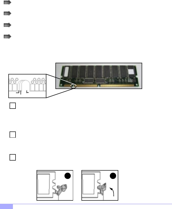
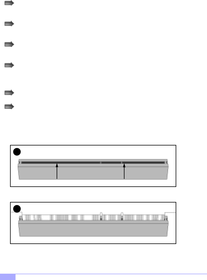
The 168-pin DIMMs (Dual In-line Memory Modules) must be of the 3.3V PC133 registered variety. The
position of the notch in the SDRAM key position will tell you whether or not a DIMM is registered (see Fig-
ure 2.1 below). All installed memory will be automatically detected, so there is no need to set any jump-
ers.
Insert the DIMM by pushing the module into the socket with even force. Do not insert one
end and then the other: install the whole module at once or you might bend the DIMM pins.
Make sure the DIMM is securely seated.
Line your module up so that the pins fit into the socket. There is only one way your DIMM can
fit properly. Make sure that the short row of pins is lined up with the short gap in the DIMM
socket.
Lock the DIMM into place by pushing the clips back on either end of the socket onto the
notches in the ends of the DIMM (see pictures below for details).
2
1
Step
1
Step
2
3
Step
unbuffered
RFU
buffered Figure 2.1
Thunder HEsl S2567 17
Removing a DIMM
Removing a DIMM is just the reverse: simply pull back the clips from the DIMM (see pictures below), and
carefully pull the module straight out. Place the DIMMs in an anti-static bag as soon as you remove them
to avoid static damage.
Memory Configurations
The DIMMs must be installed in a staggered configuration, with two DIMMs as a minimum. The diagram
below shows the two memory banks, and in which configuration they must be filled.
The table below shows some of the possible memory configurations. Not all possible configurations
are listed. Your memory configuration may differ from one or more of the combinations shown below.
21
BANK 0BANK 1BANK 2BANK 3
4GB Total Memory Possible
256MBx1
512MBx1
512MBx1
1024MBx1
0
0
256MBx1
512MBx1
512MB 1024MB
512MBx1
512MBx1
0
0
0
512MBx1
0
1024MB
512MBx1
512MBx1
2048MB
1024MBx1
1024MBx1
1024MBx1
4096MB256MB
128MBx1
128MBx1
0
0
TOTAL
64MBx1
0
64MBx1
0
128MB
512MBx1
1024MBx1
1024MBx1
512MBx1
3072MB
BANK 3
BANK 1
BANK 0
BANK 2
CPU 1
CPU 2
Match these
Match these
INSTALL
http://www.tyan.com
18
2.9 Installing the CPU and Cooling Fan
Intel Pentium III FC-PGA processors* (500 MHz through 1 GHz) can be used on this board. For more
information on CPU compatibility, check Tyan’s website at: http://www.tyan.com.
When installing your CPU, remember the following:
The CPU is a sensitive electronic component and can easily be damaged by static electricity
Do not touch the CPU pins with your fingers
You should be able to insert the CPU into the socket with virtually no force
Do not press down hard on the CPU as you might bend or break pins, or otherwise damage the
CPU
The CPU voltage will automatically be detected by the motherboard, so there is no need to set
any jumpers or BIOS setting.
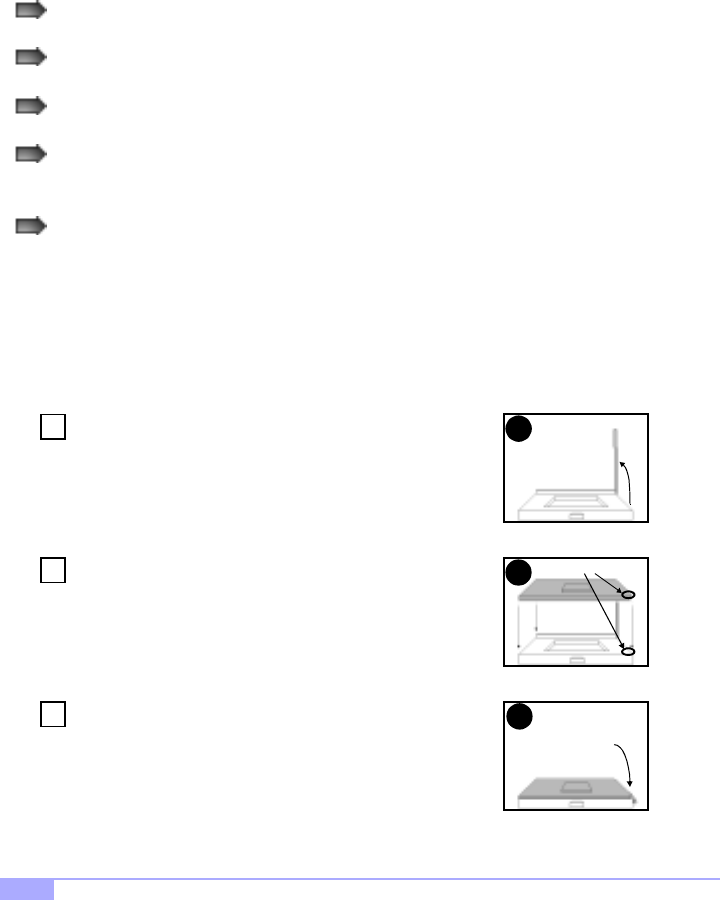
Installing the Intel Pentium III FC-PGA CPU
Before installing the CPU, check it for any visible damage. Make sure none of the pins are bent or miss-
ing. Be sure where the Pin 1 holes are on both the CPU and the socket. The following steps each have a
corresponding picture next to it to help guide you through the installation.
Carefully lift the arm of the ZIF socket until it is at a 90 degree angle
pointing away from the motherboard. Be very careful not to damage
any components that might be next to the socket.
There are two beveled corners on the CPU, which will match the
two angled corners on the socket. Carefully install the CPU by lining
both Pin 1 on the CPU and Pin 1 on the socket, making sure the
pins actually fit into the socket. Do not force the CPU into the
socket: check the pin alignment of CPU pins to socket holes.
Push down lightly on the CPU while lowering the arm on the socket
to secure the CPU (see right). A squeaking noise may be heard
while lowering the arm, or the socket may make a ‘click’ noise when
the arm is locked into position: these noises are normal.
Arm moves down
to lock CPU
Pin 1
1
2
3
2
1
Step
Step
3
Step
* 66 MHz FSB is NOT SUPPORTED due to its technological limitations. For CPU compatibility updates
and information check the Tyan website: http://www.tyan.com
Thunder HEsl S2567 19
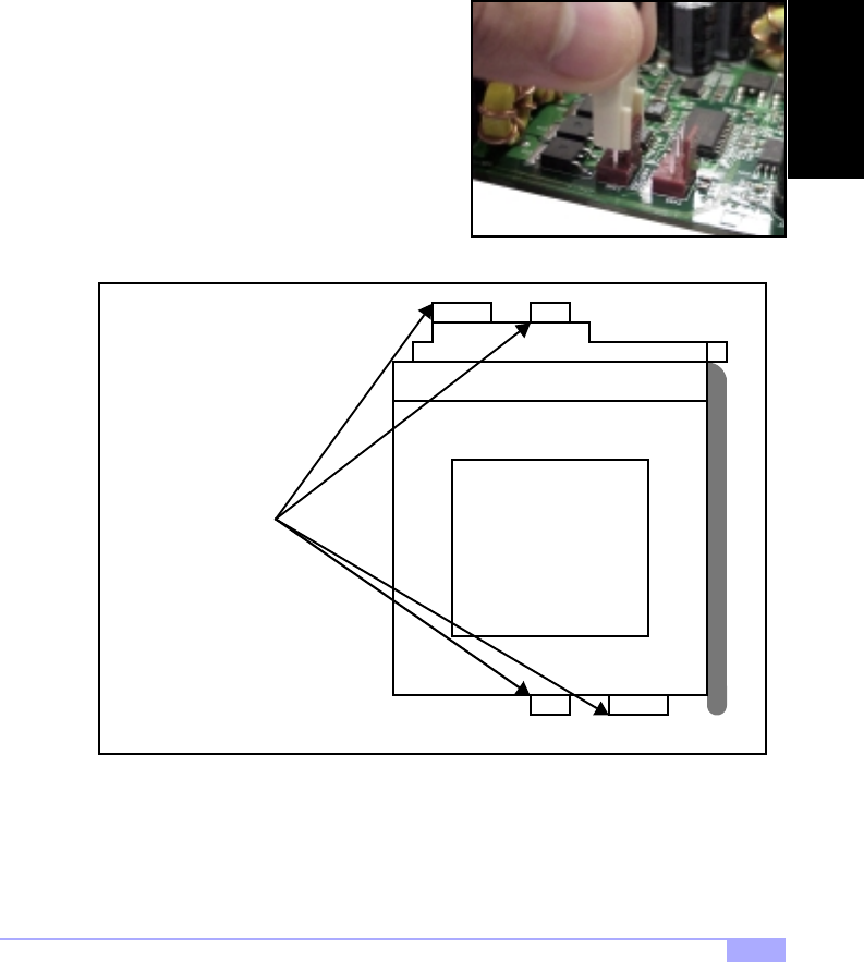
Installing the Cooling Fan
After the CPU has been installed, you will need to install the proper cooling device for the CPU. This
device, a heatsink/fan combination, can be purchased at many computer retail stores. Installation of the
cooling device may vary depending on on the fan manufacturer’s design. You should also take space into
consideration when install a cooling device: make sure the cooling device is not too big, or else you may
end up damaging components around the CPU socket. Also pay attention to the shape of the bottom of
the CPU fan(s): some are built specifically to fit only one way.
Tyan highly recommends that you use some type of
thermal compound (available from computer retail
stores), between the CPU and heat sink, to maximize
distribution of heat away from the CPU. Please use extra
caution when installing any type of clamp-style fan, or
else damage may occur to the CPU socket, and/or the
CPU itself. See Figure 2.2 (see right) for an example of
how to connect the cooling fan’s power supply. Another
diagram has also been provided below, to aid in CPU fan
installation onto the socket.
Installing Chassis Fans
Alternatively, if you wish to also install chassis fans for increased cooling, we have provided headers to
power those fans as well (see p. 13, section 2.6-D). Chassis fan installation will vary depending on your
chassis manufacturer’s design. Please check with your chassis manufacturer for details on proper chas-
sis fan installation.
Figure 2.2
Can be used to install
a cooling device
Mounting points on the CPU socket
INSTALL
http://www.tyan.com
20
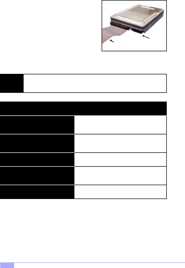
2.10 Connecting IDE and Floppy Drives
A variety of IDE and ATAPI-compliant devices* can be
installed on this motherboard, such as hard disk drives
(HDDs) and CD-ROMs.
Please keep in mind that on this motherboard, the primary IDE
connector is BLACK, and the secondary IDE connector is
WHITE. Consult the documentation that came with your IDE/
ATAPI device, or contact the device’s manufacturer for more
details on installation. Also see Figure 2.3 (see right) for an
example of the HDD with the IDE cable installed.
NOTE: Only Tyan-approved cables are recommended for this motherboard. If you are using
an existing configuration with older cables, your system might not function properly.
Use only Tyan-approved cables (i.e. the ones included with your motherboard).
Figure 2.3
Colored stripe
indicates Pin 1 Power
Some symptoms of incorrectly installed HDDs are...
May be a Master/Slave configuration problem, bad
IDE cable, or BIOS mis-configuration. Consult the
HDD documentation or contact your HDD vendor.
May be a bad cable or lack of power going to the
drive. Check the cables for damage and bad con-
nections.
Usually means the cable has been installed back-
wards.
Bad IDE cable or defective drives/motherboard. Try
another HDD, or contact your HDD vendor.
Check power cables and cabling. May be a bad
power supply or IDE drive problem.
HDD lights are constantly on
HDDs are not auto-detected
No video or beeps during bootup
HDD does not power on
Hard Disk Drive Fail message at bootup
* UDMA-33/66 IDE devices are although UDMA-33/66 transfer speeds are not reachable at this
time
Thunder HEsl S2567 21
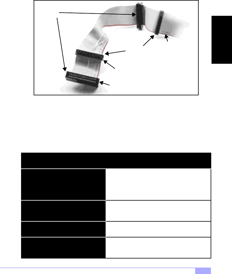
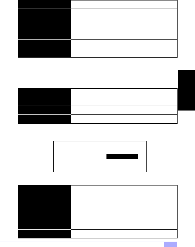
Connecting Floppy Drives
Pin 1 on the floppy cable is usually denoted by a red or colored stripe down one side of the cable. See
Figure 2.4 (below) for an example of a floppy cable. Most of the current floppy drives on the market
require that the cable be installed with the colored stripe positioned next to the power connector. In most
cases, there will be a key pin on the cable which will force a proper connection of the cable.
The first floppy (denoted as A:) is usually attached to the end of the cable with the twist in it. See Figure
2.4 (above) for an example. Drive B: is usually connected to the middle of the cable. Refer to your floppy
drive’s installation instructions, or contact your dealer if you are unsure about how to attach the floppy
drive(s). Remember, you can only have 2 floppy drives connected at any given time.
Some symptoms of incorrectly installed FDDs are...
Usually caused by faulty cables, cables put in back-
wards, or a bad floppy or motherboard. Try another
floppy drive to verify the problem or try another
cable. Also check to see if the onboard floppy is
enabled in the BIOS.
The cable, floppy, or motherboard may be faulty. Try
another cable or floppy drive to verify.
Usually signifies that the cable is on backwards.
Reverse the cable at the floppy drive end and try
again.
Check power cables and cabling. May be a bad
power supply or IDE drive problem.
FDD light is constantly on
FDDs are not auto-detected
FDD does not power on
Floppy Drive Fail message at bootup
Figure 2.4
3.5” connector
5.25” connector
Colored stripe
indicates Pin 1
Drive B:
Drive A:
INSTALL
http://www.tyan.com
22
2.11 Installing Add-on Cards**
There are a few rules you need to follow when installing add-on cards. In order to assure proper operation
and a quick installation, adhere to the following guidelines:
If you are going to install a PCI-bus interface card on your system, be aware that any one of the
six PCI slots can support a Master or Slave device.
NEVER force a card into a slot. If it doesn’t fit, look at the socket on the motherboard to make
sure there are no wires or other obstructions to the slot.
NEVER plug an ISA card into a PCI slot, or vice versa. You will void your warranty and damage
your system board if you do this.
When plugging the card in, especially when installing long cards, try to push the entire card in at
one time. Don’t force one end of the card into the socket first and then the other, or a rocking
motion between the card and the slot might occur, and could damage the pins within the socket.
Make sure the cards are seated securely into their slots.
Before turning on the system, make sure no cards are touching.
When installing the add-on cards**, make sure the cards are installed with even force; do not insert one
end and then the other. See the before (Figure 2.5a) and after (Figure 2.5b) example installation images
below for details.
Figure 2.5a*
Figure 2.5b*
Check orientation of card when installing
1
2
Push card down with even force
* diagrams are provided as an example for installation, and may not represent an actual slot
** if 100MHz FSB CPU and/or 33MHz PCI card is used, the PCI bus will not run at 66MHz
Thunder HEsl S2567 23
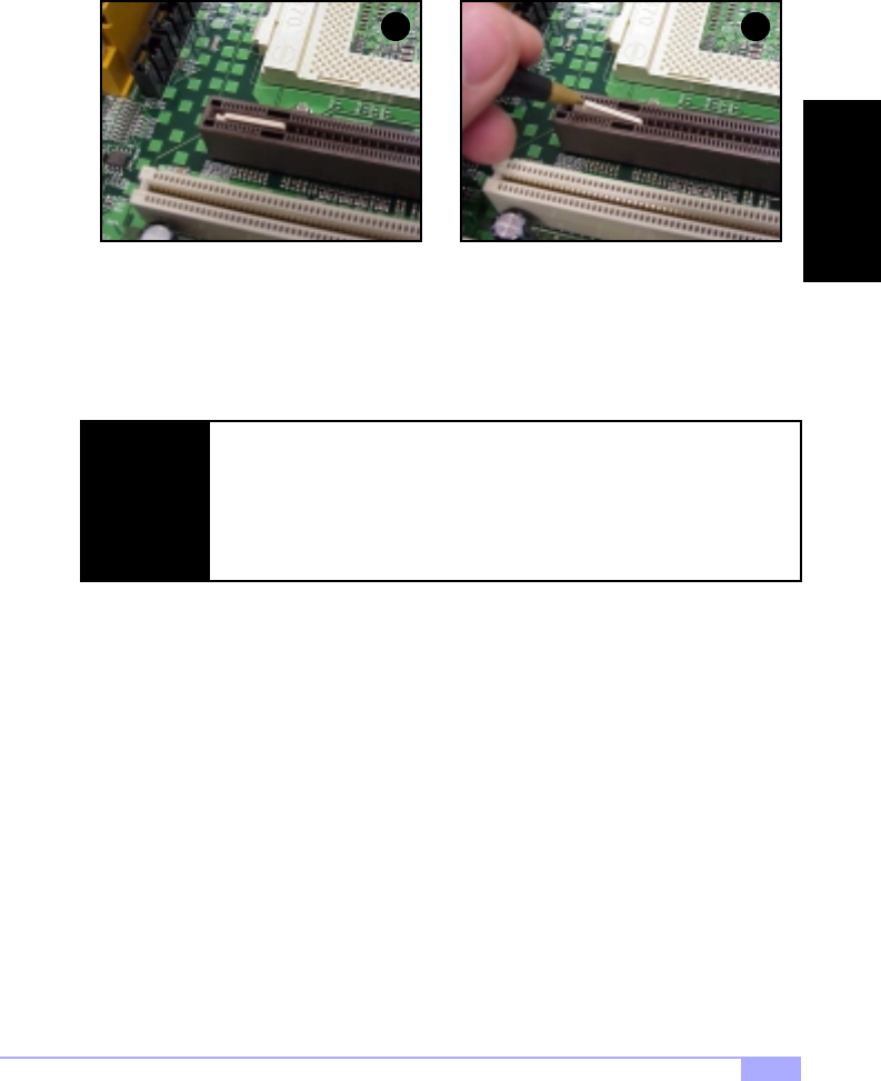
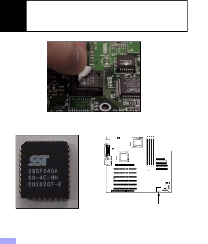
About the AGP Pro slot
If you are planning to install an AGP Pro-compliant card, a small plastic retention piece must be removed
from the AGP Pro slot before the card can be installed.
First, make sure the card you’re installing is an AGP Pro-compliant card. Locate the small plastic retention
piece in the AGP Pro slot (Figure 2.6a, above), and use a tool with a small hard tip (such as a pen) to
remove the retention piece (Figure 2.6b, above). Tyan recommends you save this piece for future
use (e.g. in case a regular AGP card is installed later on).
NOTE:
Only remove the small plastic retention piece if you are going to install an AGP
Pro-compliant card. Installing a regular AGP card without the retention piece can
cause the card to rock back and forth, possibly damaging the card and/or mother-
board.
Tyan takes no reponsibility and will not be held liable for damage related to use of
regular AGP cards without the retention piece installed.
1 2
Figure 2.6a Figure 2.6b
INSTALL
http://www.tyan.com
24
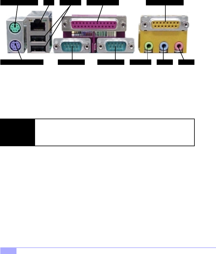
2.12 Connecting PS/2, USB, Serial and Parallel Ports
This motherboard includes ports for PS/2 mouse and keyboard, Universal Serial Bus (USB) devices, and
serial and parallel devices. Please note that the upper PS/2 port is the mouse port, and the lower PS/2
port is for the keyboard (see Figure 2.7 below).
The PS/2 connectors are probably quite familiar to you, while the USB connectors may not be. A USB
port can function as a serial, parallel, mouse, keyboard, display, or joystick port. It is capable of supporting
up to 127 daisy-chained peripheral devices. All external ports are labeled in Figure 2.7, shown below.
Connecting Serial and Parallel Ports
The serial and parallel ports can be used to connect various devices such as a mouse or printer. The con-
nectors can only be connected one way: be sure and check the orientation of the connector before install-
ing it into the port.
Figure 2.7
NOTE:
When plugging in your keyboard and mouse, or when plugging in anything into a
serial or parallel port, make sure that the power is off. Connecting these devices
and ports while the power is on is called hot plugging and may damage your sys-
tem and/or external devices that you are trying to install.
PS/2 Mouse Port
PS/2 Keyboard Port
USB Ports
Serial Port
Parallel PortLAN
Serial Port Line-out* Line-in* Mic-in*
Game/MIDI Port*
* optional feature available on some Thunder HEsl models
Thunder HEsl S2567 25
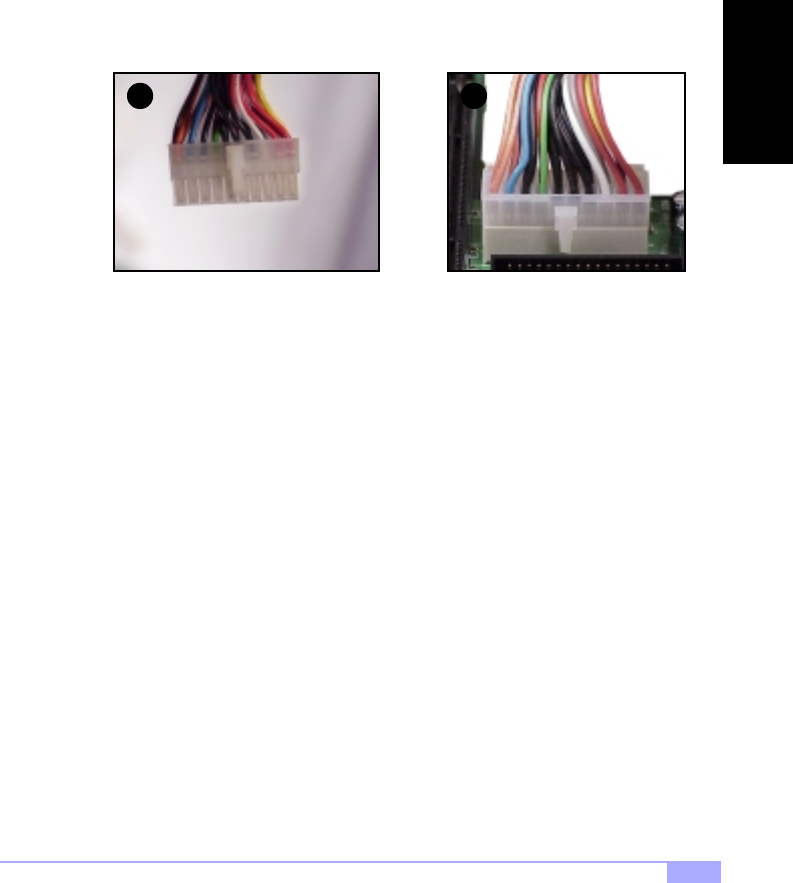
2.13 Connecting the power supply
This motherboard requires an ATX power supply. Tyan recommends using a 250W or higher power sup-
ply that also conforms to industry standard Revision 2.01. The images below show the ATX power con-
nector before (Figure 2.8a) and after (Figure 2.8b) it has been plugged in. The clip on the power
connector should lock over the tab on the onboard connector. You shouldn’t be able to plug the power
connector in any other way but just to be safe, make sure it looks like Figure 2.8b. Make certain that you
do not miss connecting any of the pins because if you do, you will void your warranty and possibly cause
damage to yourself and/or your motherboard when the power is turned on. After connecting the power,
make sure the connector is seated firmly into its socket so it will not become loose or fall off when the
computer is jostled or moved.
You are done!
Other than checking the jumper settings and cable connections, and putting the case back on, you are
done. Installing a new motherboard may seem difficult, but by following these directions, you should have
a fairly uneventful time installing our products. If you do encounter problems, your dealer will be able to
help you, or you can consult one of our many technical support resources (see p. 7).
Figure 2.8b
1 2
Figure 2.8a
INSTALL

http://www.tyan.com
26
2.14 Frequently Asked Questions (FAQ)
Q: My system sometimes becomes unstable. How should I check the system?
A: The first thing to do is to check and see if you have any device conflicts related to the IRQ, or DMA. If
you are using Microsoft Windows, the Control Panel is a good place to start investigating the conflict.
Please consult your operating system documentation for details. Secondly, slowing down the memory tim-
ing in the BIOS’ chipset setup section will help the situation as well. Many memory modules are not suit-
able for high performance systems and are probably the main source of your problem. Also check to
make sure you are using a dual Athlon approved or better power supply, and also make sure the
power supply has adequete output (Tyan recommends a 300W or better power supply). Lastly, make
sure the motherboard is receiving adequete cooling.
Q: I have a question about memory compatibility; what memory will work on my motherboard?
A: Memory compatibility information can be found on Tyan’s website at: http://www.tyan.com
Q: Where can I get additional accessories for my Tyan motherboard?
A: You can purchase additional accessories such as USB cables*, as well as other Tyan-approved acces-
sories at the Tyan Computer Online Store: http://www.etyan.com
Q: Where do I get pinout information for my motherboard?
A: Pinouts of certain headers are available on the Tyan website: http://www.tyan.com
Q: My motherboard is dead, how do I return it?
A: Contact the place of purchase or your distributor for assistance to return the motherboard for service.
RMA issues will NOT be handled via e-mail by Tyan Tech Support. Please refer to the URL link here for
more details: http://www.tyan.com/support/html/rma_faq.html
Q: How do I upgrade my BIOS?
A: Check the section about the Flash Utility (see p.38) for information on upgrading your BIOS. BIOS
update files, flash utilities, and instructions on how to install them are also available from the Tyan website
at: http://www.tyan.com
Q: Why do I get a “CMOS checksum invalid” error message during POST?
A: If you get the above error message or “Invalid configuration, run Setup” message, it is an indication
that the CMOS battery needs to be changed. Contact your dealer for assistance. Once you’ve replaced
your battery, don’t forget to check the Clear CMOS section (see p.12) so that you can reset your CMOS.
Q: Why can’t I get into the BIOS right after pressing [DEL] when asked by the system?
A: After the system displays the memory information, and then asks the user to press [DEL], the system
will then run the SCSI BIOS (if enabled, see p.33), and finally go into the system BIOS. This is a normal
boot up process.
* If your chassis supports frontside USB connectors, it will usually come with the necessary cables.
Check that your chassis is frontside USB capable. Please check with your chassis vendor for details.

Thunder HEsl S2567 27
Chapter 3: BIOS Setup
Introduction to the BIOS setup
The BIOS is the basic input/output system, required by the computer to perform functions such as CPU
and hard drive support. This chapter describes different settings for AMIBIOS that can be used to config-
ure your system.
The BIOS section of the manual is subject to change without notice and is provided here for refer-
ence purposes only. The settings and configurations of the BIOS are current at the time of print,
and therefore they may not be exactly the same as that displayed on your screen.
This manual describes the AMIBIOS setup program. The setup program lets you modify basic configura-
tion settings. The settings are then stored in a dedicated battery-backed memory, called NVRAM, that
retains the information when the power is turned off.
The AMIBIOS in your computer is a customized version of an industry-standard BIOS for IBM PC AT-
compatible personal computers. It supports Intel x86 and compatible processors. The BIOS provides crit-
ical low-level support for the system central processing, memory, and I/O subsystems.
The BIOS has been customized by adding important, but non-standard, features such as virus and pass-
word protection, power management, and detailed fine-tuning of the chipset controlling the system. The
rest of this manual is intended to guide you through the process of configuring your system using the AMI-
BIOS setup program.
Starting Setup
The BIOS is immediately activated when you first turn on the computer. The BIOS reads system configu-
ration information in CMOS RAM and begins the process of checking out the system and configuring it
through the Power-On Self Test (POST).
When these preliminaries are finished, the BIOS seeks an operating system on one of the data storage
devices (HDD, floppy drive, etc.) If one is found, the BIOS will launch that operating system and hand
control of system operations to it. During POST, you can start the setup program by pressing the [DEL]
key when the “Press DEL key to enter BIOS setup” message appears on the screen.
BIOS

http://www.tyan.com
28
Setup Keys
The table below shows how to navigate in the setup program using the keyboard.
Getting Help
Press [F1] to display a small help window that describes the appropriate keys to use and the possible
selections for the highlighted item. To exit the Help Window press [ESC] or the [F1] key again.
In Case of Problems
If you discover that you have trouble booting the computer after making and saving changes with the
BIOS setup program, you can restart the computer by either:
The best advice is to alter only settings that you thoroughly understand. In particular, do not change set-
tings in the Chipset screen unless you absolutely sure that you need to. The Chipset defaults were care-
fully chosen by Tyan or your system manufacturer for the best performance and reliability. Even a
seemingly small change to the Chipset setup may cause the system to become unstable.
Setup Variations
Not all systems have the same setup program. While the basic look and function of the setup program
remains more or less the same for all system, the appearance of your Setup screen may differ from the
screens shown here. Each system design and chipset combination require custom configurations. In
addition, the final appearance of the setup program depends on your system designer. You system
designer can decide that certain items should not be available for user configuration, and remove them
from the BIOS setup program.
Tab
Key Function
Left/Right Arrow Keys
PgUp/PgDn Keys
Moves from one selection to the next
Change from one menu to the next
Enter
Up/Down Arrow Keys Move between selections
Opens highlighted section
Change setting
Pressing [CTRL]+[ALT]+[DEL] (all three keys at the same time)
Holding the power button down until the computer shuts off
Thunder HEsl S2567 29
3.1 Main Setup
In this menu, you can alter general features such as the date and time.
3.1-A. System Date/Time
You can type in the date and time directly, or select the portion of the date or time that you want to modify
and adjust it using the cursor keys. The clock runs on a 24-hour cycle (i.e 1:00 PM is 13:00).
3.1-B. General Help
At any time, you can press [F1] to bring up a General Help screen in case you want to learn the shortcut
commands. There are two settings you should be aware of (listed below).
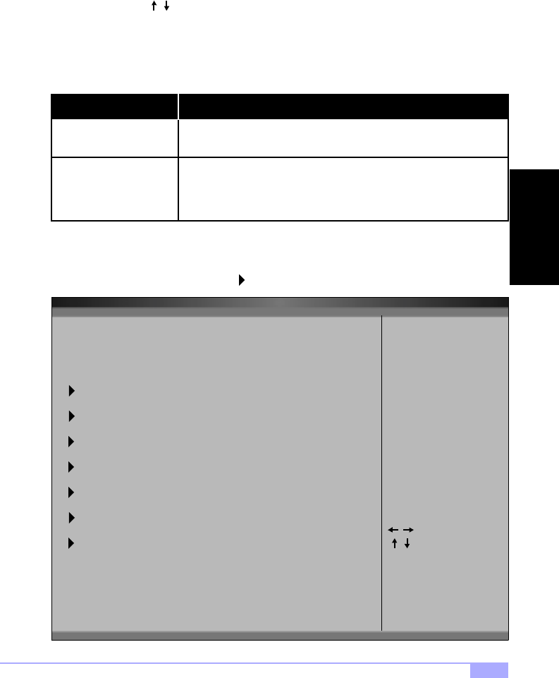
3.2 Advanced Setup
In the Advanced setup, you can setup your system devices, boot options, and more. Each option has a
configuration sub-screen (denoted by the symbol).
Load Failsafe Defaults
Load Optimal Defaults
If your system is experiencing configuration problems, you can choose
this option to reset all settings.
This will load preset options that are designed for maximum system
performance, but may not work for all computer applications. You
should not use this option if you are experiencing configuration prob-
lems.
BIOS SETUP UTILITY
Main Advanced Chipset PCIPnP Power Boot Security Exit
v02.02 (C) Copyright 1985-2000, American Megatrends, Inc.
Setup Warning
Setting items on this screen to incorrect values
may cause the system to malfunction!
SuperIO Configuration
IDE Configuration
Floppy Configuration
Event Log Configuration*
Boot Settings Configuration
Remote Access Configuration
Select Screen
Select Item
Go to Sub Screen
General Help
Save and Exit
Exit
Enter
F10
ESC
F1
Peripheral Device Configuration
* not verified at time of print, please check Tyan website for updates: http://www.tyan.com
BIOS
http://www.tyan.com
30
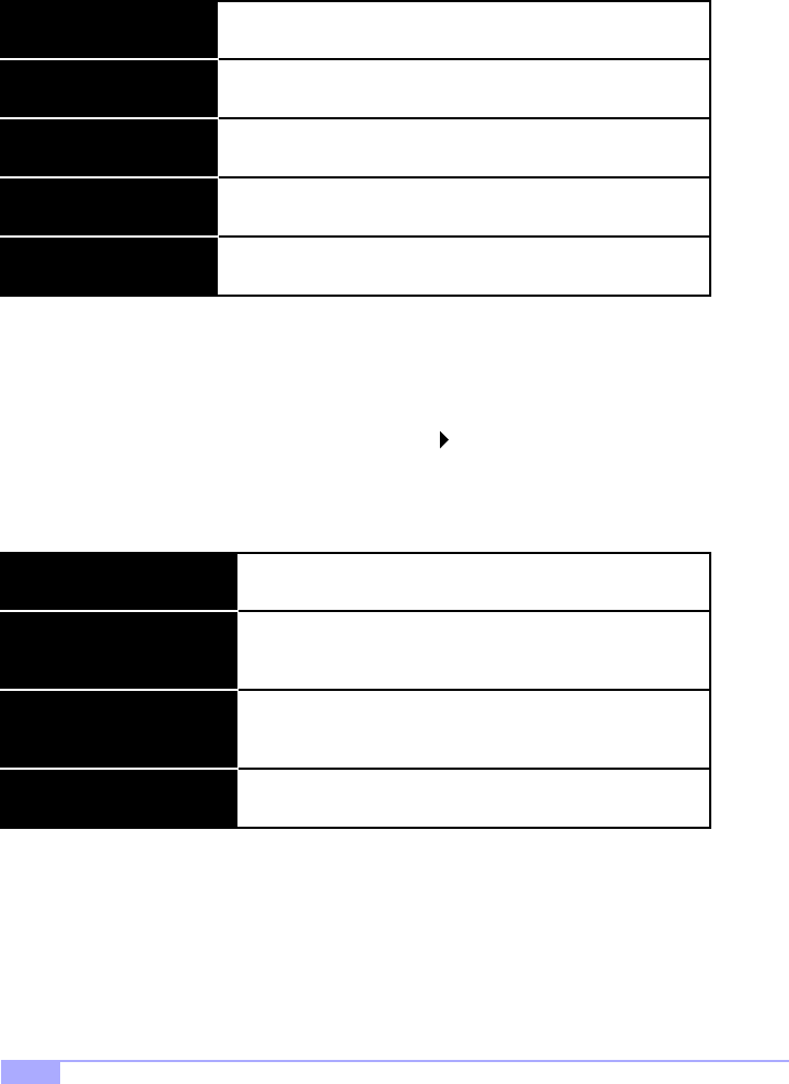
3.2-A. Configure SuperIO Configuration
In this sub screen you can configure the different hardware ports available, and change the status of the
floppy controller.
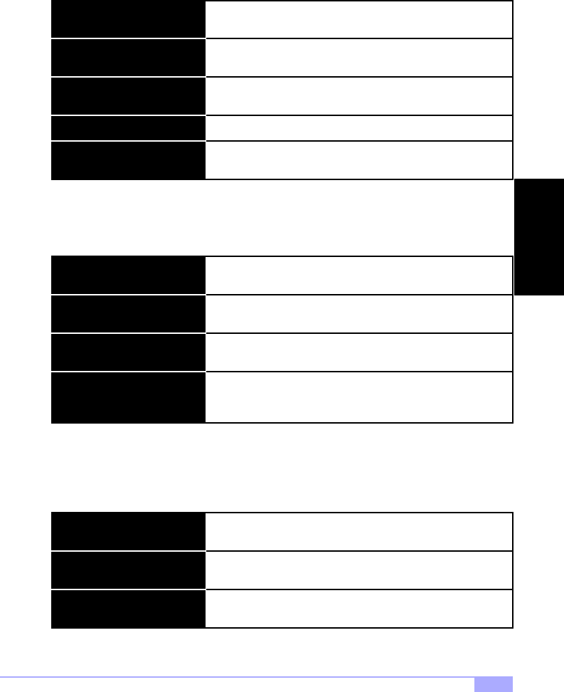
3.2-B. IDE Configuration
On bootup, the BIOS will auto-detect the existence of IDE devices such as hard drives and CD-ROMs.
You can also check the status of those IDE devices and change other IDE-related options. There are also
configuration sub screens for each IDE device (denoted by the symbol). Depending on what devices
you set up, some options may or may not be available. In most cases, the default settings that appear
when the device is detected by the BIOS will be sufficient. To absolutely sure that your settings are cor-
rect, always check the documentation for each device you set up.
An explanation of possible options in the IDE configuration sub-screens is shown on the next page.
Serial Port Address
Onboard Floppy Controller This device handles communication between the floppy drive and
the motherboard. [Default setting is Enabled]
Serial Port 2 Mode
The address of Serial Port 1 can be changed if a hardware conflict
occurs. [Default setting is Normal]
Depending on your needs, the mode of Serial Port 2 can be
altered. [Default is Normal]
Hard Disk Protect
Onboard PCI IDE Controller The PCI IDE controller is essential for communication between
the IDE devices and the motherboard. [Default setting is Both]
ATA(PI) Detect Time Out
This option disables or enables write protection to the IDE
devices. This option is only effective if the devices are being
accessed through the BIOS. [Default setting is Disabled]
The BIOS will spend a preset amount of time to detect any IDE
devices before it continues to the next stage of bootup. The
amount of time can be changed using this option. [Default is 35]
ATA(PI) 80Pin Cable Detection Selects the process that the BIOS will use to detect 80Pin
ATA(PI) cables. [Default is Host & Device]
Serial Port 2 Address You can set the address for Serial Port 2 by using this option
[Default is 2F8/IRQ3]
Parallel Port Address You can set the address for the Parallel Port by using this option.
[Default is Disabled]

Thunder HEsl S2567 31
3.2-C. Floppy Configuration
In this configuration sub-screen you can change options for your floppy drive(s). If you are unsure what
kind of floppy drive you have, you should consult the documentation that came with your drive, or consult
your vendor.
LBA/Large Mode
Type The type of IDE device installed can be configured using this
option. [Default setting is Auto for auto-detect]
Block (Multi-sector Transfer)
These modules make it possible for the BIOS to take advantage
of the additional space on drives which are larger than 504MB.
This can be auto-detected (when you select Auto for Type), or
you can manually set this mode to Disabled. [Default setting is
Auto]
When set to Auto, the block mode auto-detects the optimal num-
ber of block read/writes per section that the drive supports.
[Default is 0]
PIO Mode
Programming input/output is a method of transmitting data
between devices that use the system’s CPU as part of the data
path. There are 6 modes: 5 with their own transmission speed
and 1 auto mode. To use modes 3 and 4, you must use an
Enhanced IDE drive. [Default is Auto]
DMA Mode
S.M.A.R.T. (Self-Monitoring
Analysis and Reporting Tech-
nology)
This option secifies the Direct Memory Access mode for the IDE
device. If set to Auto, the BIOS will determine the DMA mode.
[Default is Auto]
This option allows the S.M.A.R.T. protocol to report server sys-
tem information over a network. [Default is Auto]
32Bit Data Transfer If set to On, this option allows for the transmission of 32-bits in
parallel (e.g. at the same time). If set to Off, only 16-bits will be
transmitted in parallel. [Default is Enabled]
ARMD Emulation Type Specifies the type of emulation used for a non-disk device
attached as the primary master IDE device. If set to Auto, the
BIOS will determine the emulation type. [Default is Auto]
Floppy B
Floppy A The settings are 360KB 5.25”, 1.2MB 5.25”, 720KB 3.5”, 1.44MB
3.5”, or 2.88MB 3.5”.
Diskette Write Protect
The options are the same as listed for Floppy A. [Default setting
is Disabled]
Sets whether or not the drive can be written to. [Default is Dis-
abled]
Floppy Drive Seek Sets whether or not the BIOS should check for the drive at
bootup. [Default is Disabled]
BIOS

http://www.tyan.com
32
3.2-D. Boot Settings Configuration
In the Boot Settings Configuration sub-screen, several options are available to change how the system
boots up.
Quiet Boot
Quick Boot When Enabled, the BIOS will save time during bootup by skip-
ping certain items. [Default is Enabled]
AddOn ROM Display Mode
When Disabled, the normal POST messages are displayed.
[Default setting is Disabled]
Specifies the system display mode that is set at the time that
AMIBIOS post initializes an optional ROM. If set to Force BIOS,
the current mode used by AMIBIOS is used. If set to Keep Cur-
rent, the current display mode is used. [Default is Force BIOS]
Bootup Num-Lock Sets whether or not the NumLock key should be turned on at
bootup. [Default is On]
Bootup CPU Speed Sets the initial CPU speed to high or low at bootup. [Default is
High]
PS/2 Mouse Support Sets whether or not the PS/2 ports should support a mouse
device. If set to Enabled, IRQ12 will be reserved for the mouse
device. [Default is Enabled]
Typematic Rate Sets how fast the keyboard will accept input. [Default is Fast]
System Keyboard
Primary Display
Parity Check
Boot to OS/2
Wait for ‘F1’ if error
Hit ‘DEL’ Message Display
Internal Cache
System BIOS Cacheable
Sets whether or not the keyboard exists. [Default is Present]
Sets the type of monitor that is being used. [Default is VGA/
EGA]
Sets whether or not the memory will be checked for parity.
[Default is Disabled]
Set this option to ‘Yes’ if you are using OS/2 and are using more
than 64MB of system memory. [Default is No]
If an error occurs during bootup, the BIOS will ask the user to
press ‘F1’ to enter the BIOS Setup Utility to repair the problem.
[Default is Enabled]
If Enabled, the BIOS will display an option to enter the BIOS
Setup Utility at bootup. [Default is Enabled]
Sets the type of caching algorithm that will be used for the L1
internal cache memory. [Default is Write-Back]
Sets the type of caching algorithm that will be used for the L2
external cache memory. [Default is Enabled]
Thunder HEsl S2567 33
3.2-E. Event Log Configuration*
In this sub-screen you can access the log that is created when bootup errors occur. This log will help you
troubleshoot any configuration problems you might experience. The status of the Event Log is shown on
the top half of the screen.
3.2-F. Peripheral Device Configuration
In this sub-screen, you can enable or disable certain devices/functions as your needs require.
3.2-G. Remote Access Configuration
This menu allows for setting up options related to the console redirection functions of this motherboard.
Onboard SCSI
Onboard LAN
Enables or disables the onboard SCSI controller [Default setting
is Enabled]**
The operating status of the onboard LAN controller can be
changed using this option. [Default is Enabled]
Onboard Audio* The onboard audio option can be enabled and disabled by using
this option. [Default is Enabled]
ECC Event Logging*
Event Logging* If set to Enabled, bootup error events will be logged. [Default is
Enabled]
Clear All Event Logs*
If set to Enabled, ECC events will be logged. [Default setting is
Disabled]
If set to Yes, the event log will be cleared on saving of BIOS
settings followed by reboot. [Default is No]
View Event Log* Shows you the Event Log.
Mark All Events As Read* By using this option, the events in the Event Log can be
organized to help troubleshoot configuration problems.
Power Lost Control If this function is set to Always On, and there is a sudden power
loss to the system, then the system will automatically boot up
once power is restored to the system. [Default is Always On]
Remote Access
Serial Port #
If this option is set to Disabled, the following two options
will not appear (listed below). [Default setting is Disabled]
Sets the serial port number that will be connected for console
redirection functions. [Default is COM1]
Serial Port Mode Sets the mode for the serial port chosen for console redirection
functions. [Default is 115200 8,n,1]
* optional feature available on some Thunder HEsl models
^* SCSI limited to 33MHz
BIOS

http://www.tyan.com
34
3.3 Chipset Setup
The Chipset Setup is for advanced configuration of the motherboard attributes.
C000 - CC00, 16k Shadow
Specifies how the 16k of video ROM is treated at the listed
address.
Disabled: contents of video ROM are not copied to RAM
Enabled: contents of video ROM at listed address segment is
copied (shadowed) from ROM to RAM for faster execution.
Cached/WP: contents of video ROM from listed address seg-
ment are copied from ROM to RAM and can be written to or read
from cache memory.
[Default is Cached]
D000 - DC00, 16k Shadow [Default is Disabled]
Act to Deact [Default is 6Clks]
Act to Read/Write [Default is 3Clks]
RAS Precharge Time Sets length of RAS precharge part of DRAM system memory
access cycle when SDRAM systemmemory is installed. [Default
is 3Clks]
RA Cycle Time [Default is 10Clks]
SDRAM CAS Latency [Default is CAS Latency 3]
ISA IO Cycle Delay [Default is FULL Delay]
MPS 1.4 Support [Default is Enabled]
Write Caching from P6-to-PC1 [Default is Disabled]
Memory Auto Precharge [Default is Enabled]
SDRAM Fast Timing [Default is 11-1-1-1]
Scrubbing Enable [Default is Disabled]
AGP Device Address Space Size [Default is 32MB]
AGP Operations [Default is Disabled]
Thunder HEsl S2567 35
3.4 PCI/PnP Menu*
The PCI/PnP Setup lets you configure the onboard PCI Plug-n-Play (PnP) devices available.
Reset Config Data
Plug & Play O/S Indicates if you are using a PnP O/S. [Default is No]
PCI Latency Timer
If set to Yes, PCI/PnP data will be stored in Flash on next boot.
[Default setting is No]
Specifies latency timings for PCI devices. [Default is 64]
Allocate IRQ to PCI VGA Informs PCI devices that an ISA graphics device is installed in
the system so the card will function correctly. [Default is Yes]
Palette Snooping If set to Enabled, multiple VGA devices operating on different
buses can handle data from the CPU on each set of palette reg-
isters on every video device. [Default is Disabled]
PCI IDE Bus Master Specifies that the IDE controller on the PCI bus has bus master-
ing capability. [Default is Disabled]
Offboard PCI/ISA IDE Card Specifies if an offboard PCI or ISA IDE controller card is
installed. [Default is Auto]
USB Function
Legacy USB Support
DMA Channel (0,1,3,5,7)
Reserved Memory Size
Enables USB. [Default is Enabled]
Enables legacy USB device support. [Default is Auto]
Allows listed IRQ to be used by PCI/PnP devices. [Default is
Available]
Allows listed DMA to be used by PCI/PnP devices. [Default is
Available]
Specifies size of memory area reserved for legacy ISA adapter
cards. [Default is Disabled]
* if 100MHz FSB CPU and/or 33MHz PCI card is used, the PCI bus will not run at 66MHz
BIOS

http://www.tyan.com
36
3.5 Power Menu
The Power Setup lets you configure how the BIOS handles power management.
Power Button Mode
Power Management Enables Power functions on this screen. [Default is Disabled]
Sleep Button Enable
Changes how the power button will function. [Default setting is
On/Off]
Changes the function of the sleep button. [Default is Suspend]
Green PC Monitor Power State Changes option for the Green PC compatible monitors. [Default
is StandBy]
Video Power Down Changes the event that occurs when the video powers down.
[Default is StandBy]
Hard Disk Power Down Mode Changes the event that occurs when the HDD powers down.
[Default is Disabled]
Inactivity Timer Changes the amount of time the BIOS will wait before activating
system power functions as set by the user. [Default is Off]
Suspend Time Out (Minutes)
IRQ (3,4,5,7,9,10,11,14,15)
USB Controller Resume*
PME Resume
Changes the amount of time the BIOS will wait before activating
the suspend mode. [Default is Off]
Changes how the BIOS will treat each IRQ in terms of power
management.
Changes how the BIOS will handle the USB controller power
function. [Default is Disabled]
Changes the PME power function. [Default is Disabled]
RI Resume Changes the RI power function. [Default is Disabled]
ACPI Aware OS Tells system whether OS is ACPI aware. [Default is No]
Thunder HEsl S2567 37
3.6 Boot Menu
The Boot Setup lets you configure options set for each device during boot. The options available will
depend on what devices you have installed in your computer.
3.7 Security Menu
The Security Setup lets you configure security options such as passwords and boot sector virus protec-
tion. The status of the Supervisor and User Passwords are shown at the top, and options can be set
through the rest of the configuration sub-screen.
A password screen (such as the example screen below) will appear when you select one of the Change
Password functions. To set a password, enter a unique set of 6 letters and/or numbers.
3.8 Exit Menu
Before you exit the BIOS, a set of options will be presented to you.
Hard Disk Drives
Boot Device Priority Sets the order of devices that BIOS will attempt to boot from.
Removeable Drives
Shows the available HDDs and allows changes to the order in
which each in booted (e.g. which boot firsts, second, and so on).
Shows the available removable drives and allows changes to
the order in which each in booted (e.g. which boot firsts, second,
and so on).
ATAPI CDROM Drives Shows the available CD-ROM drives and allows changes to the
order in which each in booted (e.g. which boot firsts, second,
and so on).
Change User Password
Change Supervisor Password Install or change the password.
Clear User Password
Install or change the password.
Immediately clears the User password.
Boot Sector Virus Protection Protect against boot sector viruses. [Default is Disabled]
Enter New Password:
Exit Discarding Changes
Exit Saving Changes Save changes and exit setup.
Load Optimal Defaults
Do not save changes and exit setup.
Load optimal settings. Note: May not work with all applica-
tions.
Load Failsafe Defaults Load failsafe settings. Note: May not work with all applica-
tions.
Discard Changes Disregard all changes you made.
BIOS
http://www.tyan.com
38
3.9 Flash Utility
Every BIOS file is unique for the motherboard it was designed for. For Flash Utilities, BIOS downloads,
and information on how to properly use the Flash Utility with your motherboard, you must check the Tyan
website: http://www.tyan.com
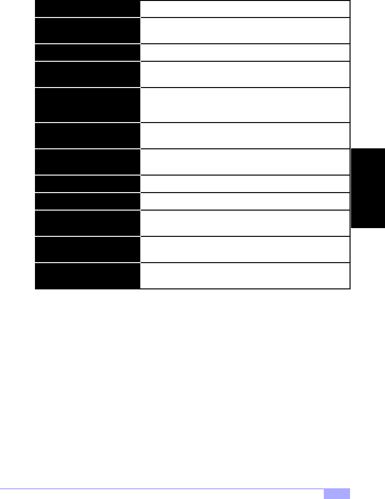
IMPORTANT! If you have a BIOS chip with part number SST 28SF040A (see Figure 3.1 below), DO
NOT flash with a BIOS that is below v1.04. Otherwise, you will render your system inoperable. In order
to find out if you have the SST 28SF040A, you will need to peel back the sticker (see Figure 3.0* below).
If you have a different chip other than the SST 28SF040A, this information does not affect you.
NOTE:
Please be aware that by flashing your BIOS, you agree that in the event of a BIOS
flash failure, you must contact your dealer for a replacement BIOS. There are no
exceptions. Tyan does not have a policy of replacing BIOS chips directly with end
users. In no event will Tyan be held responsible for damage done to the BIOS by the
end user.
Figure 3.0* - Peeling back the sticker
AMI
BIOS
* image provided as an example, and may not be representative of your motherboard

Thunder HEsl S2567 39
Chapter 4: System Resources
Note: If you experience problems with setting up your system, always check the following things in the
following order:
MEMORY, VIDEO, CPU
By checking these items, you will most likely find out what the problem might have been when setting up
your system. For more information on troubleshooting, check the Tyan website at http://www.tyan.com
4.1 Beep Codes
Fatal errors, which halt the boot process, are communicated through a series or audible beeps. For exam-
ple, if the AMI BIOS POST can initialize the video but an error occurs, an error message will be displayed.
If it cannot display video, it will convey a series of beeps.
If you hear one long beep followed by two short beeps, then a video problem has probably occured and
the BIOS is having difficulty initializing the video display. Any other beep sequences that may or may not
occur are probably due to memory problems.
4.2 Displayed Error Messages
If an error occurs after the system display has been initialized, an error message will be displayed as fol-
lows:
ERROR Message Line 1
ERROR Message Line 2
Press <F1> to continue
and the system will halt. Depending on how the Halt On setting was configured in the Standard CMOS
Setup menu, the system may or may not display the error message.
RUN SETUP UTILITY
may also appear. Press [F1] to run the Award BIOS Setup if this message appears. The following two
pages show the possible error messages and explanations.
SYSTEM

http://www.tyan.com
40
Address Line Short!
8042 Gate-A20 Error Gate A20 on the keyboard controller (8042) is not working.
Error in the address decoding circuitry.
Cache Memory Bad, Do Not
Enable Cache! Cache memory is defective.
CMOS Battery State Low The battery is running low and needs to be replaced.
The CMOS data is different than previous data. Run BIOS setup
to enter new data.
CMOS RAM values were destroyed. Run BIOS setup to enter
new data.
CMOS Checksum Failure
CMOS System Options Not Set
Video type set in BIOS does not match actual video display. Run
BIOS setup to enter new data.
CMOS Display Type Mismatch
Memory size does not match actual detected memory size. Run
BIOS setup to enter new data.
CMOS Memory Size Mismatch
Time and Date have not been set. Run BIOS setup to enter new
data.
CMOS Time and Date Not Set
No response from drive D:D: Drive Error
C: Drive Error No response from drive C:
C: Drive Failure No response from drive C:
Diskette cannot be used to boot system.Diskette Boot Failure
Some systems require a video switch to be set to either color or
monochrome. Power down the system and set the switch.
Display Switch Not Proper
Error in the DMA controller.DMA Error
CH-2 Timer Error Timer 2 has failed.
No response from drive D:D: Drive Failure
Error in the first DMA channel.DMA 1 Error
Error in the second DMA channel.DMA 2 Error

Thunder HEsl S2567 41
HDD Controller Failure
FDD Controller Failure FDD controller is not responding.
HDD controller is not responding.
Invalid Boot Diskette Diskette is not bootable.
Keyboard Error Keyboard appears to have a timing problem.
Error in keyboard connection.
System cannot find a bootable sector on any boot drive.
KB/Interface Error
No ROM BASIC
Parity error in external memory.Off Board Parity Error
Parity error in internal memory.On Board Parity Error
Parity error at unknown address.
Parity Error ???
INTR1 Error Interrupt channel 1 failed POST.
INTR2 Error Interrupt channel 2 failed POST.
Keyboard is Locked... Unlock it Keyboard lock is engaged. Power down and unlock it.
SYSTEM

http://www.tyan.com
42
Appendix I: SCSI Installation* and LAN Information
Introduction
With the dual channel onboard Ultra160 LVD SCSI option*, you can connect up to 30 SCSI peripherals
such as hard drives, CD-ROMs, and tape drives. Please note that this guide only provides basic instruc-
tions on connecting SCSI devices to your motherboard. For more detailed SCSI installation instructions,
refer to your SCSI device documentation or to LSI Logic’s website: http://www.lsilogic.com
Features* of the LSI Symbios SCSI BIOS
Legacy support for non-Ultra160 SCSI devices
The LVD signaling used for Ultra160 devices operates differently than single-ended signaling used on
Ultra, Fast, and Fast Wide SCSI devices. Ultra160 LVD SCSI devices are designed with multi-mode capa-
bility so that if a single-ended device is connected to the Ultra160 LVD SCSI bus, the Ultra160 devices
automatically switch to single-ended mode. When an Ultra160 LVD SCSI device operates in single-ended
mode it is subject to the cable distance limitations and signal noise problems of that interface. LSI recom-
mends that single-ended Ultra and earlier devices be kept on a separate channel than the Ultra160 LVD
SCSI devices. This will permit the Ultra160 devices to operate at full speed and cable distances.
Setting up internal SCSI peripherals
Its very important that SCSI peripherals be set up before installing them to the SCSI connector. The setup
for SCSI peripherals usually involves setting SCSI IDs, checking for termination, mounting the peripherals
inside the chassis, and then hooking up power to each peripheral. Since setup can vary from peripheral to
peripheral, always refer to the peripherals documentation for specific instructions. Below are some guide-
lines for setting SCSI IDs and termination on your peripherals.
Checking SCSI IDs
Both the motherboard SCSI connectors and each peripheral you connect need to have a unique ID, rang-
ing from 0 to 15. IDs do not have to be sequential, as long as each connector and each peripheral has a
different number for each channel. Each SCSI channel on the motherboard is preset to SCSI ID and
should not be changed. If you will be booting from a SCSI HDD, its best to set the disk’s ID at 0 or 1. Most
SCSI HDDs come from the factory preset to ID 0. The IDs for internal peripherals are usually set with
jumpers; external peripherals are usually set with a switch on the back of the peripheral. Check your
peripheral’s documentation for more details.
Terminating SCSI devices
To ensure reliable communication on the SCSI bus, the peripheral on the end of each cable, or the end of
the cable itself, must have a terminator installed (or enabled). The peripherals between the ends of each
cable must have the terminator removed (or disabled). Check your peripheral’s documentation for more
details.
Connecting SCSI peripherals
A total of 30 SCSI peripherals can be connector to the onboard SCSI connectors (15 devices per channel/
connector). Before connecting peripherals, be sure to also review Setting up internal SCSI peripherals
above.
Connecting internal cables for Ultra160 LVD SCSI devices
When connecting internal Ultra160 LVD peripherals there are special SCSI cables necessary to sustain
the higher speeds of LVD signaling. If your cables are not marked, you can identify most Ultra160 LVD
SCSI cables as having twisted pairs of the flat ribbon cable in between the device connectors. These
cables will usually have a terminator built into the end of the cable.
Configuration for up to 256 adapters - any 4 can be chosen for INT13
(bootrom) support
SPI-3 Parallel Protocol Request (PPR)
Basic Domain Validation
* SCSI limited to 33MHz
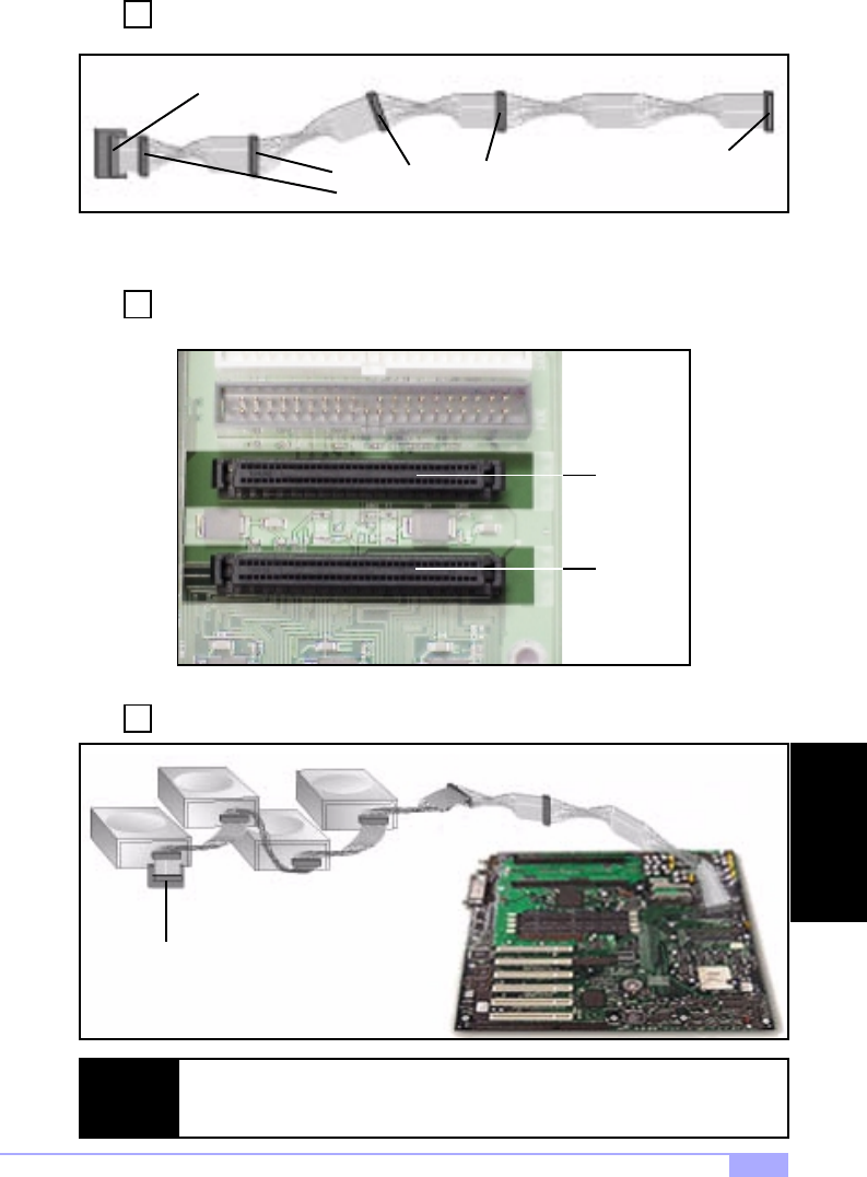
Thunder HEsl S2567 43
Locate the 68-pin internal Ultra160 LVD SCSI cable (it should look similar to the one
shown directly below).
Plug the long end of the cable(s) to the Ultra160 LVD SCSI connector(s) on the mother-
board (either channel A or channel B). Note that the image(s) below may not be com-
pletely representative of your motherboard.
Plug the remaining connectors to the internal Ultra160 LVD SCSI peripherals.
Built-in terminator
Connect to Ultra160 LVD
peripherals
Connect to motherboard
Ultra160 LVD SCSI con-
nector
NOTE: Internal Ultra160 SCSI peripherals come from the factory without termination. Proper
termination is provided by the built-in terminator at the end of the Ultra160 internal
SCSI cable.
Terminator device
Channel A
Channel B
3
Step
2
Step
1
Step
SCSI & LAN

http://www.tyan.com
44
Information on the LSI Symbios 53C1010 SCSI BIOS
The SCSI BIOS is the bootable ROM code that manages SCSI hardware resources. It is also specific to
the family of Symbios SCSI controllers or processors. By integrating with the standard system BIOS, the
Symbios SCSI BIOS extends the standard disk service routine through INT13h.
During boot time initialization, the SCSI BIOS will determine if there are other hard disks, such as an IDE
drive, that are already installed by the system BIOS. If there are, the SCSI BIOS will map any detected
SCSI drives behind the drive(s) already installed. Otherwise, the SCSI BIOS will install drives starting
with the system boot drive. In this case, the system boots from a drive controlled by the SCSI BIOS. For
4.05 versions and higher, LSI Logic supports the BIOS Boot Specification (BBS).
Boot Initialization with BIOS Boot Specification (BBS)
The Symbios SCSI BIOS provides support for the BIOS Boot Specification (BBS), which allows you to
choose which device to boot from by selecting the priority.
In the system BIOS setup, the Boot Connection Devices menu appears with a list of available boot
options. Use that menu to select the device and rearrange the order. Then exit to continue the boot pro-
cess.
CD-ROM Boot Initialization
The SCSI BIOS supports boot initialization from a CD-ROM drive.
The five types of emulation are:
The type of emulation assigns the drive letter for the CD-ROM. For example, if a 1.44MB Floppy emula-
tion CD was loaded, then the CD-ROM drive would become the designated A: drive, and the existing
floppy (if any) would become drive B:.
Starting the SCSI BIOS Configuration Utility
This motherboard comes with the SCSI BIOS version 4.xx, and it includes the Symbios SCSI BIOS Con-
figuration Utility so that you can change the default configuration of your SCSI host adapters. You may
need to change the default configuration due to conflicts between device settings or if you are looking to
optimize system performance.
If you have the LSI SCSI BIOS enabled (see p. 33), the following message will appear on your screen
after the system BIOS boots:
This message remains on your screen for about 5 seconds, giving you a short amount of time to start the
utility. When you press [CTRL-C] to start the utility, the system will pause while it loads the utility, then the
main menu for the utility will appear.
No emulation disk
Floppy 1.2MB emulation disk
Floppy 1.44MB emulation disk
Floppy 2.88MB emulation disk
Hard Disk Emulation
Press CTRL-C to start Symbios Configuration Utility...
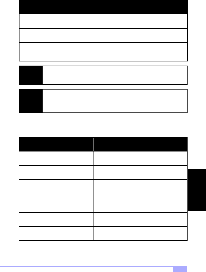
Thunder HEsl S2567 45
Error Messages
The following error messages may appear if something goes wrong during the boot process.
Using the Configuration Utility
Throughout the setup, selections that are not selectable are greyed out. Listed below are keys that you
can use throughout the setup.
Adapter removed from boot order, parame-
ters will be updated accordingly
Configuration data invalid, saving default
configuration!
This appears when an adapter is removed from the
system or relocated behind a PCI bridge.
This appears if none of the information in the
NVRAM is valid.
Error Message Possible Reason For Error
This appears when less than four adapters are in the
boot order and more adapters exist than are shown.
Found SCSI Controller not in following
Boot Order List, to Add: Press Ctrl-C to
start Symbios Configuration Utility...
NOTE: The SCSI BIOS Configuration Utility is a powerful tool. If you somehow disable all of
your controllers, pressing CTRL-A (or CTRL-E on BIOS version 4.04 or later) after
memory initialization during reboot allows you to re-enable and reconfigure.*
NOTE:
Not all devices detected by the Configuration Utility can be controlled by the BIOS.
Devices such as tape drives and scanners require that a device driver specific to that
peripheral be loaded. The SCSI BIOS Configuration Utility does allow parameters to
be modified for these devices.
F1
F2
Accesses the context sensitive help for the cursor-
resident field.
Sets cursor content to the menu selection area.
Select a menu item and press [ENTER].
Key Function
Select itemArrow Keys
Select item; use Up/Down/Left/Right keys to position
the cursor.
Home/End
Changes item value to next relative value.+/-
Abort/exit the current operating and/or exits the cur-
rent screen. User confirmation may occur.
ESC
Press [ENTER] to execute the field’s associated
function.
Enter
* under qualification at time of print, check Tyan website for updates: http://www.tyan.com
SCSI & LAN

http://www.tyan.com
46
Main Menu
This is the Main Menu setup that displays the Host Bus Adapters and their corresponding settings. Below
are the fields available along with their descriptions.
The next page describes the Boot Adapter List menu, available from the Main Menu.
Adapter
PCI Bus
Indicates the specific Symbios Host Adapter
The PCI Bus number (range 0x00 - 0xFF, 0 - 255
decimal) assigned by the system BIOS to an adapter
Field Details on field
Dev/Func
Indicates the I/O Port Number that communicates
with an adapter. The system BIOS also assigns this
number.
Port Number
Indicates the Interrupt Request Line used by an
adapter. The system BIOS also assigns this value.
IRQ
Indicates the relative boot order (0 to 3) of an
adapter. The Symbios SCSI BIOS traverses up to
four adapters in the specified order in search of
bootable media. Access the “Boot Adpater List”
Menu to modify this item.
Boot Order
Indicates whether an adapter has non-volatile mem-
ory (NVM) associated with it. An adapter’s configura-
tion is stored in its associated NVM. NVM can refer
to NVRAM that is resident on a host adapter or to
system NVS.
NVM
Indicates the PCI Device/Function assigned by the
system BIOS to an adapter.
An 8-bit value mapped as follows:
Bit # 7 6 5 4 3 2 1 0 Bits 2-0: Function (range 0 - 7)
Bits 7-3: Device (range 0x00 - 0x1F, 0-31
decimal)
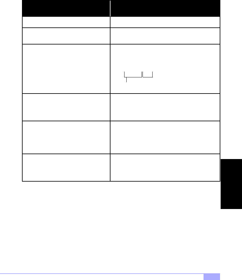
Thunder HEsl S2567 47
Boot Adapter List
The adapter boot order specifies the order in which adapters will boot when more than one Symbios
adapter is in a system.
Up to four of the total adapters in a system may be selected as bootable.
To add an adapter to the boot list, press [INSERT] while on the Boot Adapter List. This puts the cursor on
the adapter select list. Use the arrow keys to select the desired adapter and press [ENTER] to add it to
the end of the Boot Adapter List. Below are the fields available along with their descriptions.
The next page describes the Global Properties menu, available from the Main Menu.
Adapter
PCI Bus
Indicates the specific Symbios Host Adapter
The PCI Bus number (range 0x00 - 0xFF, 0 - 255
decimal) assigned by the system BIOS to an adapter
Field Details on field
Dev/Func
Specifies the relative boot order (0 to 3) of an
adapter.
- : decreases an adapter’s relative boot order
+ : increases an adapter’s relative boot order
Boot Order
Indicates whether an adapter in the boot list was
enabled during the most recent boot. Disabled
adapters and their attached devices are ignored by
the Symbios PCI SCSI BIOS., they are still visible to
the Configuration utuility.
Current Status
Specifies whether to enable an adapter upon the
next boot. The Symbios SCSI BIOS ignores disabled
adapters and their attached devices although they
are still visible to the Configuration Utility.
Next Boot
Indicates the PCI Device/Function assigned by the
system BIOS to an adapter.
An 8-bit value mapped as follows:
Bit # 7 6 5 4 3 2 1 0 Bits 2-0: Function (range 0 - 7)
Bits 7-3: Device (range 0x00 - 0x1F, 0-31
decimal)
SCSI & LAN

http://www.tyan.com
48
Global Properties
The Global Properties option on the Main Menu allows you to set Display and Video modes as well as a
pause if an altert message has been displayed. Below are the fields available along with their descrip-
tions.
The next page describes the Adapter Properties menu, available from the Main Menu.
Pause When Boot Alert Displayed
This option specifies whether to pause for user
acknowledgement after displaying an alert message
during boot. The Boot Alert setting can be either No
or Yes.
To continue after displaying a message, specify
No.
To wait for any key after displaying a message,
specify Yes.
Field Details on field
This option specifies the information display mode of
the BIOS during boot. It controls how much informa-
tion about adapters and devices are displayed dur-
ing boot. The Display Mode setting can be either
Terse or Verbose.
Boot Information Display Mode
This option sets the default value for synchronous
and wide negotiations with specified devices.
Options are: All, None, or Supported.
Negotiate with devices
Select this option to restore all default settings.<Restore Defaults>
This option specifies the default video mode for the
Configuration Utility. The Video Mode setting can be
either Color or Monochrome. The monochrome set-
ting enhances readability on a monochrome monitor.
Video Mode

Thunder HEsl S2567 49
Adapter Properties
The Adapter Properties menu allows you to view and modify adapter settings, and provides access to an
adapter’s device settings. Below are the fields available along with their descriptions.
<Device Properties> To view and modify device properties, press
[ENTER].
Field Details on field
This field indicates whether SCSI parity is enabled
for an adapter. When disabled, it is also necessary
to disable disconnects for all devices, as parity
checking for the reselection phase is NOT disabled.
If a non-parity generating device disconnects, its
operation will never complete because the reselec-
tion fails due to parity error.
SCSI Parity
This field indicates the SCSI identifier of an adapter
[0-7] or [0-15]. It is recommended that this field be
set to the highest priority SCSI identifier, which is 7.
Host SCSI ID
This field indicates the order in which to scan SCSI
identifiers on an adapter. Changing this item will
affect drive letter assignment(s) if more than one
device is attached to an adapter. Note: Changing
this item may conflict with an operating system
that automatically assigns drive order.
SCSI Bus Scan Order
This field specifies the removable media support
option for an adapter. Three settings are allowed:
None indicates no removable media support
whether the drive is selected as first (BBS), or is first
in the scan order (non-BBS).
Boot Drive Only provides removable media support
for a removable harddrive if it is first in the scan
order.
With Media Installed provides removable media
regardless of the drive ordering.
Removeable Media Support
This field defines how the Cylinder Head Sector val-
ues are mapped onto a disk without pre-existing par-
tition information. CHS Mapping allows two settings:
SCSI Plug-and-Play Mapping (default value), and
Alternate CHS Mapping.
SCSI Plug-and-Play Mapping automatically deter-
mines the most efficient and compatible mapping.
Alternate CHS Mapping utilizes an alternate, possi-
bly less efficient mapping that may be required if a
device is moved between adapters from different
vendors.
Note: Neither of these options has any effect after a
disk has been partitioned using FDISK*. To change
the CHS Mapping on a partitioned disk, use FDISK*
to delete all partitions. Then reboot the system to
clear memory or the old partitioning data will be
reused, thus nullifying the previous operation.
CHS Mapping
* CAUTION: Use care to ensure that the correct disk is the target of the FDISK.
SCSI & LAN

http://www.tyan.com
50
Adapter Properties (continued)
The next page describes the Device Properties.
Spinup Delay (secs)
This field indicates the number of seconds to wait
between spinups of devices attached to an adapter.
Staggered spinups will balance the total electrical
current load on the system during boot. The default
value is 2 seconds with choices between 1 and 10
seconds.
Field Details on field
This field indicates whether an adapter has one or
more devices attached that are shared with one or
more other adapters and therefore, the Symbios PCI
SCSI BIOS should avoid SCSI Bus resets as much
as possible.
This option allows the user to enable an adapter to
join a cluster of adapters without doing any SCSI
bus resets. This is a requirement for Microsoft Clus-
ter Server. The default value is No with an alternate
option of Yes.
Secondary Cluster Server
This field indicates whether an adapter has auto-
matic termination control, and if so, its current status.
Two settings are:
Auto:
Off:
Note: If Auto is greyed out, it means the termination
is automatic, not programmable.
The adapter automatically determines
whether it should enable or disable its ter-
mination.
Termination at the adapter is off, the
devices at the ends of the SCSI bus must
terminate the bus.
Termination Control
Select this option to restore all default settings.<Restore Defaults>

Thunder HEsl S2567 51
Device Properties
The Device Properties screen provides viewing and updating individual device settings for an adapter.
Changing a setting for the host device (for example, SCSI ID 7) changes the setting for all devices. Below
are the fields available along with their descriptions.
(continued on next page)
SCSI ID This field indicates the device’s SCSI identifier.
Field Details on field
This field indicates the ASCII device identitifer string
extracted from the device’s Inquiry Data.
Device Identifier
This field indicates the maximum synchronous data
transfer rate, in Mega Transfer per second.
Sync Rate
Mega Trans-
fers/sec Data Width=
8 MB/s Data Width=
16 MB/s Synchronous
Period (nsec)
0=Async 0=Async
5
0=Async 0=Async
5
10
10 200
10 20 100
20 20 40 50
40 40 80 25
This field indicates the maximum data width in bits.Data Width
This field indicates whether to scan for this SCSI
identifer at boot time. This item can be used to
ignore a device and to decrease boot time by dis-
abling the inquiry of unused SCSI identifiers.
Set this option to “No” if there is a device that you do
not want to be available to the system. Also, on a
bus with only a few devices attached, the user can
speed up boot time by changing this setting to “No”
for all unused SCSI IDs.
Scan ID
This field indicates whether to scan for Logical Unit
Numbers (LUNs) greater than 0 for a device. LUN 0
is always queried. This option should be used if a
multi-LUN device responds to unoccupied LUNs or if
it is desired to reduce the visibility of a multi-LUN
device to LUN zero only.
Set this option to “No” if you have problems with a
device that responds to all LUNs whether they are
occupied or not. Also, if a SCSI device with multiple
LUNs exists on your system but you do not want all
of those LUNs to be available to the system, then set
this option to “No”. This will limit the scan to LUN 0
only.
Scan LUNs > 0
This field indicates whether to allow a device to dis-
connect during SCSI operations. Some (mostly
newer) devices run faster with disconnect enabled,
while some (mostly older) devices run faster with
disconnect disabled.
Disconnect
SCSI & LAN

http://www.tyan.com
52
Device Properties (continued)
Quitting the SCSI BIOS Configuration Utility
Since some changes go into effect only after the system reboots, it is very important that you exit this util-
ity properly. To exit, press [ESC] (escape key) and respond to the prompts that follow.
Select this option to restore all default settings.<Restore Defaults>
SCSI Timeout
This field indicates the maximum amount of time [0
to 9999] in seconds to wait for a SCSI operation to
complete.
Since timeouts provide a safeguard that allows the
system to recover should an operation fail, it is rec-
ommended that a value greater than 0 be used. A
value of 0 allows unlimited time for an operation to
complete and could result int he system hanging
(waiting forever) should an operation fail.
Press [ENTER], type in a value, and then press
[ENTER] again to specify a new timeout value.
Field Details on field
This field indicates whether to allow the use of
queue tags for a device. Currently the BIOS does
not use queue tags. This item specifies queue tag
control to higher level device drivers.
Queue Tags
This field indicates whether this device may possibly
be selected as the boot device. This option is only
applicable to devices attached to adapter number 0
(in the boot list) on non-BBS systems. It provides
primitive BBS flexibility to non-BBS systems.
Boot Choice
Select this option to low-level format the device.
If enabled, this option allows low-level formatting on
a disk drive. Low-level formatting will completely and
irreversibly erase all data on the drive.
Note: Formatting will default the drive to a 512-byte
sector size even if the drive had previously been for-
matted to another sector size.
Format
Select this option to verify all sectors on the device
and to reassign defective Logical Block Addresses
(LBAs).
Verify
NOTE: If you reboot the system without properly exiting from this utility, some changes may
not take effect.
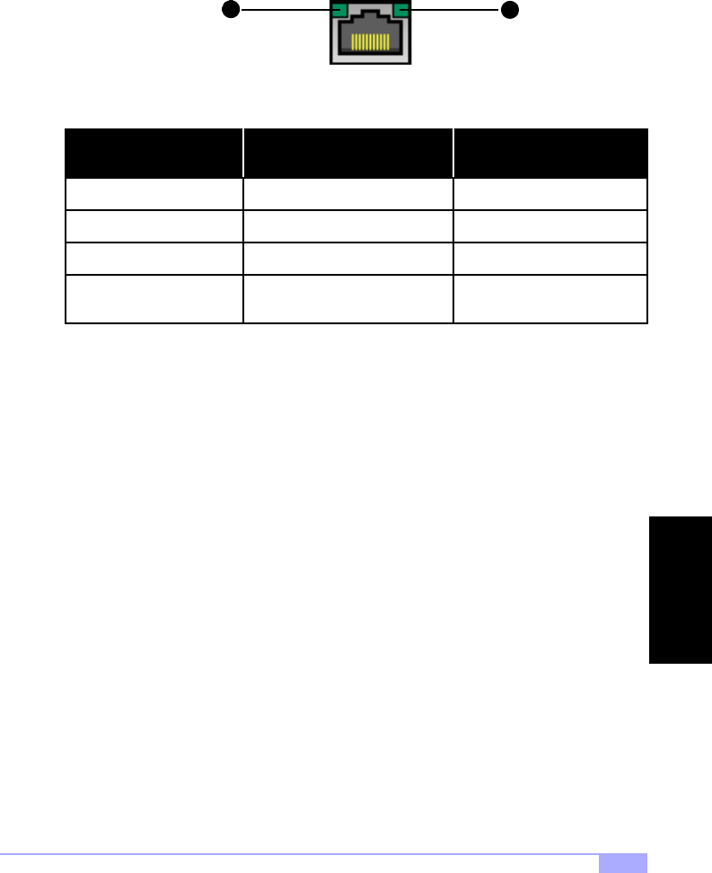
Thunder HEsl S2567 53
LAN Information
Your motherboard has an onboard Intel 82559 LAN controller, with 10/100 MBits/s transfer speed. For
more information regarding the onboard LAN controllers, check the Intel website: http://www.intel.com
Below are some explanations of what the LEDs mean, and how they display the LAN’s status.
2
1
Good connection @ 10 Mbps
No connection
LED (1) - Orange Light LED (2) - Green Light
Data being transferred
LAN Status
OFF
Good connection @ 100 Mbps ON ON
ON
OFFOFF
ON (10Mbps)
Orange (100Mbps) LED is blinking
SCSI & LAN

http://www.tyan.com
54
Appendix II: Glossary
ACPI (Advanced Configuration and Power Interface): a power management specification that allows the
operating system to control the amount of power distributed to the computer’s devices. Devices not in use
can be turned off, reducing unnecessary power expenditure.
AGP (Accelerated Graphics Port): a PCI-based interface which was designed specifically for demands of
3D graphics applications. The 32-bit AGP channel directly links the graphics controller to the main mem-
ory. While the channel runs at only 66 MHz, it supports data transmission during both the rising and falling
ends of the clock cycle, yielding an effective speed of 133 MHz.
AMR (Audio Modem Riser): a modem that can be used on Intel Reference Motherboard platforms using
Intel’s core logic chipsets supporting AC-link 2.1. It supports fax and all data feedback modes. It provides
high speed communications between your personal computer and a remove lcoation, such as an Internet
Service Provider (ISP).
AT: the original form factor of IBM’s PC.
ATAPI (AT Attachment Packet Interface): also known as IDE or ATA; a drive implementation that includes
the disk controller on the device itself. It allows CD-ROMs and tape drives to be configured as master or
slave devices, just like HDDs.
ATX: the form factor designed to replace the AT form factor. It improves on the AT design by rotating the
board 90 degrees, so that the IDE connectors are closer to the drive bays, and the CPU is closer to the
power supply and cooling fan. The keyboard, mouse, USB, serial, and parallel ports are built-in.
Bandwidth: refers to carrying capacity. The greater the bandwidth, the more data the bus, phone line, or
other electrical path, can carry. Greater bandwidth, then, also results in greater speed.
BBS (Bulletin Board System): a computer system with a number of modems hooked up to it which acts a
center for users to post messages and access information.
BIOS (Basic Input/Output System): the program that resides in the ROM chip, and provides the basic
instructions for controlling your computer’s hardware. Both the operating system and application software
use BIOS routines to ensure compatibility.
Buffer: a portion of RAM which is used to temporarily store data, usually from an application, though it is
also used when printing, and in most keyboard drivers. The CPU can manipulate data in a buffer before
copying it, all at once, to a disk drive. While this improves system performance --- reading to or writing
from a disk drive a single time is much faster than doing so repeatedly --- there is also the possibility of
losing your data should the system crash. Information stored in a buffer is temporarily stored, not perma-
nently saved.

Thunder HEsl S2567 55
Bus: a data pathway. The term is used especially to refer to the connection between the processor and
system memory, and between the processor and PCI or ISA local buses.
Bus mastering: allows peripheral devices and IDEs to access the system memory without going through
the CPU (similar to DMA channels).
Cache: a temporary storage area for data that will be needed often by an application. Using a cache low-
ers data access times, since the needed information is stored in the SRAM instead of in the slow DRAM.
Note that the cache is also much smaller than your regular memory: a typical cache size is 512KB, while
you may have as much as 1GB of regular memory.
Cache size: refers to the physical size of the cache onboard. This should not be confused with the cache-
able area, which is the total amount of memory which can be scanned by the system in search of data to
put into the cache. A typical setup would be a cache size of 512KB, and a cacheable area of 512MB. In
this case, up to 512KB of the main memory onboard is capable of being cached. However, only 512KB of
this memory will be in the cache at any given moment. Any main memory above 512MB could never be
cached.
Closed and open jumpers: jumpers and jumper pins are active when they are “on” or “closed”, and inac-
tive when they are “off” or “open”.
CMOS (Complementary Metal-Oxide Semiconductors): chips that hold the basic startup information for
the BIOS.
COM port: another name for the serial port, which is called as such because it transmits the eight bits of
a byte of data along one wire, and receives data on another single wire (that is, the data is transmitted in
serial form, one bit after another). Parallel ports transmit the bits of a byte on eight different wires at the
same time (that is, in parallel form, eight bits at the same time).
DDR (Double Data Rate): improves RAM speed to at least 200 MHz. It activates output on both the rising
and falling edge of the system clock rather than on just the rising edge, potentially doubling output.
DIMM (Dual In-line Memory Module): faster and more capacious form of RAM than SIMMs, and do not
need to be installed in pairs.
DIMM bank: sometimes called DIMM sockets, because the physical slot and the logical unit are the
same. That is, one DIMM module fits into one DIMM socket, which is capable of acting as a memory
bank.
DMA (Direct Memory Access): channels that are similar to IRQs. DMA channels allow hardware devices
(like soundcards or keyboards) to access the main memory without involving the CPU. This frees up CPU
resources for other tasks. As with IRQs, it is vital that you do not double up devices on a single line. Plug-
n-Play devices will take care of this for you.
GLOSSARY

http://www.tyan.com
56
Doze mode: in this mode, only the CPU’s speed is slowed.
DRAM (Dynamic RAM): widely available, very affordable form of RAM which has the unfortunate ten-
dency to lose data if it is not recharged regularly (every few milliseconds). This refresh requirement
makes DRAM three to ten times slower than non-recharged RAM such as SRAM.
EDO RAM (Extended Data-Out RAM): speeds access to memory locations by assuming that memory
addresses are static; the next time it looks for a bit of data, it will be at the same spot, or one nearby.
EEPROM (Electrically Erasable Programmable ROM): also called Flash BIOS, is a ROM chip which can,
unlike normal ROM, be updated. This allows you to keep up with changes in the BIOS programs without
having to buy a new chip. Tyan’s BIOS updates can be found at http://www.tyan.com
ESCD (Extended System Configuration Data): a format for storing information about Plug-n-Play devices
in the system BIOS. This information helps properly configure the system each time it boots.
Fault-tolerance: a term describing a system where one component can quickly be replaced without caus-
ing a loss of service, such as in a RAID system.
Firmware: low-level software that controls the system hardware.
Form factor: an industry term for the size, shape, power supply type, and external connector type of the
Personal Computer Board (PCB) or motherboard. The standard form factors are the AT and ATX,
although Tyan also makes some Baby-AT and ATX Footprint boards.
Global timer: onboard hardware timer, such as the Real-Time Clock (RTC).
Handshaking: a form of encryption. One system, typically the server, sends an encryption scheme to
another agent, typically a client. Thus, the client’s data is protected during transmittal to the server.
HDD: stands for Hard Disk Drive, a type of fixed drive.
H-SYNC: controls the horizontal synchronization/properties of the monitor.
IC (Integrated Circuit): the formal name for the computer chip.
IDE (Integrated Device/Drive Electronics): a simple, self-contained HDD interface. It can handle drives up
to 8.4 GB in size. Almost all IDEs sold now are in fact Enhanced IDEs (EIDEs), with maximum capacity
determined by the hardware controller.
IDE INT (IDE Interrupt): a hardware interrupt signal that goes to the IDE.

Thunder HEsl S2567 57
I/O (Input/Output): the connection between your computer and another piece of hardware (mouse, key-
board, etc.)
IRQ (Interrupt Request): an electronic request that runs from a hardware device to the CPU. The interrupt
controller assigns priorities to incoming requests and delivers them to the CPU. It is important that there is
only one device hooked up to each IRQ line; doubling up devices on IRQ lines can lock up your system.
Plug-n-Play operating systems can take care of these details for you.
ISA (Industry Standard Architecture): a slower 8- or 16-bit bus (data pathway).
Latency: the amount of time that one part of a system spends waiting for another part to catch up. This is
most common when the system sends data out to a peripheral device, and it waiting for the peripheral to
send some data back (peripherals tend to be slower than onboard system components).
Mirroring: see RAID.
NVRAM: ROM and EEPROM are both examples of Non-Volatile RAM, memory that holds its data without
power. DRAM, in contrast, is volatile.
OEMs (Original Equipment Manufacturers): Compaq or IBM package other companies’ motherboards
and hardware inside their case and sell them.
Parallel port: transmits the bits of a byte on eight different wires at the same time (that is, in parallel form,
eight bits at the same time).
PCI (Peripheral Component Interconnect): a 32-bit local bus (data pathway) which is faster than the ISA
bus. Local buses are those which operate within a single system (as opposed to a network bus, which
connects multiple systems).
PCI PIO (PCI Programmable Input/Output) modes: the data transfer modes used by IDE drives. These
modes use the CPU for data transfer (in contrast, DMA channels do not). PCI refers to the type of bus
used by these modes to communicate with the CPU.
PCI-to-PCI bridge: allows you to connect multiple PCI devices onto one PCI slot.
Pipeline burst SRAM: a fast secondary cache. It is used as a secondary cache because SRAM is slower
than SDRAM, but usually larger. Data is cached first to the faster primary cache, and then, when the pri-
mary cache is full, to the slower secondary cache.
Pipelining: improves system performance by allowing the CPU to begin executing a second instruction
before the first is completed. A pipeline can be likened to an assembly line, with a given part of the pipe-
line repeatedly executing a set part of an operation on a series of instructions.
GLOSSARY

http://www.tyan.com
58
PM timers (Power Management timers): software timers that count down the number of seconds or min-
utes until the system times out and enters sleep, suspend, or doze mode.
PnP (Plug-n-Play): a design standard that has become ascendant in the industry. Plug-n-Play devices
require little set-up to use. Novice end users can simply plug them into a computer that is running on a
Plug-n-Play aware operating system (such as Windows 98), and go to work. Devices and operating sys-
tems that are not Plug-n-Play require you to reconfigure your system each time you add or change any
part of your hardware.
PXE (Preboot Execution Environment): one of four components that together make up the Wired for Man-
agement 2.0 baseline specification. PXE was designed to define a standard set of preboot protocol ser-
vices within a client, towards the goal of allowing networked-based booting to boot using industry
standard protocols.
Striping: see RAID.
RAID (Redundant Array of Independent Disks): a way for the same data to be stored in different places
on many hard drives. By using this method, the data is stored redundantly, also the multiple hard drives
willl appear as a single drive to the operating system. RAID level 0 is is known as striping, where data is
striped (or overlapped) across multiple hard drives, but offers no fault-tolerance. RAID level 1 is known as
mirroring, which stores the data within at least two hard drives, but does not stripe. RAID level 1 also
allows for faster access time and fault-tolerance, since either hard drive can be read at the same time.
RAID level 0+1 is both striping and mirroring, providing fault-tolerance, striping, and faster access all at
the same time.
RAM (Random Access Memory): technically refers to a type of memory where any byte can be accessed
without touching the adjacent data, is often used to refer to the system’s main memory. This memory is
available to any program running on the computer.
ROM (Read-Only Memory): a storage chip which contains the BIOS; the basic instructions required to
boot the computer and start up the operating system.
SDRAM (Synchronous Dynamic RAM): called as such because it can keep two sets of memory
addresses open simultaneously. By transferring data alternately from one set of addresses and then the
other, SDRAM cuts down on the delays associated with non-synchronous RAM, which must close one
address bank before opening the next.
Serial port: called as such because it transmits the eight bits of a byte of data along one wire, and
receives data on another single wire (that is, the data is transmitted in serial form, one bit after another).
SIMM (Single In-line Memory Module): formerly the most common form of RAM for motherboards. They
must be installed in pairs, and do not have the carrying capacity or the speed of DIMMs.

Thunder HEsl S2567 59
Sleep/Suspend mode: in this mode, all devices except the CPU shut down.
SRAM (Static RAM): unlike DRAM, this type of RAM does not need to be refreshed in order to prevent
data loss. Thus, it is faster, and more expensive.
Standby mode: in this mode, the video and fixed disk drive (usually the HDD) shuts down; all other
devices continue to operate normally.
UltraDMA/33/66/100: a fast version of the old DMA channel. UltraDMA is also called UltraATA. Without
the proper UltraDMA controller, your system cannot take advantage of the higher data transmission rates
of the new UltraDMA/UltraATA HDDs.
USB (Universal Serial Bus): a versatile port. This one port type can function as a serial, parallel, mouse,
keyboard, or joystick port. It is fast enough to support video transfer, and is capable of supporting up to
127 daisy-chained peripheral devices.
VGA (Video Graphics Array): the PC video display standard.
V-SYNC: controls the vertical properties of the monitor.
ZIF socket (Zero Insertion Force socket): these sockets make it possible to insert CPUs without damag-
ing the sensitive CPU pins. The CPU is lightly placed in an open ZIF socket, and the metal level is pulled
down. This shifts the processor over and down, guiding it into place on the board.
GLOSSARY

http://www.tyan.com
60
Notice for the USA
Compliance Information Statement (Declaration of Conformity Procedure) DoC
FCC Part 15: This device complies with Part 15 of the FCC Rules.
Operation is subject to the following conditions:
1)
2)
Notice for Canada
This apparatus complies with the Class B limits for radio interference as specified in the Canadian Depart-
ment of Communications Radio Interference Regulations. (Cet appareil est conforme aux normes de
Classe B d’interference radio tel que spécifié par le Ministére Candien des Communications dans les
réglements d’inteférence radio.)
Notice for Europe (CE Mark)
This product is in conformity with the Council Directive 89/336/EEC, 92/31/EEC (EMC).
CAUTION: Lithium battery included with this board. Do not puncture, multilate, or dispose of battery in
fire. Danger of explosion if battery is incorrectly replaced. Replace only with the same or equivalent type
recommended by manufacturer. Dispose of used battery according to manufacturer instructions and in
accordance with your local regulations.
this device may not cause harmful interference, and
this device must accept any interference received including
interference that may cause undesired operation. If this
equipment does cause harmful interference to radio or televi-
sion reception, which can be determined by turning the equi-
ipment off and on, the user is encouraged to try one or more
of the following measures:
Reorient or relocate the receiving
antenna.
Increase the separation between the
equipment and receiver.
Plug the equipment into an outlet on
a circuit different from that of the
receiver.
Consult the dealer or an experienced
radio/television technician for help.
Document # D1431-101
