Mx06 Instruction Manual
User Manual: manual pdf -FilePursuit
Open the PDF directly: View PDF ![]() .
.
Page Count: 18
Page 1 of 18
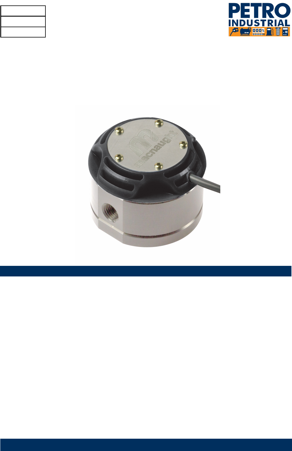
INSTRUCTION MANUAL
MODEL MX06 and MX09
1/4’’ OVAL GEAR FLOWMETER
MXL-INST06
Rev 4
12/2013
To the Owner
Please read and retain this instruction manual to assist you in the operation and maintenance of this product.
This manual contains connection and operating in-structions for the MX series Flowmeters with Pulse outputs.
Models with a Liquid Crystal Display have an addi-tional LCD instruction manual supplied. If you need further
assistance, contact your local representative or distributor for advice.
This Flow Meter has incorporated the oval rotor prin-cipal into its design. This is proven to be a reliable and
highly accurate method of measuring flow. Exceptional repeatability and high accuracy over a wide range of
fluid viscosities and flow rates are features of the oval rotor design.
With a low pressure drop and high pressure rating oval rotor flow meters are suitable for both gravity and (in-
line) pump applications.

index
Installation
Pre-installation checks Page 3
………………………………………………………….
Operating Principle Page 3
………………………………………………………….
Installation Procedure Page 3
………………………………………………………….
Maintenance Procedure
Disassembly Page 4
………………………………………………………….
Reassembly Page 4
………………………………………………………….
Flowmeter Specifications
Flowmeter Specifications Page 5
………………………………………………………….
Electrical Specifications Page 5
………………………………………………………….
Wiring Diagram - Standard Pulser Page 6
………………………………………………………….
Wiring Diagram - PCB sensor Page 7
………………………………………………………….
Wiring Diagram—Intrinsically Safe Switch Page 8
..……………………………………………….
Wiring Diagram - High Temperature Switch Page 9
…………………………………………….
Service
Troubleshooting Guide Page 10
………………………………………………………….
Maintenance Resources Page 10
………………………………………………………….
Exploded Diagram Page 11
………………………………………………………….
Spare Parts Kits Page 12
………………………………………………………….
Wetted Parts Page 13
………………………………………………………….
General
Pressure Drop Graphs Page 14
………………………………………………………….
Dimensional Diagrams Page 15-16
………………………………………………………….
Page 2 of 18
IMPORTANT INFORMATION
OPERATING PRINCIPLE
INSTALLATION PROCEDURE
FLUID COMPATABILITY
Before use, confirm the fluid to be used is
compatible with the meter. Refer to Industry
fluid compatibility charts or consult your local
representative for advice.
To prevent damage from dirt or foreign matter
it is recommended that a Y or Basket type
200 mesh strainer be installed as close as
possible to the inlet side of the meter.
When a strainer is installed it should be
regularly inspected and cleaned. Failure to
keep the strainer clean will dramatically effect
flow meter performance.
Contact your local representative for advice.
To prevent damage caused by air purge slowly
fill the meter with fluid.
To reduce pressure build-up turn off the
at the end of each day.
The reed switch can cause inaccurate rate
counts when used with high speed counters.
It is advised that a low speed counter is used or
alternatively a denounce circuit be installed.
AIR PURGE / LINE PRESSURE
STRAINER
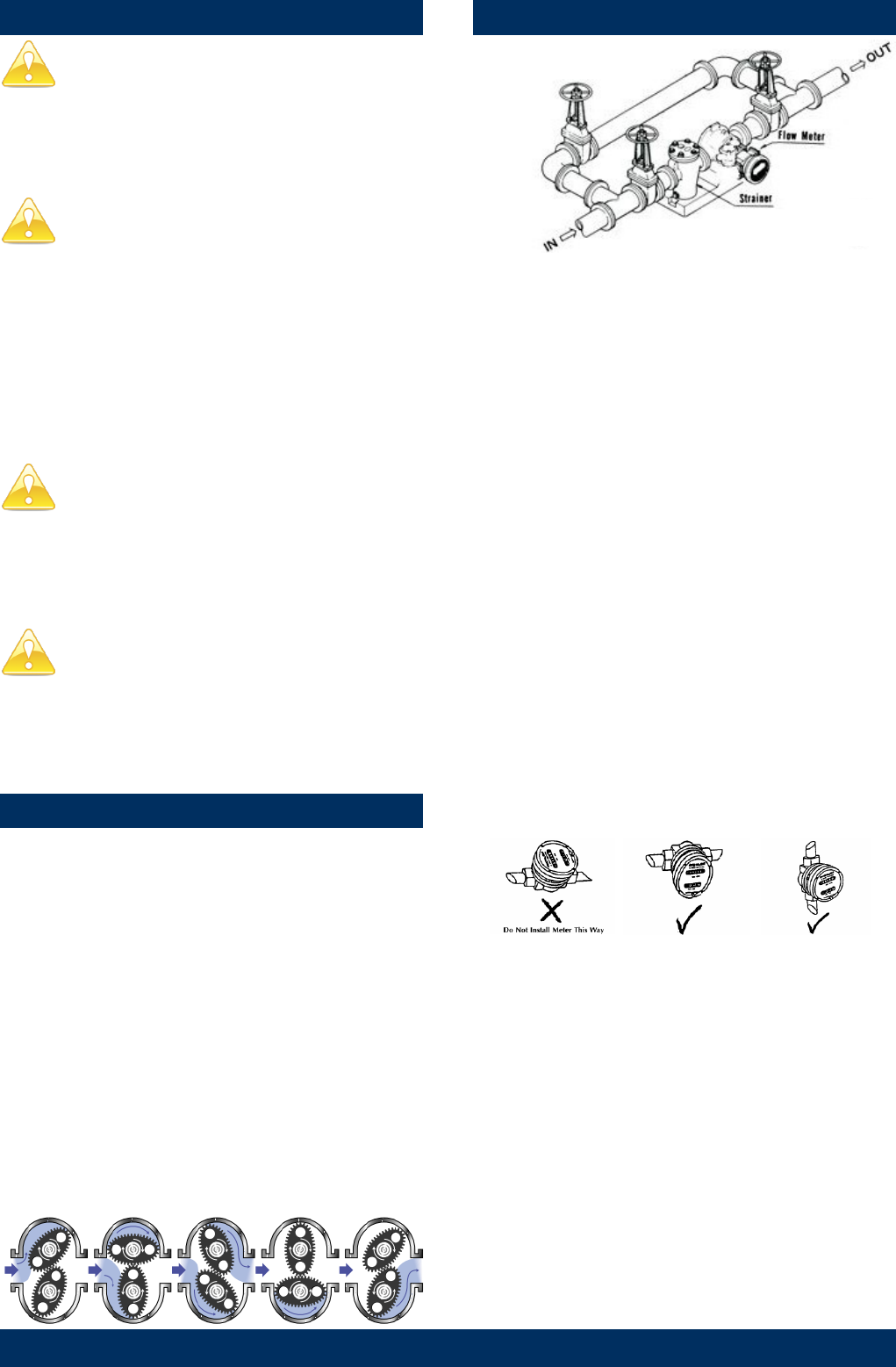
Fluid passing through the meter causes the rotors to
turn, as shown below.
One of the rotors (the active rotor) is fitted with
magnets.
The passing of the magnets are picked up by the
sensing elements (Reed and Hall Effect sensors)
located in the Pulser Circuit Board.
The excitation of these switches provides a ‘Raw
Pulse Output’ which relates to the K-Factor.
(e.g. KF 400 = 400 pulses per litre of fluid passed)
This Pulse Output Signal can either be fed directly to
an external receiving element (e.g. Data Logger or
PLC) or alternatively to an LC Display which condi-
tions the Pulse input signal to display volume of fluid
passed. (e.g. Display 1 Litre per for every 400 pulses
received)
1. It is recommended that when setting up pipe work
for meter installations, a bypass line be included
in the design. This provides the facility for a meter
to be removed for maintenance without interrupt
ing production. (see figure above)
2. Use thread sealant on all pipe threads.
3. For pump applications ensure pipe work and
Meter have the appropriate working pressure
rating to match the pressure output of the pump.
Refer to Meter Specifications section for further
details.
4. Install a wire mesh strainer, Y or basket type 200
mesh (74 micron), as close as possible to the
inlet side of the meter.
5. Note: The Flowmeter can accept flow in any
direction.
6. The meter can be installed in any orientation as
long as the meter shafts are in a horizontal plane.
(Refer to diagram below for correct installation)
.
Note: Incorrect installation can cause premature
wear of meter components.
The LC display may removed by loosening the 4
mounting screws and be orientated as required.
7. Do not over tighten meter connections. .
8. It is important that after initial installation you
fill the line slowly, high speed air purge could
cause damage to the rotors.
9. Test the system for leaks.
10. Check the strainer for swarf or foreign material,
after the first 200 litres check periodically,
particularly if the flow rate is noted to be
decreasing.
REED SWITCH
Page 3 of 18
MAINTENANCE PROCEDURE
Note: Maintenance can be carried out to the liquid
crystal displays and pulse output modules without
having to remove or isolate the meter from the proc-
ess line.
When maintenance to any other part of the meter is
required, the meter must be isolated and the line
pressure released.
Refer to the exploded parts diagram on (see Fig for
item numbers.
Note: It is advisable to mark all components with a
marker pen before disassembly, to ensure all the
components are replaced to their correct position
during the reassembly process.
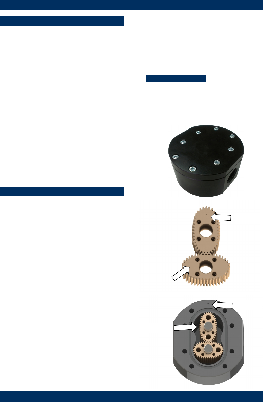
1. Remove the meter cap by loosening the bolts on
the underside of the meter body. (see FIG 1)
2. Remove the O-Ring from the O-Ring groove in the
meter cap.
Wipe clean of grease and store in clean place
3. Remove rotors from the meter body
4. Remove the shafts from the meter body.
DISASSEMBLY
REASSEMBLY
1. Before reassembling check the condition of the
rotors (replace if necessary).
2. Replace the shafts into the meter body.
3. There are two Rotor Types.
Active and Neutral.
The Active Rotor can be identified by a Dimple on
the face of the rotor. (see Fig 2)
Caution: The active rotor is always fitted
nearest ‘dimple’ on the meter body
(see FIG 3)
Replace Active Rotor.
Check the dimpled face (smooth side) of the rotor
is the lead-in face when fitting onto the shaft and
into the meter body. (see Fig 2).
Replace Neutral Rotor. Check that the smooth
side of the rotor is the leading face when fitting
onto the shaft. (see FIG 2)
Fit the neutral rotor onto the shafts ensuring that
the rotor pair are at 90 degrees to one another.
(see FIG 3)
Check their operation by turning either of the
rotors. If the rotors are not in mesh correctly,
or do not move freely, remove one of the rotors
and replace correctly at 90 degrees to one another
4. Smear the O-Ring with a light film of grease.
Replace the O-Ring into groove in the meter cap.
The O-Ring will need to be replaced if it has
grown or is damaged in anyway.
5. Replace the meter cap.
6. Insert the cap head screws and tighten in a
diagonal sequence 1, 5, 7, 3, etc.
7. Test the meter by turning the rotors with a finger
or by applying very low air pressure (no more
than a good breath) to one end of the meter,
before returning the meter to service.
Torque = 6.5 Nm
Smooth side
FIG 2
FIG 1
FIG 3 Dimple
Dimple
Active Rotor
Page 4 of 18
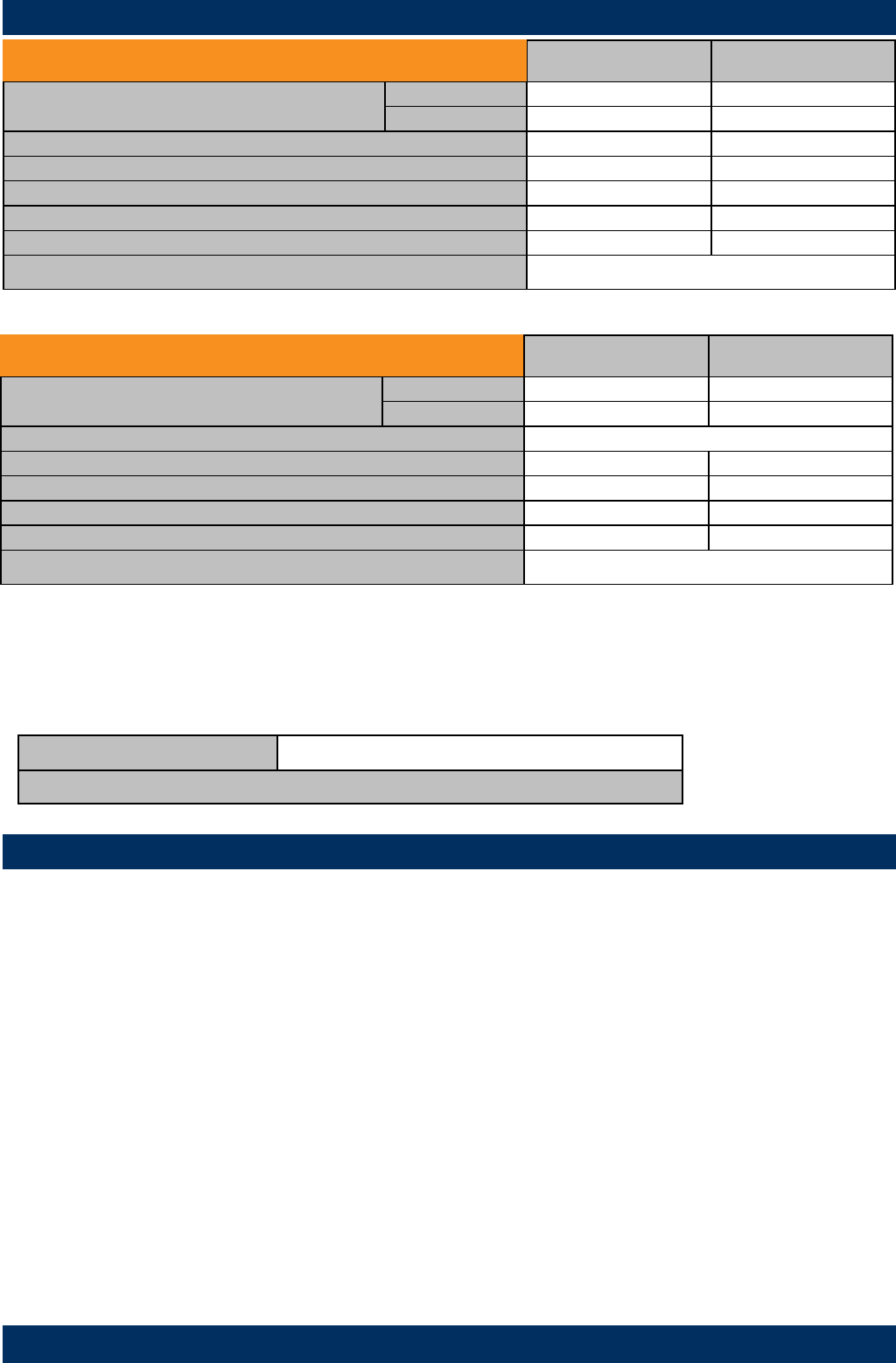
FLOWMETER SPECIFICATIONS
Model MX06 Metric US
Flow Range Below 5 cP 2 to 100 LPH 0.5 to 26 GPH
5 to 1000 cP 0.5 to 100 LPH 0.13 to 26.4 GPH
K-Factor (Sensor Pulses per Unit of Measure) 1000 pulses/L 3785.4 pulses/G
Max Temperature (model MX06F) -40°C - 80°C -40°F - 176°F
(models MX06S) -40°C - 120°C -40°F - 248°F
(models MX06P) -40°C - 150°C -40°F - 302°F
Maximum Operating Pressure1 6895 kPa 1000 psi
Accuracy of Reading ±1%
1. Conforms to Directive 97/23/EC—Cat 1
Output option: type ‘D’ type ’E’ type ‘F” type “G’ type “H”
Display Type : PR PRA ER ERA ERB ERS (remote mount only)
Display Part Number: MXD-DS MXD-ES MXD-ES MXD-GS MXD-HS ERS-RMP / ERS-RMA
Instruction Sheet: DR013 DR014 MS574 MS392 MS476 MS351
ELECTRICAL SPECIFICATIONS
The MX Flow meter series is supplied with either a Blind Pulser and Digital Display option.
Please note the wiring diagrams in the following pages are for the Blind Pulser Output Modules and the PCB
(Sensor Board), which is responsible for providing a Raw Pulse input to the LC display
If the Flow meter is supplied with an LC Display fitted, please consult the appropriate Instruction Manual, as
advised below, for all programming and wiring instructions.
High Viscosity Applications
Ensure the Flowmeter is fitted with ‘High Viscosity Rotors’ is the fluid being metered is 1000 cP or above
High Viscosity Rotors For Fluids above 1000 Centipoise (cP)
*Note: High Viscosity Rotor option available for models MX09S and MX09P only.
Analogue Output (4-20mA)
Analogue outputs are available as an auxiliary display signal by including either of the following LC displays with
your flowmeter. These may be fitted to the meter or remote (wall mount) types.
PRA 12mm LC Display with analogue output module
ERA 17mm LC Display with analogue output module
Model MX09 Metric US
Flow Range Below 5 cP 25 to 500 LPH 6.6 to 132 GPH
5 to 1000 cP 15 to 500 LPH 4 to 132 GPH
K-Factor (Sensor Pulses per Unit of Measure) Refer to Flowmeter Data Plate
Max Temperature (model MX09F) -40°C - 80°C -40°F - 176°F
(models MX09S) -40°C - 120°C -40°F - 248°F
(models MX09P) -40°C - 150°C -40°F - 302°F
Maximum Operating Pressure1 6895 kPa 1000 psi
Accuracy of Reading ±1%
1. Conforms to Directive 97/23/EC—Cat 1
Page 5 of 18
Pulser Specifications
Output Signals Standard Pulse Meter 2x Digital (Square Wave)
Reed Switch
(Mechanical Sensor)
Current Maximum 500mA
Voltage Maximum 30V DC
Contact Rating Maximum1 10W
Hall Effect IC
(Electronic Sensor)
Maximum Current 7.5mA
Operating Voltage 4.5V to 24V DC
Transistor Type Open-Collector NPN
1. Contact rating maximum is 10W. Neither current nor voltage maximums should be exceeded in achieving this.
WIRING DIAGRAM 1 Standard Pulser
Output type ‘A’
White
NPN Hall effect
Reed switch N/O
Red
Black
Green
Yellow
+VE
Signal
-VE
+VE
-VE
Page 6 of 18
Reed Switch
To maximise the life of the reed switch contacts, the pulse board comes equipped with a 1k8Ω current limiting resistor in series
with the reed switch as standard.
These resistors are user swappable should you require a different value for your system.
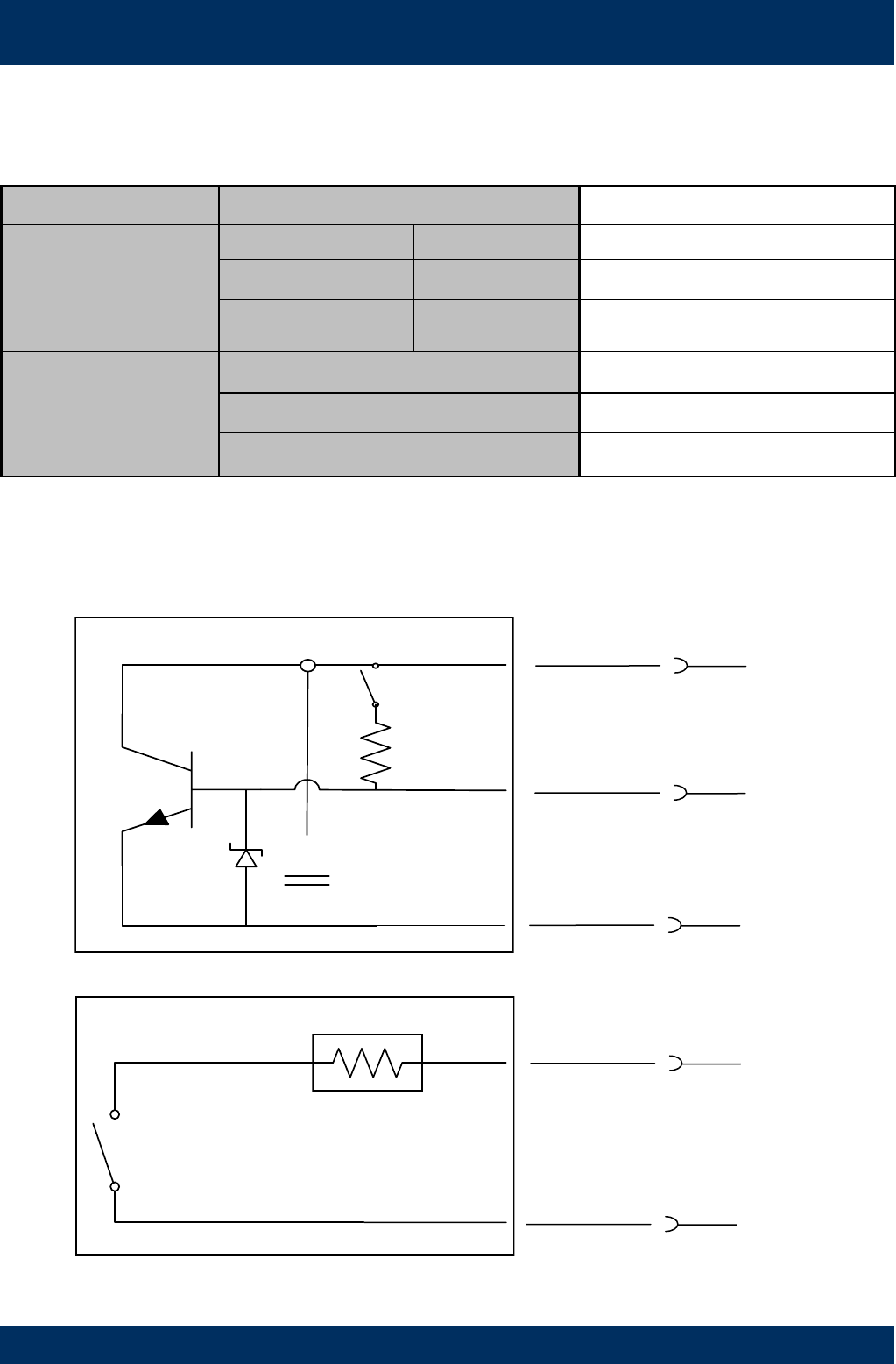
WIRING DIAGRAM 2 PCB
Output types D,E,F,G,H
Reed 1
Note:
Local Display is
connected to Reed 1
+Ve
Signal
Gnd
-
+
Hall effect built-in pull-up
On
Off
Pull-Up
Hall Effect
Reed switch current limit
Reed 1
NPN Open Collector Hall Effect Sensor
The output for the hall effect sensor is NPN (current sinking, open collector). For correct operation, it is advisable to have a pull
-up resistor installed.
The hall effect sensor is equipped with a 1k8Ω pull-up resistor between signal and supply as standard.
This in-built pull-up resistor can be bypassed by moving the jumper pin to the off position if required.
A pull-up resistor of your choosing can be installed between signal and supply, provided the in-built pull-up resistor be by-
passed first.
Pulser Specifications
Output Signals Standard Pulse Meter 2x Digital (Square Wave)
Reed Switch
(Mechanical Sensor)
Current Maximum 500mA
Voltage Maximum 30V DC
Contact Rating Maximum1 10W
Hall Effect IC
(Electronic Sensor)
Maximum Current 7.5mA
Operating Voltage 4.5V to 24V DC
Transistor Type Open-Collector NPN
1. Contact rating maximum is 10W. Neither current nor voltage maximums should be exceeded in achieving this.
Page 7 of 18
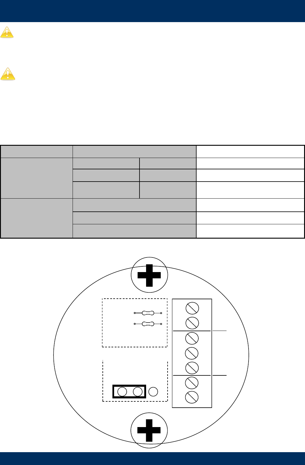
WIRING DIAGRAM 3 Intrinsically Safe (Ex ia)
Output type ‘B’
Pulser Specifications
SENSOR TYPE Omni Polar Open-Collector NPN
SPECIFICATIONS
Construction Stainless Steel Housing
Operating Voltage 5V to 30V DC
Maximum Current 15mA
Temperature Range -40 - 85oC
-40 - 185oF
CAUTION: This sensor must be installed with an approved safety barrier.
Page 8 of 18
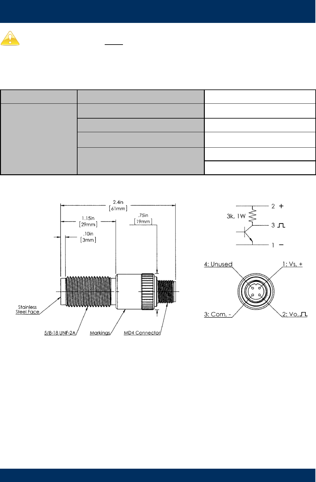
WIRING DIAGRAM 4 High Temperature
Output type ‘T’
Pulser Specifications
SENSOR TYPE OMNI POLAR NPN
SPECIFICATIONS
Construction Stainless Steel Housing
Operating Voltage 4.5 to 30V DC
Maximum Current 18mA
Temperature Range -40 - 150oC
-40 - 302oF
Page 9 of 18

TROUBLESHOOTING GUIDE
Problem Cause Remedy
Fluid will not flow
through meter
a) Foreign matter blocking rotors
b) Line strainer blocked
c) Damaged rotors
d) Meter connections over tightened
e) Fluid is too viscous
a) Dismantle meter, clean rotors (strainer must be fitted in
line)
b) Clean strainer
c) Replace rotors (Strainer must be fitted in line)
d) Re-adjust connections
e) See specifications for maximum viscosity
Reduced flow
through meter
a) Strainer is partially blocked
b) Fluid is too viscous
a) Clean strainer
b) See specifications for maximum viscosity
Meter reading
inaccurate
a) Fluid flow rate is too high or too low
b) Air in fluid
c) Excess wear caused by incorrect instal-
lation
a) See specifications for minimum and maximum flow rates
b) Bleed air from system
c) Check meter body and rotors. Replace as required. Refer
to installation instructions
Meter not giving a
pulse signal
a) Faulty hall effect sensor
b) Faulty reed switch
c) Magnets failed
a) Replace PCB Board
b) Replace PCB Board
c) Replace magnets
LCD register not
working
a) Battery not connected properly
b) Battery flat
c) Faulty wiring connections
d) Faulty LC Display
e) Faulty connection from LC Display
a) Check battery connections
b) Replace battery
c) Check wiring for loose or faulty connections
d) Replace LC Display
e) Check wiring connections
MAINTAINENCE VIDEOS
Macnaught provides an comprehensive set of ‘Maintenance Videos’ to assist the end user in all aspects of service
and/or repair of the Flowmeter range.
This web based resource can be accessed via the following URL
http://www.macnaught.com.au/mx_resources
Or by scanning the QR code below.
Page 10 of 18
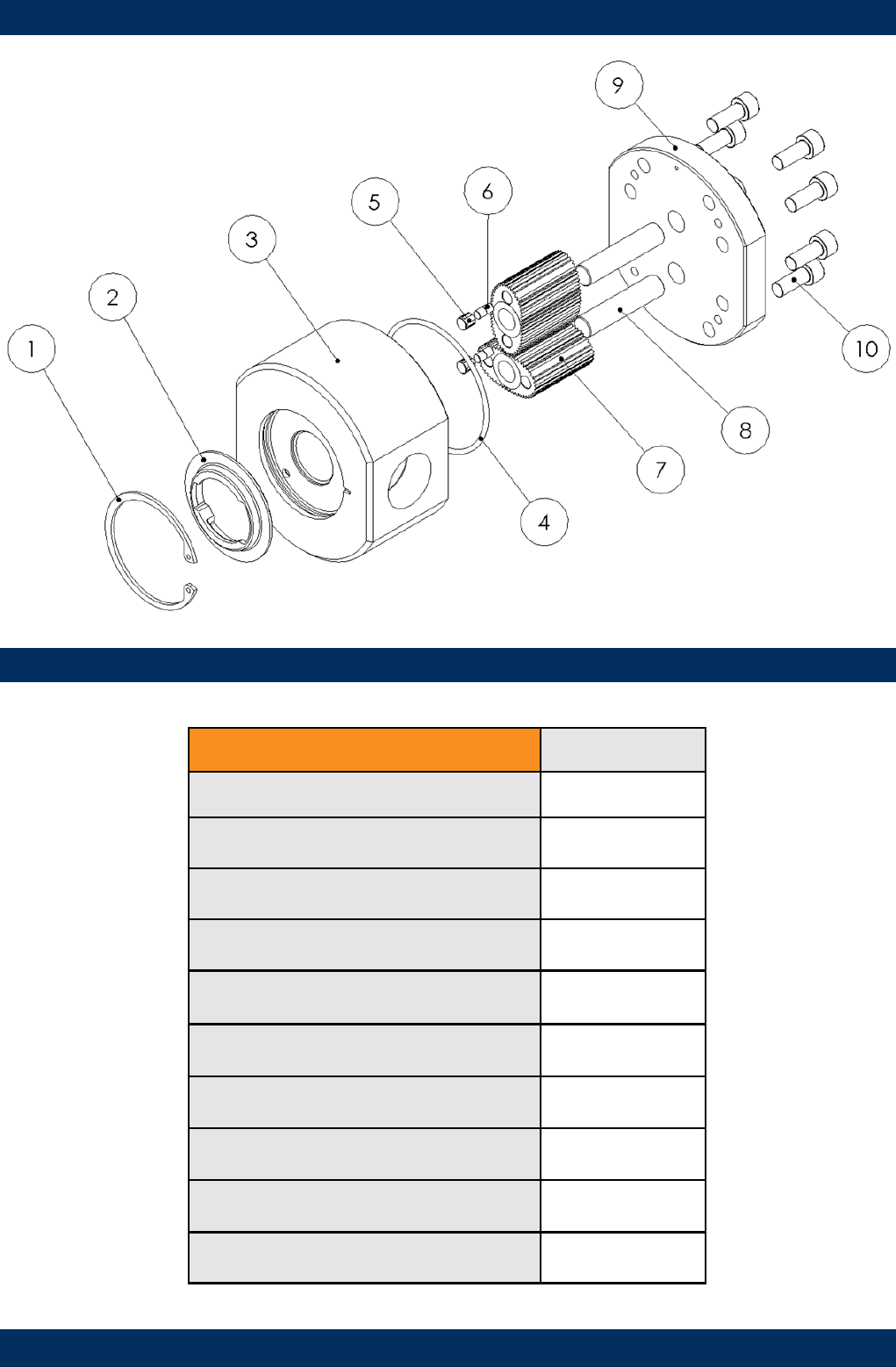
EXPLODED DIAGRAM
PARTS IDENTIFICATION
METER COMPONENTS ITEM NO.
CIRCLIP 1
CAM 2
METER BODY 3
METER CAP O-RING 4
MAGNET HOUSING 5
MAGNETS 6
ROTORS 7
ROTOR SHAFTS 8
METER CAP 9
METER CAP SCREWS 10
Page 11 of 18
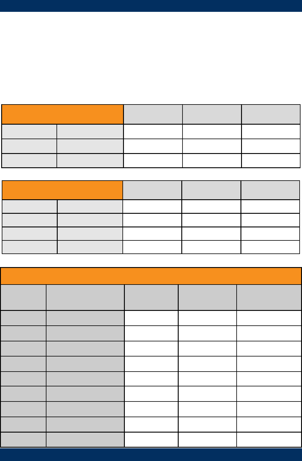
SPARE PARTS KITS
Spare Kit options, for both Flowmeter and Display/Pulser modules, are available as replacement components.
Pulser Kit / LC Display Module
- Replacement PCB complete with M-Lock electronic housing.
- LC Display module (Electronic housing not included)
Rotor Kit
- Rotor assembly (includes Meter Cap bolts and O-Ring)
Seal Kit
- O-Rings/Gaskets (includes Meter Cap Bolts)
SPARE KITS – DISPLAY AND PULSER MODULE
Output
Type Pulser Kit Display Module
only
Display/Pulser
complete
Description
Type A MXD-AS Standard Pulser
Type B MXD-BS Intrinsically Safe
Type C MXD-CS Flameproof
Type D MXS-PCB-PR MXS-DIS-PR MXD-DS PR Digital Register
Type E MXS-PCB-PR MXS-DIS-PRA MXD-ES PRA Digital Register
Type F MXS-PCB-ER MXS-DIS-ER MXD-FS ER Digital Register
Type G MXS-PCB-ER MXS-DIS-ERA MXD-GS ERA Digital Register
Type H MXS-PCB-ER MXS-DIS-ERB MXD-HS ERB Batch Controller
Type T MXD-TS High Temperature
SPARE KITS - FLOWMETER MX06F MX06S MX06P
ROTOR KIT Standard MXS06F-rotor MXS06S-rotor MXS06P-rotor
High Temp MXS06P-HTrotor
SEAL KIT MXS06F-seal MXS06S-seal MXS06P-seal
SPARE KITS - FLOWMETER MX09F MX09S MX09P
ROTOR KIT Standard MXS09F-rotor MXS09S-rotor MXS09P-rotor
High Viscosity MXS09S-HVrotor MXS09P-HVrotor
High Temp MXS09P-HTrotor
SEAL KIT MXS09F-seal MXS09S-seal MXS09P-seal
Page 12 of 18

WETTED PARTS
K - FEP/PTFE Encapsulated
SS - Stainless Steel 316 /304
Al - Aluminium AA610
CA - Carbon
FKM - Viton ®
PPS - Polyphenylene Sulphide
WETTED PARTS MX06/09F MX06/09S MX06/09P
METER BODY Alum Alum St.St
METER CAP Alum Alum St.St
ROTORS - Standard PPS St.St PPS
High Viscosity St.St. St.St
High Temp St. St
ROTOR SHAFTS St.St St.St St.St
ROTOR BUSHES CA CA
O-RINGS FKM K K
Note: High viscosity rotor option only available for the MX09 SERIES
Page 13 of 18
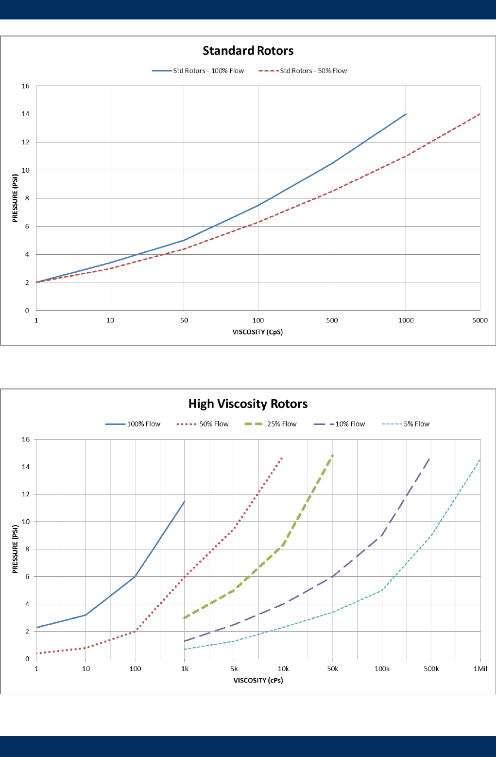
PRESSURE DROP v VISCOSITY
100%
50%
25%
10%
5%
100%
50%
Page 14 of 18
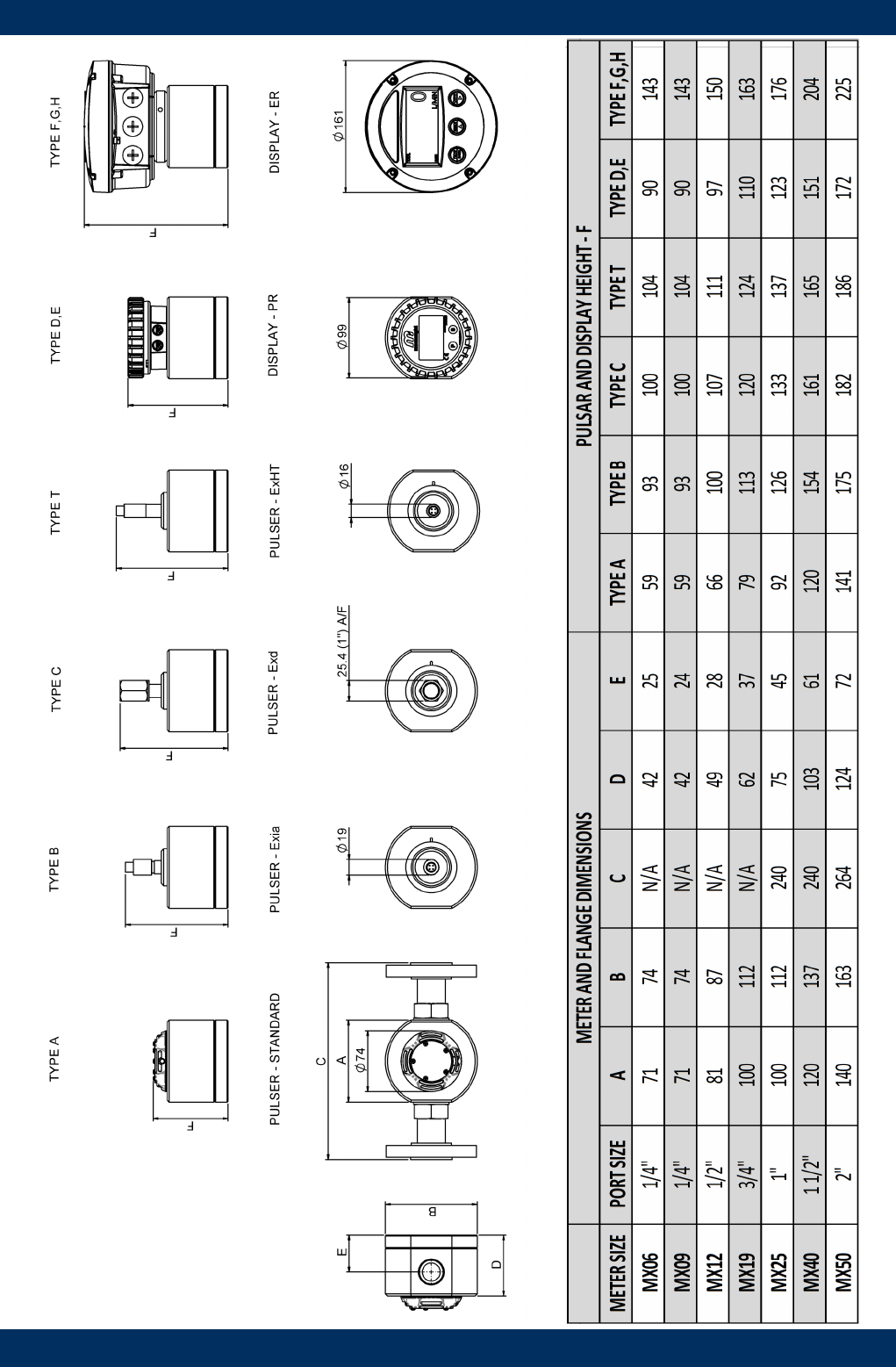
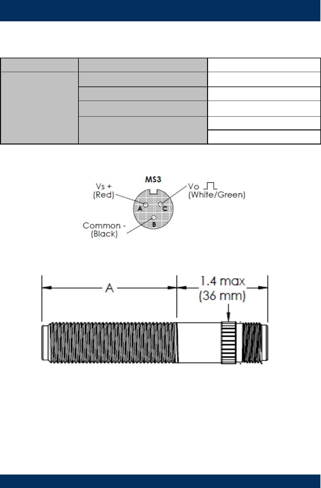
DIMENSIONS
Page 15 of 18
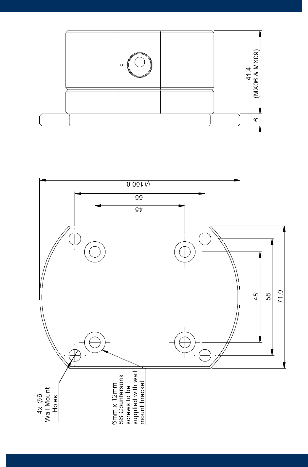
DIMENSIONS
Aluminium Wall Mount bracket to suit models MX06 / MX09
Page 16 of 18

NOTES
WEEE Directive - Waste Electrical and Electronic Equipment
The WEEE Directive requires the recycling of waste electrical and electronic equip-
ment in the European Union.
Whilst the WEEE Directive does not apply to some of Macnaught’s products, we sup-
port its policy and ask you to be aware of how to dispose of this product.
The crossed out wheelie bin symbol illustrated and found on our products signifies that
this product should not be disposed of in general waste or landfill.
Please contact your local dealer national distributor or Macnaught Technical Services
for information on product disposal.
Page 17 of 18

Page 18 of 18
EC Declaration of Conformity
EC Declaration of Conformity
In accordance with EN ISO 17050-2004
We: Macnaught Pty Ltd
Of: 41-47 Henderson St
Turrella NSW 2205
AUSTRALIA
Declare that:
Macnaught Flow Meters prefixed MX, F, CR, M or S in accordance with the following Directive;
2006/42/EC Machinery Directive (and its amending directives)
have been designed and manufactured to the following specifications;
EN ISO 12100:2010 Safety of Machinery
Declare that:
Macnaught Flow Meters prefixed MX, F, CR, M or S with flange nominal bores sizes 1” to 6” inclusive in accordance w
with the following Directive;
97/23/EC Pressure Equipment Directive (and its amending directives)
comply with the essential requirements of the Directive, classification Category 1 Group 1
Declare that:
Macnaught Flow Meter accessories prefixed DR, ER or PR as fitted to the Flow Meters or remotely mounted in accor
dance with the following Directive
2004/108/EC Electromagnetic Compatibility Directive (and its amending directives)
have been designed and manufactured to the following specifications;
EN61326-1:2006 Electromagnetic Compatibility – Electrical equipment for measurement, control and laboratory use.
I hereby declare that the equipment named above has been designed to comply with the relevant sections of the above
referenced specifications.
The product complies with all essential requirements of the Directives.
This declaration is no longer valid if the unit is modified without our agreement.
Name: Steven Gavin
Position: Operations Director
Date: 21/06/2013
Done at: Macnaught Pty Ltd
41-49 Henderson St
Turrella NSW 2205,
AUSTRALIA
Issue 6
QA-CN5573
Issued by: Graham Wilson
