Net Tool Nettool Um
User Manual: NetTool
Open the PDF directly: View PDF ![]() .
.
Page Count: 64

TM
NetToolTM
Inline Network Tester
Users Manual
PN 1560821
June 2000, Rev. 2, 3/02
© 2000, 2002 Fluke Networks, Inc. All rights reserved. Printed in USA
All product names are trademarks of their respective companies.
LIMITED WARRANTY & LIMITATION OF LIABILITY
Each Fluke Networks product is warranted to be free from defects in material and workmanship under normal use and service. The warranty period is one year
and begins on the date of purchase. Parts, accessories, product repairs and services are warranted for 90 days. This warranty extends only to the original buyer
or end-user customer of a Fluke Networks authorized reseller, and does not apply to disposable batteries, cable connector tabs, cable insulation-displacement
connectors, or to any product which, in Fluke Networks’ opinion, has been misused, altered, neglected, contaminated, or damaged by accident or abnormal
conditions of operation or handling. Fluke Networks warrants that software will operate substantially in accordance with its functional specifications for 90 days
and that it has been properly recorded on non-defective media. Fluke Networks does not warrant that software will be error free or operate without interruption.
Fluke Networks authorized resellers shall extend this warranty on new and unused products to end-user customers only but have no authority to extend a
greater or different warranty on behalf of Fluke Networks. Warranty support is available only if product is purchased through a Fluke Networks authorized sales
outlet or Buyer has paid the applicable international price. Fluke Networks reserves the right to invoice Buyer for importation costs of repair/replacement parts
when product purchased in one country is submitted for repair in another country.
Fluke Networks’ warranty obligation is limited, at Fluke Networks’ option, to refund of the purchase price, free of charge repair, or replacement of a defective
product which is returned to a Fluke Networks authorized service center within the warranty period.
To obtain warranty service, contact your nearest Fluke Networks authorized service center to obtain return authorization information, then send the product to
that service center, with a description of the difficulty, postage and insurance prepaid (FOB Destination). Fluke Networks assumes no risk for damage in transit.
Following warranty repair, the product will be returned to Buyer, transportation prepaid (FOB Destination). If Fluke Networks determines that failure was caused
by neglect, misuse, contamination, alteration, accident or abnormal condition of operation or handling, or normal wear and tear of mechanical components, Fluke
Networks will provide an estimate of repair costs and obtain authorization before commencing the work. Following repair, the product will be returned to the
Buyer transportation prepaid and the Buyer will be billed for the repair and return transportation charges (FOB Shipping Point).
THIS WARRANTY IS BUYER’S SOLE AND EXCLUSIVE REMEDY AND IS IN LIEU OF ALL OTHER WARRANTIES, EXPRESS OR IMPLIED, INCLUDING
BUT NOT LIMITED TO ANY IMPLIED WARRANTY OF MERCHANTABILITY OR FITNESS FOR A PARTICULAR PURPOSE. FLUKE NETWORKS SHALL
NOT BE LIABLE FOR ANY SPECIAL, INDIRECT, INCIDENTAL OR CONSEQUENTIAL DAMAGES OR LOSSES, INCLUDING LOSS OF DATA, ARISING
FROM ANY CAUSE OR THEORY.
Since some countries or states do not allow limitation of the term of an implied warranty, or exclusion or limitation of incidental or consequential damages, the
limitations and exclusions of this warranty may not apply to every buyer. If any provision of this Warranty is held invalid or unenforceable by a court or other
decision-maker of competent jurisdiction, such holding will not affect the validity or enforceability of any other provision. 08/01
Fluke Networks, Inc.
PO Box 777
Everett, WA 98206-0777 USA
Fluke Europe B.V.
P.O. Box 1186
5602 BD Eindhoven
The Netherlands
i
Table of Contents
Chapter Title Page
1 Overview.......................................................................................................................1-1
Introduction....................................................................................................................1-1
Register Now! ........................................................................................................... 1-2
Software Version....................................................................................................... 1-4
Supplied Equipment.................................................................................................. 1-4
Optional Equipment .................................................................................................. 1-4
Getting Assistance.................................................................................................... 1-4
Getting Acquainted ........................................................................................................ 1-5
Buttons and Indicators .............................................................................................. 1-5
Navigation Buttons.................................................................................................... 1-5
NetTool LED Indicators............................................................................................. 1-6
Link/Collision/Error LED ....................................................................................... 1-6
Utilization LED...................................................................................................... 1-6
Serial Connection................................................................................................. 1-7
NetTool Modes .............................................................................................................. 1-7
Single-ended Mode................................................................................................... 1-7
Inline Mode ............................................................................................................... 1-7

NetTool
Users Manual
ii
Cable Testing................................................................................................................. 1-8
Cable AutoTest.......................................................................................................... 1-8
Wiremap.................................................................................................................... 1-8
Service Identification ...................................................................................................... 1-9
Services Discovered.................................................................................................. 1-9
NetTool Updates, etc...................................................................................................... 1-10
PC/NetTool Link Utility ................................................................................................... 1-10
2 NetTool Menus ............................................................................................................. 2-1
Introduction ....................................................................................................................2-1
NetTool Menus............................................................................................................... 2-1
NetTool Menus - PC.................................................................................................. 2-2
Link Configuration................................................................................................. 2-2
Health ................................................................................................................... 2-2
Addresses Used ................................................................................................... 2-3
Servers Used........................................................................................................ 2-3
NetTool Menus – Setup (NetTool Icon) ..................................................................... 2-3
More NetTool Setup Options ................................................................................ 2-4
NetTool Menus - Network.......................................................................................... 2-5
Link and Cable Information........................................................................................ 2-5
Duplex Settings ......................................................................................................... 2-5
NetTool Main Menu ................................................................................................... 2-6
AutoTest ............................................................................................................... 2-6
Problems............................................................................................................... 2-7
Protocols............................................................................................................... 2-7
Key Devices.......................................................................................................... 2-8
Pinging a Single Device............................................................................................. 2-10
3 Problems.......................................................................................................................3-1

Contents
(continued)
iii
Introduction....................................................................................................................3-1
Problem Display........................................................................................................ 3-2
Link Connectivity Problems............................................................................................ 3-3
Network Problems ......................................................................................................... 3-4
Health ....................................................................................................................... 3-4
NetWare.................................................................................................................... 3-5
TCP/IP ...................................................................................................................... 3-5
Host Configuration .................................................................................................... 3-6
Name Resolution ...................................................................................................... 3-6
NetBIOS.................................................................................................................... 3-7
Web .......................................................................................................................... 3-8
Email......................................................................................................................... 3-8
Printer ....................................................................................................................... 3-9
Appendices
A Specification ........................................................................................................... A-1
B Basic Maintenence ................................................................................................. B-1
C Glossary ................................................................................................................. C-1
Index

NetTool
Users Manual
iv
v
List of Tables
Table Title Page
1-1. NetTool Overview ................................................................................................................. 1-3
1-2. Services Discovered ............................................................................................................. 1-9
2-1. Link and Polarity Level.......................................................................................................... 2-6

NetTool
Users Manual
vi
vii
List of Figures
Figure Title Page
1-1. NetTool ................................................................................................................................. 1-1
1-2. Battery Compartment............................................................................................................ 1-5
1-3. NetTool First Screen............................................................................................................. 1-5
1-4. NetTool LEDs........................................................................................................................ 1-6
1-5. Serial Cable Connection ....................................................................................................... 1-10
2-1. Top Area............................................................................................................................... 2-1
2-2. NetTool Menus...................................................................................................................... 2-2
2-3. Station Menu......................................................................................................................... 2-2
2-4. Link Configuration Details..................................................................................................... 2-2
2-5. Health Details........................................................................................................................ 2-3
2-6. Addresses Used.................................................................................................................... 2-3
2-7. Servers Used........................................................................................................................ 2-3
2-8. NetTool Setup....................................................................................................................... 2-3
2-9. NetTool Settings ................................................................................................................... 2-3
2-10. Network Menu....................................................................................................................... 2-5
2-11. Top Area............................................................................................................................... 2-5
2-12. AutoTest ............................................................................................................................... 2-6

NetTool
Users Manual
viii
2-15. Problem Log.......................................................................................................................... 2-7
2-16. Protocols ............................................................................................................................... 2-7
2-17. Protocol List........................................................................................................................... 2-7
2-18. IP Protocols........................................................................................................................... 2-7
2-19. Key Devices .......................................................................................................................... 2-8
2-20. Key Device List...................................................................................................................... 2-8
2-21. Main Menu............................................................................................................................. 2-8
2-22. Toolkit Menu.......................................................................................................................... 2-8
2-23. Health.................................................................................................................................... 2-9
2-24. Health Display ....................................................................................................................... 2-9
3-1. Problems ............................................................................................................................... 3-1
3-2. Problem Log.......................................................................................................................... 3-1
1-1
Chapter 1
Overview
Introduction
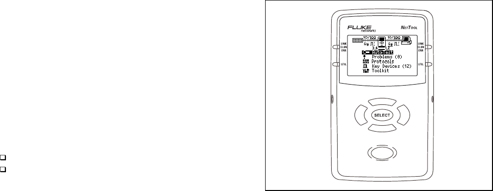
The Fluke Networks NetTool Inline Network Tester
(hereafter referred to as NetTool) is a unique handheld
device that combines cable, network, and PC
configuration testing into a single, handheld unit. NetTool
was designed specifically to speed your frontline network
troubleshooting, “moves, adds & changes,” and desktop-
to-network connectivity work.
NetTool is available in two models: NetTool Inline and
Inline Pro version.
NetTool Inline features include:
Single-ended mode
Inline mode
ahn010f.eps
Figure 1-1. NetTool

NetTool
Users Manual
1-2
Inline Pro Features include:
Single-ended mode
Inline mode
Reporter
Ping
These features are discussed throughout this manual in
their pertinent sections. You can also access
www.flukenetworks.com/nettool to access software
updates, documents, and the latest news on NetTool.
Register Now!
Get a free personalized holster for your NetTool by
visiting www.flukenetworks.com/nettool and registering
your NetTool today. Follow the instructions to get a
company or personal name embossed on the holster.
Upon registering your NetTool, Fluke Networks will send
the personalized holster free of charge.
Table 1-1 shows an overview of what NetTool provides.

Overview
Introduction
1
1-3
Table 1-1. NetTool Overview
Service Identification
Telco
Token Ring
Ethernet
Health
Broadcast/Error meters
Utilization
Cable Test
Wiremap
PC Configuration
Link Config
Health
Addresses Used
Servers Used
Ping
Single Device Ping
Ping Catalog
Reporter
Get Live Reports
Get Saved Reports
Link Configuration
Link ID
Rx Pair
Advertised Speed
Actual Speed
Level
Polarity
Advertised Duplex
Actual Duplex
Services (Key Devices)
IP Servers
IPX (NetWare) Servers
NetBIOS Servers
Printers
Routers
Problems – The Problem
Log provides a concise
list of all problems
detected, from physical
layer to application layer.
Single Ended Mode - This mode enables you to check a
network drop or network device for activity, determine its
speed and duplex settings, confirm healthy frames are
being received from the network; and to check connectivity
to the network (when plugged into a hub or switch).
Inline Mode - Inline mode occurs when NetTool is plugged
in between two devices simultaneously like a PC and the
network.
Inline Pro - The Ping and Reporter features are
permanently activated in the factory. Trial uses are
provided if you have not purchased the option.
Quick Reference Guide - Read the
NetTool Quick
Reference Guide
(P/N 1560839) that came with your
purchase to become familiar with and quickly begin using
your NetTool.
Upgrade - Get updates to NetTool software when they are
released via the internet.
Personalization - Get a free holster for your NetTool by
visiting the NetTool web site and registering your NetTool.

NetTool
Users Manual
1-4
Software Version
To determine the version of the software in your NetTool,
highlight the Setup icon and press the Select (middle)
button. Highlight About NetTool and press Select again.
The software version number is displayed on the screen
as SW Rev: x.x. Read the
NetTool Quick Reference
Guide
(P/N 1560839) and the NetTool Blaster program
helptext for instructions on updating NetTool.
Supplied Equipment
The following equipment is supplied with the NetTool:
❒ Four (4) AA batteries (P/N 1560231)
❒ Serial Cable (P/N 1541340)
❒ RJ-45 Cable (P/N 642774)
❒ Wiremap adapter (P/N 1563930)
❒ CD-ROM Disk (P/N 1560821)
NetTool Users Manual
NetTool Blaster! (update software) and
NetTool Toolkit (make full use of NetTool options)
Optional Equipment
The following optional items can be purchased through
Fluke Networks or your local distributor:
❒ A/C Adapter (P/N 1556346)
❒ Battery Charger (P/N 1572191)
❒ Rechargeable Batteries (P/N 1572184)
Getting Assistance
For operating assistance in the USA, call 1-800-283-
5853. For a complete list of contact numbers, check
Appendix B or visit the Fluke Networks web site at
www.flukenetworks.com.
Overview
Getting Acquainted
1
1-5
Getting Acquainted
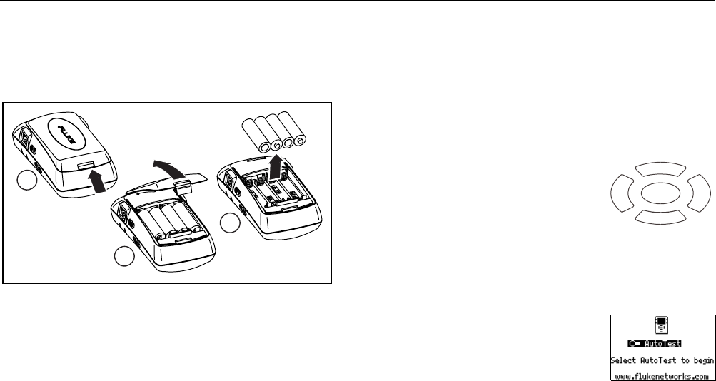
Use four (4) AA size batteries (supplied P/N 1560231) or
the optional rechargeable batteries (P/N 1572184) as
shown (optional charger PN 1572191).
1
2
3
ahn011f.eps
Figure 1-2. Battery Compartment
The optional AC adapter can be used to power the unit
and conserve battery power. The adapter plugs in to the
left side of NetTool.
Read the
NetTool Quick Reference Guide
that came with
your purchase to start using NetTool right away. You can
also access www.flukenetworks.com/nettool for the
latest news on NetTool, troubleshooting tips, and service
information.
Buttons and Indicators
⇒ Power – press once to turn on or off.
⇒ Backlight – Once NetTool has power, you may
turn on the
backlight
by pressing the power button
quickly. Turn it off by pressing the Power button
quickly again.
Navigation Buttons
After powering up NetTool, just
press the buttons that make up the
oval under the screen and highlight
an icon or menu item you wish to
view (
up
,
down
,
right
,
left
). As you
navigate, the highlighted area
flashes. Also, if a list is longer than
can be displayed, use the up and
down buttons to scroll through it.
AutoTest flashes (Figure 1-3) on
power up. Press the Select button
to begin. You can also navigate to
the NetTool Setup screen by
highlighting and selecting the
NetTool Setup icon (
NetTool Setup)
.
SELECT
ahn012f.eps
ahn013s.bmp
Figure 1-3.
NetTool First
Screen
NetTool
Users Manual
1-6
Note
If you have not registered your NetTool, you will
see a Registration Reminder Screen followed by
a screen that displays how many option trials
remain.
Be sure to install NetTool Blaster (NetTool
Toolkit installs as part of the NetTool Blaster
install process), the PC-based software that
came with your purchase on CD-ROM (check
the online help for those programs for more
information). These software programs enable
you to pass data between a NetTool and a PC.
⇒ Press Select (middle button) once to view an item
and related screens.
⇒ Within a screen that is “scrollable,” use the up and
down keys to scroll. Within a menu screen, the
right button returns you to the . The right and left
buttons act as a page up (left) or page down (right)
if there are more items to view.
⇒ Press the Up key to navigate to the (top right)
and press Select to close the current screen.
⇒ Certain screens also display a tool icon left of
the . Select this icon to access the configuration
screen for that function.
NetTool LED Indicators
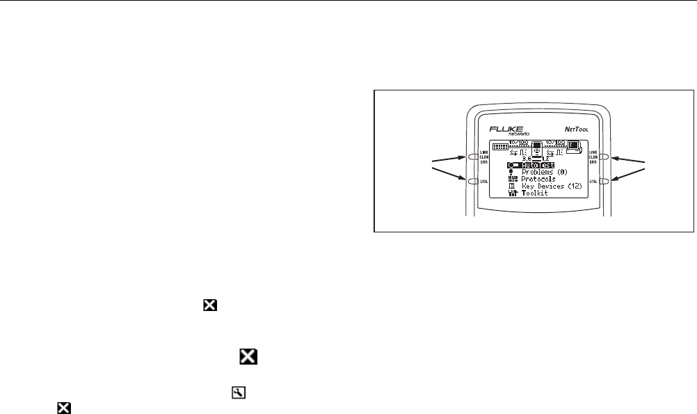
NetTool has two tricolor LED indicators on each side to
reflect link and health information at a glance.
LEDs LEDs
ahn014f.eps
Figure 1-4. NetTool LEDs
Link/Collision/Error LED
Green
= Link pulse present
Yellow
= Collisions occurring
Red
= Errors occurring (FCS, jabbers, etc.)
Utilization LED
The bottom tricolor LED indicates utilization percentages
for each side.

Overview
NetTool Modes
1
1-7
Green
= utilization levels below 40%
Yellow
= levels between 40% and 70%
Red
= levels greater than 70%
Serial Connection
Connecting NetTool to a PC via the customized serial
cable (supplied PN 1541340) allows you to:
• Download software.
• Enable options.
• Save screens.
• Use NetTool Blaster and NetTool Toolkit
programs supplied on the CD-ROM. Read the
Reporter
and
Ping Catalog
sections for more
information).
NetTool Modes
NetTool has two RJ-45 jacks, one on each side of the
unit. Plug it in and turn it on…either between two devices
like a hub and a PC or directly into a wall plate to check a
network drop.
NetTool can be used in two modes: Single-Ended Mode
and Inline Mode.
Single-ended Mode
Note
To optimize discovery, connect NetTool with the
device (like a PC) off, turn NetTool on, press
AutoTest, then turn the device on.
⇒ Plug an RJ-45 cable into a network drop or a single
network device, such as a hub, PC, server, or
printer.
⇒ Run AutoTest by pressing the Select button. The
NetTool screen displays icons for NetTool itself and
the other device.
Use this mode to quickly prove a network drop or network
device is active, determine its speed and duplex settings,
confirm healthy frames are being sent, and check
connectivity to the network (when plugged into a hub or
switch). Read Chapter 2,
NetTool Menus,
for more
information on the menus and icons.
Inline Mode
Note
NetTool must sense traffic on a network or
device so it can supply protocol or health
information.
NetTool
Users Manual
1-8
Inline means NetTool is plugged in between two devices
simultaneously such as a PC and network hub. Use this
mode to verify that a PC will communicate properly with
the network.
Cable Testing
Using Cable AutoTest, you can check cable length, detect
split pairs, or use the wiremap adapter (supplied P/N
1563930) to verify pin-to-pin continuity from the near to
the far end of a cable.
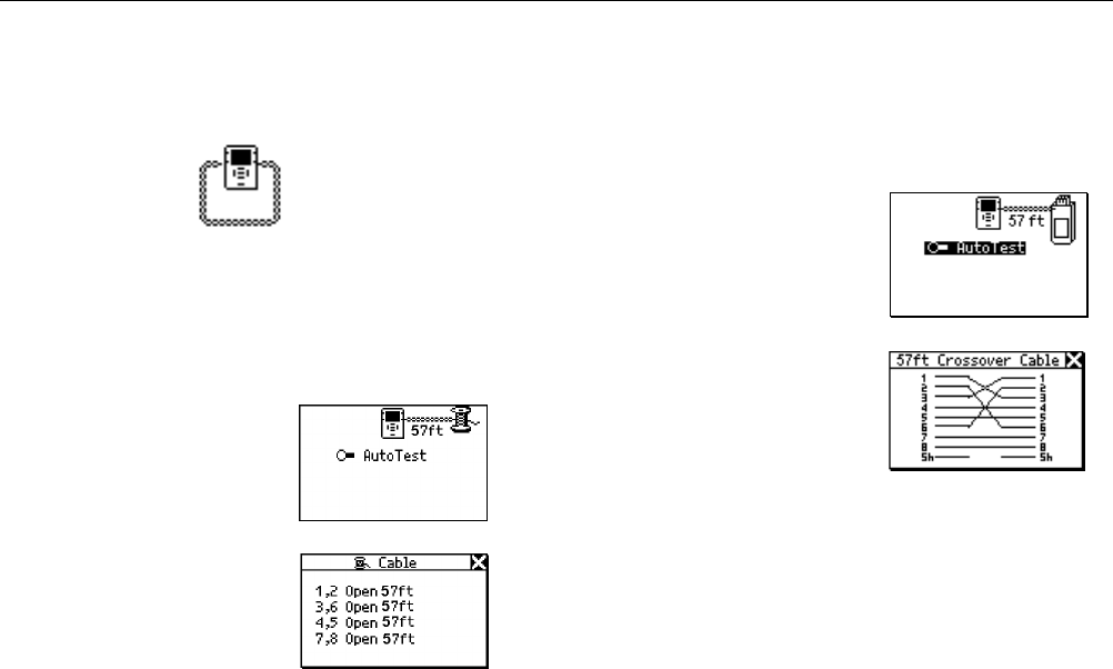
Cable AutoTest
⇒ Plug the cable to test into
the jack on either side of
the NetTool. Power up
NetTool. AutoTest
flashes. Press Select.
⇒ Highlight the Spool icon
and press Select to see
cable status. NetTool
detects cable length,
opens, shorts, and split
pairs.
⇒ This applies for patch
ahn015s.bmp
ahn016s.bmp
cables as well except you
would plug both ends in
to the NetTool and then
press Select.
Wiremap
⇒ To use wiremap, attach
the wiremap adapter to
the far end of the cable.
⇒ Power up NetTool.
AutoTest flashes. Press
Select.
⇒ Highlight the Wiremap
icon and press Select.
ahn017s.bmp
ahn018s.bmp

Overview
Service Identification
1
1-9
Service Identification
⇒ Plug NetTool in to any RJ-45 wall jack.
⇒ Power up NetTool and select AutoTest. Doing so
shows you what service is active on the jack being
tested:
Telco: Shows the tip and ring pins (in the case of
voice being carried on an RJ-45 cable).
XCaution
Although NetTool can detect Telco signals, it
is not designed to be used on the public
telephone network. Disconnect immediately.
NetTool cannot reliably discover Telco
information with the AC adapter or serial
cable connected. It also detects ISDN
signals but cannot reliably detect the S/T
interface.
⇒ Token Ring: Indicates the presence of a Token
Ring network.
Ethernet: Tells you if the jack is hot, what’s on the
other end (hub, switch, etc.), as well as the speed
and duplex, level, and polarity. Also shows the
segment ID so you can pick the right network to
hook up to a PC (if there are multiple jacks).
Services Discovered
Table 1-2 lists the services detected by NetTool.
Table 1-2. Services Discovered
Device Services
Servers IP Servers (IP services discovered): DHCP,
DNS, email (SMTP, POP, IMAP), Web
(HTTP, HTTP proxy), WINS.
NetWare Servers (IPX service types):
Nearest File Server, File Server, NetWare
Access server, Time Synchronization
Server, NetWare Directory Server (NDS),
NetWare Management Server.
NetBIOS Servers: Primary Domain
controllers, Backup Domain controllers,
Master Browsers.
Routers IP Routers: RIP, IGRP, EIGRP, OSPF,
IRDP, RIP2.
IPX routers: RIP.
Printers IP Printers - IP Printers, IP Print Spoolers.
IPX Printers - IPX Print services.
DLC Printers - Microsoft DLC, HP DLC.
NetTool
Users Manual
1-10
NetTool Updates, etc
.
Get updates to NetTool software when they are released.
To check the version you have, select the NetTool Setup
icon then select About NetTool.
⇒ To find out if there is a new version, access
www.flukenetworks.com/nettool and navigate to
the update page. Check the software file displayed
in that area and determine if it is a later version.
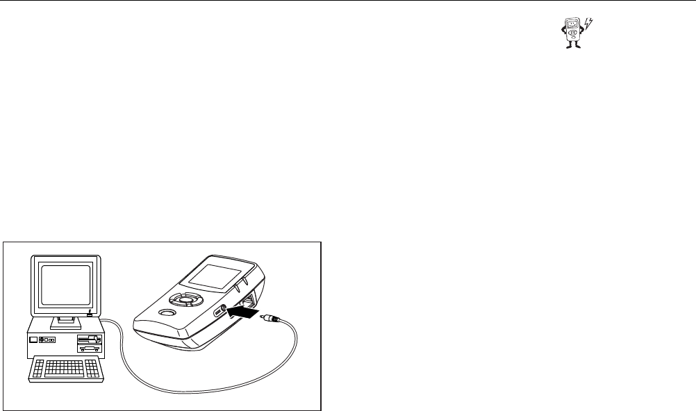
⇒ To update your NetTool, follow the web instructions
to download the file. After you download the file to
a PC connect supplied serial cable as shown in
Figure 1-5.
ahn019f.eps
Figure 1-5. Serial Cable Connection
PC/NetTool Link Utility
Updating NetTool is a simple process that requires you to
download, or otherwise make accessible to your PC, the
latest NetTool firmware file. You can then run the update
and link utilities that came on CD-ROM or from the web.
There are two PC-based software programs that install
from the CD-ROM: NetTool Blaster and NetTool Toolkit.
When you put the CD-ROM that came with your purchase
in your PC, a navigation screen displays. Install both link
utility programs by running the setup program. After you
install the programs, run them from the Start | Programs
| Fluke Networks...menu. Follow the directions given by
the online help of both programs.

Overview
PC/NetTool Link Utility
1
1-11
NetTool Blaster
After you have the latest NetTool firmware downloaded
and saved locally, NetTool Blaster enables you to:
⇒ Update NetTool – click the Update button.
⇒ Get screen shots – download screens by clicking
NetTool Blaster’s Capture button.
⇒ Add your own splash screen by clicking the
Personalize button.
⇒ Set Date/Time.
⇒ If you have purchased options and need to enter
the option key, click Options.
⇒ Change Language – as translations become
available, choose one of the associated option
buttons.
⇒ Set Communication Parameters.
NetTool Toolkit
Use NetTool Toolkit on your PC in order to take full
advantage of NetTool Pro features. NetTool Toolkit
enables you to:
⇒ Generate reports.
⇒ Download reports.
⇒ Configure ping parameters.
⇒ Configure ping catalogs.
Select Help from the top menu of either program and
follow the instructions to use NetTool Blaster or Toolkit.

NetTool
Users Manual
1-12
2-1
Chapter 2
NetTool Menus
Introduction
Navigating within NetTool is easy and fast. If a link pulse
is detected, NetTool searches for devices on the network
and then displays them on its easy-to-read display.
Navigation is based the icons and menu below them.
NetTool Menus
There are two sets of menus to assist in troubleshooting:
the top area (Figure 2-1) containing icons and the main
menu (Figure 2-2) below the icons.
ahn020s.bmp
Figure 2-1. Top Area
The three top area icons take you through menus
corresponding with the three elements of the connection:
⇒PC
⇒NetTool Setup
⇒Network
The main menu takes you through various discovery
screens that reflect NetTool’s connection to devices.
In addition, link information is displayed between the
device icons and cable information is displayed below the
NetTool Setup icon (see
Link and Cable Information
later
in this chapter)
.
NetTool
Users Manual
2-2
NetWork Icon PC Icon
NetTool Icon
Main Menu
ahn021f.eps
Figure 2-2. NetTool Menus
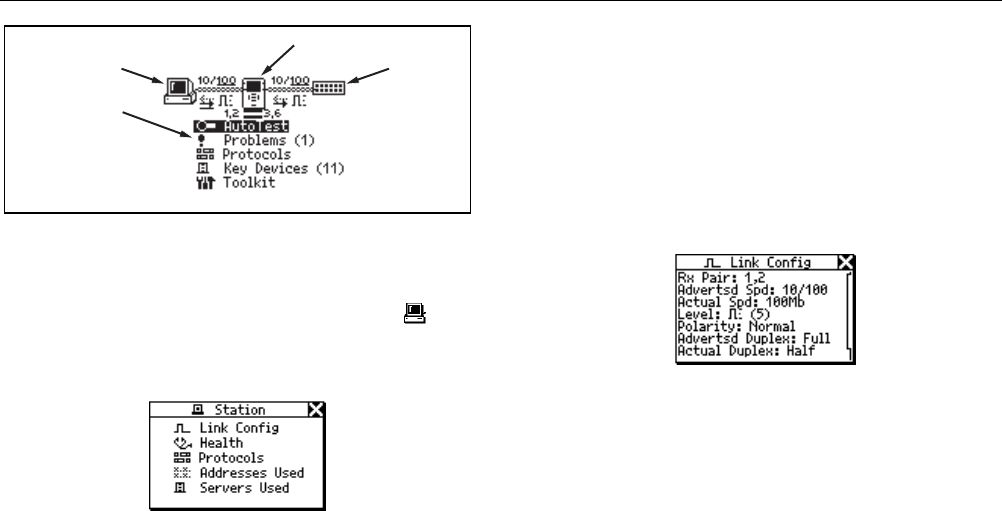
NetTool Menus - PC
⇒ Connect NetTool to a PC and press the PC icon.
The icon displays on the left or right, depending on
where you connected the cable. Figure 2-3 displays
the list of PC information you can access.
ahn022s.bmp
Figure 2-3. Station Menu
⇒ After the PC sends frames, you can scan the PC
configuration by navigating through the menu. This
view of the PC is invaluable in troubleshooting
networked PCs.
Link Configuration
The Link Config screen (Figure 2-4) provides the following
key link pulse information about the device (e.g., the PC)
to which NetTool is connected:
Receive (Rx) Pair
Advertised Speed
Actual Speed
Level
Polarity
Advertised Duplex
Actual Duplex
ahn023s.bmp
Figure 2-4. Link Configuration Details
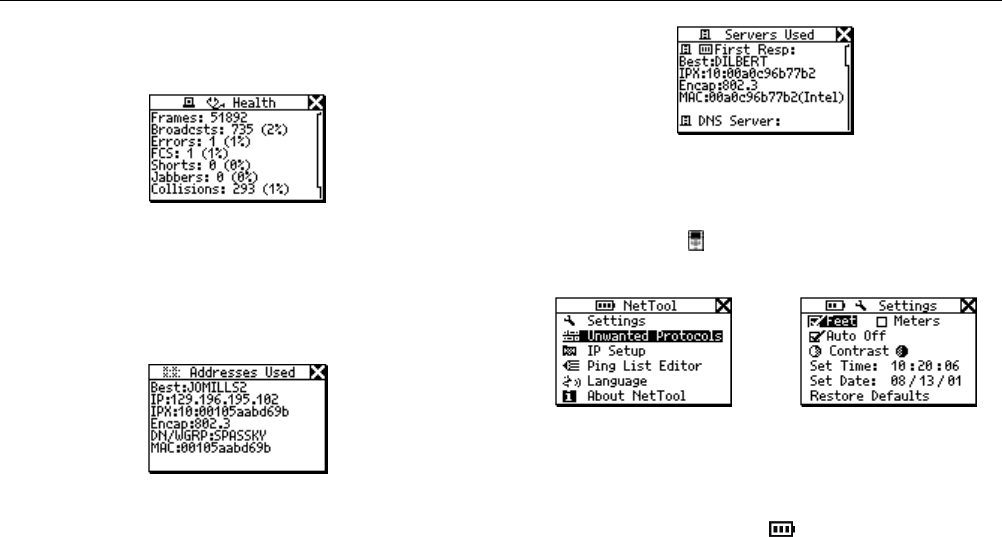
Health
The Health option enables you to check the health of
frames the PC has sent since you started AutoTest and
isolate PC related problems. There are two types of Health
screens: one that displays activity since the last AutoTest
(Figure 2-5) and one that relates to what is going on now.
In other words, statistics accessed from a device-related
menu (Figure 2-3) are cumulative (as in Figure 2-5)
whereas statistics you see from the main menu are a
NetTool Menus
NetTool Menus
2
2-3
“snap shot” of what is going on now for a given device
(Read
Health
later in this chapter).
ahn026s.bmp
Figure 2-5. Health Details
Addresses Used
NetTool displays the best-discovered name on the PC as
well as the IP, IPX, and MAC address of the PC.
ahn025s.bmp
Figure 2-6. Addresses Used
Servers Used
This area shows the network resources the PC is using,
including HTTP, SMTP, POP, WINS, Nearest NetWare,
DHCP and DNS servers, as well as the router gateway.
ahn014s.bmp
Figure 2-7. Servers Used
NetTool Menus – Setup (NetTool Icon)
Select the NetTool (middle) icon to access Setup
options. The NetTool Setup screen displays (Figure 2-8).
ahn027s.bmp
Figure 2-8. NetTool Setup ahn029s.bmp
Figure 2-9. NetTool
Settings
Access Settings (Figure 2-9) to:
⇒ Check the battery level . The battery level
indicator displays while you navigate through the
Setup screens as long as you are running on battery
power.
⇒ Select feet or meters.

NetTool
Users Manual
2-4
⇒ Enable/disable Auto Off. If you leave the unit on
without touching any keys for more than 10 minutes,
Auto Off automatically shuts the unit down to save
battery power.
⇒ Adjust the display contrast. Highlight and press
Select to decrease contrast or to increase it.
⇒ Set Time/Date…Highlight each number comprising
the time or date display and change each number
individually using the up or down arrow key. Use
the right or left arrow key to move the cursor over.
Press Select after you change all the numbers.
NetTool Time format is
HOUR:MINUTES:SECONDS. Date format is
MONTH:DAY:YEAR. The clock does not self
adjust for local time zones changes. NetTool
Blaster allows you to set the time for the NetTool
and even synch it with the PC clock (check the Help
for Blaster for details).
⇒ Select Restore Defaults to restore all factory
settings. If you have not changed any settings,
NetTool displays Defaults Restored and no action
is required.
More NetTool Setup Options
Other setup options include:
Unwanted Protocols
IP Setup
Ping List Editor
Language
About NetTool
⇒ Select Unwanted Protocols to specify protocols that
NetTool will warn you are present on the network.
This helps in situations like a network-wide migration
away from certain protocols. If NetTool sees them, it
reports them in the Problem Log.
⇒ Choose IP Setup to configure your NetTool to ping
(read the
Toolkit
-
IP Setup
section for details).
⇒ Access the Ping List Editor to view, edit, or add to
the lists of preset IP addresses that you have
previously downloaded using NetTool Toolkit. The
editor enables you to add to an existing list or edit an
existing IP address within a list.
Select one of the lists by highlighting the list name
then pressing Select. Select Add New Device to add
an IP address to that list. To edit an existing address,
select it then change any of the octets within the
address.
⇒ Choose Language. Select a language from the
available choices. Keeping your NetTool updated
ensures access to new languages as they become
available.
NetTool Menus
NetTool Menus
2
2-5
⇒ View software and hardware details. Select About
NetTool to view the serial number, MAC address, and
revision information. Be sure to record the serial
number and MAC address of your NetTool for future
reference.
NetTool Menus - Network
The Network icon displays on the left or right
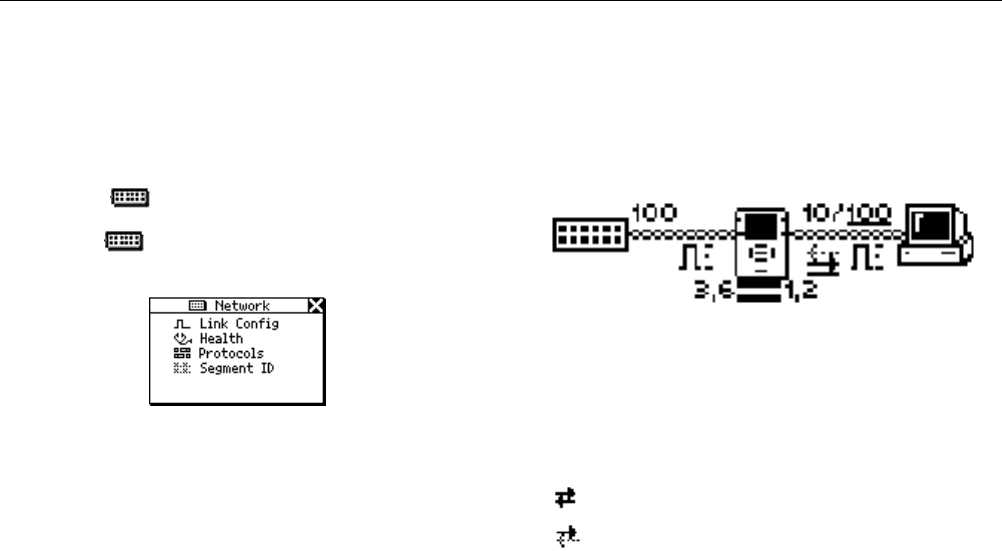
depending on where you connected the cable. Highlight
the Network icon and press Select to view network
activity (Figure 2-10).
ahn200s.bmp
Figure 2-10. Network Menu
Link Config: (described in the PC section)
Health: (described in the PC section)
Protocols: (described in the Protocols section)
Segment ID: If there are multiple Ethernet drops, knowing
the Segment ID tells you which jack to use for the correct
configuration.
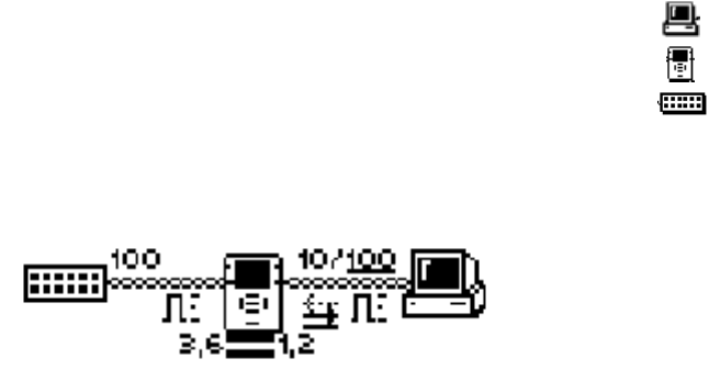
Link and Cable Information
Notice the link and cable information between the device
icons in Figure 2-11. Note the duplex settings and link
speeds that are underlined. The underline signifies a
determined or negotiated result while the non-underlined
value signifies the advertised value.
ahn020s.bmp
Figure 2-11. Top Area
Duplex Settings
NetTool
provides duplex settings for each device,
advertised or collision-determined. Duplex mismatches
can impede communication between devices.
Full Duplex
Half Duplex
Link Level and Polarity: Polarity is displayed via
waveform shaped icons as shown in Table 2-1.

NetTool
Users Manual
2-6
Table 2-1. Link and Polarity Level
Indicator Definition
Normal level, normal polarity
Normal level, reverse polarity
Low level, normal polarity
Low level, reverse polarity. Link level is
displayed by the height of the waveform.
Cable Status
NetTool shows you the status of the
cables connected to it below the Setup
icon and detects whether the cables are
straight or swapped. NetTool sees a
swap cable problem and swaps it
internally, allowing you to troubleshoot
past a simple swap cable problem.
NetTool Main Menu
The main menu items are your starting point. View
NetTool’s discovery screens to resolve connectivity
problems. The results are displayed in the top area and
within the discovery screens accessed from the main
menu.
AutoTest
⇒ Plug NetTool inline between the PC and the
network.
⇒ Power up the PC.
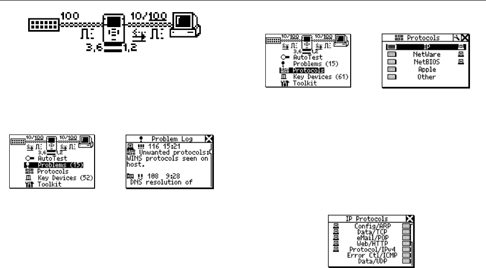
⇒ Select AutoTest. The sample results shown in
Figure 2-13 reflect NetTool connected inline
between a PC and a network hub.
ahn201s.bmp
Figure 2-12. AutoTest
NetTool Menus
NetTool Menus
2
2-7
ahn202s.bmp
Figure 2-13. AutoTest Results
⇒ Select the PC or Network icon for more link
configuration information, health, Segment ID, and
for PCs, address and server information.
Problems
ahn203s.bmp
Figure 2-14. Problems
ahn204s.bmp
Figure 2-15. Problem Log
⇒ Select Problems to view the Problem Log. The
Problem Log provides a concise list of all problems
detected, from physical layer to application layer
problems. You can think of problems fitting into two
categories: Link Connectivity level and Network
level. Read Chapter 3 for full descriptions of
problems and general troubleshooting tips.
Protocols
ahn205s.bmp
Figure 2-16. Protocols ahn206s.bmp
Figure 2-17. Protocol List
⇒ Select Protocols to view the protocols seen on the
desktop or network (Figure 2-17). This can be very
useful for finding protocol configuration mismatches.
⇒ View details by highlighting any protocol listed and
pressing Select. Figure 2-18 shows an example of
IP Protocols. The icons listed on each side
represent the device (i.e., PC, network) and whether
that given protocol is running on that device. Table
1-2 lists the protocols that NetTool can discover.
ahn207s.bmp
Figure 2-18. IP Protocols
NetTool
Users Manual
2-8
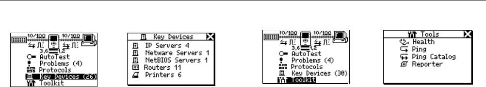
Key Devices
ahn208s.bmp
Figure 2-19. Key Devices
ahn209s.bmp
Figure 2-20. Key Device List
⇒ Select Key Devices to view all the servers, routers,
and printers NetTool has found on the network
(Figure 2-20). NetTool always attempts to display
the highest level address possible for that device,
be it a NetBIOS name, DNS name, IP address or
Mac address. This helps you determine which
services or servers exist on the network.
⇒ The list of devices can be invaluable in
troubleshooting because it verifies whether a device
is seen on the network. This helps pinpoint where a
configuration problem may exist. NetTool Toolkit
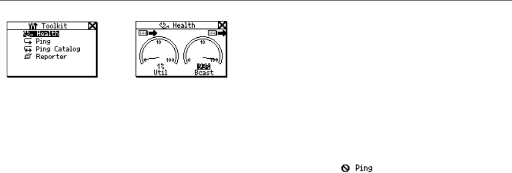
Select Toolkit to access Health statistics, Ping features,
and the Reporter option.
ahn210s.bmp
Figure 2-21. Main Menu
ahn211s.bmp
Figure 2-22. Toolkit Menu
Health
⇒ This feature enables you to segment problems.
After you select Health from the main menu, you
can view the health of frames and simultaneously
check each side of the connection for healthy
frames in real time (Figure 2-24).
⇒ Use the navigational buttons and press Select on
any item within the screen to change the view. For
example, selecting Util changes the view to
broadcast traffic, collision levels, or errors coming
from either device to which NetTool is connected.
NetTool Menus
NetTool Menus
2
2-9
ahn212s.bmp
Figure 2-23. Health
ahn213s.bmp
Figure 2-24. Health Display
⇒ You can also highlight the device in the upper right
or left to change what NetTool is viewing in real time
and the direction (to/from network or to/from PC).
This enables you to make comparisons. For
example, you may see a high percentage of network
utilization and the PC is also registering high
utilization. You can segment what the PC is doing
to contribute to that large number by highlighting
Util and pressing Select (broadcasts, errors, etc.).
⇒ Highlight the reading below a meter and press
Select to view the data expressed as “per second”
(frames broadcasts, errors, etc.) or as a percentage
of current activity.
Note
If you exit the Health display and return later
without powering down, NetTool displays the
“last-saved” settings. If you power down NetTool
while viewing the Health display, the readings will
not be saved. Access Setup screen and select
Restore Defaults to restore factory settings.
Ping
Note
The Ping option only works in single-ended
mode. If you want to ping and are in inline mode
you will see . Disconnect one of the RJ-
45 cables from the NetTool and then rerun
AutoTest.
In order to use all of the functions of the Ping
option, make sure you install the NetTool Toolkit
software on your PC so NetTool can
communicate with your PC via the serial
connection.
IP Setup
⇒ Currently, by default and “out-of-the-box,” NetTool
uses DHCP to configure itself. If you have DHCP on

NetTool
Users Manual
2-10
your network, there is no need to further configure
NetTool.
⇒ Choose Manual or DHCP IP configuration by
selecting the IP Setup icon (wrench) and
accessing the IP Setup screen. You can also do this
using NetTool’s Setup function.
⇒ If you select Manual then go back to DHCP, the IP
address is acquired after you select that option and
any subsequent time you access the IP Setup
screen. NetTool uses DHCP protocol to acquire an IP
address then uses the address according to DHCP
rules.
ahn214sbmp ahn215s.bmp
⇒ Selecting Manual configuration enables you to
statically assign to your NetTool an IP address that
complies with your network’s addressing scheme.
This applies if your network does not use DHCP or if
for whatever reason you want to manually configure it.
⇒ Using the down arrow key, highlight the address you
wish to configure (in this case NetTool) then press
Select.
⇒ On the Edit screen use the up and down arrow keys
to enter each number of the IP address one at a time
(right and left arrow keys move the cursor over) until
you enter the whole address.
⇒ Press Select after you have entered a valid IP
address for your NetTool. NetTool then lists the
updated address with the subnet and router IP
addresses. In like manner, you will need to configure
the subnet mask and router addresses. NetTool
assists you by entering the first parts of those
addresses based on common addressing rules.
Make the final corrections to those addresses as you
did the NetTool IP address before you proceed with
other tasks.
Note
For manual configuration, make sure any IP
address you assign to your NetTool is correct for
the subnet you are on.
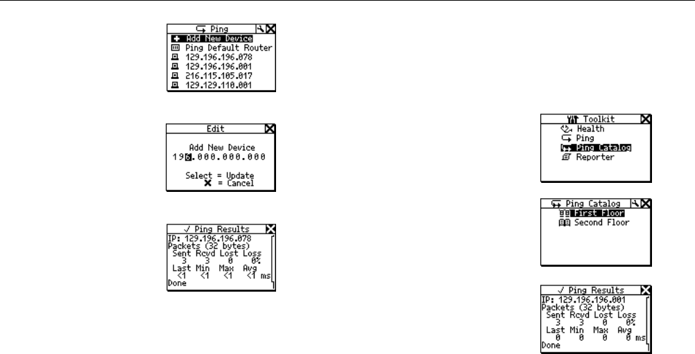
Pinging a Single Device
From the main menu select Toolkit then Ping to access
NetTool’s ping function. You can ping one IP address or a
set (Ping Catalog) of addresses that you define using
NetTool Toolkit.
NetTool Menus
NetTool Menus
2
2-11
⇒ To ping a single
device, select Add
New Device.
⇒ Enter the address and
press Select.
NetTool pings the
device and adds it to
a running list (up to
10) of recently pinged
devices. The IP
address pinged
longest ago will drop
off the list after the
tenth address.
⇒ If you need to ping
any address, highlight
it and press Select.
ahn216s.bmp
ahn217s.bmp
ahn218s.bmp
Ping Catalog
The Ping Catalog function enables you to uses lists of IP
addresses grouped based on your network configuration.
You create the grouping using NetTool Toolkit, the PC-
based software that came with your purchase. You can
keep lists of common groups of IP addresses (i.e.,
Marketing, Customer Support, First Floor, etc.). Check out
the online help for NetTool Toolkit to learn how to set up
and use the Ping List feature.
After defining and uploading the lists using NetTool Toolkit
PC software, NetTool displays the catalogs using the
names you gave them.
⇒ Select Ping Catalog
from the Toolkit
menu.
⇒ Select one of the
catalogs by
highlighting it then
pressing Select.
The list of IP
address displays
with a status icon to
the left. Ping results
display when you
highlight and select
one of the IP
addresses.
⇒ To ping the list of IP
addresses again
highlight and select
Restart.
ahn219s.bmp
ahn220s.bmp
ahn221s.bmp

NetTool
Users Manual
2-12
⇒ Check
NetTool
Setup
to see how to
edit a list of
addresses.
Running
Ping Complete
Problem with the ping. Corresponds with
the severity level of problems.
Low - one packet lost.
Medium - two packets lost.
High - three packets lost or device not
found.

3-1
Chapter 3
Problems
Introduction
Select Problems (Figure 3-1) from the main menu to
view the Problem Log. The Problem Log (Figure 3-2)
provides a concise list of all problems detected, from
physical layer to application layer problems.
ahn300s.bmp
Figure 3-1. Problems
Each type of problem has an icon associated with it. For
example, health-related problems are represented by a
stethoscope icon. As you see problems, you will
become familiar with the associated icons that display.
ahn301s.bmp
Figure 3-2. Problem Log
More importantly, you should understand that just
because something is listed in the Problem Log does not
necessarily indicate a catastrophic problem. For
example, Unwanted Protocols are listed in the Problem
Log but they are not a major impediment to the operation
of the PC on the network.

NetTool
Users Manual
3-2
Problem Display
The problem display area consists of these elements from
left to right: Problem Type, Problem Severity, Problem ID,
and Problem Text.
Sample problem
→
Problem type Naming
Health (Util)
Server
Host
Cable
Connectivity
Link
Configuration
Network
Problem Severity Low Medium High
Problem ID A problem ID is associated with
each problem that helps you
reference the problem. Check the
online Users Manual to see a text
description linked with the numeric
code.
Problem Text This area contains a concise
description of the problem found.
You can think of problems fitting into one of two
categories, Link Connectivity or Network level. Link
Connectivity problems relate to cabling or cabling
properties. Network problems are those involving
PC/network configuration settings or PC to server
interactions.
Generally, network problems you encounter in setting up
or changing a PC’s connection to the network can be
resolved by checking the network settings area on the PC.
In single-ended mode, NetTool can only report Unwanted
Protocols and link connectivity level problems. Inline
mode is required for all other problems. Read Chapter 1,
Overview
, for an explanation of these two modes.
The great thing about NetTool is that it enables you to see
which side the problem lies, between the PC and NetTool
or between NetTool and the network itself. Whether it is a

Problems
Link Connectivity Problems
3
3-3
cabling problem or a protocol mismatch, NetTool helps
you isolate a problem and keep things running.
The following section lists the problems that NetTool can
detect. Each problem is explained in more detail (if
needed) and a possible Remedy is listed. Every network
is complex and the remedy listed is meant to help you
start troubleshooting. This is not an exhaustive
troubleshooting guide.
Link Connectivity Problems
These problems involve cabling or cabling properties and
are classified as follows:
Problem:
Speed mismatch
Explanation: The network is running at 10 Mbps and the
PC is running at 100 (or vice versa). This problem
prevents connection to the network.
Remedy: Correct the speed mismatch by making sure
both devices are running at the same speed.
Problem:
Pair mismatch
Explanation: Link pulse is being sourced on the same
wire pair by both sides. This problem does not prevent
connection to the network. NetTool automatically swaps
the pairs to correct this problem.
Remedy: Check cabling. It could be plugged into an
uplink port. Also, there could be a crossover cable
between NetTool and the device.
Problem:
Duplex mismatch
Explanation: One side is running at half duplex and the
other is running full duplex. This problem prevents
connection to the network.
Remedy: Reconfigure the devices so the duplex settings
match.
Problem:
Polarity reversed
Explanation: The polarity of the detected link pulse is
reversed.
Remedy: There is most likely a pair reversed. Check
cabling to ensure the pairing is corrected.
Problem:
Level low
Explanation: The link pulse detected from a device is low.
This can negatively affect performance.
Remedy: Replace the NIC card or change hub/switch
ports. This could also be caused by excessive cable
attenuation.

NetTool
Users Manual
3-4
Problem:
Transmit pair open
Explanation: The wire pair used for transmit (1,2 or 3,6)
has an open. This problem prevents connection to the
network.
Remedy: Isolate the cable and replace it.
Network Problems
This section lists all the network problems with a brief
explanation of each problem. Also listed are some basic
corrective steps you can take for each problem (if
applicable). Keep in mind this is not an exhaustive list of
troubleshooting steps. If you know what you need, the
network administrator for the network you are
troubleshooting can provide you with a lot of information to
correct these problems.
Health
Problem:
Short Frames received (also jabber/FCS).
Explanation: Short Frame is a frame smaller than the
minimum legal size (less than 64 bytes after the preamble)
with a good frame check sequence. Jabber is defined as
frames longer than the maximum legal size (greater than
1518 bytes). Frame Check Sequence (FCS) Bad means
the header information is probably correct but the
checksum calculated by the receiving station does not
match the checksum appended to the end of the frame.
Remedy: Check NIC card or NIC driver file. This could
also be caused by cabling or grounding problems.
Problem:
Excessive utilization seen (also collisions).
Explanation: Excessive utilization/collisions is defined as
a collision rate of greater than 5 percent or a utilization
rate of greater than 70 percent.
Remedy: If this problem exists everywhere on the
network, it is most likely caused by excessive traffic. If it is
isolated to one PC, you can suspect cabling. For
collisions, suspect excessive traffic. Reduce traffic on the
network. Check cabling. Change the NIC card or
switch/hub port. For utilization, reduce the number of
stations in the collision domain. Install a switch. Use a
tool like the Fluke LanMeter, OneTouch Network
Assistant, or Protocol Inspector to determine the top
contributors to further segment this network.

Problems
Network Problems
3
3-5
NetWare
Problem:
Ethernet frame-type mismatches.
Explanation: In order for the PC and network to
communicate they both must be configured for the same
frame type (802.3-raw, 802.2, Ethernet II, and SNAP).
You can configure a client for a single frame type. A
server can optionally be configured to recognize some or
all frame types.
Remedy: Use NetTool to determine the frame types used.
If the client is suspected, determine the frame type of the
client. Determine frame types enabled on server.
Problem:
No nearest server replies seen on network.
Explanation: After a PC boots up it sends a broadcast to
initiate a connection with the closest server. If after three
attempts there is not response, this problem is listed in the
problem log.
Remedy: Ensure that GNS (Get Nearest Server) is
enabled on the server and check connectivity to routers by
doing an IPX ping with a Fluke LanMeter or OneTouch
Network Assistant. Check the Key Devices list. If the
routers are listed then NetTool is seeing the routers but
the PC is not. You might suspect a bad NIC card or NIC
card configuration file.
Problem:
No first responder seen on network. Unable
to configure PC network number.
Explanation: During boot up, a PC running IPX sends a
query to the router asking for its network number. If after
3 queries there is no response, this problem is listed in the
problem log.
Remedy: Check connectivity from the PC to the network
drop.
TCP/IP
Problem:
PC using incorrect IP subnet mask.
Explanation: NetTool has determined that the PC is not
properly configured.
Remedy: Access PC network properties and correct the
IP subnet mask.
Problem: Router issued ICMP redirect.
Hosts or
devices using incorrect gateway/routers.
Explanation: NetTool has determined that the PC is not
properly configured.
Remedy: Access PC network properties and correct the
IP address. You should also make sure the DHCP server
is giving the correct addresses.

NetTool
Users Manual
3-6
Problem:
Duplicate IP detected.
Explanation: NetTool has detected a duplicate IP address
configured on a remote device. You should never have
duplicate IPs running on the network. This problem
prevents the PC from connecting to the network until it is
resolved.
Remedy: Identify at least one of the devices and change
its address to a valid one that is not being used.
Host Configuration
Problem:
BootP/DHCP server not responding.
Explanation: The PC is dynamically configured to find
DHCP servers and none are found.
Remedy: Check the router and the DHCP server itself to
make sure they are running. Either could be
misconfigured. Check connectivity to the DHCP server.
Problem:
DHCP server issuing IP address that causes
duplicate IP on network.
Explanation: The DHCP server in question is not
detecting an address and is provisioning a duplicate.
Remedy: This could be caused by a statically configured
PC. Find the statically configured PC on the network and
changes its IP address to a valid and unique IP address.
Merging two unique networks into one could lead to this
type of problem. It could also point to a DHCP server
problem or an implementation bug.
Name Resolution
Problem:
No DNS server found on network to resolve
names.
Explanation: The PC is configured to use DNS (Domain
Name Server) and none can be found.
Remedy: Make sure the DNS server is up and running.
Access PC network properties and make sure settings are
correct.
Problem:
DNS resolution failed.
Explanation: There are multiple DNS servers on the
network and the PC is configured for the wrong one.
Remedy: Find out the correct DNS information, access
PC network properties and configure the PC with that
information.
Problem:
WINS resolution failed.
Explanation: The DNS server cannot determine the
NetBIOS names.
Remedy: You can manually fix this problem in the DNS
configuration section of network properties.

Problems
Network Problems
3
3-7
Problem:
Incorrect WINS server xxx.xxx.xxx.xxx
configured on PC.
Explanation: There are multiple WINS servers on the
network and the PC is configured for the wrong one.
Remedy: Find out the correct WINS information, access
PC network properties and configure the PC with that
information.
Problem:
No WINS server found on network to resolve
names.
Explanation: The PC is configured to use WINS
(Windows Internet Name Service) and none can be found.
Remedy: Make sure the WINS server is up and running.
Access PC network properties.
Problem:
PC WINS incorrect.
Explanation: NetTool sees a WINS server on the network
but not the one configured on the PC in question.
Remedy: View the details of the WINS server by
accessing the Key Devices list. Change the PC
configuration to match.
NetBIOS
Problem:
Incorrect Workgroup or Domain configured on
PC.
Explanation: There are specific names and privileges
needed for access to domains or workgroups. The name
is incorrectly configured or privileges are not set up.
Remedy: Make sure what domain names and privileges
are required and correct the PC configuration.
Problem:
Unable to find Primary Domain Controller
(PDC) for network.
Explanation: These domain controllers act as
gatekeepers for domain access. If one of them isn’t found
on the network, then no access can be granted.
Remedy: Various
Problem:
xxx.xxx.xxx.xxx causing duplicate NetBIOS
name.
Explanation: Only one unique NetBIOS name is allowed
on a domain.
Remedy: The name specified on the PC needs to be
changed to eliminate duplication.

NetTool
Users Manual
3-8
Problem:
PC involved in MB elections.
Explanation: NetTool sees packets from the PC that are
generating master browser elections on the network. This
can be the source of excessive traffic and slow
performance.
Remedy: Take preventive measures within the PC
configuration to stop the PC from generating Master
Browser elections.
Web
Problem:
Unable to connect to HTTP/proxy server.
Explanation: The standard proxy port is 1080. The HTTP
port is 80 on the server.
Remedy: Correct the naming or port assignments in the
setup area of the web browser software.
Email
Problem:
Unable to connect to SMTP mail server.
Explanation: The Simple Mail Transfer Protocol (SMTP)
server information is either not configured or configured
incorrectly on the PC. The server itself could be down as
well.
Remedy: Access NetTool’s Key Devices list to view
information about this server and then make corrections
within the mail setup area of the PC.
Problem:
Unable to connect to POP2 server.
Explanation: The PC cannot find the POP2 server it is
configured to find. The server itself could be down as well.
Remedy: Access NetTool’s Key Devices list to view
information about this server then make corrections within
the mail setup area of the PC.
Problem:
Unable to connect to POP3 server
Explanation: The PC cannot find the POP3 server it is
configured to find. The server itself could be down as well.
Remedy: Access NetTool’s Key Devices list to view
information about this server then make corrections within
the mail setup area of the PC.
Problem:
Unable to connect to IMAP server.
Explanation: The PC cannot find the IMAP server it is
configured to find. The server itself could be down as well.
Remedy: The IMAP server information is either not
configured or configured incorrectly on the PC. Access
NetTool’s Key Devices list to view information about this
server.

Problems
Network Problems
3
3-9
Printer
Problem:
Unable to connect to IP print spool server.
Explanation: NetTool is detecting that the PC is not able
to connect the configured IP printer server. The server
itself could be down as well.
Remedy: Access NetTool’s Key Devices list to view a list
of IP printers and correct the problem in the printer setup
area on the PC.
Problem:
Unable to connect to IP print spooler.
Explanation: The print spooler configuration on the PC is
either incorrect or the spooler itself is down or offline.
Remedy: Check the spooler itself and then access
NetTool’s Key Devices list to view a list of IP devices and
correct the problem in the printer setup area on the PC.
Unwanted protocols (when enabled)
The purpose of the Unwanted Protocols feature is to
enable you to find protocols that you do not want on the
network. For example, if you have migrated away from
NetWare on the network, NetTool will flag a device that
still has NetWare configured on it.
Problem:
NetBEUI detected
Problem:
WINs detected
Problem:
NetWare detected
Problem:
MB (master browser) election detected

NetTool
Users Manual
3-10
Appendices
Appendix Title Page
A Specifications................................................................................................................. A-1
B Basic Maintenence ........................................................................................................ B-1
C Glossary......................................................................................................................... C-1
A-1
Appendix A
Specification
General Specifications
Media Access 10Base-T and 100Base-TX.
Cable Tests Internal wiremap, cable length, opens,
shorts, and split pairs.
Ports Shielded Hub/NIC connector (RJ-45).
Serial port – customized 2.5mm
“stereo” input jack.
Interface Push button navigation of icon/menu-
driven view.
Battery Removable alkaline batteries or
optional rechargeable NiMH
batteries.
Dimensions 12.5 cm x 7.8 cm x 4.3 cm
Weight 0.21 kg (0.46 lbs).
Warranty One year. (Extended warranty
available).
LED Indicators (4) 2 on each side (Link, Utilization,
Collision, and Error).

NetTool
Users Manual
A-2
Environmental Requirements
Operating Temperature 10 °C to 30 °C with up to 95 % Relative Humidity
10 °C to 40 °C with up to 75 % Relative Humidity
Non-Operating
Temperature -20 °C to +60 °C
Approvals The Fluke NetTool has the following approvals: European Standard EN
60950, CSA/CAN C22.2 No. 950, and UL 1950.
Approvals (Accessories) The optional Universal AC Adapter for NetTool has UL, CSA, and TÜV
approvals or other approvals valid in the USA, Canada, and Europe.
Electromagnetic
Interference The Fluke NetTool complies with European standard EN 61326 Class B.
Certifications Complies with European CE directive: EMC directive 89/336/EEC and low
voltage directive 73/23/EEC.
Connection to public
telephone network NetTool should never be connected to the public telephone network.
B-1
Appendix B
Basic Maintenence
Service and Repairs
To locate an authorized service center, visit us on the
World Wide Web at www.flukenetworks.com or call Fluke
Networks using the phone numbers listed:
USA : 1-888-99-FLUKE (1-888-993-5853)
Canada: 1-800-36-FLUKE (1-800-363-5853)
Europe: +31-402-678-200
Japan: +81-3-3434-0181
Singapore: +65-738-5655
Anywhere in the world: +1-425-446-4519
For operating assistance in the USA, call
1-800-258-5853.
Maximizing Battery Life
The life of batteries is strongly influenced by the care that
they receive.
The greatest enemy of batteries is heat. When using the
optional rechargeable batteries, avoid charging them
when they are hot.
The battery life will also be shortened if you frequently
leave the NetTool in a hot place, such as a car on a warm
day, and then charge the batteries immediately upon
returning to your office.
Cleaning the Display
Clean the screen by wiping it gently with a soft cloth or
tissue moistened with isopropyl alcohol.

NetTool
Users Manual
B-2
C-1
Appendix C
Glossary
10BASE2
Sometimes called ThinLAN or CheaperNet, 10BASE2 is
the implementation of the IEEE 802.3 Ethernet standard
on thin coaxial cable. The maximum segment length is
185 meters.
10BASE5
Sometimes called ThickLAN, 10BASE5 is the
implementation of the IEEE 802.3 Ethernet standard on
thick coaxial cable. The maximum segment length is 500
meters.
10BASEF
A point-to-point fiber link. This is the draft specification for
IEEE 802.3 Ethernet over fiber optic cable.
10BASE-T
10BASE-T is the implementation of the IEEE 802.3
Ethernet standard on unshielded twisted-pair wiring. It is
a star topology, with stations directly connected to a multi-
port Hub, and it has a maximum cable length of 100
meters.
100BASE-TX
100BASE-TX is the implementation of the IEEE 802.3u
Ethernet standard on two pairs of unshielded twisted-pair
wiring. It is a star topology with a maximum cable length
of 100 meters. The maximum network diameter is 205
meters with two class II repeaters.

NetTool
Users Manual
C-2
802.2
This IEEE standard specifies Logical Link Control (LLC),
which defines services for the transmission of data
between two stations at the data-link layer of the OSI
model.
802.3
Often called Ethernet, this IEEE standard governs the
Carrier Sense Multiple Access/Collision Detection
(CSMA/CD) networks. Typical cabling standards are
10BASE-T, 10BASE2, and 10BASE5.
Access Method
The set of rules by which the network determines what
node has access to the network. The two most popular
access methods are Carrier Sense Multiple
Access/Collision Detection (Ethernet) and token passing
(Token Ring and ARCNET).
Anomaly
An impedance discontinuity causing an undesired signal
reflection on a transmission cable.
AppleTalk
AppleTalk is a networking protocol primarily used for
communications between Macintosh computers and
Apple printers. The AppleTalk network is segmented into
zones.
ARP (Address Resolution Protocol)
A member of the TCP/IP protocol suite, ARP is the
method by which a station’s MAC address is determined
given a station’s IP (Internet Protocol) address.
Attenuation
A reduction in the strength of a signal; the opposite of
gain.
Bandwidth
Bandwidth is the rate at which data can be transmitted
over a channel, measured in bits per second. For
example, Ethernet has a 10 Mbps bandwidth and FDDI
has a 100 Mbps bandwidth. Actual throughput is almost
always less than the theoretical maximum.
BPS
Bits per second. A measure of speed or raw data rate.
Often combined with metric prefixes as in kbps (for
thousands of bits per second) or Mbps (for millions of bits
per second).
Bridge (Switch)
A device that links two or more networks that use the
same OSI Data Link protocol. A bridge evaluates source
and destination addresses to pass only frames that have
a destination on the connecting network.

Appendices
Glossary
C
C-3
Broadcast
A message that is addressed to all stations on a network.
For Ethernet networks, the MAC broadcast address is
FFFFFFFFFFFF.
Broadcast Storm
A situation in which a large number of stations are
transmitting broadcast packets. This typically results in
severe network congestion. This problem is usually a
result of a misconfiguration.
Bus Topology
A bus topology is a network architecture in which all of
the nodes simultaneously receive network traffic. Ethernet
is a bus topology.
Byte
A collection of bits. A byte usually contains 8 bits.
Characteristic impedance
Characteristic impedance is the opposition (resistance
and reactance) to signal propagation on a cable. It
depends on the physical properties of a cable, which are
determined at the time of manufacture. Manufacturing
variations can cause slight differences in characteristic
impedance for the same cable type.
Client
A client is a computer that make requests of a server. A
client has only one user; a server is shared by many
users.
Collision
A collision is the result of two or more nodes transmitting
at the same time. Excessive collisions are most often
caused by a problem with the physical media.
Crossed Pair
A wiring error in twisted pair cabling in which a pair on
one connector of the cable is wired to a different pair on
the other end of the cable.
Crosstalk
Crosstalk is electrical interference generated by signal
coupling between wires in a multiwire cable.
CSMA/CD (Carrier Sense, Multiple Access with
Collision Detection)
In CSMA/CD, each node or station has equal access to
the network. Before transmitting, each station waits until
the network is not busy. Since each node has equal
access to the network, a collision (two stations
transmitting at the same time) can occur. If a collision
occurs, the affected nodes will wait a random time to
retransmit. Ethernet uses the CSMA/CD access method.

NetTool
Users Manual
C-4
dBm
Decibels below 1 mW (1 milliwatt). The logarithmic
measure of the ratio of the output power of a signal to an
input signal of 1 mW.
DECnet
Digital Equipment Corporation’s set of communication
protocols for networking computers.
Destination Address
The address of the station receiving a frame.
DNS
Domain Name Services provides a mechanism that
allows users to remember logical machine names rather
than IP addresses. DNS provides mapping between a
machine name (e.g., www.fluke.com) and its IP address
(e.g., xxx.xxx.xxx.xxx).
EIA568
Electronic Industries Association Commercial Building
Telecommunications Wiring Standard. Specifies
maximum cable lengths, installation practices, and
performance specifications for generic building wiring.
Encapsulation
Encapsulation is the method of placing one protocol into
another protocol’s format. For example, in a Novell
Ethernet environment there are four different methods to
encapsulate IPX in Ethernet/802.3 frames: 802.3 raw,
802.2, Ethernet II, and SNAP.
Ethernet
Ethernet is a 10 Mbps topology that runs over thick coax,
thin coax, twisted-pair, and fiber-optic cabling systems.
EtherTalk
EtherTalk is the AppleTalk network protocol running over
the Ethernet network transport.
Fast Ethernet
Industry standard terminology for 100Base-T. Industry
groups do not agree on using the term to refer to 100VG-
AnyLAN; some call 100VG-AnyLAN a Fast Ethernet
technology while others do not.
FCS (Frame Check Sequence)
A field transmitted in LAN frames that encodes error
checking information.

Appendices
Glossary
C
C-5
Frame
A frame is a unit of data transmission divided into groups
of bits. The header and a check sequence form the
frame.
Full-Duplex
10Base-T and 100Base-TX network operation using a
switching Hub to establish a point-to-point connection
between LAN nodes that allows simultaneous sending
and receiving of data packets. Full-duplex performance is
twice that of half-duplex performance. A 10Base-T full-
duplex network is capable of 20 Mb/s data throughput,
while a full-duplex 100Base-TX network is capable of 200
Mb/s throughput.
Half-Duplex
Network operation is one direction at a time only; either
sending or receiving data packets, but not both at the
same time.
Hops
Most commonly defined as the number of routers traveled
by a frame to reach its destination.
Hub (Repeater)
Today, most often referred to in 10BASE-T networks. A
10BASE-T Hub is essentially a multiport repeater Hub
with each segment dedicated to a single 10BASE-T
connection.
ICMP (Internet Control and Message Protocol)
A communication protocol used by every device that uses
IP. ICMP reports errors that occur during the delivery of
packets on the network.
IP (Internet Protocol)
IP is the network layer protocol for the TCP/IP suite.
IP Address
An IP address is a series of four numbers separated by
dots (“.”), each of which is between 0 and 255. An IP
address must be unique to a machine or the network will
not be able to properly deliver network information to that
machine. The address is made up of a network number,
a subnet number, and a node number.
IP Network Number
The network number consists of the first two numbers of
a device IP address on a network.

NetTool
Users Manual
C-6
IPX (Internetwork Packet Exchange)
IPX is the network layer protocol for Novell’s NetWare
protocol suite.
Jabber
A frame greater than the maximum legal size (greater
than 1518 bytes) with a good or bad frame check
sequence. In general, you should not see jabbers. The
most likely causes of jabbers are a faulty NIC/driver or
perhaps a cabling problem.
LAN (Local Area Network)
A physical network technology used over short distances
(up to a few thousand meters) to connect many
workstations and network devices using a communication
standard (Token Ring or Ethernet, for example).
Late Collision
A collision that occurs after the first 64 bytes in a frame.
In 10BASE-T networks, late collisions will be seen as
frames with a bad FCS. Causes of Late Collisions are a
faulty NIC or a network that is too long. A too-long
network is one in which the end-to-end signal propagation
time is greater that the minimum legal sized frame.
Layer
One of seven levels in the Open Systems Interconnection
(OSI) reference model. See OSI.
Link Pulse
A single-bit test pulse that is transmitted at least every
150 milliseconds during idle periods on 10BASE-T link
segments to verify link integrity.
Manufacturer Prefix
The standard partial address used to identify a particular
manufacturer. The prefix of the address is predefined
uniquely for each manufacturer, while the remainder of
the address uniquely identifies the station.
Master Browser
The Master Browser maintains the browse list, a list of
all servers in the master browser’s domain or workgroup.
MBPS
Millions of bits per second. See BPS.
Multicast
Packets that are directed to a group of nodes rather than
to a single node or all nodes. This is contrasted to a
broadcast packet, which is directed to all nodes.
NEXT
Near-end crosstalk; crosstalk between two twisted pairs
measured at the same end of the cable as the disturbing
signal source.

Appendices
Glossary
C
C-7
NIC (Network Interface Card)
A network interface card is the adapter card that plugs
into a computer to provide a network connection.
Node Number
Node number identifies the device of interest.
NVP (Nominal Velocity of Propagation)
The speed that a pulse travels along a cable, expressed
as a percentage of the speed of light in a vacuum.
Packet
A group of bits in a defined format, containing a data
message that is sent over a network.
Ping
Packet Internet Groper (ping) is a common method of
accessing devices on a network to see if they are active.
Ping sends a packet from one device, attempts to
“bounce” it off another device, and “listens” for a reply. A
successful ping indicates that the network path to that
device (including the routers in between) are up and
functioning.
Protocol
A “language” that a device uses to communicate on a
network. Examples of protocols are: TCP/IP or
AppleTalk.
Primary Domain Controller
A device that manages the common security policy and
user account databases for a group of NetBIOS servers.
The election protocols are such that the primary domain
controller has a tendency to become the master browser.
Remote Collision
A collision that occurs on the other side of a repeater.
Since a 10BASE-T Hub is a multi-port repeater with a
"segment" dedicated to each station, 10BASE-T collisions
are remote collisions.
Repeater
A repeater is a layer-1 device that regenerates and
retimes frames.

NetTool
Users Manual
C-8
Router or Gateway
A router is a device that connects subnets together. Any
packets destined for a device on a different subnet are
given the subnet’s router. Routing between subnets can
involve multiple routers. A user’s machine must be
configured to know the IP address of the router for its
subnet in order to communicate with machines on other
subnets. Mis-identified gateways are a common problem
for manually configured IP settings.
RJ-45 Connector
A modular connector used for UTP wiring. The RJ-45
connector has eight conductors to accommodate four
pairs of wires, and it has become the dominant connector
used in Ethernet and Token Ring UTP installations.
Router
A router is a network-layer device that connects networks
using like network-layer protocols. Routers can span
different network topologies. For example, a router can
interconnect two IP subnets. For a router to pass traffic,
unlike a bridge, it must be configured for the desired
protocol. Routers are more difficult to configure but offer
greater security.
Runts
Typically defined as a Ethernet frame which is less than
64 bytes. Depending on what device is counting the runts,
the frame check sequence may be good or bad.
SAP (Service Advertising Protocol)
A NetWare protocol used to request and broadcast
information about file servers, print servers, and other
services on a network.
Short Frame
A frame less than the minimum legal size (less than 64
bytes) with a good frame check sequence. In general, you
should not see Short Frames. The mostly likely cause of
a Short Frame is a faulty adapter card or driver.
Signal/Noise Ratio
The ratio of worst-case received signal level to noise level
measured at the receiver input (expressed in dB). The
S/N ratio may be expressed as NEXT(dB) -
Attenuation(dB), provided idle channel background noise
is low. Higher S/N ratios provide better channel
performance.

Appendices
Glossary
C
C-9
SNAP (Subnetwork Access Protocol)
An IP protocol that is an extended version of the IEEE
LAN logical link control (LLC) frame. SNAP provides
access to additional protocols and allows vendors to
create their own protocol sub-types.
SNMP (Simple Network Management Protocol)
Designed by the Department of Defense and commercial
TCP/IP implementors, SNMP is part of the TCP/IP
protocol suite. SNMP operates on top of the Internet
Protocol and can manage virtually any network type.
Source Address
The address of the station originating a frame.
Split Pair
The error of using wires from two different twisted pairs.
This error cancels the crosstalk elimination characteristics
of twisted pair wiring and produces crosstalk. Use a
single twisted pair for Transmit and another twisted pair
for Receive to minimize crosstalk.
Subnet
A subnet is a section of the TCP/IP network. Each
subnet has a unique subnet number and is connected to
a router which enables connection to other subnets.
Subnet Number
The subnet number is programmed into the subnet router
and follows the network number in an IP address.
TCP/IP (Transmission Control Protocol/Internet
Protocol)
TCP/IP is the protocol suite originally developed by the
Advanced Research Projects Agency (ARPA) to
interconnect a research network. It later evolved into the
Internet. The TCP/IP is an open standard not owned by
any particular organization. The term TCP/IP is often
used to refer to the entire suite of related protocols that
includes IP, FTP, Telnet, RIP.
Topology
Topology is the organization of network components. The
topology of Token Ring network components is a ring.
Transport
Transport refers to the physical method by which data is
transmitted (e.g., Ethernet, Token Ring, etc.). Different
physical network hardware and cable layout are required
for different transports.
Uptime
The amount of uninterrupted time that a resource (such
as a print server) has been available.

NetTool
Users Manual
C-10
Transceiver
In Ethernet networks, a transceiver is used to couple
electrical signals to and from an adapter to the
transmission media. In ThinLAN and 10BASE-T
networks, the transceiver is integrated directly onto the
network adapter card.
Twisted Pair
A pair of wires that are twisted together to minimize
crosstalk. Crosstalk is minimized with twisted pair wiring
by canceling the magnetic fields generated in each of the
twisted wires. Twisted pair cable (UTP or STP) is typically
made up of several twisted pairs of wires.
UTP (Unshielded Twisted Pair)
Cable that is twisted by pairs but not shielded. This
minimizes crosstalk by canceling the magnetic fields
generated in each of the twisted wires, but only when a
single twisted pair is used for Transmit or Receive
1
Index
—A—
A/C Adapter, 1-4
AutoTest, 2-6
—B—
Backlight
Enabling, 1-5
Batteries
Inserting, 1-5
Rechargeable, 1-4
Battery Life
Maximizing, B-1
Buttons and Indicator Lights, 1-5
—C—
Cable
Status, 2-6
Testing, 1-8
Cable
Serial, 1-4
CD-ROM
Contents, 1-4
—D—
Devices
Key, 2-8
Duplex Settings, 2-5
—E—
Email
Problems, 3-8
Environmental Requirements, A-2
Equipment
Optional, 1-4
Supplied, 1-4
—F—
Features, 1-3
Firmware, version, 1-4
—H—
Health
Network, 2-8

NetTool
Users Manual
2
Problems, 3-4
Holster, 1-2
—I—
Icon
Network, 2-5
PC, 2-2
Icons
Top Area, 2-1
Inline Mode
Setup, 1-7
—K—
Key Devices, 2-8
—L—
LEDs
Link, Collision, and Error, 1-6
Link
Level, 2-5
Polarity, 2-5
Link and Cable Information, 2-5
—M—
Maintenance, Instrument, B-1
Manual, Users, 1-4
Menu
Main, 2-6
Menus
Navigation, 2-1
Mode
Single-Ended and Inline, 1-7
—N—
Name Resolution
Problems, 3-6
Navigation
Menus, 2-1
NetBIOS
Problems, 3-7
NetTool
Main Menu, 2-6
Menus, 2-1
NetTool
Optional Equipment, 1-4
Supplied Equipment, 1-4
NetWare
Problems, 3-5
Network
Health, 2-8
—O—
Optional Equipment, 1-4
—P—
Polarity
Link, 2-5
Power Supply
Optional Equipment, 1-4
Printer
Problems, 3-9
Problem Log, 3-1
Problems
Viewing, 2-7
Protocols, 2-7
Unwanted, 3-9
—Q—
Quick Reference Guide, 1-4
—R—
Rechargeable Batteries
Optional Equipment, 1-4
Registration, 1-2
Results
AutoTest, 2-7

Index
(continued)
3
—S—
Screen
Cleaning, B-1
Segment ID, 2-5
Serial Cable, 1-4
Service and repairs, B-1
Service Identification
List of Services, 1-9
Short Frames
Troubleshooting, 3-4
Single-Ended Mode
Setting up, 1-7
Software, version, 1-4
Supplied Equipment, 1-4
—T—
TCP/IP
Problems, 3-5
Testing Cables, 1-8
Top Area
Icons, 2-1
Link and Cable Information, 2-5
Troubleshooting, 3-3
—U—
Unwanted Protocols, 3-9
Updating NetTool, 1-4, 1-10
Users Manual, 1-4
—V—
Version number, software, 1-4
—W—
Wiremap Adapter, 1-4

NetTool
Users Manual
4
