0603000 Configuration And Programming Net Linx Integrated Controllers NI 700/900 Ni3101sig Prog Guide
User Manual: NetLinx Integrated Controllers NI-700/900
Open the PDF directly: View PDF ![]() .
.
Page Count: 162 [warning: Documents this large are best viewed by clicking the View PDF Link!]
- NetLinx Integrated Controllers WebConsole & Programming Guide
- Overview
- Initial Configuration and Firmware Upgrade
- Overview
- Before You Start
- Preparing the NI Controller for Serial Communication
- Configuring the NI Controller for LAN Communication
- Using the ID Button to Change the Master Device Value
- Obtaining the NI Controller’s IP Address (using DHCP)
- Assigning a Static IP to the NI Controller
- Communicating Via an IP
- Verifying the Firmware Version On the Master
- Upgrading the On-board Master Firmware via an IP
- Upgrading the NI Controller Firmware Via IP
- Upgrading NXC Card Firmware Via IP
- Resetting the Factory Default System and Device Values
- Onboard WebConsole User Interface
- WebConsole - Security Options
- WebConsole - WebControl Options
- WebConsole - System Options
- System Overview
- System - Manage System
- Manage System - System Number
- Manage System - Control/Emulate Options
- Manage System - Diagnostics Options
- Manage System - Server Options
- Port Settings
- Server Port Settings
- SSL Certificate Options
- Creating an SSL Server Certificate
- SSL Certificate Entries
- Displaying SSL Server Certificate Information
- Creating a Request for an SSL Certificate
- Self-Generating an SSL Certificate
- Regenerating an SSL Server Certificate Request
- Exporting an SSL Certificate Request
- Importing an SSL Certificate
- Manage System - Clock Manager Options
- System - Manage License
- System - Manage NetLinx
- System - Manage Devices
- Manage Devices - Device Options
- Manage Devices - Bindings
- Manage Devices - User-Defined Devices
- Manage Devices - View All Active Devices
- Manage Devices - Manage Polled Ports
- NetLinx Programming
- Overview
- Port Assignments By NI Model
- Master Send_Commands
- Master IP Local Port Send_Commands
- LED Disable/Enable Send_Commands
- RS232/422/485 Ports Channels
- RS-232/422/485 Send_Commands
- RS-232/422/485 Send_String Escape Sequences
- IR / Serial Ports Channels
- IR RX Port Channels
- IR/Serial Send_Commands
- Input/Output Send_Commands
- Terminal (Program Port/Telnet) Commands
- Appendix A: IPSec Configuration File
- Appendix B: Clock Manager NetLinx Programming API
WebConsole & Programming Guide
NetLinx Integrated Controllers Last Revised: 1/4/2010
NetLinx Integrated Controllers
NI-700/900
NI-2000/3000/4000
NI-2100/3100/4100
NI-3101-SIG
NXC-ME260/64
DVX-2100HD
AMX Limited Warranty and Disclaimer
This Limited Warranty and Disclaimer extends only to products purchased directly from AMX or an AMX Authorized Partner which
include AMX Dealers, Distributors, VIP’s or other AMX authorized entity.
AMX warrants its products to be free of defects in material and workmanship under normal use for three (3) years from the date of
purchase, with the following exceptions:
• Electroluminescent and LCD Control Panels are warranted for three (3) years, except for the display and touch overlay compo-
nents are warranted for a period of one (1) year.
• Disk drive mechanisms, pan/tilt heads, power supplies, and MX Series products are warranted for a period of one (1) year.
• AMX lighting products are guaranteed to switch on and off any load that is properly connected to our lighting products, as long
as the AMX lighting products are under warranty. AMX also guarantees the control of dimmable loads that are properly con-
nected to our lighting products. The dimming performance or quality there of is not guaranteed, impart due to the random combi-
nations of dimmers, lamps and ballasts or transformers.
• AMX software is warranted for a period of ninety (90) days.
• Batteries and incandescent lamps are not covered under the warranty.
• AMX AutoPatch Epica, Modula, Modula Series4, Modula CatPro Series and 8Y-3000 product models will be free of defects in
materials and manufacture at the time of sale and will remain in good working order for a period of three (3) years following the
date of the original sales invoice from AMX. The three-year warranty period will be extended to the life of the product (Limited
Lifetime Warranty) if the warranty card is filled out by the dealer and/or end user and returned to AMX so that AMX receives it
within thirty (30) days of the installation of equipment but no later than six (6) months from original AMX sales invoice date. The
life of the product extends until five (5) years after AMX ceases manufacturing the product model. The Limited Lifetime Warranty
applies to products in their original installation only. If a product is moved to a different installation, the Limited Lifetime Warranty
will no longer apply, and the product warranty will instead be the three (3) year Limited Warranty.
All products returned to AMX require a Return Material Authorization (RMA) number. The RMA number is obtained from the AMX
RMA Department. The RMA number must be clearly marked on the outside of each box. The RMA is valid for a 30-day period. After
the 30-day period the RMA will be cancelled. Any shipments received not consistent with the RMA, or after the RMA is cancelled, will
be refused. AMX is not responsible for products returned without a valid RMA number.
AMX is not liable for any damages caused by its products or for the failure of its products to perform. This includes any lost profits, lost
savings, incidental damages, or consequential damages. AMX is not liable for any claim made by a third party or by an AMX Autho-
rized Partner for a third party.
This Limited Warranty does not apply to (a) any AMX product that has been modified, altered or repaired by an unauthorized agent or
improperly transported, stored, installed, used, or maintained; (b) damage caused by acts of nature, including flood, erosion, or earth-
quake; (c) damage caused by a sustained low or high voltage situation or by a low or high voltage disturbance, including brownouts,
sags, spikes, or power outages; or (d) damage caused by war, vandalism, theft, depletion, or obsolescence.
This limitation of liability applies whether damages are sought, or a claim is made, under this warranty or as a tort claim (including
negligence and strict product liability), a contract claim, or any other claim. This limitation of liability cannot be waived or amended by
any person. This limitation of liability will be effective even if AMX or an authorized representative of AMX has been advised of the
possibility of any such damages. This limitation of liability, however, will not apply to claims for personal injury.
Some states do not allow a limitation of how long an implied warranty last. Some states do not allow the limitation or exclusion of inci-
dental or consequential damages for consumer products. In such states, the limitation or exclusion of the Limited Warranty may not
apply. This Limited Warranty gives the owner specific legal rights. The owner may also have other rights that vary from state to state.
The owner is advised to consult applicable state laws for full determination of rights.
EXCEPT AS EXPRESSLY SET FORTH IN THIS WARRANTY, AMX MAKES NO OTHER WARRANTIES, EXPRESSED OR
IMPLIED, INCLUDING ANY IMPLIED WARRANTIES OF MERCHANTABILITY OR FITNESS FOR A PARTICULAR PURPOSE. AMX
EXPRESSLY DISCLAIMS ALL WARRANTIES NOT STATED IN THIS LIMITED WARRANTY. ANY IMPLIED WARRANTIES THAT
MAY BE IMPOSED BY LAW ARE LIMITED TO THE TERMS OF THIS LIMITED WARRANTY. EXCEPT AS OTHERWISE LIMITED
BY APPLICABLE LAW, AMX RESERVES THE RIGHT TO MODIFY OR DISCONTINUE DESIGNS, SPECIFICATIONS, WARRAN-
TIES, PRICES, AND POLICIES WITHOUT NOTICE.

Table of Contents
i
NetLinx Integrated Controllers- WebConsole & Programming Guide
Table of Contents
Overview ............................................................................................................1
NetLinx Integrated Controllers ................................................................................. 1
DVX-2100HD Enova Total Environment Controller................................................... 1
About This Document ............................................................................................... 2
Related Documents................................................................................................... 2
Quick Setup and Configuration Overview ................................................................ 3
Installation Procedures.................................................................................................... 3
Configuration and Communication.................................................................................. 3
Update the On-board Master and Controller Firmware .................................................. 3
Configure NetLinx Security on the NI Controller ............................................................ 3
Using Zero Configuration ......................................................................................... 3
Bonjour (Zero-Configuration) Client ................................................................................ 3
Connecting to a Network with a DHCP Server................................................................ 3
Initial Configuration and Firmware Upgrade ......................................................5
Overview .................................................................................................................. 5
Before You Start ....................................................................................................... 5
Preparing the NI Controller for Serial Communication ............................................. 5
Configuring the NI Controller for LAN Communication ............................................ 6
Using the ID Button to Change the Master Device Value ......................................... 6
Obtaining the NI Controller’s IP Address (using DHCP)............................................ 7
Assigning a Static IP to the NI Controller ................................................................. 8
Communicating Via an IP .......................................................................................... 9
Verifying the Firmware Version On the Master ...................................................... 11
Upgrading the On-board Master Firmware via an IP .............................................. 12
Upgrading the NI Controller Firmware Via IP ......................................................... 15
If The Connection Fails .................................................................................................. 16
Upgrading NXC Card Firmware Via IP .................................................................... 17
Resetting the Factory Default System and Device Values ...................................... 19
Onboard WebConsole User Interface ...............................................................21
WebConsole UI Overview ....................................................................................... 21
Accessing the WebConsole ........................................................................................... 22
Device Tree............................................................................................................. 22
Device Network Settings Pages.............................................................................. 23
ZeroConfig Networking ................................................................................................ 23
WebConsole - Security Options ........................................................................25
Security Overview................................................................................................... 25

ii NetLinx Integrated Controllers- WebConsole & Programming Guide
Table of Contents
Default Security Configuration ...................................................................................... 26
Login Rules .................................................................................................................... 26
User Name and Password Rules .................................................................................... 26
System Security - System Level............................................................................... 27
System Level Security - System Security Settings.......................................................... 27
System Security Access Options .............................................................................. 28
Accepting Changes ....................................................................................................... 29
System Level Security - IPSec Security Settings ............................................................ 29
Configuring Settings ..................................................................................................... 30
Uploading an Configuration File.................................................................................... 30
Managing Certificate Files............................................................................................. 30
AMX IPSec Configuration file ........................................................................................ 30
System Security - Group Level ................................................................................ 31
Adding a New Group .................................................................................................... 31
Group and User Security Access Options ................................................................ 33
Viewing Group Security Settings Details....................................................................... 34
Modifying the Properties of an Existing Group............................................................. 35
Deleting a Group........................................................................................................... 35
System Security - User Level ................................................................................... 36
Adding a New User ....................................................................................................... 36
Viewing and Editing User Security Settings .................................................................. 37
Deleting a User ............................................................................................................. 38
WebConsole - WebControl Options .................................................................39
Manage WebControl Connections .......................................................................... 39
Compression Options .................................................................................................... 39
WebConsole - System Options .........................................................................41
System Overview .................................................................................................... 41
System - Manage System ........................................................................................ 41
Manage System - System Number .......................................................................... 42
Changing the System Number On the Master............................................................... 42
Using Multiple NetLinx Masters .................................................................................... 42
Resetting the Master Controller to the Factory Defaults Configuration ....................... 42
Manage System - Control/Emulate Options............................................................ 43
Controlling or Emulating a System Device .................................................................... 43
Manage System - Diagnostics Options.................................................................... 46
Enabling Diagnostics On a Selected System Device...................................................... 46
Diagnostics Options Definitions .................................................................................... 49
Disabling all Diagnostic Options For a Device............................................................... 50
Creating and Recalling Diagnostics Presets................................................................... 50

Table of Contents
iii
NetLinx Integrated Controllers- WebConsole & Programming Guide
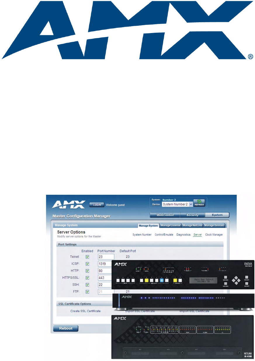
Manage System - Server Options ........................................................................... 51
Port Settings ................................................................................................................. 51
Server Port Settings ...................................................................................................... 52
SSL Certificate Options ................................................................................................. 53
Creating an SSL Server Certificate ................................................................................ 53
SSL Certificate Entries................................................................................................... 54
Displaying SSL Server Certificate Information............................................................... 55
Creating a Request for an SSL Certificate ..................................................................... 55
Self-Generating an SSL Certificate ................................................................................ 55
Regenerating an SSL Server Certificate Request........................................................... 55
Exporting an SSL Certificate Request ........................................................................... 56
Importing an SSL Certificate ......................................................................................... 56
Manage System - Clock Manager Options .............................................................. 58
Setting the Mode for the Clock Manager ..................................................................... 58
Setting Daylight Savings Rules...................................................................................... 59
Selecting a Custom NIST Server ................................................................................... 60
Adding a Custom NIST Server To the List ..................................................................... 60
Clock Manager NetLinx Programming API.................................................................... 61
System - Manage License........................................................................................ 61
Adding A New License .................................................................................................. 61
Removing a License....................................................................................................... 62
System - Manage NetLinx ....................................................................................... 63
System - Manage Devices ....................................................................................... 65
Manage Devices - Device Options .......................................................................... 65
Configuring Device Binding Options............................................................................. 65
Managing Device Modules............................................................................................ 66
Manage Devices - Bindings..................................................................................... 67
Configuring Application-Defined Devices ..................................................................... 67
Application Devices and Association Status .................................................................. 69
Viewing Physical Device Properties............................................................................... 70
Manage Devices - User-Defined Devices ................................................................ 71
Adding a User-Defined Device...................................................................................... 71
Manage Devices - View All Active Devices ............................................................. 73
Searching For All Compatible Duet Modules for a Selected Device ............................. 73
Viewing Physical Device Properties............................................................................... 74
Manage Devices - Manage Polled Ports.................................................................. 74
Editing Polled Port Settings .......................................................................................... 75
NetLinx Programming ......................................................................................77
Overview ................................................................................................................ 77

iv NetLinx Integrated Controllers- WebConsole & Programming Guide
Table of Contents
Port Assignments By NI Model .............................................................................. 77
Master Send_Commands ........................................................................................ 77
CLOCK 77
G4WC 78
~IGNOREEXTERNAL
CLOCKCOMMANDS 78
Master IP Local Port Send_Commands ................................................................... 79
UDPSENDTO 79
LED Disable/Enable Send_Commands .................................................................... 80
LED-DIS 80
LED-EN 80
RS232/422/485 Ports Channels .............................................................................. 80
RS-232/422/485 Send_Commands ......................................................................... 80
B9MOFF 80
B9MON 81
CHARD 81
CHARDM 81
CTSPSH 81
CTSPSH OFF 81
GET BAUD 81
HSOFF 82
HSON 82
RXCLR 82
RXOFF 82
RXON 82
SET BAUD 82
TSET BAUD 83
TXCLR 83
XOFF 83
XON 83
RS-232/422/485 Send_String Escape Sequences.................................................... 84
27,17,<time> 84
27,18,0 84
27,18,1 84
27,19,<time> 84
27,20,0 84
27,20,1 84
IR / Serial Ports Channels ....................................................................................... 85
IR RX Port Channels ................................................................................................ 85
IR/Serial Send_Commands ...................................................................................... 85
CAROFF 85
CARON 85
CH 86
CP 86
CTOF 86
CTON 86
GET BAUD 87
GET MODE 87
IROFF 87
POD 87

Table of Contents
v
NetLinx Integrated Controllers- WebConsole & Programming Guide
POF 87
PON 88
PTOF 88
PTON 88
SET BAUD 89
SET IO LINK 89
SET MODE 89
SP 89
XCH 90
XCHM 90
Input/Output Send_Commands .............................................................................. 91
GET INPUT 91
SET INPUT 91
Terminal (Program Port/Telnet) Commands .....................................................93
Overview ................................................................................................................ 93
Establishing a Terminal Connection Via the Program Port...................................... 93
PC COM Port Communication Settings ......................................................................... 94
NetLinx Integrated Controllers - Port Assignments ...................................................... 94
Establishing a Terminal Connection Via Telnet ....................................................... 94
Terminal Commands ............................................................................................... 95
----- Help ----- <D:P:S> 95
? or Help 95
CLEAR AUDIT LOG 95
CPU USAGE 95
DATE 95
DEVICE HOLDOFF ON|OFF 95
DEVICE STATUS <D:P:S> 95
DIPSWITCH 95
DISK FREE 95
DNS LIST <D:P:S> 96
ECHO ON|OFF 96
GET DEVICE HOLDOFF 96
GET DUET MEMORY 96
GET ETHERNET MODE 96
GET IP <D:P:S> 96
HELP SECURITY 96
ICSPMON ENABLED|DISABLED [PORT] 97
IP STATUS 97
IPSEC ON|OFF|STATUS 97
MEM 97
MSG ON|OFF 97
MSG STATS 97
OFF [D:P:S or NAME,CHAN] 97
ON [D:P:S or NAME,CHAN] 97
PASS [D:P:S or NAME] 98
PHYSICAL STATUS 98
PING [ADDRESS] 98
PROGRAM INFO 98
PULSE [D:P:S or NAME,CHAN] 98
PWD 99

vi NetLinx Integrated Controllers- WebConsole & Programming Guide
Table of Contents
REBOOT <D:P:S> 99
RENEW DHCP 99
RESETADMINPASSWORD 99
RESET FACTORY 99
ROUTE MODE DIRECT|NORMAL 99
SEND_COMMAND D:P:S or NAME,COMMAND 99
SEND_LEVEL <D:P:S>,
<LEVEL ID>,<LEVEL VALUE> 99
SEND_STRING D:P:S or NAME,STRING 99
SET DATE 100
SET DNS <D:P:S> 100
SET DUET MEMORY 100
SET ETHERNET MODE <CMD> 100
SET FTP PORT 101
SET HTTP PORT 101
SET HTTPS PORT 101
SET ICSP PORT 101
SET ICSP TCP TIMEOUT 101
SET IP <D:P:S> 102
SET LOG COUNT 102
SET QUEUE SIZE 103
SET SECURITY PROFILE 103
SET SNMP 105
SET SSH PORT 105
SET TELNET PORT 105
SET THRESHOLD 106
SET TIME 106
SET TIMELINE LOOPCNT 106
SET UDP BC RATE 106
SET URL <D:P:S> 107
SHOW AUDIT LOG 107
SHOW BUFFERS 108
SHOW COMBINE 108
SHOW DEVICE <D:P:S> 108
SHOW LOG 109
SHOW MAX BUFFERS 110
SHOW MEM 110
SHOW NOTIFY 110
SHOW REMOTE 110
SHOW ROUTE 111
SHOW SYSTEM <S> 111
ESC Pass Codes ........................................................................................................... 112
+ + ESC ESC 112
+ + ESC A 112
+ + ESC D 112
+ + ESC H 112
TCP LIST 112
TIME 112
URL LIST <D:P:S> 112
zeroconf [enable|disable|status] 112
Accessing the Security Configuration Options...................................................... 113
Setup Security Menu............................................................................................. 114
Security Options Menu................................................................................................ 115

Table of Contents
vii
NetLinx Integrated Controllers- WebConsole & Programming Guide
Edit User Menu ........................................................................................................... 116
Edit Group Menu......................................................................................................... 116
Access Rights Menu .................................................................................................... 117
Adding a Group .......................................................................................................... 117
Edit Group Menu: Add Directory Association ............................................................. 118
Default Security Configuration.................................................................................... 118
Telnet Diagnostics Commands.............................................................................. 119
REBOOT HEAP WATCH 119
SPY 119
SPY STOP 119
PHYSICAL STATUS 119
MSG STATS 119
Logging Out of a Terminal Session ....................................................................... 119
Notes on Specific Telnet/Terminal Clients ............................................................ 120
WindowsTM Client Programs ...................................................................................... 120
Linux Telnet Client ...................................................................................................... 120
Appendix A: IPSec Configuration File ............................................................121
IPSec Config file.................................................................................................... 121
Internet Key Exchange (IKE) ................................................................................. 121
ikeAddPeerAuth ......................................................................................................... 121
ikeSetProp .................................................................................................................. 123
ikeSetPropAttrib ........................................................................................................ 124
Security Policy Database (SPD) ............................................................................. 125
spdAddTransport ....................................................................................................... 125
SpdAddTunnel ........................................................................................................... 126
SpdAddBypass ........................................................................................................... 127
SpdAddDiscard .......................................................................................................... 128
SpdSetProp ................................................................................................................ 129
SpdSetPropAttrib ....................................................................................................... 134
spdSetSA .................................................................................................................... 135
Manual Key Manager (MKM) ................................................................................ 136
mkmAddBypass .......................................................................................................... 136
mkmAddDiscard ......................................................................................................... 137
mkmAddTransport ..................................................................................................... 138
mkmAddTunnel .......................................................................................................... 139
mkmSetInboundAH .................................................................................................... 140
mkmSetInboundESP ................................................................................................... 141
mkmSetOutboundAH ................................................................................................. 142
mkmSetOutboundESP ................................................................................................ 143
Sample IPSec Configuration File ........................................................................... 144
IPSec Web Configuration Interface....................................................................... 145

viii NetLinx Integrated Controllers- WebConsole & Programming Guide
Table of Contents
Appendix B: Clock Manager NetLinx Programming API .................................147
Types/Constants ................................................................................................... 147
Library Calls .......................................................................................................... 148

Overview
1
NetLinx Integrated Controllers- WebConsole & Programming Guide
Overview
NetLinx Integrated Controllers
NetLinx Integrated Controllers (Masters) can be programmed to control RS-232/422/485, Relay, IR/Serial,
and Input/Output devices using the NetLinx Studio application (version 2.4 or higher).
These NI Controllers feature an on-board Web Console which allows you to connect to the NI Controller via a
web browser and make various configuration and security settings.
The Web Console is described in this document (starting with the Onboard WebConsole User Interface section
on page 21).
These NI Controllers are Duet-compatible and can be upgraded via firmware. Duet is a dual-interpreter
firmware platform from AMX which combines the proven reliability and power of NetLinx with the extensive
capabilities of the Java® MicroEdition (JavaME) platform. Duet simplifies the programming of a system that
includes the NI-900 and other third party devices by standardizing device and function definitions, defaulting
touch panel button assignments, and controlling feedback methods.
Dynamic Device Discovery makes integration even easier by automatically identifying and communicating
with devices which support this beaconing technology.
Refer to the Manage Devices - Device Options section on page 65 for more detailed information on the use of
Dynamic Device Discovery (DDD).
DVX-2100HD Enova Total Environment Controller
The DVX-2100HD Enova Total Environment Controller utilizes an NI-2100 Controller, therefore all
controller-related information that applies to the NI-2100 is fully applicable to the DVX-2100HD.
As a Total Environment Controller, the DVX-2100HD features many functions that do not apply to NetLinx
Integrated Controllers, most of which relate directly to the Audio/Video capabilities of the DVX-2100HD.
Refer to the DVX-2100HD Operation/Reference Guide for information specific to the DVX-2100HD.
NetLinx Integrated Controllers
NI-700 (FG2105-03) NI-900 (FG2105-09) NI-3101-SIG (FG2105-08)
NI-2000 (FG2105-01) NI-2100 (FG2105-04)
NI-3000 (FG2105-02) NI-3100 (FG2105-05)
NI-4000 (FG2105) NI-4100 (FG2105-06)
NXC-ME260/64 (FG2010-64)
Environment Controllers
DVX-2100HD (FG1905-01)
Overview
2 NetLinx Integrated Controllers- WebConsole & Programming Guide
About This Document
This document describes using the on-board Web Console, as well as NetLinx send commands and terminal
communications to configure the NI Controllers:
Each major section of the Web Console is described in a separate section of this document. Refer
to:
the Onboard WebConsole User Interface section on page 21,
the WebConsole - WebControl Options section on page 39,
the WebConsole - Security Options section on page 25, and
the WebConsole - System Options section on page 41).
The Initial Configuration and Firmware Upgrade section (page 5) describes upgrading the
firmware on NI Controllers.
The Programming section (page 77) lists and defines the NetLinx send commands that are
supported by these NI Controllers.
The Terminal (Program Port/Telnet) Commands section (page 93) describes the commands and
options available via either a Program Port (RS232) or Telnet terminal session with the NI
Controller.
Related Documents
For detailed descriptions of NI Controller hardware, including specifications, port assignments, installation
procedures, connection and wiring information, refer to the Hardware Reference Guide for your Master:
Related Documents
Title
• DVX-2100HD Enova Total Environment Controller - Operation/Reference Guide
• NXI-700/900 NetLinx Integrated Controllers - Hardware Reference Guide
• NXI-x000 NetLinx Integrated Controllers - Hardware Reference Guide (NI-2000, NI-3000, NI-4000)
• NXI-x100 NetLinx Integrated Controllers - Hardware Reference Guide (NI-2100, NI-3100, NI-4100)
• NI-3101-SIG Signature Series NetLinx Integrated Controller - Operation/Reference Guide
• NXC-ME260/64 NetLinx Master-LAN Card/Module - Hardware Reference Guide
• NetLinx CardFrame, Control Cards, and NetModules Instruction Manual
• NetLinx Studio v2.4 or higher Instruction Manual
• NetLinx Programming Language Reference Guide
All product documentation is available to view or download from www.amx.com.

Overview
3
NetLinx Integrated Controllers- WebConsole & Programming Guide
Quick Setup and Configuration Overview
Installation Procedures
The general steps involved with most common installations of this device include:
Unpack and confirm the contents of box (see the Specifications tables in the Hardware Reference
Guide for each Controller).
Connect all rear panel components and supply power to the NI Controller from the external power
supply.
Configuration and Communication
The general steps involved with setting up and communicating with the NI Controllers’ on-board Master. In
the initial communication process:
Set the communication speed on the front Configuration DIP switch (default = 38400).
Connect and communicate with the on-board Master via the Program port.
Set the System Value being used with the on-board Master.
Re-assign any Device values.
You can then either get a DHCP Address for the on-board Master or assign a Static IP to the on-
board Master.
Once the IP information is determined, rework the parameters for Master Communication in order
to connect to the on-board Master via the LAN and not the Program port.
Update the On-board Master and Controller Firmware
Before using your new NI unit, you must first update your NetLinx Studio to the most recent
release.
Upgrade the on-board Master firmware through an IP Address via the LAN connector (Upgrading
the On-board Master Firmware via an IP section on page 12) (IP recommended).
Upgrade the Integrated Controller firmware through an IP Address via the LAN connector
(Upgrading the NI Controller Firmware Via IP section on page 15) (IP recommended).
Configure NetLinx Security on the NI Controller
Setup and finalize your NetLinx Security Protocols (WebConsole - Security Options section on
page 25).
Program your NI Controller (NetLinx Programming section on page 77).
Using Zero Configuration
NetLinx Controllers with firmware versions of v3.41 or higher support using "zero-configuration" client
software to quickly install multiple devices on the network.
Bonjour (Zero-Configuration) Client
You can use a zero-configuration client to determine the IP address of the Controllers. There are many zero-
configuration clients available. However, for the purposes of this document, we will refer to Bonjour for
Windows. It is free and widely available for download.
If you don’t already have it installed on your PC, download and install Bonjour for Windows before you begin.
Connecting to a Network with a DHCP Server
By using the Controllers’s zeroconf feature and the Bonjour for Windows plug-in utility, multiple devices can
be installed and configured on the network without the need to pre-configure each device before installation.
The dealer only needs to match the serial number printed on the backside of the device or from the label on the
box to the serial number that is displayed in the Bonjour browser pane.
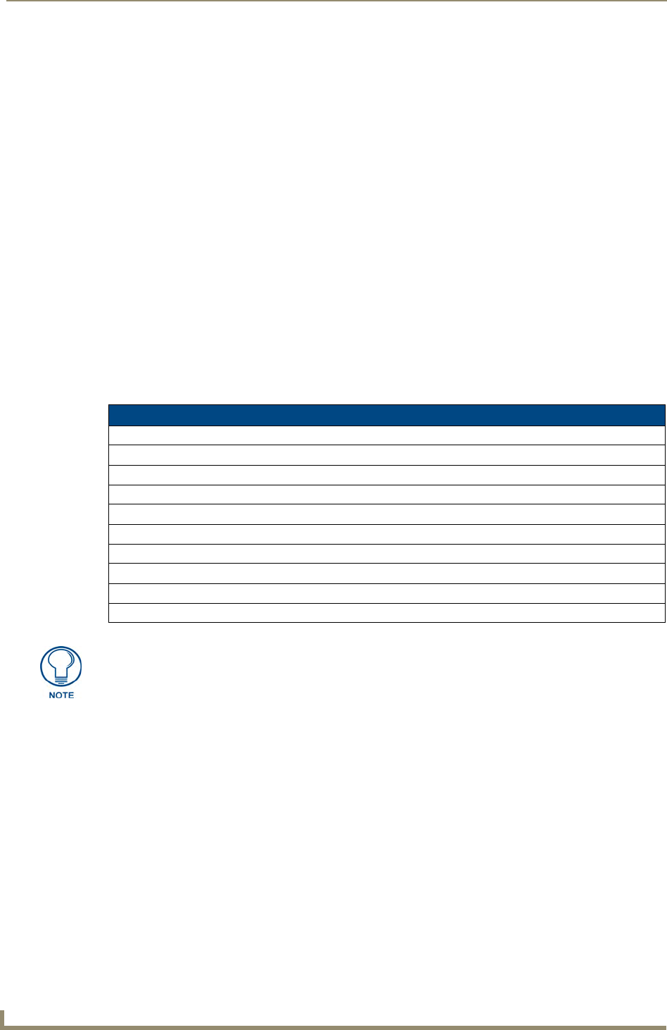
1. Launch Internet Explorer with the Bonjour plug-in.
2. Once power is applied to the device, the Bonjour plugin displays the device in the list of devices as shown
in FIG. 1:
Overview
4 NetLinx Integrated Controllers- WebConsole & Programming Guide
3. Double-click on the desired NetLinx Controller to access the Web Console of the selected device.
This requires valid login information - the browser will prompt you for User ID and Password before
displaying the configuration pages for the selected device.
Notice that the serial number is appended to the name of the device.
At this point, the device can be configured (changing IP settings, NetLinx settings, User settings, etc) via the
pages in the Web Console (see the Onboard WebConsole User Interface section on page 21).
FIG. 1 Internet Explorer with BonJour plug-in

Initial Configuration and Firmware Upgrade
5
NetLinx Integrated Controllers- WebConsole & Programming Guide
Initial Configuration and Firmware Upgrade
Overview
This section describes using the NetLinx Studio software application to perform the initial configuration of the
Master, as well as upgrading the firmware for various Master components.
NetLinx Studio is used to setup a System number, obtain/assign the IP/URL for the connected NI
Controller, and transfer firmware Kit files to the Master.
NetLinx Studio is available to download (free of charge) from www.amx.com.
Before You Start
1. Verify you have the latest version of NetLinx Studio on your PC. Use the Web Update option in NetLinx
Studio’s Help menu to obtain the latest version. Alternatively, go to www.amx.com and login as a Dealer
to download the latest version.
2. Verify that an LAN/ICSNet cable is connected from the NI Controller to the LAN Hub.
3. Connect an programming cable (RS-232) from the Program Port on the NI Controller to a COM port on
the PC being used for programming.
4. Verify that any control cards (NI-4000 and NI-4100 only) are inserted and their respective connectors are
attached to the rear of the NI Controller before continuing.
5. Verify that the NI Controller is powered On.
Preparing the NI Controller for Serial Communication
To establish serial communication with the Controller via the PROGRAM (DB9) port:
1. Launch NetLinx Studio 2.x (default location is Start > Programs > AMX Control Disc >
NetLinx Studio 2 > NetLinx Studio 2).
2. Select Settings > Master Communication Settings, from the menu bar, to open the Master
Communication Settings dialog box.
3. Click the Communications Settings button to open the Communications
Settings dialog.
4. Click the NetLinx Master radio button (from the Platform Selection section) to indicate you are working
with a NetLinx Master.
5. Click the Serial radio button (from the Transport Connection Option section) to indicate you are
connecting to the Master via a COM port.
6. Click the Edit Settings button (on the Communications Settings dialog) to open the Serial Settings dialog
and set the COM port parameters (used to communicate to the NetLinx Master).
7. Click OK to close all dialogs and return to the main application.
8. Right-click the Online Tree tab entry and select Refresh System: the
Controller should appear in the Device Tree. If not, verify that the Serial cable is connected properly, and
that the Baud Rate settings on the Controller (set via the Program Port DIP Switch) match the settings in
NetLinx Studio.
Once Serial communication has been established, use NetLinx Studio to configure the Controller for LAN
Communication, as described below.
Before commencing, verify you are using the latest firmware Kit file (this file contains
both the NI Integrated Controller and on-board Master firmware.
The NI-4000/3000/2000 Kit file begins with 2105_X000.
The NI-4100/3100/2100 Kit file begins with 2105_04_X100.
The NI-700/900 Kit file begins with 2105_03_NI-X00 and 2105_09_NI-X00
respectively.
Initial Configuration and Firmware Upgrade
6 NetLinx Integrated Controllers- WebConsole & Programming Guide
Configuring the NI Controller for LAN Communication
Before continuing, complete the COM port steps above.
1. Use an LAN cable to connect the Controller to the LAN to which the PC running NetLinx Studio is
connected.
2. Select Diagnostics > Network Address from the menu bar and enter the System, Device (0 for a
Master), and Host Name information.
3. To configure the Address:
Use a DHCP Address by selecting the Use DHCP radio button, then click the GET IP button (to
obtain a DHCP Address from the DHCP Server), click the SET IP Information button (to retain
the new address), and then finish the process by clicking the Reboot Master > OK buttons.
Use a Static IP Address by selecting the Specify IP Address radio button, enter the IP parameters
into the available fields, then click the SET IP Information button (to retain the pre-reserved IP
Address to the Master), and then click the Reboot Master > OK buttons to finish the process.
4. Repeat steps 1 - 5 from the previous section, but rather than selecting the Serial option, choose TCP/IP
and edit the settings to match the IP Address you are using (Static or IP).
5. Click on the Authentication Required radio box (if the Master is secured) and press the User Name and
Password button to enter a valid username and password being used by the secured Master.
6. Click the OK to close all dialogs and return to the main application.
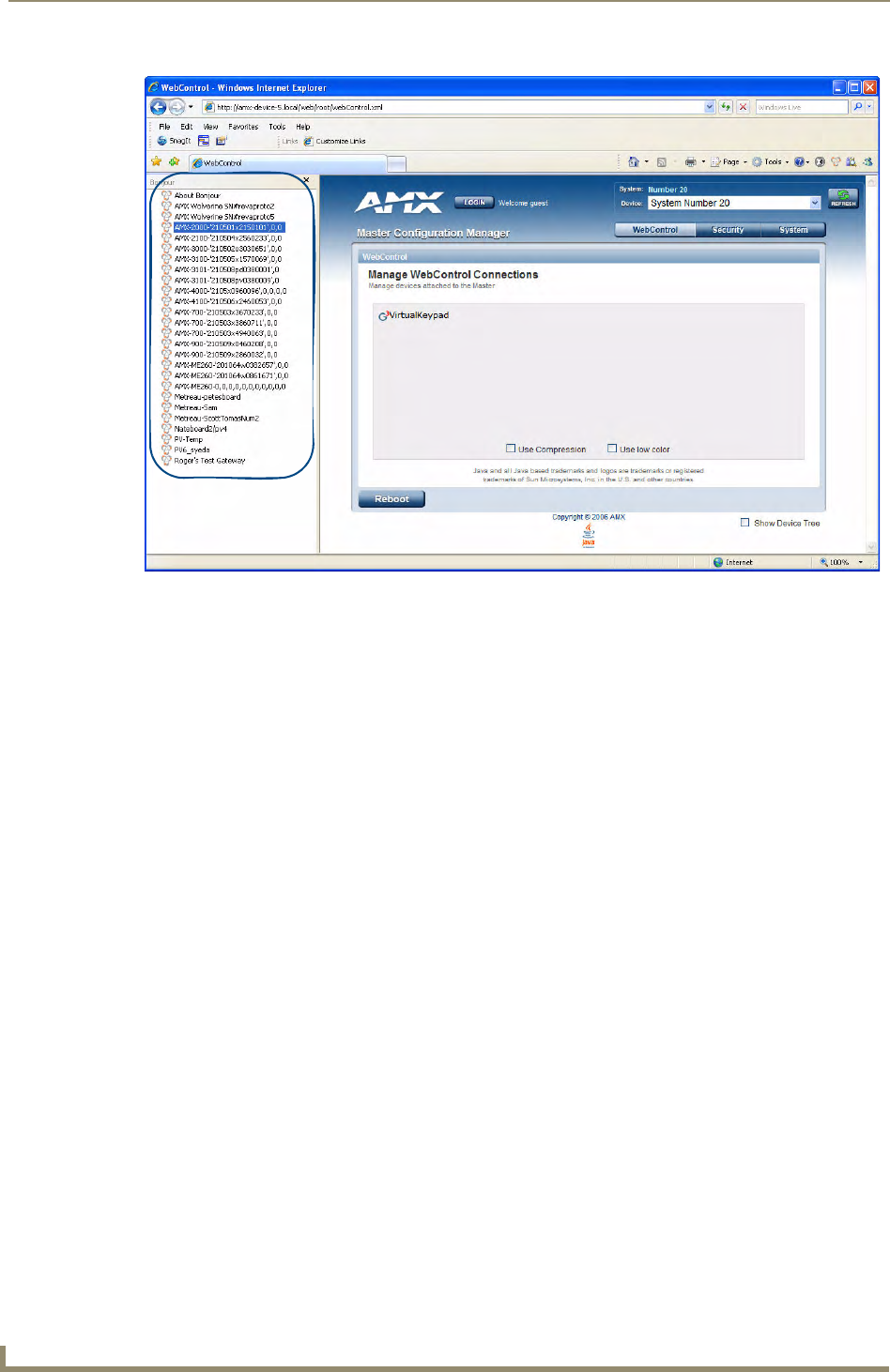
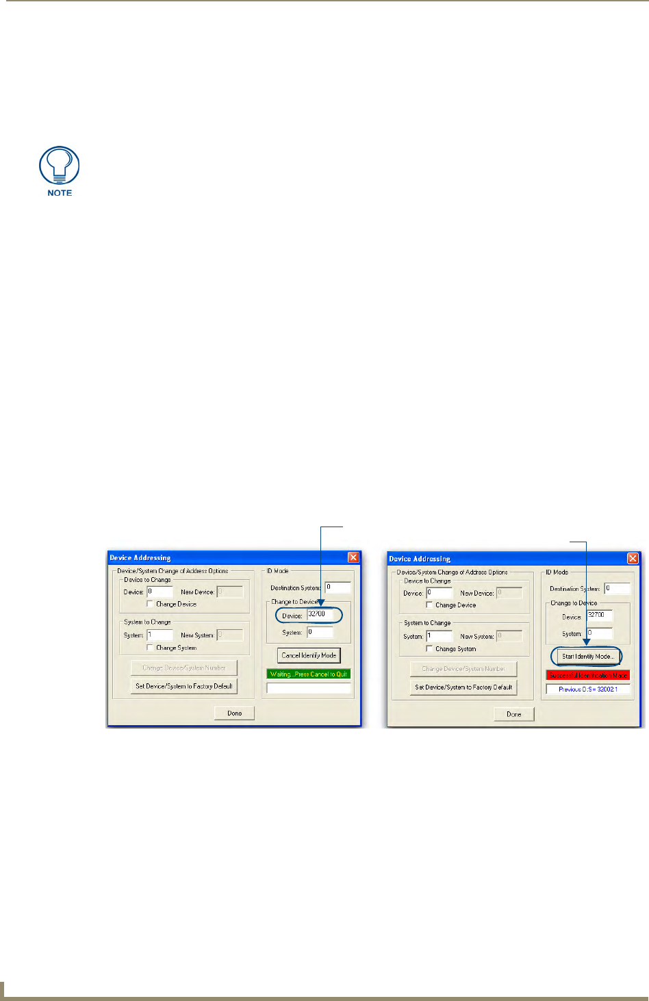
Using the ID Button to Change the Master Device Value
The steps described and the dialogs shown in this section are in the NetLinx Studio application.
1. Access the Device Addressing dialog (FIG. 1) by selecting Diagnostics > Device Addressing.
2. In the Device field (A in FIG. 1), enter the new value for the NI Controller (range = 0 - 32767).
3. Press the Start Identify Mode button (B in FIG. 1).
This action causes the *Not Active* message (in red) to display a Waiting...Press Cancel to Quit message
(in green). This message indicates that Studio is waiting to detect the device value of the NI Controller
associated with the ID button.
The NI-x100 Controllers feature an Auto MDI/MDI-X LAN port. This provides the
option of using either a standard (straight through), or a crossover LAN cable to
communicate with a PC - both cable types will work.
FIG. 1 NetLinx Studio: Device Addressing dialog (using the ID mode to set the NI Controller’s device value)
Enter the Master’s new Device value
Assign the new value to the Master
AB
Initial Configuration and Firmware Upgrade
7
NetLinx Integrated Controllers- WebConsole & Programming Guide
4. Press the NI Controller’s ID button to read the device value of the NI Controller, and assign it to the new
value entered in step 2.
Once the swap has been successfully made, a red Successful Identification Made field appears.
The previous Device and System numbers of the NI Controller are displayed below the red field.
Example: Previous D:S=32002:1,
where 32002 represents the previous device value of the NI Controller (D) and 1 represents the NI
Controller’s System value (S).
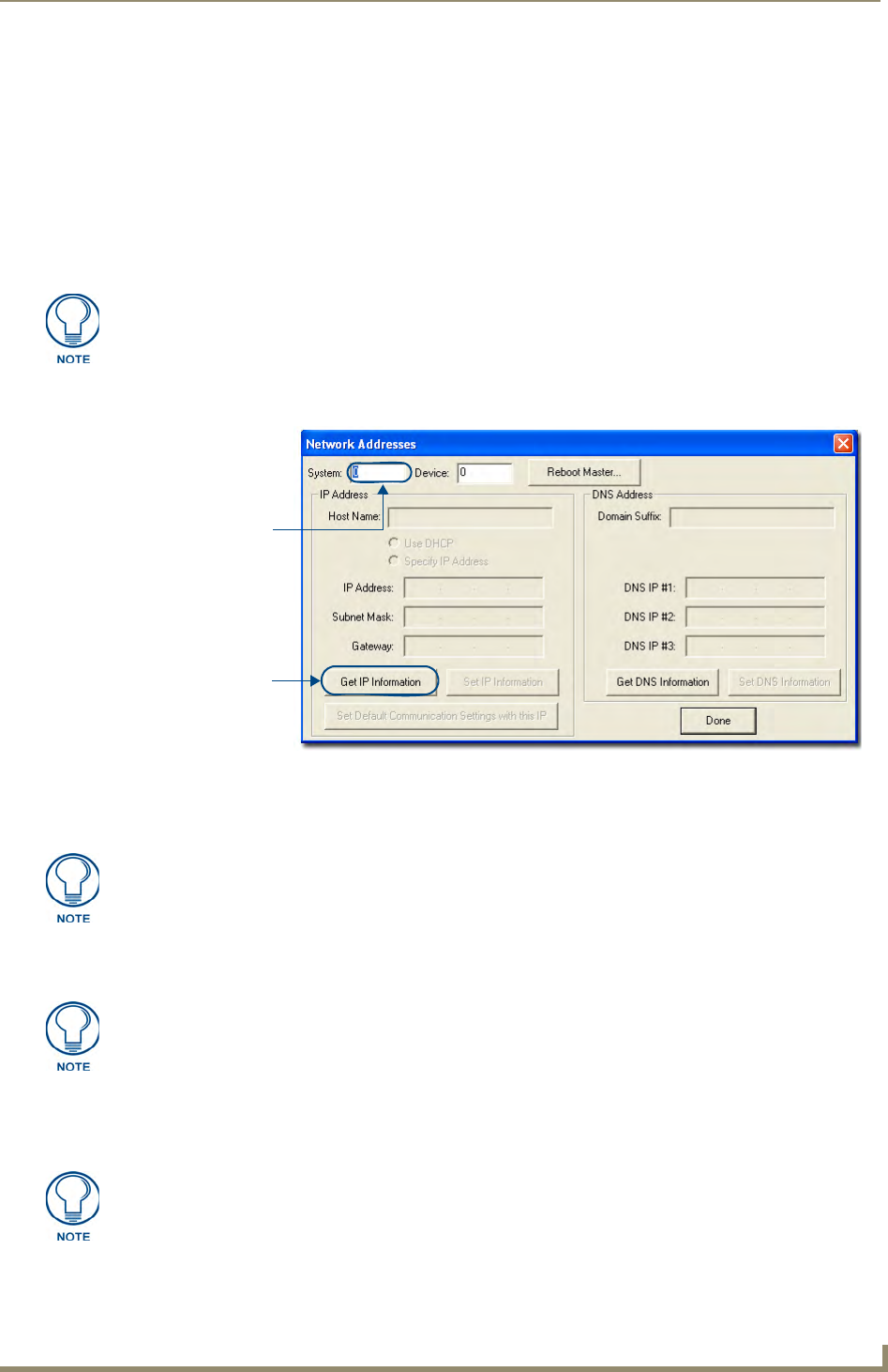
Obtaining the NI Controller’s IP Address (using DHCP)
1. In NetLinx Studio, select Diagnostics > Network Addresses from the Main menu to access the Network
Addresses dialog (FIG. 2).
2. Verify that both the System number corresponds to the System value previously assigned within the
Device Addressing tab and that zero (0) is entered into the Device field.
3. Click the Get IP Information button to configure the on-board Master for DHCP usage and then read the
IP Address obtained from the DHCP Server.
4. Note the obtained IP Address (read-only). This information is later entered into the Master
Communication Settings dialog and used by NetLinx Studio v 2.x to communicate to the NI Controller
via an IP. This address is reserved by the DHCP server and then given to the Master.
Verify there is an active LAN connection on the NI Controller’s LAN port before
beginning these procedures.
FIG. 2 NetLinx Studio: Network Addresses dialog (for a DHCP IP Address)
System Address
reflects the value
set in the Device
Addressing tab
Used to obtain a
Dynamic (DHCP)
IP Address
The system value must correspond to the Device Address entered in the Device
Addressing dialog. Refer to the Manage System - System Number section on
page 42 for more detailed instructions on setting a system value.
DO NOT enter ANY IP information at this time; this step only gets the System Master
to recognize that it should begin using an obtained DHCP Address.
If the IP Address field is empty, give the Master a few minutes to negotiate a DHCP
Address with the DHCP Server, and try again. The DHCP Server can take anywhere
from a few seconds to a few minutes to provide the Master with an IP Address.
Initial Configuration and Firmware Upgrade
8 NetLinx Integrated Controllers- WebConsole & Programming Guide
5. Verify that NetLinx appears in the Host Name field (if not, then enter it in at this time).
6. Click the Use DHCP radio button from the IP Address section.
7. Click the Set IP Information button to retain the IP Address from the DHCP server and assign it to the
on-board Master. A popup window then appears to notify you that Setting the IP information was
successful and it is recommended that the Master be rebooted.
8. Click OK to accept the change to the new IP/DNS information.
9. Click the Reboot Master button and select Yes to close the Network Addresses dialog.
10. Click Reboot (from the Tools > Reboot the Master Controller dialog) and wait for the System Master to
reboot and retain the newly obtained DHCP Address.
The STATUS and OUTPUT LEDs should begin to alternately blink during the incorporation. Wait until
the STATUS LED is the only LED to blink.
11. Press Done once until the Master Reboot Status field reads *Reboot of System Complete*.
12. Complete the communication process by continuing on to the Communicating Via an IP section on
page 9.
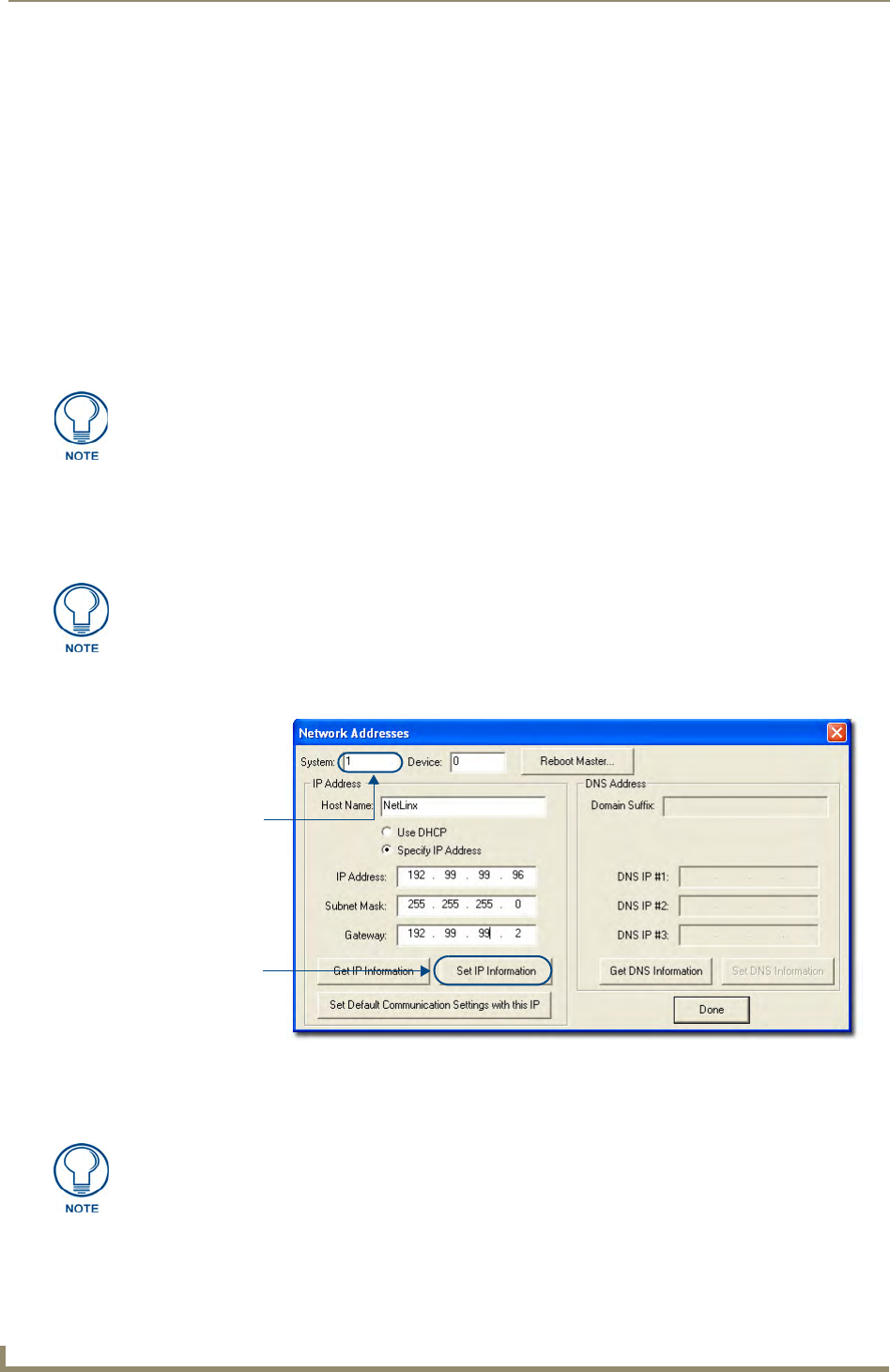
Assigning a Static IP to the NI Controller
1. In NetLinx Studio, select Diagnostics > Network Addresses from the Main menu to access the Network
Addresses dialog (FIG. 3).
2. Verify that both the System number corresponds to the System value previously assigned within the
Device Addressing tab and that zero (0) is entered into the Device field.
3. Click the Get IP Information button to temporarily configure the on-board Master for DHCP usage and
then read the IP Address obtained from the DHCP Server.
Verify that these IP values are also entered into the related fields within either the
IP Settings section of the System Connection page (on the touch panel) or within the
Address field on the web browser.
Verify there is an active LAN connection on the LAN port of the Master before
beginning these procedures.
FIG. 3 Network Addresses dialog (for a pre-obtained Static IP Address)
System Address
reflects the value
set in the Device
Addressing tab
Used to retain an
IP Address
The system value must correspond to the Device Address previously entered in the
Device Addressing tab. Refer to the Manage System - System Number section on
page 42 for more detailed instructions on setting a system value.

Initial Configuration and Firmware Upgrade
9
NetLinx Integrated Controllers- WebConsole & Programming Guide
4. Click the Specify IP Address radio button from the IP Address section. With this action, all IP fields
become editable.
5. Verify that NetLinx appears in the Host Name field (if not, then enter it in at this time).
6. Enter the IP Address, Subnet Mask, and Gateway information into their respective fields.
7. Click the Set IP Information button to cause the on-board Master to retain this new IP Address (pre-
obtained from the System Administrator).
8. Click OK to accept the change to the new IP/DNS information.
9. Click the Reboot Master button and select Yes to close the Network Addresses dialog.
10. Click Reboot (from the Tools > Reboot the Master Controller dialog) and wait for the System Master to
reboot and retain the newly obtained DHCP Address.
The STATUS and OUTPUT LEDs should begin to alternately blink during the incorporation. Wait until
the STATUS LED is the only LED to blink.
11. Press Done once until the Master Reboot Status field reads *Reboot of System Complete*.
12. Complete the communication process by continuing on to the Communicating Via an IP section on
page 9.
Communicating Via an IP
Whether the on-board Master’s IP Address was Static Set (via the Set IP Info command) or Dynamically
obtained (via the Get IP Info command), use the IP Address information from the Network Addresses dialog
to establish communication via the LAN-connected Master.
1. Use NetLinx Studio to obtain the IP Address of the NI Controller from your System Administrator.
If you do not have an IP Address:
Follow the steps outlined in either the Obtaining the NI Controller’s IP Address (using
DHCP) section on page 7,
or the Assigning a Static IP to the NI Controller section on page 8.
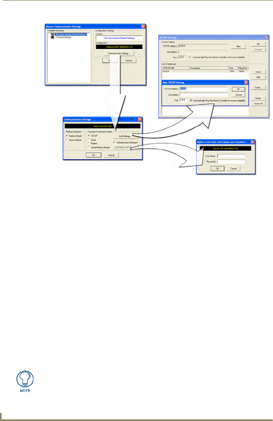
2. Select Settings > Master Communication Settings from the Main menu to open the Master
Communication Settings dialog (FIG. 4).
Verify that these IP values are also entered into the related fields within either the
IP Settings section of the System Connection page (on the touch panel) or within the
Address field on the web browser.
Initial Configuration and Firmware Upgrade
10 NetLinx Integrated Controllers- WebConsole & Programming Guide
3. Click the Communications Settings button to open the Communications Settings dialog.
4. Click on the NetLinx Master radio button (from the Platform Selection section) to indicate you are
working with a NetLinx Master (such as the NXC-ME260/64 or NI-Series of Integrated Controllers).
5. Click on the TCP/IP radio button (from the Transport Connection Option section) to indicate you are
connecting to the Master via an IP Address.
6. Click the Edit Settings button (on the Communications Settings dialog) to open the TCP/IP Settings
dialog (FIG. 4). This dialog contains a series of previously entered IP Address/URLs and their associated
names, all of which are stored within Studio and are user-editable.
7. Click the New button to open the New TCP/IP Settings dialog where you can enter both a previously
obtained DHCP or Static IP Address and an associated description for the connection into their respective
fields.
8. Place a checkmark within the Automatically Ping the Master Controller to ensure availability radio box
to make sure the Master is initially responding online before establishing full communication.
9. Click OK to close the current New TCP/IP Settings dialog and return to the previous TCP/IP Settings
dialog where you must locate your new entry within the List of Addresses section.
10. Click the Select button to make that the currently used IP Address communication parameter.
11. Click OK to return to the Communications Settings dialog and place a checkmark within the
Authentication Required radio box if your Master has been previously secured with a username/password.
12. Click on the Authentication Required radio box (if the Master is secured) and then press the User Name
and Password button to open the Master Controller User Name and Password dialog.
13. Within this dialog, you must enter a previously configured username and password (with sufficient rights)
before being able to successfully connect to the Master.
14. Click OK to save your newly entered information and return to the previous Communication Settings
dialog where you must click OK again to begin the communication process to your Master.
FIG. 4 Assigning Master Communication Settings and TCP/IP Settings
If you are currently connected to the assigned Master, a popup asks whether you
would want to temporarily stop communication to the Master and apply the new
settings.

Initial Configuration and Firmware Upgrade
11
NetLinx Integrated Controllers- WebConsole & Programming Guide
15. Click Ye s to interrupt the current communication from the Master and apply the new settings.
16. Once the particular System Master is configured for communication via an IP Address, remove the DB9
connector from the Program port on the NI on-board Master.
17. Click Reboot (from the Tools > Reboot the Master Controller dialog) and wait for the Master to reboot.
The STATUS and OUTPUT LEDs should begin to alternately blink during the incorporation. Wait until
the STATUS LED is the only LED to blink.
18. Press Done once until the Master Reboot Status field reads *Reboot of System Complete*.
19. Click the OnLine Tree tab in the Workspace window to view the devices on the System. The default
System value is one (1).
20. Right-click the associated System number and select Refresh System. This establishes a new connection
to the specified System and populates the list with devices on that system. The communication method is
then highlighted in green on the bottom of the NetLinx Studio window.
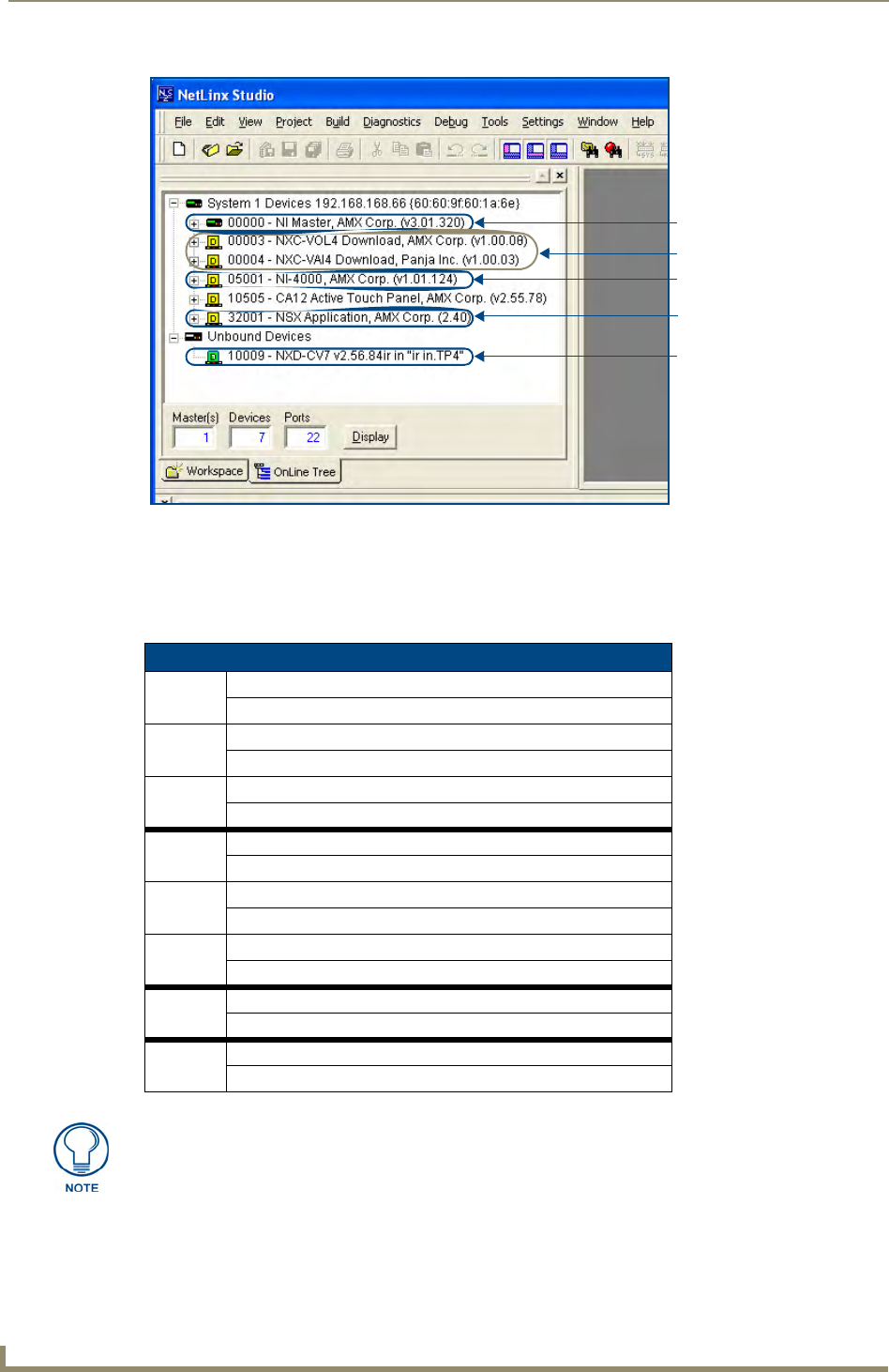
Verifying the Firmware Version On the Master
All NI Controllers contain both an on-board NI Master and an Integrated Controller. If you are using an NI-
4000 or NI-4100 with installed NXC cards, these will also show up within the Online Tree tab.
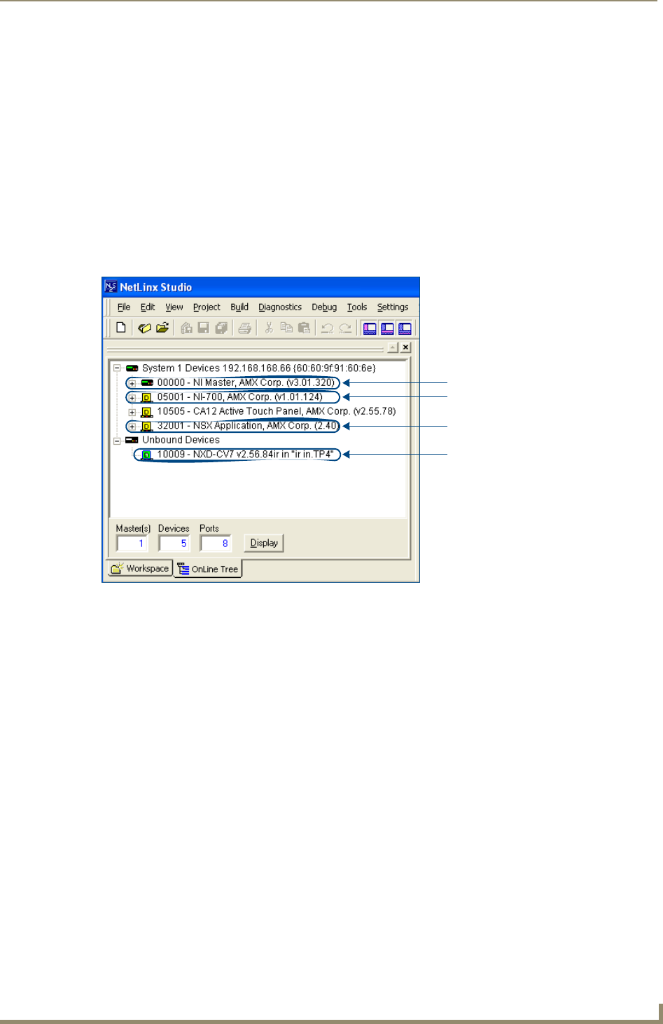
The on-board Master shows up within the Online Tree as 00000 NI Master
The Integrated Controller of the NI shows up as 0XXXX NI-XXXX (ex: 050001 NI-700)
Each of these components has its own corresponding firmware shown in parenthesis ().
1. After Studio has established a connection with the target Master, click on the OnLine Tree tab in the
Workspace window to view the devices on the System. The default System value is one (1).
2. Right-click the associated System number and select Refresh System. This establishes a new connection
to the specified System and populates the list with devices on that system. The communication method is
highlighted in green on the bottom of the NetLinx Studio window.
3. After the Communication Verification dialog indicates active communication between the PC and the
Master, verify the NetLinx Master (00000 NI Master) appears within the OnLine Tree tab of the
Workspace window (FIG. 5).
The default NI Master value is zero (00000) and cannot be changed.
4. If either the on-board NI Master or Integrated Controller is not the latest firmware version, follow the
procedures outlined in the following sections to obtain these Kit files from www.amx.com and then
transfer the new firmware Kit files to the device.
If the connection fails to establish, a Connection Failed dialog appears.
Try selecting a different IP Address if communication fails.
Press the Retry button to reconnect using the same communication parameters.
Press the Change button to alter your communication parameters and repeat
steps 4 thru 18.
The current installed firmware version of the on-board NI Master is displayed to the
right of the device within the Online Tree tab as 00000 NI Master.
Initial Configuration and Firmware Upgrade
12 NetLinx Integrated Controllers- WebConsole & Programming Guide
Upgrading the On-board Master Firmware via an IP
The on-board Master firmware Kit file is not the same as the Integrated Controller Kit file. Below is a table
outlining the current sets of on-board Master and Integrated Controller Kit files used by the NI-Series of
products:
FIG. 5 Sample NetLinx Workspace window (showing OnLine Tree tab)
Firmware Kit File usage for NI Controllers
NI-4100 On-board Master Kit file: 2105_04_NI-X100_Master
Integrated Controller Kit file: 2105_04_NI-X100
NI-3100 On-board Master Kit file: 2105_04_NI-X100_Master
Integrated Controller Kit file: 2105_04_NI-X100
NI-2100 On-board Master Kit file: 2105_04_NI-X100_Master
Integrated Controller Kit file: 2105_04_NI-X100
NI-4000 On-board Master Kit file: 2105_NI-X000_Master
Integrated Controller Kit file: 2105_NI-X000
NI-3000 On-board Master Kit file: 2105_NI-X000_Master
Integrated Controller Kit file: 2105_NI-X000
NI-2000 On-board Master Kit file: 2105_NI-X000_Master
Integrated Controller Kit file: 2105_NI-X000
NI-700 On-board Master Kit file: 2105-03_NI-X000_Master
Integrated Controller Kit file: 2105-03_NI_X00
NI-900 On-board Master Kit file: 2105-03_NI-X000_Master
Integrated Controller Kit file: 2105-09_NI_X00
On-board NI Master
Control cards (NI-4x00 ONLY)
NetLinx Integrated Controller
NetLinx Studio version
Unbound Dynamic Device
Only Master firmware Kit files use the word _Master in the Kit file name.
Initial Configuration and Firmware Upgrade
13
NetLinx Integrated Controllers- WebConsole & Programming Guide
1. Follow the procedures outlined within the Communicating Via an IP section on page 9 to connect to the
target NI device via the web.
2. After NetLinx Studio has established a connection to the target Master, click the OnLine Tree tab of the
Workspace window to view the devices on the System. The default System value is one (1).
3. Right-click the associated System number and select Refresh System. This establishes a new connection
to the specified System and populates the list with devices on that system. The communication method is
highlighted in green on the bottom of the NetLinx Studio window.
4. After the Communication Verification dialog window verifies active communication between the PC and
the Master, verify the NetLinx Master (00000 NI Master) appears in the OnLine Tree tab of the
Workspace window. The default NI Master value is zero (00000).
5. If the on-board Master firmware being used is not current, download the latest Kit file by first logging in
to www.amx.com and then navigating to Tech Center > Firmware Files, where you can locate the
desired file from within the NetLinx section of the web page.
6. Click on the desired Kit file link and after you’ve accepted the Licensing Agreement, verify you have
downloaded the correct NI Master firmware (Kit) file to a known location.
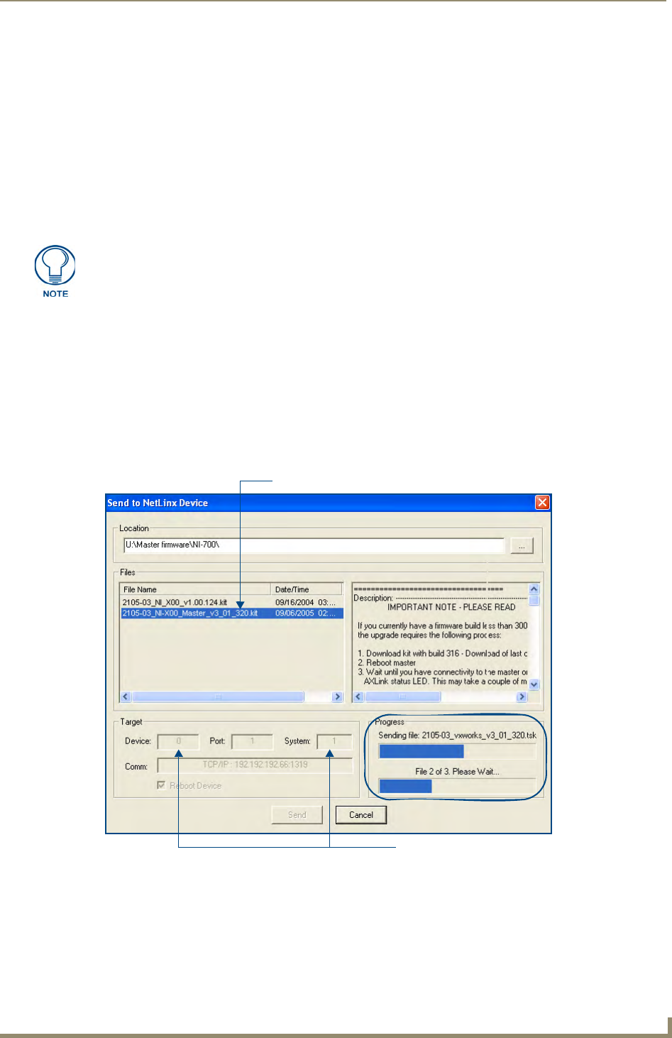
7. In NetLinx Studio, select Tools > Firmware Transfers > Send to NetLinx Device to open the Send to
NetLinx Device dialog (FIG. 6). Verify the target’s System number matches the value listed within the
active System folder in the OnLine Tree tab of the Workspace.
The Device number is always 0 for the NI Master.
8. Select the NI Master’s Kit file from the Files section (FIG. 6).
First upgrade of the on-board Master using the Master’s Kit file.
The Integrated Controller can later be upgraded using the Controller’s Kit file.
BOTH Kits should be used when upgrading any firmware associated with the
Integrated Controllers.
FIG. 6 Send to NetLinx Device dialog (showing on-board NI_Master firmware update via IP)
Selected Master firmware file
Description field for
Device and System Number
must match the Device and System values
listed in the Workspace window
Firmware download
status
selected Kit file

Initial Configuration and Firmware Upgrade
14 NetLinx Integrated Controllers- WebConsole & Programming Guide
Do not use the 2105-03_NI_Master Kit file on anything other than an NI-700/900, since each Master Kit
file is specifically configured to function on a specific NI unit.
9. Enter the System number associated with the target Master (listed in the OnLine Tree tab of the
Workspace window) and verify the Device number value. The Port field is disabled.
10. Click the Reboot Device checkbox to reboot the NI unit after the firmware update process is complete.
11. Click Send to begin the transfer. The file transfer progress is indicated on the bottom-right of the dialog
(FIG. 6).
12. After the last components fails to install, click Done.
13. Click Reboot (from the Tools > Reboot the Master Controller dialog) and wait for the System Master to
reboot.
The STATUS and OUTPUT LEDs should begin to alternately blink during the incorporation. Wait until
the STATUS LED is the only LED to blink.
14. Press Done once until the Master Reboot Status field reads *Reboot of System Complete*.
15. Repeat steps 5 - 9 again (the last component will now successfully be installed).
16. Click Close once the download process is complete.
17. Right-click the System number and select Refresh System. This establishes a new connection to the
System and populates the list with the current devices (and their firmware versions) on your system.
The Kit file for the NI-2000/3000/4000 Masters begins with 2105_NI-X000_Master.
The Kit file for the NI-2100/3100/4100 Masters begins with 2105_04_NI-X100_Master.
The Kit file for the NI-700/900 Masters begins with 2105-03_NI-X000_Master.
Only upon the initial installation of a new Kit file to an on-board Master will there
be a error message displayed indicating a failure of the last component to
successfully download.
This is part of the NI Master update procedure and requires that the firmware be
reloaded after a reboot of the unit. This consecutive process installs the final
component of the new Kit file.
The OUTPUT and INPUT LEDs alternately blink to indicate the on-board Master is
incorporating the new firmware. Allow the Master 20 - 30 seconds to reboot and fully
restart.
Initial Configuration and Firmware Upgrade
15
NetLinx Integrated Controllers- WebConsole & Programming Guide
Upgrading the NI Controller Firmware Via IP
1. Follow the procedures outlined within the Communicating Via an IP section on page 9 to connect to the
target NI device via the web.
2. After Studio has established a connection to the target Master, click the OnLine Tree tab of the
Workspace window to view the devices on the System. The default System value is one (1).
3. Right-click the associated System number and select Refresh System. This establishes a new connection
to the specified System and populates the list with devices on that system. The communication method is
highlighted in green on the bottom of the NetLinx Studio window.
4. After the Communication Verification dialog window verifies active communication between the PC and
the NI unit, verify the Integrated Controller appears in the OnLine Tree tab (FIG. 7) of the Workspace
window (ex: NI-4000 or NI-700). This entry is different than the NI Master which uses a device value of
00000 (see below):
5. If the NI Controller firmware being used is not current, download the latest Kit file by first logging in to
www.amx.com and then navigating to Tech Cente r > Firmware Files, where you can locate the desired
file from within the NI Series Device (Integrated Controller) section of the web page.
6. Click on the desired Kit file link and after you’ve accepted the Licensing Agreement, verify you have
downloaded the Integrated Controller firmware (Kit) file to a known location.
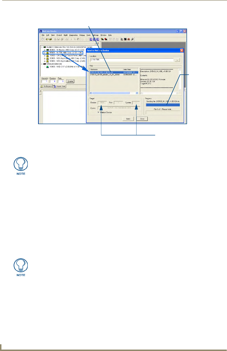
7. From within Studio, select Tools > Firmware Transfers > Send to NetLinx Device from the Main menu
to open the Send to NetLinx Device dialog (FIG. 8). Verify the target’s System number matches the value
listed within the active System folder in the OnLine Tree tab of the Workspace.
The Device must match the entry for the on-board Integrated Controller (ex: NI-4000 or
NI-700) device.
FIG. 7 Sample NetLinx Workspace window (showing separate NI-Master and Controller)
On-board Integrated Controller (NI-X000)
Unbound Dynamic Device
NetLinx Studio version
On-board NI Master
(NI-X000_Master) - Device 0
Initial Configuration and Firmware Upgrade
16 NetLinx Integrated Controllers- WebConsole & Programming Guide
Do not use the 2105-03_NI_X00 Kit file on anything other than an NI-700/900 since each Kit file is
specifically configured to function on a specific NI unit.
8. Select the Integrated Controller’s (_X00) from the Files section (FIG. 8).
9. Enter the System and Device numbers associated with the target Master (listed in the Workspace
window). The Port field is greyed-out.
10. Click the Reboot Device checkbox to reboot the NI unit after the firmware update process is complete.
11. Click Send to begin the transfer. The file transfer progress is indicated on the bottom-right of the dialog
(FIG. 8).
12. Click Close once the download process is complete.
13. Right-click the System number and select Refresh System. This establishes a new connection to the
System and populates the list with the current devices (and their firmware versions) on your system.
If The Connection Fails
If the connection fails to establish, a Connection Failed dialog appears.
Try selecting a different IP Address if communication fails.
Press the Retry button to reconnect using the same communication parameters.
Press the Change button to alter your communication parameters and repeat
steps 2 thru 11.
FIG. 8 Send to NetLinx Device dialog (showing on-board Integrated Controller firmware update via IP)
Selected on-board Integrated Controller firmware file
Device and System Number
must match the Device and System
values listed in the Workspace window
Firmware download
status
The Kit file for the Integrated Controller on the NI-2000/3000/4000 begins with
2105_NI_X000.
The Kit file for the Integrated Controller on the NI-2100/3100/4100 begins with
2105_04_NI_X100.
The Kit file for the NI-700/900 Series begins with 2105-03_NI_X000
The OUTPUT and INPUT LEDs alternately blink to indicate the unit is incorporating
the new firmware. Allow the unit 20 - 30 seconds to reboot and fully restart.
Initial Configuration and Firmware Upgrade
17
NetLinx Integrated Controllers- WebConsole & Programming Guide
Upgrading NXC Card Firmware Via IP
Before beginning with this section, verify that both the on-board Master and on-board Integrated Controller
have been updated with the latest firmware and that the NetLinx cards are securely inserted into the NI-4000 or
NI-4100.
1. Follow the procedures outlined within the Communicating Via an IP section on page 9 to connect to the
target NI device via the web.
2. After NetLinx Studio has established a connection to the target Master, click the OnLine Tree tab of the
Workspace window to view the devices on the System. The default System value is one (1).
3. Right-click the associated System number and select Refresh System. This establishes a new connection
to the specified System and populates the list with devices on that system. The communication method is
highlighted in green on the bottom of the NetLinx Studio window.
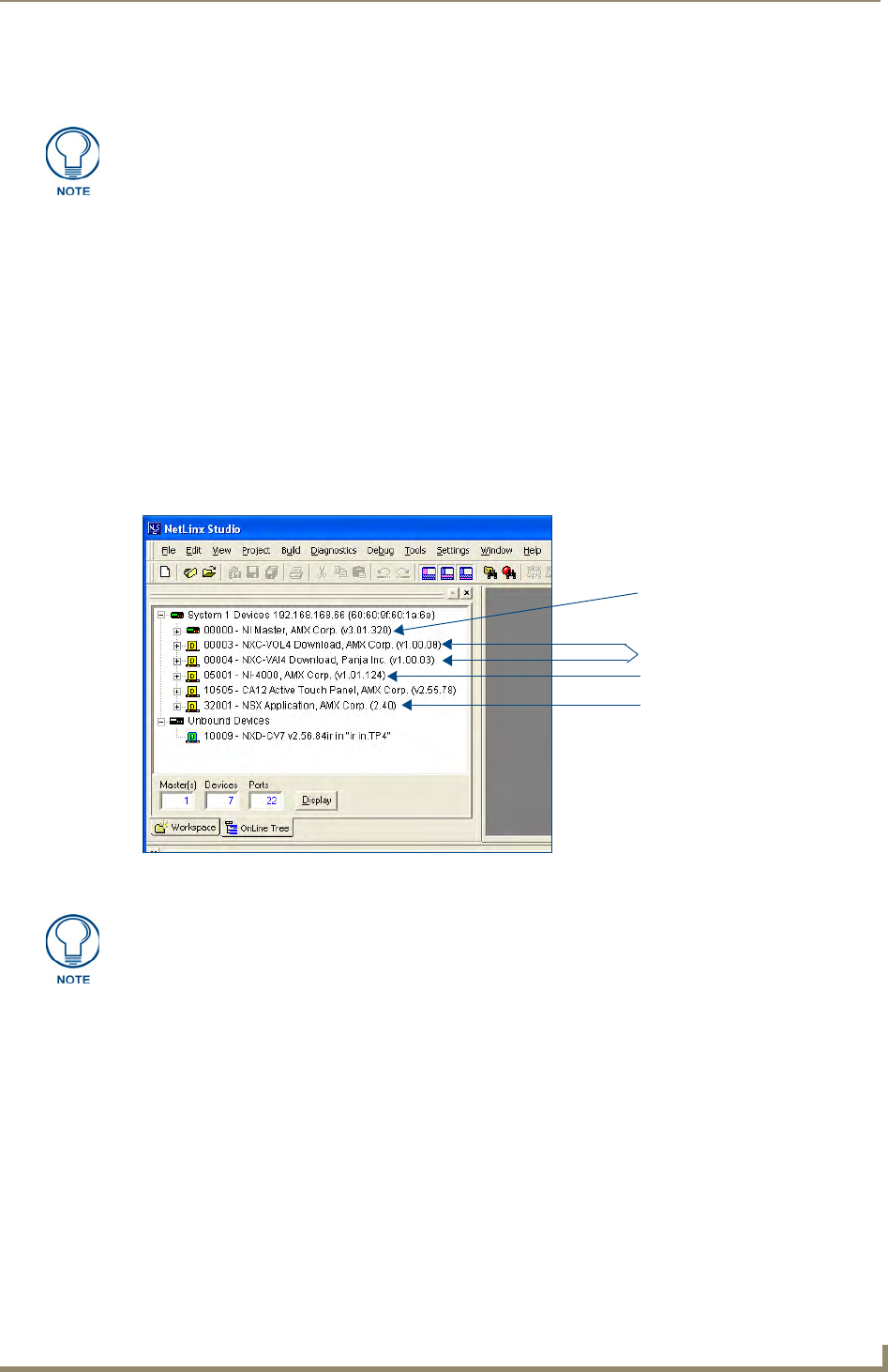
4. After the Communication Verification dialog window verifies active communication between the PC and
the NI unit, verify the NetLinx NXC Control Cards appear in the OnLine Tree tab of the Workspace
window (FIG. 9).
5. If the NXC card firmware being used is not current, download the firmware file by first logging in to
www.amx.com and then navigate to Tech Center > Firmware Files and from within the NetLinx section
of the web page locate the NXC card entries.
6. Click on the desired Kit file link and after you’ve accepted the Licensing Agreement, verify you have
downloaded the NetLinx NXC card firmware (Kit) file to a known location.
7. Verify you have downloaded the latest NetLinx Control Card firmware (Kit) file to a known location.
8. Select Tools > Firmware Transfers > Send to NetLinx Device from the Main menu to open the Send to
NetLinx Device dialog (FIG. 10). Verify the target’s Device and System numbers matches the value
listed within the System folder in the Workspace window.
This section applies to the NI-4000 and NI-4100 0nly.
FIG. 9 Sample NetLinx Workspace window (showing OnLine Tree tab)
On-board NI Master
Control cards (NI-4x00 ONLY)
NetLinx Integrated Controller
NetLinx Studio version
If the control card firmware is not up to date; download the latest firmware file from
www.amx.com > Tech Center > Downloadable Files > Firmware Files >
NXC-XXX.
In this example, the NXC-VOL card contains out-of-date firmware and requires build
1.00.09.
Initial Configuration and Firmware Upgrade
18 NetLinx Integrated Controllers- WebConsole & Programming Guide
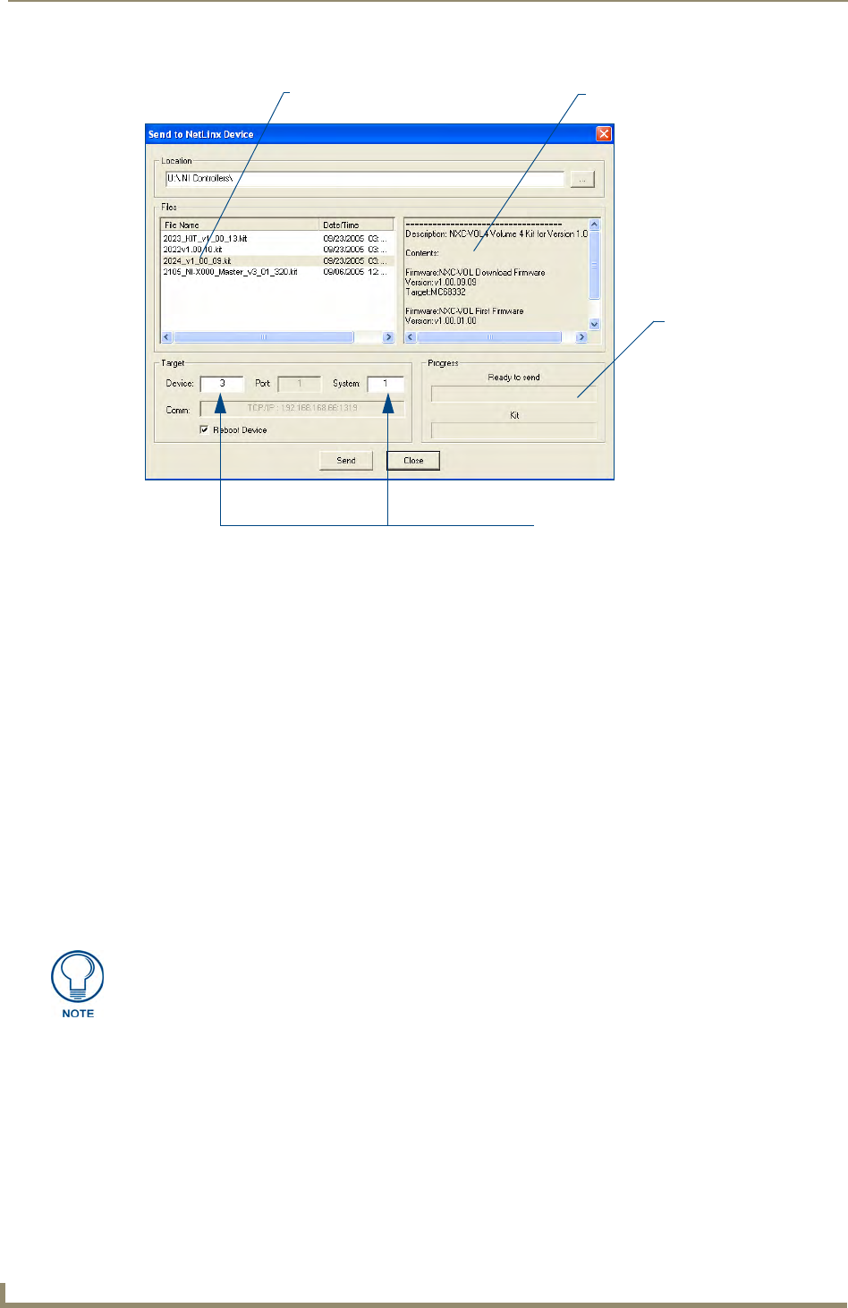
9. Select the Control Card’s Kit file from the Files section (FIG. 10) (in our above example we chose to
update the NXC-VOL4 card).
10. Enter the System and Device numbers associated with the desired Master (listed in the Workspace
window). A device value of 00003 is the same as a value of 3.
11. Click the Reboot Device checkbox to reboot the NI unit after the firmware update process is complete
and then re-detect the new NXC card firmware.
12. Click Send to begin the transfer. The file transfer progress is indicated on the bottom-right of the dialog
(FIG. 10).
13. Click Close once the download process is complete.
14. Click Reboot (from the Tools > Reboot the Master Controller dialog) and wait for the System Master to
reboot.
The STATUS and OUTPUT LEDs should begin to alternately blink during the incorporation. Wait until
the STATUS LED is the only LED to blink.
15. Press Done once until the Master Reboot Status field reads *Reboot of System Complete*.
16. Cycle power to the Master (unplug and reconnect power to the unit).
17. After Studio has establish a connection to target Master, click the OnLine Tree tab of the Workspace
window to view the devices on the System. The default System value is one (1).
18. Right-click the associated System number and select Refresh System. This establishes a new connection
to the specified System and populates the list with devices on that system.
The communication method is highlighted in green on the bottom of the NetLinx Studio window.
FIG. 10 Select Control Card firmware file for download page (via IP)
Selected Control Card Description field for selected Kit file
System Number and Device Number
must match the System and Device values
listed in the Workspace window
Firmware download
status
Firmware file
This process of cycling power acts to reset the updated NetLinx Control Card and
detect its new firmware update. It also serves to allow the Integrated Controller to
detect and reflect the new firmware on the card to the NetLinx Studio display on the
Workspace window.

Initial Configuration and Firmware Upgrade
19
NetLinx Integrated Controllers- WebConsole & Programming Guide
Resetting the Factory Default System and Device Values
1. In NetLinx Studio, access the Device Addressing dialog (FIG. 1 on page 6) by either one of these two
methods:
Right-click on any system device listed in the Workspace and select Device Addressing.
Select Diagnostics > Device Addressing from the Main menu.
2. Click the Set Device/System to Factory Default button. This resets both the system value and device
addresses (for definable devices) to their factory default settings. The system information (in the OnLine
Tree tab of the Workspace window) refreshes and then displays the new information.
3. Click Done to close the Device Addressing dialog.
4. Click Reboot (from the Tools > Reboot the Master Controller dialog) and wait for the System Master to
reboot.
The STATUS and OUTPUT LEDs should begin to alternately blink during the incorporation. Wait until
the STATUS LED is the only LED to blink.
5. Press Done once until the Master Reboot Status field reads *Reboot of System Complete*.
6. Click the OnLine Tree tab in the Workspace window to view the devices on the System.
The default System value is one (1).
7. Right-click the associated System number (or anywhere within the tab itself) and select Refresh System.
This establishes a new connection to the specified System and populates the list with devices on that
system.
8. Use Ctrl+S to save these changes to your NetLinx Project.
By setting the system to its default value (#1), Modero panels that were set to
connect to the Master on another System value will not appear in the OnLine Tree
tab of the Workspace window.
For example: A Modero touch panel was previously set to System #2. The system is
then reset to its default setting of System #1 and then refreshed from within the
Workspace window. The panel will not reappear until the system is changed (from
within the System Connection page on the Modero) to match the new value and both
the Master and panel are rebooted.

Initial Configuration and Firmware Upgrade
20 NetLinx Integrated Controllers- WebConsole & Programming Guide
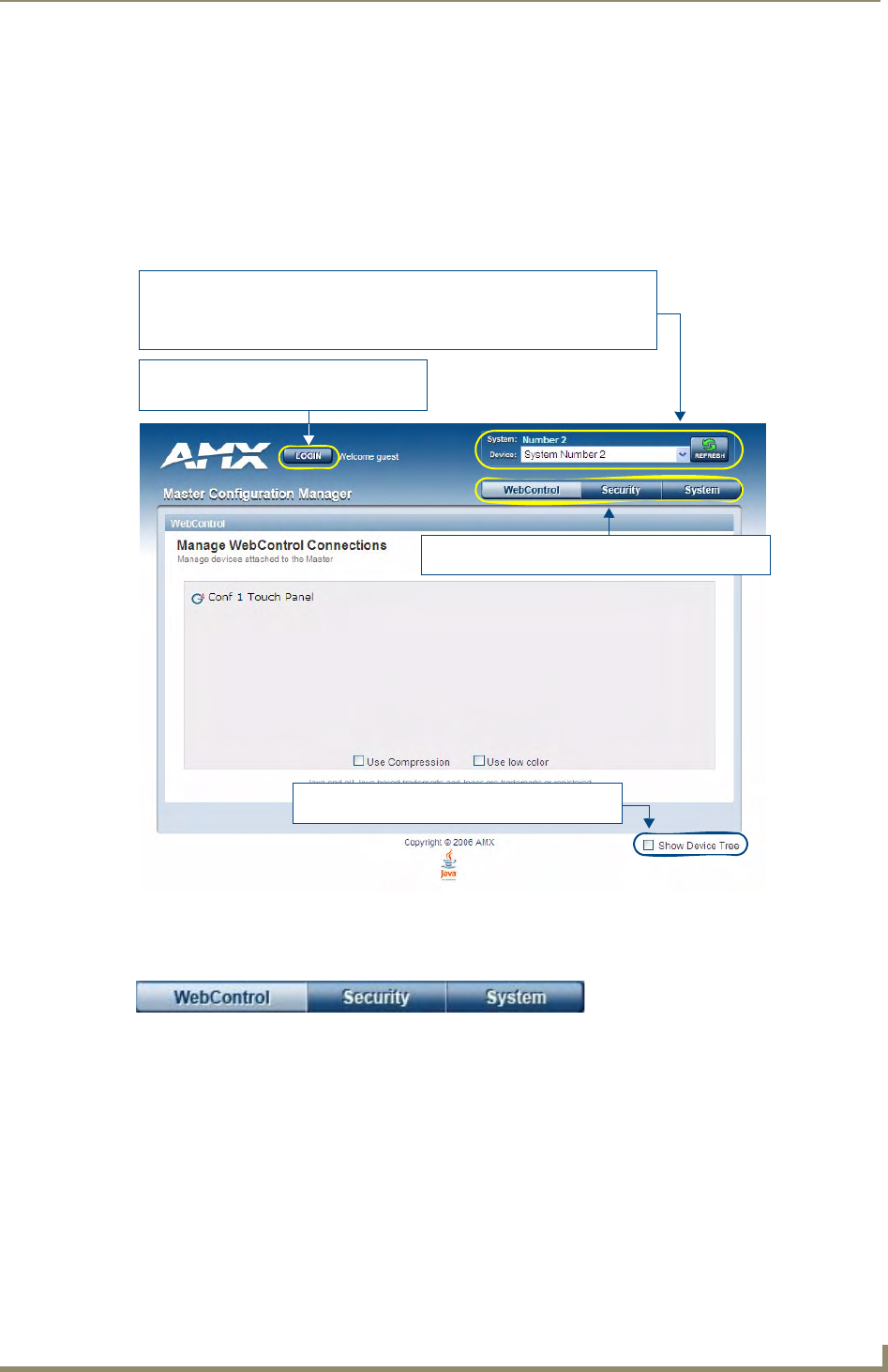
Onboard WebConsole User Interface
21
NetLinx Integrated Controllers- WebConsole & Programming Guide
Onboard WebConsole User Interface
WebConsole UI Overview
NetLinx Masters have a built-in WebConsole that allows you to make various configuration settings via a web
browser on any PC that has access to the Master. The webconsole consists of a series of web pages that are
collectively called the "Master Configuration Manager" (FIG. 1).
The webconsole is divided into three primary sections, indicated by three control buttons across the top of the
main page (FIG. 2):
WebControl: This is the option that is pre-selected when the WebConsole is accessed. Use the
options in the Manage WebControl Connections page to manage G4WebControl connections (see
the WebConsole - WebControl Options section on page 39).
Security: Click to access the System Security page. The options in this page allow you to configure
various aspects of NetLinx System and Security on the Master (see the WebConsole - Security
Options section on page 25).
System: Click to access the System Details page. The options on this page allow you to view and
configure various aspects of the NetLinx System (see the WebConsole - System Options section on
page 41).
FIG. 1 Master Configuration Manager - WebControl Page (initial view)
FIG. 2 WebConsole Control Buttons
Select this option to show/hide the Online Device Tree
(showing all devices currently connected to this Master)
Click to Login (only required if Master Security
and HTTP Access security options are enabled
on the target Master)
System/Device info:
System (read-only): indicates the name of the System currently connected
Device: click the down-arrow to select from a list of all devices connected to this Master
Refresh: Click to refresh the Device list.
Click to access the three main sections of the WebConsole
(initial view = WebControl)
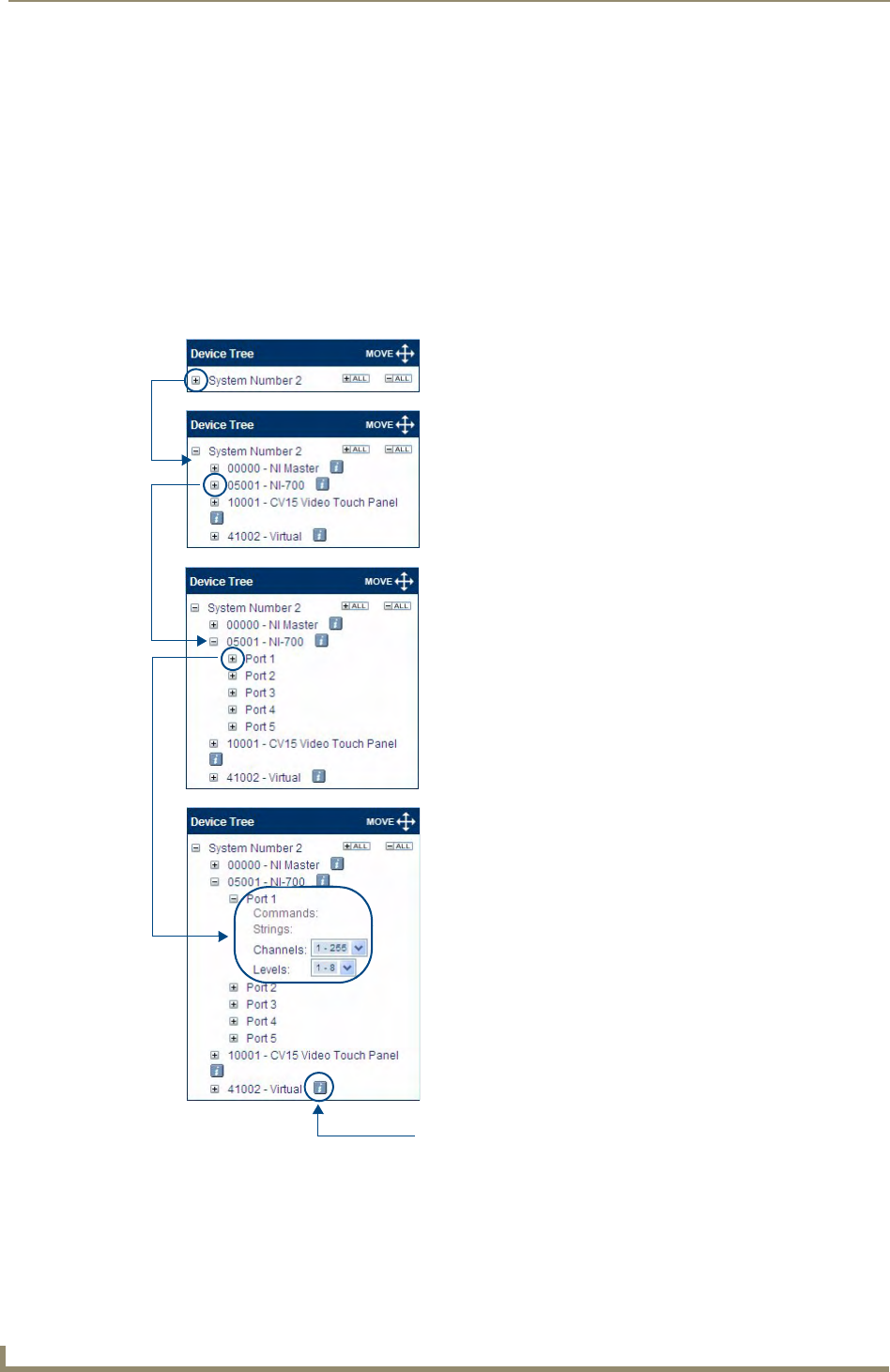
Onboard WebConsole User Interface
22 NetLinx Integrated Controllers- WebConsole & Programming Guide
Accessing the WebConsole
From any PC that has access to the LAN that the target Master resides on:
1. Open a web browser and type the IP Address of the target Master in the Address Bar.
2. Press Enter to access WebConsole for that Master. The initial view is the WebControl page (FIG. 1).
Device Tree
Click the Show Device Tree checkbox to show/hide the online device tree, which indicates all devices
currently connected to this Master. Use the plus and minus symbols to the left of each item in the Device Tree
to expand the view to include System devices, ports and individual Port settings.
At the Port view, you can use the Device Tree to make specific port assignments (including Channel and Level
assignments) (FIG. 3).
FIG. 3 Online Device Tree
(all Collapsed)
(NI-700 ports expanded)
(System devices expanded)
(NI-700 Port 1 expanded)
Opens the Network Settings
page for this device
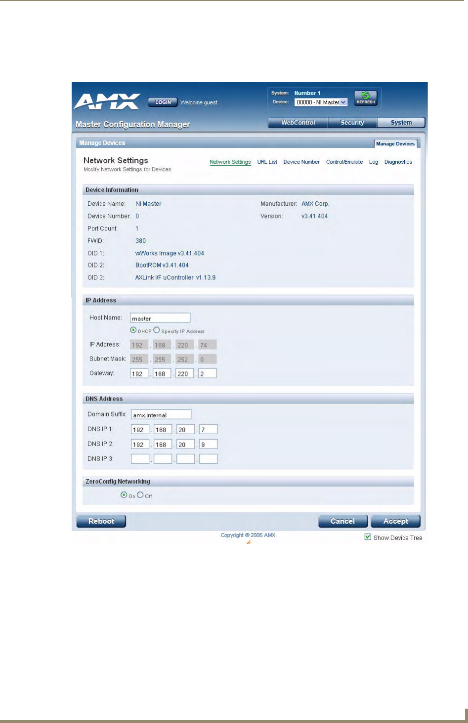
Onboard WebConsole User Interface
23
NetLinx Integrated Controllers- WebConsole & Programming Guide
Device Network Settings Pages
Click on the blue Information (i) icon next to any device listed in the Device Tree to access the Network
Settings page for the selected device (FIG. 4).
Use the options on this page to view/edit the device’s network settings.
Refer to the System - Manage System section on page 41 for details.
ZeroConfig Networking
Use these radio buttons to enable/disable the new Zero-Configuration (zeroconf) client in the Master.
By default, zeroconf is enabled (On option selected). With zeroconf enabled, the Master's web interface will be
registered via zeroconf and can be viewed through a zeroconf browser plug-in such as Bonjour for IE.
FIG. 4 Example Network Settings page for a sample CV15 connected to the Master

Onboard WebConsole User Interface
24 NetLinx Integrated Controllers- WebConsole & Programming Guide
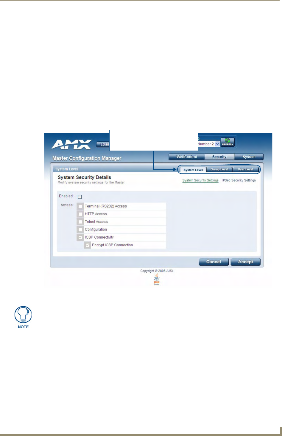
WebConsole - Security Options
25
NetLinx Integrated Controllers- WebConsole & Programming Guide
WebConsole - Security Options
Security Overview
The Security System Details page is accessed by clicking on the Security button. This page allows you to view
configure and modify the Master’s security settings at three levels:
System Level - changes made at this level affect the system globally.
See the System Security - System Level section on page 27 for details.
Group Level - changes made at this level affect specific User Groups.
See the System Security - Group Level section on page 31 for details.
User Level - changes made at this level affect individual Users.
See the System Security - User Level section on page 36 for details.
The default view for the option is System Level Security / System Security Settings (FIG. 1).
Additional security configuration options are available via Terminal/Telnet Commands:
See the Accessing the Security Configuration Options section on page 113.
Refer to the SET SECURITY PROFILE section on page 103 for information on setting Security
Profiles.
FIG. 1 System Security Details Page (System Security Settings)
These tabs provide access to the three
levels of security configuration provided
(default view = System Level)
By default, all System-level security options are disabled.

WebConsole - Security Options
26 NetLinx Integrated Controllers- WebConsole & Programming Guide
Default Security Configuration
By default, the NetLinx Master creates the following accounts, access rights, directory associations, and
security options:
FTP Security is always enabled on the Masters.
The Admin Change Password Security option (in the Group and User Level Security Details
pages is enabled by default.
All other security options are disabled by default.
Login Rules
There is no limit to the number of concurrent logins allowed for a single user. This allows for the creation of a
single User that is provided to multiple ICSP devices (touch panels, for example) using the same login to
obtain access to the Master.
For example, if you had 50 devices connected to a Master, you would not have to create 50 individual user
accounts-one for each device. Instead, you only need to create one which all 50 devices use for access.
The first layer of security for the Master is to prompt a user to enter a valid username and password before
gaining access to a secured feature on the target Master.
Depending on the Security configuration, Users may be prompted to enter a valid username and password
before gaining access to various features of the WebConsole. User access is specified by the administrator in
the Group and User Level pages of the Security section.
User Name and Password Rules
Case-sensitive.
Must be between 4 and 20 characters.
Characters such as # (pound) & (ampersand) and ’ " (single and double quotes) are invalid and
should not be used in usernames, group names, or passwords.
Default Security Configuration
Account 1 Account 2 Group 1
Username: administrator Username: NetLinx
Password: password Password: password
Group: administrator Group: none Group: administrator
Rights: All Rights: FTP Access Rights: All
Directory Association: /* Directory Association: none Directory Association: /*
Note: The "administrator" User
account cannot be deleted or
modified with the exception of its
password. Only a user with both
Configuration access and
administrator rights can alter the
administrator’s password.
Note: The "NetLinx" User
account is compatible with
previous NetLinx Master
firmware versions. This
account is initially created by
default and can later be deleted
or modified.
Note: The "administrator" Group
account cannot be deleted or
modified.
This username and password information is also used by both G4 touch panels
(within the System Connection firmware page) and AMX software applications such
as NetLinx Studio v 2.4 to communicate securely with a Master using encrypted
communication.
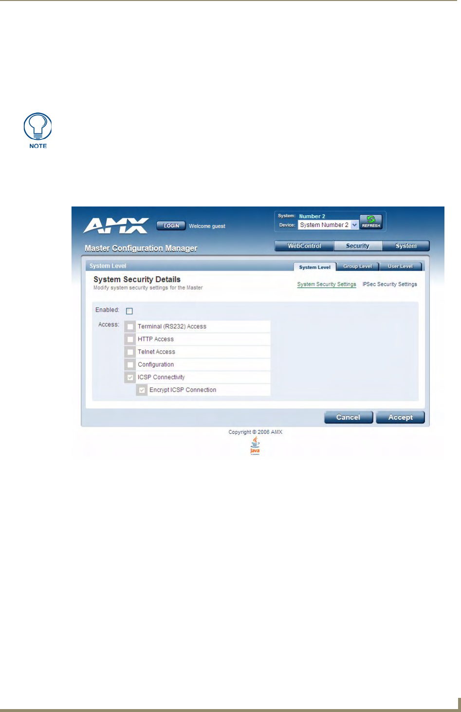
WebConsole - Security Options
27
NetLinx Integrated Controllers- WebConsole & Programming Guide
System Security - System Level
System Level Security options provide authorized users the ability to alter the current security options of the
entire system assigned to the Master.
There are two System Level Security pages, accessible via the System Security Settings and Security
Settings links in the System Level Tab:
System Level Security - System Security Settings
Click the System Security Settings link to access the System Security Details page (FIG. 2). The options in
this page allow you to establish wether the Master will require a valid username and password be entered prior
to gaining access to the configuration options.
These are global options that enable or disable the login requirement for both users and groups.
Check the Enabled option to make the Access options available for selection.
The. Security Settings option is only available on the NI-700/900 and NI-X100
series.
FIG. 2 System Security Settings Page

WebConsole - Security Options
28 NetLinx Integrated Controllers- WebConsole & Programming Guide
System Security Access Options
System Security Access Options
Option Description
Enabled: This option enables the Access options this page.
If the Master Security checkbox is not enabled, all subordinate options are
greyed-out and not selectable, meaning that the Master is completely unsecured
and can be altered by any user (regardless of their rights).
Terminal (RS232) Access: If selected, a valid username and password is required for Terminal communica-
tion via the Master’s RS232 Program port.
HTTP Access: If selected, a valid username and password is required for communication over
HTTP or HTTPS Ports, including accessing the WebConsole.
Telnet Access: If selected, a valid username and password is required for Telnet Access. Telnet
access allows communication over either the Telnet and/or SSH Ports.
Note: SSH version 2 (only) is supported.
To establish a secure Telnet connection, an administrator can decide to disable
the Telnet Port and then enable the SSH Port. Refer to the Port Settings section
on page 51 for details.
Configuration: If selected, a valid username and password is required before allowing a group/
user to alter the current Master’s security and communication settings via
NetLinx Studio.
This includes such things as: IP configuration/Reset, URL list settings, Master
communication settings, and security parameters.
ICSP Connectivity: If selected, a valid username and password is required to communicate with the
NetLinx Master via an ICSP connection (TCP/IP, UDP/IP, and RS-232).
• This feature allows communication amongst various AMX hardware and
software components. This feature works in tandem with the Require
Encryption option (see below) to require that any application or hardware
communicating with the Master must provide a valid username and password.
• In a Master-to-Master system, the Master which accepts the IP connection
initiates the authentication process. This configuration provides compatibility
with existing implementations and provides more flexibility for the
implementation of other devices.
Note: The ICSP Connectivity option is required to allow authenticated and/or
secure communication between the Master and other AMX hardware/software.
To establish an authenticated ICSP connection (where the external AMX hard-
ware/software has to provide a valid username and password), this option must
be enabled.
Encrypt ICSP Connection: If selected, this option requires that any data being transmitted or received via an
ICSP connection (among the various AMX products) be encrypted, and that any
application or hardware communicating with the Master over ICSP must provide
a valid username and password.
Note: When enabled, this option requires more processor cycles to maintain.
ICSP uses a proprietary encryption based on RC4 and also requires CHAP-type
authentication including username and password.
CHAP (Challenge Handshake Authentication Protocol) authentication is an
access control protocol for dialing into a network that provides a moderate
degree of security.
• When the client logs onto the network, the network access server (NAS) sends
the client a random value (the challenge).
• The client encrypts the random value with its password, which acts as an
encryption key. It then sends the encrypted value to the NAS, which forwards it
along with the challenge and username to the authentication server.
• The CHAP server encrypts the challenge with the password stored in its
database for the user and matches its results with the response from the client.
If they match, it indicates the client has the correct password, but the password
itself never left the client's machine.
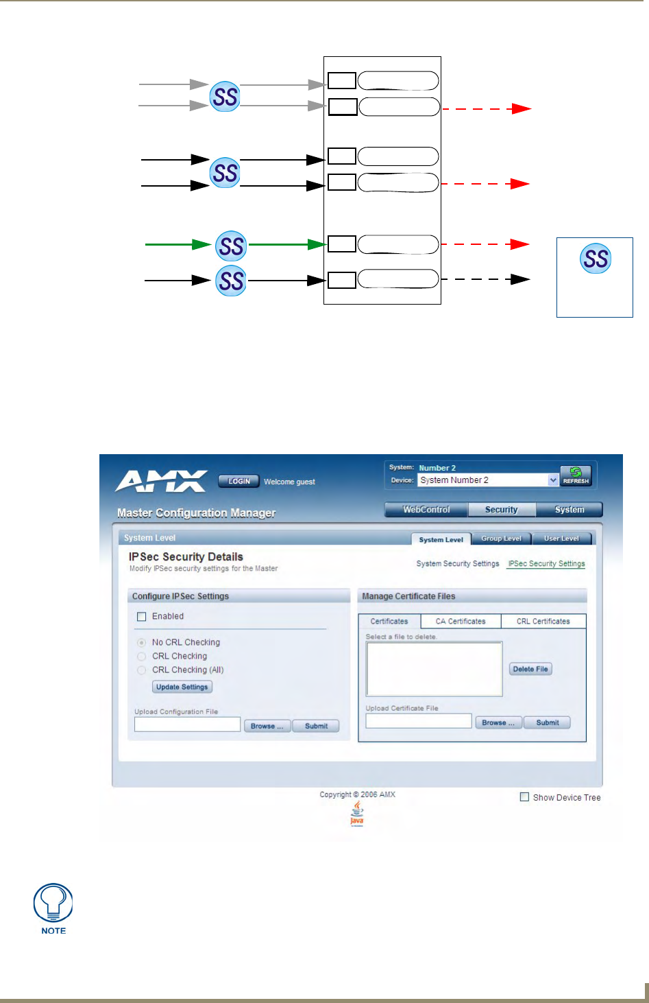
WebConsole - Security Options
29
NetLinx Integrated Controllers- WebConsole & Programming Guide
Accepting Changes
Click the Accept button to save changes on this page. Accepting changes is instantaneous and does not require
a reboot.
System Level Security - IPSec Security Settings
Click the IPSec Security Settings link to access the IPSec Security Details page (FIG. 4). The options in this
page allow you configure IPSec-specific security options on the Master at the System level.
FIG. 3 Port Communication Settings
FIG. 4 IPSec Security Settings Page
Username and
Password are
required when
enabled
Telnet Port
ICSP Port
HTTP Port
HTTPS Port
SSH Port
FTP Port
NetLinx Master
HTTP Access option
Telnet Access option
ICSP Connectivity
and Encryption option
23
80
443
1319
22
21
Telnet
Web
Browser
Browser
or SSL
AMX
Software
&
Hardware
SSH
Client
Secure
Secure
Secure
Secure
FTP
The IPSec Security Settings option is only available on the NI-700/900 and NI-X100
series.

WebConsole - Security Options
30 NetLinx Integrated Controllers- WebConsole & Programming Guide
Configuring Settings
1. Check the Enabled option to enable Security, and make the following CRL Checking options available
(click the radio buttons to toggle on/off):
No CRL Checking: No CRL (Certificate Revocation List) checking will be done.
CRL Checking: Only the certificate in question will be checked against the CRL.
CRL Checking (All): Each certificate in an entire chain of certificates should be checked against
the CRL.
2. Click the Update Settings button to save all changes to the Master.
Uploading an Configuration File
1. Click the Browse button (next to the Upload Configuration File text box) to locate and select a NetLinx
compatible configuration file from your PC (or LAN).
2. Click the Submit button to transfer the selected configuration file to the Master.
Managing Certificate Files
The Managing Certificate Files section of the page provides a display box that lists all of the existing
Certificate Files resident on the Master.
The display is separated into three tabs (click to view the selected type of Certificate Files):
Certificates: This tab displays all Identity certificates on the Master.
CA Certificates: This tab displays all Certificate Authority (CA) certificates on the Master.
CRL Certificates: This tab displays all Certificate Revocation List (CRL) certificates on the
Master.
To delete a Certificate from the Master, select a Certificate in any of the three tabs, and click Delete File.
AMX IPSec Configuration file
Refer to the Appendix A: IPSec Configuration File section on page 121 for a listing and description of the
configuration lines supported by the AMX IPSec Configuration file.
The configuration file name can use any suffix, but it will be re-suffixed to *.cfg by the
Master.
A certificate is a cryptographically signed object that associates a public key and an
identity. Certificates also include other information in extensions such as permissions
and comments
"CA" is short for "Certification Authority" - an trusted third party (or internal entity) that
issues, signs, revokes, and manages these digital certificates.

WebConsole - Security Options
31
NetLinx Integrated Controllers- WebConsole & Programming Guide
System Security - Group Level
Select the Group Level tab of the Security Page to access the Group Security Details page (FIG. 5).
The options in this page allow authorized users to assign and alter group properties such as creating,
modifying, or deleting a group’s rights, and also allows for the definition of the files/directories accessible by a
particular group.
Adding a New Group
1. Select the Group Level tab (in the Security section) to open the Group Security Details page.
2. Click the Add New Group button (see FIG. 5) to access the Add a group and modify settings page
(FIG. 6).
FIG. 5 Group Security Details page
A Group represents a logical collection of individual users. Any properties possessed
by a group are inherited by all members of that group.
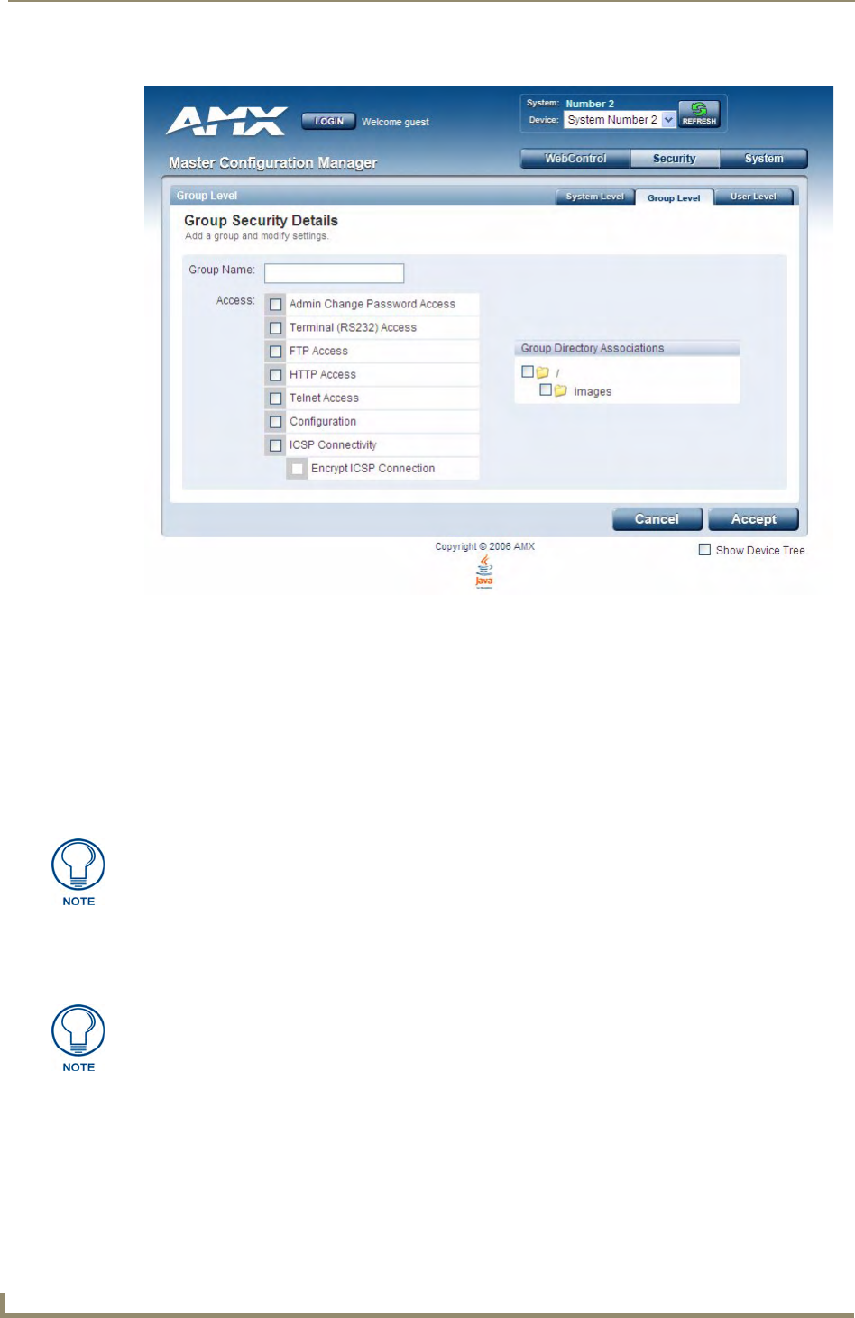
WebConsole - Security Options
32 NetLinx Integrated Controllers- WebConsole & Programming Guide
3. In the Group Name field, enter a unique name for the new group.
The name must be a valid character string consisting of 4 - 20 alpha-numeric characters.
The string is case sensitive and must be unique.
The word "administrator" cannot be used for a new group name since it already exists by default.
4. Enable the security access rights you want to provide to the group. By default, all of these options are
disabled. See the Group and User Security Access Options section on page 33 for details.
5. In the Group Directory Associations section, place a checkmark next to the directories (available on the
target Master) to provide an authorized group with access rights to the selected directories.
6. Click the Accept button to save your changes to the target Master.
If there are no errors within any of the page parameters, a “Group added successfully” is displayed at the
top of the page.
FIG. 6 Group Level Security Settings Page (Add a group and modify settings page)
If you select a group directory, all lower groups in that tree will be selected.
Security changes made from within the web browser are applied instantly, without the
need to reboot.

WebConsole - Security Options
33
NetLinx Integrated Controllers- WebConsole & Programming Guide
Group and User Security Access Options
Group and User Security Access Options
Option Description
Admin Change Password
Access:
This selection enables or disables the Administrator right to change Group and
User passwords.
Terminal (RS232) Access: If selected, a valid username and password is required for Terminal communica-
tion via the Master’s RS232 Program port.
HTTP Access: If selected, a valid username and password is required for communication over
HTTP or HTTPS Ports, including accessing the WebConsole.
Telnet Access: If selected, a valid username and password is required for Telnet Access. Telnet
access allows communication over either the Telnet and/or SSH Ports.
Note: SSH version 2 (only) is supported.
• To establish a secure Telnet connection, an administrator can decide to disable
the Telnet Port and then enable the SSH Port. Refer to the Manage System -
Server Options section on page 51.
Configuration: If selected, a valid username and password is required before allowing a group/
user to alter the current Master’s security and communication settings via
NetLinx Studio.
This includes such things as: IP configuration/Reset, URL list settings, Master
communication settings, and security parameters.
ICSP Connectivity: If selected, a valid username and password is required to communicate with the
NetLinx Master via an ICSP connection (TCP/IP, UDP/IP, and RS-232).
• This feature allows communication amongst various AMX hardware and
software components. This feature works in tandem with the Require
Encryption option (see below) to require that any application or hardware
communicating with the Master must provide a valid username and password.
• In a Master-to-Master system, the Master which accepts the IP connection
initiates the authentication process. This configuration provides compatibility
with existing implementations and provides more flexibility for the
implementation of other devices.
Note: The ICSP Connectivity option is required to allow authenticated and/or
secure communication between the Master and other AMX hardware/software.
To establish an authenticated ICSP connection (where the external AMX hard-
ware/software has to provide a valid username and password), this option must
be enabled.
Encrypt ICSP Connection: If selected, this option requires that any data being transmitted or received via an
ICSP connection (among the various AMX products) be encrypted, and that any
application or hardware communicating with the Master over ICSP must provide
a valid username and password.
Note: When enabled, this option requires more processor cycles to maintain.
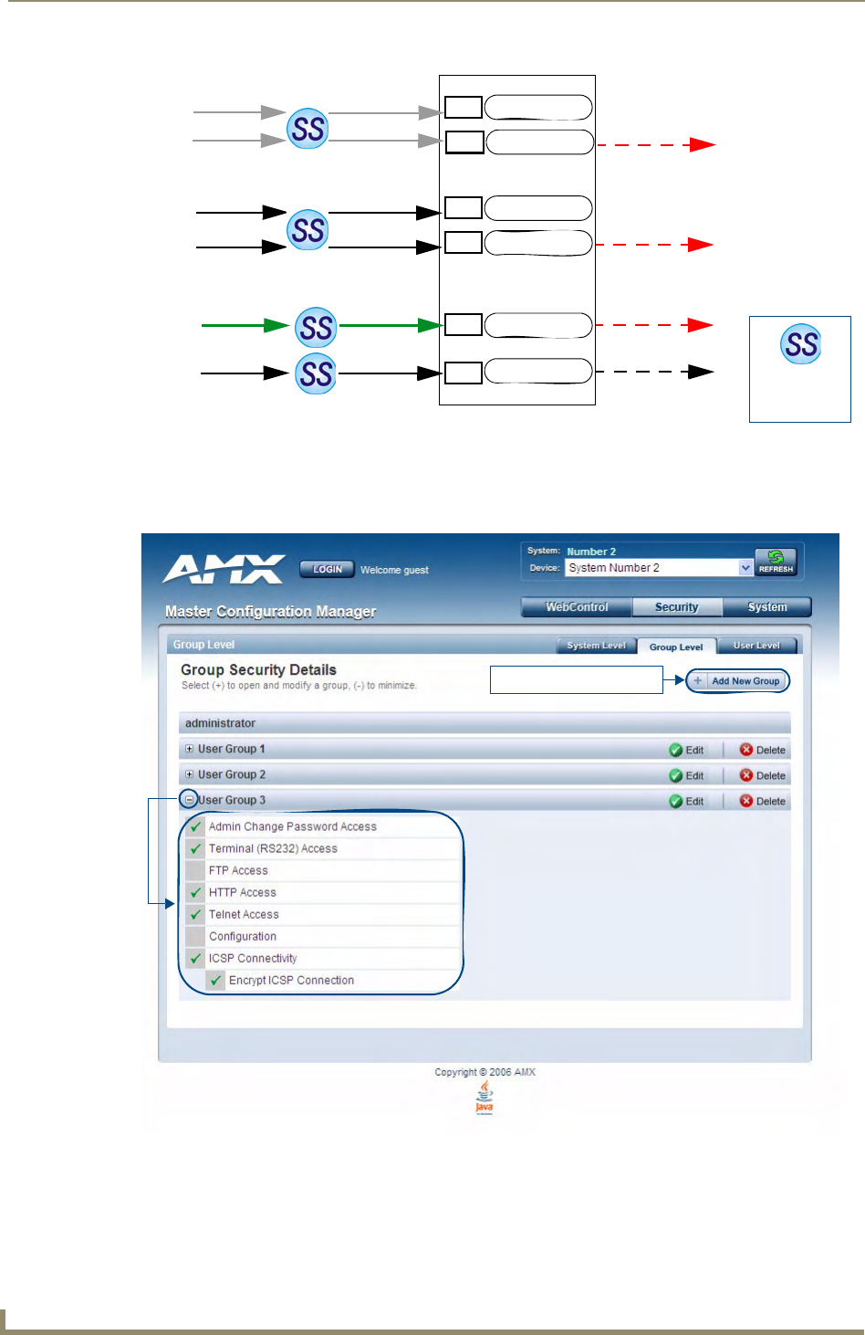
WebConsole - Security Options
34 NetLinx Integrated Controllers- WebConsole & Programming Guide
Viewing Group Security Settings Details
Click on any Group listed in the Group Security Details page to expand the view to show details for the
selected user Group (FIG. 8):
Click the Edit button to edit the Security Access options for the selected user group.
Click Delete to delete the selected User Group from the Master.
FIG. 7 Port Communication Settings
FIG. 8 Group Security Details Page
Username and
Password are
required when
enabled
Telnet Port
ICSP Port
HTTP Port
HTTPS Port
SSH Port
FTP Port
NetLinx Master
HTTP Access option
Telnet Access option
ICSP Connectivity
and Encryption option
23
80
443
1319
22
21
Telnet
Web
Browser
Browser
or SSL
AMX
Software
&
Hardware
SSH
Client
Secure
Secure
Secure
Secure
FTP
Click to add a new Group
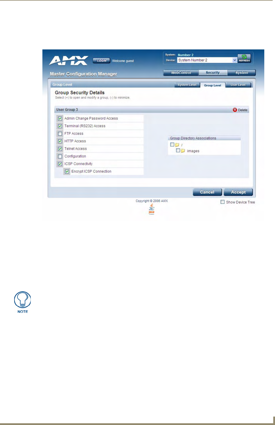
WebConsole - Security Options
35
NetLinx Integrated Controllers- WebConsole & Programming Guide
Modifying the Properties of an Existing Group
1. Select the Group Level tab (in the Security section) to open the Group Security Details page.
2. Click the Edit button to open the Group Security Details page for the selected group (FIG. 9).
3. Modify the previously configured access rights by enabling / disabling the checkboxes. See the Group
and User Security Access Options section on page 33 for details.
4. Modify the selected group’s directory access rights in the Group Directory Associations section, as
necessary (place / remove checkmarks next to the available directories).
5. Click the Accept button to save your changes to the Master.
If there are no errors with the modification of any of this page’s parameters, a “Group updated
successfully” is displayed at the top of the page.
Any properties possessed by groups (ex: access rights, update rights, directory associations, etc.) are inherited
by users assigned to that particular group.
Unchecking a security option (which is available within the associated group) does not remove that right from
the user. The only way to remove a group’s available security right from a target user is either to not associate
a group to a user or to alter the security rights of the group being associated.
Deleting a Group
1. Select the Group Level tab (in the Security section) to open the Group Security Details page.
2. Press the Delete button to remove the selected group and refresh the page. The system will prompt you to
verify this action - click OK to proceed.
If you are not logged into the Master, you receive a reminder message: "You must login before
Security Settings can be changed". In this case, log into the Master and repeat the previous steps.
FIG. 9 Group Security Details Page (Edit Group Security Details)
The "administrator" group account cannot be modified or deleted.
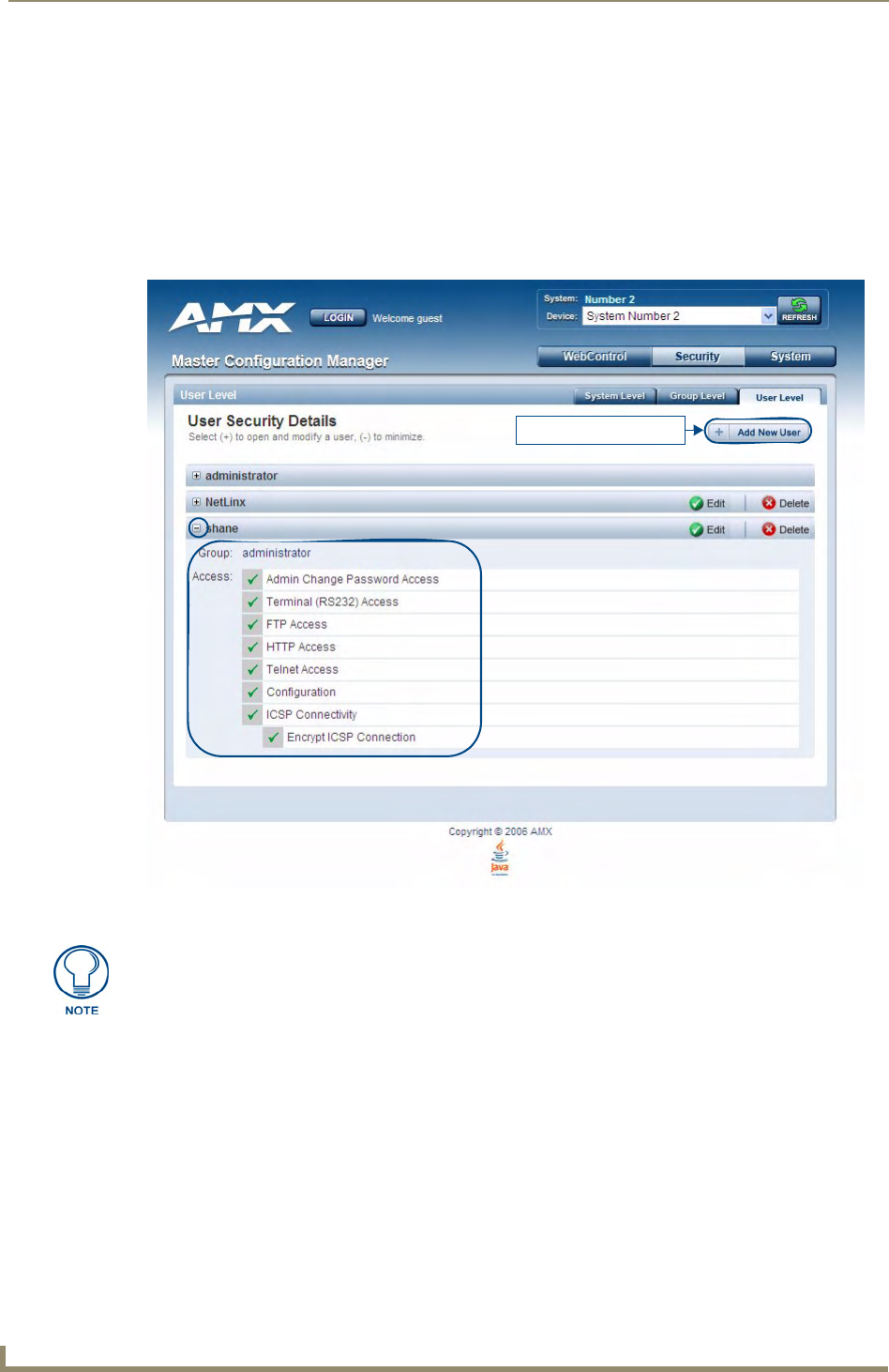
WebConsole - Security Options
36 NetLinx Integrated Controllers- WebConsole & Programming Guide
If the group is associated with several users, you might get an error while trying to delete the group.
If this happens, change the group association of those specific users utilizing the old group and
either give them a new group or assign them (none) as a group. When you return to delete the
desired group, you receive a message saying "Group deleted successfully".
3. Click the Accept button to save your changes to the Master.
System Security - User Level
Select the User Level tab of the Security Page to access the User Security Details page (FIG. 10). The options
on this page allow authorized users to add/delete User accounts and configure User’s Access rights.
Adding a New User
1. Select the User Level tab (in the Security section) to open the User Security Details page.
2. Click the Add New User button (see FIG. 10) to access the Add/Modify User page (FIG. 11).
FIG. 10 User Security Settings Page
Click to add a new User
A User represents a single client of the Master, while a Group represents a collection of Users.
Any properties possessed by a Group are inherited by all of the Users in the group.
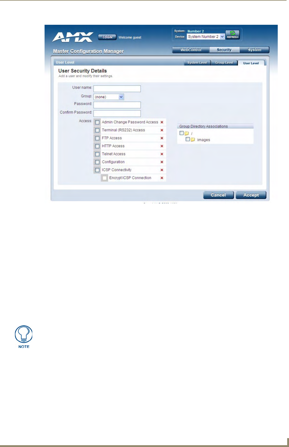
WebConsole - Security Options
37
NetLinx Integrated Controllers- WebConsole & Programming Guide
3. In the User Name field, enter a unique name for the new group.
The name must be a unique alpha-numeric character string (4 - 20 characters), and is case sensitive.
The words "administrator" and "NetLinx" cannot be used since they already exist by default.
4. In the Group drop-down list, choose from a list of pre-configured Groups and associate these rights to the
new user.
5. Enter a user password in both the Password and Password Confirm fields.
The password must be a unique alpha-numeric character string (4 - 20 characters), and is case sensitive.
6. Enable the security access rights you want to provide to the user. See the Group and User Security Access
Options section on page 33 for details.
7. In the Group Directory Associations section, place a checkmark next to the directories (available on the
target Master) to provide an authorized user with access rights to the selected directories. This selection
includes any sub-directories that exist within the selection.
8. Click the Accept button to save your changes to the Master.
Viewing and Editing User Security Settings
Click on any User listed in the User Security Details page to view and edit security settings for the selected
User (FIG. 12):
Click the Edit button to edit the Security Access options for the selected User.
Click Delete to delete the selected User from the Master.
FIG. 11 User Security Settings Page (Add/Modify User page)
Any security changes made to the Master from within the web browser are instantly
reflected within a Terminal session without the need to reboot.
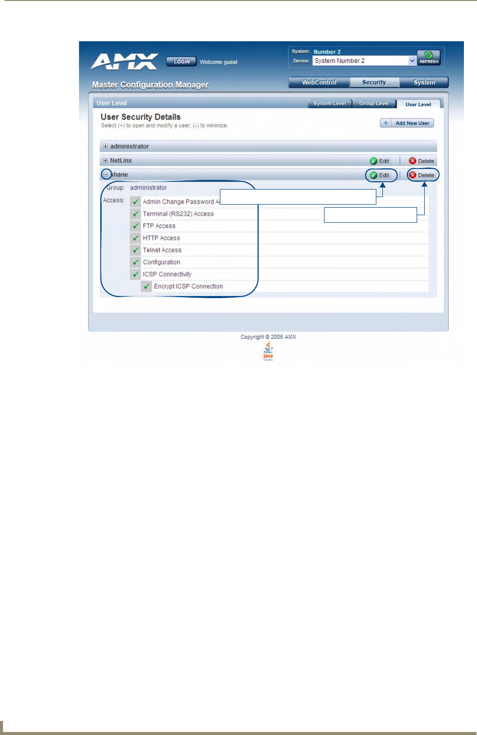
WebConsole - Security Options
38 NetLinx Integrated Controllers- WebConsole & Programming Guide
Deleting a User
1. Select the User Level tab (in the Security section) to open the User Security Details page.
2. Press the Delete button to remove the selected User and refresh the page. The system will prompt you to
verify this action - click OK to proceed.
If you are not logged into the Master, you receive a reminder message: "You must login before Security
Settings can be changed". In this case, log into the Master and repeat the previous steps.
3. Reboot the Master via the Reboot button on the Manage System Page (select the System control button
to access).
FIG. 12 User Level Security Settings Page (Viewing User Security Settings Details)
Click to edit Access settings for this User
Click to delete this User
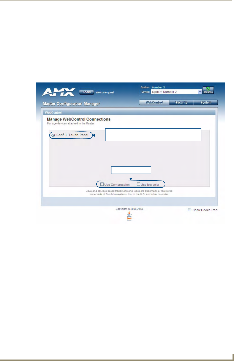
WebConsole - WebControl Options
39
NetLinx Integrated Controllers- WebConsole & Programming Guide
WebConsole - WebControl Options
Manage WebControl Connections
The WebControl page is accessed by clicking on the WebControl button (FIG. 1). This page allows you to
view all touch panels running the G4WebControl application.
Each G4WebControl-equipped touch panel connected to this Master is indicated by a link. Click on any of the
links to open a new G4WebControl window, displaying the selected panel, using the native resolution of the
target panel. For example, a CA15 panel link opens a new G4WebControl window at 800 x 600 resolution.
To establish a secure connection between the touch panel and the target Master, the panel must be using a valid
username and password (that can be matched to a previously configured user on the target Master) and the
ICSP Connectivity option must be enabled within the System Level Security page.
Compression Options
The checkboxes at the bottom of this page allow you to choose from two compression options. Use
compression to decrease response delay when viewing G4WebControl windows over a bandwidth-restricted
network, or over the Internet. By default, compression options are disabled.
Use Compression allows you to specify that the transmitted data packets be compressed. This
speeds up the visual responses from the panel by minimizing the size of the information relayed
through the web and onto the screen.
Use Low Color allows you to specify the number of colors used to display the image from the
panel be reduced. By reducing the numbers of colors, the size of the information is reduced and the
response delay is decreased.
FIG. 1 Manage WebControl Connections page (populated with 1 compatible G4 touch panel)
Click on any link listed here to open a new
G4WebControl window to view the indicated panel
Compression options

WebConsole - WebControl Options
40 NetLinx Integrated Controllers- WebConsole & Programming Guide
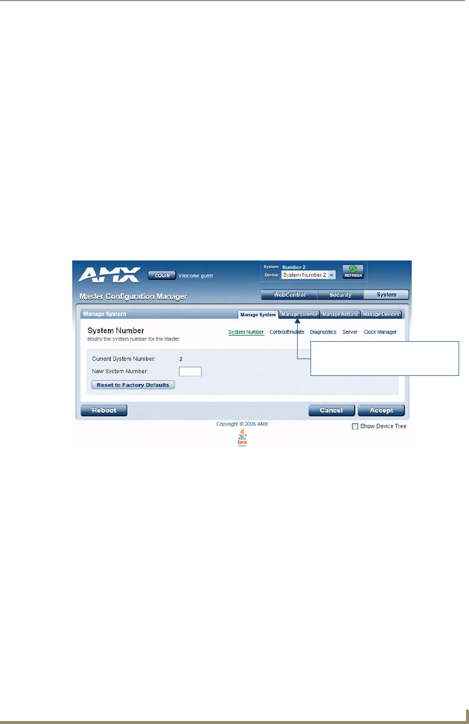
WebConsole - System Options
41
NetLinx Integrated Controllers- WebConsole & Programming Guide
WebConsole - System Options
System Overview
The Manage System page is accessed by clicking on the System button. This page allows you to view and
configure various aspects of the NetLinx System, separated by four tabs:
Manage System - Options in this tab allow you to view/change the Master’s System Number,
Control/Emulate system devices, perform Diagnostics, configure Server settings and set the time/
date via the Clock Manager. See the System - Manage System section on page 41 for details.
Manage License - Options in this tab allow you to add device licenses (Product ID and License
Key) to the Master. See the System - Manage License section on page 61 for details.
Manage NetLinx - Options in this tab allow you to view a detailed list of NetLinx devices
connected to the Master. See the System - Manage NetLinx section on page 63 for details.
Manage Devices - Options in this tab allow you to view the details of additional attached devices
(including module-supported third-party devices). See the System - Manage Devices section on
page 65 for details.
The default view for the System option is Manage System / System Number (FIG. 1).
System - Manage System
The Manage System tab contains links to several different System-related configuration pages, as described in
the following subsections:
FIG. 1 Manage System (System Number)
These tabs provide access to the various
System Management features
(default view = Manage System)

WebConsole - System Options
42 NetLinx Integrated Controllers- WebConsole & Programming Guide
Manage System - System Number
The options on this page display the current System Number assigned to the target Master (read-only), and
allow you to change the system number (see FIG. 1).
Changing the System Number On the Master
1. Enter the new numeric value into the New System Number field.
2. Click the Accept button to save this new value to the system on the target Master.
The message; "System number changed to X. Master must be rebooted for the change to take effect.",
reminds you that the Master must be rebooted before the new settings take effect.
3. Click Reboot to reboot the target Master.
The Device Tree then reads "Rebooting....". After a few seconds, the Device Tree refreshes with the
current system information (including the updated system number assignment).
If the Device Tree does not refresh within a few minutes, press the Refresh button and reconnect to
the Master.
Using Multiple NetLinx Masters
When using more than one Master, each unit must be assigned to a separate System value.
A Master’s System value can be changed but it’s device Address must always be set to zero (00000). The
Device Addressing dialog will not allow you to alter the NetLinx Master address value.
Example: Using an NI-2000 and NI-4100:
The NI-2000 could be assigned to System 1 (with an Address of 00000).
The NI-4100 could be assigned to System 2 (with an Address of 00000).
Resetting the Master Controller to the Factory Defaults Configuration
Click the Reset To Factory Defaults button. This resets the Master to its’ factory default state. This includes:
Removal of all security settings
Removal of all user files
Resetting to DHCP
Loading an empty NetLinx program.
Once reset, the Master will be effectively in an out-of-box state.
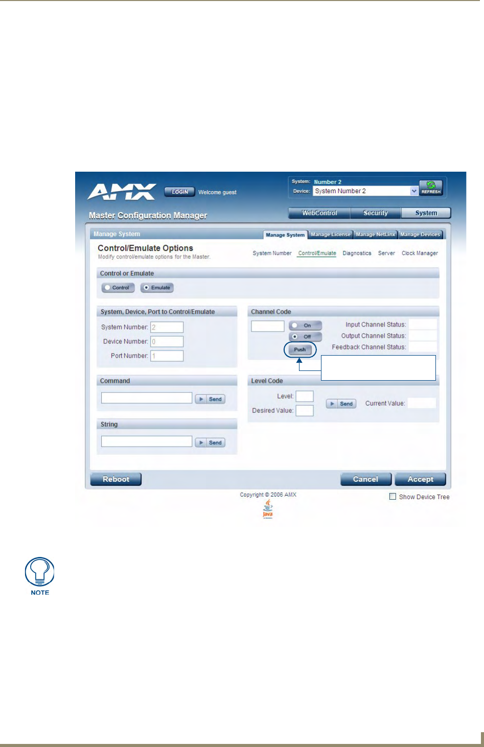
WebConsole - System Options
43
NetLinx Integrated Controllers- WebConsole & Programming Guide
Manage System - Control/Emulate Options
Click the Control/Emulate link (in the Manage System tab) to access the Control/Emulate Options page
(FIG. 2). The options on this page allow you to Control or Emulate a device connected to this Master.
Device Control/Emulation is accomplished by manipulating a target device’s channels, levels, and sending
both send commands and strings to the device.
To Control a device means that the program generates messages which appear to a specified device
to have come from the Master.
To Emulate a device means that the program generates messages which appear to the Master to
have come from a specified device (physical or virtual). When Emulate is selected, a Push button is
added to the Channel Code section (see FIG. 2).
Controlling or Emulating a System Device
1. Select the device that you want to Control or Emulate, via the Device Tree:
a. Click the Show Device Tree option to show the Device Tree window (if it is not already enabled).
b. In the Device Tree, click on the Information (i) icon for the device that you want to control or
emulate. This opens a Network Settings page showing network configuration details for the selected
device. See the Device Network Settings Pages section on page 23 for details.
FIG. 2 Manage System (Control/Emulate)
Push button only displayed if
Emulate is selected
The System Number, Device Number, and Port Number fields are read-only. Instead
of specifying these values for a System Device, select a device via the Device Tree to
populate these fields with that device’s information.

WebConsole - System Options
44 NetLinx Integrated Controllers- WebConsole & Programming Guide
c. Click on the Control/Emulate link. This opens a Control/Emulate Options page for the selected
device (FIG. 3).
2. Select either the Control or Emulate option.
3. In the Channel Code section, enter a valid Channel number to emulate Channel messages (i.e., Push/
Release, CHON, and CHOFF) for the specified <D:P:S>.
The Channel number range is 1 - 65535.
Select the On or Off buttons to Emulate Channel ON (CHON) and Channel OFF (CHOFF) messages for
the specified <D:P:S>.
4. Select the Push button to Emulate a push/release on the specified channel (not displayed if the Control
option is selected). Click and hold the Push button to observe how the device/Master responds to the push
message.
5. In the Level Code section, enter a valid Level number and Level data value for the specified <D:P:S> and
press the Send button to transmit the level data.
The Level number range is 1 - 65535.
The table below lists the valid Level data types and their ranges:
FIG. 3 Select Control/Emulate from within a selected Device’s Network Settings page
Click on Control/Emulate from within
the device’s Network Settings page
to Control/Emulate that device

WebConsole - System Options
45
NetLinx Integrated Controllers- WebConsole & Programming Guide
6. In the Command and String fields, enter any character strings that can be sent as either a String or
Command, and press Send to transmit to the Master.
When entering a Send Command, do not include the "send c" or "send_command" in the statement
- only type what would normally occur within the quotes (but don't include the quotes either).
For example to send the "CALIBRATE" send command, type CALIBRATE (no quotes) rather
than SEND_COMMAND <dev> "CALIBRATE".
String Expressions start and end with double quotes (" "). Double quotes are not escaped, rather
they are embedded within single quotes. String expressions may contain string literals, decimal
numbers, ASCII characters and hexadecimal numbers (prepended with a $), and are comma-
delimited.
String Literals start and end with single quotes ('). To escape a single quote, use three single
quotes (''').
Level Data Type Minimum Value Maximum Value
CHAR 0 255
INTEGER 0 65535
SINTEGER -32768 32767
LONG 0 429497295
SLONG -2147483648 2147483647
FLOAT -3.402823466e+38 3.402823466e+38

WebConsole - System Options
46 NetLinx Integrated Controllers- WebConsole & Programming Guide
Manage System - Diagnostics Options
Click the Diagnostics link (in the Manage System tab) to access the Diagnostics Options page (FIG. 4). The
options on this page allow authorized users to enable and monitor various diagnostic messages coming from
and going to System Devices.
Enabling Diagnostics On a Selected System Device
1. Select the device that you want to Control or Emulate, via the Device Tree:
a. Click the Show Device Tree option to show the Device Tree window (if it is not already enabled).
b. In the Device Tree, click on the Information (i) icon for the device for which you want to enable or
modify Diagnostics options. This opens a Network Settings page showing detailed information on the
selected device (including network configuration details). An example Network Settings page is
shown in FIG. 5:
c. Click on the Diagnostics link. This opens a Diagnostics Options page for the selected device
(FIG. 5).
FIG. 4 Diagnostics Options Page (with diagnostic messages enabled)
Diagnostic Options table
The System Number, Device Number, and Port Number value fields are read-only
(disabled). Instead of specifying these values for a System Device, select a device
via the Device Tree to populate these fields with that device’s values, as described
below.
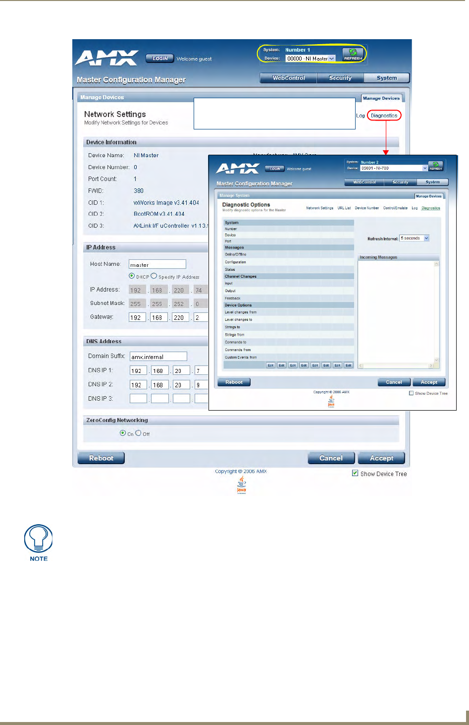
WebConsole - System Options
47
NetLinx Integrated Controllers- WebConsole & Programming Guide
2. By default, all diagnostics are disabled (see FIG. 5). To enable diagnostic messages from this device,
click on one of the Edit buttons along the bottom of the Diagnostics Options table.
This opens the Edit Options window (FIG. 6), where you can select which Diagnostics messages to
enable or disable for this device.
Once you have selected the diagnostics messages to enable, click Update to apply your changes, close the
Edit Options window, and return to the Diagnostics page.
Refer to the Diagnostics Options Definitions section on page 49 for definitions of each Diagnostic option.
FIG. 5 Select Diagnostics from within a selected Device’s Network Settings page
Click on Diagnostics from within the device’s
Network Settings page to enable/modify
diagnostics for that device
The currently selected device is also indicated in the Device field at the top of the
page.
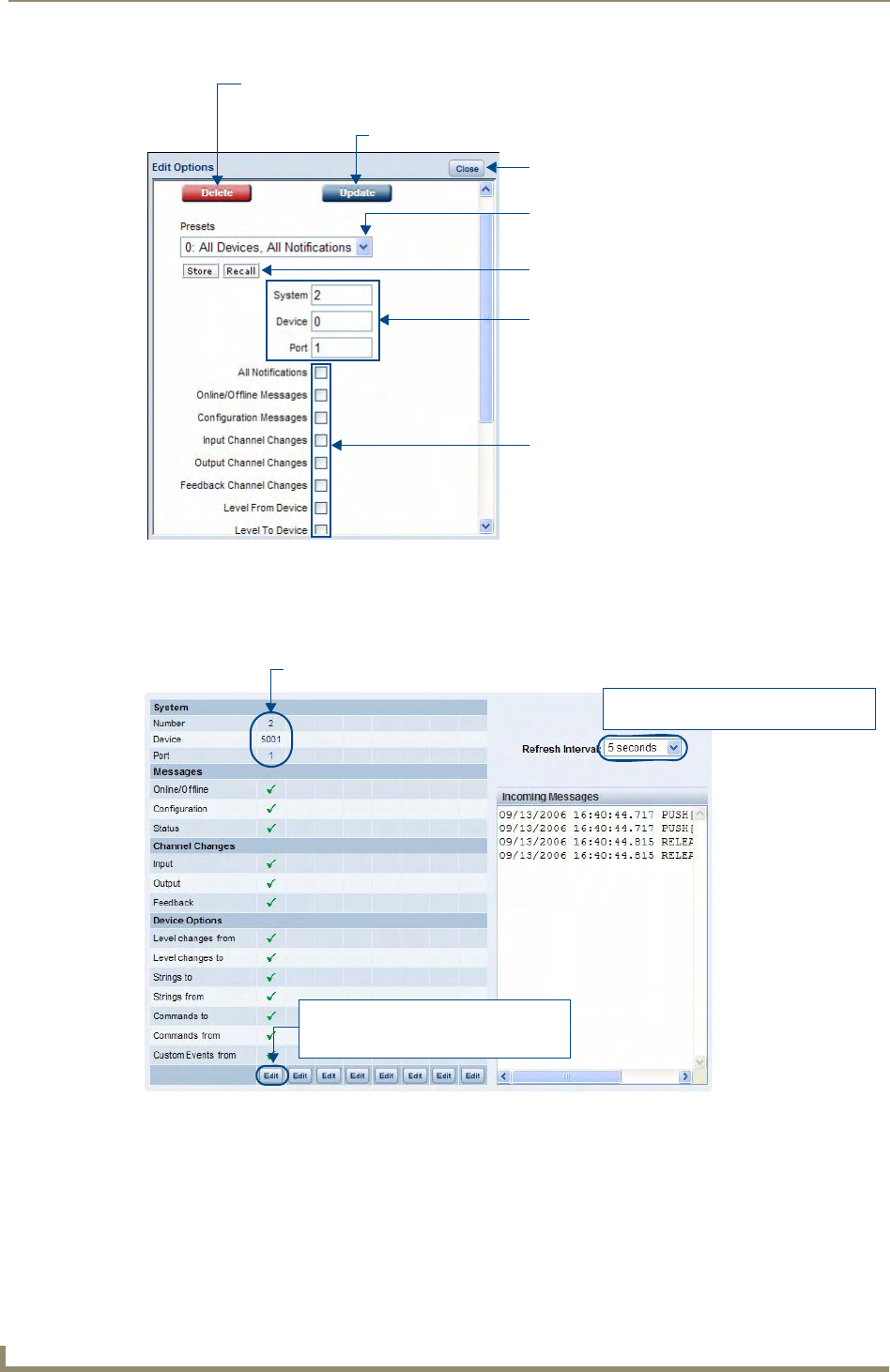
WebConsole - System Options
48 NetLinx Integrated Controllers- WebConsole & Programming Guide
3. The device that you just enabled diagnostics for appears in the Diagnostics Options page (identified by its
Number, Device and Port assignments at the top of the Diagnostics Option list), with the currently
enabled diagnostics indicated with a green checkmark (FIG. 7).
All returned messages are displayed in the Incoming Messages window. By default, all messages are
refreshed every 5 seconds, as indicated by the Refresh Interval field. Use the Refresh Interval drop-down
to specify how often your messages are updated (available values = 2 seconds, 5 seconds, or 10 seconds).
The default setting is 5 seconds.
FIG. 6 Edit Options window
FIG. 7 Edit Options window
Click to delete this device from the Diagnostics page
(disables all diagnostics on this device)
Click to apply changes
Click to close the Edit Options window
(without disabling diagnostics)
Click to select from Presets
(saved sets of enabled Diagnostic messages)
Click to Store and Recall Presets
To set Diagnostic Options for a different System
Device, enter the device’s System, Device and Port
information in these fields (and press Update to
add the specified device/diagnostics options
to the Diagnostics page).
Click the checkboxes to enable/disable
specific diagnostic messages
Scroll down to see the entire list.
(All Notifications enables all messages)
Click to select a different Refresh Rate
(default = 5 seconds)
Each device is identified here by it’s System
Number, Device and Port assignments
Click to modify the diagnostics settings
for this device, or to remove this device
from the Diagnostics Options list
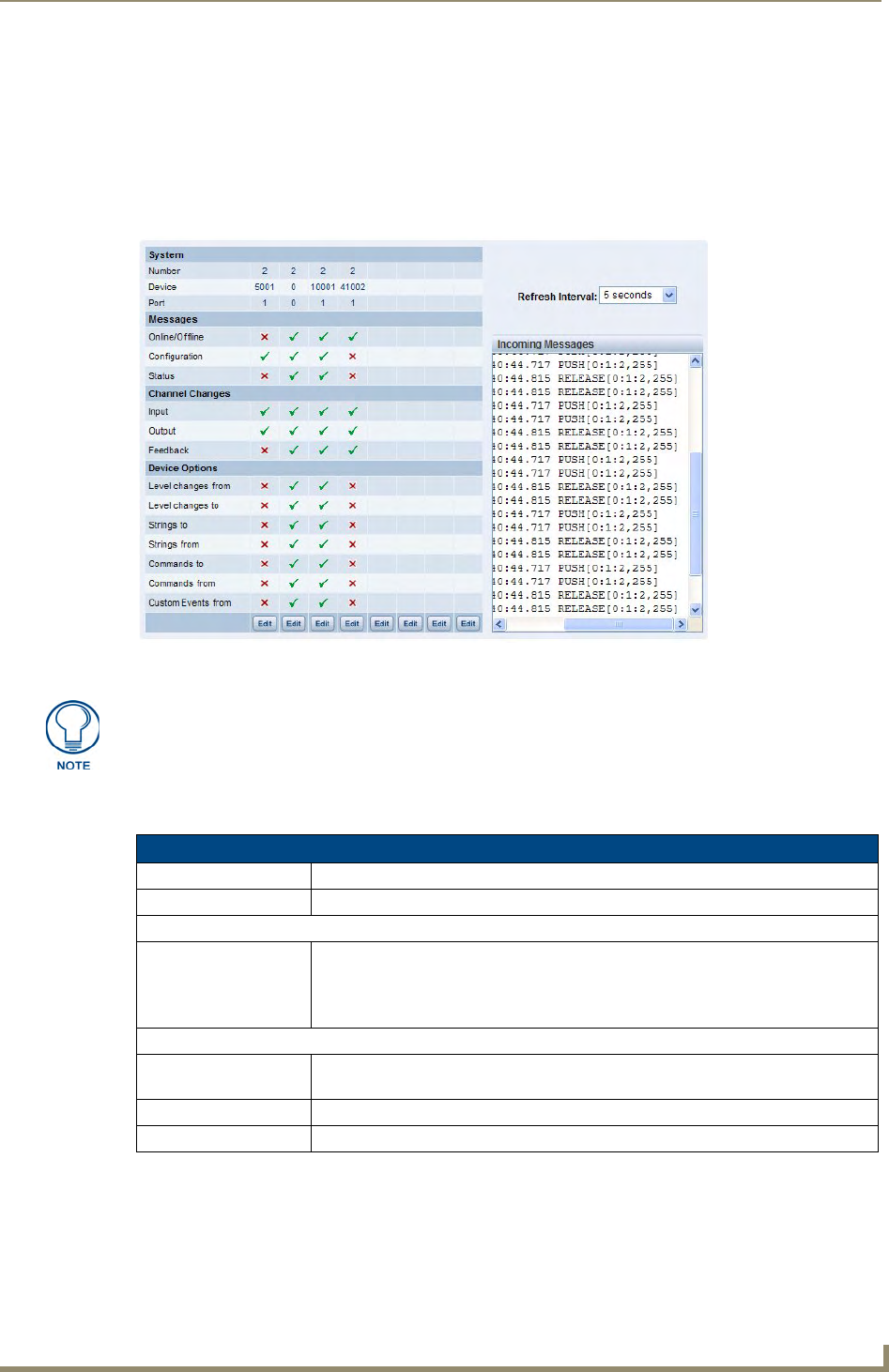
WebConsole - System Options
49
NetLinx Integrated Controllers- WebConsole & Programming Guide
4. To add more devices to the Diagnostics Options page:
Repeat steps 1-3.
Alternatively, you can click one of the Edit buttons to open the Edit Options window, and specify a
System Number, Device and Port for a known System Device. Select the Diagnostics messages that
you want to enable for this device and click Update.
The device will appear in the Diagnostics Options window, in the next available column (to the
right of the last device added - see FIG. 8).
Diagnostics Options Definitions
The following table describes each of diagnostics options that can be enabled via the Edit Options window:
FIG. 8 Edit Options window indicating four devices with Diagnostics enabled
You can monitor diagnostics for up to eight System Devices in this page.
Diagnostic Options
Diagnostic Option Description
All Notifications: Enables every notification field.
System
• Number
•Device
•Port:
Use these fields to enter a device:port:system (D:P:S) combination for the device for
which you want to enable notifications.
A value of 0 for any option gives you all of the systems, devices, or ports. This dialog
also allows you to store/recall presets.
Messages
• Online/Offline Generates a message when there is a change in the target device’s online/offline
status.
• Configuration Generates a message when there is a change in the target device’s configuration.
• Status Generates a message when there is a change in the target device’s status.
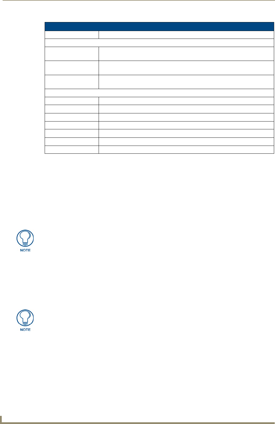
WebConsole - System Options
50 NetLinx Integrated Controllers- WebConsole & Programming Guide
Disabling all Diagnostic Options For a Device
There are two ways to disable all diagnostics for a device:
In the Edit Options window, select Delete to remove the device from the Diagnostics Options page
and disable all diagnostics.
In the Edit Options window, deselect all selected diagnostics options and click Update. This
disables all diagnostics for this device, but leaves the device on the Diagnostics Options page.
Creating and Recalling Diagnostics Presets
The Store and Recall options in the Edit Options window allow you to save and recall preset diagnostics
configurations.
1. Click the Presets down arrow to open a list of previously stored Presets. By default, the only preset is
called 0: All Devices, All Notifications. This default Preset cannot be modified.
2. Select an empty Preset (for example 1:)
3. Select the desired diagnostic options, and click Store.
4. A popup window prompts you to name this Preset. Enter a name and click OK.
To recall an existing Preset, select it from the drop-down list and click on Recall.
Diagnostic Options (Cont.)
Diagnostic Option Description
Channel Changes
• Input Generates a message when there is an input channel change (i.e. Push/Release) in
the target device.
• Output Generates a message when there is an output channel change (i.e. CHON/CHOFF)
in the target device.
• Feedback Generates a message when there is a feedback channel change in the target
device.
Device Options
• Level Changes From Generates a message when there is a level channel change from the target device.
• Level Changes To Generates a message when there is a level channel change to the target device.
• Strings To Generates a message when there is a string sent to the target device.
• Strings From Generates a message when there is a string from the target device.
• Commands To Generates a message when there is a command to the target device.
• Commands From Generates a message when there is a command from the target device.
• Custom Events From Generates a message there is a custom event occurring from the target device.
Presets are saved via cookies, so they do not persist across multiple browsers/
computers.
A Preset MUST be Recalled before clicking the Update button. If you do not press
this button, none of the fields or checkboxes are modified or selected. In essence, all
options become disabled.
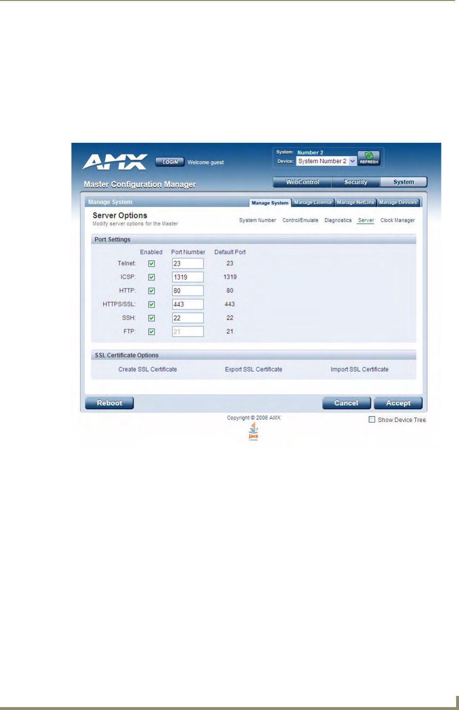
WebConsole - System Options
51
NetLinx Integrated Controllers- WebConsole & Programming Guide
Manage System - Server Options
Click the Server link (in the Manage System tab) to access the Server Options page (FIG. 9). The options on
this page allow you to:
Change the port numbers (used by the Master for various Web services)
Configure the SSL settings used on the Master
Manage existing and pending license keys, manage the active NetLinx system communication
parameters
Configure/modify the SSL certificates on the target Master
The options on this page are described below:
Port Settings
Allows a user to modify the server settings; specifically those port assignments associated with individual
services.
All items can be either enabled/disabled via the Enabled checkboxes.
The port number values (except the FTP port) can be modified in this page.
The default port for each service is listed to the right.
FIG. 9 Server Options page

WebConsole - System Options
52 NetLinx Integrated Controllers- WebConsole & Programming Guide
Server Port Settings
The following table describes each of the Port Settings presented on this page:
Server Port Settings
Feature Description
Telnet: The port value used for Telnet communication to the target Master. Enabling this feature allows
future communication with the Master via a separate Telnet application (such as HyperTermi-
nal).
• The default port value is 23.
• Refer to the NetLinx Security with a Terminal Connection section for more information on the
related procedures.
ICSP: The port value used for ICSP data communication among the different AMX software and hard-
ware products. This type of communication is used by the various AMX product for communica-
tion amongst themselves. Some examples would be: NetLinx Studio communicating with a
Master (for firmware or file information updates) and TPDesign4 communicating with a touch
panel (for panel page and firmware updates).
• The default port value is 1319.
Note: To further ensure a secure connection within this type of communication, a user can
enable the Require Encryption option which requires additional processor cycles. Enabling of
the encryption feature is determined by the user.
HTTP: The port value used for unsecure HTTP Internet communication between the web browser’s UI
and the target Master. By disabling this port, the administrator (or other authorized user) can
require that any consecutive sessions between the UI and the target Master are done over a
more secure HTTPS connection.
By default, the Master does not have security enabled and must be communicated with using
http:// in the Address field.
• The default port value is 80.
Note: One method of adding security to HTTP communication is to change the Port value. If the
port value is changed, any consecutive session to the target Master has to add the port value at
the end of the address (within the Address field). An example is if the port were changed to 99,
the new address information would be: http://192.192.192.192:99.
HTTPS/SSL: The port value used by web browser to securely communicate between the web server UI and
the target Master. This port is also used to simultaneously encrypt this data using the SSL certif-
icate information on the Master as a key.
This port is used not only used to communicate securely between the browser (using the web
server UI) and the Master using HTTPS but also provide a port for use by the SSL encryption
key (embedded into the certificate). Whereas SSL creates a secure connection between a client
and a server, over which any amount of data can be sent securely, HTTPS is designed to trans-
mit individual messages securely. Therefore both HTTPS and SSL can be seen as complemen-
tary and are configured to communicate over the same port on the Master. These two methods
of security and encryption are occurring simultaneously over this port as data is being trans-
ferred.
• The default port value is 443.
Note: Another method of adding security to HTTPS communication would be to change the port
value. If the port value is changed, any consecutive session to the target Master has to add the
port value at the end of the address (within the Address field). An example is if the port were
changed to 99, the new address information would be: http://192.192.192.192:99.
SSH: • The port value used for secure Telnet communication. A separate secure SSH Client would
handle communication over this port. When using a secure SSH login, the entire login session
(including the transmission of passwords) is encrypted; therefore it is secure method of
preventing an external user from collecting passwords.
• SSH version 2 is supported.
• The default port value is 22.
Note: If this port’s value is changed, make sure to use it within the Address field of the SSH Cli-
ent application.
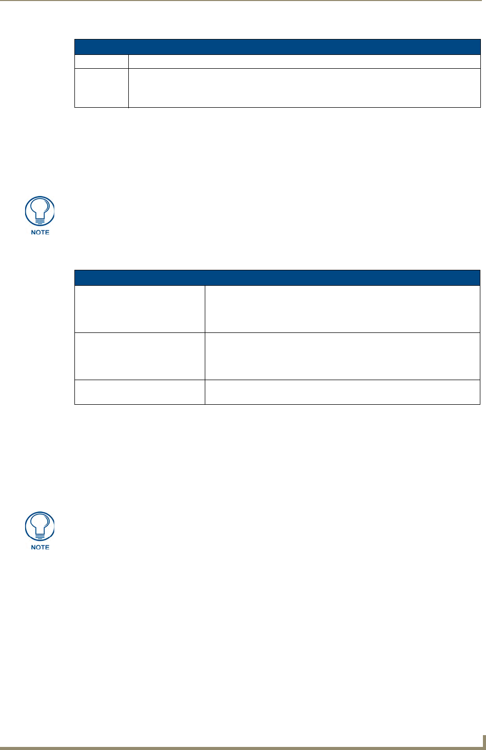
WebConsole - System Options
53
NetLinx Integrated Controllers- WebConsole & Programming Guide
Once any of the server port settings have been modified, press the Accept button to save these changes to the
Master. Once these changes are saved, the following message appears: "Unit must be rebooted for the change
to take effect".
Click the Reboot button (from the top of the page) to remotely reboot the target Master. No dialog appears
while using this button. The Device Tree then reads "Rebooting....". After a few seconds, the Device Tree
refreshes with the current system information (indicating updated port numbers).
SSL Certificate Options
There are three SSL Certificate options, presented as links along the bottom of this page:
Creating an SSL Server Certificate
Initially, a NetLinx Master is not equipped with any installed certificates. In order to prepare a Master for later
use with "CA" (officially issued) server certificates, it is necessary to:
First create a self-generated certificate which is automatically installed onto the Master.
Secondly, enable the SSL feature from the Enable Security page. Enabling SSL security after the
certificate has been self-generated insures that the target Master is utilizing a secure connection
during the process of importing a CA server certificate over the web.
1. Click the Create SSL Certificate link (under SSL Certificate Options) to access the Create SSL
Certificate window (FIG. 10).
Server Port Settings (Cont.)
Feature Description
FTP: The default port value used for FTP communication.
This port can be disabled/enabled but the value can not be changed.
• The default port value is 21.
If the Device Tree contents do not refresh within a few minutes, press the browser’s
Refresh button and reconnect to the Master.
SSL Certificate Options
Create SSL Certificate: Opens the Create SSL Certificate window where you can create a self-
generated SSL certificate.
Note: A self-generated certificate has lower security than an external CA
(officially issued) generated certificate.
Export SSL Certificate Request: Takes the user to the Server Certificate page where they can view a previ-
ously created certificate.
An authorized user can also copy the raw text from a generated Certificate
request into their clipboard and then send it to the CA.
Import SSL Certificate: Takes the user to the Import Certificate page where they can import and
paste the raw text from a CA issued Certificate.
A certificate consists of two different Keys:
The Master Key is generated by the Master and is incorporated into the text string
sent to the CA during a certificate request. It is unique to a particular request made on
a specific Master. Note that regenerating a previously requested and installed
certificate invalidates that certificate because the Master Key has been changed.
The Public Key is part of the text string that is returned from the CA as part of an
approved SSL Server Certificate. This public key is based off the submitted Master
key from the original request.
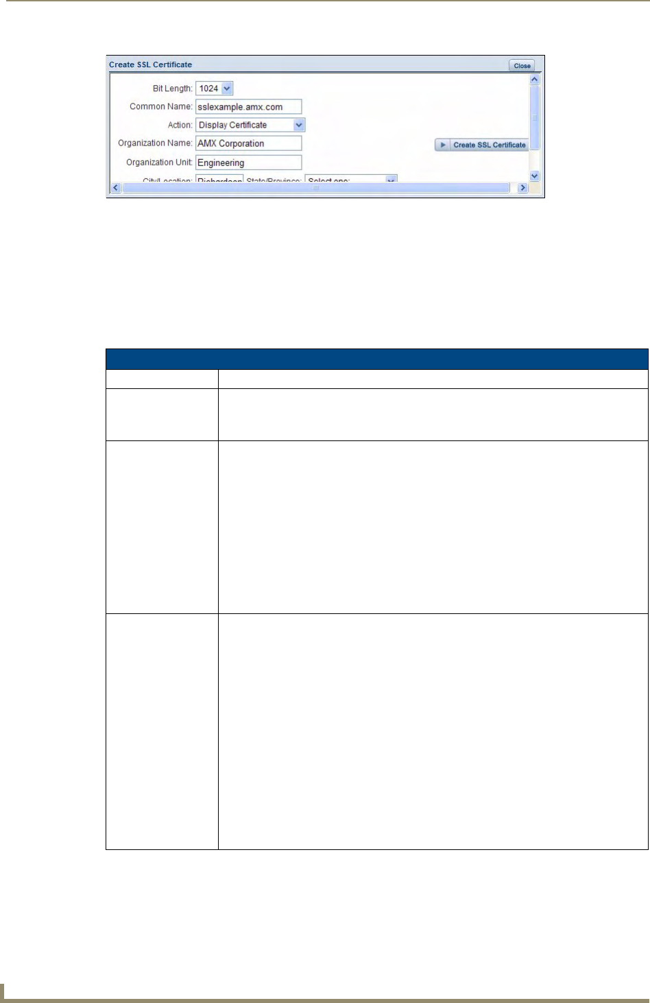
WebConsole - System Options
54 NetLinx Integrated Controllers- WebConsole & Programming Guide
2. Fill out the information in this window, according to the descriptions in the SSL Certificate Entries
section below.
3. Click Create SSL Certificate to update the Master with the information entered on this page. This
process can take several minutes.
SSL Certificate Entries
The following table describes the SSL Certificate entries presented in the Create SSL Certificate window
(FIG. 10):
FIG. 10 Create SSL Certificate window
SSL Certificate Entries
Entry Description
Bit Length: Provides a drop-down selection with three public key lengths (512, 1024, 2048).
• A longer key length results in more secure certificates.
• Longer key lengths result in increased certificate processing times.
Common Name: The Common Name of the certificate must match the URL Domain Name used for the
Master.
Example: If the address used is www.amxuser.com, that must be the Common name
and format used.
• The Common Name can not be an IP Address.
• If the server is internal, the Common Name must be Netbios.
• For every website using SSL that has a distinct DNS name, there must be a certificate
installed. Each website for SSL must also have a distinct IP Address.
• This domain name must be associated to a resolvable URL Address when creating a
request for a purchased certificate.
• The address does not need to be resolvable when obtaining a free certificate.
Action: Provides a drop-down selection with a listing of certificate actions:
•Display Certificate - Populates the Server Certificate fields with the information from
the certificate currently installed on the Master. This action is used only to display the
information contained in the certificate on the target Master.
•Create Request - Takes the information entered into these fields and formats the
certificate so it can be exported to the external Certificate Authority (CA) for later
receipt of an SSL Certificate.
This action is used to request a certificate from an external source.
•Self Generate Certificate - Takes the information entered into the previous fields and
generates its own SSL Certificate.
This action is used when no previous certificate has been installed on the target
Master, or a self-signed certificate is desired.
•Regenerate Certificate - Takes the information entered into the previous fields and
regenerates an SSL Certificate. This action changes the Master Key.
This method of certificate generation is used to modify or recreate a previously
existing certificate already on the Master.

WebConsole - System Options
55
NetLinx Integrated Controllers- WebConsole & Programming Guide
Displaying SSL Server Certificate Information
Click the Create SSL Certificate link in the Server Options page to open the Create SSL Certificate window.
By default, the Display Certificate Action is selected and the fields in this window are populated
with information from the certificate installed on the Master.
If the Master does not have a previously installed certificate, these fields are blank.
Creating a Request for an SSL Certificate
1. Click the Create SSL Certificate link in the Server Options page to open the Create SSL Certificate
window.
2. Fill out the fields, according to the descriptions in the SSL Certificate Entries section on page 54.
3. Click the down arrow next to the Action field, and choose Create Request from the drop-down list.
4. Click the Create SSL Certificate button to accept the information entered into the above fields and
generate a certificate file. Click Close to exit without making changes to the Master.
This refreshes the Server Certificate page, and if the certificate request was successful, displays a
"Certified request generated" message.
Self-Generating an SSL Certificate
1. Click the Create SSL Certificate link in the Server Options page to open the Create SSL Certificate
window.
2. Fill out the fields, according to the descriptions in the SSL Certificate Entries section on page 54.
3. Click the down arrow next to Action and choose Self Generate Certificate.
When this request is submitted, the certificate is generated and installed into the Master in one step.
4. Click Create SSL Certificate to save the new encrypted certificate information to the Master. Click
Close to exit without making changes to the Master.
Regenerating an SSL Server Certificate Request
This action allows you to is used to modify or recreate a certificate already on the Master. For example, if the
company has moved from Dallas to Houston, all of the information is reentered exactly except for the City.
1. Click the Create SSL Certificate link in the Server Options page to open the Create SSL Certificate
window.
2. Modify the certificate information as needed (see the SSL Certificate Entries section on page 54).
3. Click the down arrow next to Action and choose Regenerate Certificate.
4. Click Create SSL Certificate to save the newly modified certificate information to the Master. Click
Close to exit without making changes to the Master.
SSL Certificate Entries (Cont.)
Entry Description
Organization Name: Name of your business or organization. This is an alpha-numeric string (1 - 50 charac-
ters in length).
Organization Unit: Name of the department using the certificate. This is an alpha-numeric string
(1 - 50 characters in length).
City/Location: Name of the city where the certificate is used. This is an alpha-numeric string
(1 - 50 characters in length).
State/Province: Name of the state or province where the certificate is used (alpha-numeric string, 1 - 50
characters in length).
Note: The state/province name must be fully spelled out.
Country Name: Provides a drop-down selection with a listing of currently selectable countries.
Only use the Regenerate Certificate option when you have self-generated your own
certificate. Do not regenerate an external CA-generated certificate.
WebConsole - System Options
56 NetLinx Integrated Controllers- WebConsole & Programming Guide
Exporting an SSL Certificate Request
1. First follow the procedures outlined in the Creating a Request for an SSL Certificate section on page 55
to create a session-specific Master certificate.
2. Click the Export SSL Certificate link to display the certificate text file in the Export SSL Certificate
window (FIG. 11).
3. Place your cursor within the certificate text field. The certificate text begins with the line that reads "-----
BEGIN CERTIFICATE REQUEST-----" (scroll down to view the certificate text.)
4. Select all (Ctrl + A) of the certificate text.
You must copy all of the text within this field, including the -----BEGIN CERTIFICATE REQUEST---
-- and the -----END CERTIFICATE REQUEST----- portions. Without this text included in the CA
submission, you will not receive a CA-approved certificate.
5. Copy (Ctrl + C) the text to the clipboard.
6. Paste (Ctrl + V) this text into the Submit Request field on the CA’s Retrieve Certificate web page.
7. Choose to view the certificate response in raw DER format.
Note the Authorization Code and Reference Number (for use in the e-mail submission of the request).
8. Submit the request.
9. Paste the copied text into your e-mail document and send it to the CA with its accompanying certificate
application.
Once you have received the returned CA certificate, follow the procedures outlined in the following section to
import the returned certificate (over a secure connection) to the target Master.
Importing an SSL Certificate
Click the Import SSL Certificate link to import a CA server certificate. Before importing an SSL Certificate
you must:
First, have a self-generated certificate installed onto your target Master.
Second, enable the HTTPS/SSL feature from the Server Options page (FIG. 9), to establish a secure
connection to the Master prior to importing the encrypted CA certificate.
1. Copy the returned certificate (signed by the CA) to your clipboard.
2. Click the Import SSL Certificate link to open the Import SSL Certificate window (FIG. 12).
FIG. 11 Export SSL Certificate window
When a certificate request is generated, you are creating a private key on the Master.
You can not request another certificate until the previous request has been fulfilled.
Doing so voids any information received from the previously requested certificate and
it becomes nonfunctional if you try to use it.
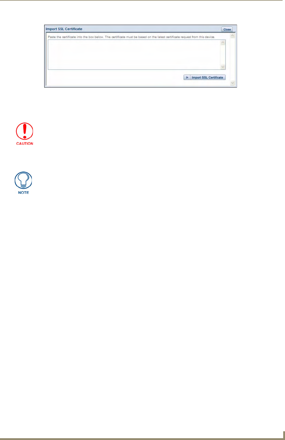
WebConsole - System Options
57
NetLinx Integrated Controllers- WebConsole & Programming Guide
3. Place the cursor inside the text box and paste the returned certificate text, in its entirety.
4. Click Import SSL Certificate to save the new certificate information to the Master.
5. Click the Display Certificate link to confirm the new certificate was imported properly to the target
Master.
FIG. 12 Import SSL Certificate window
Once a certificate has been received from an external CA and installed on a Master,
do not regenerate the certificate or alter its properties. Regenerating a previously
installed certificate, invalidates the certificate.
A CA certificate can only be imported to a target Master only after both a self-
generated certificate has been created and the SSL Enable feature has been
selected on the Master. These actions configure the Master the secure
communication necessary during the importing of the CA certificate.
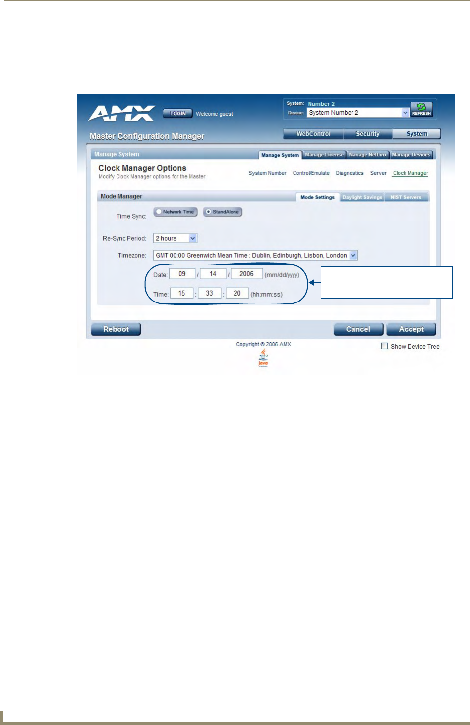
WebConsole - System Options
58 NetLinx Integrated Controllers- WebConsole & Programming Guide
Manage System - Clock Manager Options
Click the Clock Manager link (in the Manage System tab) to access the Clock Manager Options page
(FIG. 13). The options on this page allow you to enable/disable using a network time source and provide
access to Daylight Saving configuration and which NIST servers to use as a reference.
The Clock Manager Options are separated into three tabs:
Mode Settings - The Mode Manager in this tab allows you to set the Clock Manager Mode
(Network Time or Stand Alone).
Daylight Savings - The Daylight Savings Manager in this tab allows you to specify how and when
to implement Daylight Savings rules on the clock.
NIST Servers - The NIST Server Manager in this tab allows you to connect to a specific NIST
(Internet Time Service) Server.
Setting the Mode for the Clock Manager
1. In the Mode Settings tab (FIG. 13), select a Time Synch option.
Network Time: This option allows the Master to manage it’s clock by connecting to a NIST
(Internet Time Service) Server. When this option is selected, the Master will connect to the default
NIST Server to get date and time information.
You can select a different NIST Server (or specify the IP Address of a known NIST Server) in the
NIST Servers tab (see the Selecting a Custom NIST Server section on page 60).
Stand Alone: This option lets the Master use its own internal clock. When this option is selected,
two additional fields are available on this tab:
Date - Enter the current date in these fields (mm/dd/yyyy).
Time - Enter the current time in these fields (hh/mm/ss).
2. Click Accept to save these settings to the Master.
FIG. 13 Clock Manager Options - Mode Settings tab
Date and Time are only available
if Stand Alone is selected as the
Time Synch option.
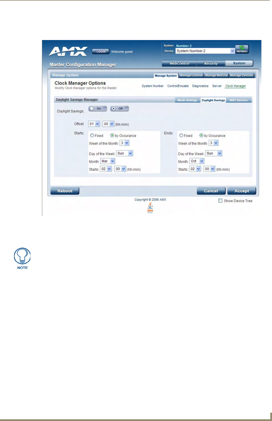
WebConsole - System Options
59
NetLinx Integrated Controllers- WebConsole & Programming Guide
Setting Daylight Savings Rules
1. In the Daylight Savings tab (FIG. 14), enable Daylight Savings mode by clicking the On button.
2. Use the Offset drop-down menus to adjust the amount of time (hours and minutes) to offset Daylight
Savings. By default, the offset is set to 1 hour.
3. Use the Starts fields to specify when Daylight Savings should start. The Starts rules include:
Select Fixed to specify the calendar date when the rule applies as a specific date ("March 21").
When Fixed is selected, use the Day, Month and Starts fields to specify the date and time (hh:mm)
to start Daylight Savings time.
Select by Occurrence to specify the calendar date when the rule applies as a heuristic,
("the 3rd Sunday in March"). When by Occurrence is selected, use the Week of the Month,
Day of the Week, Month and Starts fields to specify the occurrence to start Daylight Savings
time.
The range is 1 through Last, where Last indicates the last occurrence of a particular day of the
month. This is to accommodate months that include four weeks as well as those that include five.
4. Use the Ends fields to specify when Daylight Savings should end. The Ends rules match the Start rules,
and follow the same logic. Select Fixed or by Occurrence, and specify the End date/time information
accordingly.
5. Click Accept to save these settings to the Master.
FIG. 14 Clock Manager Options - Daylight Savings tab
Although most places that support Daylight Savings usually adjust the local time by
one hour this doesn't cover all locations. To provide flexibility for such locations it is
possible to configure a different daylight savings time offset.

WebConsole - System Options
60 NetLinx Integrated Controllers- WebConsole & Programming Guide
Selecting a Custom NIST Server
1. In the NIST Servers tab (FIG. 15), use the radio buttons to select one of the NIST Servers in the list.
2. Click Accept to save these settings to the Master.
Adding a Custom NIST Server To the List
1. Click on the radio button next to the last (blank) entry in the NIST Server Manager list.
2. In the URL field, enter the URL of the NIST Server. The URL is used only to help you manage entries,
and is not verified or used internally by the clock manager.
3. Enter the NIST Server’s IP Address in the IP field. This is used internally and must be a valid IP address.
4. Enter the NIST Server’s location in the Location field. This is used only to help the user manage entries
and it is not verified or used internally by the clock manager.
5. Click Accept to save these settings to the Master.
Removing an NIST Server From the List
1. Click on the Remove (x) button to the right of a user-added NIST Server in the NIST Server Manager list.
2. Click Accept to save these settings to the Master.
FIG. 15 Clock Manager Options - NIST Servers tab
The strings entered into the URL and Location fields are not used to connect to NIST
Servers. The IP Address (entered into the IP field) specifies the NIST Server(s) that
will be used. As stated above, the address entered into the IP field must be must be a
valid IP address (not a URL).
The built-in entries cannot be removed.
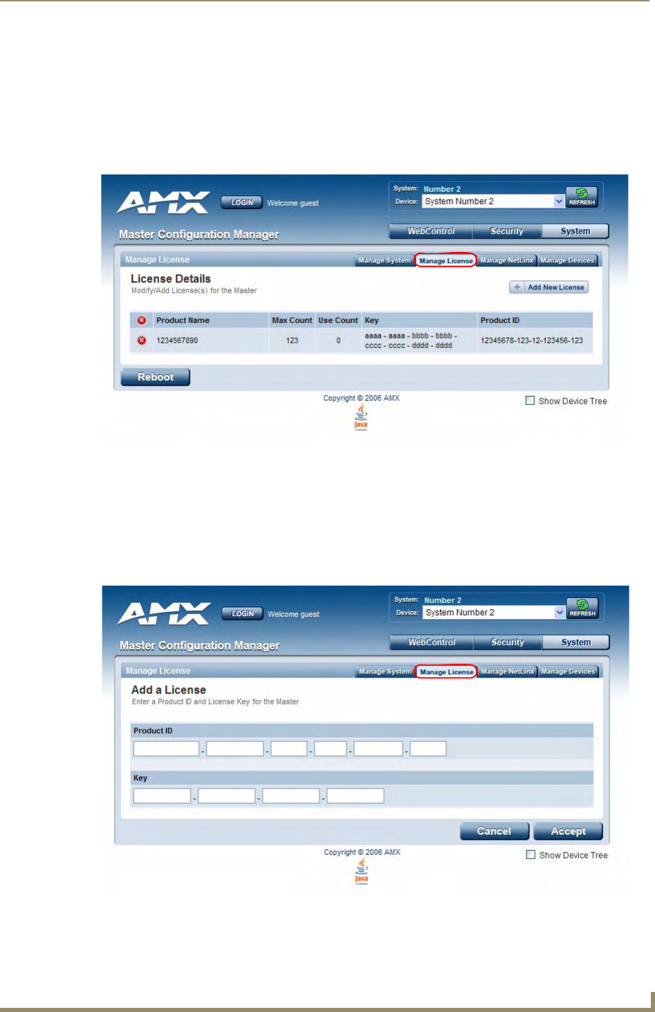
WebConsole - System Options
61
NetLinx Integrated Controllers- WebConsole & Programming Guide
Clock Manager NetLinx Programming API
Refer to Appendix B: Clock Manager NetLinx Programming API section on page 147 for a listing and
description of the Types/Constants and Library Calls that are included in the NetLinx.AXI to support Clock
Manager functions.
System - Manage License
The Manage License tab displays current as well as pending license keys (FIG. 16).
The Add New License button allows for the addition of new license keys associated with currently used
modules/products. Adding new License Keys requires the entry of both a Product ID and a Serial Key
(example: i!-Voting).
The Master confirms this registration information before running the module or product.
Adding A New License
1. Click the Add New License button to access the Add a License page (FIG. 17).
2. Enter the Product ID (certificate number) provided with the product into the Product ID fields.
FIG. 16 System - Manage License tab (with one example entry)
FIG. 17 Manage License - Add a License page

WebConsole - System Options
62 NetLinx Integrated Controllers- WebConsole & Programming Guide
Contact the AMX Sales department with both the product serial number (or certificate number) and the
serial number of target Master to register your product and in turn receive the necessary Key information
(typically 32 to 36 digits in length) which is then entered into the Key fields on this page.
3. Enter the Product Key into the Key fields. The Product Key is Master-specific and is typically provided
by AMX upon registration.
Example: AMX Meeting Manager and i!-Voting applications are examples of products that require both a
Product serial number and a Master-specific key prior to usage.
4. Press the Accept button to save the information. If there are no errors with the information on this page, a
“Key successfully added for Product ID XXXX” is displayed at the top of the page.
Removing a License
1. Click the Remove (x) icon to the left of the license that you want to remove.
2. The system will prompt you to verify this action before the license is removed from the Master. Click OK
to proceed.
3. Press the Accept button to save the information.
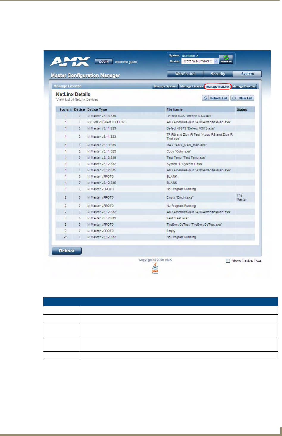
WebConsole - System Options
63
NetLinx Integrated Controllers- WebConsole & Programming Guide
System - Manage NetLinx
The Manage NetLinx tab displays a list of NetLinx devices connected to the Master, and indicates device
status for each (FIG. 18).
The table on this page consists of five columns:
FIG. 18 System - Manage NetLinx tab
NetLinx Device Details
Column Description
System: Displays the System value being used by the listed NetLinx Master.
Device: • Displays the assigned device value of the listed unit. This Device entry applies to both the
Master and those NDP-capable devices currently connected to that Master.
Device Type: • Displays a description of the target Master or connected device, and its current firmware
version. Example: NI Master v3.01.323.
File Name: Displays the program name and/or file resident on the device.

WebConsole - System Options
64 NetLinx Integrated Controllers- WebConsole & Programming Guide
Refresh List: Click this button to regenerate the device listing by looking for broadcasting devices.
This causes the Master to send out a message asking devices to resend their NDP device
announcements. The list is then updated as those devices send back their announcements to the
Master.
The information displayed can not only include Masters and devices on this system but Masters and
devices on other systems as well. By default, the target Master always appears in the list.
Clear List: Click this button causes the entries to be temporarily deleted from the page, either until
you refresh the list (using the Refresh List button), or until the Master begins to detect any multi-
cast transmissions from System Devices.
NetLinx Device Details (Cont.)
Column Description
Status: Indicates the Master or device state:
•This Master: Indicates its the target Master currently being used and being browsed to. Its
this Master’s web pages which are currently being viewed.
•Orphan: Indicates that the device is currently not yet “bound” or assigned to communicate
with a particular Master. This state shows an adjacent Bind button which is used to bind the
device to the Master whose web pages are currently being viewed.
•Searching: Indicates that the device is trying to establish communication with it's
associated Master.
•Bound: Indicates that the device has established communication with it's associated
Master. This state shows an adjacent Unbind button which is used to release/disassociate
the device from communicating with its current Master.
•Lost: Indicates that the device has tried to establish communication with it's associated or
“bound” Master, but was after a period of time, unable to establish communication.
Due to system delays, message collisions, and multicast routing, not all devices may
respond immediately.

WebConsole - System Options
65
NetLinx Integrated Controllers- WebConsole & Programming Guide
System - Manage Devices
The Manage Devices tab (FIG. 19) contains links to several different device-related pages, as described in the
following subsections:
Manage Devices - Device Options
Click the Device Options link (in the Manage Devices tab) to access the Details for Additional Devices page
(FIG. 19). The options on this page display various details specific to additional (non-NetLinx) System
Devices.
Configuring Device Binding Options
1. Use the Configure Binding Options options to specify how the Master will manage Bound Devices:
FIG. 19 System - Manage Devices (Details for Additional Devices)
Binding Options
Option Description
Enable Auto Bind: This selection allows you to toggle the state of the automatic binding for
DDD (On/Off).
When auto-binding is enabled, the Master automatically attempts to con-
nect any newly discovered device with an associated application device
(defined in the running NetLinx application).
Auto-binding can only be accomplished if the Master's firmware deter-
mines a one-to-one correlation between the newly discovered device and
a single entry within the list of defined application devices (accessed via
the Binding link at the top of this page).

WebConsole - System Options
66 NetLinx Integrated Controllers- WebConsole & Programming Guide
2. Press the Accept button to save your changes.
Managing Device Modules
Use the Manage Device Modules set of options to archive or delete modules from the Master. All modules
currently present on the Master are indicated in the Module list.
To archive a module:
1. Select a module and click the Archive Module button.
2. This action copies the selected module (*.JAR) file to your PC.
3. The system will prompt you to specify a target directory to save the module file to.
To delete a module:
Select a module and click the Delete Module button. This action deletes the selected module from the /
unbound directory.
Binding Options (Cont.)
Option Description
Enable Auto Bind (Cont.): For example, if the application only has one VCR defined and a VCR is
detected in the system, auto-binding can then be accomplished. If there
were two VCRs defined within the application, auto-binding could not be
completed due to the lack of a clearly defined one-to-one correspon-
dence.
When this option is not selected, no auto-binding activity takes place and
all binding of the newly discovered devices must be accomplished manu-
ally via the Web control interface.
Enable Auto-Shutdown: Auto-Shutdown forces the termination of modules that have lost commu-
nication with their respective physical device. This capability is needed for
plug-and-play support.
By default, Auto-Shutdown is enabled. If automatic termination of mod-
ules when they have lost communication is not desired, this selection
should be disabled.
Enable Subnet Match: This selection allows you to specify whether or not IP devices should only
be detected/discovered if they are on the same IP Subnet as the Master.
Purge Bound Modules on Reset: This selection indicates that all modules should be deleted from the bound
directory upon the next reboot.
During the binding process, the associated Duet modules for a device are
copied from the /unbound directory into a protected /bound area.
Due to the dynamic nature of Java class loading, it is not safe to delete a
running .JAR file. Therefore, this selection provides the administrator the
capability of removing existing modules upon reboot by forcing a re-acqui-
sition of the module at bind time.
This selection is a one-time occurrence - upon the next reboot, the selec-
tion is cleared.
Disable Module Search
via Internet:
This option toggles the capability of searching the Internet (either AMX's
site or a device specified site) for a device’s compatible Duet modules.
This capability is automatically disabled if the Master does not have Inter-
net connectivity.
Upon enabling Internet connectivity, the AMX License Agreement is dis-
played. The License Agreement must be accepted for Internet Module
search feature to be enabled.
When this feature is enabled, the Master queries either AMX's Online
database of device Modules and/or pulls Modules from a separate site
specified by the manufacturer's device.
You can later disable this feature by toggling this button.
Any corresponding module within the /bound directory will not be deleted. Bound
modules must be deleted via the Purge Bound Modules on Reset selection described
within the Configure Device Bindings section.
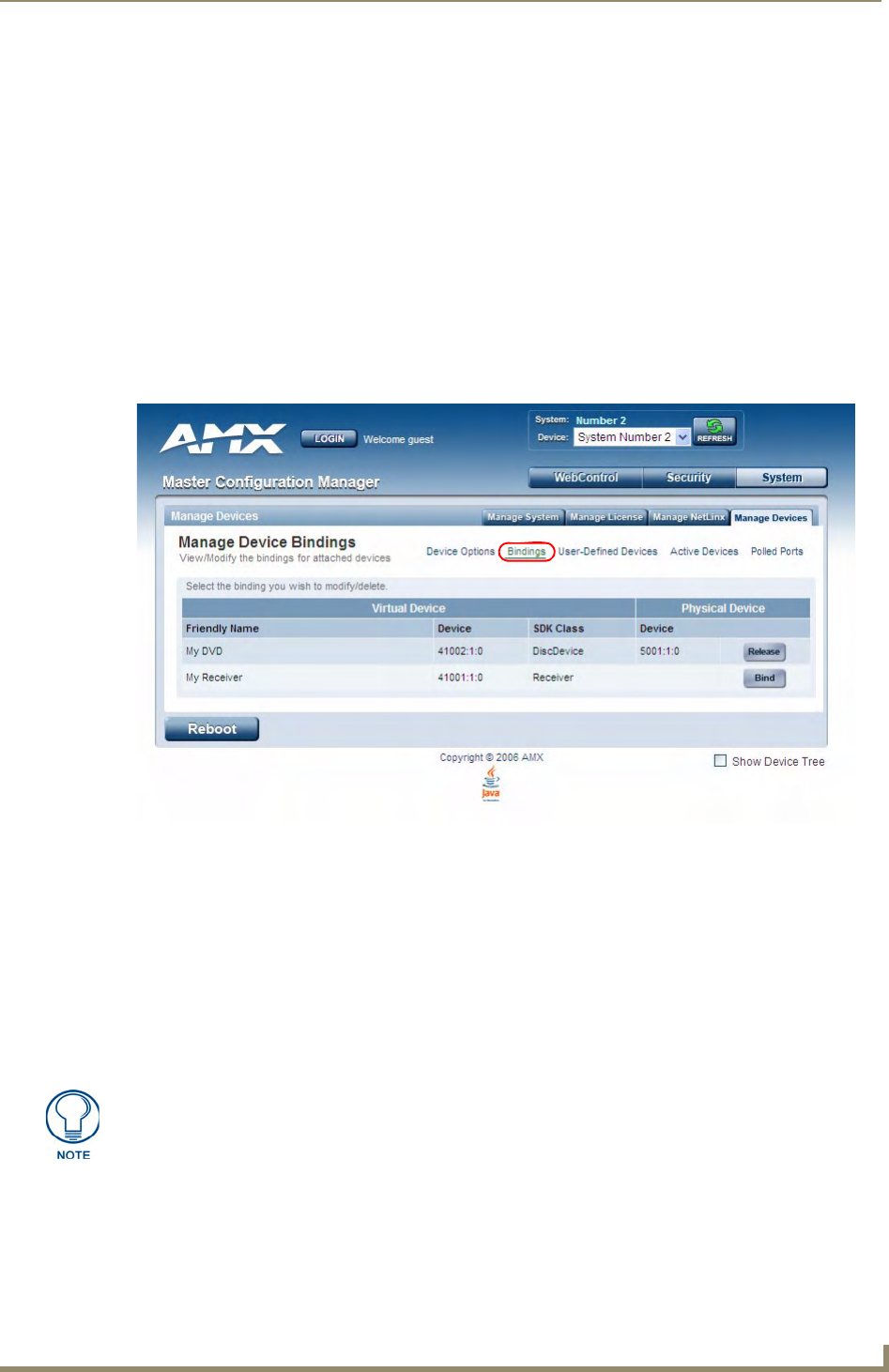
WebConsole - System Options
67
NetLinx Integrated Controllers- WebConsole & Programming Guide
To browse for a Module file and then upload it to the Master:
1. Click the Browse button next to the Select a module to upload text field to browse for Duet Modules on
your PC/Network.
2. Select the JAR file that you want to upload to the Master.
3. Click the Submit button to upload a copy of the selected JAR file to the target Master's /unbound
directory.
If a file of the same specified name already exists within the /unbound directory, the system will
prompt you to confirm overwriting the existing file.
Only JAR file types are allowed for Upload to the target Master.
Manage Devices - Bindings
Click the Bindings link (in the Manage Devices tab) to access the Manage Device Bindings page (FIG. 20).
Use the options on this page to configure application-defined Duet virtual devices with discovered physical
devices.
The table on this page displays a list of all application-defined devices, including each device’s "Friendly
Name", the Duet virtual device’s D:P:S assignment, the associated Duet Device SDK class (indicating the type
of the device), and the physical device’s D:P:S assignment. This information has to be pre-coded into the
NetLinx file currently on the Master.
Configuring Application-Defined Devices
Elements such as DUET_DEV_TYPE_DISC_DEVICE and DUET_DEV_POLLED are defined within the
NetLinx.axi file.
The NetLinx.axi file contains both the new API definitions, as well as the pre-defined constants that are used
as some of the API arguments (ex: DUET_DEV_TYPE_DISC_DEVICE).
Example Code:
FIG. 20 System - Manage Devices (Manage Device Bindings)
Physical device names are typically prefixed with "dv" and Virtual device names are
typically prefixed with "vdv".

WebConsole - System Options
68 NetLinx Integrated Controllers- WebConsole & Programming Guide
PROGRAM_NAME='DDD'
DEFINE_DEVICE
COM1 = 5001:1:0
COM2 = 5001:2:0
dvRECEIVER1 = 41000:1:0
dvDiscDevice = 41001:1:0
DEFINE_CONSTANT
DEFINE_TYPE
DEFINE_VARIABLE
DEFINE_START
STATIC_PORT_BINDING(dvDiscDevice, COM1, DUET_DEV_TYPE_DISC_DEVICE,
'My DVD', DUET_DEV_POLLED)
DYNAMIC_POLLED_PORT(COM2)
DYNAMIC_APPLICATION_DEVICE(dvRECEIVER1, DUET_DEV_TYPE_RECEIVER,
'My Receiver')
(***********************************************************)
(* THE EVENTS GO BELOW *)
(***********************************************************)
DEFINE_EVENT
DATA_EVENT [dvRECEIVER1]
{
// Duet Virtual device data events go here
}
Sample code can be found within the DEFINE_START section, as shown in FIG. 21:
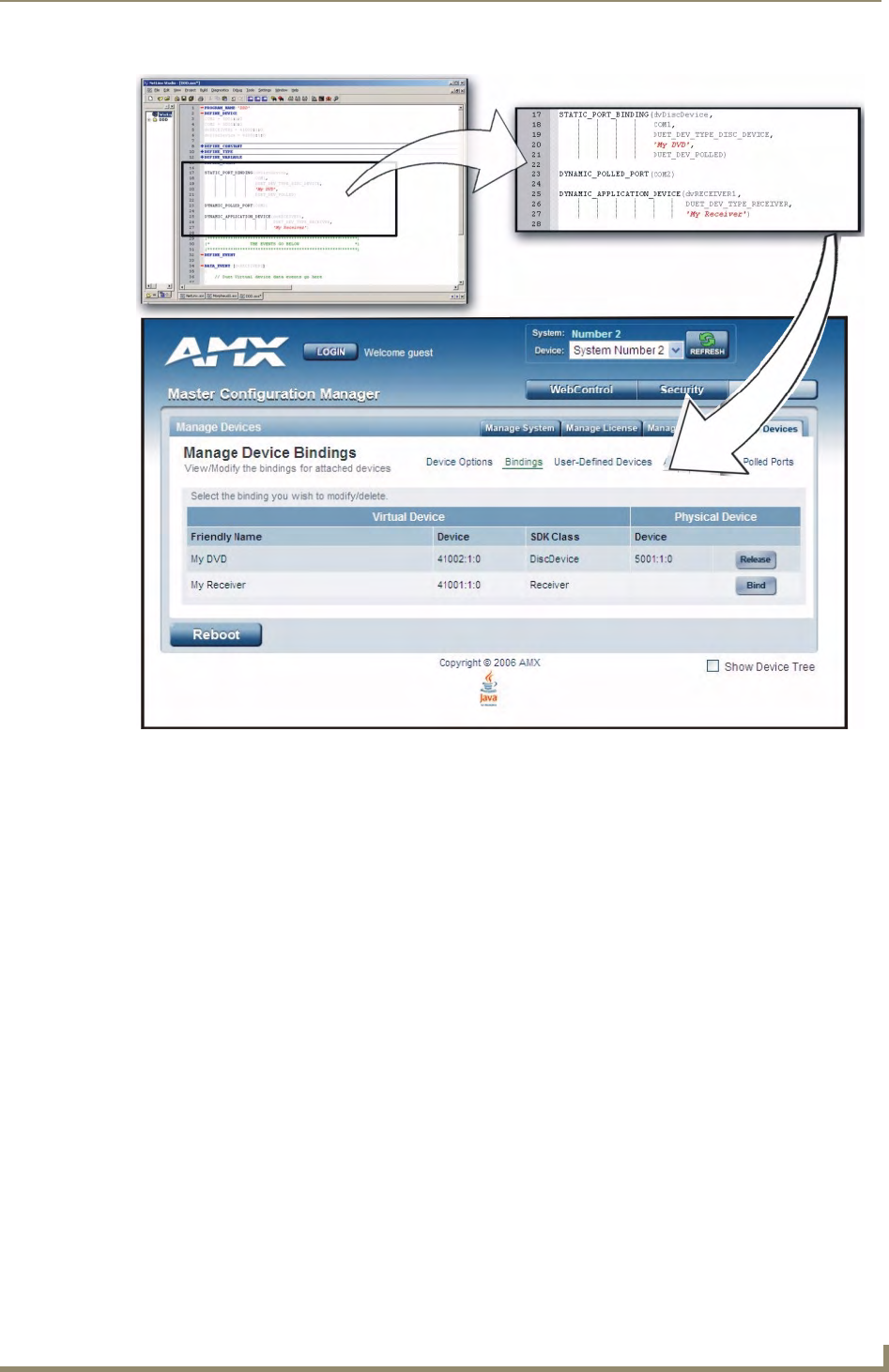
WebConsole - System Options
69
NetLinx Integrated Controllers- WebConsole & Programming Guide
This code gives the Master a “heads-up” notification to look for those devices meeting the criteria outlined
within the code.
Application Devices and Association Status
There are two types of application devices: Static Bound application devices and Dynamic application
devices:
Static Bound application devices specify both a Duet virtual device and its associated Device SDK
class type, as well as a NetLinx physical device port to which the application device is always
associated (i.e. statically bound).
Dynamic application devices specify both the Duet virtual device and its associated Device SDK
with no association to a physical port. Binding of an application device to a physical device/port
occurs at run-time (either via auto-binding or manual binding).
Application devices that have a "bound" physical device display their physical device ID within the Physical
Device column. If an associated Duet module has been started to communicate with the device, its associated
property information is displayed in a mouse-over popup dialog when the cursor hovers over the physical
device ID (see FIG. 22 on page 70).
FIG. 21 Manage Device Bindings page - showing the NetLinx code relation
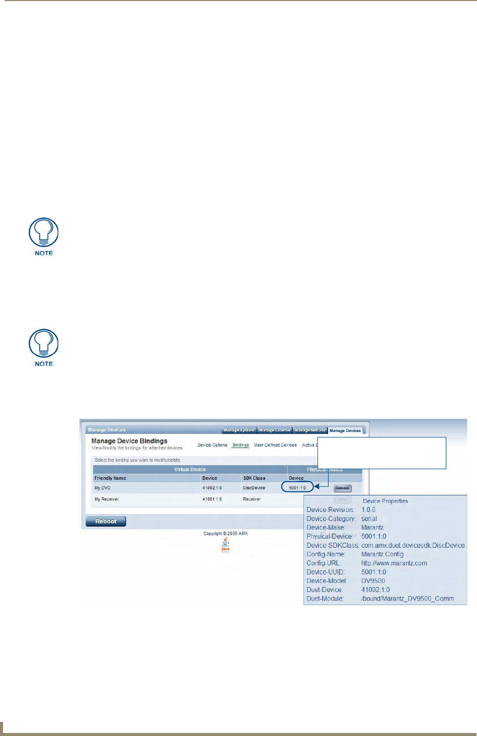
WebConsole - System Options
70 NetLinx Integrated Controllers- WebConsole & Programming Guide
Each entry in the table has one of four buttons to the right of the Physical Device D:P:S assignment:
Static Bound application devices will either be blank, or display a Release button:
Static Bound application devices that have not yet detected a physical device attached to their
associated port have a blank button.
Once a physical device is detected and its associated Duet module has been started, a Release
button is then displayed. Click Release to force the associated Duet module to be destroyed and
the firmware then returns to detecting any physical devices attached to the port.
Dynamic application devices either display a Bind or Unbind button:
Dynamic application devices that have been bound display an Unbind button. When the user
selects Unbind, any associated Duet module is then destroyed and the "link" between the
application device and the physical device is then broken.
Dynamic application devices that have not been bound to a physical device display a Bind button.
When this button is selected, a secondary display appears with a listing of all available unbound
physical devices that match the application device's Device SDK class type.
The administrator/user can then select one of the available physical devices to bind with the associated
application device. When the Save button is selected, the binding is created and a process begins within the
target Master to find the appropriate Duet Module driver. Once a driver is found, the Duet Module is then
started and associated with the specified application device (Duet virtual device). If the Cancel button is
selected, the binding activity is then aborted.
Viewing Physical Device Properties
Hold the mouse cursor over the Physical Device - Device entry in the table to display detailed device
properties for that device, in a pop-up window (FIG. 22).
If a currently bound device needs to be replaced or a Duet Module needs to be
swapped out, the device should be unbound and the new module/driver should then
be bound.
If the manufacturer device does not support Dynamic Device Discovery (DDD)
beaconing, you must use the Add New Device page to both create and manage
those values necessary to add a dynamic physical device. This process is described
in detail within the following section.
FIG. 22 Manage Device Bindings - Device Properties pop-up
Hold the mouse cursor over the
Device D:P:S assignment to open
the Device Properties pop-up
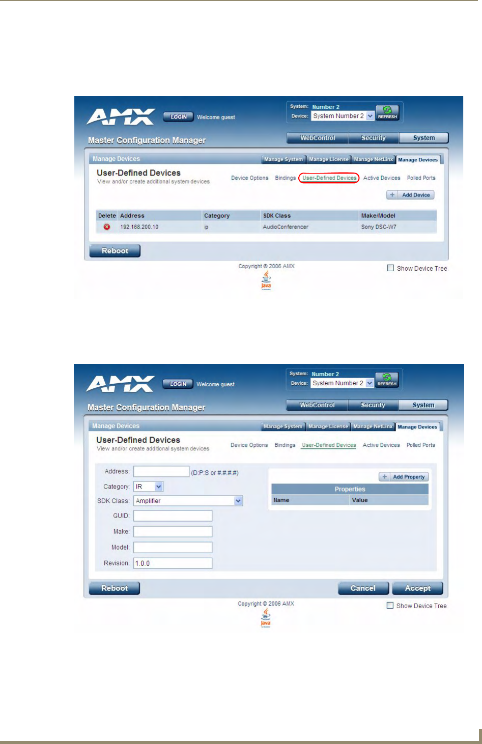
WebConsole - System Options
71
NetLinx Integrated Controllers- WebConsole & Programming Guide
Manage Devices - User-Defined Devices
Click the User-Defined Devices link (in the Manage Devices tab) to access the User-Defined Devices page
(FIG. 23). This page provides a listing with all of the dynamic devices that have been discovered in the system,
and allows you to add and delete User-Defined Devices.
Adding a User-Defined Device
1. Click the Add Device button (in the User-Defined Devices page) to access the Add User Defined Device
page (FIG. 24):
FIG. 23 System - Manage Devices (User-Defined Devices)
FIG. 24 User-Defined Devices - Add User Defined Device
WebConsole - System Options
72 NetLinx Integrated Controllers- WebConsole & Programming Guide
2. Fill in the device information fields, as described in the following table:
3. Once you are done creating the profile for the new device, click the Add Property button to access the
Name and Valu e fields property information for association with the new User Defined Device.
4. Click the Accept button. The new device is indicated in the list of discovered physical devices (in the
User-Defined Devices page).
User-Defined Device Information Fields
Address: Enter the address of the physical device in the Address field.
This information can be either the NetLinx Master port value (D:P:S) or an IP Address (#.#.#.#).
Category: Use the drop-down list to select the control method associated with the physical target device
(IR, IP, Serial, Relay, Other).
SDK Class: Use the drop-down list to select the closest Device SDK class type match for the physical target
device. The SDK-Class Types table (below) provides a listing of the available choices.
GUID: Enter the manufacturer-specified device’s GUID (Global Unique Identification) information.
Either the GUID or Make/Model must be specified in this field.
Make: Enter the name of the manufacturer for the device being used (ex: Sony, ONKYO, etc.)
• Up to 55 alpha-numeric characters
• Either the GUID or Make/Model must be specified within this field.
• Spaces in the name will be converted to underscores.
Model: Enter the model number of the device being used (ex: Mega-Tuner 1000)
• Up to 255 alpha-numeric characters
• Either the GUID or Make/Model must be specified within this field.
Revision Enter the firmware version used by the target device.
• Text is required within this field.
• The version must be in the format: major.minor.micro (where major, minor, and micro are
numbers). An example is: 1.0.0 (revision 1.0.0 of the device firmware).
SDK-Class Types
Amplifier HVAC SlideProjector
AudioConferencer IODevice Switcher
AudioMixer Keypad Text Keypad
AudioProcessor Light TV
AudioTape Monitor UPS
AudioTunerDevice Motor Utility
Camera MultiWindow VCR
Digital Media Decoder PoolSpa VideoConferencer
Digital Media Encoder PreAmpSurroundSoundProcessor VideoProcessor
Digital Media Server RelayDevice VideoProjector
Digital Satellite System Receiver VideoWall
Digital Video Recorder Security System VolumeController
Disc Device Sensor Device Weather
DocumentCamera SettopBox
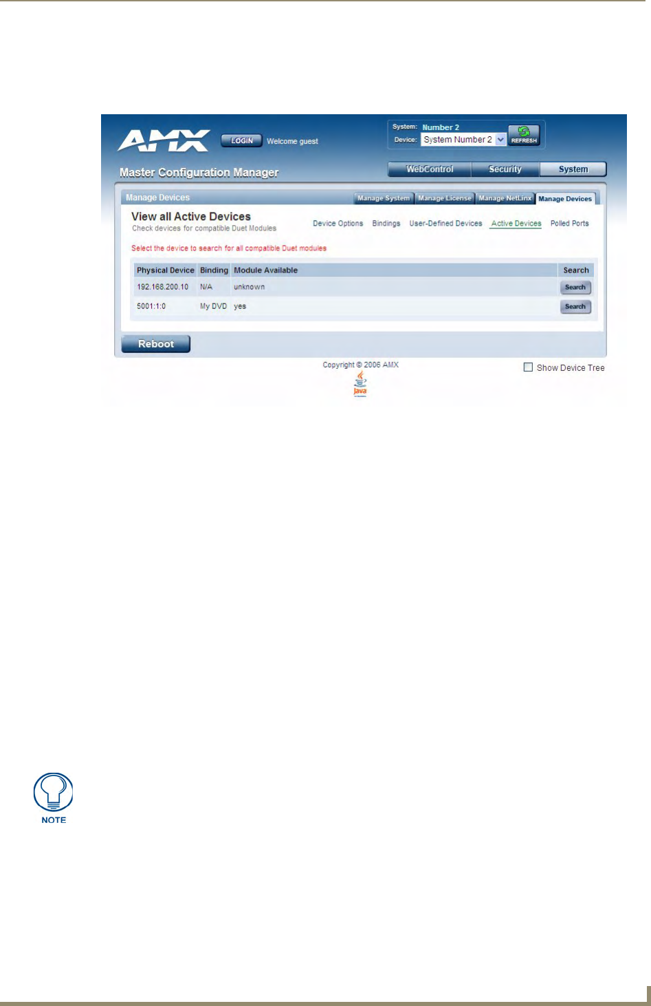
WebConsole - System Options
73
NetLinx Integrated Controllers- WebConsole & Programming Guide
Manage Devices - View All Active Devices
Click the Active Devices link (in the Manage Devices tab) to access the View All Active Devices page
(FIG. 25). The options on this page allow you to check devices for compatible Duet Modules.
Searching For All Compatible Duet Modules for a Selected Device
1. Click the Search button for the device that you want to find a Duet Module for. This action initiates a
search for compatible modules, based on the following options:
Unless the Disable Module Search via the Internet option was selected in the Manage Devices
page (see the Manage Devices - Device Options section on page 65), the search includes a query of
the AMX online database as well as any manufacturer specified URLs that match the IP Address of
the physical device for a compatible module.
If the device specified a URL in its DDD beacon, the file is retrieved from the URL either over the
Internet or from the physical device itself, provided the device has an inboard HTTP or FTP server.
If Module Search via Internet is NOT enabled, the search does NOT query the AMX online
database nor will it pull any manufacturer specified URLs that do not match the IP Address of the
physical device itself.
Modules that are retrieved from either the Internet or from the manufacturer's device are then placed into
the /unbound directory and automatically overwrite any existing module of the same name.
2. Once a list of all compatible modules is compiled, the Available Modules list is displayed on this page.
Each module is listed with its calculated “match” value. The greater the “match” value, the better the
match between the Duet Module's properties and the physical device's properties.
3. Select a module and click the Accept button to associate the selected Duet module with the physical
device.
FIG. 25 System - Manage Devices (User-Defined Devices)
This action will not affect any currently running Duet module associated with the
physical device. The module is associated with the device upon reboot.
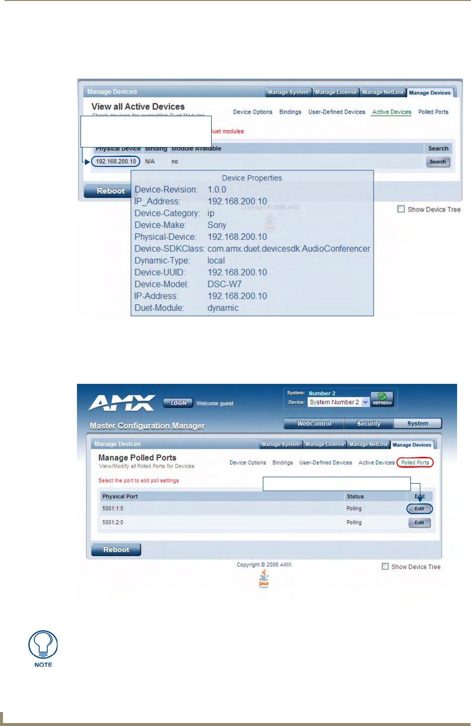
WebConsole - System Options
74 NetLinx Integrated Controllers- WebConsole & Programming Guide
Viewing Physical Device Properties
Hold the mouse cursor over the Device entry in the table to display detailed device properties for that device,
in a pop-up window (FIG. 26).
Manage Devices - Manage Polled Ports
Click the Polled Ports link (in the Manage Devices tab) to access the Manage Polled Ports page (FIG. 27).
The options on this page allow you to view/modify settings for all polled ports in the System.
FIG. 26 View All Active Devices - Device Properties pop-up
FIG. 27 System - Manage Devices (Manage Polled Ports)
Hold the mouse cursor over the
Physical Device IP Address to open
the Device Properties pop-up
Click to open the Edit Port Settings page
Polled Ports must be specified in the Master’s code in order for this page to be
populated.
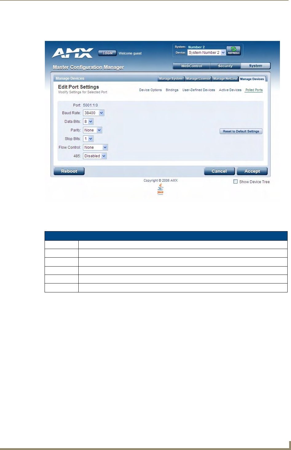
WebConsole - System Options
75
NetLinx Integrated Controllers- WebConsole & Programming Guide
Editing Polled Port Settings
Click the Edit button for a port in the Physical Port list to access the Edit Port Settings page (FIG. 28):
Use the drop-down menus to modify the Port settings.
Click Reset to Default Settings to return this port to its default configuration:
FIG. 28 Manage Polled Ports - Edit Port Settings
Default Port Settings
Baud Rate: 9600
Data Bits: 8
Parity: None
Stop Bits: 1
Flow Control None
485: Disabled

WebConsole - System Options
76 NetLinx Integrated Controllers- WebConsole & Programming Guide
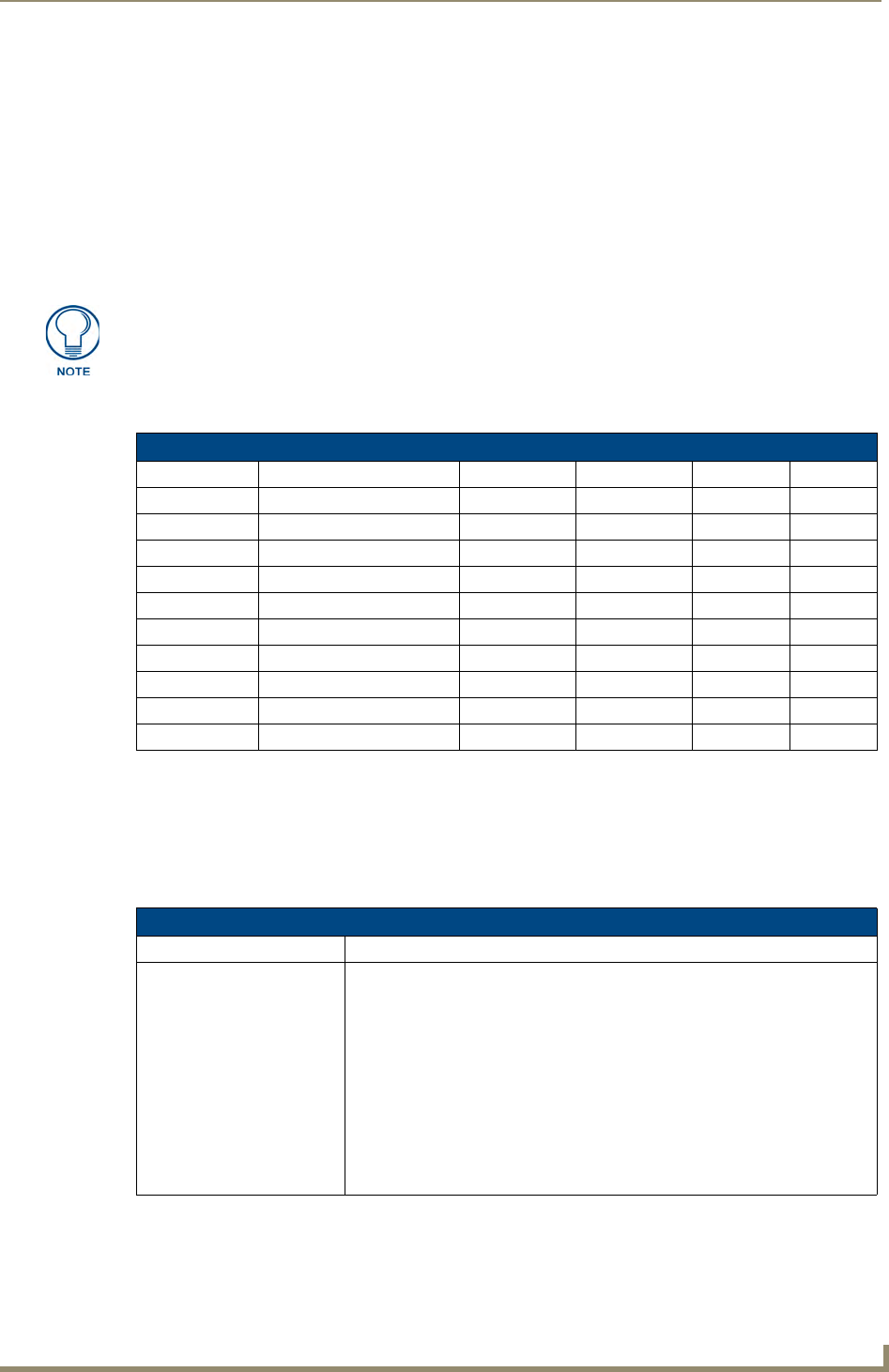
NetLinx Programming
77
NetLinx Integrated Controllers- WebConsole & Programming Guide
NetLinx Programming
Overview
This section describes the Send_Commands, Send_Strings, and Channel commands you can use to program
the Integrated Controller. The examples in this section require a declaration in the DEFINE_DEVICE section
of your program to work correctly. Refer to the NetLinx Programming Language instruction manual for
specifics about declarations and DEFINE_DEVICE information.
Port Assignments By NI Model
Master Send_Commands
These commands are specific to the Master and not the Controller. These commands are sent to the DPS 0:1:0
(the Master you are connected to).
A device (<DEV>) must first be defined in the NetLinx programming language with values for the Device:
Port: System (<D:P:S>).
NetLinx programming information for the DVX-2100HD is included in the
DVX-2100HD Operation/Reference Guide.
Port Assignments By Controller
Controller RS-232/422/485 IR/Serial IR/RX Relays I/O
NI-700 Ports 1 - 2 Port 3 Port 5 Port 4
NI-900 Port 1 Ports 2-4 Port 6 Port 5
NI-2000 Ports 1 - 3 Ports 5-8 Port 4 Port 9
NI-3000 Ports 1 - 7 Ports 9-16 Port 8 Port 17
NI-4000 Ports 1 - 7 Ports 9-16 Port 8 Port 17
NI-2100 Ports 1 - 3 Ports 5-8 Port 4 Port 9
NI-3100 Ports 1 - 7 Ports 9-16 Port 8 Port 17
NI-4100 Ports 1 - 7 Ports 9-16 Port 8 Port 17
NI-3101-SIG Ports 1 - 6 Ports 9-16 Port 8 Port 17
DVX-2100HD Ports 1 - 3 Ports 5-8 Port 4 Port 9
Master Send_Commands
Command Description
CLOCK
Set the date and time on the
Master.
The date and time settings are propagated over the local bus.
Syntax:
SEND_COMMAND <DEV>,"'CLOCK <mm-dd-yyyy> <hh:mm:ss>'"
Variables:
mm-dd-yyyy = Month, day, and year. Month and day have 2 significant digits.
Year has 4 significant digits.
hh-mm-ss = Hour, minute, and seconds. Each using only 2 significant digits.
Example:
SEND_COMMAND 0,"'CLOCK 04-12-2005 09:45:31'"
Sets the Master's date to April 12, 2005 with a time of 9:45 am.

NetLinx Programming
78 NetLinx Integrated Controllers- WebConsole & Programming Guide
Master Send_Commands (Cont.)
Command Description
G4WC
Add G4WebControl devices
to Web control list displayed
by the Web server in a
browser.
The internal G4WC Send command (to Master 0:1:0) has been revised to add
G4WebControl devices to Web control list displayed in the browser.
Syntax:
SEND_COMMAND <D:P:S>,"'G4WC "Name/Description",IP
Address/URL,IP Port,Enabled'"
Variables:
• Name/Description = A string, enclosed in double quotes, that is the
description of the G4 Web Control instance. It is displayed in the browser.
• IP Address/URL = A string containing the IP Address of the G4 Web Control
server, or a URL to the G4 Web Control server.
• IP Port = A string containing the IP Port of the G4 Web Control Server.
• Enabled = 1 or 0. If it is a 1 then the link is displayed. If it is a 0 then the link is
disabled.
The combination of Name/Description, IP Address/URL, and IP Port are used
to determine each unique listing.
Example:
SEND_COMMAND 0:1:0,"'G4WC "Bedroom",192.168.1.2,5900,1'"
Adds the BEDROOM control device using the IP Address of 192.168.1.2.
~IGNOREEXTERNAL
CLOCKCOMMANDS
Set the Master so that it
cannot have it’s time set by
another device which
generates a ‘CLOCK’
command.
Syntax:
SEND_COMMAND <D:P:S>,"'~IGNOREEXTERNALCLOCKCOMMANDS'"
Example:
SEND_COMMAND 0:1:0,"'~IGNOREEXTERNALCLOCKCOMMANDS'"

NetLinx Programming
79
NetLinx Integrated Controllers- WebConsole & Programming Guide
Master IP Local Port Send_Commands
These commands are specific to the Master and not the Controller. These commands are sent to the DPS 0:1:0
(the Master). A device must first be defined in the NetLinx programming language with values for the Device:
Port: System.
In these programming examples, <DEV> = Device. The term <D:P:S> = Device:Port:System.
Master IP Local Port Send_Commands
Command Description
UDPSENDTO
Set the IP and port number of
the UDP local ports
destination for sending future
packets.
This is only available for Type 2 and Type 3 Local Ports. Type 2 and Type 3 are
referring to the protocol type that is part of the IP_CLIENT_OPEN call
(4th parameter).
Type 1 is TCP.
Type 2 is UDP (standard)
Type 3 is UDP (2 way)
The NetLinx.axi defines constants for the protocol types:
CHAR IP_TCP = 1
CHAR IP_UDP = 2
CHAR IP_UDP_2WAY = 3
Syntax:
SEND_COMMAND <D:P:S>,"'UDPSENDTO-<IP or URL>:<UDP Port
Number>'"
Variables:
• IP or URL = A string containing the IP Address or URL of the desired
destination.
• UDP Port Number = A String containing the UDP port number of the desired
destination.
Example 1:
SEND_COMMAND 0:3:0,"'UDPSENDTO-192.168.0.1:10000'"
Any subsequent SEND_STRING to 0:3:0 are sent to the IP Address
192.168.0.1 port 10000.
Example 2:
SEND_COMMAND 0:3:0,"'UDPSENDTO-myUrl.com:15000'"
Any subsequent SEND_STRING to 0:3:0 are sent to the URL myURL.com
port 15000.
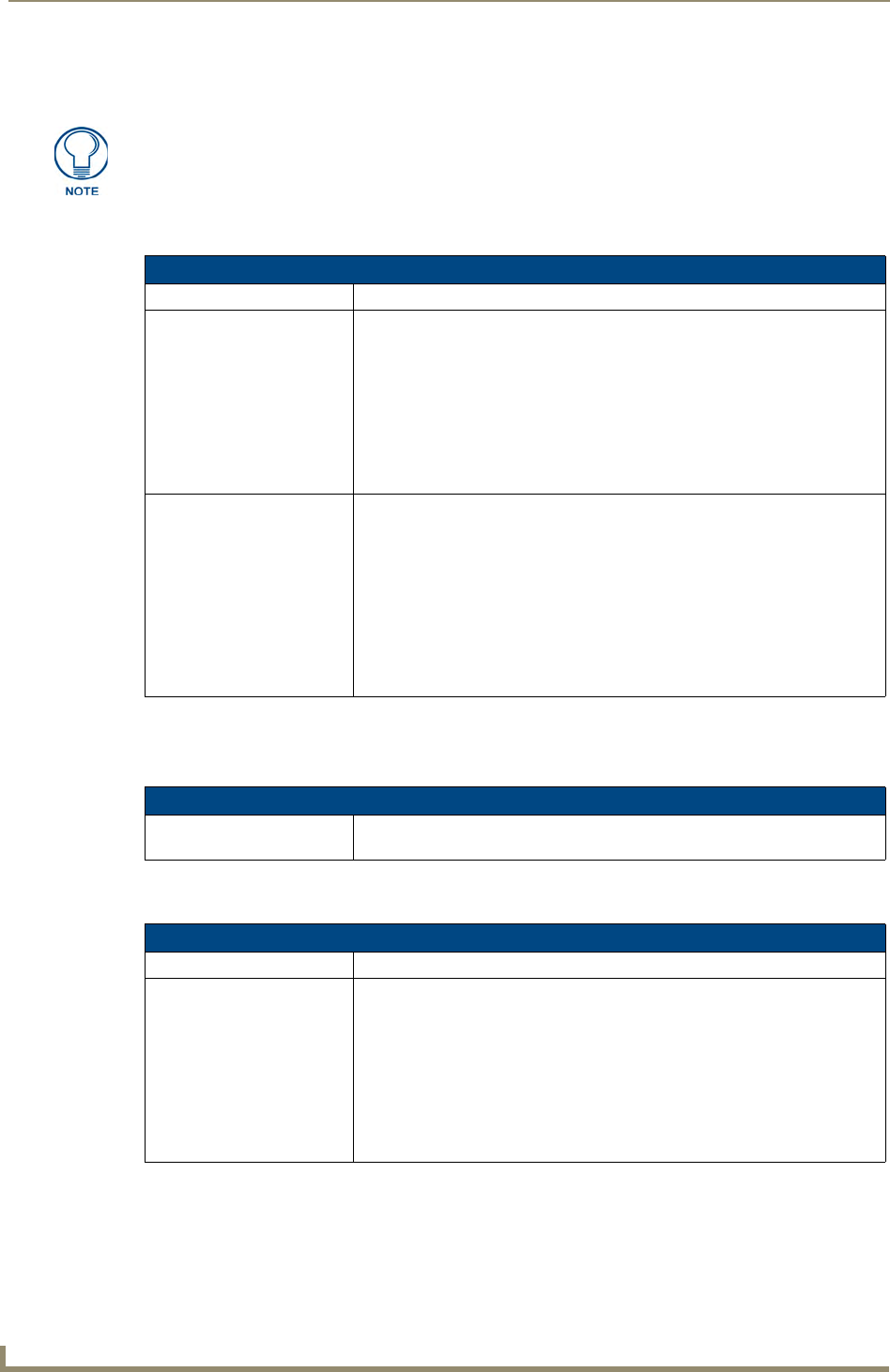
NetLinx Programming
80 NetLinx Integrated Controllers- WebConsole & Programming Guide
LED Disable/Enable Send_Commands
The following commands enable or disable the LEDs on the Integrated Controller. In the examples: <DEV> =
Port 1 of the device. Sending to port 1 of the NI-700 (affects all ports).
RS232/422/485 Ports Channels
RS232/422/485 ports are Ports 1-2 (NI-700) and Port 1 (NI-900).
RS-232/422/485 Send_Commands
The following sections only apply to the integrated controller component of the NIs.
LED Send_Commands
Command Description
LED-DIS
Disable all LEDs (on 32 LED
hardware) for a port.
Regardless of whether or not the port is active, the LED will not be lit. Issue this
command to port 1 to disable all the LEDs on the Controller. When activity
occurs on a port(s) or Controller, the LEDs will not illuminate.
Syntax:
SEND_COMMAND <DEV>,"'LED-DIS'"
Example:
SEND_COMMAND Port_1,"'LED-DIS'"
Disables all the LEDs on Port 1 of the Controller.
LED-EN
Enable the LED (on 32 LED
hardware) for a port
When the port is active, the LED is lit. When the port is not active, the LED is
not lit. Issue the command to port 1 to enable the LEDs on the Controller
(default setting). When activity occurs on a port(s) or Controller, the LEDs
illuminate.
Syntax:
SEND_COMMAND <DEV>,'LED-EN'
Example:
SEND_COMMAND System_1,'LED-EN'
Enables the System_1 Controller's LEDs.
RS232/422/485 Ports Channels
255 - CTS push channel Reflects the state of the CTS input if a 'CTSPSH' command was sent to the
port.
RS-232/422/485 Send_Commands
Command Description
B9MOFF
Set the port's communication
parameters for stop and data
bits according to the software
settings on the RS-232 port
(default).
Disables 9-bit in 232/422/455 mode. By default, this returns the communication
settings on the serial port to the last programmed parameters. This command
works in conjunction with the 'B9MON' command.
Syntax:
SEND_COMMAND <DEV>,"'B9MOFF'"
Example:
SEND_COMMAND RS232_1,"'B9MOFF'"
Sets the RS-232 port settings to match the port's configuration settings.

NetLinx Programming
81
NetLinx Integrated Controllers- WebConsole & Programming Guide
RS-232/422/485 Send_Commands (Cont.)
Command Description
B9MON
Override and set the current
communication settings and
parameters on the RS-232
serial port to 9 data bits with
one stop bit.
Enables 9-bit in 232/422/455 mode. This command works in conjunction with
the 'B9MOFF' command.
Syntax:
SEND_COMMAND <DEV>,"'B9MON'"
Example:
SEND_COMMAND RS232_1,"'B9MON'"
Resets the RS-232 port's communication parameters to nine data bits, one
stop bit, and locks-in the baud rate.
CHARD
Set the delay time between
all transmitted characters to
the value specified (in 100
Microsecond increments).
Syntax:
SEND_COMMAND <DEV>,"'CHARD-<time>'"
Variable:
time = 0 - 255. Measured in 100 microsecond increments.
Example:
SEND_COMMAND RS232_1,"'CHARD-10'"
Sets a 1-millisecond delay between all transmitted characters.
CHARDM
Set the delay time between
all transmitted characters to
the value specified (in 1-
Millisecond increments).
Syntax:
SEND_COMMAND <DEV>,"'CHARDM-<time>'"
Variable:
time = 0 - 255. Measured in 1 millisecond increments.
Example:
SEND_COMMAND RS232_1,"'CHARDM-10'"
Sets a 10-millisecond delay between all transmitted characters.
CTSPSH
Enable Pushes, Releases,
and Status information to be
reported via channel 255
using the CTS hardware
handshake input.
This command turns On (enables) channel tracking of the handshaking pins. If
Clear To Send (CTS) is set high, then channel 255 is On.
Syntax:
SEND_COMMAND <DEV>,"'CTSPSH'"
Example:
SEND_COMMAND RS232_1,"'CTSPSH'"
Sets the RS232_1 port to detect changes on the CTS input.
CTSPSH OFF
Disable Pushes, Releases,
and Status information to be
reported via channel 255.
This command disables tracking. Turns CTSPSH Off.
Syntax:
SEND_COMMAND <DEV>,"'CTSPSH OFF'"
Example:
SEND_COMMAND RS232_1,"'CTSPSH OFF'"
Turns off CTSPSH for the specified device.
GET BAUD
Get the RS-232/422/485
port’s current communication
parameters.
The port sends the parameters to the device that requested the information.
The port responds with:
<port #>,<baud>,<parity>,<data>,<stop> 485 <ENABLED | DISABLED>
Syntax:
SEND_COMMAND <DEV>,"'GET BAUD'"
Example:
SEND_COMMAND RS232_1,"'GET BAUD'"
System response example:
Device 1,38400,N,8,1 485 DISABLED

NetLinx Programming
82 NetLinx Integrated Controllers- WebConsole & Programming Guide
RS-232/422/485 Send_Commands (Cont.)
Command Description
HSOFF
Disable hardware handshak-
ing (default).
Syntax:
SEND_COMMAND <DEV>,"'HSOFF'"
Example:
SEND_COMMAND RS232_1,"'HSOFF'"
Disables hardware handshaking on the RS232_1 device.
HSON
Enable RTS (ready-to-send)
and CTS (clear-to-send)
hardware handshaking.
Syntax:
SEND_COMMAND <DEV>,"'HSON'"
Example:
SEND_COMMAND RS232_1,"'HSON'"
Enables hardware handshaking on the RS232_1 device.
RXCLR
Clear all characters in the
receive buffer waiting to be
sent to the Master.
Syntax:
SEND_COMMAND <DEV>,"'RXCLR'"
Example:
SEND_COMMAND RS232_1,"'RXCLR'"
Clears all characters in the RS232_1 device's receive buffer waiting to be sent
to the Master.
RXOFF
Disable the transmission of
incoming received charac-
ters to the Master (default).
Syntax:
SEND_COMMAND <DEV>,"'RXOFF'"
Example:
SEND_COMMAND RS232_1,"'RXOFF'"
Stops the RS232_1 device from transmitting received characters to the Master.
RXON
Start transmitting received
characters to the Master
(default).
Enables sending incoming received characters to the Master. This command is
automatically sent by the Master when a 'CREATE_BUFFER' program
instruction is executed.
Syntax:
SEND_COMMAND <DEV>,"'RXON'"
Example:
SEND_COMMAND RS232_1,"'RXON'"
Sets the RS232_1 device to transmit received characters to the Master.
SET BAUD
Set the RS-232/422/485
port's communication
parameters.
Syntax:
SEND_COMMAND <DEV>,"'SET BAUD
<baud>,<parity>,<data>,<stop> [485 <Enable | Disable>]'"
Variables:
baud = baud rates are: 115200, 76800, 57600, 38400, 19200, 9600, 4800,
2400, 1200, 600, 300, 150.
parity = N (none), O (odd), E (even), M (mark), S (space).
data = 8 data bits.
stop = 1 and 2 stop bits.
485 Disable = Disables RS-485 mode and enables RS-422.
485 Enable = Enables RS-485 mode and disables RS-422.
Note: The only valid 9 bit combination is (baud),N,9,1.
Example:
SEND_COMMAND RS232_1,"'SET BAUD 115200,N,8,1 485 ENABLE'"
Sets the RS232_1 port's communication parameters to 115,200 baud, no
parity, 8 data bits, 1 stop bit, and enables RS-485 mode.

NetLinx Programming
83
NetLinx Integrated Controllers- WebConsole & Programming Guide
RS-232/422/485 Send_Commands (Cont.)
Command Description
TSET BAUD
Temporarily set the RS-232/
422/485 port's
communication parameters
for a device.
TSET BAUD works the same as SET BAUD, except that the changes are not
permanent, and the previous values will be restored if the power is cycled on
the device.
Syntax:
SEND_COMMAND <DEV>,"'TSET BAUD
<baud>,<parity>,<data>,<stop> [485 <Enable | Disable>]'"
Variables:
baud = baud rates are: 115200, 57600, 38400, 19200, 9600, 4800, 2400,
1200, 600, 300.
parity = N (none), O (odd), E (even), M (mark), S (space).
data = 8 or 9 data bits.
stop = 1 or 2 stop bits.
485 Disable = Disables RS-485 mode and enables RS-422.
485 Enable = Enables RS-485 mode and disables RS-422.
Note: The only valid 9 bit combination is (baud),N,9,1.
Example:
SEND_COMMAND RS232_1,"'TSET BAUD 115200,N,8,1 485
ENABLE'"
Sets the RS232_1 port's communication parameters to 115,200 baud, no
parity, 8 data bits, 1 stop bit, and enables RS-485 mode.
TXCLR
Stop and clear all characters
waiting in the transmit out
buffer and stops transmis-
sion.
Syntax:
SEND_COMMAND <DEV>,"'TXCLR'"
Example:
SEND_COMMAND RS232_1,"'TXCLR'"
Clears and stops all characters waiting in the RS232_1 device's transmit buffer.
XOFF
Disable software
handshaking (default).
Syntax:
SEND_COMMAND <DEV>,"'XOFF'"
Example:
SEND_COMMAND RS232_1,"'XOFF'"
Disables software handshaking on the RS232_1 device.
XON
Enable software
handshaking.
Syntax:
SEND_COMMAND <DEV>,"'XON'"
Example:
SEND_COMMAND RS232_1,"'XON'"
Enables software handshaking on the RS232_1 device.

NetLinx Programming
84 NetLinx Integrated Controllers- WebConsole & Programming Guide
RS-232/422/485 Send_String Escape Sequences
This device also has some special SEND_STRING escape sequences:
If any of the 3 character combinations below are found anywhere within a SEND_STRING program
instruction, they will be treated as a command and not the literal characters.
In these examples: <DEV> = device.
RS-232/422/485 Send_String Escape Sequences
Command Description
27,17,<time>
Send a break character for a
specified duration to a
specific device.
Syntax:
SEND_STRING <DEV>,"27,17,<time>"
Variable:
time = 1 - 255. Measured in 100 microsecond increments.
Example:
SEND_STRING RS232_1,"27,17,10"
Sends a break character of 1 millisecond to the RS232_1 device.
27,18,0
Clear the ninth data bit by
setting it to 0 on all character
transmissions.
Used in conjunction with the 'B9MON' command.
Syntax:
SEND_STRING <DEV>,"27,18,0"
Example:
SEND_STRING RS232_1,"27,18,0"
Sets the RS232_1 device's ninth data bit to 0 on all character transmissions.
27,18,1
Set the ninth data bit to 1 for
all subsequent characters to
be transmitted.
Used in conjunction with the 'B9MON' command.
Syntax:
SEND_STRING <DEV>,"27,18,1"
Example:
SEND_STRING RS232_1,"27,18,1"
Sets the RS232_1 device's ninth data bit to 1 on all character transmissions.
27,19,<time>
Insert a time delay before
transmitting the next
character.
Syntax:
SEND_STRING <DEV>,"27,19,<time>"
Variable:
time = 1 - 255. Measured in 1 millisecond increments.
Example:
SEND_STRING RS232_1,"27,19,10"
Inserts a 10 millisecond delay before transmitting characters to the RS232_1
device.
27,20,0
Set the RTS hardware
handshake's output to high
(> 3V).
Syntax:
SEND_STRING <DEV>,"27,20,0"
Example:
SEND_STRING RS232_1,"27,20,0"
Sets the RTS hardware handshake's output to high on the RS232_1 device.
27,20,1
Set the RTS hardware
handshake's output to
low/inactive (< 3V).
Syntax:
SEND_STRING <DEV>,"27,20,1"
Example:
SEND_STRING RS232_1,"27,20,1"
Sets the RTS hardware handshake's output to low on the RS232_1 device.
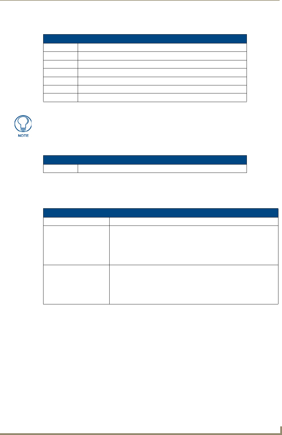
NetLinx Programming
85
NetLinx Integrated Controllers- WebConsole & Programming Guide
IR / Serial Ports Channels
IR RX Port Channels
IR/Serial Send_Commands
The following IR and IR/Serial Send_Commands generate control signals for external equipment. In these
examples: <DEV> = device.
IR / Serial Ports Channels
CHANNELS: Description
00001 - 00229 IR commands.
00229 - 00253 May be used for system call feedback.
00254 Power Fail. (Used w/ 'PON' and 'POF' commands).
00255 Power status. (Shadows I/O Link channel status).
00256 - 65000 IR commands.
65000 - 65534 Future use.
The NI series of NetLinx Masters support Serial control via the IR/RX port when using
firmware version 300 or greater.
IR / Serial Ports Channels
00001 - 00255 PUSH and RELEASE channels for the received IR code.
IR/Serial Send_Commands
Command Description
CAROFF
Disable the IR carrier signal
until a 'CARON' command is
received.
Syntax:
SEND_COMMAND <DEV>,"'CAROFF'"
Example:
SEND_COMMAND IR_1,"'CAROFF'"
Stops transmitting IR carrier signals to the IR_1 port.
CARON
Enable the IR carrier signals
(default).
Syntax:
SEND_COMMAND <DEV>,"'CARON'"
Example:
SEND_COMMAND IR_1,"'CARON'"
Starts transmitting IR carrier signals to the IR_1 port.

NetLinx Programming
86 NetLinx Integrated Controllers- WebConsole & Programming Guide
IR/Serial Send_Commands (Cont.)
Command Description
CH
Send IR pulses for the
selected channel.
All channels below 100 are transmitted as two digits. If the IR code for ENTER
(function #21) is loaded, an Enter will follow the number. If the channel is
greater than or equal to (>=) 100, then IR function 127 or 20 (whichever exists)
is generated for the one hundred digit. Uses 'CTON' and 'CTOF' times for pulse
times.
Syntax:
SEND_COMMAND <DEV>,"'CH',<channel number>"
Variable:
channel number = 0 - 199.
Example:
SEND_COMMAND IR_1,"'CH',18"
This device performs the following:
• Transmits IR signals for 1 (IR code 11). The transmit time is set with the
CTON command.
• Waits until the time set with the CTOF command elapses.
• Transmits IR signals for 8 (IR code 18).
• Waits for the time set with the CTOF command elapses. If the IR code for
Enter (IR code 21) is programmed, the Controller performs the following
steps.
• Transmits IR signals for Enter (IR code 21).
• Waits for the time set with the CTOF command elapses.
CP
Halt and Clear all active or
buffered IR commands, and
then send a single IR pulse.
You can set the Pulse and Wait times with the 'CTON' and 'CTOF' commands.
Syntax:
SEND_COMMAND <DEV>,"'CP',<code>"
Variable:
code = IR port's channel value 0 - 252 (253 - 255 reserved).
Example:
SEND_COMMAND IR_1,"'CP',2"
Clears the active/buffered commands and pulses IR_1 port's channel 2.
CTOF
Set the duration of the Off
time (no signal) between IR
pulses for channel and IR
function transmissions.
Off time settings are stored in non-volatile memory. This command sets the
delay time between pulses generated by the 'CH' or 'XCH' send commands in
tenths of seconds.
Syntax:
SEND_COMMAND <DEV>,"'CTOF',<time>"
Variable:
time = 0 - 255. Given in 1/10ths of a second. Default is 5 (0.5 seconds).
Example:
SEND_COMMAND IR_1,"'CTOF',10"
Sets the off time between each IR pulse to 1 second.
CTON
Set the total time of IR pulses
transmitted and is stored in
non-volatile memory.
This command sets the pulse length for each pulse generated by the 'CH' or
'XCH' send commands in tenths of seconds.
Syntax:
SEND_COMMAND <DEV>,"'CTON',<time>"
Variable:
time = 0 - 255. Given in 1/10ths of a second. Default is 5 (0.5 seconds).
Example:
SEND_COMMAND IR_1,"'CTON',20"
Sets the IR pulse duration to 2 seconds.

NetLinx Programming
87
NetLinx Integrated Controllers- WebConsole & Programming Guide
IR/Serial Send_Commands (Cont.)
Command Description
GET BAUD
Get the IR port’s current
DATA mode communication
parameters.
The port sends the parameters to the device that requested the information.
Only valid if the port is in Data Mode (see SET MODE command).
The port responds with:
<port #> <baud>,<parity>,<data bits>,<stop bits>
Syntax:
SEND_COMMAND <DEV>,"'GET BAUD'"
Example:
SEND_COMMAND IR_1,"'GET BAUD'"
System response example:
PORT 9 IR,CARRIER,IO LINK 0
GET MODE
Poll the IR/Serial port's
configuration parameters and
report the active mode
settings to the device
requesting the information.
The port responds with: <port #> <mode>,<carrier>,<io link channel>.
Syntax:
SEND_COMMAND <DEV>,"'GET MODE'"
Example:
SEND_COMMAND IR_1,"'GET MODE"
The system could respond with:
PORT 4 IR,CARRIER,IO LINK 0
IROFF
Halt and Clear all active or
buffered IR commands being
output on the designated
port.
Syntax:
SEND_COMMAND <DEV>,"'IROFF'"
Example:
SEND_COMMAND IR_1,"'IROFF"
Immediately halts and clears all IR output signals on the IR_1 port.
POD
Disable previously active
'PON' (power on) or 'POF'
(power off) command
settings.
Channel 255 changes are enabled. This command is used in conjunction with
the I/O Link command.
Syntax:
SEND_COMMAND <DEV>,"'POD'"
Example:
SEND_COMMAND IR_1,"'POD"
Disables the 'PON' and 'POF' command settings on the IR_1 device.
POF
Turn Off a device connected
to an IR port based on the
status of the corresponding
I/O Link input.
If at any time the IR sensor input reads that the device is ON (such as if
someone turned it on manually at the front panel), IR function 28 (if available)
or IR function 9 is automatically generated in an attempt to turn the device back
OFF. If three attempts fail, the IR port will continue executing commands in the
buffer.
If there are no commands in the buffer, the IR port will continue executing
commands in the buffer and trying to turn the device OFF until a 'PON' or 'POD'
command is received. If the IR port fails to turn the device OFF, a PUSH and
RELEASE is made on channel 254 to indicate a power failure error. You can
only use the 'PON' and 'POF' commands when an IR device has a linked
I/O channel. Channel 255 changes are disabled after receipt of this command.
You can only use the 'PON' and 'POF' commands when an IR device has a
linked I/O channel.
Syntax:
SEND_COMMAND <DEV>,"'POF'"
Example:
SEND_COMMAND IR_1,"'POF'"
Sends power down IR commands 28 (if present) or 9 to the IR_1 device.

NetLinx Programming
88 NetLinx Integrated Controllers- WebConsole & Programming Guide
IR/Serial Send_Commands (Cont.)
Command Description
PON
Turn On a device connected
to an IR port based on the
status of the corresponding
I/O Link input.
If at any time the IR sensor input reads that the device is OFF (such as if one
turned it off manually at the front panel), IR function 27 (if available) or IR
function 9 is automatically generated in an attempt to turn the device back ON.
If three attempts fail, the IR port will continue executing commands in the buffer
and trying to turn the device On.
If there are no commands in the buffer, the IR port will continue trying to turn
the device ON until a 'POF' or 'POD' command is received. If the IR port fails to
turn the device ON, a PUSH and RELEASE is made on channel 254 to indicate
a power failure error.
You can only use the 'PON' and 'POF' commands when an IR device has a
linked I/O channel. Channel 255 changes are disabled after receipt of this
command.
Syntax:
SEND_COMMAND <DEV>,"'PON'"
Example:
SEND_COMMAND IR_1,"'PON'"
Sends power up IR commands 27 or 9 to the IR_1 port.
PTOF
Set the time duration
between power pulses in
.10-second increments.
This time increment is stored in permanent memory. This command also sets
the delay between pulses generated by the 'PON' or 'POF' send commands in
tenths of seconds. It also sets the delay required after a power ON command
before a new IR function can be generated. This gives the device time to power
up and get ready for future IR commands.
Syntax:
SEND_COMMAND <DEV>,"'PTOF',<time>"
Variable:
time = 0 - 255. Given in 1/10ths of a second. Default is 15 (1.5 seconds).
Example:
SEND_COMMAND IR_1,"'PTOF',15"
Sets the time between power pulses to 1.5 seconds for the IR_1 device.
PTON
Set the time duration of the
power pulses in
.10-second increments
This time increment is stored in permanent memory. This command also sets
the pulse length for each pulse generated by the 'PON' or 'POF' send
commands in tenths of seconds.
Syntax:
SEND_COMMAND <DEV>,"'PTON',<time>"
Variable:
time = 0 - 255. Given in 1/10ths of a second. Default is 5 (0.5 seconds).
Example:
SEND_COMMAND IR_1,"'PTON',15"
Sets the duration of the power pulse to 1.5 seconds for the IR_1 device.

NetLinx Programming
89
NetLinx Integrated Controllers- WebConsole & Programming Guide
IR/Serial Send_Commands (Cont.)
Command Description
SET BAUD
Set the IR port's DATA mode
communication parameters.
Only valid if the port is in Data Mode (see SET MODE command).
Syntax:
SEND_COMMAND <DEV>,"'SET BAUD
<baud>,<parity>,<data>,<stop>'"
Variables:
baud = baud rates are: 19200, 9600, 4800, 2400, and 1200.
parity = N (none), O (odd), E (even), M (mark), S (space).
data = 7 or 8 data bits.
stop = 1 and 2 stop bits.
Example:
SEND_COMMAND IR_1,"'SET BAUD 9600,N,8,1'"
Sets the IR_1 port's communication parameters to 9600 baud, no parity, 8 data
bits, and 1 stop bit.
Note: The maximum baud rate for ports using SERIAL mode is 192000. Also,
SERIAL mode works best when using a short cable length (< 10 feet).
SET IO LINK
Link an IR or Serial port to a
selected I/O channel for use
with the 'DE', 'POD', 'PON',
and 'POF' commands.
The I/O status is automatically reported on channel 255 on the IR port. The I/O
channel is used for power sensing (via a PCS or VSS). A channel of zero
disables the I/O link.
Syntax:
SEND_COMMAND <DEV>,"'SET IO LINK <I/O number>'"
Variable:
I/O number = 1 - 8. Setting the I/O channel to 0 disables the I/O link.
Example:
SEND_COMMAND IR_1,"'SET IO LINK 1'"
Sets the IR_1 port link to I/O channel 1. The IR port uses the specified I/O input
as power status for processing 'PON' and 'POF' commands.
SET MODE
Set the IR/Serial ports for IR
or Serial-controlled devices.
Sets an IR port to either IR, Serial, or Data mode.
Syntax:
SEND_COMMAND <DEV>, 'SET MODE <mode>'"
Variable:
mode = IR, SERIAL, or DATA.
Example:
SEND_COMMAND IR_1,"'SET MODE IR'"
Sets the IR_1 port to IR mode for IR control.
Note: The maximum baud rate for ports using SERIAL mode is 192000. Also,
SERIAL mode works best when using a short cable length (< 10 feet).
SP
Generate a single IR pulse.
Use the 'CTON' to set pulse lengths and the 'CTOF' for time Off between
pulses.
Syntax:
SEND_COMMAND <DEV>,"'SP',<code>"
Variable:
code = IR code value 1 - 252 (253-255 reserved).
Example:
SEND_COMMAND IR_1, "'SP',25"
Pulses IR code 25 on IR_1 device.

NetLinx Programming
90 NetLinx Integrated Controllers- WebConsole & Programming Guide
IR/Serial Send_Commands (Cont.)
Command Description
XCH
Transmit the selected
channel IR codes in the
format/pattern set by the
'XCHM' send command.
Syntax:
SEND_COMMAND <DEV>,"'XCH <channel>'"
Variable:
channel = 0 - 9999.
Example:
For detailed usage examples, refer to the 'XCHM' command.
NOTE: This command supports 4-digit channels.
XCHM
Changes the IR output pat-
tern for the 'XCH' send
command.
Syntax:
SEND_COMMAND <DEV>,"'XCHM <extended channel mode>'"
Variable:
extended channel mode = 0 - 4.
Example:
SEND_COMMAND IR_1,"'XCHM 3'"
Sets the IR_1 device's extended channel command to mode 3.
Mode 0 Example (default): [x][x]<x><enter>
SEND_COMMAND IR_1,"'XCH 3'"
Transmits the IR code as 3-enter.
SEND_COMMAND IR_1,"'XCH 34'"
Transmits the IR code as 3-4-enter.
SEND_COMMAND IR_1,"'XCH 343'"
Transmits the IR code as 3-4-3-enter.
Mode 1 Example: <x> <x> <x> <enter>
SEND_COMMAND IR_1,"'XCH 3'"
Transmits the IR code as 0-0-3-enter.
SEND_COMMAND IR_1,"'XCH 34'"
Transmits the IR code as 0-3-4-enter.
SEND_COMMAND IR_1,"'XCH 343'"
Transmits the IR code as 3-4-3-enter.
Mode 2 Example: <x> <x> <x>
SEND_COMMAND IR_1,"'XCH 3'"
Transmits the IR code as 0-0-3.
SEND_COMMAND IR_1,"'XCH 34'"
Transmits the IR code as 0-3-4.
SEND_COMMAND IR_1,"'XCH 343'"
Transmits the IR code as 3-4-3.
Mode 3 Example: [[100][100]…] <x> <x>
SEND_COMMAND IR_1,"'XCH 3'"
Transmits the IR code as 0-3.
SEND_COMMAND IR_1,"'XCH 34'"
Transmits the IR code as 3-4.
SEND_COMMAND IR_1,"'XCH 343'"
Transmits the IR code as 100-100-100-4-3.
Mode 4:
Mode 4 sends the same sequences as the 'CH' command. Only use Mode 4
with channels 0 - 199.

NetLinx Programming
91
NetLinx Integrated Controllers- WebConsole & Programming Guide
Input/Output Send_Commands
The following Send_Commands program the I/O ports on the Integrated Controller.
I/O ports: Port 4 (NI-700).
Channels: 1 - 8 I/O channels.
I/O Send Commands
Command Description
GET INPUT
Get the active state for the
selected channels.
An active state can be high (logic high) or low (logic low or contact closure).
Channel changes, Pushes, and Releases generate reports based on their
active state. The port responds with either 'HIGH' or 'LOW'.
Syntax:
SEND_COMMAND <DEV>,"'GET INPUT <channel>'"
Variable:
channel = Input channel 1 - 8.
Example:
SEND_COMMAND IO,"'GET INPUT 1'"
Gets the I/O port's active state.
The system could respond with:
INPUT1 ACTIVE HIGH
SET INPUT
Set the input channel's active
state.
An active state can be high (logic high) or low (logic low or contact closure).
Channel changes, Pushes, and Releases generate reports based on their
active state. Setting an input to ACTIVE HIGH will disable the ability to use that
channel as an output.
Syntax:
SEND_COMMAND <DEV>,"'SET INPUT <channel> <state>'"
Variable:
channel = Input channel 1 - 8.
state = Active state HIGH or LOW (default).
Example:
SEND_COMMAND IO,"'SET INPUT 1 HIGH'"
Sets the I/O channel to detect a high state change, and disables output on the
channel.

NetLinx Programming
92 NetLinx Integrated Controllers- WebConsole & Programming Guide

Terminal (Program Port/Telnet) Commands
93
NetLinx Integrated Controllers- WebConsole & Programming Guide
Terminal (Program Port/Telnet) Commands
Overview
There are two types of terminal communications available on NetLinx Integrated Controllers:
Program Port - The "Program" port is a RS232 port located on the rear panel of the Master that
allows terminal communication with the Master. This type of terminal communication requires that
you are physically connected to the Master to access the configuration options and commands
supported. Since this method of terminal communication requires physical proximity as well as a
physical connection to the Master, it is the most secure form of terminal communication.
For this reason, all Security Configuration options are only available via the Program port (and
cannot be accessed via Telnet).
Teln et - This type of terminal communication can be accessed remotely, via TCP/IP. It is a less
secure form of terminal communication, since it does not require a physical connection to the
Master to connect. Further, the Telnet interface exposes information to the network (which could be
intercepted by an unauthorized network client).
Refer to the Terminal Commands section on page 95 for a listing of all commands available in a terminal
session.
Note that all commands in the table are available for both Program Port and Telnet sessions, with two
exceptions: "Help Security" and "Resetadminpassword". These commands are only available via a Program
Port connection.
Establishing a Terminal Connection Via the Program Port
To establish a terminal session via the Program Port, the PC COM (RS232) port on your PC must be physically
connected to the Program port on the NetLinx Master.
You will also need to know the current baud rate setting for the Master, so that you can verify that it matches
the settings on your PC.
1. In Windows, go to Start > Programs > Accessories > Communications to launch the HyperTerminal
application to open the Connection Description dialog.
2. Enter any text into the Name field and click OK. This action invokes the Connect to dialog.
3. Click the down-arrow From the Connect Using field, and select the PC COM port being used for
communication by the target Master and click OK when done.
4. From the Bits per second field, click the down-arrow and select the baud rate being used by the target
Master.
5. Configure the remaining communication parameters as follows:
6. Click OK to complete the communication parameters and open a new Terminal window.
It is recommended that you make initial configurations as well as subsequent
changes via the WebConsole. Refer to the Onboard WebConsole User
Interface section on page 21.
• Data Bits: 8
• Parity: None
• Stop bits: 1
• Flow control: None
Terminal (Program Port/Telnet) Commands
94 NetLinx Integrated Controllers- WebConsole & Programming Guide
7. Type echo on to view the characters while entering commands. If that does not work, press <Enter> key
on your keyboard.
PC COM Port Communication Settings
Be sure that your PC's COM port and terminal program's communication settings match those in the table
below:
NetLinx Integrated Controllers - Port Assignments
Each of the NetLinx Integrated Controllers has specific port assignments:
Establishing a Terminal Connection Via Telnet
1. In your Windows taskbar, go to Start > Run to open the Run dialog.
2. Type cmd in the Open field and click OK to open an instance of the Windows command interpreter
(Cmd.exe).
3. In the CMD (command), type "telnet" followed by a space and the Master’s IP Address info.
Example: >telnet XXX.XXX.XXX.XXX
4. Press Enter.
Unless Telnet security is enabled, a session will begin with a welcome banner:
Welcome to NetLinx vX.XX.XXX Copyright AMX Corp. 1999-2006
>
If Telnet security is enabled, type in the word login to be prompted for a Username and Password
before gaining access to the Master.
5. Enter your username to be prompted for a password.
If the password is correct you will see the welcome banner.
If the password is incorrect, the following will be displayed:
Login: User1
Password: *****
Login not authorized. Please try again.
After a delay, another login prompt will be displayed to allow you to try again.
It is very important to execute the 'logout' command prior to disconnecting from a
Master. Simply removing the RS-232 connector from the Program Port maintains
your logged-in status until you either return to logout via a new session or reboot the
target Master.
PC COM Port Communication Settings
• Baud: 38400 (default)
• Parity: None
• Data Bits: 8
•Stop Bits: 1
• Flow Control: None
NI-700 Port Assignments NI-900 Port Assignments
Port ICSP Port # Port ICSP Port #
• Serial Port #1 1 • Serial Port #1 1
• Serial Port #2 2 • IR/Serial Port #1 2
• IR/Serial Port 3 • IR/Serial Port #2 3
• I/O Port 4 • IR/Serial Port #3 4
• IR RX Port 5 • I/O Port 5
• IR RX Port 6

Terminal (Program Port/Telnet) Commands
95
NetLinx Integrated Controllers- WebConsole & Programming Guide
If after 5 prompts, the login information is not entered correctly, the following message will be
displayed and the connection closed:
Login not allowed. Goodbye!
To restrict access to the Master via terminal connection, enable Configuration Security on the
Master via the CONFIGURATION SECURITY option in the Security Options menu - see the
Security Options Menu section on page 115 for details). With Configuration Security enabled, a
valid user with Configuration Security access will have to login before being able to execute Telnet
commands. If security is not enabled, these commands are available to all.
If a connection is opened, but a valid a username / password combination is not entered (i.e. just
sitting at a login prompt), the connection will be closed after one minute.
Terminal Commands
The Terminal commands listed in the following table can be sent directly to the Master via either a Program
Port or a Telnet terminal session (with the exception of the "Help Security" and "Resetadminpassword"
commands, which are only available to a Program Port (RS232) connection.
In your terminal program, type "Help" or a question mark ("?") and <Enter> to access the Help Menu, and
display the Program port commands described below:
Terminal Commands
Command Description
----- Help ----- <D:P:S> (Extended diag messages are OFF)
<D:P:S>: Device:Port:System. If omitted, assumes Master.
? or Help Displays this list of commands.
CLEAR AUDIT LOG Purges the entire database of audit records.
See the SHOW AUDIT LOG section on page 107.
CPU USAGE Diagnostic tool to calculate a running average of the current CPU
usage of the Master.
DATE Displays the current date and day of the week.
Example:
>DATE
10/31/2004 Wed
DEVICE HOLDOFF ON|OFF Sets the Master to holdoff devices (i.e. does not allow them to report
ONLINE) until all objects in the NetLinx program have completed
executing the DEFINE_START section.
If set to ON, any messages to devices in DEFINE_START will be lost,
however, this prevents incoming messages being lost in the Master
upon startup.
When DEVICE_HOLDOFF is ON, you must use ONLINE events to trig-
ger device startup SEND_COMMANDs.
By default, DEVICE HOLDOFF is OFF to maintain compatibility with
Axcess systems where devices are initialized in DEFINE_START.
Note: This command sets the state of the device holdoff. The
GET DEVICE HOLDOFF command reveals whether the state is On or
Off.
Example:
>Device Holdoff ON
Device Holdoff Set.
DEVICE STATUS <D:P:S> Displays a list of all active (on) channels for the specified D:P:S.
If you enter DEVICE STATUS without the D:P:S variable, the Master
displays ports, channels, and version information.
DIPSWITCH Displays the current state of the Master controller's hardware dip-
switches.
DISK FREE Displays the total bytes of free space available on the Master.
Example:
>DISK FREE
The disk has 2441216 bytes of free space.

Terminal (Program Port/Telnet) Commands
96 NetLinx Integrated Controllers- WebConsole & Programming Guide
Terminal Commands (Cont.)
Command Description
DNS LIST <D:P:S> Displays the DNS configuration of a specific device including:
• Domain suffix·
• Configured DNS IP Information
Example:
>DNS LIST [0:1:0]
Domain suffix:amx.com
The following DNS IPs are configured
Entry 1-192.168.20.5
Entry 2-12.18.110.8
Entry 3-12.18.110.7
ECHO ON|OFF Enables/Disables echo (display) of typed characters.
GET DEVICE HOLDOFF Displays the state of the Master’s device holdoff setting.
Note: This command reveals the state of the device holdoff set using
the DEVICE HOLDOFF ON|OFF command.
Example:
>GET DEVICE HOLDOFF
Device Holdoff is off.
GET DUET MEMORY Display the amount of memory allocated for Duet Java pool. This is
the current Java memory heap size as measured in Megabytes. An
example is a value of 5 = 5 MB.
GET ETHERNET MODE Displays the current LAN configuration setting.
Settings are either "auto" in which the LAN driver will discover it's
settings based on the network it is connected to OR <speed> and
<duplex> where speed is either 10 or 100 and duplex is either full or
half.
Example:
>GET ETHERNET MODE
Ethernet mode is auto.
Note: See SET ETHERNET MODE.
GET IP <D:P:S> Displays the IP configuration of a device.
If you enter GET IP without the D:P:S variable, the Master displays it’s
D:P:S, Host Name, Type (DHCP or Static), IP Address, Subnet Mask,
Gateway IP, and MAC Address.
Example:
>GET IP [0:1:50]
IP Settings for 0:1:50
HostName MLK_INSTRUCTOR
Type DHCP
IP Address 192.168.21.101
Subnet Mask 255.255.255.0
Gateway IP 192.168.21.2
MAC Address 00:60:9f:90:0d:39
HELP SECURITY Displays security related commands.
Note: This command is only available to Program Port terminal ses-
sions. It is not available to Telnet sessions (see the Overview section
on page 93).
Example:
>HELP SECURITY
>logout Logout and close secure session
>setup security Access the security setup menus

Terminal (Program Port/Telnet) Commands
97
NetLinx Integrated Controllers- WebConsole & Programming Guide
Terminal Commands (Cont.)
Command Description
ICSPMON ENABLED|DISABLED
[PORT]
Enables or disables ICSP monitoring out the specified IP port.
By enabling icspmon on an IP port, an external application could con-
nect to that port and "listen" on the ICSP traffic.
IP STATUS Provides information about the current NetLinx IP Connections.
Example:
>IP STATUS
NetLinx IP Connections
No active IP connections
IPSEC ON|OFF|STATUS Enables/Disables IPSec security or displays current setting.
MEM Displays the largest free block of the Master’s memory.
Example:
>MEM
The largest free block of memory is 11442776 bytes.
MSG ON|OFF Enables/Disables extended diagnostic messages.
• MSG On sets the terminal program to display all messages
generated by the Master.
• MSG OFF disables the display.
Example:
> MSG ON
Extended diagnostic information messages turned on.
> MSG OFF
Extended diagnostic information messages turned off.
MSG STATS Calculates incoming and outgoing messages over a time interval.
OFF [D:P:S or NAME,CHAN] Turns off a specified channel on a device. The device can be on any
system that the Master you are connected to is able to reach.
You can specify the device number, port, and system, or the name of
the device that is defined in the DEFINE_DEVICE section of the pro-
gram.
Syntax:
OFF[name,channel]
-or-
OFF[D:P:S,channel]
Example:
>OFF[5001:7:4]
Sending Off[5001:7:4]
ON [D:P:S or NAME,CHAN] Turns on a specified channel on a device. The device can be on any
system that the Master you are connected to is able to reach.
You can specify the device number, port, and system, or the name of
the device that is defined in the DEFINE_DEVICE section of the pro-
gram.
Syntax:
ON[name,channel]
-or-
ON[D:P:S,channel]
Example:
>ON[5001:7:4]
Sending On[5001:7:4]

Terminal (Program Port/Telnet) Commands
98 NetLinx Integrated Controllers- WebConsole & Programming Guide
Terminal Commands (Cont.)
Command Description
PASS [D:P:S or NAME] Sets up a pass through mode to a device. In pass through mode, any
string received by the device is displayed on the screen, and anything
typed is sent as a string to the device.
The device can be on any system that the Master you are connected
to is able to reach.
You can specify the device number, port, and system, or the name of
the device that is defined in the DEFINE_DEVICE section of the pro-
gram.
• Mode is exited by ++ ESC ESC.
• Display Format is set by ++ ESC n
Where n =
A, format = ASCII
D, format = Decimal
H = Hex
Note: Refer to the ESC Pass Codes section on page 112 for detailed
descriptions of the supported pass codes.
Example:
>pass[5001:7:4]
Entering pass mode.
PHYSICAL STATUS Retrieve the current LED states.
PING [ADDRESS] Pings an address (IP or URL), to test network connectivity to and con-
firms the presence of another networked device. The syntax is just like
the PING application in Windows or Linux.
Example:
>ping 192.168.29.209
192.168.29.209 is alive.
PROGRAM INFO Displays a list of program files and modules residing on the Master.
Example:
>PROGRAM INFO
-- Program Name Info
-- Module Count = 1
1 Name is i!-PCLinkPowerPointTest
-- File Names = 2
1 = C:\Program Files\AMX Applications\i!-
PCLinkPowerPoint
2 = C:\Program Files\Common
Files\AMXShare\AXIs\NetLinx.axi
2 = Name is MDLPP
-- File Names = 2
1 C:\AppDev\i!-PCLink-PowerPoint\i!-
PCLinkPowerPointMod.axs
2 C:\Program files\Common
Files\AMXShare\AXIs\NetLinx.axi
PULSE [D:P:S or NAME,CHAN] Pulses a specified channel on a device on and off. The device can be
on any system the Master you are connected to can reach.
You can specify the device number, port, and system; or the name of
the device that is defined in the DEFINE_DEVICE section of the pro-
gram.
Example:
>PULSE[50001:8:50,1]
Sending Pulse[50001:8:50,1]

Terminal (Program Port/Telnet) Commands
99
NetLinx Integrated Controllers- WebConsole & Programming Guide
Terminal Commands (Cont.)
Command Description
PWD Displays the name of the current directory.
Example:
pwd
The current directory is doc:
REBOOT <D:P:S> Reboots the Master or specified device.
Example:
>REBOOT [0:1:0]
Rebooting...
RENEW DHCP Renews/Releases the current DHCP lease for the Master.
Note: The Master must be rebooted to acquire a new DHCP lease.
Example:
>RENEW DHCP
RESETADMINPASSWORD This command resets the administrator password back to "password".
Note: This command is only available to Program Port terminal ses-
sions. It is not available to Telnet sessions (see the Overview section
on page 93).
RESET FACTORY Resets the Master to factory default state including removal of all
security settings, removal of all user files, resetting to DHCP, and load-
ing an empty NetLinx program. The Master will be effectively in an out-
of-box state.
ROUTE MODE DIRECT|NORMAL Sets the Master-to-Master route mode:
• Normal mode - allows a Master to communicate with any Master
accessible via the routing tables (shown with the SHOW ROUTE
command).
This includes a directly-connected Master (route metric =1) and
indirectly connected Masters (route metric greater than 1, but less
than 16).
• Direct mode - allows communication only with Masters that are
directly connected (route metric = 1). Indirectly connected Masters
cannot be communicated within this mode.
Examples:
>ROUTE MODE DIRECT
Route Mode "Direct" Set
>ROUTE MODE NORMAL
Route Mode "Normal" Set
SEND_COMMAND D:P:S or
NAME,COMMAND
Sends a specified command to a device. The device can be on any
system that the Master you are connected to can reach.
You can specify the device number, port, and system; or the name of
the device that is defined in the DEFINE_DEVICE section of the
NetLinx Program.
The data of the string is entered with the following NetLinx string syn-
tax:
SEND_COMMAND 1:1:1,"'This is a test',13,10"
SEND_COMMAND RS232_1,"'This is a test',13,10"
SEND_LEVEL <D:P:S>,
<LEVEL ID>,<LEVEL VALUE>
Allows the user to set a level on a device via the Master's Telnet/
program port interface.
SEND_STRING D:P:S or
NAME,STRING
Sends a string to a specified device. The device can be on any system
that the Master you are connected to can reach.
You can specify the device number, port, and system; or the name of
the device defined in the DEFINE_DEVICE section of the NetLinx
Program.
The data of the string is entered with NetLinx string syntax.

Terminal (Program Port/Telnet) Commands
100 NetLinx Integrated Controllers- WebConsole & Programming Guide
Terminal Commands (Cont.)
Command Description
SET DATE Prompts you to enter the new date for the Master.
When the date is set on the Master, the new date will be reflected on
all devices in the system that have clocks (i.e. touch panels). By the
same token, if you set the date on any system device, the new date
will be reflected on the system’s Master, and on all connected devices.
Note: This command will not update clocks on devices connected to
another Master (in Master-to-Master systems).
Example:
>SET DATE
Enter Date: (mm/dd//yyyy) ->
SET DNS <D:P:S> Sets up the DNS configuration of a device.
This command prompts you to enter a Domain Name, DNS IP #1,
DNS IP #2, and DNS IP #3.
Then, enter Y (yes) to approve/store the information in the Master.
Entering N (no) cancels the operation.
Note: The device must be rebooted to enable new settings.
Example:
>SET DNS [0:1:0]
-- Enter New Values or just hit Enter to keep current
settings --
Enter Domain Suffix: amx.com
Enter DNS Entry 1 : 192.168.20.5
Enter DNS Entry 2 : 12.18.110.8
Enter DNS Entry 3 : 12.18.110.7
You have entered: Domain Name: amx.com
DNS Entry 1: 192.168.20.5
DNS Entry 2: 12.18.110.8
DNS Entry 3: 12.18.110.7
Is this correct? Type Y or N and Enter -> Y
Settings written. Device must be rebooted to
enable new settings
SET DUET MEMORY Set the amount of memory allocated for Duet Java pool. This is the
current Java memory heap size as measured in Megabytes. This
feature is used so that if a NetLinx program requires a certain size of
memory be allotted for its currently used Duet Modules, it can be
reserved on the target Master.
Valid values are:
• 2 - 8 for 32MB systems
• 2 - 36 for 64MB systems.
This setting does not take effect until the next reboot.
Note: If you are trying to accomplish this setting of the Duet Memory
size via a NetLinx program, the program command
"DUET_MEM_SIZE_SET(int)" should call REBOOT() following a set.
SET ETHERNET MODE <CMD> This command sets the current LAN configuration settings -
auto OR speed = 10 | 100, duplex = full | half
Example:
set ethernet mode auto
set ethernet mode speed=100 duplex=full
Note: See the GET ETHERNET MODE section on page 96.

Terminal (Program Port/Telnet) Commands
101
NetLinx Integrated Controllers- WebConsole & Programming Guide
Terminal Commands (Cont.)
Command Description
SET FTP PORT Enables/Disables the Master’s IP port listened to for FTP connections.
Note: The Master must be rebooted to enable new settings.
Example:
>SET FTP PORT
FTP is enabled
Do you want to enable (e) or disable (d) FTP (enter e or
d):
FTP enabled, reboot the master for the change to take
affect.
SET HTTP PORT Sets the Master’s IP port listened to for HTTP connections.
Note: The Master must be rebooted to enable new settings.
Example:
>SET HTTP PORT
Current HTTP port number = 80
Enter new HTTP port number (Usually 80) (0=disable HTTP):
Setting HTTP port number to
New HTTP port number set, reboot the master for
the change to take affect.
SET HTTPS PORT Sets the Master’s IP port listened to for HTTPS connections.
Note: The Master must be rebooted to enable new settings.
Example:
>SET HTTPS PORT
Current HTTPS port number = 443
Enter new HTTPS port number (Usually 443) (0=disable
HTTPS):
Once you enter a value and press the ENTER key, you get the follow-
ing message:
Setting HTTPS port number to
New HTTPS port number set, reboot the master for
the change to take affect.
SET ICSP PORT Sets the Master’s IP port listened to for ICSP connections.
Note: The Master must be rebooted to enable new settings.
Example:
>SET ICSP PORT
Current ICSP port number = 1319
Enter new ICSP port number (Usually 1319) (0=disable
ICSP):
Once you enter a value and press the ENTER key, you get the follow-
ing message:
Setting ICSP port number to
New ICSP port number set, reboot the master
for the change to take affect.
SET ICSP TCP TIMEOUT Sets the timeout period for ICSP and i!-WebControl TCP connections.
Note: The new timeout value is immediately (no reboot required).
Example:
>SET ICSP TCP TIMEOUT
This will set the timeout for TCP connections for both
ICSP and i!-WebControl.When no communication has been
detected for the specified number of seconds, the socket
connection is closed.ICSP and i!-WebControl have built-in
timeouts and reducing the TCP timeout below these will
cause undesirable results. The default value is 45
seconds.
The current ICSP TCP timeout is 45 seconds
Enter new timeout (in seconds):
Once you enter a value and press the ENTER key, you get the
following message:
New timeout value set (in affect immediately).

Terminal (Program Port/Telnet) Commands
102 NetLinx Integrated Controllers- WebConsole & Programming Guide
Terminal Commands (Cont.)
Command Description
SET IP <D:P:S> Sets the IP configuration of a specified device.
Enter a Host Name, Type (DHCP or Fixed), IP Address, Subnet Mask,
and Gateway IP Address.
Note: For NetLinx Central Controllers, the "Host Name" can only
consist of alphanumeric characters.
• Enter Y (yes) to approve/store the information into the Master.
• Enter N (no) to cancel the operation.
Note: The Device must be rebooted to enable new settings.
Example:
>SET IP [0:1:0]
--- Enter New Values or just hit Enter to keep current
settings ---
Enter Host Name: MLK_INSTRUCTOR
Enter IP type. Type D for DHCP or S for Static IP and then
Enter: DHCP
Enter Gateway IP: 192.168.21.2
You have entered: Host Name MLK_INSTRUCTOR
Type DHCP
Gateway IP 192.168.21.2
Is this correct? Type Y or N and Enter -> y
Settings written. Device must be rebooted to enable new
settings.
SET LOG COUNT Sets the number of entries allowed in the message log.
Note: The Master must be rebooted to enable new settings.
Example:
>SET LOG COUNT
Current log count = 1000
Enter new log count (between 50-10000):
Once you enter a value and press the ENTER key, you get the follow-
ing message:
Setting log count to
New log count set, reboot the Master for the
change to take affect.

Terminal (Program Port/Telnet) Commands
103
NetLinx Integrated Controllers- WebConsole & Programming Guide
Terminal Commands (Cont.)
Command Description
SET QUEUE SIZE Provides the capability to modify maximum message queue sizes for
various threads.
Example:
set queue size
This will set the maximum message queue sizes for several threads.
Use caution when adjusting these values.
Set Queue Size Menu:
1. Interpreter (factory default=2000, currently=600)
2. Notification Manager (factory default=2000, currently=200)
3. Connection Manager (factory default=2000, currently=500)
4. Route Manager (factory default=400, currently=200)
5. Device Manager (factory default=500, currently=500)
6. Diagnostic Manager (factory default=500, currently=500)
7. TCP Transmit Threads (factory default=600, currently=200)
8. IP Connection Manager (factory default=800, currently=500)
9. Message Dispatcher (factory default=1000, currently=500)
10. Axlink Transmit (factory default=800, currently=200)
11. PhastLink Transmit (factory default=500, currently=500)
12. ICSNet Transmit (factory default=500, currently=500)
13. ICSP 232 Transmit (factory default=500, currently=500)
14. UDP Transmit (factory default=500, currently=500)
15. NI Device (factory default=500, currently=500)
Enter choice or press ESC.
SET SECURITY PROFILE Sets a pre-defined Security Profile (a grouped set of security settings).
The Security Profile can be set to "none" (default setting), "Secure", or
"DOD" (see below).
Note: The Security Profile can only be configured via the terminal
interface of the master's Program port.
Example:
set security profile
When you press Enter, the system responds with:
Current Security Profile = 0 (none)
Enter new security profile (0=none, 1=secure, 2=DOD):
Once you enter a value and press Enter, the system responds with:
New security profile set, reboot the master for change to
fully take effect.
The three Security Profiles are described below:
None (default):
• No security is enabled and all master interface ports are available
including HTTP, HTTPS, Telnet, SSH, FTP and terminal access.
• Logins are not required on the master's Web, Telnet and terminal
interfaces.
• This is the default out-of-the-box configuration.
Secure:
• Unsecured interface ports are disabled including HTTP, Telnet and
FTP. Only HTTPS and SSH and terminal user ports are available.
• All user access requires a username/password login including
HTTPS, SSH and terminal.
• NetLinx/ICSP security is enabled requiring all NetLinx devices
connecting with the master to provide username/password
authentication and encryption.

Terminal (Program Port/Telnet) Commands
104 NetLinx Integrated Controllers- WebConsole & Programming Guide
Terminal Commands (Cont.)
Command Description
SET SECURITY PROFILE (Cont.) • Passwords must conform to a stricter set of requirements. They
must be at least 8 characters long and contain at least one upper
and one lower case alpha, one numeric and one special character
(excluding the blankspace ' ').
• Passwords cannot contain back-to-back duplicate characters.
• To ensure all account passwords conform to the new standard, all
existing user accounts are deleted and the built-in 'administrator'
and 'netlinx' account passwords are set to the secure default of
'Amx1234!'
• Failed login attempts will force a 4 second delay before a
subsequent login attempt can occur.
• Three consecutive login failures from any location will cause a 15
minute lockout for the specified user account.
• If a banner.txt file is present in the master's /user directory, the text
from the banner.txt file will be included on the master's Web login
prompt.
• All user account access will be timed out after at most 15 minutes of
inactivity by the user. Any activity after the timeout will cause the
login prompt to be displayed and login will be required to regain
access.
The inactivity timer on an SSH and terminal session will be disabled
if "msg on" logging is active.
• All account access including successful and failed logins and logouts
will be recorded in persistent storage. Audit records will be retained
for 90 days. The current audit logs can be viewed via SSH or
terminal sessions using the "show audit log" command. The audit
log can be manually cleared from SSH or terminal session using the
"clear audit log" command.
DoD:
DoD security profile has all of the security specifications of "secure"
profile along with the following additional features:
• The default Web login banner text consists of the following: "This is a
Department of Defense (DOD) computer system provided only for
authorized U.S. Government use. This system may be monitored for
all lawful purposes. All information, including personal information,
placed on or sent over this system, may be monitored. Use of this
DOD computer system, authorized or unauthorized, constitutes
consent to monitoring of this system. Unauthorized use may subject
you to criminal prosecution and penalties."
• The default Web login banner text can be overridden by providing a
banner.txt file in the /user directory.
• The SSH and terminal interface will display the following banner
after a successful login: "DOD use only! Subject to monitoring,
reporting, prosecution, and penalties."
Secure and DoD profile configuration can be tailored with more or less
security features by manually altering the master's configuration
following the secure profile selection.
For example, the master can be put into "secure" profile and then the
HTTP and Telnet interfaces can be manually re-enabled via their
existing configuration mechanism. This would enable all of the new
security features provided by the "secure" profile but still allow master
access via HTTP and Telnet.
Note: When transitioning from secure or DoD profile to the "non"
profile, user accounts are NOT wiped and the "administrator" and
"netlinx" accounts will retain their secure passwords.

Terminal (Program Port/Telnet) Commands
105
NetLinx Integrated Controllers- WebConsole & Programming Guide
Terminal Commands (Cont.)
Command Description
SET SNMP Sets SNMP read and write community strings. This command invokes
the SET SNMP sub-menu:
>SET SNMP
--- Enter New Values or just hit Enter to keep current
settings
SNMP Enabled (Y or N)? N y
Enter System Description: NetLinx VxWorks SNMPv1/v2c Agent
Enter System Contact: AMX LLC
Enter System Location: Richardson, TX USA
Enter Read community string: public
Enter Write community string:private
You have entered:
Description = NetLinx VxWorks SNMPv1/v2c Agent
Contact = AMX LLC
Location = Richardson, TX USA
Read Community = public
Write Community = private
Is this correct? Type Y or N and Enter->
Note: The "System Description", "System Contact" and "System
Location" are the values that will be published for the Master via
SNMP. The system must be rebooted once the new values are
entered.
SET SSH PORT Sets the Master’s IP port listened to for SSH connections.
Note: The Master must be rebooted to enable new settings.
Example:
>SET SSH PORT
Current SSH port number = 22
Enter new SSH port number (Usually 22) (0=disable SSH):
Once you enter a value and press the ENTER key, you get the
following message:
Setting SSH port number to 22
New SSH port number set, reboot the Master for
the change to take affect.
SET TELNET PORT Sets the Master’s IP port listened to for Telnet connections.
Note: The Master must be rebooted to enable new settings.
Example:
>SET TELNET PORT
Current telnet port number = 23
Enter new telnet port number (Usually 23)(0=disable
Telnet):
Once you enter a value and press the ENTER key, you get the
following message:
Setting telnet port number to 23
New telnet port number set, reboot the Master for
the change to take affect.

Terminal (Program Port/Telnet) Commands
106 NetLinx Integrated Controllers- WebConsole & Programming Guide
Terminal Commands (Cont.)
Command Description
SET THRESHOLD Sets the Master's internal message thresholds.
This command will set the thresholds of when particular tasks are
pended. The threshold is the number of messages queued before a
task is pended.
Use extreme caution when adjusting these values.
Note: The Master must be rebooted to enable new settings.
Example:
>SET THRESHOLD
-- This will set the thresholds of when particular tasks
are pended. The threshold is the number of messages queued
before a task is pended.--
--Use extreme caution when adjusting these values.--
Current Interpreter Threshold = 2000
Enter new Interpreter Threshold (Between 1 and
2000)(Default=10):
Once you enter a value and press the ENTER key, you get the follow-
ing message:
Current Lontalk Threshold = 50
Enter new Lontalk Threshold (Between 1 and 2000)
(Default=50):50
Current IP Threshold = 600
Enter new IP Threshold (Between 1 and 2000)
(Default=200): 600
Setting Thresholds to: Interpreter 2000
Lontalk 50
IP 600
New thresholds set, reboot the Master for
the changes to take affect.
SET TIME Sets the current time.
When the time is set on the Master, the new time will be reflected on
all devices in the system that have clocks (i.e. touch panels). By the
same token, if you set the time on any system device, the new time
will be reflected on the system’s Master, and on all connected devices.
Note: This will not update clocks on devices connected to another
Master (in Master-to-Master systems).
Example:
>SET TIME
Enter Date: (hh:mm:ss) ->
SET TIMELINE LOOPCNT Sets the Master's timeline/event max loopcount.
SET UDP BC RATE Sets the UDP broadcast rate. A broadcast message is sent by the
Master to allow devices to discover the Master. This command allows
the broadcast frequency to be changed or eliminate the broadcast
message.
Example:
>SET UPD BC RATE
Current broadcast message rate is 5 seconds between
messages.
Enter broadcast message rate in seconds between messages
(off=0 ; default=5) (valid values 0-300):
Once you enter a value and press the ENTER key, you get the follow-
ing message:
Setting broadcast message rate to 300 seconds between
messages
New broadcast message rate set.

Terminal (Program Port/Telnet) Commands
107
NetLinx Integrated Controllers- WebConsole & Programming Guide
Terminal Commands (Cont.)
Command Description
SET URL <D:P:S> Sets the initiated connection list URLs of a device.
Enter the URL address and port number of another Master or device
(that will be added to the URL list).
• Enter Y (yes) to approve/store the new addresses in the Master.
• Enter N (no) to cancel the operation.
Example:
>SET URL [0:1:0]
No URLs in the URL connection list
Type A and Enter to Add a URL or Enter to exit.
> a
Enter URL -> 192.168.21.200
Enter Port or hit Enter to accept default (1319) ->
Enter Type (Enter for permanent or T for temporary) ->
URL Added successfully.
SHOW AUDIT LOG Displays the User Account Access Audit Log.
Example:
SHOW AUDIT LOG
08-24-2009 06:54:04 <TERMINAL> administrator TERMINAL
LOGIN_SUCCESS
08-24-2009 07:05:30 <TERMINAL> administrator TERMINAL
LOGIN_SUCCESS
09-04-2009 09:21:09 <TERMINAL> administrator TERMINAL
LOGIN_SUCCESS
09-04-2009 09:25:49 192.168.220.171 administrator HTTPS
LOGIN_SUCCESS
09-04-2009 09:35:55 192.168.220.171 administrator HTTPS
LOGOUT
09-08-2009 06:07:46 192.168.220.171 administrator SSH
LOGIN_SUCCESS
09-08-2009 06:07:55 192.168.220.171 administrator SSH
LOGOUT
09-08-2009 07:44:29 192.168.220.171 administrator HTTPS
LOGIN_FAIL
09-08-2009 07:44:44 192.168.220.171 administrator HTTPS
LOGIN_SUCCESS
09-08-2009 07:45:25 192.168.220.171 administrator HTTPS
LOGOUT
Each record displays:
• Date and time of access,
• Connection source consisting of either <TERMINAL> or the IP
address of the user,
• Account username,
• Access transport mechanism (TERMINAL, HTTP, HTTPS, TELNET,
SSH)
• Activity (LOGIN_SUCCESS, LOGIN_FAIL, LOGOUT).
Note: Records older than 90 days will be automatically purged.
The entire database of audit records can be purged manually from
Telnet/SSH/terminal session using the "CLEAR AUDIT LOG"
command (see page 95).

Terminal (Program Port/Telnet) Commands
108 NetLinx Integrated Controllers- WebConsole & Programming Guide
Terminal Commands (Cont.)
Command Description
SHOW BUFFERS Displays a list of various message queues and the number of buffers
in each queue
Example:
show buffers
Thread TX RX Queued
----------- ---- ---- ----
Axlink 0
UDP 0 0-Sent=NO Waiting=NO
IPCon Mgr 0
Con Manager 0
Interpreter 0
Device Mgr 0
Diag Mgr 0
Msg Dispatch 0
Cfg Mgr 0
Route Mgr 0
Notify Mgr 0
---- ---- ----
Total 0 0 0 GrandTotal 0
Note: See the SHOW MAX BUFFERS section on page 110.
SHOW COMBINE Displays a list of devices, levels, and channels that are currently
combined.
Example:
> SHOW COMBINE
Combines
--------
Combined Device([33096:1:1],[96:1:1])
Combined Level([33096:1:1,1],[128:1:1,1],[10128:1:1,1])
Combined Device([33128:1:1],[128:1:1],[10128:1:1])
SHOW DEVICE <D:P:S> Displays a list of devices present on the bus, with their device attri-
butes.
Example:
>SHOW DEVICE [0:1:0]
Local devices for system #1 (This System)
---------------------------------------------------------
-------------------
Device (ID)Model (ID)Mfg
FWID Version
00000 (00256)NXC-ME260/64M (00001)AMX Corp.
00336 v3.00.312
(PID=0:OID=0) Serial=0,0,0,0,0,0,0,0,0,0,0,0,
Physical Address=NeuronID 000531589201
(00256)vxWorks Image (00001)
00337 v3.00.312
(PID=0:OID=1) Serial=N/A
(00256)BootROM (00001)
00338 v3.00.312
(PID=0:OID=2) Serial=N/A
(00256)AXlink I/F uContr(00001)
00270 v1.03.14
(PID=0:OID=3) Serial=0000000000000000

Terminal (Program Port/Telnet) Commands
109
NetLinx Integrated Controllers- WebConsole & Programming Guide
Terminal Commands (Cont.)
Command Description
SHOW LOG Displays the log of messages stored in the Master's memory.
The Master logs all internal messages and keeps the most recent
messages. The log contains:·
• Entries starting with first specified or most recent
• Date, Day, and Time message was logged
• Which object originated the message
• The text of the message:
SHOW LOG [start] [end]
SHOW LOG ALL
- <start> specifies message to begin the display.
- If start is not entered, the most recent message will be first.
- If end is not entered, the last 20 messages will be shown.
- If <ALL> is entered, all stored messages will be shown, starting
with the most recent.
Example:
>SHOW LOG
Message Log for System 50 Version: v2.10.75
Entry Date/Time Object
Text
--------------------------------------------------------
---------
1: 11-01-2001 THU 14:14:49 ConnectionManager
Memory Available = 11436804 <26572>
2: 11-01-2001 THU 14:12:14 ConnectionManager
Memory Available = 11463376 <65544>
3: 11-01-2001 THU 14:10:21 ConnectionManager
Memory Available = 11528920 <11512>
4: 11-01-2001 THU 14:10:21 TelnetSvr
Accepted Telnet connection:socket=14 addr=192.168.16.110
port=2979
5: 11-01-2001 THU 14:05:51 Interpreter
CIpEvent::OnLine 10002:1:50
6: 11-01-2001 THU 14:05:51 Interpreter
CIpEvent::OnLine 128:1:50
7: 11-01-2001 THU 14:05:51 Interpreter
CIpEvent::OffLine 128:1:50
8: 11-01-2001 THU 14:05:51 Interpreter
CIpEvent::OnLine 96:1:50
9: 11-01-2001 THU 14:05:51 Interpreter
CIpEvent::OffLine 96:1:50
10: 11-01-2001 THU 14:05:51 Interpreter
CIpEvent::OnLine 128:1:50
11: 11-01-2001 THU 14:05:51 Interpreter
CIpEvent::OnLine 96:1:50
12: 11-01-2001 THU 14:05:51 Interpreter
CIpEvent::OnLine 5001:16:50
13: 11-01-2001 THU 14:05:51 Interpreter
CIpEvent::OnLine 5001:15:50
14: 11-01-2001 THU 14:05:51 Interpreter

Terminal (Program Port/Telnet) Commands
110 NetLinx Integrated Controllers- WebConsole & Programming Guide
Terminal Commands (Cont.)
Command Description
SHOW MAX BUFFERS Displays a list of various message queues and the maximum number
of message buffers that were ever present on the queue.
Example:
show max buffers
Thread TX RX
----------- ---- ----
Axlink 1
UDP 1
IPCon Mgr 0 (Total for TCP Connections TX=0)
Con Manager 8
Interpreter 17
Device Mgr 8
Diag Mgr 1
Msg Dispatch 0
Cfg Mgr 0
Route Mgr 0
Notify Mgr 0
---- ---- ----
Total 2 34 GrandTotal 36
See the SHOW BUFFERS section on page 108.
SHOW MEM Displays the memory usage for all memory types.
SHOW NOTIFY Displays the Notify Device List (Master-Master). This is a list of
devices (up to 1000) that other systems have requested input from
and the types of information needed.
Note: The local system number is 1061.
Example:
>SHOW NOTIFY
Device Notification List of devices requested by other
Systems
Device:Port System Needs
------------------------------------------------------
00128:00001 00108 Channels Commands Strings Levels
33000:00001 00108 Channels Commands
SHOW REMOTE Displays the Remote Device List (Master-Master). This is a list of the
devices this system requires input from and the types of information
needed.
If when a NetLinx Master connects to another NetLinx Master, the
newly connecting system has a device that the local system desires
input from; the new system is told what information is desired from
what device.
Note: The local system number is 1062.
Example:
>SHOW REMOTE
Device List of Remote Devices requested by this System
Device Port System Needs
------------------------------------------------------
00001 00001 00001 Channels Commands
00002 00001 00001 Channels Commands
33000 00001 00001 Channels Commands
00128 00001 00108 Channels Commands Strings Levels
33000 00001 00108 Channels Commands

Terminal (Program Port/Telnet) Commands
111
NetLinx Integrated Controllers- WebConsole & Programming Guide
Terminal Commands (Cont.)
Command Description
SHOW ROUTE Displays information about how this NetLinx Master is connected to
other NetLinx Masters (routing information).
Example:
>SHOW ROUTE
Route Data:
System Route Metric PhyAddress
--------------------------------
-> 50 50 0 Axlink
SHOW SYSTEM <S> Displays a list of all devices in all systems currently on-line.
The systems lists are either directly connected to this Master (i.e. 1
hop away), or are referenced in the DEFINE_DEVICE section of the
NetLinx program.
Optionally, you may provide the desired system number as a
parameter to display only that system's information (e.g. SHOW
SYSTEM 2001).
The systems listed are in numerical order.
Example:
>SHOW SYSTEM
Local devices for system #50 (This System)
--------------------------------------------------------
----
Device (ID)Model (ID)Mfg FWID
Version
00000 (00256)Master (00001)AMX Corp.
00256 v2.10.75
(PID=0:OID=0) Serial='2010-12090',0,0,0,0,0,0
Physical Address=NeuronID 000239712501
(00256)vxWorks Image (00001)
00257 v2.00.77
(PID=0:OID=1) Serial=N/A
(00256)BootROM (00001)
00258 v2.00.76
(PID=0:OID=2) Serial=N/A
(00256)AXlink I/F uContr(00001)
00270 v1.02
(PID=0:OID=3) Serial=0000000000000000
00096 (00192)VOLUME 3 CONTROL BO(00001)AMX Corp.
00000 v2.10
(PID=0:OID=0) Serial=0000000000000000
Physical Address=Axlink
00128 (00188)COLOR LCD TOUCH PAN(00001)AMX Corp.
32778 v5.01d
(PID=0:OID=0) Serial=0000000000000000
Physical Address=Axlink
05001 (00257)NXI Download (00001)AMX Corp.
00260 v1.00.20
(PID=0:OID=0) Serial=0,0,0,0,0,0,0,0,0,0,0,0,
Physical Address=NeuronID 000189145801
(00257)NXI/NXI-1000 Boot(00001)
00261 v1.00.00
(PID=0:OID=1) Serial=0,0,0,0,0,0,0,0,0,0,0,0,
10002 (00003)PHAST PLK-IMS (00001)Phast Corp.
0003 v3.12
(PID=0:OID=0) Serial=0000000000000000
Physical Address=NeuronID 0100417BD800

Terminal (Program Port/Telnet) Commands
112 NetLinx Integrated Controllers- WebConsole & Programming Guide
ESC Pass Codes
There are 'escape' codes in the pass mode. These codes can switch the display mode or exit pass mode. The
following 'escape' codes are defined.
Terminal Commands (Cont.)
Command Description
TCP LIST Displays a list of active TCP/IP connections.
Example:
>TCP LIST
The following TCP connections exist(ed):
1: IP=192.168.21.56:1042 Socket=0 (Dead)
2: IP=192.168.21.56:1420 Socket=0 (Dead)
TIME Displays the current time on the Master.
Example:
>TIME
13:42:04
URL LIST <D:P:S> Displays the list of URL addresses programmed in the Master (or
another system if specified).
Example:
>URL LIST
The following URLs exist in the URL connection list
->Entry 0-192.168.13.65:1319 IP=192.168.13.65
State=Connected
Entry 1-192.168.13.200:1319 IP=192.168.13.200
State=Issue Connect
zeroconf [enable|disable|status] Enable, disable or view the new zeroconf client in the Master.
When zeroconf is enabled (default) the Master's web interface will be
registered via zeroconf and can be viewed through a zeroconf browser
plug-in such as Bonjour for IE.
Escape Pass Codes
Command Description
+ + ESC ESC Exit Pass Mode:
Typing a plus (shift =) followed by another plus followed by an ESC (the escape
key) followed by another escape exits the pass mode.
The Telnet session returns to "normal".
+ + ESC A ASCII Display Mode:
Typing a plus (shift =) followed by another plus followed by an ESC (the escape
key) followed by an 'A' sets the display to ASCII mode.
Any ASCII characters received by the device will be displayed by their ASCII
symbol.
Any non-ASCII characters will be displayed with a \ followed by two hex char-
acters to indicate the characters hex value.
+ + ESC D Decimal Display Mode:
Typing a plus (shift =) followed by another plus followed by an ESC (the escape
key) followed by a 'D' sets the display to decimal mode.
Any characters received by the device will be displayed with a \ followed by
numeric characters to indicate the characters decimal value.
+ + ESC H Hex Display Mode:
Typing a plus (shift =) followed by another plus followed by an ESC (the escape
key) followed by an 'H' sets the display to hexadecimal mode.
Any characters received by the device will be displayed with a \ followed by two
hex characters to indicate the characters hex value.

Terminal (Program Port/Telnet) Commands
113
NetLinx Integrated Controllers- WebConsole & Programming Guide
Accessing the Security Configuration Options
The help security option is only available to Program Port connections (see the Overview section on page 93).
1. In the Terminal session, type help security to view the available security commands. Here is a listing of
the security help:
---- These commands apply to the Security Manager and Database ----
logout Logout and close secure session
setup security Access the security setup menus
2. Type setup security to access the Setup Security menu, shown below:
>setup security
--- These commands apply to the Security Manager and Database ----
1) Set system security options for NetLinx Master
2) Display system security options for NetLinx Master
3) Add user
4) Edit user
5) Delete user
6) Show the list of authorized users
7) Add group
8) Edit group
9) Delete group
10) Show list of authorized groups
11) Set Telnet Timeout in seconds
12) Display Telnet Timeout in seconds
13) Make changes permanent by saving to flash
Or <ENTER> to return to previous menu
Security Setup ->
3. The Setup Security menu shows a list of choices and a prompt. To select one of the listed choices, simply
enter the number of the choice (1 - 13) at the prompt and press <Enter>.
Each option in the Setup Security menu displays a submenu specific to that option. The following subsections
describe using each of the Setup Security menu options.
Refer to the SET SECURITY PROFILE section on page 103 for information on
setting Security Profiles.
The 'help security' and 'setup security' functions are only available via a direct RS232
Program Port connection. They are not available to Telnet sessions.
Changes made to the target Master from within the Terminal window are not reflected
within the web browser, until the Master is rebooted and the web browser connection
is refreshed. Any changes made to the Master, from within the web browser are
instantly reflected within the Terminal session without the need to reboot.

Terminal (Program Port/Telnet) Commands
114 NetLinx Integrated Controllers- WebConsole & Programming Guide
Setup Security Menu
The Setup Security menu is described below:
Setup Security Menu
Command Description
1) Set system security
options for NetLinx Master
See the Security Options Menu section
on page 115 for descriptions of each
menu item.
This selection will bring up the Security Options Menu that allows
you to change the security options for the NetLinx Master.
These are "global" options that enable rights given to users and
groups.
For instance, if you want to disable Telnet security for all users, you
would simply go to this menu and disable Telnet security for the
entire Master. This would allow any user, whether they have the
rights to Telnet or not. These options can be thought of as options to
turn on security for different features of the NetLinx Master.
2) Display system security
options for NetLinx Master
This selection will display the current security options for the
NetLinx Master.
3) Add user This selection will prompt you for a name for the User you are add-
ing. The User name must be a unique alpha-numeric string (4 - 20
characters).
Note: User and Group names are case sensitive.
After the User is added, you will be taken to the Edit User menu to
setup the new User’s right (see page 116).
4) Edit user This selection will prompt you select a User to edit properties for.
Once you have selected the User you want to edit, it will take you to
the Edit User menu so you can edit the User's rights (see
page 116).
5) Delete user This selection will prompt you select a user to delete.
6) Show the list of
authorized users
This selection displays a list of users.
7) Add group This selection will prompt you for a name for the Group you are add-
ing. The Group name must be a unique alpha-numeric string (4 - 20
characters).
Note: User and Group names are case sensitive.
After the Group is added, you will be taken to the Edit Group menu
to setup the new users right (see page 116).
8) Edit group This selection will prompt you select a Group to edit properties for.
Once you have selected the Group you want to edit, it will take you
to the Edit Group Menu so you can edit the group's rights
(see page 116).
9) Delete group This selection will prompt you select a group to delete. A group can
only be deleted if there are no users assigned to that group.
10) Show list of authorized
groups
This selection displays a list of groups.
11) Set Telnet Timeout
in seconds
This selection allows you to set the time a telnet session waits for a
user to login. When a Telnet client connects to the NetLinx Master, it
is prompted for a username. If the client does not enter a users
name for the length of time set in this selection, the session will be
closed by the NetLinx Master.
12) Display Telnet Timeout
in seconds
This selection allows you to display the time a telnet session waits
for a user to login.
13) Make changes permanent
by saving to flash
When changes are made to the security settings of the Master, they
are initially only changed in RAM and are not automatically saved
permanently into flash. This selection saved the current security
settings into flash.
Also, if you attempt to exit the Main Security Menu and the security
settings have changed but not made permanent, you will be
prompted to save the settings at that time.

Terminal (Program Port/Telnet) Commands
115
NetLinx Integrated Controllers- WebConsole & Programming Guide
Security Options Menu
Select "Set system security" from the Setup Security Menu to access the Security Options menu, described
below:
Setup Security Menu (Cont.)
Command Description
14) Reset Database
(administrator only function)
These functions are only visible to administrators.
If a user has been given "administrator rights", this additional menu
option is displayed. This selection will reset the security database to
its Default Security Configuration settings, erasing all users and
groups that were added. This is a permanent change and you will
be asked to verify this before the database is reset.
15) Display Database
(administrator only function)
These functions are only visible to administrators.
If a user has been given "administrator rights", this additional menu
option is displayed. This selection will display the current security
settings to the terminal (excluding user passwords). It also displays
all users (minus passwords), their group assignment (if any) and
their rights, as well as all groups and their rights.
Security Options Menu
Command Description
1) Terminal (RS232) Security
(Enabled/Disabled)
This selection enables/disables Terminal Security. on the Program
(RS232) Port.
If Terminal Security is enabled, a user must have sufficient access
rights to login to a Program Port terminal session.
2) HTTP Security
(Enabled/Disabled)
This selection enables/disables HTTP (Web Server) Security.
If HTTP Security is enabled, a user must have sufficient access
rights to access the Master’s WebConsole via a web browser.
3) Telnet Security
(Enabled/Disabled)
This selection enables/disables Telnet Security.
If Telnet Security is enabled, a user must have sufficient access
rights to login to a Telnet terminal session.
4) Configuration Security
(Enabled/Disabled)
This selection enables/disables configuration access rights for the
Master.
If Configuration Security is enabled, a user must have sufficient
access rights to access the Setup Security menu (see page 114),
and make changes to the Master’s security parameters.
5) ICSP Security
(Enabled/Disabled)
This selection enables/disables security of ICSP data being trans-
mitted between the target Master and external AMX components
(software and hardware such as TPD4 and a Modero Touch Panel).
6) ICSP Encryption Required
(Enabled/Disabled)
This selection enables/disables the need to require encryption of
the ICSP communicated data. If enabled:
• All communicating AMX components must authenticate with a
valid username and password before beginning communication
with the Master.
• All communication must be encrypted.

Terminal (Program Port/Telnet) Commands
116 NetLinx Integrated Controllers- WebConsole & Programming Guide
Edit User Menu
The Edit User Menu is accessed whenever you enter the Add user, or Edit user selections from the Setup
Security menu. The Edit User Menu options are described in the following table:
Edit Group Menu
The Edit Group Menu is accessed whenever you enter the Add group, or Edit group selections from the
Setup Security menu. The Edit Group Menu options are described in the following table:
Edit User Menu
Command Description
1) Change User Password This selection prompts you to enter the new password (twice) for
the user. Once the new password is entered, the user must use
the new password from that point forward.
2) Change Inherits From Group This selection will display the current group the user is assigned
to (if any). It will then display a list of current groups and prompts
you to select the new group.
3) Add Directory Association This selection will display any current directory associations
assigned to the user, and then will prompt you for a path for the
new directory association.
4) Delete Directory Association This selection will display any current directory associations
assigned to the user, and then will prompt you to select the
directory association you want to delete.
5) List Directory Associations This selection will display any current Directory Associations
assigned to the user.
6) Change Access Rights This selection will display access the Access Rights menu, which
allows you to set the rights assigned to the user.
Note: See the Access Rights Menu section (below) for descrip-
tions of each menu item.
7) Display User Record Contents This selection will display the group the user is assigned to and
the current Access Rights assigned to the user.
Edit Group Menu
Command Description
3) Add Directory Association This selection will display any current directory associations
assigned to the group, and then will prompt you for a path for the
new directory association.
4) Delete Directory Association This selection will display any current directory associations
assigned to the group, and then will prompt you to select the
directory association you want to delete.
5) List Directory Associations This selection will display any current Directory Associations
assigned to the group.
6) Change Access Rights This selection will display access the Access Rights menu, which
allows you to set the rights assigned to the group.
Note: See the Access Rights Menu section (below) for descrip-
tions of each menu item.
7) Display Access Rights This selection will display the current Access Rights assigned to
the group.

Terminal (Program Port/Telnet) Commands
117
NetLinx Integrated Controllers- WebConsole & Programming Guide
Access Rights Menu
The Access Rights Menu is accessed whenever you select Change Access Rights (option 6) from the Edit
User menu, or Change Access Rights from the Edit Group menu. The options in this menu is described
below:
Adding a Group
1. Type 7 and <Enter> at the Security Setup prompt (at the bottom of the Main Security Menu) to add a
group account. A sample session response is:
The following groups are currently enrolled:
administrator
Enter name of new group:
2. Enter a name for the group. A group name is a valid character string (4 - 20 alpha-numeric characters)
defining the group. This string is case sensitive, and each group name must be unique.
3. Press <Enter> to display the Edit Group menu.
Access Rights Menu
Command Description
1) Terminal (RS232) Access
(Enable/Disable)
Enables/disables Terminal (RS232 Program port) Access. The
account has sufficient access rights to login to a Terminal session
if this option is enabled.
2) Admin Change Password Access
(Enable/Disable)
Enables/disables Administrator Change Password Access. The
account has sufficient access rights to change the administrator
password if this option is enabled.
3) FTP Access
(Enable/Disable)
Enables/disables FTP Access. The account has sufficient access
rights to access the NetLinx Master's FTP Server if this option is
enabled.
4) HTTP Access
(Enable/Disable)
This selection enables/disables HTTP (Web Server) Access. The
account has sufficient access rights to browse to the NetLinx
Master with a Web Browser if this option is enabled.
5) Telnet Access
(Enable/Disable)
This selection enables/disables Telnet Access. The account has
sufficient access rights to login to a Telnet session if this option is
enabled.
6) Configuration Access
(Enable/Disable)
This selection enables/disables Configuration Access rights for
the target Master. The account has sufficient access rights to
access the Main Security Menu if this option is enabled.
5) ICSP Security
(Enabled/Disabled)
This selection enables/disables ICSP communication access.
The account has sufficient access rights to initiate ICSP data
communication.
6) ICSP Encryption Required
(Enabled/Disabled)
This selection enables/disables the need to require encryption of
the ICSP communicated data.
If enabled:
- All communicating AMX components must authenticate with
a valid username and password before beginning
communication with the Master.
- All communication must be encrypted.

Terminal (Program Port/Telnet) Commands
118 NetLinx Integrated Controllers- WebConsole & Programming Guide
Edit Group Menu: Add Directory Association
1. At the Edit Group prompt, type 1 to add a new directory association.
A Directory Association is a path that defines the directories and/or files that a particular user or group
can access via the HTTP (Web) Server on the NetLinx Master. This character string can range from 1 to
128 alpha-numeric characters. This string is case sensitive. This is the path to the file or directory you
want to grant access. Access is limited to the user (i.e. doc:user) directory of the Master. All
subdirectories of the user directory can be granted access.
A single '/' is sufficient to grant access to all files and directories in the user directory and it's sub-
directory. The '*' wildcard can also be added to enable access to all files. All entries should start with a '/'.
Here are some examples of valid entries:
By default, all accounts that enable HTTP Access are given a '/*' Directory Association if no other
Directory Association has been assigned to the account.
When you are prompted to enter the path for a Directory Association, the NetLinx Master will attempt to
validate the path. If the directory or file is not valid (i.e. it does not exist at the time you entered the path),
the NetLinx Master will ask you whether you were intending to grant access to a file or directory. From
the answer, it will enter the appropriate Directory Association.
The NetLinx Master will not create the path if it is not valid. That must be done via another means, most
commonly by using an FTP client and connecting to the FTP server on the NetLinx Master.
Default Security Configuration
By default, the NetLinx Master will create the following accounts, access rights, directory associations, and
security options.
Account 1: User Name: administrator
Password: password
Group: administrator
Rights: All
Directory Association: /*
Account 2: User Name: NetLinx
Password: password
Group: none
Rights: FTP Access
Directory Association: none
Group 1: Group: administrator
Rights: All
Directory Association: /*
Security Options: FTP Security Enabled
Admin Change Password Security Enabled
All other options disabled
Path Notes
/Enables access to the user directory and all files and
subdirectories in the user directory.
/* Enables access to the user directory and all files and
subdirectories in the user directory.
/user1 If user1 is a file in the user directory, only the file is granted
access. If user1 is a subdirectory of the user directory, all
files in the user1 and its sub-directories are granted access.
/user1/ user1 is a subdirectory of the user directory. All files in the
user1 and its sub-directories are granted access.
/Room1/iWebControlPages/* /Room1/iWebControlPages is a subdirectory and all files
and its subdirectories are granted access.
/results.txt results.txt is a file in the user directory and access is
granted to that file.

Terminal (Program Port/Telnet) Commands
119
NetLinx Integrated Controllers- WebConsole & Programming Guide
The administrator user account cannot be deleted or modified with the exception of its password.
Only a user with "Change Admin Password Access" rights can change the administrator password.
The NetLinx user account is created to be compatible with previous firmware versions.
The administrator group account cannot be deleted or modified.
The FTP Security and Admin Change Password Security are always enabled and cannot be
disabled.
Telnet Diagnostics Commands
The following Telnet Diagnostics Commands provide visibility to remote Masters, in order to determine the
current state of operations, and are provided as diagnostic/troubleshooting tools.
While these commands are available for any user to execute, their output is interpretable primarily by an AMX
Technical Support Engineer.
Logging Out of a Terminal Session
Refer to the SET SECURITY PROFILE section on page 103 for information on
setting Security Profiles.
Telnet Diagnostics Commands
Command Description
REBOOT HEAP
WATCH
This command causes the Master to reboot into a Heap Watch mode, where every
memory allocation is tracked back to a task running in the Master.
This option may be useful in cases where a remote Master is indicating a continuous
loss of memory. With Heap Watch enabled, AMX Technical Support may be able to
track exactly which task is losing the memory.
SPY
SPY STOP
The SPY and SPY STOP interfaces are provided by VxWorks; AMX has made it
available to the user.
• SPY lists out all of the tasks running in the Master and their CPU usage, refreshing
every 10sec.
• SPY is very similar to a Windows Task Manager output.
This option may be useful in cases where a remote Master seems to be running but
very slowly. Enabling SPY might indicate if a specific task is using up the CPU.
SPY can also be useful in detecting infinite loops in NetLinx or Duet/Java code,
since the Interpreter or Java threads will show that they’re using all of the CPU.
PHYSICAL STATUS This command reports the current state of the Master’s Status, Output and Input
LEDs, in order to troubleshoot a remote Master.
For example, if PHYSICAL STATUS indicates that the Input LED always shows ‘1’
(or ON), it could indicate that the Master is being hammered by incoming events.
MSG STATS This command collects messages statistics for the Interpreter over a 10 second
period by calculating the number of event messages that have been processed.
This can be useful as a debugging/diagnostics tool to determine if the NetLinx Inter-
preter is running and how many messages it’s processing.
It is very important to execute the 'logout' command prior to disconnecting
from a Master. Simply removing the RS-232 connector from the Program Port
maintains your logged-in status until you either return to logout via a new session or
reboot the target Master.

Terminal (Program Port/Telnet) Commands
120 NetLinx Integrated Controllers- WebConsole & Programming Guide
Notes on Specific Telnet/Terminal Clients
Telnet and terminal clients will have different behaviors in some situations. This section states some of the
known anomalies.
WindowsTM Client Programs
Anomalies occur when using a Windows client if you are not typing standard ASCII characters (i.e. using the
keypad and the ALT key to enter decimal codes). Most programs will allow you to enter specific decimal codes
by holding ALT and using keypad numbers.
For example, hold ALT, hit the keypad 1, then hit keypad 0, then release ALT. The standard line feed code is
entered (decimal 10). Windows will perform an ANSI to OEM conversion on some codes entered this way
because of the way Windows handles languages and code pages.
The following codes are known to be altered, but others may be affected depending on the computer's setup.
Characters 15, 21, 22, and any characters above 127.
This affects both Windows Telnet and Terminal programs.
Linux Telnet Client
The Linux Telnet client has three anomalies that are known at this time:
A null (\00) character is sent after a carriage return.
If an ALT 255 is entered, two 255 characters are sent (per the Telnet RAFT).
If the code to go back to command mode is entered (ALT 29 which is ^]), the character is not sent,
but Telnet command mode is entered.
Appendix A: IPSec Configuration File
121
NetLinx Integrated Controllers- WebConsole & Programming Guide
Appendix A: IPSec Configuration File
IPSec Config file
The IPSec Configuration file contains user specified IPSec rule definitions to be applied to the running IPSec
database. The IPSec Configuration file is read at boot-up and the individual lines are applied to the IPSec
database. Configuration lines are applied to the database in the order that they appear in the configuration file.
Each line of the configuration file represents an individual rule. All lines follow the format:
<config action>=<config string>
All characters of a configuration line, both the action and the string, are case sensitive and white space is
relevant.
Lines beginning with a ‘#’ symbol are considered comments and are subsequently ignored during the loading
process.
All references to the Master’s IP address in configuration lines can be substituted by %LOCAL_ADDR% in
order to provide flexibility and reuse of an IPSec Config file. At boot, all occurrences of %LOCAL_ADDR%
will be replaced by the actual IP address of the Master. In this way, a single IPSec configuration file can be
uploaded to multiple masters that are to be configured with the same IPSec configuration without having to
specify the Master’s local IP Address directly.
The IPSec Configuration file is loaded onto the Master via the Master’s Web interface under
Security->IPSec Security Settings.
The following are the list of configuration lines supported by the AMX IPSec Configuration file.
Internet Key Exchange (IKE)
ikeAddPeerAuth
ikeAddPeerAuth
NAME ikeAddPeerAuth – add a peer's authentication information
SYNOPSIS ikeAddPeerAuth=configString
DESCRIPTION This rule is used to specify IKE authentication information between the host and a peer.
This rule may be called multiple times to define a set of peers with which the host will conduct
IKE negotiations.
NOTE Specifying KEYPFS to this function will not enable perfect forward secrecy when negotiating
with the peer unless a DHGROUP is also specified in the Phase 2 attributes, set via
spdSetPropAttrib.

Appendix A: IPSec Configuration File
122 NetLinx Integrated Controllers- WebConsole & Programming Guide
ikeAddPeerAuth (Cont.)
Rule Value:
configString
A string formatted as follows:
peerIpAddress,interfaceIpAddress,proposalName,PFS,
authenticationMethod,authenticationInfo
where
- peerIpAddress is the address of the IKE peer.
- interfaceIpAddress is the local IP address that is to communicate with the peer.
- proposalName is an existing Phase 1 proposal name, defined via ikeSetProp.
- authenticationMethod is PSK (pre-shared key) or RSA (certificate support).
- authenticationInfo depends on authenticationMethod. See below.
When authenticationMethod is PSK, authenticationInfo is the pre-shared key, represented as
printable ASCII.
When authenticationMethod is RSA, authenticationInfo is a string formatted as follows:
localKey,localKeyPassword,localCertificate[,PEER_CERT,peerCertifica
te]
•localKey - The filename where the local peer's key is stored.
•localKeyPassword - The password for the local peer's key. Specify NOPASS if there is no
password. Note that the maximum password length is
MAX_PRIVATE_KEY_PASSWORD_LENGTH.
•localCertificate - The filename where the local peer's certificate is stored.
•peerCertificate - The filename where the remote peer's certificate is locally stored. If
PEER_CERT is specified, any certificate payload(s) received from the remote IKE peer
during IKE phase 1 negotiation will be ignored and the certificate specified in
peerCertificate will be used to authenticate the remote peer.
All keys and certificates are stored on the local file system, in the directory set by the project
facility parameter IKE_CERT_PATH.
EXAMPLES Using a pre-shared key for IPv4:
ikeAddPeerAuth=100.100.100.4,100.100.100.1,mm_grp2,NOPFS,PSK,
thisisatest
Using a pre-shared key for IPv6:
ikeAddPeerAuth=3ffe:2::2,3ffe:1::2,mm_grp2,NOPFS,PSK,thisisatest
Using certificates for IPv4:
ikeAddPeerAuth=192.168.1.36,192.168.1.35,ph1_g1_1,NOPFS,RSA,
local_key.key,mypassword,local_cert.crt,PEER_CERT,peer_cert.crt
ikeAddPeerAuth=192.168.1.36,192.168.1.35,ph1_g1_1,NOPFS,RSA,
local_key.key,mypassword,local_cert.crt
ikeAddPeerAuth=192.168.1.36,192.168.1.35,ph1_g1_1,NOPFS,RSA,
local_key.key,NOPASS,local_cert.crt
Config String
Format
peerIpAddress,interfaceIpAddress,proposalName,authenticationMethod,
authenticationInfo

Appendix A: IPSec Configuration File
123
NetLinx Integrated Controllers- WebConsole & Programming Guide
ikeSetProp
ikeAddPeerAuth (Cont.)
Pre-defined
proposal
names
The following are proposal names already defined inside the AMX Firmware and available for
use in the ikeAddPeerAuth configuration:
mm_g2=mm_3des_sha,mm_3des_md5,mm_des_sha,mm_des_md5
Attributes: DHGROUP=G2, LIFETIME=28800 sec
mm_g1=mm_3des_sha,mm_3des_md5,mm_des_sha,mm_des_md5\n"
Attributes: DHGROUP=G1, LIFETIME=28800 sec
mm_prop=mm_des_md5
Attributes: DHGROUP=G2, LIFETIME=300 sec
mm_prop1= mm_des_md5
Attributes: DHGROUP=G2, LIFETIME=3600 sec
Additional IKE proposals and attributes can be created with the next two API’s.
ikeSetProp
NAME ikeSetProp – create a Phase 1 proposal
SYNOPSIS ikeSetProp=configString
DESCRIPTION This rule creates a Phase 1 proposal with previously defined Phase 1 transform names.
Rule Value:
configString
A string formatted as follows:
proposalName,transformName,[transformName][,transformName]...
where
- proposalName is a unique name for a Phase 1 proposal.
- transformName is an existing Phase 1 transform name, defined via ikeSetXform.
EXAMPLES ikeSetProp=mm_group2,mm_3des_sha,mm_3des_md5,mm_des_sha,mm_des_md5
Config String
Format proposalName,transformName,[transformName][,transformName]…
Appendix A: IPSec Configuration File
124 NetLinx Integrated Controllers- WebConsole & Programming Guide
ikeSetPropAttrib
ikeSetProp (Cont.)
Pre-defined
proposal
names
A transform consists of an encryption algorithm and a hash algorithm. The first value is the
encryption, the second the hash.
mm_3des_sha=3DES,SHA-1
mm_3des_sha2_256=3DES,SHA2-256
mm_3des_sha2_384=3DES,SHA2-384
mm_3des_sha2_512=3DES,SHA2-512
mm_3des_md5=3DES,MD5
mm_des_sha=DES,SHA-1
mm_des_sha2_256=DES,SHA2-256
mm_des_sha2_384=DES,SHA2-384
mm_des_sha2_512=DES,SHA2-512
mm_des_md5=DES,MD5
mm_aes_sha=AES,SHA-1
mm_aes_sha2_256=AES,SHA2-256
mm_aes_sha2_384=AES,SHA2-384
mm_aes_sha2_512=AES,SHA2-512
mm_aes_md5=AES,MD5
ikeSetPropAttrib
NAME ikeSetPropAttrib – set attributes of an IKE Phase 1 proposal
SYNOPSIS ikeSetPropAttrib=configString
DESCRIPTION This rule sets the attributes for a previously defined IKE Phase 1 proposal.
Rule Value:
configString
A string formatted as follows:
proposalName,attributeType,attributeValue,[attributeType,attributeV
alue]...
proposalName is the name of an existing Phase 1 proposal. Valid
attribute
type/value pairs are shown in the following table:
Attribute Type Attribute Value
• DHGROUP G1 for DH Group 1 or G2 for DH Group 2
• UNITOFTIME SECS, MINS, or HRS for seconds, minutes or hours; default is minutes.
• LIFETIME Default is 28800 seconds. If the lifetime is greater than 0 and less than
PHASE1_MIN_LIFE_IN_SECS, then it defaults to
PHASE1_MIN_LIFE_IN_SECS, which is defined in ike.h.
• SOFTLIFETIME Default is 75% of the LIFETIME. If the soft lifetime is greater than 0 and
less than PHASE1_MIN_LIFE_IN_SECS then it defaults to
PHASE1_MIN_LIFE_IN_SECS, which is defined in ike.h.
EXAMPLES ikeSetPropAttrib=mm_group2,DHGROUP,G2
ikeSetPropAttrib=mm_group2,LIFETIME,28880,UNITOFTIME,SECS
Config String
Format
proposalName,attributeType,attributeValue,[attributeType,
attributeValue]…

Appendix A: IPSec Configuration File
125
NetLinx Integrated Controllers- WebConsole & Programming Guide
Security Policy Database (SPD)
spdAddTransport
spdAddTransport
NAME spdAddTransport – add a transport mode policy
SYNOPSIS spdAddTransport=pConfStr
DESCRIPTION This rule adds a transport mode policy.
Rule Value:
pConfStr
A stringValue specifier formatted as follows:
protocolSelector[/destinationPort/sourcePort],
destinationAddressSelector,sourceAddressSelector,directionality,
useSelectors,keyManager,saProposalName
where:
- protocolSelector is a decValue IANA protocol number or ANY (6 for TCP or 17 for UDP).
- destinationPort is a decValue port number or ANY.
- sourcePort is a decValue port number or ANY.
- destinationAddressSelector is an address in the format:
ipAddress1[-ipAddress2 |/ipMaskPrefix].
- sourceAddressSelector is an address in the format:
ipAddress1[-ipAddress2 |/ipMaskPrefix].
- directionality is IN (for inbound) or OUT (for outbound). If IN, this policy applies to traffic
coming into the current host. If OUT, it applies to traffic going out of the current host. A mir-
rored policy is automatically created for the opposite traffic flow.
- useSelectors is PACKET (use packet selectors) or POLICY (use policy selectors).
- keyManager is MANUAL (manual negotiation) or IKE (key negotiation).
- saProposalName is an SA proposal name.
EXAMPLES IPv4:
spdAddTransport=ANY,30.0.0.1,30.0.30.1,OUT,PACKET,IKE,
qm_sa_default
IPv6:
spdAddTransport=ANY,3ffe:1::2,3ffe:2::2,OUT,PACKET,IKE,
qm_sa_default
Config String
Format
protocolSelector[/destinationPort/sorucePort],
destinationAddressSelector,sourceAddressSelector,directionality,
useSelector,keyManager,saProposalName

Appendix A: IPSec Configuration File
126 NetLinx Integrated Controllers- WebConsole & Programming Guide
SpdAddTunnel
SpdAddTunnel
NAME spdAddTunnel– create a tunnel mode policy in the SPD
SYNOPSIS spdAddTunnel=pConfStr
DESCRIPTION This rule creates a tunnel mode policy in the SPD.
Rule Value:
pConfStr
A stringValue specifier formatted as follows:
protocolSelector[/destinationPort/sourcePort],
destinationAddressSelector, sourceAddressSelector,directionality,
useSelectors,keyManager,saProposalName, tunnelEndpointAddress
where:
- protocolSelector is a decValue IANA protocol number or ANY (6 for TCP or 17 for UDP).
- destinationPort is a decValue port number or ANY.
- sourcePort is a decValue port number or ANY.
- destinationAddressSelector is an address in the format:
ipAddress1[-ipAddress2 | /ipMaskPrefix].
- sourceAddressSelector is an address in the format:
ipAddress1[-ipAddress2 | /ipMaskPrefix].
- directionality is IN (for inbound) or OUT (for outbound). If IN, this policy applies to traffic
coming into the current host. If OUT, it applies to traffic going out of the current host. A mir-
rored policy is automatically created for the opposite traffic flow.
- useSelectors is PACKET (use packet selectors) or POLICY (use policy selectors).
- keyManager is MANUAL (manual negotiation) or IKE (key negotiation).
- saProposalName is an SA proposal name.
- tunnelEndpointAddress is the remote gateway. You must specify a single valid IPv4 or IPv6
host address. You cannot specify multiple endpoints.
EXAMPLES IPv4:
spdAddTunnel=ANY,0.0.0.0/0,10.8.30.30,OUT,POLICY,MANUAL,
qm_sa_default,10.9.9.180
IPv6:
spdAddTunnel=ANY,::/0,3ffe:4::1,OUT,POLICY,MANUAL,qm_sa_default,
3ffe:1::2
Config String
Format
protocolSelector[/destinationPort/sorucePort],
destinationAddressSelector,sourceAddressSelector,directionality,
useSelector,keyManager,saProposalName,tunnelEndpointAddress

Appendix A: IPSec Configuration File
127
NetLinx Integrated Controllers- WebConsole & Programming Guide
SpdAddBypass
SpdAddBypass
NAME spdAddBypass– create a bypass policy in the SPD
SYNOPSIS spdAddBypass=pConfStr
DESCRIPTION This rule creates a bypass policy in the SPD.
Rule Value:
pConfStr
A stringValue specifier formatted as follows:
protocolSelector[/destinationPort/sourcePort],
destinationAddressSelector, sourceAddressSelector,
directionality,mirroring
where
- protocolSelector is a decValue IANA protocol number or ANY (6 for TCP or 17 for UDP).
- destinationPort is a decValue port number or ANY.
- sourcePort is a decValue port number or ANY.
- destinationAddressSelector is an address in the format:
ipAddress1[-ipAddress2 | /ipMaskPrefix].
- sourceAddressSelector is an address in the format:
ipAddress1[-ipAddress2 | /ipMaskPrefix].
- directionality is IN (for inbound) or OUT (for outbound). If IN, this policy applies to traffic
coming into the current host. If OUT, it applies to traffic going out of the current host.
- mirroring is NOTMIRRORED or MIRRORED. NOTMIRRORED creates a policy only in the
specified direction. MIRRORED creates two policies, one in each direction.
EXAMPLES IPv4:
spdAddBypass=17/0/17185,0.0.0.0/0,0.0.0.0/0,OUT,NOTMIRRORED
IPv6:
spdAddBypass=17/0/17185,::/0,::/0,OUT,NOTMIRRORED
Config String
Format
protocolSelector[/destinationPort/sorucePort],
destinationAddressSelector,sourceAddressSelector,directionality,
mirroring

Appendix A: IPSec Configuration File
128 NetLinx Integrated Controllers- WebConsole & Programming Guide
SpdAddDiscard
SpdAddDiscard
NAME spdAddDiscard – create a discard policy in the SPD
SYNOPSIS spdAddDiscard=pConfStr
DESCRIPTION This rule creates a discard policy in the SPD.
Rule Value:
pConfStr
A stringValue specifier formatted as follows:
protocolSelector[/destinationPort/sourcePort],
destinationAddressSelector, sourceAddressSelector,
directionality,mirroring
where
- protocolSelector is a decValue IANA protocol number or ANY (6 for TCP or 17 for UDP).
- destinationPort is a decValue port number or ANY.
- sourcePort is a decValue port number or ANY.
- destinationAddressSelector is an address in the format:
ipAddress1[-ipAddress2 | /ipMaskPrefix].
- sourceAddressSelector is an address in the format:
ipAddress1[-ipAddress2 | /ipMaskPrefix].
- directionality is IN (for inbound) or OUT (for outbound). If IN, this policy applies to traffic
coming into the current host. If OUT, it applies to traffic going out of the current host.
- mirroring is NOTMIRRORED or MIRRORED. NOTMIRRORED creates a policy only in the
specified direction. MIRRORED creates two policies, one in each direction.
EXAMPLES IPv4:
spdAddDiscard=17/17185/0,0.0.0.0/0,0.0.0.0/0,IN,NOTMIRRORED
IPv6:
spdAddDiscard=17/17185/0,::/0,::/0,IN,NOTMIRRORED
Config String
Format
protocolSelector[/destinationPort/sorucePort],
destinationAddressSelector,sourceAddressSelector,directionality,
mirroring

Appendix A: IPSec Configuration File
129
NetLinx Integrated Controllers- WebConsole & Programming Guide
SpdSetProp
SpdSetProp
NAME spdSetProp– add Phase 2 transforms to a Phase 2 proposal
SYNOPSIS spdSetProp=pConfStr
DESCRIPTION This rule adds one or more existing Phase 2 transforms to a Phase 2 proposal.
Rule Value:
pConfStr
A stringValue specifier formatted as follows:
proposalName,transformName[,transformName...]
where
- proposalName is a unique Phase 2 proposal name.
- transformName is the name of an existing Phase 2 transform. You can specify up to eight
transform names.
EXAMPLES spdSetProp=proposal_foo,ah_xform
Config String
Format proposalName,transformName,[,transformName…]
Pre-defined
proposal
names
The following are Phase II proposal names already defined inside the AMX Firmware and
available for use.
ah_g1_transport=ah_sha,ah_md5
Attributes:
DHGROUP=G1,
ENCAP=TRANSPORT
HARDLIFETIME=1800
SOFTLIFETIME=1500
ah_g2_transport=ah_sha,ah_md5
Attributes:
DHGROUP=G2
ENCAP=TRANSPORT
HARDLIFETIME=1800
SOFTLIFETIME=1500
ah_g1_tunnel=ah_sha,ah_md5
Attributes:
DHGROUP=G1
ENCAP=TUNNEL
HARDLIFETIME=1800
SOFTLIFETIME,1500
ah_g2_tunnel=ah_sha,ah_md5
Attributes:
DHGROUP=G2
ENCAP=TUNNEL
HARDLIFETIME=1800
SOFTLIFETIME=1500

Appendix A: IPSec Configuration File
130 NetLinx Integrated Controllers- WebConsole & Programming Guide
SpdSetProp (Cont.)
esp_g1_transport=esp_3des_sha,esp_3des_md5,esp_3des,esp_des_sha,esp
_des_md5,
esp_des,esp_null_sha,esp_null_md5
Attributes:
DHGROUP=G1
ENCAP=TRANSPORT
HARDLIFETIME=1800
SOFTLIFETIME,1500
esp_g2_transport=esp_3des_sha,esp_3des_md5,esp_3des,esp_des_sha,esp
_des_md5,
esp_des,esp_null_sha,esp_null_md5
Attributes=
DHGROUP=G2
ENCAP=TRANSPORT
HARDLIFETIME=1800
SOFTLIFETIME=1500
esp_g1_tunnel=esp_3des_sha,esp_3des_md5,esp_3des,esp_des_sha,esp_de
s_md5,esp_des,esp_null_sha,esp_null_md5
Attributes =
DHGROUP=G1
ENCAP=TUNNEL
HARDLIFETIME=1800
SOFTLIFETIME=1500
esp_g2_tunnel=esp_3des_sha,esp_3des_md5,esp_3des,esp_des_sha,esp_de
s_md5,esp_des,esp_null_sha,esp_null_md5
Attributes=
DHGROUP=G2
ENCAP=TUNNEL
HARDLIFETIME=1800
SOFTLIFETIME=1500

Appendix A: IPSec Configuration File
131
NetLinx Integrated Controllers- WebConsole & Programming Guide
SpdSetProp (Cont.)
Pre-defined
Phase II
transform
names
AH Transforms
ah_sha=AH_SHA
ah_sha2_256=AH_SHA2-256
ah_sha2_384=AH_SHA2-384
ah_sha2_512=AH_SHA2-512
ah_md5=AH_MD5
ah_ripemd=AH_RIPEMD
ah_aes_xcbc_mac=AH_AES-XCBC-MAC
ESP Transforms
esp_3des_sha =ESP_3DES,SHA
esp_3des_md5=ESP_3DES,MD5
esp_3des_hmac_sha=ESP_3DES,HMAC-SHA
esp_3des_hmac_sha2_256=ESP_3DES,HMAC-SHA2-256
esp_3des_hmac_sha2_384=ESP_3DES,HMAC-SHA2-384
esp_3des_hmac_sha2_512=ESP_3DES,HMAC-SHA2-512
esp_3des_hmac_ripemd=ESP_3DES,HMAC-RIPEMD
esp_3des_aes,ESP_3DES=AES-XCBC-MAC
esp_3des_hmac_md5=ESP_3DES,HMAC-MD5
esp_3des=ESP_3DES
esp_des_sha=ESP_DES,SHA
esp_des_md5=ESP_DES,MD5
esp_des_hmac_sha=ESP_DES,HMAC-SHA
esp_des_hmac_sha2_256=ESP_DES,HMAC-SHA2-256
esp_des_hmac_sha2_384=ESP_DES,HMAC-SHA2-384
esp_des_hmac_sha2_512=ESP_DES,HMAC-SHA2-512
esp_des_hmac_ripemd=ESP_DES,HMAC-RIPEMD
esp_des_aes=ESP_DES,AES-XCBC-MAC
esp_des_hmac_md5=ESP_DES,HMAC-MD5
esp_des=ESP_DES
esp_aes_cbc_sha=ESP_AES-CBC,SHA
esp_aes_cbc_md5=ESP_AES-CBC,MD5
esp_aes_cbc_hmac_sha=ESP_AES-CBC,HMAC-SHA
esp_aes_cbc_hmac_sha2_256=ESP_AES-CBC,HMAC-SHA2-256
esp_aes_cbc_hmac_sha2_384=ESP_AES-CBC,HMAC-SHA2-384
esp_aes_cbc_hmac_sha2_512=ESP_AES-CBC,HMAC-SHA2-512
esp_aes_cbc_hmac_ripemd=ESP_AES-CBC,HMAC-RIPEMD
esp_aes_cbc_aes=ESP_AES-CBC,AES-XCBC-MAC
esp_aes_cbc_hmac_md5=ESP_AES-CBC,HMAC-MD5
esp_aes_cbc=ESP_AES-CBC

Appendix A: IPSec Configuration File
132 NetLinx Integrated Controllers- WebConsole & Programming Guide
SpdSetProp (Cont.)
esp_aes_cbc_192_sha=ESP_AES-CBC,KEY_LENGTH,192,SHA
esp_aes_cbc_192_md5=ESP_AES-CBC,KEY_LENGTH,192,MD5
esp_aes_cbc_192_hmac_sha=ESP_AES-CBC,KEY_LENGTH,192,HMAC-SHA
esp_aes_cbc_192_hmac_sha2_256=ESP_AES-CBC,KEY_LENGTH,192,HMAC-SHA2-
256
esp_aes_cbc_192_hmac_sha2_384=ESP_AES-CBC,KEY_LENGTH,192,HMAC-SHA2-
384
esp_aes_cbc_192_hmac_sha2_512=ESP_AES-CBC,KEY_LENGTH,192,HMAC-SHA2-
512
esp_aes_cbc_192_hmac_ripemd=ESP_AES-CBC,KEY_LENGTH,192,HMAC-RIPEMD
esp_aes_cbc_192_aes=ESP_AES-CBC,KEY_LENGTH,192,AES-XCBC-MAC
esp_aes_cbc_192_hmac_md5=ESP_AES-CBC,KEY_LENGTH,192,HMAC-MD5
esp_aes_cbc_192=ESP_AES-CBC,KEY_LENGTH,192
esp_aes_cbc_256_sha=ESP_AES-CBC,KEY_LENGTH,256,SHA
esp_aes_cbc_256_md5=ESP_AES-CBC,KEY_LENGTH,256,MD5
esp_aes_cbc_256_hmac_sha=ESP_AES-CBC,KEY_LENGTH,256,HMAC-SHA
esp_aes_cbc_256_hmac_sha2_256=ESP_AES-CBC,KEY_LENGTH,256,HMAC-SHA2-
256
esp_aes_cbc_256_hmac_sha2_384=ESP_AES-CBC,KEY_LENGTH,256,HMAC-SHA2-
384
esp_aes_cbc_256_hmac_sha2_512=ESP_AES-CBC,KEY_LENGTH,256,HMAC-SHA2-
512
esp_aes_cbc_256_hmac_ripemd=ESP_AES-CBC,KEY_LENGTH,256,HMAC-RIPEMD
esp_aes_cbc_256_aes=ESP_AES-CBC,KEY_LENGTH,256,AES-XCBC-MAC
esp_aes_cbc_256_hmac_md5=ESP_AES-CBC,KEY_LENGTH,256,HMAC-MD5
esp_aes_cbc_256=ESP_AES-CBC,KEY_LENGTH,256
esp_aes_ctr_sha=ESP_AES-CTR,SHA
esp_aes_ctrl_hmac_sha=ESP_AES-CTR,HMAC-SHA
esp_aes_ctr_hmac_sha2_256=ESP_AES-CTR,HMAC-SHA2-256
esp_aes_ctr_hmac_sha2_384=ESP_AES-CTR,HMAC-SHA2-384
esp_aes_ctr_hmac_sha2_512=ESP_AES-CTR,HMAC-SHA2-512
esp_aes_ctr_hmac_ripemd=ESP_AES-CTR,HMAC-RIPEMD
esp_aes_ctr_aes=ESP_AES-CTR,AES-XCBC-MAC
esp_aes_ctr_hmac_md5=ESP_AES-CTR,HMAC-MD5
esp_aes_ctr_md5=ESP_AES-CTR,MD5
esp_aes_ctr_192_sha=ESP_AES-CTR,KEY_LENGTH,192,SHA
esp_aes_ctr_192_hmac_sha=ESP_AES-CTR,KEY_LENGTH,192,HMAC-SHA
esp_aes_ctr_192_hmac_sha2_256=ESP_AES-CTR,KEY_LENGTH,192,HMAC-SHA2-
256
esp_aes_ctr_192_hmac_sha2_384=ESP_AES-CTR,KEY_LENGTH,192,HMAC-SHA2-
384
esp_aes_ctr_192_hmac_sha2_512=ESP_AES-CTR,KEY_LENGTH,192,HMAC-SHA2-
512
esp_aes_ctr_192_hmac_ripemd=ESP_AES-CTR,KEY_LENGTH,192,HMAC-RIPEMD
esp_aes_ctr_192_aes=ESP_AES-CTR,KEY_LENGTH,192,AES-XCBC-MAC
esp_aes_ctr_192_hmac_md5=ESP_AES-CTR,KEY_LENGTH,192,HMAC-MD5
esp_aes_ctr_192_md5=ESP_AES-CTR,KEY_LENGTH,192,MD5

Appendix A: IPSec Configuration File
133
NetLinx Integrated Controllers- WebConsole & Programming Guide
SpdSetProp (Cont.)
esp_aes_ctr_256_sha=ESP_AES-CTR,KEY_LENGTH,256,SHA
esp_aes_ctr_256_hmac_sha=ESP_AES-CTR,KEY_LENGTH,256,HMAC-SHA
esp_aes_ctr_256_hmac_sha2_256=ESP_AES-CTR,KEY_LENGTH,256,HMAC-SHA2-
256
esp_aes_ctr_256_hmac_sha2_384=ESP_AES-CTR,KEY_LENGTH,256,HMAC-SHA2-
384
esp_aes_ctr_256_hmac_sha2_512=ESP_AES-CTR,KEY_LENGTH,256,HMAC-SHA2-
512
esp_aes_ctr_256_hmac_ripemd=ESP_AES-CTR,KEY_LENGTH,256,HMAC-RIPEMD
esp_aes_ctr_256_aes=ESP_AES-CTR,KEY_LENGTH,256,AES-XCBC-MAC
esp_aes_ctr_256_hmac_md5=ESP_AES-CTR,KEY_LENGTH,256,HMAC-MD5
esp_aes_ctr_256_md5=ESP_AES-CTR,KEY_LENGTH,256,MD5
esp_null_sha=ESP_NULL,SHA
esp_null_hmac_sha=ESP_NULL,HMAC-SHA
esp_null_hmac_sha2_256=ESP_NULL,HMAC-SHA2-256
esp_null_hmac_sha2_384=ESP_NULL,HMAC-SHA2-384
esp_null_hmac_sha2_512=ESP_NULL,HMAC-SHA2-512
esp_null_hmac_ripemd=ESP_NULL,HMAC-RIPEMD
esp_null_aes=ESP_NULL,AES-XCBC-MAC
esp_null_hmac_md5=ESP_NULL,HMAC-MD5
esp_null_md5=ESP_NULL,MD5

Appendix A: IPSec Configuration File
134 NetLinx Integrated Controllers- WebConsole & Programming Guide
SpdSetPropAttrib
SpdSetPropAttrib
NAME spdSetPropAttrib– set attributes of an IKE Phase 2 proposal
SYNOPSIS spdSetPropAttrib=pConfStr
DESCRIPTION This rule sets or modifies the attributes of an existing IKE Phase 2 proposal.
Rule Value:
pConfStr
A stringValue specifier formatted as follows:
proposalName,attributeType,attributeValue[,attributeType,
attributeValue...]
- proposalName is the name of an existing Phase 2 proposal.
- attributeType is an attribute type from the table below.
- attributeValue is an attribute value from the table below.
Attribute Type Attribute Value
• ANTIREPLAY DISABLED or ENABLED (default)
• DHGROUP NONE (default) for no PFS, G1 for D-H Group 1, G2 for D-H Group 2
• ENCAP TUNNEL or TRANSPORT
• UNITOFTIME SECS (default), MINS, or HRS
• HARDLIFETIME Default is 28800 seconds.
attributeValue is converted to seconds.
If attributeValue > 0 and attributeValue <
PHASE2_MIN_HARD_LIFE_IN_SECS then it defaults to
PHASE2_MIN_HARD_LIFE_IN_SECS, which is defined to be 120
seconds.
Behavior is undefined if attributeValue=0.
• SOFTLIFETIME Default is 75% of HARDLIFETIME.
attributeValue is converted to seconds.
If attributeValue > 0 and attributeValue <
PHASE2_MIN_SOFT_LIFE_IN_SECS then it defaults to
PHASE2_MIN_SOFT_LIFE_IN_SECS, which is defined to be
90 seconds.
Behavior is undefined if attributeValue=0.
• HARDLIFESIZE Default is 4608000 KB.
If attributeValue > 0 and attributeValue <
PHASE2_MIN_HARD_LIFE_IN_KB then it defaults to
PHASE2_MIN_HARD_LIFE_IN_KB, which is defined to be 2560 KB.
Behavior is undefined if attributeValue=0.
• SOFTLIFESIZE 0 for no lifesize; default is 75% of HARDLIFESIZE.
If attributeValue > 0 and attributeValue <
PHASE2_MIN_SOFT_LIFE_IN_KB then it defaults to
PHASE2_MIN_SOFT_LIFE_IN_KB, which is defined to be 1920 KB.
Behavior is undefined if attributeValue=0.
• PSKEEPALIVE DISABLED, ENABLED, or GLOBAL (default)
Sets the keep-alive flag for protection suites created using this proposal.
If you choose ENABLED, all protection suites derived from this proposal
will renew when their soft lifetimes expire. If you choose GLOBAL, the
global keep-alive flag will be consulted when soft lifetimes expire.

Appendix A: IPSec Configuration File
135
NetLinx Integrated Controllers- WebConsole & Programming Guide
spdSetSA
SpdSetPropAttrib (Cont.)
EXAMPLES spdSetPropAttrib=ah_default,DHGROUP,G2
spdSetPropAttrib=ah_default,ENCAP,TUNNEL,HARDLIFESIZE,4608000
spdSetPropAttrib=proposal_foo,DHGROUP,G1,ENCAP,TRANSPORT,
HARDLIFETIME,140,SOFTLIFETIME,120
Config String
Format
proposalName,attributeType,attributeValue[,attributeType,attributeV
alue…]
spdSetSA
NAME spdSetSA – create an SA proposal in the SPD– create an SA proposal in the SPD
SYNOPSIS spdSetSA=pConfStr
DESCRIPTION This rule creates an SA proposal in the SPD. An SA proposal is a list of proposals. IKE sends
the list to the peer during negotiation.
Rule Value:
pConfStr
A stringValue specifier formatted as follows:
saName,proposalName,proposalNumber[,proposalName,proposalNumber...]
where
- saName is unique Phase 2 SA name.
- proposalName is the name of an existing proposal with its attributes already set. You can
specify up to four proposal names.
- proposalNumber is the proposal number, which determines the ordering and combination of
proposals in the SA proposal.
When combining ESP and AH transforms, you may configure an ESP tunnel policy with an
AH tunnel policy, or an ESP transport policy with an AH transport policy, by using the same
proposal number for both policies.
EXAMPLES spdSetSA=qm_sa_default,esp_tunnel,1,ah_tunnel,1,esp_tunnel_A,2,
esP_tunnel_B,3
spdSetSA=qm_sa_default,esp_transport,1,ah_transport,1
spdSetSA=qm_sa_default,esp_tunnel,1,ah_tunnel,2
Config String
Format saName, proposalName,proposalNumber[,proposalName,proposalNumber…]
Pre-defined
Security Asso-
ciation (SA)
proposal
names
The following are Phase II SA proposal names already defined inside the AMX Firmware and
available for use.
qm_sa_g1_transport=esp_g1_transport,1,ah_g1_transport,2
qm_sa_g2_transport=esp_g2_transport,1,ah_g2_transport,2
qm_sa_g1_tunnel=esp_g1_tunnel,1,ah_g1_tunnel,2
qm_sa_g2_tunnel=esp_g2_tunnel,1,ah_g2_tunnel,2

Appendix A: IPSec Configuration File
136 NetLinx Integrated Controllers- WebConsole & Programming Guide
Manual Key Manager (MKM)
mkmAddBypass
mkmAddBypass
NAME mkmAddBypass – add a bypass Security Association
SYNOPSIS mkmAddBypass=cptr_mkm_sa
DESCRIPTION This rule adds a bypass Security Association (SA). After adding an SA, mkmCommit must be
called to commit the SA to the Security Association Database (SADB).
Rule Value:
cptr_mkm_sa
A string formatted as follows:
saNumber,protocolSelector[/destinationPort/sourcePort]>,
destinationAddressSelector,sourceAddressSelector,
directionality,mirroring
where
- saNumber is a decValue, a unique number to be assigned to the SA.
- protocolSelector is the IANA IP protocol number, decValue | ANY. Use 6 for TCP or 17 for
UDP.
- destinationPort and sourcePort are:
decValue | ANY.
- destinationAddressSelector and sourceAddressSelector are:
ipAddress1[-ipAddress2 | /ipMaskPrefix].
- directionality is IN | OUT. If IN then this policy applies to traffic coming into the current host.
If OUT it applies to traffic going out of the current host. A mirrored policy will automatically be
created for the opposite traffic flow.
- mirroring is NOTMIRRORED | MIRRORED. NOTMIRRORED will create a policy only in the
specified direction. MIRRORED will create two policies, one in each direction.
EXAMPLES IPv4:
mkmAddBypass=8,17/ANY/17185,0.0.0.0/0,0.0.0.0/0,OUT,NOTMIRRORED
IPv6:
mkmAddBypass=8,17/ANY/17185,::/0,::/0,OUT,NOTMIRRORED"
Config String
Format
saNumber.protocolSelector[/destinationPort/sourcePort],
destinationAddressSelector,sourceAddressSelector,directionality,
mirroring

Appendix A: IPSec Configuration File
137
NetLinx Integrated Controllers- WebConsole & Programming Guide
mkmAddDiscard
mkmAddDiscard
NAME mkmAddDiscard – add a discard Security Association
SYNOPSIS mkmAddDiscard=cptr_mkm_sa
DESCRIPTION This rule adds a discard Security Association (SA). After adding an SA, mkmCommit must be
called to commit the SA to the Security Association Database (SADB).
Rule Value:
cptr_mkm_sa
A string formatted as follows:
saNumber
protocolSelector[/destinationPort/
sourcePort],destinationAddressSelector,sourceAddressSelector,
directionality,mirroring
where
- saNumber is a decValue, a unique number to be assigned to the SA.
- protocolSelector is the IANA IP protocol number, decValue | ANY. Use 6 for TCP or 17 for
UDP.
- destinationPort and sourcePort are decValue | ANY.
- destinationAddressSelector and sourceAddressSelector are:
ipAddress1[-ipAddress2 | /ipMaskPrefix].
- directionality is IN | OUT. If IN then this policy applies to traffic coming into the current host.
If OUT it applies to traffic going out of the current host. A mirrored policy will automatically be
created for the opposite traffic flow.
- mirroring is NOTMIRRORED | MIRRORED. NOTMIRRORED will create a policy only in the
specified direction. MIRRORED will create two policies, one in each direction.
EXAMPLES IPv4:
mkmAddDiscard=9,17/ANY/17185,0.0.0.0/0,0.0.0.0/0,IN,NOTMIRRORED
IPv6:
mkmAddDiscard=9,17/ANY/17185,::/0,::/0,IN,NOTMIRRORED
Config String
Format
saNumber.protocolSelector[/destinationPort/sourcePort],
destinationAddressSelector,sourceAddressSelector,directionality,
mirroring

Appendix A: IPSec Configuration File
138 NetLinx Integrated Controllers- WebConsole & Programming Guide
mkmAddTransport
mkmAddTransport
NAME mkmAddTransport – add a transport mode Security Association
SYNOPSIS mkmAddTransport=cptr_mkm_sa
DESCRIPTION This rule adds a transport mode Security Association (SA). After adding an SA and setting the
associated transform ID and keys, mkmCommit must be called to commit the SA to the Secu-
rity Association Database (SADB).
Rule Value:
cptr_mkm_sa
A string formatted as follows:
saNumber,protocolSelector[/destinationPort/sourcePort],
destinationAddressSelector,sourceAddressSelector,
directionality,networkInterfaceAddress
where
- saNumber is a decValue, a unique number to be assigned to the SA.
- protocolSelector is the IANA IP protocol number, decValue | ANY. Use 6 for TCP or 17 for
UDP.
- destinationPort and sourcePort are:
decValue | ANY.
- destinationAddressSelector and sourceAddressSelector are:
ipAddress1[-ipAddress2 | /ipMaskPrefix].
- directionality is IN | OUT. If IN then this policy applies to traffic coming into the current host.
If OUT it applies to traffic going out of the current host. A mirrored policy will automatically be
created for the opposite traffic flow.
- networkInterfaceAddress is the IP address of the network interface to which the inbound SA
is bound.
EXAMPLES IPv4:
mkmAddTransport=5,6/2001/ANY,100.100.100.4,100.100.99.1,
OUT,100.100.99.1
IPv6:
mkmAddTransport=5,6/2001/ANY,3ffe:2::2,3ffe:1::2,OUT,3ffe:1::2
Config String
Format
saNumber.protocolSelector[/destinationPort/sourcePort],
destinationAddressSelector,sourceAddressSelector,directionality,
networkInterfaceAddress

Appendix A: IPSec Configuration File
139
NetLinx Integrated Controllers- WebConsole & Programming Guide
mkmAddTunnel
mkmAddTunnel
NAME mkmAddTunnel – add a tunnel mode Security Association
SYNOPSIS mkmAddTunnel=cptr_mkm_sa
DESCRIPTION This rule adds a tunnel mode Security Association (SA). After adding an SA and setting the
associated transform ID and keys, mkmCommit must be called to commit the SA to the Secu-
rity Association Database (SADB).
Rule Value:
cptr_mkm_sa
A string formatted as follows:
saNumber,protocolSelector[/destinationPort/sourcePort],
destinationAddressSelector,sourceAddressSelector,directionality,
tunnelEndpointIPAddress,networkInterfaceAddress
where
- saNumber is a decValue, a unique number to be assigned to the SA.
- protocolSelector is the IANA IP protocol number, decValue | ANY. Use 6 for TCP or 17 for
UDP.
- destinationPort and sourcePort are:
decValue | ANY.
- destinationAddressSelector and sourceAddressSelector are:
ipAddress1[-ipAddress2 | /ipMaskPrefix].
- directionality is IN | OUT. If IN then this policy applies to traffic coming into the current host.
If OUT it applies to traffic going out of the current host. A mirrored policy will automatically be
created for the opposite traffic flow.
- tunnelEndpointIPAddress is the identity of the remote gateway, for example "10.9.9.180" for
the IPv4 address.
- networkInterfaceAddress is the IP address of the network interface to which the inbound SA
is bound.
EXAMPLES IPv4:
mkmAddTunnel=6,17/ANY/ANY,100.100.100.0/24,100.100.200.4,
OUT,100.100.100.4,100.100.99.1")
mkmAddTunnel=7,ANY,10.8.30.30,0.0.0.0/0,IN,100.100.100.4,
100.100.99.1
IPv6:
mkmAddTunnel=6,17/ANY/ANY,3ffe:2::/64,3ffe:3::1,OUT,3ffe:2::2,
3ffe:1::2
mkmAddTunnel=7,ANY,3ffe:3::1,::/0,IN,3ffe:2::2,3ffe:1::2
Config String
Format
saNumber.protocolSelector[/destinationPort/sourcePort],
destinationAddressSelector,sourceAddressSelector,directionality,
tunnelEndpointIPAddress,networkInterfaceAddress

Appendix A: IPSec Configuration File
140 NetLinx Integrated Controllers- WebConsole & Programming Guide
mkmSetInboundAH
mkmSetInboundAH
NAME mkmSetInboundAH – set the transform ID and key for an inbound AH SA
SYNOPSIS mkmSetInboundAH=cptr_value_string
DESCRIPTION This rule sets the transform ID and key for an inbound AH SA.
Rule Value:
cptr_value_string
A string formatted as follows:
saNumber,spi,ahTransformID,key
where
- saNumber is a unique unsigned integer specified by the user.
- spi is the decValue for the security parameter index, an unsigned long. SPI >255 and
SPI < SPI_BOUNDARY, which is defined as 2048.
- ahTransformID is:
MD5 | SHA | HMAC-MD5 | HMAC-SHA | HMAC-SHA2-256 | HMAC-SHA2-384 |
HMAC-SHA2-512 | HMAC-RIPEMD | AES-XCBC-MAC
Note that MD5 (deprecated) is equivalent to HMAC-MD5; SHA (deprecated) is equivalent to
HMAC-SHA.
- key is the authentication algorithm key in hexadecimal. It must be 32 characters for MD5; 40
characters for SHA; 64 characters for SHA2-256; 96 characters for SHA2-384; 128 charac-
ters for SHA2-512; and 40 characters for RIPEMD.
The traffic selectors for the transport or tunnel SA should be added before attempting to set
the transform and keys for the same Security Association (identified by SA Number).
EXAMPLES mkmSetInboundAH=0,258,HMAC-MD5,123456789ABCDEF0FEDCBA987654321
Config String
Format saNumber.spi,ahTransformID,key

Appendix A: IPSec Configuration File
141
NetLinx Integrated Controllers- WebConsole & Programming Guide
mkmSetInboundESP
mkmSetInboundESP
NAME mkmSetInboundESP – set the transform ID and key for an inbound ESP SA
SYNOPSIS mkmSetInboundESP=configuration_string
DESCRIPTION This rule sets the transform ID and key for an inbound Encapsulating Security Payload (ESP)
Security Association (SA).
Rule Value:
configuration_string
A string formatted as follows:
saNumber,spi,espTransformID,attributeType,attributeValue
[,attributeType,attributeValue]...
where
- saNumber is a unique unsigned integer specified by the user.
- spi is the decValue for the security parameter index, an unsigned long. spi >255 and
spi < SPI_BOUNDARY, which is defined as 2048.
- espTransformID is:
ESPDES | ESP3DES | ESP_DES | ESP_3DES | ESPAES | ESP_AES | ESPAES-
CTR | ESP_AES-CTR | ESPNULL | ESP_NULL
Note that ESP transform names of the form ESPxxx are deprecated; the preferred names are
of the form ESP_xxx and the deprecated forms will be removed in the future.
Attribute types and values are shown in the following table
Attribute Type Attribute Value
• DECKEY Decryption key in hexadecimal format; must be 16 characters for DES, 48
characters for 3DES and 32 characters for AES.
• AUTHALG MD5 | SHA | HMAC-MD5 | HMAC-SHA | HMAC-SHA2-256 |
HMAC-SHA2-384 | HMAC-SHA2-512 | HMAC-RIPEMD |
AES-XCBC-MAC
• AUTHKEY Authentication key in hexadecimal format; must be 32 characters for
MD5; 40 characters for SHA; 64 characters for SHA2-256; 96 characters
for SHA2-384; 128 characters for SHA2-512; and 40 characters for
RIPEMD.
The traffic selectors for the transport or tunnel SA should be added before attempting to set
the transform and keys for the same Security Association (identified by SA Number).
Note that MD5 (deprecated) is equivalent to HMAC-MD5; SHA (deprecated) is equivalent to
HMAC-SHA.
EXAMPLES mkmSetInboundESP=00,258,ESP_DES,DECKEY,2134657812435687,AUTHALG,
HMAC-MD5,AUTHKEY,123456789ABCDEF0FEDCBA9876543210
Config String
Format
saNumber.spi,espTransformID,attributeType,attributeValue
[,attributeType,attributeValue]…

Appendix A: IPSec Configuration File
142 NetLinx Integrated Controllers- WebConsole & Programming Guide
mkmSetOutboundAH
mkmSetOutboundAH
NAME mkmSetOutboundAH – set the transform ID and key for an outbound AH SA
SYNOPSIS mkmSetOutboundAH=cptr_value_string
DESCRIPTION This rule sets the transform ID and key for an outbound AH SA.
Rule Value:
cptr_value_string
A string formatted as follows:
saNumber,spi,ahTransformID,key
where
- saNumber is a unique unsigned integer specified by the user.
- spi is the decValue for the security parameter index, an unsigned long. SPI >255 and
SPI < SPI_BOUNDARY, which is defined as 2048.
- ahTransformID is:
MD5 | SHA | HMAC-MD5 | HMAC-SHA | HMAC-SHA2-256 | HMAC-SHA2-384 |
HMAC-SHA2-512 | HMAC-RIPEMD | AES-XCBC-MAC
Note that MD5 (deprecated) is equivalent to HMAC-MD5; SHA (deprecated) is equivalent to
HMAC-SHA.
- key is the authentication algorithm key in hexadecimal. It must be 32 characters for MD5; 40
characters for SHA; 64 characters for SHA2-256; 96 characters for SHA2-384; 128 charac-
ters for SHA2-512; and 40 characters for RIPEMD.
The traffic selectors for the transport or tunnel SA should be added before attempting to set
the transform and keys for the same Security Association (identified by SA Number).
EXAMPLES mkmSetOutboundAH=0,258,HMAC-MD5,123456789ABCDEF0FEDCBA987654321
Config String
Format saNumber.spi,ahTransformID,key

Appendix A: IPSec Configuration File
143
NetLinx Integrated Controllers- WebConsole & Programming Guide
mkmSetOutboundESP
mkmSetOutboundESP
NAME mkmSetOutboundESP – set the transform ID and key for an outbound ESP SA
SYNOPSIS mkmSetOutboundESP=configuration_string
DESCRIPTION This rule sets the transform ID and key for an outbound Encapsulating Security Payload
(ESP) Security Association (SA).
Rule Value:
configuration_string
A string formatted as follows:
saNumber,spi,espTransformID,attributeType,attributeValue
[,attributeType,attributeValue]...
where
- saNumber is a unique unsigned integer specified by the user.
- spi is the decValue for the security parameter index, an unsigned long. SPI >255 and
SPI < SPI_BOUNDARY, which is defined as 2048.
- espTransformID is:
ESPDES | ESP3DES | ESP_DES | ESP_3DES | ESPAES | ESP_AES |
ESPAES-CTR | ESP_AES-CTR | ESPNULL | ESP_NULL
Note that ESP transform names of the form ESPxxx are deprecated; the preferred names are
of the form ESP_xxx and the deprecated forms will be removed in the future.
Attribute types and values are shown in the following table:
Attribute Type Attribute Value
• ENCKEY Decryption key in hexadecimal format; must be 16 characters for DES, 48
characters for 3DES and 32 characters for AES.
• AUTHALG MD5 | SHA | HMAC-MD5 | HMAC-SHA | HMAC-SHA2-256 |
HMAC-SHA2-384 | HMAC-SHA2-512 | HMAC-RIPEMD |
AES-XCBC-MAC
• AUTHKEY Authentication key in hexadecimal format; must be 32 characters for
MD5; 40 characters for SHA; 64 characters for SHA2-256; 96 characters
for SHA2-384; 128 characters for SHA2-512; and 40
characters for RIPEMD.
• IV Initialization Vector for encryption; must be 16 characters for DES and
3DES and 32 characters for AES.
The traffic selectors for the transport or tunnel SA should be added before attempting to set
the transform and keys for the same Security Association (identified by SA Number).
Note that MD5 (deprecated) is equivalent to HMAC-MD5; SHA (deprecated) is equivalent to
HMAC-SHA.
EXAMPLES mkmSetOutboundESP="00,258,ESP_DES,ENCKEY,2134657812435687,
IV,1001100110011001,AUTHALG,HMAC-MD5,AUTHKEY,
123456789ABCDEF0FEDCBA9876543210
Config String
Format
saNumber.spi,espTransformID,attributeType,attributeValue
[,attributeType,attributeValue]…

Appendix A: IPSec Configuration File
144 NetLinx Integrated Controllers- WebConsole & Programming Guide
Sample IPSec Configuration File
The following is a sample IPSec configuration file:
ikeAddPeerAuth=192.168.220.57,%LOCAL_ADDR%,mm_g2,RSA,new.key.pem,AMXCA,
new.cert.pem
ikeAddPeerAuth=192.168.220.37,%LOCAL_ADDR%,mm_g2,PSK,password
spdAddTransport=ANY,192.168.220.57,%LOCAL_ADDR%,OUT,PACKET,IKE,qm_sa_g2_transport
spdAddTransport=ANY,192.168.220.37,%LOCAL_ADDR%,OUT,PACKET,IKE,qm_sa_g2_transport
# add bypass for IKE TCP port (500)
spdAddBypass=17/500/500,192.168.220.57,%LOCAL_ADDR%,OUT,MIRRORED
spdAddBypass=17/500/500,192.168.220.37,%LOCAL_ADDR%,OUT,MIRRORED
# add bypass for IPSEC-ESP protocol
spdAddBypass=50,192.168.220.57,%LOCAL_ADDR%,OUT,MIRRORED
spdAddBypass=50,192.168.220.37,%LOCAL_ADDR%,OUT,MIRRORED
# add bypass for IPSEC-AH protocol
spdAddBypass=51,192.168.220.57,%LOCAL_ADDR%,OUT,MIRRORED
spdAddBypass=51,192.168.220.37,%LOCAL_ADDR%,OUT,MIRRORED
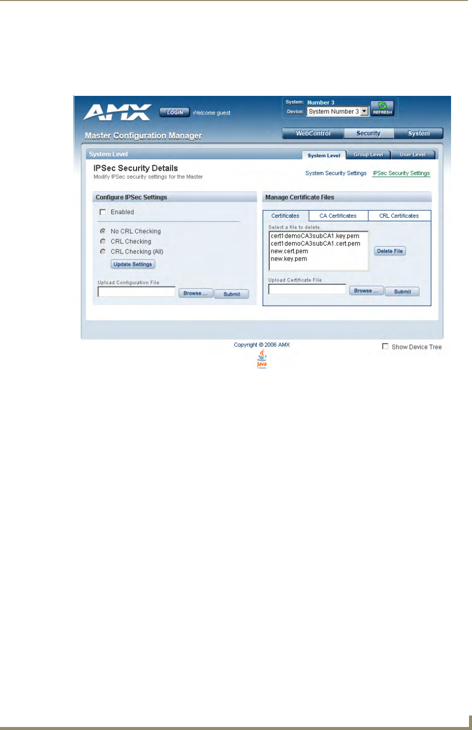
Appendix A: IPSec Configuration File
145
NetLinx Integrated Controllers- WebConsole & Programming Guide
IPSec Web Configuration Interface
Once the IPSec Config file for a system has been created on a PC, the configuration of IPSec on a Master is
accomplished via its Web interface. The following is a screen shot of the IPSec Security Settings page and
descriptions of each field (FIG. 1). All setting and file modifications require a system reboot to take effect.
The “Enabled” checkbox turns “on” and “off” the entire IPSec feature.
The CRL radio buttons indicate the level of Certificate Revocation List checking that is performed
for IPSec connections.
“CRL Checking” checks the sources certificate while “CRL Checking (All)” checks all of the
certificates in a sources certificate chain. If either “CRL Checking” or “CRL Checking (All)” are
selected, then at least one certificate must be present in the CRL Certificates directory on the
Master.
The Upload Configuration File section provides the capability to upload the IPSec Config file
onto a Master. Simply browse to the file’s location on a PC, select the file, and select “Submit”. The
file will be uploaded to its proper location on the Master.
There is no “delete” capability for the Config file. New uploads overwrite the existing Config file.
The “Certificates”, “CA Certificates” and “CRL Certificates” sub-pages provide the ability to
upload certificates, certificate authority certificates and certificate revocation list certificates
respectively onto the Master. Simply browse to the location of the certificate data on the PC, select
the file and select “Submit”. The selected file will be uploaded to the appropriate directory on the
Master.
To delete a certificate file, simply select the desired file and select “Delete”. This will cause the file
to be removed from the Master.
FIG. 1 IPSec Security Settings page

Appendix A: IPSec Configuration File
146 NetLinx Integrated Controllers- WebConsole & Programming Guide

Appendix B: Clock Manager NetLinx Programming API
147
NetLinx Integrated Controllers- WebConsole & Programming Guide
Appendix B: Clock Manager NetLinx
Programming API
Types/Constants
The NetLinx.axi file that will ship with NetLinx Studio includes the following types/constants:
(*-------------------------------------------------------------------------------
----*)
(* Added v1.28, Clock Manager Time Offset Structure *)
(*-------------------------------------------------------------------------------
----*)
STRUCTURE CLKMGR_TIMEOFFSET_STRUCT
{
INTEGER HOURS;
INTEGER MINUTES;
INTEGER SECONDS;
}
(*-------------------------------------------------------------------------------
----*)
(* Added v1.28, Clock Manager Time Server Entry Structure *)
(*-------------------------------------------------------------------------------
----*)
STRUCTURE CLKMGR_TIMESERVER_STRUCT
{
CHAR IS_SELECTED; (* TRUE/FALSE *)
CHAR IS_USER_DEFINED; (* TRUE/FALSE *)
CHAR IP_ADDRESS_STRING[48]; (* Allow enough room for IPv6 in the future
*)
CHAR URL_STRING[32]; (* Example: time.organization.net *)
CHAR LOCATION_STRING[32]; (* Example: Boulder, Colorado, US *)
}
(* Added v1.28, Clock Manager *)
INTEGER CLKMGR_MODE_NETWORK = $01; (* Used to enable Clock Manager Functionality
*)
INTEGER CLKMGR_MODE_STANDALONE = $02; (* Use a free-running clock - legacy
behavior. *)

Appendix B: Clock Manager NetLinx Programming API
148 NetLinx Integrated Controllers- WebConsole & Programming Guide
Library Calls
The NetLinx.axi file that ships with NetLinx Studio includes the following Clock Manager-specific library
calls:
NetLinx.axi - Library Calls
CLKMGR_IS_NETWORK_SOURCED() Returns FALSE/0 or TRUE/1.
The default setting is FALSE/0.
CLKMGR_SET_CLK_SOURCE
(CONSTANT INTEGER MODE)
Can be set to CLKMGR_MODE_NETWORK or
CLKMGR_MODE_STANDALONE.
CLKMGR_IS_DAYLIGHTSAVINGS_ON() Returns FALSE/0 or TRUE/1.
The default setting is FALSE/0.
CLKMGR_SET_DAYLIGHTSAVINGS_MODE
(CONSTANT INTEGER ONOFF)
Can be set to ON/TRUE or OFF/FALSE.
CLKMGR_GET_TIMEZONE() Returns Timezone as a string in the format:
UTC[+|-]HH:MM
CLKMGR_SET_TIMEZONE
(CONSTANT CHAR TIMEZONE[])
Input string must have the correct format:
UTC[+|-]HH:MM
CLKMGR_GET_RESYNC_PERIOD() Returns the Clock Manager's re-sync period in
minutes.
The default setting is one (1) hour. This setting has no
effect if the Clock Manager mode is set to STAND-
ALONE.
CLKMGR_SET_RESYNC_PERIOD
(CONSTANT INTEGER PERIOD)
Sets the re-sync period to the specified minute value.
The upper bound is 480 minutes
(i.e., 8 hours).
CLKMGR_GET_DAYLIGHTSAVINGS_OFFSET
(CLKMGR_TIMEOFFSET_STRUCT T)
Populates the TIMEOFFSET structure with the current
Daylight Savings Offset configured.
The function returns a negative SLONG value if it
encounters an error.
CLKMGR_SET_DAYLIGHTSAVINGS_OFFSET
(CONSTANT CLKMGR_TIMEOFFSET_STRUCT T)
Sets the Daylight Savings Offset to the specified value.
CLKMGR_GET_ACTIVE_TIMESERVER
(CLKMGR_TIMESERVER_STRUCT T)
Populates the TIMESERVER structure with the cur-
rently active time server's data.
The function returns a negative SLONG value if it
encounters an error.
CLKMGR_SET_ACTIVE_TIMESERVER
(CONSTANT CHAR IP[])
Sets the time server entry that has the matching IP-
ADDRESS to the IP parameter as the active time
server entry.
CLKMGR_GET_TIMESERVERS
(CLKMGR_TIMESERVER_STRUCT T[])
Populates the currently configured time server entries
from the Clock Manager into the specified
TIMESERVER array.
The function returns a negative SLONG value if it
encounters an error, otherwise the return value is set to
the number of records populated into the
CLKMGR_TIMESERVER_STRUCT array.
CLKMGR_ADD_USERDEFINED_TIMESERVER
(CONSTANT CHAR IP[], CONSTANT CHAR URL[],
CONSTANT CHAR LOCATION[])
Adds a user-defined time server entry.
CLKMGR_DELETE_USERDEFINED_TIMESERVER
(CONSTANT CHAR IP[])
Deletes the user-defined entry that has its IP-
ADDRESS matching the parameter.

Appendix B: Clock Manager NetLinx Programming API
149
NetLinx Integrated Controllers- WebConsole & Programming Guide
NetLinx.axi - Library Calls (Cont.)
CLKMGR_GET_START_
DAYLIGHTSAVINGS_RULE()
Gets a string representation of when Daylight Savings
is supposed to START.
The Fixed-Date rules have the form:
"fixed:DAY,MONTH,HH:MM:SS"
with all fields as numeric except for the word "fixed".
The Occurrence-Of-Day rules have the form:
"occurence:OCCURENCE,
DAY-OF-WEEK,MONTH,HH:MM:SS"
with all fields as numeric except for the word
"occurence".
• OCCURANCE range = 1-5
’5’ indicates the 'LAST' occurrence of a particular day
of the month.
• DAY-OF-WEEK translates as:
1=Sunday
2=Monday
3=Tuesday
4=Wednsday
5=Thursday
6=Friday
7=Saturday
Examples:
"fixed:5,10,16:00:00" = October 5, at 4:00PM).
"occurence:5,1,10,02:00:00" = last Sunday in October,
at 2:00AM).
CLKMGR_SET_START_
DAYLIGHTSAVINGS_RULE
(CONSTANT CHAR RECORD[])
Sets the START Daylight Savings rule to the specified
string which must be in either the Fixed-Date format or
the Occurence-Of-Day format.
The function returns a negative SLONG value if it
encounters an error.
The Fixed-Date rules have the form:
"fixed:DAY,MONTH,HH:MM:SS"
with all fields as numeric except for the word "fixed".
The Occurrence-Of-Day rules have the form:
"occurence:OCCURENCE,
DAY-OF-WEEK,MONTH,HH:MM:SS"
with all fields as numeric except for the word
"occurence".
• OCCURANCE range = 1-5
’5’ indicates the 'LAST' occurrence of a particular day
of the month.
• DAY-OF-WEEK translates as:
1=Sunday
2=Monday
3=Tuesday
4=Wednsday
5=Thursday
6=Friday
7=Saturday
Examples:
"fixed:5,10,16:00:00" = October 5, at 4:00PM).
"occurence:5,1,10,02:00:00" = last Sunday in October,
at 2:00AM).

Appendix B: Clock Manager NetLinx Programming API
150 NetLinx Integrated Controllers- WebConsole & Programming Guide
NetLinx.axi - Library Calls (Cont.)
CLKMGR_GET_END_
DAYLIGHTSAVINGS_RULE()
Gets a string representation of when Daylight Savings
is supposed to END.
The Fixed-Date rules have the form:
"fixed:DAY,MONTH,HH:MM:SS"
with all fields as numeric except for the word "fixed".
The Occurrence-Of-Day rules have the form:
"occurence:OCCURENCE,
DAY-OF-WEEK,MONTH,HH:MM:SS"
with all fields as numeric except for the word
"occurence".
• OCCURANCE range = 1-5
’5’ indicates the 'LAST' occurrence of a particular day
of the month.
• DAY-OF-WEEK translates as:
1=Sunday
2=Monday
3=Tuesday
4=Wednsday
5=Thursday
6=Friday
7=Saturday
Examples:
"fixed:5,10,16:00:00" = October 5, at 4:00PM).
"occurence:5,1,10,02:00:00" = last Sunday in October,
at 2:00AM).
CLKMGR_SET_END_
DAYLIGHTSAVINGS_RULE
(CONSTANT CHAR RECORD[])
Sets the END Daylight Savings rule to the specified
string which MUST be in either the Fixed-Date format
or the Occurence-Of-Day format.
The function returns a negative SLONG value if it
encounters an error.
The Fixed-Date rules have the form:
"fixed:DAY,MONTH,HH:MM:SS"
with all fields as numeric except for the word "fixed".
The Occurrence-Of-Day rules have the form:
"occurence:OCCURENCE,
DAY-OF-WEEK,MONTH,HH:MM:SS"
with all fields as numeric except for the word
"occurence".
• OCCURANCE range = 1-5
’5’ indicates the 'LAST' occurrence of a particular day
of the month.
• DAY-OF-WEEK translates as:
1=Sunday
2=Monday
3=Tuesday
4=Wednsday
5=Thursday
6=Friday
7=Saturday
Examples:
"fixed:5,10,16:00:00" = October 5, at 4:00PM).
"occurence:5,1,10,02:00:00" = last Sunday in October,
at 2:00AM).

Appendix B: Clock Manager NetLinx Programming API
151
NetLinx Integrated Controllers- WebConsole & Programming Guide

1/10 ©2009 AMX. All rights reserved. AMX and the AMX logo are registered trademarks of AMX. AMX reserves the right to alter specifications without notice at any time.
3000 RESEARCH DRIVE, RICHARDSON, TX 75082 USA • 800.222.0193 • 469.624.8000 • 469-624-7153 fax • 800.932.6993 technical support • www.amx.com
Increase Your Revenue
through education + knowledge
In the ever-changing AV industry, continual education is key to success. AMX University is
dedicated to ensuring that you have the opportunity to gather the information and
experience you need to deliver strong AMX solutions. Plus, AMX courses also help you
earn CEDIA, NSCA, InfoComm, and AMX continuing education units (CEUs).
Visit AMX University online for 24/7/365 access to:
- Schedules and registration for any AMX University course
- Travel and hotel information
- Your individual certification requirements and progress
