NI VeriStand Custom Device Developer's Guide Niveristand Cd Dev
User Manual:
Open the PDF directly: View PDF ![]() .
.
Page Count: 85

NI VeriStand 2010 Custom Device
Developer’s Guide (Beta)
This is a beta version of the guide. Please post questions, comments and feedback
on the NI Developer Zone.
Custom Device Developer’s Guide © 2010 National Instruments 2 of 85
Copyright
© 2010 National Instruments Corporation. All rights reserved.
Under the copyright laws, this publication may not be reproduced or transmitted in any form,
electronic or mechanical, including photocopying, recording, storing in an information retrieval
system, or translating, in whole or in part, without the prior written consent of National
Instruments Corporation.
National Instruments respects the intellectual property of others, and we ask our users to do the
same. NI software is protected by copyright and other intellectual property laws. Where NI
software may be used to reproduce software or other materials belonging to others, you may
use NI software only to reproduce materials that you may reproduce in accordance with the
terms of any applicable license or other legal restriction.
Trademarks
National Instruments, NI, ni.com, LabVIEW and VeriStand are trademarks of National
Instruments Corporation. Refer to the Terms of Use section on ni.com/legal for more information
about National Instruments trademarks.
Other product and company names mentioned herein are trademarks or trade names of their
respective companies.
Patents
For patents covering National Instruments products/technology, refer to the appropriate location:
Help » Patents in your software, the patents.txt file on your media, or the National Instruments
Patent Notice at ni.com/legal/patents.
Custom Device Developer’s Guide © 2010 National Instruments 3 of 85
Conventions ............................................................................................................................... 6
Introduction ................................................................................................................................ 7
What is a Custom Device? ......................................................................................................... 7
Table of Directories and Aliases ............................................................................................. 8
Custom Device Framework .................................................................................................... 9
Configuration .....................................................................................................................10
Initialization VI ................................................................................................................11
Main Page ......................................................................................................................11
Engine ...............................................................................................................................12
Custom Code ........................................................................................................................12
Custom Device XML ..............................................................................................................12
When do you Need a Custom Device? .....................................................................................13
3rd Party Hardware ................................................................................................................15
Unsupported Measurement or Generation Mode ...................................................................15
Feature ..................................................................................................................................15
Custom Device Risk Analysis ....................................................................................................15
LabVIEW Application Development .......................................................................................15
LabVIEW Real-Time Application Development ......................................................................16
NI VeriStand Background ......................................................................................................16
Hardware Driver Development ..............................................................................................16
Testing ..................................................................................................................................17
Planning the Custom Device .....................................................................................................17
Channels ...............................................................................................................................18
Properties ..............................................................................................................................20
Custom Device Decimation ................................................................................................23
Hierarchy ...............................................................................................................................23
Pages ....................................................................................................................................27
Extra Pages .......................................................................................................................29
Page ...............................................................................................................................30
GUID ..............................................................................................................................30
XML Declaration .............................................................................................................31
Build Specification ..........................................................................................................31
Type ......................................................................................................................................32
Asynchronous ....................................................................................................................33
Inline Hardware Interface ...................................................................................................36
Initialize ..........................................................................................................................36
Custom Device Developer’s Guide © 2010 National Instruments 4 of 85
Start ...............................................................................................................................37
Read Data from HW .......................................................................................................37
Write Data to HW ...........................................................................................................38
Close ..............................................................................................................................38
Inline Model Interface .........................................................................................................38
Execute Model ................................................................................................................39
Table of Custom Device Frameworks ................................................................................40
Outline of PCL Iteration ......................................................................................................41
Parallel Mode .................................................................................................................41
Low-Latency Mode .........................................................................................................42
Implement the Custom Device ..................................................................................................42
Build the Template Project .....................................................................................................43
Build the Configuration ..........................................................................................................44
Build the Driver ......................................................................................................................52
Add Custom Device Dependencies ....................................................................................53
Channel Change Detection ................................................................................................60
Debugging and Benchmarking ..................................................................................................62
LabVIEW Debugging Techniques ..........................................................................................62
Console Viewer .....................................................................................................................63
Printing to the Console ..........................................................................................................63
Printing With NIVS Debug String VI ...................................................................................63
Printing With ni_emb.dll .....................................................................................................63
Distributed System Manager .................................................................................................64
System Channels ..................................................................................................................64
Table of Debugging and Benchmarking System Channels .................................................64
System Monitor Add-on .........................................................................................................65
Real-Time Execution Tracing ................................................................................................65
Table of RT Execution Tracing Channels ...........................................................................66
Additional Debugging Options for NI VeriStand .....................................................................66
Table of Debugging and Benchmarking Techniques..............................................................67
Distributing the Custom Device .................................................................................................68
Custom Device Tips and Tricks .................................................................................................68
Custom Device Engine Events ..............................................................................................69
Block Writing and Reading ....................................................................................................70
Working with String Constants ...............................................................................................72
Custom Error Codes ..............................................................................................................72
Custom Device Developer’s Guide © 2010 National Instruments 5 of 85
Utility VIs ...............................................................................................................................72
Sort Channels by FIFO Location ........................................................................................73
Triggering Within the Custom Device.....................................................................................74
Adding Extra Pages After Creating the Custom Device Project .............................................75
Custom Device XML ..............................................................................................................76
Delete Protection ...............................................................................................................77
Limiting Occurrences of the Custom Device .......................................................................77
Rename Protection ............................................................................................................77
Action VIs...........................................................................................................................77
Run-Time Right-click Menu ................................................................................................78
Dynamic Buttons ................................................................................................................79
Upgrading VeriStand 2009 Custom Devices to 2010 ................................................................80
Beyond the Template Frameworks ............................................................................................82
Inline Custom Device with Asynchronous Threads ................................................................82
Custom Device Development Job Aid .......................................................................................85

Custom Device Developer’s Guide © 2010 National Instruments 6 of 85
Conventions
This document uses the following formatting and typographical conventions.
<>
Angle brackets that contain numbers separated by an ellipsis represent a range
of values associated with a bit or signal name—for example, AO <0..3>.
»
The » symbol leads you through nested menu items and dialog box options to a
final action. The sequence File » Page Setup » Options directs you to pull down
the File menu, select the Page Setup item, and select Options from the last
dialog box.
This icon denotes a tip, which alerts you to advisory information.
This icon denotes a note, which alerts you to important information.
This icon denotes a caution, which advises you of precautions to take to avoid
injury, data loss, or a system crash.
bold
Bold text denotes items that you must select or click in the software, such as
menu items and dialog box options. Bold text also denotes parameter names,
controls and indicators on the front panel, dialog boxes, sections of dialog boxes,
menu names, and palette names.
green
Underlined text in this color denotes a link to a help topic, help file, or Web
address.
purple
Underlined text in this color denotes a visited link to a help topic, help file, or Web
address.
italic
Italic text denotes variables, emphasis, cross-references, or an introduction to a
key concept. Italic text also denotes text that is a placeholder for a word or value
that you must supply.
monospace
Text in this font denotes text or characters that you should enter from the
keyboard, sections of code, programming examples, and syntax examples. This
font is also used for the proper names of disk drives, paths, directories,
programs, subprograms, subroutines, device names, operations, variables,
filenames, and extensions.

Custom Device Developer’s Guide © 2010 National Instruments 7 of 85
Introduction
NI VeriStand is a ready-to-use, open software environment for configuring real-time testing
applications, including hardware-in-the-loop (HIL) test systems. With NI VeriStand, you can
configure real-time input/output (IO), stimulus profiles, data logging, alarming, and other tasks;
implement control algorithms or system simulations by importing models from a variety of
software environments; and build test system interfaces quickly with a run-time editable user
interface complete with ready-to-use tools. See NI Developer Zone Tutorial: What is NI
VeriStand for more information.
When necessary, you can customize and extend NI VeriStand’s open environment with
LabVIEW, ensuring it always meets application requirements. The purpose of this document is
to provide the background, design decisions, and technical information required to understand
and develop custom devices in NI VeriStand 2010.
Understanding the NI VeriStand Engine is prerequisite to this document. See NI
VeriStand Help » Components of a Project » Understanding the VeriStand Engine for
more information.
What is a Custom Device?
While NI VeriStand provides most of the functionality required by a real-time testing application,
NI has designed the environment to be customized and extended when necessary to ensure it
always meets application requirements. Custom devices are one of several ways to customize
and extend NI VeriStand. To learn about other ways you can customize NI VeriStand, see NI
Developer Zone Tutorial: Using LabVIEW and Other Software Environments with NI VeriStand.
Custom devices give the developer complete freedom in regards to execution. Any LabVIEW
code, or any code you can call from LabVIEW, can be made into a custom device.
Custom devices give the developer complete freedom to customize the operator interface to
within System Explorer. Custom devices may present whatever configuration experience
desired by the developers. From simple controls on a VI front panel, to a company branded
pop-up window, to a silent routine that scrapes the configuration from an ActiveX database – the
developer defines the configuration experience.
Custom devices typically consist of two VI libraries (configuration and engine) that define the
behavior of the device, and an XML file that tells NI VeriStand how to load, display, use and
deploy the device. Custom devices come from developers including National Instruments, 3rd
parties, and in-house developers. The developer builds the configuration and engine libraries
and the XML file from Source Distributions in LabVIEW.
The LabVIEW Project for most custom devices starts with a template project. A VI called the
Custom Device Template Tool scripts the template project based on a few inputs from the
developer. The developer then adds-to and changes the template project to fulfill the
requirements of the custom device. The Custom Device Template Tool installs on top of NI
LabVIEW with the Full and PC versions of NI VeriStand.

Custom Device Developer’s Guide © 2010 National Instruments 8 of 85
The LabVIEW Project is needed to build the custom device, but only the configuration
and engine libraries and the XML file are required to use the custom device in NI
VeriStand.
After obtaining (or building himself) the custom device’s libraries, the operator places them in
the NI VeriStand <Common Data>\Custom Devices directory. This directory varies with the
host operating system.
Table of Directories and Aliases
<Common Data>
Alias: To Common Doc Dir
Generic Windows OS
<Public Documents>\National Instruments\NI
VeriStand 2010
Default Windows XP
C:\Documents and Settings\All Users\Shared
Documents\National Instruments\NI VeriStand 2010
Default Windows Vista &
7
C:\Users\Public\Documents\National Instruments\NI
VeriStand 2010
<Application Data>
Alias: To Application Data Dir
Generic Windows OS
<Application Data>\National Instruments\NI
VeriStand 2010
Default Windows XP
C:\Documents and Settings\All Users\Application
Data\National Instruments\NI VeriStand 2010
Default Windows Vista &
7
C:\ProgramData\National Instruments\NI VeriStand
2010
<Base>
Alias: To Base
Generic Windows OS
<Program Files>\National Instruments\NI VeriStand
2010
Default Windows XP,
Vista & 7
C:\Program Files\National Instruments\VeriStand
2010
<Custom Device Engine Destination>
PharLap / ETX
C:\ni-rt\veristand\custom devices\<custom device
name>\
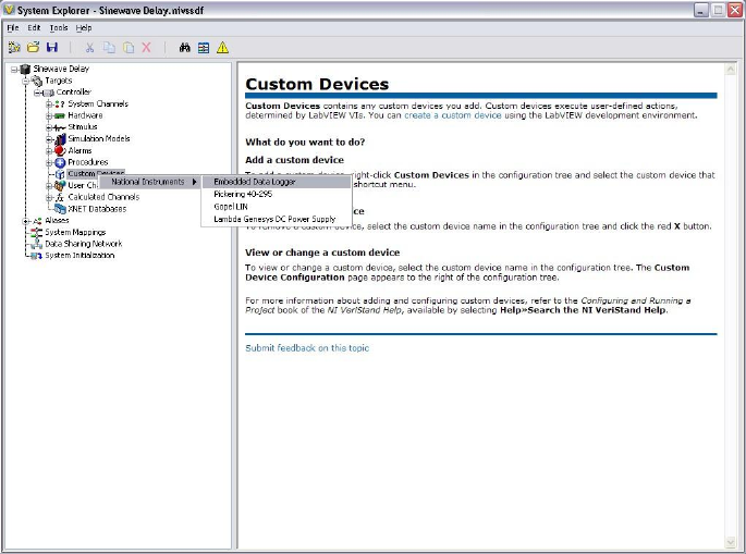
NI VeriStand parses <Common Data>\Custom Devices for custom device XML files when it
first launches. You must restart NI VeriStand to recognize newly added or modified custom
device XML files. The custom device may then be added to the system definition by right-
clicking Custom Devices from System Definition » Targets » Controller in the configuration
tree.
It’s not necessary for the operator to have any knowledge of LabVIEW or custom device
development to use the custom device. It’s not necessary to have the LabVIEW Project to use
Custom Device Developer’s Guide © 2010 National Instruments 9 of 85
a custom device. It’s courteous common practice to provide the LabVIEW Project along with
the custom device. Providing the project allows operators and other developers to modify the
custom device to suit their specific requirements.
Figure: Adding a Custom Device to a System Definition
Most custom devices consist of the two VI libraries and XML file mentioned above. Logically,
custom devices consist of three parts.
1. Custom Device Framework
2. Custom Code
3. Custom Device XML File
Custom Device Framework
The custom device framework consists of type definitions, specifically-named controls and
indicators, template VIs and a LabVIEW API. Together these items for the rules, or framework,
that allows any conforming VI to interact with NI VeriStand. There are five prebuilt types of
custom devices. Almost any requirement can be accomplished by adding or modifying code in
one of the five prebuilt devices.
The five prebuilt devices start with the Custom Device Template Tool. The template tool is
located in <vi.lib>\ NI Veristand\Custom Device Tools\Custom Device
Template Tool\Custom Device Template Tool.vi.
The developer specifies the type of custom device before running the template tool. The tool
generates the LabVIEW Project for the new custom device. The exact resources in the project
depend on the type of custom device selected.
The project is pre-populated with VIs, LabVIEW Libraries, an XML File, and two build
specifications. These resources provide the framework upon which almost all custom devices
are built.
Custom Device Developer’s Guide © 2010 National Instruments 10 of 85
NI VeriStand evolved from NI Dynamic Test Software (NI-DTS). NI-DTS evolved from
Intellectual Property (IP) called EASE obtained from a 3rd party. EASE made basic
provisions for add-on LabVIEW code. In a sense this was the first custom device
framework. Several “custom devices” were built for the original framework, and NI has
mutated them from EASE through NI-DTS and into NI-VeriStand. If you come across a
custom device that doesn’t fit into the framework provided by the Custom Device
Template Tool, you may have stumbled upon one of the original custom devices.
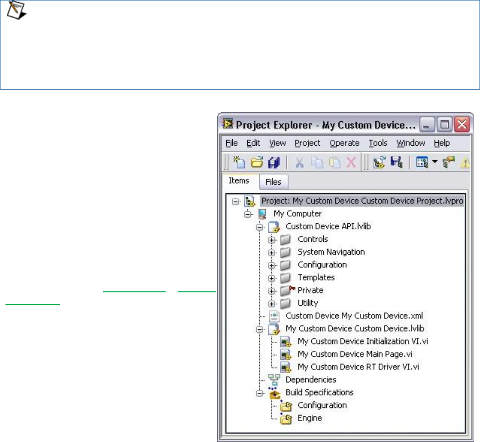
For each of the five types of custom
devices, you’ll see two VI libraries in the
LabVIEW source project: Custom
Device API.lvlib and Custom
Device Name Custom Device.lvlib.
The Custom Device API library contains
most of the type definitions, template VIs
and LabVIEW API needed to interact with
NI VeriStand’s data and timing resources.
They give a VI the ability to behave as a
native task in the NI VeriStand Engine.
Some of these VIs also appear on the
LabVIEW palette in NI VeriStand » Custom
Device API.
The <custom device name> library
contains the custom device’s configuration
and RT Engine VIs. These correspond to
the configuration and engine VI libraries
(or LLBs) mentioned earlier. Notice the
front panel and block diagram of these VIs
have been populated with objects from the
Custom Device API library.
Figure: A New Custom Device Project
Configuration
The custom device’s configuration defines the operator’s experience adding and configuring the
custom device. It is the device's operator interface (OI) or user interface (UI). The Custom
Device Template Tool provides two VIs for configuration: Initialization and Main. Additional VIs
may be added as needed.

Custom Device Developer’s Guide © 2010 National Instruments 11 of 85
When a custom device VI’s front panel is presented to the operator in the System
Explorer window, that VI is called a page. Pages are a subset of the VIs that make up a
custom device.
Initialization VI
The Custom Device Template Tool names the initialization VI <Custom Device Name>
Initialization VI.vi. It runs in the background when the custom device is first added to
the system definition. The initialization page does not run again unless the operator removes
and re-adds the custom device.
While you may rename certain objects in the custom device’s LabVIEW Project, it’s
important to understand the ramifications of doing so. For example, the Initialization VI
is referenced by name in the custom device XML file. This file is generated when you
first run the Custom Device Template Tool. If you rename the Initialization VI after
running the tool, you’ll need to manually change the path to the Initialization VI in the
custom device XML file.
The Initialization Page runs each time a new instance of the same custom device is added to
the system definition. NI VeriStand retains state information for each instance of a custom
device in the System Definition (.nivssdf) file. State is defined by the value of each control,
indicator, and property (properties are covered later) of the page. This file is human-readable
XML, so you can open the file with a text editor and take a look. There’s also a .NET API for
modifying the System Definition programmatically.
Main Page
The Custom Device Template Tool names the main page <Custom Device Name> Main
Page.vi. After the custom device has been added to the system definition, the main page
runs whenever the operator clicks on the on the custom device’s top-level item in System
Explorer’s configuration tree.
The top-level
custom device
item is selected
in the
configuration
tree.
Main Page VI
runs in the
configuration
pane.

Custom Device Developer’s Guide © 2010 National Instruments 12 of 85
Figure: Highlighting the Top-Level Item Runs the Main Page
Engine
The Custom Device Template Tool names the engine <Custom Device Name> RT
Driver.vi. It defines the behavior of the custom device on the execution host. The RT
Driver VI runs on the execution host regardless of the target’s operating system.
NI VeriStand 2009 did not support the NI VeriStand Engine on VxWorks operating
systems. Starting with NI VeriStand 2010, if you want to support VxWorks targets such
as Compact RIO, you must compile the engine library for VxWorks. PharLap and
Windows engines do not require additional compilation.
The engine runs after the custom device has been added to the system definition, configured by
the operator, and deployed to the execution host. The developer usually adds initialization,
steady-state, and shutdown code to the engine template. There aren’t any hard boundaries on
what code you can put into the engine, only on what code you should put in the engine.
NI VeriStand deploys the engine when the operator clicks Run Project from the NI VeriStand
Getting Started Window, selects Operate » Run or Operate » Deploy from the Project
Explorer, or when the system definition is deployed using the NI VeriStand Execution API.
Each of the five prebuilt custom devices has a different engine VI. Each engine VI executes at a
different time with respect to other NI VeriStand components. The timing requirements of a
custom device, and thus the type of device selected, are functions of when the device needs to
execute with respect to other NI VeriStand Engine components. We’ll cover this in detail later
on.
Not all requirements can be satisfied by one of the five types of prebuilt custom devices. Some
custom devices require multiple engine libraries (to support different real-time operating
systems for example). NI VeriStand – Set Custom Device Driver VI allows you to
programmatically change the driver library for a custom device. Some custom devices use the
prebuilt template as a launching pad for multiple parallel processes or complex frameworks.
See the section Beyond the Template Frameworks for more information. Again, custom devices
give the developer complete freedom with regard to OI/UI and execution.
Custom Code
The custom code performs any functionality desired by the custom device developer. While the
initialization and engine frameworks provide access to NI VeriStand data and timing resources,
it's up to the developer to implement the code to meet specification.
For example, the custom code might perform a single A/D conversion on a 3rd party digitizer.
The framework provides the means for sending the digitized value to the rest of the NI
VeriStand system so it can be mapped to channels, used in a stimulus profile, etc. Again, there
aren’t any hard boundaries on the code you can put into the driver.
Custom Device XML
Each custom device has an XML file that contains information used by NI VeriStand to load,
configure, display, deploy and run the device. The basic information includes VI and
dependency paths, page names, action and menu items, and Meta data for the various pages
that make up the custom device. The Custom Device Template Tool generates an XML file for
Custom Device Developer’s Guide © 2010 National Instruments 13 of 85
you and include it in the template LabVIEW Project. Any properly-formatted XML file will be
parsed by NI VeriStand. After the XML file is created by the Custom Device Template Tool, all
edits to it are manual, i.e. it is not automatically updated to reflect changes made by the
developer.
The custom device XML does not automatically synchronize with changes to the
LabVIEW project, nor does it automatically deploy. Be sure to modify the XML in the
LabVIEW Project directory when making changes. Building the Initialization
specification overwrites the XML in the <Common Data>\Custom Devices folder.
The XML file provides the ability to customize the appearance and behavior of the custom
device in System Explorer. For example, you can change the default glyph or add a right-click
menu to a custom device by adding tags to the custom device XML file.
Since NI VeriStand parses <Common Data> for custom devices when it launches, a
corrupt custom device XML file can affect the overall NI VeriStand system. You should
exercise care and make a backup of the custom device XML before modifying it.
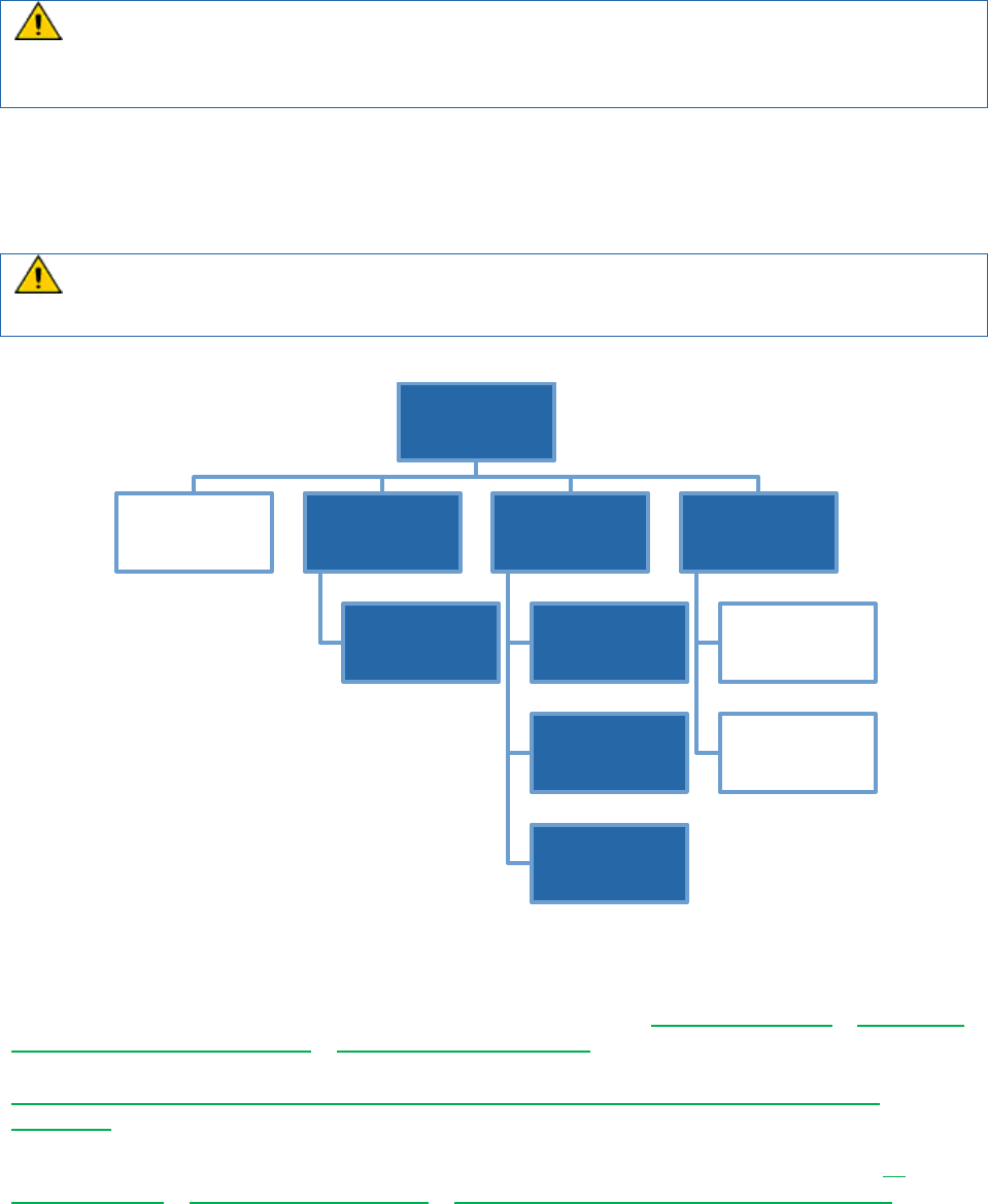
Figure: Diagram of the LabVIEW Project Created by the Custom Device Template Tool
When do you Need a Custom Device?
The built-in components of an NI VeriStand Project are listed in NI VeriStand Help » Navigating
the NI VeriStand Environment » System Explorer Window. If the built-in components do not
fulfill a specification, it can most likely be fulfilled by one of the customization methods shown in
NI Developer Zone Tutorial: Using LabVIEW and Other Software Environments with NI
VeriStand.
Four custom devices are included with NI VeriStand 2010. These devices are listed in NI
VeriStand Help » NI VeriStand Reference » Custom Devices Included with NI VeriStand.
Custom Device.lvproj
XML
Required to run the
device
Custom Device
API.lvlib
Contains all resources
for developing the
custom device
Custom Device.lvlib
Initialization VI
Runs when device is
1st added to sys
explorer
Main Page
Runs when user clicks
on device in sys
explorer
RT Driver
Runs on execution
target after configured
and deployed
Build Specifications
Engine.llb
Required to run the
custom device
Configuration.llb
Required to run the
custom device

Custom Device Developer’s Guide © 2010 National Instruments 14 of 85
1. Embedded Data Logger
2. Gopel LIN
3. Lambda Genesys DC Power Supply
4. Pickering 40-295
In addition to these four devices, a variety of custom devices have already been implemented
by National Instruments and are available for download. You should consult NI Developer Zone
Tutorial: NI VeriStand Add-ons to determine if a custom device has already been developed to
fulfill your specification.
Several hardware vendors have implemented custom devices for their hardware. You should
check with the manufacturer that a custom device doesn’t exist before you build one.

Custom Device Developer’s Guide © 2010 National Instruments 15 of 85
In general, there are three specifications that are best-suited for a custom device.
1. 3rd Party Hardware
2. Unsupported Measurement or Generation Mode
3. Feature
3rd Party Hardware
A list of hardware natively supported by NI VeriStand is found in NI VeriStand Help » NI
VeriStand Reference » Supported National Instruments Hardware. If the application requires
other hardware, it can probably be implemented in a custom device.
Unsupported Measurement or Generation Mode
Check NI VeriStand Help » Configuring and Running a Project » Configuring a System
Definition File » Adding and Configuring Hardware Devices to determine if the required
measurement or generation mode of your hardware is supported. If not, it can probably be
implemented in a custom device. For example, single-point hardware-timed analog acquisition
on NI-DAQ devices is supported out-of-the-box. Continuous analog acquisition can be
implemented as a custom device.
Feature
All of the common functionality necessary for most real-time testing applications such as host
interface communication, data logging, stimulus generation, etc, is provided by NI VeriStand –
ready to configure and use. You should first try to meet specifications with the built-in
functionality because it is engineered, tested, and supported by National Instruments.
If a built-in feature does not exist, it can be implemented by extending NI VeriStand. See NI
Developer Zone Tutorial: Using LabVIEW and Other Software Environments with NI VeriStand
for a complete list of ways to customize and extend NI VeriStand. Certain features are best
implemented as custom devices. To determine when a custom device is the most appropriate
mechanism to meet a specification, you should be familiar with all the customization methods
available. A general rule-of-thumb is that custom devices implement features that require or
use NI VeriStand channel data on the execution host.
For example, there is a TDMS File Viewer tool built into the NI VeriStand Workspace. If you
need to log NI VeriStand channels to TDMS without first sending it back to the Workspace (as
with high-speed streaming), a custom device called the Embedded Data Logger fulfills this
requirement. This custom device ships with NI VeriStand 2010. On the other hand, if you need
to display previous test results on the workspace while a new test is running, a custom
workspace object may be more appropriate than a custom device. See NI Developer Zone
Tutorial: Creating Custom Workspace Objects for NI VeriStand for more information.
Custom Device Risk Analysis
The open nature of NI VeriStand is a strong advantage over other real-time/HIL testing
solutions. It’s easy to take advantage of this extensibility by using custom devices written by
other developers. Writing your own custom device incurs a set of manageable risks. This
section provides a list of risks that should be considered before custom device development
begins.
LabVIEW Application Development
Custom devices are written in LabVIEW. The framework generated by the Custom Device
Template Tool is single-loop or action-engine VI. This architecture may be suitable for simple
custom devices.

Custom Device Developer’s Guide © 2010 National Instruments 16 of 85
Non-trivial devices will require more advanced architecture. A requisite for custom device
development is thorough knowledge of LabVIEW programming and application architectures.
This knowledge represents NI Certified LabVIEW Developer (CLD) level expertise, and is
typically obtained through NI's Training and Certification program by completing the LabVIEW
Core 1, Core 2, and Core 3 courses.
It should be mentioned that NI VeriStand custom devices are typically not large LabVIEW
applications. Custom devices are designed to be modular, self-contained plug-ins that add a
specific functionality to NI VeriStand. While custom devices are typically developed by a single
programmer, large application development best-practices may still apply. See LabVIEW 2010
Help: Best Practices for Large Application Development for more information.
LabVIEW Real-Time Application Development
Custom devices are typically designed to execute on real-time systems. This allows the
operator to perform deterministic HIL and RT test procedures. Programming for a real-time
system requires knowledge of real-time operating systems (RTOS) and specialized LabVIEW
development techniques. This knowledge is typically obtained through NI's Training and
Certification program by completing the Real-Time Application Development course, and it is
refined by working on several LabVIEW Real-Time applications.
NI VeriStand Background
Familiarity with the NI VeriStand Engine is crucial to successful custom device development.
The correct type of custom device cannot be selected in the Custom Device Template Tool
without understanding the implications of each. This knowledge is typically obtained by reading
the NI VeriStand 2010 Help, with an emphasis on Understanding the VeriStand Engine.
Experience with NI VeriStand from an operator's perspective is highly desired. This experience
enables you to build operator-friendly interfaces that conform to the standard look and feel of
other NI VeriStand components. Familiarity with NI VeriStand allows the developer to build-up a
complex system definition, which allows thorough and realistic testing and benchmarking.
Hardware Driver Development
Custom device must call a hardware or instrument driver to support 3rd-party hardware. All
National Instruments hardware comes with a LabVIEW Application Program Interface (API) that
can be used in the custom device. However, just because a LabVIEW API exists does not
guarantee the custom device can be easily implemented. Consider the following points when
evaluating the feasibility of a custom device for 3rd-party hardware.
Does an Instrument Driver exist? See NI Developer Zone » Instrument Driver Network to
search for instrument drivers.
Is a hardware driver available?
Is the driver well documented?
If necessary, is the driver compatible with LabVIEW Real-Time? See KnowledgeBase
3BMI76L1: How Can I Verify that My DLL is Executable in LabVIEW Real-Time for
instructions on checking compatibility.
NI VeriStand uses channels to pass data between different parts of the system, including to and
from custom devices. All NI VeriStand channels are LabVIEW double data type (DBL). See
LabVIEW 2010 Help » Fundamentals » Building the Block Diagram » How-To » Floating Point
Numbers for more information on LabVIEW data types.

Custom Device Developer’s Guide © 2010 National Instruments 17 of 85
Can the hardware requirement be met by passing LabVIEW DBLs to and from the
custom device during steady state operation?
If the hardware driver returns a vector, structure, or any non-DBL data, it cannot be passed
directly from the custom device to the rest of the NI VeriStand system. The developer is
responsible for coercing the data (or using an alternative communication mechanism) to pass
data from the custom device to the rest of the system. For more information on the available
communication mechanisms, see LabVIEW 2010 Real-Time Module Help » Real-Time Module
Concepts » Sharing Data in Deterministic Applications » Exploring Remote Communication
Methods.
NI VeriStand also exposes its TCP pope via dynamic event registration. This pipe may suite
your remote communication requirements. See the Custom Device Engine Events section for
more information.
Testing
A custom device is one part of an NI VeriStand system. The complete state of the operator's
system is seldom known by the custom device developer. System state includes the following
information.
What are the specifications of the execution host and host computer?
What components are in the system definition?
o How computationally intense are the simulation models?
What loop rates are required?
What is the health and resource utilization of the system?
Ideally, the custom device is implemented to be minimally burdensome, extremely efficient, and
easy to use. Depending on its complexity, it may become necessary to test, debug, and
optimize the code on systems representative of the operator’s system. Consider the following
example.
A custom device developer needs to benchmark a 3rd-party hardware custom device. He adds
the custom device to the Sine Wave example that ships with NI VeriStand 2010. He deploys
the system definition to a quad-core NI-8110 RT controller. Adding the custom device to the
system in increased the target’s CPU load by 10% per-core and RAM utilization increased
120KB. If the operator is deploying the same custom device to a single-core 8101 RT
controller, with an average CPU load of 60% because of a computationally intense model, it’s
unlikely the operator will achieve the same loop rate after adding the custom device. This
system may be incapable of running the custom device at all.
Time to test, debug and optimize the code must be factored into the development timeline. If
you’re developing for a specific operator, then it's best to test on a system representative of their
system. If you’re developing for unknown systems, then it may be appropriate to include the
specifications of the system used to obtain benchmarking and timing information with the
custom device documentation.
Planning the Custom Device
The most critical phase of custom device development is planning. Several idiosyncrasies of NI
VeriStand require more thorough planning than does a small stand-alone LabVIEW application.
There are five main things that must be planned.
1. Channels
Custom Device Developer’s Guide © 2010 National Instruments 18 of 85
2. Properties
3. Hierarchy
4. Pages
5. Device Type
After you have a clear idea of the channels, properties, hierarchy, pages, and type of custom
device, you're ready to start implementation. In the following discussion, we'll refer to a
hypothetical 3rd party analog to digital (A/D) converter, the AES-201. A hypothetical device was
chosen to simplify this discussion. If you prefer to follow along with an actual device, please
refer to NI DeveloperZone Tutorial: Building Custom Devices for NI VeriStand 2010.
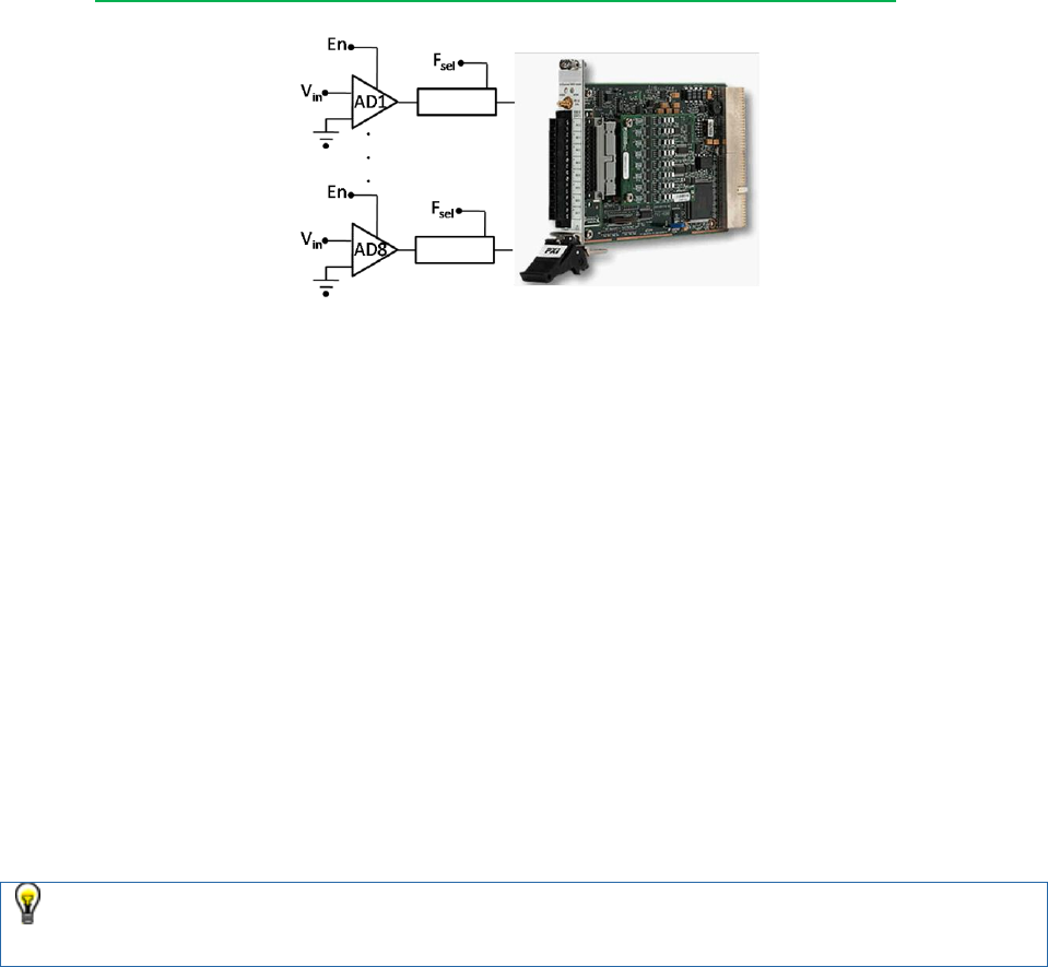
Figure: A Hypothetical Digitizer called the AES-201
The AES-201 has (8) 32-bit analog input channels (AI). The device can digitize on ±1V or
±500mV. The card has a single software trigger line. Each channel has a software enable that
is ON by default, and a 6Hz low pass filter that is OFF by default. A call to the hardware API
makes a single A/D conversion on the specified channel and returns raw data. The range of the
device cannot be changed after the device has been initialized.
Channels
Channels are the built-in mechanism used to exchange data between the custom device and
the rest of the NI VeriStand system. All channels are 64-bit floating point numbers; there is no
built-in mechanism for other channel data types. There are three common use cases for
planning a custom device channel.
1. Data generated by the custom device after it's deployed that may be required by other
parts of the NI VeriStand system.
2. Data originating elsewhere in the NI VeriStand system that may be consumed by the
custom device after it's deployed.
3. Dynamic properties that may change after the device is deployed can be implemented in
channels.
Notice the emphasis on “may”. Custom devices should be designed with a generic use-
case in mind. Just because your customer doesn’t use all channels and settings of the
hardware doesn’t mean you shouldn’t expose everything to the operator.
Given these use cases, the AES-201 custom device should have one channel each for
ADDataFromCh<1..8>. The digitized data is going to change while the device is running. The
operator may need that data to be available to the rest of the NI VeriStand system. For
example, operators often map data from hardware to simulation model inputs.

Custom Device Developer’s Guide © 2010 National Instruments 19 of 85
The operator may need the ability to map the AES-201 software trigger to another channel in
the system explorer (a calculated channel for instance). So the developer should create a
channel for SWTrig. The operator may need the ability to disable a channel or toggle the input
filter or the AES-201 while the device is running. The developer should plan an additional 16
channels: one each for FilterEnCh<1..8> and ADEnCh<1..8>.
NI VeriStand channels are always LabVIEW DBLs. It may be easier to flatten data to
DBL than it is to implement a background communication loop that passes native data
types to the rest of the system. While the AES-201’s LabVIEW API calls for Boolean
data to enable the channel or filter, you can still use a DBL channel with the assumption
that 0 = False and !0 = True.
Channels are created with NI VeriStand Custom Device API » Configuration » Add Custom
Device Channel. The type of channel is either Input or Output. Channel type is with respect to
the custom device. If the custom device passes data to the rest of the NI VeriStand system, it
requires an output channel. If the custom device gets data from the rest of the system, it
requires an input channel. For example, the AES-201 may have 8 output channels
(ADDataFromCh<1..8>) and 17 input channels (ADEnCh<1..8>, FilterEnCh<1..8> and
SWTrig).
Once the custom device is loaded into NI VeriStand, the operator can map each input channel
to a single data source. Similarly, the operator can map each output channel to an arbitrary
number of sinks. For example, you can map ADDataFromCh1 to several simulation model
inputs, but SWTrig may be mapped to a user channel or model output, but not both.
Custom Device Developer’s Guide © 2010 National Instruments 20 of 85
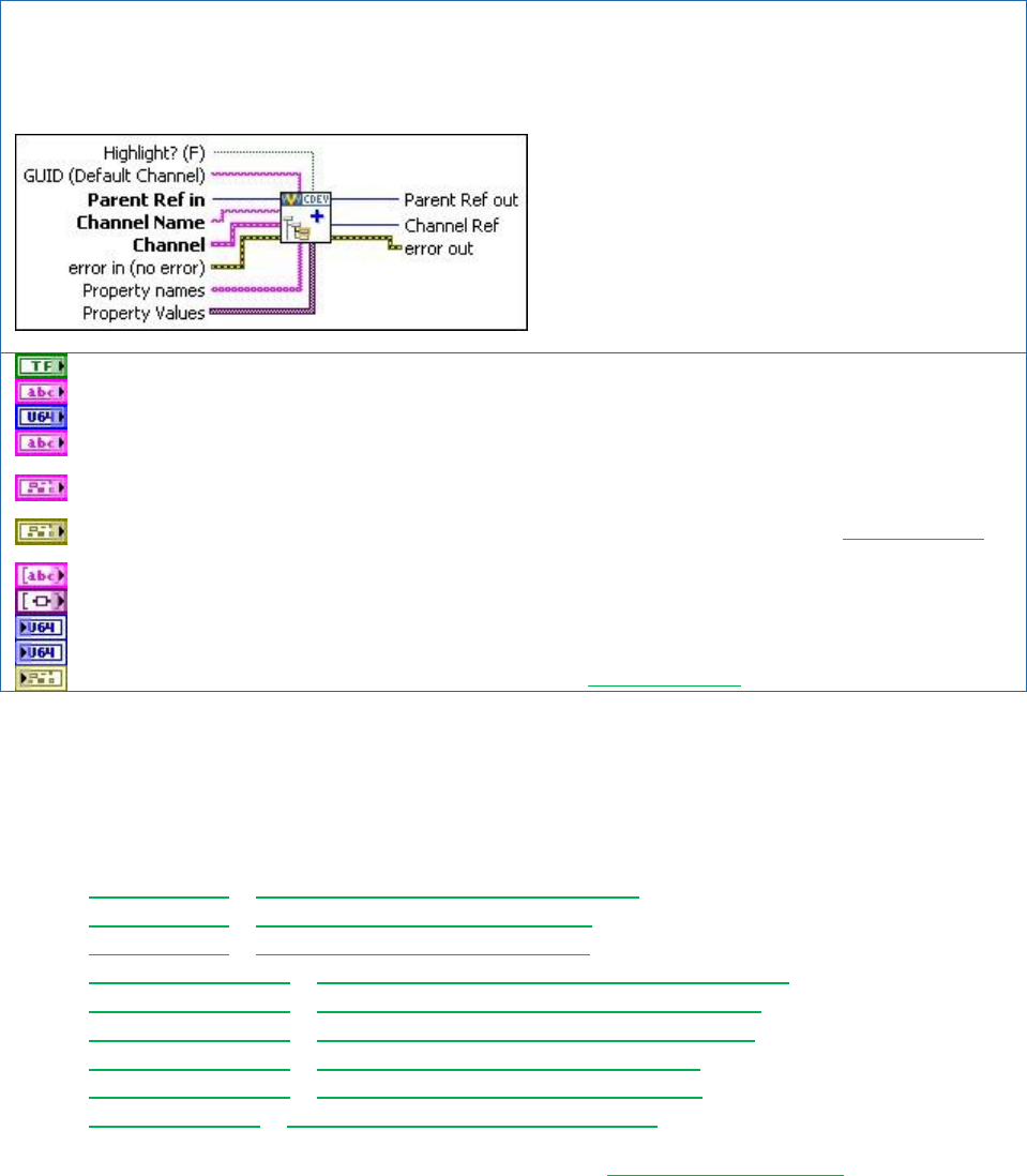
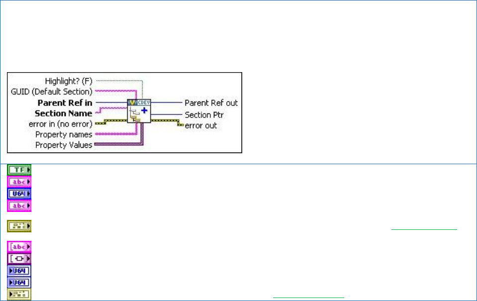
NI VeriStand – Add Custom Device Channel VI
Owning Palette: Configuration
Adds a channel to the device or device subsection specified by Parrent Ref in. If the Channel Name you specify
already exists, the VI overwrites the existing channel settings without affecting any custom properties.
Highlight? makes the item active in System Explorer.
GUID (Default Channel) the GUID of a custom channel defined in the custom device XML file.
Parent Ref in is the NI VeriStand reference to the parent section for the new channel.
Channel Name is the name of the new channel. The name is applied to the channel when the VI runs. If
the operator changes the name of the channel in the System Explorer, the changed name persists.
Channel defines the type, units, and default value of the channel. It also toggles Faultable and Scalable
properties on the channel.
error in describes error conditions that occur before this node runs. This input provides standard error in
functionality.
Property names is an string array of arbitrary property names associated with the channel.
Property Values is a variant array that cooresponds one-to-one with the property names.
Parent Ref out is a duplicate of the Parent Ref in.
Channel Ref provides the NI VeriStand reference to the new channel within the custom device.
error out contains error information. This output provides standard error out functionality.
The Add Custom Device Channel VI may be called from any VI that runs on the host computer.
There are several other VIs in the NI VeriStand Custom Device LabVIEW palette that operate
on custom device channels. The behavior of the VI is what you’d expect given the name of the
VI.
Configuration » Get Custom Device Channel Data VI
Configuration » Rename Custom Device Item VI
Configuration » Remove Custom Device Item VI
Channel Properties » Set Custom Device Channel Default Value VI
Channel Properties » Set Custom Device Channel Faultability VI
Channel Properties » Set Custom Device Channel Scalability VI
Channel Properties » Set Custom Device Channel Type VI
Channel Properties » Set Custom Device Channel Units VI
Driver Functions » Get Custom Device Channel List VI
In addition to these channel-specific VIs, any VI from the Item Properties palette may be used
with a custom device channel.
Properties
Properties are used within the custom device to communicate state information. Property
names are case-sensitive strings. Unlike channels, property values may be any standard
LabVIEW data type. Properties are the recommended way to transfer configuration and state
Custom Device Developer’s Guide © 2010 National Instruments 21 of 85
information from the configuration to the engine on a one-time basis. The transfer occurs when
the system definition is deployed to the execution host.
After the system definition is deployed, the engine may still read and write properties on the
execution host, but it may not exchange properties with the host computer using the property
VIs.
The range setting on the AES-201 is best implemented as a custom device property because
the range cannot be changed after the card has been initialized. The configuration routine on
the host computer can set the Range property of the card based on operator input. When the
operator deploys the system definition, the engine can then read the Range property. The
engine can then make the appropriate call to the hardware API to set the range.
After the AES-201 has been started, the range cannot be changed. If the operator wants to
change the range setting, he must launch System Explorer, reconfigure the custom device, and
redeploy the system definition. The engine may still read or write the Range property, but the
change is not reflected in System Explorer.
You may decide to implement the filter setting as a property. The operator would enable or
disable the filter in System Explorer by toggling a check-box on each channel’s page. On one
hand, the device would require 8 fewer channels. On the other hand, the operator could no
longer toggle the input filter while the custom device was running. To illustrate several aspects
of custom device development, we will implement the filter setting as a property.
In this small example, we have eluded to a design decision often faced by custom device
developers. As the number of use-cases and flexibility of a custom device increases, so does
the complexity of planning and implementing the device. The tradeoff is a more robust device
that requires less customization by the operator.
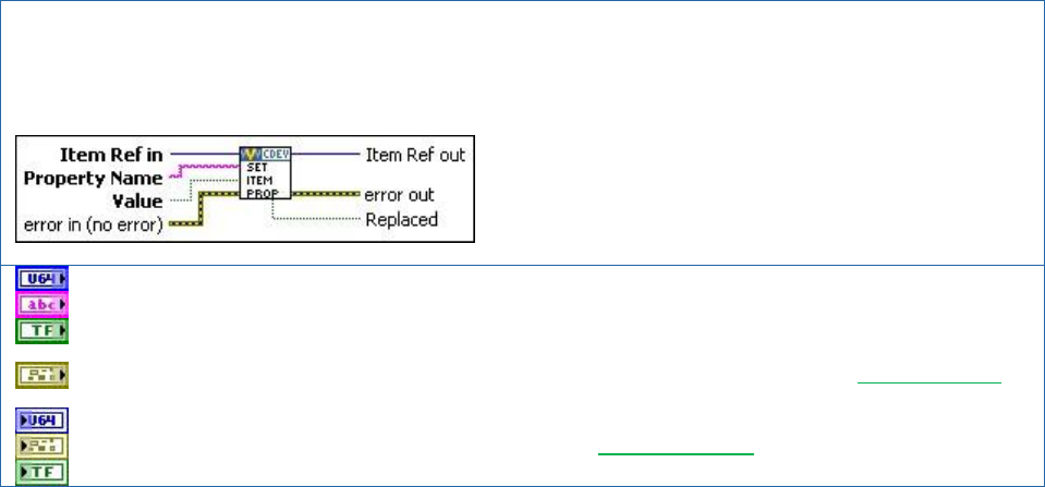
NI VeriStand – Set Item Property VI
Owning Palette: Item Properties VIs
Sets a Property Name and Value for an item. If the Property Name you specify already exists, NI VeriStand
overwrites the property.
Item Ref In is the NI VeriStand reference to the item destined for the property.
Property Name is an arbitrary case-sensitive name for the property.
Value corresponds to the value of the property. This is a polymorphic VI and the data type of the value input
cooresponds with the instance.
error in describes error conditions that occur before this node runs. This input provides standard error in
functionality.
Item Ref out is a duplicate of the Item Ref in.
error out contains error information. This output provides standard error out functionality.
Replaced indicates if the property was overwriten by the new value.
The Set Item Property VI may be called from any VI in the custom device. Properties can be
applied to any channel or section. In addition to the Set Item Property VI, properties can be set
Custom Device Developer’s Guide © 2010 National Instruments 22 of 85
when a channel or section is created by using the Property Names and Property Values
terminals.
A property must be read from the item to which it was set. For example, if you set the
Filter_Enabled property on the ADDataFromCh1 channel, you cannot read the value of the
Filter_Enabled property directly from the parent section or any reference other than
ADDataFromCh1. Properties do not inherit.
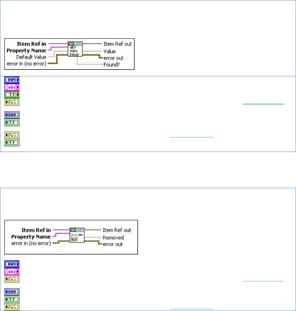
NI VeriStand – Get Item Property VI
Owning Palette: Item Properties VIs
Returns the Value of a specific item Property Name. If the Property Name does not exist for the specified item,
Value returns Default Value.
Item Ref in is the NI VeriStand reference to query for the property.
Property Name is an arbitrary case-sensitive name for the property.
Default Value is returned by the Value terminal if the property is not found.
error in describes error conditions that occur before this node runs. This input provides standard error in
functionality.
Item Ref out is a duplicate of Item Ref in.
value is the value of the property. This is a polymorphic VI and the data type of the Default Value and
Value terminals coorespond with the instance.
error out contains error information. This output provides standard error out functionality.
Found indicates if Property Name was found on Item Ref in (true) or if the default value was returned
(false).
It’s good programming practice to always use the Found terminal of the Get Item Property VI to
check that the intended property name was found on the item.
NI VeriStand – Remove Item Property VI
Owning Palette: Item Properties VIs
Removes the Property Name from an item.
Item Ref in is the NI VeriStand reference to the item.
Property Name is an arbitrary case-sensitive name for the property.
error in describes error conditions that occur before this node runs. This input provides standard error in
functionality.
Item Ref out is a duplicate of Item Ref in.
Removed indicates if the property was found and removed successfully.
error out contains error information. This output provides standard error out functionality.

Custom Device Developer’s Guide © 2010 National Instruments 23 of 85
The Get Item Property and Remove Item Property VIs may be called from any VI in the custom
device. There are several other VIs in the NI VeriStand Custom Device LabVIEW palette that
operate on custom device properties. The behavior of the VI is what you’d expect from the
name of the VI.
Item Properties » Get Item Description
Item Properties » Get Item GUID
Item Properties » Get Property Names List
Item Properties » Set Item Description
Item Properties » Set Item GUID
Device Properties » Get Custom Device Decimation
Device Properties » Get Custom Device Driver
Device Properties » Get Custom Device Version
Device Properties » Set Custom Device Decimation
Device Properties » Set Custom Device Driver
Device Properties » Set Custom Device Version
Device Properties » Specify Custom Device Execution Mode
Custom Device Decimation
You can set decimation for any type of custom device. However, decimation is handled
differently for inline and asynchronous devices. We’ll discuss the difference between these
devices later in the document.
An inline custom device is not called if its decimation indicates not to. For example, when you
decimate an inline custom device by 4, the PCL calls the custom device at every fourth iteration.
It does not mean the custom device has four times as long to execute. The inline custom
device must execute in short enough time for the entire PCL to complete its iteration including
the time to execute the inline custom device. Asynchronous devices have their channel FIFOs
read on the N’th iteration of the PCL, where N is the decimation rate of the asynchronous
device.
This information will make more sense after you understand the difference between inline and
asynchronous custom devices.
Hierarchy
NI VeriStand's System Explorer allows each custom device to present a hierarchal user
configuration interface. A hierarchal structure is not required, but it's a convenient way for the
developer to organize and present the device logically to the operator.
Custom Device Developer’s Guide © 2010 National Instruments 24 of 85
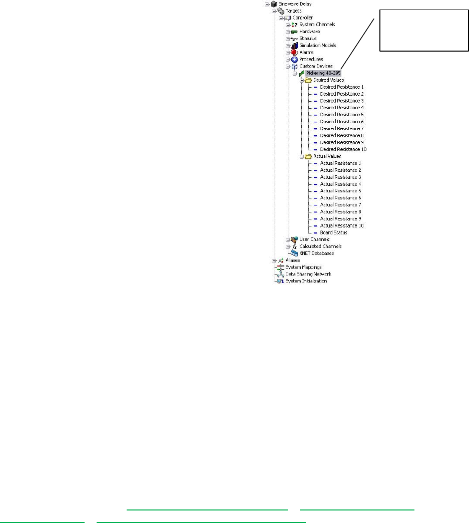
The Pickering 40-295 device that
ships with NI VeriStand has a simple
hierarchy. This custom device
hierarchy begins with the Pickering
40-295 custom device. This is the
top-level item in this custom device’s
hierarchy.
Within the next echelon are sections
for Desired Values and Actual
Values. Within each section are the
individual channels. If you're familiar
with this 3rd party hardware, the
hierarchy is an intuitive configuration
interface for the Pickering 40-295
resistive module.
There are an arbitrary number of
possible hierarchies for most custom
devices.
Figure: Hierarchy of the Pickering 40-295 Custom
Device
Within the hierarchy, there are two types of objects: sections and channels. We’ve already
discussed custom device channels. Sections provide a logical way to group items in the
hierarchy. The default section glyph (icon) is a folder, as shown in the Pickering 40-295 custom
device. The developer can change the glyph by modifying the custom device XML. A collection
of glyphs that install with NI VeriStand 2010 is found in <Application Data>\System
Explorer\Glyphs.
All items in a custom device's configuration tree are either channels or sections, regardless of
their glyph. You cannot create additional levels of custom device hierarchy from channels. You
cannot map sections to other items in NI VeriStand. You cannot exchange data through
sections during run-time as you can with channels.
Sections are created with NI VeriStand Custom Device API » Custom Device API VIs »
Configuration VIs » NI VeriStand - Add Custom Device Section.
Top-level item in
the Pickering
custom device.
Custom Device Developer’s Guide © 2010 National Instruments 25 of 85
NI VeriStand – Add Custom Device Section VI
Owning Palette: Configuration
Adds a section with the name Section Name to the device specified by Parent Ref in. If the Section Name you
specify already exists for that device, this VI updates only the GUID of that section without affecting any properties or
any child items.
Highlight? makes the item active in System Explorer.
GUID (Default Section) specifies the GUID of a custom page in the custom device XML file.
Parent Ref in is the NI VeriStand reference to the parent for the new section.
Section Name is the name of the new section. The name is applied to the channel when the VI runs. If the
operator changes the name of the section in the System Explorer, the changed name persists.
error in describes error conditions that occur before this node runs. This input provides standard error in
functionality.
Property names is an string array of arbitrary property names assigned to the section.
Property Values is a variant array that cooresponds one-to-one with the property names.
Parent Ref out is a duplicate of the Parent Ref in.
Section Ptr provides the NI VeriStand reference to the new section.
error out contains error information. This output provides standard error out functionality.
The Add Custom Device Section VI may be called from any VI that runs on the host computer.
You build-up the custom device hierarchy by using the Parent Reference terminal and the
Section Pointer terminal. Parent Reference is the level of the hierarchy that will contain the
new section. Section Pointer is the reference to the new section, one level deeper in the
custom device hierarchy than the Parent Reference. Now we’ll examine several hierarchies for
the AES-201 and discuss the advantages and disadvantages of each.
Custom Device Developer’s Guide © 2010 National Instruments 26 of 85
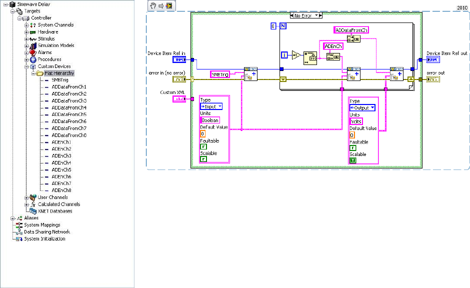
Figure: Flat Custom Device Hierarchy and Corresponding Initialization VI
The figure above is an example of a flat or single-level hierarchy for the AES-201. All of the
channels are under the main section in the configuration tree. While it’s easy to determine how
many channels are available, the type of channel is unknown and the function of the channel is
implied by the channel name. A flat hierarchy is suited for devices with a small number of
channels that all perform the same function. A flat hierarchy is less suited for large channel
count devices, or when channels perform different functions. For example, a custom device for
a multifunction data acquisition board would be difficult to present in a flat hierarchy.
Notice that the same Device Item Ref in is used to create the SWTrig, ADEnCh<1..8>, and
ADDataFromCh<1..8> channels. As a result, all of these channels appear at the same
echelon of the hierarchy. In the code above, you should be able to identify the input and output
channels. SWTrig and ADEnCh<1..8> are input channels because the custom device sinks
data from them. ADDataFromCh<1..8> are output channels because they source data to the
rest of NI VeriStand. We’ll be showing clusters as icons in much of the following material.
From an operator's perspective, custom device inputs and outputs may seem backwards.
Hardware inputs correspond to custom device outputs. The operator is not required to interact
with the custom device source code, only System Explorer. If the developer did a good job,
channel direction should make sense to the operator.
Custom Device Developer’s Guide © 2010 National Instruments 27 of 85
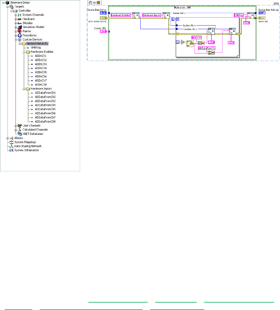
Figure: Nested Custom Device Hierarchy and Corresponding Initialization VI
The figure above is an example of a nested hierarchy for the AES-201. The channels have
been organized into Hardware Enables and Hardware Inputs sections. This device is
well-organized and fairy intuitive. Note how the Section Ptr outputs are used to create
channels beneath the corresponding section in the Initialization VI. Also note how the parent
reference is used to create the trigger channel at the same level as the two sections in the
custom device hierarchy.
You can create an arbitrarily complex hierarchy. You should plan the custom device hierarchy
to use the minimum number of sections that make the hierarchy well-organized, intuitive, and
user friendly.
Pages
Pages are VIs that System Explorer displays in the configuration pane. The configuration pane
is a Subpanel. Subpanels are LabVIEW front panel containers that allow a VI to display the
front panel of another VI. See LabVIEW 2010 Help » Fundamentals » Building the Front Panel
» Concepts » Front Panel Controls and Indicators » Subpanel Controls for more information.
An item’s page gets displayed in the Subpanel when the operator clicks on the item in system
Explorer’s configuration tree. Pages run on the host computer; they define the appearance and
configuration experience of the custom device. The Custom Device Template Tool creates two
configuration VIs by default: Initialization and Main. The Initialization VI is a simple VI (it doesn’t
get populated into the Subpanel), the Main VI is a page.
When you click on the top-most custom device item in the configuration tree, <Custom Device
Name> Main Page.vi goes into System Explorer’s configuration pane’s Subpanel and its
block diagram executes.
Custom Device Developer’s Guide © 2010 National Instruments 28 of 85
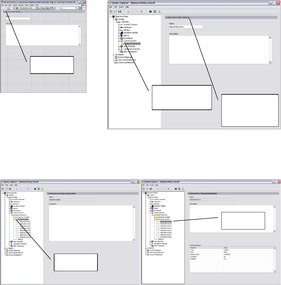
Figure: Main VI Populated into System Explorer when the Operator Clicks the Top-level
Custom Device Item in the Configuration Tree
If the developer did not assign a custom page to a new section or channel, the default section or
channel page is shown when the operator clicks on the item in the configuration tree.
Figure: The Default Section Page
Figure: The Default Channel Page
The default pages allow the operator to set a description for the section or page. NI VeriStand
retains this data in the System Definition (nivssdf) file. You cannot individually modify the block
diagram or font panel of the default pages. The Custom Device Template Tool allows the
developer to specify extra pages. Extra pages can be used to override the default page for an
item. When the developer creates an extra page and associates it with a section or channel, he
overrides the default page for that item. You can individually modify the front panel and block
diagram of extra pages. The block diagram executes when the operator clicks on the item in
the configuration tree.
The Main
Page
Clicking the top-level
item in the
configuration tree…
…runs the main
page and puts it in
the configuration
pane’s Subpanel.
A section is
highlighted.
A channel is
highlighted.
Custom Device Developer’s Guide © 2010 National Instruments 29 of 85
Before we discuss adding extra pages in detail, we must cover a two rules for modifying custom
device pages.
You must not change the size of any page's front panel. The page's front panel is
loaded into a Subpanel in the configuration pane. If you change the size of the front
panel, it may not fit correctly into the Subpanel and may be unusable.
You must not change the names or connector pane associations of any terminal
generated by the page template or Custom Device Template Tool. NI VeriStand uses
these objects to interface with the page. If they are changed, the custom device will not
work and will likely prevent the operator from deploying the system definition.
Extra Pages
Extra pages provide a way to customize the appearance and/or behavior of any item in the
custom device's hierarchy. Extra pages override the default pages. You should plan an extra
page for each item in the custom device you wish to customize differently. For example, if you
want to customize the page for each ADDataFromCh channel, but you’ll customize all
ADDataFromCh channels the same (say by adding an extra button for the filter), you only need
one extra page. NI VeriStand stores state data for each individual item in the custom device
hierarchy in the nivssdf file.
The AES-201 may call for five extra pages. One page for each section, one page each for the
ADDataFromCh<1..8> and ADEnCh<1..8> channels, and one page for the SWTrig channel.
Even if you don’t wind up using the extra pages, it’s better to have extra pages that you don’t
need than to need extra pages that you don’t have.
NI VeriStand requires four things in order to override a default page with an extra page in the
custom device.
1. Page
2. Globally Unique IDentifier (GUID)
3. XML Declaration
4. Build Specification
Custom Device Developer’s Guide © 2010 National Instruments 30 of 85
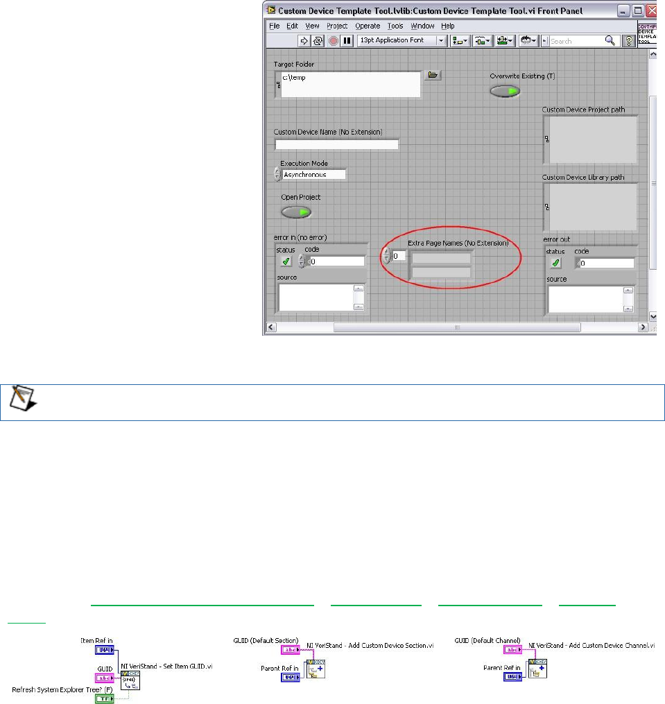
Page
A properly formed page VI must
exist. If you plan properly, you’ll be
able to specify all the extra pages
when you run the Custom Device
Template Tool. An extra page is
created for each element in the Extra
Page Names (No Extension)
control.
The tool generates the page, GUID,
XML Declaration, and includes the
page in the build specification. You’ll
find the extra page template in
Custom Device
API.lvlib\Templates\Subpane
l Page VI\Page Template.vit.
Figure: Extra Page Names Array
If you do not use the Custom Device Template Tool to create extra pages, you must
manually add and configure them.
Manually adding extra pages to a custom device after running the Custom Device Template
Tool is cumbersome. Avoid this issue by creating a few extra pages beyond what you think will
be necessary. Unused extra pages are not executed, but they do consume marginal space on
disk.
GUID
When you associate an extra page with a channel or section, you override the default page for
that item. This is done by specifying a GUID when the item is created, or by setting the item’s
GUID using NI VeriStand Custom Device API » Configuration » Item Properties » Set Item
GUID.
Figure: NI VeriStand API to Set an Item’s GUID
The Custom Device Template Tool generates a GUID for each extra page in the Extra Page
Names (No Extension) control.
There is a GUID Generator VI in <vi.lib>\NI Veristand\Custom Device
Tools\Custom Device Template Tool\Custom Device Template
Tool.lvlib:GUID Generator.vi. Before you can run this VI by itself, you must change
the Custom Device Template Tool.lvlib\subVIs access scope to public, and set the

Custom Device Developer’s Guide © 2010 National Instruments 31 of 85
VI’s Execution Priority to Normal. There is a stand-alone GUID generator VI attached to
KnowledgeBase 571B7IYP: Adding a Page to an NI VeriStand Custom Device's Configuration
Library after Running the Custom Device Template Tool. There are also a variety of free GUID
generators on-line.
XML Declaration
The custom device API associates a channel or section with a GUID. The custom device XML
associates the GUID with the page VI. The page and its GUID must be declared in the custom
device XML <PAGES> section within a <PAGE> schema. If the developer planned for the extra
pages before running the Custom Device Template Tool, the tool makes the appropriate entries
in the custom device XML file for each extra page.
<Page>
<Name>
<eng>Extra Page 1</eng>
<loc>Extra Page 1</loc>
</Name>
<GUID>36481013-A447-6517-7D1C-FBB21CAE1E9F</GUID>
<Glyph>
<Type>To Application Data Dir</Type>
<Path>System Explorer\Glyphs\default fpga category.png</Path>
</Glyph>
<Item2Launch>
<Type>To Common Doc Dir</Type>
<Path>Custom Devices\Extra Page Demo\Demo Configuration.llb\Extra Page 1.vi</Path>
</Item2Launch>
</Page> Custom Device XML Showing the Page Name, GUID, and VI
Build Specification
Extra pages are dynamically called VIs. Since they are not a part of the custom device’s VI
hierarchy, they must be explicitly included in the custom device's Build Specification. If the
developer planned for the required extra pages before running the Custom Device Template
Tool, the tool configures the build specifications to include the extra pages into the initialization
library.
If a page must be added to the custom device after the tool has been run, the developer must
edit the configuration Build Specification to include the extra page and all its dynamically called
dependencies (if any).
Custom Device Developer’s Guide © 2010 National Instruments 32 of 85
Type
While deployed to the execution
host, all custom devices run inside
the NI VeriStand Engine. The
engine is the non-visible mechanism
that controls the timing of the entire
system as well as communication
between the execution host and
host computer. See NI VeriStand
Help » Components of a Project »
Understanding the VeriStand
Engine for more information.
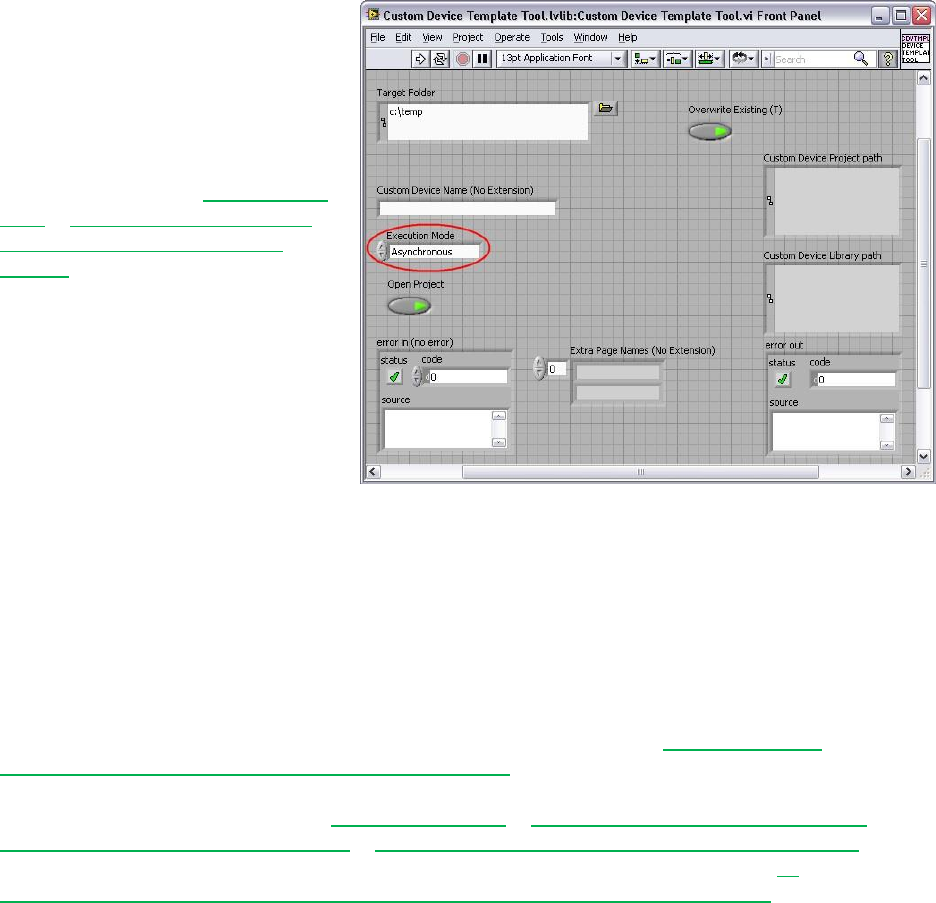
The Custom Device Template Tool
generates a new LabVIEW Project
containing one of five pre-built
device frameworks. The framework
is determined by the Execution
Mode control.
Figure: Execution Mode Control
The Execution Mode determines when the device will run with respect to the other operations
performed by the NI VeriStand Engine. There are five pre-built device frameworks. Three of
the frameworks are for custom devices; the other two are for custom timing and synchronization
devices.
Custom timing and synchronization devices are the same as regular custom devices, but they
can be configured as the hardware synchronization master to drive RTSI0. For more
information about the Real Time System Integration (RTSI) bus see KnowledgeBase
2R5FK53J: What is RTSI and How is it Configured? Custom timing and synchronization
devices are not covered in detail in this document. For more information about custom timing
and synchronization devices, see NI VeriStand Help » Configuring and Running a Project »
Configuring a System Definition File » Adding and Configuring Timing and Sync Devices. Multi-
chassis synchronization may also be accomplished using built-in features. See NI
DeveloperZone Tutorial: Creating a Distributed System With NI VeriStand 2010 for more
information.
Two of the regular custom devices run in-line with the Primary Control Loop (PCL), the other
runs in parallel with the PCL. A custom device is not limited to using just one type of framework.
Some developers have built both in-line and parallel engines for a single custom device and
allow the operator to select which mode to deploy.
Generally it's OK to alter the code within the framework depending on your needs. However
you must maintain the connector pane, controls, and indicators provided by the Custom Device
Template Tool or VI template. NI VeriStand uses these objects to interface with the custom
device. If they are changed, the custom device will not work and will likely cause errors.
Custom Device Developer’s Guide © 2010 National Instruments 33 of 85
Asynchronous
The asynchronous custom device framework provides a simple, single-loop architecture. There
are sections for initialization and cleanup before and after the loop. The asynchronous template
provides a Timed Loop which may be exchanged for a While at the developer’s discretion.
The loop runs in parallel loop to the PCL. If proper real-time development practices are adhered
to, it is unlikely to block the PCL or slow it down. Essentially this means that the rest of the NI
VeriStand system will continue to execute as expected even if the asynchronous custom device
is latent or stalls.
The loop can be synchronized to the PCL's timing source, making it pseudo-synchronous. This
applies to asynchronous devices that use a Timed Loop, While Loops cannot be used for this
purpose. The benefit of an asynchronous custom device synchronized to the PCL is that it will
not cause the PCL to be late just because the custom device finishes late. Use NI VeriStand –
Set Loop Type to specify the asynchronous Timed Loop uses the device clock. NI VeriStand
tics the device clock for all Timed Loops that have Use Device Clock set to true.
The asynchronous device can also run at a different rate than the PCL. The rate may be
defined using any execution timing method available in LabVIEW, and may iterate faster than
the PCL. The rate can also be a decimation of the PCL rate specified by Custom Device API »
Configuration » Item Property » Device Properties » Set Custom Device Decimation VI.
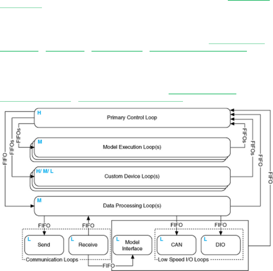
The asynchronous template provides two RT FIFOs (Device Inputs FIFO and Device Outputs
FIFO) to exchange channel data with the rest of NI VeriStand. Since the asynchronous device
runs in parallel to the PCL and passes channel data via RT FIFOs, there is a minimum of one
cycle delay from when data leaves the PCL and when it enters the custom device and vice
versa. These FIFOs correspond exactly to those shown in NI VeriStand 2010 Help »
Components of a Project » Understanding the VeriStand Engine.
Figure: The NI VeriStand Engine
Custom Device Developer’s Guide © 2010 National Instruments 34 of 85
The asynchronous device is not guaranteed to execute at the same time with respect to the
other components of the system. For example, the first iteration may execute before the PCL
processes alarms; the second and third iterations after, the fourth before et cetera.
The input controls are specially named controls that the system will use to provide the device
loop with data. The controls are not required for the device loop to run. For instance, if the
device doesn't produce any output data, then you don't need the Device Outputs FIFO control.
If you do need these controls, they must have these exact names to be functional.
The optional status notifier element is used to notify the RT engine of the last state of the
custom device, and to indicate the device has completed execution. If this control is not used, a
default No Error value is returned to the system when the device finishes execution. This error
state is not checked until the system shuts down. Use an output channel to send more
immediate status values to the system.
The asynchronous framework includes VIs from the NI VeriStand Asynchronous Device
Properties VIs palette.
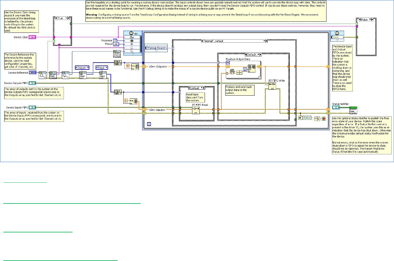
Custom Device Developer’s Guide © 2010 National Instruments 35 of 85
Figure: Asynchronous Custom Device Framework
Get Loop Type - Returns the type of loop that an asynchronous custom device uses. The type can be either While Loop or Timed
Loop. If it’s a Timed Loop, this VI also returns whether the loop uses the device clock.
Get Asynchronous Driver VI Timed Loop Name - Returns the name of the Timed Loop that a custom device uses. The VeriStand
Engine synchronizes the start of this Timed Loop with the other system Timed Loops. Use the name to ensure synchronization
occurs successfully.
Get Timed Loop Priority - Returns the priority (Low, Medium, or High) of an asynchronous custom device Timed Loop. To convert
this enumerated value to a numeric value that the Timed Loop input terminal accepts, use the Convert Timed Loop Priority Property
to Number VI.
Convert Timed Loop Priority to Number - Converts a priority value (Low, Medium, High) for a custom device Timed Loop into a
numeric value that the Timed Loop Input Node accepts. To set the priority, use the Set Timed Loop Priority VI.

Custom Device Developer’s Guide © 2010 National Instruments 36 of 85
Whenever a timing source is specified for a Timed Loop, the dt terminal is in tics of the
timing source. The asynchronous template has a default period of 100. The default
timing source is a 1KHz clock, so the default configuration iterates at 10Hz. If you set
Use Device Clock = true in the Set Loop Type VI, the Timed Loop will iterate every
once every 100 iterations of the PCL.
See LabVIEW 2010 Help » VI and Function Reference » Programming VIs and Functions »
Structures » Timed Loop for more information about the Timed Loop and its terminals.
Inline Hardware Interface
The inline hardware interface template is similar to state machine architecture. Some
developers will recognize it as an action-engine. See NI Discussion Forums » LabVIEW »
Community Nugget 4/08/2007 Action Engines for a discussion on action engines. The PCL
specifies the case to execute. An uninitialized Feedback Node is used for iterative data
transfer. There are five cases defined by the Operation enumerated control.
1. Initialize
2. Start
3. Read Data from Hardware
4. Write Data to Hardware
5. Close
This custom device runs in-line with the PCL, which calls each case at a specific time with
respect to the other components in the NI VeriStand engine. The PCL will not proceed until the
custom device case has completed.
Initialize
The Initialize case executes before the PCL starts. In this case, you can read the device
configuration information from properties using the reference to the device. Initialize data and
buffers used internally in the device. The framework compiles the list of Data References for
the custom device Inputs and Outputs in advance using Custom Device API » Driver Functions
» Get Custom Device Channel List and Custom Device API.lvlib » Templates » RT
Driver VIs » Inline » Inline Driver Utilities » Channel Data References »
Get Channel Data Reference.vi.
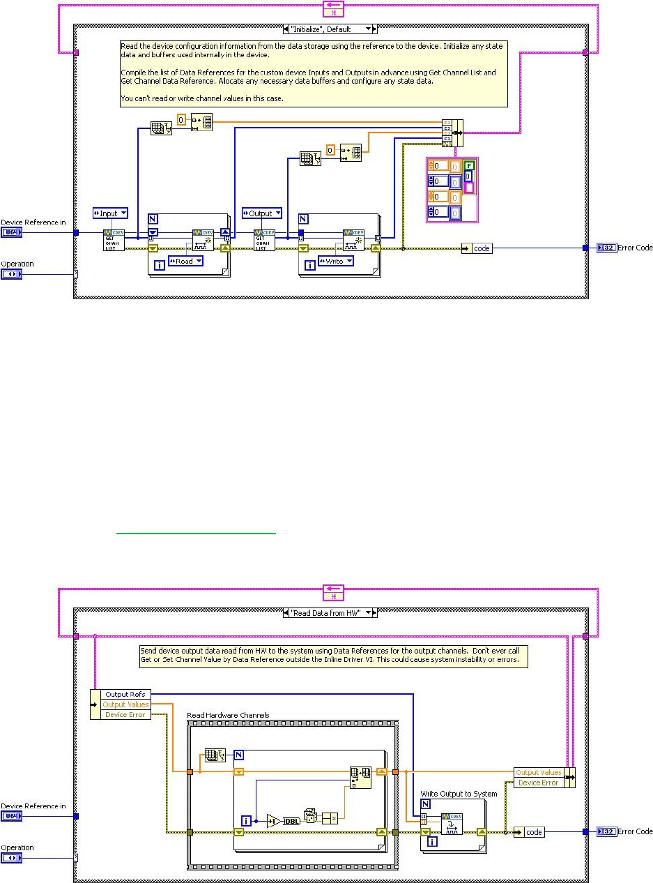
Custom Device Developer’s Guide © 2010 National Instruments 37 of 85
Figure: Initialize State of the Inline Hardware Interface Framework
Since the PCL hasn’t started yet, you can't read or write channel values in the Initialize case.
Start
The Start case executes after Initialization and before the PCL starts running. There’s no
difference between what code you can place in the Initialize and Start states. Since the PCL
hasn’t started yet, you can't read or write channel values in the Start case.
Read Data from HW
The Read Data from HW case executes at the beginning of the PCL, before other components
(such as Stimulus, Faults, Alarms, Procedures, et cetera) execute. For a detailed timing
diagram, see the Outline of PCL Iteration section. After processing system mappings, the data
obtained in this case is available to the other components of the system for the remainder of the
PCL iteration.
Figure: Read Data from HW State of the Inline Hardware Interface Framework
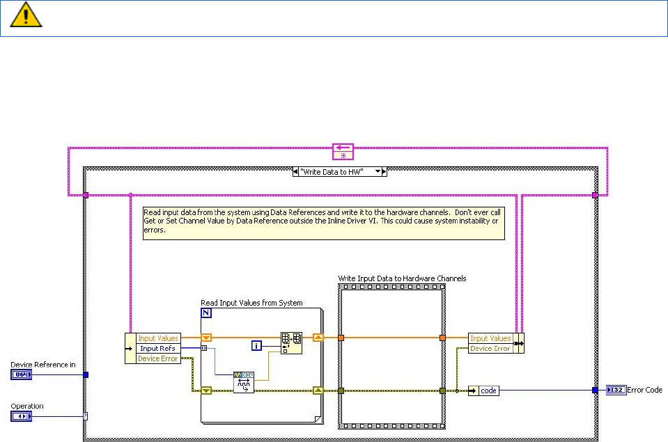
Custom Device Developer’s Guide © 2010 National Instruments 38 of 85
The template contains a Flat Sequence frame named Read Hardware Channels. You can
replace the code inside the frame with the API calls necessary to obtain data from a hardware
API.
Do not call Get or Set Channel Value by Data Reference outside the inline driver VI.
Doing so could cause system instability or errors.
Write Data to HW
The Write Data to HW case executes at the end of the PCL, after the other components (such
as Stimulus, Faults, Alarms, Procedures, et cetera) have executed.
Figure: Write Data to HW State of the Inline Hardware Interface Framework
The case contains a Flat Sequence frame named Write Input Data to Hardware Channels. You
can replace the code inside the frame with the API calls necessary to send data to a hardware
device.
Close
The Close case executes after the PCL has finished executing. It's good practice to close
references and release resources in this state. Since the PCL has terminated, you cannot read
or write channel values in this case.
Inline Model Interface
The Inline Model Interface custom device template is state machine/action engine architecture.
An uninitialized Feedback Node is used for iterative data transfer. There are four cases defined
by the Operation enumerated control.
1. Initialize – Same as Inline HW Interface
2. Start – Same as Inline HW Interface
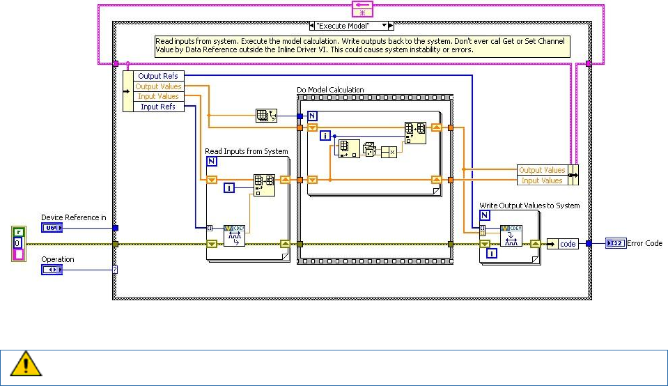
Custom Device Developer’s Guide © 2010 National Instruments 39 of 85
3. Execute Model
4. Close – Same as Inline HW Interface
This custom device is run in-line with the PCL, which calls each case at a specific time with
respect to the other components in the system. The PCL will not proceed until the custom
device case has returned.
Execute Model
The execute model case is called in the middle of the PCL. This is the one state of this device
that executes during the PCL. This state reads input data, performs a calculation, and then
writes output data to NI VeriStand. Using the Inline Model Interface mode enables you to
process data acquired from hardware inputs and send the processed values to hardware
outputs with no latency.
Figure: Execute Model State of the Inline Model Interface Framework
Do not call Get or Set Channel Value by Data Reference outside the inline driver VI.
Doing so could cause system instability or errors.

Custom Device Developer’s Guide © 2010 National Instruments 40 of 85
Table of Custom Device Frameworks
Device Type
Basic
Architecture
Framework
Data
Interface
Timing
Pros
Caveats
Use Cases
Asynchronous
Single Loop
Input and
Output FIFO
Synchronized w/
PCL
Decimation of
PCL rate (FIFOs
are read ever N’th
iteration of PCL)
Any user defined
rate
Unlikely to
adversely affect
timing of other
components in the
system
May run faster,
slower, or
decimation of PCL
1-cycle latency to
get data to/from the
device due to RT
FIFOs
Shared resources,
background
processes, non-
deterministic
hardware/
protocols,
system health
monitoring, logging,
offline analysis
Inline
Hardware
Interface
State
machine
Two steady-
state cases
Channel
references
In-line with the
PCL
Decimation of the
PCL (device
executes every
N’th iteration of
PCL, does not
have N-times as
long to finish)
Presents data to
engine before other
components
execute
Receive data from
engine after other
components have
executed
Can adversely
affect the timing of
the PCL
Most hardware,
deterministic
operations, two-
phase operations
such as stimulus-
response
Inline Model
Interface
State
machine
One steady-
state case
Channel
references
In-line with the
PCL
Decimation of the
PCL (device
executes every
N’th iteration of
PCL, does not
have N-times as
long to finish)
Send data to
engine with low
latency
Can adversely
affect the timing of
the PCL
Low-latency
calculations such
as PID,
interpolation, etc.

Custom Device Developer’s Guide © 2010 National Instruments 41 of 85
Outline of PCL Iteration
The order of operations in the Primary Control Loop varies with respect to the execution mode
of the controller. You can adjust this setting in System Explorer » Targets » Controller » Other
Settings » Execution Mode.
The Data Processing Loop (DPL) is responsible for executing Procedures, alarms, and
calculated channels. For more information about hardware timing in NI VeriStand see
KnowledgeBase 58BFIFAF: Hardware I/O Latency Times in NI VeriStand.
(N-1) means “from the previous iteration”.
Parallel Mode
1. Get hardware inputs from Controller » Hardware » Chassis
DAQ Digital Lines and Counters are read after Read From HW case of Inline
Hardware custom devices
2. Read asynchronous custom device FIFOs (N-1)
3. Run Read Data From HW case of Inline Hardware custom devices
Scaling is applied after all hardware inputs have been acquired
4. Read models from Controller » Simulation Models
5. Read from DPL (N-1)
6. Process system mappings
1
7. Run the Execute Model case of Inline Model custom devices
All hardware inputs have been acquired and all channels have been scaled
before this case runs
8. Process system mappings1
9. Execute generators
10. Process system mappings1
11. Write to DPL
12. Write to Controller » Simulation Models
13. Write hardware outputs to Controller » Hardware » Chassis
14. Run the Write to Hardware case of Inline Hardware custom devices
15. Write to Asynchronous device FIFOs
1
You can’t read data from a previous step until a “process system mappings” step has executed, even if
that step acquired the data you want. For example, you write an inline HW custom device, and inside the
read data from HW state of this custom device, you want to read the channel data from a DAQ card in the
configuration. The DAQ executes at step 1, your code executes at step 3. However, if you read the
channel for the DAQ in your code in step 3, you would get the data from the previous iteration (N-1)
because “process system mappings” hasn’t executed yet. This is the case for NIVS 2010, it will likely
change in the future.

Custom Device Developer’s Guide © 2010 National Instruments 42 of 85
Low-Latency Mode
Low latency mode executes models in-line.
1. Get hardware inputs from Controller » Hardware » Chassis
DAQ Digital Lines and Counters are read after Read From HW case of Inline
Hardware custom devices
2. Read asynchronous custom device FIFOs (N-1)
3. Run the Read Data From HW case of Inline Hardware custom devices
Scaling is applied after all hardware inputs have been acquired
4. Read from DPL (N-1)
5. Process system mappings1
6. Run the Execute Model case of Inline Model custom devices
All hardware inputs have been acquired and all channels have been scaled
before this case runs
7. Process system mappings1
8. Execute generators
9. Process mappings1
10. Write to Controller » Simulation Models
11. Wait for models to finish
12. Read from Controller » Simulation Models
13. Process system mappings1
14. Write to DPL
15. Write hardware outputs to Controller » Hardware » Chassis
16. Run the Write to Hardware case of Inline Hardware custom devices
17. Write to Asynchronous device FIFOs
Based on the timing requirements of the custom device, plan the type of device before
executing the Custom Device Template Tool. The AES-201 API sinks and sources data during
steady-state operation; the custom device needs input and output channels. The operator
needs deterministic hardware data. The AES-201 should be implemented with the Inline
Hardware type of custom device.
Implement the Custom Device
You should thoroughly plan before you implement the custom device. We’ll now implement the
custom device for the AES-201. Recall this is a hypothetical 3rd party device. By inventing our
own device and API, we’re able to focus on the custom device process and avoid the
programming tedium. If you’d like to walk through building an actual custom device, you can
follow NI DeveloperZone Tutorial: Building Custom Devices for NI VeriStand 2010.
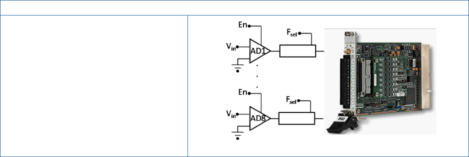
Custom Device Developer’s Guide © 2010 National Instruments 43 of 85
AES-201 Analog Input Specifications
Range: ±1V or ±500mV
Cannot be changed while digitizing
Return: 32-bit raw
Trigger: 1 software
SW Enable: Default on
Filter: 6Hz LPF default off
Figure: AES-201
Do we need a custom device?
Our customer requires 32-bits of resolution for their RT test system. This is the only PXI
digitizer that fulfills this requirement. After checking with NI.com and the manufacturer, we
found no custom device exists for the AES-201, so we determine that a new custom device is
necessary.
What are the risks?
The AES-201 ships with a hardware driver that’s compatible with LabVIEW Real-Time and a
LabVIEW API. We have a real-time desktop target that’s identical to our customer’s platform.
At our request, the customer has provided their model dll, so we can test and benchmark on a
system very similar to our customer’s system.
Implementation
Based on the AES-201, we create the following specifications.
Eight output channels ADDataFromCh<1..8>
Nine input channels ADEnCh<1..8>, SWTrig
Nine properties: FilterEn<1..8> and Range
We will use a nested two-level hierarchy
We plan to override the default channel page for ADDataFromCh<1..8> but we’ll use
the default page for everything else. We’ll create a few extra pages just to be safe.
To avoid FIFO latency, we’ll use the Hardware Inline custom device.
Build the Template Project
Open <vi.lib>\NI Veristand\Custom Device Tools\Custom Device Template
Tool\Custom Device Template Tool.vi. Configure the front panel to generate a
LabVIEW Project for the AES-201 custom device and then run the VI.
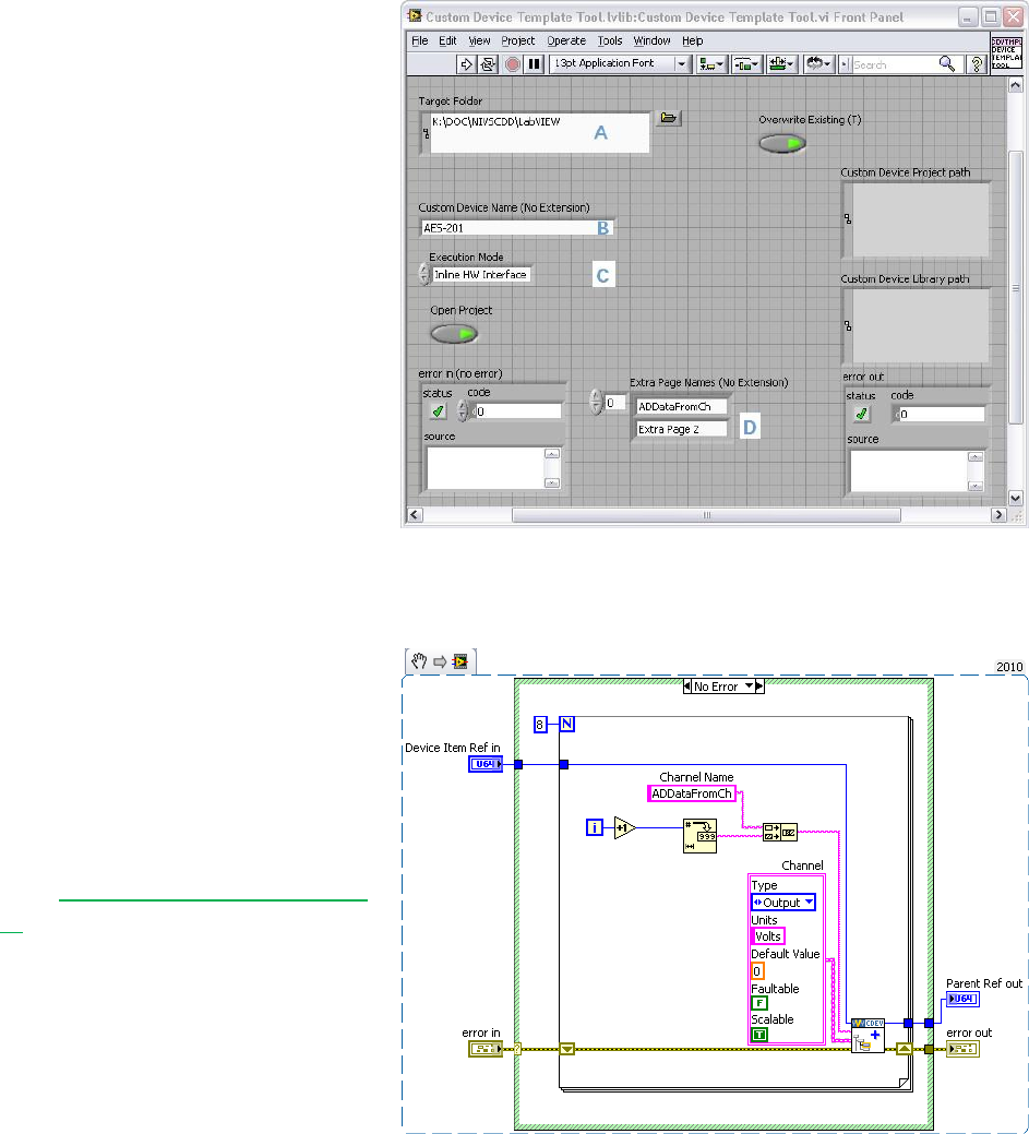
Custom Device Developer’s Guide © 2010 National Instruments 44 of 85
The Custom Device Template Tool
puts the new LabVIEW Project in a
sub folder inside the target folder
(A). The name of the custom
device (B) is also the name of the
sub folder. That is, you don’t have
to specify a sub folder for your
device because the tool makes one
for you. Select the type of custom
device from the Execution Mode
control (C). We’ll only need one
extra page, but we’ll create several
just in case requirements change
(D).
Build the Configuration
Now we’ll modify the LabVIEW
Project VIs generated by the
Custom Device Template Tool.
We’ll start with AES-201
Initialization.vi. In the
initialization VI, we’ll build-up the
default channel list. You’ve already
seen Add Custom Device Channel
VI.
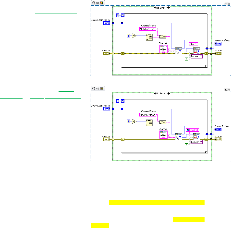
Custom Device Developer’s Guide © 2010 National Instruments 45 of 85
Add a Boolean property to each
channel using Set Item Property.
The property will indicate the state of
the filter on the channel.
It’s good practice to use Global
Variables or enum type definitions
for any constants that will be reused
throughout the custom device.
Replace the string constant with a
global variable that has the same
default value as the constant. Add
the global variable to the custom
device lvlib in the LabVIEW Project.
We want to override the default
channel page so we can add a
control to the page that allows the
operator to set the filter. We created
an extra page called
ADDataFromCh.vi for this
purpose. Look in the custom device
XML and find the GUID associated
with the extra page. While you’re at
it, change the glyph for the custom
channel page to default fpga
channel.
<Page>
<Name>
<eng>ADDataFromCh</eng>
<loc>ADDataFromCh</loc>
</Name>
<GUID>8AB4F65B-85C9-6BD6-B869-680C60278524</GUID>
<Glyph>
<Type>To Application Data Dir</Type>
<Path>System Explorer\Glyphs\default fpga
channel.png</Path>
</Glyph>
<Item2Launch>
<Type>To Common Doc Dir</Type>
<Path>Custom Devices\AES-201\AES-201
Configuration.llb\ADDataFromCh.vi</Path>
</Item2Launch>
</Page>
<Page>
Operators are used to having channels associated with that glyph. Likewise, change the glyph of
the main page to daq device.
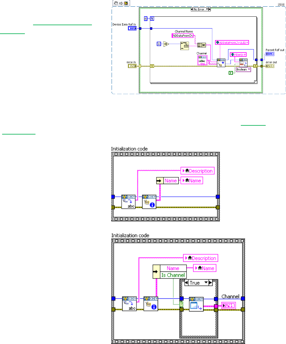
Custom Device Developer’s Guide © 2010 National Instruments 46 of 85
Add the GUID to the global variable.
Wire the global into the GUID
terminal of Add Custom Device
Channel. This associates the
channel with the VI.
Now when the operator clicks on
ADDataFromCh<1..8> in the
configuration tree,
ADDataFromCh.vi runs as a sub
panel in System Explorer instead of
the default channel page.
From here-on, we’ll set properties when we create the item rather than using the Set Item
Property VI to set them on the item reference.
Now that we’ve linked the channels
to the extra page, we’ll make edits to
the extra page, ADDataFromCh.vi.
In the Initialization frame, we’ll add
code to display the channel
information.
Operators are used to seeing
channel data when they click on a
channel, so we want to preserve that
experience. If the device is a
channel, we’ll send the channel data
to an indicator on the front panel.
It’s good practice to use the Boolean
outputs from functions in the API to
make sure that you’re operating on a
valid reference.
In this case, we’ll only retrieve the channel data if we have a valid channel reference. Another
option is to specify the default property value. The default property value is returned if the
property is not found. Using the default property value does not set the property.

Custom Device Developer’s Guide © 2010 National Instruments 47 of 85
Notice how the initialization frame
reads the name and description from
the device reference.
Do the same thing for the
FilterEn property so the operator
can see the state of the channel’s
filter setting. NI VeriStand is
responsible for passing the correct
channel reference to our custom
device, and storing state data for all
the controls and indicators. The
developer is responsible for acting
on the reference and displaying the
state.
Add a Boolean control to the front
panel called Channel Filter.
Create a case in the Event Structure
for the control’s value change. If the
FilterEn property is found, set the
property according to the value of
the control. If the FilterEn
property is not found, show a dialog
box with debugging information.
If the operator does not change this control, the property is never created. There are
several ways around this. You could initialize the property in the Initialization VI, or you
can assume a default value when you read the property.
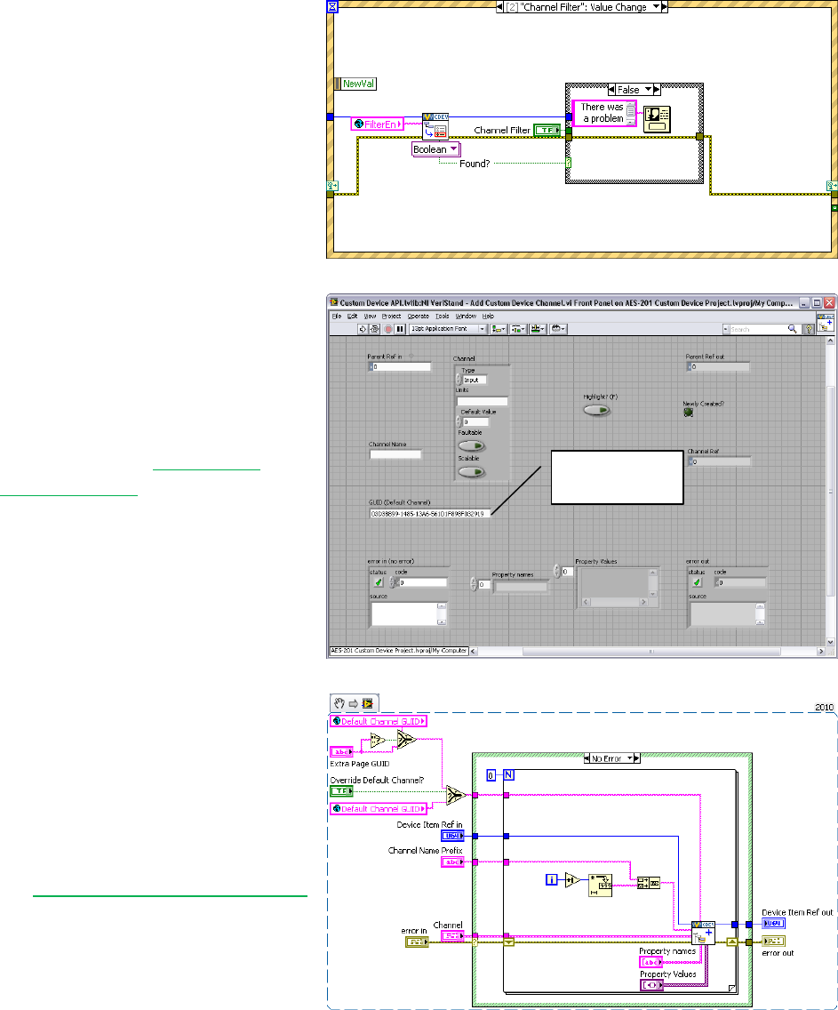
Custom Device Developer’s Guide © 2010 National Instruments 48 of 85
Remember, this VI runs on the host
computer, so we can launch a pop-
up dialog box to assist with
debugging.
Now we’ll build a subVI that creates
channels so we can reuse it for the
enable channels.
Add the default channel GUID to the
global variable. You can get it from
the front panel of Add Custom
Device Channel.
Here it is for your reference:
03D3BB99-1485-13A6-
561D1F898F032919.
If the Override Default Channel?
terminal of our subVI is true, the VI
takes a GUID from the caller. If not,
the VI uses the default channel
GUID.
Notice how properties are set from
the Add Custom Device Channel VI
directly. You can use this subVI in
many custom device projects.
Default
channel GUID
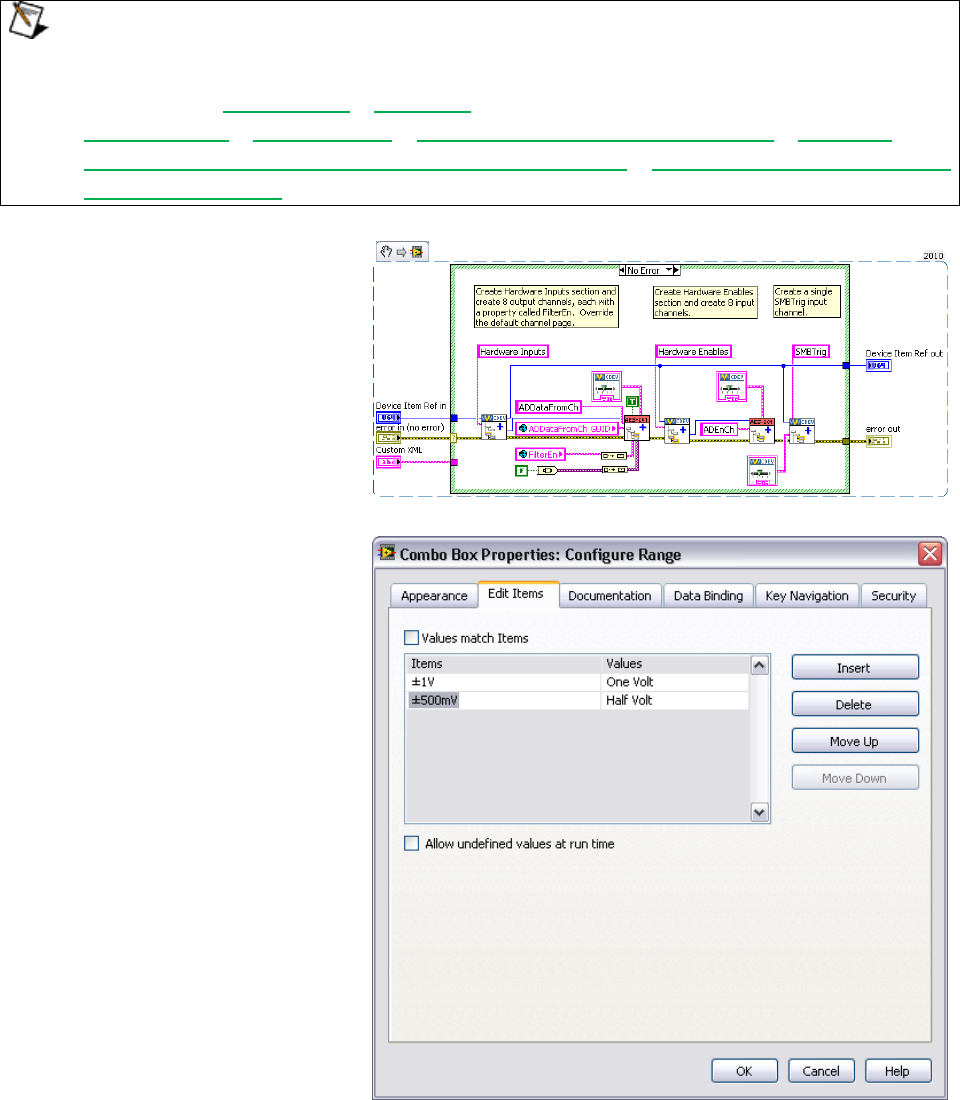
Custom Device Developer’s Guide © 2010 National Instruments 49 of 85
Custom devices execute as reentrant on the execution host. This enables the operator to
run multiple independent instances of the same custom device. Consider the case if the
operator has several AES-201 cards. Be sure to enable Reentrant execution from the
subVI’s File » VI Properties » Execution category to preserve this capability. See
LabVIEW Help » Fundamentals » Managing Performance and Memory » Concepts »
Suggestions for Using Execution Systems and Priorities » Simultaneously Calling SubVIs
from Multiple Places for more information about reentrant VIs.
The final Initialization VI creates two
sections. The Hardware Inputs
section has eight output channels.
The Hardware Enables section has
eight input channels. We also
create an input channel for the
software trigger.
Now that the initialization routine is
done, we’ll turn our attention to the
main page. We’ll use a type
definition combo box to set the
range of the AES-201. Add the type
definition to the custom device lvlib.
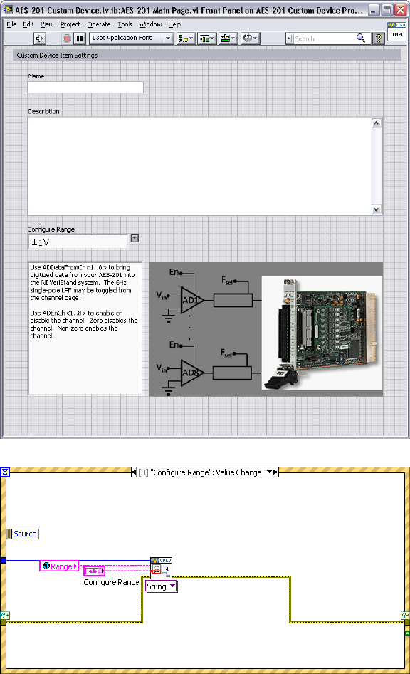
Custom Device Developer’s Guide © 2010 National Instruments 50 of 85
Modify the main page so the
operator can set the range of the
device. You don’t have to override
the main page with a custom page;
you can simply modify the main
page directly.
Add another string to the global
variable for the Range property.
Add an event case to the main page
that sets the range property when
the operator changes the value of
the control.
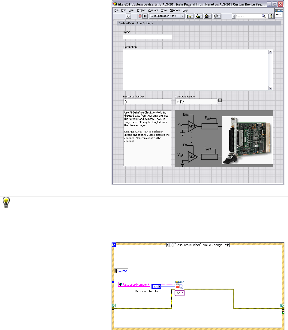
Custom Device Developer’s Guide © 2010 National Instruments 51 of 85
The engine will need some way to
know how to address the board.
Add another control so the operator
can configure a Resource
Number.
Many developers have asked for MAX integration/auto-discovery so the operator doesn’t
have to enter resource names manually. As of NI VeriStand 2010 this functionality does
not exist. You can write your own discovery routine that populates available resources, or
you can allow the operator to enter the resource name manually.
Add the event case to set the
resource number property.
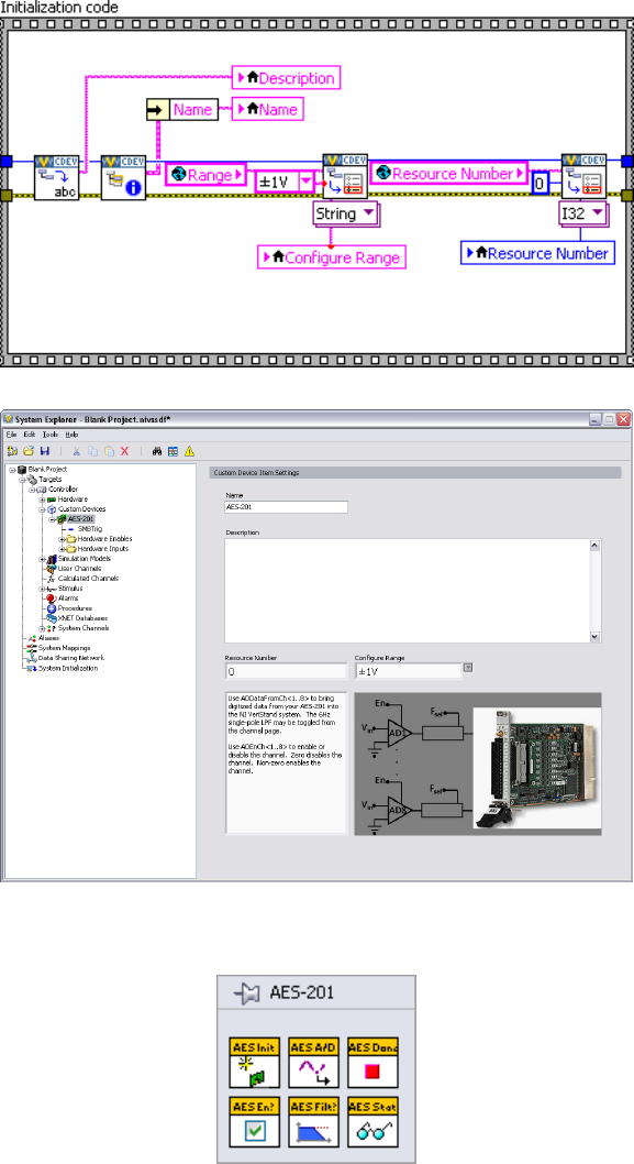
Custom Device Developer’s Guide © 2010 National Instruments 52 of 85
Read the device’s resource name
and range into the corresponding
controls in the initialization frame,
the same as you did for the extra
channel page’s filter property.
Remember, NI VeriStand stores
state and provides the correct
reference; the developer acts on the
reference and modifies the state.
Build the custom device and inspect
the hierarchy, sections, channels,
main page and extra pages. Now
we’ll turn our attention to the RT
Driver.
Build the Driver
The AES-201 comes with a simple
LabVIEW API. We’ll use the API to
build the RT driver portion of the
custom device.
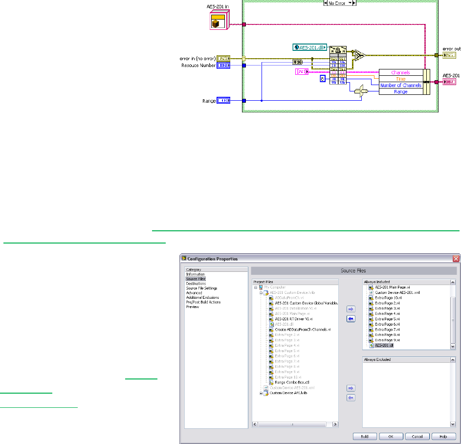
Custom Device Developer’s Guide © 2010 National Instruments 53 of 85
Functions in the API call into the
hardware dll. This is typical of a
LabVIEW API. This paradigm
requires the developer to post the
dll to the execution host.
Modify the custom device to
package the dll with the custom
device and deploy it to the
execution host.
Add Custom Device Dependencies
Shared libraries are typically .dll files on Windows/PharLap operating systems and .out files on
VxWorks systems. If you’re building a custom device for a Compact RIO execution host, you’ll
be working with .out files. See KnowledgeBase 4LRA4IQ0: What Operating System is my Real-
Time Controller Running and Why for more information.
There are two parts to packaging
dependencies. The first part is to
incorporate the dependency into the
LabVIEW Project.
Add the dll to the custom device
LabVIEW library.
Modify the configuration’s source
distribution by adding the dll to the
Always Included list.

Custom Device Developer’s Guide © 2010 National Instruments 54 of 85
Note the location of the Support
Directory. In this case it’s
C:\Documents and
Settings\All
Users\Documents\National
Instruments\NI VeriStand
2010\Custom Devices\AES-
201\Data.
Set the destination directory for the
dll to the Support Directory.
Now when you build the
configuration, LabVIEW sends the
dll to the support directory.

Custom Device Developer’s Guide © 2010 National Instruments 55 of 85
The second part in packaging dependencies is to incorporate the dependency into the custom
device. Use Add Custom Device Dependencies to deploy the library to the execution host.
NI VeriStand – Add Custom Device Dependencies VI
Owning Palette: Dependencies VIs
Adds dependencies to a custom device.
Device Ref in is the NI VeriStand reference to the custom device.
Dependencies is an array of Custom Device File Dependency controls.
Path is the path and file name of the dependency
Type is absolute or relative to one of NI VeriStand’s built-in file paths. See the What is a Custom
Device for a list of built-in file paths.
RT Destination specifies the directory and file name of the dependency on the execution host
Force Download terminal must be false.
SupportedTarget specifies the target operating systems that will receive the dependency
Version
error in describes error conditions that occur before this node runs. This input provides standard error in
functionality.
Device Ref out is a duplicate of the Device Ref in.
error out contains error information. This output provides standard error out functionality.
There are several other VIs in the NI VeriStand Dependencies VIs palette that operate on
custom device dependencies. These functions do what you’d expect given their names.
Dependencies VIs » Get Custom Device Dependencies
Dependencies VIs » Reset Custom Device Dependencies
Add the custom device dependency
to the Initialization VI.
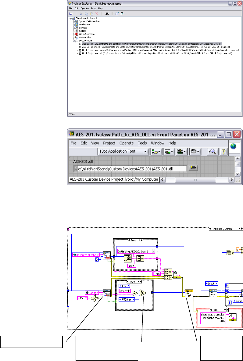
Custom Device Developer’s Guide © 2010 National Instruments 56 of 85
As a result, the Initialization VI adds
the dll to the project’s dependency
list when it runs.
You must have some way to direct
the engine to the dll on the
execution host. One way is to
deploy the dll to a folder in RT’s
search path (C:\ni-rt\system
by default).
A better way is to use a global
variable that points to the absolute
path of the dll on the execution
host.
Deploy the dll to C:\ni-rt\VeriStand\Custom Devices\<Custom Device
Name>\<library>.dll. This is more maintainable.
Read the range and resource
number properties from the custom
device reference. Recall that you
must read the property from the
correct item, and we set these
properties to the top-level device
reference. Call the AES-201 API to
initialize the board according to the
property values.
Read item property
Coerce the property
value to a data for
the API
Call the
hardware
API
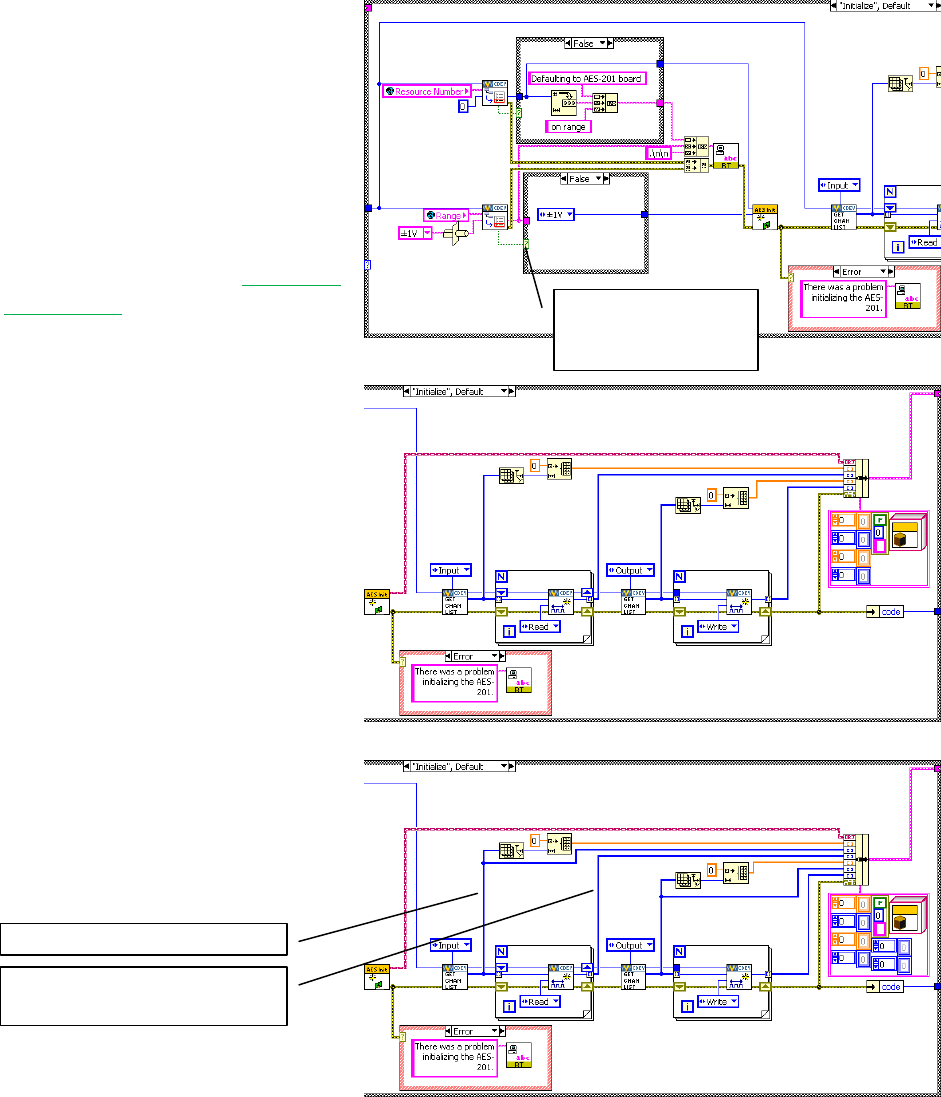
Custom Device Developer’s Guide © 2010 National Instruments 57 of 85
Remember, if the operator didn’t
trigger the event to set the property,
there won’t be a property to read.
Instead of throwing an error, default
to the value of your choice and call
the API accordingly.
It might be nice to tell the operator
what’s going on. Print a few strings
to the console. See the Printing to
the Console section for more
information.
The inline HW custom device uses
a feedback node to pass state data
between states. Add the AES-201
state data to the feedback node’s
cluster. If you’re not familiar with
LabVIEW Objects, it’s sufficient to
know that this LabVIEW object
represents all the state data needed
to use the AES-201 in subsequent
states.
Add the input and output channel
references to the state data cluster.
Use a default value if
the property is not
found.
The input channel references
The input channel data
references
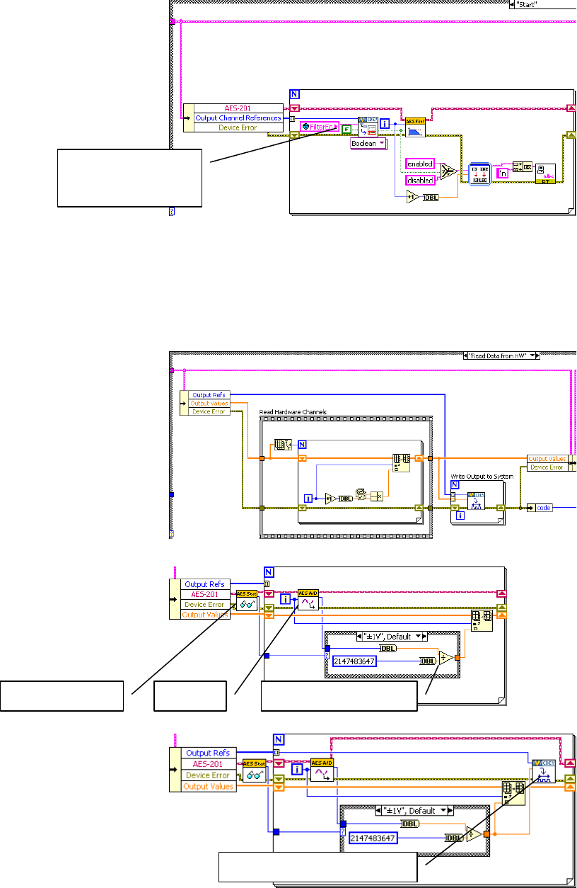
Custom Device Developer’s Guide © 2010 National Instruments 58 of 85
The output channels are for
ADDataFromCh<1..8>. Check
the filter property on each output
channel reference and call the
AES-201 API to set the filter
accordingly.
After the custom device has been configured and deployed, NI VeriStand will no longer
exchanged property information between the host computer and execution host. Since we
implemented the filter as a property, we’ll call the AES-201 API in the Start case. If the operator
wants to toggle the filter, he must reconfigure the device in System Explorer.
Now that we’ve configured the
hardware, we’ll request an A/D
sample. For this custom device,
the Read Data from HW case is
nicely suited for this operation.
Replace the Read Hardware
Channels frame with the API call to
digitize. Convert the 32-bit raw
data to DBL data depending on the
range of the AES-201.
Send the channel data to the rest
of the NI VeriStand system by
writing to the Output Reference.
Return FALSE if the
property is not found.
Query the range
Digitize
Convert to DBL
Write NI VeriStand Channels
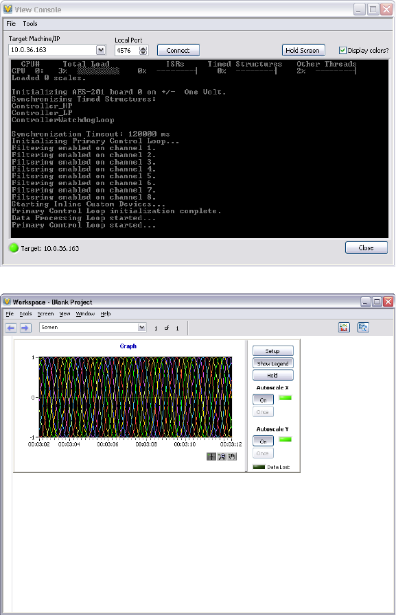
Custom Device Developer’s Guide © 2010 National Instruments 59 of 85
For flat hierarchies, the reference array corresponds one-to-one with channels as they were
created on the host computer. In other words, the first channel created is the 0’th element of
the array.
For non-flat hierarchies, the reference array corresponds top-down and one-to-one with
channels as they were created. In other words, channels at the highest level of the hierarchy
appear first in the array, then subsequent levels’ channels appear in the array in the order they
were created.
Robust custom devices do not depend on any particular order of channel references. Unique
properties or GUIDs should be used to ensure the driver VI operates on the correct channel.
The AES-201 inputs are enabled
by default. Build the custom
device, enable filtering on all
channels, add it to a new system
definition and deploy the project.
You should see messages on the
console indicating the non-default
configuration. This is a good sanity
check.
Map the ADDataFromCh<1..8>
channels to a simple graph and
make sure they display the
expected signals.
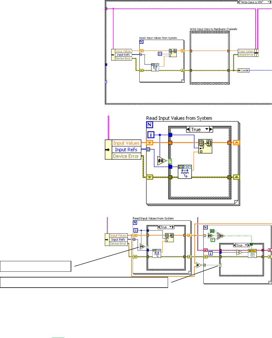
Custom Device Developer’s Guide © 2010 National Instruments 60 of 85
Now we’ll process the software
enable channels. For this custom
device, the Write Data to HW case
is nicely suited.
The SWTrig channel is higher than
the ADEnCh<1..8> input channels
in the hierarchy; even though it
was created last, it’s the first
channel in the input channel
reference array. We’ll skip the
SWTrig channel reference for
now, and read the 8 enable
channels.
Make a call to the AES-201 only if
the enable channel value has
changed. Enable the hardware
channel if the NI VeriStand channel
does not equal zero.
Channel Change Detection
You can build change detection into the custom device engine so it doesn’t perform actions if
the data hasn’t changed. This will cause differing execution times depending on data. Some
may consider this jitter; but it isn’t the literal sense of the word unless the code fails to meet
determinism requirements. And as long as you don’t fail a requirement, saving time is never
bad.
Skip the SWTrig channel
Only call the API if the enable channel has changed value
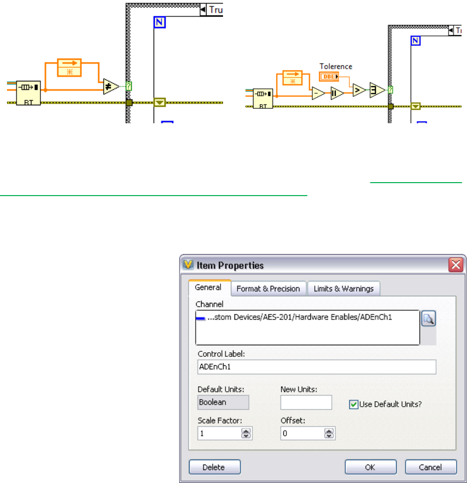
Custom Device Developer’s Guide © 2010 National Instruments 61 of 85
Figure: Simple Change Detection
Figure: Change Detection with Tollerance
There are a variety of methods for doing change detection. We’ll briefly discuss two methods.
Simple change detection can fail due to floating point precision issues. See NI Developer Zone
Tutorial: An Introduction to Floating-Point Behavior in LabVIEW for more information about how
computers handle floating point numbers.
Change detection with tolerance works-around the precision issues. Make sure to use
tolerances that avoid false triggers.
Rebuild the device and add 8
Boolean controls to the workspace.
Map each control to the
corresponding ADEnCh<1..8>
channel.
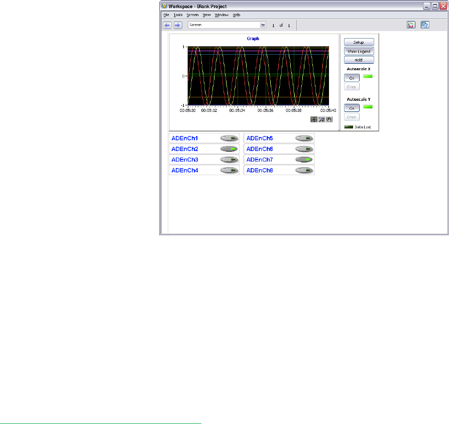
Custom Device Developer’s Guide © 2010 National Instruments 62 of 85
You should now be able to toggle
the channels on and off from the
workspace. In this contrived
example, disabled channels hold
the last sample.
Since we thoroughly planned the AES-201 custom device before we started writing code, it was
fairly straightforward to implement the device. Planning is key. The next section of the
document will cover some debugging and benchmarking techniques.
Debugging and Benchmarking
Debugging and benchmarking is a normal process of code development. There are a variety of
ways to debug and benchmark custom devices.
LabVIEW Debugging Techniques
Custom devices are written in LabVIEW code. Therefore it’s possible to develop, test and
debug in LabVIEW before running the Custom Device Template Tool. In other words, you can
use LabVIEW’s built-in debugging techniques during development; and merge the LabVIEW
code into the custom device framework after it matures.
Since the custom device is one of many parts of the system definition, the behavior of the
LabVIEW code within the custom device framework will likely differ from the stand-alone
LabVIEW application, especially in regards to timing. As a result, you should benchmark the
custom device inside of the NI VeriStand Engine.
Once added to the system definition, custom devices have been fully integrated into NI
VeriStand’s context. As a result, LabVIEW’s built-in debugging techniques are no longer
available. Several techniques are available for debugging and benchmarking the custom
device.
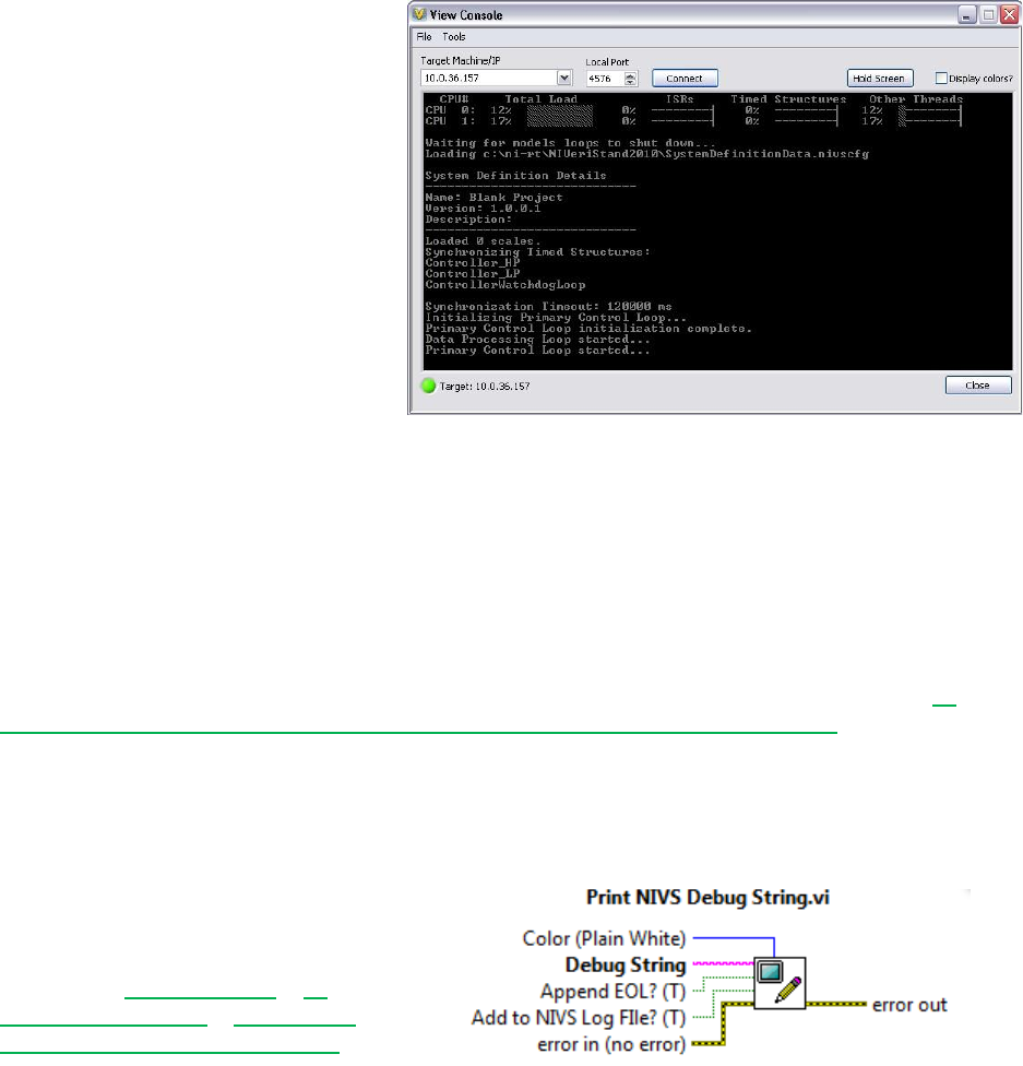
Custom Device Developer’s Guide © 2010 National Instruments 63 of 85
Console Viewer
A subcomponent of NI VeriStand RT
Engine is the RT Console Viewer.
You can install it to the execution
host using Measurement and
Automation Explorer. When
installed, the component runs a
small UDP daemon allowing the
operator to view the console from a
utility called the RT Console Viewer.
You can access the RT Console
viewer from NI VeriStand »
Workspace » Tools » Console
Viewer.
Figure: RT Console Viewer
The Console Viewer will show the system definition and the resulting CPU usage. The viewer is
also useful for displaying debugging messages. The console viewer provides a periodic
snapshot of utilization. CPU spikes and transients will probably be unobservable. If the system
is very busy, it may not update the console viewer at all. You can use other debugging methods
for a more accurate indication of resource utilization.
As the name implies, the RT Console viewer is only available on real-time targets. The RT
Console Viewer is also available as a stand-alone add-on to LabVIEW Real-Time. See NI
Developer Zone Tutorial: Remotely View Console Output of Real-Time Targets for more
information.
Printing to the Console
Printing to the console is often all that’s needed to debug an application.
Printing With NIVS Debug String VI
The recommended method of printing
to the console is to use Print NIVS
Debug String VI. You can download
the VI from NI Community » NI
VeriStand Add-Ons » Documents »
Print NI VeriStand Debug String.
This VI works on both Windows and RT execution hosts. It has an optional input to change the
color of the text. It also has an optional input to append the string to the NI VeriStand log file.
Printing With ni_emb.dll
The NIVS Debug String VI is not available in NI VeriStand 2009. You’ll find ni_emb.dll in
<labview>\Targets\NI\RT\vi.lib. This dll contains a stub function called
PrintStringToConsole. Calling this function sends a string to the RT console. Configure
the function to run in any thread using the C calling convention. The return type is void and it
has a C String pointer input constant. You’ll find this function wrapped in a VI in the same folder

Custom Device Developer’s Guide © 2010 National Instruments 64 of 85
in rtutility.llb\RT Debug String.vi. Since ni_emb.dll is a stub dll, it’s not
necessary to deploy this VI to the RT target. The stub exists so the PrintStringToConsole
function does not return an error when called on Windows.
If you do not want to call
ni_emb.dll on a Windows OS, you
can use a Conditional Disable
Structure around the dll. See NI
Developer Zone Tutorial: Using the
Conditional Disable Structure for
more information.
Figure: Disable ni_emb.dll for non-Windows
Operating Systems
You may find NI Developer Zone Example Program: DebugInfo.vi: Polymorphic VI for Showing
Debug Information on an RT System useful for printing non-string data to the console window.
You should be aware of the overhead incurred by calling this function. KnowledgeBase
3EK88SOH: Can I Use the RT Debug String In My Time-Critical Loop outlines a few caveats
and best practices for using the PrintStringToConsole function, such as using \r in a
Slash Code string constant to avoid scrolling the screen.
Distributed System Manager
You can use the NI Distributed System Manager (DSM) to monitor the CPU and memory
resources of an RT target. You must install System State Publisher on the RT target. This
component runs a small daemon that publishes the system state to DSM. See NI Distributed
System Manager for LabVIEW 2010 Help » System Manager Overview » System Manager
Overview » Monitor RT target resources for more information.
System State Publisher provides a periodic snapshot of utilization. Spikes and transients in
CPU utilization will probably not be observable. If the system is very busy, it may not update
DSM at all. You can use other debugging methods for a more accurate indication of resource
utilization.
System Channels
NI VeriStand includes dozens of system channels. System channels provide information about
what’s going on under the hood of NI VeriStand. Several of these system channels are useful in
benchmarking and debugging.
Table of Debugging and Benchmarking System Channels
System Channel
Description
HP Count
The number of times the Primary Control Loop reported being late.
HP Loop Duration
The duration of the Primary Control Loop in nanoseconds.
LP Count
The number of times the Data Processing Loop reported being late.
Model Count
The number of times the models have not completed their execution in
time.

Custom Device Developer’s Guide © 2010 National Instruments 65 of 85
If the value of the count channels increase over time, the execution host is not achieving the
desired loop rates. You can use the system channels in conjunction with an alarm or procedure
to handle the event.
System Monitor Add-on
The NI VeriStand System Monitor is a Custom Device that tracks memory resources and CPU
usage on an RT target running the NI VeriStand Engine. Set the update rate (Hz) in System
Explorer to determine how often the custom device checks CPU and memory usage and sends
them to the corresponding channel. The NI VeriStand System Monitor can only be used on an
RT target. The custom device returns an error if you target it to a Windows system.
Real-Time Execution Tracing
NI VeriStand 2010 provides built-in support for using the NI Real-Time Execution Trace Toolkit
to create trace logs for low-level debugging. The NI Execution Trace Toolkit is required to view
the log. The execution trace provides the finest grain thread and timing details of all the
debugging tools. See LabVIEW Execution Trace Toolkit Help » Viewing Trace Sessions to
learn about the information the tool provides.
The execution trace will start capturing when System Definition » Targets » Controller » System
Channels » Trace Enabled Flag becomes non-zero. When Trace Enabled Flag
becomes zero again, it finalizes the execution and stores the execution trace log file on the
target at C:\ni-rt\NIVeriStand2010\ExecutionTraces\. If you have the Execution
Trace Log Viewer open on the execution host, the target will send the log to the viewer over
Ethernet. The following channels may be used with the execution trace.

Custom Device Developer’s Guide © 2010 National Instruments 66 of 85
Table of RT Execution Tracing Channels
Channel Name
Function
Detailed Tracing
Flag
Specifies whether detailed execution tracing is enabled on the RT
target. This channel corresponds to the Detailed Tracing terminal.
Thread Tracing
Flag
Specifies whether thread execution tracing is enabled on the RT target.
This channel corresponds to the Thread Tracing terminal.
Trace Buffer
Size
Specifies the size in bytes of the execution trace buffer on the RT
target. This channel corresponds to the Buffer Size terminal.
Trace Enabled
Flag
Specifies whether execution tracing is currently active on the RT
Target.
VI Tracing Flag
Specifies whether VI execution tracing is enabled on the RT Target.
This channel corresponds to the VI Tracing terminal.
In NI VeriStand 2009, you could obtain an execution trace by using the Real-Time Trace Toolkit
Add-on.
Additional Debugging Options for NI VeriStand
Upon request, National Instrument may provide advanced debugging tools to help you resolve
certain custom device issues. These tools are a last resort when all other debugging options
have been exhausted. Please contact National Instruments for more information.

Custom Device Developer’s Guide © 2010 National Instruments 67 of 85
Table of Debugging and Benchmarking Techniques
Technique
Useful For
Granularity
Caveats
LabVIEW’s Built-in
Debugging Tools
Debugging
N/A
Useful before the LabVIEW code has been merged into the
custom device framework
LabVIEW debugging hooks do affect timing
Execution highlighting drastically affects VI timing
Console Viewer
Debugging
Benchmarking CPU
Low
Periodic snapshot of utilization, transients and spikes may be
missed
Requires the RT Console Viewer daemon
RT Debug String
Debugging
N/A
Incurs overhead, especially when the console window requires
a redraw
Distributed System
Manager
Benchmarking CPU
Benchmarking RAM
Medium
Periodic snapshot of utilization, transients and spikes may be
missed
Requires the System State Publisher daemon
System Channels
Benchmarking timing
High
Knowledge of the operator’s System Definition is required to
make good use of the system channels for benchmarking
System Monitor Add-
on
Benchmarking CPU
Benchmarking RAM
High
This add-on is an asynchronous custom device. The higher
you configure the custom device loop rate, the more overhead
it adds.
Real-Time Execution
Tracing
Debugging
Benchmarking
Ultra High
Execution trace logs contain a vast amount of detailed
information. They require a good deal of domain expertise to
interpret.
Using the tool effectively requires starting and stopping the
trace directly around the period of interest.
Additional Debugging
Options
Debugging
Must request from NI
NI must approve its use
Considered a last resort only
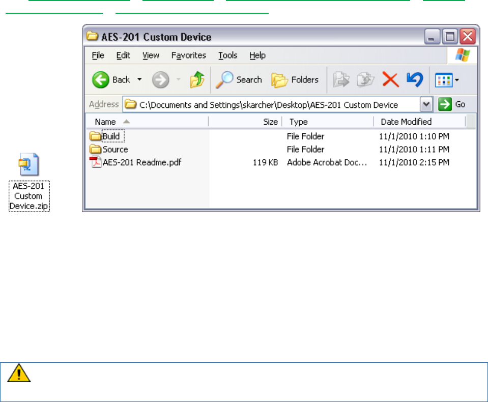
Custom Device Developer’s Guide © 2010 National Instruments 68 of 85
Distributing the Custom Device
After you build, debug, validate, and benchmark the custom device, you’ll probably want to
package it for operators and other developers to use. We’ll briefly cover a manual distribution
process. As with a generic application, you may streamline distribution by building an installer.
See LabVIEW 2010 Help » Fundamentals » Building and Distributing Applications » Creating
Build Specifications » Building an Installer (Windows) for more information.
Figure: AES-201 Distribution and Folder Hierarchy
We recommend distributing the custom device by copying the necessary files into a simple
folder hierarchy. The top-level folder should contain a Readme file and two folders: Build and
Source. By copying the contents of the Build folder to NI VeriStand’s <Common
Data>\Custom Devices\, the operator can add the custom device to his system definition.
The Source folder should contain the LabVIEW Project used to create the custom device and
any supporting libraries and dependencies required to build the custom device. For example,
you’ll want to ship the AES-201 custom device with the LabVIEW API and hardware dll.
Do not include the Custom Device API.lvlib files with the distribution. You do not want to
replace the library on the operator’s machine, and you do not want to change the library
linking on your machine.
The Readme file should contain instructions for installing, licensing, using, and modifying the
custom device. It should also contain contact information if you plan to support the device, or a
disclaimer if you don’t plan to support the device. The Readme file is a good place to put any
benchmarking information you’ve obtained.
You cannot directly use an NI VeriStand 2009 custom device in NI VeriStand 2010 or vice
versa, so it’s important to include version information for the custom device.
Custom Device Tips and Tricks
This section contains a hodgepodge of tips and tricks when developing custom devices.
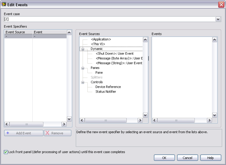
Custom Device Developer’s Guide © 2010 National Instruments 69 of 85
Custom Device Engine Events
After a custom device has been deployed, data is exchanged via custom device channels. If
channels are insufficient or overly cumbersome, you may implement your own communication
mechanism. NI VeriStand also provides access to its own TCP pipe so you don’t have to
maintain the connection. NI VeriStand’s pipe facilitates readable text and byte array data.
In the custom device API you’ll find NI VeriStand - Register Custom Device Engine Events VI.
This VI provides three dynamic events that may be registered in any VI with a reference to the
custom device.
1. Shut Down
2. Message (Byte Array)
3. Message (string)
Figure: Registering for NI VeriStand Dynamic Events
The two message events fire when some code calls NI VeriStand – Send Custom Device
Message VI.

Custom Device Developer’s Guide © 2010 National Instruments 70 of 85
Figure: Sending a Message to NI VeriStand’s Dynamic Message Events
There is an example of using the dynamic event pipe in <labview>\Examples\NI
VeriStand\Custom Devices\Communication Example\Communication Example
Custom Device Project.lvproj.
Block Writing and Reading
For inline hardware and inline model custom devices with a large number of channels, it’s more
efficient to read and write channel data using block data references. Use the following VIs to
work with block data references. Custom Device API.lvlib » Templates » RT Driver VIs » Inline
» Inline Driver Utilities » Channel Data References » NI VeriStand…
Get Channel Block Data References
Get Channel Values by Block Data Reference
Set Channel Values by Block Data Reference
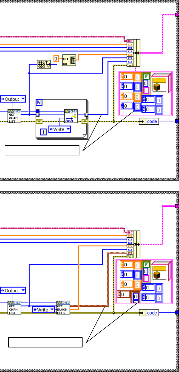
Custom Device Developer’s Guide © 2010 National Instruments 71 of 85
Recall the Initialization code that
generates a list of output channel
references.
Instead of output channel
references, obtain block references
to the output channels. Modify the
state data cluster accordingly.
Channel data references
Block data references
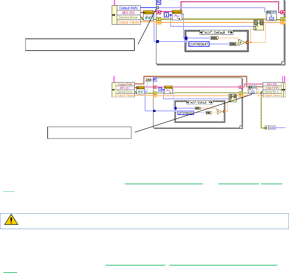
Custom Device Developer’s Guide © 2010 National Instruments 72 of 85
In the first version of the custom
device, we auto-indexed each
channel data reference.
Modify the code to write the block
reference instead. Notice the
channel block data references are
written en-mass outside the loop
rather than channel-by-channel
within the loop.
Working with String Constants
During custom device development, strings are used for property names and GUIDs. These
strings are case-sensitive and, in the case of GUIDs, long and prone to typos. To facilitate
working with these, consider using either LabVIEW Global Variables or a type definition Combo
Box control. When using the global variable, ensure that you have set the correct default value
for the control. When using the Combo Box control, uncheck the Values match Items box on
the Edit Items tab of the Properties dialog box.
The Combo Box control does not auto-update from its type definition. Completely
populate the control before using it on the block diagram.
Custom Error Codes
You may build custom error codes for your custom device by using the General Error Handler VI
or the Error Code File Editor. See LabVIEW 2010 Help: Defining Custom Error Codes in Test
Files for more information. If you use an error file, you must move the file to NI VeriStand’s
error folder. By default, this folder is located at <Program Files>\National
Instruments\VeriStand 2010\project\errors\English. You should add the error
file as a project dependency. If applicable, deploy the file to the error directory on the RT
system, located at \NI-RT\SYSTEM\errors\english for PharLap and VxWorks targets.
Utility VIs
The NI VeriStand developers have assembled a library of useful utility VIs in <vi.lib>\NI
Veristand\Custom Device Tools\Custom Device Utility Library\Custom
Device Utility Library.lvlib. The VIs in this library are documented in LabVIEW’s
Context Help window. Here is a list of the utility VIs.
Add Sections Recursively by Relative Path
Advanced Browsing Dialog
Get All Channels
Get Channel FIFO Buffer Index
Auto indexing channel data references
Writing block data references

Custom Device Developer’s Guide © 2010 National Instruments 73 of 85
Get Item Ref by Relative Path
Get Multiple Dependent Node Refs
Get Next Unique Label
Get Target Ref
Highlight Node in System Explorer
Not a Ref
Ref Constants
Report Final Error Status
Search for All Items by GUID
Search for All Items by Name
Search for All Items by Property
Search for Item by GUID
Search for Item by Name
Search for Item by Property
Search for Item
Set Multiple Dependent Node Refs
Sort Channels by FIFO Location
NI VeriStand – Get Channel FIFO Buffer Index VI returns the FIFO buffer index for the input or
output channel reference. Use this function for Asynchronous Custom Device channels to
determine what index to read or write in the FIFO arrays. The VI also returns which FIFO Buffer
(Input or Output) the channel will be located in. This function is only intended for Asynchronous
Custom Devices.
Consider a custom device to read an arbitrary list of DAQmx thermocouple inputs. One way to
accomplish the task would be to read all the hardware channels, cycle through the list of custom
device channels looking for the channel property, and write the associated hardware channel
value that corresponds to the custom device channel.
A superior way to accomplish the task is to sort the channel references in the order they appear
in the custom device FIFO, and configure the DAQmx task so the thermocouple channels are
read in the same order as they appear in the FIFO.
Figure: Sorting Asynchronous Custom Device Channels by their Order in the FIFO
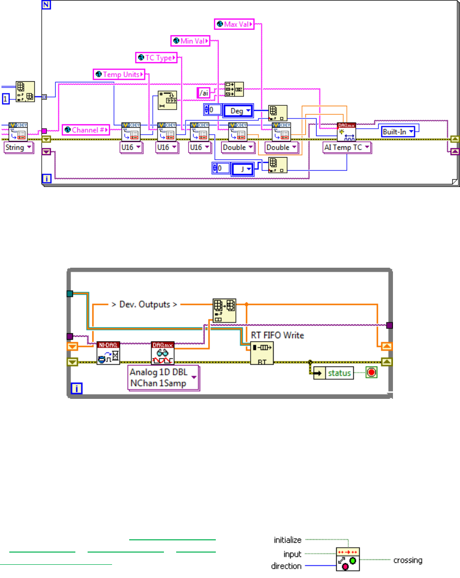
Custom Device Developer’s Guide © 2010 National Instruments 74 of 85
Figure: Adding Channels to a DAQmx Task by their Order in the Custom Device FIFO
There are several advantages of this architecture. The operator is free to add/remove/reorder
channels how he pleases, only the desired channels are configured, and writing data to the
custom device FIFO becomes naturally efficient.
Figure: Writing Multiple Hardware Channels Directly to the Custom Device FIFO
The hardware data returns from the DAQmx driver in the same order as the channel references
in the asynchronous custom device FIFO.
Triggering Within the Custom Device
There are many cases where you want to run code in the custom device when an event occurs.
By comparing the AEEnCh<1..8> channel values to the previous iteration, we implemented
simple value-triggering.
A useful VI for triggering is Signal Processing
» Point by Point » Other Functions » Boolean
Crossing Point by Point.
Figure: Boolean Crossing PtByPt VI
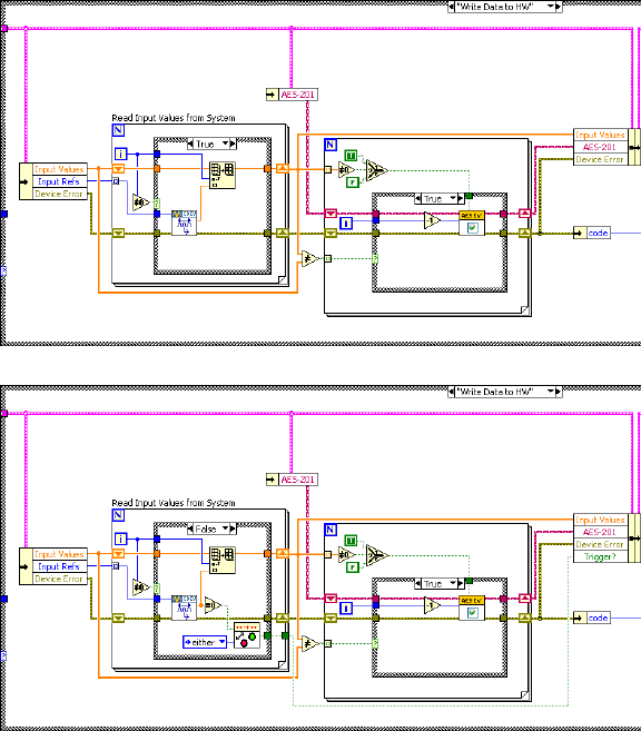
Custom Device Developer’s Guide © 2010 National Instruments 75 of 85
Recall the Write Data to HW state
that reads NI VeriStand Channels.
Add code to check the software
trigger.
Check the SWTrig channel for a
transition and handle the transition
accordingly.
This triggering VI is most useful in asynchronous custom devices that do not execute in line with
the PCL. An asynchronous device might iterate multiple times in a single iteration of the PCL,
but this triggering VI will only assert on the desired edge of the transition.
Adding Extra Pages After Creating the Custom Device Project
If your Custom Device requires additional pages for sections or channels, you should specify
their names in the Extra Page Names control of the Custom Device Template Tool before you
generate the LabVIEW project for the device. The tool ensures that the appropriate references
are available to the page, the necessary declarations go into the Custom Device XML file, and
the Build Specification deploys the page to the correct location.
There are two telltale signs that an extra page has not been added correctly to a custom device.
The first is the default section or channel page loads into System Explorer instead of the
expected extra page. The second is an error from System Explorer similar to Custom Device
Page Error: The following Custom Device page VI is not executable. The
VI might not be found at the correct location, or it is missing
dependencies that it requires to run. Please contact the Custom Device
vendor for more information on this problem.
In order to add a new page after the framework has been generated, you must manually
perform all the actions the tool performs.

Custom Device Developer’s Guide © 2010 National Instruments 76 of 85
Perform the following operations from the LabVIEW Project Explorer.
Incorrect changes to the Custom Device's XML file can corrupt the System Definition in
NI VeriStand.
Ensure the device gets the appropriate device reference. The NI VeriStand API requires
the correct Node Reference input. The NI VeriStand system is responsible for passing
this reference to the page. There’s a VI Template in Custom Device
API.lvlib\Templates\Subpanel Page VI\Page Template.vit for this
purpose. Another way to ensure the new page gets the correct Node Reference is to
copy a page generated by the Custom Device Template Tool, such as the Main page.
Create the page section in the custom device XML file. The Custom Device's XML file
tells the System Explorer how to load the device's files.
1. Open the XML file from the Project Explorer window.
2. Locate the Pages section.
3. Copy the information between Main Page’s Page and /Page declarations.
4. Paste the section immediately below the /Page declaration that closes the Main
Page section.
5. Change the eng, loc, and Path tags for the new page.
6. Change the GUID to match the extra page’s GUID you created.
7. Save and close the XML file.
Modify the configuration build specification. The Custom Device Template Tool scripts
two Build Specifications that put the custom device files in the necessary format and
location for System Explorer.
1. Open the configuration’s build specification dialog box.
2. In Source Files, expand the lvlib for your device.
3. Add the new page to the Always Included section.
4. In Source Files Settings, select the new page in the Project Files tree and
change the Destination to Custom Device <Name> Folder.
5. Click OK to close the build specification.
6. Save the LabVIEW project.
You must rebuild the Configuration and Engine build specifications to deploy the changes. You
may then use the extra page as if it were generated by the Custom Device Template Tool.
The Custom Device Template Tool is open source. If you have any questions about what the
tool does, you can refer to the code as you would any other VI.
Custom Device XML
The full set of features that can be implemented with custom device XML tags are
undocumented. Refer to the XML schema file (<common data>\Custom Devices) to
discover what features may exist. Features are shown as tag names. Consider the following
example line from the Custom Device.xsd file.
<xs:element minOccurs="0" name="ActionVIOnDelete" type="Path" />
A Line from the Custom Device XML Schema File
Custom Device Developer’s Guide © 2010 National Instruments 77 of 85
The name of this tag is ActionVIOnDelete. Adding this tag to the custom device XML runs a
VI when the operator deletes the item from System Explorer. While these features are
undocumented, the XML is fairly intuitive. You may find experimenting with the custom device
XML easier in an empty custom device. Assistance implementing the features may be obtained
by contacting National Instruments VeriStand technical support.
It may be helpful to explore NI VeriStand’s built-in components for examples on implementing
XML features. The built-in components are found in <application data>\System
Explorer\System Explorer Definition Files.
If a tag is opened, use the format </tag_name> to close the tag. If a tag must be specified but
has no value, you may use the format <tag_name /> to open and close the tag at the same
time. This format has the same effect as <tag_name>tag value</tag_name>.
Delete Protection
You can add <DeleteProtection>true</DeleteProtection> to any section in the
custom device XML to disallow deleting the item from the configuration tree in System Explorer.
Limiting Occurrences of the Custom Device
If it doesn’t make sense to have more than N instances of the custom device in a single
System Definition, you can limit the number of instances by adding
<MaxOccurrence>N</MaxOccurrence> to the custom device XML underneath the device
type.
Rename Protection
There may be cases when you depend on a custom device item to have a certain name, and
you’d like to prevent the operator from renaming the item. Add
<DisallowRenaming>true</DisallowRenaming> below the </Name>tag for any page to
prevent the operator from renaming the item.
Action VIs
There are a variety of actions that can trigger a VI to run.
OnDelete
Executes on the deletion of a node in the system definition
OnLoad
Executes on the creation of a new node or load of an existing nod in the system
definition
OnSystemShutdown
Executes on system explorer close or current system definition close
OnSave
Executes on save of system definition
OnDownload
Executes when the system definition is downloaded to the target. This VI is
called after compile is complete and binary files have been created. Writing to
memory should not be performed in this VI. The VI can be used to read from
memory and download additional files as needed
OnPaste
Executes when a node is pasted within the system definition
OnTargetTypeChange

Custom Device Developer’s Guide © 2010 National Instruments 78 of 85
Executes on change of target type in the system definition
OnDeleteRequest
Executes on the delete request before deletion of node in system definition
OnCompile
Executes when the system definition is compiled during deployment. The system
definition will only be compiled during deployment if there is not a good compile
cache available on the host. This happens when the system definition file has
been moved on disk or when changes have been made.
These VIs are useful if you need to make checks or perform cleanup operations after something
happens. The template VIs for these actions are found in the Custom Device API library.
Run-Time Right-click Menu
You can add right-click functionality in System Explorer to any custom device item. Underneath
the </Item2Launch> tag for any page, add the following framework.
</Item2Launch>
<RunTimeMenu>
<MenuItem>
<GUID>GUID</GUID>
<Type>Type_Enum</Type>
<Execution>Execution_Enum</Execution>
<Position>Position_Enum</Position>
<Behavior>Behavior_Enum</Behavior>
<Name>
<eng>Extra Page Name</eng>
<loc>Extra Page Name</loc>
</Name>
<Item2Launch>
<Type>To Common Doc Dir</Type>
<Path>...\Configuration.llb\Extra Page Name.vi</Path>
</Item2Launch>
</MenuItem>
</RunTimeMenu> Custom Device XML Right-Click Framework
GUID
A unique GUID for the extra page
Type_Enum
Describes the type of right-click item
o Action (default) runs the VI silently in the background, i.e. carry out a pre-
configured task and exit
o VI runs the VI in interactive mode displaying the front panel
Execution_Enum
o silent runs the VI silently in the background
o modal runs the VI as a modal window
o floating runs the VI as a floating window
Position_Enum
o centered (default) centers the window on the default monitor on launch
o mouse pointer puts the font panel origin at the mouse pointer on launch
Behavior_Enum
o None
Custom Device Developer’s Guide © 2010 National Instruments 79 of 85
o OpenFrontPanel (default)
Dynamic Buttons
Dynamic buttons are tied to the page and are displayed in the menu area of System Explorer.
One the page goes out of memory and a different page (with a different GUID) is loaded,
dynamic buttons disappear. Underneath the </RunTimeMenu> tag for any page, add the
following framework.

Custom Device Developer’s Guide © 2010 National Instruments 80 of 85
<RunTimeMenu/>
<ButtonList>
<Button>
<ID>A unique button ID</ID>
<Glyph>
<Type>To Application Data Dir</Type>
<Path>System Explorer\Glyphs\abc.png</Path>
</Glyph>
<Type>Type_Enum</Type>
<ReferencedGUID></ReferencedGUID>
<ButtonText>
<eng>Button Text</eng>
<loc>Button Text</loc>
</ButtonText>
<Caption>
<eng>Button Caption</eng>
<loc>Button Caption</loc>
</Caption>
<TipStrip>
<eng>Button Tip</eng>
<loc>Button Tip</loc>
</TipStrip>
<Documentation>
<eng></eng>
<loc></loc>
</Documentation>
</Button>
</ButtonList> Custom Device Dynamic Button Framework
Type_Enum
o Action runs the VI silently in the background, i.e. carry out a pre-configured task
and exit
o Dialog
o Page
o Notification send a notification to the currently loaded page and pass the unique
button ID
o Separator add a visual separator to the toolbar
In the custom device LabVIEW Project, you’ll find Custom Device API.lvlib » Utility
» NI VeriStand – Enable Dynamic Button and Disable Dynamic Button.vi to
enable/disable the button based on the unique button ID.
Upgrading VeriStand 2009 Custom Devices to 2010
While custom devices are written in LabVIEW, they depend on NI VeriStand’s framework to
behave as native tasks within the engine. Changes to NI VeriStand’s framework require
changes to the LabVIEW code. Mass compiling NI VeriStand 2009 custom devices in LabVIEW
2010 does not account for these changes; it simply saves the VIs in the new version of
LabVIEW. As a result, mass compiling alone does not upgrade the custom device to NI
VeriStand 2010. The following instructions assume that you have access to the custom device
LabVIEW source project.
Open the custom device source project in LabVIEW 2010
Mass compile the source directory
Update the build destinations

Custom Device Developer’s Guide © 2010 National Instruments 81 of 85
o Open the build specification for the configuration
o Select the Destinations category in the Configuration Properties window
o Highlight the custom device name in the Destinations list
o If necessary, direct the Destination Path control to the correct custom device
folder for your operating system. Make sure the Destination type is still LLB
o Follow the same steps for the engine’s build specificaiton
Rebuild the configuration and engine source distributions
Add the custom device to an NI VeriStand 2010 system definition – this automatically
mutates the XML file
The original XML file is renamed to Vers0_0_0_0<Custom Device Name>.xml. The mutation is
necessary due to several changes in the XML schema definition.
One major change is the alias name of the destination folder of custom devices. The actual
source folder of custom devices has not changed (<Common Data>\Custom Devices)
whereas the alias has. In NI VeriStand 2009 this folder was called <Type>To App Data
Dir</Type>. In NI VeriStand 2010 it has been changed to <Type>To Common Doc
Dir</Type>. Due to this change, the alias of the application data directory (C:\Documents
and Settings\All Users\Application Data\National Instruments\NI
VeriStand 2010) was changed from <Type>To App Data Dir</Type> to <Type>To
Application Data Dir</Type>.
The folder structure has been changed, which can affect custom devices that have referenced
internal NI VeriStand glyphs in their XML file. If the custom device glyphs are incorrect after the
mutation, change the glyph’s location alias from <To Common Doc Dir> to <To
Application Data Dir>.
NI VeriStand 2010 has introduced the knowledge of operating systems (Windows, Pharlap and
VxWorks). Existing custom device XML files get mutated to PharLapWindows.
PharLapWindows is the default if the tag is not specified in the XML. The 2010 Custom
Device Template Tool creates the tag by default. If an operator wants to run the custom device
on VxWorks, he has to modify the custom device XML file. A good start to get an idea how this
works is the Embedded Data Logger that ships with NIVS 2010.
<CustomDeviceVI>
<SourceDistribution>
<Source>
<SupportedTarget>PharlapWindows</SupportedTarget>
<Source>
<Type>To Common Doc Dir</Type>
<Path>Custom Devices\National Instruments\Embedded Data Logger\Embedded Data
Logger - Engine - PharLap.llb\Embedded Data Logger RT Driver VI.vi</Path>
</Source>
<RealTimeSystemDestination>c:\ni-rt\NIVeriStand2010\Custom Devices\National
Instruments\Embedded Data Logger\Embedded Data Logger - Engine - PharLap.llb\Embedded
Data Logger RT Driver VI.vi</RealTimeSystemDestination>
</Source>
<Source>
<SupportedTarget>VxWorks</SupportedTarget>
<Source>
<Type>To Common Doc Dir</Type>
<Path>Custom Devices\National Instruments\Embedded Data Logger\Embedded Data
Logger - Engine - VxWorks.llb\Embedded Data Logger RT Driver VI.vi</Path>
</Source>
<RealTimeSystemDestination>c:\ni-rt\NIVeriStand2010\Custom Devices\National

Custom Device Developer’s Guide © 2010 National Instruments 82 of 85
Instruments\Embedded Data Logger\Embedded Data Logger - Engine - VxWorks.llb\Embedded
Data Logger RT Driver VI.vi</RealTimeSystemDestination>
</Source>
</SourceDistribution>
</CustomDeviceVI>
Excerpt from the Embedded Data Logger XML Showing Two Separate LLBs
If the custom device’s LabVIEW source project is unavailable, the following process will update
the NI VeriStand 2009 custom device to 2010.
Open the configuration and engine LLBs and look for all custom VIs and controls
Save all custom VIs and controls to a new location
Create a new LabVIEW Project and add the custom device API library
Create a new custom device library
Add the custom files to the LabVIEW library
Recreate the source distributions for the configuration and engine LLBs
Build the new LLBs
This goal of this process is to link the custom VIs to the NI VeriStand 2010 VIs and controls
instead of the old resources in the LLBs.
Beyond the Template Frameworks
The Custom Device Template Tool provides a convenient starting point for most custom
devices; it reduces the opportunity for error; and it contains build specifications that deploy the
custom device to the correct location on disk. Now that you’ve seen the tool in action, you
should know that it’s completely unnecessary. The <vi.lib>\NI VeriStand\Custom
Device API\Cutom Device API.lvlib library contains all the template VIs, type
definitions and functions needed to make a custom device.
There’s no hard requirement for an Initialization and Engine library, or any of the VIs you’ve
seen that are part of these libraries (Main, Initialization, RT Driver). NI VeriStand will deploy a
custom device according to any properly formatted XML file, so long as the controls and
indicators provided by the appropriate VI template(s) are maintained.
One of the best resources for ideas about custom device architecture are the devices that
already exist. You may come across the following framework.
Inline Custom Device with Asynchronous Threads
Inline custom devices execute within the PCL. The device is guaranteed an opportunity to
publish and consume data to/from NI VeriStand in each iteration of the PCL. A major caveat of
inline devices is the potential for the device to introduce latency into the PCL. An asynchronous
custom device may synchronize its Timed Loop to the PCL, achieving a pseudo-synchronous
loop. Two caveats of pseudo-synchronous loops are they are not guaranteed to iterate once
per iteration of the PCL and they are not guaranteed to iterate deterministically with respect to
the PCL.
It may suite your needs to launch asynchronous worker thread(s) from an inline custom device.
The inline device is responsible for communicating channel data to/from NI VeriStand, and the
worker is responsible for nondeterministic operations on the channel data. RTFIFOs are best-
suited for communicating between the inline device and the worker(s). You’ll find an example of

Custom Device Developer’s Guide © 2010 National Instruments 83 of 85
this architecture in the Embedded Data Logger custom device that ships with NI VeriStand
2010. If you look in the Initialize case of Embedded Data Logger - Engine -
PharLap.llb\Embedded Data Logger RT Driver VI.vi, you’ll see the inline device
launch an asynchronous loop.
Figure: Launching an Asynchronous Worker Thread from an Inline Device
One RT FIFO is used to communicate information from the asynchronous worker to the inline
custom device in the Read Data from HW case.
Figure: Communicating from the Asynchronous Worker to the Inline Device
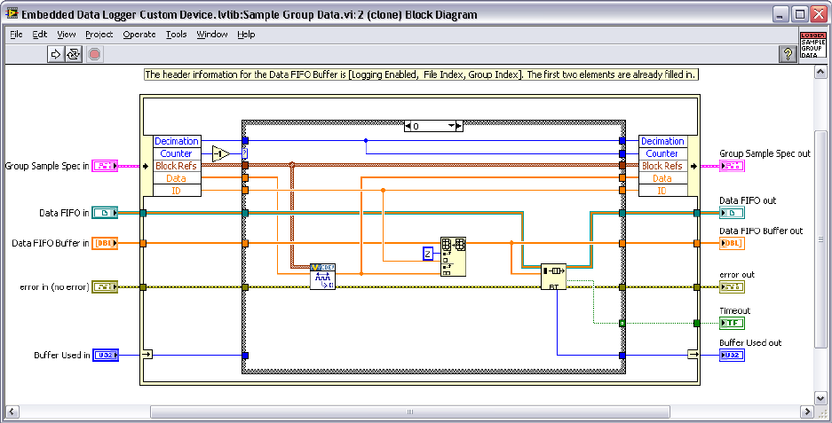
Custom Device Developer’s Guide © 2010 National Instruments 84 of 85
Another RT FIFO is used to communicate channel values to the asynchronous worker.
Figure: Communicating from the Inline Device to the Asynchronous Worker
This architecture works-around the caveats of the inline device and the pseudo-synchronous
device. A caveat of this architecture is the data must be consumed from the RT FIFOs at an
acceptable rate or the mechanism will overflow. In the RT logging custom device, the developer
tallies the number of “missed points” when this happens, but does not abort logging.
Custom Device Developer’s Guide © 2010 National Instruments 85 of 85
Custom Device Development Job Aid
Do you Need a Custom Device?
o Have you tried to meet specification with built-in NI VeriStand features?
o Do you need to support 3rd Party Hardware?
o Do you need an unsupported measurement or generation mode?
o Do you need to implement a feature?
Is a custom device the best customization mechanism for the feature?
o Have you checked that a custom device doesn’t already exist
Custom Device Risk Analysis
o Do you have the appropriate LabVIEW application development experience?
o Do you have LabVIEW Real-Time application development experience?
o Do you have an NI VeriStand operator background or understanding?
o If you need to support hardware, does an RT compatible driver exist?
o Can you test and debug on a system representative of the operator’s system?
Planning
o Channels (DBL)
Pass data from the custom device to the system
Pass data from the system to the custom device
Pass dynamic properties
o Properties (any data type)
Pass configuration data from execution host to target on one time basis
Use within the RT driver to pass around information
o Hierarchy
Use the minimum number of sections
Make the hierarchy well-organized, intuitive, and user friendly
o Extra Pages
One for each channel or section that requires other than the default page
Create a few extra just in case
o Type
Select the type based on the timing requirements of the custom device
Plan the type before executing the Custom Device Template Tool
Some devices require multiple RT Driver VIs
Implement
Debug and Benchmark
o Console Viewer
o RT Debug String
o System State Publisher
o System Channels
o System Monitor Add-on
o Real-Time Execution Tracing
o “Other” debugging options from NI
Distributing the Custom Device
o Source
o Build
o Readme
