Nokia 446PRO Service Manual. Www.s Manuals.com. Chassis 446f Manual
User Manual: Monitor Nokia 446PRO - Service manuals and Schematics. Free.
Open the PDF directly: View PDF ![]() .
.
Page Count: 59
ZB1680A
02.00
SMY052
When re---ordering manuals, please quote the model name and part number.
Level
SMA241E
xx
Contents
Service
Chassis 446F
Part List
PCB Part List
PCB Layout pictures
Monitor Dismantling
CRTmodule .............
MainBoardmodule ......
1
Nokia Display Products Oy
P. O . B o x 1 4
FIN---24101 Salo, Finland
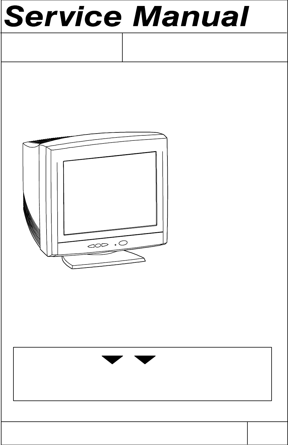
19” High Resolution Colour Monitor
446PRO
SMY052
SMA241H
1
446F
446F 1
Service
Contents
1. Product Overview
1.1. Technical Specifications
1.2. Certifications
1.2.1. Safety
1.2.2. EMC
1.2.3. X---ray, emissions, environmental, ergonomics
1.3. Preset Display Modes
1.4. S-- Capacitor Table
1.5. Monitor Connection
1.6. User Controls
1.7. Menu
2. Site Preparation
2.1. Location
2.2. Troubleshooting
2.3. Checking the Operation of Power Saver
3. Controlling the Memory for Picture Adjustments
3.1. Memory for User Adjustments
3.1.1. Adjustment
3.1.2. Resetting the User Memory
3.2. Memory for Factory Adjustments
3.2.1. Adjustment
4. Service Mode
4.1. Grouping of the Adjustments
4.2. Service Menu
4.2.1. Access to the Service Mode
4.2.2. Geometry
4.2.3. Grey Scale
4.2.4. Memory settings and Initializing the Replacement IC (IC204 on SMA)
4.2.5. Storing Adjustments
4.2.6. Exit from Service Menu
5. Workshop Maintenance
5.1. Important Safety Notice
5.2. ESD-- Sensitive Parts
5.3. Test Equipment
5.4. Test Patterns
5.5. Disassembly
6. Image performance
6.1. Image stabilising time
6.2. Colour temperature and tracking
6.3. White uniformity
6.4. Colour purity
6.5. Luminance
6.6. Image size
6.7. Linearity
6.8. Geometrical distortion
6.9. Jitter
7. Adjustment Procedure
7.1. Adjustment Flow Diagram
7.2. Preliminary Preparations
7.2.1. High Voltage
7.2.2. Coarse Width
7.3. Geometry
7.4. Grey Scale
7.4.1. The Most Dominant Colour
7.4.2. Low Light
7.4.3. High Light
7.5. Maximum/Minimum Contrast
7.6. Focus
7.7. Convergence
7.7.1. Measuring Conditions
7.7.2. Convergence Measuring Gauge
446F
2
7.7.3. Static Convergence
7.7.4. Dynamic Convergence
7.7.5. Allowed Error Levels for Convergence
7.8. Colour Purity
8. Screen and Faceplate Blemishes
8.1. Definitions of inspection conditions and terms
8.1.1. Standard observing condition
8.1.2. Zone division
8.1.3. Minimum distance beetween defects
8.1.4. Average diameter of defect
8.2. Face defect standard (black spot, stain)
8.3. Glass blemish
8.3.1. Scratch
8.3.2. Bubbles/foreign materials
Revision History
Rev Date Prepared by Comments
09.99 24.09.99
02.00 14.02.00 J. Paukku SMA241H added
446F 3
1. Product Overview
446F is a 19 inch monitor. The maximum resolution of 1600 x 1200 makes the monitor suitable for
PC, Macintosh and workstation applications in normally heated, ventialed and controlled office/home
environment. The monitor has an own power supply with nominal input voltage requirements from
90 V to 264 V.
1.1. Technical Specifications
Cathode Ray Tube 19” in diagonal 86˚deflection angle..........Antistatic, antireflex
Phosohor P22 medium short, Dot pitch 0.24 mm
Picture Size 354 mm x 265 mm with specified geometric distortion................
Maximum Picture Size 366 mm x 275 mm.......
Power Input Requirements Voltage 90-- 264 V, 50/60 Hz...Current 1.8 A/100 V, 0.8 A/240 V
Power Dissipation < 130 W Normal Operation...........<95WStand-- by
< 8 W Suspend
< 3 W Power off
Memory Locations 3 for factory preset display mode...........18 for user adjusted display mode
Geometric Distortion The distance between bezel and active screen edge shall not vary.........more than 2 mm in both vertical and horizontal dimensions
Luminance Min. 100 cd/m2(Nits) at center, with full white field.................
Video Input Input Signal: RGB, analog, max 0.7 V/ 75 τ.................Horizontal addressability: 1600 dots maximum
Vertical addressability: 1200 dots maximum
Synchronization Range Horizontal: 30 kHz to 107 kHz automatic......
Vertical: 50 Hz to 150 Hz automatic
Synchronization Signal Separate TTL , positive/negative.......Composite TTL , positive/negative
Max. Dot Frequency 230 MHz.........
Temperature Operating: +10˚Cto+35˚C................Packed: -- 3 0˚Cto+60˚C
Humidity Operating: 20% to 80 %...................Packed: 5% to 90 %
Weight 25.3 kg net.....................29.6 kg gross
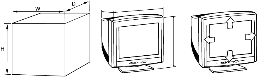
Size, Tilt and Swivel
H
DW
20
5
90
90
Dimensions
Monitor H 471 mm.................... ........
W 470 mm........
D 464 mm........
Package H 596 mm................... ........
W 600 mm........
D 571 mm........
446F
4
1.2. Certifications
The monitor has following agency approvals
1.2.1. Safety
FIMKO, DEMKO
NEMKO, SEMKO
UL / USA
CSA / Canada
T Ü V --- G S / G e r m a n y
IAA / Korea
PSB / Singapore
CCIB / China
1.2.2. EMC
F C C --- D. O. C .
VCCI / Japan
CE / Europe
RRL EMI / Korea
BSMI / Taiwan
1.2.3. X---ray, emissions, environmental, ergonomics
T Ü V --- E R G O / G e r m a n y
DHHS / USA
TCO 99 / Sweden
Blue Angel / Germany
446F 5
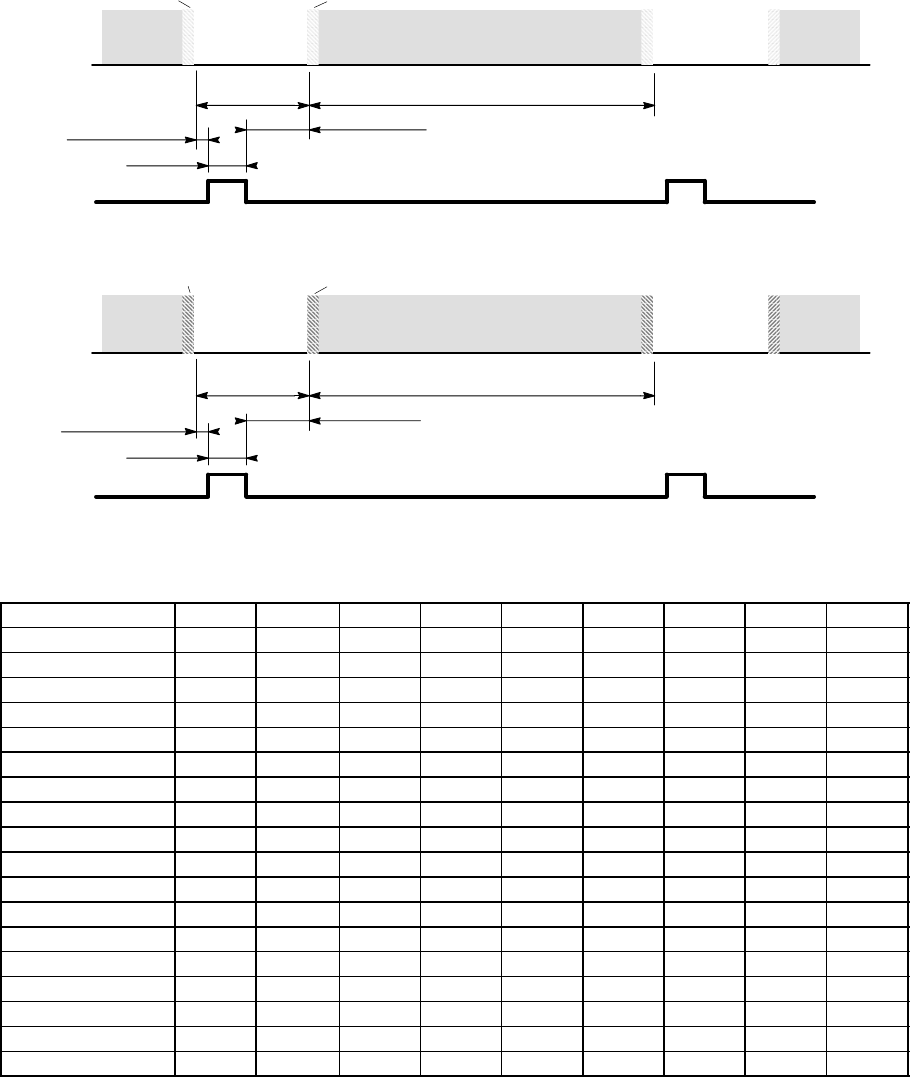
1.3. Preset Display Modes
H Front Porch
Video
Full
intensity 0.7 V
Blanking 0 V
H Active Video
HSync
HBlanking
Left BorderRight Border
HBackporch
HSync.
Signal
V Front Porch VBackPorch
Video
Full
intensity 0.7 V
Blanking 0 V
V Active Video
VSync
VBlanking
Bottom Border Upper Border
VSync.
Signal
Display Mode no 00 01 02 03 04 05 06 07 08
NCE GTF642 NCE642 NCE791 NCE513 NCE501 NCE506 NCE401 NCE406 NCE40A
VFrequency/Hz 85.0 85.0 85.0 85.0 60.0 75.0 60.3 75.0 85.06
HFrequency/kHz 91.376 91.146 106.25 68.677 48.363 60.023 37.879 46.875 53.674
HPeriod/us 10.944 10.971 9.41 14.561 20.677 16.660 26.400 21.333 18.631
Active Video/us 8.032 8.127 6.97 10.836 15.754 13.003 20.000 16.162 14.222
HResolution 1200 1280 1600 1024 1024 1024 800 800 800
HSync/us 0.803 1.016 0.83 1.02 2.092 1.219 3.200 1.616 1.14
HBackPorch/us 1.456 1.422 1.32 2.20 2.6462 2.235 2.200 3.232 2.70
VPeriod/lines 1075 1072 1250 808 806 800 628 625 631
VResolution 1024 1024 1200 768 768 768 600 600 600
VSync/lines 33 336343 3
VBackPorch/lines 47 44 46 36 29 28 23 21 27
HSyncPolarity --- + + + --- + + + +
VSyncPolarity + + + + --- + + + +
H Front Porch/us 0.65 0.41 0.27 0.51 0.37 0.20 1.00 0.32 0.57
V Front Porch/lines 11 113111 1
Dot Frequency/MHz 159.360 157.500 229.490 94.500 65.000 78.750 40.000 49.500 56.250
Interlacing no no no no no no no no no
446F
6
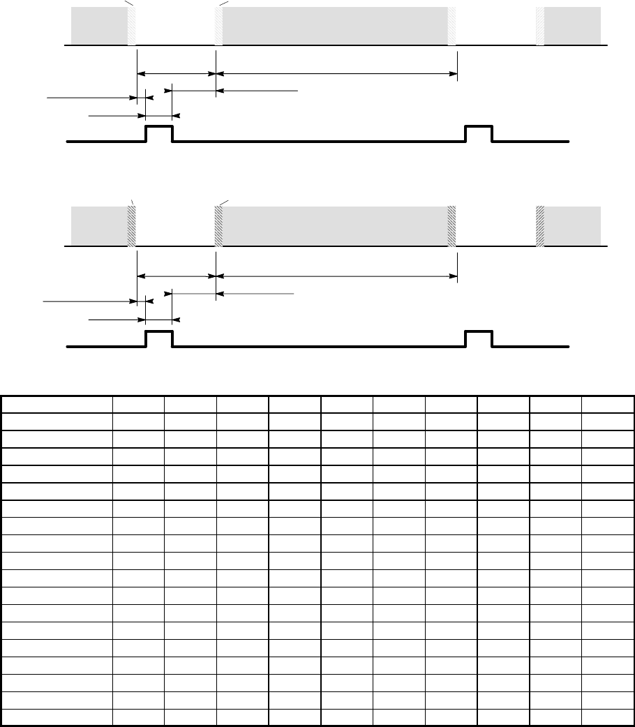
H Front Porch
Video
Full
intensity 0.7 V
Blanking 0 V
H Active Video
HSync
HBlanking
Left BorderRight Border
HBackporch
HSync.
Signal
V Front Porch VBackPorch
Video
Full
intensity 0.7 V
Blanking 0 V
V Active Video
VSync
VBlanking
Bottom Border Upper Border
VSync.
Signal
Display Mode no 09 10 11 12 13 14 15 16 17 18
NCE NCE300 NCE306 NCE30A NCE200D NCE012 NCE011 NCE603 NCE605 NCE700 NCE70X
VFrequency/Hz 59.9 75.0 85.0 70.1 75.0 75.1 60.0 75.0 60.0 75.0
HFrequency/kHz 31.472 37.500 43.269 31.467 67.500 68.681 63.981 79.976 74.995 93.755
HPeriod/us 31.774 26.667 23.111 31.780 14.815 14.560 15.630 12.504 13.334 10.666
Active Video/us 25.420 20.317 17.778 25.423 10.667 11.520 11.852 9.481 9.877 7.901
HResolution 640 640 640 1440 1152 1152 1280 1286 1600 1600
HSync/us 3.81 2.032 1.56 3.814 1.185 1.280 1.037 1.06 1.185 0.948
HBackPorch/us 1.91 3.810 2.22 1.907 2.370 1.440 2.296 1.84 1.883 1.501
VPeriod/lines 525 500 509 449 900 915 1066 1066 1250 1250
VResolution 480 480 480 400 864 870 1024 1024 1200 1200
VSync/lines 2 3 3 2 3 3 3 3 3 3
VBackPorch/lines 33 16 25 34 32 39 38 38 46 46
HSyncPolarity --- --- --- --- +--- + + + +
VSyncPolarity --- --- --- + + --- + + + +
H Front Porch/us 0.64 0.51 1.56 0.64 0.59 0.32 0.44 0.12 0.39 0.32
V Front Porch/lines 10 1 1 13 1 3 1 1 1 1
Dot Frequency/MHz 25.177 31.500 36.000 56.640 108.000 100.000 108.000 135.640 161.990 202.510
Interlacing no no no no no no no no no no

446F 7
1.4. S-- Capacitor table
f/kHz S5 S4 S3 S2 S1 S0
27.6
xxxxxx
28.4
xxxxxx
29.2
xxxxxx
30.4
xxxxxx
30.8
xxxxxx
31.8
x x x x
32.8
x x x x
33.7
x x x x
34.7
x x x x x
36.0
x x x x
37.2
x x x x
38.3
x x x
39.4
xxxxx
40.4
x x x
41.4
x x x x
42.7
x x
44.2
x x x x
45.8
x x x
47.7
x x x
49.4
x x
51.6
x x x x
53.5
x x x
54.6
x x x
55.8
x x
57.3
x x x
59.0
x x x
60.5
x x
62.2
x x
65.3

446F
8
65.3
x
68.8
xxx
71.3
x x
74.1
x x
78.2
x x
82.8
x x
87.4
x
94.0
x
100.0
108.0
446F 9
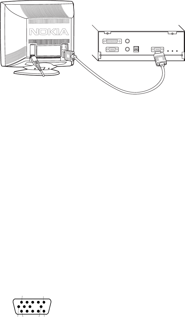
1.5. Monitor Connection
Make sure that the monitor is disconnected from mains and the power switches of
the computer and all attached devices are turned off before connecting the monitor.
-- Connect the signal cable plug to the videocontroller connector at the back of the computer.
-- Tighten the screws on the plug by hand.
-- Connect the power cord first to the monitor and then to a grounded power outlet.
If your computer is DDC compatible (PC)
-- Do not use any adapter when connecting signal cable to your computer.
-- Do not extend the signal cable with extension lead. The DDC signals will not accept extended
cable.
--- Display controller must be compatible for External +5 V
Signal connector
Pin Signal
1-- >RV Redvideo
2-- > GV Green video
3-- > BV Blue video
4<-- N.C
5 Plugged / unplugged test
6 RG Red ground
7 GG Green ground
8 BG Blue ground
9-- > DDC +5V (optional)
10 LG Logic Gnd
11 <-- ID0 ID0 (tied to LG)
12 <-- DDC SDA
13 -- > Hs Horizontal synchronization, composite sync
14 -- > Vs Vertical synchronization
15 <-- DDC SCL
1 5
61011 15
446F
10
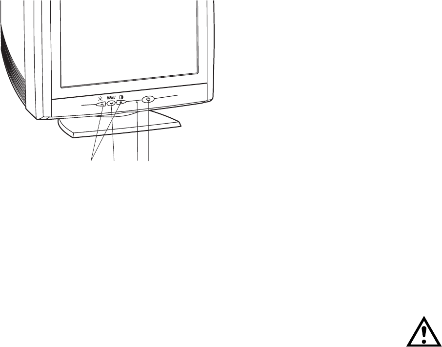
1.6. User Controls
12
34
1. Power switch
2. Power on indicator
3. Menu button
4. Select and adjustment buttons
When the power is turned on, the power-- on indicator will light.
The colour of the the power-- on light indicates the operating state of the monitor.
- Green: The monitor is in Normal, Stand---by or Suspend operation.
- Blinking Green: The monitor is in Automatic Power off state.
- Not illuminated: The monitor is turned off with power switch or disconnected from mains outlet.
The power switch does not disconnect the monitor from mains. In oder to make the monitor completely powerless, unplug the power cord from power outlet.
446F 11
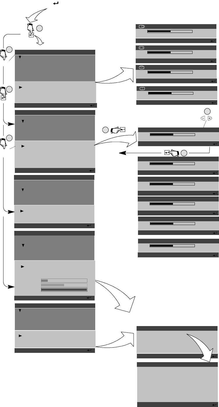
1.7.Menu
1.7.1. Moving in the menu
Menu operations are controlled with button and ---/+ buttons.
aCall the menu to the screen by pushing button.
bSelect the header with ---/+ buttons.
cPush to confirm the selection.
Adjustment and settings corresponding the header appear below the header field.
dSelect the adjustment with ---/+ buttons.
ePush to confirm the selection.
Menu disappears and a scale shows the position of the adjsutment. In addition to the bar, position
of the adjustment is shown as a percenage of the maximum value. The upper number shows the
currentvalueandtheloweroneshowsthevaluewheretheadjustentstarted.
fAdjust with ---/+ buttons.
gWhen ready, push button.
1.7.2. Exit Menu
Select EXIT MENU and pushing button.or push + and --- buttons together
446F
12
TILT
30%
PREVIOUS VALUE: 40%
A D J U S T: --- / + OK :
SIZE & POSITION
SHAPE...
SHARPNESS
COLOR...
MISCELLANEOUS
EXIT MENU
AUTO SHAPE
HORIZONTAL CENTERING
WIDTH
VERTICAL CENTERING
HEIGHT
HORIZONTAL CENTERING
53%
PREVIOUS VALUE: 50%
HEIGHT
30%
PREVIOUS VALUE: 40%
a
b
e
f
g
c
d
SIZE & POSITION
SHAPE
SHARPNESS
COLOR...
MISCELLANEOUS
EXIT MENU
DEFAULT SHAPE
TILT
ORTHOGONALITY
TRAPEZOID
PINCUSHION
PINCUSHION BALANCE
WIDTH
44%
PREVIOUS VALUE: 50%
VERTICAL CENTERING
45%
PREVIOUS VALUE: 50%
6500K, 7000K, 8000K, 9300K, 10000K, 1, 2
M O V E --- / + S E L E C T:
NOKIA 446PRO 75Hz
A D J U S T: --- / + OK :
A D J U S T: --- / + OK :
A D J U S T: --- / + OK :
A D J U S T: --- / + OK :
M O V E --- / + S E L E C T:
NOKIA 446RO 75Hz
ORTHOGONALITY
30%
PREVIOUS VALUE: 40%
A D J U S T: --- / + OK :
TRAPEDOIZ
30%
PREVIOUS VALUE: 40%
A D J U S T: --- / + OK :
PINCUSHION
30%
PREVIOUS VALUE: 40%
A D J U S T: --- / + OK :
PINCUSHION BALANCE
30%
PREVIOUS VALUE: 40%
A D J U S T: --- / + OK :
SIZE & POSITION
SHAPE
SHARPNESS
COLOR...
MISCELLANEOUS
EXIT MENU
CONTRAST
BRIGHTNESS
DEFAULT COLOR
COLOR PRESETS 9300 K
RED
GREEN
BLUE
SAVE CURRENT COLOR
M O V E --- / + S E L E C T:
NOKIA 446PRO 75Hz
SIZE & POSITION
SHAPE...
COLOR...
MISCELLANEOUS
EXIT MENU
MONITOR DEFAULTS
DEMAGNETIZE
ABOUT MONITOR
MENU OPTIONS
M O V E --- / + S E L E C T:
NOKIA 446PRO 75Hz
MENU OPTIONS
LANGUAGE/SPRACHE/LANGUE
HORIZONTAL POSITION
VERTICAL POSITION
DISAPPEARANCE TIME 1:00
BACK
A D J U S T: --- / + OK :
LANGUAGE/SPRACHE/LANGUE
ENGLISH
DEUTSCH
SVENSKA
SUOMI
ITALIANO
FRANCAIS
ESPANOL
CANCEL
A D J U S T: --- / + OK :
MOIRE
30%
PREVIOUS VALUE: 40%
A D J U S T: --- / + OK :
NAVI
NAVI
SIZE & POSITION
SHAPE
SHARPNESS
COLOR...
MISCELLANEOUS
EXIT MENU
DEFAULSHARPNESS
VERTICAL CONVERGENCE
HORIZONTAL CONVERGENCE
MOIRE
M O V E --- / + S E L E C T:
NOKIA 446RO 75Hz
--- +
446F 13
2. Site Preparation
2.1. Location
This Monitor is designed for normal office conditions. It is equipped with own power supply. It is not
to be serviced or repaired on site
2.2. Troubleshooting
Local service facilities should perform simple maintenance such as trimming. More advanced main-
tenance and repair that requires replacement of components which in turn requires testing and re-
trimming should be carried out in a central workshop.
Symptom Measures
Picture
screen is
blank
The indi-
cator on
the front
panel is
not illumi-
n
a
t
e
d
Check that the power cord is correctly connected to the monitor and to the power
outlet. If the monitor is powered through the computer, check that the computer is
switched on with the mains switch. Use a desk light, for example, to verify that
current is connected to a power outlet. If no electricity is connected to the outlet,
call an electrician.
nated Unplug the monitor from power outlet for about one minute.
The indi-
cator on
t
h
f
t
Check that the signal cable connector is connected. If the connector is loose
tighten the connector’s screws.
the front
panel is il-
l
u
m
i
n
a
t
e
d
The Monitor might be in stand-- by position. Push one of the buttons or move the
mouse.
l
u
m
i
n
a
t
e
d
U
n
p
l
u
g
t
h
e
m
o
n
i
t
o
r
f
r
o
m
o
u
t
l
e
t
f
o
r
a
b
o
u
t
o
n
e
m
i
n
u
t
e
U
np
l
ug
t
h
emon
i
t
or
f
rom ou
t
l
e
t
f
or a
b
ou
t
one m
i
nu
t
e.
Switch off the monitor and the computer. Remove the signal cable from the
computer. Switch on the monitor using the power switch. If the Selftest error menu
appears on the screen, it is evident that the monitor functions correctly and
the problem is caused by an error in other parts of the system.
Check the signal cable’s connection pins. If the pins are slightly distorted,
usenoseplierstostraightenthem.
The computer may use a timing values which are out of the monitor’s synchro-
nization range.
Picture has colour de-
f
t
Demagnetize the monitor.
fects If colour defect is repeated without the monitor having been moved, it is possible
that the monitor is influenced by a strong magnetic interference field (near to
a high power cable, for example). Try to find a better location for the monitor or
the interference source. Note that another monitor placed too near (less than
30 cm.) may also generate interference in the picture.
Picture has strong colour
defect,
Switch off the monitor and the computer. Remove the signal cable from the
computer. Switch on the monitor using the power switch.Check the colour of the
Red, Green and Blue bars. If they have pure colours, the fault is not in the monitor.
Check signal cable connectors and the computer. If the menu itself and the colour
bars are discoloured, the monitor is obviously damaged.
Pictureisstablebutdis-
torted
Your computer may use a timing for which the corresponding picture characteris--
tic adjustments have not been set at the factory. Adjust the picture characteristics
Picture is unstable Check the proximity of other electrical devices that generate magnetic fields,
such as speakers, other monitors, electric fans and fluorescent light fixtures.
s
u
c
a
s
s
p
e
a
e
s
,
o
t
e
o
t
o
s
,
e
e
c
t
c
a
s
a
d
u
o
e
s
c
e
t
g
t
t
u
e
s
Make sure your computer and video card are properly configured for your
monitor.
The automatical appearance of the Error menu on the screen means that the signal is faulty or miss-
ing.
ERROR
Red
Green
Blue
Signal: No signal
Cable not connected
ERROR
Red
Green
Blue
Signal: No signal
Cable connected OK

446F
14
2.3. Checking the Operation of PowerSaver
The proper operation of the function requires a computer with VESA DPMS power management
capabilities. Note that the power saving feature must be activated in the computer when checking
the operation.
State Colour of the power-- on indicator 5V Heater 12V Video
Normal Operation Green Yes Yes Yes Yes
Stand-- by Green Yes Yes Yes No
Suspend Red Yes Yes No No
Power Off Red Yes No No No
DPMS (Display Power Management Signaling) is a trade mark of Video Electronics Standard
Association (VESA)
446F 15
3. Controlling the Memory for Picture Adjustments
Thepictureadjustmentvaluesarestoredinnon-volatilememory.Thememoryhasseparatedareas
for User Adjustments and for Factory Adjustments.
3.1. Memory for User Adjustments
3.1.1. Adjustment
1 If there are values available in the memory for user adjustments, corresponding to the present
timing signals, they are always used.
2 New user made adjustments are stored to the memory for user adjustments.
3.1.2. Resetting the User made settings for geometry or image
3 User memory can be emptied from user made settings. Resetting affects only the timing
which is currently active. The reset function is inhibited if no corresponding factory preset dis-
play mode exists.
After resetting all picture properties are coming from memory for factory adjustments.
3.2. Memory for Factory Adjustments
3.2.1. Adjustment
4 Factory adjustments can be updated with service menu in service mode. If there is no location in
factory adjustment memory for display mode currently in use, the adjustment affects the memory
foruseradjustments.
-- If the memory location mentioned in case 1 is empty, the picture adjustment values are read
from memory for factory adjustments. Factory adjustments, corresponding to the current display
mode, are transferred to user memory if any picture property is adjusted. After that the operation
is as in case 1.
Basic
Adjustments 1
4
3
4
The memory can be
updated with Service
menu in Service Mode
The memory can be
updated with User Menu
in User Mode
Initialization
Memory for
User
Adjustments
SMA IC204
Memory for
Factory
Adjustments
SMA IC204
Preset Recall
Storing
2
Refer to the chapter
”Service Mode”

446F
16
4. Service Mode
Service Mode is needed for updating of the factory adjustments for display mode listed in the chap-
ter Preset Display Modes. If there is no location in factory adjustment memory for display mode cur-
rently in use, the adjustment affects the memory for user adjustments.
4.1. Grouping of the adjustments
There are three groups of software adjustments in service mode:
-- Geometry set
-- Grey scale adjustment set
The following table shows how the adjustments act in relation to the display modes.
Adjustment Common for
all Display
modes
Separate for
each Display
mode
Available in
User Mode
Available in
Service Mode
Horizontal centering XXX
Vertical centering XXX
Height XXX
Width XXX
Pincushion XXX
Pincushion balance XXX
Trapezoid XXX
Orthogonality XXX
S--correction X X
C--correction X X
E/W corner X X
Tilt X X X
Moire X X X
Raster X X
G2 X X
Min contrast X X
Max contrast X X
R Black level X X
G Black level X X
B Black level X X
RAmpl X X X
GAmpl X X X
BAmpl X X X
BCL adjust X X
Vertical conv X X X
Horizontal conv X X X
Init burn in test * X
Common adjustments need to be adjusted only once. Separate adjustment must be performed for
every display mode to be stored
* Init burn in test only for manufacturing purposes
446F 17
4.2. Service Menu
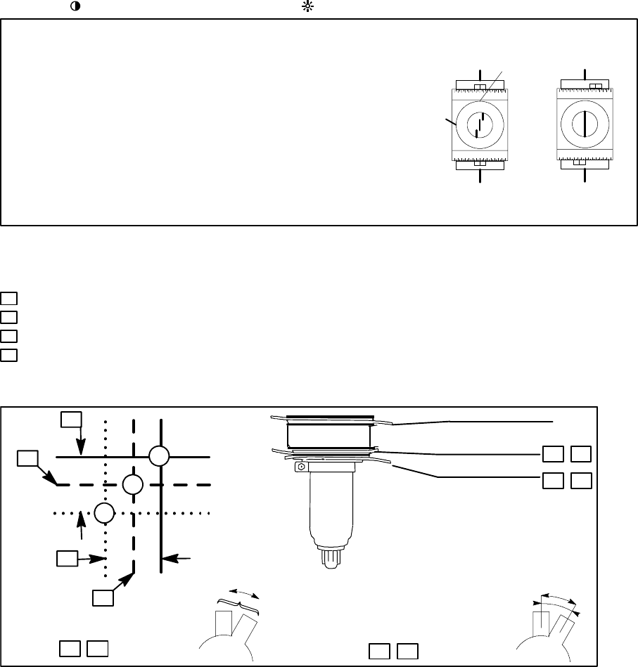
4.2.1. Access to Service Mode
Activate 9300K color temperature before you go to the service menu.
Activate the service mode always in 91.376 kHz/85 Hz (GTF642).
First switch OFF the monitor with power switch.
1) Push button down.
2) While keeping button down, switch ON the monitor.
3) Release button when the power-- on indicator is illuminated.
4) Press button.
5) Monitor ask password. Type the password (7711) with the ---/+ buttons.
6) Press button.
Select the items in the Menu with the --- or + buttons. Push the button to open Geometry, Grey
Scale, Product Information or Memory Settings. Adjust each property with the --- or + buttons.
4.2.2. Sharpness
Geometry submenu contains placement, size and shape adjustments.
GEOMETRY...
GREYSCALE...
SHARPNESS
PRODUCT INFORMATION . . .
MEMORY SETTINGS . . .
RASTER
WIDTH
HORIZONTAL CENTERING
HEIGHT
VERTICAL CENTERING
PINCUSHION
PINCUSHION BALANCE
TRAPEZOID
ORTHOGONALITY
S CORRECTION
C CORRECTION
E/W CORNER
TILT
EXIT
00: 1280x1024 85HZ
4.2.3. Grey Scale
This monitor has six preset tints. With tint numbers smaller than 3 the picture becomes reddish and
with tint numbers greater than 3 the picture turns blue.
Tint no 1 2 3 4 5 6 7
Colour Temperature 5000K 6000K 6500K 7000K 8000K 9300K 10000K
The grey scale adjustment affects directly tint number 6 (9300K) only. Other tints are derived auto-
matically from 9300K colour temperature.

446F
18
GEOMETRY...
GREYSCALE...
SHARPNESS
PRODUCT INFORMATION . . .
MEMORY SETTINGS . . .
CONTRAST
MIN CONTRAST
MAX CONTRAST
BRIGHTNESS
G2
RED BLACK LEVEL
GREEN BLACK LEVEL
BLUE BLACK LEVEL
RED AMP.
GREEN AMP.
BLUE AMP.
BCL ADJUST
EXIT
00: 1280x1024 85HZ
MODEL: HP P1110
SERIAL NUMBER FI92500061
POWER ON HOURS 23
S TA N D --- B Y H O U R S 0
SUSPEND HOURS 0
ACTIVE---OFF HOURS 0
FIRMWARE 0.19
EXIT
TYPE : O
CUSTOM COLOR: 1
DDC : EXT (24LC21)
INITIALIZE EEPROM
INIT BURN IN TEST
EXIT
GEOMETRY...
GREYSCALE...
SHARPNESS
PRODUCT INFORMATION . . .
MEMORY SETTINGS . . .
VERTICAL CONV
HORIZONTAL CONV
MOIRE
EXIT
GEOMETRY...
GREYSCALE...
SHARPNESS
PRODUCT INFORMATION . . .
MEMORY SETTINGS . . .
GEOMETRY...
GREYSCALE...
SHARPNESS
PRODUCT INFORMATION . . .
MEMORY SETTINGS . . .
00: 1280x1024 85HZ
00: 1280x1024 85HZ
00: 1280x1024 85HZ
4.2.4. Memory settings and Initializing the Replacement IC204 on SMA board
If the memory for factory adjustments is replaced, it must be initialized. During initializing all memory
locations are written with approximate values. They must be updated in service mode as explained
in the chapter ’Adjustment Procedure’.
- INTIALIZE EEPROM always with using display mode no 00! (91.376 kHz/85 Hz (GTF642))
- After initializing switch OFF the monitor.
- Activate service mode as explained before.
- Select Memory settings ---menu.
- Select Monitor type O, custom color 1 and DDC (EXT (24LC21)
Caution
Initializing of a programmed memory IC deletes all user and factory made adjustments.
4.2.5. Storing the Adjustments
When the adjustment is ready, return to the menu by pushing the button. Adjustement will be
stored automatically.
4.2.6. Exit from Service Mode
Switch off the monitor.
4.2.7. Uninstalled EEPROM
If you have uninstalled EEPROM. You can not adjust in user menu. You have to go first in service
menu and select Memory settings --- Initialize EEPROM.
446F 19
5. Workshop Maintenance
5.1. Important Safety Notice
The components, which are important for safety, are marked with special mark !on the circuit dia-
gram. It is essential that these critical parts should be replaced with manufacture’s specified parts to
prevent X-- radiation, shock, fire or other hazards.
For your own safety, use always safety isolating transformer when repairing the monitor.
5.1.1. Discharging the CRT
High voltage circuitry includes bleeder resistor which normally discharges the tube in about 5 se-
conds after the power is switched off. If you -- for safety reasons -- want to be sure about the dis-
charging, do as follows:
Wear safety goggles. A cracked CRT may implode when discharged.
The signal cable must be disconnected from the computer.
To discharge the CRT, a flat-- head screwdriver with grounding cable is required.
-- Disconnect the signal cable.
-- Connect the metal chassis of the monitor to reliable earth.
-- Connect the grounding wire to the screwdriver.
-- Connect the other end of the grounding wire to the chassis (earth).
-- Insert the screwdriver under the rubber cap of the EHT connector to discharge the tube.
5.2. ESD-- Sensitive Parts
To prevent damage, when working with electrostatic discharge (ESD) sensitive parts, observe the
following instructions:
-- Keep the ESD-- sensitive part in its original shipping container until you are ready to install the
part into the component card.
-- Just before touching the ESD-- sensitive part, discharge to the monitor any static electricity in
your body; do this by touching the metal frame or cover of the machine. If possible, keep one
hand on the frame when inserting or removing a logic card, for example.
-- Hold the ESD-- sensitive part by its edge; do not touch its pins.
5.3. Test Equipment
The following test equipment are required to adjustment procedure.
-- Safety isolating transformer
-- Digital multimeter: Fluke 87 or equivalent true RMS multimeter
-- High voltage probe: e.g. Fluke 80-- 40k
-- Signal generator: VTG220 + PC or programmable video generator
-- Colour analyzer: e.g. Minolta TV Colour Analyzer CA100
-- Convergence Gauge (CM7AR or equivalent)
-- Oscilloscope 40-- 100 MHz band width
-- Hi-- Pot tester (Flash tester with insulation measurement / Leakage current / Break down voltage)
-- ESD protection necessary
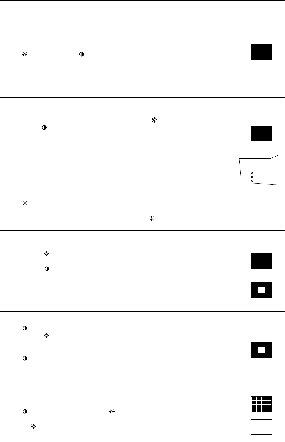
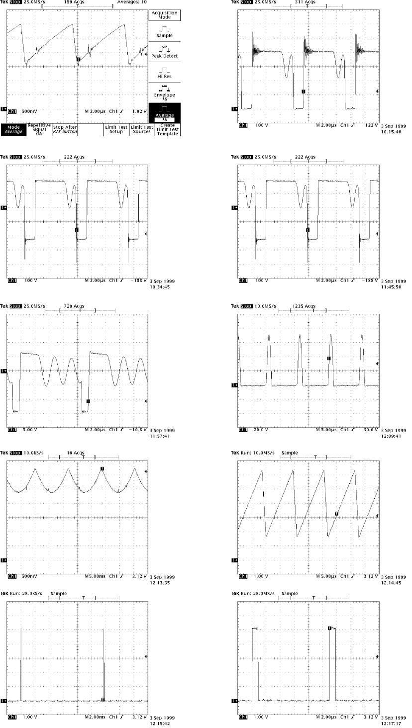
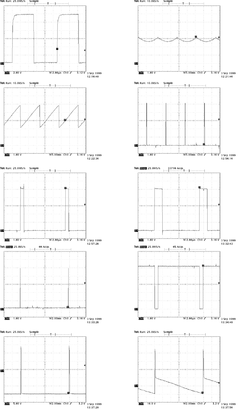
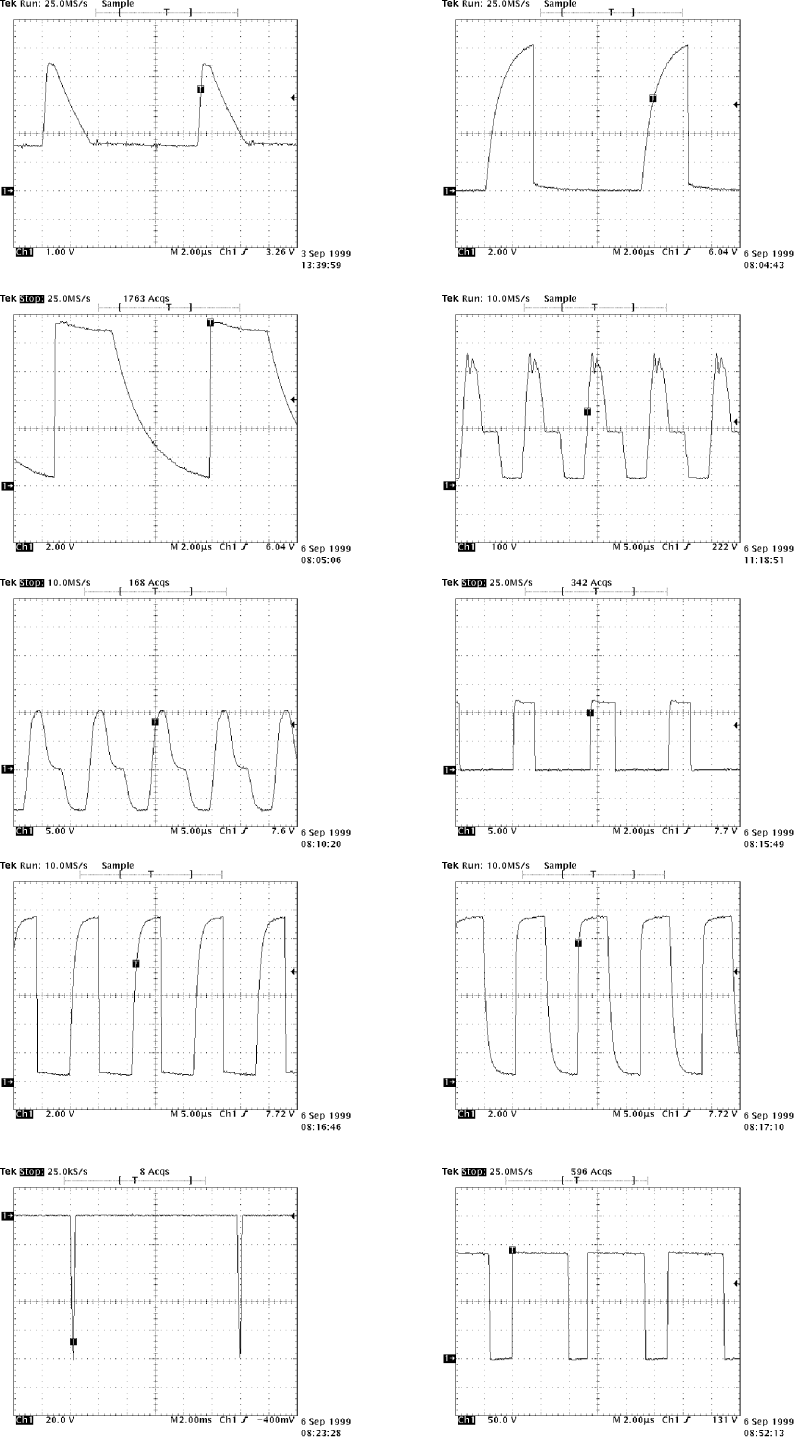
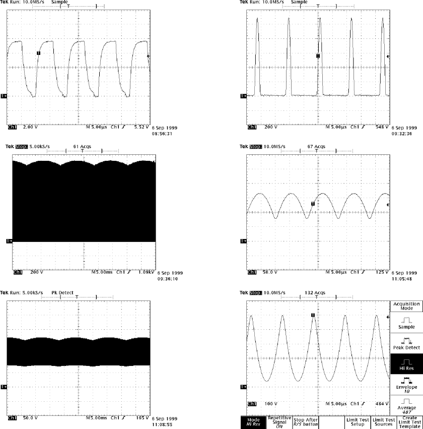
5.4. Test Patterns
Active horizontal video time
Active
video time
vertical
1 2 3 5
pixelpixelpi
pixelpixelpi
pixelpixelpi
pixelpixelpi
A --- a r e a
B --- a r e a
4Full White
Active
video time
vertical
Active horizontal video time
1Black Picture
-- Signal level = 0 V at each RGB input
2Highlight grey scale tracking
-- Signal level = 700 mV in the window at each RGB input
3Crosshatch Picture
-- Squares e.g. 20 mm x 20 mm
-- Outmost lines correspond the active vertical/horizontal video time
4Convergence test pattern
5Focus test pattern
446F
20
5.5. Disassembly
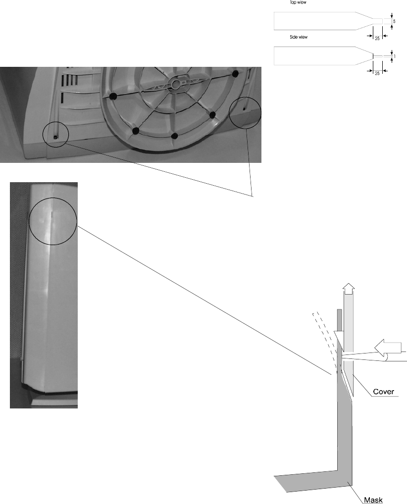
5.5.1. Cabinet
Set the monitor on cushion picture tube facing down
1. Loosen and remove two screws.
2. Open the plastic pawls with a screwdriver or special tool (for instance 860006)
Push open
Do not twist
Screw
on both sides
446F 21
6. Image performance
Measurement to verify this specification shall be made with equipment that measures the dis-
played image as if it were projected forward onto a flat plane tangent to the center of the CRT
faceplate surface and perpendicular to the Z---axis of the CRT.
Image performance specifications are applicable over specified input power conditions, speci-
fied environmental operating conditions and after being subjected to the specified non---operat-
ing environmental conditions. Before performance measurements the monitor must have been in
room temperature (20+/--- 5 degrees C) for at least 2 hours. After that the monitor must have
been warmed up with power on at least 60 minutes.
The monitor shall be positioned to a magnetic field, which is specified as 0 G horizontal field and
0.45 G vertical field (Northern Hemisphere) when ever the image performance is measured.
If there is no standardised magnetic field available, the monitor should be positioned face to
east.
All image performance specifications will be met in diffuse ambient 500 lux.
All the performance specifications are met when using factory adjusted timing modes within line
frequencies 48 kHz --- 107 kHz.
The timings below 48 kHz line frequency are usable, but not specified.
Performance is optimised for 1280 x 1024, 85 Hz (VESA) resolution.
6.1. Image stabilising time
The image shall begin to be visible in a 500 lux environment within 15 seconds of application of
power and input signals.
The image shall be stabilised within 30 seconds of application of power and input signals. ”Sta-
bilised” means that no significant changes shall occur in the image quality specifications, such
as image brightness, size, linearity and so on.
The image shall reach performance stability within 20 minutes of the application of power and
input signals. ”Performance Stability” means that the display monitor shall meet all of its image
quality specifications.
6.2. Colour temperature and tracking
The default colour temperature is 9300 ˚K
Measurement conditions:
--- test pattern 50*50 mm white field at the screen centre
--- brightness control adjusted for a background raster luminance level of 1 nit
--- input signals R, G, B with maximum amplitude
When contrast---control is adjusted for 100 nit’s luminance level, the factory adjusted colour
coordinates measured at the screen centre will be:
x = 0.283 +/--- 0.015 = x ref
y = 0.297 +/--- 0.015 = y ref
When contrast---control is adjusted from a luminance level of 100 cd/m2 to
35 cd/m2 or its adjust stop, the colour coordinates measured at the screen centre will be:
x = x ref +/--- 0.015
y = y ref +/--- 0.015
446F
22
6.3. White Uniformity
Measurement conditions:
--- Full screen picture size, Brightness in middle 100 nit
--- Magnetic field horizontal 0 Gauss
vertical 0.45 Gauss
--- Warming up time 1 hour
Maximum variation between colour coordinates between any measurement points shall not vary
more than d(x),d(y) below.
Colour coordinates from corner to center:
d(x) = ± 0.015
d(y) = ± 0.015
6.4. Colour Purity
There should not be visual discoloration with each of the red, green and blue beams after the
tube is moved to any directions.
Measurement conditions: same as spec. 8.3
6.5. Luminance
--- D e f i n it i o n :
The following methodology and definition of luminance shall be applicable throughout
this specification.
Luminance shall be measured on 1280 x 1024 85 Hz pixel format at five areas, using two differ-
ent pictures:
1. In the center of the screen white field 50*50 mm.
2. Full white field.
Thefiveareasaredefinedas:
L0 Center of the screen L1 L2
L1 Upper left of the screen
L2 Upper right of the screen L0
L3 Lower left of the screen
L4 Lower right of the screen L3 L4
--- Requirements
Maximum contrast luminance:
With the brightness control set so that background brightness is 1 nit and the contrast control
set to maximum.
L0 = 140 +/--- 20 nits (41 Ft---L) 50*50 mm white field
L 0 = 1 1 0 + / --- 1 0 n i t s ( 3 2 F t --- L ) Fu l l w h i t e f ie l d
Minimum luminance
Using full white picture, with the brightness and contrast controls in minimum, the foreground
full white field (L0) < 5 nits.
Background luminance:
The luminance of the background, measured at center of the screen without active video and in
the absence of significant ambient illumination, brightness at maximum must be:
1nit.=<L0=<7nits
The background shall be extinguished before brightness control reaches its end.
446F 23
--- Luminance uniformity:
With the brightness control set so that the background raster is just extinguished the contrast
control set for L0 = 100 nits, ( 29 Ft---L), luminance on areas L1, L2, L3 and L4 shall be greater
than (75 %) of L0.(75 nits)
6.6. Image size
Display size is defined as the width and height of the display using the active raster, not includ-
ing the border.
Measurement:
Full white field brightness set to 100 nits (29 Ft---L). Cross---hatch test pattern.
The width and the height are measured at the center of the screen.
Requirements:
Toleran ce
Nominal size: Adjusted mode Pre load or GTF based timings :
Width =354 mm ±4 ±6mm
Height=265mm ±3 ±5mm
Over the full range of operating temperature, the size shall not change more than one percent.
6.7. Linearity
Cross---hatch test pattern (16 x 12 cells). Brightness control set so that the background raster is
just extinguished and the contrast control is set to maximum.
The limits for vertical or horizontal non---linearities are 4 % for adjacent cells and 8 % for overall
linearity. The method of calculating linearity is: [ (max---min)/max ]*100 < 8 %
The measurements are done along the vertical and horizontal center lines of the screen.
Frequency range <48kHz non---linearities are 8% for adjacent cells and 12% for overall linearity.
6.8. Geometrical distortion
The distance between bezel and active screen edge shall not vary more than 1.5mm for ad-
justed mode and 4.0mm for the preloaded mode.
6.9. Jitter
Image motion in terms of dynamic pixel displacement shall be defined as jitter.
(MPR 1990:10, 1.07)
The horizontal and vertical displacement of any pixel using the ”convergence” dot and cross
hatch pattern measured using microscope with appropriate magnification.
The maximum displacements in both the horizontal and vertical directions must be less than 0.1
mm.
446F
24
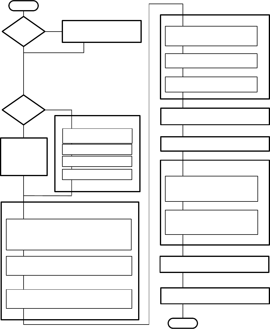
7. Adjustment Procedure
Thefollowingproceduremustbecarriedoutincaseoflargeserviceoperationse.g.whenacircuit
board or nonvolatile memory ICA has been replaced by a new one.
The order of adjustments explained here has been found to produce the desired result with the mini-
mum of effort. Adjustments can also be made in another order or completely separately.
7.1. Adjustment Flow Diagram
The Most Dominant colour
See 7.4.1
Maximum/Minimum contrast
See 7.5
Low light
See 7.4.2
High light
See 7.4.3
6.4 Gray scale
Focus
See 7.6
Adjust the convergence in the middle of
the tube with static adjustments
See 7.7.3
Adjust the convergence in the corners of
the tube with dynamic adjustments
See 7.7.4
6.7 Convergence
Exit from service mode
See 4.2.6
STOP
Perform Preliminary preparations
See 6.2
START
YES
NO
Assemblies
or components
replaced
NO
Reset user
memory for display
modes to be ad-
justed
See 3.1.2
Activate service mode and perform 7.3
para 1), 2) & 3) with 91.376 kHz/85 Hz
(GTF642)
YES
Memory
replaced
6.3 Geometry
Initializing
4.2.4 Initializing
Perform 6.3 para 4) and 5) for all display modes.
Switch OFF the monitor and
activate service mode
Switch OFF the monitor
The new settings are stored automatically.
(4.2.5)
The new settings are stored automatically.
(4.2.5)
Select display mode 00
446F 25
7.2. Preliminary Preparations
Connect the signal cable to the PC. Switch on the monitor and the PC. Let the monitor warm up for
20 minutes before starting the adjustments.
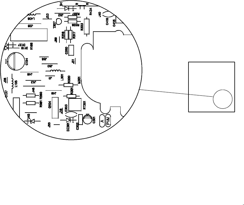
7.2.1. High Voltage
-- Select 91.376 kHz/85 Hz (GTF642) crosshatch test pattern.
-- Connect the high voltage meter to the anode of the picture tube.
-- Adjust the high voltage to 27.0 ±0.2 kV with RT301 on SMA-- board.
Front
RT301
446F
26
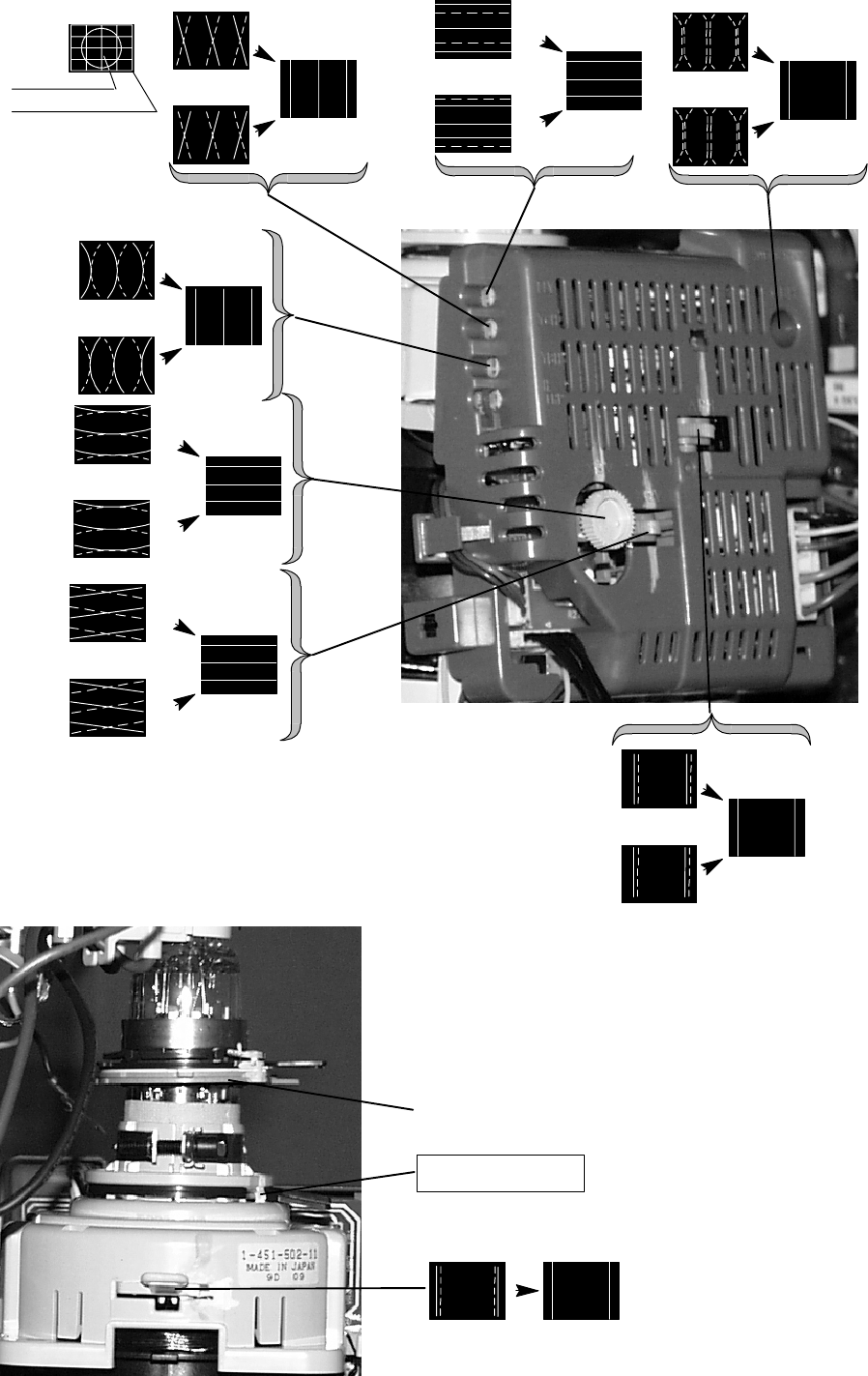
7.3. Geometry
Magnetic fields for following adjustments: vertical 0.45G and horizontal 0.0G.
Activate Service Mode in 91.376 kHz/85 Hz (GTF642).
Degaussing must be carried out before the picture adjustments. Degaussing shall be repeated if the
monitor is moved.
1) Select 91.376 kHz/85 Hz (GTF642) crosshatch test pattern.
Set to maximum and adjust until the background is faintly visible.
Reduce width until both vertical edges of the background are visible.
2) Straighten the picture if tilted.
This adjustment is common for all display modes.
3) Centre the background.
This adjustment is common for all display modes.
4) Adjust size, position and shape of the picture equal to the mask aper-
ture. Adjust first the properties with largest deviation from the correct
value.
5) Adjust final width and height.
6) The distance between bezel and active screen edge shall not vary
more than 2.0 mm in vertical and horizontal direction.
7) Repeat steps 4) and 5) for every display mode to be stored. Note that
the display mode can be changed without leaving the service mode.
GEOMETRY
GREY SCALE
SHARPNESS
PRODUCT INFORMATION
MEMORY SETTINGS
Raster
Width
Horizontal centering
Height
Vertical centering
Pincushion
Pincushion balance
Trapezoid
Orthogonality
S Correction
C Correction
E/W Corner
Tilt
==
00: 1280x1024 85HZ
==
354 --/+ 4 mm
265 --/+ 3 mm
<1.5mm
<1.5mm
<1.5mm
<1.5 mm
446F 27
7.4. Grey Scale
The grey scale is adjusted for 9300K colour temperature.
Activate Service Mode in 91.376 kHz/85 Hz (GTF642).
7.4.1. The Most Dominant Colour
The most dominant colour has been marked in a label on the deflection yoke.
It may not be correct if tube or SMH card has been changed. In that case judge
the most dominant colour from the tone of the picture after you have made the
following adjustments.
1) Select 91.376/85 (GTF642) black test pattern.
2) Set to maximum and to minimum.
3) Set Blacklevel adjustment RED/GREEN/BLUE Black Level to (step 33)
4) Set RED/GREEN/BLUE Amp (step 33) menu and G2 menu adjustments to
center (step130).
5) Placetheprobeofthecolouranalyzerinthemiddleofthescreenand
adjust with G2 trimmer until the picture illuminance is 3±1.0 cdm2(Nits)
7.4.2. Low Light
1) Select 91.376/85 (GTF642) black test pattern.
2) Adjust picture illuminance to 1.0 cdm-- 2(Nits)with in servicemenu.
3) Adjust the in servicemenu to the minimum.
4) Adjust the colour coordinates to (9300K)
x = 0.283±0.010
y = 0.297±0.010
with RED/GREEN/BLUE Black Level adjustments.
Do not adjust the most dominant colour.
During the adjustment check if brightness is chancing over tolerance, when
needed adjust it back. If Y--- and X---values are getting too far from ideal val-
ues, you have chosen wrong MOST DOMINANT COLOUR. Check the domi-
nant colour again according to the instructions.
5) Set to the maximum and check that the illuminance is still 3±1.0 cdm2.If
not, adjust with G2 in service menu.
6) Adjust picture illuminance to 1.0 cdm2(Nits)with in servicemenu and
check the colour coordinates.
7.4.3. High Light
1) Select 91.376/85 (GTF642) black test pattern.
2) Adjust with the picture illuminance to 1±0.1 cdm2(Nits).
3) Select 91.376/85 (GTF642) window test pattern.
4) Adjust with the picture illuminance in the window to 100±5 cdm2(Nits)
5) Adjust with RED/BLUE Amp the colour coordinates in the window to
x = 0.283±0.003
y = 0.297±0.003
Check after adjustment that the illuminance reading is in limits.
6) Back to low light step 4) and check colour coordinates.
7.5. Maximum/Minimum Contrast
1) Set to the maximum.
2) Adjust with the picture illuminance outside window to 1.0 cdm-- 2(Nits).
3) Adjust illuminance in the window to 140±5 cdm-- 2(Nits) with
MAX CONTRAST.
4) Set to the minimum.
5) Adjust the minimum illuminance in the window to 5 ± 1 cdm-- 2(Nits)
with MIN CONTRAST.
6) Exit from service mode.
7.6. Focus
1) Select 91.376/85 (GTF642) crosshatch test pattern
2) Set to the maximum and adjust to 70 % (background faintly visible).
3) Adjust the sharpness with FOCUS H and FOCUS V to optimum
4) Adjust until the background is invisible
5) Select focus test pattern. Check that all letters are clearly visible.
FOCUS H
Left side view
of the chassis
FOCUS V
G2
pixelpixelpi
pixelpixelpi
pixelpixelpi
pixelpixelpi
446F
28
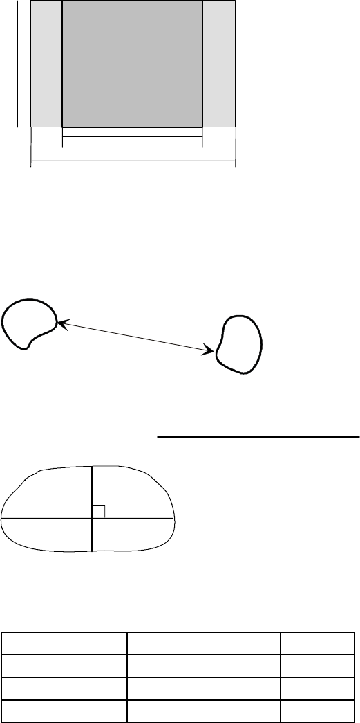
7.7. Convergence
Reduce first the convergence error in the middle of the screen to minimum using static adjustments.
After the convergence is faultless in the middle of the tube, use dynamic adjustments to eliminate
the error in the edges of the tube.
Static adjustments affects the whole picture area:
-- Magnet ring set on the tube neck (horizontal + vertical)
Dynamic adjustments affects a part of the picture area:
-- Deflection yoke trimmers.
7.7.1. Measuring Conditions
-- Adjust convergence with 91.376/85 (GTF642) line frequency.
-- Make sure that focus is correctly set at the mid-point between the screen center and the edge of
the picture.
-- Use white crosshatch test pattern with circle.
-- Adjust to near the maximum and reduce until the background disappears.
A
B0.50
Red
Green
Blue
0.5
0.500.5
X
Y
0.500.5
0.500.5
7.7.2. Convergence Measuring Gauge CM7AR
The use of the Klein CM7AR Convergence Gauge has been explained here but other types of
gauges can be used as well.
Check that the adjusting knobs (A & B) are set to zero.
-- Place the gauge on the line with marking Yupupwards when measuring horizontal line.
-- Place the gauge on the line with marking Xupupwards when measuring vertical line.
-- If the line has convergence error, the line in the window seems to be broken.
-- Use knobs A and B to adjust the line continuous.
-- If the readings are on the opposite side of zero, the convergence error is A+B (e.g. 0.2 + 0.1
=0.3).
-- If the readings are on the same side of zero, the convergence error is equal to A if A > B or
BifB>A
7.7.3. Static Convergence
The magnet rings has been set to the optimum in the factory. Readjustment is necessary only in
case the adjusting magnets have been accidentally moved.
1Adjust G vertically in the middle between R and B with 6 pole magnet rings.
2Adjust G horizontally in the middle between R and B with 6 pole magnet rings.
3Adjust R and B vertically to the same position with G line with 4 pole magnet rings.
4Adjust R and B horizontally to the same position with G line with 4 pole magnet rings.
Lock the rings with paint.
6polemagnetrings
R
G
B
SMH
1
2
Purity magnet rings.
Do not adjust !
Sliding two ring tobs toward
or away from each other
Rotating both rings together
4
4
3
4polemagnetrings
3
2
1
43
21
446F 29
7.7.4. Dynamic Convergence
Deflection yoke trimmers
A --- a r e a
B --- a r e a
RGB
RB
RB
RBRB
RGB RGB
RBRB
RB
RB
RB
RBRB
RBRB
RBRB
R
B
R
B
RB
RB
R
B
R
B
RB
RB
RB
RB
RB
RGB RGB
RB
RB
B
R
B
RB
RB
RB
R
B
R
B
R
B
R
B
R
B
R
B
RB
RB
RB
R
B
R
B
R
B
R
B
R
RGB RGB
RB
RB RBBR
RBRB
RBRB RB RB
Purity magnet rings.
Do not adjust !
See 7.7.3.
446F
30
7.7.5. Allowed Error Levels for Convergence
Area A ≤0.25 mm
Area B ≤0.35 mm
7.8. Colour Purity
Do not move purity magnet rings. If the purity magnet rings are found to have moved during trans-
portation or handling, set them just in the original position by tracing the locking paint put on purity
magnet rings and holder of beam bender and then readjust the static convergence. Beamlanding
adjustment handle to purity.
446F 31
8. Screen and Faceplate Blemishes
8.1. Definitions of inspection conditions and terms
8.1.1. Standard observing condition
Distance: 30 cm from screen face. Angle 45from Z axis.
Cosmetic inspection without raster should be done under luminance: 500lx MIN.
Color and brightness
8.1.2. Zone division
273.6 mm
273.6 mm
AB
other screen area
A Zone: 273.6 mm x 273.6 mm
B Zone: The balance of useful screen area
8.1.3. Minimum distance beetween defects
8.1.4. Average diameter of defect
Average diameter =
Long diameter + Short diameter
2
8.2. Face defect standard (black spot, stain)
Average diameter Quantity allowed Minimum
of defects A B To t a l distance
less than 0.5 44630
less than 0.3 no limit ---
446F
32
8.3. Glass blemish
8.3.1. Scratch
Width Length of single scratch
W>0.05 No limit
0.05<W<0.10 25
0.10<W<0.15 12
0.15<W None allowed
8.3.2. Bubbles/Foreign materials
Bubbles
Average diameter of defects Quantity allowed
Within any 70 mm circle
Minimum distance
0.3---0.45 212.7
Air blister
(Max. legth 6.0)
(Max. width 0.3)
212.7
Foreign material
Apply the face defect standard for blackish defects
Average of diameter
of defects
Quantity allowed
within any 70 circle
Minimum distance
0.25---0.45 212.7
Note: No limit for the defects less than 0.25 mm average diameter
446F 33
1. 2.
3. 4.
5. 6.
7. 8.
9. 10.
446F
34
11. 12.
13. 14.
15. 16.
17. 18.
19. 20.
446F 35
21. 22.
23. 24.
25. 26.
27. 28.
29. 30.
446F
36
31. 32.
33. 34.
35. 36.

446F 1
Spare Parts
Spare Parts
P/N Production
P/N
Description
446PRO 446F051 19” NOKIA 446PRO (EU)
446PRO 446F059 19” NOKIA 446PRO (US)
446F
2
Spare Parts
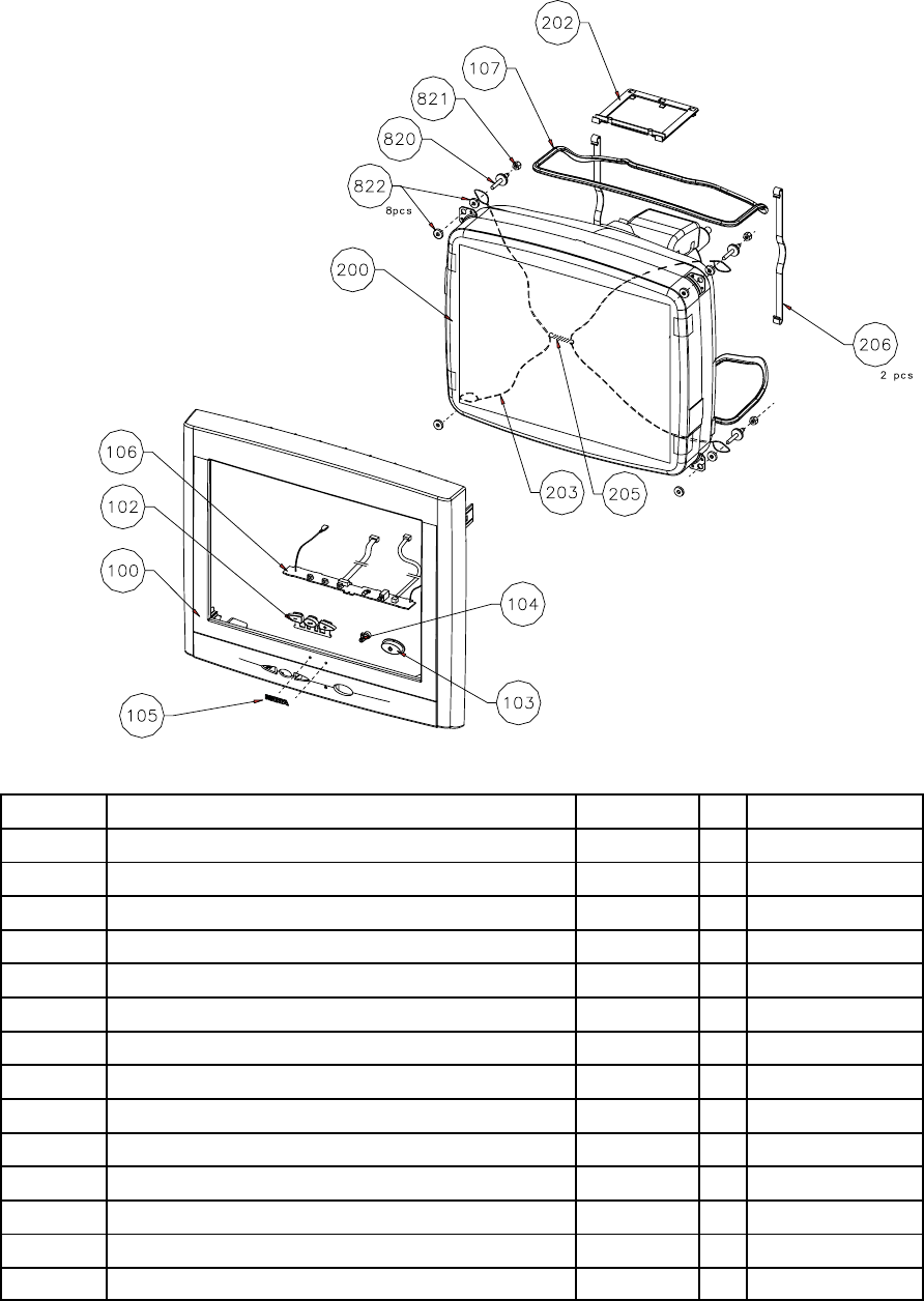
Item no Description Code PG
100 Front cover UM8180 28
102 Keypad UT1890 5
103 Power button UT1877 5
104 Light pipe UA5706 3
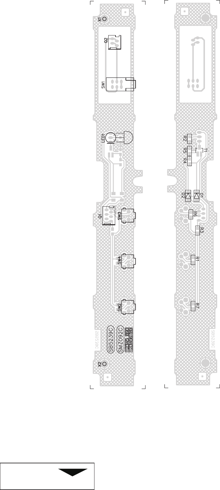
106 Control module (keypad) SMZ092 19
107 Demaign coil FD0194 22
200 Picture tube NM1056 65
202 Degaussing coil holder UG1077 4
203 Grounding wire SE2743 6
205 Grounding wire UC3016 2
206 Degaussing coil holder UG1023 3
820 Picture tube screw WC0543 3
821 Washer WJ0171 1
822 Friction plate UL0131 1
446F 3
Spare Parts
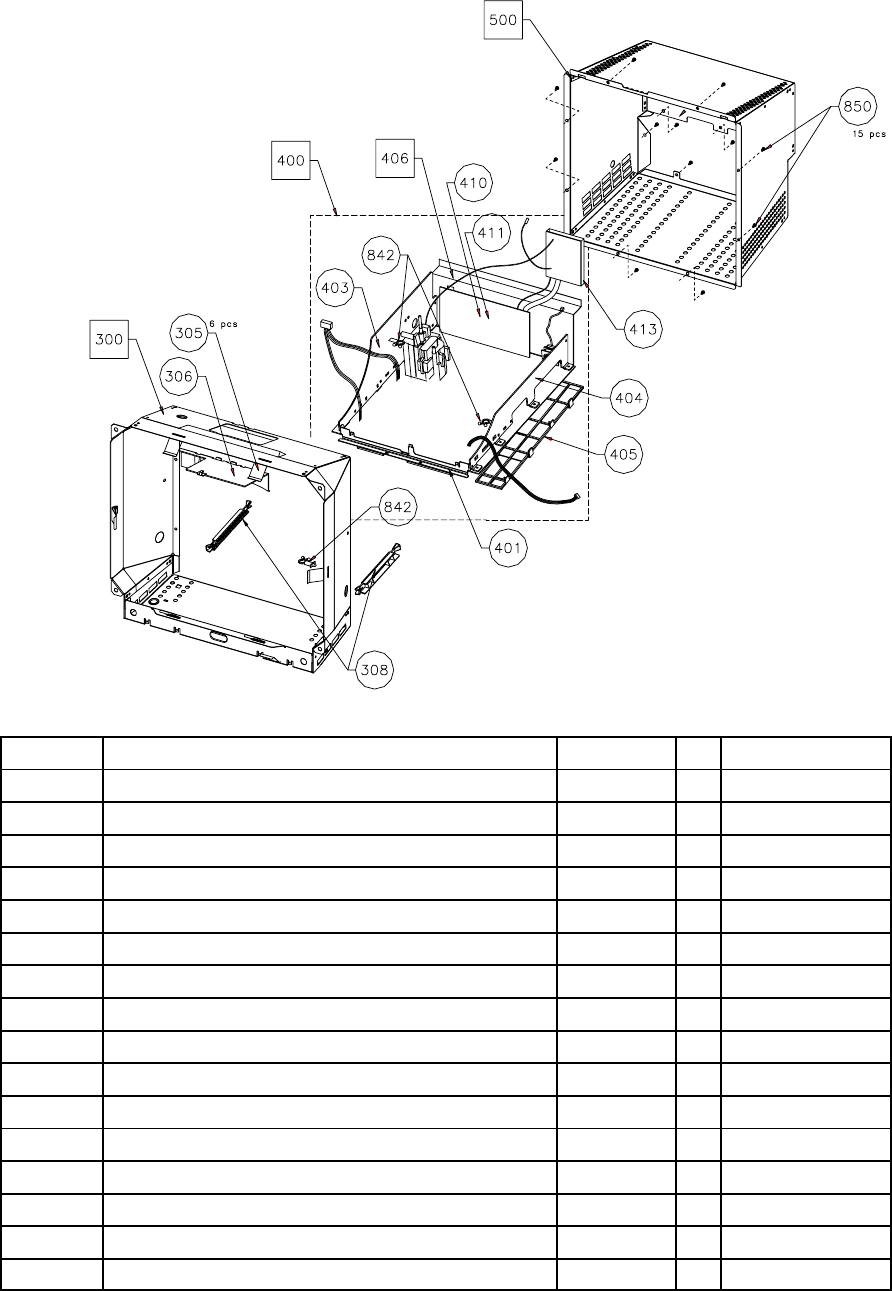
Item no Description Code PG
300 Frame assmebly UC7130 *
305 Grounding spring UC7048 *
306 Insulator UG1064 *
308 Slide bar UG1076 1
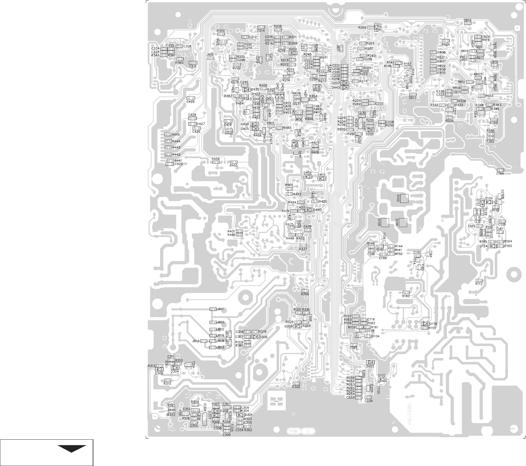
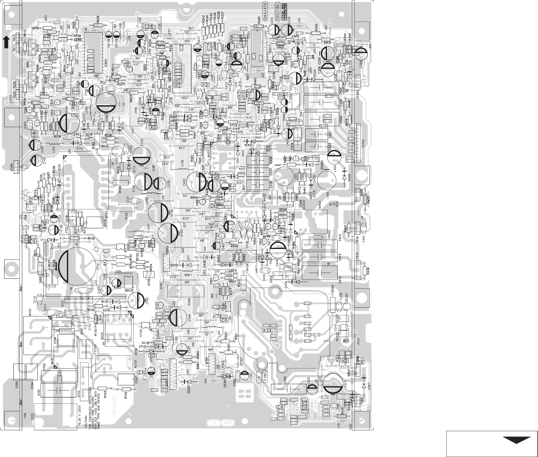
400 Main board SMA241 52
401 Brace UC7135 4
403 Cooling plate, right UC7133 21
404 Cooling plate, left UC7132 21
405 Support frame UG1050 9
406 Connector panel assembly UC7134 21
410 Cover video UC7136 21
411 Video PCB SMY052 38
413 Base module SMH160 21
500 Cover shield assembly UC7131 21
842 Wire holder UJ0251 4
850 Screw WC0354 *
446F
4
Spare Parts
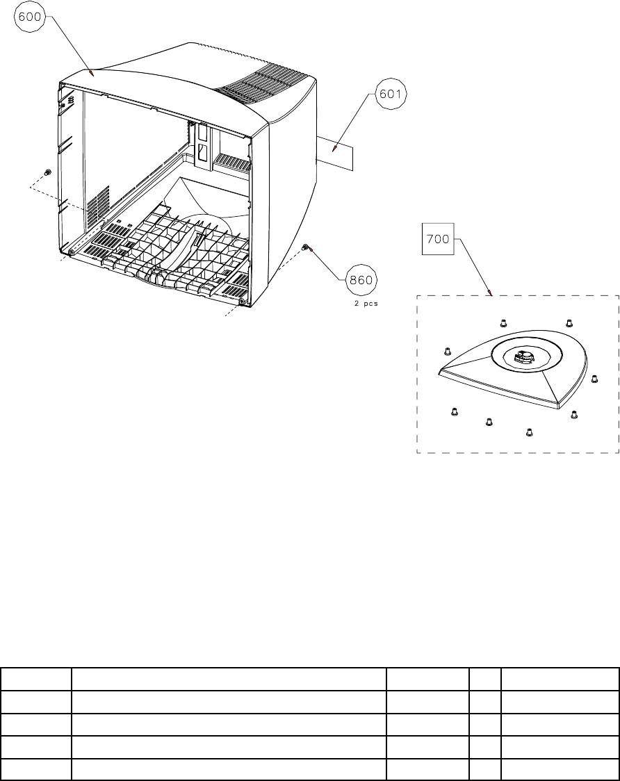
Item no Description Code PG
600 Back cover UD0670 31
601 Type label ZZ2883 7
860 Pt screw K40x20 WN 1447 WC0354 *
700 Stand assembly US0137 17

446F 5
Spare Parts
Packing materials:
Packing box ZA2597 13
Side top cushion ZA5025 14
Side bottom cushion ZA5024 14
LDPE---Plasticbag ZA0478 6
Accessories:
Power cord QM0028 14 051
Power cord QM0049 12 059
Signal cable QM0308 20
Plastic bag ZA0502 3
User guide ZK0026 11
Installation guide ZF5834 4
Mac adapter QK1518 14 059
Warranty card ZF5812 2059
* = Not normally supplied as spare part
446F
6
Spare Parts

Part
NO Description PG Item Number
SMA241H 2
446F Page 1SB5218 02.00
SMA241 MAIN BOARD 446F 55
AJ0105 WW RES 5W0 3R9 K RM15 10X10 01 RA168 RA434
AJ2603 MO RES 2W0 22R J 6--17 02 RA447
AJ2923 MO RES 2W0 470R J 6--17 02 RA129
AQ2218 TPMET.AA H10 22K RM 5X10 6--H 03 RTA301
AW0079 PTC--THERMISTOR 18R/25’C RM5 07 PTCA101 PTCA102
AW0111 NTC--THERMISTOR 5R0/25’C RM5+ 07 NTCA101
CA0306 CERCAP Y5T 220P M 2KV Y7.5 D 02 CA435
CC0513 CERCAP Y5V 3N3 S 1KV Y7.5 D 02 CA108 CA109 CA110
CA111
CE0085 X2--CAP 470N M 275VAC Y22.5 PLA 07 CA101
CE0116 Y--CAP 2N2 M 400VAC Y12.5 SDP 04 CA102 CA103 CA107
CA113
CE2196 IMPCAP 2N2 J 2KV Y22.5 081 04 CA315 CA413 CA414
CE2592 IMPCAP 27N J 400V Y15 081 05 CA438
CE2671 IMPCAP 33N J 400V Y15 061 04 CA415 CA419
CE2852 IMPCAP 68N J 400V Y15 081 04 CA420
CE2932 IMPCAP 100N J 400V Y15 SING. 03 CA437 CA439
CE2964 IMPCAP 150N K 250V Y15 091 05 CA421
CE3064 IMPCAP 330N J 400V Y22.5 112 07 CA422
CE3163 IMPCAP 680N J 250V Y22.5 112 07 CA412 CA423
CE3224 IMPCAP 1U2 J 250V Y22.5 112 06 CA424
CK0102 PESCAP MKT 10N K 250V Y10 051 02 CA404
CK0165 PESCAP MKT 22N K 630V Y10 061 02 CA118
CK1388 PESCAP MKT 10N K 250V Y7.5 040 02 CA313
CN0095 ELCAP 330U M 385V RM10 30 X 45 19 CA112
CN0819 ELCAP’2200U M 25V RM7.5 105’17 05 CA140 CA148
CN2040 ELCAP 10U M 250V RM5 105’ 10 04 CA409
CN2046 ELCAP 10U M 400V RM5 105’ 13X 04 CA162
CN2546 ELCAP 100UF M 100V RM5 105’ 14 05 CA134
CN2749 ELCAP 2200U M 16V RM5 105 14X 04 CA120 CA154 CA444
CN3160 ELCAP. 4U7 M 350V RM5 105 10X2 04 CA431
CN3250 ELCAP. 47U M 250V RM7.5 105’16 05 CA132 CA133 CA452
CN3251 ELCAP 47U M 250V RM7,5 105’ 16 07 CA314
FJ0724 CHOKE 470UH 10% 5 MM RADIAL 04 LA401
FJ0801 COMMON MODE CHOKE 3A 60UH 0.03 05 MA101
FJ1836 INPUT CHOKE LFZ2805V08 8MH 2A 08 MA102
FM0646 FLYBACK TRAFO 30..121KH MAT. 4 32 MA301
FM2560 DYNAMIC FOCUS TRAFO E20/6 445 12 MA402
FM2586 SMPS TRAFO E20/10/6 TIW N27 17 MA104
FM2589 CENTERING COIL E25/7 1.16MH 44 08 MA401 MA403
FM3909 SMPS--TRAFO ETD39 SLOT 21 MA103
FU0735 FIXED LINEARITY COIL N--S 44 09 LA404
FU0736 FIXED LINEARITY COIL S--N 44 09 LA405
JB0049 DI DTV82F 1500V 6A TO22 13 DA418
JB0100 DI GBU4K BRIDGE 800V 4A 08 DA101
JF0145 DI BYM26E 1000V 2.3A 75NS 07 DA307
JF0168 DIODE BYW98--200 200V 3A DO--27 04 DA112 DA113
JL0069 OPTOCOUPLER VRMS 5KV 04 ICA103 ICA106
JM0341 TR BUH1215(435B) N 1500V 19ATO 16 TA415
JS0061 FET IRLI620G N 200V 4.1A 0.80R 08 TA417
JS0063 FET IRFIBE30G N 800V 2.1A 3R0 10 TA306
JS0077 FET STU13NB60 600V 12.6A 0R45 16 TA103
JS0080 FET 2SJ512 P 250V 3A 1.5R TO22 09 TA303 TA405
JS0082 FET IRFI540N 100V 20A 0R52 220 08 TA416
JS2003 FETARRAY SLA5058 5X150V 7A 0.1 18 ICA402
LM0256 IC 7812 +12V REGULATOR TO--220 04 ICA104
LM0930 IC STV9379 VERT.DEFL.BOOSTER 15 ICA303
LM0945 IC 24C64 SERIAL EEPROM 8X8K DI 09 ICA204
LM0972 IC TOP223P PWM SWITCH 15W DI 13 ICA108
LM1006 IC TDA9109/SN DEFL.PROC. SDIP3 17 ICA201
LM1031 IC ST7275 8--BIT MC 32K LJO SDI 17 ICA202
LZ0077 IC--SOCKET 42--POLE DUAL LEAF 1. 06 ICA202
QA0098 CRYSTAL 24.000MHZ FUNDAM. HC--4 06 XA201
QH0074 RELAY PCB--MOUNTING 12V 5A/250V 11 REA101
QK1285 ROW CONN 1X05 5.08/7.62 VERT/L 03 QA102
QK1587 COOLING & SUPP.PART FOR RESIST 01 RA129
QK1701 PICOFLEX HEADER 1X04 1.27MM 03 QA105
QK1702 PICOFLEX HEADER 1X06 1.27MM 03 QA201
QK1704 PICOFLEX HEADER 1X10 1.27MM 04 QA104
QK1707 PICOFLEX HEADER 1X16 1.27MM 04 QA203
QK1736 SHROUDED HEADER 6POS 2.5 JST V 01 QA301
QK1754 FUSEFIT AC INLET FOR PCB VERT. 07 QA101
QM0201 DY--COIL CABLE 7--POS 4 07

Part
NO Description PG Item Number
SMA241H 2
Page 2SB5218 02.00 446F
QM0203 CONVERGENCE CABLE 6--POS 4 05 QA301
QT0002 SPARK GAP 1.2KV +--500V R=5.0MM 03 SGA302 SGA303
QT0207 GLIMM LAMP 95V 6*12.5MM 04 SGA301
QT0733 FUSE R=5.0MM T 3.15A 250V IEC 04 FA102
QT0775 FUSE 5*20MM T 6.3A 250V 1500A 03 QA101
SE2747 GROUNDING WIRE 446B/447U 03 QA101
SE2780 GROUNDING VIRE L=290MM 446F 03 XA9
UG1050 SUPPORT FRAME DN10259 09
UJ0251 TIES/CABLE BAND DN30181 44 04
JZ0020 SILICONE INSUL. 13X19MM 01 ICA303
TA103
JZ0022 SILICONE INSUL. 22X30MM 03 TA415
WC0036 HEXAGON TORX SCREW UNI6950 01
WC0446 HEXAGON.--DULL 2,9X8 FE/ZN 01
WC0530 SCREW 2,9X10 FE/ZN 01
AA0625 CF RES 0W25 10R J 2.5--7 01 RA267 RA414
AA0633 CF RES 0W25 22R J 2.5--7 01 RA220
AA0649 CF RES 0W25 100R J 2.5--7 01 RA247 RA248 RA260
RA261
AA0657 CF RES 0W25 220R J 2.5--7 01 RA126
AA0665 CF RES 0W25 470R J 2.5--7 01 RA428
AA0673 CF RES 0W25 1K0 J 2.5--7 01 RA114 RA120 RA230
RA231 RA233 RA174
AA0681 CF RES 0W25 2K2 J 2.5--7 01 RA223 RA335
AA0687 CF RES 0W25 3K9 J 2.5--7 01 RA429
AA0689 CF RES 0W25 4K7 J 2.5--7 01 RA225 RA227 RA237
RA238 RA239 RA240
RA241 RA242 RA619
RA628 RA210
AA0691 CF RES 0W25 5K6 J 2.5--7 01 RA258
AA0695 CF RES 0W25 8K2 J 2.5--7 01 RA402
AA0697 CF RES 0W25 10K J 2.5--7 01 RA145 RA401
AA0701 CF RES 0W25 15K J 2.5--7 01 RA224
AA0715 CF RES 0W25 56K J 2.5--7 01 RA257
AA0729 CF RES 0W25 220K J 2.5--7 01 RA357 RA416 RA426
AA0731 CF RES 0W25 270K J 2.5--7 01 RA448
AA0733 CF RES 0W25 330K J 2.5--7 01 RA151 RA152 RA153
RA154
AA0754 CF RES 0W25 2M2 J 2.5--7 01 RA326
AA0761 CF RES 0W25 4M7 J 2.5--7 01 RA102 RA103 RA217
AB0130 NF RES 0W5 1R80 J 2.5--7 02 RA314
AB0585 NF RES 0W25 0R22 J 2.5--7 CF 01 RA112 RA117
AB0601 NF RES 0W25 1R0 J 2.5--7 CF 01 RA320 RA421
AB0609 NF RES 0W25 2R2 J 2.5--7 CF 01 RA346
AB0617 NF RES 0W25 4R7 J 2.5--7 CF 01 RA150
AB0629 NF RES 0W25 15R J 2.5--7 CF 01 RA111
AB0785 NF RES 0W5 0R22 J 4--11 CF 02 RA138 RA142
AB0661 NF RES 0W25 330R J 2.5--7 CF 01 RA125
AB0793 NF RES 0W5 0R47 J 4--11 CF 01 RA121 RA122
AB0795 NF RES 0W5 0R56 J 4--11 CF 01 RA313
AB0809 NF RES 0W5 2R2 J 4--11 CF 01 RA466
AC3292 CHIPRES OW1 1K00 1% 0805 201 01 RA162
AC3326 CHIPRES 0W1 2K26 1% 0805 201 01 RA140
AC3346 CHIPRES OW1 3K65 1% 0805 2013 01 RA110
AC3369 CHIPRES 6K19 0W1 1% 0 01 RA252 RA329
AC3370 CHIPRES OW1 6K49 1% 0805 2013 01 RA218
AC3388 CHIPRES 0W1 10K0 1% 0805 201 01 RA156 RA157 RA407
AC3405 CHIPRES 15K0 0W1 1% 0805 01 RA404
AC3438 CHIPRES 0W1 33K2 1% 0805 201 01 RA406
AC3453 CHIPRES 47K5 0W1 1% 0805 01 RA403
AC3484 CHIPRES 0W1 100K 1% 0805 201 01 RA356
AC3616 CHIPRES 0W1 215K 1% 0805 201 01 RA276
AC4400 CHIPRES 0W1 0R0 5% 0805 20 01 RA312 RA473
AC4400 CHIPRES 0W1 0R0 5% 0805 20 01 JA801 JA802 JA803
JA805 JA806 JA807
JA812 JA809 JA811
AC4417 CHIPRES 0W1 4R7 5% 0805 20 01 RA155 RA211 RA360
AC4425 CHIPRES 0W1 10R 5% 0805 20 01 RA160 RA418
AC4433 CHIPRES 0W1 22R 5% 0805 20 01 RA322
AC4441 CHIPRES 0W1 47R 5% 0805 20 01 RA264 RA265 RA266
RA315
AC4449 CHIPRES 0W1 100R 5% 0805 2 01 RA159 RA405 RA425

Part
NO Description PG Item Number
SMA241H 2
446F Page 3SB5218 02.00
RA440 RA441 RA442
RA443 RA444 RA445
AC4455 CHIPRES 0W1 180R 5% 0805 2 01 RA602 RA611
AC4457 CHIPRES 0W1 220R 5% 0805 2 01 RA319 RA302 RA413
RA465 RA601 RA603
RA610 RA612 RA361
AC4461 CHIPRES 0W1 330R 5% 0805 2 01 RA339
AC4465 CHIPRES 0W1 470R 5% 0805 2 01 RA161 RA274 RA604
RA607 RA613 RA616
AC4467 CHIPRES 0W1 560R 5% 0805 2 01 RA132
AC4471 CHIPRES 0W1 820R 5% 0805 2 01 RA333
AC4473 CHIPRES 0W1 1K0 5% 0805 20 01 RA104 RA144 RA146
RA147 RA201 RA202
RA203 RA213 RA251
RA271 RA304 RA308
RA309 RA318 RA332
RA334 RA431 RA427
RA167 RA479 RA486
AC4475 CHIPRES 0W1 1K2 5% 0805 20 01 RA212 RA214 RA449
AC4477 CHIPRES 0W1 1K5 5% 0805 20 01 RA419
AC4479 CHIPRES 0W1 1K8 5% 0805 20 01 RA216
AC4481 CHIPRES 0W1 2K2 5% 0805 20 01 RA113 RA306
RA328 RA336 RA358
AC4483 CHIPRES 0W1 2K7 5% 0805 20 01 RA141 RA165 RA245
RA246 RA262 RA263
RA272 RA273 RA359
AC4487 CHIPRES 0W1 3K9 5% 0805 20 01 RA330 RA307
AC4489 CHIPRES 0W1 4K7 5% 0805 20 01 RA207 RA209 RA222
RA229 RA249 RA424
RA243 RA477 RA478
AC4491 CHIPRES 0W1 5K6 5% 0805 20 01 RA166 RA343 RA234
RA235 RA236
AC4493 CHIPRES 0W1 6K8 5% 0805 20 01 RA269 RA341
AC4497 CHIPRES 0W1 10K 5% 0805 20 01 RA116 RA105 RA164
RA254 RA259 RA321
RA412 RA417 RA423
RA454 RA475 RA476
RA483
AC4501 CHIPRES 0W1 15K 5% 0805 20 01 RA253 RA415
AC4503 CHIPRES 0W1 18K 5% 0805 20 01 RA450
AC4505 CHIPRES 0W1 22K 5% 0805 20 01 RA148 RA163 RA208
RA464
AC4507 CHIPRES 0W1 27K 5% 0805 20 01 RA256
AC4509 CHIPRES 0W1 33K 5% 0805 20 01 RA219
AC4513 CHIPRES 0W1 47K 5% 0805 20 01 RA250 RA463
RA275
AC4517 CHIPRES 0W1 68K 5% 0805 20 01 RA255
AC4521 CHIPRES 0W1 100K 5% 0805 2 01 RA303
AC4537 CHIPRES 0W1 470K 5% 0805 2 01 RA221
AC4569 CHIPRES 0W1 10M 5% 0805 20 01 RA244 RA331
AD0349 COMPRES 0W5 100R K 4--11 01 RA323
AD0373 COMPRES 0W5 1K0 K 4--11 01 RA324
AD0445 COMPRES 0W5 1M0 K 4--11 01 RA101
AD2745 MF RES 0W25 1M0 K 2.5--7 VR 01 RA484
AG3101 MF RES 0W5 1R00 F TC200 2.5 01 RA430
AG3133 MF RES 0W5 2R15 F TC200 2.5 01 RA344 RA345
AG3151 MF RES 0W5 3R32 F TC200 2.5 01 RA109 RA134
AG3201 MF RES 0W5 10R0 F TC50 2.5 01 RA439
AG3273 MF RES 0W5 56R2 F TC50 2.5 01 RA438 RA433 RA453
RA461 RA472 RA171
RA482 RA485 RA172
RA173
AG3301 MF RES 0W5 100R F TC50 2.5 01 RA337 RA338 RA436
RA437 RA605 RA608
RA614 RA617 RA629
RA630
AG3333 MF RES 0W5 215R F TC50 2.5 01 RA462
AG3343 MF RES 0W5 274R F TC50 2.5 01 RA169 RA347
AG3351 MF RES 0W5 332R F TC50 2.5 01 RA481
AG3381 MF RES 0W5 681R F TC50 2.5 01 RA432
AG3401 MF RES 0W5 1K00 F TC50 2.5 01 RA170
AG3465 MF RES 0W5 4K64 F TC50 2.5 01 RA451 RA452
AG3489 MF RES 0W5 8K25 F TC50 2.5 01 RA317
AG3501 MF RES 0W5 10K0 F TC50 2.5 01 RA175 RA342 RA471

Part
NO Description PG Item Number
SMA241H 2
Page 4SB5218 02.00 446F
AG3505 MF RES 0W5 11K0 F TC50 2.5 01 RA127
AG3519 MF RES 0W5 15K4 F TC50 2.5 01 RA408
AG3539 MF RES 0W5 24K9 F TC50 2.5 01 RA316
AG3551 MF RES 0W5 33K2 F TC50 2.5 01 RA340 RA446 RA474
AG3565 MF RES 0W5 46K4 F TC50 2.5 01 RA106 RA301
AG3589 MF RES 0W5 82K5 F TC50 2.5 01 RA409
AG3619 MF RES 0W5 154K F TC50 2.5 01 RA135
AG3657 MF RES 0W5 383K F TC50 2.5 01 RA420
AG3665 MF RES 0W5 464K F TC50 2.5 01 RA107 RA108
AG3681 MF RES 0W5 681K F TC50 2.5 01 RA410
CA0324 CERCAP Y5P 100P K 1KV Y5 D8 01 CA318
CA0417 CERCAP X6R 470P K 500V Y5:+1 01 CA163 CA164 CA165
CC0110 CERCAP Y5P 150P K 500V Y5: D 01 CA436
CB0473 CERCAP SL 33P J 500V Y5: D 01 CA231
CB0539 CERCAP SL 47P K 1KV Y5: D6 03 CA131
CB3059 CHIPCAP NP0 220P G 50V 0 02 CA126 CA229 CA403
CA455
CB3071 CHIPCAP NP0 680P G 50V 0 01 CA207
CB3137 CHIPCERCAP NP0 33P 50V J 0 01 CA224 CA225
CB3141 CHIPCERCAP NP0 47P 50V J 0 01 CA233 CA406 CA407
CB3151 CHIPCERCAP NP0 100P 50V J 0 01 CA305
CB3163 CHIPCERCAP NP0 330P 50V J 0 01 CA309
CB3171 CHIPCERCAP NP0 680P 50V J 0 01 CA167
CB3175 CHIPCERCAP NP0 1N0 50V J 08 03 CA146 CA306 CA310
CA326
CC0200 CERCAP Y5P 1N0 K 500V Y5: D 01 CA213 CA303 CA408
CA434
CC0240 CERCAP Y5P 2N2 K 500V Y5: D 01 CA119 CA319
CC0530 CERCAP Z5U 4N7 S 500V Y5: D 01 CA416 CA417
CC0772 CERCAP Z5V 10N Z 50V Y5: D 01 CA451
CC3280 CHIPCERCAP X7R 4N7 10% 50V 0 01 CA124 CA232 CA317
CA327
CC3320 CHIPCERCAP X7R 10N 10% 50V 0 01 CA115 CA201 CA202
CA203 CA216 CA222
CA304 CA316 CA325
CA160 CA161 CA150
CC3360 CHIPCERCAP X7R 22N 10% 50V 0 01 CA116 CA206 CA209
CC3480 CHIP CERCAP X7R 10% 100N 25V 0 01 CA129 CA456 CA457
CA245
CC3570 CHIP CERCAP Y5V 47N Z 50V 0 01 CA246
CC3580 CHIP CERCAP Y5V 100N Z 50V 0 01 CA117 CA138 CA149
CA211 CA212 CA214
CA219 CA221 CA223
CA230 CA234 CA323
CA166 CA402
CA615 CA616 CA226
CC4855 CHIPCAP Y5V 100N Z 50V 120 03 CA307 CA308 CA312
CA331 CA418 CA425
CA426 CA427 CA428
CA429
CG2625 PPRCAP KP 3N3 J 63V Y5: 050 03 CA127
CK2545 PESCAP 47N K 63V Y5: 030 02 CA302
CK2663 PESCAP MKT 150N J 63V Y5: 040 03 CA217 CA320
CK2704 PESCAP MKT 220N K 63V Y5: 040 03 CA332
CK2784 PESCAP MKT 470N K 63V Y5: 051 03 CA218
CN0372 ELCAP 22U M 50V RM5 : 7 03 CA301
CN2017 ELCAP 1U0 M 50V RM5: 105’ 6 02 CA114 CA123 CA208
CA411
CN2027 ELCAP 47U M 50V RM5: 105’ 9X 02 CA157 CA210 CA220
CA433
CN2032 ELCAP 10U M 50V RM5: 105’ 6 01 CA128 CA227 CA243
CA244 CA333 CA401
CA453 CA454
CN2523 ELCAP 100U M 25V RM5 :105’ 9 03 CA137 CA141 CA142
CA159 CA215 CA235
CA443
CN2543 ELCAP 100U M 50V RM5 105 11X1 02 CA329
CN2563 ELCAP 2U2F M 50V RM5: 105’5X1 02 CA236 CA440 CA441
CA612 CA613
CN2566 ELCAP 4U7F M 50V RM5: 105’6X1 02 CA204 CA237 CA238
CA239 CA241
CN2581 ELCAP 220U M 35V RM5 105 11X1 03 CA328 CA330
CN3206 ELCAP 10U M 50V RM5 105’ 8X14 03 CA153
FJ0433 CHOKE 15UH 10% TAPED AXIAL 140 03 LA101 LA103 LA104

Part
NO Description PG Item Number
SMA241H 2
446F Page 5SB5218 02.00
LA105 LA106 LA301
LA406
FJ0725 BEAD INDUCTOR MIN IMP360HM 02 FRA401 FRA402
JF0025 DI 1N4148 75V 200MA 4N 01 DA123 DA204 DA206
DA208 DA210 DA442
DA403 DA412 DA401
DA402 DA444
JF0060 DI 1N4002 100V 1A 01 DA125 DA308
JF0072 DI BAV21 200V 250MA 50N 01 DA420 DA421
JF0073 DI RGP10G 400V 1A 150N 02 DA419 DA424 DA426
DA427 DA428
JF0074 DI RGP15J 600V 1.5A 250N 04 DA415 DA416 DA432
DA436 DA437
JF0104 DI BYV27--200 200V 2A 25N SOD 03 DA115 DA127 DA431
JF0107 DI BYV26C 600V 1A 30N 02 DA117
JF0206 SCHOTTKY RECTIFIER 30V 1A 1N5 04 DA111
JF1005 DI P6KE200A TRANSIENT SUPPR 05 DA116
JF4003 DI BAV103 200V 250MA 50NS SOD 02 DA118 DA409 DA410
DA440
JF4005 DI LL4148 75V 150MA 4N (JF400 01 DA102 DA103 DA104
DA107 DA202 DA124
DA205 DA207 DA212
DA301 DA302 DA303
DA306 DA309 DA404
DA405 DA406 DA407
DA408 DA435
DA443
JF4012 DI BAT54C 25V 200MA SCH.BAR SO 03 DA209
JF4101 DI RHRD460S 600V 4A 30NS TO-- 08 DA109 DA122 DA126
JF4102 DI SMBYT01 400V 1A 35NS DO--241 04 DA441
JH0054 ZDI BZX83C12 12V 0.5W 01 DZA302
JH0086 ZDI BZX83C4V7 4.7V 0.5W 01 DZA201 DZA301
JH0090 ZDI BZX79B9V1 9.1V 0.5W 03 DZA101
JH4118 ZDI BZX84C12 0.225W 5% SOT-- 02 DZA401
JH4120 ZDI BZX84C18V 0.225W 5% SOT 02 DZA105
JM0099 TR BC547B N 45V 100A 20 01 TA313
JM0100 TR BC557B P 45V 100A 20 01 TA312 TA414
JM0205 TR BF423 P 250V 25MA 6 03 TA404 TA409
JM0206 TR BF420 N 300V 100MA 60M TO-- 12 TA410 TA418
JM0244 TR BF422 N 250V 25MA 60M: T 02 TA307
JM0280 TR 2N5401 P 150V 0.6A 10 02 TA411
JM0282 TR BC369 P 20V 1A 6 06 TA111
JM0285 TR BC637--16 N 40V 1A 6 04 TA412
JM4105 TR BC847B N 45V 0.1A SOT23 01 TA108 TA308 TA401
TA604 TA610
JM4107 TR BC807 P 45V SOT--23 02 TA105
JM4114 TR BC857B P 45V 100MA 150M 02 TA102 TA112 TA423
TA426 TA603 TA609
JM4125 TR DUAL P/N 50V 150MA 300MW SM 02 TA301 TA304
TA310 TA402 TA413
TA601 TA607 TA427
JM4401 TR BCR141W 50V 0.1A (2X22K)SOT 02 TA106 TA107 TA114
TA113 TA408
JM4403 TR 50V 0.1A NPN 2x4.7KOHM SOT-- 01 TA101
JM4402 TR BCR191W 50V 0.1A PNP 2X22KO 01 TA104
LM0942 IC TL431 VOLTAGE REFERENCE TO-- 04 ICA107 ICA110
LM4016 IC 74HCT86 4X2--INPUT EX--OR S 06 ICA203
LM4111 IC 4538BT 05 ICA401
LM4114 IC 4050B HEX BUFER SO--16 06 ICA301
LM4420 IC DUAL MODE EEPROM FOR DDC 2. 07 ICA205
LM4469 IC UC3843 PWM CONTROLLER SO--8 05 ICA101 ICA302
SE2747 GROUNDING WIRE 446B/447U
QK1081 BLADE CONN 4.8MM FEMALE 01 002
QK1651 BLADE CONNECTOR ’MIKROLOK’ 6.3 01 003
QK0701 WIRE TERMINAL FOR 0.20--0.50MM2 01
QK1446 WIRE TERMINAL FOR 1.85MM HOLES 01

Part
NO Description PG Item Number
SMA241H 2
Page 6SB5218 02.00 446F
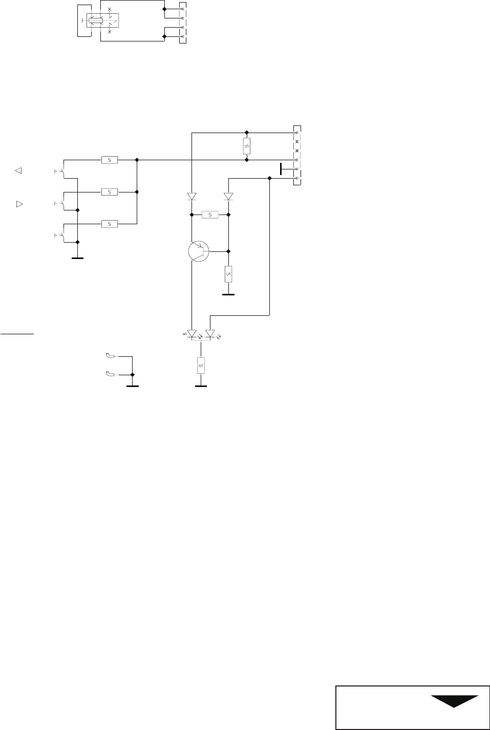
446F SMZ092C
SB5239 08.99 Page 3
1
X2
X1
JL0044
LED1
LL4148
D2
R7
15k
R1
6k8
R2
470R
R3
8k2
R4
10k
R5
10k
R6
39k
LL4148
D1
Q1
6
5
4
3
2
1
Q2
4
3
2
1
BC857B
T1
QG0326
SW1
6
5
4
3
2
1
SW4
QG0327
SW3
QG0327
SW2
QG0327 LED
5V
POWER
MENU
ECN
-
446F
SMZ092C
SB5239 08.99 Page 2
1
SMA241H
SB5218 02.00 Page 12
2
446F
SMA241H
SB5218 02.00 Page 11
2
446F
446F
SMA241H
SB5218 02.00 Page 7
2
T101
BCR112W
M103
FM3909
15
8
5
16
14
15
13
12
11
10
9
7
6
BCR141W
T114
BC807
T105
P6KE200A
D116
R150
4R7
1k00
R170
C153
10u
50V
220p
C126
C137
100u
25V
R110
3k65
100n
C129
10k0
R175
680p
C167
BYV27-200
D127
15u
L103
15u
L104
15u
L106
3R9
R168
1UC7147
C166
100n
56R2
R173 470p
C165
500V
500V
C164
470p
470p
C163
500V
56R2
R172
56R2
R171
470R
R129
RHRD460S
D122
RHRD460S
D109
RHRD460S
D126
274R
R169
3R32
R134
3R32
R109
C162
10u
400V
15u
L102
15u
L101
15u
L105
BYV98-200
D113
BYV27-200
D115
C157
47u
16V
R167
1k0
18V
DZ105
220R
R126 R166
5k6
D123
1N4148
IC110
TL431
3
2
1
R138
0R22
-T
NTC101
5R
1N4002
D125
10n
C160
C161
10n 2k7
R165
10k
R164
D124
LL4148
154k
R135
LL4148
D107
R148
22k
100n
C149
1n0
C146
R141
2k7
R144
1k0
IC103
PS2501-1L
4
32
1
T106
BCR141W
R140
2k26
C133
47u
250V
C132
47u
250V
BCR191
T104
R132
560R
11k0
R127
R125
100R
47p
C131
1kV
C134
100u
100V
C135
n.c.
R112
0R22
7812
IC104
REF
OUTIN
C140
2200u
25V
n.c.
D121
n.c.
D106
C148
2200u
25V
100n
C150
R160
10R
R142
0R22
F102
T3.15A
630V
C118
22n
R117
0R22
D112
BYV98-200
C120
2200u
16V
25V
100u
C159
C141
100u
25V
C142
100u
25V
R122
0R47
C114
1u0
50V Q104
10
9
8
7
6
5
4
3
2
1
FM2586
M104
8
7
6
54
3
2
1
S
S
S
TOP223P
IC108
S(HVRTN)
S(HVRTN)
S(HVRTN)
DRAINCONTROL
8
7
6
54
3
2
1
BYV26C
D117
330k
R154
330k
R153
330k
R152
330k
R151
C154
2200u
16V
D118
BAV103 4R7
R155
1k0
R146
T108
BC847B
IC106
PS2501-1L
4
32
1
LL4148
D103
LL4148
D102
IC107
TL431
3
2
1
R156
10k0
R157
10k0
R161
470R
22n
C116
R159
100R
R163
22k
T107
BCR141W
T111
BC369
R147
1k0
R162
1k00
T112
BC857B
R104
1k0
100n
C138
D119
80SQ045
BCR141W
T113
Q105
4
3
2
1
10k
R145
9V1
DZ101
M1
FM2586
8
7
6
54
3
2
1
Q101
D101
GBU4K
RE101
QH0074
654
321
Q102
5
4
3
2
1
4M7
R102
4M7
R103
2n2
C102
400VAC
2n2
C107
400VAC
2n2
C113
400VAC
3n3
C109
1kV
3n3
C108
1kV 3n3
C110
1kV
3n3
C111
1kV C112
330u
385V
C106
n.c.
n.c.
C105
n.c.
C104
1M0
R101
2n2
C103
400VAC
275V
C101
470n M101
FJ0801
4
32
1
FJ1836
M102
4
3
2
1
+T
18R
PTC101
+T
PTC102
18R
IC101
UC3843A
VCC
VREF
OUTPUT
GNDRT/CT
ISENSE
VFB
COMP
7
8
6
54
3
2
1
10k
R105
R111
15R
1UC6879
2n2
C119
500V
1k0
R114
1N5818
D111
0R47
R121
46k4
R106
464k
R108
464k
R107
R116
10k
R113
2k2
C123
1u0
50V
4n7
C124
BC857B
T102
LL4148
D104
63V
C127
3n3
STU13NB60
T103
100n
C117
10n
C115
50V
10u
C128
1k0
R120
2,5 LED
5
5
HEATER_5V
HEATER_5V
2,5 RESET
2,5 PREHEAT
2,5 SUSPEND
PRIMARY_Vcc
N49
2,4,5
UVLO
4,5
G1
2,4,5
2,4,5
USB_5V
USB_5V
2-5
2-5
2-5 12V
12V
12V
N109
N104
N53
2-5
2-5
2-5
5V
5V
5V
N99
3,5
3,5 15V
15V
5
5
80V
80V
3-5
3-5
185V
185V
3-5 -15V
GND
GND
PGND
2,5 DEMA
F101
OFF AFTER 3 SECONDS
NOTE: POWER IS SWITCHED
THEN THE MAIN POWER IS SWITCHED OFF.
NOTE: IF VERTICAL FLYBACK IS MISSING FROM MAIN PROCESSOR (PIN 14) AFTER START,
5V
9V
ECN
5,5V
12V
SENSING
VOLTAGE
UNDER
POWER
MAIN
+5V POWER
POWER SUPPLY
TO VIDEO
T6.3A
DEMA
0.25W NF
0.5W NF
3W etc.
2W
1W
0.5W
0.25W
SMD 1W
SMD
SMD
ELECTROLYTIC
POLYESTHER
POLYCARBONATE
POLYPROPYLENE
CERAMIC
must be replaced with original
cover are also safety components.
Safety components marked with
NOTE!
All printed boards and the back
or approved components only.
446F006
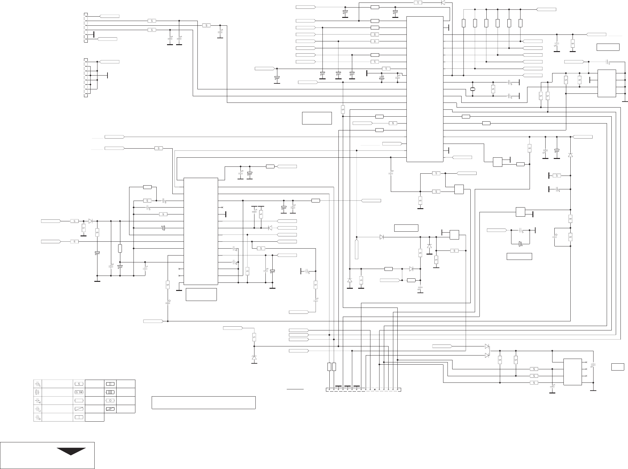
446F
SMA241H
SB5218 02.00 Page 8
2
100n
C245
47n
C246
R275
47k
R276
215k
4M7
R217
C235
100u
25V
C215
100u
25V
220p
C229
2k2
R223
4k7
R210
LL4148
D202
10u
C244
50V
C243
10u
50V
1k0
R231
n.c.
C240
10R
R267
5k6
R258
R215 n.c.
50V
4u7
C241
4k7R243
470R
R274
R273
2k7
2k7
R272
1N4148
D208
100R
R248
100RR247
1k0
R233
10n
C222 R271
1k0
R269 6k8 LL4148D212
22k
R208
680p
C207
4k7R227
R209 4k7
R207 4k7
15kR224
C239
4u7
50V
C238
4u7
50V
C237
4u7
50V
C236
2u2
50V
100n
C212
100n
C234
100n
C230
100n
C223
100n
C221
100n
C219
100n
C214
100n
C211
47p
C233
Q203
16
15
14
13
12
11
10
9
8
7
6
5
4
3
2
1
R222
4k7
R266 47R
R265 47R
R264 47R
R262
2k7
R263
2k7
D209
BAT54C
4V7
DZ201
R259
10k
100R
R260
100R
R261
R245
2k7
M24128
IC204
VCC
WC#
SCL
SDA GND
N.C.
N.C.
N.C.
8
7
6
54
3
2
1
R246
2k7
D204
1N4148
R252
6k19
R250
47k
R251
1k0
C227
10u
50V
100n
C226
n.c.
C228
33p
C231
500V
4k7
R249
D206
1N4148
R255
68k
R253
15k
R254
10k
56k
R257
4n7
C232
LL4148
D205
R256
27k
LL4148
D207
R235
5k6
R236
5k6
R234
5k6
R244
10M
C225 33p
33pC224
24.0MHz
X201
4k7
R242
R241
4k7
R240
4k7
4k7
R239
4k7
R238
R237
4k7
4k7R225
R202
1k0
R203
1k0
R201
1k0
10n
C202
10n
C201
10n
C203
4k7
R229
1k0
R230
1N4148
D210
FOC-OUT
HMOIRE
HPOS
PLL1F
R0
C0
PLL2C
HLOCKOUT
VSYNCIN
H/HVIN
BOUT
VCC
SCL
SDA
5V
ISENSE
REGIN
COMP
HREF
HFLY
HGND
B+GND
BREATH
VGND
VAGCCAP
VREF
VCAP
VOUT
EWOUT
XRAY
HOUT
GND
IC201
TDA9109SN
17
18
19
20
21
22
23
24
25
26
27
28
29
30
31
32
16
15
14
13
12
11
10
9
8
7
6
5
4
3
2
1
22R
R220
R221
470k
10n
C216
C218
470n
C217
150n
C220
47u
35V
22n
C209
1k2
R214
C208 1u0
C204
4u7
50V
C210
47u
35V
1n0
C213
500V
R211
4R7
R212
1k2
R213
1k0 R216
1k8
6k49
R218
R219
33k
22n
C206
Q201
6
5
4
3
2
1
Q202
8
7
6
5
4
3
2
1
74HCT86
IC203-4
11
13
12
74HCT86
IC203-3
810
9
74HCT86
IC203-2
6
5
4
DA1
DA0
TEST/VPP
RESET#
PA1
PA3
PA4
PA5
PA6
PA7/BLANKOUT
OSCIN
AIN2/PB2
AIN3/PB7
VDDA
GNDA
DA8
DA7
DA6
DA5
DA4
DA3
DA2
PD0/CSYNCI
HSYNCO/PD1
VSYNCO/PD2
ITC/PD3
ITB/PD4
ITA/PD5
CLAMPOUT/PD6
VSYNCI
VFBACK/AIN0/PB0
AIN1/PB1
OSCOUT
PC6
PC5/SDAI
PC4/SCLI
PC3/SDAD
PC2/RX/SCLD
PC0/OCMP/HFBACK
VDD
HSYNCI
GND
IC202
ST72T752J6B1
2221
20
19
18
17
16
15
14
13
12
11
10
9
8
7
6
5
4
3
2
142
41
40
39
38
37
36
35
34
33
32
31
30
29
28
27
26
25
24
23
74HCT86
IC203-1
32
1
IC205
24LCS21A
VCLK
VCC
SCL
SDA VSS
WP#
NC
NC
7
8
6
54
3
2
1
4
N249
1,5 LED
3,5
N-S_COIL
1,5
PREHEAT
3,5
BCL_ADJ
3,5
V_SYNC
3-5
FLYBACK
4,5
F_LIMIT
1,3-5 12V
1,5
SUSPEND
3,5
BCL
4,5
V_BLANK
3,5
SDA
3,5
SCL
4,5 LIN1
3,5
V_FLY
1,5 RESET
4,5 S5
4,5 S4
4,5 S3
4,5 S2
4,5 S1
4,5 S0
4,5
WIDTH
4,5
H_CENT
3,5
TILT
3,5
V_CONV
1,5
DEMA
3,5
G2_ADJ
3,5
H_CONV
1,4,5 USB_5V
1,4,5
UVLO
4,5
MUTE
3,5 OVER_VOLT
4,5 H_DRIVE
4,5 E/W
3,5 V_OUT
3,5 V_REF
1,3-5
1,3-5
1,3-5
1,3-5
1,3-5
1,3-5
1,3-5
1,3-5
1,3-5
1,3-5
5V
5V
5V
5V
5V
5V
5V
5V
5V
5V
4,5
V_DYN_FOC
ONLY IN USB MODEL
ECN
DDC
PROCESSOR
DEFLECTION
MEMORY
H-BLANK
V-BLANK
PROCESSOR
MAIN
1%
BCL
H_BLANK
V_BLANK
SELF_TEST
CLAMP
EXT_5V
SDA_DDC
SCL_DDC
H_SYNC
V_SYNC
KEY_PAD
TO USB
TO KEYPAD
PROCESSOR UNIT TO VIDEO
0.25W NF
0.5W NF
3W etc.
2W
1W
0.5W
0.25W
SMD 1W
SMD
SMD
ELECTROLYTIC
POLYESTHER
POLYCARBONATE
POLYPROPYLENE
CERAMIC
446F006
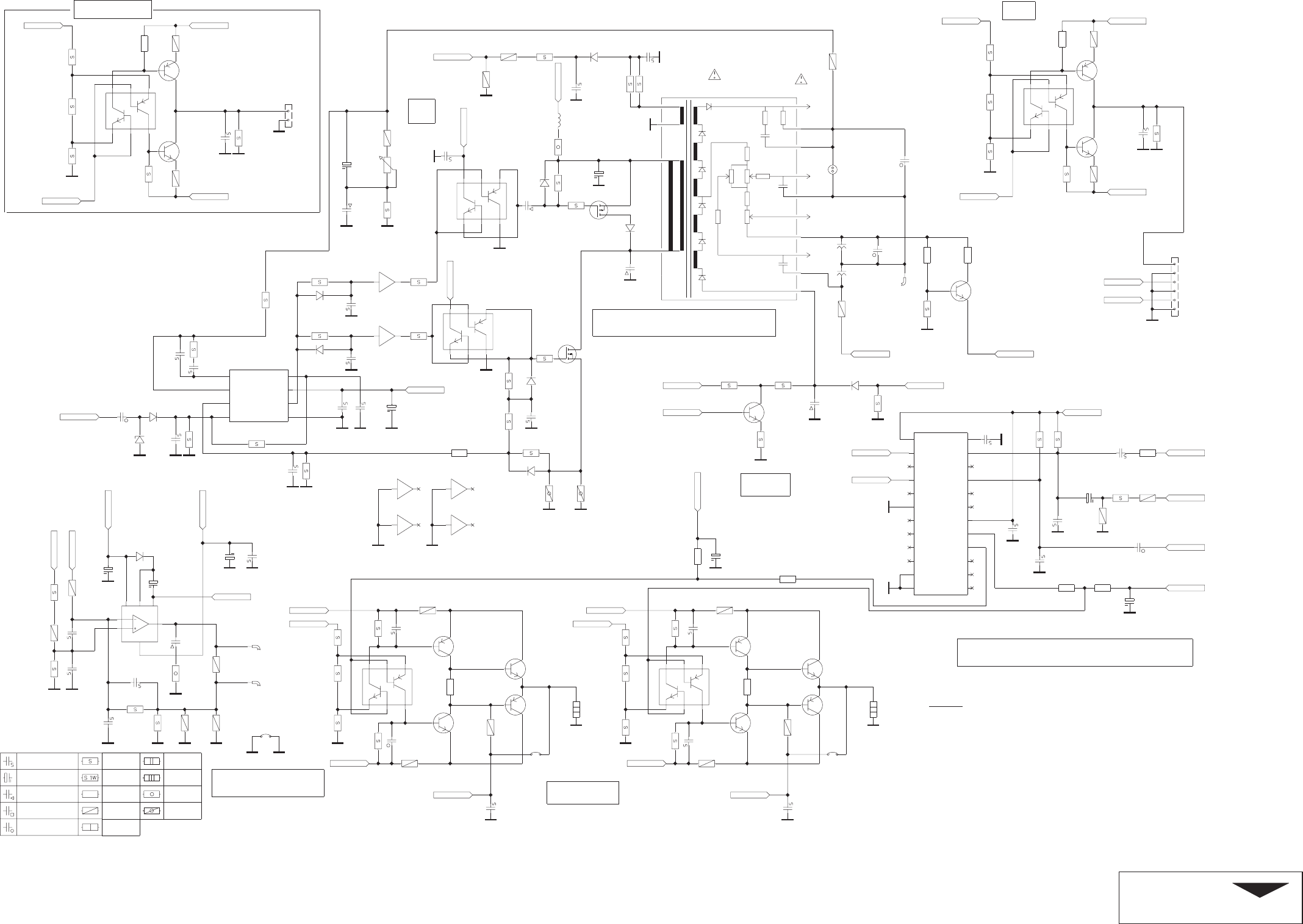
446F
SMA241H
SB5218 02.00 Page 9
2
n.c.
C334
R362
n.c.
15u
L301
220R
R361
Q301
6
5
4
3
2
1
TR DUAL P/N
T310
1
2
3
6
5
4
T314
TR DUAL P/N
1
2
3
6
5
4
1k0
R174
100R
R323
X9
TR DUAL P/N
T607
1
2
3
6
5
4
TR DUAL P/N
T601
1
2
3
6
5
4
TR DUAL P/N
T304
1
2
3
6
5
4
TR DUAL P/N
T301
1
2
3
6
5
4
150n
C320
63V
C314
47u
250V
2R15
R345
2R15
R344
J201
n.c.
R623
BC847B
T610
T609
BC857B
BC857B
T603
T604
BC847B
4R7
R360
33k2
R340
4k7
R628
n.c.
R627
2k2
R358
2k7
R359
T303
2SJ306
ST. FOCUS
DYN. FOCUS
G2
HIGH VOLT
M301
FM0646
10
9
12
13
11
14
4
15
2
1
n.c.
C602
Q302
2
1
R320
1R0
R336
2k2
IC302
UC3843A
VCC
VREF
OUTPUT
GNDRT/CT
ISENSE
VFB
COMP
7
8
6
54
3
2
1
220k
R357
R351
2k2
C322
100n
BC547B
T316
T315
BC557B
330R
R355
820R
R349
1k0
R348
1k0
R350
2k2
R353 R354
100R
R352
100R
R356
100k
n.c.
R609
n.c.
T606
R607
470R
R603
220R
T605
n.c.
R602
180R
R601
220R
470R
R604
1k0
R606
n.c.
C601
R605
100R
R608
100R
100n
C615
100R
R629
J602
n.c.
R618
n.c.
C604
n.c.
T612
n.c.
470R
R616
220R
R612
n.c.
T611
180R
R611
220R
R610
R613
470R
R615
1k0
C603
n.c.
100R
R614
100R
R617
C616
100n
R630
100R
n.c.
J601
T308
BC847B
R331
10M
D309
LL4148
R329
6k19
R328
2k2
R330
3k9
C329
100u
50V
1k0
R324
C333
10u
50V
2k2
R335
n.c.
R620
4k7
R619
RT301
22k
BYM26E
D307
1n0
C306
C613
2u2
50V
C612
2u2
50V
n.c.
C605
n.c.
C606
100n
C323
C609
n.c.
n.c.
C608 n.c.
R624
n.c.
R626
R622
n.c.
R621
n.c.
R625
n.c.
n.c.
C607
n.c.
C610
n.c.
C611
VRAMP
SGND
n.c.
IC601
N.C.
RBH
RBV
VDD
N.C.
N.C.
HRAMP
N.C.
XRESET
SDA
N.C.
SCL
N.C.
GND
N.C.
DTST
ATST
N.C.
CS1 GV
GHCS0
24
23
22
21
20
19
18
17
16
15
14
1312
11
10
9
8
7
6
5
4
3
2
1
R314
1R80
T313
BC547B
BC557B
T312
C310
1n0
470p
C309
100n
C312
R308
1k0
R309
1k0
IC301-1
4050B
23
IC301-2
4050B
45
IRFIBE30G
T306
250V
C313
10n
2kV
C315
2n2
n.c.
C311
R313
0R56
R312
0R0
R315
22R
R322
22R
R311
n.c.
R310
n.c.
12V
DZ302 R321
10k
D304
N.C.
n.c.
D305
SG303
1200V
SG302
1200V
STV9379
IC303
VDD
OUT
FG
GND
VCC
6
5
3
4
7
2
1
X3
X4
R339
330R
R333
820R
R332
1k0
R334
1k0
100R
R338
100R
R337
SG301
95V
2n2
C319
500V 2M2
R326
T307
BF422
100p
C318
1kV
10n
C316
LL4148
D306
R319
220R
R318
1k08k25
R317
24k9
R316
n.c.
R305
C324
n.c.
4n7
C317
IC301-6
4050B
1514
IC301-5
4050B
1211
IC301-4
4050B
109
IC301-3
4050B
67
C308
100n
4V7
DZ301
R304
1k0
R307
2k2
R306
2k2
R302
220R
46k4
R301
LL4148
D302
LL4148
D303
LL4148
D301
R303
100k
1n0
C303
500V
100n
C307
10n
C304
100p
C305
63V
C302
47n
C301
22u
50V
1N4002
D308
10k0
R342
R343
5k6
R341
6k8 274R
R347
R346
2R2
10n
C325
4n7
C327
1n0
C326
100n
C331
63V
C332
220n
C330
220u
35V
C328
220u
35V
2,5
N-S_COIL
2,5
BCL_ADJ
5
5
VC_OUT
VC_OUT
5
5
HC_OUT
HC_OUT
2,5 V_FLY
2,5
SCL
2,5
SDA
2,5
H_CONV
2,5
V_CONV
4,5
H_RAMP
2,5
V_SYNC
2,5
BCL
2,5
TILT
1,4,5
1,4,5 1,4,5
1,4,5
1,4,5
-15V
-15V -15V
-15V
-15V
1,5
1,5 1,5
1,5
1,5
15V
15V 15V
15V
15V
4,5
DYN_FOCUS
2,5 G2_ADJ
1,2,4,5
1,2,4,5 1,2,4,5
1,2,4,5
1,2,4,5
5V
5V
5V
5V
5V
2,5
OVER_VOLT
1,2,4,5
1,2,4,5
1,2,4,5
1,2,4,5
12V
12V
12V
12V
1,4,5
185V
2,4,5
FLYBACK
2,5
2,5
V_OUT
V_OUT
2,5
V_REF
2
2
2
2
2 2
22
2 22
BROWN
YELLOW
27KV
ECN
CONTROL
BCL
CONVERGENCE
STAT.
N.C.
N-S_COIL
VERTICAL
HV GENERATOR
ADJ.
HV
DYN. CONVERGENCE
VERT YOKE
TILT
0.25W NF
0.5W NF
3W etc.
2W
1W
0.5W
0.25W
SMD 1W
SMD
SMD
ELECTROLYTIC
POLYESTHER
POLYCARBONATE
POLYPROPYLENE
CERAMIC
446F006
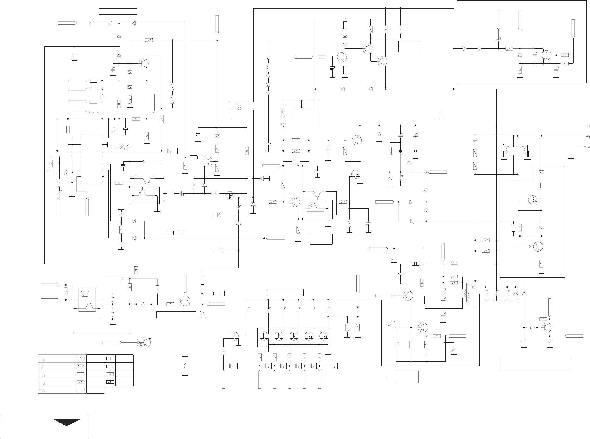
446F
SMA241H
SB5218 02.00 Page 10
2
150p
C436
500V
270k
R448
1N4148
D444
n.c.
D414
RGP15J
D432
RGP15J
D436
RGP15J
D437
1k0
R486
1n0
C434
500V
R405
100R
C443
100u
25V
100n
C457
100n
C456
LL4148
D406
1N4148
D442
12V
DZ401
1N4148
D401
383k
R420
10R
R414
1M0
R484
220k
R426
681k
R410
R473
0R0
100n
C402
82k5
R409
RGP15J
D416
RGP15J
D415
D443
LL4148
J401
56R2
R438
15u
L406
3R9
R434 250V
C412
680n
15k4
R408
R450
18k
220p
C435
2kV
R485
56R2
56R2
R433
X5
220p
C455
TR DUAL P/N
T402
1
2
3
6
5
4
TR DUAL P/N
T413
1
2
3
6
5
4
TR DUAL P/N
T427
1
2
3
6
5
4
C431
4u7
350V
100R
R437
400V
C437
100n
220p
C403
R404
15k0
R407
10k0
681R
R432
ES2G
D441
RGP10G
D424
332R
R481
100R
R425
T408
BCR141W
R424
4k7
T409
BF423
1N4148
D412
R464
22k
R423
10k
R465
220R
R477
4k7
R478
4k7 BAV103
D440
VDD
OB
VSS
O#A
OA
I#0A
I1A
C#DA
RCTCA
CTCA
4538BT
IC401
CTCB
I#0B
I1B
C#DB
RCTCB
O#B
15
11
12
13
14
9
16
10
8
7
6
5
4
3
2
1
C401
10u
50V
R406
33k2
T401
BC847B
BAV103
D409
BAV103
D410 N.C.
D411
47p
C406
47p
C407
1n0
C408
500V
250V
C404
10n
BF423
T404
R412
10k
R415
15k
R417
10k
R419
1k5
R413
220R
R418
10R
LL4148
D407
D408
LL4148
100n
C428
100n
C427
100n
C426
100n
C425
100n
C418
R445
100R
R444
100R
R443
100R
R442
100R
R441
100R
R440
100R
400V
C419
33n
250V
C423
680n
400V
C422
330n
250V
C421
150n
400V
C420
68n
BC557B
T414
R427
1k0
SLA5038
IC402
412
11
10
9
8
7
6
53
21
BYV27-200
D431
C444
2200u
10V
IRLI620G
T417
R466
2R2
T425
MPS2369
BAV103
D439
DZ404
4V7
R468
100R
R469
470R
R470
2k2
470p
C447
4n7
C445
500V
4n7
C446
274k
R467
R455
4k7
C411
1u0
50V
400V
C439
100n
L401
470u
400V
C415
33n
RGP10G
D419
360R
FR401
4R64
R439
X2
RGP10G
D428
IRF620
T419
12V
DZ402
R458
10R1M0
R457
BYV28-100
D429
L402
82u
T421
MPSA42
X1
4k64
R451
D427
RGP10G
RGP10G
D426
400V
C438
27n
C440
2u2
50V
C441
2u2
50V
R454
10k
BC857B
T423
FM2560
M402 6
8
9
10
7
5
4
R452
4k64
BF420
T418
22R
R447
R449
1k2
4n7
C416
500V
4n7
C417
500V
2kV
C413
2n2
2kV
C414
2n2
BAV21
D420
BAV21
D421
360R
FR402
T410
BF420
2N5401
T411
T412
BC637-16
R431
1k0
470R
R428
3k9
R429
1R00
R430
DTV82F
D418
T415
BUH1215
250V
C424
1u2
33k2
R446
100n
C429
T405
2SJ306
56R2
R453
L404
FU0735
N
S
L405
FU0736
N
S
R421
1R0
1N4148
D402
1N4148
D403
56R2
R461
56R2
R472
BAV21
D438
IRFI540N
T416
220k
R416
R474
33k2
C433
47u
50V
R475
10k
R476
10k
BC857B
T426
n.c.
C449
n.c.
DZ403
10n
C451
50V
250V
47u
C452
50V
10u
C454
C453
10u
50V
R480
n.c.
M403
FM2589
6
104
2
FM2589
M401
6
104
2
10k0
R471
C409
10u
250V
R479
1k0
100R
R436
R403
47k5
10k
R401
D435
LL4148
R463
47k
LL4148
D405
LL4148
D404
8k2
R402
215R
R462
C450
n.c.
10k
R483
R482
56R2
1,2,5
USB_5V
(Here)
(Here)
HC_SYNC
HC_SYNC
3,5
H_RAMP
2,5
2,5
F_LIMIT
F_LIMIT
2,3,5
2,3,5
FLYBACK
FLYBACK
2,5
S5
2,5
LIN1
3,5
DYN_FOCUS
1,3,5 -15V
2,5
V_DYN_FOC
2,5
H_CENT
1-3,5
1-3,5
5V
5V
2,5
H_DRIVE
1,3,5
1,3,5
1,3,5
1,3,5
185V 185V
185V
185V
2,5
S4
2,5
S3
2,5
S2
2,5
S1
2,5
S0
1-3,5
1-3,5
1-3,5
1-3,5
1-3,5
1-3,5
12V
12V
12V
12V
12V
12V
1,5 G1
2,5
MUTE
2,5
V_BLANK
5
5
5
5
5
5
5
5
5
5
5
55
55
5555
5
5
5
5
5
5
5
5
5
5
55
5
5
5
5
5
55
5
2
N249
2,5
E/W
2,5
WIDTH
1,2,5
UVLO
CONTROL
FOCUS
(-6V)
7,5V
ECN
60Vp
1200Vp
BLACK
BLUE
RED
2,7-3,4V
CONTROL
RASTER
250V
CONTROL
EMITTER
S-CORRECTION
BLANK-CONTROL
-170V
7,5V
WIDTH-CONTROL
6,3V
N.C.
1%
N.C.
1%
1%
1%
1%
1%
HOR.OUTPUT
HOR YOKE
0.25W NF
0.5W NF
3W etc.
2W
1W
0.5W
0.25W
SMD 1W
SMD
SMD
ELECTROLYTIC
POLYESTHER
POLYCARBONATE
POLYPROPYLENE
CERAMIC
446F006