Nokia E5 00 RM 632, 634, 699 Service Manual Level 1&2. Www.s Manuals.com. 12 V2.0
User Manual: Smartphone Nokia E5-00 RM-632, RM-634, RM-699 - Service manuals and Schematics, Disassembly / Assembly. Free.
Open the PDF directly: View PDF ![]() .
.
Page Count: 210 [warning: Documents this large are best viewed by clicking the View PDF Link!]
- 1. COPYRIGHT
- 2. WARNINGS AND CAUTIONS
- 3. ESD PROTECTION
- 4. CARE AND MAINTENANCE
- 5. BATTERY INFORMATION
- 6. EXPLODED VIEW
- 7. SERVICE DEVICES
- 8. SW-UPDATE
- 9. DISASSEMBLY INSTRUCTIONS
- 10. ASSEMBLY HINTS
- 11. SOLDER COMPONENTS
- Amendment Record Sheet
- Copyright
- Warnings and cautions
- For your safety
- Care and maintenance
- ESD protection
- Battery information
- Company policy
- Nokia E5-00; L3&4 Service Manual Structure
- 1 General information
- 2 Service Devices and Service Concepts
- 3 BB Troubleshooting and Manual Tuning Guide
- Baseband self tests in Phoenix
- Power and charging troubleshooting
- Interface troubleshooting
- User interface troubleshooting
- GPS troubleshooting
- Camera module troubleshooting
- Audio troubleshooting
- Bluetooth and FM radio troubleshooting
- WLAN troubleshooting
- Baseband manual tuning guide
- 4 RF troubleshooting
- 5 System Module
- 6 Service information differences between RM-632 and RM-634
- 7 Service information differences between RM-632 and RM-699
- Glossary
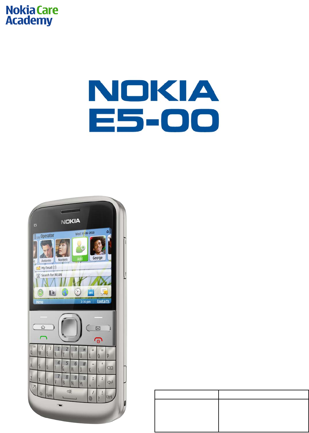
Nokia E5-00
RM-632 / RM-634 / RM-699
Service Manual Level 1&2
1
Co nf id e nt ial | Cop yrig ht © 2010 NOKIA A ll right s reserved
Version 2.0
SERVICE MANUAL
Level 1&2
RM-632 / RM-634 / RM-699
Transce iver characteristics
Band:
GSM 850/900/1800/1900 + EDGE
WCDMA 900/1900/2100 (RM-632)
WCDMA 850/1900/2100 (RM-634)
GSM 850/900/1800/1900 (RM-699)
D isplay:
QVGA (320 x 240 pixels) 2.36” screen up to 262
k colors
Camera:
5 Mpix camera with zoom up to 4x (digital)
Operating System:
Symbian v. 9.3
S60 3rd Edition, Fea ture Pack 2
Connections:
Bluetooth 2.0 + EDR
High Speed Micro USB with charging
3.5 mm AV connector
2.0 mm DC charger plug
Micro SD card up to 32 GB
WL AN 802.11 b/g
A-GPS
Transceiver with BL-4D battery pack
Ta lk t ime
Standby
GSM:
Up to 13,25 hours
WC DMA:
Up to 5,25 hours
GSM:
Up to 635 hours
WC DMA:
Up to 670 hours
Note:
Talk times are dependant on network parameters
and phone settings

Nokia E5-00
RM-632 / RM-634 / RM-699
Service Manual Level 1&2
2
Co nf id e nt ial | Cop yrig ht © 2010 NOKIA A ll right s reserved
Version 2.0
Table of contents
1. Copyright ..................................................................................................................................................................................... 4
2. Warnings and cautions........................................................................................................................................................... 5
2.1 Warnings ............................................................................................................................................................................ 5
2.2 Cautions .............................................................................................................................................................................. 5
3. ESD protection ........................................................................................................................................................................... 6
4. Care and maintenance ............................................................................................................................................................ 7
5. Battery information ................................................................................................................................................................. 8
6. Exploded view ........................................................................................................................................................................... 9
7. Service devices ........................................................................................................................................................................10
8. SW-update ................................................................................................................................................................................11
9. Disassembly instructions .....................................................................................................................................................12
10. Assembly hints ....................................................................................................................................................................19
11. Solder components............................................................................................................................................................21
Nokia E5-00
RM-632 / RM-634 / RM-699
Service Manual Level 1&2
3
Co nf id e nt ial | Cop yrig ht © 2010 NOKIA A ll right s reserved
Version 2.0
Change history
Status
Version No.
Date
Comments
Approved
1.0
25.05.2010
First approved version
Approved
2.0
29.07.2010
Updated torque value for
the assembly hints
Approved
3.0
03.03.2011
Updated operating times,
added RM-699 variant
The purpose of this document is to help NOKIA service levels 1 and 2 workshop technicians to
carry out service to NOKIA products. This Service Manual is to be used only by authorized NOKIA
service suppliers, and the content of it is confidential. Please note that NOKIA provides also other
guidance documents (e.g. Service Bulletins) for service suppliers, follow these regularly and
comply with the given instructions.
While every endeavor has been made to ensure the accuracy of this document, some errors may
exist. If you find any errors or if you have further suggestions, please notify NOKIA using the
address below:
Nokia Care Academy
service.manuals@nokia.com
Please keep in mind also that this documentation is continuously being updated and modified,
so watch always out for the newest version.

Nokia E5-00
RM-632 / RM-634 / RM-699
Service Manual Level 1&2
4
Co nf id e nt ial | Cop yrig ht © 2010 NOKIA A ll right s reserved
Version 2.0
1. COPYRIGHT
Copyright © 2010 Nokia. All rights reserved.
Reproduction, transfer, distribution or storage of part or all of the contents in this document in
any form without the prior written permission of Nokia is prohibited.
Nokia, Nokia Connecting People, and Nokia X and Y are trademarks or registered trademarks of
Nokia Corporation. Other product and company names mentioned herein may be trademarks or
tradenames of their respective owners.
Nokia operates a policy of continuous development. Nokia reserves the right to make changes
and improvements to any of the products described in this document without prior notice.
Under no circumstances shall Nokia be responsible for any loss of data or income or any special,
incidental, consequential or indirect damages howsoever caused.
The contents of this document are provided “as is”. Except as required by applicable law, no
warranties of any kind, either express or implied, including, but not limited to, the implied
warranties of merchantability and fitness for a particular purpose, are made in relation to the
accuracy, reliability or contents of this document. Nokia reserves the r ight to revise this
document or withdraw it at any time without prior notice.
The availability of particular products may vary by region.
I MPORT ANT
This document is intended for use by qualified service personnel only.

Nokia E5-00
RM-632 / RM-634 / RM-699
Service Manual Level 1&2
5
Co nf id e nt ial | Cop yrig ht © 2010 NOKIA A ll right s reserved
Version 2.0
2. WARNINGS AND CAUTIONS
Please refer to the phone’s user guide for instructions relating to operation, care and
maintenance including important safety information. Note also the following:
2.1 Warnings
1. CARE MUST BE TAKEN ON INSTALLATION IN VEHICLES FITTED WITH ELECTRONIC ENGINE
MAN AGEMENT SYSTEMS AND ANTI –SKID BRAKING SYSTEMS. UNDER CERTAIN FAULT CONDITIONS,
EMITTED RF ENERGY CAN AFFECT THEIR OPERATION. IF NECESSARY, CONSULT THE VEHICLE
DEALER/MANUFACTURER TO DETERMINE THE IMMUNITY OF VEHICLE ELECTRONIC SYSTEMS TO RF
ENERGY.
2. THE HANDPORTABLE TELEPHONE MUST NOT BE OPERATED IN AREAS LIKELY TO CONTAIN
POTENTIALLY EXPLOSIVE ATMOSPHERES, EG PETROL STATIONS (SERVICE STATIONS), BLASTING
AREAS ETC.
3. OPERATION OF ANY RADIO TRANSMITTING EQUIPMENT, INCLUDING CELLULAR TELEPHONES, MAY
INTERFERE WITH THE FUNCTIONALITY OF INADEQUATELY PROTECTED MEDICAL DEVICES. CONSULT
A PHYSICIAN OR THE MANUFACTURER OF THE MEDICAL DEVICE IF YOU HAVE ANY QUESTIONS.
OTHER ELECTRONIC EQUIPMENT MAY ALSO BE SUBJECT TO INTERFERENCE.
2.2 CautionsServicing and alignment must be undertaken by qualified personnel only.
1. Ensure all work is carried out at an anti–s ta tic worksta tion and tha t an anti–static wris t
strap is worn.
2. Use only approved components as specified in the parts list.
3. Ensure all components, modules screws and insulators are correctly re–fitted after servicing
and alignment.
4. Ensure all cables and wires are repositioned correctly

Nokia E5-00
RM-632 / RM-634 / RM-699
Service Manual Level 1&2
6
Co nf id e nt ial | Cop yrig ht © 2010 NOKIA A ll right s reserved
Version 2.0
3. ESD PROTECTION
Nokia requires that service points have sufficien t ESD protection (against sta tic
electricity) when servicing the phone.
Any product of which the covers are removed must be handled with ESD
protection. The SIM card can be replaced without ESD protection if the product
is otherwise ready for use.
To replace the covers ESD protection must be applied.
All elec tronic parts of the product are susceptible to ESD. Resis tors, too, can be
damaged by static elec tr icity discharge.
All ESD sensitive parts must be packed in metallized protective bags during
shipping and handling outside any ESD Protected Area (EPA).
Every repair action involving opening the product or handling the product
components must be done under ESD protection.
ESD protected spare part packages MUST NOT be opened/closed out of an ESD
Protected Area.
For more information and local requirements about ESD protection and ESD
Protected Area, contact your local Nokia After Market Services representative.

Nokia E5-00
RM-632 / RM-634 / RM-699
Service Manual Level 1&2
7
Co nf id e nt ial | Cop yrig ht © 2010 NOKIA A ll right s reserved
Version 2.0
4. CARE AND MAINTENANCE
This product is of superior design and craftsmanship and should be treated with care. The
suggestions below will help you to fulfil any warranty obligations and to enjoy this product for
many years.
• Keep the phone and all its parts and accessories out of the reach of small children.
• Keep the phone dry. Precipitation, humidity and all types of liquids or moisture can
contain minerals tha t will corrode electronic circuits.
• Do not use or store the phone in dusty, dirty areas. Its moving parts can be
damaged.
• Do not store the phone in hot areas. High temperatures can shorten the life of
electronic devices, damage batteries, and warp or melt certain plastics.
• Do not store the phone in cold areas. When it warms up (to its normal temperature),
moisture can form inside, which may damage electronic circuit boards.
• Do not drop, knock or shake the phone. Rough handling can break internal circuit
boards.
• Do not use harsh chemicals, cleaning solvents, or strong detergents to clean the
phone.
• Do not paint the phone. Paint can clog the moving parts and prevent proper
operation.
• Use only the supplied or an approved replacement antenna. Unauthorised antennas,
modifications or attachments could damage the phone and may violate regulations
governing radio devices.
All of the above suggestions apply equally to the product, battery, charger or any accessory.

Nokia E5-00
RM-632 / RM-634 / RM-699
Service Manual Level 1&2
8
Co nf id e nt ial | Cop yrig ht © 2010 NOKIA A ll right s reserved
Version 2.0
5. BATTERY INFORMATION
Note: A new battery’s full performance is achieved only after two or three complete charge and
discharge cycles! The battery can be charged and discharged hundreds of times but it will
eventually wear out.
When the operating time (talk-time and standby time) is noticeably shorter than normal, it is
time to buy a new battery. Use only batteries approved by the phone manufacturer and
recharge the battery only with the chargers approved by the manufacturer.
Unplug the charger when not in use. Do not leave the battery connected to a charger for longer
than a week, since overcharging may shorten its lifetime.
If left unused a fully charged battery will discharge itself over time Temperature extremes can
affect the ability of your battery to charge.
For good operation times with Ni-Cd/NiMh batteries, discharge the battery from time to time by
leaving the product switched on until it turns itself off (or by using the battery discharge facility
of any approved accessory available for the product).
Do not attemp t to discharge the battery by any other means Use the ba ttery only for its
intended purpose.
Never use any charger or battery which is damaged.
Do not short-circuit the ba ttery. Accidental short-circuiting can occur when a metallic object
(coin, clip or pen) causes direct connection of the + and - terminals of the battery (meta l str ips
on the battery) for example when you carry a spare battery in your pocket or purse.
Shortcircuiting the terminals may damage the battery or the connecting object.
Leaving the battery in hot or cold places, such as in a closed car in summer or winter conditions,
will reduce the capacity and lifetime of the battery. Always try to keep the battery between 15°C
and 25°C (59°F and 77°F).
A phone with a hot or cold battery may temporarily not work, even when the battery is fully
charged. Batteries’ performance is particularly limited in temperatures well below freezing.
Do not dispose batteries in a fire! Dispose of batter ies according to local regulations (e.g.
recycling).
Do not dispose as household waste.
Nokia E5-00
RM-632 / RM-634 / RM-699
Service Manual Level 1&2
9
Co nf id e nt ial | Cop yrig ht © 2010 NOKIA A ll right s reserved
Version 2.0
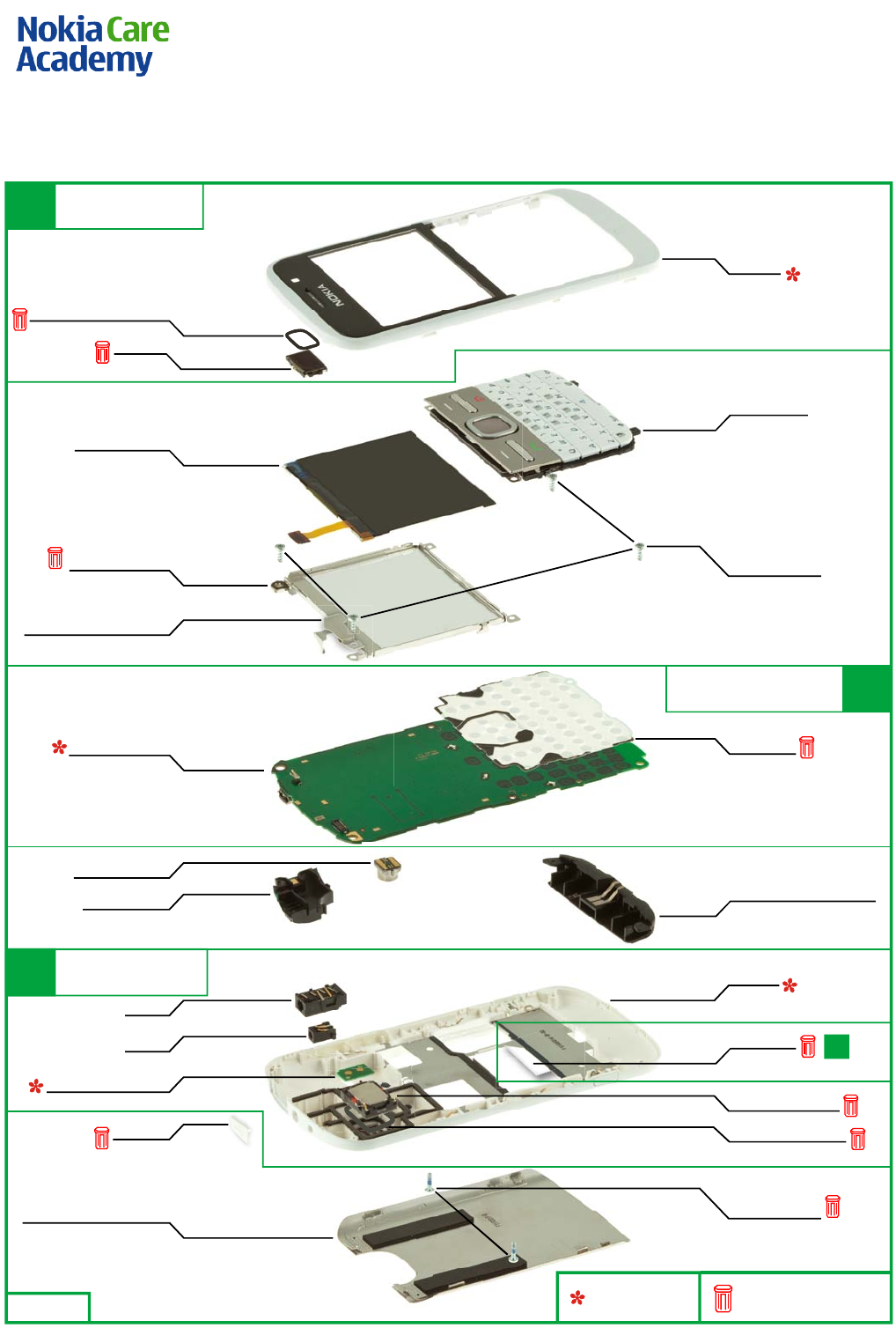
6. EXPLODED VIEW
TYPE LABEL
I0012
Only available as
assembly
These parts can not be
reused after removal
Ver. 1.0
A-COVER
I0001
DISPLAY SUPPORT
ASSEMBLY
I0008
LOCKING PLATE ASSEMBLY
I0006
LIGHT SWAP PWB
I0011
LCD AM 320x240
I0007
FLASH PWB ASSEMBLY
I0020
CAMERA MODULE
I0013
DC JACK
I0017
USB PLUG
I0015
MAIN KEYMAT
I0004
MAIN ANTENNA ASSEMBLY
I0009
SCREW TORX+ 6
M1.6X4.8MM
I0005
DOMESHEET
I0010
IHF SPEAKER 11x15
I0018
IHF SPEAKER GASKET
I0019
BATTERY COVER ASSEMBLY
I0023
SCREW TORX+ 4
M1.4X5.0MM
I0022
B-COVER
I0021
AV JACK
I0016
NCW ANTENNA
I0014
EARPIECE
I0003
EARPIECE FRONT GASKET
I0002
LIGHT SWAP PACKAGE
(I0010 - I0012) A2
A2
B-COVER ASSEMBLY
(I0016 - I0021)
A3
A COVER ASSEMBLY
(I0001 - I0003)
A1
Nokia E5-00
RM-632 / RM-634 / RM-699
Service Manual Level 1&2
10
Co nf id e nt ial | Cop yrig ht © 2010 NOKIA A ll right s reserved
Version 2.0
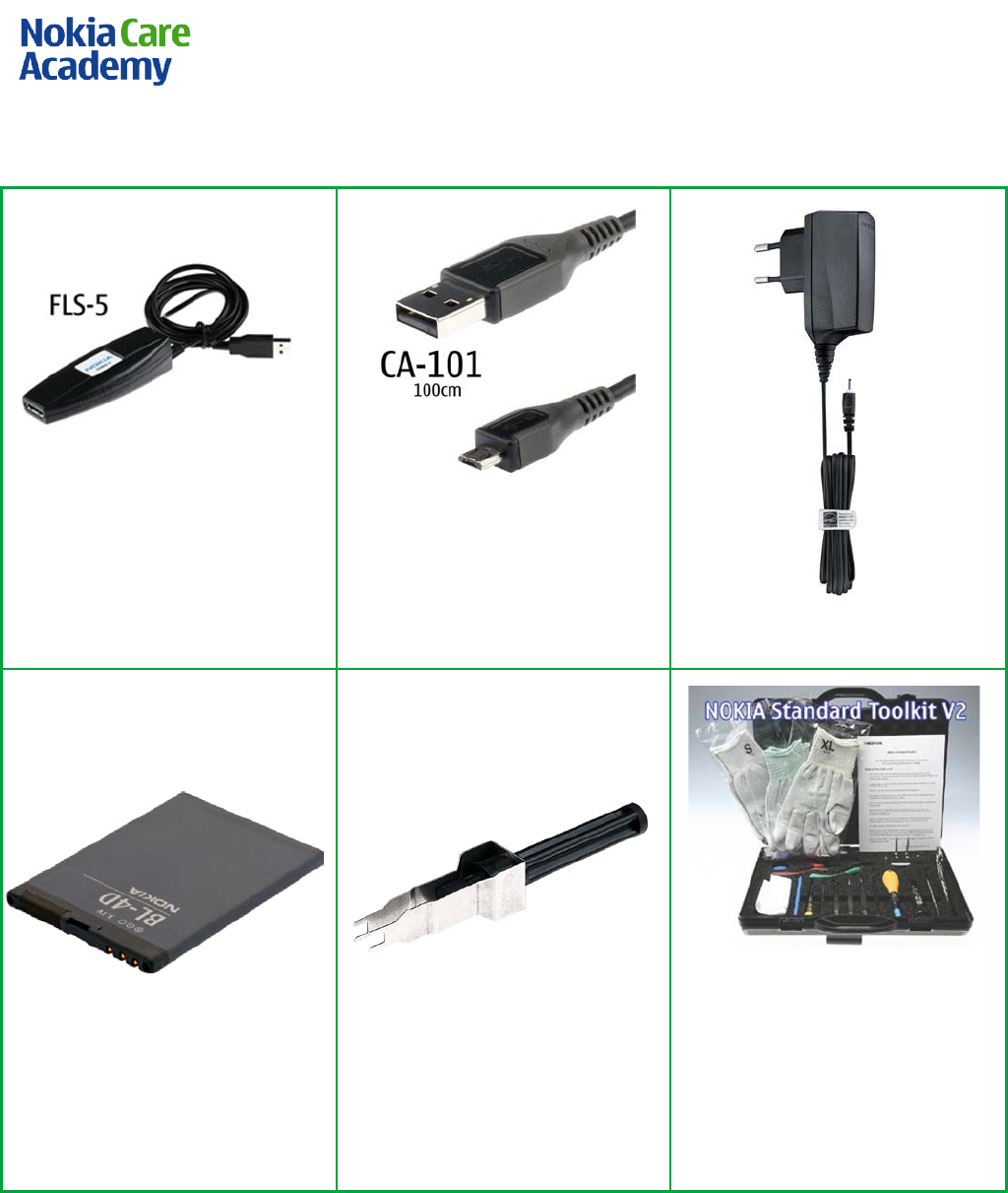
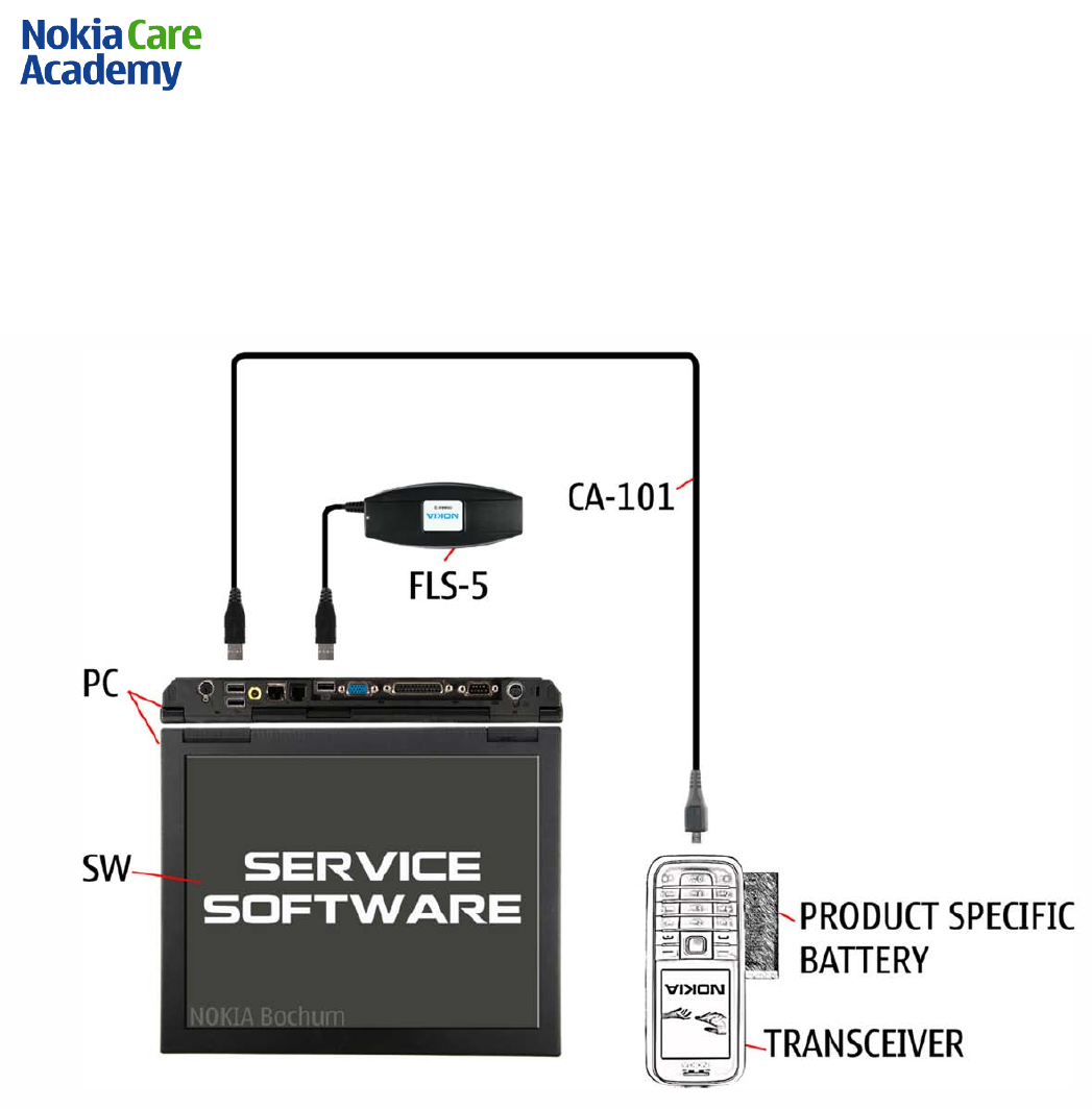
7. SERVICE DEVICES
FLS-5 Flash Device
CA-101 Service Cable
AC-8E Travel Charger
BL-4D Battery
SS-88 Camera Removal tool
NMP standard toolkit (v2)
For more information, refer to the
Service Bulletin (SB-011) on NOKIA
Online. Supplier or manufacturer
contacts for tool re-order can be
found in “Recommended service
equipment” document on N OKI A
Online.
Nokia E5-00
RM-632 / RM-634 / RM-699
Service Manual Level 1&2
11
Co nf id e nt ial | Cop yrig ht © 2010 NOKIA A ll right s reserved
Version 2.0
8. SW-UPDATE
Flash concept (Point of Sales)
To use the FLS-5 Flash Dongle, follow the user guide inside the sales package.
Please check always for the latest version of flash software, wich is available on Nokia Online.
Nokia E5-00
RM-632 / RM-634 / RM-699
Service Manual Level 1&2
12
Co nf id e nt ial | Cop yrig ht © 2010 NOKIA A ll right s reserved
Version 2.0
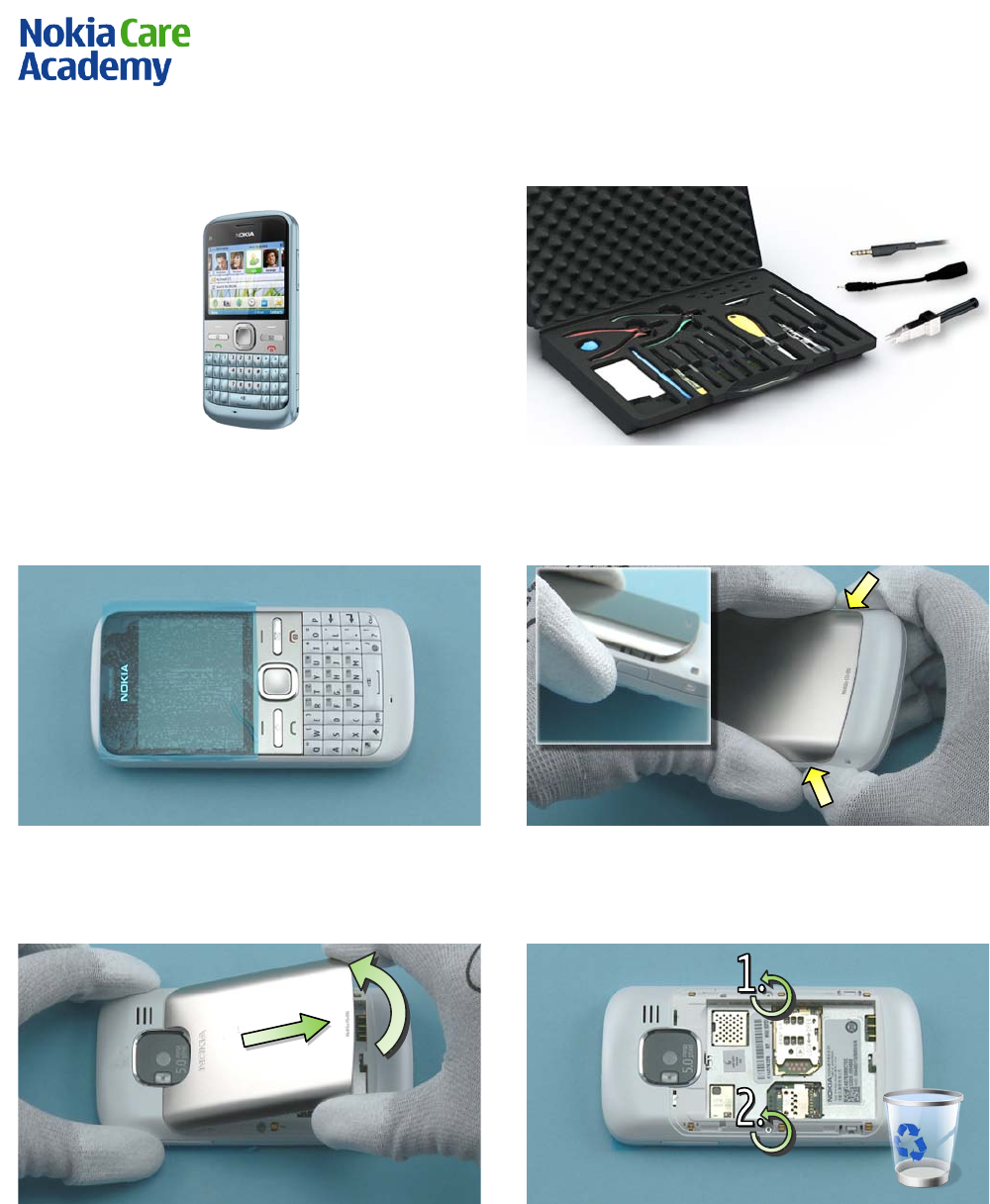
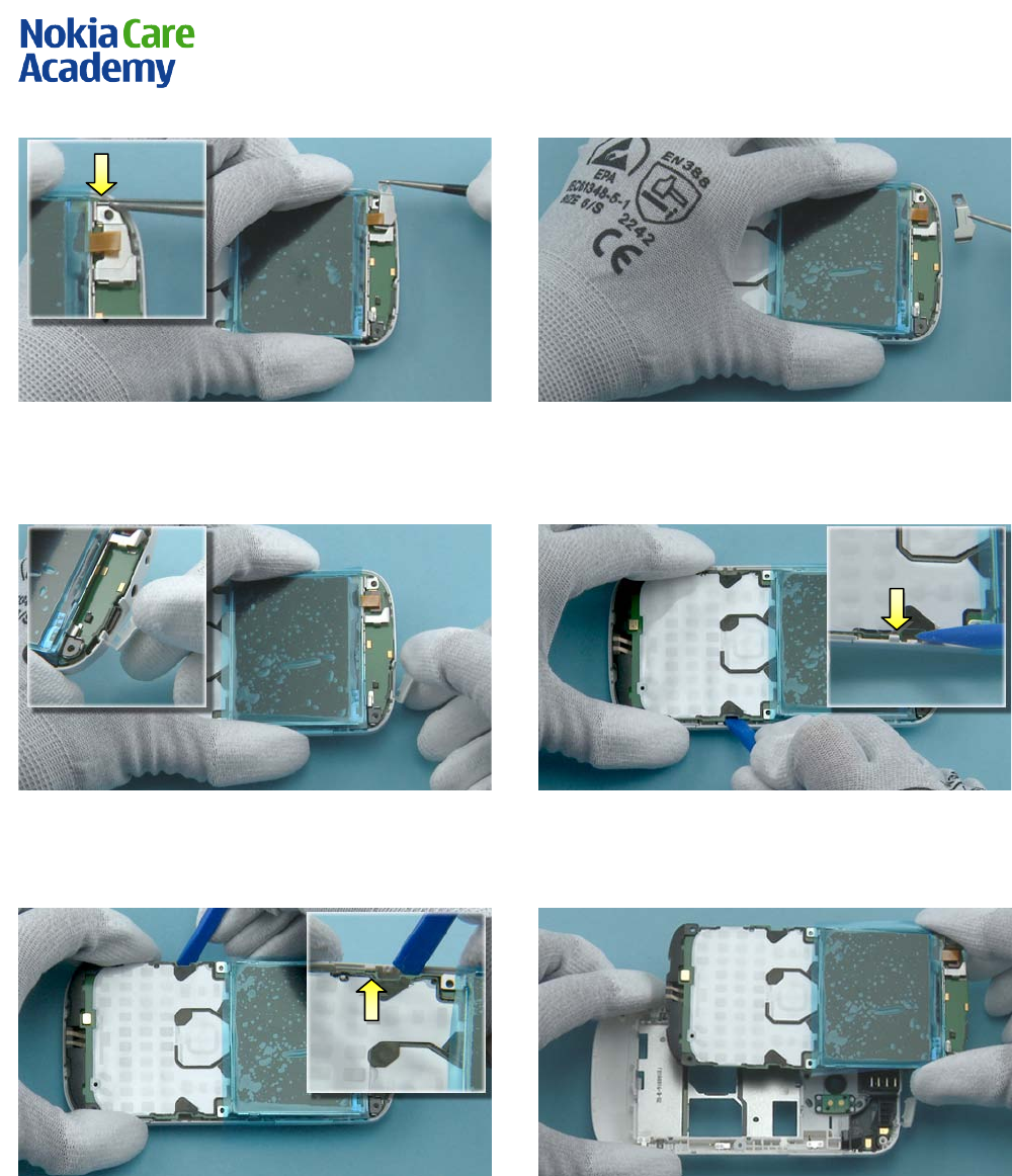
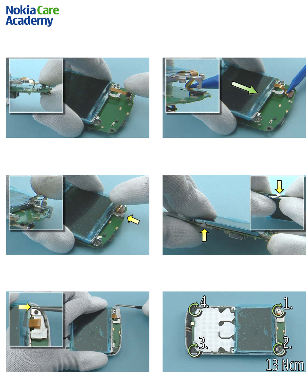
9. DISASSEMBLY INSTRUCTIONS
1) Nokia E5-00 disassembly.
2) You must use the Nokia Standard Toolkit version
2. You will also need the camera removal tool SS-88,
AV plug and the DC plug.
3) Protect the A-COVER window with a protective
fil m.
4) Release the BATTERY COVER ASSEMBLY by pressing
the release buttons on both sides.
5) Remove the BATTERY COVER ASSEMBLY by first
lifting up the bottom end. Then pull the BATTERY
COVER ASSEMBLY in the direction shown.
6) Unscrew the two TORX+ size 4 screws in the order
shown. Do not use them again!
Nokia E5-00
RM-632 / RM-634 / RM-699
Service Manual Level 1&2
13
Co nf id e nt ial | Cop yrig ht © 2010 NOKIA A ll right s reserved
Version 2.0
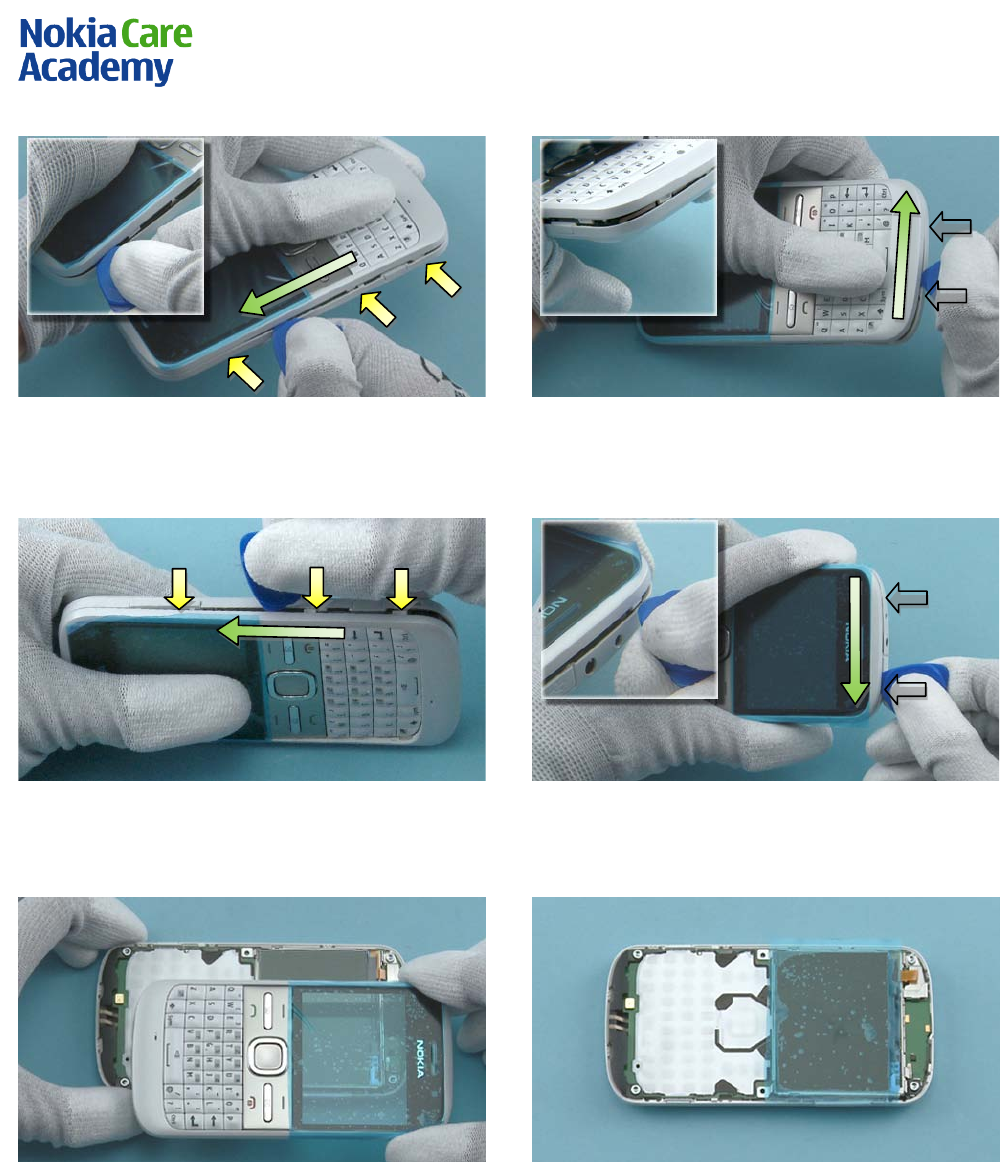
7) To detach the A-COVER ASSEMBLY, first release the
three clips on the left side by sliding the SRT-6 to
the direction shown.
8) Then release the two clips on the bottom side.
9) Continue to slide the SRT-6 in the direction
shown to release the three clips on the right s ide.
10) Finally release the two clips on the top side.
11) The display gasket in the A-COVER is lightly
glued to the LCD. Loosen the adhesive by carefully
lifting up the A-COVER. The A-COVER can now be
separated.
12) Protect the LCD with a protective film.
Nokia E5-00
RM-632 / RM-634 / RM-699
Service Manual Level 1&2
14
Co nf id e nt ial | Cop yrig ht © 2010 NOKIA A ll right s reserved
Version 2.0
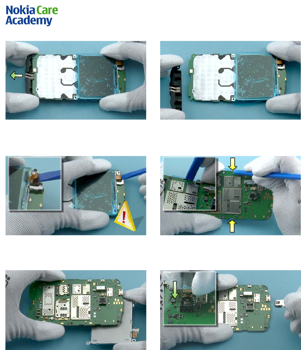
13) Release the clips holding the MAI N KEYMAT on
both sides.
14) Lift up the botto m end of the MAI N KEYMAT. Pull
out the MAI N KEYMAT in the direction shown and
remove it.
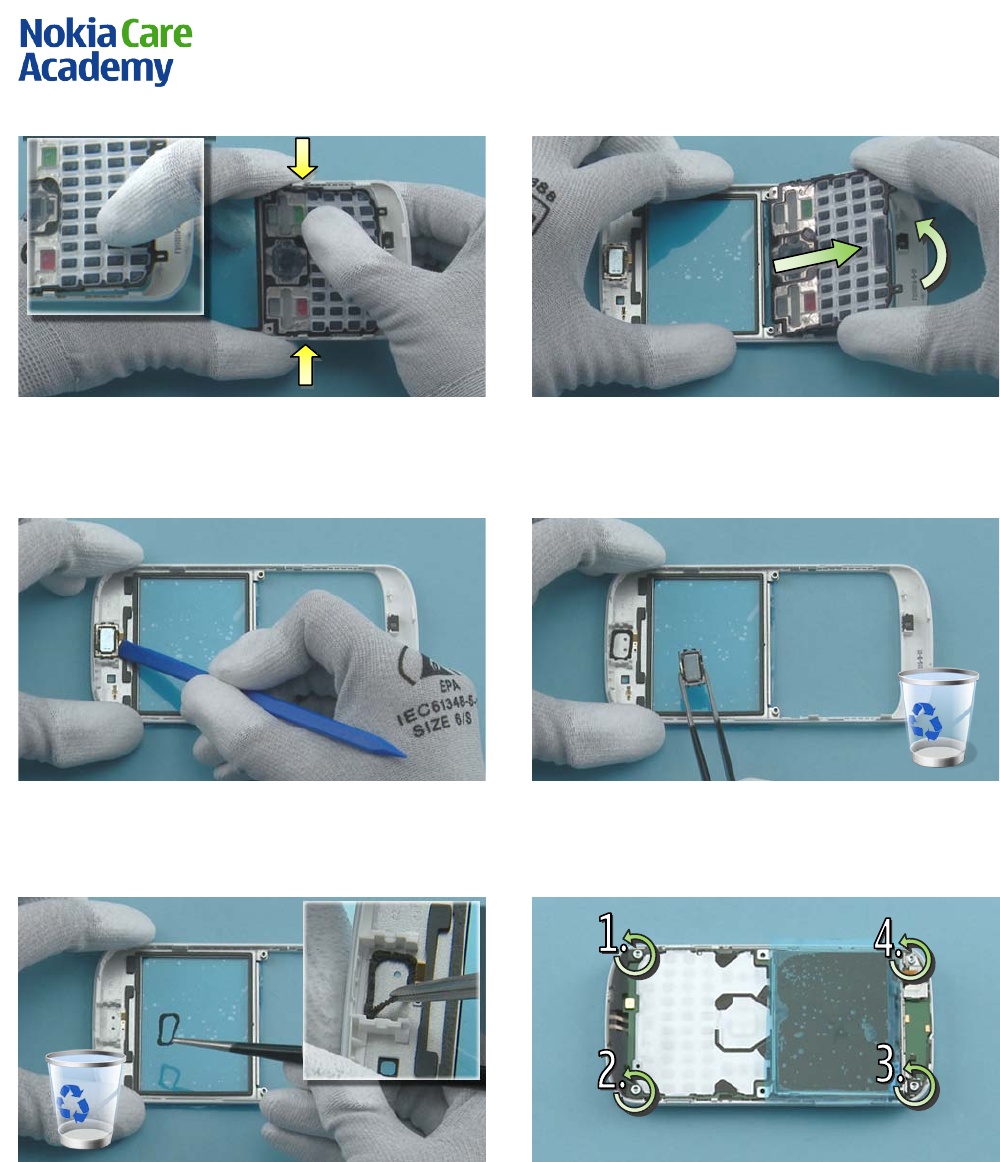
15) Use the SS-93 to release the EARPIECE.
16) Remove the EARPIECE with the tweezers. Do not
use it again.
17) Use the tweezers to remove the EARPIECE FRONT
GASKET. Discard the EARPIECE FRONT GASKET.
18) Unscrew the four TORX+ size 6 screws in the
order shown. Note that these screws can be reused.
Do not discard them!
Nokia E5-00
RM-632 / RM-634 / RM-699
Service Manual Level 1&2
15
Co nf id e nt ial | Cop yrig ht © 2010 NOKIA A ll right s reserved
Version 2.0
19) Release the clip holding the LOCKING PLATE
ASS EMBLY with the tweezers. Lift up the locking
plate as shown.
20) Remove the LOCKING PLATE ASSEMBLY with the
tweezers.
21) Open the USB PLUG.
22) To remove the LI GHT SWAP P WB, use the SS-93
to release the firs t clip …
23) … and the second clip on the other side holding
the LIGHT SWAP PWB.
24) Lift up the LIGHT SWAP PWB and remove it.
Nokia E5-00
RM-632 / RM-634 / RM-699
Service Manual Level 1&2
16
Co nf id e nt ial | Cop yrig ht © 2010 NOKIA A ll right s reserved
Version 2.0
25) To release the MAIN ANTENNA ASSEMBLY, pull it
to the direction shown.
26) Remove the MAI N ANTENNA ASSEMBLY.
27) Use the SS-93 to open the LCD CONNECTOR.
Be careful not to damage the connector!
28) Release the two clips holding the DISPLAY
SUPPORT ASSEMBLY with the SS-93.
29) Separate the DISPLAY SUPPORT ASSEMBLY.
30) Push the camera removal tool SS-88 down until
the camera retaining clips are released. Lif t up the
SS-88 and remove the CAMERA MODUL E.
Nokia E5-00
RM-632 / RM-634 / RM-699
Service Manual Level 1&2
17
Co nf id e nt ial | Cop yrig ht © 2010 NOKIA A ll right s reserved
Version 2.0
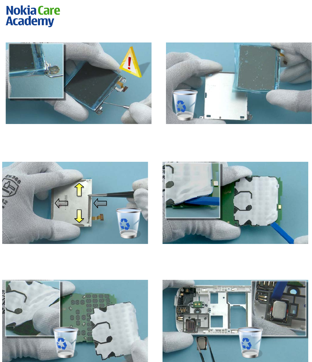
31) To release the LCD, use the dental tool to
carefully loosen the adhesive. Be careful not to
break the LCD or injure yourself with the sharp end
of the dental tool!
32) Remove the DISPLAY SUPPORT ASSEMBLY. Do not
use it again.
33) Remove the adhesive from the LCD with the
tweezers. Do not use the adhesive again.
34) Use the SS-93 to lift up one corner of the
DOMESHEET.
35) Peel off and remove the DOMESHEET. Discard the
removed DOMESHEET.
36) Use the SS-93 to release the IHF SPEAKER.
Remove the IHF SPEAKER with the tweezers. Do not
use it again.
Nokia E5-00
RM-632 / RM-634 / RM-699
Service Manual Level 1&2
18
Co nf id e nt ial | Cop yrig ht © 2010 NOKIA A ll right s reserved
Version 2.0
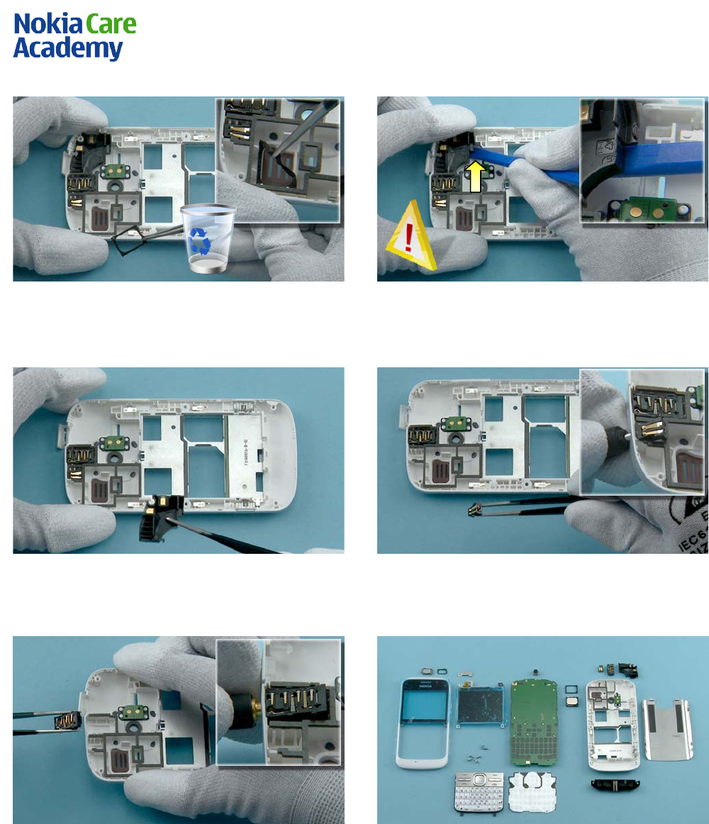
37) Use the tweezers to remove the IHF SPEAKER
GASKET. Do not use it again.
38) Use the SS-93 to carefully release the clip
holding the NCW ANTENNA. Lift up the NCW
ANTENNA with the SS-93.
39) Remove the NCW ANTENNA.
40) Release the DC JACK with the DC plug and
remove it with the tweezers.
41) Release the AV JACK with the AV plug and
remove it with the tweezers.
42) Nokia E5-00 disassembly is now complete.
-END OF DISASSEMBLY-
Nokia E5-00
RM-632 / RM-634 / RM-699
Service Manual Level 1&2
19
Co nf id e nt ial | Cop yrig ht © 2010 NOKIA A ll right s reserved
Version 2.0
10. ASSEMBLY HINTS
1) Connect the LCD connector to the engine board.
2) Use the SS-93 to carefully bend the LCD flex while
pushing the LCD carefully forward.
3) Position the top clip and carefully press down
the LCD flex.
4) Press down the clips on both sides.
5) Slide the LOCKING PLATE ASSEMBLY between the
LCD connector and the bent flex. Press down the
shown clip to lock the LOCKING PLATE ASSEMBLY.
6) Tighten the four TORX + size 6 screws to the
torque of 13 Ncm in the order shown.
Nokia E5-00
RM-632 / RM-634 / RM-699
Service Manual Level 1&2
20
Co nf id e nt ial | Cop yrig ht © 2010 NOKIA A ll right s reserved
Version 2.0
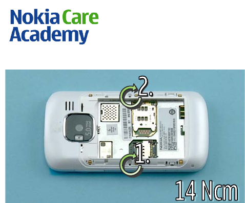
7) Tighten the two TORX + size 4 screws to the
torque of 14 Ncm in the order shown.
Nokia E5-00
RM-632 / RM-634 / RM-699
Service Manual Level 1&2
21
Co nf id e nt ial | Cop yrig ht © 2010 NOKIA A ll right s reserved
Version 2.0
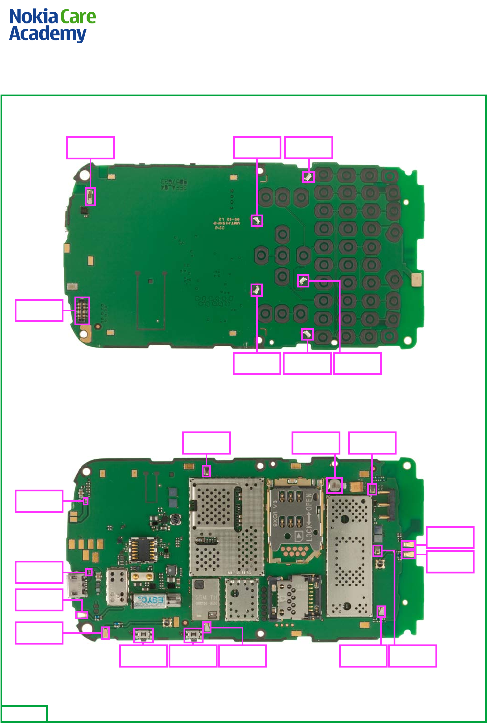
11. SOLDER COMPONENTS
V2413V2414X2409
V2410V2412V2411
X2420
S2485 S001 X2400 X2401 X2403
X2404G2200X2402
F2000
F3300
X6299
X6399
X7402
X7401
Ver. 1.0
TOP
BOTTOM

Service Manual
RM-632; RM-634; RM-699 (Nokia E5-00; L3&4)
Part No: (Issue 3)
Nokia Customer Care
COMPANY CONFIDENTIAL
Copyright © 2010 Nokia. All rights reserved.

Amendment Record Sheet
Amendment No Date Inserted By Comments
Issue 1 4/2010 NS
Issue 2 8/2010 NS RM-634 added.
Issue 3 11/2010 KF RM–699 added.
RM-632; RM-634; RM-699
Amendment Record Sheet
Page ii COMPANY CONFIDENTIAL Issue 3
Copyright © 2010 Nokia. All rights reserved.

Copyright
Copyright © 2010 Nokia. All rights reserved.
Reproduction, transfer, distribution or storage of part or all of the contents in this document in any form
without the prior written permission of Nokia is prohibited.
Nokia, Nokia Connecting People, and Nokia X and Y are trademarks or registered trademarks of Nokia
Corporation. Other product and company names mentioned herein may be trademarks or tradenames of
their respective owners.
Nokia operates a policy of continuous development. Nokia reserves the right to make changes and
improvements to any of the products described in this document without prior notice.
Under no circumstances shall Nokia be responsible for any loss of data or income or any special, incidental,
consequential or indirect damages howsoever caused.
The contents of this document are provided "as is". Except as required by applicable law, no warranties of
any kind, either express or implied, including, but not limited to, the implied warranties of merchantability
and fitness for a particular purpose, are made in relation to the accuracy, reliability or contents of this
document. Nokia reserves the right to revise this document or withdraw it at any time without prior notice.
The availability of particular products may vary by region.
IMPORTANT
This document is intended for use by qualified service personnel only.
RM-632; RM-634; RM-699
Copyright
Issue 3 COMPANY CONFIDENTIAL Page iii
Copyright © 2010 Nokia. All rights reserved.

Warnings and cautions
Warnings
•IF THE DEVICE CAN BE INSTALLED IN A VEHICLE, CARE MUST BE TAKEN ON INSTALLATION IN VEHICLES FITTED
WITH ELECTRONIC ENGINE MANAGEMENT SYSTEMS AND ANTI-SKID BRAKING SYSTEMS. UNDER CERTAIN FAULT
CONDITIONS, EMITTED RF ENERGY CAN AFFECT THEIR OPERATION. IF NECESSARY, CONSULT THE VEHICLE DEALER/
MANUFACTURER TO DETERMINE THE IMMUNITY OF VEHICLE ELECTRONIC SYSTEMS TO RF ENERGY.
•THE PRODUCT MUST NOT BE OPERATED IN AREAS LIKELY TO CONTAIN POTENTIALLY EXPLOSIVE ATMOSPHERES,
FOR EXAMPLE, PETROL STATIONS (SERVICE STATIONS), BLASTING AREAS ETC.
•OPERATION OF ANY RADIO TRANSMITTING EQUIPMENT, INCLUDING CELLULAR TELEPHONES, MAY INTERFERE
WITH THE FUNCTIONALITY OF INADEQUATELY PROTECTED MEDICAL DEVICES. CONSULT A PHYSICIAN OR THE
MANUFACTURER OF THE MEDICAL DEVICE IF YOU HAVE ANY QUESTIONS. OTHER ELECTRONIC EQUIPMENT MAY
ALSO BE SUBJECT TO INTERFERENCE.
•BEFORE MAKING ANY TEST CONNECTIONS, MAKE SURE YOU HAVE SWITCHED OFF ALL EQUIPMENT.
Cautions
•Servicing and alignment must be undertaken by qualified personnel only.
•Ensure all work is carried out at an anti-static workstation and that an anti-static wrist strap is worn.
•Ensure solder, wire, or foreign matter does not enter the telephone as damage may result.
•Use only approved components as specified in the parts list.
•Ensure all components, modules, screws and insulators are correctly re-fitted after servicing and
alignment.
•Ensure all cables and wires are repositioned correctly.
•Never test a mobile phone WCDMA transmitter with full Tx power, if there is no possibility to perform the
measurements in a good performance RF-shielded room. Even low power WCDMA transmitters may disturb
nearby WCDMA networks and cause problems to 3G cellular phone communication in a wide area.
•During testing never activate the GSM or WCDMA transmitter without a proper antenna load, otherwise
GSM or WCDMA PA may be damaged.
RM-632; RM-634; RM-699
Warnings and cautions
Page iv COMPANY CONFIDENTIAL Issue 3
Copyright © 2010 Nokia. All rights reserved.

For your safety
QUALIFIED SERVICE
Only qualified personnel may install or repair phone equipment.
ACCESSORIES AND BATTERIES
Use only approved accessories and batteries. Do not connect incompatible products.
CONNECTING TO OTHER DEVICES
When connecting to any other device, read its user’s guide for detailed safety instructions. Do not connect
incompatible products.
RM-632; RM-634; RM-699
For your safety
Issue 3 COMPANY CONFIDENTIAL Page v
Copyright © 2010 Nokia. All rights reserved.

Care and maintenance
This product is of superior design and craftsmanship and should be treated with care. The suggestions below
will help you to fulfil any warranty obligations and to enjoy this product for many years.
•Keep the phone and all its parts and accessories out of the reach of small children.
•Keep the phone dry. Precipitation, humidity and all types of liquids or moisture can contain minerals that
will corrode electronic circuits.
•Do not use or store the phone in dusty, dirty areas. Its moving parts can be damaged.
•Do not store the phone in hot areas. High temperatures can shorten the life of electronic devices, damage
batteries, and warp or melt certain plastics.
•Do not store the phone in cold areas. When it warms up (to its normal temperature), moisture can form
inside, which may damage electronic circuit boards.
•Do not drop, knock or shake the phone. Rough handling can break internal circuit boards.
•Do not use harsh chemicals, cleaning solvents, or strong detergents to clean the phone.
•Do not paint the phone. Paint can clog the moving parts and prevent proper operation.
•Use only the supplied or an approved replacement antenna. Unauthorised antennas, modifications or
attachments could damage the phone and may violate regulations governing radio devices.
All of the above suggestions apply equally to the product, battery, charger or any accessory.
RM-632; RM-634; RM-699
Care and maintenance
Page vi COMPANY CONFIDENTIAL Issue 3
Copyright © 2010 Nokia. All rights reserved.

ESD protection
Nokia requires that service points have sufficient ESD protection (against static electricity) when servicing
the phone.
Any product of which the covers are removed must be handled with ESD protection. The SIM card can be
replaced without ESD protection if the product is otherwise ready for use.
To replace the covers ESD protection must be applied.
All electronic parts of the product are susceptible to ESD. Resistors, too, can be damaged by static electricity
discharge.
All ESD sensitive parts must be packed in metallized protective bags during shipping and handling outside
any ESD Protected Area (EPA).
Every repair action involving opening the product or handling the product components must be done under
ESD protection.
ESD protected spare part packages MUST NOT be opened/closed out of an ESD Protected Area.
For more information and local requirements about ESD protection and ESD Protected Area, contact your local
Nokia After Market Services representative.
RM-632; RM-634; RM-699
ESD protection
Issue 3 COMPANY CONFIDENTIAL Page vii
Copyright © 2010 Nokia. All rights reserved.

Battery information
Note: A new battery's full performance is achieved only after two or three complete charge and
discharge cycles!
The battery can be charged and discharged hundreds of times but it will eventually wear out. When the
operating time (talk-time and standby time) is noticeably shorter than normal, it is time to buy a new battery.
Use only batteries approved by the phone manufacturer and recharge the battery only with the chargers
approved by the manufacturer. Unplug the charger when not in use. Do not leave the battery connected to
a charger for longer than a week, since overcharging may shorten its lifetime. If left unused a fully charged
battery will discharge itself over time.
Temperature extremes can affect the ability of your battery to charge.
For good operation times with Li-Ion batteries, discharge the battery from time to time by leaving the product
switched on until it turns itself off (or by using the battery discharge facility of any approved accessory
available for the product). Do not attempt to discharge the battery by any other means.
Use the battery only for its intended purpose.
Never use any charger or battery which is damaged.
Do not short-circuit the battery. Accidental short-circuiting can occur when a metallic object (coin, clip or
pen) causes direct connection of the + and - terminals of the battery (metal strips on the battery) for example
when you carry a spare battery in your pocket or purse. Short-circuiting the terminals may damage the battery
or the connecting object.
Leaving the battery in hot or cold places, such as in a closed car in summer or winter conditions, will reduce
the capacity and lifetime of the battery. Always try to keep the battery between 15°C and 25°C (59°F and 77°
F). A phone with a hot or cold battery may temporarily not work, even when the battery is fully charged.
Batteries' performance is particularly limited in temperatures well below freezing.
Do not dispose of batteries in a fire!
Dispose of batteries according to local regulations (e.g. recycling). Do not dispose as household waste.
RM-632; RM-634; RM-699
Battery information
Page viii COMPANY CONFIDENTIAL Issue 3
Copyright © 2010 Nokia. All rights reserved.

Company policy
Our policy is of continuous development; details of all technical modifications will be included with service
bulletins.
While every endeavour has been made to ensure the accuracy of this document, some errors may exist. If
any errors are found by the reader, NOKIA MOBILE PHONES Business Group should be notified in writing/e-
mail.
Please state:
•Title of the Document + Issue Number/Date of publication
•Latest Amendment Number (if applicable)
•Page(s) and/or Figure(s) in error
Please send to:
NOKIA CORPORATION
Nokia Mobile Phones Business Group
Nokia Customer Care
PO Box 86
FIN-24101 SALO
Finland
E-mail: Service.Manuals@nokia.com
RM-632; RM-634; RM-699
Company policy
Issue 3 COMPANY CONFIDENTIAL Page ix
Copyright © 2010 Nokia. All rights reserved.

RM-632; RM-634; RM-699
Company policy
(This page left intentionally blank.)
Page x COMPANY CONFIDENTIAL Issue 3
Copyright © 2010 Nokia. All rights reserved.

Nokia E5-00; L3&4 Service Manual Structure
1 General information
2 Service Devices and Service Concepts
3 BB Troubleshooting and Manual Tuning Guide
4 RF troubleshooting
5 System Module
6 Service information differences between RM-632 and RM-634
7 Service information differences between RM-632 and RM-699
Glossary
RM-632; RM-634; RM-699
Nokia E5-00; L3&4 Service Manual Structure
Issue 3 COMPANY CONFIDENTIAL Page xi
Copyright © 2010 Nokia. All rights reserved.

RM-632; RM-634; RM-699
Nokia E5-00; L3&4 Service Manual Structure
(This page left intentionally blank.)
Page xii COMPANY CONFIDENTIAL Issue 3
Copyright © 2010 Nokia. All rights reserved.

1 — General information
Nokia Customer Care
Issue 3 COMPANY CONFIDENTIAL Page 1 – 1
Copyright © 2010 Nokia. All rights reserved.

RM-632; RM-634; RM-699
General information
(This page left intentionally blank.)
Page 1 – 2 COMPANY CONFIDENTIAL Issue 3
Copyright © 2010 Nokia. All rights reserved.

Table of Contents
Product selection................................................................................................................................................... 1–5
Phone features ...................................................................................................................................................... 1–5
Software and user interface features.................................................................................................................. 1–6
Accessories............................................................................................................................................................. 1–6
Technical specifications........................................................................................................................................ 1–7
General specifications...................................................................................................................................... 1–7
Main RF characteristics for GSM850/900/1800/1900 and WCDMA band I, II and VIII phones .................. 1–8
Battery endurance............................................................................................................................................ 1–9
Environmental conditions ............................................................................................................................... 1–9
List of Tables
Table 1 Battery and chargers ............................................................................................................................... 1–7
Table 2 Car accessories ......................................................................................................................................... 1–7
Table 3 Headsets ................................................................................................................................................... 1–7
Table 4 Cables ........................................................................................................................................................ 1–7
List of Figures
Figure 1 RM-632 (Nokia E5-00) product picture................................................................................................. 1–5
RM-632; RM-634; RM-699
General information
Issue 3 COMPANY CONFIDENTIAL Page 1 – 3
Copyright © 2010 Nokia. All rights reserved.

RM-632; RM-634; RM-699
General information
(This page left intentionally blank.)
Page 1 – 4 COMPANY CONFIDENTIAL Issue 3
Copyright © 2010 Nokia. All rights reserved.
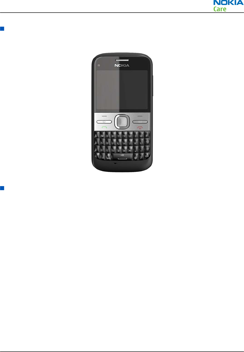
Product selection
RM-632 (Nokia E5-00) is a GSM/WCDMA dual mode phone, supporting EGSM850/900/1800/1900 and WCDMA
bands I, II and VIII.
Figure 1 RM-632 (Nokia E5-00) product picture
Phone features
Display and keypad features
•Horizontal 2.36" QVGA display with 256K colors
•Full QWERTY, Home key + Messaging, Call and End keys, 4 way + select, Volume keys
Hardware features
•Main camera: 5 megapixel EDOF camera with integrated flash
•MicroUSB connector/charger plug for data transfer (USB 2.0) and charging
•High speed USB (FS/HS)
•2 mm charger plug interface
•Bluetooth version 2.0
•microSD memory card connector
•Stereo Music Player
•Integrated handsfree speaker
•Internal vibra
•Plug-in SIM 1.8V and 3.0V, more than 1000 entries
•Nokia 3.5mm AV connector
•FM-radio with headset as antenna
RM-632; RM-634; RM-699
General information
Issue 3 COMPANY CONFIDENTIAL Page 1 – 5
Copyright © 2010 Nokia. All rights reserved.

RF features
•Ïnternal antennas
•GSM/EDGE 850/900/1800/1900
•WCDMA band I, II and VIII
•High speed upload - HSUPA cat 5 (2.0 Mbps)
•High speed download - HSDPA cat 9 (10.2 Mbps)
•EDGE: MSC 32
•GPRS: MSC 32
•CSD for browsing and as data modem
Software and user interface features
Selection of software application and features
•Operating System: Symbian v. 9.3
•User Interface: S60 3rd Edition, Feature Pack 2
•PIM: Contacts, Calendar, To-do, Notes & Active Notes, Recorder, Calculator, Clock, Converter
•Call management: call logs, speed dial, enhanced voice dialing, talking ring tone
•People centric home screen
•3D stereo ringing tones, Up to 64 Polyphonic Midi, MP3 tones, video ringing tones
•OMA DRM 2.0, OMA DRM2 video, Windows DRM, WMV
•Offline mode, and SIM-less operation
•Flashlite 3.0, Java TM MIDP 2.0
•FM radio
•Audio messaging
•Java &Api's MIDP2.0, JSR75 (file connection and PIM), JSR82 (BT), JSR135, JSR139 (CLDC1.1), JSR184 (3D),
JSR185 (JTWI R1)
•3GPP H.263 playback+streaming, H.264 and MPEG4
•Video, MP3, AAC and 64 polyphonic ringing tones
•Music Player for MP3, AAC, AAC+, eAAC+, WMA
•WAP 2.0, XHTML browser over HTTP/TCP/IP stack
•OMA SyncML 1.1.2 (local)
Accessories
Sales package contents
•Nokia E5-00 phone
•Nokia Battery BL-4D
•Travel Charger AC-8E
•Nokia Stereo Headset WH-102
•Nokia Micro USB Cable CA-101D
•Nokia MU-37, 2 GB micro SD
RM-632; RM-634; RM-699
General information
Page 1 – 6 COMPANY CONFIDENTIAL Issue 3
Copyright © 2010 Nokia. All rights reserved.
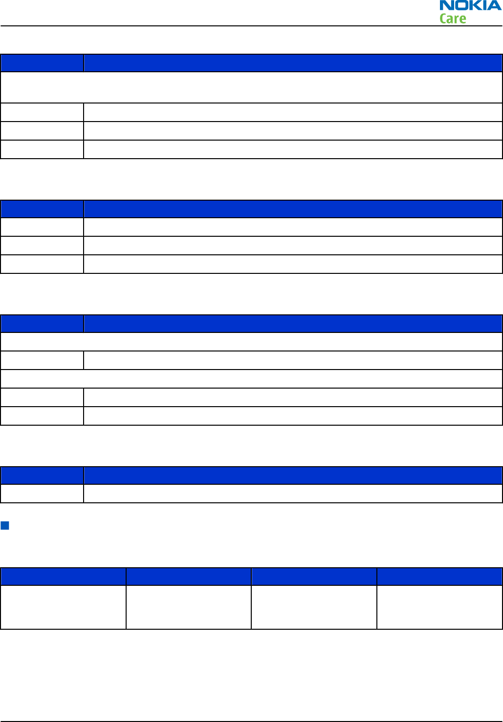
Table 1 Battery and chargers
Type Name
Note: This phone is charged through the smaller Nokia standard charger interface (2.0 mm plug). A 3.5
mm compatible Nokia standard charger can be used together with the CA-44 charger adapter.
BL-4D Battery 1200 mAh Li-Ion
AC-8 Travel Charger
AC-6 USB charger
Table 2 Car accessories
Type Name
CK-100 Bluetooth car kit
DC-9 Mobile charger
HK-510 Plug-In car kit with display and DSP
Table 3 Headsets
Type Name
Wired
WH-102 Stereo headset
Wireless
BH-105 Bluetooth headset
BH-214 Bluetooth stereo headset
Table 4 Cables
Type Name
CA-101D Micro USB cable
Technical specifications
General specifications
Unit Dimension (mm) Weight (g) Volume (cc)
RM-632 transceiver with
BL-4D 1200 mAh Li-Ion
battery pack
115*58.9*12.8 128 75
RM-632; RM-634; RM-699
General information
Issue 3 COMPANY CONFIDENTIAL Page 1 – 7
Copyright © 2010 Nokia. All rights reserved.
Main RF characteristics for GSM850/900/1800/1900 and WCDMA band I, II and VIII phones
Parameter Unit
Cellular system GSM850, EGSM900, GSM1800/1900, WCDMA I (2100), WCDMA II (1900)
and WCDMA VIII (900)
Rx frequency band GSM850: 869 - 894 MHz
EGSM900: 925 - 960 MHz
GSM1800: 1805 - 1880 MHz
GSM1900: 1930 - 1990 MHz
WCDMA I (2100): 2110 - 2170 MHz
WCDMA II (1900): 1930 - 1990
WCDMA VIII (900): 925- 960 MHz
Tx frequency band GSM850: 824 - 849 MHz
EGSM900: 880 - 915 MHz
GSM1800: 1710 - 1785 MHz
GSM1900: 1850 - 1910 MHz
WCDMA I (2100): 1920 - 1980 MHz
WCDMA II (1900): 1850 - 1910
WCDMA VIII (900): 880 - 915 MHz
Output power GSM850: +5 ...+33dBm/3.2mW ... 2W
GSM900: +5 … +33dBm/3.2mW … 2W
GSM1800: +0 … +30dBm/1.0mW … 1W
GSM1900: +0 … +30dBm/1.0mW … 1W
WCDMA I (2100): -50 ... +24 dBm/0.01μW ... 251.2mW
WCDMA II (1900): -50 ... +24 dBm/0.01μW ... 251.2mW
WCDMA VIII (900): -50 ... +24 dBm/0.01μW ... 251.2mW
Number of RF channels GSM850: 124
GSM900: 174
GSM1800: 374
GSM1900: 299
WCDMA I (2100): 277
WCDMA II (1900): 289
WCDMA VIII (900): 152
Channel spacing 200 kHz
RM-632; RM-634; RM-699
General information
Page 1 – 8 COMPANY CONFIDENTIAL Issue 3
Copyright © 2010 Nokia. All rights reserved.
Parameter Unit
Number of Tx power levels GSM850: 15
GSM900: 15
GSM1800: 16
GSM1900: 16
WCDMA I (2100): 75
WCDMA II (1900): 75
WCDMA VIII (900): 75
Battery endurance
Battery Talk time Standby time
BL-4D 1200 mAh Li-ion GSM: up to 8 h 30 min
WCDMA: up to 5 h 6 min
GSM: up to 649 h
WCDMA: up to 533 h
Note: Variation in operation times will occur depending on SIM card, network settings and usage.
Talk time is increased by up to 30% if half rate is active, and reduced by 5% if enhanced full rate is
active.
Environmental conditions
Environmental
condition Ambient temperature Notes
Normal operation -15 oC ... +55 oCSpecifications fulfilled
Reduced performance 55 oC ... +70 oCOperational only for short periods
Intermittent or no
operation -40 oC ... -15 oC and +70 oC ... +85oCOperation not guaranteed but an
attempt to operate will not damage
the phone
No operation or
storage <-40 oC and >+85 oCNo storage. An attempt to operate
may cause permanent damage
Charging allowed -10 oC ... +60 oC
Long term storage
conditions 0 oC ... +85 oC
Humidity and water
resistance
Relative humidity range is 5 to 95%.
Condensed or dripping water may
cause intermittent malfunctions.
Protection against dripping water
has to be implemented in (enclosure)
mechanics.
Continuous dampness will cause
permanent damage to the module.
RM-632; RM-634; RM-699
General information
Issue 3 COMPANY CONFIDENTIAL Page 1 – 9
Copyright © 2010 Nokia. All rights reserved.

RM-632; RM-634; RM-699
General information
(This page left intentionally blank.)
Page 1 – 10 COMPANY CONFIDENTIAL Issue 3
Copyright © 2010 Nokia. All rights reserved.

2 — Service Devices and
Service Concepts
Nokia Customer Care
Issue 3 COMPANY CONFIDENTIAL Page 2 – 1
Copyright © 2010 Nokia. All rights reserved.

RM-632; RM-634; RM-699
Service Devices and Service Concepts
(This page left intentionally blank.)
Page 2 – 2 COMPANY CONFIDENTIAL Issue 3
Copyright © 2010 Nokia. All rights reserved.

Table of Contents
Service devices....................................................................................................................................................... 2–5
Product specific devices................................................................................................................................... 2–5
FS-147........................................................................................................................................................... 2–5
MJ-266 .......................................................................................................................................................... 2–5
SS-88............................................................................................................................................................. 2–5
General devices................................................................................................................................................. 2–5
CU-4............................................................................................................................................................... 2–6
FLS-5 ............................................................................................................................................................. 2–7
FPS-21........................................................................................................................................................... 2–7
PK-1............................................................................................................................................................... 2–8
PKD-1 ............................................................................................................................................................ 2–8
RJ-230 ........................................................................................................................................................... 2–8
SB-6............................................................................................................................................................... 2–8
SB-7............................................................................................................................................................... 2–9
SRT-6............................................................................................................................................................. 2–9
SS-46............................................................................................................................................................. 2–9
SS-62............................................................................................................................................................. 2–9
SX-4............................................................................................................................................................... 2–9
Cables.............................................................................................................................................................. 2–10
CA-101 ....................................................................................................................................................... 2–10
CA-31D ....................................................................................................................................................... 2–10
CA-58RS...................................................................................................................................................... 2–10
CA-89DS ..................................................................................................................................................... 2–11
DAU-9S....................................................................................................................................................... 2–11
PCS-1.......................................................................................................................................................... 2–11
XRS-6.......................................................................................................................................................... 2–12
Service concepts ................................................................................................................................................. 2–12
POS (Point of Sale) flash concept ................................................................................................................. 2–12
Flash concept with FPS-21............................................................................................................................ 2–13
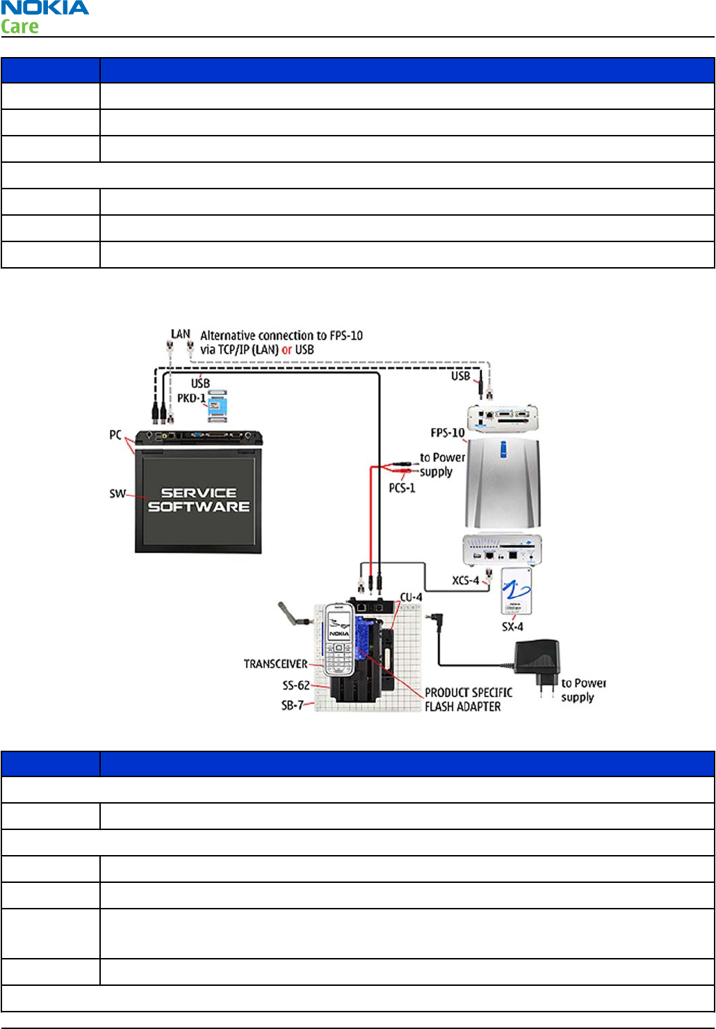
CU-4 flash concept with FPS-21.................................................................................................................... 2–14
Module jig service concept........................................................................................................................... 2–15
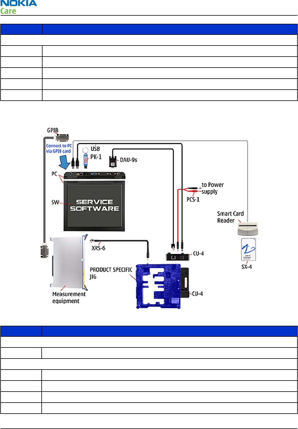
Service concept for RF testing and RF/BB tuning....................................................................................... 2–16
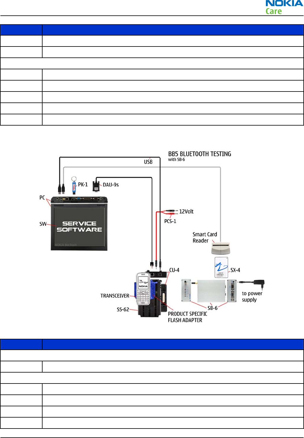
Bluetooth testing concept with SB-6 .......................................................................................................... 2–17
WLAN functionality testing concept with SB-7 .......................................................................................... 2–18
List of Tables
Table 5 Attenuation values ............................................................................................................................... 2–10
List of Figures
Figure 2 POS flash concept ................................................................................................................................ 2–12
Figure 3 Basic flash concept with FPS-21......................................................................................................... 2–13
Figure 4 CU-4 flash concept with FPS-21.......................................................................................................... 2–14
Figure 5 Module jig service concept ................................................................................................................. 2–15
Figure 6 Service concept for RF testing and RF/BB tuning ............................................................................. 2–16
Figure 7 Service concept for RF testing and RF/BB tuning ............................................................................. 2–17
Figure 8 WLAN functionality testing concept with SB-7................................................................................. 2–18
RM-632; RM-634; RM-699
Service Devices and Service Concepts
Issue 3 COMPANY CONFIDENTIAL Page 2 – 3
Copyright © 2010 Nokia. All rights reserved.

RM-632; RM-634; RM-699
Service Devices and Service Concepts
(This page left intentionally blank.)
Page 2 – 4 COMPANY CONFIDENTIAL Issue 3
Copyright © 2010 Nokia. All rights reserved.
Service devices
Product specific devices
The table below gives a short overview of service devices that can be used for testing, error analysis, and
repair of product RM-632; RM-634; RM-699. For the correct use of the service devices, and the best effort of
workbench setup, please refer to various concepts.
FS-147 Flash adapter
•FS-147 is equipped with a clip interlock system
•provides standardised interface towards Control Unit
•provides RF connection
•multiplexing between USB and FBUS media, controlled by VUSB
Note: Close lid of SD and SIM reader before attaching the flash
adapter.
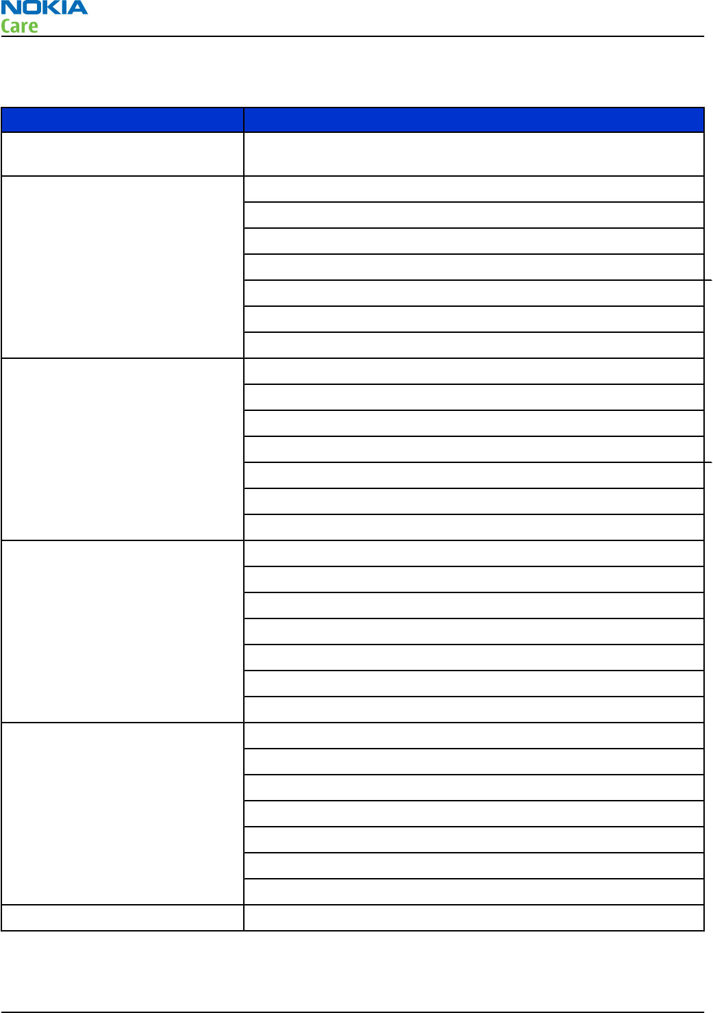
MJ-266 Module jig
MJ-266 is meant for component level troubleshooting.
The jig includes an RF interface for GSM and WCDMA. In addition, it has
the following features:
•Provides mechanical interface with the engine module
•Provides galvanic connection to all needed test pads in module
•Connector for control unit
•Access for USB connector
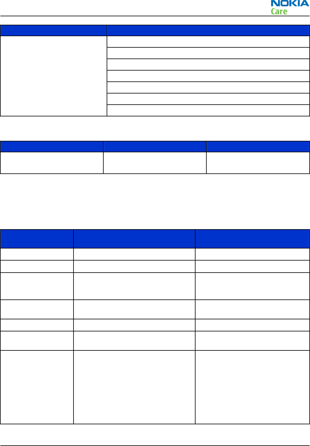
SS-88 Camera removal tool
The camera removal tool SS-88 is used to remove/attach the camera
module from/to the socket.
General devices
The table below gives a short overview of service devices that can be used for testing, error analysis, and
repair of product RM-632; RM-634; RM-699. For the correct use of the service devices, and the best effort of
workbench setup, please refer to various concepts.
RM-632; RM-634; RM-699
Service Devices and Service Concepts
Issue 3 COMPANY CONFIDENTIAL Page 2 – 5
Copyright © 2010 Nokia. All rights reserved.
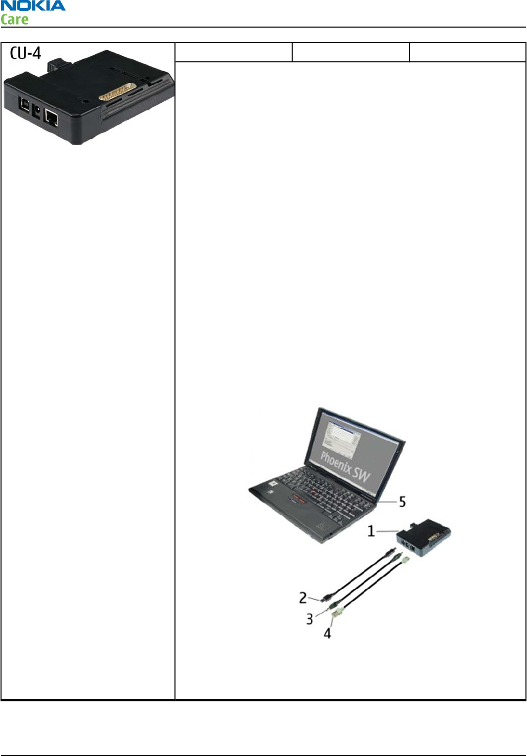
CU-4 Control unit
CU-4 is a general service tool used with a module jig and/or a flash
adapter. It requires an external 12 V power supply.
The unit has the following features:
•software controlled via USB
•EM calibration function
•Forwards FBUS/Flashbus traffic to/from terminal
•Forwards USB traffic to/from terminal
•software controlled BSI values
•regulated VBATT voltage
•2 x USB2.0 connector (Hub)
•FBUS and USB connections supported
When using CU-4, note the special order of connecting cables and
other service equipment:
Instructions
1 Connect a service tool (jig, flash adapter) to CU-4.
2 Connect CU-4 to your PC with a USB cable.
3 Connect supply voltage (12 V)
4 Connect an FBUS cable (if necessary).
5 Start Phoenix service software.
Note: Phoenix enables CU-4 regulators via USB when it is
started.
Reconnecting the power supply requires a Phoenix restart.
RM-632; RM-634; RM-699
Service Devices and Service Concepts
Page 2 – 6 COMPANY CONFIDENTIAL Issue 3
Copyright © 2010 Nokia. All rights reserved.
FLS-5 Flash device
FLS-5 is a dongle and flash device incorporated into one package,
developed specifically for POS use.
Note: FLS-5 can be used as an alternative to PK-1.
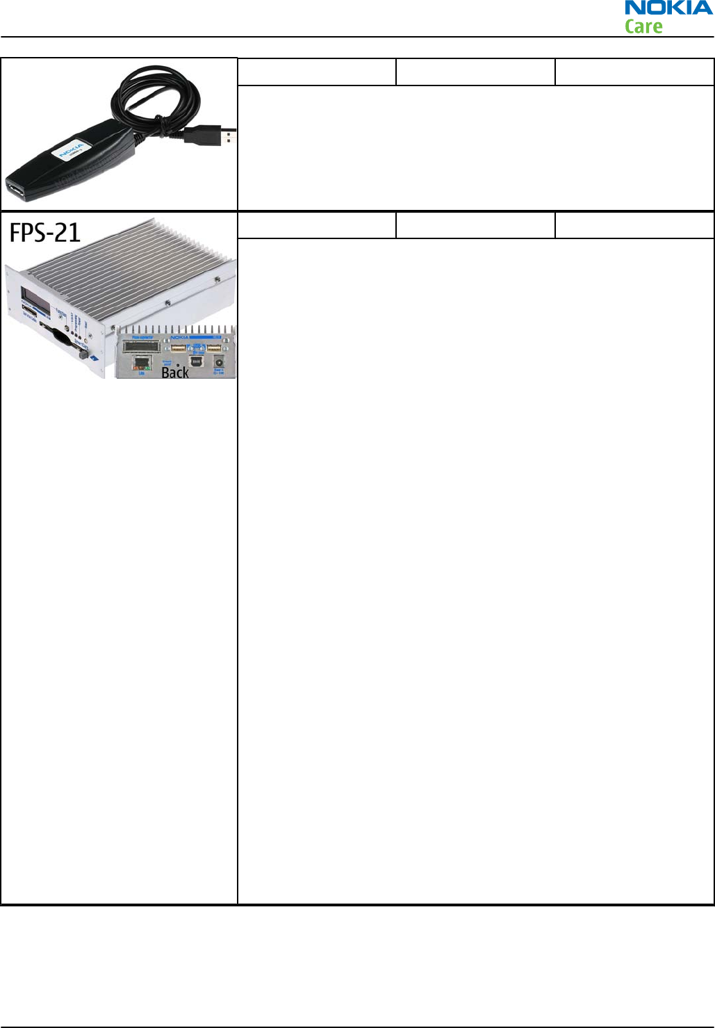
FPS-21 Flash prommer
FPS-21 sales package:
•FPS-21 prommer
•AC-35 power supply
•CA-31D USB cable
FPS-21 interfaces:
Front
•Service cable connector
Provides Flashbus, USB and VBAT connections to a mobile device.
•SmartCard socket
A SmartCard is needed to allow DCT-4 generation mobile device
programming.
Rear
•DC power input
For connecting the external power supply (AC-35).
•Two USB A type ports (USB1/USB3)
Can be used, for example, for connecting external storage memory
devices or mobile devices
•One USB B type device connector (USB2)
For connecting a PC.
•Phone connector
Service cable connection for connecting Flashbus/FLA.
•Ethernet RJ45 type socket (LAN)
For connecting the FPS-21 to LAN.
Inside
•Four SD card memory slots
For internal storage memory.
Note: In order to access the SD memory card slots inside
FPS-21, the prommer needs to be opened by removing the
front panel, rear panel and heatsink from the prommer body.
RM-632; RM-634; RM-699
Service Devices and Service Concepts
Issue 3 COMPANY CONFIDENTIAL Page 2 – 7
Copyright © 2010 Nokia. All rights reserved.
PK-1 Software protection
key
PK-1 is a hardware protection key with a USB interface. It has the same
functionality as the PKD-1 series dongle.
PK-1 is meant for use with a PC that does not have a series interface.
To use this USB dongle for security service functions please register
the dongle in the same way as the PKD-1 series dongle.
PKD-1 SW security device
SW security device is a piece of hardware enabling the use of the
service software when connected to the parallel (LPT) port of the PC.
Without the device, it is not possible to use the service software.
Printer or any such device can be connected to the PC through the
device if needed.
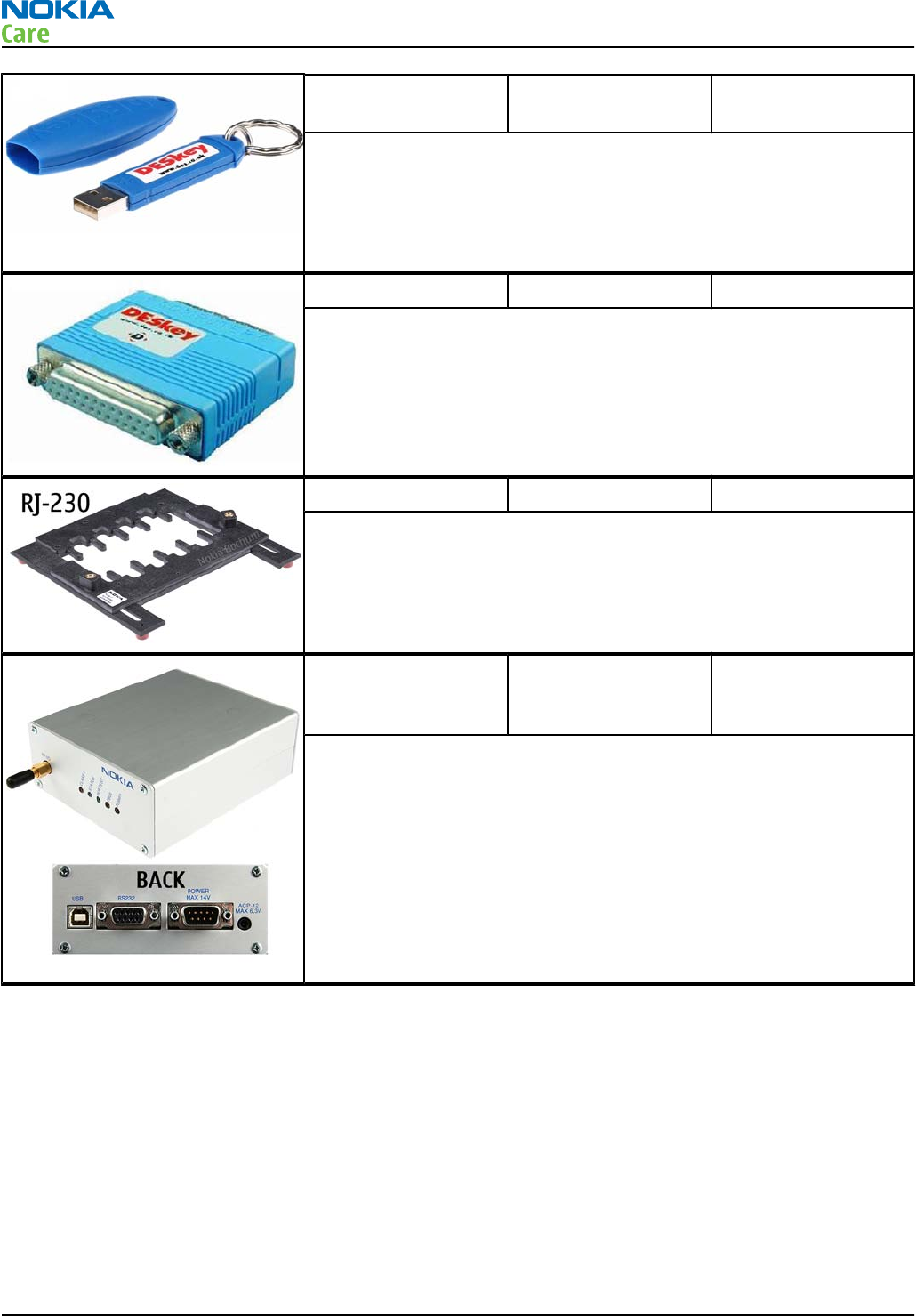
RJ-230 Soldering jig
RJ-230 is a soldering jig used for soldering and as a rework jig for the
engine module.
SB-6 Bluetooth test and
interface box (sales
package)
The SB-6 test box is a generic service device used to perform Bluetooth
bit error rate (BER) testing, and establishing cordless FBUS connection
via Bluetooth. An ACP-8x charger is needed for BER testing and an
AXS-4 cable in case of cordless interface usage testing .
Sales package includes:
•SB-6 test box
•Installation and warranty information
RM-632; RM-634; RM-699
Service Devices and Service Concepts
Page 2 – 8 COMPANY CONFIDENTIAL Issue 3
Copyright © 2010 Nokia. All rights reserved.
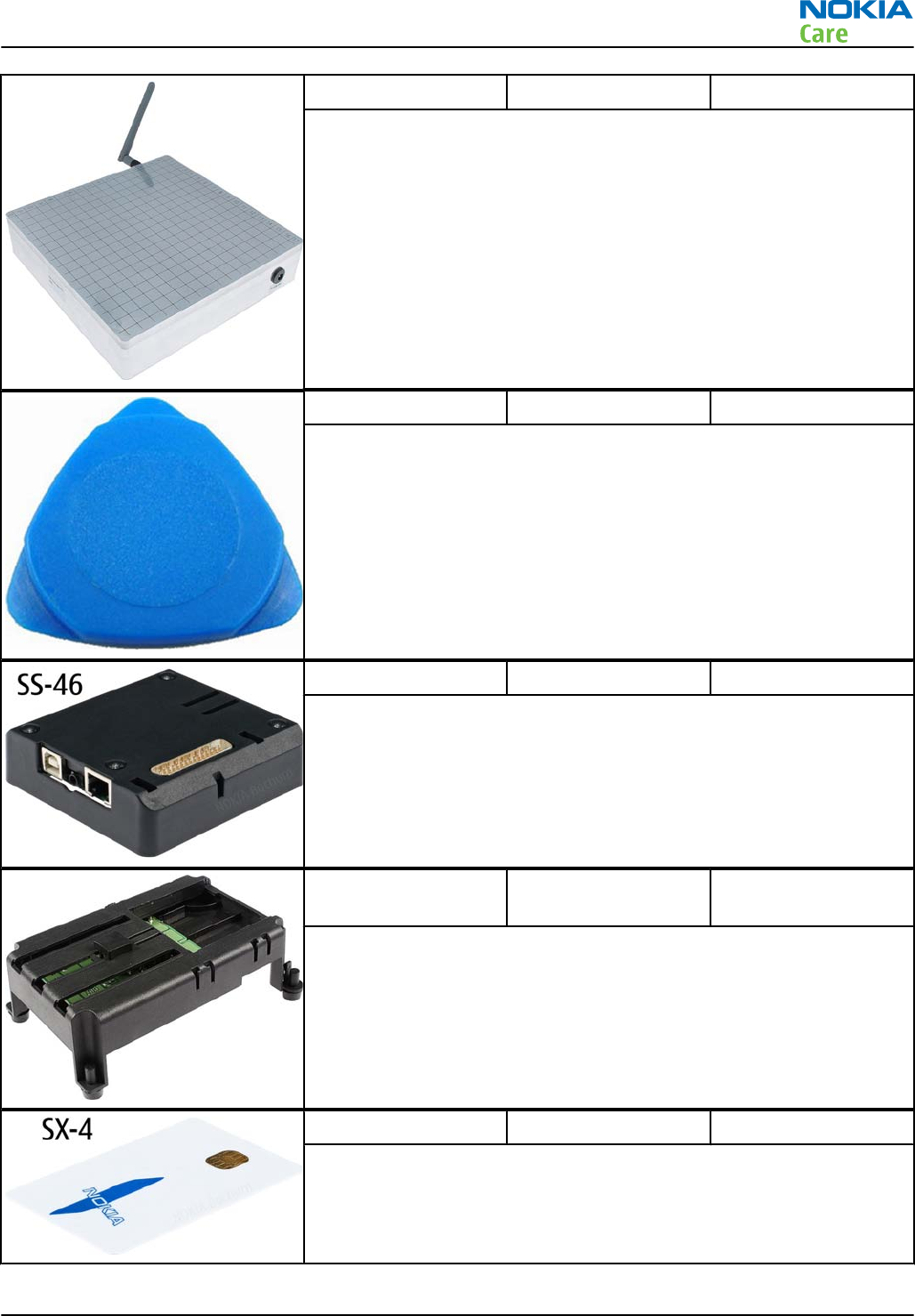
SB-7 WLAN test box
WLAN test requires defined position for the device.
SRT-6 Opening tool
SRT-6 is used to open phone covers.
Note: The SRT-6 is included in the Nokia Standard Toolkit.
SS-46 Interface adapter
SS-46 acts as an interface adapter between the flash adapter and
FPS-20/FPS-21.
SS-62 Generic flash adapter
base for BB5
•generic base for flash adapters and couplers
•SS-62 equipped with a clip interlock system
•provides standardised interface towards Control Unit
•multiplexing between USB and FBUS media, controlled by VUSB
SX-4 Smart card
SX-4 is a BB5 security device used to protect critical features in tuning
and testing.
SX-4 is also needed together with FPS-20/FPS-21 when DCT-4 phones
are flashed.
RM-632; RM-634; RM-699
Service Devices and Service Concepts
Issue 3 COMPANY CONFIDENTIAL Page 2 – 9
Copyright © 2010 Nokia. All rights reserved.
Cables
The table below gives a short overview of service devices that can be used for testing, error analysis, and
repair of product RM-632; RM-634; RM-699. For the correct use of the service devices, and the best effort of
workbench setup, please refer to various concepts.
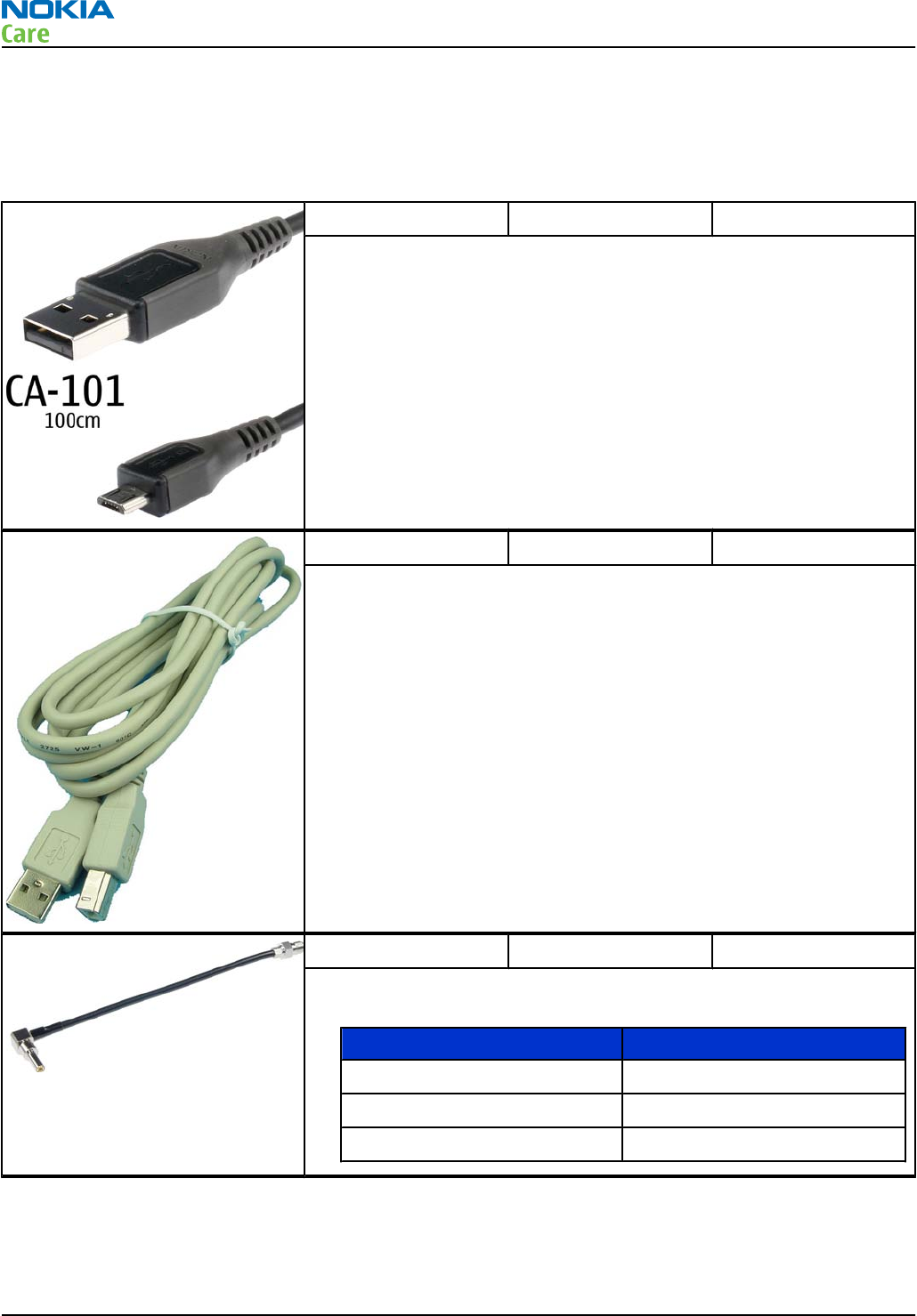
CA-101 Micro USB cable
The CA-101 is a USB-to-microUSB data cable that allows connections
between the PC and the phone.
CA-31D USB cable
The CA-31D USB cable is used to connect FPS-20/FPS-21 to a PC. It is
included in the FPS-20/FPS-21 sales packages.
CA-58RS RF tuning cable
Product-specific adapter cable for RF tuning.
•Table 5 Attenuation values
Band Attenuation Rx/Tx
GSM850/900 0.2...0.3 dB
GSM1800/1900 0.3...0.4 dB
WCDMA/WLAN 0.4...0.6 dB
RM-632; RM-634; RM-699
Service Devices and Service Concepts
Page 2 – 10 COMPANY CONFIDENTIAL Issue 3
Copyright © 2010 Nokia. All rights reserved.
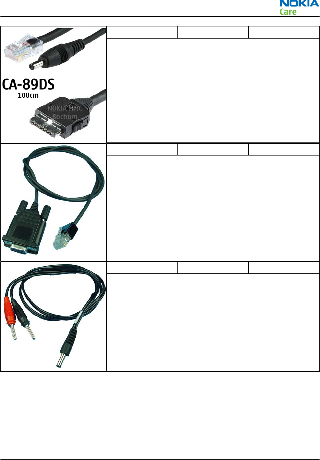
CA-89DS Cable
Provides VBAT and Flashbus connections to mobile device
programming adapters.
DAU-9S MBUS cable
The MBUS cable DAU-9S has a modular connector and is used, for
example, between the PC's serial port and module jigs, flash adapters
or docking station adapters.
Note: Docking station adapters valid for DCT4 products.
PCS-1 Power cable
The PCS-1 power cable (DC) is used with a docking station, a module
jig or a control unit to supply a controlled voltage.
RM-632; RM-634; RM-699
Service Devices and Service Concepts
Issue 3 COMPANY CONFIDENTIAL Page 2 – 11
Copyright © 2010 Nokia. All rights reserved.
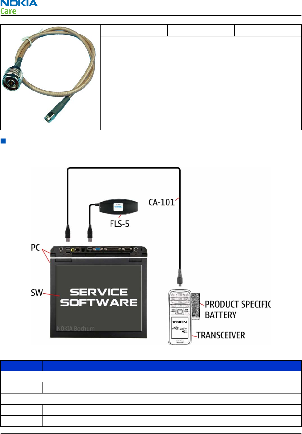
XRS-6 RF cable
The RF cable is used to connect, for example, a module repair jig to
the RF measurement equipment.
SMA to N-Connector approximately 610 mm.
Attenuation for:
•GSM850/900: 0.3+-0.1 dB
•GSM1800/1900: 0.5+-0.1 dB
•WCDMA/WLAN: 0.6+-0.1dB
Service concepts
POS (Point of Sale) flash concept
Figure 2 POS flash concept
Type Description
Product specific tools
BL-4D Battery
Other tools
FLS-5 POS flash dongle
PC with service software
RM-632; RM-634; RM-699
Service Devices and Service Concepts
Page 2 – 12 COMPANY CONFIDENTIAL Issue 3
Copyright © 2010 Nokia. All rights reserved.
Type Description
Cables
CA-101 Micro USB cable
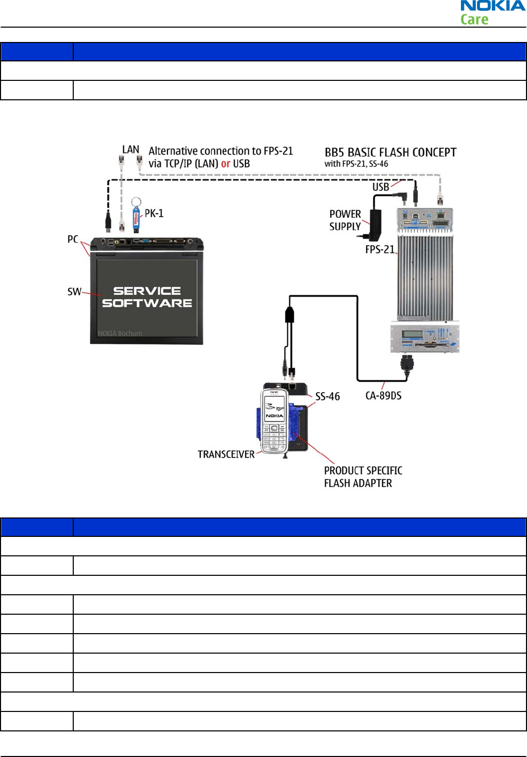
Flash concept with FPS-21
Figure 3 Basic flash concept with FPS-21
Type Description
Product specific devices
FS-147 Flash adapter
Other devices
FPS-21 Flash prommer box
AC-35 Power supply
PK-1 SW security device
SS-46 Interface adapter
PC with Phoenix service software
Cables
CA-89DS Service cable
RM-632; RM-634; RM-699
Service Devices and Service Concepts
Issue 3 COMPANY CONFIDENTIAL Page 2 – 13
Copyright © 2010 Nokia. All rights reserved.
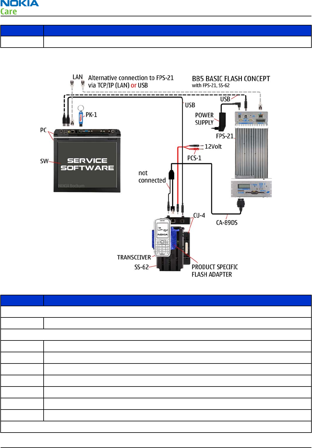
Type Description
USB cable
CU-4 flash concept with FPS-21
Figure 4 CU-4 flash concept with FPS-21
Type Description
Product specific devices
FS-147 Flash adapter
Other devices
CU-4 Control unit
FPS-21 Flash prommer box
AC-35 Power supply
PK-1 SW security device
SS-62 Flash adapter base
SX-4 Smart card (for DCT-4 generation mobile device programming)
PC with Phoenix service software
Cables
RM-632; RM-634; RM-699
Service Devices and Service Concepts
Page 2 – 14 COMPANY CONFIDENTIAL Issue 3
Copyright © 2010 Nokia. All rights reserved.
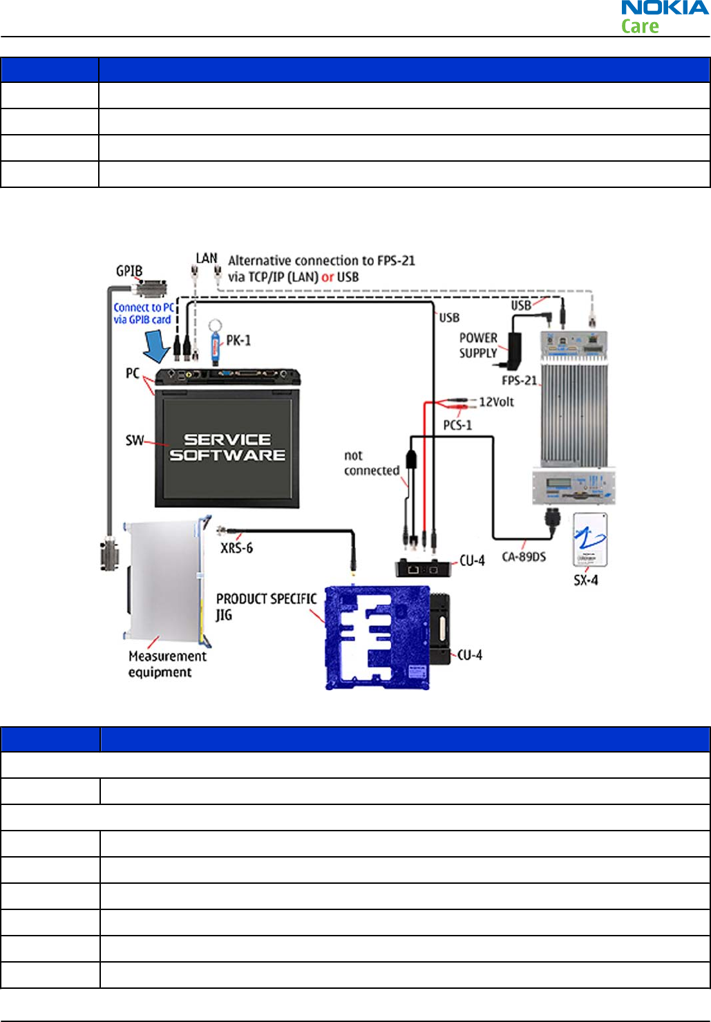
Type Description
PCS-1 Power cable
CA-89DS Service cable
Standard USB cable
USB cable
Module jig service concept
Figure 5 Module jig service concept
Type Description
Phone specific devices
MJ-266 Module jig
Other devices
CU-4 Control unit
FPS-21 Flash prommer box
PK-1/PKD-1 SW security device
SX-4 Smart card
PC with VPOS and Phoenix service software
Measurement equipment
RM-632; RM-634; RM-699
Service Devices and Service Concepts
Issue 3 COMPANY CONFIDENTIAL Page 2 – 15
Copyright © 2010 Nokia. All rights reserved.
Type Description
Cables
CA-89DS Service cable
PCS-1 DC power cable
XRS-6 RF cable
USB cable
GPIB control cable
Service concept for RF testing and RF/BB tuning
Figure 6 Service concept for RF testing and RF/BB tuning
Type Description
Product specific devices
MJ-266 Module jig
Other devices
CU-4 Control unit
PK-1 SW security device
SX-4 Smart card
Measurement equipment
RM-632; RM-634; RM-699
Service Devices and Service Concepts
Page 2 – 16 COMPANY CONFIDENTIAL Issue 3
Copyright © 2010 Nokia. All rights reserved.
Type Description
Smart card reader
PC with Phoenix service software
Cables
DAU-9S MBUS cable
PCS-1 DC power cable
XRS-6 RF cable
GPIB control cable
USB cable
Bluetooth testing concept with SB-6
Figure 7 Service concept for RF testing and RF/BB tuning
Type Description
Product specific devices
FS-147 Flash adapter
Other devices
CU-4 Control unit
SS-62 Flash adapter base
PK-1 SW security device
SX-4 Smart card
RM-632; RM-634; RM-699
Service Devices and Service Concepts
Issue 3 COMPANY CONFIDENTIAL Page 2 – 17
Copyright © 2010 Nokia. All rights reserved.
Type Description
SB-6 Bluetooth test and interface box
Smart card reader
PC with Phoenix service software
Cables
DAU-9S MBUS cable
PCS-1 DC power cable
USB cable
WLAN functionality testing concept with SB-7
Figure 8 WLAN functionality testing concept with SB-7
Type Description
Product specific tools
FS-147 Flash adapter
Other tools
CU-4 Control unit
PCS-1 DC power cable
PK-1 SW Security device
Note: PK-1 can be used instead of PKD-1.
SS-62 Generic base adapter
Cables
RM-632; RM-634; RM-699
Service Devices and Service Concepts
Page 2 – 18 COMPANY CONFIDENTIAL Issue 3
Copyright © 2010 Nokia. All rights reserved.

Type Description
PCS-1 Power cable
DAU-9S Cable
Standard USB cable
RM-632; RM-634; RM-699
Service Devices and Service Concepts
Issue 3 COMPANY CONFIDENTIAL Page 2 – 19
Copyright © 2010 Nokia. All rights reserved.

RM-632; RM-634; RM-699
Service Devices and Service Concepts
(This page left intentionally blank.)
Page 2 – 20 COMPANY CONFIDENTIAL Issue 3
Copyright © 2010 Nokia. All rights reserved.

3 — BB Troubleshooting and
Manual Tuning Guide
Nokia Customer Care
Issue 3 COMPANY CONFIDENTIAL Page 3 – 1
Copyright © 2010 Nokia. All rights reserved.

RM-632; RM-634; RM-699
BB Troubleshooting and Manual Tuning Guide
(This page left intentionally blank.)
Page 3 – 2 COMPANY CONFIDENTIAL Issue 3
Copyright © 2010 Nokia. All rights reserved.

Table of Contents
Baseband self tests in Phoenix ............................................................................................................................ 3–5
Power and charging troubleshooting................................................................................................................. 3–7
Dead or jammed device troubleshooting...................................................................................................... 3–7
Power key troubleshooting............................................................................................................................. 3–9
General voltage checking troubleshooting ............................................................................................... 3–10
General power checking............................................................................................................................... 3–11
Charging troubleshooting ............................................................................................................................ 3–12
USB charging troubleshooting..................................................................................................................... 3–12
Battery current measuring fault troubleshooting ..................................................................................... 3–14
Clocking troubleshooting ............................................................................................................................. 3–15
Interface troubleshooting ................................................................................................................................. 3–16
Flash programming fault troubleshooting................................................................................................. 3–16
SIM card troubleshooting ............................................................................................................................. 3–19
MicroSD card troubleshooting...................................................................................................................... 3–21
USB troubleshooting..................................................................................................................................... 3–22
USB data interface troubleshooting....................................................................................................... 3–22
USB charging troubleshooting................................................................................................................ 3–24
User interface troubleshooting......................................................................................................................... 3–25
Keyboard troubleshooting ........................................................................................................................... 3–25
Navi key LEDs troubleshooting .................................................................................................................... 3–26
Keymat LEDs troubleshooting...................................................................................................................... 3–26
Display module troubleshooting................................................................................................................. 3–27
General instructions for display troubleshooting................................................................................. 3–27
Display fault troubleshooting ................................................................................................................. 3–29
Display backlight troubleshooting ......................................................................................................... 3–30
Ambient light sensor (ALS)........................................................................................................................... 3–31
ALS troubleshooting ................................................................................................................................ 3–31
ALS functionality check............................................................................................................................ 3–32
ALS retuning ............................................................................................................................................. 3–32
GPS troubleshooting .......................................................................................................................................... 3–34
GPS settings for Phoenix............................................................................................................................... 3–34
GPS control................................................................................................................................................ 3–34
GPS Quick Test window ........................................................................................................................... 3–34
GPS antenna................................................................................................................................................... 3–35
GPS failure troubleshooting......................................................................................................................... 3–36
GPS basic checks troubleshooting ............................................................................................................... 3–37
Camera module troubleshooting...................................................................................................................... 3–38
Introduction to camera troubleshooting ................................................................................................... 3–38
Camera troubleshooting............................................................................................................................... 3–38
Taking and evaluating test pictures....................................................................................................... 3–38
Camera troubleshooting.......................................................................................................................... 3–39
Camera baseband troubleshooting........................................................................................................ 3–39
Camera no recognizable viewfinder image troubleshooting.............................................................. 3–40
Camera bad image quality troubleshooting ......................................................................................... 3–41
Camera flash troubleshooting ................................................................................................................ 3–42
Audio troubleshooting....................................................................................................................................... 3–44
Audio troubleshooting test instructions..................................................................................................... 3–44
Internal earpiece troubleshooting .............................................................................................................. 3–46
Internal microphone troubleshooting........................................................................................................ 3–46
Internal handsfree (IHF) troubleshooting................................................................................................... 3–47
RM-632; RM-634; RM-699
BB Troubleshooting and Manual Tuning Guide
Issue 3 COMPANY CONFIDENTIAL Page 3 – 3
Copyright © 2010 Nokia. All rights reserved.

Acoustics troubleshooting............................................................................................................................ 3–48
Introduction to acoustics troubleshooting ........................................................................................... 3–48
Earpiece troubleshooting........................................................................................................................ 3–49
IHF troubleshooting................................................................................................................................. 3–50
Microphone troubleshooting .................................................................................................................. 3–51
Vibra troubleshooting................................................................................................................................... 3–52
Bluetooth and FM radio troubleshooting ........................................................................................................ 3–53
Bluetooth troubleshooting .......................................................................................................................... 3–53
FM radio troubleshooting............................................................................................................................. 3–54
WLAN troubleshooting....................................................................................................................................... 3–55
WLAN functionality test using SB-7 and Phoenix....................................................................................... 3–55
WLAN layout and test points........................................................................................................................ 3–55
WLAN settings for Phoenix........................................................................................................................... 3–56
WLAN functional tests................................................................................................................................... 3–58
WLAN failure troubleshooting ..................................................................................................................... 3–60
Baseband manual tuning guide........................................................................................................................ 3–62
Certificate restoring ...................................................................................................................................... 3–62
Product code change .................................................................................................................................... 3–65
Energy management calibration................................................................................................................. 3–69
List of Tables
Table 6 Display module troubleshooting cases............................................................................................... 3–27
Table 7 Pixel defects .......................................................................................................................................... 3–28
Table 8 Calibration value limits ........................................................................................................................ 3–70
List of Figures
Figure 9 Flashing pic 1. Take single trig measurement for the rise of the BSI signal................................. 3–17
Figure 10 Flashing pic 2. Take single trig measurement for the rise of the BSI signal............................... 3–18
Figure 11 GPS Control dialog box...................................................................................................................... 3–34
Figure 12 GPS Quick Test window for GPS troubleshooting .......................................................................... 3–35
Figure 13 GPS antenna location........................................................................................................................ 3–35
Figure 14 Differential output waveform of the Ext_in_IHF_out out loop measurement when speaker is
connected. ................................................................................................................................................ 3–45
RM-632; RM-634; RM-699
BB Troubleshooting and Manual Tuning Guide
Page 3 – 4 COMPANY CONFIDENTIAL Issue 3
Copyright © 2010 Nokia. All rights reserved.

Baseband self tests in Phoenix
Context
Always start the troubleshooting procedure by running the Phoenix self tests. If a test fails, please follow the
diagram below.
If the phone is dead and you cannot perform the self tests, go to
Dead or jammed device troubleshooting.
RM-632; RM-634; RM-699
BB Troubleshooting and Manual Tuning Guide
Issue 3 COMPANY CONFIDENTIAL Page 3 – 5
Copyright © 2010 Nokia. All rights reserved.
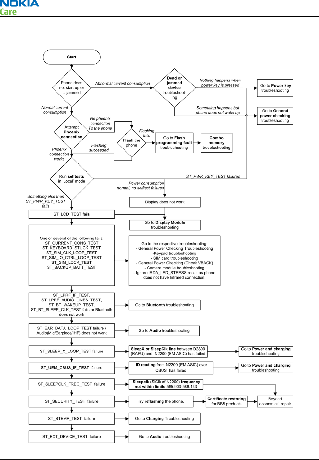
Troubleshooting flow
RM-632; RM-634; RM-699
BB Troubleshooting and Manual Tuning Guide
Page 3 – 6 COMPANY CONFIDENTIAL Issue 3
Copyright © 2010 Nokia. All rights reserved.
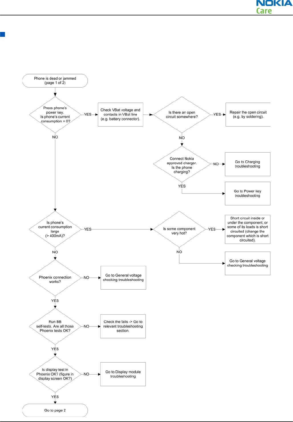
Power and charging troubleshooting
Dead or jammed device troubleshooting
Troubleshooting flow - Page 1 of 2
RM-632; RM-634; RM-699
BB Troubleshooting and Manual Tuning Guide
Issue 3 COMPANY CONFIDENTIAL Page 3 – 7
Copyright © 2010 Nokia. All rights reserved.
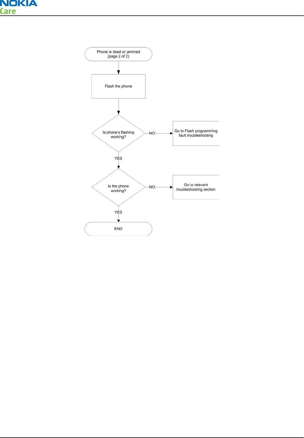
Troubleshooting flow - Page 2 of 2
RM-632; RM-634; RM-699
BB Troubleshooting and Manual Tuning Guide
Page 3 – 8 COMPANY CONFIDENTIAL Issue 3
Copyright © 2010 Nokia. All rights reserved.
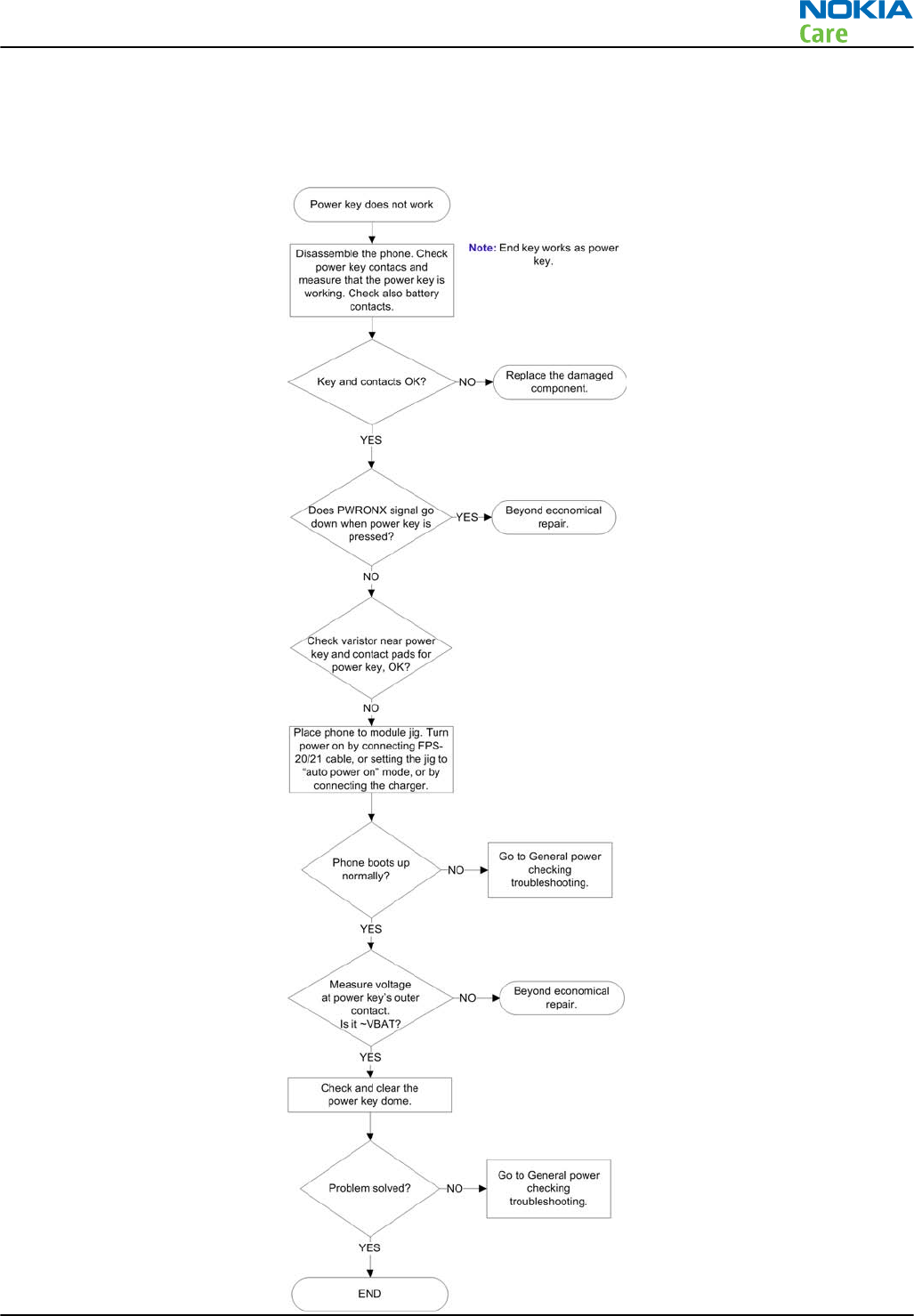
Power key troubleshooting
Troubleshooting flow
RM-632; RM-634; RM-699
BB Troubleshooting and Manual Tuning Guide
Issue 3 COMPANY CONFIDENTIAL Page 3 – 9
Copyright © 2010 Nokia. All rights reserved.
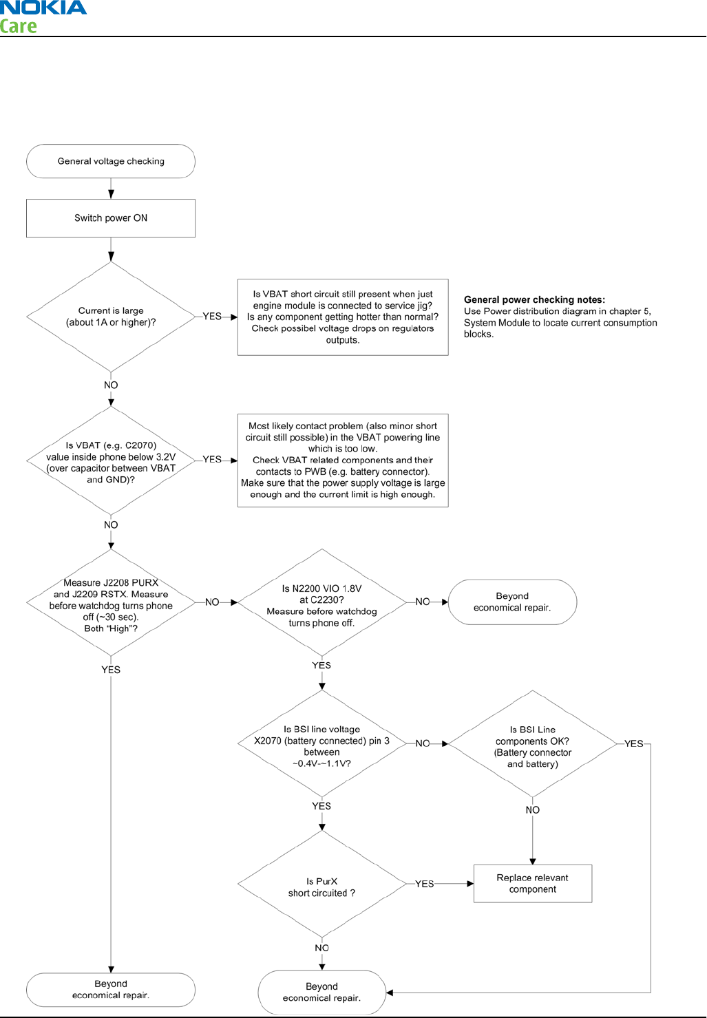
General voltage checking troubleshooting
Troubleshooting flow
RM-632; RM-634; RM-699
BB Troubleshooting and Manual Tuning Guide
Page 3 – 10 COMPANY CONFIDENTIAL Issue 3
Copyright © 2010 Nokia. All rights reserved.
General power checking
Check the following voltages:
Signal
Rename Regulator Sleep Idle Nominal
voltage Main user Notes
VIO Pearl/Gazoo ON ON 1.8 Memory, I/Os,
Display
VBACK Pearl/Gazoo ON ON 2.5 Back-up
battery
VSIM1 Pearl/Gazoo ON ON 1.8/3.0 SIM card
VAUX1 Pearl/Gazoo ON ON 2.8 TV-OUT, 3DFS,
MR, Display
VAUX2 Pearl/Gazoo OFF OFF 2.5 ALS
VANA Pearl/Gazoo ON ON 2.5 Audio
VR1 Pearl/Gazoo OFF ON 2.5 Crystal
oscillators
VRFC Pearl/Gazoo OFF ON 1.8 RAPU
converters
VRCP1 Pearl/Gazoo 4.75 To RF parts
VREF Pearl/Gazoo ON ON 1.25 RF reference
VCORE Pearl/Gazoo ON ON 1.2 RAPU digital Can change due
to RAPU version
& SW
VOUT Pearl/Gazoo OFF OFF 2.5 Video switch
VCAM_2V8 N1421 OFF OFF 2.8 Camera Disabled in
sleep
VCAM_1V8 N1420 OFF OFF 1.800 Camera Disabled in
sleep
VMEM Pearl/Gazoo OFF OFF 2.9 microSD Disabled in
sleep
RM-632; RM-634; RM-699
BB Troubleshooting and Manual Tuning Guide
Issue 3 COMPANY CONFIDENTIAL Page 3 – 11
Copyright © 2010 Nokia. All rights reserved.
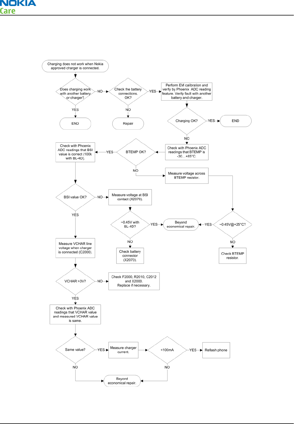
Charging troubleshooting
Troubleshooting flow
RM-632; RM-634; RM-699
BB Troubleshooting and Manual Tuning Guide
Page 3 – 12 COMPANY CONFIDENTIAL Issue 3
Copyright © 2010 Nokia. All rights reserved.

USB charging troubleshooting
Context
For instructions regarding USB charging troubleshooting, see section USB charging troubleshooting
(page 3–24 ) .
RM-632; RM-634; RM-699
BB Troubleshooting and Manual Tuning Guide
Issue 3 COMPANY CONFIDENTIAL Page 3 – 13
Copyright © 2010 Nokia. All rights reserved.
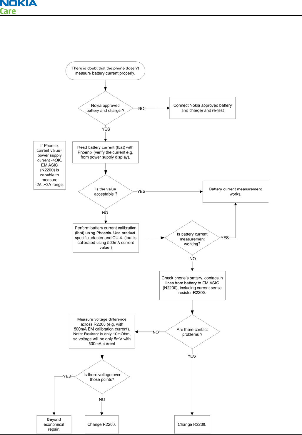
Battery current measuring fault troubleshooting
Troubleshooting flow
RM-632; RM-634; RM-699
BB Troubleshooting and Manual Tuning Guide
Page 3 – 14 COMPANY CONFIDENTIAL Issue 3
Copyright © 2010 Nokia. All rights reserved.
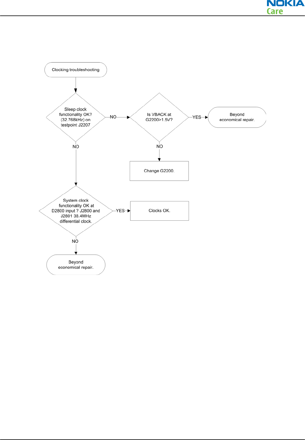
Clocking troubleshooting
Troubleshooting flow
RM-632; RM-634; RM-699
BB Troubleshooting and Manual Tuning Guide
Issue 3 COMPANY CONFIDENTIAL Page 3 – 15
Copyright © 2010 Nokia. All rights reserved.
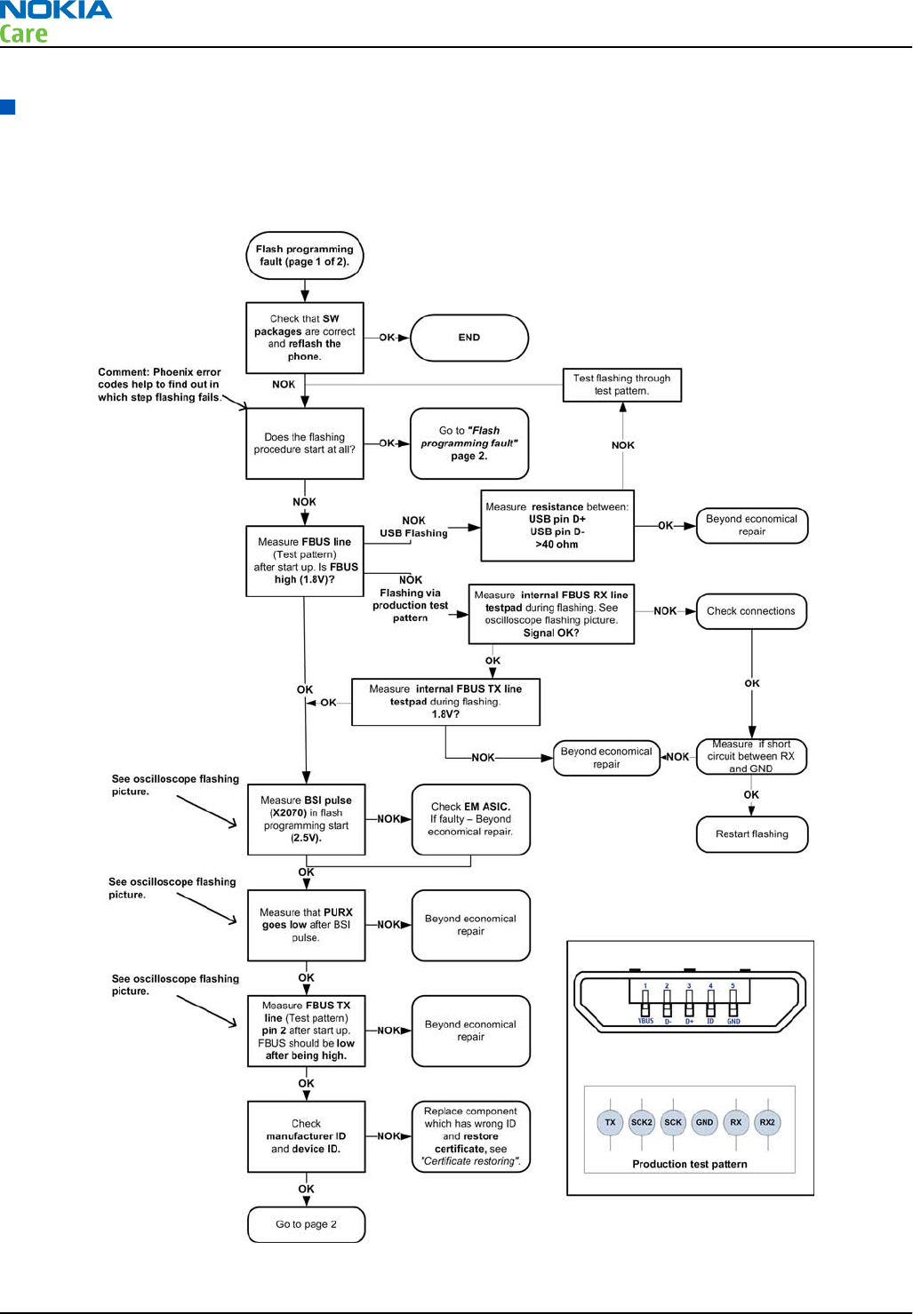
Interface troubleshooting
Flash programming fault troubleshooting
Troubleshooting flow - Page 1 of 2
RM-632; RM-634; RM-699
BB Troubleshooting and Manual Tuning Guide
Page 3 – 16 COMPANY CONFIDENTIAL Issue 3
Copyright © 2010 Nokia. All rights reserved.
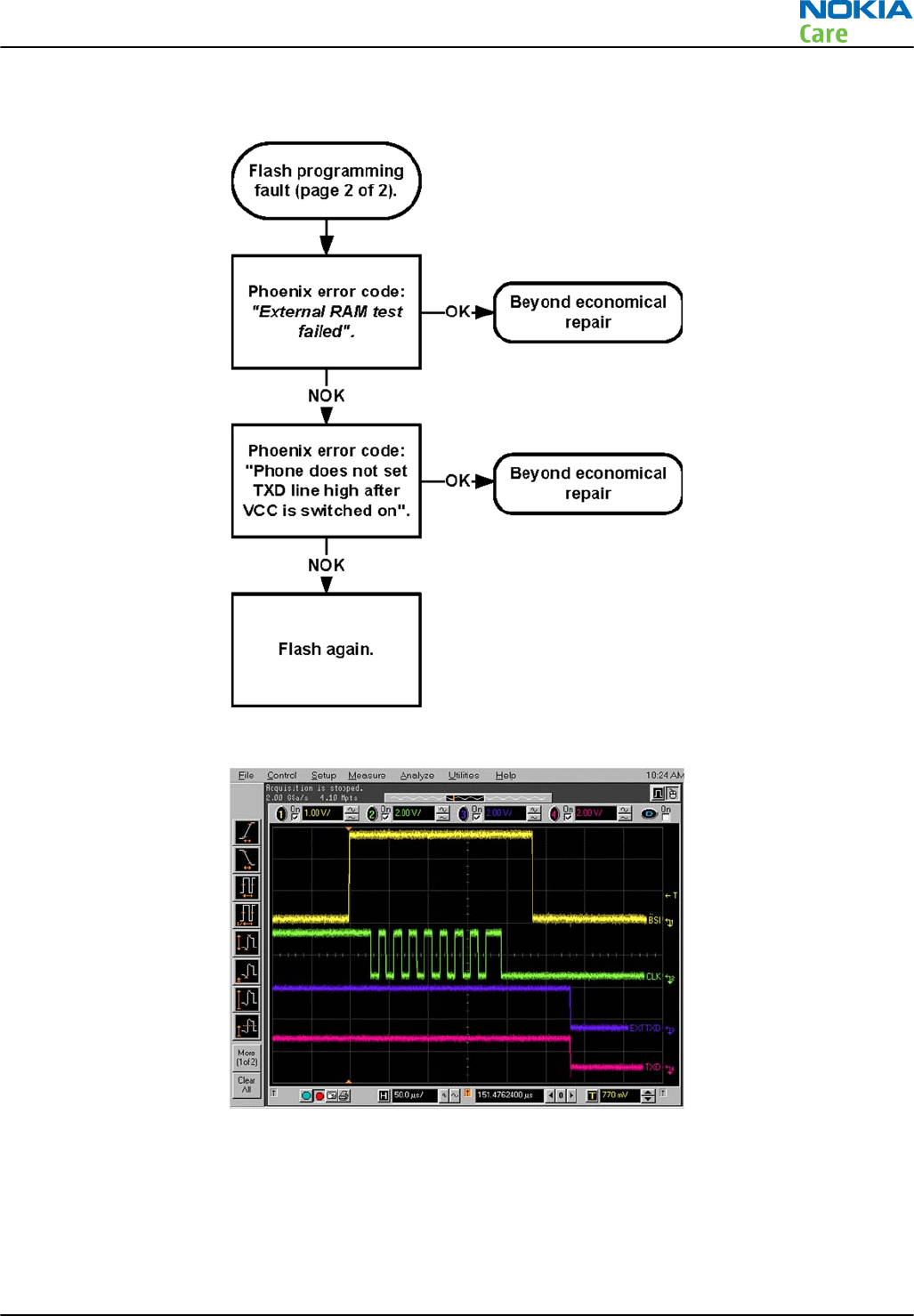
Troubleshooting flow - Page 2 of 2
Figure 9 Flashing pic 1. Take single trig measurement for the rise of the BSI signal
RM-632; RM-634; RM-699
BB Troubleshooting and Manual Tuning Guide
Issue 3 COMPANY CONFIDENTIAL Page 3 – 17
Copyright © 2010 Nokia. All rights reserved.
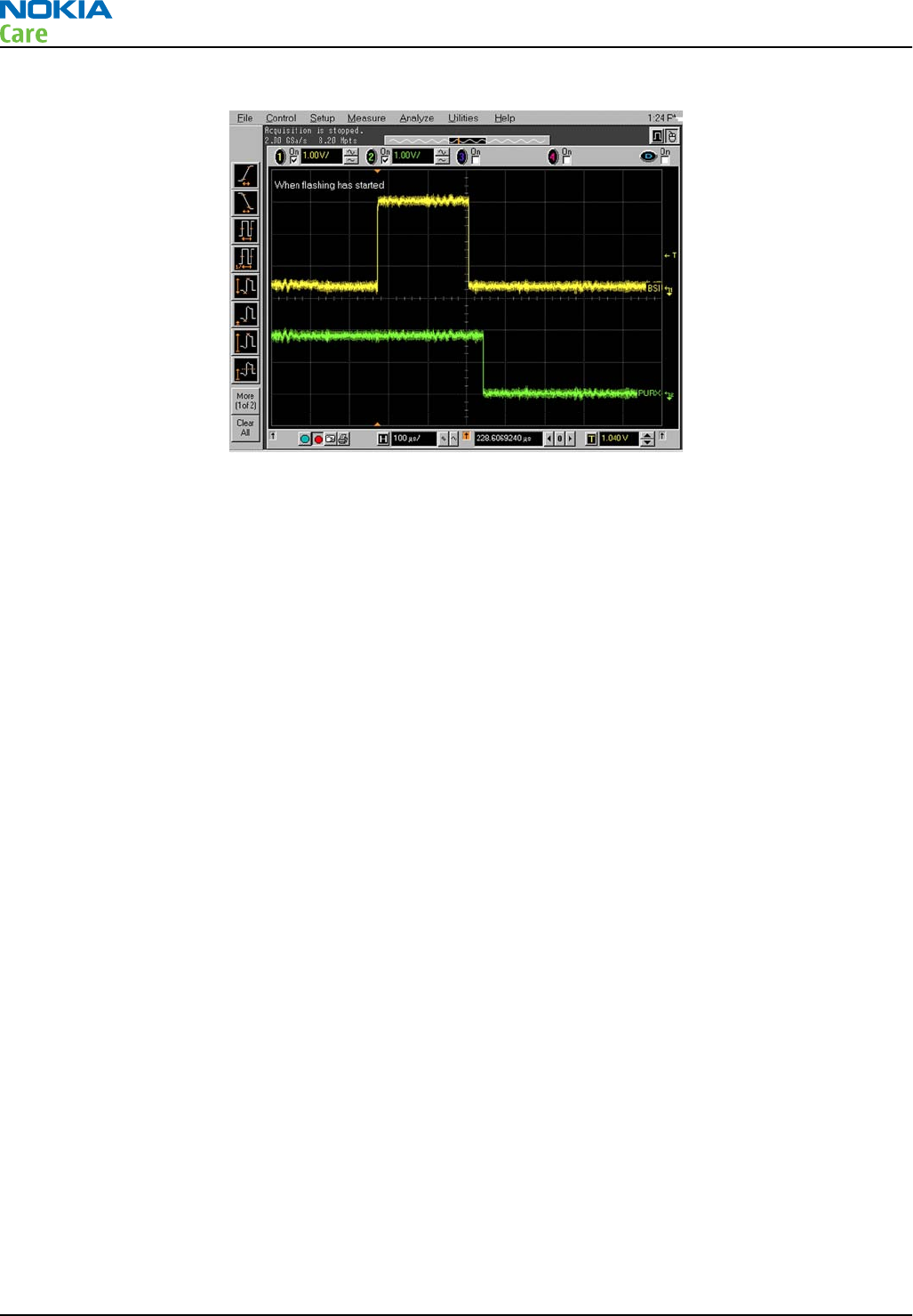
Figure 10 Flashing pic 2. Take single trig measurement for the rise of the BSI signal
RM-632; RM-634; RM-699
BB Troubleshooting and Manual Tuning Guide
Page 3 – 18 COMPANY CONFIDENTIAL Issue 3
Copyright © 2010 Nokia. All rights reserved.
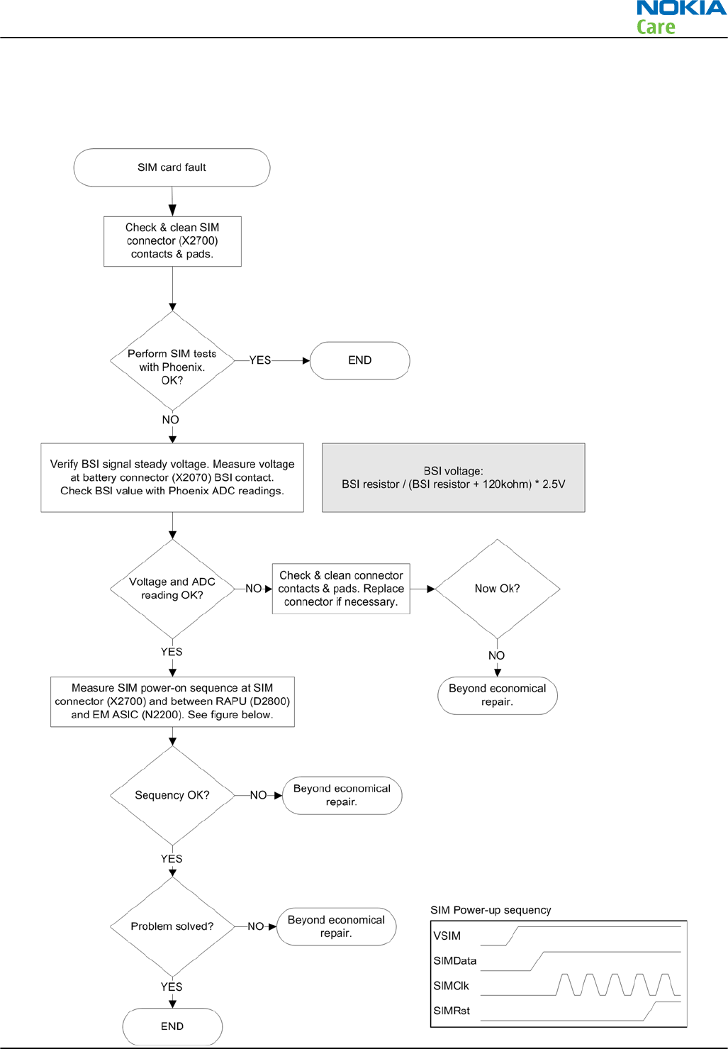
SIM card troubleshooting
Troubleshooting flow
RM-632; RM-634; RM-699
BB Troubleshooting and Manual Tuning Guide
Issue 3 COMPANY CONFIDENTIAL Page 3 – 19
Copyright © 2010 Nokia. All rights reserved.
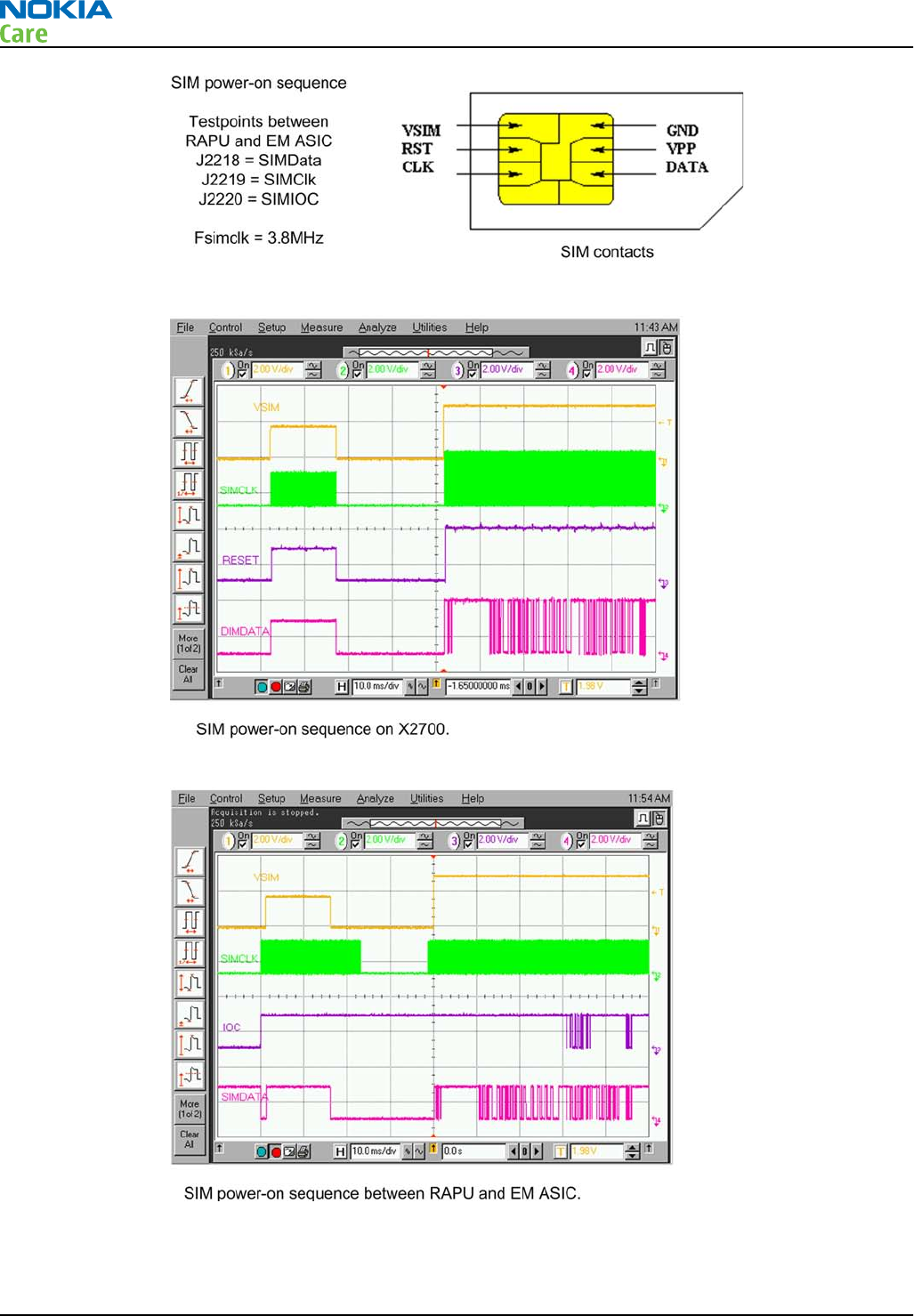
RM-632; RM-634; RM-699
BB Troubleshooting and Manual Tuning Guide
Page 3 – 20 COMPANY CONFIDENTIAL Issue 3
Copyright © 2010 Nokia. All rights reserved.
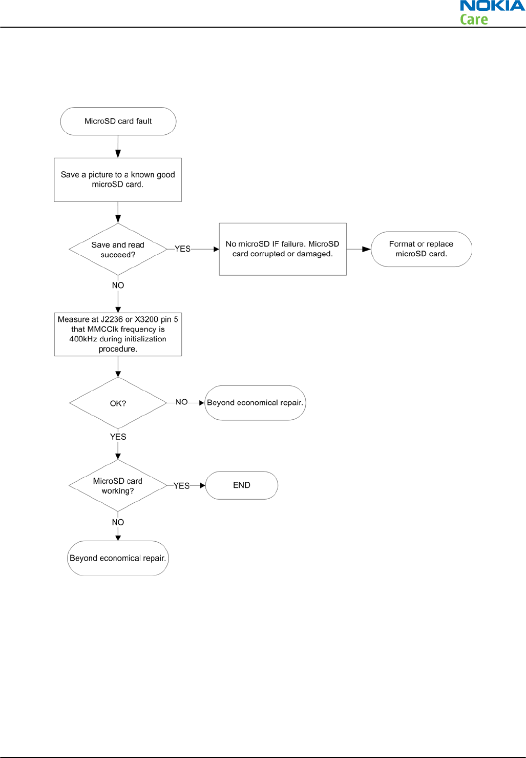
MicroSD card troubleshooting
Troubleshooting flow
RM-632; RM-634; RM-699
BB Troubleshooting and Manual Tuning Guide
Issue 3 COMPANY CONFIDENTIAL Page 3 – 21
Copyright © 2010 Nokia. All rights reserved.
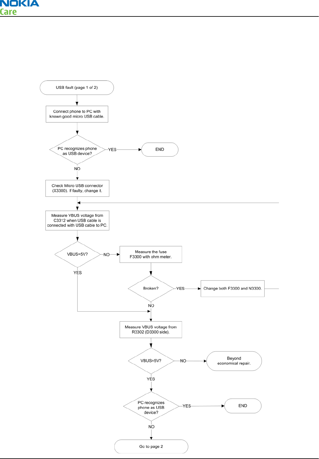
USB troubleshooting
USB data interface troubleshooting
Troubleshooting flow - Page 1 of 2
RM-632; RM-634; RM-699
BB Troubleshooting and Manual Tuning Guide
Page 3 – 22 COMPANY CONFIDENTIAL Issue 3
Copyright © 2010 Nokia. All rights reserved.
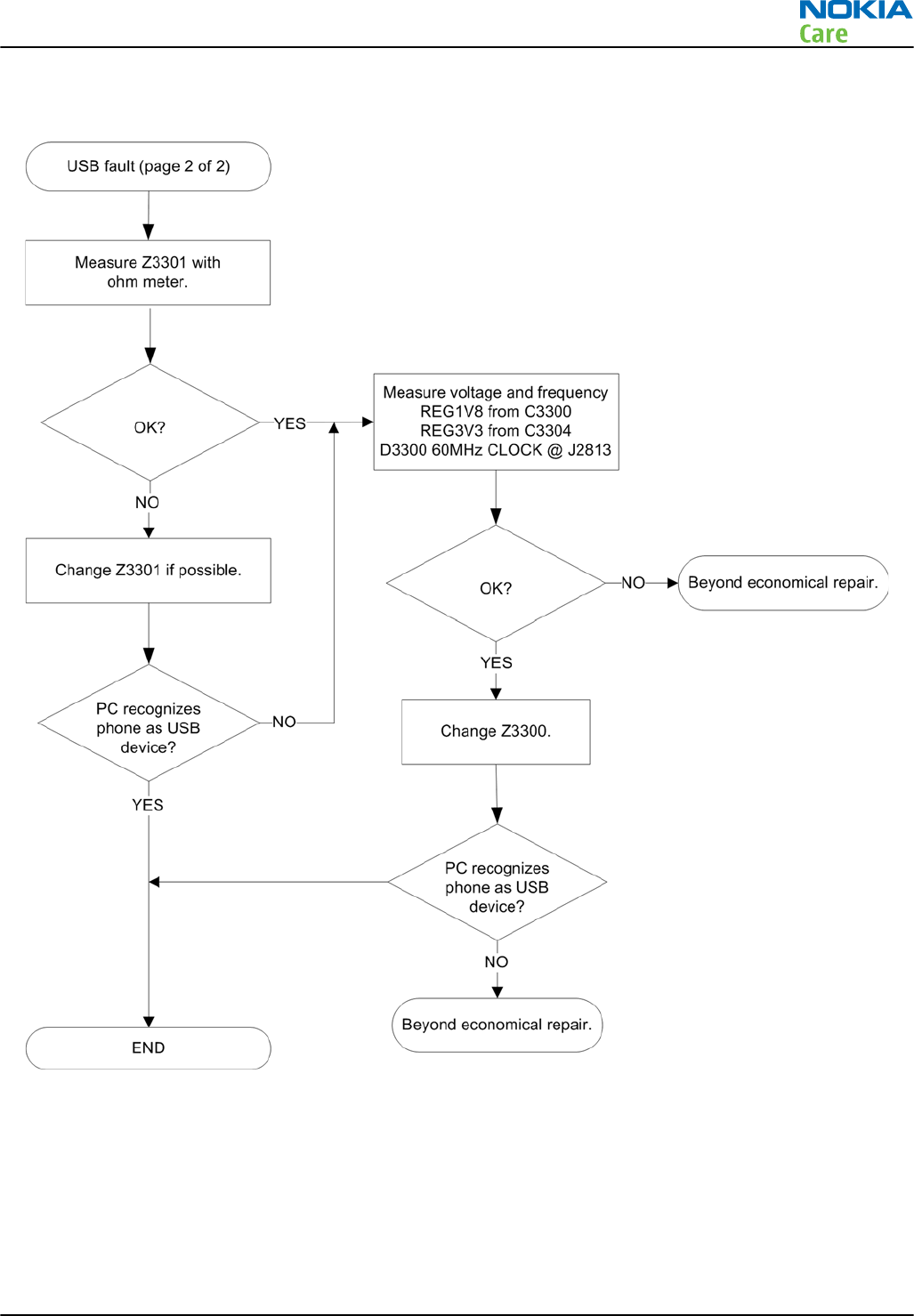
Troubleshooting flow - Page 2 of 2
RM-632; RM-634; RM-699
BB Troubleshooting and Manual Tuning Guide
Issue 3 COMPANY CONFIDENTIAL Page 3 – 23
Copyright © 2010 Nokia. All rights reserved.
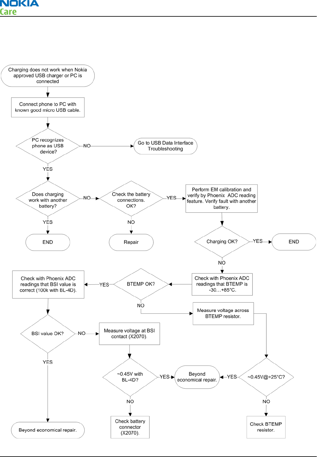
USB charging troubleshooting
Troubleshooting flow
RM-632; RM-634; RM-699
BB Troubleshooting and Manual Tuning Guide
Page 3 – 24 COMPANY CONFIDENTIAL Issue 3
Copyright © 2010 Nokia. All rights reserved.
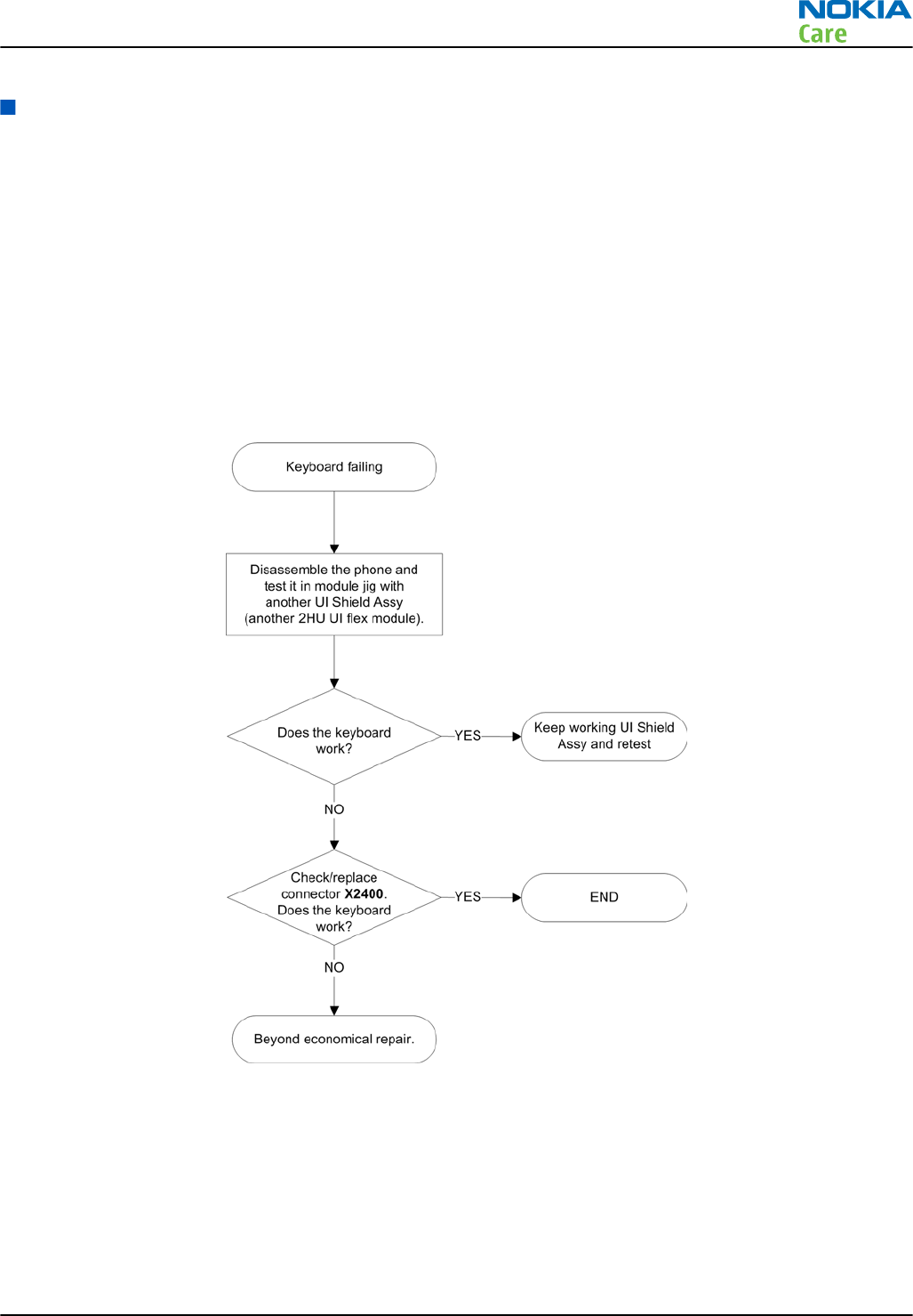
User interface troubleshooting
Keyboard troubleshooting
Context
There are two possible failure modes in the keyboard module:
•One or more keys are stuck, so that the key does not react when a keydome or a side key is pressed. This
kind of failure is caused by mechanical reasons (dirt, rust, mechanical damage, etc.)
•Malfunction of several keys at the same time; this happens when one or more rows or columns in the key
matrix are failing (shortcut or open connection).
If the failure mode is not clear, start with the Keyboard test in Phoenix.
Keyboard troubleshooting
RM-632; RM-634; RM-699
BB Troubleshooting and Manual Tuning Guide
Issue 3 COMPANY CONFIDENTIAL Page 3 – 25
Copyright © 2010 Nokia. All rights reserved.
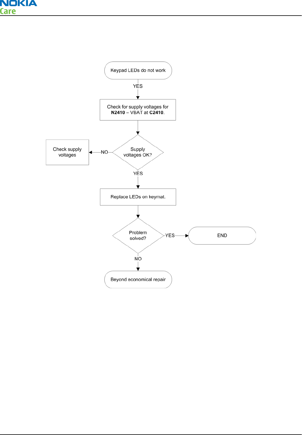
Navi key LEDs troubleshooting
Troubleshooting flow
RM-632; RM-634; RM-699
BB Troubleshooting and Manual Tuning Guide
Page 3 – 26 COMPANY CONFIDENTIAL Issue 3
Copyright © 2010 Nokia. All rights reserved.
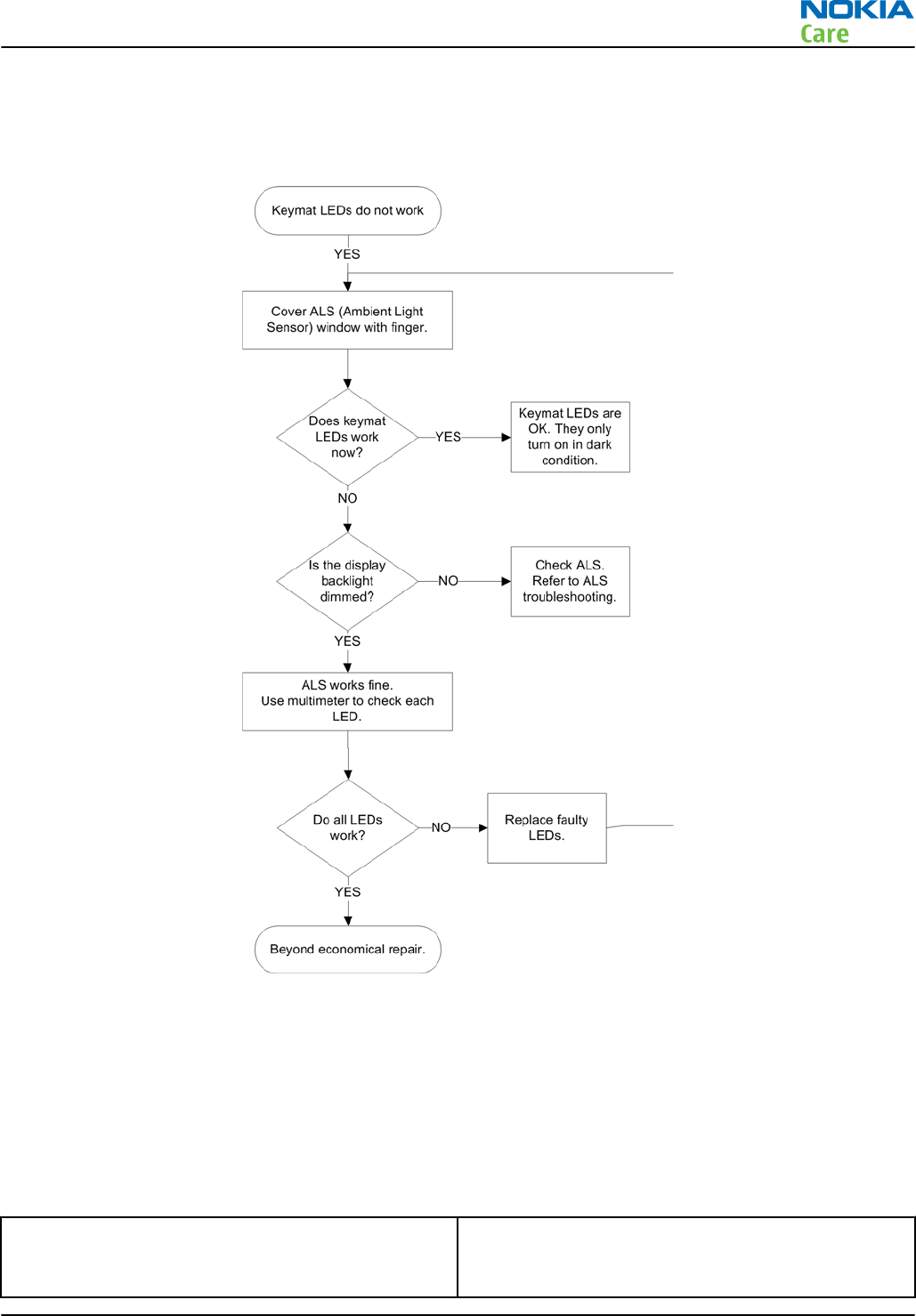
Keymat LEDs troubleshooting
Troubleshooting flow
Display module troubleshooting
General instructions for display troubleshooting
Context
•The display is in a normal mode when the phone is in active use.
•The operating modes of the display can be controlled with the help of
Phoenix
.
Table 6 Display module troubleshooting cases
Display blank There is no image on the display. The display looks
the same when the phone is on as it does when the
phone is off. The backlight can be on in some cases.
RM-632; RM-634; RM-699
BB Troubleshooting and Manual Tuning Guide
Issue 3 COMPANY CONFIDENTIAL Page 3 – 27
Copyright © 2010 Nokia. All rights reserved.
Image on the display not correct Image on the display can be corrupted or a part of
the image can be missing.
•If a part of the image is missing, change the
display module.
•If the image is otherwise corrupted, follow the
display fault troubleshooting flowchart.
Backlight dim or not working at all Backlight LED components are inside the display
module. Backlight failure can also be in the
connector or in the backlight power source in the
main engine of the phone.
This means that in case the display is working
(image OK), the backlight is faulty.
Visual defects (pixel) Pixel defects can be checked by controlling the
display with Phoenix. Use both colours, black and
white, on a full screen.
The display may have some random pixel defects
that are acceptable for this type of display. The
criteria when pixel defects are regarded as a display
failure, resulting in a replacement of the display, are
presented the following table.
Table 7 Pixel defects
Item White dot defect Black dot
defect Total
1Defect counts R G B White Dot
Total
1 1
1 1 1 1
2 Combined
defect counts
Not allowed.
Two single dot defects that are within 5 mm of each other should be
interpreted as combined dot defect.
Steps
1. Verify with a working display that the fault is not on the display module itself.
The display module cannot be repaired.
2. Check that the cellular engine is working normally.
i To check the functionality, connect the phone to a docking station.
ii Start
Phoenix
service software.
iii Read the phone information to check that also the application engine is functioning normally (you
should be able to read the APE ID).
3. Proceed to the display fault troubleshooting flowchart.
Use the Display Test tool in
Phoenix
to find the detailed fault mode.
RM-632; RM-634; RM-699
BB Troubleshooting and Manual Tuning Guide
Page 3 – 28 COMPANY CONFIDENTIAL Issue 3
Copyright © 2010 Nokia. All rights reserved.
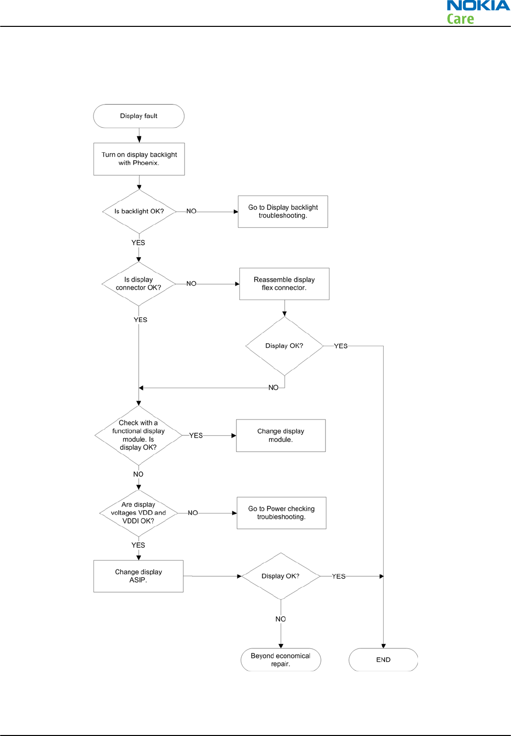
Display fault troubleshooting
Troubleshooting flow
RM-632; RM-634; RM-699
BB Troubleshooting and Manual Tuning Guide
Issue 3 COMPANY CONFIDENTIAL Page 3 – 29
Copyright © 2010 Nokia. All rights reserved.
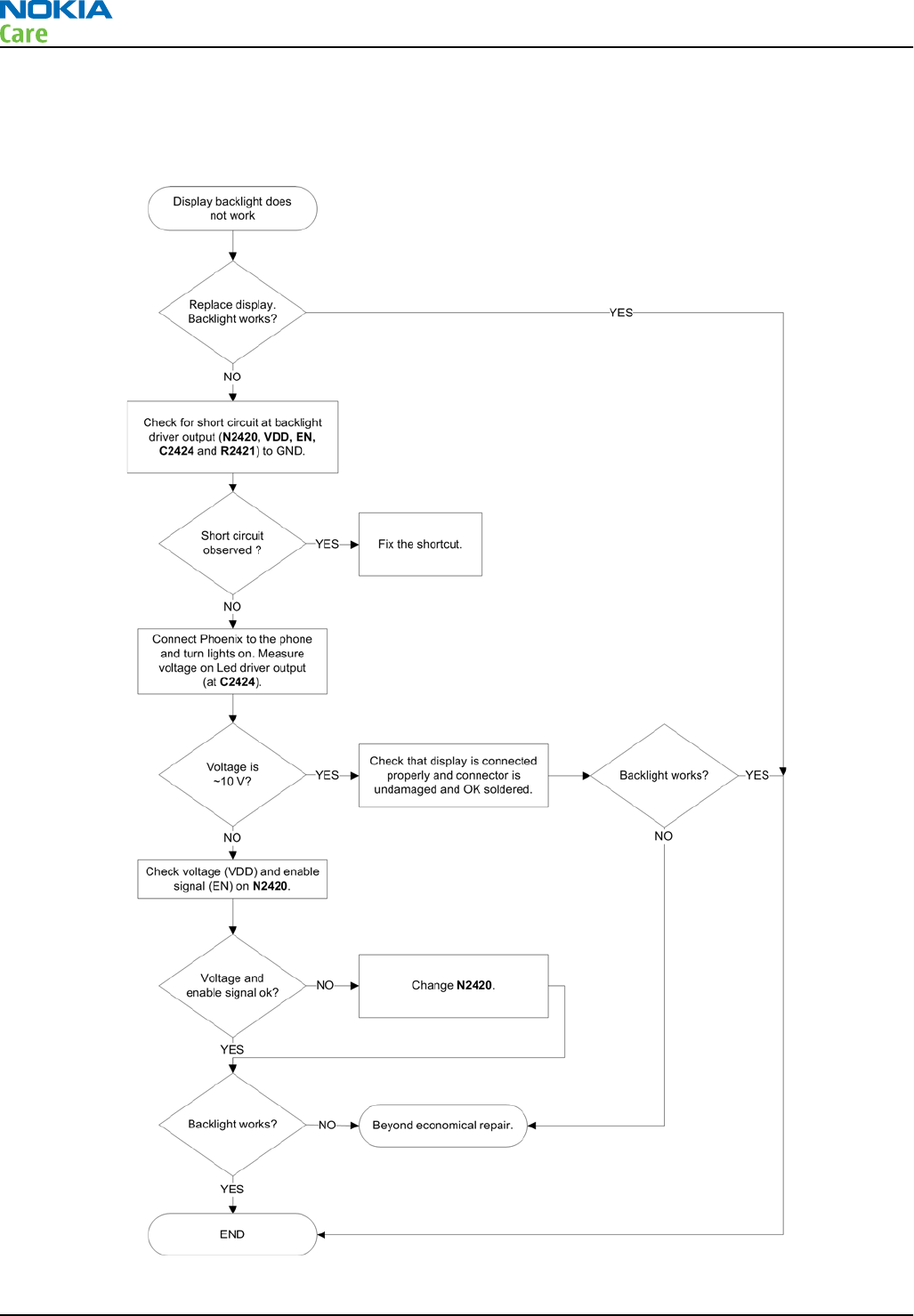
Display backlight troubleshooting
Troubleshooting flow
RM-632; RM-634; RM-699
BB Troubleshooting and Manual Tuning Guide
Page 3 – 30 COMPANY CONFIDENTIAL Issue 3
Copyright © 2010 Nokia. All rights reserved.
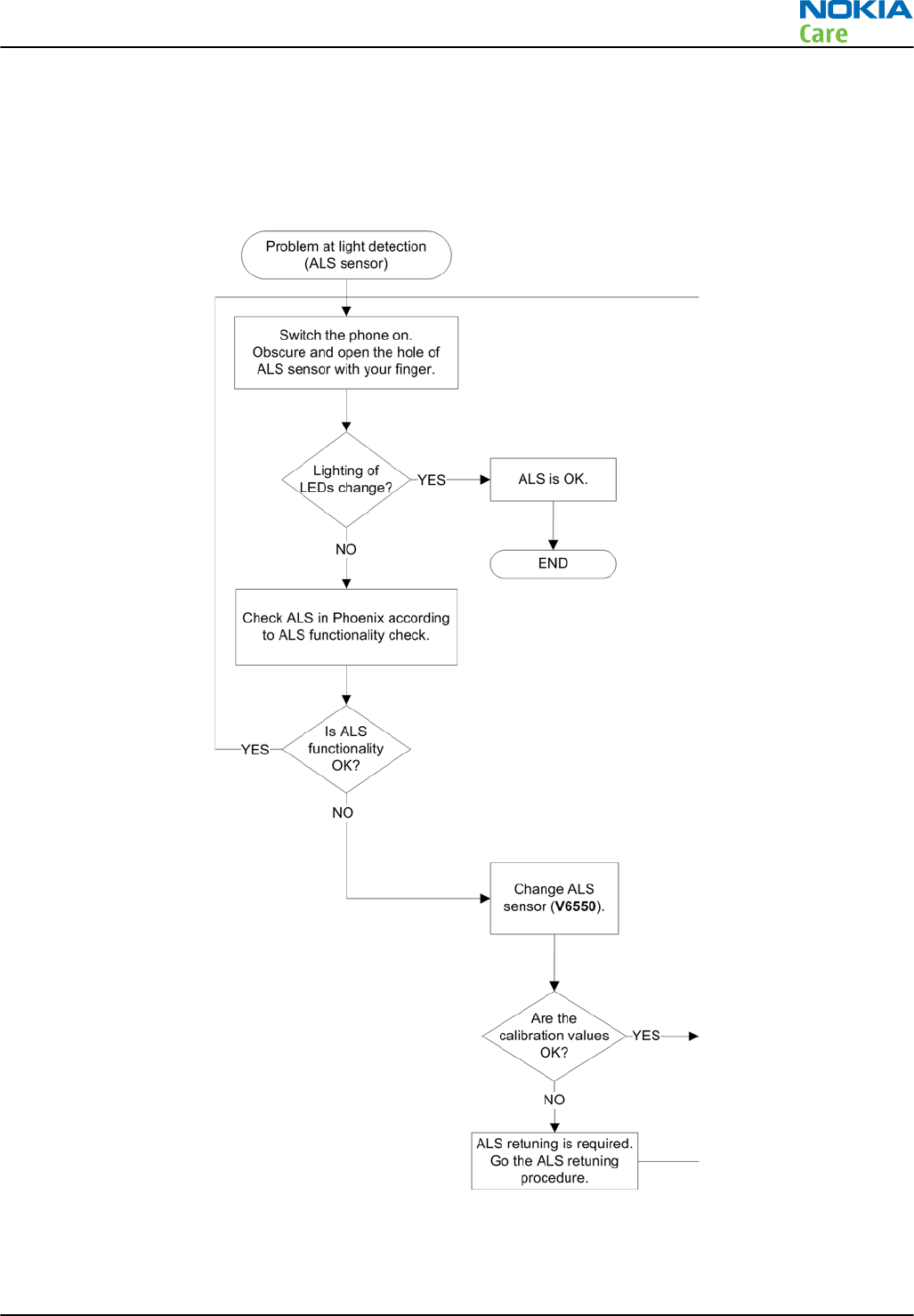
Ambient light sensor (ALS)
ALS troubleshooting
Troubleshooting flow
RM-632; RM-634; RM-699
BB Troubleshooting and Manual Tuning Guide
Issue 3 COMPANY CONFIDENTIAL Page 3 – 31
Copyright © 2010 Nokia. All rights reserved.
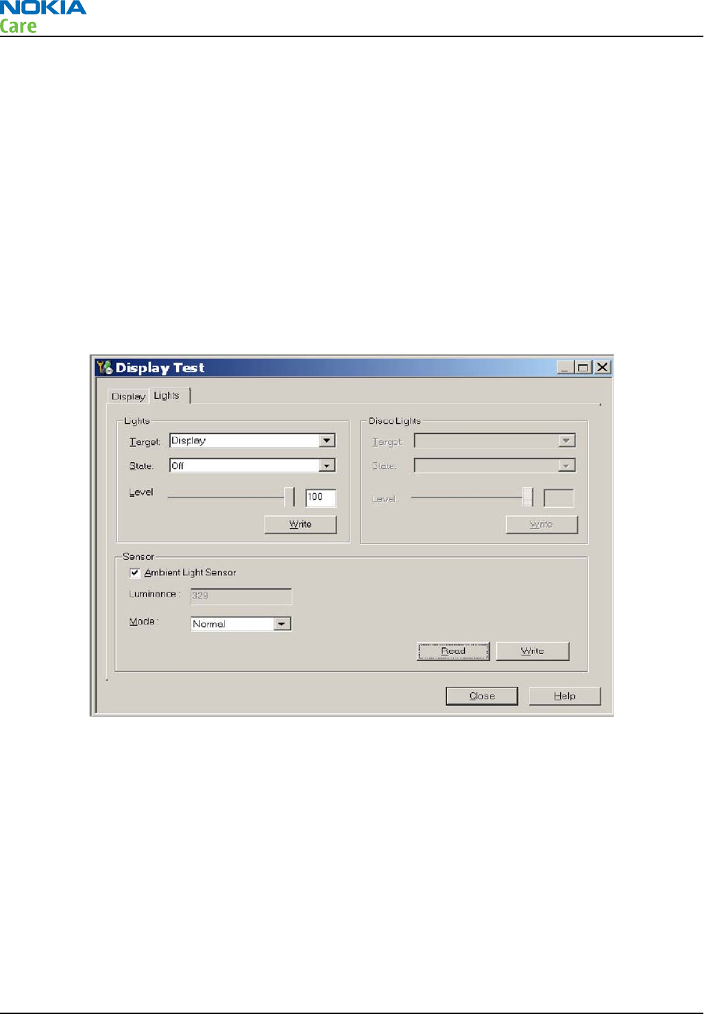
ALS functionality check
Steps
1. Connect phone to Phoenix and set the phone (e.g. on the table) so that the amount of ambient light seen
by ALS is as stable as possible.
2. Start Phoenix
3. Choose File -> Scan product
4. Choose Testing -> Display Test
5. Open the Lights tab, check Ambient Light Sensor check box, click Read, cover the sensor and click Read
again. When covered, Luminance reading should be less than after clicking Read without covering the
sensor.
6. If component doesn’t give any reading or reading doesn’t change when sensor is/is not covered, replace
the part.
Note: After replacing the ALS. If calibration values of the new sensor are lost or for some other
reason, ALS re-tuning is required (see instructions later in this document).
When doing the ALS calibration procedure, it is required to have a reference phone, which includes
calibrated ALS. ALS re-tuning instructions show why the reference phone is needed.
ALS retuning
Steps
1. Connect reference phone to
Phoenix
and set the phone (e.g. on the table) so that the amount of ambient
light seen by ALS is as stabile as possible.
2. Start
Phoenix
.
3. Choose File→Scan Product.
RM-632; RM-634; RM-699
BB Troubleshooting and Manual Tuning Guide
Page 3 – 32 COMPANY CONFIDENTIAL Issue 3
Copyright © 2010 Nokia. All rights reserved.
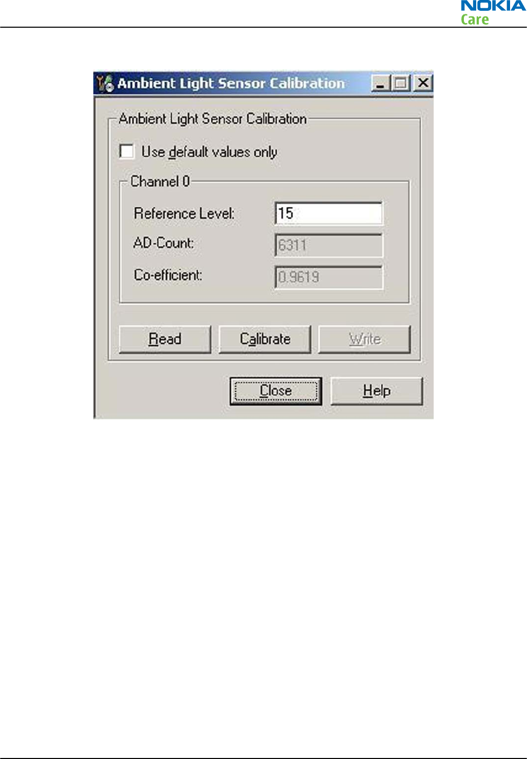
4. Choose Tuning -> Ambient Light Sensor Calibration. You should see the following window
5. Read AD-count values for Channel 0 by click Read button and write them down.
6. Repeat 1-5 for the phone to be calibrated and make sure the phone to be calibrated is located in the
same place as reference phone was when luminance reading was taken.
7. Calculate co-efficient from reference phone and phone to be calibrated AD-count values by division: Co-
efficient = AD-count(reference phone) / AD-count(phone to be calibrated), write down the calculated co-
efficient values.
8. -> Iterate by changing Channel 0 (reference level) value (remove cross from ‘Use default values only’).
After writing some value to Channel 0 (reference value), calibrate button must be pressed. Stop iterating
when Co-efficient is equal to Co-efficient calculated in bullet 7. Note that decimal numbers should be
used in the iteration in order to achieve enough precision (e.g. 200.2455)
9. After having same Co-efficient value in “Co-efficient” textbox as the calculated value, make sure that
ambient light values (read using Testing → Display Test → “Luminance” textbox) are almost the same
in reference phone and calibrated phone. Remember that illuminance readings for reference and
calibrated phones must be done in the same ambient light conditions. If illuminance values differs a lot
(difference max. +- 10%), repeat whole ALS re-tuning procedure.
10. To end the calibration, click Close.
RM-632; RM-634; RM-699
BB Troubleshooting and Manual Tuning Guide
Issue 3 COMPANY CONFIDENTIAL Page 3 – 33
Copyright © 2010 Nokia. All rights reserved.
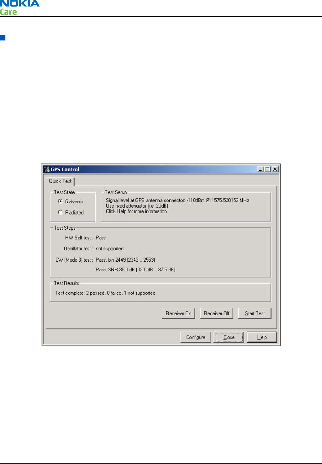
GPS troubleshooting
GPS settings for Phoenix
GPS control
Context
Use the following to test GPS using Phoenix.
Steps
1. Start Phoenix service software.
2. From the File menu, select Scan Product and check that the correct product version is displayed.
3. From the Testing menu, select GPS Control. This opens up
GPS Control
dialogue box, as shown in the
figure below, and enables the GPS.
Figure 11 GPS Control dialog box
Select Receiver On to confirm the GPS is enabled and is in idle mode; at this point all clocks should be
present, GPS_En_Reset & SleepX should be high, and Vdd_Dig, Vcc_TCXO & Vcc_PLL/VCO will be present.
Receiver On turns on all RF sections of the ASIC and so all LDOs will be on. These checks are part of GPS
basic checks troubleshooting (page 3– 0 ) .
GPS Quick Test window
The
GPS Quick Test
window has all the necessary functionality for GPS troubleshooting. Ensure the test setup
is correct and click Start Test. (Select Help for further information).
RM-632; RM-634; RM-699
BB Troubleshooting and Manual Tuning Guide
Page 3 – 34 COMPANY CONFIDENTIAL Issue 3
Copyright © 2010 Nokia. All rights reserved.
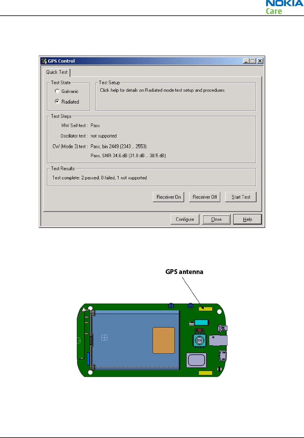
This test will perform three tests in one; Self Test, Oscillator Test and CW Test, and will provide a Pass/Fail
response. The
GPS Quick Test
window also contains a Receiver On button. These checks are part of GPS
failure troubleshooting (page 3– 0 ) .
Figure 12 GPS Quick Test window for GPS troubleshooting
GPS antenna
The GPS antenna is covering the GPS band. It is located on the main PWB as shown below.
Figure 13 GPS antenna location
RM-632; RM-634; RM-699
BB Troubleshooting and Manual Tuning Guide
Issue 3 COMPANY CONFIDENTIAL Page 3 – 35
Copyright © 2010 Nokia. All rights reserved.
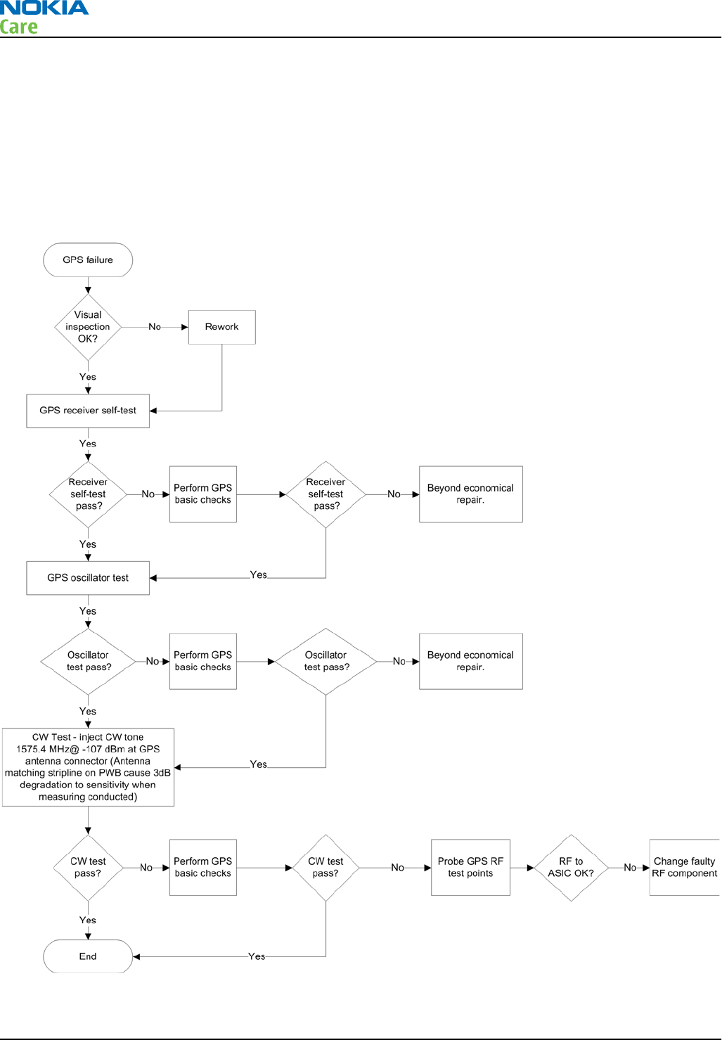
GPS failure troubleshooting
Context
GPS troubleshooting is broken down into two parts: general GPS failure troubleshooting and GPS basic checks
troubleshooting. The GPS failure troubleshooting flow can be followed and, where applicable, will feed into
the GPS basic checks troubleshooting flow.
Troubleshooting flow
RM-632; RM-634; RM-699
BB Troubleshooting and Manual Tuning Guide
Page 3 – 36 COMPANY CONFIDENTIAL Issue 3
Copyright © 2010 Nokia. All rights reserved.
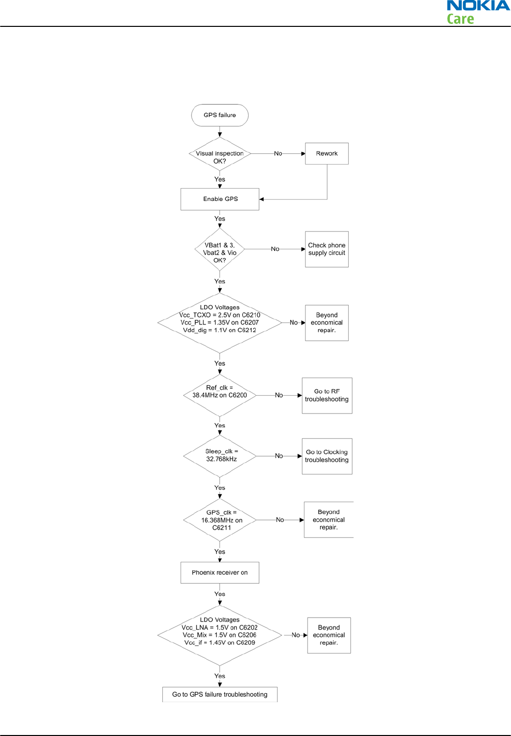
GPS basic checks troubleshooting
Troubleshooting flow
RM-632; RM-634; RM-699
BB Troubleshooting and Manual Tuning Guide
Issue 3 COMPANY CONFIDENTIAL Page 3 – 37
Copyright © 2010 Nokia. All rights reserved.

Camera module troubleshooting
Introduction to camera troubleshooting
Bad conditions often cause bad pictures. Therefore, the camera operation has to be checked in constant
conditions or by using a second, known-to-be-good Nokia device as reference. Image quality is hard to
measure quantitatively, and the difference between a good and a bad picture can be small. Some training
or experience may be needed to detect what is actually wrong.
When checking for possible errors in camera functionality, knowing what error is suspected significantly
helps the testing by narrowing down the amount of test cases. The following types of image quality problems
are common:
•Dust (black spots)
•Lack of sharpness
•Bit errors
Camera troubleshooting
Taking and evaluating test pictures
When
taking
a test picture, remember the following:
•Avoid bright fluorescent light, 50/60Hz electrical network or high artificial illumination levels
•If the phone is hot, let it rest for a while before taking the picture
•Make sure the optical system is clean
•Use highest possible resolution
•Make sure the light is sufficient (bright office lightning)
•Do not take the picture towards a light source
•Hold the phone as still as possible when taking the picture
•If camera has auto focus: Pictures should be taken both at infinity ~>2m and at macro distance ~10-15 cm
in order to verify auto focus functionality
When
evaluating
a test picture, remember the following:
•The center of the picture is sharper than the edges
•The image may be blurred, though it does not show in the viewfinder
•Analyse the picture from your PC monitor, full colour setting is recommended
•If possible, compare with a picture of the same motive taken with a similar Nokia device
•If camera has auto focus: Remember that the white focussing frame which appears when the camera
button is pressed halfway down, must turn green for auto focus lock. If the frame turns red, the camera
is not focussed!
RM-632; RM-634; RM-699
BB Troubleshooting and Manual Tuning Guide
Page 3 – 38 COMPANY CONFIDENTIAL Issue 3
Copyright © 2010 Nokia. All rights reserved.
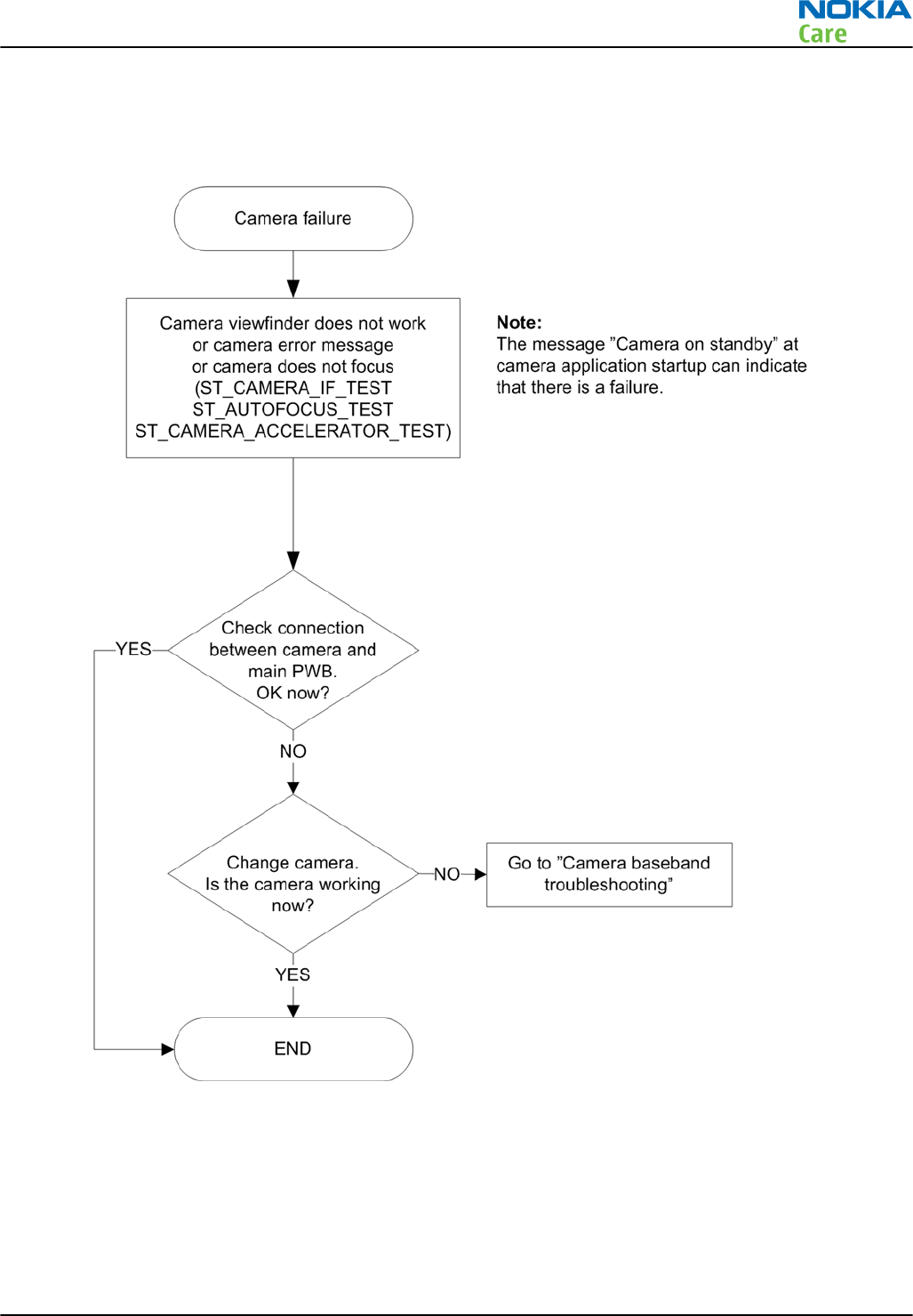
Camera troubleshooting
Troubleshooting flow
RM-632; RM-634; RM-699
BB Troubleshooting and Manual Tuning Guide
Issue 3 COMPANY CONFIDENTIAL Page 3 – 39
Copyright © 2010 Nokia. All rights reserved.
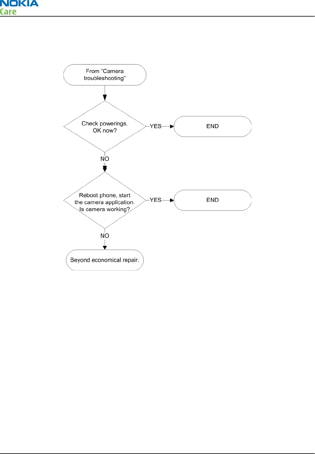
Camera baseband troubleshooting
Troubleshooting flow
RM-632; RM-634; RM-699
BB Troubleshooting and Manual Tuning Guide
Page 3 – 40 COMPANY CONFIDENTIAL Issue 3
Copyright © 2010 Nokia. All rights reserved.
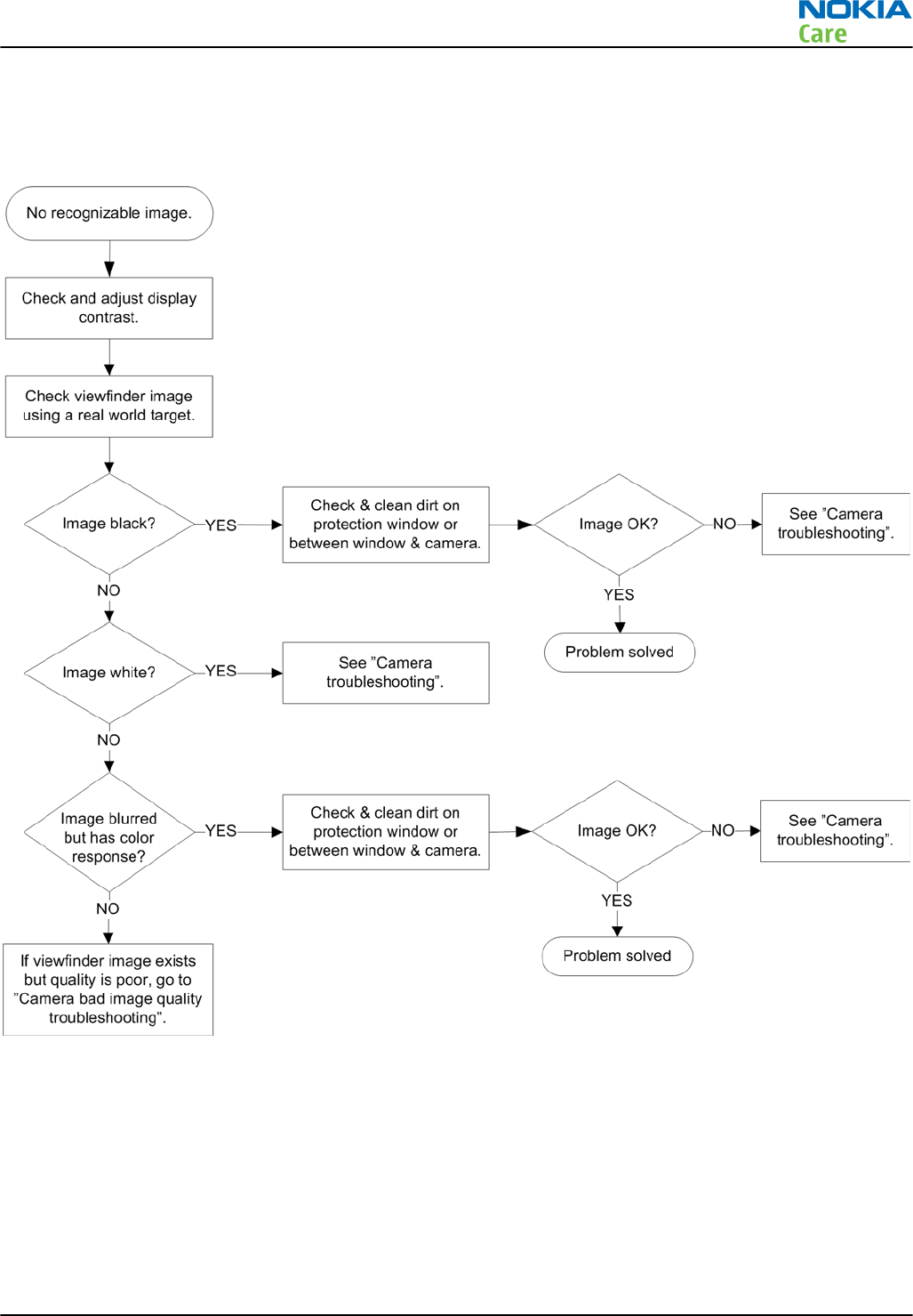
Camera no recognizable viewfinder image troubleshooting
Troubleshooting flow
RM-632; RM-634; RM-699
BB Troubleshooting and Manual Tuning Guide
Issue 3 COMPANY CONFIDENTIAL Page 3 – 41
Copyright © 2010 Nokia. All rights reserved.
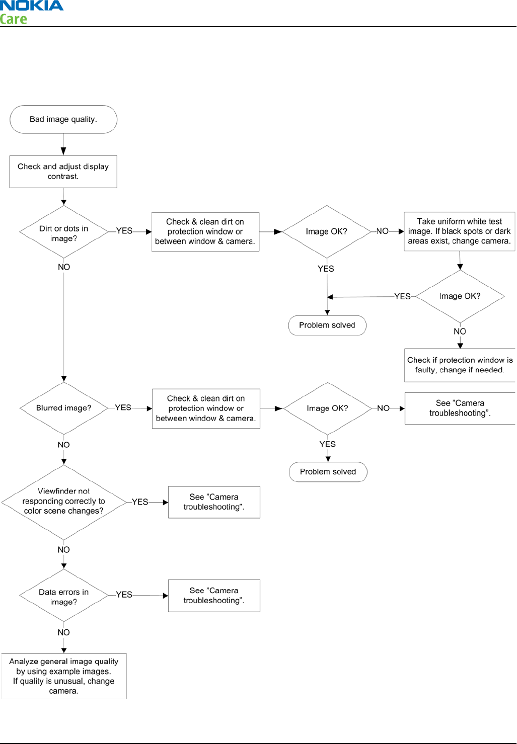
Camera bad image quality troubleshooting
Troubleshooting flow
RM-632; RM-634; RM-699
BB Troubleshooting and Manual Tuning Guide
Page 3 – 42 COMPANY CONFIDENTIAL Issue 3
Copyright © 2010 Nokia. All rights reserved.
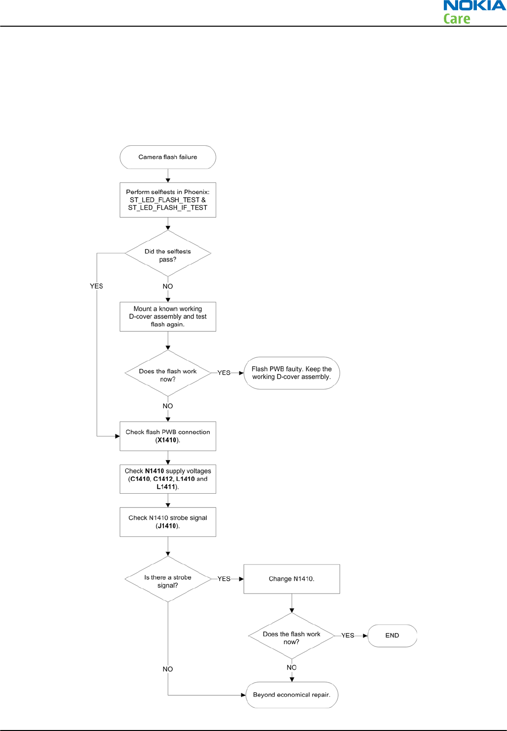
Camera flash troubleshooting
Context
Note: Before checking flash functionality, make sure that the camera is working ok.
Troubleshooting flow
RM-632; RM-634; RM-699
BB Troubleshooting and Manual Tuning Guide
Issue 3 COMPANY CONFIDENTIAL Page 3 – 43
Copyright © 2010 Nokia. All rights reserved.
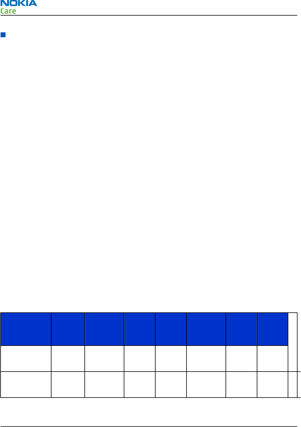
Audio troubleshooting
Audio troubleshooting test instructions
Differential external earpiece and internal earpiece outputs can be measured either with a single-ended or
a differential probe.
When measuring with a single-ended probe each output is measured against the ground.
Internal handsfree output is measured using a current probe, if a special low-pass filter designed for
measuring a digital amplifier is not available. Note also that when using a current probe, the input signal
frequency must be set to 2kHz.
The input signal for each loop test can be either single-ended or differential.
Required equipment
The following equipment is needed for the tests:
•Oscilloscope
•Function generator (sine waveform)
•Phoenix service software
•Battery voltage 3.7V
Test procedure
Audio can be tested using the Phoenix audio routings option. These different audio loop paths can be
activated:
•Mic2P to Internal earpiece
•Mic2P microphone to Internal handsfree speaker
Each audio loop sets routing from the specified input to the specified output enabling a quick in-out test.
Loop path gains are fixed and they cannot be changed using Phoenix. Correct pins and signals for each test
are presented in a table in the following section.
Phoenix audio loop tests and test results
The results presented in this table apply when no accessory is connected and battery voltage is set to 3.7V.
Earpiece, internal microphone and speaker are in place during measurement. Applying a headset accessory
during measurement causes a significant drop in measured quantities.
The gain values presented in the table apply for a differential output vs. single-ended/differential input.
Loop test Input
terminal Output
terminal Path
gain [dB]
(fixed)
Input
voltage
[mVp-p]
Differential
output
voltage
[mVp-p]
Output
DC level
[V]
Output
current
[mA]
External Mic to
Internal
Earpiece
E2005 EarP and
EarN
~9 100 288 NA NA
External Mic to
Internal
handsfree
E2005 IHFSpLP
and
IHFSpLN
~16 100 600 NA NA
RM-632; RM-634; RM-699
BB Troubleshooting and Manual Tuning Guide
Page 3 – 44 COMPANY CONFIDENTIAL Issue 3
Copyright © 2010 Nokia. All rights reserved.
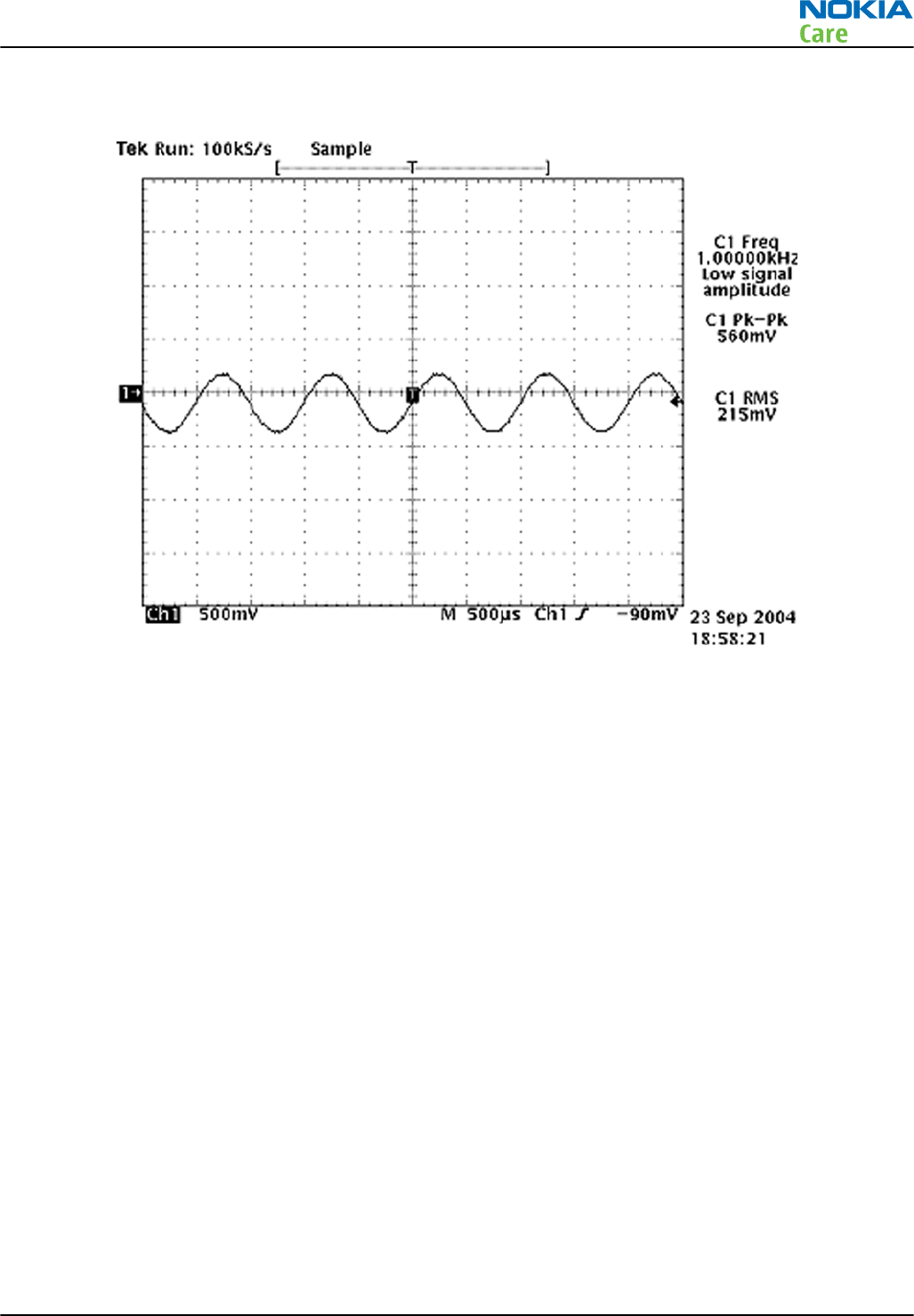
Measurement data
If a special low-pass filter designed for measuring digital amplifiers is unavailable, the measurement must be performed with a
current probe and the input signal frequency must be 2kHz.
Figure 14 Differential output waveform of the Ext_in_IHF_out out loop measurement when speaker is connected.
RM-632; RM-634; RM-699
BB Troubleshooting and Manual Tuning Guide
Issue 3 COMPANY CONFIDENTIAL Page 3 – 45
Copyright © 2010 Nokia. All rights reserved.
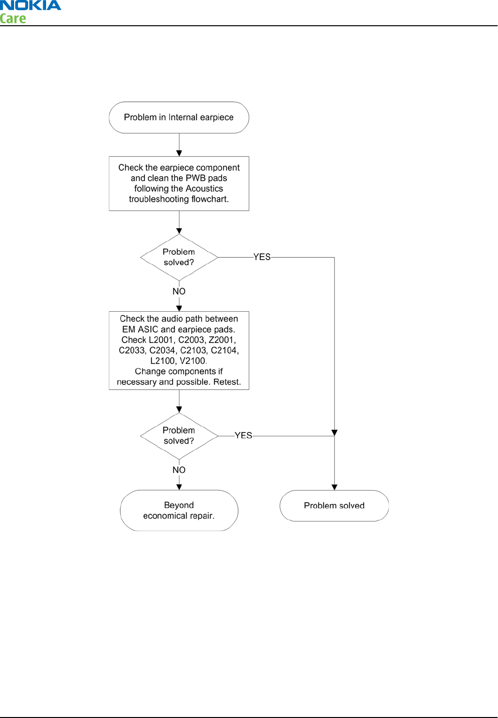
Internal earpiece troubleshooting
Troubleshooting flow
RM-632; RM-634; RM-699
BB Troubleshooting and Manual Tuning Guide
Page 3 – 46 COMPANY CONFIDENTIAL Issue 3
Copyright © 2010 Nokia. All rights reserved.
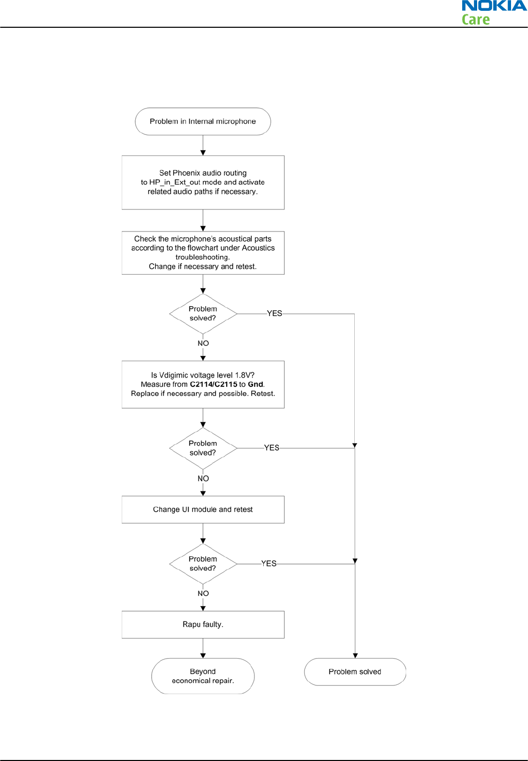
Internal microphone troubleshooting
Troubleshooting flow
RM-632; RM-634; RM-699
BB Troubleshooting and Manual Tuning Guide
Issue 3 COMPANY CONFIDENTIAL Page 3 – 47
Copyright © 2010 Nokia. All rights reserved.
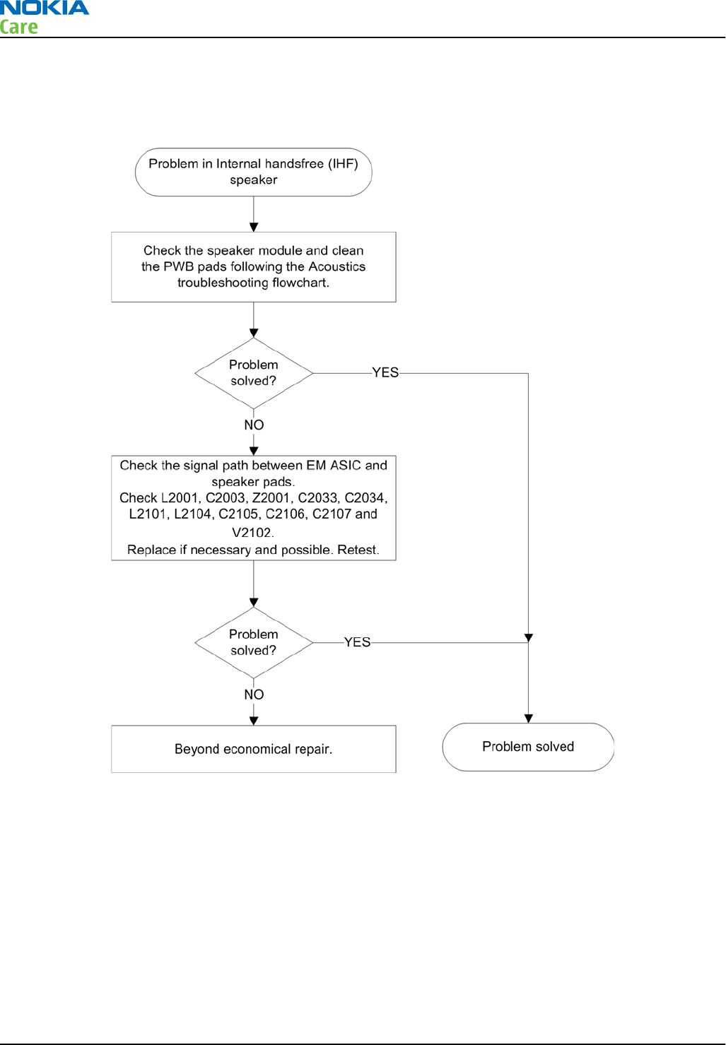
Internal handsfree (IHF) troubleshooting
Troubleshooting flow
Acoustics troubleshooting
Introduction to acoustics troubleshooting
Acoustics design ensures that the sound is detected correctly with a microphone and properly radiated to
the outside of the device by the speaker. The acoustics of the phone include three basic systems: earpiece,
integrated handsfree (IHF) and microphone.
The sound reproduced from the earpiece eradiates through a single hole on the front cover (A-cover). The
sound reproduced from the IHF speaker radiates from the sound hole located on the back side on the top
part of the phone. The inlet for the microphone is found in the bottom.
For a correct functionality of the phone, all sound holes must be always open. When the phone is used, care
must be taken not to close any of those holes with a hand or fingers. The phone should be dry and clean,
and no objects must be located in such a way that they close any of the holes.
RM-632; RM-634; RM-699
BB Troubleshooting and Manual Tuning Guide
Page 3 – 48 COMPANY CONFIDENTIAL Issue 3
Copyright © 2010 Nokia. All rights reserved.
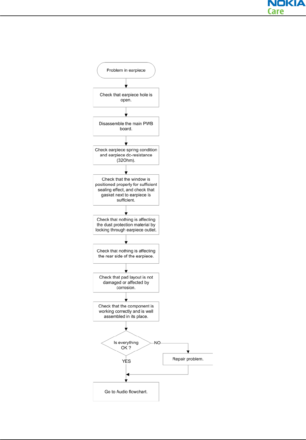
Earpiece troubleshooting
Troubleshooting flow
RM-632; RM-634; RM-699
BB Troubleshooting and Manual Tuning Guide
Issue 3 COMPANY CONFIDENTIAL Page 3 – 49
Copyright © 2010 Nokia. All rights reserved.
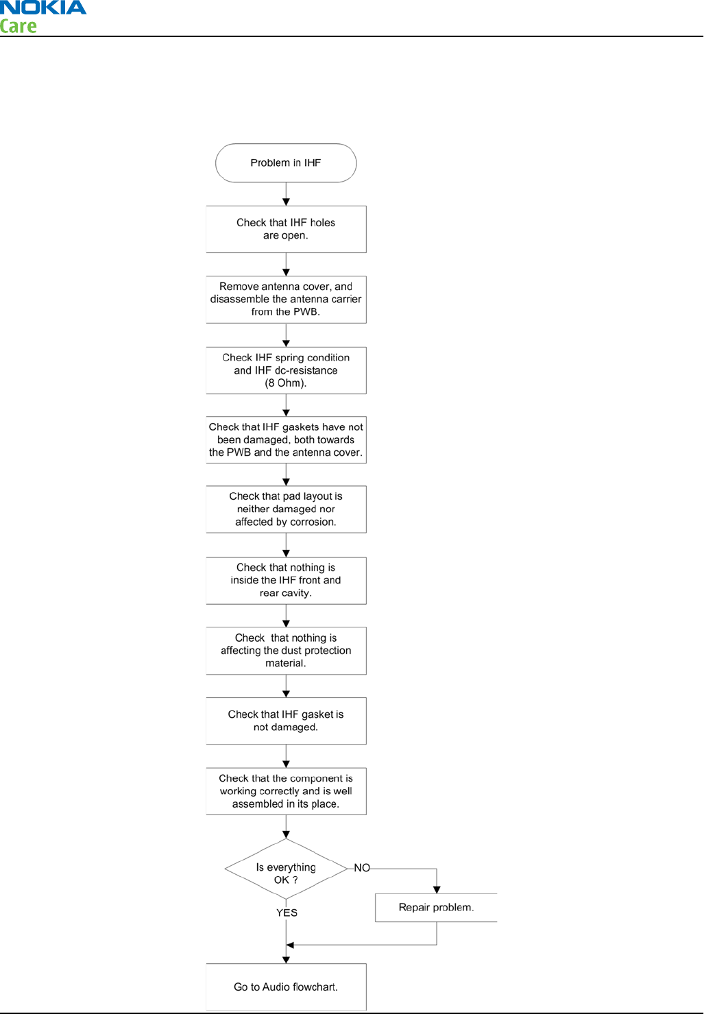
IHF troubleshooting
Troubleshooting flow
RM-632; RM-634; RM-699
BB Troubleshooting and Manual Tuning Guide
Page 3 – 50 COMPANY CONFIDENTIAL Issue 3
Copyright © 2010 Nokia. All rights reserved.
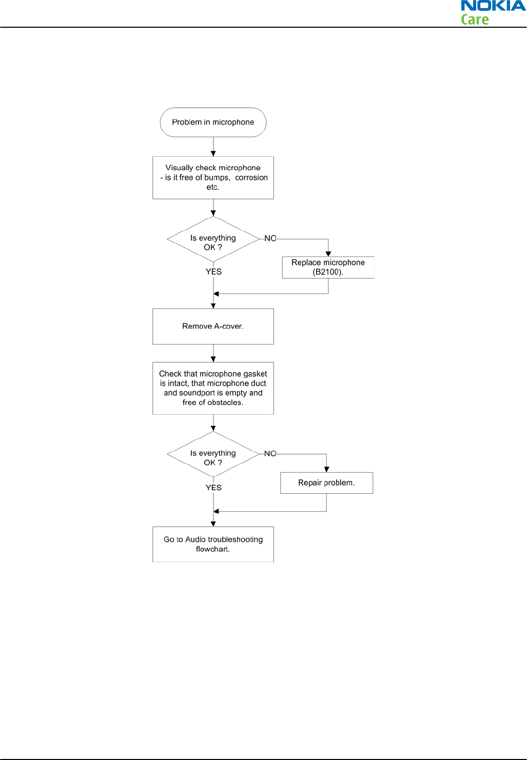
Microphone troubleshooting
Troubleshooting flow
RM-632; RM-634; RM-699
BB Troubleshooting and Manual Tuning Guide
Issue 3 COMPANY CONFIDENTIAL Page 3 – 51
Copyright © 2010 Nokia. All rights reserved.
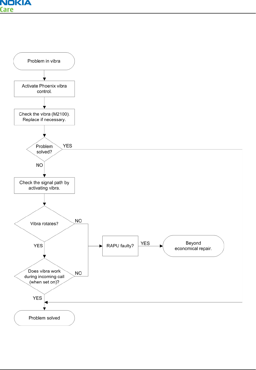
Vibra troubleshooting
Troubleshooting flow
RM-632; RM-634; RM-699
BB Troubleshooting and Manual Tuning Guide
Page 3 – 52 COMPANY CONFIDENTIAL Issue 3
Copyright © 2010 Nokia. All rights reserved.
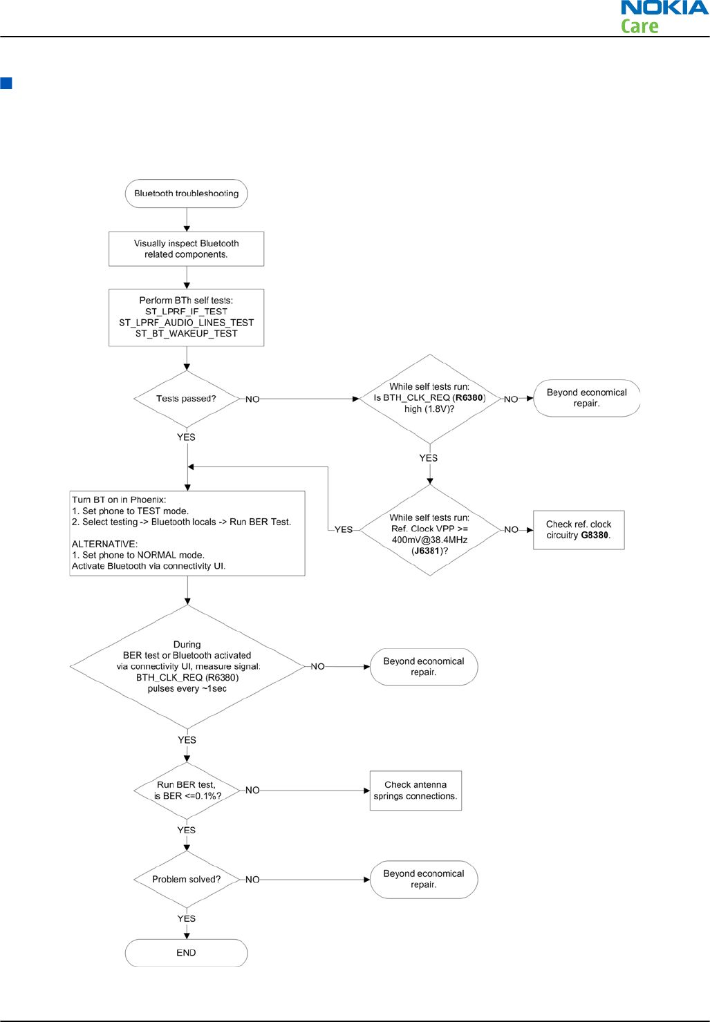
Bluetooth and FM radio troubleshooting
Bluetooth troubleshooting
Troubleshooting flow
RM-632; RM-634; RM-699
BB Troubleshooting and Manual Tuning Guide
Issue 3 COMPANY CONFIDENTIAL Page 3 – 53
Copyright © 2010 Nokia. All rights reserved.
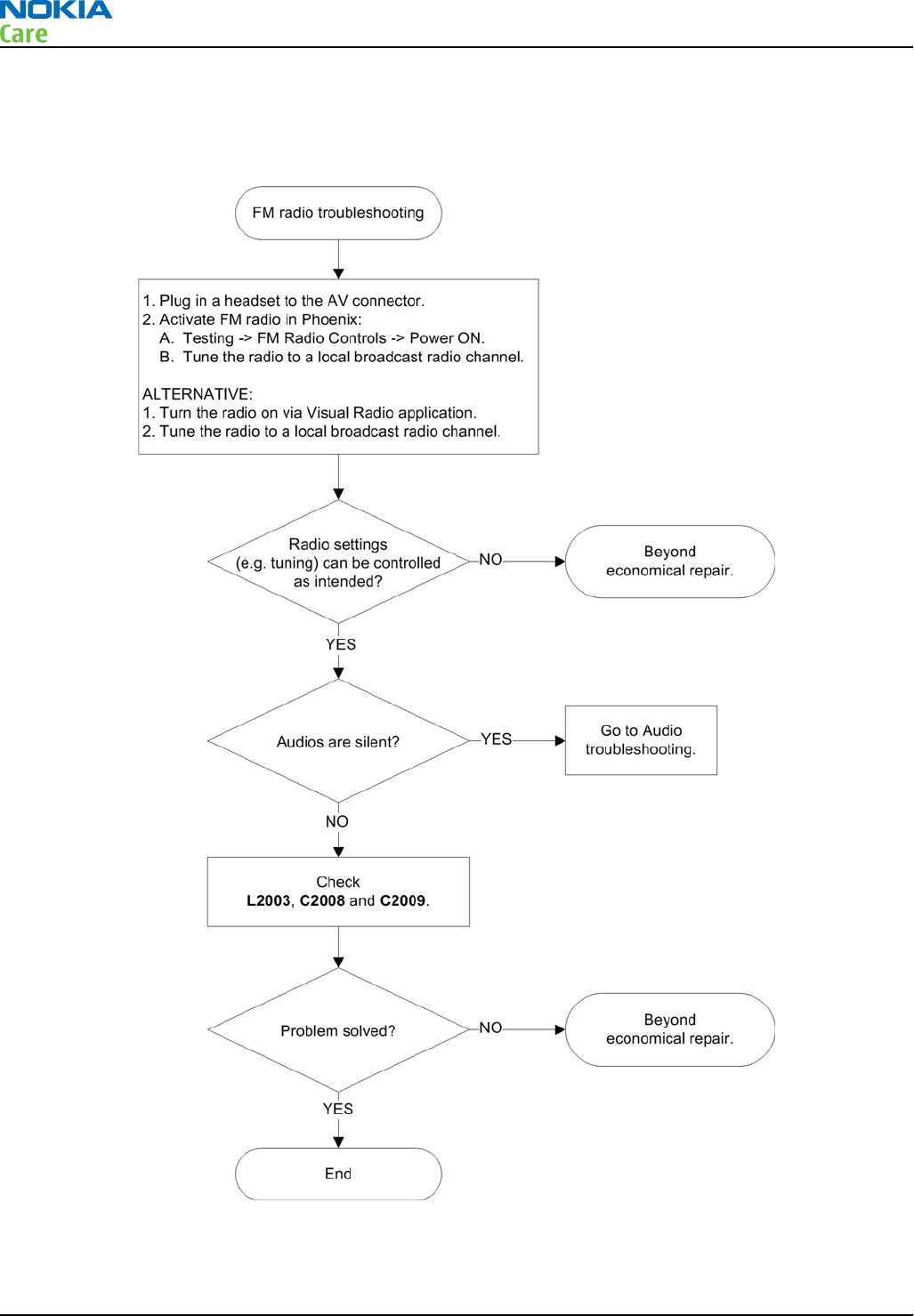
FM radio troubleshooting
Troubleshooting flow
RM-632; RM-634; RM-699
BB Troubleshooting and Manual Tuning Guide
Page 3 – 54 COMPANY CONFIDENTIAL Issue 3
Copyright © 2010 Nokia. All rights reserved.
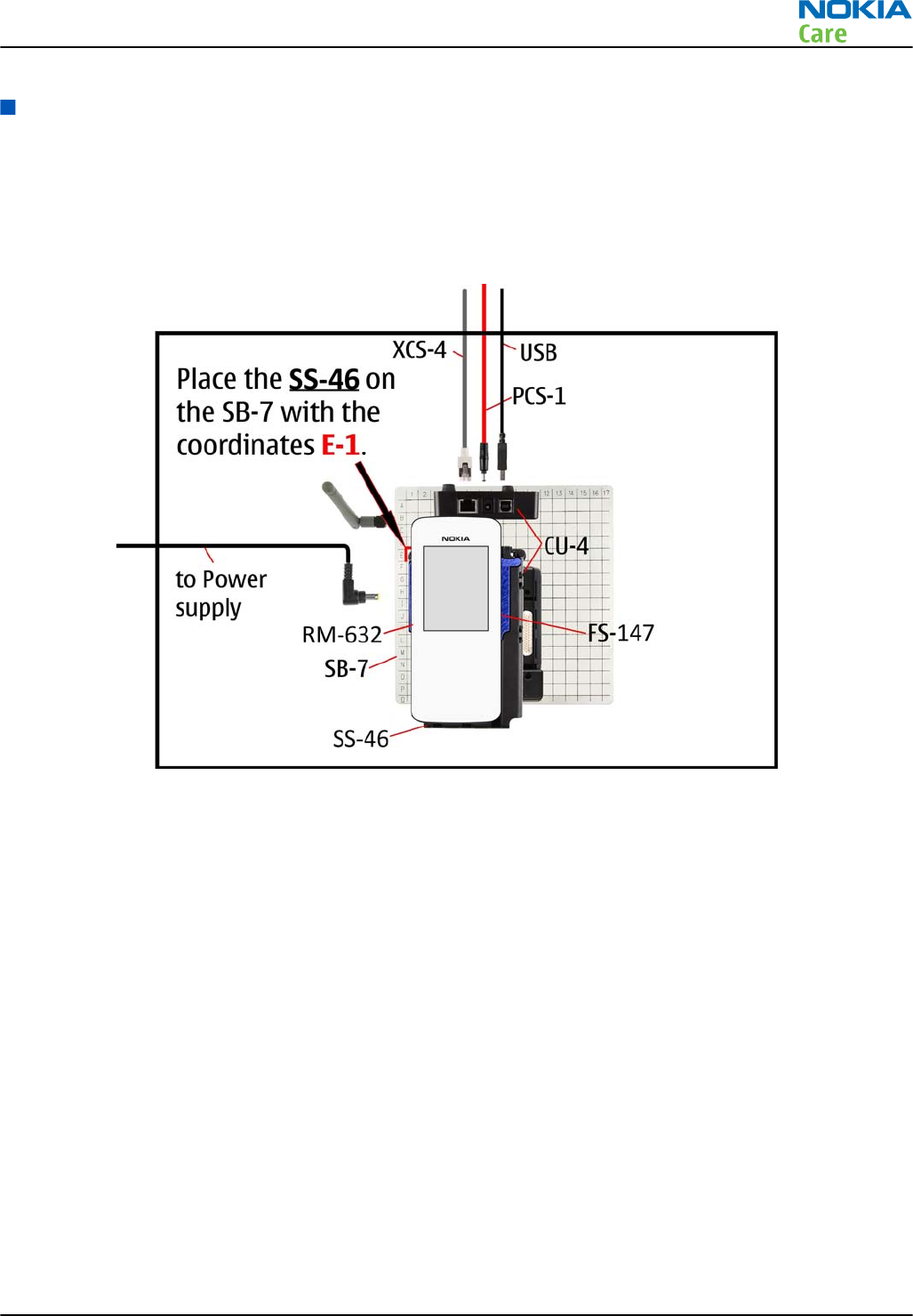
WLAN troubleshooting
WLAN functionality test using SB-7 and Phoenix
Steps
1. Place the phone on the SB-7 WLAN test box (see figure below). The co-ordinates are E1 - for the upper left
foot.
2. Start
Phoenix
service software and turn the phone to normal mode.
3. Make connection to the phone with
Phoenix
, if the phone powers up in local or test mode, then select
Normal or RF inactive mode via the
Phoenix
Operating mode function.
4. Search for SB-7 WLAN Test box via WLAN application. Go to Menu→settings→Connectivity→Wi-Fi.
Select the first item on the sub-menu Available Networks
5. If the name of the WLAN test Box"default" appears on the list of found networks, the phone is OK.
Note: Local WLAN environment may affect test results, especially if there are many WLAN access
points nearby and any of them are using the same WLAN channel as SB-7. If the phone is able to see
and connect to local WLAN networks via its own inbuilt WLAN menu, then the phone is OK even if
the SB-7 can not be detected. Consider repeating the test where local networks do not interfere with
the lower strength signal of the SB-7 box.
If you still can’t find the name of the WLAN test Box (Default) on the list under Scan results, the
phone is not OK and you should proceed to WLAN troubleshooting.
WLAN layout and test points
The WLAN module has been optimised to achieve the smallest possible PWB area and adding test points will
compromise this layout efficiency. There is also an added risk that test point will compromise the WLAN
performance – the layout is quite sensitive and there have been EMC issues that were directly attributed to
use of test points.
RM-632; RM-634; RM-699
BB Troubleshooting and Manual Tuning Guide
Issue 3 COMPANY CONFIDENTIAL Page 3 – 55
Copyright © 2010 Nokia. All rights reserved.
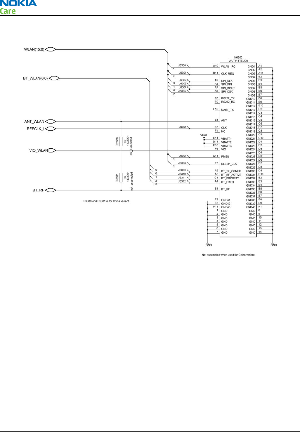
The recommendation is to use no test points and use software tests in Phoenix to verify the operation of the
WLAN module. For reference, all test points provided on the schematic are summarised below.
The sequence of events during the start up of WLAN is:
1 PMEM is asserted high when Wlan module is first enabled by the Host.
2 WLAN module should respond by driving CLK REQ high to request the 38.4MHz clock.
3Host engine turns on the 38.4MHz clock and then generates the SPI Clock to start the download of software
to the WLAN module.
Adding more test points in a product is not strictly necessary.
WLAN settings for Phoenix
Use the following to test WLAN using Phoenix:
1 Set phone into Local Mode .
2 From the File menu, select Scan Product and check that the correct product version is displayed
3 From the Testing menu, select Self Test. This opens up a Self Test dialogue box, as shown below.
Select the ST_WLAN_TEST check box as shown and then select Start button. The test turns on the WLAN, sets
up the SPI interface and then downloads the WLAN firmware into the WLAN module. During the download
the WLAN acknowledges the data blocks and so the self test is a good way to confirm that the WLAN module
is communicating with the Host. The result column will change to Passed after a few seconds if operating
properly.
RM-632; RM-634; RM-699
BB Troubleshooting and Manual Tuning Guide
Page 3 – 56 COMPANY CONFIDENTIAL Issue 3
Copyright © 2010 Nokia. All rights reserved.
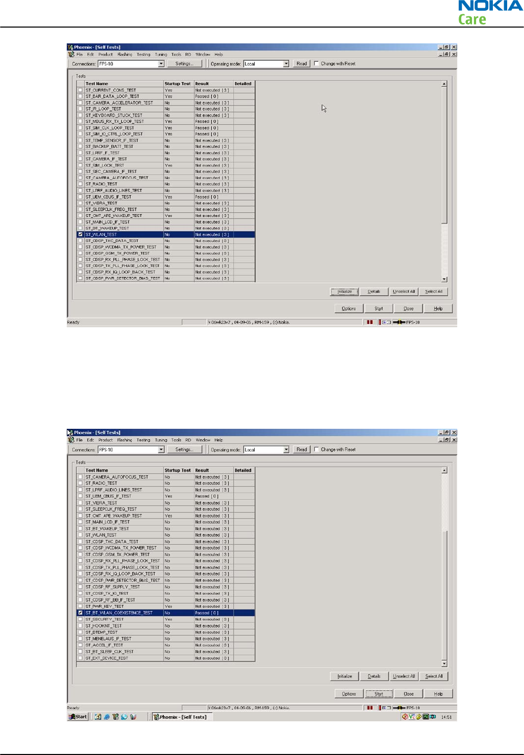
In addition, a test of the WLAN to BT interface can be done by selecting the
ST_BT_WLAN_COEXISTENCE_TEST check box and selecting Start button.
This test verifies that the WLAN to BT co-existence interface signals are properly connected and there are no
open circuit or shorts on the four interface signals.
The co-existence interface comprises BT Txconfig, BT RF Active, BT Priority, and BT Frequency.
RM-632; RM-634; RM-699
BB Troubleshooting and Manual Tuning Guide
Issue 3 COMPANY CONFIDENTIAL Page 3 – 57
Copyright © 2010 Nokia. All rights reserved.
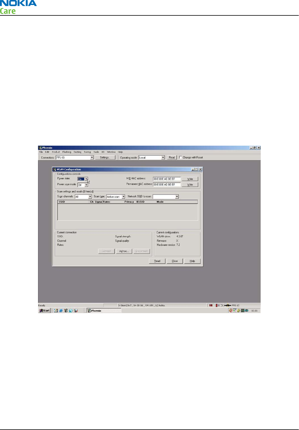
In summary these two Self tests provide a simple means of ensuring the Host engine is able to communicate
with the WLAN module and check the interface to BT. More detailed WLAN performance test is covered in
WLAN functional test section.
WLAN functional tests
On/Off test
From the testing toolbar select WLAN Configuration option. This opens the WLAN configuration dialogue
box below. Selecting the Power state option button (as indicated), the WLAN can be turned ON and OFF:
1 With Power State set to OFF, measure the dc power supply current consumption of the flash adaptor.
2 Next return the Power state to ON and re-measure the dc power supply current of the flash adaptor.
The difference between the currents in (1) and (2) should be between 160 to 200mA. When WLAN is ON, the
firmware has been downloaded and the WLAN module is in the receive state. When OFF WLAN is powered
down.
TX tests
From the testing toolbar select WLAN Tx Test option shown below. This test can be used to verify TX
configuration and functionality. The default settings are sufficient for testing the TX operation, although
other channels and data rates are equally suitable. To start the test, select the Start option button:
1 Measure and record the TX ON current consumption of the Phone/ flash adaptor.
2Monitor the WLAN TX spectrum on a Spectrum analyser either using a co-ax cable connected to the WLAN
TX antenna port or by making a radiated test with a suitable WLAN antenna connected to the spectrum
analyser input. (When making a radiated test ensure that other WLAN devices are not transmitting as
these may be detected as well, confusing the result).
3 To finish the test select the Finish option button
4 Measure the TX OFF current consumption of the phone/flash adaptor.
RM-632; RM-634; RM-699
BB Troubleshooting and Manual Tuning Guide
Page 3 – 58 COMPANY CONFIDENTIAL Issue 3
Copyright © 2010 Nokia. All rights reserved.
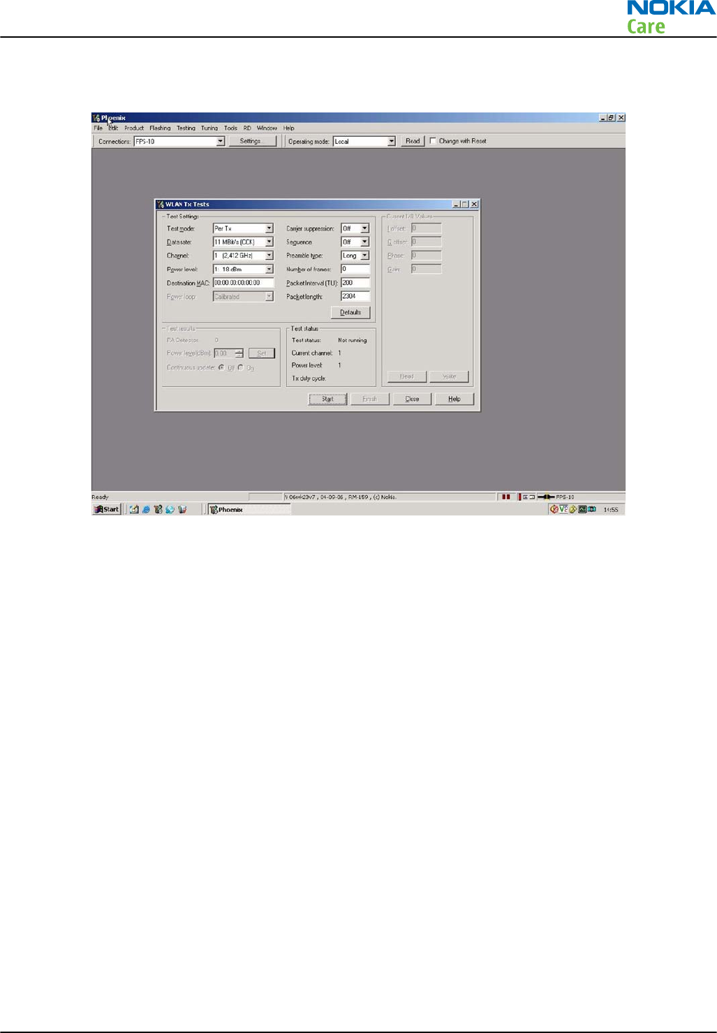
The difference between the two readings should be 100mA – 130mA and measures the transmit current in
11MBPS, 802.11b mode of operation.
RX Tests
There are different options available for testing the Rx path. The simplest is to use the WLAN to report Rx
packets when operating in an area where there is an active WLAN network. Simply starting an Rx test will
show the number of packets detected by the WLAN module as it monitors the network. However, it does
require a properly configured WLAN network. The alternative approach is to make a conducted test using a
signal generator connected to the WLAN antenna port. The drawback in this approach is that the WLAN
antenna connection in the phone is not actually tested.
From the testing toolbar select WLAN Rx Test option shown below. This test can be used to verify Rx
configuration and functionality.
Before starting the test, change test mode to "Generator mode" and then select the Start option button to
start the test.
As the WLAN monitors an active WLAN network, the Rx test results window will update and show the number
of Frames received, as well as the Packer error rate. If there is no data reported in the "Rx test results" screen,
please change the "test channel" number.
Monitoring the detected frames is a simple method to verify the WLAN antenna and receiver path is working
properly. The current consumption of the phone/flash adaptor before and during the Rx test should be the
same (10 mA max difference).
RM-632; RM-634; RM-699
BB Troubleshooting and Manual Tuning Guide
Issue 3 COMPANY CONFIDENTIAL Page 3 – 59
Copyright © 2010 Nokia. All rights reserved.
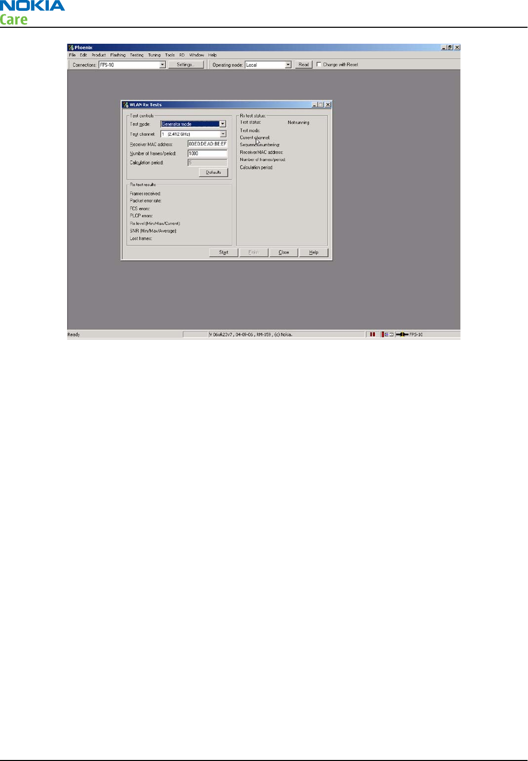
RM-632; RM-634; RM-699
BB Troubleshooting and Manual Tuning Guide
Page 3 – 60 COMPANY CONFIDENTIAL Issue 3
Copyright © 2010 Nokia. All rights reserved.
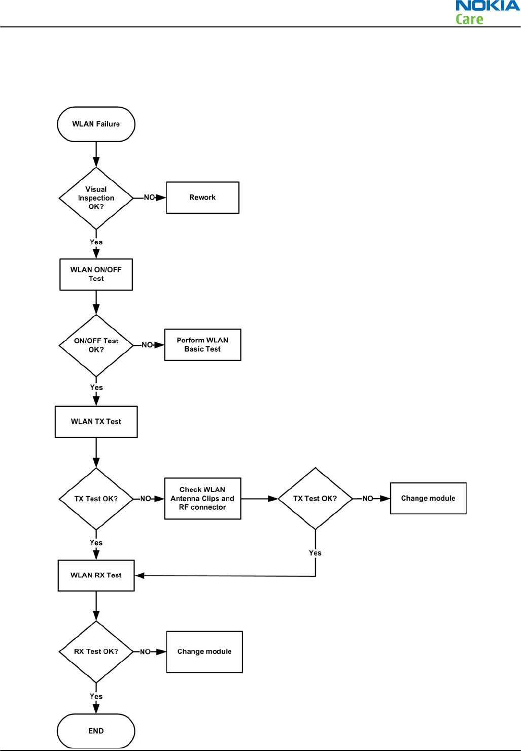
WLAN failure troubleshooting
Troubleshooting flow
RM-632; RM-634; RM-699
BB Troubleshooting and Manual Tuning Guide
Issue 3 COMPANY CONFIDENTIAL Page 3 – 61
Copyright © 2010 Nokia. All rights reserved.

Baseband manual tuning guide
Certificate restoring
Context
This procedure is performed when the device certificate is corrupted for some reason.
All tunings (RF & Baseband, UI) must be done after performing the certificate restoring procedure.
Required equipment and setup:
•Latest
Phoenix
service software.
•“Tucson add on” package if one has been released between complete Phoenix releases
•FPS-10 or 21 Flash prommer updated with latest flash update package.
•Latest product specific data package, supporting for the variants you want to change the phones to.
Certificate restoring without flashing does not require data packages to be installed
•SX-4 or SX-4T Smart Card, which has been registered for Tucson use in Nokia Online Security Device Master,
and for which local Nokia Care has granted Tucson user rights
•BB 5.0 models:SS-46 with phone specific flash adapter connected to flash prommer
•DCT-4 models:JBV-1 with phone specific flash adapter connected to flash prommer
•Active online connection to internet, please refer to Technical Bulletins for IP addresses
Connection to Tucson online server:
•All requests are handled online. That means a permanent Internet connection is required. Previously used
e-mail based system is no longer in use.
•Phoenix, when contacting Tucson server, is using IP address, 147.243.3.169 port 443
Terms in Tucson:
•When certificate restoring for BB 5 products or IMEI rebuild for DCT-4 products is performed, existing data
from Nokia System is programmed in the phone. The phone will be in the same condition as it was when
it left the factory for the first time.
•If “Product Code Change” has been SUCCESSFULLY performed with Tucson after the phone left the factory,
it will be restored back to the variant it was made into during Product Code change event.
•It is recommended to perform “Restore” function without selecting “Flash Product” – option to avoid
possible SW downgrade which causes the phone to die.
The procedure for certificate restoring is the following:
Steps
1. Connect phone and scan product, read phone information to check communication with phone.
2. Open
Tools
->
Menu
.
RM-632; RM-634; RM-699
BB Troubleshooting and Manual Tuning Guide
Page 3 – 62 COMPANY CONFIDENTIAL Issue 3
Copyright © 2010 Nokia. All rights reserved.
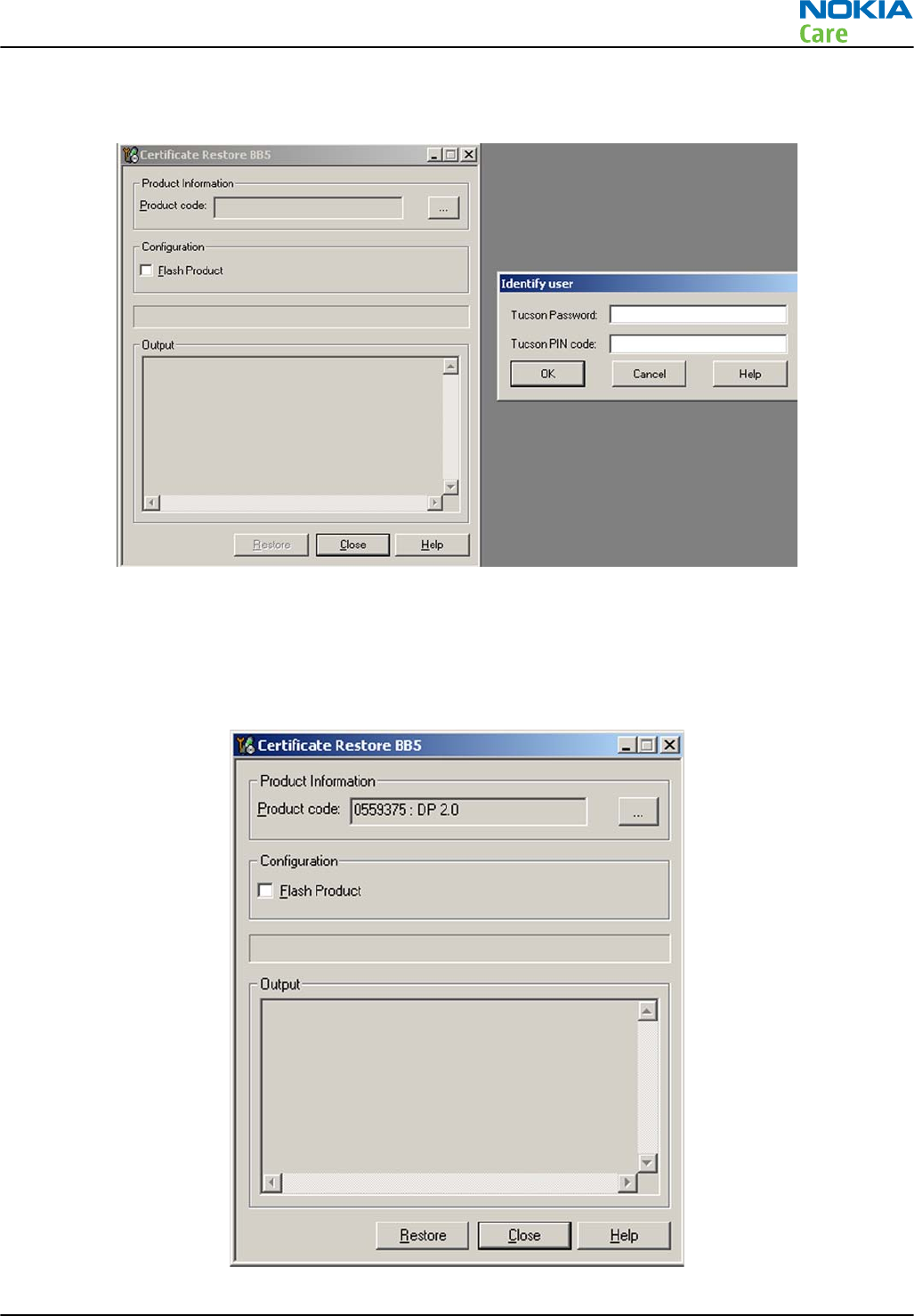
3. Provide Tucson password and PIN code which have been delivered to you by email. Please note that
characters are case sensitive.
4. Select OK, Phoenix will read product information from phone.
5. Product code shown on the UI does not matter, because during restoring it will be replaced by the product
code which is the latest one stored in Nokia system.
6. It is recommended to perform "Restore"-function without selecting "Flash Product"-option to avoid
possible SW downgrade which causes the phone to die.
RM-632; RM-634; RM-699
BB Troubleshooting and Manual Tuning Guide
Issue 3 COMPANY CONFIDENTIAL Page 3 – 63
Copyright © 2010 Nokia. All rights reserved.
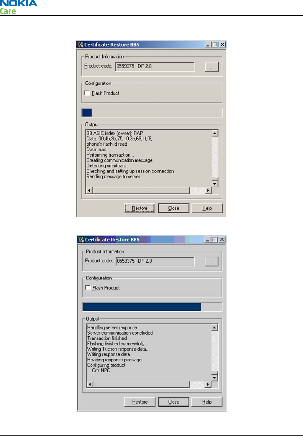
7. Information from phone and Smart Card are read and connection to Tucson server is established.
8. Information from Nokia system is retreived and programmed in the phone.
RM-632; RM-634; RM-699
BB Troubleshooting and Manual Tuning Guide
Page 3 – 64 COMPANY CONFIDENTIAL Issue 3
Copyright © 2010 Nokia. All rights reserved.
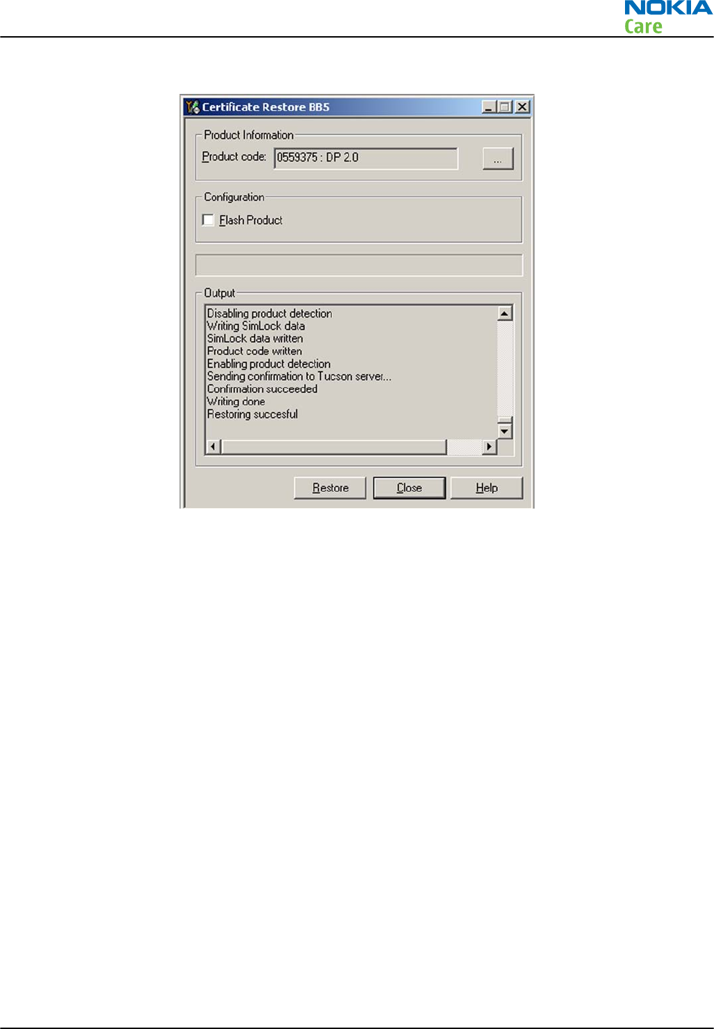
9. After programming, confirmation about successful event is sent to Nokia system.
Next actions
After a successful rewrite, you must retune the phone completely by using
Phoenix
tuning functions.
Important: Perform all tunings: RF, BB, and UI.
Product code change
Context
•When Product Code change with Tucson is successfully performed, phone variant will be changed. Data
for the new variant is extracted from Nokia System, and programmed in the phone.
•After successful change, phone specific information in Nokia systems will match the new variant, and it
can be used for e.g. certificate restoring. If you perform several product code changes, Nokia system will
always be up to date with the latest successful event.
•Failed / incomplete actions will not change the phone specific information in Nokia systems.
•This function can be performed with or without flashing the phone with correct software, selection can
be made by checking / unchecking the tick box on Phoenix UI.
The procedure for product code change is the following:
Steps
1. Connect phone and scan product, read phone information to check communication with phone
2. Open
Tools
->
Product Code Change
.
RM-632; RM-634; RM-699
BB Troubleshooting and Manual Tuning Guide
Issue 3 COMPANY CONFIDENTIAL Page 3 – 65
Copyright © 2010 Nokia. All rights reserved.
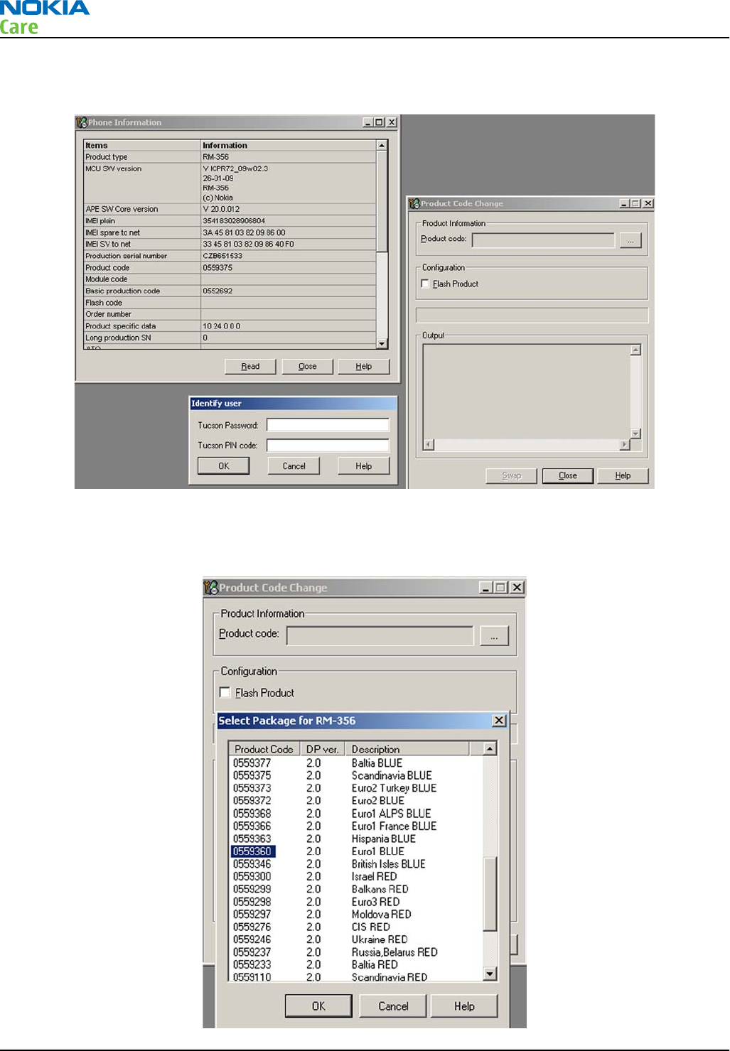
3. Provide Tucson password and PIN code which have been delivered to you by email. Please note that
characters are case sensitive.
4. Select product code of new variant from list. If the product code you want is not shown, please install
correct data package including the variant.
5. Select “OK” and “SWAP”.
RM-632; RM-634; RM-699
BB Troubleshooting and Manual Tuning Guide
Page 3 – 66 COMPANY CONFIDENTIAL Issue 3
Copyright © 2010 Nokia. All rights reserved.
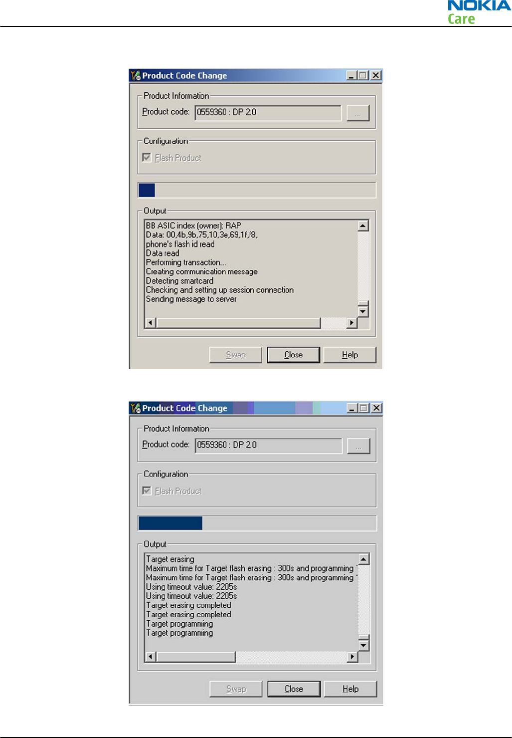
6. Information from phone is read and connection to Tucson server is established.
7. If “Flash Product” – option was selected, phone SW is programmed.
RM-632; RM-634; RM-699
BB Troubleshooting and Manual Tuning Guide
Issue 3 COMPANY CONFIDENTIAL Page 3 – 67
Copyright © 2010 Nokia. All rights reserved.
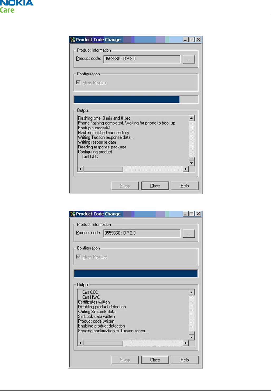
8. New data retrieved from Nokia system is programmed in the phone.
9. Confirmation about successful event is sent to Nokia system.
RM-632; RM-634; RM-699
BB Troubleshooting and Manual Tuning Guide
Page 3 – 68 COMPANY CONFIDENTIAL Issue 3
Copyright © 2010 Nokia. All rights reserved.
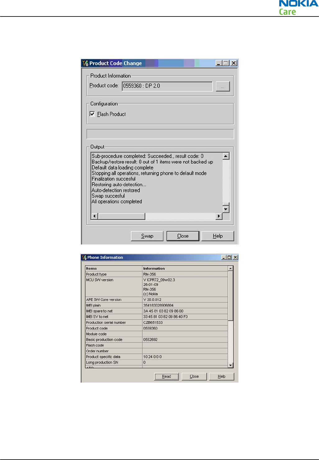
10. Phone has now been changed to another variant. If there is need to restore the data, this information
will be sent back to phone. Warranty information in NOL will show the current information in about 24
hours.
Energy management calibration
Prerequisites
Energy Management (EM) calibration is performed to calibrate the setting (gain and offset) of AD converters
in several channels (that is, battery voltage, BSI, battery current) to get an accurate AD conversion result.
Hardware setup:
RM-632; RM-634; RM-699
BB Troubleshooting and Manual Tuning Guide
Issue 3 COMPANY CONFIDENTIAL Page 3 – 69
Copyright © 2010 Nokia. All rights reserved.
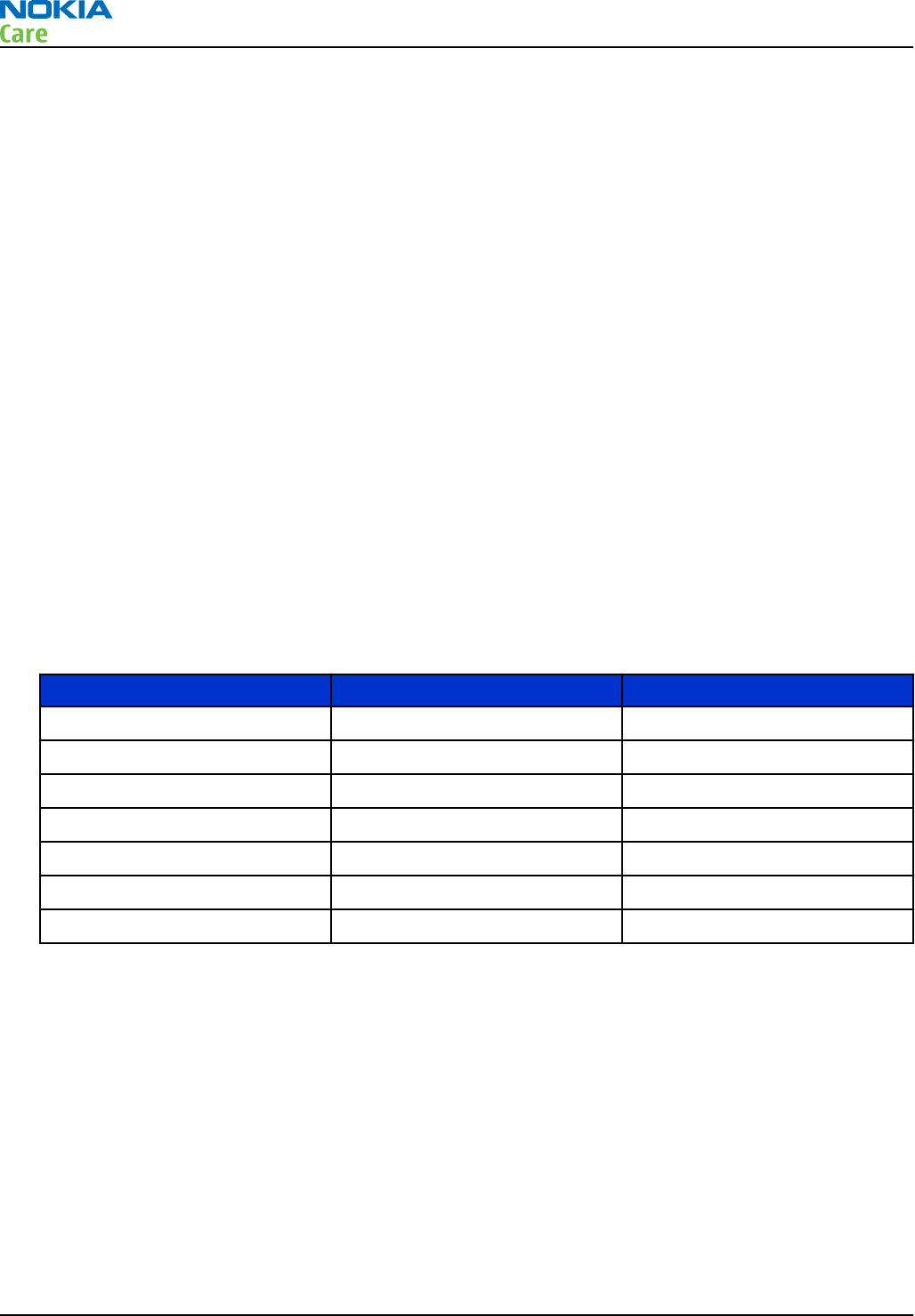
•An external power supply is needed.
•Supply 12V DC from an external power supply to CU-4 to power up the phone.
•The phone must be connected to a CU-4 control unit with a product-specific flash adapter.
Steps
1. Place the phone to the docking station adapter (CU-4 is connected to the adapter).
2. Start
Phoenix
service software.
3. Choose File → Scan Product.
4. Choose Tuning → Energy Management Calibration.
5. To show the current values in the phone memory, click Read, and check that communication between
the phone and CU-4 works.
6. Check that the CU-4 used check box is checked.
7. Select the item(s) to be calibrated.
Note: ADC calibration has to be performed before other item(s). However, if all calibrations are
selected at the same time, there is no need to perform the ADC calibration first.
8. Click Calibrate.
The calibration of the selected item(s) is carried out automatically.
The candidates for the new calibration values are shown in the
Calculated values
column. If the new
calibration values seem to be acceptable (please refer to the following "Calibration value limits" table),
click Write to store the new calibration values to the phone permanent memory.
Table 8 Calibration value limits
Parameter Min. Max.
ADC Offset -30 +40
ADC Gain 12000 14000
BSI Gain 1100 1350
VBAT Offset 2635 2755
VBAT Gain 14900 15900
VCHAR Gain N/A N/A
IBAT (ICal) Gain 7750 12250
9. Click Read, and confirm that the new calibration values are stored in the phone memory correctly. If the
values are not stored to the phone memory, click Write and/or repeat the procedure again.
10. To end the procedure, close the
Energy Management Calibration
window.
RM-632; RM-634; RM-699
BB Troubleshooting and Manual Tuning Guide
Page 3 – 70 COMPANY CONFIDENTIAL Issue 3
Copyright © 2010 Nokia. All rights reserved.

4 — RF troubleshooting
Nokia Customer Care
Issue 3 COMPANY CONFIDENTIAL Page 4 – 1
Copyright © 2010 Nokia. All rights reserved.

RM-632; RM-634; RM-699
RF troubleshooting
(This page left intentionally blank.)
Page 4 – 2 COMPANY CONFIDENTIAL Issue 3
Copyright © 2010 Nokia. All rights reserved.

Table of Contents
General RF troubleshooting ................................................................................................................................. 4–5
Introduction to RF troubleshooting ............................................................................................................... 4–5
RF key components .......................................................................................................................................... 4–6
Auto tuning............................................................................................................................................................ 4–6
Introduction to auto tuning............................................................................................................................ 4–6
Auto tuning procedure .................................................................................................................................... 4–7
Self test troubleshooting...................................................................................................................................... 4–7
Phoenix self test troubleshooting .................................................................................................................. 4–7
Receiver troubleshooting ..................................................................................................................................... 4–9
Introduction to receiver (RX) troubleshooting.............................................................................................. 4–9
GSM RX chain activation for manual measurements/GSM RSSI measurement .......................................... 4–9
GSM receiver troubleshooting flowchart .................................................................................................... 4–10
WCDMA RX chain activation for manual measurement............................................................................. 4–11
WCDMA RSSI measurement .......................................................................................................................... 4–12
WCDMA receiver troubleshooting flowchart............................................................................................... 4–13
Transmitter troubleshooting ............................................................................................................................ 4–14
Introduction to transmitter (TX) troubleshooting..................................................................................... 4–14
GSM transmitter troubleshooting................................................................................................................ 4–14
GSM transmitter troubleshooting flowchart .............................................................................................. 4–18
WCDMA transmitter troubleshooting .......................................................................................................... 4–18
WCDMA transmitter troubleshooting flowchart......................................................................................... 4–22
Troubleshooting with RF-shield removed ....................................................................................................... 4–23
Introduction................................................................................................................................................... 4–23
Voltage checking ........................................................................................................................................... 4–23
VCTCXO troubleshooting ............................................................................................................................... 4–25
RF component reference .............................................................................................................................. 4–26
Antenna............................................................................................................................................................... 4–28
Antenna overview ......................................................................................................................................... 4–28
List of Figures
Figure 15 RF key components .............................................................................................................................. 4–6
Figure 16 Auto tuning concept with CMU200..................................................................................................... 4–7
Figure 17 Phoenix RSSI Reading window ........................................................................................................... 4–9
Figure 18 Phoenix Rx Control window with sample settings (WCDMA band I)............................................ 4–11
Figure 19 Phoenix Rx Power Measurement window...................................................................................... 4–12
Figure 20 Phoenix RF Controls window ........................................................................................................... 4–14
Figure 21 Typical readings ................................................................................................................................ 4–16
Figure 22 Phoenix WCDMA Tx control window ............................................................................................... 4–19
Figure 23 Typical readings ................................................................................................................................ 4–21
Figure 24 Phoenix WCDMA Tx Control window settings................................................................................. 4–24
Figure 25 Test points for voltage checking ..................................................................................................... 4–25
Figure 26 Component reference block diagram.............................................................................................. 4–27
RM-632; RM-634; RM-699
RF troubleshooting
Issue 3 COMPANY CONFIDENTIAL Page 4 – 3
Copyright © 2010 Nokia. All rights reserved.

RM-632; RM-634; RM-699
RF troubleshooting
(This page left intentionally blank.)
Page 4 – 4 COMPANY CONFIDENTIAL Issue 3
Copyright © 2010 Nokia. All rights reserved.

General RF troubleshooting
Introduction to RF troubleshooting
Most RF semiconductors are static discharge sensitive
ESD protection must be applied during repair (ground straps and ESD soldering irons).
Pre-baking
These parts are moisture sensitive and must be pre-baked prior to soldering:
•VAPAUS RFIC (N7500)
•TX FEM (N7520)
•WCDMA PA (N7540)
•Mikki DC/DC converter (N7560)
Discrete components
In addition to the key components, there are a number of discrete components (resistors, inductors and
capacitors) for which troubleshooting is done mainly by
visual inspection
.
Capacitors: check for short circuits.
Resistors: check value with an ohm meter.
Note: In-circuit measurements should be evaluated carefully.
Measuring equipment
All measurements should be done using:
•Module jig MJ-266
•Flash adapter FS-147
•Control unit CU-4/Interface adapter SS-46
•An oscilloscope for low frequency and DC measurements. Recommended probe: 10:1, 10MOhm/8pF.
•A radio communication tester including RF generator and spectrum analyser, for example Rohde & Schwarz
CMU200. (Alternatively a spectrum analyser and a RF generator can be used. However, some tests in this
guide are not possible to perform if this solution is chosen).
Note: A mobile phone WCDMA transmitter should never be tested with full TX power (only if it is
possible to perform the measurement in a good RF-shielded room). Even low power WCDMA
transmitters may disturb nearby WCDMA networks and cause problems to 3G cellular phone
communication in a wide area.
Note: All measurements with an RF coupler should be performed in an RF-shielded environment
because nearby base stations can disturb sensitive receiver measurements. If there is no possibility
to use RF shielded environment, testing at frequencies of nearby base stations should be avoided.
Level of repair
The scope of this guideline is to verify functionality of the cellular RF block without removing RF shield.
Instructions for finding the faulty component are provided in some cases, but the whole RF block still needs
to be replaced even when a single component is faulty.
RM-632; RM-634; RM-699
RF troubleshooting
Issue 3 COMPANY CONFIDENTIAL Page 4 – 5
Copyright © 2010 Nokia. All rights reserved.
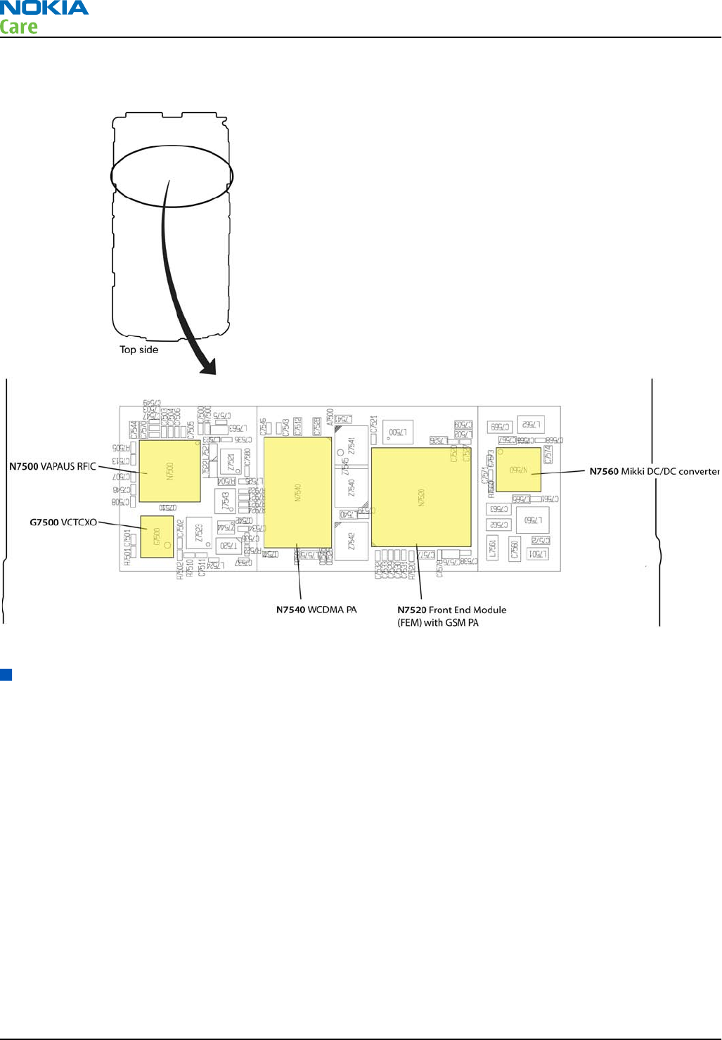
RF key components
Figure 15 RF key components
Auto tuning
Introduction to auto tuning
This phone can be tuned automatically.
Auto tune is designed to align the phone's RF part easier and faster. It performs calibrations, tunings and
measurements of RX and TX. The results are displayed and logged in a result file, if initiated.
Hardware set up
Hardware requirements for auto tuning:
•PC (Windows 2000/XP) with GPIB card
•PK-1/PDK-1 service dongle
•Power supply
•Product specific module jig
•Cables: RF cable XRS-6, USB cable, GBIP cable and MBUS cable DAU-9S
•Signal analyser (TX), signal generator (RX) and RF-splitter or one device including all.
RM-632; RM-634; RM-699
RF troubleshooting
Page 4 – 6 COMPANY CONFIDENTIAL Issue 3
Copyright © 2010 Nokia. All rights reserved.
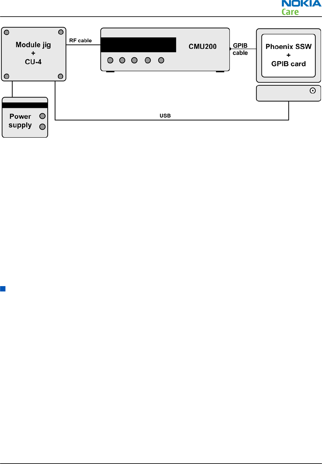
Figure 16 Auto tuning concept with CMU200
Auto tuning procedure
Prerequisites
Install the phone-specific data package, e.g.
Nokia_firmware_RM_576_xxx_v1.00.exe
.
The data package defines the phone-specific settings.
Steps
1. Make sure the phone (in the jig) is connected to the equipment. Else, some menus will not be shown in
Phoenix.
2. Go to loss settings by selecting Tuning (Alt_U) → SET LOSS from the menu.
3. Set the loss between CMV200 and the phone. (Total loss = cable + jig)
4. Go to auto tuning by selecting Tuning (Alt_U) → Auto-tune (Alt_A) from the menu.
5. Start auto tuning by clicking the Tune button.
Self test troubleshooting
Phoenix self test troubleshooting
Context
Always start the troubleshooting procedure by running the Phoenix self tests. If a test fails, please follow the
diagram below.
If the phone is dead and you cannot perform the self tests, go to Dead or jammed device troubleshooting
(page 4–7 ) in chapter 3, Baseband troubleshooting and manual tuning guide.
Note: Self tests are recommended to be made when phone is in jig and a 50Ω load connected to
the RF connector. Otherwise power tests may fail depending on antenna load
RM-632; RM-634; RM-699
RF troubleshooting
Issue 3 COMPANY CONFIDENTIAL Page 4 – 7
Copyright © 2010 Nokia. All rights reserved.
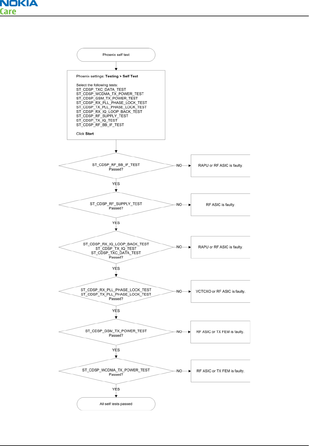
Troubleshooting flow
RM-632; RM-634; RM-699
RF troubleshooting
Page 4 – 8 COMPANY CONFIDENTIAL Issue 3
Copyright © 2010 Nokia. All rights reserved.
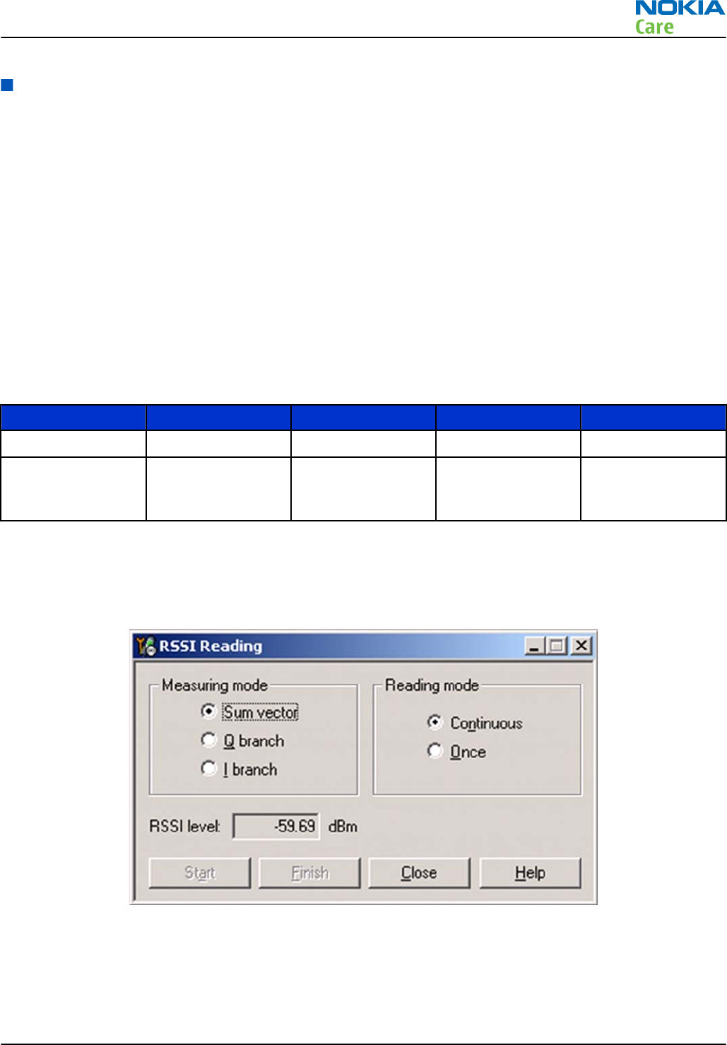
Receiver troubleshooting
Introduction to receiver (RX) troubleshooting
RX can be tested by making a phone call or in local mode. For the local mode testing, use Phoenix service
software.
The main RX troubleshooting measurement is RSSI reading. This test measures the signal strength of the
received signal. For GSM RSSI measurements, see section GSM RX chain activation for manual measurements/
GSM RSSI measurement (page 4–9 ) . For a similar test in WCDMA mode, see section WCDMA RSSI
measurement (page 4–12 ) .
The RX path for GSM and WCDMA are using the same filters in some bands. Please refer to RF components
reference (page 4–26 ) for details.
GSM RX chain activation for manual measurements/GSM RSSI measurement
Prerequisites
Make the following settings in signal generator and Phoenix service software:
Setting GSM850 GSM900 GSM1800 GSM1900
Phoenix Channel 190 37 700 661
Signal generator
to antenna
connector
881.46771MHz
(67.71kHz offset)
at -60dBm
942.46771MHz
(67.71kHz offset)
at -60dBm
1842.86771MHz
(67.71kHz offset)
at -60dBm
1960.06771MHz
(67.71kHz offset)
at -60dBm
Steps
1. Set the phone to local mode.
2. Activate RSSI reading in Phoenix by selecting Testing → GSM → RSSI reading .
Figure 17 Phoenix RSSI Reading window
Results
The reading should reflect the level of the signal generator (minus losses) ±5dB.
When varying the level in the range -30 to -102dBm the reading should then follow within ±5dB.
RM-632; RM-634; RM-699
RF troubleshooting
Issue 3 COMPANY CONFIDENTIAL Page 4 – 9
Copyright © 2010 Nokia. All rights reserved.
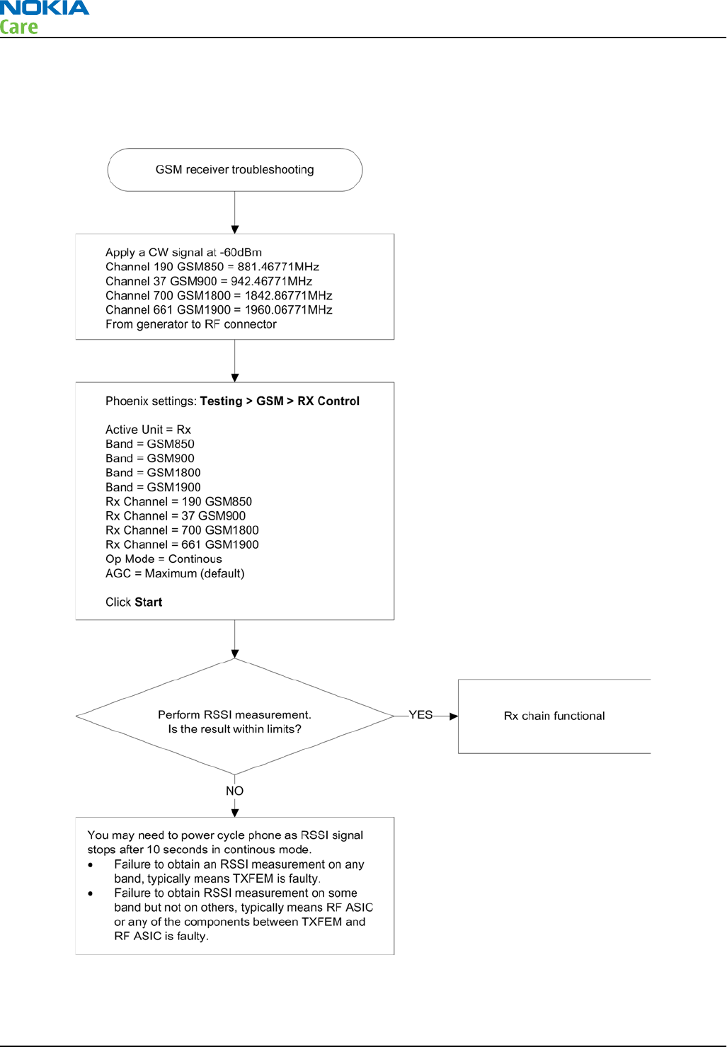
GSM receiver troubleshooting flowchart
Troubleshooting flow
RM-632; RM-634; RM-699
RF troubleshooting
Page 4 – 10 COMPANY CONFIDENTIAL Issue 3
Copyright © 2010 Nokia. All rights reserved.
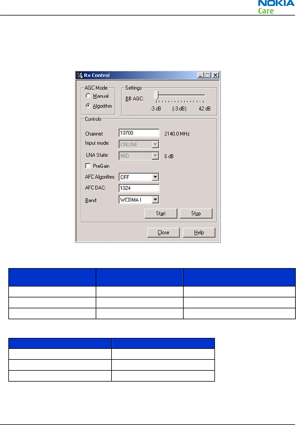
WCDMA RX chain activation for manual measurement
Steps
1. In Phoenix, select Testing → WCDMA → Rx Control . The Phoenix Rx Control window opens.
Figure 18 Phoenix Rx Control window with sample settings (WCDMA band I)
2. Make settings for the band to be tested according to the following table:
Band to be tested Phoenix Channel Signal generator to antenna
connector
WCDMA I 10700 2141.0MHz
WCDMA II 9800 1961.0MHz
WCDMA VIII 3013 943.6MHz
3. Make the following general settings (the same values for all bands):
Setting Value
AGC Mode Algorithm
AFC Algorithm OFF
AFC DAC 1024
4. Click Start to activate the settings.
If the settings are changed later on (for example, change of channel) you have to click Stop and Start
again.
RM-632; RM-634; RM-699
RF troubleshooting
Issue 3 COMPANY CONFIDENTIAL Page 4 – 11
Copyright © 2010 Nokia. All rights reserved.
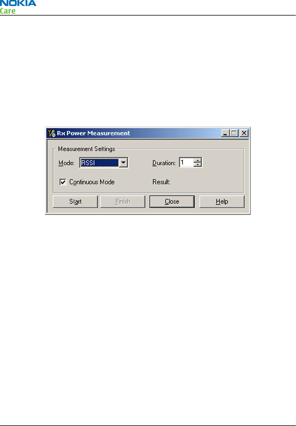
Note: Clicking Stop also disables TX control if it was active.
WCDMA RSSI measurement
Prerequisites
WCDMA RX must be activated before RSSI can be measured. For instructions, please refer to WCDMA RX chain
activation for manual measurement (page 4–11 ) .
Connect signal generator to RF connector and use appropriate frequency for each channel.
Steps
1. In Phoenix select Testing → WCDMA → RX Power measurement . The Rx Power Measurement window
opens.
Figure 19 Phoenix Rx Power Measurement window
2. In the RX Power measurement window, select:
•Mode: RSSI
•Continuous mode
3. Click Start to perform the measurement.
Note: WCDMA RSSI measurement is accurate only with WCDMA modulated signal.
RM-632; RM-634; RM-699
RF troubleshooting
Page 4 – 12 COMPANY CONFIDENTIAL Issue 3
Copyright © 2010 Nokia. All rights reserved.
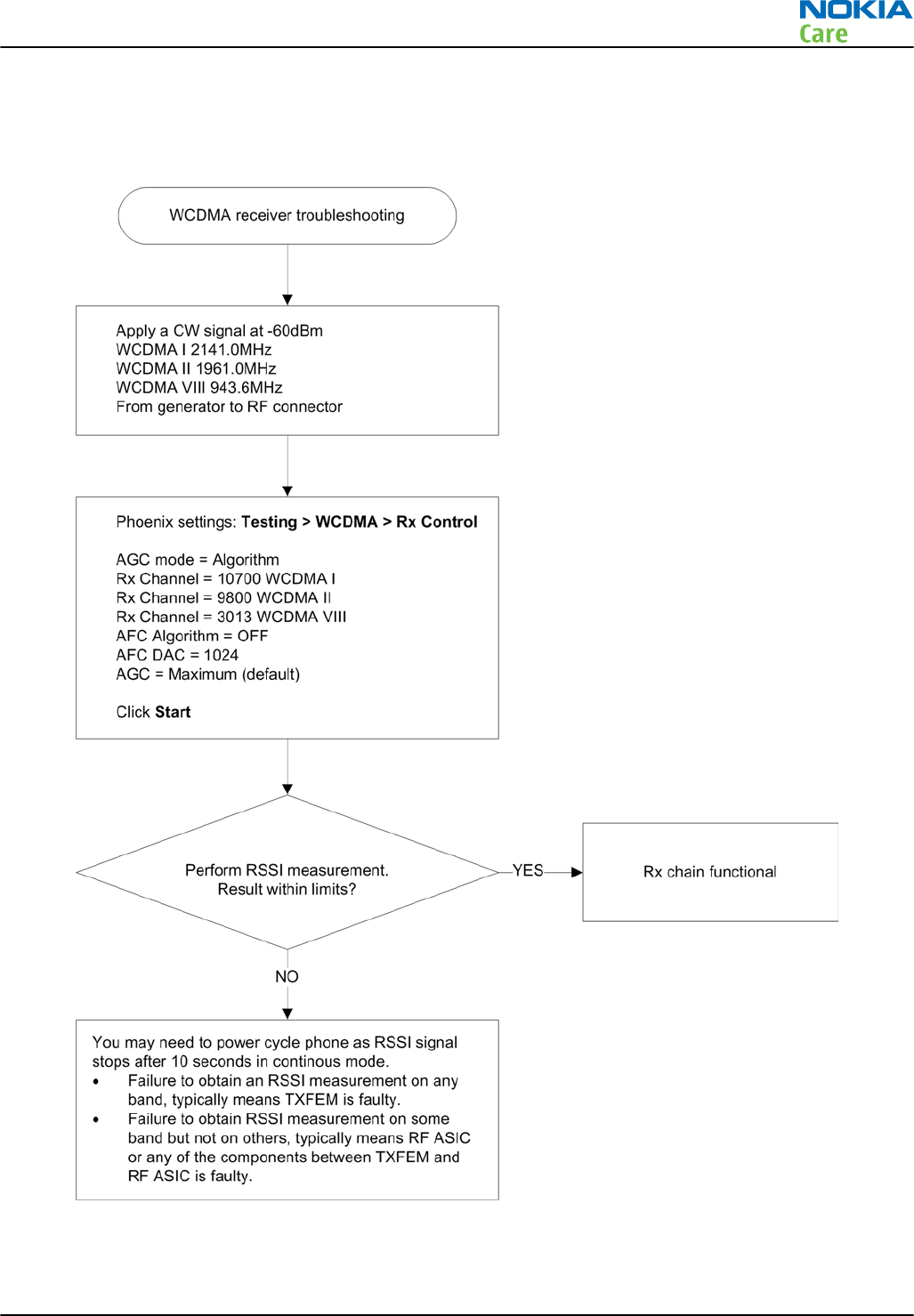
WCDMA receiver troubleshooting flowchart
Troubleshooting flow
RM-632; RM-634; RM-699
RF troubleshooting
Issue 3 COMPANY CONFIDENTIAL Page 4 – 13
Copyright © 2010 Nokia. All rights reserved.
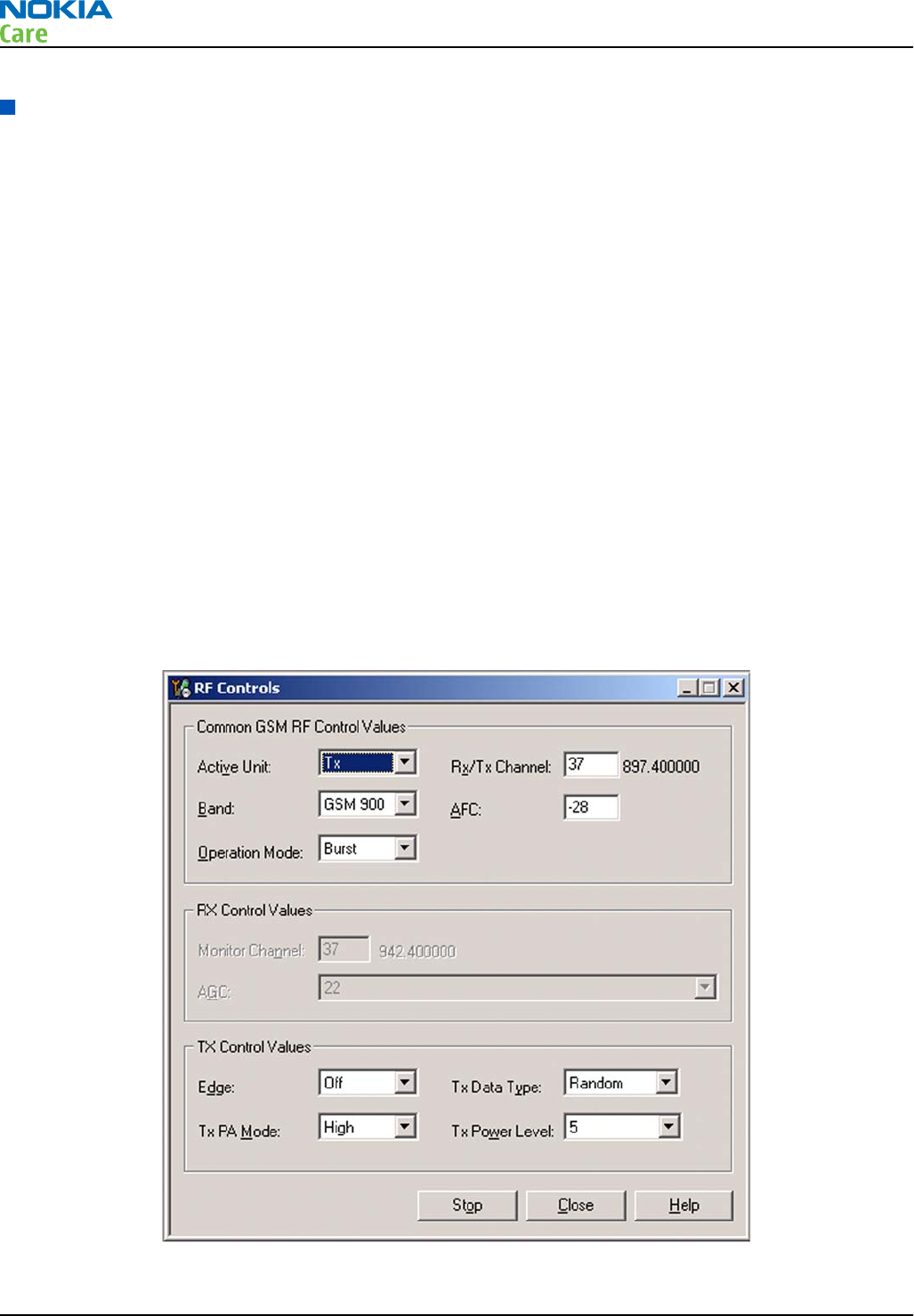
Transmitter troubleshooting
Introduction to transmitter (TX) troubleshooting
Please note the following before performing transmitter tests:
•TX troubleshooting requires TX operation.
•Do not transmit on frequencies that are in use!
•The transmitter can be controlled in local mode for diagnostic purposes.
•The most useful Phoenix tool for GSM transmitter testing is “RF Control”; in WCDMA transmitter testing
the best tool is “TX Control”.
•Remember that re-tuning is not a fix! Phones are tuned correctly in production.
•The RX path for GSM and WCDMA are using the same filters in some bands. Please refer to RF components
reference (page 4–26 ) for details.
Note: Never activate the GSM or WCDMA transmitter without a proper antenna load. Always connect
a 50Ω load to the RF connector (antenna, RF-measurement equipment or at least a 2W dummy load);
otherwise the GSM or WCDMA Power amplifier (PA) may be damaged.
GSM transmitter troubleshooting
Steps
1. Set the phone to local mode.
2. In Phoenix, select Testing → GSM → Rf Controls . The RF Controls window opens.
Figure 20 Phoenix RF Controls window
3. Make the following settings:
RM-632; RM-634; RM-699
RF troubleshooting
Page 4 – 14 COMPANY CONFIDENTIAL Issue 3
Copyright © 2010 Nokia. All rights reserved.
Setting Value
Active Unit Tx
Rx/Tx Channel 37
Band GSM 900
AFC -28
Operation Mode Burst
Edge Off
Tx Data Type Random
Tx PA Mode High
Tx Power Level 5
4. Check the basic TX parameters, using a communication analyser (e.g. CMU200).
•Power
•Phase error
•Modulation
•Switching spectrum
RM-632; RM-634; RM-699
RF troubleshooting
Issue 3 COMPANY CONFIDENTIAL Page 4 – 15
Copyright © 2010 Nokia. All rights reserved.
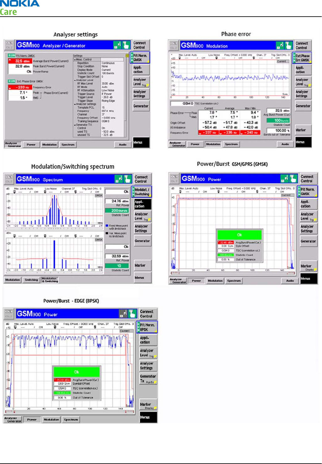
Figure 21 Typical readings
5. Change the power level in RF controls window and make sure the power reading follows accordingly.
RM-632; RM-634; RM-699
RF troubleshooting
Page 4 – 16 COMPANY CONFIDENTIAL Issue 3
Copyright © 2010 Nokia. All rights reserved.

Next actions
You can troubleshoot the GSM transmitter for each GSM band separately, one band at a time. If you want to
troubleshoot GSM850, GSM1800 or GSM1900, change the band in the RF controls window and set the
communication analyser accordingly.
RM-632; RM-634; RM-699
RF troubleshooting
Issue 3 COMPANY CONFIDENTIAL Page 4 – 17
Copyright © 2010 Nokia. All rights reserved.
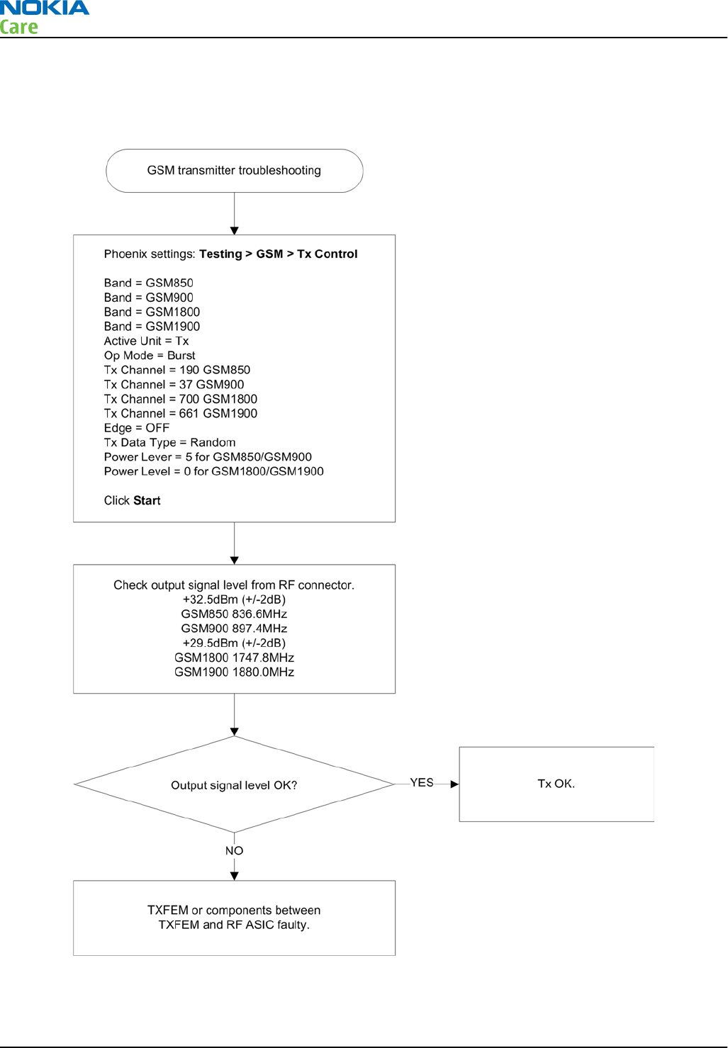
GSM transmitter troubleshooting flowchart
Troubleshooting flow
RM-632; RM-634; RM-699
RF troubleshooting
Page 4 – 18 COMPANY CONFIDENTIAL Issue 3
Copyright © 2010 Nokia. All rights reserved.
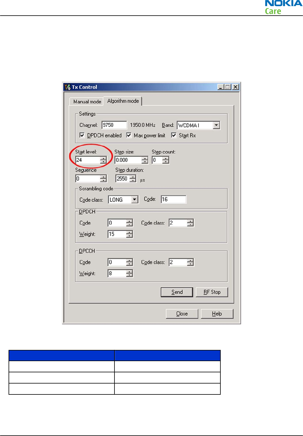
WCDMA transmitter troubleshooting
Steps
1. Set the phone to local mode.
2. In Phoenix, select Testing → WCDMA → Tx control . The Tx Control window opens.
Figure 22 Phoenix WCDMA Tx control window
3. Make settings for the band to be tested, according to the following table:
Band Channel
WCDMA I 9750
WCDMA II 9400
WCDMA VIII 2788
4. Make the following general settings (the same values for all bands). Note that Max power limit is not
checked by default.
RM-632; RM-634; RM-699
RF troubleshooting
Issue 3 COMPANY CONFIDENTIAL Page 4 – 19
Copyright © 2010 Nokia. All rights reserved.
Setting Value
DPDCH enabled Checked
Max power limit Checked
Start Rx Checked
Start level 24
Step size 0
Step count 0
Sequency 0
Step duration 2550
Code class LONG
Code 16
DPDCH code 0
Weight 15
Code class 2
DPCCH code 0
Weight 8
Code class 2
Note: Use the Start level option to set the TX power level.
5. Click Send to enable the settings and activate TX.
If settings are changed (eg. new channel selected), you have to click RF Stop and Send again.
6. Check the basic TX parameters using a communication analyser (e.g. CMU200).
RM-632; RM-634; RM-699
RF troubleshooting
Page 4 – 20 COMPANY CONFIDENTIAL Issue 3
Copyright © 2010 Nokia. All rights reserved.

Figure 23 Typical readings
RM-632; RM-634; RM-699
RF troubleshooting
Issue 3 COMPANY CONFIDENTIAL Page 4 – 21
Copyright © 2010 Nokia. All rights reserved.
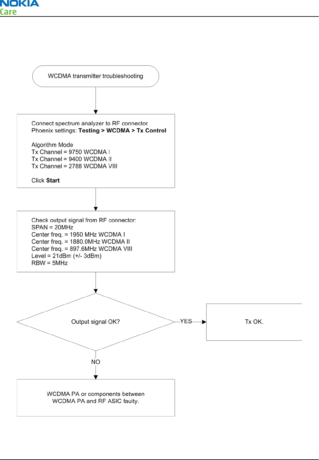
WCDMA transmitter troubleshooting flowchart
Troubleshooting flow
RM-632; RM-634; RM-699
RF troubleshooting
Page 4 – 22 COMPANY CONFIDENTIAL Issue 3
Copyright © 2010 Nokia. All rights reserved.
Troubleshooting with RF-shield removed
Introduction
The RF-shield should not be removed in order to replace single components on the RF block. This chapter
only assists in locating the faulty component for statistical purposes.
Voltage checking
Steps
1. Set up the main board in the module jig. The phone should be in local mode.
2. Check the following:
TP# Signal name Test point Voltage (all bands)
1 VCTCXO (G7500) supply C7501 2.5V
2RFIC Vapaus (N7500) supply from DC/DC
converter
C7570 2.8V
3 TXFEM (N7520) supply from DC/DC
converter
C7521 1.3V-3.8V (only when transmitting and
depends on output power).
4 WCDMA PA (N7540) supply from DC/DC
converter
C7528 0.7V-3.1V (only when transmitting and
depends on output power). The value
will be 3.1V when settings as described
in the note below are used.
5 Vbat at WCDMA PA (N7540) C7512 3.7V (Vbattery)
6 Supply input to DC/DC conv C7527 3.7V (Vbattery)
Note: When using settings as shown in the following Tx Control window, the result at TP4 should
be 3.1V.
RM-632; RM-634; RM-699
RF troubleshooting
Issue 3 COMPANY CONFIDENTIAL Page 4 – 23
Copyright © 2010 Nokia. All rights reserved.
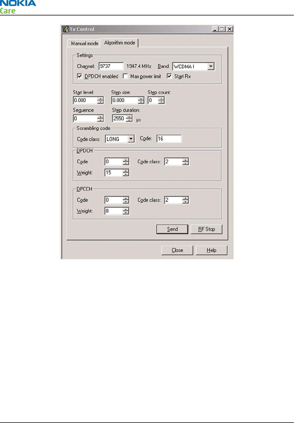
Figure 24 Phoenix WCDMA Tx Control window settings
RM-632; RM-634; RM-699
RF troubleshooting
Page 4 – 24 COMPANY CONFIDENTIAL Issue 3
Copyright © 2010 Nokia. All rights reserved.
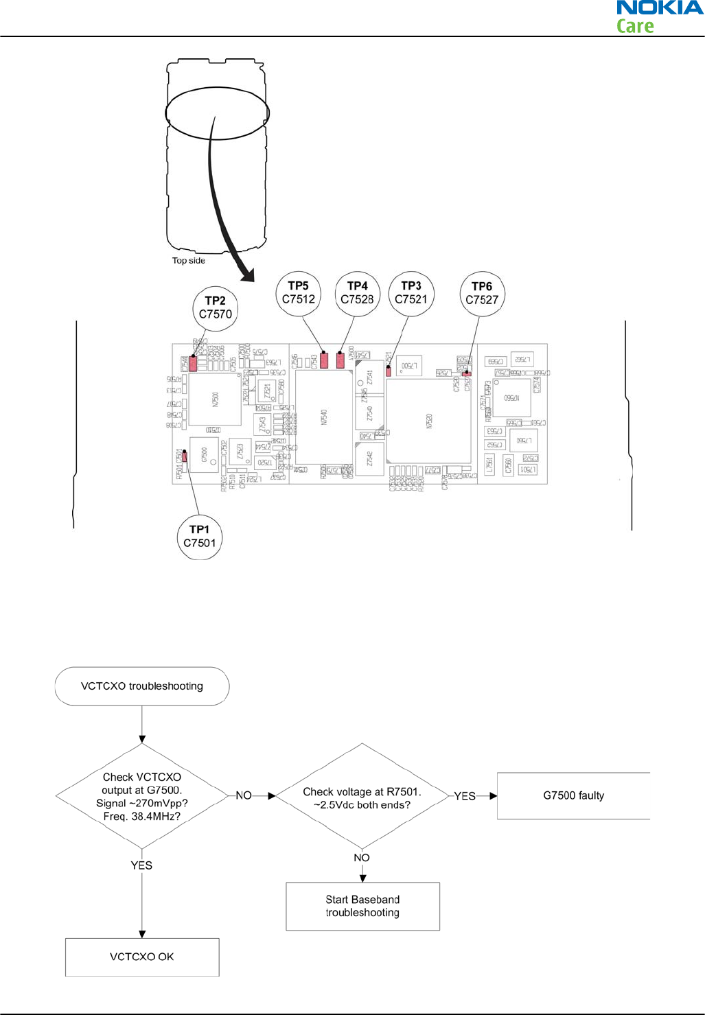
Figure 25 Test points for voltage checking
VCTCXO troubleshooting
Troubleshooting flow
RM-632; RM-634; RM-699
RF troubleshooting
Issue 3 COMPANY CONFIDENTIAL Page 4 – 25
Copyright © 2010 Nokia. All rights reserved.
RF component reference
Component reference table
This table shows the components used for the different bands. It can be used as a reference when
troubleshooting which components may or may not be faulty.
GSM850 GSM900 GSM1800 GSM1900 WCDMA1 WCDMA2 WCDMA8
Reference RX TX RX TX RX TX RX TX RX TX RX TX RX TX
G7500 XXXXXXXXXXXXXX
L7500 XXXXXXXXXXXXXX
N7500 XXXXXXXXXXXXXX
N7520 XXXXXXXXXXXXXX
N7540 X X X
N7560 XXXXXXXXXXXXXX
T7520 X X
Z7521 X X
Z7523 X X
Z7540 X X X
Z7541 X X
Z7542 X X X
Z7543 X X
Z7544 X
X means that the component is used for the band in the current column.
For further reference, see Component reference schematics on the following page.
RM-632; RM-634; RM-699
RF troubleshooting
Page 4 – 26 COMPANY CONFIDENTIAL Issue 3
Copyright © 2010 Nokia. All rights reserved.

RF block diagram
Figure 26 Component reference block diagram
RM-632; RM-634; RM-699
RF troubleshooting
Issue 3 COMPANY CONFIDENTIAL Page 4 – 27
Copyright © 2010 Nokia. All rights reserved.

Antenna
Antenna overview
The main antenna has one antenna element (GSM and WCDMA).
In the GSM/WCDMA antenna there is one feed and one ground contact.
The BT/WLAN antenna is a discreet component on PWB. The GPS antenna is also a discrete component on
PWB.
Main antenna functionality
The main GSM+WCDMA antenna is functioning normally when the feed and GND C-clips take proper contact
to the PWB, and the antenna foil is visually intact in the antenna frame. The main antenna functionality must
also be checked by measuring the transmitted power with RF coupler at GSM900 channel 124.
RM-632; RM-634; RM-699
RF troubleshooting
Page 4 – 28 COMPANY CONFIDENTIAL Issue 3
Copyright © 2010 Nokia. All rights reserved.

5 — System Module
Nokia Customer Care
Issue 3 COMPANY CONFIDENTIAL Page 5 – 1
Copyright © 2010 Nokia. All rights reserved.

RM-632; RM-634; RM-699
System Module
(This page left intentionally blank.)
Page 5 – 2 COMPANY CONFIDENTIAL Issue 3
Copyright © 2010 Nokia. All rights reserved.

Table of Contents
Introduction........................................................................................................................................................... 5–5
Phone description ............................................................................................................................................ 5–5
Energy management............................................................................................................................................. 5–7
Battery and charging ....................................................................................................................................... 5–7
Normal and extreme voltages ........................................................................................................................ 5–8
Power key and system power-up................................................................................................................... 5–9
Modes of operation.......................................................................................................................................... 5–9
Clocking scheme............................................................................................................................................... 5–9
Power distibution ......................................................................................................................................... 5–11
SIM interface ....................................................................................................................................................... 5–12
MicroSD card interface ....................................................................................................................................... 5–12
USB....................................................................................................................................................................... 5–13
USB interface.................................................................................................................................................. 5–13
MicroUSB connector ...................................................................................................................................... 5–13
User interface...................................................................................................................................................... 5–14
Display interface............................................................................................................................................ 5–14
Keyboard interface........................................................................................................................................ 5–14
Ambient light sensor (ALS) interface........................................................................................................... 5–15
GPS interface....................................................................................................................................................... 5–15
Audio interface ................................................................................................................................................... 5–16
AV connector....................................................................................................................................................... 5–17
Bluetooth interface ............................................................................................................................................ 5–17
FM radio interface............................................................................................................................................... 5–18
RF description ..................................................................................................................................................... 5–18
Receiver (RX).................................................................................................................................................. 5–18
Transmitter (TX) ............................................................................................................................................ 5–19
List of Tables
Table 9 Nominal voltages..................................................................................................................................... 5–8
Table 10 Key signal matrix ................................................................................................................................ 5–14
List of Figures
Figure 27 Battery pin order.................................................................................................................................. 5–7
Figure 28 Blade battery connector ...................................................................................................................... 5–8
Figure 29 Small (right) and wide (left) charger plugs ....................................................................................... 5–8
Figure 30 Power distribution diagram ............................................................................................................ 5–11
Figure 31 SIM interface ...................................................................................................................................... 5–12
Figure 32 MicroSD card interface ...................................................................................................................... 5–12
Figure 33 USB interface...................................................................................................................................... 5–13
Figure 34 MicroUSB connector .......................................................................................................................... 5–14
Figure 35 Display interface................................................................................................................................ 5–14
Figure 36 Keyboard interface............................................................................................................................ 5–15
Figure 37 Ambient light sensor (ALS) interface............................................................................................... 5–15
Figure 38 GPS interface...................................................................................................................................... 5–16
Figure 39 Audio interface.................................................................................................................................. 5–16
Figure 40 AV connector...................................................................................................................................... 5–17
Figure 41 Bluetooth interface........................................................................................................................... 5–17
Figure 42 FM radio interface ............................................................................................................................. 5–18
RM-632; RM-634; RM-699
System Module
Issue 3 COMPANY CONFIDENTIAL Page 5 – 3
Copyright © 2010 Nokia. All rights reserved.

RM-632; RM-634; RM-699
System Module
(This page left intentionally blank.)
Page 5 – 4 COMPANY CONFIDENTIAL Issue 3
Copyright © 2010 Nokia. All rights reserved.
Introduction
Phone description
RAPU is the main digital baseband ASIC in the phone. It contains functionality for both WCDMA and GSM EDGE.
Gazoo (N2200) is main audio and energy management controller for the phone.
Key components
Function Description Item ref
Main PWB
AV connector X2001
Baseband ASIC EM ASIC Gazoo N2200
RF ASIC VAPAUS N7500
Processor RAPU D2800
GSM PA Front end module (FEM), quad band N7520
WCDMA PA N7540
Oscillators VCTCXO
Balun GSM
G7500
T7520
Memory Combo 2G DDR + 4G M3 (stacked with RAPU) D3000
Back-up battery RTC back-up battery 311 G2200
Bluetooth + FM radio BTHFMRDS2.2D module N6000
USB USB tranceiver D3300
GPS GPS5350 N6200
WLAN TI WL1251 N6300
Battery BL-4D
Battery connector Tabby blade interface X2070
MicroSD connector X3200
RF connector X7400
SIM connector X2700
Charging connector X2000
RM-632; RM-634; RM-699
System Module
Issue 3 COMPANY CONFIDENTIAL Page 5 – 5
Copyright © 2010 Nokia. All rights reserved.
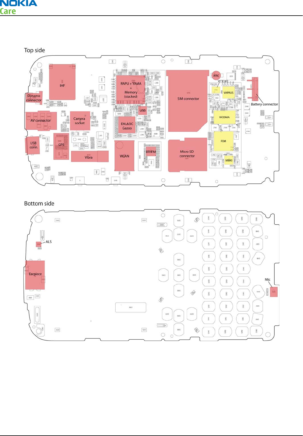
Key component placement
RM-632; RM-634; RM-699
System Module
Page 5 – 6 COMPANY CONFIDENTIAL Issue 3
Copyright © 2010 Nokia. All rights reserved.
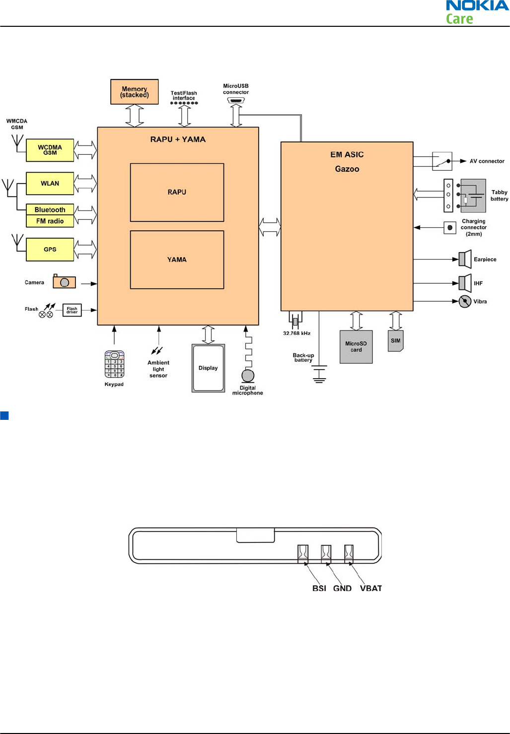
System module block diagram
Energy management
Battery and charging
BL-4D battery
The phone is powered by a 3-pole BL-4D 1200 mAh battery (Li-Ion). The three poles of the battery are named
VBAT, BSI and GND, where the BSI line is used to recognize the battery capacity. This is done by means of an
internal battery pull down resistor.
Figure 27 Battery pin order
The battery temperature is estimated by measuring separate battery temperature NTC via the BTEMP line of
EM ASIC (N2200). This resistor is located on the main PWB, at a place where the phone temperature is closest
to the battery temperature.
Battery connector
The battery connector is a blade connector. It has three blades;
•BSI (Battery size indicator)
RM-632; RM-634; RM-699
System Module
Issue 3 COMPANY CONFIDENTIAL Page 5 – 7
Copyright © 2010 Nokia. All rights reserved.
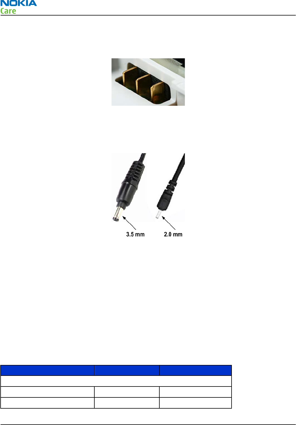
•GND (Ground)
•VBAT (Battery voltage)
The BSI line is used to recognize the battery capacity by a battery internal pull down resistor.
Figure 28 Blade battery connector
Charging
This phone is charged through the smaller Nokia standard interface (2.0 mm plug). The wider standard
charger plug (3.5 mm) can be used together with a CA-44 charger adapter.
Figure 29 Small (right) and wide (left) charger plugs
The phone can also be charged via USB using CA-101 or a USB charger e.g. AC-6.
Charging is controlled by EM ASIC (N2200), and external components are needed to protect the baseband
module against EMC, reverse polarity and transient frequency deviation.
Charging a dead battery
Charging of a dead battery has to be carried out via an approved NOKIA charger. If the phone is charged via
USB, CA-101 or preferably an AC-6 must be used.
Normal and extreme voltages
Energy management is mainly carried out in the EM ASIC (N2200). that contains a number of regulators. In
addition there are also some external regulators.
In the table below normal and extreme voltages are shown when a BL-4D battery is used.
Table 9 Nominal voltages
Voltage Voltage [V] Condition
General Conditions
Nominal voltage 3.700
Lower extreme voltage 3.145
RM-632; RM-634; RM-699
System Module
Page 5 – 8 COMPANY CONFIDENTIAL Issue 3
Copyright © 2010 Nokia. All rights reserved.
Voltage Voltage [V] Condition
Higher extreme voltage
4.2(fast charging)
HW Shutdown Voltages
Vmstr+ 2.1 ± 0.1 Off to on
Vmstr- 1.9 ± 0.1 On to off
SW Shutdown Voltages
Sw shutdown 3.1 In call
Sw shutdown 3.2 In idle
Min Operating Voltage
Vcoff+ 2.9 ± 0.1 Off to on
Vcoff- 2.6 ± 0.1 On to off
Power key and system power-up
When the battery is placed in the phone, the power key circuits are energized. When the power key is pressed,
the system boots up (if an adequate battery voltage is present).
Power down can be initiated by pressing the power key again and the system is powered down with the aid
of SW. The power key is connected to EM ASIC (N2200) via the PWRONX signal.
Modes of operation
Mode Description
NO_SUPPLY (Dead) mode means that the main battery is not present or its voltage is too low (below
EM ASIC master reset threshold) and that the back-up battery voltage is too low.
BACK_UP The main battery is not present or its voltage is too low but back-up battery voltage is
adequate and the 32 kHz oscillator is running (RTC is on).
PWR_OFF In this mode (warm), the main battery is present and its voltage is over EM ASIC master
reset threshold. All regulators are disabled, PurX is on low state, the RTC is on and the
oscillator is on. PWR_OFF (cold) mode is almost the same as PWR_OFF (warm), but the
RTC and the oscillator are off.
RESET RESET mode is a synonym for start-up sequence. RESET mode uses 32kHz clock to count
the REST mode delay (typically 16ms).
SLEEP SLEEP mode is entered only from PWR_ON mode with the aid of SW when the system’s
activity is low.
FLASHING FLASHING mode is for SW downloading.
Clocking scheme
In BB5.44, two main clocks are provided to the system: 38.4MHz RF clock produced by VCTCXO in the RF section
and 32.768kHz sleep clock produced by EM ASIC N2200 with an external crystal.
32 k Sleep Clock is always powered on after startup. Sleep clock is used by RAPU for low-power operation.
SMPS Clk is 2.4MHz clock line from RAPU to EM ASIC N2200. In deep sleep mode, when VCTCXO is off, this signal
is set to '0'-state.
RM-632; RM-634; RM-699
System Module
Issue 3 COMPANY CONFIDENTIAL Page 5 – 9
Copyright © 2010 Nokia. All rights reserved.

CLK600. The clock source is an internal RC oscillator in EM ASIC N2200 (during the power-up sequence) or
RAPU SMPS Clk.
Bluetooth has a separate 38.4MHz TCXO clock oscillator.
RM-632; RM-634; RM-699
System Module
Page 5 – 10 COMPANY CONFIDENTIAL Issue 3
Copyright © 2010 Nokia. All rights reserved.
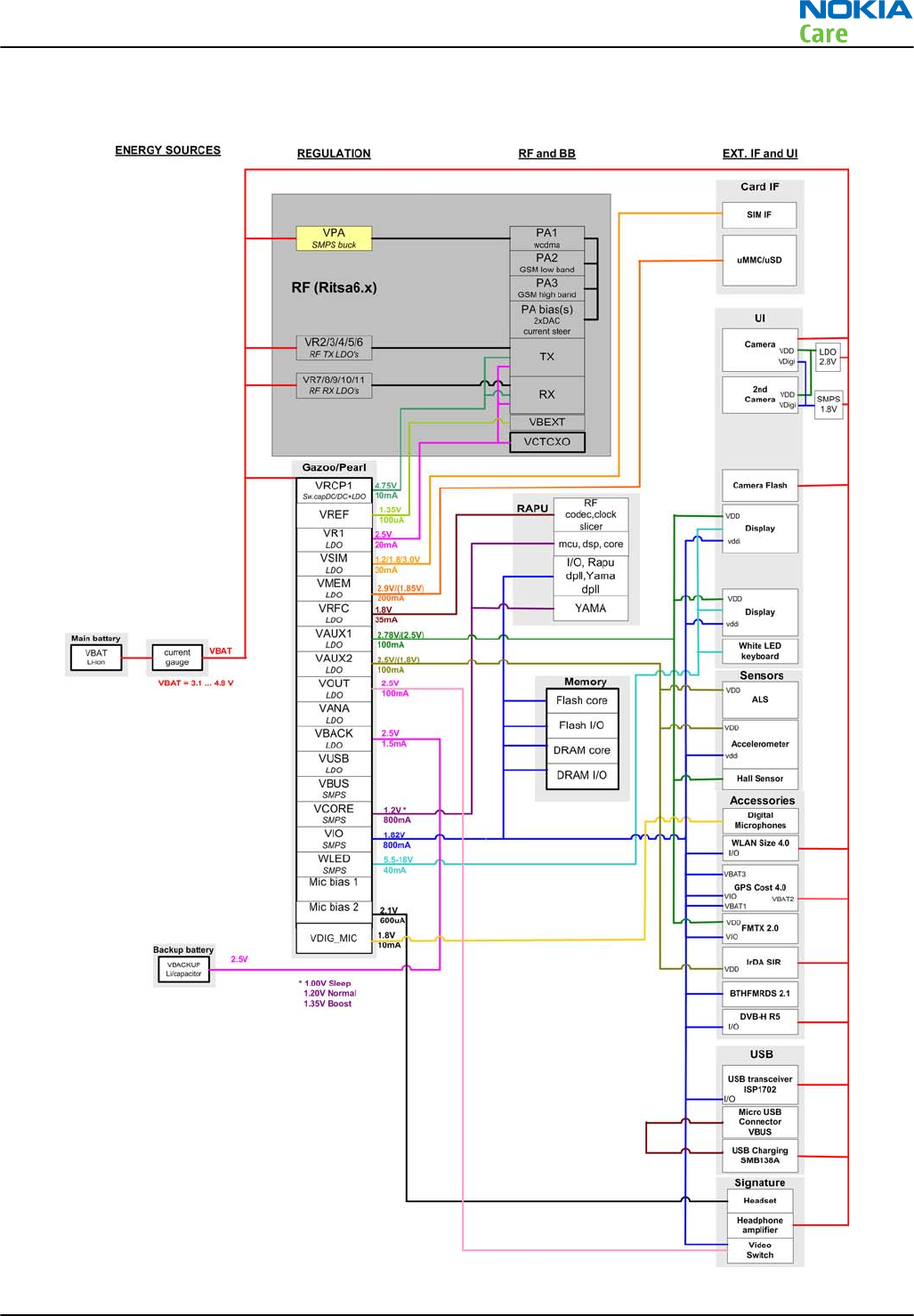
Power distibution
Figure 30 Power distribution diagram
RM-632; RM-634; RM-699
System Module
Issue 3 COMPANY CONFIDENTIAL Page 5 – 11
Copyright © 2010 Nokia. All rights reserved.
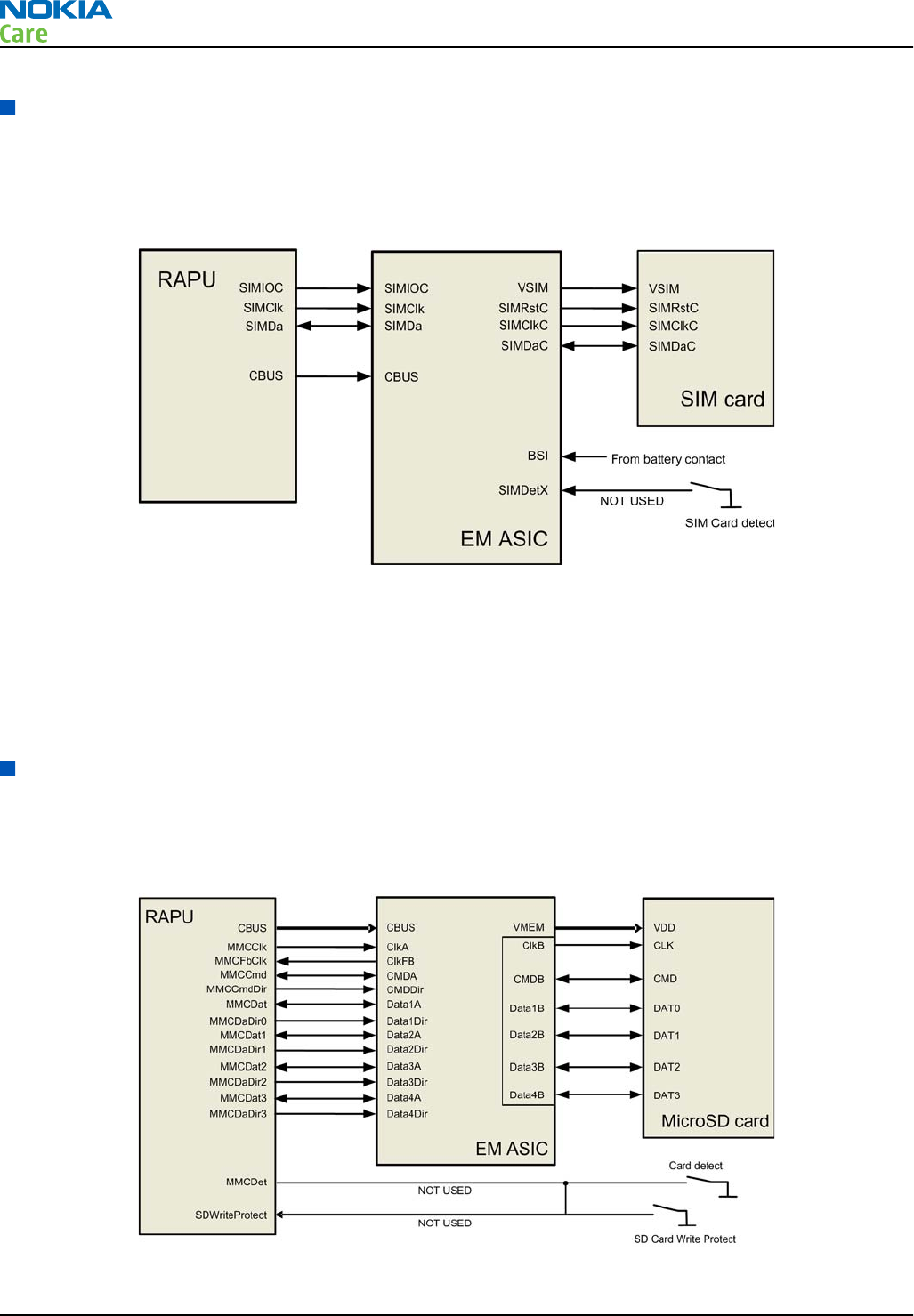
SIM interface
The phone has a SIM (Subscriber Identification Module) interface including a SIM connector. The connector
is only accessible when the battery is removed.
The SIM interface consists of an internal interface between RAPU and EM ASIC (N2200), and an external
interface between EM ASIC and SIM contacts.
Figure 31 SIM interface
The EM ASIC handles the detection of the SIM card. The detection method is based on the BSI line. Because of
the location of the SIM connector, removing the battery causes a quick power down of the SIM interface.
The SIM interface supports both 1.8V and 3.0V SIM cards. The SIM interface voltage is first 1.8 V when the SIM
card is inserted, and if the card does not response to the ATR (Answer to Request), a 3V interface voltage is
used.
MicroSD card interface
The microSD card interface has one internal interface between RAPU and EM ASIC and one external interface
between EM ASIC and the microSD card. The microSD card connector is mounted on a separate PWB, the Micro
PWB.
Figure 32 MicroSD card interface
RM-632; RM-634; RM-699
System Module
Page 5 – 12 COMPANY CONFIDENTIAL Issue 3
Copyright © 2010 Nokia. All rights reserved.
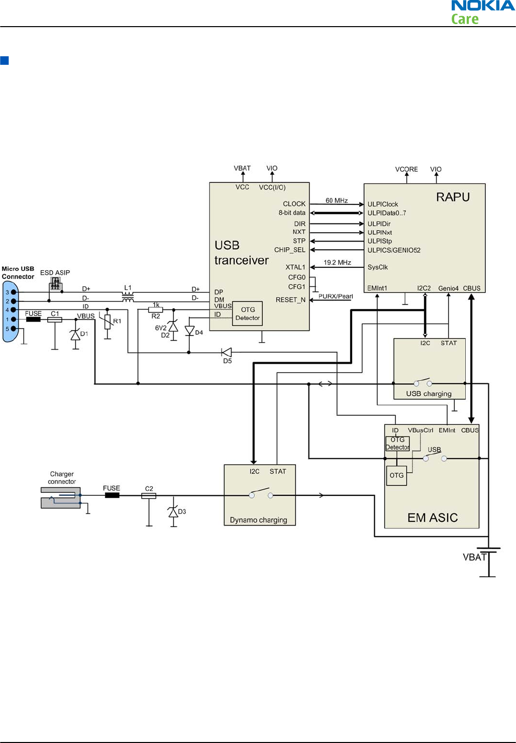
USB
USB interface
The phone has an interface for USB (Universal Serial Bus). USB is a differential serial bus that provides a wired
connectivity between the phone and, for example a PC.
Figure 33 USB interface
The phone supports USB 2.0 with High-Speed (480 Mbps).
Hot swap is supported, which means that USB devices may be plugged in and out at any time.
MicroUSB connector
This phone is provided with a specific connector for microUSB.
RM-632; RM-634; RM-699
System Module
Issue 3 COMPANY CONFIDENTIAL Page 5 – 13
Copyright © 2010 Nokia. All rights reserved.
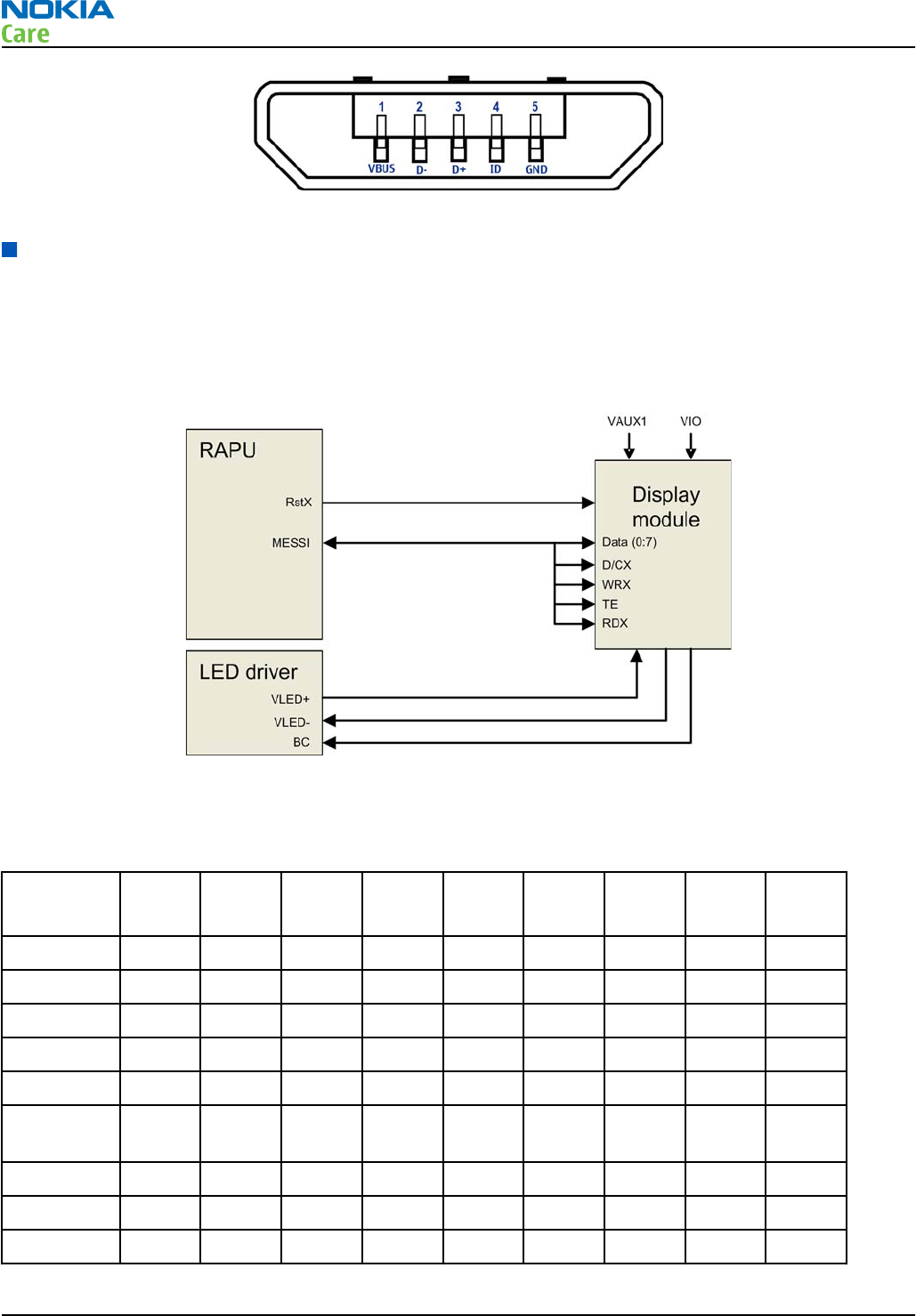
Figure 34 MicroUSB connector
User interface
Display interface
The following block diagram illustrates the display interface. Command signals and transmitted data to the
display module comes directly from RAPU.
Display backlight is provided by an external LED driver.
Figure 35 Display interface
Keyboard interface
Table 10 Key signal matrix
KEY_COL
KEY_ROW
<0> <1> <2> <3> <4> <5> <6> <7> <8>
<0> FN Shift Chr Space N Vol + Space &
<1> Z X C V B Vol - M , ;
<2> A S D F G H J K
<3> Q W E R T Y U I
<4> ? ! CTRL Left Select Right Down S60-L
<5> . : Return Soft-
Left
Up Soft-
Right
S60-R Send
<6> L BS
<7> O P
<8>
RM-632; RM-634; RM-699
System Module
Page 5 – 14 COMPANY CONFIDENTIAL Issue 3
Copyright © 2010 Nokia. All rights reserved.
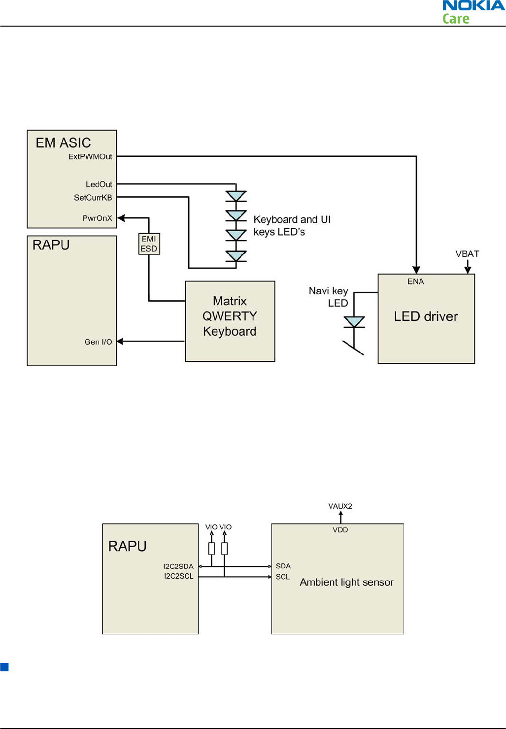
The following block diagram shows the keyboard interface.
The keyboard interface is implemented with RAPU’s GENIOs.
The LED's at the UI keys are controlled by a LED driver. The driver is controlled by a PWM signal from EM ASIC
Gazoo.
The keyboard LED's are controlled directly by EM ASIC Gazoo.
Figure 36 Keyboard interface
Ambient light sensor (ALS) interface
Ambient light sensor information is used to control keyboard and display brightness.
•Keyboard backlight is turned OFF, when it is not needed.
•Display brightness is dimmed, when environment lighting is dark.
The ambient light sensor is calibrated in production and can be re-tuned in service points, though not
recommended unless calibration coefficient is lost for some reason
Figure 37 Ambient light sensor (ALS) interface
GPS interface
The phone includes a built in GPS receiver and could operate as a stand-alone positioning device. The antenna
for GPS is located at the top of the A-cover, see section GPS antenna (page 5– 0 ) .
The GPS receiver is connected to RAPU ASIC.
RM-632; RM-634; RM-699
System Module
Issue 3 COMPANY CONFIDENTIAL Page 5 – 15
Copyright © 2010 Nokia. All rights reserved.
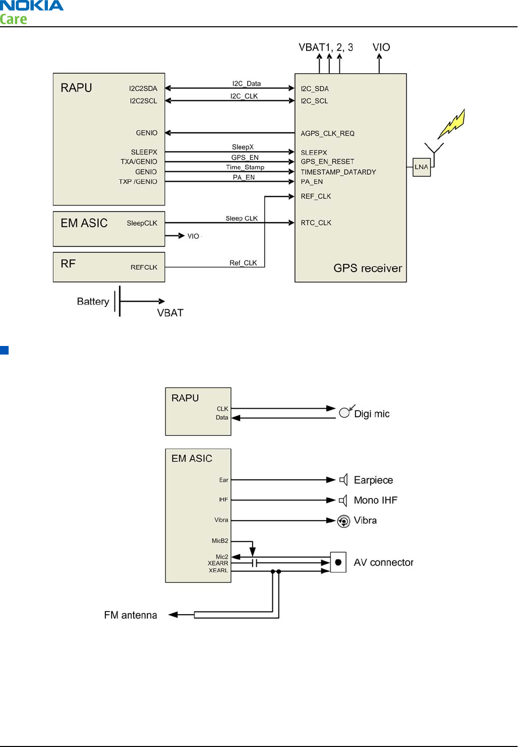
Figure 38 GPS interface
Audio interface
The following block diagram illustrates the audio interface of the phone:
Figure 39 Audio interface
The digital microphone is connected directly to RAPU.
The earpiece is driven directly by a built-in amplifier included in EM ASIC.
The IHF speaker is driven directly by a built-in stereo amplifier included in EM ASIC.
The vibra is driven directly by a built-in amplifier included in EM ASIC.
RM-632; RM-634; RM-699
System Module
Page 5 – 16 COMPANY CONFIDENTIAL Issue 3
Copyright © 2010 Nokia. All rights reserved.
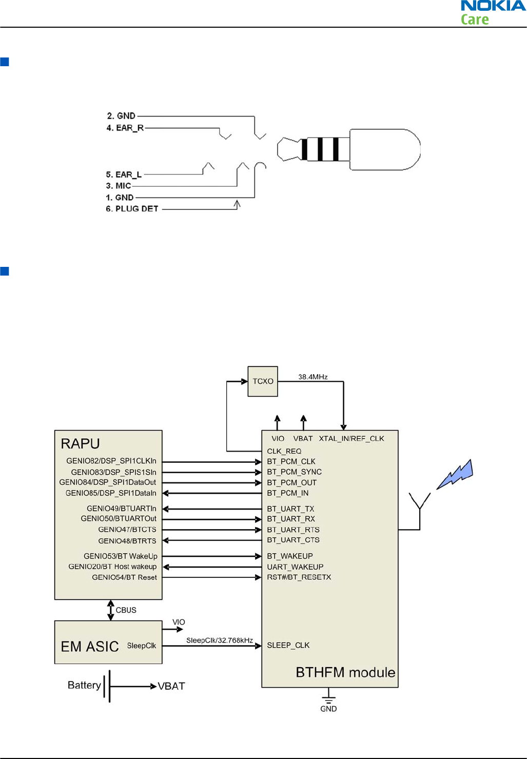
AV connector
The AV connector handles audio signals output and input. It has audio left and right signals separately (pins
4 and 5) and microphone signals wired to pin 3.
Figure 40 AV connector
The plug detection signal handles the AV connector plug detection with HeadDet signal from EM ASIC.
Bluetooth interface
Bluetooth provides a fully digital link for communication between a master unit (the phone) and one or more
slave units (e.g. a wireless headset). Data and control interface for a low power RF module is provided by the
BTHFM module.
Bluetooth is physically integrated with FM radio in the BTHFM module ASIC, but from a functional point of
view they have nothing in common
Figure 41 Bluetooth interface
RM-632; RM-634; RM-699
System Module
Issue 3 COMPANY CONFIDENTIAL Page 5 – 17
Copyright © 2010 Nokia. All rights reserved.
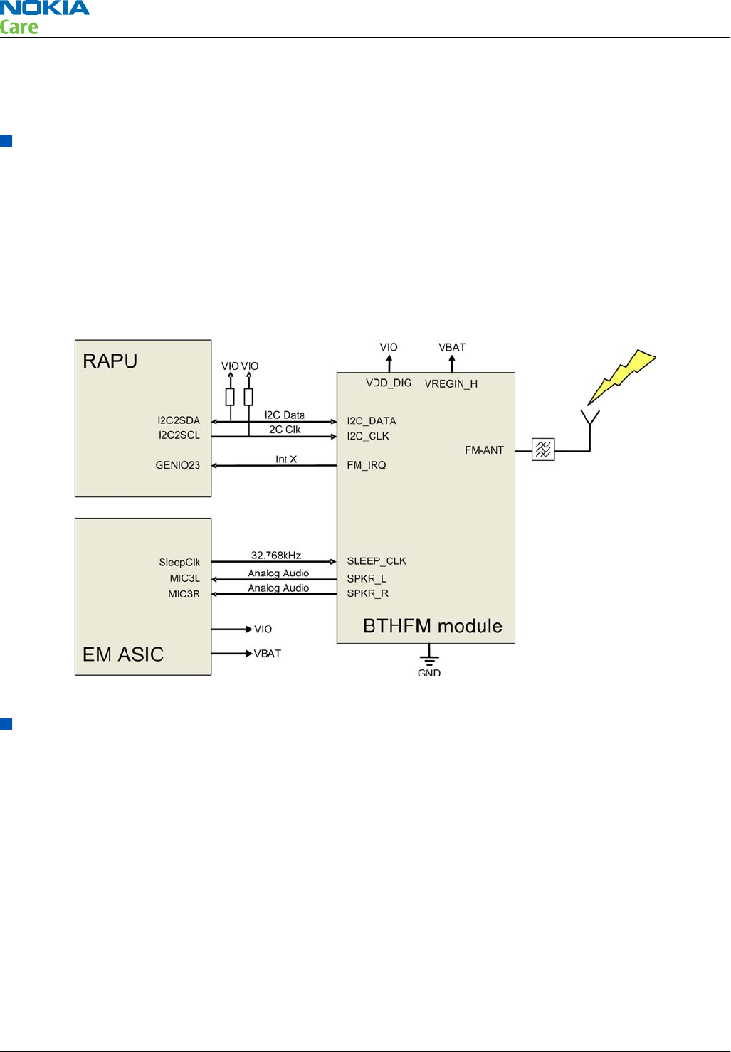
The BTHFM module is powered by VBAT and the regulated voltage VIO. For audio applications the Bluetooth
has a PCM data bus. In addition an UART (universal asynchronous receiver/transmitter) is used for data
communication and controls.
FM radio interface
The FM radio system is controlled by RAPU via the I2C bus. EM ASIC delivers the needed voltages and the clock
reference (32.768kHz SleepClk). EM ASIC also processes the analog audio.
The FM receiver fully supports reception over US/European (87.5MHz to 108MHz) and Japanese (76MHz to
90MHz) FM band. The FM receiver comprises an RF receiver with fully integrated VCO, a stereo FM demodulator
and a RDS demodulator.
A headset accessory is used as an external antenna. The headset is connected to the AV connector.
FM radio is physically integrated with Bluetooth in the BTHFM module ASIC, but from a functional point of
view FM radio and Bluetooth have nothing in common.
Figure 42 FM radio interface
RF description
Receiver (RX)
An analogue signal is received by the phone's antenna. The signal is converted to a digital signal and is then
transferred further to the baseband (e.g. to the earpiece).
The receiver functions are implemented in the RF ASIC.
Signals with different frequencies take different paths, therefore being handled by different components.
The principle of GSM and WCDMA is the same.
RM-632; RM-634; RM-699
System Module
Page 5 – 18 COMPANY CONFIDENTIAL Issue 3
Copyright © 2010 Nokia. All rights reserved.
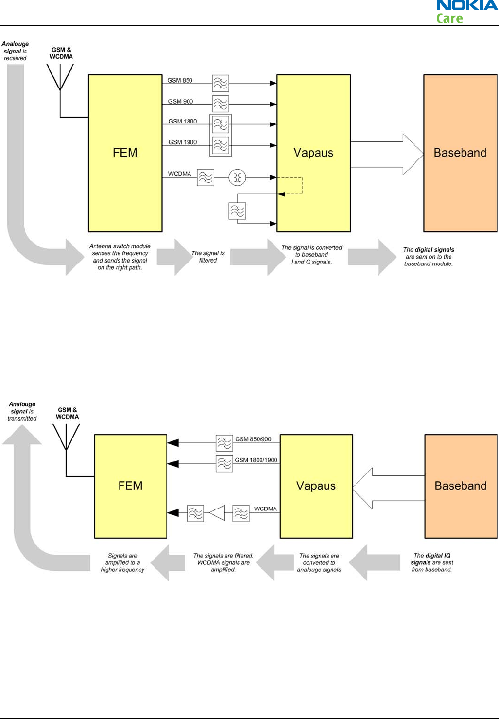
Transmitter (TX)
The digital baseband signal (e.g. from the microphone) is converted to an analogue signal, which is then
amplified and transmitted from the antenna. The frequency of this signal can be tuned to match the bandwith
of the system in use (e.g. GSM900).
The transmitter functions are implemented in the RF ASIC.
Even though the GSM and WCDMA signals are sent via different components, the principle of the transmission
is the same.
RM-632; RM-634; RM-699
System Module
Issue 3 COMPANY CONFIDENTIAL Page 5 – 19
Copyright © 2010 Nokia. All rights reserved.

RM-632; RM-634; RM-699
System Module
(This page left intentionally blank.)
Page 5 – 20 COMPANY CONFIDENTIAL Issue 3
Copyright © 2010 Nokia. All rights reserved.

6 — Service information
differences between RM-632
and RM-634
Nokia Customer Care
Issue 3 COMPANY CONFIDENTIAL Page 6 – 1
Copyright © 2010 Nokia. All rights reserved.

RM-632; RM-634; RM-699
Service information differences between RM-632 and
RM-634
(This page left intentionally blank.)
Page 6 – 2 COMPANY CONFIDENTIAL Issue 3
Copyright © 2010 Nokia. All rights reserved.

Table of Contents
General information.............................................................................................................................................. 6–5
RM-634 product data ....................................................................................................................................... 6–5
Main RF characteristics for GSM850/900/1800/1900 and WCDMA V (850), WCDMA II (1900) and WCDMA
I (2100) phones ...................................................................................................................................... 6–5
RF troubleshooting................................................................................................................................................ 6–6
Differences between RM-632 and RM-634..................................................................................................... 6–6
Receiver troubleshooting................................................................................................................................ 6–7
WCDMA RX chain activation for manual measurement........................................................................... 6–7
WCDMA RSSI measurement ........................................................................................................................ 6–8
WCDMA receiver troubleshooting flowchart ......................................................................................... 6–10
Transmitter troubleshooting ....................................................................................................................... 6–11
WCDMA transmitter troubleshooting..................................................................................................... 6–11
WCDMA transmitter troubleshooting flowchart.................................................................................... 6–14
List of Tables
Table 11 Remote connectivity.............................................................................................................................. 6–5
List of Figures
Figure 43 RM-632 RF components difference..................................................................................................... 6–7
Figure 44 Phoenix Rx Control window with sample settings (WCDMA band I)............................................... 6–8
Figure 45 Phoenix Rx Power Measurement window......................................................................................... 6–9
Figure 46 Phoenix WCDMA Tx control window ............................................................................................... 6–11
Figure 47 Typical readings ................................................................................................................................ 6–13
RM-632; RM-634; RM-699
Service information differences between RM-632 and
RM-634
Issue 3 COMPANY CONFIDENTIAL Page 6 – 3
Copyright © 2010 Nokia. All rights reserved.

RM-632; RM-634; RM-699
Service information differences between RM-632 and
RM-634
(This page left intentionally blank.)
Page 6 – 4 COMPANY CONFIDENTIAL Issue 3
Copyright © 2010 Nokia. All rights reserved.

General information
RM-634 product data
RM-634 (Nokia E5–00.2) is an LTA variant of the RM-632.
The key product data differences between the RM-632 and RM-634 are described below.
Connectivity
Table 11 Remote connectivity
Operating bands RM-634: EGSM 850/900/1800/1900, WCDMA/HSDPA
850/1900/2100 (V/II/I)
Main RF characteristics for GSM850/900/1800/1900 and WCDMA V (850), WCDMA II (1900) and
WCDMA I (2100) phones
Parameter Unit
Cellular system GSM850, EGSM900, GSM1800/1900, WCDMA V (850), WCDMA II
(1900) and WCDMA I (2100)
Rx frequency band GSM850: 869 - 894MHz
EGSM900: 925 - 960 MHz
GSM1800: 1805 - 1880 MHz
GSM1900: 1930 - 1990 MHz
WCDMA V (850): 871 - 892 MHz
WCDMA II (1900): 1932 - 1988 MHz
WCDMA I (2100): 2110 - 2170 MHz
Tx frequency band GSM850: 824 - 849MHz
EGSM900: 880 - 915 MHz
GSM1800: 1710 - 1785 MHz
GSM1900: 1850 - 1910 MHz
WCDMA V (850): 826 - 847 MHz
WCDMA II (1900): 1852 - 1908 MHz
WCDMA I (2100): 1920 - 1980 MHz
Output power GSM850: +5 ...+32.5dBm/3.2mW ... 2W
GSM900: +5 … +32.5dBm/3.2mW … 2W
GSM1800: +0 … +30dBm/1.0mW … 1W
GSM1900: +0 … +30dBm/1.0mW … 1W
WCDMA V (850): -50 ... +23 dBm/0.01μW ... 199.5mW
WCDMA II (1900): -50 ... +22 dBm/0.01μW ... 158.5mW
WCDMA I (2100): -50 ... +23 dBm/0.01μW ... 199.5mW
RM-632; RM-634; RM-699
Service information differences between RM-632 and
RM-634
Issue 3 COMPANY CONFIDENTIAL Page 6 – 5
Copyright © 2010 Nokia. All rights reserved.
Parameter Unit
EDGE output power EDGE850: +5 … +29dBm/3.2mW … 794mW
EDGE900: +5 … +29dBm/3.2mW … 794mW
EDGE1800: +0 … +26dBm/1.0mW … 400mW
EDGE1900:+0 … +26dBm/1.0mW … 400mW
Number of RF channels GSM850: 124
GSM900: 174
GSM1800: 374
GSM1900: 299
WCDMA V (850): 108
WCDMA II (1900): 289
WCDMA I (2100): 277
Channel spacing GSM: 200 kHz
WCDMA: 4.8 MHz
Number of Tx power levels GSM850: 15
GSM900: 15
GSM1800: 16
GSM1900: 16
WCDMA V (850): 75
WCDMA II (1900): 75
WCDMA I (2100): 75
RF troubleshooting
Differences between RM-632 and RM-634
The type designator can be seen on the product type label.
RF components difference
The PWB type code is the same for both RM-632 and RM-634. The only PWB difference is on the RF block, in
which the assembly of the following components differs between RM-632 and RM-634:
•Z7521
•Z7542
•Z7544
RM-632; RM-634; RM-699
Service information differences between RM-632 and
RM-634
Page 6 – 6 COMPANY CONFIDENTIAL Issue 3
Copyright © 2010 Nokia. All rights reserved.
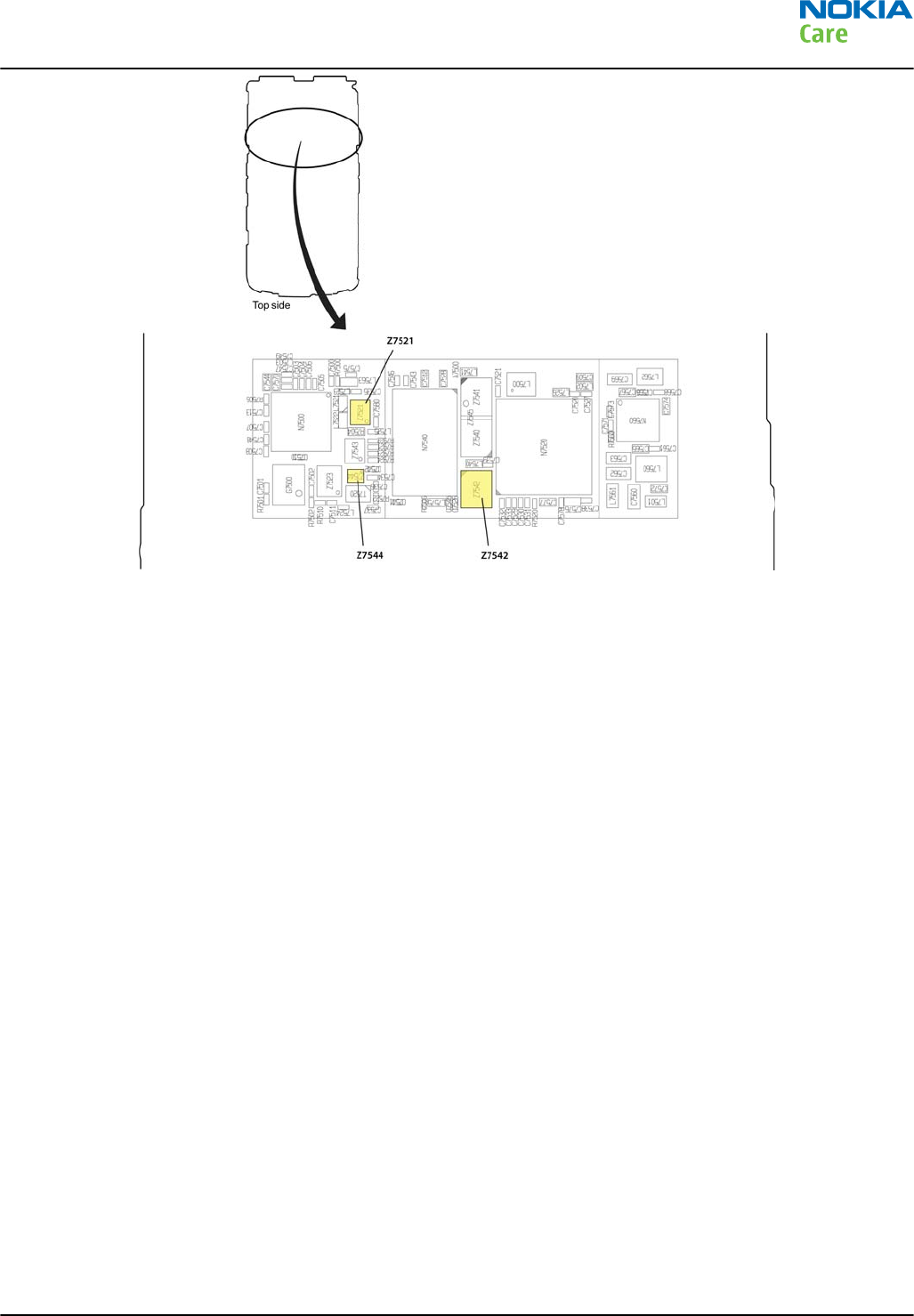
Figure 43 RM-632 RF components difference
Receiver troubleshooting
WCDMA RX chain activation for manual measurement
Steps
1. In Phoenix, select Testing → WCDMA → Rx Control . The Phoenix Rx Control window opens.
RM-632; RM-634; RM-699
Service information differences between RM-632 and
RM-634
Issue 3 COMPANY CONFIDENTIAL Page 6 – 7
Copyright © 2010 Nokia. All rights reserved.
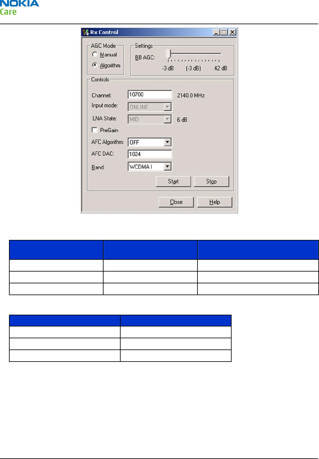
Figure 44 Phoenix Rx Control window with sample settings (WCDMA band I)
2. Make settings for the band to be tested according to the following table:
Band to be tested Phoenix Channel Signal generator to antenna
connector
WCDMA I 10700 2141.0MHz
WCDMA II 9800 1961.0MHz
WCDMA V 4400 881.0MHz
3. Make the following general settings (the same values for all bands):
Setting Value
AGC Mode Algorithm
AFC Algorithm OFF
AFC DAC 1024
4. Click Start to activate the settings.
If the settings are changed later on (for example, change of channel) you have to click Stop and Start
again.
Note: Clicking Stop also disables TX control if it was active.
WCDMA RSSI measurement
Prerequisites
WCDMA RX must be activated before RSSI can be measured. For instructions, please refer to WCDMA RX chain
activation for manual measurement (page 6–11 ) .
RM-632; RM-634; RM-699
Service information differences between RM-632 and
RM-634
Page 6 – 8 COMPANY CONFIDENTIAL Issue 3
Copyright © 2010 Nokia. All rights reserved.
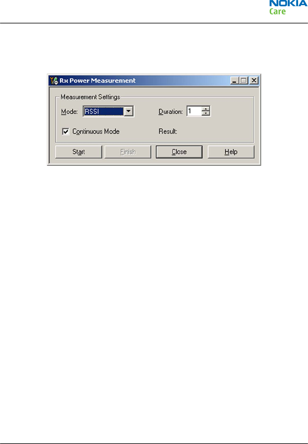
Connect signal generator to RF connector and use appropriate frequency for each channel.
Steps
1. In Phoenix select Testing → WCDMA → RX Power measurement . The Rx Power Measurement window
opens.
Figure 45 Phoenix Rx Power Measurement window
2. In the RX Power measurement window, select:
•Mode: RSSI
•Continuous mode
3. Click Start to perform the measurement.
Note: WCDMA RSSI measurement is accurate only with WCDMA modulated signal.
RM-632; RM-634; RM-699
Service information differences between RM-632 and
RM-634
Issue 3 COMPANY CONFIDENTIAL Page 6 – 9
Copyright © 2010 Nokia. All rights reserved.
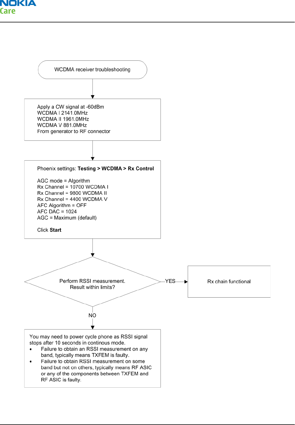
WCDMA receiver troubleshooting flowchart
Troubleshooting flow
RM-632; RM-634; RM-699
Service information differences between RM-632 and
RM-634
Page 6 – 10 COMPANY CONFIDENTIAL Issue 3
Copyright © 2010 Nokia. All rights reserved.
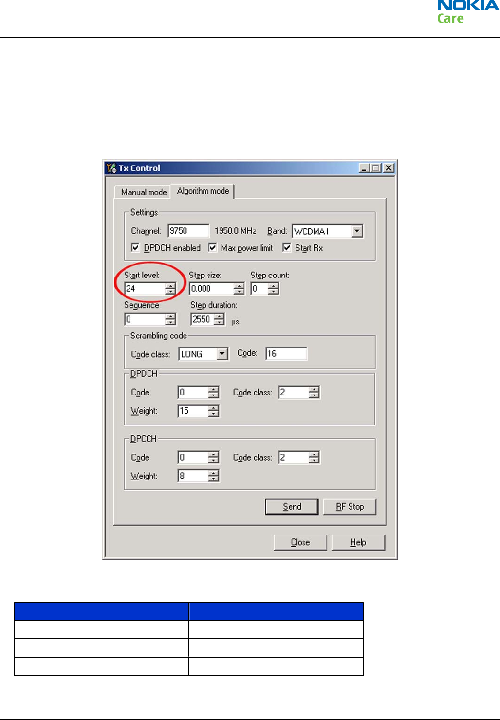
Transmitter troubleshooting
WCDMA transmitter troubleshooting
Steps
1. Set the phone to local mode.
2. In Phoenix, select Testing → WCDMA → Tx control . The Tx Control window opens.
Figure 46 Phoenix WCDMA Tx control window
3. Make settings for the band to be tested, according to the following table:
Band Channel
WCDMA I 9750
WCDMA II 9400
WCDMA V 4175
4. Make the following general settings (the same values for all bands). Note that Max power limit is not
checked by default.
RM-632; RM-634; RM-699
Service information differences between RM-632 and
RM-634
Issue 3 COMPANY CONFIDENTIAL Page 6 – 11
Copyright © 2010 Nokia. All rights reserved.
Setting Value
DPDCH enabled Checked
Max power limit Checked
Start Rx Checked
Start level 24
Step size 0
Step count 0
Sequency 0
Step duration 2550
Code class LONG
Code 16
DPDCH code 0
Weight 15
Code class 2
DPCCH code 0
Weight 8
Code class 2
Note: Use the Start level option to set the TX power level.
5. Click Send to enable the settings and activate TX.
If settings are changed (eg. new channel selected), you have to click RF Stop and Send again.
6. Check the basic TX parameters using a communication analyser (e.g. CMU200).
RM-632; RM-634; RM-699
Service information differences between RM-632 and
RM-634
Page 6 – 12 COMPANY CONFIDENTIAL Issue 3
Copyright © 2010 Nokia. All rights reserved.
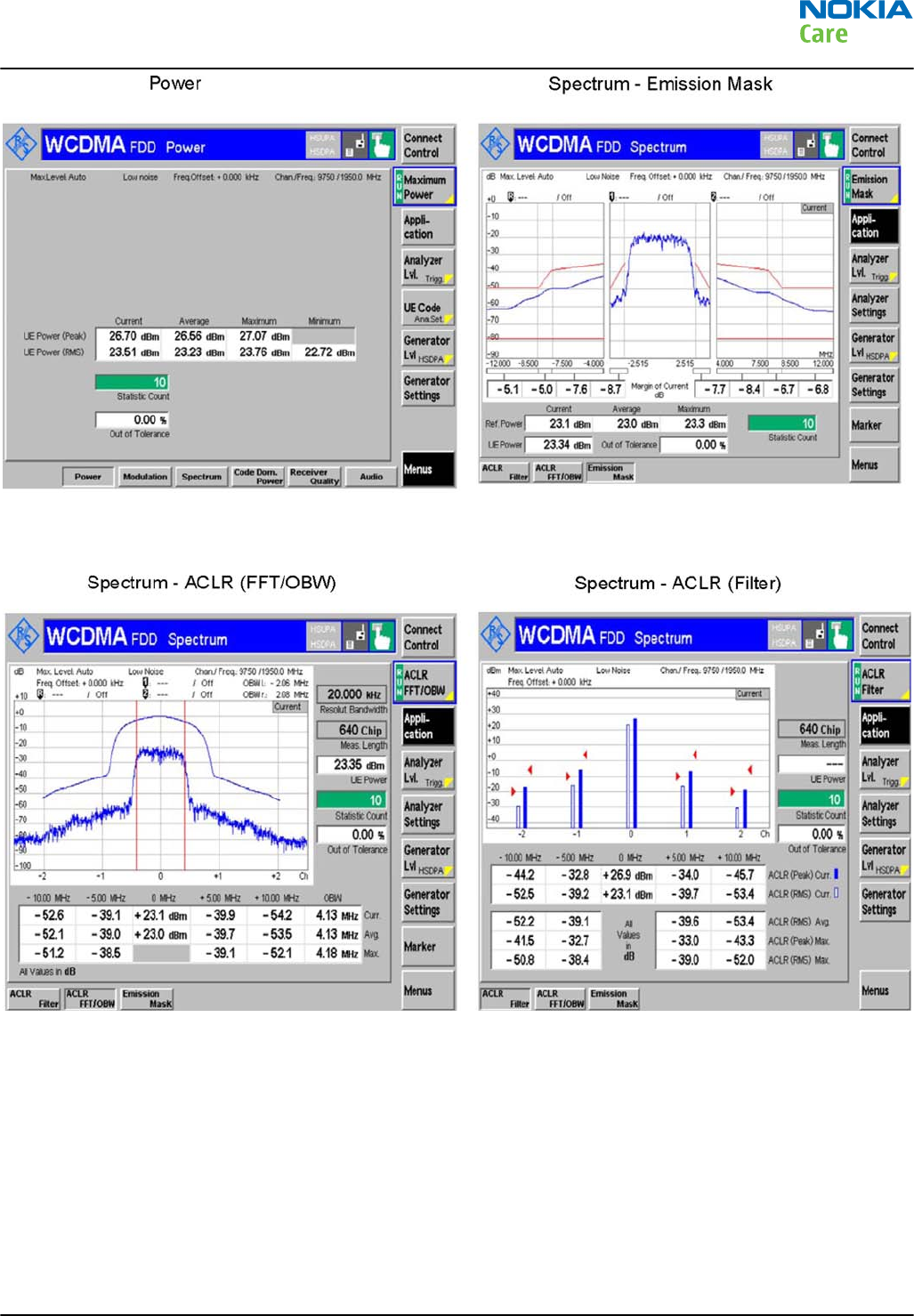
Figure 47 Typical readings
RM-632; RM-634; RM-699
Service information differences between RM-632 and
RM-634
Issue 3 COMPANY CONFIDENTIAL Page 6 – 13
Copyright © 2010 Nokia. All rights reserved.
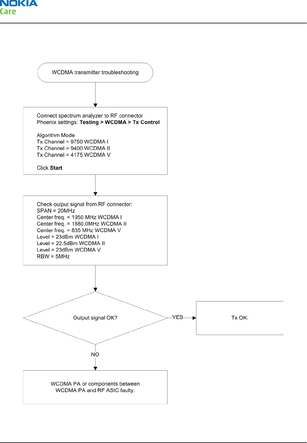
WCDMA transmitter troubleshooting flowchart
Troubleshooting flow
RM-632; RM-634; RM-699
Service information differences between RM-632 and
RM-634
Page 6 – 14 COMPANY CONFIDENTIAL Issue 3
Copyright © 2010 Nokia. All rights reserved.

7 — Service information
differences between RM-632
and RM-699
Nokia Customer Care
Issue 3 COMPANY CONFIDENTIAL Page 7 – 1
Copyright © 2010 Nokia. All rights reserved.

RM-632; RM-634; RM-699
Service information differences between RM-632 and
RM-699
(This page left intentionally blank.)
Page 7 – 2 COMPANY CONFIDENTIAL Issue 3
Copyright © 2010 Nokia. All rights reserved.

Table of Contents
RM-699 product data ............................................................................................................................................ 7–5
BB troubleshooting ............................................................................................................................................... 7–5
RM-632 and RM-699 differences ..................................................................................................................... 7–5
List of Tables
Table 12 Remote connectivity.............................................................................................................................. 7–5
List of Figures
Figure 48 RM-699 product picture....................................................................................................................... 7–5
Figure 49 Type designators in RM-632 and RM-699 C-cover type label........................................................... 7–5
RM-632; RM-634; RM-699
Service information differences between RM-632 and
RM-699
Issue 3 COMPANY CONFIDENTIAL Page 7 – 3
Copyright © 2010 Nokia. All rights reserved.

RM-632; RM-634; RM-699
Service information differences between RM-632 and
RM-699
(This page left intentionally blank.)
Page 7 – 4 COMPANY CONFIDENTIAL Issue 3
Copyright © 2010 Nokia. All rights reserved.
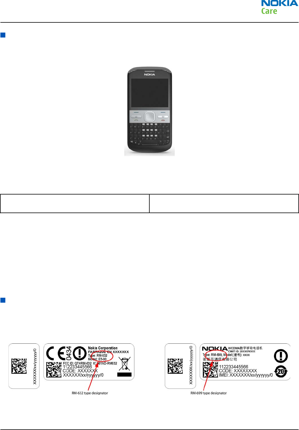
RM-699 product data
RM-699 is a 2G variant of RM-632. The difference is software controlled, so there is no difference mechanically.
The key product data differences between the RM-699 (2G) and RM-632 (3G) are described below.
Figure 48 RM-699 product picture
Connectivity
Table 12 Remote connectivity
Operating bands RM-699: EGSM 850/900/1800/1900 (no WCDMA/
HSDPA)
Sales package
•Nokia E5–00 phone (RM-699)
•Nokia Battery (BL-4D)
•Travel charger AC-8C
•Nokia Stereo Headset WH-102
•Nokia Micru USB Cable CA-101D
•Nokia MU-37, 2 GB micro SD
BB troubleshooting
RM-632 and RM-699 differences
Mechanically the RM-632 and RM-699 are identical. As illustrated in the figure below, the label on the C-cover/
PWB enable quick differentiation between the two variants.
Figure 49 Type designators in RM-632 and RM-699 C-cover type label
RM-632; RM-634; RM-699
Service information differences between RM-632 and
RM-699
Issue 3 COMPANY CONFIDENTIAL Page 7 – 5
Copyright © 2010 Nokia. All rights reserved.

RM-632; RM-634; RM-699
Service information differences between RM-632 and
RM-699
(This page left intentionally blank.)
Page 7 – 6 COMPANY CONFIDENTIAL Issue 3
Copyright © 2010 Nokia. All rights reserved.

Glossary
Nokia Customer Care
Issue 3 COMPANY CONFIDENTIAL Page Glossary– 1
Copyright © 2010 Nokia. All rights reserved.

RM-632; RM-634; RM-699
Glossary
(This page left intentionally blank.)
Page Glossary– 2 COMPANY CONFIDENTIAL Issue 3
Copyright © 2010 Nokia. All rights reserved.
A/D-converter Analogue-to-digital converter
ACI Accessory Control Interface
ADC Analogue-to-digital converter
ADSP Application DPS (expected to run high level tasks)
AGC Automatic gain control (maintains volume)
ALS Ambient light sensor
AMSL After Market Service Leader
ARM Advanced RISC Machines
ARPU Average revenue per user (per month or per year)
ASIC Application Specific Integrated Circuit
ASIP Application Specific Interface Protector
B2B Board to board, connector between PWB and UI board
BA Board Assembly
BB Baseband
BC02 Bluetooth module made by CSR
BIQUAD Bi-quadratic (type of filter function)
BSI Battery Size Indicator
BT Bluetooth
CBus MCU controlled serial bus connected to UPP_WD2, UEME and Zocus
CCP Compact Camera Port
CDMA Code division multiple access
CDSP Cellular DSP (expected to run at low levels)
CLDC Connected limited device configuration
CMOS Complimentary metal-oxide semiconductor circuit (low power consumption)
COF Chip on Foil
COG Chip on Glass
CPU Central Processing Unit
CSD Circuit-switched data
CSR Cambridge silicon radio
CSTN Colour Super Twisted Nematic
CTSI Clock Timing Sleep and interrupt block of Tiku
CW Continuous wave
D/A-converter Digital-to-analogue converter
DAC Digital-to-analogue converter
DBI Digital Battery Interface
DBus DSP controlled serial bus connected between UPP_WD2 and Helgo
RM-632; RM-634; RM-699
Glossary
Issue 3 COMPANY CONFIDENTIAL Page Glossary– 3
Copyright © 2010 Nokia. All rights reserved.
DCT-4 Digital Core Technology
DMA Direct memory access
DP Data Package
DPLL Digital Phase Locked Loop
DSP Digital Signal Processor
DTM Dual Transfer Mode
DtoS Differential to Single ended
EDGE Enhanced data rates for global/GSM evolution
EGSM Extended GSM
EM Energy management
EMC Electromagnetic compatibility
EMI Electromagnetic interference
ESD Electrostatic discharge
FCI Functional cover interface
FM Frequency Modulation
FPS Flash Programming Tool
FR Full rate
FSTN Film compensated super twisted nematic
GMSK Gaussian Minimum Shift Keying
GND Ground, conductive mass
GPIB General-purpose interface bus
GPRS General Packet Radio Service
GSM Group Special Mobile/Global System for Mobile communication
HSDPA High-speed downlink packet access
HF Hands free
HFCM Handsfree Common
HS Handset
HSCSD High speed circuit switched data (data transmission connection faster than GSM)
HW Hardware
I/O Input/Output
IBAT Battery current
IC Integrated circuit
ICHAR Charger current
IF Interface
IHF Integrated hands free
IMEI International Mobile Equipment Identity
RM-632; RM-634; RM-699
Glossary
Page Glossary– 4 COMPANY CONFIDENTIAL Issue 3
Copyright © 2010 Nokia. All rights reserved.
IR Infrared
IrDA Infrared Data Association
ISA Intelligent software architecture
JPEG/JPG Joint Photographic Experts Group
LCD Liquid Crystal Display
LDO Low Drop Out
LED Light-emitting diode
LPRF Low Power Radio Frequency
MCU Micro Controller Unit (microprocessor)
MCU Multiport control unit
MIC, mic Microphone
MIDP Mobile Information Device Profile
MIN Mobile identification number
MIPS Million instructions per second
MMC Multimedia card
MMS Multimedia messaging service
MP3 Compressed audio file format developed by Moving Picture Experts Group
MTP Multipoint-to-point connection
NFC Near field communication
NTC Negative temperature coefficient, temperature sensitive resistor used as a
temperature sensor
OMA Object management architecture
OMAP Operations, maintenance, and administration part
Opamp Operational Amplifier
PA Power amplifier
PCM Pulse Code Modulation
PDA Pocket Data Application
PDA Personal digital assistant
PDRAM Program/Data RAM (on chip in Tiku)
Phoenix Software tool of DCT4.x and BB5
PIM Personal Information Management
PLL Phase locked loop
PM (Phone) Permanent memory
PUP General Purpose IO (PIO), USARTS and Pulse Width Modulators
PURX Power-up reset
PWB Printed Wiring Board
RM-632; RM-634; RM-699
Glossary
Issue 3 COMPANY CONFIDENTIAL Page Glossary– 5
Copyright © 2010 Nokia. All rights reserved.

PWM Pulse width modulation
RC-filter Resistance-Capacitance filter
RDS Radio Data Service
RF Radio Frequency
RF PopPort ™ Reduced function PopPort ™ interface
RFBUS Serial control Bus For RF
RSK Right Soft Key
RS-MMC Reduced size Multimedia Card
RSS Web content Syndication Format
RSSI Receiving signal strength indicator
RST Reset Switch
RTC Real Time Clock (provides date and time)
RX Radio Receiver
SARAM Single Access RAM
SAW filter Surface Acoustic Wave filter
SDRAM Synchronous Dynamic Random Access Memory
SID Security ID
SIM Subscriber Identity Module
SMPS Switched Mode Power Supply
SNR Signal-to-noise ratio
SPR Standard Product requirements
SRAM Static random access memory
STI Serial Trace Interface
SW Software
SWIM Subscriber/Wallet Identification Module
TCP/IP Transmission control protocol/Internet protocol
TCXO Temperature controlled Oscillator
Tiku Finnish for Chip, Successor of the UPP
TX Radio Transmitter
UART Universal asynchronous receiver/transmitter
UEME Universal Energy Management chip (Enhanced version)
UEMEK See UEME
UI User Interface
UPnP Universal Plug and Play
UPP Universal Phone Processor
UPP_WD2 Communicator version of DCT4 system ASIC
RM-632; RM-634; RM-699
Glossary
Page Glossary– 6 COMPANY CONFIDENTIAL Issue 3
Copyright © 2010 Nokia. All rights reserved.
USB Universal Serial Bus
VBAT Battery voltage
VCHAR Charger voltage
VCO Voltage controlled oscillator
VCTCXO Voltage Controlled Temperature Compensated Crystal Oscillator
VCXO Voltage Controlled Crystal Oscillator
VF View Finder
Vp-p Peak-to-peak voltage
VSIM SIM voltage
WAP Wireless application protocol
WCDMA Wideband code division multiple access
WD Watchdog
WLAN Wireless local area network
XHTML Extensible hypertext markup language
Zocus Current sensor (used to monitor the current flow to and from the battery)
RM-632; RM-634; RM-699
Glossary
Issue 3 COMPANY CONFIDENTIAL Page Glossary– 7
Copyright © 2010 Nokia. All rights reserved.

RM-632; RM-634; RM-699
Glossary
(This page left intentionally blank.)
Page Glossary– 8 COMPANY CONFIDENTIAL Issue 3
Copyright © 2010 Nokia. All rights reserved.