P SETC Nortec Owners Manual
User Manual: SETC
Open the PDF directly: View PDF ![]() .
.
Page Count: 72
- Ta ble Of Con tents
- GEN ERAL 1
- SE IN DOOR IN STAL LA TION 13
- Back Page.pdf
- Ta ble Of Con tents
- HP HVAC TYP I CAL IN STAL LA TION 1
- IN TRO DUC TION 2
- GEN ERAL HP SERIES TECH NI CAL CON SID ER ATIONS 2
- ADI A BATIC COOLING PHE NOM E NA 2
- AB SORP TION DIS TANCE 2
- PUMP MOD ULE NOISE 2
- PUMP SHUT DOWN 2
- 1.0 HIGH PRES SURE PUMP MOD ULE 3
- 2.1 NOZ ZLE FLOW RATE 7
- 2.2 HIGH-PRESSURE FEED LINE PRES SURE LOSS 7
- 3.0 WA TER QUAL ITY 8
- 4.0 GUIDE LINES FOR IN STAL LA TION AND LO CA TION OF HP HVAC 8
- 7.1 PUMP MOD ULE LO CA TION 19
- 7.2 Wa ter sup ply to the pump 19
- 7.3 VOLT AGE FLUC TU A TIONS 19
- 7.4 FIL TER CAR TRIDGES 19
- 7.5 High Pres sure Lines to Man i folds 19
- 7.6 PUMP DRAIN 20
- 7.7 POWER SUPPLY SPE CIAL CON SID ER ATIONS 20
- 7.8 Pump Con trol WIRING 20
- 8.0 IN STAL LA TION OF HIGH-PRESSURE FEED LINES AND FIT TINGS 21
- 10.0 SYS TEM MAIN TE NANCE 26
- 10.1 TRIPLEXE CE RAMIC PLUNGER PUMP - CRANK CASE OIL 26
- 10.2 STAIN LESS STEEL PUMP 27
- 10.3 ELEC TRI CAL MOTOR SER VICE 27
- 10.4 IN LET WA TER FIL TERS 27
- 10.5 AT OM IZA TION LINES/MAN I FOLD HOSES 27
- 10.6 SYS TEM FLUSH ΠSHUT DOWN - WIN TER IZING 27
- 10.7 DE COM MIS SIONING 27
- 10.8 FROST PRO TEC TION 28
- 10.9 IN LET WA TER PRES SURE SWITCH 28
- 10.11 MIST ELIMINATOR MAIN TE NANCE 29
- 11. TROU BLE SHOOTING 30-31
- Figure list
- 3
- Pump Modules 5
- Pump Modules - CONTINUED 6
- Fig ure #1 Nozzle Flow Rate for 0.008fl Orifice 7
- Fig ure #2 Nozzle Flow Rate For 0.008fl 7
- Fig ure #3 Various Typical Manifold Set-ups (Top View) 9
- Fig ure #4 Typical Manifold Set-up 9
- Fig ure #5 Air Break End Cap 9
- Fig ure #6 Nozzle Manifolds 10
- Fig ure #7 Clamp Assembly 10
- Fig ure #9 Manifold Connections 12
- Fig ure #10 General Plenum Assembly 14
- Fig ure #12 Drain Pan Spacing 14
- Fig ure #11 Filter Bank 14
- Fig ure #14 Top and Side Channels 15
- Fig ure #15 Installing the Bottom Support 15
- Fig ure #16 Centre Bracket Inserted 15
- Fig ure #13 Corner Brackets 15
- Fig ure #17 Centre Post Fasten 16
- Fig ure #18 Filters Alignment 16
- Fig ure #20 Aligning top Support 16
- Fig ure #19 Installing Filters 16
- Fig ure #21 Installation Completed 16
- Fig ure #22 Unions 19
- Fig ure #23 Male Connector 19
- Fig ure #24 Female Connector 19
- Fig ure #25 90º Elbow 19
- Fig ure #26 Tee Connection 19
- Fig ure #29 Male Fittings 20
- Fig ure #28 Female Swivel Fittings 20
- Fig ure #27 Use of Re-usable Hose Fittings 20
- Fig ure #30 Male Fittings 20
- Fig ure #31 Installation of Reusable Hose Fittings 21
- Fig ure #32 Improper Fitting / Installation of Hose 21
- Fig ure #34 Tube Bending 22
- Fig ure #33 Tube Fittings 22
- Fig ure #35 Crank Case Oil Levels 24
- Fig ure #36 Crank Case Oil Levels 24
- Fig ure #37 Crank Case Oil Levels 24
- Fig ure #38 Low Pressure Water Switch 26
- Fig ure #39 Nozzle Cleaning Tool 26
- Fig ure #40 Proper Spray Pattern 26
- Fig ure #41 Nozzle Anti-Drip Assembly 27
- Ta ble Of Con tents
SE Series
Steam Exchange Humidifier
Installation,
Operation & Maintenance
Guide
2008-05-07
1720292-B
IMPORTANT: Read and save this guide for future reference. This
guide to be left with equipment owner.

WARNING:
Improper installation, adjustment, alteration, service or maintenance
can cause injury or property damage. For assistance or additional
information consult a qualified installer or a service agency.

Table Of Contents
GENERAL 1
- RECEIVING & UNPACKING EQUIPMENT................................1
- DELIVERY ................................................1
- GENERAL SPECIFICATIONS ......................................1
- MODEL DESIGNATION .........................................1
MODEL CAPACITY & PHYSICAL DATA 2-7
FLOOR STAND 8
CEILING MOUNTING INSTALLATION 9
TYPICAL SE INSTALLATION DIAGRAM 10
SETC OUTDOOR DIMENSIONS 11
ROOF CURB DIMENSIONS 12
SE INDOOR INSTALLATION 13
- LOCATING AND MOUNTING ......................................13
- PRIMARY WIRING ...........................................13
- ELECTRICAL ..............................................14
- LOW VOLTAGE CONTROL WIRING .................................14
- CONTROL INSTALLATION .......................................17
- PLUMBING ...............................................17
- WATER QUALITY ............................................17
- FILL WATER SUPPLY LINE ......................................17
- DRAIN LINE ...............................................18
- STEAM CONDENSATE OUTLET ....................................18
- AUXILIARY DRAIN OUTLET ......................................18
- STEAM LINES AND CONDENSATE LINE ...............................18
- PRESSURIZED STEAM CONNECTIONS ...............................18
- STEAM SUPPLY PIPING ........................................18
ACTUATOR INSTALLATION 19
- WHAT COMES WITH THE ACTUATOR ................................19
- INSTALLATION INSTRUCTIONS ....................................19
- PRE-LOADING INSTRUCTIONS ....................................19
SETC OUTDOOR INSTALLATION 21
- MOUNTING ...............................................21
- PRESSURIZED STEAM SUPPLY ...................................21
- ELECTRICAL INSTALLATION .....................................21
- FILL WATER SUPPLY LINE ......................................23
- DRAIN LINE ...............................................23
- AUX DRAIN ...............................................23
- STEAM LINES..............................................23
OPERATION 23
- WATER MANAGEMENT ........................................23
INSPECTION AND START-UP PROCEDURE 24
- START UP PROCEDURE .......................................24
- FILLING THE SYSTEM .........................................24
- STARTING THE HUMIDIFIER .....................................24
- TAKING OUT OF OPERATION .....................................25
- SE INSPECTION CHECK LIST ...................................26-27
SCALE MANAGEMENT 28
- WATER QUALITY ............................................28
MAINTENANCE 29
- DRAINING THE TANK .........................................29
- CLEANING THE STAINLESS STEEL TANK & FLOAT CHAMBER ..................29
- ADJUSTMENTS/REPLACEMENTS OF COMPONENTS........................30
- SERVICING THE UNIT .........................................30
- TRANSFORMER REPLACEMENT ...................................31
- FILL VALVE REPLACEMENT......................................31
- DRAIN PUMP REPLACEMENT .....................................31
- FILL BOX REPLACEMENT .......................................32
- REMOVAL OF HEAT EXCHANGER ..................................32
- FAULT CONDITIONS ..........................................32
- SETC SETTINGS ..........................................33-34
- SETC LOGIC CONTROL BOARD ...................................35
- KEYPAD DISPLAY MENU STRUCTURE ..............................36-41
- NORTEC TC CONTROLLER ......................................42
- FAULT AND WARNING LIST ......................................52
- MANDATORY MAINTENANCE SCHEDULE ..............................53
- SETC INTERNAL WIRING DIAGRAM .................................54
- SEP INTERNAL WIRING DIAGRAM ..................................55
- SE SERIES SPARE PARTS ....................................56-63
GENERAL
This installation guide has been designed to
provide assistance when installing, mounting, and
sizing a SE Series humidifier. Actual on site
application may vary. Consult Walter Meier (Nortec)
Technical Services or your local Walter Meier (Nortec)
representative.
RECEIVING & UNPACKING EQUIPMENT
1. Check packing slip to ensure ALL material has
been delivered.
2. All material shortages are to be reported to
Walter Meier (Nortec) within 48 hours from
receipt of goods. Walter Meier (Nortec)
assumes no responsibility for any material
shortages beyond this period.
3. Inspect shipping boxes for damage and note
on shipping waybill accordingly.
4. After unpacking, inspect equipment for
damage and if damage is found, notify the
shipper promptly.
5. All Walter Meier (Nortec) products are shipped
on an F.O.B. factory basis. Any and all
damage, breakage or loss claims are to be
made directly to the shipping company.
DELIVERY
The standard delivery includes:
1. Steam Exchange humidifier equipped with
desired options.
2. In a bag you will find:
- Manuals.
- Plastic adapter for potable, RO, DI or
softened water connection.
- Steam hose for steam outlet with clamps.
3. The SE Series comes complete with a
telescopic stand mounted inside the unit legs.
Stand cross bracing is shipped with the unit.
(Optional on SE 50).
4. Steam valve, actuator, and wye strainer.
5. Desired accessories ordered.
GENERAL SPECIFICATIONS
The NORTEC SE Series humidifier is a completely
new design based on leading edge technology. The
SE is designed to provide clean atmospheric steam at
an economical price.
-1-
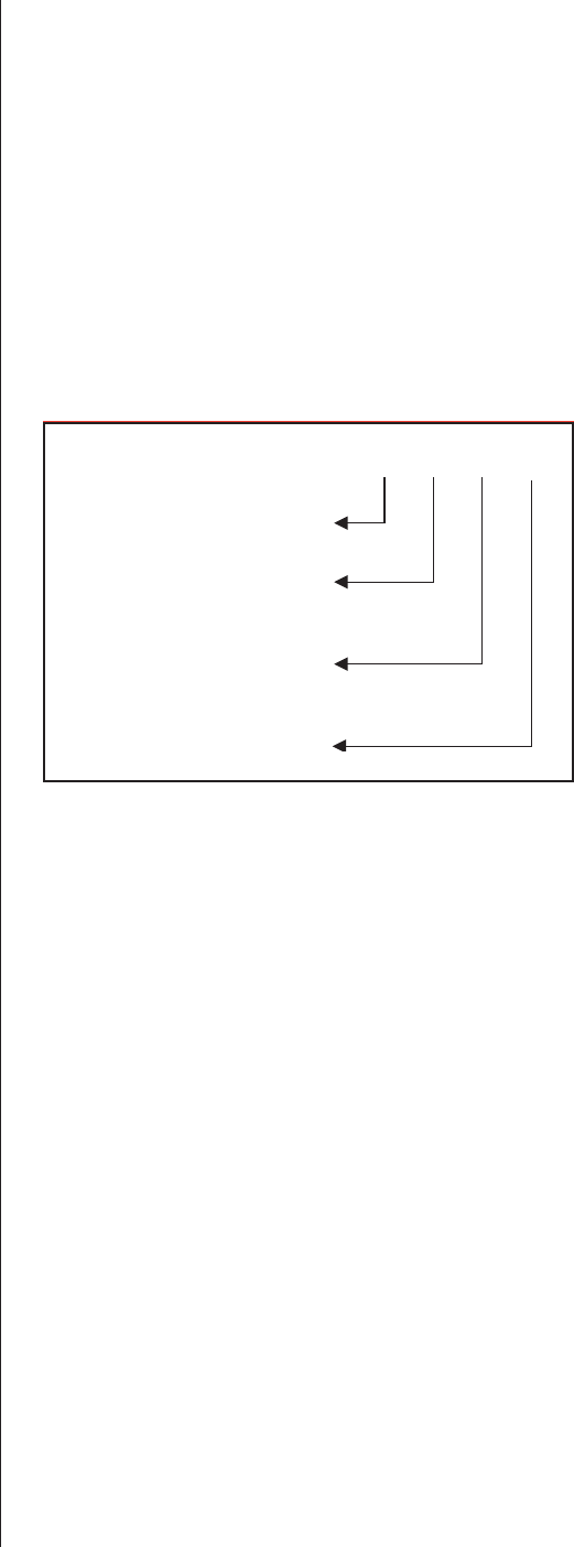
MODEL DESIGNATION
The unit specification label indicates the model of
Steam Exchange humidifier according to the following
chart:
SE 100
PRODUCT LINE
(Steam Exchange Humidifier)
Humidifier size
TC = Total Controller
c/w KEYPAD
P = Economical
TC
50
100
175
250
375
475
675
950
1050
Outdoor
O
C
.
-2-
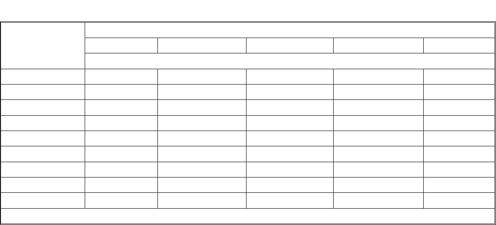
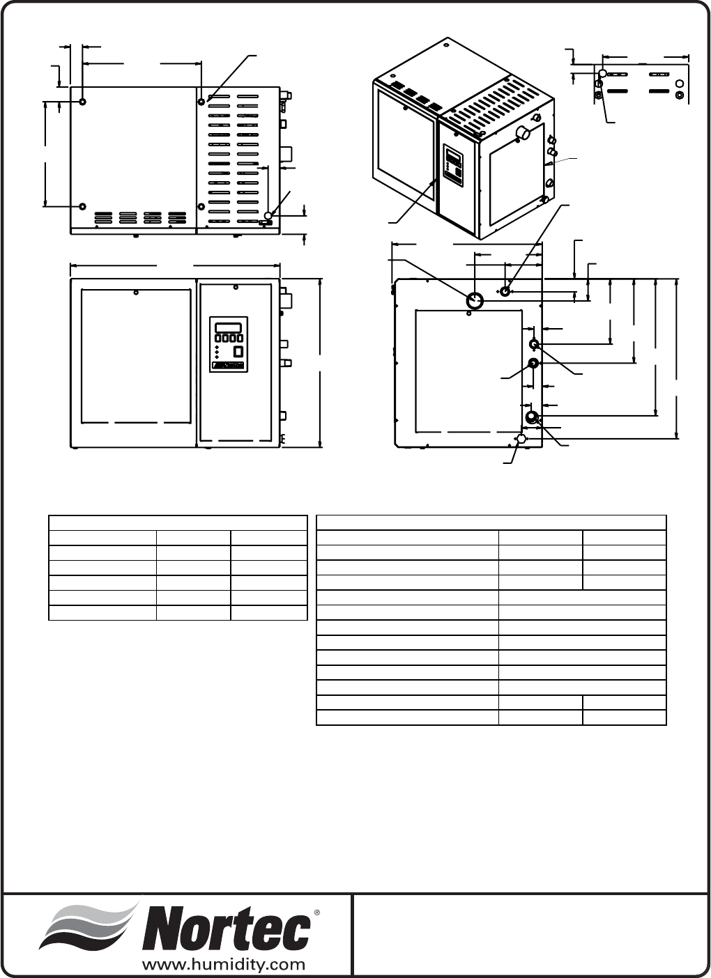
MODEL CAPACITY & PHYSICAL DATA
SETC/SEP
Operating Steam Pressure
5 psi (34kpa) 7 psi (48kpa) 10 psi (69 kpa) 13 psi (90 kpa) 15 psi (103 kpa)
Lbs/hr (kg/hr)
SE 50 17 (8) 20 (9) 28 (13) 40 (18) 50 (23)
SE 100 33 (15) 41 (19) 58 (26) 80 (36) 100 (45)
SE 175 45 (20) 59 (27) 88 (40) 131 (59) 175 (79)
SE 250 77 (35) 98 (44) 140 (64) 200 (91) 250 (113)
SE 375 105 (48) 136 (62) 200 (91) 294 (133) 375 (170)
SE 475 161 (73) 201 (91) 279 (127) 388 (176) 475 (215)
SE 675 200 (91) 256 (116) 368 (167) 531 (241) 675 (306)
SE 950 386 (175) 463 (210) 609 (276) 800 (363) 950 (431)
SE 1050 446 (202) 529 (240) 682 (309) 880 (399) 1050 (476)
NOTE: Specification subject to change without notice. Rated capacity applies with no blowdown.
Table #1
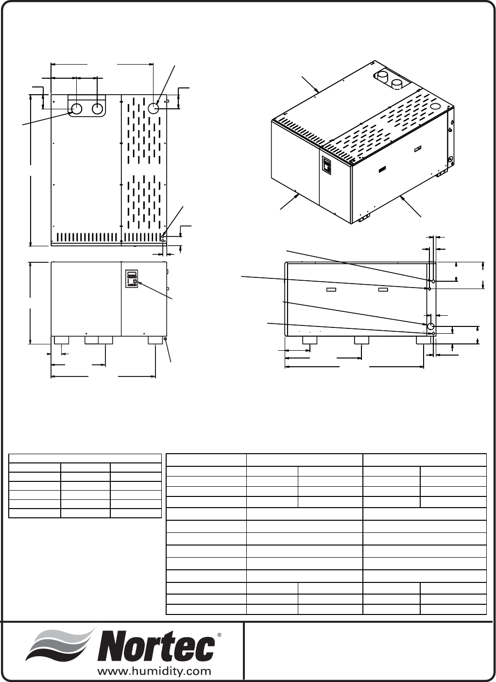
AUXILIARY DRAIN/
CONDENSATE RETURN
TO UNIT 1/2 NPT FEMALE
BOILER STEAM IN
1/2 NPT MALE
STEAM OUTLET
1 3/4" O.D TUBE
SUPPLY WATER
3/4 BSPP MALE OR
1/2 NPT MALE
POWER AND CONTROL
POWER AND CONTROL
BOTTOM PORT
FASTENING POINTS
FOR CEILING MOUNT
7/8 TUBE, DRAIN
3/4 NPT MALE
CONDENSATE OUT
FRONT
RIGHT
4 9/16"
11.6 cm
8 1/4"
21.0 cm
10 5/16"
26.2 cm
1 1/16"
2.8 cm
2 9/16"
6.5 cm
8 3/4"
22.3 cm
7/8"
2.3 cm
1 3/8"
3.5 cm
14 1/2"
36.9 cm
12 13/16"
32.6 cm
1 1/2"
3.8 cm
2 1/4"
5.8 cm
1 7/16"
3.7 cm
25 5/8"
65.1 cm
20 5/8"
52.4 cm
18 3/8"
46.7 cm
1"
2.6 cm
8"
20.3 cm
16 3/4"
42.6 cm
19 9/16"
49.7 cm
1 13/16"
46.3mm
2 11/16"
6.9 cm
1 9/16"
4.0 cm
Physical Data
SETC / SEP 50
3/27/06
TOP 0” 0 cm
LEFT 0” 0 cm
RIGHT 30" 76 cm
REAR 0” 0 cm
FRONT 30" 76 cm
BOTTOM 0” 0 cm
SERVICE CLEARANCE TECHNICAL DATA
Max. Rated Steam 56 lb/hr 25.4 kg/hr
Nominal @ 5 psi 3-17 lb/hr 1.4-7.7 kg/hr
Nominal @ 10 psi 6-28 lb/hr 2.7- 12.7 kg/hr
Nominal @ 15 psi 10-50 lb/hr 4.5-22.6 kg/hr
Steam Valve CV
Supply Water Con.
Drain Water Connection
Aux. Drain Con.
Pressure Steam In
Steam Cond. Out
Atm. Steam Out
Weight Empty 125 lb 57 kg
Weight Full 180 lb 82 kg
SE 50
2.2
1 x 1.75 OD (4.5 cm)
¾” NPT male
½”NPTor¾”BSPPmale
0.825” (2.1 cm) tube
½” NPT female
½” NPT male
-3-
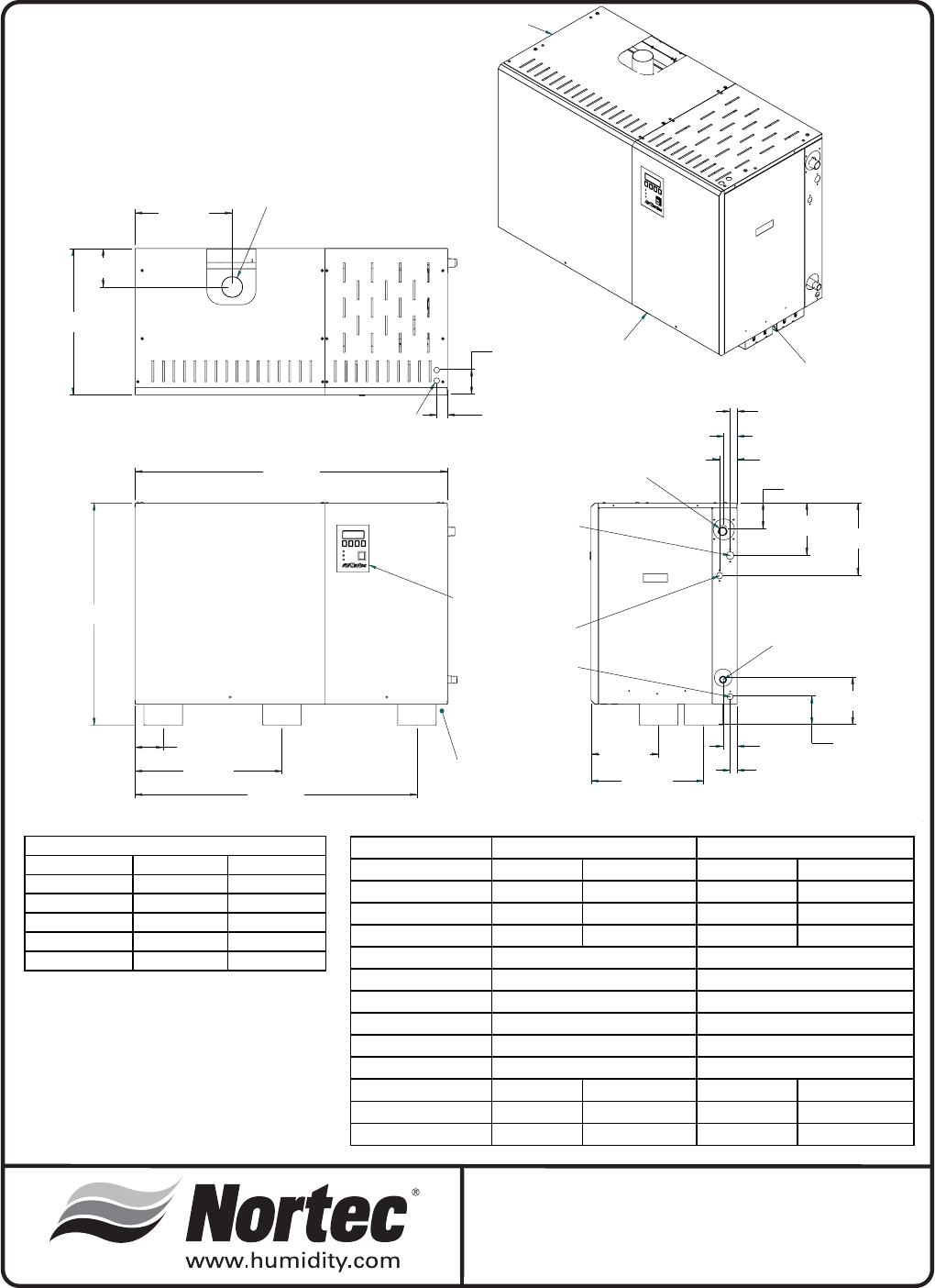
Physical Data
SETC 100 - 175
5/4/07
Technical data
Max.Rated Steam 105 lb/hr 48 kg/hr 180 lb/hr 82 kg/hr
Nominal @ 5psi 5-33 lb/hr 2-15 kg/hr 7-45 lb/hr 3-20 kg/hr
Nominal @10psi 9-58 lb/hr 4-26 kg/hr 13-88 lb/hr 6-40 kg/hr
Nominal @15psi 15-100 lb/hr 7-45 kg/hr 26-175 lb/hr 12-79 kg/hr
Steam Valve CV
Supply water con.
Drain water con.
Aux. drain con.
Pressure steam in.
Steam Cond. Out.
Atm. Steam Out. 1 x 1.75” OD 1 x 4.4 cm OD 1 x 3.00” OD 1 x 7.62cm OD
Weight Empty 267 lb 121 kg 267 lb 121kg
Weight Full 423 lb 192 kg 423 lb 192 kg
2.8
0.5” NPT
0.5” NPT female
7.5
0.5” NPT
.75" NPT
0.5” NPT
0.75” O.D. tube
0.5” NPT female
0.5” NPT
.75" NPT
0.75” O.D. tube
SE 100 SE 175
TOP 36” 91 cm
LEFT 0” 0 cm
RIGHT 30" 76 cm
REAR 0” 0 cm
FRONT 30" 76 cm
BOTTOM 0” 0 cm
SERVICE CLEARANCE
PRESSURE
STEAM INLET
WATER INLET
DRAIN
STEAM
CONDENSATE OUTLET
AUX. DRAIN
TOP
FRONT
RIGHT SIDE
POWER SUPPLY
STEAM OUTLET
CONTROL SIGNAL
CONTROL PANEL
20.8"
( 53cm )
13.9"
( 35.2cm )
5.5"
( 13.9cm )
44.5"
( 113.2cm )
31.6"
( 80.3cm )
9.7"
( 24.6cm )
16.1"
( 40.8cm )
7.4"
( 18.92cm ) 10.3"
( 26.2cm )
1.0"
( 2.5cm )
2.5"
( 6.4cm )
6.8"
( 17.18cm )
1.9"
( 4.83cm )
3.7"
( 9.47cm )
2.0"
( 5.1cm )
1.0"
( 2.5cm )
4.1"
( 10.3cm )
4.0"
( 10.2cm )
21.0"
( 53.3cm )
40.2"
( 102.2cm )
3.5"
( 9cm )
1.5"
( 3.9cm )
-4-
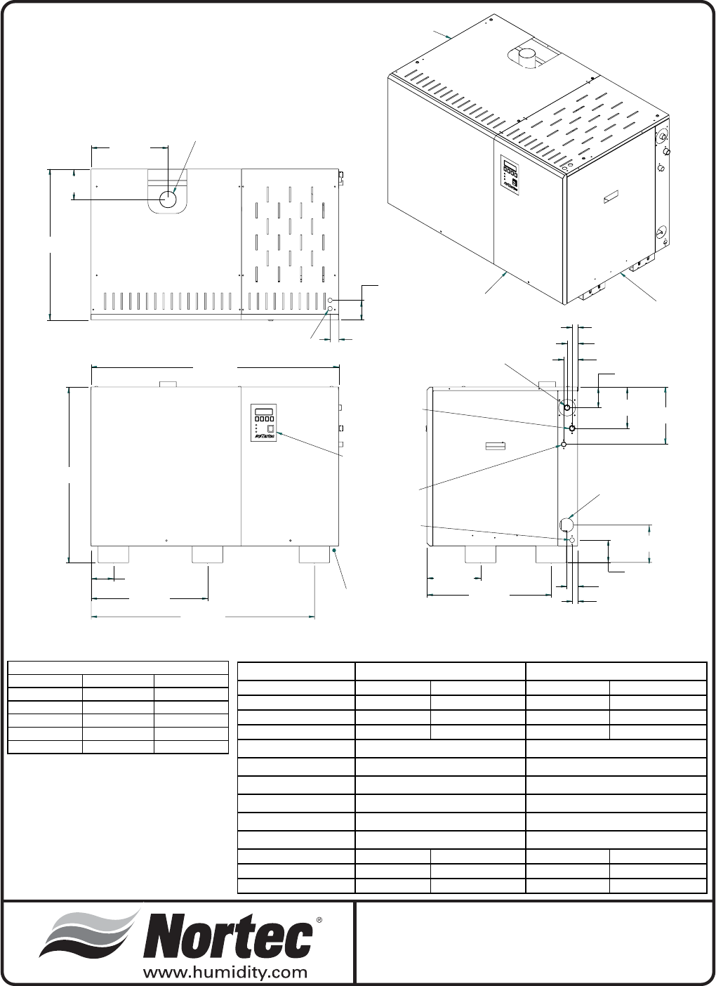
Physical Data
SETC 250 - 375
5/4/07
Technical data
Max.Rated Steam 255 lb/hr 115 kg/hr 380 lb/hr 172 kg/hr
Nominal @ 5psi 11-77 lb/hr 5-35 kg/hr 15-105 lb/hr 7-47 kg/hr
Nominal @10psi 21-140 lb/hr 10-64 kg/hr 30-200 lb/hr 14-91 kg/hr
Nominal @15psi 37-250 lb/hr 17-114 kg/hr 56-375 lb/hr 25-170 kg/hr
Steam Valve
Supply water con.
Drain water con.
Aux. drain con.
Pressure steam in.
Steam Cond. Out.
Atm. Steam Out. 1 x 3” OD 1 x 7.62 cm OD 1 x 4” OD 1 x 10.2cm OD
Weight Empty 355 lb 161 kg 355 lb 161 kg
Weight Full 599 lb 272 kg 599 lb 272 kg
SE 250 SE 375
0.5” NPT 0.5” NPT
12 28
0.75” O.D. tube 0.75” O.D. tube
0.5” NPT female 0.5” NPT female
1.0” NPT 1” NPT
.75” NPT .75” NPT
TOP 36” 91 cm
LEFT 0” 0 cm
RIGHT 30" 76 cm
REAR 0” 0 cm
FRONT 30" 76 cm
BOTTOM 0” 0 cm
SERVICE CLEARANCE
PRESSURE
STEAM INLET
STEAM
CONDENSATE OUTLET
9.7"
( 24.6cm )
22.4"
( 56.8cm )
1.9"
( 4.8cm )
1.0"
( 2.6cm )
2.5"
( 6.4cm )
3.7"
( 9.5cm )
7.4"
( 18.9cm )
2.0"
( 5.1cm )
1.0"
( 2.5cm )
4.1"
( 10.3cm )
6.8"
( 17.2cm )
CONTROL PANEL
POWER SUPPLY
44.6"
( 113.3cm )
31.6"
( 80.3cm )
4.0"
( 10.2cm )
21.0"
( 53.3cm )
40.2"
( 102.2cm )
27.2"
( 69cm )
13.9"
( 35.2cm )
5.5"
( 13.9cm )
3.5"
( 9cm )
1.5"
( 3.9cm )
STEAM OUTLET
CONTROL SIGNAL
WATER INLET
DRAIN
AUX. DRAIN
TOP
FRONT
RIGHT SIDE
10.3"
( 26.2cm )
-5-
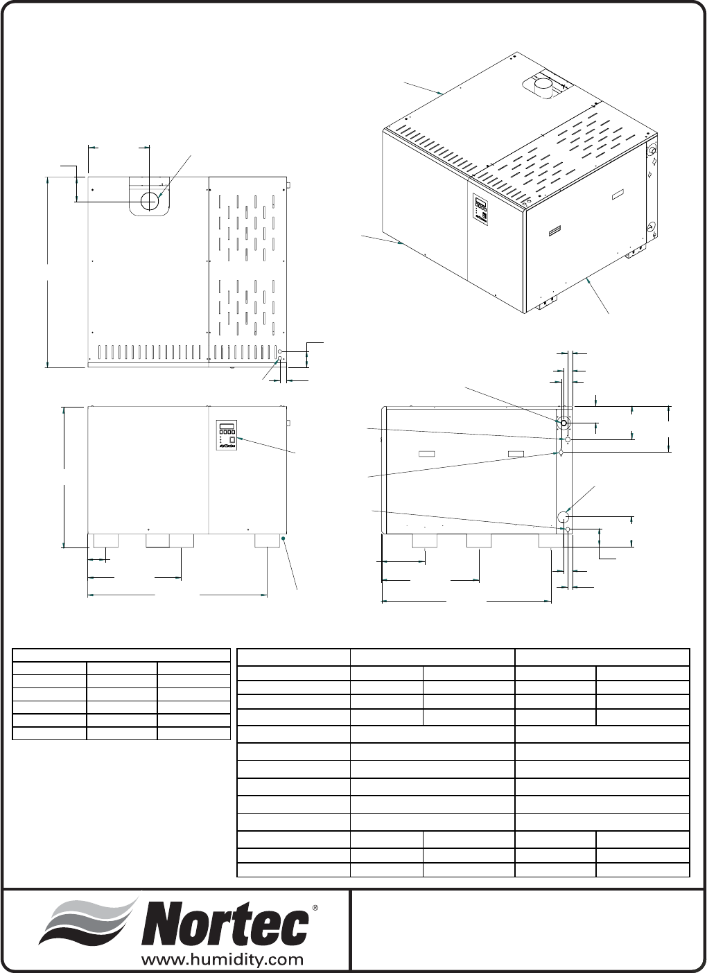
Physical Data
SETC 475 - 675
5/4/07
Technical data
Max.Rated Steam 480 lb/hr 217 kg/hr 680 lb/hr 308 kg/hr
Nominal @ 5psi 24-161 lb/hr 11-73 kg/hr 30-200 lb/hr 14-91 kg/hr
Nominal @10psi 42-279 lb/hr 19-127kg/hr 55-368 lb/hr 25-167 kg/hr
Nominal @15psi 71-475 lb/hr 32-215 kg/hr 101-675 lb/hr 46-306 kg/hr
Steam Valve CV
Supply water con.
Drain water con.
Aux. drain con.
Pressure steam in.
Steam Cond. Out.
Atm. Steam Out. 1 x 4” OD 1 x 10.16cm OD 1 x 4” OD 1 x 10.16cm OD
Weight Empty 529 lb 240 kg 529 lb 240 kg
Weight Full 992 lb 450 kg 992 lb 450 kg
SE 475 SE 675
0.5” NPT 0.5” NPT
20 28
0.75” O.D. tube 0.75” O.D. tube
0.5” NPT female 0.5” NPT female
1.25 ” NPT 1.5” NPT
1.0” NPT 1.0” NPT
TOP 36” 91 cm
LEFT 30" 76 cm
RIGHT 30" 76 cm
REAR 0” 0 cm
FRONT 30" 76 cm
BOTTOM 0” 0 cm
SERVICE CLEARANCE
3.7"
( 9.5cm ) 7.4"
( 18.9cm ) 10.3"
( 26.2cm )
1.9"
( 4.8cm )
1.0"
( 2.5cm )
2.5"
( 6.4cm )
6.8"
( 17.2cm )
4.1"
( 10.3cm )
2.0"
( 5.1cm )
1.0"
( 2.5cm )
9.7"
( 24.6cm )
21.9"
( 55.5cm )
38.0"
( 96.4cm )
31.6"
( 80.3cm )
4.0"
( 10.2cm )
21.0"
( 53.3cm )
40.2"
( 102.2cm )
13.7"
( 34.9cm )
5.5"
( 13.9cm )
3.5"
( 9cm )
1.5"
( 3.9cm )
42.7"
( 108.6cm )
CONTROL SIGNAL
CONTROL PANEL
POWER SUPPLY
PRESSURE
STEAM INLET
WATER INLET
DRAIN
STEAM
CONDENSATE OUTLET
AUX. DRAIN
STEAM OUTLET
TOP
FRONT
RIGHT SIDE
-6-
Technical data
Max.Rated Steam 960 lb/hr 435 kg/hr 1070 lb/hr 485 kg/hr
Nominal @ 5psi 58-386 lb/hr 26-175 kg/hr 67-446 lb/hr 30-202 kg/hr
Nominal @10psi 91-609 lb/hr 41-276 kg/hr 102-682 lb/hr 46-309 kg/hr
Nominal @15psi 142-950 lb/hr 64-430 kg/hr 158-1050 lb/hr 72-476 kg/hr
Steam Valve CV
Supply water con.
Drain water con.
Aux. drain con.
Pressure steam in.
Steam Cond. Out.
Atm. Steam Out. 2 x 4” OD 2 x 10.16cm OD 2 x 4” OD 2 x 10.16cm OD
Weight Empty 703 lb 319 kg 703 lb 319 kg
Weight Full 1384 lb 628 kg 1384 lb 628 kg
1.25” NPT 1.25” NPT
0.75” O.D. tube 0.75” O.D. tube
0.5” NPT female 0.5” NPT female
2.0” NPT 2.5” NPT
SE 950 SE 1050
0.5” NPT 0.5” NPT
40 65
TOP 36” 91 cm
LEFT 30" 76 cm
RIGHT 30" 76 cm
REAR 0” 0 cm
FRONT 30" 76 cm
BOTTOM 0” 0 cm
SERVICE CLEARANCE
Physical Data
SETC 950 - 1050
5/4/07
1.0"
( 2.5cm )
2.5"
( 6.4cm )
7.4"
( 18.9cm ) 10.3"
( 26.2cm )
4.1"
( 10.3cm )
6.8"
( 17.2cm )
2.0"
( 5.1cm )
1.0"
( 2.5cm )
9.7"
( 24.6cm ) 29.7"
( 75.3cm ) 53.6"
( 136.1cm )
31.6"
( 80.3cm )
4.0"
( 10.2cm )
21.0"
( 53.3cm )
40.2"
( 102.2cm )
9.9"
( 25cm )
39.5"
( 100.2cm )
8.0"
( 20.3cm )
58.3"
( 148.2cm )
5.5"
( 13.9cm ) 5.3"
( 13.6cm )
3.5"
( 9cm )
STEAM
OUTLETS
CONTROL SIGNAL
PRESSURE STEAM INLET
CONTROL PANEL
POWER SUPPLY
AUX. DRAIN
STEAM CONDENSATE
OUTLET
WATER INLET
DRAIN
1.5"
( 3.9cm )
RIGHT SIDE
FRONT
TOP
-7-

-8-
I
::r
~
3
c.
~
8
3 •
g~8
~"'"
.,g:",
00>"
o ,
"'''Co
m-
~~
>m
3
~
~
t
~
m
0«>"''''''''-''
",""''''~
1'0
~~Qg~2~aQ~~
fr1
3:mni~--<nim'2:'«lm~
;::
m~"'m~"'~6~;::i'i
i'"
Z((lmZ((lIZ:;!~i"7
-<
:l::j';:~~-<c:tO'J
!::
m(!)
z
r";c;,;-<~~m-<;;;(O~
~
-<:'-<;m;t>O ,"
I;!;-"'';Z
~
",(J);t>z-<~ce;mZO
mI«loom>:m::<l
° e
-<
2:;;:~~~:':QJ!lc-<tl
-
"m~,",
~-..,
-,,0
mm[Il-L
-":m~»8g
~
:i Q
r:;:
~
~
~}J
-<
(3
Z
om
:;::-<__
:r<""
~
....
o"m~~mm(;jT
-<I"T1(J)"'mm
r-<c::;j
;r:~5rJ~':'l~::!liii~~
~m~8tj~~((l~6;t>
o~~~'-<o
QRzF
-<0
LIO-<:;;-<:,JCO::2
I""
o-m
-<:1:
~m
m-<m--."PI
m> 0
"T1Izr:::lOC:I:I3:
m
rmlil",rr.lOCZ
(f)
QOl!ii
-<~r;::-
:t>
!!rj>m~~;;:mQ2j;fI1
z -<-- 0
-<
--,,;:: z
~O~~()Izmoo;l
-<b-<C~Z~"'"T1:::Jm
fiim=i:Sl>~~~f:j~~
I
iii
~
r
~
m 0
~.:-'
ii1-<
P
c"",,,,mlll
"'Z~
;<l-<m;c-<
I~»
mmPOmI
c"'r
I"'Cl>~
3:"'rc
zc;;;~Zm
03",Z
-<"::
,0
"T;3
o~
IQ
z
m'-C:<
m-"
C
;tl
CO
f;im
oj
;;:
~~
GJ;tl
"
-<
(Jl(jj
25
I
C:;O
~;;;
:;;
~
0;;1
rt1
~
"'l'
<:J
8
,
S
m
W
~
~
.~
i~
..
~
~~
00
as
'z
Om
~Ii
~21
80
.
~
~
o
i
o
~
o
i
U "
4}J~n
•
~
,
§
3O.2i"
76.7=
,~.
w
I~~
1
.4cm
"
~
o
o
w
~
" ffi
>
ffi
o
"
"
g
c
z
~
w "
0
0
m r!,
-~
~
m
~
r
~
#
::('
II~/
,
w
mo
"m
g~
"
,
ffi
~
~
g
> >
•
. "
~
I';
>
C'
"
~
ffi
@
~
l,
~o
~
'
,
~
~
.-,
,
'-,
-.J
ffil"'I
....
I0>I""~
2
~
oo~
cr--<OQ»g
_--<\<-
~;::~
L0~~lj)S::m'"
~~~(/)~;>J~
mli~~(D"'C:»
CI
<:
:;:;;U);Z
zmOol>--<O
O;lJxmOm'
I';:
m
G';
~
o
~
~
z
""
W",I",I
...
~o
...
I~~
~.
"
•
ti
tiitilNIN
"
"'
I"'I~~
.8
D
'"
c;')1::!
" <
~<
[;jl
"'I
"'I
'-"I
mill:!
~
~~
[;ll
",I'"
1,-"
1m
~o
DO
·0
••
~~
~.
DO
"0
~
c
o
~
-9-
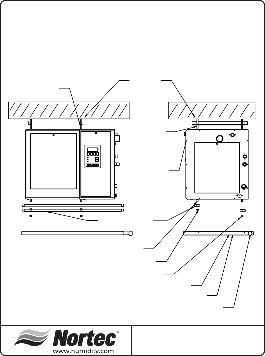
SECURE RODS
TO STABLE STRUCTURE
UPPER BRACING BRACKET
RECOMMENDED
SLIDE UNIT ONTO RODS
THROUGH HOLES PROVIDED
IF USING FACTORY HARDWARE, RODS CAN
ONLY EXTEND 1" PAST THE BOTTOM OF THE CABINET
SLIDE FACTORY SUPPLIED
BOTTOM BRACKETS IN PLACE
SECURE BRACKETS TO RODS. PROPER INSTALLATION MEANS MUST BE
USED TO ENSURE THAT THE ASSEMBLY DOES NOT DETACH
IF USING FACTORY DRIP PAN, FASTENING HARDWARE MUST BE CONCEALED
WITHIN THE PROFILE OF THE BOTTOM BRACKETS
ATTACH DRIP PAN. SECURE TO BOTTOM BRACKETS VIA END SCREW ATTACHMENT
1/2 NPT PLUMBING OR EQUIVALENT IS RECOMMENDED
TERMINATE AT DRAIN
DO NOT DRAIN UNIT INTO DRIP PAN. DO NOT ROUTE ANY OTHER FLUID TO DRIP PAN.
DRIP PAN IS NOT A STRUCTURAL MEMBER AND CANNOT BE USED TO SUPPORT OTHER ELEMENTS
NOTES:
1. UNIT WEIGHT WITH WATER = 180 LB. THIS DOES NOT INCLUDE THE ADDITIONAL PLUMBING NEEDED
FOR CONNECTION. TOTAL WEIGHT MUST BE DETERMINED BY OTHERS.
2. STRUCTURAL CONSIDERATIONS ARE THE RESPONSIBILITY OF OTHERS.
3. PROPER MOUNTING MEANS, SUCH AS; THE SECURING OF FASTENERS OR OTHER JOINTS, IS THE
RESPONSIBILITY OF OTHERS.
4. UNIT CANNOT BE USED AS A STRUCTURAL MEMBER. NO OTHER COMPONENTS MAY BE ATTACHED TO
IT.
5. SERVICE ACCESS IS REQUIRED AT THE FRONT AND RIGHT SIDE OF THE UNIT. A MINIMUM OF
30” (76 cm) CLEARANCE IS NEEDED.
6. SIZES AND FEATURE LOCATIONS ARE TO BE DERIVED FROM THE UNIT DIMENSIONAL DRAWINGS OR
BY CONSULTING THE FACTORY.
THREADED ROD
3/8" OR METRIC M10
SE 50
Ceiling Mounting Installation (Optional)
3/27/06
-10-
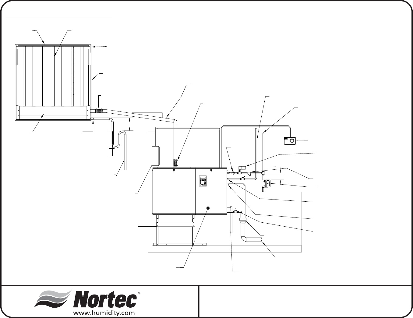
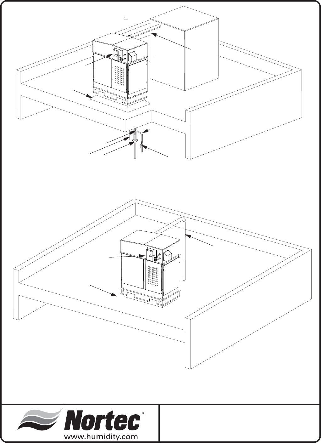
Typical SE Installation
SAM-e (Short Absoption Manifold)
Can be installed in the Horizontal
duct or vertical Duct or a AHU.
Reference SAM-e Installtion
Manual
Condensate Return
to drain or sump pump
Primary wire and
disconnect (By Others)
Standard
Telescopic
Stand
(Option by
Nortec)
1/2" NPT Supply water
connection. (Manual shut-off
valve by Others)
3/4" O.D. Drain connection
to funnel drain or sump pump
1/2" NPT Aux. Drain, Optional
Plugged at factory
(Shut-off valve by Others)
Funnel with 1" air gap
supplied by others
Controls (By Nortec or by Others)
Steam Valve and Actuator must be located 6" max.
from the SE humidifier.
Inlet located on top of unit for SE models 475 to 1050.
Valve and Actuator must be installed horizontally.
Refer to the Invensys installation manual for details.
12"
2"
1. This drawing is for reference only. Installation
must conform to all local codes.
2. Refer to physical data drawings for dimensions.
6"Min
6" min., P-Trap must be 2" more than
duct static pressure
3/4" NPT Condensate
Return
Copper or S.S.
pipe - 1" Insulation
Recommanded
Stainless Steel
Steam Header
Galvanized Mounting Frame
Optional
Typical SE Installation
Stainless steel
steam tubes
Open floor drain must be properly sized
and rated for maximum temperature requirements.
Duct or AHU
Short-Absorption Manifold (SAM-e)
6" Long hose cuff and 2 gear
clamps for steam line connection.
(by Nortec)
Union
(by Others)
6" Long hose cuff for 1.75" dia. tubing
4" long hose cuff for 3" & 4" dia. tubing
and 2 gear clamps for steam line connection.
(By Nortec)
Steam condensate drain.
Return to nonpressurized system,
by gravity only
Pressurized steam connection from Boiler
Max. 15 psi
Min. 5 psi
Water supply
30 to 80 psig
Drain water cooler and
F & T Steam trap(s)
Located inside unit. Installed
at Nortec
Steam trap (By Nortec or by Others)
Return to nonpressurized system,
by gravity only
Wye strainer (By Nortec)
6"Min
-11-
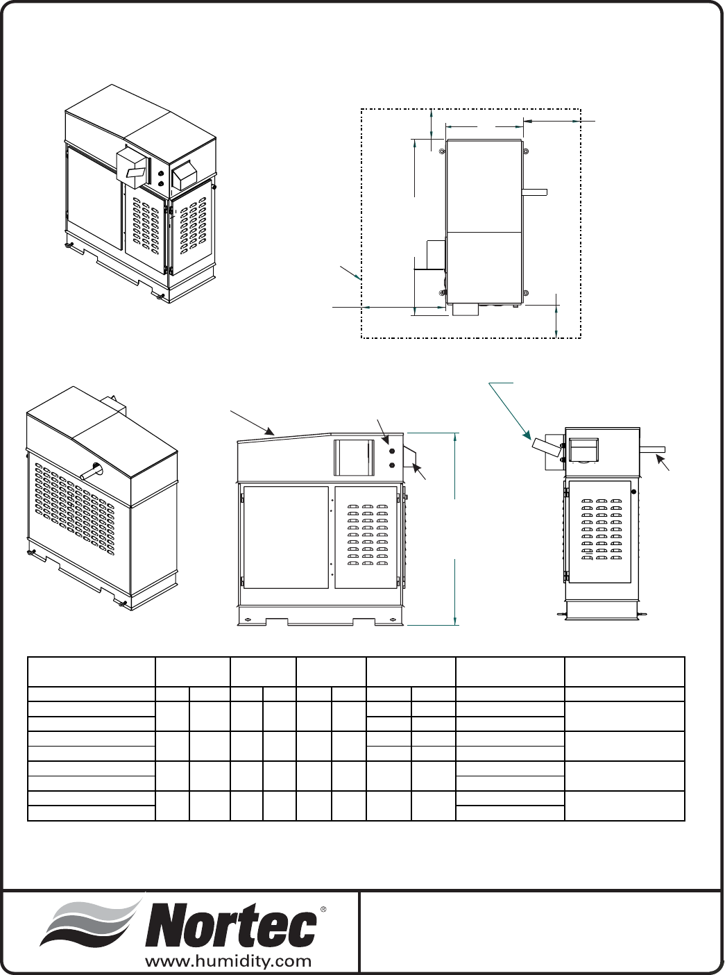
NEMA RATED
JUNCTION BOX
(By Others)
CLEARANCE
ENVELOPE
A
30”
(76.2 cm)
10”
(258mm)
*Required for
SETC Outdoor
475-1050
49.7”
(126.2 cm) 12”
(30.5 cm)
40”
(101.6 cm)
54.3”
(138 cm)
RIGHT
Steam
Outlet(s)
TOP
FRONT
RIGHT
BACK
LEFT
*Cleaning Port for
SETC Outdoor 475-1050 Power and
Controls
Vent
Hood
FRONT
Cleaning
Port
in cm lbs kg lbs kg in cm NPT
SETC Outdoor 100 1x1.75 1x4.4
SETC Outdoor 175 1x3 1x7.6
SETC Outdoor 250 1x3 1x7.6
SETC Outdoor 375 1x4 1x10.2
SETC Outdoor 475
SETC Outdoor 675
SETC Outdoor 950
SETC Outdoor 1050 1.25
Model
1x4 1x10.2
Steam Condensate
Outlet
0.75
0.75
1
2.5
2x4 2x10.2
1.5
1.25
1.5
2
NPT
0.5
0.75
1
Pressure Steam
Inlet
AShipped
Weight
Operating
Weight
Steam Outlet
(O.D.)
192
272
450
628
423
599
992
1384
121
161
240
319
267
355
529
703
27.9
21.5 54.6
70.8
59.1 150
11143.5
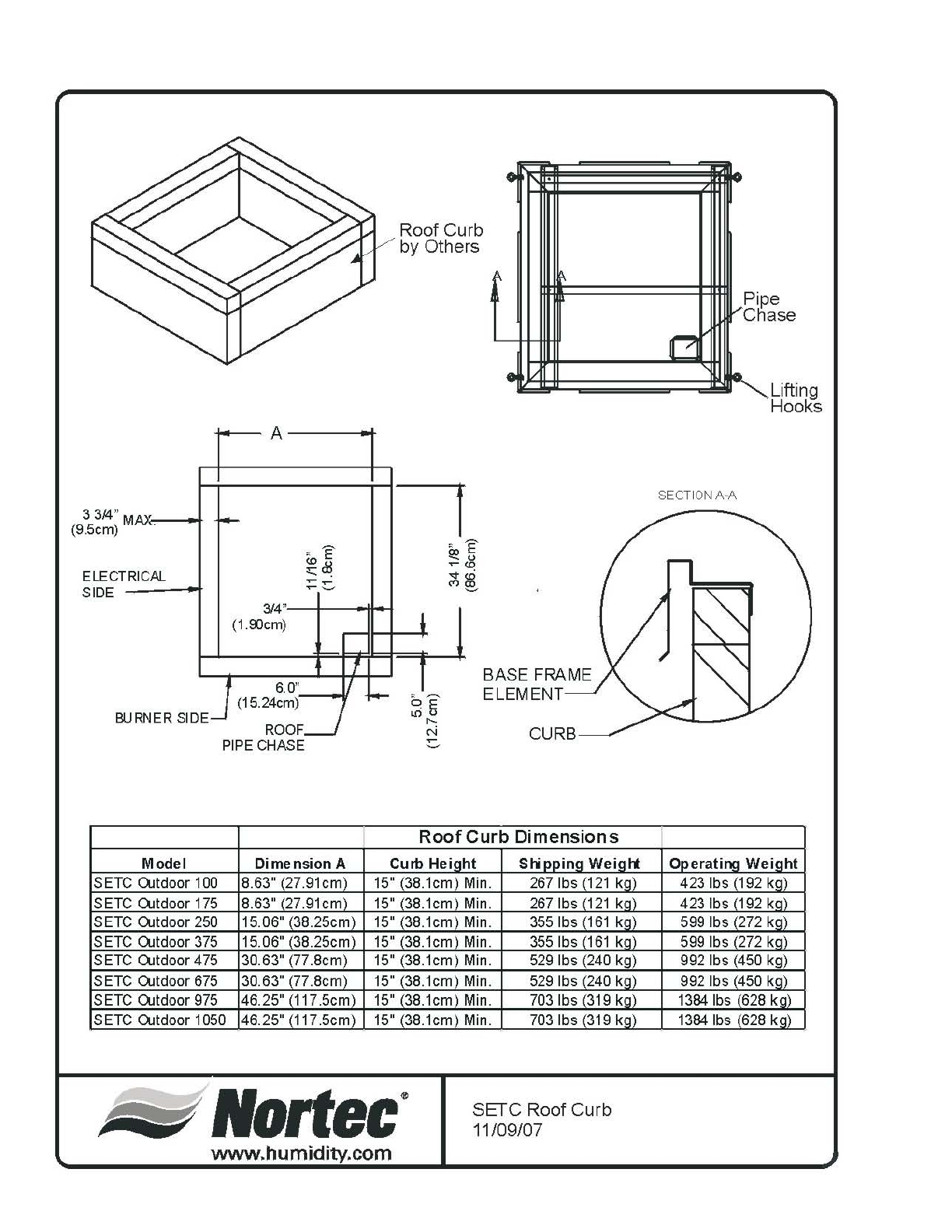
SETC Outdoor Dimensions
1/26/04
-12-
A
3314 '
(9.5cm) M -
ELECT
SIDE
RICAI...
BlJ
RNER
SlDE---J
<E
~d!
:::::::-
3/4"
(1.00cm)
f
6.0"
(15.24cm)
ROOF
PIPE CHASE
Model Dimension A
S ETC OJtdoor 100 8.63" (27.91cm)
S ETC OJtdoor 175 8.63" 27.91cm)
S ETC OJtdoor 250 15.06" 38.25cm)
SETC OJtdoor
375
15.06" (38.25cm)
S ETC OJtdoor 475 30.63" (77.Bcm)
S ETC OJtdoor 675 30.63" 77.8cm
S ETC OJtdoor 975 46.25" 117.5cm)
S ETC OJtdoor 1050 46.25" 117.5cm)
-
Roof Curb
by Others
I
1E
.,
~
I
1
~5
~
N
CURB-~
Roof
Curb
Dimensions
Curb
Hei~ht
Stippino
Weiott
15" (38.1cm) Min.
267
Ibs
(121
k9)
15" (38.1cm) Min.
267
Ibs
(121
kal
15" (38.1cm) Min.
355
Ibs
161
kg)
15" (38.1cm) Min.
355
Ibs
(161
k9)
15" (38.1cm) Min.
529
Ibs (240 k9)
15" (38.1cm) Min.
529
Ibs 240 kg)
15" (38.1cm) Min. 7031bs (319
kal
15" (38.1cm) Min. 7031bs (319 kq)
lIortec'
SErC
Roof Curb
11/09/07
www"humidity.com
SECTION
A-A
Lifting
HooKs
Operati~
Wei~ht
423 Ibs (192 k9)
423 Ibs (192 kal
599 Ibs (272 k9)
599 Ibs (272 k9)
992 Ibs (450 k9)
992 Ibs (450 k9)
1384
Ibs
628 kq)
1384
Ibs
628 kq)
SE INDOOR INSTALLATION
LOCATING AND MOUNTING
SE Series humidifiers are designed to mount on
an SE Stand (Included with all models) or floor. The
clearance dimensions shown in this manual are for
reference only and are the minimum required for
maintenance of the humidifier. Local and National
Codes should be consulted prior to final location and
installation of the humidifier. NORTEC cannot accept
responsibility for installation code violations.
·Figure #1 shows the locations of all required
connections to the Steam Exchange Humidifier.
Careful consideration should be given to all of
these connections when choosing a location for
the humidifier.
·For front and side clearance requirements (for
access during installation, maintenance and
troubleshooting), refer to pages3-6.
·DO NOT locate humidifier any further than
absolutely necessary from steam distributor
location. Net output will be reduced as a result of
heat loss through steam line. Also, increased
static pressure (over 12" W.C.) will result in hot
water going down the drain. Consult factory if this
situation occurs.
·Where possible, mount humidifier at a height
convenient for servicing.
·Ensure the humidifier is mounted level.
·Ambient temperature location for humidifier:
41ºF - 104ºF (5ºC - 40ºC).
·Relative humidity location for humidifiers:
5% rh - 80% rh.
·DO NOT mount humidifier on hot surfaces.
·DO NOT mount humidifiers in an area where
freezing may occur.
·If humidifiers are mounted on roof, a properly
ventilated, temperature controlled, (above
freezing), weatherproof model should be used.
Consult your local representative for more
information on NORTEC’s SETC Outdoor model.
·DO NOT mount humidifiers on vibrating surface.
Consult factory.
·The humidifier shall not be installed directly on
carpeting, tile or other combustible material other
than wood flooring.
·Some insulating materials may be combustible.
Prior to installing this appliance examine the area
for insulating material. If this appliance is
installed in an insulated space, it must be kept
free and clear of insulating materials. If insulation
is added after the appliance is installed, it will be
necessary to examine the area again.
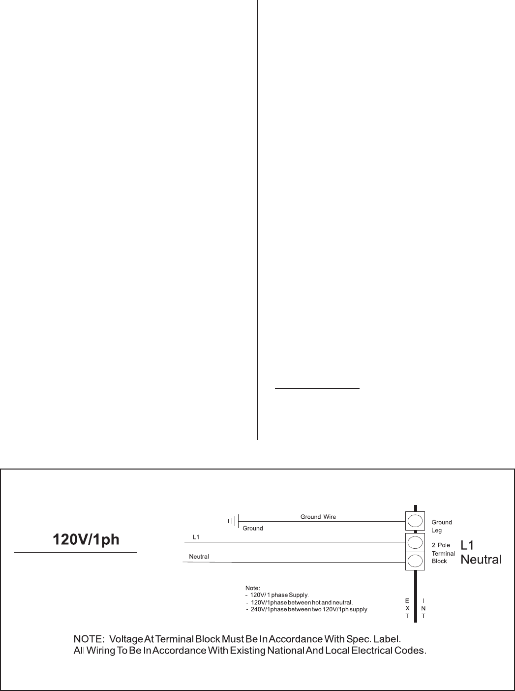
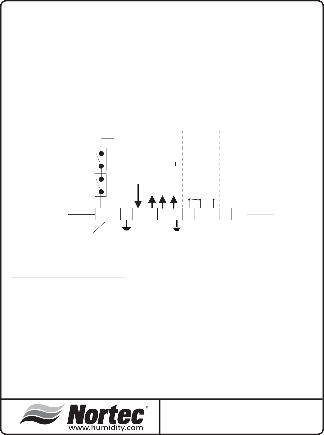
PRIMARY WIRING
All work concerning the electrical installation
must be performed by qualified personnel.
-13-
Figure #1
Primary Wiring to Humidifier
ELECTRICAL
WARNING: The electrical parts inside the
humidifier are very sensitive to electrostatic discharge.
Appropriate measures against electrostatic discharge
(ESD protection) must be taken when carrying out
installation work.
·The humidifier should only be connected to
primary power (main power) after all installation
work has been completed.
·An external disconnect switch(by others) must be
installed close to the unit to allow for power
interruption during servicing and/or maintenance.
·Humidifiers require field wiring to primary voltage
terminal blocks. Power requirement must be
110-120/1/60Vac, 15A or 20 A for SETC Outdoor
950 &1050 separately fused circuit, single phase.
Wiring can be fed through a 7/8" hole on the
bottom or the top of the control compartment.
·When installed, the appliance must be electrically
grounded in accordance with local codes or, in
the absence of local codes, with the National
Electrical Code, ANSI/NFPA 70, and/or the CSA
C22.1 Electrical Code, if an external electrical
source is utilized.
·External wiring sizes must be in accordance with
NEC and/or CEC and existing local electrical
codes and by-laws.
LOW VOLTAGE CONTROL WIRING
(See Page 14 for details)
All SE models require at least one type of input
control signal for unit operation. Refer to the sections
below that detail the types of controls that can be used
with each model.
Low voltage control terminal strips are provided in
the electrical compartment. Refer to the specific
control wiring diagram supplied with each unit.
Field wiring from humidistat to humidifier and
between devices should be shielded 18 AWG or
heavier and kept as short as possible.
Controls are available from NORTEC as
accessories and can be ordered with the humidifier.
Controls by others may also be used as long as they
meet the criteria noted below. The following is a
summary of the common types of controls that may be
used with NORTEC SE Humidifiers.
A – Wall or Duct Mounted Control On/Off
Humidistat: Wired to make on drop in humidity, break
on rise to set point. Set to desired RH. Can be a
make/break set of contacts from a Building
Management System.
B – Duct Mounted Safety High Limit On/Off
Humidistat: Wired to make on drop in humidity, break
on rise to safety set point. Set to approximately 85%
RH as a safety to prevent saturation and wetting in the
duct. Highly recommended for ducted applications.
C – Duct Mounted Safety Air Proving On/Off
Switch: Wired to make when sensing air flow, break
when no air flow. Used as a safety to prevent
saturation when there is no air flow. Highly
recommended for ducted applications.
D – Wall or Duct Mounted Modulating Humidistat:
Provides a modulating signal to the unit that
represents the output (up to 100%) required from the
humidifier. Signal type can be changed in the field via
dip switch settings on the logic control board. Refer to
SETC Setting section.
The SETC can accept a single or dual control
signal. The SEP can only accept a single control
signal:
SETC SEP
0-20 mA
4-20 mA 4-20 mA
0-10 VDC 0-10 VDC
2-10 VDC
0-5 VDC
1-5 VDC
ON/OFF ON/OFF
The unit must be ordered from the factory for the
desired signal type and number of channels. If no
signal type was specified, ON/OFF control signal will
be set as default. When configured for 2-channel
modulation the humidifier will generate steam only if
both channels indicate a demand (see D). If both
channels are demanding steam the humidifier will
satisfy the lower demand signal.
-14-
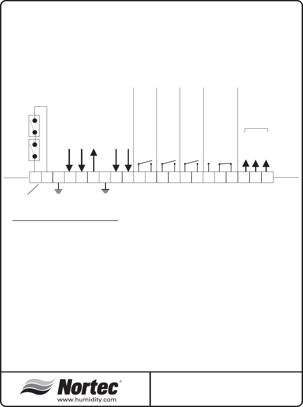
SETC SERIES
EXTERNAL CONTROLS WIRING CONNECTIONS
LOW VOLTAGE TERMINAL STRIP
WARNING: Failure to wire the controller in accordance with the wiring diagram that was supplied
with the unit could permanently damage the SETC board. Such errors will void the unit warranty.
NOTE: This is a wiring diagram only. For specific wiring instructions, it is necessary to refer
to the wiring diagram which is supplied with each unit.
generic
Low Voltage Terminal Strip
1 & 2: Wire all on/off controls and safeties between these two terminals. If not used, jumper1&2forthe
unit to operate.
4: Modulating input to humidifier “A”.
5: Modulating input to humidifier “B”.
6: 10 Vdc output (20 mA max.) Can be used to simulate demand to unit..
8: When 24 Vac input received, the unit will initialize a full tank blowdown.
9: Safety interrupt (24 Vac).
10 & 11: Remote indication connection for humidifier “on” status indication.
12 & 13: Remote indication connection for humidifier “active” status.
14 & 15: Remote indication connection for service required indication.
16,17 & 18: Remote indication connection for fault indication.
19, 20 & 21: Modulating output and 24VAC power to actuator
1234
6
5
7
8
910
1211
EXTERNAL
INTERNAL
EXTERNAL
INTERNAL
Security Loop
Modulation Input Signal “A"
Modulation Input Signal “B”
10 Vdc output (20 mA max.)
Full Tank Blow Down (FTBD)
enable (24 Vac)
Safety Interrupt (24 Vac)
NOTE: If no On/Off Control is used then a field jumper
must be connected across terminals 1 and 2 in order
for the humidifier to operate.
14 1815
16
17
13
COM
COM
COM
COM
N.O.
N.O.
N.O.
N.C.
N.O.
Humidifier “ON”
Humidifier “ACTIVE”
Humidifier “SERVICE”
Humidifier “FAULT”
19 20 21
24V (Hot)
Common
Signal
Actuator
SETC SERIES
External Controls Wiring Connections
09/16/2004
-15-
-16-
SEP SERIES
External Controls Wiring Connections
09/16/2004
SEP SERIES
EXTERNAL CONTROLS WIRING CONNECTIONS
LOW VOLTAGE TERMINAL STRIP
WARNING: Failure to wire the controller in accordance with the wiring diagram that was supplied
with the unit could permanently damage the SEP board. Such errors will void the unit warranty.
NOTE: This is a wiring diagram only. For specific wiring instructions, it is necessary to refer
to the wiring diagram which is supplied with each unit.
generic
Low Voltage Terminal Strip
1 & 2: Wire all on/off controls and safeties between these two terminals. If not used, jumper1&2forthe
unit to operate.
4: Modulating input to humidifier
5,6&7: Modulating output and 24VAC power to actuator
8, 9 & 10: Remote indication connection for fault indication.
1234
6
5
7
8
910
1211
EXTERNAL
INTERNAL
EXTERNAL
INTERNAL
Security Loop
Modulation Input Signal
NOTE: If no On/Off Control is used then a field jumper
must be connected across terminals 1 and 2 in order
for the humidifier to operate.
COM
N.C.
N.O.
Humidifier “FAULT”
24V (Hot)
Common
Signal
Actuator
CONTROL INSTALLATION
·Mount any wall humidistat (control or high limit)
over standard electrical box at height similar to
typical thermostat. Any wall humidistat should be
in location representative of overall space being
humidified and not in path of blower pack or air
supply grille. Do not mount on an outside wall
where temperature fluctuations can affect control
response. (Windows, sky lights, sinks, coffee
machines, etc.)
·Mount duct humidistat in location representative
of overall air humidity, usually in return duct. Do
not mount it directly in front of steam distributor or
in turbulent or mixing zone. Mount humidistat
where air’s humidity and temperature are uniform
and representative of spaces being humidified.
·Mount duct high limit humidistat downstream of
steam distributors far enough that, under normal
humidity and air flow conditions, steam will have
been fully absorbed (typically at least 10 feet). It
must be located to sense high humidity only
when uniform and representative air is
over-humidified or approaching saturation.
·Mount duct air-proving switch so that it is able to
sense air flow or lack thereof it. Wire it to make
when air flow is sensed and break when air flow
fails.
·Check operation of all on/off controls before
starting humidifier.
·Calibration of controls (on/off or modulation) in
the field may be necessary due to shipping and
handling. Verify humidistat accuracy before
commissioning system.
PLUMBING
NOTE: All water supply and drain line
connections should be installed in accordance with
local plumbing codes.
WATER QUALITY
·The humidifier is intended to operate on cold
water.
·DO NOT use a hot water source to supply the
humidifier. Minerals will adhere more easily to
surfaces and the fill valve’s small flow regulating
orifice could become plugged.
·Consider using a water softener. Longer
operating times between tank cleaning will be
achieved with softened water.
·Reverse osmosis (RO) water can provide very
long periods before cleaning is required since it is
cleaner than softened water. Deionized (DI)
water may be used with all models with the
stainless steel water supply option. Consult your
NORTEC representative for a quote on a water
treatment system.
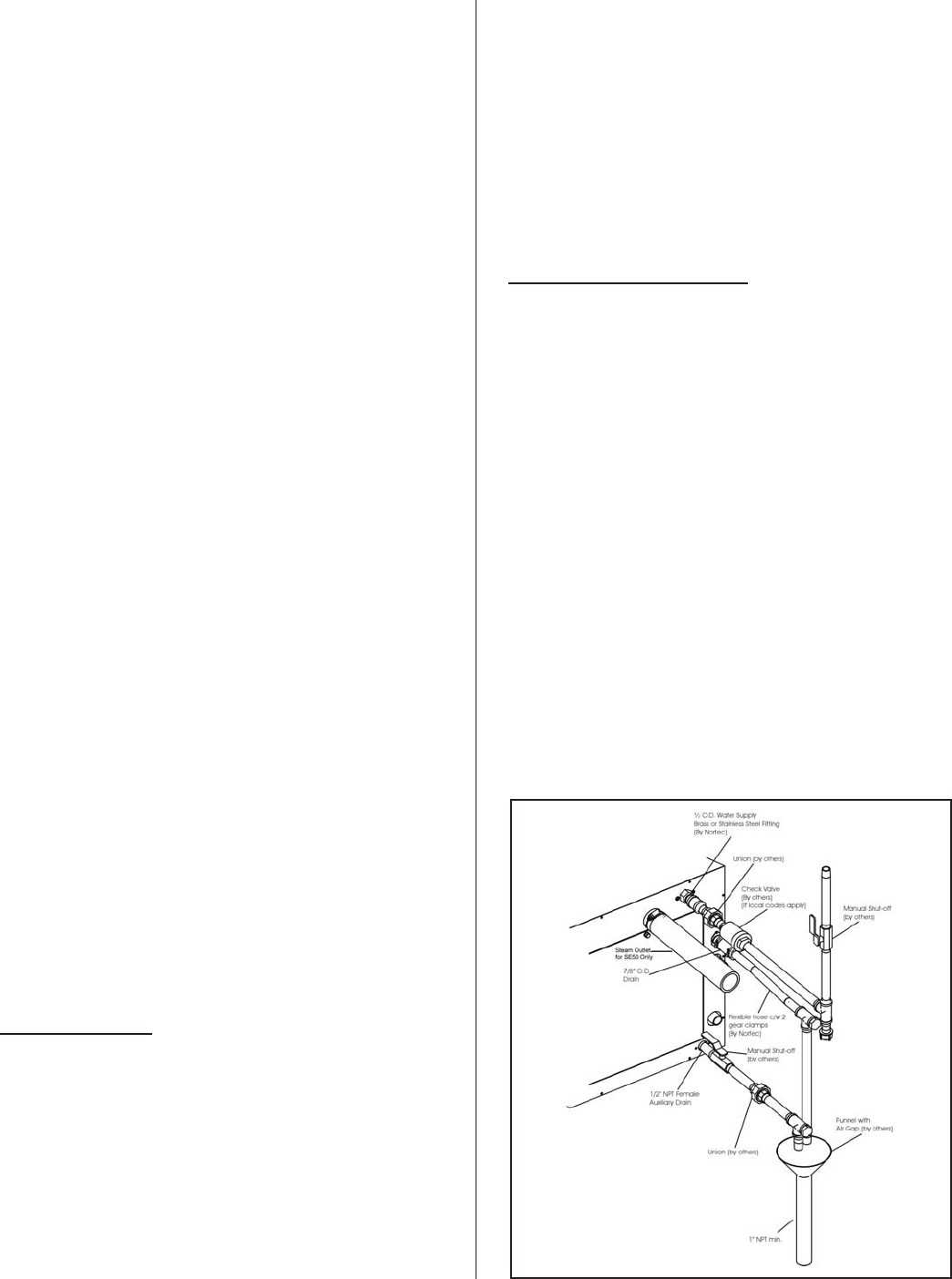
FILL WATER SUPPLY LINE
·Each unit is supplied with an adapter for the fill
valve (½”NPT ). The SE 50-675 has a fill rate of
10l/min (2.6 gpm) and the SE 950-1050 of
17l/min (4.5gpm). Size of piping is a minimum ½”
copper, recommend ¾” up to within 4 feet of unit.
·Standard fill valves are sized for water pressure
ranging from 30 to 80 psig (ideally 55 to 60 psig).
For other pressures, consult factory. This
pressure should be measured at the humidifier if
the water pressure is suspect.
·It is recommended to have a faucet installed
close to the humidifier to allow quick filling of the
system on initial start up. This can also be very
useful for mandatory cleaning of the unit.
·ALWAYS supply and install a shut-off valve and
union in the water supply line dedicated to the
humidifier to facilitate servicing.
-17-
Figure #2
Installation

DRAIN LINE
·The humidifier is equipped with a ¾”O.D. drain
outlet connection on the side of the humidifier. A
vacuum break valve is installed internal to the
unit on the drain line. The drain water line must
be piped to a drain funnel to provide an air gap
before connection to the building drainage
system.
·The drain line should not end in a sink used
frequently by personnel, or where plumbing
codes prohibit it. Route to a floor drain or
equivalent for safety reasons. Internal drain water
tempering will ensure a maximum of 140ºF
(60ºC) exiting water temperature.
·Keep drain lines as short as possible. Keep drain
lines sloped down, not level and not up since low
spots in drain lines will accumulate sediment and
cause backup. The drain line should be 1-1.5"
O.D. or larger. Consult local codes.
·When the drain pump is activated, the tank drains
at a rate of 7-8 gal/min (18-20 l/min).
STEAM CONDENSATE OUTLET
MODEL OUTLET
SE 50, 100, 175, 250 and 375 ¾” NPT
SE 475, and 675 1” NPT
SE 950, and 1050 1 ¼” NPT
·The SE humidifier has a condensate return line
connection for removal of the condensate
formed in the heat exchange.
·Condensate line after the steam trap(s) must be
atmospheric and lower than the traps at all times.
If required, a condensate pump (by others) can
be used to return condensate to the humidifier.
AUXILIARY DRAIN OUTLET
·An auxiliary drain port is also provided on the
side of the humidifier. It can be used to manually
drain the unit, if required. The unit is shipped
with this connection plugged. It is recommended
to install a shut off valve on this line.
·The auxiliary drain port is used when the freeze
protection option is required. Install a shut off
valve on this line and pipe to the drain funnel.
The manual shut off valve must always be in the
open position when the unit is operating but can
be closed for servicing of the unit.
STEAM LINES AND CONDENSATE LINES
For steam line installation between the humidifier
and distribution system, consult the distribution system
installation manual. Steam Distributor Installation
Manual - Form #XX-231 and SAM-e, Short Absorption
Manifold - Form #XX-249.
The SE series of Steam Exchange humidifiers can
develop steam pressures up to 12” w.c. to overcome
duct and steam line pressures. An enclosed trap on
the drain line prevents steam from going to drain.
Duct pressures above 12” will cause steam to exit
through the drain line. Consult factory.
PRESSURIZED STEAM CONNECTIONS
Proper design and sizing of steam supply lines
should be preformed by a qualified firm.
STEAM SUPPLY PIPING
The steam valve, actuator, wye strainer, and
shut-off valve should be installed by a qualified
technician.
Steam supply to the unit must be taken from the
top of the supply main. Do not take from the sides or
the bottom. The steam shut-off valve (supplied by
others) should be installed on the supply line at the
unit, followed by the wye strainer.
The steam valve and Actuator must be located as
close as possible to the humidifier. Further than 6”
(15cm) away may result in lower output.
-18-
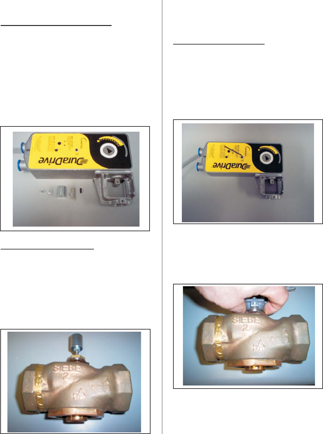
ACTUATOR INSTALLATION
WHAT COMES WITH THE ACTUATOR
1. Jam Nut
2. Lock Washer
3. Stem Extension
4. Connecting Pin
5. Set Screw
INSTALLATION INSTRUCTIONS
1. Thread jam nut on to the valve stem as far as
it will go. At least ½” of the valve stem should
extend above the nut.
2. Place lock washer over the valve stem so it is
seated on the jam nut.
3. Thread the stem extension on to the valve
stem making contact with the lock washer.
4. Pre-load the actuator
PRE-LOADING INSTRUCTIONS
1. Inserting the hex wrench as illustrated and
cranking 1 ½ turns in the direction shown on
the actuator. Lock it into position with the
locking mechanism using a slotted
screwdriver.
2. Install the actuator on the valve and tighten
the mounting nut and raise the valve stem to
the full up position.
3. Rotate the stem extension until it’s hole lines
up with the hole in the shaft of the actuator.
-19-
Figure #3
Actuator Parts
Figure #4
Installation Instructions
Figure #5
Pre-loading Instructions
Figure #6
Pre-loading Instructions

4. Insert connecting pin to secure stem extension
and tighten jam nut against stem extension
using 5/16” open-end wrench.
5. Affix open/closed label to the indicator in the
appropriate position.
6. Insert set screw (packaged with actuator) into
the most accessible side. Tighten with size 10
IP Torx bit to 20-25 lb-in.
7. Apply power to the actuator and check the
system operation (steam output) in relation to
the control signal.
-20-
Figure #7
Pre-loading Instructions
SETC OUTDOOR
INSTALLATION
SETC Outdoor units come complete with internal
ventilation (cooling) for the electronics, and optional
heaters for freeze protection in cold climates.
All installations must conform with local building
codes. NORTEC can not accept responsibility for
installation code violations.
MOUNTING
·A typical rooftop installation is shown on page 19.
·The SETC Outdoor unit comes standard with
cut-outs in the base to allow for lifting by a forklift.
When lifting by this method, ensure that the forks
extend across the entire base to prevent tipping
or damage to the unit.
·The enclosure also comes complete with four (4)
removable lifting lugs fastened to the base. All
four lugs must be utilized if moving the unit in this
manner. Protect the cabinet from damage from
the lifting cables/chains during lifting. The lifting
lugs should be removed from the base once the
unit has been correctly positioned on the curb
mounting.
·The SETC Outdoor models have a zero”
clearance to combustibles. However, choose the
location for the humidifier to allow for side and
frontal clearances for access during installation,
maintenance and servicing.
·The integral base of the SETC Outdoor model is
designed to mount on a curb. The curb must be
built to structurally support the entire weight of
the humidifier when in operation.
·Ensure that the humidifier is mounted level.
·The pan in the bottom of all outdoor models has a
pipe chase for routing of services into the
humidifier from below.
·It is not necessary to make the hole in the roof
the same size as the curb. The curb drawing
shows the location and size of the pipe chase
required. The pipe chase should be sealed when
the installation is complete to ensure positive or
negative pressure from the building.
·The panels of the outdoor model have louvers to
provide ventilation for the electronics and air for
the combustion process. Locate the unit so that
louvered panels are a minimum of 10 ft (3m)
from any mechanical exhaust outlet.
·When mounted on the curb, the lowest air intake
louvers must be a minimum of 12” (30.5cm)
above any surface where snow or ice could
accumulate. In areas where normal snow
accumulation is higher, mount the unit
accordingly.
·Do not store or use gasoline or other flammable
vapors and liquids in the vicinity of the humidifier.
PRESSURE STEAM SUPPLY
·Steam Lines are to be routed through the pipe
chase located on the floor of the unit.
·The steam valve and actuator must be located as
close as possible to the unit.
·A wye strainer must be installed prior to the
valve.
·Please refer to Actuator Installation Section.
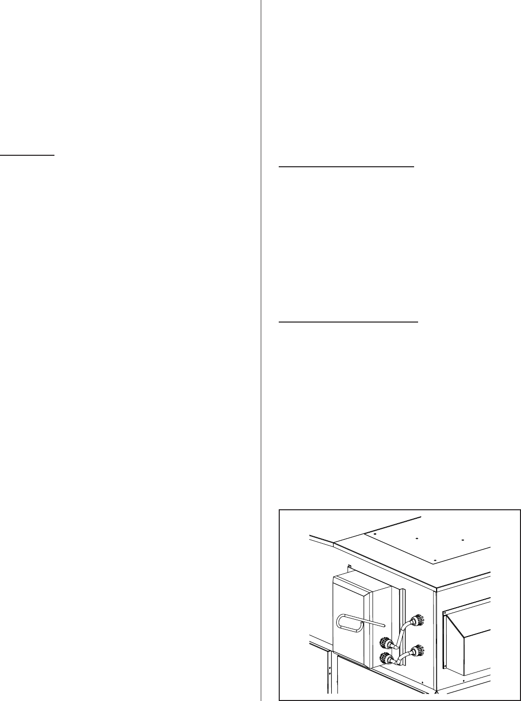
ELECTRICAL INSTALLATION
·Power and control wiring is to be routed into the
humidifier through the pipe chase in the base pan
of the outdoor models located in the heat
exchange area.
·Installation details for primary and low voltage
control wiring are the same as for indoor units.
-21-
Figure #8
Electrical Disconnect Installation
-22-
Typical SETC Outdoor Installation
AHU
Steam Line
Water
Supply
Manual
Shut-off
Drain
Lines
Funnel
With Air Gap
Roof Curb
(by others)
Electrical
Disconnect
(by others)
Pressure Steam
Supply
Steam Line
Electrical
Disconnect
(by others)
Roof Curb
(by others)

·A field supplied NEMA rated disconnect switch
must be mounted external to the SETC Outdoor
unit to allow for power interruption during
servicing and/or maintenance. A mounting plate,
located on the front of each outdoor model above
the electrical access door, is available for
mounting of the disconnect switch. Two electrical
conduits are provided for routing the primary
wiring to the disconnect switch and then back
inside the enclosure to the main power terminal
strip. See Electrical Disconnect Installation
Figure for details.
FILL WATER SUPPLY LINE
·Each unit is supplied with a ½” NPT male
connection to the fill valve. Refer to Installation
Figure for connection details. A minimum fill rate
of 10 l/min (2.6 gpm) is required for the SE
100-675 and 17 l/min (4.5 gpm) for SE 950-1050.
Allowable pressure range is 30-80 psig.
·Always install a manual shut off within the
building to allow isolation of the water to the unit.
A union must be installed on the fill line prior to
the fill valve to allow for servicing.
·Heat trace fill line piping above rooftop from the
pipe chase up to the fill valve.
DRAIN LINE
·SETC Outdoor units have an integrated 12” (30.5
cm) w.c. trap and vacuum break valve on the
drain line.
·Route the drain hose to a drain funnel in the
building to provide an air gap before entering
main building drain/sewage system.
·When the drain pump is activated, the tank drains
at a rate of 18-20 l/min (7-8 gpm).
·Internal drain water tempering will ensure a
maximum of 140°F (60°C) during normal
operation.
AUXILIARY DRAIN
·Standard SETC Outdoor units come with a
capped ¾”NPT auxiliary drain connection at the
bottom of the tank. It is recommended to install a
manual shut-off valve on this connection and
route to drain (provide an air gap).
·SETC Outdoor units equipped with a freeze
protection package have a normally open drain
valve mounted at the auxiliary drain connection and
piping that terminates at the pipe chase in the base
pan. This valve opens and will drain the contents of
the tank in the event of a power failure. Install a
manual shut off valve on this line and pipe to the
drain funnel. This valve must always be left in the
open position when in operation but can be closed
for servicing of the unit.
·Drain pipe should be capable of withstanding
200°F temperatures.
STEAM LINES
·The steam outlet connection is located at the
back of the SETC Outdoor unit. Steam hose(s)
and clamps are supplied with the unit and are
intended to provide a flexible coupling outside of
the unit to the building steam lines.
·SETC OUTDOOR models can develop steam
pressures up to 12” (30.5 cm) w.c. to overcome
duct and steam line pressures. Pressures above
12” (30.5 cm) w.c. will cause steam to exit
through the drain line.
·Steam lines can be routed to an air handler on
the roof or pipe chase (external to the unit)
through the rooftop to enter the building.
·All steam lines must be insulated to reduce
losses.
·For steam line installation guidelines, consult the
distribution system installation manual (Steam
Distributor Installation Manual Form #XX-231 and
SAM-e Short Absorption Manifold Form #XX-249
END OF SETC OUTDOOR
OPERATION
WATER MANAGEMENT
The SE Series is equipped with a unique float
chamber water level monitoring device. Two magnetic
floats measure 5 different water levels on the SETC
models, and 2 different water levels on the SEP
models for proper operation. The float chamber and
board are located away from the boiling action to
increase reading accuracy and reduce mineral
build-up.
The float chamber is connected to the tank under
the water level and above the water level to ensure
equalization of pressure between the tank and float
chamber. In addition, cooling water is introduced in
-23-

the float chamber to reduce scale build-up. The unit
also includes an internal 1” air gap and a vacuum
breaker to prevent siphoning effect.
On initial start-up, the solenoid operated fill valve
fills the tank. The water level reaches the backup float
first and then the main float. If the backup and main
floats do not read the same water level during the
operation of the unit, the unit will shut down on a fault.
The unit will continue to fill to the top yellow position.
The drain pump will then be energized to drain the
water level down to just below the bottom red position
and then the fill valve will energize again to fill the unit
to the middle green position. During this time the
software is performing a test on the fill valve and drain
pump.
If a demand signal is present, the unit will then
begin to open the steam valve. As the unit operates,
the fill valve will be pulsed to maintain the water level
between the yellow and green positions. During steam
production the unit will also check if the floats and
drain pump are operational by activating a drain
sequence every 24 hours. (adjustable to time of day)
INSPECTION AND START UP
PROCEDURE
START-UP CHECKLIST
Before the SE humidifier is operated for the first
time, a complete inspection must be performed to
ensure that the installation and all water, pressure
steam, atmospheric steam lines, and electrical
connections to the humidifier conform to the guidelines
in this manual. Complete the checklist on pages 24 &
25 before commissioning the unit.
Qualified personnel must correct any deficiencies
with the installation before commissioning takes place.
Prior to starting the humidifier, it is necessary to
ensure that no dirt or dust has accumulated in the
electronics compartment. A build up of dust on the
electronics can cause overheating and early failure of
the components.
FILLING THE SYSTEM
Before the SE unit will open the steam valve, it
must be filled with water and the internal controller
must have completed a self-test to verify that the water
fill system, level controller, and drain pump are
functioning correctly.
·Close the shut-off valve in the pressure steam
supply line.
·Remove any demand signal to the unit.
·Open the shut-off valve in the water supply line.
·Switch the humidifier on.
·The fill valve will energize and the tank will begin
to fill (fill time is approximately 10 to 30 minutes
depending on the SE model). Once the float
chamber has registered low water level, the unit
will perform an internal test of the fill and drain
system as described in the Water Management
section.
·At the completion of the test, the float chamber
will indicate middle float position (green LED) and
the unit will go into standby mode until a demand
signal is received.
STARTING THE HUMIDIFIER
Once the tank has been filled, the humidifier is
ready to be put into operation.
·Verify that the inspection checklist has been
completed and all deficiencies with the
installation have been corrected.
·Open the shut-off valve in the pressure steam
supply line.
·Open the shut-off valve in the water supply line.
·Ensure all external controls connected to the
security loop are closed.
-24-
Float Chamber
P
ressure
Equalizer
Aux. Drain
Drain Pump
Dual Fill Valv
e
Drain Outlet
Vacuum Break
Fill Chamber
Main Fill to System
Internal Trap
Figure #9
Plumbing Connections

·Verify that the building demand signal is
connected to the humidifier.
·Install and secure all cabinet service doors.
·Switch the humidifier on.
·At the completion of the float test, the humidifier
will begin to open the steam valve and warm up
the water.
·Depending on the system demand, the actuator
will open or close to control the amount of steam
injected into the heat exchangers.
·The water in the tank will heat up and begin to
boil, delivering steam to the distribution system.
·During the boiling sequence the water fill valve
will periodically activate to replenish water that
has evaporated from the tank.
·Once the humidity requirements have been
satisfied (demand drops below minimum %) the
steam valve will be de-energized and will be shut
off.
·The humidifier will go into standby mode until the
next call for humidity.
TAKING OUT OF OPERATION
If it is required that the humidifier be taken out of
operation (e.g. for service or end of season
shut-down), proceed as follows:
·Remove the demand signal or open the security
loop, allowing the steam valve to shut off.
·Switch the main power switch from On to Off and
then to the Drain position. The drain pump will be
energized and the tank will begin to drain.
·Once the tank has completely emptied, shut off
the drain switch.
·Close the shut-off valve in the pressure steam
supply line.
·Close the shut-off valve in the water supply line.
·Isolate the humidifier from the electrical power
supply at the main disconnect switch.
-25-

SE Series Inspection Checklist
SE INSPECTION CHECK LIST
HUMIDIFIER MOUNTING
£Verify proper clearances around the unit
£Humidifier mounted level
£Humidifier properly secured to stand and stand bolted to floor
£All service doors accessible
£Roof curb sized correctly (Outdoor Model Only)
PRESSURE STEAM PIPING
£Test joints for leaks
£Manual shut-off valve installed prior to Steam Valve & Actuator
£F&T Trap installed prior to Steam Valve & Actuator (by others)
ATMOSPHERIC STEAM or STEAM DISTRIBUTION LINES
£Slope up 2” per 12”
£Sloped back to drain
£Slope down1/2” per 12”
£Trapped 2” more than static duct pressure
Traps £- Size _______________
Insulated £
Length/Size _______________
90º Elbows £qty: ______
45º Elbows £qty: ______
Can condensate be trapped anywhere in the steam line? Yes £No £
CONDESNATE LINES
£Sloped back to drain
£Trap is greater than 2” duct static pressure
£Size of Trap ___________
-26-

SE Series Inspection Checklist
SUPPLY WATER LINE
£Nortec supplied adapter installed on fill valve (1/2” NPT)
£Manual shut off valve and union installed
£Verified pressure (30-80 psig)
£Water source of 10 L/min (2.6 gpm) for SE 100-675 or 17L/min (4.5 gpm) for
SE 950-1050
£Leak tested
£½” dia. at max 4ft from the unit
DRAIN LINES
£Air gap located within 3ft of the unit
£Minimum drain line size of 1” – 1.5” in dia.
£Downward slope
£Tundish (funnel) installed to provide air gap
£Temperature rating of piping
£Hose connections tightened
£Auxiliary drain piped with shut off valve to tundish
WATER QUALITY
Well Water £City Water £Softened Water £RO/DI £Water £
Conductivity:______ mmhos Hardness: ______ GPG Silica: ______ ppm
Chlorides: ______ ppm pH: ______
ELECTRICAL INSTALLATION
£Comply with local regulations
£Proper supply voltage (must match rating plate) and breaker size
£Electrical disconnect switch close to humidifier
£Cables properly affixed
£Low voltage wiring & control signal(s) wired to correct terminals
£Humidifier configured for correct control signal(s)
TYPE OF CONTROLS INSTALLED/LOCATION/WIRING/SETTING
£High Limit ___________________________________________
£Air Proving ___________________________________________
£Modulation Control _____________________________________
£On/Off Control ________________________________________
£Controls by Nortec ____________________________________
£Control by Others _____________________________________
-27-
SCALE MANAGEMENT
The steam exchange humidifier will periodically
“blowdown” water from the tank to reduce the
concentration of total dissolved solids that accumulate
during long term operation.
Steam Exchange Humidifiers are shipped factory
set with a blowdown of 25%. This setting ensures that
scale build-up will be minimized for all water
conditions.
Once the water conditions are known, the
blowdown rate can be adjusted by software (SETC
models) or by using dip switches on the logic control
board (SEP models).
Another effective means of controlling the amount
of scale in the tank is with the use of the Full Tank
Blowdown (FTBD) built into the software. When this
feature is activated, the drain pump will be energized
to drain the entire contents of the tank and then the
tank will be refilled with fresh water, thus keeping the
amount of total dissolved solids to a minimum. The
feature can be programmed in the software to occur
after a specific amount of operating time and can also
be triggered by a signal sent to the humidifier from a
building management system.
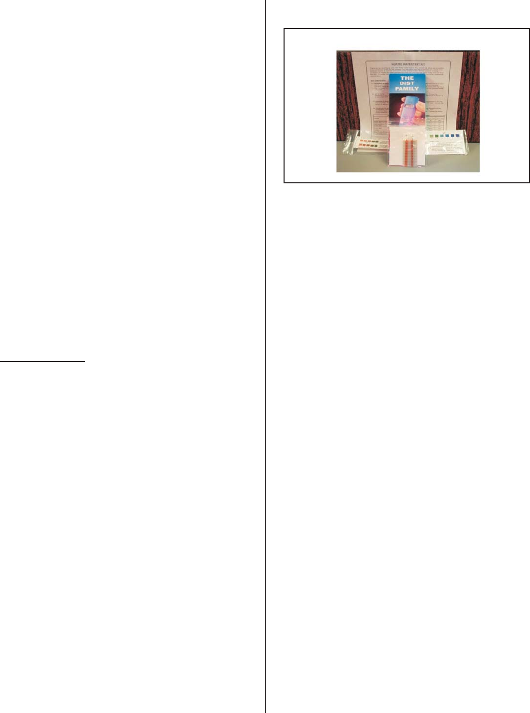
WATER QUALITY
Due to the wide range of water conditions found
throughout North America it is important that the
blowdown is set according to the local water
conditions. By water conditions we are referring to the
hardness of the water supplied to the humidifier. The
hardness is measured in grains per gallon. It is also
important to test for silica content. Silicates may cause
foaming and contribute to scale buildup in the
humidifier tank and float chamber.
If you are unaware of the hardness or silica
content of your water supply, there are many “do it
yourself” kits which can be purchased, or there are
several companies that will perform the tests for a
reasonable price. You can even contact your
municipality for your water condition or order the
NORTEC water test kit.
Note: Water quality conditions resulting in
component failures are not covered under
NORTEC’s standard warranty.
·Silica Test: Measured in ppm (parts per million)
Follow the directions with the kit. A high reading will
decrease the performance of your system. The
recommended operating range for silica is 0 ppm to
14 ppm. Note: A high silica content along with a
high hardness content may increase the service
intervals of the system . Consult the factory if this
condition exists at the site.
·Hardness: Measured in gpg (grains per gallon).
Follow the instructions on each individually
wrapped test strip and use the colour chart
provided. The recommended operating range for
hardness is 0 gpg to 12 gpg. Note: High
hardness along with high silica may increase the
service intervals of the system. Consult the
factory if this condition exists at the site.
·pH: Follow the directions on the test strip bottle.
The recommended operating range for pH is 6.5
to 7.5 on the colour scale. Consult the factory if
outside these parameters.
·Chlorides: Measured in ppm (parts per million).
Follow the directions on the test strip bottle. The
recommended level for chlorides is not to exceed
25 ppm. High levels of chlorides will attack
stainless steel. Add an in-line carbon filter that
will remove up to 99% of the chlorides. Consult
the factory for additional information if your water
contain high levels of chlorides.
·Conductivity: Measured in micromhos. Follow
the directions for the conductivity pen found
inside the box. Multiply the digital reading by 1.5.
The recommended operating range for
conductivity is 0 - 1500 micromhos. Consult the
factory if you measure outside these parameters.
-28-
Figure #10
Site Water Test Kit P/N 1507214

Tech-
nology Water
Type Water
Cond.
Range
Hard-
ness
Range
Silica
Range Alklin.
Range Chlor.
Range
Steam
Exch-
ange
Microm
-hos GPG PPM pH PPM
Potable 0-1500 0-12 0-14 6.5-7.5 0-25
Treated 0-100 0-1 0-1 7-7.5 0-25
·NORTEC recommends performing a semi-annual
water analysis to ensure optimal performance.
·The humidifier is intended to operate on cold
potable tap water.
·DO NOT use a hot water source to supply the
humidifier. Minerals will adhere more easily to
surfaces and the fill valve's small flow regulating
orifice could become plugged.
·Consider using a water softener. Longer
operating times between tank cleaning will be
reached on softened water.
·Reverse osmosis (RO) water can provide very
long times before cleaning is required since it is
cleaner than softened water. Deionized (DI)
water may be used with all models.
·Consult your NORTEC representative for a
quote on a water treatment system.
MAINTENANCE
To ensure proper performance and long operating
life of the SE humidifier, a proper maintenance
schedule should be followed. Since the amount and
type of maintenance required is generally a result of
how much the humidifier operates, all SE humidifiers
monitor the amount of steam produced over time, and
will indicate when service is required. All units come
factory set with a service interval of 500 hours. This
service interval can be adjusted through software
(SETC models) or by jumpers settings (SEP models)
on the logic control board. Refer to the maintenance
schedule for maintenance guidelines and intervals.
All maintenance work must be performed by
experienced and trained personnel.
NOTE: Use only NORTEC original parts to
replace damaged or defective components. Failure to
do so may cause improper operation of the humidifier
and will void warranty.
DRAINING THE TANK
During extended periods of inactivity such as off-
season, it is advisable to drain the water from the tank.
On all models this is accomplished by switching the
unit to “Drain”.
Do not remove the front or top clean out port on
the tank until the unit is completely drained and cool.
The SETC model includes a pre-cleaning
sequence feature. When activated (through the
keypad), the unit will flush the humidifier, refill with cold
water, and flush again reducing the scale accumulated
at the bottom of the tank.
CLEANING THE STAINLESS STEEL TANK
& FLOAT CHAMBER
CAUTION: Water and scale may be hot enough
to cause burns. Turn off humidifier and allow it to cool
before cleaning.
It is recommended that the tank be cleaned at
least once every season to maintain optimum
operation. It may be necessary to increase the
frequency of cleaning or increase the blowdown
setting in areas of hard water or prolonged annual
usage (see the “Blowdown Setting section of this
manual).
Cleaning of the humidifier is mandatory and must
be performed on a regular basis.
To reduce cleaning time, use the pre-cleaning
sequence on the SETC model to help evacuate
mineral debris from the unit. Check the controller
operation to activate this feature.
The heat exchanger walls are usually self
cleaning. The mineral build-up flakes off, due to the
expansion and contraction and boiling action during
on/off cycles, and settles to the bottom of the tank. The
end block will have scale build-up. These surfaces
must be cleaned at regular intervals.
Most cleaning will be done through the front door
of the unit. Remove cabinet door on the left of the
LCD display using a Philips screwdriver. Remove the
side tank port opening, by removing the 3/16” nuts (½”
key or socket is needed).
Additional cleaning ports are available on the top
of the SE 475/675 and SE 950/1050 models. To
access these ports, remove the top cabinet panel
using a Phillips screwdriver. Remove the top cleaning
ports by removing the nuts.
-29-
Removal of the heat exchanger(s) is not
necessary to clean the inside of the tank.
Scoop out loose scale with a small shovel such as
those used for gardening. Once loose scale is
removed, use a scraper such as a plastic windshield
scraper to remove scale adhering to the tank or heat
exchanger walls. DO NOT use a metal scraper that
will scratch the stainless steel surfaces of the tank.
Once all large pieces of scale have been removed,
vacuum the tank out with a shop vacuum, fill part way
with water, and flush remaining sediment from the tank
through the drain.
Due to the presence of polymer gaskets around
the heat exchanger, do not use any harsh cleaning
chemicals. Please consult NORTEC prior to using any
chemicals. Once the lid has been replaced, fill the unit
with water and examine for leaks.
Inspect the drain and fill lines assembly for scale
build-up and if necessary, remove them from the
humidifier for cleaning. If the blowdown assembly
becomes blocked, scale build-up in the tank will be
accelerated and damage to the humidifier could result.
The drain pump may be opened and cleaned. Consult
NORTEC for proper procedure.
Re-assemble the drain and blowdown if they were
removed. Re-install tank top and side lids making sure
tank cover gasket is intact. Do not over tighten nuts. If
using a torque wrench do not exceed 50 in-lb ( 5 ft-lb).
Re-seal all cabinet lids.
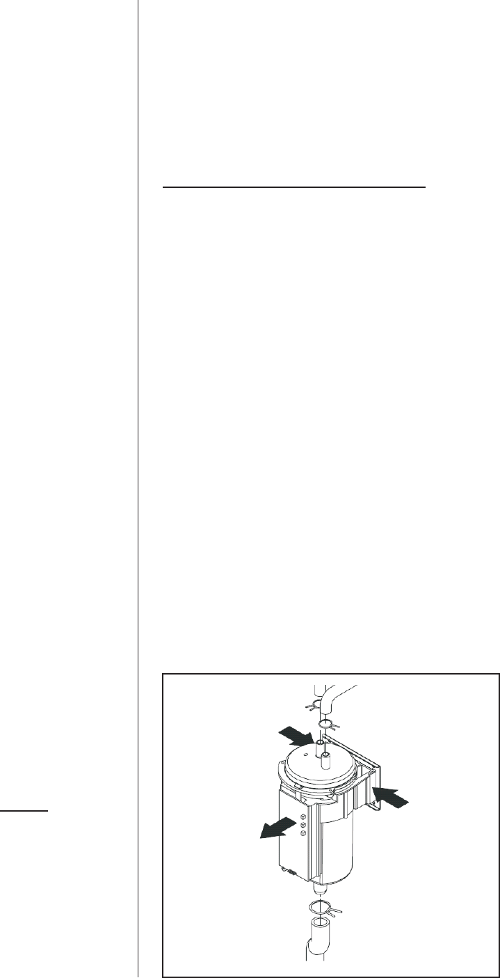
Cleaning the float chamber is accomplished by
removing the screws to access the floats and using a
small brush to gently clean the scale from the floats
and chamber. Ensure that floats are back in place and
o-ring is properly seated before tightening screws on
float chamber. Special attention must be used when
removing or re-installing the float chamber. The switch
board must be replaced into the same position as
before cleaning and the tie-wrap must be used to hold
the float chamber in position.
ADJUSTMENTS/REPLACEMENTS OF
COMPONENTS
NOTE: CONSULT FACTORY PRIOR TO THE
REPLACEMENT OF ANY COMPONENT.
DANGER - SHOCK HAZARD - Make sure
electrical power to the appliance is disconnected
to avoid potential serious injury or damage to
components.
SERVICING THE UNIT
Caution: Disconnect power before servicing this
appliance.
Caution: Label all wires prior to disconnection
when servicing controls. Wiring errors can cause
improper and dangerous operation.
Float Chamber Replacement (Figure #6)
1. Drain the contents of the tank and then shut
off electrical power and water supply to the
humidifier.
2. Remove the left front service access door.
3. Remove the cable connection to the float
board.
4. Remove the hose clamps on the float chamber
and remove all hoses (note the correct hose
assignment).
5. Squeeze both sides of the mounting bracket to
release it from the slots in the support bracket
behind the float chamber.
6. Reverse the above sequence to install the
new module.
7.7. Leak test all water connections before
re-commissioning the humidifier.
-30-
Figure #11
Float Chamber Removal
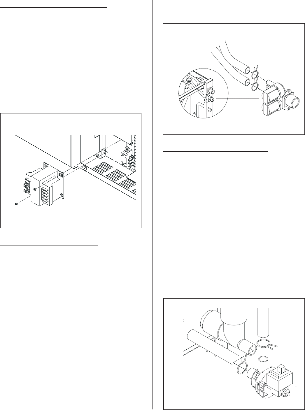
Transformer Replacement (Figure #12)
1. Shut off electrical power to the appliance.
2. Remove front access door.
3. Disconnect wiring connections from
transformer leads labeling as required.
4. Remove screws (2) holding transformer.
5. Reverse above procedure to re-install.
Fill Valve Replacement (Figure #13)
1. Shut off electrical power and water supply to
the humidifier.
2. Remove the right side service access door.
3. Remove all wiring connections to the fill valve.
4. Remove the hose clamps on the fill valve
outlets and remove hoses (note the correct
hose assignment).
5. Remove the 2 screws securing the fill valve to
the cabinet and remove the valve.
6. Reverse the above sequence to install the
new module.
7.7. Leak test all water connections before
re-commissioning the humidifier.
Drain Pump Replacement (Figure #14)
1. Drain the unit completely. If the pump is
broken use the auxiliary drain out port.
2. Shut off electrical power to the appliance.
3. Remove front and right doors.
4. Remove wiring connections to the pump.
5. Remove hoses attached to the pump.
6. Reverse above procedure to re-install.
NOTE: To avoid water spillage (some water
will be left on the tank bottom after manual
-31-
Figure #12
Transformer Detail
Figure #13
Fill Valve Detail
Figure #14
Drain Pump Detail
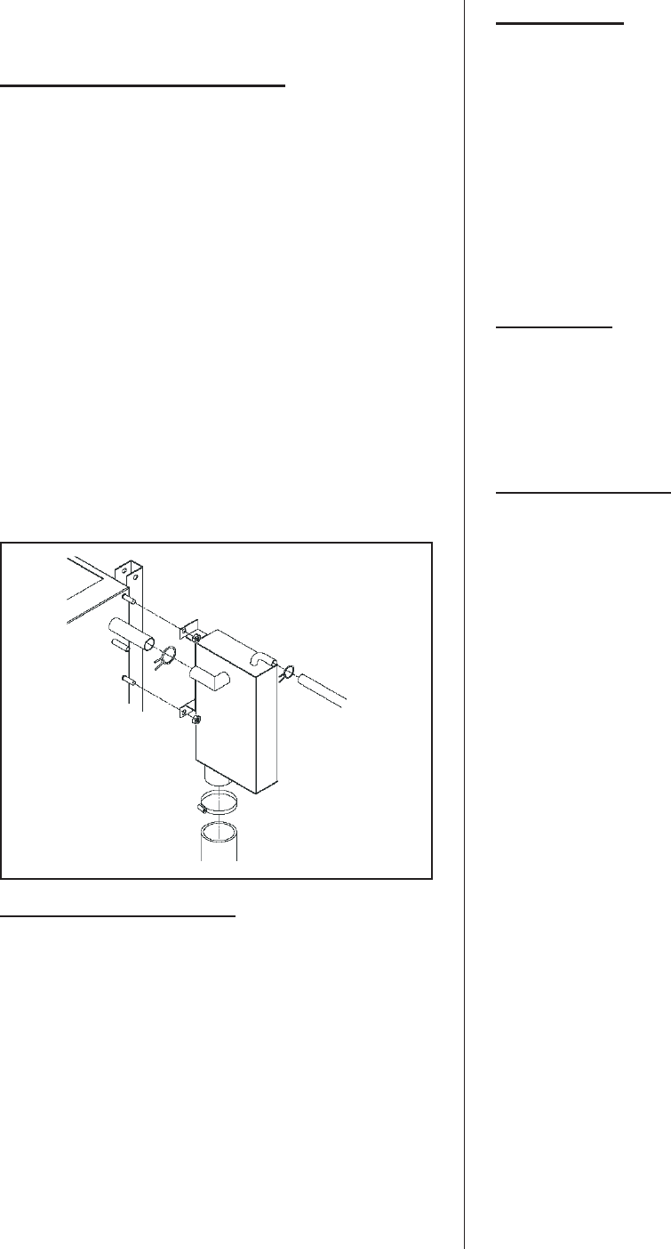
draining) use shop vac to remove left over
water.
Fill Box Replacement (Figure #15)
1.1. Drain the contents of the tank and then shut
off electrical power and water supply to the
humidifier.
2.2. Remove the right side service access door.
3.3. Remove the hose clamps and remove all
hoses.
4.4. Undo the 2 nuts securing the fill box to the
tank.
5.5. Reverse the above sequence to install the
new module.
6.6. Leak test all water connections before
re-commissioning the humidifier.
Removal of Heat Exchanger
1.1. Take the humidifier out of operation.
2. Unlock and remove the right side panel(s).
3. Unlock and remove the left and the right top
panels.
4. Free all piping of the respective heat
exchanger.
5. Unscrew the nuts on the heat exchanger and
pull out the heat exchanger from the tank.
Re-installation is carried out in the reverse
sequence. Replace all seals with new ones.
SETC MODELS
Faults are indicated with a fault message on the
display of SETC models. Recovery from lockout
requires resetting of the humidifier. This can be
achieved by momentarily shutting off the power switch
then turning it back on, or by pressing the reset button
on the logic control board mounted inside the electrical
cabinet.
A history of all faults is stored in memory of
the software and can be viewed through the service
level on the display. Refer to the keypad display menu
structure at the end of the manual.
SEP MODELS
Faults are indicated on SEP models with blinking
red lights. Check the LED sequence for the fault
before shutting off the unit. Resetting the humidifier
clears the fault. This can be achieved by shutting off
the power switch, then turning it back on.
FAULT CONDITIONS
Fault F1- Humidifier no filling: Yellow LED
Flashes twice.
Probable Cause:
- Fill Valve not energizing
- Water supply interrupted
- Float level indication inoperable
- Tank leaking.
Fault F2 - Humidifier not draining: Yellow LED
flashes once.
Probable Cause:
- Drain pump blocked
- Drain pump inoperable
- Float level indication inoperable
- Drain line restricted
Fault F3 - Float level inconsistent: Yellow LED
flashes four times.
Probable Cause:
- Defective float level board
- Defective float chamber
-32-
Figure #15
Fill Box Detail

-33-
SETC SETTINGS
3 DAY DRAIN
3 DAY DRAIN FUNCTION SW3/7
Function Disabled OFF
Function Enabled (Factory set) ON
KEEP WARM/INDOOR FREEZE PROTECTION PACKAGE
3 DAY DRAIN FUNCTION SW5/7
Function Enabled ON
Function Disabled (Factory set) - 3 day drain OFF
ANALOG CHANNEL 1
Input Range SW1/1 SW4/1 SW 4/2
0-10V input OFF OFF OFF
0-5V input OFF ON OFF
2-10V input OFF OFF ON
1-5V input OFF ON ON
0-20mA input ON OFF OFF
4-20mA input ON OFF ON
ON/OFF + inst. jumper
between4&6 ON ON ON
ANALOG CHANNEL 2
Input Range SW1/2 SW4/3 SW 4/4
0-10V input OFF OFF OFF
0-5V input OFF ON OFF
2-10V input OFF OFF ON
1-5V input OFF ON ON
0-20mA input ON OFF OFF
4-20mA input ON OFF ON
ON/OFF + inst. jumper
between4&6 ON ON ON
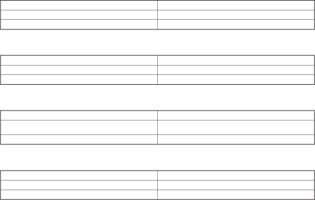
-34-
INPUT CHANNEL
DUAL CHANNEL FUNCTION SW4/5
One Channel Input OFF
Dual Channel Inputs ON
TIME PROPORTIONING
TIME PROPORTIONING SW4/7
Disabled (Factory set) OFF
Enabled ON
MAINTENANCE SHUTDOWN
MAINTENANCE SHUTDOWN FUNCTION SW5/4
Unit will shutdown 72 hours after service time expired, by gen-
erating an error. OFF
Unit will display warning but continues to operate. (Factory set) ON
FULL TANK BLOWDOWN
FULL TANK BLOWDOWN FUNCTION SW5/8
Disabled OFF
Enabled (Factory set) ON
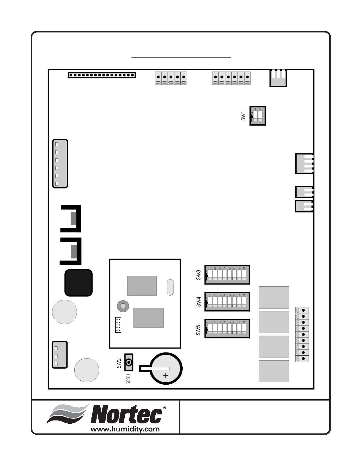
DIP Switch Settings
SETC
Logic Control Board
-35 -
,
................
,
o
o
o
o
o
o
0
..
~
[J
o
~
~
~
~
CO'
tlortec®
www.humidity.com
~
I
C')
,
:;::
0
<r)
0
3f'
<r)
0 [i .
[J
.
[J
•
'"
'
[J
.
:;::
<r)
[i .
0 [i .
[i .
[J
.
0
(I
.
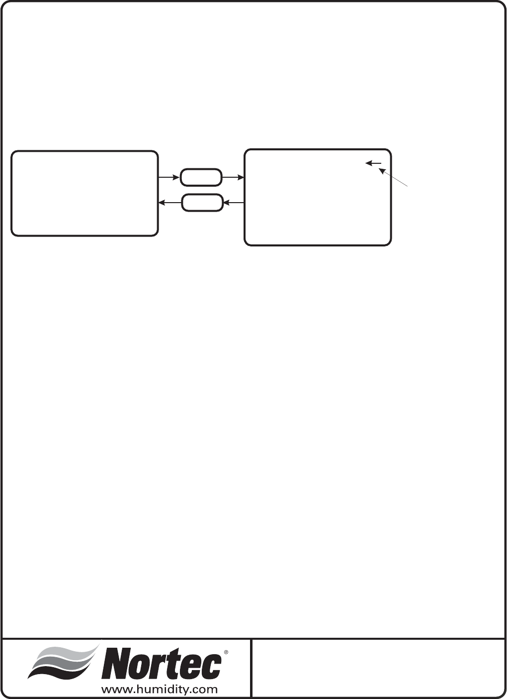
-36-
NORTEC SETC-250
VERSION X.XX
SYSTEM LOCKOUT
09.05.03 9:30
SYSTEM STATUS
USER SETTINGS
SERVICE LEVEL
MENU
MENU
USE THE
UP/DOWN
ARROWS
TO MOVE THE
POINTER TO
SELECT A
MENU ITEM.
TO OPEN THE
SELECTION,
PRESS THE ENTER
BUTTON.
INTRODUCTORY SCREEN MAIN MENU
Keypad Display Menu Structure
System Status 1
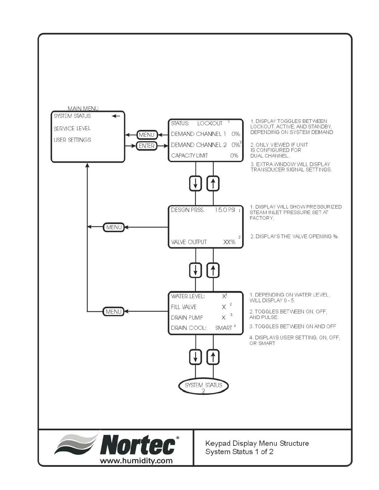
-37-
SYS
TE
M STA
TU
S
~
R
V
I
C
E
LE
V
EL
US
ER
~
nIN
GS
MENU
M
ENU
ENTER
STA
TU
S: L
OC
KO
UT
DEMAND
CHA
NNEL
1 0%
DEMAND
CHANNEL
2
rJ%2
CAPAC
I
TY
LI
M
IT
m,
DE
SGN
PRSS,
15,
OPSI
1
VA
LVE O
UTPUT
XX"/"
WA
TER
LE
V
EL:
x'
1 DIS
PL
AY
TOGGLES
BE
TV\
EB
~
L
OC
I
\O
UT, AC
TI
VE,
AN
D ST
Jl.N
DB
Y,
DEPENDI
NG
ON
SYSTEM DEM
AN
D
2.
ON
LY V
IE
VVE
D
IF
UN
IT
IS
CON
FIGU R
ED
F
OR
DU
AL
C
H
AN~
IEL
3.
EX
TR
A WI
NDOWW
LL
DISPL
AY
TR
ANS
DU
CER SI
GNAl
SETTINGS
1 DI
SP
L
AY
WlLL SH
OW
PRESSURIZ
ED
STEAM INLET PRE
SS
URE SET AT
FACTORY
2 DI
SP
L
AYS
THE VAlVE OPEN I
NG
%
1 DEPENDI
NG
ON
WATER LEV
EL
,
W
ILL
DI
SP
L
AY
0 - 5
L
_-{J;m~I+-
____
~
F
ILL
VA
L
VE
M
ENU
DRA
IN
PUMP
x
x 2. T
OGG
LE
S B
ET
V\EEN
ON,
O
FF
,
AN
D PULSE
DRA
IN
COO
L:
SMAR
T 4 3. T
OGG
LE
S
B
ET
v\
EE
~
1
ON
AN D O
FF
Nonec
·
www.humidity.com
SYS
TE
M ST
ATUS
2
4. DIS
PL
AYS
USER SETTI
NG
,
ON,
O
FF
,
OR
SMART
Keypad Display Menu Structure
System Status 1 of 2
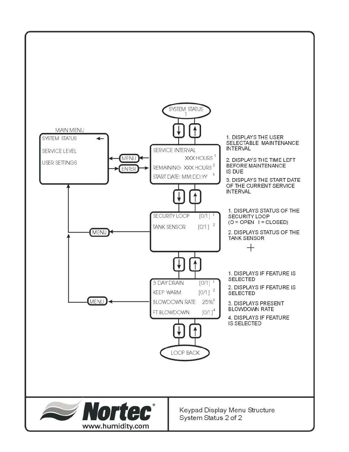
-38-
SYSTEM STATUS 2 of 2
SYS
TE
M S
TATU
S
1
MAIN
MENU
SYS
TEM
STATUS
~~:\"'~I
S
ER
VIC
E I
NTER
VA
L
r..
XXX
H
OJRS
1
~
E
#
N
;
TE::
R
~~
I
REMAIN
ING
XXX
H
OJRS
2
SERVIC
E L
EVE
L
U
~R S
ETI
I
NGS
ST
AR
T
Dl\TE:
MM
:DD
:W
SEOJRI
TY
L
oa::'
[0/1] 1
L----1(E]~1r----__l
TA
NK
S
EN
Sa< [0/1] 2
.-
MENU
3
DAY
CRA
IN [0/1] I
I
on
I '
L
__
~~!)
·
+------I
KEEP
WARM
MENU
III
BLOWDOWN
RATE
25%3
FT
BLOWOOWN [
Ofl
]4
LOCfl
BACK
1.
DI
SPLA
YS
THE
US
ER
SELECTA
BLE
MAINTENANCE
INTER
VA
L
2.
DI
SPLA
YS
THE
TI
ME LEFT
BEF
O
RE
MA
INTENP.N
CE
IS DUE
3.
DI
SPLA
YS
THE
STA
RT
DA
TE
OF
THE
CURRENT S
ER
VICE
INTER
VA
L
1.
DI
S
PLA
YS
STA
TU
S OF
THE
SECURITY L
OO
P
(0
= O
PEN
I = CL
OS
ED
)
2.
DI
S
PLA
YS
S
TATU
S OF
THE
TANK
S
EN
SO
R
+
1.
DI
S
PLA
YS
IF
FE
A
TURE
IS
S
ELE
C
TED
2.
DI
S
PLA
YS
IF
FEATURE
IS
S
ELE
C
TED
3.
DI
S
PLA
YS
PRE
S
ENT
BL
OWDOVI.N
RA
TE
4.
DI
S
PLA
YS
IF
FE
A
TURE
IS S
ELE
C
TED
Nortec
· Keypad
Di
s
pl
ay Menu
Stru
cture
System
Sta
tus 2 of 2
www
.
humidity.com
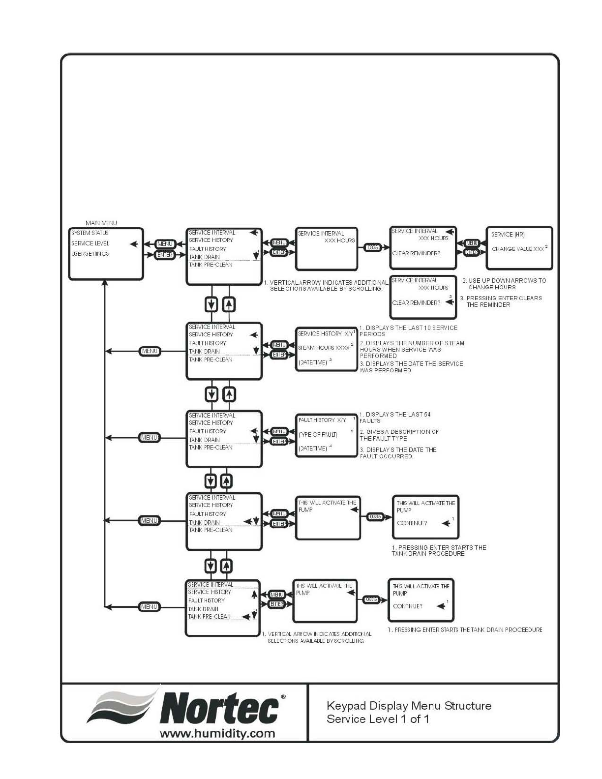
-39-
II
Ii
~ft
CD/;
" "
<
'"'
_."0
" "
"
"-
'0
"
_.
<
if>
,,"0
- "
~
'"'
g,s:
~"
"
c
>'i
-
c
~
c
ro
• I
"
>'
~~
'"
~R
j~
go
2'
o§
,
~
,
o
o
"
"
o
n
~"
Q
,0
§l
.,
c "
0 >
0
..
~
,
H
~
I....-';"";;;.J
•
,
,
o
•
8
~
n
c
,
~~
~il
8
~ ~
om
§""
;!i
~~
~
:;:
~~
_0
9
~~
li
~~
...
":;
o 0
\......;,....;
.
:.1
c~
"
o
~
I
m
~
m
,
o
z
~
o
S
o
~
m
>
~
~
.
,
m
•
o
~
m
o
~
m
o
~
o
m
>
~
"
"
o
"
8
..
~
~
lJJj
~
> ' §
~
...
~
I -.1
• i
:ijl
O C
m m
I(J)
~~
:;:~
~~ ~~
-
IO
~~
g ~
~
ill~
o "
r 0
o •
" 0
o
~
o
Q 0
>
~
i ,
m _
C I
, 3
,
,
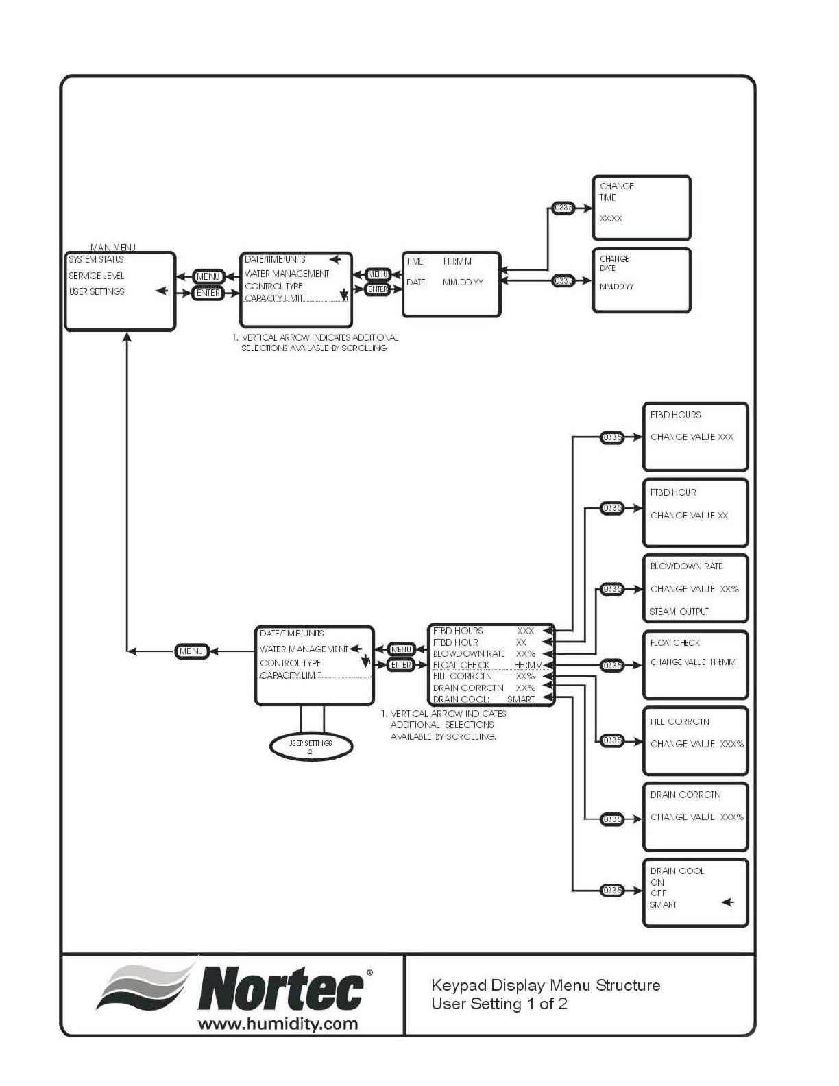
-40-
"'
-
TI
ME
>C,,'"
,
..,
"M' ",
MM
CfW l
Gl:
~
~
~
,
LE
\H , DA
TE
MM
,
CQ
YV
LSER
SE
TI
NGS
-+
; "M
'1
.
..
M\\
OOYV
1.
Vffi
TI
CAl
AARON
I
I\OC.Ar
ES ACaTK)I\jA,l
S
H
E
a
~
i\V/lJ
lJ\BL
E
8{
SOl
a l
N:;.
F
TBD
H
OU
RS
CH
>\'J
G/:
V
Al
UE
XXX
F
TBD
HOJ R
CH,
A."JG/:
V
Al
UE
XX
BL
O M
X),
M-J
RA
TE
~
CH,
A."JG/:
V
Al
UE
:0:%
S
TE
AM
OJT
PU
T
~
:; Fl()l"T C
ftO
O:
+
"'"
''''
e-+
,,~
"IC'
,
~
g;,.
"'" C
HAl
I G
VA
LUE
ftt
M\o1
, ,
~
MN"
.I-
11 ,
AD
OOl
O
NA
L
S
H
E
C
TI
~
FILL
CC
o:lR
CTN
<
:;
AV';
IL
Nl
LE
BY
S
Ol
O
LLl
~
,
"""
CH~GI:
VAl
UE
XXX%
,
DRAJN
CO'l
RCTN
CHA'JGI:
VAL
UE
XXX%
DR.AJN
CCXX
""
cr
,
S
MM
T
-+
l'
Nortec
· Keypad Display Menu Structure
User Setting 1 of 2
www
.
hu
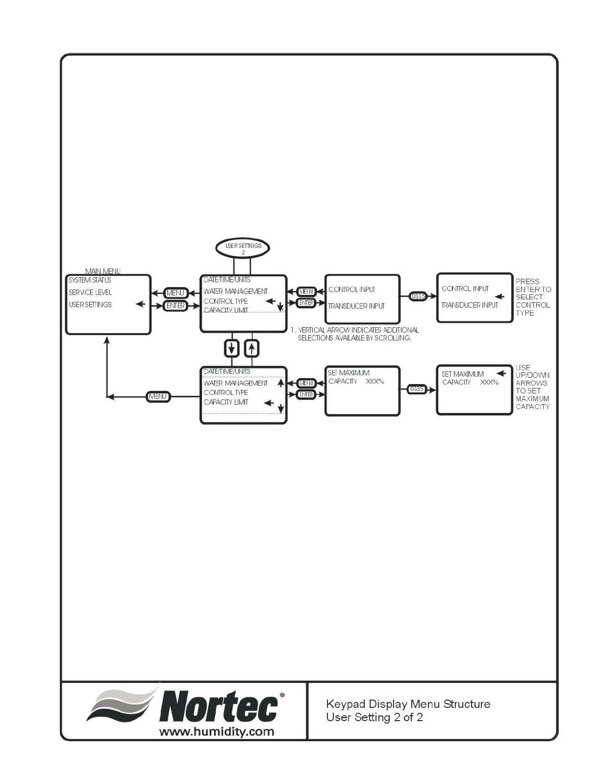
-41-
ca
lT
ru
TYPE
WMER
MA"iAGEM:NT
}----l
CCMRCX
TYPE
0\PAOTY
L1
MT
..
Nortec
·
www.humidity
.c
om
PR
E
SS
L.(!!l~>I
C~
TR
Ct
I
~
LIT
EN
TE
R TO
r
..
SELECT
~
CCN
TC
KX
I
NPJT
T
RAN3CO::
ER
I
NPU
T
S
EL
EC
n
0\6
AVAJlABL
E
BY
S(J<a
Ll
NG.
XXX%
r-----
.....
USE
S
ET
MI\XlMJv1
..
UP
/lX)'AN
CAPAOTY
XXX"!.
H5H
S
ET
MAXIMUM
CA
P
AC
I
TY
'--
__
oJ
Keypad Display Menu Structure
User Setting 2
of
2
-42-
NORTEC TC CONTROLLER
INTRODUCTORY SCREEN
Product name
NORTEC SETC (100-1050)
Version
The display will indicate the revision level of the
control software
System
Depending on system activity, the display will
toggle between LOCKOUT, ACTIVE or STANDBY.
Date/Time
The actual date and time will be displayed.
MAIN MENU
The main menu lists the available sub menus
where system adjustments can be made. Some of
the menus are password and jumper protected to
block access by unauthorized personnel.
System status
Displays various system parameters as the user
scrolls through the lists. For further details see specific
section below.
Service Level: (password protected)
This section is specific to all service related
activity. For further details see specific section below.
User Settings: (password protected)
This section allows the user to set parameters
specific to their requirements. For further details see
specific section below.
NORTEC SETC 250
VERSION X.XX
SYSTEM LOCKOUT
06.07.03 9:30
SYSTEM STATUS
SERVICE LEVEL
USER SETTINGS
-43-
SYSTEM STATUS
SCREEN 1:
Status:
Displays the present status of the system.
Depending on system activity at the time, the field
could display: lockout (security loop open), active (unit
generating steam) or standby (security loop closed but
no modulation demand signal).
Demand channel 1:
This field will display the modulation demand input
on that channel.
Demand channel 2:
Field only visible if the unit is configured for dual
modulation. This field will display the modulation
demand input on that channel.
Capacity limit:
This field displays the user adjusted capacity limit
set for the humidifier.
SCREEN 2:
System demand:
This field displays the total system demand as a
percentage.
Valve output:
This field will display how much open the valve is
in %.
SCREEN 3:
Water level:
This field displays the present water level detected
by the float system.
Fill valve:
This field displays status of fill valve, on, off, or
pulsed.
Drain pump:
This field displays status of drain pump, on or off.
Drain cool:
This field displays the user (or factory default)
setting.
OFF: fill will not activate when drain is activated.
ON: fill will activate whenever the drain activates.
SMART: fill will activate only when drain water is
hot.
STATUS: LOCKOUT
DEMAND CHANNEL 1 0%
DEMAND CHANNEL 2 0%
CAPACITY LIMIT 0%
DESGN PRSS. 15.0 PSI
VALVE OUTPUT XXXLB
WATER LEVEL: X
FILL VALVE [O/I]
DRAIN PUMP [O/I]
DRAIN COOL: SMART
SCREEN 4:
Service interval:
This field displays the user (or factory default)
setting for the humidifiers service reminder in steam
hours.
Remaining:
This field displays the amount of time (steam
hours) remaining before the next service is to be
performed.
Start Date:
This field displays the date this service interval
began.
SCREEN 5:
Security loop:
This field displays the status of the security loop
(terminals 1 and 2 on LV terminal strip). If it is open
the display will indicate “O”, if it is closed the display
will indicate “I”.
Tank sensor
This field displays the status of the tank sensor
input. If it is open the display will indicate “0”, if it is
closed the display will indicate “1”. Closed indicates
that the tank temperature is above 160ºF (70ºC).
This input is used for the “keep warm” feature and
for activating the fill valve during blowdown cycles.
SCREEN 6:
3 day drain
This field indicates if the feature has been selected
(0 = no, 1 = yes).
Keep warm
This field indicates if the feature has been selected
(0 = no, 1 = yes).
Blowdown rate:
This field displays the selected blowdown rate.
Full tank blowdown
This field indicates if the feature has been selected
(0 = no, 1 = yes).
-44-
SECURITY LOOP [0/1]
TANK SENSORS [0/1]
3 DAY DRAIN 1
KEEP WARM 0
BLOWDOWN RATE XX%
FT BLOWDOWN 1
SERVICE INTERVAL
XXX HOURS
START DATE: MM:DD:YY
REMAINING XXX HOURS
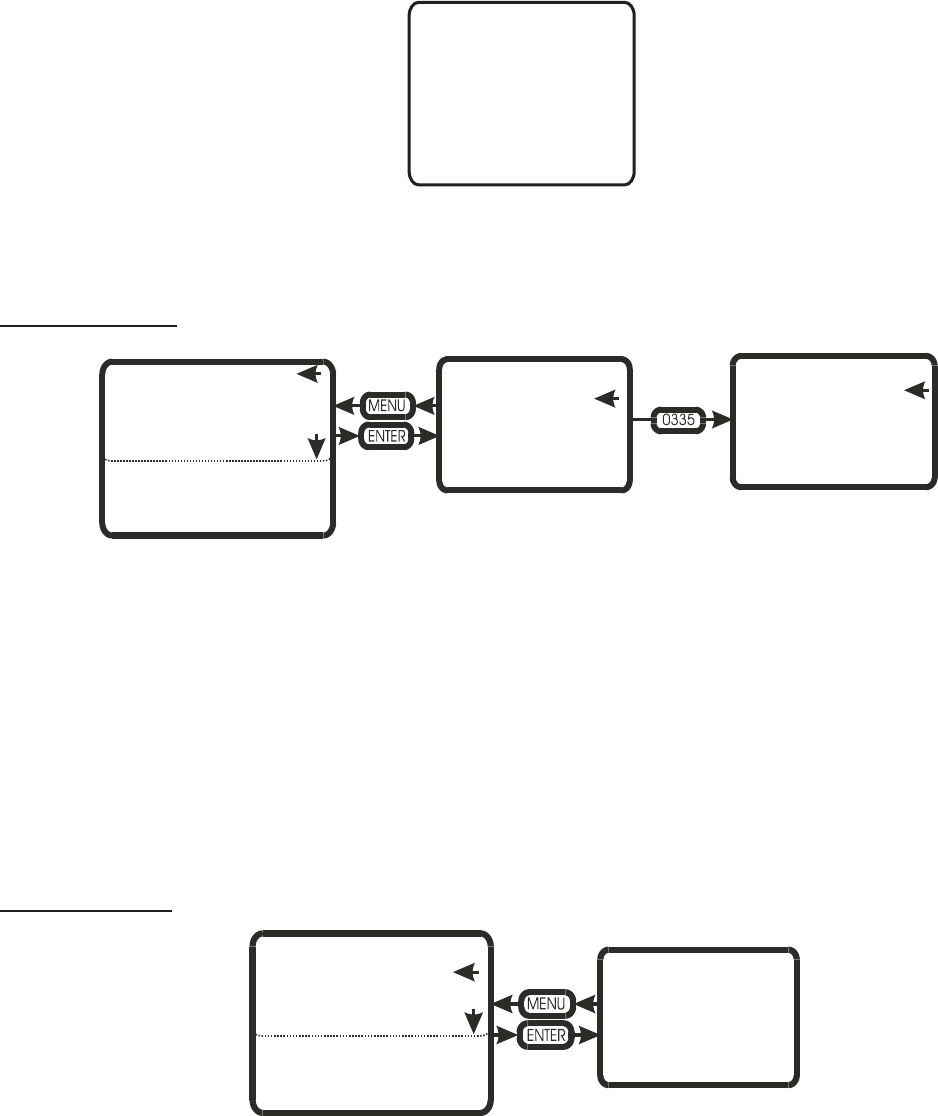
-45-
SERVICE LEVEL
The service level area is where service related tasks are performed. Below is a description of each field and what
can be performed in them. When a parameter requires a change, press the two arrow key and enter the password
(0335). As long as you remain in this section, you will not need to enter the password more than once.
Service interval
In this area the customer can set a service interval for humidifier MAINTENANCE.
MAINTENANCE TIME
XXX HOURS
This field displays the user selected MAINTENANCE time. To change the time selected enter the user code and
adjust the time in SET MAINT. TIME (0-3000 hours, 0 = disabled).
MAINTENANCE DUE
XXX HOURS
This field displays the time remaining until the next service interval. To reset the MAINTENANCE due time, enter
the user code and select CLEAR REMINDER?
Service history
In this area the customer can view the history of service maintenance performed on the humidifier.
SERVICE HISTORY X/Y
The service history stores the last 10 service periods.
X = service occurrence, where 1 is the most recent.
Y = total number of recorded services (up to 10 maximum).
SERVICE INTERVAL
SERVICE HISTORY
FAULT HISTORY
TANK DRAIN
TANK PRE-CLEAN
BURNERS
SHORT CYCLE DELAY
MAINTENANCE TIME
XXX HOURS
MAINTENANCE DUE
XXX HOURS
SERVICE INTERVAL
XXX HOURS
CLEAR REMINDER?
SERVICE INTERVAL
SERVICE HISTORY
FAULT HISTORY
TANK DRAIN
TANK PRE-CLEAN
SERVICE HISTORY X/Y
STEAM HOURS XXXX
(DATE/TIME)
SERVICE INTERVAL
SERVICE HISTORY
FAULT HISTORY
TANK DRAIN
TANK PRE-CLEAN
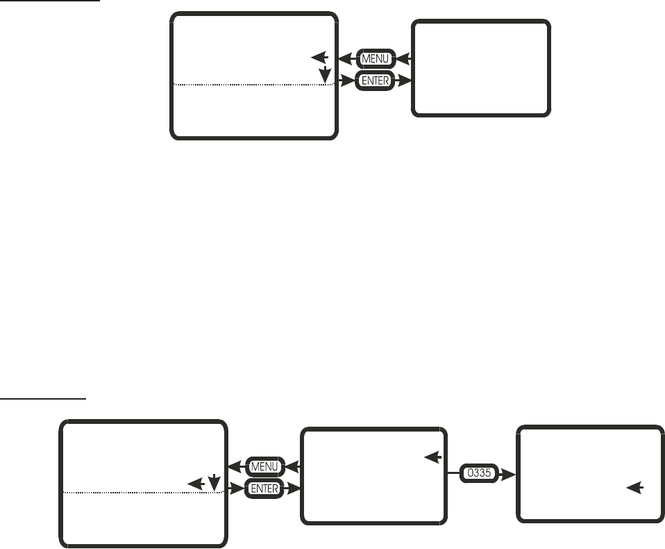
-46-
STEAM HOURS XXX
(DATE/TIME)
This field displays the steam hours and the date and time when the specific service (X) was performed.
Fault history
In this area the customer can view the history of recorded faults for the humidifier.
FAULT HISTORY X/Y
The fault history stores the last 54 system faults.
X = fault occurrence, where 1 is the most recent.
Y = total number of recorded faults (up to 54 maximum).
(type of fault) and (date/time)
A description of the fault type is displayed along with a date and time stamp when the fault occurred.
Tank Drain
The tank drain feature, when activated, will activate the drain valve for a fixed period of time (depending on unit
size).
To drain the tank press enter when CONTINUE is selected. During the tank drain cycle the display will indicate
the tank is draining and the amount of time remaining on the cycle. To interrupt the cycle the unit must be switched off
then on. Must enter service password to activate this function.
FAULT HISTORY X/Y
(TYPE OF FAULT)
(DATE/TIME)
SERVICE INTERVAL
SERVICE HISTORY
FAULT HISTORY
TANK DRAIN
TANK PRE-CLEAN
THIS WILL DRAIN
CONTENTS OF TANK
THIS WILL DRAIN
CONTENTS OF TANK
CONTINUE?
SERVICE INTERVAL
SERVICE HISTORY
FAULT HISTORY
TANK DRAIN
TANK PRE-CLEAN
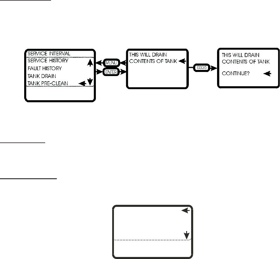
-47-
Tank Pre-Clean
The tank pre-clean feature when activated will activate the drain valve for a fixed period of time (depending on
unit size). The fill valve will then activate, filling the tank partially with cold water. At the completion of the fill cycle the
tank will once again drain.
This will help to flush out any accumulated minerals as well as cool the tank for the service personnel.
To pre-clean the tank press enter when CONTINUE is selected. During the tank pre-clean cycle the display will
indicate the tank is draining and the amount of time remaining on the cycle. To interrupt the cycle the unit must be
switched off then on. Must enter service password to activate this function.
User Settings
When a parameter requires a change, press the two arrow key and enter the password (0335). As long as you
remain in this section, you will not need to enter the password more than once.
Date / Time Units
This field is used for modifying the Date, time and the units of measurement. The date and time are important
parameters when features such as full tank blowdown are enabled.
DATE/TIME
WATER MANAGEMENT
CONTROL TYPE
CAPACITY LIMIT
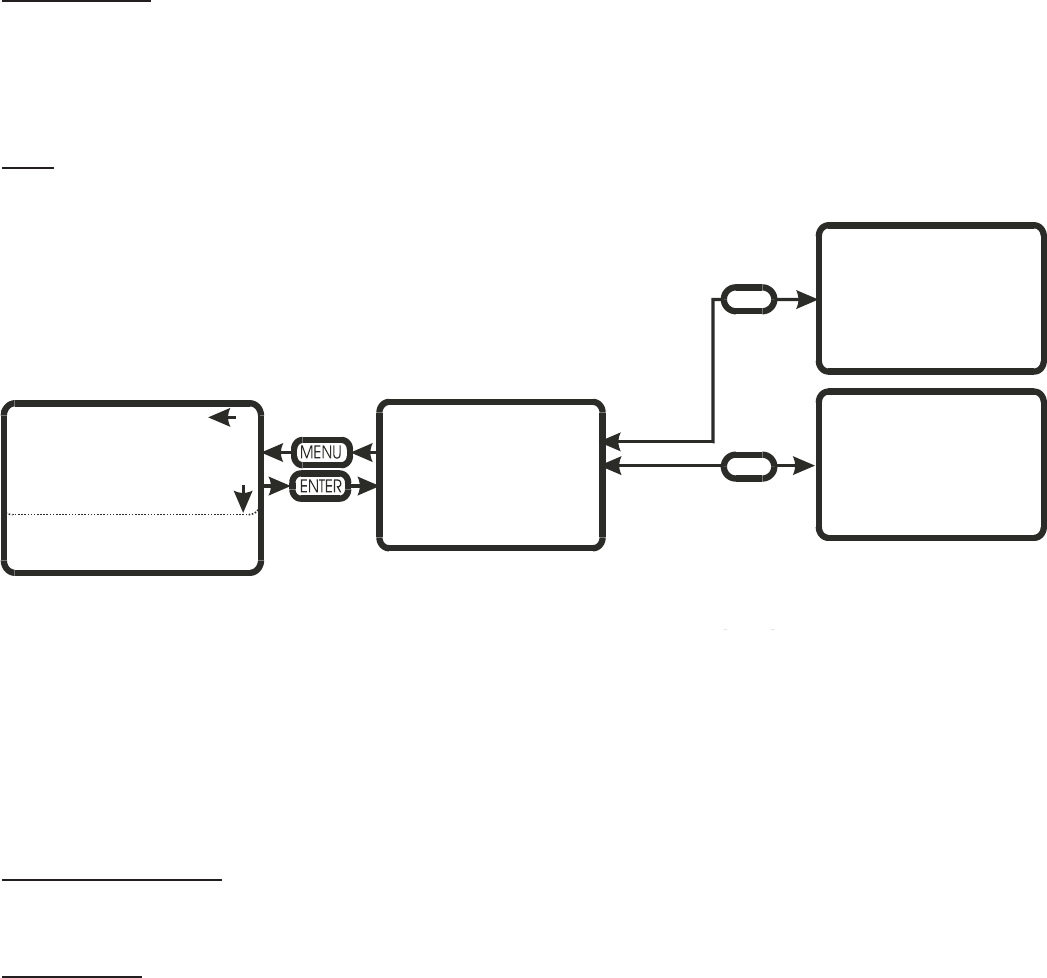
-48-
Time (of day)
To set the time of day, highlight the selection then enter the user code (0335). Press enter. Use the UP/DOWN
arrows to adjust the hours (24 hour format). Pressing enter saves the setting and indexes the display to minutes. Use
the UP/DOWN arrows to adjust the minutes. Pressing enter saves the setting and returns the user to the previous
menu.
Date
To set the date, highlight the selection then enter the user code (0335). Press enter. Use the UP/DOWN arrows to
select the month. Pressing enter saves the setting and indexes the display to number of the month. Use the
UP/DOWN arrows to adjust the number. Pressing enter saves the setting and indexes the display to year. Use the
UP/DOWN arrows to adjust the year. Pressing enter saves the setting and returns the user to the previous menu.
Water Management
This section allows the user to set time based parameters and adjust water control parameters.
FTBD Hours
This section allows the user to set the frequency of full tank blowdowns (FTBD). FTBD’s drains and re-fills the
entire contents of the humidifier after a preset accumulated operating time. Run time is measured in steam hours
(weighted run time hours), and can be adjusted from 0 hours (feature off) to 400 hours in 25 hour increments.
Once the FTBD time has expired, the controller will wait until the FTBD hour to initiate the cycle. This prevents
random drains at times when they would be inconvenient.
TIME HH:MM
DATE MM.DD.YY
DATE/TIME
LANGUAGE CONTROLS
WATER MANAGEMENT
CONTROL TYPE
CAPACITY LIMIT
1
CHANGE VALUE
MM.DD.YY
CHANGE VALUE
XX:XX
0335
0335
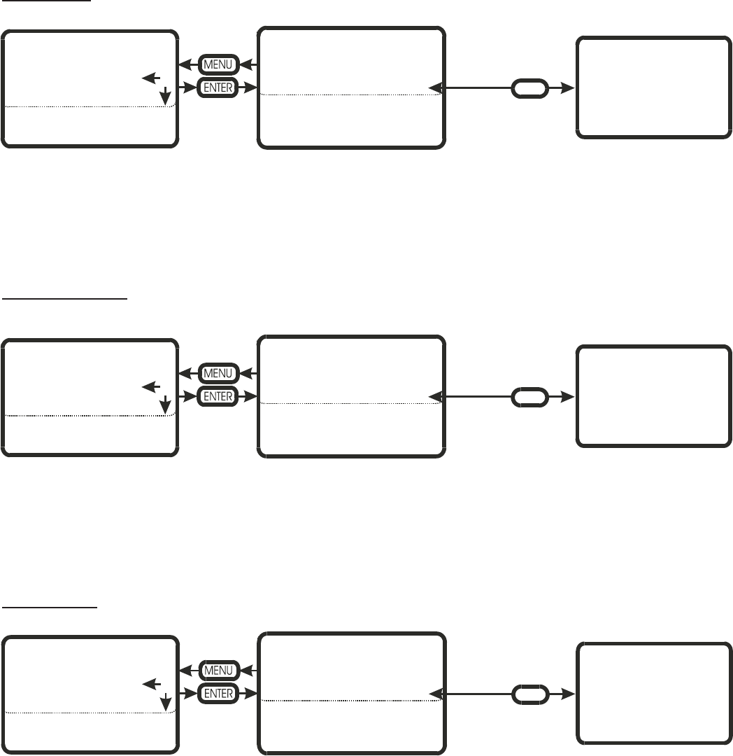
-49-
FTBD Hour
Works in conjunction with FTBD hours.
Here the user sets the time of day (24 hour format) when they want the FTBD to execute. The time can be set to
trigger the cycle during off hours, when the humidity requirements are minimal.
The time is adjusted in one-hour increments.
Blowdown Rate
This parameter adjusts the frequency of blowdown cycles.
Depending on water quality, the blowdown rate can be adjusted from 5% to 50%. The percentage is based on the
steam production rate i.e. a 10% BD rate will drain 10 kg. of water for every 100 kg. of steam produced.
The higher the mineral content of the water the higher the BD rate should be set.
Float Check
This parameter sets the time of day the controller will force a float check.
Float checks are important to ensure the water level detection system is operating correctly. The float check also
tests the fill and drain system and will report any problems detected.
To set the time of day, highlight the selection then enter the user code (0335). Press enter. Use the UP/DOWN
arrows to adjust the hours (24 hour format). Pressing enter saves the setting and indexes the display to minutes. Use
the UP/DOWN arrows to adjust the minutes. Pressing enter saves the setting and returns the user to the previous
menu.
FTBD HOUR
CHANGE VALVE XXX
DATE/TIME FTBD HOURS XXX
FTBD HOUR XX
BLOWDOWN RATE XX%
FLOAT CHECK HH:MM
FILL CORRCTN XX%
DRAIN CORRCTN XX%
DRAIN COOL: ON
WATER MANAGEMENT
CONTROL TYPE
CAPACITY LIMIT
C
0335
BLOWDOWN RATE
CHANGE VALUE XX%
STEAM OUTPUT
DATE/TIME FTBD HOURS XXX
FTBD HOUR XX
BLOWDOWN RATE XX%
FLOAT CHECK HH:MM
FILL CORRCTN XX%
DRAIN CORRCTN XX%
DRAIN COOL: ON
WATER MANAGEMENT
CONTROL TYPE
CAPACITY LIMIT
0335
FLOAT CHECK
CHANGE VALUE HH:MM
DATE/TIME FTBD HOURS XXX
FTBD HOUR XX
BLOWDOWN RATE XX%
FLOAT CHECK HH:MM
FILL CORRCTN XX%
DRAIN CORRCTN XX%
DRAIN COOL: ON
WATER MANAGEMENT
CONTROL TYPE
CAPACITY LIMIT
0335
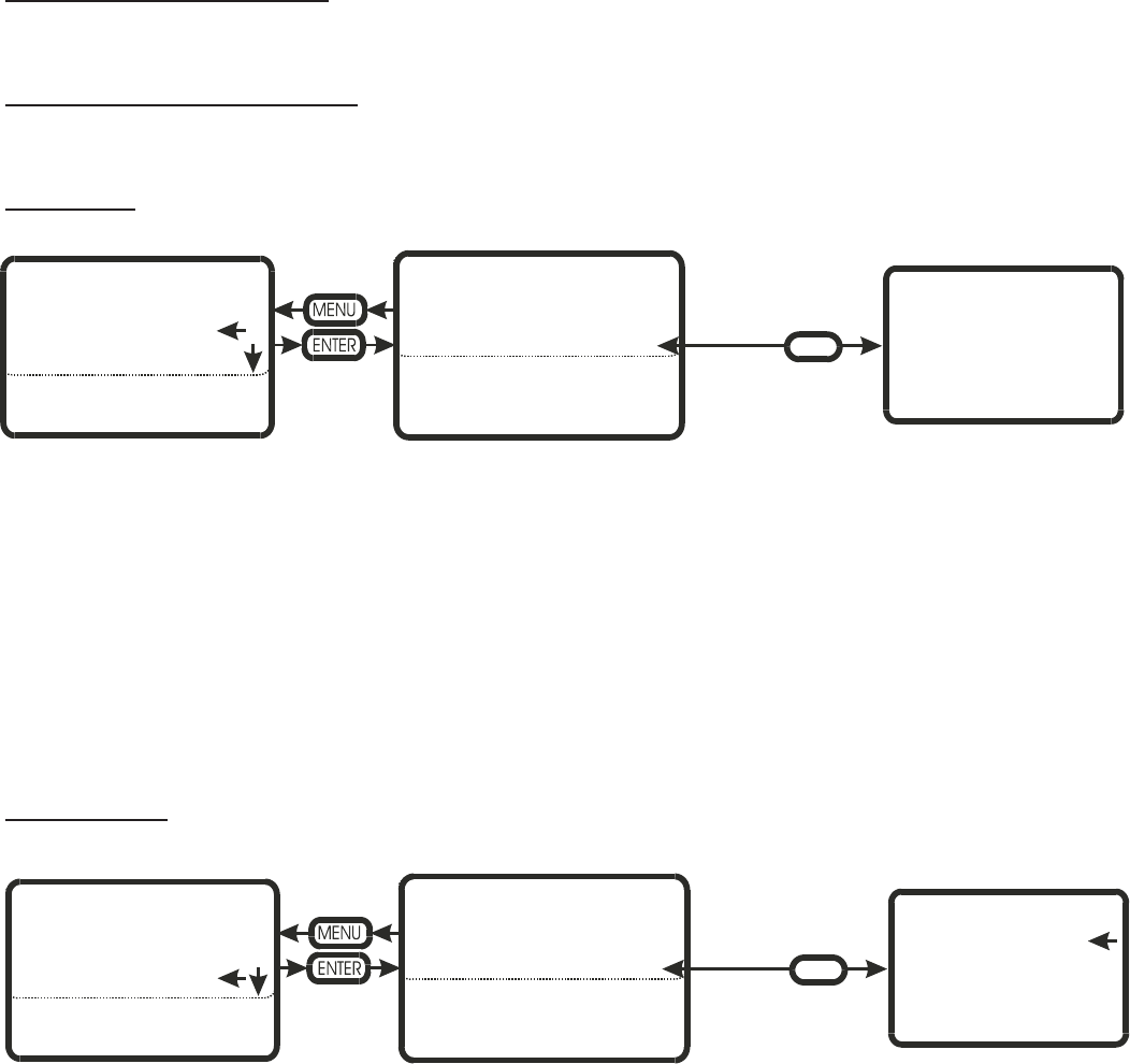
-50-
Fill CORRCTN (correction)
Used for adjusting the fill rate. Adjustments to be made under factory direction only.
Drain CORRCTN (correction)
Used for adjusting the drain rate. Adjustments to be made under factory direction only.
Drain Cool
The customer can select the type of drain water tempering they require (depending on local plumbing codes)
The customer can select ON, OFF, or SMART.
ON – whenever the drain valve is activated through software, the fill valve will automatically activate. This is the
factory default setting, but is the most wasteful of water since it will activate even if the drain water is cool.
OFF – The drain water is never tempered. This can be used where plumbing codes permit. Some process waters
are very expensive, so the customer may choose to temper the drain water through other means.
SMART – The humidifier has a tank sensor that communicates the water temperature to the controller. If the
water is hot during drain cycles the fill valve will be activated. This is the most “water smart” of the settings.
Control Input
This section is used for configuring the controller for a controller input or a transducer input.
To select control input, highlight the selection then enter the user code (0335). Press enter. Use the UP/DOWN
arrows to select control input.
The controllers dip switches then determine the type (0-10 Vdc, 0-20 mA, etc.) of control signal to process.
DRAIN COOL:
ON
OFF
SMART
DATE/TIME FTBD HOURS XXX
FTBD HOUR XX
BLOWDOWN RATE XX%
FLOAT CHECK HH:MM
FILL CORRCTN XX%
DRAIN CORRCTN XX%
DRAIN COOL: ON
WATER MANAGEMENT
CONTROL TYPE
CAPACITY LIMIT
0335
CONTROL TYPE
CONTROL INPUT
TRANSDUCER INPUT
DATE/TIME CONTROL TYPE
CONTROL INPUT
TRANSDUCER INPUT
WATER MANAGEMENT
CONTROL TYPE
CAPACITY LIMIT
0335
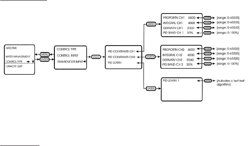
-51-
Transducer Input
This section is used to configure the controller for transducer signals
In this section you can adjust the proportional, integral and derivative constants. There is also a PID learn
algorithm which will tune the various PID constants for optimal performance.
Capacity Limit
In this section the customer can adjust the maximum output of the humidifier between 25-100%.
To adjust the maximum capacity, highlight the selection then enter the user code (0335). Press enter. Use the
UP/DOWN arrows to adjust the output between 25 and 100%.

-52-
FAULT AND WARNING LIST
FAULT
DRAIN NOT
WORKING
DRAIN IS BLOCKED
There are many time windows in the GS
software. If, during a drain cycle, the time
window for the water level to drop is exceeded,
this fault is generated
-Ensure that pump is being energized
-Check for blockage in all aspects of
the drain system
-Float board defective
-Consult factory
FAULT
FLOAT CHECK
Once every 24 hours (provided the unit is
powered and in an operating or standby
condition) the controller will test the water
level detection circuit. If the test fails this fault
is displayed
-Ensure the proper operation of the fill
valve and drain valve via the
diagnostics screen
-Float board is defective
-Consult factory
FAULT
ILLEGAL FLOAT
COMBINATION
If the controller detects two or more float level
readings, which are not expected (ex. Switch 1
and 3 ON or switch 1, 2, and 3 ON) this fault
will be recorded.
-Miswired float board
-Defective float board
-Consult factory
FAULT
FILL VALVE ON
DETECTION
INCONSISTENT
The controller monitors the water level as it
fills and drains. It expects to see the levels
increase logically (1-2-3-4-5). If the water level
increases and jumps a step (1-2-4-5) this fault
will be generated. The same holds for water
level decreasing.
-Float board defective
-Contact agent for replacement float
board
FAULT
KEEP WARM TIME
OUT
TOOLONGTO
HEAT
During a keep warn cycle, if the tank
temperature sensor does not open within a
certain time window, this fault is generated.
-Ensure that the thank temperature
sensor is connected
-Defective tank temperature switch
-Contact agent for replacement switch.
FAULT (WARNING)
MAINTENANCE
TIME
HAS ELAPSED
In the user menu the user sets the maintenance
time. Once this time expires a warning is
displayed. 72 hours later the warning changes
to this fault. The maintenance time is measured
in weighted operational hours.
With switch 5, #4 deactivated, this fault is
enabled
-Perform tank cleaning and all other
maintenance requirements outlined in
the manual.
SETC Fault (Warning)
Displayed
Description of Fault Troubleshooting

-53-
MANDATORY MAINTENANCE SCHEDULE
PARTS 30 DAYS
after
initial
start-up
MID End of
Season WHAT NEEDS TO BE DONE?
REGULAR MAINTENANCE PREVENTATIVE MAINTENANCE
Drain Lines X
- Switch to drain and make sure
water flows freely. Unit should be
completely drained afer a
maximum of 20 min.
Tank XXX
- Adjust blow down times when
required. Check that scale has
not accumulated above 2”.
- Drill out tank nipples when
required to ensure nipples are not
blocked with scale.
- Clean tank when required. - Clean tank.
Float Chamber X X X - Ensure floats move freely - Clean scale from float chamber
and hose connecting to it.
Fill Lines X X X - Inspect for leaks.
Drain Lines X X X - Inspect for leaks at the drain
pump, fill cup and float chamber.
Steam Traps X -Clean to remove all deposits.
- If damaged replace trap seat if
required
-Inspect for corrosion
-Check floats move freely
- Install new thermal disc if
-Check if orifices are not plugged
- Clean
Wye Strainer X X - Inspect for corrosion
- Clean strainer
- Replace any parts showing signs
of wear
Condensate X - Check for leaks
- Clean
- Replace worn seals.
- Follow maintenance
recommendations.
Steam Valve’s X - Check valve seat
- Clean to remove all deposits.
- If damaged replace steam valve
if required
Boiler X - Putting out correct steam
pressure
- Water test
- Follow manufacturer’s
recommendations
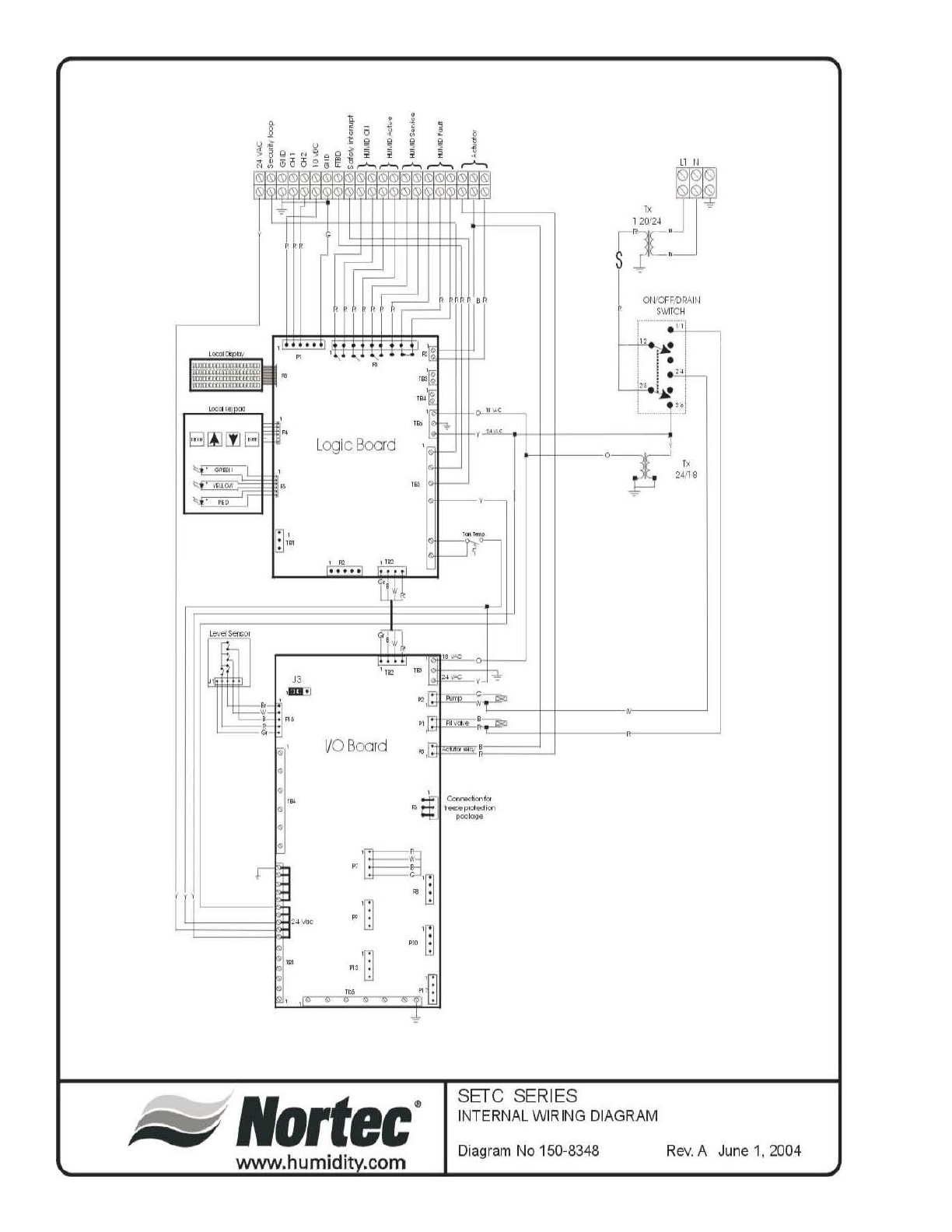
-54-
II
L
og
ic B
oa
rd
I/
O
Boa
rd
•
,
~
'0
. .
.
·:
0
·.'
0
lIortec
·
www.humidi.com
S
Er
e S
ERIE
S
OI
I'CfF,
PI1Al
II
SII\1
TCH
,',1
INTERN
AL
W
IR IN
G
DIAGRAM
Diagram
No
150-8348
Rev
. A
June
1,
2004
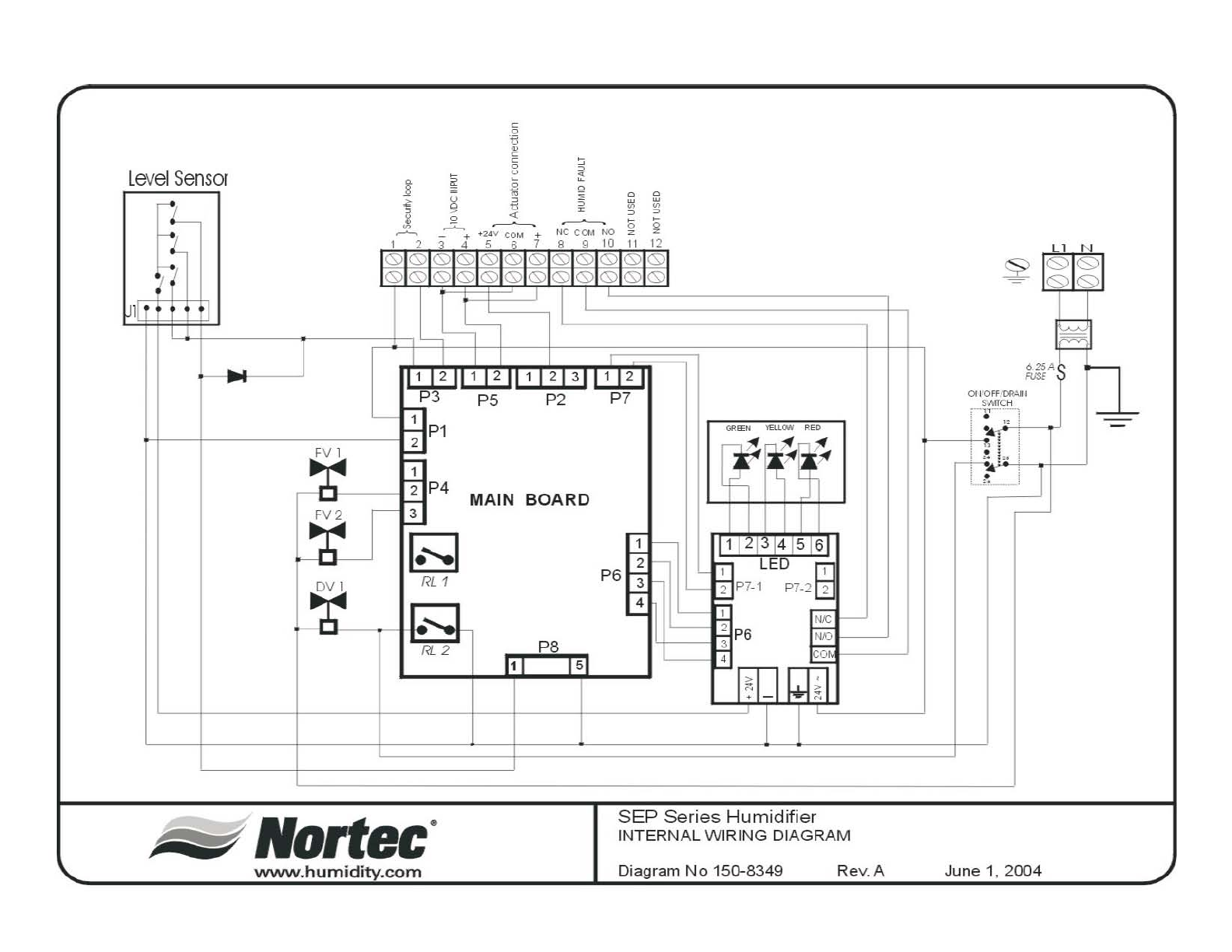
-55-
l
evel
Se
nsor
IT-
~
l
l
!itii
l
--..
~
FV I
~
F
V2
l
-t
1
~
~
c
o
"
•
c
c
o
u
E _
~ ~ ~
~
tl
:::>
III
III
<>:
I
:::>:::>
~ ~
'
2'~
+
g g
1
,
L:
L-
1
P1
2
1
2
P4
MArN
BOARD
3
~
1
2
P6
3
'
~
I
r.
....
P8
)1)
)5)
~~f
I I
1 I L 4 5 6
LED
fEl
~
P7-1 P7-2 2
, i
,
P6
,
,
fill~
SEP
Series Humidifier
INTERNA L
Wl
R ING
DIAGRAM
www
.
humidity
.com Diagram
No
150-8349
Re
v. A
Ll
N
~
1
~
1
9
1
I
'~A~
I
F~
r.
I
----L-
,---
June 1,
2004

107
116
104
109
101
113
102
103 105
115
112
114
110
111
108
106
SE 100-1050
Internal - Exploded View
July 2007
-56-

-57-
SE Series Spare Parts List - Internals
SE100 SE175 SE 250 SE 375 SE 475 SE 675 SE 950 SE1050
101 Cover Plate, Clean-Out Port 2523457 11112233
102 Gasket, Tank Cover Plate 2524361 11112233
103 Fill Box 2526152 11111111
104 Vacuum Break Valve 1/2"npt 1505959 11111111
105 P-Trap 2526521 11111111
106 Heat Exchanger Gasket
Single 2524405 11
Dual 2524403 1 1 2 2 3 3
107 Dual Fill Valve 10.0 l/min & 0.35 l/min 1505759 11111111
108 Auxilliary Drain Termination 1506925 11111111
109 Steam Trap, 15psi 1508849 11112233
110 Heat Exchanger Replacement Kit
Mini 2530901 11
Single 2530902 1 1 2 2 3 3
111 Drain Pump 24v 60 hz 1502644 11111111
112 Lower Mixing Box 1506749 11111111
113 Tank Thermal sensor 1506026 11111111
114 Float Chamber 1115933 1 1 1 1 1 1 1 1
115 Float Chamber Mounting Bracket 1113777 1 1 1 1 1 1 1 1
116 Float Board 2511137 11111111
Quantity per unit
Item # Description Part #
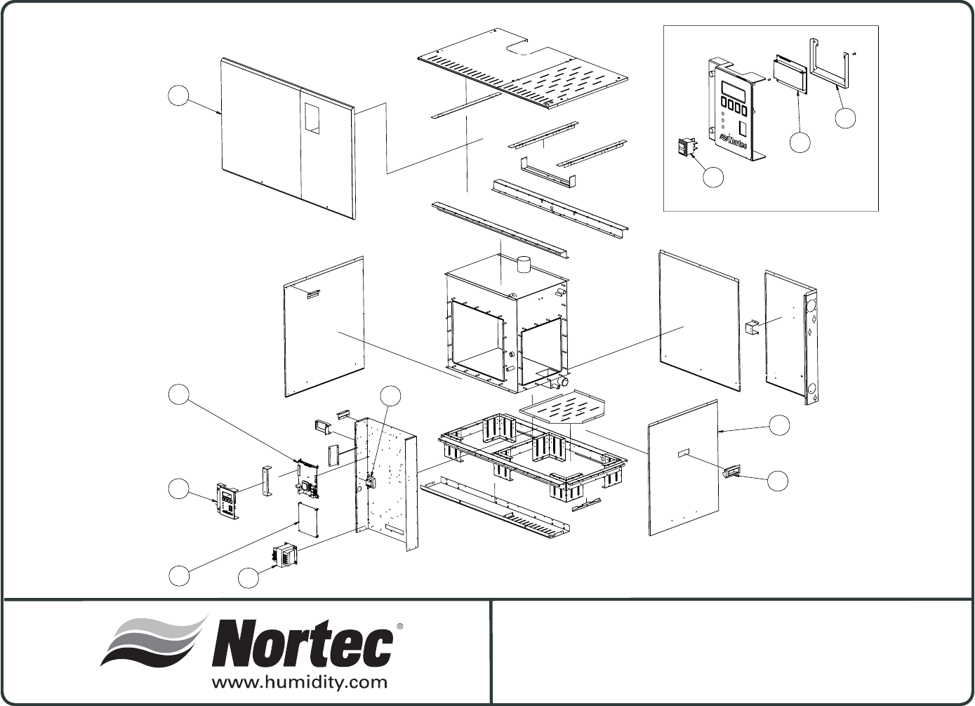
SE 100-1050
Indoor Cabinetry - Exploded View
July 2007
See exploded view
on the right side
202
201
203
205 204
208
206 207
Exploded view of item 208
208c
208a
208b
-58-

-59-
SE Series Spare Parts List - Cabinetry
Item # Description Part # SE100 SE175 SE 250 SE 375 SE 475 SE 675 SE 950 SE1050
201 Service Door Assembly
Mini 2524439 1 1
Single 2524440 1 1
Double 2524441 1 1
Triple 2524458 1 1
202 Front Door Assembly 2528421 11111111
203 Recessed Handle 2523444 11112222
204 Transformer 24/16V 15VA 50/60 hz 1505760 11111111
205 Control Board
SETC units 1508357 11111111
SEP units 1508577 11111111
206 I/O Board (SETC units) 1504760 11111111
LED Board (SEP units) 1508619 11111111
207 Transformer, 120/24V, 150VA 1504859 11111111
Fuse for Transformer, 6.25 Amp 1505020 11111111
208a LCD Display Assembly 1507741 11111111
b LCD Mounting Bracket 1506951 11111111
c On-Off-Drain Switch 1453001 11111111
Slotted Wire Duct (not shown) 1506041 order by length required
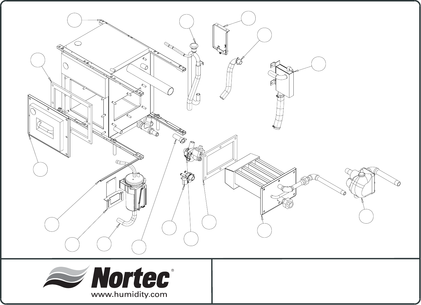
-60-
SE 50
INTERNALS-EXPLODED VIEW
3/31/2006
14
10
2
4
8
12
15
11
7
6
9
13
16
1
3
5
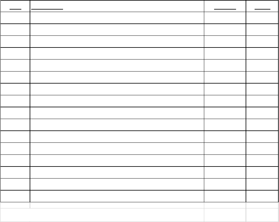
-61-
SE Spare Parts List - Internals
Item Description Part No. SE 50
1 Tank Replacement Kit, SE50 2520458 1
2 Gasket, Tank/H.E. Assembly, SE50 1510179 1
3 Heat Exchanger Replacement Kits, SE50 2520460 1
4 Gasket, Clean Out Port, SE50 1510180 1
5 Cover Plate Kit, Clean Out Port, SE50 2520461 1
6 Rail, Float Chamber Support, SE50 2520241 1
7 Bracket, Float Chamber Mount, SE50 2520240 1
8 F&T Trap Assembly, with Plumbing, SE50 1500181 1
9 Fill Box Assembly with Connections, SE50 2520235 1
10 Pump Drain, 24VDC, 60HZ (DPS 25-119) 1502644 1
11 P Trap Mount Assembly, SE50 2520137 1
12 P Trap Assembly, Complete, SE50 1510187 1
13 Termination Assembly with Connections, SE50 2520236 1
14 Auxiliary Drain Termination 1506925 1
15 Dual Fill Valve, 5.5L -.35 L/Min 1704234 1
16 Float Chamber Assembly, with Board and Connections, SE50 2520239 1
NOTE: Kits include fastening hardware such as nuts and washer assemblies will include hoses
and clmaps for item 16, float board may be ordered seperatly p/n: 1114913
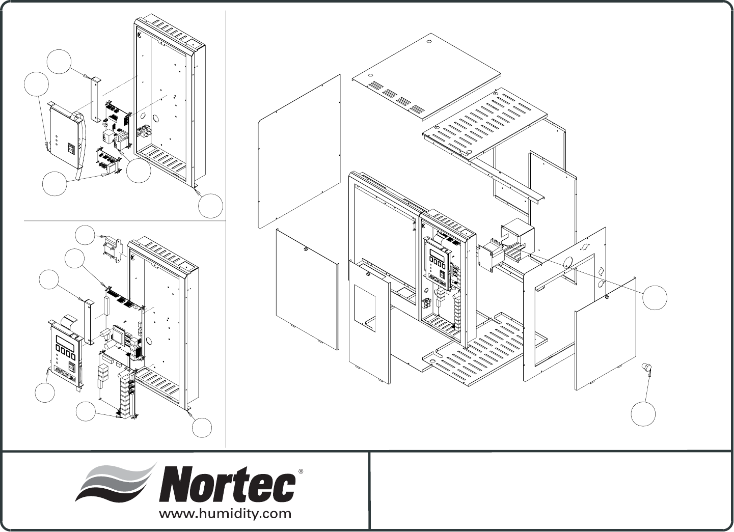
-62-
4
2
3
1
6
5
7
4
5
4
2
1
3
SETC ELECTRICAL COMPONENTS
SEP ELECTRICAL COMPONENTS
SE50
CABINETRY-EXPLODED VIEW

-63-
SE Spare Parts List - Cabinetry
SETC Electrical Components
Item Description Part No. SE 50
1 Panel Assembly, Electrical Front, Cabinet SE50 2520268 1
2 I/O Board, GS-SE Series 1504760 1
3 SETC Logic Board Assembly 1508357 1
4 Transforner 24/16V, 15VA 1505760 1
5 SETC, Display-Keypad Assembly, SE50 2520274 1
6 Bracket, Assembly, Key Pad Mount, Cabinet, SE50 2520272 1
Not Shown Wire Harness SETC 2520808 1
SEP Electrical Components
Item Description Part No. SE 50
1 Panel Assembly, Electrical Front, Cabinet SE50 2520268 1
2 SEP Display / Keypad Assembly, SE50 2520279 1
3 Bracket, Assembly, Key Pad Mount, Cabinet, SE50 2520272 1
4 SEP Control Board 1508577 1
5 SEP, Led Board Assembly 1508619 1
Not Shown Wire Harness SEP 1508352 1
SE50 Spare Parts List - Cabinetry
Item Description Part No. SE 50
1 Panel Assembly, Electrical Front, Cabinet SE50 2520267 1
2 I/O Board, GS-SE Series 2520267 1
3 SETC Logic Board Assembly 2520270 1
4 Transforner 24/16V, 15VA 2520313 1
5 SETC, Display-Keypad Assembly, SE50 2520271 1
6 Bracket, Assembly, Key Pad Mount, Cabinet, SE50 2520281 1
7 Pipe Plug, 1/2 NPT 1507043 1
Not Shown Fuse For Transformer 1505020 1
THIS PAGE INTENTIONALLY LEFT BLANK
THIS PAGE INTENTIONALLY LEFT BLANK
THIS PAGE INTENTIONALLY LEFT BLANK

LIMITED WARRANTY
Walter Meier Inc. and/or Walter Meier Ltd. (hereinafter collectively referred to as THE COMPANY),
warrant for a period of two years from date of shipment, that THE COMPANY's manufactured and
assembled products, not otherwise expressly warranted, are free from defects in material and
workmanship. No warranty is made against corrosion, deterioration, or suitability of substituted materials
used as a result of compliance with government regulations.
THE COMPANY's obligations and liabilities under this warranty are limited to furnishing replacement
parts to the customer, F.O.B. THE COMPANY's factory, providing the defective part(s) is returned freight
prepaid by the customer. Parts used for repairs are warranted for the balance of the term of the warranty
on the original humidifier or 90 days, whichever is longer.
The warranties set forth herein are in lieu of all other warranties expressed or implied by law. No
liability whatsoever shall be attached to THE COMPANY until said products have been paid for in full and
then said liability shall be limited to the original purchase price for the product. Any further warranty must
be in writing, signed by an officer of THE COMPANY.
THE COMPANY's limited warranty on accessories, not of Walter Meier’s manufacture, such as
controls, humidistats, pumps, etc. is limited to the warranty of the original equipment manufacturer from
date of original shipment of humidifier.
THE COMPANY makes no warranty and assumes no liability unless the equipment is installed in
strict accordance with a copy of the catalog and installation manual in effect at the date of purchase and
by a contractor approved by THE COMPANY to install such equipment.
THE COMPANY makes no warranty and assumes no liability whatsoever for consequential damage
or damage resulting directly from misapplication, incorrect sizing or lack of proper MAINTENANCE of the
equipment.
THE COMPANY retains the right to change the design, specification and performance criteria of its
products without notice or obligation.

E65185
PRINTED IN CANADA
Walter Meier (Climate USA) Inc.
826 Proctor Avenue, Ogdensburg, New York 13669
Walter Meier (Climate Canada) Ltd.
2740 Fenton Road, Ottawa, Ontario K1T3T7
Tel: 866 NORTEC 1 Fax: 613 822 7964
northamerica.climate@waltermeier.com www.humidity.com
