CD1 OLYMPIC 30A OM 184 693C O184693c Hob
OM-184 693C to the manual 1ab7b6c6-9129-40c0-ad32-2b219c337b00
User Manual: OLYMPIC 30A OM-184 693C
Open the PDF directly: View PDF ![]() .
.
Page Count: 24
Processes
OM-184 693C
March 2000
Olympic 30A
Description
MIG (GMAW) Welding
Feeder Gun

Hobart Welders manufactures a full line
of welders and welding related equipment.
For information on other quality Hobart
products, contact your local Hobart distributor
to receive the latest full line catalog or
individual catalog sheets. To locate your nearest
distributor or service agency call 1-877-Hobart1.
Thank you and congratulations on choosing Hobart.
Now you can get the job done and get it done right.
We know you don’t have time to do it any other way.
This Owner’s Manual is designed to help you get the
most out of your Hobart products. Please take time
to read the Safety precautions. They will help you
protect yourself against
potential hazards on the
worksite. We’ve made
installation and operation
quick and easy. With Hobart you can count on
years of reliable service with proper
maintenance. And if for some reason the unit
needs repair, there’s a Troubleshooting section
that will help you figure out what the problem
is. The parts list will then help you to decide
which exact part you may need to fix the
problem. Warranty and service information for
your particular model are also provided.
Hobart is registered to the
ISO 9001 Quality System
Standard.
From Hobart to You
Hobart offers a Technical
Manual which provides
more detailed service and
parts information for your
unit. To obtain a Technical
Manual, contact your local
distributor. Your distributor
can also supply you with
Welding Process Manuals
such as SMAW, GTAW,
GMAW, and GMAW-P.

TABLE OF CONTENTS
SECTION 1 – SAFETY PRECAUTIONS - READ BEFORE USING 1. . . . . . . . . . . . . . . . . . . . . . . . . . . .
1-1. Symbol Usage 1. . . . . . . . . . . . . . . . . . . . . . . . . . . . . . . . . . . . . . . . . . . . . . . . . . . . . . . . . . . . . . . .
1-2. Arc Welding Hazards 1. . . . . . . . . . . . . . . . . . . . . . . . . . . . . . . . . . . . . . . . . . . . . . . . . . . . . . . . . .
1-3. Additional Symbols for Installation, Operation, and Maintenance 3. . . . . . . . . . . . . . . . . . . . . .
1-4. Principal Safety Standards 3. . . . . . . . . . . . . . . . . . . . . . . . . . . . . . . . . . . . . . . . . . . . . . . . . . . . .
1-5. EMF Information 4. . . . . . . . . . . . . . . . . . . . . . . . . . . . . . . . . . . . . . . . . . . . . . . . . . . . . . . . . . . . . .
SECTION 2 – INSTALLATION 5. . . . . . . . . . . . . . . . . . . . . . . . . . . . . . . . . . . . . . . . . . . . . . . . . . . . . . . . . . .
2-1. Specifications 5. . . . . . . . . . . . . . . . . . . . . . . . . . . . . . . . . . . . . . . . . . . . . . . . . . . . . . . . . . . . . . . .
2-2. Removing Top Cover 5. . . . . . . . . . . . . . . . . . . . . . . . . . . . . . . . . . . . . . . . . . . . . . . . . . . . . . . . . .
2-3. Adjusting Contact Tip Position 5. . . . . . . . . . . . . . . . . . . . . . . . . . . . . . . . . . . . . . . . . . . . . . . . . . .
2-4. Installing Wire Spool And Threading Welding Wire 6. . . . . . . . . . . . . . . . . . . . . . . . . . . . . . . . . .
2-5. Rotating Canister 6. . . . . . . . . . . . . . . . . . . . . . . . . . . . . . . . . . . . . . . . . . . . . . . . . . . . . . . . . . . . .
2-6. Connecting To BETA-MIG 251 Welding Power Source 7. . . . . . . . . . . . . . . . . . . . . . . . . . . . .
2-7. Installing Gas Supply 7. . . . . . . . . . . . . . . . . . . . . . . . . . . . . . . . . . . . . . . . . . . . . . . . . . . . . . . . . .
2-8. Adjusting Drive Roll And Spool Brake Pressure 8. . . . . . . . . . . . . . . . . . . . . . . . . . . . . . . . . . . .
SECTION 3 – OPERATION 9. . . . . . . . . . . . . . . . . . . . . . . . . . . . . . . . . . . . . . . . . . . . . . . . . . . . . . . . . . . . .
3-1. Controls 9. . . . . . . . . . . . . . . . . . . . . . . . . . . . . . . . . . . . . . . . . . . . . . . . . . . . . . . . . . . . . . . . . . . . .
3-2. Shielding Gas 9. . . . . . . . . . . . . . . . . . . . . . . . . . . . . . . . . . . . . . . . . . . . . . . . . . . . . . . . . . . . . . . .
SECTION 4 – MAINTENANCE & TROUBLESHOOTING 10. . . . . . . . . . . . . . . . . . . . . . . . . . . . . . . . . . . .
4-1. Routine Maintenance 10. . . . . . . . . . . . . . . . . . . . . . . . . . . . . . . . . . . . . . . . . . . . . . . . . . . . . . . . . .
4-2. Changing Contact Tip And Liner 10. . . . . . . . . . . . . . . . . . . . . . . . . . . . . . . . . . . . . . . . . . . . . . . . .
4-3. Gun Drive Assembly Maintenance 11. . . . . . . . . . . . . . . . . . . . . . . . . . . . . . . . . . . . . . . . . . . . . . .
4-4. Replacing Canister Inlet Guide 12. . . . . . . . . . . . . . . . . . . . . . . . . . . . . . . . . . . . . . . . . . . . . . . . . .
4-5. Replacing Spool Canister 12. . . . . . . . . . . . . . . . . . . . . . . . . . . . . . . . . . . . . . . . . . . . . . . . . . . . . .
4-6. Replacing Contact Tip Adapter 13. . . . . . . . . . . . . . . . . . . . . . . . . . . . . . . . . . . . . . . . . . . . . . . . . .
4-7. Troubleshooting 13. . . . . . . . . . . . . . . . . . . . . . . . . . . . . . . . . . . . . . . . . . . . . . . . . . . . . . . . . . . . . .
SECTION 5 – ELECTRICAL DIAGRAMS 14. . . . . . . . . . . . . . . . . . . . . . . . . . . . . . . . . . . . . . . . . . . . . . . . .
SECTION 6 – PARTS LIST 16. . . . . . . . . . . . . . . . . . . . . . . . . . . . . . . . . . . . . . . . . . . . . . . . . . . . . . . . . . . . . .
WARRANTY
OM-184 693

OM-184 693 Page 1
SECTION 1 – SAFETY PRECAUTIONS - READ BEFORE USING
som _nd_4/98
1-1. Symbol Usage
Means Warning! Watch Out! There are possible
hazards with this procedure! The possible hazards are
shown in the adjoining symbols.
Marks a special safety message.
Means “Note”; not safety related.
This group of symbols means Warning! Watch Out! possible
ELECTRIC SHOCK, MOVING PARTS, and HOT PARTS hazards.
Consult symbols and related instructions below for necessary
actions to avoid the hazards.
1-2. Arc Welding Hazards
The symbols shown below are used throughout this manual
to call attention to and identify possible hazards. When you
see the symbol, watch out, and follow the related instructions
to avoid the hazard. The safety information given below is
only a summary of the more complete safety information
found in the Safety Standards listed in Section 1-4. Read and
follow all Safety Standards.
Only qualified persons should install, operate, maintain, and
repair this unit.
During operation, keep everybody, especially children, away.
ELECTRIC SHOCK can kill.
Touching live electrical parts can cause fatal
shocks or severe burns. The electrode and work
circuit is electrically live whenever the output is on.
The input power circuit and machine internal
circuits are also live when power is on. In semiautomatic or
automatic wire welding, the wire, wire reel, drive roll housing, and all
metal parts touching the welding wire are electrically live. Incorrectly
installed or improperly grounded equipment is a hazard.
Do not touch live electrical parts.
Wear dry, hole-free insulating gloves and body protection.
Insulate yourself from work and ground using dry insulating mats
or covers big enough to prevent any physical contact with the
work or ground.
Do not use AC output in damp areas, if movement is confined, or if
there is a danger of falling.
Use AC output ONLY if required for the welding process.
If AC output is required, use remote output control if present on
unit.
Disconnect input power or stop engine before installing or
servicing this equipment. Lockout/tagout input power according
to OSHA 29 CFR 1910.147 (see Safety Standards).
Properly install and ground this equipment according to its
Owner’s Manual and national, state, and local codes.
Always verify the supply ground – check and be sure that input
power cord ground wire is properly connected to ground terminal
in disconnect box or that cord plug is connected to a properly
grounded receptacle outlet.
When making input connections, attach proper grounding
conductor first – double-check connections.
Frequently inspect input power cord for damage or bare wiring –
replace cord immediately if damaged – bare wiring can kill.
Turn off all equipment when not in use.
Do not use worn, damaged, undersized, or poorly spliced cables.
Do not drape cables over your body.
If earth grounding of the workpiece is required, ground it directly
with a separate cable.
Do not touch electrode if you are in contact with the work, ground,
or another electrode from a different machine.
Use only well-maintained equipment. Repair or replace damaged
parts at once. Maintain unit according to manual.
Wear a safety harness if working above floor level.
Keep all panels and covers securely in place.
Clamp work cable with good metal-to-metal contact to workpiece
or worktable as near the weld as practical.
Insulate work clamp when not connected to workpiece to prevent
contact with any metal object.
Do not connect more than one electrode or work cable to any
single weld output terminal.
SIGNIFICANT DC VOLTAGE exists after removal of
input power on inverters.
Turn Off inverter, disconnect input power, and discharge input
capacitors according to instructions in Maintenance Section
before touching any parts.
Welding produces fumes and gases. Breathing
these fumes and gases can be hazardous to your
health.
FUMES AND GASES can be hazardous.
Keep your head out of the fumes. Do not breathe the fumes.
If inside, ventilate the area and/or use exhaust at the arc to
remove welding fumes and gases.
If ventilation is poor, use an approved air-supplied respirator.
Read the Material Safety Data Sheets (MSDSs) and the
manufacturer’s instructions for metals, consumables, coatings,
cleaners, and degreasers.
Work in a confined space only if it is well ventilated, or while
wearing an air-supplied respirator. Always have a trained watch-
person nearby. Welding fumes and gases can displace air and
lower the oxygen level causing injury or death. Be sure the
breathing air is safe.
Do not weld in locations near degreasing, cleaning, or spraying
operations. The heat and rays of the arc can react with vapors to
form highly toxic and irritating gases.
Do not weld on coated metals, such as galvanized, lead, or
cadmium plated steel, unless the coating is removed from the
weld area, the area is well ventilated, and if necessary, while
wearing an air-supplied respirator. The coatings and any metals
containing these elements can give off toxic fumes if welded.
OM-184 693 Page 2
Arc rays from the welding process produce intense
visible and invisible (ultraviolet and infrared) rays
that can burn eyes and skin. Sparks fly off from the
weld.
ARC RAYS can burn eyes and skin.
Wear a welding helmet fitted with a proper shade of filter to protect
your face and eyes when welding or watching (see ANSI Z49.1
and Z87.1 listed in Safety Standards).
Wear approved safety glasses with side shields under your
helmet.
Use protective screens or barriers to protect others from flash and
glare; warn others not to watch the arc.
Wear protective clothing made from durable, flame-resistant
material (leather and wool) and foot protection.
Welding on closed containers, such as tanks,
drums, or pipes, can cause them to blow up. Sparks
can fly off from the welding arc. The flying sparks,
hot workpiece, and hot equipment can cause fires
and burns. Accidental contact of electrode to metal objects can
cause sparks, explosion, overheating, or fire. Check and be sure the
area is safe before doing any welding.
WELDING can cause fire or explosion.
Protect yourself and others from flying sparks and hot metal.
Do not weld where flying sparks can strike flammable material.
Remove all flammables within 35 ft (10.7 m) of the welding arc. If
this is not possible, tightly cover them with approved covers.
Be alert that welding sparks and hot materials from welding can
easily go through small cracks and openings to adjacent areas.
Watch for fire, and keep a fire extinguisher nearby.
Be aware that welding on a ceiling, floor, bulkhead, or partition
can cause fire on the hidden side.
Do not weld on closed containers such as tanks, drums, or pipes,
unless they are properly prepared according to AWS F4.1 (see
Safety Standards).
Connect work cable to the work as close to the welding area as
practical to prevent welding current from traveling long, possibly
unknown paths and causing electric shock and fire hazards.
Do not use welder to thaw frozen pipes.
Remove stick electrode from holder or cut off welding wire at
contact tip when not in use.
Wear oil-free protective garments such as leather gloves, heavy
shirt, cuffless trousers, high shoes, and a cap.
Remove any combustibles, such as a butane lighter or matches,
from your person before doing any welding.
FLYING METAL can injure eyes.
Welding, chipping, wire brushing, and grinding
cause sparks and flying metal. As welds cool,
they can throw off slag.
Wear approved safety glasses with side
shields even under your welding helmet.
BUILDUP OF GAS can injure or kill.
Shut off shielding gas supply when not in use.
Always ventilate confined spaces or use
approved air-supplied respirator.
HOT PARTS can cause severe burns.
Do not touch hot parts bare handed.
Allow cooling period before working on gun or
torch.
MAGNETIC FIELDS can affect pacemakers.
Pacemaker wearers keep away.
Wearers should consult their doctor before
going near arc welding, gouging, or spot
welding operations.
NOISE can damage hearing.
Noise from some processes or equipment can
damage hearing.
Wear approved ear protection if noise level is
high.
Shielding gas cylinders contain gas under high
pressure. If damaged, a cylinder can explode.
Since gas cylinders are normally part of the welding
process, be sure to treat them carefully.
CYLINDERS can explode if damaged.
Protect compressed gas cylinders from excessive heat,
mechanical shocks, slag, open flames, sparks, and arcs.
Install cylinders in an upright position by securing to a stationary
support or cylinder rack to prevent falling or tipping.
Keep cylinders away from any welding or other electrical circuits.
Never drape a welding torch over a gas cylinder.
Never allow a welding electrode to touch any cylinder.
Never weld on a pressurized cylinder – explosion will result.
Use only correct shielding gas cylinders, regulators, hoses, and
fittings designed for the specific application; maintain them and
associated parts in good condition.
Turn face away from valve outlet when opening cylinder valve.
Keep protective cap in place over valve except when cylinder is in
use or connected for use.
Read and follow instructions on compressed gas cylinders,
associated equipment, and CGA publication P-1 listed in Safety
Standards.

OM-184 693 Page 3
1-3. Additional Symbols For Installation, Operation, And Maintenance
FIRE OR EXPLOSION hazard.
Do not install or place unit on, over, or near
combustible surfaces.
Do not install unit near flammables.
Do not overload building wiring – be sure power supply system
is properly sized, rated, and protected to handle this unit.
FALLING UNIT can cause injury.
Use lifting eye to lift unit only, NOT running
gear, gas cylinders, or any other accessories.
Use equipment of adequate capacity to lift and
support unit.
If using lift forks to move unit, be sure forks are
long enough to extend beyond opposite side of
unit.
OVERUSE can cause OVERHEATING
Allow cooling period; follow rated duty cycle.
Reduce current or reduce duty cycle before
starting to weld again.
Do not block or filter airflow to unit.
STATIC (ESD) can damage PC boards.
Put on grounded wrist strap BEFORE
handling boards or parts.
Use proper static-proof bags and boxes to
store, move, or ship PC boards.
MOVING PARTS can cause injury.
Keep away from moving parts.
Keep away from pinch points such as drive
rolls.
WELDING WIRE can cause injury.
Do not press gun trigger until instructed to do
so.
Do not point gun toward any part of the body,
other people, or any metal when threading
welding wire.
MOVING PARTS can cause injury.
Keep away from moving parts such as fans.
Keep all doors, panels, covers, and guards
closed and securely in place.
H.F. RADIATION can cause interference.
High-frequency (H.F.) can interfere with radio
navigation, safety services, computers, and
communications equipment.
Have only qualified persons familiar with
electronic equipment perform this installation.
The user is responsible for having a qualified electrician
promptly correct any interference problem resulting from the
installation.
If notified by the FCC about interference, stop using the
equipment at once.
Have the installation regularly checked and maintained.
Keep high-frequency source doors and panels tightly shut,
keep spark gaps at correct setting, and use grounding and
shielding to minimize the possibility of interference.
ARC WELDING can cause interference.
Electromagnetic energy can interfere with
sensitive electronic equipment such as
computers and computer-driven equipment
such as robots.
Be sure all equipment in the welding area is
electromagnetically compatible.
To reduce possible interference, keep weld cables as short as
possible, close together, and down low, such as on the floor.
Locate welding operation 100 meters from any sensitive elec-
tronic equipment.
Be sure this welding machine is installed and grounded
according to this manual.
If interference still occurs, the user must take extra measures
such as moving the welding machine, using shielded cables,
using line filters, or shielding the work area.
1-4. Principal Safety Standards
Safety in Welding and Cutting
, ANSI Standard Z49.1, from American
Welding Society, 550 N.W. LeJeune Rd, Miami FL 33126
Safety and Health Standards
, OSHA 29 CFR 1910, from Superinten-
dent of Documents, U.S. Government Printing Office, Washington,
D.C. 20402.
Recommended Safe Practices for the Preparation for Welding and
Cutting of Containers That Have Held Hazardous Substances
,
American Welding Society Standard AWS F4.1, from American
Welding Society, 550 N.W. LeJeune Rd, Miami, FL 33126
National Electrical Code
, NFPA Standard 70, from National Fire
Protection Association, Batterymarch Park, Quincy, MA 02269.
Safe Handling of Compressed Gases in Cylinders
, CGA Pamphlet
P-1, from Compressed Gas Association, 1235 Jefferson Davis
Highway, Suite 501, Arlington, VA 22202.
Code for Safety in Welding and Cutting
, CSA Standard W117.2, from
Canadian Standards Association, Standards Sales, 178 Rexdale
Boulevard, Rexdale, Ontario, Canada M9W 1R3.
S
afe Practices For Occupation And Educational Eye And Face
Protection
, ANSI Standard Z87.1, from American National Standards
Institute, 1430 Broadway, New York, NY 10018.
Cutting And Welding Processes
, NFPA Standard 51B, from National
Fire Protection Association, Batterymarch Park, Quincy, MA 02269.

OM-184 693 Page 4
1-5. EMF Information
Considerations About Welding And The Effects Of Low Frequency
Electric And Magnetic Fields
Welding current, as it flows through welding cables, will cause electro-
magnetic fields. There has been and still is some concern about such
fields. However, after examining more than 500 studies spanning 17
years of research, a special blue ribbon committee of the National
Research Council concluded that: “The body of evidence, in the
committee’s judgment, has not demonstrated that exposure to power-
frequency electric and magnetic fields is a human-health hazard.”
However, studies are still going forth and evidence continues to be
examined. Until the final conclusions of the research are reached, you
may wish to minimize your exposure to electromagnetic fields when
welding or cutting.
To reduce magnetic fields in the workplace, use the following
procedures:
1. Keep cables close together by twisting or taping them.
2. Arrange cables to one side and away from the operator.
3. Do not coil or drape cables around your body.
4. Keep welding power source and cables as far away from opera-
tor as practical.
5. Connect work clamp to workpiece as close to the weld as
possible.
About Pacemakers:
Pacemaker wearers consult your doctor first. If cleared by your doctor,
then following the above procedures is recommended.
OM-184 693 Page 5
SECTION 2 – INSTALLATION
2-1. Specifications
Wire Diameter
Range
Approximate
Wire Feed
Range
Cooling
Method Maximum
Spool Size Weld Circuit
Rating Overall
Dimensions Weight
.025 Thru 1/16 in
(0.6 Thru 1.6 mm)
Aluminum Wire
.025 Thru .045 in
(0.6 Thru 1.1 mm)
Hard Or Cored Wire
70 To 875 ipm
(1.7 To 22.2
mpm) Air Cooled 4 in (102 mm)
Diameter
100 Volts, 200
Amperes,
100% Duty
Cycle Using
Argon
Shielding Gas
Length: 15-3/8 in
(390 mm)
Width: 2-1/2 in
(64 mm)
Height: 10-3/4 in
(273 mm)
2.9 lb
(1.3 kg) Gun Only
14 lb
(6.4 kg)
Gun With Cable
Use weld control or welding power source Owner’s Manual during gun installation.
If contact tip, liner, and drive roll groove are not correct for wire size and type, see
Section 4 to change parts as needed. See Parts List for other available contact
tips.
NOTE
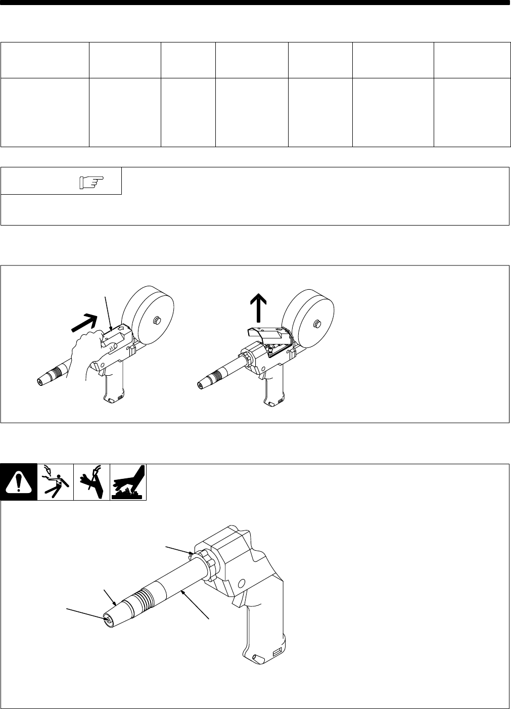
2-2. Removing Top Cover
150 882-B
1 Top Cover
Push back and lift off as shown.
To reinstall cover, set rear of cover
in gun/feeder, and push cover
back, down, and forward until it
clicks into position.
1
2-3. Adjusting Contact Tip Position
150 434-A
1 Contact Tip
2 Nozzle
Adjusting barrel changes contact
tip location from 1/16 in (1.6 mm)
out end of nozzle to 1/4 in (6.3 mm)
inside nozzle.
For aluminum welding, contact tip
should be at least 1/8 in (3.2 mm)
inside nozzle. For steel welding,
contact tip should be flush with end
of nozzle.
3 Jam Nut
4 Barrel
To change contact tip location,
loosen jam nut, and turn barrel.
Tighten jam nut.
1
3
4
2
OM-184 693 Page 6
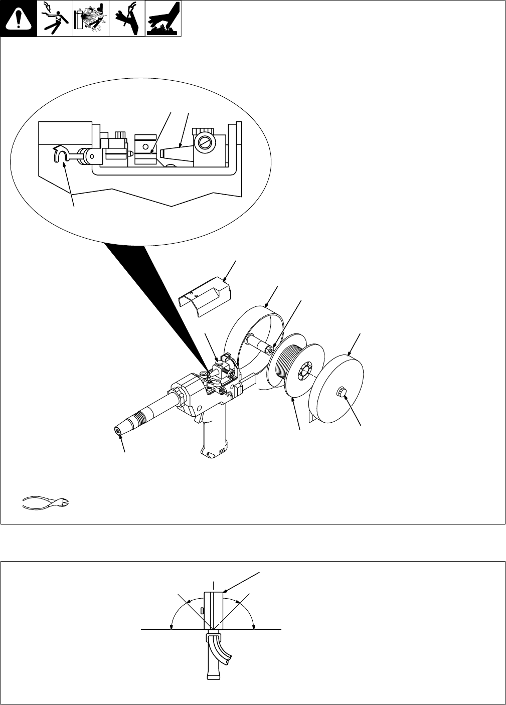
2-4. Installing Wire Spool And Threading Welding Wire
150 436-A
1 Top Cover
2 Canister
3 Canister Cover
4 Thumbscrew (Canister
Cover)
Loosen thumbscrew and remove
cover.
5 Wire Spool
Loosen wire from spool, cut off
bent wire, and pull 6 in (150 mm) of
wire off spool.
6 Pressure Roll Assembly
Lift arm and open pressure roll
assembly.
7 Canister Inlet Guide
8 Drive Roll Groove
For wire sizes .035 in (0.9 mm) and
smaller use small groove, and
.047 in (1.2 mm) and 1/16 in
(1.6 mm) use large groove.
9 Contact Tip
Thread wire through canister inlet
guide, along drive roll groove, and
out contact tip.
Install spool so wire feeds off
bottom.
10 Spool Brake Thumbnut
If necessary, turn thumbnut coun-
terclockwise slightly to install
spool.
11 Thumbscrew (Canister
Rotation)
Loosen thumbscrew to rotate can-
ister (see Section 2-5).
Close and secure pressure roll
assembly.
Reinstall top cover and canister
cover.
Tools Needed:
9
1
2
10
3
4
5
6
7
8
11
2-5. Rotating Canister
150 433-A
1 Canister
Loosen canister rotation thumb-
screw (see Section 2-4). Move
canister to desired position. Tight-
en thumbscrew.
1
Rear View
OM-184 693 Page 7
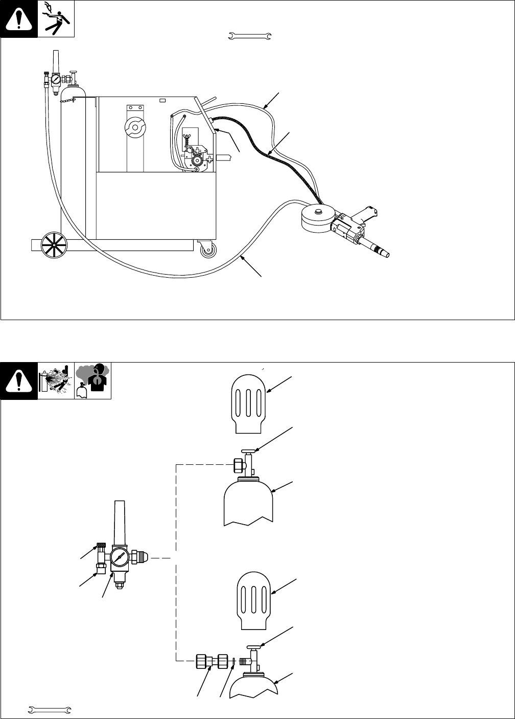
2-6. Connecting To BETA-MIG251 Welding Power Source
801 758-A
1 Spool Gun Control Module
See BETA-MIG 251 Owner’s
Manual for spool gun control
module installation instructions.
2 Gas Hose
Connect fitting to regulator/flow-
meter (see Section 2-7).
3 Trigger Control Cord
Insert plug into receptacle, and
tighten threaded collar.
4 Weld Cable
Connect to positive (+) weld output
terminal on welding power source
according to its Owner’s Manual.
Tools Needed:
1-1/8, 5/8 in
1
2
3
4
+_
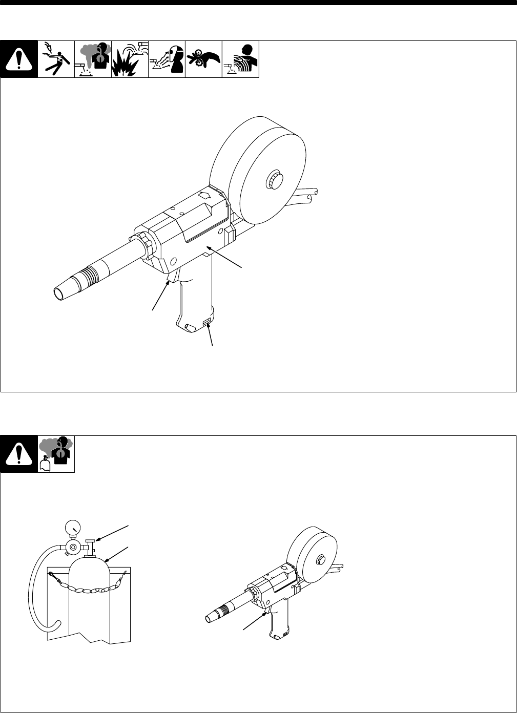
2-7. Installing Gas Supply
ssb3.1* 5/94 – 158 697-A
Obtain gas cylinder and chain to
running gear, wall, or other station-
ary support so cylinder cannot fall
and break off valve.
1 Cap
2 Cylinder Valve
Remove cap, stand to side of
valve, and open valve slightly. Gas
flow blows dust and dirt from valve.
Close valve.
3 Cylinder
4 Regulator/Flowmeter
Install so face is vertical.
5 Gas Hose Connection
Fitting has 5/8-18 right-hand
threads.
6 Flow Adjust
Typical flow rate is 20 cfh (cubic
feet per hour). Check wire man-
ufacturer’s recommended flow
rate.
Make sure flow adjust is closed
when opening cylinder to avoid
damage to the flowmeter.
7CO
2 Adapter
8 O-Ring
Install adapter with O-ring between
regulator/flowmeter and CO2
cylinder.
Tools Needed:
1-1/8, 5/8 in CO2 Gas
78
3
1
2
4
5
6
1
2
3
Argon Gas
OR
OM-184 693 Page 8
2-8. Adjusting Drive Roll And Spool Brake Pressure
Ref. 151 112-A / S-0651
1 Top Cover
2 Canister Cover
3 Thumbscrew
Loosen thumbscrew and remove
cover.
4 Spool
Cut welding wire off at contact tip.
Retract wire onto spool and
secure.
5 Spool Brake Thumbnut
Grasp spool in one hand and turn
while adjusting spool brake thumb-
nut. When a slight force is needed
to turn spool, tension is set. Do not
overtighten.
Reinstall canister cover. Thread
welding wire (see Section 2-4).
6 Drive Roll Tension Thumbnut
Turn On unit and check drive roll
pressure by feeding wire against a
wood board or concrete surface;
wire should feed steadily without
slipping.
Adjust drive roll tension thumbnut
if necessary. Do not overtighten.
Turn Off unit. Reinstall top cover.
Tools Needed:
WOOD
1
2
5
3
4
6
Adjusting Pressure
OM-184 693 Page 9
SECTION 3 – OPERATION
3-1. Controls
Ref. 147 741-B
1 Trigger
Press trigger to energize welding
power source contactor (if applica-
ble), start shielding gas flow, and
begin wire feed.
For shielding gas preflow and post-
flow, lightly press trigger before
and after welding.
2 Wire Speed Control
Use control to adjust wire feed
speed. The numbers in the open-
ing are not a wire feed speed and
are for reference only.
3 Rating Label Location
1
2
3
3-2. Shielding Gas
sb5.1* 6/92 – S-0621-C / Ref. 147 741-B
1 Shielding Gas Cylinder
2 Valve
3 Gun Trigger
Open valve on cylinder just before
welding.
Gun trigger turns weld output and
gas flow on and off. For shielding
gas preflow and postflow, lightly
press trigger before and after
welding.
Close valve on cylinder when fin-
ished welding.
1
2
3
OM-184 693 Page 10
SECTION 4 – MAINTENANCE & TROUBLESHOOTING
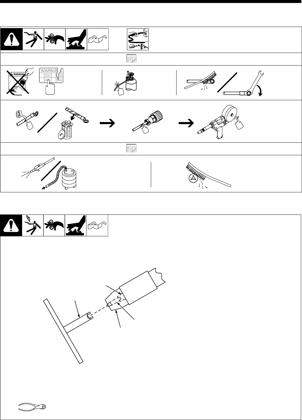
4-1. Routine Maintenance
Disconnect power
before maintaining.
Maintain more often
during severe conditions.
3 Months
Replace
Damaged Or
Unreadable
Labels
Replace
Damage
Gas Hose
Clean
And
Tighten
Weld
Terminals
Repair Or Replace
Cracked Cables
And Cords
6 Months
Blow Out Or
Vacuum Inside Clean
Drive
Rolls
4-2. Changing Contact Tip And Liner
150 437
Remove top cover and open pres-
sure roll assembly as shown in
Section 4-3.
1 Contact Tip Wrench
Insert wrench into nozzle over con-
tact tip.
2 Compression Nut
Loosen nut. Pull out contact tip.
3 Contact Tip
4 Nozzle
Pull wire out nozzle and liner
should slide out. If necessary, tilt
nozzle down to remove liner.
Close pressure roll assembly. Re-
install top cover.
Install new liner and contact tip
over wire. Cut off wire at end of
contact tip.
Tighten nut just until contact tip is
secure. Overtightening nut will
damage adapter.
Tools Needed:
1
2
3
4
OM-184 693 Page 11
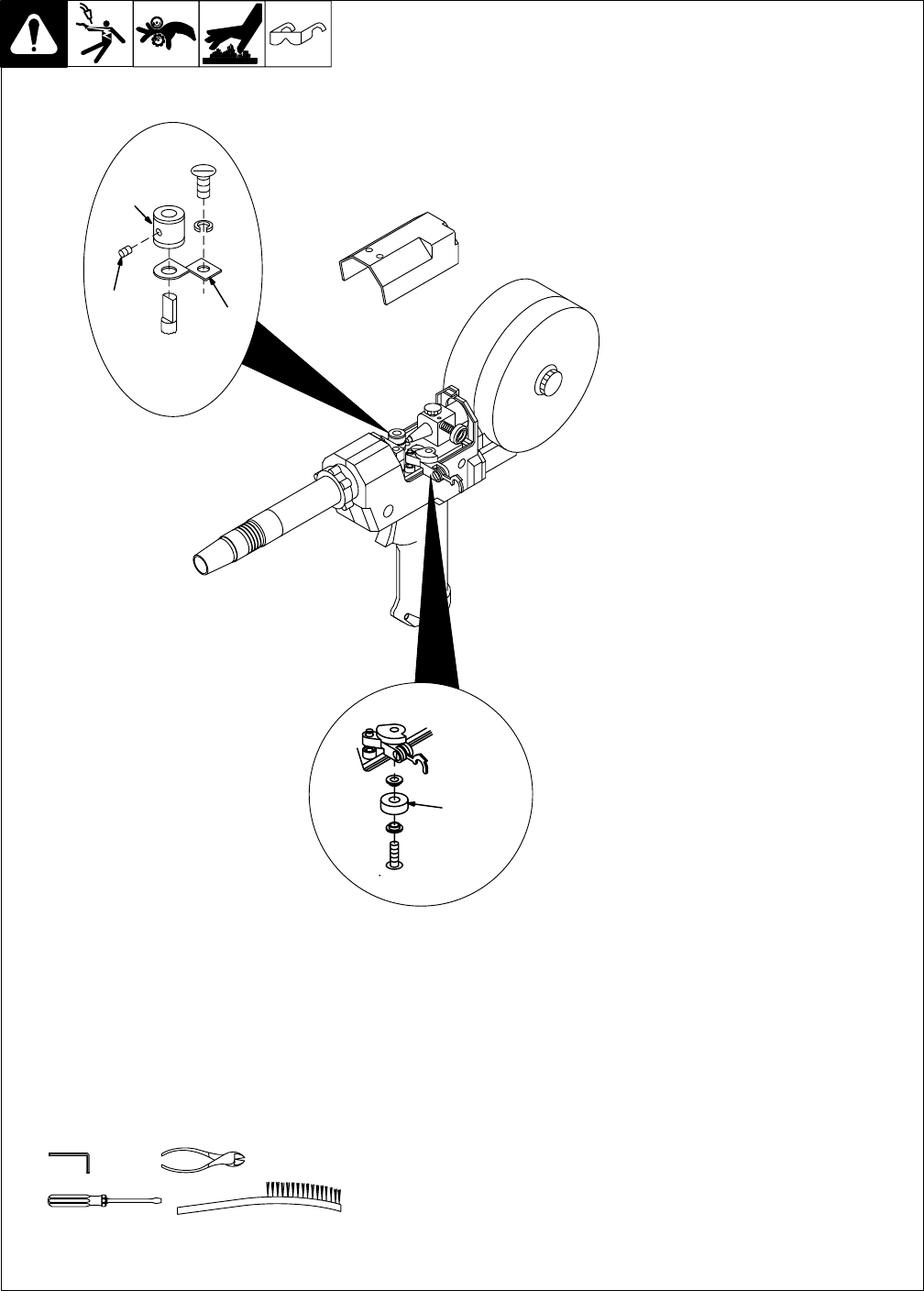
4-3. Gun Drive Assembly Maintenance
Ref. 149 967-C / Ref. 800 945-A
Retract wire onto spool.
1 Setscrew
2 Current Pick-Up Tab
This tab helps prevent burnback
caused by welding arcs inside the
contact tip. This tab may be re-
moved to provide an insulated
drive roll. (If tab is removed, a
smaller diameter contact tip is rec-
ommended. See options in Parts
List.) Lightly grease top of tab be-
fore reinstalling.
3 Drive Roll
Use wire brush to clean drive roll.
Install drive roll with desired groove
down, and turn drive roll so one
setscrew faces flat side of shaft.
4 Bearing
Use wire brush to clean bearing.
Line up drive roll groove with bear-
ing groove and liner opening.
Tighten setscrews.
Thread welding wire through gun
(see Section 3-3). Close and se-
cure pressure roll assembly. Adjust
drive roll pressure, if necessary
(see Section 3-8). Reinstall top
cover.
Tools Needed:
5/16 in
3
12
4
OM-184 693 Page 12
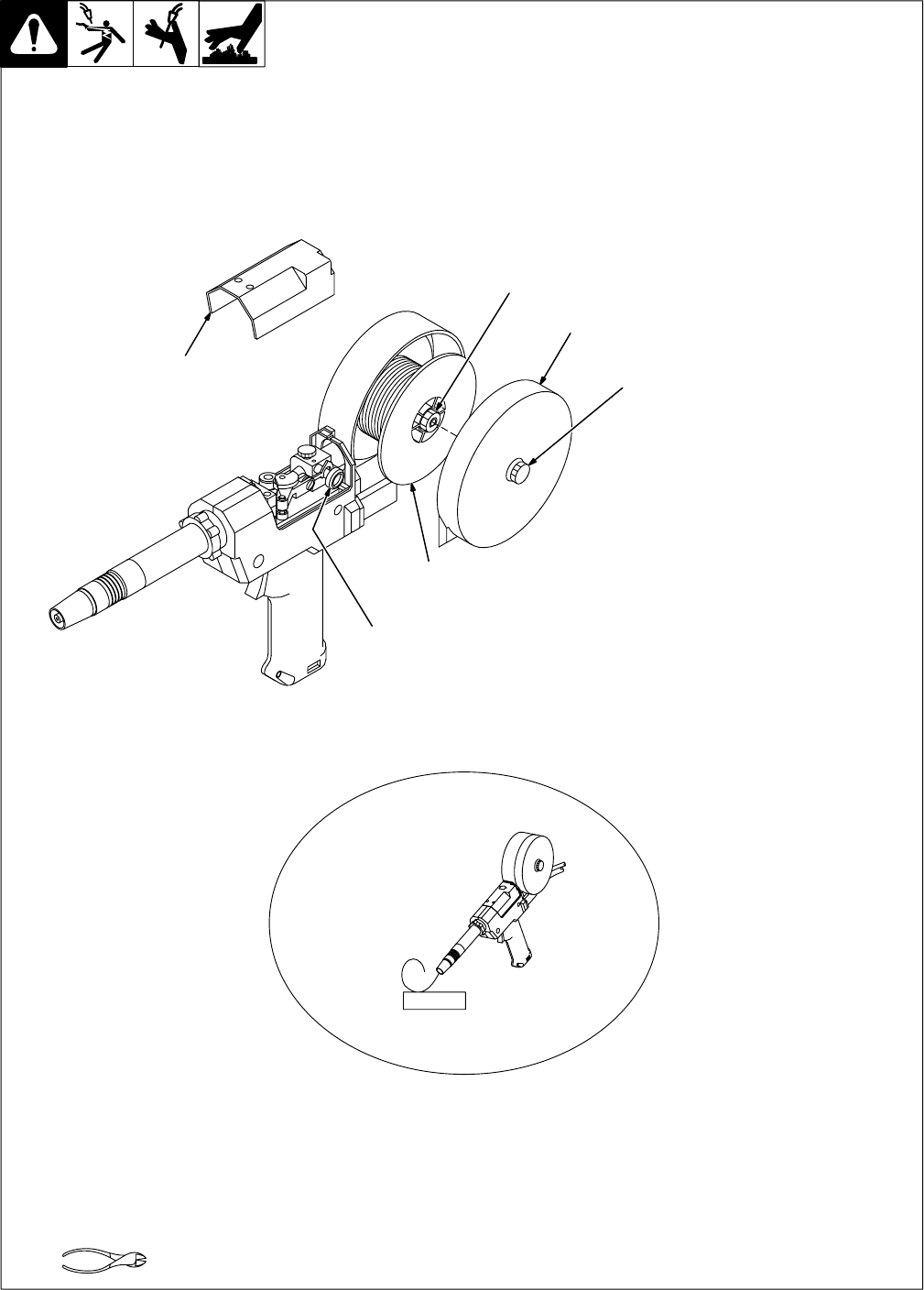
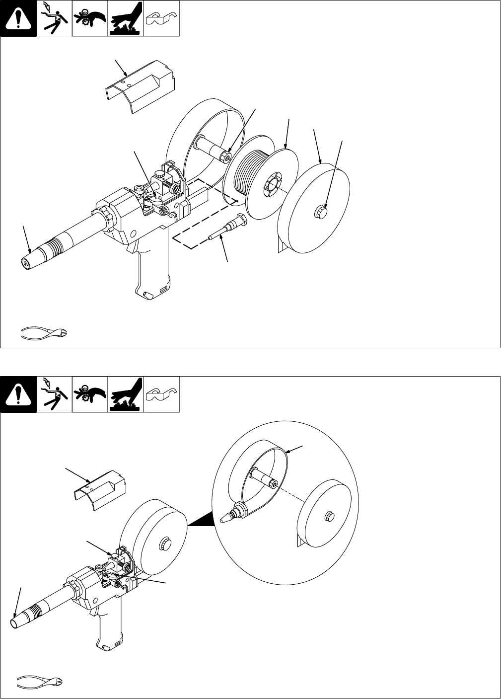
4-4. Replacing Canister Inlet Guide
Ref. 150 436-A / Ref. 149 967-C
1 Top Cover
2 Pressure Roll Assembly
Cut off welding wire where it enters
pressure roll assembly area.
3 Nozzle
Pull wire out nozzle.
4 Thumbscrew
5 Canister Cover
Loosen thumbscrew and remove
cover.
6 Wire Spool
7 Spool Brake Thumbnut
Loosen thumbnut, retract wire onto
spool, secure, and remove spool.
8 Canister Inlet Guide
Turn counterclockwise to remove.
Install new guide.
Reinstall spool and thread welding
wire (see Section 2-4).
Close pressure roll assembly. Ad-
just spool brake pressure and drive
roll pressure if necessary (see
Section 2-8).
Reinstall covers.
Tools Needed:
1
2
3
4
5
6
7
8
4-5. Replacing Spool Canister
Ref. 149 967-C
1 Top Cover
2 Pressure Roll Assembly
Cut off welding wire where it enters
pressure roll assembly area.
3 Nozzle
Pull wire out nozzle.
4 Thumbscrew (Canister
Rotation)
Turn thumbscrew counterclock-
wise three full turns.
5 Spool Canister
Remove as shown. Push new can-
ister into wire drive housing until
fully seated. Tighten thumbscrew.
Install spool and thread welding
wire (see Section 2-4).
Close pressure roll assembly. Ad-
just spool brake pressure and drive
roll pressure as necessary (see
Section 2-8).
Reinstall covers.
Tools Needed:
1
2
3
4
5
OM-184 693 Page 13
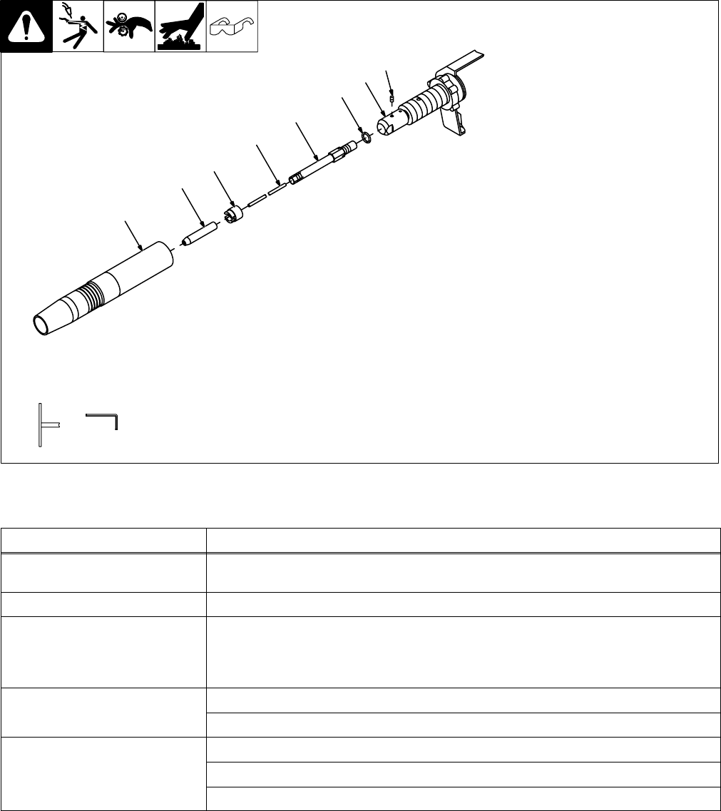
4-6. Replacing Contact Tip Adapter
150 430-B
1 Barrel Extension
Remove as shown.
2 Contact Tip
3 Compression Nut
To remove, see Section 4-2.
4 Liner
5 Contact Tip Adapter
6 O-Ring
7 Head Tube
8 Head Tube Setscrew
Loosen setscrews and remove
adapter.
Install new o-ring and adapter, and
tighten setscrews. Reinstall con-
tact tip, compression nut, and
nozzle.
Tools Needed:
3/32 in
1
2
3
4
5
678
4-7. Troubleshooting
Trouble Remedy
No weld output; gun/feeder does not
work.
Place Power switch on welding power source in the On position (see welding power source Owner’s
Manual).
Erratic weld output. Tighten and clean all connections.
Pressing gun/feeder trigger does not
energize weld control; welding wire is
not energized; shielding gas does not
flow.
Secure plug from gun/feeder trigger cord into 10-socket receptacle on weld control (see Section 2-6).
Wire feeds, shielding gas flows, but
ldi i i t i d
Secure control cable leads in welding power source (see welding power source Owner’s Manual).
welding wire is not energized. See Troubleshooting section in welding power source Owner’s Manual.
Wire feeds erratically. Check and correct drive roll pressure (see Section 2-8).
Clean drive roll or replace drive roll (see Section 4-3).
Decrease spool brake pressure (see Section 2-8).
OM-184 693 Page 14
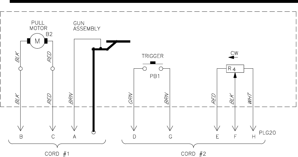
SECTION 5 – ELECTRICAL DIAGRAMS
195 712-A
Figure 5-1. Circuit Diagram For Gun/Feeder

OM-184 693 Page 15
Notes
OM-184 693 Page 16
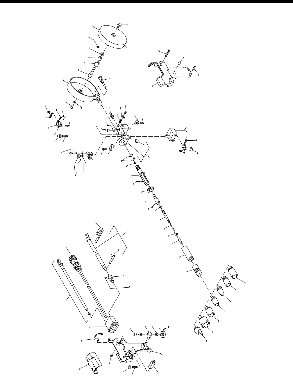
SECTION 6 – PARTS LIST
Figure 6-1. Complete Assembly 143 116-K
*Includes Items 6 & 7
**Includes Item 71
Hardware is common and
not available unless listed.
12
3
45*
6
7
8
10
9
11
12
13
14
15
16
17
18
19 20 21 22
23
24 25 26
27 28 2329
30
31
32
83
34
33
3536 35
84
38
39 40 41
42
43
44
45 46
47
48 49
50 5152 53 54 55
56
57
58 59
60
61
62
71
67
68 35
70
69**
72
73
74
75
76
77
78
79
80
81
82
64
65
66
63

OM-184 693 Page 17
Part
No.
Dia.
Mkgs.
Item
No. Description Quantity
Figure 6-1. Complete Assembly (Product No. 130 831-01-9)
1 133 479 COVER 1. . . . . . . . . . . . . . . . . . . . . . . . . . . . . . . . . . . . . . . . . . . . . . . . . . . . . . . . . . . . . . . . . . . . . . . . . . .
2 135 196 SPRING, closure cover 1. . . . . . . . . . . . . . . . . . . . . . . . . . . . . . . . . . . . . . . . . . . . . . . . . . . . . . . . . . . . . .
3 133 362 STRAIN RELIEF, cable 1. . . . . . . . . . . . . . . . . . . . . . . . . . . . . . . . . . . . . . . . . . . . . . . . . . . . . . . . . . . . . .
4 182 824 HOSE, gas in 1. . . . . . . . . . . . . . . . . . . . . . . . . . . . . . . . . . . . . . . . . . . . . . . . . . . . . . . . . . . . . . . . . . . . . .
5 198 810 CABLE, control 1. . . . . . . . . . . . . . . . . . . . . . . . . . . . . . . . . . . . . . . . . . . . . . . . . . . . . . . . . . . . . . . . . . . . .
6 R4 137 854 POTENTIOMETER, C sltd sft 1/T .5W 10K ohm 1. . . . . . . . . . . . . . . . . . . . . . . . . . . . . . . . . . . .
7 PB1 000 369 SWITCH, lim 10A 125/250VAC DPST plgr 1. . . . . . . . . . . . . . . . . . . . . . . . . . . . . . . . . . . . . . .
8 073 476 CLAMP, strap rbr 5 holes .375 wide x 4.625 lg 13. . . . . . . . . . . . . . . . . . . . . . . . . . . . . . . . . . . . . . . . .
9 137 479 CABLE, power 1. . . . . . . . . . . . . . . . . . . . . . . . . . . . . . . . . . . . . . . . . . . . . . . . . . . . . . . . . . . . . . . . . . . . .
10 152 577 STRIP, cop .010 x 2.000 x .750 1. . . . . . . . . . . . . . . . . . . . . . . . . . . . . . . . . . . . . . . . . . . . . . . . . . . . . . .
11 137 495 FITTING, connection power weld 1. . . . . . . . . . . . . . . . . . . . . . . . . . . . . . . . . . . . . . . . . . . . . . . . . . . . .
12 141 694 SCREW, set .312-18 x .375sch stl 1. . . . . . . . . . . . . . . . . . . . . . . . . . . . . . . . . . . . . . . . . . . . . . . . . . . .
13 144 861 WASHER, anti-turn 1. . . . . . . . . . . . . . . . . . . . . . . . . . . . . . . . . . . . . . . . . . . . . . . . . . . . . . . . . . . . . . . . .
14 135 127 LOCK, shaft pot .250-32 x .125dia shaft 1. . . . . . . . . . . . . . . . . . . . . . . . . . . . . . . . . . . . . . . . . . . . . . .
15 134 856 KNOB, speed control 1-10 .140 shaft x 1.125 OD 1. . . . . . . . . . . . . . . . . . . . . . . . . . . . . . . . . . . . . . .
16 602 169 SCREW, set stl sch 8-32 x .187 cup pt 1. . . . . . . . . . . . . . . . . . . . . . . . . . . . . . . . . . . . . . . . . . . . . . . .
17 144 862 EXTENSION, nozzle 1. . . . . . . . . . . . . . . . . . . . . . . . . . . . . . . . . . . . . . . . . . . . . . . . . . . . . . . . . . . . . . . .
18 156 821 EXTENSION, barrel 2.875 lg 1. . . . . . . . . . . . . . . . . . . . . . . . . . . . . . . . . . . . . . . . . . . . . . . . . . . . . . . . .
19 ♦136 171 TIP, contact .025/31 wire 1. . . . . . . . . . . . . . . . . . . . . . . . . . . . . . . . . . . . . . . . . . . . . . . . . . . . . . . . . . .
19 ♦135 428 TIP, contact .030/41 wire 1. . . . . . . . . . . . . . . . . . . . . . . . . . . . . . . . . . . . . . . . . . . . . . . . . . . . . . . . . . .
19 135 430 TIP, contact .035/52 wire 1. . . . . . . . . . . . . . . . . . . . . . . . . . . . . . . . . . . . . . . . . . . . . . . . . . . . . . . . . . . .
19 135 424 TIP, contact .047/61 wire 1. . . . . . . . . . . . . . . . . . . . . . . . . . . . . . . . . . . . . . . . . . . . . . . . . . . . . . . . . . . .
19 ♦135 425 TIP, contact .062/81 wire 1. . . . . . . . . . . . . . . . . . . . . . . . . . . . . . . . . . . . . . . . . . . . . . . . . . . . . . . . . . .
136 821 WRENCH, nut tip contact 1. . . . . . . . . . . . . . . . . . . . . . . . . . . . . . . . . . . . . . . . . . . . . . . . . . . . . . . . . . . . . . .
166 575 WRENCH, hex .078 across the flat 1. . . . . . . . . . . . . . . . . . . . . . . . . . . . . . . . . . . . . . . . . . . . . . . . . . . . . .
20 136 748 NUT, .375-24 .41dia stl 1. . . . . . . . . . . . . . . . . . . . . . . . . . . . . . . . . . . . . . . . . . . . . . . . . . . . . . . . . . . . . .
21 136 683 LINER, teflon .045-1/16 wire x 6.875 lg 1. . . . . . . . . . . . . . . . . . . . . . . . . . . . . . . . . . . . . . . . . . . . . . . .
21 136 682 LINER, teflon .023-.035 wire x 6.875 lg 1. . . . . . . . . . . . . . . . . . . . . . . . . . . . . . . . . . . . . . . . . . . . . . . .
22 164 421 ADAPTER, contact tip 1. . . . . . . . . . . . . . . . . . . . . . . . . . . . . . . . . . . . . . . . . . . . . . . . . . . . . . . . . . . . . . .
23 164 485 O-RING .176 ID x .070CS 2. . . . . . . . . . . . . . . . . . . . . . . . . . . . . . . . . . . . . . . . . . . . . . . . . . . . . . . . . . .
24 604 612 SCREW, set 8-32 x .125 cup pt sch stl 1. . . . . . . . . . . . . . . . . . . . . . . . . . . . . . . . . . . . . . . . . . . . . . . .
25 164 422 TUBE, head 1. . . . . . . . . . . . . . . . . . . . . . . . . . . . . . . . . . . . . . . . . . . . . . . . . . . . . . . . . . . . . . . . . . . . . . .
26 058 685 NUT, 1.000-8 1.5knrl nyl 1. . . . . . . . . . . . . . . . . . . . . . . . . . . . . . . . . . . . . . . . . . . . . . . . . . . . . . . . . . . . .
27 602 172 SCREW, set 10-32 x .187 cup point sch stl 1. . . . . . . . . . . . . . . . . . . . . . . . . . . . . . . . . . . . . . . . . . . . .
28 164 423 ADAPTER, tip head 1. . . . . . . . . . . . . . . . . . . . . . . . . . . . . . . . . . . . . . . . . . . . . . . . . . . . . . . . . . . . . . . . .
29 134 800 O-RING, .614 ID x .070CS 2. . . . . . . . . . . . . . . . . . . . . . . . . . . . . . . . . . . . . . . . . . . . . . . . . . . . . . . . . . .
30 133 365 CLAMP, head tube 1. . . . . . . . . . . . . . . . . . . . . . . . . . . . . . . . . . . . . . . . . . . . . . . . . . . . . . . . . . . . . . . . . .
31 000 417 SCREW, 10-24 x1.000sochd hex 2. . . . . . . . . . . . . . . . . . . . . . . . . . . . . . . . . . . . . . . . . . . . . . . . . . . . .
32 162 041 BEARING BLOCK ASSEMBLY 1. . . . . . . . . . . . . . . . . . . . . . . . . . . . . . . . . . . . . . . . . . . . . . . . . . . . . . .
604 638 SCREW, 6-32 x .375sochd hex 3. . . . . . . . . . . . . . . . . . . . . . . . . . . . . . . . . . . . . . . . . . . . . . . . . . . . . . . . . .
143 480 SCREW, 6-32 x .625sochd hex stl 1. . . . . . . . . . . . . . . . . . . . . . . . . . . . . . . . . . . . . . . . . . . . . . . . . . . . . . .
33 136 135 ROLL, drive VK groove .023-1/16 wire (consisting of) 1. . . . . . . . . . . . . . . . . . . . . . . . . . . . . . . . . . .
33 183 357 ROLL, drive VK groove .030/.035 wire (consisting of) 1. . . . . . . . . . . . . . . . . . . . . . . . . . . . . . . . . . .
33 183 358 ROLL, drive VK groove .047/.062 wire (consisting of) 1. . . . . . . . . . . . . . . . . . . . . . . . . . . . . . . . . . .
34 604 612 SCREW, set stl sch 8-32 x .125 cup point 2. . . . . . . . . . . . . . . . . . . . . . . . . . . . . . . . . . . . . . . . . . . . . .
35 114 045 SCREW, 6-32 x .500hexwhd slt stl slffmg 3. . . . . . . . . . . . . . . . . . . . . . . . . . . . . . . . . . . . . . . . . . . . . .
36 602 198 WASHER, lock .141 ID stl split 1. . . . . . . . . . . . . . . . . . . . . . . . . . . . . . . . . . . . . . . . . . . . . . . . . . . . . . .
38 134 623 BEARING, idler roll 1. . . . . . . . . . . . . . . . . . . . . . . . . . . . . . . . . . . . . . . . . . . . . . . . . . . . . . . . . . . . . . . . .
39 132 852 ARM, pressure 1. . . . . . . . . . . . . . . . . . . . . . . . . . . . . . . . . . . . . . . . . . . . . . . . . . . . . . . . . . . . . . . . . . . . .
40 605 798 WASHER, shldr nyl .375 OD x .168 ID x .080 2. . . . . . . . . . . . . . . . . . . . . . . . . . . . . . . . . . . . . . . . . .
41 133 083 SPRING, tension adj drive roll 1. . . . . . . . . . . . . . . . . . . . . . . . . . . . . . . . . . . . . . . . . . . . . . . . . . . . . . . .
42 144 860 SCREW, 8-32 x .437flathd slt stl 1. . . . . . . . . . . . . . . . . . . . . . . . . . . . . . . . . . . . . . . . . . . . . . . . . . . . . .
43 058 968 RING, retainer E 1. . . . . . . . . . . . . . . . . . . . . . . . . . . . . . . . . . . . . . . . . . . . . . . . . . . . . . . . . . . . . . . . . . .
44 135 474 PIN, hinge 1. . . . . . . . . . . . . . . . . . . . . . . . . . . . . . . . . . . . . . . . . . . . . . . . . . . . . . . . . . . . . . . . . . . . . . . . .
45 155 565 SCREW, thumb 1. . . . . . . . . . . . . . . . . . . . . . . . . . . . . . . . . . . . . . . . . . . . . . . . . . . . . . . . . . . . . . . . . . . .
134 799 O-RING, .176 ID x .070CS (used w/thumbscrew) 1. . . . . . . . . . . . . . . . . . . . . . . . . . . . . . . . . . . . . . . . . .
46 135 126 SCREW, set 6-32 x .125 cup point sch stl 1. . . . . . . . . . . . . . . . . . . . . . . . . . . . . . . . . . . . . . . . . . . . . .

OM-184 693 Page 18
Part
No.
Dia.
Mkgs.
Item
No. Description Quantity
Figure 6-1. Complete Assembly (Continued)
47 602 209 WASHER, tooth .256 ID stl intl 1. . . . . . . . . . . . . . . . . . . . . . . . . . . . . . . . . . . . . . . . . . . . . . . . . . . . . . .
48 602 154 SCREW, .250-20 x .500hexhd stl slffmg 1. . . . . . . . . . . . . . . . . . . . . . . . . . . . . . . . . . . . . . . . . . . . . . .
49 132 527 CANISTER, spool 1. . . . . . . . . . . . . . . . . . . . . . . . . . . . . . . . . . . . . . . . . . . . . . . . . . . . . . . . . . . . . . . . . .
50 148 488 POST, support spool 1. . . . . . . . . . . . . . . . . . . . . . . . . . . . . . . . . . . . . . . . . . . . . . . . . . . . . . . . . . . . . . . .
51 132 529 PAD, brake 1. . . . . . . . . . . . . . . . . . . . . . . . . . . . . . . . . . . . . . . . . . . . . . . . . . . . . . . . . . . . . . . . . . . . . . . .
52 148 489 WASHER, anti-turn .380 ID 1. . . . . . . . . . . . . . . . . . . . . . . . . . . . . . . . . . . . . . . . . . . . . . . . . . . . . . . . . .
53 132 524 NUT, .375-24 .56knrl alum 1. . . . . . . . . . . . . . . . . . . . . . . . . . . . . . . . . . . . . . . . . . . . . . . . . . . . . . . . . . .
54 000 364 RING, retainer ext .145 shaft grv x .025thk 1. . . . . . . . . . . . . . . . . . . . . . . . . . . . . . . . . . . . . . . . . . . . .
55 132 526 COVER, spool 1. . . . . . . . . . . . . . . . . . . . . . . . . . . . . . . . . . . . . . . . . . . . . . . . . . . . . . . . . . . . . . . . . . . . .
56 132 528 SCREW, thumb canister 1. . . . . . . . . . . . . . . . . . . . . . . . . . . . . . . . . . . . . . . . . . . . . . . . . . . . . . . . . . . . .
57 132 521 GUIDE, inlet canister 1. . . . . . . . . . . . . . . . . . . . . . . . . . . . . . . . . . . . . . . . . . . . . . . . . . . . . . . . . . . . . . . .
58 112 896 SPRING, cprsn .240 OD x .020 wire x .437 1. . . . . . . . . . . . . . . . . . . . . . . . . . . . . . . . . . . . . . . . . . . .
59 135 773 NUT, 8-32 .56knrl stl 1. . . . . . . . . . . . . . . . . . . . . . . . . . . . . . . . . . . . . . . . . . . . . . . . . . . . . . . . . . . . . . . .
60 143 360 SCREW, 8-32 x .500panhd phl stl 1. . . . . . . . . . . . . . . . . . . . . . . . . . . . . . . . . . . . . . . . . . . . . . . . . . . .
61 136 679 CLAMP, strain relief 1. . . . . . . . . . . . . . . . . . . . . . . . . . . . . . . . . . . . . . . . . . . . . . . . . . . . . . . . . . . . . . . . .
62 129 351 SCREW, 8-32 x .500hexwhd slt stl slffmg 1. . . . . . . . . . . . . . . . . . . . . . . . . . . . . . . . . . . . . . . . . . . . . .
63 164 591 CASE, gun LH 1. . . . . . . . . . . . . . . . . . . . . . . . . . . . . . . . . . . . . . . . . . . . . . . . . . . . . . . . . . . . . . . . . . . . .
64 173 527 SCREW, 8-32 x 1.500 2. . . . . . . . . . . . . . . . . . . . . . . . . . . . . . . . . . . . . . . . . . . . . . . . . . . . . . . . . . . . . . .
65 143 397 BLANK, snap in nylon 1. . . . . . . . . . . . . . . . . . . . . . . . . . . . . . . . . . . . . . . . . . . . . . . . . . . . . . . . . . . . . . .
66 173 528 SCREW, 8-32 x .875 1. . . . . . . . . . . . . . . . . . . . . . . . . . . . . . . . . . . . . . . . . . . . . . . . . . . . . . . . . . . . . . . .
67 B2 161 813 MOTOR, gear PM 24VDC 420RPM 10.2:1 ratio 1. . . . . . . . . . . . . . . . . . . . . . . . . . . . . . . . . . . .
68 164 592 TRIGGER 1. . . . . . . . . . . . . . . . . . . . . . . . . . . . . . . . . . . . . . . . . . . . . . . . . . . . . . . . . . . . . . . . . . . . . . . . .
69 164 582 HOUSING, wire drive (consisting of) 1. . . . . . . . . . . . . . . . . . . . . . . . . . . . . . . . . . . . . . . . . . . . . . . . . .
70 058 262 CAP, valve 1. . . . . . . . . . . . . . . . . . . . . . . . . . . . . . . . . . . . . . . . . . . . . . . . . . . . . . . . . . . . . . . . . . . . . . . . .
71 135 580 FITTING, gas 1. . . . . . . . . . . . . . . . . . . . . . . . . . . . . . . . . . . . . . . . . . . . . . . . . . . . . . . . . . . . . . . . . . . . . .
146 555 SCREW, set 8-32 x .125 cup sch 2. . . . . . . . . . . . . . . . . . . . . . . . . . . . . . . . . . . . . . . . . . . . . . . . . . . . . . . .
72 ♦050 115 NOZZLE, 1/2 orf x 1-5/8 lg 1. . . . . . . . . . . . . . . . . . . . . . . . . . . . . . . . . . . . . . . . . . . . . . . . . . . . . . . . . .
050 622 NOZZLE, 5/8 orf x 1-5/8 lg 1. . . . . . . . . . . . . . . . . . . . . . . . . . . . . . . . . . . . . . . . . . . . . . . . . . . . . . . . . . . . . .
73 164 590 CASE, gun RH 1. . . . . . . . . . . . . . . . . . . . . . . . . . . . . . . . . . . . . . . . . . . . . . . . . . . . . . . . . . . . . . . . . . . . .
74 183 884 SPRING, cprsn .240 OD x .026 wire x 1.000 1. . . . . . . . . . . . . . . . . . . . . . . . . . . . . . . . . . . . . . . . . . .
75 184 101 WASHER, shldr .140 ID x .250 OD 1. . . . . . . . . . . . . . . . . . . . . . . . . . . . . . . . . . . . . . . . . . . . . . . . . . .
76 135 647 NUT, 8-32 .33knrl brs 3. . . . . . . . . . . . . . . . . . . . . . . . . . . . . . . . . . . . . . . . . . . . . . . . . . . . . . . . . . . . . . .
83 162 042 CONTACT, current pick-up 1. . . . . . . . . . . . . . . . . . . . . . . . . . . . . . . . . . . . . . . . . . . . . . . . . . . . . . . . . . .
84 134 624 BEARING, flg nyl .140 ID x .187 OD x .375flg x .031thk 2. . . . . . . . . . . . . . . . . . . . . . . . . . . . . . . . .
♦OPTIONAL
To maintain the factory original performance of your equipment, use only Manufacturer’s Suggested
Replacement Parts. Model and serial number required when ordering parts from your local distributor.

Warranty Questions?
Call
1-877-HOBART1
for your local
Hobart distributor.
hobart standard 7/00
Service
You always get the fast,
reliable response you
need. Most replacement
parts can be in your
hands in 24 hours.
Support
Need fast answers to the
tough welding questions?
Contact your distributor or
call 1-800-332-3281. The
expertise of the distributor
and Hobart is there to
help you, every step of
the way.
Effective January 1, 2000
(Equipment with a serial number preface of “LA” or newer)
This limited warranty supersedes all previous Hobart warranties and is exclusive with no other
guarantees or warranties expressed or implied.
LIMITED WARRANTY – Subject to the terms and conditions
below, Hobart Welding Products., Troy, Ohio, warrants to its
original retail purchaser that new Hobart equipment sold after
the effective date of this limited warranty is free of defects in
material and workmanship at the time it is shipped by Hobart.
THIS WARRANTY IS EXPRESSLY IN LIEU OF ALL OTHER
WARRANTIES, EXPRESS OR IMPLIED, INCLUDING THE
WARRANTIES OF MERCHANTABILITY AND FITNESS.
Within the warranty periods listed below, Hobart will repair or
replace any warranted parts or components that fail due to
such defects in material or workmanship. Hobart must be
notified in writing within thirty (30) days of such defect or
failure, at which time Hobart will provide instructions on the
warranty claim procedures to be followed.
Hobart shall honor warranty claims on warranted equipment
listed below in the event of such a failure within the warranty
time periods. All warranty time periods start on the date that
the equipment was delivered to the original retail purchaser, or
one year after the equipment is sent to a North American
distributor or eighteen months after the equipment is sent to an
International distributor.
1. 5 Years Parts – 3 Years Labor
* Original main power rectifiers
* Inverters (input and output rectifiers only)
2. 3 Years — Parts and Labor
* Transformer/Rectifier Power Sources
* Plasma Arc Cutting Power Sources
* Semi-Automatic and Automatic Wire Feeders
* Inverter Power Supplies
* Intellitig
* Engine Driven Welding Generators
(NOTE: Engines are warranted separately by
the engine manufacturer.)
3. 1 Year — Parts and Labor
* DS-2 Wire Feeder
* Motor Driven Guns (w/exception of Spoolmate
185 & Spoolmate 250)
* Process Controllers
* Positioners and Controllers
* Automatic Motion Devices
* RFCS Foot Controls
* Induction Heating Power Sources
* Water Coolant Systems
* HF Units
* Grids
* Maxstar 140
* Spot Welders
* Load Banks
* Hobart Cyclomatic Equipment
* Running Gear/Trailers
* Plasma Cutting Torches (except APT & SAF
Models)
* Field Options
(NOTE: Field options are covered under True
Blue for the remaining warranty period of the
product they are installed in, or for a minimum of
one year — whichever is greater.)
4. 6 Months — Batteries
5. 90 Days — Parts
* MIG Guns/TIG Torches
* Induction Heating Coils and Blankets
* APT, ZIPCUT & PLAZCUT Model Plasma Cutting
Torches
* Remote Controls
* Accessory Kits
* Replacement Parts (No labor)
* Spoolmate 185 & Spoolmate 250
* Canvas Covers
HOBART’s Limited Warranty shall not apply to:
1. Consumable components; such as contact tips,
cutting nozzles, contactors, brushes, slip rings,
relays or parts that fail due to normal wear.
2. Items furnished by Hobart, but manufactured by others,
such as engines or trade accessories. These items are
covered by the manufacturer’s warranty, if any.
3. Equipment that has been modified by any party other
than Hobart, or equipment that has been improperly
installed, improperly operated or misused based upon
industry standards, or equipment which has not had
reasonable and necessary maintenance, or equipment
which has been used for operation outside of the
specifications for the equipment.
HOBART PRODUCTS ARE INTENDED FOR PURCHASE
AND USE BY COMMERCIAL/INDUSTRIAL USERS AND
PERSONS TRAINED AND EXPERIENCED IN THE USE
AND MAINTENANCE OF WELDING EQUIPMENT.
In the event of a warranty claim covered by this warranty, the
exclusive remedies shall be, at Hobart’s option: (1) repair; or
(2) replacement; or, where authorized in writing by Hobart in
appropriate cases, (3) the reasonable cost of repair or
replacement at an authorized Hobart service station; or (4)
payment of or credit for the purchase price (less reasonable
depreciation based upon actual use) upon return of the goods
at customer’s risk and expense. Hobart’s option of repair or
replacement will be F.O.B., Factory at Appleton, Wisconsin, or
F.O.B. at a Hobart authorized service facility as determined by
Hobart. Therefore no compensation or reimbursement for
transportation costs of any kind will be allowed.
TO THE EXTENT PERMITTED BY LAW, THE REMEDIES
PROVIDED HEREIN ARE THE SOLE AND EXCLUSIVE
REMEDIES. IN NO EVENT SHALL HOBART BE LIABLE
FOR DIRECT, INDIRECT, SPECIAL, INCIDENTAL OR
CONSEQUENTIAL DAMAGES (INCLUDING LOSS OF
PROFIT), WHETHER BASED ON CONTRACT, TORT OR
ANY OTHER LEGAL THEORY.
ANY EXPRESS WARRANTY NOT PROVIDED HEREIN
AND ANY IMPLIED WARRANTY, GUARANTY OR
REPRESENTATION AS TO PERFORMANCE, AND ANY
REMEDY FOR BREACH OF CONTRACT TORT OR ANY
OTHER LEGAL THEORY WHICH, BUT FOR THIS
PROVISION, MIGHT ARISE BY IMPLICATION,
OPERATION OF LAW, CUSTOM OF TRADE OR COURSE
OF DEALING, INCLUDING ANY IMPLIED WARRANTY OF
MERCHANTABILITY OR FITNESS FOR PARTICULAR
PURPOSE, WITH RESPECT TO ANY AND ALL
EQUIPMENT FURNISHED BY HOBART IS EXCLUDED
AND DISCLAIMED BY HOBART.
Some states in the U.S.A. do not allow limitations of how long
an implied warranty lasts, or the exclusion of incidental,
indirect, special or consequential damages, so the above
limitation or exclusion may not apply to you. This warranty
provides specific legal rights, and other rights may be
available, but may vary from state to state.
In Canada, legislation in some provinces provides for certain
additional warranties or remedies other than as stated herein,
and to the extent that they may not be waived, the limitations
and exclusions set out above may not apply. This Limited
Warranty provides specific legal rights, and other rights may
be available, but may vary from province to province.

PRINTED IN USA 2001 Hobart Welding Products. 1/01
Hobart Welding Products
An Illinois Tool Works Company
600 West Main Street
Troy, OH 45373 USA
For Technical Assistance:
Call1-800-332-3281
For Literature Or Nearest Dealer:
Call 1-877-Hobart1
Model Name Serial/Style Number
Purchase Date (Date which equipment was delivered to original customer.)
Distributor
Address
City
State Zip
Please complete and retain with your personal records.
Always provide Model Name and Serial/Style Number.
To locate a Distributor,
retail or service location:
Call 1-877-Hobart1 or visit our website at
www.HobartWelders.com
Contact your Distributor for:
Welding Supplies and Consumables
Options and Accessories
Personal Safety Equipment
Service and Repair
Replacement Parts
Training (Schools, Videos, Books)
Technical Manuals (Servicing Information
and Parts)
Circuit Diagrams
Welding Process Handbooks
Contact the Delivering Carrier for:
For assistance in filing or settling claims,
contact your distributor and/or equipment
manufacturer’s Transportation Department.
Resources Available
Owner’s Record
File a claim for loss or damage during
shipment.
For technical assistance:
Call 1-800-332-3281
