Ocr4all User Guide Eng
User Manual:
Open the PDF directly: View PDF ![]() .
.
Page Count: 28

OCR4all'–'An'Open'Source'Tool'Providing'an'Easy'to'Use'
(Semi-)Automatic'OCR'Workflow'for'Historical'Printings'
'
User'Guide'
Version'1.0,'April'2019'
'
'
'
'
'
'
'
'
'
'
'
'
'
'
'
'
'
'
'
'
'
'
'
1"
!
Contents'
1."OCR4all"..........................................................................................................................."2!
1.1"Introduction"..........................................................................................................................."2!
1.2"Setup"and"file"structure".........................................................................................................."3!
2."Preparation"of"scans"and"images"(Scantailor)".................................................................."3!
3."Start"and"Overview"........................................................................................................."4!
3.1"Start"OCR4all".........................................................................................................................."4!
3.2"Project"Overview"..................................................................................................................."4!
4."Workflow"......................................................................................................................."6!
4.2"Preprocessing"........................................................................................................................"7!
4.3"Noise"Removal"......................................................................................................................."8!
4.4"Segmentation"–"LAREX"..........................................................................................................."9!
4.4.1!Defaults!..................................................................................................................................!9!
4.4.2!Overview!and!EDIT!...............................................................................................................!10!
4.4.3!Specific!settings:!Regions,!Parameters,!Reading!Order,!Settings!.........................................!12!
4.4.4!Exemplified!Segmentation!of!a!scan!....................................................................................!15!
4.4.5!Further!editing!options!.........................................................................................................!18!
4.4.6!End!of!Segmentation!with!LAREX!.........................................................................................!20!
4.5"Region"Extraction"................................................................................................................."21!
4.6"Line"Segmentation"..............................................................................................................."21!
4.7"Recognition".........................................................................................................................."22!
4.8"Ground"Truth"Production"....................................................................................................."23!
4.9"Evaluation"............................................................................................................................"24!
4.10"OCR"Model"Training"..........................................................................................................."24!
4.11"Result"Generation".............................................................................................................."26!
5."Errors,"frequent"problems"and"their"evasion"................................................................."27!
!
'
!
2"
!
1.'OCR4all'
1.1'Introduction
OCR4all is a software designed'to digitally explore primarily very early printed texts whose
elaborate printing types and often uneven layout concepts are beyond the recognition abilities
of most other recognition software. Understandably and independently to use, OCR4all’s
suggested workflow also explicitly focusses users with no technical background and combines
different tools in one consistent interface. A frequent change between software is not necessary
anymore.
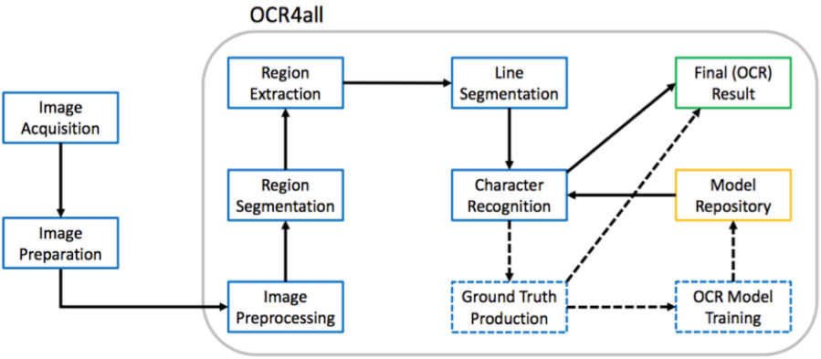
From the images’ preparation (“Preprocessing”) via the layout segmentation (“Region
Segmentation” with LAREX), the extraction of classified layout regions (“Region Extraction”),
the segmentation of lines (“Line Segmentation”) and character recognition (“Recognition”) to
the identified characters’ correction (“Ground Truth Production”) and the building of book
specific OCR-models in one software, OCR4all describes an adequate OCR-workflow (s. fig.
1).
Fig. 1: OCR4all workflow’s main constituents.
Especially due to the possibility to forge and train book specific recognition models
theoretically also applicable on other printings, OCR4all is able to achieve very good results in
digital character recognition. Regarding its total concept, this guide provides an extensive and
detailed insight in work and possible application of OCR4all within the scope of OCR
especially of early printings. While chapter 1 explains setup and file structure, chapter 2 treats
a recommended preparation of scans and images outside of OCR4all aimed at the results’
improvement and the various steps’ facilitation within OCR4all. Chapter 3 examines starting
OCR4all as well as an overview of its fundamental functions. The following chapter 4 offers a
very detailed view on the different consecutive sub modules of above described OCR workflow
and presents the initial editing of printings and creation of OCR texts practically. The
concluding fifth chapter treats the current most frequent user problems.

3"
!
1.2'Setup'and'file'structure'
As soon as OCR4all has been installed completely (click here for a guide), the file “ocr4all”
with its sub files “data” and “models” offers a basic and necessary file structure for editing
works.
“data” both saves all data a user wants to edit in OCR4all and stores data created during the
OCR-workflow in OCR4all. For this purpose, in “data” needs to be established a file for the
book itself (please evade mutated vowels and blanks during the naming!) containing another
file named “Original” (insert the scans/images here). While proceeding using OCR4all, more
files will be added automatically to the “Original”-file, carrying and saving the different edition
steps of the scans/images. Like this, i. e. the binary images created during the “Preprocessing”
step will be saved in the “PreProc” file’s subfile “Binary”. First OCR results can be found in
the “OCR” file. The total results will be found in the “Result” file.
In “models”, general mixed models made for recognition can be stored (see a selection here).
Also book specific models created with OCR4all will be stored in the work’s file. As soon as
the process of training starts, the newly created models will be numbered (starting at “0”) and
stored in the “models/name-of-work/book” file.
2.'Preparation'of'scans'and'images'(Scantailor)'
Very often, the works to produce an OCR from are merely available as facsimiles. While their
individual images will mostly have a good to very good quality, their general condition will not
be fit for a direct import into OCR4all. Such a case would be images also picturing i. e. the
book cover or back or parts of the bearing surface. By binarizing such images during the
workflow, different contrasts in the originals will cause black dividing lines both problematic
for OCR and segmentation. The rotation of scans or displaying two pages per scan also offer
problems.
These problems can be evaded by preparing the images suitably very easily: The goal thus must
be using scans showing only those contents supposed to be recognised. At the same time, these
scans should – beside the contents – also offer a reasonable amount of free space at the margins
in order not to make certain parts of the segmentation more complicated than necessary. So it’s
useful to both remove explicitly those parts of the image not belonging to the actual book page
and thus need not be recognised and simultaneously sustain as much as possible of the original
printing page (i. e. not cutting away the margins completely).
Theoretically, all image editing software is suitable for this task. In this case though,
“Scantailor” is recommended for it can edit and standardize big amounts of images in a
relatively short span of time. Detailed guides and videos can be found here.
'
'
4"
!
3.'Start'and'Overview'
3.1'Start'OCR4all'
− Start Docker:'
• Linux: Docker starts automatically by starting the computer
• Docker for Windows: Start docker via Docker-Icon in “programs”, wait for “Docker
is running”
• Docker Toolbox: Open Docker Quickstart Terminal, wait for “Docker is configured
to use default machine...”
− Start OCR4all:
• Linux: Open terminal, type “docker start -ia ocr4all” and confirm via “Enter”, wait
for start of server
• Windows 10 (Pro, Enterprise, Education): Open Windows PowerShell, type
command “docker start -ia ocr4all”, confirm via “Enter”, wait for start of sever
• Older Windows versions (with Docker Toolbox): type “docker start -ia ocr4all” in
the Docker Quickstart Terminal, confirm via “Enter”, wait for start of server
− Afterwards, OCR4all can be selected in the browser according to used docker-version
in following domains:
• Linus, Docker for Windows, MacOS: http://localhost:1476/OCR4all_Web/
• Docker Toolbox: http://192.168.99.100:1476/OCR4all_Web/
'
3.2'Project'Overview'
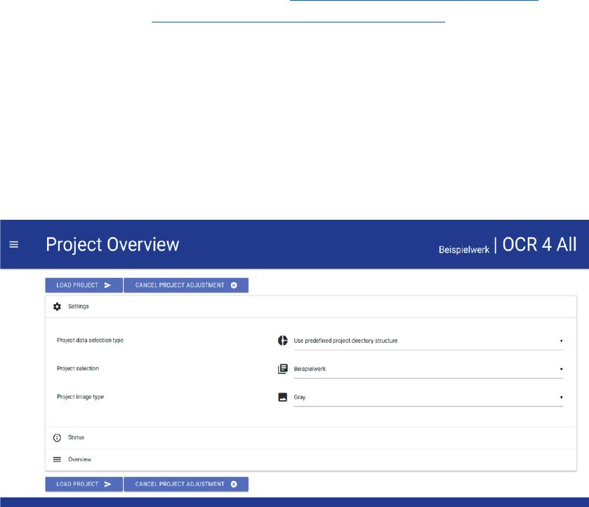
By opening OCR4all within the browser, the user automatically reaches the home page “Project
Overview”:
− ‘Settings’: The option ‘settings’ enables to select the work which shall be edited. For
this purpose, the respective work created beforehand as file in ocr4all/data/work’s title
(s. 1.2.) is selected in ‘Project Selection’ from a dropdown list. Additionally, ‘Gray’ will
be selected in ‘Project image type’.
Fig. 2: Settings in Project Overview.
5"
!
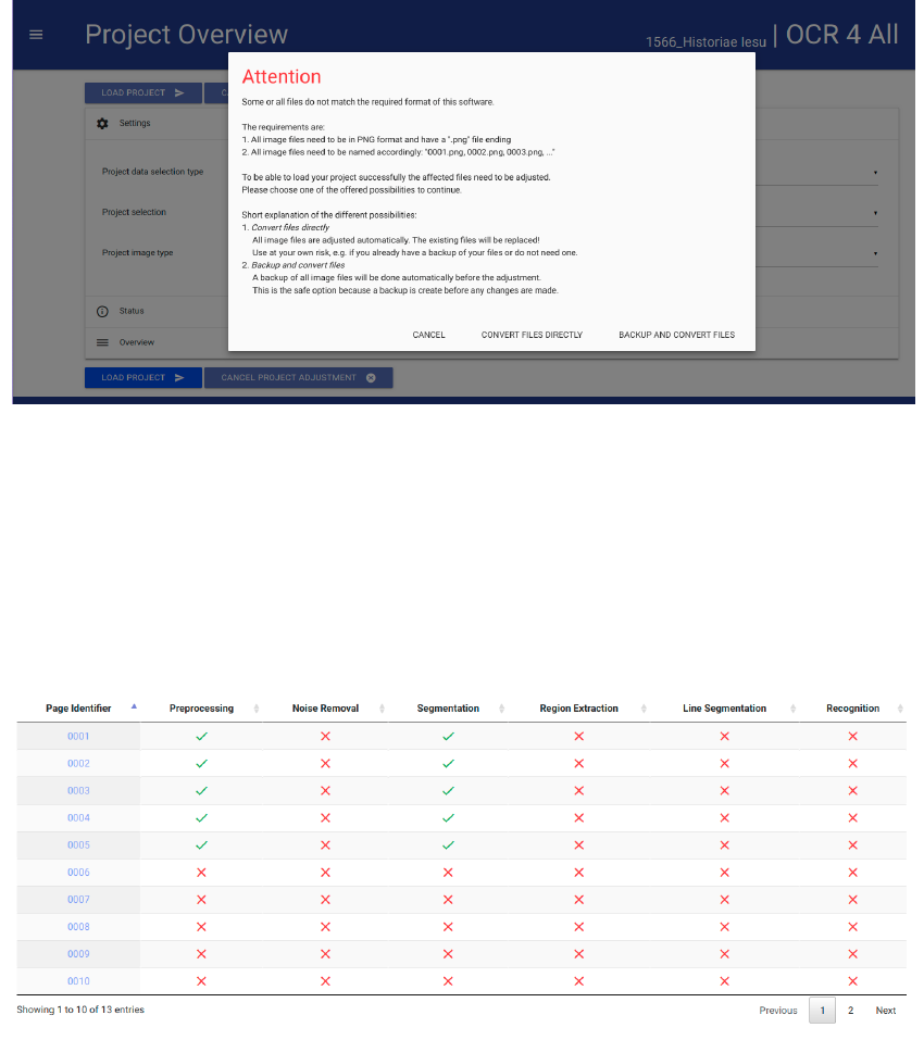
− After selecting the work follows loading it by hitting “LOAD PROJECT”. As OCR4all
demands certain, prescripted data file naming and types (0001.png and so on), “LOAD”
can cause a request to convert. This can be done in OCR4all.
Fig. 3: Possible data conversion.
− In “Overview”, the tabular structured, momentary state of the loaded work’s edition
always can be viewed. Each page of the edited work receives an individual line as “Page
Identifier” while columns (from left to right) depict the typical and suggested OCR4all
workflow. By editing certain steps of the overall workflow, the corresponding pages will
be marked as “edited” (check) within the overview. With “Show...entries” and “Search”,
the display can be changed manually, and especially extensive works can be searched.
Fig. 4: Overview.
− By hitting individual “Page Identifier”, both condition of editing and already available
data can be viewed during the whole process. The columns “Images” and “Segments”
offer this as well as the options “Original”, “Binary”, “Gray” and “Noise Removal”.
6"
!
4.'Workflow'
OCR4all generally offers two different alternatives for OCR workflows which can differ
extremely in energy expend, almost necessarily in verifiability of part results and thus the
produced data’s quality. In the following, both alternatives will be introduced and classified.
!
4.1'Process'Flow
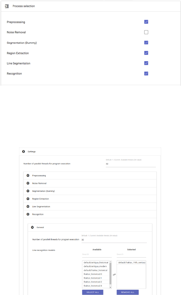
The option “Process Flow” (main menu ☰→ Process Flow) offers an almost fully automated
workflow. In it, merely those scans which should be edited are selected from the right-side bar
and afterwards, by respective checks, all work steps which are supposed to be executed on the
data.
'
'
'
'
'
Fig. 5: Parts of the “Process Flow”.
Only the step “Recognition” requires selecting a suitable OCR model or model package (five
simultaneous and interacting individual models, s. also Chap. 4.7) for the recognition. Use
“Settings” → “Recognition” → “General” as depicted in the following image, from the list of
all available OCR models (“Line recognition models – Available”).
'
'
'
'
'
'
'
'
Fig. 6: Selecting a suitable OCR model.
7"
!
It’s generally possible to select more than one model for the recognition. It’s only recommended
though, if different types occur within the edited text.
“EXECUTE” starts the “Process Flow”. The individual part module’s process notification
enables trailing the current state of editing. After a complete run of the workflow, the results
can be checked in the option “Ground Truth Production” (☰).
'
'
'
'
'
'
Fig. 7: Lines with corresponding OCR result.
If the created OCR lines correspond to wished or requested accuracy, final results can already
be created (TXT and/or PageXML) via “Result Generation” (☰). If they do not, they can be
corrected before the result generation (s. Chap. 4.8).
Besides the “Process Flow”, OCR4all also offers the possibility of a sequential workflow in
which the user runs the different part modules independently (s. fig. 1) in order to guarantee the
produced data’s correctness and quality. As the separate part modules are based on each other,
this approach seems sensible especially for very early printings and their complex and extensive
layout.
It’s recommended particularly to first time users to run the following step-by-step OCR
workflow at least once in order to understand the function of the individual part modules.
4.2'Preprocessing'
Input: original image (coloured, grayscale or binary).
Output: deskewed binary (and grayscale) image.
− This step aims at creating binary and grayscale images providing the foundation for a
successful segmentation and OCR.
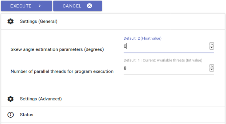
− All scans supposed to be edited are selected at the right hand sidebar; all settings
(“Settings (General)” and “Settings (Advanced)” remain, meaning both the to be edited
image’s angle remains unchanged as well as the automatically generated number of used
CPUs by the part module (the latter concerns all of OCR4all‘s following part modules!)
8"
!
Fig. 8: Settings for preprocessing.
− Binarization can be started by hitting “EXECUTE”. The step’s progress can be followed
within the console, more precisely in “Console Output”. If necessary, warnings are
dispensed during the binarization in “Console Error”. They do not affect the
binarization’s result though.
− The binarized image data and grayscale images are saved in the respective, automatically
generated file ocr4all/data/work’s title/PreProc. The binarization’s success can be
controlled either here or in “Project Overview” via hitting any “Page Identifier” or the
display screen “Binary”. Additionally, there should be checks for all edited images in the
project overview’s column “Preprocessing”.
'
4.3'Noise'Removal'
Input: noisy binary image.
Output: binary image with no/less noise.
− The option “Noise Removal” can delete minor pollution like blotches or spots on from
scans. The respectively edited data is being saved in ocr4all/data/work’s
title/PreProc/Despeckled and are available for further steps.
− For using “Noise Removal”, hit the corresponding step in the main menu and select those
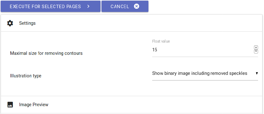
scans to be edited in the right-hand sidebar. Adopt all defaults at first and, after hitting
“EXECUTE”, examine the results on a trial basis by hitting the respective scan’s
lettering on the right-hand sidebar. In “Image Preview”, you can now view the
comparison of unedited and edited image. Red pigmented image elements have been
deleted in this step.
9"
!
'
'
'
'
'
'
Fig. 9: Settings for noise removal.
− In case too many disturbing elements are left on the scan, tentatively increase the
magnitude of “Maximal size for removing contours”, repeat the step by hitting
“EXECUTE” again and once again control the results.
− In case too many image elements have been removed, correct the magnitude of
“Maximal size for removing contours” downwards.
− Repeat the process until content with the results.
4.4'Segmentation'–'LAREX'
Input: preprocessed images.
Output: structural information on regions (position and type) and their reading order.
LAREX serves as segmentation tool, structuring and classifying the printing pages’ layout for
further editing steps. The basic assumption lies within a repeating pool of different layout
elements used for especially early printings, making them consistent to a certain degree. Thus,
users can rely upon different tools and aids to structure a printing page (segment it) in a way to
adequately determine all information concerning the layout for the workflow’s following steps.
This includes besides the basic distinction text versus non-text (i. e. text versus image/woodcut)
and their further specification (i. e. for a text headline, main text, page number) also information
concerning the reading order (meaning order of reading and usage) of the existing elements.
These results are saved as XML data in ocr4all/data/work’s title/PreProc/Binary individually
attributed to their respective binarized image file. In case the Noise Removal has been executed
before the segmentation, the corresponding data can be found in ocr4all/data/work’s
title/PreProc/Despeckled.
'
4.4.1'Defaults'
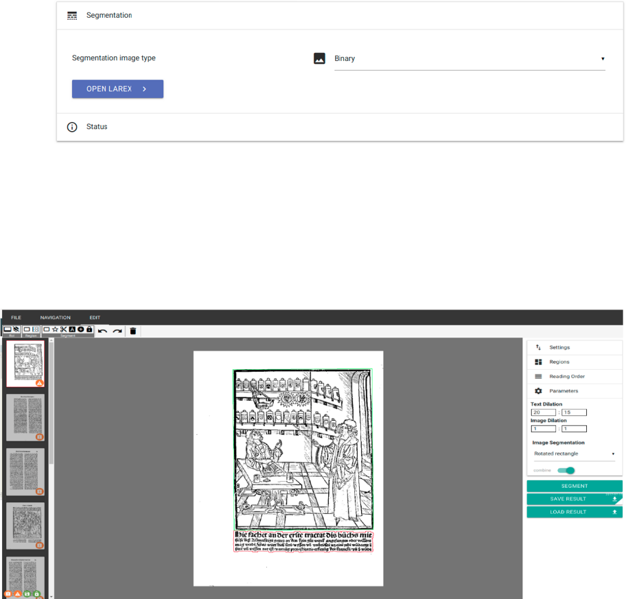
− Menu: “Segmentation” -› “LAREX”.
− “Segmentation image type”: “Binary” in case the process should be continued with
binarized data; “Despeckled” in case the step “Noise Removal” has been executed
before.
− “OPEN LAREX” -› “LAREX” opens in new tab.
10"
!
'
'
'
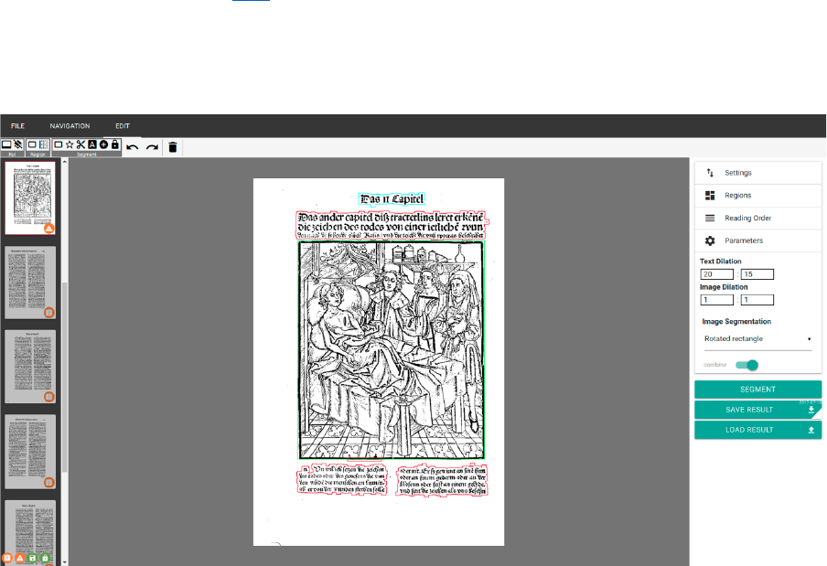
Fig. 10: LAREX settings.
In the middle, the first of all selected scans is displayed. There already exist first segmentation
results generated by the automatic segmentation of each scan as soon as it’s being selected for
the first time. These results are not saved. It is now the user’s job to further determine settings
meant to adapt the displayed automatic segmentation results to the respective work’s layout or
add manual corrections in order to achieve a correct segmentation result.
Fig. 11: home page and automatic segmentation results.
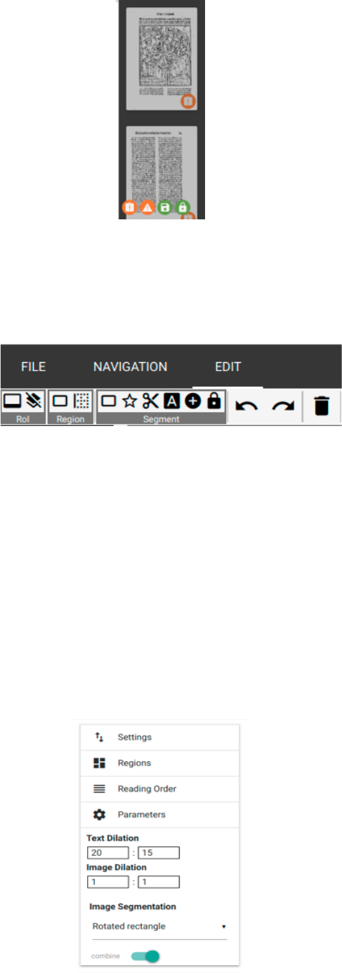
4.4.2'Overview'and'EDIT'
In the left-hand sidebar, all selected and to be edited scans are displayed. Corresponding to their
edition status, the receive different coloured markings in the right bottom corner:
− Exclamation mark, orange: “There is no segmentation for this page.” – There are no
segmentation results for this page at the moment.
− Warning triangle, orange: “Current segmentation may be unsaved.” – The current
segmentation results might not be saved yet (s. below).
− Disk, green: “Segmentation was saved in this session.” – There are saved segmentation
results for this scan saved as XML data.
− Lock, green: “There is a segmentation for this page on the server.” – The individual
saved segmentation results have been confirmed after ending the whole work’s
segmentation as correct. (s. below).
11"
!
'
'
'
'
'
'
Fig. 12: different states of editing.
'
The head runner offers the options “FILE”, “NAVIGATION” and “EDIT”:
'
'
Fig. 13: Head runner’s different menu items.
− FILE: There are not settings or changings necessary for the LAREX version integrated
in OCR4all!
− NAVIGATION: The here possible settings structure the general display of scans and
images in LAREX, i. e. the scan’s position within the viewer or certain zoom settings.
These settings also can be changed via mouse and/or touchpad (simple moving of the
displayed scan by keeping the mouse’s/touchpad’s left area held and moving the
mouse/touchpad; zoom via scrolling or touchpad’s zoom settings).
− EDIT: The different options of editing a scan are displayed here, complemented by the
right-hand sidebar. While options running under “EDIT” generally are made for the
respective scan’s specific editing (s. below), work based and global options are displayed
on the right hand sidebar.
'
'
'
'
'
'
'
Fig. 14: Right sidebar’s settings.
12"
!
However, they always can be complemented, changed and adapted. It’s helpful and sensible in
this case to always save all influenced settings regarding the recognition parameters
(“Parameters”) and the layout elements determined by the user and given in the work to be able
to use them again when using LAREX again. It enables working with work specific settings.
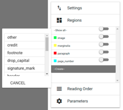
4.4.3'Specific'settings:'Regions,'Parameters,'Reading'Order,'Settings'
− “Regions”: Each scan (and with it work’s and text) page consists, following the idea and
concept of LAREX, of different layout elements. These include i. e. main text
(paragraph), marginalia, page number, etc. In LAREX, it’s necessary to assign a certain,
predefined “region” respectively layout region to each layout element. Regarding the
following steps and a homogenous recognition of the displayed contents, this assignment
has to be consistent throughout the whole work! Apart from several predefined and
settled layout regions like “image” (i. e. graphic displays like wood cuts, decorative
initials etc.), “paragraph” (main text) or “page_number” (page number), the user can also
add and define more, work specific layout regions in “Create”. Like this, the region’s
colour as well as its minimum size (available via ‘minSize’) in which it’s supposed to
recognize layout elements can be settled. The thus defined layout region is added to the
work specific list via the “SAVE” button.
'
'
'
'
'
'
'
'
'
Fig. 15: setting options in Regions.
− Additionally, “regions” also provides the possibility to assign a certain, predefined place
to layout regions on the scan which will be applied automatically for following scans’
segmentation (when opening them). If a layout keeps repeating itself throughout the
work, it’s possible to generate a kind of layout model with whose aid the automatic
segmentation can be improved. This also probably lessens the number of interventions
the user has to take. To adapt the layout region’s position to the pages’ layout within the
work, the layout region’s current position can be viewed and changed by a simple
selection on the following scan.
13"
!
'
'
'
'
'
'
'
'
'
'
Fig. 16: Display out layout regions and layout model.
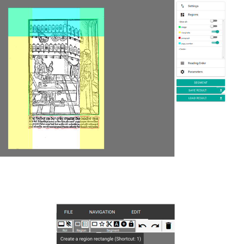
If a new “region” is defined by the user, it can be settled and always changed by the user
via “EDIT” and the following option “Region” -› “Create a region rectangle (Shortcut:
1)”. It is not possible to define a layout region for “images” on the scan page.
Fig. 17: setup of new layout regions.
At the same time, it is not always sensible to settle consistent positions for layout regions
throughout the whole work. Especially if the position of certain “regions” (like
headings, headers and also page numbers or signature title) keep varying, wrong
recognitions can occur by settling defined positions. In this case it’s more useful to
manually correct respective layout elements. If a layout region’s position should be
deleted completely, it is deleted by selecting via hitting it and using “Del”.
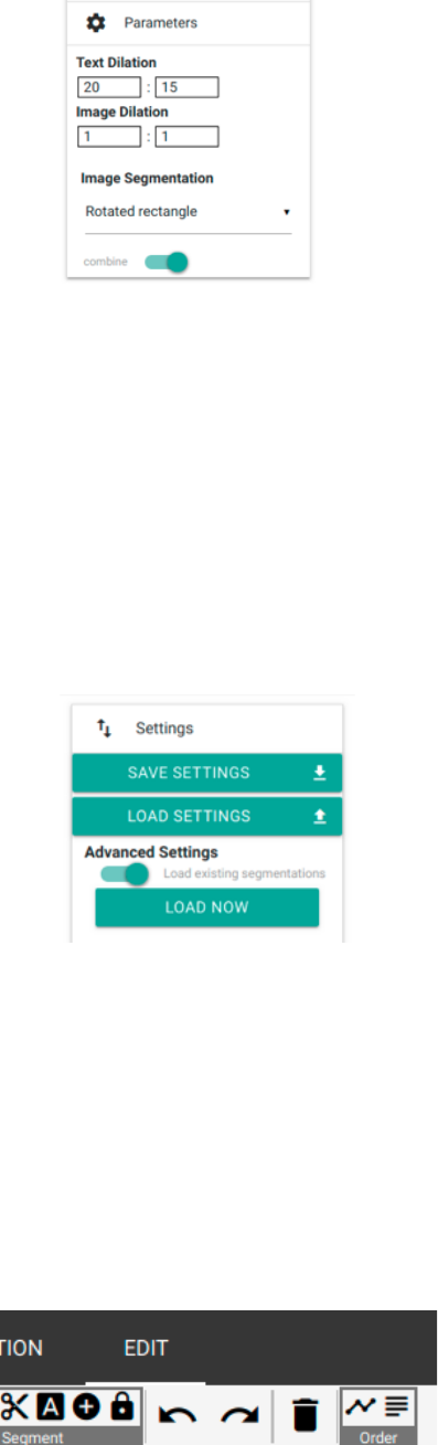
− “Parameters”: General parameters for text and image recognition are defined here. The
necessity to define work specific parameters reasons in the very inconsistent layout and
printing type of especially early modern printings. Words and whole lines can be printed
in different distances. In order to evade i. e. these distances being recognized as own
layout regions and not as belonging to the paragraph, “Text Dilation” enables to swell
the region supposed to be recognized as text in X and Y direction. It overcomes line and
word distances and links wide-spaced paragraphs. It’s recommended to text different
settings in order to optimize them.
14"
!
Fig. 18: settings in Parameters.
− “Settings”: In “settings”, the segmentation and display options defined in “regions” and
“parameters” can be saved and if necessary (i. e. while continuing a work’s segmentation
after a break) reloaded. The buttons “SAVE SETTINGS” and “LOAD SETTINGS”
serve this purpose. If saved, XML data is created which has to be reselected while
loading. Additionally, it’s also possible to reload and review already saved segmentation
results. For this, hit “LOAD NOW” in “Advanced Settings”. In case XML data has been
saved for the respective scan, it’s being loaded now. At the same time, this option can be
automatically realized by starting LAREX if respective segmentation results are
available.
'
'
'
'
Fig. 19: Settings.
− “Reading Order”: To display a page’s segmented and in the following recognizable text
in the right reading order, it’s crucial to define the reading order of the respective layout
elements in order to sustain the text. This definition can be automatic with an i. e. simple
and clear layout. More complex layout structures however demand setting the reading
order manually in order to evade errors in the sequence.
Select “Reading Order” in the right-hand sidebar. Because of this, the option “Order”
appears in “EDIT”, divided in “Auto generate a reading order” and “Set a reading order”
to choose from.
Fig. 20: On the right: Reading order in head runner among “EDIT”.
15"
!
By choosing the automatic reading order’s creation, a naive listing of all the layout
elements contained in the text in the right-hand sidebar from top to bottom. By defining
the sequence manually, the individual elements have to be chosen (by hitting them) by
the user in the right order to be displayed in said list (s. below). Like all interventions in
LAREX, the reading order too can be changed constantly before saving it.
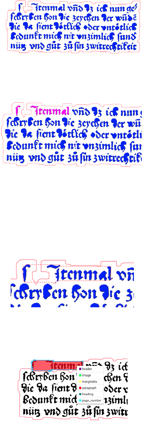
4.4.4'Exemplified'Segmentation'of'a'scan'
By loading a scan, LAREX automatically produces first segmentation results. These have to be
corrected in the following.
The following segmentation run corresponds to the fourth page of the standard work “Cirurgia”
which can be downloaded here while downloading the OCR file structure.
Error analysis: Which layout elements have been recognized correctly, which one is defective,
which ones not at all? Are there usage marks, borders, pollutions or text parts which are not
supposed to be recognized at the margins but influence the segmentation result?
Fig. 21: Automatic segmentation result of “Cirurgia’s” fourth page.
“Region of Interest” (RoI): If there are elements relevant for recognition but outside of the
scans sections and which influence the segmentation result negatively (i. e. users’ marks,
pollutions, libraries’ seal etc.), a RoI can be defined to automatically exclude these areas from
recognition ab initio. Select in “EDIT” and “RoI” the option “Set the Region of Interest” and
draw a rectangle around the contents which should be segmented via keeping the left mouse
button held.
16"
!
Fig. 22: Determining a Region of Interest.
If a RoI has been set, hit “SEGMENT” on the right-hand side – elements outside of the RoI will
not be considered anymore. Please note: If a RoI is set, it’s conveyed to all other scans which
will be opened during working on. As the parts of a scan which are relevant for segmentation
can change for different reasons, it’s quite probable the RoIs have to be adapted to the individual
scans condition. To achieve this, hit individual areas of the RoI and move them via mouse.
Independently from the RoI, the option “Create an ignore rectangle” produces a so called ignore
region which whose aid smaller scan regions can be ignored and thus be excluded from
segmentation.
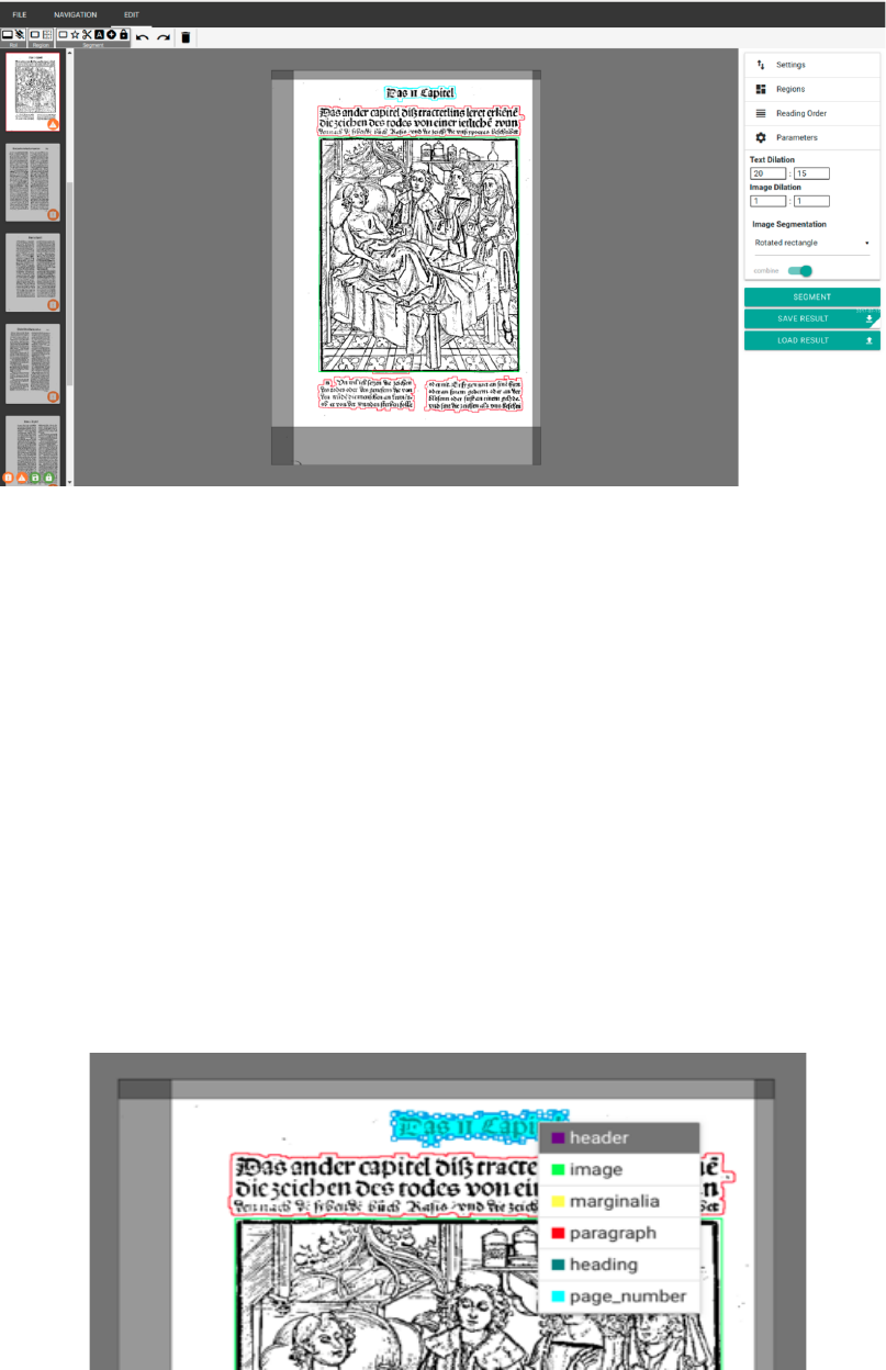
Correction of defectively recognized layout elements:
Defectively recognizes layout elements can be changed in their typification. Hit the respective
element with the right mouse button and select the correct region from the opening choices.
Fig. 23: Correction of a defective typification.
Severing an adhered heading from the following text can be managed via three alternatives:
Firstly, there’s the possibility to draw a rectangle around the region supposed to be classified.
Choose from “EDIT” – “Segment” the option “Create a fixed segment rectangle” (Shortcut 3),
17"
!
draw a window around the corresponding region via mouse and choose the right naming from
the opening menu. Secondly, the region’s selection works via polygon. This would be especially
recommended with complex, confusing or interlaced layouts including inclined edges,
rotundities in images and woodcuts or decorative initials in paragraphs. In this case, choose
“Create a fixed segment polygon” (Shortcut 4) from “EDIT” – “Segment” and frame the
corresponding region with a dot line by linking the end to the beginning and thus forming a
polygon. There’ll also be a menu here to choose the right naming from.
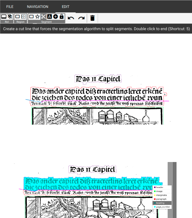
The third possibility lies in dividing the text recognized as “Paragraph” consisting of heading
and main text with a cut line. Select this one via “Create a cut line” (Shortcut 5) from “EDIT”
– “Segment”.
'
Fig. 24: Selecting the cut line via “EDIT”.
With the left mouse button, the line is being drawn across the area supposed to be split like a
polygon with several clicks. By putting a double click with the left mouse button, the line’s
ending point is set.
Fig. 25: Determining the cut line between two areas of one layout element.
If “SEGMENT” is being hit now, the formerly as one recognized layout area gets divided into
two different layout elements. After this, the heading’s area can be renamed correctly via
clicking the right mouse button and choosing the corresponding name.
Fig. 26: Divided areas’ correct typification.
In case layout elements, defectively drawn cut lines, defective polygons etc. must be deleted,
just select them by clicking them with the left mouse button and afterwards hit “Del” or “Delete
selected items” in “EDIT”.
18"
!
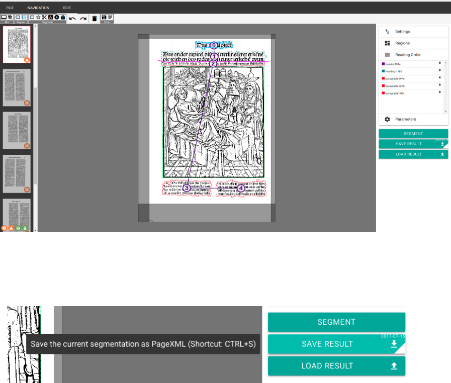
Determination of a “Reading Order” (s. above):
Fig. 27: Determining a Reading Order.
Saving the current scan’s segmentation result: To save the result, hit “SAVE RESULT” or
press Ctrl + S. Both actions cause a XML data including the segmentation results to be saved
within the OCR4all file structure.
Fig. 28: Saving segmentation results.
Now the next scan can be chosen from the left sidebar. If a scan’s segmentation needs to be
changed afterwards, the new segmentation has to be saved once – like this, the old XML data
is being replaced by the new and current one.
4.4.5'Further'editing'options'
Furthermore, there generally more editing options for scans being introduced now:
− For deleting or merging several layout elements to one combined region, it’s useful to
be able to select them at the same time. Just keep the shift-key held and draw a rectangle
around the corresponding layout regions via mouse. The regions have to be completely
inside the rectangle. Layout region selected like that appear with a blue frame.
− “Select contours to combine (with “C”) to segments (see function combine)”
(Shortcut 6): This tool can be used to achieve best segmentation results even with very
narrowly and detailed printed pages. The basic idea consists in layout elements being
framed by contours provided by the separate text types or the borders of images or
decorative initials - without waste margin produced by manual segmentation which can
keep producing overlapping elements and thus inaccuracies influencing the OCR.
To run this tool, hit the corresponding button in “EDIT” (or the shortcut 6). All of the
page’s parts recognized as layout elements will be dyed blue.
19"
!
' '
'
'
Fig. 29: Contour display.
If single types or even parts of types are hit now, they become purple – they’re selected
now.
'
'
'
'
Fig. 30: Contour selection.
It’s also possible to select several types, whole words or lines or parts of complete layout
elements (s. above: Shift + selection via drawing a rectangle). If shortcut “C” is used
after selecting certain types, words, lines etc., all selected elements will be compiled to
an own layout element – independent from their former element membership. A layout
element created like this can be located much more delicately compared to automatically
recognized elements because of the orientation on single types’ or images’ borders. Like
this, a much more detailed segmentation is possible.
'
'
Fig. 31: Combining chosen contours to a new layout element.
Fix the intervention by hitting “SEGMENT”. To conclude, the created, autonomic
layout element can be renamed freely as descripted above.
'
'
'
Fig. 32: Segmented layout elements’ typification.
20"
!
− “Combine selected segments or contours” (Shortcut “C”): To combine several,
separately recognized layout elements to just a single one, select the according regions
completely (s. above) and hit “C” respectively the corresponding button in “EDIT”.
− “Fix/unfix segments, for it to persist a new auto segmentation” (Shortcut “F”): This
function can fix layout elements for a further segmentation run of a scan. The respective
layout element has to be selected via a click, then click “F” or the corresponding button.
Fixed elements appear with a broken border. To delete the fixation, just repeat the
operation.
− Zoom: Very small printed text or complex layout can be zoomed in via the mouse’s
wheel. The space key resets the display to its original condition.
− For especially detailed and thus complex layouts, segmentation results can be optimized
via special detail interventions. The as layout elements recognized parts of a scan
page’s outlines will be displayed, seen up close, as a dotted line.'
'
'
'
'
'
'
Fig. 33: Dot line as layout elements’ outline.
These dots can be moved singularly or severally in order to i. e. evade overlapping ones
in very narrow printings with other bordering layout elements. Single dots can be moved
via held left mouse button. By clicking the line, new dots can be created as well. The
dots’ deletion is possible via “Del”.
− “LOAD RESULTS”: This function enables to load already existing segmentation
results for a certain scan directly from OCR4all´s file structure into LAREX.
4.4.6'End'of'Segmentation'with'LAREX'
− If all segmentation works of one work have been completed in LAREX (meaning if
results have been saved for each page of a work), these savings now are available in
said OCR4all file structure. This does not mean, however, they are already usable for
coming work steps.
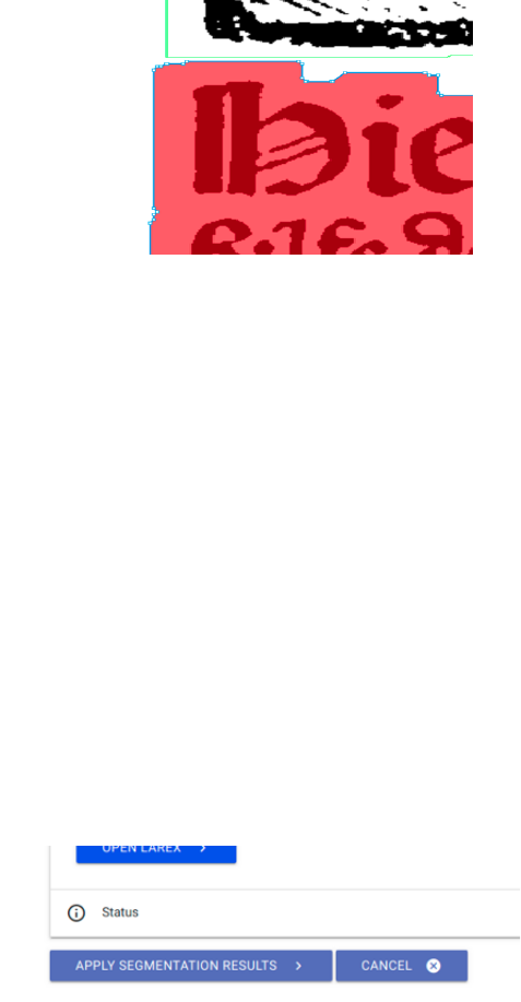
− After saving all results in LAREX and the simple closing of the LAREX tab, “Apply
Segmentation Results” must necessarily be hit to make the created data useful for further
editing. Additionally, all scans should be selected in the right-hand sidebar.
'
'
Fig. 34: Apply segmentation results.
21"
!
− To check whether segmentation and saving the results was successful, check the column
“Segmentation” in “Project Overview”.
4.5'Region'Extraction'
Input: preprocessed image and segmentation information as PageXML.
Output: extracted, deskewed text region images
In the region extraction, the layout elements of each scan determined and classified in LAREX
will be clipped, saved and renamed (according to the layout region they belong to) as single
data. This step is necessary as pre-stage of the following Line Segmentation and with it OCR.
− To extract the regions, select “Region Extraction”, keep all settings and hit
“EXECUTE”. If necessary, the results afterwards can be checked via “Project
Overview” – “Page Identifier” – “Segments” (right column of the display).
' '
'
'
Fig. 35: Region Extraction’s settings.
4.6'Line'Segmentation'
Input: deskewed region images.
Output: extracted text lines.
− Directly preparing the following OCR, this step cuts all layout elements (s. above)
containing text to lines (OCR works on a line based).
'
'
'
Fig. 36: Line segmentation’s settings.
− In general, the existing settings can be kept here as well. Important limitation
regarding the layout: In case the layout consists of at least two columns and LAREX
segmented these to independent main text, the pre-set factor -1 (which confirms the
layout has just one column and thus a column separation is not necessary) in “Maximum
# of whitespace column separators” has to be changed as following:
• Explanation: “Whitespace column separators” mean the white margins around texts
seen as columns.
• For a layout of two columns with consecutive text (meaning the respective first
lines of the two columns are no unity regarding the content), the factor of “Maximum
# of whitespace column separators” has to be set at 3: This specification is explained
by the left hand whitespace of the left column, the right hand whitespace of the right
column and the shared whitespace between the two columns.
22"
!
• For a layout of three columns, the factor correspondingly would have to be set at 4
etc.
− As soon as all settings are set as wished, hit “EXECUTE” and check the results in
“Project Overview”. In here, the single lines get the individual layout elements as
subitems (s. above).
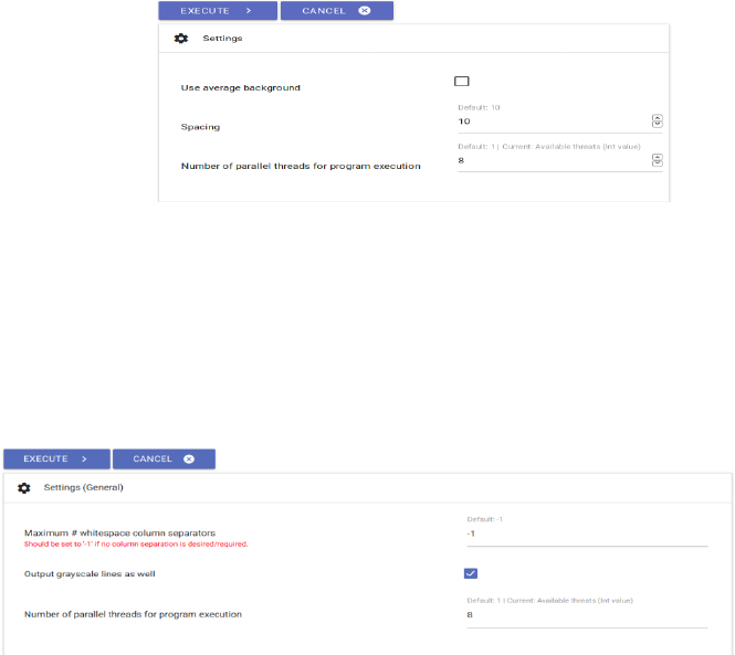
− Especially for the line segmentation, using advanced settings (“Settings (Advanced)”)
is useful, if i. e. console errors are displayed and correspondingly the line segmentation
could not be run flawlessly. To give a common example: If the letters are printed too
small, the minimum breadth set in the defaults will be undercut by whole lines. This
minimum breadth however can be changed by lowering the factor of “Minimum scale
permitted” in “Limits”. After that, the repeated run of the line segmentation will be done
correctly and without an error message.
− You can also check the line segmentation’s correctness in “Ground Truth Production”:
Via a dropdown list, the individual scans with their corresponding lines can be viewed
in their reading order – the lines’ corresponding description fields are still empty though.
These will be filled via the following recognition.
4.7'Recognition'
Input: text line images and one or several OCR models.
Output: textual OCR output on line level.
− The recognition is the recognition of all layout elements’ text based on the lines created
in the Line Segmentation (s. above).
− Select “Recognition” in the menu. In the right-hand sidebar, the work’s scans or printing
pages are listed which already fulfil all preconditions for OCR (meaning all steps apart
from “Noise Removal” have been run on them). Select those you would like to have an
OCR text for.
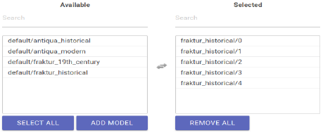
− Now select in “Line recognition models” in the column “Available” all models or model
groups which are apt to recognize the types of your work’s text (i. e. early modern
fracture, historical fracture, italics, historical antiqua etc.). Using model groups (five
simultaneous and interlinked acting individual models) instead of individual models
is urgently recommended! By simply hitting them, they’ll be moved into the column
“Selected”. By using the “Search” function, it’s possible to filter names if especially
many models are available.
'
'
'
'
Fig. 37: Selecting a mixed model group for text recognition.
− Adapting the advanced settings normally is not necessary.
− Now hit “EXECUTE” and wait for the recognition while checking the progress on the
console’s bar.
− If the recognition is finished, the result for each line can be checked in “Ground Truth
Production”.
23"
!
4.8'Ground'Truth'Production'
Input: line image and the corresponding OCR output, if available.
Output: line-based ground truth.
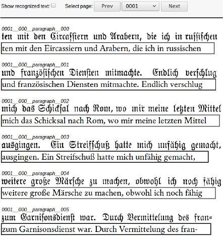
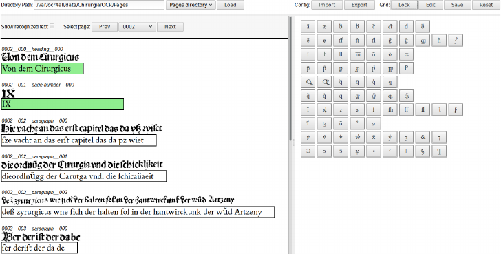
− In “Ground Truth Production” the texts produced by the Recognition can be viewed,
corrected and saved as basis for training as so called “Ground Truth”.
− The correction tool is designed in two columns: Left, the pages’ lines and their generated
OCR text (s. above) are presented under each other. The option “Select page” allows to
navigate either via dropdown list or via “Prev” and “Next”.
Fig. 38: Ground Truth Production.
On the right, there is the so-called “Virtual Keyboard” offering special characters
(ligations, abbreviations, diacriticals etc.). These can be added to the corresponding lines
by navigating the cursor to the right position and then selecting the respective character
from the keyboard. To add characters to the keyboard, just select “EDIT” and the options
“Click to add new button” and “Drag button to delete” appear. If characters should be
added, just hit the corresponding option and add the character via copy & paste into the
opening form. If characters should be deleted from the keyboard, they must be drawn
via mouse to the delete option’ s waste bin icon. If all wished changes have been made,
save the keyboard via “Save” and block it via “Lock”. By hitting “Reset”, the virtual
keyboard can always be brought back to its original condition. By choosing the options
“Import” and “Export”, work specific keyboards can be saved within the system and
always be loaded anew (i. e. if the text correction must be stopped or if the keyboard is
also apt for working on another work).
− To correct defective recognitions of single lines, just click in the corresponding line.
The now appearing red frame displays the line’s current editing status. If all
interventions have been made and the line is flawless, click outside of the line or in
another line. The lastly edited line colours green, meaning the line automatically has
been saved in the OCR4all structure as “Ground Truth”. It can now (together with all
other corrected lines) be used as training basis for work specific models as wells as for
the used OCR models’ evaluation or it will be made available by generating the total
results (s. below).
24"
!
− If correcting the work via “Ground Truth” makes obvious the degree of recognition by
mixed models is not enough yet because of several reasons to run a manual, finishing
correction without too extensive effort of time, OCR4all offers the possibility to train
work specific models. These generally have a higher recognition rate than mixed
models.
'
4.9'Evaluation
Input: line-based OCR predictions and the corresponding ground truth.
Output: error statistics.
− “Evaluation” serves to identify a currently used model’s recognition rate (mixed or work
specific).
− To generate these, select all scans which were recognized by this current model and
corrected afterwards in “Ground Truth Production”. If “EXECUTE” is hit now and all
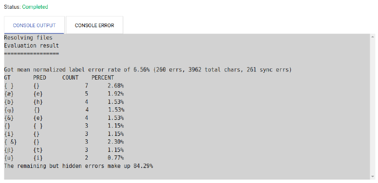
settings are kept, a table is made available in the console: On the very top, the error rate
in percent is displayed as well as the total number of errors (‘errs’). Below, a comparison
of the recognized text and text corrected in Ground Truth is listed tabularly and found
faults are displayed. The first column shows the corrected text (“GT”), the second
column the formerly recognized text (“PRED”), behind the fault’s frequency and the
fault’s percentage from the number of total errors.
'
'
'
'
'
'
'
'
Fig. 39: Evaluation result with total error rate, the ten most frequent errors and their percentage in the number
of total errors.
− With this tabularly list and the recognition rate (100% - error rate), the user can decide
whether or not a (new) work specific models’ training is necessary or sensible.
4.10'OCR'Model'Training'
Input: line images with corresponding ground truth, optionally already existing models to build
from.
Output: one or several OCR models.
The general aim is to achieve a mostly flawless text. Then why create book specific models via
Training instead of simple finishing text correction?
The better the model being used for recognition, the shorter the span of time used for correction.
Idea and sense of a continuing model training therefore is training constantly better models by
25"
!
continuing correction and thus reduce the effort of correction for the remaining scans to a
minimum.
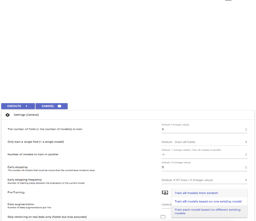
− Within the training tool, book specific models can be trained on the basis of the Ground
Truth produced for one work’s all existing lines. Put following factors in the general
settings:
• “The number of folds (= the number of models) to train”: 5 -› A model group
consisting of five single modules will be trained.
• “Only train a single fold (= a single model)”: Do not fill in anything! -› All five
single models will be trained instead of just one.
• “Number of models to train in parallel”: -1: -› All models of one group will be
trained simultaneously.
• “Early stopping frequency”: Keep default! -› Describes number of training steps
between the model’s individual evaluation while training.
• “Pre-Training”: “Train each model based on different existing models” (In the
following, five dropdown lists open up; in each, one of the mixed models used (as
recommended) for the text’s recognition is suggested; independently from the
current training’s iteration: Even if i. e. already the third book specific model is
trained: still all five models used in the beginning will be suggested or “Train all
models based on one existing model” (In case the first recognition was made on
basis of a single mixed model, just one model is written down; once again, this
mixed model has to be chosen for each iteration though).
• “Data augmentation”: Do not fill in anything. -› But: Describes number of data
augmentation per line. A factor, i. e. 5 can be indicated here to increase the training
material’s mass used for training. It can result in creating better models, but requires
much more training time.
• “Skip retraining on real data only”: Do not choose!
− The advanced settings remain unchanged.
'
Fig. 40: Settings for training work specific model groups.
26"
!
− Hit “EXECUTE” to start the training. The training can be followed by controlling the
console. The time span for training varies depending on the Ground Truth of existing
lines’ total mass.
− Corresponding to above’s settings, work specific model groups (consisting of five single
models) are created by the training which are saved in ocr4all/work’s title/0.
Correspondingly, the model group is names “0”. It can now be used for further workings
on the work and enhancing the recognition in “Recognition” and the column of selectable
models to recognize new scans. If a second work specific model group should be created
to i. e. rectify the first model’s weaknesses, repeat the process as described here. The
new work specific model is automatically named “1”. Further model groups’ names will
be continued in that style.
4.11'Result'Generation'
Input: OCR results on line basis, optionally ground truth (if present) and additional data
obtained from the region and line segmentation steps.
Output: final output as text (lines combined to pages and the entire book) and PageXML files
on page basis.
'
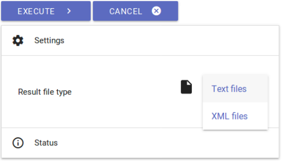
Fig. 41: result generation.
− In case recognition and correction are finished in the user’s opinion, the results can be
generated either as TXT or XML data. They will be stored in ocr4all/data/Results.
− It can be chosen in “Settings” whether text or PageXML data should be generated. In
case of text data, a single TXT file is generated as well as a coherent one containing the
edited work’s full text.
− The PageXML data is dispensed on scan basis and contains information concerning date
of creation, last data changes, meta data referring to the scan, page volume, the layout
elements used for the scan including accurate coordinates, the existing layout elements’
reading order, the individual text lines and to the lines itself.
'
!
!

27"
!
5.'Errors,'frequent'problems'and'their'evasion'
Problems while installing and starting Docker:
− Problems while installing Docker? A detailed guide can be found here.
− Problems while starting Docker containers for OCR4all? No server start possible? First
restart Docker, if necessary, reload the OCR4all image and recreate the respective
container. Follow the setup guide for OCR4all (here).
Problems while selecting a work in Project Overview:
− Problems in “Project Overview” - works are not displayed? Please control the file
structure. Follow the guide lines from chapter 1.2. In case your file structure is correct,
remove all OCR4all Docker containers and run the “Docker run...” command according
to the setup guide (available here!) again.
− No work selection possible? Please check your work’s names do not include blanks or
mutated vowels.
Seperate part module’s results are not displayed in “Project Overview”:
− Did you hit “Apply segmentation results” after segmenting in LAREX?
Seperate workflow steps or part modules cannot be run:
− A separate part module only can edit a certain number of scans or data sets
simultaneously (about 400). I. e. if more than 400 pages are selected for one action, there
will be an error report. It’s recommended in this situation to lessen the number of scans
and run the step in several successive runs by dividing the total amount of data.
If you have any questions/remarks, or run into any problems, please do not hesitate to
contact us via mail (christian.reul@uni-wuerzburg.de, maximilan.wehner@uni-
wuerzburg.de) or to open an issue on GitHub!
Guide written by Maximilian Wehner, translated by Tanja Kohl.
'
'
'
'
'
