650SD O_gw_650sd O Gw
User Manual: o_gw_650sd
Open the PDF directly: View PDF ![]() .
.
Page Count: 13
OPERATOR’S MANUAL
GRAVITY BOXES
and Set-Up Instructions for
J. & M. Mfg. Co., Inc.
P.O. Box 547 Ft. Recovery, OH 45846
Ph: (419) 375-2376 Fax: (419) 375-2708
www.jm-inc.com
JMMAN0101 (Rev. 03/10/03)
650SD Gravity Box

2
TO THE DEALER:
J. & M. Mfg. Co. Inc. warrants against defects in construction or materials for a period of ONE year. We reserve the right
to inspect and decide whether material or construction was faulty or whether abuse or accident voids our guarantee.
Warranty service must be performed by a dealer or service center authorized by J. & M. Mfg. Co. Inc. to sell and/or
service the type of product involved, which will use only new or remanufactured parts or components furnished by J. &
M. Mfg. Co. Inc. Warranty service will be performed without charge to the purchaser for parts or labor based on the
Warranty Labor Times schedule. Under no circumstance will allowable labor times extend beyond the maximum hours
indicated in the Warranty Labor Times schedule for each warranty procedure. The purchaser will be responsible,
however, for any service call and/or transportation of the product to and from the dealer or service center’s place of
business, for any premium charged for overtime labor requested by the purchaser, and for any service and/or maintenance
not directly related to any defect covered under the warranty. Costs associated with equipment rental, product down
time, or product disposal are not warrantable and will not be accepted under any circumstance.
Each warranty term begins on the date of product delivery to the purchaser. Under no circumstance will warranty be
approved unless (i) the product warranty registration card (attached to the inside of the Operator’s Manual) has been
properly completed and submitted to the equipment manufacturer, and (ii) a warranty authorization number has been
issued by the equipment manufacturer. This Warranty is effective only if the warranty registration card is returned
within 30 days of purchase.
This warranty does not cover a component which fails, malfunctions or is damaged as a result of (i) improper modification
or repair, (ii) accident, abuse or improper use, (iii) improper or insufficient maintenance, or (iv) normal wear or tear. This
warranty does not cover products that are previously owned and extends solely to the original purchaser of the product.
Should the original purchaser sell or otherwise transfer this product to a third party, this Warranty does not transfer to
the third party purchaser in any way. J. & M. Mfg. Co. Inc. makes no warranty, express or implied, with respect to tires
or other parts or accessories not manufactured by J. & M. Mfg. Co. Inc. Warranties for these items, if any, are provided
separately by their respective manufacturers.
THIS WARRANTY IS EXPRESSLY IN LIEU OF ALL OTHER WARRANTIES OR CONDITIONS, EXPRESS, IMPLIED
OR STATUTORY, INCLUDING ANY IMPLIED WARRANTY OF MERCHANTABILITY OR FITNESS FOR PARTICULAR
PURPOSE.
In no event shall J. & M. Mfg. Co. Inc. be liable for special, direct, incidental or consequential damages of any kind. The
exclusive remedy under this Warranty shall be repair or replacement of the defective component at J. & M. Mfg. Co.
Inc’s. option. This is the entire agreement between J. & M. Mfg. Co. Inc. and the Owner about warranty and no J. & M.
Mfg. Co. Inc. employee or dealer is authorized to make any additional warranty on behalf of J. & M. Mfg. Co. Inc.
The manufacturer reserves the right to make product design and material changes at any time without notice. They
shall not incur any obligation or liability to incorporate such changes and improvements in products previously sold to
any customer, nor shall they be obligated or liable for the replacement of previously sold products with products or parts
incorporating such changes.
Read manual instructions and safety rules. Make sure all items on the Dealer’s Pre-Delivery and Delivery Check Lists
in the Operator’s Manual are completed before releasing equipment to the owner.
The dealer must complete the Warranty Registration Card attached to the inside of this manual and return to J. & M.
Mfg. Co. Inc. at the address indicated on the card. Warranty claims will be denied if the Warranty Registration Card
has not been completed and returned.
EXPRESS WARRANTY:
SERVICE:
The equipment you have purchased has been carefully manufactured to provide dependable and satisfactory use.
Like all mechanical products, it will require cleaning and upkeep. Lubricate the unit as specified. Observe all safety
information in this manual and safety signs on the equipment.
For service, your authorized J. & M. dealer has trained mechanics, genuine J. & M. service parts, and the necessary
tools and equipment to handle all your needs.
Use only genuine J. & M. service parts. Substitute parts may void the warranty and may not meet standards required
for safe and satisfactory operation. Record the model number and serial number of your equipment in the spaces
provided:
Provide this information to your dealer to obtain correct repair parts.
Serial No.: Date of Purchase:
Purchased From:
3
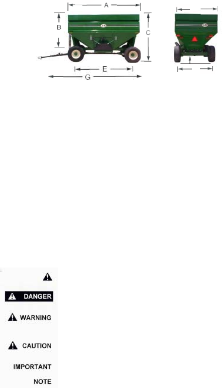
650SD GRAVITY BOX
SPECIFICATIONS
DIMENSIONS
A) 180”
B) 93”
C) 122”
D) 92”
E) 138”
F) 114”
G) 278”
H) 16”
GENERAL INFORMATION
TO THE OWNER:
The purpose of this manual is to assist you in operating and maintaining your gravity box in a safe manner.
Read it carefully. It furnishes information and instructions that will help you achieve years of dependable
performance and help maintain safe operating conditions. If this machine is used by an employee or is
loaned or rented, make certain that the operator(s), prior to operating:
1. Is instructed in safe and proper use.
2. Reviews and understands the manual(s) pertaining to this machine.
Throughout this manual, the term IMPORTANT is used to indicate that failure to observe can cause damage
to equipment. The terms CAUTION, WARNING and DANGER are used in conjunction with the Safety-Alert
Symbol, (a triangle with an exclamation mark), to indicate the degree of hazard for items of personal safety.
When you see this symbol, carefully read the message that follows and be alert to the possibility of personal
injury or death. This Safety-Alert symbol indicates a hazard and means
ATTENTION! BECOME ALERT! YOUR SAFETY IS INVOLVED!
Indicates an imminently hazardous situation that, if not avoided, will
result in death or serious injury.
Indicates a potentially hazardous situation that, if not avoided,
could result in death or serious injury, and includes hazards that
are exposed when guards are removed.
Indicates a potentially hazardous situation that, if not avoided, may
result in minor or moderate injury.
Indicates that failure to observe can cause damage to equipment.
Indicates helpful information.
SPECIFICATIONS
Capacity* 650 bushels
Door Width 36”
Chute Height** 14”
Understructure 3/8” x 3” x 6” Runners
Taillights Standard
Front Ladder Standard
Hopper Construction 12 GA
Weight 6,200 lbs. (650SD Box with 24 Ton Running Gear and 18-22.5 Tires)
* Bushel capacity measured with #2 corn at 15% moisture (56 lbs. test weight)
** Measured with 18-22.5 tires
F
H
D
4
GENERAL INFORMATION
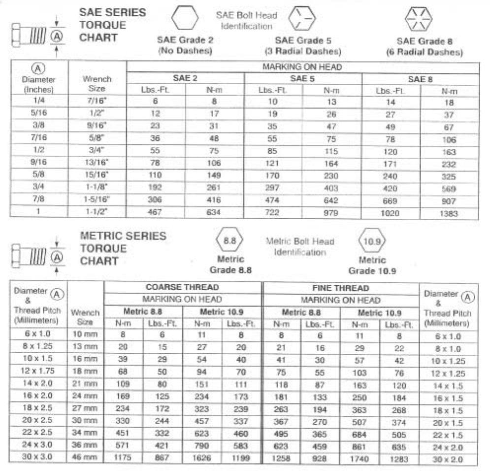
BOLT TORQUE CHART
Always tighten hardware to these values unless a different torque or tightening procedure is listed for a
specific application.
Fasteners must always be replaced with the same grade as specified in the manual parts list.
Always use the proper tool for tightening hardware: SAE for SAE hardware and Metric for metric hardware.
Make sure fastener threads are clean and you start thread engagement properly.
All torque values are given to specifications used on hardware defined by SAE J1701 & J1701M JUL 96.

5
TABLE OF CONTENTS
INTRODUCTION 2
EXPRESS WARRANTY 2
SPECIFICATIONS 3
GENERAL INFORMATION 3
BOLT TORQUE CHART 4
SAFETY RULES 6
SAFETY SIGNS 7
OPERATION 8
ROUTINE MAINTENANCE 8
PARTS LIST/DIAGRAMS 9-10
LIGHT KIT 11-12
SERVICE RECORDS 13

6
SAFETY
SAFETY RULES
ATTENTION! BECOME ALERT! YOUR SAFETY IS INVOLVED!
Safety is a primary concern in the design and manufacture of our products. Unfortunately, our efforts to
provide safe equipment can be erased by an operator’s single careless act. In addition, hazard control and
accident prevention are dependent upon the awareness, concern, judgement, and proper training of personnel
involved in the operation, transport, maintenance and storage of equipment.
Make certain that the operator(s), prior to operating is instructed in safe and proper use and reviews and
understands the manual(s) pertaining to this machine.
Read this manual before you operate this machine. If you do not understand any part of this manual, or need
more information, contact the manufacturer or your authorized dealer.
Understand that your safety and the safety of other persons is measured by how you service, and operate
this machine. Know the positions and functions of all controls before you try to operate them. Make sure to
check all controls in a safe area before starting you work.
The safety information given in this manual does not replace safety codes, federal, state or local laws. Make
certain your machine has the proper equipment as designated by local laws and regulations.
A frequent cause of personal injury or death is from persons falling off equipment and being run over. Do not
permit persons to ride on this machine.
Travel speeds should be such that complete control and machine stability is maintained at all times. Where
possible, avoid operating near ditches, embankments and holes. Reduce speed when turning, crossing
slopes and rough, slick or muddy surfaces.
Collision of high speed road traffic and slow moving machines can cause personal injury or death. On roads,
use flasher lights according to local laws. Keep slow-moving-vehicle emblem visible. Pull over to let faster
traffic pass.
Never adjust, service, clean, or lubricate gravity box until all power is shut off.
Keep all safety shields in place.
Keep hands, feet, hair and clothing away from moving parts while unit is in operation.
The service ladder is for service work only. If you must climb into grain tank, be certain that all power is shut
off and then use extreme caution when climbing into grain tank.
Never allow anyone in, near or on the gravity box during transporting or unloading grain. Moving grain is
dangerous and can cause entrapment, resulting in severe injury or death by suffocation.
Make sure that the gravity box is properly fastened to the running gear.
Make sure that everyone is clear of equipment before applying power to the machinery used in conjunction
with the box or when moving the equipment.
Never overload the wagon. Overloading the wagon is dangerous and can cause extensive damage to both
the box and running gear. Do not tow loaded gravity box in excess of 20 mph.
Never add more sideboards to the gravity box than what is recommended, as the box is not designed to carry
the additional weight.

7
750-16 OWNER’S MANUAL
SAFETY SIGNS
ATTENTION! BECOME ALERT! YOUR SAFETY IS INVOLVED!
Replace Immediately If Damaged or Missing!
IMPORTANT: Install new safety signs if the old signs
are destroyed, lost, painted over or cannot be read. When
parts are replaced that have safety signs, make sure you
install a new sign with each new part. New signs are
available from the manufacturer or your authorized dealer.
Ref. # Description Part # Req’d
1 Sign, Danger DD-101 1
2 Sign, Caution DC-109 1
3 Sign, Information DI-115 1
4 Sign, Warning DW-107 1
DD-101
DC-109
DI-115
23
1
DW-107

8
750-16 OWNER’S MANUAL
OPERATING INSTRUCTION / MAINTENANCE
Before the gravity box is put into service:
Has the track assembly (opens door) been lubricated for less wear on the sprocket and track and for easier
door operation?
Has the SMV (Slow Moving Vehicle) Emblem been positioned with a point of the triangle upward and as near
to the rear and centered or as near to the left of center of the unit as practicable? Is it located two to ten feet
above the ground measured from the lower edge of the emblem?
Has the gravity box been properly attached to the running gear? If no rocking bolster is used, bolt all four
corners (use the 1/2” bolts provided) of the gravity box runners to the running gear. (If the box is used in
rough terrain, bolt a minimum of two corners and chain (or cable) the remaining corners to allow more box
flexibility).
Have all braces, bolts, nuts, lug bolts, and lug nuts been checked to ensure that they are properly fastened?
Have the safety instructions been read and clearly understood by the operator(s) of this machine?
Do the lights work properly? Are all reflective decals clean and visible? Are they positioned correctly?
BE CERTAIN THAT ALL POWER IS SHUT OFF BEFORE SERVICING THE GRAVITY BOX.
BRAKING SYSTEM REQUIREMENTS
For towed equipment WITHOUT brakes, the following is recommended:
Do NOT tow equipment that does not have brakes at speeds over 32 km/h (20 mph); or that, when fully
loaded, has a mass (weight) over 1.5t (3300 lb) and more than 1.5 times the mass (weight) of the towing unit.
For towed equipment WITH brakes, the following is recommended:
Do NOT tow equipment that has brakes at speeds over 40 km/h (25 mph); or that, when fully loaded, has a
mass (weight) more that 4.5 times the mass (weight) of the towing unit.
Before filling the gravity box, make certain that no one is inside the grain tank. Never allow children or
anyone in, near, or on the gravity box during transport or during loading or unloading of grain. Be aware that
moving grain is dangerous and can cause entrapment, resulting in severe injury or death by suffocation.
After hauling corrosive materials such as fertilizers, be sure to wash out the grain tank to prevent premature
rusting. Bare spots on metal should be primer coated before applying the outer surface paint.
Check the box periodically for cracks in welds and for other structural damage. Have cracked welds fixed
immediately. Failure to do so could result in extensive damage and greatly reduce the life of the gravity box.
9
# Part # Description Qty
1 78812-BNW 7/8" x 8 1/2" Bolt w/nut, washers 1
2 URB-6750 Upper Rocking Bolster 1
3 12512-HBN 1/2" x 5 1/2" Bolt w/nut, washers 8
4 782B-LN 7/8" x 2 1/4" Bolt w/lock nut, lock
washer
2
GRAVITY BOX PARTS LIST
ROCKING BOLSTER ASSEMBLY
FRONT
VIEW
2
4
3
4
1
2
1
4
3
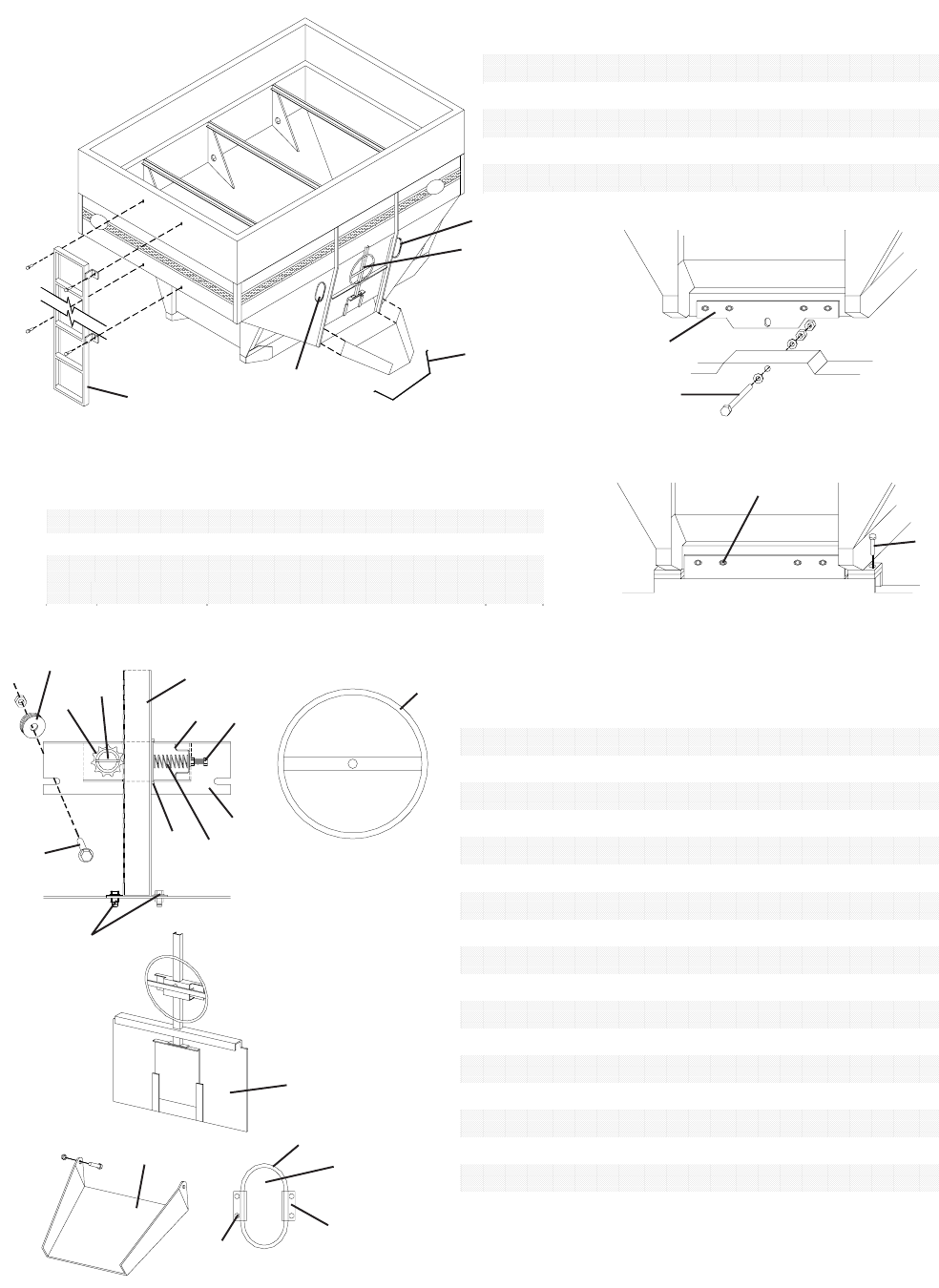
CHUTE, DOOR AND WHEEL ASSEMBLY
# Part # Description Qty
1 D-650 Door 1
2 GC-650 Grain Chute 1
3 IW-71212 Inspection Window 2
4 62095-7 Window Molding 2
5 WB-4 Window Brace - Inside 4
6 WB-4B Window Brace - Outside 4
7 TA-28 Track Assembly 1
8 138RP 1 3/8" Roll Pin 1
9 11T40 11 Tooth Sprocket 1
10 WGA-1034 Welded Guide Assembly 1
11 MC-250 Metal Clip 1
12 GL-250 Galvanized Clip 1
13 DS-250 Door Spring 1
14 WPS-250 Wheel Pin & Strap 1
15 381-HBN-F 3/8" x 1" Bolt w/nut (flange) 2
16 3834-HBN 3/8" x 3/4" Bolt w/nut 8
17 38112BN 3/8" x 1 1/2" Bolt w/nut 3
18 12LFW Large Flat Washer 10
11
13
10
12
17
8
9
2
1
3
14
4
5/6
7
REAR
VIEW
# Part # Description Qty
1 LL-8 Ladder 1
2 31617-CS 3/16" x 17" Chain with S-Hook 1
3 CWA-750 Complete Wheel Assembly 1
4 IWK-1 Window Kit Complete 2
5 381-HBN-F 3/8" x 1" Flange Bolt w/Nut 4
6 381-HBN 3/8" x 1" Bolt w/Nut 2
17
16
18
15
10
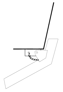
MOUNTING THE CENTER DUMP CHUTE
Locate plates on both underneath
sides of the door. Bolt the Center
Dump Chute to the first hole of the
plate as shown. The second hole is
used to chain the chute in place
when not in use.
11
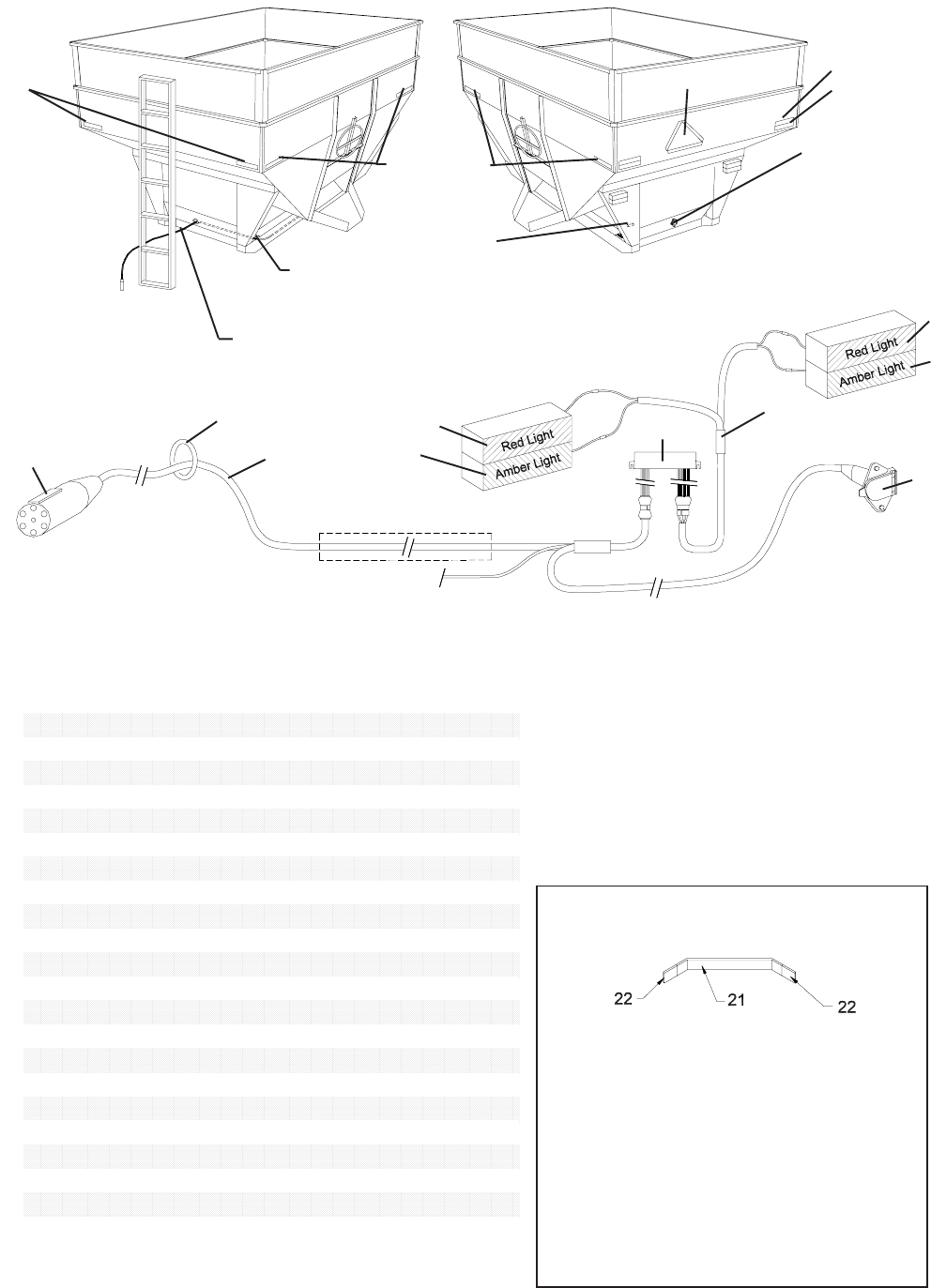
GRAVITY BOX LIGHT INSTALLATION GUIDE
Light Enhancer
mounted on back
side of rear leg.
Run the 7-Wire Nose Box, 4-Wire Connector, and Black
and White wires through the steel runner or conduit of
the gravity box to the rear of the box.
Run the main wiring harness with the 7-Prong Connector End
through the center front leg panel as shown.
Run wire to the
opposite side (Red
and Amber Lights)
along bracing
connecting near
the gravity box
steel runners.
Front/Side View Rear/Side View
Red Decal
Orange Decal
Amber
Decal
Amber Decal
13
10 8
9
4
7
2
8
9
Black/White wire for #19 Floodlight
(Floodlight standard on 650SD and
750SD only)
Run wiring harness through steel runner
SMV Emblem
GRAVITY BOX LIGHT KIT PARTS LIST
* Assembled as one unit
IMPORTANT: Position the SMV Emblem
with a point of the triangle upward and as near
to the rear and centered or as near to the left
of center of the unit as practicable. The SMV
Emblem should be located two to ten feet
above the ground measured from the lower
edge of the emblem.
# Part # Description Qty
1 7-WCE 7-Wire Connector End 1*
2 7-WNB 7-Wire Nose Box 1*
3 WH-1N Main Wiring Harness 1*
4 LH-1 Light Harness 1
5 ------ ---------- ---
6 ------ ---------- ---
7 LE-1B Light Enhancer 1
8 LT-R1 Red Light 2
9 LT-A1 Amber Light 2
10 PG-1L Plastic Grommet 1
11 RD-A1 Amber Reflective Decal 6
12 RD-R1 Red Reflective Decal 2
13 RD-O1 Orange Reflective Decal 2
14 141-CB 1/4" x 1" Carriage Bolt 8
15 14-FN 1/4" Flange Nut 8
16 181-HB 1/8" x 1" Hex Bolt 2
17 18-HN 1/8" Hex Nut 2
18 1434-SDST 1/4" x 3/4" Self-Tapping Screw 7
19 WLC-1 Wire Loom Clamp 3
20 SMV-2 Slow Moving Vehicle Emblem 1
21 WHB-1 White Harness Storage Bracket 1
22 RCW-1 Rubber Cap for Bracket 2
23 OFL-1 Flood Light 1
SECURING THE WIRE HARNESS
STORAGE BRACKET
Place the wire harness storage bracket
against the front face of the gravity box.
Secure the bracket using two 1/4” x 3/4”
Self-Tapping Screws. Slide the Rubber
End Caps over each end of the Wire
Harness Storage Bracket. Securely wrap
the Main Wiring Harness around the
bracket for storage. To prevent injury, do
NOT secure the storage bracket along the
side of the ladder.
12
Slide the Main Wiring Harness 7-Prong Connector End through the Front Angle Bracket towards the hitch.
The black and white wire and 7-Wire Nose Box on the Main Wiring Harness should run to the rear of the
gravity box through either the steel runner or conduit.
Place black Plastic Grommet around the circular cut-out of the Front Angle Bracket.
Secure the 7-Wire Nose Box and Angle Bracket of the Main Wiring Harness back along the runner to the door
opening of the gravity box for the optional door light. If the gravity box does not have the optional door light,
wrap black and white wire and place inside steel runner of gravity box for storage.
Drill two holes in rear leg of gravity box as shown and secure Light Enhancer on inside face of rear leg using
two 1/8” x 1” Hex Bolts and Nuts. (Note: The Light Enhancer should be mounted so the two sets of wire
connectors hang from the enhancer box.)
Connect the Main Wiring Harness to the Light Enhancer.
Slide the bolt head of one 1/4” x 1” Carriage Bolt through each of the two slots located on the rear side of each
light. The bolt pattern should correspond to the hole pattern on the rear leg of the gravity box. Place the light
wire through the hole provided on the rear leg, then slide the bolts through the two holes on the rear leg and
secure with 1/4” Flange Nut. Repear for each light. (NOTE: When mounting the red and amber lights to the
gravity box, the Red Light should be mounted above the Amber Light on each side.)
Connect Light Wiring Harness to the Light Enhancer and the red and amber lights on the rear leg above. To
connect the opposite side red and amber lights, run the Light Wiring Harness along the gravity box bracing
connecting the steel runners. Secure the Light Wiring Harness using the three Wire Loom Clamps and Self
Tapping Screws.
Place one amber reflective decal at each extreme end of both sides and front of the gravity box as shown.
Place one red and one orange reflective decal at each extreme end of the rear of the gravity box as shown.
The red decal should be placed above the orange decal.
GRAVITY BOX LIGHT KIT SET UP INSTRUCTIONS:

13
SERVICE / MAINTENANCE RECORD
Date Description Notes
