Onyx 80 Series Premium Live Analog Mixers Owner's Manual Mackie 3280 Onyx80series Om
Mackie Onyx 2480 Owner's Manual onyx80series_om Mackie - Onyx 2480 - Owner's Manual
Mackie Onyx 4880 Owner's Manual onyx80series_om Mackie - Onyx 4880 - Owner's Manual
Mackie Onyx 4080 Owner's Manual onyx80series_om Mackie - Onyx 4080 - Owner's Manual
Mackie Onyx 3280 Owner's Manual onyx80series_om Mackie - Onyx 3280 - Owner's Manual
Mackie Onyx 2480 Owner's Manual onyx80series_om Mackie - Onyx 2480 - Owner's Manual
User Manual: Mackie Onyx 3280 Owner's Manual Mackie - Onyx 3280 - Owner's Manual
Open the PDF directly: View PDF ![]() .
.
Page Count: 36

OWNER’S MANUAL
PREMIUM LIVE ANALOG MIXERS
w/PERKINS EQ & ONYX MIC PREAMPS
ONYX 80 SERIES
ONYX 80 SERIES
1. Read these instructions.
2. Keep these instructions.
3. Heed all warnings.
4. Follow all instructions.
5. Do not use this apparatus near water.
6. Clean only with dry cloth.
7. Do not block any ventilation openings. Install in accordance with the
manufacturer’s instructions.
8. Do not install near any heat sources such as radiators, heat registers,
stoves, or other apparatus (including amplifiers) that produce heat.
9. Do not defeat the safety purpose of the polarized or grounding-type
plug. A polarized plug has two blades with one wider than the other.
A grounding-type plug has two blades and a third grounding prong.
The wide blade or the third prong are provided for your safety. If the
provided plug does not fit into your outlet, consult an electrician for
replacement of the obsolete outlet.
10.
Protect the power cord from being walked on or pinched particularly at
plugs, convenience receptacles, and the point where they exit from the
apparatus.
11.
Only use attachments/accessories specified by the manufacturer.
12.
Use only with a cart, stand, tripod, bracket, or table specified by the
manufacturer, or sold with the apparatus. When a cart is used, use
caution when moving the cart/apparatus combination to avoid injury
from tip-over.
13.
Unplug this apparatus during lightning storms or when unused for long
periods of time.
14.
Refer all servicing to qualified service personnel. Servicing is required
when the apparatus has been damaged in any way, such as power-
supply cord or plug is damaged, liquid has been spilled or objects have
fallen into the apparatus, the apparatus has been exposed to rain or
moisture, does not operate normally, or has been dropped.
15.
This Onyx mixer has been designed with Class-I construction and must
be connected to a mains socket outlet with a protective earthing con-
nection (the third grounding prong).
16.
This Onyx mixer has been equipped with an all-pole, rocker-style AC
mains power switch. This switch is located on the rear panel and
should remain readily accessible to the user.
17.
This apparatus does not exceed the Class A/Class B (whichever is
applicable)
limits for radio noise emissions from digital apparatus as
set out in the radio interference regulations of the Canadian Department
of Communications.
ATTENTION — Le présent appareil numérique n’émet pas de bruits
radioélectriques dépassant las limites applicables aux appareils numériques de
class A/de class B (selon le cas) prescrites dans le réglement sur le brouillage
radioélectrique édicté par les ministere des communications du Canada.
18.
Exposure to extremely high noise levels may cause permanent hearing
loss. Individuals vary considerably in susceptibility to noise-induced
hearing loss, but nearly everyone will lose some hearing if exposed to
sufficiently intense noise for a period of time. The U.S. Government’s
Occupational Safety and Health Administration (OSHA) has specified
the permissible noise level exposures shown in the following chart.
According to OSHA, any exposure in excess of these permissible limits
could result in some hearing loss. To ensure against potentially danger-
ous exposure to high sound pressure levels, it is recommended that all
persons exposed to equipment capable of producing high sound pres-
sure levels use hearing protectors while the equipment is in operation.
Ear plugs or protectors in the ear canals or over the ears must be worn
when operating the equipment in order to prevent permanent hearing
loss if exposure is in excess of the limits set forth here.
Important Safety Instructions
WARNING — To reduce the risk of fire or
electric shock, do not expose this apparatus
to rain or moisture.
Duration Per Day Sound Level dBA, Typical
In Hours Slow Response Example
8 90 Duoinsmallclub
6 92
4 95 SubwayTrain
3 97
2 100 Veryloudclassicalmusic
1.5 102
1 105 TamiscreamingatAdrianaboutdeadlines
0.5 110
0.25orless 115 Loudestpartsatarockconcert
PORTABLE CART WARNING
Carts and stands - The
Component should be used
only with a cart or stand
that is recommended by
the manufacturer.
A Component and cart
combination should be
moved with care. Quick
stops, excessive force, and
uneven surfaces may cause
the Component and cart
combination to overturn.
CAUTION AVIS
RISK OF ELECTRIC SHOCK
DO NOT OPEN
RISQUE DE CHOC ELECTRIQUE
NE PAS OUVRIR
CAUTION: TO REDUCE THE RISK OF ELECTRIC SHOCK
DO NOT REMOVE COVER (OR BACK)
NO USER-SERVICEABLE PARTS INSIDE
REFER SERVICING TO QUALIFIED PERSONNEL
ATTENTION: POUR EVITER LES RISQUES DE CHOC
ELECTRIQUE, NE PAS ENLEVER LE COUVERCLE. AUCUN
ENTRETIEN DE PIECES INTERIEURES PAR L'USAGER. CONFIER
L'ENTRETIEN AU PERSONNEL QUALIFIE.
AVIS: POUR EVITER LES RISQUES D'INCENDIE OU
D'ELECTROCUTION, N'EXPOSEZ PAS CET ARTICLE
A LA PLUIE OU A L'HUMIDITE
The lightning flash with arrowhead symbol within an equilateral
triangle is intended to alert the user to the presence of uninsulated
"dangerous voltage" within the product's enclosure, that may be
of sufficient magnitude to constitute a risk of electric shock to persons.
Le symbole éclair avec point de flèche à l'intérieur d'un triangle
équilatéral est utilisé pour alerter l'utilisateur de la présence à
l'intérieur du coffret de "voltage dangereux" non isolé d'ampleur
suffisante pour constituer un risque d'éléctrocution.
The exclamation point within an equilateral triangle is intended to
alert the user of the presence of important operating and maintenance
(servicing) instructions in the literature accompanying the appliance.
Le point d'exclamation à l'intérieur d'un triangle équilatéral est
employé pour alerter les utilisateurs de la présence d'instructions
importantes pour le fonctionnement et l'entretien (service) dans le
livret d'instruction accompagnant l'appareil.
Part No. SW0598 Rev. B 01/08
©2005-2008 LOUD Technologies Inc. All Rights Reserved.
Owner’s Manual
Owner’s Manual
Table of Contents
Introduction ................................................................................................................4
Getting Started ..........................................................................................................5
Zero the Controls .......................................................................................................................................5
Connections .................................................................................................................................................5
Set the Levels ..............................................................................................................................................5
Instant Mixing .............................................................................................................................................5
Hookup Diagrams ..................................................................................................... 6
Onyx 80 Series Features ........................................................................................10
Channel Strips ...........................................................................................................................................10
Auxiliary Section ......................................................................................................................................14
Group Section ...........................................................................................................................................16
Metering, Matrix, and Power LEDs ......................................................................................................17
TALKBACK Section, MUTE GROUPS, and MONO OUT ..................................................................19
MAIN MIX and PHONES/MONITOR Section .................................................................................0
Rear Panel ...................................................................................................................................................1
Appendix A: Service Information ........................................................................5
Troubleshooting .......................................................................................................................................5
Repair .........................................................................................................................................................6
Appendix B: Connections ......................................................................................7
Appendix C: Technical Info ..................................................................................0
Onyx 80 Series Specications .............................................................................................................0
Onyx 80 Series Dimensions ...................................................................................................................
Onyx 80 Series Block Diagram .............................................................................................................
Onyx 80 Series Gain Structure Diagram ........................................................................................... 4
Onyx 80 Series Limited Warranty ......................................................................5
Don’t forget to visit our website at www.mackie.com for more
information about this and other Mackie products.
R

4
ONYX 80 SERIES
ONYX 80 SERIES
Introduction
Thank you for choosing a Mackie Onyx 80 Series
professional live mixing console. The Onyx 80 Series of
mixers feature all-new analog circuitry and the latest
technologies for live sound reinforcement in a durable,
road-worthy package.
The Onyx 80 Series mixing consoles come in four
sizes: the 24-channel Onyx 2480, 32-channel Onyx 3280,
40-channel Onyx 4080, and the flagship 48-channel Onyx
4880. The master section and channel strip configura-
tion are the same for all four models, the only difference
being number of channels.
The Onyx 80 Series consoles are equipped with our
new premium precision-engineered studio-grade Onyx
mic preamps. Mackie is renowned for the high-quality
mic preamps used in our mixers, and the Onyx mic pre’s
are better than ever, with specifications rivaling expen-
sive stand-alone mic preamplifiers.
Each mono channel strip features an individual phan-
tom power switch, low-cut filter, polarity switch, pre-EQ
channel insert, and an all new four-band EQ design with
sweepable mids and EQ bypass switch.
All mono channels have eight Aux sends with a stereo-
link function (can provide up to four IEM mixes), Pan,
Mute and Mute Group assign, PFL Solo, 100 mm Fader,
Group and Main Mix assign, and four signal-level indica-
tors. In addition, balanced direct outputs are provided
on DB-25 connectors (eight channels per connector) for
multitrack recording.
The master section features eight stereo Aux inputs,
eight Master Aux sends, eight Group Masters, an Aux/
Group Flip function, a 10x2 Matrix, a Phones/Monitor
section, and a Talkback section with routing switches
that allow you to communicate through the Aux Sends,
Group outputs, or the L/R mix.
HOW TO USE THIS MANUAL
We know that many of you can’t wait to get your new
mixing console hooked up, and you’re probably not going
to read the manual first (sigh!). So the next section is a
Quick-Start Guide to help you get the mixer set up fast
so you can start using it right away. Right after that are
the ever popular hook-up diagrams that show typical
mixer setups for live sound, recording and mixdown.
Then, when you have time, read the Features Descrip-
tion section. This describes every knob, button, and con-
nection point on the Onyx 80 Series, roughly following
the signal flow through the mixer.
Throughout this section you’ll find illustrations with
each feature numbered. If you want to know more about
a feature, simply locate it on the appropriate illustra-
tion, notice the number attached to it, and find that
number in the nearby paragraphs.
This icon marks information that is
critically important or unique to the
Onyx 80 Series. For your own good,
read them and remember them. They
will be on the final test.
This icon leads you to in-depth
explanations of features and practi-
cal tips. While not mandatory, they
usually have some valuable nugget of
information.
A PLUG FOR THE CONNECTOR SECTION
Appendix B is a section on connectors: XLR connec-
tors, balanced connectors, unbalanced connectors, and
special hybrid connectors.
More resources on our website at www.mackie.com.
THE GLOSSARY: A Haven of Non-Techiness for
the Neophyte
The “Glossary of Terms” is a fairly comprehensive
dictionary of pro-audio terms. If terms like “clipping,”
“noise floor,” or “unbalanced” leave you blank, refer to
this glossary for a quick explanation.
ARCANE MYSTERIES ILLUMINATED
“Arcane Mysteries” discusses some of the down ‘n’
dirty practical realities of microphones, fixed installa-
tions, grounding, and balanced versus unbalanced lines.
It’s a goldmine for the neophyte, and even the seasoned
pro might learn a thing or two.
Please write your serial number here for future
reference (i.e., insurance claims, tech support,
return authorization, etc.)
Purchased at:
Date of purchase:

5
Owner’s Manual
Owner’s Manual
Getting Started
READ THIS PAGE!!
Even if you’re one of those people
who never read manuals, all we ask
is that you read this page now before
you begin using the Onyx 80 Series.
You’ll be glad you did!
Zero the Controls
1. Turn down the channel GAIN, AUX, and Fader con-
trols, and center the channel EQ and PAN controls.
2. Set all push button switches to their “out” positions.
3. In the Master section, turn all the rotary knobs
“down,” the switches “out,” and the faders down.
4. Turn the POWER switch off.
Connections
If you already know how you want to connect the Onyx
80 Series mixing console, go ahead and connect the
inputs and outputs the way you want them. If you just
want to get sound through the mixer, follow these steps:
1. Plug a microphone or other signal source into chan-
nel 1’s MIC or LINE input [67/68]. If it’s a line-level
input, push in the LINE [2] switch.
2. Plug in the detachable linecord, connect it to an
AC outlet, and turn on the Onyx 80 Series’ POWER
switch [85].
3. Connect cords from the Onyx 80 Series’ MAIN OUTS
[79] (XLR connectors or 1/4" TRS connectors on
the rear panel) to your amplifier.
4. Hook up speakers to the amp and turn it on. If the
amplifier has level controls, set them however the
manufacturer recommends (usually all the way up).
Set the Levels
To set the channel GAIN controls, it’s not even neces-
sary to hear what you’re doing at the outputs of the
mixer. If you want to listen while you work, plug head-
phones into the PHONES jack [65] on the front panel,
then set the PHONES knob [64] about one-quarter of
the way up and the SOLO LEVEL [61] about halfway up.
The following steps must be performed one channel at
a time.
1. Push in the channel’s PFL [22] solo switch.
2. Play something into the selected input. This could
be an instrument, a singing or speaking voice, or
a line input such as a CD player or tape recorder
output. Be sure that the volume of the input source
is the same as it would be during normal use. If it
isn’t, you might have to readjust these levels during
the middle of the set.
3. Adjust the channel’s GAIN [5] control so that the
LEDs on the Left Solo meter stay around “0” and
never go higher than “+7.”
4. If you’d like to apply some EQ, do so now and return
to step 3. Remember to push in the EQ IN/OUT
[12] button or the EQ controls won’t do anything.
5. Disengage that channel’s PFL solo switch.
6. Repeat for each channel.
Instant Mixing
1. Leave the microphone plugged into channel 1 and
connect a keyboard, guitar or other instrument to
channel 2. Be sure to “Set the Levels” for channel 2
as described above.
2.
To get sound out of the speakers, push in the MAIN
MIX assign switch [21] next to the faders on channels
1 and 2, turn up channel 1 and 2 faders [33] to the
“U” mark and slowly turn up the left and right MAIN
MIX [60] faders to a comfortable listening level.
3. Sing and play. You’re a star! Adjust the faders for
channels 1 and 2 to bring your voice and your
instrument up and down to create your own mix.
Other Nuggets of Wisdom
• For optimum sonic performance, the channel and
MAIN MIX faders should be set near the “U” (unity
gain) markings.
• Always turn the MAIN MIX faders, GROUP faders,
and MONITOR knob down before making connec-
tions to and from your Onyx 80 Series.
• When you shut down your equipment, turn off the
amplifiers first. When powering up, turn on the
amplifiers last.
• Never listen to loud music for prolonged periods.
Please see the Safety Instructions on page 2 for
information on hearing protection.
• Save the shipping box! You may need it someday,
and you don’t want to have to pay for another one.
That’s it for the “Getting Started” section. Next comes
the “Hookup” section that shows you some typical ways
that you might use the Onyx 80 Series in real applica-
tions. After that, take the grand tour of the mixer, with
descriptions of every knob, button, input, and output.
We encourage you to take the time to read all of the
feature descriptions, but at least you know it’s there if
you have any questions.
6
ONYX 80 SERIES
ONYX 80 SERIES
Stereo Power
Amplifier
In (record)
Stereo Compressor
Mono Compressor
Multi Effect
Processor
Mono Power
Amplifier
Stage Monitors
Left PA Speaker Right PA Speaker
Stereo EQ
Mono EQ
Headphones
Keyboard or other
line level input
Stereo Guitar Effects
Drum
Machine
Bass Guitar
Electric Guitar
DI Boxes
Electric Guitar
Vocal Mics
Digital Multitrack
Hard Disk Recorder
Stereo In-Ear Monitor
System (IEM)
Out
In
Out
In
Out
In
Stereo Compressor
Stereo Recorder
Out
In
Out
In
SELECT
SELECTSELECTSELECT
11
12
10
16 16
15
14
15
13
14
9
7
8
6
5
23
24
22
21
19
20
18
17
3
4
2
1
15
16
14
13
13
12 12
11
10
11
9
10
9
88
7
6
7
5
6
5
44
3
2
3
1
2
1
24 24
23
22
23
21
22
21
20 20
19
18
19
17
18
17
CHANNEL INSERTS
CHANNEL INPUTS STEREO AUX INPUTS
MONO
OUT
PHONES
OUT
3
4
5
1
2
6
7
8
MAIN
OUT
MONTIOR
OUT
MATRIX
OUT
MAIN
OUT
DIRECT OUT
9-16
DIRECT OUT
1-8
L
R
MAIN
INSERTS
L
R
DIRECT OUT
17-24
3
4
5
1
2
6
7
8
AUX SEND
AUX SEND INSERTS
3
4
5
1
2
6
7
8
3
4
5
1
2
6
7
8
GROUP SEND
GROUP SEND INSERTS
3
4
L
R
L
R
L
R
A
B
7
8
L
R
L
R
1
2
L
R
L
R
5
6
L
R
L
R
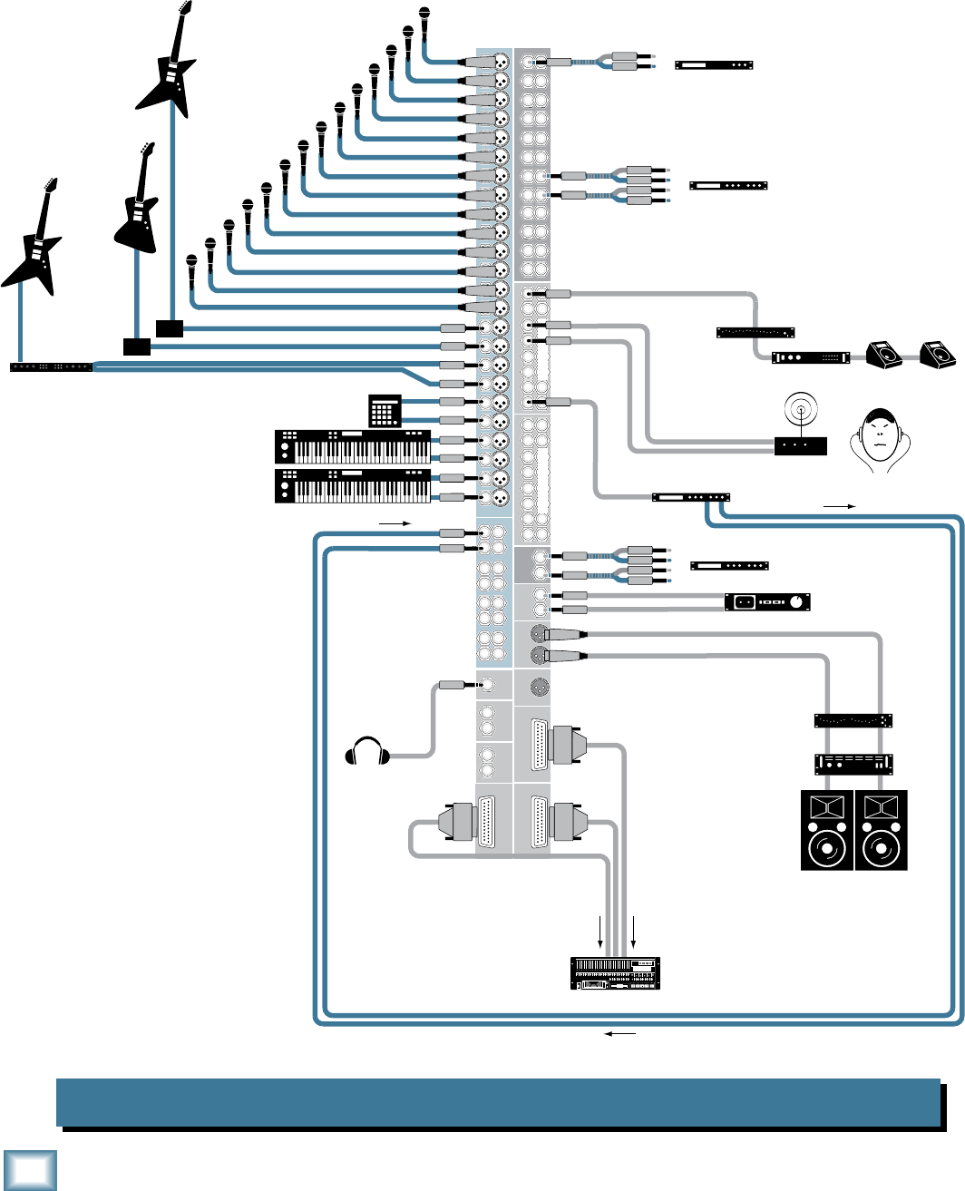
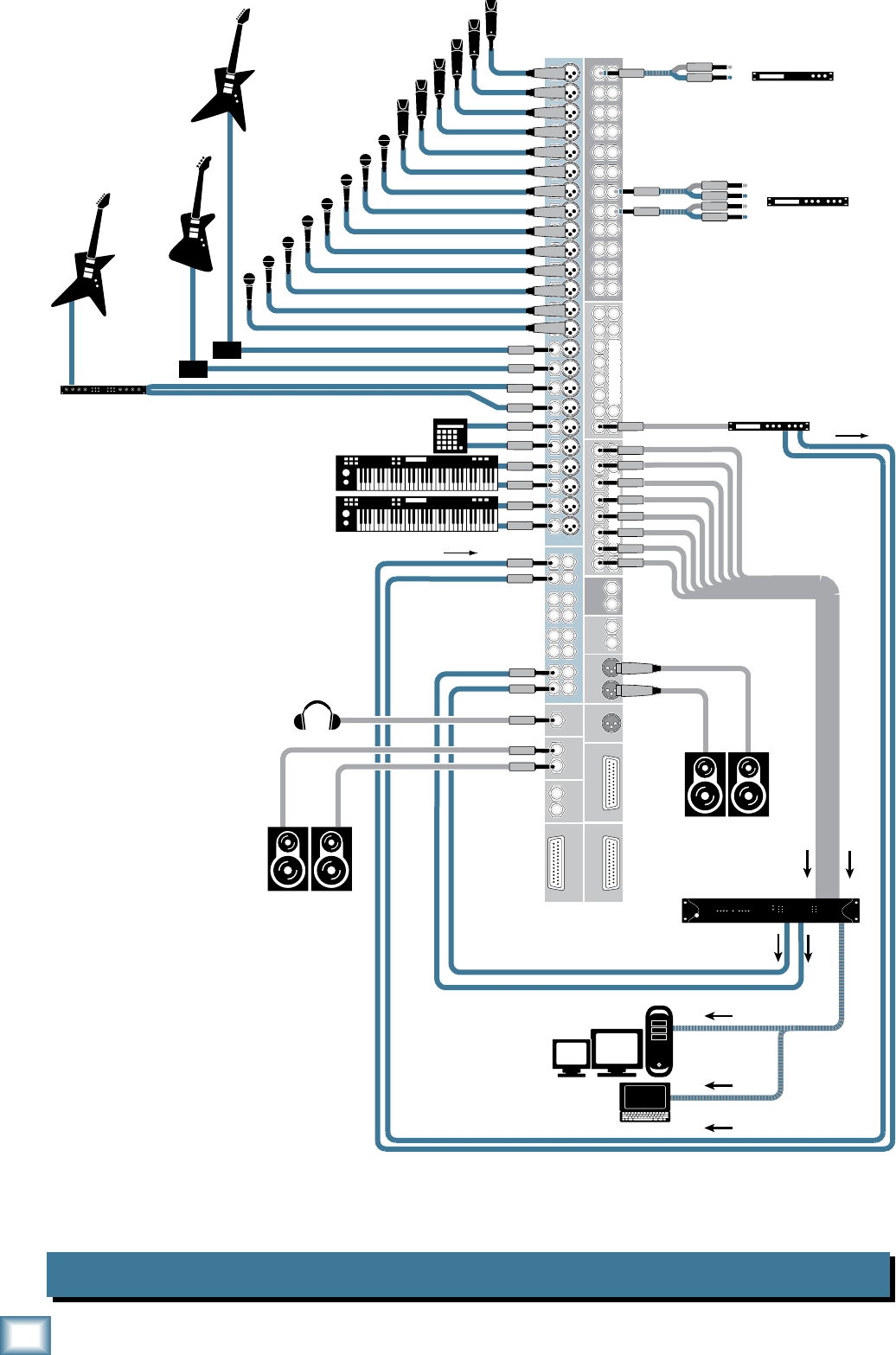
Hookup Diagrams
Onyx 2480 Live Mix and Multitrack Recording
This hookup diagram demonstrates how
you can do a live multitrack recording
using the DIRECT OUTs. The DIRECT
OUTs provide an analog balanced direct
output for each channel, post-EQ.
Aux Send 1 is used for stage monitors,
and Aux Sends 3 and 4 are a stereo pair
driving an IEM system. Aux Sends 5/6
and 7/8 could provide two more stereo
sends for IEM systems.
7
Owner’s Manual
Owner’s Manual
Onyx 2480 Multitrack Recording in a Studio (Tracking)
The DIRECT OUTs provide an analog balanced direct output for each chan-
nel, tapped after the GAIN control and EQ controls. The Main Outs are used for
monitors in the studio, and the Monitor Outs are used for monitors in the control
room. In addition, the Phones Out drives a headphone distribution amplifier to
provide individual monitor level control for the talent.
Stereo Compressor
Mono Compressor
Multi Effect
Processor
Keyboard or other
line level input
Drum
Machine
Vocal Mics
Digital Multitrack
Hard Disk Recorder
Out
In
Out
In
Out
In
SELECT
SELECTSELECTSELECT
Powered
Studio Monitors
for Studio
Powered
Studio Monitors
for Control Room Headphone Distribution
Amp
Headphones
for Studio
Stereo Guitar Effects
Bass Guitar
Electric Guitar
Electric Guitar
DI Boxes
Digital Delay
11
12
10
16 16
15
14
15
13
14
9
7
8
6
5
23
24
22
21
19
20
18
17
3
4
2
1
15
16
14
13
13
12 12
11
10
11
9
10
9
88
7
6
7
5
6
5
44
3
2
3
1
2
1
24 24
23
22
23
21
22
21
20 20
19
18
19
17
18
17
CHANNEL INSERTS
CHANNEL INPUTS STEREO AUX INPUTS
MONO
OUT
PHONES
OUT
3
4
5
1
2
6
7
8
MAIN
OUT
MONTIOR
OUT
MATRIX
OUT
MAIN
OUT
DIRECT OUT
9-16
DIRECT OUT
1-8
L
R
MAIN
INSERTS
L
R
DIRECT OUT
17-24
3
4
5
1
2
6
7
8
AUX SEND
AUX SEND INSERTS
3
4
5
1
2
6
7
8
3
4
5
1
2
6
7
8
GROUP SEND
GROUP SEND INSERTS
3
4
L
R
L
R
L
R
A
B
7
8
L
R
L
R
1
2
L
R
L
R
5
6
L
R
L
R
8
ONYX 80 SERIES
ONYX 80 SERIES
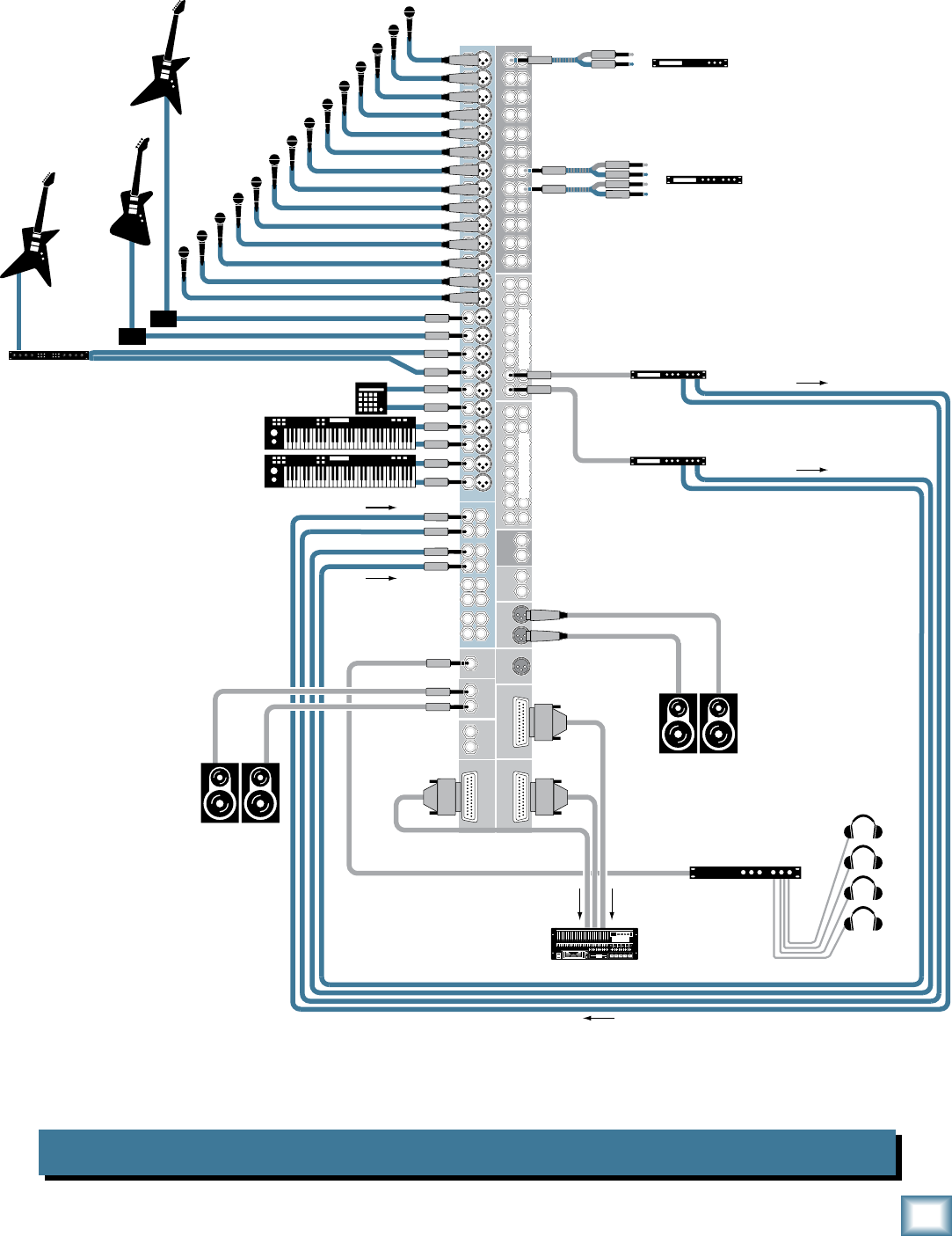
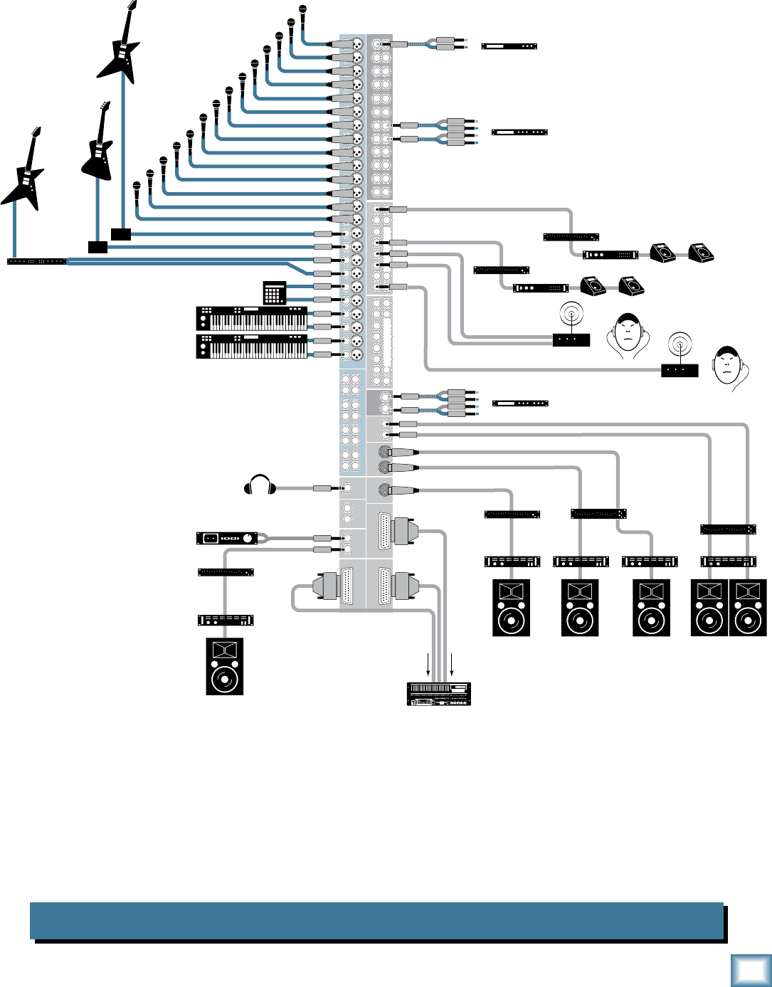
Onyx 2480 Computer Recording
In this hookup diagram, the tracking channels are routed to the Group 1-8 outputs.
These are connected to the analog audio interface to your DAW or laptop. A 2-track
return is provided by the DAW (or laptop) to Stereo Aux Input 4 on the Onyx 2480 for
playback of the master mix.
To Desktop
or
Laptop Computer
Stereo Compressor
Mono Compressor
Multi Effect
Processor
Keyboard or other
line level input
Drum
Machine
Vocal Mics
Out
In
Out
In
Out
In
Powered
Studio Monitors
for Studio
Powered
Studio Monitors
for Control Room
Headphones
Audio I/O for Workstation
Stereo Guitar Effects
Bass Guitar
Electric Guitar
Electric Guitar
DI Boxes
11
12
10
16 16
15
14
15
13
14
9
7
8
6
5
23
24
22
21
19
20
18
17
3
4
2
1
15
16
14
13
13
12 12
11
10
11
9
10
9
88
7
6
7
5
6
5
44
3
2
3
1
2
1
24 24
23
22
23
21
22
21
20 20
19
18
19
17
18
17
CHANNEL INSERTS
CHANNEL INPUTS STEREO AUX INPUTS
MONO
OUT
PHONES
OUT
3
4
5
1
2
6
7
8
MAIN
OUT
MONTIOR
OUT
MATRIX
OUT
MAIN
OUT
DIRECT OUT
9-16
DIRECT OUT
1-8
L
R
MAIN
INSERTS
L
R
DIRECT OUT
17-24
3
4
5
1
2
6
7
8
AUX SEND
AUX SEND INSERTS
3
4
5
1
2
6
7
8
3
4
5
1
2
6
7
8
GROUP SEND
GROUP SEND INSERTS
3
4
L
R
L
R
L
R
A
B
7
8
L
R
L
R
1
2
L
R
L
R
5
6
L
R
L
R
9
Owner’s Manual
Owner’s Manual
Onyx 2480 House of Worship
Power Amp
Mono Mode
In (record)
Stereo Compressor
Mono Compressor
Mono Power
Amplifier
Stage Monitors
Left PA Speaker Right PA Speaker
Stereo EQ
Mono EQ
Headphones Mono EQ
Keyboard or other
line level input
Stereo Guitar Effects
Drum
Machine
Bass Guitar
Electric Guitar
DI Boxes
Electric Guitar
Vocal Mics
Digital Multitrack
Hard Disk Recorder
Mono Power
Amplifier
Stage Monitors
Mono EQ
Assistive Listening
System
Out
In
Out
In
Out
In
Stereo Compressor
Stereo Recorder
Out
In
Out
In
SELECT
SELECTSELECTSELECT
Power Amp
Mono Mode
Center PA Speaker
Mono EQ
Power Amp
Mono Mode
Nursery Zone Speaker
Power Amp
Mono Mode Stereo Power
Amplifier
Left and Right Chapel Speaker
s
(Overflow)
Stereo EQ
Stereo In-Ear Monitor
System (IEM)
11
12
10
16 16
15
14
15
13
14
9
7
8
6
5
23
24
22
21
19
20
18
17
3
4
2
1
15
16
14
13
13
12 12
11
10
11
9
10
9
88
7
6
7
5
6
5
44
3
2
3
1
2
1
24 24
23
22
23
21
22
21
20 20
19
18
19
17
18
17
CHANNEL INSERTS
CHANNEL INPUTS STEREO AUX INPUTS
MONO
OUT
PHONES
OUT
3
4
5
1
2
6
7
8
MAIN
OUT
MONTIOR
OUT
MATRIX
OUT
MAIN
OUT
DIRECT OUT
9-16
DIRECT OUT
1-8
L
R
MAIN
INSERTS
L
R
DIRECT OUT
17-24
3
4
5
1
2
6
7
8
AUX SEND
AUX SEND INSERTS
3
4
5
1
2
6
7
8
3
4
5
1
2
6
7
8
GROUP SEND
GROUP SEND INSERTS
3
4
L
R
L
R
L
R
A
B
7
8
L
R
L
R
1
2
L
R
L
R
5
6
L
R
L
R
In a House of Worship application, the Onyx 80 Series provides plenty of Aux Sends
for stage monitors, stereo in-ear monitoring, and assistive listening systems. The
MONO output is used for the center PA speaker located between the Left and Right
speakers. The 1/4-inch Main Outputs provide a feed to the chapel for overflow needs.
The Matrix A output provides a custom mix for a mono recording and the Matrix B
output provides a custom mix for the nursery.
10
ONYX 80 SERIES
ONYX 80 SERIES
Onyx 80 Series Features
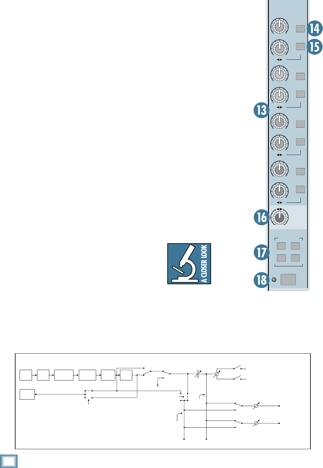
Channel Strips
Depending on the model that you purchased, there are
24, 32, 40, or 48 channel strips. Each channel has a mic
and line input connector and an insert jack for connect-
ing an external signal processor.
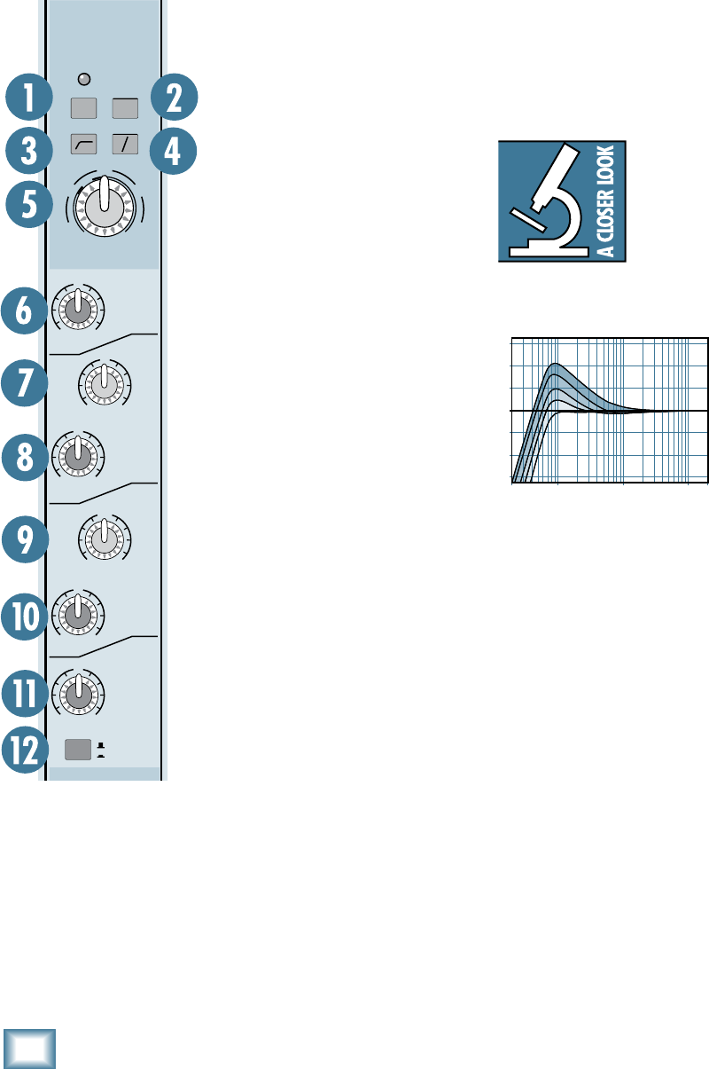
1. 48V Phantom Power Switch
Most professional condenser mi-
crophones require phantom power,
which is a low-current DC voltage
delivered to the microphone on
pins 2 and 3 of the XLR microphone
connector. Push in the 48V button
if your microphone needs phantom
power. An LED lights just above the
button to indicate that phantom
power is active on that channel.
Dynamic microphones, like
Shure’s SM57 and SM58, do not
require phantom power. However,
phantom power will not harm most
dynamic microphones should you
accidentally plug one in while the
phantom power is turned on. Be
careful with older ribbon micro-
phones. Check the manual for your
microphone to find out for sure
whether or not phantom power can
damage it.
Note: Be sure the MAIN MIX
faders [60] are turned down when
connecting microphones to the
MIC Inputs, especially when phan-
tom power is turned on, to prevent
pops from getting through to the
speakers.
. MIC/LINE Switch
This button switches between the MIC and LINE in-
puts. When the button is out (MIC), the XLR MIC input
is used and the LINE input is disconnected. When the
button is pushed in, the 1/4" input is used and the XLR
MIC input is disconnected.
. Low-Cut Switch
The Low-Cut switch, often referred to as a high-pass
filter, cuts bass frequencies below 100 Hz at a rate of 18
dB per octave.
We recommend that you use the Low-Cut filter on
every microphone application except kick drum, bass
guitar, bassy synth patches, or recordings of earth-
quakes. These aside, there isn’t much down there that
you want to hear, and filtering it out makes the low stuff
you do want much more crisp and tasty. Not only that,
but the Low-Cut filter can help reduce the possibility
of feedback in live situations and it helps to conserve
amplifier power.
Another way to use the Low Cut filter
is in combination with the LOW EQ on
vocals during live performances.
Many
times, bass shelving EQ can really ben-
efit voices. Trouble is, adding LOW EQ
also boosts stage rumble, mic handling
clunks, and breath pops. Low Cut removes all those prob-
lems so you can add LOW EQ without losing a woofer.
Here’s what the
combination of LOW EQ
and Low Cut looks like
in terms of frequency
curves.
4. Polarity Switch
Pushing in this switch simply reverses the polarity of the
signal. This provides an easy way to correct a microphone
or line source whose polarity is opposite from the other
microphones, either from a miswired cable or from not
following the AES standard for Pin 2/Pin 3.
5. GAIN Control
If you haven’t already, please read “Set the Levels” on
page 5.
The GAIN control adjusts the input sensitivity of the mic
and line inputs. This allows the signal from the outside
world to be adjusted to optimal internal operating levels.
If the signal is plugged into the XLR jack, there is 0 dB
of gain (unity gain) with the knob turned all the way
down, ramping up to 60 dB of gain fully up.
GROUP
ASSIGN
5-6
1-2
3-4
7-8
MAIN
MIX
10
dB
30
20
10
OO
40
5
5
U
60
50
OL
+10
0
-20
OO
MAX
OO
MAX
OO
MAX
OO
MAX
OO
MAX
OO
MAX
OO
MAX
OO
MAX
1
MUTE GROUP
FREQ
U
+15-15
U
+15-15
U
+15-15
U
+15-15
HIGH
12 kHz
HIGH
MID
LOW
80 Hz
FREQ
LOW
MID
100Hz
GAIN
+40dB
U
-20dB
U
20
30
40
60
1
AUX
SEND
1
2
PAN
PRE
STEREO
RL
OUT
IN
3
4
PRE
STEREO
RL
5
6
PRE
STEREO
RL
7
8
PRE
STEREO
RL
RL
2k
8kHz400Hz
400
2k100
EQ
LINE
0
PFL
MUTE
EQ
1
3
2
4
48V48V
20Hz 100Hz 1kHz 10kHz 20kHz
–15
–10
–5
0
+5
+10
+15
Low Cut with Low EQ Boosted
11
Owner’s Manual
Owner’s Manual
When connected to the 1/4" jack, there is 20 dB of
attenuation all the way down, and 40 dB of gain fully up,
with a “U” (unity gain) mark at about 10:00.
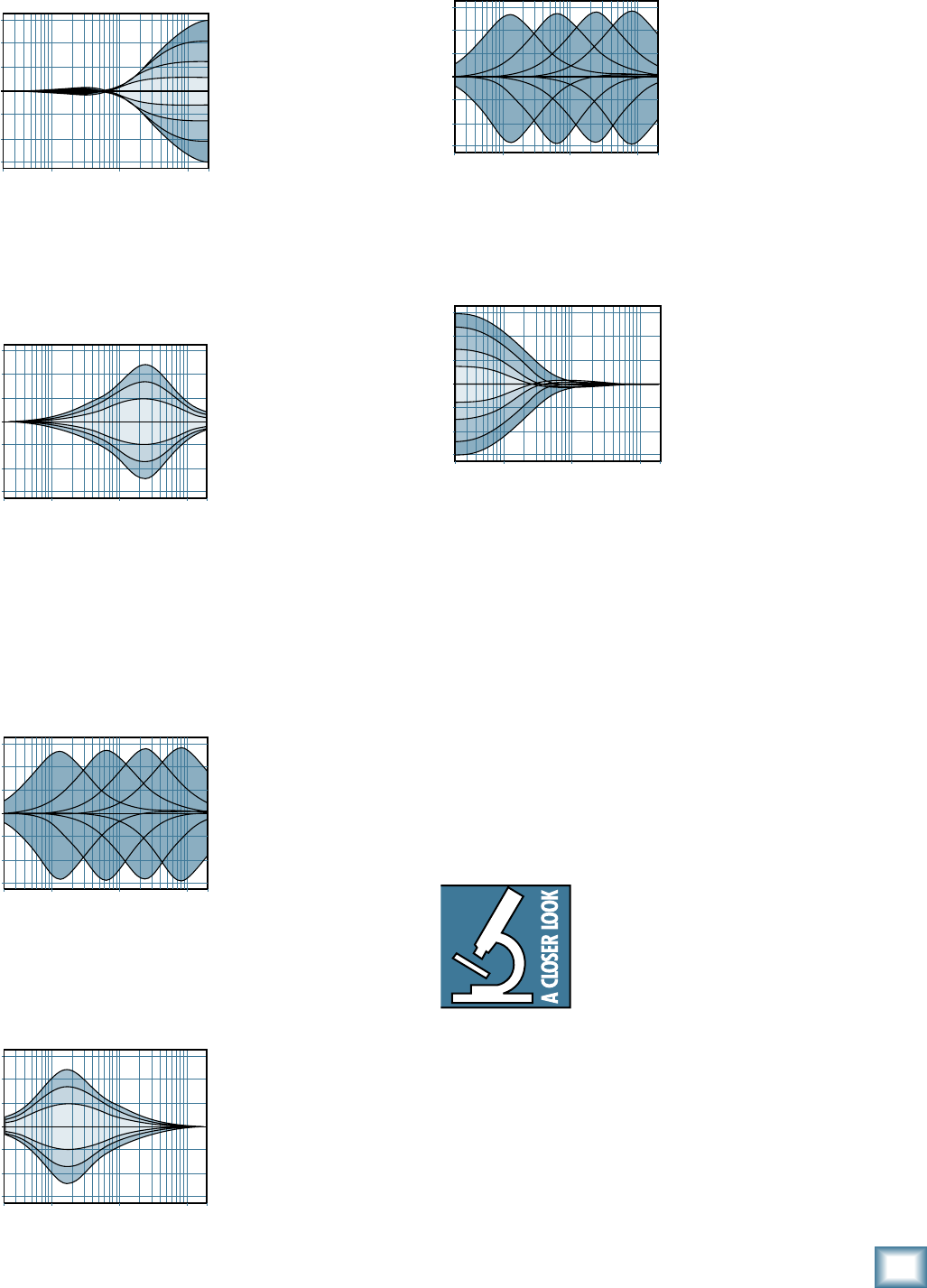
6. HIGH EQ
This control gives you
up to 15 dB boost or cut
at 12 kHz, and it is also
flat at the center detent.
Use it to add sizzle to
cymbals, and an overall
sense of transparency or
edge to the keyboards,
vocals, guitar, and bacon
frying. Turn it down a little to reduce sibilance, or to
hide tape hiss.
7. HIGH MID EQ
Short for “midrange,”
this knob provides 15 dB
of boost or cut centered
at the frequency deter-
mined by its FREQ knob
(see HIGH MID FREQ
next). Midrange EQ is
often thought of as the
most dynamic because the frequencies that define any
particular sound are almost always found in this range.
The HIGH MID EQ range (400 Hz to 8 kHz) includes
the female vocal range as well as the fundamentals and
harmonics for many instruments.
8. HIGH MID FREQ
This knob ranges from
400 Hz to 8 kHz and
determines the center
frequency for the HIGH
MID EQ filter. This allows
you to zero in on the
precise narrow band of
frequencies you want
to have affected by the
HIGH MID EQ.
9. LOW MID EQ
This is a second mid-
range EQ control that pro-
vides 15 dB of boost or cut
centered at the frequency
determined by its FREQ
knob. It extends down to
100 Hz, which includes
the male vocal range and the fundamentals of some lower
instruments (guitar, lower brass).
10. LOW MID FREQ
This knob ranges from
100 Hz to 2 kHz and
determines the center
frequency for the LOW
MID EQ filter. This allows
you to zero in on the
precise narrow band of
frequencies you want to
have affected by the LOW
MID EQ.
11. LOW EQ
This control gives you
up to 15 dB of boost or
cut at 80 Hz. The circuit
is flat (no boost or cut)
at the center detent
position. This frequency
represents the punch in
bass drums, bass guitar,
fat synth patches, and
some really serious male
singers.
Note: Used in conjunction with the Low Cut switch,
you can boost the LOW EQ without injecting tons of
infrasonic debris into the mix.
1. EQ IN/OUT Switch
This is a true hardware bypass of the Perkins EQ cir-
cuitry to insure that there is no coloration of the signal
if the EQ is not needed. When this button is out, the EQ
controls have no effect on the signal. You can use this
switch to make an A/B comparison between the EQ’d
signal and the signal without EQ.
We have completely redesigned the
EQ circuits in the Onyx Series of
mixers, based on the designs of Cal
Perkins, an industry-leader in audio
engineering for over three decades
and long-time Mackie collaborator.
This “neo-classic” design provides the sweet musicality
of the British EQ
sound, while still maintaining 15 dB of
boost and cut with optimum Q
and minimum phase shift
(in other words, it gives you plenty of control and is
pleasing to the ear!).
The 4-band equalization has LOW shelving at 80 Hz,
LOW MID peaking, sweepable from 100 Hz to 2 kHz on
the mono channels, HIGH MID peaking, sweepable from
20
Hz
100
Hz
1k
Hz
10k
Hz
20k
Hz
–15
–10
–5
0
+5
+10
+15
High EQ
20
Hz
100
Hz
1k
Hz
10k
Hz
20k
Hz
–15
–10
–5
0
+5
+10
+15
High Mid EQ
20Hz 100Hz 1kHz 10kHz 20kHz
–15
–10
–5
0
+5
+10
+15
Low EQ
20Hz 100Hz 1kHz 10kHz 20kHz
–15
–10
–5
0
+5
+10
+15
Mid EQ Freq Sweep
20
Hz
100
Hz
1k
Hz
10k
Hz
20k
Hz
–15
–10
–5
0
+5
+10
+15
Low Mid EQ
20Hz 100Hz 1kHz 10kHz 20kHz
–15
–10
–5
0
+5
+10
+15
Mid EQ Freq Sweep
1
ONYX 80 SERIES
ONYX 80 SERIES
GROUP
ASSIGN
5-6
1-2
3-4
7-8
MAIN
MIX
10
dB
30
20
10
OO
40
5
5
U
60
50
OL
+10
0
-20
OO
MAX
OO
MAX
OO
MAX
OO
MAX
OO
MAX
OO
MAX
OO
MAX
OO
MAX
1
MUTE GROUP
FREQ
U
+15-15
U
+15-15
U
+15-15
U
+15-15
HIGH
12 kHz
HIGH
MID
LOW
80 Hz
FREQ
LOW
MID
100Hz
GAIN
+40dB
U
-20dB
U
20
30
40
60
1
AUX
SEND
1
2
PAN
PRE
STEREO
RL
OUT
IN
3
4
PRE
STEREO
RL
5
6
PRE
STEREO
RL
7
8
PRE
STEREO
RL
RL
2k
8kHz400Hz
400
2k100
EQ
LINE
0
PFL
MUTE
EQ
1
3
2
4
48V48V
400 Hz to 8 kHz on the mono channels,
and HIGH shelv-
ing at 12 kHz. “Shelving” means that the circuitry boosts
or cuts all frequencies past the specified frequency. For
example, rotating the LOW EQ knob 15 dB to the right
boosts bass frequencies below 80 Hz and
continuing on
down to the lowest note you ever heard. “Peaking” means
that the frequencies around the center frequency are
less affected by the EQ the further away they are.
1. AUX Sends
These tap a portion of each channel’s signal out to
either an effects processor or for stage monitoring. The
AUX Send levels are controlled by the channel’s AUX 1-8
knobs, and by the AUX MASTER 1-8 knobs [37].
These are more than just effects and monitor sends.
They can be used to create stereo in-ear monitor mixes,
generate separate mixes for recording, for another zone,
or “mix-minuses” for broadcast.
14. PRE Switch
This switch is used to select whether the Aux send
signal is pre-fader or post-fader. When the PRE switch
is up, the Aux send signal is post-fader, which is usually
used when you are using the Aux send to go to an effects
processor. This way, when fader changes are made, the
“wet” signal going to the effects processor moves up and
down along with the “dry” signal, maintaining a balance
between them.
When the PRE switch is pushed in, the Aux send signal
is pre-fader, which is usually used for sending to monitors
(stage monitor wedges or IEM, in-ear monitor systems).
This way, when changes are made to fader levels in the
front-of-house mix, it doesn’t affect the monitor mix.
The pre-fader Aux Sends are post-EQ by default. How-
ever, an internal jumper is provided on each channel to
change the pre-fader Aux Sends to pre-EQ, if desired.
This requires some soldering skills, so contact Tech Sup-
port for information on how to access the pre/post-EQ
jumpers for the Aux Sends.
15. STEREO Switch
When this switch is pushed in,
the associated odd/even pair of
Aux sends become a stereo send
and pan control, respectively. For
example, if you press the STEREO
switch for Aux 1 and 2, the Aux 1
knob controls the signal level to
both Aux 1 and Aux 2, and the Aux
2 knob controls the panning of the
signal between Aux 1 and 2. This
is useful for providing a stereo mix
for IEM (in-ear monitor) systems.
16. PAN
PAN adjusts the amount of chan-
nel signal sent to the left versus the
right outputs
.
With the PAN knob hard left,
the signal feeds the MAIN LEFT
(and GROUP 1, 3, 5, and 7,
depending on the setting of the
GROUP ASSIGN switches). With
the knob
hard right, the signal
feeds the MAIN RIGHT (and
GROUP 2, 4, 6, and 8).
Constant Loudness
The Onyx
80 Series
PAN control
employs a
design called
“Constant
Loudness.” If you have a channel
panned hard left (or right) and then pan to the center,
the signal is attenuated 3 dB to maintain the same ap-
parent loudness. Otherwise, it would make the sound
appear much louder when panned center.
GAIN POLARITY INSERTLOW CUT EQ
EQ
IN/OUT MUTE FADER PAN
ASSIGN
PRE/POST
PRE/POST
AUX SEND 1
KNOB
"POST"
SIGNAL
"PRE" SIGNAL
TO AUX SENDS 3-8
INTERNAL JUMPER
INTERNAL
JUMPER
Aux "Pre vs. Post"
Signal Flow Diagram
POST-
MUTE
PRE-EQ
PRE-EQ
POST-EQ
INPUT
DIRECT
OUT
TO AUX SEND 1
BUS
AUX SEND 2
KNOB
TO AUX SEND 2
BUS
1
Owner’s Manual
Owner’s Manual
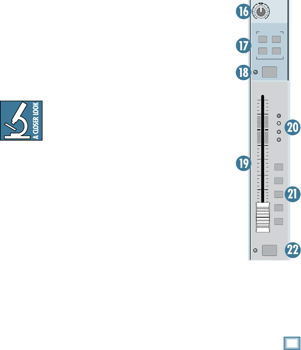
17. MUTE GROUP Assign Switches
Use these switches to assign the channel to one or
more mute groups. The master mute groups [54] are lo-
cated in the Master section next to the Talkback section.
When a master mute group switch is pressed, all the
channels assigned to that mute group are muted. This
makes it easy to mute a number of channels all at once,
for example, all the drum mics or all the vocal mics.
18. MUTE
Press this switch to mute the individual channel. This
disconnects the channel’s signal from all the Groups,
the Main Mix, and Aux Send buses (pre* and post-
fader). You can still solo the channel (PFL) when the
MUTE switch is pushed in.
* If the pre-fader Aux Send’s internal jumper is wired for pre-EQ
[14], the MUTE switch will not affect the PRE Aux Send.
19. Channel Fader
The fader controls the channel’s level…from off to unity
gain at the “U” marking, on up to 10 dB of additional gain.
“U” Like Unity Gain
Mackie mixers have a “U” symbol
on almost every level control. This
“U” stands for “unity gain,” meaning
no change in signal level. Once you
have adjusted the input signal to
line-level, you can set every control
at “U” and your signals will travel through the mixer at
optimal levels. What’s more, all the labels on our level
controls are measured in decibels (dB), so you’ll know
what you’re doing level-wise if you choose to change a
control’s settings.
0. Signal Level LEDs
These LEDs indicate the channel’s signal level after
the GAIN and EQ controls, but just prior to the chan-
nel’s
fader. So even if the fader is turned down, you can
see if a signal is present.
If you’ve followed the “Set the Levels”
procedure, the
–20 and 0 LEDs should light frequently, the +10 LED
should light occasionally, and the OL (Overload) LED
should not light at all. If the OL LED is blinking fre-
quently, the signal is probably distorted from overdriving
the input. Either turn down the GAIN control or turn
down the signal at its source.
1. GROUP and MAIN MIX ASSIGN Switches
Alongside each channel fader are five buttons referred
to as channel assignment switches. Used in conjunction
with the channel’s PAN knob, they are used to deter-
mine the destination of the channel’s signal.
With the PAN knob [12] at the center detent, the left
and right sides receive equal signal levels (GROUPS 1-2,
3-4, 5-6, 7-8, and MAIN MIX L-R). To feed only one side
or the other, turn the PAN knob accordingly.
If you’re doing a mixdown to a 2-track, for example,
simply engage the MAIN MIX switch on each channel
that you want to hear, and they’ll be sent to the MAIN
MIX bus. If you want to create a subgroup of certain
channels, engage either the 1-2, 3-4, 5-6, or 7-8 switches
instead of the MAIN MIX, and they’ll be sent to the ap-
propriate Group faders. From there, the groups can be
sent back to the MAIN MIX (using
the MAIN MIX assign switches
[41]
above the Group faders), allowing
you to use the Group faders as a
master control for those channels.
If you’re creating new tracks or
bouncing existing ones, you’ll also
use the GROUP ASSIGN switches,
but not the MAIN MIX switch. Here,
you don’t want the subgroups sent
back into the MAIN MIX bus, but
sent out, via the GROUP SEND jacks
[74], to your multitrack inputs.
However, if you’re printing tracks
via the DIRECT OUTS [70], the
channel assignment switches don’t
matter because the DIRECT OUTS
come before the ASSIGN switches.
. PFL SOLO Switch
This handy switch allows you to
hear signals through your head-
phones or monitor outputs without
having to route them to the MAIN or
GROUP mixes. Folks use solo in live
work to preview channels before
they are let into the mix, or just to
check out what a particular channel
is up to anytime during a session.
You can solo as many channels at a
time as you like.
The Onyx 80 Series has two solo
modes. PFL (Pre-Fader Listen) is
the default solo mode, and the mode used for soloing
individual channels and the stereo Aux Inputs. AFL (Af-
ter-Fader Listen) is activated whenever an AFL switch
is pressed on an Aux Send, Matrix, or Group.
PFL solo mode always overides any AFL solo mode.
The Rude Solo LEDS below the SOLO meters indicate
which solo mode is active.
GROUP
ASSIGN
5-6
1-2
3-4
7-8
MAIN
MIX
10
dB
30
20
10
OO
40
5
5
U
60
50
OL
+10
0
-20
OO
MAX
OO
MAX
OO
MAX
OO
MAX
OO
MAX
OO
MAX
OO
MAX
OO
MAX
1
MUTE GROUP
FREQ
U
+15-15
U
+15-15
U
+15-15
U
+15-15
HIGH
12 kHz
HIGH
MID
LOW
80 Hz
FREQ
LOW
MID
100Hz
GAIN
+40dB
U
-20dB
U
20
30
40
60
1
AUX
SEND
1
2
PAN
PRE
STEREO
RL
OUT
IN
3
4
PRE
STEREO
RL
5
6
PRE
STEREO
RL
7
8
PRE
STEREO
RL
RL
2k
8kHz400Hz
400
2k100
EQ
LINE
0
PFL
MUTE
EQ
1
3
2
4
48V48V
14
ONYX 80 SERIES
ONYX 80 SERIES
Soloed channels are sent to the PHONES output,
MONITOR outputs, and SOLO Meters. PFL mode (Pre-
Fader Listen) sends the channel’s signal after the GAIN
and EQ controls, but before the channel fader, to the
PFL solo bus. AFL mode (After-Fader Listen), sends the
signal post-fader, making it ideal for mixdown soloing.
VERY IMPORTANT: Remember, PFL
mode taps the channel signal before
the fader. If you have a channel’s
fader set way below “U” (unity gain),
PFL solo won’t know that and will
send a unity gain signal to the MONITOR OUT, PHONES
output, and meter display. That may result in a startling
level boost at these outputs when switching from AFL to
PFL mode.
Auxiliary Section
This section includes the AUX MASTERS (Sends) and
the STEREO AUX INPUTS. These can be a bit confus-
ing to the uninitiated, so here’s the whole idea behind
aux sends and inputs: sends are outputs and inputs are
inputs. AUX SENDs tap signals off the channels, via the
AUX knobs [13], mix these signals together, then send
them out the AUX SEND jacks [72].
These outputs are fed to the inputs of an external
processor like a reverb or digital delay. From there, the
mono or stereo outputs of this external device are fed
back to the mixer’s STEREO AUX INPUT jacks [71].
These signals are sent through the AUX INPUT faders
[33], and finally delivered to a GROUP [43] and/or
the MAIN MIX [60], depending on the ASSIGN [35]
switches.
So, the original “dry” signals go from the channels to
the MAIN MIX and the affected “wet” signals go from
the AUX INPUTS to the MAIN MIX, and once mixed
together, the dry and wet signals combine to create a
glorious sound!
The AUX SENDS can also be used to provide another
mix for stage monitors, for example. In this case, the
AUX INPUTS aren’t used to return the signal. Instead,
they can be used as additional stereo inputs.
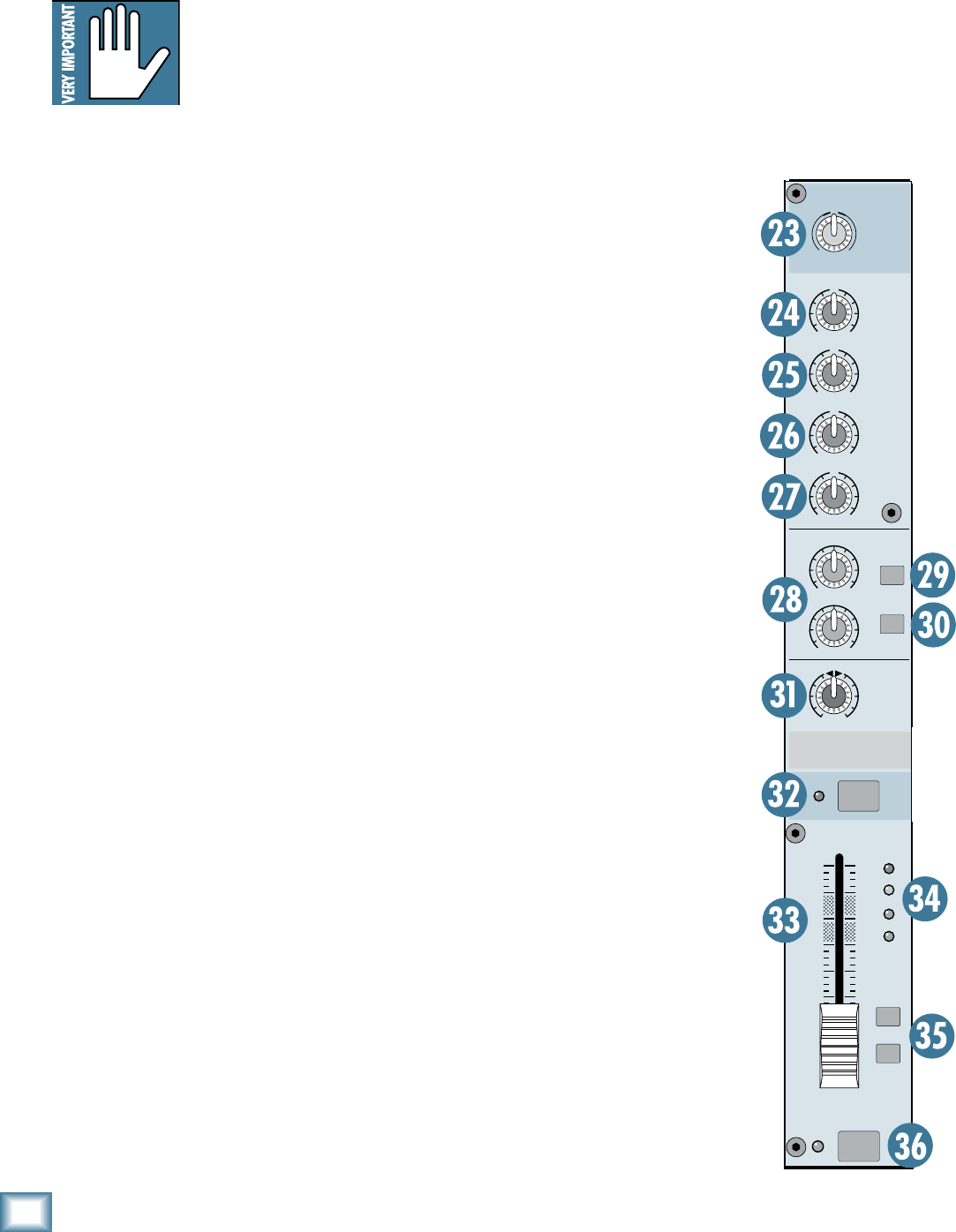
Stereo Aux Input Section
The stereo Aux Inputs can be used as mono or stereo
line-input channel strips, or to return the signal from
an external effects processor connected to an Aux Send.
These versatile channel strips are nearly as full-featured
as the mono channel strips.
. GAIN Control
If you haven’t already, please read “Set the Levels” on
page 5.
The GAIN control adjusts the input sensitivity of the
stereo line inputs. This allows the signal from the outside
world to be adjusted to optimal internal operating levels.
There is 20 dB of attenuation
with the knob turned all
the way down, ramping up to 20 dB of gain fully up, with
a “U” (unity gain) mark at 12:00.
4. HIGH EQ
This control gives you up to 15
dB boost or cut above 12 kHz, and
it is also flat at the center detent.
Use it to add sizzle to cymbals, and
an overall sense of transparency
or edge to the keyboards, vocals,
guitar, and bacon frying. Turn it
down a little to reduce sibilance,
or to hide tape hiss.
5. HIGH MID EQ
Short for “midrange,” this knob
provides 15 dB of boost or cut at
2.5 kHz. Midrange EQ is often
thought of as the most dynamic
because the frequencies that
define any particular sound are
almost always found in this range.
The HIGH MID EQ frequencies
include the female vocal range
as well as the fundamentals and
harmonics for many instruments.
6. LOW MID EQ
This is a second midrange EQ
control that provides 15 dB of boost
or cut centered at 400 Hz. This
includes the male vocal range and
the fundamentals of some lower
instruments (guitar, lower brass).
7. LOW EQ
This control gives you up to 15
dB of boost or cut below 80 Hz. The
circuit is flat (no boost or cut) at
the center detent position. This
frequency represents the punch in
bass drums, bass guitar, fat synth
patches, and some really serious
male singers.
STEREO 1
OL
+10
0
-20
dB
30
20
10
OO
40
50
5
5
U
60
10
MAIN
MIX
GROUP
ASSIGN
7-8
LOW
80Hz
AUX
SEND
LOW
MID
400Hz
HIGH
12kHz
HIGH
MID
2.5kHz
2
1
STEREO
3-4
OO
MAX
OO
MAX
U
+15-15
U
+15-15
U
+15-15
U
+15-15
RL
BAL
U
+20dB-20dB
GAIN
MUTE
PFL

15
Owner’s Manual
Owner’s Manual
8. AUX SEND 1 and (Aux Inputs 1-4)
AUX SEND 5 and 6 (Aux Inputs 5-8)
These tap a portion of each channel’s signal out to ei-
ther an effects processor or for stage monitoring. These
go to the same Aux Send buses as the mono channel Aux
Sends. The Aux Input Aux Sends are always pre-fader.
Aux Inputs 1-4 send their signals to Aux 1 and Aux 2.
Aux Inputs 5-8 send their signals to Aux 5 and 6.
FEEDBACK LOOP WARNING: It is
common to use an Aux Send to route
signals to an external processor, and
then return the signal from the pro-
cessor via the Aux Inputs.
Since the
Aux Inputs on the Onyx 80 Series have Aux Sends of their
own, you could accidentally route the Aux Input to an
Aux Send that is being returned via that same Aux Input.
This will cause a feedback loop, characterized by a LOUD
howl or screech through the sound system, followed by
howls of discontent from the audience.
Be careful with
the Aux Sends on the Aux Inputs!
9. AUX -4 Switch (Aux Inputs 1-4)
AUX 7-8 Switch (Aux Inputs 5-8)
For Aux Inputs 1-4:
Press this switch to send the Aux Input signal to the
Aux 3 and 4 buses instead of the Aux 1 and 2 buses.
The Aux 1 and 2 knobs for that channel strip suddenly
become Aux 3 and 4 knobs!
For Aux Inputs 5-8:
Press this switch to send the Aux Input signal to the
Aux 7 and 8 buses instead of the Aux 5 and 6 buses.
The Aux 5 and 6 knobs for that channel strip suddenly
become Aux 7 and 8 knobs!
0. STEREO Switch
When this switch is up, both Aux Sends are fed a
mono sum of the stereo channel’s signal (L+R).
When this switch is pushed in, the two Aux sends
become a stereo send, with Aux 1 sending the right
signal and Aux 2 sending the left signal. The same thing
applies when Aux 3-4 is selected for Aux Inputs 1-4, and
for Aux 5 and 6 (and Aux 7-8) for Aux Inputs 5-8.
This is useful for providing a stereo mix for IEM (in-
ear monitor) systems.
1. BALANCE
BALANCE adjusts the amount of channel signal sent
to the left versus the right outputs. On the stereo Aux
Input channels, the BALANCE knob works like the bal-
ance control on your home stereo (panning left turns
down the right channel, and panning right turns down
the left channel).
. MUTE
Press this switch to mute the channel. This discon-
nects the channel’s signal from all the Groups, the Main
Mix, and Aux Send buses. You can still solo the channel
in PFL mode when the MUTE switch is pushed in.
. Stereo Aux Input Fader
The fader controls the stereo channel’s level, from
off to unity gain at the “U” marking, on up to 10 dB of
additional gain.
4. Signal Level LEDs
These LEDs indicate the channel’s signal level after
the GAIN and EQ controls, but just prior to the chan-
nel’s
fader. So even if the fader is turned down, you can
see if a signal is present.
If you’ve followed the “Set the Levels”
procedure, the
–20 and 0 LEDs should light frequently, the +10 LED
should light occasionally, and the OL (Overload) LED
should not light at all. If the OL LED is blinking fre-
quently, the signal is probably distorted from overdriving
the input. Either turn down the GAIN control or turn
down the signal at its source.
5. GROUP and MAIN MIX ASSIGN Switches
Alongside each channel fader are two buttons referred
to as channel assignment switches. Used in conjunction
with the channel’s BALANCE knob, they are used to
determine the destination of the channel’s signal.
The Aux Inputs are assignable to GROUPS 7-8 and
the MAIN MIX. With the BALANCE knob [31] at the
center detent, the left and right stereo signal is equally
balanced. To feed only one side or the other, turn the
BALANCE knob accordingly.
6. PFL Solo Switch
Like the PFL switch on the mono channels, this
switch allows you to hear signals through your head-
phones or monitor outputs without having to route them
to the MAIN or GROUP mixes. Since this is Pre-Fader
Listen, you can listen to the stereo Aux Input even when
the Aux Input fader is turned down. Unlike the mono
channel PFL, the Aux Input PFL is a stereo signal (post-
balance control).
PFL solo mode always overides AFL solo mode. The
Rude Solo LEDS below the SOLO meters indicate which
solo mode is active.
16
ONYX 80 SERIES
ONYX 80 SERIES
10
dB
30
20
10
OO
40
5
5
U
60
50
OL
+10
0
-20
10
dB
30
20
10
OO
40
5
5
U
60
50
OL
+10
0
-20
AUX 1AUX 2
GROUP 1GROUP 2
OO
+15
GAIN
OO
+15
GAIN
GROUP/AUX
FLIP
GROUP/AUX
FLIP
PAN
MAIN
MIX
RL
PAN
MAIN
MIX
RL
STEREO
MUTE
MUTE
AFL
AFL
MUTE
MUTE
AFL
AFL
STEREO
Master Aux Send Section
7. AUX 1 -8 MASTERS
The AUX MASTERS provide overall control over the
AUX SEND levels, just before they are delivered to the
AUX SEND outputs [72]. These knobs go from off (∞)
to +15 dB when turned all the way up.
This is usually the knob you turn up when the lead
singer glares at you, points at his stage monitor, and
sticks his thumb up in the air. (It would follow that if
the singer stuck his thumb down, you’d turn the knob
down, but that never happens.)
8. MUTE
Press this switch
to mute the Aux
Send output. When
the MUTE switch is
pushed in on an Aux
Send, you can still
solo the Aux Send
(see AFL Solo Switch
next).
9. AFL Solo
Switch
The AFL switch
allows you to hear
the Aux Send signal
through your head-
phones or monitor
outputs. This comes
after the Aux Send
GAIN control, so you
can hear the relative
signal level on each
Aux Send.
When you engage
the AFL switch on two
consecutive odd/even
Aux Sends (i.e., 1 and
2, 3 and 4, etc.), the
soloed signal appears
in stereo in the head-
phones and monitor
outputs. This is useful
when you are using
a pair of Aux Sends
in stereo to feed an
in-ear monitoring
system.
Remember, PFL solo mode always overides AFL solo
mode. If you engage a PFL solo switch on a mono or
stereo channel, the AFL solo is disconnected from the
headphones and monitor outputs and replaced with the
PFL signal. The Rude Solo LEDS below the SOLO meters
indicate which solo mode is active.
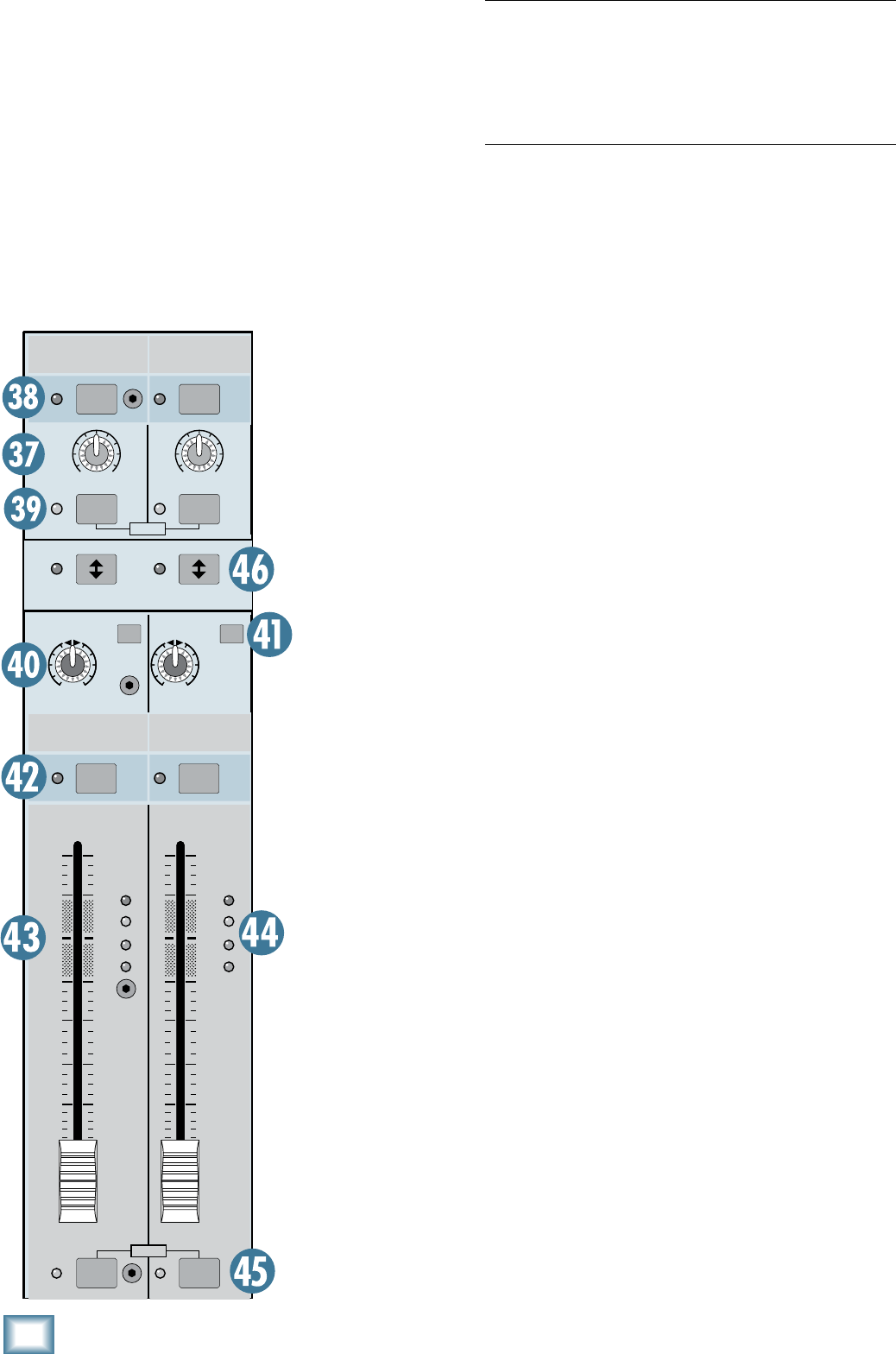
Group Section
There are eight group masters (or submasters, if you
prefer) that feed the eight group sends [74].
40. PAN
Note: The Group PAN control works only when the
MAIN MIX switch is engaged (see next).
PAN adjusts the amount of signal sent to the left
versus the right outputs.
With the PAN knob hard left, the signal feeds the
MAIN LEFT output, and with the knob
hard right, the
signal feeds the MAIN RIGHT output.
41. MAIN MIX Assign Switch
Push in this switch to send the Group signal to the left
and right MAIN OUTS. When the PAN control is centered,
the signal is sent equally to the left and right outputs.
The signal sent to the MAIN OUTS is after the Group
Insert, Fader, and MUTE switch.
4. MUTE Switch
Press this switch to mute the Group output. When the
MUTE switch is pushed in on a Group, you can still solo
the Group signal (see AFL Solo Switch [39] ahead).
4. GROUP Fader
This fader controls the Group’s signal level, from off to
unity gain at the “U” marking, on up to 10 dB of addi-
tional gain.
44. Signal Level LEDs
These LEDs indicate the Group’s signal level after
the Fader and MUTE switch.
So if the MUTE switch is
pushed in or the Faders are down, the Signal Level LEDs
won’t light.
17
Owner’s Manual
Owner’s Manual
MAIN TO
MON/PHONES
PHONES
LEVEL
SOLO
OO
MAX
OO
MAX
MONITOR
OO
MAX
10
dB
30
20
10
OO
40
5
5
U
60
50
MAIN
MIX
PHONES/
MONITOR
0dB=0dBu
MATRIX
A B
A B
20
10
7
4
2
0
2
4
7
10
20
30
20
10
7
4
2
0
2
4
7
10
20
30
LSOLO R
CLIP
RUDE
SOLO
PFL AFL
GROUP
1
MATRIX
MASTER
DESTINATION
TALKBACK
AUX
3-4
AUX
5-6 AUX
7-8
AUX
1-2
TALKBACK
GRPS
1-8 MAIN
L/R
MUTE GROUPS
MASTER
PRE
FADER
1
2
3
4
MONO
OUT
LEVEL
LEFT
RIGHT
GROUP
2
GROUP
3
GROUP
4
GROUP
5
GROUP
6
GROUP
7
GROUP
8
+15V -15V +48V +12V
OO
+15
OO
+15
OO
MAX
OO
MAX
OO
MAX
OO
MAX
OO
MAX
OO
MAX
OO
MAX
OO
MAX
OO
MAX
OO
MAX
OO
MAX
OO
MAX
OO
MAX
OO
MAX
OO
MAX
OO
MAX
OO
MAX
OO
MAX
OO
MAX
OO
MAX
OO
MAX
OO
MAX
STEREO
MUTE
MUTE
MUTE
MUTE
AFLAFL
POWER
45. AFL Solo Switch
The AFL switch allows you to hear the Group signal
through your headphones or monitor outputs. This
comes after the Group Fader and before the MUTE
switch, so you can hear the relative signal level on each
Group even when they are muted.
When you engage the AFL switch on two consecutive
odd/even Groups (i.e., 1 and 2, 3 and 4, etc.), the soloed
signal appears in stereo in the headphones and moni-
tor outputs. This is useful when you are using a pair
of Group Sends in stereo to feed an in-ear monitoring
system.
Remember, PFL solo mode always overides AFL solo
mode. If you engage a PFL solo switch on a mono or
stereo channel, the AFL solo is disconnected from the
headphones and monitor outputs and replaced with the
PFL signal. The Rude Solo LEDS below the SOLO meters
indicate which solo mode is active.
46. GROUP/AUX FLIP Switch
This switch “flips” the controls for the Aux Sends and
the Group Sends, so that the Group Faders control the
Aux Send levels, and the Aux Send GAIN controls adjust
the Group levels. The Group signals still appear at the
GROUP SEND outputs and the Aux Send signals still
appear at the AUX SEND outputs.
This allows you to use the long-throw (100 mm)
Group Fader to make more precise settings for the Aux
Sends, if required.
The following chart shows what happens to each
control in the Aux Send and Group sections when the
GROUP/AUX FLIP Switch is pushed in:
Metering, Matrix, and Power
LEDs
47. POWER Indicators
These four LEDs indicate the status of the internal
power supply voltages. The +15V and –15V supplies
power the audio circuits, the +48V is the phantom
power applied to the XLR MIC inputs (when the 48V
switch is pushed in on the channel strips), and the –12V
supply powers some internal relay circuits and the lamp
connectors.
When all four LEDs are lit, you know that the internal
power supply (or the external redundant power supply,
if connected) is operating correctly.
48. SOLO Meters
The Onyx SOLO
meters are made up of
two columns of twelve
LEDs, with three
colors to indicate dif-
ferent ranges of signal
level, traffic light
style. They range from
–30 at the bottom, to 0
in the middle, to +20
(CLIP) at the top.
If there are no
channels in SOLO, the
meters won’t do any-
thing. When a channel is soloed, the meters reflect the
program level of the selected source prior to the SOLO,
MONITOR, and PHONES [61/63/64] level knobs.
When a mono channel (or channels) is soloed, only the
left meter indicates signal, confirming the monophonic
status of the soloed signal. When a stereo Aux Input is
soloed, or stereo AFL solo mode is selected, both meters
indicate the corresponding left and right signals.
Aux Send MUTE Mutes Group Signal
Aux Send GAIN Adjusts Group Signal
Aux Send AFL Solos Group Signal
Aux Send Control
With GROUP/AUX FLIP Switch Down
Function Group Control Function
Group MUTE Mutes Aux Send Signal
Group Fader Adjusts Aux Send Signal
Group AFL Solos Aux Send Signal
Signal Level LEDs Indicates Aux Send Signal Level
Main Mix Switch Routes Group Signal to Main Mix
Group PAN Adjusts amount of Group Signal
to left and right Main Mix
18
ONYX 80 SERIES
ONYX 80 SERIES
49. RUDE SOLO Lights
These LEDs flash on and off when a channel’s solo is
active, as an additional reminder beyond the indicating
LEDs next to each PFL or AFL button. The green LED
indicates PFL solo mode, and the amber LED indicates
AFL solo mode. If you work on a mixer that has a solo
function with no indicator lights and you happen to
forget you’re in solo mode, you can easily be tricked
into thinking that something is wrong with your mixer.
Hence, the RUDE SOLO lights. It’s especially handy at
about 3 am when no sound is coming out of your moni-
tors but your multitrack is playing back like mad.
50. LEFT/RIGHT Level Meters
Like the SOLO meters, the Onyx 80 Series Left and
Right Level meters are made up of two columns of
twelve LEDs, with three colors to indicate different
ranges of signal level, traffic light style. They range from
–30 at the bottom, to 0 in the middle, to +20 (CLIP) at
the top.
The 0 LED in the middle is labeled 0 dB = 0 dBu.
You may already be an expert at the
world of “+4” (+4 dBu=1.23 V) and
“–10” (–10 dBV=0.32 V) operating
levels. What makes a mixer one or
the other is the relative 0 dB VU (or
0 VU) chosen for the meters. A “+4”
mixer, with +4 dBu pouring out the back will actually
read 0 VU on its meters. A “–10” mixer, with a –10 dBV
signal trickling out will read, you guessed it, 0 VU on its
meters. So when is 0 VU actually 0 dBu? Right now!
Mackie mixers show things as they really are. When 0
dBu (0.775 V) is at the outputs, it shows as 0 dB VU on
the meters. What could be easier? By the way, the most
wonderful thing about standards is that there are so
many to choose from.
Thanks to the Onyx 80 Series’ wide dynamic range,
you can get a good mix with peaks flashing anywhere
between –20 and +10 dB on the meters. Most amplifiers
clip at about +10 dBu, and some recorders aren’t so
forgiving either. For best real-world results, try to keep
your peaks between “0” and “+7.”
Remember, audio meters are just tools to help assure
you that your levels are “in the ballpark.” You don’t have
to stare at them (unless you want to).
51. MATRIX A and B Input Controls
The Matrix A and B controls allow you to create
separate mixes, or a stereo mix, from Groups 1 through
8 and the Left and Right Mix outputs. Simply adjust
the 10 input controls to create the mix you want at the
MATRIX A or B outputs.
5. MATRIX A and B MASTER Controls
Use these controls to adjust the overall signal level at
the MATRIX A and B outputs.
5. AFL Solo
Switch
The AFL switch allows
you to hear the Matrix
signal through your
headphones or moni-
tor outputs. This comes
after the MATRIX MAS-
TER, so you can hear the
relative signal level of
each Matrix output.
When you engage the
AFL switch on both MA-
TRIX A and B, the soloed
signal appears in stereo
in the headphones and
monitor outputs. This is
useful when you want to
use both Matrix outputs
to create a stereo mix.
Remember, PFL solo
mode always overides
AFL solo mode. If you
engage a PFL solo switch
on a mono or stereo
channel, the AFL solo is
disconnected from the
headphones and moni-
tor outputs and replaced
with the PFL signal. The
Rude Solo LEDS below
the SOLO meters indi-
cate which solo mode is
active.
MAIN TO
MON/PHONES
PHONES
LEVEL
SOLO
OO
MAX
OO
MAX
MONITOR
OO
MAX
10
dB
30
20
10
OO
40
5
5
U
60
50
MAIN
MIX
PHONES/
MONITOR
0dB=0dBu
MATRIX
A B
A B
20
10
7
4
2
0
2
4
7
10
20
30
20
10
7
4
2
0
2
4
7
10
20
30
LSOLO R
CLIP
RUDE
SOLO
PFL AFL
GROUP
1
MATRIX
MASTER
DESTINATION
TALKBACK
AUX
3-4
AUX
5-6 AUX
7-8
AUX
1-2
TALKBACK
GRPS
1-8 MAIN
L/R
MUTE GROUPS
MASTER
PRE
FADER
1
2
3
4
MONO
OUT
LEVEL
LEFT
RIGHT
GROUP
2
GROUP
3
GROUP
4
GROUP
5
GROUP
6
GROUP
7
GROUP
8
+15V -15V +48V +12V
OO
+15
OO
+15
OO
MAX
OO
MAX
OO
MAX
OO
MAX
OO
MAX
OO
MAX
OO
MAX
OO
MAX
OO
MAX
OO
MAX
OO
MAX
OO
MAX
OO
MAX
OO
MAX
OO
MAX
OO
MAX
OO
MAX
OO
MAX
OO
MAX
OO
MAX
OO
MAX
OO
MAX
STEREO
MUTE
MUTE
MUTE
MUTE
AFLAFL
POWER
19
Owner’s Manual
Owner’s Manual
TALKBACK Section, MUTE GROUPS, and MONO OUT
By the way, it is okay to have more than one destina-
tion switch pushed in at the same time. The talkback
signal will be routed to all the destinations you have
selected. But if you don’t have any of the destination
switches pushed in, the talkback signal won’t go to any
internal destination (it appears at the TALKBACK OUT
jack [77] regardless of the destination switch settings).
57. TALKBACK Switch
This is a latching switch, meaning it’s always active
when the switch is pushed in. As long as the switch is
engaged, the talkback signal is routed to the TALKBACK
OUT jack [77] and to the outputs determined by the
destination switches [56].
Push the switch again to
release it, and the talkback circuit is turned off.
MONO OUT Section
In addition to the Left and Right Main Mix outputs,
the Onyx 80 Series provides an independent mono-
phonic output. The Left and Right Main Mix signals are
summed and sent to the MONO OUT [78].
58. MONO OUT Level Control
This controls the output level at the MONO OUT.
59. PRE FADER
Switch
When this switch is
up, the Mono Out signal
contains the summed
Left and Right Main Mix
signal after the MAIN
MIX faders, so the Mono
Output is controlled by
both the MAIN MIX fad-
ers and the MONO OUT
level control.
When this switch is
pushed in, the Mono Out
signal sums the Left and
Right Main Mix signal
before the MAIN MIX
faders, so even if the
MAIN MIX faders are
turned all the way down,
you still get a signal at
the MONO OUT.
MAIN TO
MON/PHONES
PHONES
LEVEL
SOLO
OO
MAX
OO
MAX
MONITOR
OO
MAX
10
dB
30
20
10
OO
40
5
5
U
60
50
MAIN
MIX
PHONES/
MONITOR
0dB=0dBu
MATRIX
A B
A B
20
10
7
4
2
0
2
4
7
10
20
30
20
10
7
4
2
0
2
4
7
10
20
30
LSOLO R
CLIP
RUDE
SOLO
PFL AFL
GROUP
1
MATRIX
MASTER
DESTINATION
TALKBACK
AUX
3-4
AUX
5-6 AUX
7-8
AUX
1-2
TALKBACK
GRPS
1-8 MAIN
L/R
MUTE GROUPS
MASTER
PRE
FADER
1
2
3
4
MONO
OUT
LEVEL
LEFT
RIGHT
GROUP
2
GROUP
3
GROUP
4
GROUP
5
GROUP
6
GROUP
7
GROUP
8
+15V -15V +48V +12V
OO
+15
OO
+15
OO
MAX
OO
MAX
OO
MAX
OO
MAX
OO
MAX
OO
MAX
OO
MAX
OO
MAX
OO
MAX
OO
MAX
OO
MAX
OO
MAX
OO
MAX
OO
MAX
OO
MAX
OO
MAX
OO
MAX
OO
MAX
OO
MAX
OO
MAX
OO
MAX
OO
MAX
STEREO
MUTE
MUTE
MUTE
MUTE
AFLAFL
POWER
54. MUTE GROUPS MASTER
Remember the four MUTE GROUP [17] switches in
each channel strip, just above the channel fader and
MUTE switch? Well, these are the master switches used
to engage the four mute groups.
When a MUTE GROUP MASTER switch is pushed
in, all of the channels assigned to that mute group are
muted and their corresponding mute LEDs light. You
can engage more than one mute group at a time. If
a channel is assigned to two or more mute groups, it
remains muted as long as any one of the mute groups it
is assigned to is activated.
Mute groups are handy for quickly turning off a num-
ber of microphones all at once; for example, all the vocal
mics during a break, or all the drum mics...just for fun.
TALKBACK Section
The talkback feature allows the engineer to commu-
nicate with the talent either through the AUX 1-8 [72]
outputs, GROUPS 1-8 [74] outputs, or the MAIN L/R
[79] outputs. In addition, a TALKBACK LINE OUT [77]
jack is provided on the rear panel for patching into an
external intercom system. Connect an external micro-
phone to the TALKBACK MIC IN XLR [76] connector on
the rear panel.
55. TALKBACK LEVEL
Use this knob to control the level of the talkback
signal being routed to the AUX, GROUP, or MAIN L/R
outputs. This also controls the talkback level for the
TALKBACK LINE OUT.
You should start with the TALKBACK LEVEL control
turned down, and then slowly turn it up until you get
confirmation from whoever is listening to headphones
or monitors that they can hear you. Once you have set
the level, you can leave it there for the duration of the
session (or the gig).
56. TALKBACK DESTINATION Switches
These switches route the talkback signal to various
outputs, including AUX 1-2, AUX 3-4, AUX 5-6, AUX 7-8,
GROUPS 1-8, and MAIN L/R OUTS. You might use a pair
of Aux Sends to communicate with musicians on-stage
through their monitors during a live performance. These
could be floor wedges or in-ear monitors.
0
ONYX 80 SERIES
ONYX 80 SERIES
MAIN MIX and PHONES/
MONITOR Section
60. MAIN MIX Faders
These are the master faders that control the levels at
the MAIN OUTS.
When MAIN MIX TO MON/PHONES [62] is selected in
the PHONES/MONITOR Section, the MAIN MIX fader also
controls the main mix level in the PHONES and MONI-
TOR outputs [65/81].
When the faders are fully down, the MAIN MIX is off. The
“U” marking indicates unity gain, and fully up provides 10
dB of additional gain. Typically, these faders are set near
the “U” label and left alone, but they can be used for song
fade-outs or quick system-wide mutes.
61. SOLO LEVEL
The SOLO LEVEL control is used to adjust the volume
of the solo’ed signal as it is routed to the MONITOR and
PHONES outputs. This control is independent of, and
prior to, the MONITOR and PHONES level controls.
This controls the solo signal level for both PFL and
AFL solo modes.
6. MAIN TO MON/PHONES Switch
This switch routes the
stereo L/R Main Mix sig-
nal (post-fader) to both
the Monitor and Phones
outputs when there are
no solo switches en-
gaged. The L/R Main Mix
signal is overridden in
the Monitor and Phones
outputs by any PFL or
AFL solo.
Note: If a PFL solo
switch is engaged, it
overrides the AFL solo
mode, including MAIN
TO MON/PHONES.
6. MONITOR Level Control
This controls the signal level at both the Left and
Right MONITOR OUTS [81].
64. PHONES Level Control
This controls the signal level at the stereo headphone
output [65].
65. Headphone Jack
This is where you plug in your stereo headphones. It is
a
1/4" TRS stereo jack and provides the same signal that
is
routed to the MONITOR outputs [81]
. The volume is
controlled with the PHONES knob [64].
WARNING: The headphone amp
is designed to drive any standard
headphones to a very loud level. We’re
not kidding! It can cause permanent
hearing damage. Even intermediate
levels may be painfully loud with some headphones.
BE CAREFUL! Always start with the PHONES level
turned all the way down before connecting headphones
to the PHONES jack. Keep it down until you’ve put on
the headphones. Then turn it up slowly. Why? Always
remember: “Engineers who fry their ears, find them-
selves with short careers.”
66. Lamp Connectors
These 4-pin connectors provide +12 volts DC for
gooseneck lamps. The Onyx 2480 has two lamp connec-
tors, while the Onyx 3280, 4080, and 4880 all have three
lamp connectors. See your Mackie dealer for gooseneck
lamp recommendations (12 V lamps with 4-pin XLR-type
connectors).
MAIN TO
MON/PHONES
PHONES
LEVEL
SOLO
OO
MAX
OO
MAX
MONITOR
OO
MAX
10
dB
30
20
10
OO
40
5
5
U
60
50
MAIN
MIX
PHONES/
MONITOR
0dB=0dBu
MATRIX
A B
A B
20
10
7
4
2
0
2
4
7
10
20
30
20
10
7
4
2
0
2
4
7
10
20
30
LSOLO R
CLIP
RUDE
SOLO
PFL AFL
GROUP
1
MATRIX
MASTER
DESTINATION
TALKBACK
AUX
3-4
AUX
5-6 AUX
7-8
AUX
1-2
TALKBACK
GRPS
1-8 MAIN
L/R
MUTE GROUPS
MASTER
PRE
FADER
1
2
3
4
MONO
OUT
LEVEL
LEFT
RIGHT
GROUP
2
GROUP
3
GROUP
4
GROUP
5
GROUP
6
GROUP
7
GROUP
8
+15V -15V +48V +12V
OO
+15
OO
+15
OO
MAX
OO
MAX
OO
MAX
OO
MAX
OO
MAX
OO
MAX
OO
MAX
OO
MAX
OO
MAX
OO
MAX
OO
MAX
OO
MAX
OO
MAX
OO
MAX
OO
MAX
OO
MAX
OO
MAX
OO
MAX
OO
MAX
OO
MAX
OO
MAX
OO
MAX
STEREO
MUTE
MUTE
MUTE
MUTE
AFLAFL
POWER
0dB=0dBu
MATRIX
A B
PREMIUM LIVE ANALOG MIXER WITH PERKINS EQ AND ONYX MIC PREAMPS
20
10
7
4
2
0
2
4
7
10
20
30
20
10
7
4
2
0
2
4
7
10
20
30
LSOLO R
CLIP
RUDE
SOLO
PFL AFL
GROUP
1
GROUP
2
GROUP
3
GROUP
4
+15V -15V +48V +12V
POWER
6
5
7-8
LOW
80Hz
AUX
SEND
LOW
MID
400Hz
HIGH
12kHz
HIGH
MID
2.5kHz
2
1
STEREO
U
+20dB-20dB
3-4
OO
MAX
OO
MAX
U
+15-15
U
+15-15
U
+15-15
U
+15-15
RL
BAL
LOW
80Hz
AUX
SEND
LOW
MID
400Hz
HIGH
12kHz
HIGH
MID
2.5kHz
2
1
STEREO
3-4
OO
MAX
OO
MAX
U
+15-15
U
+15-15
U
+15-15
U
+15-15
RL
BAL
LOW
80Hz
AUX
SEND
LOW
MID
400Hz
HIGH
12kHz
HIGH
MID
2.5kHz
2
1
STEREO
3-4
OO
MAX
OO
MAX
U
+15-15
U
+15-15
U
+15-15
U
+15-15
RL
BAL
LOW
80Hz
AUX
SEND
LOW
MID
400Hz
HIGH
12kHz
HIGH
MID
2.5kHz
2
1
STEREO
3-4
OO
MAX
OO
MAX
U
+15-15
U
+15-15
U
+15-15
U
+15-15
RL
BAL
LOW
80Hz
AUX
SEND
LOW
MID
400Hz
HIGH
12kHz
HIGH
MID
2.5kHz
STEREO
OO
MAX
OO
MAX
U
+15-15
U
+15-15
U
+15-15
U
+15-15
RL
BAL
6
5
7-8
LOW
80Hz
AUX
SEND
LOW
MID
400Hz
HIGH
12kHz
HIGH
MID
2.5kHz
STEREO
OO
MAX
OO
MAX
U
+15-15
U
+15-15
U
+15-15
U
+15-15
RL
BAL
6
5
7-8
LOW
80Hz
AUX
SEND
LOW
MID
400Hz
HIGH
12kHz
HIGH
MID
2.5kHz
STEREO
OO
MAX
OO
MAX
U
+15-15
U
+15-15
U
+15-15
U
+15-15
RL
BAL
6
5
7-8
LOW
80Hz
AUX
SEND
LOW
MID
400Hz
HIGH
12kHz
HIGH
MID
2.5kHz
STEREO
OO
MAX
OO
MAX
U
+15-15
U
+15-15
U
+15-15
U
+15-15
RL
BAL
GAIN
U
+20dB-20dB
GAIN
U
+20dB-20dB
GAIN
U
+20dB-20dB
GAIN
U
+20dB-20dB
GAIN
U
+20dB-20dB
GAIN
U
+20dB-20dB
GAIN
U
+20dB-20dB
GAIN
OO
MAX
OO
MAX
OO
MAX
OO
MAX
OO
MAX
OO
MAX
OO
MAX
OO
MAX
1
Owner’s Manual
Owner’s Manual
RISK OF ELECTRIC SHOCK
DO NOT OPEN
REPLACE WITH THE SAME TYPE FUSE AND RATING.
DISCONNECT SUPPLY CORD BEFORE CHANGING FUSE
UTILISE UN FUSIBLE DE RECHANGE DE MÊME TYPE.
DEBRANCHER AVANT DE REMPLACER LE FUSIBLE
WARNING:
TO REDUCE THE RISK OF FIRE OR ELECTRIC SHOCK, DO NOT
EXPOSE THIS EQUIPMENT TO RAIN OR MOISTURE. DO NOT REMOVE COVER.
NO USER SERVICEABLE PARTS INSIDE. REFER SERVICING TO QUALIFIED PERSONNEL.
CAUTION
AVIS:
RISQUE DE CHOC ELECTRIQUE — NE PAS OUVRIR
SERIAL NUMBER MANUFACTURING DATE
1
LINE
MIC
INSERT
(BALANCED)
DIRECT OUTS CHAN 1-8
O
N
Y
X
M
I
C
P
R
E
2
LINE
MIC
INSERT
O
N
Y
X
M
I
C
P
R
E
3
LINE
MIC
INSERT
O
N
Y
X
M
I
C
P
R
E
4
LINE
MIC
INSERT
O
N
Y
X
M
I
C
P
R
E
5
LINE
MIC
INSERT
O
N
Y
X
M
I
C
P
R
E
6
LINE
MIC
INSERT
O
N
Y
X
M
I
C
P
R
E
7
LINE
MIC
INSERT
O
N
Y
X
M
I
C
P
R
E
8
LINE
MIC
INSERT
O
N
Y
X
M
I
C
P
R
E
Rear Panel
This is where all the connections are made to the
Onyx 80 Series (except the headphones and lamps).
67. MIC Input
This is a female XLR connector, which accepts a bal-
anced microphone input from almost any type of micro-
phone. The microphone preamps feature our new Onyx
design, with higher fidelity and headroom rivaling any
standalone mic preamp on the market today.
The XLR inputs are wired as follows:
Pin 1 = Shield or ground
Pin 2 = Positive (+ or hot)
Pin 3 = Negative (– or cold)
68. LINE Input
This is a 1/4" TRS connector, which accepts a balanced or
unbalanced line-level input signal from almost any source.
When connecting a balanced signal to the LINE inputs,
wire them as follows:
Tip = Positive (+ or hot)
Ring = Negative (– or cold)
Sleeve = Shield or ground
When connecting an unbalanced signal, wire them as
follows:
Tip = Positive (+ or hot)
Sleeve = Shield or ground
69. INSERT
These 1/4
"
TRS jacks provide a send and return point
for each channel. Use the INSERT jacks to connect
serial effects devices such as compressors,
equalizers,
de-essers, or filters to each individual channel.
The INSERT points are after the GAIN, Polarity, and
Low Cut controls, but before the EQ and Fader controls.
The send (tip) is low-impedance, capable of driving any
device. The return (ring) is high-impedance and can be
driven by almost any device.
Special insert cables are available, specially designed
for this kind of insert jack. They are wired as follows:
“from tip”
this plug connects to one of the
mixer’s Channel Insert jacks. “to ring”
tip ring
sleeve
SEND to processor
RETURN from processor
(TRS plug)
Tip = Send (output to effects device)
Ring = Return ( input from effects device)
Sleeve = Common ground (connect shield to all
three sleeves)
Besides being used for inserting external devices,
these jacks can also be used as channel direct outputs;
post-GAIN, post-LOW CUT, and pre-EQ. This is an unbal-
anced direct out, in contrast to the DIRECT OUTS on
the rear panel, which are balanced direct outputs, post-
GAIN, post-INSERT, and pre-EQ.
ONYX 80 SERIES
ONYX 80 SERIES
RISK OF ELECTRIC SHOCK
DO NOT OPEN
REPLACE WITH THE SAME TYPE FUSE AND RATING.
DISCONNECT SUPPLY CORD BEFORE CHANGING FUSE
UTILISE UN FUSIBLE DE RECHANGE DE MÊME TYPE.
DEBRANCHER AVANT DE REMPLACER LE FUSIBLE
WARNING:
TO REDUCE THE RISK OF FIRE OR ELECTRIC SHOCK, DO NOT
EXPOSE THIS EQUIPMENT TO RAIN OR MOISTURE. DO NOT REMOVE COVER.
NO USER SERVICEABLE PARTS INSIDE. REFER SERVICING TO QUALIFIED PERSONNEL.
CAUTION
AVIS:
RISQUE DE CHOC ELECTRIQUE — NE PAS OUVRIR
SERIAL NUMBER MANUFACTURING DATE
1
LINE
MIC
INSERT
(BALANCED)
DIRECT OUTS CHAN 1-8
O
N
Y
X
M
I
C
P
R
E
2
LINE
MIC
INSERT
O
N
Y
X
M
I
C
P
R
E
3
LINE
MIC
INSERT
O
N
Y
X
M
I
C
P
R
E
4
LINE
MIC
INSERT
O
N
Y
X
M
I
C
P
R
E
5
LINE
MIC
INSERT
O
N
Y
X
M
I
C
P
R
E
6
LINE
MIC
INSERT
O
N
Y
X
M
I
C
P
R
E
7
LINE
MIC
INSERT
O
N
Y
X
M
I
C
P
R
E
8
LINE
MIC
INSERT
O
N
Y
X
M
I
C
P
R
E
Here are three ways you use the INSERT jacks:
Direct out with no signal interruption to master.
Insert only to first “click.”
Channel Insert jack
Channel Insert jack
Channel Insert jack
Direct out with signal interruption to master.
Insert all the way in to the second “click.”
For use as an effects loop.
(TIP = SEND to effect, RING = RETURN from effect)
MONO PLUG
MONO PLUG
STEREO
PLUG
70. DIRECT OUTS
Each of these DB-25 connectors provides balanced
direct outputs for eight channels. They are designed to
be connected directly to a recorder’s analog inputs, and
use the TASCAM standard pinout for analog signal con-
nections (the same standard used on the analog cards
for the Mackie D8B and Hard Disk Recorder).
The signal at the DIRECT OUTS comes after the
input GAIN control, Polarity switch, Low-Cut switch,
and INSERT jack, but before the EQ. This way you can
EQ a channel and adjust the channel fader to suit your
live mix, but it has no effect on the signal going to the
recorder. This provides maximum flexibility for the
mixdown stage.
Internal jumpers are provided to change the DIRECT
OUTS to post-EQ on a channel-by-channel basis, if
desired. This requires some soldering skills, so contact
Tech Support for information on how to access the
pre/post-EQ jumpers for the DIRECT OUTS.
See Appendix B for a wiring diagram of the DIRECT OUT
connectors.
71. STEREO AUX INPUTS 1-8
These 1/4" TRS input connectors accept balanced or
unbalanced line-level stereo signals from an external
processor or other line-level device. The stereo AUX IN-
PUTS use a technique called jack normalling. If a signal
is plugged into the LEFT (MONO) side and nothing is
plugged into the RIGHT side, the signal is automatically
connected to both LEFT and RIGHT sides.
As soon as
something is plugged into the RIGHT side, the normalled
connection is broken and the LEFT and RIGHT inputs
become stereo inputs (LEFT goes to the LEFT MAIN OUT
and RIGHT goes to the RIGHT MAIN OUT).
7. AUX SENDS 1-8
These 1/4
"
TRS output connectors provide balanced
or unbalanced line-level signals for connecting to the
inputs of effects devices or stage monitor amplifiers.
7. AUX SEND INSERTS
These 1/4
"
TRS jacks are for connecting serial effects
such as compressors, equalizers, deessers, or filters. The
insert point is after the mix amps, but before the Aux
Send Masters (and before the GROUP/AUX FLIP switch,
so the insert point only affects the Aux Send signal).
Refer to the description of the channel insert
on page 21
to see how to make this connection.
74. GROUP SENDS 1-8
These 1/4
"
TRS output connectors provide balanced
or unbalanced line-level signals for connecting to the
inputs of any line-level device.
75. GROUP SEND INSERTS
These 1/4
"
TRS jacks are for connecting serial effects
such as compressors, equalizers, deessers, or filters. The
insert point is after the mix amps, but before the Group
Send Masters (and before the GROUP/AUX FLIP switch,
so the insert point only affects the Group Send signal).
Refer to the description of the channel insert
on page 21
to see how to make this connection.
Owner’s Manual
Owner’s Manual
76. TALKBACK MIC IN
This is where you plug in your external talkback
microphone. This female XLR connector does not have
phantom power, so use a dynamic microphone or a self-
powered condenser microphone.
77. TALKBACK LINE OUT
This 1/4" TRS output connector provides a balanced or
unbalanced line-level signal for connecting to the input
of an external intercom system or other line-level device.
78. MONO OUT
This male XLR output connector provides a balanced
line-level signal that is a combination of the left and right
MAIN OUT signals (L+R). You can use this for a separate
mix that doesn’t require a stereo feed, or to simply test
the monaural compatibility of your stereo mix.
79
. LEFT/RIGHT MAIN OUTS
There are two sets of outputs for the Left/Right Main
Outputs: Male XLR connectors that provide balanced
line-level signals and 1/4" TRS connectors that provide
balanced or unbalanced line-level signals. Each XLR
connector is in parallel with its corresponding 1/4" TRS
connector, and carries exactly the same signal.
This represents the end of the mixer chain, where
your fully mixed stereo signal enters the real world.
Connect these to the inputs of your main power ampli-
fiers, powered speakers, or serial effects processor (like
a graphic equalizer or compressor/limiter).
INSERT
MAIN OUTS
LEFT
RIGHT 1
(MONO)
LEFT
RIGHT 2
(MONO)
LEFT
RIGHT 3
(MONO)
LEFT
RIGHT 4
(MONO)
LEFT
RIGHT 5
(MONO)
LEFT
RIGHT 6
(MONO)
LEFT
RIGHT 7
(MONO)
LEFT
RIGHT 8
(MONO)
MAIN
INSERT
(TIP=SEND
RING=RETURN)
MONITOR
OUT
MONO
MIC
IN
LINE
OUT
TALKBACK
RIGHT LEFT
BAL/UNBAL
BAL/UNBAL
MATRIX
OUT
B
A
R
L
R
L
R
L
BAL/UNBAL
BALANCED BALANCED BALANCED BALANCED
AUX SEND GROUP SEND
1
INSERT
2
INSERT
3
INSERT
4
INSERT
5
INSERT
6
INSERT
7
INSERT
8
INSERT
1
INSERT
2
INSERT
3
INSERT
4
INSERT
5
INSERT
6
INSERT
7
INSERT
8
BAL/UNBALBAL/UNBAL
STEREO AUX INPUT
BAL/UNBAL
POWER
~100-240VAC
50-60Hz 240W
FUSE: 5A SLO-BLO
REDUNDANT
POWER SUPPLY
80. MAIN INSERT
These 1/4
"
TRS jacks are for connecting serial effects
such as compressors, equalizers, deessers, or filters. The
insert point is after the mix amps, but before the MAIN
MIX faders. Refer to the description of the channel
insert
on page 21 to see how to make this connection.
81. MONITOR OUT
These 1/4" TRS jacks provide a balanced line-level signal
that can be used to provide another main mix output (with
MAIN MIX TO MON/PHONES selected in the PHONES/
MONITOR Section), or to monitor soloed channels.
Connect these outputs to the inputs of an amplifier,
powered speaker, headphone distribution amplifier, or
recording device.
8. MATRIX OUT
These 1/4
"
TRS jacks provide balanced line-level sig-
nals for the MATRIX A and B mixes. These can be con-
nected to the inputs of an amplifier, powered speaker,
headphone distribution amplifier, or recording device.
8.
REDUNDANT POWER SUPPLY Connector
This is where you connect the optional Onyx PS
External Redundant Power Supply. Normally, the Onyx
80 Series operates on its built-in universal power sup-
ply. With the Onyx PS connected, in the unlikely event
that the internal power supply should fail, the external
supply will seamlessly take over powering the Onyx 80
Series mixing console.
This provides an extra measure of insurance that the
show will go on.
4
ONYX 80 SERIES
ONYX 80 SERIES
INSERT
MAIN OUTS
LEFT
RIGHT 1
(MONO)
LEFT
RIGHT 2
(MONO)
LEFT
RIGHT 3
(MONO)
LEFT
RIGHT 4
(MONO)
LEFT
RIGHT 5
(MONO)
LEFT
RIGHT 6
(MONO)
LEFT
RIGHT 7
(MONO)
LEFT
RIGHT 8
(MONO)
MAIN
INSERT
(TIP=SEND
RING=RETURN)
MONITOR
OUT
MONO
MIC
IN
LINE
OUT
TALKBACK
RIGHT LEFT
BAL/UNBAL
BAL/UNBAL
MATRIX
OUT
B
A
R
L
R
L
R
L
BAL/UNBAL
BALANCED BALANCED BALANCED BALANCED
AUX SEND GROUP SEND
1
INSERT
2
INSERT
3
INSERT
4
INSERT
5
INSERT
6
INSERT
7
INSERT
8
INSERT
1
INSERT
2
INSERT
3
INSERT
4
INSERT
5
INSERT
6
INSERT
7
INSERT
8
BAL/UNBALBAL/UNBAL
STEREO AUX INPUT
BAL/UNBAL
POWER
~100-240VAC
50-60Hz 240W
FUSE: 5A SLO-BLO
REDUNDANT
POWER SUPPLY
84. Power Receptacle
This is a standard 3-prong IEC power connector.
Connect the detachable linecord (included in the box
with your Onyx 80 Series) to the power receptacle, and
plug the other end of the linecord into an AC outlet.
The Onyx 80 Series has a universal power supply that
can accept any AC voltage ranging from 100 VAC to 240
VAC. No need for voltage select switches. It will work
virtually anywhere in the world. That’s why we call it
a “Planet-Earth” power supply! This also means that it
is less susceptible to voltage sags or spikes, providing
greater electromagnetic isolation and better protection
against AC line noise.
85. POWER Switch
This one is self-explanatory. When the POWER switch
is turned ON, power is supplied to the Onyx 80 Series
and the four POWER LEDs on the front panel light up.
Note: If the external Redundant Power Supply is con-
nected and turned on, the unit will power up regardless
of the setting of this switch.

5
Owner’s Manual
Owner’s Manual
Appendix A: Service Information
If you think your Mackie product has a problem,
please check out the following troubleshooting tips and
do your best to confirm the problem. Visit the Support
section of our website (www.mackie.com/support)
where you will find lots of useful information such as
FAQs, documentation, and user forums. You may find
the answer to the problem without having to send your
Mackie product away.
Troubleshooting
No Power
• Our favorite question: Is it plugged in?
• Make sure the power cord is securely seated in the
IEC socket [84] and plugged all the way into the
AC outlet.
• Make sure the AC outlet is live (check with a tester
or lamp).
• Is the POWER [85] switch on? Make sure the
POWER switch on the rear panel is in the ON posi-
tion (up).
• Are the POWER LEDs [47] on the front panel il-
luminated? If not, make sure the AC outlet is live.
• Are all the lights out in your building? If so, contact
your local power company to get power restored.
• If the POWER LEDs are not illuminated, and you
are certain that the AC outlet is live, it will be
nec-
essary to have your Onyx 80 Series serviced. There
are no user serviceable parts inside. Refer to “Repair”
at the end of this section to find out how to proceed.
• If you have an external Redundant Power Supply, try
using it to power the Onyx 80 Series. It is possible to
operate the Onyx 80 Series in this way, even if the
internal supply has failed.
Bad Channel
• Is the MUTE button [18] pushed in?
• Is the input GAIN control [5] for the channel
turned up?
• Is the fader [19] turned up?
• Is the signal source turned up? Make sure the
signal level from the selected input source is high
enough to light up some of the INPUT meter [20]
LEDs next to the channel’s fader.
• Is the channel assigned to a bus (GROUP ASSIGN
or MAIN MIX button pushed in)?
• Is there something plugged into the CHANNEL
INSERT jack [63]? Try unplugging any INSERT
devices.
• Try the same source signal in another channel, set
up exactly like the suspect channel.
Bad Output
• Is the associated level control (if any) turned up?
• If it’s one of the MAIN OUTPUTS, try unplugging all
the others. For example, if it’s the 1/4
"
LEFT MAIN
OUT, unplug the XLR LEFT OUTPUT. If the problem
goes away, it’s not the mixer.
• If it’s a stereo pair, try switching them around. For
example, if a left output is presumed dead, switch
the left and right cords at the mixer end. If the
problem stays on the left side, it’s not the mixer.
Bad Sound
• Is the input connector plugged completely into the
jack?
• Is it loud and distorted? Make sure the input GAIN
control for the input is set correctly. Reduce the
signal level on the input source if possible.
• If possible, listen to the signal with headphones
plugged into the input source device. If it sounds
bad there, it’s not the Onyx 80 Series causing the
problem.
Noise/Hum
• Turn down the AUX INPUT faders [33]. If the noise
disappears, it’s coming from whatever is plugged
into the AUX INPUTS [71].
• Turn down each channel, one by one. If the noise
disappears, it’s coming from whatever is plugged
into that channel.
• Check the signal cables between the input sources
and the Onyx. Disconnect them one by one. When
the noise goes away, you’ll know which input source
is causing the problem.
• Sometimes it helps to plug all the audio equipment
into the same AC circuit so they share a common
ground.

6
ONYX 80 SERIES
ONYX 80 SERIES
Repair
For warranty repair or replacement, refer to the war-
ranty information on page 35.
Non-warranty repair for Mackie products is available
at a factory-authorized service center. To locate your
nearest service center, visit www.mackie.com, click
“Support” and select “Locate a Service Center.” Service
for Mackie products living outside the United States can
be obtained through local dealers or distributors.
If you do not have access to our website, you can
call our Tech Support department at 1-800-898-3211,
Monday-Friday, 7 am to 5 pm Pacific Time, to explain the
problem. Tech Support will tell you where the nearest
factory-authorized service center is located in your area.
Need Help?
You can reach a technical support representative
Monday through Friday
from 7 AM to 5 PM PST at:
1-800-898-11
After hours, visit www.mackie.com and click Support,
or email us at: techmail@mackie.com
R
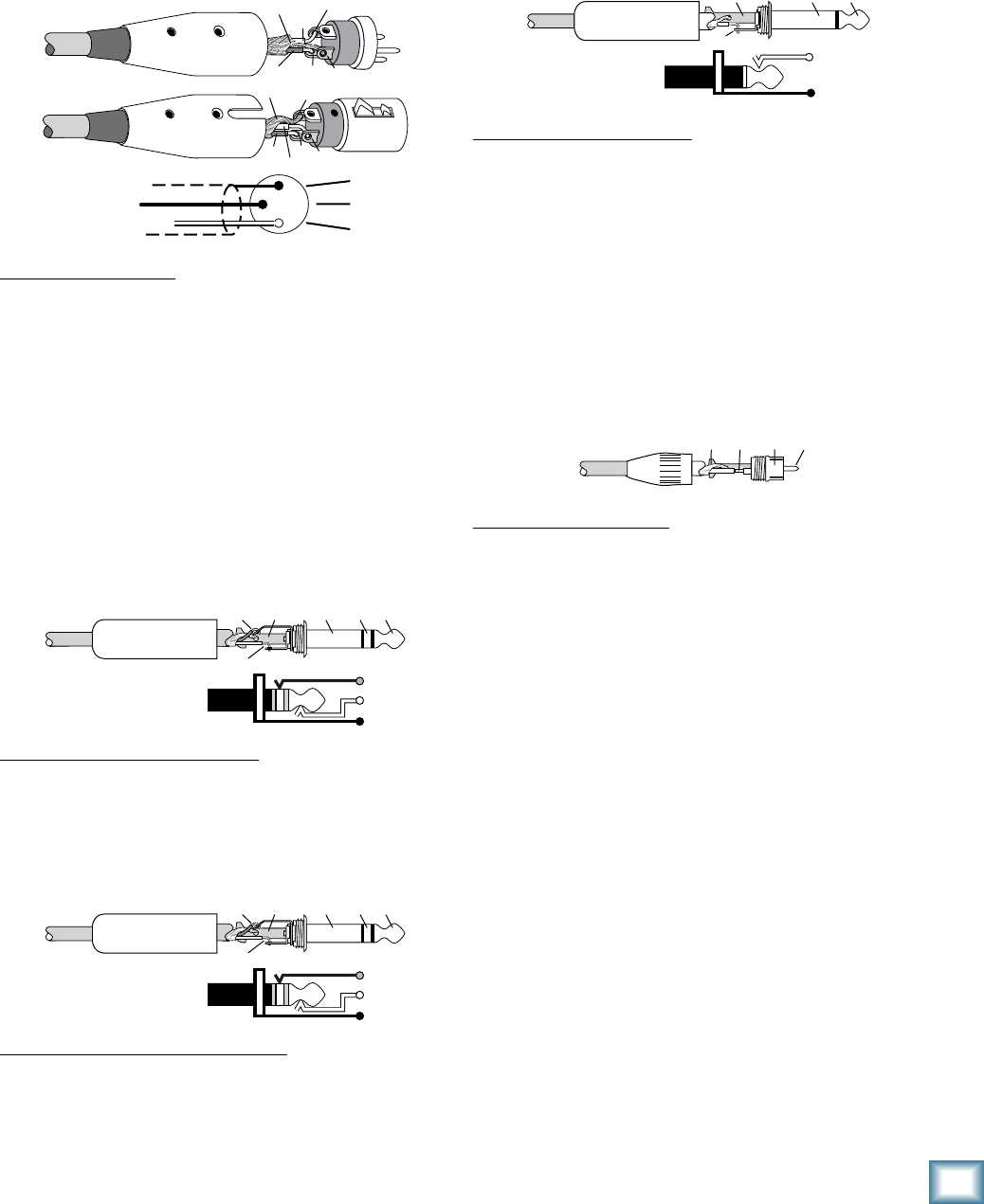
7
Owner’s Manual
Owner’s Manual
Appendix B: Connections
1/4"
TS Phone Plugs and Jacks
“TS” stands for Tip-Sleeve, the two connection points
available on a mono 1/4
"
phone jack or plug. They are
used for unbalanced signals.
SLEEVE
TIP
TIPSLEEVE
TIP
SLEEVE
1/4
"
TS Unbalanced Wiring:
Sleeve = Shield
Tip = Hot (+)
RCA Plugs and Jacks
RCA-type plugs (also known as phono plugs) and jacks
are often used in home stereo and video equipment and
in many other applications. They are unbalanced and
electrically equivalent to a 1/4
"
TS phone plug.
TI
P
SLEEVE
TIPSLEEVE
RCA Unbalanced Wiring:
Sleeve = Shield
Tip = Hot (+)
Unbalancing a Line
In most studio, stage, and sound reinforcement situ-
ations, there is a combination of balanced and unbal-
anced inputs and outputs on the various pieces of
equipment. This usually will not be a problem in making
connections.
• When connecting a balanced output to an unbal-
anced input, be sure the signal high (hot) connec-
tions are wired to each other, and that the balanced
signal low (cold) goes to the ground (earth)
connection at the unbalanced input. In most cases,
the balanced ground (earth) will also be connected
to the ground (earth) at the unbalanced input. If
there are ground-loop problems, this connection
may be left disconnected at the balanced end.
XLR Connectors
The mono channels use 3-pin female XLR connectors
on the MIC inputs. They are wired as follows, according
to standards specified by the AES (Audio Engineering
Society).
2
2
31
1
SHIELD
COLD
HOT
SHIELD
COLD
HOT
3
SHIELD
COLD
HOT
3
2
1
XLR Balanced Wiring:
Pin 1 = Shield
Pin 2 = Hot (+)
Pin 3 = Cold (–)
1/4" TRS Phone Plugs and Jacks
“TRS” stands for Tip-Ring-Sleeve, the three connection
points available on a stereo 1/4
"
or balanced phone
jack or plug. TRS jacks and plugs are used for balanced
signals and stereo headphones:
Balanced Mono
SLEEVE
TIPSLEEVE
TIP
RING
RING
TIP
SLEEVERING
1/4
"
TRS Balanced Mono Wiring:
Sleeve = Shield
Tip = Hot (+)
Ring = Cold (–)
Stereo Headphones
SLEEVE
TIPSLEEVE
TIP
RING
RING
TIP
SLEEVERING
1/4
"
TRS Stereo Unbalanced Wiring:
Sleeve = Shield
Tip = Left
Ring = Right
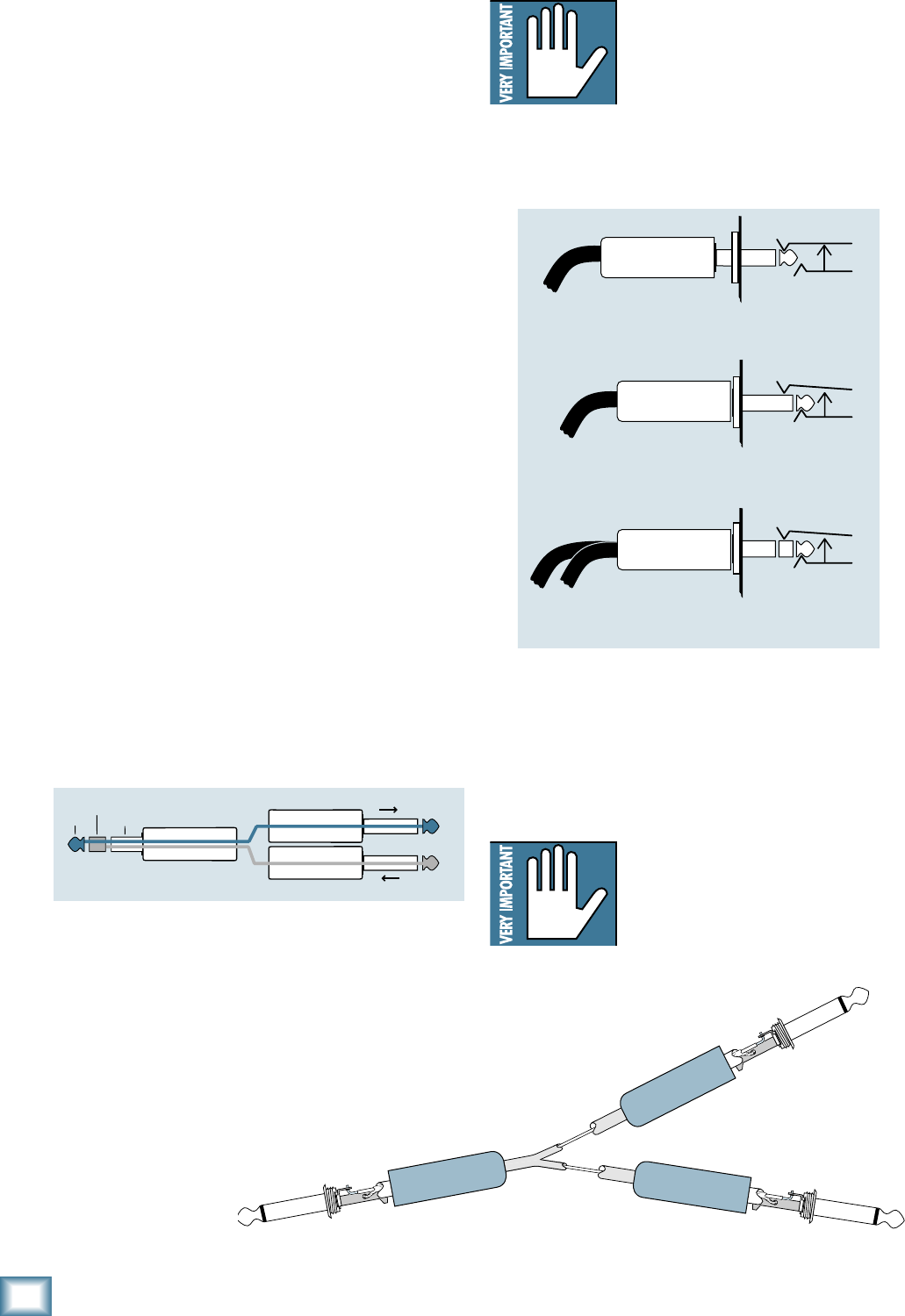
8
ONYX 80 SERIES
ONYX 80 SERIES
• When connecting an unbalanced output to a bal-
anced input, be sure that the signal high (hot)
connections are wired to each other. The unbal-
anced ground (earth) connection should be wired
to the low (cold) and the ground (earth) connec-
tions of the balanced input. If there are ground-loop
problems, try disconnecting the unbalanced ground
(earth) connection from the balanced input ground
(earth) connection, leaving the unbalanced ground
connected to the balanced input low (cold) con-
nection only.
In some cases, you may have to make up special
adapters to interconnect your equipment. For example,
you may need a balanced XLR female connected to an
unbalanced 1/4
"
TS phone plug. Many common adapters
can be found at your local electronics supply store.
The balanced-to-unbalanced connection has been
anticipated in the wiring of Mackie jacks. A 1/4
"
TS plug
inserted into a 1/4
"
TRS balanced input, for example,
will automatically unbalance the input and make all the
right connections. Conversely, a 1/4
"
TRS plug inserted
into a 1/4
"
unbalanced input will not necessarily tie the
ring (low or cold) to ground (earth).
TRS Send/Receive Insert Jacks
Mackie’s single-jack inserts are three-conductor 1/4
"
TRS phone jacks. They are unbalanced, but have both
the mixer output (send) and mixer input (return)
signals in one connector.
The sleeve is the common ground (earth) for both
signals. The send from the mixer to the external unit is
carried on the tip, and the return from the unit to the
mixer is on the ring.
“from tip”
this plug connects to one of the
mixer’s Channel Insert jacks. “to ring”
tip ring
sleeve
SEND to processor
RETURN from processor
(TRS plug)
Using the Send Only on an Insert Jack
If you insert a 1/4
"
TS (mono) plug only partially (to
the first click) into a Mackie insert jack, the plug will
not activate the jack switch and will not open the insert
loop in the circuit (thereby allowing the channel signal
to continue on its merry way through the mixer).
This allows you to tap out the channel’s signal at that
point in the circuit without interrupting normal operation.
Note: Do not overload or short-circuit
the signal you are tapping from the
mixer. That will affect the internal
signal.
If you push the 1/4
"
TS plug in to the second click,
you will open the jack switch and create a direct out,
which does interrupt the signal in that channel.
Direct out with no signal interruption to master.
Insert only to first “click.”
Channel Insert jack
Channel Insert jack
Channel Insert jack
Direct out with signal interruption to master.
Insert all the way in to the second “click.”
For use as an effects loop.
(TIP = SEND to effect, RING = RETURN from effect)
MONO PLUG
MONO PLUG
STEREO
PLUG
Mults and “Y”s
A mult or “Y” connector allows you to route one output
to two or more inputs by simply providing parallel wir-
ing connections. You can make “Y”s and mults for the
outputs of both unbalanced and balanced circuits.
Remember: Only mult or “Y” an
output into several inputs. If you need
to combine several outputs into one
input, you must use a mixer, not a
mult or a “Y.”
Y-Cord Splitter
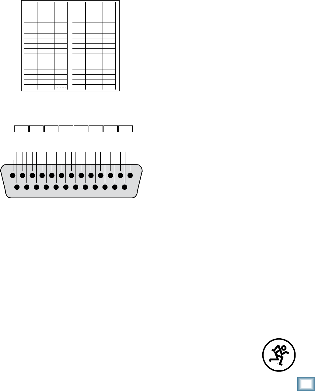
9
Owner’s Manual
Owner’s Manual
DB25 Connectors
The DIRECT OUTS on the back of the Onyx 80 Series
provide balanced direct outputs for all the mono chan-
nels on female DB25 connectors. These connectors are
pin-for-pin compatible with the analog (not TDIF) DB25
connectors found on TASCAM DTRS recorders, which has
become an industry standard for many professional audio
manufacturers. They are also the same pinout as the ana-
log cards for the Mackie D8B and hard disk recorders.
Pin 1 + Ch 8
Pin 2 shield Ch 8
Pin 3 – Ch 7
Pin 4 + Ch 6
Pin 5 shield Ch 6
Pin 6 – Ch 5
Pin 7 + Ch 4
Pin 8 shield Ch 4
Pin 9 – Ch 3
Pin 10 + Ch 2
Pin 11 shield Ch 2
Pin 12 – Ch 1
Pin 13 N/C
Signal
Description
DIRECT
OUTS 1-8
DIRECT
OUTS 1-8
Pin 14 – Ch 8
Pin 15 + Ch 7
Pin 16 shield Ch 7
Pin 17 – Ch 6
Pin 18 + Ch 5
Pin 19 shield Ch 5
Pin 20 – Ch 4
Pin 21 + Ch 3
Pin 22 shield Ch 3
Pin 23 – Ch 2
Pin 24 + Ch 1
Pin 25 shield Ch 1
Signal
Description
12345678910111213
141516171819202122232425
HOT
COLD
GROUND
HOT
COLD
GROUND
HOT
COLD
GROUND
HOT
COLD
GROUND
HOT
COLD
GROUND
HOT
COLD
GROUND
HOT
COLD
GROUND
HOT
COLD
GROUND
CH 1
CH 9
CH 17
CH 25
CH 33
CH 41
N/C
CH 2
CH 10
CH 18
CH 26
CH 34
CH 42
CH 3
CH 11
CH 19
CH 27
CH 35
CH 43
CH 4
CH 12
CH 20
CH 28
CH 36
CH 44
CH 5
CH 13
CH 21
CH 29
CH 37
CH 45
CH 6
CH 14
CH 22
CH 30
CH 38
CH 46
CH 7
CH 15
CH 23
CH 31
CH 39
CH 47
CH 8
CH 16
CH 24
CH 32
CH 40
CH 48
Several companies make DB25-to-DB25 cables specifi-
cally for audio, with proper shielding to reduce crosstalk
and noise.
DB25 cables that break out to XLR, 1/4" TRS, or TT
connectors for connecting to other mixers or audio gear
are also readily available. See your Mackie dealer for
details.
R

0
ONYX 80 SERIES
ONYX 80 SERIES
Appendix C: Technical Info
Onyx 80 Series Specifications
Frequency Response
Mic Input to Main Output (Gain @ Unity)
+0, –1 dB, <10 Hz to 80 kHz
+0, –3 dB, <10 Hz to 130 kHz
Distortion (THD & IMD)
Mic Input to Main Output (@ +4 dBu)
THD: < 0.007% max, 0.005% typical, 20 Hz to 20 kHz
SMPTE IMD: < 0.005% (7 kHz/60 Hz, 4:1)
Dynamic Range
>105 dB, 24 channels assigned
>115 dB, one-channel assigned
Noise Floor
Signal-to-Noise Ratio:
–87 dBu (ref. +4 dBu, Mic In to Main Out,
48 channels and Main Mix levels at unity)
–90 dBu, (ref. +4 dBu, Mic In to Main Out,
24 channels and Main Mix levels at unity)
Equivalent Input Noise (E.I.N.), 20 Hz to 20 kHz Bandwidth,
150Ω source impedance
–129.5 dBu @ +60 dB gain
Mic Output Noise:
Direct Output: –98 dBu (minimum gain)
Residual Output Noise:
Main Out: –100 dBu (Channel and Main Mix levels off)
Main Out: –83 dBu (48 channels and Main Mix levels
at unity)
–86 dBu (24 channels and Main Mix levels
at unity)
Common Mode Rejection Ratio (CMRR)
Mic In: >70 dB @ 1 kHz, Gain @ maximum
Crosstalk
Adjacent Inputs: < –95 dB @ 1 kHz
Input to Output: < –85 dB @ 1 kHz
Input Gain Control Range
Mic In: 0 dB to +60 dB
Line In: –20 dB to + 40 dB, mono channels
Phantom Power
+48 VDC
Equalization
Mono Channel EQ:
High: ±15 dB @ 12 kHz
High Mid:
±15 dB, sweepable from 400 Hz to 8 kHz
Low Mid:
±15 dB, sweepable from 100 Hz to 2 kHz
Low: ±15 dB @ 80 Hz
Stereo Channel (Aux Input) EQ:
High: ±15 dB @ 12 kHz
High Mid:
±15 dB @ 2.5 kHz
Low Mid:
±15 dB @ 400 Hz
Low: ±15 dB @ 80 Hz
Mixer Rated Output
Main Outs: +4 dBu
Aux Send: +4 dBu
Group Send: +4 dBu
Monitor Out: +4 dBu
Matrix Out: +4 dBu
Maximum Rated Output:
+21 dBu @ Main XLR and TRS outputs
Maximum Input Levels
Mic Input: +21 dBu, Gain @ unity
Line Input: +30 dBu, Gain @ –20 dB
Aux Input: +21 dBu
Maximum Voltage Gain
Mic Input to:
Main Out: 90 dB
Group Send: 80 dB
Aux Sends: 86 dB
Monitor Out: 102 dB
Matrix Out: 105 dB
Phones Out: 102 dB
Line Input to:
Main Out: 70 dB
Group Send: 60 dB
Aux Sends: 66 dB
Monitor Out: 82 dB
Matrix Out: 85 dB
Phones Out: 82 dB
Stereo Aux Input to:
Main Out: 50 dB
Group Send: 40 dB
Aux Sends: 39 dB
Monitor Out: 62 dB
Matrix Out: 65 dB
Phones Out: 62 dB
Input Impedance
Mic Input: 2.4 kΩ, balanced
Mono Channel Line Input: 30 kΩ balanced;
15 kΩ unbalanced
Stereo Aux Inputs: 20 kΩ balanced;
20 kΩ unbalanced
Output Impedance
Main Out: 150 Ω balanced, XLR outputs;
150 Ω TRS outputs
Direct Out: 300 Ω
Group Sends: 100 Ω
Monitor Out: 100 Ω
Matrix Out: 100 Ω
Aux Sends: 100 Ω
Phones Out: 25 Ω

1
Owner’s Manual
Owner’s Manual
Channel Level LED (Sensitivity)
0 LED = 0 dBu (normal operating level)
VU Meters
Main and Solo Left and Right, 12 segments:
Clip (+20), +10, +7, +4, +2, 0, –2, –4, –7, –10, –20, –30
0 LED = 0 dBu
AC Power Requirements
Power Consumption:
Onyx 2480 180 watts
Onyx 3280 200 watts
Onyx 4080 220 watts
Onyx 4880 240 watts
Universal AC Power Supply:
100 VAC – 240 VAC, 50-60 Hz
Physical Dimensions and Weight
Onyx 2480
Height: 9.4 in/239 mm
Width: 48.8 in/1240 mm
Depth: 29.6 in/751 mm
Weight: 95 lb/43 kg
Onyx 3280
Height: 9.4 in/239 mm
Width: 60.0 in/1523 mm
Depth: 29.6 in/751 mm
Weight: 113 lb/51 kg
Onyx 4080
Height: 9.4 in/239 mm
Width: 70.4 in/1788 mm
Depth: 29.6 in/751 mm
Weight: 131 lb/59 kg
Onyx 4880
Height: 9.4 in/239 mm
Width: 81.3 in/2065 mm
Depth: 29.6 in/751 mm
Weight: 149 lb/68 kg
Options
Onyx PS External Redundant Power Supply
LOUD Technologies Inc. is always striving to improve our prod-
ucts by incorporating new and improved materials, components,
and manufacturing methods. Therefore, we reserve the right to
change these specifications at any time without notice.
“Mackie.”, “Onyx,” and the “Running Man” are registered
trademarks of LOUD Technologies Inc. All other brand names
mentioned are trademarks or registered trademarks of their
respective holders, and are hereby acknowledged.
©2005-2008 LOUD Technologies Inc. All Rights Reserved.
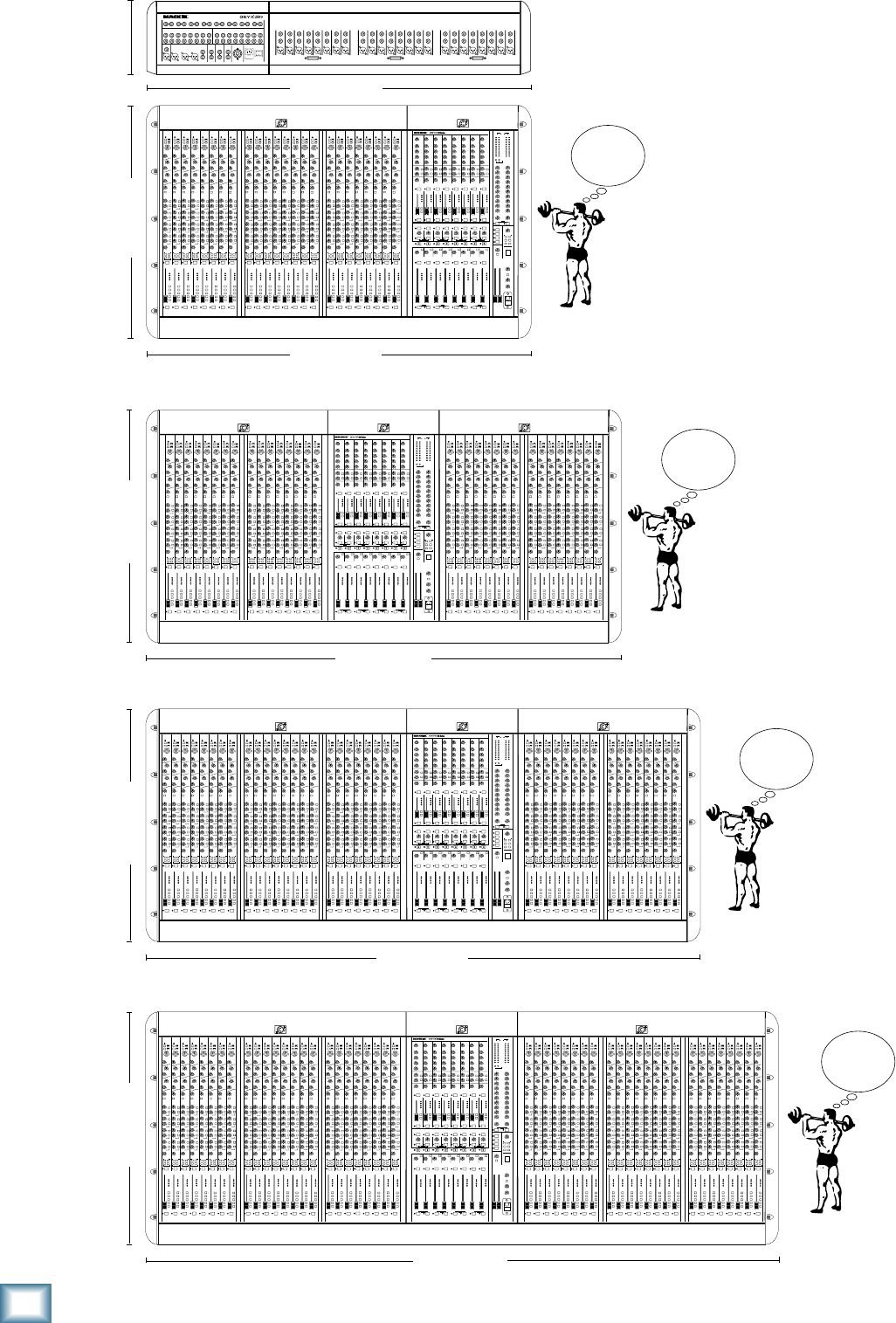
ONYX 80 SERIES
ONYX 80 SERIES
Onyx 80 Series Dimensions
MATRIX
PREMIUM LIVE ANALOG MIXER WITH PERKINS EQ AND ONYX MIC PREAMPS
GROUP
1
MATRIX
MASTER
TALKBACK
LEFT
RIGHT
GROUP
2
GROUP
3
GROUP
4
GROUP
5
GROUP
6
GROUP
7
GROUP
8
POWER
1 2 3 4
2
137
5
4 6 8
5 6 7 8
121110 16151413
9
AUX
SEND
MUTE
9
MUTE GROUP
PFL
10
AUX
SEND
MUTE
MUTE GROUP
PFL
11
AUX
SEND
MUTE
MUTE GROUP
PFL
12
AUX
SEND
MUTE
MUTE GROUP
PFL
13
AUX
SEND
MUTE
MUTE GROUP
PFL
14
AUX
SEND
MUTE
MUTE GROUP
PFL
15
AUX
SEND
MUTE
MUTE GROUP
PFL
16
AUX
SEND
MUTE
MUTE GROUP
PFL
201918 24232221
17
AUX
SEND
MUTE
17
MUTE GROUP
PFL
18
AUX
SEND
MUTE
MUTE GROUP
PFL
19
AUX
SEND
MUTE
MUTE GROUP
PFL
20
AUX
SEND
MUTE
MUTE GROUP
PFL
21
AUX
SEND
MUTE
MUTE GROUP
PFL
22
AUX
SEND
MUTE
MUTE GROUP
PFL
23
AUX
SEND
MUTE
MUTE GROUP
PFL
24
AUX
SEND
MUTE
MUTE GROUP
PFL
1 27 8
5 6 3 4
PAN PAN
PAN PAN PAN PAN
PAN PAN
432 8765
1
AUX
SEND
MUTE
1
MUTE GROUP
PFL
2
AUX
SEND
MUTE
MUTE GROUP
PFL
3
AUX
SEND
MUTE
MUTE GROUP
PFL
4
AUX
SEND
MUTE
MUTE GROUP
PFL
5
AUX
SEND
MUTE
MUTE GROUP
PFL
6
AUX
SEND
MUTE
MUTE GROUP
PFL
7
AUX
SEND
MUTE
MUTE GROUP
PFL
8
AUX
SEND
MUTE
MUTE GROUP
PFL
PAN PAN
PAN PAN PAN PAN
PAN PAN PAN PAN
PAN PAN PAN PAN
PAN PAN
29.6 in/751 mm 9.4 in/239 mm
48.8 in/1240 mm
48.8 in/1240 mm
WEIGHT
95 lb/
43 kg
Onyx 2480
MATRIX
PREMIUM LIVE ANALOG MIXER WITH PERKINS EQ AND ONYX MIC PREAMPS
GROUP
1
MATRIX
MASTER
TALKBACK
LEFT
RIGHT
GROUP
2
GROUP
3
GROUP
4
GROUP
5
GROUP
6
GROUP
7
GROUP
8
POWER
1 2 3 4
2
137
5
4 6 8
5 6 7 8
432 8765
1
AUX
SEND
MUTE
1
MUTE GROUP
PFL
2
AUX
SEND
MUTE
MUTE GROUP
PFL
3
AUX
SEND
MUTE
MUTE GROUP
PFL
4
AUX
SEND
MUTE
MUTE GROUP
PFL
5
AUX
SEND
MUTE
MUTE GROUP
PFL
6
AUX
SEND
MUTE
MUTE GROUP
PFL
7
AUX
SEND
MUTE
MUTE GROUP
PFL
8
AUX
SEND
MUTE
MUTE GROUP
PFL
121110 16151413
9
AUX
SEND
MUTE
9
MUTE GROUP
PFL
10
AUX
SEND
MUTE
MUTE GROUP
PFL
11
AUX
SEND
MUTE
MUTE GROUP
PFL
12
AUX
SEND
MUTE
MUTE GROUP
PFL
13
AUX
SEND
MUTE
MUTE GROUP
PFL
14
AUX
SEND
MUTE
MUTE GROUP
PFL
15
AUX
SEND
MUTE
MUTE GROUP
PFL
16
AUX
SEND
MUTE
MUTE GROUP
PFL
201918 24232221
17
AUX
SEND
MUTE
17
MUTE GROUP
PFL
18
AUX
SEND
MUTE
MUTE GROUP
PFL
19
AUX
SEND
MUTE
MUTE GROUP
PFL
20
AUX
SEND
MUTE
MUTE GROUP
PFL
21
AUX
SEND
MUTE
MUTE GROUP
PFL
22
AUX
SEND
MUTE
MUTE GROUP
PFL
23
AUX
SEND
MUTE
MUTE GROUP
PFL
24
AUX
SEND
MUTE
MUTE GROUP
PFL
282726 32313029
25
AUX
SEND
MUTE
25
MUTE GROUP
PFL
26
AUX
SEND
MUTE
MUTE GROUP
PFL
27
AUX
SEND
MUTE
MUTE GROUP
PFL
28
AUX
SEND
MUTE
MUTE GROUP
PFL
29
AUX
SEND
MUTE
MUTE GROUP
PFL
30
AUX
SEND
MUTE
MUTE GROUP
PFL
31
AUX
SEND
MUTE
MUTE GROUP
PFL
32
AUX
SEND
MUTE
MUTE GROUP
PFL
1 27 8
5 6 3 4
PAN PAN
PAN PAN PAN PAN
PAN PAN PAN PAN
PAN PAN PAN PAN
PAN PAN PAN PAN
PAN PAN PAN PAN
PAN PAN PAN PAN
PAN PAN PAN PAN
PAN PAN
29.6 in/751 mm
60.0 in/1523 mm
WEIGHT
113 lb/
51 kg
Onyx 3280
MATRIX
PREMIUM LIVE ANALOG MIXER WITH PERKINS EQ AND ONYX MIC PREAMPS
GROUP
1
MATRIX
MASTER
TALKBACK
LEFT
RIGHT
GROUP
2
GROUP
3
GROUP
4
GROUP
5
GROUP
6
GROUP
7
GROUP
8
POWER
1 2 3 4
2
137
5
4 6 8
5 6 7 8
121110 16151413
9
AUX
SEND
MUTE
9
MUTE GROUP
PFL
10
AUX
SEND
MUTE
MUTE GROUP
PFL
11
AUX
SEND
MUTE
MUTE GROUP
PFL
12
AUX
SEND
MUTE
MUTE GROUP
PFL
13
AUX
SEND
MUTE
MUTE GROUP
PFL
14
AUX
SEND
MUTE
MUTE GROUP
PFL
15
AUX
SEND
MUTE
MUTE GROUP
PFL
16
AUX
SEND
MUTE
MUTE GROUP
PFL
201918 24232221
17
AUX
SEND
MUTE
17
MUTE GROUP
PFL
18
AUX
SEND
MUTE
MUTE GROUP
PFL
19
AUX
SEND
MUTE
MUTE GROUP
PFL
20
AUX
SEND
MUTE
MUTE GROUP
PFL
21
AUX
SEND
MUTE
MUTE GROUP
PFL
22
AUX
SEND
MUTE
MUTE GROUP
PFL
23
AUX
SEND
MUTE
MUTE GROUP
PFL
24
AUX
SEND
MUTE
MUTE GROUP
PFL
282726 32313029
25
AUX
SEND
MUTE
25
MUTE GROUP
PFL
26
AUX
SEND
MUTE
MUTE GROUP
PFL
27
AUX
SEND
MUTE
MUTE GROUP
PFL
28
AUX
SEND
MUTE
MUTE GROUP
PFL
29
AUX
SEND
MUTE
MUTE GROUP
PFL
30
AUX
SEND
MUTE
MUTE GROUP
PFL
31
AUX
SEND
MUTE
MUTE GROUP
PFL
32
AUX
SEND
MUTE
MUTE GROUP
PFL
363534 40393837
33
AUX
SEND
MUTE
33
MUTE GROUP
PFL
34
AUX
SEND
MUTE
MUTE GROUP
PFL
35
AUX
SEND
MUTE
MUTE GROUP
PFL
36
AUX
SEND
MUTE
MUTE GROUP
PFL
37
AUX
SEND
MUTE
MUTE GROUP
PFL
38
AUX
SEND
MUTE
MUTE GROUP
PFL
39
AUX
SEND
MUTE
MUTE GROUP
PFL
40
AUX
SEND
MUTE
MUTE GROUP
PFL
1 27 8
5 6 3 4
PAN PAN
PAN PAN PAN PAN
PAN PAN
432 8765
1
AUX
SEND
MUTE
1
MUTE GROUP
PFL
2
AUX
SEND
MUTE
MUTE GROUP
PFL
3
AUX
SEND
MUTE
MUTE GROUP
PFL
4
AUX
SEND
MUTE
MUTE GROUP
PFL
5
AUX
SEND
MUTE
MUTE GROUP
PFL
6
AUX
SEND
MUTE
MUTE GROUP
PFL
7
AUX
SEND
MUTE
MUTE GROUP
PFL
8
AUX
SEND
MUTE
MUTE GROUP
PFL
PAN PAN
PAN PAN PAN PAN
PAN PAN PAN PAN
PAN PAN PAN PAN
PAN PAN PAN PAN
PAN PAN PAN PAN
PAN PAN PAN PAN
PAN PAN PAN PAN
PAN PAN
29.6 in/751 mm
70.4 in/1788 mm
WEIGHT
131 lb/
59 kg
Onyx 4080
MATRIX
PREMIUM LIVE ANALOG MIXER WITH PERKINS EQ AND ONYX MIC PREAMPS
GROUP
1
MATRIX
MASTER
TALKBACK
LEFT
RIGHT
GROUP
2
GROUP
3
GROUP
4
GROUP
5
GROUP
6
GROUP
7
GROUP
8
POWER
1 2 3 4
2
137
5
4 6 8
5 6 7 8
121110 16151413
9
AUX
SEND
MUTE
9
MUTE GROUP
PFL
10
AUX
SEND
MUTE
MUTE GROUP
PFL
11
AUX
SEND
MUTE
MUTE GROUP
PFL
12
AUX
SEND
MUTE
MUTE GROUP
PFL
13
AUX
SEND
MUTE
MUTE GROUP
PFL
14
AUX
SEND
MUTE
MUTE GROUP
PFL
15
AUX
SEND
MUTE
MUTE GROUP
PFL
16
AUX
SEND
MUTE
MUTE GROUP
PFL
201910 24232221
17
AUX
SEND
MUTE
17
MUTE GROUP
PFL
18
AUX
SEND
MUTE
8
MUTE GROUP
PFL
19
AUX
SEND
MUTE
MUTE GROUP
PFL
20
AUX
SEND
MUTE
MUTE GROUP
PFL
21
AUX
SEND
MUTE
MUTE GROUP
PFL
22
AUX
SEND
MUTE
MUTE GROUP
PFL
23
AUX
SEND
MUTE
MUTE GROUP
PFL
24
AUX
SEND
MUTE
MUTE GROUP
PFL
282726 32313029
25
AUX
SEND
MUTE
25
MUTE GROUP
PFL
26
AUX
SEND
MUTE
MUTE GROUP
PFL
27
AUX
SEND
MUTE
MUTE GROUP
PFL
28
AUX
SEND
MUTE
MUTE GROUP
PFL
29
AUX
SEND
MUTE
MUTE GROUP
PFL
30
AUX
SEND
MUTE
MUTE GROUP
PFL
31
AUX
SEND
MUTE
MUTE GROUP
PFL
32
AUX
SEND
MUTE
MUTE GROUP
PFL
363534 40393837
33
AUX
SEND
MUTE
33
MUTE GROUP
PFL
34
AUX
SEND
MUTE
MUTE GROUP
PFL
35
AUX
SEND
MUTE
MUTE GROUP
PFL
36
AUX
SEND
MUTE
MUTE GROUP
PFL
37
AUX
SEND
MUTE
MUTE GROUP
PFL
38
AUX
SEND
MUTE
MUTE GROUP
PFL
39
AUX
SEND
MUTE
MUTE GROUP
PFL
40
AUX
SEND
MUTE
MUTE GROUP
PFL
1 27 8
5 6 3 4
PAN PAN
PAN PAN PAN PAN
PAN PAN
432 8765
1
AUX
SEND
MUTE
1
MUTE GROUP
PFL
2
AUX
SEND
MUTE
MUTE GROUP
PFL
3
AUX
SEND
MUTE
MUTE GROUP
PFL
4
AUX
SEND
MUTE
MUTE GROUP
PFL
5
AUX
SEND
MUTE
MUTE GROUP
PFL
6
AUX
SEND
MUTE
MUTE GROUP
PFL
7
AUX
SEND
MUTE
MUTE GROUP
PFL
8
AUX
SEND
MUTE
MUTE GROUP
PFL
PAN PAN
PAN PAN PAN PAN
PAN PAN PAN PAN
PAN PAN PAN PAN
PAN PAN PAN PAN
PAN PAN PAN PAN
PAN PAN PAN PAN
PAN PAN PAN PAN
PAN PAN
444342 48474645
41
AUX
SEND
MUTE
41
MUTE GROUP
PFL
42
AUX
SEND
MUTE
MUTE GROUP
PFL
43
AUX
SEND
MUTE
MUTE GROUP
PFL
44
AUX
SEND
MUTE
MUTE GROUP
PFL
45
AUX
SEND
MUTE
MUTE GROUP
PFL
46
AUX
SEND
MUTE
MUTE GROUP
PFL
47
AUX
SEND
MUTE
MUTE GROUP
PFL
48
AUX
SEND
MUTE
MUTE GROUP
PFL
PAN PAN
PAN PAN PAN PAN
PAN PAN
29.6 in/751 mm
81.3 in/2065 mm
WEIGHT
149 lb/
68 kg
Onyx 4880
Owner’s Manual
Owner’s Manual
Onyx 80 Series Block Diagram
L
R
PFL L
Main
Main Mix L
Main Mix R
Pan
PFL
Aux
Sends
Left
Right
Group 1
Out
Group 2
Out
Aux 1 Out
Aux 1 Level
L Sum
R Sum
Group 1
Group 2
1
2
Group
Aux 1
Aux 1
Group Meters
Assign
Talkback Assign
Talkback Mic
Aux 2
to Aux 1-2
Aux 3
Aux 4
AFL L
AFL R
Mono Out
Mono Level
3
4
Aux 2 Out
Aux 2 Level
Aux 2
Aux 1 AFL
Aux 2 AFL
(Aux 3-8 identical)
Aux 5
Aux 6
(Group 3-8 identical)
Group 1 Level
Group to Main Mix
L
R
L/R
1/2
3/4
to Aux 5-6
.
L Insert
R Insert
in
EQ out Mute
Talkback
Level
Main Out
48V
Mic/Line Inputs
Mic
Line
Insert
HPF
Gain
+
-
Direct Out
LO MID MID
80 100~2K 400~8K 12K
HI
100 Hz
Low Cut
Bypass
Phantom Power
Phase
(1-8)
(9-16)
(17-24)
Aux 7
Aux 8
5
6
7
8
5/6
7/8
L-R
7/8
L
R
PFL L
Main
1
2
Group
Aux 1
Aux 2
Aux 3
Aux 4
AFL L
AFL R
3
4
Aux 5
Aux 6
Aux 7
Aux 8
5
6
7
8
to Aux 3-4
to Aux 7-8
L
R
Mute
Insert
Insert
Insert
Insert
LO MID MID
80 400 2.5K 12K
HI
L
(Mono)
R
Stereo Aux
Inputs 1-8
Group 1 AFL
Group 2 AFL
Group 2 Level
post
pre
Solo Logic
Phones
RUDE
SOLO
LEDS
Phones
Level
PFL L
AFL R
PFL R
Solo Level
Solo Meters Monitor
L Out
Line
Mic 180
0
Post-Fader
Pre-Fader
Aux 3&4
Aux 1&2
Matrix A
Matrix B
Matrix A
Matrix B
Mute
stereo
stereo
stereo
stereo
Main
Meters
Monitor
R Out
Matrix A
Matrix B
to Matrix A
to Matrix A
to Matrix B
to Matrix B
to Matrix A
to Matrix A
to Matrix B
to Matrix B
1
2
Matrix A
Out
Matrix B
Out
Matrix Master
A
B
from Main Level L
R
to Monitor/Phones
Monitor
Level
Fader
Balance
Main Mix to Phones
Off
PFL AFL
Matrix A AFL
Amber-AFL
Green-PFL
Matrix B AFL
AFL L
PFL R
HPF
PFL R
+
-
+
-
Gain
–20 to +20dB
to Main L-R
PFL
Mute Groups
to Group 1-8
jumper
Mute Groups
1
2
3
4
Aux 7&8
Aux 5&6
(Channel 1-4)
(Channel 5-8)
4
3
2
1
Flip 1
Flip 2
Flip button - allows fader,
solo, mute, and metering
to be exchanged
between grp & aux
sends without swapping
outputs
jumper
post-
Mute
pre-
EQ
pre-EQ
post-EQ
Talkback
Out
Talkback
to Talkback Out
Aux Sends
Stereo
Mono
Mic: 0 to +60 dB
Line: –20 to +40 dB
4-Band EQ
OL
0
-20
+10
PFL
Fader
Level 2
3
1
2
3
1
2
3
1
Mute
Mute
Mute
OL
0
-20
+10
OL
0
-20
+10
2
3
1
2
3
1
4-Band EQ
OL
0
-20
+10
NOTE: Switches are shown in the default (out) position.
MACKIE
ONYX 80 SERIES
BLOCK DIAGRAM
(#011205_DB/DF)
4
ONYX 80 SERIES
ONYX 80 SERIES
+30 dBu max in
20 dB loss, TRIM down
40 dB gain, TRIM up
LINE IN, mono channels
MIC IN, mono channels
60 dB gain, TRIM up
0 dB gain, TRIM down
+21 dBu max in +15 dB up
–15 dB
down –15 dB
down –15 dB
down
LOW
+15 dB up
–15 dB
down
LOW MID
+15 dB up
HIGH MID
+15 dB up
HIGH
+10 dB up
FADER PAN ASSIGN
–3 dB center
EQ MUTE MIX
0 dB XLR and 1/4" Out
OUTPUTS
MONO CHANNEL MAIN MIX and GROUPS
to A
to A
AF
From F or G
(MAIN)
G
E
D
B C
0dB
0dB
+12 dB up
OUTPUT
0dB
LEVELLEVEL
MONITOR/PHONES
0 dB
AUX MIX AUX Master
0dB
OUTPUT
AUX SEND
+21 dBu max out (XLR and 1/4" Out)
+21 dBu max out
FADER
OUTPUTS
MONO
LEVEL
+10 dB up
+21 dBu max in
20 dB loss, TRIM down
20 dB gain, TRIM up
LINE IN, stereo channels
0 dB
(Insert
Send)
(Insert
Return)
(Insert
Send)
(Insert
Return)
INSERT
Send INSERT
Return
–6 dB
–6 dB
–6 dB
–0 dB
0 dB
+15 dB up
+10 dB up
SOLO (PFL/AFL)
0dB
MACKIE ONYX 80 SERIES
LEVEL DIAGRAM
012605
+15 dB up
–15 dB
down –15 dB
down –15 dB
down
LOW
+15 dB up
–15 dB
down
LOW MID
+15 dB up
HIGH MID
+15 dB up
HIGH
+10 dB up
FADER
BALANCE ASSIGN
–3 dB center
EQ MUTE
STEREO CHANNEL
‘E’
‘I’‘H’
From A, C, D, H, I
0 dB
+10 dB up
0 dB
0 dB XLR Out
‘F’ ‘G’
+10 dB up
0 dB
MATRIX MIX MATRIX Master
0dB
OUTPUT
MATRIX
+21 dBu max out
–3 dB
From G
(Main and Groups)
From B, G, H From G (MAIN) or K
G
K
G
+15 dB up
0 dB
TALKBACK IN
–50 dB
0 dB
0dB
TB ASSIGN
TALKBACK
LEVEL
Onyx 80 Series Gain Structure Diagram

5
Owner’s Manual
Owner’s Manual
Onyx 80 Series Limited Warranty
A. LOUD Technologies Inc. warrants all materials,
workmanship and proper operation of this product for a period
of one year from the original date of purchase. You may
purchase an additional 24-month Extended Warranty (for a
total of 36 months of coverage). Visit our website and follow
the “Product Registration” links for details (www.mackie.com).
If any defects are found in the materials or workmanship or
if the product fails to function properly during the applicable
warranty period, LOUD Technologies, at its option, will repair
or replace the product.
This warranty applies only to equipment
sold and delivered within the U.S. and Canada by LOUD
Technologies Inc. or its authorized dealers.
B. For faster processing (not to mention a free gift), register
online or mail in the product registration card.
C. Unauthorized service, repairs, or modification of Mackie
products will void this warranty. To obtain repairs or
replacement under warranty, you must have a copy of your
sales receipt from the authorized Mackie dealer where you
purchased the product. It is necessary to establish purchase
date and determine whether your Mackie product is within
the warranty period.
D. To obtain warranty repair or replacement:
1.
Call Mackie Technical Support at 800/898-3211, 7 AM
to 5 PM Monday through Friday (Pacific Time) to get
authorization for repair or replacement. Alternately, go to
the Mackie website, click “Support” (www.mackie.com/
support), and follow the instructions for reporting a warranty
issue and submitting a request for an advance replacement.
2.
Advance Replacement: Mackie will ship a replacement
unit to you along with an invoice for the suggested
retail price of the replacement unit. You must return the
defective unit immediately to cancel the invoice. If you do
not return the defective unit within 30 days, you must pay
the full amount stated in the invoice to satisfy your debt.
3. Repair: When you call Mackie Technical Support,
explain the problem and obtain a Service Request
Number. Have your Mackie product’s serial number
ready. You must have a Service Request Number before
you can obtain factory-authorized service.
• Pack the product in its original shipping carton. Also
include a note explaining exactly how to duplicate the
problem, a copy of the sales receipt with price and date
showing, your daytime phone number and return street
address (no P.O. boxes or route numbers, please!), and
the Service Request Number. If we cannot duplicate the
problem or establish the starting date of your Limited
Warranty, we may, at our option, charge for service time
and parts.
• Ship the product in its original shipping carton,
freight prepaid to the authorized service center. Write
the Service Request Number in BIG PRINT on top of
the box. The address of your closest authorized service
center will be given to you by Technical Support, or it
may be obtained from our website. Once it’s repaired,
the authorized service center will ship it back by ground
shipping, pre-paid (if it qualified as a warranty repair).
Note: Under the terms of the warranty, you must ship
or drop-off the unit to an authorized service center.
The return ground shipment is covered for those units
deemed by us to be under warranty.
Note: You must have a sales receipt from an authorized
Mackie dealer for your unit to be considered for
warranty repair.
IMPORTANT: Make sure that the Service Request Number
is plainly written on the shipping carton. No receipt, no
warranty service.
E. LOUD Technologies reserves the right to inspect any
products that may be the subject of any warranty claims before
repair or replacement is carried out. LOUD Technologies may,
at our option, require proof of the original date of purchase in
the form of a dated copy of the original dealer’s invoice or sales
receipt. Final determination of warranty coverage lies solely
with LOUD Technologies.
F. Any products returned to one of the LOUD Technologies
factory-authorized service centers, and deemed eligible
for repair or replacement under the terms of this warranty
will be repaired or replaced. LOUD Technologies and its
authorized service centers may use refurbished parts for repair
or replacement of any product. Products returned to LOUD
Technologies that do not meet the terms of this Warranty
will not be repaired unless payment is received for labor,
materials, return freight, and insurance. Products repaired
under warranty will be returned freight prepaid by LOUD
Technologies to any location within the boundaries of the USA
or Canada.
G. LOUD Technologies warrants all repairs performed
for 90 days or for the remainder of the warranty period.
This warranty does not extend to damage resulting from
improper installation, misuse, neglect or abuse, or to exterior
appearance. This warranty is recognized only if the inspection
seals and serial number on the unit have not been defaced or
removed.
H. LOUD Technologies assumes no responsibility for the
timeliness of repairs performed by an authorized service
center.
I. This warranty is extended to the original purchaser. This
warranty may be transferred to anyone who may subsequently
purchase this product within the applicable warranty period
for a nominal fee. A copy of the original sales receipt is
required to obtain warranty repairs or replacement.
J. This is your sole warranty. LOUD Technologies does not
authorize any third party, including any dealer or sales
representative, to assume any liability on behalf of LOUD
Technologies or to make any warranty for LOUD Technologies
Inc.
K. THE WARRANTY GIVEN ON THIS PAGE IS THE SOLE
WARRANTY GIVEN BY LOUD TECHNOLOGIES INC.
AND IS IN LIEU OF ALL OTHER WARRANTIES, EXPRESS
AND IMPLIED, INCLUDING THE WARRANTIES OF
MERCHANTABILITY AND FITNESS FOR A PARTICULAR
PURPOSE. THE WARRANTY GIVEN ON THIS PAGE SHALL BE
STRICTLY LIMITED IN DURATION TO ONE YEAR FROM THE
DATE OF ORIGINAL PURCHASE FROM AN AUTHORIZED
MACKIE DEALER. UPON EXPIRATION OF THE APPLICABLE
WARRANTY PERIOD, LOUD TECHNOLOGIES INC. SHALL
HAVE NO FURTHER WARRANTY OBLIGATION OF ANY
KIND. LOUD TECHNOLOGIES INC. SHALL NOT BE LIABLE
FOR ANY INCIDENTAL, SPECIAL, OR CONSEQUENTIAL
DAMAGES THAT MAY RESULT FROM ANY DEFECT IN THE
MACKIE PRODUCT OR ANY WARRANTY CLAIM. Some states
do not allow exclusion or limitation of incidental, special, or
consequential damages or a limitation on how long warranties
last, so some of the above limitations and exclusions may not
apply to you. This warranty provides specific legal rights and
you may have other rights which vary from state to state.
Please keep your sales receipt in a safe place.

