Dimâge Scan Multi II Os2883_2e Os2883 2e
User Manual: os2883_2e
Open the PDF directly: View PDF ![]() .
.
Page Count: 125 [warning: Documents this large are best viewed by clicking the View PDF Link!]
Software Instruction Man
Software Instruction Manual
ual

– 2 –
• This manual may not be copied in part or whole without prior written permission from Minolta
Co., Ltd. © 2000 Minolta Co., Ltd.
• Every necessary caution has been taken to ensure the accuracy of this instruction manual.
Please contact us if you have any questions, find any errors, or notice missing information.
• Minolta is not responsible for loss, damage, or other results occurring during the operation of
this product.
• Microsoft, Windows®, Windows 95®, Windows 98®, Windows 2000®, and Windows NT®are
registered trademarks of the Microsoft Corporation.
• Macintosh™, Apple®, and Power Macintosh®are registered trademarks of Apple Computer, Inc.
• Adobe®and Photoshop™ are registered trademarks of Adobe Systems Incorporated.
• Digital ROC2™, Digital ROC™, and Digital GEM™ are trademarks of Applied Science Fiction in
U. S. A.
• Other corporate and product names are the trademarks and registered trademarks of their
respective companies.
Thank you for purchasing the Minolta Dimâge Scan Multi II. The Dimâge Scan Multi II is a
multiple format film scanner capable of scanning medium-format, 35mm, 16mm, and sleeved
APS film. With the optional APS adapter, advanced photo system film in the cassette can also be
scanned.
This manual has been designed to help you understand the operation of your scanner. To realize
all the benefits of your scanner, please read this manual and the accompanying hardware manual
thoroughly.
The instructions in this manual assume you have a working knowledge of the operating system
for your computer (Macintosh OS, Windows®95, Windows®98, Windows®2000, or Windows®NT)
and its conventions. Familiarity with the mouse and standard operating system menus and
commands is necessary before operating the Dimâge Scan Multi II software.
This manual does not instruct in the:
• basic use of personal computers.
• use of Window®95, Windows®98, Windows®2000, Windows®NT, or Mac OS.
• use of Adobe Photoshop, Paint Shop Pro, or Corel PHOTO-PAINT.
The examples in this manual use Windows software. The appearance of some screens may differ
from the examples when using Windows NT or the Macintosh operating system.

– 3 –
TABLE OF CONTENTS
SYSTEM REQUIREMENTS – PC/AT . . . . . . . . . . . . . . . . . . . . . . . . . . . . . . . . . .7
SYSTEM REQUIREMENTS – MACINTOSH . . . . . . . . . . . . . . . . . . . . . . . . . . . . .8
INSTALL THE SOFTWARE . . . . . . . . . . . . . . . . . . . . . . . . . . . . . . . . . . . . . . . . .9
WINDOWS 95/98/98SE/2000/NT4.0 . . . . . . . . . . . . . . . . . . . . . . . . . . . . . . . . . . . . . . . . . . . . . . . . . . . . . . . . .9
MACINTOSH . . . . . . . . . . . . . . . . . . . . . . . . . . . . . . . . . . . . . . . . . . . . . . . . . . . . . . . . . . . . . . . . . . . . . . . . . .12
INSTALL THE PLUG-IN – MACINTOSH . . . . . . . . . . . . . . . . . . . . . . . . . . . . . . . . . . . . . . . . . . . . . . . . . . . . .14
STARTING UP THE SOFTWARE – WINDOWS . . . . . . . . . . . . . . . . . . . . . . . . .15
WINDOWS 95/98/98SE/2000/NT . . . . . . . . . . . . . . . . . . . . . . . . . . . . . . . . . . . . . . . . . . . . . . . . . . . . . . . . . . .15
STARTING UP THE SOFTWARE – MACINTOSH . . . . . . . . . . . . . . . . . . . . . . .17
THE FLOW CHART TO PRESCAN . . . . . . . . . . . . . . . . . . . . . . . . . . . . . . . . . .18
MAIN WINDOW . . . . . . . . . . . . . . . . . . . . . . . . . . . . . . . . . . . . . . . . . . . . . . . . .19
MAIN WINDOW – NAMES OF PARTS . . . . . . . . . . . . . . . . . . . . . . . . . . . . . . . . . . . . . . . . . . . . . . . . . . . . . . .19
SELECTING THE FILM FORMAT . . . . . . . . . . . . . . . . . . . . . . . . . . . . . . . . . . . . . . . . . . . . . . . . . . . . . . . . . .20
SELECTING THE FILM TYPE . . . . . . . . . . . . . . . . . . . . . . . . . . . . . . . . . . . . . . . . . . . . . . . . . . . . . . . . . . . . .21
INDEX SCAN . . . . . . . . . . . . . . . . . . . . . . . . . . . . . . . . . . . . . . . . . . . . . . . . . . .22
INDEX WINDOW – NAMES OF PARTS . . . . . . . . . . . . . . . . . . . . . . . . . . . . . . . . . . . . . . . . . . . . . . . . . . . . . .22
MAKING AN INDEX SCAN . . . . . . . . . . . . . . . . . . . . . . . . . . . . . . . . . . . . . . . . . . . . . . . . . . . . . . . . . . . . . . .23
SELECTING INDEX IMAGE . . . . . . . . . . . . . . . . . . . . . . . . . . . . . . . . . . . . . . . . . . . . . . . . . . . . . . . . . . . . . .24
SELECTING FRAMES . . . . . . . . . . . . . . . . . . . . . . . . . . . . . . . . . . . . . . . . . . . . . . . . . . . . . . . . . . . . . . . . . .24
ROTATING THE INDEX FRAMES . . . . . . . . . . . . . . . . . . . . . . . . . . . . . . . . . . . . . . . . . . . . . . . . . . . . . . . . . .25
FLIPPING THE INDEX FRAMES . . . . . . . . . . . . . . . . . . . . . . . . . . . . . . . . . . . . . . . . . . . . . . . . . . . . . . . . . . .25
MAGNIFYING THE INDEX IMAGE . . . . . . . . . . . . . . . . . . . . . . . . . . . . . . . . . . . . . . . . . . . . . . . . . . . . . . . . .26
REVERSING THE INDEX IMAGE . . . . . . . . . . . . . . . . . . . . . . . . . . . . . . . . . . . . . . . . . . . . . . . . . . . . . . . . . .27
SAVING AFTER LINING UP THE INDEX SCAN IMAGES . . . . . . . . . . . . . . . . . . . . . . . . . . . . . . . . . . . . . . . .28
SAVING THE INDEX SCAN IMAGES AS AN INDEX FILE . . . . . . . . . . . . . . . . . . . . . . . . . . . . . . . . . . . . . . . .30
LOADING THE INDEX SCAN IMAGES SAVED AS THE INDEX FILE . . . . . . . . . . . . . . . . . . . . . . . . . . . . . . .31
PRESCAN . . . . . . . . . . . . . . . . . . . . . . . . . . . . . . . . . . . . . . . . . . . . . . . . . . . . .32
MAKING A PRESCAN . . . . . . . . . . . . . . . . . . . . . . . . . . . . . . . . . . . . . . . . . . . . . . . . . . . . . . . . . . . . . . . . . .32
PRESCAN TAB – NAMES OF PARTS . . . . . . . . . . . . . . . . . . . . . . . . . . . . . . . . . . . . . . . . . . . . . . . . . . . . . . .33
ROTATING THE PRESCAN IMAGE . . . . . . . . . . . . . . . . . . . . . . . . . . . . . . . . . . . . . . . . . . . . . . . . . . . . . . . . .34
FLIPPING THE PRESCAN IMAGE . . . . . . . . . . . . . . . . . . . . . . . . . . . . . . . . . . . . . . . . . . . . . . . . . . . . . . . . .34
FULL-SCREEN VIEW . . . . . . . . . . . . . . . . . . . . . . . . . . . . . . . . . . . . . . . . . . . . . . . . . . . . . . . . . . . . . . . . . . .35
MAGNIFYING OR REDUCING THE VIEW . . . . . . . . . . . . . . . . . . . . . . . . . . . . . . . . . . . . . . . . . . . . . . . . . . .36
SCROLLING THE VIEW . . . . . . . . . . . . . . . . . . . . . . . . . . . . . . . . . . . . . . . . . . . . . . . . . . . . . . . . . . . . . . . . .37
AUTO EXPOSURE LOCK . . . . . . . . . . . . . . . . . . . . . . . . . . . . . . . . . . . . . . . . . . . . . . . . . . . . . . . . . . . . . . . .38
AE AREA LOCK . . . . . . . . . . . . . . . . . . . . . . . . . . . . . . . . . . . . . . . . . . . . . . . . . . . . . . . . . . . . . . . . . . . . . . .39
FOCUS . . . . . . . . . . . . . . . . . . . . . . . . . . . . . . . . . . . . . . . . . . . . . . . . . . . . . . . . . . . . . . . . . . . . . . . . . . . . . .40
POINT AF . . . . . . . . . . . . . . . . . . . . . . . . . . . . . . . . . . . . . . . . . . . . . . . . . . . . . . . . . . . . . . . . . . . . . . . . . . . .40
MANUAL FOCUS . . . . . . . . . . . . . . . . . . . . . . . . . . . . . . . . . . . . . . . . . . . . . . . . . . . . . . . . . . . . . . . . . . . . . .41
AUTO CROPPING . . . . . . . . . . . . . . . . . . . . . . . . . . . . . . . . . . . . . . . . . . . . . . . . . . . . . . . . . . . . . . . . . . . . .42
MANUAL CROPPING . . . . . . . . . . . . . . . . . . . . . . . . . . . . . . . . . . . . . . . . . . . . . . . . . . . . . . . . . . . . . . . . . . .43
APS FORMATS; C, H, AND P . . . . . . . . . . . . . . . . . . . . . . . . . . . . . . . . . . . . . . . . . . . . . . . . . . . . . . . . . . . . .45
DISPLAYING FRAME NUMBER . . . . . . . . . . . . . . . . . . . . . . . . . . . . . . . . . . . . . . . . . . . . . . . . . . . . . . . . . . .46
RGB/CMY INFO . . . . . . . . . . . . . . . . . . . . . . . . . . . . . . . . . . . . . . . . . . . . . . . . . . . . . . . . . . . . . . . . . . . . . . .46

– 4 –
TABLE OF CONTENTS
IMAGE CORRECTION . . . . . . . . . . . . . . . . . . . . . . . . . . . . . . . . . . . . . . . . . . . .47
PRESCAN TAB – NAMES OF PARTS . . . . . . . . . . . . . . . . . . . . . . . . . . . . . . . . . . . . . . . . . . . . . . . . . . . . . . .47
TONE CURVES AND HISTOGRAM . . . . . . . . . . . . . . . . . . . . . . . . . . . . . . . . . . . . . . . . . . . . . . . . . . . . . . . .48
CORRECTING THE TONE CURVES . . . . . . . . . . . . . . . . . . . . . . . . . . . . . . . . . . . . . . . . . . . . . . . . . . . . . . . .49
TONE CURVES BY FREEHAND . . . . . . . . . . . . . . . . . . . . . . . . . . . . . . . . . . . . . . . . . . . . . . . . . . . . . . . . . . .50
SPECIFYING THE BLACK, WHITE OR GRAY POINT . . . . . . . . . . . . . . . . . . . . . . . . . . . . . . . . . . . . . . . . . . .51
CORRECTING THE HISTOGRAM . . . . . . . . . . . . . . . . . . . . . . . . . . . . . . . . . . . . . . . . . . . . . . . . . . . . . . . . . .54
CORRECTING THE HISTOGRAM – AUTO SETTING . . . . . . . . . . . . . . . . . . . . . . . . . . . . . . . . . . . . . . . . . . .54
CORRECTING THE HISTOGRAM – EACH R, G, B CHANNEL . . . . . . . . . . . . . . . . . . . . . . . . . . . . . . . . . . . .55
CORRECTING THE HISTOGRAM – RESET . . . . . . . . . . . . . . . . . . . . . . . . . . . . . . . . . . . . . . . . . . . . . . . . . .55
CORRECTING BRIGHTNESS/CONTRAST/COLOR BALANCE . . . . . . . . . . . . . . . . . . . . . . . . . . . . . . . . . . . .56
CORRECTING BRIGHTNESS/CONTRAST/COLOR BALANCE – AUTO SETTING . . . . . . . . . . . . . . . . . . . . .57
CORRECTING BRIGHTNESS/CONTRAST/COLOR BALANCE – RESET . . . . . . . . . . . . . . . . . . . . . . . . . . . .57
CORRECTING HUE/SATURATION/LIGHTNESS . . . . . . . . . . . . . . . . . . . . . . . . . . . . . . . . . . . . . . . . . . . . . . .58
CORRECTING HUE/SATURATION/LIGHTNESS – AUTO SETTING . . . . . . . . . . . . . . . . . . . . . . . . . . . . . . . .59
CORRECTING HUE/SATURATION/LIGHTNESS – RESET . . . . . . . . . . . . . . . . . . . . . . . . . . . . . . . . . . . . . . .59
VARIATION CORRECTION . . . . . . . . . . . . . . . . . . . . . . . . . . . . . . . . . . . . . . . . . . . . . . . . . . . . . . . . . . . . . . .60
VARIATION CORRECTION – COLOR BALANCE . . . . . . . . . . . . . . . . . . . . . . . . . . . . . . . . . . . . . . . . . . . . . .61
VARIATION CORRECTION – BRIGHTNESS & CONTRAST CORRECTION . . . . . . . . . . . . . . . . . . . . . . . . . .62
VARIATION CORRECTION – SATURATION CORRECTION . . . . . . . . . . . . . . . . . . . . . . . . . . . . . . . . . . . . . .63
CANCELLING THE IMAGE CORRECTION . . . . . . . . . . . . . . . . . . . . . . . . . . . . . . . . . . . . . . . . . . . . . . . . . . .64
REDO THE CORRECTION . . . . . . . . . . . . . . . . . . . . . . . . . . . . . . . . . . . . . . . . . . . . . . . . . . . . . . . . . . . . . . .64
DELETING THE IMAGE CORRECTION (DELETING ALL THE IMAGE CORRECTIONS) . . . . . . . . . . . . . . . .64
SNAPSHOT . . . . . . . . . . . . . . . . . . . . . . . . . . . . . . . . . . . . . . . . . . . . . . . . . . . . . . . . . . . . . . . . . . . . . . . . . .65
IMAGE CORRECTION JOB . . . . . . . . . . . . . . . . . . . . . . . . . . . . . . . . . . . . . . . . . . . . . . . . . . . . . . . . . . . . . .66
IMAGE CORRECTION JOB – SAVING IMAGE CORRECTION JOB . . . . . . . . . . . . . . . . . . . . . . . . . . . . . . . .66
IMAGE CORRECTION JOB – LOADING IMAGE CORRECTION JOB . . . . . . . . . . . . . . . . . . . . . . . . . . . . . . .67
CHECKING THE CORRECTION RESULT WHILE LINING UP IMAGES . . . . . . . . . . . . . . . . . . . . . . . . . . . . . .68
FULL-SCREEN VIEWING THE POST-CORRECTION IMAGE . . . . . . . . . . . . . . . . . . . . . . . . . . . . . . . . . . . . .68
DIGITAL ROC/GEM . . . . . . . . . . . . . . . . . . . . . . . . . . . . . . . . . . . . . . . . . . . . . .69
DIGITAL ROC . . . . . . . . . . . . . . . . . . . . . . . . . . . . . . . . . . . . . . . . . . . . . . . . . . . . . . . . . . . . . . . . . . . . . . . . .69
DIGITAL GEM . . . . . . . . . . . . . . . . . . . . . . . . . . . . . . . . . . . . . . . . . . . . . . . . . . . . . . . . . . . . . . . . . . . . . . . . .70
THE FLOW CHART TO THE FINAL SCAN . . . . . . . . . . . . . . . . . . . . . . . . . . . .74
JOB . . . . . . . . . . . . . . . . . . . . . . . . . . . . . . . . . . . . . . . . . . . . . . . . . . . . . . . . . .75
LOADING A JOB . . . . . . . . . . . . . . . . . . . . . . . . . . . . . . . . . . . . . . . . . . . . . . . . . . . . . . . . . . . . . . . . . . . . . . .76
CATEGORIES . . . . . . . . . . . . . . . . . . . . . . . . . . . . . . . . . . . . . . . . . . . . . . . . . . . . . . . . . . . . . . . . . . . . . . . . .77
FINAL SCAN . . . . . . . . . . . . . . . . . . . . . . . . . . . . . . . . . . . . . . . . . . . . . . . . . . .78

– 5 –
TABLE OF CONTENTS
SCAN SETTINGS WINDOW . . . . . . . . . . . . . . . . . . . . . . . . . . . . . . . . . . . . . . .80
SCAN SETTINGS WINDOW – NAMES OF PARTS . . . . . . . . . . . . . . . . . . . . . . . . . . . . . . . . . . . . . . . . . . . . .80
REGARDING THE SETTING ITEMS OF THE SCAN SETTINGS WINDOW . . . . . . . . . . . . . . . . . . . . . . . . . . .81
EXAMPLE OF THE SCAN SETTING – WHEN DISPLAYING IN A MONITOR . . . . . . . . . . . . . . . . . . . . . . . . .84
EXAMPLE OF THE SCAN SETTING – WHEN PRINTING A SCANNED IMAGE . . . . . . . . . . . . . . . . . . . . . . .85
REGISTERING A JOB . . . . . . . . . . . . . . . . . . . . . . . . . . . . . . . . . . . . . . . . . . . . . . . . . . . . . . . . . . . . . . . . . .86
DELETING A JOB . . . . . . . . . . . . . . . . . . . . . . . . . . . . . . . . . . . . . . . . . . . . . . . . . . . . . . . . . . . . . . . . . . . . . .87
SETTING THE PREFERENCES . . . . . . . . . . . . . . . . . . . . . . . . . . . . . . . . . . . . .88
THE DISPLAY IN THE PREFERENCES WINDOW . . . . . . . . . . . . . . . . . . . . . . . . . . . . . . . . . . . . . . . . . . . . .88
REGARDING THE SETTING ITEMS OF THE PREFERENCES WINDOW . . . . . . . . . . . . . . . . . . . . . . . . . . . .89
COLOR MATCHING . . . . . . . . . . . . . . . . . . . . . . . . . . . . . . . . . . . . . . . . . . . . . . . . . . . . . . . . . . . . . . . . . . . .92
COLOR MATCHING – THE SETTING OF OUTPUT COLOR IMAGE . . . . . . . . . . . . . . . . . . . . . . . . . . . . . . . .92
REGARDING OUTPUT COLOR SPACE SETTINGS AVAILABLE . . . . . . . . . . . . . . . . . . . . . . . . . . . . . . . . . .93
COLOR MATCHING – THE SETTING OF ICC PROFILE . . . . . . . . . . . . . . . . . . . . . . . . . . . . . . . . . . . . . . . . .95
NAVIGATION . . . . . . . . . . . . . . . . . . . . . . . . . . . . . . . . . . . . . . . . . . . . . . . . . . .96
THE AUTOMATIC OPERATION BY THE NAVIGATION FUNCTION . . . . . . . . . . . . . . . . . . . . . . . . . . . . . . . . .98
INPUTTING THE NAME OF NAVIGATION SET AND SAVING IT . . . . . . . . . . . . . . . . . . . . . . . . . . . . . . . . . .100
SELECTING A NAVIGATION SET . . . . . . . . . . . . . . . . . . . . . . . . . . . . . . . . . . . . . . . . . . . . . . . . . . . . . . . . .100
DELETING A NAVIGATION SET . . . . . . . . . . . . . . . . . . . . . . . . . . . . . . . . . . . . . . . . . . . . . . . . . . . . . . . . . .101
SLIDE FEEDER (OPTIONAL ACCESSORY) . . . . . . . . . . . . . . . . . . . . . . . . . .102
LOADING TIME – WINDOWS . . . . . . . . . . . . . . . . . . . . . . . . . . . . . . . . . . . . . .104
LOADING TIME – MACINTOSH . . . . . . . . . . . . . . . . . . . . . . . . . . . . . . . . . . . .105
JOB FILE LIST – 35 MM . . . . . . . . . . . . . . . . . . . . . . . . . . . . . . . . . . . . . . . . .106
JOB FILE LIST – 6 X 4.5 . . . . . . . . . . . . . . . . . . . . . . . . . . . . . . . . . . . . . . . . .108
JOB FILE LIST – 6 X 6 . . . . . . . . . . . . . . . . . . . . . . . . . . . . . . . . . . . . . . . . . .110
JOB FILE LIST – 6 X 7 . . . . . . . . . . . . . . . . . . . . . . . . . . . . . . . . . . . . . . . . . .112
JOB FILE LIST – 6 X 8 . . . . . . . . . . . . . . . . . . . . . . . . . . . . . . . . . . . . . . . . . .114
JOB FILE LIST – 6 X 9 . . . . . . . . . . . . . . . . . . . . . . . . . . . . . . . . . . . . . . . . . .116
JOB FILE LIST – APS . . . . . . . . . . . . . . . . . . . . . . . . . . . . . . . . . . . . . . . . . . .118
JOB FILE LIST – 16 MM . . . . . . . . . . . . . . . . . . . . . . . . . . . . . . . . . . . . . . . . .120
JOB FILE LIST – CENTER AREA 2820 . . . . . . . . . . . . . . . . . . . . . . . . . . . . .122

– 6 –
Please register this software before using it.
You will receive technical support, as well as software upgrade and product information once this
software is registered. Complete and return the enclosed Product & Software Registration form
after detaching it from the Warranty. No postage is necessary.
• The information provided in the questionnaire will only be used for Minolta customer service
and product research & development. The information you provide will be kept private and
confidential.
The Dimage Scan Multi II and the supplied software are not designed for use with sepia color
film. However, if you intend to use sepia color film, select Color Negative in the film type (p.xx).
After the final scan, retouch the saved image using the image editing application so that a
sepia tone is reproduced.
Also, when scanning sepia color film with an APS cassette, [The film type cannot be selected.]
appears if the Auto Detect (color) is selected in the film type. In this case, select Color
Negative and perform the final scan. After the final scan, retouch the saved image using the
image editing application so that a sepia tone is reproduced.
SOFTWARE REGISTRATION

– 7 –
SYSTEM REQUIREMENTS – PC/AT
CPU: IBM PC/AT compatible with an Intel Pentium processor 90 MHz or above.
• Support cannot be provided for custom or home built machines.
Pentium III Processor is recommended when loading with 16 bit or using the
Digital ROC/GEM functions.
Orerating System: Windows®95 (inc. OSR2), Windows®98 (inc. Second Edition),
Windows®2000 Professional, Windows®NT 4.0
Memory: A minimum of 32 MB (megabytes) of RAM.
A minimum of 512 MB when loading with 16 bit and using the Digital
ROC/GEM functions.
Hard Disk Space: About 600 MB or more of available hard disk space.
About 2 GB or more of available hard disk space when loading with 16 bit
and using the Digital ROC/GEM functions. (About 3 GB or more is
recommended.)
Monitor: Minimum VGA (640 x 480) monitor capable of displaying High Color (16 bit)
is required. XGA (1024 x 768) or larger is recommended.
CD-ROM Drive: Necessary (when installing the software.)
Recommended SCSI Board:
Adaptec AHA-1510B, AHA-1520B, AHA-1540CP, AHA-2910B, AHA-2910C,
AHA-2920C, AHA-2940, AHA-2940U/W/AU/UW/U2W, SCSI Card
19160/29160/29160N, AVA-2902E/2903B/2906
Other: Photoshop Ver. 3.0.5, Ver.4.0.1, Ver. 5.0.2, Ver. 5.5, Photoshop 5.0 LE, Paint
Shop Pro Ver. 6, Corel PHOTO-PAINT Ver. 9* have been fully tested for use
with the TWAIN driver software.
*Corel Scan is not recommended.

– 8 –
CPU: Power PC, Power Macintosh G3, Blue & White Power Macintosh G3 and
Power Macintosh G4
(Except for 68 K Macintosh and Mac OS compatible unit)
Power Macintosh G4 is recommended when loading with 16 bit and using
the Digital ROC/GEM functions.
Operation System: Mac OS 7.5.3 to 9.0.4
Memory: A minimum of 32 MB (megabytes) application RAM in addition to the
requirements for the Mac OS.
256 MB or more when loading with 16 bit and using the Digital ROC/GEM
functions.
Hard Disk Space: About 600 MB or more of available hard disk space.
About 2 GB or more of available hard disk space when loading with 16 bit
and using the Digital ROC/GEM functions. (About 3 GB or more is
recommended.)
Monitor: Minimum 13 (640 x 480) inch monitor capable of displaying at least 32,000
Colors.
19 inch(1024 x 768) or larger is recommended.
CD-ROM Drive: Necessary (when installing the software.)
Recommended SCSI Board:
With a Power Macintosh and Power Macintosh G3
The standard built-in SCSI board
Connecting to the extension board inserted into the PCI bus/NuBus is not
available.)
With a Blue & White Power Macintosh G3*, Power Macintosh G4
Adaptec PowerDomain 2940UW/U2W, PowerDomain 2930U, SCSI Card
2906, and AVA-2903B
* Some models in the Blue & White Power Macintosh G3 series use the
Ultra2 Wide SCSI board as the standard built-in SCSI board, however,
connecting the Dimage Scan Multi II to the standard built-in SCSI board is
not recommended. The connecting capacity may be limited and the full
capabilities of the PC may not be usable due to the specifications of the
standard built-in SCSI board.
When using the model which has the standard built-in SCSI board, insert
the recommended SCSI board as described above in the open slot without
detaching the standard built-in SCSI board and then connect the Dimage
Scan Multi II to the SCSI connctor on the inserted SCSI board.
Other: Adobe PhotoShop Ver. 4.0.1, Ver. 5.0.2, Ver. 5.5 and Adobe Photoshop 5.0
LE have been fully tested for use with the plug-in software.
SYSTEM REQUIREMENTS – MACINTOSH
– 9 –
To use the Dimage Scan Multi II, install the software by following the procedure below.
CAUTION – Before installing
• Make sure that the Damage Scan Multi II is connected to your PC correctly. For connecting the
Dimage Scan Multi II to the PC, refer to the hardware instruction manual.
• The antivirus system extensions may conflict with the operation of this installer. Remove or
disable any extensions before launching this installer and replace or re-enable them when
installations are complete.
INSTALL THE SOFTWARE
These installation instructions assume drive C or D is the CD-ROM drive or the startup disk drive
respectively.
WINDOWS 95/98/98SE/2000/NT4.0
Turn on the Dimâge Scan Multi II.
1
Turn on the PC and start up Windows.
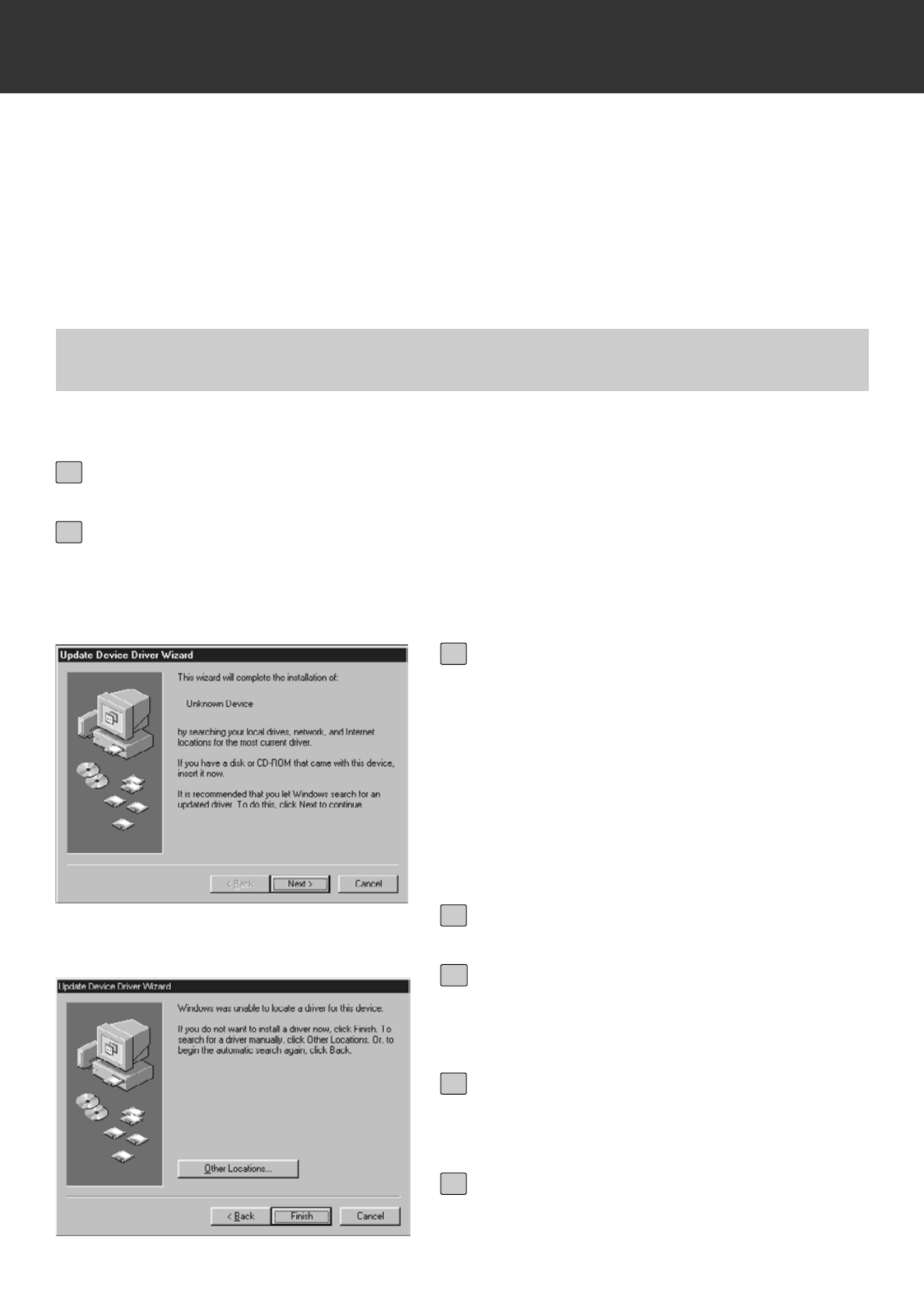
• The“[New Hardware Found” window will appear.
2
Click on [Next >] in the first dialog
box.
3a
Click on [Finish] in the second dialog
box.
3b
Select “Do not install a driver.” and
click on [OK].
• This dialog box may appear several times.
Repeat step 3 until the dialog box no longer
appears.
3
FOR WINDOWS 2000/NT4.0
FOR WINDOWS 95 RELEASE 2 (OSR2)
• The 2 dialog boxes shown on the left will
appear.
Click on [Next >] until [Finish]
appears and Click on [Finish] at last.
3
Insert the Dimâge Scan Multi II CD-
ROM into the CD-ROM drive.
4
FOR WINDOWS 98
– 10 –
INSTALL THE SOFTWARE
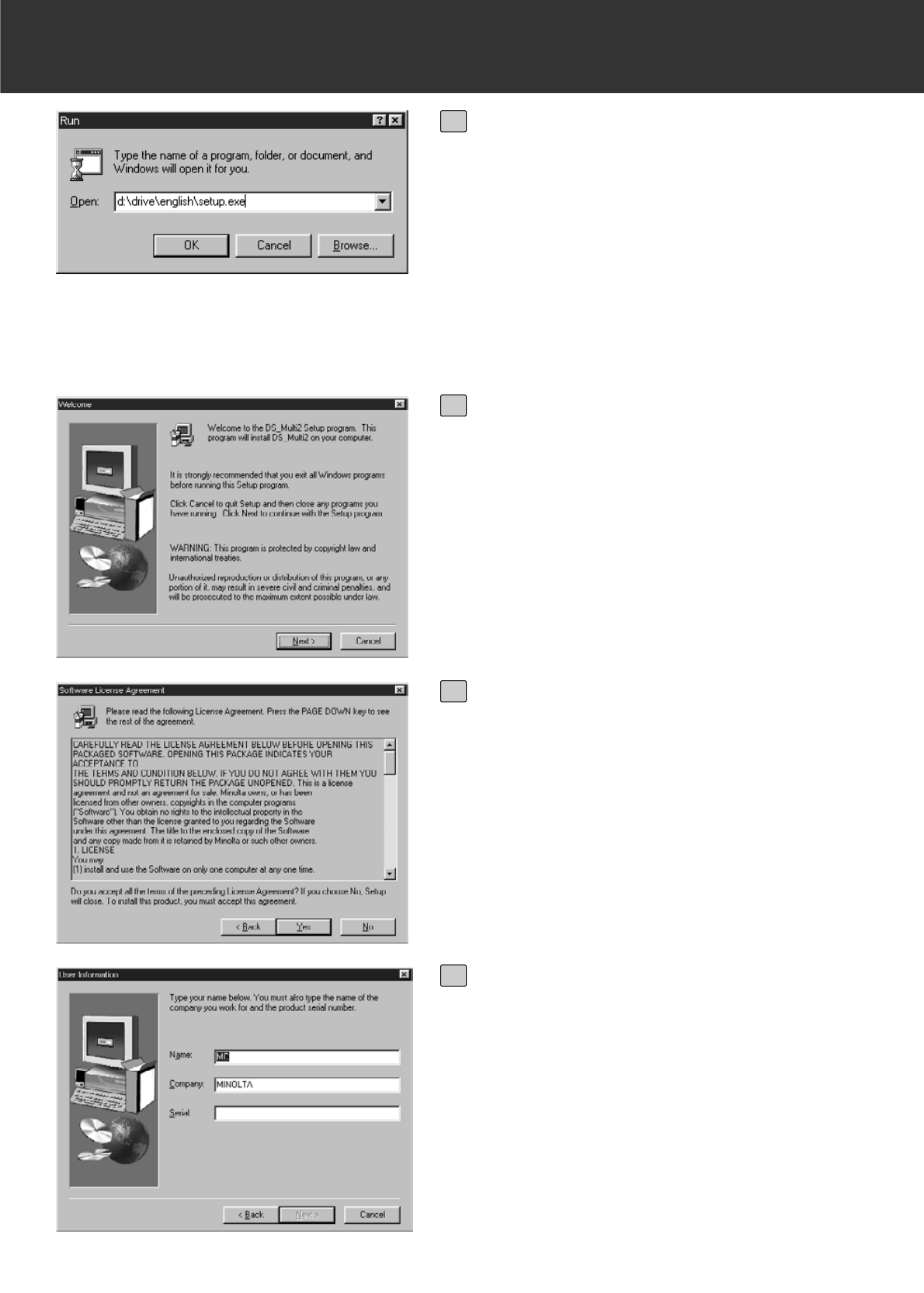
From the START button, select Run…
When the Run dialog box appears,
enter D:driver\english\setup.exe from
the Open drop-down list, then click
on [OK].
• The following dialog box will appear.
5
Click on [Next >].
• The Software License Agreement will appear.
6
After reading the agreement, if you
accept it, click on [Yes].
• The [Serial Number Input] dialog box will
appear.
If you do not accept, click on [No]. Setup will
be cancelled.
7
Enter your name, company name and
the serial number described on the
CD-ROM case and click on [Next >].
• The Choose Destination Location dialog box
will appear.
• Take care to type them correctly, otherwise,
[Next >] cannot be clicked.
8
– 11 –
INSTALL THE SOFTWARE
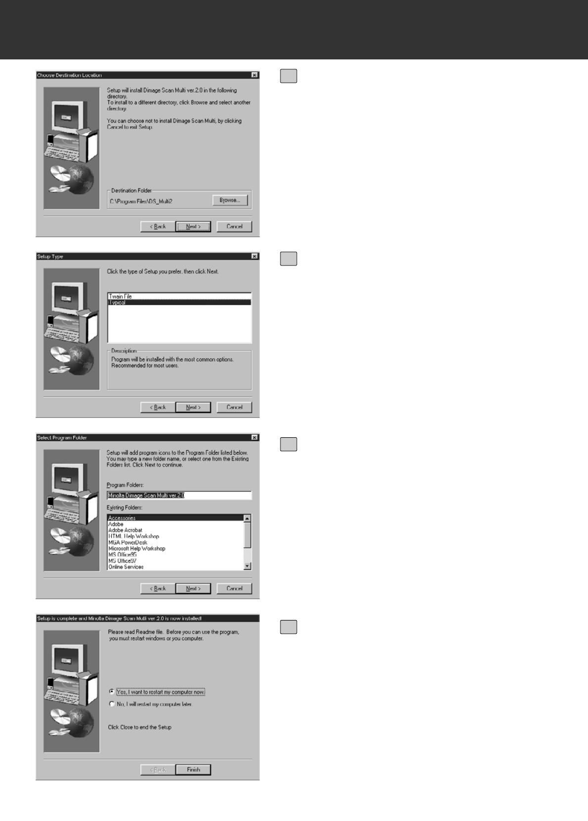
To install the software into the direc-
tory in the default setting ;C:\Program
Files\DS_Multi II, click on [Next >].
• The “Setup Type” dialog box will appear.
• To select another destination directory, click
on [Browse…] and select the directory. Click
on [OK].
9
Select the setup type and click on
[Next >].
• Normally, select “Typical” When the DS Multi
II Utility software is not used, select [TWAIN
File].
• When [Next >] is clicked on, the [Select
Program Folder] dialog box appears.
10
The name of the program folder in
which program icons will be added is
displayed. Confirm the name and
click on [Next >].
• Setup will begin.
• When setup is complete, the “Setup is com-
plete and Minolta Dimage Scan Multi ver.2.0
is now installed!” dialog box appears.
11
Make sure that the message “Yes, I
want to restart my computer now.” is
checkmarked and click on [Finish].
• Your computer is restarted.
12
– 12 –
INSTALL THE SOFTWARE
MACINTOSH
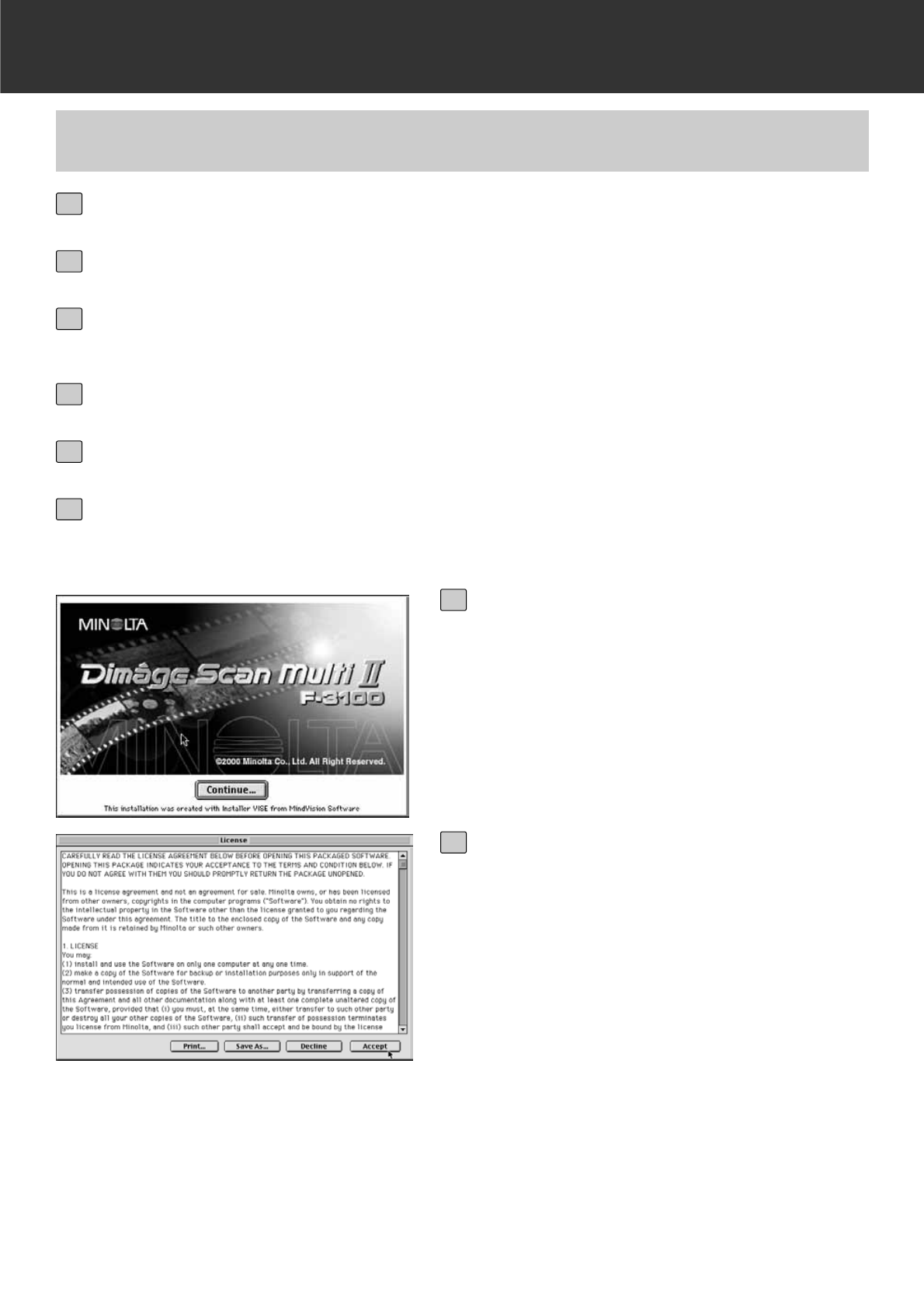
Click on [Continue…].
• The user License Agreement will appear.
7
After reading the agreement, if you
accept it, click on [Accept].
• The Easy Install dailog box will appear.
When [Print…] is clicked, the user License
Agreement can be printed.
When [Save As…] is clicked, the content of
the License Agreement is saved as a text file.
If you do not accept the user License
Agreement, click on [Decline]. The installation
will be cancelled.
8
Double-click on the DS Multi II Installer icon.
• The install screen will appear.
6
Turn on the Dimâge Scan Multi II.
1
Turn on the PC and start up the Mac OS.
2
After the desk-top window is displayed, insert the Dimage Scan Multi II
CD-ROM into the CD-ROM drive.
3
Double-click on the Dimage Scan Multi II CD-ROM icon.
4
Double-click on the Driver folder and English folder.
5
– 13 –
INSTALL THE SOFTWARE
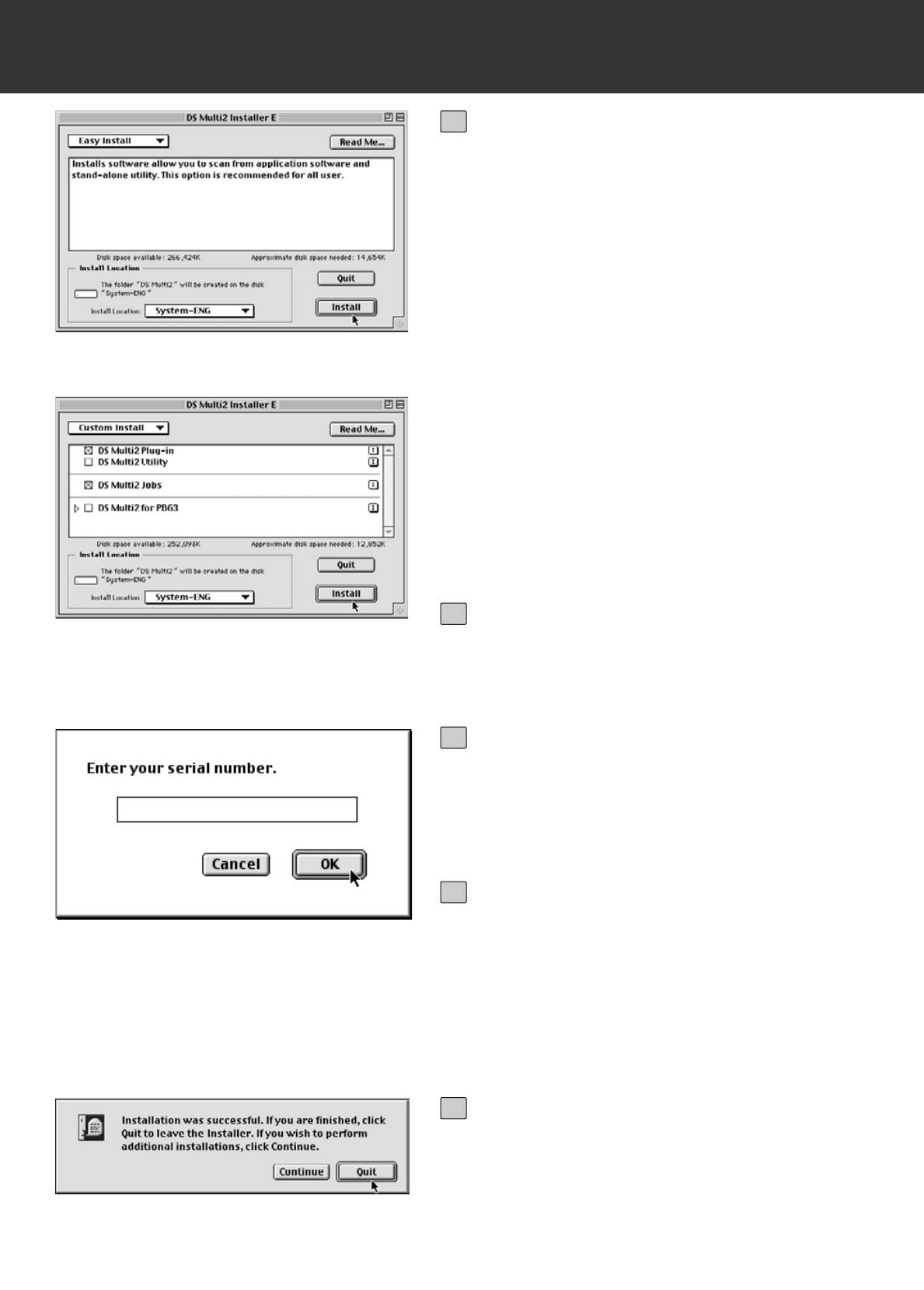
Confirm the install location of the
software displayed in Install Location.
To change the location
• Select Install Lacation from the Install
Location pull-down menu and specify the
folder or make a new folder.
When Easy Install is selected, all the folders
are installed.
9
Click on [Install].
• The [Enter your serial number] dialog box will
appear.
10
Enter the serial number described on
the back of the CD-ROM case.
• Type it correctly.
11
Click on [OK].
• The installation will begin. Follow the proce-
dure displayed in the window.
• When the installation is complete, a message
appears informing you installation was suc-
cessful.
12
Click on [Quit].
13
When installing either the DS Multi Plug-in or
the DS Multi Utility, select the Custom Install.
1 Select Custom Install from the [Install Select]
pull-down menu.
2 Click on the checkbox of the file to be
installed.
– 14 –
INSTALL THE SOFTWARE
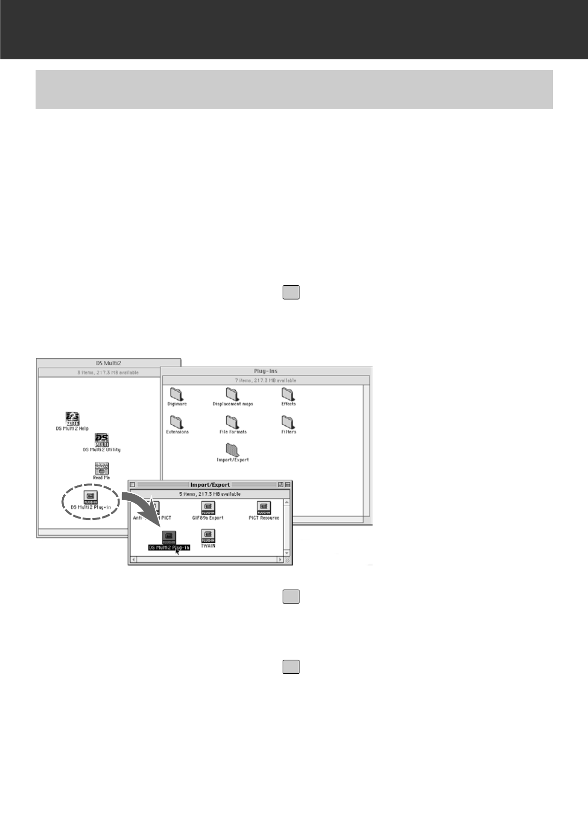
Once the installation procedure is complete, move the DS Multi Plug-in from the Dimage Scan
Multi folder to the appropriate folder for the host application.
You can use the DS Multi II Plug-in when Adobe Photoshop is functioning.
As this DS Multi Plug-in cannot be installed automatically, install this Plug-in by performing the
following procedure after the installation is complete.
When using only the DS Multi Utility without activating the DS Multi Plug-in, the installation is not
necessary.
INSTALL THE PLUG-IN – MACINTOSH
If Adobe Photoshop is functioning,
quit it.
1
Open the Adobe Photoshop folder,
and open the Photoshop Plug-ins
folder.
2
Drag and drop the DS Multi II Plug-in
folder in the DS Multi II folder into the
Plug-in’s Import/Export folder.
3
– 15 –
STARTING UP THE SOFTWARE – WINDOWS
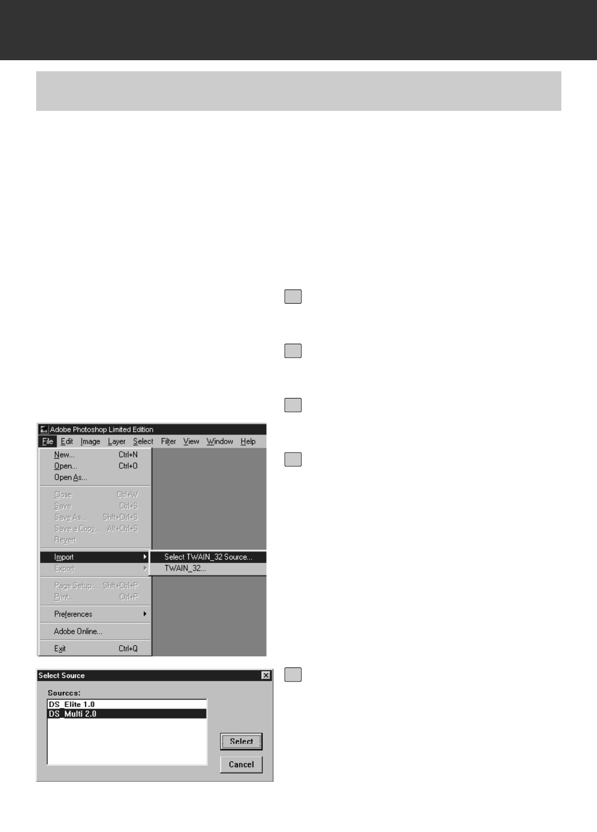
Turn on the Dimage Scan Multi II.
1
Turn on the PC and start up Windows.
2
Start up Adobe Photoshop LE.
3
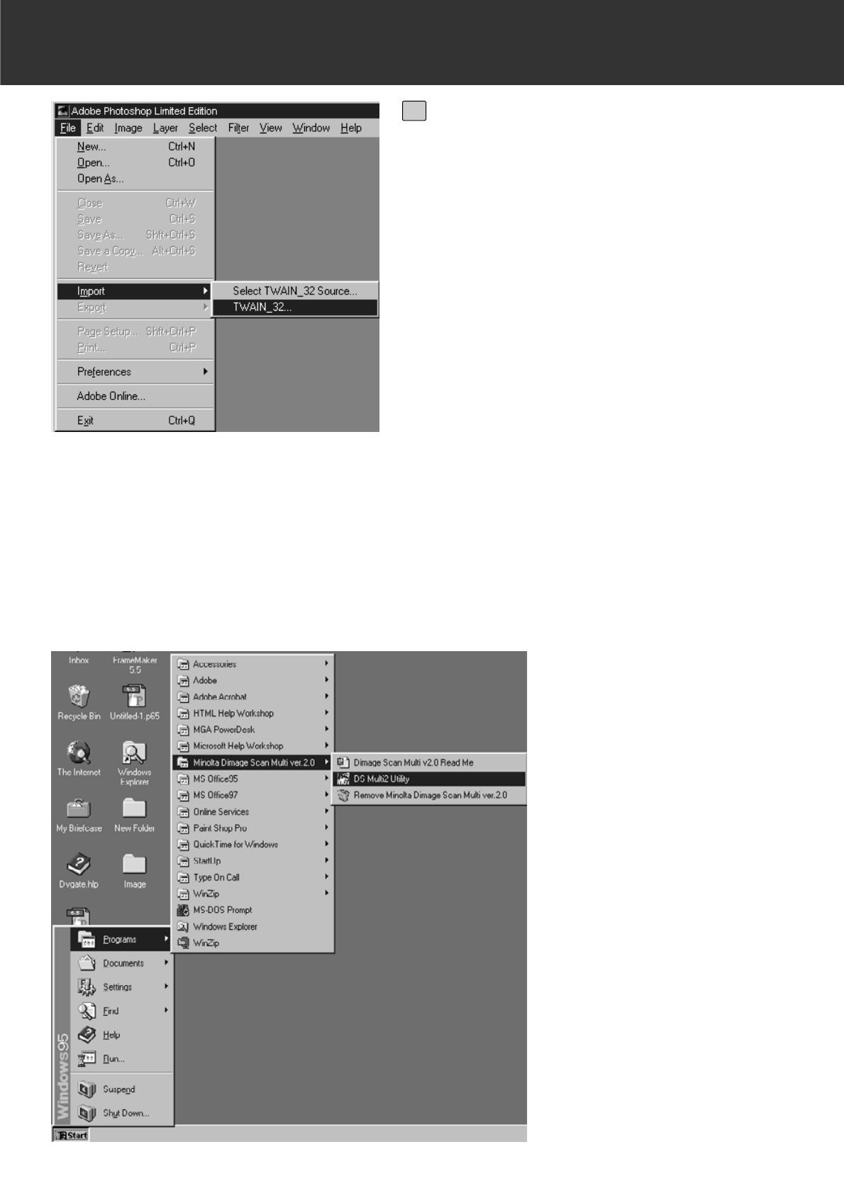
Select File -> Import -> Select
TWAIN_32 Source… .
• The [Select TWAIN Source] dialog box
appears.
4
Select DS Multi 2.0 from the Source
list, then click on Select.
5
STARTING UP THE TWAIN DRIVER
WINDOWS 95/98/98SE/2000/NT4.0
This uses Adobe Photoshop 5.0LE as an example. The commands and displays may vary among
applications. For details, refer to the instruction manual of the image editing software you use.
– 16 –
STATING UP THE SOFTWARE – WINDOWS
Select File -> Import -> TWAIN_32.
6
STARTING UP THE UTILITY SOFTWARE
When you intend to scan and save images only, use the DS Multi II Utility software.
After performing step 1 and 2 on page 15, select Start -> Programs -> Minolta
Dimage Scan Multi ver.2.0 -> DS Multi II Utility.
• The software will function and the Main window (p.19) will appear.
– 17 –
STATING UP THE SOFTWARE – MACINTOSH
Turn on the Dimage Scan MultI II.
1
Turn on the PC and start up Mac OS.
2
Start up Adobe Photoshop LE.
3
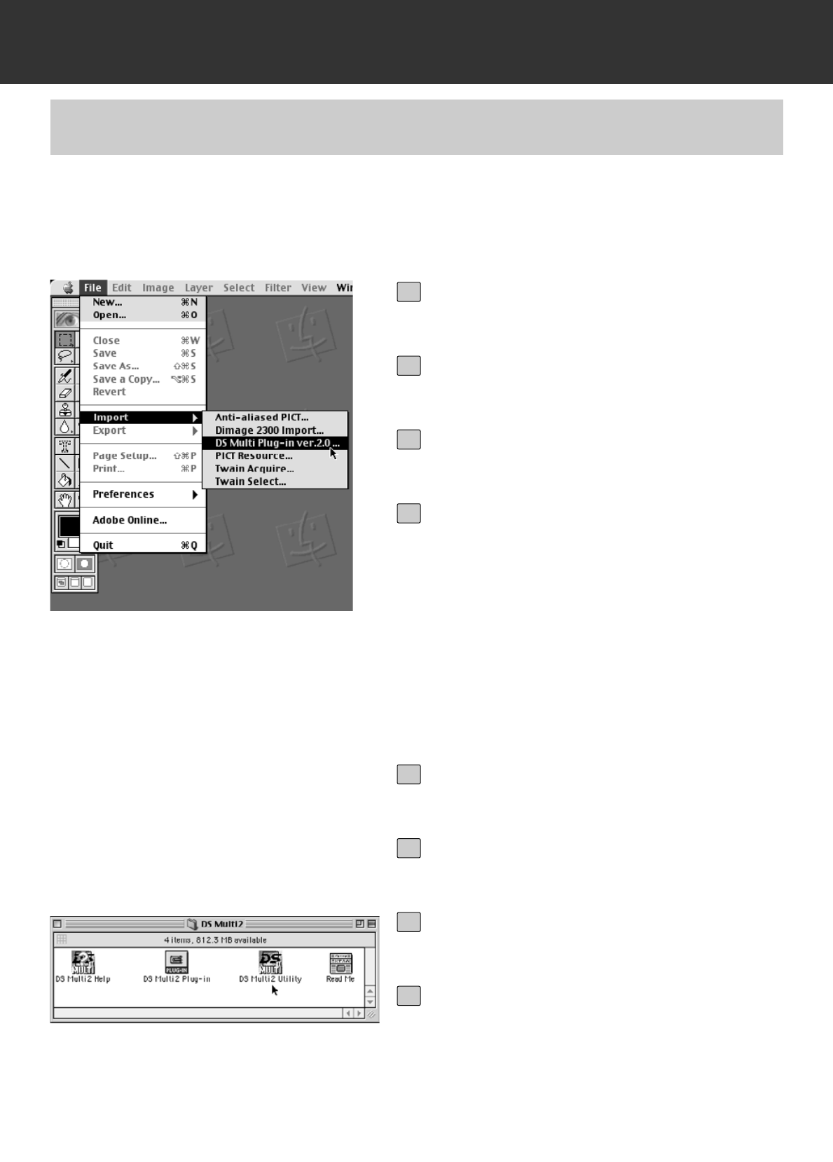
Select File -> Import -> DS Multi Plug-
in ver. 2.0….
• The software will function and the Main win-
dow (p.19) will appear.
4
STARTING UP THE Adobe Photoshop PLUG-IN
MACINTOSH
This instruction assumes that the DS Multi II folder is installed in the Plug-ins Import/Export folder
of Adobe Photoshop 5.0 LE. For the installation of the DS Multi II Plug-in, see page 14.
Turn on the Dimage Scan Multi II.
1
Turn on the PC and start up Mac OS.
2
Double-click on the DS Multi II folder.
3
Double-click on the DS Multi II Utility
icon.
• The software will function and the Main win-
dow (p.19) will appear.
4
STARTING UP THE UTILITY SOFTWARE
When you intend to scan and save images only, use the DS Multi ii Utility software.
– 18 –
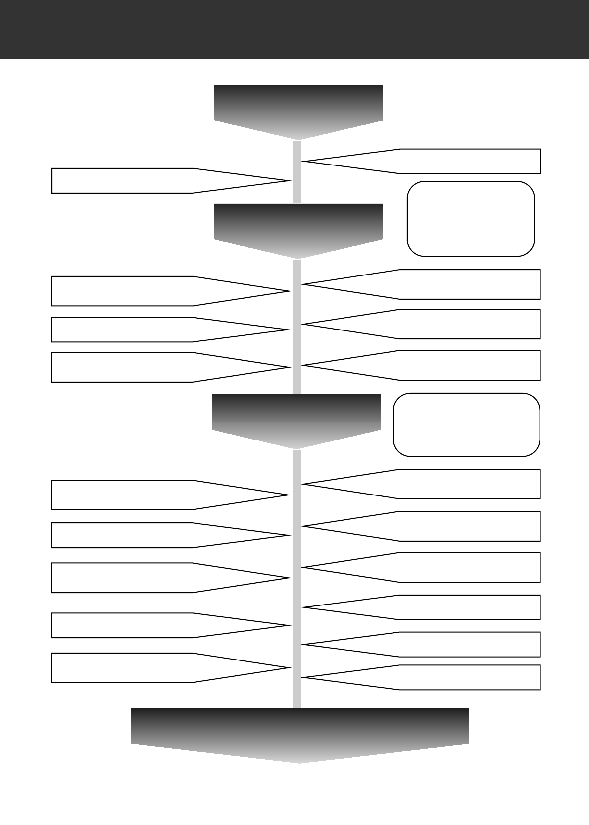
THE FLOW CHART TO PRESCAN
Main Window
Selecting the Film Type (p.21)
Selecting the Film Format (p.20)
Index Scan
When using the Slide
Mount Holder, 35 mm
Film Holder or APS
adapter (optional
accessory)
Selecting Frames (p.24)
Saving the Index Scan Images
(p.30)
Rotating/Flipping Index Frames
(p.25)
Reversing the Frame Order (p.27)
Saving after Lining Up the Index
Scan Images (p.28)
Prescan
Magnififying the Index Image
(p.26)
Scrolling Prescan Images (p.37)
Auto Cropping/Manual Cropping
(p.42 to 44)
Manual Focus (p.41)
Changing CHP Cropping Area
(p.45)
Rotating/Flipping Prescan Images
(p.34)
Magnifying/Reducing Prescan
Images (p.36)
AE Area/AE Area Lock
(p.38 to 39)
Point Auto Focus (p.40)
Displaying RGB/CMY (p.46)
Displaying Frame Number (p.46)
When using Medium Format
Film Holder, Universal Film
Holder (optional accessory)
or Slide Feeder (optional
accessory)
Full-Screen View (p.35)
To the Image Correction Window (p.47)
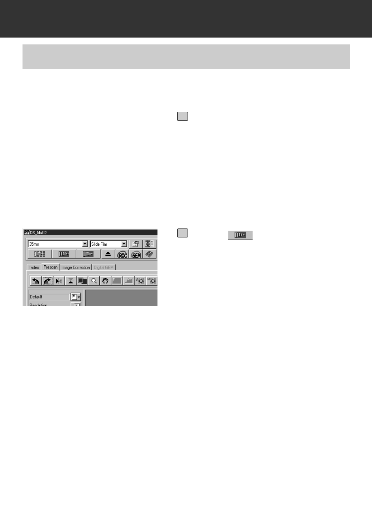
– 19 –
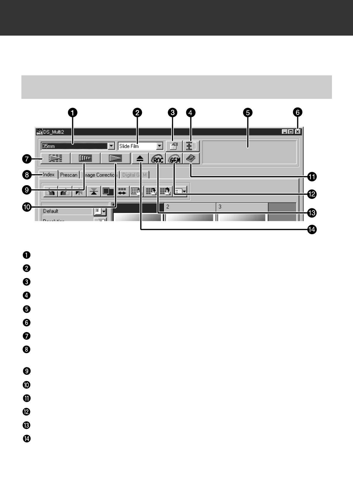
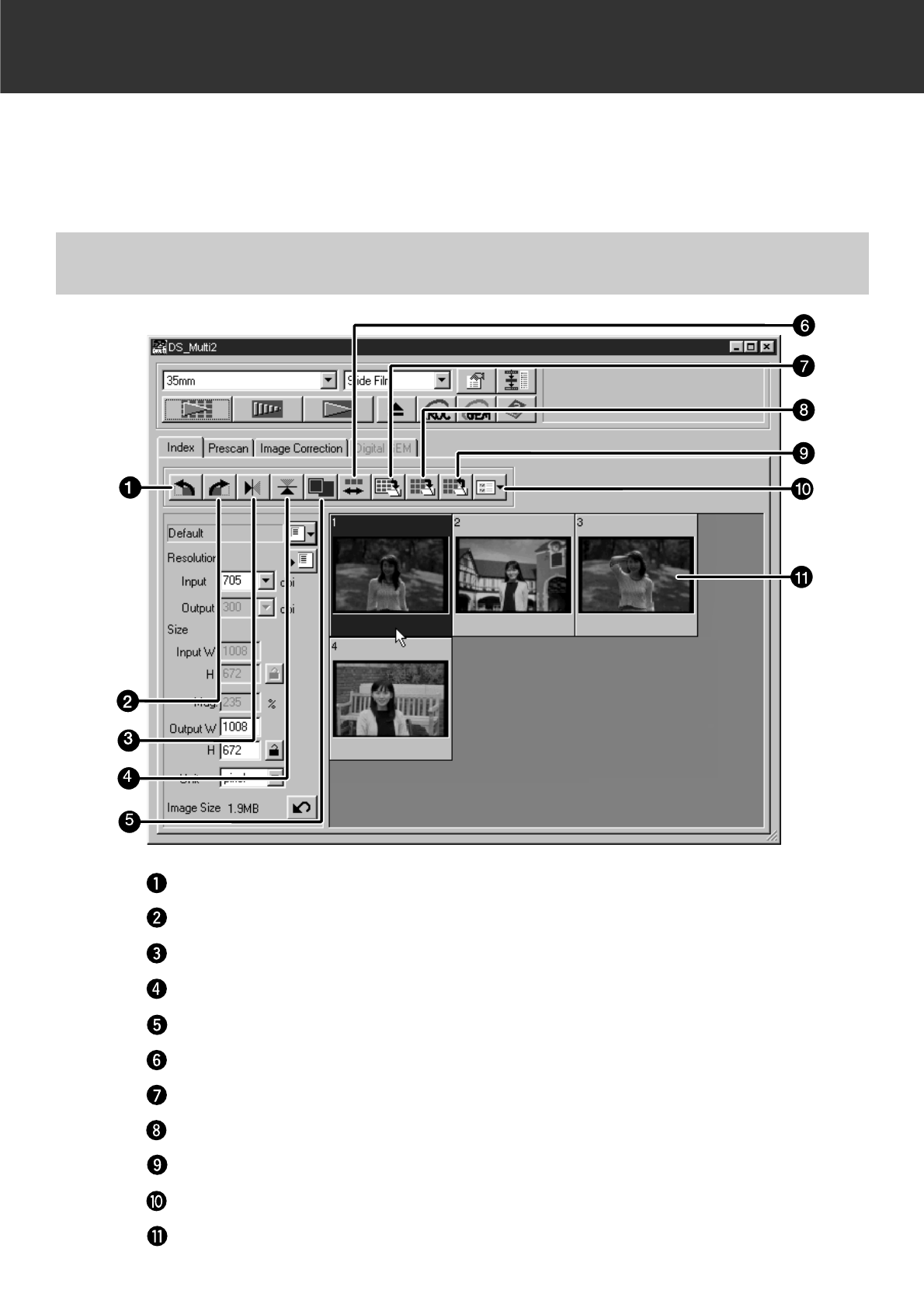
MAIN WINDOW
The Main Window appears when you launch the software. This is the main window for the
Dimâge Scan Multi II software.
Film Format list box
Film Type list box
Preferences button
Navigation button
Status bar
Closing button (The upper left side of the window on Macintosh)
Index Scan button
Tab (Switching the Tab of the Index Scan/ Prescan/Image
Correction/Digital GEM Window)
Prescan button
Scan button
Help button
Digital GEM button
Digital ROC button
Eject button
MAIN WINDOW – NAMES OF PARTS
– 20 –
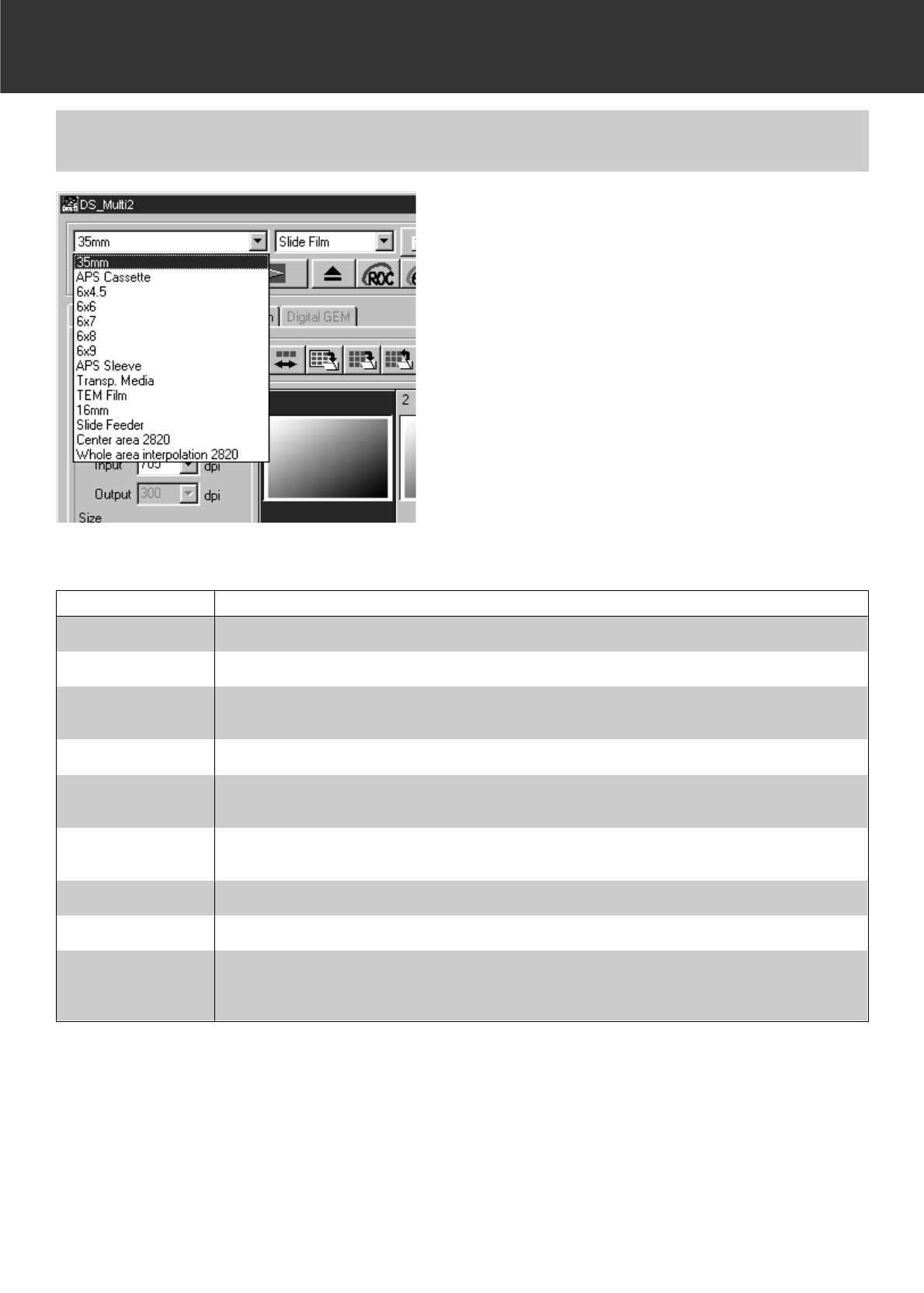
MAIN WINDOW
In the Main window, select the film for-
mat from the drop-down list.
• The Index window (p.22) will appear if 35mm or
APS Cassette is selected.
• The Prescan window will (p.33) appear if a
Medium-Format Film Size (6x4.5, 6x6, 6x7, 6x8,
6x9), APS Sleeve, Transparent Media, TEM
Film, 16 mm, Center Area 2820 or Whole Area
Interpolation 2820 is selected.
• The following list shows the film formats and
appropriate holders for scanning.
* shows optional accessories.
FILM FORMAT HOLDER
35mm 35mm Film Holder FH-M1 (sleeved film)/Slide Mount Holder SH-M2 (mounted slides)
APS Cassette APS Adapter AD-100*
6x4.5, 6x6, 6x7,
6x8, 6x9 Medium Format Film Holder MH-M1 and the mask corresponding to each film size, or Universal
Holder UH-M1* and Wide Universal Mask WM-M1*
APS Sleeve Medium Format Film Holder MH-M1 and APS mask
Transp. Media Slide Mount Holder SH-M2, or Universal Holder UH-M1* and Wide Universal Mask WM-M1*
TEM Film Medium Format Film Holder MH-M1 and the mask corresponding to each film size, or Universal
Holder UH-M1* and Wide Universal Mask WM-M1*
16mm Medium Format Film Holder MH-M1 and 16mm mask
Slide Feeder Slide Feeder SC-100*
Center area 2820/
Whole area interpo-
lation 2820
Medium Format Film Holder MH-M1 and the mask corresponding to each film size, or Universal
Holder UH-M1* and Wide Universal Mask WM-M1*
SELECTING THE FILM FORMAT
– 21 –
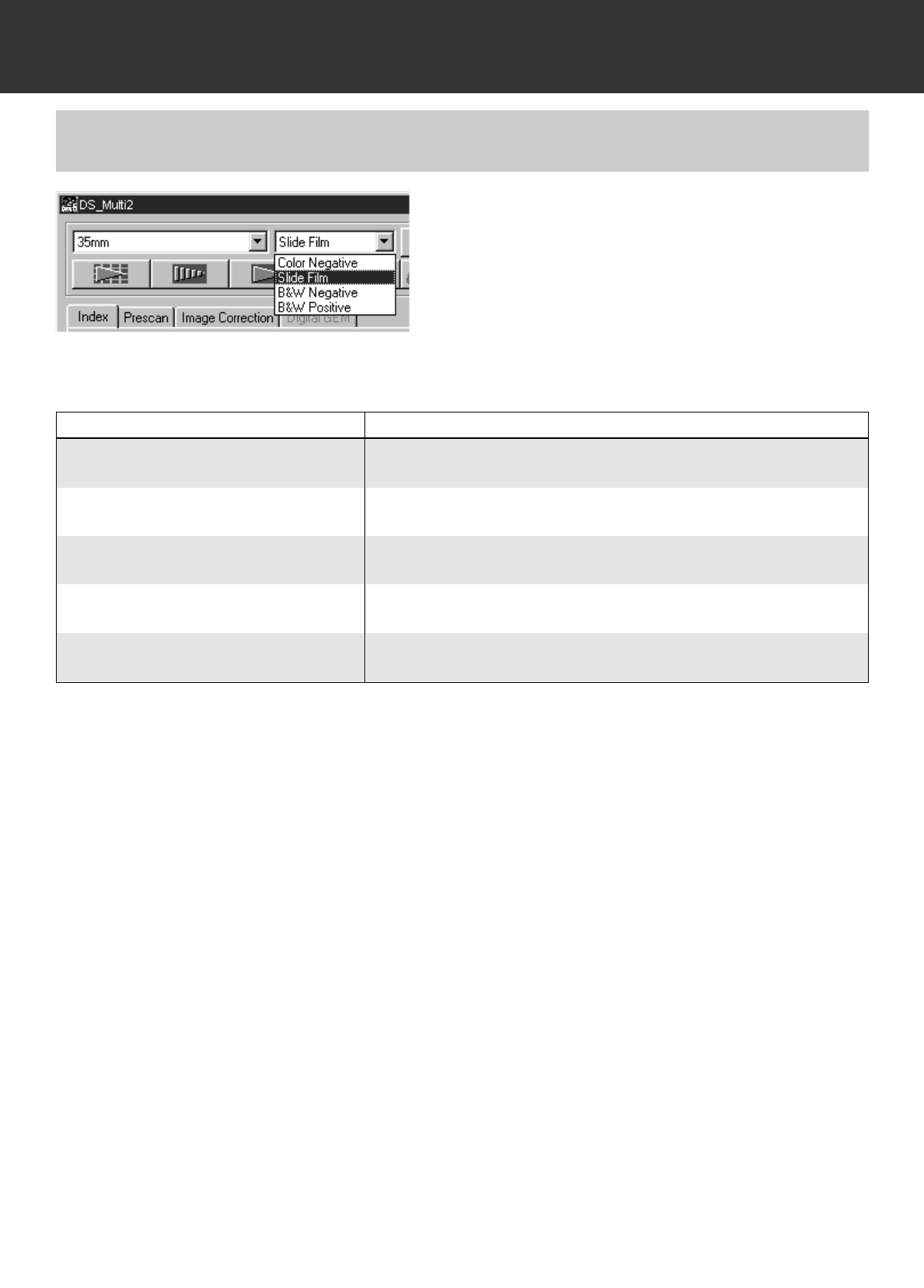
MAIN WINDOW
In the Main window, select the type of
film from the drop-down list.
• The film type options differ according to the the
film format currently selected.
Auto Detect (APS Cassette)
The APS cassette has a built-in disk in which data such as the film sensitivity (ISO), the number
of film or the type of film, etc. is recorded. When selecting the [Auto Detect], the scanner detects
the information and specifies the film type automatically.
SELECTING THE FILM TYPE
FILM FORMATS FILM TYPES
35mm, Medium-format films, APS Sleeve,
16mm, Slide Feeder Color Negative, Color Positive, B&W Negative, B&W Positive
APS Cassette Auto Detect (colour), Color Negative, Color Positive
Transparent Media Special (colour), Color Negative, Color Positive, B&W Negative,
B&W Positive
TEM film Special (B&W), Color Negative, Color Positive, B&W Negative,
B&W Positive
Center Area 2820/
Whole Area interpolation 2820 Special (colour), Special (B&W), Color Negative, Color Positive,
B&W Negative, B&W Positive
Special (Color/B&W)
The transparent media or TEM film differs from ordinary camera film in characteristics such as
transparency rate, etc. When selecting [Special], the scanner specifies the film type according to
the characteristics of the transparent media or TEM film.
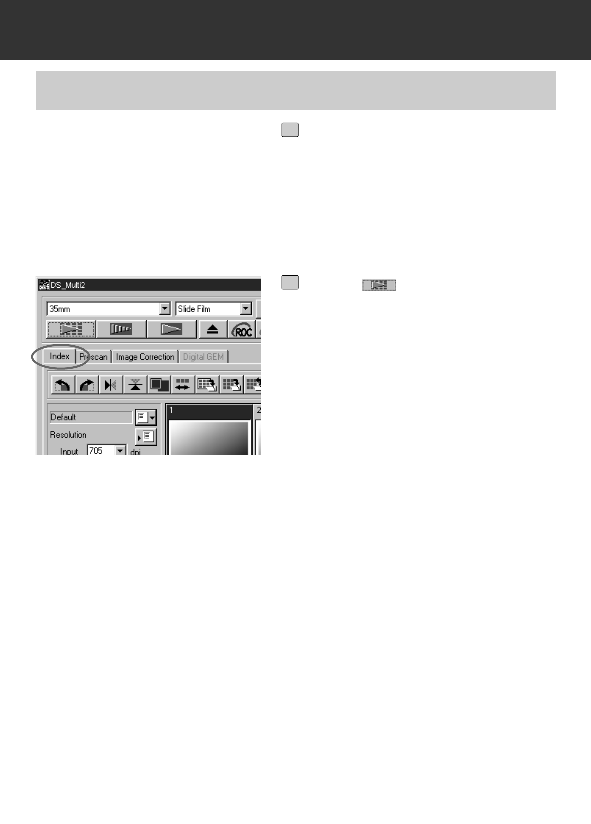
– 22 –
INDEX SCAN
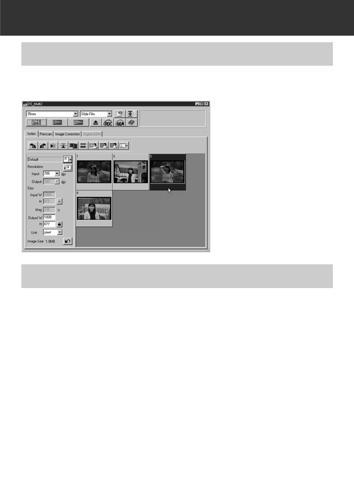
When [35 mm]or [APS Cassette] is selected in the film format, the Index tab in the Main window
is activated. (The Index window is displayed in the front.) When the index scan is performed, the
index images of all frames set in a Slide Mount Holder SH-M2, 35 mm Film Holder FH-M1 or an
APS adapter (optional accessory) are displayed in the Index window.
INDEX WINDOW – NAME OF PARTS
Rotate Left button
Rotate Right button
Flip Horizontal button
Flip Vertical button
Index Image Magnifying Display button
Reverse frame order button
Save Index Image button
Save Index Scan button
Index Load button
Image Correction Job Load button
Index images
– 23 –
INDEX SCAN
• There are two modes of the index scan; [High-Speed Scan] and [High-Quality Scan]. These
modes can be switched in the Preferences. The default setting (after installing the software) is
[High-Speed Scan].
• To cancel the index scan halfway:
Windows Press the Esc key.
Macintosh Press Command and the period key simultaneously.
• To delete all index images displayed in the Main window:
When the Index window is activated (displayed in the front),
Windows Press Ctrl, Shift, and R simultaneously.
Macintosh Press Command, Shift and R simultaneously.
MAKING AN INDEX SCAN
Insert the film holder into the scanner
as instructed by the hardware manu-
al.
• Index scans can only be performed when
using the 35mm film holder, slide mount
holder, or optional APS adapter.
1
Click on in the Main window.
• All frames will be scanned and appear in the
Index window in the order in which the
frames are scanned.
• When using the 35mm film holder, the
frames are scanned in the following order: 1,
2, 4, 3, 5, 6. This is not a malfunction but for.
The index images are displayed in the order
of 1, 2, 3, 4, 5, 6.
2
– 24 –
INDEX SCAN
Index frame can be selected by clicking on the desired frame. The selected frame can be rotated
in 90° increments either clockwise or counterclockwise or flipped horizontally or vertically (p.25) .
Moreover, that can be also prescanned by clicking on the Prescan button (p.32).
SELECTING INDEX IMAGE
To select more than 2 index frames, perform the following procedure when the Index window is
displayed.
SELECTING FRAMES
Windows
• Click on the desired index frames while holding the Ctrl key.
To cancel the selected frame, click on the frame to be cancelled again while holding the Ctrl
key.
• To select a sequence of index frames
Example: To select the images from frame numbers 2 to 9
Click on the images of frame numbers 2 and 9 while holding the Shift key.
• To select all the frames, press the Ctrl and A keys simultaneously.
Macintosh
• Click on the desired frames while holding the Commend key.
To cancel the selected frame, click on the frame to be cancelled again while holding the
Command key.
• To select a sequence of index frames
Example: To select the images from frame numbers 2 to 9
Click on the images of frame numbers 2 and 9 while holding the Shift key.
To select all the frames, press the Command and A keys simultaneously.
– 25 –
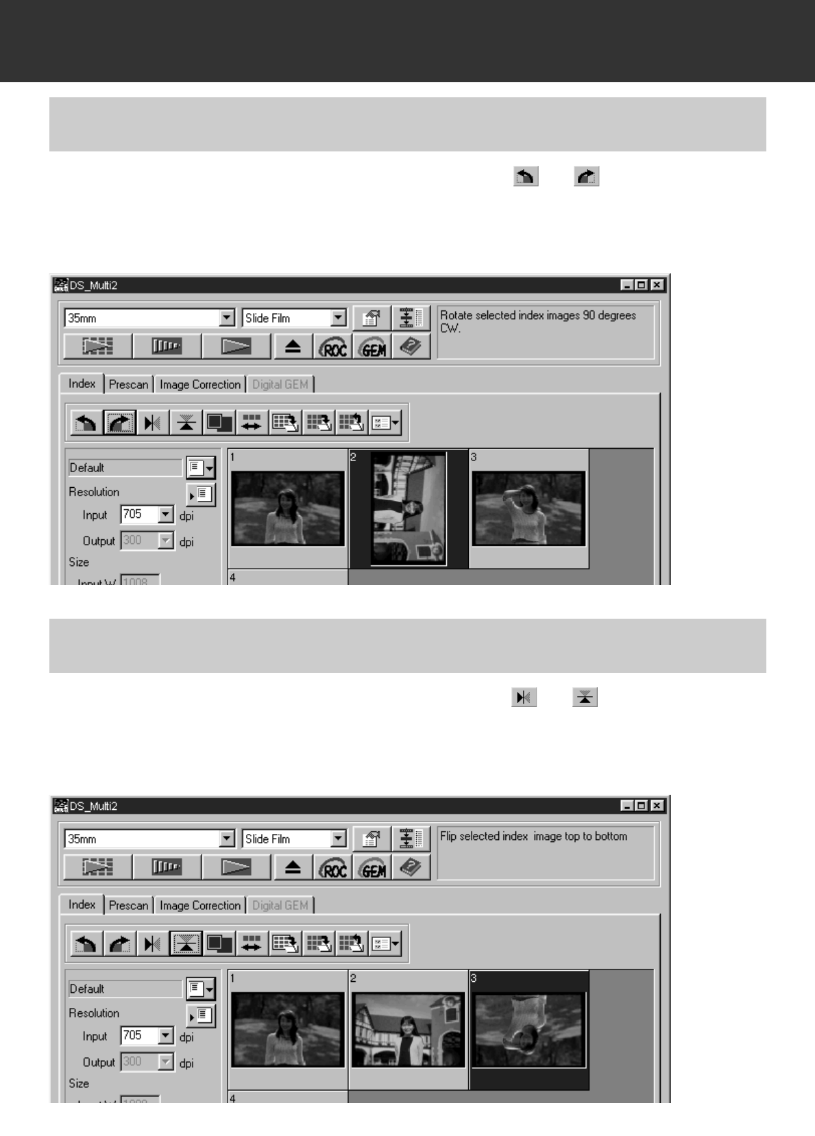
INDEX SCAN
Select the frame (p. 24) to be rotated and click on or .
• Each time the Rotate Left button or Rotate Right button is clicked, the index frame is rotated in
90° increments either clockwise or counterclockwise.
ROTATING THE INDEX FRAMES
Select the frame (p. 24) to be flipped and click on or .
• To cancel flipping frame, click on the Flip Horizontal button or Flip Vertical button again.
FLIPPING THE INDEX FRAMES
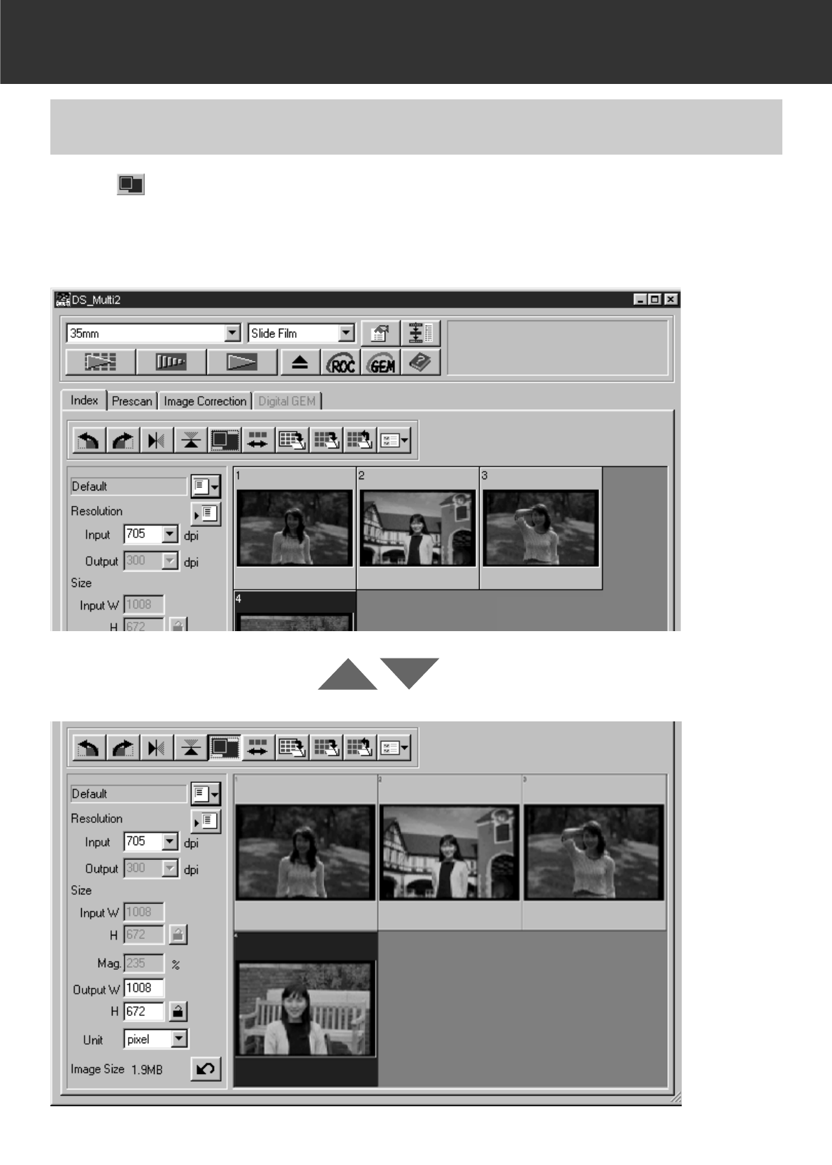
– 26 –
INDEX SCAN
When is clicked, the index image is magnified. When the button is clicked
again, the image returns to the previous size.
MAGNIFYING THE INDEX IMAGE
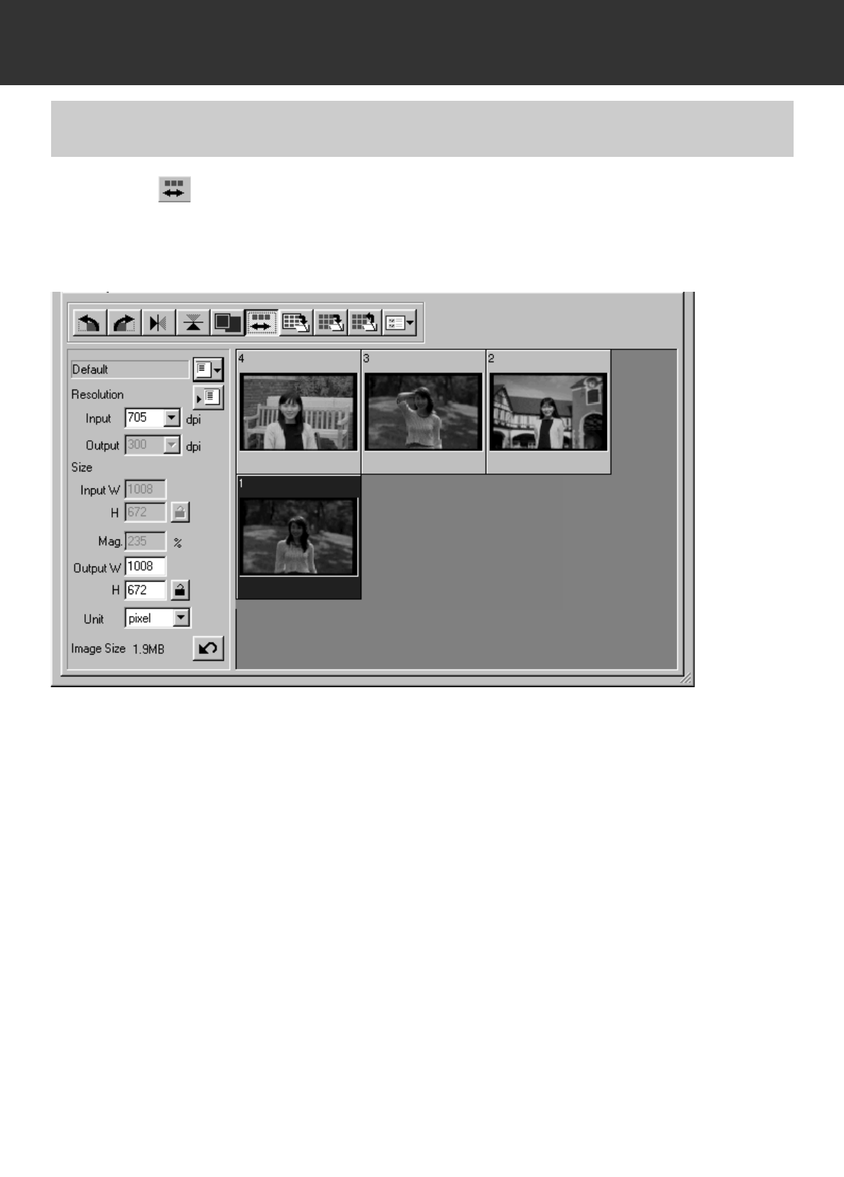
– 27 –
INDEX SCAN
Each time button is clicked, the order of the index frames is switched
between reverse order and original order.
REVERSING THE INDEX IMAGE
– 28 –
INDEX SCAN
The index scan images can be lined up like an album (as shown on the next page) and then
saved as an image file.
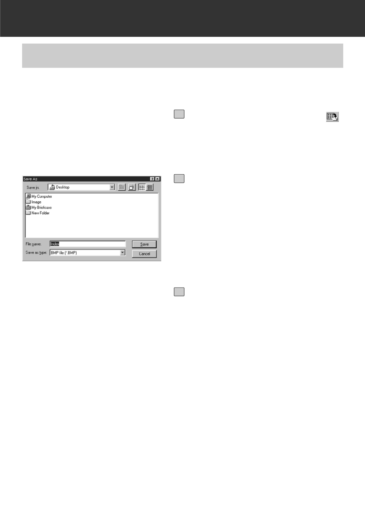
SAVING AFTER LINING UP THE INDEX SCAN IMAGES
Click on Save Index Image button .
• The standard save dialog box for your oper-
ating system will appear.
1
Select the file type to be saved from
the [Save as Type] list box (or the file
format pull-down menu).
• Windows: The displayed index scan image
can be saved in the Windows®Bitmap (BMP)
file format or the JPEG file format.
• Macintosh: The displayed index scan image
can be saved in the PICT file format or JPEG
file format.
2
Enter the desired file name, choose
the file destination and then click on
Save.
• When the index scan images are displayed,
these images are saved regardless of the
film set in the scanner.
• When the index images are not displayed,
the index images are saved after performing
the index scan.
• If there are index images which have not
been scanned yet, those images will be
scanned and then all index images including
those images will be saved.
3
– 29 –
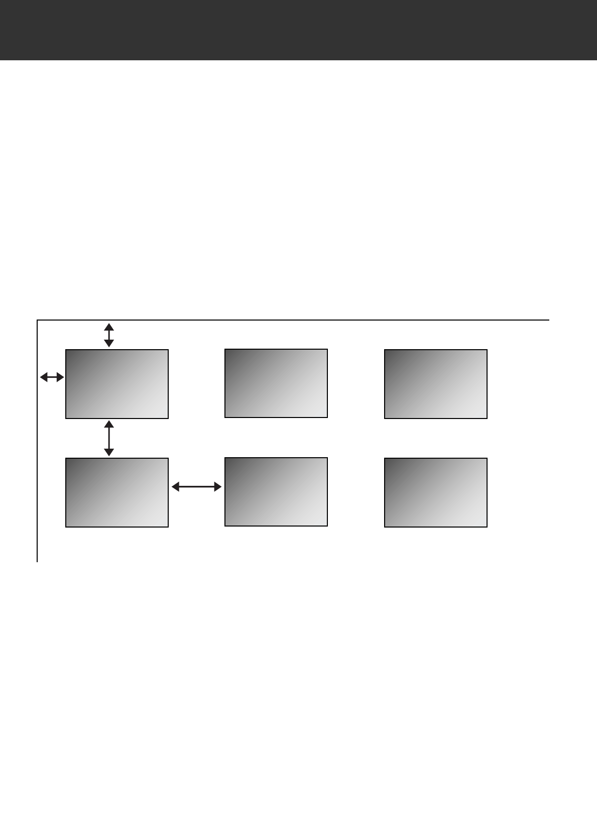
The index scan images are arranged in the image file to be saved as follows
• When there are 4 index frames, the frames are arranged in 4 columns of one line.
When there are more than 6 index frames, the frames are arranged in 6 columns multiplied by
the necessary number of lines (for example, when there are 15 index frames, the frames are
arranged in 6 columns multiplied by 3 lines.)
• A spacing of 50 pixels is allocated at the top, bottom, right and left sides of the window.
• The horizontal or vertical space between frames is 100 pixels or 70 pixels respectively.
• The output resolution of the image file to be saved is 300 dpi.
INDEX SCAN
1
789
23
50 pixels
50 pixels
100
pixels
70 pixels
– 30 –
INDEX SCAN
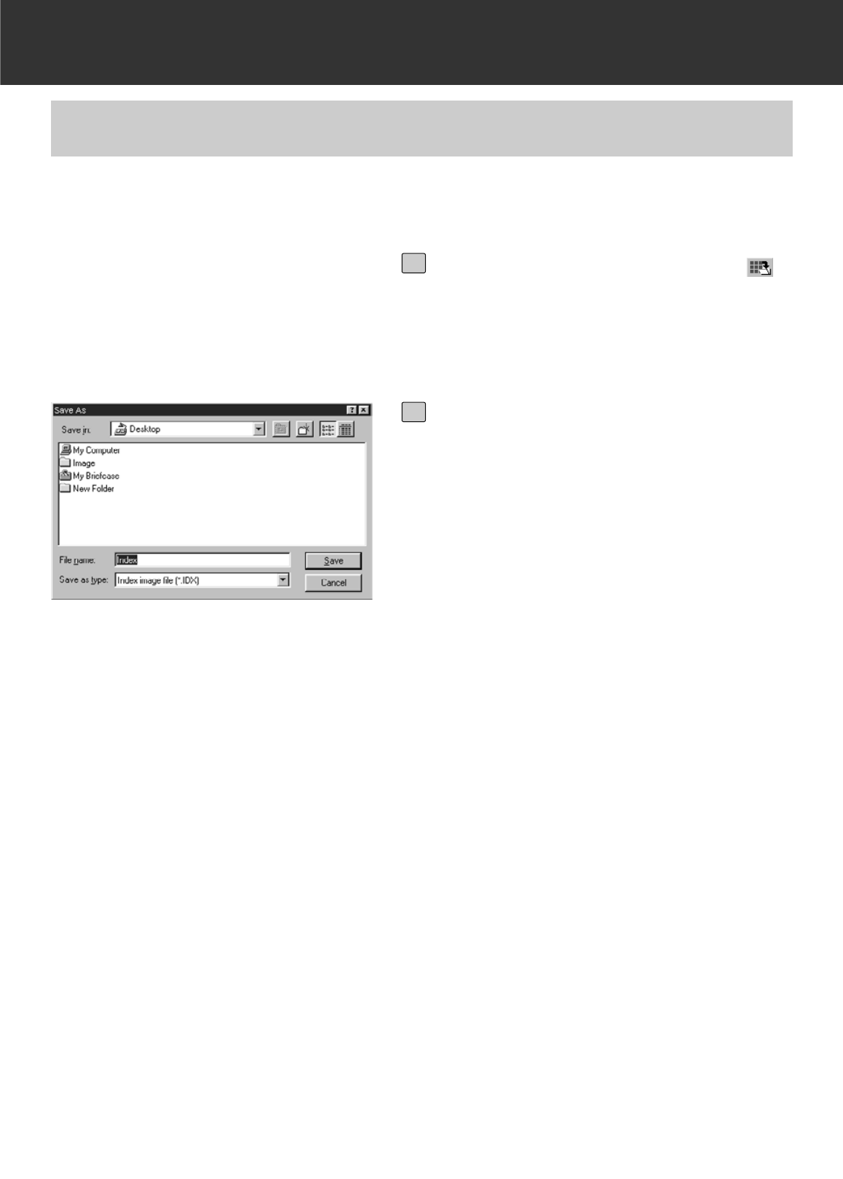
The index images can also be saved as an index file using the original file format of this software.
SAVING THE INDEX SCAN IMAGES AS AN INDEX FILE
Click on Save Index Scan button .
• The standard save dialog box for your oper-
ating system will appear.
1
Enter the desired file name, choose
the file destination, then click on
Save.
• File types other than the Index Image file
(*.idx) cannot be selected in the [Save as
Type] list box (or the file format pull-down
menu).
• When the index scan images are displayed,
these images are saved regardless of the
film set in the scanner.
• When the index images are not displayed,
the index images are saved after performing
the index scan.
• If there are index images which have not
been scanned yet, those images will be
scanned and then all index images including
those images will be saved.
• The index image file is saved in the original
format of this software.
2
– 31 –
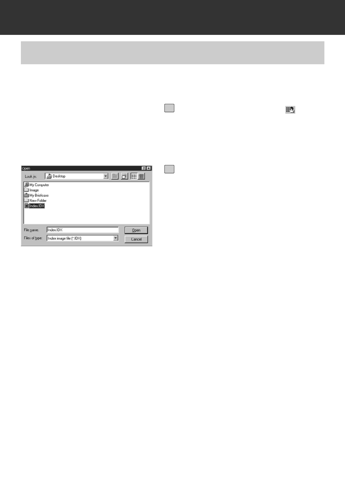
INDEX SCAN
The index images can be displayed in the Index window by loading the index file saved in the
original format of this software.
LOADING THE INDEX SCAN IMAGES SAVED AS THE INDEX FILE
Click on Index Load button .
• The standard open dialog box for your oper-
ating system will appear.
1
Select the file to be loaded and then
click on [Open].
• When the previous index scan image is dis-
played, the image is replaced with the cur-
rent loaded image.
2
– 32 –
PRESCAN
MAKING A PRESCAN
Insert the film holder loaded with a
film into the scanner by following the
procedure of the hardware instruction
manual.
• When using the slide mount holder, 35 mm
film holder or APS adapter (optional acces-
sory), select the index scan image to be
prescanned by performing the index scan
before making a prescan (p.23 to 24).
1
Click on in the Main window.
• The prescan will begin.
• When the prescan is complete, the pres-
canned image appears in the Prescan win-
dow.
2
– 33 –
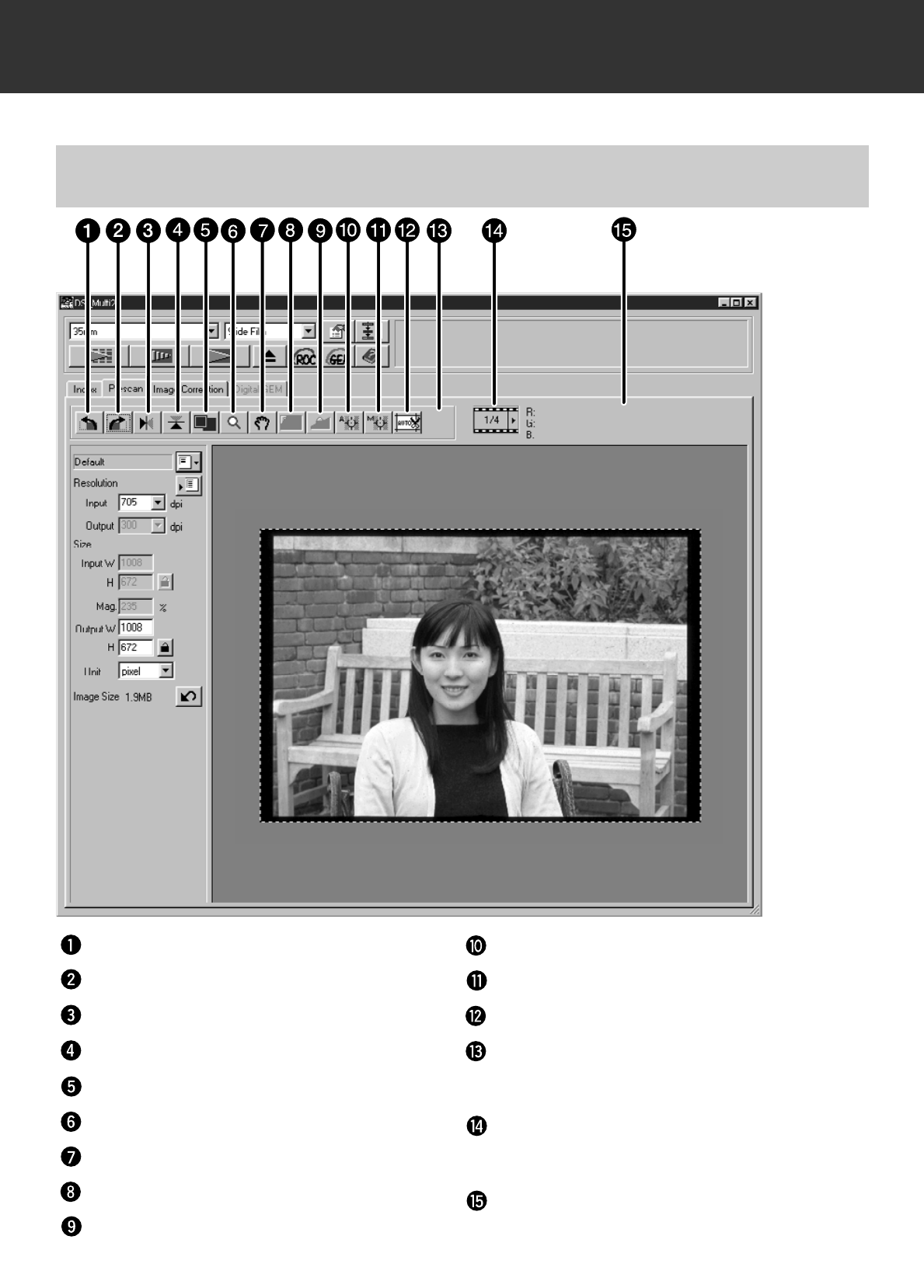
PRESCAN
When prescan is performed, the Prescan window changes to the following window.
PRESCAN TAB – NAMES OF PARTS
Rotate Left button
Rotate Right button
Flip Horizontal button
Flip Vertical button
Full-Scale View button
Zoom button
Scroll button
AE Area Lock button
AE Lock button
Point AE button
Manual Focus button
Auto Cropping button
Change CHP button (Only when [APS
Cassette] or [APS Sleeve] is selected in the
film format.)
Frame Number Display (Only when [35 mm]
or [APS Cassette] is selected in the film
format.)
RGB/CMY display
– 34 –
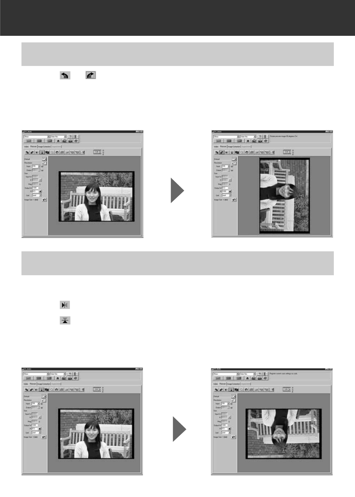
PRESCAN
Click on or .
• Each time the Rotate Left button or Rotate Right button is clicked, the prescan image rotates
in 90° increments either counterclockwise or clockwise.
• Changes performed in the Prescan image will be reflected in the final scan.
ROTATING THE PRESCAN IMAGE
The Flip Vertical and Flip Horizontal buttons let you flip the image from top to bottom or left to
right before scanning.
Click on to flip the image from left to right.
Click on to flip the image from top to bottom.
• To cancel flipping frame, click on the Flip Horizontal button or Flip Vertical button again.
• Changes will be reflected in the Prescan image.
FLIPPING THE PRESCAN IMAGE
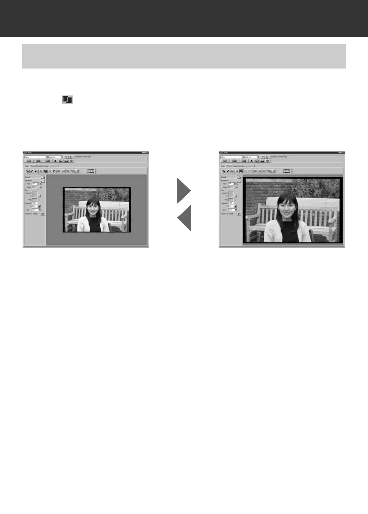
– 35 –
PRESCAN
The Full-Screen View button enlarges the area inside the cropping frame so it fills the screen.
This allows you to see close details and view the final composition.
Click on .
• The prescan image is magnified so that it fits in the Main window.
• When the Full-Screen button is clicked again, the prescan image returns to the previous size.
FULL-SCREEN VIEW
– 36 –
PRESCAN
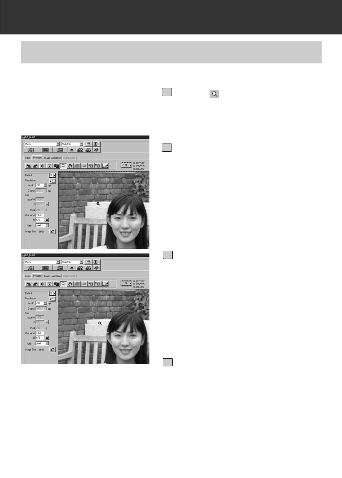
The Zoom button magnifies or reduces the prescan image regardless of the cropping frame.
MAGNIFYING OR REDUCING THE VIEW
Click on in the Prescan window.
• The pointer will change to a magnifying glass
with a “+” inside.
1
Click anywhere on the image to zoom
in.
• The clicked position will be the center of the
magnified view in the Prescan window. When
clicking on repeatedly, the image is magnified
accordingly.
• When the maximum magnification is
reached, the “+” will disappear. The view of
the prescan image cannot be magnified any
further.
2
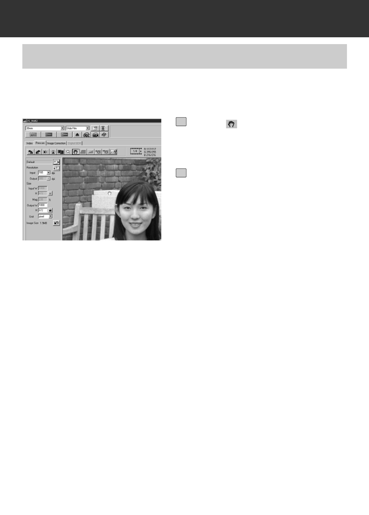
To reduce the view of the prescan
image:
Windows:
Press and hold the Ctrl key.
Macintosh:
Press and hold the Option key.
• The pointer will change to a magnifying glass
with a “-” inside.
3
Click anywhere on the image to zoom
out.
• The clicked position will be the center of the
reduced view in the Prescan window. When
clicking on repeatedly, the image is reduced
accordingly.
• When the maximum reduction is reached,
the “-” will disappear. The view of the prescan
image cannot be reduced any further.
4
– 37 –
PRESCAN
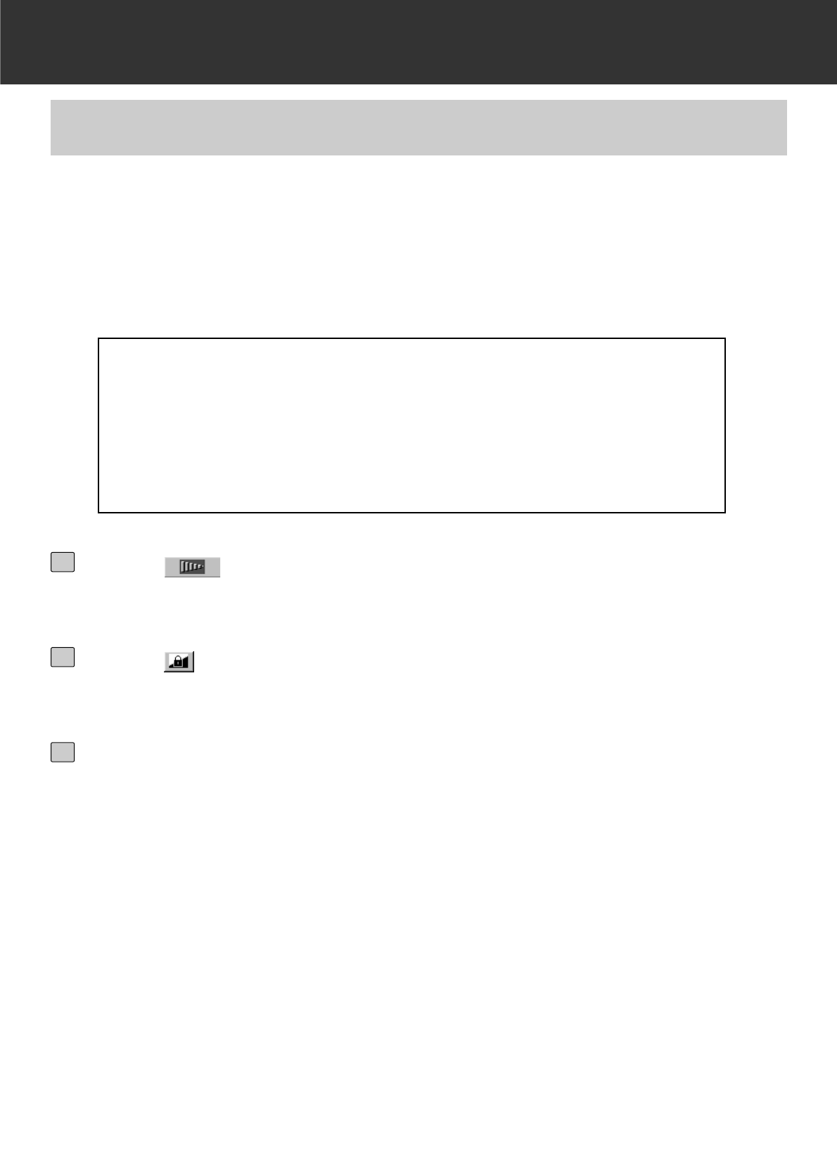
The Scroll button can only be selected when the view of the Prescan image has been magnified
by the Zoom button. This function allows you to view other parts of the image when it is too big to
fit in the window.
SCROLLING THE VIEW
Click on .
• The pointer will change to a hand icon.
1
Click on and drag the image to move
the image.
• The image moves according to the move-
ment of the mouse.
2
– 38 –
PRESCAN
AE (Auto Exposure) function is performed in the following
cases:
• When prescanning negative film.
• When selecting [Auto Expose for Slides] in the Preferences (p.89) and pres-
canning colour positive film.
AE Lock allows you to lock an auto exposure value.
Once the auto exposure is locked, multiple images in a same film are scanned with the same
exposure settings when performing the prescan and the final scan. With the AE lock function, for
example, when scanning a backlit scene or a scene where exposure comoensation has been
used, you can obtain a scanned image which reflects the exposure correction made when taking
a photograph.
AUTO EXPOSURE LOCK
Click on .
• The prescan is performed with the AE function.
1
Click on .
• The exposure setting displayed in the Prescan window is locked.
2
Select an image to which the same locked exposure setting is to be
applied and click on the Prescan button.
• The locked exposure setting will apply to the selected prescan image.
• The prescan and the final scan will be performed with the locked exposure setting until the
AE Lock function is cancelled by clicking on the AE lock button again.
• When [Auto Expose for Slides] in the Preferences (p. 89) is not checkmarked, the AE lock
function is not available with a positive film.
3
– 39 –
PRESCAN
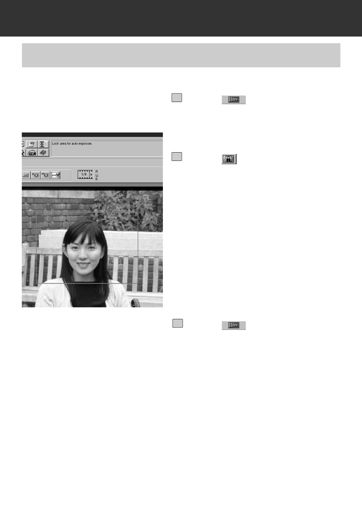
A specified area in the prescan image can be exposed automatically.
AE AREA LOCK
Click on .
• The prescan is performed with the AE func-
tion.
1
Click on .
• When the Shift key is pressed, the AE area
is indicated by a line instead of the cropping
area indicated by a dashed line. By dragging
the line surrounding AE area, the AE area
can be specified.
2
Click on again.
• The specified area is exposed automatically.
• To cancel the AE area lock function, click on
the AE Area Lock button again.
3
– 40 –
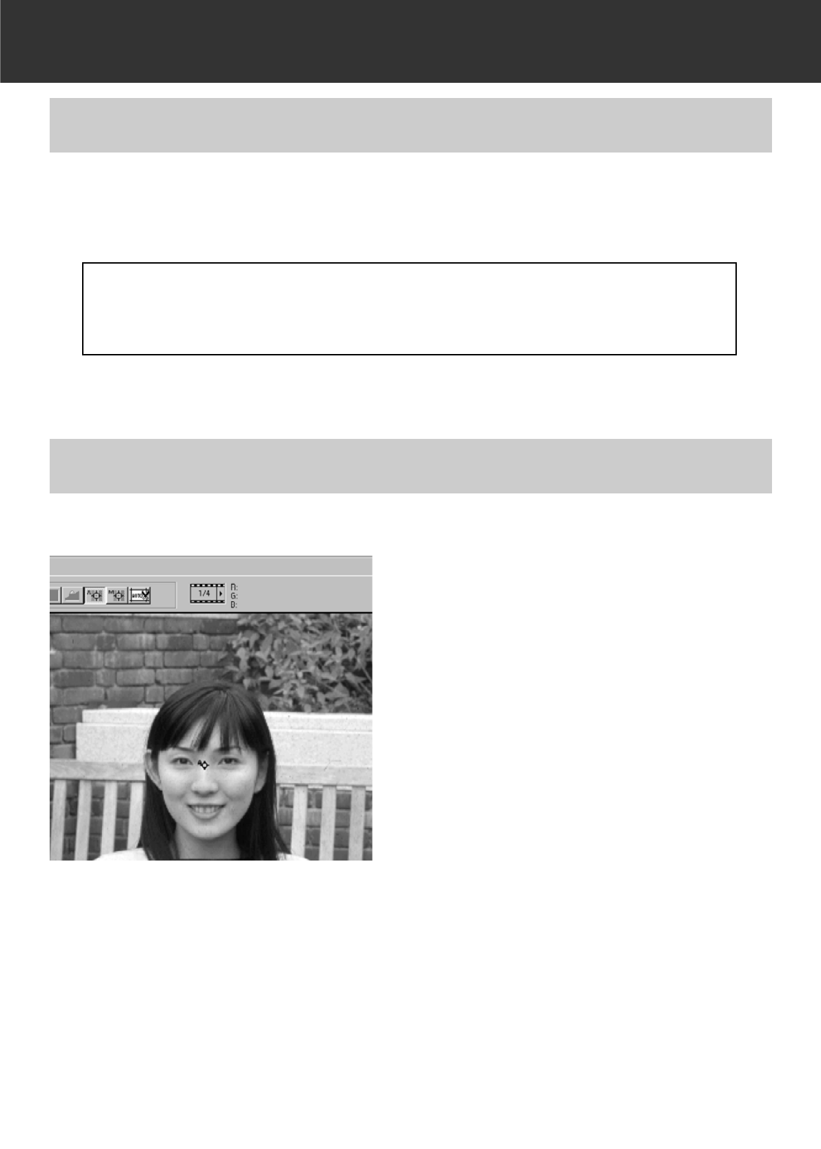
PRESCAN
The Dimage Scan Multi II uses the center of the image to focus. If the film is warped or curled, or
if [Auto Focus at Scan] is not checkmarked in the Preferences (p. 88), the focus should be
adjusted with the Point AF or the Manual Focus function.
FOCUS
The focus is determined by detecting the contrast in an image. Therefore, the focus
may not be adjusted appropriately in an area wiuth no contrast (such as a white cloud
or a solid black subject).
A specified point in the prescan image can be focused automatically.
POINT AF
– 41 –
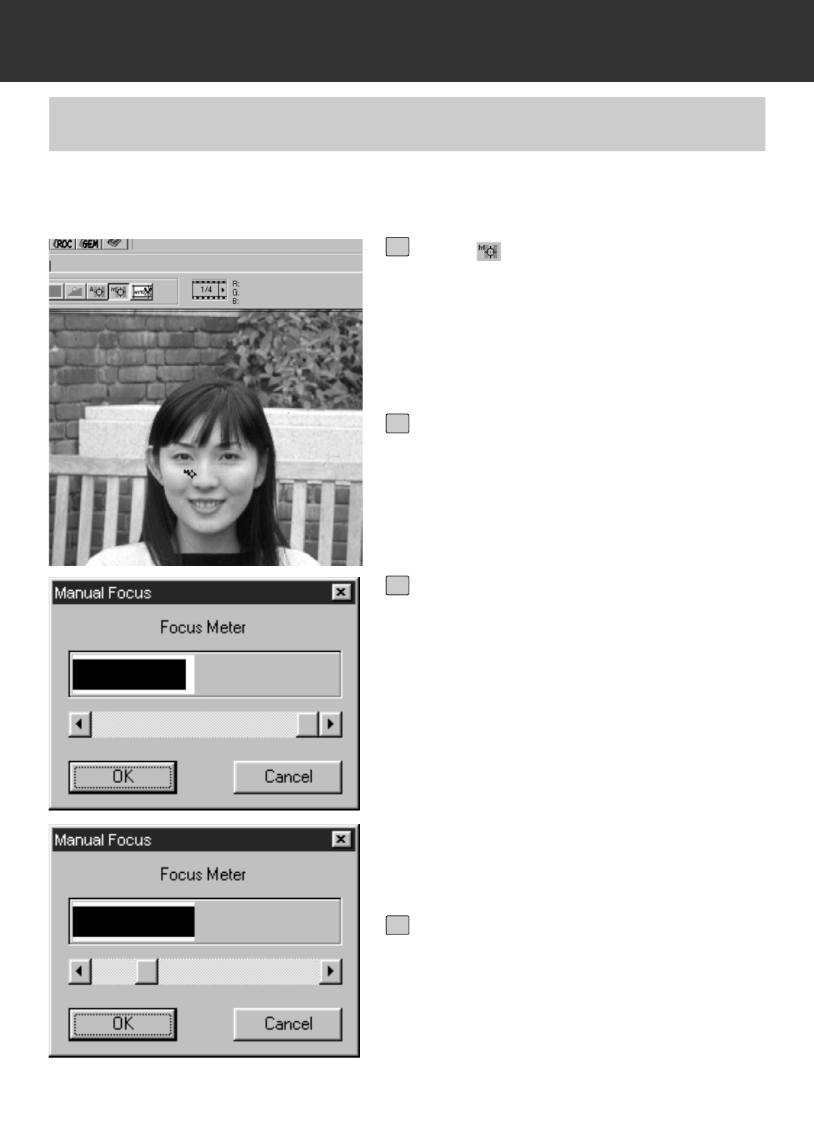
PRESCAN
Press in the Prescan window.
• The pointer will change to the Manual Focus
icon.
• When you click the Point AF button again,
The pointer shape returns to the original one.
1
Click on the area of the image to be
in sharp focus.
• The Focus Control dialog box will appear.
2
Adjust the slider until the black and
white bars are at their longest for
maximum focus.
• The black bar shows the current focus value
and the white bar shows the maximum focus
value previously obtained.
• Click and drag the slider to the left and right.
Click on the slider arrow to make a small
change. Click on the slider bar to make a
larger change.
• When [Cancel] is clicked on, the manual
focus setting is cancelled and the Focus
Control dialog box disappear.
3
Click on [OK].
• The point clicked on step 2 will be focused
and the prescan will begin again.
4
Use manual focus to focus on a specific area of the image or to reduce the appearance of grain
in grainy film (such as high-speed or pushed film) by slightly defocusing it.
MANUAL FOCUS
– 42 –
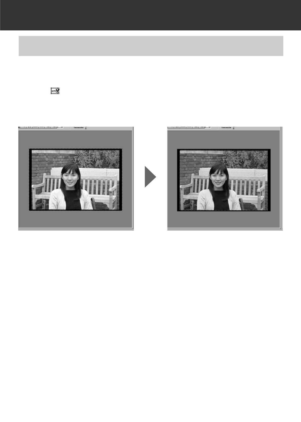
PRESCAN
The prescan image can be cropped automatically so that a holder frame or a slide mount holder
frame is removed.
AUTO CROPPING
Click on .
• The auto cropping will begin and the prescan image can be cropped automatically so that a
holder frame or a slide mount holder frame is removed.
– 43 –
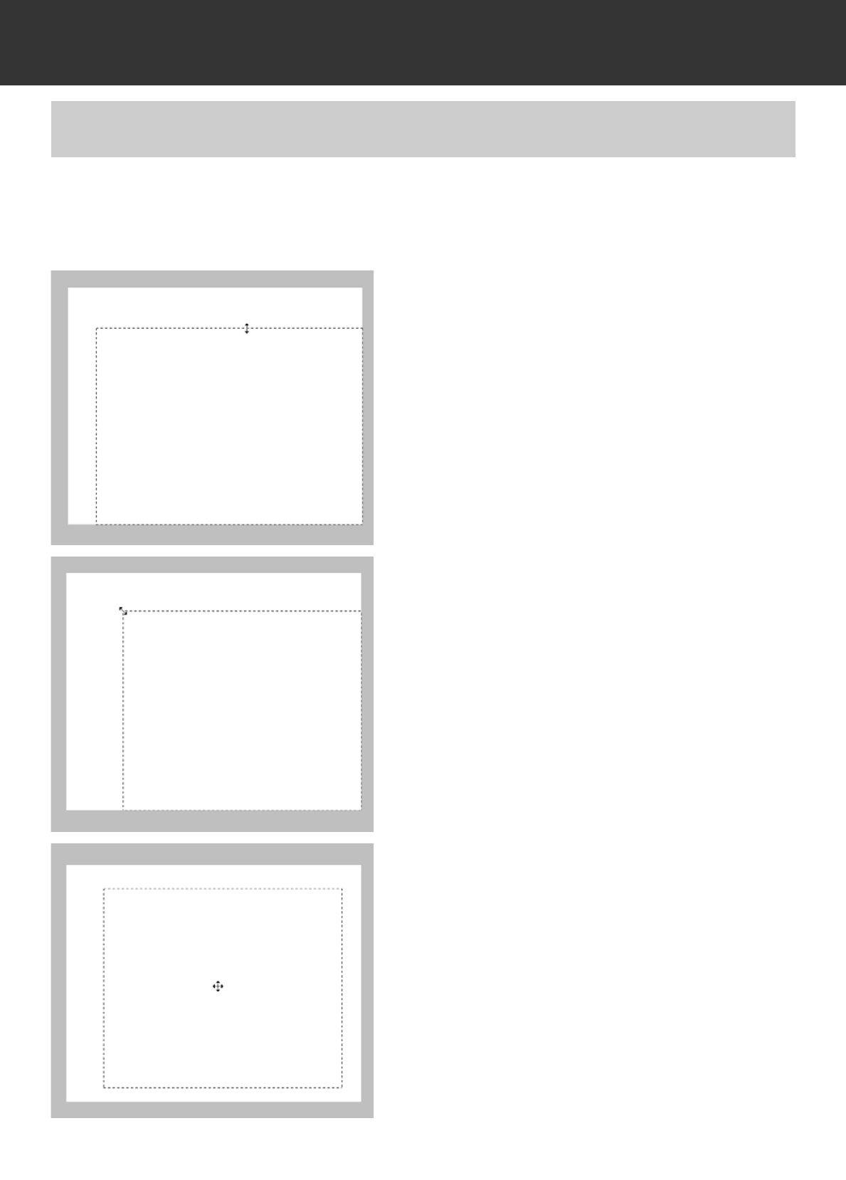
PRESCAN
By adjusting the cropping frame indicated by a dashed line in the prescan image, the cropping
area for the final scan can be determined. Unnecessary part can be removed before
prescanning. The prescan can also be performed without cropping.
MANUAL CROPPING
Resize only a cropping frame by click-
ing on the frame to be resized, then
dragging the pointer up or down or left
or right.
Resize the cropping frame proportional-
ly by clicking on the corners of the
frame, then dragging the pointer in or
out.
Move the cropping frame without
changing its size by placing the pointer
inside the frame, then click and drag it
to its new location.

– 44 –
PRESCAN
Define a new cropping frame by clicking
and dragging outside the current frame.
The previously displayed cropping
frame is cancelled.
* You can resize the cropping frame to cover the full prescan image again by pressing the
following keys.
When the Prescan window is displayed:
Windows: Press the Ctrl key and A key simultaneously.
Macintosh: Press the Command key and A key simultaneously.
– 45 –
PRESCAN
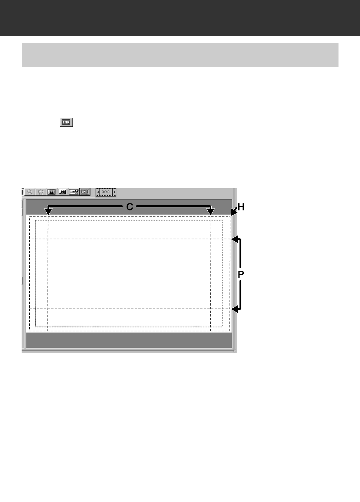
When APS Cassette or APS Sleeve is selected in the film format, the CHP button in the Prescan
window allows you to quickly and easily define the cropping frame by the standard APS formats;
C, H, and P.
APS FORMATS; C, H, AND P
Click on to display the APS cropping frames.
• Each time the CHP button is clicked, the cropping frames are displayed in the order of C, H
and P.
• The cropping area can be defined by dragging the cropping frames (p.43 to 44).
– 46 –
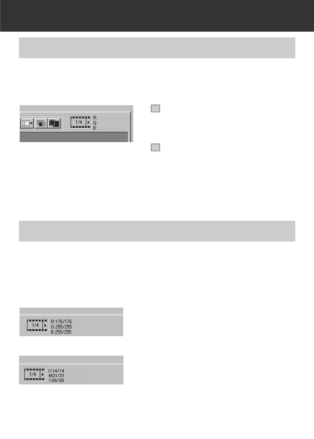
PRESCAN
When 35 mm or APS Cassette is selected in the film format, the frame number display appears
in the Prescan window.
It shows the frame number of the currently displayed prescan image and the total frame number.
DISPLAYING FRAME NUMBER
The RGB (red, green and blue channel) value at the pointer position or the CHY (cyan, magenta
and yellow) value is displayed in the Prescan window.
RGB/CMY INFO
To display the next frame, click on
the Right Arrow button.
1
To display the previous frame, click
on the Left Arrow button.
• When the selected image is not prescanned
yet, the prescan image is displayed after the
image is prescanned.
2
To display the CMY value,
Windows:
Press and hold the Shift key while the
Prescan window is displayed.
Macintosh:
Press and hold the Command key while
the Prescan window is displayed.
• While the key is pressed, the CMY value is dis-
played. When the key is released, the display
returns to the RGB value.
Normally the RGB value is displayed.
– 47 –
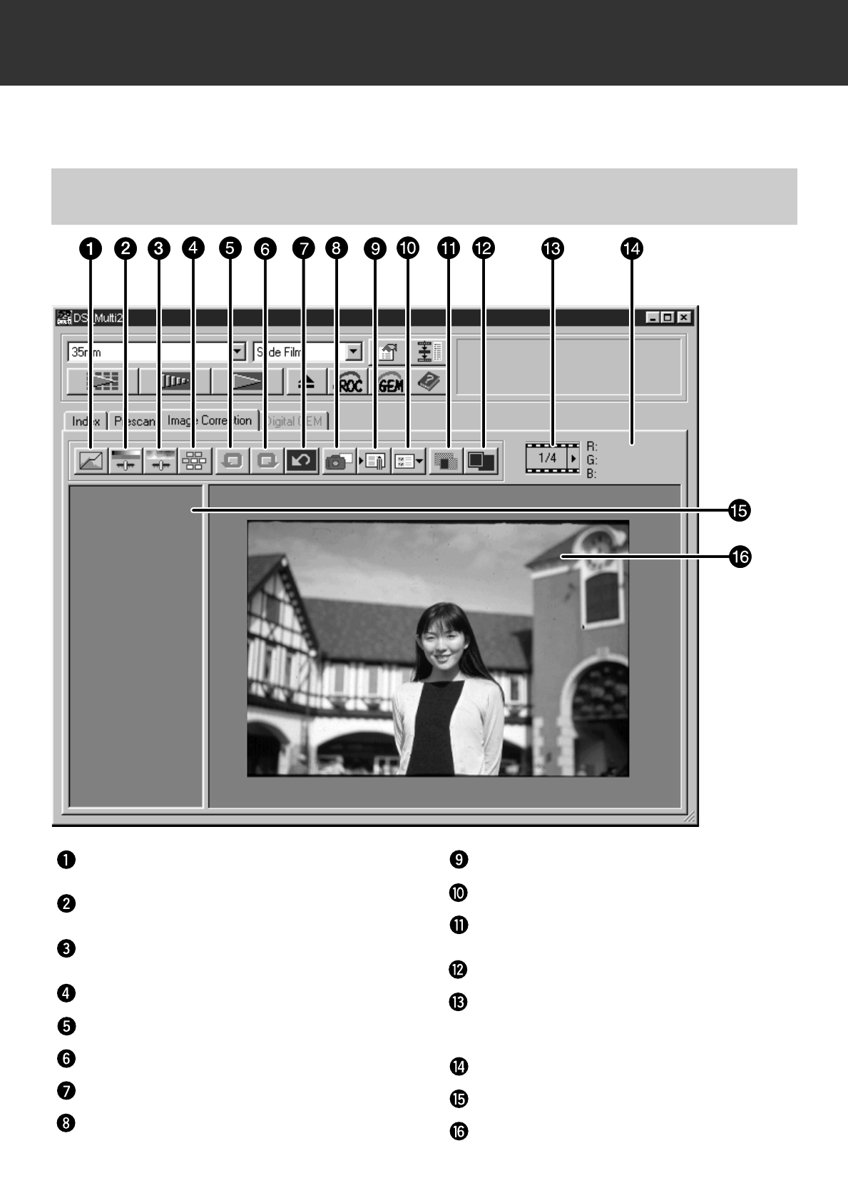
IMAGE CORRECTION
IMAGE CORRECTION TAB – NAMES OF PARTS
To correct prescan images, click on the Image Correction tab.
The Prescan window changes to the following window.
Tone Curves/Histogram Correction button
Brightness/Contrast/Color Balance
Correction button
Hue/Saturation/Lightness Correction button
Variations button
Undo button
Redo button
Correction Reset button
Snapshot button
Image Correction Job Load button
Image Correction Job Save button
Pre/Post Correction Comparison Display
button
Full-Screen View button
Frame Number display (Only when 35
mm or APS Cassette is selected in the
film format)
RGB/CMY Value display
Snapshot display area
Image Correction display area
– 48 –
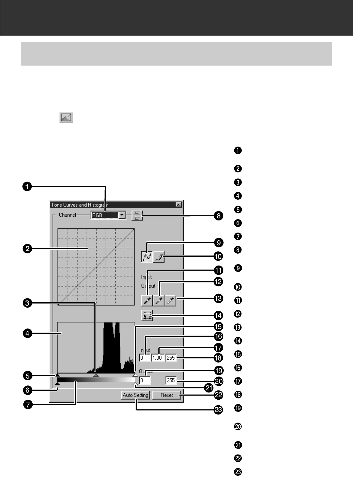
IMAGE CORRECTION
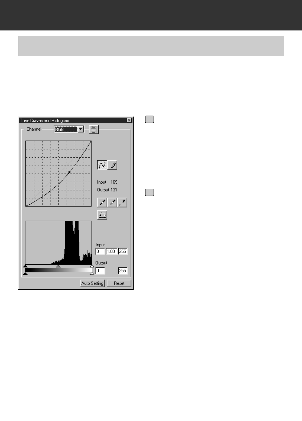
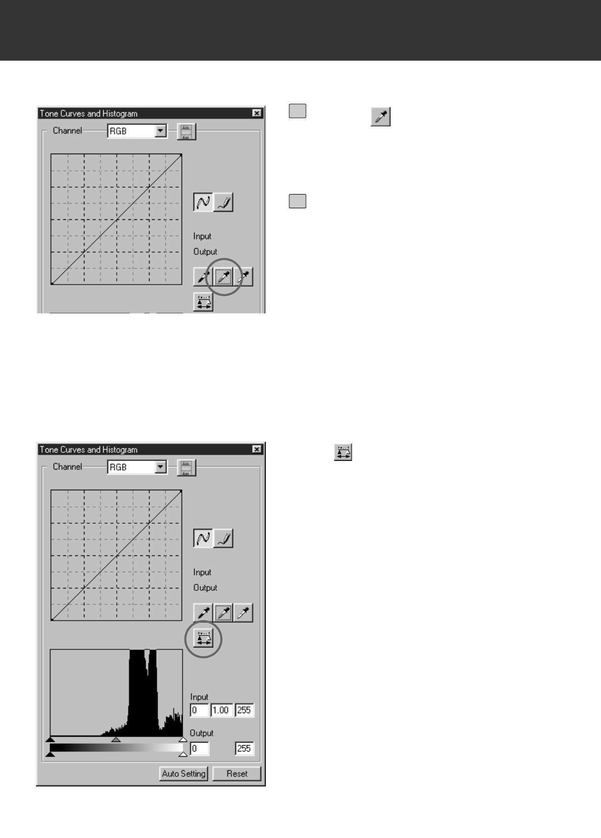
The Tone Curves and Histogram dialog box allows you to change the tone curves and correct the
output value directly. Also, the Histogram part allows you to correct the input and output level in
all RGB colours or in each RGB colour.
TONE CURVES AND HISTOGRAM
Click on .
• Tone Curves and Histogram Correction dialog box will appear
Channel Selection list box
Tone curves
Input Gamma slider
Higstogram
Input Shadow slider
Output Shadow slider
Gray scale
Histogram RGB display
button
Tone curves/Smooth Curve
button
Freehand curve button
Black point button
Gray point button
White point button
Apply button
Input Highlight slider
Input Shadow text box
Input Gamma text box
Input Highlight text box
Output Shadow text box
Output Highlight text box
Output Highlight slider
Reset button
Auto Setting
– 49 –
IMAGE CORRECTION
The tone curve shows the standard input level of Dimage Scan Multi II in the horizontal axis and
the output level for corresponding input level in the vertical axis.
When selecting RGB in the Channel Selection list box, R, G and B are corrected at a same rate.
And when selecting R, G or B, each colour is corrected separately.
CORRECTING THE TONE CURVES
Click on the arrow next to the
Channel Selection list box to select
the channel (R, G, B, RGB) of the
colour to be corrected.
• When a prescan image is monochrome, only
RGB can be selected.
1
Click and drag the portion of the
curve to be changed.
• The value of the horizontal axis is displayed
in the Input box, and that of the vertical axis
is displayed in the Output box respectively.
• The change will be reflected in the prescan
image displayed in the Image Correction dis-
play area.
2
– 50 –
IMAGE CORRECTION
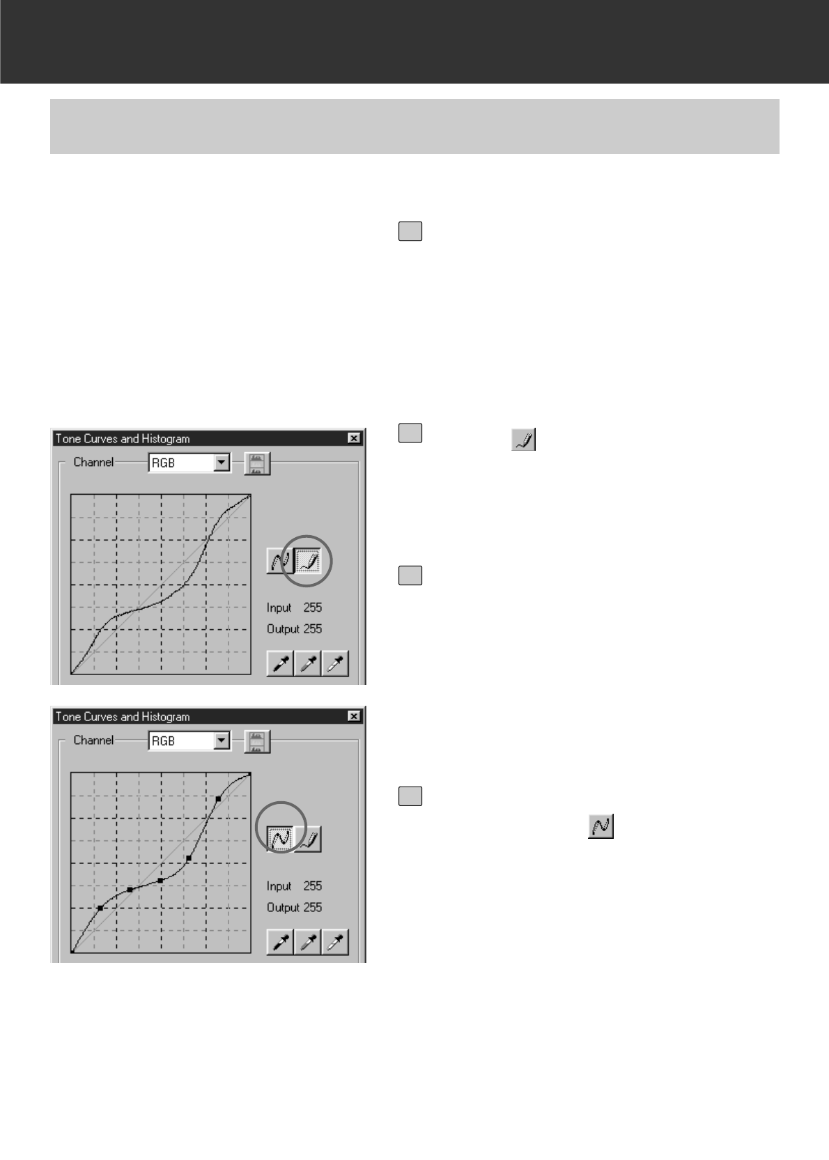
This function allows you to draw tone curves by freehands.
TONE CURVES BY FREEHAND
Click on the arrow next to the
Channel Selection list box to select
the channel (R, G, B, RGB) of the
colour to be corrected.
• When a prescan image is monochrome, only
RGB can be selected.
1
Click on and move the cursor on
the tone curve display.
• The cursor changes to the pencil shape.
2
Draw the desired curve by dragging.
• The value of the horizontal axis is displayed
in the Input box, and that of the vertical axis
is displayed in the Output box respectively.
• The change will be reflected in the prescan
image displayed in the Image Correction dis-
play area.
3
When the curve you drew is not
smooth, click on to smooth the
curve point.
4
– 51 –
IMAGE CORRECTION
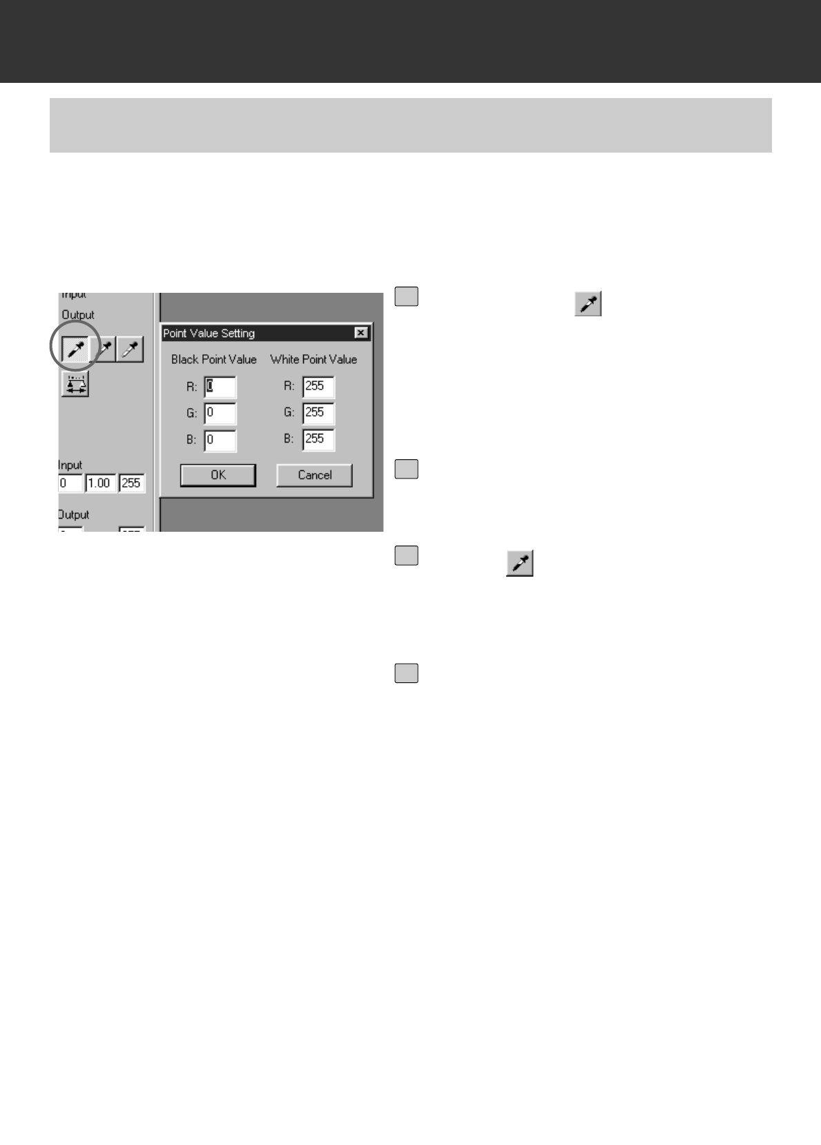
Specifying the Black point
This function allows you to correct a prescan image by specifying the shadow point , highlight
point or gray point.
SPECIFYING THE BLACK, WHITE OR GRAY POINT
Double-click on .
• The Point Value Setting dialog box is dis-
played.
• The initial value of the Black point is 0 in
each R, G and B.
1
Input the desired black point value
and click on [OK].
2
Click on .
• The cursor changes to the black dropper
shape.
3
Click on the shadow point to be cor-
rected in the prescan image.
• The image is corrected so that the point you
clicked is a shadow point. The colour of the
shadow point is the black point value you
input in step 2.
• The change will be reflected in the prescan
image displayed in the Image Correction dis-
play area.
4
– 52 –
IMAGE CORRECTION
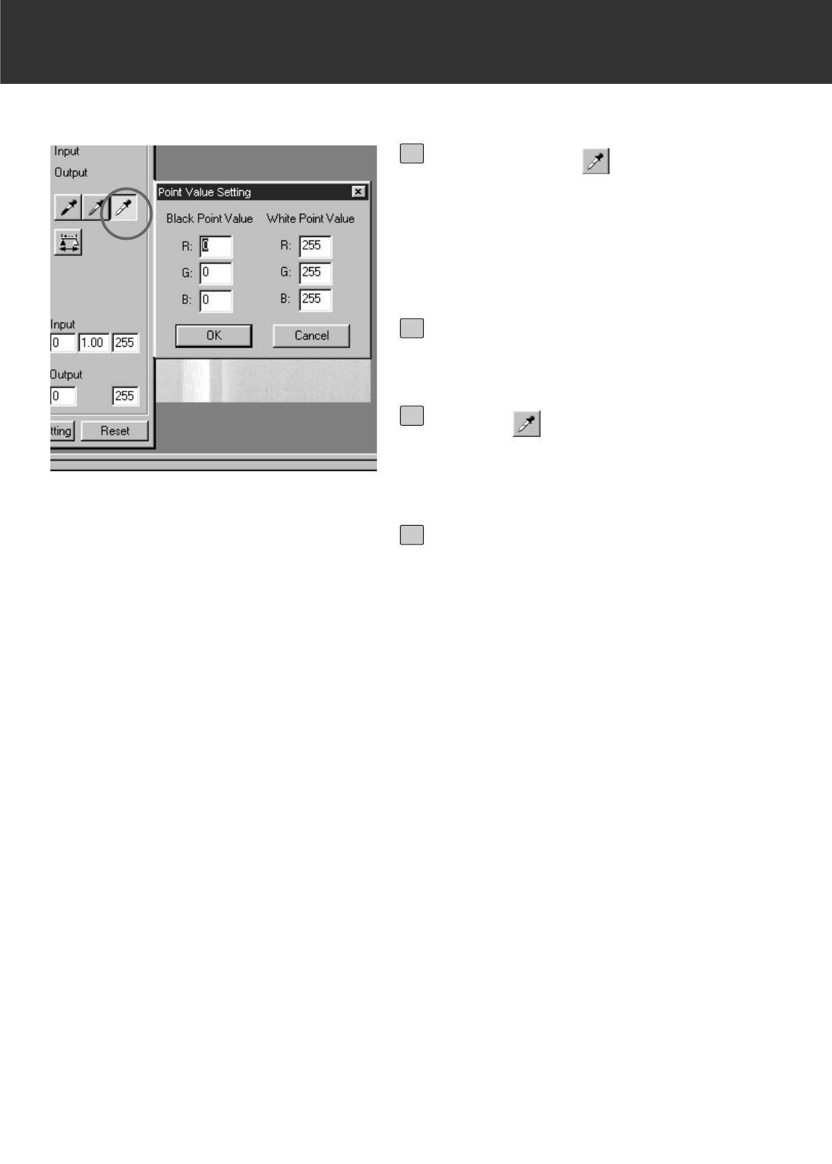
Setting the White point
Double-click on .
• The Point Value Setting dialog box is dis-
played.
• The initial value of the White point is 255 in
each R, G and B.
1
Input the desired white point value
and click on [OK].
2
Click on .
• The cursor changes to the white dropper
shape.
3
Click on the highlight point to be cor-
rected in the prescan image.
• The image is corrected so that the point you
clicked is a highlight point. The colour of the
highlight point is the white point value you
input in step 2.
• The change will be reflected in the prescan
image displayed in the Image Correction dis-
play area.
4
– 53 –
IMAGE CORRECTION
When is clicked, the histogram of
images after making corrections can be
displayed.
The histogram after making corrections
is displayed as long as you press this
button. When the button is released, the
histogram returns to the previous one.
Setting the Gray point
Click on the gray point to be correct-
ed in the Prescan image.
• The image is corrected so that the point you
clicked is a gray point. The colour is bal-
anced and the value of brightness is not
changed on that point.
• The change will be reflected in the prescan
image displayed in the Image Correction dis-
play area.
2
Click on .
• The cursor changes to the gray dropper
shape.
1
– 54 –
IMAGE CORRECTION
The input slide bar and the output slider are under
the Histogram window.
The input slider has the Highlight slider (right),
gamma slider (middle) and shadow slider (left).
The output slider has the Highlight slider (right)
and Shadow slider (left).
The Histogram can be corrected by dragging each
slider or inputting the value directly in each Input or
Output level box.
For example, if you use the input Highlight slider
and input shadow slider to remove areas which
contain no pixels (flat line at left or right) the
original colour will be better represented.
Although the output slider does not normally need
to be adjusted, use it according to the
characteristics of the output equipment. For
example, use the output slider when the black part
is not printed clearly with the 0 setting in the black
level. (In this case, adjust the Output level by
moving the Output Shadow slider to the right
slightly while checking the correction result).
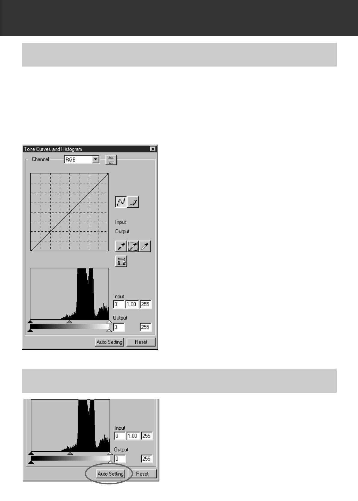
The Histogram part allows you to correct images by specifying the input and output area from the
information including in a film. Also, this window displays the histogram of the image area inside
the cropping frame in each RGB colour. The level is indicated in 256 colour steps (0 to 255) from
left to right side.
The tone curves and histogram are linked each other. When the tone curve is corrected, the
histogram is automatically corrected and vice versa.
CORRECTING THE HISTOGRAM
Click on the Auto setting button.
• The image is corrected automatically by remov-
ing no information (pixels) parts from the his-
togram and using all tone steps from 0 to 255.
• The change will be reflected in the prescan
image displayed in the Image Correction display
area.
CORRECTING THE HISTOGRAM – AUTO SETTING
– 55 –
IMAGE CORRECTION
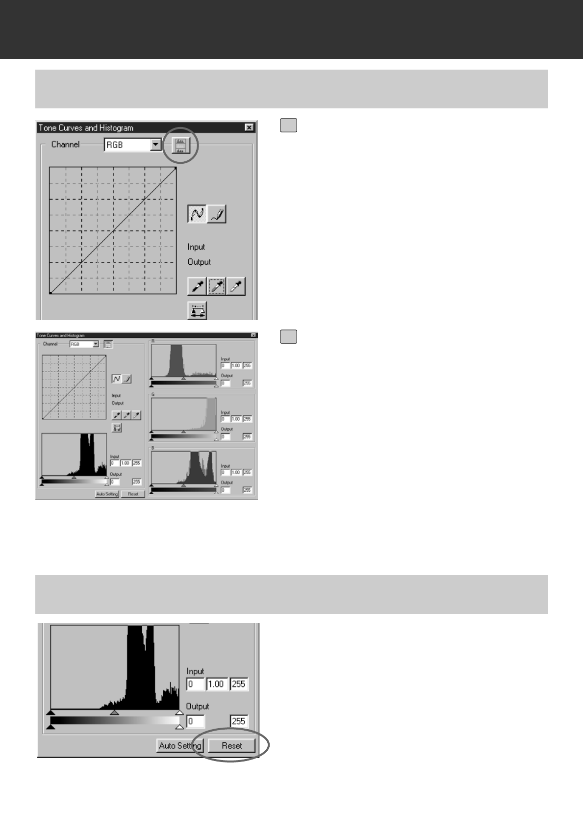
Click on the Reset button.
• All corrections made in the Tone Curves and
Histogram dialog box will be reset. The prescan
image will also return to the previous image.
CORRECTING THE HISTOGRAM – EACH R, G, B CHANNEL
Click on the Histogram RGB display
button.
• The RGB Histogram display will appear in
the Tone Curves and Histogram dialog box.
• When the Histogram RGB display button is
clicked again, the histogram of each R, G, B
channel will disappear.
1
By dragging the Input Highlight slid-
er (right) or the Input Shadow slider
(left) in each R, G, B channel or
inputting the value directly in each
text box, the Histogram RGB can be
corrected.
• The change will be reflected in the prescan
image displayed in the Image Correction dis-
play area.
• The change corrected in each R, G, B chan-
nel will be also reflected in each correspond-
ing tone curve.
2
CORRECTING THE HISTOGRAM – RESET
– 56 –
IMAGE CORRECTION
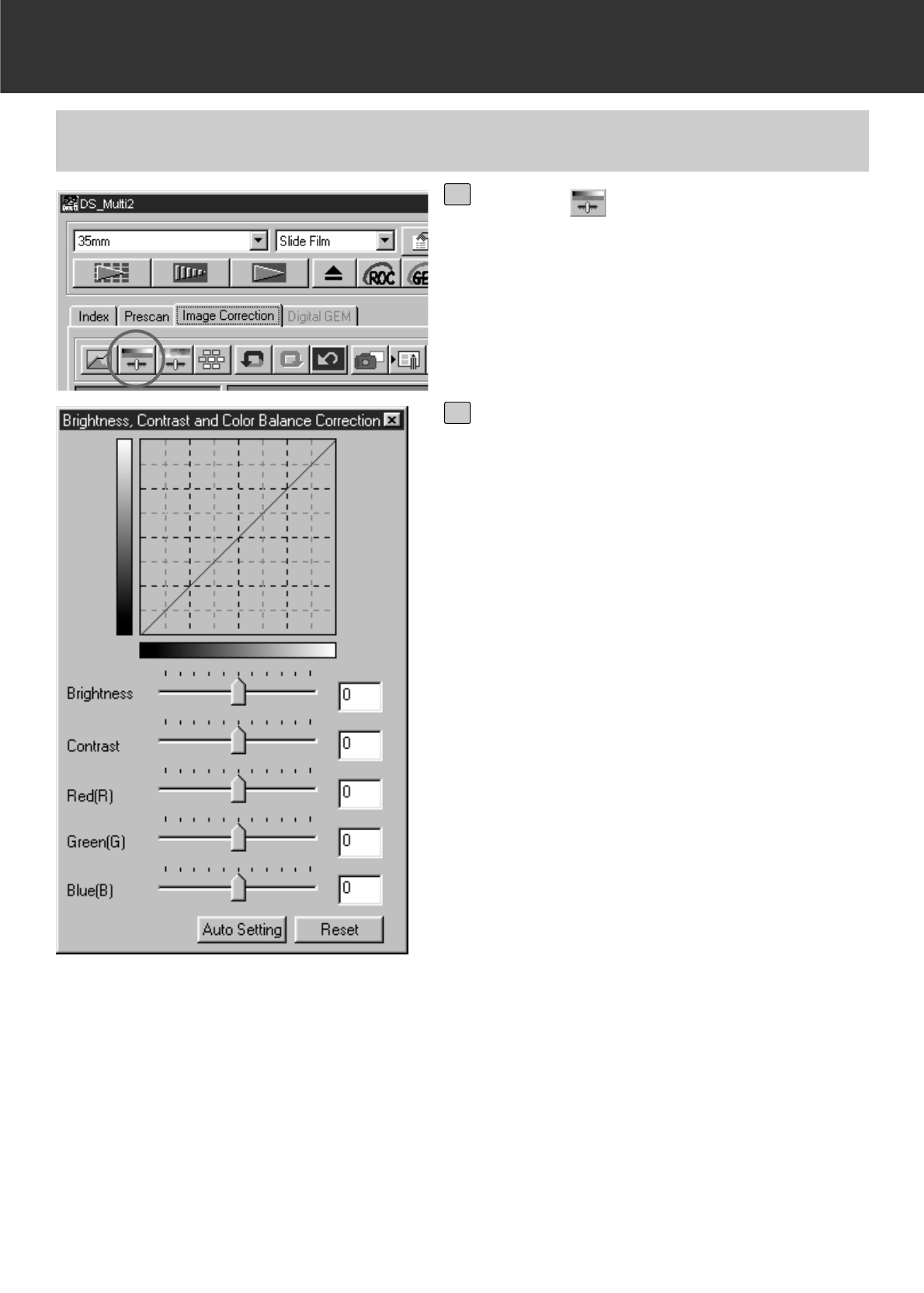
Brightness correction: By dragging the Brightness slider to the right (or inputting a big
plus number in the text box), the brightness of the image is
raised.
Contrast correction: By dragging the Contrast slider to the right (or inputting a big
plus number in the text box), bright parts will be made brighter
and dark parts will be made darker.
RGB color balance correction: By dragging the Colour Balance slider to the right (or inputting a
big plus number in the text box), each colour content is
increased to emphasize each colour.
CORRECTING BRIGHTNESS/CONTRAST/COLOR BALANCE
Click on .
• The Brightness, Contrast, Color Balance
Correction dialog box will appear.
1
Drag each Brightness, Contrast, Red
(R), Green (G) or Blue (B) slider or
input each value directly in each text
box.
•Values from –100 to +100 can be input.
• The change will be reflected in the prescan
image displayed in the Image Correction dis-
play area.
2
– 57 –
IMAGE CORRECTION
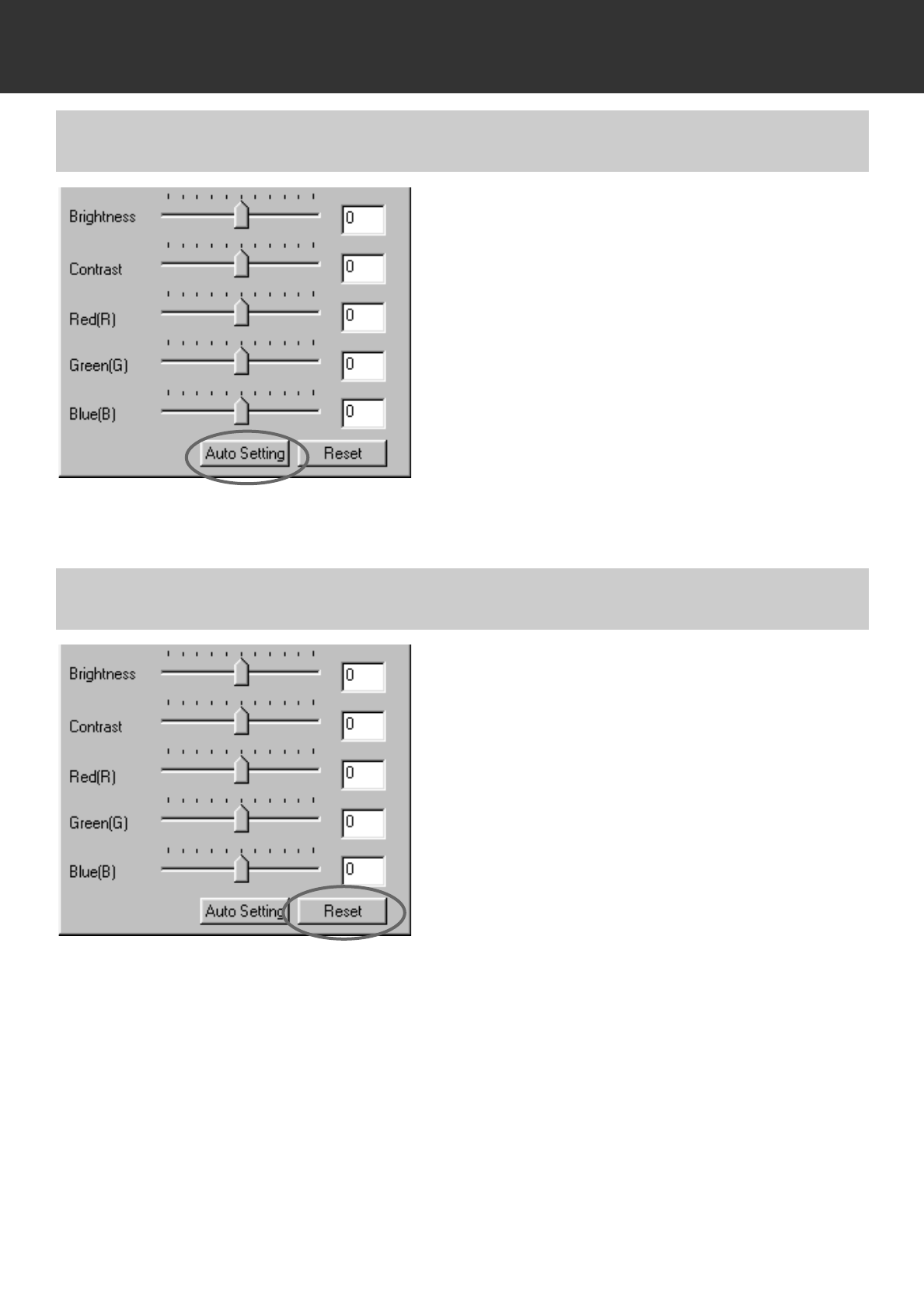
Click on the Auto Setting button.
• The brightness and contrast of the image is cor-
rected automatically according to the lightness
information without changing the RGB input
colour balance.
• The change will be reflected in the prescan
image displayed in the Image Correction display
area.
Click on the Reset button.
• The corrections made in the Brightness,
Contrast, Colour Balance Correction dialog box
will all be reset. The prescan image will also
return to the previous image.
CORRECTING BRIGHTNESS/CONTRAST/COLOR BALANCE – AUTO SETTING
CORRECTING BRIGHTNESS/CONTRAST/COLOR BALANCE – RESET
– 58 –
IMAGE CORRECTION
Hue correction: By dragging the Hue slider, the colour of the image displayed in Pre-
Correction Colour Sample is changed as shown in Post-Correction Colour
Sample. When the Hue slider is dragged to the rightmost or leftmost side,
the hue of the image is reversed.
Saturation correction: By dragging the Saturation slider to the right (or inputting a big plus
number in the text box), the colours become more saturated. By dragging
the Saturation slider to the left (or inputting a big minus number in the
text box), the saturation of the image is reduced.
Lightness correction: By dragging the Lightness slider to the right (or inputting a big plus
number in the text box), the lightness of the image is raised.
Post-Correction Colour Sample
Pre-Correction Colour Sample
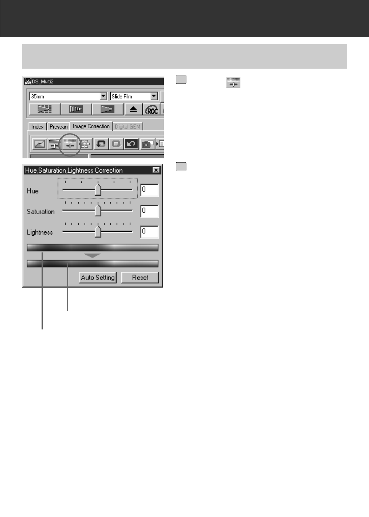
CORRECTING HUE/SATURATION/LIGHTNESS
Click on .
• The Hue, Saturation, Lightness Correction
dialog box will appear.
1
Drag each Hue, Saturation or
Lightness slider or input each value
directly in each text box.
• Values from –180 to +180 or –100 to +100
can be input in the Hue or the Saturation and
Lightness respectively.
• The change will be reflected in the prescan
image displayed in the Image Correction dis-
play area.
2
– 59 –
IMAGE CORRECTION
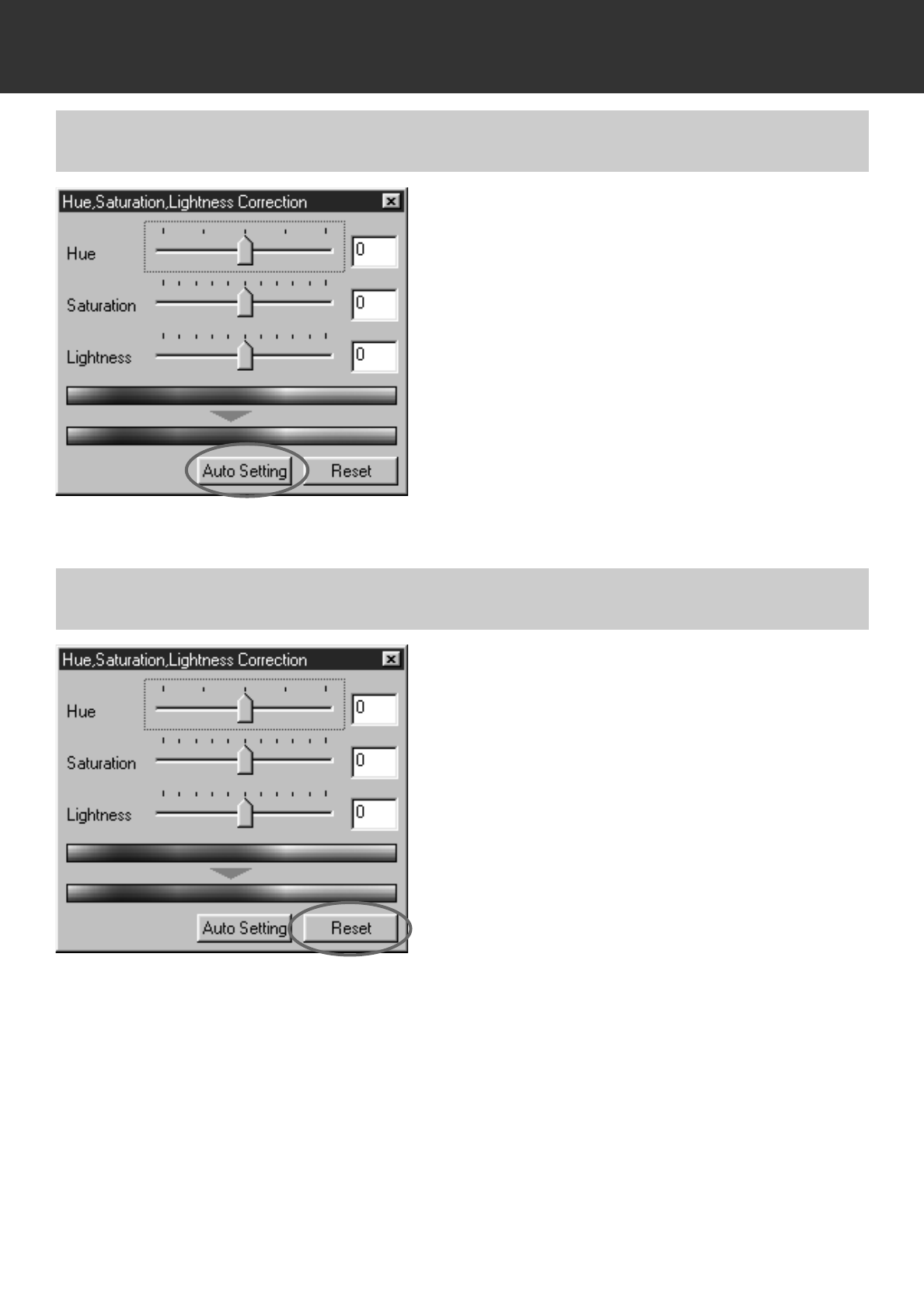
Click on the Auto Setting button.
• The saturation of the image is corrected auto-
matically without changing the hue and lightness
information.
• The change will be reflected in the prescan
image displayed in the Image Correction display
area.
Click on the Reset button.
• The corrections made in the Hue, Saturation,
Lightness Correction dialog box will all be reset.
The prescan image will also return to the previ-
ous image.
CORRECTING HUE/SATURATION/LIGHTNESS – AUTO SETTING
CORRECTING HUE/SATURATION/LIGHTNESS – RESET
– 60 –
IMAGE CORRECTION
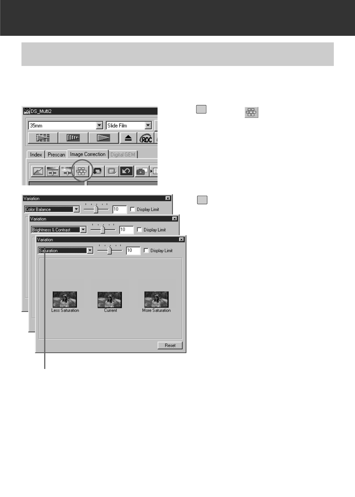
Correction list box
The Variation correction allows you to correct the brightness, contrast and saturation while
checking the simulated image after correction.
VARIATION CORRECTION
Click on .
• The Variation correction dialog box
will appear.
1
Click on the arrow in the
Correction list box to select
the correction item.
• Colour Balance, Brightness &
Contrast and Saturation can be
selected from the Correction list
box.
• Colour Balance and Saturation can-
not be selected when B&W is
selected in the film type.
• A number of frames of variation
images corrected according to the
selected correction item are dis-
played.
2
– 61 –
IMAGE CORRECTION
Variation Amount Control slider
Limit indication checkbox
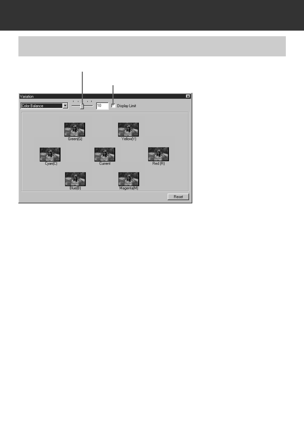
In the Colour Balance correction, 6 images that have been corrected by one-step in each red (R),
magenta (M), blue (B), cyan (C), green (G) or yellow (Y) direction from the center image are
displayed. When the image in the direction to be corrected is clicked, the image is placed in
center and new variation images are displayed.
By dragging the Variation Amount Control slider, the value of correction can be changed in the
range from 1 to 20 (The initial value is 10).
When the Limit indication check box is checkmarked and the image is corrected in each red (R),
magenta (M), blue (B), cyan (C), green (G) or yellow (Y) direction, any part of the image which
has been corrected beyond the range which can be displayed is displayed in reversed colour.
VARIATION CORRECTION – COLOUR BALANCE
– 62 –
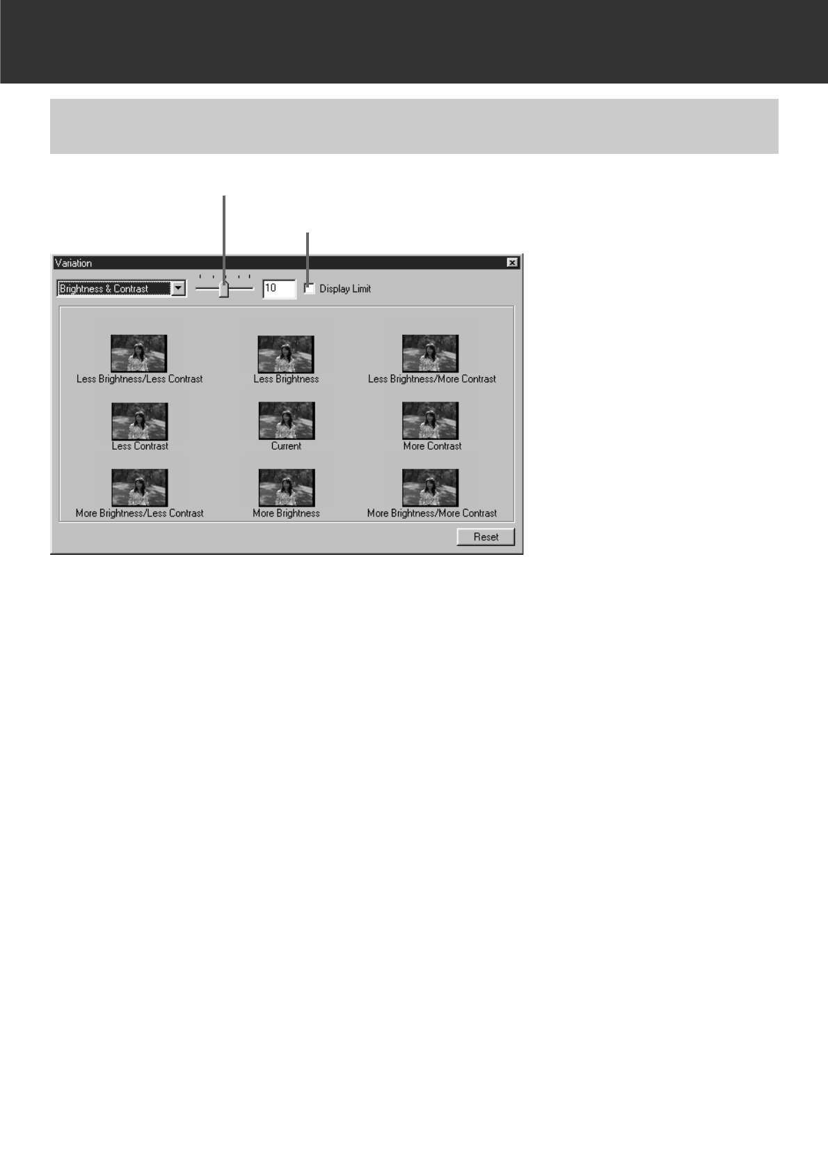
Variation Amount Control slider
Limit indication checkbox
In the Brightness & Contrast correction, 8 images that have been corrected from the center
image by one-step in the horizontal direction for brightness and in the vertical direction for
contrast are displayed. When the image in the direction to be corrected is clicked, the image is
placed in the center and new variation images are displayed.
By dragging the Variation Amount Control slider, the value of correction can be changed in the
range from 1 to 20 (The initial value is 10).
When the Limit indication check box is checkmarked and the brightness and contrast are
corrected, any part of the image which has been corrected beyond the range which can be
displayed is displayed in reversed colour.
IMAGE CORRECTION
VARIATION CORRECTION – BRIGHTNESS & CONTRAST CORRECTION
– 63 –
IMAGE CORRECTION
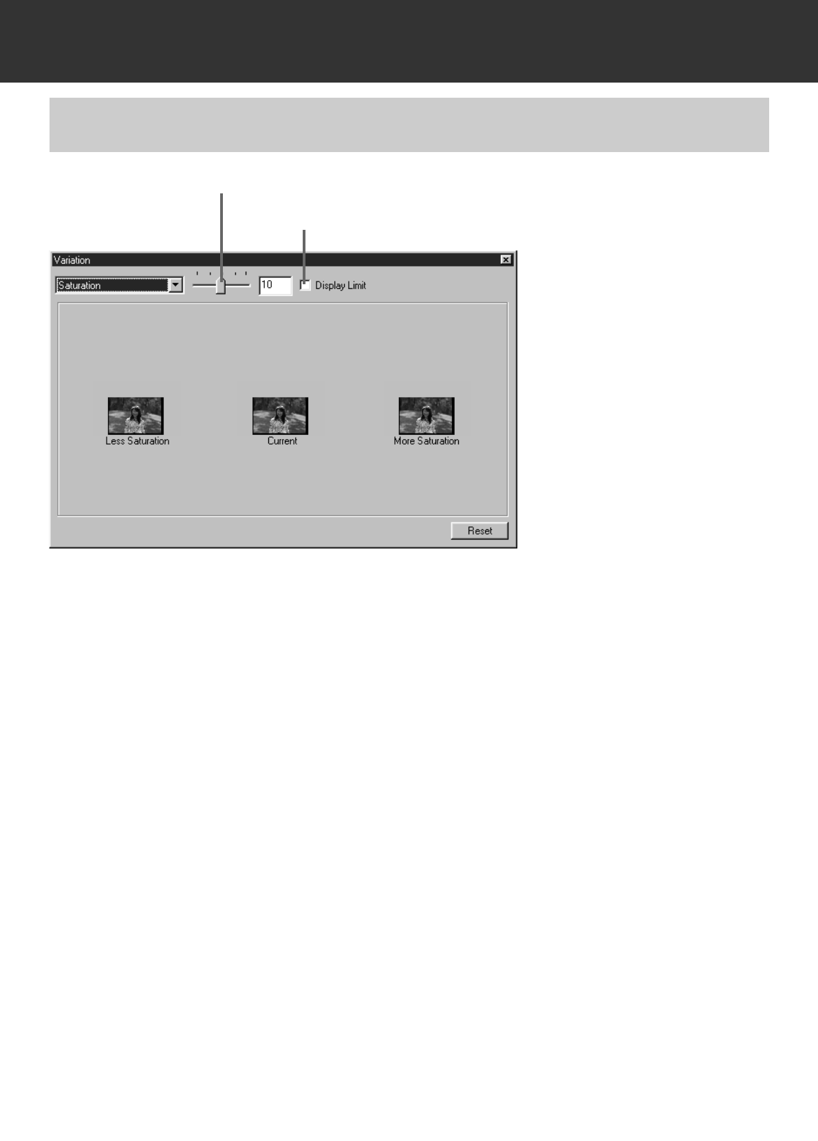
Variation Amount Control slider
Limit indication checkbox
In the Saturation correction, 2 images in which saturation has been corrected from the center
image by one-step are displayed on the right and left sides of the center image. When the image
in the direction to be corrected is clicked, the image is placed in the center and new variation
images are displayed.
By dragging the Variation Amount Control slider, the value of correction can be changed in the
range from 1 to 20 (The initial value is 10).
When the Limit indication check box is checkmarked and the saturation is corrected, any part of
the image which has been corrected beyond the range which can be displayed is displayed in
reversed colour.
VARIATION CORRECTION – SATURATION CORRECTION
– 64 –
IMAGE CORRECTION
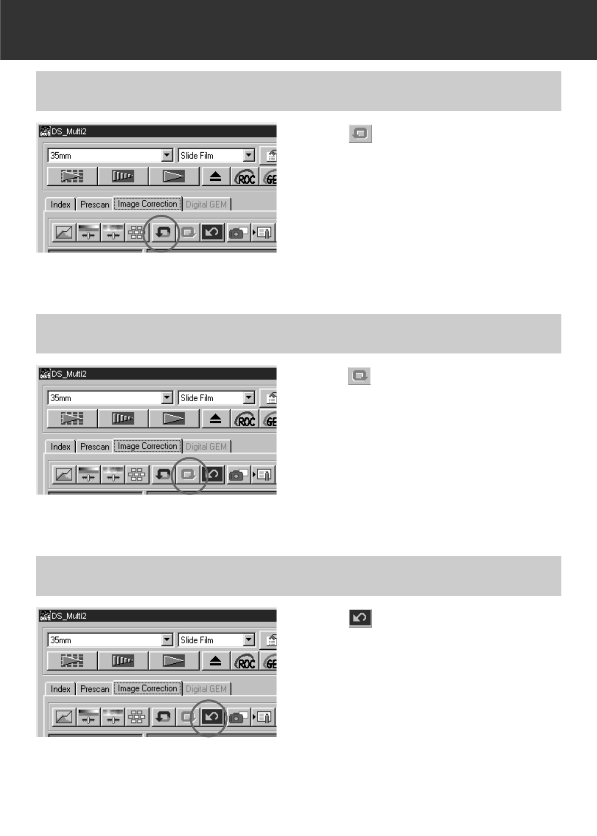
Click on .
• The image correction will be cancelled and the
image will return to the previous one. The image
before correction will be restored as long as suf-
ficient memory is available.
CANCELLING THE IMAGE CORRECTION
Click on .
• The cancelled image correction will be resumed.
REDO THE CORRECTION
Click on .
• All the image corrections will be reset and the
image will return to the initial state.
• All the correction items will be reset. Even if the
Redo button is clicked, nothing can be resumed.
DELETING THE IMAGE CORRECTION
(DELETING ALL THE IMAGE CORRECTION)
– 65 –
IMAGE CORRECTION
• The thumbnail images are displayed in the Snapshot display area as long as there is sufficient
memory available.
• When the thumbnail image in the Snapshot display area is clicked, that image is displayed as
a prescan image.
• To delete the thumbnail image in the Snapshot display area, click on the thumbnail image to
be deleted then press the Delete key (Press the Command key and D key simultaneously for
Macintosh).
• When the Correction Reset button (p.64) is clicked or the software is shut down, all the thumb-
nail images in the Snapshot display area are deleted.
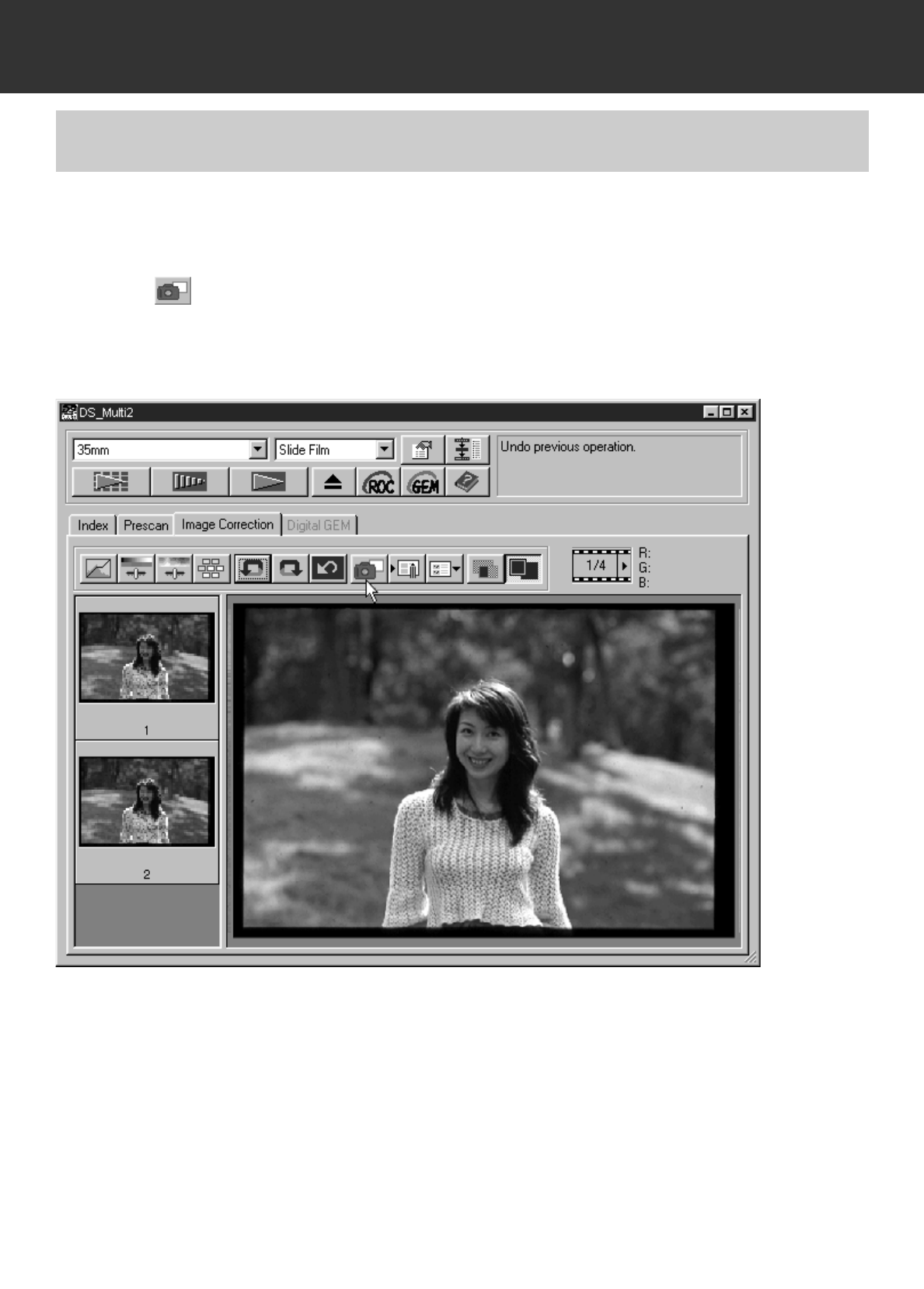
The current prescan image can be stored in the Snapshot display area temporarily and displayed
as a thumbnail.
SNAPSHOT
Click on .
• The current prescan images are stored in the Snapshot display area temporarily and displayed
as a thumbnail.
– 66 –
IMAGE CORRECTION
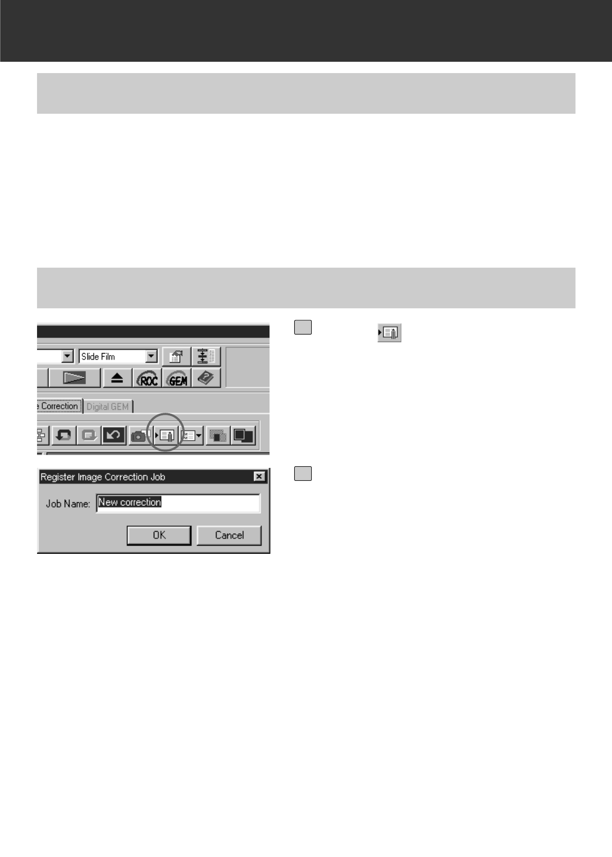
The image correction setting in each correction window can be saved as an image correction job.
Once the correction item is saved, you can easily correct the image by loading the appropriate
correction job.
IMAGE CORRECTION JOB
IMAGE CORRECTION JOB – SAVING IMAGE CORRECTION JOB
Click on .
• The register Image Correction Job dialog
box will appear.
1
Input the job name and click on [OK].
• The current image correction setting is
saved as an image correction job.
2
– 67 –
IMAGE CORRECTION
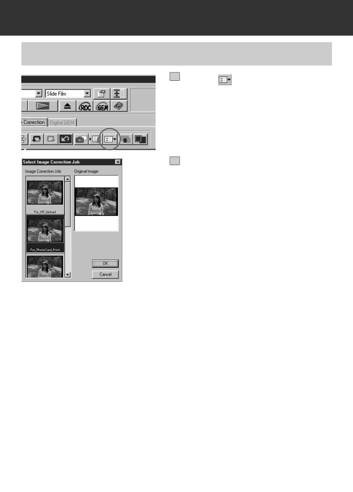
IMAGE CORRECTION JOB – LOADING IMAGE CORRECTION JOB
Click on .
• The Select Image Correction Job dialog box
will appear.
1
Select the image correction job and
click on [OK].
• The saved image correction job will be
applied to the currently displayed prescan
image.
2
– 68 –
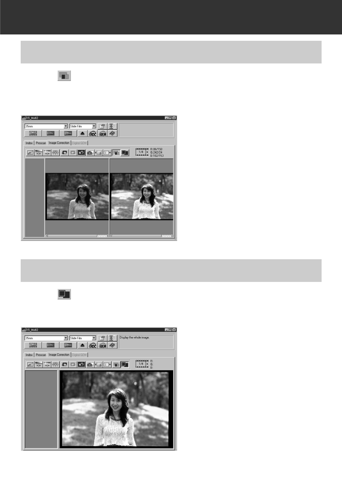
IMAGE CORRECTION
Click on .
• The correction result can be checked easily because the pre-correction image is displayed in
the left side and the post-correction image is displayed in the right side.
CHECKING THE CORRECTION RESULT WHILE LINING UP IMAGES
Click on .
• The post-correction image will be displayed in the Image Correction display area.
FULL-SCREEN VIEWING THE POST-CORRECTION IMAGE
– 69 –
DIGITAL ROC/GEM
The Digital ROC (Reconstruction Of Colour) function is an image correct function that can restore
the colour quality of a faded image.
If the colour of the film has faded with the passage of time, the changed colour can be corrected
automatically by reconstructing colour when scanning so that a digital image with an appropriate
colour can be restored.
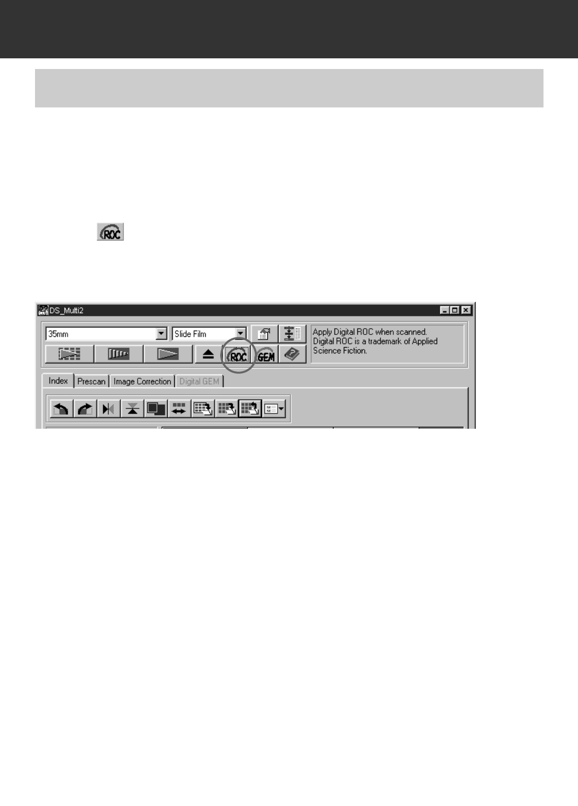
DIGITAL ROC
Click on in the Main window.
• The Digital ROC function is turned on. When the preview scan and final scan (p.78) are per-
formed, the colour quality of a faded image is restored and the corrected image is displayed.
• When scanning a B&W film, or a colour film when 16 bit linear is selected as the scanning
mode in the Preferences, the Digital ROC function cannot be used.
• When the Digital ROC function is turned on, the settings of [Auto Expose for Slides] in the
Preferences, the colour matching, the AE Lock function when prescanning (p.38) or the AE
Area Lock function (p.39) are cancelled.
• When using the Digital ROC function, be sure and perform the prescan and adjust the focus
with the Point AF or Manual Focus function (p.40 to 41) before the final scan. Putting a check-
mark on [Auto Focus at Scan] in the Preferences is recommended.
• To turn off the Digital ROC function, click on the Digital ROC button again.
• The Digital ROC function may not always be obtained effectively depending on the conditions
of the film or the faded colour.
• Much more time is required for scanning when the Digital ROC function is turned on, com-
pared with when that function is turned off.
– 70 –
DIGITAL ROC/GEM
The images of developed film are composed of high-density grains. These grains sometimes
clump together so that the images look rough. This function detects the grains when scanning
and equalizes them. So, a sharp and smooth image can be obtained even when the image of 35
mm film is magnified.
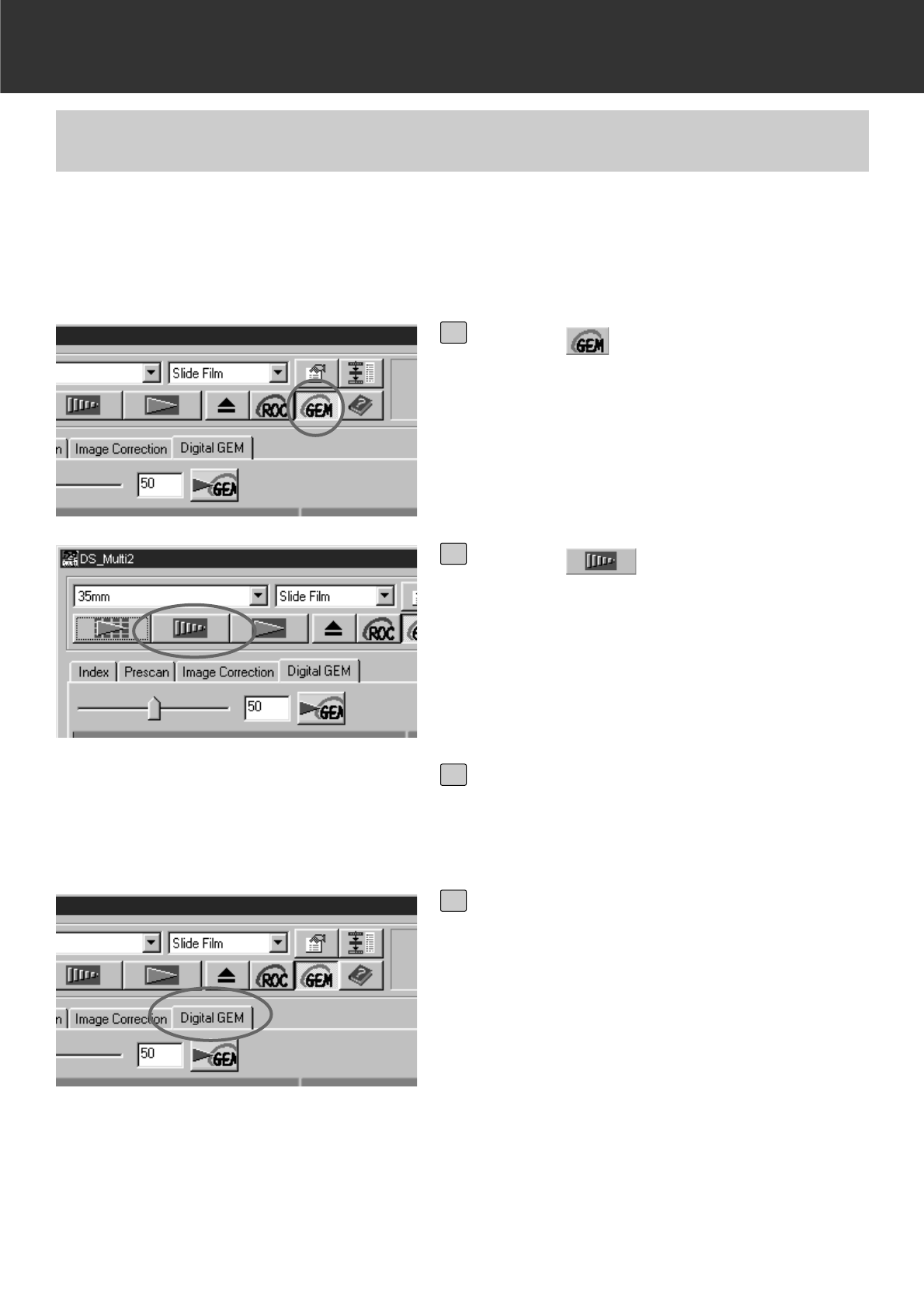
DIGITAL GEM
Click on in the Main window.
• The [Digital GEM] tab will be activated.
1
Click on in the Main window.
• The prescan will begin.
• The Prescan window will appear and the
prescan image will be displayed in the win-
dow.
2
Select the desired Input Resolution in
the Scan Settings window (P. 80-81).
3
Click on [Digital GEM] tab.
• The next page window will appear.
4
– 71 –
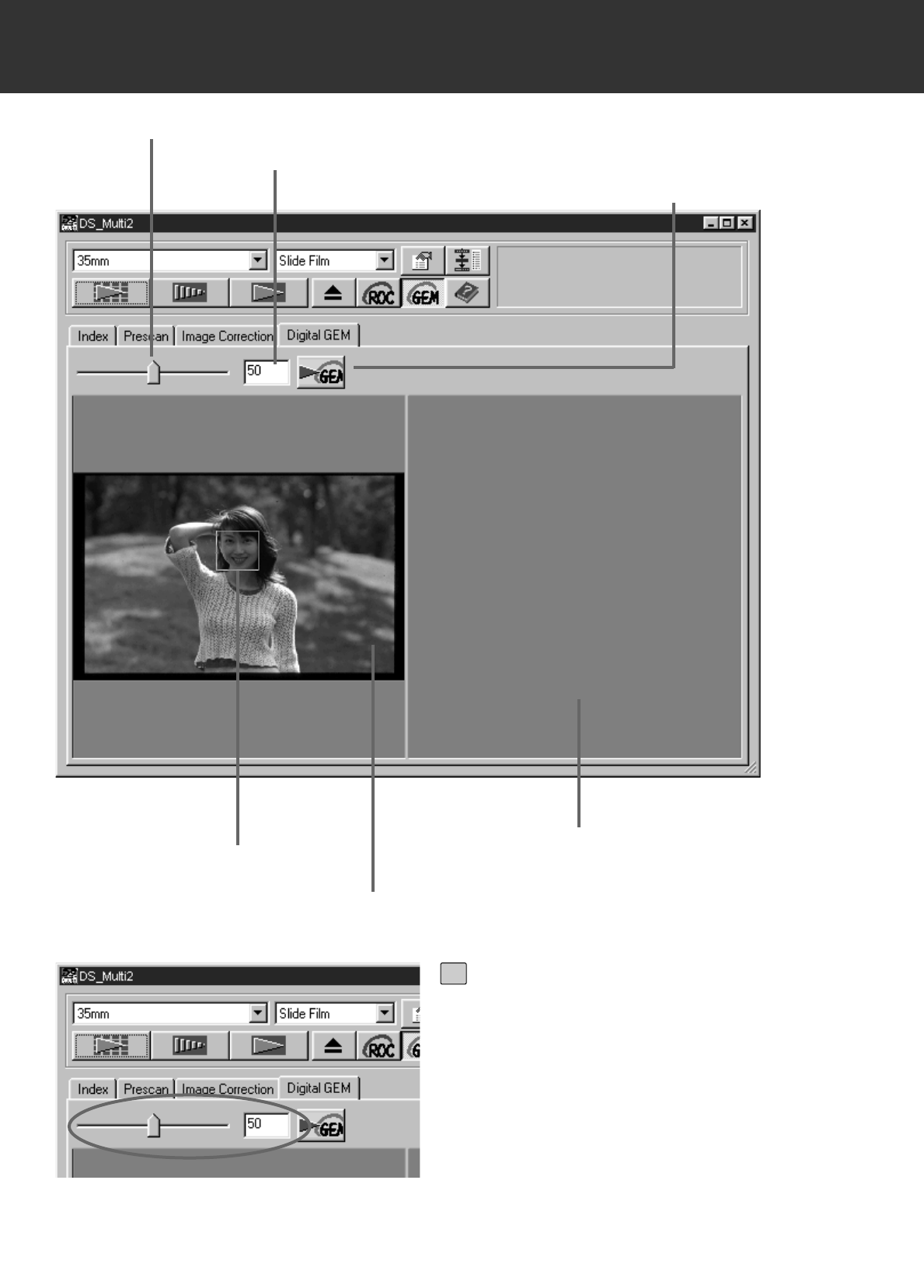
DIGITAL ROC/GEM
Digital GEM Adjust slider
Digital GEM text box
Digital GEM check button
Digital GEM check area Digital GEM image display check area
Digital GEM image display area
Drag the Digital GEM Adjust slider or
input the desired value directly in the
text box.
• Values from 0 to 100 can be input.
• The bigger the value is, the more effective
the correction result is.
5
– 72 –
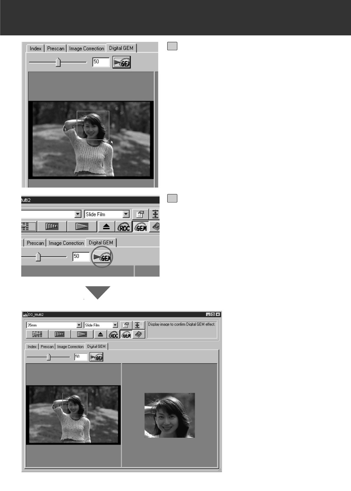
DIGITAL ROC/GEM
Change the Digital GEM check area
size or move that area if necessary
and specify the image area to be
checked.
• The Digital GEM check area is specified in
the center of the image and the size of 64
pixels x 64 pixels.
• To move the area or change the area size,
refer to the operations of the cropping frame
(p.43 to 44).
6
Click on the Digital GEM check but-
ton.
• To get the Digital GEM check image, the film
will be scanned according to the input resolu-
tion specified in step 3.
• The image area specified in step 6 will be
corrected according to the value specified in
step 5, and displayed in the Digital GEM
check image display area and the correction
result can be checked.
7
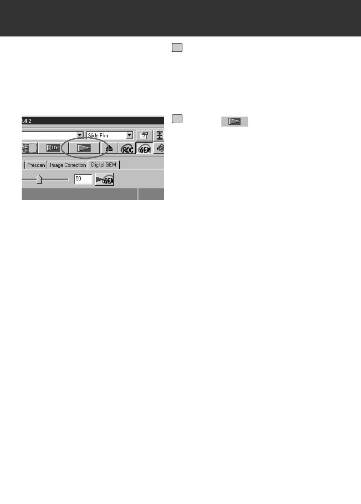
– 73 –
DIGITAL ROC/GEM
• When scanning a B&W film, the Digital GEM function is not available.
• When using the Digital GEM function, be sure and perform the prescan and adjust focus with
the Point AF or Manual Focus function (p.40 to 41) before the final scan. Putting a checkmark
on [Auto Focus at Scan] in the Preferences is recommended.
• The Digital GEM function may not always operate effectively depending on the condition of the
film.
• Much more time is required for scanning when the Digital GEM function is turned on compared
with when that function is turned off.
Repeat steps 5 to 7 if necessary and
specify the Digital GEM adjust value
so that an appropriate correction
result can be obtained.
8
Click on .
• The image will be scanned and corrected
according to the specified value (Digital GEM
adjust value).
• For operations after performing the final
scan, see page 86.
9
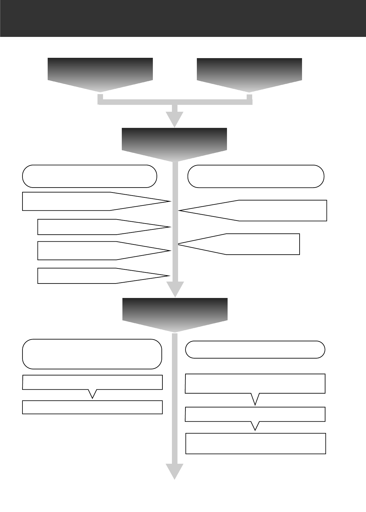
– 74 –
FLOW CHART TO THE FINAL SCAN
Image Correction
Job Digital ROC/GEM
When Setting in the Scan Settings Part
Window
Scan Job Category (p.77)
Loading the Image Correction Job
(p.76)
Example of the Scan Settings
(p.84)
Scan Settings
When Using the Utility Software (p.78)
The Final Scan
When using the Image Correction Job
Deleting a Job (p.87)
Registering the Image Correction
Job (p.86)
When using Twain Driver/Plug-in
Software/Image Editing Application (p.78)
The Final Scan
Saving in an Image Editing Application The Final Scan
Saving with the Specified File Name in the
Specified File Destinatio
The Selection Items in the Scan
Settings Window (p.80)
Inputting a File Name/Selecting a File Destination

– 75 –
JOB
Before scanning, it is necessary to make various settings in the Scan Settings window (p. 80)
such as the amount of detail required to read the original film (input resolution), the amount of
detail required for output (output resolution), the size required for output (output
size/magnifications), etc.
It is important that these settings are made properly in order to achieve optimal results for the
size and/or purpose of the final image. A beginner may find these settings to be complicated and
difficult to understand.
“Job” is a function that allows you to save all the item settings made to the Scan Settings window
to a particular file so that this file can be recalled when necessary for any future jobs that require
the same settings. Properly used, this function can simplify the complicated process of setting the
resolution, image size, magnifications, etc. scanner settings, so that even a beginner can easily
execute the ideal settings required for the job.
Up to 8 items can be set to numerical values in the Scan Settings window. One pattern reflecting
settings for each of the 8 items can be saved to a Job file. Should these settings be changed, the
new settings can be saved to another job file. All Job files are collected within the “Job File List”
that designates 10 individual categories for each image output destination (device to which the
job is to be output). In total, approximately 570 different types are available.
Because other optional settings can be registered to the Job File List, intermediate and advanced
users can increase their work efficiency by saving commonly used scanner settings to the Job
File List. Also, it is possible to reduce work time by saving settings to the Job File List when
specific settings are required, regardless of the image to be scanned.
• When installing the setup program (installer) by following the instructions, the job files are
installed in the following folders for each category.
When using Windows®(The startup hard disk assumes drive C.)
[C:] -> [Program Files Folder] -> [DS_Multi II Folder] -> [Job Folder]
When using Macintosh
[System Folder of Start Up Disk] ->[Preferences Folder] ->[DSMulti II Jobs Folder]
• For adding or deleting a job file, see “Registering a Job” or “Deleting a Job” described on the
following pages. The files in the folders described above can not be operated with Explorer (or
Finder on Macintosh).
• The “Scan Job File List” in which all the scan job settings are listed, is at the end of this
instruction manual.
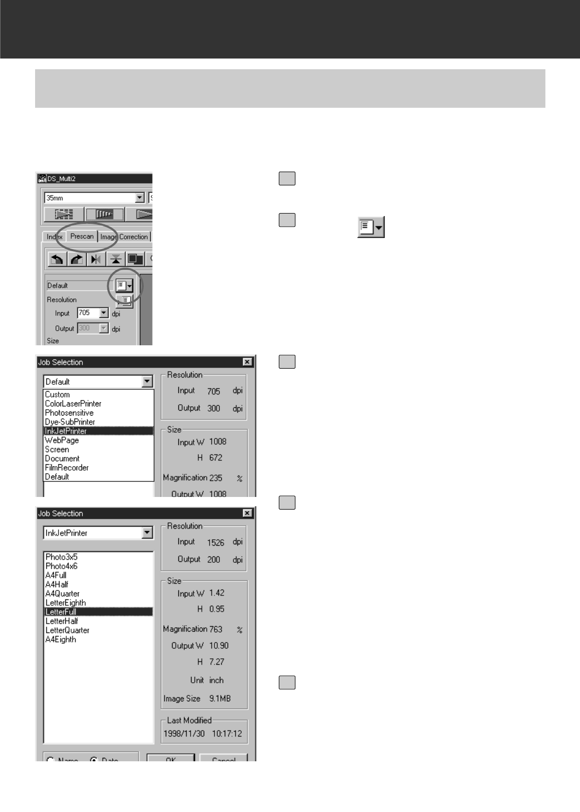
– 76 –
JOB
The scan setting of the job file can be applied to the current prescan image by loading a job file
from the preset Job File List.
LOADING A JOB
Click on the Prescan tab.
1
Click on .
• The Job Selection dialog box will appear.
2
Select the appropriate category from
the list box.
3
Select the job file name to be applied
from the list.
• The scan setting saved in the selected job
file will be displayed in the right of the win-
dow. When another job file is selected, the
setting is changed correspondingly.
• By clicking on the Name or Date option but-
ton, the format of the Job File List can be
changed.
4
Click on [OK].
• The selected scan setting will applied to the
prescan image and the Job Selection dialog
box will disappear. The selected job will be
displayed in the Job Name list box.
5
– 77 –
JOB
CATEGORIES:
Scan Job Category Description
Custom This category allows the user to create customized
settings using the Scan Settings part.
Colour Laser Printer (Digital colour
copiers and colour laser printers) Uses an output resolution of 400 dpi. There are two
image-size options; letter and A4.
Photosensitive (Printers that use
photosensitive/photographic
material)
Uses an output resolution of 400 dpi, 300 dpi 267 dpi
and 180 dpi. The image size will vary.
Dye-sub (Dye-sublimation printers) Uses an output resolution of 300 dpi. There are 11
available image sizes.
Ink-jet (Ink-jet printers) Uses an output resolution of 200 dpi. The image size
will vary.
Web Page (For use on home pages) Uses an output resolution of 72 dpi. Image size is listed
in pixels and will vary. There also 4 standard PhotoCD
size available.
Screen (For display on monitors) Uses an output resolution of 72 dpi. Image size is listed
in pixels and will be the VGA standard of 640 x 480
pixels or larger.
Document (For insertion into
documents) Uses an output resolution of 72 dpi. Image size can be
determined by a variety of paper sizes.
Film Recorder For high input resolution images that will be output to a
film recorder.
Default This category uses the default settings for each film
format. The settings appear in the Job Selection
window.
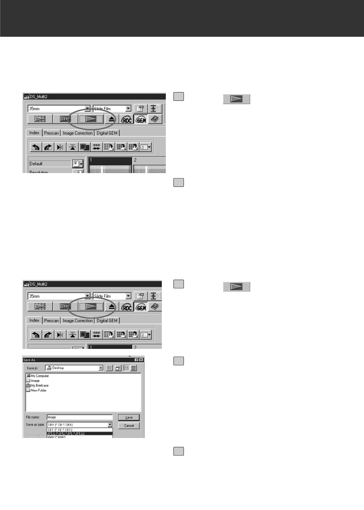
– 78 –
FINAL SCAN
After cropping frames, correcting images and specifying the scanning settings, the final scan is
performed.
When using Twain Driver/Plug-in Software
Click on in the Main window.
• The final scan will begin.
• When the final scan is complete, the final
scan images will appear in the window of the
image editing application you use.
1
Perform suubsequent operations
according to the instruction for your
image editing application.
• For details, see the instruction manual for the
image editing application.
2
When Using the Utility Software
Click on in the Main window.
• The standard save dialog box for your oper-
ating system will appear.
1
Enter the desired file name and select
the file destination.
2
Select the file type from the [Save as
type] list box (or the file format drop-
down list).
3
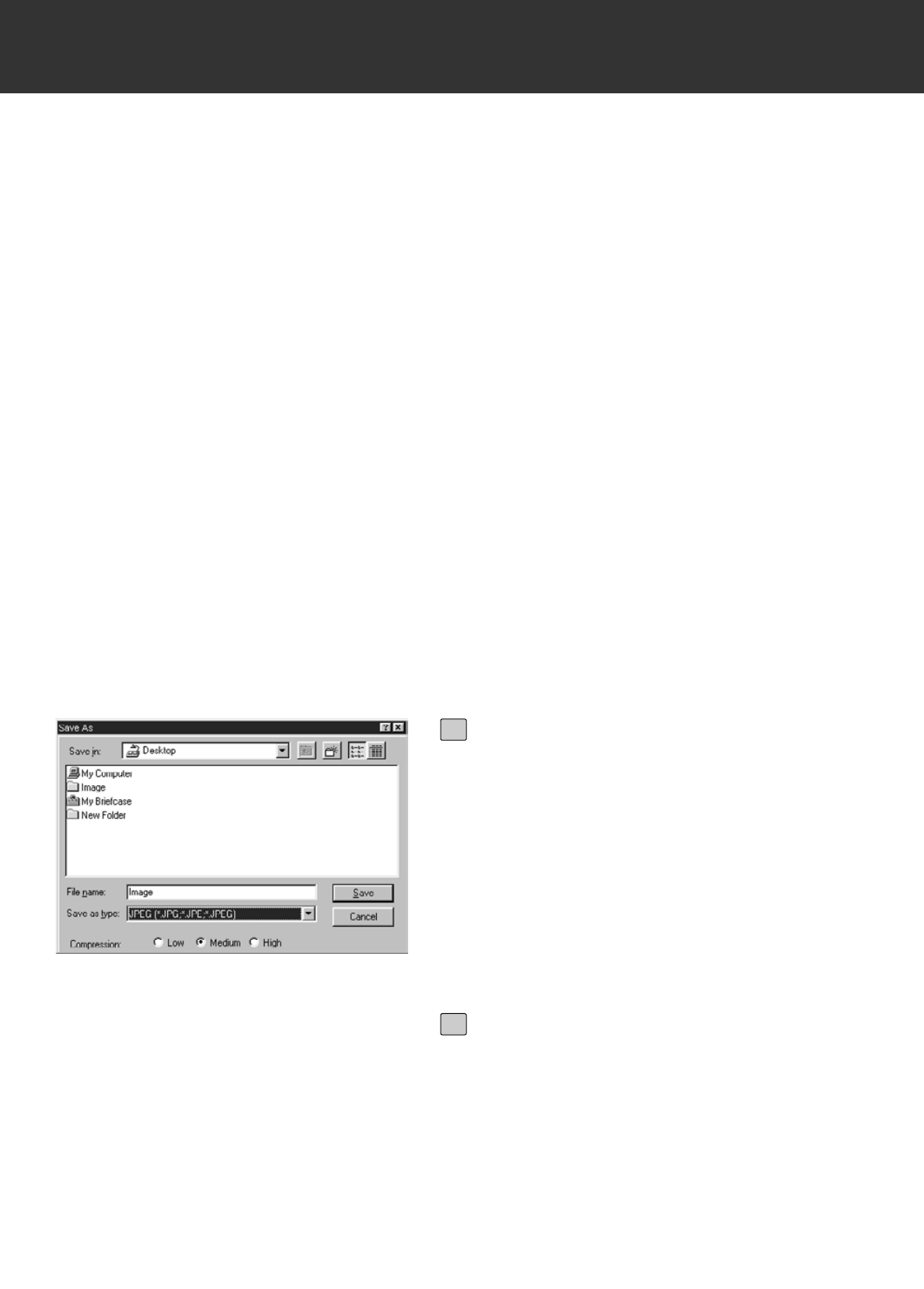
– 79 –
FINAL SCAN
With the the DS Multi II Utility software, you can save the final scan in one of the following file
fomats.
Windows®Bitmap (BMP)
(Windows only) The BMP graphic file format is for bit-mapped images.
BMP images are supported by the Paint accessory and can easily be opened on most PCs
running Windows.
JPEG
The JPEG (Joint Photographic Experts Group) compression standard is capable of producing a
high compression ratio while maintaining image quality. JPEG is a widely supported image file
format.
TIFF
Tagged Image File Format (TIFF) files contain bit-mapped data. In addition to being a widely
supported format, TIFF is able to handle the colour palette needed for professional-quality
images and graphics.
PICT (Macintosh operating system only)
The PICT graphic file format uses a lossless compression scheme and is compatible with many
Macintosh applications.
• Only TIFF can be selected when using a utility software and selecting 16-bit or 16-bit linear in
the [Colour depth] of the Preferences (p.89).
• PICT can not be selected when the width of the image size is over 4096 pixel.
Select the compression rate when
selecting JPEG as a file type.
• When ‘low’ is selcted, the file size is large.
However, the deterioration of image is
reduced comparedwith selecting [Medium] or
[High compression].
• When ‘High’ is selected, the file size is small-
er. Howver, there is more degradation to
image qulaity, compared to using medium or
low.
4
Click on [Save] (or [OK]).
• The final scan will begin.
• When the final scan is complete, the final
scan image is saved in the selected location,
with the file name you input, and in the
specifed file type.
• After the image is saved, the display returns
to the Prescan window.
5
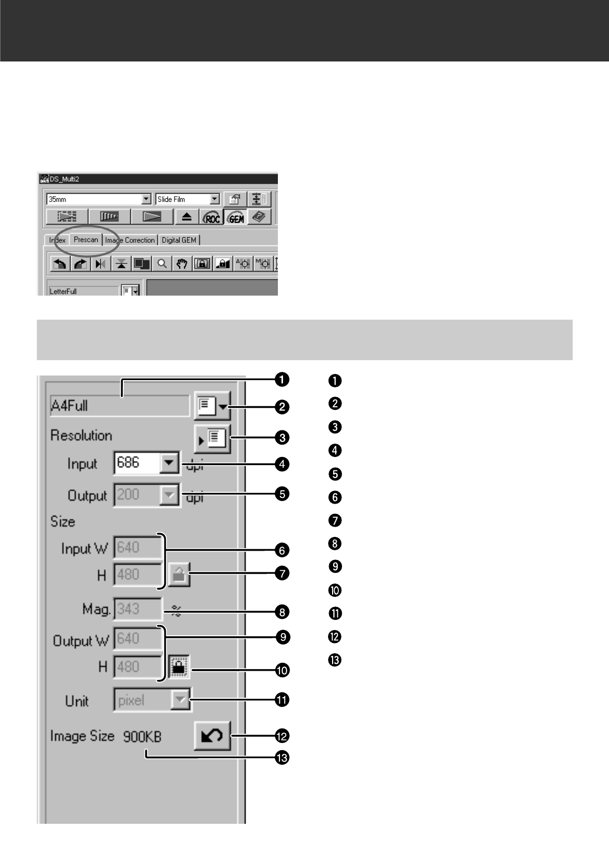
– 80 –
SCAN SETTINGS WINDOW
Click on the Prescan tab in the Main
window.
The Scan Settings window allows you to make various settings such as the amount of detail
required to read the original film (input resolution), the amount of detail required for output (output
resolution), the size required for output (output size/magnifications), etc.
When the Scan Settings window is not displayed
SCAN SETTINGS WINDOW – NAMES OF PARTS
Job Name list box
Job Load button
Job Save button
Input Resolution list box
Output Resolution list box
Input size text box
Input size lock button
Magnification size text box
Output size text box
Output size lock button
Unit list box
Reset button
Image Size display

– 81 –
SCAN SETTINGS WINDOW
Job Name list box
This shows the selected job file name. When a job file is not selected, the job file in the default
setting is selected and “Default” appears in the box. When the job file in the default setting is not
specified, [“Untitled “] appears in the box.
Job Load button
This opens the Job Selection dialog box (p.76).
Job Registry button
This opens the Job Registry dialog box (p.86).
This allows you to save (register) the settings in the Scan Settings dialog box naming it as a job
file.
Input Resolution list box
This allows you to specify an input resolution by selecting from the values displayed in this list or
by inputting value directly.
The values displayed in this list vary depending on the film format as shown below.
The value with “#” is the default setting.
<When selecting 35 mm, APS Cassette, APS Sleeve, Transparent Media, 16 mm or Center
area 2820>
2820/1410/940/#705/470/352/282
(When inputting value directly, the desired value from 176 to 2820 is available.)
<When selecting 6 x 4.5, 6 x 6, 6 x 7, 6 x 8, 6 x 9, TEM Film, Whole area interpolation 2820>
2820/1128/564/376/#282/188/141/112
(When inputting value directly, the desired value from 70 to 2820 is available.)
Output Resolution list box
This allows you to specify an output resolution by selecting from the values displayed in this list
or by inputting value directly.
The values displayed in this list are the followings.
The value with “#” is the default setting.
2400/1200/800/720/600/400/360/350/#300/240/200/180/150/96/72/36
(When inputting value directly, the desired value from 36 to 2400 is available.)
• When “pixel” is selected in the Unit list box, the output resolution cannot be selected or
specified.
Input Size text box
This allows you to specify an input size. Although the input size is normally determined according
to the size of the cropping frame you specified (p.42 to 44), you can also input a value in each W
(wide) or H (Height) box. In this case, the size of the cropping frame changes according to the
value you input.
• When “pixel” is selected in the Unit list box, the input resolution cannot be selected or specified.
REGARDING THE SETTING ITEMS OF THE SCAN SETTINGS WINDOW

– 82 –
SCAN SETTINGS WINDOW
Input size lock button
This locks the value in each Input size W or H text box so that you cannot change the value.
While the Input size is locked, the cropping frame is also locked, therefore, that size cannot be
changed.
Magnification Size text box
This allows you to specify a magnification size. Normally, the value which an input resolution is
divided by an output resolution or the value which an output size is divided by an input size is
indicated in percentage.You can also input a value in this box.
• When the input and output sizes are not locked, the input resolution and the output sizes are
changed according to the magnification size you specified.
• When the output size is locked, the input resolution and the input sizes (W/H) are changed
according to the magnification size you specified.
• When the input size is locked, the input resolution and the output sizes (W/H) are changed
according to the magnification size you specified.
• When “pixel” is selected in the Unit list box, the magnification size cannot be selected or
specified.
Output Size text box
This allows you to specify an output size. With the default setting, the image is printed in a scale
of 100 % after performing the final scan.
Although the output size is normally determined by the input and output resolutions and the
cropping frame you specified (p.42 to 44), you can also input a value directly in each W (Wide) or
H (Height) box. In this case, the input resolution and the input size change according to the
values you input and the size of cropping frame also changes correspondingly.
Output size lock button
This locks the value in each Output size W or H text box so that you cannot change the value.
Unit list box
This allows you to select the unit of Input size and Output size from the following units displayed
in the list box. The value with “#” is the default setting.
#pixel/mm/cm/inch/pica/point
Reset button
This resets the scan settings to the settings of the currently selected job file.
Image Size display
This shows the estimated image file size after performing the final scan with the current settings.

– 83 –
SCAN SETTINGS WINDOW
Input resolution Output size
––––––––––––––– = ––––––––––––– = Magnification size
Output resolution Input size
Input resolution 100 mm
––––––––––––––– = ––––––––––––– = about 4 times
400 dpi 24 mm
(the shorter side of the film)
It shows that an input resolution value of 1600 dpi (400 dpi x 4) is necessary.
Resolution and Output size
Image resolution is the number of pixels per inch (about 25.4 mm) and represented in dpi
(dot per inch). As the image size and resolution affect the size of image data file, the higher
the resolution value of image is, the longer the scanning time and printing time are required
compared with the lower value resolution of image.
The necessary resolution value is determined by the output device such as a printer, monitor,
etc. For example, for a commonly used monitor or printer, the resolution value needs 72 dpi
or 300 to 400 dpi respectively. Each item can be represented in the following formula.
Example: When printing the image of 35 mm film using the printer with the resolution value of
400 dpi, in the size of 15 cm x 10 cm and with a high-quality image as possible.
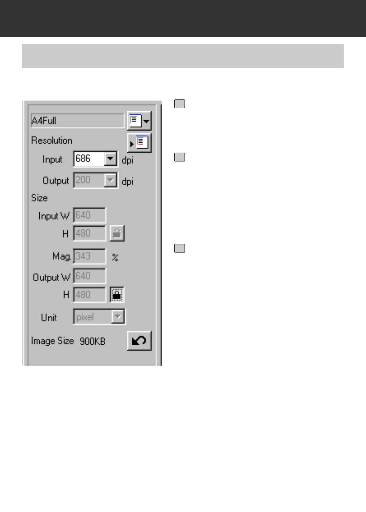
– 84 –
SCAN SETTINGS WINDOW
EXAMPLE OF THE SCAN SETTING – WHEN DISPLAYING IN A MONITOR
Select “Pixel” from the Unit list box.
• The Output Resolution list box and the Input
W and H size text boxes are not available.
1
Input “640” and “480” in the Output W
and H size text boxes respectively
and click on the Output size lock but-
ton.
• The Output size is locked so that the size
cannot be changed.
2
Drag the cropping frame to determine
the cropping area.
• While the cropping area is changed, the input
resolution is also changed accordingly.
*The scan settings are complete.
3
This explains how to display in a 13 inch monitor (640 x 480) as an example.
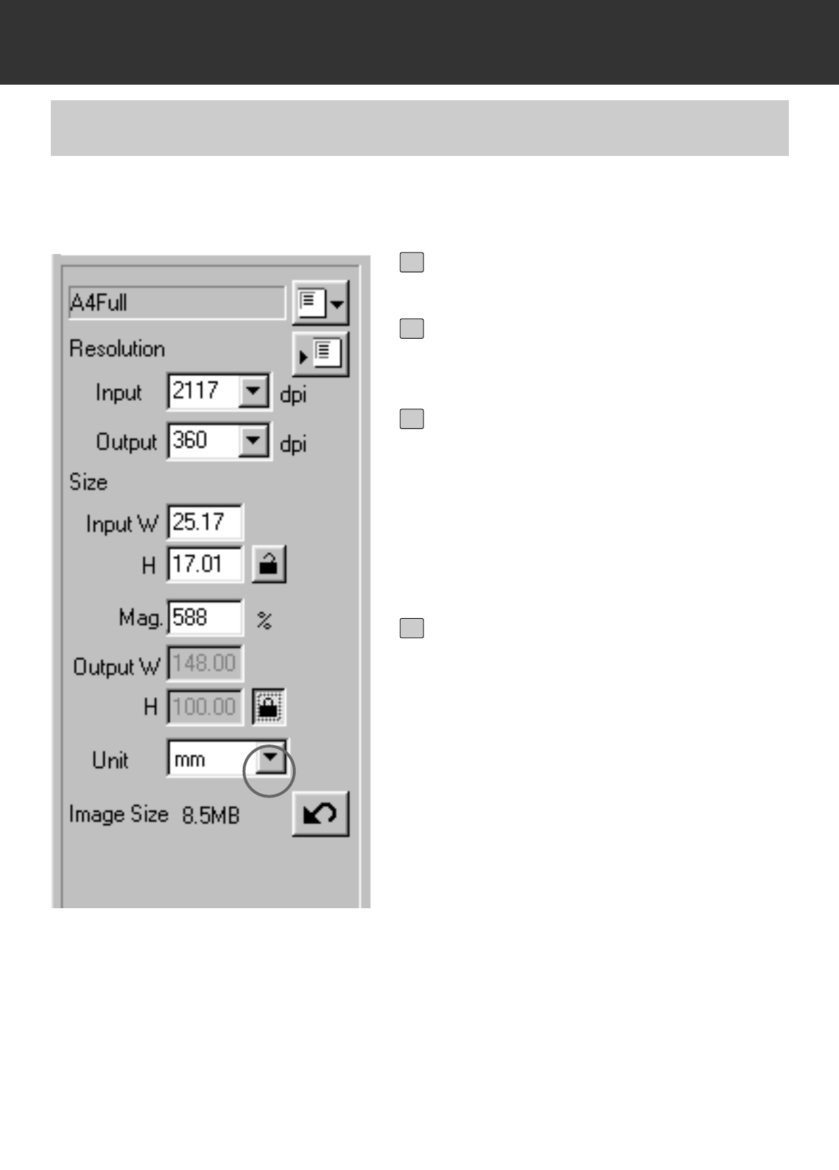
– 85 –
SCAN SETTINGS WINDOW
EXAMPLE OF THE SCAN SETTING –
WHEN PRINTING A SCANNED IMAGE
Select “mm” from the Unit list box.
1
Select “360” from the Output resolu-
tion list box.
2
Input 148 and 100 in the Output W
and H size text boxes respectively
and click on the Output size lock but-
ton.
• The Output size is locked so that the size
cannot be changed.
3
Drag the cropping frame to determine
the cropping area.
• While the cropping area is changed, the
input resolution is also changed accordingly.
• As the output size is locked, the ratio of
length and breadth of the cropping frame is
not changed. To change that ratio, click on
the Output size lock button again to cancel
the lock mode. In this case, however, the
image size is changed according to the crop-
ping area.
*The scan settings are complete.
4
This explains how to print in a post card of 148 x 100 mm (width x height) with the resolution of
360 dpi printer as an example.
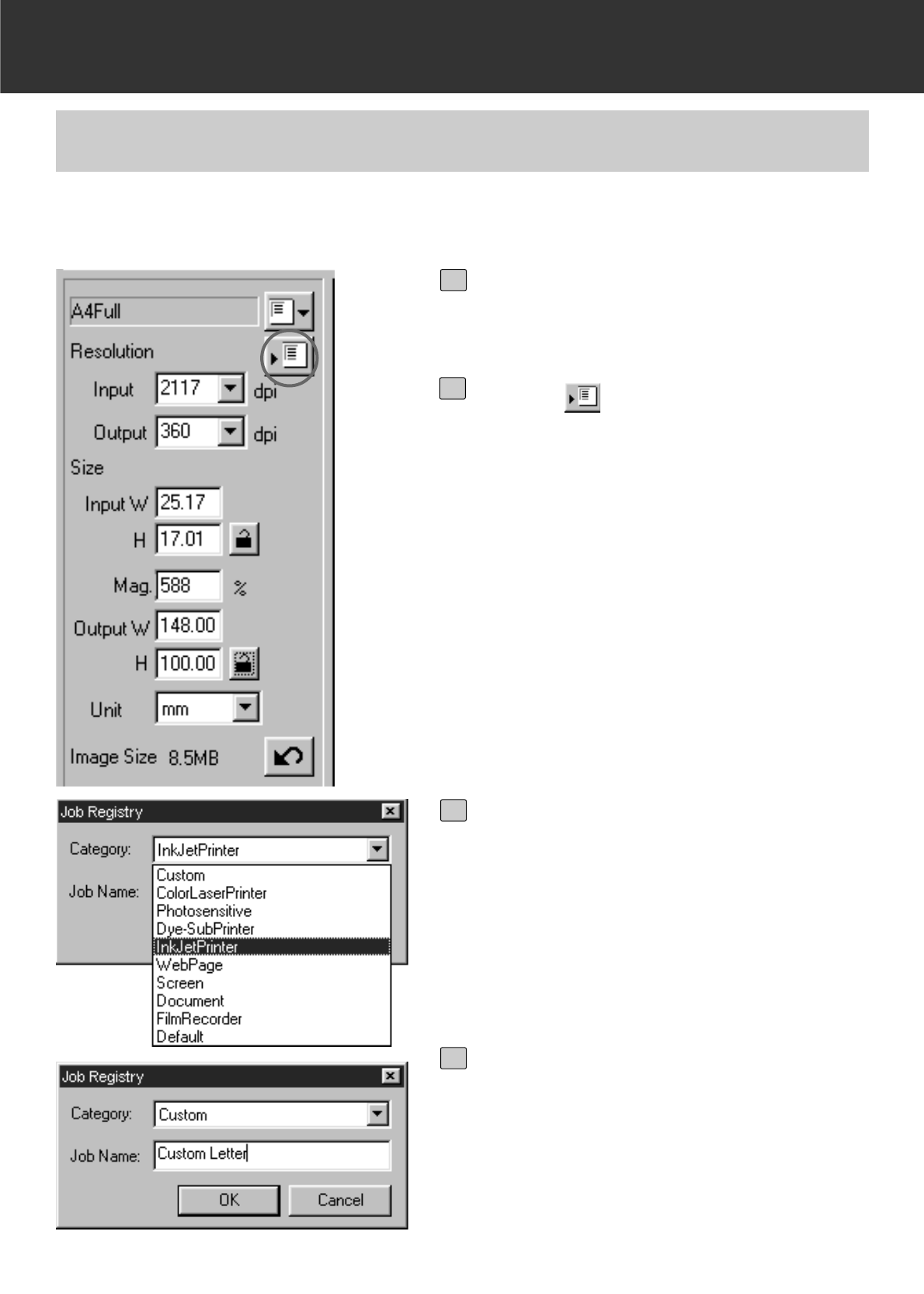
– 86 –
SCAN SETTINGS WINDOW
REGISTERING A JOB
Specify the scan settings to be regis-
tered in the Scan Settings window.
1
Click on .
• The Job Registry dialog box will appear.
2
Select the desired category to be reg-
istered from the Category list box.
3
Input the job name to be registered
and click on [OK].
• The scan settings you specified are regis-
tered with the specified name as a job file.
The Job Registry dialog box will disappear.
• Input the job name within 24 characters.
4
In addition to the Job settings included with the software, it is possible to register your own Job
settings in the Job File List.
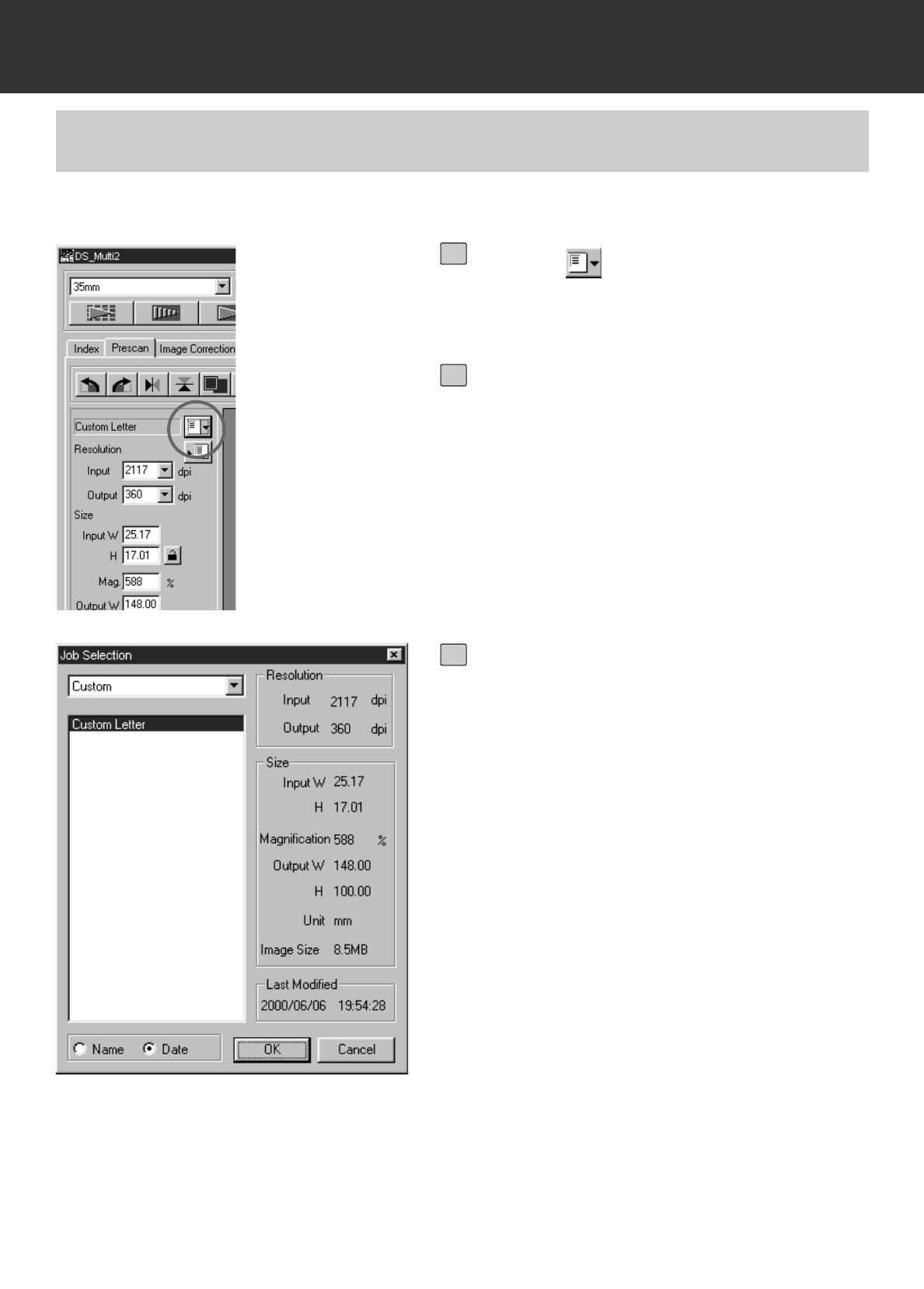
– 87 –
SCAN SETTINGS WINDOW
DELETING A JOB
Click on .
• The Job Selection dialog box will appear.
1
From the Category list box, select the
category in which the job to be delet-
ed is registered.
2
After clicking on the job name to be
deleted,
Windows®:
Press the Delete key.
Macintosh:
Press the Command key and D key
simultaneously.
• The deleted job cannot be restored again. If
you delete the job mistakenly, register the job
again by following the procedure described
on page 86.
3
It is possible to delete a job file from the Job File List when it is no longer needed.
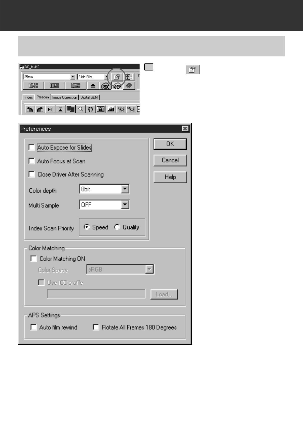
– 88 –
SETTING THE PREFERENCES
THE PREFERENCE WINDOW DISPLAY
Click on in the Main window.
• The Preferences window will appear.
1

– 89 –
SETTING THE PREFERENCES
Auto Expose for Slides
This option allows you to select whether to perform auto exposure during the prescan or the final
scan when using colour slides. As colour slide users often adjust the exposure and colour when
taking a photograph, the Auto Expose function when performing the prescan or final scan is
turned off in the default setting (The checkmark is not on the checkbox). However, when scanning
a slide which is underexposed or when using the AE Lock or AE Area lock function (p.38, 39),
click on the checkbox of “Auto Expose for Slide” so that the Auto Expose function is turned on.
Auto Focus at Scan
This option allows you to select whether to use the Autofocus function when performing the
prescan or the final scan.
To obtain higher scanning speed, the Autofocus function is turned off in the default setting (The
checkmark is not on the checkbox). However, if you intend to use the Autofocus function when
scanning, click on the checkbox of “Auto Focus at Scan”.
When using the Digital ROC or Digital GEM function (p.69 to 73), it is recommended to turn on
the Autofocus function by clicking on the checkbox of “Auto Focus at Scan”.
Close the Driver Software After Scanning
This option allows you to select whether to close the driver software after scanning when using
Twain driver or Plug-in Software and image editing application.
The driver software is specified not to be closed after scanning in the default setting (The
checkmark is not on the checkbox). This setting is convenient when scanning multiple images
continuously and loading them into an image editing application such as Adobe Photoshop.
However, if you intend to retouch each image in the editing software after scanning, click on the
checkbox to display the checkmark.
Colour depth
This option allows you to specify the format when outputting the scanned data to a file or an
application software. Select one from the following items of the list box.
The default setting is 8 bit.
8 bit Outputs an image of 8 bits for each R, G or B channel
16 bit Outputs the image of 16 bits for each R, G or B channel
16 bit linear Outputs the image of 16 bits for each R, G or B channel but corrections
such as a gamma correction cannot be made. Therefore, when scanning a negative film, it is
output as a negative image.
* Only TIFF can be selected when using the utility software and selecting 16 bit or 16 bit linear as
a colour depth.
* When selecting 16 bit, the image size display in the Scan Settings window is represented in the
16 bit size (8 bit x 2).
* Some types of graphic application software cannot handle 16 bit image files.
REGARDING THE SETTING ITEMS OF THE PREFERENCES WINDOW

– 90 –
SETTING THE PREFERENCES
Multi Sample
This option allows you to select the Multi-Sampling setting. This function reduces random noise in
the image by analyzing the data of a number of sample scans in advance. Select one from the
following items of the list box.
The Multi-Sample Scanning function is turned off in the default setting.
OFF Multi-Sample Scanning functionnot used.
2 times Performs sampling 2 times.
4 times Performs sampling 4 times.
8 times Performs sampling 8 times.
16 times Performs sampling 16 times.
* The more times the image is sampled, the longer the required time for scanning.
Index Scan Priority
This option allows you to select either a high speed index scan or a quality index scan by clicking
on “Speed” or “Quality”.The default setting is “Speed”.
Speed This performs the index scan at high speed. The autofocus function is not used
while scanning. The index images are displayed in a thumbnail representation after
only easy-auto expose function is performed for each frame.
Quality After prescanning each frame, the size of the prescan images is reduced and those
images are displayed in the thumbnail representation. Therefore, it takes longer to
display index images. However, the prescan image can then be immediately
displayed just by double-clicking the index image. Whether the autofocus function or
the auto expose function for a colour slide film is performed when prescanning
depends on the setting of Auto Focus at Scan or Auto Exposure for Slides.
Colour Matching
When displaying the scanned image in the monitor of the PC, the colour of the image varies
depending on the type of the monitor. This option allows you to match the colour data of the
scanned image to the monitor specifications.
For details, see page 92.
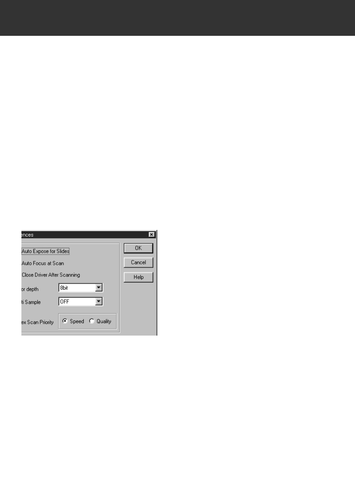
– 91 –
SETTING THE PREFERENCES
APS Settings – Auto Film Rewind
This option allows you to select whether to rewind or not to rewind the film in the APS cassette
automatically before the APS adapter (optional accessory) is ejected. The film is rewound in the
default setting. (The checkmark is on the checkbox). When setting not to rewind a film, click on
the checkbox to remove the checkmark.
* When ejecting the APS adapter by pressing the eject button in front of this scanner, the film is
rewound regardless of this setting.
APS Settings – Rotate All Frames 180 Degrees
This option allows you to select whether to display or not to display all index frames in the Index
window rotated by 180 degrees when performing the index scan with the APS adapter (optional
accessory).
When using an APS film shot by a camera in which the film holder is on the left side of the back,
such as Minolta Vectis S-1/S-100, all index frames are displayed upside-down with the normal
setting of the index scan. In this case, click on the checkbox to display the checkmark so that the
frames are displayed correctly.
The frames are not rotated in the default setting (The checkmark is not on the checkbox).
When clicking on [OK], the settings in
the Preferences are determined.The
Preferences window will disappear.
When clicking on [Cancel], each setting
is reset to the previous one.
When clicking on [Help], the Help file is
displayed.
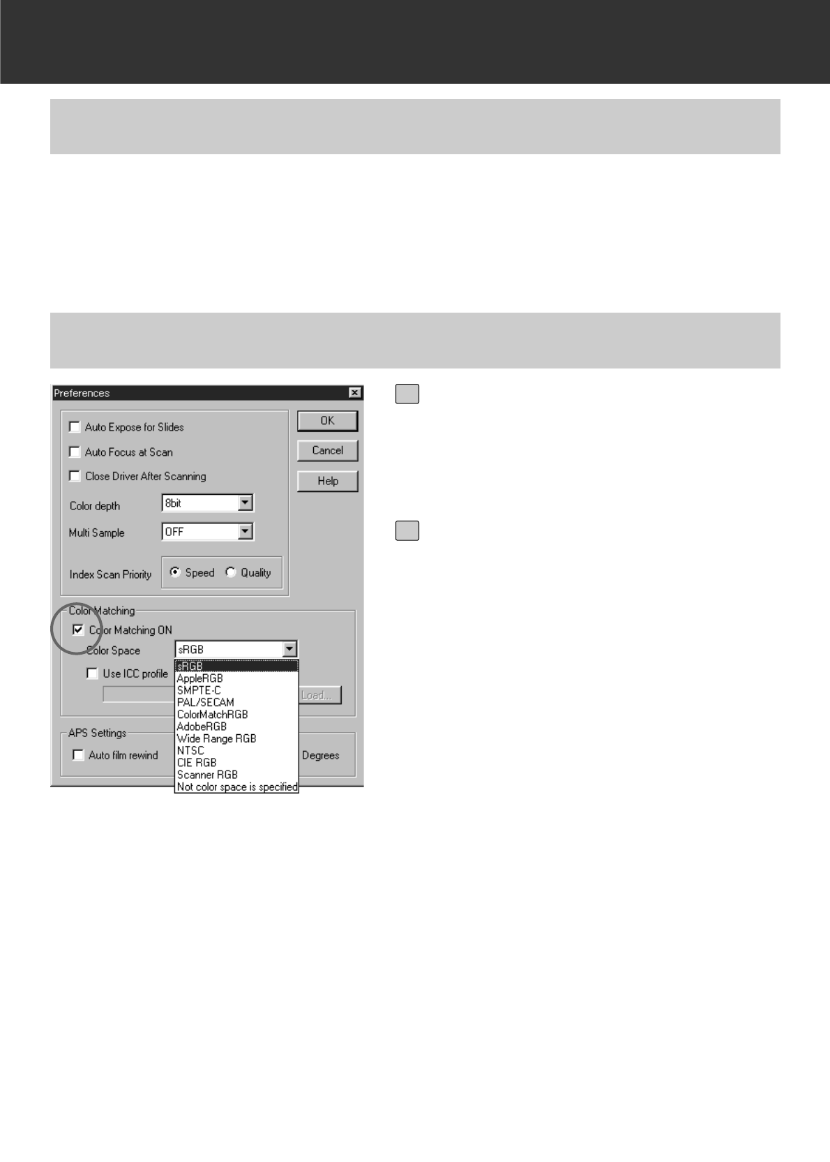
– 92 –
SETTING THE PREFERENCES
When displaying the scanned image in the monitor of the PC, the colour or light and shade of the
image varies depending on the colour format of the monitor or the characteristics of colour
representation. The Colour Matching function matches the colour data of the image to the monitor
specifications (colour space).
COLOUR MATCHING
COLOUR MATCHING – THE SETTING OF OUTPUT COLOUR IMAGE
Click on Colour Matching ON to dis-
play the checkmark.
• When this checkmark is displayed, the
required time of scanning becomes longer.
1
Select the desired colour space from
the Output Colour Space list box.
• For the available colour space setting, see
the next page.
2

– 93 –
SETTING THE PREFERENCES
sRGB
This is the colour spacing standard promoted by Hewlett-Packard and Microsoft. Because sRGB
reflects the quality of average PC monitors, this standard is well suited for handling images that
are to be displayed on the Web. However, because of its limited colour scale, it is not suitable for
professional prepress usage. sRGB is widely used around the world, and is considered to be the
colour spacing standard for multi-media and Internet usage.
Apple RGB
This Apple based colour spacing has been available since the Apple 13 model. It is used as a
standard default setting for software such as Adobe Illustrator, Adobe Photoshop Ver. 4 and
higher, etc. Because this colour spacing standard is widely used in the world of Desktop
Publishing (DTP), it is suited for the reproduction of older version DTP files. As this standard
affords a wider colour scale than sRGB, it is commonly employed when a printed product is the
intended objective.
SMPTE-C
This colour spacing is currently the accepted standard used in the USA for television
broadcasting. This standard is the most suitable colour spacing available for work intended for
television broadcast in the USA.
PAL/SECAM
This colour spacing is currently the accepted standard used in Europe for television broadcasting.
This standard is the most suitable colour spacing available for work intended for television
broadcasting in Europe.
ColourMatch RGB
This colour spacing standard has a wide colour scale and is considered ideal for use with Radius
Press View monitors, which are used commonly in the prepress (publishing?) world.
Adobe RGB
This colour spacing standard offers a wider colour scale than ColourMatch RGB. The extensive
range of colours available with this colour spacing make this standard the most suitable standard
for prepress usage. However, this range also includes many colours that cannot be printed
(colours other than CMYK, etc.).
Broad Spectrum Colour Scale RGB
Utilizing the genuine coordinates of the colour spectrum, this colour spacing standard offers an
extremely extensive selection of colours. However, most of the colours available in this range
cannot be displayed on standard computer monitors, or be used for printing.
NTSC
This colour spacing is currently the accepted standard used in Japan for television broadcasting.
This standard is the most suitable colour spacing available for work intended for television
broadcast in Japan.
CIE RGB
This is the colour spacing defined by the CIE (Commissin Internationale d`Eclairage).
REGARDING OUTPUT COLOUR SPACE SETTINGS AVAILABLE
– 94 –
SETTING THE PREFERENCES
The recommendable settings of “Output colour space” and “ICC profile use/not use” according to
the combination of each operating system and the image editing application are as follows:
OS Using application Output colour
space ICC profile
Windows®/
Mac OS
Adobe Photoshop Ver.5.0.2/5.5
The monitor colour matching
function is set to ON.
Select the same
colour space as
specified in the
application.
use
Adobe Photoshop Ver.5.0.2/5.5
The monitor colour matching
function is set to OFF.
No colour space is
specified use
Windows®/
Mac OS
When using an application other
than Adobe Photoshop and the
monitor colour matching function is
set to off, or when using an
application other than Adobe
Photoshop and that application
does not have the monitor colour
matching function.
No colour space is
specified use
Windows®98
When using an application other
than Adobe Photoshop and that
application is applied to the sRGB
colour space.
“sRGB” use
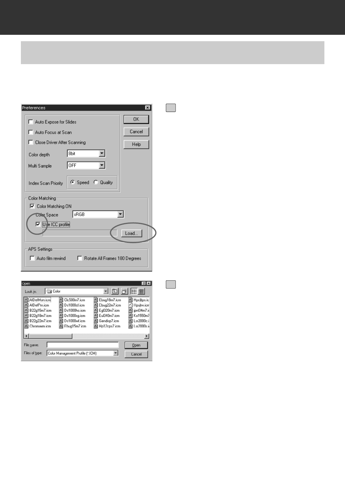
– 95 –
SETTING THE PREFERENCES
Click on the checkbox of Use ICC
profile to display the checkmark and
click on Load.
• The file open dialog box will appear.
1
Select the ICC profile of the monitor
you use and click on [Open].
2
To use the ICC profile, specify the ICC profile of the monitor you use by following the procedure
below.
COLOUR MATCHING – THE SETTING OF ICC PROFILE
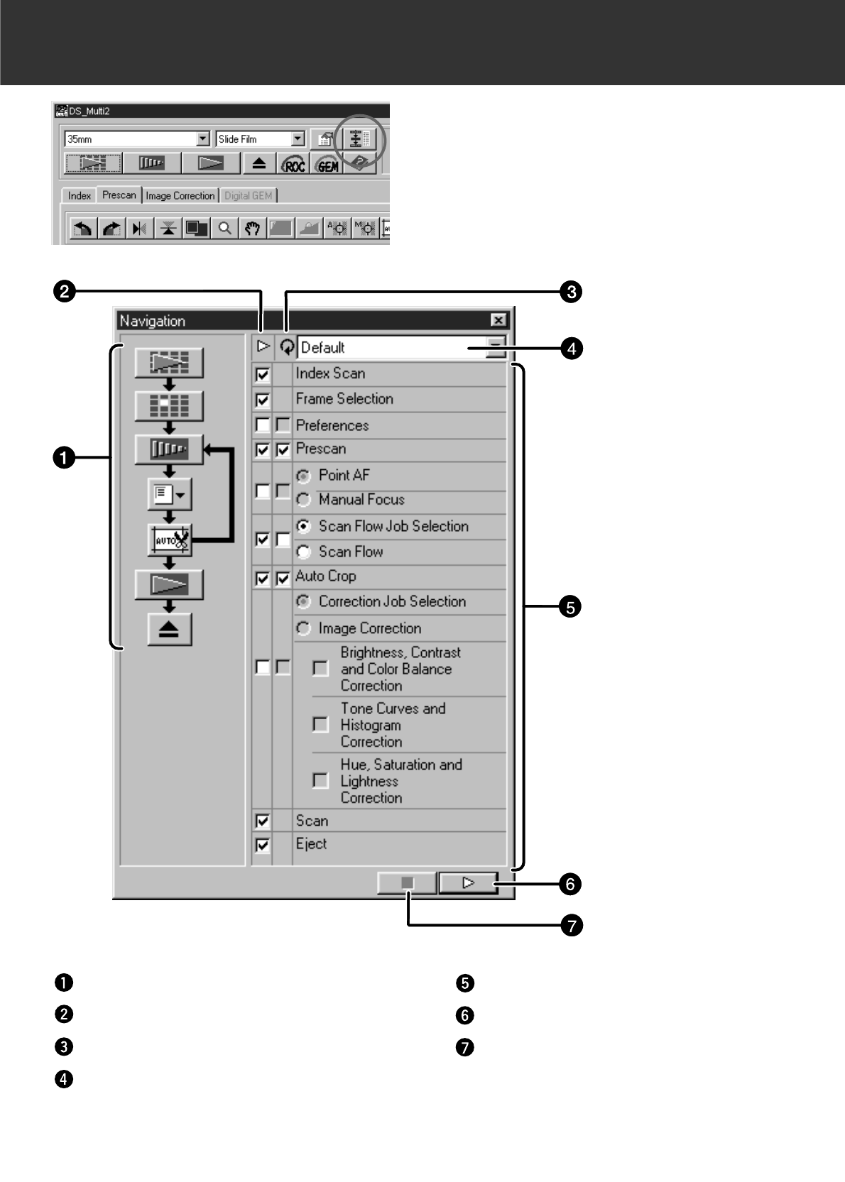
– 96 –
NAVIGATION
The Navigation function allows you to automate a
series of operations of scanning. When clicking on
the Navigation button in the Main window, the
Navigation window appears.
Navigation Flow
Operation Item checkboxes
Repeated Operation Item checkboxes
Navigation Menu list box
Operation items
Navigation Start button
Navigation Stop button

– 97 –
NAVIGATION
Navigation Flow
The flow chart for the automatic operation is represented by icons according to the settings of the
Operation Item checkboxes and the Repeated Operation Item checkboxes.
By clicking on the icon, the operation can be started from the item of the icon you clicked.
Operation Item checkboxes
Only the items which are selected in these checkboxes can be performed in the automatic
operation. The icons in the flow chart change depending on the settings of the Operation Item
checkboxes. When the checkbox is clicked to remove the checkmark, the icon of the clicked item
is removed from the flow chart. The checkboxes of “Index Scan” and “Frame Selection” are
available only when “35 mm” or “APS Cassette” is selected in the film format (p.20).
Repeated Operation Item checkboxes
The items which are selected in these checkboxes are performed repeatedly for each frame. The
icons in the flow chart change depending on the settings of the Repeated Operation Item
checkbox. When the checkbox is clicked to remove the checkmark, the icon of the clicked item is
removed from the flow chart. These checkboxes are available only when “35 mm” or “APS
Cassette” is selected in the film format (p.20).
Navigation Menu list box
The flow determined by the settings of the Operation Item checkboxes and the Repeated
Operation Item checkboxes is called a “Navigation Set”. By clicking on the Navigation Menu list
box to display the menu, operations such as naming a navigation set and saving it, or selecting or
deleting the saved navigation set can be performed.
When the Navigation window is displayed for the first time, the default setting is selected.
Operation Items
The operations which can be performed automatically are displayed. The order of the item cannot
be changed. It is not possible to add items to the list or delete them from it.
Navigation Start button
This button activates automatic operation according to the settings of the Operation Item
checkboxes and the Repeated Operation Item checkboxes.
Navigation Stop button
This button stops the automatic operation. When the Navigation Start button is clicked in this
mode, the operation resumes.
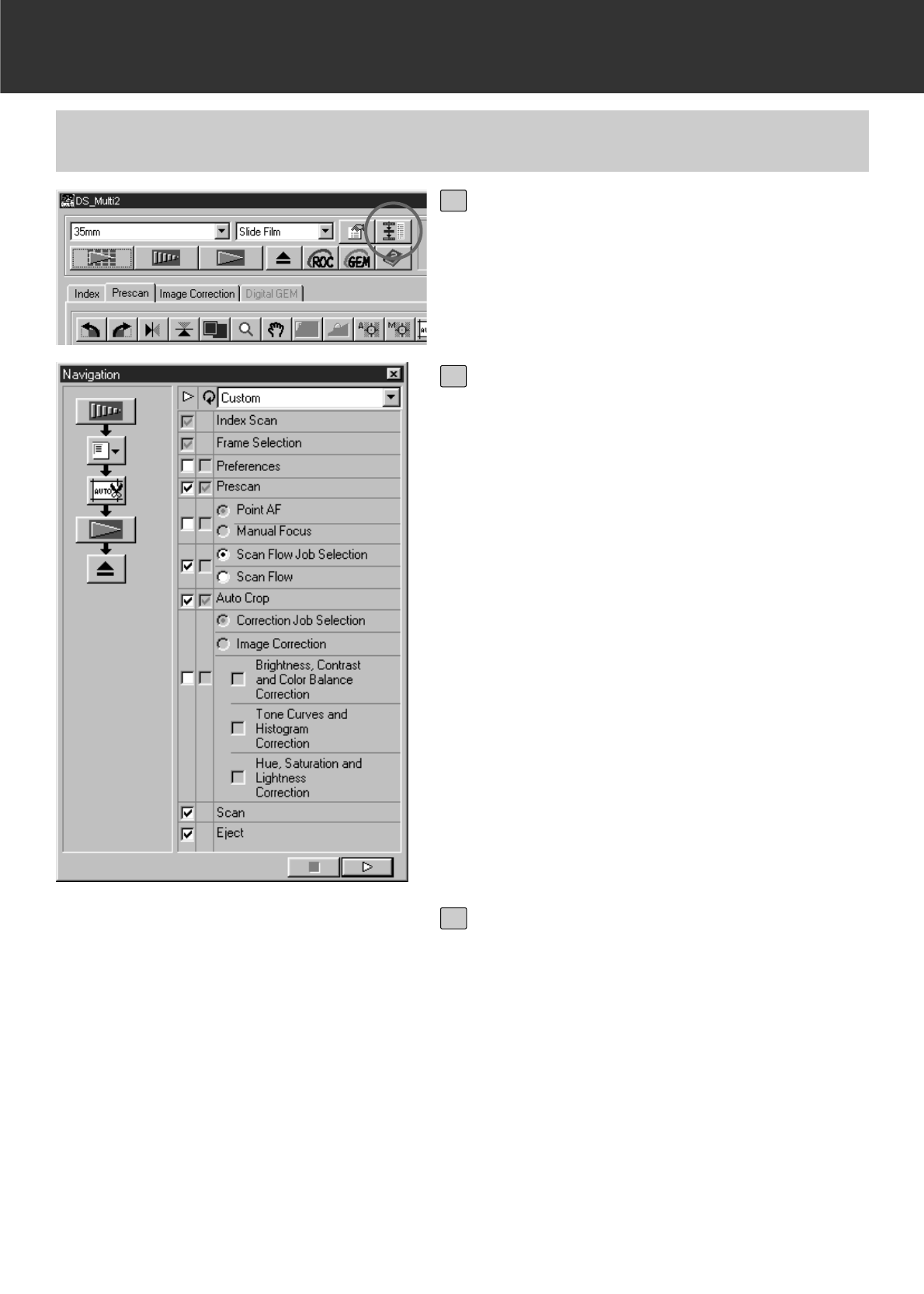
– 98 –
NAVIGATION
AUTOMATIC OPERATION USING THE NAVIGATION FUNCTION
Click on the Navigation button.
• The Navigation window will appear.
• When the Navigation window is displayed for
the first time, the navigation set in the default
setting is selected.
1
Select the operation items to be auto-
mated in the Operation Item check-
boxes and the Repeated Operation
Item checkboxes.
• The Index Scan or Frame Selection is avail-
able only when “35 mm” or “APS Cassette” is
selected in the film format.
• The Repeated Operation Item checkboxes
are available only when “35 mm” or “APS
Cassette” is selected in the film format.
• When performing the automatic operation in
the default setting, skip this step.
• When Point AF or Manual Focus, Auto Crop,
Correction Job Selection or Image Correction
are selected, be sure and select the Prescan
Operation Item checkbox at the same time.
2
Click on the Navigation Start button.
• The automatic operation will start.
• If you click on the Navigation Stop button, the
automatic operation stops temporarily. To
resume the operation, click on the Navigation
Start button.
3
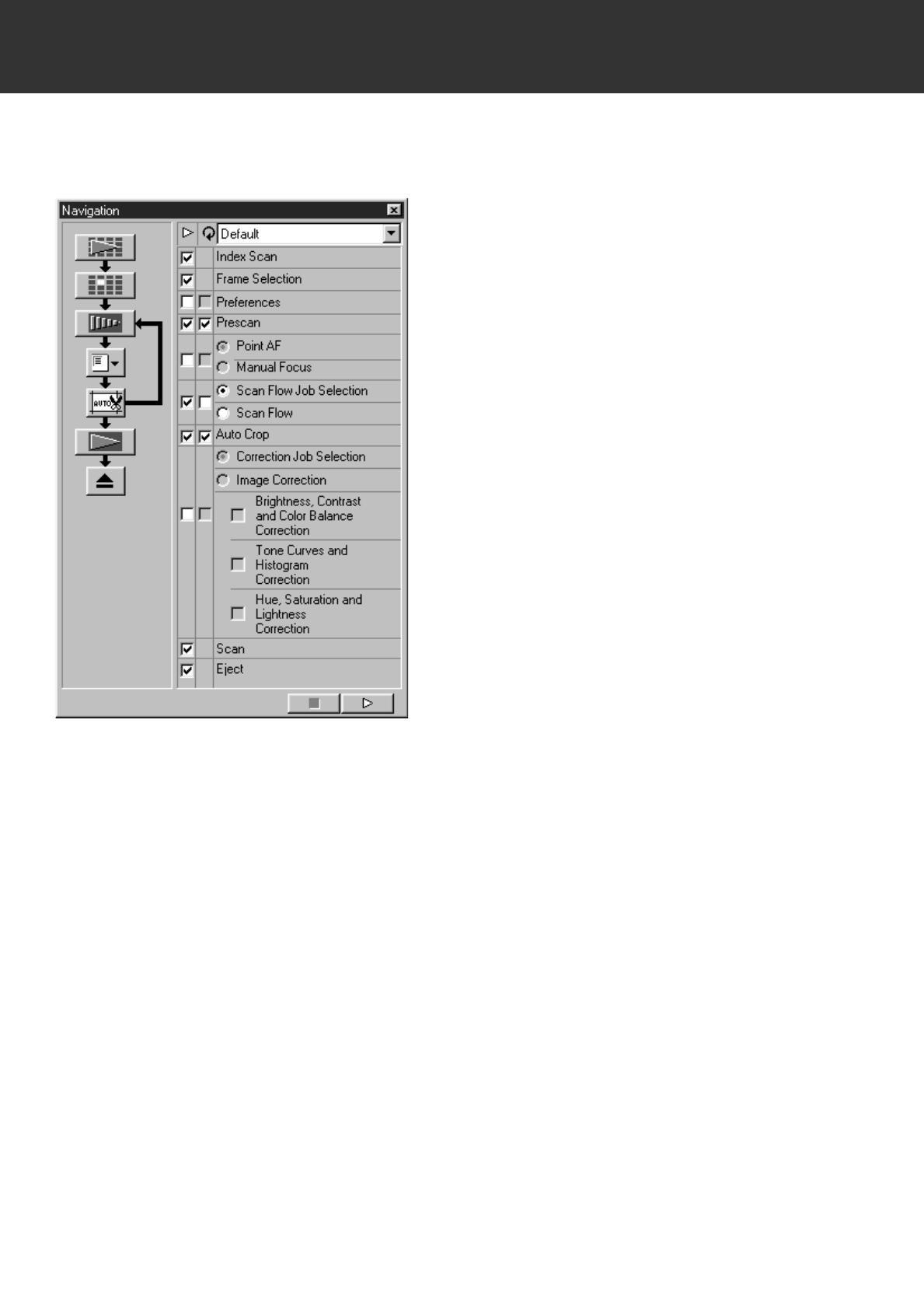
– 99 –
NAVIGATION
Though the Navigation function automates a series of scanning operations, the operations which
require you to select or input something cannot be automated.
For example, when performing the Navigation set
described on the left, the operation stops
temporarily after performing the index scan of all
frames and the frames are displayed in a
thumbnail representation. After performing “Frame
Selection” by clicking on the image to be
prescanned and pressing the Enter key, or by
double-clicking on the image to be prescanned, the
operation resumes.
And, when “Scan Flow Job Selection” is swlected,
the Job Selection window appears and the
operation stops temporarily. After selecting the job
file to be applied, the operation re-starts.
When using the utility software, rather than the
Twain Driver/Plug-in Software, the file save dialog
box is displayed and the operation stops
temporarily when “Scan” is readied. After
specifying or inputting the file destination, file name
and file type and clicking on Save in the file save
dialog box, the operation resumes and the final
scan is performed.
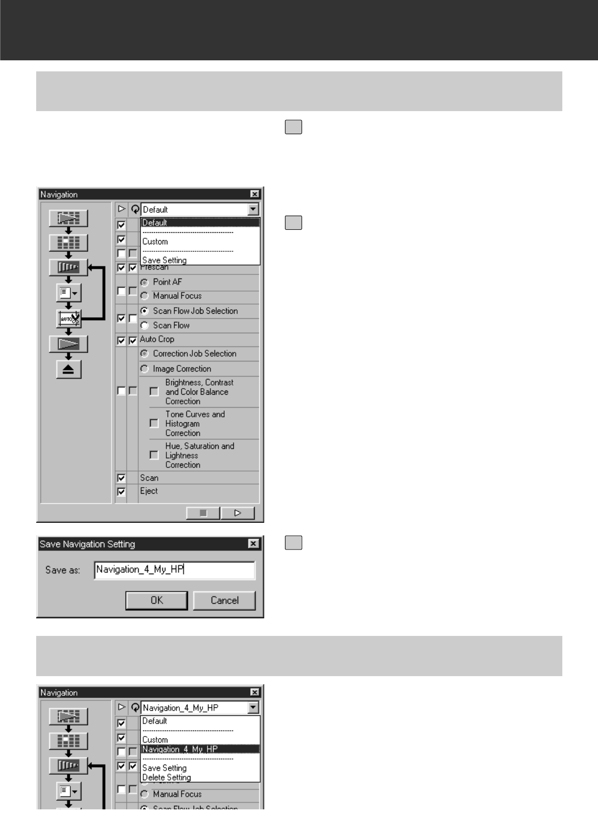
– 100 –
NAVIGATION
Click on the Navigation Menu list box
to select the menu to be used.
NAMING AND SAVING A NAVIGATION SET
Select the operation items to be auto-
mated in the Operation Item check-
boxes and the Repeated Operation
Item checkboxes.
1
Click on the Navigation Menu list box
to select [Save Setting].
• The navigation set saving dialog box will
appear.
2
Input the name of the navigation set
and click on OK.
3
SELECTING A NAVIGATION SET
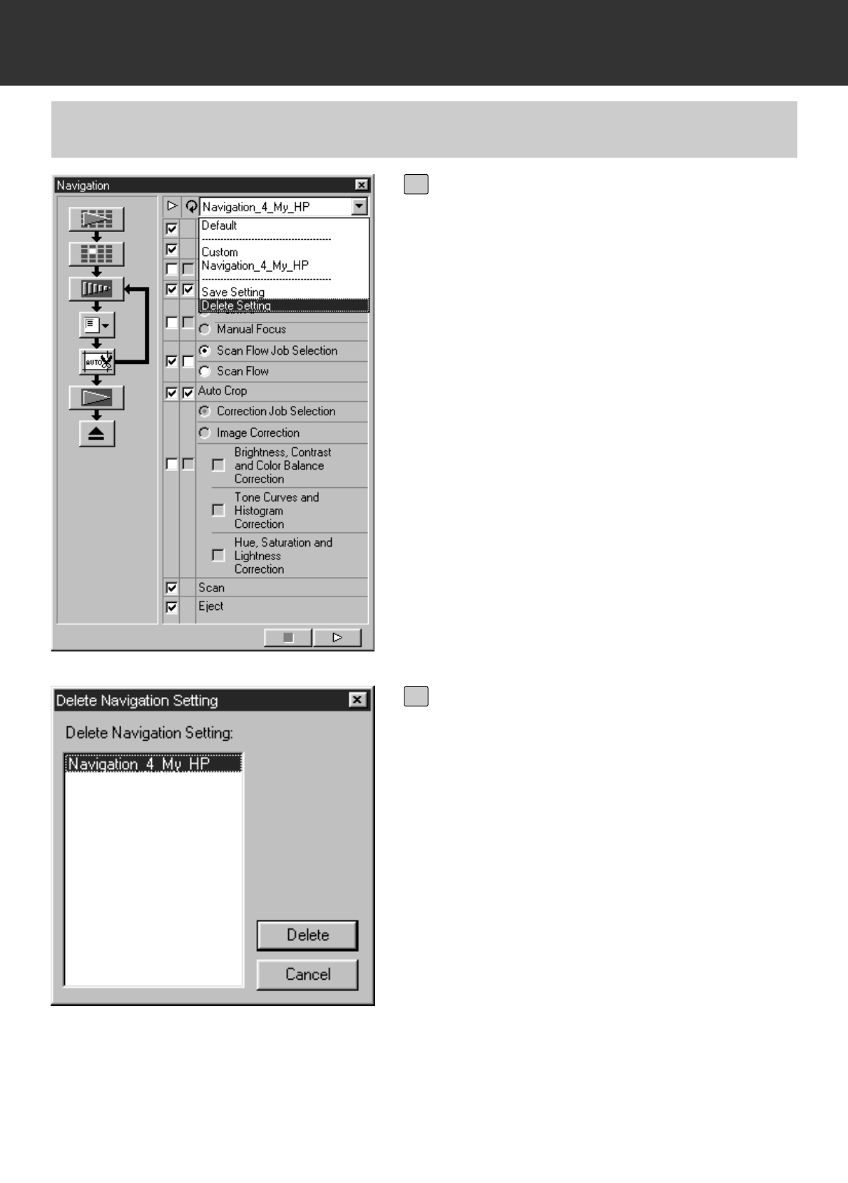
– 101 –
NAVIGATION
DELETING A NAVIGATION SET
Click on the Navigation Menu list box
to select [Delete Setting].
• The navigation set deleting dialog box will
appear.
1
Select the navigation set to be delet-
ed and click on Delete.
2
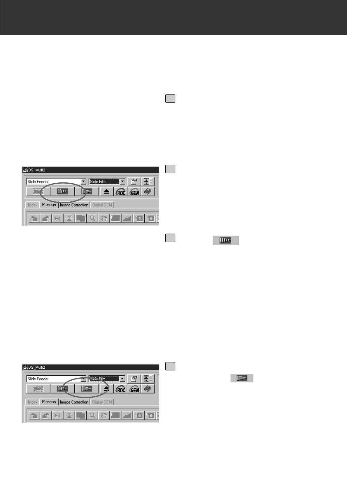
– 102 –
SLIDE FEEDER (optional accessory)
The optional slide feeder can scan automatically up to 50 mounted 35mm slides continuously.
The data of scanned images can be also saved onto a hard disc, etc.
For the names of parts of the slide feeder, and instructions for attaching to or detaching from the
Dimage Scan Multi II or loading the slides, see the instruction manual supplied with the slide
feeder.
Attach the slide feeder to the Dimage
Scan Multi II and load the slides by
following the procedure described in
the instruction manual supplied with
the slide feeder.
1
Select Slide Feeder from the Film
Format list box and select the film to
be set from the Film Type list box.
2
Click on in the Main window.
• The first slide to be scanned in the supply-
side storage (on the left side) is loaded into
the scanner and prescanned, and the pres-
can image is displayed.
• The cropping frame function or image correc-
tions described on page 48 to 68 or the
Digital ROC/GEM functions described on
page 69 to 73 can be applied to the prescan
image.
3
After performing the image correc-
tion, click on in the Main win-
dow.
• The file save dialog box will appear.
• The same image correction performed for the
prescan image is applied to the other slides.
4
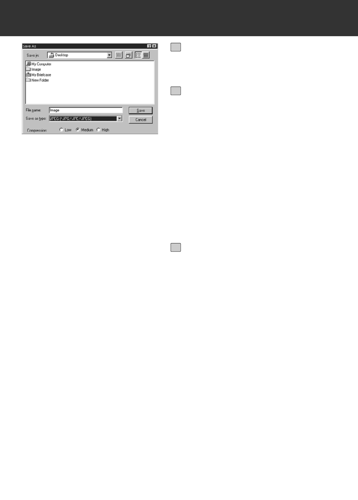
– 103 –
SLIDE FEEDER (optional accessory)
Specify the file destination and input
the file name to be saved.
5
When using the DS Multi II Utility
software, select the file type to be
saved from the [Save as Type] list box
(or the file format pull-down menu).
• When selecting JPEG as a file type, select
the compression rate from the 3 items.
• The number of frames with which
[Continuous Scanning -> Continuous
Loading] can be performed varies depending
on the image editing application. For details,
refer to the instruction manual supplied with
the image editing application you use.
6
Click on [Save] (or [OK]).
• The final scan will begin.
• Every time an image is scanned, the image
is saved with the input file name adding a
serial number of 2 digits in the specified loca-
tion and file type.
For example, when inputting My_Birthday as
a file name and specifying JPEG as a file
type, the image is saved with the file name of
My_Birthday01.jpg, My_Birthday02.jpg,
My_Birthday03.jpg, My_Birthday04.jpg… .
7
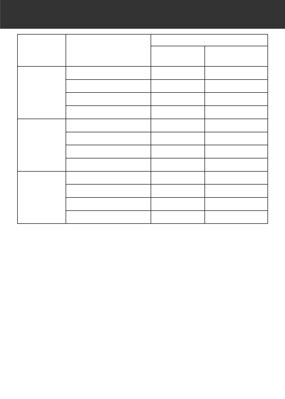
– 104 –
LOADING TIME – WINDOWS®
The preferences in loading time
CPU : Pentium III 700MHz
RAM : 757MB
OS : Winsows®98 Second Edition
Applications : Adobe Photoshop 5.5
Memory allocation to applications : 570MB
Colour matching : OFF
Driver : TWAIN_32 Sources
ASPI version : 4.57
SCSI board : Adaptec AHA-2940AU
*The loading time changes according to the preferences you use.
*The values described above do not include the transfer time to the PC.
Film Format Digital ROC/Digital GEM
Operations
Prescan Final Scan
(after Prescan)
35mm in 2820 dpi
(Colour Positive)
Digital ROC OFF/Digital GEM OFF about 14 sec. about 45 sec.
Digital ROC ON/Digital GEM OFF about 1 min. 30 sec. about 60 sec.
Digital ROC OFF/Digital GEM ON about 35 sec. about 2 min. 40 sec.
Digital ROC ON/Digital GEM ON about 1 min. 30 sec. about 2 min. 00 sec.
6 x 9 in 1128 dpi
(Colour Positive)
Digital ROC OFF/Digital GEM OFF about 25 sec. about 55 sec.
Digital ROC ON/Digital GEM OFF about 3 min. 20 sec. about 1 min. 20 sec.
Digital ROC OFF/Digital GEM ON about 50 sec. about 2 min. 40 sec.
Digital ROC ON/Digital GEM ON about 3 min. 20 sec. about 2 min. 10 sec.
6 x 9 in 2820 dpi
(Colour Positive)
Digital ROC OFF/Digital GEM OFF about 25 sec. about 4 min. 00 sec.
Digital ROC ON/Digital GEM OFF about 3 min. 20 sec. about 7 min. 40 sec.
Digital ROC OFF/Digital GEM ON about 50 sec. about 13 min. 40 sec.
Digital ROC ON/Digital GEM ON about 3 min. 20 sec. about 13 min. 00 sec.

– 105 –
LOADING TIME – MACINTOSH
The preferences in loading time
CPU : PowerPC G4 450MHz
RAM : 768MB
OS : Mac OS 9.0.4
Applications : Adobe Photoshop 5.5
Memory allocation to applications : 570MB
Colour matching : OFF
Driver : Dimage Scan Multi Photoshop Plug-in 2.0
Virtual memory : OFF
SCSI board : Adaptec PowerDomain 2940UW
*The loading time changes according to the preferences you use.
*The values described above do not include the transfer time to the Mac.
Film Format Digital ROC/Digital GEM
Operations
Prescan Final Scan
(after Prescan)
35mm in 2820 dpi
(Colour Positive)
Digital ROC OFF/Digital GEM OFF about 7 sec. about 50 sec.
Digital ROC ON/Digital GEM OFF about 3 min. 10 sec. about 55 sec.
Digital ROC OFF/Digital GEM ON about 20 sec. about 6 min. 30 sec.
Digital ROC ON/Digital GEM ON about 3 min. 10 sec. about 3 min. 50 sec.
6 x 9 in 1128 dpi
(Colour Positive)
Digital ROC OFF/Digital GEM OFF about 10 sec. about 55 sec.
Digital ROC ON/Digital GEM OFF about 7 min. 30 sec. about 1 min. 10 sec.
Digital ROC OFF/Digital GEM ON about 20 sec. about 6 min. 20 sec.
Digital ROC ON/Digital GEM ON about 7 min. 30 sec. about 4 min. 00 sec.
6 x 9 in 2820 dpi
(Colour Positive)
Digital ROC OFF/Digital GEM OFF about 10 sec. about 4 min. 30 sec.
Digital ROC ON/Digital GEM OFF about 7 min. 30 sec. about 7 min. 50 sec.
Digital ROC OFF/Digital GEM ON about 20 sec. about 25 min. 30 sec.
Digital ROC ON/Digital GEM ON about 7 min. 30 sec. about 21 min. 20 sec.
– 106 –
JOB FILE LIST – 35 MM
Category Job name Input Res. Output Res. Mag. Unit Input
Size
Lock(IN) Output
Size
Lock(OUT) Input
Pixels
WH WH W
H
2820 34 24 4032 2688
Custom default 705 300 235 pixel 1008 672 OFF 1008 672 OFF 1008 672
ColorLaserPrinter MaxSize_600dpi 2820 600 470 mm 36 24 OFF 170 113 ON 4032 2688
A4Quater_600dpi 2447 600 407 mm 36 24 OFF 148 99 ON 3496 2331
A4Eighth_600dpi 1735 600 289 mm 36 24 OFF 105 70 ON 2480 1653
LetterQuater_600dpi 2291 600 381 inch 11
OFF 5 4 ON 3276 2184
LetterEighth_600dpi 1702 600 283 inch 11
OFF 4 3 ON 2430 1620
MaxSize_400dpi 2820 400 705 mm 36 24 OFF 256 170 ON 4032 2688
A4Half_400dpi 2313 400 578 mm 36 24 OFF 210 140 ON 3307 2204
A4Quater_400dpi 1622 400 405 mm 36 24 OFF 147 98 ON 2315 1543
A4Eighth_400dpi 1156 400 289 mm 36 24 OFF 105 70 ON 1653 1100
LetterHalf_400dpi 2291 400 572 inch 11
OFF 8 5 ON 3276 2184
LetterQuater_400dpi 1526 400 381 inch 11
OFF 5 4 ON 2180 1452
LetterEighth_400dpi 1133 400 283 inch 11
OFF 4 3 ON 1620 1080
Photosensitive MaxSize 2820 400 705 mm 36 24 OFF 256 170 ON 4032 2688
A5_400dpi 2313 400 578 mm 36 24 OFF 210 140 ON 3307 2204
8x10_400dpi 2798 400 699 inch 11
OFF 10 7 ON 4000 2664
5x7_400dpi 1961 400 490 inch 11
OFF 7 5 ON 2804 1868
PostCard4x6_400dpi 1678 400 419 inch 11
OFF 6 4 ON 2400 1600
Letter_267dpi 2039 267 763 inch 11
OFF 11 7 ON 2910 1941
A4_267dpi 2187 267 819 mm 36 24 OFF 297 198 ON 3122 2081
A5_267dpi 1545 267 578 mm 36 24 OFF 210 140 ON 2207 1471
8x10_267dpi 1870 267 700 inch 11
OFF 10 7 ON 2670 1780
5x7_267dpi 1307 267 489 inch 11
OFF 7 5 ON 1869 1244
PostCard4x6_267dpi 1120 267 419 inch 11
OFF 6 4 ON 1602 1068
1597 360 443 mm 36 24 OFF 161 107 ON 2281 1516
2L_360dpi 1727 360 479 mm 36 24 OFF 174 116 ON 2466 1644
14x17_180dpi 2123 180 1179 mm 36 24 OFF 428 285 ON 3033 2019
11x14_180dpi 1747 180 970 mm 36 24 OFF 352 235 ON 2494 1665
10x12_180dpi 1494 180 830 mm 36 24 OFF 301 200 ON 2133 1417
797 180 442 mm 36 24 OFF 160 107 ON 1133 758
2L_180dpi 863 180 479 mm 36 24 OFF 174 116 ON 1233 822
Dye-SubPrinter A4Full 2455 300 818 mm 36 24 OFF 297 198 ON 3507 2340
A4Half 1735 300 578 mm 36 24 OFF 210 140 ON 2480 1653
A4Quater 1223 300 407 mm 36 24 OFF 148 99 ON 1748 1165
A4Eighth 867 300 289 mm 36 24 OFF 105 70 ON 1240 827
LetterFull 2291 300 763 inch 11
OFF 11 7 ON 3270 2184
LetterHalf 1714 300 571 inch 11
OFF 8 5 ON 2451 1632
LetterQuater 1144 300 381 inch 11
OFF 5 4 ON 1635 1089
LetterEighth 850 300 283 inch 11
OFF 4 3 ON 1215 810
1223 300 407 mm 36 24 OFF 148 99 ON 1748 1165
Photo4x6 1240 300 413 mm 36 24 OFF 150 100 ON 1771 1182
Photo3x5/Photo9x13 1049 300 349 mm 36 24 OFF 127 85 ON 1500 999
Ink-JetPrinter A4Full 1637 200 818 mm 36 24 OFF 297 198 ON 2338 1559
A4Half 1156 200 578 mm 36 24 OFF 210 139 ON 1653 1094
A4Quater 814 200 407 mm 36 24 OFF 148 99 ON 1165 775
A4Eighth 577 200 288 mm 36 24 OFF 105 70 ON 826 549
LetterFull 1526 200 763 inch 11
OFF 11 7 ON 2180 1454
LetterHalf 1144 200 572 inch 11
OFF 8 5 ON 1634 1090
LetterQuater 763 200 381 inch 11
OFF 5 4 ON 1090 726
LetterEighth 566 200 283 inch 11
OFF 4 3 ON 810 540
814 200 407 mm 36 24 OFF 148 99 ON 1165 775
Photo4x6 826 200 413 mm 36 24 OFF 150 100 ON 1181 787
Photo3x5/Photo9x13 699 200 349 mm 36 24 OFF 127 85 ON 1000 665
WebPage 1023x682 716 300 238 pixel 1023 682 OFF 1023 682 ON 1023 682
960x640 671 300 223 pixel 960 640 OFF 960 640 ON 960 640
870x580 608 300 202 pixel 870 580 OFF 870 580 ON 870 580
768x512 537 300 179 pixel 768 512 OFF 768 512 ON 768 512
624x416 436 300 145 pixel 624 416 OFF 624 416 ON 624 416
600x400 419 300 139 pixel 600 400 OFF 600 400 ON 600 400
480x320 335 300 111 pixel 480 320 OFF 480 320 ON 480 320
PhotoCD2048x3072 2148 300 716 pixel 3072 2048 OFF 3072 2048 ON 3072 2048
PhotoCD1024x1536 1074 300 358 pixel 1536 1024 OFF 1536 1024 ON 1536 1024
PhotoCD512x768 537 300 179 pixel 768 512 OFF 768 512 ON 768 512
PhotoCD256x348 243 300 81 pixel 348 232 OFF 348 232 ON 348 232
Screen 1280x1024 895 300 298 pixel 1280 853 OFF 1280 853 ON 1280 853
1280x960 895 300 298 pixel 1280 853 OFF 1280 853 ON 1280 853
1152x870 805 300 268 pixel 1152 768 OFF 1152 768 ON 1152 768
1024x768 716 300 238 pixel 1024 682 OFF 1024 682 ON 1024 682
832x624 582 300 194 pixel 832 554 OFF 832 554 ON 832 554
800x600 559 300 186 pixel 800 533 OFF 800 533 ON 800 533
640x480 447 300 149 pixel 640 426 OFF 640 426 ON 640 426
Document A4Half 416 72 577 mm 36 24 OFF 210 139 ON 595 396
A4Quater 293 72 406 mm 36 24 OFF 148 98 ON 419 277
A4Eighth 207 72 287 mm 37 24 OFF 104 70 ON 297 198
LetterHalf 411 72 570 inch 11
OFF 85 ON 587 391
LetterQuater 274 72 380 inch 11
OFF 5 4 ON 391 260
LetterEighth 203 72 281 inch 11
OFF 4 3 ON 290 193
FilmRecorder 35mmSlideFull 2382 2400 99 mm 36 24 OFF 36 24 ON 3401 2267
35mmSlideHalf 1586 2400 66 mm 36 24 OFF 24 16 ON 2267 1511
35mmSlideQuater 1189 2400 49 mm 37 24 OFF 18 12 ON 1700 1133

– 107 –
JOB FILE LIST – 35 MM
– 108 –
JOB FILE LIST – 6 X 4.5
Category Job name Input Res. Output Res. Mag. Unit Input Size
Lock(IN)
Output Size Lock(OUT) Input
Pixels
WH WH W H
1128 42 56 1856 2496
Custom default 282 300 94 pixel 464 624 OFF 464 624 OFF 464 624
ColorLaserPrinter MaxSize_600dpi 1128 600 188 mm 42 56 OFF 79 105 ON 1856 2496
A4Eighth_600dpi 1065 600 177 mm 42 56 OFF 74 100 ON 1752 2355
LetterEighth_600dpi 985 600 164 inch 2 2 OFF 3 4 ON 1620 2178
MaxSize_400dpi 1128 400 282 mm 41 56 OFF 117 158 ON 1856 2496
A4Quater_400dpi 1006 400 251 mm 42 56 OFF 105 141 ON 1653 2220
A4Eighth_400dpi 709 400 177 mm 42 56 OFF 74 100 ON 1166 1568
LetterEighth_400dpi 657 400 164 inch 2 2 OFF 3 4 ON 1080 1452
Photosensitive MaxSize 1128 400 282 mm 42 56 OFF 117 158 ON 1856 2496
PostCard4x6_400dpi 975 400 243 inch 2 2 OFF 4 5 ON 1604 2156
A5_267dpi 946 267 354 mm 42 56 OFF 148 199 ON 1555 2091
5x7_267dpi 813 267 304 inch 2 2 OFF 5 7 ON 1337 1796
PostCard4x6_267dpi 731 267 273 inch 2 2 OFF 5 6 ON 1201 1615
1035 360 287 mm 42 56 OFF 120 161 ON 1700 2281
2L_360dpi 1097 360 304 mm 42 56 OFF 127 171 ON 1800 2423
11x14_180dpi 988 180 548 mm 42 56 OFF 229 308 ON 1622 2182
10x12_180dpi 969 180 538 mm 42 56 OFF 225 302 ON 1594 2140
517 180 287 mm 42 56 OFF 120 161 ON 850 1140
2L_180dpi 547 180 303 mm 42 56 OFF 127 171 ON 900 1211
Dye-SubPrinter MaxSize 1128 300 376 mm 42 56 OFF 157 211 ON 1856 2496
A4Half 1065 300 355 mm 42 56 OFF 148 199 ON 1748 2350
A4Quater 748 300 249 mm 42 56 OFF 104 140 ON 1228 1653
A4Eighth 531 300 177 mm 42 56 OFF 74 100 ON 874 1175
LetterHalf 995 300 331 inch 2 2 OFF 5 7 ON 1638 2202
LetterQuater 744 300 248 inch 2 2 OFF 4 5 ON 1224 1644
LetterEighth 492 300 164 inch 2 2 OFF 3 4 ON 810 1089
718 300 239 mm 42 56 OFF 100 134 ON 1181 1582
Photo4x6 1077 300 359 mm 42 56 OFF 150 201 ON 1771 2374
Photo3x5, Photo9x13 631 300 210 mm 42 56 OFF 88 118 ON 1039 1393
Ink-JetPrinter A4Full 1006 200 503 mm 42 56 OFF 210 282 ON 1653 2220
A4Half 709 200 354 mm 42 56 OFF 148 199 ON 1165 1566
A4Quater 502 200 251 mm 42 56 OFF 105 141 ON 826 1110
A4Eighth 353 200 176 mm 42 56 OFF 74 99 ON 582 782
LetterFull 995 200 497 inch 2 2 OFF 8 11 ON 1638 2200
LetterHalf 663 200 331 inch 2 2 OFF 5 7 ON 1090 1468
LetterQuater 496 200 248 inch 2 2 OFF 4 5 ON 816 1096
LetterEighth 328 200 164 inch 2 2 OFF 3 4 ON 540 726
478 200 239 mm 42 56 OFF 100 134 ON 787 1055
Photo4x6 718 200 359 mm 42 56 OFF 150 201 ON 1181 1582
Photo3x5, Photo9x13 420 200 210 mm 42 56 OFF 88 118 ON 692 929
WebPage 761x1024 462 300 154 pixel 761 1024 OFF 761 1024 ON 761 1024
714x960 434 300 144 pixel 714 960 OFF 714 960 ON 714 960
647x870 393 300 131 pixel 647 870 OFF 647 870 ON 647 870
571x768 347 300 115 pixel 571 768 OFF 571 768 ON 571 768
464x624 282 300 94 pixel 464 624 OFF 464 624 ON 464 624
446x600 271 300 90 pixel 446 600 OFF 446 600 ON 446 600
356x480 216 300 72 pixel 356 480 OFF 356 480 ON 356 480
PhotoCD1024x1536 622 300 207 pixel 1024 1377 OFF 1024 1377 ON 1024 1377
PhotoCD512x768 311 300 103 pixel 512 688 OFF 512 688 ON 512 688
PhotoCD256x348 155 300 51 pixel 256 344 OFF 256 344 ON 256 344
PhotoCD128x192 77 300 25 pixel 128 172 OFF 128 172 ON 128 172
Screen 1280x1024 578 300 192 pixel 952 1280 OFF 952 1280 ON 952 1280
1280x960 578 300 192 pixel 952 1280 OFF 952 1280 ON 952 1280
1152x870 521 300 173 pixel 857 1152 OFF 857 1152 ON 857 1152
1024x768 462 300 154 pixel 761 1024 OFF 761 1024 ON 761 1024
832x624 376 300 125 pixel 618 832 OFF 618 832 ON 618 832
800x600 361 300 120 pixel 595 800 OFF 595 800 ON 595 800
640x480 218 300 72 pixel 360 484 OFF 360 484 ON 360 484
Document A4Half 254 72 352 mm 42 57 OFF 148 198 ON 419 561
A4Quater 180 72 250 mm 42 56 OFF 105 140 ON 297 396
A4Eighth 127 72 176 mm 42 57 OFF 74 99 ON 209 280
LetterHalf 238 72 330 inch 2 2 OFF 5 7 ON 392 526
LetterQuater 178 72 247 inch 2 2 OFF 4 5 ON 293 393
LetterEighth 117 72 162 inch 2 2 OFF 3 4 ON 193 259

– 109 –
JOB FILE LIST – 6 X 4.5

– 110 –
JOB FILE LIST – 6 X 6
Category Job name Input Res. Output Res. Mag. Unit Input Size
Lock(IN)
Output Size Lock(OUT) Input
Pixels
WH WH W H
1128 56 56 2496 2496
Custom default 282 300 94 pixel 624 624 OFF 624 624 OFF 624 624
ColorLaserPrinter MaxSize_600dpi 1128 600 188 mm 56 56 OFF 105 105 ON 2488 2488
A4Eighth_600dpi 791 600 131 mm 57 57 OFF 74 74 ON 1748 1748
LetterQuater_600dpi 1128 600 188 inch 2 2 OFF 4 4 ON 2496 2496
LetterEighth_600dpi 732 600 122 inch 2 2 OFF 3 3 ON 1620 1620
MaxSize_400dpi 1128 400 282 mm 56 56 OFF 158 158 ON 2488 2488
A4Quater_400dpi 748 400 187 mm 56 56 OFF 105 105 ON 1653 1653
A4Eighth_400dpi 526 400 131 mm 57 57 OFF 74 74 ON 1165 1165
LetterQuater_400dpi 770 400 192 inch 2 2 OFF 4 4 ON 1700 1700
LetterEighth_400dpi 488 400 122 inch 2 2 OFF 3 3 ON 1080 1080
Photosensitive MaxSize 1128 400 282 mm 56 56 OFF 158 158 ON 2496 2496
A5_400dpi 1053 400 263 mm 56 56 OFF 148 148 ON 2330 2330
5x7_400dpi 905 400 226 inch 2 2 OFF 5 5 ON 2000 2000
PostCard4x6_400dpi 723 400 180 inch 2 2 OFF 4 4 ON 1600 1600
A5_267dpi 704 267 263 mm 56 56 OFF 148 148 ON 1555 1555
5x7_267dpi 604 267 226 inch 2 2 OFF 5 5 ON 1335 1335
PostCard4x6_267dpi 482 267 180 inch 2 2 OFF 4 4 ON 1068 1068
770 360 213 mm 56 56 OFF 120 120 ON 1700 1700
2L_360dpi 815 360 226 mm 56 56 OFF 127 127 ON 1800 1800
14x17_180dpi 1128 180 626 mm 56 56 OFF 352 352 ON 2496 2496
11x14_180dpi 880 180 488 mm 56 56 OFF 274 274 ON 1948 1941
10x12_180dpi 802 180 445 mm 56 56 OFF 250 250 ON 1771 1771
381 180 212 mm 56 56 OFF 119 119 ON 843 843
2L_180dpi 407 180 226 mm 56 56 OFF 127 127 ON 900 900
Dye-SubPrinter MaxSize 1128 300 376 mm 56 56 OFF 211 211 ON 2496 2496
A4Quater 560 300 186 mm 56 56 OFF 104 104 ON 1228 1228
A4Eighth 395 300 131 mm 56 56 OFF 74 74 ON 872 872
LetterQuater 576 300 192 inch 2 2 OFF 4 4 ON 1275 1275
LetterEighth 366 300 122 inch 2 2 OFF 3 3 ON 810 810
533 300 177 mm 56 56 OFF 100 100 ON 1179 1179
Photo4x6 533 300 177 mm 56 56 OFF 100 100 ON 1179 1179
Photo3x5, Photo9x13 470 300 156 mm 56 56 OFF 88 88 ON 1039 1039
Ink-JetPrinter A4Full 748 200 374 mm 56 56 OFF 210 210 ON 1653 1653
A4Half 526 200 263 mm 56 56 OFF 148 148 ON 1165 1165
A4Quater 373 200 186 mm 56 56 OFF 104 104 ON 818 818
A4Eighth 263 200 131 mm 56 56 OFF 74 74 ON 581 581
LetterFull 770 200 385 inch 2 2 OFF 9 9 ON 1702 1702
LetterHalf 492 200 246 inch 2 2 OFF 5 5 ON 1090 1090
LetterQuater 384 200 192 inch 2 2 OFF 4 4 ON 850 850
LetterEighth 244 200 122 inch 2 2 OFF 3 3 ON 540 540
356 200 178 mm 56 56 OFF 100 100 ON 786 786
Photo4x6 356 200 178 mm 56 56 OFF 100 100 ON 786 786
Photo3x5, Photo9x13 312 200 156 mm 56 56 OFF 88 88 ON 691 691
WebPage 1024x1024 462 300 154 pixel 1024 1024 OFF 1024 1024 ON 1024 1024
960x960 434 300 144 pixel 960 960 OFF 960 960 ON 960 960
870x870 393 300 131 pixel 870 870 OFF 870 870 ON 870 870
768x768 347 300 115 pixel 768 768 OFF 768 768 ON 768 768
624x624 282 300 94 pixel 624 624 OFF 624 624 ON 624 624
600x600 271 300 90 pixel 600 600 OFF 600 600 ON 600 600
480x480 216 300 72 pixel 480 480 OFF 480 480 ON 480 480
PhotoCD2048x3072 925 300 308 pixel 2048 2048 OFF 2048 2048 ON 2048 2048
PhotoCD1024x1536 462 300 154 pixel 1024 1024 OFF 1024 1024 ON 1024 1024
PhotoCD512x768 231 300 77 pixel 512 512 OFF 512 512 ON 512 512
PhotoCD256x348 115 300 38 pixel 256 256 OFF 256 256 ON 256 256
Screen 1280x1024 462 300 154 pixel 1024 1024 OFF 1024 1024 ON 1024 1024
1280x960 434 300 144 pixel 960 960 OFF 960 960 ON 960 960
1152x870 393 300 131 pixel 870 870 OFF 870 870 ON 870 870
1024x768 347 300 115 pixel 768 768 OFF 768 768 ON 768 768
832x624 282 300 94 pixel 624 624 OFF 624 624 ON 624 624
800x600 271 300 90 pixel 600 600 OFF 600 600 ON 600 600
640x480 216 300 72 pixel 480 480 OFF 480 480 ON 480 480
Document A4Half 189 72 262 mm 56 56 OFF 147 147 ON 419 419
A4Quater 134 72 186 mm 56 56 OFF 104 104 ON 297 297
A4Eighth 94 72 130 mm 57 57 OFF 74 74 ON 209 209
LetterHalf 177 72 245 inch 2 2 OFF 5 5 ON 391 391
LetterQuater 138 72 191 inch 2 2 OFF 4 4 ON 306 306
LetterEighth 87 72 120 inch 2 2 OFF 3 3 ON 193 193

– 111 –
JOB FILE LIST – 6 X 6

– 112 –
JOB FILE LIST – 6 X 7
Category Job name Input Res. Output Res.
Mag.
Unit Input Size Lock(IN) Output Size Lock(OUT) Input
Pixels
WH WH W H
1128 70 56 3104 2496
Custom default 282 300 94 pixel 776 624 OFF 776 624 OFF 776 624
ColorLaserPrinter MaxSize_600dpi 1128 600 188 mm 70 56 OFF 131 105 ON 3104 2496
A4Eighth_600dpi 791 600 131 mm 70 56 OFF 92 74 ON 1448 1748
LetterQuater_600dpi 1128 600 188 inch 3 2 OFF 5 4 ON 3102 2496
LetterEighth_600dpi 732 600 122 inch 3 2 OFF 3 3 ON 2016 1620
Max
S
ize_400dpi 1128 400 282 mm 70 56
O
FF 197 158
O
N 3104 2496
A4Half_400dpi 1053 400 263 mm 70 56 OFF 184 148 ON 2897 2330
A4Quater_400dpi 748 400 187 mm 70 56 OFF 130 105 ON 2047 1653
A4Eighth_400dpi 526 400 131 mm 70 57 OFF 92 74 ON 1448 1165
LetterHalf_400dpi 985 400 246 inch 3 2 OFF 7 5 ON 2712 2180
LetterQuater_400dpi 770 400 192 inch 3 2 OFF 5 4 ON 2116 1700
LetterEighth_400dpi 488 400 122 inch 3 2 OFF 3 3 ON 1344 1080
Photosensitive MaxSize 1128 400 282 mm 70 56 OFF 197 158 ON 3104 2496
A5_400dpi 1053 400 263 mm 70 56 OFF 184 148 ON 2897 2330
5x7_400dpi 905 400 226 inch 3 2 OFF 6 5 ON 2488 2000
PostCard4x6_400dpi 723 400 180 inch 3 2 OFF 5 4 ON 1988 1600
A4_267dpi 999 267 374 mm 70 56 OFF 261 210 ON 2743 2207
A5_267dpi 704 267 263 mm 70 56 OFF 184 148 ON 1934 1555
8x10_267dpi 965 267 361 inch 3 2 OFF 10 8 ON 2656 2136
5x7_267dpi 604 267 226 inch 3 2 OFF 6 5 ON 1660 1335
PostCard4x6_267dpi 482 267 180 inch 3 2 OFF 5 4 ON 1326 1068
770 360 213 mm 70 56 OFF 149 120 ON 2111 1700
2L_360dpi 815 360 226 mm 70 56 OFF 158 127 ON 2239 1800
14x17_180dpi 1128 180 626 mm 70 56 OFF 438 352 ON 3103 2494
11x14_180dpi 880 180 488 mm 70 56 OFF 341 274 ON 2416 1941
10x12_180dpi 802 180 445 mm 70 56
O
FF 311 250
O
N 2203 1771
384 180 213 mm 70 56 OFF 149 119 ON 1055 843
2L_180dpi 407 180 226 mm 70 56 OFF 158 127 ON 1119 900
Dye-SubPrinter MaxSize 1128 300 376 mm 70 56 OFF 262 211 ON 3104 2496
A4Half 791 300 263 mm 70 56 OFF 184 148 ON 2173 1748
A4Quater 560 300 186 mm 70 56 OFF 130 104 ON 1535 1228
A4Eighth 395 300 131 mm 70 56 OFF 92 74 ON 1086 872
LetterHalf 740 300 246 inch 3 2 OFF 7 5 ON 2037 1638
LetterQuater 576 300 192 inch 3 2 OFF 5 4 ON 1584 1275
LetterEighth 366 300 122 inch 3 2 OFF 3 3 ON 1008 810
533 300 177 mm 70 56 OFF 124 100 ON 1464 1179
Photo4x6 532 300 177 mm 70 56 OFF 124 100 ON 1464 1177
Photo3x5, Photo9x13 470 300 156 mm 70 56 OFF 109 88 ON 1287 1039
Ink-JetPrinter A4Full 748 200 374 mm 70 56 OFF 261 210 ON 2055 1653
A4Half 526 200 263 mm 70 56 OFF 184 148 ON 1448 1165
A4Quater 373 200 186 mm 70 56 OFF 130 104 ON 1023 818
A4Eighth 263 200 131 mm 70 56 OFF 92 74 ON 723 581
LetterFull 770 200 385 inch 3 2 OFF 11 9 ON 2120 1700
LetterHalf 492 200 246 inch 3 2 OFF 7 5 ON 1356 1090
LetterQuater 384 200 192 inch 3 2 OFF 5 4 ON 1058 850
LetterEighth 244 200 122 inch 3 2 OFF 3 3 ON 670 540
356
200
178
mm
70
56
OFF
124
100
ON
976
786
Photo4x6 354 200 177 mm 70 56 OFF 124 100 ON 976 787
Photo3x5, Photo9x13 312 200 156 mm 70 56 OFF 109 88 ON 858 689
WebPage 1273x1024 462 300 154 pixel 1273 1024 OFF 1273 1024 ON 1273 1024
1194x960 434 300 144 pixel 1194 960 OFF 1194 960 ON 1194 960
1082x870 393 300 131 pixel 1082 870 OFF 1082 870 ON 1082 870
955x768 347 300 115 pixel 955 768 OFF 955 768 ON 955 768
776x624 282 300 94 pixel 776 624 OFF 776 624 ON 776 624
746x600 271 300 90 pixel 746 600 OFF 746 600 ON 746 600
597x480 216 300 72 pixel 597 480 OFF 597 480 ON 597 480
PhotoCD2048x3072 925 300 308 pixel 2546 2048 OFF 2546 2048 ON 2546 2048
PhotoCD1024x1536 462 300 154 pixel 1273 1024 OFF 1273 1024 ON 1273 1024
PhotoCD512x768 231 300 77 pixel 636 512 OFF 636 512 ON 636 512
PhotoCD256x348 115 300 38 pixel 318 256 OFF 318 256 ON 318 256
Screen 1280x1024 462 300 154 pixel 1273 1024 OFF 1273 1024 ON 1273 1024
1280x960 434 300 144 pixel 1194 960 OFF 1194 960 ON 1194 960
1152x870 393 300 131 pixel 1082 870 OFF 1082 870 ON 1082 870
1024x768 347 300 115 pixel 955 768 OFF 955 768 ON 955 768
832x624 282 300 94 pixel 776 624 OFF 776 624 ON 776 624
800x600 271 300 90 pixel 746 600 OFF 746 600 ON 746 600
640x480 216 300 72 pixel 597 480 OFF 597 480 ON 597 480
Document A4Half 189 72 262 mm 70 57 OFF 184 147 ON 521 419
A4Quater 134 72 186 mm 70 56 OFF 130 104 ON 368 297
A4Eighth 94 72 130 mm 71 57 OFF 92 74 ON 260 209
LetterHalf 177 72 245 inch 3 2 OFF 7 5 ON 487 392
LetterQuater 138 72 191 inch 3 2 OFF 5 4 ON 380 306
LetterEighth 87 72 120 inch 3 2 OFF 3 3 ON 240 193

– 113 –
JOB FILE LIST – 6 X 7
– 114 –
JOB FILE LIST – 6 X 8
Category Job name Input Res. Output Res. Mag. Unit Input
Size
Lock(IN) Output Size Lock(OUT) Input
Pixels
WH WH WH
1128 78 56 3472 2496
Custom default 282 300 94 pixel 868 624 OFF 868 624 OFF 868 624
ColorLaserPrinter MaxSize_600dpi 1128 600 188 mm 78 56 OFF 146 105 ON 3472 2496
A4Eighth_600dpi 753 600 125 mm 78 56 OFF 98 70 ON 2315 1664
LetterQuater_600dpi 1065 600 177 inch 3 2 OFF 5 4 ON 3270 2351
LetterEighth_600dpi 732 600 122 inch 3 2 OFF 4 3 ON 2253 1620
MaxSize_400dpi 1128 400 282 mm 78 56 OFF 220 158 ON 3472 2496
A4Half_400dpi 1053 400 263 mm 78 56 OFF 205 148 ON 3242 2331
A4Quater_400dpi 748 400 187 mm 78 56 OFF 146 105 ON 2300 1654
A4Eighth_400dpi 526 400 131 mm 79 56 OFF 102 74 ON 1621 1165
LetterHalf_400dpi 985 400 246 inch 3 2 OFF 8 5 ON 3032 2180
LetterQuater_400dpi 708 400 177 inch 3 2 OFF 5 4 ON 2180 1566
LetterEighth_400dpi 488 400 122 inch 3 2 OFF 4 3 ON 1500 1080
Photosensitive MaxSize 1128 400 282 mm 78 56 OFF 220 158 ON 3472 2496
A5_400dpi 1053 400 263 mm 78 56 OFF 205 148 ON 3228 2331
5x7_400dpi 905 400 226 inch 3 2 OFF 7 5 ON 2780 2000
PostCard4x6_400dpi 723 400 180 inch 3 2 OFF 6 4 ON 2224 1600
A4_267dpi 999 267 374 mm 78 56 OFF 292 210 ON 3069 2207
A5_267dpi 704 267 263 mm 78 56 OFF 205 148 ON 2155 1556
8x10_267dpi 869 267 325 inch 3 2 OFF 10 7 ON 2670 1919
5x7_267dpi 604 267 226 inch 3 2 OFF 7 5 ON 1856 1335
PostCard4x6_267dpi 482 267 180 inch 3 2 OFF 6 4 ON 1485 1068
770 360 213 mm 78 56 OFF 166 120 ON 2353 1701
2L_360dpi 815 360 226 mm 78 56 OFF 176 127 ON 2494 1800
14x17_180dpi 1009 180 560 mm 78 56 OFF 438 315 ON 3104 2231
11x14_180dpi 820 180 455 mm 78 56 OFF 356 256 ON 2523 1813
10x12_180dpi 702 180 390 mm 78 56 OFF 305 219 ON 2161 1552
384 180 213 mm 78 56 OFF 166 120 ON 1176 850
2L_180dpi 407 180 226 mm 78 56 OFF 176 127 ON 1247 900
Dye-SubPrinter MaxSize 1128 300 376 mm 78 56 OFF 293 211 ON 3472 2496
A4Half 791 300 263 mm 78 56 OFF 205 148 ON 2421 1748
A4Quater 560 300 186 mm 78 56 OFF 146 105 ON 1724 1240
A4Eighth 395 300 131 mm 79 57 OFF 102 74 ON 1205 874
LetterHalf 740 300 246 inch 3 2 OFF 8 5 ON 2274 1635
LetterQuater 531 300 177 inch 3 2 OFF 5 4 ON 1635 1175
LetterEighth 366 300 122 inch 3 2 OFF 4 3 ON 1125 810
533 300 177 mm 79 56 OFF 139 100 ON 1642 1181
Photo4x6 544 300 181 mm 78 56 OFF 141 102 ON 1665 1205
Photo3x5, Photo9x13 465 300 155 mm 77 56 OFF 120 87 ON 1417 1028
Ink-JetPrinter A4Full 748 200 374 mm 78 56 OFF 292 210 ON 2299 1654
A4Half 526 200 263 mm 78 56 OFF 205 148 ON 1543 1166
A4Quater 373 200 186 mm 78 56 OFF 145 104 ON 1138 818
A4Eighth 263 200 131 mm 79 56 OFF 102 74 ON 803 582
LetterFull 742 200 371 inch 3 2 OFF 11 8 ON 2280 1640
LetterHalf 492 200 246 inch 3 2 OFF 8 5 ON 1516 1090
LetterQuater 370 200 185 inch 3 2 OFF 6 4 ON 1140 820
LetterEighth 244 200 122 inch 3 2 OFF 4 3 ON 750 540
356 200 178 mm 78 56 OFF 139 100 ON 1094 787
Photo4x6 363 200 181 mm 78 56 OFF 142 102 ON 1117 803
Photo3x5, Photo9x13 309 200 154 mm 79 56 OFF 121 87 ON 952 685
WebPage 1280x920 416 300 138 pixel 1280 920 OFF 1280 920 ON 1280 920
1152x828 374 300 124 pixel 1152 828 OFF 1152 828 ON 1152 828
1024x736 332 300 110 pixel 1024 736 OFF 1024 736 ON 1024 736
832x598 270 300 90 pixel 832 598 OFF 832 598 ON 832 598
800x575 259 300 86 pixel 800 575 OFF 800 575 ON 800 575
640x460 208 300 69 pixel 640 460 OFF 640 460 ON 640 460
Photo
C
D2048x3072 925 300 308 pixel 2848 2048
O
FF
2848
2048
O
N 2848 2048
PhotoCD1024x1536 462 300 154 pixel 1424 1024 OFF 1424 1024 ON 1424 1024
PhotoCD512x768 231 300 77 pixel 712 512 OFF 712 512 ON 712 512
PhotoCD256x348 113 300 37 pixel 348 250 OFF 348 250 ON 348 250
1280x1024 416 300 138 pixel 1280 920 OFF 1280 920 ON 1280 920
Screen 1280x960 416 300 138 pixel 1280 920 OFF 1280 920 ON 1280 920
1152x870 374 300 124 pixel 1152 828 OFF 1152 828 ON 1152 828
1024x768 332 300 110 pixel 1024 736 OFF 1024 736 ON 1024 736
832x624 270 300 90 pixel 832 598 OFF 832 598 ON 832 598
800x600 259 300 86 pixel 800 575 OFF 800 575 ON 800 575
640x480 208 300 69 pixel 640 460 OFF 640 460 ON 640 460
Document A4Half 189 72 262 mm 79 56 OFF 206 148 ON 584 420
A4Quater 134 72 186 mm 79 56 OFF 146 105 ON 414 298
A4Eighth 94 72 130 mm 79 57 OFF 103 74 ON 292 210
LetterHalf 177 72 245 inch 3 2 OFF 8 5 ON 546 392
LetterQuater 133 72 184 inch 3 2 OFF 6 4 ON 411 295
LetterEighth 87 72 120 inch 3 2 OFF 4 3 ON 270 193

– 115 –
JOB FILE LIST – 6 X 8
– 116 –
Category Job name Input Res. Output Res. Mag. Unit Input Size
Lock(IN)
Output Size Lock(OUT) Input
Pixels
WH WH W H
1128 84 56 3712 2496
Custom default 282 300 94 pixel 928 624 OFF 928 624 OFF 928 624
ColorLaserPrinter MaxSize_600dpi 1128 600 188 mm 84 56 OFF 157 105 ON 3712 2496
A4Quater_600dpi 1065 600 177 mm 84 56 OFF 148 100 ON 3496 2355
A4Eighth_600dpi 753 600 125 mm 84 56 OFF 105 71 ON 2480 1667
LetterQuater_600dpi 995 600 165 inch 3 2 OFF 5 4 ON 3276 2202
LetterEighth_600dpi 776 600 129 inch 3 2 OFF 4 3 ON 2550 1716
MaxSize_400dpi 1128 400 282 mm 84 56 OFF 235 158 ON 3712 2496
A4Half_400dpi 1006 400 251 mm 84 56 OFF 210 141 ON 3307 2220
A4Quater_400dpi 709 400 177 mm 84 56 OFF 148 100 ON 2330 1568
A4Eighth_400dpi 503 400 125 mm 84 57 OFF 105 71 ON 1653 1111
LetterHalf_400dpi 1035 400 258 inch 3 2 OFF 9 6 ON 3404 2288
LetterQuater_400dpi 663 400 165 inch 3 2 OFF 5 4 ON 2184 1468
LetterEighth_400dpi 517 400 129 inch 3 2 OFF 4 3 ON 1700 1144
Photosensitive MaxSize 1128 400 282 mm 84 56 OFF 235 158 ON 3712 2496
A5_400dpi 1006 400 251 mm 84 56 OFF 210 141 ON 3307 2220
5x7_400dpi 851 400 212 inch 3 2 OFF 7 5 ON 2800 1884
PostCard4x6_400dpi 731 400 182 inch 3 2 OFF 6 4 ON 2404 1616
A4_267dpi 949 267 355 mm 84 56 OFF 297 199 ON 3122 2091
A5_267dpi 671 267 251 mm 84 56 OFF 210 140 ON 2207 1471
8x10_267dpi 813 267 304 inch 3 2 OFF 10 7 ON 2670 1796
5x7_267dpi 568 267 212 inch 3 2 OFF 7 5 ON 1869 1254
PostCard4x6_267dpi 486 267 182 inch 3 2 OFF 6 4 ON 1602 1076
711 360 197 mm 84 56 OFF 165 110 ON 2338 1559
2L_360dpi 768 360 213 mm 84 56 OFF 178 119 ON 2522 1686
14x17_180dpi 931 180 517 mm 84 56 OFF 432 290 ON 3061 2055
11x14_180dpi 768 180 426 mm 84 56 OFF 356 239 ON 2522 1693
10x12_180dpi 657 180 365 mm 84 56 OFF 305 205 ON 2161 1452
355 180 197 mm 84 56 OFF 165 110 ON 1169 779
2L_180dpi 383 180 212 mm 84 56 OFF 177 119 ON 1254 843
Dye-SubPrinter MaxSize 1128 300 376 mm 84 56 OFF 314 211 ON 3712 2496
A4Half 753 300 251 mm 84 56 OFF 210 141 ON 2480 1665
A4Quater 531 300 177 mm 84 56 OFF 148 100 ON 1748 1175
A4Eighth 376 300 125 mm 84 56 OFF 104 71 ON 1228 833
LetterHalf 913 300 304 inch 3 2 OFF 10 7 ON 3000 2022
LetterQuater 638 300 212 inch 3 2 OFF 7 5 ON 2100 1413
LetterEighth 547 300 182 inch 3 2 OFF 6 4 ON 1803 1212
531 300 177 mm 84 56 OFF 148 100 ON 1748 1175
Photo4x6 538 300 179 mm 84 56 OFF 150 100 ON 1772 1192
Photo3x5, Photo9x13 456 300 152 mm 84 56 OFF 127 85 ON 1500 1008
Ink-JetPrinter A4Full 711 200 355 mm 84 56 OFF 297 199 ON 2338 1573
A4Half 503 200 251 mm 84 56 OFF 210 141 ON 1655 1113
A4Quater 354 200 177 mm 84 56 OFF 148 100 ON 1165 784
A4Eighth 251 200 125 mm 84 56 OFF 105 70 ON 826 554
LetterFull 663 200 331 inch 3 2 OFF 11 7 ON 2184 1468
LetterHalf 607 200 303 inch 3 2 OFF 10 7 ON 2000 1345
LetterQuater 425 200 212 inch 3 2 OFF 7 5 ON 1401 942
LetterEighth 365 200 182 inch 3 2 OFF 6 4 ON 1201 807
354 200 177 mm 84 57 OFF 148 100 ON 1165 784
Photo4x6 359 200 179 mm 84 57 OFF 150 100 ON 1181 794
Photo3x5, Photo9x13 303 200 151 mm 84 57 OFF 127 85 ON 1000 671
WebPage 1023x688 311 300 103 pixel 1023 688 OFF 1023 688 ON 1023 688
960x646 291 300 97 pixel 960 646 OFF 960 646 ON 960 646
870x585 264 300 88 pixel 870 585 OFF 870 585 ON 870 585
768x516 233 300 77 pixel 768 516 OFF 768 516 ON 768 516
624x419 189 300 63 pixel 624 419 OFF 624 419 ON 624 419
600x403 182 300 60 pixel 600 403 OFF 600 403 ON 600 403
480x322 145 300 48 pixel 480 322 OFF 480 322 ON 480 322
PhotoCD2048x3072 934 300 311 pixel 3072 2067 OFF 3072 2067 ON 3072 2067
PhotoCD1024x1536 467 300 155 pixel 1536 1033 OFF 1536 1033 ON 1536 1033
PhotoCD512x768 233 300 77 pixel 768 516 OFF 768 516 ON 768 516
PhotoCD256x348 105 300 35 pixel 348 234 OFF 348 234 ON 348 234
Screen 1280x1024 389 300 129 pixel 1280 861 OFF 1280 861 ON 1280 861
1280x960 389 300 129 pixel 1280 861 OFF 1280 861 ON 1280 861
1152x870 350 300 116 pixel 1152 775 OFF 1152 775 ON 1152 775
1024x768 311 300 103 pixel 1024 688 OFF 1024 688 ON 1024 688
832x624 252 300 84 pixel 832 559 OFF 832 559 ON 832 559
800x600 243 300 81 pixel 800 538 OFF 800 538 ON 800 538
640x480 194 300 64 pixel 640 430 OFF 640 430 ON 640 430
Document A4Half 180 72 250 mm 84 57 OFF 210 141 ON 595 400
A4Quater 127 72 176 mm 84 56 OFF 148 99 ON 419 281
A4Eighth 90 72 125 mm 84 56 OFF 105 70 ON 297 199
LetterHalf 218 72 302 inch 3 2 OFF 10 7 ON 720 484
LetterQuater 153 72 212 inch 3 2 OFF 7 5 ON 504 338
LetterEighth 131 72 181 inch 3 2 OFF 6 4 ON 432 290
JOB FILE LIST – 6 X 9

– 117 –
JOB FILE LIST – 6 X 9
– 118 –
JOB FILE LIST – APS
Category Job name Input Res. Output Res.
Mag.
Unit Input Size
Lock(IN)
Output
Size
Lock(OUT) Input
Pixels
WH WH W H
2820 30 17 3328 1920
Custom default 705 300 235 pixel 832 480 OFF 832 480 OFF 832 480
ColorLaserPrinter MaxSize_600dpi 2820 600 470 mm 30 17 OFF 140 81 ON 3328 1920
A4Eighth_600dpi 2104 600 350 mm 30 17 OFF 105 61 ON 2483 1433
LetterEighth_600dpi 2161 600 360 inch 1 1 OFF 4 2 ON 2550 1471
MaxSize_400dpi 2820 400 705 mm 30 17 OFF 211 121 ON 3328 1920
A4Half_400dpi 2809 400 702 mm 30 17 OFF 210 121 ON 3315 1912
A4Quater_400dpi 1977 400 494 mm 30 17 OFF 148 85 ON 2334 1346
A4Eighth_400dpi 1401 400 350 mm 30 17 OFF 105 61 ON 1654 954
LetterQuater_400dpi 1851 400 462 inch 1 1 OFF 5 3 ON 2184 1260
LetterEighth_400dpi 1440 400 360 inch 1 1 OFF 4 2 ON 1700 981
Photosensitive MaxSize 2820 400 705 mm 30 17 OFF 211 121 ON 3328 1920
A5_400dpi 2809 400 702 mm 30 17 OFF 210 121 ON 3315 1912
5x7_400dpi 2374 400 593 inch 1 1 OFF 7 4 ON 2802 1616
PostCard4x6_400dpi 2039 400 509 inch 1 1 OFF 6 3 ON 2406 1388
Letter_267dpi 2472 267 925 inch 1 1 OFF 11 6 ON 2917 1683
A4_267dpi 2654 267 994 mm 30 17 OFF 297 171 ON 3132 1807
A5_267dpi 1870 267 700 mm 30 17 OFF 210 121 ON 2207 1273
8x10_267dpi 2263 267 847 inch 1 1 OFF 10 6 ON 2670 1540
5x7_267dpi 1586 267 594 inch 1 1 OFF 7 4 ON 1871 1080
PostCard4x6_267dpi 1359 267 508 inch 1 1 OFF 6 3 ON 1604 925
1935 360 537 mm 30 17 OFF 161 93 ON 2284 1317
2L_360dpi 2092 360 581 mm 30 17 OFF 174 100 ON 2469 1424
14x17_180dpi 2578 180 1432 mm 30 17 OFF 429 247 ON 3042 1755
11x14_180dpi 2117 180 1176 mm 30 17 OFF 352 203 ON 2498 1441
10x12_180dpi 1809 180 1005 mm 30 17 OFF 301 173 ON 2135 1231
966 180 536 mm 30 17 OFF 160 93 ON 1140 657
2L_180dpi 1046 180 581 mm 30 17 OFF 174 100 ON 1234 712
Dye-SubPrinter MaxSize 2820 300 940 mm 30 17 OFF 281 162 ON 3328 1920
A4Half 2104 300 701 mm 30 17 OFF 210 121 ON 2483 1429
A4Quater 1482 300 494 mm 30 17 OFF 148 85 ON 1749 1009
A4Eighth 1050 300 350 mm 30 17 OFF 105 61 ON 1240 715
LetterFull 2776 300 925 inch 1 1 OFF 11 6 ON 3276 1890
LetterHalf 2161 300 720 inch 1 1 OFF 9 5 ON 2550 1471
LetterQuater 1385 300 461 inch 1 1 OFF 5 3 ON 1635 943
LetterEighth 1080 300 360 inch 1 1 OFF 4 2 ON 1275 735
1500 300 500 mm 30 17 OFF 150 86 ON 1771 1021
Photo3x5, Photo9x13 1270 300 423 mm 30 17 OFF 127 73 ON 1500 864
Ink-JetPrinter A4Full 1977 200 988 mm 30 17 OFF 297 171 ON 2338 1346
A4Half 1401 200 700 mm 30 17 OFF 210 121 ON 1654 954
A4Quater 987 200 493 mm 30 17 OFF 148 85 ON 1165 672
A4Eighth 700 200 350 mm 30 17 OFF 105 60 ON 826 476
LetterFull 1846 200 923 inch 1 1 OFF 11 6 ON 2180 1256
LetterHalf 1440 200 720 inch 1 1 OFF 9 5 ON 1700 981
LetterQuater 924 200 462 inch 1 1 OFF 5 3 ON 1090 629
LetterEighth 720 200 360 inch 1 1 OFF 4 2 ON 850 490
Photo4x6 1001 200 500 mm 30 17 OFF 150 86 ON 1181 681
Photo3x5, Photo9x13 846 200 423 mm 30 17 OFF 127 73 ON 1000 574
WebPage 1280x739 1085 300 361 pixel 1280 739 OFF 1280 739 ON 1280 739
1152x665 976 300 325 pixel 1152 665 OFF 1152 665 ON 1152 665
1024x590 867 300 289 pixel 1024 590 OFF 1024 590 ON 1024 590
832x480 705 300 235 pixel 832 480 OFF 832 480 ON 832 480
800x461 678 300 226 pixel 800 461 OFF 800 461 ON 800 461
640x369 542 300 180 pixel 640 369 OFF 640 369 ON 640 369
PhotoCD1024x1536 1303 300 434 pixel 1536 887 OFF 1536 887 ON 1536 887
PhotoCD512x768 650 300 216 pixel 768 443 OFF 768 443 ON 768 443
PhotoCD256x348 294 300 98 pixel 348 200 OFF 348 200 ON 348 200
Screen 1280x1024 1085 300 361 pixel 1280 739 OFF 1280 739 ON 1280 739
1280x960 1085 300 361 pixel 1280 739 OFF 1280 739 ON 1280 739
1152x870 976 300 325 pixel 1152 665 OFF 1152 665 ON 1152 665
1024x768 867 300 289 pixel 1024 590 OFF 1024 590 ON 1024 590
832x624 705 300 235 pixel 832 480 OFF 832 480 ON 832 480
800x600 678 300 226 pixel 800 461 OFF 800 461 ON 800 461
640x480 542 300 180 pixel 640 369 OFF 640 369 ON 640 369
Document A4Half 504 72 700 mm 30 17 OFF 210 121 ON 595 343
A4Quater 355 72 493 mm 30 17 OFF 148 85 ON 419 241
A4Eighth 251 72 348 mm 30 17 OFF 105 60 ON 297 171
LetterHalf 518 72 719 inch 1 1 OFF 9 5 ON 612 352
LetterQuater 332 72 461 inch 1 1 OFF 5 3 ON 392 226
LetterEighth 259 72 359 inch 1 1 OFF 4 2 ON 306 175

– 119 –
JOB FILE LIST – APS
– 120 –
JOB FILE LIST – 16 MM
Category Job name Input Res. Output Res. Mag. Unit Input Size Lock(IN) Output Size Lock(OUT) Input
Pixels
WH WH W H
2820 36 15 4032 1680
Custom default 705 300 235 pixel 1008 420 OFF 1008 420 OFF 1008 420
ColorLaserPrinter MaxSize_600dpi 2820 600 470 mm 36 15 OFF 170 71 ON 4032 1680
A4Quater_600dpi 2447 600 407 mm 36 15 OFF 148 61 ON 3496 1438
A4Eighth_600dpi 1735 600 289 mm 36 15 OFF 105 43 ON 2480 1015
LetterQuater_600dpi 2291 600 381 inch 1 1 OFF 5 2 ON 3270 1362
LetterEighth_600dpi 1782 600 297 inch 1 1 OFF 4 2 ON 2544 1062
MaxSize_400dpi 2820 400 705 mm 36 15 OFF 256 106 ON 4032 1680
A4Half_400dpi 2313 400 578 mm 36 15 OFF 210 87 ON 3307 1370
A4Quater_400dpi 1629 400 407 mm 36 15 OFF 148 61 ON 2330 960
A4Eighth_400dpi 1156 400 289 mm 36 15 OFF 105 43 ON 1653 677
LetterHalf_400dpi 2382 400 595 inch 1 1 OFF 8 4 ON 3396 1416
LetterQuater_400dpi 1526 400 381 inch 1 1 OFF 5 2 ON 2180 908
LetterEighth_400dpi 1187 400 296 inch 1 1 OFF 4 2 ON 1696 708
Photosensitive MaxSize 2820 400 705 mm 36 15 OFF 256 106 ON 4032 1680
A5_400dpi 2313 400 578 mm 36 15 OFF 210 87 ON 3307 1370
8x10_400dpi 2798 400 699 inch 1 1 OFF 10 4 ON 4000 1664
5x7_400dpi 1961 400 490 inch 1 1 OFF 7 3 ON 2800 1164
PostCard4x6_400dpi 1678 400 419 inch 1 1 OFF 6 3 ON 2400 1000
Letter_267dpi 2039 267 763 inch 1 1 OFF 11 5 ON 2910 1212
A4_267dpi 2187 267 819 mm 36 15 OFF 297 123 ON 3122 1292
A5_267dpi 1545 267 578 mm 36 15 OFF 210 87 ON 2207 914
8x10_267dpi 1870 267 700 inch 1 1 OFF 10 4 ON 2670 1110
5x7_267dpi 1307 267 489 inch 1 1 OFF 7 3 ON 1869 776
PostCard4x6_267dpi 1120 267 419 inch 1 1 OFF 6 3 ON 1602 667
1637 360 454 mm 36 15 OFF 165 68 ON 2338 963
2L_360dpi 1765 360 490 mm 36 15 OFF 178 74 ON 2522 1048
14x17_180dpi 2142 180 1190 mm 36 15 OFF 432 180 ON 3061 1275
11x14_180dpi 1765 180 980 mm 36 15 OFF 356 148 ON 2522 1048
10x12_180dpi 1513 180 840 mm 36 15 OFF 305 127 ON 2161 900
818 180 454 mm 36 15 OFF 165 68 ON 1169 481
2L_180dpi 882 180 490 mm 36 15 OFF 178 74 ON 1261 524
Dye-SubPrinter A4Full 2455 300 818 mm 36 15 OFF 297 123 ON 3507 1452
A4Half 1735 300 578 mm 36 15 OFF 210 87 ON 2480 1027
A4Quater 1223 300 407 mm 36 15 OFF 148 61 ON 1748 720
A4Eighth 867 300 289 mm 36 15 OFF 105 43 ON 1240 507
LetterFull 2291 300 763 inch 1 1 OFF 11 5 ON 3270 1362
LetterHalf 1782 300 594 inch 1 1 OFF 8 4 ON 2547 1062
LetterQuater 1144 300 381 inch 1 1 OFF 5 2 ON 1635 681
LetterEighth 890 300 296 inch 1 1 OFF 4 2 ON 1272 531
1223 300 407 mm 36 15 OFF 148 61 ON 1748 720
Photo4x6 1240 300 413 mm 36 15 OFF 150 62 ON 1771 732
Photo3x5, Photo9x13 1049 300 349 mm 36 15 OFF 127 52 ON 1500 614
Ink-JetPrinter A4Full 1637 200 818 mm 36 15 OFF 297 123 ON 2338 968
A4Half 1156 200 578 mm 36 15 OFF 210 87 ON 1653 685
A4Quater 814 200 407 mm 36 15 OFF 148 61 ON 1165 480
A4Eighth 577 200 288 mm 36 15 OFF 105 43 ON 826 338
LetterFull 1526 200 763 inch 1 1 OFF 11 5 ON 2180 908
LetterHalf 1189 200 594 inch 1 1 OFF 8 4 ON 1698 708
LetterQuater 763 200 381 inch 1 1 OFF 5 2 ON 1090 454
LetterEighth 593 200 296 inch 1 1 OFF 4 2 ON 848 354
814 200 407 mm 36 15 OFF 148 61 ON 1165 480
Photo4x6 826 200 413 mm 36 15 OFF 150 62 ON 1181 488
Photo3x5, Photo9x13 699 200 349 mm 36 15 OFF 127 52 ON 1000 409
WebPage 1024x426 716 300 238 pixel 1024 426 OFF 1024 426 ON 1024 426
960x400 671 300 223 pixel 960 400 OFF 960 400 ON 960 400
870x362 608 300 202 pixel 870 362 OFF 870 362 ON 870 362
768x320 537 300 179 pixel 768 320 OFF 768 320 ON 768 320
624x260 436 300 145 pixel 624 260 OFF 624 260 ON 624 260
600x250 419 300 139 pixel 600 250 OFF 600 250 ON 600 250
480x200 335 300 111 pixel 480 200 OFF 480 200 ON 480 200
PhotoCD2048x3072 2148 300 716 pixel 3072 1280 OFF 3072 1280 ON 3072 1280
PhotoCD1024x1536 1074 300 358 pixel 1536 640 OFF 1536 640 ON 1536 640
PhotoCD512x768 537 300 179 pixel 768 320 OFF 768 320 ON 768 320
PhotoCD256x348 243 300 81 pixel 348 144 OFF 348 144 ON 348 144
Screen 1280x1024 895 300 298 pixel 1280 533 OFF 1280 533 ON 1280 533
1280x960 895 300 298 pixel 1280 533 OFF 1280 533 ON 1280 533
1152x870 805 300 268 pixel 1152 480 OFF 1152 480 ON 1152 480
1024x768 716 300 238 pixel 1024 426 OFF 1024 426 ON 1024 426
832x624 582 300 194 pixel 832 346 OFF 832 346 ON 832 346
800x600 559 300 186 pixel 800 333 OFF 800 333 ON 800 333
640x480 447 300 149 pixel 640 266 OFF 640 266 ON 640 266
Document A4Half 416 72 577 mm 36 15 OFF 210 87 ON 595 247
A4Quater 293 72 406 mm 36 15 OFF 148 61 ON 420 173
A4Eighth 208 72 288 mm 37 15 OFF 105 43 ON 298 122
LetterHalf 427 72 593 inch 1 1 OFF 8 4 ON 611 254
LetterQuater 274 72 380 inch 1 1 OFF 5 2 ON 392 163
LetterEighth 213 72 295 inch 1 1 OFF 4 2 ON 305 127

– 121 –
JOB FILE LIST – 16 MM

– 122 –
JOB FILE LIST – CENTER AREA 2820
Category Job name Input Res. Output Res. Mag. Unit Input Size Lock(IN) Output
Size
Lock(OUT) Input Pixels
WH WH W H
2820 87 24 9280 2688
Custom default 705 300 235 pixel 2320 672 OFF 2320 672 OFF 2320 672

– 123 –

© 2000 Minolta Co., Ltd. under the Berne Convention and
Universal Copyright Convention
9222-2883-69 P-A006
A Minolta Austria Ges.m.b.H
Amalienstr. 59-61, A-1131 Wien, Österreich
Tel:01 87868 176
Fax:01 87868 153
http://www.minoltaeurope.com
B Minolta Belgium Branch
Prins Boudewijnlaan 1
B-2550 Kontich, België
Tel: 03 451 07 00
Fax: 03 458 50 48
http://www.minolta.be en http://www.minolta.nl
CAN Minolta Canada Inc., Head Office
369 Britannia Road East,
Mississauga, Ontario L4Z 2H5, Canada
Tel.0905 890 66 00
Fax0905 890 71 99
http://www.minolta.com
CH Minolta (Schweiz) AG
Riedstr. 6, CH-8953 Dietikon, Schweiz
Tel:157 57 11 (sFr 2.15/min)
Fax:01 741 33 12
http://www.minolta.ch
D Minolta Europe GmbH
Minoltaring 11,
D-30855 Langenhagen,
Deutschland
Reparatur/Repair
Senator-Helmken-Strasse 1,
D-28279 Bremen,
Deutschland
Hotline: Tel: 0221 5 60 60 31
Fax: 0221 5 60 60 40
http://www.minolta.de
DK Paul Westheimer A/S
Erhvervsvej 30, DK-2610 Rødovre, Danmark
Tel:44 85 34 00
Fax:44 85 34 01
http://www.minoltaeurope.com
E Videosonic S.A.
c/ Valportillo II, 8, Pol. Ind. de Alcobendas,
E-28108 Alcobendas/Madrid, Spain
Tel:91 4840077
Fax:91 4840079
http://www.minoltaeurope.com
F Minolta France S. A.
365, Route de Saint-Germain,
F-78420 Carrières-Sur-Seine, France
Tel:0130 86 62 37
Fax:0130 86 62 82
http://www.minolta.fr
FIN Minolta Finland Branch
Niittykatu 6, PL 37 SF-02201 Espoo, Finland
Tel:435 565 0
Fax:435 565 56
http://www.minolta.fi
GB Minolta (UK) LTD. Photographic Division
Precedent Drive,
Rooksley, Milton Keynes, MK13 8HF, England
Tel:01 908 208 349
Fax:01 908 208 334
http://www.minoltaeurope.com
IRL Photopak Sales
241 Western Industrial Estate, Naas Road,
Dublin 12, Ireland
Tel:01 45 66 400
Fax:01 45 00 452
http://www.minoltaeurope.com
I Rossi & C. S.p.A.
Via Ticino 40,
I – 50019 Osmannoro Sesto Fiorentino (Fi),
Italy
Tel.:055 323141
Fax:055 32314252
http://www.minoltafoto.it
N Scandiafilm AS
Enebakkveien 304, N-1188 Oslo 11, Norge
Tel:022 28 00 00
Fax:022 28 17 42
http://www.minoltaeurope.com
NL Minolta Camera Benelux B.V.
Zonnebaan 39, Postbus 6000
3600 HA Maarssen, Nederland
Tel: 030 247 08 09
Fax: 030 247 08 88
http://www.minolta.nl
P Minolta Portugal Lda
Av. do Brasil 33-a, P-1700 Lisboa, Portugal
Tel:01793 00 16
Fax:01 793 10 64
http://www.minoltaeurope.com
S Minolta Svenska AB
P. O. Box 9058, Albygatan 114, S-17109 Solna,
Sverige
Tel:08 627 76 50
Fax:08 627 76 21
http://www.minoltaeurope.com
Sin Minolta Singapore (Pte) Limited
10 Teban Gardens Crescent, Singapore 2260
Tel:56 35 533
Fax:56 10 217
http://www.minolta.com

