137.229150 Osha3170
User Manual: 137.229150
Open the PDF directly: View PDF ![]() .
.
Page Count: 60
Safeguarding Equipment and
Protecting Employees from
Amputations
www.osha.gov
Small Business Safety and
Health Management Series
OSHA 3170-02R 2007

Employers are responsible for providing a safe and
healthful workplace for their employees. OSHA’s
role is to assure the safety and health of America’s
employees by setting and enforcing standards; pro-
viding training, outreach, and education; establish-
ing partnerships; and encouraging continual im-
provement in workplace safety and health.
This publication is in the public domain and may be
reproduced, fully or partially, without permission.
Source credit is requested, but not required.
This information is available to sensory impaired
individuals upon request. Voice phone: (202) 693-
1999; teletypewriter (TTY) number: (877) 889-5627.
Edwin G. Foulke, Jr.
Assistant Secretary of Labor for
Occupational Safety and Health

Safeguarding Equipment
and Protecting Employees
from Amputations
Occupational Safety and Health Administration
U.S. Department of Labor
OSHA 3170-02R
2007

2
Occupational Safety and
Health Administration
This OSHA publication is not a standard or regulation, and it creates no new legal obligations. The
publication is advisory in nature, informational in content, and is intended to assist employers in
providing a safe and healthful workplace. The Occupational Safety and Health Act requires employers
to comply with hazard-specific safety and health standards. In addition, pursuant to Section 5(a)(1),
the General Duty Clause of the Act, employers must provide their employees with a workplace free
from recognized hazards likely to cause death or serious physical harm. Employers can be cited for
violating the General Duty Clause if there is a recognized hazard and they do not take reasonable
steps to prevent or abate the hazard. However, failure to implement these recommendations is not,
in itself, a violation of the General Duty Clause. Citations can only be based on standards, regula-
tions, and the General Duty Clause.

Contents
Introduction 5
OSHA Standards 5
National Consensus Standards 6
Recognizing Amputation Hazards 7
Hazardous Mechanical Components 7
Hazardous Mechanical Motions 7
Hazardous Activities 9
Hazard Analysis 9
Controlling Amputation Hazards 9
Safeguarding Machinery 9
Primary Safeguarding Methods 10
Guards 10
Safeguarding Devices 13
Secondary Safeguarding Methods 16
Probe Detection and Safety Edge Devices 16
Awareness Devices 17
Safeguarding Methods 17
Safe Work Procedures 18
Complementary Equipment 18
Administrative Issues 19
Inspection and Maintenance 19
Lockout/Tagout 20
Specific Machine Hazards and
Safeguarding Methods 20
Hazards of Mechanical Power Presses 20
Safeguarding Mechanical Power Presses 22
Other Controls for Mechanical Power Press
Servicing and Maintenance 23
Training 24
Additional Requirements 24
Power Press Brakes 25
Hazards of Power Press Brakes 25
Safeguarding Power Press Brakes 25
Other Controls for Power Press Brakes 26
Hazards of Conveyors 26
Safeguarding Conveyors 28
Other Controls for Conveyors 29
Hazards of Printing Presses 30
Safeguarding Printing Presses 31
Other Controls for Printing Presses 32
Hazards of Roll-Forming and
Roll-Bending Machines 33
Safeguarding Roll-Forming and
Roll-Bending Machines 33
Other Controls for Roll-Forming and
Roll-Bending Machines 34
Hazards of Shearing Machines 35
Safeguarding Shearing Machines 36
Other Controls for Shearing Machines 36
Hazards of Food Slicers 37
Safeguarding and Other Controls for
Food Slicers 38
Hazards of Meat Grinders 38
Safeguarding and Other Controls for
Meat Grinders 39
Hazards of Meat-Cutting Band Saws 39
Safeguarding and Other Controls for
Meat-Cutting Band Saws 40
Hazards of Drill Presses 41
Safeguarding and Other Controls for
Drill Presses 42
Hazards of Milling Machines 43
Safeguarding and Other Controls for
Milling Machines 44
Hazards of Grinding Machines 45
Safeguarding and Other Controls for
Grinding Machines 46
Hazards of Slitters 46
Safeguarding and Other Controls for
Slitters 47
OSHA Assistance 49
References 51
Appendix A.
Amputation Hazards Not Covered
in this Guide 53
Appendix B.
Amputation Hazards Associated
with Other Equipment and Activities 54
Appendix C.
OSHA Regional Offices 55
SAFEGUARDING EQUIPMENT AND PROTECTING EMPLOYEES FROM AMPUTATIONS 3

4
Occupational Safety and
Health Administration
List of Tables
Table 1. Commonly Used Machine Guards 12
Table 2. Types of Safeguarding Devices 13
List of Figures
Figure 1. Rotating Motion 7
Figure 2. Reciprocating Motion 7
Figure 3. Transversing Motion 7
Figure 4. Cutting Action 7
Figure 5. Punching Action 8
Figure 6. Shearing Action 8
Figure 7. Bending Action 8
Figure 8. In-Running Nip Points 8
Figure 9. Fixed Guard on a Power Press 11
Figure 10. Power Press with an Adjustable
Barrier Guard 11
Figure 11. Self-Adjusting Guard on a
Radial Saw 11
Figure 12. Interlocked Guard on a Roll
Make-up Machine 11
Figure 13. Pullback Device on a Power Press 13
Figure 14. Restraint Device on a Power Press 16
Figure 15. Presence-Sensing Device on a
Power Press 16
Figure 16. Two-Hand Control 16
Figure 17. Power Press with a Gate 16
Figure 18. Power Press with a Plunger Feed 17
Figure 19. Shuttle Ejection Mechanism 18
Figure 20. Safety Tripod on a Rubber Mill 18
Figure 21. Typical Hand-Feeding Tools 19
Figure 22. Properly Guarded Foot Control 19
Figure 23. Part Revolution Mechanical Power
Press with a Two-Hand Control 21
Figure 24. Hand-Feeding Tools Used in
Conjunction with Pullbacks
on a Power Press 23
Figure 25. Power Press Brake Bending Metal 25
Figure 26. Two-Person Power Press Brake
Operation with Pullbacks 26
Figure 27. Belt Conveyor 27
Figure 28. Screw Conveyor 27
Figure 29. Chain Driven Live Roller Conveyor 27
Figure 30. Slat Conveyor 28
Figure 31. Roll-to-Roll Offset Printing Press 31
Figure 32. Sheet-Fed Offset Printing Press 31
Figure 33. Roll-Forming Machine 33
Figure 34. In-Feed Area of a Roll-Forming
Machine 33
Figure 35. Hydraulic Alligator Shear 35
Figure 36. Power Squaring Shear 35
Figure 37. Meat Slicer 37
Figure 38. Stainless Steel Meat Grinder 38
Figure 39. Stainless Steel Meat-Cutting
Band Saw 40
Figure 40. Drill Press with a Transparent
Drill Shield 41
Figure 41. Bed Mill 43
Figure 42. Horizontal Surface Grinder 45
Figure 43. Paper Slitter 47

Introduction
Amputations are among the most severe and dis-
abling workplace injuries that often result in perma-
nent disability. They are widespread and involve
various activities and equipment. (The U.S. Bureau
of Labor Statistics 2005 annual survey data indicat-
ed that there were 8,450 non-fatal amputation cases
– involving days away from work – for all private
industry. Approximately forty-four percent (44%) of
all workplace amputations occurred in the manu-
facturing sector and the rest occurred across the
construction, agriculture, wholesale and retail trade,
and service industries.) These injuries result from
the use and care of machines such as saws, press-
es, conveyors, and bending, rolling or shaping
machines as well as from powered and non-pow-
ered hand tools, forklifts, doors, trash compactors
and during materials handling activities.
Anyone responsible for the operation, servicing,
and maintenance (also known as use and care) of
machines (which, for purposes of this publication
includes equipment) — employers, employees,
safety professionals, and industrial hygienists—
should read this publication. Primary safeguarding,
as used in this publication, includes control meth-
ods that protect (e.g., prevent employee contact
with hazardous machine areas) employees from
machine hazards through effective machine guard-
ing techniques. In addition, a hazardous energy
control (lockout/tagout) program needs to comple-
ment machine safeguarding methods in order to
protect employees during potentially hazardous
servicing and maintenance work activities.
This guide can help you, the small business
employer, identify and manage common amputa-
tion hazards associated with the operation and care
of machines. The first two sections of the document,
Recognizing Amputation Hazards and Controlling
Amputation Hazards, look at sources of amputa-
tions and how to safeguard machinery and control
employee exposure to hazardous energy (lockout/
tagout) during machine servicing and maintenance
activities. The section on Specific Machinery
Hazards and Safeguarding Methods identifies the
hazards and various control methods for machinery
associated with workplace amputations, such as:
mechanical power presses, press brakes, convey-
ors, printing presses, roll-forming and roll-bending
machines, shears, food slicers, meat grinders, meat-
cutting band saws, drill presses, milling machines,
grinding machines, and slitting machines.
The information in this booklet does not specif-
ically address amputation hazards on all types of
machinery in general industry, construction, mar-
itime and agricultural operations; however, many
of the described safeguarding techniques may be
used to prevent other amputation injuries. Ad-
ditionally, while this manual concentrates attention
on concepts and techniques for safeguarding
mechanical motion, machines obviously present a
variety of other types of energy hazards that cannot
be ignored. For example, pressure system failure
could cause fires and explosions. Machine electri-
cal sources also pose electrical hazards that are
addressed by other OSHA standards, such as the
electrical standards contained in Subpart S. Full
discussion of these matters is beyond the scope of
this publication. For compliance assistance purpos-
es, references and the appendices are provided on
applicable OSHA standards, additional information
sources, and ways you may obtain OSHA assistance.
OSHA Standards
Although this guide recommends ways to safeguard
and lockout/tagout energy sources associated with
machinery hazards, there are legal requirements in
OSHA standards that you need to know about and
comply with. The following OSHA standards are a
few of the regulations that protect employees from
amputation hazards.
Machinery and Machine Guarding:
29 CFR Part 1910, Subpart O
• 1910.211 – Definitions
• 1910.212 – General requirements for all
machines
• 1910.213 – Woodworking machinery require-
ments
• 1910.215 – Abrasive wheel machinery
• 1910.216 – Mills and calenders in the rubber
and plastics industries
• 1910.217 – Mechanical power presses
• 1910.218 – Forging machines
• 1910.219 – Mechanical power-transmission
apparatus
Control of Hazardous Energy (Lockout/Tagout):
29 CFR 1910.147
Hand and PowerTools:
29 CFR Part 1926, Subpart I
• 1926.300 – General requirements
• 1926.303 – Abrasive wheels and tools
• 1926.307 – Mechanical power-transmission
apparatus
Conveyors:
29 CFR 1926.555
SAFEGUARDING EQUIPMENT AND PROTECTING EMPLOYEES FROM AMPUTATIONS 5

Concrete and Masonry Construction
29 CFR Part 1926, Subpart Q
• 1926.702 – Requirements for equipment and
tools
Consult these standards directly to ensure full
compliance with the provisions as this publication
is not a substitute for the standards. States with
OSHA-approved plans have at least equivalent
standards. For detailed information about machine
guarding and lockout/tagout, see the following
resources:
• Machine Guarding Safety and Health Topics
Page (http://www.osha.gov/SLTC/machine
guarding/index.html)
• Machine Guarding eTool (http://www.osha.gov/
SLTC/etools/machineguarding/index.html)
• OSHA Publication 3067, Concepts and Techniques
of Machine Safeguarding (http://www.osha.gov/
Publications/Mach_Safeguarding/toc.html)
• OSHA Directive STD 01-05-019 [STD 1-7.3],
Control of Hazardous Energy (Lockout/Tagout)—
Inspection Procedures and Interpretive Guidance
• Control of Hazardous Energy (Lockout/Tagout)
Safety and Health Topics Page (http://www.osha.
gov/SLTC/controlhazardousenergy/index.html)
• OSHA’s Lockout Tagout Interactive Training
Program (http://www.osha.gov/dts/osta/
lototraining/index.htm)
• OSHA Publication 3120, Control of Hazardous
Energy (Lockout/Tagout)
OSHA standards, directives, publications,
and other resources are available online at
www.osha.gov.
National Consensus Standards
OSHA recognizes the valuable contributions of
national consensus standards and these voluntary
standards may be used as guidance and recognition
of industry accepted practices. For example, the
American National Standards Institute (ANSI) pub-
lishes numerous voluntary national consensus stan-
dards on the safe care and use of specific machinery.
These consensus standards provide you with useful
guidance on how to protect your em-ployees from
machine amputation hazards and the control
methods described may assist you in complying
with OSHA performance-based standards.
Furthermore, OSHA encourages employers to
abide by the more current industry consensus stan-
dards since those standards are more likely to be
abreast of the state of the art than an applicable
OSHA standard may be. However, when a consen-
sus standard addresses safety considerations, OSHA
may determine that the safety practices described
by that consensus standard are less protective than
the requirement(s) set forth by the pertinent OSHA
regulations. OSHA enforcement policy regarding
the use of consensus standards is that a violation
of an OSHA standard may be deemed de minimis
in nature if the employer complies with a consen-
sus standard (that is not incorporated by reference)
rather than the OSHA standard in effect and if the
employer’s action clearly provides equal or greater
employee protection. (Such de minimis violations
require no corrective action and result in no penalty.)
For example, the OSHA point-of-operation
guarding provisions, contained in paragraph
1910.212(a)(3), require the guarding device to…be
in conformance with any appropriate standards
thereof, or in the absence of applicable specific
standards, shall be so designed and constructed as
to prevent the operator from having any part of his
body in the danger zone during the operating cycle.
The terms applicable standards or appropriate stan-
dards, as used in the context of 29 CFR 1910.212,
are references to those private consensus stan-
dards that were adopted (source standards) or
incorporated by reference in the OSHA standards.
In some instances, a specific national consensus
standard (that is not incorporated by reference or a
source standard), such as an ANSI standard for a
particular machine, may be used for guidance pur-
poses to assist employers in preventing an opera-
tor from having any body part in the machine dan-
ger zone during the operating cycle. Also, OSHA
may, in appropriate cases, use these consensus
standards as evidence that machine hazards are rec-
ognized and that there are feasible means of cor-
recting the hazard. On the other hand, some nation-
al consensus standards may sanction practices that
provide less employee protection than that provided
by compliance with the relevant OSHA provisions.
In these cases, compliance with the specific consen-
sus standard provision would not constitute compli-
ance with the relevant OSHA requirement.
Under the Fair Labor Standards Act (FLSA), the
Secretary of Labor has designated certain non-
farm jobs as particularly hazardous for employ-
ees younger than 18. Generally, these employ-
ees are prohibited from operating:
• Band saws • Circular saws • Guillotine
shears • Punching and shearing machines
• Meatpacking or meat-processing machines
• Certain power-driven machines: Paper products
machines, Woodworking machines, Metal
forming machines, and Meat slicers.
6
Occupational Safety and
Health Administration
Recognizing Amputation
Hazards
To prevent employee amputations, you and your
employees must first be able to recognize the con-
tributing factors, such as the hazardous energy associ-
ated with your machinery and the specific employee
activities performed with the mechanical operation.
Understanding the mechanical components of
machinery, the hazardous mechanical motion that
occurs at or near these components and specific
employee activities performed in conjunction with
machinery operation will help employees avoid injury.
Hazardous Mechanical Components
Three types of mechanical components present
amputation hazards:
Point of Operation is the area of the machine
where the machine performs work – i.e., mechani-
cal actions that occur at the point of operation,
such as cutting, shaping, boring, and forming.
Power-Transmission Apparatus is all components
of the mechanical system that transmit energy,
such as flywheels, pulleys, belts, chains, couplings,
connecting rods, spindles, cams, and gears.
Other Moving Parts are the parts of the machine
that move while the machine is operating, such
as reciprocating, rotating, and transverse mov-
ing parts as well as lead mechanisms and auxil-
iary parts of the machine.
Hazardous Mechanical Motions
A wide variety of mechanical motion is potentially
hazardous. Here are the basic types of hazardous
mechanical motions:
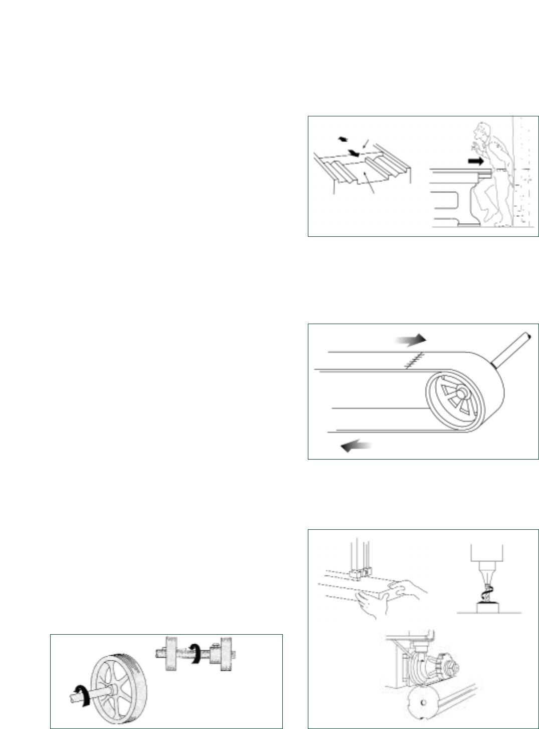
Rotating Motion (Figure 1) is circular motion such
as action generated by rotating collars, couplings,
cams, clutches, flywheels, shaft ends, and spin-
dles that may grip clothing or otherwise force a
body part into a dangerous location. Even smooth
surfaced rotating machine parts can be hazardous.
Projections such as screws or burrs on the rotat-
ing part increase the hazard potential.
Figure 1 Rotating Motion
Reciprocating Motion (Figure 2) is back-and-forth
or up-and-down motion that may strike or entrap
an employee between a moving part and a fixed
object.
Figure 2 Reciprocating Motion
Transversing Motion (Figure 3) is motion in a
straight, continuous line that may strike or catch
an employee in a pinch or shear point created by
the moving part and a fixed object.
Figure 3 Transversing Motion
Cutting Action (Figure 4) is the action that cuts
material and the associated machine motion may
be rotating, reciprocating, or transverse.
Figure 4 Cutting Action
SAFEGUARDING EQUIPMENT AND PROTECTING EMPLOYEES FROM AMPUTATIONS 7
Table
Bed (stationary)
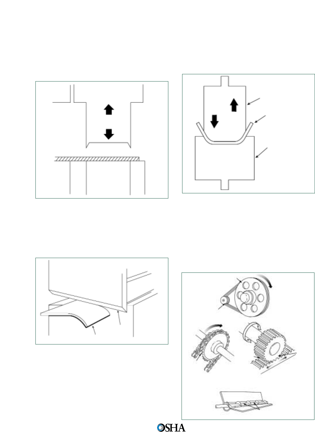
Punching Action (Figure 5) begins when power
causes the machine to hit a slide (ram) to stamp
or blank metal or other material. The hazard
occurs at the point of operation where the
employee typically inserts, holds, or withdraws
the stock by hand.
Figure 5 Punching Action
Shearing Action (Figure 6) involves applying
power to a slide or knife in order to trim or shear
metal or other materials. The hazard occurs at the
point of operation where the employee typically
inserts, holds, or withdraws the stock by hand.
Figure 6 Shearing Action
Bending Action (Figure 7) is power applied to a
slide to draw or stamp metal or other materials in
a bending motion. The hazard occurs at the point
of operation where the employee typically inserts,
holds, or withdraws the stock by hand.
Figure 7 Bending Action
In-Running Nip Points (Figure 8), also known as
“pinch points,” develop when two parts move
together and at least one moves in rotary or circu-
lar motion. In-running nip points occur whenever
machine parts move toward each other or when
one part moves past a stationary object. Typical
nip points include gears, rollers, belt drives, and
pulleys.
Figure 8 In-Running Nip Points
8
Occupational Safety and
Health Administration
Blade
Stock
Punch
Stock
Die
Nip Point
Nip
Point
Typical Nip Point
Nip Point
Nip Point
Nip
Point

Hazardous Activities
Employees operating and caring for machinery
perform various activities that present potential
amputation hazards.
Machine set-up/threading/preparation,*
Machine inspection,*
Normal production operations,
Clearing jams,*
Machine adjustments,*
Cleaning of machine,*
Lubricating of machine parts,* and
Scheduled and unscheduled maintenance.*
* These activities are servicing and/or mainte-
nance activities.
Hazard Analysis
You can help prevent workplace amputations by
looking at your workplace operations and identify-
ing the hazards associated with the use and care of
the machine. A hazard analysis is a technique that
focuses on the relationship between the employee,
the task, the tools, and the environment. When
evaluating work activities for potential amputation
hazards, you need to consider the entire machine
operation production process, the machine modes
of operation, individual activities associated with
the operation, servicing and maintenance of the
machine, and the potential for injury to employees.
The results from the analysis may then be used
as a basis to design machine safeguarding and an
overall energy control (lockout/tagout) program.
This is likely to result in fewer employee amputa-
tions; safer, more effective work methods; reduced
workers’ compensation costs; and increased em-
ployee productivity and morale.
Controlling Amputation
Hazards
Safeguarding is essential for protecting employees
from needless and preventable injury. A good rule
to remember is:
Any machine part, function, or process that may
cause injury must be safeguarded.
In this booklet, the term primary safeguarding
methods refers to machine guarding techniques
that are intended to prevent or greatly reduce the
chance that an employee will have an amputation
injury. Refer to the OSHA general industry (e.g.,
Subpart O) and construction (e.g., Subparts I and
N) standards for specific guarding requirements.
Many of these standards address preventive meth-
ods (such as using barrier guards or two-hand trip-
ping devices) as primary control measures; while
other OSHA standards allow guarding techniques
(such as a self-adjustable table saw guard) that
reduce the likelihood of injury. Other less protective
safeguarding methods (such as safe work methods)
that do not satisfactorily protect employees from
the machine hazard areas are considered second-
ary control methods.
Machine safeguarding must be supplemented
by an effective energy control (lockout/tagout)
program that ensures that employees are protected
from hazardous energy sources during machine
servicing and maintenance work activities.
Lockout/tagout plays an essential role in the pre-
vention and control of workplace amputations. In
terms of controlling amputation hazards, employ-
ees are protected from hazardous machine work
activities either by: 1) effective machine safeguard-
ing, or 2) lockout/tagout where safeguards are ren-
dered ineffective or do not protect employees from
hazardous energy during servicing and mainte-
nance operations.
Additionally, there are some servicing activities,
such as lubricating, cleaning, releasing jams and
making machine adjustments that are minor in
nature and are performed during normal produc-
tion operations. It is not necessary to lockout/
tagout a machine if the activity is routine, repetitive
and integral to the production operation provided
that you use an alternative control method that
affords effective protection from the machine’s
hazardous energy sources.
Safeguarding Machinery
The employer is responsible for safeguarding
machines and should consider this need when pur-
chasing machinery. Almost all new machinery is
SAFEGUARDING EQUIPMENT AND PROTECTING EMPLOYEES FROM AMPUTATIONS 9

available with safeguards installed by the manufac-
turer, but used equipment may not be.
If machinery has no safeguards, you may be
able to purchase safeguards from the original
machine manufacturer or from an after-market
manufacturer. You can also build and install the
safeguards in-house. Safeguarding equipment
should be designed and installed only by technical-
ly qualified professionals. If possible, the original
equipment manufacturer should review the safe-
guard design to ensure that it will protect employ-
ees without interfering with the operation of the
machine or creating additional hazards.
Regardless of the source of safeguards, the
guards and devices used need to be compatible
with a machine’s operation and designed to ensure
safe operator use. The type of operation, size, and
shape of stock, method of feeding, physical layout
of the work area, and production requirements all
affect the selection of safeguards. Also, safeguards
should be designed with the machine operator in
mind as a guarding method that interferes with the
operation of the machine may cause employees to
override them. To ensure effective and safe operator
use, guards and devices should suit the operation.
The Performance Criteria for Safeguarding
[ANSI B11.19-2003] national consensus standard
provides valuable guidance as the standard
addresses the design, construction, installation,
operation and maintenance of the safeguarding
used to protect employees from machine hazards.
The following safeguarding method descriptions
are, in part, structured like and, in many ways are
similar to this national consensus standard.
The Performance Criteria for Safeguarding [ANSI
B11.19-2003] defines safeguarding as the protec-
tion of personnel from hazards by the use of
guards, safeguarding devices awareness devices,
safeguarding methods, or safe work procedures.
The following ANSI B11.19 definitions describe
the various types of safeguarding:
Guard: A barrier that prevents exposure to an
identified hazard.
Safeguarding device: A device that detects or
prevents inadvertent access to a hazard.
NOTE: The 1990 ANSI B11.19 term Safeguarding
device was modified to Safeguarding (Protective)
Device in the revised 2003 ANSI standard and the
new term includes a detection component. De-
vices that detect, but do not prevent employee
exposure to machine hazards are not considered
by OSHA to be primary safeguarding methods.
Awareness device: A barrier, signal or sign that
warns individuals of an impending, approaching
or present hazard.
Safeguarding method: Safeguarding implement-
ed to protect individuals from hazards by the
physical arrangement of distance, holding, open-
ings, or positioning of the machine or machine
production system to ensure that the operator
cannot reach the hazard.
Safe work procedures: Formal written instruc-
tions developed by the user which describe how
a task is to be performed.
Primary Safeguarding Methods
Two primary methods are used to safeguard
machines: guards and some types of safeguarding
devices. Guards provide physical barriers that pre-
vent access to danger areas. Safeguarding devices
either prevent or detect operator contact with the
point of operation or stop potentially hazardous
machine motion if any part of an individual’s body
is within the hazardous portion of the machine.
Both types of safeguards need to be properly
designed, constructed, installed, used and main-
tained in good operating condition to ensure
employee protection.
Criteria for Machine Safeguarding
• Prevents employee contact with the hazard
area during machine operation.
• Avoids creating additional hazards.
• Is secure, tamper-resistant, and durable.
• Avoids interfering with normal operation of
the machine.
• Allows for safe lubrication and maintenance.
Guards
Guards usually are preferable to other control
methods because they are physical barriers that
enclose dangerous machine parts and prevent
employee contact with them. To be effective,
guards must be strong and fastened by any secure
method that prevents the guard from being inad-
vertently dislodged or removed. Guards typically
are designed with screws, bolts and lock fasteners
and usually a tool is necessary to unfasten and
10
Occupational Safety and
Health Administration
remove them. Generally, guards are designed not
to obstruct the operator’s view or to prevent
employees from doing a job.
In some cases, guarding may be used as an
alternative to lockout/tagout because employees
can safely service or maintain machines with a
guard in place. For example, polycarbonate and
wire-mesh guards provide greater visibility and can
be used to allow maintenance employees to safely
observe system components. In other instances,
employees may safely access machine areas, with-
out locking or tagging out, to perform maintenance
work (such as machine cleaning or oiling tasks)
because the hazardous machine components
remain effectively guarded.
Guards must not create additional hazards such
as pinch points or shear points between guards
and other machine parts. Guard openings should
be small enough to prevent employees from
accessing danger areas. (See Table 1 and Figures
9 through 12 for commonly used machine guards.)
Figure 9 Fixed Guard on a Power Press
Figure 10 Power Press with an Adjustable Barrier Guard
SAFEGUARDING EQUIPMENT AND PROTECTING EMPLOYEES FROM AMPUTATIONS 11
Figure 11 Self-Adjusting Guard on a Radial Saw
Figure 12 Interlocked Guard on a Roll Make-up Machine
Transparent Insert
Entering
Stock
Exiting
Stock
Bar
Guard
Handle
Anti-
Kickback
Device
Blade
Switch Guard

12
Occupational Safety and
Health Administration
Type
Fixed
Adjustable
Self-
Adjusting
Interlocking
Barrier
Guards
Method of
Safeguarding
Barrier that allows for
stock feeding but does not
permit operator to reach
the danger area.
Barrier that adjusts for
a variety of production
operations.
Barrier that moves
according to the size of the
stock entering point of
operation. Guard is in place
when machine is at rest
and pushes away when
stock enters the point of
operation.
Shuts off or disengages
power and prevents
machine start-up when
guard is open. Should
allow for inching of
machine.
Advantages
• Can be constructed to suit
many applications.
• Permanently encloses
the point of operation or
hazard area.
• Provides protection
against machine repeat.
• Allows simple, in-plant
construction, with mini-
mal maintenance.
• Can be constructed to
suit many applications.
• Can be adjusted to admit
varying stock sizes.
• Off-the-shelf guards are
often commercially avail-
able.
• Allows access for some
minor servicing work, in
accordance with the lock-
out/tagout exception,
without time-consuming
removal of fixed guards.
Limitations
• Sometimes not practical
for changing production
runs involving different
size stock or feeding
methods.
• Machine adjustment and
repair often require guard
removal.
• Other means of protecting
maintenance personnel
often required
(lockout/tagout).
• May require frequent
maintenance or
adjustment.
• Operator may make
guard ineffective.
• Does not provide
maximum protection.
• May require frequent
maintenance and
adjustment.
• May require periodic
maintenance or adjust-
ment.
• Movable sections cannot
be used for manual feed-
ing.
• Some designs may be
easy to defeat.
• Interlock control circuitry
may not be used for all
maintenance and servic-
ing work.
Table 1. Commonly Used Machine Guards
Types of Machine Guards
Safeguarding Devices
Safeguarding devices are controls or attachments
that, when properly designed, applied and used,
usually prevent inadvertent access by employees to
hazardous machine areas by:
• Preventing hazardous machine component oper-
ation if your hand or body part is inadvertently
placed in the danger area;
• Restraining or withdrawing your hands from the
danger area during machine operation;
• Requiring the use of both of your hands on
machine controls (or the use of one hand if the
control is mounted at a safe distance from the
danger area) that are mounted at a predeter-
mined safety distance; or
• Providing a barrier which is synchronized with
the operating cycle in order to prevent entry to
the danger area during the hazardous part of the
cycle.
These types of engineering controls, which
either prevent the start of or stop hazardous
motion, may be used in place of guards or as
supplemental control measures when guards alone
do not adequately enclose the hazard. In order for
these safeguarding devices to accomplish this
requirement, they must be properly designed and
installed at a predetermined safe distance from the
machine’s danger area. Other safeguarding devices
(probe detection and safety edge devices) that
merely detect, instead of prevent, inadvertent
access to a hazard are not considered primary safe-
guards. (See Table 2 and Figures 13 through 17 for
the types of safeguarding devices.)
Figure 13 Pullback Device on a Power Press
SAFEGUARDING EQUIPMENT AND PROTECTING EMPLOYEES FROM AMPUTATIONS 13
Pullback
Mechanism
Pullback
Straps
Wristbands
Type
Pullback
Devices
Method of
Safeguarding
Cords connected to
operator’s wrists and
linked mechanically to
the machine automatically
withdraw the hands from
the point of operation
during the machine cycle.
Advantages
• Allows the hands to enter
the point of operation for
feeding and removal.
• Provides protection even
in the event of mechani-
cal repeat.
Limitations
• Close supervision ensures
proper use and adjust-
ment. Must be inspected
prior to each operator
change or machine set-up.
• Limits operator’s move-
ment and may obstruct
their work space.
• Operator may easily make
device ineffective by not
adjusting the device
properly.
Table 2. Types of Safeguarding Devices
Types of Machine Guards

14
Occupational Safety and
Health Administration
Type
Restraint
Devices
Presence-
Sensing
Devices
Presence-
Sensing
Mats
Method of
Safeguarding
Wrists are connected by
cords and secured to a
fixed anchor point which
limit operator’s hands from
reaching the point of oper-
ation at any time.
Interlock into the machine’s
control system to stop
operation when the sens-
ing field (photoelectric,
radio frequency, or electro-
magnetic) is disturbed.
Interlock into machine’s
control system to stop
operation when a predeter-
mined weight is applied to
the mat. A manual reset
switch must be located out-
side the protected zone.
Advantages
• Simple, few moving
parts; requires little
maintenance.
• Operator cannot reach
into the danger area.
• Little risk of mechanical
failure; provides protec-
tion even in the event of
mechanical repeat.
• Adjusts to fit different
stock sizes.
• Allows access to load
and unload the machine.
• Allows access to the
guarded area for main-
tenance and set-up
activities.
• Full visibility and access
to the work area.
• Install as a perimeter
guard or over an entire
area.
• Configure for many
applications.
Limitations
• Close supervision re-
quired to ensure proper
use and adjustment.
Must be inspected prior
to each operator change
or machine set-up.
• Operator must use hand
tools to enter the point of
operation.
• Limits the movement of
the operator; may
obstruct work space
around operator.
• Operator may easily make
device ineffective by dis-
connecting the device.
• Restricted to machines
that stop operating cycle
before operator can reach
into danger area (e.g.,
machines with partial
revolution clutches or
hydraulic machines).
• Must be carefully main-
tained and adjusted.
• Does not protect
operator in the event
of a mechanical failure.
• Operator may make
device ineffective.
• Restricted to machines
that stop operating cycle
before operator can reach
into danger area (e.g.,
machines with part-
revolution clutches or
hydraulic machines).
• Some chemicals can
degrade the mats.
• Does not protect
operator during
mechanical failures.
Table 2. Types of Safeguarding Devices (continued)
Types of Machine Guards

SAFEGUARDING EQUIPMENT AND PROTECTING EMPLOYEES FROM AMPUTATIONS 15
Type
Two-
Hand
Control
Two-
Hand Trip
Type “A”
Gate
(move-
able
barrier)
Type “B”
Gate
(move-
able
barrier)
Method of
Safeguarding
Requires concurrent and
continued use of both
hands, preventing them
from entering the danger
area.
Requires concurrent use of
both hands, prevents them
from being in danger area
when machine cycle starts.
Applicable to mechanical
power presses. Provides
barrier between danger
area and operator (or other
employees) until comple-
tion of machine cycle.
Applicable to mechanical
power presses and press
brakes. Provides a barrier
between danger area and
operator (or other employ-
ees) during the down-
stroke.
Advantages
• Operator’s hands are at
a predetermined safety
distance.
• Operator’s hands are free
to pick up new parts after
completion of first part of
cycle.
• Operator’s hands are at
a predetermined safety
distance.
• Can be adapted to
multiple operations.
• No obstruction to hand
feeding.
• Prevents operator from
reaching into danger area
during machine cycle.
• Provides protection from
machine repeat.
• May increase production
by allowing the operator
to remove and feed the
press on the upstroke.
Limitations
• Requires a partial cycle
machine with a brake
and anti-repeat feature.
• Operator may make
devices without anti-
tiedown ineffective.
• Protects the operator
only.
• Operator may make
devices without anti-
tiedown ineffective.
• Protects the operator
only.
• Sometimes impractical
because distance require-
ments may reduce pro-
duction below acceptable
level.
• May require adjustment
with tooling changes.
• Requires anti-repeat
feature.
• May require frequent
inspection and regular
maintenance.
• May interfere with opera-
tor’s ability to see work.
• Can only be used on
machines with a part-
revolution clutch or
hydraulic machines.
• May require frequent
inspection and regular
maintenance.
• May interfere with the
operator’s ability to see
work.
Table 2. Types of Safeguarding Devices (continued)
Types of Machine Guards
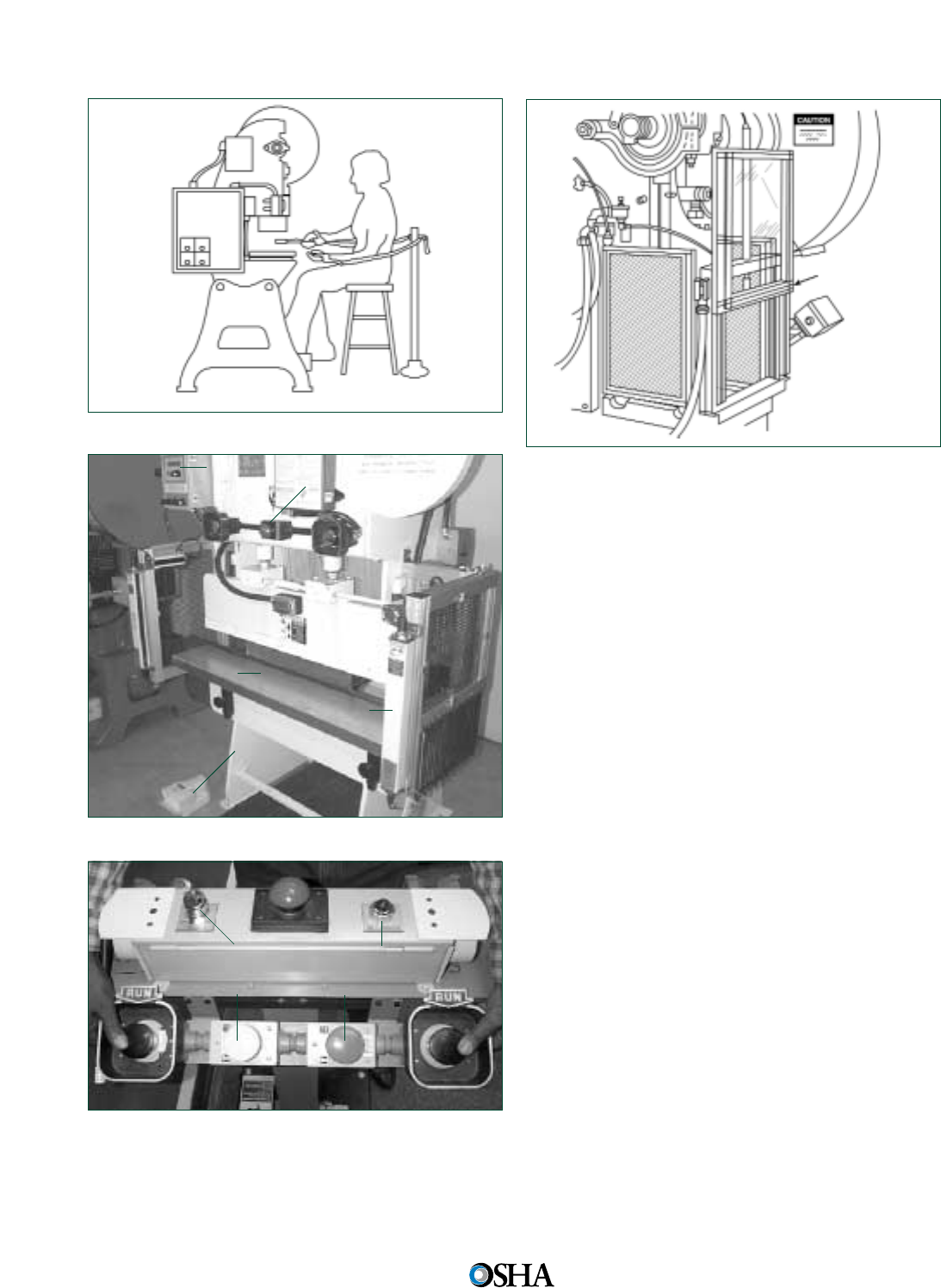
Figure 17 Power Press with a Gate
Secondary Safeguarding Methods
Other safeguarding methods, such as those described
in the Performance Criteria for Safeguarding (ANSI
B11.19-2003), may also provide employees with
some protection from machine hazards. Detection
safeguarding devices, awareness devices, safe-
guarding methods and safe work procedures are
described in this section. These methods provide a
lesser degree of employee protection than the pri-
mary safeguarding methods and they are consid-
ered secondary control measures as they do not
prevent employees from placing or having any part
of their bodies in the hazardous machine areas.
Secondary safeguarding methods are accept-
able only when guards or safeguarding devices
(that prevent you from being exposed to machine
hazards) cannot be installed due to reasons of
infeasibility. Where it is feasible to use primary
safeguarding methods, secondary safeguarding
methods may supplement these primary control
measures; however, these secondary safeguarding
methods must not be used in place of primary safe-
guarding methods.
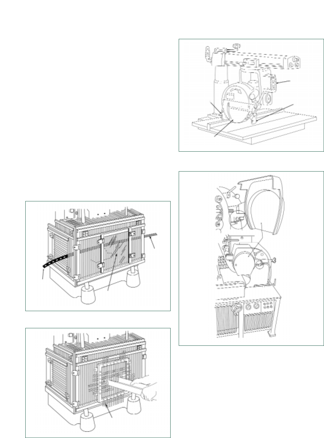
Probe Detection and Safety Edge Devices
A probe detection device (sometimes referred to as
a ring guard) detects the presence or absence of a
person’s hand or finger by encircling all or part of
the machine hazard area. The ring guard makes
you aware of your hand’s entry into a hazardous
area and usually stops or prevents a hazardous
machine cycle or stroke, thereby reducing the likeli-
hood of injuring yourself in the point of operation.
These types of detection devices are commonly
used on spot welders, riveters, staplers and stack-
Figure 14 Restraint Device on a Power Press
Figure 15 Presence-Sensing Device on a Power Press
Figure 16 Two-Hand Control
16
Occupational Safety and
Health Administration
Emergency Stop
Press
Bed
Control
Box
Light
Curtain
Guarded
Foot Control
Key Selector Capable
of Being Supervised
Gate
Light Indicator
Emergency Stop
Top Stop
Safe Distance Safeguarding
Safeguarding by safe distance (by location) may
involve an operator holding and supporting a work-
piece with both hands at a predetermined mini-
mum safe distance or, if both hands cannot be used
to hold the work-piece at a distance so that the
operator cannot reach the hazard with the free
hand. For example, the feeding process itself can
create a distance safeguard if the operators main-
tain a safe distance between their hands and the
point of operation. Additionally, where material
position gauges are used, they need to be of suffi-
cient height and size to prevent slipping of the
material past the gauges.
Another example of a safe distance safeguard-
ing method is the use of gravity feed methods that
reduce or eliminate employee exposure to machine
hazards as the part slides down a chute into the
point of operation. Automatic and semiautomatic
feeding and ejection methods can also protect the
employee by minimizing or eliminating employee
exposure with potentially hazardous machinery
components. An employee places the part in a
magazine which is then fed into the point of opera-
tion. Automatic and semiautomatic ejection methods
include pneumatic (jet of air), magnetic, mechanical
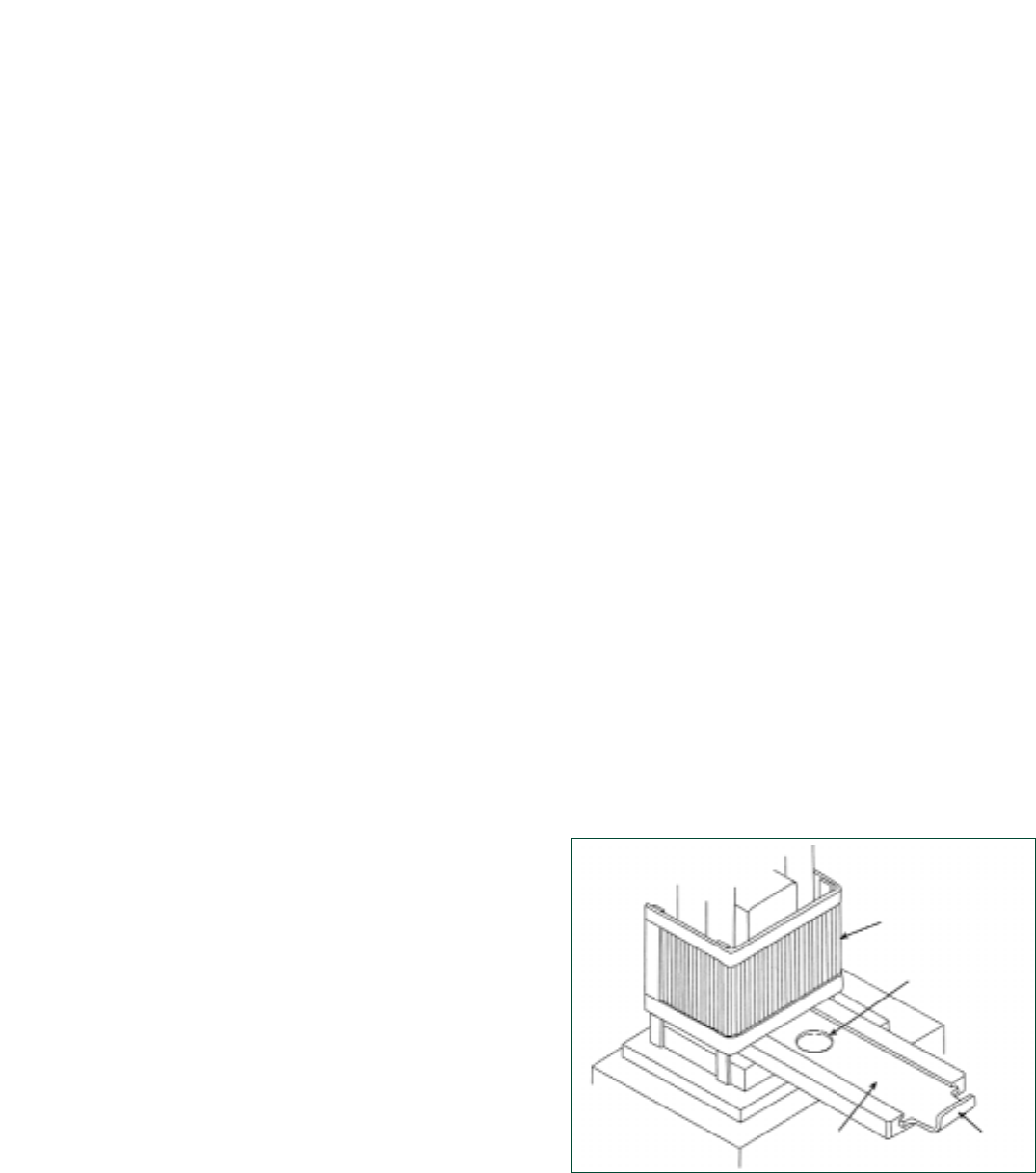
(such as an arm), or vacuum. Figures 18 and 19
illustrate different types of automatic feeding and
ejecting methods.
Figure 18 Power Press with a Plunger Feed
SAFEGUARDING EQUIPMENT AND PROTECTING EMPLOYEES FROM AMPUTATIONS 17
ers because primary safeguarding methods are not
possible. However, probe detection devices do not
prevent inadvertent access to the point-of-operation
danger area; rather, they serve as a warning mech-
anism and may prevent the initiation of or stop the
machine cycle if an employee’s hand or finger(s) is
too close to the hazard area.
A safety edge device (sometimes called a bump
switch) is another type of safeguard that detects the
presence of an employee when they are in contact
with the device’s sensing edge. A safety edge
device protects employees by initiating a stop com-
mand when the sensing surface detects the pres-
ence of a person; however, they do not usually,
when used by themselves, prevent inadvertent
access to machine danger areas. Therefore, addi-
tional guarding or safeguarding devices must be
provided to prevent employee exposure to a
machine hazard.
Awareness Devices
Awareness devices warn employees of an impend-
ing, approaching or present hazard. The first type
is an awareness barrier which allows access to
machine danger areas, but it is designed to contact
the employee, creating an awareness that he or she
is close to the danger point. Awareness signals,
through the use of recognizable audible or visual
signals, are other devices that alert employees to
an approaching or present hazard. Lastly, aware-
ness signs are used to notify employees of the
nature of the hazard and to provide instructions
and training information. OSHA standard 1910.145
provides design, application, and use specifications
for accident prevention (danger, caution, safety
instruction) signs and (danger, caution, warning)
tags.
Safeguarding Methods
Safeguarding methods protect employees from
hazards by the physical arrangement of distance,
holding, openings or the positioning of the
machine components to ensure that the operator
cannot reach the hazard. Some safeguarding work
methods include safe distance safeguarding, safe
holding safeguarding and safe opening safeguard-
ing. Requirements for these secondary control
measures may be found in ANSI B11.19-2003.
Proper training and supervision are essential to
ensure that these secondary safeguarding methods
are being used properly. Safeguarding work meth-
ods may require the use of awareness devices,
including the use of accident prevention signs where
there is a need for warning or safety instruction.
Plunger Plunger
Handle
Point of
Operation
Guard
Nest
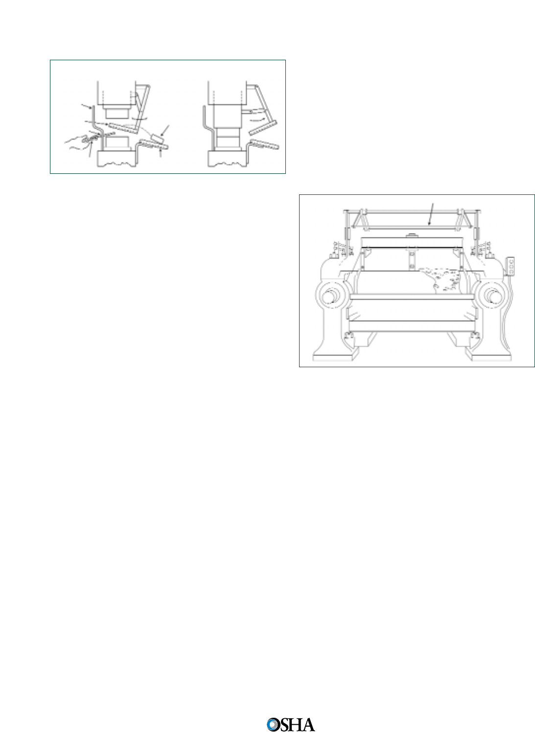
Figure 19 Shuttle Ejection Mechanism
Safe Holding Safeguarding (Safe Work-Piece
Safeguarding)
Operator’s hands are maintained away from the
hazardous portion of the machine cycle by requir-
ing that both hands are used to hold or support the
work-piece, or by requiring that one hand holds the
work-piece while the other hand operates the
machine. For instance, if the stock is several feet long
and only one end of the stock is being worked on,
the operator may be able to hold the opposite end
while performing the work. The operator’s body
parts are out of the machine hazard area during the
hazardous portion of the machine cycle. However,
this work method only protects the operator.
Safe Opening Safeguarding
This method limits access to the machine haz-
ardous areas by the size of the opening or by clos-
ing off the danger zone access when the work-piece
is in place in the machine. Operators are prevented
from reaching the hazard area during the machine
operation; however, employee access to the danger
area is not adequately guarded when the work-
piece is not in place.
Safe Work Procedures
Safe work procedures are formal, written instruc-
tions which describe how a task is to be performed.
These procedures should incorporate appropriate
safe work practices, such as prohibiting employees
from wearing loose clothing or jewelry and requir-
ing the securing of long hair with nets or caps.
Clothing, jewelry, long hair, and even gloves can get
entangled in moving machine parts.
Complementary Equipment
Complementary equipment is used in conjunction
with selected safeguarding techniques and it is, by
itself, not a safeguarding method. Some common
complementary equipment used to augment
machine safeguarding include:
18
Occupational Safety and
Health Administration
Emergency Stop Devices
Emergency stop devices are designed to be used
in reaction to an incident or hazardous situation
and, as such, are not considered machine safe-
guarding. These devices, such as buttons, rope-
pulls, cable-pulls, or pressure-sensitive body bars,
neither detect nor prevent employee exposure to
machine hazards; rather they initiate an action to
stop hazardous motion when an employee recog-
nizes a hazard and activates them. (See Figure 20.)
Figure 20 Safety Tripod on a Rubber Mill
Work-Holding Equipment
Work-holding equipment is not used to feed or re-
move the work-piece, but rather to hold it in place
during the hazardous portion of the machine cycle.
Clamps, jigs, fixtures and back gauges are exam-
ples of work-holding equipment. This equipment
may be used to reduce or eliminate the need for an
employee to place their hands in the hazard area.
Feeding and Ejection Systems
A feeding and ejection system (e.g., a gravity fed
chute; semi-automatic and automatic feeding and
ejection equipment), by itself, does not constitute
secondary safeguarding. However, the use of prop-
erly designed feed and ejection mechanisms can
protect employees by minimizing or eliminating the
need for them to be in a hazard area during the
hazardous motion of the machine.
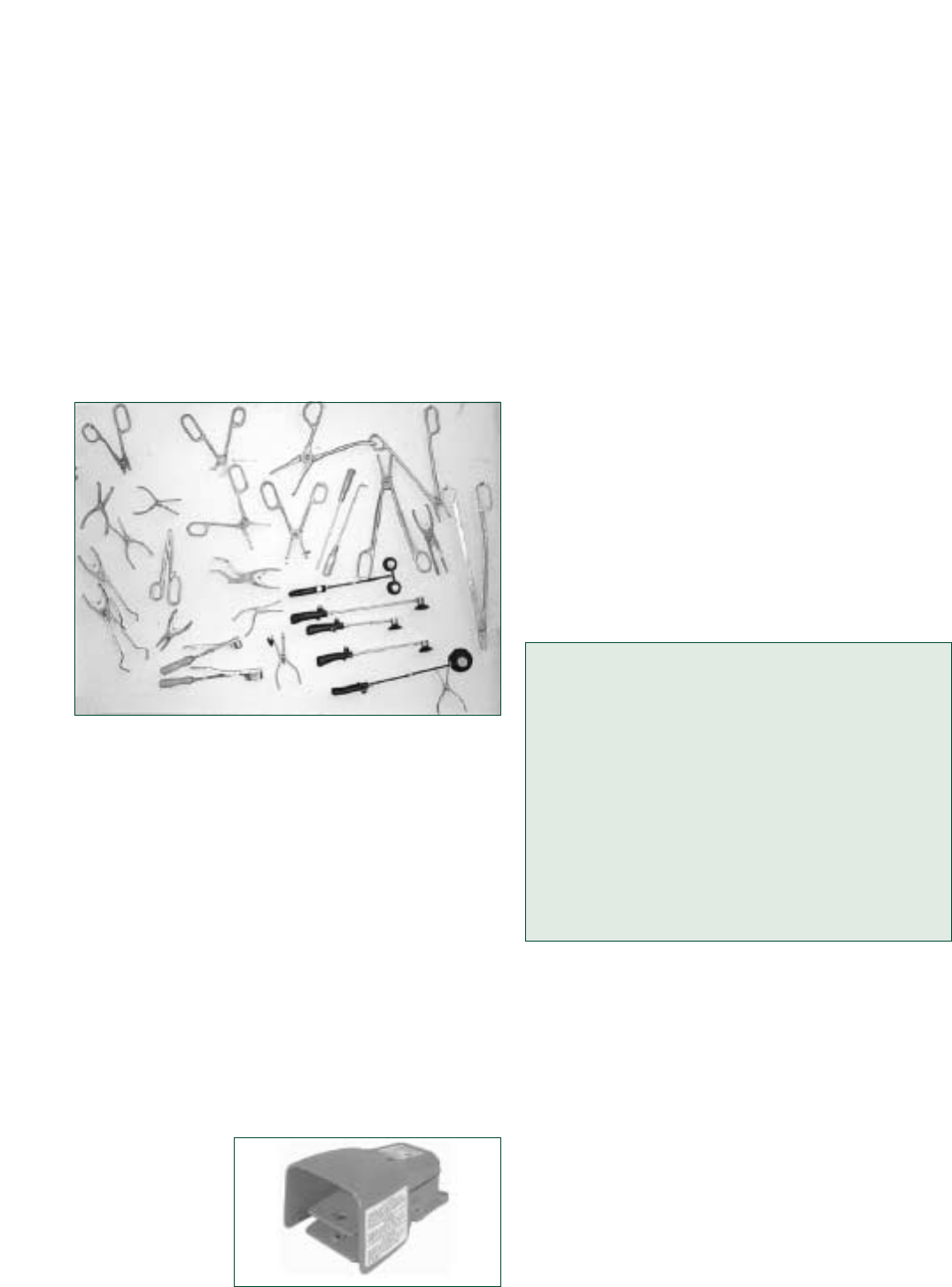
Hand-Feeding Tools
Operators can use tools to feed and remove materi-
al into and from machines so as to keep their
hands away from the point of operation. However,
this must be done only in conjunction with the
guards and safeguarding devices described previ-
ously. Hand tools are not point-of-operation guard-
Slide in
Down
Position
Slide in
Up
Position
Point of
Operation
Guard
Completed
Part
Chute
Pan
Shuttle
Feeding
Tool
Stock
Tripod
ing or safeguarding devices and they need to be
designed to allow employees’ hands to remain out-
side of the machine danger area. Using hand tools
requires close supervision to ensure that the opera-
tor does not bypass their use to increase produc-
tion. It is recommended that these tools be stored
near the operation to promote their use.
To prevent injury and repetitive trauma disor-
ders, hand-feeding tools should be shatterproof
and ergonomically designed for the specific task
being performed. (Figure 21 shows typical hand-
feeding tools.)
Figure 21 Typical Hand-Feeding Tools
Foot Controls
Foot controls that are not securely fixed at a safe
distance do not constitute machine safeguarding
because they do not keep the operator’s hands out
of the danger area. If you use foot-actuated con-
trols that are not single-control safeguarding
devices, they will need to be used with some type
of guard or other safeguarding device.
Improperly used foot-actuated controls may
increase productivity, but the freedom of hand
movement increases the risk of a point-of-operation
injury or amputation. Foot controls must be guard-
ed to prevent accidental activation by another
employee or by falling material. Do not ride the
foot pedal. Ensure that the machine control circuit
is properly designed to prevent continuous cycling.
(See Figure 22 for an example of a properly guard-
ed foot control.)
Figure 22
Properly Guarded
Foot Control
SAFEGUARDING EQUIPMENT AND PROTECTING EMPLOYEES FROM AMPUTATIONS 19
Administrative Issues
As an employer, you need to consider housekeep-
ing practices, employee apparel, and employee
training. Implement good housekeeping practices
to promote safe working conditions around ma-
chinery by doing the following:
• Remove slip, trip, and fall hazards from the
areas surrounding machines;
• Use drip pans when oiling equipment;
• Remove waste stock as it is generated;
• Make the work area large enough for machine
operation and maintenance; and
• Place machines away from high traffic areas to
reduce employee distraction.
Employees should not wear loose-fitting cloth-
ing, jewelry, or other items that could become
entangled in machinery, and long hair should be
worn under a cap or otherwise contained to pre-
vent entanglement in moving machinery.
Adequate instruction in the safe use and care of
machines and supervised on-the-job training are
essential in preventing amputation injuries. Only
trained employees should operate machinery.
Train Employees in the Following:
• All hazards in the work area, including
machine-specific hazards;
• Machine operating procedures, lockout/tagout
procedures and safe work practices;
• The purpose and proper use of machine safe-
guards; and
• All procedures for responding to safeguarding
problems such as immediately reporting un-
safe conditions such as missing or damaged
guards and violations of safe operating prac-
tices to supervisors.
In addition to employee instruction and training,
employers need to provide adequate supervision
to reinforce safe practices. Take disciplinary ac-
tion to enforce safe work practices and working
conditions.
Inspection and Maintenance
Good inspection, maintenance and repair proce-
dures contribute significantly to the safety of the
maintenance crew as well as to the operators. To
ensure the integrity of the machinery and machine
safeguards, a proactive, versus a break-down main-

Specific Machine Hazards
and Safeguarding Methods
As discussed earlier, 8,450 known non-fatal ampu-
tation cases (involving days away from work)
occurred in 2005 for all of private industry. The
most prevalent injury source was, by far, machin-
ery, which accounted for approximately 60% (5,080
instances) of the amputation cases.1The machinery
listed here cause amputation injuries, and appropri-
ate safeguarding and hazardous energy control
(lockout/tagout) methods are addressed in this sec-
tion. Employers need to consult the OSHA standard
for specific machinery to ensure compliance with
all requirements. For other types of hazardous
sources of injury, see Appendix B.
Machinery Associated with Amputations
1. Mechanical Power Presses
2. Power Press Brakes
3. Powered and Non-Powered Conveyors
4. Printing Presses
5. Roll-Forming and Roll-Bending Machines
6. Shearing Machines
7. Food Slicers
8. Meat Grinders
9. Meat-Cutting Band Saws
10. Drill Presses
11. Milling Machines
12. Grinding Machines
13. Slitters
Hazards of Mechanical Power Presses
Although there are three major types of power
presses—mechanical, hydraulic, and pneumatic—
the machinery that accounts for a large number of
workplace amputations are mechanical power
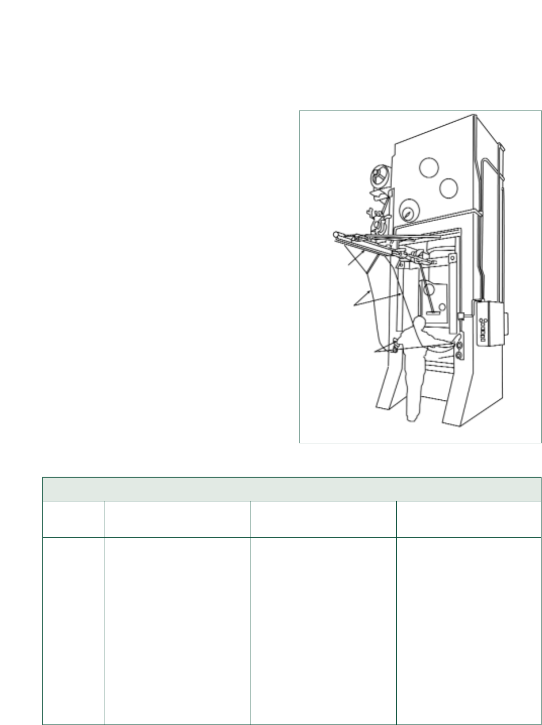
presses.
In mechanical power presses, tools or dies are
mounted on a slide, or ram, which operates in a
controlled, reciprocating motion toward and away
from the stationary bed or anvil containing the
lower die. When the upper and lower dies press
together – to punch, shear or form – the work-
piece, the desired piece is produced. Once the
downstroke is completed, the re-formed work-piece
20
Occupational Safety and
Health Administration
tenance program needs to be established based
upon the:
• Manufacturer’s recommendations;
• Good engineering practice; and
• Any applicable OSHA provisions (such as the
mechanical power press inspection and mainte-
nance requirements, contained in 1910.217(e)).
Lockout/Tagout
OSHA’s lockout/tagout (LOTO) standard, 29 CFR
1910.147, establishes minimum performance re-
quirements for controlling hazardous energy and it
is intended to complement and augment machine
safeguarding practices. The lockout/tagout standard
applies only if employees are exposed to hazard-
ous energy during servicing/maintenance activities.
An employer may avoid the requirements of the
LOTO standard if the safeguarding method elimi-
nates your employees’ exposure to the machine
danger area during the servicing or maintenance
work by using Machinery and Machine Guarding
methods in accordance with the requirements con-
tained in 29 CFR 1910, Subpart O.
Additionally, because some minor servicing may
have to be performed during normal production
operations, an employer may be exempt from
LOTO in some instances. Minor tool changes and
adjustments and other minor servicing operations,
which take place during normal production opera-
tions, are not covered by lockout/tagout if they are
routine, repetitive and integral to the use of the
machine for production and if work is performed
using alternative effective protective measures that
provide effective employee protection.
In short, a hazardous energy control program is
a critical part of an overall strategy to prevent
workplace amputations during machine servicing
and maintenance activities, such as during the set-
ting up of machines for production purposes, by-
passing guards to clear jams or lubricate parts, and
inspecting, adjusting, replacing, or otherwise serv-
icing machine parts. Machine amputations occur
when an employer does not have or fails to imple-
ment practices and procedures to disable and con-
trol a machine’s energy sources during machine
servicing and maintenance work.
1U.S. Department of Labor, Bureau of Labor Statistics
(BLS); Annual Survey data, Table R25. Number of non-
fatal occupational injuries or illnesses involving days
away from work by source of injury or illness and select-
ed natures of injury or illness, 2005.
is removed either automatically or manually, a new
work-piece is fed into the die, and the process is
repeated. (See Figure 23.)
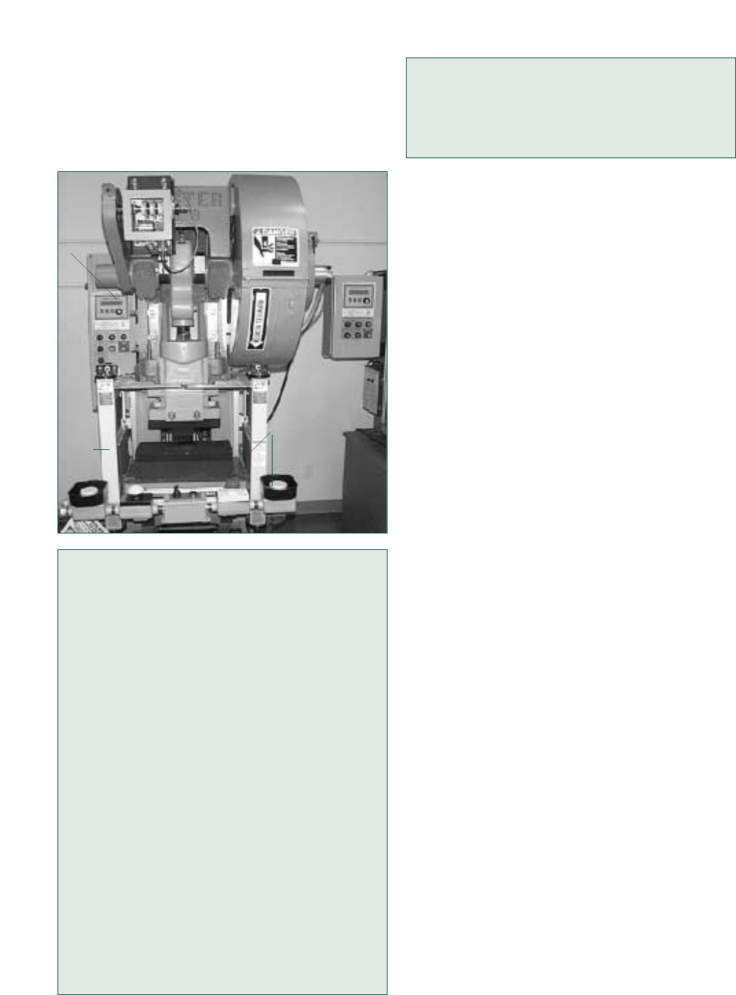
Figure 23 Part Revolution Mechanical Power Press with
a Two-Hand Control
Controls for Machines with Clutches
Certain machines can be categorized based on
the type of clutch they use—full-revolution or
part-revolution. Differing modes of operation for
these two clutches determine the type of guard-
ing that can be used.
Full-revolution clutches, once activated, com-
plete a full cycle of the slide (lowering and rais-
ing of the slide) before stopping at dead center
and cannot be disengaged until the cycle is com-
plete. So, presence-sensing devices will not
work and operators must be protected during
the entire press operating cycle. For example,
properly applied barrier guards or two-hand
trip devices that are installed at a safe distance
from the hazard area may be used.
Machines incorporating full-revolution
clutches, such as mechanical power presses,
must also incorporate a single-stroke device and
anti-repeat feature.
The majority of part-revolution presses are
air clutch and brake. They are designed to trap
air in a chamber or tube. When the compressed
air is put into these chambers, the clutch is
engaged, the brake disengaged and the press
makes a single stroke. To stop the press, the
reverse takes place. Thus, the part-revolution
clutch can be disengaged at any time during the
cycle to stop the cycle before it completes the
downstroke.
For safeguarding purposes, part-revolution
mechanical power presses can be equipped with
presence-sensing devices, but full-revolution
mechanical power presses cannot.
NOTE: Likewise, most hydraulic power presses
and their associated control systems are similar to
part-revolution mechanical power presses in that
the slide can be stopped at any point in the cycle.
In order to ensure the integrity of the safety-related
functions, safeguarding devices (such as presence-
sensing devices) may only be used on hydraulic
power presses that are properly designed and con-
structed (in accordance with good engineering
practice) to accommodate the safeguarding system.
Refer to OSHA’s Machine Guarding eTool for addi-
tional information on hydraulic presses.
Amputations occurring from the point of opera-
tion hazards are the most common types of injuries
associated with mechanical power presses.
Improperly applied safeguarding methods (such as
using a guard with more than maximum allowable
openings or 2-hand palm buttons that are mounted
within the safety distance of the press) may allow
operators unsafe access to the press’s hazardous
area. These unsafe conditions may result in an
amputation when an operator, for example, instinc-
tively reaches into the point of operation to adjust a
misaligned part or release a jam. Also, amputations
occur when an operator’s normal feeding rhythm is
interrupted, resulting in inadvertent placement of the
operator’s hands in the point of operation. Such
injuries usually happen while the operator is riding
the foot pedal. Additionally, some amputations are
linked to mechanical (such as the failure of a single-
stroke linkage), electrical (such as a control relay fail-
ure), or pneumatic (such as the loss of air pressure
to the clutch/brake) machine component failure.
Examples of inadequate or ineffective safe-
guarding and hazardous energy control practices
include the following:
• Guards and devices disabled to increase produc-
tion, to allow the insertion of small-piece work, or
to allow better viewing of the operation.
• Two-hand trips/controls bridged or tied-down to
allow initiation of the press cycle using only one
hand.
• Devices such as pullbacks or restraints improp-
erly adjusted.
SAFEGUARDING EQUIPMENT AND PROTECTING EMPLOYEES FROM AMPUTATIONS 21
Control
Box
Control
Box
Light
Curtain

• Controls of a single-operator press bypassed by
having a coworker activate the controls while
the operator positions or aligns parts in the die,
or repairs or troubleshoots the press.
• Failure to properly disable, isolate press energy
sources, and lockout/tagout presses before an
employee performs servicing or maintenance
work.
Case History #1
While using an unguarded, foot-pedal-operated,
full-revolution mechanical power press that
made trip collars for wood stoves, an employee
used his hands to feed and remove finished parts
and scrap metal. He placed the completed part to
the left side of the press, and then turned to
place the scrap in the bin behind him. As he
turned back to face the press, he inadvertently
stepped on the foot pedal and activated the press
while his hand was in the die area. His left hand
was amputated at the wrist.
Case History #2
An employee was operating an unguarded 10-
ton, full-revolution mechanical power press to
stamp mailbox parts, and using a hand tool to
load the press, she placed her left hand in the
lower die to reposition a misaligned part. At the
same time, she inadvertently depressed the foot
pedal, activating the press and crushing her left
index finger.
Case History #3
A power press operator and helper were instruc-
ted to temporarily halt production and each
employee decided to perform servicing tasks.
The operator had a problem with a hydraulic
fluid leak and decided to deflect the liquid spray
by installing a temporary barrier while, at the
same time, the helper decided to clean up the
metal chips from the press area. The operator
then activated the press and repositioned the
press slide in order to install the cardboard barri-
er. This mechanical power press action fatally
crushed the helper’s head because his head was
between the dies while he was in the process of
cleaning up the metal chips.
Source: OSHA IMIS Accident Investigation Database.
Safeguarding Mechanical Power Presses
Mechanical power presses are extremely versatile
and selecting appropriate safeguarding methods
depends on the specific press design and use. You
should consider the press, the type of clutch used,
22
Occupational Safety and
Health Administration
the stock size, the length of production runs, and
the method of feeding.
You can use primary safeguarding methods,
such as guards or safeguarding devices, to prevent
injuries. For example, 29 CFR 1910.217 requires
employers to provide and ensure the use of point
of operation guards or properly installed devices on
every operation performed on a press when the die
opening is greater than 1/4inch.
In addition, guards must conform to the maxi-
mum permissible openings of Table O-10 of 29 CFR
1910.217. Guards must prevent entry of hands or
fingers into the point of operation through, over,
under, or around the guard.
Mechanical Power Press Safeguarding
Methods by Clutch Type
Full-Revolution Clutch Part-Revolution Clutch
Point of Operation Guard Point of Operation Guard
Pullback Pullback
Restraint Restraint
Type A Gate Type A Gate
Two-Hand Trip Type B Gate*
Two-Hand Control*
Presence-Sensing Device*
*”Hands-in-Die” operations require additional safe-
guarding measures: See 1910.217(c)(5).
Mechanical power press point of operation safe-
guards must accomplish the following goals:
• Prevent or stop the normal press stroke if the
operator’s hands are in the point of operation;
or
• Prevent the operator from reaching into the
point of operation as the die closes; or
• Withdraw the operator’s hands if inadvertently
placed in the point of operation as the die clos-
es; or
• Prevent the operator from reaching the point of
operation at any time; or
• Require the operator to use both hands for the
machine controls that are located at such a dis-
tance that the slide completes the downward
travel or stops before the operator can reach
into the point of operation; or
• Enclose the point of operation before a press
stroke can be started to prevent the operator
from reaching into the danger area before die
closure or enclose the point of operation prior
to stoppage of the slide motion during the
downward stroke.
Source: 29 CFR 1910.217(c)(3)(i).
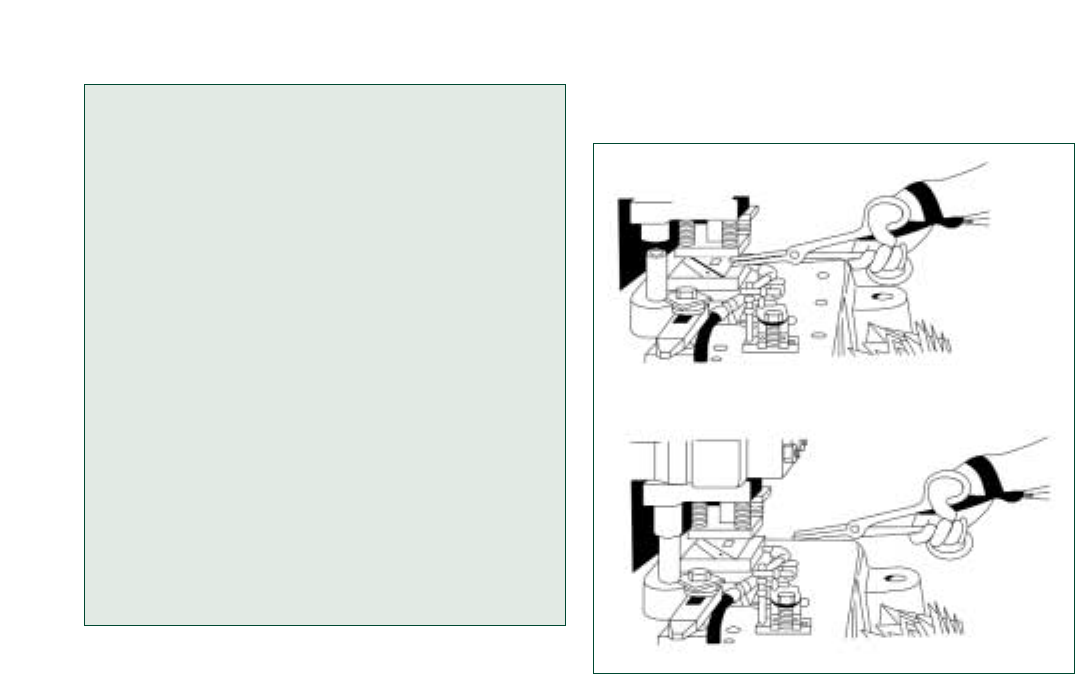
Figure 24 Hand-Feeding Tools Used in Conjunction with
Pullbacks on a Power Press
• Removing scrap or stuck work with tools is
required even when hand feeding is allowed
according to 29 CFR 1910.217(d)(1)(ii). Em-
ployers must furnish and enforce the use of
hand tools for freeing or removing work or
scrap pieces from the die to reduce the amount
of time an operator’s hand is near the point of
operation.
• Control point of operation hazards created when
guards are removed for set-up and repair by
operating the machine in the inch mode. This
involves using two-hand controls (or a single
control mounted at a safe distance from the
machine hazards) to gradually inch the press
through a stroke when the dies are being tested
on part-revolution clutch presses.
• Observe energy control procedures and prac-
tices for press servicing and maintenance work.
For example, the changing of dies on a mechan-
ical power press requires the employer to estab-
lish a die-setting procedure that employs point-
of-operation safeguarding method(s) such as the
safe usage of an inch or jog safety device for die
set-up purposes together with LOTO. These
devices safely position the mechanical power
press slide utilizing a point-of-operation safe-
guarding technique. Thus, an energy control
procedure for these types of presses would
SAFEGUARDING EQUIPMENT AND PROTECTING EMPLOYEES FROM AMPUTATIONS 23
“No Hands-in-Die” Policy
In general, a “no-hands-in-die” policy needs to
be implemented and followed whenever possible
– that is, in the event the press is not designed
for “hands-in-die” production work. Under this
policy, operators must never place their hands in
the die area (point-of-operation) while perform-
ing normal production operations. Adherence to
this safety practice will reduce the risk of point of
operation amputations.
In terms of part-revolution mechanical power
presses that use a two-hand control, presence-
sensing device or type B gate, OSHA does allow
“hands-in-die” operation if the press control reli-
ability and brake monitoring system require-
ments are met. If these press design safety fea-
tures are not complied with, then employers
must incorporate a “no-hands-in-die” policy.
Source: 29 CFR 1910.217(c)(5).
Other Controls for Mechanical Power
Press Servicing and Maintenance
Secondary safeguarding methods may be used
alone or in combination (to achieve near equivalent
protection) only when the employer can show that
it is impossible to use any of the primary safe-
guarding methods. The following are some work
practices, complementary equipment and energy
control measures that may be used to supplement
primary safeguarding:
• If employees operate presses under a “no-
hands-in-die” policy using complementary feed-
ing methods such as hand-tool feeding, employ-
ers still must protect operators through the use
of primary safeguarding methods, such as a
properly applied two-hand control or trip safe-
guarding device. Hand-tool feeding alone does
not ensure that the operator’s hands cannot
reach the danger area. (Figure 24 illustrates the
use of hand-feeding tools in conjunction with
pullbacks on a power press.)
Ram Up-Die Open
Ram Descending-Die Closing

need to integrate both point-of-operation safe-
guarding method(s) for slide positioning as well
as LOTO procedures for the die setting opera-
tion.
Additional power press energy control precau-
tions (e.g., use of safety blocks; LOTO the press dis-
connect switch if re-energization presents a hazard)
will be necessary if employees need to place their
hands/arms in a press working area (the space
between the bolster plate and the ram/slide) to
perform the servicing and/or maintenance activity
(such as adjusting, cleaning or repairing dies) be-
cause the inch or jog safety device will not protect
employees from ram movement due to potential
mechanical energy (resulting from the ram/slide
position and associated gravitational force), press
component or control system malfunction, or press
activation by others.
Minor Servicing
At times, OSHA recognizes that some minor
servicing may have to be performed during nor-
mal production operations, so a lockout/tagout
exception is allowed. See the 29 CFR 1910.147(a)
(2)(ii) Note for details. For example, a press oper-
ator may need to perform a minor die cleaning
task on a regular basis for product quality pur-
poses and the use of safety blocks – inserted
between the press dies – that are interlocked with
the press electrical controls would constitute
effective protection. Properly designed and
applied safety block interlocks may be used in
lieu of locking or tagging out the press’s electrical
energy source for purposes of the minor servic-
ing exception.
Source: 29 CFR 1910.147(a)(2)(ii) Note.
Training
Training is essential for employee protection. As an
employer, you should:
• Train operators in safe mechanical press opera-
tion and hazardous energy control (lockout/
tagout) procedures and techniques before they
begin work on the press.
• Supervise operators to ensure that correct pro-
cedures and techniques are being followed.
Additional Requirements
In addition, work practices such as regular mechan-
ical power press inspection, maintenance, and
reporting are essential.
• 29 CFR 1910.217(e)(1)(i) requires a program of
periodic and regular inspections of mechanical
power presses to ensure that all of the press
parts, auxiliary equipment and safeguards are
in safe operating condition and adjustment.
Inspection certification records must be main-
tained.
• 29 CFR 1910.217(e)(1)(ii) requires you to inspect
and test the condition of the clutch/brake mech-
anism, anti-repeat feature, and single-stroke
mechanism on at least a weekly basis for press-
es without control reliability and brake system
monitoring. Certification records must be main-
tained of these inspections and the maintenance
performed.
• 29 CFR 1910.217(g)(1) requires the reporting of
all point of operation injuries to operators or
other employees within 30 days to either the
Director of the Directorate of Standards and
Guidance, OSHA, U.S. Department of Labor,
Washington, DC 20210, or the state agency
administering a plan approved by OSHA. You
can also use the Internet to report injuries (www.
osha.gov/pls/powerpress/mechanical.html).
Applicable Standards
• 29 CFR 1910.147, Control of hazardous energy
(lockout/tagout).
• 29 CFR 1910.217, Mechanical power presses.
• 29 CFR 1910.219, Mechanical power-transmis-
sion apparatus.
Sources of Additional Information
• OSHA Instruction CPL 3-00-002 [CPL 2-1.35],
National Emphasis Program on Amputations
• OSHA Publication 3067, Concepts and
Techniques of Machine Safeguarding
(http://www.osha.gov/Publications/Mach_
Safeguard/toc.html)
• OSHA Machine Guarding eTool (http://www.
osha.gov/SLTC/etools/machineguarding/index.
html)
• OSHA Lockout/Tagout Interactive Training
Program (http://www.osha.gov/dts/osta/
lototraining/index.htm)
• NIOSH CIB 49, Injuries and Amputations
Resulting From Work with Mechanical Power
Presses (May 22, 1987)
• OSHA Instruction STD 01-12-021 [STD 1-
12.21]—29 CFR 1910.217, Mechanical Power
Presses, Clarifications (10/30/78)
• ANSI B11.1-2001, Safety Requirements for
Mechanical Power Presses
24
Occupational Safety and
Health Administration
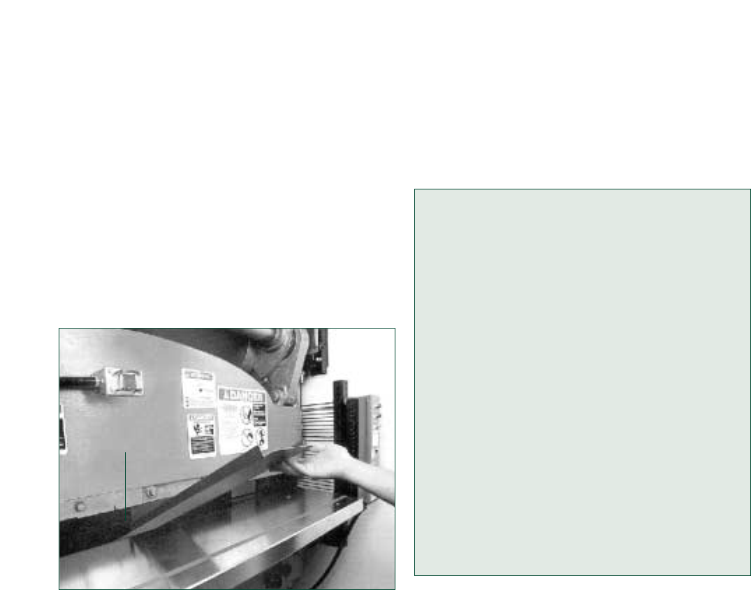
Power Press Brakes
Power press brakes are similar to mechanical
power presses in that they use vertical reciprocat-
ing motion and are used for repetitive tasks. Press
brake operation is either mechanical or hydraulic.
Press brakes are either general-purpose or spe-
cial-purpose brakes, according to ANSI B11.3-2002,
Safety Requirements for Power Press Brakes.
General purpose press brakes have a single opera-
tor control station. A servo-system activates the
special purpose brake, which may be equipped
with multiple operator/helper control stations. (See
Figure 25 for a power press brake operation.)
Figure 25 Power Press Brake Bending Metal
Hazards of Power Press Brakes
As with mechanical power presses, point of opera-
tion injuries are the most common type of injury
associated with power press brakes. Here are some
frequent causes of amputations from power press
brakes:
• Foot controls being inadvertently activated while
the operator’s hand is in the point of operation.
The likelihood of this type of injury increases as
the size of stock decreases and brings the opera-
tor’s hands closer to the point of operation.
• Parts of the body caught in pinch points created
between the stock and the press brake frame
while the bend is being made.
• Controls of a single-operator press bypassed by
having a coworker activate the controls while
SAFEGUARDING EQUIPMENT AND PROTECTING EMPLOYEES FROM AMPUTATIONS 25
the operator positions or aligns stock or repairs
or troubleshoots the press.
• Failure to properly lockout/tagout presses during
the necessary tasks of making adjustments,
clearing jams, performing maintenance,
installing or aligning dies, or cleaning the
machine.
Case History #4
An operator was bending small parts using an
80-ton unguarded press brake. This required the
employee’s fingers to be very close to the point
of operation; and, consequently, the operator lost
three fingers when his hand entered the point
of operation. The operator on the previous shift
had reported to the supervisor that the opera-
tor placed his fingers close to the point of opera-
tion, but was told that nothing could be done and
that the operator should be careful.
Case History #5
An operator was bending metal parts using a 36-
ton part-revolution power press brake that was
foot-activated and equipped with a light curtain.
About 3-4 inches of the light curtain had been
“blanked out” during a previous part run. While
adjusting a part at the point of operation, the
employee accidentally activated the foot pedal
and amputated three fingertips.
Safeguarding Power Press Brakes
Primary safeguarding methods, such as physical
guards and point of operation safeguarding devices
(movable barrier devices, presence-sensing de-
vices, pull-back devices, restraint devices, single-
and two-hand devices) can be used to effectively
guard power press brakes. (Figure 26 shows a gen-
eral-purpose power press brake used in conjunc-
tion with pullbacks.) Some safeguarding methods,
such as presence-sensing devices, may require
muting or blanking to allow the bending of materi-
al. Always ensure that these safety devices are
properly installed, maintained, and used in accor-
dance with the manufacturer’s guidelines for the
specific stock and task to be performed. Failure to
do so could leave sensing field channels "blanked
out" and expose operators to point-of-operation
hazards as the safeguarding device’s safety dis-
tance increases when blanking is used.
Press Bed
Point of Operation

Figure 26 Two-Person Power Press Brake Operation
with Pullbacks
In other instances, such as with special-purpose
power press brakes, machines are equipped with
advanced control systems that are adaptable to all
forms of safeguarding concepts and devices, such
as two-hand controls and multiple operator/helper
actuating controls. For example, two-hand down,
foot through (actuation) methods are used to safe-
guard employees while they operate press brakes.
With this safeguarding system, an operator uses a
two-hand control to lower the press brake ram, for
example, to within 1/4inch or less of the lower die
(which is considered a safe opening). The operator
then has the ability to maneuver and align the
work-piece within this 1/4inch safe opening area
and he or she is protected from the amputation
hazard. Then the foot control is used by the opera-
tor to safely actuate the machine to produce the
desired product.
Because of constraints imposed by certain man-
ufacturing or fabricating processes, safeguarding
by maintaining a safe distance from the point of
operation may be acceptable. However, this is per-
mitted only when safeguarding by barrier guard
or safeguarding devices is not feasible (impossi-
ble) – that is, where the use of primary safeguard-
ing method (such as a restraint device) is not fea-
sible. Additional information about a safe distance
safeguarding program can be found in OSHA
Instruction 02-01-025 [CPL 2-1.25] – Guidelines for
Point of Operation Guarding of Power Press
Brakes.
26
Occupational Safety and
Health Administration
Other Controls for Power Press Brakes
The following are some secondary safeguarding
methods and complementary equipment that may
be used to supplement primary safeguarding or
alone or in combination when primary safeguard-
ing methods are not feasible:
• Safe distance safeguarding,
• Safe holding safeguarding,
• Safe work procedures,
• Work-holding equipment (such as back gauges),
• Properly designed and protected foot pedals,
and
• Hand-feeding tools.
Ensure that proper safeguarding and lockout/
tagout procedures are developed and implemented
for power press brakes. Train and supervise em-
ployees in these procedures and conduct periodic
inspections to ensure compliance.
Applicable Standards
• 29 CFR 1910.147, Control of hazardous energy
(lockout/tagout).
• 29 CFR 1910.212, General requirements for all
machines.
• 29 CFR 1910.219, Mechanical power-transmis-
sion apparatus.
Sources of Additional Information
• OSHA Publication 3067, Concepts and
Techniques of Machine Safeguarding
(http://www.osha.gov/Publications/Mach_
Safeguard/toc.html)
• OSHA Machine Guarding eTool (http://www.
osha.gov/SLTC/etools/machineguarding/index.
html)
• OSHA Lockout/Tagout Interactive Training
Program (http://www.osha.gov/dts/osta/
lototraining/index.htm)
• OSHA Directive – CPL 02-01-025 [CPL 2-1.25],
Guidelines for Point of Operation Guarding of
Power Press Brakes
• ANSI B11.3-2002, Safety Requirements for
Power Press Brakes
Hazards of Conveyors
Conveyors are used in many industries to transport
materials horizontally, vertically, at an angle, or
around curves. Many conveyors have different and
unique features and uses, so that hazards vary due
Wristlets
Point of
Operation
Press Bed
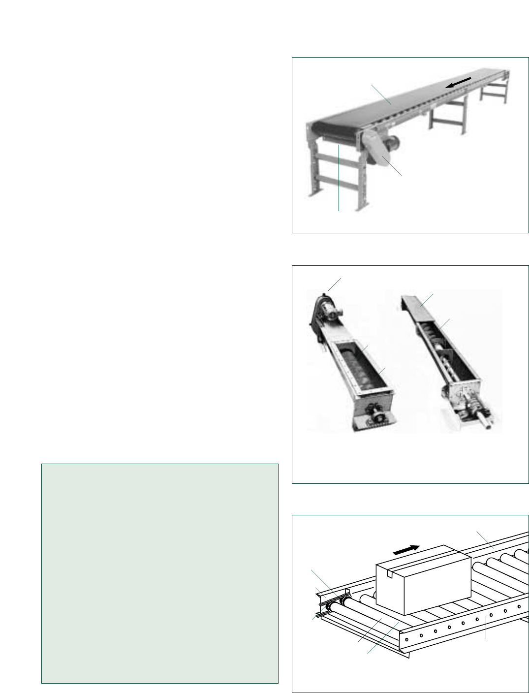
to the material conveyed, the location of the con-
veyor, and the proximity of the conveyer to the
employees. Types include unpowered and pow-
ered, live roller, slat, chain, screw, and pneumatic.
Conveyors eliminate or reduce manual material
handling tasks, but they present amputation haz-
ards associated with mechanical motion. (See
Figures 27 through 30 for examples of common
conveyors.)
Conveyor-related injuries typically involve a
employee’s hands or fingers becoming caught in
nip points or shear points on conveyors and may
occur in these situations:
• Cleaning and maintaining a conveyor, especially
when it is still operating.
• Reaching into an in-going nip point to remove
debris or to free jammed material.
• Allowing a cleaning cloth or an employee’s
clothing to get caught in the conveyor and pull
the employee’s fingers or hands into the con-
veyor.
Other conveyor-related hazards include improp-
erly guarded gears, sprocket and chain drives, hori-
zontal and vertical shafting, belts and pulleys, and
power transmission couplings. Overhead convey-
ors warrant special attention because most of the
conveyor’s drive train is exposed. Employees have
also been injured or killed while working in areas
underneath conveyors and in areas around lubrica-
tion fittings, tension adjusters, and other equipment
with hazardous energy sources.
Case History #6
While removing a cleaning rag from the ingoing
nip point between the conveyor belt and its tail
pulley (the unpowered end of the conveyor), an
employee’s arm became caught in the pulley,
which amputated his arm below the elbow.
Case History #7
While servicing a chain-and-sprocket drive
assembly on a roof tile conveyor system, an
employee turned off the conveyor, removed the
guard, and began work on the drive assembly
without locking out the system. When someone
started the conveyor, the employee’s fingers
became caught in the chain-and-sprocket drive
and were amputated.
SAFEGUARDING EQUIPMENT AND PROTECTING EMPLOYEES FROM AMPUTATIONS 27
Figure 27 Belt Conveyor
Figure 28 Screw Conveyor
Figure 29 Chain Driven Live Roller Conveyor
Fixed Guard Over
Power-Transmission
Apparatus
Belt
In-Running Nip
Some guards and covers are not shown to facilitate
viewing of moving parts. Equipment must not be
operated without guards and covers in place.
Fixed Guard Over
Power-Transmission
Apparatus
In-Running
Nip Point
Fixed Guard
In-Running
Nip Point
Screw
Rotating Motion
Fixed Guard
In-Running
Nip Point
Chain
In-Running
Nip Point
Fixed Guard
Sprocket
Roller

Figure 30 Slat Conveyor
Safeguarding Conveyors
As conveyor hazards vary depending on the appli-
cation, employers need to look at each conveyor to
evaluate and determine what primary safeguarding
methods and energy control (lockout/tagout)
practices are required. Where necessary for the
protection of employees, conveyors need to have
mechanical guards that protect the employee from
nip points, shear points, and other moving parts,
including power-transmission apparatus. Guards
may include barriers, enclosures, grating, fences, or
other obstructions that prevent inadvertent physical
contact with operating machine components, such
as point of operation areas, belts, gears, sprockets,
chains, and other moving parts. A brief description
of the hazards and recognized safeguarding meth-
ods is presented for common types of conveyors.
Typical Conveyor Hazards and
Safeguarding Methods
Belt Conveyors
Hazards: Belt-conveyor drive mechanisms and
conveying mediums are hazardous as are the fol-
lowing belt-conveyor areas: 1) conveyor take-up
and discharge ends; 2) where the belt or chain
enters or exits the in-going nip point; 3) where
the belt wraps around pulleys; 4) snub rollers
where the belt changes direction, such as take-
ups; 5) where multiple conveyors are adjoined;
or 6) on transfers or deflectors used with belt
conveyors.
Controls: The hazards associated with nip and
shear points must be safeguarded. Side guards
(spill guards), if properly designed can prevent
employee contact with power-transmission com-
ponent, in-going nip points and the conveying
medium. Secondary safeguarding methods for
hazard control include the use of standard railings
or fencing, or safeguarding by distance (location),
and installing hazard awareness devices, such as
pre-start-up signals and warning signs.
Screw Conveyors
Hazards: Screw conveyors are troughs with a
revolving longitudinal shaft on which a spiral or
twisted plate is designed. In-going nip points, of
turning helical flights for the entire length of the
screw conveyor, exist between the revolving
shaft and trough. Since the trough is not usually
required to be covered for proper operation of
the conveyor and because many screw convey-
ors are located at or near the floor level, the haz-
ard of stepping into the danger area is ever pres-
ent. Once caught, the victim is pulled further into
the path of the conveying medium.
Controls: A screw conveyor housing must com-
pletely enclose the moving elements (screw
mechanism, power transmission apparatus) of
the conveyor, except for the loading and dis-
charge points. Permanently affixed grids or poly-
carbonate can be installed for visibility purposes
to allow the operator to inspect the operation.
Alternatively, the trough side walls should be
high enough to prevent employees from reach-
ing over and falling into the trough. Open
troughs can be used if covers are not feasible;
but employees need to be protected by second-
ary safeguarding methods, such as a railing or
fence.
Feed loading and discharge points can usually
be guarded by providing enclosures, screening,
grating, or some other interruption across the
openings which will allow the passage of the
material without allowing the entry of a part of
the employee’s body into the moving part(s).
Chain Conveyors
Hazards: Nip points occur when a chain contacts
a sprocket, such as when a chain runs around a
sprocket or when the chain is supported by a
sprocket or when a shoe above the chain pre-
cludes the chain from lifting off the sprocket. Nip
points also occur at drives, terminals, take-ups
(automatic take-ups may also have shear points),
and idlers. Employee clothing, jewelry, and long
hair may also get entangled and caught in the
moving chain conveyor.
28
Occupational Safety and
Health Administration
Fixed Guard Over
Power-Transmission
Apparatus
In-Running
Nip Point
Fixed Guard
Slats

Controls: Sometimes, moving chains cannot be
enclosed without impairing the functioning of the
conveyor. However, in some cases, barrier
guards may be installed around the moving parts
for hazard enclosure purposes or, in other in-
stances, nip and shear points may be eliminated
by placing a guard at the nip point or shear
point. Other secondary safeguarding options
include safeguarding by distance (location) and
the use of awareness devices.
Roller Conveyors
Hazards: Roller conveyors are used to move
material on a series of parallel rollers that are
either powered or gravity-fed. Powered roller
conveyors have the hazard of snagging and
pulling objects, including hands, hair, and cloth-
ing into the area between the rollers and the sta-
tionary components of the conveyor. In-going
nip points generally exist between the drive
chain and sprockets; between belt and carrier
rollers; and at terminals, drives, take-ups, idlers,
and snub rollers.
Controls: Roller conveyors need to, where feasi-
ble, have permanent barrier guards that can be
adjusted as necessary to protect the employee
from nip and shear points. For example, the
unused section of rollers closest to the employ-
ees needs to be guarded when transporting
small items on a roller conveyor that do not
require the use of the entire roller width. Also,
conveyor hazards may be reduced by eliminating
or minimizing projections from the roller and
through the use of pop-up rollers. Other second-
ary safeguarding options include safeguarding
by distance (location) and the use of awareness
devices.
Other Controls for Conveyors
The following are some secondary safeguarding
methods, work practices, and complementary
equipment that may be used to supplement pri-
mary safeguarding or alone or in combination
when primary safeguarding methods are not feasi-
ble:
• Safeguarding by safe distance (by location) —
locating moving parts away from employees to
prevent accidental contact with the hazard
point—is one option for safeguarding convey-
ors. It is particularly difficult, however, to use
this method when employees need to be at or
near unguarded moving parts.
• Use prominent awareness devices, such as
warning signs or lights, to alert employees to
the conveyor operation.
• Allow only trained individuals to operate con-
veyors and only trained, authorized staff to per-
form servicing and maintenance work.
• Visually inspect the entire conveyor and imme-
diate work area prior to start-up to determine
that the actuation will not cause an employee
hazard.
• Inspect and test conveyor safety mechanisms,
such as its alarms, emergency stops, and safe-
guarding methods.
• Do not use any conveyor which is unsafe until it
is made safe.
• Forbid employees from riding on conveyors.
• Prohibit employees working with or near con-
veyors from wearing loose clothing or jewelry,
and require them to secure long hair with a net
or cap.
• Install emergency stop devices on conveyors
where employees work when they cannot other-
wise control the movement of the conveyor.
This recognized safety feature provides employ-
ees with the means to shut off the equipment in
the event of a hazardous situation or emergency
incident.
For emergency stop devices, you will need these
engineering controls:
• Equip conveyors with interlocking devices that
shut them down during an electrical or mechani-
cal overload such as product jam or other stop-
page. Emergency devices need to be installed so
that they cannot be overridden from other loca-
tions.
• When conveyors are arranged in a series, all
should automatically stop whenever one stops.
• Equip conveyors with emergency stop controls
that require manual resetting before resuming
conveyor operation.
• Install clearly marked, unobstructed emergency
stop buttons or pull cords within easy reach of
employees.
• Provide continuously accessible conveyor belts
with emergency stop cables that extend the
entire length of the conveyor belt to allow access to
the cable from any point along the belt.
• Ensure that conveyor controls or power sources
can accept a lockout/tagout device to allow safe
maintenance practices.
SAFEGUARDING EQUIPMENT AND PROTECTING EMPLOYEES FROM AMPUTATIONS 29

Sources of Additional Information
• OSHA Publication 3067, Concepts and
Techniques of Machine Safeguarding
(http://www.osha.gov/Publications/Mach_
Safeguard/toc.html)
• OSHA Machine Guarding eTool (http://www.
osha.gov/SLTC/etools/machineguarding/index.
html)
• OSHA Lockout/Tagout Interactive Training
Program (http://www.osha.gov/dts/osta/
lototraining/index.htm)
• ASME B20.1-2003, Safety Standard for
Conveyors and Related Equipment.
• ANSI/CEMA 350-2003, Screw Conveyors.
• ANSI/CEMA 401-2003, Unit Handling
Conveyors—Roller Conveyors—Non-powered.
• ANSI/CEMA 402-2003, Unit Handling
Conveyors—Belt Conveyors.
• ANSI/CEMA 403-2003, Unit Handling
Conveyors—Belt Driven Live Roller Conveyors.
• ANSI/CEMA 404-2003, Unit Handling
Conveyors—Chain Driven Live Roller
Conveyors.
• ANSI/CEMA 405-2003, Package Handling
Conveyors—Slat Conveyors
Hazards of Printing Presses
Printing presses vary by type and size, ranging
from relatively simple manual presses to the com-
plex large presses used for printing newspapers,
magazines, and books. Printing presses are often
part of a larger system that also includes cutting,
binding, folding, and finishing equipment. Many
modern printing presses rely on computer controls,
and the high speeds of such equipment often re-
quire rapid machine adjustments to avoid waste.
This section discusses amputation hazards asso-
ciated with two common types of printing presses:
web-fed and sheet-fed printing press systems.
Web-fed printing presses are fed by large continu-
ous rolls of substrate such as paper, fabric or
plastic; sheet-fed printing presses, as their name
implies, are fed by large sheets of substrate. In both
types, the substrate typically feeds through a series
of cylinders containing printing plates and support-
ing cylinders moving in the opposite direction.
(Figures 31 and 32 illustrate a roll-to-roll offset
printing press and a sheet-fed offset printing press.)
30
Occupational Safety and
Health Administration
• Perform servicing and maintenance under an
energy control program in accordance with the
Control of hazardous energy (lockout/tagout), 29
CFR 1910.147, standard. For example, instruct
employees to lubricate, align, service, and main-
tain conveyors when the conveyor is locked or
tagged out if the task would expose them to an
area of the conveyor (or adjacent machinery)
where hazardous energy exists.
Minor Servicing
At times, OSHA recognizes that some minor
servicing may have to be performed during nor-
mal production operations, so a lockout/tagout
exception is allowed. See the 29 CFR 1910.147(a)
(2)(ii) Note for details. An example of a common
conveyor minor servicing activity involves pack-
age jams where an employee must frequently
dislodge the jam. To prevent unexpected start-up
of the conveyor, employers may adopt alterna-
tive control measures, such as opening (placing
in the off position) local disconnects or control
switches to prevent conveyor start-up. These
properly applied devices, if used, must be
under the exclusive control of the employee per-
forming the jam release, so that no other person
can restart the conveyor without the knowledge
and consent of the person performing the servic-
ing work.
Source: 29 CFR 1910.147(a)(2)(ii) Note.
Applicable Standards
• 29 CFR 1910.147, Control of hazardous energy
(lockout/tagout).
• 29 CFR 1910.212, General requirements for all
machines.
• 29 CFR 1910.219, Mechanical power-transmis-
sion apparatus.
• 29 CFR 1910.269, Electric power generation,
transmission and distribution [as detailed in
section (v)(11)].
• 29 CFR 1926.555, Conveyors.
• ANSI B20.1-57, Safety Code for Conveyors,
Cableways, and Related Equipment – as incor-
porated by reference in 1910.218(j)(3),
1910.261(a)(3)(x), 1910.261(b)(1),
1910.261(c)(15)(iv), 1910.261(f)(4),
1910.261(j)(2), 1910.265(c)(18)(i)].
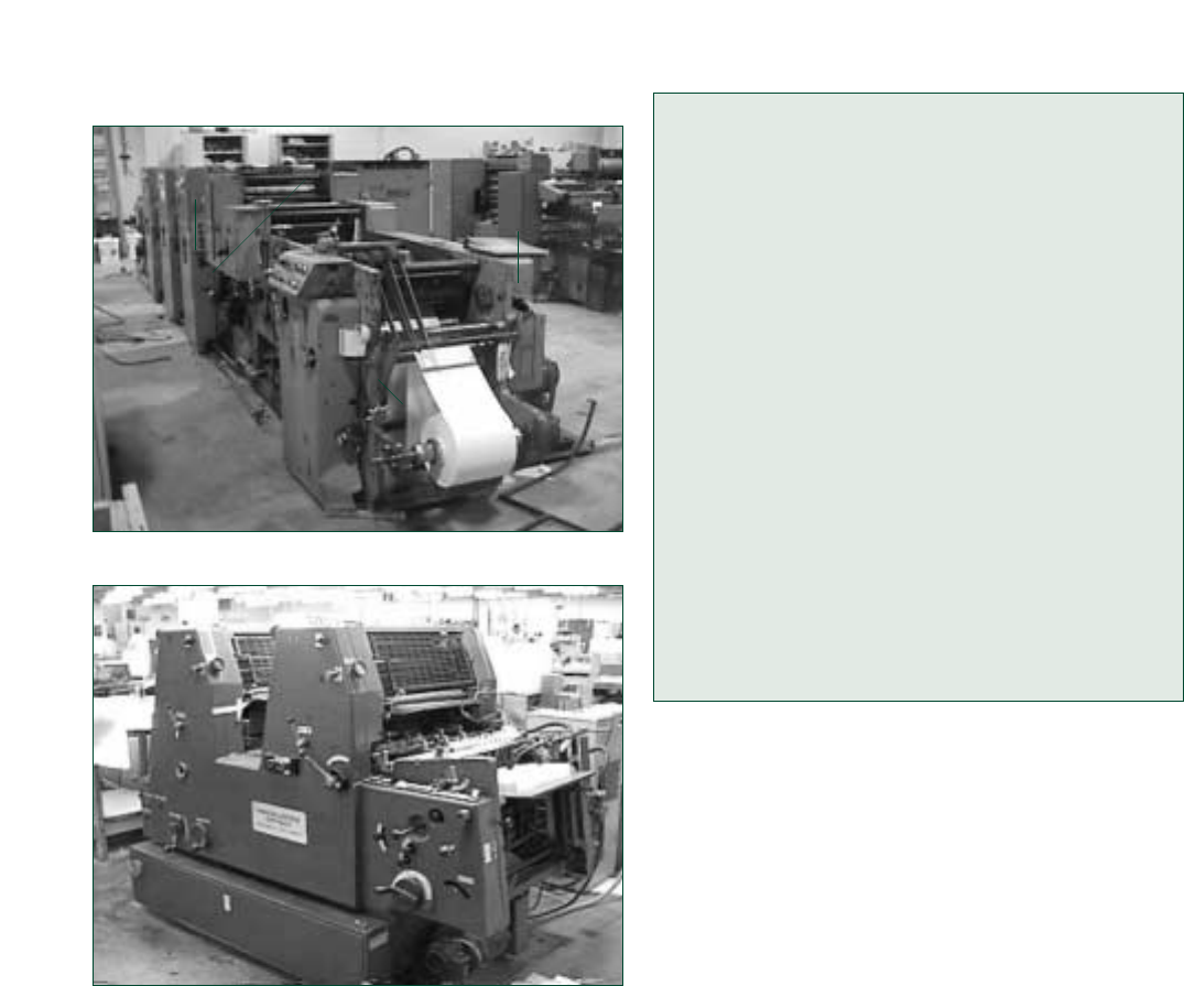
Figure 31 Roll-to-Roll Offset Printing Press
Figure 32 Sheet-Fed Offset Printing Press
As with other machines, printing press-related
amputations occur during servicing and mainte-
nance activities. For example, amputations occur
when employees get their fingers or hands caught
in the in-going nip points created between two
rollers while:
• Hand-feeding the leading edge of paper into the
in-running rollers during press set-up while the
machine is operating;
• Adjusting ink flow on a press;
• Cleaning ink off the press while it is operating;
• Attempting to free material from the rollers;
• Straightening misaligned sheets of paper in the
press;
• Jogging the printer and making adjustments to
the equipment (such as adjusting the nip wheel
on a sheeter);
• Using rags to clean machinery adjacent to un-
guarded rollers.
Source: OSHA IMIS Accident Investigation Database.
Case History #8
An employee was adding ink at the top of a
printing press when he spotted a small piece of
wood in the area of the moving rollers. He
caught his hand in the moving rollers as he
attempted to remove the wood and had to have
his forearm surgically amputated.
Case History #9
An offset printing press operator lost his right
hand while attempting to remove dried ink on a
moving roller using a rag. The guard covering
the lower ink train rollers had been flipped up,
exposing the rollers. The rag got caught in a
nearby roller, pulling the employee’s hand into
the in-going nip point. The employee immediate-
ly hit the press stop button, but the roller rotated
one-half turn before stopping. His hand was
crushed and had to be amputated at the hospital.
Source: OSHA IMIS Accident Investigation Database.
Safeguarding Printing Presses
As with most machinery, you can rely on primary
safeguarding methods to protect employees
against injuries when using printing presses. For
example, some primary safeguarding methods
include the following:
• Install guards on all mechanical hazard points
that are accessible during normal operation --
such as accessible in-going nip points between
rollers and power-transmission apparatus
(chains and sprockets).
• Safeguard nip point hazards with barrier guards
or nip guards. Nip guards need to be designed
and installed without creating additional haz-
ards.
• Install fixed barrier guards, with tamper-proof
fasteners, at rollers that do not require operator
access.
• Properly designed, applied, and maintained
safeguarding devices (such as presence-sensing
devices and mats) may also be used to keep
your body out of machine danger areas. How-
ever, these control circuit devices are no substi-
tute for lockout/tagout.
• Use hold-to-run controls (such as inch or re-
verse) that protect employees from machine
mechanical hazards by either: 1) requiring the
use of both hands for control initiation purpos-
es; or 2) are mounted at a safe distance so that
an employee cannot inch or reverse the press
SAFEGUARDING EQUIPMENT AND PROTECTING EMPLOYEES FROM AMPUTATIONS 31

and simultaneously access any unguarded dan-
ger area or otherwise reach into the danger zone
while the press is operating.
Other Controls for Printing Presses
The following are some secondary safeguarding
methods, work practices, and complementary
equipment that may be used to supplement primary
safeguarding or alone or in combination when pri-
mary safeguarding methods are not feasible:
• Make sure that printing presses attended by
more than one operator or ones outside of the
operator’s viewing area are equipped with visual
and audible warning devices to alert employees
regarding the press’s operational status—in
operation, safe mode, or impending operation.
• Install visual warning devices of sufficient num-
ber and brightness and locate them so that they
are readily visible to press personnel.
• Ensure that audible alarms are loud enough to
be heard above background noise.
• Provide a warning system that activates for at
least 2 seconds prior to machine motion.
• Use additional secondary safeguarding methods
such as safeguarding by location and safe work
(operating) procedures for printing presses.
• Ensure that all press operators receive appropri-
ate training and supervision until they can work
safely on their own.
• Prohibit employees working with or near print-
ing presses from wearing loose clothing or jew-
elry and require them to secure long hair with a
net or cap.
• Conduct periodic inspections to ensure compli-
ance.
• Perform servicing and maintenance under an
energy control program in accordance with the
Control of hazardous energy (lockout/tagout), 29
CFR 1910.147, standard.
Minor Servicing
At times, OSHA recognizes that some minor
servicing may have to be performed during nor-
mal production operations, so a lockout/tagout
exception is allowed. See the 29 CFR 1910.147(a)
(2)(ii) Note for details. Minor servicing can
include, among other things, tasks such as clear-
ing of certain types of minor paper jams; minor
cleaning; minor lubricating and minor adjusting
operations; certain plate and blanket changing
32
Occupational Safety and
Health Administration
tasks; and, in some cases, paper webbing and
paper roll changing. Generally speaking, minor
servicing is considered to include those tasks
involving operations that can be safely accom-
plished by employees and where extensive dis-
assembly of equipment is not required.
One such control method that does offer effec-
tive alternative protection is the inch-safe-service
technique when it is used in conjunction with the
main drive control. This technique is specified in
the American National Standards (ANSI B65.1
and ANSI B65.2) for web- and sheet-fed printing
presses and binding and finishing equipment,
respectively.
Also, interlock guards and presence-sensing
safeguarding devices, if properly designed,
applied and maintained, would also be consid-
ered effective protection. For example, you could
simply open the barrier guard and rely on the
protection afforded by the properly designed
interlock control circuit while clearing minor
paper jams and other minor servicing functions
that occur using normal production operations
and which meet the criteria in the lockout/tagout
exception.
Source: 29 CFR 1910.147(a)(2)(ii) Note.
Applicable Standards
• 29 CFR 1910.147, Control of hazardous energy
(lockout/tagout).
• 29 CFR 1910.212, General requirements for all
machines.
• 29 CFR 1910.219, Mechanical power-transmis-
sion apparatus.
Sources of Additional Information
• OSHA Publication 3067, Concepts and
Techniques of Machine Safeguarding
(http://www.osha.gov/Publications/Mach_
Safeguard/toc.html)
• OSHA Machine Guarding eTool (http://www.
osha.gov/SLTC/etools/machineguarding/index.
html)
• OSHA Lockout/Tagout Interactive Training
Program (http://www.osha.gov/dts/osta/
lototraining/index.htm)
• ANSI B65.1-2005, Safety Standard - Printing
Press Systems
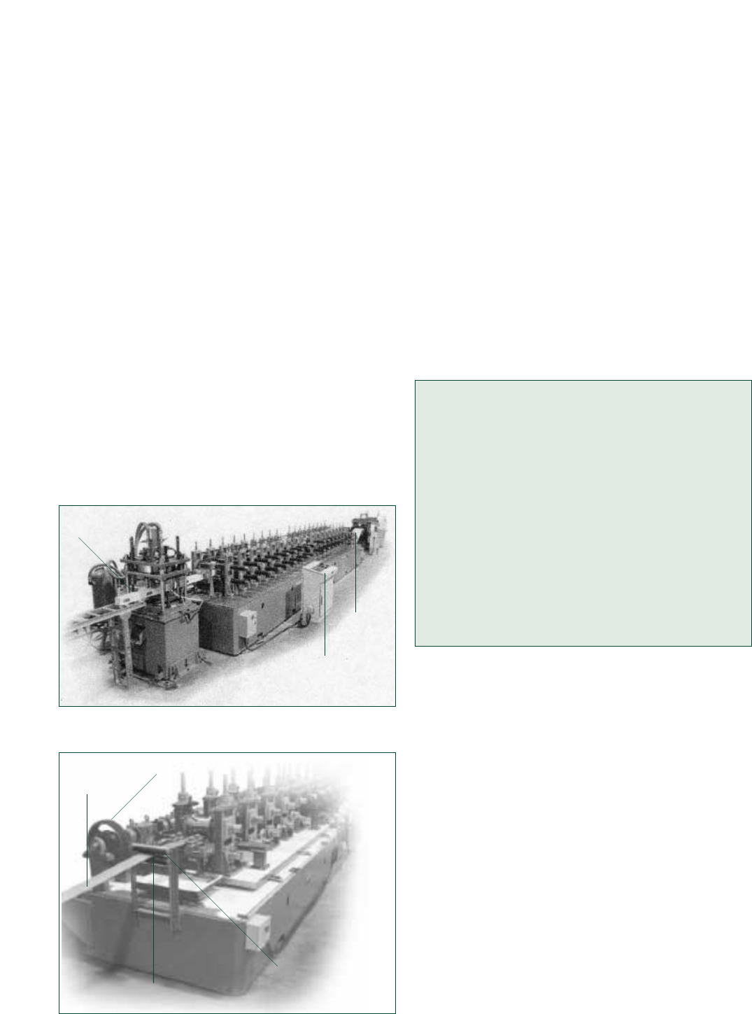
Hazards of Roll-Forming and
Roll-Bending Machines
Roll-forming and roll-bending machines primarily
perform metal bending, rolling, or shaping func-
tions. Roll-forming is the process of bending a
continuous strip of metal to gradually form a pre-
determined shape using a self-contained machine.
Roll-forming machines contain a series of rolls that
may or may not have braking systems. Roll-form-
ing machines may also perform other processes
on the metal, including piercing holes, slots, or
notches; stamping; flanging; and stretch-bending.
Roll-bending machines usually have three rolls
arranged like a pyramid and they perform essential-
ly the same process as roll-forming, except that the
machine produces a bend across the width of flat
or pre-formed metal to achieve a curved or angular
configuration.
Roll-forming and roll-bending machines fre-
quently are set up and operated by one person.
(Figure 33 illustrates a roll-forming machine pro-
ducing a finished product. Figure 34 illustrates the
in-feed section of a roll-forming machine.)
Figure 33 Roll-Forming Machine
Figure 34 In-Feed Area of a Roll-Forming Machine
SAFEGUARDING EQUIPMENT AND PROTECTING EMPLOYEES FROM AMPUTATIONS 33
The most common type of amputation hazard
associated with roll-forming and roll-bending
machines are point of operation hazards created by
in-running nip points. Amputations occur when the
hands of the operator feeding material through the
rolls get caught and are then pulled into the point
of operation. Causes of amputations related to roll-
forming and roll-bending machines can occur from
the following:
• Having an unguarded or inadequately guarded
point of operation;
• Locating the operator control station too close to
the process;
• Activating the machine inadvertently; and
• Performing cleaning, clearing, changing, or
inspecting tasks while the machine is operating
or is not properly locked or tagged out.
Case History #10
While feeding a metal sheet into a roller, an
employee caught his right hand in the roller and
amputated one finger.
Case History #11
An employee wearing gloves caught his left
hand in a roll-forming machine, resulting in par-
tial amputation of two fingers. The employee
was standing close to the moving rollers, feeding
flat steel sheet from behind and catching it on
the front side. There was no point of operation
guard on the front roller and the foot operating
pedal was very close to the machine.
Safeguarding Roll-Forming and Roll-
Bending Machines
Roll-forming and roll-bending machines are avail-
able in a wide variety of sizes and designs, and
safeguarding methods must be tailored for each
machine. Several factors affect the ways to safe-
guard the equipment, including whether a machine
has a brake system, its size, operating speed, thick-
ness of product, length of production runs, required
production accuracy, sheet feeding methods, and
part removal methods. Depending on the size and
type of machine, a number of different primary
safeguarding methods may be required to ade-
quately protect the operator as well as other em-
ployees nearby. For example, you can do the
following:
• Install fixed or adjustable point of operation bar-
rier guards at the in-feed and out-feed sections
of machines. If the stock or end-product does
Entering
Stock
Finished
Product
Operator
Control
Station
Guide Rollers
Power Transmission Apparatus
Entering
Stock
In-Running Nip Point

the rolls stop turning (via a brake and clutch
assembly) when you release the foot switch.
• Develop and implement safe work (operating)
procedures for roll-forming and roll-bending
machines.
• Safeguard operator control stations to prevent
inadvertent activation by unauthorized employees.
• Ensure that all operators receive appropriate on-
the-job training under the direct supervision of
experienced operators until they can work safely
on their own.
• Prohibit employees working with or near print-
ing presses from wearing loose clothing or jew-
elry and require them to secure long hair with a
net or cap.
• Install safety trip controls, such as a pressure-
sensitive body bar or safety tripwire cable, on
the in-feed section of the machine to shut down
the machine if an employee gets too close to the
point of operation.
• Install emergency stop controls that are readily
accessible to the operator.
• Conduct periodic inspections to ensure compli-
ance.
• Perform servicing and maintenance under an
energy control program in accordance with the
Control of hazardous energy (lockout/tagout), 29
CFR 1910.147, standard.
Applicable Standards
• 29 CFR 1910.147, Control of hazardous energy
(lockout/tagout).
• 29 CFR 1910.212, General requirements for all
machines.
• 29 CFR 1910.219, Mechanical power-transmis-
sion apparatus.
Sources of Additional Information
• OSHA Publication 3067, Concepts and
Techniques of Machine Safeguarding
(http://www.osha.gov/Publications/Mach_
Safeguard/toc.html)
• OSHA Machine Guarding eTool (http://www.
osha.gov/SLTC/etools/machineguarding/index.
html)
• OSHA Lockout/Tagout Interactive Training
Program (http://www.osha.gov/dts/osta/
lototraining/index.htm)
• ANSI B11.12-2005, Safety Requirements for
Roll-Forming and Roll-Bending Machines
34
Occupational Safety and
Health Administration
not differ greatly from run to run, a fixed guard
may be preferable. If the stock or end-product is
variable, however, an adjustable guard may be
more suitable.
• Install fixed point of operation guards to cover
the sides of the rollers to prevent entry of cloth-
ing and parts of your body into the in-going nip
points of the rollers.
• Install fixed or interlocked guards to cover any
other rotating parts, such as power-transmission
apparatus.
• Install and use properly applied presence-sens-
ing safeguarding devices (light curtains, safety
mats) on roll-forming and roll-bending machines
(those equipped with brakes) to protect you
from hazardous machine areas during normal
production operations.
• Install and use properly applied two-hand con-
trol safeguarding devices to protect you from
the machine hazards during roll-bending pro-
duction operations.
• Ensure that operators use the jog mode during
feeding operations, if appropriate, and that the
control station requires the use of both hands
or is mounted at a safe distance from the ma-
chine’s danger areas.
• Allow only one control station to operate at any
one time when a single machine has more than
one set of operator controls. This does not apply
to the emergency stop controls, which must be
operable from all locations at all times, such as
accessible in-going nip points between rollers
and power-transmission apparatus (chains and
sprockets).
Other Controls for Roll-Forming and
Roll-Bending Machines
The following are some secondary safeguarding
methods, work practices, and complementary
equipment that may be used to supplement primary
safeguarding or alone or in combination when pri-
mary safeguarding methods are not feasible:
• Use proper lighting and awareness barrier
devices (such as interlocking gates around the
perimeter of the machine to prevent unautho-
rized entry), awareness signals and signs.
• Position (safeguard by location) operating sta-
tions in a way that ensures that operators are
not exposed to the machine’s point of operation.
• Locate foot pedal controls away from the point
of operation and guard them in such a way as to
prevent inadvertent activation. Some foot con-
trols use dead-man (hold-to-run) features so that
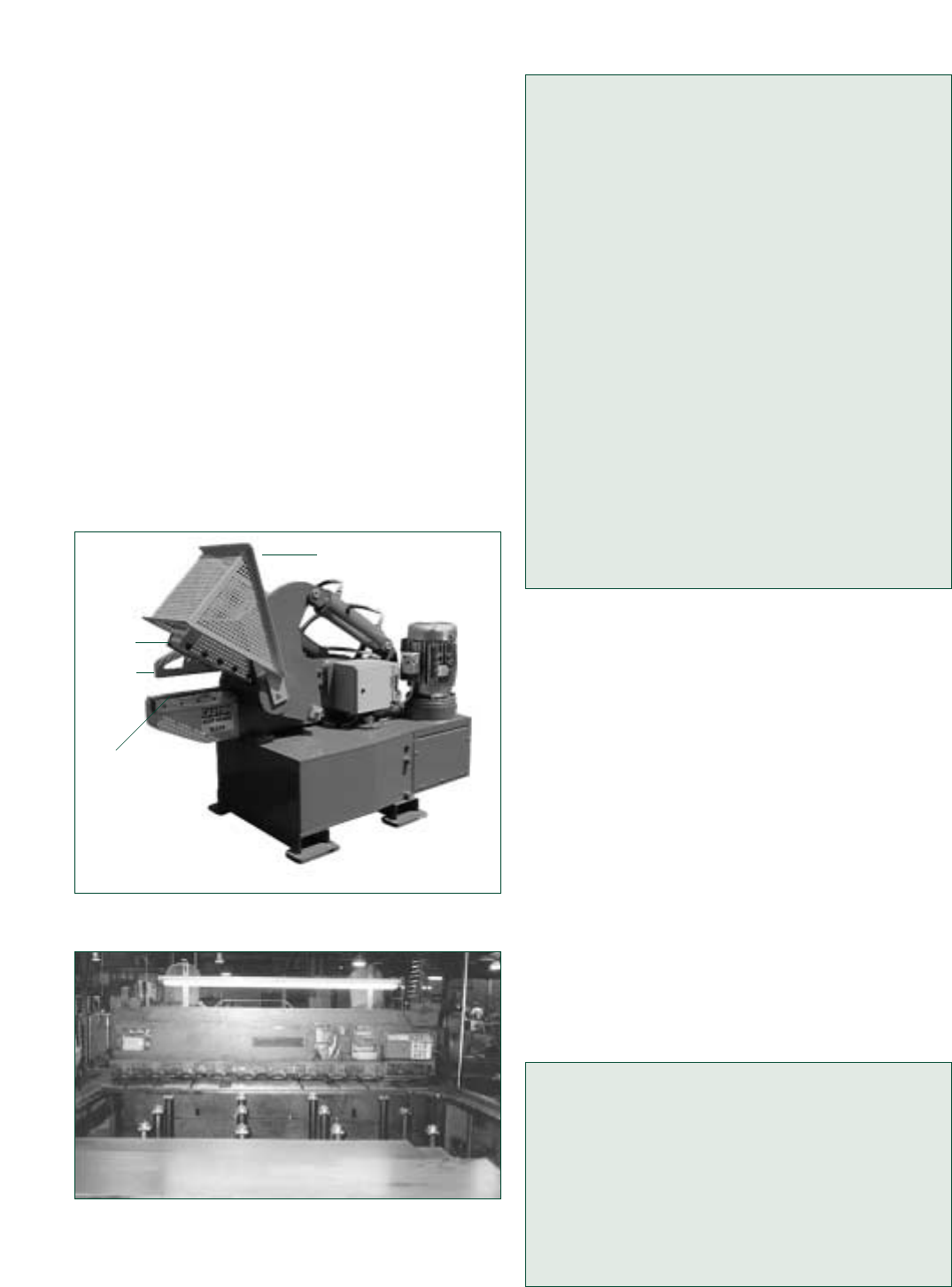
Hazards of Shearing Machines
Mechanical power shears contain a ram for their
shearing action. The ram moves a non-rotary
blade at a constant rate past the edge of a fixed
blade. Shears may be mechanically, hydraulically,
hydra-mechanically, pneumatically, or manually
powered and are used to perform numerous func-
tions such as squaring, cropping, and cutting to
length.
In the basic shear operation, stock is fed into the
point of operation between two blades. A hold-
down may then be activated that applies pressure
to the stock to prevent movement. One complete
cycle consists of a downward stroke of the top
blade until it passes the lower fixed blade followed
by an upward stroke to the starting position. (See
Figures 35 and 36 for examples of alligator and
power squaring shears.)
Figure 35 Hydraulic Alligator Shear
Figure 36 Power Squaring Shear
Shears can be categorized as stand-alone manu-
al shears, stand-alone automatic shears, and
process-line shears.
Stand-alone manual shears. An operator controls
them from a control station. The operator feeds
the shear either by hand or by activating the
automatic loading mechanism and activates the
equipment using hand or foot controls or a trip-
ping device on the back side of the shear. An
example is an alligator shear.
Stand-alone automatic shears. These feed and
stroke automatically and continuously. The oper-
ator uses hand-activated or foot-activated con-
trols to initiate the operation, which requires lim-
ited additional operator interaction. An example
is a guillotine shear.
Process-line shears. These are integrated into an
automated production process and are controlled
automatically as part of the process. Examples
include crop shears and cut-to-length shears.
The two primary point-of-operation hazards on
shears are the shear blade and the material hold-
downs. Amputations may occur in the following
situations:
• The foot control inadvertently activates while
the operator’s hands are in the point of opera-
tion. Such amputations usually relate to foot-
activated, stand-alone manual shears that
require the use of both hands to feed the stock.
• A tripping device located on the back side of the
shear’s mouth operates the shear but does not
prevent the operator from reaching into the
hazard area. Such tripping devices, commonly
found on stand-alone manual shears, may in-
crease productivity but must be used in conjunc-
tion with primary safeguards.
• When there is no hold-down and stock being fed
into a stand-alone manual shear kicks out and
strikes the operator’s hands or fingers.
Case History #12
After breaking metal with a mechanical alliga-
tor shear, an employee turned the shear off and
was picking up debris on the ground when he
placed his left hand on the shear and amputat-
ed his fingers. The shear’s flywheel was not
equipped with a clutch or similar device. So,
when the shear was shut off, the jaw continued
to operate on stored energy.
SAFEGUARDING EQUIPMENT AND PROTECTING EMPLOYEES FROM AMPUTATIONS 35
Hold
Down
Point of
Operation Guard
Lower
Fixed
Blade
Top
Blade

Case History #13
An employee was cutting material with a 50-inch
guillotine shear equipped with two-hand trip but-
tons to prevent employees from reaching into
the blade area. He had taped up one of the but-
tons and used his knee to trip the other button.
With both hands under the blade, he inadvertent-
ly hit the free button with his knee. This activated
a stroke of the blade which amputated both of
his hands just below the wrists.
Source: OSHA IMIS Accident Investigation Database.
Safeguarding Shearing Machines
Because shears have a wide variety of applications,
safeguarding methods must be determined individ-
ually for each machine based on its use. A number
of different safeguarding methods may be neces-
sary to adequately protect the operator as well as
other employees nearby. For example, you will
need to consider the machine size, operating
speed, size and type of material, length of produc-
tion runs, required accuracy of the work, methods
for material feeding and removal, operator controls,
and clutch type.
Here are some primary safeguarding options for
protecting employees from the shear’s point of
operation during feeding activities at the front of
the machine:
• Install a properly applied fixed or adjustable
point of operation guard at the in-feed of the
shearing machine to prevent operator contact
with the shear’s point of operation as well as
the pinch point of the hold-down. The guard’s
design must prevent the employee from reach-
ing under or around it.
• Install and arrange two-hand trips and controls
so that the operator must use both hands to ini-
tiate the shear cycle. Two-hand trips and con-
trols need to be designed so that they cannot be
defeated easily. The Safety Requirements for
Shears (ANSI B11.4-2003) standard recommends
the installation of additional safeguarding when
two-hand controls are used on part-revolution
shears, based on the nature of the shearing
operation. This national consensus standard
specifies the use of guards on full-revolution
shears.
• Use a properly applied presence-sensing
device, such as a light curtain, on shears that
are hydraulically powered or equipped with a
part-revolution clutch.
36
Occupational Safety and
Health Administration
• Mount guarded foot-pedal controls at a safe dis-
tance (single control safeguarding devices) away
from the point of operation to protect the opera-
tor during the operating cycle.
• Use pull-backs or restraints for stand-alone
manual shears when other guarding methods
are not feasible or do not adequately protect
employees. (These devices may not be appro-
priate if the job requires employees’ mobility.)
• Use automatic-feeding devices such as convey-
ors with stand-alone manual shears when the
material is uniform in size and shape.
• Equip mechanical shears with either a part-revo-
lution or full-revolution clutch. Methods of safe-
guarding depend on the type of clutch in use.
Shears equipped with full-revolution clutches
used in single-stroke operations must be equip-
ped with an anti-repeat feature.
Other Controls for Shearing Machines
The following are some secondary safeguarding
methods, work practices, and complementary
equipment that may be used to supplement
primary safeguarding or alone or in combination
when primary safeguarding methods are not
feasible:
• Install guarded operating stations at a safe dis-
tance (safeguarding by location) from the
shear’s point of operation to prevent inadvertent
activation.
• Develop and implement safe work (operating)
procedures for shearing machines and conduct
periodic inspections to ensure compliance.
• Use proper lighting and awareness devices,
such as awareness barriers and warning signs,
to warn employees of the hazard.
• Install hold-down (work-holding) devices that
prevent the work piece from kicking up and
striking the operator. Hold-down devices may
eliminate the need for employees to hold the
material near the point of operation.
• Instruct operators to use distancing tools when
their hands might otherwise reach into the point
of operation because of the size of the material
being cut.
• Where it is possible to stop the shear during
its operating cycle, install an emergency stop
device—such as a pressure-sensitive body bar,
safety tripod, or safety tripwire cable—at the
in-feed section of the shear.
• Install an awareness barrier or a safety trip con-
trol (safety tripwire or safety tripod) on the back
side of the shear.
• Ensure that all operators receive on-the-job
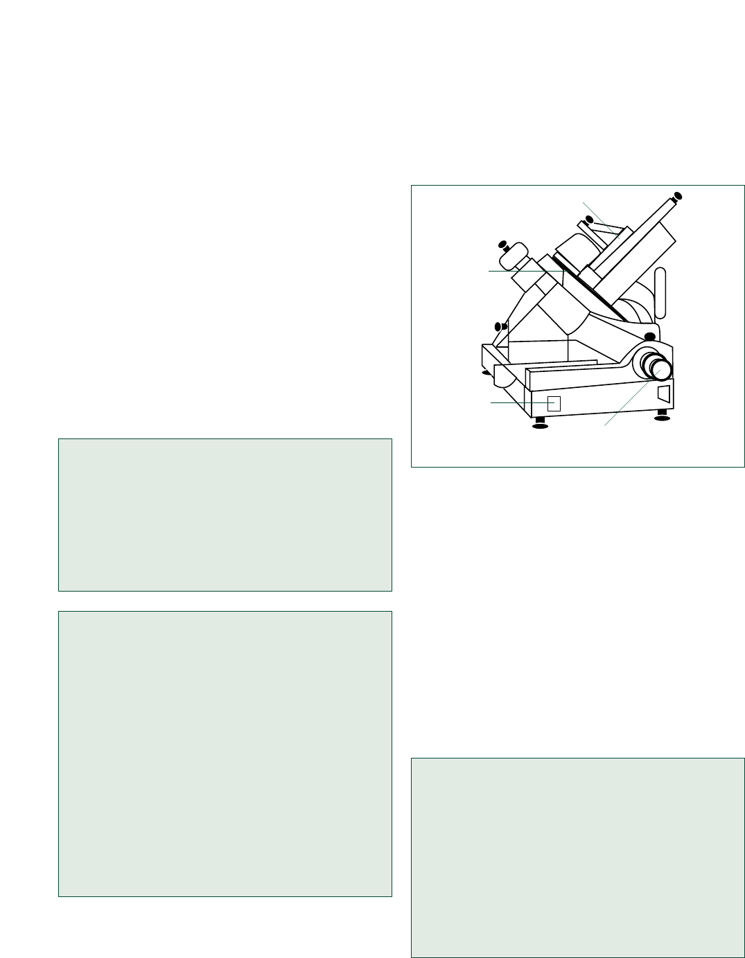
pushing/guarding device or plunger may be used
to apply pressure to the food against the slicer
blade, or pressure may be applied by gravity and/or
by an attachment connected to the food holder.
(See Figure 37.)
Figure 37 Meat Slicer
Amputations resulting from work with food
slicers can occur as follows:
• When the operator adjusts or services the slicer
while it is still operating or while it is switched
off but still plugged in, or energized. In the latter
case, amputations occur when the operator acci-
dentally switches the slicer on.
• When the operator fails to use the sliding attach-
ment on the food-holding device, especially
when slicing small pieces of meat.
• When the operator hand-feeds food into a
chute-fed slicer without using the proper push-
ing/guarding device or plunger.
Case History #14
Two employees, an operator and an assistant,
were using a meat slicer to slice turkey. The
assistant was holding a box of turkey in a tilted
position while the operator fed the turkey into
the slicer. The operator removed the guard
from the meat slicer because the turkey kept
jamming. The slicer’s knives caught the opera-
tor’s glove and pulled his hand into the knives,
amputating his finger just above the nail.
SAFEGUARDING EQUIPMENT AND PROTECTING EMPLOYEES FROM AMPUTATIONS 37
training under the direct supervision of experi-
enced operators until they can work safely on
their own.
• Instruct employees to perform routine mainte-
nance on the clutch and braking systems.
• Instruct employees to inspect all guarding to
ensure that it is in place properly before the
machine is operated.
• Instruct supervisors to ensure that operators
keep their hands out of the shear’s point of oper-
ation at all times while the machine is energized
and not properly locked out.
• Instruct employees not to perform activities on
the back side of a shear while it is operating or
still energized.
• Prohibit employees from riding the foot activa-
tion pedal.
• Perform servicing and maintenance under an
energy control program in accordance with the
Control of hazardous energy (lockout/tagout), 29
CFR 1910.147, standard.
Applicable Standards
• 29 CFR 1910.212, General requirements for all
machines
• 29 CFR 1910.219, Mechanical power-transmis-
sion apparatus
• 29 CFR 1910.147, Control of hazardous energy
(lockout/tagout)
Sources of Additional Information
• OSHA Instruction CPL 03-00-002, National
Emphasis Program on Amputations.
• OSHA Publication 3067, Concepts and
Techniques of Machine Safeguarding
(http://www.osha.gov/Publications/Mach_
Safeguard/toc.html)
• OSHA Machine Guarding eTool (http://www.
osha.gov/SLTC/etools/machineguarding/index.
html)
• OSHA Lockout/Tagout Interactive Training
Program (http://www.osha.gov/dts/osta/
lototraining/index.htm)
• ANSI B11.4-2003, Safety Requirements for
Shears.
Hazards of Food Slicers
Food slicers are electrically powered machines typi-
cally equipped with a rotary blade, an on/off switch,
thickness adjustment, and a food holder or chute. A
On/Off
Switch
Meat Holder
Thickness
Adjustment
Rotating
Blade
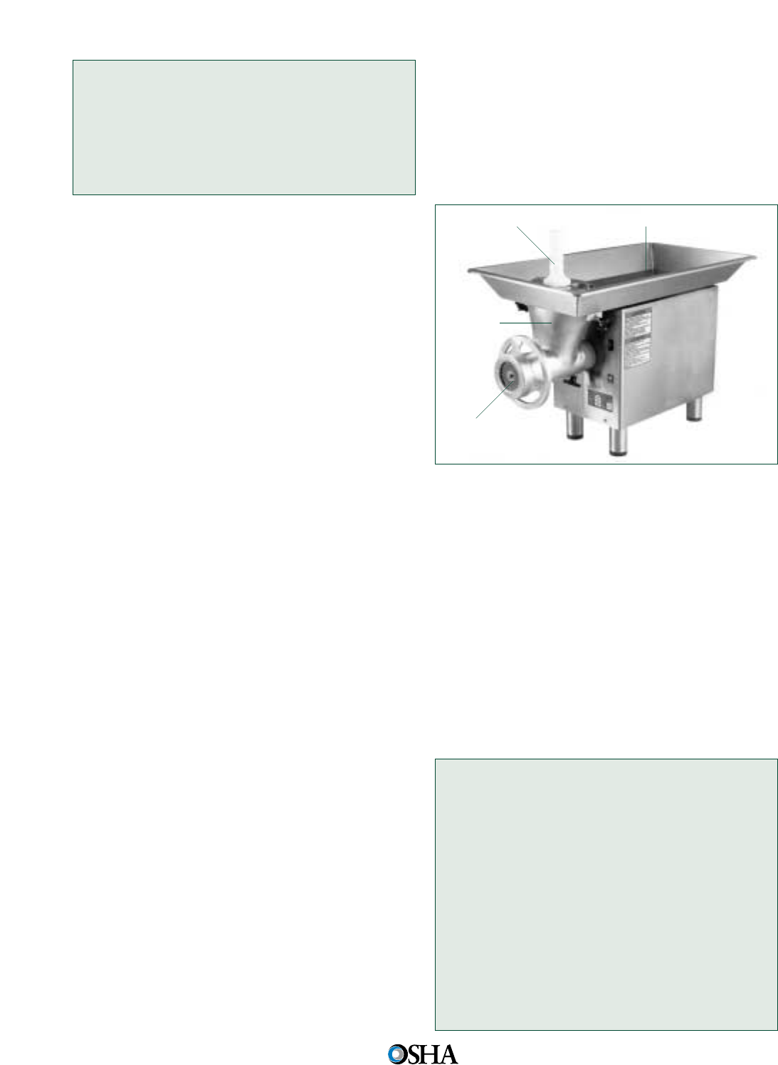
Case History #15
An employee was cleaning a meat slicer that was
turned off but was still plugged in. He inadver-
tently turned the machine on by bumping the
on/off switch, resulting in an amputation of his
right ring finger.
Safeguarding and Other Controls
for Food Slicers
Food slicers must be used with guards that cover
the unused portions of the slicer blade on both the
top and bottom of the slicer. You should buy slicers
already equipped with a feeding attachment on the
sliding mechanism of the food holder or purchase
the attachment separately and install it before use.
Instruct employees to use a pushing/guarding de-
vice with chute-fed slicers.
The following are some secondary safeguarding
methods, work practices and complementary
equipment that may be used to supplement primary
safeguarding or alone or in combination when pri-
mary safeguarding methods are not feasible:
• Develop and implement safe work (operating)
procedures for slicers and conduct periodic
inspections to ensure compliance.
• Ensure that all operators receive on-the-job
training under the direct supervision of experi-
enced operators until they can work safely on
their own.
• Use warning signs to alert employees of the
hazard and safety instructions.
• Instruct operators to use plungers to feed food
into chute-fed slicers. For other slicers, they
should use the feeding attachment located on
the food-holder.
• Never place food into the slicer by hand-feeding
or hand pressure.
• Instruct operators to retract the slicer blade dur-
ing cleaning operations.
• Instruct operators to turn off and unplug slicers
when not in use or when left unattended for any
period of time.
• Perform servicing and maintenance under an
energy control program in accordance with the
Control of hazardous energy (lockout/tagout), 29
CFR 1910.147, standard. You can avoid slicer
lockout/tagout if the equipment is cord-and-plug
connected equipment simply by having exclu-
sive control over the attachment plug after you
shut the slicer off and unplug it from the energy
source.
Hazards of Meat Grinders
Electric meat grinders typically have a feeding tray
attached to a tubular throat, a screw auger that
pushes meat to the cutting blade and through the
cutting plate, an on/off switch, a reverse switch,
and a plunger. (See Figure 38.)
Figure 38 Stainless Steel Meat Grinder
Amputations can occur when:
• The operator reaches into the throat of the
grinder while it is still operating or while it is
switched off but still plugged in (energized). In
the latter case, amputations can occur when the
operator accidentally switches the grinder back
on.
• The operator fails to use the attached feeding
tray and throat.
Defective meat grinders, such as ones with
holes in the throat or screw auger area, are also a
source of workplace amputations and must be
taken out of service.
Case History #16
An operator amputated his arm below the elbow
while hand-feeding potatoes into a 5-horsepower
meat grinder through a feed throat with a 4-inch-
by-6-inch opening and no point of operation
guard. This untrained employee had been work-
ing on the machine for only 15 minutes.
Case History #17
An employee amputated her hand about 4 inches
above the wrist while using an inadequately
guarded meat grinder. She had disassembled the
grinder to clean it, but did not replace the fixed
guard along with the stainless steel tray when
38
Occupational Safety and
Health Administration
Feeding Tray
Grinder Plate
Throat
Plunger

she reassembled it. Also, she did not use the
plunger provided for feeding the meat into the
grinder. The machine pulled her hand into the
3-inch diameter auger and amputated it above
the wrist.
Source: OSHA IMIS Accident Investigation Database.
Safeguarding and Other Controls for
Meat Grinders
Meat grinders must be retrofitted with a primary
safeguard, such as a properly designed tapered
throat or fixed guard, in cases where the machine
design is such that an employee’s hand may come
in contact with the point-of-operation (that is the
auger cutter area). You should buy meat grinders
already equipped with this primary safeguard.
The following are some other secondary safe-
guarding methods, work practices, and comple-
mentary equipment that may be used to supple-
ment primary safeguarding or alone or in combina-
tion when primary safeguarding methods are not
feasible:
• Develop and implement safe work (operating)
procedures for meat grinders to ensure that the
guards are adequate and in place, and that the
grinder feeding methods are performed safely.
Conduct periodic inspections of grinder opera-
tions to ensure compliance.
• Use warning signs to alert employees of the
hazard and safety instructions.
• Ensure that all operators receive appropriate
on-the-job training under direct supervision of
experienced operators until they can work safely
on their own.
• Provide operators with properly sized plungers
to eliminate the need for their hands to enter the
feed throat during operation.
• Instruct operators to use the proper plunger
device to feed meat into grinders. No other
device should be used to feed the grinder.
• Instruct employees to operate grinders only with
feeding trays and throats installed.
• Instruct operators to use the meat grinder only
for its intended purpose.
• Instruct operators to turn off and unplug grinders
when not in use or when left unattended for any
period of time.
• Perform servicing and maintenance under an
energy control program in accordance with the
Control of hazardous energy (lockout/tagout), 29
CFR 1910.147, standard. You can avoid slicer
lockout/tagout if the equipment is cord-and-plug
connected equipment simply by having exclu-
sive control over the attachment plug after you
shut the slicer off and unplug it from the energy
source.
Applicable Standards
• 29 CFR 1910.147, Control of hazardous energy
(lockout/tagout).
• 29 CFR 1910.212, General requirements for all
machines.
• 29 CFR 1910.219, Mechanical power-transmis-
sion apparatus.
Sources of Additional Information
• OSHA Instruction CPL 03-00-002, National
Emphasis Program on Amputations.
• OSHA Publication 3067, Concepts and
Techniques of Machine Safeguarding
(http://www.osha.gov/Publications/Mach_
Safeguard/toc.html)
• OSHA Machine Guarding eTool (http://www.
osha.gov/SLTC/etools/machineguarding/index.
html)
• OSHA Lockout/Tagout Interactive Training
Program (http://www.osha.gov/dts/osta/
lototraining/index.htm)
Hazards of Meat-Cutting Band Saws
Band saws can cut wood, plastic, metal, or meat.
These saws use a thin, flexible, continuous steel
strip with cutting teeth on one edge that runs
around two large motorized pulleys or wheels. The
blade runs on two pulleys (driver and idler) and
passes through a hole in the work table where the
operator feeds the stock. Blades are available with
various teeth sizes, and the saws usually have
adjustable blade speeds.
Unlike band saws used in other industries,
meat-cutting band saws are usually constructed of
stainless steel for sanitary purposes and for easy
cleaning. The table, which may slide or roll, has a
pushing guard installed to protect the operator
while feeding the saw. Meat-cutting band saws
may also be equipped with a fence and pushing
guard to feed the meat through the band saw. (See
Figure 39.)
SAFEGUARDING EQUIPMENT AND PROTECTING EMPLOYEES FROM AMPUTATIONS 39
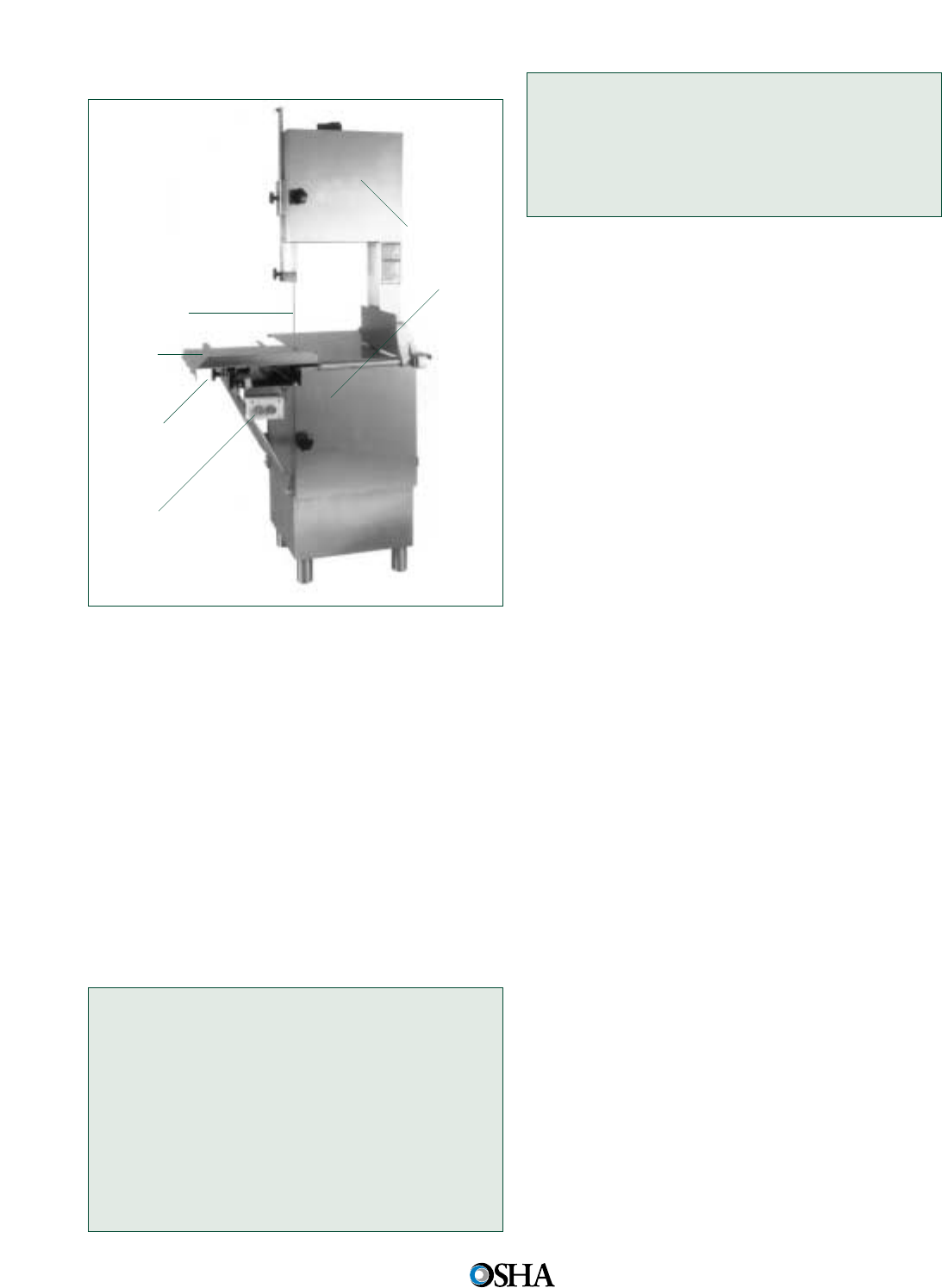
Figure 39 Stainless Steel Meat-Cutting Band Saw
Amputations occur most frequently when opera-
tors’ hands contact the running saw blade while
feeding meat into the saw. The risk of amputation
is greatest when operators place their hands too
close to the saw blade, in a direct line with the saw
blade, or beneath the adjustable guard during feed-
ing operations. Here are some common causes of
amputations involving meat-cutting band saws:
• The operator’s hand slips off the meat or other-
wise accidentally runs through the blade.
• The operator attempts to remove meat from the
band saw table while the blade is still moving.
• The operator’s gloves, jewelry, or loose-fitting
clothing became entangled in the saw blade.
Case History #18
While operating a band saw to cut pork loin, an
employee amputated his right index finger when
his hand slipped and contacted the moving blade.
Case History #19
An operator amputated the tip of his right ring
finger while using a band saw to cut 1/4-inch
slabs of meat from a 4-inch thick piece of beef.
As the piece of meat got smaller, his hands
moved too close to the saw blade. The employee
was not using the pusher guard provided for the
saw.
Source: OSHA IMIS Accident Investigation Database.
Safeguarding and Other Controls for
Meat-Cutting Band Saws
Primary safeguarding methods that you can use
include the following:
• Install a self-adjusting guard over the entire
blade, except at the working portion, or point
of operation of the blade. The guard must be
adjustable to cover the unused portion of the
blade above the meat during cutting operations.
• Enclose the pulley mechanism and motor com-
pletely.
The following are some secondary safeguard-
ing methods, work practices, and complementary
equipment that may be used to supplement pri-
mary safeguarding or alone or in combination
when primary safeguarding methods are not fea-
sible:
• Develop and implement safe work (operating)
procedures for meat-cutting band saws to
ensure that the guards are adequate and in
place and that operators safely perform feeding
methods.
• Ensure that all operators receive adequate on-
the-job training under the direct supervision of
experienced operators until they can work safely
on their own.
• Use warning signs to alert employees of the
hazard and safety instructions.
• Install a brake on one or both wheels to prevent
the saw blade from coasting after the machine is
shut off.
• Provide a pushing guard or fence to feed meat
into the saw blade.
• Instruct operators to use the pushing guard or
fence to feed the saw, especially when cutting
small pieces of meat.
• Instruct operators to adjust the point of opera-
tion guard properly to fit the thickness of the
meat.
• Instruct operators to use only sharp meat-cut-
ting blades and to tighten blades to the appro-
priate tension with the machine’s tension control
device.
40
Occupational Safety and
Health Administration
Fixed
Power
Transmission
Apparatus
Guard
Operator
Control
Blade
Adjustable
Point of
Operation
Guard
Pushing
Guard
Sliding
Table

• Instruct operators not to wear gloves, jewelry, or
loose-fitting clothing while operating a band
saw and to secure long hair in a net or cap.
• Prohibit operators from removing meat from the
band saw while the saw blade is still moving.
• Instruct operators to turn off and unplug band
saws when not in use or when left unattended
for any period of time.
• Conduct periodic inspections of the saw opera-
tion to ensure compliance.
• Perform servicing and maintenance under an
energy control program in accordance with the
Control of hazardous energy (lockout/tagout), 29
CFR 1910.147, standard. You can avoid slicer
lockout/tagout if the equipment is cord-and-plug
connected equipment simply by having exclu-
sive control over the attachment plug after you
shut the band saw off and unplug it from the
energy source.
Applicable Standards
• 29 CFR 1910.147, Control of hazardous energy
(lockout/tagout).
• 29 CFR 1910.212, General requirements for all
machines.
• 29 CFR 1910.219, Mechanical power-transmis-
sion apparatus.
Sources of Additional Information
• OSHA Publication 3067, Concepts and
Techniques of Machine Safeguarding
(http://www.osha.gov/Publications/Mach_
Safeguard/toc.html)
• OSHA Machine Guarding eTool (http://www.
osha.gov/SLTC/etools/machineguarding/index.
html)
• OSHA Lockout/Tagout Interactive Training
Program (http://www.osha.gov/dts/osta/
lototraining/index.htm)
• OSHA Publication 3157, A Guide for Protecting
Workers from Woodworking Hazards (http://
www.osha.gov/Publication/osha3157.pdf)
Hazards of Drill Presses
Electric drill presses use a rotating bit to drill or cut
holes in wood or metal. The holes may be cut to a
desired preset depth or completely through the
stock. A basic drill press operation consists of
selecting an appropriate drill bit, tightening the bit
in the chuck, setting the drill depth, placing the
material on the drill press bed, securing the work
to the bed so that it will not rotate during drilling,
turning the drill press on, and pulling the drill press
lever down so that the drill bit will be lowered into
the stock. (See Figure 40.)
Figure 40 Drill Press with aTransparent Drill Shield
Amputations typically occur when the operator’s
gloves, loose-fitting clothing, or jewelry become
entangled in the rotating drill bit. Here are some
other causes of drill press-related amputations:
• Inadequately guarding points of operation or
power-transmission (such as belt and pulleys)
devices;
• Removing a part from a drill press while wear-
ing gloves;
• Making adjustments to the drill press, such as
setting the depth, securing the material to the
drill press bed, and repositioning the wood or
metal, while the drill bit is still rotating;
• Changing the drill bit with the operating control
unprotected so that a falling object or otherwise
bumping the switch can accidentally start up the
press spindle and tool assembly;
• Performing servicing and maintenance activities,
such as changing pulleys and belts, without de-
energizing and locking/taging out the drill press.
Case History #20
A mechanic amputated the first joints of his left
index and middle fingers while changing the belt
position on a multi-pulley drill press. While the
mechanic was pulling the belt on, it suddenly
went around the outside pulley, pulling the
mechanic’s fingers through the nip point.
SAFEGUARDING EQUIPMENT AND PROTECTING EMPLOYEES FROM AMPUTATIONS 41
Drill Bit
Clamps to
Hold Work in
Place

Case History #21
A machinist amputated his left index finger at the
first joint while drilling holes in a machined part.
As he moved the part to begin drilling another
hole, his gloved hand got caught in the drill bit.
Source: OSHA IMIS Accident Investigation Database.
Safeguarding and Other Controls for
Drill Presses
For drill presses, you must be protected from the
rotating chuck and swarf that is produced by the
drill bit. Guarding at the point-of-operation is diffi-
cult because of the nature of the drilling press. The
following primary safeguarding methods can be
installed to guard the operator and other employ-
ees from rotating parts, flying chips, and cuttings:
• Specifically designed shields can be attached to
the quill and used to guard this area. For exam-
ple, telescopic shielding that retracts as the drill
bit contacts the piece or a more universal-type
shield can be applied.
• Automatic machines and high-production ma-
chines could have enclosures designed and
installed to guard the employee from the entire
drilling operation.
• Install guarding over the motor, belts, and pul-
leys.
• Install an adjustable guard to cover the unused
portion of the bit and chuck above the material
being worked.
The following are some secondary safeguarding
methods, work practices, and complementary
equipment that may be used to supplement pri-
mary safeguarding or alone or in combination
when primary safeguarding methods are not feasi-
ble:
• Automatic machines and high-production
machines could use barricades to separate the
employee from the entire drilling operation.
• Develop and implement safe work (operating)
practices, such as removing the chuck immedi-
ately after each use, for drill press operations
and conduct periodic inspections to ensure com-
pliance.
• Train and supervise all operators until they can
work safely on their own.
• Use the drill press only for its intended purposes.
42
Occupational Safety and
Health Administration
• Instruct employees not to wear gloves, jewelry,
or loose-fitting clothing while operating a drill
press and to secure long hair in a net or cap.
• Make sure that operators secure material to the
drill press bed with clamps (work-holding equip-
ment) before drilling, so that the material will
not spin and strike the operator. The operator
should not manually secure the work to the drill
press bed while drilling holes.
• Do not adjust the drill press while the drill bit is
still rotating.
• Replace projecting chucks and set screws with
non-projecting safety-bit chucks and set screws.
• Cover operator controls so that the drill press
cannot be turned on accidentally.
• Shut off the drill press when not in use or when
left unattended for any period of time.
• Perform servicing and maintenance under an
energy control program in accordance with the
Control of hazardous energy (lockout/tagout), 29
CFR 1910.147, standard.
Minor Servicing
At times, OSHA recognizes that some minor
servicing may have to be performed during nor-
mal production operations, so a lockout/tagout
exception is allowed. See the 29 CFR
1910.147(a)(2)(ii) Note, for details. For example,
minor drill press tool changes and adjustments
may be performed without lockout/tagout if the
machine’s electrical disconnect or control (on/off)
switches control all the hazardous energy and
are: 1) properly designed and applied in accor-
dance with good engineering practice; 2) placed
in an off (open) position; and 3) under the exclu-
sive control of the employee performing the
minor servicing task.
Source: 29 CFR 1910.147(a)(2)(ii) Note.
Cord- and Plug-connected Electric Equipment
The OSHA LOTO standard would not apply when
employees are performing servicing and mainte-
nance work on a cord- and plug-connected drill
press if the press is unplugged and the plug is in
the exclusive control of the employee performing
the task. The employee would be able to control
the press from being energized by controlling the
attachment plug.
Source: 29 CFR 1910.147(a)(2)(ii)(A).
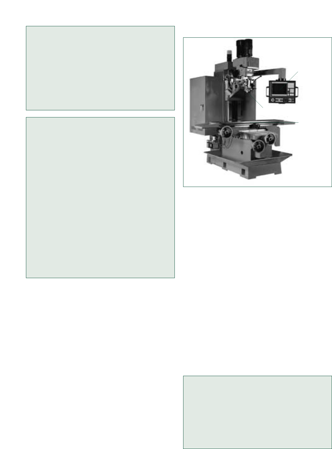
Applicable Standards
• 29 CFR 1910.147, Control of hazardous energy
(lockout/tagout).
• 29 CFR 1910.212, General requirements for all
machines.
• 29 CFR 1910.213, Woodworking machinery
requirements.
• 29 CFR 1910.219, Mechanical power-transmis-
sion apparatus.
Sources of Additional Information
• OSHA Publication 3067, Concepts and
Techniques of Machine Safeguarding
(http://www.osha.gov/Publications/Mach_
Safeguard/toc.html)
• OSHA Machine Guarding eTool (http://www.
osha.gov/SLTC/etools/machineguarding/index.
html)
• OSHA Lockout/Tagout Interactive Training
Program (http://www.osha.gov/dts/osta/
lototraining/index.htm)
• OSHA Publication 3157, A Guide for Protecting
Workers from Woodworking Hazards (http://
www.osha.gov/Publication/osha3157.pdf)
• ANSI B11.8-2001, Safety Requirements for
Manual Milling, Drilling and Boring Machines
with or without Automatic Control
• ANSI O1.1-2004, Safety Requirements for
Woodworking Machinery
Hazards of Milling Machines
Electric milling machines cut metal using a rotating
cutting device called a milling cutter. These ma-
chines cut flat surfaces, angles, slots, grooves,
shoulders, inclined surfaces, dovetails, and
recessed cuts. Cutters of different sizes and shapes
are available for a wide variety of milling opera-
tions.
Milling machines include knee-and-column
machines, bed-type or manufacturing machines,
and special milling machines designed for special
applications. Typical milling operations consist of
selecting and installing the appropriate milling cut-
ter, loading a work-piece on the milling table, con-
trolling the table movement to feed the part against
the rotating milling cutter, and callipering or meas-
uring the part. (See Figure 41.)
SAFEGUARDING EQUIPMENT AND PROTECTING EMPLOYEES FROM AMPUTATIONS 43
Figure 41 Bed Mill
Some frequent causes of amputation from
milling machines include:
• Loading or unloading parts and callipering or
measuring the milled part while the cutter is still
rotating;
• Operating milling machines with the safety door
selector switch on bypass;
• Inspecting the milling machine gearbox with the
machine still operating;
• Manually checking the machine for loose gears
(by removing the gearbox cover) while comput-
erized cutting software program was operating;
• Performing servicing and maintenance activities
such as setting up the machine, changing and
lubricating parts, clearing jams, and removing
excess oil, chips, fines, turnings, or particles
either while the milling machine is stopped but
still energized, or while the cutter is still rotating;
and
• Getting jewelry or loose-fitting clothing entan-
gled in the rotating cutter.
Case History #22
While replacing parts on a horizontal milling
machine, an employee shut off the machine,
which put the revolving cutter in a neutral posi-
tion. The employee, however, did not disengage
the clutch to stop the cutter and proceeded to
replace parts while the cutter was still moving.
He amputated three fingers.
Control
System
Milling
Bed
Milling
Cutter

Case History #23
An employee was using a milling machine to cut
metal samples to length. After a part had been
cut, the employee needed to gauge the part size.
While he was checking the edge of the sample,
the blade caught the tip of his glove, pulled his
hand into the cutting area, and amputated his
right ring finger and part of his middle finger.
Source: OSHA IMIS Accident Investigation Database.
Safeguarding and Other Controls for
Milling Machines
The following primary safeguarding methods will
help protect you from point-of-operation and other
milling machine hazard areas:
• Install guards (fixed, movable, and interlocked)
that enclose the milling cutter’s point-of-opera-
tion;
• Install properly applied safeguarding devices,
such as presence-sensing devices and two-hand
control methods;
• Install guards around the machine’s power
transmission components (such as drive mecha-
nisms).
The following are some secondary safeguarding
methods, work practices, and complementary
equipment that may be used to supplement pri-
mary safeguarding or alone or in combination
when primary safeguarding methods are not feasi-
ble:
• Use other safeguarding devices such as splash
shields, chip shields, or barriers if they provide
effective protection to the operator and when it
is impractical to guard cutters without interfer-
ing with normal production operations or creat-
ing a more hazardous situation.
• Install awareness devices, such as barriers and
warning signs, around the milling table.
• Instruct operators not to use a jig or vise (work-
holding equipment) that prevents the point of
operation guard from being adjusted appropri-
ately.
• Develop and implement safe (operating) work
procedures for machine operators, such as safe
work procedures for installing and using fixtures
and tooling.
• Instruct operators to place the jig or vise locking
arrangement so that force must be exerted away
from the cutter.
44
Occupational Safety and
Health Administration
• Ensure that all operators receive appropriate
safe work procedure training by experienced
operators until they can work safely on their
own.
• Instruct operators to move the work-holding
device back to a safe distance when loading or
unloading parts and callipering or measuring
the work and not to perform these activities
while the cutter is still rotating unless the cutter
is adequately guarded.
• Instruct employees not to wear gloves, jewelry,
or loose-fitting clothing while operating a milling
machine and to secure long hair in a net or cap.
• Prohibit operators from reaching around the cut-
ter or hob to remove chips while the machine is
in motion or not locked or tagged out.
• Conduct periodic inspections to ensure compli-
ance.
• Perform servicing and maintenance under an
energy control program in accordance with the
Control of hazardous energy (lockout/tagout), 29
CFR 1910.147, standard.
Minor Servicing
At times, OSHA recognizes that some minor
servicing may have to be performed during nor-
mal production operations, so a lockout/tagout
exception is allowed. See the 29 CFR
1910.147(a)(2)(ii) Note, for details. For example,
minor milling machine tool changes and adjust-
ments may be performed without lockout/tagout
if the machine’s electrical disconnect or control
(on/off) switches control all the hazardous energy
and are: 1) properly designed and applied in
accordance with good engineering practice; 2)
placed in an off (open) position; and 3) under the
exclusive control of the employee performing the
minor servicing task.
Source: 29 CFR 1910.147(a)(2)(ii) Note.
Applicable Standards
• 29 CFR 1910.147, Control of hazardous energy
(lockout/tagout)
• 29 CFR 1910.212, General requirements for all
machines
• 29 CFR 1910.219, Mechanical power-transmis-
sion apparatus

Sources of Additional Information
• OSHA Publication 3067, Concepts and
Techniques of Machine Safeguarding
(http://www.osha.gov/Publications/Mach_
Safeguard/toc.html)
• OSHA Machine Guarding eTool (http://www.
osha.gov/SLTC/etools/machineguarding/index.
html)
• OSHA Lockout/Tagout Interactive Training
Program (http://www.osha.gov/dts/osta/
lototraining/index.htm)
• National Safety Council, Accident Prevention
Manual for Industrial Operations: Engineering
and Technology. 10th Ed. Itasca, IL
• ANSI B11.8-2001, Safety Requirements for
Manual Milling, Drilling and Boring Machines
with or without Automatic Control
Hazards of Grinding Machines
Grinding machines primarily alter the size, shape,
and surface finish of metal by placing a work-piece
against a rotating abrasive surface or wheel. Grind-
ing machines may also be used for grinding glass,
ceramics, plastics, and rubber.
Examples of grinding machines include abrasive
belt machines, abrasive cutoff machines, cylindrical
grinders, centerless grinders, gear grinders, internal
grinders, lapping machines, off-hand grinders, sur-
face grinders, swing frame grinders, and thread
grinders. (See Figure 42.)
Figure 42 Horizontal Surface Grinder
SAFEGUARDING EQUIPMENT AND PROTECTING EMPLOYEES FROM AMPUTATIONS 45
Amputation injuries can occur when the opera-
tor’s hands enter the point of operation during the
following activities:
• Bypassing the grinding machine safety switch
feature in order to clean the machine while it is
running;
• Wearing gloves while grinding, where it is possi-
ble to have the glove get caught between the
revolving disc and the table;
• Fixing a jammed grinder machine by turning
the machine off, removing the blade guard and
reaching into the danger area before the blades
stop turning;
• Operating a grinding machine with non-func-
tional interlocks and without the guard in place;
• Using an incorrectly adjusted or missing work
rest or a poorly maintained or unbalanced abra-
sive wheel;
• Adjusting the work rest, balancing the wheel,
cleaning the area around the abrasive wheel and
loading and unloading parts or measuring parts
while the abrasive wheel is still rotating;
• Attempting to stop a rotating abrasive wheel by
hand.
Case History #24
After grinding a piece of steel on an off-hand
grinder, an employee turned off the machine and
tried to stop the wheel with a piece of scrap
steel. His hand slipped and hit the rotating abra-
sive wheel, amputating the tip of his left middle
finger.
Case History #25
An employee was operating a large surface
grinder to grind a groove into a steel part in a
large pump repair shop. The part was secured
with a vise and placed on a magnetic table. The
employee was trying to measure the groove
while the table was moving back and forth
beneath the grinding wheel. The safe practice,
both written and customary, is to disengage the
hydraulics for the table and stop the wheel
before reaching in to measure or remove a part.
Though experienced at operating this machine
and aware of the strict rule, the employee
attempted to take measurements while the table
and wheel were moving and ground off part of
his left index finger.
Fixed
Guard
Grinding
Bed
Grinding
Wheel
Fixed
Guard

Safeguarding and Other Controls for
Grinding Machines
You can help prevent employee accidents and
injuries by using primary safeguarding methods.
Here are some examples:
• Install safety guards that cover the spindle end,
nut, and flange projections or otherwise ensure
adequate operator protection;
• Install adjustable and rigid work rests on off-
hand grinding machines; and
• Install guards over power belts and drives.
The following are some secondary safeguarding
methods, work practices, and complementary
equipment that may be used to supplement primary
safeguarding or alone or in combination when
primary safeguarding methods are not feasible:
• Develop and implement safe work procedures
for grinding machine operations.
• Install warning and safety instruction signs.
• Ensure that all operators receive appropriate on-
the-job training and supervision until they can
work safely on their own.
• Use abrasive discs and wheels that are correctly
rated for the grinder’s maximum operating spin-
dle speed. The disc or wheel rating is marked on
the disc or wheel in surface feet per minute.
• Inspect and sound test the grinding wheel to
ensure that it is not defective, unbalanced,
loose, or too small.
• Adjust the work rest to within 1/8inch of the
wheel.
• Do not wear gloves, jewelry, or loose-fitting
clothing while operating grinding machines and
secure long hair in a net or cap.
• Do not adjust the guard or clean the grinding
machine while the abrasive wheel is still rotating.
• Conduct periodic inspections to ensure compli-
ance.
• Perform servicing and maintenance under an
energy control program in accordance with the
Control of hazardous energy (lockout/tagout), 29
CFR 1910.147, standard.
Cord- and Plug-connected Electric Equipment
The OSHA LOTO standard would not apply when
employees are performing servicing and mainte-
nance work on a cord- and plug-connected grind-
ing machine if the grinder is unplugged and the
plug is in the exclusive control of the employee
performing the task. The employee would be
able to control the grinder from being energized
by controlling the attachment plug.
Applicable Standards
• ANSI B7.1-1970, Safety Code for the Use, Care
and Protection of Abrasive Wheels [incorporat-
ed by reference in 1910.94(b)(5)(i)(a),
1910.215(b)(12) and 1910.218(j)(5)].
• 29 CFR 1910.147, Control of hazardous energy
(lockout/tagout).
• 29 CFR 1910.215, Abrasive wheel machinery.
• 29 CFR 1910.219, Mechanical power-transmis-
sion apparatus.
• 29 CFR 1926.303, Abrasive wheels and tools.
Sources of Additional Information
• OSHA Publication 3067, Concepts and
Techniques of Machine Safeguarding
(http://www.osha.gov/Publications/Mach_
Safeguard/toc.html)
• OSHA Machine Guarding eTool (http://www.
osha.gov/SLTC/etools/machineguarding/index.
html)
• OSHA Lockout/Tagout Interactive Training
Program (http://www.osha.gov/dts/osta/
lototraining/index.htm)
• ANSI B7.1—2000, Use, Care, and Protection of
Abrasive Wheels.
• ANSI B11.9—1975 (R2005), Safety Require-
ments for the Construction, Care, and Use of
Grinding Machines.
Hazards of Slitters
Slitters use rotary knives to slit flat rolled metal,
plastic film, paper, plastic, foam, and rubber as well
as other coiled or sheet-fed materials. Slitters range
from small hand-fed paper slitters to large-scale
automated metal slitters, complete with metal pro-
cessing and handling units such as unwinders and
rewinders. Both light and heavy gauge slitters are
available. (See Figure 43.)
46
Occupational Safety and
Health Administration

Figure 43 Paper Slitter
Amputations often occur when clothing or body
parts come in contact with slitter blades or get
caught in the movement of coils and rolls. Here are
some examples:
• Employees can inadvertently get their fingers
and hands caught in the in-going nip points of
the slitter or associated machinery such as re-
winders.
• Gloves, jewelry, long hair and loose clothing
can get entangled in in-going nip points or in
the rotary knives of the slitter.
• Employees can suffer an amputation when
clearing, adjusting, cleaning, or servicing the
slitter while it is either still operating, or shut
off but still plugged in (energized).
Case History #26
An employee was operating a precision slitting
machine to slit a roll of aluminum. As the em-
ployee reached into the machine to make an
adjustment because the aluminum was not being
slit properly, the employee’s right arm got caught
in the slitter. A set of rollers pulled his arm and
amputated his right thumb and forefinger.
Case History #27
An employee was feeding cardboard strips onto
slit steel as it was being coiled on a slitter
machine. While the machine was operating, the
employee was placing the cardboard strips on the
coils. After reaching over the steel strips, the
coiled steel on the mandrel pulled his right arm
into the machine and amputated it.
Source: OSHA IMIS Accident Investigation Database.
SAFEGUARDING EQUIPMENT AND PROTECTING EMPLOYEES FROM AMPUTATIONS 47
Safeguarding and Other Controls for
Slitters
The following primary safeguards may be used to
protect employees from the hazardous portions of
the slitter and auxiliary equipment:
• Install a fixed or adjustable point-of-operation
guard to prevent inadvertent entry of body parts
into a hazardous area of the slitter system.
• Install a fixed point of operation guard to cover
the sides of the unwinder or rewinder to prevent
an employee’s hands or clothing from entering
into the rollers.
• Properly applied presence-sensing devices (such
as light curtains, radio-frequency devices, safety
mats) may be used to control employee exposure
to certain types of hazards (such as the slitter
knives’ point-of-operation hazard) by stopping
or preventing machine system operation in the
event any part of an employee’s body is detect-
ed in a sensing field.
• Install fixed or interlocked guards to cover other
moving parts of the machine such as the power-
transmission apparatus.
The following are some secondary safeguarding
methods, work practices, and complementary
equipment that may be used to supplement primary
safeguarding or alone or in combination when
primary safeguarding methods are not feasible:
• Use awareness devices, such as an awareness
barrier or fence (with an interlocking gate) and
hazard warning/safety instruction signs around
the perimeter of the machine to alert people of
the hazard and prevent unauthorized entry.
• Awareness signals may also be used to alert
you of an existing or approaching hazard as
these devices issue a warning sound or provide
a visible warning light.
• Restrict employee access to hazardous areas
through the application of safeguarding by loca-
tion techniques – such as utilizing the facility lay-
out (walls) and equipment location (elevation)
for isolation purposes.
• Develop and implement safe work procedures
for machine operators and conduct periodic
inspections to ensure compliance.
• Develop an operator training program to ensure
that all operators are knowledgeable and profi-
cient in the safeguarding methods and work
procedures. Employees need to be supervised
on a regular basis to ensure that they are follow-
ing the safety program requirements.

Sources of Additional Information
• OSHA Publication 3067, Concepts and
Techniques of Machine Safeguarding
(http://www.osha.gov/Publications/Mach_
Safeguard/toc.html)
• OSHA Machine Guarding eTool (http://www.
osha.gov/SLTC/etools/machineguarding/index.
html)
• OSHA Lockout/Tagout Interactive Training
Program (http://www.osha.gov/dts/osta/
lototraining/index.htm)
• ANSI B11.14—1996, Coil Slitting Machines
Safety Requirements for Construction, Care
and Use
48
Occupational Safety and
Health Administration
• Perform servicing and maintenance under an
energy control program in accordance with the
Control of hazardous energy (lockout/tagout), 29
CFR 1910.147, standard.
Applicable Standards
• 29 CFR 1910.147, Control of hazardous energy
(lockout/tagout)
• 29 CFR 1910.212, General requirements for all
machines
• 29 CFR 1910.219, Mechanical power-transmis-
sion apparatus

SAFEGUARDING EQUIPMENT AND PROTECTING EMPLOYEES FROM AMPUTATIONS 49
OSHA Assistance
OSHA can provide extensive help through a variety of
programs, including technical assistance about effec-
tive safety and health programs, state plans, work-
place consultations, voluntary protection programs,
strategic partnerships, training and education, and
more. An overall commitment to workplace safety and
health can add value to your business, to your work-
place, and to your life.
Safety and Health Program Management Guidelines
Effective management of employee safety and health
protection is a decisive factor in reducing the extent
and severity of work-related injuries and illnesses and
their related costs. In fact, an effective safety and
health program forms the basis of good employee
protection and can save time and money (about $4
for every dollar spent) and increase productivity and
reduce employee injuries, illnesses, and related work-
ers’ compensation costs.
To assist employers and employees in developing
effective safety and health programs, OSHA pub-
lished recommended Safety and Health Program
Management Guidelines (54 Federal Register (16):
3904-3916, January 26, 1989). These voluntary guide-
lines can be applied to all places of employment cov-
ered by OSHA.
The guidelines identify four general elements criti-
cal to the development of a successful safety and
health management system:
• Management leadership and employee involvement,
• Worksite analysis,
• Hazard prevention and control, and
• Safety and health training.
The guidelines recommend specific actions, under
each of these general elements, to achieve an effec-
tive safety and health program. The Federal Register
notice is available online at www.osha.gov.
State Programs
The Occupational Safety and Health Act of 1970 (OSH
Act) encourages states to develop and operate their
own job safety and health plans. OSHA approves and
monitors these plans. Twenty-four states, Puerto Rico
and the Virgin Islands currently operate approved
state plans: 22 cover both private and public (state
and local government) employment; Connecticut,
New Jersey, New York and the Virgin Islands cover
the public sector only. States and territories with their
own OSHA-approved occupational safety and health
plans must adopt standards identical to, or at least as
effective as, the Federal OSHA standards.
Consultation Services
Consultation assistance is available on request to
employers who want help in establishing and main-
taining a safe and healthful workplace. Largely funded
by OSHA, the service is provided at no cost to the
employer. Primarily developed for smaller employers
with more hazardous operations, the consultation
service is delivered by state governments employing
professional safety and health consultants. Compre-
hensive assistance includes an appraisal of all mech-
anical systems, work practices, and occupational safe-
ty and health hazards of the workplace and all aspects
of the employer’s present job safety and health pro-
gram. In addition, the service offers assistance to
employers in developing and implementing an effec-
tive safety and health program. No penalties are pro-
posed or citations issued for hazards identified by the
consultant. OSHA provides consultation assistance to
the employer with the assurance that his or her name
and firm and any information about the workplace will
not be routinely reported to OSHA enforcement staff.
Under the consultation program, certain exemplary
employers may request participation in OSHA’s Safety
and Health Achievement Recognition Program
(SHARP). Eligibility for participation in SHARP in-
cludes receiving a comprehensive consultation visit,
demonstrating exemplary achievements in workplace
safety and health by abating all identified hazards, and
developing an excellent safety and health program.
Employers accepted into SHARP may receive an
exemption from programmed inspections (not com-
plaint or accident investigation inspections) for a peri-
od of 1 year. For more information concerning consul-
tation assistance, see OSHA’s website at
www.osha.gov.
Voluntary Protection Programs (VPP)
Voluntary Protection Programs and on-site consulta-
tion services, when coupled with an effective en-
forcement program, expand employee protection to
help meet the goals of the OSH Act. The VPPs moti-
vate others to achieve excellent safety and health
results in the same outstanding way as they estab-
lish a cooperative relationship between employers,
employees, and OSHA.
For additional information on VPP and how to
apply, contact the OSHA regional offices listed at the
end of this publication.
Strategic Partnership Program
OSHA’s Strategic Partnership Program, the newest
member of OSHA’s cooperative programs, helps
encourage, assist, and recognize the efforts of part-
ners to eliminate serious workplace hazards and
achieve a high level of employee safety and health.
Whereas OSHA’s Consultation Program and VPP entail

50
Occupational Safety and
Health Administration
one-on-one relationships between OSHA and individ-
ual worksites, most strategic partnerships seek to
have a broader impact by building cooperative rela-
tionships with groups of employers and employees.
These partnerships are voluntary, cooperative relation-
ships between OSHA, employers, employee represen-
tatives, and others (e.g., trade unions, trade and pro-
fessional associations, universities, and other govern-
ment agencies).
For more information on this and other coopera-
tive programs, contact your nearest OSHA office, or
visit OSHA’s website at www.osha.gov.
Alliance Program
The Alliance Program enables organizations commit-
ted to workplace safety and health to collaborate with
OSHA to prevent injuries and illnesses in the work-
place. OSHA and the Alliance participants work
together to reach out to, educate, and lead the
nation’s employers and their employees in improving
and advancing workplace safety and health.
Groups that can form an Alliance with OSHA
include employers, labor unions, trade or professional
groups, educational institutions and government
agencies. In some cases, organizations may be build-
ing on existing relationships with OSHA that were
developed through other cooperative programs.
There are few formal program requirements for
Alliances and the agreements do not include an
enforcement component. However, OSHA and the
participating organizations must define, implement,
and meet a set of short- and long-term goals that fall
into three categories: training and education; outreach
and communication; and promotion of the national
dialogue on workplace safety and health.
OSHA Training and Education
OSHA area offices offer a variety of information serv-
ices, such as compliance assistance, technical advice,
publications, audiovisual aids and speakers for special
engagements. OSHA’s Training Institute in Arlington
Heights, IL, provides basic and advanced courses in
safety and health for Federal and state compliance
officers, state consultants, Federal agency personnel,
and private sector employers, employees, and their
representatives.
The OSHA Training Institute also has established
OSHA Training Institute Education Centers to address
the increased demand for its courses from the private
sector and from other federal agencies. These centers
are nonprofit colleges, universities, and other organi-
zations that have been selected after a competition for
participation in the program.
OSHA also provides funds to nonprofit organiza-
tions, through grants, to conduct workplace training
and education in subjects where OSHA believes there
is a lack of workplace training. Grants are awarded
annually. Grant recipients are expected to contribute
20 percent of the total grant cost.
For more information on grants, training, and edu-
cation, contact the OSHA Training Institute, Office of
Training and Education, 2020 South Arlington Road,
Arlington Heights, IL 60005, (847) 297-4810, or see
Outreach on OSHA’s website at www.osha.gov. For
further information on any OSHA program, contact
your nearest OSHA regional office listed at the end of
this publication.
Information Available Electronically
OSHA has a variety of materials and tools available on
its website at www.osha.gov. These include electronic
compliance assistance tools, such as Safety and
Health Topics, eTools, Expert Advisors; regulations,
directives and publications; videos and other informa-
tion for employers and employees. OSHA’s software
programs and compliance assistance tools walk you
through challenging safety and health issues and
common problems to find the best solutions for your
workplace.
A wide variety of OSHA materials, including stan-
dards, interpretations, directives and more can be
purchased on CD-ROM from the U.S. Government
Printing Office, Superintendent of Documents, toll-free
phone (866) 512-1800.
OSHA Publications
OSHA has an extensive publications program. For a
listing of free or sales items, visit OSHA’s website at
www.osha.gov or contact the OSHA Publications
Office, U.S. Department of Labor, 200 Constitution
Avenue, NW, N-3101, Washington, DC 20210:
Telephone (202) 693-1888 or fax to (202) 693-2498.
Contacting OSHA
To report an emergency, file a complaint, or seek
OSHA advice, assistance, or products, call (800) 321-
OSHA or contact your nearest OSHA Regional or Area
office listed at the end of this publication. The tele-
typewriter (TTY) number is (877) 889-5627.
Written correspondence can be mailed to the near-
est OSHA Regional or Area Office listed at the end of
this publication or to OSHA’s national office at: U.S.
Department of Labor, Occupational Safety and Health
Administration, 200 Constitution Avenue, N.W.,
Washington, DC 20210.
By visiting OSHA’s website at www.osha.gov, you
can also:
• file a complaint online,
• submit general inquiries about workplace safety
and health electronically, and
• find more information about OSHA and occupation-
al safety and health.

SAFEGUARDING EQUIPMENT AND PROTECTING EMPLOYEES FROM AMPUTATIONS 51
References
American National Standards Institute
• ANSI B5.52M-1980 (R1994), Presses, General
Purpose, Single Point, Gap Type, Mechanical
Power (Metric)
• ANSI B5.37—1970 (R1994), External Cylindrical
Grinding Machines—Centerless
• ANSI B5.42—198 (R1994), External Cylindrical
Grinding Machines—Universal
• ANSI B7.1—2000, Use, Care, and Protection of
Abrasive Wheels
• ANSI B11.1-2001, Safety Requirements for
Mechanical Power Presses
• ANSI B11.3-2002, Safety Requirements for the
Construction, Care, and Use of Power Press
Brakes
• ANSI B11.4-2003, Safety Requirements for
Construction, Care, and Use of Shears
• ANSI B11.8-2001, Safety Requirements for
Manual Milling, Drilling and Boring Machines
with or without Automatic Control
• ANSI B11.9—1975 (R2005), Safety Requirements
for the Construction, Care, and Use of Grinding
Machines
• ANSI B11.12-1996, Safety Requirements for
Construction, Care, and Use of Roll-Forming and
Roll-Bending Machines
• ANSI B11.14—1996, Coil Slitting Machines
Safety Requirements for Construction, Care and
Use
• ANSI B11.19-2003, Performance Criteria for
Safeguarding
• ANSI B20.1-57, Safety Code for Conveyors,
Cableways, and Related Equipment [incorporat-
ed by reference in 1926.555(a)(8)]
• ANSI B65.1-2005, Safety Standard—Printing
Press Systems
• ANSI B65.2-2005, Binding and Finishing
Systems
• ANSI O1.1-2004, Safety Requirements for
Woodworking Machinery
American National Standards Institute/
Conveyor Equipment Manufacturers
Association
• ANSI/CEMA 350-2003, Screw Conveyors for Bulk
Material
• ANSI/CEMA 401-2003, Unit Handling
Conveyors—Roller Conveyors—Non-powered
• ANSI/CEMA 402-2003, Unit Handling
Conveyors—Belt Conveyors
• ANSI/CEMA 403-2003, Unit Handling
Conveyors—Belt Driven Live Roller Conveyors
• ANSI/CEMA 404-2003, Unit Handling
Conveyors—Chain Driven Live Roller Conveyors
• ANSI/CEMA 405-2003, Unit Handling
Conveyors—Slat Conveyors
• ANSI/CEMA 406-2003, Unit Handling
Conveyors—Line-shaft Driven Live Roller
Conveyors
American National Standards Institute/
American Society of Mechanical
Engineers
• ANSI/ASME B20.1-2003, Safety Standard for
Conveyors and Related Equipment
National Institute for Occupational
Safety and Health
• NIOSH Current Intelligence Bulletin (CIB) 49,
Injuries and Amputations Resulting from Work
with Mechanical Power Presses (May 22, 1987)
National Safety Council
• National Safety Council, Accident Prevention
Manual for Industrial Operations: Engineering
and Technology. 9th ed. Itasca, IL
• National Safety Council, Accident Prevention
Manual for Business and Industry: Engineering
and Technology 11th ed. Itasca, IL

52
Occupational Safety and
Health Administration
Occupational Safety and Health
Administration Standards
• 29 CFR 1910.147—Control of hazardous energy
(lockout/tagout).
• 29 CFR 1910.211—Definitions.
• 29 CFR 1910.212—General requirements for all
machines.
• 29 CFR 1910.213—Woodworking machinery
requirements.
• 29 CFR 1910.215—Abrasive wheel machinery.
• 29 CFR 1910.217—Mechanical power presses.
• 29 CFR 1910.219—Mechanical power-transmis-
sion apparatus.
• 29 CFR 1926.300—General requirements.
• 29 CFR 1926.301—Hand tools.
• 29 CFR 1926.302—Power-operated hand tools.
• 29 CFR 1926.303—Abrasive wheels and tools.
• 29 CFR 1926.304—Woodworking tools.
• 29 CFR 1926.307—Mechanical power-transmis-
sion apparatus.
• 29 CFR 1926.555—Conveyors.
Occupational Safety and Health
Administration Instructions
• OSHA Instruction CPL 03-00-003, National
Emphasis Program on Amputations
• OSHA Instruction STD 01-12-021—29 CFR
1910.217, Mechanical Power Presses,
Clarifications (10/30/78)
• OSHA Instruction CPL 02-01-025, Guidelines for
Point of Operation Guarding of Power Press
Brakes
• OSHA Instruction STD 01-05-019, Control of
Hazardous Energy (Lockout/Tagout)—Inspection
Procedures and Interpretive Guidance
Occupational Safety and Health
Administration Training Programs
• OSHA’s Lockout Tagout Interactive Training
Program (http://www.osha-slc.gov/dts/osta/loto-
training/index.htm)
Occupational Safety and Health
Administration Publications
• OSHA Publication 3067, Concepts and
Techniques of Machine Safeguarding
(http://www.osha.gov/Publications/Mach_
Safeguard/toc.html)
• OSHA Publication 3120 - Control of Hazardous
Energy (Lockout/Tagout)
• OSHA Publication 3157 - A Guide for Protecting
Workers from Woodworking Hazards
(http://www.osha.gov/Publication/osha3157.pdf)
Occupational Safety and Health
Administration Topic Pages
• Safety and Health Topics – Control of Hazardous
Energy – Lockout/Tagout (http://www.osha.gov/
SLTC/controlhazardousenergy/index.html)
• Safety and Health Topics – Machine Guarding
(http://www.osha.gov/SLTC/machineguarding/
index.html)

SAFEGUARDING EQUIPMENT AND PROTECTING EMPLOYEES FROM AMPUTATIONS 53
Appendix A.
Amputation Hazards Not
Covered in this Guide
The following amputation hazards and related
activities are not specifically covered in detail in this
document. They are either covered in other OSHA
publications or specific OSHA standards. While
you may find the general hazard recognition and
machine guarding concepts presented in the
Recognizing Amputations Hazards and Controlling
Amputation Hazards sections of this document
helpful, please refer to the applicable topic-specific
resources and standards listed in the reference sec-
tion of this publication for a complete discussion of
these hazards.
Amputation Hazards Associated
with Saws
Saws are the top source of amputations in whole-
sale and retail trade and in the construction indus-
try. Stationary saws, such as band, radial arm and
table saws, account for a substantial number of
amputations in the workplace. Sawing machinery
used for woodworking applications is not specifical-
ly addressed in this guide.
You can find specific guidance on these saws in
OSHA Publication 3157, A Guide for Protecting
Workers from Woodworking Hazards; 29 CFR
1910.213, Woodworking machinery requirements;
29 CFR 1910.243, Guarding of portable powered
tools; and 29 CFR 1926.304, Woodworking tools.
For additional information on how to safeguard
saws and implement hazardous energy control
practices, you can find guidance at OSHA’s
Machine Guarding eTool section for Saws (http://
www.osha.gov/SLTC/etools/machineguarding/saws.
html) Also, the national consensus standard, ANSI
O1.1-2004, Safety Requirements for Woodworking
Machinery, may provide you with valuable infor-
mation on how to prevent amputations.
Amputation Hazards Associated with
Plastics Machinery
Plastics processing machines are complex pieces
of equipment that require safeguarding and a haz-
ardous energy control program. Serious injuries,
including fatalities, amputations, avulsions, burns
and cuts can occur, especially during servicing and
maintenance work. You can find specific guidance
at OSHA’s “Machine Guarding” eTool section for
“Plastics Machinery” (http://www.osha.gov/SLTC/
etools/machineguarding/plastics/h_injectmold.html).
Amputation Hazards in Agriculture and
Maritime Operations
Requirements for machine guarding in agriculture
operations are contained in the Standards for
Agriculture, 29 CFR Part 1928 Subpart D—Safety for
Agricultural Equipment, and requirements for
machine guarding in maritime operations can be
found in the Shipyard Employment Standards, 29
CFR Part 1915 Subpart H—Tools and Related
Equipment, the Marine Terminals Standard, 29 CFR
Part 1917 Subpart G—Machine Guarding, and the
Longshoring Standard, 29 CFR Part 1918 Subpart
I—General Working Conditions.
Additional Health and Safety Hazards
Other health and safety hazards associated with
using stationary machines, but not addressed in
this guide, include noise, vibration, ergonomic
stresses, exposure to hazardous chemicals (e.g.,
metalworking fluids) and dust, electric hazards, and
flying objects.
Please visit the OSHA website at www.osha.gov
for more information on how to recognize and con-
trol these hazards.

54
Occupational Safety and
Health Administration
Appendix B.
Amputation Hazards
Associated with Other
Equipment and Activities
Although machinery is associated with amputations
more frequently than any other source, amputa-
tions can result from other sources. This appendix
briefly identifies other equipment and activities
associated with amputations:
• Powered and Non-Powered Hand Tools.
Portable hand tools, such as saws, grinders,
shears, and bolt cutters are associated with
amputations in the construction, retail trade,
and services industries.
• Material Handling. Amputations related to
manual material handling tasks often result
when heavy or sharp objects fall from an elevat-
ed surface or shift during transfer. Amputation
often occurs when the employee attempts to
limit the movement of, or damage to, material
as it shifts or falls.
• Forklifts. Amputation hazards related to forklift
operation and use include employees being
trapped or pinned between the forklift and
another object; struck or run over by the forklift;
struck by falling or shifting loads or overturning
forklifts.
• Doors and Covers. Amputation hazards are not
limited to mechanical equipment or heavy
loads. Doors also have the potential to ampu-
tate fingers. These injuries typically result when
a door closes while a person’s hands are in the
doorjamb. Manhole covers, commercial garbage
disposal covers, and tank or bin covers can also
amputate fingers and toes.
• Trash Compactors. Many businesses use small
trash compactors for reducing the volume of
wastes such as cardboard. Often these com-
pactors are not properly guarded and employ-
ees are not properly trained in their use. The
majority of these amputations result from
employees being struck by the ram/piston either
during the initiating stroke or the return stroke.
The ram/piston should be guarded if any part of
an operator’s body is exposed to the danger
area during the operating cycle. Likewise, before
reaching into any trash compactor the operator
should de-energize and lock out the machine.

Appendix C.
OSHA Regional Offices
Region I
(CT,* ME, MA, NH, RI, VT*)
JFK Federal Building, Room E340
Boston, MA 02203
(617) 565-9860
Region II
(NJ,* NY,* PR,* VI*)
201 Varick Street, Room 670
New York, NY 10014
(212) 337-2378
Region III
(DE, DC, MD,* PA, VA,* WV)
The Curtis Center
170 S. Independence Mall West
Suite 740 West
Philadelphia, PA 19106-3309
(215) 861-4900
Region IV
(AL, FL, GA, KY,* MS, NC,* SC,* TN*)
61 Forsyth Street, SW
Atlanta, GA 30303
(404) 562-2300
Region V
(IL, IN,* MI,* MN,* OH, WI)
230 South Dearborn Street
Room 3244
Chicago, IL 60604
(312) 353-2220
Region VI
(AR, LA, NM,* OK, TX)
525 Griffin Street, Room 602
Dallas, TX 75202
(214) 767-4731 or 4736 x224
Region VII
(IA,* KS, MO, NE)
City Center Square
1100 Main Street, Suite 800
Kansas City, MO 64105
(816) 426-5861
Region VIII
(CO, MT, ND, SD, UT,* WY*)
1999 Broadway, Suite 1690
PO Box 46550
Denver, CO 80202-5716
(720) 264-6550
Region IX
(American Samoa, AZ,* CA,* HI,* NV,*
Northern Mariana Islands)
71 Stevenson Street, Room 420
San Francisco, CA 94105
(415) 975-4310
Region X
(AK,* ID, OR,* WA*)
1111 Third Avenue, Suite 715
Seattle, WA 98101-3212
(206) 553-5930
*These states and territories operate their own
OSHA-approved job safety and health programs
and cover state and local government employees
as well as private sector employees. The
Connecticut, New Jersey, New York and Virgin
Islands plans cover public employees only. States
with approved programs must have standards that
are identical to, or at least as effective as, the
Federal standards.
Note: To get contact information for OSHA Area
Offices, OSHA-approved State Plans and OSHA
Consultation Projects, please visit us online at
www.osha.gov or call us at 1-800-321-OSHA.
SAFEGUARDING EQUIPMENT AND PROTECTING EMPLOYEES FROM AMPUTATIONS 55

56
Occupational Safety and
Health Administration