View / The Manual P1userm
User Manual: View / the Manual Productivity1000 User Manual and Inserts
Open the PDF directly: View PDF ![]() .
.
Page Count: 252 [warning: Documents this large are best viewed by clicking the View PDF Link!]
- Productivity1000 User Manual
- Warning
- History
- Table of Contents
- Chapter 1 - Getting Started
- Introduction
- Conventions Used
- Before you begin...
- Productivity Suite System Requirements
- Step 1: Install Programming Software
- Step 2: Launch Programming Software
- Step 3: Install Hardware
- Step 4: Apply Power to CPU
- Step 5: Establish PC to CPU Communications
- Step 6: Open/Read Hardware Configuration
- Step 7: Create a Project
- Step 8: Save Project
- Step 9: Write Project to CPU
- Step 10: Place CPU in RUN Mode
- Step 11: Test the Project Using the Monitor Mode
- Chapter 2 - Specifications
- Chapter 3 - Analog I/O Specifications
- Chapter 4 - Specialty Module Specifications (Reserved for Future Release)
- Chapter 5 - Installation and Wiring
- Chapter 6 - Communications
- Communications
- Communications: Connectivity
- Communications: Ethernet����������������������������������������������������������������������������������������
- TCP and UDP Port Numbers����������������������������������������������������������������������������������������
- IP Addressing and Subnetting
- PC Setup����������������������������������������
- CPU Setup�������������������������������������������
- TCP Connection Behavior with Modbus TCP and Network Instructions����������������������������������������������������������������������������������������������������������������������������������������������������������������������������������������������������������������
- Communications Modbus Functionality�������������������������������������������������������������������������������������������������������������������������
- Master/Client Function Code and Data Type Support�������������������������������������������������������������������������������������������������������������������������������������������������������������������
- Slave/Server Function Code and Data Type Support����������������������������������������������������������������������������������������������������������������������������������������������������������������
- Assigning Modbus Addresses to Tags����������������������������������������������������������������������������������������������������������������������
- Modbus Options����������������������������������������������������������
- Modbus Instructions�������������������������������������������������������������������������
- Network Instructions����������������������������������������������������������������������������
- Automatic Poll versus Manual Polling and Interlocking
- Message Queue
- EtherNet/IP for the Productivity Series�������������������������������������������������������������������������������������������������������������������������������������
- Terminology Definitions�������������������������������������������������������������������������������������
- Network Layer Chart�������������������������������������������������������������������������
- EtherNet/IP Data
- Class 1 and Class 3 Connections�������������������������������������������������������������������������������������������������������������
- Setup Example: Productivity1000 as EtherNet/IP Adapter
- Setup Example: Productivity1000 as EtherNet/IP Scanner
- Troubleshooting Tips����������������������������������������������������������������������������
- ProNET
- Custom Protocol Over Ethernet�������������������������������������������������������������������������������������������������������
- Communications: Port Configuration
- Ethernet Configuration
- Local Ethernet Port Settings����������������������������������������������������������������������������������������������������
- Remote Access Configuration
- Serial Configuration.�������������������������������������������������������������������������������
- RS-232 and RS-485 Port Settings�������������������������������������������������������������������������������������������������������������
- Communications: Error Codes�������������������������������������������������������������������������������������������������
- Productivity1000 Communication Error Codes����������������������������������������������������������������������������������������������������������������������������������������������
- P1000 EtherNet/IP Error Codes�������������������������������������������������������������������������������������������������������
- Chapter 7 - Maintenance andTroubleshooting
- Appendix A - European Union Directives (CE)
- Appendix B - Productivity1000 Error Codes
- Chapter 1 - Getting Started

Manual Number: P1-USER-M

Notes:

~ WARNING ~
Thank you for purchasing automation equipment from Automationdirect.com®, doing business as,
AutomationDirect. We want your new automation equipment to operate safely. Anyone who installs or
uses this equipment should read this publication (and any other relevant publications) before installing or
operating the equipment.
To minimize the risk of potential safety problems, you should follow all applicable local and national
codes that regulate the installation and operation of your equipment. These codes vary from area to area
and usually change with time. It is your responsibility to determine which codes should be followed, and
to verify that the equipment, installation, and operation is in compliance with the latest revision of these
codes.
At a minimum, you should follow all applicable sections of the National Fire Code, National Electrical
Code, and the codes of the National Electrical Manufacturer’s Association (NEMA). There may be local
regulatory or government offices that can also help determine which codes and standards are necessary for
safe installation and operation.
Equipment damage or serious injury to personnel can result from the failure to follow all applicable
codes and standards. We do not guarantee the products described in this publication are suitable for
your particular application, nor do we assume any responsibility for your product design, installation, or
operation.
Our products are not fault-tolerant and are not designed, manufactured or intended for use or resale as
on-line control equipment in hazardous environments requiring fail-safe performance, such as in the
operation of nuclear facilities, aircraft navigation or communication systems, air traffic control, direct life
support machines, or weapons systems, in which the failure of the product could lead directly to death,
personal injury, or severe physical or environmental damage (“High Risk Activities”). AutomationDirect
specifically disclaims any expressed or implied warranty of fitness for High Risk Activities.
For additional warranty and safety information, see the Terms and Conditions section of our catalog.
If you have any questions concerning the installation or operation of this equipment, or if you need
additional information, please call us at 770-844-4200.
This publication is based on information that was available at the time it was printed. At
AutomationDirect we constantly strive to improve our products and services, so we reserve the right to
make changes to the products and/or publications at any time without notice and without any obligation.
This publication may also discuss features that may not be available in certain revisions of the product.
Trademarks
This publication may contain references to products produced and/or offered by other companies. The
product and company names may be trademarked and are the sole property of their respective owners.
AutomationDirect disclaims any proprietary interest in the marks and names of others.
Copyright 2017, Automationdirect.com® Incorporated
All Rights Reserved
No part of this manual shall be copied, reproduced, or transmitted in any way without the prior, written
consent of Automationdirect.com® Incorporated. AutomationDirect retains the exclusive rights to all
information included in this document.

~ ADVERTENCIA ~
Gracias por comprar equipo de automatización de Automationdirect.com®. Deseamos que su nuevo equipo
de automatización opere de manera segura. Cualquier persona que instale o use este equipo debe leer esta
publicación (y cualquier otra publicación pertinente) antes de instalar u operar el equipo.
Para reducir al mínimo el riesgo debido a problemas de seguridad, debe seguir todos los códigos de seguridad
locales o nacionales aplicables que regulan la instalación y operación de su equipo. Estos códigos varian de
área en área y usualmente cambian con el tiempo. Es su responsabilidad determinar cuales códigos deben ser
seguidos y verificar que el equipo, instalación y operación estén en cumplimiento con la revisión mas reciente
de estos códigos.
Como mínimo, debe seguir las secciones aplicables del Código Nacional de Incendio, Código Nacional Eléctrico,
y los códigos de (NEMA) la Asociación Nacional de Fabricantes Eléctricos de USA. Puede haber oficinas de
normas locales o del gobierno que pueden ayudar a determinar cuales códigos y normas son necesarios para una
instalación y operación segura.
Si no se siguen todos los códigos y normas aplicables, puede resultar en daños al equipo o lesiones serias a
personas. No garantizamos los productos descritos en esta publicación para ser adecuados para su aplicación
en particular, ni asumimos ninguna responsabilidad por el diseño de su producto, la instalación u operación.
Nuestros productos no son tolerantes a fallas y no han sido diseñados, fabricados o intencionados para uso
o reventa como equipo de control en línea en ambientes peligrosos que requieren una ejecución sin fallas,
tales como operación en instalaciones nucleares, sistemas de navegación aérea, o de comunicación, control de
tráfico aéreo, máquinas de soporte de vida o sistemas de armamentos en las cuales la falla del producto puede
resultar directamente en muerte, heridas personales, o daños físicos o ambientales severos (“Actividades de Alto
Riesgo”). Automationdirect.com específicamente rechaza cualquier garantía ya sea expresada o implicada
para actividades de alto riesgo.
Para información adicional acerca de garantía e información de seguridad, vea la sección de Términos
y Condiciones de nuestro catálogo. Si tiene alguna pregunta sobre instalación u operación de este equipo, o
si necesita información adicional, por favor llámenos al número 770-844-4200 en Estados Unidos.
Esta publicación está basada en la información disponible al momento de impresión. En Automationdirect.
com nos esforzamos constantemente para mejorar nuestros productos y servicios, así que nos reservamos el
derecho de hacer cambios al producto y/o a las publicaciones en cualquier momento sin notificación y sin
ninguna obligación. Esta publicación también puede discutir características que no estén disponibles en ciertas
revisiones del producto.
Marcas Registradas
Esta publicación puede contener referencias a productos producidos y/u ofrecidos por otras compañías. Los nombres de las
compañías y productos pueden tener marcas registradas y son propiedad única de sus respectivos dueños. Automationdirect.com,
renuncia cualquier interés propietario en las marcas y nombres de otros.
PROPIEDAD LITERARIA 2017, AUTOMATIONDIRECT.COM® INCORPORATED
Todos los derechos reservados
No se permite copiar, reproducir, o transmitir de ninguna forma ninguna parte de este manual sin previo consentimiento por escrito
de Automationdirect.com® Incorprated. Automationdirect.com retiene los derechos exclusivos a toda la información incluida en
este documento. Los usuarios de este equipo pueden copiar este documento solamente para instalar, configurar y mantener el equipo
correspondiente. También las instituciones de enseñanza pueden usar este manual para propósitos educativos.

~ AVERTISSEMENT ~
Nous vous remercions d’avoir acheté l’équipement d’automatisation de Automationdirect.com®, en faisant des
affaires comme, AutomationDirect. Nous tenons à ce que votre nouvel équipement d’automatisation fonctionne en
toute sécurité. Toute personne qui installe ou utilise cet équipement doit lire la présente publication (et toutes les
autres publications pertinentes) avant de l’installer ou de l’utiliser.
Afin de réduire au minimum le risque d’éventuels problèmes de sécurité, vous devez respecter tous les codes locaux
et nationaux applicables régissant l’installation et le fonctionnement de votre équipement. Ces codes diffèrent d’une
région à l’autre et, habituellement, évoluent au fil du temps. Il vous incombe de déterminer les codes à respecter et
de vous assurer que l’équipement, l’installation et le fonctionnement sont conformes aux exigences de la version la
plus récente de ces codes.
Vous devez, à tout le moins, respecter toutes les sections applicables du Code national de prévention des incendies,
du Code national de l’électricité et des codes de la National Electrical Manufacturer’s Association (NEMA). Des
organismes de réglementation ou des services gouvernementaux locaux peuvent également vous aider à déterminer
les codes ainsi que les normes à respecter pour assurer une installation et un fonctionnement sûrs.
L’omission de respecter la totalité des codes et des normes applicables peut entraîner des dommages à l’équipement
ou causer de graves blessures au personnel. Nous ne garantissons pas que les produits décrits dans cette publication
conviennent à votre application particulière et nous n’assumons aucune responsabilité à l’égard de la conception, de
l’installation ou du fonctionnement de votre produit.
Nos produits ne sont pas insensibles aux défaillances et ne sont ni conçus ni fabriqués pour l’utilisation ou la revente
en tant qu’équipement de commande en ligne dans des environnements dangereux nécessitant une sécurité absolue,
par exemple, l’exploitation d’installations nucléaires, les systèmes de navigation aérienne ou de communication, le
contrôle de la circulation aérienne, les équipements de survie ou les systèmes d’armes, pour lesquels la défaillance du
produit peut provoquer la mort, des blessures corporelles ou de graves dommages matériels ou environnementaux
(«activités à risque élevé»). La société AutomationDirect nie toute garantie expresse ou implicite d’aptitude à
l’emploi en ce qui a trait aux activités à risque élevé.
Pour des renseignements additionnels touchant la garantie et la sécurité, veuillez consulter la section Modalités et
conditions de notre documentation. Si vous avez des questions au sujet de l’installation ou du fonctionnement de cet
équipement, ou encore si vous avez besoin de renseignements supplémentaires, n’hésitez pas à nous téléphoner au
770-844-4200.
Cette publication s’appuie sur l’information qui était disponible au moment de l’impression. À la société
AutomationDirect, nous nous efforçons constamment d’améliorer nos produits et services. C’est pourquoi nous
nous réservons le droit d’apporter des modifications aux produits ou aux publications en tout temps, sans préavis ni
quelque obligation que ce soit. La présente publication peut aussi porter sur des caractéristiques susceptibles de ne
pas être offertes dans certaines versions révisées du produit.
Marques de commerce
La présente publication peut contenir des références à des produits fabriqués ou offerts par d’autres entreprises. Les
désignations des produits et des entreprises peuvent être des marques de commerce et appartiennent exclusivement à
leurs propriétaires respectifs. AutomationDirect nie tout intérêt dans les autres marques et désignations.
Copyright 2017, Automationdirect.com® Incorporated
Tous droits réservés
Nulle partie de ce manuel ne doit être copiée, reproduite ou transmise de quelque façon que ce soit sans le
consentement préalable écrit de la société Automationdirect.com® Incorporated. AutomationDirect conserve les
droits exclusifs à l’égard de tous les renseignements contenus dans le présent document.

Notes
Productivity1000 User Manual
Please include the Manual Number and the Manual Issue, both shown below,
when communicating with Technical Support regarding this publication.
Manual Number: P1-USER-M
Issue: 1st Edition
Issue Date: 11/17
Publication History
Issue Date Description of Changes
1st Edition 11/17 Original

Notes

Table of ConTenTs
Chapter 1: Getting Started
Introduction ............................................................................................................... 1–2
Purpose of this Manual .............................................................................................1–2
About Getting Started .............................................................................................. 1–2
Online Help Files and Other Documentation ............................................................ 1–2
Technical Support ....................................................................................................1–2
Conventions Used ......................................................................................................1–3
Key Topics for Each Chapter .....................................................................................1–3
Before you begin... ....................................................................................................1–4
Productivity Suite System Requirements .................................................................. 1–5
Step 1: Install Programming Software......................................................................1–6
Step 2: Launch Programming Software ..................................................................1–11
Online Help ............................................................................................................1–12
Step 3: Install Hardware .......................................................................................... 1–13
Step 4: Apply Power to CPU ...................................................................................1–17
Step 5: Establish PC to CPU Communications ........................................................1–18
Step 6: Open/Read Hardware Configuration .........................................................1–19
Step 7: Create a Project ...........................................................................................1–21
Step 8: Save Project .................................................................................................1–27
Step 9: Write Project to CPU ...................................................................................1–28
Step 10: Place CPU in RUN Mode ...........................................................................1–29
Step 11: Test the Project Using the Monitor Mode ............................................... 1–30

Table of Contents
Hardware User Manual, 1st Edition
ii 1000
Chapter 2: Specifications
Overview ....................................................................................................................2–2
CPU System:.............................................................................................................2–2
P1-01AC Power Supply .............................................................................................. 2–3
P1-01AC Specifications .............................................................................................2–4
Power Connections ..................................................................................................2–5
Productivity1000 CPU Module ..................................................................................2–7
P1-540 Specifications ...............................................................................................2–7
Battery (Optional) ....................................................................................................2–9
Port Specifications ..................................................................................................2–10
MICRO USB IN Port ................................................................................................2–10
Ethernet Port .......................................................................................................... 2–11
Micro SD Slot ......................................................................................................... 2–12
RS-232 Port ............................................................................................................ 2–13
RS-485 Port ............................................................................................................ 2–14
I/O Modules Overview ............................................................................................2–15
Discrete I/O Modules ..............................................................................................2–16
P1-08SIM Input Simulator ......................................................................................2–18
P1-08ND3 DC Sinking/Sourcing Input ...................................................................2–19
P1-08TD1 Sinking DC Output ................................................................................ 2–22
P1-08TD2 Sourcing DC Output ..............................................................................2–25
P1-08TRS Isolated Relay Output .............................................................................2–28
P1-16TR Relay Output ............................................................................................ 2–31
P1-15CDD1 Input/Output ......................................................................................2–34
P1-15CDD2 Input/Output ......................................................................................2–37
P1-16CDR Discrete Input/Relay Output .................................................................. 2–40
Chapter 3: Analog I/O Specifications
Analog I/O Modules Overview ..................................................................................3–2
Analog I/O Modules ..................................................................................................3–3
P1-04ADL-1 Analog Input ........................................................................................3–4
P1-04ADL-2 Analog Input ........................................................................................3–8
P1-04THM Analog Input ........................................................................................3–12
P1-04NTC Thermister .............................................................................................3–17

Table of Contents
iii
Hardware User Manual, 1st Edition
1000
P1-04DAL-1 Analog Output ...................................................................................3–21
P1-04DAL-2 Analog Output ...................................................................................3–25
Chapter 4: Specialty Module Specifications
Left Blank For Future Use
Chapter 5: Installation and Wiring
Safety Guidelines .......................................................................................................5–2
Plan for Safety ..........................................................................................................5–2
Three Levels of Protection ........................................................................................5–3
Orderly System Shutdown ........................................................................................5–3
System Power Disconnect ........................................................................................5–3
Emergency Stop Circuits .........................................................................................5–4
Introduction to the Productivity1000 Mechanical Design .......................................5–5
Dimensions and Installation ......................................................................................5–6
Mounting Guidelines ................................................................................................. 5–9
Enclosures ................................................................................................................5–9
Mounting Position ....................................................................................................5–9
Grounding ...............................................................................................................5–9
Mounting Clearances .............................................................................................5–10
Temperature Considerations ...................................................................................5–10
Power Considerations .............................................................................................5–10
Agency Approvals ...................................................................................................5–11
Using Mounting Rails .............................................................................................5–11
Installing the Power Supply ....................................................................................5–12
Installing the I/O Modules ......................................................................................5–14
Wiring Guidelines ....................................................................................................5–15
Wiring to the Power Supply ...................................................................................5–15
Grounding .............................................................................................................5–15
Fuse Protection .......................................................................................................5–16

Table of Contents
Hardware User Manual, 1st Edition
iv 1000
I/O Modules Wiring Options ...................................................................................5–17
Hand Wiring System ...............................................................................................5–17
ZIPLink Wiring System ...........................................................................................5–18
Removable Terminal Blocks (Optional) ...................................................................5–20
Planning the I/O Wiring Routes .............................................................................. 5–22
System Wiring Strategies ........................................................................................5–23
CPU Isolation Boundaries .......................................................................................5–23
Sinking/Sourcing Concepts ....................................................................................5–24
I/O “Common Terminal” Concepts ........................................................................5–25
DC Input Wiring Methods ...................................................................................... 5–26
DC Output Wiring Methods ................................................................................... 5–26
Relay Outputs - Wiring Methods ............................................................................5–28
Relay Outputs – Transient Suppression for Inductive Loads in a Control System .....5–29
Chapter 6: PLC Communications
Communications: Capabilities ................................................................................... 6-1
Communication Ports ............................................................................................... 6-1
Communications: Connectivity ................................................................................. 6-7
P1-540 Port Connections ......................................................................................... 6-7
ASCII and Custom Protocol Functionality............................................................ 6-12
ASCII Instructions ................................................................................................... 6-12
Custom Protocol Instructions ................................................................................. 6-13
Communications: Ethernet ...................................................................................... 6-15
TCP and UDP Port Numbers .................................................................................. 6-15
IP Addressing and Subnetting ................................................................................ 6-15
PC Setup ................................................................................................................ 6-16
CPU Setup .............................................................................................................. 6-17
TCP Connection Behavior with Modbus TCP and Network Instructions ................. 6-18
Communications Modbus Functionality ................................................................. 6-19
Master/Client Function Code and Data Type Support ............................................ 6-19
Slave/Server Function Code and Data Type Support .............................................. 6-21
Assigning Modbus Addresses to Tags ..................................................................... 6-22
Modbus Options .................................................................................................... 6-25
Modbus Instructions ............................................................................................... 6-28

Table of Contents
v
Hardware User Manual, 1st Edition
1000
Network Instructions .............................................................................................. 6-30
Automatic Poll versus Manual Polling and Interlocking ........................................... 6-31
Message Queue ...................................................................................................... 6-33
EtherNet/IP for the Productivity Series .................................................................. 6-34
Terminology Definitions ......................................................................................... 6-34
Network Layer Chart .............................................................................................. 6-35
EtherNet/IP Data .................................................................................................... 6-35
Class 1 and Class 3 Connections ............................................................................ 6-36
Setup Example: Productivity1000 as EtherNet/IP Adapter ...................................... 6-36
Setup Example: Productivity1000 as EtherNet/IP Scanner ...................................... 6-39
Troubleshooting Tips .............................................................................................. 6-42
ProNET .................................................................................................................. 6-45
Custom Protocol Over Ethernet .............................................................................. 6-47
Communications: Port Configuration ..................................................................... 6-49
Ethernet Configuration ........................................................................................... 6-49
External Ethernet Port Settings ............................................................................... 6-50
Local Ethernet Port Settings.................................................................................... 6-51
Remote Access Configuration ................................................................................. 6-51
Serial Configuration ................................................................................................ 6-52
RS-232 and RS-485 Port Settings ............................................................................ 6-52
Communications: Error Codes ................................................................................ 6-55
Productivity1000 Communication Error Codes ....................................................... 6-55
Productivity1000 EtherNet/IP Error Codes ............................................................. 6-56
Chapter 7: Maintenance & Troubleshooting
Hardware Maintenance ............................................................................................. 7–2
Diagnostics .................................................................................................................7–3
CPU Functions Indicators ..........................................................................................7–4
PWR Indicator ............................................................................................................ 7–5
RUN Indicator ............................................................................................................7–7
CPU Indicator .............................................................................................................7–7
Communications Problems .......................................................................................7–7
I/O Module Troubleshooting ....................................................................................7–8

Table of Contents
Hardware User Manual, 1st Edition
vi 1000
Noise Troubleshooting ............................................................................................7–10
Run Time vs. Stop Transfer Instruction ..................................................................7–11
Forcing I/O Points ...................................................................................................7–14
Appendix A: European Union Directives (CE)
European Union Directives ........................................................................................A–2
Member Countries ...................................................................................................A–2
Applicable Directives ................................................................................................A–2
Compliance .............................................................................................................A–2
General Safety ..........................................................................................................A–4
Special Installation Manual .......................................................................................A–4
Other Sources of Information ...................................................................................A–4
Basic EMC Installation Guidelines .............................................................................A–5
Enclosures .. .............................................................................................................A–4
Mains Filters .............................................................................................................A–5
Suppression and Fusing ............................................................................................ A–5
Internal Enclosure Grounding ...................................................................................A–5
Equipotential Grounding ..........................................................................................A–5
Communications and Shielded Cables .....................................................................A–6
Analog and RS232 Cables ........................................................................................A–7
Multidrop Cables ......................................................................................................A–7
Shielded Cables Within Enclosures............................................................................A–7
Analog Modules and RF Interference ........................................................................A–7
Network Isolation .....................................................................................................A–8
Items Specific to the Productivity1000 .....................................................................A–9
Appendix B: Productivity1000 Error Codes
Communications Error Codes ...................................................................................B–2
Module Error Codes .................................................................................................B–3
CPU Error Codes ......................................................................................................B–4
Project Error Codes ...................................................................................................B–5
Project Error Messages .............................................................................................B–7

GettinG Started 1
1
1
Chapter
Chapter
Chapter
In This Chapter...
Introduction ............................................................................................................... 1–2
Purpose of this Manual .............................................................................................1–2
About Getting Started .............................................................................................. 1–2
Online Help Files and Other Documentation ............................................................ 1–2
Technical Support ....................................................................................................1–2
Conventions Used ......................................................................................................1–3
Key Topics for Each Chapter .....................................................................................1–3
Before you begin... ....................................................................................................1–4
Productivity Suite System Requirements .................................................................. 1–5
Step 1: Install Programming Software......................................................................1–6
Step 2: Launch Programming Software ..................................................................1–11
Online Help ............................................................................................................1–12
Step 3: Install Hardware .......................................................................................... 1–13
Step 4: Apply Power to CPU ...................................................................................1–17
Step 5: Establish PC to CPU Communications ........................................................1–18
Step 6: Open/Read Hardware Configuration .........................................................1–19
Step 7: Create a Project ...........................................................................................1–21
Step 8: Save Project .................................................................................................1–27
Step 9: Write Project to CPU ...................................................................................1–28
Step 10: Place CPU in RUN Mode ...........................................................................1–29
Step 11: Test the Project Using the Monitor Mode ............................................... 1–30

Chapter 1: Getting Started
1
2
3
4
5
6
7
8
9
10
11
12
13
14
A
B
C
D
1–2 Hardware User Manual, 1st Edition
1000
Introduction
Purpose of this Manual
Thank you for purchasing the AutomationDirect Productivity1000 Programmable Controller
(CPU) family of products. This hardware user manual provides information that will help
you install, set up, program, troubleshoot, and maintain your Productivity1000 CPU system.
The manual includes information that is critical to the safety of the personnel who will install
and use the controller and to the machinery, processes, and equipment controlled by the
CPU.
The manual also includes important information about power and signal wiring, mounting of
the CPU, and configuring the CPU system.
About Getting Started
If you are familiar with Programmable Controllers in general, then following the simple steps
in this first chapter may be all you require to start being productive using a Productivity1000
CPU system. After you have completed the steps, your Productivity1000 controller will be
running the ladder logic project that you programmed.
Online Help Files and Other Documentation
The Productivity1000 programming software, Productivity Suite, is available as a download
from our website.
See http://www.automationdirect.com/products/pseries.html.
The Productivity Suite software includes searchable online help topics covering all aspects of
the software, instruction set, module setup, and communications.
In addition, each power supply, CPU, and I/O module includes an installation insert.
Technical Support
We strive to make our manuals the best in the industry. We rely on your feedback to let
us know if we are reaching our goal. If you cannot find the solution to your particular
application, or if for any reason you need technical assistance, please call us at:
1–770–844–4200
Our technical support group will work with you to answer your questions. They are available
Monday through Friday from 9:00 A.M. to 6:00 P.M. Eastern Time. We also encourage you
to visit our web site where you can find information about our company and specific technical
information about a wide array of our products.
http://www.automationdirect.com
Chapter 1: Getting Started
1
2
3
4
5
6
7
8
9
10
11
12
13
14
A
B
C
D
1–3
Hardware User Manual, 1st Edition
1000
Conventions Used
When you see the “note pad” icon in the left-hand margin, the paragraph to its immediate right will be a
special note. Notes represent information that may make your work quicker or more efficient. The word
NOTE: in boldface will mark the beginning of the text.
When you see the “exclamation point” icon in the left-hand margin, the paragraph to its immediate right
will be a warning. This information could prevent injury, loss of property, or even death in extreme
cases. Any warning in this manual should be regarded as critical information that should be read in its
entirety. The word WARNING in boldface will mark the beginning of the text.
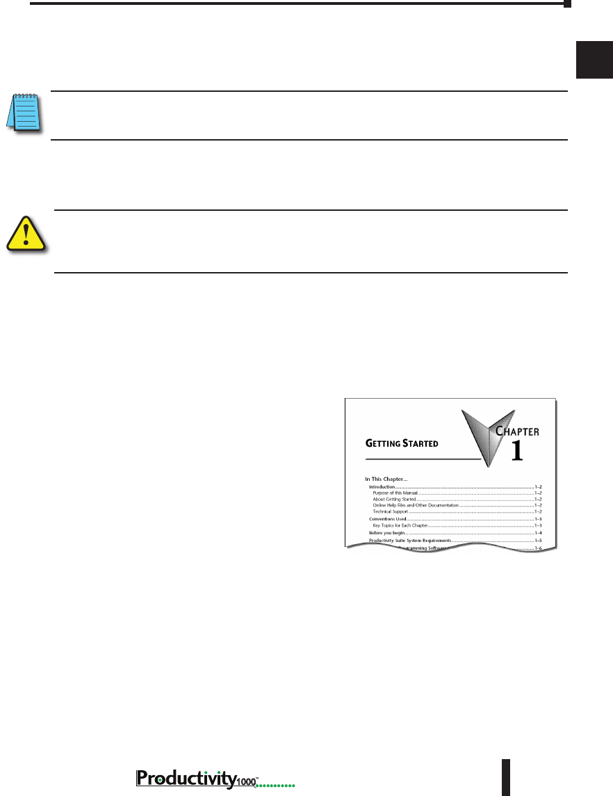
Key Topics for Each Chapter
The beginning of each chapter will list the key
topics that can be found in that chapter.
Chapter 1: Getting Started
1
2
3
4
5
6
7
8
9
10
11
12
13
14
A
B
C
D
1–4 Hardware User Manual, 1st Edition
1000
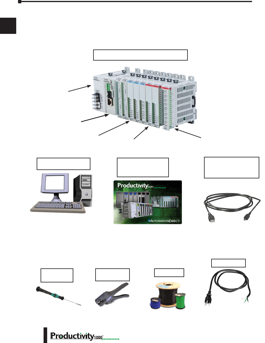
Before you begin...
It is recommended that the following items be available to make this short step-by-step
introduction to the Productivity1000 System go smoothly.
P1-540 CPU Module
Screwdriver
TW-SD-MSL-1
USB-A to Micro USB-B
Programming Cable
PC Running
Windows 7, 8, 8.1 & 10
Hookup Wire
AC Power Cord
P1-01AC Power Supply
Productivity1000 System Example
Wire Strippers
DN-WS
Not available from
Automationdirect.com
Output Modules
Analog Input Modules P1-08TRS Output Module
Download software from our website
at: www.automationdirect.com under
“Programmable Controllers”.
Not available from
Automationdirect.com.
Productivity Suite
Programming Software
PS-PGMSW

Chapter 1: Getting Started
1
2
3
4
5
6
7
8
9
10
11
12
13
14
A
B
C
D
1–5
Hardware User Manual, 1st Edition
1000
Productivity Suite System Requirements
Productivity Suite Windows-based programming software (CD-ROM or web download) works
with Windows 10 or Windows® 8 or 8.1 (Home or Professional), or Windows 7 (Home,
Professional, Ultimate, 32 or 64-bit) or Vista® (Home, Basic, Premium, 32 or 64-bit). Please
check the following requirements when choosing your PC configuration:
• Vista or Windows 7 or later Personal Computer with a Windows 10 or Windows 8,
8.1 OS. Personal Computer (Windows Vista) with an 800 MHz or (Windows 7 &
higher) 1GHz processor (CPU) clock speed recommended; Intel Pentium/Celeron
family or AMD K6/Athlon/Duron family, or compatible processor recommended.
• SVGA 1024x768 pixels resolution (1280 x 1024 pixels resolution recommended).
• 300MB free hard-disk space.
• RAM: Vista or Windows 7 & higher with GUI version 3.0.0.x or higher RAM = 2GB
memory (4GB recommended).
**GUI version 1.10 or lower RAM = 512MB free RAM (1GB recommended).
• CD-ROM or DVD drive for installing software from the CD.
• USB or Ethernet Port for project transfer to CPU.
NOTE: USB or Ethernet cable is also required for communications between PC and CPU.
Chapter 1: Getting Started
1
2
3
4
5
6
7
8
9
10
11
12
13
14
A
B
C
D
1–6 Hardware User Manual, 1st Edition
1000
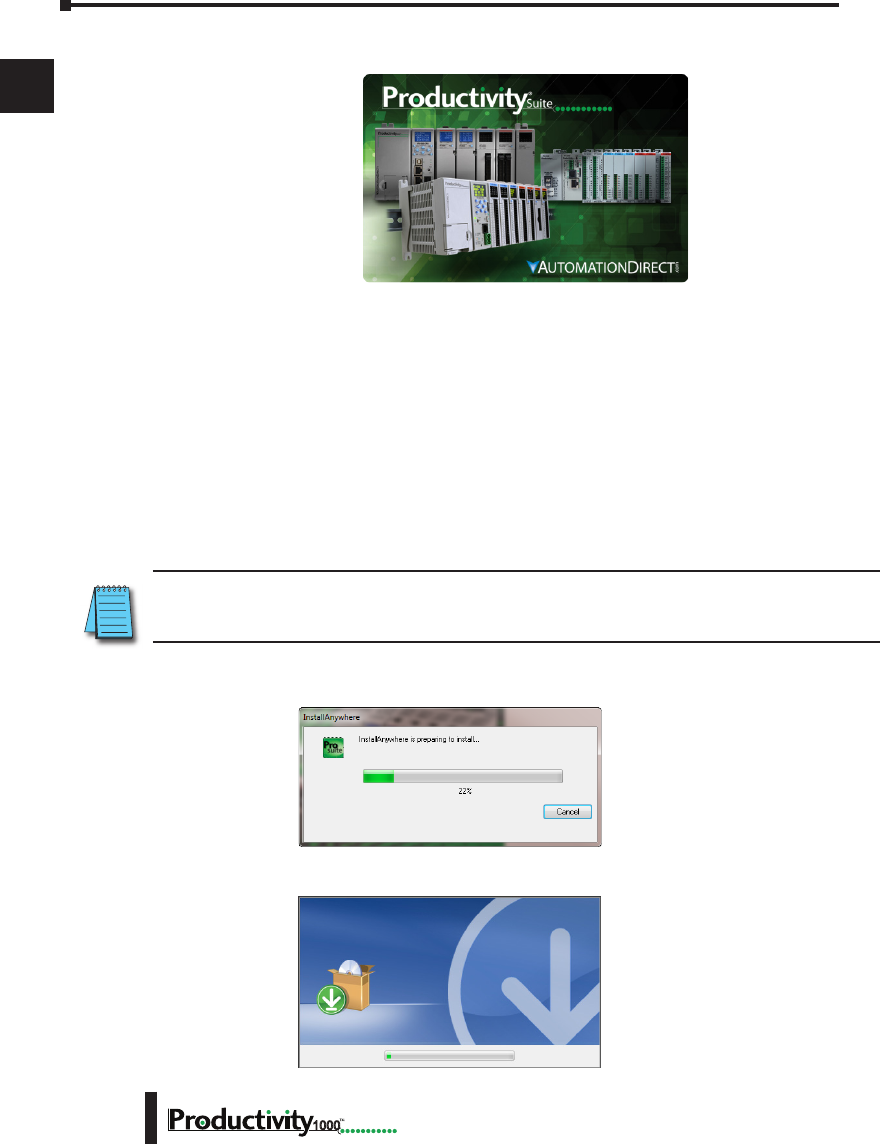
Step 1: Install Programming Software
1. Download the latest version of the Productivity Suite Programming Software from the
Automationdirect website.
Or, if the Productivity Suite Programming Software CD is available, insert it into your PC CD
drive. The install dialog box should appear after a short time.
2. Click on the Start menu icon (bottom left corner of screen), and select Run or for Windows 7
users, type “run” in the search field to locate this application.
• Type the following in the Open text field: D: install.exe, where D: is the drive letter of the
CD drive being used, or browse to the location of the “install.exe” file that was downloaded and
selected this file.
• Select OK and follow the dialog boxes shown throughout the next pages.
NOTE: See the Productivity Suite Installation and Productivity Suite Startup topics for additional details if
needed.
3. The “InstallAnywhere” pop-up (shown below) will appear briefly while the software is
preparing to install.
• The progress pop-up (shown below) will appear while the software is setting up the directory.
Chapter 1: Getting Started
1
2
3
4
5
6
7
8
9
10
11
12
13
14
A
B
C
D
1–7
Hardware User Manual, 1st Edition
1000
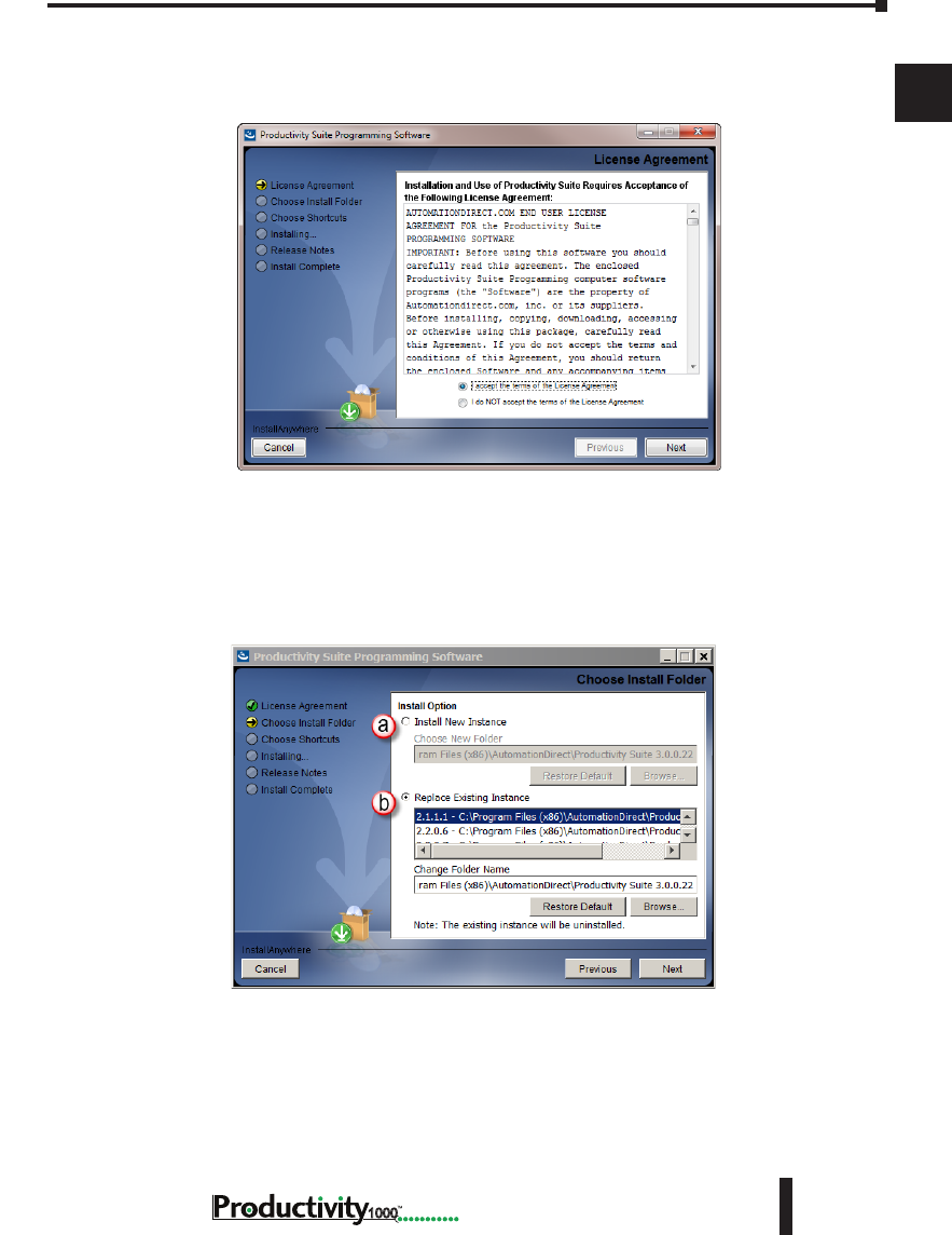
4. Carefully read the software license agreement. If you agree to the terms and conditions of
this agreement, select the “I accept the terms of the License Agreement” and then the “Next”
button.
5. The “Choose Install Folder” window will open next. If this is the first installation of the
Productivity Suite Software on your PC, choose
(a) Install New Instance: This option will install a new instance of the Productivity Suite
software in the default location, C:\Program Files\AutomationDirect\Productivity Suite
<Software Version>; or choose a different one using the Browse button.
If the installer detects a previous version of Productivity Suite on your PC, there is another option
available with this window:
(b) Replace Existing Instance: This option allows you to uninstall the previous version
of the software and install the new version in its place. If this option is chosen the
following window appears. Click “Uninstall” to continue.
Chapter 1: Getting Started
1
2
3
4
5
6
7
8
9
10
11
12
13
14
A
B
C
D
1–8 Hardware User Manual, 1st Edition
1000
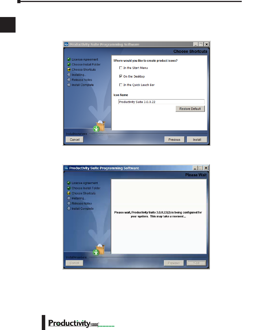
6. Once you have selected the install folder and whether or not to delete any previous
instances, the “Choose Shortcuts” window will appear. If a Shortcut Icon is desired for
the software select the location where the icon will be created. The default location is
“On the Desktop”. Once all selections have been made, click “Install” to begin the installation.
Chapter 1: Getting Started
1
2
3
4
5
6
7
8
9
10
11
12
13
14
A
B
C
D
1–9
Hardware User Manual, 1st Edition
1000
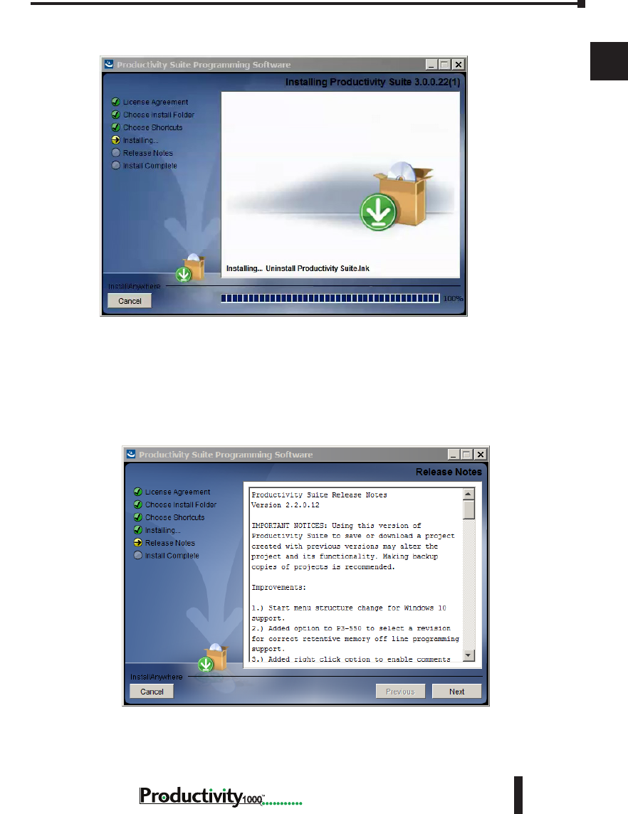
A status window will appear displaying the status of the installation.
7. The next screen to appear contains the Release Notes for this version of the Productivity Suite
software. This is an opportunity to review the software version release notes. You may read
these before selecting the “Next” button.
Chapter 1: Getting Started
1
2
3
4
5
6
7
8
9
10
11
12
13
14
A
B
C
D
1–10 Hardware User Manual, 1st Edition
1000
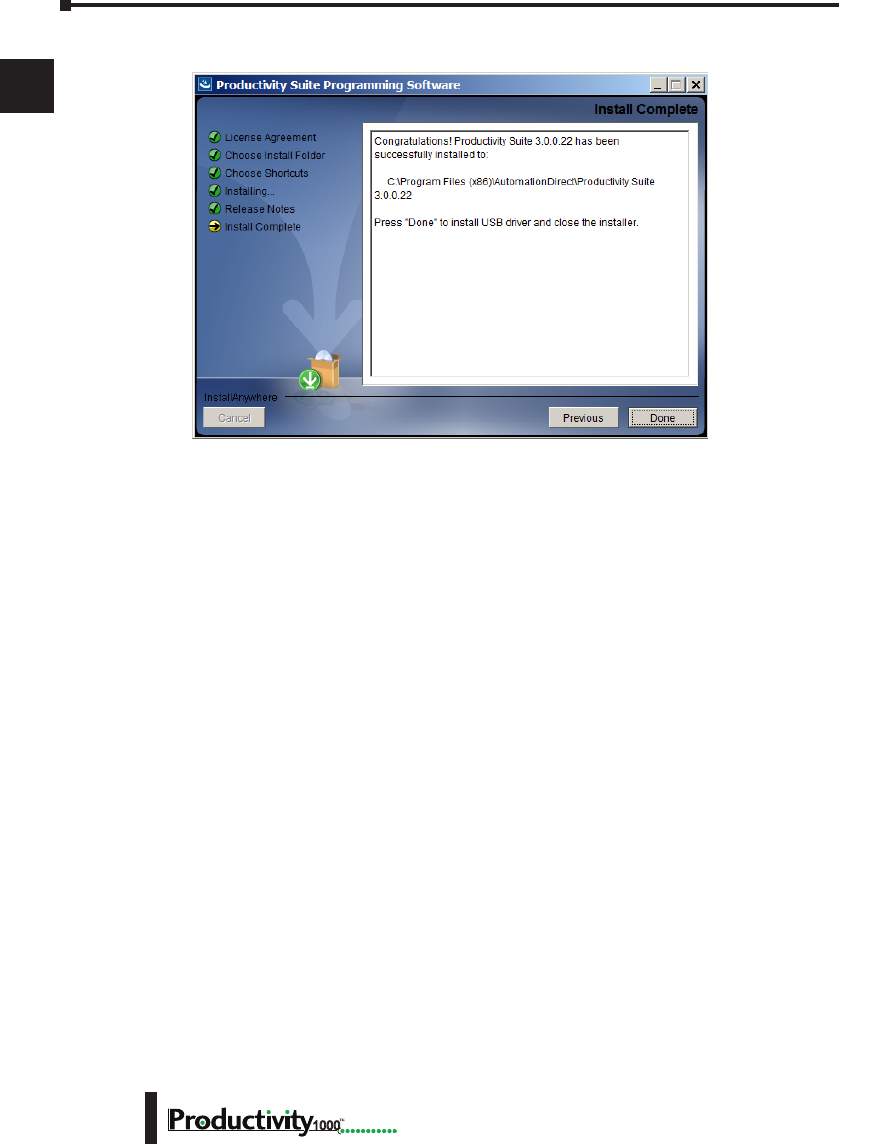
8. The Installation is now complete. Select “Done”.
Chapter 1: Getting Started
1
2
3
4
5
6
7
8
9
10
11
12
13
14
A
B
C
D
1–11
Hardware User Manual, 1st Edition
1000
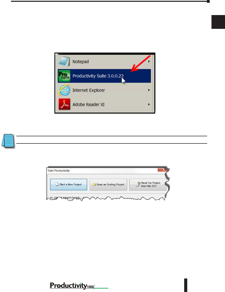
Step 2: Launch Programming Software
After installing the Productivity Suite Programming Software, PS-PGMSW, launch the software
by double clicking the desktop Productivity Suite Icon. Or from the PC’s ‘Start’ menu, slide
the mouse pointer through the menus (start>All Programs>AutomationDirect>Productivity
Suite x.x.x.x>Productivity Suite) to the Productivity Suite Programming Software selection,
and use the left mouse button to click on it.
The Productivity Suite Programming Software will start up and display the Main Window as
shown here.
NOTE: The recommended minimum screen size for the Productivity Suite Software is 1024 X 786 pixels.
Click on the ‘Start a New Project’ in the Start Productivity dialog box to open a programming
window.
Chapter 1: Getting Started
1
2
3
4
5
6
7
8
9
10
11
12
13
14
A
B
C
D
1–12 Hardware User Manual, 1st Edition
1000
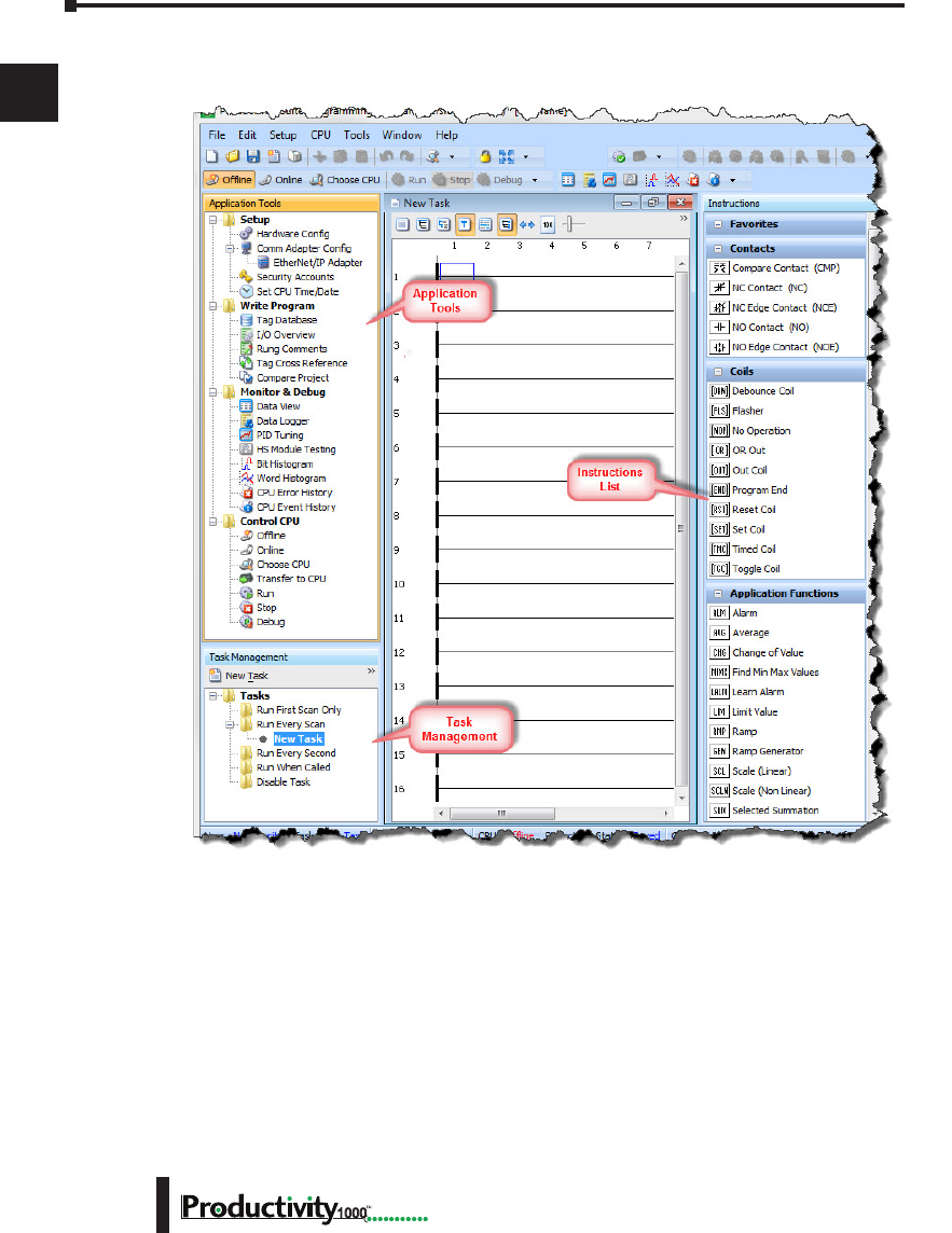
The Programming Window is divided into menus and toolbars that work together to make
project development as simple as possible.
Online Help
It is essential that you use the Productivity Suite online Help to familiarize yourself with the
software. Keep it open on your desktop and refer to it frequently as you build your system.
Click on the toolbar Help button to open the Help file.
Chapter 1: Getting Started
1
2
3
4
5
6
7
8
9
10
11
12
13
14
A
B
C
D
1–13
Hardware User Manual, 1st Edition
1000
Step 3: Install Hardware
The Productivity1000 CPU system components snap together to form a configured CPU
in minutes. See Chapter 5, Installation and Wiring, for more detailed hardware installation
information. What follows are the basic steps:
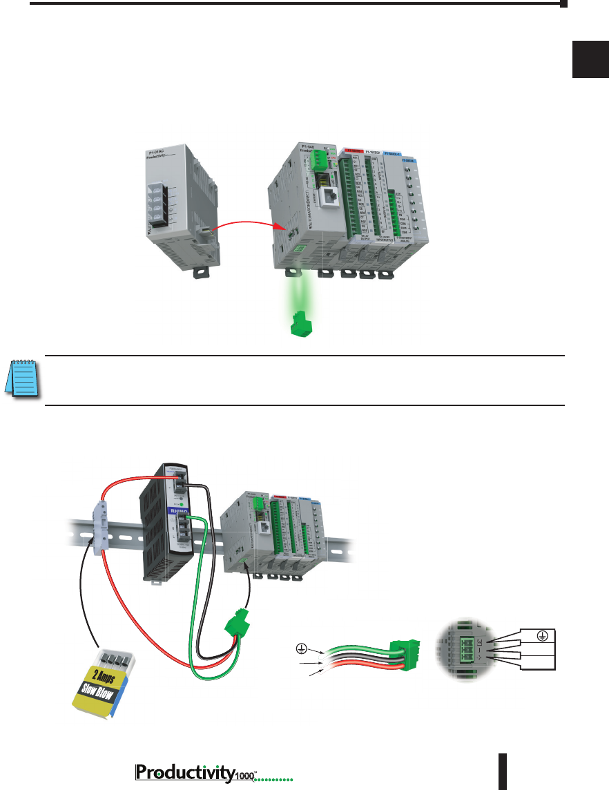
1. Connect power supply to CPU.
NOTE: Optional Power Connector must be removed before connecting P1-01AC Power Supply. This
precludes connection of two separate power supplies.
2. OR using an alternate power source connect directly to CPU Optional Power Connector
terminals.
G
0V
24VDC
G
0V
24VDC
Use ADC
Part # S5062-R
G
0V
24VDC
G
0V
24VDC
Optional Power Connector must be Removed
before P1-01AC Power Supply may be installed
Remove Optional
Power Connector
Align Power Supply
Connector and pilot
pins slide onto
P1 CPU module.
Chapter 1: Getting Started
1
2
3
4
5
6
7
8
9
10
11
12
13
14
A
B
C
D
1–14 Hardware User Manual, 1st Edition
1000
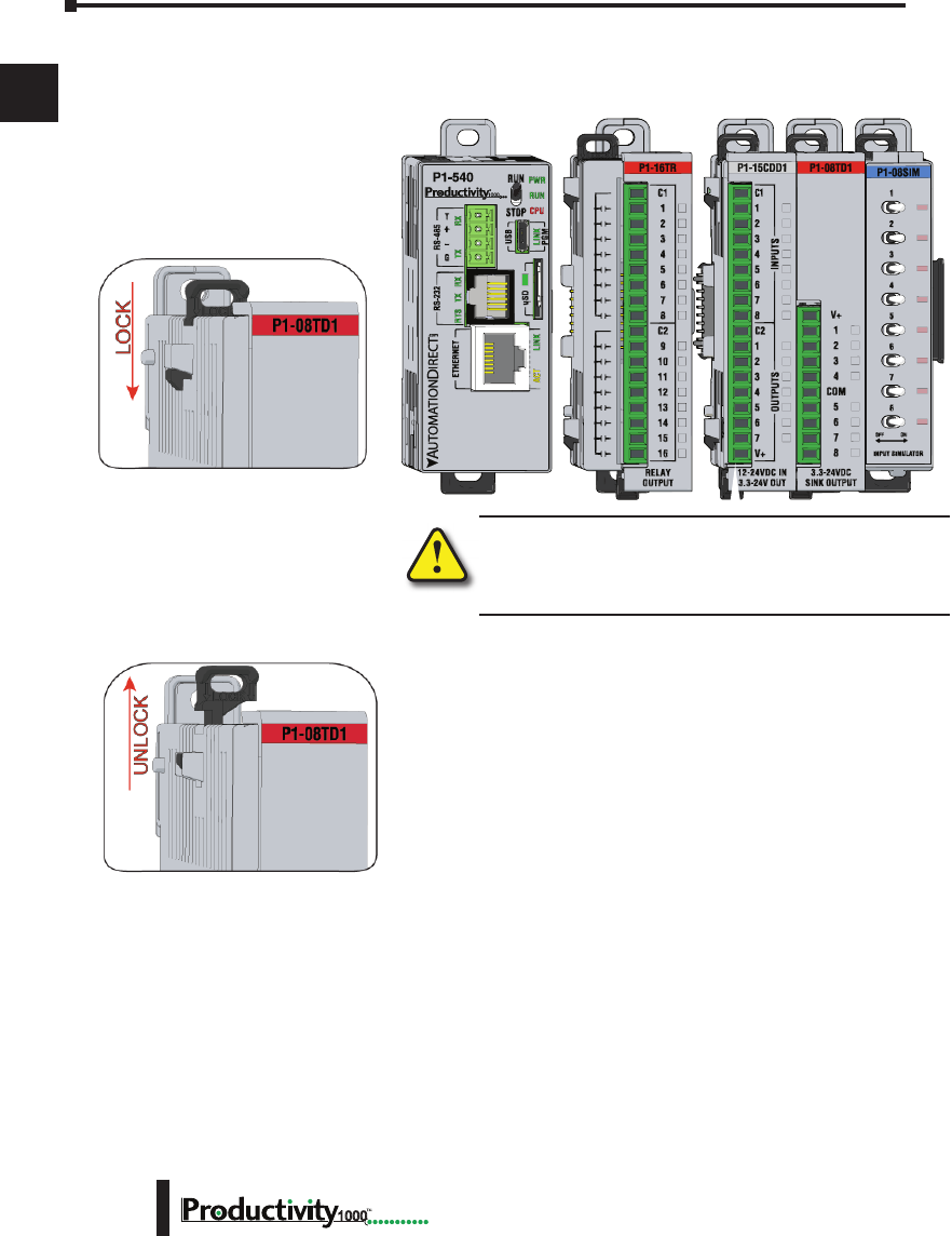
3. Install I/O Modules and engage locking tabs.
WARNING: Explosion hazard – Do not connect, disconnect
modules or operate switches while circuit is live.
Productivity1000 System does not support Hot Swapping!
Step One:
With latch in “locked” position, align
connectors on the side of each module
and stack by pressing together. An
audible click indicates lock is engaged.
Step Two:
To unstack modules, pull locking latch up
into the unlocked position and then pull
modules apart.
Module Installation
WARNING: Do not add or remove modules with
field power applied.
Step One: With latch
in “locked” position, align
connectors on the side of
each module and stack
by pressing together.
Click indicates lock is
engaged.
Step Three: To unstack modules, pull
locking latch up into the unlocked position
and then pull modules apart.
Step Two: Attach field wiring using
the removable terminal block or ZIPLink
wiring system.
LOCK
UNLOCK
WIRE STRIP
LENGTH
MIN
MAX
P1-08TD1
secure after modules
are connected.
Chapter 1: Getting Started
1
2
3
4
5
6
7
8
9
10
11
12
13
14
A
B
C
D
1–15
Hardware User Manual, 1st Edition
1000
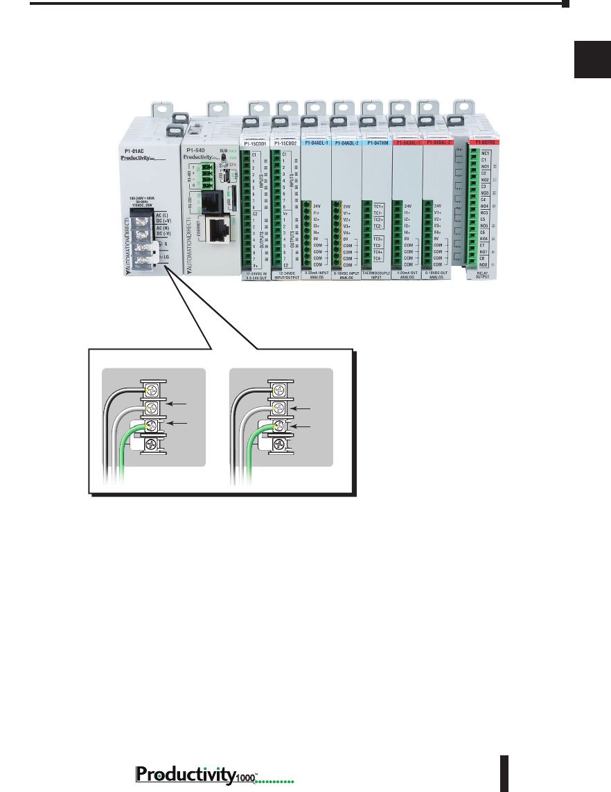
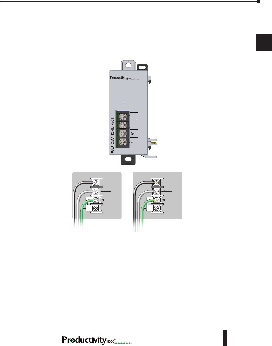
4. Connect appropriate wiring to the power supply (P1-01AC) and I/O (P1-08TRS module) in
this example.
P1-01AC
The power supply and load
are connected through an DC
or AC current source.
Power Hookup
Grounding
A good common ground reference (earth ground) is essential for proper operation of
the Productivity1000 system. One side of all control circuits, power circuits and the
ground lead must be properly connected to earth ground by either installing a ground
rod in close proximity to the enclosure or by connecting to the incoming power system
ground. There must be a single-point ground (i.e. copper bus bar) for all devices in the
enclosure that require an earth ground.
P1 -01A C
AC (L)
AC (N)
G
LG
100-240V 48V A
50-60Hz
125VDC, 20W
DC (+V)
DC (-V)
®
DC (+V)
DC (-V)
GND
LOGIC
GND
AC (L)
AC (N)
GND
LOGIC
GND
125VDC 100–240 VAC
Chapter 1: Getting Started
1
2
3
4
5
6
7
8
9
10
11
12
13
14
A
B
C
D
1–16 Hardware User Manual, 1st Edition
1000
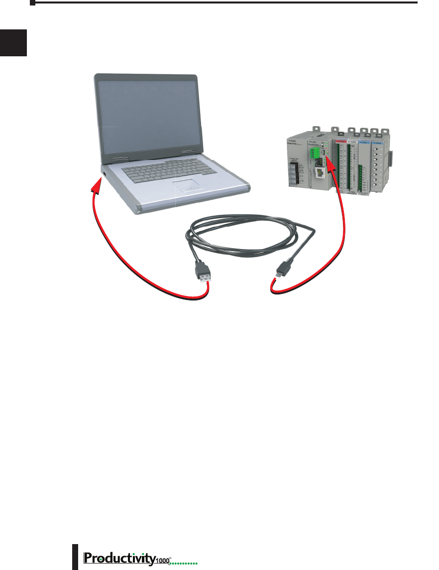
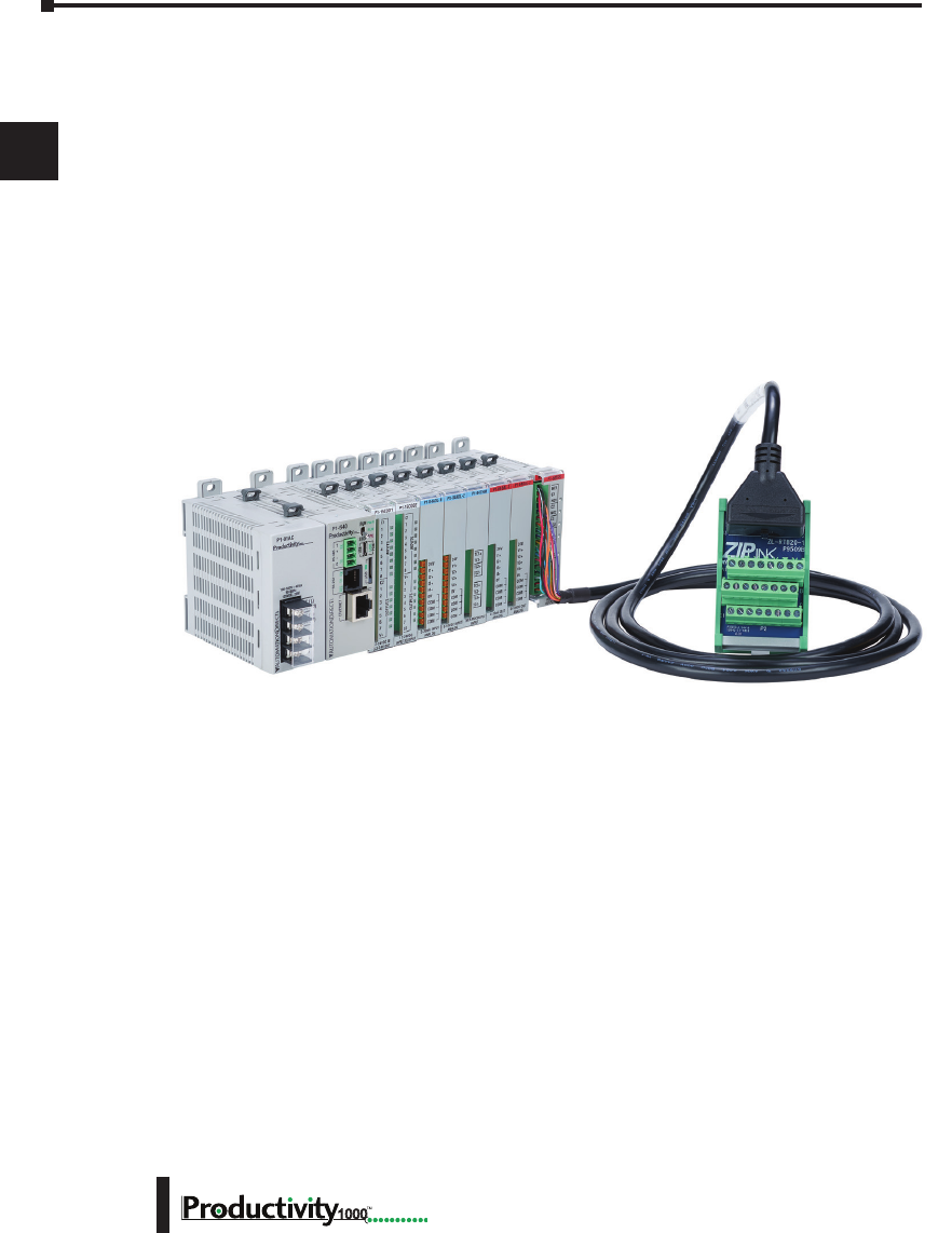
5. Connect USB cable. Use a Micro USB cable with a Type A and Micro Type B connectors as
shown below.

Chapter 1: Getting Started
1
2
3
4
5
6
7
8
9
10
11
12
13
14
A
B
C
D
1–17
Hardware User Manual, 1st Edition
1000
Step 4: Apply Power to CPU
Ensure proper wiring and the correct voltage is available before connecting wiring to the power
supply. Once this is verified, connect power to the power supply. Once power is applied, the
CPU will perform a self evaluation and verification. See Chapters 2 and 5 of this manual for
more power supply and input wiring information.
Chapter 1: Getting Started
1
2
3
4
5
6
7
8
9
10
11
12
13
14
A
B
C
D
1–18 Hardware User Manual, 1st Edition
1000
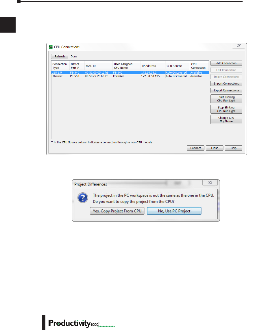
Step 5: Establish PC to CPU Communications
Select “Choose CPU” icon on the CPU Toolbar and the dialog box shown below will appear.
Highlight the installed CPU listed in the dialog box and select “Connect”.
When initially going Online with the CPU, a pop-up window will notify you of a project
difference between the CPU and the PC. Select “No, Use PC Project” command button.
Chapter 1: Getting Started
1
2
3
4
5
6
7
8
9
10
11
12
13
14
A
B
C
D
1–19
Hardware User Manual, 1st Edition
1000
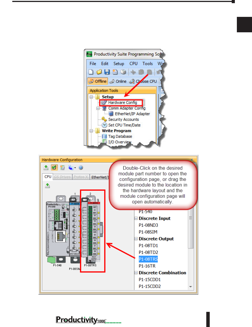
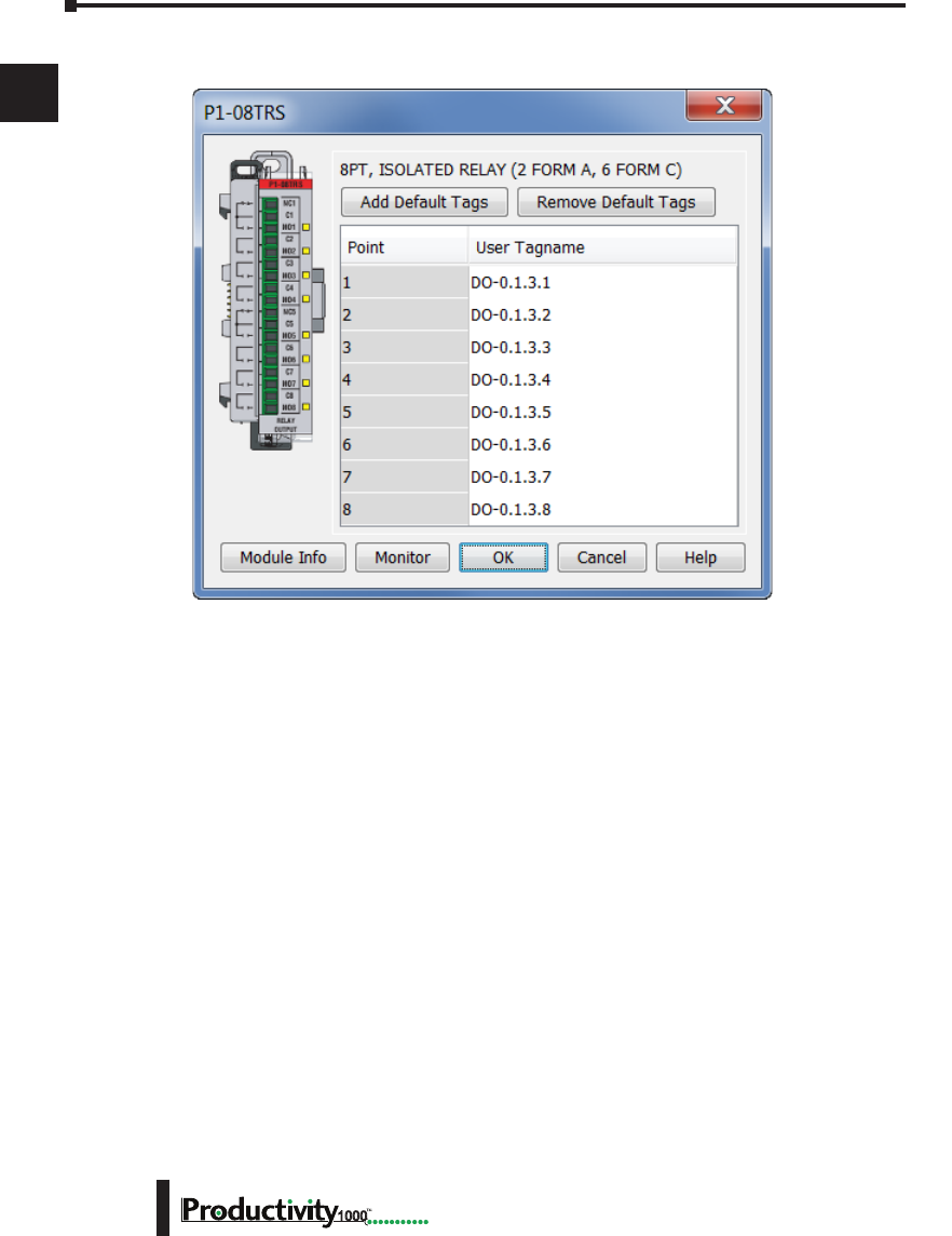
Step 6: Open/Read Hardware Configuration
Before we create a project we must configure the hardware so we’ll have default input and output
tags for use in our project. With the CPU in “STOP” Mode, select Hardware Configuration
under Application Tools and the following screen opens.
Chapter 1: Getting Started
1
2
3
4
5
6
7
8
9
10
11
12
13
14
A
B
C
D
1–20 Hardware User Manual, 1st Edition
1000
This screen shows the user tag names for all eight I/O points. Select “OK”.
Chapter 1: Getting Started
1
2
3
4
5
6
7
8
9
10
11
12
13
14
A
B
C
D
1–21
Hardware User Manual, 1st Edition
1000
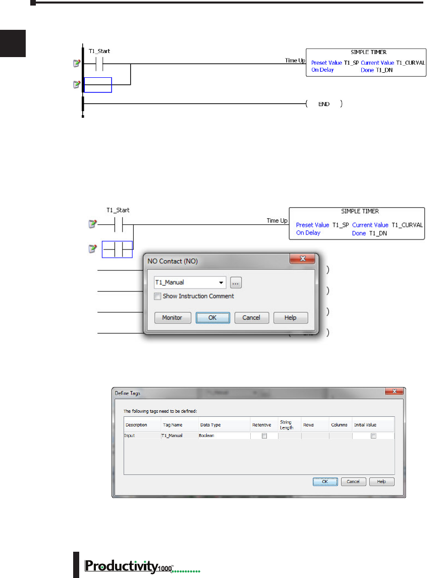
Step 7: Create a Project
We’re going to start by entering a simple ladder logic program in the order that follows.
Rung #1
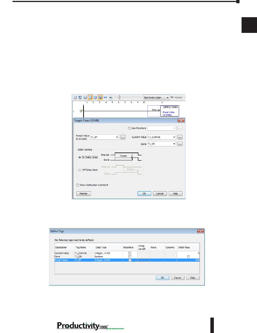
Select the “END” position on Rung #1 with your cursor. From the Instruction List on the
right, scroll down to Counters/Timers section and double click on the Simple Timer (STMR)
instruction. The “Simple Timer” instruction automatically is placed on the selected rung and
the Simple Timer (STMR) dialog box pops up.
1. Enter ‘T1_SP’ into the Preset Value field.
2. Enter ‘T1_CURVAL’ into the Current Value field.
3. Enter ‘T1_DN’ into the Done field.
4. Select “OK”.
The Define Tags dialog box opens. Select OK.
5. Enter preset time value of 300ms into “Initial Value” field for Tag T1_SP.
Chapter 1: Getting Started
1
2
3
4
5
6
7
8
9
10
11
12
13
14
A
B
C
D
1–22 Hardware User Manual, 1st Edition
1000
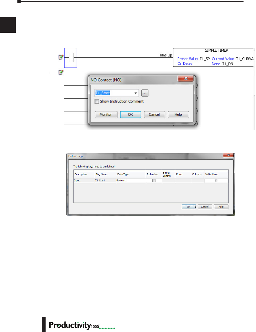
Place the cursor on the first position on Rung #1 as shown below. In the Instruction List
on the right, scroll up to Contacts section and double click on “NO Contact (NO)”. A NO
Contact (NO) is placed at this rung position and a dialog box pops up.
1. Enter ‘T1_Start’ into the text box.
2. Select OK.
The Define Tags dialog box opens. Select “OK”.
Chapter 1: Getting Started
1
2
3
4
5
6
7
8
9
10
11
12
13
14
A
B
C
D
1–23
Hardware User Manual, 1st Edition
1000
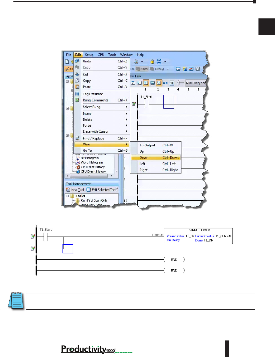
With the cursor on Rung #1, to the right of contact ‘T1_Start’, we are going to begin drawing
a branch circuit. Under the Edit drop down menu, select “Wire”, then select “Down”. Notice
that a wire has been added.
NOTE: There is also a wire Erase With Cursor tool in the Edit drop down menu that is used to erase any
lines that were created using the Wire tools.
Chapter 1: Getting Started
1
2
3
4
5
6
7
8
9
10
11
12
13
14
A
B
C
D
1–24 Hardware User Manual, 1st Edition
1000
Next we’ll draw a wire to the left. Under the Edit drop down menu, select “Wire”, then select
“Left”.
Next we’ll add another normally-open contact. Place the box cursor on the first position on the
newly created SubRung #1. From the Instruction List click & drag a Contact (NO) into this
box. A NO Contact (NO) dialog box pops up.
1. Enter ‘T1_Manual’ into the field.
2. Select “OK”.
The Define Tags dialog box opens. Select “OK”.
Chapter 1: Getting Started
1
2
3
4
5
6
7
8
9
10
11
12
13
14
A
B
C
D
1–25
Hardware User Manual, 1st Edition
1000
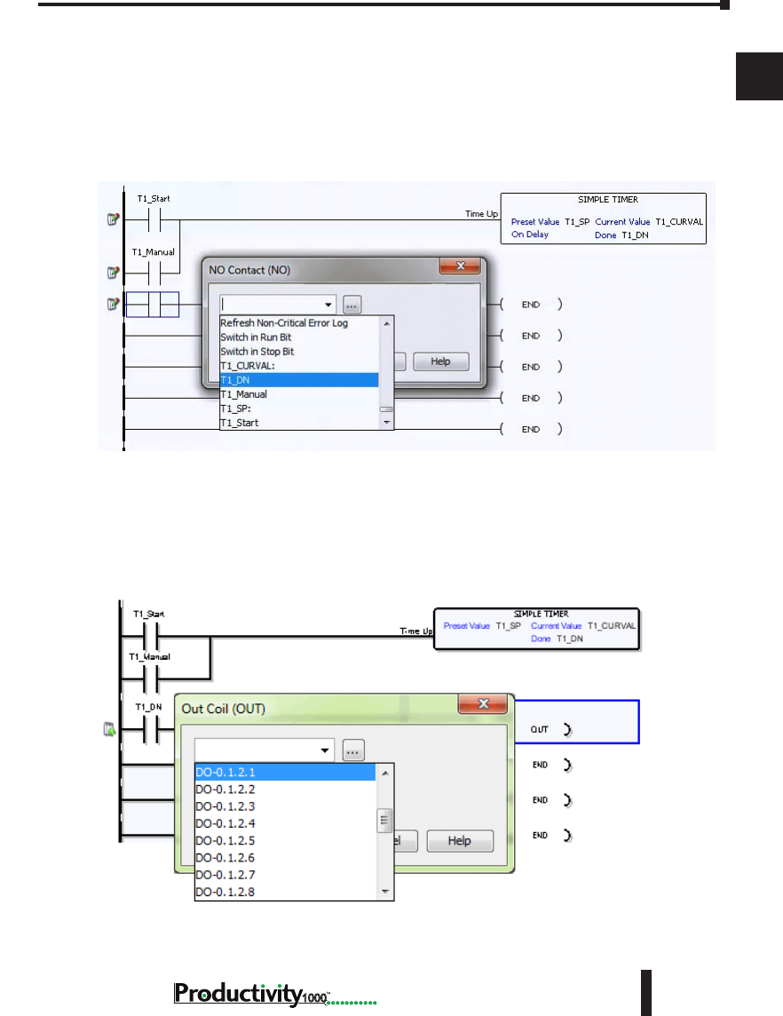
Rung #2
Next we’ll add another normally-open contact at the start of Rung #2. Click & drag a “NO
Contact (NO)” into this box. A NO Contact (NO) dialog box pops up.
1. In the empty tag field press the down arrow on the right to open a drop-down list; scroll down
and select ‘T1_DN’.
2. Select “OK”.
Next we’ll add an Out coil at the end of the rung. Place the cursor at the end of the rung.
From the Instructions list Coil section, double click on an “Out Coil (OUT)”. An Out Coil
(OUT) is placed on the rung and a dialog box pops up.
1. In the tag field press the down arrow on the right to open a drop-down list; scroll down and select
‘DO-0.1.2.1’.
2. Select OK.
Chapter 1: Getting Started
1
2
3
4
5
6
7
8
9
10
11
12
13
14
A
B
C
D
1–26 Hardware User Manual, 1st Edition
1000
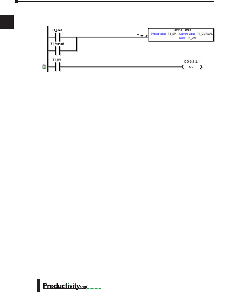
The ladder program now looks like this. When either of the T1 contacts are energized, the
timer starts. When it times out, contact T1_DN energizes and turns on the rung 2 output.
Chapter 1: Getting Started
1
2
3
4
5
6
7
8
9
10
11
12
13
14
A
B
C
D
1–27
Hardware User Manual, 1st Edition
1000
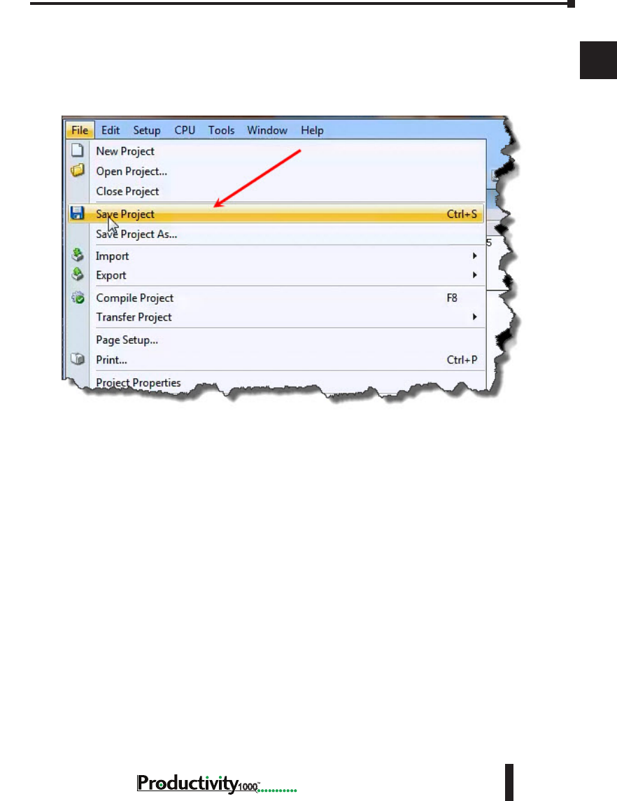
Step 8: Save Project
Save the project by opening the File drop-down menu and selecting Save Project.
Chapter 1: Getting Started
1
2
3
4
5
6
7
8
9
10
11
12
13
14
A
B
C
D
1–28 Hardware User Manual, 1st Edition
1000
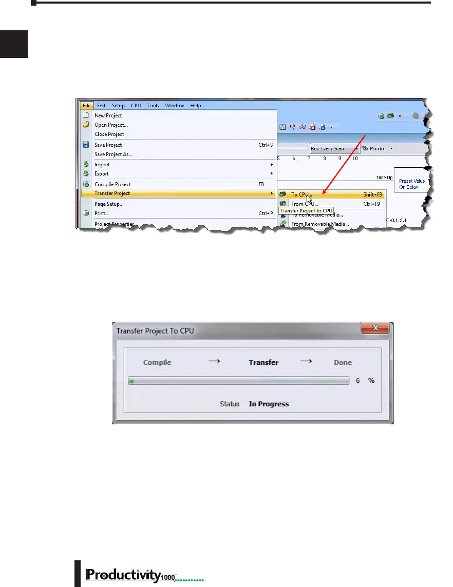
Step 9: Write Project to CPU
Next we will transfer the project to the CPU. Transfer Project is accessed by selecting Transfer
Project from the File Menu.
Select “To CPU” from the Transfer Project menu.
The project will then be Transferred to the CPU from the PC. During the transfer a status
window will open displaying the process.
Chapter 1: Getting Started
1
2
3
4
5
6
7
8
9
10
11
12
13
14
A
B
C
D
1–29
Hardware User Manual, 1st Edition
1000
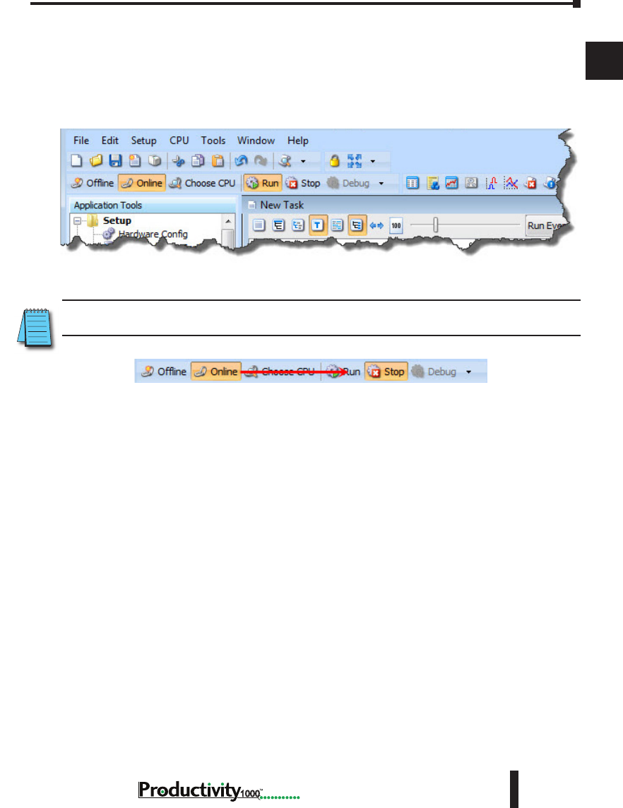
Step 10: Place CPU in RUN Mode
Next, verify the Run/Stop switch on the CPU faceplate is placed in the Run position and
then place the CPU in RUN mode on the Productivity Software Toolbar so the ladder logic
program executes.
NOTE: If the Run/Stop switch on the CPU is in the Stop position, the Run button on the Programming
Software Toolbar will be disabled.
Chapter 1: Getting Started
1
2
3
4
5
6
7
8
9
10
11
12
13
14
A
B
C
D
1–30 Hardware User Manual, 1st Edition
1000
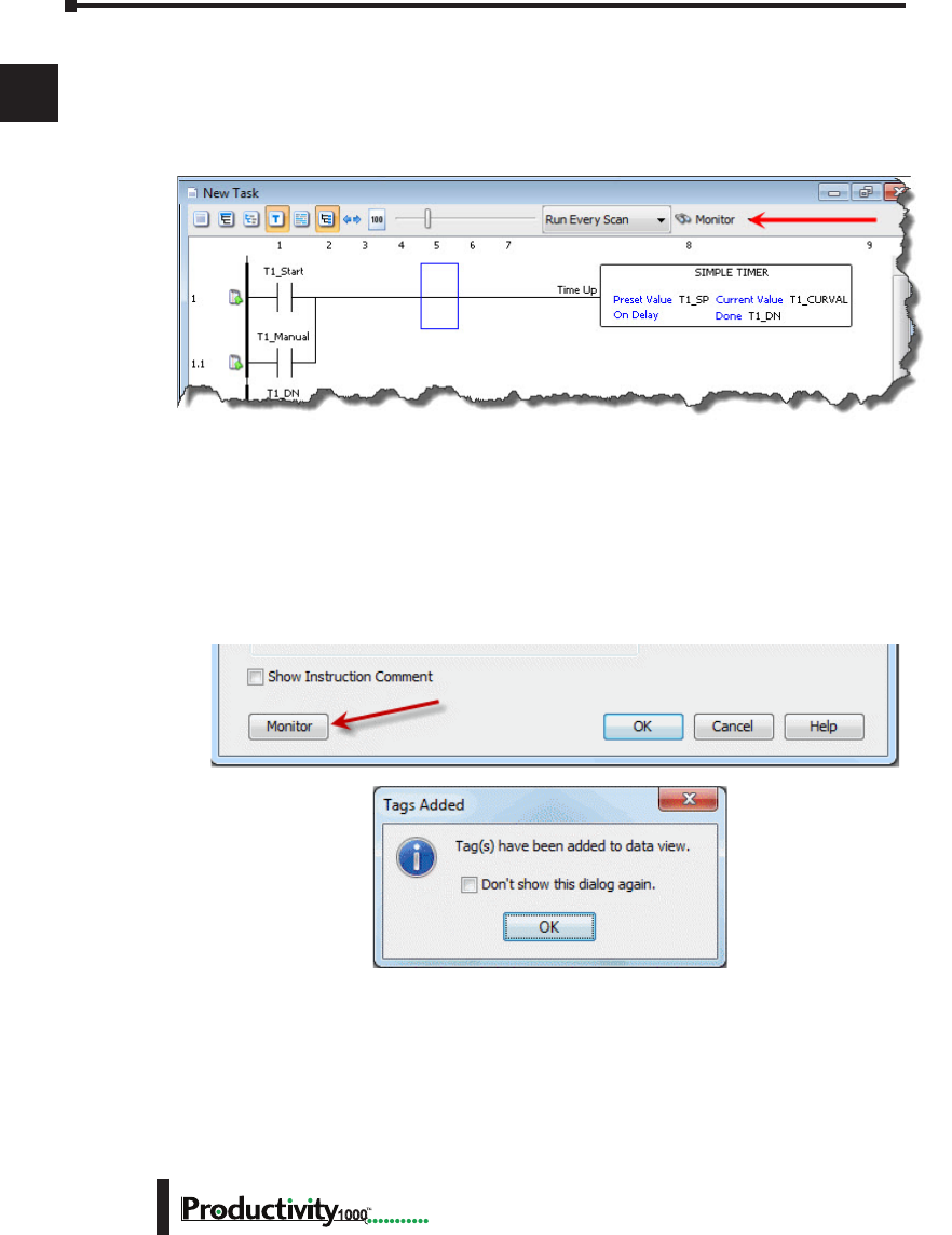
Step 11: Test the Project Using Monitor Mode
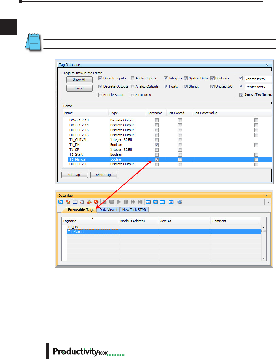
In this next step, use the Monitor Mode and Data View to test the ladder logic program. Select
Monitor Mode from the top of the Ladder Logic screen to display the status of Boolean and
Integer Tags.
Using Data View, the Tag values can be viewed or manipulated for testing the project. The
Data View window can be accessed by selecting Data View from the Tools Menu of the Main
Menu.
For the Simple Timer Instruction, a Monitor button is provided that, when selected, will load
the tags associated with the instruction into Data View.
Chapter 1: Getting Started
1
2
3
4
5
6
7
8
9
10
11
12
13
14
A
B
C
D
1–31
Hardware User Manual, 1st Edition
1000
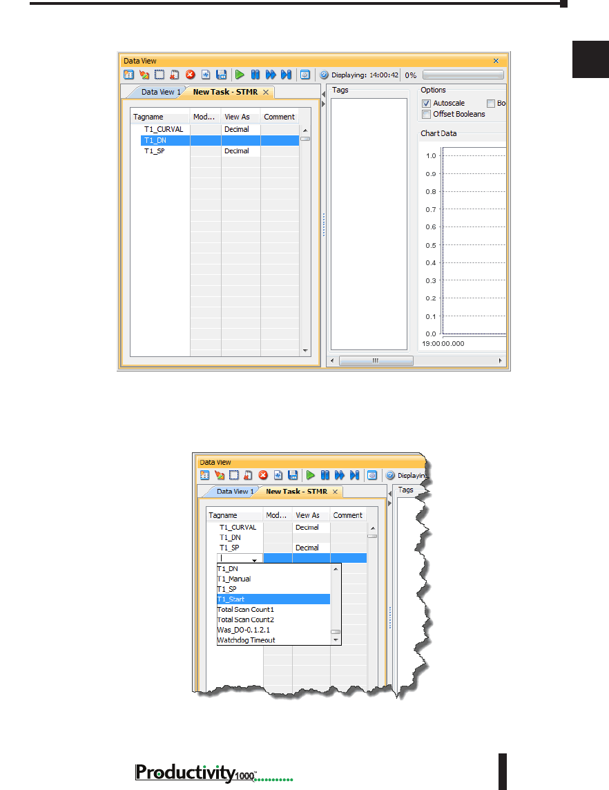
The tags will be placed in a separate Tab titled New Task - STMR as seen below.
The remaining tagnames in the Ladder Logic can be added to the Data View window by
clicking on a blank area in the Tagname column. This will display a drop down menu where
the tags can be selected. Scroll down the list and select the tags to be added.
Chapter 1: Getting Started
1
2
3
4
5
6
7
8
9
10
11
12
13
14
A
B
C
D
1–32 Hardware User Manual, 1st Edition
1000
Once all of the tagnames have been added, they can now be monitored and manipulated. See
the Data View help file topic for additional details if needed.
NOTE: Force must be enabled for a Tag in the Tag Database before Force can be used in Data View.

In This Chapter...
Overview ....................................................................................................................2–2
P1-01AC Power Supply .............................................................................................. 2–3
Productivity1000 CPU Module ..................................................................................2–7
I/O Modules Overview ............................................................................................2–15
Discrete I/O Modules ..............................................................................................2–16
SpecificationS
Chapter
Chapter
Chapter
2
2
2
Chapter 2: Specifications
1
2
3
4
5
6
7
8
9
10
11
12
13
14
A
B
C
D
1000 Hardware User Manual, 1st Edition
2–2
Overview
Hardware
The Productivity1000 system of components is designed to combine practical PLC
features in a compact and expandable design, with a simple-to-use philosophy. A powerful
Productivity1000 PLC can be expanded with the addition of easily connected I/O modules.
The Productivity1000 PLC system does not require a mounting base. The Productivity1000
PLC and I/O modules are connected together via an expansion port on the right side of the
PLC case. A variety of I/O modules are available for flexible and optimal system configuration.
The Productivity1000 PLC is supported by the robust and powerful Productivity Suite
programming software; designed with an easy-to-use instruction set that covers all applications
suitable for this class of PLC. The CPU stores and executes the user designed program.
Chapter 2: Specifications
1
2
3
4
5
6
7
8
9
10
11
12
13
14
A
B
C
D
2–3
Hardware User Manual, 1st Edition,
1000
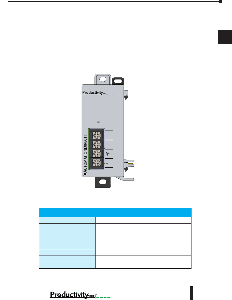
P1-01AC Power Supply
The P1-01AC power supply module requires power from an external 120–240 VAC or
125VDC source. When the power supply is connected to the P1-540 CPU, it will provide
required power to the Productivity1000 CPU.
No Power Budgeting
Any combination of I/O modules may be installed in any slot without power budget
considerations.
Terminal Block Specications
Number of positions
4 screw terminals
Wire Range
22–12 AWG (0.324 to 3.31 mm²)
Solid / Stranded conductor
3/64 in (1.2 mm) Insulation Max.
1/4 in (6–7 mm) Strip Length
Conductors
Use copper conductors, 75°C or equivalent
Screw Driver
1/4 in (6.5 mm) maximum
Screw Size
M3
Screw Torque
7–9 lb·in (0.882–1.02 N·m)
P1-01AC
P1-01AC
AC (L)
AC (N)
G
LG
100-240V 48VA
50-60Hz
125VDC, 20W
DC (+V)
DC (-V)
®
*Recommended screw driver P/N: TW-SD-MSL-2
Chapter 2: Specifications
1
2
3
4
5
6
7
8
9
10
11
12
13
14
A
B
C
D
1000 Hardware User Manual, 1st Edition
2–4
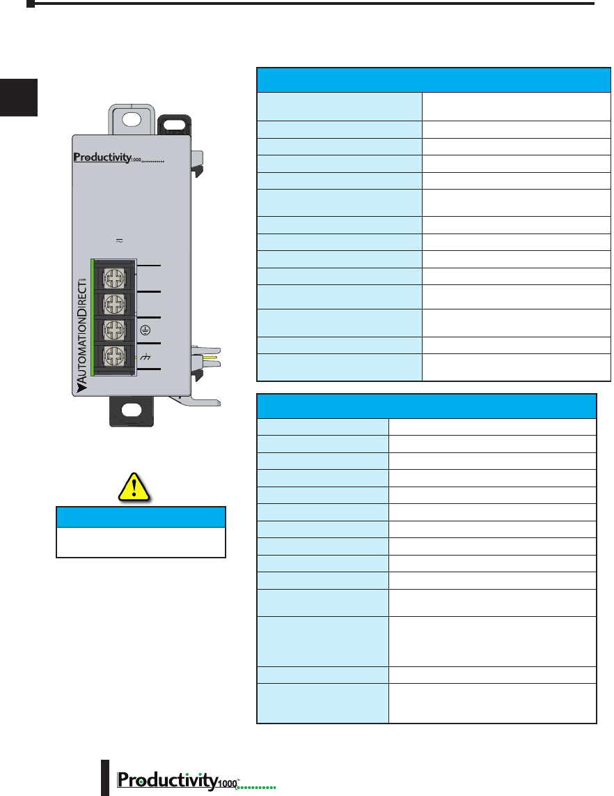
P1-01AC
*See CE Declaration of Conformity for details.
P1-01AC Power Supply
IMPORTANT!
User Specications
Input Voltage Range (Tolerance)
100–240 VAC (-15% / +10%)
125VDC (-15% / +20%)
Rated Operating Frequency
50 to 60Hz with ±5% tolerance
Maximum Input Power
48VA (AC) 20W(DC)
Cold Start Inrush Current
21A
Maximum Inrush Current (Hot Start)
21A
Input Fuse Protection (Internal)
Micro fuse 250V, 1A
Non-replaceable
Efciency
75%
Output Voltages
24VDC, 0.67 A
Maximum Output Power
16W
Isolated User 24VDC Output
None
Output Protection for Over Current,
Over Voltage, and Over Temperature
Self resetting
Under Input Voltage Lock-out
40–75 VAC - 24VDC On @ 76.15 VAC
55–99 VDC - 24VDC On @ 100.2 VDC
Input Transient Protection
Varistor, plus input choke and lter
Operating Design Life
10 years at full load at 40°C ambient and
5 years at 60°C ambient
General Specications
Operating Temperature
0º to 60ºC (32º to 140ºF)
Storage Temperature
-20º to 70ºC (-4º to 158ºF)
Humidity
5 to 95% (non-condensing)
Environmental Air
No corrosive gases permitted
Vibration
IEC60068-2-6 (Test Fc)
Shock
IEC60068-2-27 (Test Ea)
Insulation Resistance
>10MΩ @ 500VDC
Heat Dissipation
5000mW
Enclosure Type
Open Equipment
Voltage Withstand (dielectric)
2100VDC applied for 2 seconds
Module Location
Power Supply latches to CPU in the module
stacking Productivity1000 System.
EU Directive
See the “EU Directive” topic in the Productivity
Suite Help File. Information can also be
obtained at:
www.productivity1000.com
Weight
146g (5.1 oz)
Agency Approvals
UL 61010-2-201 le E139594, Canada & USA
CE (EN61131-2 EMC and EN61010-2-201
Safety)*
P1-01AC
AC (L)
AC (N)
G
LG
100-240V 48VA
50-60Hz
125VDC, 20W
DC (+V)
DC (-V)
®
Hot-Swapping Information
Note: This device cannot be Hot
Swapped.
Chapter 2: Specifications
1
2
3
4
5
6
7
8
9
10
11
12
13
14
A
B
C
D
2–5
Hardware User Manual, 1st Edition,
1000
Power Connections
Grounding
A good common ground reference (earth ground) is essential for proper operation of the Productivity1000
system. One side of all control circuits, power circuits and the ground lead must be properly connected to
earth ground by either installing a ground rod in close proximity to the enclosure or by connecting to the
incoming power system ground. There must be a single-point ground (i.e. copper bus bar) for all devices in
the enclosure that require an earth ground.
Power Hookup
Grounding
A good common ground reference (earth ground) is essential for proper operation of
the Productivity1000 system. One side of all control circuits, power circuits and the
ground lead must be properly connected to earth ground by either installing a ground
rod in close proximity to the enclosure or by connecting to the incoming power system
ground. There must be a single-point ground (i.e. copper bus bar) for all devices in the
enclosure that require an earth ground.
P1-01AC
AC (L)
AC (N)
G
LG
100-240V 48VA
50-60Hz
125VDC, 20W
DC (+V)
DC (-V)
®
+V
-V
GND
LOGIC
GND
AC (L)
AC (N)
GND
LOGIC
GND
125VDC 100–240 VAC
P1-01AC
Chapter 2: Specifications
1
2
3
4
5
6
7
8
9
10
11
12
13
14
A
B
C
D
1000 Hardware User Manual, 1st Edition
2–6
P1-540 RUN
STOP
PWR
RUN
CPU
REMOTE I/O
RS-232 RS-485
10/100
ETHERNET
ACT LINK
G
-
+
T
LINK ACT
PGM
LINK
RXTXTXRTSRX
USB
µSD
®
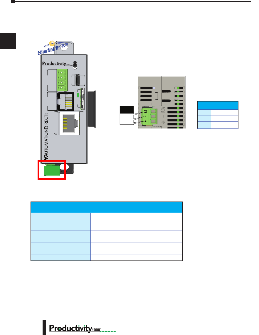
P1-540
Productivity1000 Alternate Power Supply Connection *
All Productivity1000 CPUs require 24VDC input power. When using an alternate 24VDC power
source, connect wiring to the bottom removable terminal block as shown below.
Removable connector included.
Spare connectors available
(part no. PCON-KIT).
Pin Signal
LG
Ground
–
24V DC –
+
24V DC +
Removable Terminal Block Specifications
Part Number P1-PWRCON (Included in PCON-KIT)
Number of Positions 3 Screw Terminals
Pitch 3.5 mm
Wire Range 28–12 AWG Solid Conductor
30–12 AWG Stranded Conductor
Screw Driver Width 1/8 in (3.175 mm) Maximum
Screw Size M2.5
Screw Torque 4.5 lb·in (0.51 N·m)
Productivity1000 Power Supplies
All Productivity1000 PLC CPUs require 24VDC input power from either a P1000
power supply or other 24VDC ±2% external power supply.
Power supply snaps onto the P1000 CPU and will supply power to the PLC CPU
and I/O modules.
• P1-01AC: AC Input 85–132 / 170–264 VAC, 8W (power for CPU and up to
8 modules)
LG
-
+
Power
Terminal
* If you do not use a Productivity1000 power supply (P1-01AC), then use a power supply that has transformer isolation. Use different 24VDC supplies for the
CPU and inductive loads to keep the CPU power clean and free of voltage spikes caused by switching solenoids, motors and relay coils.
* Recommended Fuse: 2A Slow Blow
Removable Terminal Block Specications
Part Number
PCON-KIT (Includes power terminal block)
Number of Positions
3 Screw Terminals
Pitch
3.5 mm
Wire Range
28–16 AWG Solid Conductor
28–16 AWG Stranded Conductor
Screw Driver
1/8 inch (3.175 mm) Maximum
Screw Size
M2
Screw Torque
1.7 lb·in (0.4 N·m)
Chapter 2: Specifications
1
2
3
4
5
6
7
8
9
10
11
12
13
14
A
B
C
D
2–7
Hardware User Manual, 1st Edition,
1000
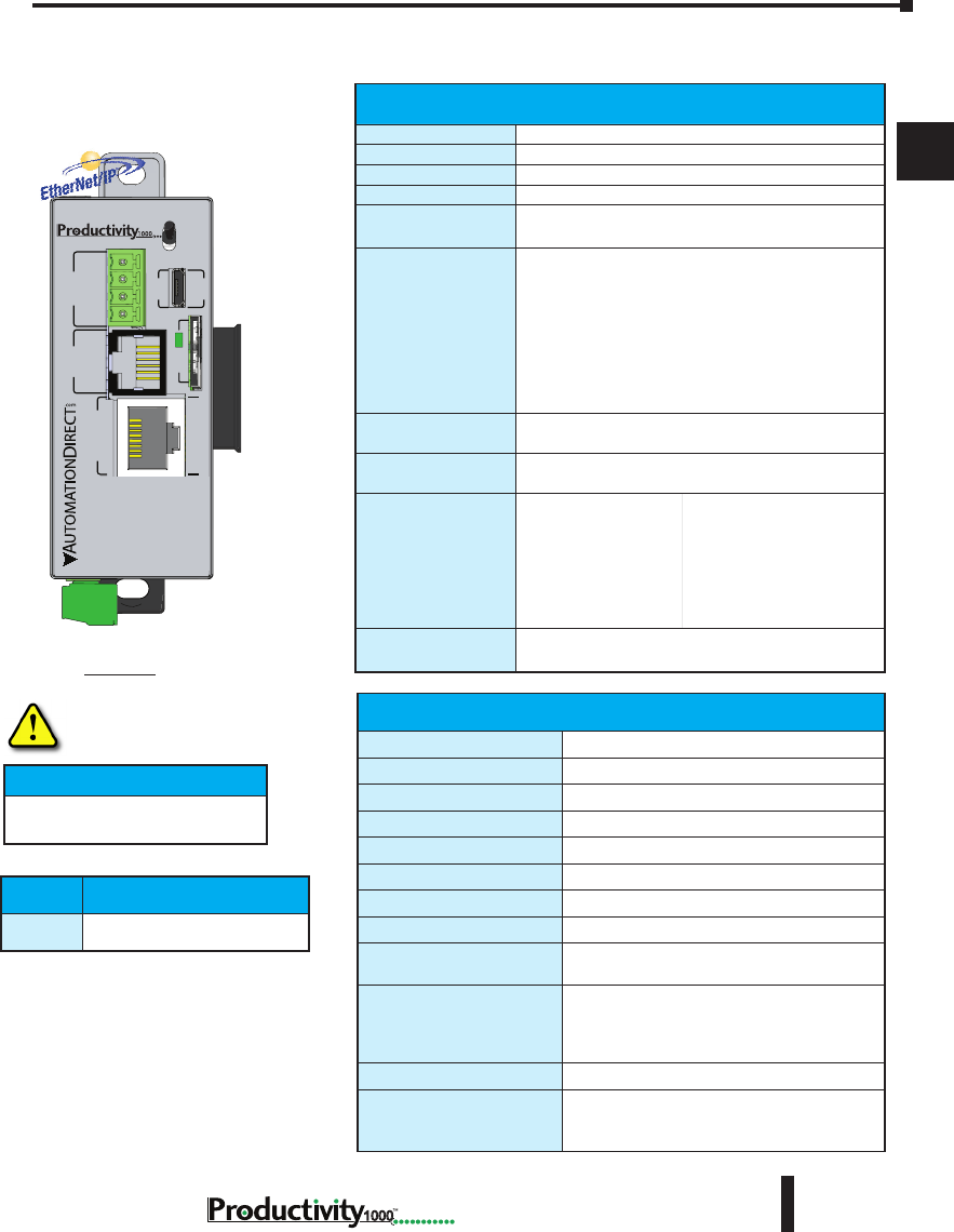
Hot-Swapping Information
Note: This device cannot be Hot
Swapped.
IMPORTANT!
* If you do not use a Productivity1000 power supply
(P1-01AC), then use a power supply that has transformer
isolation. Use different 24VDC supplies for the CPU and
inductive loads to keep the CPU power clean and free of
voltage spikes caused by switching solenoids, motors and
relay coils.
P1-540 RUN
STOP
PWR
RUN
CPU
REMOTE I/O
RS-232 RS-485
10/100
ETHERNET
ACT LINK
G
-
+
T
LINK ACT
PGM
LINK
RXTXTXRTSRX
USB
µSD
®
Productivity1000 CPU Module
P1-540 CPU Specifications
P1-540
General Specications
Operating Temperature
0º to 60ºC (32º to 140ºF)
Storage Temperature
-20º to 70ºC (-4º to 158ºF)
Humidity
5 to 95% (non-condensing)
Environmental Air
No corrosive gases permitted
Vibration
IEC60068-2-6 (Test Fc)
Shock
IEC60068-2-27 (Test Ea)
Heat Dissipation
3810mW
Enclosure Type
Open Equipment
Module Location
Controller connector on the side of the power
supply in a Productivity1000 System.
EU Directive
See the “EU Directive” topic in the Productivity
Suite Help File. Information can also be
obtained at:
www.productivity1000.com
Weight
136g (4.8 oz)
Agency Approvals
UL 61010-2-201 le E139594, Canada & USA
CE (EN61131-2 EMC and EN61010-2-201
Safety)*
*See CE Declaration of Conformity for details.
CPU Productivity Suite
P1-540 Version 3.0 or later
CPU Specications*
User Memory
50MB (Includes program, data and documentation)
Memory Type
Flash and Battery Backed RAM
Retentive Memory
500kB
Scan Time
1.3 ms (1K Boolean, 128 I/O)
External Power
Voltage Range*
24VDC ±2% @ 5W
plus 1.25 W per additional I/O module
Communications;
4 Integrated Ports
USB IN: Programming, Monitoring, Debug, Firmware
ETHERNET: (10/100 Mbps Ethernet) Programming,
Monitoring, Debug, Firmware, Email SMTP Client,
Modbus TCP Client (16 Servers) and Server (16
Clients), EtherNet/IP Scanner (32) and Adapter (4),
Custom Protocol over Ethernet, ProNET.
RS-232: (RJ12, 1200–115.2k baud) ASCII, Modbus
RS-485: Removable Terminal Included,
(1200–115.2k baud) ASCII, Modbus RTU
Data Logging/Project
Transfer
microSD card slot
Hardware Limits
of System
128 Hardware I/O Points: All 16-point I/O Modules
Instruction Types
Application Functions
Array Functions
Counters/Timers
Communications
Data Handling
Drum Sequencers
Math Functions
PID
Program Control
String Functions
System Functions
Contacts
Coils
Real Time Clock
Accuracy
±2s per day typical at 25°C
±10s per day maximum at 60°C
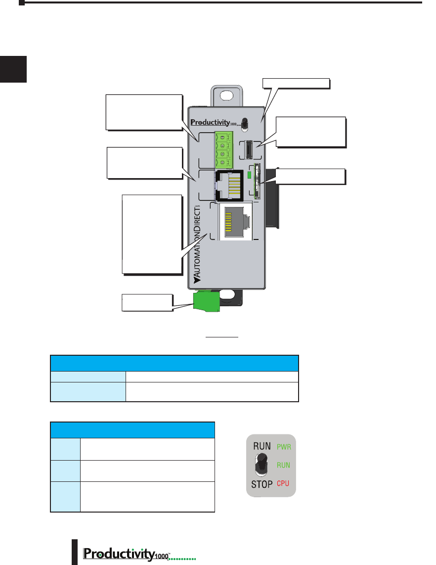
Chapter 2: Specifications
1
2
3
4
5
6
7
8
9
10
11
12
13
14
A
B
C
D
1000 Hardware User Manual, 1st Edition
2–8
Productivity1000 CPU Module
P1-540
CPU Run/Stop Switch Specications
RUN position
Executes user program, run-time edits possible.
STOP position
Does not execute user program, normal program load
position.
P1-540 Module Faceplate Layout
CPU Status Indicators
PWR
Green LED is illuminated when power is
ON
RUN
Green LED is illuminated when CPU is in
RUN mode
CPU
Red LED is illuminated during power ON
reset, power down, or watch-dog time-out.
CPU Front Panel
P1-540 RUN
STOP
PWR
RUN
CPU
REMOTE I/O
RS-232 RS-485
10/100
ETHERNET
ACT LINK
G
-
+
T
LINK ACT
PGM
LINK
RXTXTXRTSRX
USB
µSD
™
External Power
- 24VDC
Micro USB 2.0 (Type B)
- Programming
- Online monitoring
- Firmware/Debug
RS-485 Serial Port
- Modbus/ASCII
(master peripheral device
or multiple slave devices)
using the same protocol
RS-232 Serial Port (RJ12)
- Modbus/ASCII
(master or slave)
peripheral device
CPU Status Indicators
microSD Port
- removable flash memory
10/100 MB
Ethernet Port
- Programming
- Online monitoring
- Email (SMTP client)
- Ethernet IP Client
and Server
- Modbus TCP Client
and Server
- Custom Protocol
over Ethernet
- ProNet
CPU Status Indicators
PWR Green LED is illuminated when power is ON
RUN Green LED is illuminated when CPU is in RUN mode
CPU Red LED is illuminated during power ON reset, power down, or
watch-dog time-out
CPU Run/Stop Switch Specifications
RUN position Executes user program, run-time edits possible
STOP position Does not execute user program, normal program load position
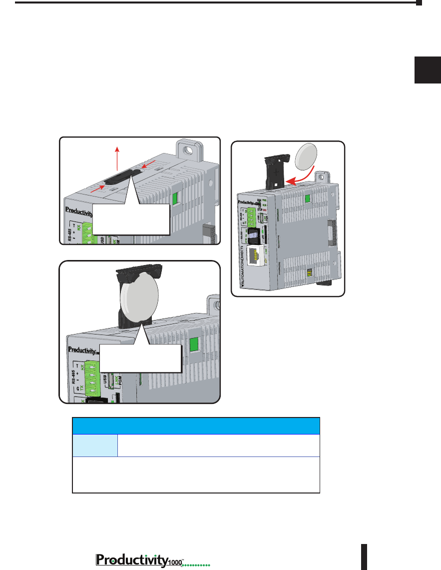
Chapter 2: Specifications
1
2
3
4
5
6
7
8
9
10
11
12
13
14
A
B
C
D
2–9
Hardware User Manual, 1st Edition,
1000
Battery (Optional)
D2-BAT-1
Coin type, 3.0 V Lithium battery, 560mA, battery number
CR2354
Note: Although not needed for program backup, an uninstalled battery is
included with the P1-540. Install this battery if you want the CPU to retain
the Time and Date along with any Tagname values that you have set up as
retentive.
A battery is included with the P1-540 CPU module, but is not installed. The battery
may be installed in order to retain the Time and Date along with any Tagname values
that are set up as retentive.
The battery is not required for program backup.
Battery Installation Procedure
Battery (Optional)
D2-BAT-1 Coin type, 3.0V Lithium battery, 560mA, battery number CR2354
Note: Although not needed for program backup, an uninstalled battery is included with the
P1-540. Install this battery if you want the CPU to retain the Time and Date along with any
Tagname values that you have set up as retentive.
Step One:
Open battery compartment
located on the top of the CPU.
Step Two:
Insert battery and
close compartment.
Squeeze tabs and
pull battery holder up
to remove battery.
P1-540
+-
P1-540
Take care to insert
battery behind tab.
P1-540
P1-540 Battery
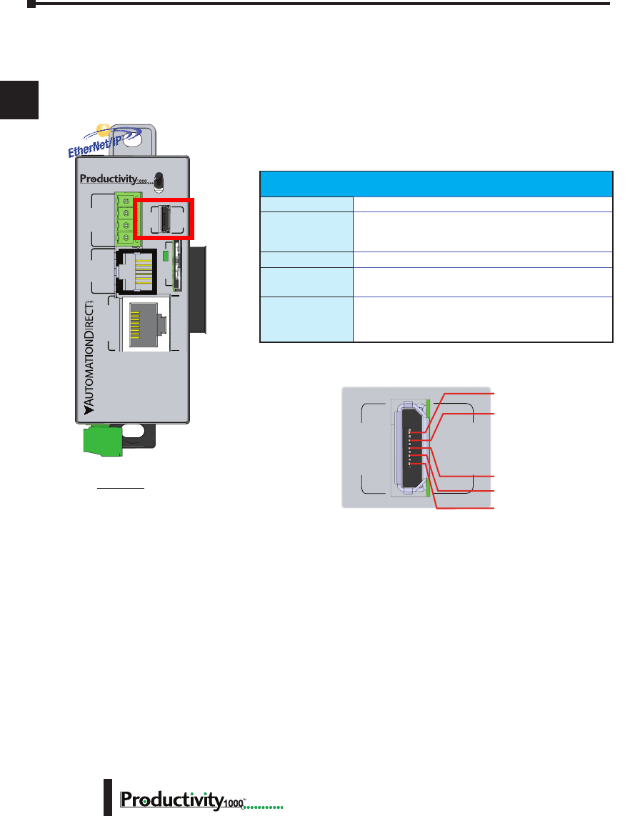
Chapter 2: Specifications
1
2
3
4
5
6
7
8
9
10
11
12
13
14
A
B
C
D
1000 Hardware User Manual, 1st Edition
2–10
P1-540 Communication Ports
The P1-540 CPU has several communications ports. The following pages contain their
specifications and pin-out diagrams.
P1-540
MicroUSB Programming Port
Used exclusively for connecting to a PC running
the Productivity Suite programming software.
Micro USB Input Specications
Port Name
MicroUSB
Description
Standard MicroUSB Slave input for programming and
on-line monitoring, with built-in surge protection. Not
compatible with older full speed USB devices.
Transfer Rate
480 Mbps
Port Status LED
Green LED is illuminated when LINK is established to
programming software.
Cables
USB Type A to MicroUSB Type B:
6ft cable part # USB-CBL-AMICB6
15ft cable part # USB-CBL-AMICB15
P1-540 RUN
STOP
PWR
RUN
CPU
REMOTE I/O
RS-232 RS-485
10/100
ETHERNET
ACT LINK
G
-
+
T
LINK ACT
PGM
LINK
RXTXTXRTSRX
USB
µSD
®
Micro USB Type B Slave Input Specifications
Port Name MICRO USB
Description
Standard Micro USB Slave input for programming and online
monitoring, with built-in surge protection. Not
compatible with older full speed USB devices.
Transfer Rate 480 Mbps
Port Status LED Green LED is illuminated when LINK is established to programming
software.
Cables
USB Type A to Micro USB Type B:
6ft cable part # USB-CBL-AMICB6
15ft cable part # USB-CBL-AMICB15
PGM
LINK
USB
1 VBUS
2 D-
3 D+
4 ID
5 GND
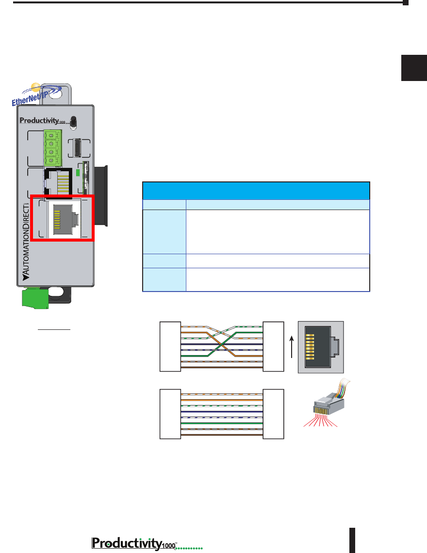
Chapter 2: Specifications
1
2
3
4
5
6
7
8
9
10
11
12
13
14
A
B
C
D
2–11
Hardware User Manual, 1st Edition,
1000
RJ-45 style connector used for:
• Connection to a PC running the ProductivitySuite
programming software
• Modbus TCP Client connections
(Modbus requests sent from the CPU)
• Modbus TCP Server connections
(Modbus requests received by the CPU)
• EtherNet/IP (Client/Server)
• Custom Protocol over Ethernet
• ProNET
• Outgoing Email
P1-540
Port Specifications
Ethernet Specifications
Port Name ETHERNET
Description
Standard transformer isolated Ethernet port with built-in surge protection
for programming, online monitoring, Email (SMTP client), Modbus/TCP
client/server connections (fixed IP or DHCP) and Ethernet IP client/server
connections.
Transfer
Rate 10 Mbps and 100 Mbps (auto-crossover)
Port Status
LED
LINK (Amber LED) is solid when network LINK is established. ACT
(Green LED) flashes when port is active.
1 2 3 4 5 6 7 8
8-pin RJ45 Connector
(8P8C)
TD+
TD–
RD+
RD–
1
2
3
4
5
6
7
8
TD+
TD–
RD+
RD–
1
2
3
4
5
6
7
8
TD+
TD–
RD+
RD–
1
2
3
4
5
6
7
8
TD+
TD–
RD+
RD–
1
2
3
4
5
6
7
8
RJ45 RJ45
RJ45 RJ45
OR/WHT
OR
GRN/WHT
BLU
BLU/WHT
GRN
BRN/WHT
BRN
OR/WHT
OR
GRN/WHT
BLU
BLU/WHT
GRN
BRN/WHT
BRN
OR/WHT
OR
GRN/WHT
BLU
BLU/WHT
GRN
BRN/WHT
BRN
GRN/WHT
GRN
OR/WHT
BLU
BLU/WHT
OR
BRN/WHT
BRN
Patch (Straight-through) Cable
Crossover Cable
8
1
10/BASE-T/100BASE-TX
Ethernet Specications
Port Name ETHERNET
Description
Standard transformer isolated Ethernet port with built-in
surge protection for programming, online monitoring, Email
(SMTP client), Modbus/TCP client/server connections (xed
IP or DHCP), EtherNet/IP Scanner/Apapter, Custom Protocol
over Ethernet and ProNET connections.
Transfer Rate
10 Mbps and 100 Mbps (auto-crossover).
Port Status
LED
LINK (Amber LED) is solid when network LINK is
established. ACT (Green LED) ashes when port is active.
P1-540 RUN
STOP
PWR
RUN
CPU
REMOTE I/O
RS-232 RS-485
10/100
ETHERNET
ACT LINK
G
-
+
T
LINK ACT
PGM
LINK
RXTXTXRTSRX
USB
µSD
®
P1-540 Ethernet Port
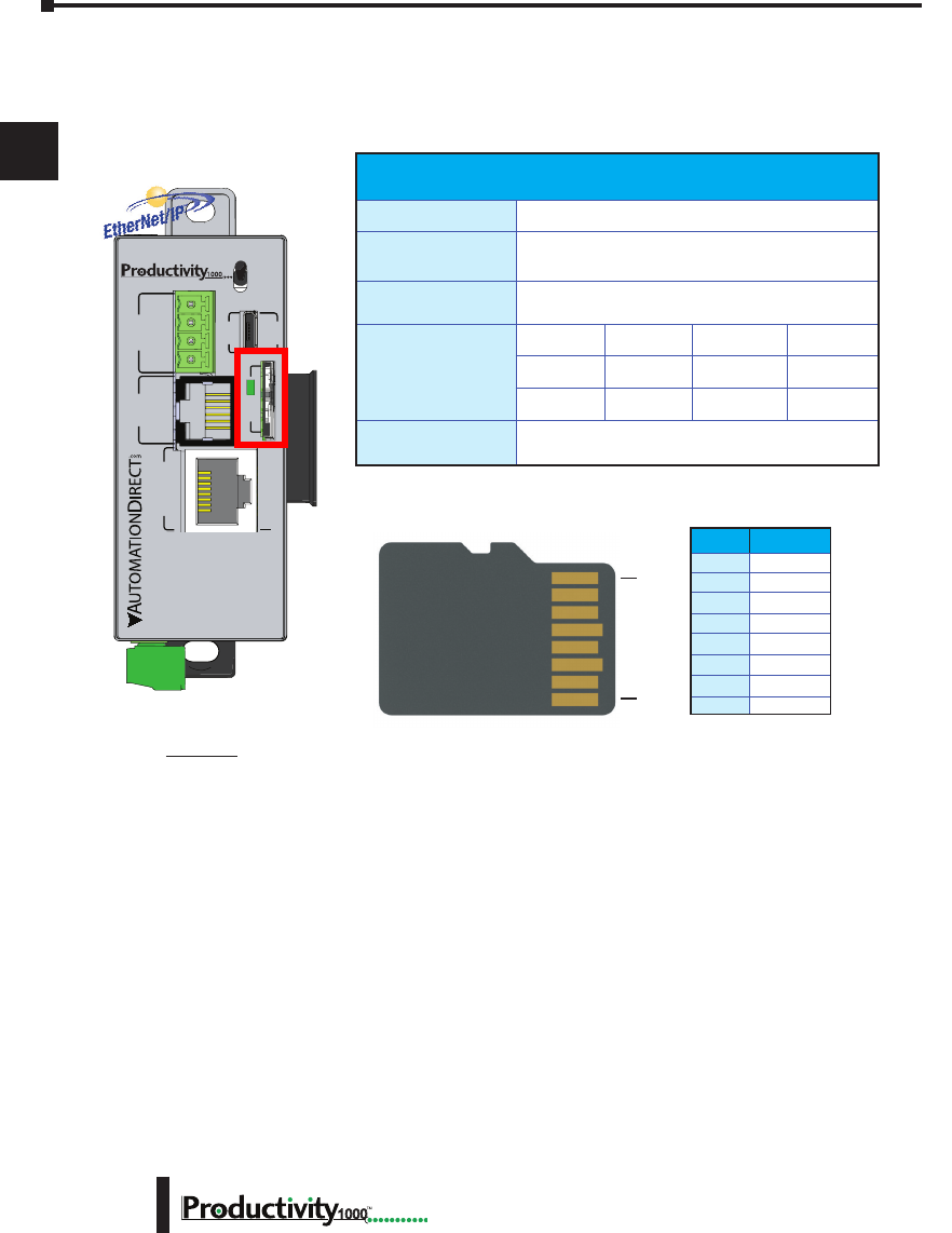
Chapter 2: Specifications
1
2
3
4
5
6
7
8
9
10
11
12
13
14
A
B
C
D
1000 Hardware User Manual, 1st Edition
2–12
microSD Slot
Used for data logging.
P1-540
1
8
PinSD
1
2
3
4
5
6
7
8
DAT2
CD/DAT3
CMD
VDD
CLK
VSS
DAT0
DAT1
microSD Specications
Port Name
microSD
Description
Standard microSD socket for data logging
Maximum Card
Capacity
32GB
Transfer Rate
(ADATA microSDHC
Class 4 memory card)
Mbps Minimum Typical Maximum
Read 14.3 14.4 14.6
Write 4.8 4.9 5.1
Port Status LED
Green LED is illuminated when card is inserted/
detected
Note: Card not included with unit.
P1-540 RUN
STOP
PWR
RUN
CPU
REMOTE I/O
RS-232 RS-485
10/100
ETHERNET
ACT LINK
G
-
+
T
LINK ACT
PGM
LINK
RXTXTXRTSRX
USB
µSD
®
Pin SD
1
DAT2
2
CD/DAT3
3
CMD
4
VDD
5
CLK
6
VSS
7
DAT0
8
DAT1
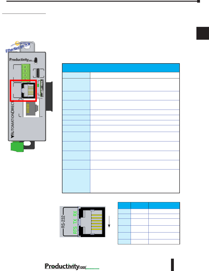
Chapter 2: Specifications
1
2
3
4
5
6
7
8
9
10
11
12
13
14
A
B
C
D
2–13
Hardware User Manual, 1st Edition,
1000
6-Pin RJ12 Female
Modular Connector
RS-232 Port
RJ-12 style connector used for:
• Modbus RTU Master connections
• Modbus RTU Slave connections
• ASCII full or half duplex communications
• Custom Protocol Incoming and Outgoing
communications
P1-540 RS-232 Port
RS-232 Specications
Port Name
RS-232
Description
Non-isolated RS-232 DTE port connects the CPU as a
Modbus/ASCII master or slave to a peripheral device.
Includes ESD and built-in surge protection
Data Rates
Selectable,1200, 2400, 4800, 9600, 19200, 33600, 38400,
57600, and 115200 baud
+5V Cable Power
Source
210mA maximum at 5V, ±5%. Reverse polarity and
overload protected
TXD
RS-232 Transmit output
RXD
RS-232 Receive input
RTS
Handshaking output for modem control
GND
Logic ground
Maximum Output
Load (TXD/RTS)
3kΩ, 1000pf
Minimum Output
Voltage Swing
±5V
Output Short
Circuit Protection
±15mA
Port Status LED
Green LED is illuminated when active for TXD, RXD and
RTS
Cable Options
EA-MG-PGM-CBL
D2-DSCBL
USB-RS232 with D2-DSCBL
FA-CABKIT
FA-ISOCON for converting RS-232 to isolated RS-485
P1-540 RUN
STOP
PWR
RUN
CPU
REMOTE I/O
RS-232 RS-485
10/100
ETHERNET
ACT LINK
G
-
+
T
LINK ACT
PGM
LINK
RXTXTXRTSRX
USB
µSD
®
Pin Label Signal
1GND
Logic Ground
2+5V
210mA Maximum
3RXD
RS-232 Input
4TXD
RS-232 Output
5RTS
RS-232 Output
6GND
Logic Ground
1
6
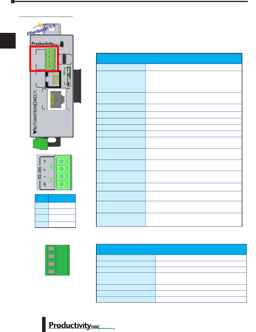
Chapter 2: Specifications
1
2
3
4
5
6
7
8
9
10
11
12
13
14
A
B
C
D
1000 Hardware User Manual, 1st Edition
2–14
RS-485 Port
A 4-pin removable terminal block used for:
• Modbus RTU Master connections
• Modbus RTU Slave connections
• ASCII Incoming and Outgoing communications
• Custom Protocol Incoming and Outgoing communications
P1-540 RS-485 Port
P1-540 RUN
STOP
PWR
RUN
CPU
REMOTE I/O
RS-232 RS-485
10/100
ETHERNET
ACT LINK
G
-
+
T
LINK ACT
PGM
LINK
RXTXTXRTSRX
USB
µSD
®
RS-485 Port Specications
Port Name
RS-485
Description
Non-isolated RS-485 port connects the CPU as
a Modbus/ASCII master or slave to a peripheral
device. Includes ESD/EFT protection and automatic
echo cancellation when transmitter is active
Data Rates
Selectable, 1200, 2400, 4800, 9600, 19200, 33600,
38400, 57600, and 115200 baud
TXD+/RXD+
RS-485 transceiver high
TXD-/RXD-
RS-485 transceiver low
GND
Logic ground
Input Impedance
19kΩ
Maximum Load
50 transceivers, 19kΩ each, 60Ω termination
Output Short Circuit
Protection
±250mA, thermal shut-down protection
Electrostatic Discharge
Protection
±8kV per IEC1000-4-2
Electrical Fast Transient
Protection
±2kV per IEC1000-4-4
Minimum Differential
Output Voltage
1.5 V with 60Ω load
Fail Safe Inputs
Logic high input state if inputs are unconnected
Maximum Common Mode
Voltage
-7.5 V to 12.5 V
Port Status LED
Green LED illuminated when active for TXD and RXD
Cable Options
L19827-XXX from AutomationDirect.com
Removable connector included.
Spare connectors available
(part no. P3-RS485CON-1).
Removable Terminal Block Specications
Part Number
P3-RS485CON-1
Number of Positions
4 Screw Terminals
Pitch
3.5 mm
Wire Range
28–16 AWG Solid Conductor
28–16 AWG Stranded Conductor
Screw Driver
1/8 inch (3.175 mm) Maximum
Screw Size
M2
Screw Torque
1.7 lb·in (0.4 N·m)
Pin Signal
T
Termination
+
TXD+/RXD+
–
TXD-/RXD-
G
GND

Chapter 2: Specifications
1
2
3
4
5
6
7
8
9
10
11
12
13
14
A
B
C
D
2–15
Hardware User Manual, 1st Edition,
1000
I/O Modules Overview
A variety of discrete and analog I/O modules are available for use in the P1000 System.
Each I/O module is identified as an “Input”, “Output”, or “Input/Output” module on its
front panel using the color coding scheme listed below. See the following pages for discrete
I/O module specifications and Chapter 3 for analog I/O module specifications.
Discrete Input Modules
Module Type and
Part Number
(Blue: Input)
Discrete Output Modules
Output Type
Module Type and
Part Number
(Red: Output)
Analog Input Modules Analog Output Modules Discrete Input/Output Modules
Module Signal
Type
Module Type and
Part Number
(White: Input/Output)
Module Type and
Part Number
(Blue: Input)
Input Type
Module Type and
Part Number
(Red: Output)
Output Type
V+
2
3
4
COM
5
6
7
8
1
P1-08TD1
3.3-24VDC
SINK OUTPUT
COM
COM
COM
COM
24V
I2+
I3+
I4+
0V
I1+
P1-04ADL-1
0-20mA INPUT
ANALOG
24V
I2+
I3+
I4+
0V
COM
COM
COM
COM
I1+
P1-04DAL-1
4-20mA OUT
ANALOG
P1-15CDD1
C1
1
2
3
4
5
6
7
8
1
2
3
4
5
6
7
V+
C2
INPUTSOUTPUTS
12-24VDC IN
3.3-24V OUT
C1
2
3
4
C2
5
6
7
8
1
12-24VDC
INPUT
P1-08ND3
Input Type
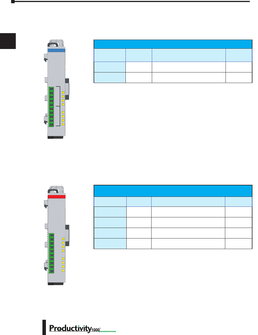
Chapter 2: Specifications
1
2
3
4
5
6
7
8
9
10
11
12
13
14
A
B
C
D
1000 Hardware User Manual, 1st Edition
2–16
Discrete I/O Modules
Discrete Input Modules
Discrete Output Modules
Productivity1000 Discrete Output Modules
Part Number Number of
Outputs Description See Page
P1-08TD1
8Sinking Output 2-22
P1-08TD2
8Sourcing Output 2-25
P1-08TRS
8Isolated Relay Output 2-28
P1-16TR
16 Relay Output 2-31
Productivity1000 Discrete Input Modules
Part Number Number of
Inputs Description See Page
P1-08SIM
8Input Simulator Module 2-18
P1-08ND3
8Sinking/Sourcing 12–24 VDC Input 2-19
V+
2
3
4
COM
5
6
7
8
1
P1-08TD1
3.3-24VDC
SINK OUTPUT
C1
2
3
4
C2
5
6
7
8
1
12-24VDC
INPUT
P1-08ND3
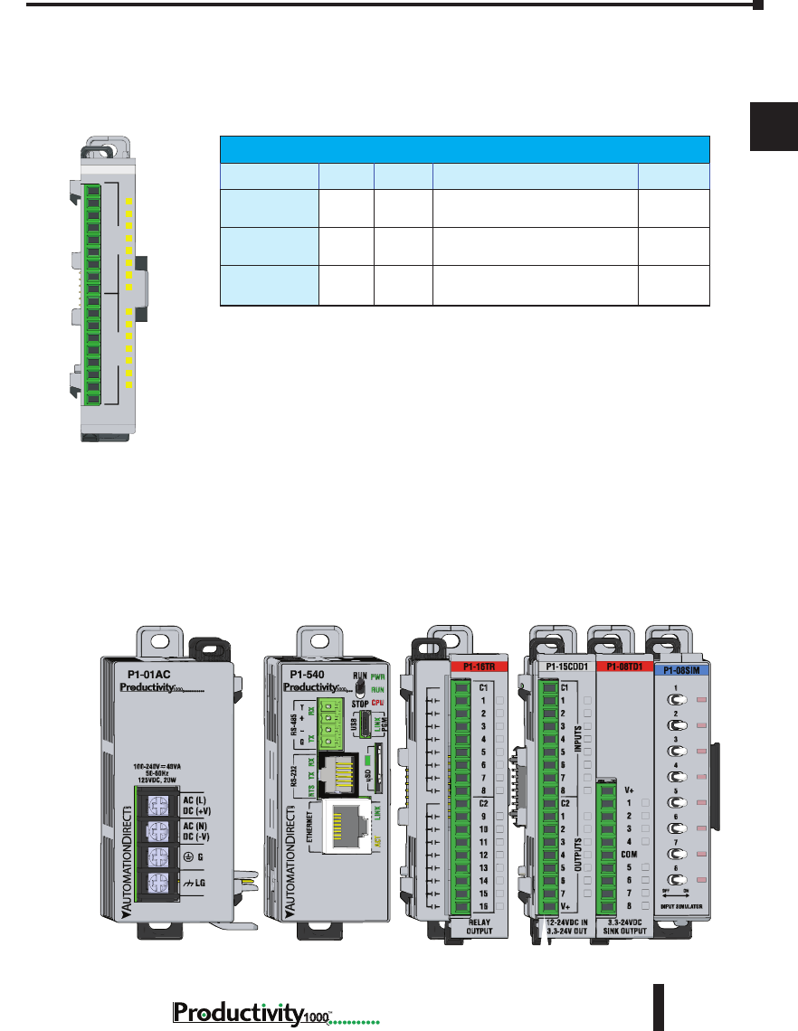
Chapter 2: Specifications
1
2
3
4
5
6
7
8
9
10
11
12
13
14
A
B
C
D
2–17
Hardware User Manual, 1st Edition,
1000
Discrete Combo I/O Modules
Discrete Combo Input/Output Modules
Productivity1000 Discrete Combo Modules
Part Number Inputs Outputs Description See Page
P1-15CDD1
8 7 Input: Sinking/Sourcing;
Output: Sinking 2-34
P1-15CDD2
8 7 Input: Sinking/Sourcing;
Output: Sourcing 2-37
P1-16CDR
8 8 Input: Sinking/Sourcing;
Output: Relay 2-40
P1-15CDD1
C1
1
2
3
4
5
6
7
8
1
2
3
4
5
6
7
V+
C2
INPUTSOUTPUTS
12-24VDC IN
3.3-24V OUT
Module Installation
WARNING: Do not add or remove modules with
field power applied.
Step One: With latch
in “locked” position, align
connectors on the side of
each module and stack
by pressing together.
Click indicates lock is
engaged.
Step Three: To unstack modules, pull
locking latch up into the unlocked position
and then pull modules apart.
Step Two: Attach field wiring using
the removable terminal block or ZIPLink
wiring system.
LOCK
UNLOCK
WIRE STRIP
LENGTH
MIN
MAX
P1-08TD1
secure after modules
are connected.
I/O Modules Installation
A variety of discrete and analog I/O modules can be added to the P1000 PLC to create a
custom control system. To add an I/O module (verify field power is not energized), with the
latch in “locked” position, align connectors on the side of each module and press together. An
audible click indicates the module lock is engaged. Verify each connecting module tab is firmly
in the locked position.
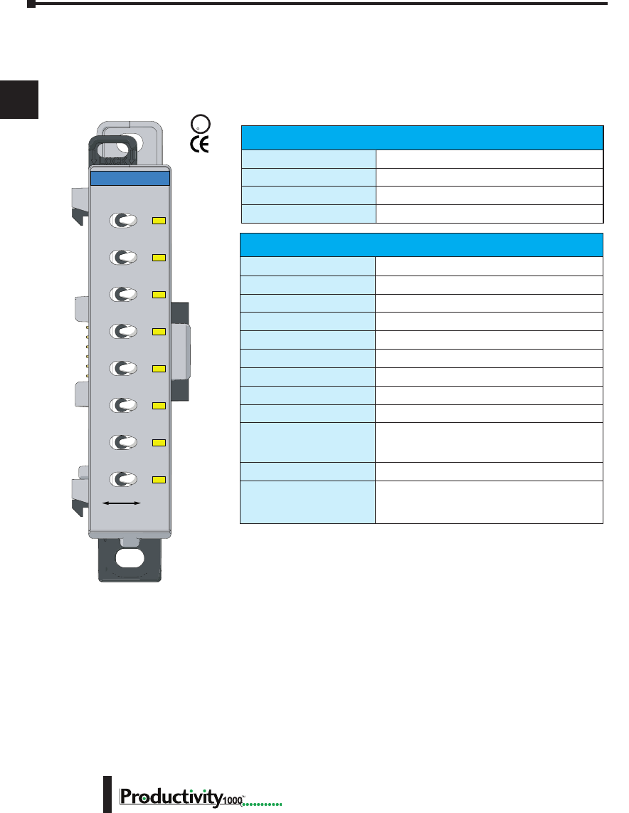
Chapter 2: Specifications
1
2
3
4
5
6
7
8
9
10
11
12
13
14
A
B
C
D
1000 Hardware User Manual, 1st Edition
2–18
P1-08SIM Input Simulator Module
The P1-08SIM Input Simulator Module provides 8 toggle switches to simulate input devices.
UL
C
US
R
Input Specications
Inputs per Module
8 Internal switches
OFF to ON Response
Max. 20ms
ON to OFF Response
Max. 20ms
Status Indicators
Logic Side (8 points)
General Specications
Operating Temperature
0° to 60°C (32° to 140°F)
Storage Temperature
-20° to 70°C (-4° to 158°F)
Humidity
5 to 95% (non-condensing)
Environmental Air
No corrosive gases permitted
Vibration
IEC60068-2-6 (Test Fc)
Shock
IEC60068-2-27 (Test Ea)
Heat Dissipation
200mW
Enclosure Type
Open Equipment
Module Location
Any I/O slot in a Productivity1000 System.
EU Directive
See the “EU Directive” topic in the Productivity
Suite Help File. Information can also be obtained
at: www.productivity1000.com
Weight
70g (2.5 oz)
Agency Approvals
UL 61010-2-201 le E139594, Canada & USA
CE (EN61131-2 EMC and EN61010-2-201
Safety)*
1
8
7
6
5
4
3
2
OFF ON
INPUT SIMULATOR
P1-08SIM
* See CE Declaration of Conformity for details. See the D.O.C. for details.
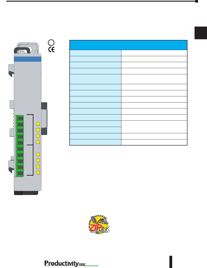
Chapter 2: Specifications
1
2
3
4
5
6
7
8
9
10
11
12
13
14
A
B
C
D
2–19
Hardware User Manual, 1st Edition,
1000
P1-08ND3 Sinking/Sourcing DC Input
The P1-08ND3 Fast Response Input Module provides eight inputs for switches and
other devices connected to ground or supplies ranging from 12–24 VDC for use with the
Productivity1000 system.
We recommend using pre-wired ZIPLink cables and
connection modules. See Chapter 5.
If you wish to hand-wire your module, removable
terminal blocks are sold separately. Order part
number P1-10RTB or P1-10RTB-1
Input Specications
Inputs per Module
8 (Sink/Source)
External 24VDC Power Required
12–24 VDC
Input Voltage Range
10.2–26.4 VDC
Peak Voltage
30VDC
Input Current
3.5 mA @ 12VDC
7.5 mA @ 24VDC
Maximum Input Current @ Temp
10mA @ 26.4 VDC
Input Impedance
3kΩ
ON Voltage Level
>9.5 VDC
OFF Voltage Level
<7VDC
Maximum ON Current
2mA
Maximum OFF Current
1.6 mA
OFF to ON Response
2ms Maximum, 1ms Typical
ON to OFF Response
Status Indicators
Logic Side (8 points)
Commons
2 (4 points/common)
U
L
CUS
R
Terminal blocks sold separately.
C1
2
3
4
C2
5
6
7
8
1
12-24VDC
INPUT
P1-08ND3

Chapter 2: Specifications
1
2
3
4
5
6
7
8
9
10
11
12
13
14
A
B
C
D
1000 Hardware User Manual, 1st Edition
2–20
* See the Declaration of Conformity for details.
* Recommended screw driver: P/N TW-SD-MSL-1.
P1-08ND3 Sinking/Sourcing DC Input, (continued)
General Specications
Operating Temperature
0° to 60°C (32° to 140°F),
Storage Temperature
-20° to 70°C (-4° to 158°F)
Humidity
5 to 95% (non-condensing)
Environmental Air
No corrosive gases permitted
Vibration
IEC60068-2-6 (Test Fc)
Shock
IEC60068-2-27 (Test Ea)
Field to Logic Side Isolation
1800VAC applied for 1 second
Insulation Resistance
>10MV @ 500 VDC
Heat Dissipation
2000mW
Enclosure Type
Open Equipment
Module Location
Any I/O position in a Productivity1000 System.
Field Wiring
Use ZIPLink wiring system or removable terminal
block (sold separately). See “Wiring Options” in
Chapter 5.
EU Directive
See the “EU Directive” topic in the Productivity
Suite Help File. Information can also be obtained
at: www.productivity1000.com
Connector Type
(sold separately) 10-position removable terminal block
Weight
85g (3oz)
Agency Approvals
UL 61010-2-201 le E139594, Canada & USA
CE (EN61131-2 EMC and EN61010-2-201 Safety)*
Removable Terminal Block Specications
Part Number P1-10RTB P1-10RTB-1
Number of
Positions
10 Screw Terminals 10 Spring Clamp Terminals
Wire Range
30–16 AWG (0.051–1.31mm²)
Solid / Stranded Conductor
3/64 in. (1.2 mm) Insulation
Max.
1/4 in. (6–7 mm) Strip Length
28–16 AWG (0.081–1.31 mm²)
Solid / Stranded Conductor
3/64 in. (1.2 mm) Insulation Max.
19/64 in. (7–8 mm) Strip Length
Conductors
“USE COPPER CONDUCTORS, 75°C” or Equivalent.
Screw Driver
0.1 inch (2.5 mm) Maximum*
Screw Size
M2 N/A
Screw Torque
2.5 lb·in (0.28 N·m) N/A
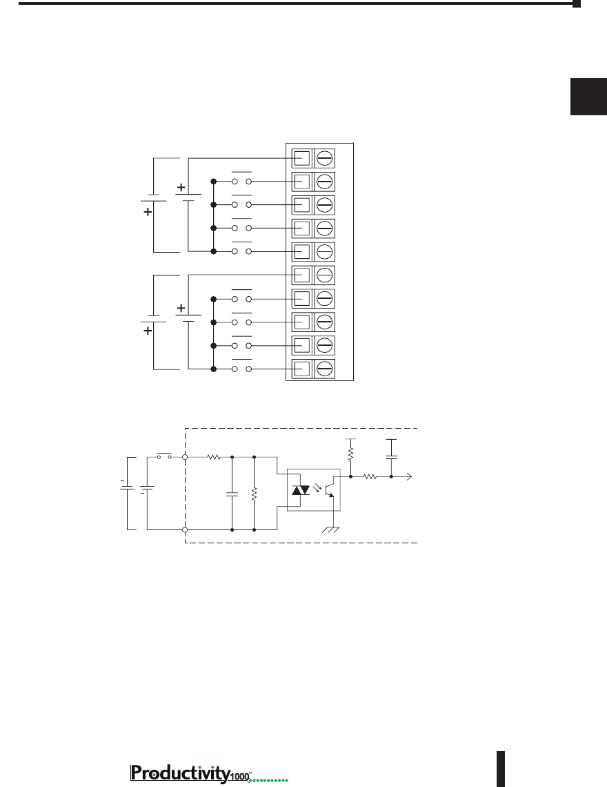
Chapter 2: Specifications
1
2
3
4
5
6
7
8
9
10
11
12
13
14
A
B
C
D
2–21
Hardware User Manual, 1st Edition,
1000
P1-08ND3 Sinking/Sourcing DC Input (continued)
Wiring Diagrams
P1-08ND3 Schematic and Wiring Diagram
Single Supply
24VDC
24VDC
–
–
–
–
C1
1
2
3
4
C2
5
6
7
8
12345678910
INPUT
COM
Internal Module Circuitry
Optical Isolator
24VDC
+
+
Equivalent Input Circuit
P1-08ND3 Schematic and Wiring Diagram
Single Supply
24VDC
24VDC
–
–
–
–
C1
1
2
3
4
C2
5
6
7
8
12345678910
INPUT
COM
Internal Module Circuitry
Optical Isolator
24VDC
+
+
Equivalent Input Circuit
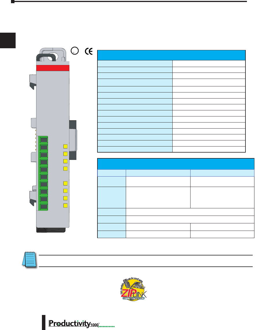
Chapter 2: Specifications
1
2
3
4
5
6
7
8
9
10
11
12
13
14
A
B
C
D
1000 Hardware User Manual, 1st Edition
2–22
P1-08TD1 Sinking DC Output
The P1-08TD1 DC Output Module provides eight outputs that sink up to 1A per output
from loads powered by 3.3–24 VDC supplies for use with the Productivity1000 system.
U
L
CUS
R
We recommend using pre-wired ZIPLink cables
and connection modules. See Chapter 5.
If you wish to hand-wire your module, removable
terminal blocks are sold separately. Order part
number P1-10RTB or P1-10RTB-1
Output Specications
Outputs per Module
8 sinking
Output Type
N-channel MOSFET, open drain
Rated Voltage
3.3–24 VDC
Operating Voltage Range (Tolerance)
2.9–26.4 VDC
Maximum Output Current
1A continuous
Minimum Load Current
1mA
Maximum Leakage Current
0.3 mA @ 26.4 VDC
On Voltage Drop
0.2 VDC
Maximum Inrush Current
4A for 50ms, 6A for 10ms
OFF to ON Response
≤0.5 ms
ON to OFF Response
≤0.5 ms
Status Indicators
Logic Side (8 pins)
Commons
1 non-isolated
Maximum Applicable Fuse
8A
External Power Supply Required
12–24 VDC (-15%/+20%), 22mA
V+
2
3
4
COM
5
6
7
8
1
P1-08TD1
3.3-24VDC
SINK OUTPUT
Removable Terminal Block Specications
Part Number P1-10RTB P1-10RTB-1
Number of
Positions
10 Screw Terminals 10 Spring Clamp Terminals
Wire Range
30–16 AWG (0.051–1.31 mm²)
Solid / Stranded Conductor
3/64 in. (1.2 mm) Insulation Max.
1/4 in. (6–7 mm) Strip Length
28–16 AWG (0.081–1.31 mm²)
Solid / Stranded Conductor
3/64 in. (1.2 mm) Insulation Max.
19/64 in. (7–8 mm) Strip Length
Conductors
“USE COPPER CONDUCTORS, 75°C” or Equivalent.
Screw Driver
0.1 in (2.5 mm) Maximum*
Screw Size
M2 N/A
Screw Torque
2.5 lb·in (0.28 N·m) N/A
* Recommended screw driver: P/N TW-SD-MSL-1
Terminal blocks sold separately.
NOTE: Module shown with flip-up finger-safe terminal cover removed for clarity.

Chapter 2: Specifications
1
2
3
4
5
6
7
8
9
10
11
12
13
14
A
B
C
D
2–23
Hardware User Manual, 1st Edition,
1000
P1-08TD1 Sinking DC Output (continued)
General Specications
Operating Temperature
0° to 60°C (32° to 140°F)
Storage Temperature
-20° to 70°C (-4° to 158°F)
Humidity
5 to 95% (non-condensing)
Environmental Air
No corrosive gases permitted
Vibration
IEC60068-2-6 (Test Fc)
Shock
IEC60068-2-27 (Test Ea)
Field to Logic Side Isolation
1800VAC applied for 1 second
Insulation Resistance
>10MΩ @ 500VDC
Heat Dissipation
1800mW
Enclosure Type
Open Equipment
Module Keying to Backplane
Electronic
Module Location
Any I/O position in a Productivity1000 System
Field Wiring
Use ZIPLink Wiring System or removable terminal block
(sold separately). See “Wiring Options” in Chapter 5.
EU Directive
See the “EU Directive” topic in the Productivity Suite
Help File. Information can also be obtained at: www.
productivity1000.com
Connector Type
(sold separately)
10-position removable terminal block
Weight
60g (2.1 oz)
Agency Approvals
UL 61010-2-201 le E139594, Canada & USA
CE (EN61131-2 EMC and EN61010-2-201 Safety)*
* See CE Declaration of Conformity for details.
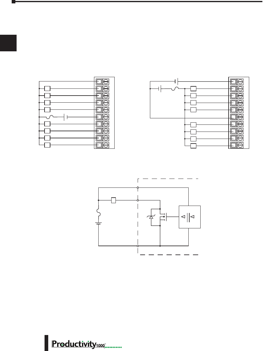
Chapter 2: Specifications
1
2
3
4
5
6
7
8
9
10
11
12
13
14
A
B
C
D
1000 Hardware User Manual, 1st Edition
2–24
P1-08TD1 Sinking DC Output (continued)
Wiring Diagrams
P1-08TD1 Schematic and Wiring Diagram
12–24V
OUTPUT
INTERNAL MODULE
DIGITAL
ISOLATION
Sink
L
COM
V+
8A Max
12345678910
L
L
L
L
L
L
L
L
24V
1
2
3
4
CO
M
5
6
7
8
12–24VDC
+ -
12345678910
L
L
L
L
L
L
L
L
24V
1
2
3
4
COM
5
6
7
8
12–24VDC
+ -
Dual Power SourceSingle Power Source
8A Max
8A Max
+ -
P1-08TD1 Schematic and Wiring Diagram
12–24V
OUTPUT
INTERNAL MODULE
DIGITAL
ISOLATION
Sink
L
COM
V+
8A Max
12345678910
L
L
L
L
L
L
L
L
24V
1
2
3
4
0V
5
6
7
8
12–24VDC
+ -
12345678910
L
L
L
L
L
L
L
L
24V
1
2
3
4
0V
5
6
7
8
12–24VDC
+ -
Dual Power SourceSingle Power Source
8A Max
8A Max
+ -
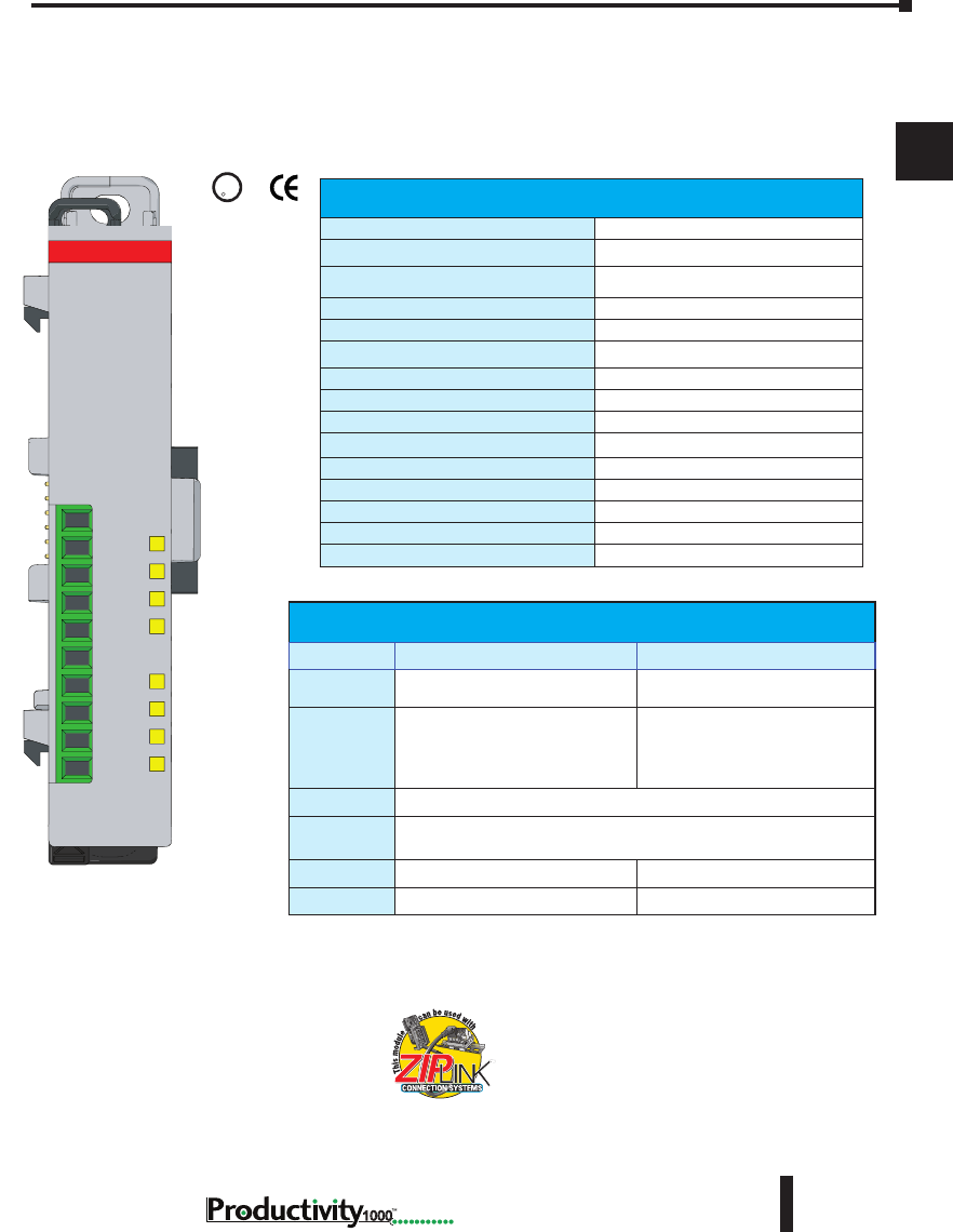
Chapter 2: Specifications
1
2
3
4
5
6
7
8
9
10
11
12
13
14
A
B
C
D
2–25
Hardware User Manual, 1st Edition,
1000
P1-08TD2 Sourcing DC Output
The P1-08TD2 DC Output Module provides eight non-isolated outputs that source up to 1A
per output from a 12–24 VDC supply for use with the Productivity1000 system.
U
L
CUS
R
We recommend using pre-wired ZIPLink cables
and connection modules. See Chapter 5.
If you wish to hand-wire your module, removable
terminal blocks are sold separately. Order part
number P1-10RTB or P1-10RTB-1.
Output Specications
Outputs per Module
8 sourcing
Voltage Rating
12–24 VDC
Operating Voltage Range
10.2–28.8 VDC
Output Type
P-channel MOSFET, open source
Maximum Output Current
1A per point
Minimum Load Current
1mA
Maximum Leakage Current
0.3 mA @ 28.8 VDC
On Voltage Drop
0.2 VDC @ 1A
Maximum Inrush Current
4A for 50ms, 6A for 10ms
OFF to ON Response
0.5 ms
ON to OFF Response
0.5 ms
Status Indicators
Logic Side (8 points)
Commons
1
Maximum Applicable Fuses
8A
External Power Supply Required
12–24 VDC (-15%/+20%) @ 22mA
V+
2
3
4
COM
5
6
7
8
1
P1-08TD2
12-24VDC
SOURCE OUT
Terminal blocks sold separately.
Removable Terminal Block Specications
Part Number P1-10RTB P1-10RTB-1
Number of
Positions
10 Screw Terminals 10 Spring Clamp Terminals
Wire Range
30–16 AWG (0.051–1.31 mm²)
Solid / Stranded Conductor
3/64 in. (1.2 mm) Insulation Max.
1/4 in. (6–7 mm) Strip Length
28–16 AWG (0.081–1.31 mm²)
Solid / Stranded Conductor
3/64 in. (1.2 mm) Insulation Max.
19/64 in. (7–8 mm) Strip Length
Conductors
“USE COPPER CONDUCTORS, 75°C” or Equivalent.
Screw Driver
0.1 in (2.5 mm) Maximum*
Screw Size
M2 N/A
Screw Torque
2.5 lb·in (0.28 N·m) N/A
* Recommended screw driver: P/N TW-SD-MSL-1

Chapter 2: Specifications
1
2
3
4
5
6
7
8
9
10
11
12
13
14
A
B
C
D
1000 Hardware User Manual, 1st Edition
2–26
P1-08TD2 Sourcing DC Output (continued)
General Specications
Operating Temperature
0° to 60°C (32° to 140°F)
Storage Temperature
-20° to 70°C (-4° to 158°F)
Humidity
5 to 95% (non-condensing)
Environmental Air
No corrosive gases permitted
Vibration
IEC60068-2-6 (Test Fc)
Shock
IEC60068-2-27 (Test Ea)
Field to Logic Side Isolation
1800VAC applied for 1 second
Insulation Resistance
>10MΩ @ 500VDC
Heat Dissipation
2600mW
Enclosure Type
Open Equipment
Module Keying to Backplane
Electronic
Module Location
Any I/O position in a Productivity1000 system
Field Wiring
Use ZIPLink Wiring System or removable terminal
block (sold separately). See “Wiring Options” in
Chapter 5.
EU Directive
See the “EU Directive” topic in the Productivity
Suite Help File. Information can also be obtained
at: www.productivity1000.com
Connector Type
(sold separately)
10-position removable terminal block
Weight
58g (2.1 oz)
Agency Approvals
UL 61010-2-201 le E139594, Canada & USA
CE (EN61131-2 EMC and EN61010-2-201
Safety)*
* See CE Declaration of Conformity for details.
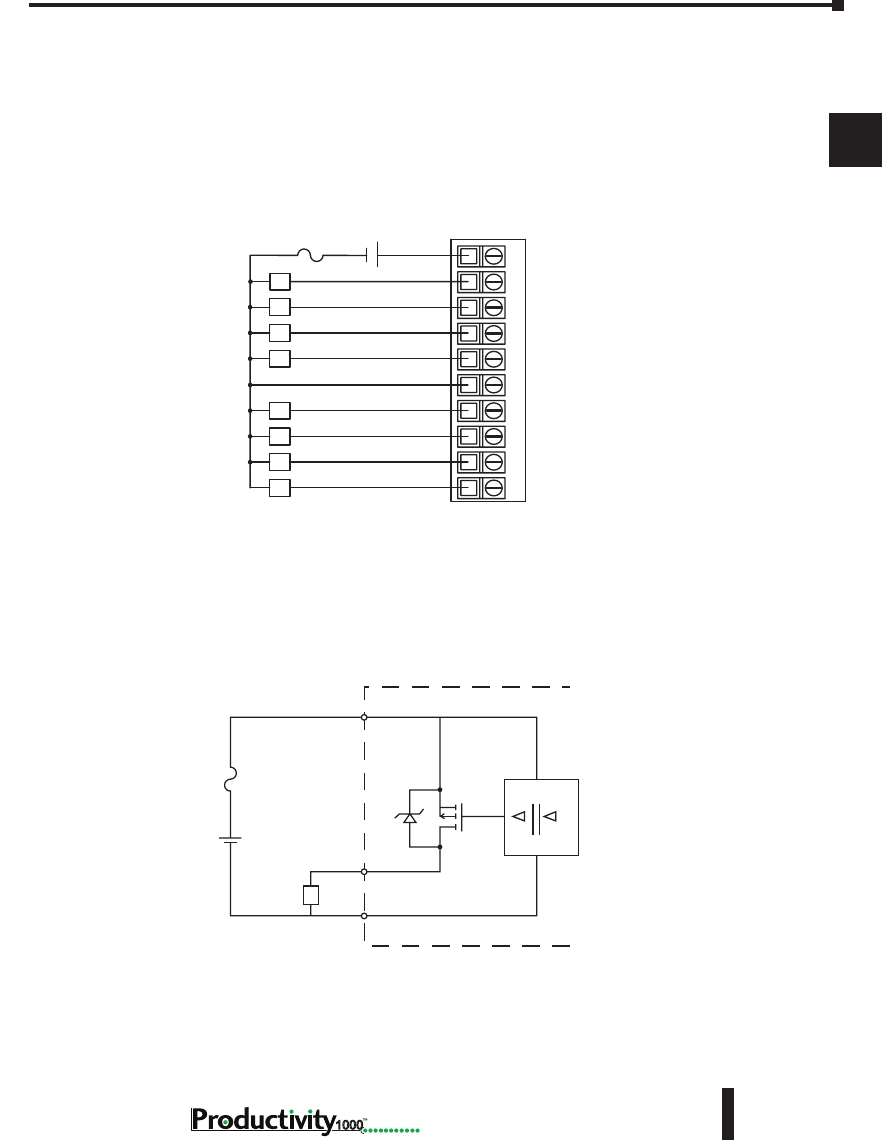
Chapter 2: Specifications
1
2
3
4
5
6
7
8
9
10
11
12
13
14
A
B
C
D
2–27
Hardware User Manual, 1st Edition,
1000
Wiring Diagrams
P1-08TD2 Sourcing Output (continued)
P1-08TD2 Schematic and Wiring Diagram
12345678910
L
L
L
L
L
L
L
L
V+
1
2
3
4
COM
5
6
7
8
12–24 VDC
+ -
Single Power Source
8A Max
12–24 V
24V INTERNAL MODULE
DIGITAL
ISOLATION
Source
L0V
P1-08TD2 Schematic and Wiring Diagram
12345678910
L
L
L
L
L
L
L
L
V+
1
2
3
4
COM
5
6
7
8
12–24 VDC
+ -
Single Power Source
8A Max
12–24 V
24V INTERNAL MODULE
DIGITAL
ISOLATION
Source
LCOM
8A Max
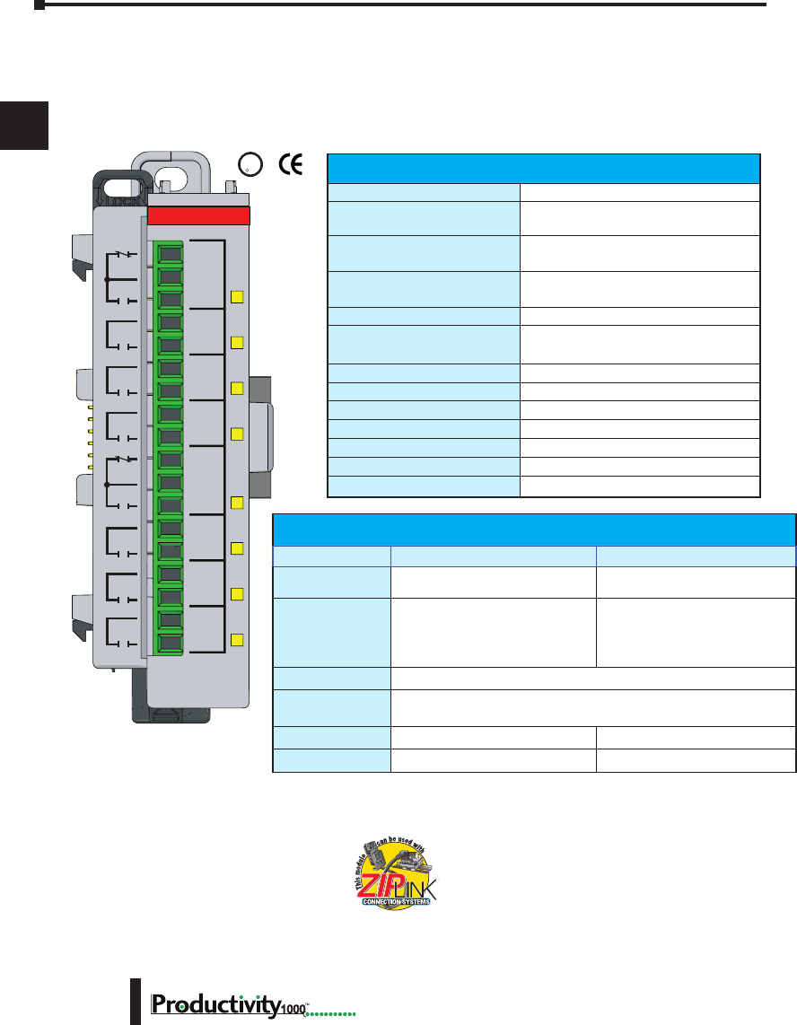
Chapter 2: Specifications
1
2
3
4
5
6
7
8
9
10
11
12
13
14
A
B
C
D
1000 Hardware User Manual, 1st Edition
2–28
P1-08TRS Isolated Relay
The P1-08TRS high-current isolated relay output module provides eight, 3A surge protected
outputs. The P1-08TRS offers both normally open and normally closed relay contacts for use
with the Productivity1000 System.
U
L
C
US
R
Removable Terminal Block Specications
Part Number P2-RTB P2-RTB-1
Number of Positions
18 Screw Terminals 18 Spring Clamp Terminals
Wire Range
30–16 AWG (0.051– 1.31 mm²)
Solid / Stranded Conductor
3/64 in. (1.2 mm) Insulation Max.
1/4 in. (6–7 mm) Strip Length
28–16 AWG (0.081–1.31 mm²)
Solid / Stranded Conductor
3/64 in. (1.2 mm) Insulation Max.
19/64 in. (7–8 mm) Strip Length
Conductors
“USE COPPER CONDUCTORS, 75°C” or Equivalent.
Screw Driver
0.1 in (2.5 mm) Maximum*
Screw Size
M2 N/A
Screw Torque
2.5 lb·in (0.28 N·m) N/A
We recommend using pre-wired ZIPLink cables
and connection modules. See Chapter 5.
If you wish to hand-wire your module,
removable terminal blocks are sold separately.
Order part number P2-RTB or P2-RTB-1.
Terminal blocks sold separately.
Output Specications
Outputs per Module
8
Rated Voltage
6.25–30 VDC
6–120 VAC
Operating Voltage Range
5.1–28.8 VDC
5.1–132 VAC
Output type
6 Relays, FORM A (SPST)
2 Relays, FORM C (SPDT)
AC Frequency
47–63 Hz
Maximum Output Current
3A / point @ 60°C for both AC and DC
2A / point if used with ZIPLink Cable
Minimum Load Current
5mA @ 5VDC
Maximum Inrush Current
3A for 10ms
OFF to ON Response
<10ms
ON to OFF Response
<10ms
Status Indicators
Logic Side (8 points)
Commons
8 Isolated (1 point / common)
Maximum Applicable Fuse
8A Max
C1
NO1
C2
NO2
C3
NO3
C4
NO4
C5
NO5
C6
NO6
C7
NO7
C8
NO8
NC5
NC1
P1-08TRS
RELAY
OUTPUT
* Recommended screw driver: P/N TW-SD-MSL-1

Chapter 2: Specifications
1
2
3
4
5
6
7
8
9
10
11
12
13
14
A
B
C
D
2–29
Hardware User Manual, 1st Edition,
1000
Typical Relay Life
Voltage & Type of Load
Operations at 4A Load Current
30VDC Resistive
100,000
30VDC Solenoid
100,000
120VAC Resistive
100,000
120VAC Solenoid
100,000
P1-08TRS Isolated Relay (continued)
General Specications
Operating Temperature
0° to 60°C (32° to 140°F),
Storage Temperature
-20° to 70°C (-4° to 158°F)
Humidity
5 to 95% (non-condensing)
Environmental Air
No corrosive gases permitted
Vibration
IEC60068-2-6 (Test Fc)
Shock
IEC60068-2-27 (Test Ea)
Field to Logic Side Isolation
1800VAC applied for 1 second
Insulation Resistance
>10MΩ @ 500VDC
Heat Dissipation
3000mW
Enclosure Type
Open Equipment
Module Keying
Electronic
Module Location
Any I/O position in a Productivity1000 system
Field Wiring
Use ZIPLink Wiring System or removable terminal
block (sold separately). See “Wiring Options” in
Chapter 5.
EU Directive
See the “EU Directive” topic in the Productivity
Suite Help File. Information can also be obtained
at: www.productivity1000.com
Connector Type (sold separately)
18-position removable terminal block
Weight
112g (4oz)
Agency Approvals
UL 61010-2-201 le E139594, Canada & USA
CE (EN61131-2 EMC and EN61010-2-201
Safety)*
* See CE Declaration of Conformity for details.
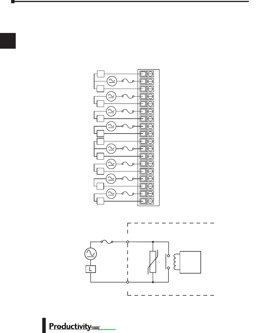
Chapter 2: Specifications
1
2
3
4
5
6
7
8
9
10
11
12
13
14
A
B
C
D
1000 Hardware User Manual, 1st Edition
2–30
P1-08TRS Isolated Relay (continued)
Wiring Diagrams
P1-08TRS Schematic and Wiring Diagram
8 A
User Supplied
External Fuse
Internal Module Circuitry
6–27 VDC
6–120 VAC
50–60 Hz Relay
Drive
Circuit
OUTPUT
COM
NC1
NO1
C2
NO2
C3
NO3
C4
NO4
NC5
C5
NO5
C6
NO6
C7
NO7
C8
NO8
12345678910 11 12 1813 14 15 16 17
L
L
L
L
L
L
L
L
L
6–27 VDC
6–120 VAC
50–60 Hz
C1
L
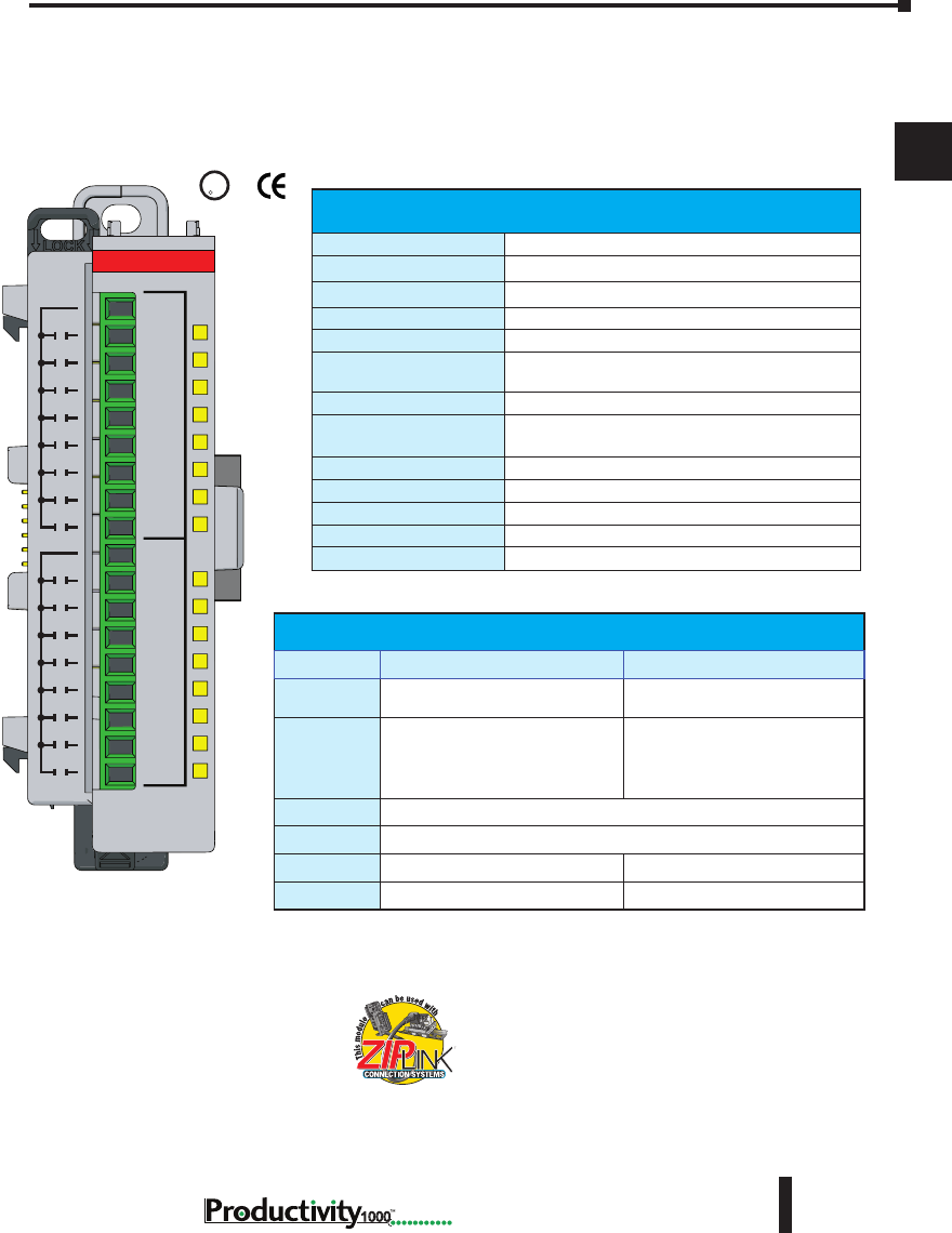
Chapter 2: Specifications
1
2
3
4
5
6
7
8
9
10
11
12
13
14
A
B
C
D
2–31
Hardware User Manual, 1st Edition,
1000
P1-16TR Relay Output
The P1-16TR Relay Output Module provides sixteen 2A outputs with two isolated commons
for use with the Productivity1000 system.
U
L
CUS
R
Terminal blocks sold separately.
Removable Terminal Block Specications
Part Number P2-RTB P2-RTB-1
Number of
Positions
18 Screw Terminals 18 Spring Clamp Terminals
Wire Range
30–16 AWG (0.051–1.31 mm²)
Solid / Stranded Conductor
3/64 in. (1.2 mm) Insulation Max.
1/4 in. (6–7 mm) Strip Length
28–16 AWG (0.081–1.31 mm²)
Solid / Stranded Conductor
3/64 in. (1.2 mm) Insulation Max.
19/64 in. (7–8 mm) Strip Length
Conductors
“USE COPPER CONDUCTORS, 75°C” or Equivalent.
Screw Driver
0.1 in (2.5 mm) Maximum*
Screw Size
M2 N/A
Screw Torque
2.5 lb·in (0.28 N·m) N/A
We recommend using pre-wired ZIPLink cables
and connection modules. See Chapter 5.
If you wish to hand-wire your module,
removable terminal blocks are sold separately.
Order part number P2-RTB or P2-RTB-1.
Output Specications
Outputs Channels
16
Rated Voltage
6.25–30 VDC, 6–120 VAC
Operating Voltage Range
5–30 VDC, 5–144 VAC
Output Type
Relay, FORM A (SPST)
AC Frequency
47–63 Hz
Maximum Output Current
2A / point, 8A / common for both AC and DC
2A / point, 4A / common if used with ZIPLink Cable
Minimum Load Current
5mA @ 5VDC
Maximum Inrush Current
2400VA make, 240VA break @ 120 or 240VAC
(Make current is 2 AC cycles)
OFF to ON Response
≤10ms
ON to OFF Response
≤10ms
Status Indicators
Logic Side (16 points)
Commons
2 Isolated (8 point / common)
Maximum Applicable Fuse
8A
1
2
3
4
5
6
7
8
9
10
11
12
13
14
15
16
C2
C1
P1-16TR
RELAY
OUTPUT
* Recommended screw driver: P/N TW-SD-MSL-1

Chapter 2: Specifications
1
2
3
4
5
6
7
8
9
10
11
12
13
14
A
B
C
D
1000 Hardware User Manual, 1st Edition
2–32
P1-16TR Relay Output (continued)
General Specications
Operating Temperature
0° to 60°C (32° to 140°F)
Storage Temperature
-20° to 70°C (-4° to 158°F)
Humidity
5 to 95% (non-condensing)
Environmental Air
No corrosive gases permitted
Vibration
IEC60068-2-6 (Test Fc)
Shock
IEC60068-2-27 (Test Ea)
Field to Logic Side Isolation
1800VAC applied for 1 second
Insulation Resistance
>10MΩ @ 500VDC
Heat Dissipation
3000mW
Enclosure Type
Open Equipment
Module Location
Any I/O position in a Productivity1000 System.
Field Wiring
Use ZIPLink Wiring System or removable terminal block
(sold separately). See “Wiring Options” in Chapter 5.
EU Directive
See the “EU Directive” topic in the Productivity Suite
Help File. Information can also be obtained at: www.
productivity1000.com
Connector Type (sold
separately)
18-position removable terminal block
Weight
91g (3.2 oz)
Agency Approvals
UL 61010-2-201 le E139594, Canada & USA
CE (EN61131-2 EMC and EN61010-2-201 Safety)*
* See CE Declaration of Conformity for details.
Typical Relay Life
Voltage & Type of Load
Operations at 1A Load Current
30VDC Resistive
100,000
30VDC Solenoid
100,000
120VAC Resistive
100,000
120VAC Solenoid
100,000
240VAC Resistive
100,000
240VAC Solenoid
100,000
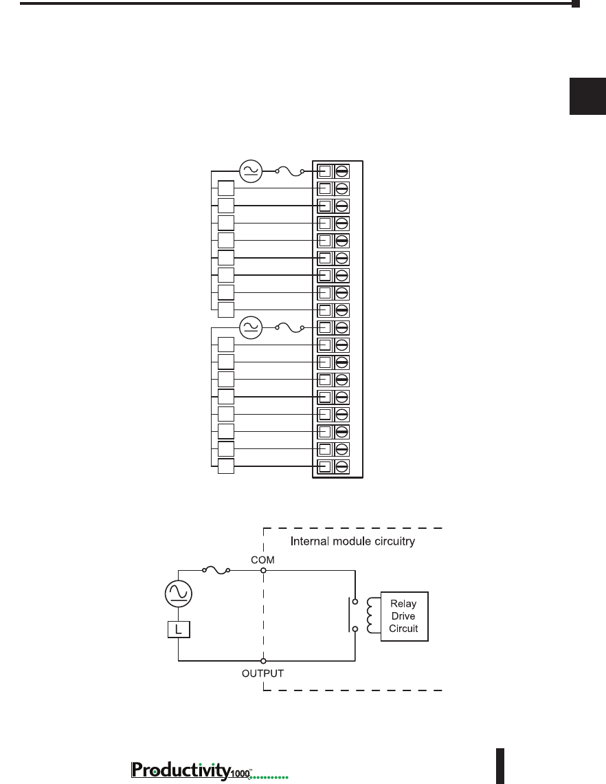
Chapter 2: Specifications
1
2
3
4
5
6
7
8
9
10
11
12
13
14
A
B
C
D
2–33
Hardware User Manual, 1st Edition,
1000
P1-16TR Relay Output (continued)
Wiring Diagrams
P1-16TR Schematic and Wiring Diagram
C1
1
2
3
4
5
6
7
8
C2
9
10
11
12
13
14
15
16
6–24 VDC
6–120 VAC
50–60 Hz L
L
L
L
L
L
L
L
L
L
L
L
L
L
L
L
EXTERNAL
FUSE
RECOMMENDED
6–24 VDC
6–120 VAC
50–60 Hz
1234567891011121813 14 15 16 17
8A Max
6–24 VDC
6–120 VAC
50–60 Hz 8A Max
User Supplied
External Fuse
P1-16TR Schematic and Wiring Diagram
C1
1
2
3
4
5
6
7
8
C2
9
10
11
12
13
14
15
16
6–24 VDC
6–120 VAC
50–60 Hz L
L
L
L
L
L
L
L
L
L
L
L
L
L
L
L
EXTERNAL
FUSE
RECOMMENDED
6–24 VDC
6–120 VAC
50–60 Hz
12345678910 11 12 1813 14 15 16 17
C1
1
2
3
4
5
6
7
8
C2
9
10
11
12
13
14
15
16
135–240 VAC
50–60 Hz
L
L
L
L
L
L
L
L
L
L
L
L
L
L
L
L
C1 and C2 Must
Be Linked Externally
for this Voltage Range
1234567891011121813 14 15 16 17
6–24 VDC
6–120 VAC
50 –60 Hz
8A Max
User Supplied
External Fuse
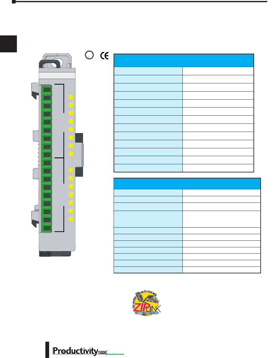
Chapter 2: Specifications
1
2
3
4
5
6
7
8
9
10
11
12
13
14
A
B
C
D
1000 Hardware User Manual, 1st Edition
2–34
P1-15CDD1 Input/Output Module
The P1-15CDD1 Input/Output Module provides eight 12–24 VDC inputs plus seven
outputs that sink up to 1A per output for loads connected to 3.3–24 V supplies for use with
the Productivity1000 system.
P1-15CDD1
C1
1
2
3
4
5
6
7
8
1
2
3
4
5
6
7
V+
C2
INPUTSOUTPUTS
12-24VDC IN
3.3-24V OUT
U
L
CUS
R
We recommend using pre-wired ZIPLink cables
and connection modules. See Chapter 5.
If you wish to hand-wire your module, removable
terminal blocks are sold separately. Order part
number P2-RTB or P2-RTB-1
Terminal blocks sold separately.
Input Specications
Inputs
8 (sink/source)
Rated Voltage
12–24 VDC
Operating Voltage Range
10.2–26.4 VDC
Input Current
7.6 mA @ 24VDC
Maximum Input Current
8.8 mA @ 27.6 VDC)
Maximum ON Current
2.5 mA
Maximum OFF Current
0.5 mA
ON Voltage Level
>7.6 VDC
OFF Voltage Level
<6.4 VDC
OFF to ON Response
2ms Max
ON to OFF Response
2ms Max
Status Indicators
Logic Side (8 points)
Commons
1
Output Specications
Outputs per Module
7 sinking
Rated Voltage
3.3–24 VDC
Operating Voltage Range
2.8–30 VDC
Maximum Output Current
1A continuous
4A temporary overload, 50ms
6A temporary overload, 10ms
On Voltage Drop
0.18 VDC
OFF to ON Response
0.5 ms
ON to OFF Response
0.5 ms
Status Indicators
Logic Side (7 points)
Commons
1
Maximum Applicable Fuse
8A
External Power Supply Required
12–24 VDC (-15%/+20%) @ 25mA

Chapter 2: Specifications
1
2
3
4
5
6
7
8
9
10
11
12
13
14
A
B
C
D
2–35
Hardware User Manual, 1st Edition,
1000
P1-15CDD1 Input/Output Module (continued)
Removable Terminal Block Specications
Part Number P2-RTB P2-RTB-1
Number of
Positions
18 Screw Terminals 18 Spring Clamp Terminals
Wire Range
30–16 AWG (0.051–1.31mm²)
Solid / Stranded Conductor
3/64 in. (1.2 mm) Insulation Max.
1/4 in. (6–7 mm) Strip Length
28–16 AWG (0.081–1.31 mm²)
Solid / Stranded Conductor
3/64 in. (1.2 mm) Insulation Max.
19/64 in. (7–8 mm) Strip Length
Conductors
“USE COPPER CONDUCTORS, 75°C” or Equivalent.
Screw Driver
0.1 in (2.5 mm) Maximum*
Screw Size
M2 N/A
Screw Torque
2.5 lb·in (0.28 N·m) N/A
General Specications
Operating Temperature
0° to 60°C (32° to 140°F)
Storage Temperature
-20° to 70°C (-4° to 158°F)
Humidity
5 to 95% (non-condensing)
Environmental Air
No corrosive gases permitted
Vibration
IEC60068-2-6 (Test Fc)
Shock
IEC60068-2-27 (Test Ea)
Field to Logic Side Isolation
1800VAC applied for 1 second
Insulation Resistance
>10MΩ @ 500VDC
Heat Dissipation
1800mW
Enclosure Type
Open Equipment
Module Location
Any I/O slot in any Productivity1000 System.
Field Wiring
Use ZIPLink Wiring System or removable terminal
block (sold separately). See “Wiring Options” in
Chapter 5.
EU Directive
See the “EU Directive” topic in the Productivity Suite
Help File. Information can also be obtained at: www.
productivity1000.com
Connector Type (sold separately)
18-position removable terminal block
Weight
71g (2.5 oz)
Agency Approvals
UL 61010-2-201 le E139594, Canada & USA
CE (EN61131-2 EMC and EN61010-2-201 Safety)*
* See CE Declaration of Conformity for details..
* Recommended screw driver: P/N TW-SD-MSL-1
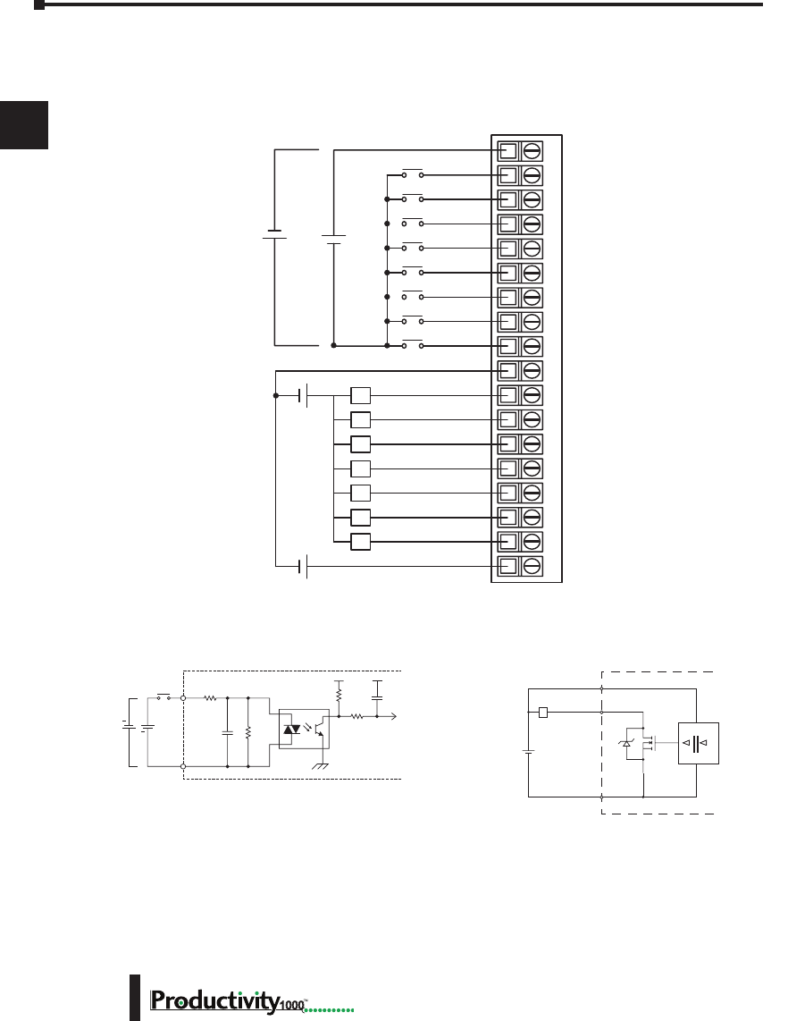
Chapter 2: Specifications
1
2
3
4
5
6
7
8
9
10
11
12
13
14
A
B
C
D
1000 Hardware User Manual, 1st Edition
2–36
P1-15CDD1 Input/Output Module (continued)
P1-15CDD1 Schematic and Wiring Diagram
12–24 VDC
V+
OUTPUT
INTERNAL MODULE
C1/C2
DIGITAL
ISOLATION
Sink
L
INPUT
COM
Internal Module Circuitry
Optical Isolator
24VDC
+
+
Typical Input Circuit
Typical Output Circuit
12345678910 11 12 1813 14 15 16 17
L
L
L
L
L
L
L
C1
1
2
3
4
5
6
7
8
C2
1
2
3
4
5
6
7
V+
3.3–24 VDC
+ -
+
-
+
-
24VDC
12–24 VDC
+ -
Wiring Diagrams
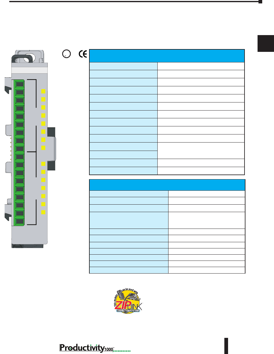
Chapter 2: Specifications
1
2
3
4
5
6
7
8
9
10
11
12
13
14
A
B
C
D
2–37
Hardware User Manual, 1st Edition,
1000
P1-15CDD2 Input/Output
The P1-15CDD2 Input/Output Module provides eight 12–24 VDC inputs plus seven 12–24
VDC outputs that source up to 1A per output to loads connected to ground for use with the
Productivity1000 system.
P1-15CDD2
12-24VDC
INPUT/OUTPUT
C1
1
2
3
4
5
6
7
8
1
2
3
4
5
6
7
C2
V+
INPUTSOUTPUTS
U
L
C
US
R
We recommend using pre-wired ZIPLink cables
and connection modules. See Chapter 5.
If you wish to hand-wire your module, removable
terminal blocks are sold separately. Order part
number P2-RTB or P2-RTB-1.
Input Specications
Inputs per Module
8 (Sinking/Sourcing)
Rated Voltage
12–24 VDC
Operating Voltage Range
10.4–28.8 VDC
Input Current
8.4 mA @ 24VDC
Maximum Input Current
11mA @ 28.8 VDC)
Input Impedance
3kΩ
Maximum ON Current
2.5 mA
Maximum OFF Current
1.8 mA
ON Voltage Level*
>8VDC
OFF Voltage Level
<6VDC
OFF to ON Response
2ms max
ON to OFF Response
Status Indicators
Logic Side (8 points)
Commons
1
Output Specications
Outputs per Module
7 (sourcing)
Voltage Rating
12–24 VDC
Operating Voltage Range
10.2–28.8 VDC
Maximum Output Current
1A continuous
4A temporary overload, 50ms
6A temporary overload, 10ms
On Voltage Drop
25mV
OFF to ON Response
0.5 ms
ON to OFF Response
0.5 ms
Status Indicators
Logic Side (7 points)
Commons
1
Maximum Applicable Fuse
8A
External Power Supply Required
12–24 VDC (-20%/+25%) @ 50mA
Terminal blocks sold separately.

Chapter 2: Specifications
1
2
3
4
5
6
7
8
9
10
11
12
13
14
A
B
C
D
1000 Hardware User Manual, 1st Edition
2–38
Removable Terminal Block Specications
Part Number P2-RTB P2-RTB-1
Number of
Positions
18 Screw Terminals 18 Spring Clamp Terminals
Wire Range
30–16 AWG (0.051–1.31 mm²)
Solid / Stranded Conductor
3/64 in. (1.2 mm) Insulation
Max.
1/4 in. (6–7 mm) Strip Length
28–16 AWG (0.081–1.31 mm²)
Solid / Stranded Conductor
3/64 in. (1.2 mm) Insulation Max.
19/64 in. (7–8 mm) Strip Length
Conductors
“USE COPPER CONDUCTORS, 75°C” or Equivalent.
Screw Driver
0.1 in (2.5 mm) Maximum*
Screw Size
M2 N/A
Screw Torque
2.5 lb·in (0.28 N·m) N/A
P1-15CDD2 Input/Output Module (continued)
General Specications
Operating Temperature
0° to 60°C (32° to 140°F)
Storage Temperature
-20° to 70°C (-4° to 158°F)
Humidity
5 to 95% (non-condensing)
Environmental Air
No corrosive gases permitted
Vibration
IEC60068-2-6 (Test Fc)
Shock
IEC60068-2-27 (Test Ea)
Field to Logic Side Isolation
1800VAC applied for 1 second
Insulation Resistance
>10MΩ @ 500VDC
Heat Dissipation
1800mW
Enclosure Type
Open Equipment
Module Keying
Electronic
Module Location
Any I/O position in a Productivity1000 system
Field Wiring
Use ZIPLink Wiring System or removable terminal
block (sold separately). See “Wiring Options” in
Chapter 5.
EU Directive
See the “EU Directive” topic in the Productivity Suite
Help File. Information can also be obtained at:
www.productivity1000.com
Connector Type (sold separately)
18-position removable terminal block
Weight
71g (2.5 oz)
Agency Approvals
UL 61010-2-201 le E139594, Canada & USA
CE (EN61131-2 EMC and EN61010-2-201 Safety)*
* See CE Declaration of Conformity for details.
* Recommended screw driver: P/N TW-SD-MSL-1
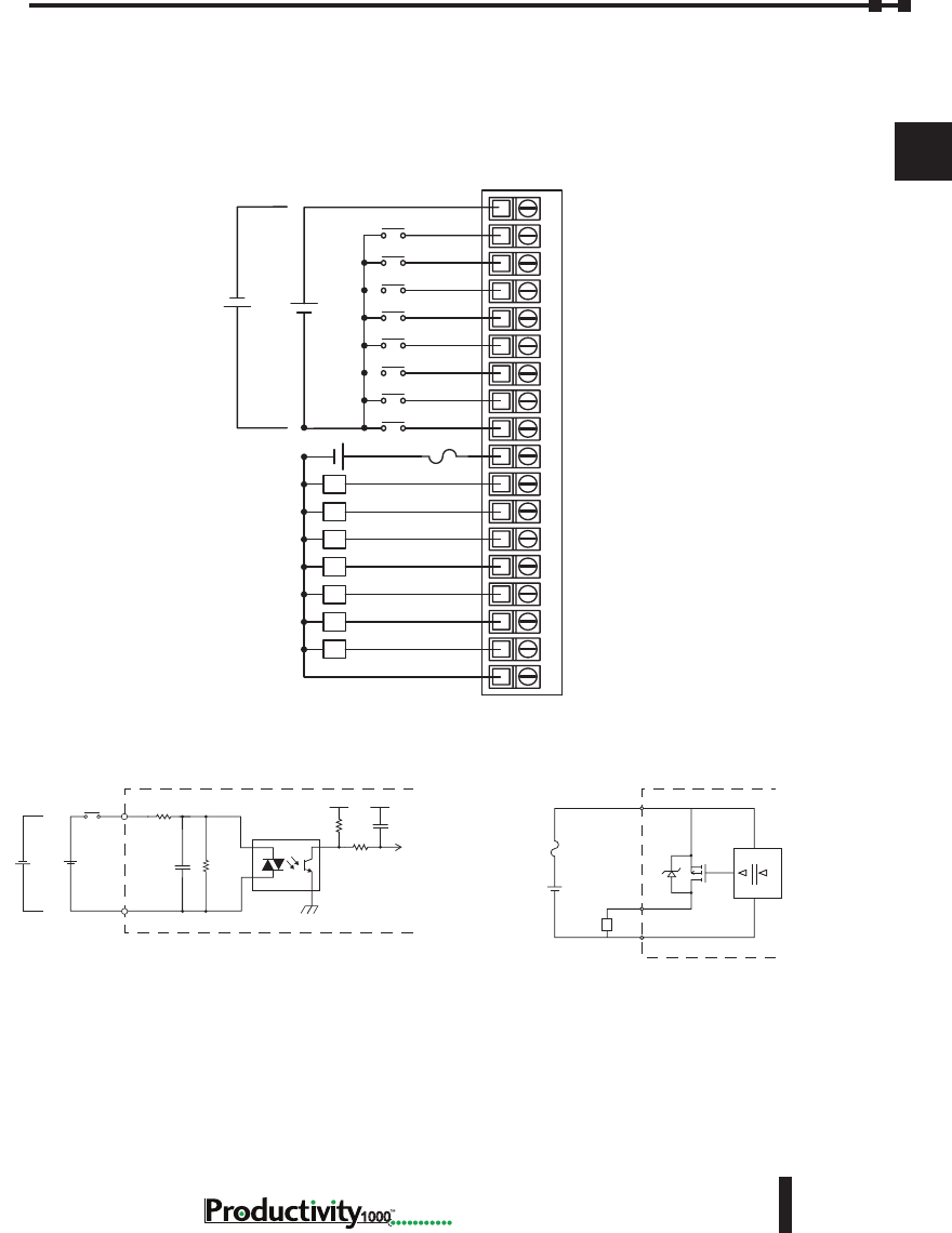
Chapter 2: Specifications
1
2
3
4
5
6
7
8
9
10
11
12
13
14
A
B
C
D
2–39
Hardware User Manual, 1st Edition,
1000
Wiring Diagrams
P1-15CDD2 Input/Output Module (continued)
P1-15CDD2 Schematic and Wiring Diagram
12345678910 11 12 1813 14 15 16 17
L
L
L
L
L
L
L
C1
1
2
3
4
5
6
7
8
V+
1
2
3
4
5
6
7
C2
12–24 VDC
+ -
+
-
+
-
24VDC
8A Max
+12–24 VDC
INPUT
INTERNAL MODULE CIRCUITRY
COM
Optical Isolator
+
-
+
-
Equivalent Input Circuit
+12–24 VDC
OUTPUT
INTERNAL MODULE CIRCUITRY
COM
Optical Isolator
+-
Equivalent Output Circuit
*
L
+V
*Zener Diode Power Dissipation: 200mW
8A Max
P1-15CDD2 Schematic and Wiring Diagram
12345678910 11 12 1813 14 15 16 17
L
L
L
L
L
L
L
C1
1
2
3
4
5
6
7
8
V+
1
2
3
4
5
6
7
C2
12–24 VDC
+ -
+
-
+
-
24VDC
8A Max
+12–24 VDC
INPUT
INTERNAL MODULE CIRCUITRY
C1
Optical Isolator
+
-
+
-
Equivalent Input Circuit
12–24 V
V+ INTERNAL MODULE
DIGITAL
ISOLATION
Source
LC2
8A Max
+
-
Equivalent Output Circuit
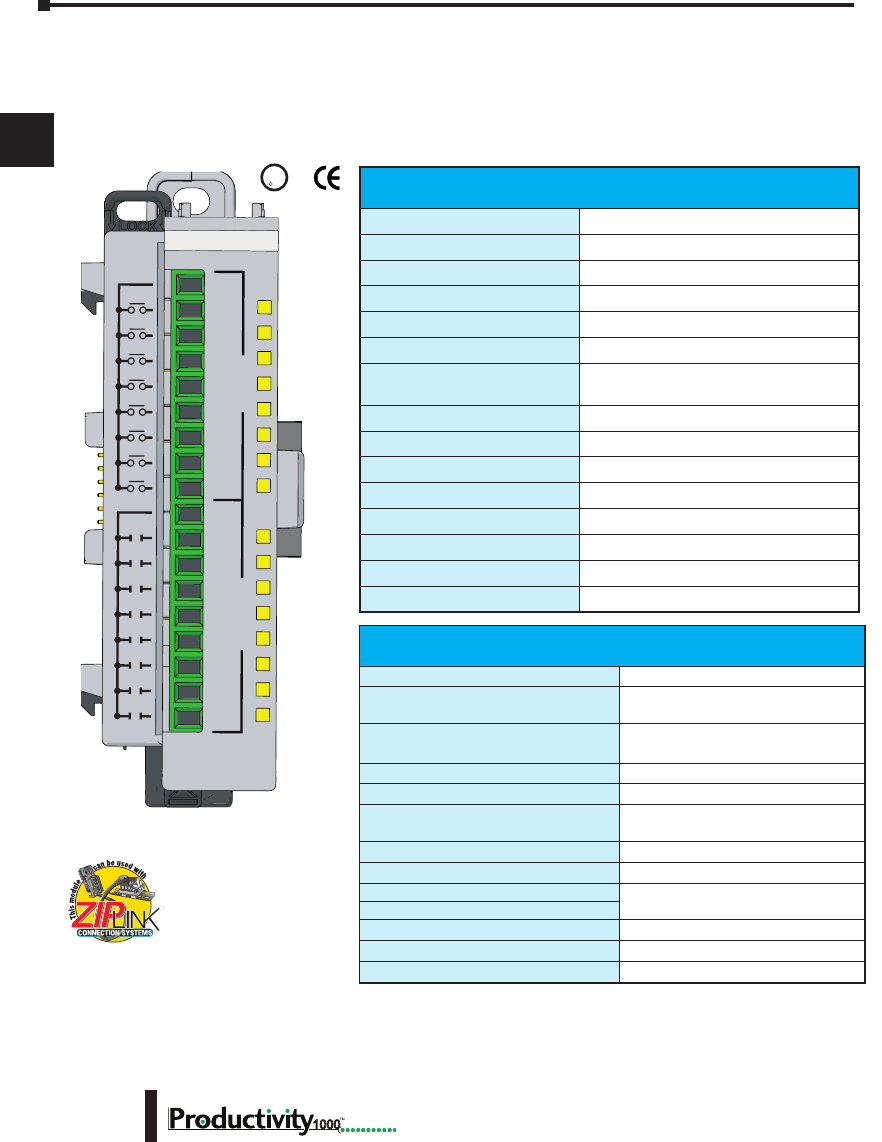
Chapter 2: Specifications
1
2
3
4
5
6
7
8
9
10
11
12
13
14
A
B
C
D
1000 Hardware User Manual, 1st Edition
2–40
Input Specications
Inputs per Module
8 (sink/source)
Rated Voltage
24 VAC/VDC
Operating Voltage Range
20.4–27.6 VAC/VDC
Peak Voltage
27.6 VAC/ 30VDC
AC Frequency
47–63 Hz
Input Current
8mA @ 24 VAC/VDC
Maximum Input Current
10mA @ 27.6 VAC
10mA @ 30VDC
ON Voltage Level
>9.5 VDC, >8VAC
OFF Voltage Level
<4.5 VDC, <4VAC
Maximum ON Current
2.5 mA
Maximum OFF Current
0.5 mA
OFF to ON Response
AC: 10ms DC: 6ms
ON to OFF Response
AC: 20ms DC: 10ms
Status Indicators
Logic Side (8 points)
Commons
1 (8 points/common)
P1-16CDR Discrete Input/ Relay Output Module
The P1-16CDR Discrete Input / Relay Output Module provides eight 24 VAC/VDC inputs
and eight relay outputs for use with the Productivity1000 system.
P1-16CDR
1
2
3
4
5
6
7
8
1
2
3
4
5
6
7
8
C2
C1
INPUTSOUTPUTS
24VAC/VDC IN
RELAY OUTPUT
U
L
CUS
R
We recommend using pre-wired ZIPLink
cables and connection modules. See
Chapter 5.
If you wish to hand-wire your module, removable
terminal blocks are sold separately. Order part
number P2-RTB or P2-RTB-1.
Terminal blocks sold separately.
Output Specications
Outputs per Module
8
Rated Voltage
6.25–24 VDC
6–120 VAC
Operating Voltage Range
5.31–28.8 VDC
5–132 VAC
Output Type
Relay, Form A (SPST)
AC Frequency
47–63 Hz
Maximum Output Current
1A / point, 8A / common @ 60°C
for both AC and DC
Minimum Load Current
5mA @ 5VDC
Maximum Inrush Current
5A for 10ms
OFF to ON Response
m10ms
ON to OFF Response
Status Indicators
Logic Side (8 points)
Commons
1 (8 point / common)
Maximum Applicable Fuse
8A

Chapter 2: Specifications
1
2
3
4
5
6
7
8
9
10
11
12
13
14
A
B
C
D
2–41
Hardware User Manual, 1st Edition,
1000
P1-16CDR Discrete Input/ Relay Output Module
Removable Terminal Block Specications
Part Number P2-RTB P2-RTB-1
Number of
Positions
18 Screw Terminals 18 Spring Clamp Terminals
Wire Range
30–16 AWG (0.051–1.31 mm²)
Solid / Stranded Conductor
3/64 in. (1.2 mm) Insulation Max.
1/4 in. (6–7 mm) Strip Length
28–16 AWG (0.081–1.31 mm²)
Solid / Stranded Conductor
3/64 in. (1.2 mm) Insulation Max.
19/64 in. (7–8 mm) Strip Length
Conductors
“USE COPPER CONDUCTORS, 75°C” or Equivalent.
Screw Driver
0.1 in (2.5 mm) Maximum*
Screw Size
M2 N/A
Screw Torque
2.5 lb·in (0.28 N·m) N/A
General Specications
Operating Temperature
0° to 60°C (32° to 140°F)
Storage Temperature
-20° to 70°C (-4° to 158°F)
Humidity
5 to 95% (non-condensing)
Environmental Air
No corrosive gases permitted
Vibration
IEC60068-2-6 (Test Fc)
Shock
IEC60068-2-27 (Test Ea)
Field to Logic Side Isolation
1800VAC applied for 1 second
Insulation Resistance
>10MΩ @ 500VDC
Heat Dissipation
2730mW
Enclosure Type
Open Equipment
Module Location
Any I/O position in a Productivity1000 System.
Field Wiring
Use ZIPLink Wiring System or removable terminal
block (sold separately). See “Wiring Options” in
Chapter 5.
EU Directive
See the “EU Directive” topic in the Productivity Suite
Help File. Information can also be obtained at:
www.productivity1000.com
Connector Type (sold separately)
18-position removable terminal block
Weight
88g (3.2 oz)
Agency Approvals
UL 61010-2-201 le E139594, Canada & USA
CE (EN61131-2 EMC and EN61010-2-201 Safety)*
* See CE Declaration of Conformity for details.
* Recommended screw driver: P/N TW-SD-MSL-1
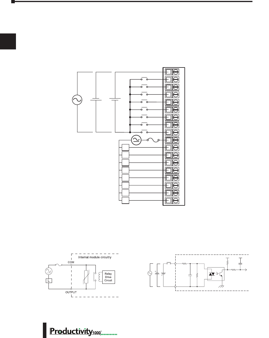
Chapter 2: Specifications
1
2
3
4
5
6
7
8
9
10
11
12
13
14
A
B
C
D
1000 Hardware User Manual, 1st Edition
2–42
P1-16CDR Discrete Input/ Relay Output Module (continued)
Wiring Diagrams
P1-16CDR Schematic and Wiring Diagram
C1
1
2
3
4
5
6
7
8
C2
1
2
3
4
5
6
7
8
24VAC
50–60 Hz
L
L
L
L
L
L
L
L
EXTERNAL
FUSE
RECOMMENDED
6–24 VDC
6–120 VAC
50–60 Hz
12345678910 11 12 1813 14 15 16 17
+
+
-
-
24VDC
6–24 VDC
6–120 VAC
50 –60 Hz
8A
User Supplied
External Fuse
INPUT
COM
Internal Module Circuitry
Optical Isolator
24VDC
+
+
24VAC
Equivalent Input Circuit
Equivalent Output Circuit
P1-16CDR Schematic and Wiring Diagram
C1
1
2
3
4
5
6
7
8
C2
1
2
3
4
5
6
7
8
24VAC
50–60 Hz
L
L
L
L
L
L
L
L
EXTERNAL
FUSE
RECOMMENDED
6–27 VDC
6–240 VAC
50–60 Hz
12345678910 11 12 1813 14 15 16 17
+
+
-
-
24VDC
6–27 VDC
6–240 VAC
50 –60 Hz
8A
User Supplied
External Fuse
INPUT
COM
Internal Module Circuitry
Optical Isolator
24VDC
+
+
24VAC
Equivalent Input Circuit
Equivalent Output Circuit

1000
3
3
3
AnAlog I/o
SpecIfIcAtIonS
Chapter
Chapter
Chapter
In This Chapter...
Analog I/O Modules Overview ..................................................................................3–2
Analog I/O Modules ..................................................................................................3–3
Analog Input Modules ...............................................................................................3–4
Analog Output Modules .......................................................................................... 3–21
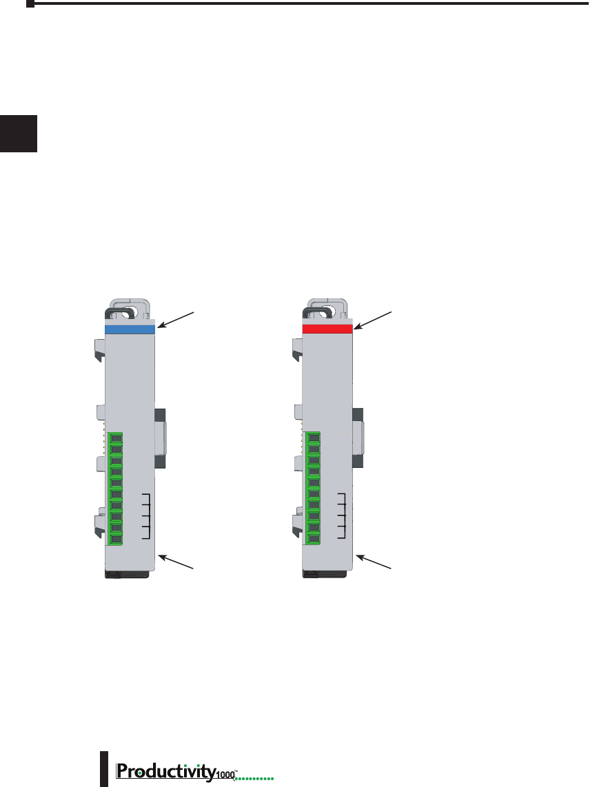
Chapter 3: Analog I/O Specifications
1
2
3
4
5
6
7
8
9
10
11
12
13
14
A
B
C
D
Hardware User Manual, 1st Edition
3–2 1000
Analog I/O Modules Overview
A variety of analog I/O modules are available for use with Productivity1000 system.
Each I/O module is identified as an “Input” or “Output”module on its front panel using the
color coding scheme listed below. See Chapter 2 for discrete I/O module specifications and
Chapter 5 for module wiring and communications. The following pages contain the analog
I/O module specifications.
There are six analog I/O modules available; four Input and 2 Output modules. The
specifications and wiring diagrams, along with configuration and signal scaling information
are in this chapter.
Use the hardware configuration tool in the Productivity Suite programming software to
setup the I/O modules. See the Productivity Suite help file for in-depth configuration and
programming concepts.
Analog Input Modules
Input Type Output Type
Module Type and
Part Number
(Blue: Input)
Analog Output Modules
Module Type and
Part Number
(Red: Output)
COM
COM
COM
COM
24V
I2+
I3+
I4+
0V
I1+
P1-04ADL-1
0-20mA INPUT
ANALOG
24V
I2+
I3+
I4+
0V
COM
COM
COM
COM
I1+
P1-04DAL-1
4-20mA OUT
ANALOG
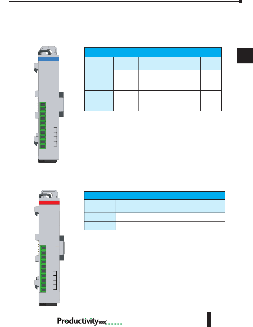
Chapter 3: Analog I/O Specifications
1
2
3
4
5
6
7
8
9
10
11
12
13
14
A
B
C
D
3–3
Hardware User Manual, 1st Edition
1000
Productivity1000 Analog Input Modules
Part Number Number of
Channels Description See Page
P1-04ADL-1 4Analog Input (Current) 3–4
P1-04ADL-2 4Analog Input (Voltage) 3–8
P1-04THM 4Analog Thermocouple Input 3-12
P1-04NTC 4Analog Thermistor Input 3–17
Productivity1000 Analog Output Modules
Part Number Number of
Channels Description See Page
P1-04DAL-1 4Analog Output (Current) 3–21
P1-04DAL-2 4Analog Output (Voltage) 3–25
Analog Input Modules
Analog Output Modules
Analog I/O Modules
COM
COM
COM
COM
24V
I2+
I3+
I4+
0V
I1+
P1-04ADL-1
0-20mA INPUT
ANALOG
24V
I2+
I3+
I4+
0V
COM
COM
COM
COM
I1+
P1-04DAL-1
4-20mA OUT
ANALOG
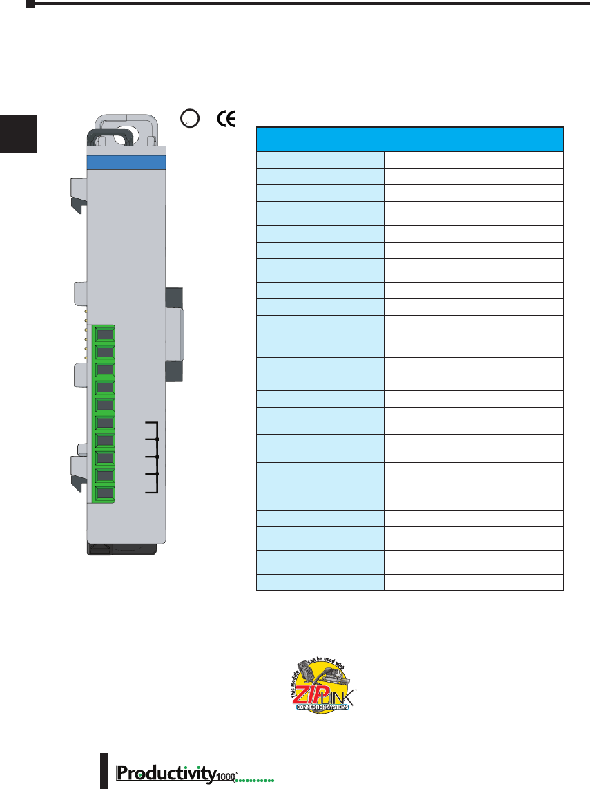
Chapter 3: Analog I/O Specifications
1
2
3
4
5
6
7
8
9
10
11
12
13
14
A
B
C
D
Hardware User Manual, 1st Edition
3–4 1000
P1-04ADL-1 Analog Input
The P1-04ADL-1 Low Resolution Analog Input Module provides four current sinking
channels for converting 0–20 mA analog signals to a digital value of 0–8191 (13-bit) for use
with the Productivity1000 system.
We recommend using pre-wired ZIPLink cables
and connection modules. See Chapter 5.
If you wish to hand-wire your module, removable
terminal blocks are sold separately. Order part
number P1-10RTB or P1-10RTB-1
Input Specications
Input Channels
4
Input Range
0–20mA
Signal Resolution
13-bit
Resolution Value of LSB
(least signicant bit)
0–20mA = 2.44 μA per count
(1LSB = 1 count)
Data Range
0–8191 counts
Input Type
Sinking, Single-ended (1 common)
Maximum Continuous
Overload
±31mA
Input Impedance
247Ω, ±0.5%, 1/4W Current Input
Filter Characteristics
Low Pass, -3dB @ 120Hz
Sample Duration Time
2.5 ms per channel
(Does not include ladder scan time)
All Channel Update Rate
10ms
Open Circuit Detection Time
Zero reading within 100ms
Conversion Method
Successive approximation
Accuracy vs Temperature
±75PPM / ºC maximum
Maximum Inaccuracy
0.5% of range
(including temperature drift)
Linearity Error (end to end)
±0.037% of range
Monotonic with no missing codes
Input Stability and
Repeatability
±0.024% of range
Maximum Full Scale
Calibration Error
±0.098% of range
Offset Calibration Error
±0.098% of range
Max Crosstalk at DC, 50Hz
and 60Hz
±0.049% of range
Recommended Fuse
(external)
Edison S500-32-R, 0.032 A fuse
External DC Power Required
24VDC (-20% / + 25%), 30mA
Terminal block sold separately.
COM
COM
COM
COM
24V
I2+
I3+
I4+
0V
I1+
P1-04ADL-1
0-20mA INPUT
ANALOG
U
L
C
US
R

Chapter 3: Analog I/O Specifications
1
2
3
4
5
6
7
8
9
10
11
12
13
14
A
B
C
D
3–5
Hardware User Manual, 1st Edition
1000
P1-04ADL-1 Analog Input (continued)
Removable Terminal Block Specications
Part Number P1-10RTB P1-10RTB-1
Number of
positions
10 Screw Terminals 10 Spring Clamp Terminals
Wire Range
30–16 AWG (0.051–1.31 mm²)
Solid / Stranded Conductor
3/64 in. (1.2 mm) Insulation Max.
1/4 in (6– 7 mm) Strip Length
28–16 AWG (0.081–1.31 mm²)
Solid / Stranded Conductor
3/64 in (1.2 mm) Insulation Max.
19/64 in (7–8 mm) Strip Length
Conductors
“USE COPPER CONDUCTORS, 75ºC” or equivalent.
Screw Driver
0.1 in (2.5 mm) Maximum
Screw Size
M2 N/A
Screw Torque
2.5 lb in (0.28 N·m) N/A
* See CE Declaration of Conformity for details.
* Recommended screw driver P/N: TW-SD-MSL-1.
General Specications
Operating Temperature
0º to 60ºC (32º to 140ºF)
Storage Temperature
-20º to 70ºC (-4º to 158ºF)
Humidity
5 to 95% (non-condensing)
Environmental Air
No corrosive gases permitted
Vibration
IEC60068-2-6 (Test Fc)
Shock
IEC60068-2-27 (Test Ea)
Field to Logic Side
Isolation
1800VAC applied for 1 second
Insulation Resistance
>10MΩ @ 500VDC
Heat Dissipation
1200mW
Enclosure Type
Open Equipment
Module Location
Any I/O position in a Productivity1000 System
Field Wiring
Use ZIPLink Wiring System or removable terminal
block (not included). See “Wiring Options” in
Chapter 5.
EU Directive
See the “EU Directive” topic in the Productivity Suite
Help File. Information can also be obtained at:
www.productivity2000.com
Terminal Type (sold
separately)
10-position Removable Terminal Block
Weight
71g (2.5 oz)
Agency Approvals
UL 61010-2-201 le E139594, Canada & USA
CE (EN61131-2 EMC and EN61010-2-201 Safety)*
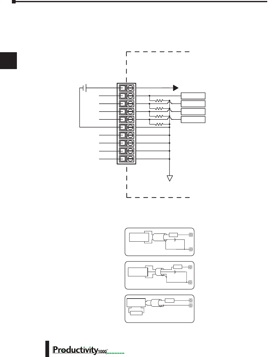
Chapter 3: Analog I/O Specifications
1
2
3
4
5
6
7
8
9
10
11
12
13
14
A
B
C
D
Hardware User Manual, 1st Edition
3–6 1000
P1-04ADL-1 Analog Input (continued)
Wiring Diagrams
P1-04ADL-1 Schematic
I1+
I2+
I3+
I4+
0V
COM
COM
- +
24 VDC User
Supplied Power
CH1 ADC
CH2 ADC
CH3 ADC
CH4 ADC
ISOLATED ANALOG
CIRCUIT POWER
ISOLATED ANALOG
CIRCUIT COMMON
INTERNAL
MODULE CIRCUITRY
24V
247Ω
247Ω
247Ω
247Ω
COM
COM
P1-04ADL-1 Wiring Diagram
.032 A
2-Wire 4–20 mA
Transmitter
fuse
.032 A
fuse
Note: Do not connect both ends of shield.
I+
I+
COM
4-Wire 4–20 mA
Transmitter
Current Input Circuits
2-Wire Transmitter
4-Wire Transmitter
An Edison S500-32-R 0.032 A fast-acting
fuse is recommended for current loops.
+24VDC User
Supplied Power
+
–
+
–
User Supplied
Transmitter Power
AC or DC
+
.032 A
fuse
COM
I+
3-Wire Current
Transmitter
3-Wire Transmitter
+
–+24VDC User
Supplied Power
+–
+–
COM
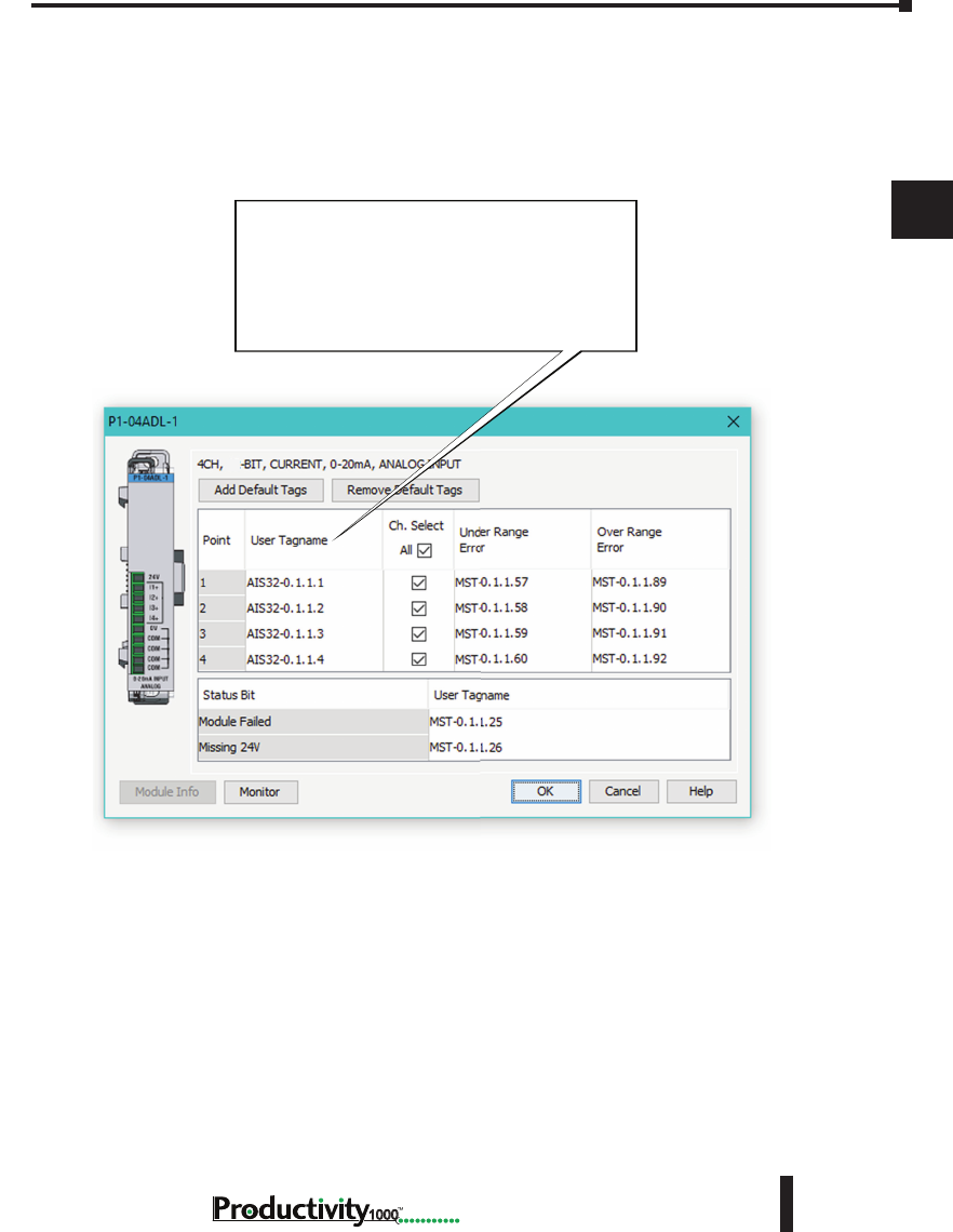
Chapter 3: Analog I/O Specifications
1
2
3
4
5
6
7
8
9
10
11
12
13
14
A
B
C
D
3–7
Hardware User Manual, 1st Edition
1000
P1-04ADL-1 Analog Input (continued)
Module Configuration
Module Configuration
Using the Hardware Configuration tool in
the Productivity Suite programming software,
drag and drop the P1-04ADL-1 module into the
configuration.
If desired, assign a User Tagname to each
input point (channel) selected and to each Status
Bit Item.
13
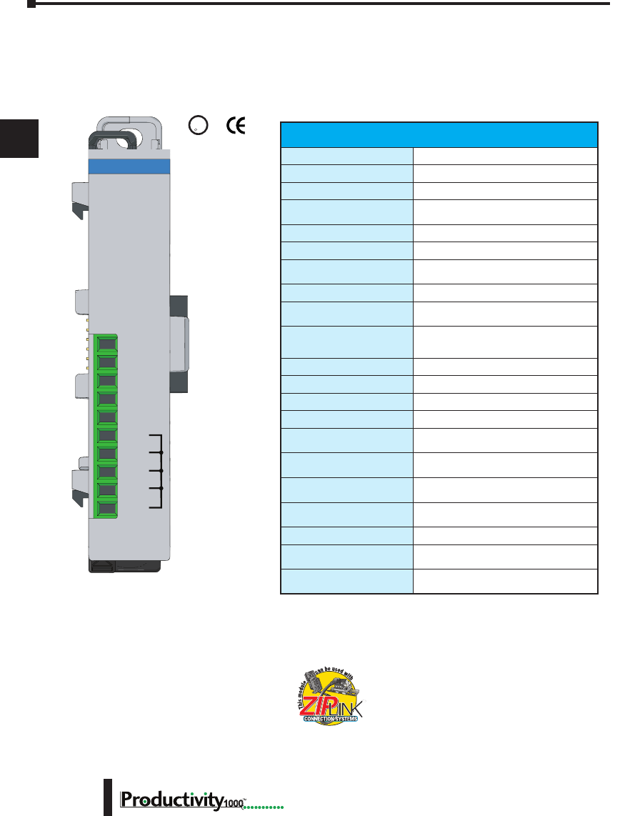
Chapter 3: Analog I/O Specifications
1
2
3
4
5
6
7
8
9
10
11
12
13
14
A
B
C
D
Hardware User Manual, 1st Edition
3–8 1000
P1-04ADL-2 Analog Input
The P1-04ADL-2 Low Resolution Voltage Analog Input Module provides four channels for
converting 0–10 VDC analog signals to digital values of 0–8191 (13-bit) for use with the
Productivity1000 system.
We recommend using pre-wired ZIPLink cables
and connection modules. See Chapter 5.
If you wish to hand-wire your module, removable
terminal blocks are sold separately. Order part
number P1-10RTB or P1-10RTB-1
Input Specications
Input Channels
4
Input Range
0–10 VDC
Signal Resolution
13-bit
Resolution Value of LSB
0–10 VDC = 1.22 mV per count
(1 LSB = 1 count)
Data Range
0–8191 counts
Input Type
Single-ended (1 common)
Maximum Continuous
Overload
±100VDC
Input Impedance
>150kΩ
Hardware Filter
Characteristics
Low Pass, -3dB @ 300Hz
Sample Duration Time
2.5 ms per channel
(does not include ladder scan time)
All Channel Update Rate
10ms
Open Circuit Detection Time
Zero reading within 100ms
Conversion Method
Successive approximation
Accuracy vs Temperature
±75PPM / ºC maximum
Maximum Inaccuracy
0.5% of range
(including temperature drift)
Linearity Error (end to end)
±0.036% of range
Monotonic with no missing codes
Input Stability and
Repeatability
±0.024% of range
Full Scale Calibration Error
(including offset)
±0.097% of range
Offset Calibration Error
±0.097% of range
Max Crosstalk at DC,
50Hz and 60Hz
±0.049% of range
External 24VDC Power
Required
24VDC (-20% / +25%), 30mA
Terminal block sold separately.
24V
V2+
V3+
V4+
0V
COM
COM
COM
COM
V1+
P1-04ADL-2
0-10VDC INPUT
ANALOG
U
L
CUS
R

Chapter 3: Analog I/O Specifications
1
2
3
4
5
6
7
8
9
10
11
12
13
14
A
B
C
D
3–9
Hardware User Manual, 1st Edition
1000
P1-04ADL-2 Analog Input (continued)
* * See CE Declaration of Conformity for details.
Removable Terminal Block Specications
Part Number P1-10RTB P1-10RTB-1
Number of
positions
10 Screw Terminals 10 Spring Clamp Terminals
Wire Range
30–16 AWG (0.051–1.31 mm²)
Solid / Stranded Conductor
3/64 in. (1.2 mm) Insulation Max.
1/4 in (6– 7 mm) Strip Length
28–16 AWG (0.081–1.31 mm²)
Solid / Stranded Conductor
3/64 in (1.2 mm) Insulation Max.
19/64 in (7–8 mm) Strip Length
Conductors
“USE COPPER CONDUCTORS, 75ºC” or equivalent.
Screw Driver
0.1 in (2.5 mm) Maximum
Screw Size
M2 N/A
Screw Torque
2.5 lb in (0.28 N·m) N/A
* Recommended screw driver P/N: TW-SD-MSL-1.
General Specications
Operating Temperature
0º to 60ºC (32º to 140ºF)
Storage Temperature
-20º to 70ºC (-4º to 158ºF)
Humidity
5 to 95% (non-condensing)
Environmental Air
No corrosive gases permitted
Vibration
IEC60068-2-6 (Test Fc)
Shock
IEC60068-2-27 (Test Ea)
Field to Logic Side
Isolation
1800VAC applied for 1 second
Insulation Resistance
>10MΩ @ 500VDC
Heat Dissipation
1200mW
Enclosure Type
Open Equipment
Module Location
Any I/O position in a Productivity1000 System
Field Wiring
Use ZIPLink Wiring System or removable terminal
block (not included). See “Wiring Options” in
Chapter 5.
EU Directive
See the “EU Directive” topic in the Productivity Suite
Help File. Information can also be obtained at:
www.productivity2000.com
Terminal Type (sold
separately)
10-position Removable Terminal Block
Weight
62g (2.2 oz)
Agency Approvals
UL 61010-2-201 le E139594, Canada & USA
CE (EN61131-2 EMC and EN61010-2-201 Safety)*
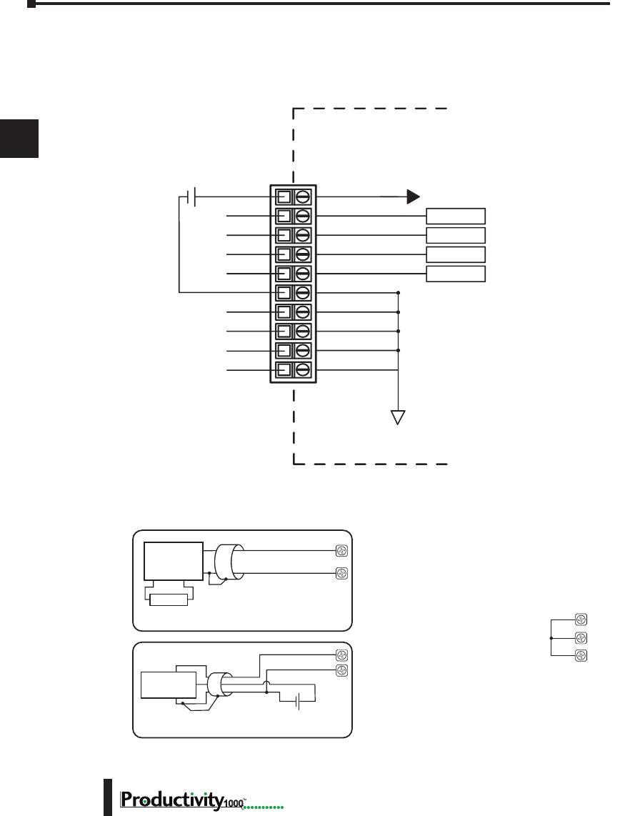
Chapter 3: Analog I/O Specifications
1
2
3
4
5
6
7
8
9
10
11
12
13
14
A
B
C
D
Hardware User Manual, 1st Edition
3–10 1000
P1-04ADL-2 Analog Input (continued)
Wiring Diagrams
P1-04ADL-2 Schematic
V1+
V2+
V3+
V4+
0V
COM
COM
- +
24 VDC User
Supplied Power
CH1 ADC
CH2 ADC
CH3 ADC
CH4 ADC
ISOLATED ANALOG
CIRCUIT POWER
ISOLATED ANALOG
CIRCUIT COMMON
INTERNAL
MODULE CIRCUITRY
24V
COM
COM
P1-04ADL-2 Wiring Diagram
- +
24 VDC User
Supplied Power
Voltage Input Circuits
+
3-Wire Voltage
Transmitter
V+
COM
3-Wire Transmitter
4-Wire Transmitter
COM
V+
4-Wire Voltage
Transmitter
Transmitter
Power Supply
AC or DC
+
–
Notes for maximum accuracy:
1. Jumper unused inputs to common.
V3+
V4+
COM
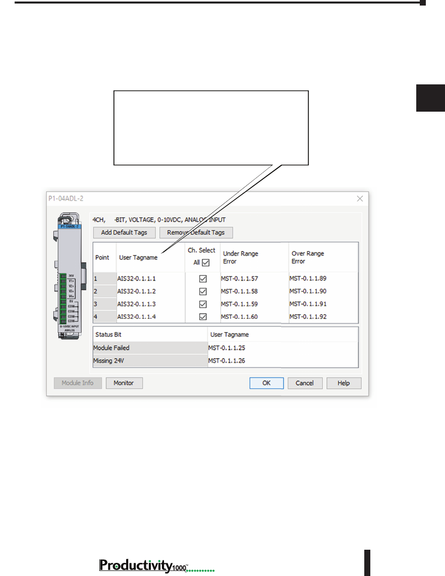
Chapter 3: Analog I/O Specifications
1
2
3
4
5
6
7
8
9
10
11
12
13
14
A
B
C
D
3–11
Hardware User Manual, 1st Edition
1000
P1-04ADL-2 Analog Input (continued)
Module Configuration
Module Configuration
Using the Hardware Configuration tool in
the Productivity Suite programming software,
drag and drop the P1-04ADL-2 module into the
configuration.
If desired, assign a User Tagname to each
input point (channel) selected and to each
Status Bit Item.
13
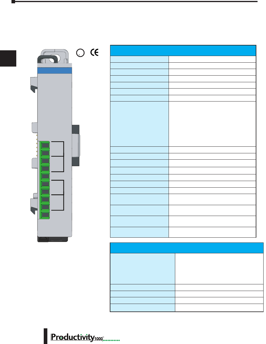
Chapter 3: Analog I/O Specifications
1
2
3
4
5
6
7
8
9
10
11
12
13
14
A
B
C
D
Hardware User Manual, 1st Edition
3–12 1000
P1-04THM Analog Input
The P1-04THM Thermocouple Input Module provides four differential channels for receiving
thermocouple and voltage input signals for use with the Productivity1000 system.
U
L
CUS
R
Terminal Block Included. Not
Compatible with ZIPLink.
Warranty: Thirty-day money-
back guarantee. Two-year
limited replacement. (See www.
productivity1000.com for details).
Thermocouple Input Specications
Input Channels
4 Differential
Data Format
Floating Point
Common Mode Range
±1.25 V
Common Mode Rejection
100dB @ DC and 130dB @ 60Hz
Input Impedance
>5MΩ
Maximum Ratings
Fault protected inputs to ±50V
Resolution
16-bit, ±0.1°C or °F
Thermocouple Input Ranges
Type J -190° to 760°C (-310° to 1400°F);
Type E -210° to 1000°C (-346° to 1832°F);
Type K -150° to 1372°C (-238° to 2502°F);
Type R 65° to 1768°C (149° to 3214°F);
Type S 65° to 1768°C (149° to 3214°F);
Type T -230° to 400°C (-382° to 752°F);
Type B 529° to 1820°C (984° to 3308°F);
Type N -70° to 1300°C (-94° to 2372°F);
Type C 65° to 2320°C (149° to 4208°F);
Thermocouple Linearization
Automatic
Cold Junction Compensation
Automatic
Sample Duration Time
270ms
All Channel Update Rate
1.08 s
Open Circuit Detection Time
Within 5s
Conversion Method
Sigma-Delta
Accuracy vs. Temperature
±50ppm per °C (maximum)
Maximum Inaccuracy
±3°C maximum
(excluding thermocouple error).
Linearity Error
±1°C maximum (±0.5°C typical)
Monotonic with no missing codes.
Warm-up Time
30 minutes for ±1% repeatability
2 minutes to reach voltage specications
External Power Supply
Required
None
Voltage Input Specications
Linear mV Device Input Ranges
0–39.0625 mVDC,
±39.0625 mVDC,
±78.125 mVDC,
0–156.25 mVDC,
±156.25 mVDC,
0–1250 mVDC
Max Voltage Input Offset Error
0.05% @ 0°– 60°C, typical 0.04% @ 25°C
Max Voltage Input Gain Error
0.06% @ 25°C
Max Voltage Input Linearity Error
0.05% @ 0°– 60°C, typical 0.03% @ 25°C
Max Voltage Input Impedance
0.2% @ 0°– 60°C, typical 0.06% @ 25°C
TC1+
TC2+
TC2-
TC3+
TC3-
TC4+
TC4-
TC1-
P1-04THM
THERMOCOUPLE
INPUT

Chapter 3: Analog I/O Specifications
1
2
3
4
5
6
7
8
9
10
11
12
13
14
A
B
C
D
3–13
Hardware User Manual, 1st Edition
1000
Conguration/Diagnostics
Burn-out Detection: High Side/Disable
1 bit per module
°C/°F (T/C Only)
1 bit per module
Module Diagnostics Failure
1 bit per module
Burn-out (on if T/C input is open – no
connection between TCn+ and TCn-)
1 bit per channel
Channel Under-range (T/C only)
1 bit per channel
Channel Over-range (T/C only)
1 bit per channel
P1-04THM Analog Input (continued)
General Specications
Operating Temperature
0º to 60ºC (32º to 140ºF)
Storage Temperature
-20º to 70ºC (-4º to 158ºF)
Humidity
5 to 95% (non-condensing)
Environmental Air
No corrosive gases permitted
Vibration
IEC60068-2-6 (Test Fc)
Shock
IEC60068-2-27 (Test Ea)
Field to Logic Side
Isolation
1800VAC applied for 1 second
Heat Dissipation
100mW
Enclosure Type
Open Equipment
Module Location
Any I/O position in a Productivity1000 System
Field Wiring
Removable terminal block (included).
The P1-04THM module is not compatible with the
ZIPLink wiring system.
EU Directive
See the “EU Directive” topic in the Productivity
Suite Help File. Information can also be obtained
at:
www.productivity1000.com
Connector Type (Included)
10-position removable terminal block
Weight
58g (2.0 oz)
Agency Approvals
UL 61010-2-201 le E139594, Canada & USA
CE (EN61131-2 EMC and EN61010-2-201 Safety)*
* See CE Declaration of Conformity for details.
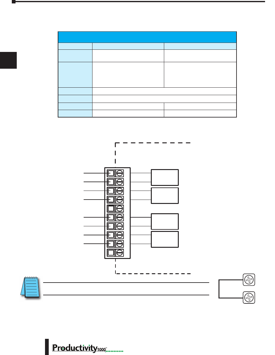
Chapter 3: Analog I/O Specifications
1
2
3
4
5
6
7
8
9
10
11
12
13
14
A
B
C
D
Hardware User Manual, 1st Edition
3–14 1000
P1-04THM Analog Input (continued)
Wiring Diagrams
NOTE: Install jumper wire on each unused input; TC+ to TC-.
Removable Terminal Block Specications
Part Number P1-10RTB P1-10RTB-1
Number of
positions
10 Screw Terminals 10 Spring Clamp Terminals
Wire Range
30–16 AWG (0.051–1.31 mm²)
Solid / Stranded Conductor
3/64 in. (1.2 mm) Insulation Max.
1/4 in (6– 7 mm) Strip Length
28–16 AWG (0.081–1.31 mm²)
Solid / Stranded Conductor
3/64 in (1.2 mm) Insulation Max.
19/64 in (7–8 mm) Strip Length
Conductors
“USE COPPER CONDUCTORS, 75ºC” or equivalent.
Screw Driver
0.1 in (2.5 mm) Maximum
Screw Size
M2 N/A
Screw Torque
2.5 lb in (0.28 N·m) N/A
* Recommended screw driver P/N: TW-SD-MSL-1.
P1-04THM Schematic
TC1+
TC1-
TC2+
TC2-
TC3+
TC4+
TC3-
TC4-
CH1 T/C
INPUT
INTERNAL
MODULE CIRCUITRY
CH2 T/C
INPUT
CH3 T/C
INPUT
CH4 T/C
INPUT
12345678910
TC+
TC-
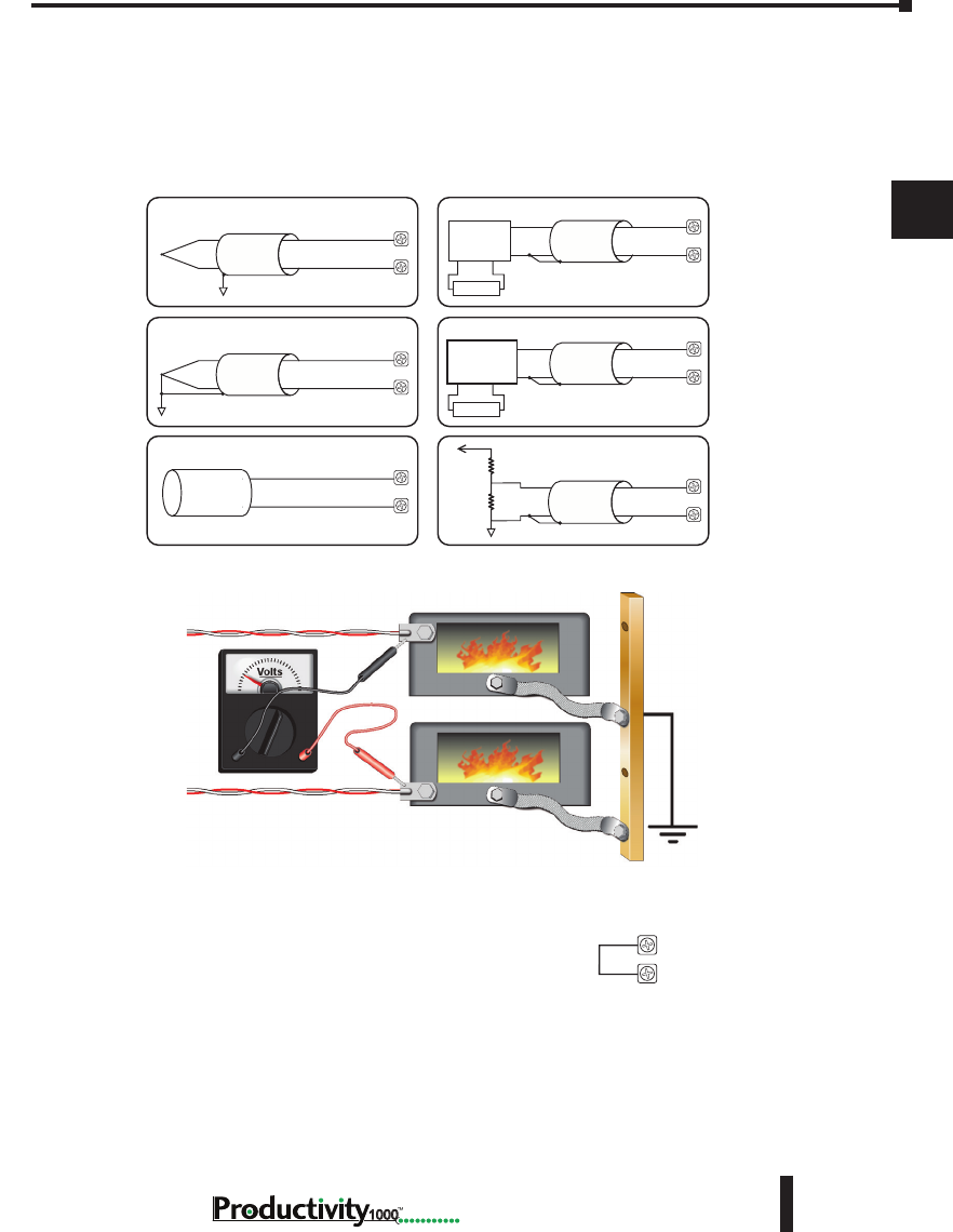
Chapter 3: Analog I/O Specifications
1
2
3
4
5
6
7
8
9
10
11
12
13
14
A
B
C
D
3–15
Hardware User Manual, 1st Edition
1000
P1-04THM Analog Input (continued)
Wiring Diagrams
AC or DC
AC or DC
Thermocouple Input CircuitsVoltage Input Circuits
Excitation
Power Supply
Transmitter
Power Supply
Ungrounded/Shielded
Thermocouple TC+
TC-
TC+
TC-
TC+
TC-
Grounded/Shielded
Thermocouple
Infrared
Thermocouple
4-wire
Voltage
Transmitter
Load Cell
or
Strain Gauge
Voltage Divider
TC+
TC-
TC+
TC-
TC+
TC-
NOTES:
1. Connect shield to thermocouple signal/ground only. Do not connect to both ends.
2. Install jumper wire on each unused input, TC+ to TC-.
3. With grounded thermocouples, take precautions to prevent having a voltage
potential between thermocouple tips. A voltage of 1.25V or greater between tips
will skew measurements.
4. Use shielded, twisted thermocouple extension wire that matches the thermocouple
type. Use thermocouple-compatible junction blocks.
TC+
TC-
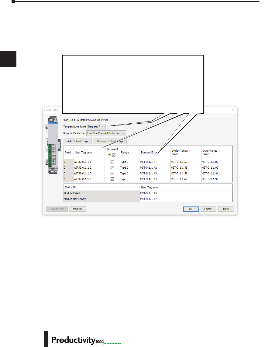
Chapter 3: Analog I/O Specifications
1
2
3
4
5
6
7
8
9
10
11
12
13
14
A
B
C
D
Hardware User Manual, 1st Edition
3–16 1000
P1-04THM Analog Input (continued)
Module Configuration
Module Configuration
Using the Hardware Configuration tool in the
Productivity Suite programming software, drag and drop
the P1-04THM module into the base configuration.
Select Automatic Module Verification or No Verification.
Specify Te mperature Scale and Burnout Detection, and
use the drop down menu to select module range and
resolution. If desired, assign a User Tagname to each
output point channel selected and to each Status Bit Item.
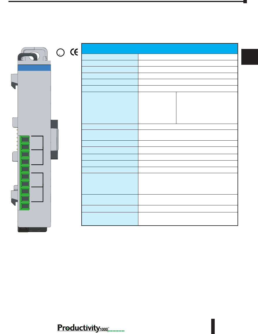
Chapter 3: Analog I/O Specifications
1
2
3
4
5
6
7
8
9
10
11
12
13
14
A
B
C
D
3–17
Hardware User Manual, 1st Edition
1000
P1-04NTC Thermistor
The P1-04NTC module provides four Thermistor input channels for use with the
Productivity1000 system.
U
L
CUS
R
Terminal Block Included.
Not Compatible with ZIPLink.
Warranty: Thirty-day money-back guarantee.
Two-year limited replacement.
(See www.productivity1000.com for details).
NTC Input Specications
Input Channels
4 Single Ended (Temperature only)
Data Format
Floating Point
Common Mode Rejection
100dB @ DC
Input Impedance
>5MΩ
Maximum Ratings
Fault protected inputs to ±50V
Resolution
16-bit, ±0.1°C or °F
Thermistor Input Ranges
2252
10K-AN Type 1
10K-CP Type 2
5K
3K
1.8K
-40° to 150°C (-40° to 300°F)
Thermistor Linearization
Automatic
Sample Duration
Dependent on digital lter settings -
61ms @ 33Hz; 4ms @ 470Hz
Sample Duration Time
Per channel: 61ms @ 33Hz, 4ms @ 470Hz
All Channel Update Rate
1.2 s @ 33Hz; 300ms @ 470Hz
Open Circuit Detection Time
Within 5s @ 33Hz
Conversion Method
Sigma-Delta
Accuracy vs. Temperature
±35PPM per °C (maximum)
Maximum Inaccuracy
±1°C maximum (33Hz)
±2.5°C maximum (470Hz)
(Excluding thermistor error;
including temperature drift)
Linearity Error
±0.5°C maximum (±0.35°C typical)
Monotonic with no missing codes
Filter Characteristics
Digital lter cutoff frequencies: 33Hz, 470Hz.
External Power Supply
Required
None
CH1+
CH2+
CH2-
CH3+
CH3-
CH4+
CH4-
CH1-
P1-04NTC
THERMISTOR
INPUT

Chapter 3: Analog I/O Specifications
1
2
3
4
5
6
7
8
9
10
11
12
13
14
A
B
C
D
Hardware User Manual, 1st Edition
3–18 1000
P1-04NTC Thermistor (continued)
General Specications
Operating Temperature
0º to 60ºC (32º to 140ºF)
Storage Temperature
-20º to 70ºC (-4º to 158ºF)
Humidity
5 to 95% (non-condensing)
Environmental Air
No corrosive gases permitted
Vibration
IEC60068-2-6 (Test Fc)
Shock
IEC60068-2-27 (Test Ea)
Field to Logic Side
Isolation
1800VAC applied for 1 second
Heat Dissipation
100mW
Enclosure Type
Open Equipment
Module Location
Any I/O position in a Productivity1000 System
Field Wiring
Removable terminal block (included).
The P1-04NTC module is not compatible with the
ZIPLink wiring system.
EU Directive
See the “EU Directive” topic in the Productivity
Suite Help File. Information can also be obtained
at:
www.productivity1000.com
Connector Type
(included)
10-position removable terminal block
Weight
60g (2.1 oz)
Agency Approvals**
UL 61010-2-201 le E139594, Canada & USA
CE (EN61131-2 EMC and EN61010-2-201 Safety)*
* See CE Declaration of Conformity for details.
Removable Terminal Block Specications
Part Number P1-10RTB P1-10RTB-1
Number of
positions
10 Screw Terminals 10 Spring Clamp Terminals
Wire Range
30–16 AWG (0.051–1.31 mm²)
Solid / Stranded Conductor
3/64 in. (1.2 mm) Insulation Max.
1/4 in (6– 7 mm) Strip Length
28–16 AWG (0.081–1.31 mm²)
Solid / Stranded Conductor
3/64 in (1.2 mm) Insulation Max.
19/64 in (7–8 mm) Strip Length
Conductors
“USE COPPER CONDUCTORS, 75ºC” or equivalent.
Screw Driver
0.1 in (2.5 mm) Maximum
Screw Size
M2 N/A
Screw Torque
2.5 lb in (0.28 N·m) N/A
* Recommended screw driver P/N: TW-SD-MSL-1.
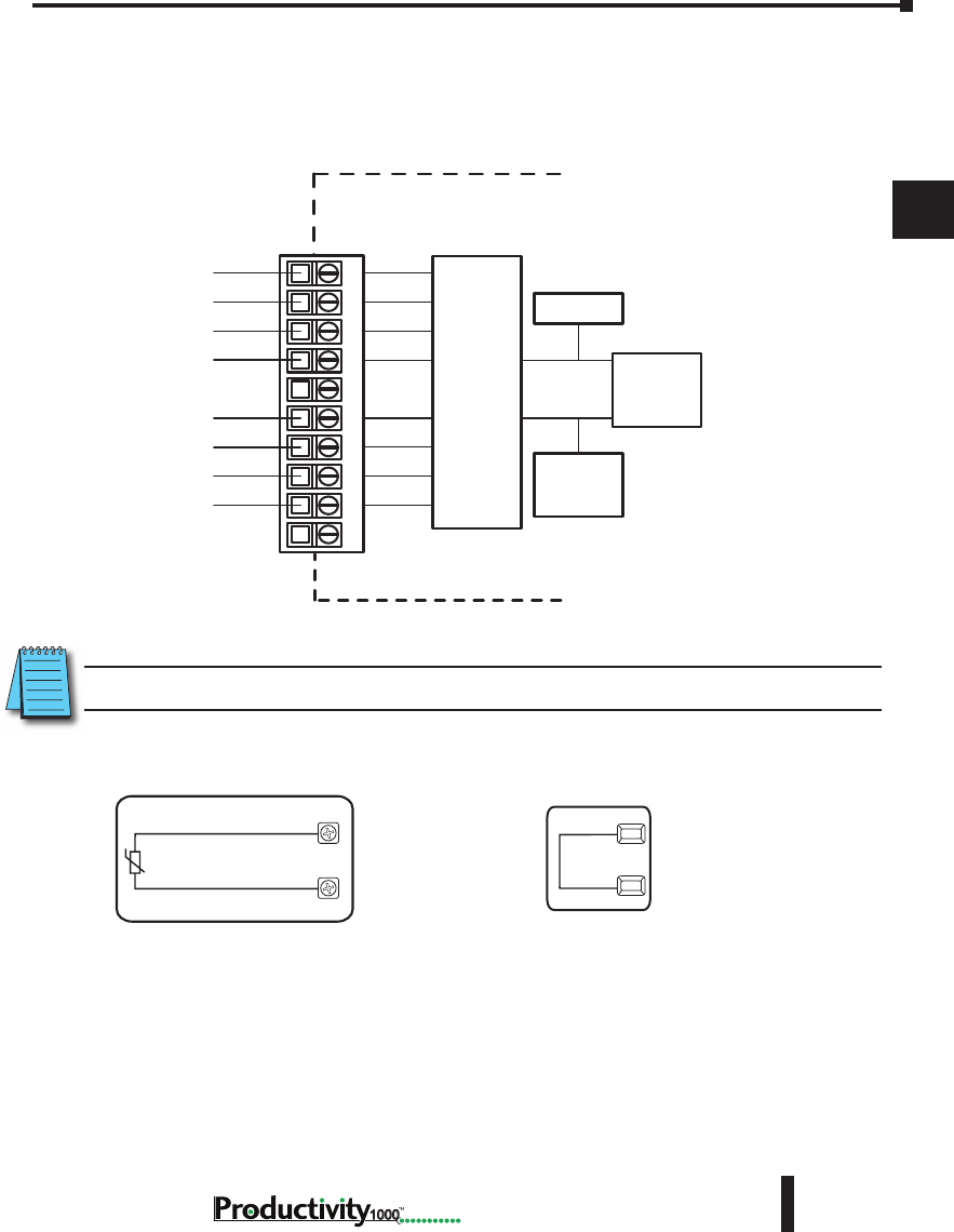
Chapter 3: Analog I/O Specifications
1
2
3
4
5
6
7
8
9
10
11
12
13
14
A
B
C
D
3–19
Hardware User Manual, 1st Edition
1000
P1-04NTC Thermistor (continued)
Wiring Diagrams
Thermistor Input
CH1+
CH1-
NOTE: Install jumper wire on each unused input; CH+ to CH-.
P1-04NTC Schematic
CH1+
CH1-
CH2+
CH2-
CH3+
CH4+
CH3-
CH4-
INTERNAL
MODULE CIRCUITRY
10 µA
Current
Source
Ref. Adj.
A to D
Converter
Analog Switch
ANALOG CIRCUIT COMMON
12345678910
P1-04NTC Wiring Diagram
Thermistor Input
CH1+
CH1-
NOTES:
1. Install jumper wire on each unused input. CH1+ to CH1-
Jumpers
CH1+
CH1-
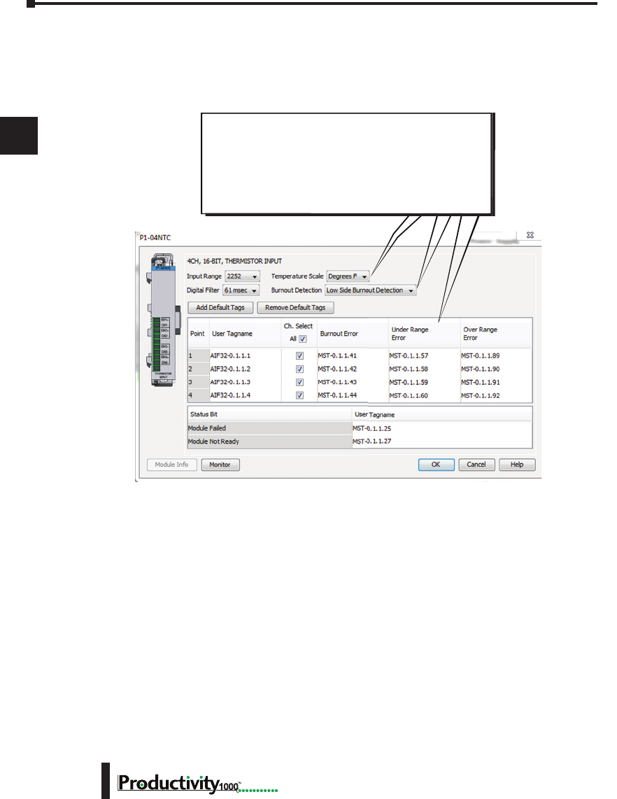
Chapter 3: Analog I/O Specifications
1
2
3
4
5
6
7
8
9
10
11
12
13
14
A
B
C
D
Hardware User Manual, 1st Edition
3–20 1000
P1-04NTC Thermistor (continued)
Module Configuration
Using the Hardware Configuration tool in the
Productivity Suite programming software, drag and drop
the P1-04NTC module into the base configuration.
Specify Te mperature Scale and Burnout Detection, and
use the drop down menu to select module range and
resolution. If desired, assign a User Tagname to each
output point channel selected and to each Status Bit Item.
Module Configuration
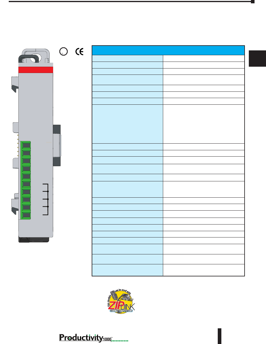
Chapter 3: Analog I/O Specifications
1
2
3
4
5
6
7
8
9
10
11
12
13
14
A
B
C
D
3–21
Hardware User Manual, 1st Edition
1000
P1-04DAL-1 Analog Output
The P1-04DAL-1 Low Resolution Analog Output Module provides four current sourcing
channels for converting a digital value of 0–4095 (12-bit) to 4–20 mA analog signals for use
with the Productivity1000 system.
We recommend using pre-wired ZIPLink cables
and connection modules. See Chapter 5.
If you wish to hand-wire your module, removable
terminal blocks are sold separately. Order part
number P1-10RTB or P1-10RTB-1
Output Specications
Output Channels
4
Output Range
4–20mA
Signal Resolution
12-bit
Resolution Value of LSB
(least signicant bit)
4–20mA = 3.9 μA / count
1 LSB = 1 count
Data Range
0 to 4095 counts
Output Type (sourcing)
Current sourcing at 20mA max
Output Value in Fault Mode
Less than 4mA
Load Impedance
0–570Ω (19.2 VDC),
0–690Ω (21.6 VDC),
0–810Ω (24VDC),
0–930Ω (26.4 VDC),
0–1100Ω (30.0 VDC),
Minimum Load: 0Ω @ 0–45°C
125Ω @ 45–60°C ambient temperature
Maximum Inductive Load
1mH
Allowed Load Type
Grounded
Maximum Inaccuracy
1% of range
Maximum Full Scale Calibration Error
(Including Offset)
±0.2% of range minimum
Maximum Offset Calibration Error
±0.2% of range maximum
Accuracy vs. Temperature
±75PPM / °C maximum full-scale
calibration change
(±0.005% of range / °C)
Max Crosstalk at DC, 50/60Hz
-72dB, 1 LSB
Linearity Error (End to End)
±4 counts max., (±0.1% of full scale)
Output Stability and Repeatability
±2 count after 10 min. warm up (typical)
Output Ripple
±0.2% of full scale
Output Settling Time
0.3 ms max., 5µs min. (full scale range)
All Channel Update Rate
2ms (max)
Maximum Continuous Overload
Outputs open circuit protected
Type of Output Protection
Electronically current limited to 20mA
or less
Output Signal at Power Up
and Power Down
4mA
External Power Supply Required
24VDC (-20% / +25%),140mA
(Loop power included)
24V
I2+
I3+
I4+
0V
COM
COM
COM
COM
I1+
P1-04DAL-1
4-20mA OUT
ANALOG
Terminal block sold separately.
UL
CUS
R

Chapter 3: Analog I/O Specifications
1
2
3
4
5
6
7
8
9
10
11
12
13
14
A
B
C
D
Hardware User Manual, 1st Edition
3–22 1000
P1-04DAL-1 Analog Output (continued)
General Specications
Operating Temperature
0º to 60ºC (32º to 140ºF)
Storage Temperature
-20º to 70ºC (-4º to 158ºF)
Humidity
5 to 95% (non-condensing)
Environmental Air
No corrosive gases permitted
Vibration
IEC60068-2-6 (Test Fc)
Shock
IEC60068-2-27 (Test Ea)
Field to Logic Side
Isolation
1800VAC applied for 1 second
Insulation Resistance
>10MΩ @ 500VDC
Heat Dissipation
2000mW Maximum
Enclosure Type
Open Equipment
Module Location
Any I/O position in a Productivity1000 System
Field Wiring
Use ZIPLink Wiring System or removable terminal
block (not included). See “Wiring Options” in
Chapter 5.
EU Directive
See the “EU Directive” topic in the Productivity Suite
Help File. Information can also be obtained at:
www.productivity2000.com
Terminal Type
(sold separately)
10-position Removable Terminal Block
Weight
85.1 g (3.0 oz)
Agency Approvals
UL 61010-2-201 le E139594, Canada & USA
CE (EN61131-2 EMC and EN61010-2-201 Safety)*
* See CE Declaration of Conformity for details.
Removable Terminal Block Specications
Part Number P1-10RTB P1-10RTB-1
Number of
positions
10 Screw Terminals 10 Spring Clamp Terminals
Wire Range
30–16 AWG (0.051–1.31 mm²)
Solid / Stranded Conductor
3/64 in. (1.2 mm) Insulation Max.
1/4 in (6– 7 mm) Strip Length
28–16 AWG (0.081–1.31 mm²)
Solid / Stranded Conductor
3/64 in (1.2 mm) Insulation Max.
19/64 in (7–8 mm) Strip Length
Conductors
“USE COPPER CONDUCTORS, 75ºC” or equivalent.
Screw Driver
0.1 in (2.5 mm) Maximum
Screw Size
M2 N/A
Screw Torque
2.5 lb in (0.28 N·m) N/A
* Recommended screw driver P/N: TW-SD-MSL-1.
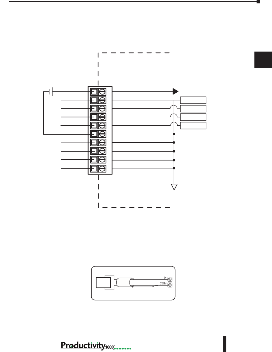
Chapter 3: Analog I/O Specifications
1
2
3
4
5
6
7
8
9
10
11
12
13
14
A
B
C
D
3–23
Hardware User Manual, 1st Edition
1000
P1-04DAL-1 Analog Output (continued)
Wiring Diagrams
Current Source Output Circuit
4 - 20mA
Load
Note: Shield is connected to common at the source device.
P1-04DAL-1 Schematic
I+1
I+2
I+3
I+4
0V
COM
- +
CH1 DAC
CH2 DAC
CH3 DAC
CH4 DAC
CIRCUIT POWER
INTERNAL
MODULE CIRCUITRY
24VDC User
Supplied Power
10
1 2 3 4 5 6 7 8 9
ISOLATED ANALOG
ISOLATED ANALOG
CIRCUIT COMMON
4–20 mA current sourcing
4–20 mA current sourcing
4–20 mA current sourcing
4–20 mA current sourcing
COM
COM
COM
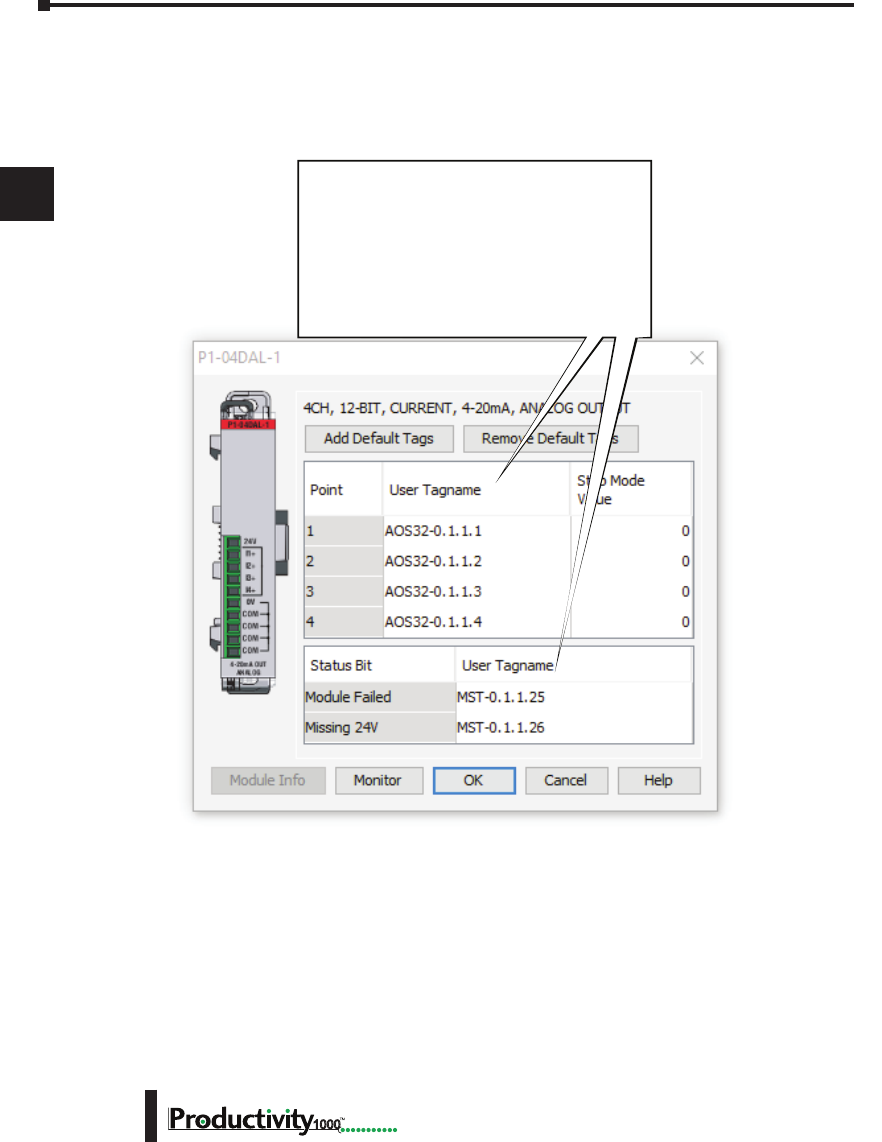
Chapter 3: Analog I/O Specifications
1
2
3
4
5
6
7
8
9
10
11
12
13
14
A
B
C
D
Hardware User Manual, 1st Edition
3–24 1000
P1-04DAL-1 Analog Output (continued)
Module Configuration
Module Configuration
Using the Hardware Configuration tool in the
Productivity Suite programming software, drag
and drop the P1-04DAL-1 module into the base
configuration.
If desired, assign a User Tagname to each
output point channel selected and to each
Status Bit Item. A Stop Mode Value may also
be assigned.
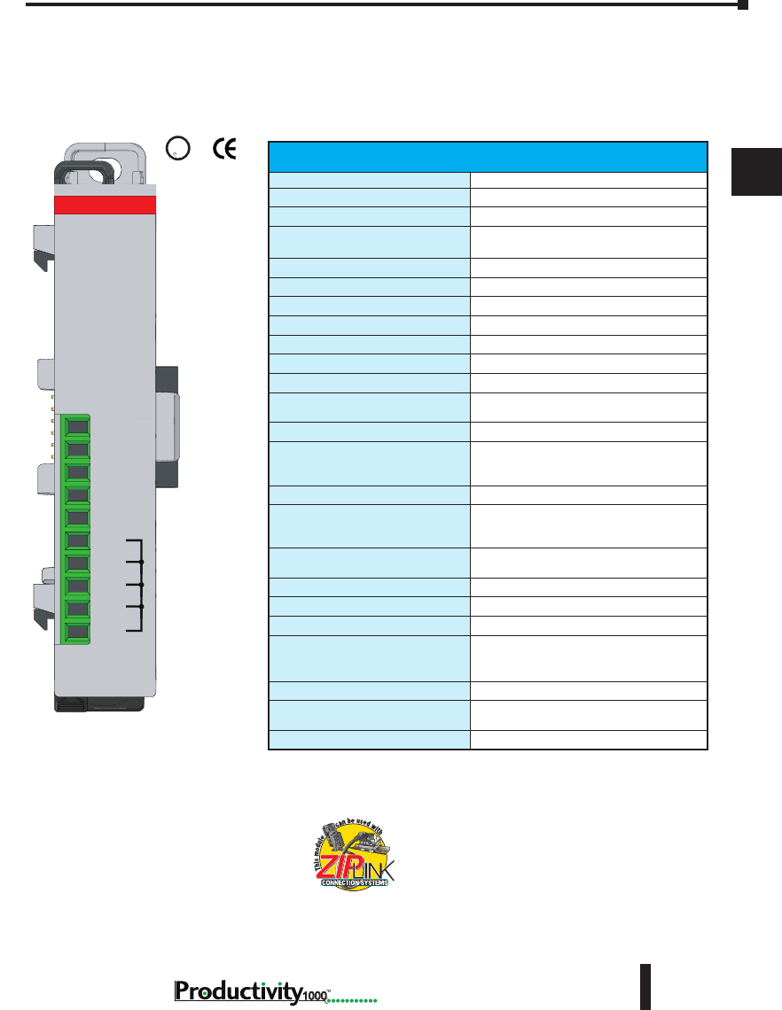
Chapter 3: Analog I/O Specifications
1
2
3
4
5
6
7
8
9
10
11
12
13
14
A
B
C
D
3–25
Hardware User Manual, 1st Edition
1000
P1-04DAL-2 Analog Output
The P1-04DAL-2 Low Resolution Voltage Analog Output Module provides four outputs for
converting digital values from 0–4095 (12-bit) to 0–10 VDC analog signals for use with the
Productivity1000 system.
We recommend using pre-wired ZIPLink cables
and connection modules. See Chapter 5.
If you wish to hand-wire your module, removable
terminal blocks are sold separately. Order part
number P1-10RTB or P1-10RTB-1
Output Specications
Output Channels
4
Module Signal Input Range
0–10V
Output Signal Resolution
12-bit
Resolution Value of LSB
(least signicant bit)
0–10V = 2.44 mV per count
1 LSB = 1 count
Data Range
0 to 4095 counts
Output Type
Voltage sourcing at 10mA
Output Value in Fault Mode
0V
Load Impedance
≥1000Ω
Maximum Capacitive Load
0.01 µF
Allowed Load Type
Grounded
Maximum Inaccuracy
0.5% of range
Maximum Full Scale Calibration
Error (Not Including Offset)
±0.2% of range
Maximum Offset Calibration Error
±0.2% of range
Accuracy vs. Temperature
±75PPM / °C maximum full-scale
calibration change
(±0.0025% of range / °C)
Max Crosstalk
-72dB, 1 LSB
Linearity Error (End to End)
±4 LSB maximum, (±0.1% of full scale)
Monotonic with no missing codes
Output Stability and Repeatability
±2% LSB after 10 min. warm up
(typical)
Output Ripple
±0.2% of full scale
Output Settling Time
0.3 ms max., 5µs min. (full scale range)
All Channel Update Rate (typical)
2ms
Maximum Continuous Overload
Outputs current limited to 40mA typical
Continuous overloads on multiple
outputs can damage the module.
Type of Output Protection
0.1 µF Transient Suppressor
Output Signal at Power Up and
Power Down
0V
External Power Supply Required
24VDC (-20% / +25%), 100mA
Terminal block sold separately.
U
L
CUS
R
24V
V2+
V3+
V4+
0V
COM
COM
COM
COM
V1+
P1-04DAL-2
0-10VDC OUT
ANALOG

Chapter 3: Analog I/O Specifications
1
2
3
4
5
6
7
8
9
10
11
12
13
14
A
B
C
D
Hardware User Manual, 1st Edition
3–26 1000
P1-04DAL-2 Analog Output (continued)
* See CE Declaration of Conformity for details.
General Specications
Operating Temperature
0º to 60ºC (32º to 140ºF)
Storage Temperature
-20º to 70ºC (-4º to 158ºF)
Humidity
5 to 95% (non-condensing)
Environmental Air
No corrosive gases permitted
Vibration
IEC60068-2-6 (Test Fc)
Shock
IEC60068-2-27 (Test Ea)
Field to Logic Side Isolation
1800VAC applied for 1 second
Insulation Resistance
>10MΩ @ 500VDC
Heat Dissipation
2000mW
Enclosure Type
Open Equipment
Module Location
Any I/O position in a Productivity1000 System
Field Wiring
Use ZIPLink Wiring System or removable terminal
block (sold separately). See “Wiring Options” in
Chapter 5.
EU Directive
See the “EU Directive” topic in the Productivity Suite
Help File. Information can also be obtained at:
www.productivity1000.com
Connector Type (Not included)
10-position removable terminal block
Weight
62g (2.2 oz)
Agency Approvals
UL 61010-2-201 le E139594, Canada & USA
CE (EN61131-2 EMC and EN61010-2-201 Safety)*
Removable Terminal Block Specications
Part Number P1-10RTB P1-10RTB-1
Number of
positions
10 Screw Terminals 10 Spring Clamp Terminals
Wire Range
30–16 AWG (0.051–1.31 mm²)
Solid / Stranded Conductor
3/64 in. (1.2 mm) Insulation Max.
1/4 in (6– 7 mm) Strip Length
28–16 AWG (0.081–1.31 mm²)
Solid / Stranded Conductor
3/64 in (1.2 mm) Insulation Max.
19/64 in (7–8 mm) Strip Length
Conductors
“USE COPPER CONDUCTORS, 75ºC” or equivalent.
Screw Driver
0.1 in (2.5 mm) Maximum
Screw Size
M2 N/A
Screw Torque
2.5 lb in (0.28 N·m) N/A
* Recommended screw driver P/N: TW-SD-MSL-1.
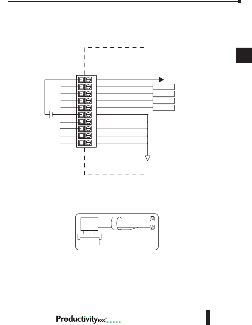
Chapter 3: Analog I/O Specifications
1
2
3
4
5
6
7
8
9
10
11
12
13
14
A
B
C
D
3–27
Hardware User Manual, 1st Edition
1000
P1-04DAL-2 Analog Output (continued)
Wiring Diagrams
Load
Power Supply
0 - 10
VDC Load
Voltage Output Circuits
V+
COM
P1-04DAL-2 Schematic
V1+
V2+
V3+
V4+
0V
- +
24VDC User
Supplied
Power
CH1 DAC
CH2 DAC
CH3 DAC
CH4 DAC
CIRCUIT POWER
INTERNAL
MODULE CIRCUITRY
24V
10
1 2 3 4 5 6 7 8 9
ISOLATED ANALOG
ISOLATED ANALOG
CIRCUIT COMMON
voltage source
voltage source
voltage source
voltage source
COM
COM
COM
COM
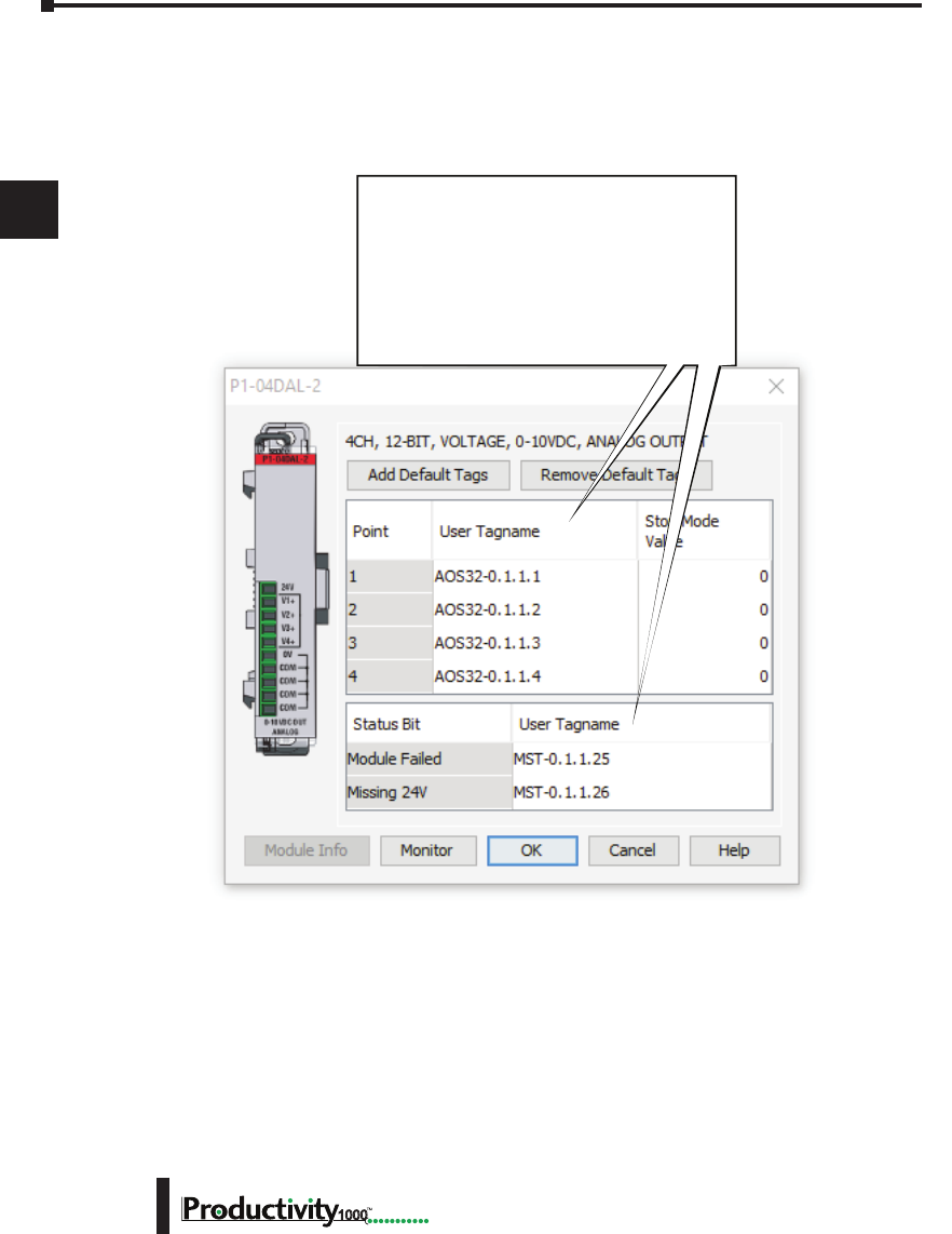
Chapter 3: Analog I/O Specifications
1
2
3
4
5
6
7
8
9
10
11
12
13
14
A
B
C
D
Hardware User Manual, 1st Edition
3–28 1000
P1-04DAL-2 Analog Output (continued)
Module Configuration
Module Configuration
Using the Hardware Configuration tool in the
Productivity Suite programming software, drag
and drop the P1-04DAL-2 module into the base
configuration.
If desired, assign a User Tagname to each
output point channel selected and to each
Status Bit Item. A Stop Mode Value may also
be assigned.

Specialty Module
SpecificationS
Chapter
Chapter
Chapter
4
4
4
Reserved For Future Release

Chapter 4: Specialty Module Specifications
1
2
3
4
5
6
7
8
9
10
11
12
13
14
A
B
C
D
Hardware User Manual, 1st Edition
4–2 1000
Notes

5
5
5
InstallatIon and
WIrIng
Chapter
Chapter
Chapter
In This Chapter...
Safety Guidelines .......................................................................................................5–2
Introduction to the Productivity1000 Mechanical Design .......................................5–5
Dimensions and Installation ......................................................................................5–6
Mounting Guidelines ................................................................................................. 5–9
Wiring Guidelines ....................................................................................................5–15
I/O Module Wiring Options ....................................................................................5–17
System Wiring Strategies ........................................................................................5–23
Chapter 5: Installation and Wiring
A
2
3
4
5
3
3
3
3
3
3
3
3
3
3
3
3
3
Hardware User Manual, 1st Edition
5–2 1000
Safety Guidelines
NOTE: Products with CE marks perform their required functions safely and adhere to relevant standards
as specified by CE directives provided they are used according to their intended purpose and that the
instructions in this manual are adhered to. The protection provided by the equipment may be impaired if this
equipment is used in a manner not specified in this manual. A listing of our international affiliates is available
on our Web site at http://www.automationdirect.com.
WARNING: Providing a safe operating environment for personnel and equipment is your responsibility
and should be your primary goal during system planning and installation. Automation systems can fail
and may result in situations that can cause serious injury to personnel or damage to equipment. Do not
rely on the automation system alone to provide a safe operating environment. You should use external
electromechanical devices, such as relays or limit switches, that are independent of the CPU application
to provide protection for any part of the system that may cause personal injury or damage. Every
automation application is different, so there may be special requirements for your particular application.
Make sure you follow all national, state, and local government requirements for the proper installation
and use of your equipment.
Plan for Safety
The best way to provide a safe operating environment is to make personnel and equipment
safety part of the planning process. You should examine every aspect of the system to determine
which areas are critical to operator or machine safety. If you are not familiar with CPU system
installation practices, or your company does not have established installation guidelines, you
should obtain additional information from the following sources.
• NEMA — The National Electrical Manufacturers Association, located in Washington, D.C.,
publishes many different documents that discuss standards for industrial control systems. You can
order these publications directly from NEMA. Some of these include:
ICS 1, General Standards for Industrial Control and Systems
ICS 3, Industrial Systems
ICS 6, Enclosures for Industrial Control Systems
• NEC — The National Electrical Code provides regulations concerning the installation and use of
various types of electrical equipment. Copies of the NEC Handbook can often be obtained from
your local electrical equipment distributor or your local library.
• Local and State Agencies — many local governments and state governments have additional
requirements above and beyond those described in the NEC Handbook. Check with your local
Electrical Inspector or Fire Marshall office for information.

Chapter 5: Installation and Wiring
A
2
3
4
5
3
3
3
3
3
3
3
3
3
3
3
3
3
5–3
Hardware User Manual, 1st Edition
1000
Three Levels of Protection
WARNING: The control program must not be the only form of
protection for any problems that may result in a risk of personal
injury or equipment damage.
The publications mentioned provide many ideas and
requirements for system safety. At a minimum, you should
follow these regulations. Also, you should use the following
techniques, which provide three levels of system control.
1. Orderly system shutdown sequence in the CPU control
program.
2. Mechanical disconnect for output module power.
3. Emergency stop switch for disconnecting system power.
Orderly System Shutdown
The first level of fault detection is ideally the CPU control program, which can identify machine
problems. Certain shutdown sequences should be performed. These types of problems are
usually things such as jammed parts, etc. that do not pose a risk of personal injury or equipment
damage.
System Power Disconnect
You should also use electromechanical devices, such as master control relays and/or limit
switches, to prevent accidental equipment startup at an unexpected time. These devices should
be installed in a manner that will prevent any machine operations from occurring.
For example, if the machine in the illustration has a jammed part, the CPU control program
can turn off the saw blade and retract the arbor. If the operator must open the guard to remove
the part, you should also include a bypass switch that disconnects all system power any time
the guard is opened.
Jam
Detect
RST
Retract
Arm
Turn off
Saw
RST
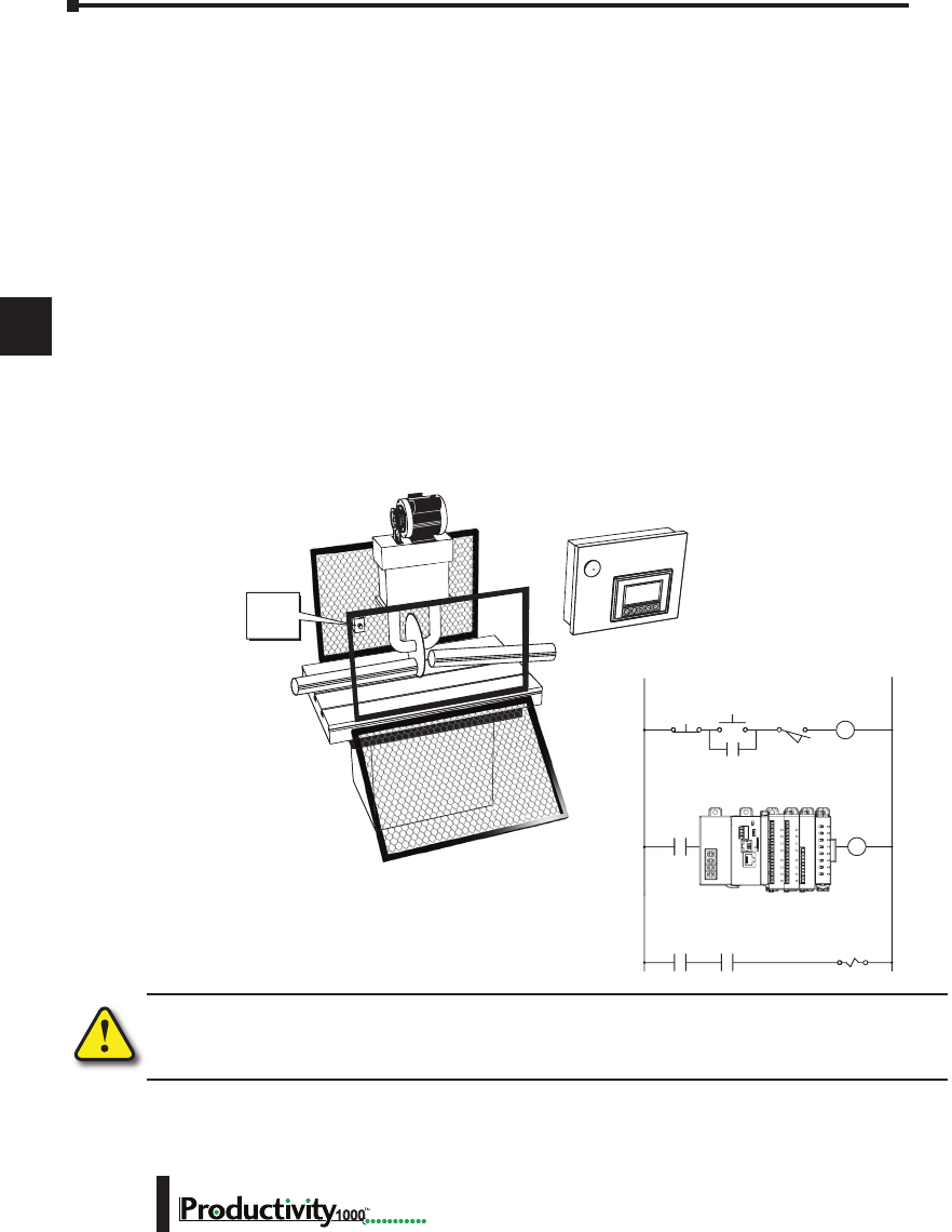
Chapter 5: Installation and Wiring
A
2
3
4
5
3
3
3
3
3
3
3
3
3
3
3
3
3
Hardware User Manual, 1st Edition
5–4 1000
Emergency Stop Circuits
Emergency stop (E-Stop) circuits are a critical part of automation safety. For each machine
controlled by a CPU, provide an emergency stop device that is wired outside the CPU and
easily accessed by the machine operator.
E-Stop devices are commonly wired through a master control relay (MCR) or a safety control
relay (SCR) that will remove power from the CPU I/O system in an emergency.
MCRs and SCRs provide a convenient means for removing power from the I/O system
during an emergency situation. By de-energizing an MCR (or SCR) coil, power to the input
(optional) and output devices is removed. This event occurs when any emergency stop switch
opens. However, the CPU continues to receive power and operate even though all its inputs
and outputs are disabled.
The MCR circuit could be extended by placing a CPU fault relay (closed during normal
CPU operation) in series with any other emergency stop conditions. This would cause
the MCR circuit to drop the CPU I/O power in case of a CPU failure (memory error, I/O
communications error, etc.).
WARNING: For some applications, field device power may still be present on the terminal block even
though the CPU is turned off. To minimize the risk of electrical shock, remove all field device power
before you expose or remove CPU wiring.
Saw Arbor
E-StopPower On
Use E-Stop and Master Control Relay
Limit
Switch
Master
Control
Relay (MCR)
L1 N
MCR
MCRCR1
MCRCR1
S
E-
S
to
p
P
ower
O
n
U
se E-Stop and Maste
S
L
1
MCR
MCR
EMERGENCY
STOP
Guard
Limit
Switch
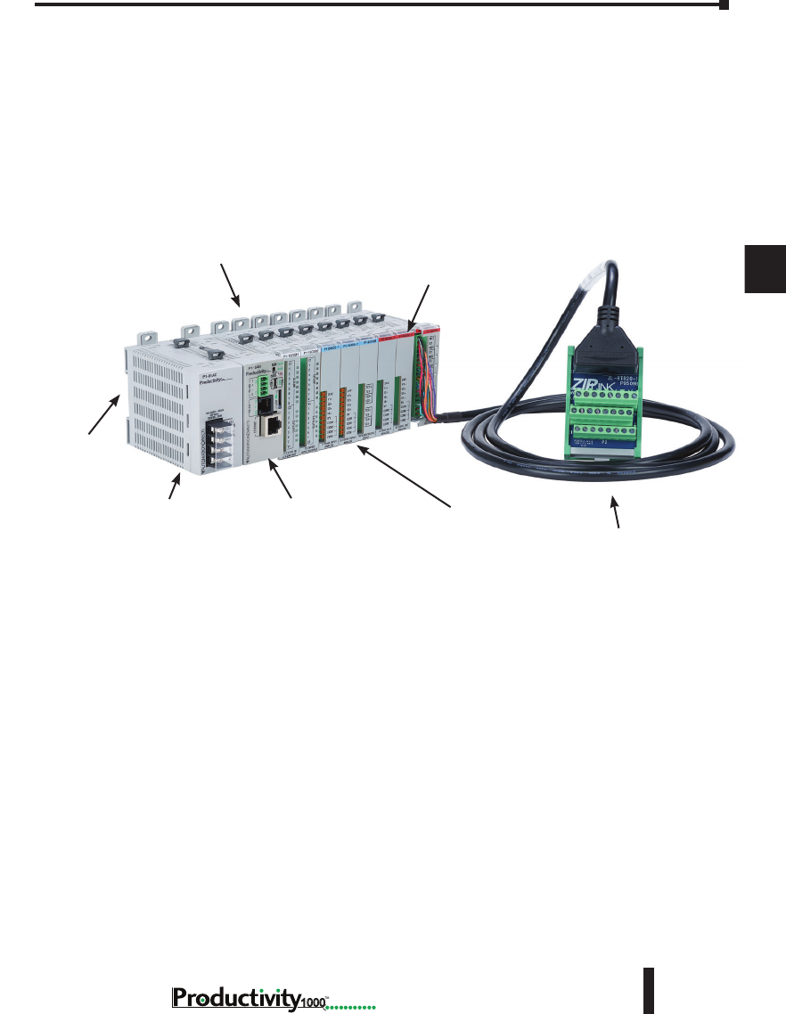
Chapter 5: Installation and Wiring
A
2
3
4
5
3
3
3
3
3
3
3
3
3
3
3
3
3
5–5
Hardware User Manual, 1st Edition
1000
Introduction to the Productivity1000 Mechanical Design
The Productivity1000 is a modular system that allows expansion by means of directly
connecting additional modules to the CPU. Each Productivity1000 system requires one
CPU module. Connect any I/O module combination (up to 8 modules) to the right of the
CPU without power budget or module type restrictions.
Typical Productivity1000 System
I/O Modules (Input)
CPU
Power Supply
Base Mounting Tabs
I/O Modules (Output)
ZIPLink Wiring
System
DIN Rail
Mounting
Slot
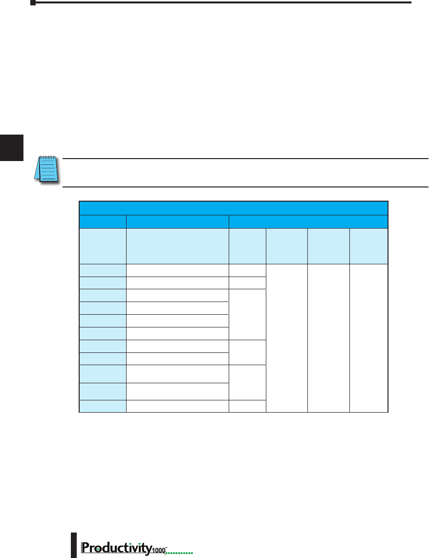
Chapter 5: Installation and Wiring
A
2
3
4
5
3
3
3
3
3
3
3
3
3
3
3
3
3
Hardware User Manual, 1st Edition
5–6 1000
Dimensions and Installation
Before installing the CPU system you will need to know the dimensions of the components
considered. These diagrams provide the dimensions to use in defining your enclosure
specifications. Remember to leave room for module insertion and/or replacement and for
potential expansion. If you are using other components in your system, refer to the appropriate
manual to determine how those units can affect mounting dimensions.
The height and depth dimension is the same for all modules. The width varies depending
on your choice of I/O module. Productivity1000 is designed to be mounted on standard
35mm DIN rail, or it may be surface mounted. Make sure you have followed the installation
guidelines for proper spacing.
NOTE: Dimensional drawings for the CPU, power supply and all modules are available on the
AutomationDirect.com site.
Productivity1000 Component Dimensions
Module Dimensions
Description Width
mm [in]
Height
Faceplate
mm [in]
Height
w/Tabs
mm [in]
Depth
mm [in]
P1-540
CPU 32.8 [1.89]
77.0 [3.03] 92.8 [3.65] 86.6 [3.41]
P1-01AC
AC/DC Power Supply 35.0 [1.38]
P1-08SIM
Simulator Input
17.2 [0.58]
P1-08ND3
Sinking/Sourcing 12–24 VDC Input
P1-08TD1
Sinking Output
P1-08TD2
Sourcing Output
P1-08TRS
Isolated Relay Output
26.2 [1.03]
P1-16TR
Relay Output
P1-15CDD1
Input: Sinking/Sourcing;
Output: Sinking 17.2 [0.58]
P1-15CDD2
Input: Sinking/Sourcing;
Output: Sourcing
P1-16CDR
Discrete Relay Combo Module 26.2 [1.03]
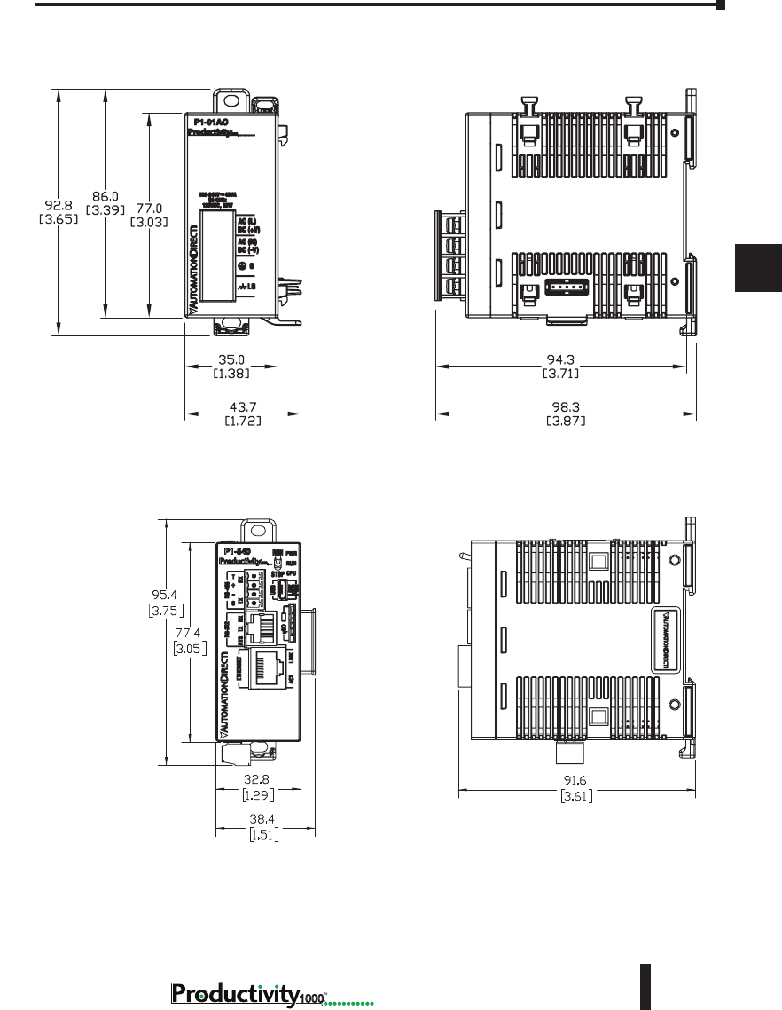
Chapter 5: Installation and Wiring
A
2
3
4
5
3
3
3
3
3
3
3
3
3
3
3
3
3
5–7
Hardware User Manual, 1st Edition
1000
P1-01AC
P1-540
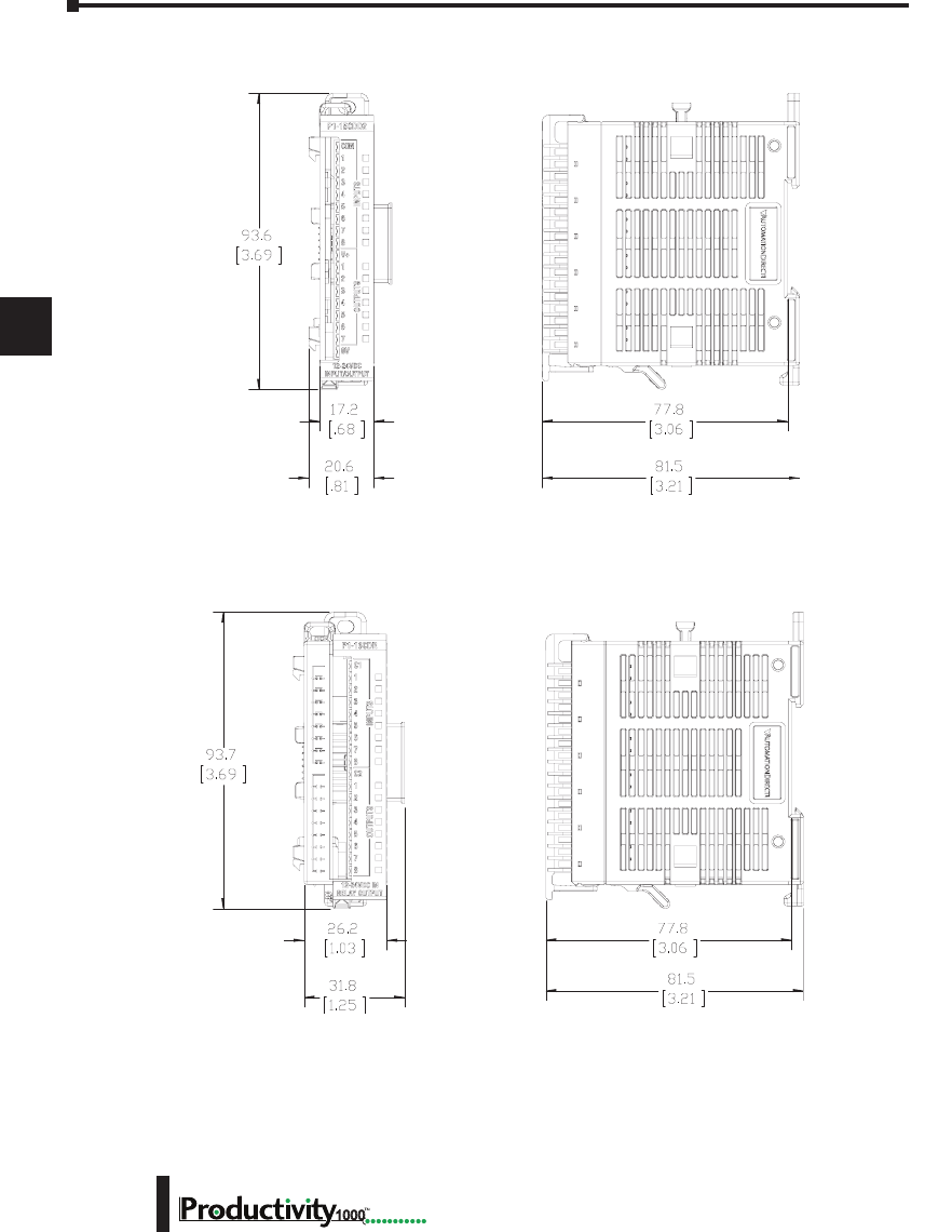
Chapter 5: Installation and Wiring
A
2
3
4
5
3
3
3
3
3
3
3
3
3
3
3
3
3
Hardware User Manual, 1st Edition
5–8 1000
I/O Modules
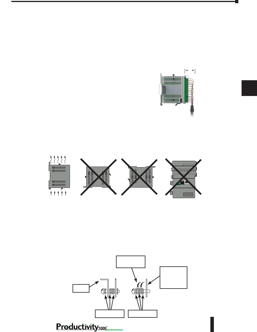
Chapter 5: Installation and Wiring
A
2
3
4
5
3
3
3
3
3
3
3
3
3
3
3
3
3
5–9
Hardware User Manual, 1st Edition
1000
Mounting Guidelines
Enclosures
Your selection of a proper enclosure is important to ensure safe and proper operation of your
Productivity1000 system. Applications for the Productivity1000 system vary and may require
additional hardware considerations. The minimum considerations for enclosures include:
• Conformance to electrical standards
• Protection from the elements in an industrial
environment
• Common ground reference
• Maintenance of specified ambient temperature
• Access to the equipment
• Security or restricted access
• Sufficient space for proper installation and maintenance
of the equipment
Mounting Position
Mount the CPU and expansion modules horizontally, as shown in the illustration on the
following page, to provide proper ventilation. Do not mount vertically, upside down, or on a
flat horizontal surface.
Grounding
A sound common ground reference (earth ground) is essential for proper operation of the
Productivity1000 system. One side of all control circuits and power circuits along with the
ground lead must be properly connected to earth ground (earthing) by either installing a ground
rod in close proximity to the enclosure or by connecting to the incoming power system ground.
There must be a single-point ground (i.e. copper bus bar) for all devices in the enclosure that
require an earth ground.
Airflow
Panel or
Single Point
Ground
Ground Braid
Copper Lugs
Star Washers Star Washers
Panel
2ʺ
NOTE: Add 2ʺ to mountin
g
depth when using ZIPLink
cable.
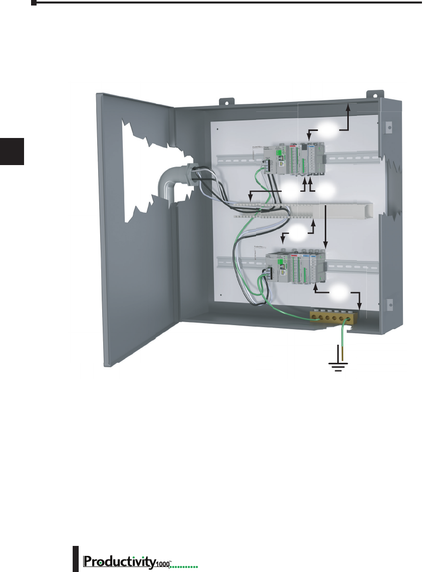
Chapter 5: Installation and Wiring
A
2
3
4
5
3
3
3
3
3
3
3
3
3
3
3
3
3
Hardware User Manual, 1st Edition
5–10 1000
Mounting Clearances
Provide a minimum clearance of 2 inches (50mm) on all sides of the module(s). Allow extra
door clearance for operator panels and other door mounted items. There should be a minimum
of 3 inches (76mm) clearance between the module(s) and any wire duct, and a minimum of 7.2
inches (183mm) from chassis to chassis in a multiple unit installation.
Temperature Considerations
The Productivity1000 system enclosure should be installed in an environment which is within
the specified equipment operating temperature. If the environment temperature deviates above
or below the specification, measures such as cooling or heating the enclosure should be taken to
maintain the specification.
Power Considerations
The Productivity1000 system is designed to be powered by 110/240 VAC or 125VDC power
supply. The Productivity1000 has achieved CE certification without requiring EMF/RFI line
noise filters on the AC power supply. Please review the European Union (CE) material in
Appendix A for more information.
2”
50mm
min
2”
50mm
min
7.2”
183mm
min
18
3”
76mm
min
3”
76mm
min
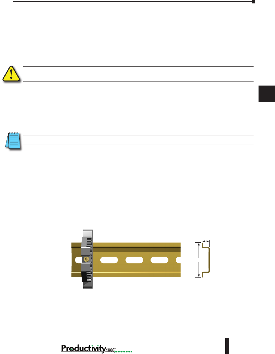
Chapter 5: Installation and Wiring
A
2
3
4
5
3
3
3
3
3
3
3
3
3
3
3
3
3
5–11
Hardware User Manual, 1st Edition
1000
In addition to the panel layout guidelines, other specifications can affect the installation of a
CPU system. Always consider the following:
• Environmental Specifications
• Power Requirements
• Agency Approvals
• Enclosure Selection and Component Dimensions
WARNING: Do not disconnect equipment unless power has been switched off or the area is known to be
non–hazardous.
Agency Approvals
Some applications require agency approvals for particular components. The Productivity1000
CPU agency approvals are listed below:
• UL (Underwriters’ Laboratories, Inc.)
• CUL (Canadian Underwriters’ Laboratories, Inc.)
• CE (European Economic Union)
NOTE: See the “EU Directives(CE)” in Appendix A in this manual for more information.
Using Mounting Rails
The Productivity1000 modules can be secured to the cabinet using mounting rails. You
should use rails that conform to DIN EN standard 50022. We offer a complete line of DIN
rail, DINnectors and DIN rail mounted apparatus. These rails are approximately 35mm high,
with a depth of 7.5 mm. If you mount the module(s) on a DIN rail, you should also consider
using end brackets on each side of the base. The end brackets keep the module(s) from sliding
horizontally along the rail, thus minimizing the possibility of accidentally pulling the wiring
loose.
DIN Rail
Dimensions
7.5 mm
35 mm
End Bracket (Part No. DN-EB35)
DIN Rail (Part No. DN-R35S1)
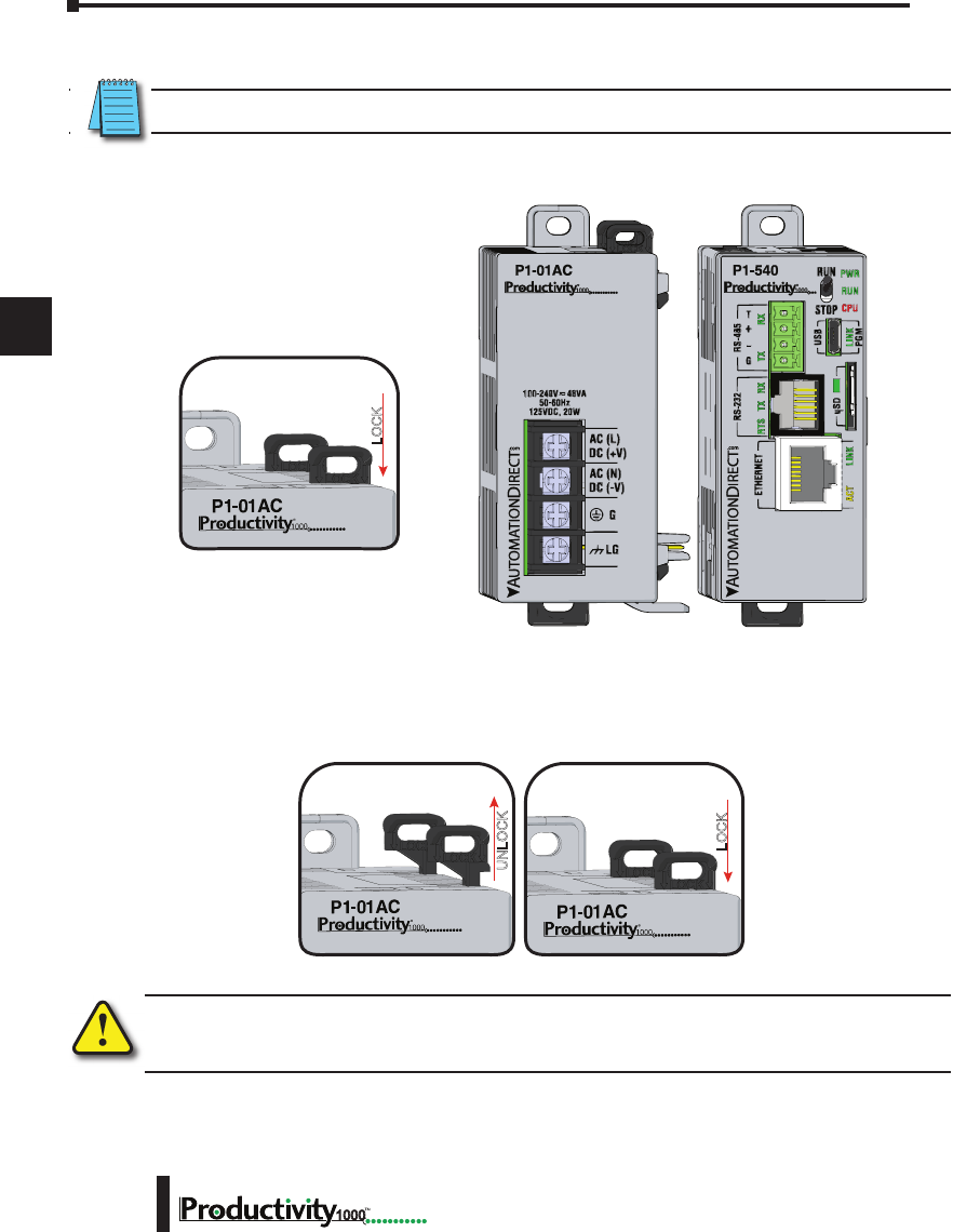
Chapter 5: Installation and Wiring
A
2
3
4
5
3
3
3
3
3
3
3
3
3
3
3
3
3
Hardware User Manual, 1st Edition
5–12 1000
Installing the Power Supply
WARNING: Explosion hazard – Do not connect, disconnect or operate switches while circuit is live unless
the area is known to be non-hazardous. Do not hot swap.
Step One:
With latch in “locked” position, align
connectors on the side of each module
and stack by pressing together. An
audible click indicates lock is engaged.
Step Two:
To unstack modules, pull locking latch up
into the unlocked position and then pull
modules apart.
Module Installation
WARNING: Do not add or remove
modules with field power applied.
Step One: With latch
in “locked” position, align
connectors on the side of
each module and stack
by pressing together.
Click indicates lock is
engaged.
Step Two: To unstack modules, pull locking
latch up into the unlocked position and then pull
modules apart.
AC (L)
DC (+V)
AC (N)
DC (-V)
P1-540
LOCK
UNLOCK
Module Installation
WARNING: Do not add or remove modules with
field power applied.
Step One: With latch
in “locked” position, align
connectors on the side of
each module and stack
by pressing together.
Click indicates lock is
engaged.
Step Three: To unstack modules, pull
locking latch up into the unlocked position
and then pull modules apart.
Step Two: Attach field wiring using
the removable terminal block or ZIPLink
wiring system.
LOCK
UNLOCK
WIRE STRIP
LENGTH
MIN
MAX
P1-08TD1
secure after modules
are connected.
NOTE: Removable DC power connector must be removed prior to performing this step.
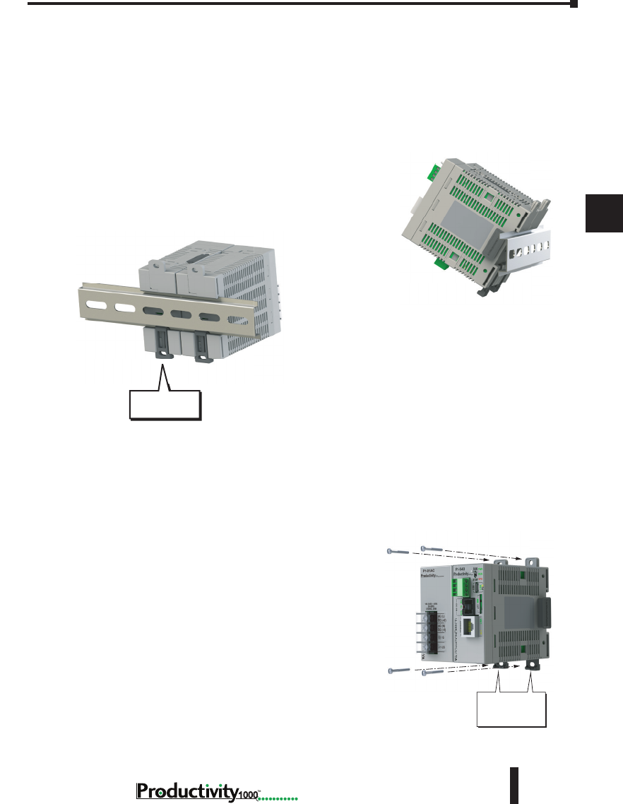
Chapter 5: Installation and Wiring
A
2
3
4
5
3
3
3
3
3
3
3
3
3
3
3
3
3
5–13
Hardware User Manual, 1st Edition
1000
DIN Rail Mounting P1000 System
If you examine the module(s), you’ll notice retaining clips. To secure the module(s) to a DIN
rail, place the module(s) onto the rail and gently push up on the retaining clips. The clips lock
the module onto the rail. To remove the module(s), pull down on the retaining clips, slightly
lift up the base, and pull it away from the rail.
This installation procedure applies to the P1-540 CPU module with power supply.
Step 1: Rotate unit upwards as you engage rear
DIN rail slot (image at right). Once engaged, rotate
unit downwards, firmly pressing into DIN rail. A
noticeable click affirms the unit is secure to DIN rail.
Step 2: Ensure all retaining clips are pushed up into
DIN rail.
Install end brackets on either side of unit to ensure unit
will not slide along the DIN rail.
Surface Mounting P1000 System
The P1000 system may be surface mounted as well.
Extend the lower tabs for ease of access. Use mounting
holes in top and bottom tabs to secure the unit to
panel surface.
Extend lower tabs to
install hardware for
surface mount
installation.
Push up
retaining clips
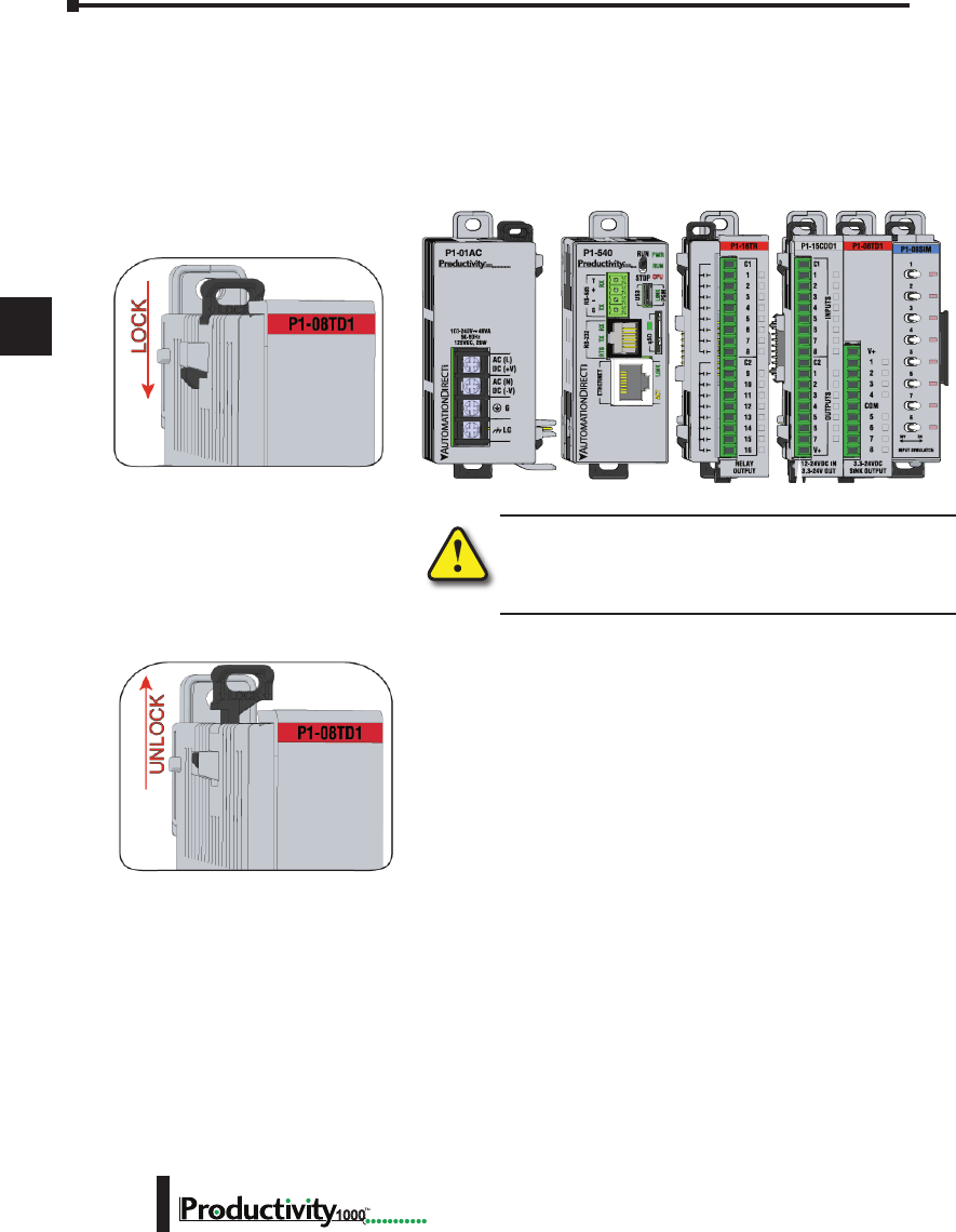
Chapter 5: Installation and Wiring
A
2
3
4
5
3
3
3
3
3
3
3
3
3
3
3
3
3
Hardware User Manual, 1st Edition
5–14 1000
Installing the I/O Modules
WARNING: Explosion hazard – Do not connect, disconnect
modules or operate switches while circuit is live.
Productivity1000 System does not support Hot Swapping!
Step One:
With latch in “locked” position, align
connectors on the side of each module
and stack by pressing together. An
audible click indicates lock is engaged.
Step Two:
To unstack modules, pull locking latch up
into the unlocked position and then pull
modules apart.
Module Installation
WARNING: Do not add or remove modules with
field power applied.
Step One: With latch
in “locked” position, align
connectors on the side of
each module and stack
by pressing together.
Click indicates lock is
engaged.
Step Three: To unstack modules, pull
locking latch up into the unlocked position
and then pull modules apart.
Step Two: Attach field wiring using
the removable terminal block or ZIPLink
wiring system.
LOCK
UNLOCK
WIRE STRIP
LENGTH
MIN
MAX
P1-08TD1
secure after modules
are connected.
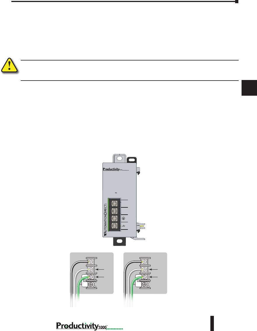
Chapter 5: Installation and Wiring
A
2
3
4
5
3
3
3
3
3
3
3
3
3
3
3
3
3
5–15
Hardware User Manual, 1st Edition
1000
Wiring Guidelines
Wiring Power Supply
Connect the AC power source input wiring to the power supply as shown. The power supply
terminals can accept up to 14 AWG solid or stranded wire. Do not over tighten the terminal
screws; the recommended torque is 7 to 9 inch-pounds (0.882 to 1.02 N·m).
WARNING: Once the power wiring is connected, secure the terminal block cover in the closed position.
When the cover is open there is a risk of electrical shock if you accidentally touch the connection
terminals or power wiring.
Grounding
A good common ground reference (earth ground) is essential for proper operation of the
Productivity1000 system. One side of all control circuits and power circuits along with the
ground lead must be properly connected to earth ground by either installing a ground rod in
close proximity to the enclosure or by connecting to the incoming power system ground. There
must be a single-point ground (i.e. copper bus bar) for all devices in the enclosure that require an
earth ground.
P1-01AC
Power Hookup
Grounding
A good common ground reference (earth ground) is essential for proper operation of
the Productivity1000 system. One side of all control circuits, power circuits and the
ground lead must be properly connected to earth ground by either installing a ground
rod in close proximity to the enclosure or by connecting to the incoming power system
ground. There must be a single-point ground (i.e. copper bus bar) for all devices in the
enclosure that require an earth ground.
P1-01AC
AC (L)
AC (N)
G
LG
100-240V 48VA
50-60Hz
125VDC, 20W
DC (+V)
DC (-V)
®
+V
-V
GND
LOGIC
GND
AC (L)
AC (N)
GND
LOGIC
GND
125VDC 100–240 VAC
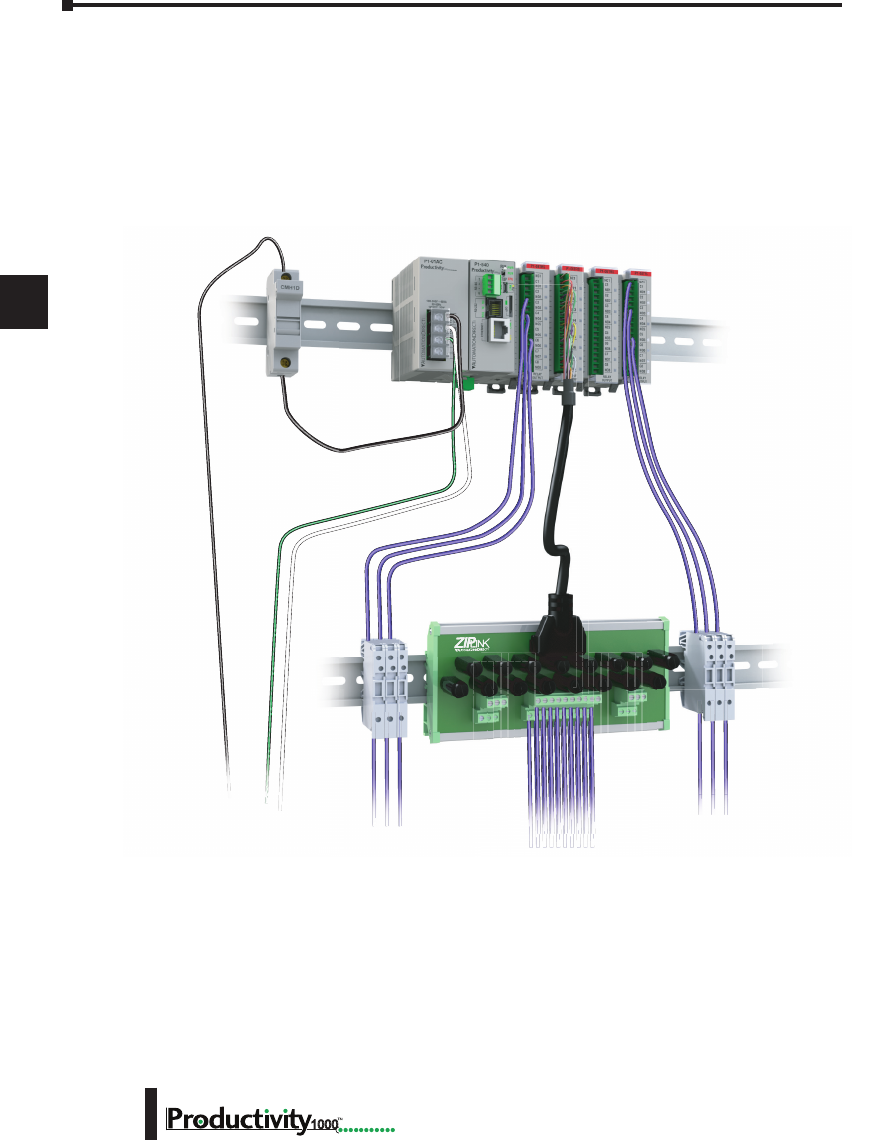
Chapter 5: Installation and Wiring
A
2
3
4
5
3
3
3
3
3
3
3
3
3
3
3
3
3
Hardware User Manual, 1st Edition
5–16 1000
Fuse Protection
Some of the Input and Output I/O module circuits do not have internal fuses. In order to
protect your modules, we suggest you add external fuses to your I/O wiring. A fast-blow fuse
with a lower current rating than the I/O bank’s common current rating can be wired to each
common; or a fuse with a rating of slightly less than the maximum current per output point
can be added to each output. Refer to the I/O module specifications in Chapter 2 to find the
maximum current per output point or per output common. Adding the external fuse does not
guarantee the prevention of CPU damage, but it will provide added protection.

Chapter 5: Installation and Wiring
A
2
3
4
5
3
3
3
3
3
3
3
3
3
3
3
3
3
5–17
Hardware User Manual, 1st Edition
1000
I/O Module Wiring Options
There are two available methods for wiring most I/O modules: Hand wiring to the optional
removable I/O module terminal blocks or using the ZIPLink wiring system.
NOTE: Thermocouple and Thermistor modules are not compatible with the ZIPLink system and are shipped
with the terminal blocks included.
Hand Wiring System
Field wiring is attached using the removable terminal block connector. Use Wire Strip Length
reference on the terminal block, as a guide when preparing wire for termination. For easier
assembly, wire may be connected to terminal block prior to installing block into expansion
module.
e: To unstack modules, pull
into the unlocked position
odules apart.
WIRE STRIP
LENGTH
MIN
MAX
P1-08TD1

Chapter 5: Installation and Wiring
A
2
3
4
5
3
3
3
3
3
3
3
3
3
3
3
3
3
Hardware User Manual, 1st Edition
5–18 1000
I/O Module Wiring Options
ZIPLink Wiring System
The ZIPLink wiring system is the recommended method, which allows quick and easy
connection using cables that are prewired to the I/O module terminals at one end and plug into
a ZIPLink connector module terminal block at the other end. Use the tables on the following
page to specify your ZIPLink wiring system.
Terminal Block With Pigtail Cable
For most I/O modules you can also purchase ZIPLink pigtail cables.
ZIPLink Pigtail Cable
ZIPLink Pre-Wired Cables ZIPLink Module
ZIPLink Wiring
System
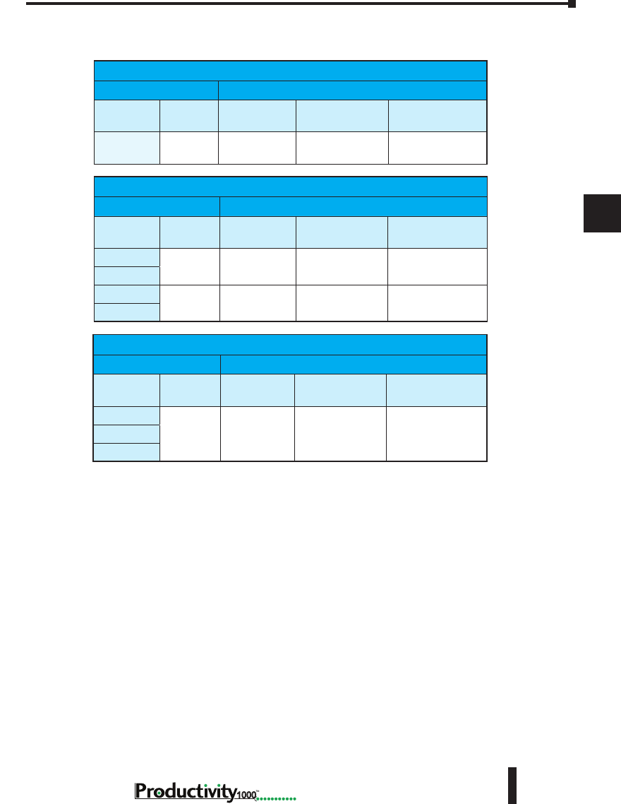
Chapter 5: Installation and Wiring
A
2
3
4
5
3
3
3
3
3
3
3
3
3
3
3
3
3
5–19
Hardware User Manual, 1st Edition
1000
Input and Output Modules ZIPLink Selections
Productivity1000 Input Module ZIPLink Selector
I/O Module ZIPLink
Input
Module # of Terms Component Module Part No. Cable Part No.
P1-08ND3
10 Feedthrough ZL-RTB20 or
ZL-RTB20-1 ZL-P1-CBL10*
Productivity1000 Output Module ZIPLink Selector
I/O Module ZIPLink
Output
Module # of Terms Component Module Part No. Cable Part No.
P1-08TD1
10 Feedthrough ZL-RTB20 or
ZL-RTB20-1 ZL-P1-CBL10*
P1-08TD2
P1-08TRS
18 Feedthrough ZL-RTB20 or
ZL-RTB20-1 ZL-P1-CBL18*
P1-16TR
Productivity1000 Combo Modules ZIPLink Selector
I/O Module ZIPLink
Output
Module # of Terms Component Module Part No. Cable Part No.
P1-15CDD1
18 Feedthrough ZL-RTB20 or
ZL-RTB20-1 ZL-P1-CBL18*
P1-15CDD2
P1-16CDR
* Select the cable length by replacing the * with: Blank = 0.5 m, -1 = 1.0 m,
or -2 = 2.0 m.
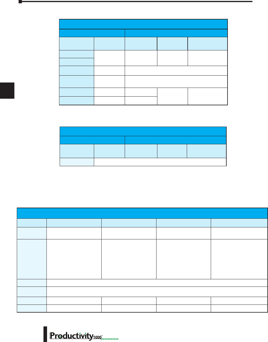
Chapter 5: Installation and Wiring
A
2
3
4
5
3
3
3
3
3
3
3
3
3
3
3
3
3
Hardware User Manual, 1st Edition
5–20 1000
Removable Terminal Blocks (Optional)
The hand wiring method consists of purchasing the associated removable I/O module terminal
block (table below) and hand wiring from the I/O terminal block to a DIN rail mounted
terminal block.
Analog Modules ZIPLink Selections
Productivity1000 Analog Module ZIPLink Selector
Module ZIPLink
Analog Module # of Terms Component Module Cable
P1-04ADL-1
10 Feedthrough ZL-RTB20 or
ZL-RTB20-1 ZL-P1-CBL10*
P1-04ADL-2
P1-04THM
T/C Wire
Only See Note 1
P1-04NTC
Copper
Conductors See Note 1
P1-04DAL-1
10 Feedthrough ZL-RTB20 or
ZL-RTB20-1 ZL-P1-CBL10*
P1-04DAL-2
10 Feedthrough
Productivity1000 Specialty Modules ZIPLink Selector
Module ZIPLink
Input Module # of Terms Component Module Cable
P1-08SIM
See Note 1
* Select the cable length by replacing the * with: Blank = 0.5 m, -1 = 1.0 m, or -2 = 2.0 m.
1. These modules are not supported by the ZIPLink wiring system.
Removable Terminal Block Specications
Part Number P2-RTB P2-RTB-1 P1-10RTB P1-10RTB-1
Number of
positions
18 Screw Terminals 18 Spring Clamp Terminals 10 Screw Terminals 10 Spring Clamp Terminals
Wire Range
30–16 AWG
(0.051– 1.31 mm²)
Solid / Stranded Conductor
3/64 in. (1.2 mm) Insulation
Maximum
Strip Length:
1/4 in. (6–7 mm)
28–16 AWG
(0.081–1.31 mm²)
Solid / Stranded Conductor
3/64 in. (1.2 mm) Insulation
Maximum
Strip Length:
19/64 in. (7–8 mm)
30–16 AWG
(0.051–1.31 mm²)
Solid / Stranded Conductor
3/64 in. (1.2 mm) Insulation
Maximum
Strip Length:
1/4 in. (6–7 mm)
28-16 AWG
(0.081–1.31 mm²)
Solid / Stranded Conductor
3/64 in. (1.2 mm)
Insulation Maximum
Strip Length:
19/64 in. (7–8 mm)
Conductors
“USE COPPER CONDUCTORS, 75°C” or Equivalent.
Screw Driver
Width
0.1 in (2.5 mm) Maximum *
Screw Size
M2 N/A M2 N/A
Screw Torque
2.5 lb·in (0.28 N·m) N/A 2.5 lb·in (0.28 N·m) N/A
* Select Automationdirect Screwdriver P/N TW-SD-MSL-1
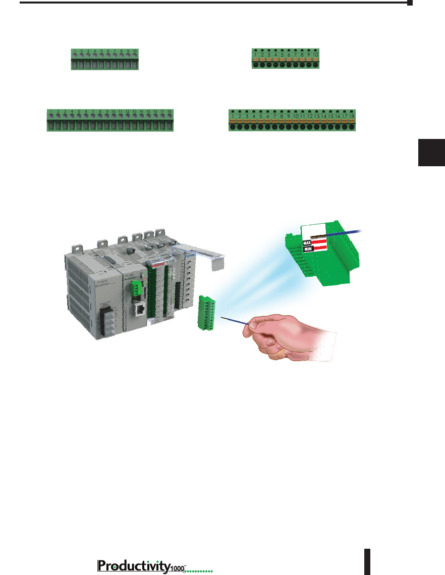
Chapter 5: Installation and Wiring
A
2
3
4
5
3
3
3
3
3
3
3
3
3
3
3
3
3
5–21
Hardware User Manual, 1st Edition
1000
P2-RTB (screw terminals)
Removable Terminal Block
P1-10RTB (screw terminals)
Removable Terminal Block
P2-RTB-1 (spring-clip terminals)
Removable Terminal Block
P1-10RTB-1 (spring-clip terminals)
Removable Terminal Block
Removable Terminal Blocks, continued
Terminal Block Installation
WIRE STRIP
LENGTH
WIRE STRIP
LENGTH
Reference the Wire Strip Length gauge printed on the end of the terminal strip as a guide to
properly strip wire insulation prior to inserting into terminal block. For ease of assembly, block
maybe wired prior to installation, if desired.
Insert terminal block as follows:
Step 1: Raise finger-safe terminal guard.
Step 2: Align terminal block with module terminal pins, ensuring correct orientation of
block.
Step 3: Firmly and evenly press terminal block onto terminal pins until seated. Lower finger-
safe guard into place.

Chapter 5: Installation and Wiring
A
2
3
4
5
3
3
3
3
3
3
3
3
3
3
3
3
3
Hardware User Manual, 1st Edition
5–22 1000
Planning the I/O Wiring Routes
The following guidelines provide general information on how to wire the I/O connections to
Productivity1000 modules. For specific information on wiring a particular I/O module refer
to the module specifications in Chapter 2.
1. If using removable terminal blocks, follow the wire size guidelines in the I/O modules
specifications in Chapter 2.
2. Always use a continuous length of wire. Do not splice wires to attain a needed length.
3. Use the shortest possible wire length.
4. Use wire trays for routing where possible.
5. Avoid running low voltage control wires near high voltage wiring.
6. Avoid confusion by laying input wiring separate from output wiring where possible.
7. To minimize voltage drops when wires must run a long distance, consider using multiple
wires for the return line.
8. Avoid running DC wiring in close proximity to AC wiring where possible.
9. Avoid creating sharp bends in the wires; follow accepted Electrical Code standards.
Terminal Block Removal
Remove terminal block as follows:
Step 1: Raise terminal cover.
Step 2: Pull terminal block release lever forward.
This will lift terminal block away from
pins.
Step 2: Grasp block firmly and pull away from
module.
WARNING: Ensure local and remote power supplies have been disconnected prior to removing terminal
block.
Terminal Cover
Terminal Release Lever
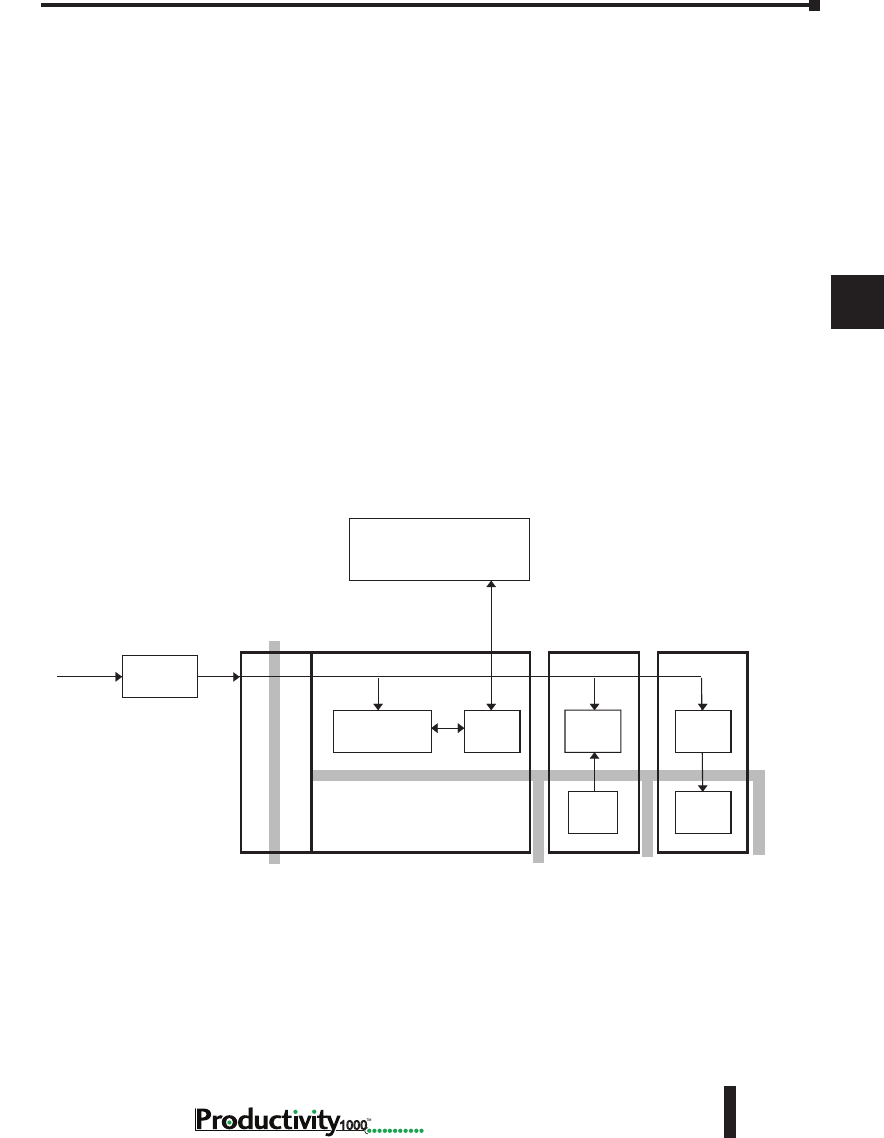
Chapter 5: Installation and Wiring
A
2
3
4
5
3
3
3
3
3
3
3
3
3
3
3
3
3
5–23
Hardware User Manual, 1st Edition
1000
System Wiring Strategies
The Productivity1000 system is very flexible and will work in many different wiring configurations. By
studying this section before actual installation, you may find the best wiring strategy for your application.
This will help to lower system cost and wiring errors, and avoid safety problems.
CPU Isolation Boundaries
CPU circuitry is divided into three main regions separated by isolation boundaries, shown
in the drawing below. Electrical isolation provides safety, so that a fault in one area does not
damage another. The transformer in the power supply provides magnetic isolation between
the primary and secondary sides. Optical isolators provide isolation in Input and Output
circuits. This isolates logic circuitry from the field side, where factory machinery connects.
The discrete inputs are isolated from the discrete outputs because each is isolated from the
logic side. Isolation boundaries protect the devices which are connected to the communication
ports, such as PCs and HMIs, from power input faults or field wiring faults. When wiring a
CPU, it is extremely important to avoid making external connections that connect logic side
circuits to any other.
CPU Module
Power Supply
Power
Input
PC, HMI, or other
communication devices
Output ModuleInput Module
Isolation Boundary
Logic CircuitCom
Ports
Input
Circuit
Output
Circuit
Logic
Circuit
Logic
Circuit
Filter
Optional
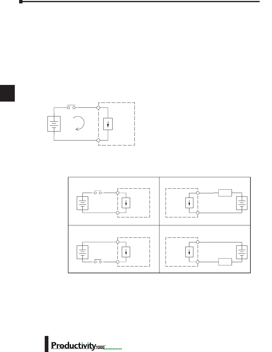
Chapter 5: Installation and Wiring
A
2
3
4
5
3
3
3
3
3
3
3
3
3
3
3
3
3
Hardware User Manual, 1st Edition
5–24 1000
Sinking/Sourcing Concepts
Before wiring field devices to the CPU I/O, it’s necessary to have a basic understanding of
“sinking” and “sourcing” concepts. Use of these terms occurs frequently in input or output
circuit discussions. These terms only apply to DC circuits, not AC circuits. The purpose of
this section is to explain the terms. The short definitions are as follows:
Sinking = Path to supply ground (–) or switching ground.
Sourcing = Path to supply source (+) or switching +V.
Input and output points that are either sinking or sourcing can conduct current in only one
direction. This means it is possible to wire the external supply and field device to the I/O
point with current trying to flow in the wrong direction, in which case the circuit will not
operate.
The diagram on the left shows a “sinking” CPU input.
To properly connect the external supply, connect it so
that the input provides a path to ground (–). Start
at the CPU input terminal, follow through the input
sensing circuit, exit at the common terminal, and
connect the supply (–) to the common terminal.
The switch between the supply (+) and the input
completes the circuit. Current flows in the direction
of the arrow when the switch is closed. By applying the circuit principle above to the four
possible combinations of input/output sinking/sourcing types, we have the four circuits as
shown below.
+
–
Input
Sensing
CPU
Common
Input
(sinking)
+
–
Input
Sensing
Load
Sinking Input Sinking Output
Sourcing Input Sourcing Output
CPU
Input
Common
+
–
Output
Switch
CPU Output
Common
+
–
Input
Sensing
Load
CPU
Input
Common
+
–
Output
Switch
CPU
Output
Common
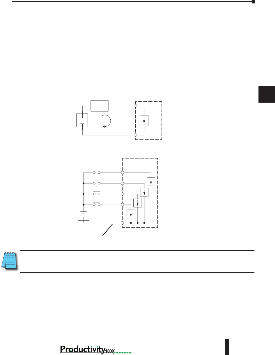
Chapter 5: Installation and Wiring
A
2
3
4
5
3
3
3
3
3
3
3
3
3
3
3
3
3
5–25
Hardware User Manual, 1st Edition
1000
I/O “Common Terminal” Concepts
In order for a CPU I/O circuit to operate, current must enter at one terminal and exit at
another. This means at least two terminals are associated with every I/O point. In the figure
below, the input or output terminal is the main path for the current. One additional terminal
must provide the return path to the power supply.
If there was unlimited module space then every I/O point could have two dedicated terminals
as the figure above shows. Providing this level of flexibility is not practical or necessary for
most applications. Most I/O point groups share the return path (common) among two or
more I/O points. The figure below shows a group (or bank) of four input points which share a
common return path. In this way, the four inputs require only five terminals instead of eight.
+
–
I/O
Circuit
Return Path
Main Path
(I/O point)
Field
Device
CPU
+
–
Input Sensing
Input 4
Common
Input 3
Input 2
CPU
Input 1
Electrical Common
To All Input Points
NOTE: In the circuit above, the current in the common path is equal to the sum of the energized channels.
This is especially important in output circuits, where larger gauge wire is sometimes needed for the
commons.
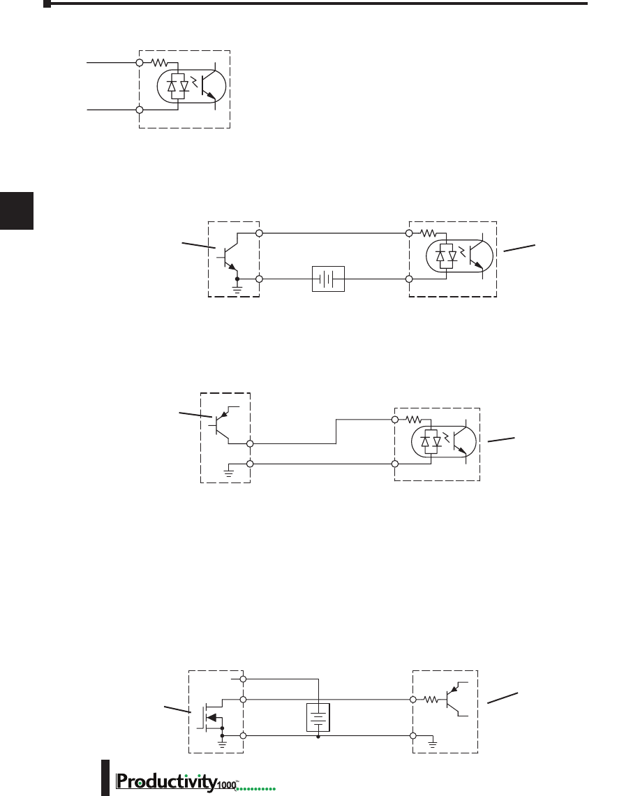
Chapter 5: Installation and Wiring
A
2
3
4
5
3
3
3
3
3
3
3
3
3
3
3
3
3
Hardware User Manual, 1st Edition
5–26 1000
DC Input Wiring Methods
I/O modules with DC inputs can be wired as either sinking or
sourcing inputs. The dual diodes (shown in this diagram) allow
current to flow in either direction. Inputs grouped by a common
point must be either all sinking or all sourcing. DC inputs typically
operate in the range of +12–24 VDC.
Sinking Input Sensor (NPN Type) to CPU Sourcing Input
In the following example, a field device has an open-collector NPN transistor output. When
energized, it sinks current to ground from the DC input point. The CPU input current is
sourced from the common terminal connected to power supply (+).
Sourcing Input Sensor (PNP Type) to CPU Sinking Input
In the following example, a field device has an open-emitter PNP transistor output. When
energized, it sources current to the CPU input point, which sinks the current to ground. Since
the field device loop is sourcing current, no additional power supply is required for the module.
DC Output Wiring Methods
I/O modules with DC output circuits are wired as all current sinking only or current sourcing
only depending on which output module part number is used. DC outputs typically operate
in the range of +5–24 VDC.
CPU Sinking Output to Sourcing Load Device
Many applications require connecting a CPU output point to a DC input on a field device load.
This type of connection is made to carry a low-level DC signals.
In the following example, the CPU output point sinks current to ground (common) when
energized. The output is connected to a field device load with a sourcing input.
CPU DC Input
Common
Input
Field Device
Output (sourcing)
Ground Common
Input
(sinking)
DC PNP Sensor
(Sourcing)
CPU Input
(Sinking)
Field Device
+
–
CPU DC Input
Output
Ground Common
Supply
(sinking)
Input
(sourcing)
DC NPN Sensor
(Sinking)
CPU Input
(Sourcing)
Field DeviceCPU DC Output
+DC Power
+
–
Power
20-28 VDC
Output
(sinking)
Common
Input
(sourcing)
Ground
DC Load
(Sourcing)
CPU Output
(Sinking)
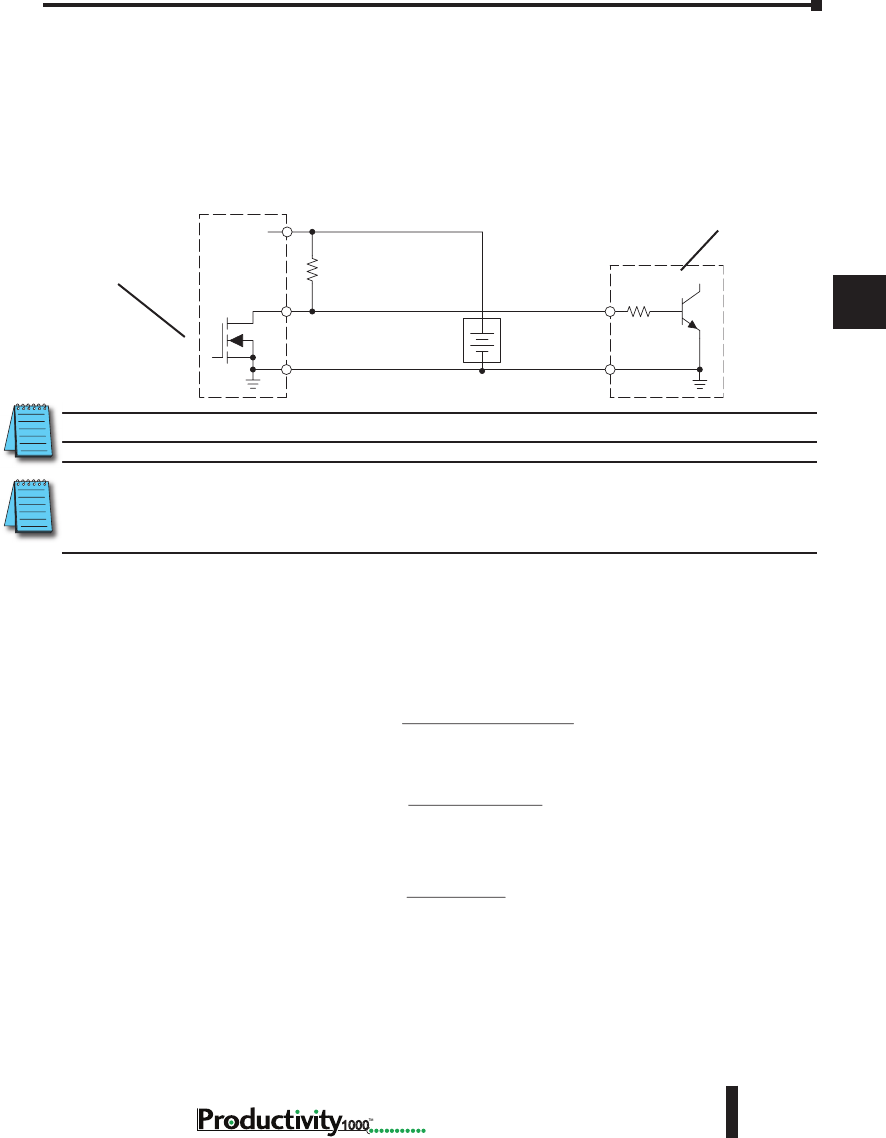
Chapter 5: Installation and Wiring
A
2
3
4
5
3
3
3
3
3
3
3
3
3
3
3
3
3
5–27
Hardware User Manual, 1st Edition
1000
CPU DC Sinking Output to Sinking Load Device
In the example below, a sinking output point is connected to the sinking input of a field device
load. In this case, both the CPU output and field device input are sinking type. Since the
circuit must have one sourcing and one sinking device, we add sourcing capability to the CPU
output by using a pull-up resistor. In the circuit below, we connect R pull-up from the output
to the DC output circuit power input.
NOTE: DO NOT attempt to drive a heavy load (>25mA) with this pull-up method.
NOTE: Using the pull-up resistor to implement a sourcing output has the effect of inverting the output point
logic. In other words, the field device input is energized when the CPU output is OFF, from a ladder logic
point-of-view. Your ladder program must comprehend this and generate an inverted output. Or, you may
choose to cancel the effect of the inversion elsewhere, such as in the field device.
It is important to choose the correct value of Rpull-up. In order to do so, we need to know the
nominal input current to the field device (Iinput) when the input is energized. If this value
is not known, it can be calculated as shown (a typical value is 15mA). Then use Iinput and
the voltage of the external supply to compute Rpull-up. Then calculate the power Ppull-up (in
watts), in order to size Rpull-up properly.
Field Device
Output
Ground
Input
Common
CPU DC Output
+DC pwr
+
–
(sourcing)
(sinking)
Power
(sinking)
pull-up
Supply
R
input
R
CPU Output
(Sinking with
Pull-up Resistor)
DC NPN Load
(Sinking)
pull-up
Rinput
R
=supply
V– 0.7–
input
I
input
I=input (turn–on)
V
input
R
R
pull-up
P=supply
V2
pull-up
R
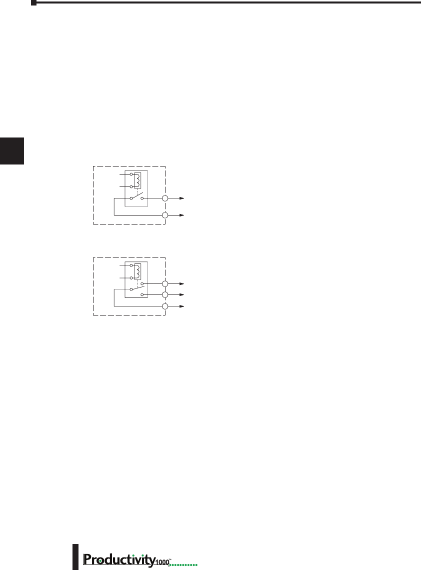
Chapter 5: Installation and Wiring
A
2
3
4
5
3
3
3
3
3
3
3
3
3
3
3
3
3
Hardware User Manual, 1st Edition
5–28 1000
Relay Outputs - Wiring Methods
Relay outputs are available for the Productivity1000. Relays are best for the following
applications:
• Loads that require higher currents than the solid-state outputs can deliver
• Cost-sensitive applications
• Some output channels need isolation from other outputs (such as when some loads require
different voltages than other loads)
Some applications in which NOT to use relays:
• Loads that require currents under 10mA
• Loads which must be switched at high speed or heavy duty cycle.
Relay outputs are available in two contact arrangements.
Form A type, or SPST (single pole, single throw) type. They
are normally open and are the simplest to use. The Form
C, or SPDT (single pole, double throw) type has a center
contact which moves and a stationary contact on either side.
This provides a normally closed contact and a normally open
contact.
The relays in some relay output modules share common
terminals, which connect to the wiper contact in each relay
of the bank. Other relay modules have relays which are
completely isolated from each other. In all cases, the module
drives the relay coil when the corresponding output point is
on.
Relay with Form A contacts
Relay with Form C contacts
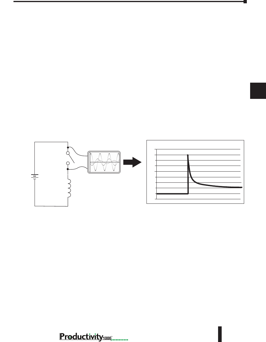
Chapter 5: Installation and Wiring
A
2
3
4
5
3
3
3
3
3
3
3
3
3
3
3
3
3
5–29
Hardware User Manual, 1st Edition
1000
Relay Outputs – Transient Suppression for Inductive Loads in a Control System
The following pages are intended to give a quick overview of the negative effects of transient
voltages on a control system and provide some simple advice on how to effectively minimize
them. The need for transient suppression is often not apparent to the newcomers in the
automation world. Many mysterious errors that can afflict an installation can be traced back
to a lack of transient suppression.
What is a Transient Voltage and Why is it Bad?
Inductive loads (devices with a coil) generate transient voltages as they transition from being
energized to being de-energized. If not suppressed, the transient can be many times greater
than the voltage applied to the coil. These transient voltages can damage CPU outputs or other
electronic devices connected to the circuit, and cause unreliable operation of other electronics
in the general area. Transients must be managed with suppressors for long component life and
reliable operation of the control system.
This example shows a simple circuit with a small 24V/125mA/3W relay. As you can see, when
the switch is opened, thereby de-energizing the coil, the transient voltage generated across the
switch contacts peaks at 140V.
In the same circuit, replacing the relay with a larger 24V/290mA/7W relay will generate a
transient voltage exceeding 800V (not shown). Transient voltages like this can cause many
problems, including:
• Relay contacts driving the coil may experience arcing, which can pit the contacts and reduce the
relay’s lifespan.
• Solid state (transistor) outputs driving the coil can be damaged if the transient voltage exceeds the
transistor’s ratings. In extreme cases, complete failure of the output can occur the very first time a
coil is de-energized.
• Input circuits, which might be connected to monitor the coil or the output driver, can also be
damaged by the transient voltage.
A very destructive side-effect of the arcing across relay contacts is the electromagnetic
interference (EMI) it can cause. This occurs because the arcing causes a current surge, which
releases RF energy. The entire length of wire between the relay contacts, the coil, and the
power source carries the current surge and becomes an antenna that radiates the RF energy. It
will readily couple into parallel wiring and may disrupt the CPU and other electronics in the
area. This EMI can make an otherwise stable control system behave unpredictably at times.
Oscilloscope
Relay Coil
(24V/125mA/3W,
AutomationDirect part no.
750R-2C-24D)
24 VDC
+
-
160
140
120
100
40
20
-20
Volts
80
60
0
Example: Circuit with no Suppression
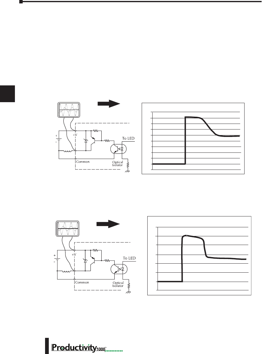
Chapter 5: Installation and Wiring
A
2
3
4
5
3
3
3
3
3
3
3
3
3
3
3
3
3
Hardware User Manual, 1st Edition
5–30 1000
CPU’s Integrated Transient Suppressors
Although the CPU outputs typically have integrated suppressors to protect against transients,
they are not capable of handling them all. It is usually necessary to have some additional
transient suppression for an inductive load.
Here is another example using the same 24V/125mA/3W relay used earlier. This example
measures the PNP transistor output of a typical CPU, which incorporates an integrated Zener
diode for transient suppression. Instead of the 140V peak in the first example, the transient
voltage here is limited to about 40V by the Zener diode. While the CPU will probably tolerate
repeated transients in this range for some time, the 40V is still beyond the module’s peak
output voltage rating of 30V.
5HOD\
&RLO
9'&
2VFLOORVFRSH
)RUWKLVH[DPSOHD9P$:
UHOD\LVXVHG$XWRPDWLRQ'LUHFW
SDUWQR5&'
9ROWV
Example: Small Inductive Load with Only Integrated Suppression
The next example uses the same circuit as above, but with a larger 24V/290mA/7W relay,
thereby creating a larger inductive load. As you can see, the transient voltage generated is much
worse, peaking at over 50V. Driving an inductive load of this size without additional transient
suppression is very likely to permanently damage the CPU output.
Example: Larger Inductive Load with Only Integrated Suppression
5HOD\
&RLO
9'&
2VFLOORVFRSH
)RUWKLVH[DPSOHDP$:
UHOD\LVXVHG$XWRPDWLRQ'LUHFW
SDUWQR6&(*9'&
9ROWV
Additional transient suppression should be used in both of these examples. If you are unable
to measure the transients generated by the connected loads of your control system, using
additional transient suppression on all inductive loads would be the safest practice.
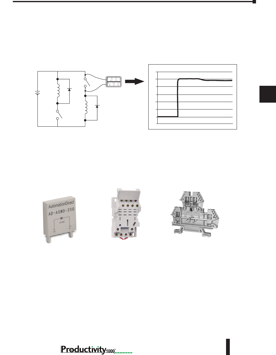
Chapter 5: Installation and Wiring
A
2
3
4
5
3
3
3
3
3
3
3
3
3
3
3
3
3
5–31
Hardware User Manual, 1st Edition
1000
Types of Additional Transient Protection
DC Coils:
The most effective protection against transients from a DC coil is a flyback diode. A flyback
diode can reduce the transient to roughly 1V over the supply voltage, as shown in this example.
Oscilloscope
24 VDC
DC Flyback Circuit
Sinking
Sourcing
+
_
30
25
20
15
10
5
0
-5
Volts
Many AutomationDirect socketed relays and motor starters have add-on flyback diodes
that plug or screw into the base, such as the AD-ASMD-250 protection diode module and
784-4C-SKT-1 socket module shown below. If an add-on flyback diode is not available for
your inductive load, an easy way to add one is to use AutomationDirect’s DN-D10DR-A
diode terminal block, a 600VDC power diode mounted in a slim DIN rail housing.
DN-D10DR-A
Diode Terminal Block
AD-ASMD-250
Protection Diode Module
784-4C-SKT-1
Relay Socket
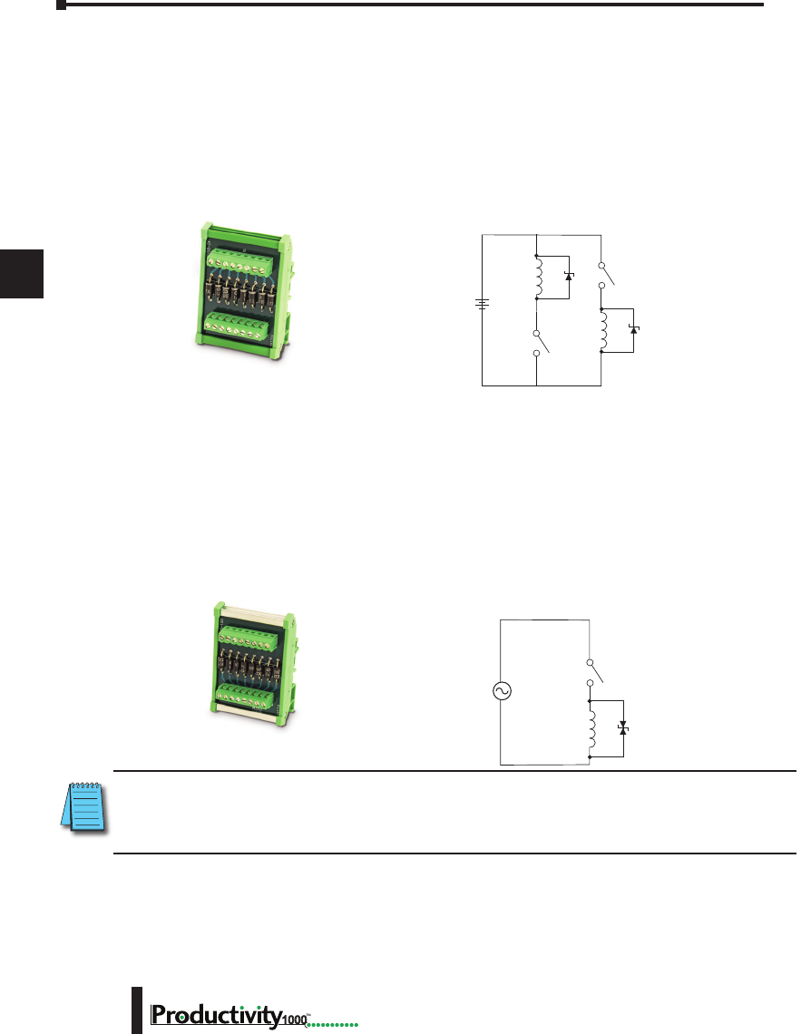
Chapter 5: Installation and Wiring
A
2
3
4
5
3
3
3
3
3
3
3
3
3
3
3
3
3
Hardware User Manual, 1st Edition
5–32 1000
ZL-TSD8-24
Transorb Module
AC Coils:
Two options for AC coils are MOVs or bi-directional TVS diodes. These devices are most
effective at protecting the driver from a transient voltage when connected across the driver
(CPU output) but are also commonly connected across the coil. The optimum voltage rating
for the suppressor is the lowest rated voltage available that will NOT conduct at the supply
voltage, while allowing a safe margin.
AutomationDirect’s ZL-TSD8-120 transorb module is a good choice for 120VAC circuits. It
is a bank of eight bi-directional 180V TVS diodes.
ZL-TSD8-120
Transorb Module
NOTE: Manufacturers of devices with coils frequently offer MOV or TVS diode suppressors as an add-
on option which mount conveniently across the coil. Before using them, carefully check the suppressor
ratings. Just because the suppressor is made specifically for that part does not mean it will reduce the
transient voltages to an acceptable level.
For example, a MOV or TVS diode rated for use on 24-48 VDC coils would need to have a
high enough voltage rating to NOT conduct at 48V. That suppressor might typically start
conducting at roughly 60VDC. If it were mounted across a 24V coil, transients of roughly
84V (if sinking output) or -60V (if sourcing output) could reach the CPU output. Many
semiconductor CPU outputs cannot tolerate such levels.
Two more common options for DC coils are Metal Oxide Varistors (MOV) or TVS diodes.
These devices should be connected across the driver (CPU output) for best protection as shown
below. The optimum voltage rating for the suppressor is the lowest rated voltage available that
will NOT conduct at the supply voltage, while allowing a safe margin.
AutomationDirect’s ZL-TSD8-24 transorb module is a good choice for 24VDC circuits. It
has a bank of 8 uni-directional 30V TVS diodes. Since they are uni-directional, be sure to
observe the polarity during installation. MOVs or bi-directional TVS diodes would install at
the same location, but have no polarity concerns.
24 VDC
DC MOV or TVS Diode Circuit
Sinking Sourcing
+
_
VAC
A
C MOV or Bi-Directional Diode Circuit

6
6
6
CommuniCations
Chapter
Chapter
Chapter
In This Chapter...
Communications ........................................................................................................ 6-1
Communication Ports ............................................................................................... 6-1
Communications: Connectivity ................................................................................. 6-7
P1-540 Port Connections ......................................................................................... 6-7
ASCII and Custom Protocol Functionality ............................................................... 6-12
ASCII Instructions ................................................................................................... 6-12
Custom Protocol Instructions ................................................................................. 6-13
Communications: Ethernet ...................................................................................... 6-15
TCP and UDP Port Numbers .................................................................................. 6-15
IP Addressing and Subnetting ................................................................................ 6-15
PC Setup ................................................................................................................ 6-16
CPU Setup .............................................................................................................. 6-17
TCP Connection Behavior with Modbus TCP and Network Instructions ................. 6-18
Communications Modbus Functionality ................................................................. 6-19
Master/Client Function Code and Data Type Support ............................................ 6-19
Slave/Server Function Code and Data Type Support .............................................. 6-21
Assigning Modbus Addresses to Tags ..................................................................... 6-22
Modbus Options .................................................................................................... 6-25
Modbus Instructions ............................................................................................... 6-28
Network Instructions .............................................................................................. 6-30
Automatic Poll versus Manual Polling and Interlocking ........................................... 6-31
Message Queue ...................................................................................................... 6-33
EtherNet/IP for the Productivity Series .................................................................. 6-34
Terminology Definitions ......................................................................................... 6-34
Network Layer Chart .............................................................................................. 6-35
EtherNet/IP Data .................................................................................................... 6-35

Hardware User Manual, 1st Edition
1000 Hardware User Manual, 1st Edition
Table of Contents
ii
Class 1 and Class 3 Connections ............................................................................ 6-36
Setup Example: Productivity1000 as EtherNet/IP Adapter ...................................... 6-36
Setup Example: Productivity1000 as EtherNet/IP Scanner ...................................... 6-39
Troubleshooting Tips .............................................................................................. 6-42
ProNET .................................................................................................................. 6-45
Custom Protocol Over Ethernet .............................................................................. 6-47
Communications: Port Configuration ..................................................................... 6-49
Ethernet Configuration ........................................................................................... 6-49
Local Ethernet Port Settings.................................................................................... 6-51
Remote Access Configuration ................................................................................. 6-51
Serial Configuration ................................................................................................ 6-52
RS-232 and RS-485 Port Settings ............................................................................ 6-52
Communications: Error Codes ................................................................................ 6-55
Productivity1000 Communication Error Codes ....................................................... 6-55
P1000 EtherNet/IP Error Codes .............................................................................. 6-56
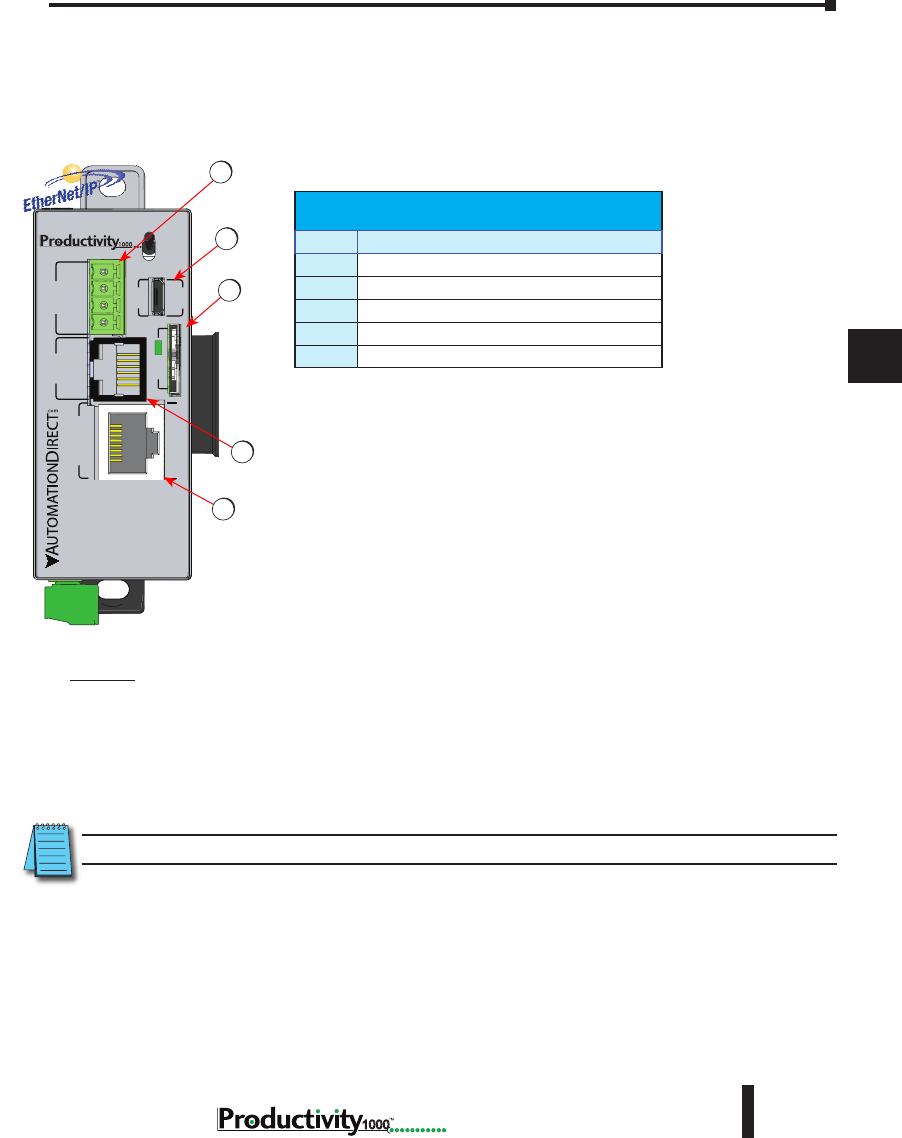
1
2
3
4
5
6
7
8
9
10
11
12
13
14
A
B
C
D
Chapter 6: Communications
6-1
Hardware User Manual, 1st Edition
1000
Hardware User Manual, 1st EditionHardware User Manual, 1st Edition
Communications
Communication Ports
The AutomationDirect Productivity1000 CPU is provided with several
Communications Ports. A detailed description of each of these ports follows in the
sections below.
Communication Ports:
1. microSD Card: The microSD card slot is provided for data logging
capability. Files stored on the microSD card by a P1-540 or the
Productivity Suite programming software are stored under a default
name, so only one project may be handled at a time on a microSD
card. Existing projects on the microSD card will be overwritten
without a prompt.
Data Logging: The Data Logger tool allows setup of periodic or
event-based data logging of tag and System Errors to the microSD
card. Data Logger setup is accessed under the Monitor & Debug
Menu. See Communications Connectivity section for more
information.
2. MicroUSB : The microUSB 2.0 port uses a Type B connector.
It is used for connection to a PC running the Productivity Suite
programming software and Online monitoring of program.
NOTE: The microUSB port is NOT compatible with older 1.0/1.1 full speed USB devices.
General Specications
Item # Communication Port
1
microSD Slot
2
MicroUSB 2.0 Programming Port
3
RS232 Serial Port (RJ12)
4
RS485 Serial Port (TB Style)
5
10/100 MB Ethernet Port
P1-540
P1-540 RUN
STOP
PWR
RUN
CPU
REMOTE I/O
RS-232 RS-485
10/100
ETHERNET
ACT LINK
G
-
+
T
LINK ACT
PGM
LINK
RXTXTXRTSRX
USB
µSD
®2
4
1
5
3
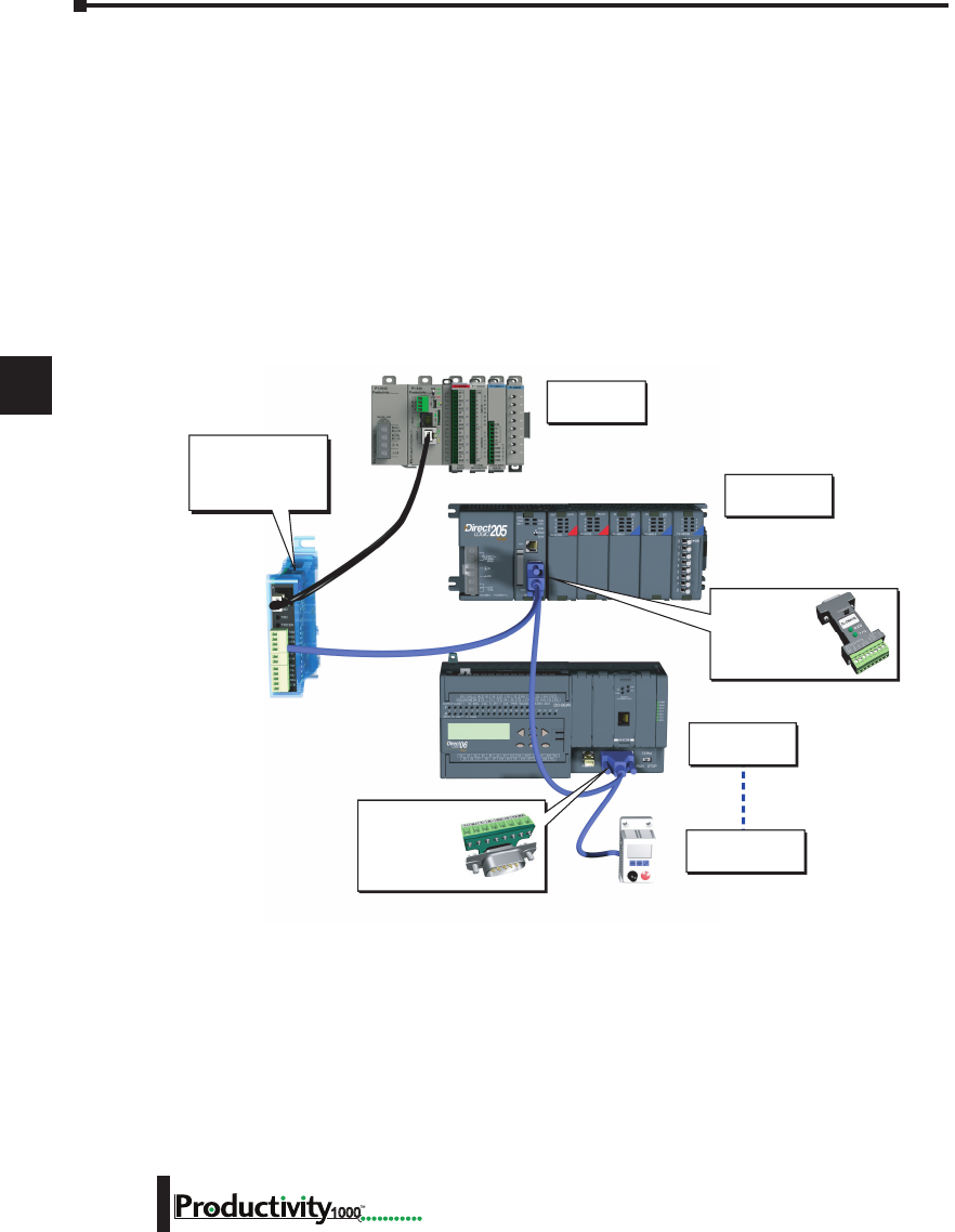
1
2
3
4
5
6
7
8
9
10
11
12
13
14
A
B
C
D
Chapter 6: Communications
6-2 Hardware User Manual, 1st Edition
1000
P1-540 Communication Ports, cont’d
3. RS-232: The RS-232 port is an RJ-12 connector located on the lower right front of the CPU.
This port can be used for:
• Modbus RTU Master connections.
• Modbus RTU Slave connections.
• ASCII Incoming and Outgoing communications.
• Custom Protocol Incoming and Outgoing communications.
Modbus RTU Master connections: The RS-232 port is intended to be used for point-to-point
connections but it is possible to connect up to 128 devices on a network if an RS-232 to RS-485/422
converter is connected to the port (such as a FA-ISOCON). This is accomplished by using the
communications instructions in the ladder project (MRX, MWX, RX, WX). If 4-wire RS-485 or
RS-422 communications is needed, using this port with an FA-ISOCON is the best method. See
Communications Connectivity section in this manual for more information.
Modbus RTU Slave connections: The RS-232 port is intended to be used for point-to-point
connections but it is possible for the RS-232 port to be used on a Modbus RTU network by using
a RS-232 to RS-485/422 converter. The port is addressable in the Hardware Configuration in the
Productivity Suite programming software. It is important to note that the RS-232 port cannot be
a Modbus RTU master and slave concurrently. If the port is set to Modbus RTU and there are no
communications instructions (MRX, MWX, RX, WX) in the project, the CPU will automatically
respond to Modbus requests from a Modbus master. See Communications Connectivity section for
more information.
Modbus RTU
Slave Device 2
Modbus RTU
Slave Device 128
Modbus RTU
Slave Device 1
Modbus RTU
Master
ZIPLink Comm
Port Adapter
Required
Part No.
ZL-CMA15L
ZIPLink Comm
Port Adapter
Required
Part No.
ZL-CMA15
FA-ISOCON
may be directly
powered by P1-540
RS-232 port.
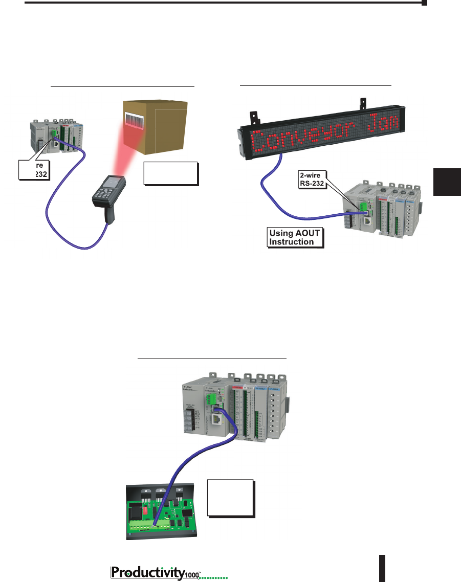
1
2
3
4
5
6
7
8
9
10
11
12
13
14
A
B
C
D
Chapter 6: Communications
6-3
Hardware User Manual, 1st Edition
1000
Hardware User Manual, 1st Edition
Using AIN
Instruction
2-wire
RS-232
RS-232 ASCII In Communication
Using AOUT
Instruction
2-wire
RS-232
RS-232 ASCII Out Communication
P1-540 Communication Ports, cont’d
ASCII Incoming and Outgoing communications: The RS-232 port can be used for sending and
receiving non-sequenced String data. This feature is typically used for receiving bar code strings from
a scanner or sending statistical data to a terminal or serial printer using the ASCII IN and ASCII OUT
instructions. See Communications Connectivity section for more information
Custom
Protocol
Device
RS-232 Custom Protocol In and Out
Custom Protocol Incoming and Outgoing communications: The RS-232 port can be used for
sending and receiving non-sequenced byte arrays to various devices. This function is typically used
for communicating with devices that don’t support the Modbus protocol but have another serial
communications protocol. This is accomplished by using the Custom Protocol In and Custom
Protocol Out instructions. The RS-232 port is intended to be used for point-to-point connections but
it is possible for the RS-232 port to be used on a multi-node network by using a RS-232 to RS-485/422
converter. See Communications Connectivity section for more information.
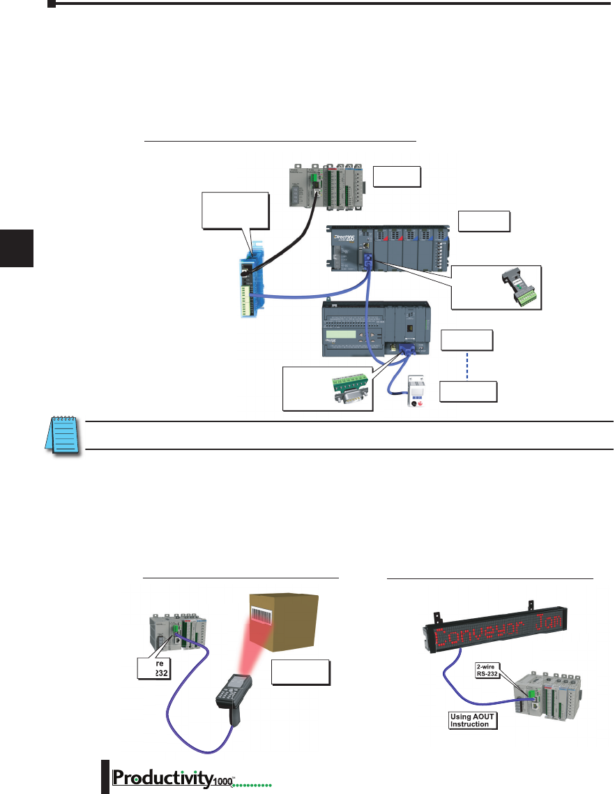
1
2
3
4
5
6
7
8
9
10
11
12
13
14
A
B
C
D
Chapter 6: Communications
6-4 Hardware User Manual, 1st Edition
1000
Using AIN
Instruction
2-wire
RS-232
RS-232 ASCII In Communication
Using AOUT
Instruction
2-wire
RS-232
RS-232 ASCII Out Communication
Modbus RTU
Slave Device 2
Modbus RTU
Slave Device 128
Modbus RTU
Slave Device 1
Modbus RTU
Master
ZIPLink Comm
Port Adapter
Required
Part No.
ZL-CMA15L
ZIPLink Comm
Port Adapter
Required
Part No.
ZL-CMA15
FA-ISOCON
may be directly
powered by P1-540
RS-232 port.
RS-485 Modbus RTU Slave Network Topology
ASCII Incoming and Outgoing Communications: The RS-485 port can be used for sending
and receiving non-sequenced String data. If long distances are required between the ASCII
device and the CPU, the RS-485 port is the better selection because of its increased distance
support (1,000 meters). ASCII communications are typically used for receiving bar code strings
from a scanner or sending statistical data to a terminal or serial printer using the ASCII IN and
ASCII OUT instructions. See Communications Connectivity section for more information.
P1-540 Communication Ports, cont’d
4. The Modbus RTU Slave Connections: The RS-485 network port is used for multi-node
networks. The port is addressable in the Hardware Configuration in the Productivity Suite
programming software. If the port is set to Modbus RTU and there are no communications
instructions (MRX, MWX, RX, WX) in the project, the CPU will automatically respond to
Modbus requests from a Modbus master. See Communications Connectivity section for more
information.
NOTE: See respective PLC Manual for communication port cable pinouts.
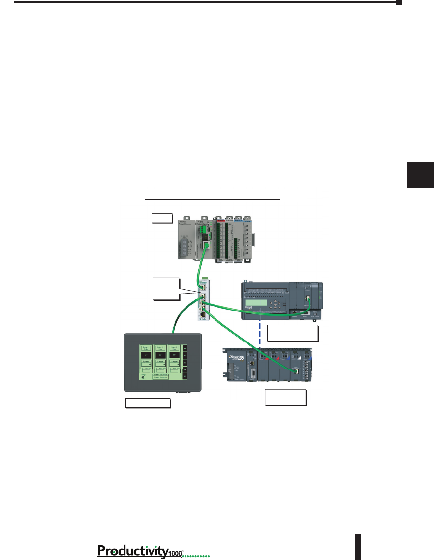
1
2
3
4
5
6
7
8
9
10
11
12
13
14
A
B
C
D
Chapter 6: Communications
6-5
Hardware User Manual, 1st Edition
1000
Hardware User Manual, 1st Edition
P1-540 Communication Ports, cont’d
5. Ethernet: The Ethernet port is 10/100Base-T Ethernet with an RJ-45 style connector. It is used for:
• Connection to a PC running the Productivity Suite programming software.
• Modbus TCP Client connections (Modbus requests sent from the CPU).
• Modbus TCP Server connections (Modbus requests received by the CPU).
• Custom Protocol over Ethernet
• ProNET
• EtherNet/IP Scanner (32 Adapters)
• EtherNet/IP Adapter (4 scanners) with 8 connections per device.
• Outgoing Email.
Modbus TCP Client Connections: The CPU can connect to 16 Modbus TCP server devices
concurrently by means of communications instructions in the ladder program (MRX, MWX, RX,
WX). It is possible to connect to more than 16 Modbus TCP server devices, but not concurrently.
This is accomplished by having communications instructions for more than 16 devices in the ladder
program and controlling the enabling and disabling of the instructions so that only 16 devices are
enabled at a given time. To connect to non Productivity1000 devices, use the MRX (Modbus Read)
and MWX (Modbus Write) instructions.
The greatest difference in the RX versus the MRX is that with the RX, the Tag Name in the target CPU
can be referenced directly and does not need a corresponding Modbus address. This is accomplished
by mapping local and remote tagnames together within the local CPU’s RX instruction. Once the
instruction is set up to read a remote project, the “Tags of Remote Project” or “Array Tags of Remote
Project” drop down lists will be accessible. Map the Tag of the Remote project to a Tag in the Local
project to read this data.
C-More Device 1
P1-540
Modbus TCP
Client Device 2
UP to Modbus TCP
Client Device 32
Stride
Ethernet
Switch
Modbus TCP Client (RX-WX)

1
2
3
4
5
6
7
8
9
10
11
12
13
14
A
B
C
D
Chapter 6: Communications
6-6 Hardware User Manual, 1st Edition
1000
P1-540 Communication Ports, cont’d
Modbus TCP Server Connections: The CPU can serve data back to 16 Modbus TCP Client devices
concurrently. If 16 Modbus TCP Client devices are connected to the CPU, then any new TCP
connection requests will be denied until one of the existing 16 devices drops its connection. If the
Client device connecting to the CPU is not a Productivity1000 device, then a Modbus address must
be assigned to the tag that is being requested. This is done in the Tag Database window. If the device
connecting to the CPU is another P1000 CPU or C-more panel, no Modbus address is required.
Custom Protocol Incoming and Outgoing Communications: The Ethernet port can be used for
sending and receiving non-sequenced byte arrays to various devices. This function is typically used for
communicating with devices that don’t support the Modbus protocol but have another custom Ethernet
communications protocol. This is accomplished by configuring a "Custom Protocol Ethernet Device"
using the hardware configuration and then using the "Custom Protocol Ethernet (CPE)" instruction.
See Communications Connectivity section for more information.
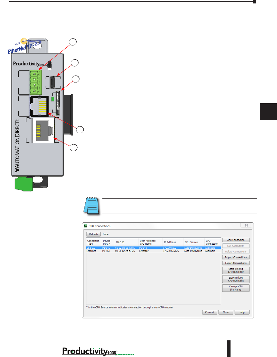
1
2
3
4
5
6
7
8
9
10
11
12
13
14
A
B
C
D
Chapter 6: Communications
6-7
Hardware User Manual, 1st Edition
1000
Hardware User Manual, 1st Edition
Communications: Connectivity
P1-540 Port Connections
The AutomationDirect Procuctivity1000 P1-540 CPU is
provided with several communications ports. The Connectivity
for each of these ports is described in the following sections. The
Communication Ports available are:
1. microSD Card Slot
For program data logging (microSD card not included with
processor).
2. MicroUSB Port
Programming port with a USB 2.0 Type Micro B female
connector. This port requires a MicroUSB Type A-Micro B cable
(such as the USB-CBL-AMICB6 cable).
The Micro USB Port is the simplest method of connecting the
Productivity Suite Programming Software to the P1-540 CPU.
After the programming software has been installed, connect a USB
A-Micro- B cable to the CPU and select the “Choose CPU” option.
The dialog shown below will appear.
Highlight the CPU listed in the dialog box and click on “Connect”.
No configuration is required.
NOTE: The MicroUSB port is NOT compatible with older 1.0/1.1 full speed
USB devices.
P1-540 RUN
STOP
PWR
RUN
CPU
REMOTE I/O
RS-232 RS-485
10/100
ETHERNET
ACT LINK
G
-
+
T
LINK ACT
PGM
LINK
RXTXTXRTSRX
USB
µSD
®2
4
1
5
3
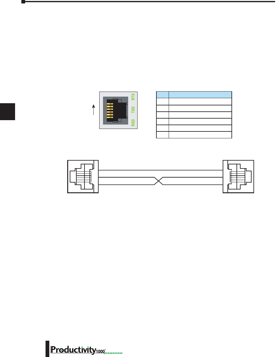
1
2
3
4
5
6
7
8
9
10
11
12
13
14
A
B
C
D
Chapter 6: Communications
6-8 Hardware User Manual, 1st Edition
1000
6-pin RJ12 Female
Modular Connector
6
1
6 GND Logic Ground
5 RTS RS-232 Output
4 TXD RS-232 Output
3 RXD RS-232 Input
2 +5V 210mA Maximum
1 GND Logic Ground
Pin # Signal
1 0V
3 RXD
4 TXD
0V 1
RXD 3
TXD 4
3. RS-232 Port:
Serial RS-232 multipurpose communications port with RJ12 connector.
The RS-232 Port can be connected to Modbus RTU master or slave devices, as well as devices that
output non-sequenced ASCII strings or characters. The manner in which these devices are wired to
the CPU depends whether the device is considered to be Data Terminal Equipment (DTE) or Data
Communications Equipment (DCE).
If two DTE devices are connected together, the RX and TX signals should cross or the RX of one device
should go to the TX of the other device and the TX of one device should go to the RX of the other device
(as shown below).
The CPU is considered a DTE device. Most Modbus or ASCII devices being connected to the
CPU will also be considered a DTE device and will need to swap TX and RX, but you should always
consult the documentation of that device to verify. If a communication device, such as a Modem, is
placed between the CPU and another Modbus or ASCII device it will most likely require connecting
the signals straight across (TX to TX and RX to RX). Again, this can differ from manufacturer to
manufacturer so always consult the documentation before wiring the devices together.
The RTS signal on pin 5 of the RS-232 Port will turn on when the TX signal is turned on and the
RTS signal will turn off when the TX signal turns off. The amount of time that the RTS signal turns
on before the TX signal turns on and the amount of time that the RTS signal waits before turning off
after the TX signal turns off is adjustable in the P1-540 CPU Module Configuration for the RS-232
Port. The RTS signal is very often required for media converters, such as a RS-232 to RS-422/485
converter (much like the FA-ISOCON).
The RTS signal is sometimes required for use with radio modems as well (Key on and off control).
There is also +5VDC @ 210mA on pin 2 available for powering an external device such as the
C-more Micro panel.
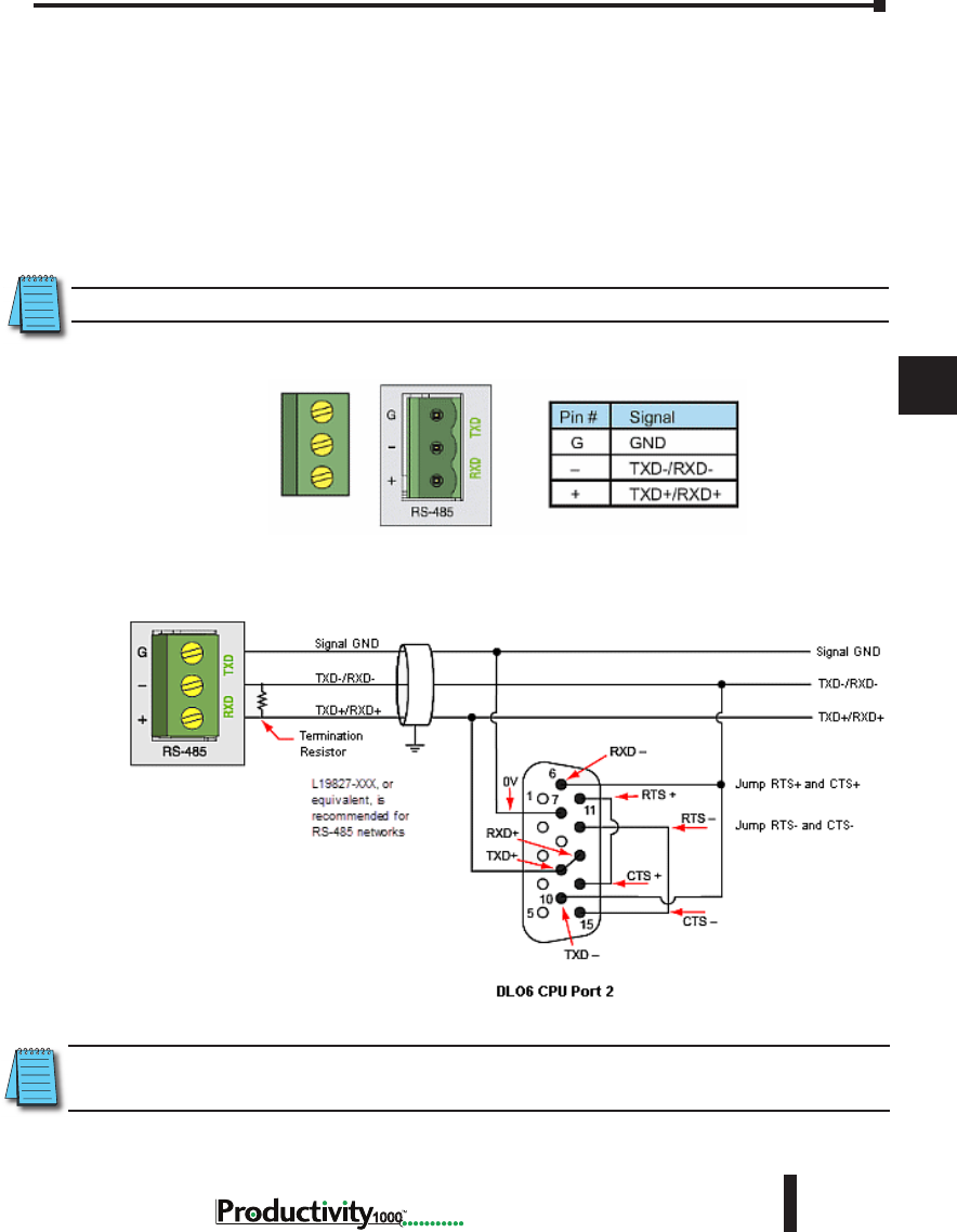
1
2
3
4
5
6
7
8
9
10
11
12
13
14
A
B
C
D
Chapter 6: Communications
6-9
Hardware User Manual, 1st Edition
1000
Hardware User Manual, 1st Edition
4. RS-485 Port
The RS-485 multipurpose serial communications port requires a removable 3-pin connector (See
below). This port is useful for connecting multiple Modbus and ASCII devices on one network and/or
connecting devices to the CPU at distances greater than 50 feet (RS-232 limit). The RS-485 standard
supports distances of up to 1000 meters without requiring a repeater. The RS-485 Port on the CPU
can support up to 50 devices, depending on load of each device (this assumes a 19K Ohm load for each
device). This number can be increased by placing an RS-485 repeater on the network, if necessary.
This port only supports RS-485 2-wire connections. For 4-wire RS-485 or RS-422, a converter, such
as an FA-ISOCON, should be used with the RS-232 Port.
NOTE: A 120 Ohm resistor is required at each end of the network for termination.
NOTE: ZIPLink Comm Port Adapter Part No. ZL-CMA15 or ZL-CMA15L may be used to make the connection
at DL06 or DL205 CPU Port 2.
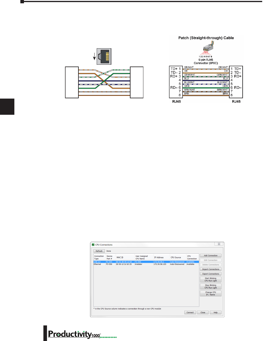
1
2
3
4
5
6
7
8
9
10
11
12
13
14
A
B
C
D
Chapter 6: Communications
6-10 Hardware User Manual, 1st Edition
1000
5. Ethernet Port
The 10/100 Base-T Ethernet port with RJ45 connector is used for programming and Modbus TCP
Client/Server functions.
General Information
Crossover cables can be used to directly connect two endpoint Ethernet devices such as a PC
network interface card and the CPU. Crossover or patch (or Straight-through) cables can be
used to directly connect endpoint Ethernet devices and the CPU.
The maximum distance for one cable or segment is 100 meters (328 feet). If the distance
required between 2 devices is greater than 100 meters, add an Ethernet switch to extend the
distance. An Ethernet switch can be added every 100 meters (or less) almost indefinitely. Each
Ethernet switch added will incur some latency (actual amount differs between switches and
manufacturers). So if a very long distance is needed between 2 Ethernet devices, it may be
better to convert to fiber optics.
The External Ethernet Port can be used as a programming port, a Modbus TCP Client (16
Servers) and Server (16 Clients), EtherNet/IP Scanner (32) and Adapter (4 ), Custom Protocol
over Ethernet, ProNET.
The External Ethernet Port can also be used to send emails using the EMAIL instruction.
Create a Connection
To communicate with the Productivity Suite programming software, connect an Ethernet cable
from the PC to the CPU External Ethernet Port. Once the software has been opened, click on
CPU and select the “Choose CPU” option. The dialog shown below will appear.
TD+
TD–
RD+
RD–
1
2
3
4
5
6
7
8
TD+
TD–
RD+
RD–
1
2
3
4
5
6
7
8
RJ45 RJ45
OR/WHT
OR
GRN/WHT
BLU
BLU/WHT
GRN
BRN/WHT
BRN
GRN/WHT
GRN
OR/WHT
BLU
BLU/WHT
OR
BRN/WHT
BRN
Crossover Cable
10Base-T/100Base-TX
1
8
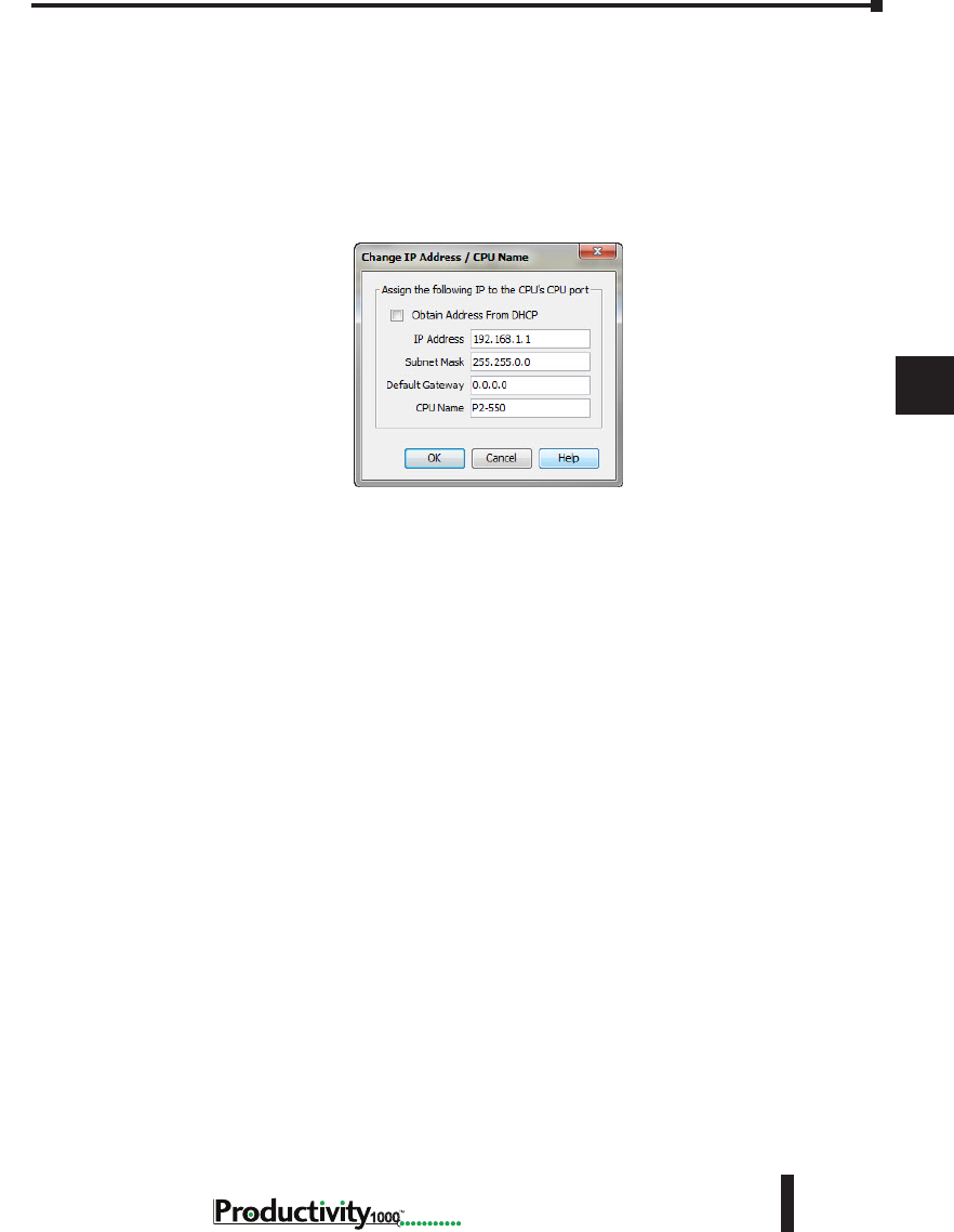
1
2
3
4
5
6
7
8
9
10
11
12
13
14
A
B
C
D
Chapter 6: Communications
6-11
Hardware User Manual, 1st Edition
1000
Hardware User Manual, 1st Edition
5. Ethernet Port, cont’d
Highlight the CPU that you wish to connect to and press the “Connect” button. You may see in the
CPU Connections dialog box CPU’s that are not on the same subnet as your PC, but this does not
mean you can connect to them. To connect to the CPU, you must configure either your PC or your
CPU to be in the same subnet. You can easily change the Ethernet settings of the CPU by highlighting
it and selecting the “Change CPU IP/Name” button (shown below). Or if you prefer, the PC Setup
section of this chapter contains information on configuring the Ethernet settings of your PC.
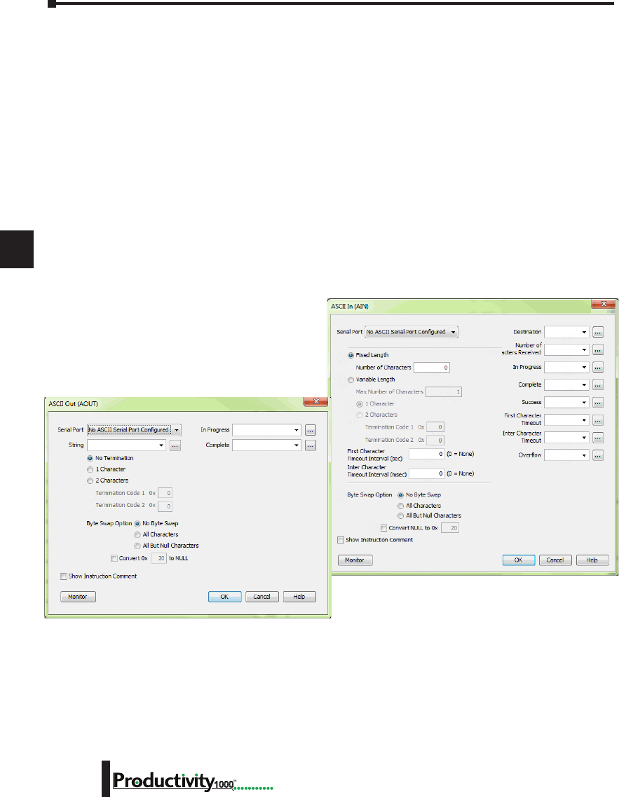
1
2
3
4
5
6
7
8
9
10
11
12
13
14
A
B
C
D
Chapter 6: Communications
6-12 Hardware User Manual, 1st Edition
1000
ASCII and Custom Protocol Functionality
Besides Modbus RTU, there are two additional functions supported on the serial ports in the
Productivity1000 system.
• The first function is the ability to send and receive text-based data with devices such as bar code
readers and serial printers.
• The second function is the ability to communicate serially with other devices that do not support
the Modbus protocol and lack a Productivity1000 driver.
ASCII Instructions
The ASCII In/Out instructions use the String data type to send or receive text-based data
through the serial port. The String data type is only intended for use with the “printable
character set”. This can include numbers, letters or special characters.
With the ASCII In instruction, the CPU can receive a fixed length of characters or a variable length of
characters with a termination code (an ‘end of message’ character).
The ASCII Out instruction sends text-based data out of
the serial port to various devices for control, printing
or display.
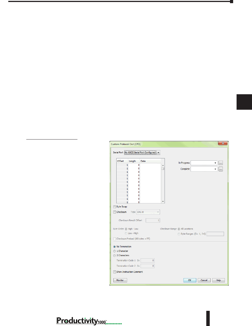
1
2
3
4
5
6
7
8
9
10
11
12
13
14
A
B
C
D
Chapter 6: Communications
6-13
Hardware User Manual, 1st Edition
1000
Hardware User Manual, 1st Edition
ASCII and Custom Protocol Functionality, cont’d
While the ASCII In instruction and the ASCII Out instruction can both be used in a project,
they are not intended to be used in conjunction with one another. In other words, it is not
advisable to use the ASCII Out instruction to send a String to a device that will respond (if the
response is needed) and to use the ASCII In instruction to try to receive this data.
The ASCII instruction limitations are:
1. AIN and AOUT cannot be enabled at the same time on the same serial port.
2. When the AOUT completes, the AIN cannot be enabled until the next logic scan.
3. AIN does not buffer data received while the AIN is not active. If a device responds too quickly,
some of the response may be lost before the AIN instruction can start receiving data.
Custom Protocol Instructions
The Custom Protocol is a HEX based protocol used to communicate with devices that do
not have the standard Modbus RTU Protocol. There are two instructions used with Custom
Protocol communication:
• Custom Protocol Out (CPO)
• Custom Protocol In (CPI)
Custom Protocol Out
The Custom Protocol Out
instruction allows the user to send
a ‘byte formatted’ packet of data
out of the CPU serial port.
Constant values and/or Tag values
can be used as the source for data
transmitted. There are several
formatting options including Byte
Swap and Checksum.
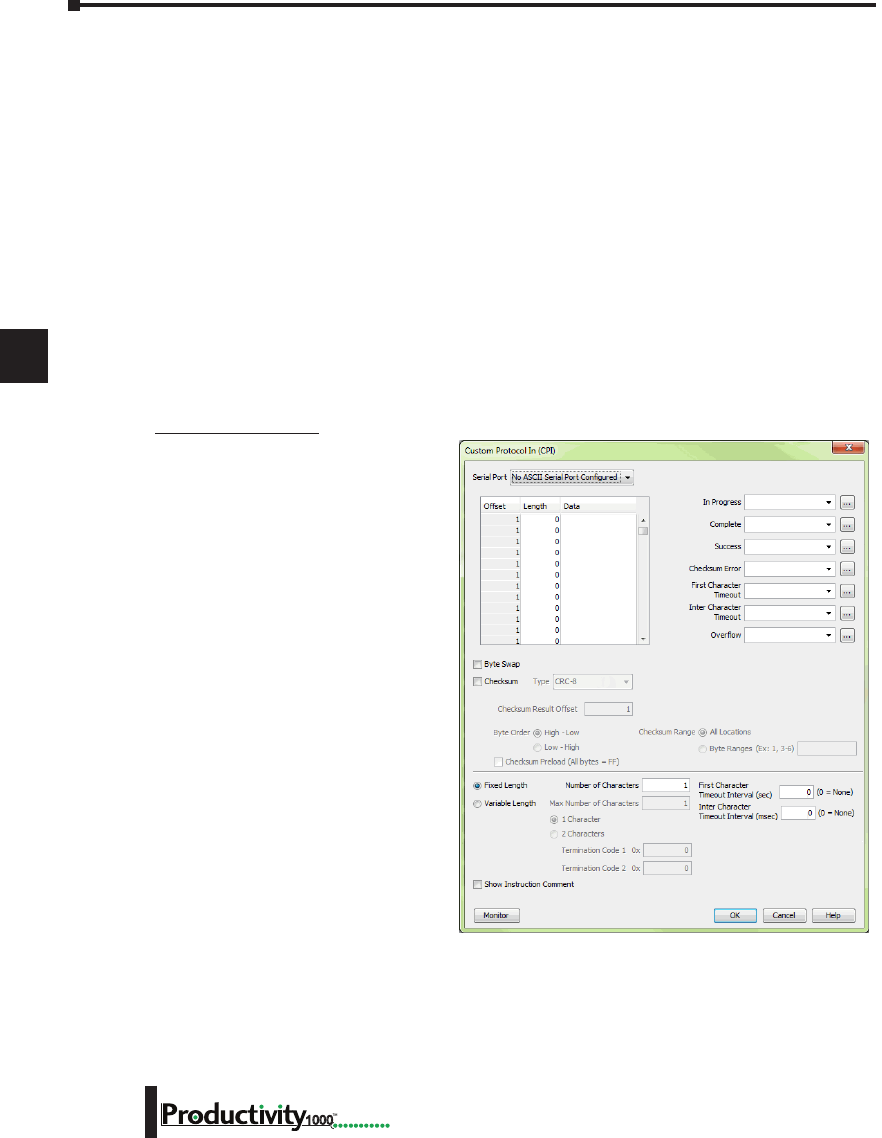
1
2
3
4
5
6
7
8
9
10
11
12
13
14
A
B
C
D
Chapter 6: Communications
6-14 Hardware User Manual, 1st Edition
1000
ASCII and Custom Protocol Functionality, cont’d
The Checksum option allows the user to select where in the packet the checksum should be
inserted, what type of Checksum (CRC-8 bit, CRC-16 bit, CRC-32 bit, XOR-8 bit, XOR-16
bit and XOR 32 bit), which bytes of the data source should be used in the calculation of the
checksum, what the byte order should be of the checksum (if greater than 8 bit) and how to
preload the checksum calculation.
If the device requires a different Checksum calculation, this can be done outside of the
instruction in other ladder code and the resulting Tag values can be inserted where appropriate
in the packet.
Termination characters can also be specified when needed.
The Custom Protocol Out instruction is for transmission only. If information needs to be
received from field devices, the Custom Protocol In instruction will have to be used. Unlike
ASCII, the Custom Protocol will buffer the received data. When the Custom Protocol In
instruction is executed, it will retrieve any data held in this buffer. Therefore, the lost responses
found with ASCII communication do not occur with Custom Protocol communication.
Custom Protocol In
The Custom Protocol In instruction
has similar formatting options to the
Custom Protocol Out instruction.
The Custom Protocol In instruction
will calculate the Checksum of the
data packet received based on the
criteria specified in the instruction
and this will determine the state of the
status bits assigned to the instruction.
If the Checksum calculation passes
based on the criteria specified in the
instruction, the “Success” status bit
will become true. If the Checksum
calculation fails, the “Checksum
Error” status bit will become true.
With the CPI instruction, the packet
termination must be specified, either
in terms of a termination character(s)
or a packet length. If a Checksum
is expected in the reply, be sure to
include this in the Fixed Length
value specified.
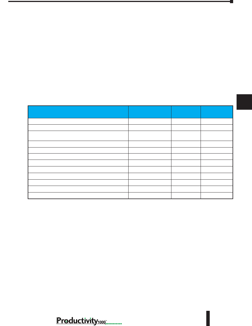
1
2
3
4
5
6
7
8
9
10
11
12
13
14
A
B
C
D
Chapter 6: Communications
6-15
Hardware User Manual, 1st Edition
1000
Hardware User Manual, 1st Edition
Communications: Ethernet
TCP and UDP Port Numbers
When doing TCP/IP and UDP/IP communications, there is a Source Port number
and Destination Port number for every message. The Client device must be aware of the
Destination Port Number(s) the Server device is expecting to see and the Server device must
listen for this Destination Port number. After the Server device has received the message
with the Destination Port Number it is listening on, it will formulate the return message
(if the applications require this) with the Source Port Number from the message sent as its
Destination Port Number.
It is important to understand a little about the Port numbering concept because many Ethernet
devices, such as routers with firewalls, will block messages with Destination Port numbers that
are not configured for that device. Listed below are the default Port Numbers used in the
Productivity1000 system. Some of these are configurable, allowing more flexibility when going
through routers in many applications.
IP Addressing and Subnetting
IP Addresses (used in conjunction with the Subnet Mask and Default Gateway address) are
used for network routing. This allows for easy and logical separation of networks.
It is outside of the scope of this user manual to explain how IP Addresses and Subnet masks are
configured for actual usage. There are many books, documents and tools (Subnet calculators)
on the internet that provide this information. Each facility and network will incorporate their
own rules and guidelines for how their networks are to be configured.
Port Port Number
(Decimal Format) TCP or UDP Configurable
Programming Software CPU Discovery 8888 UDP No
Programming Software Connection and Project Transfer 9999 UDP No
Modbus Client Connections
(MRX, MWX, RX and WX instructions) 502 TCP Yes
Modbus Server Connections 502 TCP Yes
GS-Drive Discovery 28784 UDP No
GS-Drive Connection 502 TCP No
Remote I/O Discovery 8887 UDP No
Remote I/O Connection 8887 UDP No
Email Instruction 25 TCP No
EtherNet/IP 44818 TCP Yes
EtherNet/IP 2222 UDP No*
ProNET 18888 UDP Yes
* Adapters may choose to respond using another port number.
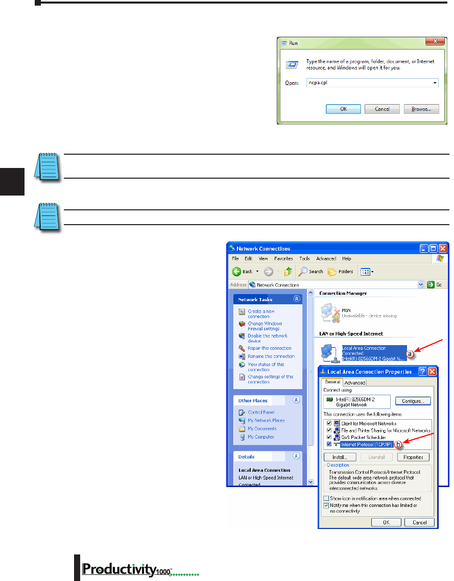
1
2
3
4
5
6
7
8
9
10
11
12
13
14
A
B
C
D
Chapter 6: Communications
6-16 Hardware User Manual, 1st Edition
1000
PC Setup
For testing and verification purpose, it is
recommended that the PC and the CPU be
on an isolated Ethernet switch. Configure the
PC’s network interface card setting as described
below.
1. Go to Start, then Run, type ncpa.cpl in the
Open field and click on OK to bring up the
Network Connections dialog.
NOTE: Many system settings on your computer require Administrative privileges. Consult with your IT
department for necessary privileges and approvals.
NOTE: You should record initial settings prior to making any network configuration changes.
2. Network Connections
a. Right click on the
Network interface
shown in the Network
Connections dialog
and select Properties. If
there is more than one
Network Interface on the
PC, be sure to choose
the one connected to the
Ethernet Switch with the
CPU on it.
b. From the Local Area
Connection Properties
window, highlight the
Internet Protocol(TCP/
IP) selection and click on
Properties.
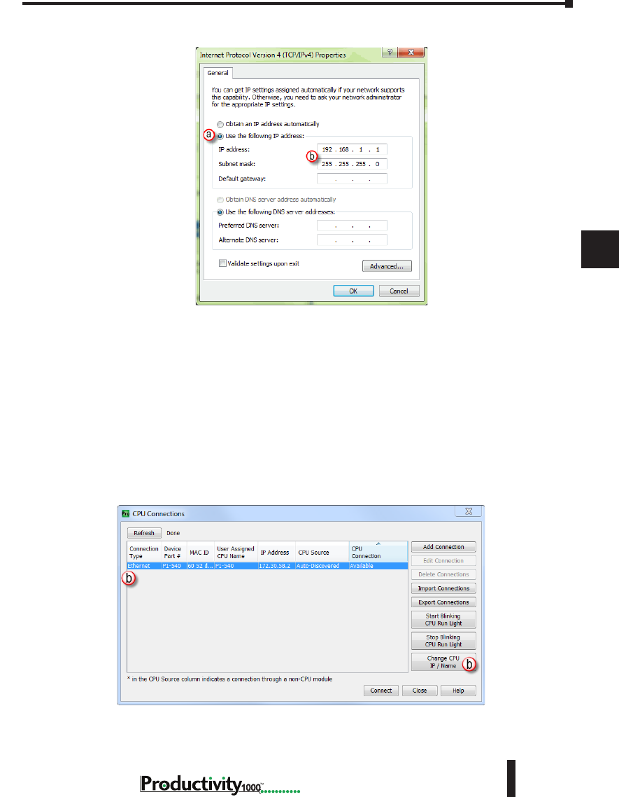
1
2
3
4
5
6
7
8
9
10
11
12
13
14
A
B
C
D
Chapter 6: Communications
6-17
Hardware User Manual, 1st Edition
1000
Hardware User Manual, 1st Edition
PC Setup, cont’d
3. Internet Protocol (TCP/IP) Properties.
a. In the Properties window, select Use the following IP address.
b. Enter an IP Address of 192.168.1.1 and Subnet Mask 255.255.255.0 and select OK. Select
OK again on the Local Area Connection Properties window.
CPU Setup
Now configure the CPU’s network IP setting as shown below.
1. Select CPU from the Productivity Suite Software Main Menu and then select Choose CPU
from the drop down menu.
2. The CPU Connections window will open as shown below.
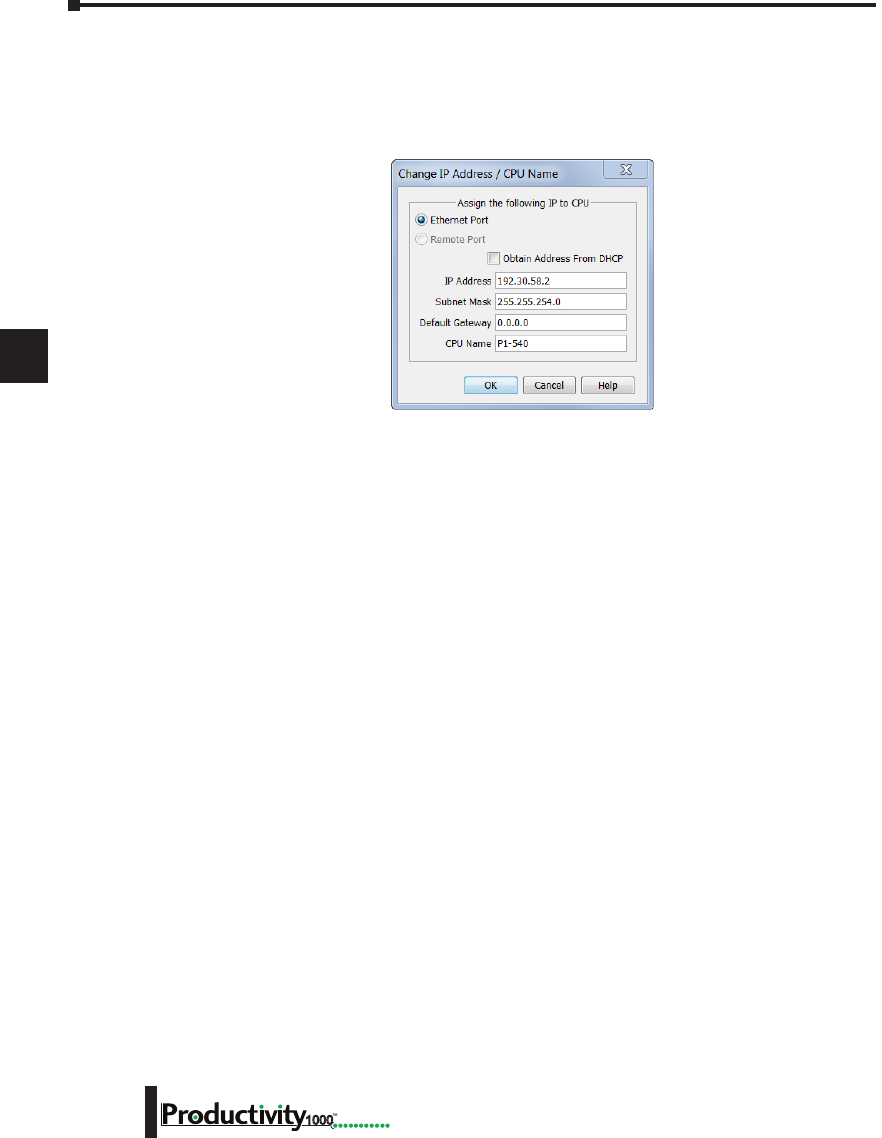
1
2
3
4
5
6
7
8
9
10
11
12
13
14
A
B
C
D
Chapter 6: Communications
6-18 Hardware User Manual, 1st Edition
1000
CPU Setup, cont’d
a. Click to highlight the CPU connected to the Ethernet switch.
b. Select the “Change CPU IP/Name” button.
3. The Change IP Address/CPU Name window will open as shown below.
• Enter an IP Address of 192.168.1.2 and Subnet Mask 255.255.0.0 for the CPU’s network IP
setting and select OK.
The CPU is now configured with the correct IP Address for connectivity with the PC. The IP
Address and Subnet Mask settings will very likely differ from what will be used in the actual
application. Consult the Network Administrator of the facility where the CPU will be installed
to get the appropriate settings for that network.
TCP Connection Behavior with Modbus TCP and Network Instructions
When performing communications over TCP, a Connection must be established before the
applications can transfer data. The connection is typically maintained until the application
decides that the connection is no longer needed and then the connection will be severed.
Frequent connects and disconnects are not efficient for the Client or the Server and can add
unnecessary network traffic. But maintaining connections needlessly is also costly to the Client
and Server in terms of processing and memory so this should also be avoided.
The CPU allows user control of Client connections through enabling and disabling the rungs
containing Modbus and Network instructions. The MRX, MWX, RX and WX instructions
have two options for sending messages: Automatic Poll and Manual Poll.
Automatic Poll sends out messages at a specified rate. When enabled, the instruction performs
a TCP connect with the Server device. Once the connection is established, the instruction
messages are sent at the rate entered in the poll rate field. This continues until the instruction
is disabled. The TCP connection will automatically be severed five seconds after the instruction
is disabled.
Manual Poll sends out a message each time the instruction is enabled. Enabling the instruction
performs a TCP connect with the Server device and sends the message one time. The TCP
connection will automatically be severed five seconds after receiving the reply from the Server
device. If the instruction gets another positive edge enable within the five seconds, the message
will be sent and the disconnect of the TCP connection will be delayed by an additional five
seconds.

1
2
3
4
5
6
7
8
9
10
11
12
13
14
A
B
C
D
Chapter 6: Communications
6-19
Hardware User Manual, 1st Edition
1000
Hardware User Manual, 1st Edition
Communications Modbus Functionality
Master/Client Function Code and Data Type Support
The following table lists the Modbus data type, the function code and the CPU source data
type that is supported when the CPU is the Client or Master on a Modbus TCP or serial
connection.
Modbus Client/Master Support (Using MRX and MWX Instructions)
Function
Code Function Name Modbus 984 Addressing
(Zero Based)
Modbus 984
Addressing
Productivity1000 Tag Types
(Data designation or source)
01 Read Coil Status 000000 - 065535 000001 - 065536
Discrete Output (DO)
Boolean (C )
Boolean System (SBRW)
02 Read Coil Status 100000 - 165535 100001 - 165536
Discrete Input (DI)
Boolean (C )
Boolean System (SBRW)
03 Read Holding
Registers 400000 - 465535 400001 - 465536
Integer 8 bit Unsigned (U8)
Integer 16 bit (S16)
Integer 16 bit Unsigned (U16)
Integer 16 bit BCD (B16)
Integer 32 bit (S32)
Integer 32 bit BCD (B32)
Integer 32 bit Float (F32)
Integer 16 bit System (SWRW)
04 Read Input
Registers 300000 - 365535 300001 -365536
Integer 8 bit Unsigned (U8)
Integer 16 bit (S16)
Integer 16 bit Unsigned (U16)
Integer 16 bit BCD (B16)
Integer 32 bit (S32)
Integer 32 bit BCD (B32)
Integer 32 bit Float (F32)
Integer 16 bit System (SWRW)
05 Write Single Coil 000000 - 065535 000001 - 065536
Discrete Input (DI)
Discrete Output (DO)
Boolean (C )
Boolean System (SBRW)
Boolean System Read Only (SBR)

1
2
3
4
5
6
7
8
9
10
11
12
13
14
A
B
C
D
Chapter 6: Communications
6-20 Hardware User Manual, 1st Edition
1000
Modbus Client/Master Support (Using MRX and MWX Instructions) (continued)
Function
Code Function Name Modbus 984 Addressing
(Zero Based)
Modbus 984
Addressing
Productivity1000 Tag Types
(Data designation or source)
06 Write Single
Register 400000 - 465535 400001 - 465536
Integer 8 bit Unsigned (U8)
Integer 16 bit (S16)
Integer 16 bit Unsigned (U16)
Integer 16 bit BCD (B16)
Integer 32 bit (S32)
Integer 32 bit BCD (B32)
Integer 32 bit Float (F32)
Integer 16 bit System (SWRW)
Integer 16 bit System Read Only (SWR)
15 Write Multiple
Coils 000000 - 065535 000001 - 065536
Discrete Input (DI)
Discrete Output (DO)
Boolean (C )
Boolean System (SBRW)
Boolean System Read Only (SBR)
16 Write Multiple
Registers 400000 - 465535 400001 - 465536
Integer 8 bit Unsigned (U8)
Integer 16 bit (S16)
Integer 16 bit Unsigned (U16)
Integer 16 bit BCD (B16)
Integer 32 bit (S32)
Integer 32 bit BCD (B32)
Integer 32 bit Float (F32)
Integer 16 bit System (SWRW)
Integer 16 bit System Read Only (SWR)

1
2
3
4
5
6
7
8
9
10
11
12
13
14
A
B
C
D
Chapter 6: Communications
6-21
Hardware User Manual, 1st Edition
1000
Hardware User Manual, 1st Edition
Slave/Server Function Code and Data Type Support
The following table lists the Modbus data type, the function code and the CPU source data type
that is supported when the CPU is the Server or Slave on a Modbus TCP or serial connection.
Modbus Server/Slave Support
Function Code Function Name Modbus 984 Addressing Productivity1000 Tag Types
(Data designation or source)
01 Read Coil Status 000001 - 065536
Discrete Output (DO)
Boolean (C )
Boolean System (SBRW)
02 Read Coil Status 100001 - 165536 Discrete Input (DI)
Boolean System Read Only (SBR)
03 Read Holding Registers 400001 - 465536
Integer 8 bit Unsigned (U8)
Integer 16 bit (S16)
Integer 16 bit Unsigned (U16)
Integer 16 bit BCD (B16)
Integer 32 bit (S32)
Integer 32 bit BCD (B32)
Integer 32 bit Float (F32)
Integer 16 bit System (SWRW)
String
04 Read Input Registers 300001 -365536
Analog Input, Integer 32 bit (AIS32)
Analog Input, Float 32 bit (AIF32)
Integer 16 bit System Read Only (SWR)
05 Write Single Coil 000001 - 065536
Discrete Output (DO)
Boolean (C)
Boolean System (SBRW)
06 Write Single Register 400001 - 465536
Integer 8 bit Unsigned (U8)
Integer 16 bit (S16)
Integer 16 bit Unsigned (U16)
Integer 16 bit BCD (B16)
Integer 32 bit (S32)
Integer 32 bit BCD (B32)
Integer 32 bit Float (F32)
Integer 16 bit System (SWRW)
Integer 16 bit System Read Only (SBR)
String
15 Write Multiple Coils 000001 - 065536
Discrete Output (DO)
Boolean (C )
Boolean System (SBRW)
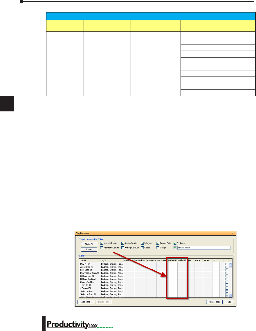
1
2
3
4
5
6
7
8
9
10
11
12
13
14
A
B
C
D
Chapter 6: Communications
6-22 Hardware User Manual, 1st Edition
1000
Assigning Modbus Addresses to Tags
There are many different data types in the CPU. Because of this, the Modbus addresses need
to be mapped to the various tag data types in the CPU.
There are two ways to map Modbus addresses to Tags in the Programming software:
• Modbus mapping in Tag Database window.
• Modbus mapping when creating Tags.
1. Modbus mapping in Tag Database window:
• There are only two data sizes in the Modbus protocol: bits and words. In the CPU,
there are multiple size types, so it is sometimes necessary to map multiple Modbus
addresses to a single Tag entity. There are also array data structures in the CPU.
When Modbus addresses are mapped to arrays, they will be mapped as a contiguous
block of addresses. This is, in fact, the most efficient method to handle Modbus
communications.
• In the Tag Database window, there are two columns named “Mod Start” and “Mod
End”. To map a Modbus address to a tag in the Tag Database window, simply
double-click in the Mod Start field for the Tag.
Modbus Server/Slave Support (continued)
Function Code Function Name Modbus 984 Addressing Productivity1000 Tag Types
(Data designation or source)
16 Write Multiple Registers 400001 - 465536
Integer 8 bit Unsigned (U8)
Integer 16 bit (S16)
Integer 16 bit Unsigned (U16)
Integer 16 bit BCD (B16)
Integer 32 bit (S32)
Integer 32 bit BCD (B32)
Integer 32 bit Float (F32)
Integer 16 bit System (SWRW)
Integer 16 bit System Read Only (SBR)
String
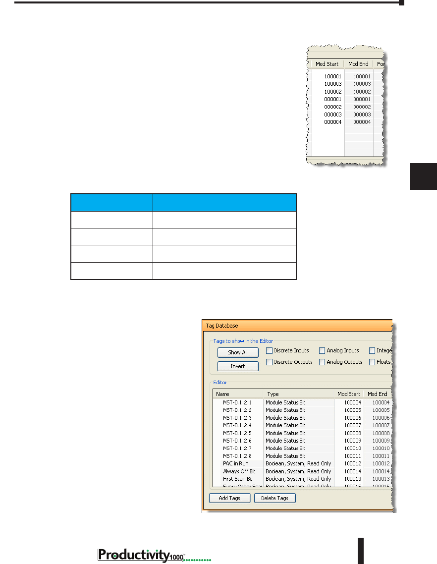
1
2
3
4
5
6
7
8
9
10
11
12
13
14
A
B
C
D
Chapter 6: Communications
6-23
Hardware User Manual, 1st Edition
1000
Hardware User Manual, 1st Edition
Assigning Modbus Addresses, cont’d
• When this is done, two values will appear in the field
The left most value is the Modbus data type. This is
fixed based upon the tag data type. The chart below
indicates the four different Modbus data types in the
984 addressing scheme.
Address Identifier Modbus 984 Address Type
0xxxxx Coil (Read/Write bit)
1xxxxx Input (Read Only bit)
3xxxxx Input Register (Read Only 16 bit word)
4xxxxx Holding Register (Read/Write 16 bit word)
The right most value in
the “Mod Start” field is the
address offset (range is from
1 – 65535). You can accept
the value that is pre-filled or
the value can be changed.
The software automatically
pre-fills the address offset with
the next available address.
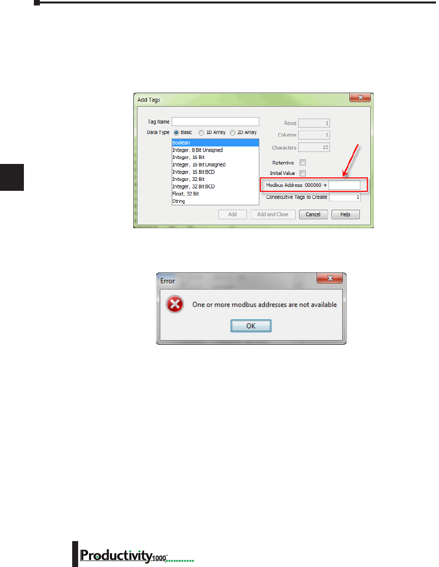
1
2
3
4
5
6
7
8
9
10
11
12
13
14
A
B
C
D
Chapter 6: Communications
6-24 Hardware User Manual, 1st Edition
1000
Assigning Modbus Addresses, cont’d
2. Modbus mapping when creating Tags:
Modbus addresses can be assigned to Tags as they are created in the Tag Database.
Type in the Modbus offset value when entering the Tag Name and Data Type.
If the address is already assigned, a warning message will appear.
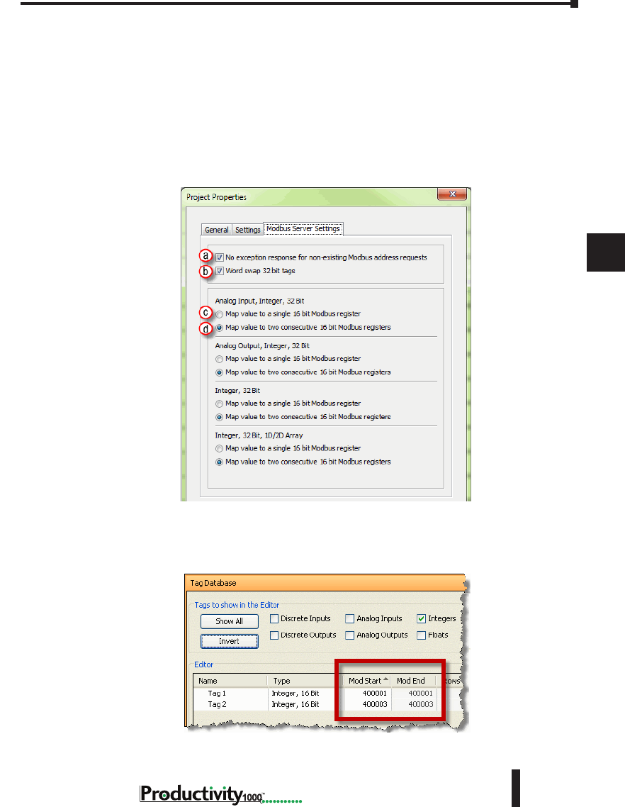
1
2
3
4
5
6
7
8
9
10
11
12
13
14
A
B
C
D
Chapter 6: Communications
6-25
Hardware User Manual, 1st Edition
1000
Hardware User Manual, 1st Edition
Modbus Options
The Modbus protocol does not have a specific method outlined for data types outside of bits
and 16-bit words. Most systems now have 32-bit data types. In order to transport 32-bit data
types across Modbus, they must be placed into two Modbus 16-bit registers. Unfortunately,
some devices do not support this method, so sometimes incompatibilities in the order in which
the 16-bit high word and low word are handled between devices persist.
In order to alleviate this situation, there are some options for handling this in the programming
software. To find the Modbus Address options, go to File and click on Project Properties and
then click on the “Modbus Server Settings” tab.
a. No exception response for non-existing Modbus address requests: Because the Modbus
addresses can be manually assigned to tags, it is possible that gaps can occur in the Modbus
address mapping. For example: Tag 1 has Modbus address 400001 assigned to it and Tag 2 has
Modbus address 400003 assigned to it.
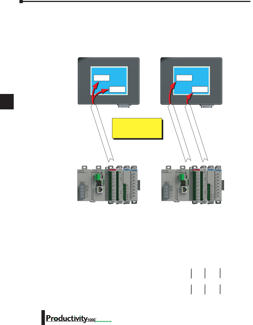
1
2
3
4
5
6
7
8
9
10
11
12
13
14
A
B
C
D
Chapter 6: Communications
6-26 Hardware User Manual, 1st Edition
1000
Modbus Options, cont’d
Most Modbus Master/Client devices will attempt to optimize their data requests to a Modbus
Slave/Server device by requesting blocks of data instead of individual registers. In the case
mentioned previously, most Modbus masters would send one read request starting at 400001
and a size of three instead of sending two read requests starting at 400001 with size one and
400003 with size one as shown below.
In the example shown above on left, a Modbus Slave/Server device should give an exception
response since there is no Modbus Address of 400002 in the device. This method can cause a
lot of inefficiencies. By selecting the “No exception response for non-existing Modbus address
requests” option, the CPU will not give an exception response to the request. Note that if
Modbus address 400002 by itself were requested it would give an exception response.
b. Word swap 32 bit tags: (S-32, AIS-32, AOS-32, F-32, FI-32, FO-32):
Word swap allows the word order of 32-bit tags to be changed when sending the values across
Modbus. The default selection is on, which returns the data low word first.
Tag 1 (Integer, 32-Bit) = 305,419,896 (hex = 0x12345678)
Tag1 Modbus address = 400001, 400002
Modbus reply for Tag 1 (Word Swap ON ) = 01 03 04 56 78 12 34
Modbus reply for Tag 1 (Word Swap OFF) = 01 03 04 12 34 56 78
Display Object
400001
Display Object
400003
Display Object
400001
Display Object
400003
Read Request 400001-400003
Read Request #1 for 400001
Read Request #2 for 400003
More efficient to do 1 block
read of 400001 – 400003
than 2 reads of 400001 by
itself and 400003 by itself.
High
Word
First
Low
Word
Last
Low
Word
First
High
Word
Last
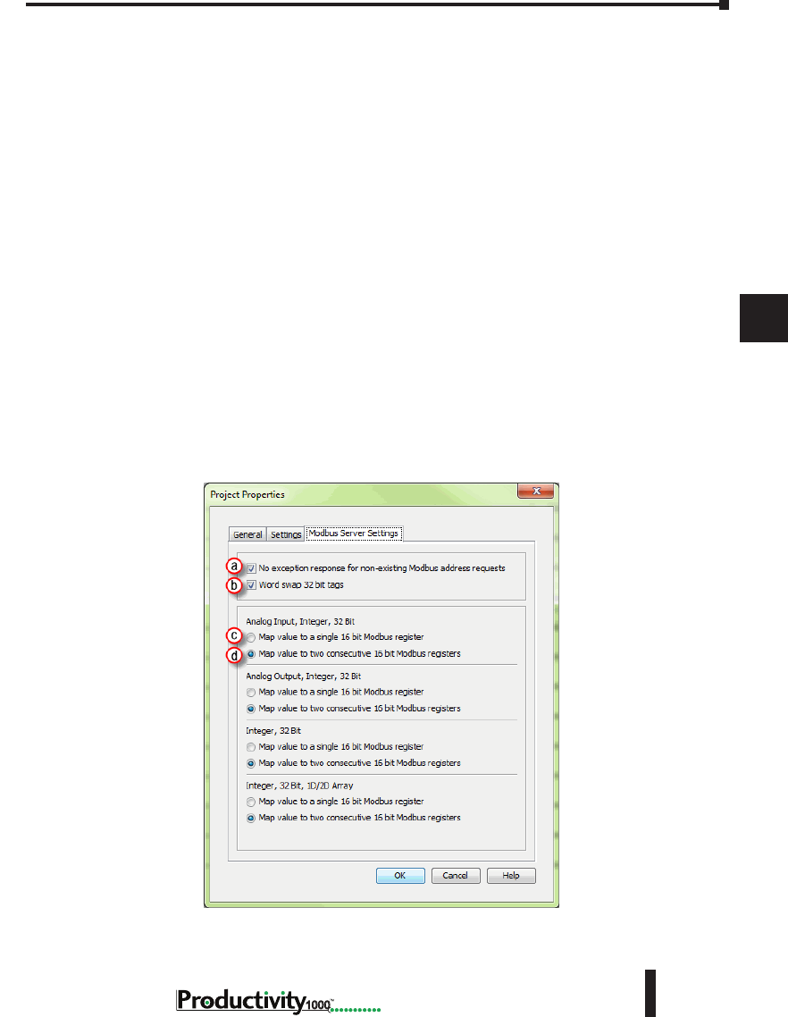
1
2
3
4
5
6
7
8
9
10
11
12
13
14
A
B
C
D
Chapter 6: Communications
6-27
Hardware User Manual, 1st Edition
1000
Hardware User Manual, 1st Edition
Modbus Options, cont’d
c. Map value to a single 16 bit Modbus register:
This option allows for compatibility with devices that do not support 32-bit Modbus
functionality. This option can be selected individually for the Analog Input and Output Signed
32 data types and the Internal Signed 32 data types, including the array form of these data types.
This function is only useful when the value contained in a 32-bit tag does not exceed a signed
15-bit value (32,765).
Tag 1 (Integer, 32-Bit) = 22136 (hex = 0x00005678)
With “Map value to a single 16 bit Modbus register” turned OFF =
Tag 1 Modbus address = 400001, 400002
Modbus reply for Tag1 (Word Swap ON) = 01 03 04 56 78 00 00
With “Map value to a single 16 bit Modbus register” turned ON =
Tag 1 Modbus address = 400001
Modbus reply for Tag1 = 01 03 02 56 78
d. Map value to two consecutive 16-bit Modbus registers:
Allows for 32-bit data types to be mapped to two consecutive 16-bit registers. This option is
selected as default.
All of the options in the “Modbus Address” tab of the Project Properties only apply to the
Modbus Slave/Server functionality. Similar options are available for the Modbus Master/Client
functions as well and are available in the MRX and MWX Modbus instructions.
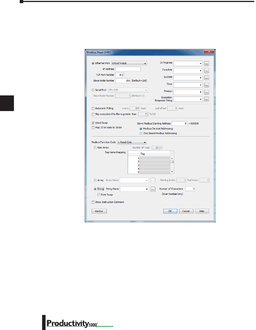
1
2
3
4
5
6
7
8
9
10
11
12
13
14
A
B
C
D
Chapter 6: Communications
6-28 Hardware User Manual, 1st Edition
1000
Modbus Instructions
To read or set data in other Modbus Slave/Server devices, there are two instructions available
in the programming software, Modbus Read and Modbus Write.
• The Modbus Read (MRX) instruction is used to read data from other Modbus devices into
Tags of the CPU.
• The MRX instruction can be used for Modbus TCP or Modbus RTU. There are several
status bits that can be used to determine whether the read message was successful and if it was
not, the reason why.
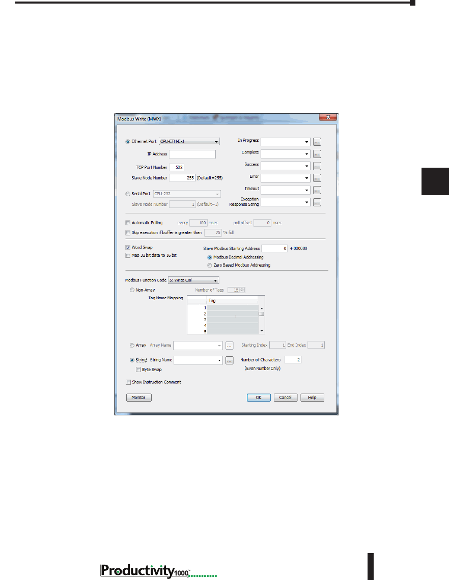
1
2
3
4
5
6
7
8
9
10
11
12
13
14
A
B
C
D
Chapter 6: Communications
6-29
Hardware User Manual, 1st Edition
1000
Hardware User Manual, 1st Edition
Modbus Instructions, cont’d
There is an “Automatic Polling” feature in the instruction to make it easier to read a device on a
pre-determined poll rate. There is also a “poll offset” field that can be used when simultaneous
instructions are enabled with the Automatic Polling feature to help stagger the flow of messages
being sent to the network.
• The Modbus Write (MWX) instruction is very similar in layout and configuration to the
MRX instruction. It is used to write values to a Modbus device from the tags in the CPU.
• The MWX operates very similarly to the MRX instruction. There are also many status bits to
indicate the success or reason for failure when sending a message.
• The Automatic Polling option is also available to the MWX instruction, although greater care
should be taken when using this feature in this instruction. This is explained in better detail in
the “Message Queue” section.
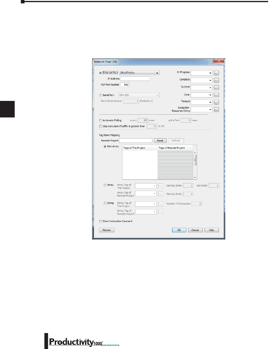
1
2
3
4
5
6
7
8
9
10
11
12
13
14
A
B
C
D
Chapter 6: Communications
6-30 Hardware User Manual, 1st Edition
1000
Network Instructions
The Network Read (RX) and Network Write (WX) instructions are used to communicate to
other CPU’s. They are very similar in operation to the MRX and MWX instructions but they
target Tag Names instead of Modbus addresses in the other CPU. There is also a significant
performance gain in using the RX and WX instructions when communicating to other CPU’s
as opposed to using the MRX and MWX instructions.
The same status bits are available in the RX instruction as in the MRX instruction and operate
in the same manner. The greatest difference in the RX versus the MRX is that with the RX,
the Tag Name in the target CPU can be referenced directly and does not need a corresponding
Modbus address. The way this is accomplished is by mapping local and remote tagnames
together within the local CPU’s RX instruction. Once the instruction is set up to read a remote
project, the “Tags of Remote Project” or “Array Tags of Remote Project” drop down lists will
be accessible. Map the Tag of the Remote project to a Tag in the Local project to read this
data.
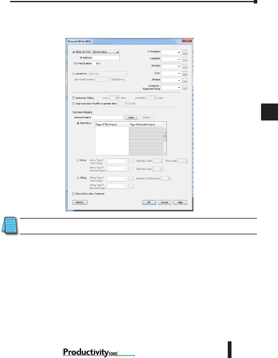
1
2
3
4
5
6
7
8
9
10
11
12
13
14
A
B
C
D
Chapter 6: Communications
6-31
Hardware User Manual, 1st Edition
1000
Hardware User Manual, 1st Edition
Network Instructions, cont’d
The WX instruction operates in the same manner except that the data from the Local tags will
be written into the Tags of the remote project. No Modbus mapping is required.
NOTE: The PC programming software project for the Remote CPU must be accessible by the PC running the
programming software for the Local project.
Automatic Poll versus Manual Polling and Interlocking
In many cases when performing multiple communications requests to other devices, the
message flow must be explicitly controlled in ladder code so that a message is not sent while
another one is in operation. This usually requires writing ‘interlocking’ code between the
instructions which typically involves the use of timers and shift registers, etc. Sometimes this
is necessary because of the application but in other cases where the CPU just wants to read
changing values from other devices and the frequency of that update is not critical it would be
much more efficient to skip the unnecessary code complexity of interlocking.
The desire to make it easier to communicate to other devices brought about the “Automatic
Polling” feature and the “Message Queue” in the CPU. The Automatic Polling feature allows
the user to choose the rate at which messages are sent without having to use a separate timer and
enabling logic. The ‘Message Queue’ allows the user to stage the messages from the ladder code
to go out to each physical communications port without requiring interlocking logic.
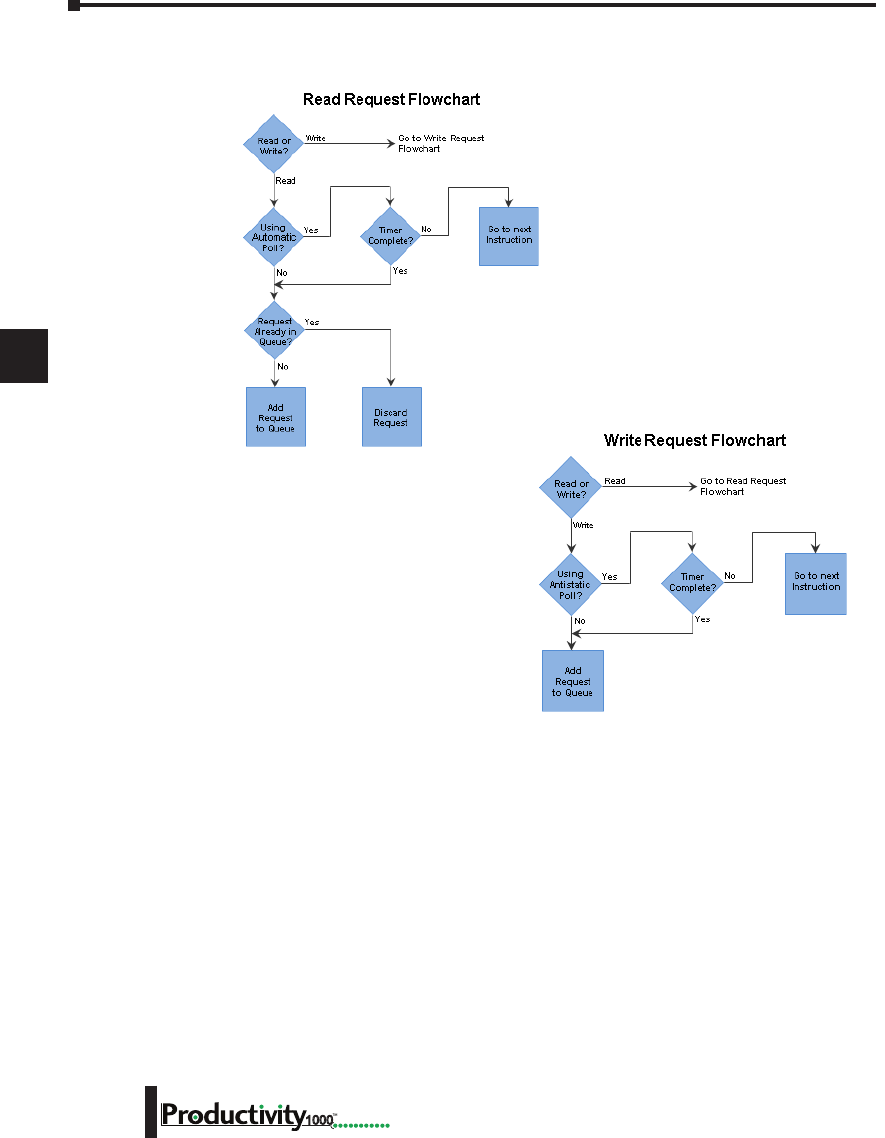
1
2
3
4
5
6
7
8
9
10
11
12
13
14
A
B
C
D
Chapter 6: Communications
6-32 Hardware User Manual, 1st Edition
1000
Network Instructions, cont’d
The implementation of how the message
queue works is slightly different based on
whether the request is a read request or a
write request.
Write requests will fill the queue much
faster than read requests. That’s why
it is advisable to carefully choose when
doing write requests whether to use the
“Automatic Poll” feature or to manually
send write requests only when needed (data
to write has changed). When designing a
system, it is important to know the total time it takes to send a request and get a reply for
each target device. The Poll time should be longer than this time. The longer the poll time
can be, within tolerance of the application, the better the overall network performance. So for
efficiency in programming and for the best possible performance for the system, conservative
poll rates should be used when utilizing the “Automatic Poll” feature.
There is also a “Poll offset” field in the communications instructions. This helps prevent the
instructions from being queued all at the same time. When the CPU project starts, a master
timer begins. The ladder scan will look to see if the instruction is enabled. If it is enabled, it
will begin the Automatic Poll timer at the specified poll offset value from the master time clock.

1
2
3
4
5
6
7
8
9
10
11
12
13
14
A
B
C
D
Chapter 6: Communications
6-33
Hardware User Manual, 1st Edition
1000
Hardware User Manual, 1st Edition
Message Queue
If the application requires more explicit, orderly control of each message sent to the devices,
turn off the “Automatic Poll” feature. Using the instruction’s status bits, logically control each
message as required.
All of the above explains how messages get into the “queue”. There are several factors involved
with how each queue (1 for each physical port) is emptied.
• Serial port queues: The serial port queues empty slower than the Ethernet port queues, not
just because of the hardware speed itself but because of the nature of serial communications.
Each request sent must wait for a response or a timeout (whichever comes first). Once the
reply is received for a request or a timeout has occurred, the next item in the list can be sent.
So the response time of the slave devices on the network will largely affect the speed at which
the queue fills and empties.
• Ethernet port queues: The Ethernet port queue can empty faster because when sending
requests to multiple devices, the CPU does not have to wait on a response from one device
before sending a request to another device due to the inherent nature of the Ethernet
hardware. However, sending multiple requests to the same Ethernet device does necessitate
that the CPU waits for a response from the first request before sending another request to that
same device.
Another difference in the Ethernet port queue versus the Serial port queue spawns from the
TCP ‘connection’ based behavior of Modbus TCP. If a TCP connection is lost to a device
and there are still requests in the queue for that device, those requests will be dropped from the
queue. There are three ways this can happen:
1. If a TCP timeout occurs (server device fails to respond within specified timeout value), the TCP
connection is lost.
2. If the server device closes the connection, then all of the requests will be dropped.
3. And, finally, if all rungs with communications instructions to a device are disabled for five
seconds, the CPU will drop the TCP connection for that device in order to free up valuable
resources that could be used elsewhere in the system.
This is another factor that should be considered when designing the system. If it is imperative
that no message be lost when communicating to a device, each instruction should be explicitly
handled one by one (interlocking logic).

1
2
3
4
5
6
7
8
9
10
11
12
13
14
A
B
C
D
Chapter 6: Communications
6-34 Hardware User Manual, 1st Edition
1000
EtherNet/IP for the Productivity Series
Terminology Definitions
A lot of terminology associated with EtherNet/IP is not always clear. Some of these terms are
listed below along with their respective definitions.
• Scanner: This is the term used to describe the device that initiates the EtherNet/IP sessions.
The Scanner is sometimes referred to as the “Originator” as well. In more standard Ethernet
terms, the Scanner would often be called the “Client”.
• Adapter: This is the device that responds to the EtherNet/IP communications that are
initiated by the Scanner. The Adapter is also known as the “Target” as well. Typically, the
Adapter is an Ethernet “Server”.
• Object: In EtherNet/IP, an Object is a representation of a defined set of Ethernet
connections, behaviors, services and data attributes. There are standard objects and there are
custom defined objects as well. See Object Modeling example below.
• Class: A Class is a set of Objects that are related in some fashion. See Object Modeling
example below.
• Instance: An Instance is an actual, usable manifestation of an Object. See Object Modeling
example below.
• Attributes: Attributes are the specific items within an Object Class. The category of
Attributes should be the same for all Instances of an Object but the actual Attribute itself
might vary. See Object Modeling example below.
• Connection Point: A Connection Point value is the “Class Code” reference for a data block.
This value is required for access to input and output data in IO Messaging. It is typically
defined for each input and output data block by the Adapter device manufacturer.
• IO Messaging: IO Messaging (also called “Implicit Messaging”) is a method of reading and
writing blocks of data without defining the Connection Point and size for each block transfer.
The Connection Point, size and transfer rate (RPI) are defined at the beginning and then the
data blocks are transferred at the specified intervals.
• Explicit Messaging: This method of reading or writing data requires that each message defines
the type of data and size of data needed for each request.
Object Modeling Example:
Class ------- Definition of Automobile
Attributes -- Make, Model, etc…
Object ------ A Ford Mustang
Instance ----Sally’s Ford Mustang
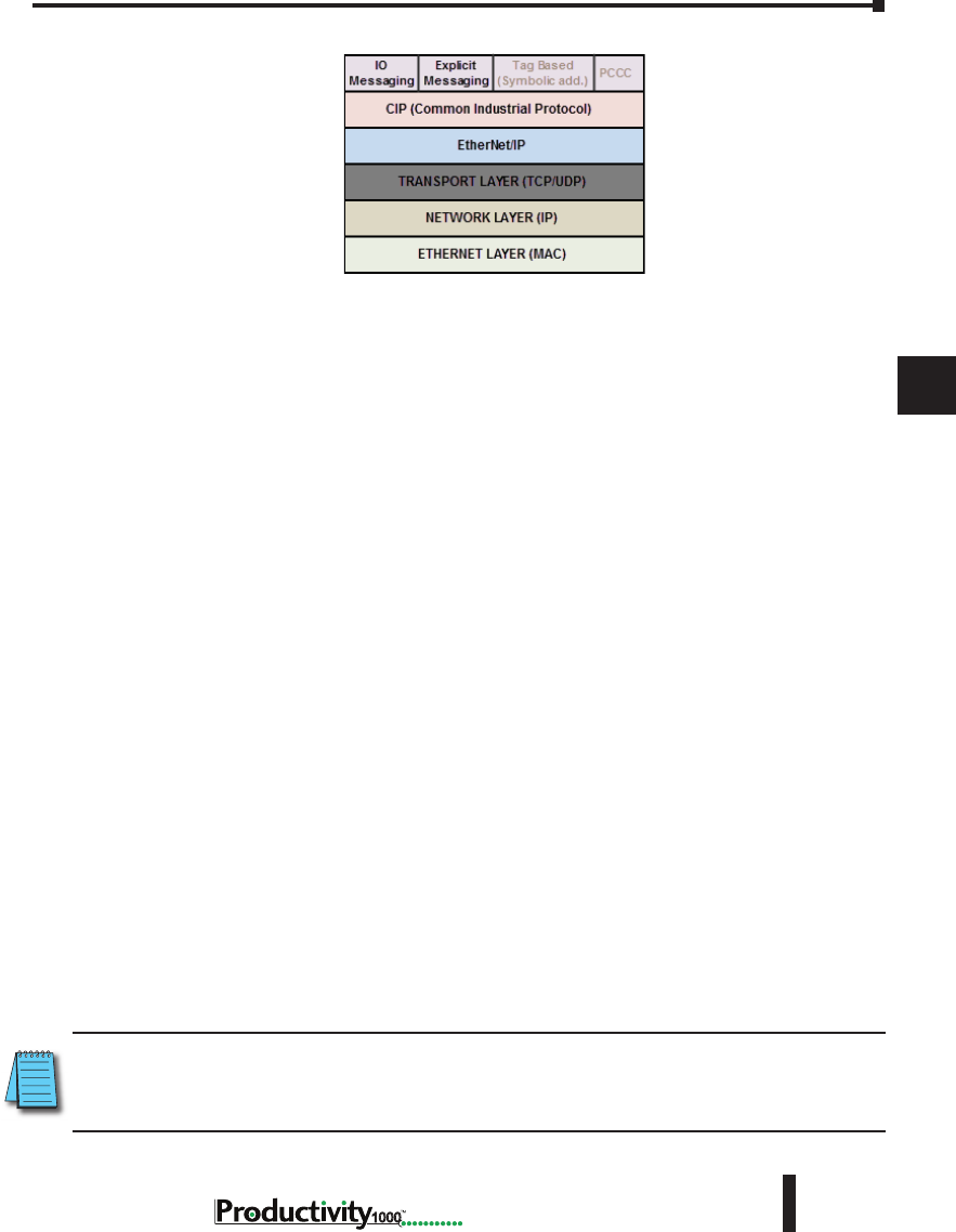
1
2
3
4
5
6
7
8
9
10
11
12
13
14
A
B
C
D
Chapter 6: Communications
6-35
Hardware User Manual, 1st Edition
1000
Hardware User Manual, 1st Edition
Network Layer Chart
The diagram above illustrates the OSI seven layer model and how EtherNet/IP fits into this
model. In general, there are three basic layers for sending and receiving data in the EtherNet/
IP protocol:
• EtherNet/IP layer (Register Session, etc…)
• CIP layer (CIP Forward Open, etc…)
• The uppermost layer,which contains several different types of messaging.
The ODVA (Open DeviceNet Vendor Association) specification defines many different types
of messaging that reside on the CIP layer. Two types of messaging supported in the phase
1 release of the Productivity Series EtherNet/IP protocol are I/O Messaging and Explicit
Messaging. I/O Messaging is accomplished through a Class 1 Connection and Explicit
Messaging can be accomplished through a Class 3 Connection or an Unconnected Message.
Tag Based Messaging (used for reading and writing values to Allen Bradley Control and
CompactLogix PLCs) and PCCC (used for reading and writing values to Allen Bradley
MicroLogix and SLC PLCs) are planned for subsequent phases of this protocol.
EtherNet/IP Data
When doing I/O Messaging, the data that is transported is defined as “Input” data and
“Output” data. Don’t confuse this type of data with what most PLCs define as Input data and
Output data. In most PLCs, Inputs are typically associated with an Input module that reads
points from real word devices. Outputs are typically associated with an Output module that
turns off and on real word devices.
In I/O Messaging, Input data is data that is sent from the target device back to the Originator
or to multiple devices that are listening (multicast messages). Output data is data that is sent
from the Target device. This data may or may not be connected to real word devices. That
is completely dependent upon the Adapter device. For example: When the Productivity1000
is configured as an EtherNet/IP Adapter device, the Input data and Output data is defined in
internal data arrays and does not directly tie to any Input and Output point to the real world.
If it is desired to tie these array elements to real word devices, that must be accomplished in
code by Copy commands (or other instructions).
NOTE: The Scanner (originator) in the P1000 will only accept messages from an Adapter (target) device with
an established connection with a Scanner. The Adapter (target) in the P1000 will respond back to a Scanner
(originator) in the method (Multicast or Unicast) that is sent in the forward open message from the Scanner
(originator).
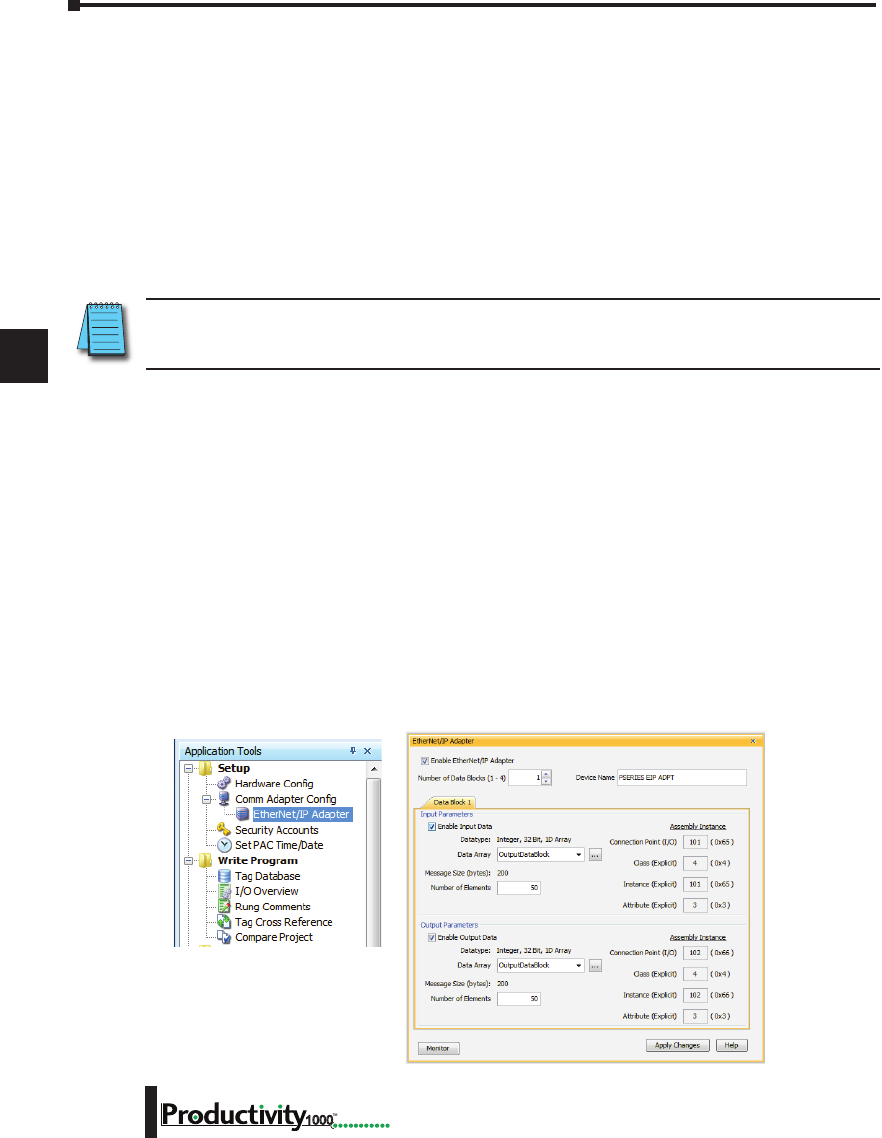
1
2
3
4
5
6
7
8
9
10
11
12
13
14
A
B
C
D
Chapter 6: Communications
6-36 Hardware User Manual, 1st Edition
1000
Class 1 and Class 3 Connections
What are they and how are they best used?
• Class 1 Connection is the transport mechanism that IO Messaging uses to send data. The
basic concept is that data is sent in one direction: the Originator sends Output data in a
Unicast UDP message to the Target and the Target sends Input data in either a Unicast
message back to the Originator or Multicast UDP messages to multiple devices. The Input
data and Output data messages have no relationship to each other. This method works well
for Remote I/O type data and is very efficient due to little overhead and reduced handshaking
messages on the wire. Class 3 Connection is one of the mechanisms that Explicit messaging
uses. Class 3 messaging uses TCP messages unlike Class 1. Each Class 3 request has a
header that defines the type of data requested as well as the size requested. It allows for more
flexibility in messaging but does create additional overhead.
NOTE: Explicit messaging can be accomplished with unconnected messages as well for more infrequent
requests. Explicit messaging is a slower performing method of communications but it typically allows for
more flexibility and control when the situation requires it.
When can the P1000 CPU use Class 1 or Class 3 Connections?
• Class 1 and Class 3 Connections can be accomplished with the Productivity1000 CPU as an
Adapter or as a Scanner or both simultaneously.
How many connections can the Productivity1000 support for EtherNet/IP?
• 4 - TCP
• 4 - EtherNet IP
• 4 - CIP (Up to 4 CIP connections are allowed per EtherNet/IP connection. Therefore, if one
device can support 4 CIP connections then you can have up to a total of 16 CIP connections
using 4 devices)
Setup Example: Productivity1000 as EtherNet/IP Adapter
The Adapter setup is accomplished through the EtherNet/IP Adapter setup under the Comm
Adapter Config section of the Setup menu as seen on right.
When the EtherNet/IP Adapter is selected from the menu the window shown here will open.
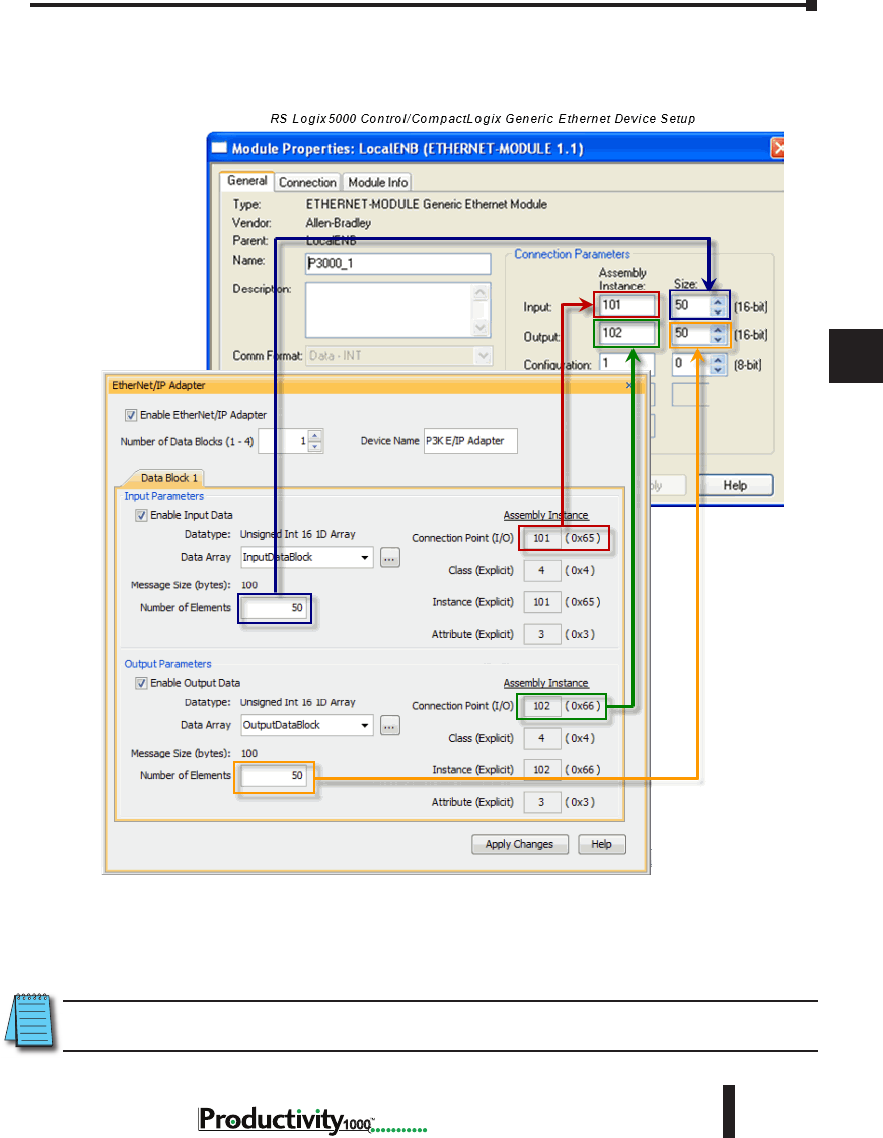
1
2
3
4
5
6
7
8
9
10
11
12
13
14
A
B
C
D
Chapter 6: Communications
6-37
Hardware User Manual, 1st Edition
1000
Hardware User Manual, 1st Edition
Fill in the required parameters and once configured these parameters will be used to configure
the Scanner side as shown in the examples below. The first example shows how to setup a
Class 1 IO Message connection from a 3rd party EtherNet/IP Scanner device (an Allen Bradley
PLC).
The following example shows how a Class 3 Explicit Message might be accomplished from a
3rd party device (Allen Bradley PLC). As you can see the Input Data must be retrieved in one
connection or message and the output data in another. Remember that Class 3 messaging is
not as efficient in protocol messaging as Class 1 but it does allow for granular control.
NOTE: In this example, size configuration is not shown on the Scanner side. The tag created for the
Destination must be large enough to contain the data requested (shown with dashed boxes).
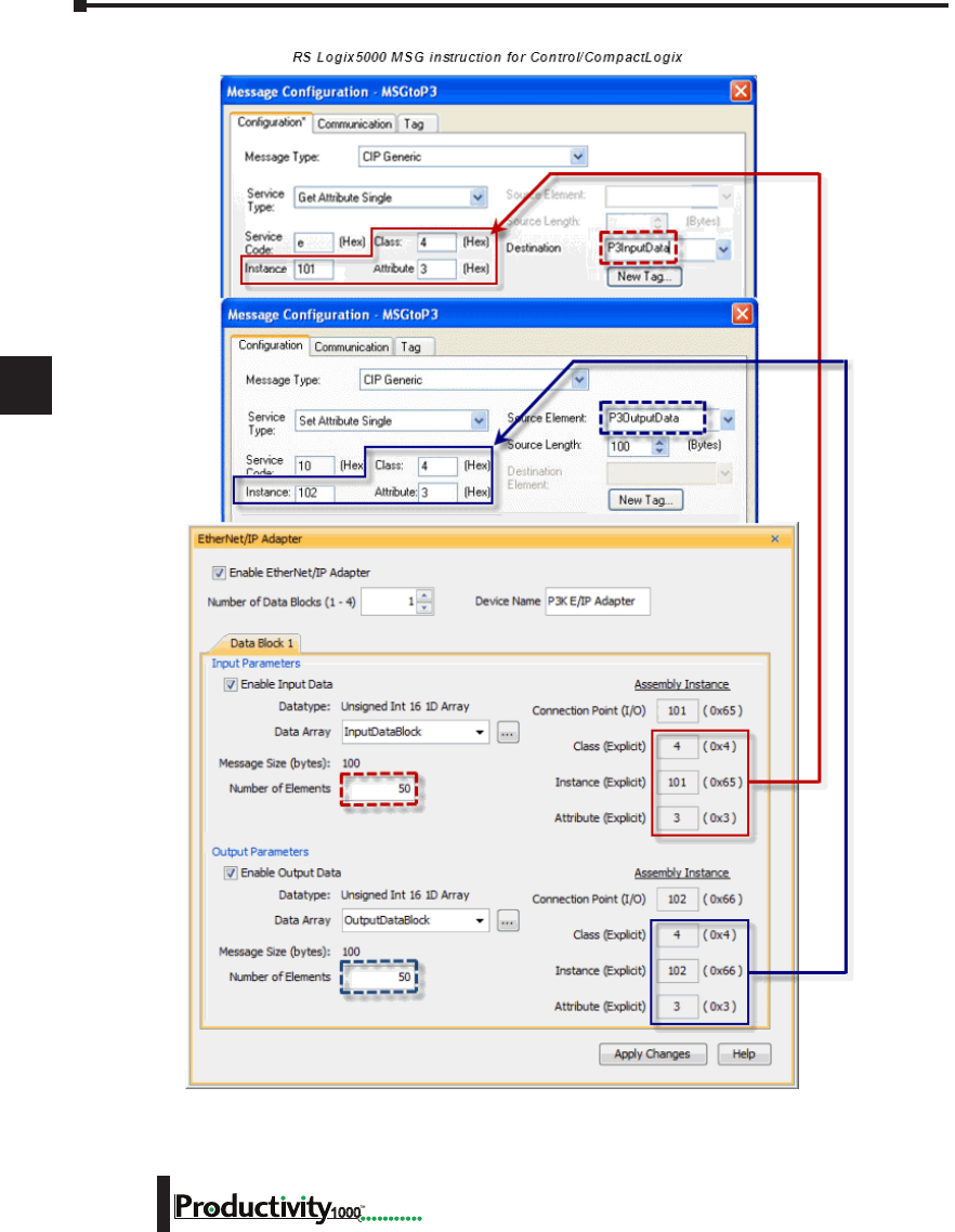
1
2
3
4
5
6
7
8
9
10
11
12
13
14
A
B
C
D
Chapter 6: Communications
6-38 Hardware User Manual, 1st Edition
1000
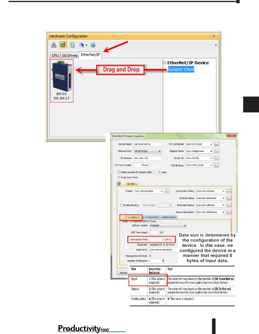
1
2
3
4
5
6
7
8
9
10
11
12
13
14
A
B
C
D
Chapter 6: Communications
6-39
Hardware User Manual, 1st Edition
1000
Hardware User Manual, 1st Edition
Setup Example: Productivity1000 as EtherNet/IP Scanner
This example shows how to connect the Productivity1000 Scanner function to an EtherNet/
IP adapter device using Class 1 I/O Messaging. First, create an EtherNet/IP device in the
Hardware Configuration as seen
below:
Configure the parameters to
match the settings of the Adapter
device. The image on right shows
the setup of the Input data.
The size, in this case, is dynamic
to the configuration of the device.
For this particular example, we
configured the device in a manner
that allows it to publish 8 bytes
of data for Input. Many devices
will have a fixed configuration
that should be published in the
manufacturer’s documentation.
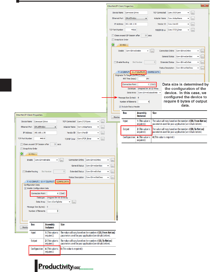
1
2
3
4
5
6
7
8
9
10
11
12
13
14
A
B
C
D
Chapter 6: Communications
6-40 Hardware User Manual, 1st Edition
1000
The Output data must also be
configured. Its data is also dynamic
based upon the configuration. In
our example, we configured the
device in a manner that caused it to
require 8 bytes of Output data.
The image on left shows the setup for the
Configuration data. The Configuration data, for
most devices, is a fixed size. Some devices will
require that the Configuration data Connection
Point be included in the Forward Open message
(as shown on left) even if the size is 0. Some
devices will require that the Configuration data
Connection Point not be in the Forward Open
and the checkbox option in the image below
would need to be de-selected.
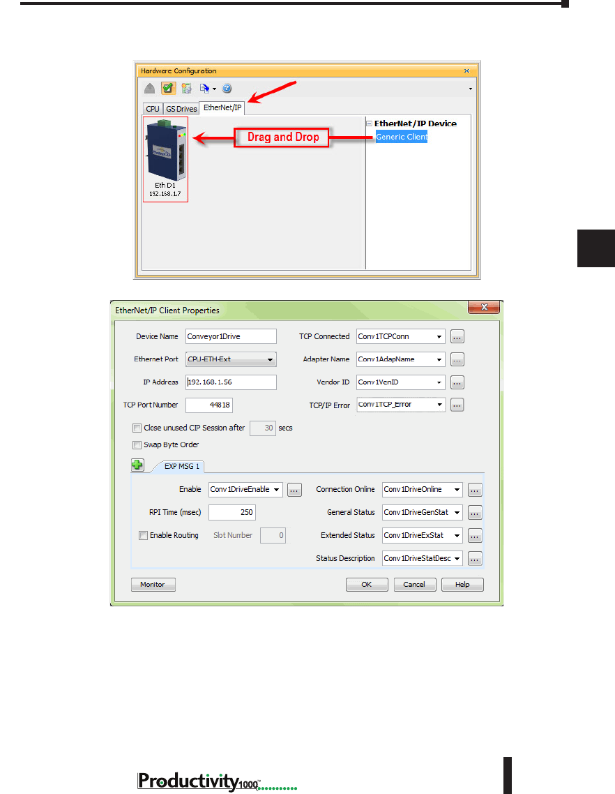
1
2
3
4
5
6
7
8
9
10
11
12
13
14
A
B
C
D
Chapter 6: Communications
6-41
Hardware User Manual, 1st Edition
1000
Hardware User Manual, 1st Edition
The following example shows how to connect the Productivity1000 Scanner function to an
EtherNet/IP Adapter device using Class 3 Explicit Messaging. As with IO Messaging, an
EtherNet/IP device must be created in the Hardware Configuration as seen below:
Explicit Messages can be performed in 2 ways: Unconnected or Connected (Class 3). The
advantage of using Unconnected messaging is it allows more discrete control of each request.
The disadvantage of Unconnected messaging is that Unconnected messages have a lower
priority and will take longer to get serviced on some devices. Connected messages get serviced
faster since there is a connection established to the device. If Connected messaging is desired,
create an Explicit Message tab as shown in the image above. If Unconnected messaging is
desired, do not create an Explicit Message tab. Only fill out the information in the upper
portion of the EtherNet/IP Client Properties window.
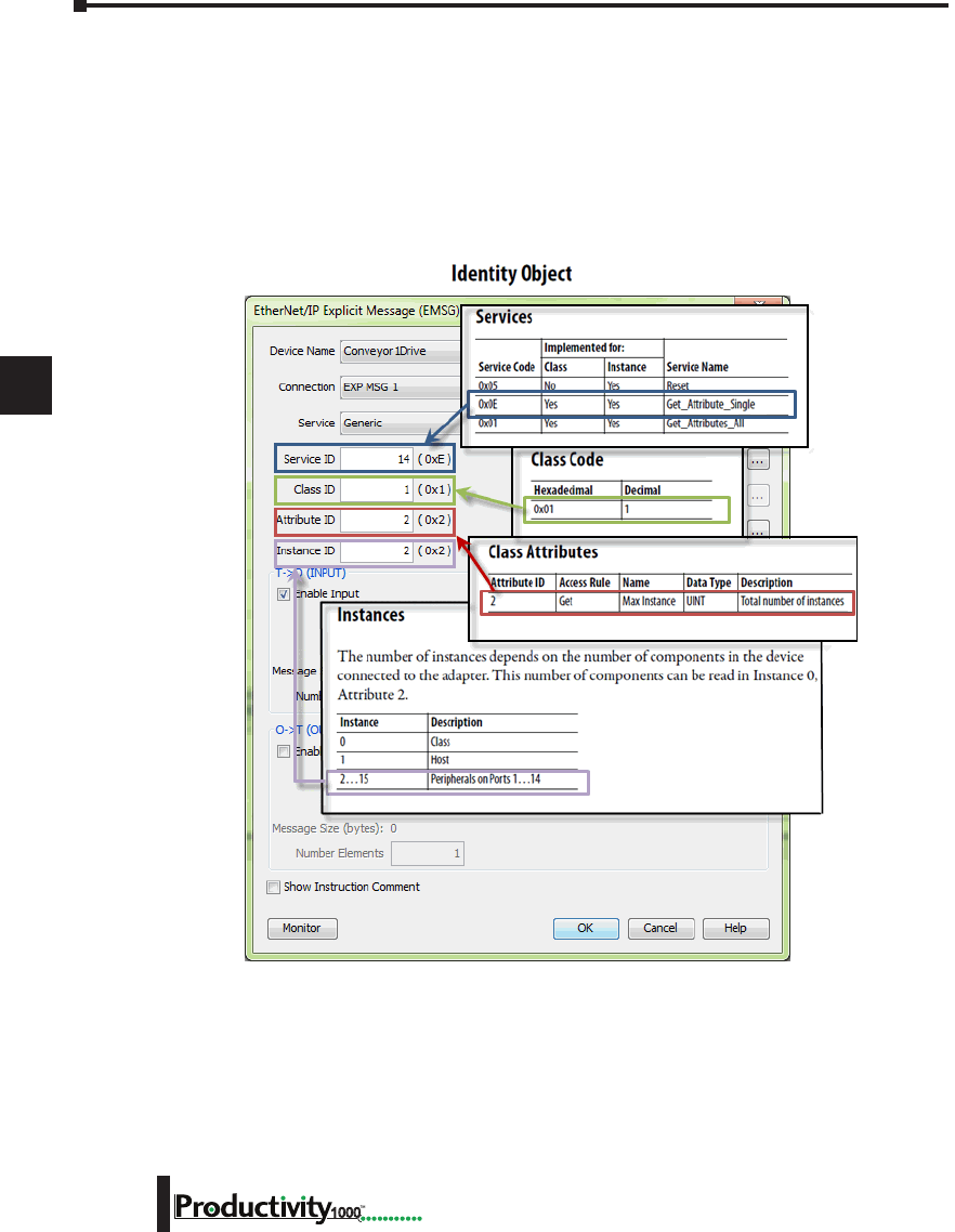
1
2
3
4
5
6
7
8
9
10
11
12
13
14
A
B
C
D
Chapter 6: Communications
6-42 Hardware User Manual, 1st Edition
1000
Once the desired parameters have been entered, the device may now be referenced in the
Explicit Message Instruction. If Unconnected messaging has been selected, choose the
Unconnected MSG option in the Connection drop down box. If Connected messaging has
been selected, choose the Explicit Message that was configured in the EtherNet/IP Client
Properties window in the Connection drop down box. The rest of the settings should be
matched to the specifications documented by the manufacturer. An example for requesting
the Identity of a device is shown below. The data array configured for this function must be
sufficient in size to hold the returned data from the device for this object. Data can also be
written to the device if it supports an object for this purpose. If data is being written, enable the
Output selection and specify the data array and size required by that device’s object.
Troubleshooting Tips:
1. Use the diagnostic tags in the Hardware Configuration and Explicit Message Instruction:
As explained previously in the Network Layer Chart section, there are multiple layers
of messaging involved with EtherNet/IP. If it appears that the Productivity1000 is not
communicating with another EtherNet/IP device, there are diagnostic tags available to
narrow down which layer of the protocol is preventing successful communications.

1
2
3
4
5
6
7
8
9
10
11
12
13
14
A
B
C
D
Chapter 6: Communications
6-43
Hardware User Manual, 1st Edition
1000
Hardware User Manual, 1st Edition
a. At the TCP layer, there is a TCP Connected field that will expose the status of the TCP/IP
connection when a tag is populated in this field.
b. There is an Adapter Name field for a String tag and a Vendor ID field for an Integer tag.
Both of these fields can help to identify whether the Productivity1000 is connected to the
correct device or not.
c. At the CIP layer, there is a Connection Online field for a Boolean tag.
d. There are three additional fields to help determine why the CIP session might not be
successful: General Status for an Integer tag, Extended Status for an Integer Data Array and
Status Description for a String tag.
2. Use the TCP connected tag:
First check the TCP Connected tag. If the connection has been enabled (by turning
on the tag configured in the Enable field or triggering an Explicit Message instruction
with an Unconnected MSG specified) and the TCP Connected tag is not true, check the
following items:
a. Cabling. Ensure that all of the cables are connected and in good shape. In most cases, the
Ethernet port that the cable is connected to should indicate a Link Good LED. Ensure that
any interim Ethernet switches are powered up and functioning and that the end device is
powered up and functional.
b. IP address and correct subnet. Check that the IP address entered into the IP Address field
is the correct address for the device that you are connecting to. Also check that the EtherNet/
IP device’s IP address and subnet mask is compatible with the IP address and subnet mask
of the Productivity1000. If there are any routers in between the two, ensure that a proper
default gateway that matches the router’s IP address is configured. If you are unfamiliar with
proper IP addressing and subnet configuration, consult with the network administrator for
guidance.
c. TCP Port number. The default listening TCP port number for EtherNet/IP is 44818.
Check that the target device is listening on this specific port number. If it is not, change the
value in TCP Port Number field to the appropriate value. If there are interim router devices
that are using port forwarding, ensure that the router is properly configured for this setup.
NOTE: Attempting to do IO Messaging across routers (different subnets) is unlikely to be successful. IO
Messaging uses multicast messaging in many cases and the Port number is not necessarily fixed when the
IO Messaging is established (the Forward Open message has the ability to ‘negotiate’ the port number used
for the IO Messages).
d. Adapter Name and Vendor ID. If the network contains many EtherNet/IP devices and
these devices may not necessarily be connected to the Productivity1000, it may be a good
safeguard to check the Adapter Name and Vendor ID returned and verify that these devices
are the correct devices to which it is connected.
3. Use the Connection Online and Error tags:
If the TCP Connected tag is true and the Adapter Name and Vendor ID look correct, the next
tags to look at are the Connection Online, the General Status, the Extended Status and the Status
Description.
If the Enable tag is true and the Connection Online tag is not true, check the General Status value
along with the Extended Status value(s) and the Status Description. If the General Status value and
the Extended Status value(s) are part of the defined errors from the ODVA specification, the Status
Description should also return a more descriptive String. Once these errors are known, it may be
possible to very simply make the adjustment in the settings to correct the issue.
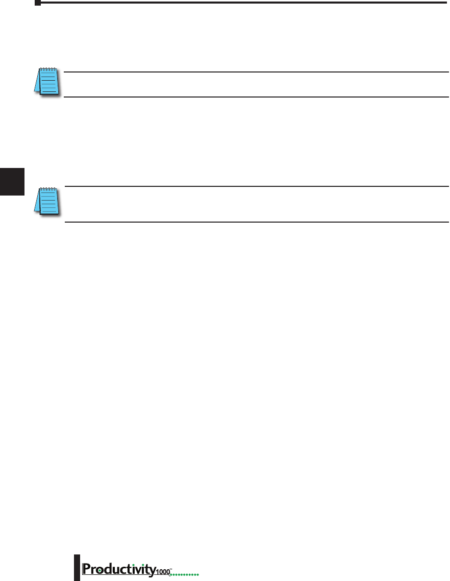
1
2
3
4
5
6
7
8
9
10
11
12
13
14
A
B
C
D
Chapter 6: Communications
6-44 Hardware User Manual, 1st Edition
1000
If it is not obvious from the description, first check the manufacturer’s documentation for corrective
action in this particular scenario.
If the manufacturer’s documentation doesn’t give corrective action, check the EtherNet/IP Error
Code List in this chapter for possible solutions.
NOTE: This may not always solve the problem as each device manufacturer may publish the error for slightly
different reasons.
If the Connection Online tag is true and the data being received is different than what is expected,
verify that the correct Connection Point values and/or Class, Instance, Attribute values are
configured. There may be multiple areas of available data in that device. Verify that the correct data
types are being used for both sides. If the data types are mismatched, this may make the data ‘appear’
to be incorrect.
Another great tool that can be used is Wireshark. Wireshark is a free network analyzer tool that can
be downloaded from www.wireshark.com.
NOTE: Using this tool implies some knowledge of how networking protocols function. Using Wireshark will
also require that you have a true Ethernet hub (not an unmanaged switch) or a managed switch with Port
mirroring capability.
You may also use the following basic steps to check your EtherNet/IP Setup.
EtherNet/IP I/O Message Troubleshooting:
1. Does the IP Address set up in the Scanner match the Adapter IP Address?
2. Is the enable tag entered into the Scanner turned ON?
3. Does the connection point entered into the I/O Message Data Block match the connection point
of the Adapter?
4. Does the number of elements match the Adapter?
5. Does the data type match the Adapter?
Steps 4 & 5 are important because the number of bytes being read from or written to the Adapter
have to match the Adapter bytes allocated.
EtherNet/IP Explicit Message Troubleshooting:
1. Does the IP Address set up in the Scanner match the Adapter IP Address?
2. Is the enable tag entered into the Scanner turned ON when not using the Unconnected MSG
connection type?
3. Make sure the logic for the EtherNet/IP Explicit Message (EMSG) is TRUE so the instruction is
enabled.
4. When using Get or Set single attributes in the Service field make sure the Instance ID matches the
Instance ID of the Adapter.
5. When using Generic in the Service field make sure the Service ID, Class ID, Attribute ID and
Instance ID match the Adapter settings.
6. Does the number of elements match the Adapter?
7. Does the data type match the Adapter?
Steps 6 & 7 are important because the number of bytes being read from or written to the Adapter
have to match the Adapter bytes allocated.
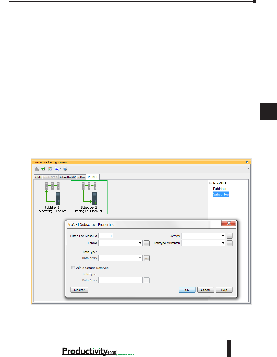
1
2
3
4
5
6
7
8
9
10
11
12
13
14
A
B
C
D
Chapter 6: Communications
6-45
Hardware User Manual, 1st Edition
1000
Hardware User Manual, 1st Edition
ProNET
Productivity Network (ProNET) provides the ability to share data with other P-Series
CPU’s, This can easily be accomplished using the Productivity Network (PNET) setup in
the Hardware Configuration window used to join a data sharing network consisting of other
P-Series controllers.
Each member of the data sharing network receives data from all of the other P-Series controllers
on that data sharing network. Each node can optionally send data to the other nodes of the data
sharing network by electing to “publish” data.
The ProNET configuration uses UDP broadcast packets to publish the blocks of data to the
network. One caveat with the use of broadcast packets is that it limits the scope of the shared
data network to the local broadcast domain.
ProNET uses the verbs ‘publishing’ and ‘subscribing’ to describe how the controller data is
exchanged with other P-Series controllers on the data sharing network.
Publishing is analogous to sending data, and is done only if ProNET is configured to ‘publish’
one or more of its assigned tags. If so configured, the P-Series controller will broadcast a packet
that contains the data from the selected tags.
Subscribing is analogous to receiving data, and is accomplished by ‘subscribing to’ a publisher’s
global ID of any P-Series CPU on the data sharing network set up to publish its data.
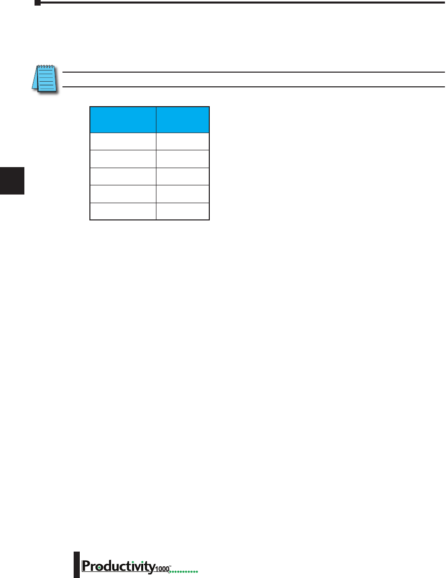
1
2
3
4
5
6
7
8
9
10
11
12
13
14
A
B
C
D
Chapter 6: Communications
6-46 Hardware User Manual, 1st Edition
1000
The ProNET configuration works with a 1D array tag(s) that can contain up to 65535
elements, however you are limited to 32 total 32-bit elements, 64 total 16-bit elements, or 128
total 8-bit or Boolean elements of data per publisher array data type. These tags provide the
local storage for the data sent and received over the data-sharing network.
When the input logic to the ProNET configuration is Enabled, it operates at a fixed rate of 10
times per second (100 msec.), the instruction will publish all of the elements of the array that it
is configured to publish, and will process any ProNET nodes that it receives. When the input
logic is OFF, (the device is disabled), it DOES NOT publish any of its tags and DOES NOT
process any ProNET nodes that it receives.
NOTE: The message size for each data type is limited to 128 bytes regardless of the defined array size.
Data Type Number of
Elements
Boolean 128
Integer 8-Bit 128
Integer 16-Bit 64
Integer 32-Bit 32
Integer 64-Bit 32
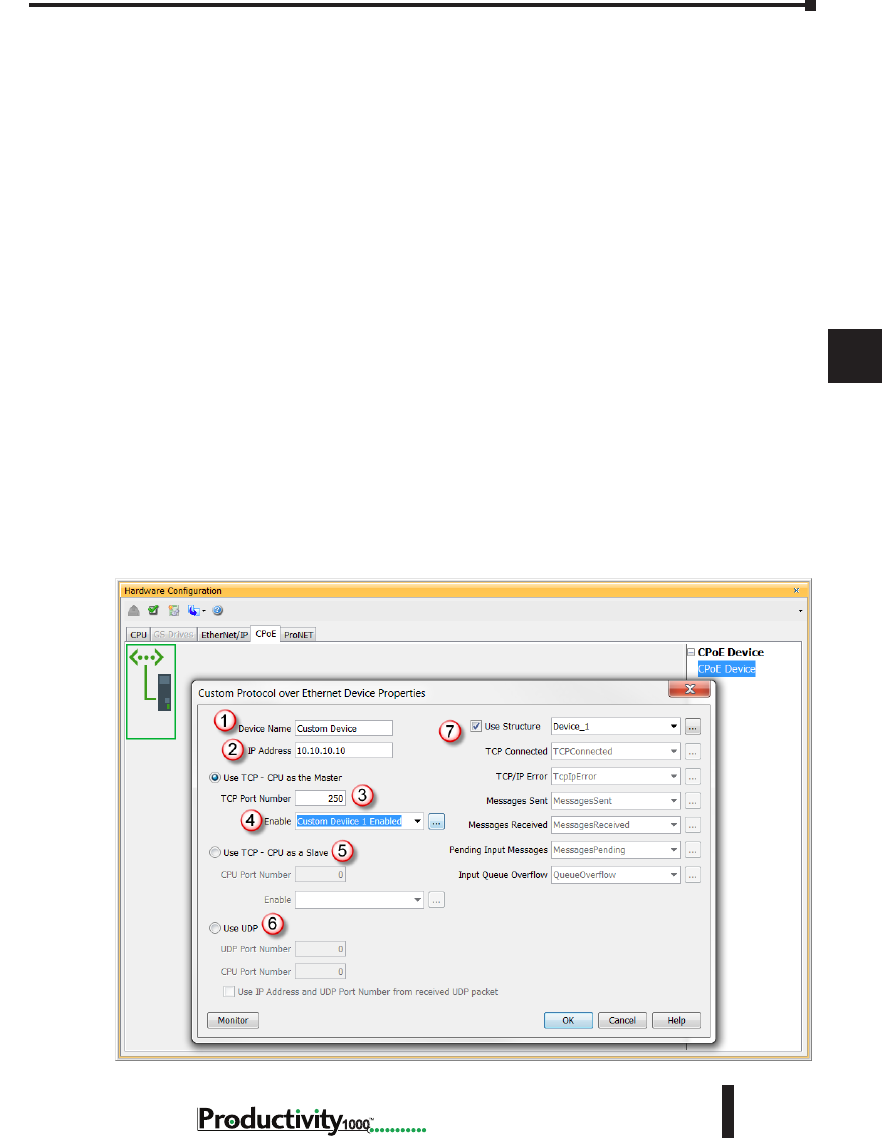
1
2
3
4
5
6
7
8
9
10
11
12
13
14
A
B
C
D
Chapter 6: Communications
6-47
Hardware User Manual, 1st Edition
1000
Hardware User Manual, 1st Edition
Custom Protocol over Ethernet Functionality
Besides Modbus RTU, EtherNet/IP, and ProNET the Productivity1000 system has the ability to
communicate via Ethernet with other devices using the Custom Protocol over Ethernet (CPoE).
Custom Protocol over Ethernet
The Custom Protocol is a HEX based protocol used to communicate with devices that do
not support one of the other protocols on Productivity1000. There are two steps to initiate
communications via the Custom Protocol over Ethernet:
• First you must set up a device in the hardware configuration under the CPoE tab.
• Then you must use the Custom Protocol Ethernet( CPE) instruction to initiate messages.
Hardware Configuration
First you must set up a device to talk to in the CPoE tab of the hardware configuration. This
will Require you to:
1. Enter a Device Name
2. Enter the IP Address of the device you wish to communicate with.
3. Enter the port number of the device.
4. Enter an Enable tag to enable the device if using TCP.
5. Choose whether you wish to Use the PLC as the master or the slave device via TCP connection
6. Choose whether you wish to use a UDP connection.
7. Enter tags for status of this device for troubleshooting (Example below shows the Structure
method used).

1
2
3
4
5
6
7
8
9
10
11
12
13
14
A
B
C
D
Chapter 6: Communications
6-48 Hardware User Manual, 1st Edition
1000
Custom Protocol Ethernet Instruction
Next you must use the Custom Protocol Ethernet instruction in ladder.
1. The instruction can be chosen Receive or Send messages to the Custom Device.
2. The user can choose to use:
• A table with tags that allow the user to send a specific data.
• An array tag that is numerical can be used to Send/Receive from.
• A string tag that contains an ASCII string to be sent or string location to receive characters to.
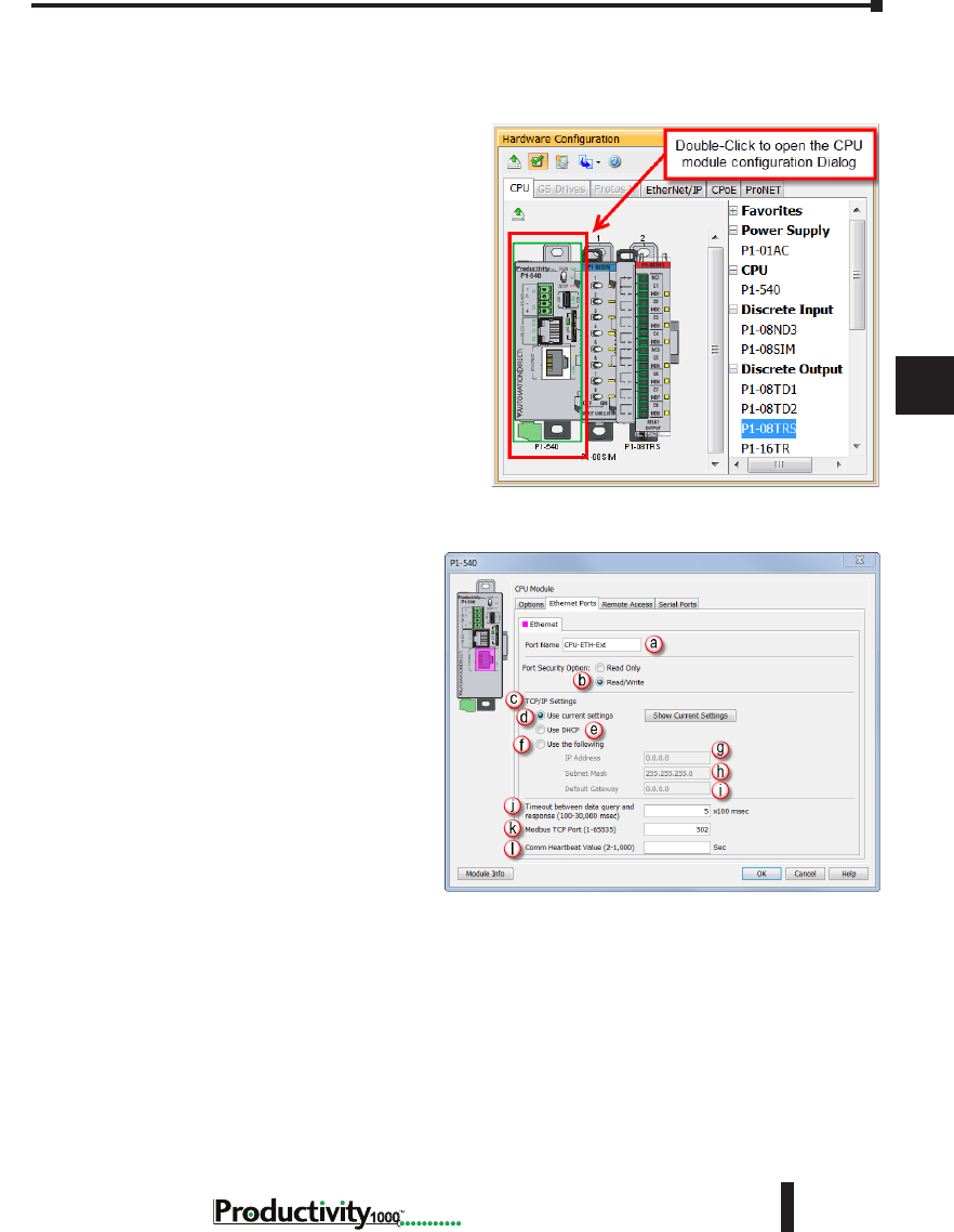
1
2
3
4
5
6
7
8
9
10
11
12
13
14
A
B
C
D
Chapter 6: Communications
6-49
Hardware User Manual, 1st Edition
1000
Hardware User Manual, 1st Edition
Communications: Port Configuration
The Communications Port Configuration for any module containing comm ports is accessed from
the Hardware Configuration window. For example, to access the P1-540 communications port
configuration, first select the CPU from
the Hardware Configuration window by
double left-clicking or by right-clicking the
CPU and selecting Open from the drop
down menu. This will display the P1-540
configuration window seen here.
The following descriptions will focus on the
P1-540 communications ports.
Ethernet Configuration
Ethernet Ports: The 10/100Base-T
Ethernet port on the P1-540 CPU.
• Ethernet: The Ethernet port can
connect to Modbus TCP Client
devices, Modbus TCP Server devices
and PCs running the Productivity1000
programming software. The Ethernet
Port is configured with an IP Address,
Subnet Mask and Default Gateway,
allowing it to function seamlessly on a
typical LAN network.
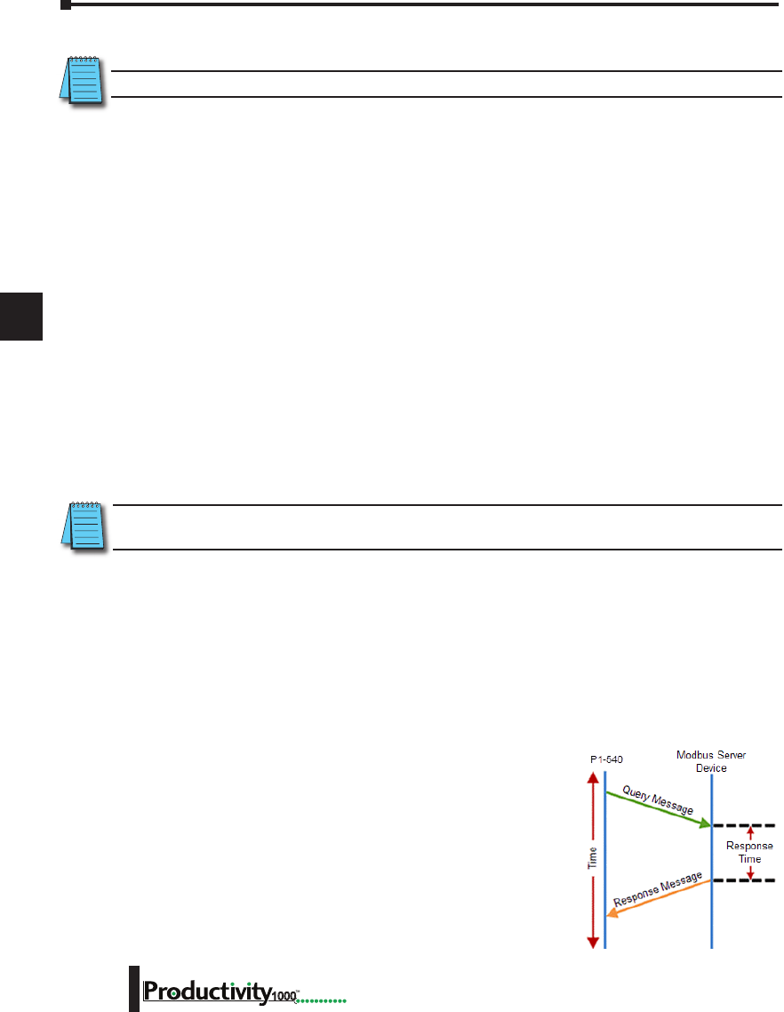
1
2
3
4
5
6
7
8
9
10
11
12
13
14
A
B
C
D
Chapter 6: Communications
6-50 Hardware User Manual, 1st Edition
1000
External Ethernet Port Settings
NOTE: Two CPU Remote I/O networks cannot co-exist on the same LAN.
a. Port Name: Allows the entry of a unique Name for the Ethernet Port. This Name is referenced in
the Communications instructions (MRX, MWX, RX, WX) to select the Port to send the request
from.
b. Port Security Option: This Option can be used as a simple Security measure to prevent Modbus
TCP write requests from being accepted by the CPU. To allow Reads and Writes, select Read/Write.
c. TCP/IP Settings: The IP Setting of this Port may be changed in several ways:
• The settings may be entered manually in the Choose CPU tool in the Productivity Suite
programming software. This allows the user to make changes to the IP to allow connection
by the computer running the Productivity Suite programming software. Changes are sent
using Multicast Messages.
• The TCP/IP Settings can be saved as part of the project. This must be Enabled in the
P1-540 Hardware Configuration Settings by selecting Use the Following (Item f below). If
handled this way, the Settings stored in the project will take effect at Project Transfer and at
boot up only. The Settings may be changed after boot up.
d. Use Current Settings: When selected, Project Transfer or boot up will not make changes to the
TCP/IP Settings of the CPU.
e. Use DHCP: This specifies that the CPU should request its IP Settings from a DHCP Server on the
network.
NOTE: If the CPU is set to use DHCP for it’s IP Settings it cannot, in all likelihood, be used as a Modbus TCP
Server.
f. Use The Following: If this Option is selected, the CPU will set itself to the specified project Settings
upon Project Transfer or at boot up.
g. IP Address: This field is where the IP Address is specified in Four Octets.
• For Example: 192.168.1.5
h. Subnet Mask: This field is where the Subnet Mask is specified in Four Octets (i.e., 255.255.255.0 ).
The Subnet Mask is used in conjunction with the IP Address to configure a Logical Network.
i. Default Gateway: This field is where the Default Gateway Address is specified in Four Octets (i.e.,
192.168.1.1). This is typically the IP Address of the router on the network. If a target IP Address is
specified in an outgoing message from the CPU that is not in the
Local Subnet, the Default Gateway Address is where this message
will be sent.
j. Timeout Between Data Query and Response: The Time period
specified in this field is the Time between the queries sent from the
CPU (via a Communication instruction, such as a MRX, MWX,
RX or WX) and the Time a response from that device is received.
If the Response takes longer to receive or is not received within the
specified Time period, a Timeout Error will occur for the given
instruction. Each instruction has a Timeout Status bit that can be
assigned to it.
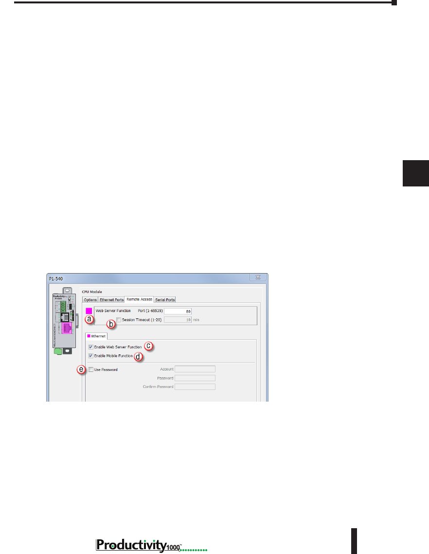
1
2
3
4
5
6
7
8
9
10
11
12
13
14
A
B
C
D
Chapter 6: Communications
6-51
Hardware User Manual, 1st Edition
1000
Hardware User Manual, 1st Edition
k. Modbus TCP Port: This is the listening TCP Port Number for Modbus TCP connections. If
necessary, this value can be adjusted for advanced router access. In most situations, this Port
Number should be left at 502.
l. Comm Heartbeat Value: This feature allows the ladder logic in the CPU to know if a device has
stopped communicating to the CPU. If a value is placed in this field, the CPU will start a timer
between each communication packet coming in to the CPU. If a communication packet fails to be
received by the CPU within the specified time period, the System Bit Ethernet Heartbeat Timeout
Bit will become true.
Local Ethernet Port Settings
m. Timeout Between Data Query and Response: The Time period specified in this field is the Time
between the queries sent from the CPU (for Remote I/O Nodes and GS Drive Nodes) and the Time
a Response from that device is Received. If the Response takes longer to receive (or is not received)
than the specified Time period, a Timeout Error will occur for the given device and an Error will be
generated in the Error Log. See Modbus Server diagram shown on previous page.
n. Comm Heartbeat Value: This value specifies how long the Remote I/O Slaves should wait for a
communication packet from the CPU. If a communication packet is not received from the CPU
within the specified time period, all outputs on the Remote Slave will be turned OFF.
Remote Access Configuration
a. Web Server Function: Provides the ability to make a non secure web connection to the P1-540 in
order to access the USB pen drive and view read-only system tags. When enabled, a port number
selection is required.
• Port: (Default 80) Allows user to set a port number ranging from 1-65535.
b. Session Timeout: Allows the user to set a specific time limit (1-20 mins.) on inactivity that will
close the Web Server connection. If there is no activity between the PC and the Web Server for the
specified time limit, the connection will close.
c. Enable Web Server Function: Select this box to enable/disable Web Server Function > See (a) above.
d. Mobile Function: Enables Remote Access which allows the CPU Data Remote Monitor App to
monitor the selected tags.
e. Password Option: Allows the user to set a password for access to the Web Server.
• Enter an account name and password of up to a combination of 16 numbers and characters
(can include special characters).
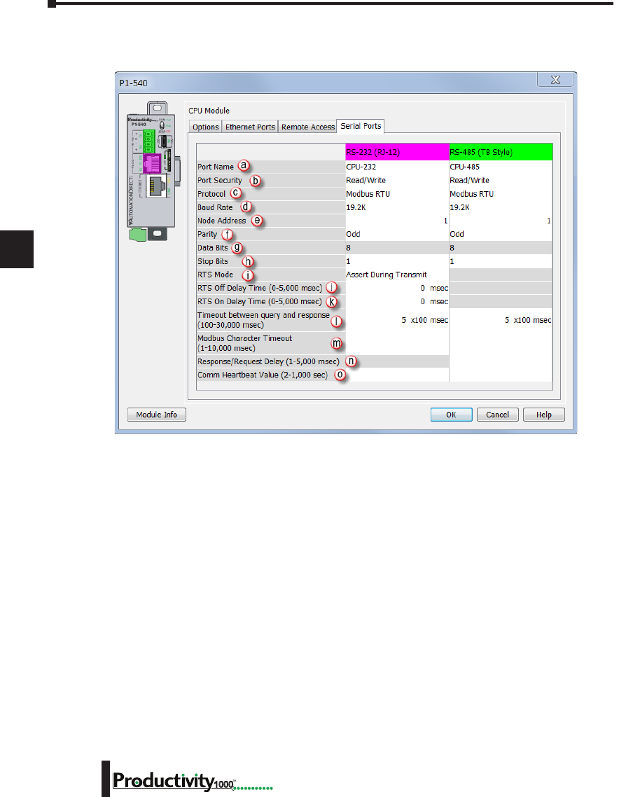
1
2
3
4
5
6
7
8
9
10
11
12
13
14
A
B
C
D
Chapter 6: Communications
6-52 Hardware User Manual, 1st Edition
1000
Serial Configuration
When the Serial Ports Tab is selected, the Serial Ports settings are displayed as shown below.
There are two Serial Ports on the P1-540 CPU; an RS-232 Port with an RJ-12 connector and
a 2-wire RS-485 Port with a removable three point terminal block. Both Ports are capable
of Modbus RTU Client (device that initiates communications requests) and Server (device
that responds to communications requests) communications. They are also capable of ASCII
outgoing strings and incoming strings.
RS-232 and RS-485 Port Settings
a. Port Name: Allows the entry of a unique name for the RS-232 and RS-485 Ports. This name
is referenced inside of the Communications instructions (MRX, MWX, RX, WX) and ASCII
instructions (AIN, AOUT, CPO, CPI) to select the Port to send or receive the request.
b. Port Security: This Option can be used as a simple Security measure to prevent Modbus TCP
write requests from being accepted by the CPU. To allow Reads and Writes, select Read/Write.
c. Protocol: This field determines whether the Port is used for Modbus RTU communications,
sending or receiving ASCII Strings or performing the Custom Protocol function.
d. Baud Rate: Choose the Baud Rate that your device and the CPU should communicate in this field.
The appropriate choice will vary greatly with device, application and environment. The important
point is that all devices communicating on the network need to be set to the same Baud Rate. The
available Baud Rates are 1200, 2400, 9600, 19200, 33600, 38400, 57600 and 115200 bps.
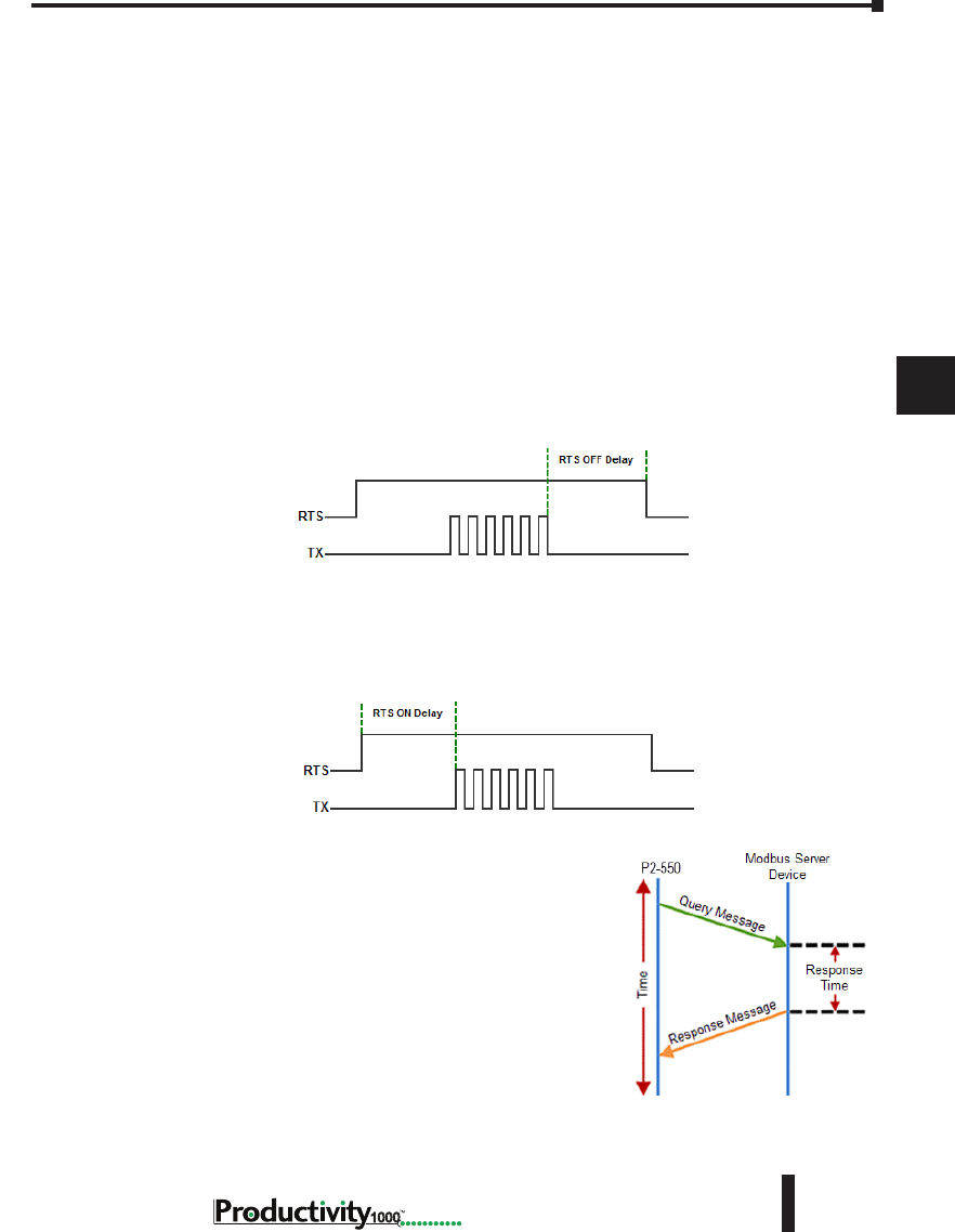
1
2
3
4
5
6
7
8
9
10
11
12
13
14
A
B
C
D
Chapter 6: Communications
6-53
Hardware User Manual, 1st Edition
1000
Hardware User Manual, 1st Edition
RS-232 and RS-485 Port Settings, cont’d
e. Node Address: This field is used only when the CPU is a Modbus RTU Server device. This
field is used to uniquely identify the CPU on the network. This setting is also sometimes referred
to as a Station Address. This field can be set from 1 to 247.
f. Parity: The Parity Bit is used as a simple, low-level form of Error Detection. All devices on the
network need to be at the same Parity setting. The appropriate choice will vary with devices.
Valid selections are None, Even and Odd.
g. Data Bits: This field determines whether the communications packet uses Seven Data Bits or
Eight Data Bits. Eight Data Bits is the only valid selection for Modbus RTU. Either Seven or
Eight Data Bits can be selected when using ASCII communications. Set this field to match the
device that is connected to the CPU.
h. Stop Bits: This field determines whether the communications packet uses One or Two Stop
Bits. Set this field to match the device that is connected to the CPU.
i. RTS Mode: This field allows selection of whether or not RTS is asserted during data
transmission. Used for hardware handshaking in the standard way. You may need to manually
configure RTS. Refer to your instrument documentation to determine its specific behavior.
j. RTS Off Delay Time (RS-232 Only): This Time period is the amount of Time between the
end of the data transmission to when the RTS signal is turned off. The diagram below illustrates
this. This setting may be needed when using media converters (RS-232 to RS-422/485
converters) and/or radio modems. A delay may be needed at the end of the data transmission
for processing time in the devices.
k. RTS On Delay Time (RS-232 Only): This Time period
is the amount of Time between when the RTS Signal is
turned ON and the data transmission begins. The diagram
above illustrates this. This setting may be needed when
using media converters (RS-232 to RS-485 converters)
and/or radio modems. A delay may be needed after the
assertion of the RTS Signal and when the data transmission
begins for processing time in the device.
l. Timeout Between Query and Response: The Time period
specified in this field is the Time between the queries sent
from the CPU (via a Communication instruction, such as
an MRX, MWX, RX, or WX) and the Time a Response
from that device is Received. If the Response takes longer
to receive (or is not received) than the specified Time period, a Timeout Error will occur for the
given instruction. Each instruction has a Timeout Status bit that can be assigned to it.
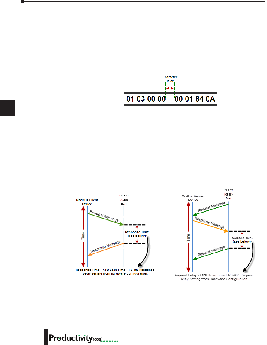
1
2
3
4
5
6
7
8
9
10
11
12
13
14
A
B
C
D
Chapter 6: Communications
6-54 Hardware User Manual, 1st Edition
1000
RS-232 and RS-485 Port Settings, cont’d
m. Modbus Character Timeout: The Modbus Character Delay Time is specified as the Time
between two bytes (or characters) within a given Modbus Message. The Modbus RTU
specification states that this time must be no more than 1.5 Character Times (real time based
on Baud Rate). Sometimes delays do occur between bytes when using radio modems, media
converters, etc. This setting allows some tolerance in these situations for the incoming Modbus
Messages in the CPU. The CPU will wait for the amount of time specified in this field before
discarding the incomplete packet. If the CPU does not receive the remainder of the Message
within the specified Time Frame, it will discard the first portion of the Message and wait for a
new Message.
n. Response/Request Delay (RS-485 Only): This setting is used when the CPU is a Modbus RTU
Server or Client on the RS-485 Port.
The total Response Time can be up to the Total CPU Scan Time + the Value specified in this
field. When using 2-wire RS-485 communications, sometimes Echoes can occur since both
devices use the same differential signal pair to send and receive.
• If acting as a Server (on left below), upon receiving a Modbus Request, the CPU will wait
for the time period specified in this field before sending a Response. This can be used with
slow clients that need extra time to change from sending to receiving.
• If acting as a Client (on right below), after receiving a Modbus Response, the CPU will
wait for the time period specified in this field before sending another Request. This can be
used to delay request messages in order to give extra time for slow server devices.
o. Comm Heartbeat Value: This feature allows the ladder logic in the CPU to know if a device
has stopped communicating to the CPU. If a value is placed in this field, the CPU will start
a timer between each communication packet coming in to the CPU. If a communication
packet fails to be received by the CPU within the specified Time period, the System Bit RS-232
Heartbeat Timeout Bit or RS-485 Heartbeat Timeout Bit will become true.
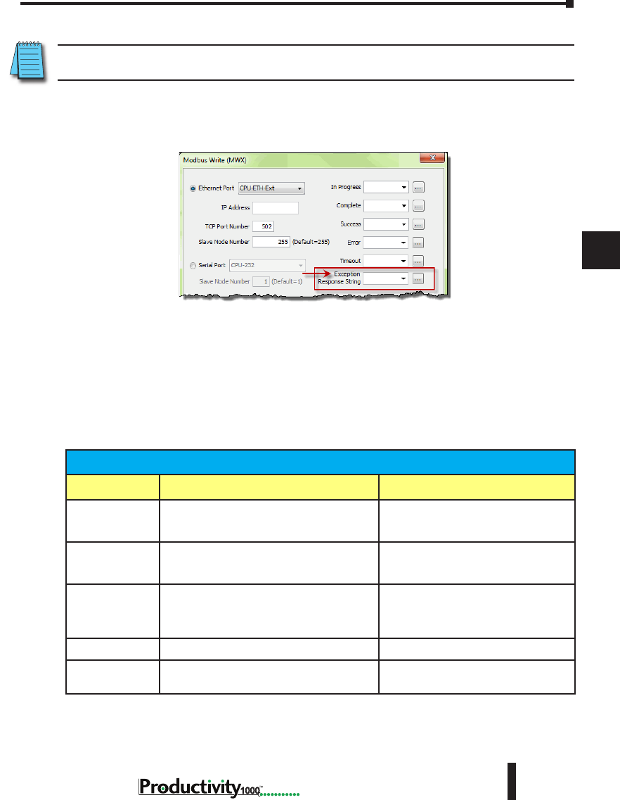
1
2
3
4
5
6
7
8
9
10
11
12
13
14
A
B
C
D
Chapter 6: Communications
6-55
Hardware User Manual, 1st Edition
1000
Hardware User Manual, 1st Edition
Communications: Error Codes
NOTE: The only time you will see Communications Error Codes is when the CPU is the Master of a
Communications Network.
To simplify the process of identifying a possible Error, the Productivity1000 CPU will
automatically report to a specific memory location an Error Code that helps identify the
existing issue. The Error Codes are reported in the Exception Response String Tag specified in
the instruction as shown below.
The Exception Response String field is available on the following instructions:
The Table shown below provides a list of Productivity1000 Communication Error Codes that
may be reported by the Productivity CPU.
• GS Drives Read • GS Drives Write • Modbus Read
• Modbus Write • Network Read • Network Write
• Dataworx Request
Productivity1000 Communication Error Codes
Error Code Description Suggested Fix
01 Function Code not supported.
Check instruction or connected device
and correct Function code or address
range selected.
02
Address out of range. This error is typically
generated when a Modbus address has been
requested that does not exist in the CPU.
Check instruction or connected device
and correct Function code or address
range selected.
03
Illegal Data Value. This error is typically
generated when the Modbus request sent to
the CPU is formed incorrectly.
Check the Modbus request against the
Modbus protocol specication (www.
modbus.org) to verify that it was formed
correctly.
04 Device Failure. Check connected device.
06 Slave Device is Busy. This error is typically
due to excess communications to the EDRV.
Slow down the poll rate in the GS
instruction.
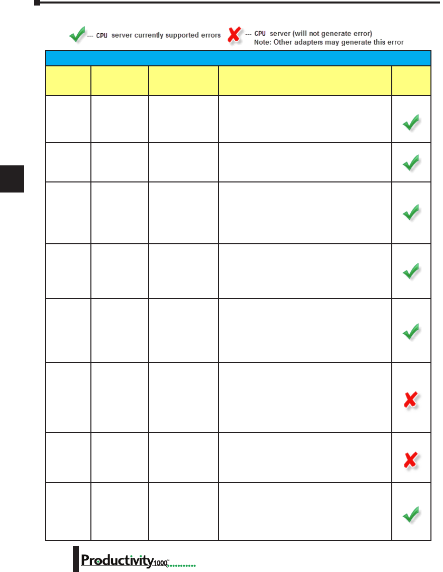
1
2
3
4
5
6
7
8
9
10
11
12
13
14
A
B
C
D
Chapter 6: Communications
6-56 Hardware User Manual, 1st Edition
1000
P1000 EtherNet/IP Error Codes
P1000 EtherNet/IP Error Codes
General
Status Error
Extended Status
Error Name Description P1000
Supported
0x01 0x0100
Connection In Use/
Duplicate Forward
Open
A connection is already established from the target
device sending a Forward Open request or the target
device has sent multiple forward open request. This
could be caused by poor network trafc. Check the
cabling, switches and connections.
0x01 0x0103
Transport Class/
Trigger Combination
not supported
The Transport class and trigger combination is not
supported. The Productivity1000 CPU only supports
Class 1 and Class 3 transports and triggers: Change of
State and Cyclic.
0x01 0x0106 Owner Conict
An existing exclusive owner has already congured a
connection to this Connection Point. Check to see if
other Scanner devices are connected to this adapter
or verify that Multicast is supported by adapter device
if Multicast is selected for Forward Open. This could
be caused by poor network trafc. Check the cabling,
switches and connections.
0x01 0x0107 Target Connection
Not Found
This occurs if a device sends a Forward Close on a
connection and the device can’t nd this connection.
This could occur if one of these devices has powered
down or if the connection timed out on a bad
connection. This could be caused by poor network
trafc. Check the cabling, switches and connections.
0x01 0x0108
Invalid Network
Connection
Parameter
This error occurs when one of the parameters
specied in the Forward Open message is not
supported such as Connection Point, Connection type,
Connection priority, redundant owner or exclusive
owner. The Productivity1000 CPU does not return
this error and will instead use errors 0x0120, 0x0121,
0x0122, 0x0123, 0x0124, 0x0125 or 0x0132 instead.
0x01 0x0109 Invalid Connection
Size
This error occurs when the target device doesn’t
support the requested connection size. Check the
documentation of the manufacturer’s device to verify
the correct Connection size required by the device.
Note that most devices specify this value in terms of
bytes. The Productivity1000 CPU does not return this
error and will instead use errors 0x0126, 0x0127 and
0x0128.
0x01 0x0110
Target for
Connection Not
Congured
This error occurs when a message is received with a
connection number that does not exist in the target
device. This could occur if the target device has
powered down or if the connection timed out. This
could be caused by poor network trafc. Check the
cabling, switches and connections.
0x01 0x0111 RPI Not Supported
This error occurs if the Originator is specifying an RPI
that is not supported. The Productivity1000 CPU will
accept a minimum value of 10ms on a CIP Forward
Open request. However, the CPU will produce at the
specied rate up to the scan time of the installed
project. The CPU cannot product any faster than the
scan time of the running project.
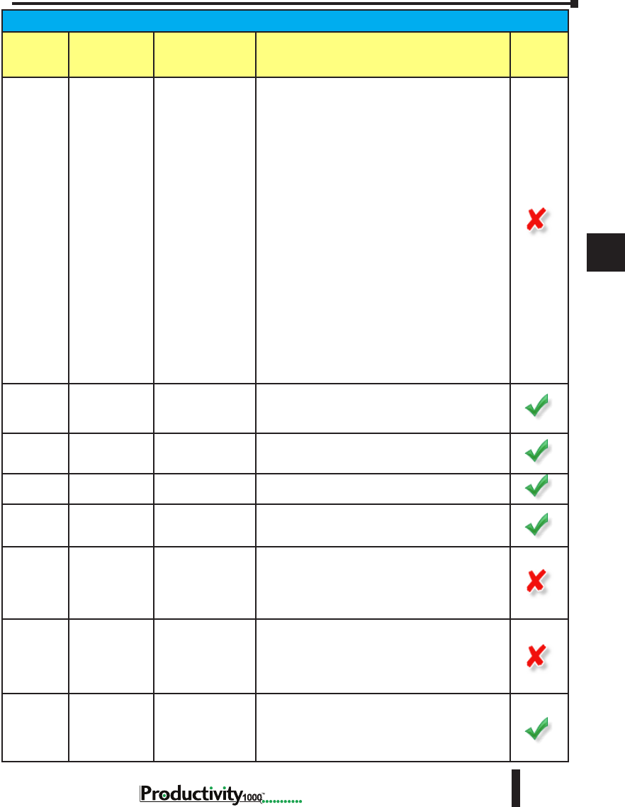
1
2
3
4
5
6
7
8
9
10
11
12
13
14
A
B
C
D
Chapter 6: Communications
6-57
Hardware User Manual, 1st Edition
1000
Hardware User Manual, 1st Edition
P1000 EtherNet/IP Error Codes
General
Status Error
Extended Status
Error Name Description P1000
Supported
0x01 0x0112 RPI Value not
acceptable
This error can be returned if the Originator is
specifying an RPI value that is not acceptable. There
may be six additional values following the extended
error code with the acceptable values. An array can
be dened for this eld in order to view the extended
error code attributes. If the Target device supports
extended status, the format of the values will be as
shown below:
• Unsigned Integer 16, Value = 0x0112, Explanation:
Extended Status code
• |Unsigned Integer 8, Value = variable, Explanation:
Acceptable Originator to Target RPI type, values:
0 = The RPI specied in the forward open was
acceptable (O -> T value is ignored), 1 = unspecied
(use a different RPI), 2 = minimum acceptable RPI
(too fast), 3 = maximum acceptable RPI (too slow),
4 = required RPI to corrected mismatch (data is
already being consumed at a different RPI), 5 to 255
= reserved.
• Unsigned Integer 32, Value = variable, Explanation:
Value of O -> T RPI that is within the acceptable
range for the application.
• Unsigned Integer 32, Value = variable, Explanation:
Value of T -> O RPI that is within the acceptable
range for the application.
0x01 0x0113 Out of Connections
The Productivity1000 EtherNet/IP Adapter connection
limit of 4 when doing Class 3 connections has been
reached. An existing connection must be dropped in
order for a new one to be generated.
0x01 0x0114 Vendor ID or Product
Code Mismatch
The compatibility bit was set in the Forward Open
message but the Vendor ID or Product Code did not
match.
0x01 0x0115 Device Type
Mismatch
The compatibility bit was set in the Forward Open
message but the Device Type did not match.
0x01 0x0116 Revision Mismatch
The compatibility bit was set in the Forward Open
message but the major and minor revision numbers
were not a valid revision.
0x01 0x0117
Invalid Produced
or Consumed
Application Path
This error is returned from the Target device when the
Connection Point parameters specied for the O -> T
(Output) or T -> O (Input) connection is incorrect or not
supported. The Productivity1000 CPU does not return
this error and uses the following error codes instead:
0x012A, 0x012B or 0x012F.
0x01 0x0118
Invalid or
Inconsistent
Conguration
Application Path
This error is returned from the Target device when
the Connection Point parameter specied for the
Conguration data is incorrect or not supported. The
Productivity1000 CPU does not return this error and
uses the following error codes instead: 0x0129 or
0x012F.
0x01 0x0119
Non-listen Only
Connection Not
Opened
This error code is returned when an Originator device
attempts to establish a listen only connection and
there is no non-listen only connection established.
The Productivity1000 CPU does not support listen only
connections as Scanner or Adapter.
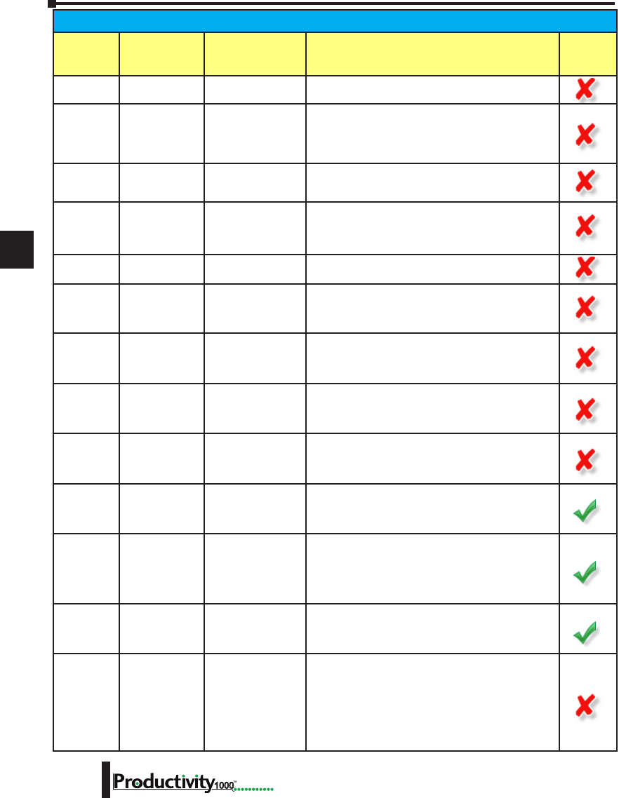
1
2
3
4
5
6
7
8
9
10
11
12
13
14
A
B
C
D
Chapter 6: Communications
6-58 Hardware User Manual, 1st Edition
1000
P1000 EtherNet/IP Error Codes
General
Status Error
Extended Status
Error Name Description P1000
Supported
0x01 0x011A Target Object Out of
Connections
The maximum number of connections supported by
this instance of the object has been exceeded.
0x01 0x011B
RPI is smaller than
the Production
Inhibit Time
The Target to Originator RPI is smaller than the Target
to Originator Production Inhibit Time. Consult the
manufacturer’s documentation as to the minimum
rate that data can be produced and adjust the RPI to
greater than this value.
0x01 0x011C Transport Class Not
Supported
The Transport Class requested in the Forward Open is
not supported. Only Class 1 and Class 3 classes are
supported in the Productivity1000 CPU.
0x01 0x011D Production Trigger
Not Supported
The Production Trigger requested in the Forward Open
is not supported. In Class 1, only Cyclic and Change
of state are supported in the Productivity1000 CPU. In
Class 3, Application object is supported.
0x01 0x011E Direction Not
Supported
The Direction requested in the Forward Open is not
supported.
0x01 0x011F
Invalid Originator
to Target Network
Connection Fixed/
Variable Flag
The Originator to Target xed/variable ag specied
in the Forward Open is not supported. Only Fixed is
supported in the Productivity1000 CPU.
0x01 0x0120
Invalid Target to
Originator Network
Connection Fixed/
Variable Flag
The Target to Originator xed/variable ag specied
in the Forward Open is not supported. Only Fixed is
supported in the Productivity1000 CPU.
0x01 0x0121
Invalid Originator
to Target Network
Connection Priority
The Originator to Target Network Connection Priority
specied in the Forward Open is not supported. Low,
High, Scheduled and Urgent are supported in the
Productivity1000 CPU.
0x01 0x0122
Invalid Target to
Originator Network
Connection Priority
The Target to Originator Network Connection Priority
specied in the Forward Open is not supported. Low,
High, Scheduled and Urgent are supported in the
Productivity1000 CPU.
0x01 0x0123
Invalid Originator
to Target Network
Connection Type
The Originator to Target Network Connection Type
specied in the Forward Open is not supported. Only
Unicast is supported for O -> T (Output) data in the
Productivity1000 CPU.
0x01 0x0124
Invalid Target to
Originator Network
Connection Type
The Target to Originator Network Connection Type
specied in the Forward Open is not supported.
Multicast and Unicast is supported in the
Productivity1000 CPU. Some devices may not support
one or the other so if this error is encountered try the
other method.
0x01 0x0125
Invalid Originator
to Target Network
Connection
Redundant_Owner
The Originator to Target Network Connection
Redundant_Owner ag specied in the Forward Open
is not supported. Only Exclusive owner connections
are supported in the Productivity1000 CPU.
0x01 0x0126 Invalid Conguration
Size
This error is returned when the Conguration data sent
in the Forward Open does not match the size specied
or is not supported by the Adapter. The Target device
may return an additional Unsigned Integer 16 value
that species the maximum size allowed for this data.
An array can be dened for this eld in order to view
the extended error code attributes.

1
2
3
4
5
6
7
8
9
10
11
12
13
14
A
B
C
D
Chapter 6: Communications
6-59
Hardware User Manual, 1st Edition
1000
Hardware User Manual, 1st Edition
P1000 EtherNet/IP Error Codes
General
Status Error
Extended
Status Error Name Description P1000
Supported
0x01 0x0127 Invalid Originator to
Target Size
This error is returned when the Originator to Target (Output
data) size specied in the Forward Open does not match what
is in the Target. Consult the documentation of the Adapter
device to verify the required size. Note that if the Run/Idle
header is requested, it will add 4 additional bytes and must
be accounted for in the Forward Open calculation. The
Productivity1000 CPU always requires the Run/Idle header
so if the option doesn’t exist in the Scanner device, you
must add an additional 4 bytes to the O -> T (Output) setup.
Some devices may publish the size that they are looking for
as an additional attribute (Unsigned Integer 16 value) of the
Extended Error Code. An array can be dened for this eld in
order to view the extended error code attributes.
Note: This error may also be generated when a Connection
Point value that is invalid for IO Messaging (but valid for
other cases such as Explicit Messaging) is specied, such as
0. Please verify if the Connection Point value is valid for IO
Messaging in the target device.
0x01 0x0128 Invalid Target to
Originator Size
This error is returned when the Target to Originator (Input
data) size specied in the Forward Open does not match
what is in Target. Consult the documentation of the Adapter
device to verify the required size. Note that if the Run/
Idle header is requested, it will add 4 additional bytes and
must be accounted for in the Forward Open calculation. The
Productivity1000 CPU does not support a Run/Idle header for
the T -> O (Input) data. Some devices may publish the size
that they are looking for as an additional attribute (Unsigned
Integer 16 value) of the Extended Error Code. An array can be
dened for this eld in order to view the extended error code
attributes.
Note: This error may also be generated when a Connection
Point value that is invalid for IO Messaging (but valid for
other cases such as Explicit Messaging) is specied, such as
0. Please verify if the Connection Point value is valid for IO
Messaging in the target device.
0x01 0x0129
Invalid
Conguration
Application Path
This error will be returned by the Productivity1000 CPU if a
Conguration Connection with a size other than 0 is sent to
the CPU. The Conguration Connection size must always be
zero if it this path is present in the Forward Open message
coming from the Scanner device.
0x01 0x012A Invalid Consuming
Application Path
This error will be returned by the Productivity3000 CPU if the
Consuming (O -> T) Application Path is not present in the
Forward Open message coming from the Scanner device or if
the specied Connection Point is incorrect.
0x01 0x012B Invalid Producing
Application Path
This error will be returned by the Productivity1000 CPU if
the Producing (T -> O) Application Path is not present in the
Forward Open message coming from the Scanner device or if
the specied Connection Point is incorrect.
0x01 0x012C Cong. Symbol
Does not Exist
The Originator attempted to connect to a conguration tag
name that is not supported in the Target.
0x01 0x012D Consuming Symbol
Does not Exist
The Originator attempted to connect to a consuming tag name
that is not supported in the Target.
0x01 0x012E Producing Symbol
Does not Exist
The Originator attempted to connect to a producing tag name
that is not supported in the Target.
0x01 0x012F
Inconsistent
Application Path
Combination
The combination of Conguration, Consuming and Producing
application paths specied are inconsistent.
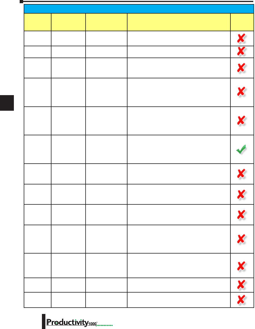
1
2
3
4
5
6
7
8
9
10
11
12
13
14
A
B
C
D
Chapter 6: Communications
6-60 Hardware User Manual, 1st Edition
1000
P1000 EtherNet/IP Error Codes
General
Status Error
Extended Status
Error Name Description P1000
Supported
0x01 0x0130
Inconsistent
Consume data
format
Information in the data segment not consistent with
the format of the data in the consumed data.
0x01 0x0131 Inconsistent Product
data format
Information in the data segment not consistent with
the format of the data in the produced data.
0x01 0x0132
Null Forward
Open function not
supported
The target device does not support the function
requested in the NULL Forward Open request. The
request could be such items as “Ping device”,
“Congure device application”, etc.
0x01 0x0133
Connection Timeout
Multiplier not
acceptable
The Connection Multiplier specied in the Forward
Open request not acceptable by the Target device
(once multiplied in conjunction with the specied
timeout value). Consult the manufacturer device’s
documentation on what the acceptable timeout and
multiplier are for this device.
0x01 0x0203 Connection Timed
Out
This error will be returned by the Productivity1000
CPU if a message is sent to the CPU on a connection
that has already timed out. Connections time out if
no message is sent to the CPU in the time period
specied by the RPI rate X Connection multiplier
specied in the Forward Open message.
0x01 0x0204 Unconnected
Request Timed Out
This time out occurs when the device sends
an Unconnected Request and no response is
received within the specied time out period. In the
Productivity1000 CPU, this value may be found in
the hardware conguration under the Ethernet port
settings for the P1-540.
0x01 0x0205
Parameter Error
in Unconnected
Request Service
This error occurs when Connection Tick Time/
Connection time-out combination is specied in the
Forward Open or Forward Close message this is not
supported by the device.
0x01 0x0206
Message Too
Large for
Unconnected Send
Service
Occurs when Unconnected_Send message is too large
to be sent to the network.
0x01 0x0207
Unconnected
Acknowledge
without Reply
This error occurs if an Acknowledge was received but
no data response occurred. Verify that the message
that was sent is supported by the Target device using
the device manufacturer’s documentation.
0x01 0x0301 No Buffer Memory
Available
This error occurs if the Connection memory buffer in
the target device is full. Correct this by reducing the
frequency of the messages being sent to the device
and/or reducing the number of connections to the
device. Consult the manufacturer’s documentation for
other means of correcting this.
0x01 0x0302
Network Bandwidth
not Available for
Data
This error occurs if the Producer device cannot
support the specied RPI rate when the connection
has been congured with schedule priority. Reduce the
RPI rate or consult the manufacturer’s documentation
for other means to correct this.
0x01 0x0303
No Consumed
Connection ID Filter
Available
This error occurs if a Consumer device doesn’t have
an available consumed_connection_id lter.
0x01 0x0304
Not Congured to
Send Scheduled
Priority Data
This error occurs if a device has been congured for
a scheduled priority message and it cannot send the
data at the scheduled time slot.
1
2
3
4
5
6
7
8
9
10
11
12
13
14
A
B
C
D
Chapter 6: Communications
6-61
Hardware User Manual, 1st Edition
1000
Hardware User Manual, 1st Edition
P1000 EtherNet/IP Error Codes
General
Status Error
Extended Status
Error Name Description P1000
Supported
0x01 0x0305 Schedule Signature
Mismatch
This error occurs if the schedule priority information
does not match between the Target and the Originator.
0x01 0x0306
Schedule Signature
Validation not
Possible
This error occurs when the schedule priority
information sent to the device is not validated.
0x01 0x0311 Port Not Available
This error occurs when a port number specied
in a port segment is not available. Consult the
documentation of the device to verify the correct port
number.
0x01 0x0312 Link Address Not
Valid
The Link address specied in the port segment is not
correct. Consult the documentation of the device to
verify the correct port number.
0x01 0x0315 Invalid Segment in
Connection Path
This error occurs when the target device cannot
understand the segment type or segment value in the
Connection Path. Consult the documentation of the
device to verify the correct segment type and value. If
a Connection Point greater than 255 is specied this
error could occur.
0x01 0x0316
Forward Close
Service Connection
Path Mismatch
This error occurs when the Connection path in
the Forward Close message does not match the
Connection Path congured in the connection. Contact
Tech Support if this error persists.
0x01 0x0317 Scheduling Not
Specied
This error can occur if the Schedule network segment
or value is invalid.
0x01 0x0318 Link Address to Self
Invalid
If the Link address points back to the originator
device, this error will occur.
0x01 0x0319 Secondary Resource
Unavailable
This occurs in a redundant system when the
secondary connection request is unable to duplicate
the primary connection request.
0x01 0x031A Rack Connection
Already established
The connection to a module is refused because part or
all of the data requested is already part of an existing
rack connection.
0x01 0x031B Module Connection
Already established
The connection to a rack is refused because part or
all of the data requested is already part of an existing
module connection.
0x01 0x031C Miscellaneous
This error is returned when there is no other
applicable code for the error condition. Consult
the manufacturer’s documentation or contact Tech
support if this error persist.
0x01 0x031D
Redundant
Connection
Mismatch
This error occurs when these parameters don’t match
when establishing a redundant owner connection: O
-> T RPI, O -> T Connection Parameters, T -> O RPI, T
-> O Connection Parameters and Transport Type and
Trigger.
0x01 0x031E
No more User
Congurable Link
Resources Available
in the Producing
Module
This error is returned from the Target device when no
more available Consumer connections available for a
Producer.
1
2
3
4
5
6
7
8
9
10
11
12
13
14
A
B
C
D
Chapter 6: Communications
6-62 Hardware User Manual, 1st Edition
1000
P1000 EtherNet/IP Error Codes
General
Status Error
Extended Status
Error Name Description P1000
Supported
0x01 0x031F
No User
Congurable
Link Consumer
Resources
Congured in the
Producing Module
This error is returned from the Target device when no
Consumer connections have been congured for a
Producer connection.
0x01 0x0800 Network Link Ofine The Link path is invalid or not available.
0x01 0x0810
No Target
Application Data
Available
This error is returned from the Target device when the
application has no valid data to produce.
0x01 0x0811
No Originator
Application Data
Available
This error is returned from the Originator device when
the application has no valid data to produce.
0x01 0x0812
Node Address has
changed since
the Network was
scheduled
This species that the router has changed node
addresses since the value congured in the original
connection.
0x01 0x0813 Not Congured for
Off-subnet Multicast
The producer has been requested to support a
Multicast connection for a consumer on a different
subnet and does not support this functionality.
0x01 0x0814
Invalid Produce/
Consume Data
format
Information in the data segment not consistent with
the format of the data in the consumed or produced
data. Errors 0x0130 and 0x0131 are typically used for
this situation in most devices now.
0x02 N/A
Resource
Unavailable for
Unconnected Send
The Target device does not have the resources to
process the Unconnected Send request.
0x04 N/A
Path Segment Error
in Unconnected
Send
The Class, Instance or Attribute value specied in the
Unconnected Explicit Message request is incorrect
or not supported in the Target device. Check the
manufacturer’s documentation for the correct codes
to use.
0x09 Index to error Error in Data
Segment
This error code is returned when an error is
encountered in the Data segment portion of a Forward
Open message. The Extended Status value is the
offset in the Data segment where the error was
encountered.
0x0C Optional Object State Error
This error is returned from the Target device when the
current state of the Object requested does not allow
it to be returned. The current state can be specied in
the Optional Extended Error status eld.
0x10 Optional Device State Error
This error is returned from the Target device when the
current state of the Device requested does not allow
it to be returned. The current state can be specied in
the Optional Extended Error status eld.
0x13 N/A Not Enough Data Not enough data was supplied in the service request
specied.
0x15 N/A Too Much Data Too much data was supplied in the service request
specied.

Maintenance and
troubleshooting 7
7
7
Chapter
Chapter
Chapter
In This Chapter...
Hardware Maintenance ............................................................................................. 7–2
Diagnostics .............................................................................................................7–3
CPU Functions Indicators ..........................................................................................7–4
PWR Indicator ...........................................................................................................7–5
RUN Indicator ...........................................................................................................7–7
CPU Indicator ............................................................................................................7–7
Communications Problems .......................................................................................7–7
I/O Module Troubleshooting ....................................................................................7–8
Noise Troubleshooting ............................................................................................7–10
Run Time vs. Stop Mode Transfer Instruction ........................................................7–11
Forcing I/O Points ...................................................................................................7–14
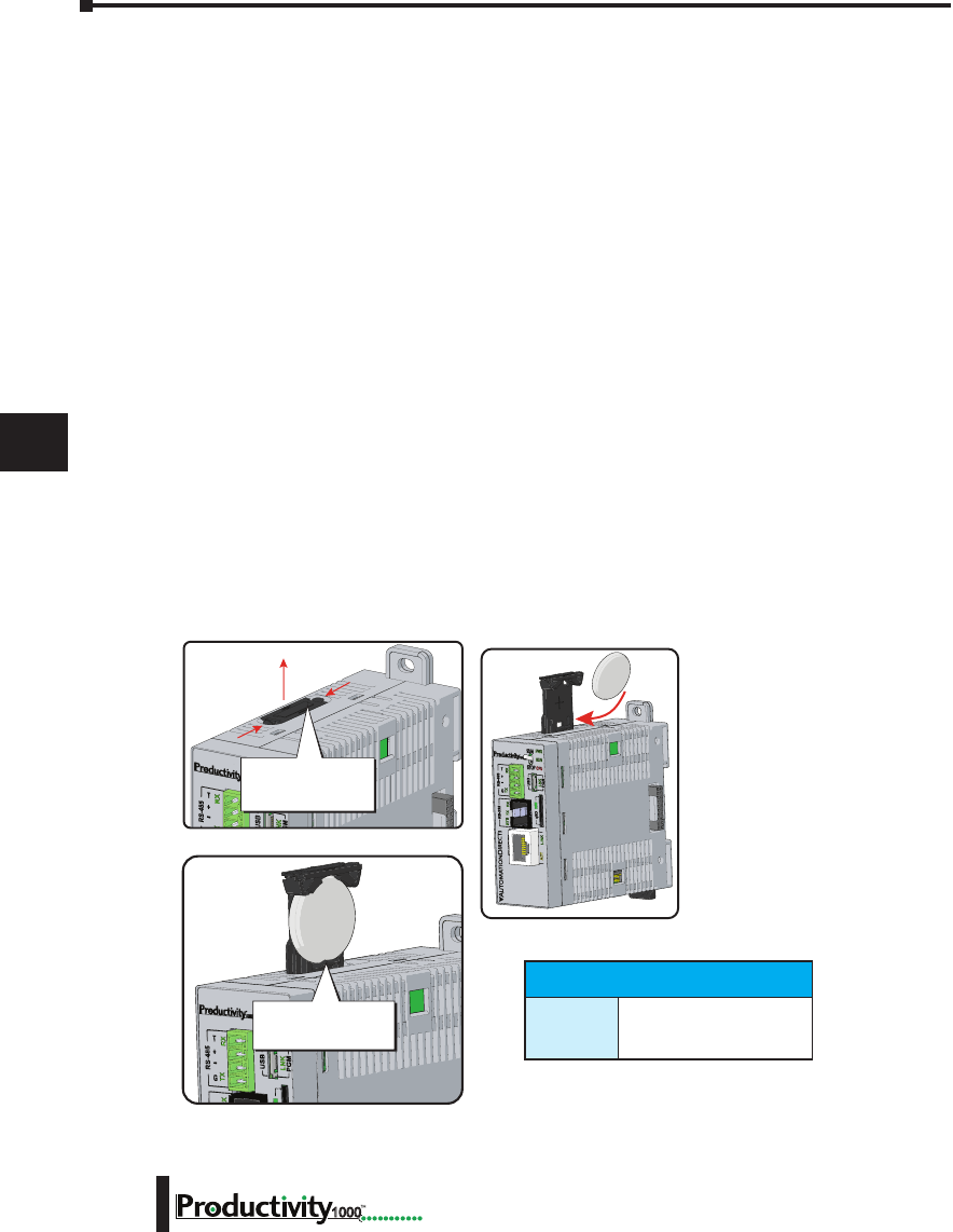
Chapter 7: Maintenance and Troubleshooting
1
2
3
4
5
6
7
8
9
10
11
12
13
14
A
B
C
D
7–2 Hardware User Manual, 1st Edition
1000
Hardware Maintenance
Standard Maintenance
The Productivity1000 is a low maintenance system requiring only a few periodic checks to help
reduce the risks of problems. Routine maintenance checks should be made regarding two key
items.
• Air quality (cabinet temperature, airflow, etc.)
• CPU battery
Air Quality Maintenance
The quality of the air your system is exposed to can affect system performance. If you have
placed your system in an enclosure, verify that the ambient temperature is not exceeding
the equipment operating specifications. If there are filters in the enclosure, clean or replace
them as necessary to ensure adequate airflow. A good rule of thumb is to check your system
environment every one to two months. Make sure the Productivity1000 is operating within
the system operating specifications.
CPU Battery Replacement
A battery is included with the CPU, but is not installed. The battery can be installed to retain
the Time and Date along with any Tagname values that are set up as retentive.
The battery is not needed for program backup.
Battery (Optional)
D2-BAT-1
Coin type, 3.0 V Lithium
battery, 560mA, battery
number CR2354
Battery Installation Procedure
Battery (Optional)
D2-BAT-1 Coin type, 3.0V Lithium battery, 560mA, battery number CR2354
Note: Although not needed for program backup, an uninstalled battery is included with the
P1-540. Install this battery if you want the CPU to retain the Time and Date along with any
Tagname values that you have set up as retentive.
Step One:
Open battery compartment
located on the top of the CPU.
Step Two:
Insert battery and
close compartment.
Squeeze tabs and
pull battery holder up
to remove battery.
P1-540
+-
P1-540
Take care to insert
battery behind tab.
P1-540

Chapter 7: Maintenance and Troubleshooting
1
2
3
4
5
6
7
8
9
10
11
12
13
14
A
B
C
D
7–3
Hardware User Manual, 1st Edition
1000
Diagnostics
Diagnostics
Your Productivity1000 system performs many pre-defined diagnostic routines with every CPU scan.
The diagnostics have been designed to detect various types of failures for the CPU and I/O modules.
There are two primary error classes, critical and non-critical.
Critical Errors
Critical errors are errors the CPU has detected that offer a risk of the system not functioning safely or
properly. If the CPU is in Run Mode when a critical error occurs, the CPU will switch to Stop Mode
(Remember, in Stop Mode all outputs are turned off). If a critical error is detected while the CPU is
in Stop Mode, the CPU will not enter Run Mode until the error has been corrected. Here are some
examples of critical errors:
• Power supply failure
• Parity error or CPU malfunction
• I/O configuration errors
• Certain programming errors.
Non-Critical Errors
Non-critical errors are flagged by the CPU as requiring attention. They can neither cause the CPU
to change from Run Mode to Stop Mode, nor do they prevent the CPU from entering Run Mode.
There are system tags the application program can use to detect if a non-critical error has occurred.
The application program can be used to take the system to an orderly shutdown or to switch the
CPU to Stop Mode if necessary.
Some examples of non-fatal errors are:
• Backup battery voltage low
• All I/O module errors
• Certain programming errors.
Finding Diagnostic Information
The CPU automatically logs critical and non-critical error codes. Logged errors can be found
in the following places marked with a time and date stamp:
• Under the Monitor Debug tool of Productivity Suite in the CPU Error History window. The 20
most recent critical and non-critical errors are listed.
Error Codes
See Appendix B “Productivity1000 Error Codes” for a complete list of error messages sorted
by error types.
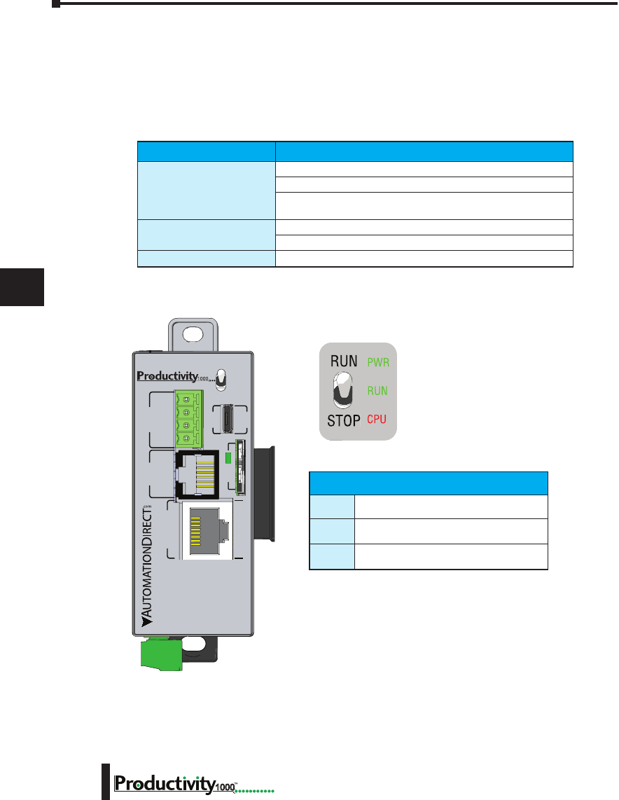
Chapter 7: Maintenance and Troubleshooting
1
2
3
4
5
6
7
8
9
10
11
12
13
14
A
B
C
D
7–4 Hardware User Manual, 1st Edition
1000
CPU Functions Indicators
The Productivity1000 CPU has indicators on the faceplate to help diagnose problems with
the system. The table below gives a quick reference of potential problems associated with each
status indicator. The pages following the table contain a detailed analysis of each of these
indicator problems.
Indicator Status Potential Problems
PWR (off)
1. System voltage is incorrect.
2. Power supply/CPU is faulty.
3. Other components such as an I/O module has power supply
shorted.
RUN (will not come on) 1. CPU programming error
2. Switch in STOP position
CPU (blink) CPU internal error
CPU Status Indicators
PWR
Green LED is illuminated when power
is on
RUN
Green LED is illuminated when CPU is in
RUN mode
CPU
Red LED is illuminated during power on
reset, power down, or watch-dog time-out.
P1-540 RUN
STOP
PWR
RUN
CPU
REMOTE I/O
RS-232 RS-485
10/100
ETHERNET
ACT LINK
G
-
+
T
LINK ACT
PGM
LINK
RXTXTXRTSRX
USB
µSD
®
CPU Status Indicators
PWR Green LED is illunimated when power is ON
RUN Green LED is illuminated when CPU is in RUN mode
CPU Red LED is illuminated during power ON reset, power down, or
watch-dog time-out
CPU Run/Stop Switch Specifications
RUN position Executes user program, run-time edits possible
STOP position Does not execute user program, normal program load position

Chapter 7: Maintenance and Troubleshooting
1
2
3
4
5
6
7
8
9
10
11
12
13
14
A
B
C
D
7–5
Hardware User Manual, 1st Edition
1000
PWR Indicator
There are three general reasons for the CPU power status LED (PWR) to be OFF:
1. Power to the module is incorrect or is not applied.
2. Module power supply is faulty.
3. Other component(s) have the power supply shut down.
Faulty or Incorrect Power Supply
If the voltage to/from the power supply is not correct, the CPU may not operate properly or
may not operate at all. Use the following guidelines to correct the problem.
WARNING: To minimize the risk of electrical shock, always disconnect the system power before
inspecting the physical wiring.
1. First, disconnect the system power and check all incoming wiring for loose connections.
2. If you are using a separate termination panel, check those connections to make sure the wiring is
connected to the proper location.
3. If the connections are acceptable, reconnect the system power and measure the voltage at the
base terminal strip to ensure it is within specification. If the voltage is not correct, shut down
the system and correct the problem.
4. If all wiring is connected correctly and the incoming power is within the specifications required,
the power supply should be replaced.
Faulty CPU
There is no simple test for a faulty CPU other than substituting a known good one to see if
this corrects the problem. If you have experienced major power surges, it is possible the CPU
and power supply have been damaged. If you suspect this is the cause, a line conditioner
should be installed on the incoming line. This will keep damaging voltage spikes from
reaching the CPU.

Chapter 7: Maintenance and Troubleshooting
1
2
3
4
5
6
7
8
9
10
11
12
13
14
A
B
C
D
7–6 Hardware User Manual, 1st Edition
1000
PWR Indicator, cont’d
Device or Module Causes the Power Supply to Shutdown
Module:
If the PWR LED is operating normally but the power supply shuts down, check each module
for a possible connector problem as follows:
1. Turn off power to the system.
2. Remove a module from the system.
3. Reapply power to the system.
4. Check for power supply normal operation.
5. Repeat procedure until defective module is found and replaced.
Device:
A 5V charge may be originating from the CPU communications port.
Test as follows:
1. Turn off power to the CPU.
2. Disconnect all external devices (i.e., communication cables) from the CPU.
3. Reapply power.
4. If power supply operates normally then check for a shorted device or shorted cable.

Chapter 7: Maintenance and Troubleshooting
1
2
3
4
5
6
7
8
9
10
11
12
13
14
A
B
C
D
7–7
Hardware User Manual, 1st Edition
1000
Run Indicator
If the CPU will not enter the Run mode (the RUN indicator is off), the problem is usually
in the application program, unless the CPU has a critical error. If a critical error has
occurred, the CPU LED should be on. You can use a programming device to determine
the cause of the error.
A complete list of error codes can be found in Appendix B.
CPU Indicator
If the CPU indicator is on, a critical error has occurred in the CPU. Generally, this is not
a programming problem but an actual hardware error. The CPU indicator should blink
briefly and then do an automatic reboot.
If the error clears, you should monitor the system and determine what caused the problem.
You will find this problem is sometimes caused by high frequency electrical noise introduced
into the CPU from an outside source. Check your system grounding and install electrical
noise filters if the grounding is suspected. If power cycling the system does not reset the
error, or if the problem returns, you should replace the CPU.
Communications Problems
If a communication error occurs, the indicator will come on and stay on until a successful
communication has been completed. If you cannot establish communications with the
CPU, check these items:
• The cable is disconnected.
• The cable has a broken wire or has been wired incorrectly.
• The cable is improperly terminated or grounded.
• The device connected is not operating at the correct baud rate.
• The device connected to the port is sending data incorrectly.
• A grounding difference exists between the two devices.
• Electrical noise is causing intermittent errors.
• The CPU has a bad communication port; the CPU should be replaced.

Chapter 7: Maintenance and Troubleshooting
1
2
3
4
5
6
7
8
9
10
11
12
13
14
A
B
C
D
7–8 Hardware User Manual, 1st Edition
1000
I/O Module Troubleshooting
Things to Check
If you suspect an I/O error, there are several things that could be causing the problem.
• A blown fuse
• A loose terminal block
• The 24VDC supply has failed
• The module has failed
• The I/O configuration check detects a change in the I/O configuration
Error Codes
See Appendix B for Productivity1000 error code information.
Also, in the Productivity Suite programming software, you can go to:
Tools > CPU Error History, and
Tools > CPU Event History
Next, click on “CPU Error”or “Event History” tab to get an updated list of critical errors,
non-critical errors and event history that should indicate problems or changes to the I/O.
This list will give the “GS” (group, slot numbers).
Some Quick Steps
When troubleshooting the Productivity1000 I/O modules there are a few facts you should be
aware of which may assist you in quickly correcting an I/O problem:
• The output modules cannot detect shorted or open output points. If you suspect one or more
points on a output module to be faulty, you should measure the voltage drop from the common to
the suspect point. Remember, when using a Digital Volt Meter, leakage current from an output
device, such as a triac or a transistor, must be considered. A point which is off may appear to be
ON if no load is connected to the point.
• The I/O point status indicators on the modules are logic side indicators. This means the LED
which indicates the ON or OFF status reflects the status of the point in respect to the CPU. For
an output module, the status indicators could be operating normally, while the actual output device
(transistor, triac etc.) could be damaged. With an input module, if the indicator LED is ON, the
input circuitry should be operating properly. To verify proper functionality, check to see that the
LED goes off when the input signal is removed.
• Leakage current can be a problem when connecting field devices to I/O modules. False input
signals can be generated when the leakage current of an output device is great enough to turn on
the connected input device. To correct this, install a resistor in parallel with the input or output of
the circuit. The value of this resistor will depend on the amount of leakage current and the voltage
applied but usually a 10K to 20K resistor will work. Ensure the wattage rating of the resistor is
correct for your application.
• The easiest method to determine if a module has failed is to replace it if you have a spare. However,
if you suspect another device to have caused the failure in the module, that device may cause the
same failure in the replacement module as well. As a point of caution, you may want to check
devices or power supplies connected to the failed module before replacing it with a spare module.
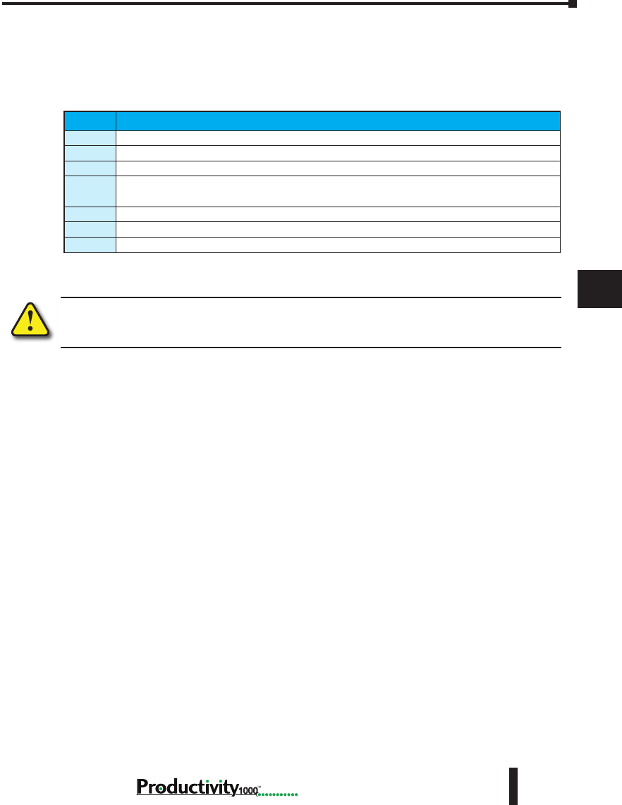
Chapter 7: Maintenance and Troubleshooting
1
2
3
4
5
6
7
8
9
10
11
12
13
14
A
B
C
D
7–9
Hardware User Manual, 1st Edition
1000
Testing Output Points
Output points can be set ON or OFF using the force function to override a point even while
the program is running. However, this is not a recommended method to test the output
points. If you want to do an I/O check independent of the application program, follow the
procedure in the table below:
WARNING: Depending on your application, forcing I/O points may cause unpredictable machine
operation that can result in a risk of personal injury or equipment damage. Make sure you have taken
all appropriate safety precautions prior to testing any I/O points.
Step Action
1. Use Productivity Suite programming software to communicate online to the CPU.
2. Change to Program Mode.
3. Go to the first rung of the ladder.
4. Insert a rung with an “END” statement. (This will cause program execution to occur only at address
0 and prevent the application program from turning the I/O points on or off).
5. Change to Run Mode.
6. Use the programming device to set (turn) on or off the points you wish to test.
7. When you finish testing I/O points delete the “END” statement at the first rung.

Chapter 7: Maintenance and Troubleshooting
1
2
3
4
5
6
7
8
9
10
11
12
13
14
A
B
C
D
7–10 Hardware User Manual, 1st Edition
1000
Noise Troubleshooting
Electrical Noise Problems
Noise is one of the most difficult problems to diagnose. Electrical noise, whether conducted
or radiated, can enter a system in many different ways. It may be difficult to determine how
the noise is entering the system but the corrective actions for either type of noise problem are
similar.
• Conducted noise is when the electrical interference is introduced into the system by way of an attached
wire, panel connection, etc. It may enter through an I/O module, a power supply connection, the
communication ground connection, or the chassis ground connection.
• Radiated noise is when the electrical interference is introduced into the system without a direct
electrical connection, much in the same manner as radio waves.
Reducing Electrical Noise
While electrical noise cannot be eliminated completely, it can be reduced such that it will not
adversely affect system function. Proper grounding of components and signal wiring along
with proper isolation of voltages can minimize noise in the system.
1. Grounding:
• Most noise problems result from improper grounding of the system. A good earth ground can be the
single most effective way to correct noise problems. If a ground is not available, install a ground rod
as close to the system as possible.
• Ensure all ground wires are single point grounds and are not daisy chained from one device to
another. Ground metal enclosures around the system. A loose wire is no more than a large antenna
waiting to introduce noise into the system; therefore, you should tighten all connections in your
system. Loose ground wires are more susceptible to noise than the other wires in your system.
Review Chapter 5, “Installation and Wiring”, if you have questions regarding how to ground your
system.
2. Isolation:
• Electrical noise can enter the system through the power source for the CPU and I/O. Installing an
isolation transformer for all AC sources can correct this problem.
• DC power sources should be well grounded, good quality power supplies. Switching DC power
supplies commonly generate more noise than linear supplies.
• Separate input wiring from output wiring.
• Never run I/O wiring close to high voltage wiring.
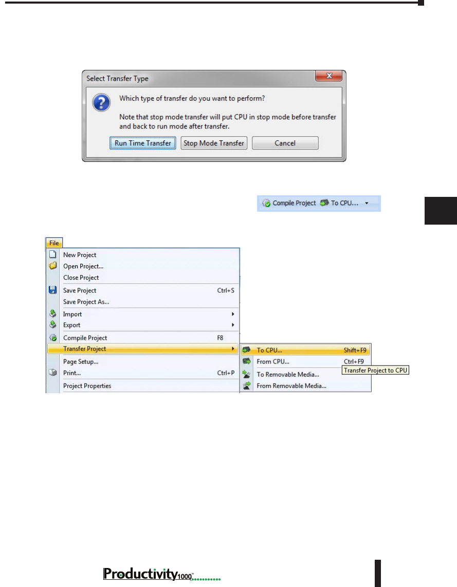
Chapter 7: Maintenance and Troubleshooting
1
2
3
4
5
6
7
8
9
10
11
12
13
14
A
B
C
D
7–11
Hardware User Manual, 1st Edition
1000
Run Time vs. Stop Mode Transfer Instruction
Here we describe the actions and differences between Run Time & Stop Mode transfers as
shown in this dialog box.
The above dialog is accessed two ways: (only when CPU is online AND in run mode)
Perform either of the following to transfer project to the CPU:
1. Click on the “To CPU” icon on the Tool Bar, or
2. Click through from the File menu > Transfer Project > To CPU.
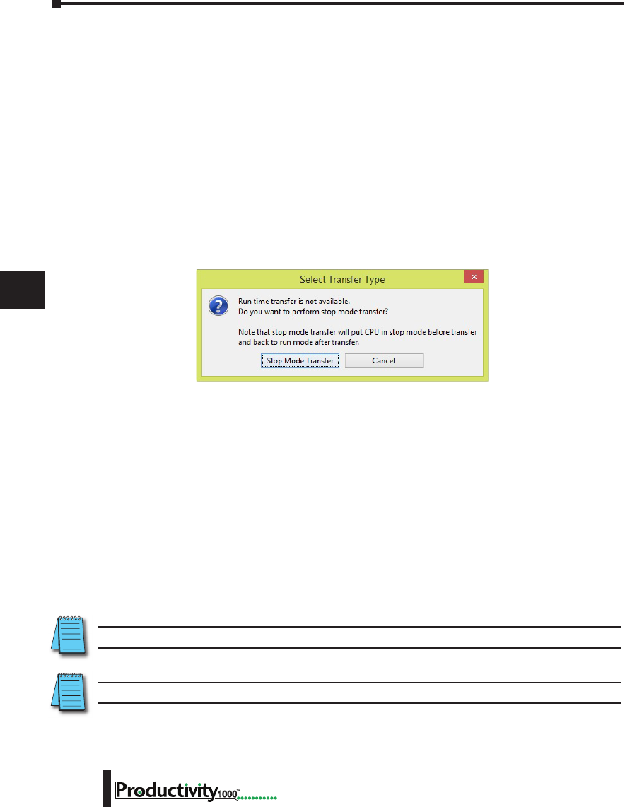
Chapter 7: Maintenance and Troubleshooting
1
2
3
4
5
6
7
8
9
10
11
12
13
14
A
B
C
D
7–12 Hardware User Manual, 1st Edition
1000
Run Time Transfers
Run Time Transfer allows the user to transfer edits to a project in the CPU without stopping
the CPU scan, therefore not stopping the process. Be aware that a Run Time Transfer will
affect the length of your scan time, which should be considered if your process is susceptible
to varying or lengthy scan times. The download time is longer compared to a Stop Mode
transfer.
During a Run Time transfer, the current project file continues running until the entire
project file is transferred to the CPU. Once downloaded, the ladder logic files swap and begin
executing the new file. The Tag Database is shared between the two project files during a Run
Time transfer, therefore current operating values will not be effected.
Because the Tag database is shared, any edits to the Tag database will force a Stop Mode
transfer.
Stop Mode Transfers
Stop Mode Transfers allows the user to transfer any and all ladder, Tag Database and
configuration changes to the CPU.
Because the CPU is in stop mode, the project transfer is much faster than a Run Time Transfer
and also loads all initial values to the tags once the project is switched from Stop to Run.
Following are conditions that will force the user to perform a Stop Mode Transfer:
1. Any changes to the hardware configuration, such as:
A. Adding or removing hardware.
B. Changing the configuration of a piece of hardware.
• Ethernet or serial port configuration.
C. Adding an EhterNet/IP device and any configured changes
2. Adding > 5000 tags of any type (Excluding Strings and Structures).
NOTE: This limit is accumulated between each stop mode transfer.
3. Adding >50,000 characters or changing the length of a String data type Tag.
NOTE: This limit is accumulated between each stop mode transfer.
4. Changes to Data Logger.
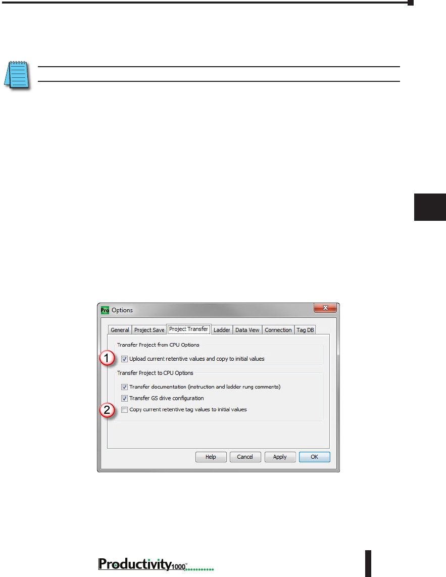
Chapter 7: Maintenance and Troubleshooting
1
2
3
4
5
6
7
8
9
10
11
12
13
14
A
B
C
D
7–13
Hardware User Manual, 1st Edition
1000
5. Changes to Modbus Server settings under Project Properties.
6. Changes to the buffer size for a FILI instruction.
7. Adding >5,000 elements of a Structures data type to Tag Database.
NOTE: This limit is accumulated between each stop mode transfer.
8. Enabling Bit of Word under Project Properties.
9. Enabling Structures in Project Properties.
10. Enable and Disable of EhterNet/IP Adapter.
As the CPU goes from Stop to Run after a Stop Mode Transfer, tags are initialized as if the
project is being executed for the first time. This includes Retentive Tags. If it’s desirable
that the values of Retentive Tags be retained through a Stop Mode Transfer, there are two
methods available. Both options may be enabled and they can be found under Tools >
Options > Project Transfer
1. Upload current retentive values and copy to initial values. This option works during
program upload. When selected, place the CPU in Stop Mode so Retentive Tag values
are stable, then upload the project. Productivity Suite will copy the current value of
all Retentive Tags to their Initial Values in the Tag Database of the project. Perform
your edits and transfer the project back to the CPU. When the CPU goes back to run,
your Retentive Tags will be initialized with their old values. This is a simple process
and is convenient for quick edits to the program, but the CPU must remain in Stop
Mode while the project is edited to ensure that no retentive values have changed during
editing.
2. Copy current retentive tag values to initial values. This option works during program
download. This process is more involved, but the CPU will use the values from the
project currently running as the initial values of the project being transferred. For more
information refer to the Options topic in the help file.
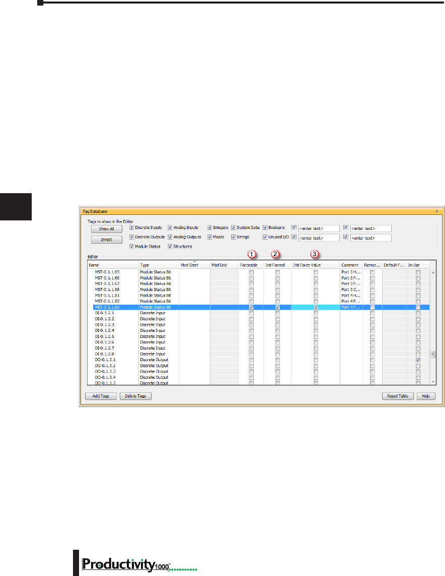
Chapter 7: Maintenance and Troubleshooting
1
2
3
4
5
6
7
8
9
10
11
12
13
14
A
B
C
D
7–14 Hardware User Manual, 1st Edition
1000
Forcing I/O Points
Following is a description of the actions, expectations and indications of forcing a value in the
Productivity1000 controller.
Advantages of Forces
Almost all tags can be written to in the software without Forcing. However, if the ladder
logic or an external device (operator interface panel, Modbus device, etc.) is connected to your
controller and writing to those tags, the values you write from a Data View will be over-written.
Conversely, if you write a Forced value, this will not be overwritten or reset until you manually
remove the force or reset by means of a Stop to Run mode transition, a Stop Mode Transfer,
or a controller power cycle.
Enabling Forces
The Productivity1000 CPU is a Tag based controller where forcing a tag begins by identifying
any tag you wish to be “Forceable” within the Tag database.
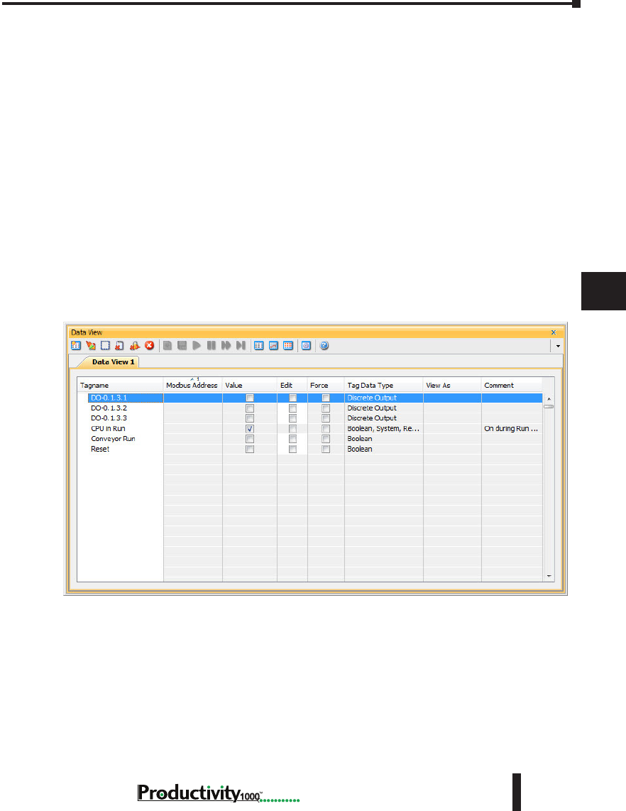
Chapter 7: Maintenance and Troubleshooting
1
2
3
4
5
6
7
8
9
10
11
12
13
14
A
B
C
D
7–15
Hardware User Manual, 1st Edition
1000
There are three columns within the Tag database that affect the forcing of all tags.
1. “Forceable” - Checking the box in this column identifies the corresponding tag as being
able to be forced within the system.
2. “Init Forced” - Checking the box in this column identifies that corresponding tag as
being forced as soon as the project is loaded and the processor is switched to Run mode.
3. “Init Force Value” - The state of the box in this column identifies the initial forced state
of the Boolean tag:
• A check mark in a box equates to a logical “1” or “ON”, and
• An unchecked box equates to a logical ”0” or “OFF”. The value placed in this
field for Integer or Floating point tags will be written into the tag.
Forcing Tags in Your System
All forcing of tags can be accomplished through the Data View window or directly in
the program interface while in “Monitor” mode, as long as the “Forceable” box has been
checked in Tag Database. I/O may also be directly forced in I/O View by clicking on
individual I/O points.
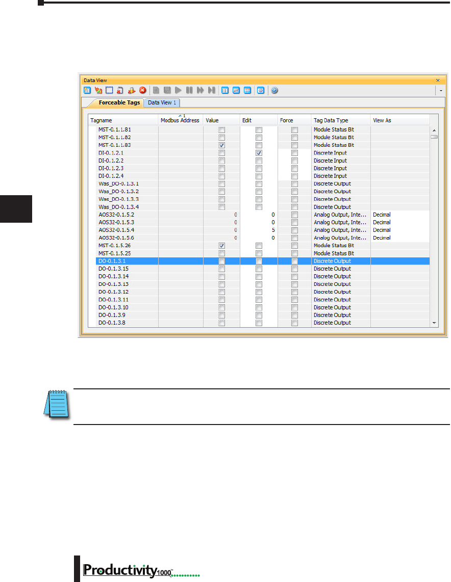
Chapter 7: Maintenance and Troubleshooting
1
2
3
4
5
6
7
8
9
10
11
12
13
14
A
B
C
D
7–16 Hardware User Manual, 1st Edition
1000
From the DataView Window, enter the tags you wish to force, or you can view all forceable
tags from the “Forceable Tags” tab automatically created for you when you enable tags as
forceable in the tag database.
From either of these windows you have the option to select the check box in the Force column.
When this box is checked and the row is selected (selected rows show high-lighted blue) and
you select the Send Edit(s) button, the current row(s) will be forced.
NOTE: You can select multiple rows by clicking and holding down the left mouse button and dragging up or
down. This selects consecutive rows. If you wish to select various rows, simple hold the “Ctrl” control key
on your keyboard while left mouse clicking the rows.
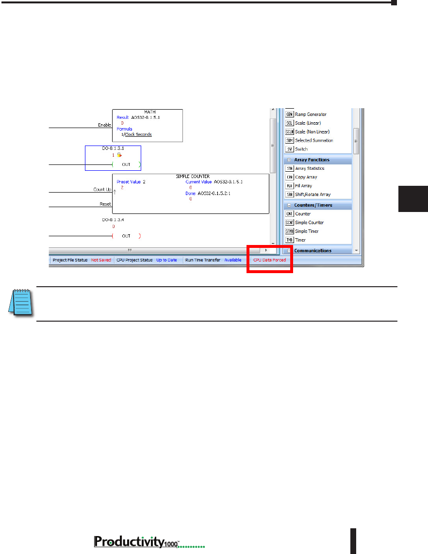
Chapter 7: Maintenance and Troubleshooting
1
2
3
4
5
6
7
8
9
10
11
12
13
14
A
B
C
D
7–17
Hardware User Manual, 1st Edition
1000
Identifying Forced Values
There are two indications that forces are active on your controller.
1. All active forces will be shown in the Forceable tab of the Data View window as shown in the
previous view.
2. You will also see “CPU Data Forced” in Red in the lower right of the Status bar of your
software interface.
NOTE: Only Forced tags with an initial force value specified in the Tag database will be retained after
a Stop to Run transition, Stop Mode transfer, or a power cycle. All forced values are retained during a
Run Time transfer.
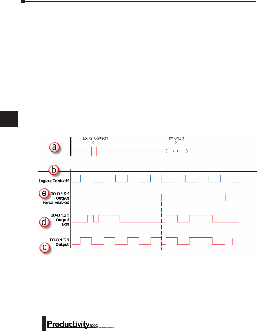
Chapter 7: Maintenance and Troubleshooting
1
2
3
4
5
6
7
8
9
10
11
12
13
14
A
B
C
D
7–18 Hardware User Manual, 1st Edition
1000
Force Value Timing Chart
The chart below illustrates how the states of a discrete output are varied when forces and edits
are applied. The ladder rung at the top of the chart (a) shows the logical arrangement of
Logical Contact1 and discrete Output DO-0.1.3.1.
Under normal operation, Logical Contact1 (b) is driven by a clock pulse. This clock pulse
is then fed to the discrete Output DO-0.1.3.1 (c). Edits written to the contact or the coil
from the Data View window within the software will be written one time and will not be
forced. With the clock pulse driving the contact, any software edits made to this contact will
be allowed but will be overwritten by the logic on the very next scan. Any software edits made
to the output will not be allowed and will not register. Edits can only change the state of the
output if there are no other logistic or outside factors influencing the output.
In order to change the state of Logical Contact1 or discrete Output DO-0.1.3.1 while the
clock pulse is driving it, a force must be introduced. The DO-0.1.3.1 Output Edit line (d)
represents edits sent to the discrete output from the Data View window. The DO-0.1.3.1
Output Force Enabled line (e) shows the point at which the software forces the output edit to
take effect. The dotted lines represent the force being enabled and then disabled by the user.
When the force is enabled, any edits made will register at the output regardless of the state of
Logical Contact1. When the force is disabled, all output edits will be ignored.

EuropEan union
DirEctivEs (cE)
Appendix
Appendix
Appendix
A
A
In This Appendix...
European Union (EU) Directives ........................................................A-2
Basic EMC Installation Guidelines ......................................................A-5

Appendix A: European Union Directives (CE)
A
2
3
4
5
6
7
8
9
10
11
12
13
14
A
B
C
D
Hardware User Manual, 1st Edition
A–2 1000
European Union (EU) Directives
NOTE: The information contained in this section is intended as a guideline and is based on our interpretation
of the various standards and requirements. Since the actual standards are issued by other parties, and in
some cases governmental agencies, the requirements can change over time without advance warning or
notice. Changes or additions to the standards can possibly invalidate any part of the information provided in
this section.
This area of certification and approval is absolutely vital to anyone who wants to do business in
Europe. One of the key tasks that faced the EU member countries and the European Economic
Area (EEA) was the requirement to bring several similar yet distinct standards together into one
common standard for all members. The primary purpose of a single standard was to make it
easier to sell and transport goods between the various countries and to maintain a safe working
and living environment. The Directives that resulted from this merging of standards are now
legal requirements for doing business in Europe. Products that meet these Directives are
required to have a CE mark to signify compliance.
Member Countries
As of January 1, 2015, the members of the EU are Austria, Belgium, Bulgaria, Croatia, Republic
of Cyprus, Czech Republic, Denmark, Estonia, Finland, France, Germany, Greece, Hungary,
Ireland, Italy, Latvia, Lithuania, Luxembourg, Malta, Netherlands, Poland, Portugal, Romania,
Slovakia, Slovenia, Spain, Sweden, and United Kingdom. Iceland, Liechtenstein, and Norway
together with the EU members make up the European Economic Area (EEA) and all are covered
by the Directives.
Applicable Directives
There are several Directives that apply to our products. Directives may be amended, or added,
as required.
• Electromagnetic Compatibility Directive (EMC) — this Directive attempts to ensure that devices,
equipment, and systems have the ability to function satisfactorily in an electromagnetic environment
without introducing intolerable electromagnetic disturbance to anything in that environment.
• Machinery Safety Directive — this Directive covers the safety aspects of the equipment, installation,
etc. There are several areas involved, including testing standards covering both electrical noise
immunity and noise generation.
• Low Voltage Directive — this Directive is also safety related and covers electrical equipment that has
voltage ranges of 50–1000 VAC and/or 75–1500 VDC.
• Battery Directive — this Directive covers the production, recycling, and disposal of batteries.
Compliance
NOTE: As of July 22, 2017 ROHS has been added as an additional requirement for CE Compliance per Directive
2011/65/EU. All products bearing the CE mark must be ROHS compliant.
Certain standards within each Directive already require mandatory compliance. The EMC
Directive, which has gained the most attention, became mandatory as of January 1, 1996. The
Low Voltage Directive became mandatory as of January 1, 1997.

A
2
3
4
5
6
7
8
9
10
11
12
13
14
A
B
C
D
Appendix A: European Union Directives (CE)
A–3
Hardware User Manual, 1st Edition
1000
Ultimately, we are all responsible for our various pieces of the puzzle. As manufacturers,
we must test our products and document any test results and/or installation procedures that
are necessary to comply with the Directives. As a machine builder, you are responsible for
installing the products in a manner which will ensure compliance is maintained. You are also
responsible for testing any combinations of products that may (or may not) comply with the
Directives when used together. The end user of the products must comply with any Directives
that may cover maintenance, disposal, etc., of equipment or various components. Although we
strive to provide the best assistance available, it is impossible for us to test all possible configurations of
our products with respect to any specific Directive. Because of this, it is ultimately your responsibility
to ensure that your machinery (as a whole) complies with these Directives and to keep up with
applicable Directives and/or practices that are required for compliance.
This then is the product specific standard for CPUs and covers the low voltage and EMC
directives as required for European CE certification. This standard has many tests together
with test procedures and limits, but also references the below standards for some tests.
Productivity1000 systems, manufactured by FACTS Engineering, when properly installed
and used, conform to the Electromagnetic Compatibility (EMC), Low Voltage Directive, and
Machinery Directive requirements of the following standards:
• Product Specific Standard for Programmable Controllers
EN61131-2:2007 EMC, EN61010-:2010 and EN61010-2-201: 2013 Safety Programmable
controllers, equipment requirements and tests.
• Warning on Electrostatic Discharge (ESD)
We recommend that all personnel take necessary precautions to avoid the risk of transferring static
charges to inside the control cabinet, and clear warnings and instructions should be provided on the
cabinet exterior. Such precautions may include the use of earth straps, grounding mats and similar
static-control devices, or the powering off of the equipment inside the enclosure before the door is
opened.
IEC 60068 IEC
60417
IEC
60664
IEC
60695
IEC
60707
IEC
60947
IEC
60950
IEC
61000
IEC
61010
2-1:1990 part
2 Test A All Parts 1:1992
Part 1
2-1 (all
sheets)
Part 2
:1999 5-1:1997
Part 5-1
1:2001
Part 1
4-2:1995
Part 4-2
1:2001
Part 1
2-2:1974 part
2 Test B 3:1992 7-1:2002
Part 7-1
4-3:2002
Part 4-3
2-6:1995 Part
2: Test Fc 4-4:1995
2-6:1995 Part
2: Test Fc
CISPR
11:1999
4-5:1995
Part 4-5
2-14:1984 Part
2 Test N
CISPR
16-1:1999
Part 1
4-6:1996
Part 4-6
2-27:1987 Part
2 Test Ea
CISPR
16-2:1999
Part 2
4-8:1993
Part 4-8
2-30:1980 Part
2 Test Db
4-12:1995
Part 4-12
2-31:1969 Part
Test Ec
2-32:1975 Part
2 Test Ed
For undated references, the latest edition of the referenced
document (including any amendments) applies.

Appendix A: European Union Directives (CE)
A
2
3
4
5
6
7
8
9
10
11
12
13
14
A
B
C
D
Hardware User Manual, 1st Edition
A–4 1000
• Warning on Radio Interference (RFI)
This is a class A product. In a domestic environment this product may cause radio
interference in which case the user may be required to take adequate measures.
General Safety
• External switches, circuit breaker or external fusing, are required for these devices.
• The switch or circuit breaker should be mounted near the programmable controller equipment.
Special Installation Manual
The installation requirements to comply with the requirements of the Machinery Directive,
EMC Directive and Low Voltage Directive are slightly more complex than the normal
installation requirements found in the United States. To help with this, we have published a
special manual which you can order or download from our website:
• DA–EU–M – EU Installation Manual that covers special installation requirements to meet the EU
Directive requirements. Refer to this manual for updated information.
Other Sources of Information
Although the EMC Directive gets the most attention, other basic Directives, such as the
Machinery Directive and the Low Voltage Directive, also place restrictions on the control
panel builder. Because of these additional requirements it is recommended that the following
publications be purchased and used as guidelines:
• BSI publication BS TH 42073: November 2000 – covers the safety and electrical aspects of the
Machinery Directive
• EN 60204–1:2006 – Safety of Machinery; General electrical requirements for machinery, including
Low Voltage and EMC considerations
• IEC 61000–5–2: EMC earthing and cabling requirements
• IEC 61000–5–1: EMC general considerations
It may be possible for you to obtain this information locally; however, the official source of
applicable Directives and related standards is:
Publications Office
2, rue Mercier
2985 Luxembourg
LUXEMBOURG
Quickest contact is via the web at:
http://ec.europa.eu/growth/single-market/european-standards/harmonised-standards.
Another source is the British Standards Institution at:
British Standards Institution – Sales Department, Linford Wood:
Milton Keynes, MK14 6LE, United Kingdom.
The quickest contact is via the web at www.bsigroup.com

A
2
3
4
5
6
7
8
9
10
11
12
13
14
A
B
C
D
Appendix A: European Union Directives (CE)
A–5
Hardware User Manual, 1st Edition
1000
Basic EMC Installation Guidelines
Enclosures
The simplest way to meet the safety requirements of the Machinery and Low Voltage Directives
is to house all control equipment in an industry standard lockable steel enclosure. This
normally has an added benefit because it will also help to reduce EMC emissions. Although
the RF emissions from the programmable controller equipment, when measured in the open
air, are well below the EMC Directive limits, certain configurations can increase emission
levels. Holes in the enclosure, for the passage of cables or to mount operator interfaces, can
increase emissions.
Mains Filters
Productivity1000 AC powered power supplies do not require extra mains filtering to comply
with the EMC Directive on conducted RF emissions.
Suppression and Fusing
In order to comply with the fire risk requirements of the Low Voltage and Machinery Directive
standards EN 61010–1 and EN 60204–1, it is necessary to fuse both sides of the power inputs
(on both AC and DC units).
Transient suppressors must be protected by fuses and the capacity of the transient suppressor
must be greater than the blow characteristics of the fuses or circuit breakers to avoid a fire risk.
A recommended AC supply input arrangement for the Productivity1000 is to use twin 3 amp
TT fused terminals with fuse blown indication, such as DINnectors DN–F10L terminals, or
twin circuit breakers.
Internal Enclosure Grounding
A heavy-duty star earth terminal block should be provided in every cubicle for the connection
of all earth ground straps, protective earth ground connections, mains filter earth ground wires,
and mechanical assembly earth ground connections. This should be installed to comply with
safety and EMC requirements, local standards, and the requirements found in IEC 61000–5–
2. The Machinery Directive also requires that the common terminals of the programmable
controller input modules, and common supply side of loads driven from programmable
controller output modules should be connected to the protective earth ground terminal.
Equipotential Grounding
Adequate site earth grounding must be provided for equipment containing modern electronic
circuitry. The use of isolated earth electrodes for electronic systems is forbidden in some
countries. Make sure you check any requirements for your particular destination. IEC 61000–
5–2 covers equipotential bonding of earth grids adequately, but special attention should be
given to apparatus and control cubicles that contain I/O devices, remote I/O racks, or have
inter-system communications with the primary CPU system enclosure.
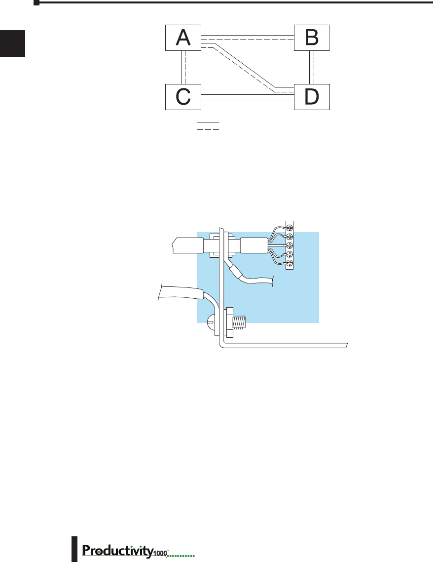
Appendix A: European Union Directives (CE)
A
2
3
4
5
6
7
8
9
10
11
12
13
14
A
B
C
D
Hardware User Manual, 1st Edition
A–6 1000
An equipotential bond wire must be provided alongside all serial communications cables, and
to any separate items of the plant which contain I/O devices connected to the programmable
controller. The diagram shows an example of four physical locations connected by a
communications cable.
Communications and Shielded Cables
Good quality 24 AWG minimum twisted-pair shielded cables, with overall foil and braid
shields are recommended for analog cabling and communications cabling outside of the
programmable controller enclosure. To date it has been a common practice to only provide
an earth ground for one end of the cable shield in order to minimize the risk of noise caused
by earth ground loop currents between apparatus. The procedure of only grounding one end,
which primarily originated as a result of trying to reduce hum in audio systems, is no longer
applicable to the complex industrial environment. Shielded cables are also efficient emitters of
RF noise from the CPU system, and can interact in a parasitic manner in networks and between
multiple sources of interference.
The recommendation is to use shielded cables as electrostatic “pipes” between apparatus and
systems, and to run heavy gauge equipotential bond wires alongside all shielded cables. When
a shielded cable runs through the metallic wall of an enclosure or machine, it is recommended
in IEC 61000–5–2 that the shield should be connected over its full perimeter to the wall,
preferably using a conducting adapter, and not via a pigtail wire connection to an earth ground
bolt. Shields must be connected to every enclosure wall or machine cover that they pass through.
Screened
Cable
Equi-potential
Bond
Control Cubicle
To Earth
Block
Conductive
Adapter
Serial
I/O
Key Serial Communication Cable
Equipotential Bond
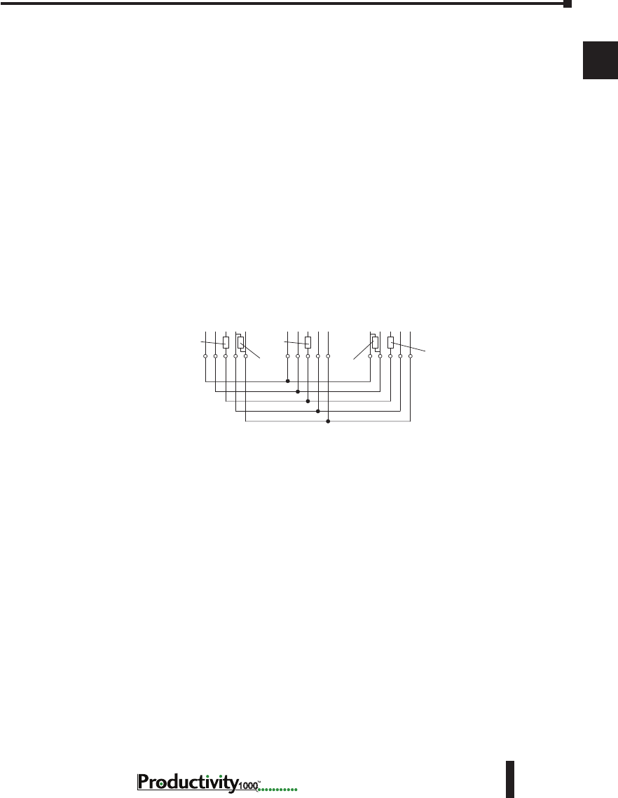
A
2
3
4
5
6
7
8
9
10
11
12
13
14
A
B
C
D
Appendix A: European Union Directives (CE)
A–7
Hardware User Manual, 1st Edition
1000
Analog and RS232 Cables
Providing an earth ground for both ends of the shield for analog circuits provides the perfect
electrical environment for the twisted pair cable as the loop consists of signal and return, in a
perfectly balanced circuit arrangement, with connection to the common of the input circuitry
made at the module terminals. RS232 cables are handled in the same way.
Multidrop Cables
RS422 twin twisted pair, and RS485 single twisted pair cables also require a 0V link, which
has often been provided in the past by the cable shield. It is now recommended that you use
triple twisted pair cabling for RS422 links, and twin twisted pair cable for RS485 links. This is
because the extra pair can be used as the 0V inter-system link. With loop DC power supplies
earth grounded in both systems, earth loops are created in this manner via the inter-system 0v
link. The installation guides encourage earth loops, which are maintained at a low impedance
by using heavy equipotential bond wires. To account for non–European installations using
single-end earth grounds, and sites with far from ideal earth ground characteristics, we
recommend the addition of 100 ohm rated resistors at each 0V link connection in network and
communications cables.
Shielded Cables Within Enclosures
When you run cables between programmable controller items within an enclosure which also
contains susceptible electronic equipment from other manufacturers, remember that these
cables may be a source of RF emissions. There are ways to minimize this risk. Standard data
cables connecting CPUs and/or operator interfaces should be routed well away from other
equipment and their associated cabling. You can make special serial cables where the cable
shield is connected to the enclosure’s earth ground at both ends, the same way as external cables
are connected.
Analog Modules and RF Interference
The readings from all analog modules will be affected by the use of devices that exhibit high
field strengths, such as mobile phones and motor drives.
All AutomationDirect products are tested to withstand field strength levels up to 10V/m,
which is the maximum required by the relevant EU standards. While all products pass this
test, analog modules will typically exhibit deviations of their readings. This is quite normal,
however, systems designers should be aware of this and plan accordingly.
When assembling a control system using analog modules, these issues must be adhered to and
should be integrated into the system design. This is the responsibility of the system builder/
commissioner.
RXD
Master
RXDTXD 0V
+– +–
Slave n
TXD 0V
+ – + –
Last Slave
RXD TXD0V
+ – + –
Termination
100 100
Termination
100
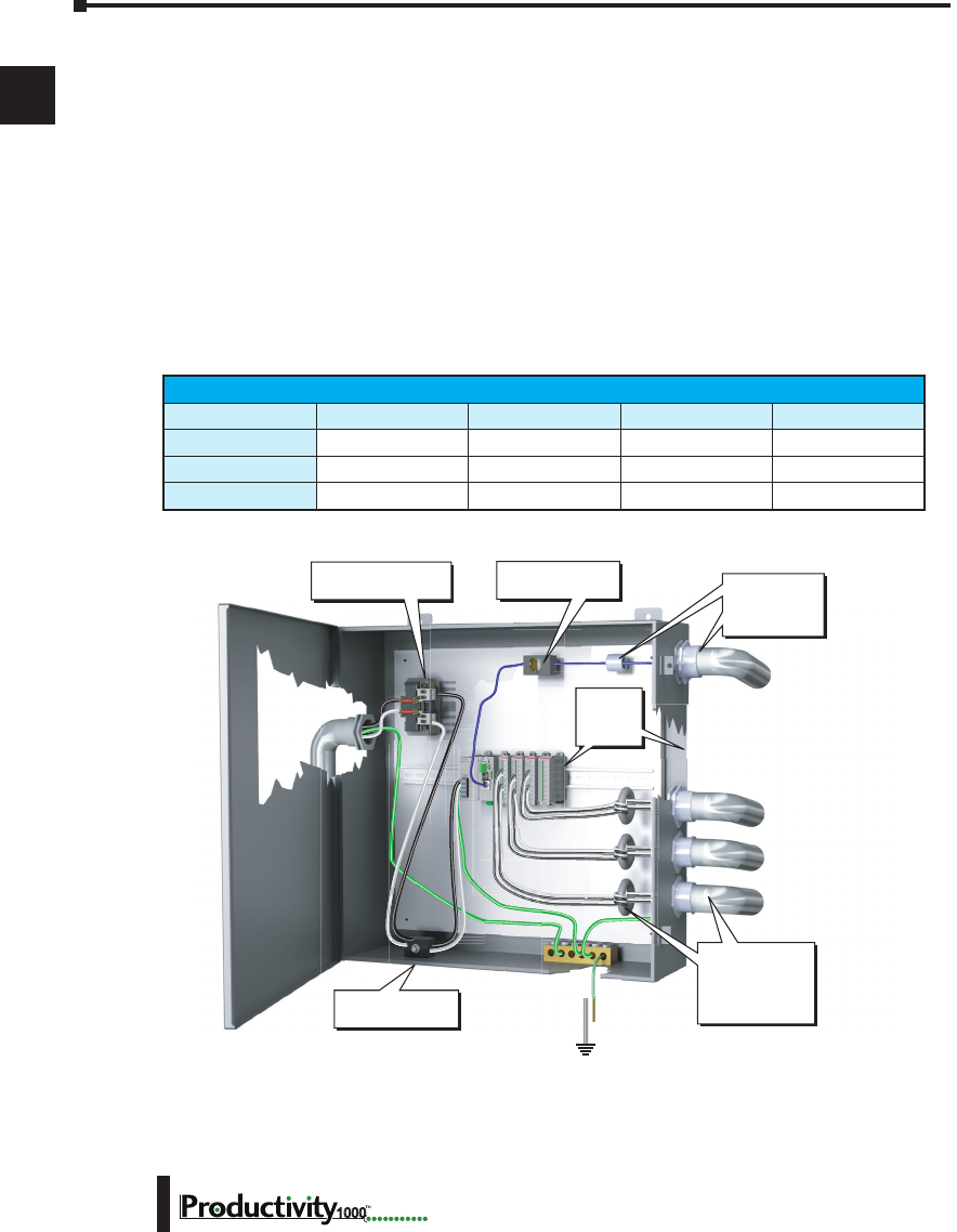
Appendix A: European Union Directives (CE)
A
2
3
4
5
6
7
8
9
10
11
12
13
14
A
B
C
D
Hardware User Manual, 1st Edition
A–8 1000
Network Isolation
For safety reasons, it is a specific requirement of the Machinery Directive that a keyswitch
must be provided that isolates any network input signal during maintenance, so that remote
commands cannot be received that could result in the operation of the machinery. To avoid
the introduction of noise into the system, any keyswitch assembly should be housed in its own
earth grounded steel box and the integrity of the shielded cable must be maintained.
Again, for further information on EU directives we recommend that you get a copy of our EU
Installation Manual (DA–EU–M) online. Also, you can check the EU Commission’s official
web site at:
http://publications.europa.eu.
It is good Engineering practice to install toroid inductors on the I/O wiring and the
communications cables such as listed in the table below.
2" (50mm)
minimum
clearance
all sides
Lockout switch for
communication
Mains Fuse/
Isolation Transformer
Pressure-sensitive
switch for power
Separate conduit
and toroid coils
for DC signals,
AC signals, and
analog signals
Toroid and
conduit for
communication
cable
Toroid Inductors
Manufacturer Mfg. Part Number Outside Diameter Inside Diameter Length
RS Online 2606795 17.5 mm 9.5 mm 28.5 mm
Fair-Rite 2643665702 17.45 mm 9.5 mm 28.6 mm
Wurth Elektronick 7427009 17.5 mm 9.5 mm 28.5 mm

A
2
3
4
5
6
7
8
9
10
11
12
13
14
A
B
C
D
Appendix A: European Union Directives (CE)
A–9
Hardware User Manual, 1st Edition
1000
Items Specific to the Productivity1000
• The rating between all circuits in this product are rated as basic insulation only, as appropriate for
single fault conditions.
• It is the responsibility of the system designer to earth one side of all control and power circuits, and
to earth the braid of screened cables.
• This equipment must be properly installed while adhering to the guidelines of the in house CPU
installation manual DA–EU–M, and the installation standards IEC 61000–5–1, IEC 61000–5–2
and IEC 61131–4.
• It is a requirement that all CPU equipment must be housed in a protective steel enclosure,
which limits access to operators by a lock and power breaker. If access is required by operators
or untrained personnel, the equipment must be installed inside an internal cover or secondary
enclosure.
• It should be noted that the safety requirements of the machinery directive standard EN60204–1
state that all equipment power circuits must be wired through isolation transformers or isolating
power supplies, and that one side of all AC or DC control circuits must be earthed.
• Both power input connections to the programmable controller must be separately fused using 3
amp T-type anti–surge fuses, and a transient suppressor fitted to limit supply overvoltages.
• If the equipment is used in a manner not specified by the manufacturer the protection provided by
the equipment may be impaired.

Appendix A: European Union Directives (CE)
A
2
3
4
5
6
7
8
9
10
11
12
13
14
A
B
C
D
Hardware User Manual, 1st Edition
A–10 1000
Notes

Productivity1000
Error codEs B
B
B
Appendix
Appendix
Appendix
In This Appendix:
Productivity1000 Error Codes .............................................................. B–1
Communications Error Codes ...................................................................................B–2
Module Error Codes .................................................................................................B–3
CPU Error Codes ......................................................................................................B–4
Project Error Codes ...................................................................................................B–5
Project Error Messages .............................................................................................B–7

Appendix B: Productivity1000 Error Codes
A
B
3
4
5
6
7
8
9
10
11
12
13
14
A
B
C
D
Hardware User Manual, 1st Edition
B–2 1000
Communications Error Codes
Error Code Description Suggested Fix
01 Function Code not supported Check instruction or connected device and correct Function
code or address range selected.
02 Address out of range. This error is typically
generated when a Modbus address has been
requested that does not exist in the CPU.
Check instruction or connected device and correct Function
code or address range selected.
03 Illegal Data Value. This error is typically generated
when the Modbus request sent to the CPU is formed
incorrectly.
Check the Modbus request against the Modbus protocol
specification (www.modbus.org) to verify that it was
formed correctly.
04 Device Failure Check connected device

Appendix B: Productivity1000 Error Codes
A
B
3
4
5
6
7
8
9
10
11
12
13
14
A
B
C
D
B–3
Hardware User Manual, 1st Edition
1000
Module Error Codes
Error Code Cause Solution
E02101 One or more module status bits are set. Examine the individual module status bits for the module(s) in
question to determine the cause of the error and appropriate
action.
E02110 Module firmware is incompatible with
project.
Recompile and transfer project to CPU. If problem persists,
upgrade module firmware to latest version, then recompile and
transfer project using latest Programming Software.
E02111 Module firmware is incompatible with
project.
Recompile and transfer project to CPU. If problem persists,
upgrade module firmware to latest version, then recompile and
transfer project using latest Programming Software.
E02112 Module configuration data is invalid. Recompile and transfer project to CPU. If problem persists,
upgrade module firmware to latest version, then recompile and
transfer project using latest Programming Software.
E02113 Module configuration data is invalid. Recompile and transfer project to CPU. If problem persists,
upgrade module firmware to latest version, then recompile and
transfer project using latest Programming Software.
E02114 Unable to configure module.
Restart CPU. If problem persists, recompile and transfer project
to CPU. If problem persists, upgrade module firmware to
latest version, then recompile and transfer project using latest
Programming Software.
E02115 Unable to configure module.
Restart CPU. If problem persists, recompile and transfer project
to CPU. If problem persists, upgrade module firmware to
latest version, then recompile and transfer project using latest
Programming Software.
E02210 Too many modules G000 P1 CPU only supports 8 modules at a time. Remove power and
remove all modules past the 8th module.
E02301 Expected module is not installed, or the
installed module is defective. Install the correct module.
E02302 Expected module is not installed, or the
installed module is defective. Install the correct module.

Appendix B: Productivity1000 Error Codes
A
B
3
4
5
6
7
8
9
10
11
12
13
14
A
B
C
D
Hardware User Manual, 1st Edition
B–4 1000
CPU Error Codes
Error Code Cause Solution
E05101 The CPU battery is low. Replace CPU’s Battery.
E05106 I2C bus has locked up. Self-recoverable. If problem persists, restart system.
E05120 The module specified has a Firmware Error. Replace the unit. If unit is in warranty, call AutomationDirect for
an RA number.
E05121 The module specified has a Hardware Error. Replace the unit. If unit is in warranty, call AutomationDirect for
an RA number.
E05122 The module specified has an Internal Error. Replace the unit. If unit is in warranty, call AutomationDirect for
an RA number.

Appendix B: Productivity1000 Error Codes
A
B
3
4
5
6
7
8
9
10
11
12
13
14
A
B
C
D
B–5
Hardware User Manual, 1st Edition
1000
Error Code Cause Solution
E03000 - E03199 Internal firmware file system error. Power cycle CPU. If problem persists, contact AutomationDirect
for repair or replacement.
E03201 - E03299 Internal firmware operating system error. Power cycle CPU. If problem persists, contact AutomationDirect
for repair or replacement.
E03301 Unable to exit RUN mode. Power cycle CPU. If problem persists, contact AutomationDirect
for repair or replacement.
E03801 - E03899 Internal firmware USB error. Problem should self recover. If problem persists, power cycle
CPU.
E03901 A scan exceeded the timeout specified in
CPU Hardware Configuration. Verify that For/Next loops are handled properly. Adjust the
timeout setting.
E04101 Scan attempted access beyond array
limits. Txxxx is task ID. Rxxxx is rung
number.
Correct problem in ladder logic or data that caused invalid
access.
E04201 Internal firmware Data Logging error. Problem should self recover. If problem persists, power cycle
CPU.
E04202 Cannot create data logging folder. Ensure a supported storage device is properly installed in USB
OUT port on CPU. If problem persists, restart system.
E04203 Cannot write data to data logging storage
device.
Ensure a supported storage device is properly installed in USB
OUT port on CPU. If problem persists, restart system.
E04204 Internal firmware Data Logging buffer is
greater than 50% full. Problem should self recover. If problem persists, power cycle
CPU.
E04205 Internal firmware Data Logging buffer
overflow.
Problem should self recover. If problem persists, power cycle
CPU.
E04210 Invalid system ID found while loading
project. Load new project.
E04220 Email instruction failed. Problem should self recover. If problem persists, power cycle
CPU.
E04300 - E04302 A project file is missing. Load new project.
E04303 Internal firmware project loader failure. Problem should self recover. If problem persists, power cycle
CPU.
E04304 Project load failure limit exceeded.
Project has been removed. Load new project.
E04305 - E04306 Internal firmware project loader failure. Problem should self recover. If problem persists, power cycle
CPU. If problem persists, load new project.
E04307 Project file corrupt. Load new project.
E04308 - E04315 Internal firmware project loader failure. Load new project.
Project Error Codes

Appendix B: Productivity1000 Error Codes
A
B
3
4
5
6
7
8
9
10
11
12
13
14
A
B
C
D
Hardware User Manual, 1st Edition
B–6 1000
Project Error Codes - Continued
Error Code Cause Solution
E04316 Project upload failed. Retry the process.
E04317 Internal firmware project loader failure., Load new project.
E04318 Modbus TCP connection limit exceeded. Reduce the number of concurrently enabled MRX, MWX, RX
and WX Instructions to no more than 64.
E04319 Internal error. Self-recoverable, if problem persists restart CPU.
E04320 One or more RS232 parameters contain invalid
values. Verify that all RS232 parameters in project contain valid settings.
E04321 One or more RS485 parameters contain invalid
values. Verify that all RS485 parameters in project contain valid settings.

Appendix B: Productivity1000 Error Codes
A
B
3
4
5
6
7
8
9
10
11
12
13
14
A
B
C
D
B–7
Hardware User Manual, 1st Edition
1000
Project Error Messages
Error Message Cause Solution
Cannot create a task with the name
‘<taskname>’ because a task with that
name already exists.
The name of the new task already exists. Create a unique task name.
The help file ‘<helpfilename>’
cannot be found.
The help file cannot be found in the
location that it was installed.
Re-install the software. The
ProductivitySuite Help file: P3-HELP.chm
should be located in the following folder:
C:\ProgramFiles\AutomationDirect\
ProductivitySuite x.x.x.x\data\help
The topic ‘<topicname>’ does not
exist.
A referenced help topic has either been
changed, moved, or deleted from the help
file.
Re-install the software or download the
Latest Help File version.
Task name cannot be empty. An attempt was made to create a task
without a task name. Create a unique task name.
The task name has an invalid
character ‘<taskname>’.
An attempt was made to create a task with
an invalid character in the name. Create a unique task name using valid
characters only.
The task name ‘<taskname>’ already
exists. The name of the new task already exists. Create a unique task name.
Tagname cannot be all digits. A tagname that consists of only digits was
entered. There must be at least one letter in a
tagname.
Cannot complete the operation
because the P1-540 folder already
exists.
The P1-540 folder already exists on the
target removable USB drive and the create
folder option is checked.
Uncheck the create folder option in the
dialog and try transfer again.
Cannot complete the operation
because the P1-540 folder does not
exist.
The P1-540 folder does not exist on the
target removable USB drive and the create
option is not checked.
Check the create folder option in the dialog
and try transfer again.
Cannot complete the operation due to
failure to create the P1-540 folder. System could not create the P1-540 folder. This might be due to a read only drive.
Failed to reboot CPU. CPU failed to reboot. Reboot CPU again or cycle power.
Failed to get CPU date & time from
CPU. CPU failed to return date & time data. Check CPU to PC connection.
Failed to set CPU date & time. CPU failed to set date & time. Check CPU to PC connection.
CPU does not exist. A CPU does not exist in the configuration.
Add a CPU to the hardware configuration
or connect to the CPU and select
“read configuration” in the Hardware
Configuration dialog.
Rebooting the CPU failed. CPU failed to reboot. Reboot CPU again or Cycle power
The IP address
‘<IP Address>’ is already on the
network. Please use a different
address.
The new CPU IP address is used by
another entity on the network.
Select a unique IP address. You may need
to contact your networks IT department
to verify.
Cannot change CPU name. Failed to change CPU name due to a CPU
error or a network problem Check CPU to PC connection.

Appendix B: Productivity1000 Error Codes
A
B
3
4
5
6
7
8
9
10
11
12
13
14
A
B
C
D
Hardware User Manual, 1st Edition
B–8 1000
Error Message Cause Solution
Cannot change IP configuration due
to CPU error. CPU failed to change IP configuration. Check CPU to PC connection and network
configuration. Connections through a
router may also cause conflicts.
Cannot change IP configuration due
to network problem.
CPU failed to respond to the IP
configuration request.
Check CPU to PC connection and network
configuration. Connections through a
router may also case conflicts.
Could not connect to the CPU. CPU is not able to be connected. Check CPU to PC connection.
Could not disconnect the CPU. CPU is not able to be disconnected. Check CPU to PC connection.
Could not connect to the selected
CPU. Failed to validate security on connection. Check CPU to PC connection and required
security passwords.
Cannot blink CPU due to CPU error. CPU failed to blink CPU run light. Check CPU to PC connection and clear
existing CPU errors.
Cannot blink CPU due to network
problem. CPU failed to respond to the blink request. Check CPU to PC connection and network
configuration. Connections through a
router may also cause conflicts.
Failed to retrieve I/O inventory from
CPU ‘<CPU Name>’.
CPU failed to respond to the inventory
request.
Check CPU to PC connection and request
again.
Failed to put the CPU to run mode. CPU is not able to be put in run mode. CPU mode switch must be in the Run
position and errors cleared.
Failed to put the CPU to stop mode. CPU is not able to be put in stop mode. Check CPU to PC connection.
Failed to put the CPU to debug mode. CPU is not able to be put in debug mode. Check CPU to PC connection. CPU must be
in STOP before entering debug mode.
CPU has existing connection. CPU cannot be connected since it has
already connected to another software. Verify existing connections.
Failed to put the CPU into <CPU
Mode> mode because CPU
connection is lost.
CPU connection is lost while setting CPU
mode. Check CPU to PC connection.
Project Error Messages - Continued

Appendix B: Productivity1000 Error Codes
A
B
3
4
5
6
7
8
9
10
11
12
13
14
A
B
C
D
B–9
Hardware User Manual, 1st Edition
1000
Error Message Cause Solution
Failed to put the CPU into <CPU
Mode> mode because CPU has
existing critical error.
Cannot set CPU mode due to critical errors
on the CPU. Check CPU to PC connection and clear
errors.
Failed to put the CPU into run mode
because the CPU switch is set to the
STOP position.
Cannot set CPU to run mode since the run/
stop switch is in the stop position. Place the CPU switch in Run.
Could not connect to the detected
CPU.
An unknown failure occurred on
connection. Check CPU to PC connection.
You do not have permission to access
this feature.
The security setup does not allow the current
user to perform this operation. Check CPU to PC connection and required
security passwords.
You need to specify a user name. The name on a user account was deleted
while editing the profile. Specify the user name.
You need to specify a password. The password on a user account was
deleted while editing the profile. Specify the password.
The two passwords do not match. The password on a user account was
changed and the verification does not
match the new value.
Re-enter the password and check to make
sure both are the same.
At least one user needs to have
“Project Transfer From CPU and
Monitor Data” selected to enable the
protection feature.
Project Transfer from CPU and Data
Monitor security was enabled without a
user with these rights currently defined.
Define at least one user with the
appropriate project transfer rights.
At least one user needs to have
“Project Transfer To CPU” selected
to enable the protection feature.
Project Transfer to CPU security was
enabled without a user with these rights
currently defined.
Define at least one user with the
appropriate project transfer rights.
You must connect to a CPU first.
User tried to Set Factory Defaults, Reboot
the CPU, Read the SRAM, or Clear CPU
Memory without first being connected to
the CPU.
Check CPU to PC connection.
The current project does not contain
a CPU in the configuration. Go to:
Setup>Hardware Config to correct the
problem.
The user tried to download a project that
does not contain a CPU to the CPU or USB
Pen Drive.
Add a CPU to the hardware configuration
or connect to the CPU and in the hardware
configurations dialog select “read
configuration”.
The CPU firmware is in service
mode. The requested action is not
available in this mode.
The user tried to transfer a project to a CPU
that is in Service Mode.
Check CPU to PC connection and upgrade
firmware.
Please select a search result first. In the Find dialog, User pressed the GoTo
button before selecting an entry in the
Search Results list. Define your search criteria and try again.
Incorrect Key Code. User entered an invalid license keycode. Verify correct key code was entered.
Pay close attention to capitalization, and
mixture of letters and numbers.
Project Error Messages - Continued

Appendix B: Productivity1000 Error Codes
A
B
3
4
5
6
7
8
9
10
11
12
13
14
A
B
C
D
Hardware User Manual, 1st Edition
B–10 1000
NOTES:
