ADAM 6000 Manual I/O Module 5000 Series Para Alumnos 6017
User Manual: I/O Module 5000 Series
Open the PDF directly: View PDF ![]() .
.
Page Count: 10
ADAM-60174402-1/1
© 2002 by B&B Electronics. All rights reserved.
International Headquarters:
707 Dayton Road P.O. Box 1040 Ottawa, IL 61350 USA
815-433-5100 Fax 433-5104
www.bb-elec.com orders@bb-elec.com support@bb-elec.com
Westlink Commercial Park Oranmore Co. Galway Ireland
+353 91 792444 Fax +353 91 792445
www.bb-europe.com orders@bb-elec.com support@bb-europe.com
Integrate
–
Expand
–
Simplify B&B ELECTRONICS PRODUCT INFORMATION
PRODUCT INFORMATION
PRODUCT INFORMATION
PRODUCT INFORMATION
Model: ADAM-6017
8-channel Analog Input
with Digital Output Module
Overview
The ADAM-6017 is designed with 8-channel analog inputs and 2 digital outputs to satisfy all plant needs. Each
analog channel is allowed to configure an individual range for variety of applications. Provides math functions: Max.,
Min., Avg.
This Ethernet-enabled data acquisition and control module features I/O, data acquisition, web browser and
networking capabilities all in one module. 10/100 Mbps communication rate and 2000 VRMS surge protection.
Features
Communication rate: 10/100 Mbps
I/O type: 8 AI / 2 DO
Input type: mV, V, mA
Surge protection: 2000VRMS
Provides math functions: Max., Min., Avg.
Provides default/customized web page
Analog Input
Effective resolution: 16-bit
Channels: 8 differential
Input type: mV, V, mA
Input range: ±150 mV, ±500 mV, 0-5 V, ±10 V, 0-20 mA, 4-20 mA
Isolation voltage: 2000 V DC
Fault and overvoltage protection: Withstands up to ±35 V
Sampling rate: 10 samples/sec.
Input impedance: 20 W
Bandwidth: 13.1 Hz @ 50 Hz,
15.72 @ 60 Hz
Accuracy: ±0.1% or better
Zero drift: ±6 µV/ ºC
Span drift: ±25 ppm/ ºC
CMR @ 50/60: 92 dB min.
Digital Output
Channels: 2
Open collector to 30 V
200 mA max. load
Optical isolation: 5000 VRMS
Power
Requirements: Unregulated +10 ~ +30 V DC
Consumption: 2 W
Built-in Watchdog Timer
4-1 Analog Input Module
Analog input modules use an A/D converter to convert sensor voltage, current, thermocouple or RTD
signals into digital data. The digital data is then translated into engineering units. When prompted by the
host computer, the data is sent through a standard 10/100 based-T Ethernet interface. Users would able
to read the current status via pre-built web page or any HMI software package supported Modbus/TCP
protocol. The analog input modules protect your equipment from ground loops and power surges by
providing opto-isolation of the A/D input and trans-former based isolation up to 3,000 VDC .
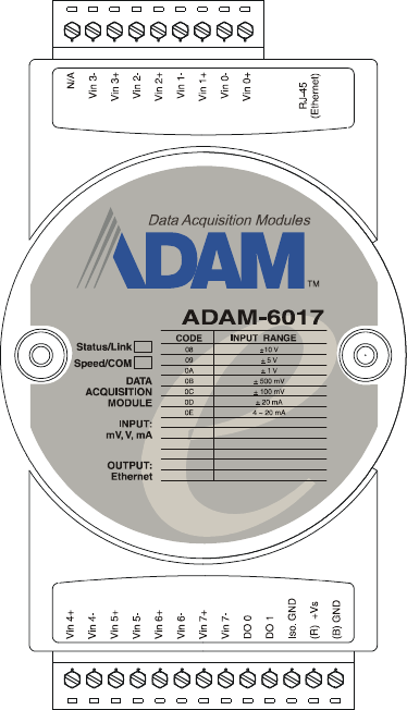
ADAM-6017 8-channel Analog Input with 2/DO Module
The ADAM-6017 is a 16-bit, 8-channel analog differential input module that provides programmable
input ranges on all channels. It accepts millivoltage inputs (±100mV, ±500mV), voltage inputs (±1V, ±5V
and ±10V) and current input (±20 mA, 4~20 mA) and provides data to the host computer in engineering
units (mV, V or mA). In order to satisfy all plant needs in one module, ADAM-6017 has designed with 8
analog inputs and 2 digital outputs. Each analog channel is allowed to configure an individual range for
variety of applications.
ADAM-6017
Figure 4-1: ADAM-6017 8-channel Analog Input w/2DO Module
ADAM-6017 Specification
Analog Input:
• Effective resolution: 16-bit
• Channels: 8 differential
• lnput type: mV, V, mA
• lnput range: ±150 mV, ±500 mV, ±1 V, ±5 V, ±10 V, 0-20 mA, 4-20 mA
• Isolation voltage: 3000 VDC
• Fault and overvoltage protection: Withstands overvoltage up to ±35 V
• Sampling rate: 10 samples/sec.
• Input impedance: 20 M ohm
• Bandwidth: 13.1 Hz @ 50 Hz, 15.72 Hz @ 60 Hz
• Accuracy: ±0.1% or better
• Zero drift: ±6 µV/° C
• Span drift: ±25 ppm/° C
• CMR @ 50/60 Hz: 92 dB min.
Digital Output:
• Channel: 2
Open Collector to 30 V
200 mA max. load
• Optical Isolation: 5000VRMS
Built-in Watchdog Timer
Power
• Power requirements: Unregulated +10 ~ +30 VDC
• Power consumption: 2 W
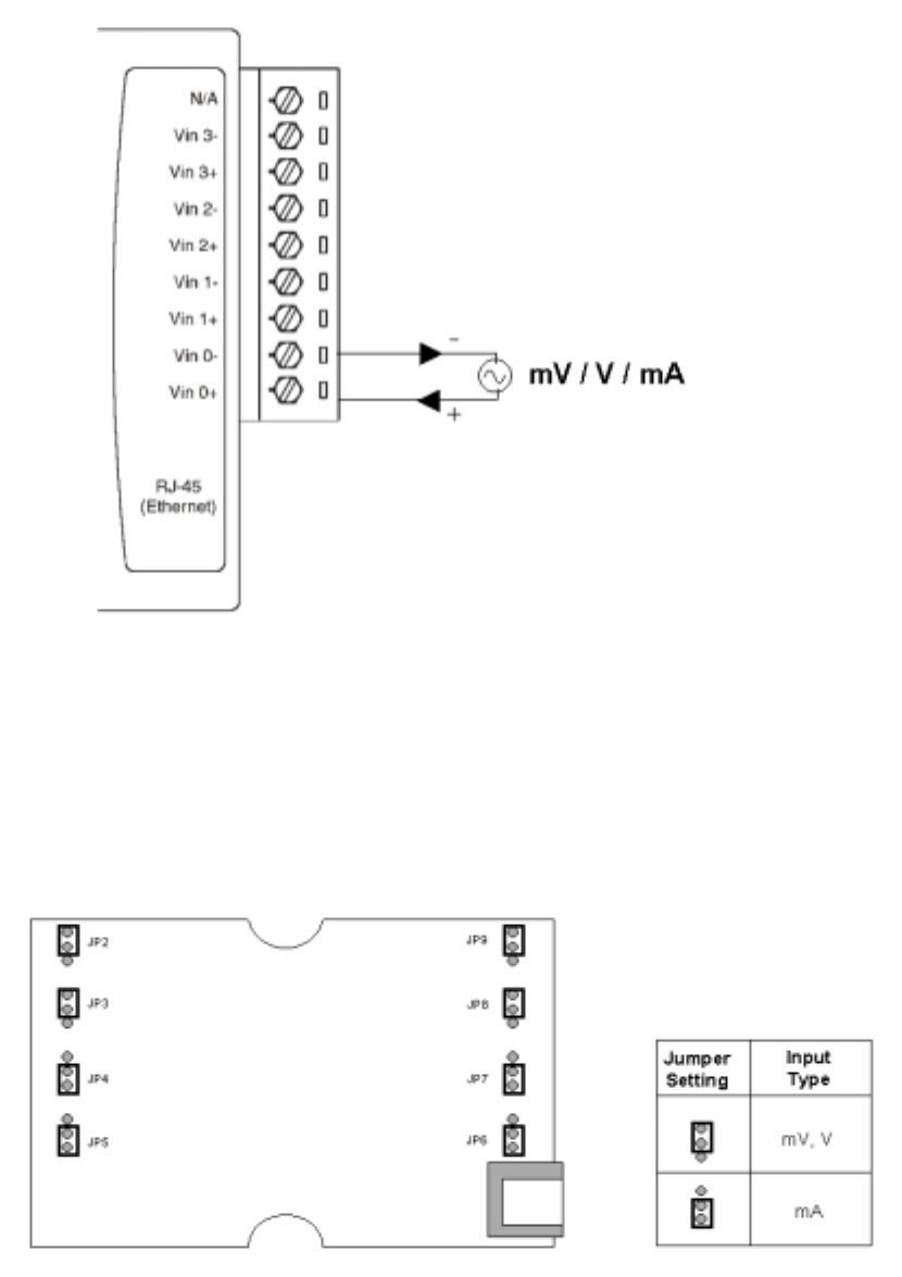
Application Wiring
Figure 4-2: ADAM-6017 millivoltage, voltage, and current Input Wiring
ADAM-6017 has built with a 120 ohms resistor in each channel, users do not have to add any resistors
in addition for current input measurement. Just adjust the jumper setting to choose the specific input
type you need. Refer to Figure 4-3, each analog input channel has built-in a jumper on the PCB for
users to set as a voltage mode or current mode.
Figure 4-3: ADAM-6017 Analog Input Type Setting
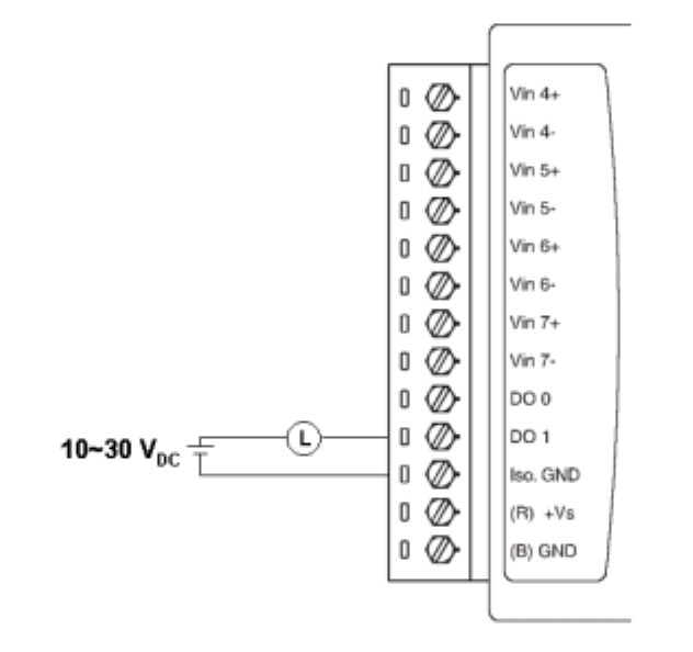
Figure 4-4: ADAM-6017 Digital Output wiring
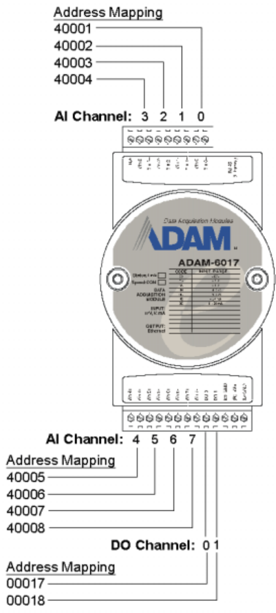
Assigning address for ADAM-6017 Modules
Basing on Modbus/TCP standard, the addresses of the I/O channels in ADAM-6000 modules you place
in the system are defined by a simple rule. Please refer the Figures 4-5 to map the I/O address.
Figure 4-5: ADAM-6017 I/O Address Mapping
6-3 ADAM-6000 Commands
ADAM-6000 and ADAM-5000/TCP system accept a command/response form with the host computer.
When systems are not transmitting they are in listen mode. The host issues a command to a system
with a specified address and waits a certain amount of time for the system to respond. If no response
arrives, a time-out aborts the sequence and returns control to the host. This chapter explains the
structure of the commands with Modbus/TCP protocol, and guides to use these command sets to
implement user’s programs.
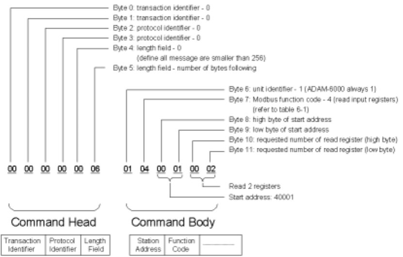
6-3-1 Command Structure
It is important to understand the encapsulation of a Modbus request or response carried on the
Modbus/TCP network. A complete command is consisted of command head and command body. The
command head is prefixed by six bytes and responded to pack Modbus format; the command body
defines target device and requested action. Following example will help you to realize this structure
quickly.
Example:
If you want to read the first two values of ADAM-6017 (address: 40001~40002), the request command
should be:
Figure 6-1 Request Comment Structure
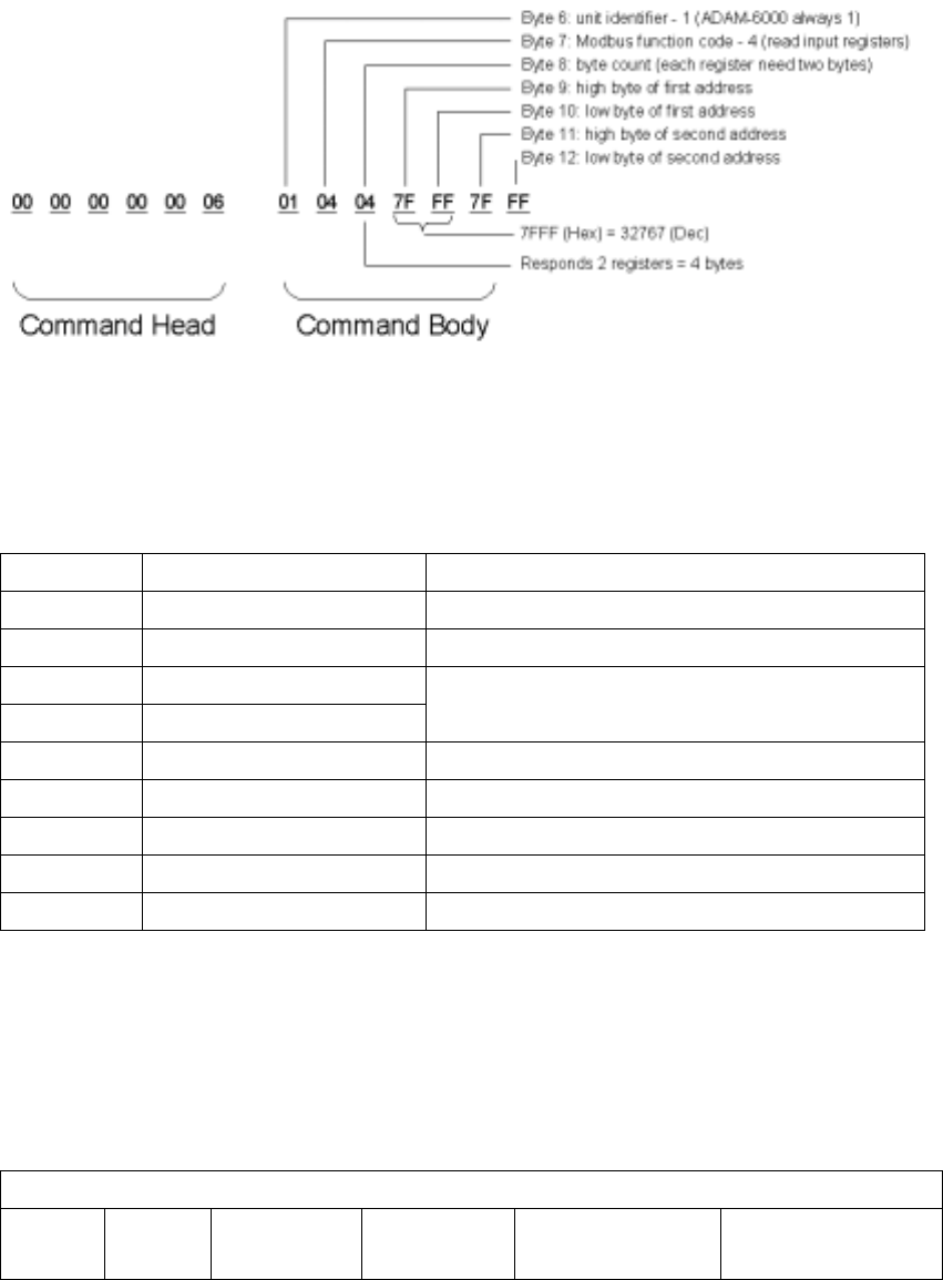
And the response should be:
Figure 6-2 Response Comment Structure
6-3-2 Modbus Function Code Introductions
To full-fill the programming requirement, there is a series of function code standard for user’s
reference…
Code (Hex) Name Usage
01 Read Coil Status Read Discrete Output Bit
02 Read Input Status Read Discrete Input Bit
03 Read Holding Registers
04 Read Input Registers
Read 16-bit register. Used to read integer
or floating point process data.
05 Force Single Coil Write data to force coil ON/OFF
06 Preset Single Register Write data in 16-bit integer format
08 Loopback Diagnosis Diagnostic testing of the communication port
15 Force Multiple Coils Write multiple data to force coil ON/OFF
16 Preset Multiple Registers Write multiple data in 16-bit integer format
Table 6-1 Response Comment Structure
Function Code 01
The function code 01 is used to read the discrete output’s ON/OFF status of ADAM-6000 modules in a
binary data format.
Request message format for function code 01:
Command Body
Station
Address Function
Code Start Address
High Byte Start Address
Low Byte Requested Number
of Coil High Byte Requested Number
of Coil Low Byte
Example: Read coil number 1 to 8 (address number 00017 to 00024) from ADAM-6000 Modules
01 01 00 17 00 08
07

Response message format for function code 01:
Command Body
Station
Address Function
Code Byte
Count Data Data …
Example: Coils number 2 and 7 are on, all others are off.
01 01 01 42
In the response the status of coils 1 to 8 is shown as the byte value 42 hex, equal to 0100 0010
binary.
Function Code 02
The function code 02 is used to read the discrete input’s ON/OFF status of ADAM-6000 in a binary data
format.
Request message format for function code 02:
Command Body
Station
Address Function
Code Start Address
High Byte Start Address
Low Byte Requested Number
of Input High Byte Requested Number
of Input Low Byte
Example: Read coil number 1 to 8 (address number 00001 to 00008) from ADAM-6000 modules
01 01 00 01 00 08
Response message format for function code 02:
Command Body
Station
Address Function
Code Byte
Count Data Data …
Example: input number 2 and 3 are on, all others are off.
01 01 01 60
In the response the status of input 1 to 8 is shown as the byte value 60 hex, equal to 0110 0000
binary.
Function Code 03/04
The function code 03 or 04 is used to read the binary contents of input registers
Request message format for function code 03 or 04:
Command Body
Station
Address Function
Code Start Address
High Byte Start Address
Low Byte Requested Number
of Register High Byte Requested Number
of Register Low Byte
Example: Read Analog inputs #1 and #2 in addresses 40001 to 40002 as floating point value from
ADAM-6017 module
01 04 00 01 00 02

Response message format for function code 03 or 04:
Command Body
Station
Address Function
Code Byte
Count Data Data …
Example: Analog input #1 and #2 as floating point values where AI#1=100.0 and AI#2=55.32
01 04 08 42 C8 00 00 47 AE 42 5D
Function Code 05
Force a single coil to either ON or OFF. The requested ON/OFF state is specified by a constant in the
query data field. A value of FF 00 hex requests it to be ON. A value of 00 00 hex requests it to be OFF.
And a value of FF FF hex requests it to release the force.
Request message format for function code 05:
Command Body
Station
Address Function
Code Coil Address
High Byte Coil Address
Low Byte Force Data
High Byte Force Data
Low Byte
Example: Force coil 3 (address 00003) ON in ADAM-6000 module
01 05 00 03 FF 00
Response message format for function code 05:
The normal response is an echo of the query, returned after the coil state has been forced.
Command Body
Station
Address Function
Code Coil Address
High Byte Coil Address
Low Byte Force Data
High Byte Force Data
Low Byte
Function Code 06
Presets integer value into a single register.
Request message format for function code 06:
Command Body
Station
Address Function
Code Register Address
High Byte Register Address
Low Byte Preset Data
High Byte Preset Data
Low Byte
Example: Preset register 40002 to 00 04 hex in ADAM-6000 module
01 06 00 02 00 04
Response message format for function code 06:
The normal response is an echo of the query, returned after the coil state has been preset.
Command Body
Station
Address Function
Code Register Address
High Byte Register Address
Low Byte Preset Data
High Byte Preset Data
Low Byte
