PCR M30_M50_M80_e Roland Corporation M80 Owner's Manual M30 M50 Om
Roland Corporation PCR-M50 Owner's Manual pcr-m30_m50_m80_om Roland Corporation - PCR-M50 - Owner's Manual
Roland Corporation PCR-M30 Owner's Manual pcr-m30_m50_m80_om Roland Corporation - PCR-M30 - Owner's Manual
Roland Corporation PCR-M80 Owner's Manual pcr-m30_m50_m80_om Roland Corporation - PCR-M80 - Owner's Manual
Roland Corporation PCR-M50 Owner's Manual pcr-m30_m50_m80_om Roland Corporation - PCR-M50 - Owner's Manual
Roland Corporation PCR-M30 Owner's Manual pcr-m30_m50_m80_om Roland Corporation - PCR-M30 - Owner's Manual
User Manual: Roland Corporation PCR-M80 Owner's Manual Roland Corporation - PCR-M80 - Owner's Manual
Open the PDF directly: View PDF ![]() .
.
Page Count: 124 [warning: Documents this large are best viewed by clicking the View PDF Link!]
- Important Notes
- Contents
- Contents of the package
- Quick page reference table
- Names of things and what they do
- Setup
- Operation
- Basic connections and MIDI flow
- Input / output devices
- Use MIDI functionality
- Table of operating modes
- Startup mode
- Features Useful When Playing
- Setting the MIDI Transmit Channel
- Selecting Sounds on a Sound Module (Sending Program Change / Bank Select Massages)
- Transmitting a Reset message (What to do if there are “stuck” MIDI notes)
- Changing the Memory Sets
- Transmitting the current controller values all at once
- Assign MIDI messages
- Copying a MIDI message assignment (ASSIGN COPY)
- Canceling a MIDI message assignment (NO ASSIGN)
- Saving a Memory Set (SAVE)
- Transmitting/receiving bulk data (BULK)
- Protecting a Memory Set (PROTECT)
- System settings
- F8 CLOCK ON / OFF (Keyboard: 0)
- F8 CLOCK DEFAULT TEMPO (Keyboard: 1)
- F8 CLOCK PORT SET (Keyboard: 2)
- VELOCITY CURVE (Keyboard: 3)
- KEYBOARD PORT SET (Keyboard: 4)
- H-ACTIVITY ON / OFF (Keyboard: 5)
- USB MIDI DRIVER MODE (Keyboard: 6)
- STARTUP MEMORY (Keyboard: 7)
- FACTORY RESET (Keyboard: 8)
- MIDI I/F MODE (Keyboard: 9)
- KEY VELOCITY(Keyboard: A)
- V-LINK mode
- Appendices
- index
Owner’s Manual
Thank you for purchasing the MIDI keyboard controller PCR-M30/
50/80.
Copyright © 2004 ROLAND CORPORATION
All rights reserved. No part of this publication may be reproduced in
any form without the written permission of ROLAND CORPORATION.
Before using this unit, carefully read the sections entitled:
“USING THE UNIT SAFELY” and “IMPORTANT NOTES”
(OWNER’S MANUAL pp. 2–4). These sections provide
important information concerning the proper operation of
the unit. Additionally, in order to feel assured that you have
gained a good grasp of every feature provided by your new
unit, Owner’s manual should be read in its entirety. The
manual should be saved and kept on hand as a convenient
reference.
03789401 4MP
Owner’s Manual
To resize thickness, move all items on the front cover
and center registration marks to left or right.
As of December 1, 2005 (EDIROL-1)
Information
When you need repair service, call your nearest EDIROL/Roland Service Center or authorized
EDIROL/Roland distributor in your country as shown below.
EUROPE
EDIROL (Europe) Ltd.
Studio 3.4 114 Power Road
London W4 5PY
U. K.
TEL: +44 (0)20 8747 5949
FAX:+44 (0)20 8747 5948
http://www.edirol.com/europe
Deutschland
TEL: 0700 33 47 65 20
France
TEL: 0810 000 371
Italia
TEL: 02 93778329
CANADA
Roland Canada Music Ltd.
(Head Office)
5480 Parkwood Way Richmond
B. C., V6V 2M4 CANADA
TEL: (604) 270 6626
Roland Canada Music Ltd.
(Toronto Office)
170 Admiral Boulevard
Mississauga On L5T 2N6
CANADA
TEL: (905) 362 9707
U. S. A.
Roland Corporation U.S.
5100 S. Eastern Avenue
Los Angeles, CA 90040-2938,
U. S. A.
TEL: (323) 890 3700
EGYPT
Al Fanny Trading Office
9, EBN Hagar A1 Askalany
Street,
ARD E1 Golf, Heliopolis,
Cairo 11341, EGYPT
TEL: 20-2-417-1828
REUNION
Maison FO - YAM Marcel
25 Rue Jules Hermann,
Chaudron - BP79 97 491
Ste Clotilde Cedex,
REUNION ISLAND
TEL: (0262) 218-429
SOUTH AFRICA
Paul Bothner(PTY)Ltd.
Royal Cape Park, Unit 24
Londonderry Road, Ottery 7800
Cape Town, SOUTH AFRICA
TEL: (021) 799 4900
CHINA
Roland Shanghai Electronics
Co.,Ltd.
5F. No.1500 Pingliang Road
Shanghai 200090, CHINA
TEL: (021) 5580-0800
Roland Shanghai Electronics
Co.,Ltd.
(BEIJING OFFICE)
10F. No.18 3 Section Anhuaxili
Chaoyang District Beijing
100011 CHINA
TEL: (010) 6426-5050
Roland Shanghai Electronics
Co.,Ltd.
(GUANGZHOU OFFICE)
2/F., No.30 Si You Nan Er Jie
Yi Xiang, Wu Yang Xin Cheng,
Guangzhou 510600, CHINA
TEL: (020) 8736-0428
HONG KONG
Parsons Music Ltd.
8th Floor, Railway Plaza, 39
Chatham Road South, T.S.T,
Kowloon, HONG KONG
TEL: 2333 1863
INDIA
Rivera Digitec (India) Pvt. Ltd.
409, Nirman Kendra
Mahalaxmi Flats Compound
Off. Dr. Edwin Moses Road,
Mumbai-400011, INDIA
TEL: (022) 2493 9051
INDONESIA
PT Citra IntiRama
J1. Cideng Timur No. 15J-150
Jakarta Pusat
INDONESIA
TEL: (021) 6324170
KOREA
Cosmos Corporation
1461-9, Seocho-Dong,
Seocho Ku, Seoul, KOREA
TEL: (02) 3486-8855
MALAYSIA/
SINGAPORE
Roland Asia Pacific Sdn. Bhd.
45-1, Block C2, Jalan PJU 1/39,
Dataran Prima, 47301 Petaling
Jaya, Selangor, MALAYSIA
TEL: (03) 7805-3263
PHILIPPINES
G.A. Yupangco & Co. Inc.
339 Gil J. Puyat Avenue
Makati, Metro Manila 1200,
PHILIPPINES
TEL: (02) 899 9801
TAIWAN
ROLAND TAIWAN
ENTERPRISE CO., LTD.
Room 5, 9fl. No. 112 Chung
Shan N.Road Sec.2, Taipei,
TAIWAN, R.O.C.
TEL: (02) 2561 3339
THAILAND
Theera Music Co. , Ltd.
330 Verng NakornKasem, Soi
2, Bangkok 10100, THAILAND
TEL: (02) 2248821
VIETNAM
SAIGON MUSIC
DISTRIBUTOR
(TAN DINH MUSIC)
138 Tran Quang Khai Street
Dist. 1, Ho Chi Minh City
VIETNAM
TEL: (08) 848-4068
AUSTRALIA/
NEW ZEALAND
Roland Corporation
Australia Pty.,Ltd.
38 Campbell Avenue
Dee Why West. NSW 2099
AUSTRALIA
For Australia
Tel: (02) 9982 8266
For New Zealand
Tel: (09) 3098 715
ARGENTINA
Instrumentos Musicales S.A.
Av.Santa Fe 2055
(1123) Buenos Aires
ARGENTINA
TEL: (011) 4508-2700
BARBADOS
A&B Music Supplies LTD
12 Webster Industrial Park
Wildey, St.Michael, Barbados
TEL: (246)430-1100
BRAZIL
Roland Brasil Ltda.
Rua San Jose, 780 Sala B
Parque Industrial San Jose
Cotia - Sao Paulo - SP, BRAZIL
TEL: (011) 4615 5666
CHILE
Comercial Fancy II S.A.
Rut.: 96.919.420-1
Nataniel Cox #739, 4th Floor
Santiago - Centro, CHILE
TEL: (02) 688-9540
COLOMBIA
Centro Musical Ltda.
Cra 43 B No 25 A 41 Bododega 9
Medellin, Colombia
TEL: (574)3812529
CURACAO
Zeelandia Music Center Inc.
Orionweg 30
Curacao, Netherland Antilles
TEL:(305)5926866
DOMINICAN REPUBLIC
Instrumentos Fernando Giraldez
Calle Proyecto Central No.3
Ens.La Esperilla
Santo Domingo,
Dominican Republic
TEL:(809) 683 0305
ECUADOR
Mas Musika
Rumichaca 822 y Zaruma
Guayaquil - Ecuador
TEL:(593-4)2302364
GUATEMALA
Casa Instrumental
Calzada Roosevelt 34-01,zona 11
Ciudad de Guatemala
Guatemala
TEL:(502) 599-2888
HONDURAS
Almacen Pajaro Azul S.A. de C.V.
BO.Paz Barahona
3 Ave.11 Calle S.O
San Pedro Sula, Honduras
TEL: (504) 553-2029
MARTINIQUE
Musique & Son
Z.I.Les Mangle
97232 Le Lamantin
Martinique F.W.I.
TEL: 596 596 426860
Gigamusic SARL
10 Rte De La Folie
97200 Fort De France
Martinique F.W.I.
TEL: 596 596 715222
MEXICO
Casa Veerkamp, s.a. de c.v.
Av. Toluca No. 323, Col. Olivar
de los Padres 01780 Mexico
D.F. MEXICO
TEL: (55) 5668-6699
NICARAGUA
Bansbach Instrumentos
Musicales Nicaragua
Altamira D'Este Calle Principal
de la Farmacia 5ta.Avenida
1 Cuadra al Lago.#503
Managua, Nicaragua
TEL: (505)277-2557
IRELAND
Roland Ireland
G2 Calmount Park, Calmount
Avenue, Dublin 12
Republic of IRELAND
TEL: (01) 4294444
ITALY
Roland Italy S. p. A.
Viale delle Industrie 8,
20020 Arese, Milano, ITALY
TEL: (02) 937-78300
NORWAY
Roland Scandinavia Avd.
Kontor Norge
Lilleakerveien 2 Postboks 95
Lilleaker N-0216 Oslo
NORWAY
TEL: 2273 0074
POLAND
MX MUSIC SP.Z.O.O.
UL. Gibraltarska 4.
PL-03664 Warszawa POLAND
TEL: (022) 679 44 19
PORTUGAL
Roland Iberia, S.L.
Portugal Office
Cais das Pedras, 8/9-1 Dto
4050-465, Porto, PORTUGAL
TEL: 22 608 00 60
ROMANIA
FBS LINES
Piata Libertatii 1,
535500 Gheorgheni,
ROMANIA
TEL: (266) 364 609
RUSSIA
MuTek
Dorozhnaya ul.3,korp.6
117 545 Moscow, RUSSIA
TEL: (095) 981-4967
SPAIN
Roland Iberia, S.L.
Paseo García Faria, 33-35
08005 Barcelona SPAIN
TEL: 93 493 91 00
SWEDEN
Roland Scandinavia A/S
SWEDISH SALES OFFICE
Danvik Center 28, 2 tr.
S-131 30 Nacka SWEDEN
TEL: (0)8 702 00 20
SWITZERLAND
Roland (Switzerland) AG
Landstrasse 5, Postfach,
CH-4452 Itingen,
SWITZERLAND
TEL: (061) 927-8383
UKRAINE
TIC-TAC
Mira Str. 19/108
P.O. Box 180
295400 Munkachevo,
UKRAINE
TEL: (03131) 414-40
UNITED KINGDOM
Roland (U.K.) Ltd.
Atlantic Close, Swansea
Enterprise Park, SWANSEA
SA7 9FJ,
UNITED KINGDOM
TEL: (01792) 702701
BAHRAIN
Moon Stores
No.16, Bab Al Bahrain Avenue,
P.O.Box 247, Manama 304,
State of BAHRAIN
TEL: 17 211 005
PERU
Audionet
Distribuciones Musicales SAC
Juan Fanning 530
Miraflores
Lima - Peru
TEL: (511) 4461388
TRINIDAD
AMR Ltd
Ground Floor
Maritime Plaza
Barataria Trinidad W.I.
TEL: (868)638 6385
URUGUAY
Todo Musica S.A.
Francisco Acuna de Figueroa 1771
C.P.: 11.800
Montevideo, URUGUAY
TEL: (02) 924-2335
VENEZUELA
Instrumentos Musicales
Allegro,C.A.
Av.las industrias edf.Guitar
import
#7 zona Industrial de Turumo
Caracas, Venezuela
TEL: (212) 244-1122
AUSTRIA
Roland Elektronische
Musikinstrumente HmbH.
Austrian Office
Eduard-Bodem-Gasse 8,
A-6020 Innsbruck, AUSTRIA
TEL: (0512) 26 44 260
BELGIUM/FRANCE/
HOLLAND/
LUXEMBOURG
Roland Central Europe N.V.
Houtstraat 3, B-2260, Oevel
(Westerlo) BELGIUM
TEL: (014) 575811
CZECH REP.
K-AUDIO
Kardasovska 626.
CZ-198 00 Praha 9,
CZECH REP.
TEL: (2) 666 10529
DENMARK
Roland Scandinavia A/S
Nordhavnsvej 7, Postbox 880,
DK-2100 Copenhagen
DENMARK
TEL: 3916 6200
FINLAND
Roland Scandinavia As, Filial
Finland
Elannontie 5
FIN-01510 Vantaa, FINLAND
TEL: (0)9 68 24 020
GERMANY
Roland Elektronische
Musikinstrumente HmbH.
Oststrasse 96, 22844
Norderstedt, GERMANY
TEL: (040) 52 60090
GREECE
STOLLAS S.A.
Music Sound Light
155, New National Road
Patras 26442, GREECE
TEL: 2610 435400
HUNGARY
Roland East Europe Ltd.
Warehouse Area ‘DEPO’ Pf.83
H-2046 Torokbalint,
HUNGARY
TEL: (23) 511011
CYPRUS
Radex Sound Equipment Ltd.
17, Diagorou Street, Nicosia,
CYPRUS
TEL: (022) 66-9426
IRAN
MOCO INC.
No.41 Nike St., Dr.Shariyati Ave.,
Roberoye Cerahe Mirdamad
Tehran, IRAN
TEL: (021) 285-4169
ISRAEL
Halilit P. Greenspoon & Sons
Ltd.
8 Retzif Ha’aliya Hashnya St.
Tel-Aviv-Yafo ISRAEL
TEL: (03) 6823666
JORDAN
MUSIC HOUSE CO. LTD.
FREDDY FOR MUSIC
P. O. Box 922846
Amman 11192 JORDAN
TEL: (06) 5692696
KUWAIT
EASA HUSAIN AL-YOUSIFI
& SONS CO.
Abdullah Salem Street,
Safat, KUWAIT
TEL: 243-6399
LEBANON
Chahine S.A.L.
Gerge Zeidan St., Chahine
Bldg., Achrafieh, P.O.Box: 16-
5857
Beirut, LEBANON
TEL: (01) 20-1441
OMAN
TALENTZ CENTRE L.L.C.
Malatan House No.1
Al Noor Street, Ruwi
SULTANATE OF OMAN
TEL: 2478 3443
QATAR
Badie Studio & Stores
P.O. Box 62,
Doha, QATAR
TEL: 423554
SAUDI ARABIA
aDawliah Universal
Electronics APL
Corniche Road, Aldossary
Bldg., 1st Floor, Alkhobar,
SAUDI ARABIA
P.O.Box 2154, Alkhobar 31952
SAUDI ARABIA
TEL: (03) 898 2081
SYRIA
Technical Light & Sound
Center
Rawda, Abdul Qader Jazairi St.
Bldg. No. 21, P.O.BOX 13520,
Damascus, SYRIA
TEL: (011) 223-5384
TURKEY
ZUHAL DIS TICARET A.S.
Galip Dede Cad. No.37
Beyoglu - Istanbul / TURKEY
TEL: (0212) 249 85 10
U.A.E.
Zak Electronics & Musical
Instruments Co. L.L.C.
Zabeel Road, Al Sherooq Bldg.,
No. 14, Grand Floor, Dubai,
U.A.E.
TEL: (04) 3360715
ASIA
AFRICA
AUSTRALIA/
NEW ZEALAND
EUROPE
CENTRAL/LATIN
AMERICA
MIDDLE EAST
NORTH AMERICA
This product complies with the requirements of European Directive 89/336/EEC.
For EU Countries
For Canada
This Class B digital apparatus meets all requirements of the Canadian Interference-Causing Equipment Regulations.
Cet appareil numérique de la classe B respecte toutes les exigences du Règlement sur le matériel brouilleur du Canada.
NOTICE
AVIS
For the USA
FEDERAL COMMUNICATIONS COMMISSION
RADIO FREQUENCY INTERFERENCE STATEMENT
This equipment has been tested and found to comply with the limits for a Class B digital device, pursuant to Part 15 of the
FCC Rules. These limits are designed to provide reasonable protection against harmful interference in a residential
installation. This equipment generates, uses, and can radiate radio frequency energy and, if not installed and used in
accordance with the instructions, may cause harmful interference to radio communications. However, there is no guarantee
that interference will not occur in a particular installation. If this equipment does cause harmful interference to radio or
television reception, which can be determined by turning the equipment off and on, the user is encouraged to try to correct the
interference by one or more of the following measures:
– Reorient or relocate the receiving antenna.
– Increase the separation between the equipment and receiver.
– Connect the equipment into an outlet on a circuit different from that to which the receiver is connected.
– Consult the dealer or an experienced radio/TV technician for help.
This device complies with Part 15 of the FCC Rules. Operation is subject to the following two conditions:
(1) This device may not cause harmful interference, and
(2) This device must accept any interference received, including interference that may cause undesired operation.
Unauthorized changes or modification to this system can void the users authority to operate this equipment.
This equipment requires shielded interface cables in order to meet FCC class B Limit.
2
USING THE UNIT SAFELY
001
• Before using this unit, make sure to read the
instructions below, and the Owner’s Manual.
................................................................................................
002c
• Do not open (or modify in any way) the unit or its
AC adaptor.
................................................................................................
003
• Do not attempt to repair the unit, or replace parts
within it (except when this manual provides
specific instructions directing you to do so). Refer
all servicing to your retailer, the nearest Roland
Service Center, or an authorized Roland
distributor, as listed on the “Information” page.
................................................................................................
004
• Never use or store the unit in places that are:
• Subject to temperature extremes (e.g., direct
sunlight in an enclosed vehicle, near a heating
duct, on top of heat-generating equipment); or
are
• Damp (e.g., baths, washrooms, on wet floors); or
are
• Humid; or are
• Exposed to rain; or are
• Dusty; or are
• Subject to high levels of vibration.
................................................................................................
007
• Make sure you always have the unit placed so it is
level and sure to remain stable. Never place it on
stands that could wobble, or on inclined surfaces.
................................................................................................
008c
• Be sure to use only the AC adaptor supplied with
the unit. Also, make sure the line voltage at the
installation matches the input voltage specified on
the AC adaptor’s body. Other AC adaptors may
use a different polarity, or be designed for a
different voltage, so their use could result in
damage, malfunction, or electric shock.
................................................................................................
009
• Do not excessively twist or bend the power cord,
nor place heavy objects on it. Doing so can damage
the cord, producing severed elements and short
circuits. Damaged cords are fire and shock
hazards!
................................................................................................
011
• Do not allow any objects (e.g., flammable material,
coins, pins); or liquids of any kind (water, soft
drinks, etc.) to penetrate the unit.
................................................................................................
012c
• Immediately turn the power off, remove the AC
adaptor from the outlet, and request servicing by
your retailer, the nearest Roland Service Center, or
an authorized Roland distributor, as listed on the
“Information” page when:
• The AC adaptor or the power-supply cord has
been damaged; or
• If smoke or unusual odor occurs
• Objects have fallen into, or liquid has been
spilled onto the unit; or
• The unit has been exposed to rain (or otherwise
has become wet); or
• The unit does not appear to operate normally or
exhibits a marked change in performance.
................................................................................................
Used for instructions intended to alert
the user to the risk of injury or material
damage should the unit be used
improperly.
* Material damage refers to damage or
other adverse effects caused with
respect to the home and all its
furnishings, as well to domestic
animals or pets.
Used for instructions intended to alert
the user to the risk of death or severe
injury should the unit be used
improperly.
The ● symbol alerts the user to things that must be
carried out. The specific thing that must be done is
indicated by the design contained within the circle. In
the case of the symbol at left, it means that the power-
cord plug must be unplugged from the outlet.
The symbol alerts the user to important instructions
or warnings.The specific meaning of the symbol is
determined by the design contained within the
triangle. In the case of the symbol at left, it is used for
general cautions, warnings, or alerts to danger.
The symbol alerts the user to items that must never
be carried out (are forbidden). The specific thing that
must not be done is indicated by the design contained
within the circle. In the case of the symbol at left, it
means that the unit must never be disassembled.
For the USA
DECLARATION OF CONFORMITY
Compliance Information Statement
Model Name :
Type of Equipment :
Responsible Party :
Address :
Telephone :
PCR-M30/50/80
MIDI KEYBOARD CONTROLLER
Roland Corporation U.S.
5100 S. Eastern Avenue, Los Angeles, CA 90040-2938
(323) 890 3700
3
014
•In households with small children, an adult should
provide supervision until the child is capable of
following all the rules essential for the safe operation of
the unit.
................................................................................................
014
• Protect the unit from strong impact.
(Do not drop it!)
................................................................................................
015
• Do not force the unit’s power-supply cord to share
an outlet with an unreasonable number of other
devices. Be especially careful when using extension
cords—the total power used by all devices you
have connected to the extension cord’s outlet must
never exceed the power rating (watts/amperes) for
the extension cord. Excessive loads can cause the
insulation on the cord to heat up and eventually
melt through.
................................................................................................
016
• Before using the unit in a foreign country, consult
with your retailer, the nearest Roland Service
Center, or an authorized Roland distributor, as
listed on the “Information” page.
................................................................................................
023
• DO NOT play a CD-ROM disc on a conventional
audio CD player. The resulting sound may be of a
level that could cause permanent hearing loss.
Damage to speakers or other system components
may result.
................................................................................................
101b
• The unit and the AC adaptor should be located so
their location or position does not interfere with
their proper ventilation.
................................................................................................
102d
• Always grasp only the output plug or the body of
the AC adaptor when plugging into, or
unplugging from, this unit or an outlet.
................................................................................................
103b
• At regular intervals, you should unplug the AC
adaptor and clean it by using a dry cloth to wipe
all dust and other accumulations away from its
prongs. Also, disconnect the power plug from the
power outlet whenever the unit is to remain
unused for an extended period of time. Any
accumulation of dust between the power plug and
the power outlet can result in poor insulation and
lead to fire.
................................................................................................
104
• Try to prevent cords and cables from becoming
entangled. Also, all cords and cables should be
placed so they are out of the reach of children.
................................................................................................
106
• Never climb on top of, nor place heavy objects on
the unit.
................................................................................................
107d
• Never handle the AC adaptor body, or its output
plugs, with wet hands when plugging into, or
unplugging from, an outlet or this unit.
................................................................................................
108b
•Before moving the unit, disconnect the AC adaptor
and all cords coming from external devices.
................................................................................................
109b
• Before cleaning the unit, turn off the power and
unplug the AC adaptor from the outlet (p. 14).
................................................................................................
110b
• Whenever you suspect the possibility of lightning
in your area, disconnect the AC adaptor from the
outlet.
................................................................................................
PCR-M30/50/80.book 3 ページ 2005年11月10日 木曜日 午後2時49分

4
Important Notes
291a
In addition to the items listed under “USING THE UNIT SAFELY” on page 2-3, please read and observe the following:
Power Supply
301
• Do not connect this unit to same electrical outlet that is
being used by an electrical appliance that is controlled by
an inverter (such as a refrigerator, washing machine,
microwave oven, or air conditioner), or that contains a
motor. Depending on the way in which the electrical
appliance is used, power supply noise may cause this unit
to malfunction or may produce audible noise. If it is not
practical to use a separate electrical outlet, connect a power
supply noise filter between this unit and the electrical
outlet.
302
• The AC adaptor will begin to generate heat after long
hours of consecutive use. This is normal, and is not a cause
for concern.
307
• Before connecting this unit to other devices, turn off the
power to all units. This will help prevent malfunctions
and/or damage to speakers or other devices.
Placement
352a
• This device may interfere with radio and television
reception. Do not use this device in the vicinity of such
receivers.
352b
• Noise may be produced if wireless communications
devices, such as cell phones, are operated in the vicinity of
this unit. Such noise could occur when receiving or initi-
ating a call, or while conversing. Should you experience
such problems, you should relocate such wireless devices
so they are at a greater distance from this unit, or switch
them off.
354a
• Do not expose the unit to direct sunlight, place it near
devices that radiate heat, leave it inside an enclosed
vehicle, or otherwise subject it to temperature extremes.
Excessive heat can deform or discolor the unit.
355b
• When moved from one location to another where the
temperature and/or humidity is very different, water
droplets (condensation) may form inside the unit. Damage
or malfunction may result if you attempt to use the unit in
this condition. Therefore, before using the unit, you must
allow it to stand for several hours, until the condensation
has completely evaporated.
358
•Do not allow objects to remain on top of the keyboard. This
can be the cause of malfunction, such as keys ceasing to
produce sound.
Maintenance
401a
• For everyday cleaning wipe the unit with a soft, dry cloth
or one that has been slightly dampened with water. To
remove stubborn dirt, use a cloth impregnated with a mild,
non-abrasive detergent. Afterwards, be sure to wipe the
unit thoroughly with a soft, dry cloth.
402
• Never use benzine, thinners, alcohol or solvents of any
kind, to avoid the possibility of discoloration and/or defor-
mation.
Repairs and Data
452
• Please be aware that all data contained in the unit’s
memory may be lost when the unit is sent for repairs.
Important data should always be backed up in another
MIDI device (e.g., a sequencer), or written down on paper
(when possible). During repairs, due care is taken to avoid
the loss of data. However, in certain cases (such as when
circuitry related to memory itself is out of order), we regret
that it may not be possible to restore the data, and Roland
assumes no liability concerning such loss of data.
PCR-M30/50/80.book 4 ページ 2005年11月10日 木曜日 午後2時49分

5
Important Notes
Additional Precautions
551
• Please be aware that the contents of memory can be
irretrievably lost as a result of a malfunction, or the
improper operation of the unit. To protect yourself against
the risk of loosing important data, we recommend that you
periodically save a backup copy of important data you
have stored in the unit’s memory in another MIDI device
(e.g., a sequencer).
552
• Unfortunately, it may be impossible to restore the contents
of data that was stored in another MIDI device (e.g., a
sequencer) once it has been lost. Roland Corporation
assumes no liability concerning such loss of data.
553
• Use a reasonable amount of care when using the unit’s
buttons, sliders, or other controls; and when using its jacks
and connectors. Rough handling can lead to malfunctions.
556
• When connecting / disconnecting all cables, grasp the
connector itself—never pull on the cable. This way you will
avoid causing shorts, or damage to the cable’s internal
elements.
558b
• To avoid disturbing your neighbors, try to keep the unit’s
volume at reasonable levels (especially when it is late at
night).
559b
• When you need to transport the unit, pack it in shock-
absorbent material. Transporting the unit without doing so
can cause it to become scratched or damaged, and could
lead to malfunction.
561
• Use only the specified expression pedal (EV-5; sold
separately). By connecting any other expression pedals,
you risk causing malfunction and/or damage to the unit.
Handling CD-ROMs
801
• Avoid touching or scratching the shiny underside
(encoded surface) of the disc. Damaged or dirty CD-ROM
discs may not be read properly. Keep your discs clean
using a commercially available CD cleaner.
204
*Microsoft and Windows are registered trademarks of Mi-
crosoft Corporation.
206e
*The screen shots in this document are used in compliance
with the guidelines of the Microsoft Corporation.
206j
* Windows
®
is known officially as: “Microsoft
®
Windows
®
operating system.”
207
*Apple and Macintosh are registered trademark of Apple
Computer, Inc.
209
* MacOS is a trademark of Apple Computer, Inc.
213
* Pentium is a registered trademark of Intel Corporation.
220
*All product names mentioned in this document are trade-
marks or registered trademarks of their respective owners.
231
* OMS is a registered trademark of Opcode Systems, Inc.
232
* FreeMIDI is a trademark of Mark of the Unicorn, Inc.
PCR-M30/50/80.book 5 ページ 2005年11月10日 木曜日 午後2時49分

6
Contents
Important Notes ...............................................................................4
Contents ...........................................................................................6
Contents of the package .................................................................8
Quick page reference table............................................................. 9
Names of things and what they do ..............................................10
Panel ..........................................................................................................................................10
Rear Panel .................................................................................................................................14
Setup......................................................... 15
Getting Connected and Installing Drivers (Windows)................ 16
Installing the driver.................................................................................................................16
Windows XP users.............................................................................................................16
Windows 2000 users .......................................................................................................... 21
Windows Me/98 users......................................................................................................25
Settings and checking
~Specifying the MIDI input/output destination~..............................................................26
Windows XP users.............................................................................................................26
Windows 2000 / Me users................................................................................................27
Windows 98 users .............................................................................................................. 28
Getting Connected and Installing Drivers (Macintosh).............. 29
Mac OS X users ........................................................................................................................29
Installing the driver ...........................................................................................................29
Mac OS settings ..................................................................................................................30
Mac OS 9 users .........................................................................................................................32
Installing the driver ...........................................................................................................32
Setting the driver................................................................................................................33
Operation.................................................. 39
Basic connections and MIDI flow................................................. 40
USB connections with your computer
- Sending MIDI messages to your application -..................................................................40
MIDI flow............................................................................................................................40
USB connections with your computer
- Using the PCR-M30/50/80 as a MIDI interface -.............................................................41
MIDI flow............................................................................................................................41
When using a MIDI connection.............................................................................................42
MIDI flow............................................................................................................................42
Input / output devices....................................................................43
Use MIDI functionality ...................................................................45
Table of operating modes .......................................................................................................45
PCR-M30/50/80.book 6 ページ 2005年11月10日 木曜日 午後2時49分

7
Contents
Startup mode............................................................................................................................46
PLAY mode.........................................................................................................................46
Features Useful When Playing ..............................................................................................47
Setting the MIDI Transmit Channel......................................................................................48
MIDI Channel mode (MIDI CH)......................................................................................48
Selecting Sounds on a Sound Module
(Sending Program Change / Bank Select Massages) .........................................................50
Program Change mode (PROGRAM CHANGE)..........................................................51
Bank mode (BANK)...........................................................................................................52
Transmitting a Reset message (What to do if there are “stuck” MIDI notes).................53
Panic Mode (PANIC)......................................................................................................... 53
Changing the Memory Sets....................................................................................................54
Memory mode (MEMORY) .............................................................................................. 54
Transmitting the current controller values all at once .......................................................55
Snapshot mode (SNAPSHOT) .........................................................................................55
Assign MIDI messages............................................................................................................56
Edit mode (EDIT) ...............................................................................................................56
Copying a MIDI message assignment (ASSIGN COPY) ...................................................82
Canceling a MIDI message assignment (NO ASSIGN)......................................................83
Saving a Memory Set (SAVE) ................................................................................................84
Transmitting/receiving bulk data (BULK) ..........................................................................85
Protecting a Memory Set (PROTECT) ..................................................................................88
System settings .............................................................................89
F8 CLOCK ON / OFF (Keyboard: 0) ..............................................................................90
F8 CLOCK DEFAULT TEMPO (Keyboard: 1)...............................................................90
F8 CLOCK PORT SET (Keyboard: 2) ..............................................................................90
VELOCITY CURVE (Keyboard: 3) ..................................................................................91
KEYBOARD PORT SET (Keyboard: 4) ...........................................................................92
H-ACTIVITY ON / OFF (Keyboard: 5) ..........................................................................92
USB MIDI DRIVER MODE (Keyboard: 6)......................................................................92
STARTUP MEMORY (Keyboard: 7)................................................................................93
FACTORY RESET (Keyboard: 8) ..................................................................................... 93
MIDI I/F MODE (Keyboard: 9) .......................................................................................94
KEY VELOCITY(Keyboard: A) ........................................................................................95
V-LINK mode ..................................................................................96
Appendices................................................ 97
Memory sets................................................................................... 98
Troubleshooting ..........................................................................104
Problems related to the USB driver.....................................................................................104
Problems when using the PCR-M30/50/80 ......................................................................110
MIDI implementation....................................................................112
Main specifications......................................................................117
index .............................................................................................118
PCR-M30/50/80.book 7 ページ 2005年11月10日 木曜日 午後2時49分

8
Contents of the package
The PCR-M30/50/80 includes the following items. When you open the package, first make sure
that all items are included. If any are missing, contact the dealer where you purchased the PCR-
M30/50/80.
MIDI Keyboard Controller
PCR-M30/50/80
fig.pcr-M30
*This figure is the PCR-M30.
AC adaptor
This is the only AC adaptor you should use with the PCR-M30/50/80. Do not use any AC
adaptor other than the supplied one, since doing so may cause malfunction.
USB cable
Use this to connect the USB connector of your computer with the USB connector of the
PCR-M30/50/80. For details on connections and driver installation, refer to Setup
(Windows
➔
p. 16/Macintosh
➔
p. 29).
* Please use only the included USB cable. If you require a replacement due to loss or damage, please
contact a “EDIROL/Roland Service Center” listed in the “Information” section at the end of this
manual.
CD-ROM
This contains drivers and editors for use with the PCR-M30/50/80.
Template sheets (two sheets)
One of these templates lists the messages that are assigned to the knobs and sliders (controllers)
by GM2 memory (memory no. 0). A blank sheet is also included for you to make a note of your
own controller settings.
Owner’s Manual
This is the manual you are reading. Please keep it on hand for reference.
PCR-M30/50/80.book 8 ページ 2005年11月10日 木曜日 午後2時49分
9
Quick page reference table
p. 110
Before you begin
Driver Installation p. 16, p. 29
Settings p. 43
Names of things and what they do p. 10
Table of operating modes p. 45
System settings p. 89
Using the MIDI functionality
Startup mode p. 46
Features Useful When Playing p. 47
Pitch Bend p. 47
Modulation p. 47
Octave Shift p. 47
Transpose p. 47
Setting the MIDI Transmit Channel p. 48
Selecting Sounds on a Sound Module p. 50
Transmitting a Reset message p. 53
Changing memory sets p. 54
Transmitting the current controller values all at once p. 55
Assign MIDI messages p. 56
Note Assign p. 57
Aftertouch Assign p. 60
Control Change Assign p. 63
Program Change Assign p. 66
RPN/NRPN Assign p. 69
Sys Ex. Assign p. 72
Tempo Assign p. 81
Copying a MIDI message assignment p. 82
Canceling a MIDI message assignment p. 83
Saving a memory set p. 84
Transmitting/receiving bulk data p. 85
Protecting a memory set p. 88
Making system settings
F8 Clock p. 90
Velocity Curve p. 91
Keyboard Port Set p. 92
H-Activity On / Off p. 92
USB MIDI Driver Mode p. 92
Startup Memory p. 93
Factory Reset p. 93
MIDI I/F Mode p. 94
Key Velocity p. 95
Trouble Shooting
Problems related to the USB driver p. 104
Problems when using the PCR-M30/50/80 p. 110
PCR-M30/50/80.book 9 ページ 2005年11月10日 木曜日 午後2時49分
10
Names of things and what they do
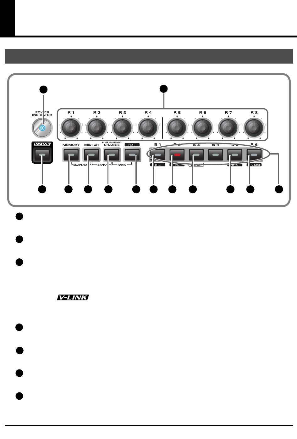
Power Indicator
Lights when the power is on.
Controllers [R1]-[R8]
You can assign MIDI messages to these controllers.(
➔
“Assign MIDI messages”
(p. 56))
V-LINK Button
Press the V-LINK button to enter
V-LINK mode
(p. 96). When V-LINK mode is on, the V-LINK
button will light.
V-LINK
V-LINK ( ) is a function that lets you play music and images. By using this with a
V-LINK compatible video device, you can enjoy various video effects that are linked to your
performance.
MEMORY Button
Accesses memories that are stored within the PCR-M30/50/80.
MIDI CH Button
Specifies the transmission channel (“current channel”) for the keyboard and bender.
PROGRAM CHANGE Button
Transmits program change messages on the current channel.
EDIT Button
Used to assign MIDI messages to the controllers.
Panel
fig.panelA_60
12
10 1312119876543
1
2
3
4
5
6
7
PCR-M30/50/80.book 10 ページ 2005年11月10日 木曜日 午後2時49分

11
Names of things and what they do
DEC Button
Decreases the value of a setting by one (except in
PLAY mode
(p. 46)).
INC Button
Increases the value of a setting by one (except in
PLAY mode
(p. 46)).
VELCRV Button
By turning on the power while holding down the
[VELCRV]
button, you can access a screen
that lets you specify the velocity curve.(p. 91)
HEX Button
When not in
PLAY mode
(p. 46), sets the
input mode
(p. 49) to hexadecimal (HEX input mode).
DECIMAL Button
When not in
PLAY mode
(p. 46), sets the
input mode
(p. 49) to decimal (DECIMAL input
mode).
Controllers [B1]-[B6]
You can assign MIDI messages to these controllers. (
➔
“Assign MIDI messages”
(p. 56))
8
9
10
11
12
13
PCR-M30/50/80.book 11 ページ 2005年11月10日 木曜日 午後2時49分
12
Names of things and what they do
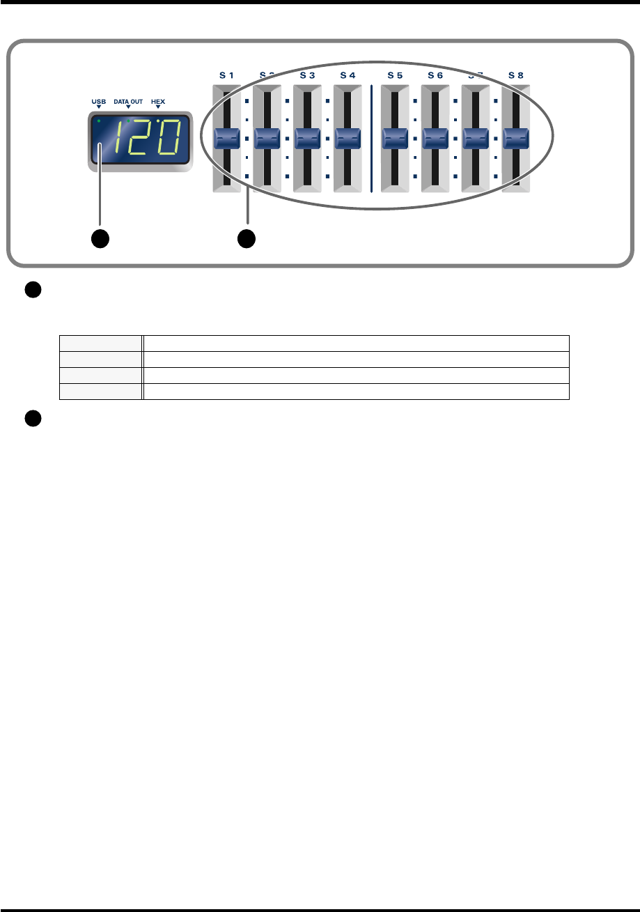
Display
Indicates the current status and various other information.
Controllers [S1]-[S8]
You can assign MIDI messages to these controllers. (
➔
“Assign MIDI messages”
(p. 56))
Number
Operating a controller will cause its current value to appear in the display for a time.
USB
Lights if the PCR-M30/50/80 is connected to your computer via USB.
DATA OUT
This will blink when MIDI messages are transmitted via USB or MIDI OUT.
HEX
Lights when the value shown in the display is hexadecimal.
fig.panelB_60
1514
14
15
PCR-M30/50/80.book 12 ページ 2005年11月10日 木曜日 午後2時49分
13
Names of things and what they do
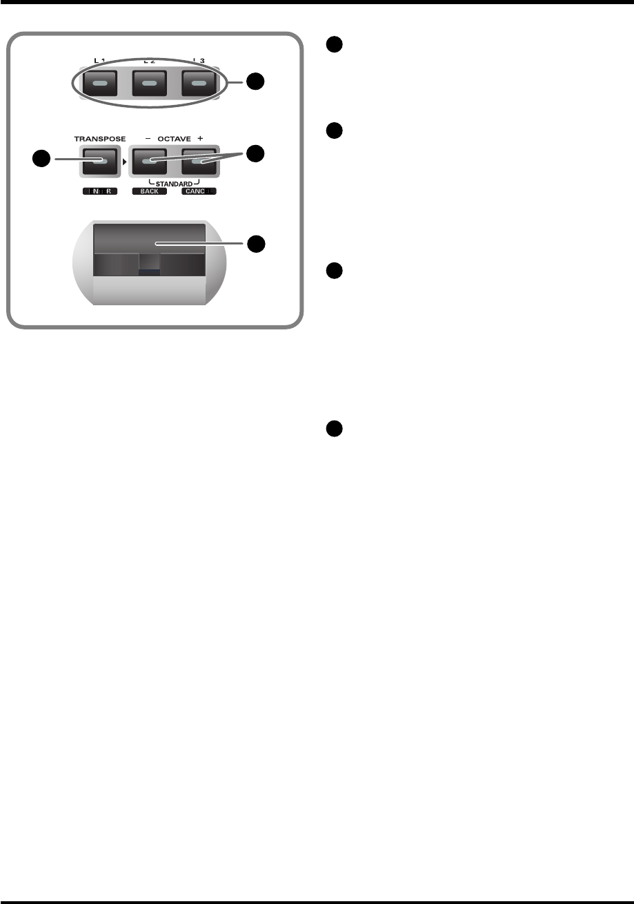
Controllers [L1]-[L3]
You can assign MIDI messages to these
controllers.
(
➔
“Assign MIDI messages”
(p. 56))
TRANSPOSE/ENTER Button
Use
[TRANSPOSE]
+
[OCTAVE -/+]
to
transpose the pitch of the keyboard in
semitone steps. Also, in any mode except
PLAY mode, it functions as the
[ENTER]
button, which you need to press to confirm
the settings you’ve made.
OCTAVE -/+
Press
[OCTAVE -/+]
to shift the pitch of the
keyboard up or down in steps of an octave.
When not in PLAY mode, use these buttons
to return to the previous setting item (the
[BACK]
button) or to cancel the setting and
return to PLAY mode (the
[CANCEL]
button).
BENDER Lever
This lever can be used to modify the pitch or
apply vibrato.
fig.panelC_60
16
17 18
19
16
17
18
19
PCR-M30/50/80.book 13 ページ 2005年11月10日 木曜日 午後2時49分
14
Names of things and what they do
Security Slot ( ) [PCR-M30/50]
A commercially available security lock can be attached here.
http://www.kensington.com/
AC adaptor jack
Connect the include AC adaptor to this jack. Insert the plug firmly so it won’t get unplugged
accidentally.
Power switch
USB connector
Use this when connecting the PCR-M30/50/80 to your computer via a USB cable.
MIDI IN/OUT connectors
These can be connected to the MIDI connectors of other MIDI devices to transmit and receive
MIDI messages.
Controller [P1] and [P2]
You can connect the appropriate type of pedals to these jacks and use them as controllers.
You can also assign MIDI messages to these controllers as desired.
(
➔
“Assign MIDI messages”
(p. 56))
Rear Panel
DC
Power on using the AC adaptor
OFF
Power is off
USB
Power on using a USB cable (when not using the AC adaptor)
*USB(=BUS power) can be used when the PCR-M30/50/80 is connected to your computer
via a USB cable. In this case, the power will be supplied from your computer via the USB
cable. To use the PCR-M30/50/80 with bus power, set the power switch to USB.
For some computers, the PCR-M30/50/80 may not operate if bus power is used. In this
case, use the included AC adaptor.
HOLD
Connect a pedal switch to this jack and use it as a Hold pedal.
EXPRESSION
Connect an expression pedal to this jack and use it to control tone or volume in real time.
fig.rear_50
252423222120
20
21
22
23
24
25
PCR-M30/50/80.book 14 ページ 2005年11月10日 木曜日 午後2時49分

15
Setup
This section explains how to install the drivers needed for connecting the PCR-M30/50/80 to a
computer, and make the necessary settings.
Getting Connected and Installing Drivers (Windows)
.............................. (p. 16)
Getting Connected and Installing Drivers (Macintosh)
........................... (p. 29)
What is a driver?
A “driver” is software that transfers data between the PCR-M30/50/80 and application
software running on your computer, when your computer and the PCR-M30/50/80 are
connected by a USB cable. The driver sends data from your application to the PCR-M30/50/80,
and from the PCR-M30/50/80 to your application.
PCR-M30/50/80.book 15 ページ 2005年11月10日 木曜日 午後2時49分
16
Getting Connected and Installing
Drivers (Windows)
1
Disconnect all USB cables except for a USB keyboard and USB mouse (if
used).
2
Open the
System Properties
dialog box.
1.
Click the Windows
start
menu, and from the menu, select
Control
Panel
.
2.
In
“Pick a category,”
click
“Performance and Maintenance.”
3.
In
“or pick a Control Panel icon,”
click the
System
icon.
fig.2-1_30
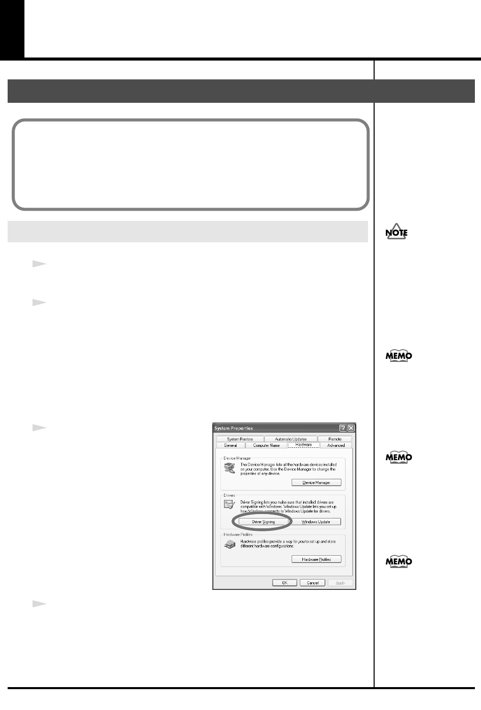
3
Click the
Hardware
tab, and then
click
[Driver Signing]
.
Open the
Driver Signing Options
dialog box.
4
Make sure that
“What action do you want Windows to take?”
is set to
“Ignore.”
If it is set to
“Ignore,”
simply click
[OK]
.
If it is not set to
“Ignore,”
make a note of the current setting (“Warn” or
“Block”). Then change the setting to
“Ignore
” and click
[OK]
.
Installing the driver
Windows XP users
The installation procedure will differ depending on your system.
Please proceed to one of the following sections, depending on the system you
use.
• Windows XP users ................................................................... (p. 16)
• Windows 2000 users ................................................................ (p. 21)
• Windows Me/98 users............................................................ (p. 25)
You must log on using a
user name with an
administrative account
type (e.g., Administrator).
For details on user
accounts, please consult
the system administrator
of your computer.
Depending on how your
system is set up, the
System icon may be
displayed directly in the
Control Panel (the Classic
view). In this case, double-
click the System icon.
What you actually see on
your computer screen may
b
e different, depending on
your computing
environment and the
operating system you're
using.
If you changed “What
action do you want
Windows to take?,” you
must restore the previous
setting after you have
installed the driver.
(➔
If you changed “What
action do you want
Windows to take?”
(p.
19))
PCR-M30/50/80.book 16 ページ 2005年11月10日 木曜日 午後2時49分
17
Getting Connected and Installing Drivers (Windows)
5
Click
[OK]
to close the
System Properties
dialog box.
6
Exit all currently running software.
Also close any open windows. If you are using virus checking or similar
software, be sure to exit it as well.
7
Prepare the CD-ROM.
Insert the CD-ROM into the CD-ROM drive of your computer.
8
Click the Windows
start
button. From the menu that appears, select
“Run...”
The
“Run...”
dialog box will appear.
fig.2-3_45
9
Specify the name of the file you
want to execute.
Enter the following into the
“Open”
field, and click
[OK]
.
(drive name): \Driver\USB_XP2K\SETUPINF.EXE
The
SetupInf
dialog box will appear.
You are now ready to install the driver.
*In the explanatory example shown here, the drive name is given as
“D:.”
The drive
name
“D:”
may be different for your system. Specify the drive name of your CD-
ROM drive.
10
Use the USB cable to connect the PCR-M30/50/80 to your computer.
1.
With the power switch turned
OFF
, connect the
AC adaptor
to the
PCR-M30/50/80
.
2.
Connect the
AC adaptor
to an electrical outlet.
3.
Use the
USB cable
to connect the
PCR-M30/50/80
to your computer.
11
Set the PCR-M30/50/80’s
power switch
to the
ON
(DC) position.
Near the task bar, your computer will indicate
“Found New Hardware.”
Please wait.
If the screen indicates
“Windows can perform
the same action each
time you insert a disk or
connect a device with
this kind of file,” click
[Cancel].
To check the drive name
Click the Start button, and
choose My Computer from
the menu that appears. In
the window that appears,
check the drive name of
the CD-ROM drive
into which you inserted
the CD-ROM in step 7.
The drive name is the (D:)
or (E:) displayed by the
CD-ROM drive.
Once the connections have
b
een completed, turn on
power to your various
devices in the order
specified. By turning on
devices in the wrong
order, you risk causing
malfunction and/or
damage to speakers and
other devices.
This unit is equipped with
a protection circuit. A brief
interval (a few seconds)
after power up is required
b
efore the unit will operate
normally.
PCR-M30/50/80.book 17 ページ 2005年11月10日 木曜日 午後2時49分
18
Getting Connected and Installing Drivers (Windows)
12
The
Found New Hardware Wizard
will appear.
Select
“Install from a list or specific location (Advanced),”
and click
[Next]
.
fig.2-7_40
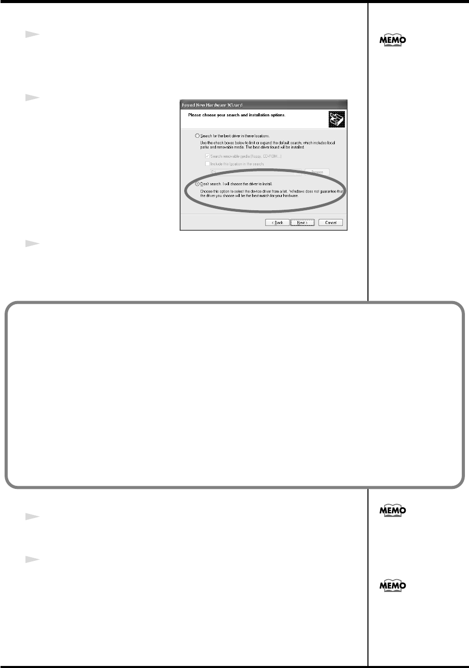
13
The screen will indicate
“Please choose your search
and installation options.”
Select
“Don’t search. I will
choose the driver to install,”
and click
[Next]
.
14
Make sure that the
“Model”
field indicates
“EDIROL PCR,”
and click
[Next]
.
Driver installation will begin.
15
The
Insert Disk
dialog box will appear.
Click
[OK]
.
16
The
Files Needed
dialog box will appear.
Input the following into the
“Copy files from”
field, and click
[OK]
.
(drive name):\DRIVER\USB_XP2K.
If the Found New
Hardware Wizard asks
you whether you want to
connect to Windows
Update, choose “No” and
then click [Next].
If the “What action do you want Windows to take?” (Step 4) setting was not set to “Ignore,” a
“Hardware Installation” dialog box will appear.
A dialog box with a “!” symbol will appear.
1. Click [Continue Anyway].
2. Continue the installation.
A dialog box with a “x” symbol will appear.
1. Click [OK].
2. When the “Found New Hardware Wizard” appears, click [Finish].
3. Return to step 1 (p. 16) and re-install the driver from the beginning of the procedure.
The Insert Disk dialog
may not appear. In that
case, proceed to the next
step.
Specify the drive name of
your CD-ROM drive.
PCR-M30/50/80.book 18 ページ 2005年11月10日 木曜日 午後2時49分
19
Getting Connected and Installing Drivers (Windows)
17
The screen will indicate
“Completing the Found New Hardware Wizard.”
Make sure that the
“Model”
field indicates
“EDIROL PCR,”
click
[Finish]
.
Wait until
“Found New Hardware”
appears near the taskbar.
18
When driver installation has been completed, the
System Settings Change
dialog box will appear.
Click
[Yes]
. Windows will restart automatically.
If the “What action do you want Windows to take?” (Step 4) setting was not set to “Ignore,” a
“Hardware Installation” dialog box will appear.
A dialog box with a “!” symbol will appear.
1. Click [Continue Anyway].
2. Continue the installation.
If the System Settings
Change dialog box does
not appear, restart
Windows from the Start
menu.
If you changed “What action do you want Windows to take?”
If you changed the Driver Signing Options (p. 16), restore the original
setting after Windows restarts.
1. Log on to Windows using the user name of an administrative account
(e.g., Administrator).
2. Click the Windows start menu, and from the menu that appears, select
Control Panel.
3. In “Pick a category,” click “Performance and Maintenance.”
4. In “or pick a Control Panel icon,” click the System icon. The System
Properties dialog box will appear.
5. Click the Hardware tab, and then click [Driver Signing]. The Driver
Signing Options dialog box will appear.
6. Return the What action do you want Windows to take? setting to the
original setting (either “Warn” or “Block”), and click [OK].
7. Click [OK]. The System properties dialog box will close.
Depending on how your
system is set up, the
System icon may be
displayed directly in the
Control Panel (classic
view). In this case, double-
click the System icon.
This completes installation of the driver.
Next, we recommend that you give priority to background services on your computer, so MIDI
processing will be as smooth as possible. (➔ Giving priority to background services (p. 20))
PCR-M30/50/80.book 19 ページ 2005年11月10日 木曜日 午後2時49分
20
Getting Connected and Installing Drivers (Windows)
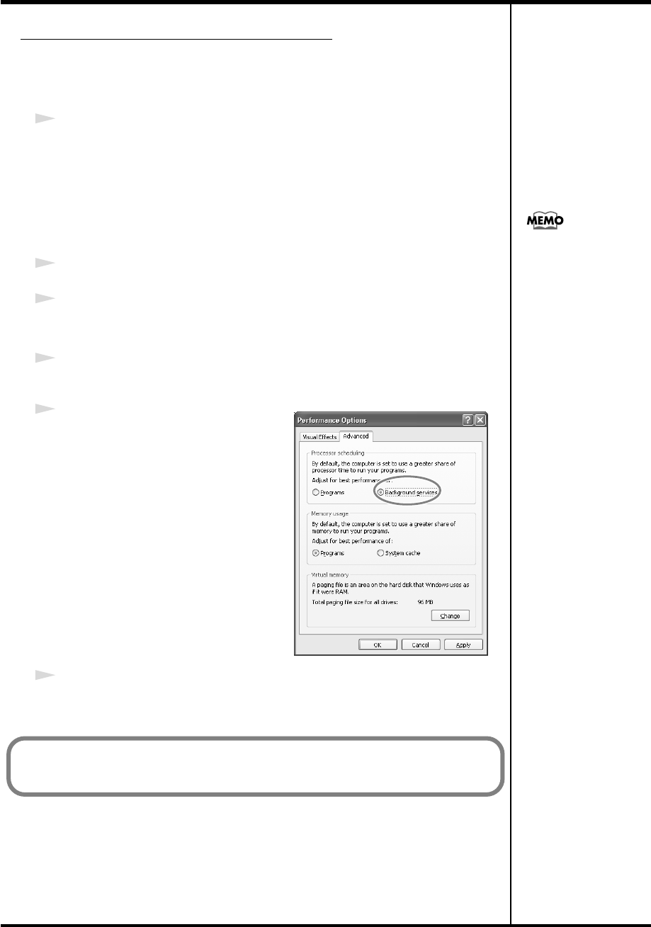
Giving priority to background services
In Windows XP, make settings to give priority to background services. To
ensure that MIDI processing occurs smoothly, use the following procedure to
make settings.
1
Open the
System Properties
dialog box.
1.
Click the Windows
start
menu, and from the menu, select
Control
Panel
.
2.
In
“Pick a category,”
click
“Performance and Maintenance.”
3.
In
“or pick a Control Panel icon,”
click the
System
icon.
2
Click the
Advanced
tab.
3
At the right of the
Performance
field, click
[Settings]
.
The
Performance Options
dialog box will appear.
4
Click the
Advanced
tab.
fig.2-30a
5
In the
Processor Scheduling
field,
select
“Background services,”
and
click
[OK]
.
6
In the
System Properties
dialog box, click
[OK]
.
The
System Properties
dialog box will close.
Depending on how your
system is set up, the
System icon may be
displayed directly in the
Control Panel (the Classic
view). In this case, double-
click the System icon.
Next, make device settings.
(➔Settings and checking(p. 26))
PCR-M30/50/80.book 20 ページ 2005年11月10日 木曜日 午後2時49分
21
Getting Connected and Installing Drivers (Windows)
1
Disconnect all USB cables except for a USB keyboard and USB mouse (if
used).
2
Open the
System Properties
dialog box.
1.
Click the Windows
Start
menu, and from the menu that appears, select
Settings
|
Control Panel
.
2.
In
Control Panel
, double-click the
System
icon.
fig.05-2_30
3
Click the
Hardware
tab, and then
click
[Driver Signing]
.
The
Driver Signing Options
dialog box will appear.
4
Make sure that
“File signature verification”
is set to
“Ignore.”
If it is set to
“Ignore,”
simply click
[OK]
.
If it is not set to
“Ignore,”
make a note of the current setting (“Warn” or
“Block”). Then change the setting to
“Ignore”
and click
[OK]
.
5
Click
[OK]
to close the
System Properties
dialog box.
6
Exit all currently running software.
Also close any open windows. If you are using virus checking or similar
software, be sure to exit it as well.
7
Prepare the CD-ROM.
Insert the CD-ROM into the CD-ROM drive of your computer.
8
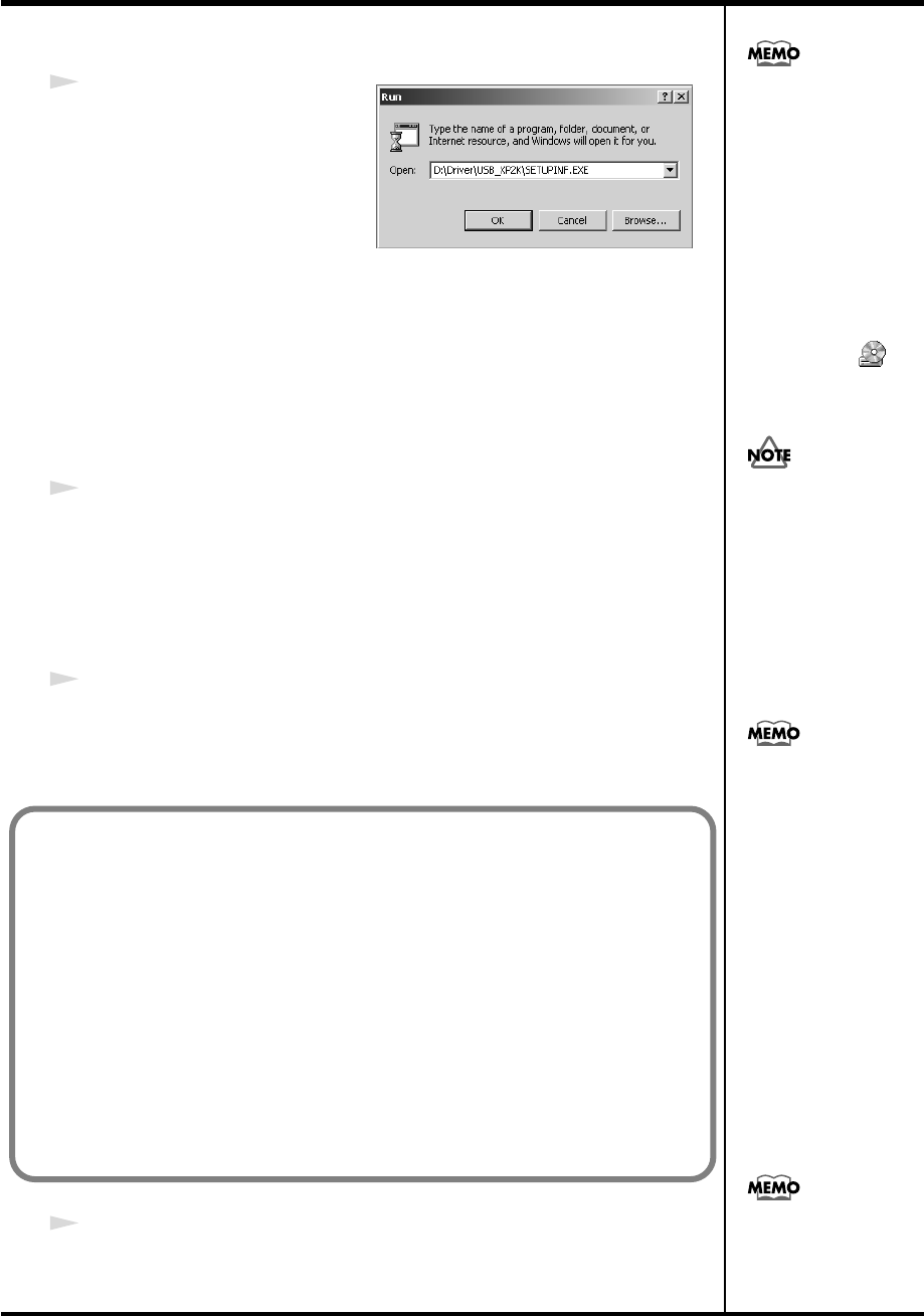
Click the Windows
Start
menu. From the menu that appears, select
“Run...”
The
“Run...”
dialog box will appear.
Windows 2000 users
Log on to Windows as a
user with administrative
privileges (such as
Administrator).
If you changed “File
signature verification,”
you must restore the
previous setting after you
have installed the driver.
(→“If you changed “File
signature verification””
(p. 23))
PCR-M30/50/80.book 21 ページ 2005年11月10日 木曜日 午後2時49分
22
Getting Connected and Installing Drivers (Windows)
fig.05-5_40
9
In the dialog box that appears,
input the following into the
“Open”
field, and click
[OK]
.
(drive name):\Driver\USB_XP2K\SETUPINF.EXE
The
SetupInf
dialog box will appear.
You are now ready to install the driver.
*In the explanatory example shown here, the drive name is given as
“D:.”
The drive
name
“D:”
may be different for your system. Specify the drive name of your CD-
ROM drive.
10
Use the USB cable to connect the PCR-M30/50/80 to your computer.
1.
With the power switch turned
OFF
, connect the
AC adaptor
to the
PCR-M30/50/80
.
2.
Connect the
AC adaptor
to an electrical outlet.
3.
Use the
USB cable
to connect the
PCR-M30/50/80
to your computer.
11
Set the PCR-M30/50/80’s
power switch
to the
ON
(DC) position.
Near the task bar, your computer will indicate
“Found New Hardware.”
Please wait.
12
The
Insert Disk
dialog box will appear.
Click
[OK]
.
To check the drive name
In the Windows desktop,
double-click the My
Computer icon. In the
window that appears,
check the drive name of
the CD-ROM drive into
which you inserted the
CD-ROM in step7.
The drive name is the (D:)
or (E:) displayed by the
CD-ROM drive .
Once the connections have
b
een completed, turn on
power to your various
devices in the order
specified. By turning on
devices in the wrong
order, you risk causing
malfunction and/or
damage to speakers and
other devices.
This unit is equipped with
a protection circuit. A brief
interval (a few seconds)
after power up is required
b
efore the unit will operate
normally.
If the “File signature verification” (Step 4) setting was not set to “Ignore,”
a “Digital Signature Not Found” dialog box will appear.
If “File signature verification” is set to “Warn”
1. Click [Yes].
2. Continue the installation.
If “File signature verification” is set to “Block”
1. Click [OK].
2. When the “Found New Hardware Wizard” appears, click [Finish].
3. Return to step 1 (p. 21) and re-install the driver from the beginning
of the procedure.
If the Insert Disk dialog
b
ox does not appear,
proceed to the next step.
PCR-M30/50/80.book 22 ページ 2005年11月10日 木曜日 午後2時49分
23
Getting Connected and Installing Drivers (Windows)
13
The
Files Needed
dialog box will appear.
Input the following into the
“Copy files from”
field, and click
[OK]
.
(drive name): \DRIVER\USB_XP2K
14
The screen will indicate
“Completing the Found New Hardware Wizard.”
Make sure that the
“Model”
field indicates
“EDIROL PCR,”
Click
[Finish]
.
15
The
System Settings Change
dialog box may appear.
Click
[Yes]
. Windows will restart automatically.
Specify the drive name of
your CD-ROM drive.
If the “File signature verification” (Step 4) setting was not set to “Ignore,” a “Digital Signature Not
Found” dialog box will appear.
1. Click [Yes].
2. Continue the installation.
If the System Settings
Change dialog box does
not appear, restart
Windows from the Start
menu.
If you changed “File signature verification”
If you changed the “File signature verification” (p. 21) setting, restore the original setting after Windows
restarts.
1. After Windows restarts, log in to Windows as a user with administrative privileges, (such as
Administrator).
2. In the Windows desktop, right-click the My Computer icon, and from the menu that appears,
select Properties. The System Properties dialog box will appear.
3. Click the Hardware tab, and then click [Driver Signing]. The Driver Signing Options dialog box
will appear.
4. Return the “File signature verification” setting to the original setting (either “Warn” or
“Block”), and click [OK].
5. Click [OK]. The System Properties dialog box will close.
This completes installation of the driver.
Next, we recommend that you give priority to background services on your computer, so MIDI
processing will be as smooth as possible.(➔Giving priority to background services (p. 24))
PCR-M30/50/80.book 23 ページ 2005年11月10日 木曜日 午後2時49分
24
Getting Connected and Installing Drivers (Windows)
Giving priority to background services
In Windows 2000, make settings to give priority to background services. If
you fail to make this setting, you may experience interruptions in the sound.
To ensure that MIDI processing occurs smoothly, use the following
procedure to make settings.
1
Click the Windows
Start
menu, and from the menu that appears, select
Settings
|
Control Panel
. In
Control Panel
, double-click the
System
icon.
2
Click the
Advanced
tab.
3
At the right of the
Performance
field, click
[Performance Options]
.
The
Performance Options
dialog box will appear.
fig.back2000
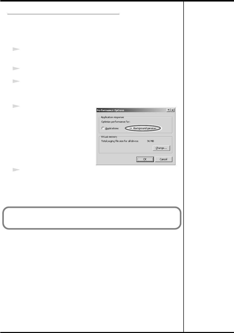
4
In the
Application response
field, choose
“Background
services”
and click
[OK]
.
5
Click
[OK]
to close the
System Properties
dialog box.
Next, make device settings.
(➔Settings and checking (p. 26))
PCR-M30/50/80.book 24 ページ 2005年11月10日 木曜日 午後2時49分
25
Getting Connected and Installing Drivers (Windows)
1
With the PCR disconnected, start up Windows.
Disconnect all USB cables except for a USB keyboard and USB mouse (if
used).
If you are using virus checking or similar software, be sure to exit it as well.
2
Exit all currently running software.
Also close any open windows. If you are using virus checking or similar
software, be sure to exit it as well.
3
Prepare the CD-ROM.
Insert the CD-ROM into the CD-ROM drive of your computer.
4
Click the Windows
Start
menu. From the menu that appears, select
Run...
.
The
“Run...”
dialog box will appear.
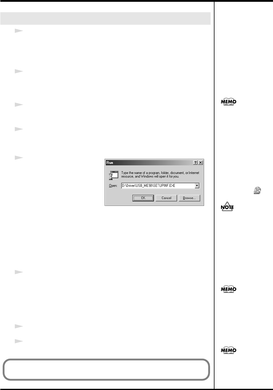
fig.05-13
5
In the dialog box that appears,
input the following into the
“Open”
field, and click
[OK]
.
(drive name): \Driver\USB_ME98\SETUPINF.EXE
The
SetupInf
dialog box will appear.
You are now ready to install the driver.
*In the explanatory example shown here, the drive name is given as
“D:.”
The drive
name
“D:”
may be different for your system. Specify the drive name of your CD-
ROM drive.
6
Use the USB cable to connect the PCR-M30/50/80 to your computer.
1.
With the power switch turned
OFF
, connect the
AC adaptor
to the
PCR-M30/50/80
.
2.
Connect the
AC adaptor
to an electrical outlet.
3.
Use the
USB cable
to connect the
PCR-M30/50/80
to your computer.
7
Set the PCR-M30/50/80’s
power switch
to the
ON
(DC) position.
8
In the
SetupInf
dialog box, click
[OK]
.
Windows Me/98 users
To check the drive name
In the Windows desktop,
double-click the My
Computer icon. In the
window that appears,
check the drive name of
the CD-ROM drive into
which you inserted the
CD-ROM in step3.
The drive name is the (D:)
or (E:) displayed by the
CD-ROM drive .
Once the connections have
b
een completed, turn on
power to your various
devices in the order
specified. By turning on
devices in the wrong
order, you risk causing
malfunction and/or
damage to speakers and
other devices.
This unit is equipped with
a protection circuit. A brief
interval (a few seconds)
after power up is required
b
efore the unit will operate
normally.
If a message recommends
that you restart Windows,
restart Windows as
directed.
Next, make device settings.
(➔Settings and checking (p. 26))
PCR-M30/50/80.book 25 ページ 2005年11月10日 木曜日 午後2時49分
26
Getting Connected and Installing Drivers (Windows)
Make the following settings so that you can use the MIDI functionality of the
PCR-M30/50/80. For a connection diagram, refer to
“Basic connections
and MIDI flow”
(p. 40).
1
Open
Control Panel
.
Click the Windows
start
menu, and from the menu that appears, select
Control Panel
.
2
Open the
Sounds and Audio Devices Properties
dialog box.
In
“Pick a category”
click
“Sound, Speech, and Audio Devices.”
Next, in
“or pick a Control Panel icon,”
click the
sounds and Audio Devices
icon.
3
Click the
Audio
tab.
fig.XP-E
4
For
MIDI music playback
, click the
▼
located at the right of
[Default
device]
, and select the MIDI device
from the list that appears.
If you want to use Media Player to play
a sound module connected to the
PCR’s MIDI OUT connector, select
EDIROL PCR MIDI OUT
.
5
Close the
Sounds and Audio Devices Properties
dialog box.
Click
[OK]
to complete the settings.
Settings and checking
~Specifying the MIDI input/output destination~
Windows XP users
Depending on how your
system is set up, the
Sounds and Audio
Devices icon may be
displayed directly in the
Control Panel (the Classic
view). In this case, double-
click the Sounds and
Audio Devices icon.
Select the appropriate
MIDI device for your
system. You do not
necessarily have to select
EDIROL PCR MIDI OUT.
For details on the PCR’s
input/output devices,
refer to“Input / output
devices” (p. 43).
This completes settings for using the PCR with an software that uses the standard Windows device
settings, such as Media Player.
For details on how to make these settings, refer to the owner’s manual for your software.
For details on the PCR’s input/output devices, refer to “Input / output devices” (p. 43).
PCR-M30/50/80.book 26 ページ 2005年11月10日 木曜日 午後2時49分
27
Getting Connected and Installing Drivers (Windows)
Make the following settings so that you can use the MIDI functionality of the
PCR-M30/50/80. For a connection diagram, refer to
“Basic connections
and MIDI flow”
(p. 40).
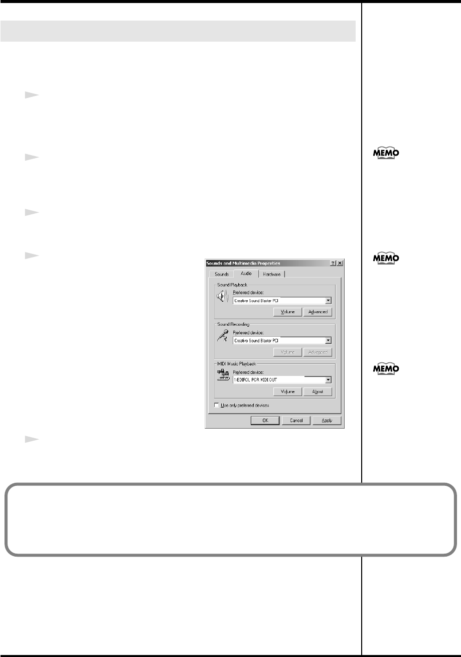
1
Open
Control Panel
.
Click the Windows
Start
menu, and from the menu that appears, select
Settings
|
Control Panel
.
2
Open the
Sounds and Multimedia Properties
.
In
Control Panel
, double-click the
Sounds and Multimedia
icon to open the
Sounds and Multimedia Properties
dialog box.
3
Click the
AUDIO
tab.
fig.2K-E
4
For
MIDI music playback
, click the
▼
located at the right of
[Preferred
device]
, and select the MIDI device
from the list that appears.
If you want to use Media Player to play
a sound module connected to the
PCR’s MIDI OUT connector, select
EDIROL PCR MIDI OUT
.
5
Close the
Sounds and Multimedia
Properties
dialog box.
Click
[OK]
to complete the settings.
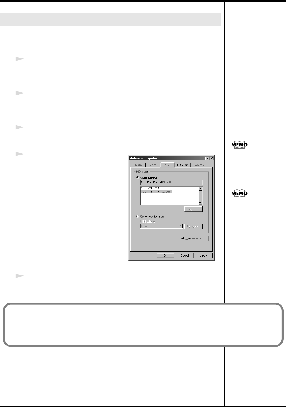
Windows 2000 / Me users
If the Sound and
Multimedia icon is not
displayed, click “Show all
control panel options” in
the frame at the left.
Select the appropriate
MIDI device for your
system. You do not
necessarily have to select
EDIROL PCR MIDI OUT.
For details on the PCR’s
input/output devices,
refer to “Input / output
devices” (p. 43).
This completes settings for using the PCR with an software that uses the standard Windows device
settings, such as Media Player.
For details on how to make these settings, refer to the owner’s manual for your software.
For details on the PCR’s input/output devices, refer to “Input / output devices” (p. 43).
PCR-M30/50/80.book 27 ページ 2005年11月10日 木曜日 午後2時49分
28
Getting Connected and Installing Drivers (Windows)
Make the following settings so that you can use the MIDI functionality of the
PCR-M30/50/80. For a connection diagram, refer to
“Basic connections
and MIDI flow”
(p. 40).
1
Open
Control Panel
.
Click the Windows
Start
menu, and from the menu that appears, select
Settings
|
Control Panel
.
2
Open the
Multimedia Properties
dialog box.
In
Control Panel
, double-click the
Multimedia
icon to open the
“Multimedia
Properties”
dialog box.
3
Click the
MIDI
tab.
fig.98-E
4
Set
“MIDI output.”
Select
[Single instrument]
, and select
the MIDI device from the list that
appears, and click
[Apply]
.
If you want to use Media Player to play
a sound module connected to the
PCR’s MIDI OUT connector, select
EDIROL PCR MIDI OUT
.
5
Close the
Multimedia Properties
dialog box.
Click
[OK]
to complete the settings.
Windows 98 users
For details on the PCR’s
input/output devices,
refer to “Input / output
devices” (p. 43).
Select the appropriate
MIDI device for your
system. You do not
necessarily have to select
EDIROL PCR MIDI OUT.
This completes settings for using the PCR with an software that uses the standard Windows device
settings, such as Media Player.
For details on how to make these settings, refer to the owner’s manual for your software.
For details on the PCR’s input/output devices, refer to “Input / output devices” (p. 43).
PCR-M30/50/80.book 28 ページ 2005年11月10日 木曜日 午後2時49分
29
Getting Connected and Installing
Drivers (Macintosh)
If the
“Authenticate”
dialog box appears during the installation, input the
password and click
“OK.”
1
Disconnect all USB cables other than those for your keyboard and mouse,
and restart your Macintosh.
2
Prepare the CD-ROM.
Insert the CD-ROM into the CD-ROM drive of your computer.
3
In the
Driver (Mac OS X)
folder of the CD-ROM, double-click
PCRUSBDriver.pkg
.
4
The display will indicate
“Welcome to the EDIROL PCR Driver Installer.”
Click
[Continue]
.
5
The display will indicate
“Select a Destination.”
Click the drive in which the operating system is installed to select it, and then
click
[Continue]
.
6
The display will indicate
“Easy Install.”
Click
[Install]
or
[Upgrade]
.
7
The display will indicate
“Installing this software requires you to restart
your computer when the installation is done.”
Click
[Continue Installation]
.
8
The display will indicate
“The software was successfully installed.”
Click
[Restart]
to restart your computer.
This completes installation of the PCR driver.
Next, make MIDI device settings.
Mac OS X users
Installing the driver
The installation procedure will differ depending on your system.
Please proceed to one of the following sections, depending on the system you
use.
• Mac OS X users......................................................................... (p. 29)
• Mac OS 9 users ......................................................................... (p. 32)
What you actually see on
your computer screen may
b
e different, depending on
your computing
environment and the
operating system you're
using.
Select your startup disk as
the drive.
PCR-M30/50/80.book 29 ページ 2005年11月10日 木曜日 午後2時49分
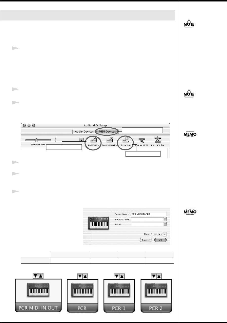
30
Getting Connected and Installing Drivers (Macintosh)
Make the following settings so that you can use the MIDI functionality of the
PCR-M30/50/80. For a connection diagram, refer to
“Basic connections
and MIDI flow”
(p. 40).
1
Use the USB cable to connect the PCR-M30/50/80 to your computer.
1.
With the power switch turned
OFF
, connect the
AC adaptor
to the
PCR-M30/50/80
.
2.
Connect the
AC adaptor
to an electrical outlet.
3.
Use the
USB cable
to connect the
PCR-M30/50/80
to your computer.
2
Set the PCR-M30/50/80’s
power switch
to the
ON
(DC) position.
3
Open the
Applications
folder of your Macintosh hard disk. In the
Utilities
folder, double-click
Audio MIDI Setup
to open the
Audio MIDI Setup
.
fig.osx2a-e
4
Click the
MIDI Devices
tab.
5
Click
“Add Device”
four times.
Four
new external MIDI devices
will appear.
6
Specify a name for each
new external device
.
1.
Click
Show Info
.
2.
Enter the name in the
Device Name
field.
Enter the following for
each
new external
device
.
Mac OS settings
First Second Third Fourth
Device Name
PCR MIDI IN, OUT PCR PCR 1 PCR 2
Once the connections have
b
een completed, turn on
power to your various
devices in the order
specified. By turning on
devices in the wrong
order, you risk causing
malfunction and/or
damage to speakers and
other devices.
Connect the cable to the
USB connector of the
Macintosh itself, not to the
USB connector of the
keyboard.
This unit is equipped with
a protection circuit. A brief
interval (a few seconds)
after power up is required
b
efore the unit will operate
normally.
4
6
5
Click MIDI Devices
Click Add Dvice
Click Show Info
For details on MIDI device
settings, refer to the
owner’s manual for the
software you are using.
PCR-M30/50/80.book 30 ページ 2005年11月10日 木曜日 午後2時49分
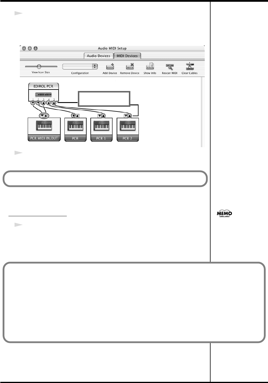
31
Getting Connected and Installing Drivers (Macintosh)
7
Connect the
▼
and
▲
symbols (which signify the outputs and inputs) of the
EDIROL PCR
icon to those of the
New External Device
icon by using the
mouse to drag between them.
8
Close the
Audio MIDI Setup
.
Software settings
1
Make MIDI device settings on your sequencer software.
For details on the PCR’s input/output devices, refer to
“Input / output
devices”
(p. 43).
Use the mouse to
drag a connection
Next, make software settings.
For details on MIDI device
settings, refer to the
owner’s manual for the
software you are using.
When using the PCR with your software
Before using the PCR with your software, please note the following points.
• Use the USB cable to connect the PCR to your computer before you start up your software.
• Do not disconnect the USB cable from the PCR while your software is running.
• Quit your software before you disconnect the USB cable from the PCR.
• Turn off the Sleep function of your Macintosh.
• The PCR will not operate in the Mac OS X Classic environment. Use the PCR when the Classic
environment is not running.
PCR-M30/50/80.book 31 ページ 2005年11月10日 木曜日 午後2時49分
32
Getting Connected and Installing Drivers (Macintosh)
Use either OMS or FreeMIDI as the MIDI driver.
The included
PCR driver
is an add-on module for using the PCR with OMS
or FreeMIDI.
* Either
OMS
or
FreeMIDI
must be installed in your Macintosh, as appropriate for
the sequencer software you are using.
Use the following procedure to install the PCR driver.
1
Exit all currently running software.
If you are using a virus checker or similar software, be sure to exit this as well.
2
Prepare the CD-ROM.Insert the CD-ROM into the CD-ROM drive.
3
Double-click the
PCR Driver-E Installer
icon (found in the
Driver E (Mac
OS 9,8)
folder of the CD-ROM) to start up the installer.
4
Verify the
Install Location
, and click
[Install]
.
fig.05-20
5
If a message like the following is
displayed, click
[Continue]
.
The other currently running
softwares will exit, and installation
will continue.
6
A dialog box will indicate
Installation was successful
.
Click
[Restart]
to restart your Macintosh.
Mac OS 9 users
Installing the driver
OMS can be found in the
OMS 2.3.8 E folder within
the OMS (Mac OS 9,8)
folder of the CD-ROM. If
you would like to know
more about OMS, refer to
OMS_2.3_Mac.pdf which
can be found in the same
folder.
If a PCR is already connected to your Macintosh when you install the driver,
a message like the following will appear when the Macintosh is started up.
Perform the steps described below as appropriate for the message that is
displayed.
If the screen indicates:
“Software needed for the USB device “EDIROL PCR” is not available.
Would you like to look for the software on the Internet?”➔ click [Cancel].
If the screen indicates:
“The software needed to use the USB device “PCR” cannot be found.
Please refer to the device documentation to install the necessary
software.”➔ click [OK].
If you install OMS or
FreeMIDI after installing
the PCR driver, you must
install the PCR driver once
again.
Disconnect the PCR from
the Macintosh before you
perform the installation.
The installation location
will be shown differently
depending on your
system. Make sure that
you have selected the
startup disk for the system
you are currently using.
PCR-M30/50/80.book 32 ページ 2005年11月10日 木曜日 午後2時49分
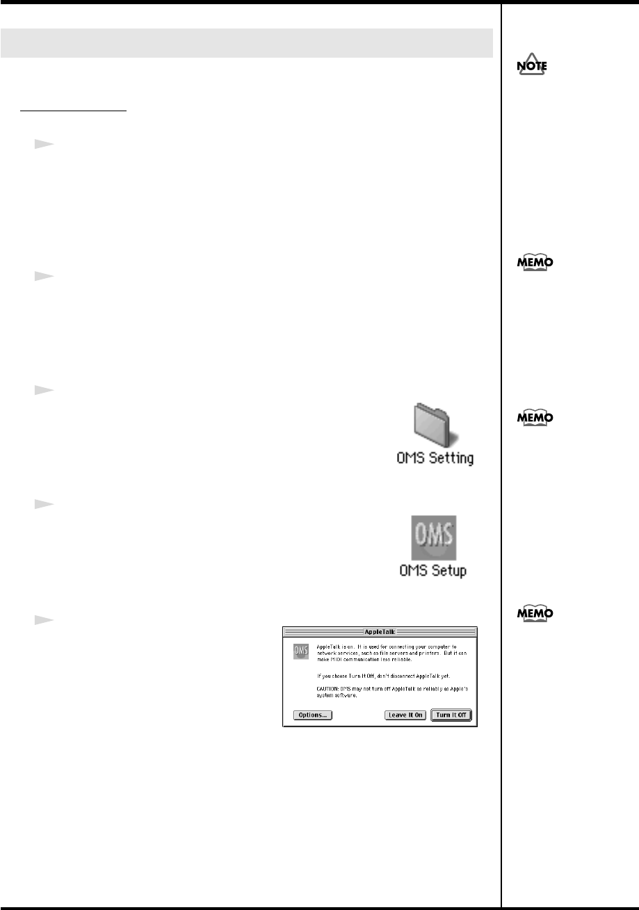
33
Getting Connected and Installing Drivers (Macintosh)
If you are using FreeMIDI, proceed to
“FreeMIDI settings”
(p. 36).
OMS settings
1
Use the USB cable to connect the PCR-M30/50/80 to your computer.
1.
With the power switch turned
OFF
, connect the
AC adaptor
to the
PCR-M30/50/80
.
2.
Connect the
AC adaptor
to an electrical outlet.
3.
Use the
USB cable
to connect the
PCR-M30/50/80
to your computer.
2
Set the PCR-M30/50/80’s
power switch
to the
ON
(DC) position.
* Connect the cable to the USB connector of the Macintosh itself, not to the USB
connector of the keyboard.
fig.3-3
3
From the CD-ROM, drag the
Driver E (Mac OS 9,8)
-
OMS Setting
folder into the
Opcode
-
OMS
Applications
folder on the hard disk of your Macintosh
to copy it there.
fig.3-4
4
In the
Opcode
-
OMS Applications
folder where you
installed OMS, double-click
OMS Setup
to start it up.
fig.3-5_35
5
If a dialog box like the one shown
here appears, click
[Turn It Off]
. A
confirmation
dialog box will then
appear, so click
[OK]
.
Setting the driver
Once the connections have
b
een completed, turn on
power to your various
devices in the order
specified. By turning on
devices in the wrong
order, you risk causing
malfunction and/or
damage to speakers and
other devices.
This unit is equipped with
a protection circuit. A brief
interval (a few seconds)
after power up is required
b
efore the unit will operate
normally.
If you are using the PCR in
conjunction with other
MIDI devices, make
settings as described in
Readme_E.htm located in
the Driver E (Mac OS 9,8)
folder of the CD-ROM.
We recommend that you
turn off AppleTalk, by
selecting Chooser from the
Apple menu.
PCR-M30/50/80.book 33 ページ 2005年11月10日 木曜日 午後2時49分
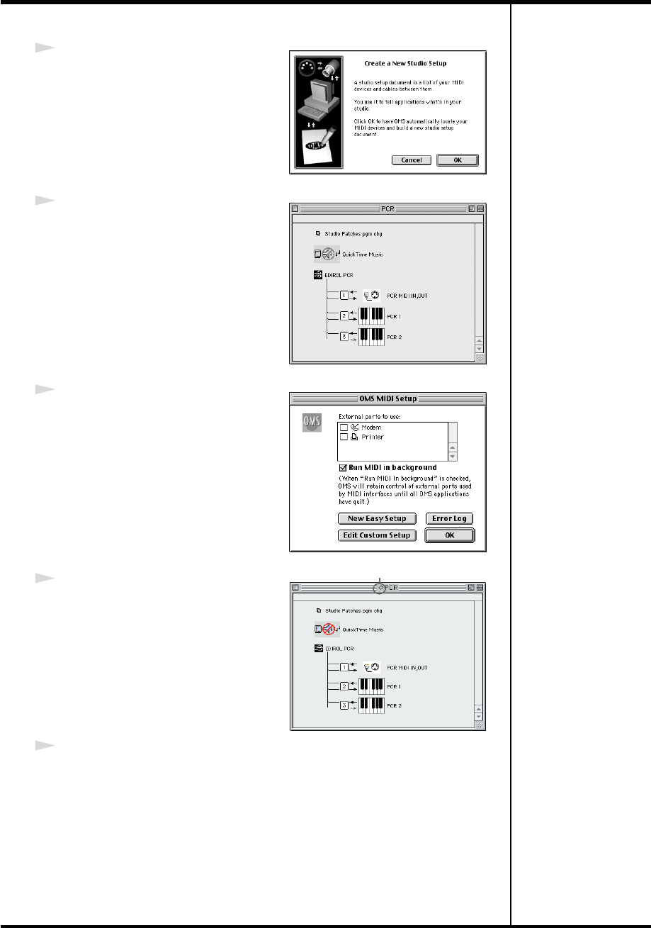
34
Getting Connected and Installing Drivers (Macintosh)
fig.3-6_35
6
The
Create a New Studio Setup
dialog box will appear. Click
[Cancel]
.
If you accidentally clicked
[OK]
, click
[Cancel]
in the next screen.
fig.3-8_35
7
Choose
“Open”
from the
File
menu.
From the
OMS Setting
folder that you
copied in
step 3
, select the
PCR
file,
and click
[Open]
.
A screen like the one shown here will
appear.
fig.3-9_35
8
From the
Edit
menu, select
OMS MIDI
Setup
.
In the
OMS MIDI Setup
dialog box that
appears, check
Run MIDI in
background
, and click
[OK]
.
fig.3-10_40
9
From the
File
menu, choose
Make
Current
.
* If you are unable to select
Make
Current
, it has already been applied,
and you may continue to the next step.
10
Verify that MIDI transmission and reception can be performed correctly.
From the
Studio
menu, choose
Test Studio
.
A diamond mark (◊) indicate in the settings are enabled.
PCR-M30/50/80.book 34 ページ 2005年11月10日 木曜日 午後2時49分
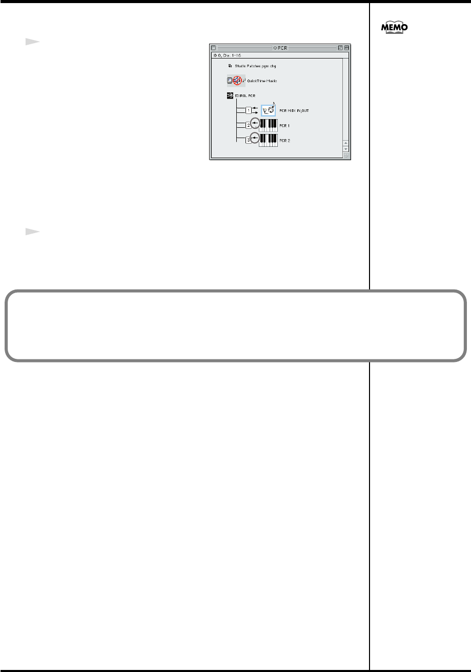
35
Getting Connected and Installing Drivers (Macintosh)
fig.OMS3
11
Try playing the keyboard of the PCR.
If the arrow beside number
2
or
3
in
the diagram at right blinks, the
settings have been made correctly.
When you move the mouse cursor
near the MIDI connector icon, the
cursor will change to a
shape.
If a MIDI sound module is connected
to the PCR’s MIDI OUT connector,
click the MIDI connector icon shown
in the diagram at the right. If you hear
sound, the settings have been made
correctly.
12
Exit
OMS Setup
.
From the
File
menu, choose
[Exit]
. If the
AppleTalk confirmation
dialog box
appears, click
[OK]
to close the dialog box.
For details on the PCR’s
input/output devices,
refer to “Input / output
devices” (p. 43).
This completes installation of the driver.
Next, make MIDI device settings in your sequencer or other software.
For details on how to make these settings, refer to the owner’s manual for your software.
For details on the PCR’s input / output devices, refer to “Input / output devices” (p. 43).
PCR-M30/50/80.book 35 ページ 2005年11月10日 木曜日 午後2時49分

36
Getting Connected and Installing Drivers (Macintosh)
FreeMIDI settings
1
Use the USB cable to connect the PCR-M30/50/80 to your computer.
1.
With the power switch turned
OFF
, connect the
AC adaptor
to the
PCR-M30/50/80
.
2.
Connect the
AC adaptor
to an electrical outlet.
3.
Use the
USB cable
to connect the
PCR-M30/50/80
to your computer.
2
Set the PCR-M30/50/80’s
power switch
to the
ON
(DC) position.
* Connect the cable to the USB connector of the Macintosh itself, not to the USB
connector of the keyboard.
3
From the CD-ROM, drag the
Driver E (Mac OS 9,8)
-
FreeMIDI Setting
folder into the
FreeMIDI Applications
folder on the hard disk of your
Macintosh to copy it there.
4
Open the
FreeMIDI Applications
folder from the location into which you
installed
FreeMIDI
, and double-click the
FreeMIDI Setup
icon to start it up.
5
The first time you start up, use the following procedure.
1.
A dialog box saying
“Welcome to FreeMIDI!”
will appear.
Click
[Continue]
.
2.
The
FreeMIDI Preferences
dialog box will appear.
Click
[Cancel]
.
3.
The
About Quick Setup
dialog box will appear.
Click
[Cancel]
.
Once the connections have
b
een completed, turn on
power to your various
devices in the order
specified. By turning on
devices in the wrong
order, you risk causing
malfunction and/or
damage to speakers and
other devices.
This unit is equipped with
a protection circuit. A brief
interval (a few seconds)
after power up is required
b
efore the unit will operate
normally.
If you are using the PCR in
conjunction with other
MIDI devices, make
settings as described in
Readme_E.htm located in
the Driver E (Mac OS 9,8)
folder of the CD-ROM.
When “OMS is installed
on this computer...”
appears, click [FreeMIDI].
PCR-M30/50/80.book 36 ページ 2005年11月10日 木曜日 午後2時49分
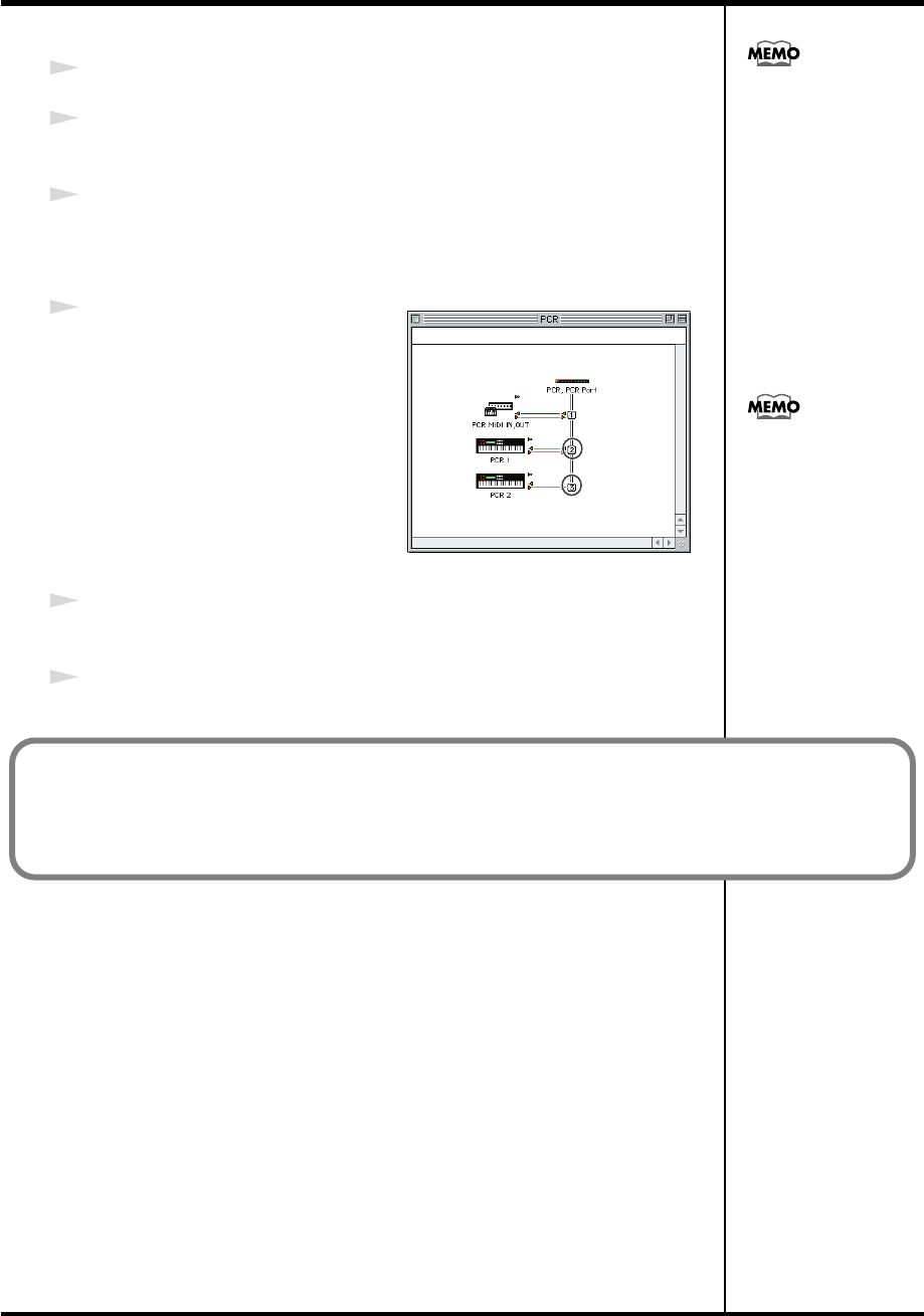
37
Getting Connected and Installing Drivers (Macintosh)
6
From the
File
menu, choose
Open
.
7
Select
PCR
from the
FreeMIDI Setting
folder you copied in
step 3
, and click
[Open]
.
8
Verify that MIDI transmission and reception occur correctly.
From the
MIDI
menu, choose
Check Connections
.
fig.FreeMIDI
9
Try playing the keyboard of the PCR.
If the number
2
or
3
in the diagram at
right changes to a
shape, the
settings have been made correctly.
If a MIDI sound module is connected
to the PCR’s MIDI OUT connector,
click the PCR MIDI IN, OUT icon
shown in the diagram at the right. If
you hear sound, the settings have
been made correctly.
10
Once again choose the
MIDI
menu command
Check Connections
to end
the test.
11
From the
File
menu, choose
Quit
to exit
FreeMIDI Setup
.
If you are unable to select
Open, make settings as
follows.
1.From the File menu,
choose FreeMIDI
Preference.
2.Uncheck “Use OMS
when available.”
3.Close FreeMIDI.
Return to step 4 and
continue the procedure.
For details on the PCR’s
input/output devices,
refer to “Input / output
devices” (p. 43).
This completes installation of the driver.
Next, make MIDI device settings in your sequencer or other software.
For details on how to make these settings, refer to the owner’s manual for your software.
For details on the PCR’s input/output devices, refer to “Input / output devices” (p. 43).
PCR-M30/50/80.book 37 ページ 2005年11月10日 木曜日 午後2時49分

38
Memo
PCR-M30/50/80.book 38 ページ 2005年11月10日 木曜日 午後2時49分

39
Operation
The PCR-M30/50/80 is a controller that transmits MIDI messages. You cannot perform using
only the PCR-M30/50/80 by itself. You will need to connect it to a sound module or computer.
The various controllers (
[R1-R8]
,
[S1-S8]
,
[B1-B6]
,
[L1-L3], [P1, P2]
) can be assigned almost
any message you want to get the control you need for your particular setup. For details on the
messages that can be assigned, refer to
“Assign MIDI messages”
(p. 56).
PCR-M30/50/80.book 39 ページ 2005年11月10日 木曜日 午後2時49分
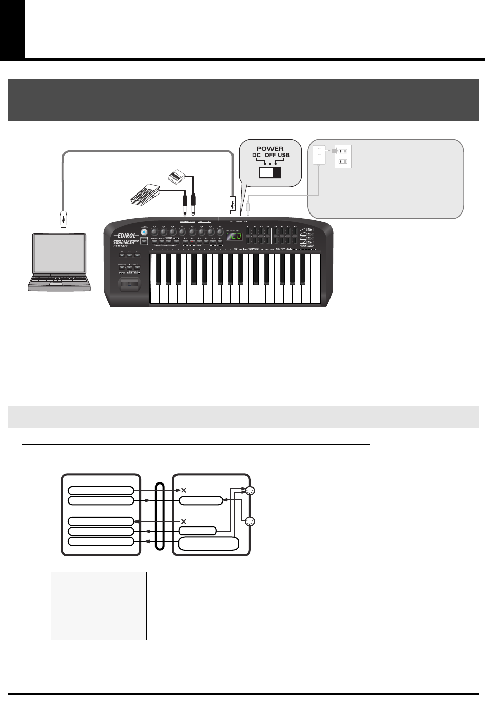
40
Basic connections and MIDI flow
fig.connect-basic
*To prevent malfunction and/or damage to speakers or other devices, always turn down the volume, and
turn off the power on all devices before making any connections.
* Use only the specified expression pedal (EV-5; sold separately). By connecting any other expression
pedals, you risk causing malfunction and/or damage to the unit.
Turn MIDI I/F MODE OFF as described in “MIDI I/F MODE” (p. 94).
fig.flow-USB-b
* For an explanation of the items in the diagram, refer to
“Input / output devices”
(p. 43).
USB connections with your computer
- Sending MIDI messages to your application -
MIDI flow
BULK RECEPTION
BULK data is received here
PORT 1
Of the keyboard, bender lever, and other controllers, those that have been set to
PORT 1
will transmit data from here
PORT 2
Of the keyboard, bender lever, and other controllers, those that have been set to
PORT 2
will transmit data from here
BULK TRANSMISSION
BULK data is transmitted from here
USB cable AC adaptor
It is not necessary to connect the AC
adaptor if you are using a USB connection.
However, with some computers, the PCR-
M30/50/80 may not operate when powered
from the USB bus. In this case, set the
power switch to the DC position and
connect the AC adaptor.
Roland
DP Series (sold separately)
EV-5
(sold separately)
MIDI OUT
MIDI IN
PCR-M30/50/80PC
USB
EDIROL PCR
EDIROL PCR MIDI OUT
EDIROL PCR 2
EDIROL PCR 1 PORT 1
EDIROL PCR MIDI IN
MIDI I/F MODE OFF
PORT 2 /
BULK RECEPTION
MIDI OUT DEVICE
MIDI IN DEVICE
BULK TRANSMISSION
PCR-M30/50/80.book 40 ページ 2005年11月10日 木曜日 午後2時49分
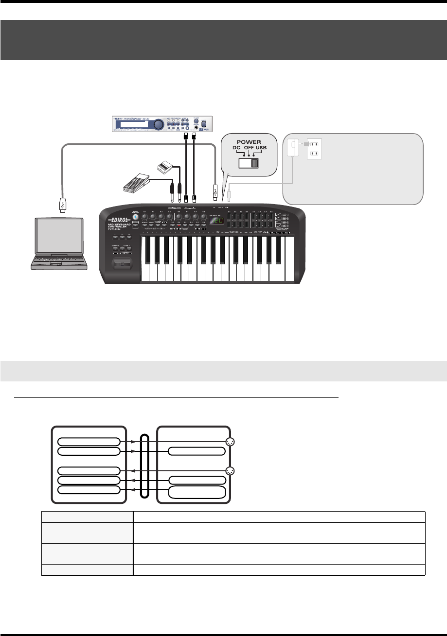
41
Basic connections and MIDI flow
*If you want to use Media Player to play a sound module connected to the PCR’s MIDI OUT connector,
make driver settings as described in
“Settings and checking~Specifying the MIDI input/
output destination~”
(p. 26).
fig.connect-MIDI-IF
*To prevent malfunction and/or damage to speakers or other devices, always turn down the volume, and
turn off the power on all devices before making any connections.
* Use only the specified expression pedal (EV-5; sold separately). By connecting any other expression
pedals, you risk causing malfunction and/or damage to the unit.
Turn MIDI I/F MODE ON as described in “MIDI I/F MODE” (p. 94).
fig.flow-USB-b
* For an explanation of the items in the diagram, refer to
“Input / output devices”
(p. 43).
USB connections with your computer
- Using the PCR-M30/50/80 as a MIDI interface -
MIDI flow
BULK RECEPTION
BULK data is received here
PORT 1
Of the keyboard, bender lever, and other controllers, those that have been set to
PORT 1
will transmit data from here
PORT 2
Of the keyboard, bender lever, and other controllers, those that have been set to
PORT 2
will transmit data from here
BULK TRANSMISSION
BULK data is transmitted from here
MIDI OUT
MIDI sound module (sold separately) MIDI IN
MIDI
IN
MIDI
IN
USB cable
AC adaptor
It is not necessary to connect the AC
adaptor if you are using a USB connection.
However, with some computers, the PCR-
M30/50/80 may not operate when powered
from the USB bus. In this case, set the
power switch to the DC position and
connect the AC adaptor.
Roland
DP series
(sold separately)
EV-5
(sold separately)
MIDI
OUT
MIDI
OUT
PCR-M1PC
USB
EDIROL PCR
EDIROL PCR MIDI OUT
EDIROL PCR 2
EDIROL PCR 1
EDIROL PCR MIDI IN
MIDI OUT
MIDI IN
MIDI I/F MODE ON
PORT 1
PORT 2 /
MIDI OUT DEVICE
MIDI IN DEVICE
BULK RECEPTION
BULK TRANSMISSION
PCR-M30/50/80.book 41 ページ 2005年11月10日 木曜日 午後2時49分
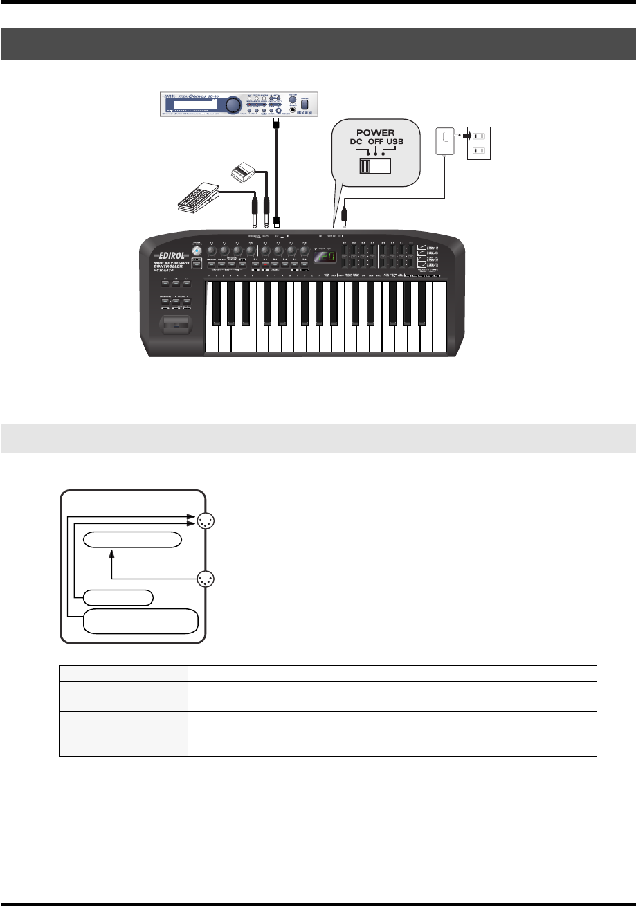
42
Basic connections and MIDI flow
fig.connect-midi
* Use only the specified expression pedal (EV-5; sold separately). By connecting any other expression
pedals, you risk causing malfunction and/or damage to the unit.
fig.flow-midi
* For an explanation of the items in the diagram, refer to
“Input / output devices”
(p. 43).
When using a MIDI connection
MIDI flow
BULK RECEPTION
BULK data is received here
PORT 1
Of the keyboard, bender lever, and other controllers, those that have been set to
PORT 1
will transmit data from here
PORT 2
Of the keyboard, bender lever, and other controllers, those that have been set to
PORT 2
will transmit data from here
BULK TRANSMISSION
BULK data is transmitted from here
MIDI sound module (sold separately)
MIDI IN
MIDI OUT
AC adaptor
Roland
DP series
(sold separately)
EV-5
(sold separately)
PCR-M30/50/80
MIDI OUT
MIDI IN
PORT 1
PORT 2 /
BULK RECEPTION
BULK TRANSMISSION
PCR-M30/50/80.book 42 ページ 2005年11月10日 木曜日 午後2時49分
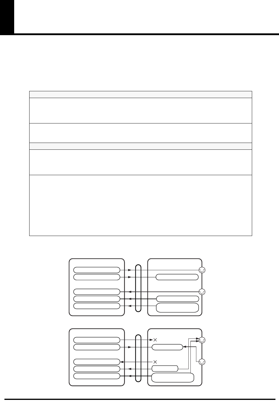
43
Input / output devices
In order to obtain the best performance from your software, you must make the appropriate
input/output device settings.
For details on these settings, refer to the owner’s manual for your software.
* If you are unable to select the PCR-M30/50/80 in the device settings for your software, it is possible
that the driver was not installed correctly. Please reinstall the driver.
fig.flow-USB
MIDI OUT device
PCR MIDI OUT (Mac OS 9: PCR MIDI IN, OUT)
If you specify
PCR MIDI OUT
as the output port for your sequencer software, messages will
be transmitted from the MIDI OUT connector of the PCR-M30/50/80 itself.
* Turn MIDI I/F MODE ON as described in “MIDI I/F MODE” (p. 94).
PCR (Mac OS 9: PCR 1)
This is the bulk reception port. When receiving bulk data into the PCR-M30/50/80, select
PCR
as the output port for your sequencer software or other program.
MIDI IN device
PCR MIDI IN (Mac OS 9: PCR MIDI IN, OUT)
If you specify
PCR MIDI IN
as the input port for your sequencer software, messages will be
input from the PCR-M30/50/80’s
MIDI IN
connector.
* Turn MIDI I/F MODE ON as described in “MIDI I/F MODE” (p. 94).
PCR 1
PCR 2
These ports receive messages from the keyboard, Bender Lever, and controllers.
The port assignment determines how the keyboard, Bender Lever, and controllers are mapped
to
PCR 1
or
PCR 2
.
You may find it convenient to select
PCR 1
for messages used for real-time performance on a
software synthesizer or for recording on a sequencer track, and select
PCR 2
for messages
used to control a sequencer (e.g., sequencer start/stop, or track fader control).
PCR 2
is also the bulk transmission port. When transmitting bulk data from the PCR-M30/
50/80, select
PCR 2
as the input port for your sequencer software.
PCR-M30/50/80PC
USB
EDIROL PCR
EDIROL PCR MIDI OUT
EDIROL PCR 2
EDIROL PCR 1
EDIROL PCR MIDI IN
MIDI OUT
MIDI IN
MIDI OUT
MIDI IN
PCR-M30/50/80PC
USB
EDIROL PCR
EDIROL PCR MIDI OUT
EDIROL PCR 2
EDIROL PCR 1 PORT 1
EDIROL PCR MIDI IN
MIDI I/F MODE ON
MIDI I/F MODE OFF
PORT 1
PORT 2 /
PORT 2 /
MIDI OUT DEVICE
MIDI IN DEVICE
BULK RECEPTION
MIDI OUT DEVICE
MIDI IN DEVICE
BULK RECEPTION
BULK TRANSMISSION
BULK TRANSMISSION
PCR-M30/50/80.book 43 ページ 2005年11月10日 木曜日 午後2時49分
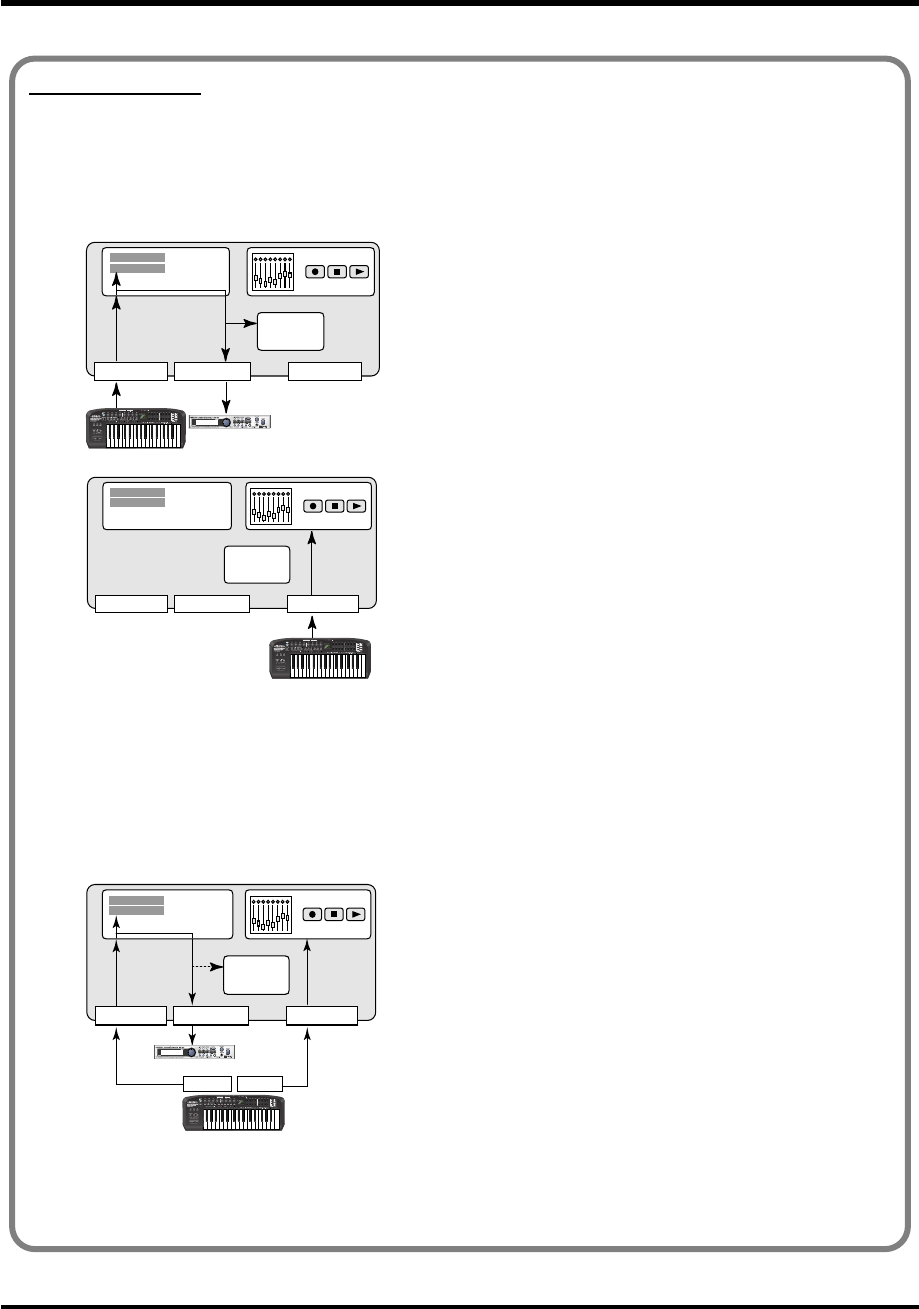
44
Input / output devices
Two MIDI ports
* Two MIDI ports are available only when using a USB connection (p. 40-p. 41). When using a MIDI connection (p. 42), the
two ports are merged (combined into one) for output.
Some sequencer software that supports MIDI controllers lets you independently specify the MIDI
input port used for recording MIDI tracks (the “MIDI IN port”) and the MIDI input port used to control
the software (the “CTRL IN port”).
fig.midi-port.e
Normally, you will connect your MIDI keyboard to the
MIDI IN port, and use it for recording your performance
on tracks or using the MIDI Thru function of your software
to play sound modules or soft synthesizers. The MIDI
messages sent here have the meaning that is assigned to
them by the MIDI specification. In other words, when you
play the keyboard, note messages will be transmitted and
recorded on the track, and the sound module that receives
these messages will produce sound.
fig.midi-port2.e
In contrast, the data received from the CTRL IN port is
used to operate your software in the same way as data from
your computer’s mouse or keyboard; it will not be recorded
on the tracks or “thru-ed” to your sound module or soft
synthesizer. The MIDI messages sent here are interpreted
in a completely different way than defined in the MIDI
specification.
For this reason, messages that are input from the CTRL IN
port are not normally “thru-ed” to your sound module or
soft synthesizer.
For example, even if you play your keyboard to send a
note-on message, the software that receives this message
will not produce a note; instead, it might interpret this
message as meaning that the PLAY/STOP button had been
pressed.
The actual operation that will occur will depend on the
software you are using.
fig.midi-port3.e
Since the same MIDI message can be interpreted in
completely different ways, as described above, the software
lets you specify the MIDI IN port and CTRL IN port
separately so that the two types can be distinguished.
When the PCR-M30/50/80 is connected via USB, you can
select either of the two MIDI ports (PCR 1, PCR 2) as the
output destination for MIDI messages produced by the
fader and knobs, and buttons of the PCR-M30/50/80.
In other words, by assigning “PCR 1” as your software’s
MIDI IN port and “PCR 2” as its CTRL IN port, you can do
things like using the button operations to control mixer
operations in your software while using the knobs to edit
your software synthesizer.
The output destination of the MIDI messages transmitted when you operate the PCR-M30/50/80’s
knobs, and buttons can be specified separately for each controller. (➔Assign MIDI messages (p. 56))
Sequencer software
MIDI IN port MIDI OUT port CTRL IN port
Record on
tracks
Software
synthesizer
Track
Track
THRU
MIDI sound module
PCR
Track
Track
THRU
Sequencer software
MIDI IN port MIDI OUT port CTRL IN port
Record on tracks
Software
synthesizer
PCR
Track
Track
PCR 1 PCR 2
THRU
MIDI IN port MIDI OUT port CTRL IN port
Record on tracks
Software
synthesizer
MIDI sound module
Sequencer software
PCR
PCR-M30/50/80.book 44 ページ 2005年11月10日 木曜日 午後2時49分
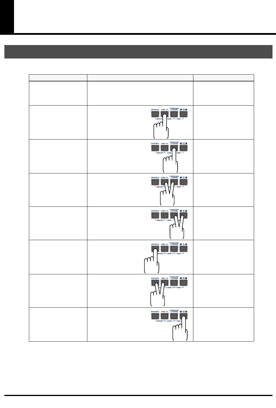
45
Use MIDI functionality
You can switch modes at any time, as shown below.
You are returned to Play mode once a setting or a process has been completed within the other
modes. If you want to return to Play mode without completing a setting or operation, press the
button for the current mode (i.e., the button that is lit). Alternatively, press the
[CANCEL]
button. The setting you were in the process of making will be discarded.
Table of operating modes
Mode Switching modes Explanation
PLAY mode
(p. 46)
When you turn on the power, the PCR-M30/50/
80 will start up in PLAY mode.
Transmit MIDI messages
by playing the keyboard
or operating the control-
lers.
MIDI Channel mode
(MIDI CH)
(p. 48)
Press the
[MIDI CH]
.
Set the transmit channel
(
Current channel
(p. 48))
for the keyboard, bender
lever.
Program Change mode
(PROGRAM CHANGE)
(p. 51)
Press the
[PGOGRAM
CHANGE]
.
Transmit program change
messages on the
Current
channel
(p. 48).
Bank mode
(BANK)
(p. 52)
Simultaneously, press the
[PGOGRAM CHANGE]
and the
[MIDI CH]
.
Transmit bank select mes-
sages (MSB, LSB) on the
Current channel
(p. 48).
Panic mode
(PANIC)
(p. 53)
Simultaneously, press the
[PGOGRAM CHANGE]
and the
[EDIT]
.
Stop “stuck” notes or oth-
er problems with the
sound on a connected
MIDI sound module.
Memory mode
(MEMORY)
(p. 54)
Press the
[MEMORY]
.
Recall a memory set from
internal memory into the
current memory
(p. 84).
Snapshot mode
(SNAPSHOT)
(p. 55)
Simultaneously, press the
[MEMORY]
and the
[MIDI
CH]
.
Transmit the current val-
ues of controllers ([R1--
R8] or [S1--S8]) at once.
Edit mode
(EDIT)
(p. 56)
Press the
[EDIT]
.
Assign MIDI messages to
the controllers, transmit/
receive bulk data, or make
system settings.
PCR-M30/50/80.book 45 ページ 2005年11月10日 木曜日 午後2時49分
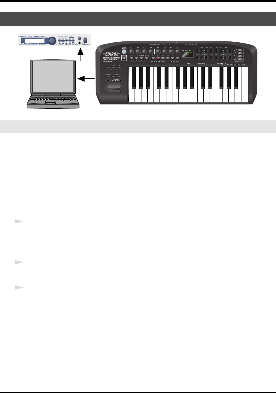
46
Use MIDI functionality
fig.play1
When you power up the PCR-M30/50/80, it will start up in
PLAY mode
.
In PLAY mode, playing the keyboard will transmit note messages to play the connected MIDI
device.
The display will show the
Current channel
(p. 48).
In PLAY mode, you can play the keyboard to produce sound on a connected sound module,
and also use various other functions, such as operating the Bender Lever to change the pitch of
the currently sounding note (Pitch Bend), or to add vibrato (Modulation), or switching the
octave (Octave Shift).
In order to send MIDI messages from the PCR-M30/50/80 to your application, perform the
following steps.
1
Set the MIDI channel the PCR-M30/50/80 will use to transmit to the same channel on the
application is using to receive on.
Use MIDI Channel mode to set the MIDI transmit channel.
(
➔
MIDI Channel mode
(p. 48)).
2
Select a sound on your MIDI sound module.
(
➔
Selecting Sounds on a Sound Module
(p. 50).
3
Once you have finished making settings, try playing the keyboard.
When you play the keyboard in
PLAY mode
, MIDI messages are sent to the application.
*Since the PCR-M30/50/80 does not contain a sound generator, you cannot play MIDI data using the
PCR-M30/50/80 alone.
Startup mode
PLAY mode
MIDI Sound Generator
PCR-M30/50/80.book 46 ページ 2005年11月10日 木曜日 午後2時49分
47
Use MIDI functionality
While playing the keyboard, move the Bender Lever to the left to lower
the pitch of the currently selected patch, or to the right to raise its
pitch. This is known as
pitch bend
.
You can also apply vibrato by gently pressing the Modulation
Controller. This is known as
modulation
.
If you push the lever away from you and the same time move it to the
right or left, you can apply both effects at once.
*The amount of pitch change (“bend range”) depends on the settings of your
sound module.
Octave Shift
and
Transpose
can be set independently.
To switch the PCR-M30/50/80 to PLAY mode...
When you turn on the power, the PCR-M30/50/80 will start up in PLAY mode.
To return to PLAY mode from another mode (
➔
“Setting the MIDI Transmit Channel”
(p. 48)),
press the button of the current mode (i.e., the button that is lit).
Alternatively, you can press the
[CANCEL]
button. In this case, the setting you had been
making will be cancelled.
Features Useful When Playing
Applying Pitch Changes to Notes
(Pitch Bend)
Move the
Bender Lever
(left or right) to transmit
Pitch Bend
mes-
sages, and apply subtle pitch changes to notes.
* The amount of pitch change (“bend range”) depends on the set-
tings of your sound module.
Modifying the Sound of Notes
(Modulation)
Push the
Bender Lever
away from you to transmit
Modulation
messages, changing the sound in real time (usually by adding a vi-
brato effect).
* The type of change this produces in the sound depends on the set-
tings of your sound module.
Changing Octaves
(Octave Shift)
You can press
[OCTAVE -]
or
[OCTAVE +]
to raise or lower the
pitch range of the keyboard (the Octave Shift function).
Press
[OCTAVE -]
once to lower the pitch range one octave. Press
it once again to lower the range an additional octave. Permissible
settings for this range from -4 to 5 octaves.
[OCTAVE -]
or
[OC-
TAVE +]
will light according to the current Octave Shift setting.If
you simultaneously press
[OCTAVE -]
and
[OCTAVE +]
, the Oc-
tave Shift setting will be reset to 0, restoring the normal pitch range
of the keyboard.
Transpose the Pitch of the Keyboard
(Transpose)
You can press
[TRANSPOSE]
+
[OCTAVE +]
or
[TRANSPOSE]
+
[OCTAVE -]
to transpose the keyboard in semitone steps (the
Transpose function).You can transpose the pitch in a range of -12-
12 (semitones).
* If you press and hold
[TRANSPOSE]
,
[OCTAVE -]
or
[OCTAVE
+]
will light according to the current Transpose setting.
* If you hold down
[TRANSPOSE]
and simultaneously press
[OC-
TAVE -]
and
[OCTAVE +]
, the Transpose setting will be reset to 0.
Modulation
Pitch Bend
PCR-M30/50/80.book 47 ページ 2005年11月10日 木曜日 午後2時49分
48
Use MIDI functionality
To control your sound module, set the PCR-M30/50/80’s
current channel
to the MIDI receive channel
that’s selected on your sound module. Use
MIDI Channel mode
to set the
current channel
.
fig.MIDIch-1
fig.MIDIch
1
Press the
[MIDI CH]
button.
The
[MIDI CH]
button will light. The display will show the current channel
setting.
* The
[HEX]
or
[DECIMAL]
button will also light according to the
input mode
(p. 49).
2
Use the
[DEC]
[INC]
buttons or the
[0]
-
[F]
keys of the keyboard to specify the desired channel
number.
3
Press the
[ENTER]
button.
The setting will be cancelled if you press another button instead of the
[ENTER]
button.
The
current channel
has now been set.
Setting the MIDI Transmit Channel
MIDI Channel mode (MIDI CH)
DEC
Change the current value by -1
INC
Change the current value by +1
00-0F
The input value
HEX
...00-0F
DECIMAL
...1-16
Current channel
The current channel is the transmit channel for the keyboard, Bender Lever.
* Each controller has its own independent transmit channel setting.
However, if OMNI mode (p. 49) is on, the controllers will also transmit on the current channel you specify here.
1 23
PCR-M30/50/80.book 48 ページ 2005年11月10日 木曜日 午後2時49分
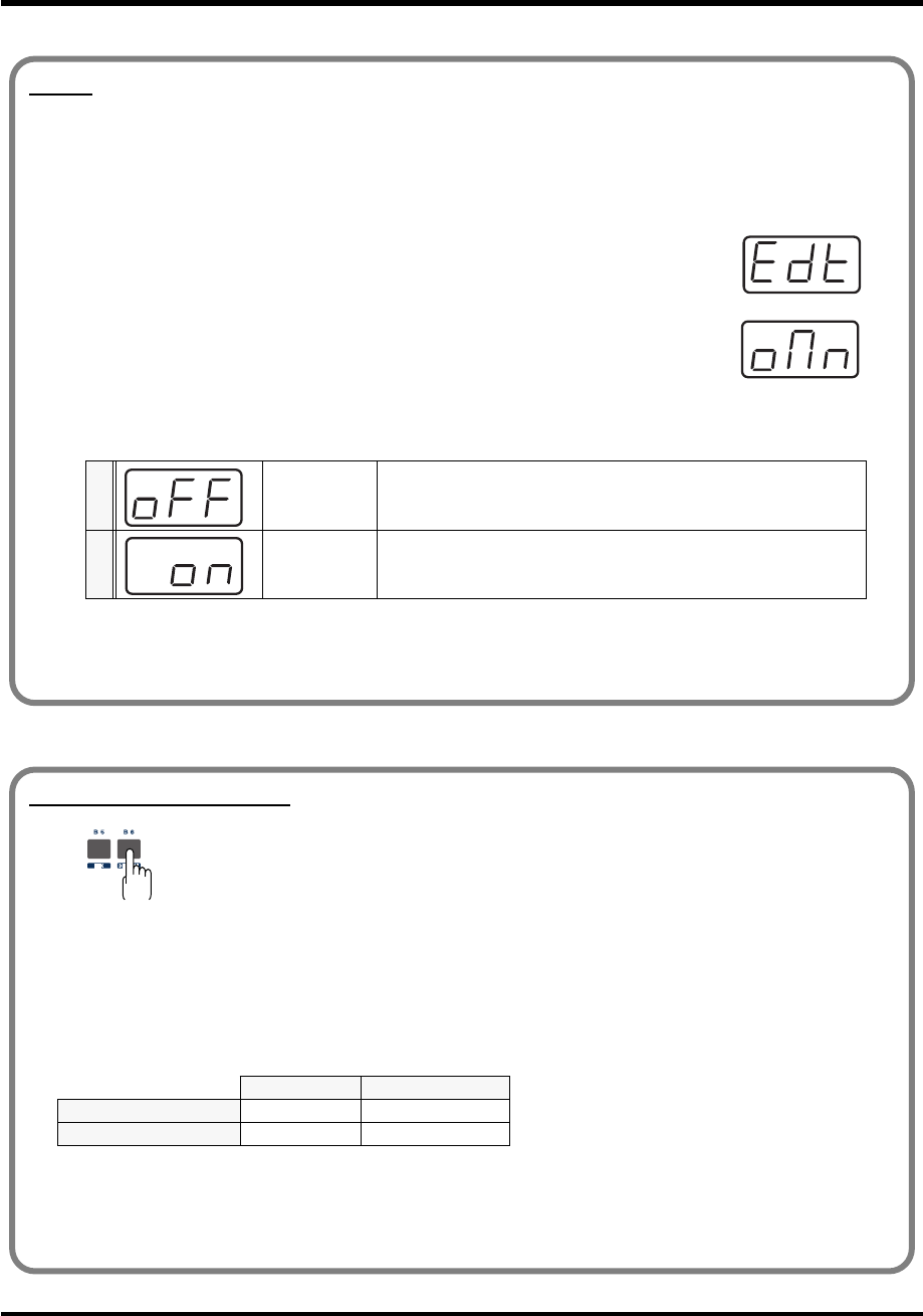
49
Use MIDI functionality
OMNI
If you turn the Omni setting ON, all messages will be transmitted on the Current channel (p. 48)
regardless of the channel that is specified for each controller.
Also, all messages will be transmitted to the KEYBOARD PORT(p. 92) regardless of the port that is
specified for each controller.
fig.omn
1. Press the [EDIT] button.
The display will indicate “EDT.”
fig.omn
2. Press the [OMNI] key.
The display will blink “OMN.”
3. Confirm what’s indicated and press the [ENTER] button.
The display will show the current setting.
4. Use the [DEC] [INC] buttons or the [0] [1] keys to select the mode.
5. Press the [ENTER] button.
0 OMNI OFF Messages will be transmitted on the channel and port specified for
each controller.
1 OMNI ON
Messages will be transmitted on the current channel from the Key-
board Port, regardless of the channel and port specified for each con-
troller.
Setting the input mode
fig.hexdec
If you are not in Play mode, you can use one of two ways to input a numerical value into
the PCR-M30/50/80; Decimal input mode or Hexadecimal input mode.
If you want to input decimal numbers, press the [DECIMAL] button. If you want to input
hexadecimal numbers, press the [HEX] button.
* When you turn on the power, the PCR-M30/50/80 will start up in Decimal mode.
Decimal and hexadecimal numbers correspond as follows.
Decimal: 0-127
Hexadecimal: 00-7F
However, for MIDI CH and PROGRAM CHANGE, the values are as follows.
*Normally, the display will show three digits when using Decimal input mode. For this reason, there will be no
indication of the parameter you are now inputting, and you may lose track of what you are doing. If this occurs,
you can temporarily switch back to Hexadecimal mode to check the parameter you are inputting. Then switch
back to Decimal mode and continue.
Decimal Hexadecimal
MIDI CH 1-16 00-0F
PROGRAM CHANGE 1-128 00-7F
PCR-M30/50/80.book 49 ページ 2005年11月10日 木曜日 午後2時49分

50
Use MIDI functionality
To select a sound on your MIDI sound module, transmit a Program Change in
Program
Change mode
.
To select a sound from a different bank, first use
Bank mode
to transmit a Bank Select message
that switches the bank. Then transmit a program change.
* You must send the Bank Select message before sending the Program Change message.
•
Program Change Mode
......................................................... (p. 51)
•
Bank mode
............................................................................... (p. 52)
Selecting Sounds on a Sound Module
(Sending Program Change / Bank Select Massages)
What is a bank?
MIDI sound modules organize their numerous sounds in various groups according to the category of
sound.
These groups are called “banks.”
Program Change messages can only select sounds within the same bank, but by using these in
conjunction with Bank Select messages, you can select different variations of sound.
* The way in which sounds are organized will differ for each sound module. For details, refer to the owner’s
manual of the sound module you are using.
PCR-M30/50/80.book 50 ページ 2005年11月10日 木曜日 午後2時49分
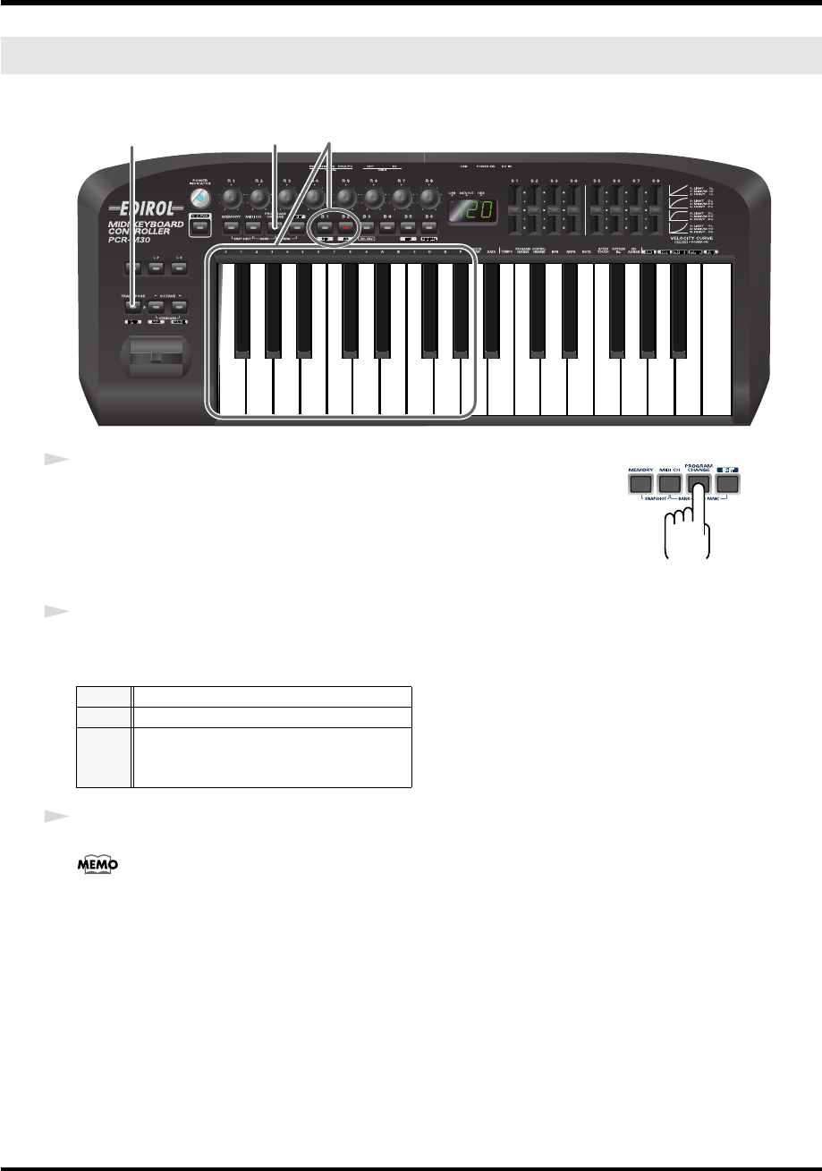
51
Use MIDI functionality
This mode lets you transmit a program change message on the
Current channel
(p. 48).
fig.PC-1_75
fig.program
1
Press the
[PROGRAM CHANGE]
button.
The
[PROGRAM CHANGE]
button will light. The display will indicate the
program change that was transmitted most recently.
* The
[HEX]
or
[DECIMAL]
button will also light according to the
input mode
(p. 49).
2
Use the
[DEC][INC]
buttons or the
[0]
-
[F]
keys of the keyboard to specify the program change
you want to transmit.
3
Press the
[ENTER]
button.
The setting will be cancelled if you press another button instead of the
[ENTER]
button.
The program change has now been transmitted.
Program Change mode (PROGRAM CHANGE)
DEC
Change the current value by -1
INC
Change the current value by +1
00- 0F
The input value
HEX
...00-7F
DECIMAL
...1-128
12
3
PCR-M30/50/80.book 51 ページ 2005年11月10日 木曜日 午後2時49分
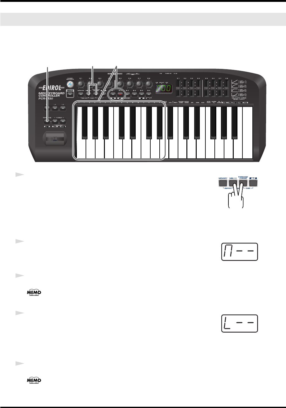
52
Use MIDI functionality
This mode lets you transmit a bank select (MSB, LSB) message on the
Current channel
(p. 48).
The program change message you most recently transmitted (specified) in
Program Change
mode
(p. 51) will also be transmitted following the bank select message.
fig.BANK-1_75
fig.bank
1
Simultaneously press the
[PROGRAM CHANGE]
button and
[MIDI CH]
button.
The
[PROGRAM CHANGE]
and
[MIDI CH]
buttons will light. The display
will indicate the most recently transmitted bank select (MSB) value.
* The
[HEX]
or
[DECIMAL]
button will also light according to the
input mode
(p. 49).
fig.BANK-2
2
First, specify the bank select MSB (CC#00).
Use the
[DEC][INC]
buttons or the
[0]
-
[F]
keys of the keyboard to specify the
bank select MSB that you want to transmit.
3
Press the
[ENTER]
button.
The setting will be cancelled if you press another button instead of the
[ENTER]
button.
fig.BANK-3
4
Next, specify the bank select LSB (CC#32).
The display will indicate the most recently transmitted bank select (LSB)
value.
Use the
[DEC][INC]
buttons or the
[0]
-
[F]
keys of the keyboard to specify the
bank select LSB that you want to transmit.
5
Press the
[ENTER]
button.
The setting will be cancelled if you press another button instead of the
[ENTER]
button.
The bank select has now been transmitted.
Bank mode (BANK)
12,4
3,5
*1 Reference
*1 Reference
*1 The -- area displays the currently set value. If it has not been set, the default setting will be displayed. Even if you change the type or mode
of the MIDI message that is assigned, the default setting will be displayed. This will be lit if the value is the same as the currently set value,
or will blink if the value is different.
PCR-M30/50/80.book 52 ページ 2005年11月10日 木曜日 午後2時49分
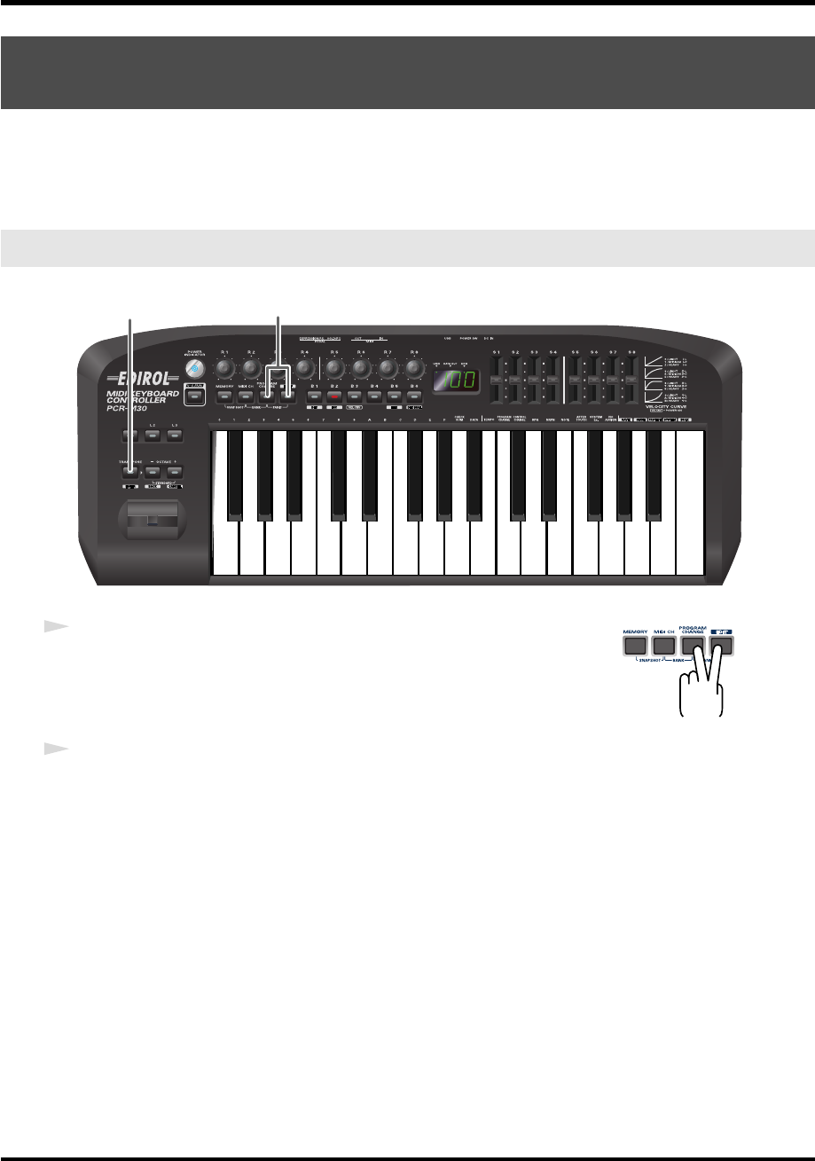
53
Use MIDI functionality
If notes on a connected MIDI sound module become “stuck,” or if there is something wrong
with the sound, you can execute the Panic function to solve the problem.
When you execute the Panic function,
All sounds off,
All notes off,
and
Reset all controllers
messages will be transmitted on all channels.
fig.panic-1_80
fig.panic
1
Simultaneously press the
[PROGRAM CHANGE]
button and
[EDIT]
button.
The
[PROGRAM CHANGE]
button and
[EDIT]
button will light.
2
Press the
[ENTER]
button.
The
[PROGRAM CHANGE]
button and
[EDIT]
button will blink.
The Panic function has now been executed.
Transmitting a Reset message
(What to do if there are “stuck” MIDI notes)
Panic Mode (PANIC)
1
2
PCR-M30/50/80.book 53 ページ 2005年11月10日 木曜日 午後2時49分
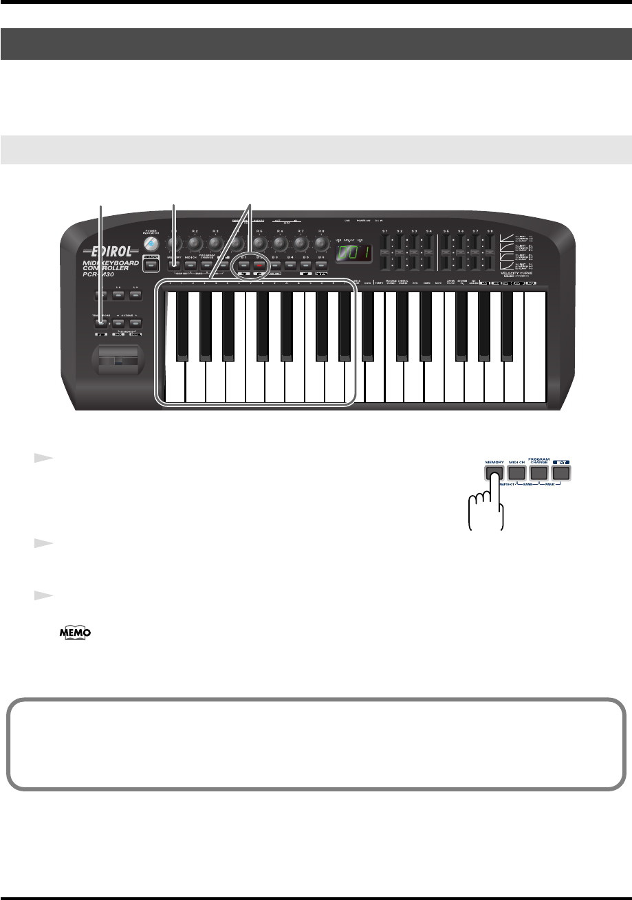
54
Use MIDI functionality
When the PCR-M30/50/80 is shipped, its internal memory contains sixteen different settings.
For details on the contents of each memory number, refer to
“Memory sets”
(p. 98).
You will use Memory mode to change the Memory sets.
fig.memory-1_80
fig.memory
1
Press the
[MEMORY]
button.
The
[MEMORY]
button will light. The display will indicate the memory
number that you selected most recently.
2
Use the
[DEC][INC]
buttons or the
[0]
-
[F]
keys of the keyboard to specify the memory number
that you want to recall.
3
Press the
[ENTER]
button.
The setting will be cancelled if you press another button instead of the
[ENTER]
button.
The memory has now been recalled.
Changing the Memory Sets
Memory mode (MEMORY)
1 2
3
For details on customizing (editing) the controller settings, refer to “Assign MIDI messages” (p. 56).
If you edit the controller settings of a memory you recall, and want to keep your changes, you must
save the memory before powering down the PCR-M30/50/80. For the procedure, refer to “Saving a
memory set” (p. 84).
PCR-M30/50/80.book 54 ページ 2005年11月10日 木曜日 午後2時49分
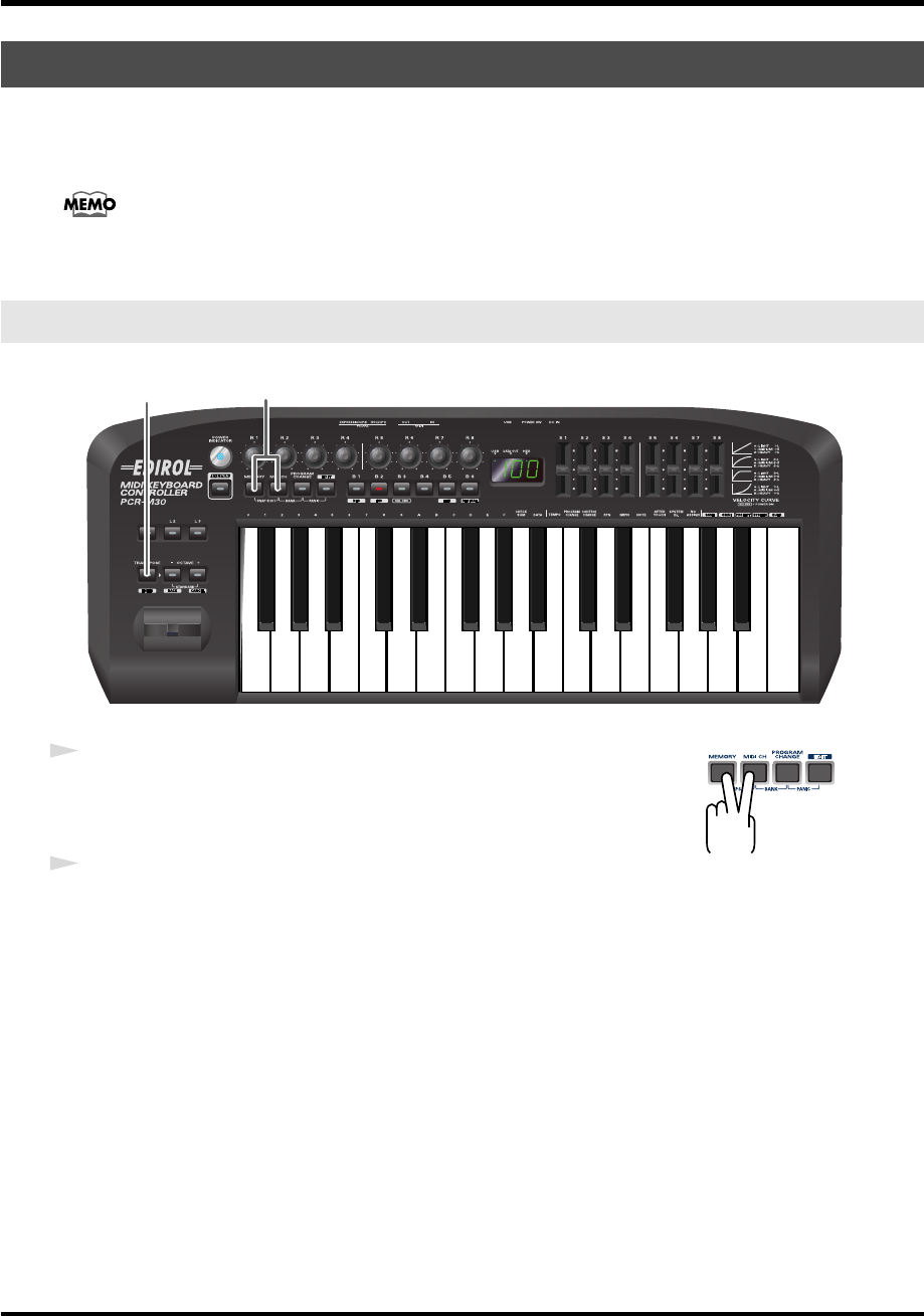
55
Use MIDI functionality
Once you have set the various controllers to the desired settings, you can transmit a detailed
description of this state in the form of a
“snapshot
.
”
When you execute this function, the
current values of the controllers
[R1-R8]
or
[S1-S8]
will be transmitted.
This is convenient when you want to record the state of these controllers together at the
beginning of a song in your sequencer, as the initial values.
fig.snap-1_80
fig.snap
1
Simultaneously press the
[MEMORY]
button and the
[MIDI CH]
button.
The
[MEMORY]
and
[MIDI CH]
buttons will light.
2
Press the
[ENTER]
button.
The
[MEMORY]
and
[MIDI CH]
button will blink several times.
The snapshot will be transmitted.
Transmitting the current controller values all at once
Snapshot mode (SNAPSHOT)
1
2
PCR-M30/50/80.book 55 ページ 2005年11月10日 木曜日 午後2時49分
56
Use MIDI functionality
You can assign the following functions to a controller.
You will use Edit mode to assign MIDI messages.
* You can copy assigned messages to another controller, or cancel an assignment. For details, refer to
Copying a MIDI message assignment
(p. 82) or
Canceling a MIDI message assignment
(p. 83).
*If you want to assign a single-byte system message (system realtime message, tune request) or a freely
specified message of up to 24 bytes, refer to
“SYS EX. ASSIGN”
(p. 72).
fig.Edit-1_80
Assign MIDI messages
MIDI Message Assigning method
NOTE
➔
NOTE ASSIGN (p. 57)
AFTERTOUCH
➔
AFTERTOUCH ASSIGN (p. 60)
CONTROL CHANGE
➔
CONTROL CHANGE ASSIGN (p. 63)
PROGRAM CHANGE
➔
PROGRAM CHANGE ASSIGN (p. 66)
RPN
➔
RPN / NRPN ASSIGN (p. 69)
NRPN
➔
RPN / NRPN ASSIGN (p. 69)
Sys Ex
➔
Sys Ex. ASSIGN (p. 72)
TEMPO (20-250)
➔
TEMPO ASSIGN (p. 81)
Edit mode (EDIT)
How Basic mode and Advanced mode differ
The assignments NOTE, AFTERTOUCH, CONTROL CHANGE, PROGRAM CHANGE, RPN, NRPN,
Sys Ex. can be made either in Basic mode or Advanced mode.
Use the mode that is appropriate for your purpose.
•Basic mode :You can make assignments easily, with the minimum number of steps.
•Advanced mode :A greater number of steps are required, but you can specify more parameters
and make more sophisticated assignments.
* For these assignments, the rightmost digit (third place) in the display is a number that indicates the mode
(Basic mode or Advanced mode).
PCR-M30/50/80.book 56 ページ 2005年11月10日 木曜日 午後2時49分
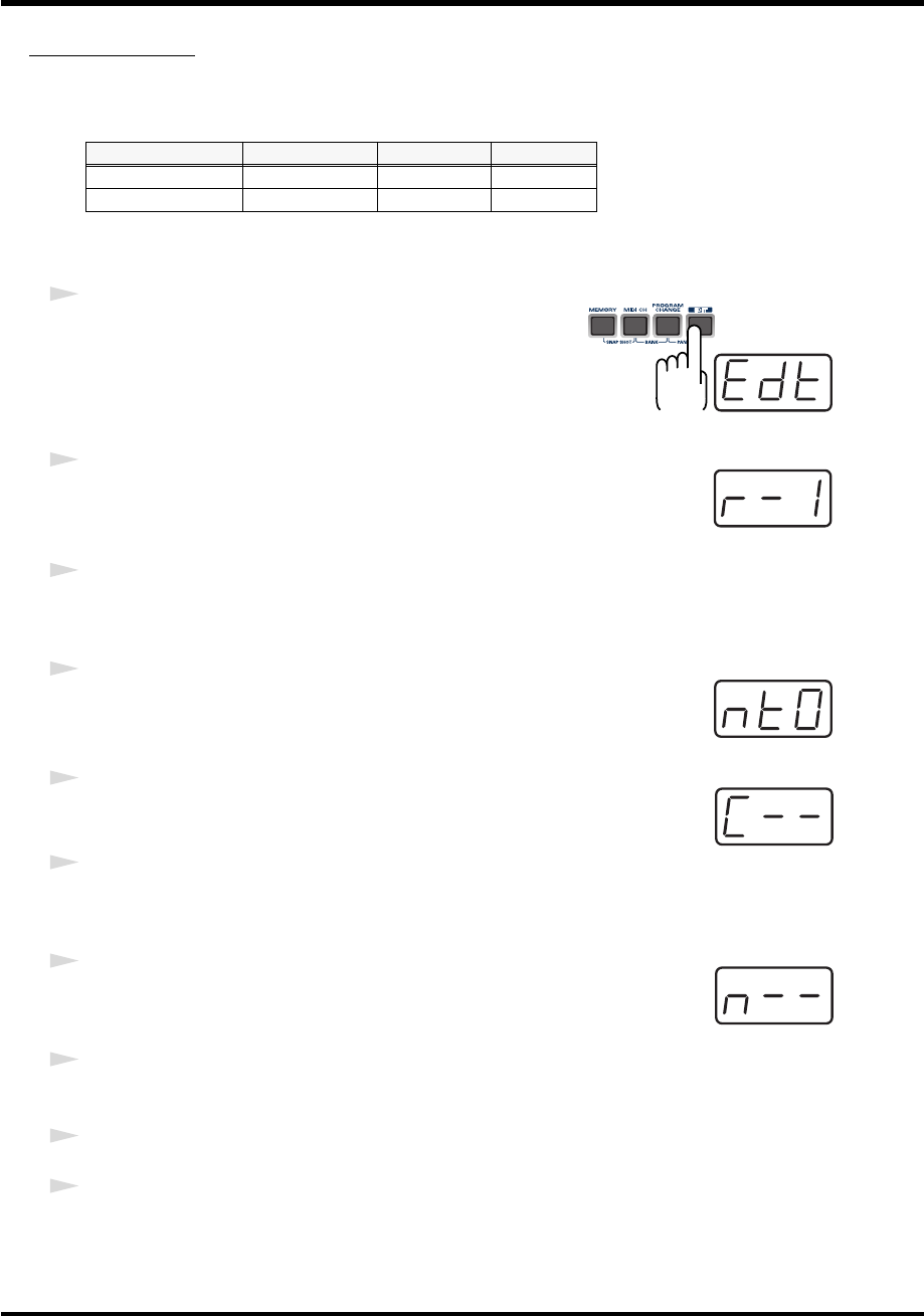
57
Use MIDI functionality
NOTE ASSIGN
Here’s how to assign a Note message to a controller. In addition to being used to play sounds,
note messages can also be used to control a sequencer.
■
Basic mode
fig.edt
1
Press the
[EDIT]
button.
The display will indicate “EDT.”
fig.r-1
2
Slightly move the controller to which you want to assign a Note message.
In the case of a button, press that button.
The display will indicate the number of the selected controller.
3
Verify that the display shows the correct controller number, and press the
[ENTER]
button.
fig.nt0
4
Press the
[NOTE]
key.
The display will indicate “NT0.”
fig.c
5
Press the
[ENTER]
button.
The display will indicate “C–.”
6
Input the channel. Use the
[DEC][INC]
buttons or the
[0]
-
[F]
keys to specify
the channel.
fig.n
7
Press the
[ENTER]
button.
The display will indicate “N–.”
8
Input the note number. Use the
[DEC][INC]
buttons or the
[0]
-
[F]
keys to specify the note
number.
9
Press the
[ENTER]
button.
10
If you are making an assignment for a button, specify the button mode.
(
➔
“Specifying the button mode”
(p. 59))
Mode Keyboard Velocity Port
Basic mode 0 100 (64H) PORT 1
Advanced mode 1 Assignable Assignable
*1 Reference
*1 Reference
PCR-M30/50/80.book 57 ページ 2005年11月10日 木曜日 午後2時49分

58
Use MIDI functionality
•If you set
[S1--S8]
,
[R1--R8]
, or
[P2]
to NOTE ASSIGN, the specified velocity value will be
transmitted when the controller is at its maximum position. If the controller is lowered
slightly below its maximum position, note messages with a velocity of zero will be
transmitted.
• If you assign this to
[B1–B6]
or
[P1]
, the specified velocity value will be transmitted when
you turn the controller on. When you turn the controller off, a note message with a velocity
value of 0 will be transmitted.
■Advanced mode
Advanced mode 1 of NOTE ASSIGN lets you specify the velocity value in addition to the items
of Basic mode.
1. Press the [EDIT] button.
2. Slightly move the controller to which you want to assign a Note message.
In the case of a button, press that button.
The display will indicate the number of the selected controller.
3. Verify that the display indicates the correct controller, and press the [ENTER] button.
4. Press the [NOTE] key and then press key [1].
The display will indicate “NT1.”
5. Press the [ENTER] button.
6. Input the channel.
7. Press the [ENTER] button.
8. Input the note number.
fig.v
9. Press the [ENTER] button.
The display will indicate “V–.”
10. Input the velocity.
fig.p
11. Press the [ENTER] button.
The display will indicate “P–.”
12. Specify the output port. (➔“Specifying the port” (p. 59))
13. If you are making an assignment for a button, specify the button mode.
(➔“Specifying the button mode” (p. 59))
*1 Reference
*1 Reference
*1 The -- area displays the currently set value. If it has not been set, the default setting will be displayed. Even if you change the type or mode
of the MIDI message that is assigned, the default setting will be displayed. This will be lit if the value is the same as the currently set value,
or will blink if the value is different.
PCR-M30/50/80.book 58 ページ 2005年11月10日 木曜日 午後2時49分
59
Use MIDI functionality
Specifying the button mode
When you make Assign settings in Edit mode(p. 56) to assign a message to a button, you must specify
the operating mode of the button (button mode).
When you use a button as a controller, turning the button on will transmit the maximum specified
value, and turning it off will transmit the minimum value.
1. Press the [0] or [1] key to select either Latch mode or Toggle mode.
2. Press the [ENTER] button.
0 Latch mode The setting will turn on when you press the button, and off when you
release it. The button will remain lit while you are pressing it.
1 Toggle mode
The setting will alternate on/off each time you press the button. The
button will light when an On message is transmitted, and will go dark
when an Off message is transmitted.
Specifying the port
When you are making Assign settings in Edit mode(p. 56) and have selected Advanced mode, you
must specify the USB port to which the message assigned to the controller will be sent when using a
USB connection.
1. Press a key [1] - [3] to select the port.
2. Press the [ENTER] button.
* For details on the port, refer to “Input / output devices” (p. 43).
1 PORT 1 Messages will be sent to “PCR 1”
2 PORT 2 Messages will be sent to “PCR 2”
3 PORT 1, 2 Messages will be sent to both “PCR 1” and “PCR 2”
*1 The -- area displays the currently set value. If it has not been set, the default setting will be displayed. Even if you change the type or mode
of the MIDI message that is assigned, the default setting will be displayed. This will be lit if the value is the same as the currently set value,
or will blink if the value is different.
PCR-M30/50/80.book 59 ページ 2005年11月10日 木曜日 午後2時49分
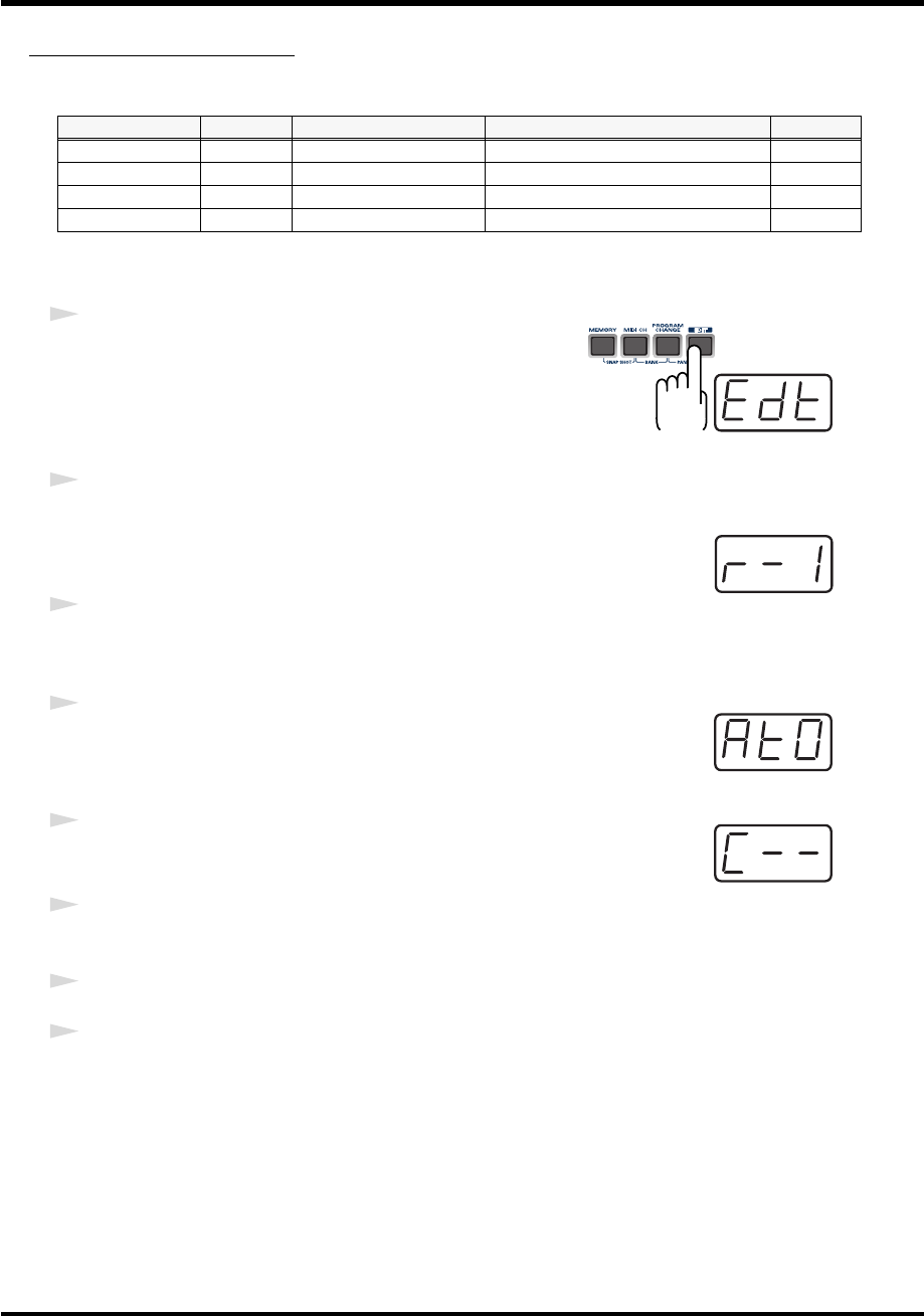
60
Use MIDI functionality
AFTERTOUCH ASSIGN
Here’s how to assign an Aftertouch message to a controller.
■
Basic mode
fig.edt
1
Press the
[EDIT]
button.
The display will indicate “EDT.”
fig.r-1
2
Slightly move the controller to which you want to assign an Aftertouch
message. In the case of a button, press that button.
The display will indicate the number of the selected controller.
3
Verify that the display shows the correct controller number, and press the
[ENTER]
button.
fig.at0
4
Press the
[AFTERTOUCH]
key.
The display will indicate “AT0.”
fig.c
5
Verify that the display is correct, and press the
[ENTER]
button.
The display will indicate “C–.”
6
Input the channel. Use the
[DEC][INC]
buttons or the
[0]
-
[F]
keys to specify
the channel.
7
Press the
[ENTER]
button.
8
If you are making an assignment for a button, specify the button mode.
(
➔
“Specifying the button mode”
(p. 59))
Mode Keyboard Message Value range Port
Basic mode 0 Channel Pressure 0-127(00-7FH) Port 1
Advanced mode 1 1 Channel Pressure Upper and lower limits are assignable Assignable
Advanced mode 2 2 Polyphonic Key Pressure 0-127(00-7FH) Port 1
Advanced mode 3 3 Polyphonic Key Pressure Upper and lower limits are assignable Assignable
*1 Reference
*1 The -- area displays the currently set value. If it has not been set, the default setting will be displayed. Even if you change the type or mode
of the MIDI message that is assigned, the default setting will be displayed. This will be lit if the value is the same as the currently set value,
or will blink if the value is different.
PCR-M30/50/80.book 60 ページ 2005年11月10日 木曜日 午後2時49分
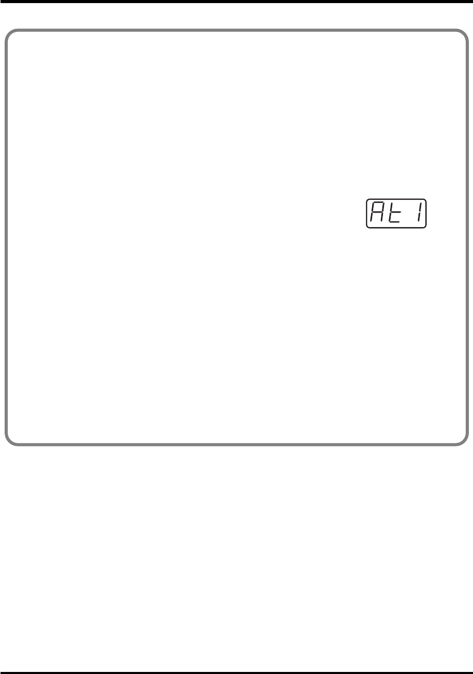
61
Use MIDI functionality
■Advanced mode 1-3
Advanced mode 1 of AFTERTOUCH ASSIGN lets you specify the upper and lower limits of
the aftertouch value in addition to the items of Basic mode. Advanced modes 2 and 3 let you
specify an aftertouch message for an individual note (Polyphonic Key Pressure) instead of
specifying the channel.
1. Press the [EDIT] button.
2. Slightly move the controller to which you want to assign an Aftertouch message. In the
case of a button, press that button.
The display will indicate the number of the selected controller.
3. Verify that the display indicates the correct controller, and press the [ENTER] button.
fig.at1
4. Press the [AFTERTOUCH] key and then press a key [1]-[3].
The display will indicate the selected mode.
5. Press the [ENTER] button.
6. Input the channel.
7. Press the [ENTER] button.
8. If you are using Advanced modes 2 or 3, input the note number.
9. If you are using Advanced modes 2 or 3, Press the [ENTER] button.
10. If you are using Advanced modes 1 or 3, specify the upper limit and lower limit of the
value as described in “Specifying the range of values (upper and lower limits)” (p. 62).
11. If you are using Advanced modes 1 or 3, specify the output port.
(➔“Specifying the port” (p. 59))
12. If you are making an assignment for a button, specify the button mode.
(➔“Specifying the button mode” (p. 59))
PCR-M30/50/80.book 61 ページ 2005年11月10日 木曜日 午後2時49分

62
Use MIDI functionality
Specifying the range of values (upper and lower limits)
If in Edit mode you selected an Assign type (p. 56) that lets you specify the range of values, you will
need to specify the upper limit and lower limit of the value.
Normally, when using Decimal input mode, the value you are specifying appears in the display as a
three digit number. This means that there is no indication of which parameter you are currently
entering, so you may lose track of what you are doing. If this occurs, you can temporarily switch to
Hex input mode to check the parameter that you are now inputting. Then switch back to Decimal input
mode and continue. (➔“Setting the input mode” (p. 49))
fig.max
1. The following display will appear.
2. Use the [DEC] [INC] buttons, or the [0] - [F] keys to specify the
upper limit.
fig.min
3. Press the [ENTER] button.
The following display will appear.
4. Use the [DEC] [INC] buttons, or the [0] - [F] keys to specify the lower limit.
5. Press the [ENTER] button.
*1 Reference
*1 Reference
*1 The -- area displays the currently set value. If it has not been set, the default setting will be displayed. Even if you change the type or mode
of the MIDI message that is assigned, the default setting will be displayed. This will be lit if the value is the same as the currently set value,
or will blink if the value is different.
PCR-M30/50/80.book 62 ページ 2005年11月10日 木曜日 午後2時49分
63
Use MIDI functionality
CONTROL CHANGE ASSIGN
Here’s how to assign a control change message to a controller.
■
Basic mode
fig.edt
1
Press the
[EDIT]
button.
The display will indicate “EDT.”
fig.r-1
2
Slightly move the controller to which you want to assign a Control Change
message. In the case of a button, press that button.
The display will indicate the number of the selected controller.
3
Confirm what’s indicated, and press the
[ENTER]
button.
fig.cc0
4
Press the
[CONTROL CHANGE]
key.
The display will indicate “CC0.”
fig.c
5
Confirm what’s indicated, and press the
[ENTER]
button.
The display will indicate “C–.”
6
Input the channel. Use the
[DEC][INC]
buttons or the
[0]
-
[F]
keys to specify
the channel.
fig.n
7
Press the
[ENTER]
button.
The display will indicate “N–.”
8
Use the
[DEC][INC]
buttons or the
[0]
-
[F]
keys to specify the control change
number.
9
Press the
[ENTER]
button.
10
If you are making an assignment for a button, specify the button mode.
(
➔
“Specifying the button mode”
(p. 59))
Mode keyboard Value range Port
Basic mode 0 0-127(00-7FH) PORT 1
Advanced mode 1 1 Upper and lower limits are assignable Assignable
Advanced mode 2 2 Simulates a rotary encoder Assignable
*1 Reference
*1 Reference
*1 The -- area displays the currently set value. If it has not been set, the default setting will be displayed. Even if you change the type or mode
of the MIDI message that is assigned, the default setting will be displayed. This will be lit if the value is the same as the currently set value,
or will blink if the value is different.
PCR-M30/50/80.book 63 ページ 2005年11月10日 木曜日 午後2時49分

64
Use MIDI functionality
■Advanced mode 1
Advanced mode 1 of CONTROL CHANGE ASSIGN lets you specify the upper and lower
limits of the control change value in addition to the items of Basic mode.
1. Press the [EDIT] button.
2. Slightly move the controller to which you want to assign a Control Change message. In
the case of a button, press that button.
The display will indicate the number of the selected controller.
3. Confirm what’s indicated, and press the [ENTER] button.
4. Press the [CONTROL CHANGE] key and then press key [1].
The display will indicate “CC1.”
5. Press the [ENTER] button.
6. Input the channel.
7. Press the [ENTER] button.
8. Input the control change number.
9. Press the [ENTER] button.
The following display will appear.
fig.p
10. Specify the range of values.
(➔“Specifying the range of values (upper and lower limits)” (p. 62))
The display will indicate “P-.”
11. Specify the output port. (➔“Specifying the port” (p. 59))
12. If you are making an assignment for a button, specify the button mode.
(➔“Specifying the button mode” (p. 59))
*1 Reference
*1 The -- area displays the currently set value. If it has not been set, the default setting will be displayed. Even if you change the type or mode
of the MIDI message that is assigned, the default setting will be displayed. This will be lit if the value is the same as the currently set value,
or will blink if the value is different.
PCR-M30/50/80.book 64 ページ 2005年11月10日 木曜日 午後2時49分

65
Use MIDI functionality
■Advanced mode 2
Advanced mode 2 simulates the operation of a conventional rotary encoder. If this is assigned
to a controller, moving that controller toward the right (upward) of center will have the same
effect as turning the encoder clockwise, and moving the controller toward the left (downward)
of center will have the same effect as turning the encoder counterclockwise. As the controller is
moved further away from the center, the result will be the same as if the rotary encoder were
moved more quickly.
You can assign advanced mode 2 to a button, but it will not function.
1. Press the [EDIT] button.
2. Slightly move the controller to which you want to assign a Control Change message.
The display will indicate the number of the selected controller.
3. Confirm what’s indicated, and press the [ENTER] button.
4. Press the [CONTROL CHANGE] key and then press key [2].
The display will indicate “CC2.”
5. Press the [ENTER] button.
6. Input the channel.
7. Press the [ENTER] button.
8. Input the control change number. Use the [DEC][INC] buttons or the [0]-[F] keys to
specify the control change number.
fig.p
9. Press the [ENTER] button.
The display will indicate “P–.”
10. Specify the output port. (➔“Specifying the port” (p. 59))
*1 Reference
*1 The -- area displays the currently set value. If it has not been set, the default setting will be displayed. Even if you change the type or mode
of the MIDI message that is assigned, the default setting will be displayed. This will be lit if the value is the same as the currently set value,
or will blink if the value is different.
PCR-M30/50/80.book 65 ページ 2005年11月10日 木曜日 午後2時49分
66
Use MIDI functionality
PROGRAM CHANGE ASSIGN
Here’s how to assign a program change message to a controller.
■
Basic mode
fig.edt
1
Press the
[EDIT]
button.
The display will indicate “EDT.”
fig.r-1
2
Slightly move the controller to which you want to assign a Program Change
message. In the case of a button, press that button.
The display will indicate the number of the selected controller.
3
Confirm what’s indicated, and press the
[ENTER]
button.
fig.pc0
4
Press the
[PROGRAM CHANGE]
key.
The display will indicate “PC0.”
fig.c
5
Confirm what’s indicated, and press the
[ENTER]
button.
The display will indicate “C–.”
6
Input the channel. Use the
[DEC][INC]
buttons or the
[0]
-
[F]
keys to specify
the channel.
fig.n
7
Press the
[ENTER]
button.
The display will indicate “N–.”
8
Use the
[DEC][INC]
buttons or the
[0]
-
[F]
keys to specify the program
change number.
9
Press the
[ENTER]
button.
* If you assign Basic mode to
[S1–S8]
,
[R1–R8]
, or
[P2]
, moving the controller to the maximum
position will transmit the assigned control change messages.
Mode Number Effect Bank Port
Basic mode 0 Fixed value Not output PORT 1
Advanced mode 1 1 Upper and lower limits are assignable Not output PORT 1
Advanced mode 2 2 Fixed value Output Assignable
Advanced mode 3 3 PC DEC Not output PORT 1
Advanced mode 4 4 PC INC Not output PORT 1
*1 Reference
*1 Reference
*1 The -- area displays the currently set value. If it has not been set, the default setting will be displayed. Even if you change the type or mode
of the MIDI message that is assigned, the default setting will be displayed. This will be lit if the value is the same as the currently set value,
or will blink if the value is different.
PCR-M30/50/80.book 66 ページ 2005年11月10日 木曜日 午後2時49分
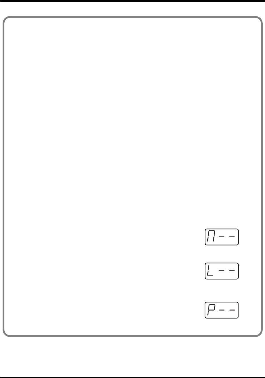
67
Use MIDI functionality
■Advance mode 1, 2
Advanced mode 1 of PROGRAM CHANGE ASSIGN lets you specify the upper and lower
limits of the program change value. Advanced mode 2 lets you transmit BANK LSB/MSB
settings in addition to the program change.
1. Press the [EDIT] button.
2. Slightly move the controller to which you want to assign a Program Change message. In
the case of a button, press that button. The display will indicate the number of the selected
controller.
3. Confirm what’s indicated, and press the [ENTER] button.
Advanced mode 1-Specifying the range of values
4. Press the [PROGRAM CHANGE] key and then press key [1].
5. Press the [ENTER] button.
6. Input the channel.
7. Press the [ENTER] button.
8. Specify the range of values.
(➔“Specifying the range of values (upper and lower limits)” (p. 62))
Advanced mode 2-Transmitting bank data
4. Press the [PROGRAM CHANGE] key and then press key [2].
5. Press the [ENTER] button.
6. Input the channel.
7. Press the [ENTER] button.
fig.BANK-2
8. Specify the bank select MSB (CC#00). Use the [DEC][INC] buttons or the
[0]-[F] keys to specify the MSB.
9. Press the [ENTER] button.
fig.BANK-3
10. Specify the bank select LSB (CC#32). Use the [DEC][INC] buttons or the
[0]-[F] keys to specify the LSB.
11. Press the [ENTER] button.
12. Input the program change number.
fig.p1
13. Press the [ENTER] button.
The display will indicate “P–.”
14. Specify the output port. (➔“Specifying the port” (p. 59))
*1 Reference
*1 Reference
*1 Reference
*1 The -- area displays the currently set value. If it has not been set, the default setting will be displayed. Even if you change the type or mode
of the MIDI message that is assigned, the default setting will be displayed. This will be lit if the value is the same as the currently set value,
or will blink if the value is different.
PCR-M30/50/80.book 67 ページ 2005年11月10日 木曜日 午後2時49分

68
Use MIDI functionality
Program Change Decrement function (PC DEC)
This transmits a program change that is one less than the previously transmitted program
change number.
Program Change Increment function (PC INC)
This transmits a program change that is one greater than the previously transmitted program
change number.
The
PC DEC
or
PC INC
is transmitted on the current channel, just as in
“Program Change
mode”
(p. 51). The value that is actually transmitted will appear in the display.
• In the explanation here, the “previously transmitted program number” refers to the one
that was last transmitted by Advanced Mode 3 or 4 or in
“Program Change mode”
(p. 51).
• Program changes transmitted by basic mode or advanced modes 1 and 2 will not affect the
increment/decrement functions.
■Advanced modes 3 and 4
Advanced mode 3 lets you assign the Program Change Decrement function (PC DEC) to a
controller.
Advanced mode 4 lets you assign the Program Change Increment function (PC INC) to a
controller.
1. Press the [EDIT] button.
2. Slightly move the controller to which you want to assign Program Change DEC/INC. In
the case of a button, press that button.
The display will indicate the number of the selected controller.
3. Confirm what’s indicated, and press the [ENTER] button.
4. Press the [PROGRAM CHANGE] key and then press key [3] or [4].
5. Press the [ENTER] button.
PCR-M30/50/80.book 68 ページ 2005年11月10日 木曜日 午後2時49分
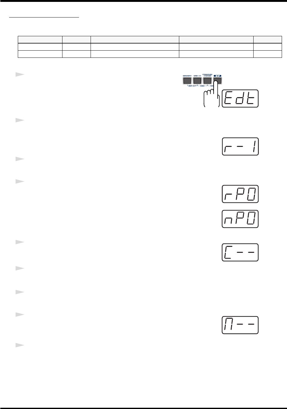
69
Use MIDI functionality
RPN/NRPN ASSIGN
Here’s how you can assign an RPN or NRPN message to a controller.
fig.edt
1
Press the
[EDIT]
button.
The display will indicate “EDT.”
fig.r-1
2
Slightly move the controller to which you want to assign an RPN or NRPN
message. In the case of a button, press that button.
The display will indicate the number of the selected controller.
3
Confirm what’s indicated, and press the
[ENTER]
button.
fig.rp0
4
Press the
[RPN]
key.
The display will indicate “RP0.”
fig.np0
* If you want to assign an NRPN message, press the
[NRPN]
key. The following
procedure is the same as for RPN.
fig.c
5
Confirm what’s indicated, and press the
[ENTER]
button.
The display will blink “C–.”
6
Input the channel. Use the
[DEC][INC]
buttons or the
[0]
-
[F]
keys to specify
the channel.
7
Press the
[ENTER]
button.
fig.BANK-2
8
Use the
[DEC][INC]
buttons or the
[0]
-
[F]
keys to specify the RPN MSB
(CC#101) or NRPN MSB (CC#99).
9
Press the
[ENTER]
button.
Mode Keyboard Data entry MSB (CC#6) range Data entry LSB (CC#38) range Port
Basic mode 0 0-127(00-7FH) Not transmitted PORT 1
Advanced mode 1 1 Upper and lower limits are assignable 00-7FH Assignable
*1 Reference
*1 Reference
*1 The -- area displays the currently set value. If it has not been set, the default setting will be displayed. Even if you change the type or mode
of the MIDI message that is assigned, the default setting will be displayed. This will be lit if the value is the same as the currently set value,
or will blink if the value is different.
PCR-M30/50/80.book 69 ページ 2005年11月10日 木曜日 午後2時49分

70
Use MIDI functionality
fig.BANK-3
10
Use the
[DEC][INC]
buttons or the
[0]
-
[F]
keys to specify the RPN LSB
(CC#100) or NRPN LSB (CC#98).
11
Press the
[ENTER]
button.
12
If you are making an assignment for a button, specify the button mode.
(
➔
“Specifying the button mode”
(p. 59))
*1 Reference
PCR-M30/50/80.book 70 ページ 2005年11月10日 木曜日 午後2時49分

71
Use MIDI functionality
■Advanced mode
In Advanced mode for RPN/NRPN, you can specify the upper and lower limit of the data entry
MSB (CC#6) value when the RPN/NRPN message is transmitted, as well as the various settings
available in Basic mode.
1. Press the [EDIT] button.
2. Slightly move the controller to which you want to assign the RPN or NRPN message. In
the case of a button, press that button.
The display will indicate the number of the selected controller.
3. Confirm what’s indicated, and press the [ENTER] button.
4. Press the [RPN] key and then press key [1].
*If you want to assign an NRPN message, press the [NRPN] key. The following procedure is the same
as for RPN.
5. Press the [ENTER] button.
6. Input the channel. Use the [DEC][INC] buttons or the [0]-[F] keys to specify the channel.
7. Press the [ENTER] button.
8. Use the [DEC][INC] buttons or the [0]-[F] keys to specify the RPN MSB (CC#101) or NRPN
MSB (CC#99).
9. Press the [ENTER] button.
10. Use the [DEC][INC] buttons or the [0]-[F] keys to specify the RPN LSB (CC#100) or NRPN
LSB (CC#98).
11. Press the [ENTER] button.
fig.p
12. Specify the lower limit of the data entry MSB (CC#06) value.
(➔“Specifying the range of values (upper and lower limits)” (p. 62))
The display will indicate “P-.”
13. Specify the output port. (➔“Specifying the port” (p. 59))
14. If you are making an assignment for a button, specify the button mode.
(➔“Specifying the button mode” (p. 59))
*1 Reference
*1 The -- area displays the currently set value. If it has not been set, the default setting will be displayed. Even if you change the type or mode
of the MIDI message that is assigned, the default setting will be displayed. This will be lit if the value is the same as the currently set value,
or will blink if the value is different.
PCR-M30/50/80.book 71 ページ 2005年11月10日 木曜日 午後2時49分
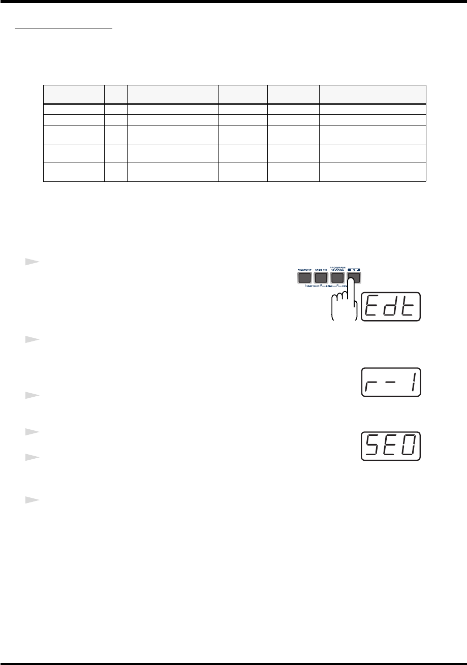
72
Use MIDI functionality
SYS EX. ASSIGN
Here’s how you can assign a system exclusive message to a controller. Advanced mode 2 lets
you assign a single-byte system message (System realtime message, tune request).
Advanced modes 3 and 4 let you assign any desired message.(Input up to 24 bytes)
SYS EX. ASSIGN can calculate the checksum automatically, and lets you specify a variable
(data) range or embed a channel/block number within the message.
(
➔
“Sys Ex. ASSIGN items”
(p. 74))
In SYS EX. ASSIGN, the input mode will be
HEX mode
(p. 49).
fig.edt
1
Press the
[EDIT]
button.
The display will indicate “EDT.”
fig.r-1
2
Slightly move the controller to which you want to assign the system
exclusive message. In the case of a button, press that button.
The display will indicate the number of the selected controller.
3
Confirm what’s indicated, and press the
[ENTER]
button.
fig.se0
4
Press the
[SYSTEM Ex.]
key.
5
If you want to select an Advanced mode, press a key from
[1]
to
[4]
.
The selected mode will blink in the display.
6
Confirm what’s indicated, and press the
[ENTER]
button.
Then continue with the procedure described in Basic mode or Advanced mode.
For some actual examples of settings, refer to
“Examples of assigning system exclusive
messages”
(p. 77).
Mode number Key-
board Mode Value range Required
ending Notes/restrictions
Basic mode 0 Sys Ex. message Default range Input F7 1st byte fixed at F0
Advanced mode 1 1 Sys Ex. message Assignable Input F7 1st byte fixed at F0
Advanced mode 2 2 Single byte system message - - [0-5, 7, 9, D, E] [DATA]
[CHECKSUM] buttons are invalid
Advanced mode 3 3 Any desired MIDI message Default range Specified num-
ber of bytes [CHECKSUM] button is invalid
Advanced mode 4 4 Any desired MIDI message Assignable Specified num-
ber of bytes [CHECKSUM] button is invalid
PCR-M30/50/80.book 72 ページ 2005年11月10日 木曜日 午後2時49分
73
Use MIDI functionality
■For Basic mode or Advanced mode 1
fig.f0 The display will blink “F0,” which is the first byte (starting status byte) of a
system exclusive message. (This cannot be changed.)
7. Confirm what’s indicated, and press the [ENTER] button.
8. Use the [0]-[F] keys to input the second byte.
9. Press the [ENTER] button.
10. Input the third and subsequent bytes in the same way.
11. When you have finished inputting the message, use the keyboard to enter [F] and [7],
specifying the ending status byte “F7.”
12. Press the [ENTER] button.
13. Specify the output port. (➔“Specifying the port” (p. 59))
14. If you are making an assignment for a button, specify the button mode.
(➔“Specifying the button mode” (p. 59))
■For Advanced mode 2
fig.f- The display will indicate “F-.”
7. Use the [6], [8], [A]-[C], [F] keys to specify the system message.
8. Press the [ENTER] button.
9. Specify the output port. (➔“Specifying the port” (p. 59))
■For Advanced modes 3 or 4
fig.l– The display will indicate “L–.”
7. Use the [0]-[F] keys of the keyboard to specify the number (decimal) of
bytes you want to input.
8. Press the [ENTER] button.
9. Use the [0]-[F] keys to input the first byte.
10. Press the [ENTER] button.
11. Input the second and subsequent bytes in the same way.
12. After you have input the number of bytes you specified in step 7, the PCR-M30/50/80
will check whether the messages you’ve input are indeed valid MIDI messages. If there is
a problem, the display will indicate “ERR.” In this case, you should press the [ENTER]
button, which takes you back to step 7, where you can input the values over again.
13. In the case of Advanced mode 4, specify the upper and lower limits.
(➔“Specifying the range of values (upper and lower limits)” (p. 62))
14. Specify the output port. (➔“Specifying the port” (p. 59))
15. If you are making an assignment for a button, specify the button mode.
(➔“Specifying the button mode” (p. 59))
*1 Reference
*1 The -- area displays the currently set value. If it has not been set, the default setting will be displayed. Even if you change the type or mode
of the MIDI message that is assigned, the default setting will be displayed. This will be lit if the value is the same as the currently set value,
or will blink if the value is different.
PCR-M30/50/80.book 73 ページ 2005年11月10日 木曜日 午後2時49分
74
Use MIDI functionality
Sys Ex. ASSIGN items
•
Specifying the checksum
.................................................... (p. 74)
•
Specifying the location of the data
................................... (p. 75)
•
Inputting channel/block data
............................................... (p. 76)
■
Specifying the checksum
The PCR-M30/50/80 can automatically calculate the checksum of a system exclusive message
and embed it in the message. In order to use this function, you must use the following
procedure to specify the starting location from which the checksum is calculated, and the
location at which the checksum is inserted. You can also select the type of checksum.
For an actual example, please read the Sys Ex.ASSIGN section
Bend Pitch Control
(p. 79).
fig.css
1.
Press the
[CHECKSUM]
key before you input the byte at which
checksum calculation should begin.
The display will indicate “CSS” (Checksum Start).
If you press the
[CHECKSUM]
key once again, “CSS” (Checksum Start)
will be cancelled.
2.
Press the
[ENTER]
button.
3.
Continue inputting data.
fig.cs1
4.
Press the
[CHECKSUM]
key at the location where the checksum should
be inserted.
The display will indicate “CS1” (Checksum type 1).
5.
Press the
[ENTER]
button.
Checksum types
There are two types of checksum, as follows.
Switching the type
fig.cs12
If you want to switch to type 2, press the
[2]
key after you press
[CHECKSUM]
in
step 4. To switch back to type 1, press
the
[1]
key.
1CHECKSUM TYPE 1
This is the method used by Roland and most other manufac-
turers
2CHECKSUM TYPE 2
Select this if the method other than type 1 is used
[2]
[CHECKSUM]
[1]
*1 Reference
[CHECKSUM]
*1 The -- area displays the currently set value. If it has not been set, the default setting will be displayed. Even if you change the type or mode
of the MIDI message that is assigned, the default setting will be displayed. This will be lit if the value is the same as the currently set value,
or will blink if the value is different.
PCR-M30/50/80.book 74 ページ 2005年11月10日 木曜日 午後2時49分
75
Use MIDI functionality
■
Specifying the location of the data
Here’s how to specify the location and data type of the variable portion (data) within a system
exclusive message.
The range of data values will be the default range in the case of Basic mode or Advanced mode
3. In the case of Advanced modes 1 and 4, you can specify the range of data values.
For an actual example, please read the Sys Ex. ASSIGN section
Master Volume
(p. 78).
1.
Press the
[DATA]
key at the location where you want to input the data.
The display will indicate “DT0.”
2.
Use the
[0]
-
[4]
keys to select the type of data.
* In the case of DT1-DT4 (data consisting of two or more bytes), a data area will automatically be
allocated for the next byte, and “-DT” will be displayed. (This cannot be changed.)
3.
Press the
[ENTER]
button.
4.
If you selected DT1 through DT4, the display will indicate “-DT.”
Press the
[ENTER]
button.
Data
number Data type Default range Target of range setting Example
(specified upper/lower limits)
DT0
7bit 00H-7F Specify the range of data(00H-7FH) 04-45
(lower limit 4H, upper limit 45H)
DT1
4bit/4bit 0H/0H-FH/FH Specify the range of the first byte (0H-FH), sec-
ond byte is fixed at 0H-FH
0/0-D/F
(lower limit 0H, upper limit DH)
DT2
7bit/7bit
(MSB/LSB)
00H/00H-7FH/
7FH
Specify the MSB range (00H-7FH), LSB is fixed
at 00H-7FH
23/00-68/7F
(lower limit 23H, upper limit 68H)
DT3
7bit/7bit
(LSB/MSB)
00H/00H-7FH/
7FH
Specify the MSB range (00H-7FH), LSB is fixed
at 00H-7FH
00/23-7F/68
(lower limit 23H, upper limit 68H)
DT4
4bit/4bit/
4bit/4bit
7H/FH/0H/1H-
8H/0H/FH/FH
Specify the limits of positive/negative change
as a value from 00H to FFH, centered on 8000H. 7/F/0/2-8/0/5/0
(lower limit FEH, upper limit 50H)
8000H
FFFF
max
min
PCR-M30/50/80.book 75 ページ 2005年11月10日 木曜日 午後2時49分
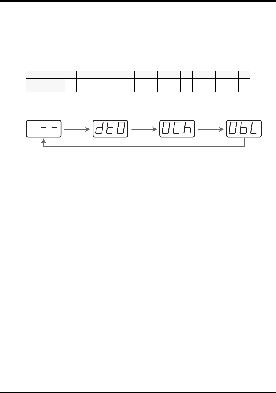
76
Use MIDI functionality
■
Inputting channel/block data
If a system exclusive message includes a channel or GS block number, here’s how to specify the
type and the value of the upper bits. For the channel and block number, the setting of the
current channel
will be inserted as the lower bits. (The block number is not actually a channel,
but corresponds to the “part” within a GS sound module. On the PCR-M30/50/80, this
corresponds to the channel for the sake of convenience.)
For an actual example, refer to
Bend Pitch Control
(p. 79) in the section on the Edit Mode.
1.
Press the
[DATA]
key several times at the location where you want to input the channel/
block number, to select “0CH” for the channel or “0BL” for the block.
fig.chbl
2.
Use the
[0]
-
[7]
keys to input the value of the upper four bits.
The “0” in the display will change to the numerical value that you input.
3.
Press the
[ENTER]
button.
Current channel 1 2 3 4 5 6 7 8 9 10 11 12 13 14 15 16
CH
0 1 2 3 4 5 6 7 8 9 A B C D E F
BL
1 2 3 4 5 6 7 8 9 0 A B C D E F
[DATA]
[DATA]
[DATA]
[DATA]
*1 Reference
*1 The -- area displays the currently set value. If it has not been set, the default setting will be displayed. Even if you change the type or mode
of the MIDI message that is assigned, the default setting will be displayed. This will be lit if the value is the same as the currently set value,
or will blink if the value is different.
PCR-M30/50/80.book 76 ページ 2005年11月10日 木曜日 午後2時49分

77
Use MIDI functionality
Examples of assigning system exclusive messages
•
GM2 System On
..................................................................... (p. 77)
•
Master Volume
........................................................................ (p. 78)
•
Bend Pitch Control
................................................................ (p. 79)
■
GM2 System On
F0 7E 7F 09 03 F7
Here’s how to assign a GM2 System On system exclusive message in
Basic mode
.
1.
Press the
[EDIT]
button.
The display will indicate “EDT.”
2.
Slightly move the controller to which you want to assign the system exclusive message. In
the case of a button, press that button.
The display will indicate the number of the selected controller.
3.
Confirm what’s indicated, and press the
[ENTER]
button.
4.
Press the
[SYSTEM Ex.]
key.
The display will indicate “SE0.”
5.
Confirm what’s indicated, and press the
[ENTER]
button.
The display will indicate “F0,” which is the first byte (beginning status) of a system exclusive
message. This cannot be changed. (This cannot be changed.)
6.
Confirm what’s indicated, and press the
[ENTER]
button.
7.
Use the
[7]
and
[E]
keys to input the second byte “7E.”
8.
Confirm what’s indicated, and press the
[ENTER]
button.
9.
Use the
[7]
and
[F]
keys to input the third byte “7F.”
10.
Confirm what’s indicated, and press the
[ENTER]
button.
Input the fourth and fifth bytes in the same way.
11.
Finally, use the
[F]
and
[7]
keys to input the ending status byte “F7.”
12.
Confirm what’s indicated, and press the
[ENTER]
button.
13.
Specify the output port. (
➔
“Specifying the port”
(p. 59))
14.
If you are making an assignment for a button, specify the button mode.
(
➔
“Specifying the button mode”
(p. 59))
The GM2 System On message has now been assigned.
PCR-M30/50/80.book 77 ページ 2005年11月10日 木曜日 午後2時49分

78
Use MIDI functionality
■
Master Volume
F0 7F 7F 04 01 vL vM F7
Since a Master Volume message has a data range of 00 00–7F 7F and we do not need to specify the
range, we will use
Basic mode
. Since the two bytes of data are in the order of LSB and then MSB,
we will select “DT3” when we input the data.
1.
Press the
[EDIT]
button.
The display will indicate “EDT.”
2.
Slightly move the controller to which you want to assign the system exclusive message. In
the case of a button, press that button.
The display will indicate the number of the selected controller.
3.
Confirm what’s indicated, and press the
[ENTER]
button.
4.
Press the
[SYSTEM Ex.]
key.
The display will blink “SE0.”
5.
Confirm what’s indicated, and press the
[ENTER]
button.
The display will indicate “F0,” which is the first byte (beginning status) of a system exclusive
message. (This cannot be changed.)
6.
Confirm what’s indicated, and press the
[ENTER]
button.
7.
Use the
[7]
and
[F]
keys to input the second byte “7F.”
8.
Confirm what’s indicated, and press the
[ENTER]
button.
9.
Input the third, fourth and fifth bytes in the same way.
10.
Since the sixth byte is the data area, press the
[DATA]
key, and then press
[3]
.
The display will indicate “DT3.”
11.
Confirm what’s indicated, and press the
[ENTER]
button.
12.
Since we selected “DT3” as the sixth byte, the seventh byte will automatically be allocated
as the data area and cannot be modified.
13.
Confirm what’s indicated, and press the
[ENTER]
button.
14.
Use the
[F]
and
[7]
keys to input the ending status byte “F7.”
15.
Confirm what’s indicated, and press the
[ENTER]
button.
16.
Specify the output port. (
➔
“Specifying the port”
(p. 59))
17.
If you are making an assignment for a button, specify the button mode.
(
➔
“Specifying the button mode”
(p. 59))
The Master Volume message has now been assigned.
PCR-M30/50/80.book 78 ページ 2005年11月10日 木曜日 午後2時49分

79
Use MIDI functionality
■
Bend Pitch Control
Since the GS Bend Pitch Control message has a data range of 40H–58H (0–24 semitones), we will select
Advanced mode 1
, which lets us specify the range. Since the data format is one byte, we will select
“DT0” (p. 75) when inserting the data.
1.
Press the
[EDIT]
button.
The display will indicate “EDT.”
2.
Slightly move the controller to which you want to assign the system exclusive message. In
the case of a button, press that button.
The display will indicate the number of the selected controller.
3.
Confirm what’s indicated and press
[ENTER]
.
4.
Press the
[SYSTEM Ex.]
key, and then press the
[1]
key.
The display will indicate “SE1.”
5.
Confirm what’s indicated and press
[ENTER]
.
The display will blink “F0,” which is the first byte (beginning status) of a system exclusive
message. (This cannot be changed.)
6.
Confirm what’s indicated and press
[ENTER]
.
7.
Use the
[4]
and
[1]
keys to input the second byte “41.”
8.
Confirm what’s indicated and press
[ENTER]
.
9.
Input the third, fourth and fifth bytes in the same way.
10.
Since the sixth byte is the beginning of the checksum calculation area, press the
[CHECKSUM]
key to specify this byte as the beginning of the area for which the checksum
will be calculated.
11.
Confirm what’s indicated and press
[ENTER]
.
12.
Input the sixth byte.
13.
Since the seventh byte will have “2” in the upper bits and the block number in the lower
bits, press
[DATA]
three times.
The display will indicate “0BL.”
fig.checksum
14.
To specify “2” for the upper bits, press the
[2]
key.
The display will indicate “2BL.”
15.
Confirm what’s indicated and press
[ENTER]
.
16.
In the same way, enter bytes 8.
F0 41 10 42 12 40 2x 10 DATA SUM F7
Address Data Checksum
Block number 1 byte
Checksum calculation region
PCR-M30/50/80.book 79 ページ 2005年11月10日 木曜日 午後2時49分

80
Use MIDI functionality
17.
Since the ninth byte is the data area, press the
[DATA]
key.
The display will indicate “DT0.”
18.
Confirm what’s indicated and press
[ENTER]
.
19.
Since the ten byte will contain the checksum, press the
[CHECKSUM]
key to specify the
location at which the checksum will be input.
The display will blink “CS1” (Checksum Type 1).
20.
Confirm what’s indicated and press
[ENTER]
.
21.
Press the
[F]
and then
[7]
keys to input the ending status “F7.”
22.
Confirm what’s indicated and press
[ENTER]
.
23.
Next, specify an upper limit value of “58” for the data area.
24.
Press
[ENTER]
.
25.
Specify a lower limit value of “40” for the data area.
26.
Press
[ENTER]
.
27.
Specify the output port.
(
➔
“Specifying the port”
(p. 59))
28.
If you are making an assignment for a button, specify the button mode.
(
➔
“Specifying the button mode”
(p. 59))
The GS Bend Pitch Control message has been assigned.
PCR-M30/50/80.book 80 ページ 2005年11月10日 木曜日 午後2時49分
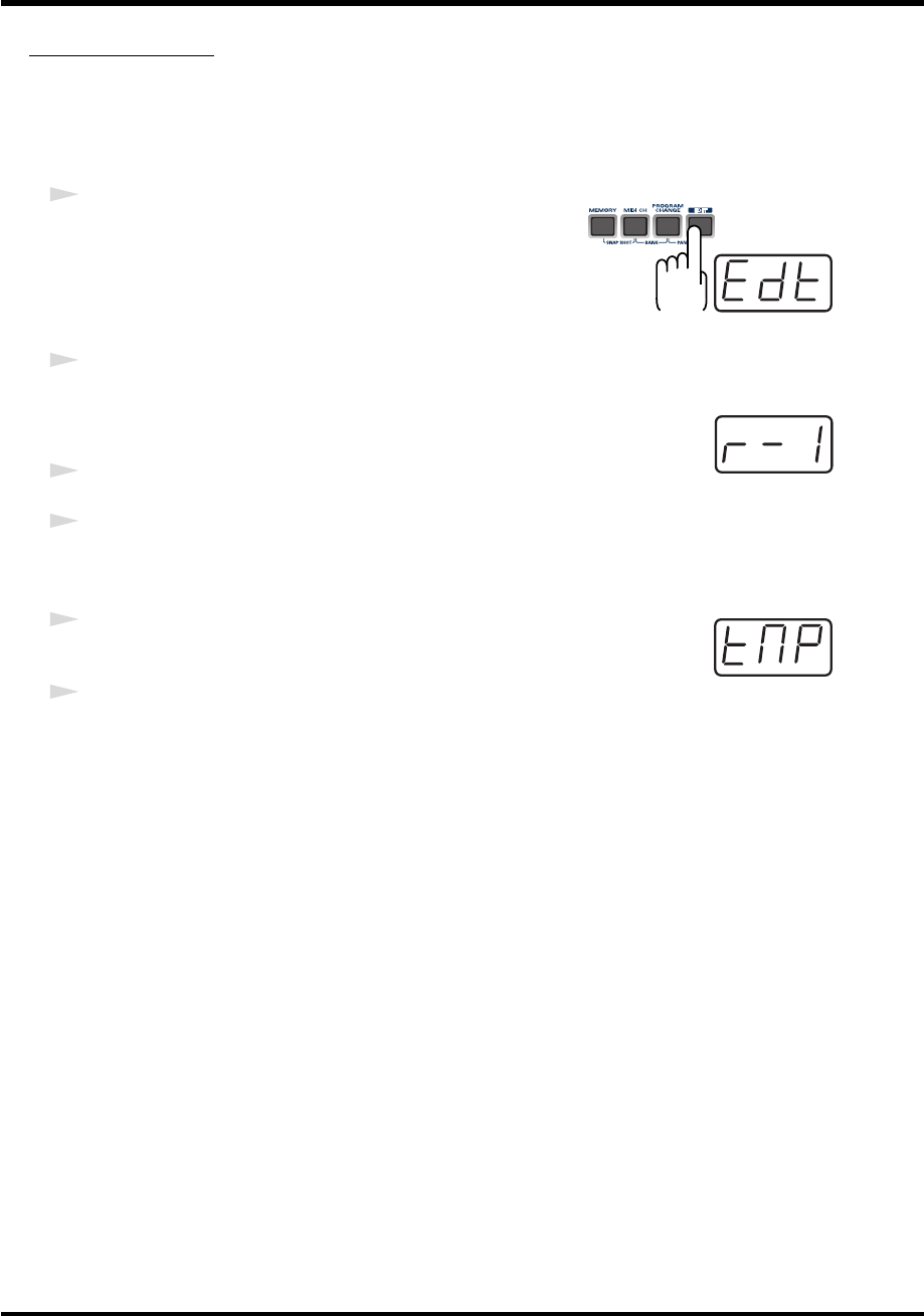
81
Use MIDI functionality
TEMPO ASSIGN
You can assign a controller to adjust the speed (20-250) of the F8 Clock message.
* In order to transmit F8 Clock messages, the F8 CLOCK setting must be “ON.”
(
➔
“F8 CLOCK ON/OFF”
(p. 90))
fig.edt
1
Press the
[EDIT]
button.
The display will indicate “EDT.”
fig.r-1
2
Slightly move the controller to which you want to assign TEMPO. In the case
of a button, press that button.
The display will indicate the number of the selected controller.
3
Confirm what’s indicated and press the
[ENTER]
button.
4
Press the
[TEMPO]
key.
The display will indicate “TMP.”
fig.tmp
5
Confirm what’s indicated and press the
[ENTER]
button.
6
If you are making the assignment for a button, specify the button mode.
(
➔
“Specifying the button mode”
(p. 59))
*In the case of a button, the value will be fixed at maximum (250) for ON, and minimum (20) for OFF.
PCR-M30/50/80.book 81 ページ 2005年11月10日 木曜日 午後2時49分
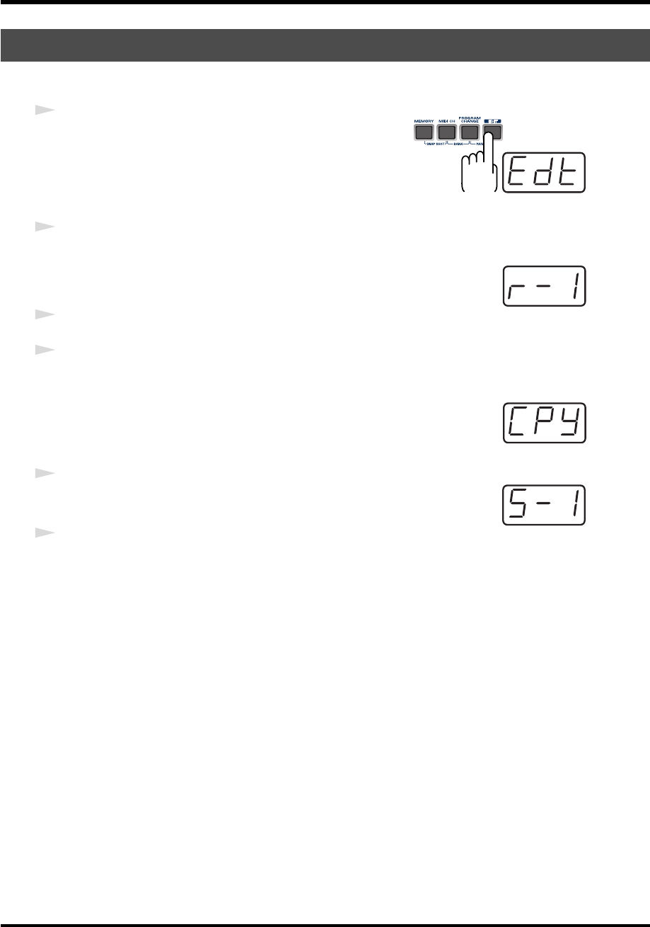
82
Use MIDI functionality
Here’s how a message assigned to a controller can be copied to another controller.
fig.edt
1
Press the
[EDIT]
button.
The display will indicate “EDT.”
fig.r-1
2
Slightly move the controller to which you want to copy the assignment (the
“copy destination”). In the case of a button, press that button.
The display will indicate the number of the selected controller.
3
. Confirm what’s indicated and press the
[ENTER]
button.
4
Slightly move the controller whose assignment you want to copy (the “copy source”). In the
case of a button, press that button.
fig.cpy
The display will indicate “CPY.”
fig.s-1
5
Press the
[ENTER]
button.
The display will blink the copy-source controller number.
6
Confirm what’s indicated and press the
[ENTER]
button.
Copying a MIDI message assignment (ASSIGN COPY)
PCR-M30/50/80.book 82 ページ 2005年11月10日 木曜日 午後2時49分
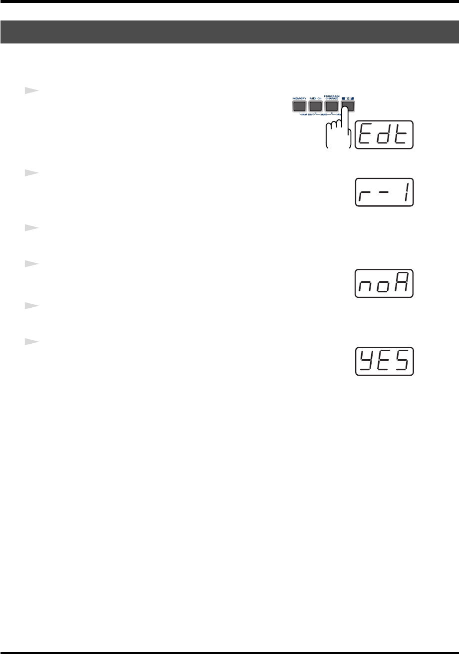
83
Use MIDI functionality
Here’s how you can cancel the message assigned to a controller. Once its assignment is
cancelled, no message will be transmitted when you operate that particular controller.
fig.edt
1
Press the
[EDIT]
button.
The display will indicate “EDT.”
fig.r-1
2
Slightly move the controller whose assignment you want to cancel. In the
case of a button, press that button.
The display will indicate the number of the selected controller.
3
Confirm what’s indicated and press the
[ENTER]
button.
fig.noa
4
Press the
[NO ASSIGN]
key.
The display will indicate “NOA.”
5
Press the
[ENTER]
button.
fig.yes
6
The display will blink “YES,” so press the
[ENTER]
button once again.
Canceling a MIDI message assignment (NO ASSIGN)
PCR-M30/50/80.book 83 ページ 2005年11月10日 木曜日 午後2時49分
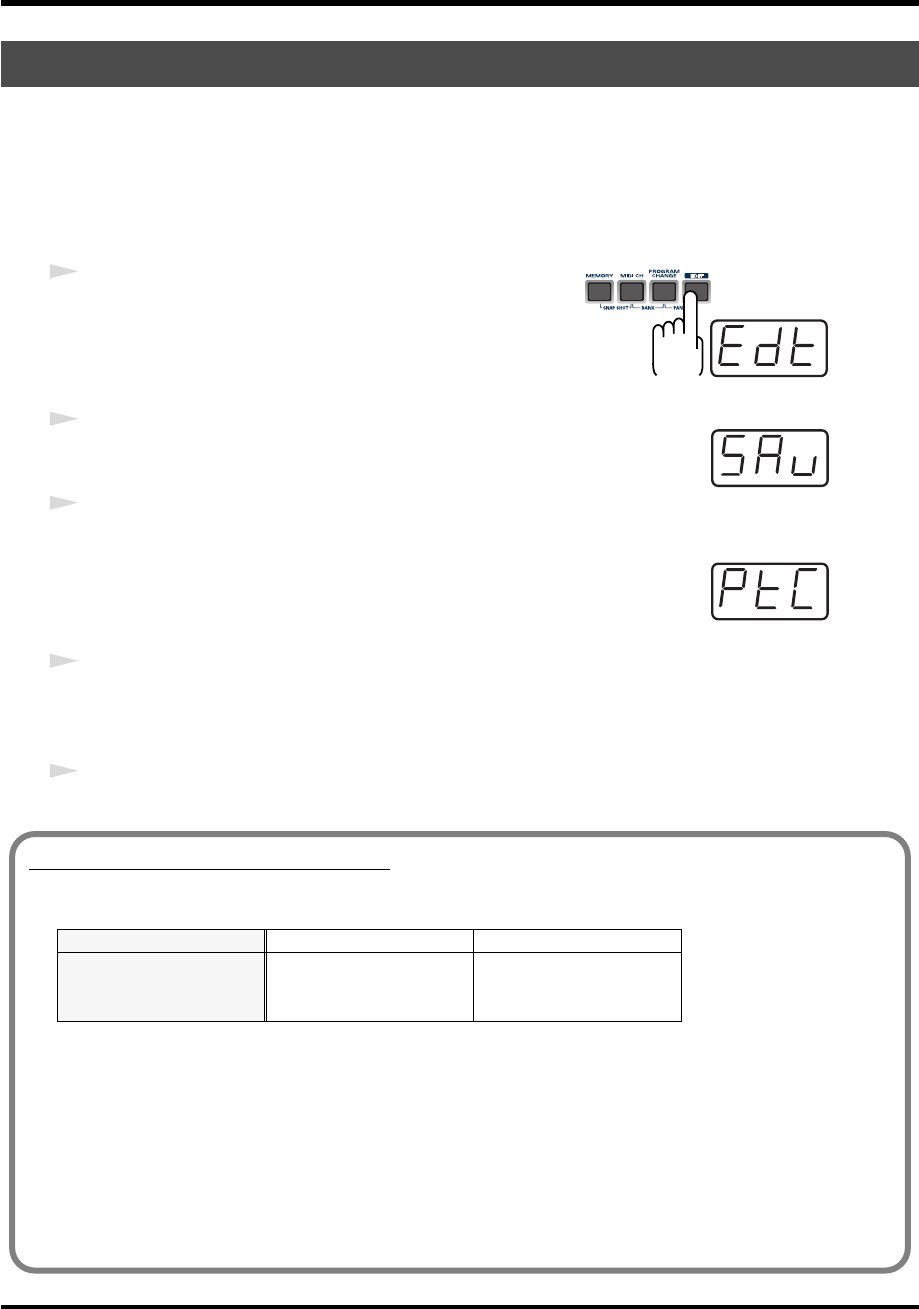
84
Use MIDI functionality
Here’s how to save the settings of the
current memory
into internal memory.
You can save settings into internal memory numbers 1-F.
You cannot save to memory number 0 (GM2).
*After you edit the settings, perform the “SAVE” operation as needed. If you turn off the power without
performing “SAVE,” your changes will be lost.
fig.edt
1
Press the
[EDIT]
button.
The display will indicate “EDT.”
fig.sav
2
Press the
[SAVE]
key.
The display will blink “SAV.”
3
Confirm what’s indicated and press the
[ENTER]
button.
fig.ptc
* If the display indicates “PTC,” it means that the Save could not be carried out
because the
PROTECT
setting (p. 88) is on. Turn PROTECT off, and then try the
4. operation once again from step 1.
4
Select a memory number 1-F. Use the
[DEC]
[INC]
buttons or the
[1]
-
[F]
keys to specify the
save-destination memory number.
The specified memory number will blink in the display.
5
Confirm what’s indicated and press the
[ENTER]
button.
Saving a Memory Set (SAVE)
About the memories of the PCR
The PCR has the following sixteen memories.
“Current memory” is a location into which you can recall one of these memories.
In order to use one of the saved memories, you must recall it into current memory as described
in “Memory mode” (p. 54).
The contents of current memory will be lost when you turn off the power. If you have modified
the settings in current memory, perform the “SAVE” operation if you want to keep your
changes.
You can set the “STARTUP MEMORY” (p. 93) setting to specify the memory that will be loaded
into current memory when you turn on the power.
Memory number 0 GM2 SET Cannot be saved
Memory number 1
User memories (15) Can be saved:
Memory number F
PCR-M30/50/80.book 84 ページ 2005年11月10日 木曜日 午後2時49分
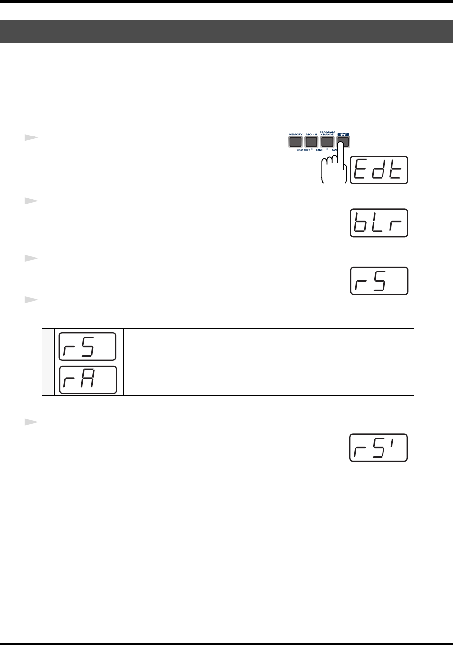
85
Use MIDI functionality
Bulk dump allows a large amount of data to be transferred in a single operation. For example,
this can be used to store all settings of a device into a computer or sequencer.
*When you transmit or receive Bulk data, the contents of the
current memory
(p. 84)will be lost. Save
the
current memory
settings as needed before you perform this operation.
■
Receive mode
fig.edt
1
Press the
[EDIT]
button.
The display will indicate “EDT.”
fig.blr
2
Press the
[BULK]
key.
The display will blink “BLR” (Bulk Receive).
fig.rs
3
Confirm what’s indicated and press the
[ENTER]
button.
The display will indicate “RS,” and the “S” will blink.
4
Use the
[DEC]
[INC]
buttons or the
[0]
[1]
keys to select the mode.
fig.rs1
5
Confirm what’s indicated and press the
[ENTER]
button.
The third digit of the display will blink, and the PCR-M30/50/80 will wait to
receive bulk data.
Transmitting/receiving bulk data (BULK)
0SINGLE BULK
A memory will be received as bulk data. The received data will
overwrite the current memory. Memories 1-F will not be affected.
1ALL BULK
All memories will be received as bulk data. The received data will
overwrite memories 1-F.
PCR-M30/50/80.book 85 ページ 2005年11月10日 木曜日 午後2時49分
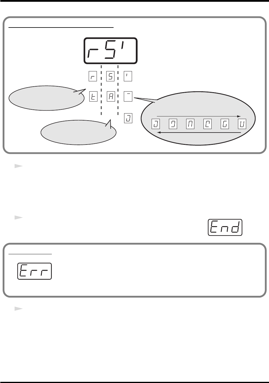
86
Use MIDI functionality
6
Transmit bulk data from your sequencer or other device.
Specify “PCR” (Mac OS 9: PCR 1) as the MIDI output device for your sequencer software. For
details on this setting, refer to the manual of your sequencer software.
For details on the port that will be used to transfer bulk data, refer to
“Input / output devices”
(p. 43).
fig.end
7
When the PCR finishes receiving the bulk data, the display will indicate
“END.”
8
Confirm what’s indicated and press the
[ENTER]
button.
About the display in Bulk mode
fig.bulk-dis
Transmit
Receive
ALL
BULK
SINGLE
BULK
1st digit:
indicates Receive mode or
Transmit mode
receiving
transmitting
Waiting to receive
(blinking)
Waiting to transmit
(blinking)
Transmitting
2nd digit:
Single Bulk or All Bulk
3rd digit: indicates
Transmitting/Receiving/Waiting states
Error display
fig.err
If the data could not be received correctly, the display will blink “ERR.”
If this occurs, press the [CANCEL] button to cancel the “ERR” display.
Once “ERR” has been dismissed, perform the bulk reception procedure over again,
from step 1.
PCR-M30/50/80.book 86 ページ 2005年11月10日 木曜日 午後2時49分
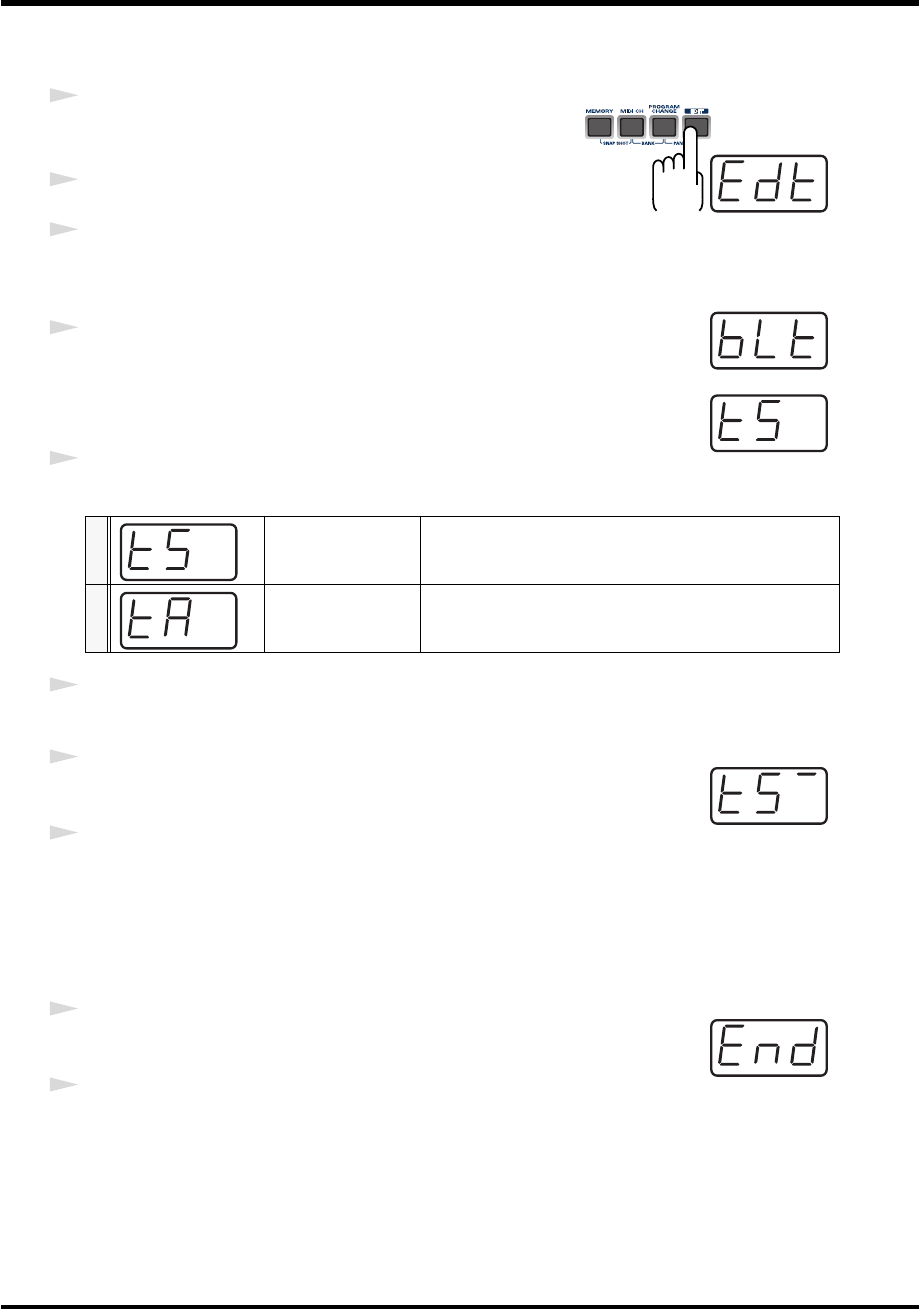
87
Use MIDI functionality
■
Transmit mode
fig.edt
1
Press the
[EDIT]
button.
The display will indicate “EDT.”
2
Press the
[BULK]
key.
3
Press the
[1]
key.
fig.blt
The display will blink “BLT” (Bulk Transmit).
4
Confirm what’s indicated and press the
[ENTER]
button.
fig.ts
The display will indicate “TS,” and the “S” will blink.
5
Use the
[DEC]
[INC]
buttons or the
[0]
[1]
keys to select the mode.
6
Confirm what’s indicated and press the
[ENTER]
button.
fig.bs-1
7
The third digit of the display will blink, and the PCR-M30/50/80 will wait
to transmit bulk data.
8
Press the
[ENTER]
button.
On your sequencer software, specify “PCR 2” as the MIDI input device. For details on this
setting, refer to the manual of your sequencer software.
For details on the port that will be used to transfer bulk data, refer to
“Input / output devices”
(p. 43).
fig.end
9
When the PCR finishes receiving the bulk data, the display will indicate
“END.”
10
Confirm what’s indicated and press the
[ENTER]
button.
0SINGLE BULK
The currently recalled memory (the current memory) will
be transmitted as bulk data
1ALL BULK
All memories (memories 1-F) will be transmitted as bulk
data.
PCR-M30/50/80.book 87 ページ 2005年11月10日 木曜日 午後2時49分
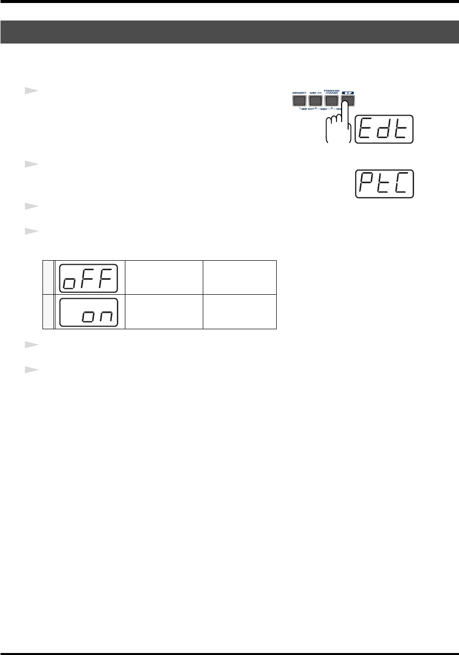
88
Use MIDI functionality
If you turn the Protect setting ON, ALL BULK (p. 85) reception and SAVE (p. 84) operations will
be disabled.
fig.edt
1
Press the
[EDIT]
button.
The display will indicate “EDT.”
fig.ptc
2
Press the
[PROTECT]
key.
The display will blink “PTC.”
3
Confirm what’s indicated and press the
[ENTER]
button.
4
The display will show the current setting.
5
Use the
[DEC]
[INC]
buttons or the
[0] [1]
keys to select the mode.
6
Press the
[ENTER]
button.
Protecting a Memory Set (PROTECT)
0PROTECT OFF
Allow changes.
1PROTECT ON
Prohibit changes.
PCR-M30/50/80.book 88 ページ 2005年11月10日 木曜日 午後2時49分
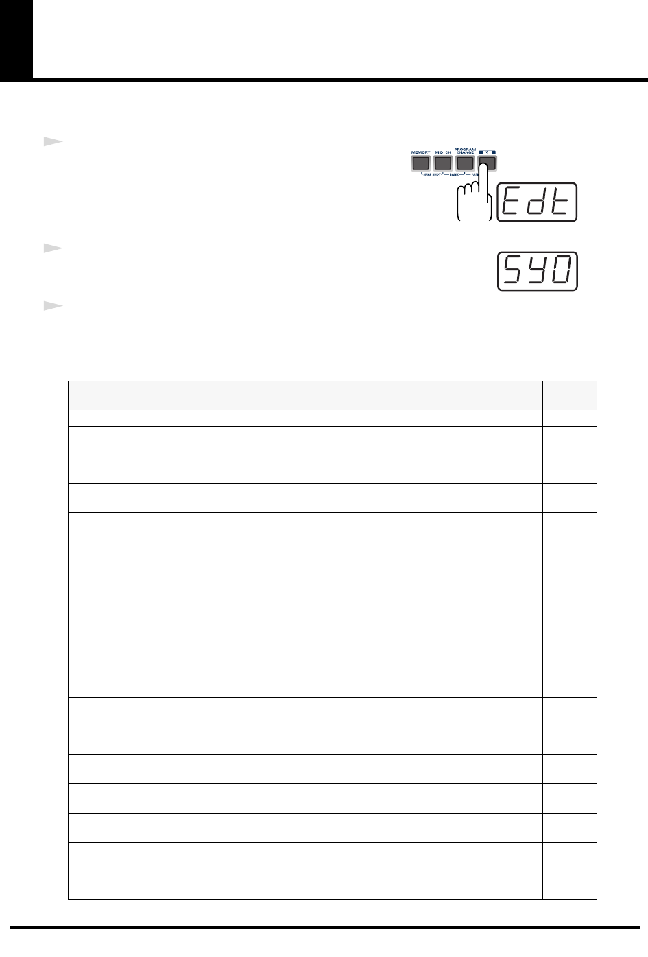
89
System settings
Here’s how you can make various system settings for the PCR-M30/50/80.
fig.edt
1
Press the
[EDIT]
button.
The display will indicate “EDT.”
fig.sy0
2
Press the
[SYSTEM]
key.
The display will indicate “SY0.”
3
Use the
[0]
-
[A]
keys to specify the System setting that you want to set, and then press the
[ENTER]
button.
Confirm what’s indicated and use the appropriate method to make the setting.
Mode Key-
board Content of the setting Default Setting
method
F8 CLOCK ON/OFF 0 Specify whether F8 Clock is to be transmitted. OFF p. 90
F8 CLOCK DEFAULT
TEMPO 1
If “F8 CLOCK ON/OFF” is ON, specify the default
value of the F8 Clock. After the power is turned on,
this tempo will continue to be output until you
move a controller to which TEMPO is assigned.
120 p. 90
F8 CLOCK PORT SET 2 If “F8 CLOCK ON/OFF” is ON, specify the port
from which the F8 Clock is to be transmitted. PORT 1 p. 90
VELOCITY CURVE 3
When you play the keyboard of the PCR-M30/50/
80, note messages will be transmitted with a veloc-
ity value that corresponds to your playing
strength. By setting the VELOCITY CURVE, you
can modify the keyboard's sensitivity and the
curve that is followed when the velocity value
changes.
1-MEDIUM p. 91
KEYBOARD PORT SET 4
Specify the port from which messages produced by
the BENDER lever of the keyboard are to be trans-
mitted.
PORT 1 p. 92
H-ACTIVITY ON/OFF 5
Turn this ON if you are using certain applications
(such as Pro Tools LE). When ON, “90 00 7F” will
be output from PCR 2 approximately every 500 ms.
OFF p. 92
USB MIDI DRIVER
MODE 6
Specify the type of USB MIDI driver used for USB
connection.
* The setting will take effect the next time you turn
on the power
Original
Driver p. 92
STARTUP MEMORY 7 Specify the memory that will be selected when the
power is turned on. GM2 p. 93
FACTORY RESET 8 Restore all settings of the PCR-M30/50/80 to their
factory-set condition. - p. 93
MIDI I/F MODE 9 Specify whether the PCR-M30/50/80 will function
as a MIDI interface using its MIDI connectors. ON p. 94
KEY VELOCITY A
Specify whether the transmitted velocity value will
vary according to the keyboard sensitivity and
curve you selected in “VELOCITY CURVE”, or
will always be transmitted at a fixed value.
TOUCH p. 95
PCR-M30/50/80.book 89 ページ 2005年11月10日 木曜日 午後2時49分

90
System settings
Perform steps 1-3.
fig.hyo
4
Use the
[DEC]
[INC]
buttons or the
[0]
or
[1]
keys to switch F8 CLOCK ON /
OFF.
The display will indicate either “ON” or “OFF.”
5
Press the
[ENTER]
button.
Perform steps 1-3.
4
Use the
[DEC]
[INC]
buttons or the
[0]
-
[F]
keys to specify F8 CLOCK DEFAULT TEMPO.
(Value range 20-250)
The specified value will indicate in the display.
5
Press the
[ENTER]
button.
Perform steps 1-3.
4
Use the
[DEC]
[INC]
buttons or the
[1]
-
[3]
keys to specify F8 CLOCK PORT SET.
(
➔
“Specifying the port”
(p. 59))
The specified port will indicate in the display.
5
Press the
[ENTER]
button.
F8 CLOCK ON / OFF (Keyboard: 0)
F8 CLOCK DEFAULT TEMPO (Keyboard: 1)
F8 CLOCK PORT SET (Keyboard: 2)
0OFF
1ON
PCR-M30/50/80.book 90 ページ 2005年11月10日 木曜日 午後2時49分
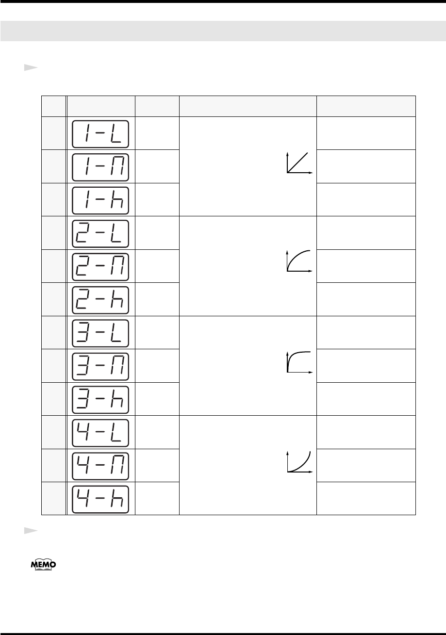
91
System settings
Perform steps 1-3.
4
Use the
[DEC]
[INC]
buttons or the
[0]
-
[B]
keys to specify
the keyboard sensitivity and curve.
5
Press the
[ENTER]
button.
You can also access the VELOCITY CURVE setting screen by holding down the
[VELCRV]
button while you
turn on the power.
VELOCITY CURVE (Keyboard: 3)
Key-
board Setting
0 1-LIGHT
The standard setting. The
volume will change in a nat-
ural way according to your
playing strength.
High velocity values will be
produced even if you play
the keyboard softly.
11-MEDIUM
The keyboard sensitivity
will be normal.
21-HEAVY
High velocity values will be
produced only if you play
the keyboard strongly.
32-LIGHT
Compared to curve
1
, the
volume will change more
significantly for softly
played notes.
High velocity values will be
produced even if you play
the keyboard softly.
4 2-MEDIUM
The keyboard sensitivity
will be normal.
5 2-HEAVY
High velocity values will be
produced only if you play
the keyboard strongly.
63-LIGHT
Variations in your playing
strength will produce natu-
ral-sounding changes in
volume.
High velocity values will be
produced even if you play
the keyboard softly.
73-MEDIUM
The keyboard sensitivity
will be normal.
83-HEAVY
High velocity values will be
produced only if you play
the keyboard strongly.
94-LIGHT
Compared to curve
1
, the
volume will change more
significantly for the strong-
ly played notes.
High velocity values will be
produced even if you play
the keyboard softly.
A4-MEDIUM
The keyboard sensitivity
will be normal.
B 4-HEAVY
High velocity values will be
produced only if you play
the keyboard strongly.
1
2
3
4
PCR-M30/50/80.book 91 ページ 2005年11月10日 木曜日 午後2時49分
92
System settings
Perform steps 1-3.
4
Use the
[DEC]
[INC]
buttons or the
[1]
-
[3]
keys to specify KEYBOARD PORT SET.
(
➔
“Specifying the port”
(p. 59))
The specified port will indicate in the display.
5
Press the
[ENTER]
button.
Perform steps 1-3.
fig.hyo
4
Use the
[DEC]
[INC]
buttons or the
[0]
or
[1]
keys to switch H-ACTIVITY ON /
OFF.
The display will indicate either “ON” or “OFF.”
5
Press the
[ENTER]
button.
Perform steps 1-3.
4
Use the
[DEC]
[INC]
buttons or the
[0]
or
[1]
keys to specify the USB MIDI DRIVER MODE.
*
FPT = Fast Processing Technology for MIDI Transmission:
Effective use is made of the USB bandwidth according to the amount of MIDI data to be transmitted,
ensuring that MIDI data processing will always occur optimally.
5
Press the
[ENTER]
button.
KEYBOARD PORT SET (Keyboard: 4)
H-ACTIVITY ON / OFF (Keyboard: 5)
USB MIDI DRIVER MODE (Keyboard: 6)
0Original driver *FPT
technology is used to perform high-speed MIDI transfer.
Normally, we recommend that you use this mode.
1Generic driver
Select this if you are using the standard MIDI driver provided by
your operating system.
0OFF
1ON
PCR-M30/50/80.book 92 ページ 2005年11月10日 木曜日 午後2時49分
93
System settings
Perform steps 1-3.
4
Use the
[DEC]
[INC]
buttons or the
[0]
or
[1]
keys to specify the GM2/LAST ACCESS
MEMORY setting.
5
Press the
[ENTER]
button.
Perform steps 1-3.
fig.rst
4
The display will indicate “RST.”
fig.yes
5
Press the
[ENTER]
button.
The display will blink “YES.”
6
Press the
[ENTER]
button.
STARTUP MEMORY (Keyboard: 7)
0GM2 MEMORY
When the PCR starts up, memory number 0 (GM2) will be
loaded into current memory (p. 84) regardless of the state in
which the power was turned off.
1LAST ACCESS
MEMORY
Upon power-up, the PCR-M30/50/80 will recall the mem-
ory that was last recalled or saved into current memory (p.
84).
FACTORY RESET (Keyboard: 8)
PCR-M30/50/80.book 93 ページ 2005年11月10日 木曜日 午後2時49分
94
System settings
Perform steps 1-3.
4
Use the
[DEC]
[INC]
buttons or the
[0]
-
[1]
keys to specify MIDI I/F MODE.
5
Press the
[ENTER]
button.
MIDI I/F MODE (Keyboard: 9)
0MIDI I/F MODE
ON
The MIDI connectors on the rear panel of the PCR-M30/50/80 will
function as a MIDI interface. MIDI messages from a computer con-
nected via USB to the PCR-M30/50/80 will be sent to the MIDI
sound module connected to the PCR-M30/50/80’s MIDI OUT con-
nector. MIDI messages from a MIDI device connected to the PCR-
M30/50/80’s MIDI IN connector will be sent to the computer.
1MIDI I/F MODE
OFF
MIDI messages received by the PCR-M30/50/80 are not output
from the PCR-M30/50/80. MIDI messages will be transferred be-
tween the PCR-M30/50/80 and the computer, or between the PCR-
04.9.3 and an external MIDI device.
PCR-M1PC
USB
EDIROL PCR
EDIROL PCR MIDI OUT
EDIROL PCR 2
EDIROL PCR 1
EDIROL PCR MIDI IN
MIDI OUT
MIDI IN
MIDI I/F MODE ON
PORT 1
PORT 2 /
MIDI OUT DEVICE
MIDI IN DEVICE
BULK RECEPTION
BULK TRANSMISSION
MIDI OUT
MIDI IN
PCR-M30/50/80PC
USB
EDIROL PCR
EDIROL PCR MIDI OUT
EDIROL PCR 2
EDIROL PCR 1 PORT 1
EDIROL PCR MIDI IN
MIDI I/F MODE OFF
PORT 2 /
BULK RECEPTION
MIDI OUT DEVICE
MIDI IN DEVICE
BULK TRANSMISSION
PCR-M30/50/80.book 94 ページ 2005年11月10日 木曜日 午後2時49分
95
System settings
Key Velocity mode lets you specify whether the transmitted velocity value will vary according
to your keyboard playing strength and the specified
“VELOCITY CURVE”
(p. 91), or will
always be transmitted at a fixed value.
The PCR-M30/50/80 detects the strength with which you play a key, and transmits the velocity
value accordingly. However, if you set Key Velocity mode to a fixed value, the velocity will be
transmitted at this fixed value regardless of how strongly you play the keys. You can use the
Key Velocity mode to specify a fixed value if you don't want your playing dynamics to have an
effect.
4
Use the
[DEC]
[INC]
buttons or the keyboard to specify the Key Velocity mode.
5
Press the
[ENTER]
button.
KEY VELOCITY(Keyboard: A)
0TOUCH
Velocity values will be transmitted according to the key-
board sensitivity and curve you selected in “VELOCITY
CURVE” (p. 91).
1-127 Fixed value
Velocity will be transmitted at the specified value regard-
less of how strongly you play the keyboard.
PCR-M30/50/80.book 95 ページ 2005年11月10日 木曜日 午後2時49分

96
V-LINK mode
When you press the
[V-LINK]
button, the PCR will transmit a V-LINK ON message and will
enter V-LINK mode (V-LINK ON). When you press the
[V-LINK]
button once again, the PCR
will transmit a V-LINK OFF message and will exit V-LINK mode (V-LINK OFF).
• Clip Ctrl Rx MIDI ch: 16
• Color Ctrl Rx MIDI ch: 16
• Sender Model Name: EDIROL PCR
Set the MIDI channel to “16” for parameters that you want to control via V-LINK.
PCR-M30/50/80.book 96 ページ 2005年11月10日 木曜日 午後2時49分

97
Appendices
This section contains troubleshooting information and explanations of convenient
functions.You may read this material as necessary.
Memory sets
..................................................................................p. 98
Troubleshooting
...........................................................................p. 104
MIDI implementation
...................................................................p. 112
Main specifications
......................................................................p. 117
PCR-M30/50/80.book 97 ページ 2005年11月10日 木曜日 午後2時49分
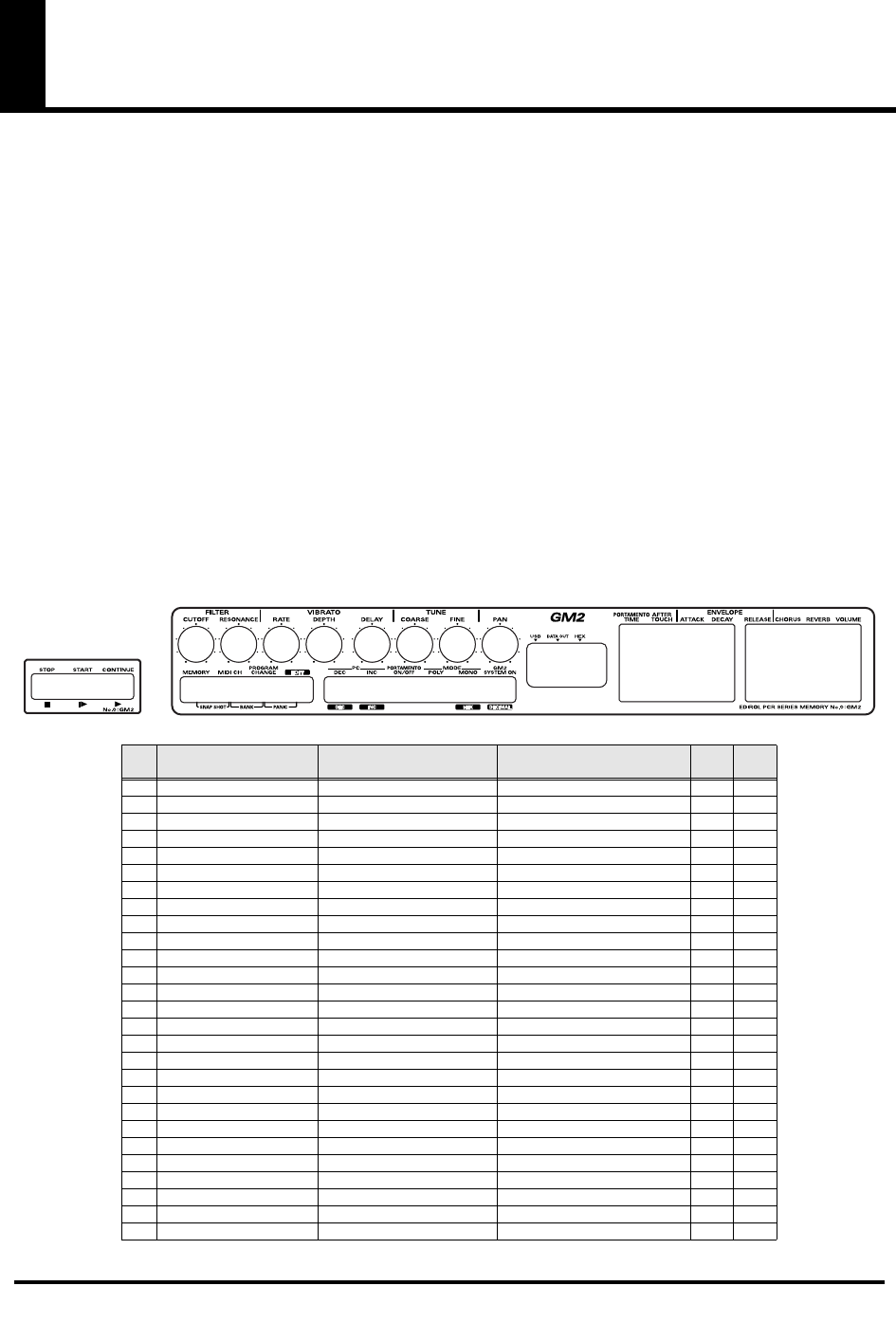
98
Memory sets
With the factory settings, the GM2 set shown in the illustration is assigned to the controllers.
Use the included template.
The following memory sets are also provided.
GM2 SET (MEMORY: 0)
...........................................(p. 98)
MCR-8 MODE 3(SONAR) SET
................................(p. 99)
MCR-8 MODE 3(SONAR) - A (MEMORY: 1).............(p. 99)
MCR-8 MODE 3(SONAR) - B (MEMORY: 2) ............. (p. 99)
MCR-8 MODE 3(SONAR) - C (MEMORY: 3).............(p. 99)
MCR-8 MODE 3(SONAR) - D (MEMORY: 4).............(p. 99)
MCR-8 MODE 4(Cubase 5/SX) SET
......................(p. 100)
MCR-8 MODE 4(Cubase 5/SX) - A (MEMORY: 5)....(p. 100)
MCR-8 MODE 4(Cubase 5/SX) - B (MEMORY: 6) ....(p. 100)
MCR-8 MODE 4(Cubase 5/SX) - C (MEMORY: 7) .... (p. 100)
MCR-8 MODE 4(Cubase 5/SX) - D (MEMORY: 8)....(p. 100)
H-COMPATIBLE (ProTools LE, Digital Performer) SET
(MEMORY: 9)
............................................................. (p. 101)
GS SET
........................................................................ (p. 101)
GS-A (MEMORY: A) ...................................................... (p. 101)
GS-B (MEMORY: B)........................................................ (p. 102)
GS-C (MEMORY: C)....................................................... (p. 102)
XG SET
........................................................................ (p. 103)
XG-A (MEMORY: D)...................................................... (p. 103)
XG-B (MEMORY: E)....................................................... (p. 103)
For details on settings for actually using each memory set with your application, refer to the Read Me file for each memory set, located in the
Memory Files folder of the CD-ROM.
You can download the latest additional memory sets from the following website.
■
GM2 SET (MEMORY: 0)
fig.gm2-tmp
Parameter Message (Hex.) Range (Hex.) Ch. Por
t
R1 FILTER CUTOFF CC 74(4A) 0(00) - 127(7F) 1 1
R2 FILTER RESONANCE CC 71(47) 0(00) - 127(7F) 1 1
R3 VIBRATO RATE CC 76(4C) 0(00) - 127(7F) 1 1
R4 VIBRATO DEPTH CC 77(4D) 0(00) - 127(7F) 1 1
R5 VIBRATO DELAY CC 78(4E) 0(00) - 127(7F) 1 1
R6 COARSE TUNING RPN 0/2(00/02) 0/-(00/--) - 127/-(7F/--) 1 1
R7 FINE TUNING RPN 0/1(00/01) 0/0(00/00) - 127/127(7F/7F) 1 1
R8 PAN (CHANNEL) CC 10(0A) 0(00) - 127(7F) 1 1
S1 PORTAMENTO TIME CC 5(05) 0(00) - 127(7F) 1 1
S2 AFTERTOUCH CHANNEL PRESSURE 0(00) - 127(7F) 1 1
S3 ENVELOPE ATTACK CC 73(49) 0(00) - 127(7F) 1 1
S4 ENVELOPE DECAY CC 75(4B) 0(00) - 127(7F) 1 1
S5 ENVELOPE RELEASE CC 72(48) 0(00) - 127(7F) 1 1
S6 CHORUS CC 93(5D) 0(00) - 127(7F) 1 1
S7 REVERB CC 91(5B) 0(00) - 127(7F) 1 1
S8 VOLUME (CHANNEL) CC 7(07) 0(00) - 127(7F) 1 1
B1 PROGRAM CHANGE DEC PROGRAM CHANGE min:1(00) - -
B2 PROGRAM CHANGE INC PROGRAM CHANGE max:128(7F) - -
B3 PORTAMENTO ON/OFF CC 65(41) 0(00) / 127(7F) 1 1
B4 POLY MODE ON B0 7F 00 - 1 1
B5 MONO MODE ON B0 7E 01 - 1 1
B6 GM2 SYSTEM ON F0 7E 7F 09 03 F7 - - 1
L1 STOP FC - - 2
L2 START FA - - 2
L3 CONTINUE FB - - 2
P1 HOLD CC 64(40) 0(00) / 127(7F) 1 1
P2 EXPRESSION CC 11(0B) 0(00) - 127(7F) 1 1
PCR-M30/50/80.book 98 ページ 2005年11月10日 木曜日 午後2時49分
99
Memory sets
■
MCR-8 MODE 3(SONAR) SET
When using this memory set, turn the PCR-M30/50/80's
OMNI
(p. 49) setting
OFF
.
* To display the external controller toolbar, open Display | Toolbars, and select External Controllers.
MCR-8 MODE 3(SONAR) - A (MEMORY: 1)
MCR-8 MODE 3(SONAR) - C (MEMORY: 3)
MCR-8 MODE 3(SONAR) - B (MEMORY: 2)
MCR-8 MODE 3(SONAR) - D (MEMORY: 4)
Parameter Message
(Hex.) Range (Hex.) Ch. Port
R1 TRACK 1 *1 CC 16(10) 0(00) - 127(7F) 1 2
R2 TRACK 2 *1 CC 16(10) 0(00) - 127(7F) 2 2
R3 TRACK 3 *1 CC 16(10) 0(00) - 127(7F) 3 2
R4 TRACK 4 *1 CC 16(10) 0(00) - 127(7F) 4 2
R5 TRACK 5 *1 CC 16(10) 0(00) - 127(7F) 5 2
R6 TRACK 6 *1 CC 16(10) 0(00) - 127(7F) 6 2
R7 TRACK 7 *1 CC 16(10) 0(00) - 127(7F) 7 2
R8 TRACK 8 *1 CC 16(10) 0(00) - 127(7F) 8 2
S1 TRACK 1 *2 CC 17(11) 0(00) - 127(7F) 1 2
S2 TRACK 2 *2 CC 17(11) 0(00) - 127(7F) 2 2
S3 TRACK 3 *2 CC 17(11) 0(00) - 127(7F) 3 2
S4 TRACK 4 *2 CC 17(11) 0(00) - 127(7F) 4 2
S5 TRACK 5 *2 CC 17(11) 0(00) - 127(7F) 5 2
S6 TRACK 6 *2 CC 17(11) 0(00) - 127(7F) 6 2
S7 TRACK 7 *2 CC 17(11) 0(00) - 127(7F) 7 2
S8 TRACK 8 *2 CC 17(11) 0(00) - 127(7F) 8 2
B1 TRACK 1 *3 CC 80(50) 0(00) / 127(7F) 1 2
B2 TRACK 2 *3 CC 80(50) 0(00) / 127(7F) 2 2
B3 TRACK 3 *3 CC 80(50) 0(00) / 127(7F) 3 2
B4 TRACK 4 *3 CC 80(50) 0(00) / 127(7F) 4 2
B5 TRACK 5 *3 CC 80(50) 0(00) / 127(7F) 5 2
B6 TRACK 6 *3 CC 80(50) 0(00) / 127(7F) 6 2
L1 << CC 82(52) 0(00) / 127(7F) 13 2
L2
■
Stop CC 82(52) 0(00) / 127(7F) 14 2
L3 > Play CC 82(52) 0(00) / 127(7F) 15 2
P1 HOLD CC 64(40) 0(00) / 127(7F) 1 1
P2 EXPRESSION CC 11(0B) 0(00) - 127(7F) 1 1
Parameter Message
(Hex.) Range (Hex.) Ch. Port
R1 TRACK 9 *1 CC 16(10) 0(00) - 127(7F) 9 2
R2 TRACK 10 *1 CC 16(10) 0(00) - 127(7F) 10 2
R3 TRACK 11 *1 CC 16(10) 0(00) - 127(7F) 11 2
R4 TRACK 12 *1 CC 16(10) 0(00) - 127(7F) 12 2
R5 TRACK 13 *1 CC 16(10) 0(00) - 127(7F) 13 2
R6 TRACK 14 *1 CC 16(10) 0(00) - 127(7F) 14 2
R7 TRACK 15 *1 CC 16(10) 0(00) - 127(7F) 15 2
R8 TRACK 16 *1 CC 16(10) 0(00) - 127(7F) 16 2
S1 TRACK 9 *2 CC 17(11) 0(00) - 127(7F) 9 2
S2 TRACK 10 *2 CC 17(11) 0(00) - 127(7F) 10 2
S3 TRACK 11 *2 CC 17(11) 0(00) - 127(7F) 11 2
S4 TRACK 12 *2 CC 17(11) 0(00) - 127(7F) 12 2
S5 TRACK 13 *2 CC 17(11) 0(00) - 127(7F) 13 2
S6 TRACK 14 *2 CC 17(11) 0(00) - 127(7F) 14 2
S7 TRACK 15 *2 CC 17(11) 0(00) - 127(7F) 15 2
S8 TRACK 16 *2 CC 17(11) 0(00) - 127(7F) 16 2
B1 TRACK 9 *3 CC 80(50) 0(00) / 127(7F) 9 2
B2 TRACK 10 *3 CC 80(50) 0(00) / 127(7F) 10 2
B3 TRACK 11 *3 CC 80(50) 0(00) / 127(7F) 11 2
B4 TRACK 12 *3 CC 80(50) 0(00) / 127(7F) 12 2
B5 TRACK 13 *3 CC 80(50) 0(00) / 127(7F) 13 2
B6 TRACK 14 *3 CC 80(50) 0(00) / 127(7F) 14 2
L1 Automation Write CC 82(52) 0(00) / 127(7F) 12 2
L2
■
Stop CC 82(52) 0(00) / 127(7F) 14 2
L3 Rec CC 82(52) 0(00) / 127(7F) 11 2
P1 HOLD CC 64(40) 0(00) / 127(7F) 1 1
P2 EXPRESSION CC 11(0B) 0(00) - 127(7F) 1 1
Parameter Message
(Hex.) Range (Hex.) Ch. Port
R1 TRACK 1 *1 CC 16(10) 0(00) - 127(7F) 1 2
R2 TRACK 2 *1 CC 16(10) 0(00) - 127(7F) 2 2
R3 TRACK 3 *1 CC 16(10) 0(00) - 127(7F) 3 2
R4 TRACK 4 *1 CC 16(10) 0(00) - 127(7F) 4 2
R5 TRACK 5 *1 CC 16(10) 0(00) - 127(7F) 5 2
R6 TRACK 6 *1 CC 16(10) 0(00) - 127(7F) 6 2
R7 TRACK 7 *1 CC 16(10) 0(00) - 127(7F) 7 2
R8 TRACK 8 *1 CC 16(10) 0(00) - 127(7F) 8 2
S1 TRACK 1 *2 CC 17(11) 0(00) - 127(7F) 1 2
S2 TRACK 2 *2 CC 17(11) 0(00) - 127(7F) 2 2
S3 TRACK 3 *2 CC 17(11) 0(00) - 127(7F) 3 2
S4 TRACK 4 *2 CC 17(11) 0(00) - 127(7F) 4 2
S5 TRACK 5 *2 CC 17(11) 0(00) - 127(7F) 5 2
S6 TRACK 6 *2 CC 17(11) 0(00) - 127(7F) 6 2
S7 TRACK 7 *2 CC 17(11) 0(00) - 127(7F) 7 2
S8 TRACK 8 *2 CC 17(11) 0(00) - 127(7F) 8 2
B1 TRACK 1 *4 CC 81(51) 0(00) / 127(7F) 1 2
B2 TRACK 2 *4 CC 81(51) 0(00) / 127(7F) 2 2
B3 TRACK 3 *4 CC 81(51) 0(00) / 127(7F) 3 2
B4 TRACK 4 *4 CC 81(51) 0(00) / 127(7F) 4 2
B5 TRACK 5 *4 CC 81(51) 0(00) / 127(7F) 5 2
B6 TRACK 6 *4 CC 81(51) 0(00) / 127(7F) 6 2
L1 << CC 82(52) 0(00) / 127(7F) 13 2
L2
■
Stop CC 82(52) 0(00) / 127(7F) 14 2
L3 > Play CC 82(52) 0(00) / 127(7F) 15 2
P1 HOLD CC 64(40) 0(00) / 127(7F) 1 1
P2 EXPRESSION CC 11(0B) 0(00) - 127(7F) 1 1
Parameter Message
(Hex.) Range (Hex.) Ch. Port
R1 TRACK 9 *1 CC 16(10) 0(00) - 127(7F) 9 2
R2 TRACK 10 *1 CC 16(10) 0(00) - 127(7F) 10 2
R3 TRACK 11 *1 CC 16(10) 0(00) - 127(7F) 11 2
R4 TRACK 12 *1 CC 16(10) 0(00) - 127(7F) 12 2
R5 TRACK 13 *1 CC 16(10) 0(00) - 127(7F) 13 2
R6 TRACK 14 *1 CC 16(10) 0(00) - 127(7F) 14 2
R7 TRACK 15 *1 CC 16(10) 0(00) - 127(7F) 15 2
R8 TRACK 16 *1 CC 16(10) 0(00) - 127(7F) 16 2
S1 TRACK 9 *2 CC 17(11) 0(00) - 127(7F) 9 2
S2 TRACK 10 *2 CC 17(11) 0(00) - 127(7F) 10 2
S3 TRACK 11 *2 CC 17(11) 0(00) - 127(7F) 11 2
S4 TRACK 12 *2 CC 17(11) 0(00) - 127(7F) 12 2
S5 TRACK 13 *2 CC 17(11) 0(00) - 127(7F) 13 2
S6 TRACK 14 *2 CC 17(11) 0(00) - 127(7F) 14 2
S7 TRACK 15 *2 CC 17(11) 0(00) - 127(7F) 15 2
S8 TRACK 16 *2 CC 17(11) 0(00) - 127(7F) 16 2
B1 TRACK 9 *4 CC 81(51) 0(00) / 127(7F) 9 2
B2 TRACK 10 *4 CC 81(51) 0(00) / 127(7F) 10 2
B3 TRACK 11 *4 CC 81(51) 0(00) / 127(7F) 11 2
B4 TRACK 12 *4 CC 81(51) 0(00) / 127(7F) 12 2
B5 TRACK 13 *4 CC 81(51) 0(00) / 127(7F) 13 2
B6 TRACK 14 *4 CC 81(51) 0(00) / 127(7F) 14 2
L1 Automation Write CC 82(52) 0(00) / 127(7F) 12 2
L2
■
Stop CC 82(52) 0(00) / 127(7F) 14 2
L3 Rec CC 82(52) 0(00) / 127(7F) 11 2
P1 HOLD CC 64(40) 0(00) / 127(7F) 1 1
P2 EXPRESSION CC 11(0B) 0(00) - 127(7F) 1 1
Generic Surface Preset *1 *2 *3 *4
Roland MCR-8 (Aux Send 1) Aux Send 1 Pan Aux Send 1 Level Aux Send 1 Pre/Post Aux Send 1 Enable
Roland MCR-8 (Aux Send 2) Aux Send 2 Pan Aux Send 2 Level Aux Send 2 Pre/Post Aux Send 2 Enable
Roland MCR-8 (Mute + Solo) Pan Volume Mute Solo
Roland MCR-8 (Record Arming) Pan Volume White Arm Record Arm
PCR-M30/50/80.book 99 ページ 2005年11月10日 木曜日 午後2時49分
100
Memory sets
■
MCR-8 MODE 4(Cubase 5/SX) SET
When using this memory set, turn the PCR-M30/50/80's
OMNI
(p. 49) setting
OFF
.
MCR-8 MODE 4(Cubase 5/SX) - A (MEMORY: 5)
MCR-8 MODE 4(Cubase 5/SX) - C (MEMORY: 7)
MCR-8 MODE 4(Cubase 5/SX) - B (MEMORY: 6)
MCR-8 MODE 4(Cubase 5/SX) - D (MEMORY: 8)
Parameter Message
(Hex.) Range (Hex.) Ch. Port
R1 TRACK 1 PAN CC 72(48) 0(00) - 127(7F) 16 2
R2 TRACK 2 PAN CC 73(49) 0(00) - 127(7F) 16 2
R3 TRACK 3 PAN CC 74(4A) 0(00) - 127(7F) 16 2
R4 TRACK 4 PAN CC 75(4B) 0(00) - 127(7F) 16 2
R5 TRACK 5 PAN CC 76(4C) 0(00) - 127(7F) 16 2
R6 TRACK 6 PAN CC 77(4D) 0(00) - 127(7F) 16 2
R7 TRACK 7 PAN CC 78(4E) 0(00) - 127(7F) 16 2
R8 TRACK 8 PAN CC 79(4F) 0(00) - 127(7F) 16 2
S1 TRACK 1 FADER CC 64(40) 0(00) - 127(7F) 16 2
S2 TRACK 2 FADER CC 65(41) 0(00) - 127(7F) 16 2
S3 TRACK 3 FADER CC 66(42) 0(00) - 127(7F) 16 2
S4 TRACK 4 FADER CC 67(43) 0(00) - 127(7F) 16 2
S5 TRACK 5 FADER CC 68(44) 0(00) - 127(7F) 16 2
S6 TRACK 6 FADER CC 69(45) 0(00) - 127(7F) 16 2
S7 TRACK 7 FADER CC 70(46) 0(00) - 127(7F) 16 2
S8 TRACK 8 FADER CC 71(47) 0(00) - 127(7F) 16 2
B1 TRACK 1 SOLO CC 0(00) 0(00) / 127(7F) 16 2
B2 TRACK 2 SOLO CC 1(01) 0(00) / 127(7F) 16 2
B3 TRACK 3 SOLO CC 2(02) 0(00) / 127(7F) 16 2
B4 TRACK 4 SOLO CC 3(03) 0(00) / 127(7F) 16 2
B5 TRACK 5 SOLO CC 4(04) 0(00) / 127(7F) 16 2
B6 TRACK 6 SOLO CC 5(05) 0(00) / 127(7F) 16 2
L1 << CC 19(13) 0(00) / 127(7F) 16 2
L2
■
Stop CC 21(15) 0(00) / 127(7F) 16 2
L3 > Play CC 22(16) 0(00) / 127(7F) 16 2
P1 HOLD CC 64(40) 0(00) / 127(7F) 1 1
P2 EXPRESSION CC 11(0B) 0(00) - 127(7F) 1 1
Parameter Message
(Hex.) Range (Hex.) Ch. Port
R1 TRACK 9 PAN CC 56(38) 0(00) - 127(7F) 16 2
R2 TRACK 10 PAN CC 57(39) 0(00) - 127(7F) 16 2
R3 TRACK 11 PAN CC 58(3A) 0(00) - 127(7F) 16 2
R4 TRACK 12 PAN CC 59(3B) 0(00) - 127(7F) 16 2
R5 TRACK 13 PAN CC 60(3C) 0(00) - 127(7F) 16 2
R6 TRACK 14 PAN CC 61(3D) 0(00) - 127(7F) 16 2
R7 TRACK 15 PAN CC 62(3E) 0(00) - 127(7F) 16 2
R8 TRACK 16 PAN CC 63(3F) 0(00) - 127(7F) 16 2
S1 TRACK 9 FADER CC 48(30) 0(00) - 127(7F) 16 2
S2 TRACK 10 FADER CC 49(31) 0(00) - 127(7F) 16 2
S3 TRACK 11 FADER CC 50(32) 0(00) - 127(7F) 16 2
S4 TRACK 12 FADER CC 51(33) 0(00) - 127(7F) 16 2
S5 TRACK 13 FADER CC 52(34) 0(00) - 127(7F) 16 2
S6 TRACK 14 FADER CC 53(35) 0(00) - 127(7F) 16 2
S7 TRACK 15 FADER CC 54(36) 0(00) - 127(7F) 16 2
S8 TRACK 16 FADER CC 55(37) 0(00) - 127(7F) 16 2
B1 TRACK 9 SOLO CC 32(20) 0(00) / 127(7F) 16 2
B2 TRACK 10 SOLO CC 33(21) 0(00) / 127(7F) 16 2
B3 TRACK 11 SOLO CC 34(22) 0(00) / 127(7F) 16 2
B4 TRACK 12 SOLO CC 35(23) 0(00) / 127(7F) 16 2
B5 TRACK 13 SOLO CC 36(24) 0(00) / 127(7F) 16 2
B6 TRACK 14 SOLO CC 37(25) 0(00) / 127(7F) 16 2
L1 << CC 20(14) 0(00) / 127(7F) 16 2
L2
■
Stop CC 21(15) 0(00) / 127(7F) 16 2
L3 Rec CC 23(17) 0(00) / 127(7F) 16 2
P1 HOLD CC 64(40) 0(00) / 127(7F) 1 1
P2 EXPRESSION CC 11(0B) 0(00) - 127(7F) 1 1
Parameter Message
(Hex.) Range (Hex.) Ch. Port
R1 TRACK 1 PAN CC 72(48) 0(00) - 127(7F) 16 2
R2 TRACK 2 PAN CC 73(49) 0(00) - 127(7F) 16 2
R3 TRACK 3 PAN CC 74(4A) 0(00) - 127(7F) 16 2
R4 TRACK 4 PAN CC 75(4B) 0(00) - 127(7F) 16 2
R5 TRACK 5 PAN CC 76(4C) 0(00) - 127(7F) 16 2
R6 TRACK 6 PAN CC 77(4D) 0(00) - 127(7F) 16 2
R7 TRACK 7 PAN CC 78(4E) 0(00) - 127(7F) 16 2
R8 TRACK 8 PAN CC 79(4F) 0(00) - 127(7F) 16 2
S1 TRACK 1 FADER CC 64(40) 0(00) - 127(7F) 16 2
S2 TRACK 2 FADER CC 65(41) 0(00) - 127(7F) 16 2
S3 TRACK 3 FADER CC 66(42) 0(00) - 127(7F) 16 2
S4 TRACK 4 FADER CC 67(43) 0(00) - 127(7F) 16 2
S5 TRACK 5 FADER CC 68(44) 0(00) - 127(7F) 16 2
S6 TRACK 6 FADER CC 69(45) 0(00) - 127(7F) 16 2
S7 TRACK 7 FADER CC 70(46) 0(00) - 127(7F) 16 2
S8 TRACK 8 FADER CC 71(47) 0(00) - 127(7F) 16 2
B1 TRACK 1 MUTE CC 40(28) 0(00) / 127(7F) 16 2
B2 TRACK 2 MUTE CC 41(29) 0(00) / 127(7F) 16 2
B3 TRACK 3 MUTE CC 42(2A) 0(00) / 127(7F) 16 2
B4 TRACK 4 MUTE CC 43(2B) 0(00) / 127(7F) 16 2
B5 TRACK 5 MUTE CC 44(2C) 0(00) / 127(7F) 16 2
B6 TRACK 6 MUTE CC 45(2D) 0(00) / 127(7F) 16 2
L1 << CC 19(13) 0(00) / 127(7F) 16 2
L2
■
Stop CC 21(15) 0(00) / 127(7F) 16 2
L3 > Play CC 22(16) 0(00) / 127(7F) 16 2
P1 HOLD CC 64(40) 0(00) / 127(7F) 1 1
P2 EXPRESSION CC 11(0B) 0(00) - 127(7F) 1 1
Parameter Message
(Hex.) Range (Hex.) Ch. Port
R1 TRACK 9 PAN CC 56(38) 0(00) - 127(7F) 16 2
R2 TRACK 10 PAN CC 57(39) 0(00) - 127(7F) 16 2
R3 TRACK 11 PAN CC 58(3A) 0(00) - 127(7F) 16 2
R4 TRACK 12 PAN CC 59(3B) 0(00) - 127(7F) 16 2
R5 TRACK 13 PAN CC 60(3C) 0(00) - 127(7F) 16 2
R6 TRACK 14 PAN CC 61(3D) 0(00) - 127(7F) 16 2
R7 TRACK 15 PAN CC 62(3E) 0(00) - 127(7F) 16 2
R8 TRACK 16 PAN CC 63(3F) 0(00) - 127(7F) 16 2
S1 TRACK 9 FADER CC 48(30) 0(00) - 127(7F) 16 2
S2 TRACK 10 FADER CC 49(31) 0(00) - 127(7F) 16 2
S3 TRACK 11 FADER CC 50(32) 0(00) - 127(7F) 16 2
S4 TRACK 12 FADER CC 51(33) 0(00) - 127(7F) 16 2
S5 TRACK 13 FADER CC 52(34) 0(00) - 127(7F) 16 2
S6 TRACK 14 FADER CC 53(35) 0(00) - 127(7F) 16 2
S7 TRACK 15 FADER CC 54(36) 0(00) - 127(7F) 16 2
S8 TRACK 16 FADER CC 55(37) 0(00) - 127(7F) 16 2
B1 TRACK 9 MUTE CC 88(58) 0(00) / 127(7F) 16 2
B2 TRACK 10 MUTE CC 89(59) 0(00) / 127(7F) 16 2
B3 TRACK 11 MUTE CC 90(5A) 0(00) / 127(7F) 16 2
B4 TRACK 12 MUTE CC 91(5B) 0(00) / 127(7F) 16 2
B5 TRACK 13 MUTE CC 92(5C) 0(00) / 127(7F) 16 2
B6 TRACK 14 MUTE CC 93(5D) 0(00) / 127(7F) 16 2
L1 << CC 20(14) 0(00) / 127(7F) 16 2
L2
■
Stop CC 21(15) 0(00) / 127(7F) 16 2
L3 Rec CC 23(17) 0(00) / 127(7F) 16 2
P1 HOLD CC 64(40) 0(00) / 127(7F) 1 1
P2 EXPRESSION CC 11(0B) 0(00) - 127(7F) 1 1
PCR-M30/50/80.book 100 ページ 2005年11月10日 木曜日 午後2時49分
101
Memory sets
■
H-COMPATIBLE (ProTools LE, Digital Performer) SET (MEMORY: 9)
When using this memory set, turn the PCR-M30/50/80's
OMNI
(p. 49) setting
OFF
, and turn the
H-ACTIVITY
(p. 92) setting
ON
.
■
GS SET
When using this memory set, you will find it convenient to turn the PCR-M30/50/80's
OMNI
(p. 49)
setting
ON
.
GS-A (MEMORY: A)
Parameter Message (Hex.) Range (Hex.) Ch. Port
R1 ROTARY ENCODER 1 B0 40 dd DEC(01) / INC(41) - 2
R2 ROTARY ENCODER 2 B0 41 dd DEC(01) / INC(41) - 2
R3 ROTARY ENCODER 3 B0 42 dd DEC(01) / INC(41) - 2
R4 ROTARY ENCODER 4 B0 43 dd DEC(01) / INC(41) - 2
R5 ROTARY ENCODER 5 B0 44 dd DEC(01) / INC(41) - 2
R6 ROTARY ENCODER 6 B0 45 dd DEC(01) / INC(41) - 2
R7 ROTARY ENCODER 7 B0 46 dd DEC(01) / INC(41) - 2
R8 ROTARY ENCODER 8 B0 47 dd DEC(01) / INC(41) - 2
S1 FADER 1 B0 0F 00 B0 2F 40 B0 00 dd B0 20 00 B0 0F 00 B0 2F 00 0(00) - 127(7F) - 2
S2 FADER 2 B0 0F 01 B0 2F 40 B0 01 dd B0 21 00 B0 0F 01 B0 2F 00 0(00) - 127(7F) - 2
S3 FADER 3 B0 0F 02 B0 2F 40 B0 02 dd B0 22 00 B0 0F 02 B0 2F 00 0(00) - 127(7F) - 2
S4 FADER 4 B0 0F 03 B0 2F 40 B0 03 dd B0 23 00 B0 0F 03 B0 2F 00 0(00) - 127(7F) - 2
S5 FADER 5 B0 0F 04 B0 2F 40 B0 04 dd B0 24 00 B0 0F 04 B0 2F 00 0(00) - 127(7F) - 2
S6 FADER 6 B0 0F 05 B0 2F 40 B0 05 dd B0 25 00 B0 0F 05 B0 2F 00 0(00) - 127(7F) - 2
S7 FADER 7 B0 0F 06 B0 2F 40 B0 06 dd B0 26 00 B0 0F 06 B0 2F 00 0(00) - 127(7F) - 2
S8 FADER 8 B0 0F 07 B0 2F 40 B0 07 dd B0 27 00 B0 0F 07 B0 2F 00 0(00) - 127(7F) - 2
B1 MUTE 1 B0 0F 00 B0 2F dd ON(42) / OFF(02) - 2
B2 SOLO 1 B0 0F 00 B0 2F dd ON(43) / OFF(03) - 2
B3 REC 1 B0 0F 00 B0 2F dd ON(47) / OFF(07) - 2
B4 WRITE 1 B0 0F 00 B0 2F dd ON(44) / OFF(04) - 2
B5 TRACK < B0 0F 0A B0 2F dd ON(40) / OFF(00) - 2
B6 TRACK > B0 0F 0A B0 2F dd ON(42) / OFF(02) - 2
L1 REWIND B0 0F 0E B0 2F dd ON(41) / OFF(01) - 2
L2 STOP B0 0F 0E B0 2F dd ON(43) / OFF(03) - 2
L3 PLAY B0 0F 0E B0 2F dd ON(44) / OFF(04) - 2
P1 HOLD CC 64(40) 0(00) / 127(7F) 1 1
P2 EXPRESSION CC 11(0B) 0(00) - 127(7F) 1 1
Parameter Message (Hex.) Range (Hex.)) Ch. Port
R1 REVERB MACRO F0 41 10 42 12
40 01 30 dd SUM
F7 0(00) - 7(07) - 1
R2 REVERB CHARACTER F0 41 10 42 12
40 01 31 dd SUM
F7 0(00) - 7(07) - 1
R3 REVERB PRE-LPF F0 41 10 42 12
40 01 32 dd SUM
F7 0(00) - 7(07) - 1
R4 REVERB TIME F0 41 10 42 12
40 01 34 dd SUM
F7 0(00) - 127(7F) - 1
R5 REVERB PREDELAY TIME F0 41 10 42 12
40 01 37 dd SUM
F7 0(00) - 127(7F) - 1
R6 REVERB DELAY FEEDBACK F0 41 10 42 12
40 01 35 dd SUM
F7 0(00) - 127(7F) - 1
R7 REVERB LEVEL F0 41 10 42 12
40 01 33 dd SUM
F7 0(00) - 127(7F) - 1
R8 PART PANPOT F0 41 10 42 12
40 1x 1C dd SUM
F7 1(01) - 127(7F) BLOCK 1
S1 VIBRATO RATE F0 41 10 42 12
40 1x 30 dd SUM
F7 0(00) - 64(40) - 127(7F) BLOCK 1
S2 VIBRATO DEPTH F0 41 10 42 12
40 1x 31 dd SUM
F7 0(00) - 64(40) - 127(7F) BLOCK 1
S3 VIBRATO DELAY F0 41 10 42 12
40 1x 37 dd SUM
F7 0(00) - 64(40) - 127(7F) BLOCK 1
S4 TVF&TVA ENV.ATTACK F0 41 10 42 12
40 1x 34 dd SUM
F7 0(00) - 64(40) - 127(7F) BLOCK 1
S5 TVF&TVA ENV.DECAY F0 41 10 42 12
40 1x 35 dd SUM
F7 0(00) - 64(40) - 127(7F) BLOCK 1
S6 TVF&TVA ENV.RELEASE F0 41 10 42 12
40 1x 36 dd SUM
F7 0(00) - 64(40) - 127(7F) BLOCK 1
S7 REVERB SEND LEVEL F0 41 10 42 12
40 1x 22 dd SUM
F7 0(00) - 127(7F) BLOCK 1
S8 PART LEVEL F0 41 10 42 12
40 1x 19 dd SUM
F7 0(00) - 127(7F) BLOCK 1
B1 PROGRAM CHANGE DEC PROGRAM CHANGE min:1 (00) - -
B2 PROGRAM CHANGE INC PROGRAM CHANGE max:128 (7F) - -
B3 NRPN ON/OFF F0 41 10 42 12
40 1x 0A dd SUM
F7 OFF(00) / ON(01) BLOCK 1
B4 RANDOM PAN F0 41 10 42 12
40 1x 1C 00 SUM
F7 - BLOCK 1
B5 MODE POLY/MONO F0 41 10 42 12
40 1x 13 dd SUM
F7 MONO(00) / POLY(01) BLOCK 1
B6 GS RESET F0 41 10 42 12
40 00 7F 00 41
F7 - - 1
L1 STOP FC - - 2
L2 START FA - - 2
L3 CONTINUE FB - - 2
P1 HOLD CC 64(40) 0(00) / 127(7F) 1 1
P2 EXPRESSION CC 11(0B) 0(00) - 127(7F) 1 1
PCR-M30/50/80.book 101 ページ 2005年11月10日 木曜日 午後2時49分
102
Memory sets
GS-B (MEMORY: B)
GS-C (MEMORY: C)
Parameter Message (Hex.) Range (Hex.) Ch. Port
R1 CHORUS MACRO F0 41 10 42 12
40 01 38 dd SUM
F7 0(00) - 7(07) - 1
R2 CHORUS PRE-LPF F0 41 10 42 12
40 01 39 dd SUM
F7 0(00) - 7(07) - 1
R3 CHORUS DELAY F0 41 10 42 12
40 01 3C dd SUM
F7 0(00) - 127(7F) - 1
R4 CHORUS RATE F0 41 10 42 12
40 01 3D dd SUM
F7 0(00) - 127(7F) - 1
R5 CHORUS DEPTH F0 41 10 42 12
40 01 3E dd SUM
F7 0(00) - 127(7F) - 1
R6 CHORUS FEEDBACK F0 41 10 42 12
40 01 3B dd SUM
F7 0(00) - 127(7F) - 1
R7 CHORUS LEVEL F0 41 10 42 12
40 01 3A dd SUM
F7 0(00) - 127(7F) - 1
R8 PART PANPOT F0 41 10 42 12
40 1x 1C dd SUM
F7 1(01) - 127(7F) BLOCK 1
S1 CHORUS SEND LEVEL TO REVERB F0 41 10 42 12
40 01 3F dd SUM
F7 0(00) - 64(40) - 127(7F) BLOCK 1
S2 CHORUS SEND LEVEL TO DELAY F0 41 10 42 12
40 01 40 dd SUM
F7 0(00) - 64(40) - 127(7F) BLOCK 1
S3 TVF CUTOFF FREQ F0 41 10 42 12
40 1x 32 dd SUM
F7 0(00) - 64(40) - 127(7F) BLOCK 1
S4 TVF RESONANCE F0 41 10 42 12
40 1x 33 dd SUM
F7 0(00) - 64(40) - 127(7F) BLOCK 1
S5 MODULATION DEPTH F0 41 10 42 12
40 2x 04 dd SUM
F7 0(00) - 127(7F) BLOCK 1
S6 BEND RANGE F0 41 10 42 12
40 2x 10 dd SUM
F7 64(40) - 88(58) BLOCK 1
S7 CHORUS SEND LEVEL F0 41 10 42 12
40 1x 21 dd SUM
F7 0(00) - 127(7F) BLOCK 1
S8 PART LEVEL F0 41 10 42 12
40 1x 19 dd SUM
F7 0(00) - 127(7F) BLOCK 1
B1 PROGRAM CHANGE DEC PROGRAM CHANGE min:1 (00) - -
B2 PROGRAM CHANGE INC PROGRAM CHANGE max:128 (7F) - -
B3 NRPN ON/OFF F0 41 10 42 12
40 1x 0A dd SUM
F7 OFF(00) / ON(01) BLOCK 1
B4 RANDOM PAN F0 41 10 42 12
40 1x 1C 00 SUM
F7 - BLOCK 1
B5 MODE POLY/MONO F0 41 10 42 12
40 1x 13 dd SUM
F7 MONO(00) / POLY(01) BLOCK 1
B6 GS RESET F0 41 10 42 12
40 00 7F 00 41
F7 - - 1
L1 STOP FC - - 2
L2 START FA - - 2
L3 CONTINUE FB - - 2
P1 HOLD CC 64(40) 0(00) / 127(7F) 1 1
P2 EXPRESSION CC 11(0B) 0(00) - 127(7F) 1 1
Parameter Message (Hex.) Range (Hex.) Ch. Port
R1 DELAY MACRO F0 41 10 42 12
40 01 50 dd SUM
F7 0(00) - 9(09) - 1
R2 DELAY PRE-LPF F0 41 10 42 12
40 01 51 dd SUM
F7 0(00) - 7(07) - 1
R3 DELAY TIME RATIO LEFT F0 41 10 42 12
40 01 53 dd SUM
F7 1(01) - 120(78) - 1
R4 DELAY TIME CENTER F0 41 10 42 12
40 01 52 dd SUM
F7 1(01) - 115(73) - 1
R5 DELAY TIME RATIO RIGHT F0 41 10 42 12
40 01 54 dd SUM
F7 1(01) - 120(78) - 1
R6 DELAY FEEDBACK F0 41 10 42 12
40 01 59 dd SUM
F7 0(00) - 64(40) - 127(7F) - 1
R7 DELAY LEVEL F0 41 10 42 12
40 01 58 dd SUM
F7 0(00) - 127(7F) - 1
R8 PART PANPOT F0 41 10 42 12
40 1x 1C dd SUM
F7 1(01) - 127(7F) BLOCK 1
S1 DELAY SEND LEVEL TO REVERB F0 41 10 42 12
40 01 5A dd SUM
F7 0(00) - 127(7F) - 1
S2 DELAY LEVEL LEFT F0 41 10 42 12
40 01 56 dd SUM
F7 0(00) - 127(7F) - 1
S3 DELAY LEVEL CENTER F0 41 10 42 12
40 01 55 dd SUM
F7 0(00) - 127(7F) - 1
S4 DELAY LEVEL RIGHT F0 41 10 42 12
40 01 57 dd SUM
F7 0(00) - 127(7F) - 1
S5 EQ LOW GAIN F0 41 10 42 12
40 02 01 dd SUM
F7 22(34) - 64(40) - 76(4C) - 1
S6 EQ HIGH GAIN F0 41 10 42 12
40 02 03 dd SUM
F7 22(34) - 64(40) - 76(4C) - 1
S7 DELAY SEND LEVEL F0 41 10 42 12
40 1x 2C dd SUM
F7 0(00) - 127(7F) BLOCK 1
S8 PART LEVEL F0 41 10 42 12
40 1x 19 dd SUM
F7 0(00) - 127(7F) BLOCK 1
B1 EQ ON / OFF F0 41 10 42 12
40 4x 20 dd SUM
F7 OFF(00) / ON(01) BLOCK 1
B2 EQ LOW FREQ (200Hz/400Hz) F0 41 10 42 12
40 02 00 dd SUM
F7 200Hz(00) / 400Hz(01) - 1
B3 EQ HIGH FREQ (3kHz/6kHz) F0 41 10 42 12
40 02 02 dd SUM
F7 3kHz(00) / 6kHz(01) - 1
B4 RANDOM PAN F0 41 10 42 12
40 1x 1C 00 SUM
F7 - BLOCK 1
B5 MODE POLY/MONO F0 41 10 42 12
40 1x 13 dd SUM
F7 MONO(00) / POLY(01) BLOCK 1
B6 GS RESET F0 41 10 42 12
40 00 7F 00 41
F7 - - 1
L1 STOP FC - - 2
L2 START FA - - 2
L3 CONTINUE FB - - 2
P1 HOLD CC 64(40) 0(00) / 127(7F) 1 1
P2 EXPRESSION CC 11(0B) 0(00) - 127(7F) 1 1
PCR-M30/50/80.book 102 ページ 2005年11月10日 木曜日 午後2時49分
103
Memory sets
■
XG SET
When using this memory set, you will find it convenient to turn the PCR-M30/50/80's
OMNI
(p. 49)
setting
ON
.
XG-A (MEMORY: D)
XG-B (MEMORY: E)
Parameter Message (Hex.) Range (Hex.) Ch. Port
R1 BEND PITCH CONTROL F0 43 10 4C
08 0ch 23 dd
F7 0(00) - 64(40) - 127(7F) CURRENT CH 1
R2 BEND FILTER CONTROL F0 43 10 4C
08 0ch 24 dd
F7 0(00) - 64(40) - 127(7F) CURRENT CH 1
R3 BEND AMPLITUDE CONTROL F0 43 10 4C
08 0ch 25 dd
F7 0(00) - 64(40) - 127(7F) CURRENT CH 1
R4 PITCH EG INITIAL LEVEL F0 43 10 4C
08 0ch 69 dd
F7 0(00) - 64(40) - 127(7F) CURRENT CH 1
R5 PITCH EG ATTACK TIME F0 43 10 4C
08 0ch 6A dd
F7 0(00) - 64(40) - 127(7F) CURRENT CH 1
R6 PITCH EG RELEASE LEVEL F0 43 10 4C
08 0ch 6B dd
F7 0(00) - 64(40) - 127(7F) CURRENT CH 1
R7 PITCH EG RELEASE TIME F0 43 10 4C
08 0ch 6C dd
F7 0(00) - 64(40) - 127(7F) CURRENT CH 1
R8 PAN F0 43 10 4C
08 0ch 0E dd
F7 1(01) - 64(40) - 127(7F) CURRENT CH 1
S1 BEND LFO PMOD DEPTH F0 43 10 4C
08 0ch 26 dd
F7 0(00) - 127(7F) CURRENT CH 1
S2 BEND LFO FMOD DEPTH F0 43 10 4C
08 0ch 27 dd
F7 0(00) - 127(7F) CURRENT CH 1
S3 BEND LFO AMOD DEPTH F0 43 10 4C
08 0ch 28 dd
F7 0(00) - 127(7F) CURRENT CH 1
S4 REVERB SEND F0 43 10 4C
08 0ch 13 dd
F7 0(00) - 127(7F) CURRENT CH 1
S5 CHORUS SEND F0 43 10 4C
08 0ch 12 dd
F7 0(00) - 127(7F) CURRENT CH 1
S6 VARIATION SEND F0 43 10 4C
08 0ch 14 dd
F7 0(00) - 127(7F) CURRENT CH 1
S7 DRY LEVEL F0 43 10 4C
08 0ch 11 dd
F7 0(00) - 127(7F) CURRENT CH 1
S8 VOLUME F0 43 10 4C
08 0ch 0B dd
F7 0(00) - 127(7F) CURRENT CH 1
B1 PROGRAM CHANGE DEC PROGRAM CHANGE min:1 (00) - -
B2 PROGRAM CHANGE INC PROGRAM CHANGE max:128 (7F) - -
B3 PART MODE NORMAL/DRUM F0 43 10 4C
08 0ch 07 dd
F7 OFF(00) / ON(01) CURRENT CH 1
B4 RANDOM PAN F0 43 10 4C
08 0ch 0E 00
F7 - CURRENT CH 1
B5 MONO/POLY MODE F0 43 10 4C
08 0ch 05 dd
F7 MONO(00) / POLY(01) CURRENT CH 1
B6 XG SYSTEM ON F0 43 10 4C
00 00 7E 00
F7 - - 1
L1 STOP FC - - 2
L2 START FA - - 2
L3 CONTINUE FB - - 2
P1 HOLD CC 64(40) 0(00) / 127(7F) 1 1
P2 EXPRESSION CC 11(0B) 0(00) - 127(7F) 1 1
Parameter Message (Hex.) Range (Hex.) Ch. Port
R1 MW PITCH CONTROL F0 43 10 4C
08 0ch 1D dd
F7 0(00) - 64(40) - 127(7F) CURRENT CH 1
R2 MW FILTER CONTROL F0 43 10 4C
08 0ch 1E dd
F7 0(00) - 64(40) - 127(7F) CURRENT CH 1
R3 MW AMPLITUDE CONTROL F0 43 10 4C
08 0ch 1F dd
F7 0(00) - 64(40) - 127(7F) CURRENT CH 1
R4 REVERB PAN F0 43 10 4C
02 01 0D dd
F7 0(00) - 64(40) - 127(7F) - 1
R5 CHORUS PAN F0 43 10 4C
02 01 2D dd
F7 0(00) - 64(40) - 127(7F) - 1
R6 VARIATION PAN F0 43 10 4C
02 01 57 dd
F7 0(00) - 64(40) - 127(7F) - 1
R7 SEND VARIATION TO REVERB F0 43 10 4C
02 01 58 dd
F7 0(00) - 127(7F) - 1
R8 SEND VARIATION TO CHORUS F0 43 10 4C
02 01 59 dd
F7 0(00) - 127(7F) - 1
S1 MW LFO PMOD DEPTH F0 43 10 4C
08 0ch 20 dd
F7 0(00) - 127(7F) CURRENT CH 1
S2 MW LFO FMOD DEPTH F0 43 10 4C
08 0ch 21 dd
F7 0(00) - 127(7F) CURRENT CH 1
S3 MW LFO AMOD DEPTH F0 43 10 4C
08 0ch 22 dd
F7 0(00) - 127(7F) CURRENT CH 1
S4 REVERB RETURN F0 43 10 4C
02 01 0C dd
F7 0(00) - 127(7F) - 1
S5 CHORUS RETURN F0 43 10 4C
02 01 2C dd
F7 0(00) - 127(7F) - 1
S6 VARIATION RETURN F0 43 10 4C
02 01 56 dd
F7 0(00) - 127(7F) - 1
S7 SEND CHORUS TO REVERB F0 43 10 4C
02 01 2E dd
F7 0(00) - 127(7F) - 1
S8 VOLUME F0 43 10 4C
08 0ch 0B dd
F7 0(00) - 127(7F) CURRENT CH 1
B1 PROGRAM CHANGE DEC PROGRAM CHANGE min:1 (00) - -
B2 PROGRAM CHANGE INC PROGRAM CHANGE max:128 (7F) - -
B3 PART MODE NORMAL/DRUM F0 43 10 4C
08 0ch 07 dd
F7 OFF(00) / ON(01) CURRENT CH 1
B4 RANDOM PAN F0 43 10 4C
08 0ch 0E 00
F7 - CURRENT CH 1
B5 MONO/POLY MODE F0 43 10 4C
08 0ch 05 dd
F7 MONO(00) / POLY(01) CURRENT CH 1
B6 XG SYSTEM ON F0 43 10 4C
00 00 7E 00
F7 - - 1
L1 STOP FC - - 2
L2 START FA - - 2
L3 CONTINUE FB - - 2
P1 HOLD CC 64(40) 0(00) / 127(7F) 1 1
P2 EXPRESSION CC 11(0B) 0(00) - 127(7F) 1 1
PCR-M30/50/80.book 103 ページ 2005年11月10日 木曜日 午後2時49分

104
Troubleshooting
Trouble shooting is organized
according to different operating
systems. Refer to the icon(s) at the left
of the title to find your items you need.
*For details on operating your Windows
or Macintosh computer, refer to the
owner’s manual of the computer and
operating system you are using.
Cannot install the driver correctly
Did you make the correct connections and settings for installation? Check each one of the
following items.
• Is the PCR-M30/50/80 connected correctly?
Make sure that the USB connector of your computer is connected to the PCR-M30/50/80 by a
USB cable.
• Is the PCR-M30/50/80’s power switch to the ON position?
Make sure that the power set to the ON position.
• Could any other USB device be connected?
Before you install, disconnect all USB devices except for your mouse and keyboard.
• Could other applications or resident software (such as antivirus programs) be running?
Installation may not be successful if other programs are running.
• Is the CD-ROM correctly inserted into your CD-ROM drive?
Installation is not possible unless the CD-ROM included with the PCR-M30/50/80 is inserted
in your CD-ROM drive. Make sure that the CD-ROM is correctly inserted into your CD-ROM
drive.
• Are you installing the software from a networked CD-ROM drive?
The software cannot be installed from a networked CD-ROM drive.
Be sure to close all other programs before installation.
• Is the CD-ROM or the lens of the CD-ROM dirty?
If the CD-ROM or the lens of the CD-ROM drive is dirty, the installer may not work correctly.
Clean the disc and/or lens using a commercially-available CD cleaner or lens cleaner.
• Is your computer’s power-conservation mode turned off?
If power-conservation settings are enabled on your computer, please disable any such settings.
(For the procedure, refer to the owner’s manual of your computer.)
• Is there sufficient free space on your hard disk?
Delete unneeded files to increase the amount of free space. After deleting the unneeded files,
empty the recycling bin.
Problems related to the USB driver
fig.winmac
Problems common to Windows and Macintosh
fig.win
Problems occurring only in Windows
fig.mac
Problems occurring only in Macintosh
PCR-M30/50/80.book 104 ページ 2005年11月10日 木曜日 午後2時49分

105
Troubleshooting
Device Manager indicate any of these: “Other device,” “Unknown device,” or a device for
which “?”, “!” or “x” is displayed?
If the driver installation could not be successfully completed, the installed driver may remain
in an incomplete state. Make sure to install the driver over again
(
➔
“Getting Connected and Installing Drivers (Windows)”
(p. 16)).
You attempted to install using the procedure in “Installing the driver,” but the installation
was not successful.
Use the procedure in Deleting the driver (p. 109) to uninstall the driver.
Then set the PCR to the following driver mode, turn the PCR’s power on again, and install the
driver once again.
“USB MIDI DRIVER MODE “
(p. 92) 0: Original driver
Is OMS or FreeMIDI installed? (Mac OS 9)
The PCR-M30/50/80 driver cannot be installed unless OMS or FreeMIDI are installed. Please
install OMS or FreeMIDI.
PCR-M30/50/80.book 105 ページ 2005年11月10日 木曜日 午後2時49分

106
Troubleshooting
“Find new hardware wizard” does not execute automatically
“Find new hardware wizard” ends before the process is completed
“Found unknon device”
appears even though you installed the
driver
The “Insert Disk” dialog box does not appear
• Is the USB cable connected correctly?
Make sure that the PCR-M30/50/80 and your computer are correctly connected via a USB
cable.
• Does your computer or USB hub have sufficient power supply capacity?
The PCR-M30/50/80 cannot be connected if insufficient power is supplied to it. Check whether
one of the following cases apply.
- If you are using the PCR-M30/50/80 with a notebook computer that is running on its battery,
operation may be unreliable with some models of computer. If this is the case, connect the AC
adaptor to your notebook computer.
- The power conservation mode of your computer may limit the power that is supplied to USB.
Check the settings of your computer.
- In some cases, the PCR-M30/50/80 cannot be used with a bus-powered hub (a hub that does
not contain a power supply). Please use a self-powered hub (a hub that contains a power
supply).
• Is USB enabled on your computer?
Refer to the operation manual for your computer, and make sure that USB is enabled.
• Does your computer meet the USB specifications?
If you are using a computer that does not fulfill the electrical requirements of the USB
specifications, operation may be unstable. In this case, you may be able to solve the problem by
connecting a USB hub.
If the above actions do not solve the problem, it is possible that the PCR-M30/50/80 has been
incorrectly detected by the computer. Please reinstall the driver from the beginning of the
procedure. (
➔
“Getting Connected and Installing Drivers (Windows)”
(p. 16))
• It has been found that in some cases, not all of the Windows 98 files required to support
audio via USB are installed when a computer is shipped.
Please contact the manufacturer of your computer.
PCR-M30/50/80.book 106 ページ 2005年11月10日 木曜日 午後2時49分

107
Troubleshooting
Device Manager shows“?,” “!,” or “USB Composite Device”
The “Insert Disk” dialog box does not appear
• It is possible that the computer has detected the PCR incorrectly.
Re-install the driver. (
➔
“Getting Connected and Installing Drivers (Windows)”
(p. 16))
Can’t install/delete/use the driver in Windows XP/2000
• Did you log on to Windows as a user with administrative privileges?
In order to install/delete/re-install the driver in Windows XP/2000, you must be logged into
Windows as a user with administrative privileges, such as Administrator. For details, please
contact the system administrator for your computer system.
• Did you make “Driver Signing Options”?
In order to install/re-install the driver, you must make “Driver Signing Options.”
(
➔
Windows XP
(p. 16),
Windows 2000
(p. 21))
Windows XP/2000 displays a “Hardware Installation” or
“Digital Signature Not Found” dialog box
• Did you make “Driver Signing Options”?
In order to install/re-install the driver, you must make the settings described in “Driver Signing
Options.”(
➔
Windows XP
(p. 16),
Windows 2000
(p. 21))
“Found unknown device” appears even though you
installed the driver
If your computer or USB hub has two or more USB connectors, and you connect the PCR-M30/
50/80 to a USB connector to which the PCR-M30/50/80 has never been connected before, the
“Unknown device” dialog box may appear even on a computer onto which you have already
installed the driver.
Refer to
“Installing the driver”
(p. 16), and install the driver once again. This is not a
malfunction.
If the “Found unknown device” dialog box appears even though the PCR-M30/50/80 is
connected to the same USB connector as before, it is possible that the computer has detected the
PCR-M30/50/80 incorrectly. Please reinstall the driver from the beginning of the procedure
(
➔
“Getting Connected and Installing Drivers (Windows)”
(p. 16).
PCR-M30/50/80.book 107 ページ 2005年11月10日 木曜日 午後2時49分

108
Troubleshooting
PCR-M30/50/80 is not detected when making OMS or
FreeMIDI settings (Mac OS 9 users)
• Is the PCR-M30/50/80 detected?
- Reconnect the USB cable.
- If other USB devices are connected, connect only the PCR-M30/50/80.
- It is possible that the Macintosh did not correctly detect and initialize the PCR-M30/50/80.
Leave the PCR-M30/50/80’s USB cable connected, and restart your Macintosh. If it is still not
detected, shut down your Macintosh, and then restart it.
- In some cases, the PCR-M30/50/80 will not be detected if you have connected it to the USB
connector located on the keyboard of the Macintosh. Please connect it to a USB connector on the
Macintosh itself.
PCR-M30/50/80.book 108 ページ 2005年11月10日 木曜日 午後2時49分

109
Troubleshooting
■Deleting the driver
If you were unable to install the driver according to the procedure given, the PCR-M30/50/80
may not be recognized correctly by the computer. In this case, use the following procedure to
delete the driver, and then follow the procedure to install the driver once again.
Windows users
Here’s how to uninstall the dedicated driver.
1. Start up Windows with the PCR-M30/50/80 disconnected.
Disconnect all USB cables other than a USB keyboard or USB mouse.
*If you are using Windows XP Professional/2000, log on as a user that has administrative privileges (e.g.,
Administrator).
2. Insert the CD-ROM into the CD-ROM drive of your computer.
3. From the Windows Start menu, choose “Run....”
In the Run dialog box, input the following into the Open field, and click [OK].
Windows XP/2000 users: D:\DRIVER\USB_XP2K\Uninstal.EXE
Windows Me/98 users: D:\DRIVER\USB_ME98\Uninstal.EXE
* The drive name D: may be different on your system. Use the drive name for your CD-ROM drive.
4. Follow the on-screen instructions to uninstall the driver.
Macintosh (Mac OS 9) users
1. Turn off the power of the PCR-M30/50/80.
Also disconnect the USB cable (by which the PCR-M30/50/80 is connected) from your
Macintosh.
2. From the system extensions folder, drag “USB PCR-M30/50/80 Driver” and “USB PCR-M30/
50/80 Audio Driver” into the trash to delete it.
3. Delete PCR-M30/50/80 from the OMS Folder inside the System folder, or drag PCR-M30/
50/80 Driver from the FreeMIDI Folder inside the System folder to the trash.
4. Restart the Macintosh.
PCR-M30/50/80.book 109 ページ 2005年11月10日 木曜日 午後2時49分

110
Troubleshooting
Sound is interrupted during MIDI playback
• In Windows, did you make the setting described in “Giving priority to background
services”?
In order to ensure that MIDI processing occurs smoothly, make the setting described in “Giving
priority to background services.”(
➔
Windows XP
(p. 20),
Windows 2000
(p. 24))
Can’t play back / record MIDI
• Did you plug in the USB cable, or unplug it while an application was running?
Exit all applications that are using the PCR-M30/50/80, and exit all applications that are using
the PCR-M30/50/80, and re-connect the PCR-M30/50/80.
• Is your computer in Suspend or Sleep mode?
If so, get your computer to resume normal operation, then exit all applications that are using
the PCR-M30/50/80. Next, turn the PCR-M30/50/80’s power off, then switch it on again.
• Have you specified the MIDI data output destination in your playback software?
For some software, you may need to specify the PCR-M30/50/80 as the output destination for
MIDI data. For details on making this setting, refer to the owner’s manual of the software you
are using.
• Was the driver installed correctly?
In order for you to play back audio data via the PCR-M30/50/80, the driver must be installed.
For installation and settings, refer to
“Getting Connected and Installing Drivers”
(
Windows
:
p. 16/
Macintosh
: p. 29).
• Are you running multiple applications?
If multiple applications are running simultaneously, an error message may appear. If this
occurs, click
[OK]
and exit the other applications.
Even if an application window is closed, it is still running if it appears in the taskbar. Be sure to
exit unneeded applications displayed.
Playback or recording halts midway through, and then
becomes impossible
• Was a heavy processing load experienced while using the PCR-M30/50/80, such as
accessing the CD-ROM drive or a network?
If an operation involving a heavy processing load is performed while the PCR-M30/50/80 is in
use, it may not operate correctly. If this occurs, stop playback/recording, and then try resuming
playback/recording. If you are still unable to play back/record, exit all applications that use the
PCR-M30/50/80, switch off the PCR-M30/50/80, then turn it on again.
Problems when using the PCR-M30/50/80
PCR-M30/50/80.book 110 ページ 2005年11月10日 木曜日 午後2時49分

111
Troubleshooting
Operating system becomes unstable
• Operation becomes unstable when the computer is started up with the PCR-M30/50/80
already connected
Please start up your computer with the PCR-M30/50/80 disconnected, and then connect the
PCR-M30/50/80. On a computer that uses a USB keyboard, starting up the computer with the
PCR-M30/50/80 already connected may cause operation to become unstable. In this case, start
up the computer with the PCR-M30/50/80 disconnected, and then connect the PCR-M30/50/
80.
PCR-M30/50/80.book 111 ページ 2005年11月10日 木曜日 午後2時49分

112
MIDI implementation
Model: PCR-M30/50/80 Version 1.00 2004.11.1
1. Receive data
■
System exclusive messages
●
Universal non-realtime system exclusive message
❍
Identity request message
Status Data byte Status
F0H 7EH, dev, 06H, 01H F7H
Byte Explanation
F0H Exclusive status
7EH ID number (Universal non-realtime system exclusive message)
dev Device ID (10 or 7FH (Broadcast))
06H Sub ID #1 (PCR-M30/50/80)
01H Sub ID #1 (PCR-M30/50/80)
F7H EOX (End of Exclusive)
●
Data transmission
The PCR-M30/50/80 can use Bulk Dump (p. 115) to transfer its internal memory
set data (p. 98).
❍
Data Set 1 (DT1)
These messages transmit the actual data, and are used to transfer data settings to a
device.
Status Data byte Status
F0H 41H, 10H, 00H, 62H, 12H,
aaH, ddH, ...eeH, sum F7H
Byte Explanation
F0H Exclusive status
41H ID number (Roland)
10H Device ID (For the PCR-M30/50/80, fixed at 10H)
00H Model ID #1 (PCR-M30/50/80)
62H Model ID #1 (PCR-M30/50/80)
12H Command ID (RQ1)
aaH Address
ddH Data
:
:
:
eeH Data
sum Checksum
F7H EOX (End of Exclusive)
*The amount of data that can be transmitted at once is fixed for each type of data.
Data that does not have the specified starting address and data size will not be
received. Refer to the explanation in 3. Bulk Dump (p. 115).
*There must be an interval of at least 40 ms between each exclusive message that
is sent.
*Also, you must leave an interval of at least 500 ms after transmitting one set of
bulk dump data.
2. Transmit data
■
Channel voice messages
In addition to the channel voice messages that can be transmitted in each mode, the
PCR-M30/50/80 lets you assign any channel voice message to any controller and
transmit it.
●
Note off
Status 2nd byte 3rd byte
9nH kkH 00H
n = MIDI channel number:0H – FH (Ch.1 – 16)
kk = note number: 00H – 7FH (0 – 127)
* Transmitted when you release a key in Play mode.
●
Note on
Status 2nd byte 3rd byte
9nH kkH vvH
n = MIDI channel number: 0H – FH (Ch.1 – 16)
kk = note number: 00H – 7FH (0 – 127)
vv = note on velocity: 01H – 7FH (1 – 127)
* Transmitted when you push a key in Play mode.
●
Polyphonic key pressure
Status 2nd byte 3rd byte
AnH kkH vvH
n = MIDI channel number: 0H – FH (Ch.1 – 16)
kk = note number: 00H – 7FH (0 – 127)
vv = key pressure: 00H – 7FH (0 – 127)
●
Control change
Status 2nd byte 3rd byte
BnH ccH vvH
n = MIDI channel number: 0H – FH (Ch.1 – 16)
cc = controller number: 00H – 77H
vv = control value: 00H – 7FH
❍
Bank Select (Controller number 0, 32)
Status 2nd byte 3rd byte
BnH 00H mmH
BnH 20H llH
n = MIDI channel number: 0H – FH (Ch.1 – 16)
mm = Bank number MSB: 00H – 7FH
ll = Bank number LSB: 00H – 7FH
* Transmitted in Bank mode.
❍
Modulation (Controller number 1)
Status 2nd byte 3rd byte
BnH 01H vvH
n = MIDI channel number:0H – FH (Ch.1 – 16)
vv = Modulation depth:00H – 7FH (0 – 127)
*Transmitted by upward/downward operation of the BENDER lever in Play
mode.
PCR-M30/50/80.book 112 ページ 2005年11月10日 木曜日 午後2時49分

113
MIDI implementation
●
Program change
Status 2nd byte
CnH ppH
n = MIDI channel number: 0H – FH (Ch.1 – 16)
pp = Program number: 00H – 7FH (prog. 1 – prog. 128)
* Transmitted in Program change mode.
●
Channel pressure
Status 2nd byte
DnH vvH
n = MIDI channel number: 0H – FH (Ch.1 – 16)
vv = Channel pressure: 00H – 7FH (0 – 127)
●
Pitch bend change
Status 2nd byte 3rd byte
EnH llH mmH
n = MIDI channel number: 0H – FH (Ch.1 – 16)
mm, ll = Pitch Bend value: 00 00H – 40 00H – 7FH 7FH
(-8192 – 0 – +8191)
*Transmitted by rightward/leftward operation of the BENDER lever in Play
mode.
■
Channel mode messages
In addition to the channel mode messages that can be transmitted in Panic mode,
the PCR-M30/50/80 lets you assign any channel voice message to any controller
and transmit it.
●
Channel mode messages
Status 2nd byte 3rd byte
BnH ccH vvH
n = MIDI channel number: 0H – FH (Ch.1 – 16)
cc = controller number: 78H – 7FH
vv = control value: 00H – 7FH
❍
All sounds off (Controller number 120)
Status 2nd byte 3rd byte
BnH 78H 00H
n = MIDI channel number: 0H – FH (Ch.1 – 16)
* Transmitted in Panic mode.
❍
Reset all controllers (Controller number 121)
Status 2nd byte 3rd byte
BnH 79H 00H
n = MIDI channel number: 0H – FH (Ch.1 – 16)
* Transmitted in Panic mode.
❍
All notes off (Controller number 123)
Status 2nd byte 3rd byte
BnH 7BH 00H
n = MIDI channel number: 0H – FH (Ch.1 – 16)
* Transmitted in Panic mode.
■
System common message
On the PCR-M30/50/80 you can assign the following system common messages to
any controller and transmit them.
●
MTC quarter frame
Status 2nd byte
F1H mmH
mm = Message type/value
●
Song position pointer
Status 2nd byte 3rd byte
F2H mmH llH
mm, ll = Song position: 00 00H - 7F 7FH (0-16383)
●
Song select
Status 2nd byte
F3H mmH
mm = Song number: 00 00H - 7F 7FH (0-16383)
●
Tune request
Status
F6H
■
System realtime message
In addition to the Active Sensing messages that are transmitted constantly, the
PCR-M30/50/80 allows you to assign the following system realtime messages
(other than Active Sensing) to any controller and transmit them.
●
Timing clock
Status
F8H
* Transmitted if the System setting F8 CLOCK is ON.
●
Start
Status
FAH
●
Continue
Status
FBH
●
Stop
Status
FCH
●
Active sensing
Status
FEH
* Transmitted at intervals of approximately 250 ms.
* Cannot be assigned to a controller.
●
System reset
Status
FFH
PCR-M30/50/80.book 113 ページ 2005年11月10日 木曜日 午後2時49分

114
MIDI implementation
■
System exclusive message
The PCR-M30/50/80 is able to transmit the following exclusive messages:
exclusive messages assigned to the controllers, Identity Reply, V-LINK messages,
and Bulk Dump.
●
Universal non-realtime system exclusive
❍
Identity reply
This message will be transmitted when an Identity Request message is received.
Status Data byte Status
F0H 7EH,10H,06H,02H,41H,62H,01H, F7H
00H,00H,00H,01H,00H,00H
Byte Explanation
F0H Exclusive status
7EH ID number (Universal non-realtime message)
10H Device ID (For the PCR-M30/50/80, fixed at 10H)
06H Sub ID #1 (General Information)
02H Sub ID #1 (Identity Reply)
41H ID number (Roland)
62H 01H Device family code
00H 00H Device family number code
00H 01H Software revision level
00H 00H :
F7H EOX (End of Exclusive)
●
V-LINK message
❍
V-LINK ON
Transmitted when entering V-LINK mode.
Status Data byte Status
F0H 41H,10H,00H,51H,12H, F7H
10H,00H,00H,01H,0FH,0FH,51H
Byte Explanation
F0H Exclusive status
41H ID number (Roland)
10H Device ID (For the PCR-M30/50/80, fixed at 10H)
00H 51H Model ID (V-LINK)
12H Command ID (DT1)
10H 00H 00H Address
01H V-LINK ON
0FH Clip Control Rx. MIDI Ch. (16ch)
0FH Color Control Rx. MIDI Ch. (16ch)
51H Checksum
F7H EOX (End of Exclusive)
❍
V-LINK OFF
Transmitted when exiting V-LINK mode.
Status Data byte Status
F0H 41H,10H,00H,51H,12H, F7H
10H,00H,00H,00H,70H
Byte Explanation
F0H Exclusive status
41H ID number (Roland)
10H Device ID (For the PCR-M30/50/80, fixed at 10H)
00H 51H Model ID (V-LINK)
12H Command ID (DT1)
10H 00H 00H Address
00H V-LINK OFF
51H Checksum
F7H EOX (End of Exclusive)
❍
Sender Model Name
Transmitted when entering V-LINK mode.
Status Data byte Status
F0H 41H,10H,00H,51H,12H, F7H
10H,71H,00H,45H,44H,49H,52H,4FH,4CH,
20H,50H,43H,52H,00H,3BH
Byte Explanation
F0H Exclusive status
41H ID number (Roland)
10H Device ID (For the PCR-M30/50/80, fixed at 10H)
00H 51H Model ID (V-LINK)
12H Command ID (DT1)
aaH Address
10H 71H 00H Data
45H 44H 49H Model name (EDIROL PCR)
52H 4FH 4CH :
20H 50H 43H :
52H 00H :
3BH Checksum
F7H EOX (End of Exclusive)
●
Data transmission
❍
Data Set 1 DT1 (12H)
Transmitted when you execute Bulk TX in the Bulk mode.
Status Data byte Status
F0H 41H, 10H, 00H, 62H, 12H,
aaH, ddH, ...eeH, sum F7H
Byte Explanation
F0H Exclusive status
41H ID number (Roland)
10H Device ID
00H Model ID #1 (PCR-M30/50/80)
62H Model ID #1 (PCR-M30/50/80)
12H Command ID (RQ1)
aaH Address
ddH Data
:
:
:
eeH Data
sum Checksum
F7H EOX (End of Exclusive)
*The amount of data that can be transmitted at once is fixed for each type of data.
Data that does not have the specified starting address and data size will not be
received. Refer to the explanation in 3. Bulk Dump.
*There must be an interval of at least 40 ms between each exclusive message that
is sent.
*Also, you must leave an interval of at least 500 ms after transmitting one set of
bulk dump data.
PCR-M30/50/80.book 114 ページ 2005年11月10日 木曜日 午後2時49分
115
MIDI implementation
3. Bulk dump
Bulk dump allows a large amount of data to be transferred in a single operation.
For example, this can be used to store all settings of a device into a computer or
sequencer.
On the PCR-M30/50/80, a bulk dump will be transmitted when you execute the
Bulk mode operation BULK TX. The bulk dump is transmitted as several exclusive
messages.
Address Parameter Packets
00H, 00H, 00H, 00H--00H, 00H, 1A, 7F Current memory 27
* You must leave an interval of at least 40 ms between each exclusive message.
*In the case of ALL BULK, the contents of memories 1--F will be transmitted as
the current memory, consecutively from memory 1 through memory F. After
transmitting one set of bulk dump data, you must leave an interval of at least
500 ms.
*Please be aware that if you modify the data dumped from the PCR-M30/50/80
by changing the order in which the exclusive messages are transmitted, by
inserting other messages between the system exclusive messages, or by
speeding up the timing of the transmission, the data may not be set correctly
when the PCR-M30/50/80 receives it.
4. Supplementary material
●
Decimal and Hexadecimal table
(An “H” is appended to the end of numbers in hexadecimal notation.)
In MIDI documentation, data values and addresses/sizes of Exclusive messages,
etc. are expressed as hexadecimal values for each 7 bits.
The following table shows how these correspond to decimal numbers.
fig.11-22e
*The decimal expression of the MIDI channel, program change, etc., is one
greater than the decimal value shown in the table above.
*The hexadecimal expression for each 7 bits allows a maximum of 128 steps (0--
127) to be expressed by one byte of data. Multiple bytes are used if the data
requires greater resolution than this. For example, a value expressed by two 7-
bit bytes “aa” and “bbH” would be aa x 128 + bb.
*In the case of signed (+/-) data, 00H = -64, 40H = +/-0, and 7FH = +63; i.e., a
value 64 less than the decimal value shown in the above table is used. In the case
of a two-byte value, 00 00H = -8192, 40 00 = +/-0, and 7F 7F = +8191. For
example, a value of “aa” and “bbH” would have a decimal expression of aa bbH
- 40 00H = aa x 128 + bb - 64 x 128.
*In the case of data indicated as “use nibble data,” hexadecimal expression in 4-
bit units is used. A nibble-expressed value of the two bytes 0a and 0bH would
have a value of a x 16 + b.
<Example1>
What is the decimal expression of 5AH?
From the preceding table, 5AH = 90.
<Example2>
What is the decimal expression of the 7-bit hexadecimal value 12 34H?
From the preceding table, 12H = 18, and 34H = 52.
Thus, this is 18 x 128 + 52 = 2356
<Example3>
What is the decimal expression of the nibble-expressed value 0A 03 09 0D?
From the preceding table, 0AH = 10, 03H = 3, 09H = 9, and 0DH = 13.
Thus, this is ((10 x 16 + 3) x 16 + 9) x 16 + 13 = 41885
<Example4> What is the nibble-expressed value of decimal 1258?
1258 ÷ 16 = 78 (quotient) ... 10 (remainder)
78 ÷ 16 = 4 (quotient) ... 14 (remainder)
4 ÷ 16 = 0 (quotient) ... 4 (remainder)
From the preceding table, 0 = 00H, 4 = 04H, 14 = 0EH, 10 = 0HA.
Thus, the nibble-expressed value is 00 04 0E 0AH
●
Example of an actual MIDI message
<Example1> CE 04
CnH is the Program Change status. “n” is the MIDI channel number. EH = 14, and
04H = 04. Thus, this is a program change message on MIDI channel 15, for program
number 05.
●
Checksum calculation
In order to verify that the message was received correctly, Roland exclusive
messages (RQ1, DT1) add a checksum following the end of the data (before the F7).
The checksum value is determined by the address and data (or size) of the
exclusive message that is transmitted.
❍
Calculating the checksum
(“H” has been added following hexadecimal values)
The checksum is a value that results in a lower 7 bits of 0 when the address, size,
and checksum itself are added together.
Specifically, the calculation will be as follows when the exclusive message you
want to transmit has an address of aa bb ccH and data or size of dd ee ffH.
aa + bb + cc + dd + ee + ff = total
total ÷ 128 = quotient ... remainder
128 - remainder = checksum
*However, as an exception, the checksum for a remainder of 0 is not 80H but
rather 00H.
Dec. Hex. Dec. Hex. Dec. Hex. Dec. Hex.
0
1
2
3
4
5
6
7
8
9
10
11
12
13
14
15
16
17
18
19
20
21
22
23
24
25
26
27
28
29
30
31
00H
01H
02H
03H
04H
05H
06H
07H
08H
09H
0AH
0BH
0CH
0DH
0EH
0FH
10H
11H
12H
13H
14H
15H
16H
17H
18H
19H
1AH
1BH
1CH
1DH
1EH
1FH
32
33
34
35
36
37
38
39
40
41
42
43
44
45
46
47
48
49
50
51
52
53
54
55
56
57
58
59
60
61
62
63
20H
21H
22H
23H
24H
25H
26H
27H
28H
29H
2AH
2BH
2CH
2DH
2EH
2FH
30H
31H
32H
33H
34H
35H
36H
37H
38H
39H
3AH
3BH
3CH
3DH
3EH
3FH
64
65
66
67
68
69
70
71
72
73
74
75
76
77
78
79
80
81
82
83
84
85
86
87
88
89
90
91
92
93
94
95
40H
41H
42H
43H
44H
45H
46H
47H
48H
49H
4AH
4BH
4CH
4DH
4EH
4FH
50H
51H
52H
53H
54H
55H
56H
57H
58H
59H
5AH
5BH
5CH
5DH
5EH
5FH
96
97
98
99
100
101
102
103
104
105
106
107
108
109
110
111
112
113
114
115
116
117
118
119
120
121
122
123
124
125
126
127
60H
61H
62H
63H
64H
65H
66H
67H
68H
69H
6AH
6BH
6CH
6DH
6EH
6FH
70H
71H
72H
73H
74H
75H
76H
77H
78H
79H
7AH
7BH
7CH
7DH
7EH
7FH
PCR-M30/50/80.book 115 ページ 2005年11月10日 木曜日 午後2時49分

116
MIDI implementation
Function...
Basic
Channel
Mode
Note
Number :
Velocity
After
Touch
Pitch Bend
Control
Change
Program
Change
System Exclusive
System
Common
System
Real Time
Aux
Messages
Notes
Transmitted Recognized Remarks
Default
Changed
Default
Messages
Altered
True Voice
Note On
Note Off
Key's
Channel's
0-119
: True Number
: Song Position
: Song Select
: Tune Request
: Clock
: Commands
: All Sound Off
: Reset All Controllers
: Local On/Off
: All Notes Off
: Active Sensing
: System Reset
1
1–16
Mode 3
OMNI ON/OFF, MONO, POLY
O (9n v=1–127)
O (9n v=0)
O
0–127
O
O
O
O (0–127)
**************
O
O
O (0–127)
O
O
O
O *1 (120)
O *1 (121)
O
O *1 (123)
O
O
X
X
X
X
X
X
X
X
X
X
X
X
X
X
X
O
X
X
X
X
X
X
X
X
X
X
X
* 1 When PANIC is transmitted.
MIDI KEYBOARD CONTROLLER
Model PCR-M30/50/80
Date : Nov. 01, 2004
Version : 1.00
MIDI Implementation Chart
**************
**************
Mode 1 : OMNI ON, POLY
Mode 3 : OMNI OFF, POLY
Mode 2 : OMNI ON, MONO
Mode 4 : OMNI OFF, MONO
O : Yes
X : No
PCR-M30/50/80.book 116 ページ 2005年11月10日 木曜日 午後2時49分

117
Main specifications
■
PCR-M30/PCR-M50/PCR-M80: MIDI KEYBOARD CONTROLLER
●
Keyboard
PCR-M30: 32 Keys (with velocity)
PCR-M50: 49 Keys (with velocity)
PCR-M80: 61 Keys (with velocity)
●
Controller
Memory Button
MIDI Channel Button
Program Change Button
Edit Button
V-LINK Button
Octave Shift Button (+/-)
Transpose Button
Assignable Button (B1--6, L1--3)
Bender/Modulation Lever
Assignable Rotary Volume (R1--8)
Assignable Slider (S1--8)
Assignable Pedal (P1--2)
●
Display
7 segments, 3 characters (LED)
Power Indicator
●
Rear Panel
Power Switch (USB BUS/OFF/DC IN)
●
Connectors
Hold Pedal Jack
Expression Pedal Jack
MIDI Jacks (IN/OUT)
USB Jack
DC IN Jack
●
Power Supply
DC 9 V (AC Adaptor) or USB Bus Powered
●
Current Draw
300 mA (AC Adaptor)
300 mA (USB Bus Power)
●
Dimensions
PCR-M30:
600 (W) x 232 (D) x 86.4 (H) mm
23-5/8 (W) x 9-3/16 (D) x 3-7/16 (H) inches
PCR-M50:
833 (W) x 232 (D) x 86.4 (H) mm
32-13/16 (W) x 9-3/16 (D) x 3-7/16 (H) inches
PCR-M80:
1,000(W) x 232(D) x 86.4 (H) mm
39-3/8(W) x 9-3/16 (D) x 3-7/16 (H) inches
●
Weight
PCR-M30: 2.4 kg / 5 lbs 5 oz (excluding AC adaptor)
PCR-M50: 3.3 kg / 7 lbs 5 oz (excluding AC adaptor)
PCR-M80: 3.7 kg / 8 lbs 3 oz (excluding AC adaptor)
●
Accessories
AC Adaptor
CD-ROM
USB Cable
Owner's Manual
Template Sheets (GM2/BLANK)
●
Options
Pedal Switch: DP Series
Expression Pedal: EV-5
* In the interest of product improvement, the specifications and/or appearance of this unit are subject to
change without prior notice.
14spec.fm 117 ページ 2006年2月17日 金曜日 午前9時27分

118
index
A
AC adaptor jack .................................................... 14
Active sensing ..................................................... 113
Advanced mode .................................................... 56
Aftertouch
Aftertouch Assign ............................... 56, 60–61
Aftertouch message .................................. 56, 60
All notes off ................................................... 53, 113
All sounds off ................................................ 53, 113
AppleTalk ........................................................ 33, 35
Assign Copy .......................................................... 82
Assignments
Aftertouuch ................................................ 56, 60
Contorol Change ....................................... 56, 63
Note ............................................................. 56–57
Program Change ....................................... 56, 66
RPN/NRPN ............................................... 56, 69
Sys Ex. ......................................................... 56, 72
Tempo ............................................................... 81
Audio MIDI Setup ................................................ 30
B
Bank .................................................................. 45, 52
Bank Mode ................................................. 45, 52
Bank Select ......................................... 45, 52, 112
What is a bank? ............................................... 50
Basic Mode ............................................................. 56
Bend Pitch Control ............................................... 79
Bender Lever ................................................... 13, 46
Block Number ........................................... 72, 76, 79
Bulk ............................................................. 43, 85–87
All Bulk ................................................. 85, 87–88
Bulk dump ....................................................... 85
Bulk Mode ........................................................ 86
Bulk Reception ........................................... 40–42
Bulk Transmission .......................................... 40
Single Bulk ................................................. 85, 87
BUS Power ............................................................. 14
C
Cancel .................................................... 13, 45, 47, 86
Channel Mode Messages .................................... 113
Channel Pressure ..................................... 60, 98, 113
Channel Voice Messages .................................... 112
Checksum ........................................... 72, 74, 79, 115
Checksum types ............................................... 74
Specifying the checksum ................................ 74
Continue ............................................................... 113
Control Change .................................................... 112
Assigning a control change message ...... 63–64
Control Change Assign ....................... 56, 63–64
Control Change message .......................... 56, 63
Simulating the operation of a
conventional rotary encoder .......................... 65
Specifying the upper and lower limits of the
control change value ....................................... 64
Controllers ........................................................ 10–12
Copy ........................................................................ 82
Cubase ................................................................... 100
Current Channel .................................................... 48
Current Memory .............................................. 84–85
D
Data
Data Entry ................................................... 69, 71
Data Set 1 ................................................. 112, 114
Data Transmission ................................. 112, 114
Data Out .................................................................. 12
Data Set 1 ...................................................... 112, 114
DEC Button ............................................................. 11
Decimal
Decimal and Hexadecimal table .................. 115
Decimal Button ................................................. 11
Decimal input mode .................................. 11, 49
Device Settings ....................................................... 43
Digital Signature ...................................... 22–23, 107
Driver
Driver Signing ................................ 16, 19, 21, 23
Getting Connected and Installing Drivers ... 15
Specifying the USB MIDI Driver Mode ........ 92
What is a driver ................................................ 15
PCR-M30/50/80.book 118 ページ 2005年11月10日 木曜日 午後2時49分

119
index
E
Edit .......................................................................... 56
Edit Button ....................................................... 10
Edit mode ......................................................... 45, 56
Aftertouch Assign ..................................... 56, 60
Control Change Assign ............................ 56, 63
Note Assign ...................................................... 56
Program Chenge Assign .......................... 56, 66
RPN/NRPN Assign .................................. 56, 69
Sys Ex. Assign ............................................ 56, 72
Tempo Assign ............................................ 56, 81
Enter Button ........................................................... 13
Error ........................................................................ 86
F
F8 Clock
Assigning Tempo ............................................ 81
F8 Clock Dfault Tempo ............................ 89–90
F8 Clock On/Off ....................................... 89–90
F8 Clock Port Set ....................................... 89–90
Factory Reset ................................................... 89, 93
Features Useful When Playing
Applying Pitch Changes to Notes ................ 47
Changing Octaves ........................................... 47
Modifying the Sound of Notes ...................... 47
Transpose the Pitch of the Keyboard ........... 47
G
Generic driver ....................................................... 92
GM2 Set ............................................................ 84, 98
GM2 System On .................................................... 77
GS .......................................................................... 101
GS Set ............................................................ 101–102
H
H-Activity On/Off ......................................... 89, 92
H-Compatible Set ............................................... 101
HEX Button ............................................................ 11
Hexadecimal (HEX input mode) .................. 11, 49
I
Identity Reply ....................................................... 114
Identity Request Message ................................... 112
INC Button ............................................................. 11
Input Mode
Decimal .............................................................. 49
Hexadecimal ..................................................... 49
Setting the Input Mode ................................... 49
Insert Disk ................................................. 18, 22, 106
K
Key Velocity ..................................................... 89, 95
Keyboard Port Set ............................................ 89, 92
L
Last Access Memory ............................................. 93
Latch Mode ............................................................. 59
LSB ....................................... 45, 52, 67, 69, 71, 75, 78
PCR-M30/50/80.book 119 ページ 2005年11月10日 木曜日 午後2時49分

120
index
M
Master Volume ...................................................... 78
MCR-8 Mode Set ........................................... 99–100
Memory ............................................................ 45, 54
About the memories of the PCR ................... 84
Changing the Memory Sets ........................... 54
Memory Button ............................................... 10
Memory Mode ........................................... 45, 54
Memory Number ...................................... 84, 93
Memory Sets .................................................... 98
Protecting a memory set ................................ 88
User Memories ................................................ 84
MIDI ........................................................................ 45
Assign MIDI messages ................................... 56
Canceling a MIDI message assignment ....... 83
Copying a MIDI message assignment ......... 82
MIDI CH ..................................................... 48–49
MIDI CH Button .............................................. 10
MIDI Channel Mode ................................. 45, 48
MIDI Devices ................................................... 30
MIDI I/F Mode .............................. 40–41, 89, 94
MIDI I/F Mode Off ......................................... 94
MIDI I/F Mode On ......................................... 94
MIDI In Device ................................................ 43
MIDI In/Out Connectors ............................... 14
MIDI Out Device ............................................. 43
Selecting Sounds on a Sound Module .......... 50
Setting the MIDI Transmit Channel ............. 48
Use MIDI functionality ................................... 45
MIDI CH ................................................................ 45
MIDI Interface ................................................. 41, 89
Modulation .............................................. 46–47, 112
MSB ..................................... 45, 52, 67, 69, 71, 75, 78
MTC quarter frame ............................................. 113
Multimedia Properties ................................... 27–28
N
No Assign .............................................................. 83
Note
Note Assign ................................................ 56–57
Note Message ............................................. 56–57
Specifying the velocity value ......................... 58
Note Off ................................................................ 112
Note On ................................................................ 112
NRPN
RPN/NRPN Assign .................................. 56, 69
RPN/NRPN Message ............................... 56, 69
O
Octave ................................................................ 13, 47
Octave -/+ ......................................................... 13
Octave Shift ....................................................... 47
Octave Shift ............................................................ 47
OMNI ...................................................................... 49
OMNI Off .......................................................... 49
OMNI On .......................................................... 49
OMS ......................................................................... 33
Original Driver ....................................................... 92
Other Device ......................................................... 105
P
Panic .................................................................. 45, 53
Panic Mode ....................................................... 45, 53
PC DEC ................................................................... 66
PC INC .................................................................... 66
PCR .......................................................................... 43
PCR 1 ....................................................................... 43
PCR 2 ....................................................................... 43
PCR MIDI IN .......................................................... 43
PCR MIDI OUT ...................................................... 43
Pitch ............................................................. 13, 46–47
Pitch Bend ......................................................... 46–47
Pitch Bend Change .............................................. 113
PLAY Mode ...................................................... 45–46
Polyphonic Key Pressure ........................ 60–61, 112
PORT ................................................................. 40–42
Specifying the port ........................................... 59
Power Indicator ..................................................... 10
Power Switch ......................................................... 14
Preferred Device .................................................... 27
Program Change ................................ 45, 49, 51, 113
Decrement Function ........................................ 68
Increment Function .......................................... 68
Program Change Assign ..................... 56, 66–68
Program Change Button ................................. 10
Program Change message ........................ 56, 66
Program Change Mode ............................. 45, 51
transmit a program change ............................ 51
Transmitting bank data ................................... 67
Protect
Protect Off ......................................................... 88
Protect On ......................................................... 88
Protecting a memory set
Protect ................................................................ 88
PCR-M30/50/80.book 120 ページ 2005年11月10日 木曜日 午後2時49分

121
index
R
Reset all controllers ...................................... 53, 113
Rotary Encoder ...................................................... 65
RPN
RPN/NRPN Assign .................................. 56, 69
RPN/NRPN Message ............................... 56, 69
S
Save ................................................................... 84, 88
Saving a memory set ............................................ 84
Security Slot ........................................................... 14
Snapshot ........................................................... 45, 55
Snapshot Mode ............................................... 45, 55
SONAR ................................................................... 99
Song Position Pointer ......................................... 113
Song Select ........................................................... 113
Sounds and Audio Devices Properties .............. 26
Sounds and Multimedia Properties ................... 27
Specifying the button mode ................................ 59
Latch mode ....................................................... 59
Specifying the range of values ............................ 62
Start ....................................................................... 113
Startup Memory .............................................. 89, 93
GM2 Memory .................................................. 93
Last Access Mmemory ................................... 93
Startup Mode ......................................................... 46
Stop ....................................................................... 113
Sys Ex
Assigning a single-byte system message ..... 72
Examples of assigning system exclusive
messages ........................................................... 77
Inputting channel/block data ....................... 76
Specifying the checksum ................................ 74
Specifying the location of the data ............... 75
Sys Ex Assign ............................. 56, 72, 112, 114
System Exclusive message ....... 56, 72, 112, 114
System .................................................................... 89
System Common Message ................................. 113
System Message .................................................... 72
System Realtime Message .................................. 113
System Reset ........................................................ 113
System Settings
F8 Clock Dfault Tempo ................................... 89
F8 Clock On/Off .............................................. 89
F8 Clock Port Set .............................................. 89
Factory Reset .................................................... 89
H-Activity On/Off ........................................... 89
Key Velocity ...................................................... 89
Keyboard Port Set ............................................ 89
MIDI I/F Mode ................................................ 89
Startup Memory ............................................... 89
USB MIDI Driver Mode .................................. 89
Velocity Curve .................................................. 89
T
Tempo
F8 Clock message ....................................... 56, 81
Tempo Assign ............................................. 56, 81
Timing clock ......................................................... 113
Toggle Mode .......................................................... 59
Transpose .......................................................... 13, 47
Transpose/Enter Button ................................. 13
Tune Request ........................................................ 113
U
Universal non-realtime system exclusive 112, 114
Unknown device .......................................... 105, 107
USB .......................................................................... 12
USB connections with your computer .......... 40–41
USB Connector ....................................................... 14
USB MIDI Driver Mode .................................. 89, 92
Generic Driver .................................................. 92
Original Driver ................................................. 92
User Semories ......................................................... 84
V
VELCRV Button ..................................................... 11
Velocity ................................................................... 58
Velocity Curve ................................................. 89, 91
Vibrato ......................................................... 13, 46–47
V-LINK .................................................................... 10
V-LINK Button ................................................. 10
V-LINK Message ............................................ 114
X
XG Set .................................................................... 103
PCR-M30/50/80.book 121 ページ 2005年11月10日 木曜日 午後2時49分

122
Memo
PCR-M30/50/80.book 122 ページ 2005年11月10日 木曜日 午後2時49分
This product complies with the requirements of European Directive 89/336/EEC.
For EU Countries
For Canada
This Class B digital apparatus meets all requirements of the Canadian Interference-Causing Equipment Regulations.
Cet appareil numérique de la classe B respecte toutes les exigences du Règlement sur le matériel brouilleur du Canada.
NOTICE
AVIS
For the USA
FEDERAL COMMUNICATIONS COMMISSION
RADIO FREQUENCY INTERFERENCE STATEMENT
This equipment has been tested and found to comply with the limits for a Class B digital device, pursuant to Part 15 of the
FCC Rules. These limits are designed to provide reasonable protection against harmful interference in a residential
installation. This equipment generates, uses, and can radiate radio frequency energy and, if not installed and used in
accordance with the instructions, may cause harmful interference to radio communications. However, there is no guarantee
that interference will not occur in a particular installation. If this equipment does cause harmful interference to radio or
television reception, which can be determined by turning the equipment off and on, the user is encouraged to try to correct the
interference by one or more of the following measures:
– Reorient or relocate the receiving antenna.
– Increase the separation between the equipment and receiver.
– Connect the equipment into an outlet on a circuit different from that to which the receiver is connected.
– Consult the dealer or an experienced radio/TV technician for help.
This device complies with Part 15 of the FCC Rules. Operation is subject to the following two conditions:
(1) This device may not cause harmful interference, and
(2) This device must accept any interference received, including interference that may cause undesired operation.
Unauthorized changes or modification to this system can void the users authority to operate this equipment.
This equipment requires shielded interface cables in order to meet FCC class B Limit.
2
USING THE UNIT SAFELY
001
• Before using this unit, make sure to read the
instructions below, and the Owner’s Manual.
................................................................................................
002c
• Do not open (or modify in any way) the unit or its
AC adaptor.
................................................................................................
003
• Do not attempt to repair the unit, or replace parts
within it (except when this manual provides
specific instructions directing you to do so). Refer
all servicing to your retailer, the nearest Roland
Service Center, or an authorized Roland
distributor, as listed on the “Information” page.
................................................................................................
004
• Never use or store the unit in places that are:
• Subject to temperature extremes (e.g., direct
sunlight in an enclosed vehicle, near a heating
duct, on top of heat-generating equipment); or
are
• Damp (e.g., baths, washrooms, on wet floors); or
are
• Humid; or are
• Exposed to rain; or are
• Dusty; or are
• Subject to high levels of vibration.
................................................................................................
007
• Make sure you always have the unit placed so it is
level and sure to remain stable. Never place it on
stands that could wobble, or on inclined surfaces.
................................................................................................
008c
• Be sure to use only the AC adaptor supplied with
the unit. Also, make sure the line voltage at the
installation matches the input voltage specified on
the AC adaptor’s body. Other AC adaptors may
use a different polarity, or be designed for a
different voltage, so their use could result in
damage, malfunction, or electric shock.
................................................................................................
009
• Do not excessively twist or bend the power cord,
nor place heavy objects on it. Doing so can damage
the cord, producing severed elements and short
circuits. Damaged cords are fire and shock
hazards!
................................................................................................
011
• Do not allow any objects (e.g., flammable material,
coins, pins); or liquids of any kind (water, soft
drinks, etc.) to penetrate the unit.
................................................................................................
012c
• Immediately turn the power off, remove the AC
adaptor from the outlet, and request servicing by
your retailer, the nearest Roland Service Center, or
an authorized Roland distributor, as listed on the
“Information” page when:
• The AC adaptor or the power-supply cord has
been damaged; or
• If smoke or unusual odor occurs
• Objects have fallen into, or liquid has been
spilled onto the unit; or
• The unit has been exposed to rain (or otherwise
has become wet); or
• The unit does not appear to operate normally or
exhibits a marked change in performance.
................................................................................................
Used for instructions intended to alert
the user to the risk of injury or material
damage should the unit be used
improperly.
* Material damage refers to damage or
other adverse effects caused with
respect to the home and all its
furnishings, as well to domestic
animals or pets.
Used for instructions intended to alert
the user to the risk of death or severe
injury should the unit be used
improperly.
The ● symbol alerts the user to things that must be
carried out. The specific thing that must be done is
indicated by the design contained within the circle. In
the case of the symbol at left, it means that the power-
cord plug must be unplugged from the outlet.
The symbol alerts the user to important instructions
or warnings.The specific meaning of the symbol is
determined by the design contained within the
triangle. In the case of the symbol at left, it is used for
general cautions, warnings, or alerts to danger.
The symbol alerts the user to items that must never
be carried out (are forbidden). The specific thing that
must not be done is indicated by the design contained
within the circle. In the case of the symbol at left, it
means that the unit must never be disassembled.
For the USA
DECLARATION OF CONFORMITY
Compliance Information Statement
Model Name :
Type of Equipment :
Responsible Party :
Address :
Telephone :
PCR-M30/50/80
MIDI KEYBOARD CONTROLLER
Roland Corporation U.S.
5100 S. Eastern Avenue, Los Angeles, CA 90040-2938
(323) 890 3700
Owner’s Manual
Thank you for purchasing the MIDI keyboard controller PCR-M30/
50/80.
Copyright © 2004 ROLAND CORPORATION
All rights reserved. No part of this publication may be reproduced in
any form without the written permission of ROLAND CORPORATION.
Before using this unit, carefully read the sections entitled:
“USING THE UNIT SAFELY” and “IMPORTANT NOTES”
(OWNER’S MANUAL pp. 2–4). These sections provide
important information concerning the proper operation of
the unit. Additionally, in order to feel assured that you have
gained a good grasp of every feature provided by your new
unit, Owner’s manual should be read in its entirety. The
manual should be saved and kept on hand as a convenient
reference.
03789401 5MP
Owner’s Manual
To resize thickness, move all items on the front cover
and center registration marks to left or right.
As of December 10, 2005 (EDIROL-1)
Information When you need repair service, call your nearest EDIROL/Roland Service Center or authorized
EDIROL/Roland distributor in your country as shown below.
EUROPE
EDIROL (Europe) Ltd.
Studio 3.4 114 Power Road
London W4 5PY
U. K.
TEL: +44 (0)20 8747 5949
FAX:+44 (0)20 8747 5948
http://www.edirol.com/europe
Deutschland
TEL: 0700 33 47 65 20
France
TEL: 0810 000 371
Italia
TEL: 02 93778329
CANADA
Roland Canada Music Ltd.
(Head Office)
5480 Parkwood Way Richmond
B. C., V6V 2M4 CANADA
TEL: (604) 270 6626
Roland Canada Music Ltd.
(Toronto Office)
170 Admiral Boulevard
Mississauga On L5T 2N6
CANADA
TEL: (905) 362 9707
U. S. A.
Roland Corporation U.S.
5100 S. Eastern Avenue
Los Angeles, CA 90040-2938,
U. S. A.
TEL: (323) 890 3700
EGYPT
Al Fanny Trading Office
9, EBN Hagar A1 Askalany
Street,
ARD E1 Golf, Heliopolis,
Cairo 11341, EGYPT
TEL: 20-2-417-1828
REUNION
Maison FO - YAM Marcel
25 Rue Jules Hermann,
Chaudron - BP79 97 491
Ste Clotilde Cedex,
REUNION ISLAND
TEL: (0262) 218-429
SOUTH AFRICA
Paul Bothner(PTY)Ltd.
Royal Cape Park, Unit 24
Londonderry Road, Ottery 7800
Cape Town, SOUTH AFRICA
TEL: (021) 799 4900
CHINA
Roland Shanghai Electronics
Co.,Ltd.
5F. No.1500 Pingliang Road
Shanghai 200090, CHINA
TEL: (021) 5580-0800
Roland Shanghai Electronics
Co.,Ltd.
(BEIJING OFFICE)
10F. No.18 3 Section Anhuaxili
Chaoyang District Beijing
100011 CHINA
TEL: (010) 6426-5050
Roland Shanghai Electronics
Co.,Ltd.
(GUANGZHOU OFFICE)
2/F., No.30 Si You Nan Er Jie
Yi Xiang, Wu Yang Xin Cheng,
Guangzhou 510600, CHINA
TEL: (020) 8736-0428
HONG KONG
Parsons Music Ltd.
8th Floor, Railway Plaza, 39
Chatham Road South, T.S.T,
Kowloon, HONG KONG
TEL: 2333 1863
INDIA
Rivera Digitec (India) Pvt. Ltd.
409, Nirman Kendra
Mahalaxmi Flats Compound
Off. Dr. Edwin Moses Road,
Mumbai-400011, INDIA
TEL: (022) 2493 9051
INDONESIA
PT Citra IntiRama
J1. Cideng Timur No. 15J-150
Jakarta Pusat
INDONESIA
TEL: (021) 6324170
KOREA
Cosmos Corporation
1461-9, Seocho-Dong,
Seocho Ku, Seoul, KOREA
TEL: (02) 3486-8855
MALAYSIA/
SINGAPORE
Roland Asia Pacific Sdn. Bhd.
45-1, Block C2, Jalan PJU 1/39,
Dataran Prima, 47301 Petaling
Jaya, Selangor, MALAYSIA
TEL: (03) 7805-3263
PHILIPPINES
G.A. Yupangco & Co. Inc.
339 Gil J. Puyat Avenue
Makati, Metro Manila 1200,
PHILIPPINES
TEL: (02) 899 9801
TAIWAN
ROLAND TAIWAN
ENTERPRISE CO., LTD.
Room 5, 9fl. No. 112 Chung
Shan N.Road Sec.2, Taipei,
TAIWAN, R.O.C.
TEL: (02) 2561 3339
THAILAND
Theera Music Co. , Ltd.
330 Soi Verng NakornKasem,
New Road, Sumpantawongse,
Bangkok 10100, THAILAND
TEL: (02) 224-8821
VIETNAM
SAIGON MUSIC
DISTRIBUTOR
(TAN DINH MUSIC)
138 Tran Quang Khai Street
Dist. 1, Ho Chi Minh City
VIETNAM
TEL: (08) 848-4068
AUSTRALIA/
NEW ZEALAND
Roland Corporation
Australia Pty.,Ltd.
38 Campbell Avenue
Dee Why West. NSW 2099
AUSTRALIA
For Australia
Tel: (02) 9982 8266
For New Zealand
Tel: (09) 3098 715
ARGENTINA
Instrumentos Musicales S.A.
Av.Santa Fe 2055
(1123) Buenos Aires
ARGENTINA
TEL: (011) 4508-2700
BARBADOS
A&B Music Supplies LTD
12 Webster Industrial Park
Wildey, St.Michael, Barbados
TEL: (246)430-1100
BRAZIL
Roland Brasil Ltda.
Rua San Jose, 780 Sala B
Parque Industrial San Jose
Cotia - Sao Paulo - SP, BRAZIL
TEL: (011) 4615 5666
CHILE
Comercial Fancy II S.A.
Rut.: 96.919.420-1
Nataniel Cox #739, 4th Floor
Santiago - Centro, CHILE
TEL: (02) 688-9540
COLOMBIA
Centro Musical Ltda.
Cra 43 B No 25 A 41 Bododega 9
Medellin, Colombia
TEL: (574)3812529
CURACAO
Zeelandia Music Center Inc.
Orionweg 30
Curacao, Netherland Antilles
TEL:(305)5926866
DOMINICAN REPUBLIC
Instrumentos Fernando Giraldez
Calle Proyecto Central No.3
Ens.La Esperilla
Santo Domingo,
Dominican Republic
TEL:(809) 683 0305
ECUADOR
Mas Musika
Rumichaca 822 y Zaruma
Guayaquil - Ecuador
TEL:(593-4)2302364
GUATEMALA
Casa Instrumental
Calzada Roosevelt 34-01,zona 11
Ciudad de Guatemala
Guatemala
TEL:(502) 599-2888
HONDURAS
Almacen Pajaro Azul S.A. de C.V.
BO.Paz Barahona
3 Ave.11 Calle S.O
San Pedro Sula, Honduras
TEL: (504) 553-2029
MARTINIQUE
Musique & Son
Z.I.Les Mangle
97232 Le Lamantin
Martinique F.W.I.
TEL: 596 596 426860
Gigamusic SARL
10 Rte De La Folie
97200 Fort De France
Martinique F.W.I.
TEL: 596 596 715222
MEXICO
Casa Veerkamp, s.a. de c.v.
Av. Toluca No. 323, Col. Olivar
de los Padres 01780 Mexico
D.F. MEXICO
TEL: (55) 5668-6699
NICARAGUA
Bansbach Instrumentos
Musicales Nicaragua
Altamira D'Este Calle Principal
de la Farmacia 5ta.Avenida
1 Cuadra al Lago.#503
Managua, Nicaragua
TEL: (505)277-2557
IRELAND
Roland Ireland
G2 Calmount Park, Calmount
Avenue, Dublin 12
Republic of IRELAND
TEL: (01) 4294444
ITALY
Roland Italy S. p. A.
Viale delle Industrie 8,
20020 Arese, Milano, ITALY
TEL: (02) 937-78300
NORWAY
Roland Scandinavia Avd.
Kontor Norge
Lilleakerveien 2 Postboks 95
Lilleaker N-0216 Oslo
NORWAY
TEL: 2273 0074
POLAND
MX MUSIC SP.Z.O.O.
UL. Gibraltarska 4.
PL-03664 Warszawa POLAND
TEL: (022) 679 44 19
PORTUGAL
Roland Iberia, S.L.
Portugal Office
Cais das Pedras, 8/9-1 Dto
4050-465, Porto, PORTUGAL
TEL: 22 608 00 60
ROMANIA
FBS LINES
Piata Libertatii 1,
535500 Gheorgheni,
ROMANIA
TEL: (266) 364 609
RUSSIA
MuTek
Dorozhnaya ul.3,korp.6
117 545 Moscow, RUSSIA
TEL: (095) 981-4967
SPAIN
Roland Iberia, S.L.
Paseo García Faria, 33-35
08005 Barcelona SPAIN
TEL: 93 493 91 00
SWEDEN
Roland Scandinavia A/S
SWEDISH SALES OFFICE
Danvik Center 28, 2 tr.
S-131 30 Nacka SWEDEN
TEL: (0)8 702 00 20
SWITZERLAND
Roland (Switzerland) AG
Landstrasse 5, Postfach,
CH-4452 Itingen,
SWITZERLAND
TEL: (061) 927-8383
UKRAINE
TIC-TAC
Mira Str. 19/108
P.O. Box 180
295400 Munkachevo,
UKRAINE
TEL: (03131) 414-40
UNITED KINGDOM
Roland (U.K.) Ltd.
Atlantic Close, Swansea
Enterprise Park, SWANSEA
SA7 9FJ,
UNITED KINGDOM
TEL: (01792) 702701
BAHRAIN
Moon Stores
No.16, Bab Al Bahrain Avenue,
P.O.Box 247, Manama 304,
State of BAHRAIN
TEL: 17 211 005
PERU
Audionet
Distribuciones Musicales SAC
Juan Fanning 530
Miraflores
Lima - Peru
TEL: (511) 4461388
TRINIDAD
AMR Ltd
Ground Floor
Maritime Plaza
Barataria Trinidad W.I.
TEL: (868)638 6385
URUGUAY
Todo Musica S.A.
Francisco Acuna de Figueroa 1771
C.P.: 11.800
Montevideo, URUGUAY
TEL: (02) 924-2335
VENEZUELA
Instrumentos Musicales
Allegro,C.A.
Av.las industrias edf.Guitar
import
#7 zona Industrial de Turumo
Caracas, Venezuela
TEL: (212) 244-1122
AUSTRIA
Roland Elektronische
Musikinstrumente HmbH.
Austrian Office
Eduard-Bodem-Gasse 8,
A-6020 Innsbruck, AUSTRIA
TEL: (0512) 26 44 260
BELGIUM/FRANCE/
HOLLAND/
LUXEMBOURG
Roland Central Europe N.V.
Houtstraat 3, B-2260, Oevel
(Westerlo) BELGIUM
TEL: (014) 575811
CZECH REP.
K-AUDIO
Kardasovska 626.
CZ-198 00 Praha 9,
CZECH REP.
TEL: (2) 666 10529
DENMARK
Roland Scandinavia A/S
Nordhavnsvej 7, Postbox 880,
DK-2100 Copenhagen
DENMARK
TEL: 3916 6200
FINLAND
Roland Scandinavia As, Filial
Finland
Elannontie 5
FIN-01510 Vantaa, FINLAND
TEL: (0)9 68 24 020
GERMANY
Roland Elektronische
Musikinstrumente HmbH.
Oststrasse 96, 22844
Norderstedt, GERMANY
TEL: (040) 52 60090
GREECE
STOLLAS S.A.
Music Sound Light
155, New National Road
Patras 26442, GREECE
TEL: 2610 435400
HUNGARY
Roland East Europe Ltd.
Warehouse Area ‘DEPO’ Pf.83
H-2046 Torokbalint,
HUNGARY
TEL: (23) 511011
CYPRUS
Radex Sound Equipment Ltd.
17, Diagorou Street, Nicosia,
CYPRUS
TEL: (022) 66-9426
IRAN
MOCO INC.
No.41 Nike St., Dr.Shariyati Ave.,
Roberoye Cerahe Mirdamad
Tehran, IRAN
TEL: (021) 285-4169
ISRAEL
Halilit P. Greenspoon & Sons
Ltd.
8 Retzif Ha’aliya Hashnya St.
Tel-Aviv-Yafo ISRAEL
TEL: (03) 6823666
JORDAN
MUSIC HOUSE CO. LTD.
FREDDY FOR MUSIC
P. O. Box 922846
Amman 11192 JORDAN
TEL: (06) 5692696
KUWAIT
EASA HUSAIN AL-YOUSIFI
& SONS CO.
Abdullah Salem Street,
Safat, KUWAIT
TEL: 243-6399
LEBANON
Chahine S.A.L.
Gerge Zeidan St., Chahine
Bldg., Achrafieh, P.O.Box: 16-
5857
Beirut, LEBANON
TEL: (01) 20-1441
OMAN
TALENTZ CENTRE L.L.C.
Malatan House No.1
Al Noor Street, Ruwi
SULTANATE OF OMAN
TEL: 2478 3443
QATAR
Badie Studio & Stores
P.O. Box 62,
Doha, QATAR
TEL: 423554
SAUDI ARABIA
aDawliah Universal
Electronics APL
Corniche Road, Aldossary
Bldg., 1st Floor, Alkhobar,
SAUDI ARABIA
P.O.Box 2154, Alkhobar 31952
SAUDI ARABIA
TEL: (03) 898 2081
SYRIA
Technical Light & Sound
Center
Rawda, Abdul Qader Jazairi St.
Bldg. No. 21, P.O.BOX 13520,
Damascus, SYRIA
TEL: (011) 223-5384
TURKEY
ZUHAL DIS TICARET A.S.
Galip Dede Cad. No.37
Beyoglu - Istanbul / TURKEY
TEL: (0212) 249 85 10
U.A.E.
Zak Electronics & Musical
Instruments Co. L.L.C.
Zabeel Road, Al Sherooq Bldg.,
No. 14, Grand Floor, Dubai,
U.A.E.
TEL: (04) 3360715
ASIA
AFRICA
AUSTRALIA/
NEW ZEALAND
EUROPE
CENTRAL/LATIN
AMERICA
MIDDLE EAST
NORTH AMERICA
