825064 00 Pfc Manual
User Manual: pfc-manual
Open the PDF directly: View PDF ![]() .
.
Page Count: 258 [warning: Documents this large are best viewed by clicking the View PDF Link!]
- Contents
- Figures
- Tables
- 1 Introduction
- 2 Safety
- 3 Installation
- Overview
- Chapter Contents
- 3.1 How to Install the Cryosurface
- 3.2 How to Install the Refrigeration Unit
- 3.3 How to Connect the Cryosurface to the Refrigeration Unit
- 3.4 How to Prepare the Cryopump for Operation
- 3.5 Cryosurface & Cryogenic Feed-through Specification
- 3.6 Refrigerant Line Specification
- 3.7 Brazing Specification
- 3.8 How to Install the Remote Control (Optional)
- 4 Operation
- 5 Periodic Inspection and Maintenance
- 6 Model History
- 7 Troubleshooting and Repair
- Overview
- Contents
- 7.1 If Unit Has A Leak
- 7.2 If Unit Has Lost Performance
- 7.3 What to Do If the Cryopump Stops Running
- 7.3.1 Low (Suction) Pressure Lamp is Lighted
- 7.3.2 High (Discharge) Pressure Lamp is Lighted
- 7.3.3 High Discharge Temperature Lamp Is Lighted
- 7.3.4 High Liquid (Line) Temperature Lamp is Lighted
- 7.3.5 “Unit OK” Lamp & Compressor Cycle Off & On
- 7.3.6 System Control, Temperature Display, and High Voltage Box
- 7.3.7 SYSTEM CONTROL Printed Circuit Board Indicator Lamps
- 7.4 What to Do If the Cryosurface is Not Cryopumping Adequately
- 7.5 How to Calculate Voltage Unbalance
- 8 Disconnection, Storage, and Reshipment
- 9 Options
- 10 Drawings
- Glossary

Brooks Automation
Polycold Systems
Polycold Fast Cycle
Water Vapor Cryopump
Customer Instruction Manual
For Vacuum Chamber Applications
Serial # ______________________
Model Type Size Refrigerant
PFC 550 670 HC
PFC/PFC 551 672 LT
PFC/P 552 1100
PFC/P 660 1101
P/P with Tempera-
ture Control Valve 661 1102
P with Temperature
Control Valve 662
Options
CE Mark
High Liquid Temperature Alarm
Isolated Interface
GVE Remote
Temperature Module
Option #:
Set Point A:
Set Point B:
2nd Temp. Meter
Document Number 825064-00, Revision 09

Polycold Fast Cycle Water Vapor Cryopump
Customer Instruction Manual
Brooks Automation
Revision 09
Information provided within this document is subject to change without notice, and although believed to be accurate,
Brooks Automation assumes no responsibility for any errors, omissions, or inaccuracies.
AcuLigner, AcuLine, AcuTran, AcuTrav, AeroLoader IV, AeroTrak, ARV 2000, AquaTran, Atmospheric Express, BALI
400 Indexer, BiSymmetrik, ExpressLock, FabExpress, FixLoad, FrogLeg, Gemini, Gemini Express, Gemini Express Tan-
dem, Guardian Bare Reticle Stocker, Hercules, Hercules Express, InCooler, InLigner, InLine Express, Leapfrog, Linear
eXchange, MagnaTran 7, MagnaTran 70, MagnaTran 8, MagnaTran X, Marathon, Marathon Express, Marathon Express
Tandem, MicroTool, MultiTran, OneFab AMHS, OpenMTS, PASIV, PF-100, PowerPak, Reliance ATR, Reliance DFR,
Reliance WCR, SENTRY, TCM, Time Optimal Trajectory, TopCooler, TurboStocker, TurboStocker XT, Ultrasort, VacuT-
ran, VCD, VCE, VPE, WAVE, WAVE II, Zaris, Z-Bot, Aquatrap, Conductron, Convectron, Cool Solutions, Cryodyne,
Cryogem, Cryogenerator, CryoTiger, Cryo-Torr, CTI-Cryogenics, FastRegen™, GOLDLink, Granville-Phillips, GUTS,
Helix, Micro-Ion, Mini-Convectron, Mini-Ion™, On-Board, Polycold, RetroEase, RetroFast, Stabil-Ion, ThinLine™, True-
BlueSM, TurboPlus, and Vacuum AssuranceSM are trademarks of Brooks Automation Hardware.
All other trademarks are properties of their respective owners.
© Brooks Automation 2006, All Rights Reserved. The information included in this manual is Brooks Proprietary Infor-
mation and is provided for the use of Brooks customers only and cannot be used for distribution, reproduction, or sale with-
out the expressed written permission of Brooks Automation. This information may be incorporated into the user’s
documentation, however any changes made by the user to this information is the responsibility of the user.
Brooks Automation
15 Elizabeth Drive
Chelmsford, MA 01824
Phone +1 (978) 262-2400
Fax +1 (978) 262-2500
For emergencies, contact Technical Support +1 (978) 262-2900
www.brooks.com
July 31, 2006 Revision 09 825064-00, Per EC #_____; Alison Dann
This manual is available in the following languages: English.
This technology is subject to United States export Administration Regulations and authorized to the destination only;
diversion contrary to U.S. law is prohibited.
Printed in the U.S.A.
© 2006 by Brooks Automation Inc.
All rights reserved.
Printed in the United States of America.
Trademark Recognition:Armaflex® is a registered trademark of Armstrong World Industries, Inc.
CPI UltraSeal™ is a trademark of Parker Hannifin Corporation.
Phillips® is a registered trademark of Phillips Screw Company.
Polycold® is a registered trademark of Brooks Automation Inc.
VCR® is a registered trademark of Cajon Company.
is a registered trademark of Brooks Automation Inc.

Polycold Fast Cycle Water Vapor Cryopump
Customer Instruction Manual
Brooks Automation
Revision 09
Limited Warranty Terms
Polycold® Systems Cooling Products, CryoTiger®,AquaTrap®, Polycold Compact Cooler, Repair Services and Certified
Refurbished Products
Polycold® Systems cryogenic cooling products, including water vapor cryopumps (PFC, PCT, FLC, FI), chillers (PGC,
PGCL), cryocoolers (P), CryoTiger, AquaTrap, Polycold Compact Cooler (PCC) and accessories, Certified Refurbished
products (the “Products”) and Repair Service (i.e.- repairs other than warranty repairs) are warranted to be free from
defects in materials and/or workmanship under normal service for the time period as set forth in Table A below from date
of shipment from Brooks Automation, Inc. (“Brooks”). The warranty for Repair Service and Products is limited to the
component parts replaced or repair performed by Brooks at Brooks’ facility. Customer is responsible for all charges and
expenses for Brooks Services provided at Customer’s location by Brooks technicians as set forth in a quotation. Certified
Refurbished Products and warranty exchange Products are remanufactured to like-new condition and contain used parts
and materials.
Table A
BROOKS MAKES NO OTHER REPRESENTATIONS OR WARRANTIES, EXPRESS OR IMPLIED, WITH RESPECT
TO PRODUCTS OR SERVICES. UNLESS EXPRESSLY IDENTIFIED AS A WARRANTY, SPECIFICATIONS IN
ANY PRODUCT DATASHEET CONSTITUTE PERFORMANCE GOALS ONLY, AND NOT WARRANTIES.
BROOKS MAKES NO WARRANTY RESPECTING THE MERCHANTABILITY OF PRODUCTS OR THEIR SUIT-
ABILITY OR FITNESS FOR ANY PARTICULAR PURPOSE OR USE, OR RESPECTING INFRINGEMENT OF
INTELLECTUAL PROPERTY RIGHTS. BROOKS DISCLAIMS ANY WARRANTY WITH RESPECT TO PROD-
UCTS MODIFIED WITHOUT BROOKS’ WRITTEN CONSENT, REPAIRS MADE OUTSIDE OF OUR FACTORY,
PRODUCTS RENDERED DEFECTIVE BY CUSTOMER MISUSE, NEGLIGENCE, CORROSIVE ATMOSPHERES,
ATTACK BY FREE CHEMICALS WITHIN THE SYSTEM, ACCIDENT, DAMAGE BY CUSTOMER OR CUS-
TOMER’S AGENT, OPERATION CONTRARY TO OUR RECOMMENDATION, IF THE SERIAL NUMBER HAS
BEEN ALTERED, DEFACED OR REMOVED, THE USE OF SERVICE REPLACEMENT REFRIGERANTS FROM
ANY THIRD PARTY NOT LICENSED BY BROOKS, OR THE PRODUCT IS OTHERWISE COMPROMISED BY
USE OF UNAUTHORIZED PARTS OR SERVICE, ALL AS DETERMINED BY BROOKS IN ITS SOLE DISCRE-
TION.
IN NO EVENT WILL CUSTOMER BE ENTITLED TO, NOR WILL BROOKS BE LIABLE FOR INDIRECT, SPE-
CIAL, INCIDENTAL, PUNITIVE OR CONSEQUENTIAL DAMAGES OF ANY NATURE, INCLUDING WITHOUT
LIMITATION NEGLIGENCE, STRICT LIABILITY, OR OTHERWISE, ARISING AT ANY TIME, FROM ANY
CAUSE WHATSOEVER, INCLUDING, WITHOUT LIMITATION, DOWN-TIME COSTS, DATA LOSS, DAMAGE
TO ASSOCIATED EQUIPMENT, REMOVAL AND/OR REINSTALLATION COSTS, REPROCUREMENT COSTS,
OR LOST PROFITS, EVEN IF BROOKS HAS BEEN ADVISED OF THE POSSIBILITY OF SUCH DAMAGES, AND
EVEN IF THE LIMITED REMEDIES OF REPAIR OR REPLACEMENT FAIL OF THEIR ESSENTIAL PURPOSE.
THIS WAIVER OF LIABILITY DOES NOT APPLY TO EITHER BROOKS’ LIABILITY UNDER A STATUTE, ACT
OR LAW PERTAINING TO BODILY INJURY, OR TO ANY LIABILITY INCURING OUT OF DAMAGE TO THE
BODY, HEALTH OR LIFE OF A PERSON.
Product New Product
Warranty
Repair
Service
Warranty
Certified Refurbished
Cryogenic Cooling Products
Warranty
Cryotiger® Products and Systems
AquaTrap® Products and Systems
Polycold® Compact Cooler (PCC) 15 Months 12 Months N/A
Cryogenic cooling products, including:
Water vapor cryopumps (PFC, PCT, FLC,
FI), chillers (PGC, PGCL), cryocoolers (P),
and accessories
24 Months 12 Months 12 months

Polycold Fast Cycle Water Vapor Cryopump
Customer Instruction Manual
Brooks Automation
Revision 09
The exclusive remedies for breach of warranty will be either repair or replacement of the nonconforming parts or Products
during the warranty period at the sole discretion of Brooks, shipped ExWorks (Incoterms 2000) Brooks factory. Cus-
tomer’s recovery from Brooks for any claim shall not exceed the amount paid by customer to Brooks for the Product or
Service giving rise to such claim, irrespective of the nature of the claim, whether in contract, tort, warranty, or otherwise.
Customer must inspect the Products within a reasonable time upon receipt, and must notify Brooks within 30 days of dis-
covering a defect. Every claim on account of defective material or workmanship shall be deemed waived unless made in
writing within the warranty period specified above. Brooks does not assume, or authorize any other person to assume, any
other obligations or liabilities in connection with the sale of the Products.
All Polycold Products are also subject to the Brooks Automation, Inc. General Terms and Conditions, Polycold® Prod-
ucts, an excerpt of which is set forth above.
Polycold® is a registered trademark of Brooks Automation, Inc.
Doc# PS-02 Rev D / January 26, 2006
3800 Lakeville Hwy • Petaluma, California 94954 U.S.A. • 707.769.7000 • Toll Free: 888.4.Polycold • Fax 707.769.1380
E-mail petaluma.sales@brooks.com • www.brooks.com

Polycold Fast Cycle Water Vapor Cryopump Contents
Customer Instruction Manual
Brooks Automation 825064-00
Revision 09 i
Contents
Contents. . . . . . . . . . . . . . . . . . . . . . . . . . . . . . . . . . . . . . . . . . . . . . . . . . . . . . . . . . . . . . . . . . i
Figures. . . . . . . . . . . . . . . . . . . . . . . . . . . . . . . . . . . . . . . . . . . . . . . . . . . . . . . . . . . . . . . . . . . v
Tables . . . . . . . . . . . . . . . . . . . . . . . . . . . . . . . . . . . . . . . . . . . . . . . . . . . . . . . . . . . . . . . . . . .ix
Section 1 - Introduction
General Precautions. . . . . . . . . . . . . . . . . . . . . . . . . . . . . . . . . . . . . . . . . . . . . . . . . . . .1-2
General precautions to follow at all times . . . . . . . . . . . . . . . . . . . . . . . . . . .1-2
Emergency Shut-Down Procedures . . . . . . . . . . . . . . . . . . . . . . . . . . . . . . . . . . . . . .1-6
PFC Description and Applications . . . . . . . . . . . . . . . . . . . . . . . . . . . . . . . . . . . . . . .1-7
Refrigeration Unit Features . . . . . . . . . . . . . . . . . . . . . . . . . . . . . . . . . . . . . . . . . . . . .1-10
Location of Isolation & Solenoid Valves. . . . . . . . . . . . . . . . . . . . . . . . . . . . . . . . . . .1-13
Refrigeration Unit Data. . . . . . . . . . . . . . . . . . . . . . . . . . . . . . . . . . . . . . . . . . . . . . . . .1-15
Recommended Items to Keep in Stock . . . . . . . . . . . . . . . . . . . . . . . . . . . . . . . . . . . .1-16
Section 2 - Safety
Safety Hazards and Safeguards. . . . . . . . . . . . . . . . . . . . . . . . . . . . . . . . . . . . . . . . . .2-2
Danger, Warning, and Caution Alerts . . . . . . . . . . . . . . . . . . . . . . . . . . . . . . . . . . . .2-3
Safety Training Guidelines. . . . . . . . . . . . . . . . . . . . . . . . . . . . . . . . . . . . . . . . . . . . . .2-6
Potential Hazards During Maintenance and Servicing . . . . . . . . . . . . . . . . . . . . . .2-8
Lock-Out and Tag-Out Instructions (LOTO). . . . . . . . . . . . . . . . . . . . . . . . . . . . . . .2-18

Contents Polycold Fast Cycle Water Vapor Cryopump
Customer Instruction Manual
825064-00 Brooks Automation
ii Revision 09
Safety Interlocks. . . . . . . . . . . . . . . . . . . . . . . . . . . . . . . . . . . . . . . . . . . . . . . . . . . . . . .2-20
Circuit Breaker and Fuse Protection . . . . . . . . . . . . . . . . . . . . . . . . . . . . . . . . . . . . . .2-21
Section 3 - Installation
How to Install the Cryosurface . . . . . . . . . . . . . . . . . . . . . . . . . . . . . . . . . . . . . . . . . .3-3
If the Cryosurface is a Coil . . . . . . . . . . . . . . . . . . . . . . . . . . . . . . . . . . . . . . . .3-3
If the Cryosurface Is a Baffle . . . . . . . . . . . . . . . . . . . . . . . . . . . . . . . . . . . . . .3-5
How to Install the Refrigeration Unit . . . . . . . . . . . . . . . . . . . . . . . . . . . . . . . . . . . . .3-7
Inspect the Unit . . . . . . . . . . . . . . . . . . . . . . . . . . . . . . . . . . . . . . . . . . . . . . . . .3-7
Position the Unit. . . . . . . . . . . . . . . . . . . . . . . . . . . . . . . . . . . . . . . . . . . . . . . . .3-9
Place the Unit . . . . . . . . . . . . . . . . . . . . . . . . . . . . . . . . . . . . . . . . . . . . . . . . . . .3-10
Connect the Electrical Power . . . . . . . . . . . . . . . . . . . . . . . . . . . . . . . . . . . . . .3-17
Connect the Cooling Water . . . . . . . . . . . . . . . . . . . . . . . . . . . . . . . . . . . . . . .3-27
How to Install Refrigeration Unit to Meet ASHRAE Requirements . . . . .3-30
How to Connect the Cryosurface to the Refrigeration Unit . . . . . . . . . . . . . . . . . .3-32
Connect the Refrigerant Line . . . . . . . . . . . . . . . . . . . . . . . . . . . . . . . . . . . . . .3-32
Position the Refrigerant Line . . . . . . . . . . . . . . . . . . . . . . . . . . . . . . . . . . . . . .3-35
Check the Refrigerant Line & Cryosurface for Leaks. . . . . . . . . . . . . . . . . .3-39
Evacuate the Refrigerant Line and Cryosurface . . . . . . . . . . . . . . . . . . . . . .3-44
Connect the COIL IN & COIL OUT Thermocouples . . . . . . . . . . . . . . . . . .3-47
How to Prepare the Cryopump for Operation . . . . . . . . . . . . . . . . . . . . . . . . . . . . .3-52
Open the Isolation Valves. . . . . . . . . . . . . . . . . . . . . . . . . . . . . . . . . . . . . . . . .3-52
Cycle the Cryopump & Check for Refrigerant Leaks. . . . . . . . . . . . . . . . . .3-53
Insulate the Exposed Tubes and Couplings. . . . . . . . . . . . . . . . . . . . . . . . . .3-55
Evaluate the Cryopump . . . . . . . . . . . . . . . . . . . . . . . . . . . . . . . . . . . . . . . . . .3-58
Cryosurface & Cryogenic Feed-through Specification. . . . . . . . . . . . . . . . . . . . . . .3-67
If the Cryosurface is a Coil . . . . . . . . . . . . . . . . . . . . . . . . . . . . . . . . . . . . . . . .3-67
If the Cryosurface is a Baffle. . . . . . . . . . . . . . . . . . . . . . . . . . . . . . . . . . . . . . .3-71
Refrigerant Line Specification . . . . . . . . . . . . . . . . . . . . . . . . . . . . . . . . . . . . . . . . . . .3-74
How to Build the Feed and Return Lines. . . . . . . . . . . . . . . . . . . . . . . . . . . .3-75
Brazing Specification. . . . . . . . . . . . . . . . . . . . . . . . . . . . . . . . . . . . . . . . . . . . . . . . . . .3-78
How to Install the Remote Control (Optional) . . . . . . . . . . . . . . . . . . . . . . . . . . . . .3-79
Connect the Remote Control to a Remote Connector. . . . . . . . . . . . . . . . . .3-79
Additional Instructions for Remote Temperature Indication. . . . . . . . . . .3-87
COLDEST LIQUID (TC #9):. . . . . . . . . . . . . . . . . . . . . . . . . . . . . . . . . . . . . . .3-88
Section 4 - Operation
What the Cryopump Does in STANDBY, COOL, and DEFROST . . . . . . . . . . . . .4-2

Polycold Fast Cycle Water Vapor Cryopump Contents
Customer Instruction Manual
Brooks Automation 825064-00
Revision 09 iii
Special notes for PFC/PFC or PFC/P. . . . . . . . . . . . . . . . . . . . . . . . . . . . . . .4-2
How to Use the Cryopump . . . . . . . . . . . . . . . . . . . . . . . . . . . . . . . . . . . . . . . . . . . . .4-4
If the Cryosurface is a Coil . . . . . . . . . . . . . . . . . . . . . . . . . . . . . . . . . . . . . . . .4-4
If the Cryosurface is a Baffle. . . . . . . . . . . . . . . . . . . . . . . . . . . . . . . . . . . . . . .4-5
Section 5 - Periodic Inspection and Maintenance
Record Temperatures and Pressures Every Month . . . . . . . . . . . . . . . . . . . . . . . . .5-2
Check the Cryopump Every Six Months . . . . . . . . . . . . . . . . . . . . . . . . . . . . . . . . . .5-4
Section 6 - Model History
Review of Configurations. . . . . . . . . . . . . . . . . . . . . . . . . . . . . . . . . . . . . . . . . . . . . . .6-2
PFC 1101 . . . . . . . . . . . . . . . . . . . . . . . . . . . . . . . . . . . . . . . . . . . . . . . . . . . . . . .6-2
PFC 1102 . . . . . . . . . . . . . . . . . . . . . . . . . . . . . . . . . . . . . . . . . . . . . . . . . . . . . . .6-2
PFC 661 . . . . . . . . . . . . . . . . . . . . . . . . . . . . . . . . . . . . . . . . . . . . . . . . . . . . . . . .6-4
PFC 662 and 672. . . . . . . . . . . . . . . . . . . . . . . . . . . . . . . . . . . . . . . . . . . . . . . . .6-4
PFC 670 . . . . . . . . . . . . . . . . . . . . . . . . . . . . . . . . . . . . . . . . . . . . . . . . . . . . . . . .6-5
PFC 551 . . . . . . . . . . . . . . . . . . . . . . . . . . . . . . . . . . . . . . . . . . . . . . . . . . . . . . . .6-5
PFC 552 . . . . . . . . . . . . . . . . . . . . . . . . . . . . . . . . . . . . . . . . . . . . . . . . . . . . . . . .6-5
Revision Histories . . . . . . . . . . . . . . . . . . . . . . . . . . . . . . . . . . . . . . . . . . . . . . . . . . . . .6-7
PFC-550 HC. . . . . . . . . . . . . . . . . . . . . . . . . . . . . . . . . . . . . . . . . . . . . . . . . . . . .6-7
PFC-550 LT . . . . . . . . . . . . . . . . . . . . . . . . . . . . . . . . . . . . . . . . . . . . . . . . . . . . .6-7
PFC-660 HC. . . . . . . . . . . . . . . . . . . . . . . . . . . . . . . . . . . . . . . . . . . . . . . . . . . . .6-7
PFC-670 HC. . . . . . . . . . . . . . . . . . . . . . . . . . . . . . . . . . . . . . . . . . . . . . . . . . . . .6-7
PFC-1100 HC. . . . . . . . . . . . . . . . . . . . . . . . . . . . . . . . . . . . . . . . . . . . . . . . . . . .6-7
PFC-1100 LT . . . . . . . . . . . . . . . . . . . . . . . . . . . . . . . . . . . . . . . . . . . . . . . . . . . .6-7
PFC-552 HC. . . . . . . . . . . . . . . . . . . . . . . . . . . . . . . . . . . . . . . . . . . . . . . . . . . . .6-7
PFC-662 HC. . . . . . . . . . . . . . . . . . . . . . . . . . . . . . . . . . . . . . . . . . . . . . . . . . . . .6-8
PFC-672 HC. . . . . . . . . . . . . . . . . . . . . . . . . . . . . . . . . . . . . . . . . . . . . . . . . . . . .6-8
PFC-1102 HC. . . . . . . . . . . . . . . . . . . . . . . . . . . . . . . . . . . . . . . . . . . . . . . . . . . .6-8
Section 7 - Troubleshooting and Repair
If Unit Has A Leak. . . . . . . . . . . . . . . . . . . . . . . . . . . . . . . . . . . . . . . . . . . . . . . . . . . . .7-2
If Unit Has Lost Performance. . . . . . . . . . . . . . . . . . . . . . . . . . . . . . . . . . . . . . . . . . . .7-3
What to Do If the Cryopump Stops Running . . . . . . . . . . . . . . . . . . . . . . . . . . . . . .7-5
Low (Suction) Pressure Lamp is Lighted . . . . . . . . . . . . . . . . . . . . . . . . . . . .7-7
High (Discharge) Pressure Lamp is Lighted . . . . . . . . . . . . . . . . . . . . . . . . .7-9
High Discharge Temperature Lamp Is Lighted . . . . . . . . . . . . . . . . . . . . . .7-15

Contents Polycold Fast Cycle Water Vapor Cryopump
Customer Instruction Manual
825064-00 Brooks Automation
iv Revision 09
High Liquid (Line) Temperature Lamp is Lighted. . . . . . . . . . . . . . . . . . . .7-17
“Unit OK” Lamp & Compressor Cycle Off & On. . . . . . . . . . . . . . . . . . . . .7-19
System Control, Temperature Display, and High Voltage Box . . . . . . . . .7-20
SYSTEM CONTROL Printed Circuit Board Indicator Lamps. . . . . . . . . . .7-23
What to Do If the Cryosurface is Not Cryopumping Adequately . . . . . . . . . . . . .7-25
Check Coil Temperatures . . . . . . . . . . . . . . . . . . . . . . . . . . . . . . . . . . . . . . . . .7-25
COIL IN Temperature OK, COIL OUT Temperature Not OK . . . . . . . . . .7-26
COIL IN and COIL OUT Temperatures are Not OK . . . . . . . . . . . . . . . . . .7-29
What to Do If the Cryosurface is Not Defrosting Adequately . . . . . . . . . .7-30
How to Calculate Voltage Unbalance. . . . . . . . . . . . . . . . . . . . . . . . . . . . . . . . . . . . .7-33
Section 8 - Disconnection, Storage, and
Reshipment
How to Shut Down or Ship the Cryopump. . . . . . . . . . . . . . . . . . . . . . . . . . . . . . . .8-2
How to Disconnect the Refrigerant Line . . . . . . . . . . . . . . . . . . . . . . . . . . . . . . . . . .8-3
How to Replace the Refrigerant. . . . . . . . . . . . . . . . . . . . . . . . . . . . . . . . . . . . . . . . . .8-7
Section 9 - Options
CE Mark Units . . . . . . . . . . . . . . . . . . . . . . . . . . . . . . . . . . . . . . . . . . . . . . . . . . . . . . . .9-2
Isolated Interface Option . . . . . . . . . . . . . . . . . . . . . . . . . . . . . . . . . . . . . . . . . . . . . . .9-5
Leybold Isolated Interface Option. . . . . . . . . . . . . . . . . . . . . . . . . . . . . . . . . . . . . . . .9-15
Temperature Module Options. . . . . . . . . . . . . . . . . . . . . . . . . . . . . . . . . . . . . . . . . . .9-20
High Liquid Line Temperature Alarm Option . . . . . . . . . . . . . . . . . . . . . . . . . . . . .9-26
How to Install the GVE Remote Control Option. . . . . . . . . . . . . . . . . . . . . . . . . . . .9-28
Connect the GVE Remote Control Option. . . . . . . . . . . . . . . . . . . . . . . . . . .9-28
Section 10 - Drawings
Glossary . . . . . . . . . . . . . . . . . . . . . . . . . . . . . . . . . . . . . . . . . . . . . . . . . . . . . . . . . . . . . . . . . .1

Polycold Fast Cycle Water Vapor Cryopump Figures
Customer Instruction Manual
Brooks Automation 825064-00
Revision 09 v
Figures
Figure Title Page
1-1 PFC cryopump—primary application . . . . . . . . . . . . . . . . . . . . . . . . . . . . . .1-8
1-2 PFC cryopump—secondary application . . . . . . . . . . . . . . . . . . . . . . . . . . . .1-9
1-3 PFC features . . . . . . . . . . . . . . . . . . . . . . . . . . . . . . . . . . . . . . . . . . . . . . . . . . . .1-11
1-4 PFC/PFC & PFC/P—additional features . . . . . . . . . . . . . . . . . . . . . . . . . . .1-12
1-5 Location of isolation & solenoid valves . . . . . . . . . . . . . . . . . . . . . . . . . . . . .1-13
2-1 Typical Warning Labels . . . . . . . . . . . . . . . . . . . . . . . . . . . . . . . . . . . . . . . . . .2-5
2-2 Exterior Label Placement . . . . . . . . . . . . . . . . . . . . . . . . . . . . . . . . . . . . . . . . .2-14
2-3 Interior Label Placement 550s, 552s, 660s, 662s, 670s, 672s (670 shown) . .2-15
2-4 Interior Label Placement 1100 . . . . . . . . . . . . . . . . . . . . . . . . . . . . . . . . . . . . .2-16
2-5 Interior Label Placement 1102 . . . . . . . . . . . . . . . . . . . . . . . . . . . . . . . . . . . . .2-17
2-6 Power Disconnect Switch in OFF position –
Unlocked (Left), Locked (Right) (Customer supplied lock out device not
shown.) . . . . . . . . . . . . . . . . . . . . . . . . . . . . . . . . . . . . . . . . . . . . . . . . . . . . . . . .2-19
3-1 Polycold’s 2-inch (50 mm) Feed-through with Port Requirements . . . . . .3-4
3-2 Typical Unit Label and Nameplate. . . . . . . . . . . . . . . . . . . . . . . . . . . . . . . . .3-10
3-3 Unit Placement Considerations . . . . . . . . . . . . . . . . . . . . . . . . . . . . . . . . . . . .3-11
3-4 PFC Footprint (not to scale) . . . . . . . . . . . . . . . . . . . . . . . . . . . . . . . . . . . . . . .3-12
3-5 PFC 550, 551, 552, 660, 661, 662, 670, 672, 1100, 1101, and 1102 . . . . . . . . .3-13
3-6 Electrical Block Diagram. . . . . . . . . . . . . . . . . . . . . . . . . . . . . . . . . . . . . . . . . .3-15
3-7 System Block Diagram . . . . . . . . . . . . . . . . . . . . . . . . . . . . . . . . . . . . . . . . . . .3-16
3-8 Location of Compressor Hold-down Nuts . . . . . . . . . . . . . . . . . . . . . . . . . .3-17
3-9 Control Voltage Check—Voltmeter Connections. . . . . . . . . . . . . . . . . . . . .3-19
3-10 High Voltage Box Panel Removal; External Ground Stud Locations . . . .3-26
3-11 High Voltage Box Component Locations. . . . . . . . . . . . . . . . . . . . . . . . . . . .3-27
3-12 Cooling Water Supply and Drain Lines Location. . . . . . . . . . . . . . . . . . . . .3-30
3-13 Parker CPI UltraSeal coupling (standard fitting) . . . . . . . . . . . . . . . . . . . . .3-34
3-14 Cajon VCR Coupling (optional fitting). . . . . . . . . . . . . . . . . . . . . . . . . . . . . .3-35
3-15 Refrigerant line connection. . . . . . . . . . . . . . . . . . . . . . . . . . . . . . . . . . . . . . . .3-37
3-16 Isolation Valves Location . . . . . . . . . . . . . . . . . . . . . . . . . . . . . . . . . . . . . . . . .3-39
3-17 Evacuation Valve, Refrigerant Line & Cryosurface Relationship. . . . . . . .3-41
3-18 Refrigerant Line & Cryosurface—Leak-check Charging Set-up. . . . . . . . .3-42

Figures Polycold Fast Cycle Water Vapor Cryopump
Customer Instruction Manual
825064-00 Brooks Automation
vi Revision 09
3-19 Couplings—Leak-checking Method . . . . . . . . . . . . . . . . . . . . . . . . . . . . . . . .3-44
3-20 Refrigerant Line & Cryosurface—Evacuation Set-up. . . . . . . . . . . . . . . . . .3-46
3-21 Evacuation Valve Closure. . . . . . . . . . . . . . . . . . . . . . . . . . . . . . . . . . . . . . . . .3-47
3-22 Low Voltage Box Panel Removal. . . . . . . . . . . . . . . . . . . . . . . . . . . . . . . . . . .3-49
3-23 Thermocouple (TC) positions identification . . . . . . . . . . . . . . . . . . . . . . . . .3-51
3-24 Location of Isolation Valves. . . . . . . . . . . . . . . . . . . . . . . . . . . . . . . . . . . . . . .3-53
3-25 Insulating Exposed Tubes and Couplings Method. . . . . . . . . . . . . . . . . . . .3-57
3-26 Compressor parts location . . . . . . . . . . . . . . . . . . . . . . . . . . . . . . . . . . . . . . . .3-61
3-27 Cooling water flow direction check . . . . . . . . . . . . . . . . . . . . . . . . . . . . . . . .3-62
3-28 Remote Connector Assembly. . . . . . . . . . . . . . . . . . . . . . . . . . . . . . . . . . . . . .3-81
3-29 Wire Side of Remote Connector Plug . . . . . . . . . . . . . . . . . . . . . . . . . . . . . . .3-82
3-30 Low Voltage Box Panel Removal. . . . . . . . . . . . . . . . . . . . . . . . . . . . . . . . . . .3-85
3-31 Jumper J11 location . . . . . . . . . . . . . . . . . . . . . . . . . . . . . . . . . . . . . . . . . . . . . .3-86
6-1 PFC Model 1102 Hardware . . . . . . . . . . . . . . . . . . . . . . . . . . . . . . . . . . . . . . .6-3
6-2 Electrical Changes to PFC Models with CE Mark. . . . . . . . . . . . . . . . . . . . .6-4
6-3 PFC Model 672 Hardware . . . . . . . . . . . . . . . . . . . . . . . . . . . . . . . . . . . . . . . .6-5
6-4 PFC Model 552 Hardware . . . . . . . . . . . . . . . . . . . . . . . . . . . . . . . . . . . . . . . .6-6
7-1 Unit indicator lamps . . . . . . . . . . . . . . . . . . . . . . . . . . . . . . . . . . . . . . . . . . . . .7-6
7-2 Pressure Switch . . . . . . . . . . . . . . . . . . . . . . . . . . . . . . . . . . . . . . . . . . . . . . . . .7-13
7-3 1102 . . . . . . . . . . . . . . . . . . . . . . . . . . . . . . . . . . . . . . . . . . . . . . . . . . . . . . . . . . .7-13
7-4 1100 . . . . . . . . . . . . . . . . . . . . . . . . . . . . . . . . . . . . . . . . . . . . . . . . . . . . . . . . . . .7-14
7-5 660 and 670 . . . . . . . . . . . . . . . . . . . . . . . . . . . . . . . . . . . . . . . . . . . . . . . . . . . . .7-14
7-6 552, 662, and 672. . . . . . . . . . . . . . . . . . . . . . . . . . . . . . . . . . . . . . . . . . . . . . . . .7-14
7-7 551 and 661 . . . . . . . . . . . . . . . . . . . . . . . . . . . . . . . . . . . . . . . . . . . . . . . . . . . . .7-15
7-8 Control voltage circuit breaker . . . . . . . . . . . . . . . . . . . . . . . . . . . . . . . . . . . .7-22
7-9 SYSTEM CONTROL printed circuit board indicator lamps . . . . . . . . . . . .7-23
8-1 Parker CPI UltraSeal coupling—O-ring removal tool usage (standard fitting)
. . . . . . . . . . . . . . . . . . . . . . . . . . . . . . . . . . . . . . . . . . . . . . . . . . . . . . . . . . . . . . .8-6
9-1 PFC and PFC/PFC isolated interface option—internal wiring. . . . . . . . . .9-8
9-2 PFC and PFC/PFC isolated interface option suggested wiring for
customer’s control system9-9
9-3 PFC/P isolated interface option—internal wiring . . . . . . . . . . . . . . . . . . . .9-10
9-4 PFC/P isolated interface option—suggested wiring for customer’s control sys-
tem9-11
9-5 Isolated interface option—wire side of isolated I/O connector plug . . . .9-12
9-6 Leybold isolated interface option- schematic . . . . . . . . . . . . . . . . . . . . . . . .9-16
9-7 Leybold isolated interface option – wiring side of isolated I/O connector plug
9-17
9-8 Temperature module options identification . . . . . . . . . . . . . . . . . . . . . . . . .9-21
9-9 Temperature module options—parts identification for option 600212-029-23
9-10 Temperature module options—parts identification for option 600212-039-24
9-11 Temperature module options—parts identification for option 600212-049-25

Polycold Fast Cycle Water Vapor Cryopump Figures
Customer Instruction Manual
Brooks Automation 825064-00
Revision 09 vii
9-12 Wire side of remote connector plug . . . . . . . . . . . . . . . . . . . . . . . . . . . . . . . .9-30
10-1 Cryopump Simplified Controls Diagram (6-2) . . . . . . . . . . . . . . . . . . . . . .10-3
10-2 High Voltage Box (6-3) . . . . . . . . . . . . . . . . . . . . . . . . . . . . . . . . . . . . . . . . . .10-4
10-3 High Voltage Box—575 V Compressor Only (6-4) . . . . . . . . . . . . . . . . . . .10-5
10-4 SYSTEM CONTROL Printed Circuit Board (6-5) . . . . . . . . . . . . . . . . . . . .10-6
10-5 PFC Refrigerant Circuit Controls . . . . . . . . . . . . . . . . . . . . . . . . . . . . . . . . .10-7
10-6 PFC Remote Connector Functions. . . . . . . . . . . . . . . . . . . . . . . . . . . . . . . . .10-8
10-7 PFC/PFC Remote Connector Functions. . . . . . . . . . . . . . . . . . . . . . . . . . . .10-9
10-8 PFC/P Remote Connector Functions . . . . . . . . . . . . . . . . . . . . . . . . . . . . . .10-10
This Page Intentionally Left Blank

Figures Polycold Fast Cycle Water Vapor Cryopump
Customer Instruction Manual
825064-00 Brooks Automation
viii Revision 09

Polycold Fast Cycle Water Vapor Cryopump Tables
Customer Instruction Manual
Brooks Automation 825064-00
Revision 09 ix
Tables
Table Title Page
2-1 Warning Label Legend . . . . . . . . . . . . . . . . . . . . . . . . . . . . . . . . . . . . . . . . . . .2-4
2-2 PFC Circuit Breaker and Fuse Protection. . . . . . . . . . . . . . . . . . . . . . . . . . . .2-21
3-1 Acceptable Balance Pressures for Refrigeration Units†. . . . . . . . . . . . . . . .3-8
3-2 PFC Dimensions. . . . . . . . . . . . . . . . . . . . . . . . . . . . . . . . . . . . . . . . . . . . . . . . .3-14
3-3 Electrical Supply and Protection Requirements . . . . . . . . . . . . . . . . . . . . . .3-20
3-4 Cooling Water Flow Requirements. . . . . . . . . . . . . . . . . . . . . . . . . . . . . . . . .3-28
3-5 Pressure Relief Piping Requirements to Comply with ANSI/ASHRAE 15-1994
. . . . . . . . . . . . . . . . . . . . . . . . . . . . . . . . . . . . . . . . . . . . . . . . . . . . . . . . . . . . . . .3-31
3-6 Pressures and Temperatures in Standby . . . . . . . . . . . . . . . . . . . . . . . . . . . .3-60
3-7 Pressures and Temperatures in Cool . . . . . . . . . . . . . . . . . . . . . . . . . . . . . . .3-63
3-8 Cryosurface Temperature Needed for Desired Water Vapor Partial Pressure
. . . . . . . . . . . . . . . . . . . . . . . . . . . . . . . . . . . . . . . . . . . . . . . . . . . . . . . . . . . . . . .3-64
3-9 Cryocoil Size Specification . . . . . . . . . . . . . . . . . . . . . . . . . . . . . . . . . . . . . . . .3-68
3-10 Remote Connector Wiring Worksheet . . . . . . . . . . . . . . . . . . . . . . . . . . . . . .3-82
5-1 Inspection Log . . . . . . . . . . . . . . . . . . . . . . . . . . . . . . . . . . . . . . . . . . . . . . . . . .5-3
7-1 System Control Lamps are Off; Temperature Display & High Voltage Box
Lamp are Lighted. . . . . . . . . . . . . . . . . . . . . . . . . . . . . . . . . . . . . . . . . . . . . . . .7-21
7-2 ystem Control Lamps, Temperature Display & High Voltage Box Lamps are
Off. . . . . . . . . . . . . . . . . . . . . . . . . . . . . . . . . . . . . . . . . . . . . . . . . . . . . . . . . . . . .7-22
9-1 Pressure Relief Piping Requirements to Comply with EN378 . . . . . . . . . .9-4
9-2 Isolated Interface Option—Electrical Requirements . . . . . . . . . . . . . . . . . .9-6
9-3 Isolated Interface Option Parts List. . . . . . . . . . . . . . . . . . . . . . . . . . . . . . . . .9-7
9-4 Isolated Interface Option—Isolated I/O Connector Wiring Worksheet . .9-13
9-5 Leybold Isolated Interface Option—Isolated I/O Connector Wiring Worksheet
9-17
9-6 Remote Connector Wiring Worksheet . . . . . . . . . . . . . . . . . . . . . . . . . . . . . .9-31
10-1 Additional P & IDs and Electrical Schematics. . . . . . . . . . . . . . . . . . . . . . .10-2

Tables Polycold Fast Cycle Water Vapor Cryopump
Customer Instruction Manual
825064-00 Brooks Automation
xRevision 09
This Page Intentionally Left Blank

Polycold Fast Cycle Water Vapor Cryopump
Customer Instruction Manual
Brooks Automation 825064-00
Revision 09 1-1
1Introduction
Overview
This Introduction provides a brief description of Brooks Automation Product, high-
lighting its features, subsystems, operation, specifications, and some safety precau-
tions.
Chapter Contents
1.1 General Precautions. . . . . . . . . . . . . . . . . . . . . . . . . . . . . . . . . . . . . . . . . . . . . . . . .1-2
1.2 Emergency Shut-Down Procedures . . . . . . . . . . . . . . . . . . . . . . . . . . . . . . . . . . .1-6
1.3 PFC Description and Applications . . . . . . . . . . . . . . . . . . . . . . . . . . . . . . . . . . . .1-7
1.4 Refrigeration Unit Features . . . . . . . . . . . . . . . . . . . . . . . . . . . . . . . . . . . . . . . . . .1-10
1.5 Location of Isolation & Solenoid Valves. . . . . . . . . . . . . . . . . . . . . . . . . . . . . . . .1-13
1.6 Refrigeration Unit Data. . . . . . . . . . . . . . . . . . . . . . . . . . . . . . . . . . . . . . . . . . . . . .1-15
1.7 Recommended Items to Keep in Stock. . . . . . . . . . . . . . . . . . . . . . . . . . . . . . . . .1-16
Introduction Polycold Fast Cycle Water Vapor Cryopump
General Precautions Customer Instruction Manual
825064-00 Brooks Automation
1-2 Revision 09
1.1 General Precautions
Review the instruction manual before performing any procedure including the rou-
tine operation of Polycold’s Cool Solutions ® Fast Cycle Water Vapor Cryopump.
1.1.1 General precautions to follow at all times
NOTE: When installing or servicing this equipment outside the USA, comply with appli-
cable local requirements.
WARNING
GENERAL HAZARD
Failure to review this manual could result in death or serious
injury. Review this manual before performing any procedure
including routine operation of Polycold’s Cool Solutions ® Fast
Cycle Water Vapor Cryopump.
CAUTION
GENERAL HAZARD
United States federal law requires a certified refrigeration techni-
cian (Type 2, High Pressure) for any procedure that could release
refrigerant to the atmosphere. This includes installing the cry-
opump, some inspection procedures, disconnecting the refriger-
ant lines, some troubleshooting procedures, repair, and disposal
of the unit.
A qualified refrigeration technician must do all refrigeration
work.
WARNING
ELECTRICAL
Failure to have a qualified electrician do all electrical work could
result in death or serious injury.
A qualified electrician must do all electrical work.
Polycold Fast Cycle Water Vapor Cryopump Introduction
Customer Instruction Manual General Precautions
Brooks Automation 825064-00
Revision 09 1-3
1.1.1.1 Specific Hazards and How to Avoid Them
Refrigeration unit (or cryopump, once installed) contains pressurized gas.
DANGER
GENERAL HAZARD
Do not bypass or change the setting of any protective device. The
repeated resetting of a protective device may void the warranty
and, if not avoided, will cause death or serious injury.
Review this manual before performing any procedure including
routine operation of Polycold’s Cool Solutions ® Fast Cycle Water
Vapor Cryopump. Reset protective devices only as defined
throughout this manual.
WARNING
FLAMMABLE MATERIAL (1101, 1100, 670, 661, 660, 551, and 550
ONLY)
Do not open the refrigerant circuit to the atmosphere. Do not
change the settings of the valves or loosen any fittings. Opening
the refrigerant circuit or changing valve settings along with the
failure to following instructions in this manual could result in
death or serious injury.
Review this manual before performing any procedure including
routine operation of Polycold’s Cool Solutions ® Fast Cycle Water
Vapor Cryopump. Inspect the refrigerant circuit and change
valve settings only as defined throughout this manual.
CAUTION
GENERAL HAZARD
Do not connect the refrigeration unit to an existing cryosurface
unless it meets specification. Doing so could cause minor or mod-
erate injury.
See section 3.5 Cryosurface & Cryogenic Feed-through Specifica-
tion for more information.
Introduction Polycold Fast Cycle Water Vapor Cryopump
General Precautions Customer Instruction Manual
825064-00 Brooks Automation
1-4 Revision 09
Refrigerant is harmful to the environment and to human health. Refrigerant may also
be flammable. (This warning does not apply to PFC- 552, 662, 672, and 1102).
Hazardous voltages exist at all times after the power is connected.
DANGER
GENERAL HAZARD
Do not bypass or change the settings of any protective device on
the refrigeration unit. Resetting of a protective device may void
your warranty and, if not avoided, will cause death or serious
injury.
Review this manual before performing any procedure including
routine operation of Polycold’s Cool Solutions ® Fast Cycle Water
Vapor Cryopump. Do not bypass or change the settings of any
protective devices on the refrigeration unit.
WARNING
CHEMICAL HAZARD
Do not release refrigerant to the atmosphere. Opening the refrig-
erant circuit or changing valve settings along with the failure to
following instructions in this manual could result in death or seri-
ous injury.
Review this manual before performing any procedure including
routine operation of Polycold’s Cool Solutions ® Fast Cycle Water
Vapor Cryopump. Do not release refrigerant to the atmosphere.
CAUTION
GENERAL HAZARD
Failure to review this manual may result in minor or moderate
injury.
See the enclosed Material Safety Data Sheet (MSDS) section for
additional information and protective measures for Polycold’s
Cool Solutions ® Fast Cycle Water Vapor Cryopump.
Polycold Fast Cycle Water Vapor Cryopump Introduction
Customer Instruction Manual General Precautions
Brooks Automation 825064-00
Revision 09 1-5
WARNING
ELECTRICAL
Failure to have a qualified electrician do all electrical work could
result in death or serious injury.
Do not reach inside the refrigeration unit. A qualified electrician
must do all electrical work.
CAUTION
EXTREME TEMPERATURES EXIST
Extreme temperatures (cold & hot) exist while the refrigeration
unit is operating and for at least an hour after the unit is turned
off. Contact with a cold or hot surface may result in minor or
moderate injury.
Do not touch any uninsulated part of the refrigerant circuit
when the unit is operating. This includes the solenoid and hand
valves, any uninsulated part of the refrigerant line or
feedthrough, and the cryosurface. Also, do not reach inside
Polycold’s Cool Solutions ® Fast Cycle Water Vapor Cryopump’s
refrigeration unit.
CAUTION
GENERAL HAZARD
Moving or repositioning the refrigerant line may result in minor
or moderate injury.
Do not attempt to move or position the refrigerant line. The insu-
lation hardens when cold and may crack.
Introduction Polycold Fast Cycle Water Vapor Cryopump
Emergency Shut-Down Procedures Customer Instruction Manual
825064-00 Brooks Automation
1-6 Revision 09
1.2 Emergency Shut-Down Procedures
Refrigerant Leak
1. For all leaks: Follow the instructions in the MSDS, especially if the leak is large.
2. For a leak on the refrigerant line or cryosurface: If the leak is not too large, limit
the amount of refrigerant lost. Follow the instructions in section 8.2 How to
Disconnect the Refrigerant Line.
Electrical Problem
1. Turn off the unit.
2. Turn the power disconnect switch to the OFF position
3. Disconnect the refrigeration unit from your electrical supply, if necessary.
WARNING
CHEMICAL HAZARD
Do not release refrigerant to the atmosphere. Opening the refrig-
erant circuit or changing valve settings along with the failure to
following instructions in this manual could result in death or seri-
ous injury.
Review this manual before performing any procedure including
routine operation of Polycold’s Cool Solutions ® Fast Cycle Water
Vapor Cryopump. Do not release refrigerant to the atmosphere.
WARNING
ELECTRICAL
Failure to have a qualified electrician do all electrical work could
result in death or serious injury.
Do not reach inside the refrigeration unit. A qualified electrician
must do all electrical work.

Polycold Fast Cycle Water Vapor Cryopump Introduction
Customer Instruction Manual PFC Description and Applications
Brooks Automation 825064-00
Revision 09 1-7
1.3 PFC Description and Applications
The Polycold Fast Cycle Water Vapor Cryopump (PFC) is a cryogenic refrigeration
system that captures volatile molecules by freezing them onto a cold surface. It con-
sists of a refrigeration unit, a refrigerant line, and a cryosurface with cryogenic
feedthrough. The refrigeration unit can pump cold or hot refrigerant in a continuous
loop through the refrigerant line and cryosurface. The refrigerant is actually a propri-
etary mixture of refrigerants made by Brooks Polycold Systems Inc.
The primary application of the PFC is to capture water vapor in a vacuum chamber
after opening the high vacuum valve. For this application, the cryosurface is nor-
mally a coil. The coil can be quickly cooled and defrosted to correspond with vacuum
chamber cycles. See Figure 1-1.
The PFC can also be used to control backstreaming. See Figure 1-2. For this applica-
tion, the cryosurface is a baffle. “Fast Cycle” refers to the faster interchange between
cool and defrost. However, quick cooling and defrosting is not normally required or
desired for this application.
NOTE: Backstreaming will contaminate the system because it is the process of hot vapor
migrating and condensing on cold surfaces. When the vacuum pump is used, the
pump oil heats up and travels opposite of the pumping direction and condenses the
system resulting in system contamination.
The PFC/PFC is the same as a PFC except that the PFC/PFC has two refrigerant cir-
cuits. Each refrigerant circuit services a separate cryosurface. Both cryosurfaces can
be quickly defrosted.
The PFC/P also has two refrigerant circuits. Each refrigerant circuit services a sepa-
rate cryosurface. However, only the first refrigerant circuit can be quickly defrosted.

Introduction Polycold Fast Cycle Water Vapor Cryopump
PFC Description and Applications Customer Instruction Manual
825064-00 Brooks Automation
1-8 Revision 09
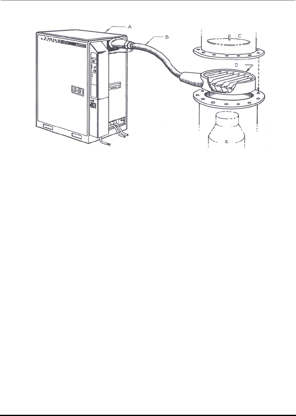
Figure 1-1: PFC cryopump—primary application
A. Refrigeration unit
B. Refrigerant line
C. Cryogenic feedthrough
D. Vacuum chamber wall
E. Cryosurface
Polycold Fast Cycle Water Vapor Cryopump Introduction
Customer Instruction Manual PFC Description and Applications
Brooks Automation 825064-00
Revision 09 1-9
Figure 1-2: PFC cryopump—secondary application
A. Refrigeration unit
B. Refrigerant line
C. High vacuum valve
D. Cryobaffle
E. High vacuum pump

Introduction Polycold Fast Cycle Water Vapor Cryopump
Refrigeration Unit Features Customer Instruction Manual
825064-00 Brooks Automation
1-10 Revision 09
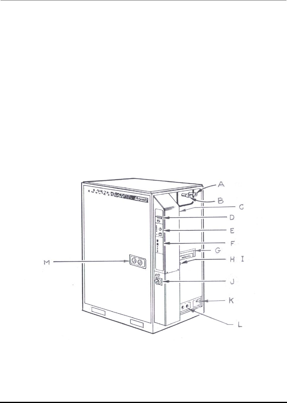
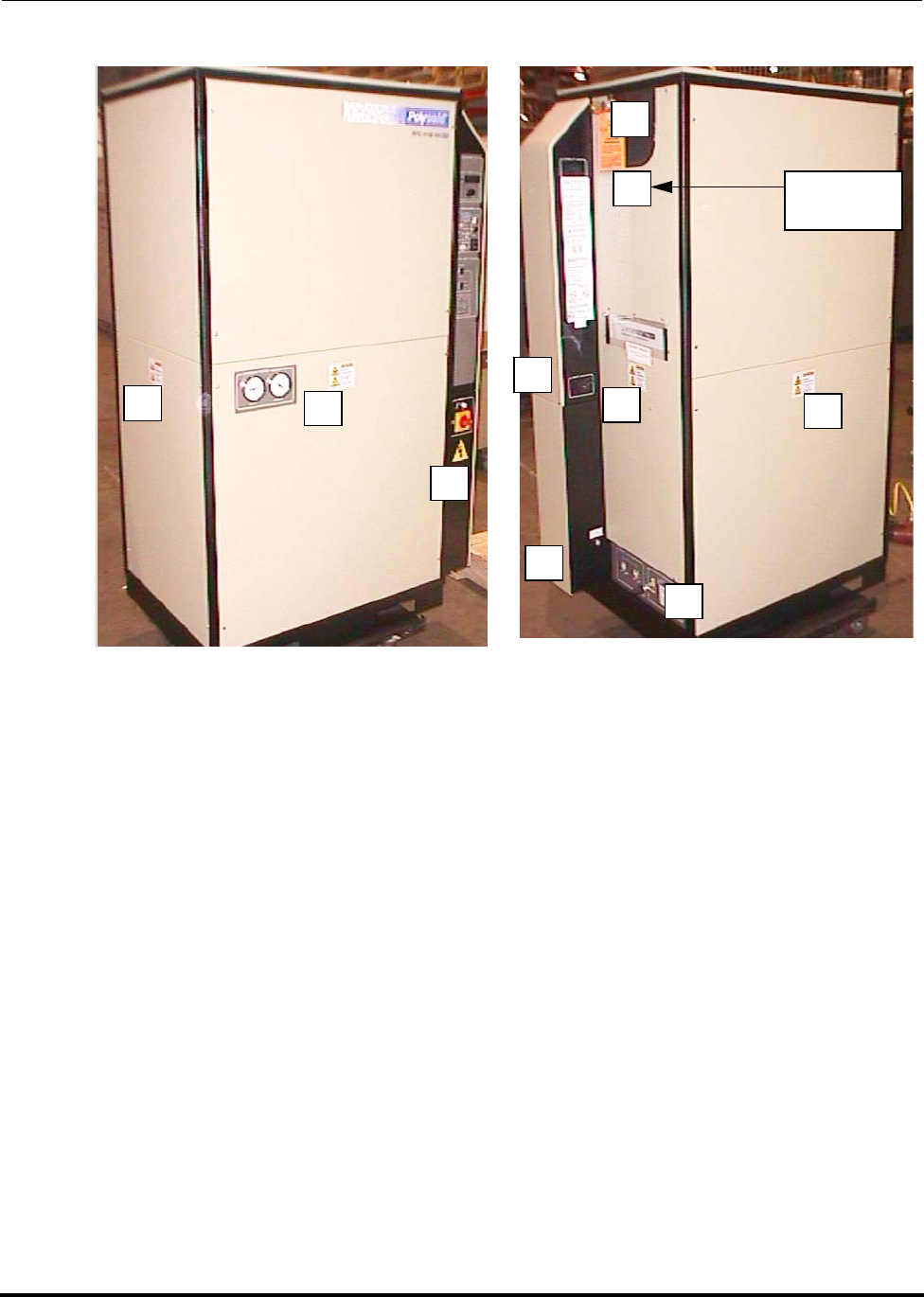
1.4 Refrigeration Unit Features
See Figure 1-3 and Figure 1-4.
Couplings for the Refrigerant Line
A. #1 Return
B. #1 Feed
Low Voltage Box
C. The EXTERNAL TC port allows thermocouples on the refrigerant line to be
connected to the TC SELECT switch. See section 3.3.5 Connect the COIL IN & COIL
OUT Thermocouples for more information.
D. The TEMPERATURE module displays the temperatures of various thermocou-
ples that will help monitor the cryopump. See Figure 3-23 and section 3.8.2 Addi-
tional Instructions for Remote Temperature Indication for more information.
E. The SYSTEM CONTROL module will help troubleshoot the cryopump if a pro-
tective device has shut it off. See section 7.3 What to Do If the Cryopump Stops Run-
ning for more information.
F. The PFC CIRCUIT 1 module controls the refrigerant circuit. See section 4.1
What the Cryopump Does in STANDBY, COOL, and DEFROST for more information.
I. The REMOTE connector permits remote control of the unit and provides status
information to a remote location. See section 3.8 How to Install the Remote Control
(Optional) for more information.
High Voltage Box
J. The power disconnect switch disconnects the main power when it is in the OFF
(O) position. The switch must be in the OFF (O) position to open the high voltage box.
Utility Panel
K. REFRIGERANT connections (EVACUATION VALVE and PRESSURE RELIEF
OUTLET)
L. COOLING WATER connections
Polycold Fast Cycle Water Vapor Cryopump Introduction
Customer Instruction Manual Refrigeration Unit Features
Brooks Automation 825064-00
Revision 09 1-11
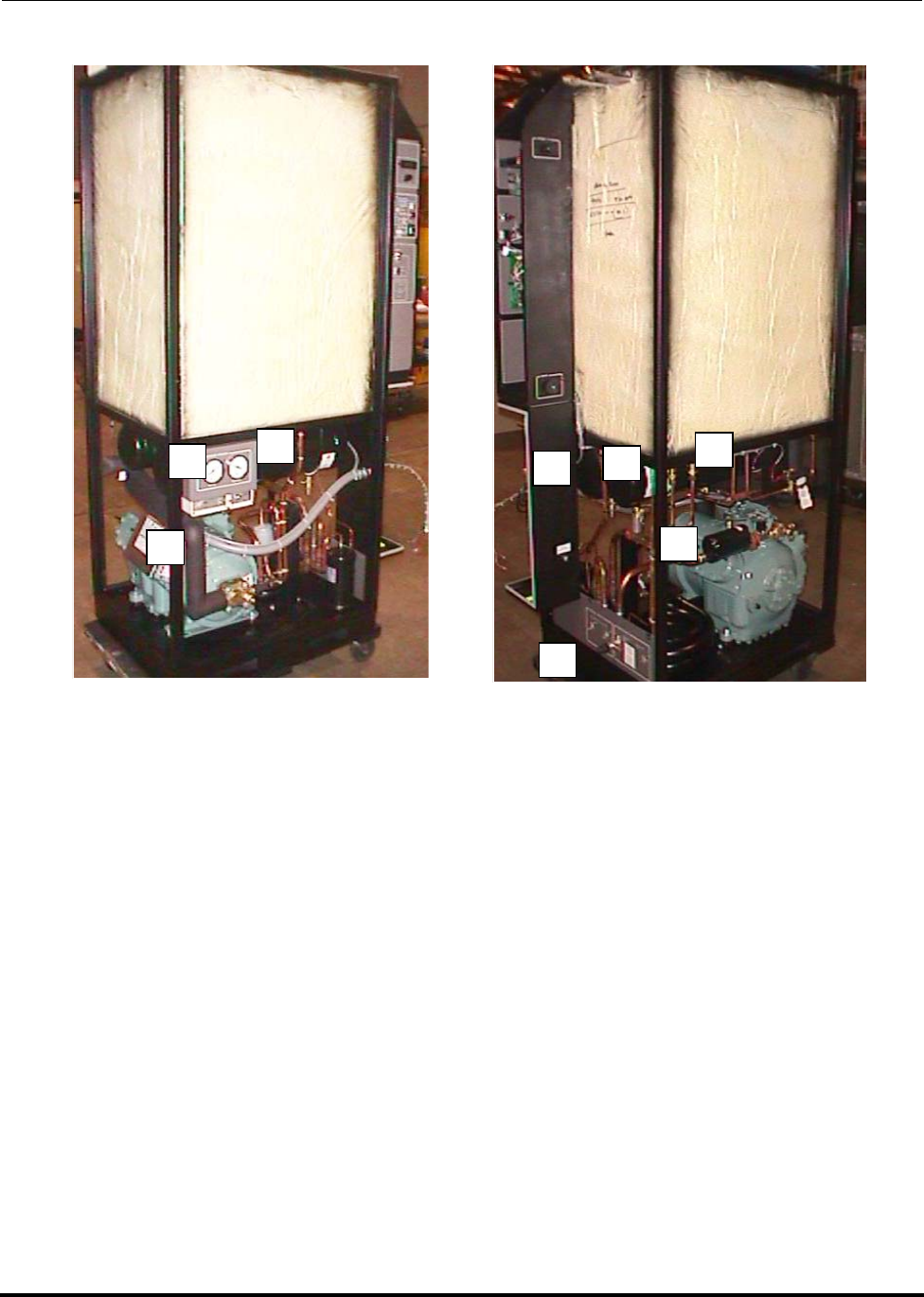
Other
G. Pocket for manual
H. Nameplate (above the REMOTE connector)
M. COMPRESSOR PRESSURE gauges
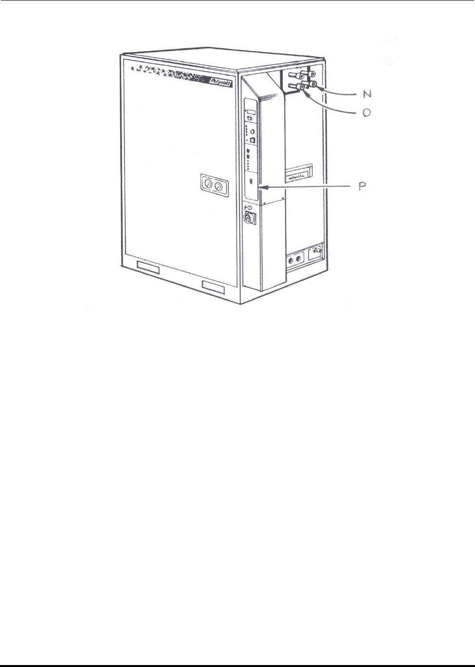
For PFC/PFC or PFC/P
N. #2 Return
O. #2 Feed
P. The PFC CIRCUIT 2 or COOLING CIRCUIT 2 module controls a second refrig-
erant circuit. See section 4.1 “What the Cryopump does in STANDBY, COOL, &
DEFROST” for more information.
Figure 1-3: PFC features
Introduction Polycold Fast Cycle Water Vapor Cryopump
Refrigeration Unit Features Customer Instruction Manual
825064-00 Brooks Automation
1-12 Revision 09
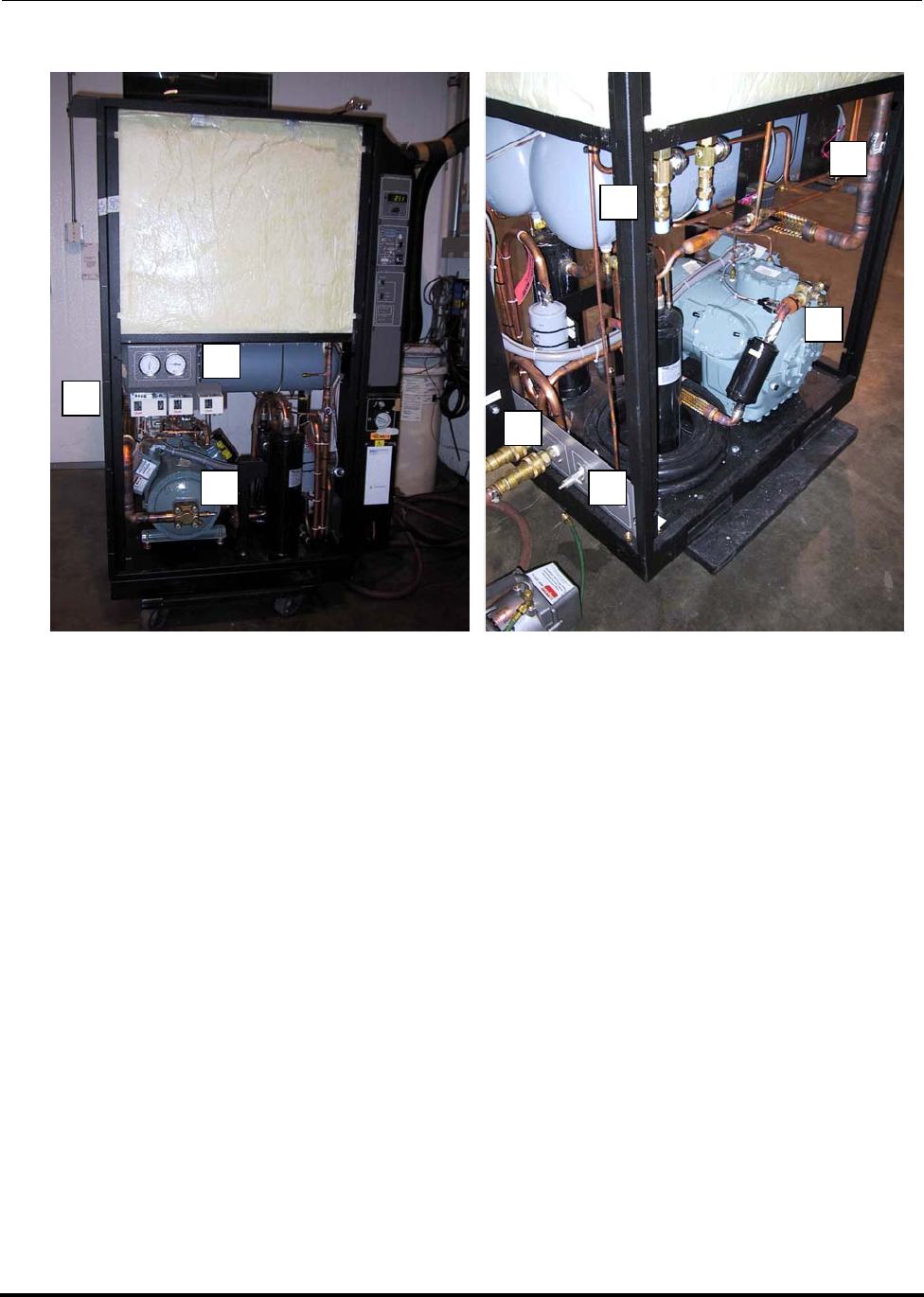
Figure 1-4: PFC/PFC & PFC/P—additional features
Polycold Fast Cycle Water Vapor Cryopump Introduction
Customer Instruction Manual Location of Isolation & Solenoid Valves
Brooks Automation 825064-00
Revision 09 1-13
1.5 Location of Isolation & Solenoid Valves
Figure 1-5: Location of isolation & solenoid valves
NOTE: Two valve box shown in this figure. Some units have a single box.
A. Cold gas feed isolation valve
B. Hot gas feed isolation valve
C. Common return isolation valve
D. #2 Cool solenoid valve (PFC/PFC or PFC/P only)

Introduction Polycold Fast Cycle Water Vapor Cryopump
Location of Isolation & Solenoid Valves Customer Instruction Manual
825064-00 Brooks Automation
1-14 Revision 09
E. #1 Cool solenoid valve
F. Buffer tank solenoid valve (660s & 1100s only)
G. Defrost solenoid valve
H. #2 Defrost solenoid valve (PFC/PFC only)

Polycold Fast Cycle Water Vapor Cryopump Introduction
Customer Instruction Manual Refrigeration Unit Data
Brooks Automation 825064-00
Revision 09 1-15
1.6 Refrigeration Unit Data
Refrigeration
Unit
Dimensions
Width x Depth x
Height in (mm)
Weight or
Mass
lb (kg)
Maximum Sound
Pressure Level
dB(A)†
550, 551, 552 37.5 x 26 x 72.5
(953 x 660 x 1842) 900
(408) 71
660, 661, 670,
672 37.5 x 26 x 72.5
(953 x 660 x 1842) 1055
(478) 72
662 37.5 x 26 x 72.5
(953 x 660 x 1842) 1050
(476) 72
1100, 1101 41.5 x 28 x 66.5
(1054 x 711 x 1689) 1200
(544) 81
1102 41.5 x 28 x 66.5
(1054 x 711 x 1689) 1200
(544) 73
† Notes regarding maximum sound pressure level:
Units were tested in a manufacturing environment while under maximum
load in the COOL mode. Measurements were made on each side of the
unit at a distance of 39 inches (1.0 m) and at a height of 63 inches (1.6 m).
Measurements taken from each side of the unit did not vary significantly.
However, measurements did vary with the specific acoustics of the envi-
ronment in which the unit was placed. For example, the maximum sound
pressure level of an 1100 in an anechoic chamber is 67 dB(A).
The abbreviation dB(A) means decibels with an “A” weighting.

Introduction Polycold Fast Cycle Water Vapor Cryopump
Recommended Items to Keep in Stock Customer Instruction Manual
825064-00 Brooks Automation
1-16 Revision 09
1.7 Recommended Items to Keep in Stock
Description Polycold Part Number
Refrigerant Charge (2 each) 940027-12 for 550-HC
940027-13 for 550-LT
940070-12 for 551-HC
940079-12 for 552-HC
940027-15 for 660-HC
940070-15 for 661-HC
940079-15 for 662-HC
940027-19 for 1100-LT
940027-35 for 1100-HC
940070-19 for 1101-LT
940070-35 for 1101-HC
940079-35 for 1102-HC
NOTE: Part numbers are different if
requesting shipment in spe-
cial tanks.
Tape, pipe insulation (flexible Armaflex elasto-
meric thermal insulation tape) 060120-00
Adhesive, pipe insulation (glue used for Armaflex
pipe insulation) 060121-00
Sheet, pipe insulation (foam like sheet with a
smooth skin on one side which forms the outer
exposed insulation surface)
060105-00
Tube, pipe insulation, smaller diameter 060123-08 for PFC-1100, 1101, and
1102
060123-04 for 550, 551, 552, 660, 661,
662, 670, 672
PFC/PFC-1100, PFC/PFC-1101,
and
PFC/PFC-1102

Polycold Fast Cycle Water Vapor Cryopump Introduction
Customer Instruction Manual Recommended Items to Keep in Stock
Brooks Automation 825064-00
Revision 09 1-17
Tube, pipe insulation, larger diameter 060123-05 for PFC-1100, 1101, and
1102
060123-07 for 550, 551, 552, 660, 661,
662, 670, 672
PFC/PFC-1100,
PFC/PFC-1101, and
PFC/PFC-1102
Panel fasteners 840156-00
O-ring removal tool for 550, 551, 552, 660, 661, 662
and, PFC/PFC-1100, PFC/PFC-1101, and PFC/
PFC-1102
810004-00
O-rings, Parker CPI UltraSeal couplings for 550s,
551s, 552s, 660s, 661s, 662s and, PFC/PFC-1100s,
PFC/PFC-1101s, and PFC/PFC-1102s only
840151-00
Gaskets, Cajon VCR couplings for PFC-1100s, PFC-
1101s, and PFC-1102s only 840152-00
Gaskets, COOL solenoid valve (XUJ) copper gas-
kets for flare solder adapter fittings (flared at one
end and used to solder connections on the other
end)
389038-01
COOL solenoid valve (XUJ)
1 each for PFC
2 each for PFC/PFC or PFC/P
380061-00
DEFROST solenoid valve service kit (B6S1)
1 each for PFC
2 each for PFC/PFC or PFC/P
NOTE: This is also the BUFFER valve on 660s, 661s,
and 662s.
380090-00
BUFFER solenoid valve service kit (B9S1) for 1100s,
1101s, and 1102s only 380091-00
Compressor oil, Zerol 150 1 gallon (3.8 L) 840050-00
Gasket set, compressor 810002-00
Gasket, compressor suction valve 389031-00
Description Polycold Part Number

Introduction Polycold Fast Cycle Water Vapor Cryopump
Recommended Items to Keep in Stock Customer Instruction Manual
825064-00 Brooks Automation
1-18 Revision 09
Gasket, compressor discharge valve 389032-00 for 550s, 551s, and 552s
389033-00 for 660s, 661s, 662s, 670s,
and 672s 1100s, 1101s, and 1102s
Fuses, 1 A, 600 V, time-delay (slow fuse) for 575 V
compressor only 335042-04
Filter drier assembly, liquid line 452085-02 for 550s, 551s, and 552s
452085-03 for 660s, 661s, 662s, 670s,
and 672s
452166-00 for 1100s, 1101s, and
1102s
Discharge thermostat, high limit, 275°F (135°C) 327032-00
Discharge thermostat, high-high limit, 300°F
(149°C) 327031-00
Fuses, 1 A, SYSTEM CONTROL board 335043-10
Relay, SYSTEM CONTROL board 333019-01
Relay, PFC module board 333019-02
Type T thermocouple wire
20 AWG (0.50 mm² cross-sectional area) 320201-01
Angle valve, 1/4 inch NPT, 1/4 inch flare 380000-00
1/4 inch flare nuts 200000-00
1/4 inch bonnets 238001-00
NOTE: Some items may be combined in kits at a reduced price.
Description Polycold Part Number

Polycold Fast Cycle Water Vapor Cryopump Introduction
Customer Instruction Manual
Brooks Automation 825064-00
Revision 09 1-19
This Page Intentionally Left Blank

Introduction Polycold Fast Cycle Water Vapor Cryopump
Customer Instruction Manual
825064-00 Brooks Automation
1-20 Revision 09

Polycold Fast Cycle Water Vapor Cryopump
Customer Instruction Manual
Brooks Automation 825064-00
Revision 09 2-1
2 Safety
Overview
This chapter describes safety guidelines for the Brooks Automation Product. All per-
sonnel involved in the operation or maintenance of the Product must be familiar with
the safety precautions outlined in this chapter.
NOTE: These safety recommendations are basic guidelines. If the facility where the Prod-
uct is installed has additional safety guidelines they should be followed as well,
along with the applicable national and international safety codes.
Chapter Contents
2.1 Safety Hazards and Safeguards. . . . . . . . . . . . . . . . . . . . . . . . . . . . . . . . . . . . . . .2-2
2.2 Danger, Warning, and Caution Alerts . . . . . . . . . . . . . . . . . . . . . . . . . . . . . . . . .2-3
2.3 Safety Training Guidelines. . . . . . . . . . . . . . . . . . . . . . . . . . . . . . . . . . . . . . . . . . .2-6
2.4 Potential Hazards During Maintenance and Servicing . . . . . . . . . . . . . . . . . . .2-8
2.5 Lock-Out and Tag-Out Instructions (LOTO). . . . . . . . . . . . . . . . . . . . . . . . . . . .2-18
2.6 Safety Interlocks. . . . . . . . . . . . . . . . . . . . . . . . . . . . . . . . . . . . . . . . . . . . . . . . . . . .2-20
2.7 Circuit Breaker and Fuse Protection . . . . . . . . . . . . . . . . . . . . . . . . . . . . . . . . . . .2-21

Polycold Fast Cycle Water Vapor Cryopump
Customer Instruction Manual
Brooks Automation 825064-00
Revision 09 2-2
2.1 Safety Hazards and Safeguards
This chapter summarizes safety concerns (hazards, precautions, and ergonomics)
associated with the operation and service of Polycold’s Cool Solutions ® Fast Cycle
Water Vapor Cryopump.
The Fast Cycle Water Vapor Cryopump has been designed to conform to all known
safety requirements applicable to our products. Under normal operation the Fast
Cycle Water Vapor Cryopump presents no hazard to its operator or other personnel.
Tool secured access panels shield operators and other personnel working in the area
of the equipment from the operation or possible failure of the components that com-
pose the equipment.
Only qualified service personnel are authorized to open or remove the panels and
must be in accordance with the safety instructions presented in this chapter and
throughout the manual. In service and repair operations, the direct refrigeration and
heating equipment may potentially expose personnel to the following hazards:
• Electrical shock
• Hazardous Materials
• Lifting Hazards
• Cold Surfaces
• Hot Surfaces
The information and instructions provided in this chapter and throughout this man-
ual are intended to help service personnel work with the equipment in a safe, effec-
tive, and efficient manner. The emergency and safety procedures are provided to
help service personnel develop safe practices and establish safe conditions for work-
ing with Polycold’s Cool Solutions ® Fast Cycle Water Vapor Cryopump.

Polycold Fast Cycle Water Vapor Cryopump
Customer Instruction Manual
Brooks Automation 825064-00
Revision 09 2-3
2.2 Danger, Warning, and Caution Alerts
Danger, Warning, and Caution alerts are integral parts of these instructions:
NOTE: Note: Information in this section is for users in the USA and for users complying
with SEMI S2 requirements.
• DANGER is used to indicate an imminently hazardous situation that, if not
avoided, will result in death or serious injury.
• WARNING is used to indicate a potentially hazardous situation that, if not
avoided, could result in death or serious injury.
• CAUTION is used to indicate a potentially hazardous situation that, if not
avoided, may result in minor or moderate injury.
• CAUTION is also used when failure to follow instructions or precautions can
result in damage to the equipment.
Danger, Warning, and Caution alerts must be read carefully, understood thoroughly,
and observed at all times. If this equipment is used in a manner not specified by the
manufacturer, the protection provided by the equipment may be impaired. Pictorial
hazard alerts affixed to the direct refrigeration and heating equipment and its compo-
nents are in accordance with ANSI, FDA, SEMI, and (where applicable) IEC stan-
dards. Pictorial hazard alerts follow the format described below:
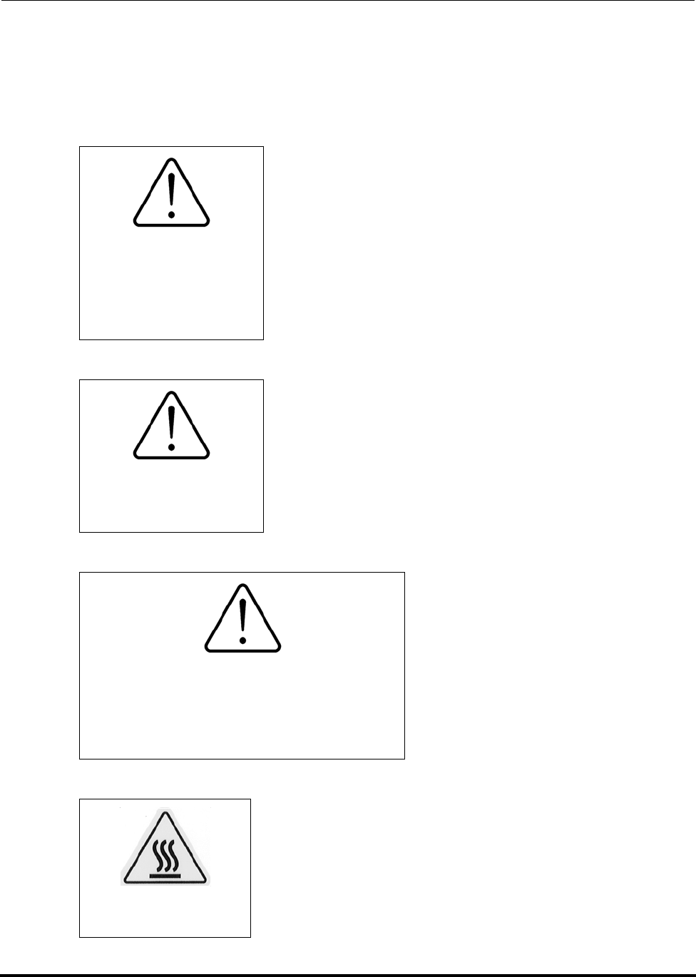
CAUTION
GENERAL HAZARD
Moving or repositioning the refrigerant line may result in minor
or moderate injury.
Do not attempt to move or position the refrigerant line. The insu-
lation hardens when cold and may crack.
Hazard
Keyword
Level
Pictogram (icon)
depicting nature
of hazard
Text describing
hazard and what
might/could happen
Text describing
how to avoid
the hazard

Polycold Fast Cycle Water Vapor Cryopump
Customer Instruction Manual
Brooks Automation 825064-00
Revision 09 2-4
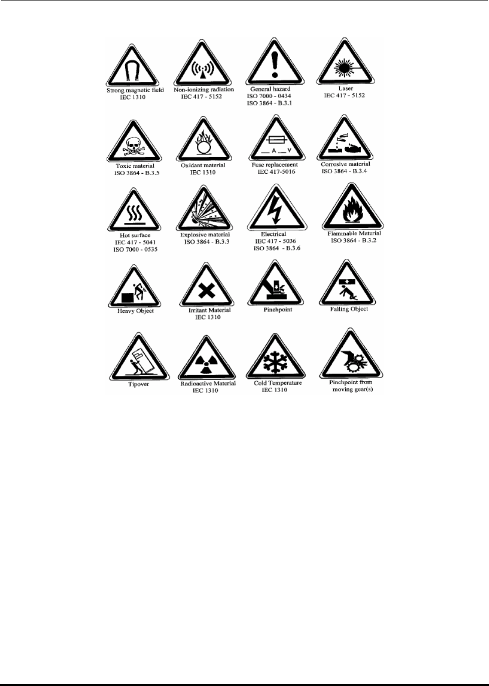
This page includes pictogram representations used on semiconductor manufacturing
equipment. This information is provided for customers using this equipment for
semiconductor process equipment. Other users may refer to this information as well.
Some of these pictograms will be found on Polycold’s Cool Solutions ® Fast Cycle
Water Vapor Cryopump equipment. Actual label configurations and placement will
be found in this chapter. Please note, for purposes of clarity, most illustrations depict-
ing hazardous exposures show components in their most hazardous state (i.e., covers
removed, safety interlocks, and other safeguards defeated) as they might appear dur-
ing a major service activity. Most tasks do not require that the hazards be exposed to
this degree.
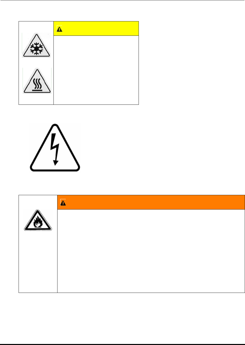
Table 2-1: Warning Label Legend
‡ SAFETY ALERT SYMBOL
DANGER - White Lettering / Red Back-
ground
(Safety Red: per ANSI Z535.4 - 15 parts
Warm Red, 1 part Rubine Red, 1/4 part
Black)
White Triangle / Red Exclamation
Point
WARNING - Black Lettering / Orange Back-
ground
(Safety Orange: per ANSI Z535.4 - 13 parts
Yellow, 3 parts Warm Red, 1/4 part Black)
Black Triangle / Orange Exclamation
Point
CAUTION - Black Lettering / Yellow Back-
ground
(Safety Yellow: per ANSI Z535.4 - Pantone
108C)
Black Triangle / Yellow Exclamation
Point
Polycold Fast Cycle Water Vapor Cryopump
Customer Instruction Manual
Brooks Automation 825064-00
Revision 09 2-5
Figure 2-1: Typical Warning Labels

Polycold Fast Cycle Water Vapor Cryopump
Customer Instruction Manual
Brooks Automation 825064-00
Revision 09 2-6
2.3 Safety Training Guidelines
The safety information in this chapter is a summary of the safety information that is to
be successfully conveyed to service personnel as part of their training on Polycold’s
Cool Solutions ® Fast Cycle Water Vapor Cryopump. The training program is intended
to ensure that any person who undertakes the service of the Fast Cycle Water Vapor
Cryopump can demonstrate competence to perform the required tasks safely.
Accordingly, training required for each task includes, but is not limited to, the follow-
ing:
• A review of applicable safety standards and procedures, such as those pre-
sented in this chapter.
• A review of maintenance and safety recommendations applicable to vendor
supplied equipment.
• An explanation of the purpose of a subsystem and its operation.
• An explanation of the specific tasks and responsibilities of each person (opera-
tor, service personnel, etc.) assigned to the Fast Cycle Water Vapor Cryopump
equipment.
• The person(s) (identified by name, location, and telephone number) to be con-
tacted when required actions are beyond the training and responsibility of the
person being trained.
• Identification of the recognized hazards associated with each task.
• Identification of, and appropriate responses to, unusual operating conditions.
• Explanation of the functions and limitations of all safeguards and their design
characteristics.
• Instructions for the functional testing (or other means of assurance) for proper
operation of safeguarding devices.
Safe use and service of the Fast Cycle Water Vapor Cryopump equipment also
requires the following:
• Service personnel should understand the operation of process-related hard-
ware interlocks, and the sequences of hardware operation that are executed
automatically, as explained in this chapter.
• The equipment should not be used without assuring correct operation of all
connected facilities, especially fugitive emissions exhaust.
• Service personnel should always assume that high voltage is present unless
they have personally turned it off and locked it out.
• The equipment should not be operated without all guards and safety devices
in place.

Polycold Fast Cycle Water Vapor Cryopump
Customer Instruction Manual
Brooks Automation 825064-00
Revision 09 2-7
• The equipment should be shutdown, locked-out, and not be operated while it
is being maintained.
• Users should not attempt to defeat, modify, or disable any of the equipment's
safety interlock switches.
• Only Polycold Systems trained service personnel should perform installation,
assembly, operation, disassembly, service, or maintenance of the Fast Cycle
Water Vapor Cryopump equipment.
• All safety related incidents or near misses should be reported to a supervisor
or to Brooks Polycold Systems Inc.
• The user should carefully review and understand manufacturer provide mate-
rial safety data sheets (MSDS) for materials used by this equipment.
Definition of Electrical Work Types
The following are the four types of electrical work in SEMI S2-0200:
Type 1- Equipment is fully deenergized.
Type 2- Equipment is energized. Energized circuits are covered or protected.
NOTE: Type 2 work includes tasks where the energized circuits are or can be measured by
placing probes through suitable openings in the covers or insulators.
Type 3- Equipment is energized. Energized circuits are exposed and inadvertent con-
tact with uninsulated energized parts is possible. Potential exposures are no greater
than 30 volts rms, 42.4 volts peak, 60 volts dc or 240 volt-amps in dry locations.
Type 4- Equipment is energized. Energized circuits are exposed and inadvertent con-
tact with uninsulated energized parts is possible. Potential exposures are greater than
30 volts rms, 42.4 volts peak, 60 volts dc or 240 volt-amps in dry locations. Potential
exposures to radio-frequency currents exist; refer to SEMI S2-0200, Table A5-1 of
Appendix 5 for a listing of these values.
Polycold Fast Cycle Water Vapor Cryopump
Customer Instruction Manual
Brooks Automation 825064-00
Revision 09 2-8
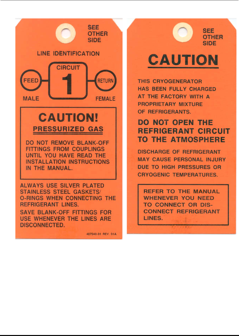
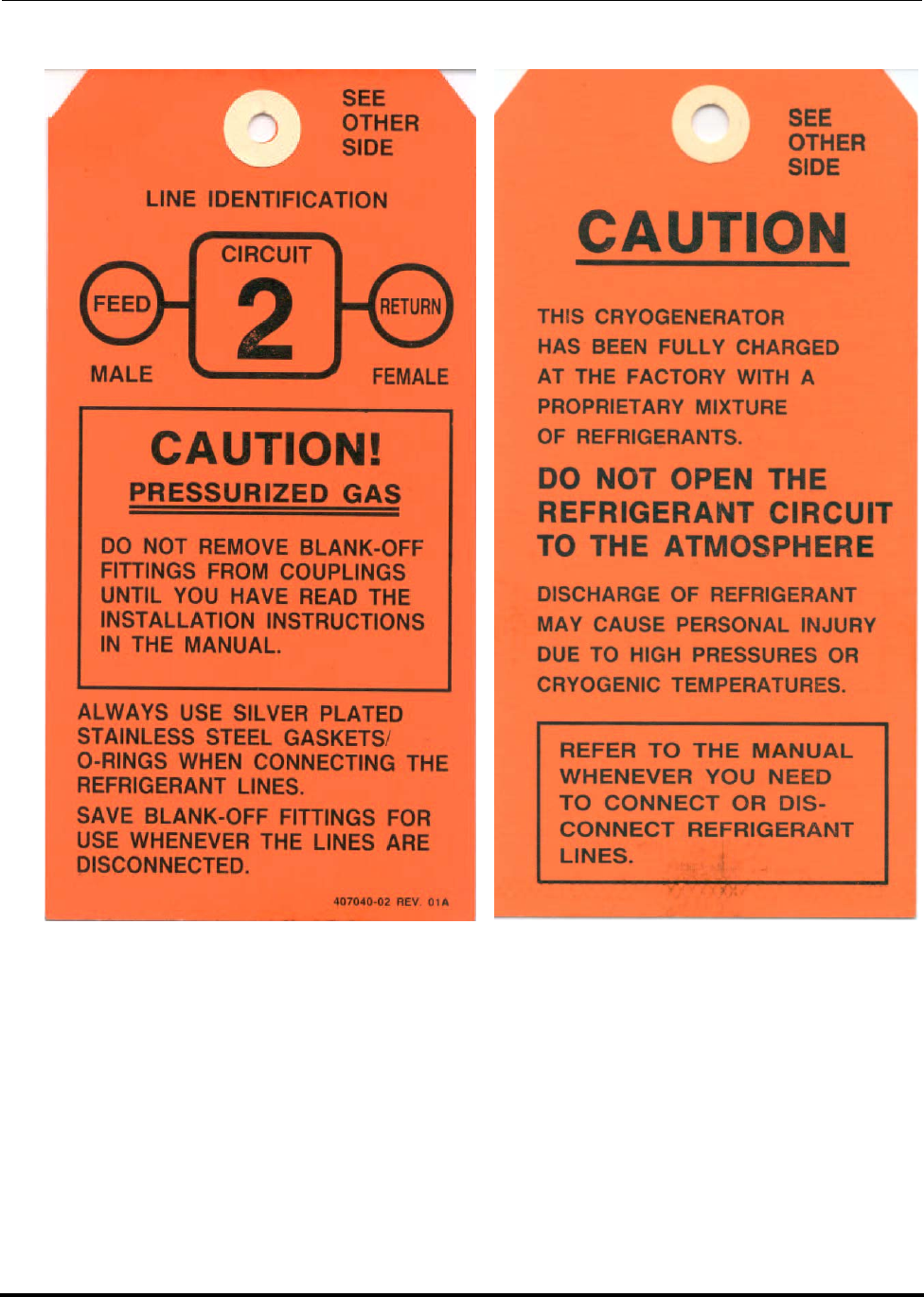
2.4 Potential Hazards During Maintenance and Servicing
NOTE: This section applies to users wishing to comply with SEMI S2 requirements.
1
2
3
4
WARNING!
VALVE UNDER
PRESSURE WHEN-
EVER SYSTEM IS
PRESSURIZED
CAUTION!
PREVENT LEAKS -
CAP THE VALVE
WARNING!
This valve is to remain sealed open. If
this valve is closed when servicing the
unit, the unit must be attended until the
valve is reopened and resealed.
CAUTION!
Hot Surface Inside
Polycold Fast Cycle Water Vapor Cryopump
Customer Instruction Manual
Brooks Automation 825064-00
Revision 09 2-9
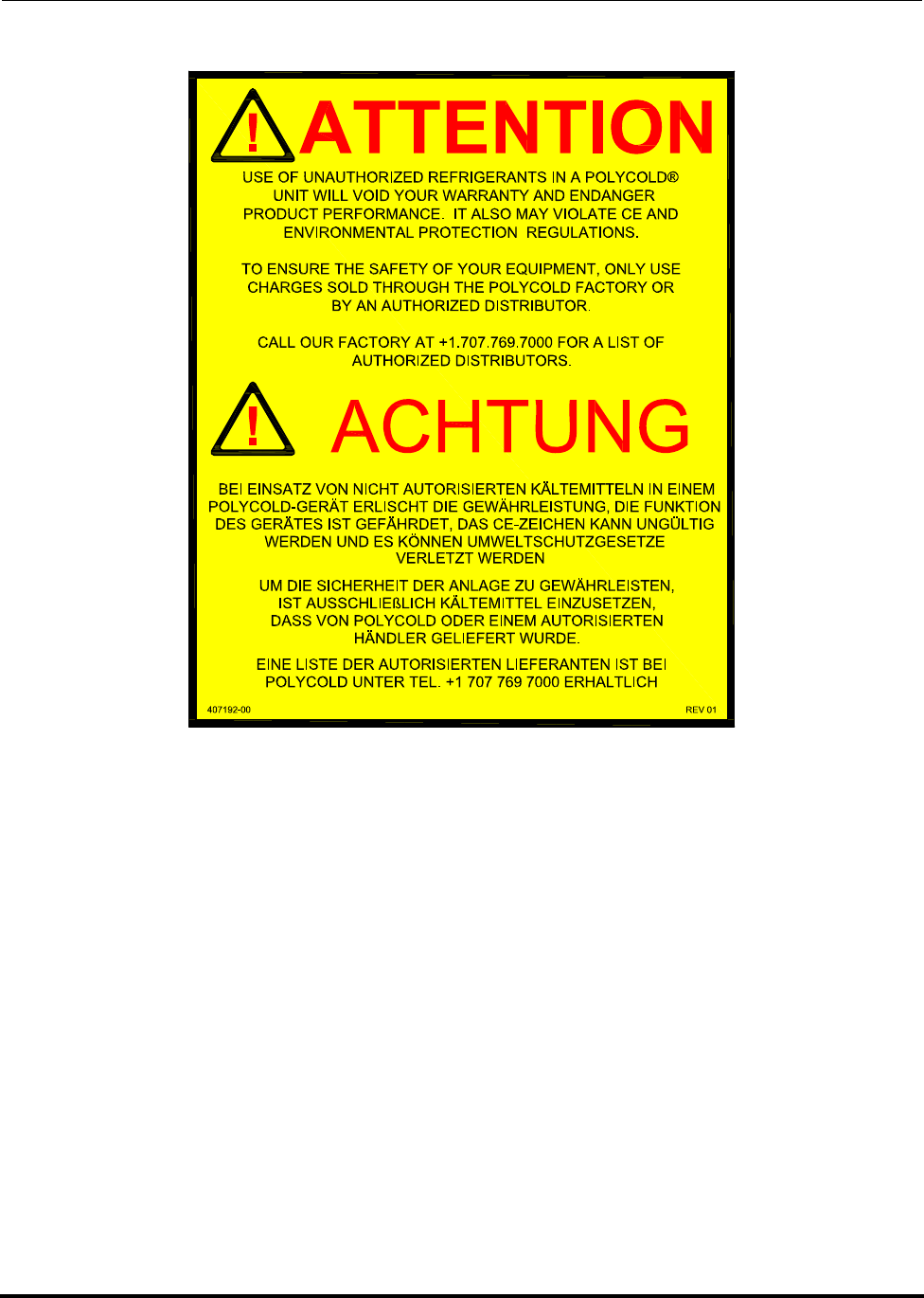
5
6
8
9
(CE Marked Units Only)
10
This valve is
only open when
the valve stem is
in the middle
position (mid-
seated)
PRIMARY REFRIGERANT
EXPANSION
407020 REV 01 XQS23689
R2000 SERIES
24 V AC
PUSH TO RESET
Polycold Fast Cycle Water Vapor Cryopump
Customer Instruction Manual
Brooks Automation 825064-00
Revision 09 2-10
11
12
13
CAUTION
Extreme Temperatures.
Can cause burns or frostbite.
Do not touch exposed piping.
WARNING
FLAMMABLE MATERIAL (1101, 1100, 670, 661, 660, 551, and 550
ONLY)
Do not open the refrigerant circuit to the atmosphere. Do not
change the settings of the valves or loosen any fittings. Opening the
refrigerant circuit or changing valve settings along with the failure
to following instructions in this manual could result in death or seri-
ous injury.
Review this manual before performing any procedure including
routine operation of Polycold’s Cool Solutions ® Fast Cycle Water
Vapor Cryopump. Inspect the refrigerant circuit and change valve
settings only as defined throughout this manual.
Polycold Fast Cycle Water Vapor Cryopump
Customer Instruction Manual
Brooks Automation 825064-00
Revision 09 2-11
14
Polycold Fast Cycle Water Vapor Cryopump
Customer Instruction Manual
Brooks Automation 825064-00
Revision 09 2-12
15
Polycold Fast Cycle Water Vapor Cryopump
Customer Instruction Manual
Brooks Automation 825064-00
Revision 09 2-13
Polycold Fast Cycle Water Vapor Cryopump
Customer Instruction Manual
Brooks Automation 825064-00
Revision 09 2-14
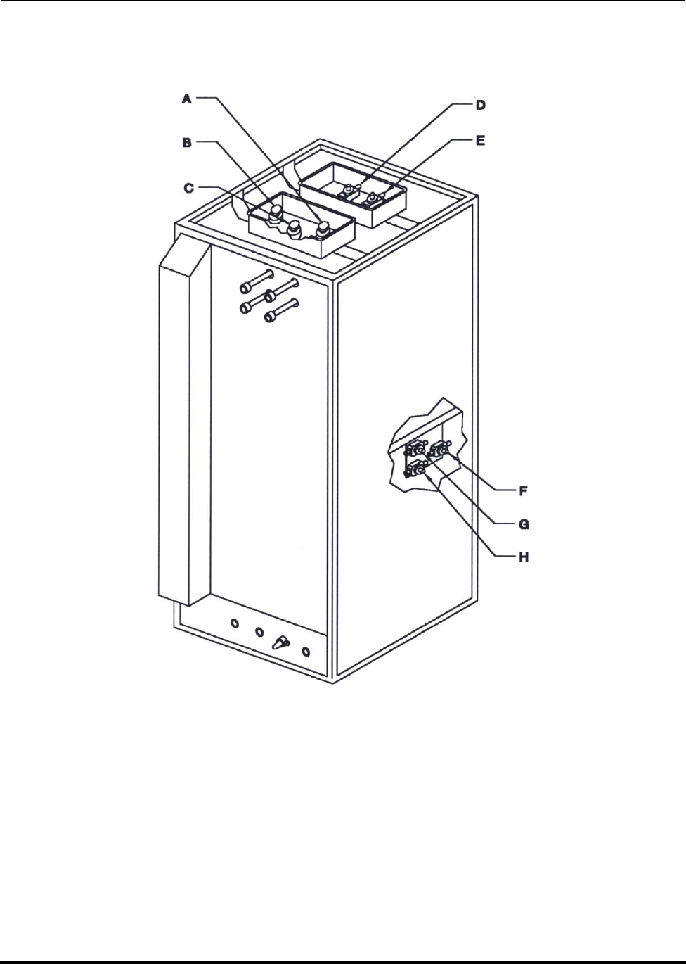
16
Figure 2-2: Exterior Label Placement
Exterior, Left Front Oblique Exterior, Right Rear Oblique
11
11 11
11
12
10
15 Dual Circuit
Units Only
14
9
5
Polycold Fast Cycle Water Vapor Cryopump
Customer Instruction Manual
Brooks Automation 825064-00
Revision 09 2-15
Figure 2-3: Interior Label Placement 550s, 552s, 660s, 662s, 670s, 672s (670 shown)
Interior, Left Front Oblique Interior, Right Rear Oblique
5
2
6236
1
1

Polycold Fast Cycle Water Vapor Cryopump
Customer Instruction Manual
Brooks Automation 825064-00
Revision 09 2-16
Figure 2-4: Interior Label Placement 1100
Interior, Left Front Oblique Interior, Right Rear Oblique
10 5
2
6
2
3
1
2
Polycold Fast Cycle Water Vapor Cryopump
Customer Instruction Manual
Brooks Automation 825064-00
Revision 09 2-17
Figure 2-5: Interior Label Placement 1102
Interior, Left Front Oblique Interior, Right Rear Oblique
10
5
2
6
2
3
1
2
Polycold Fast Cycle Water Vapor Cryopump
Customer Instruction Manual
Brooks Automation 825064-00
Revision 09 2-18
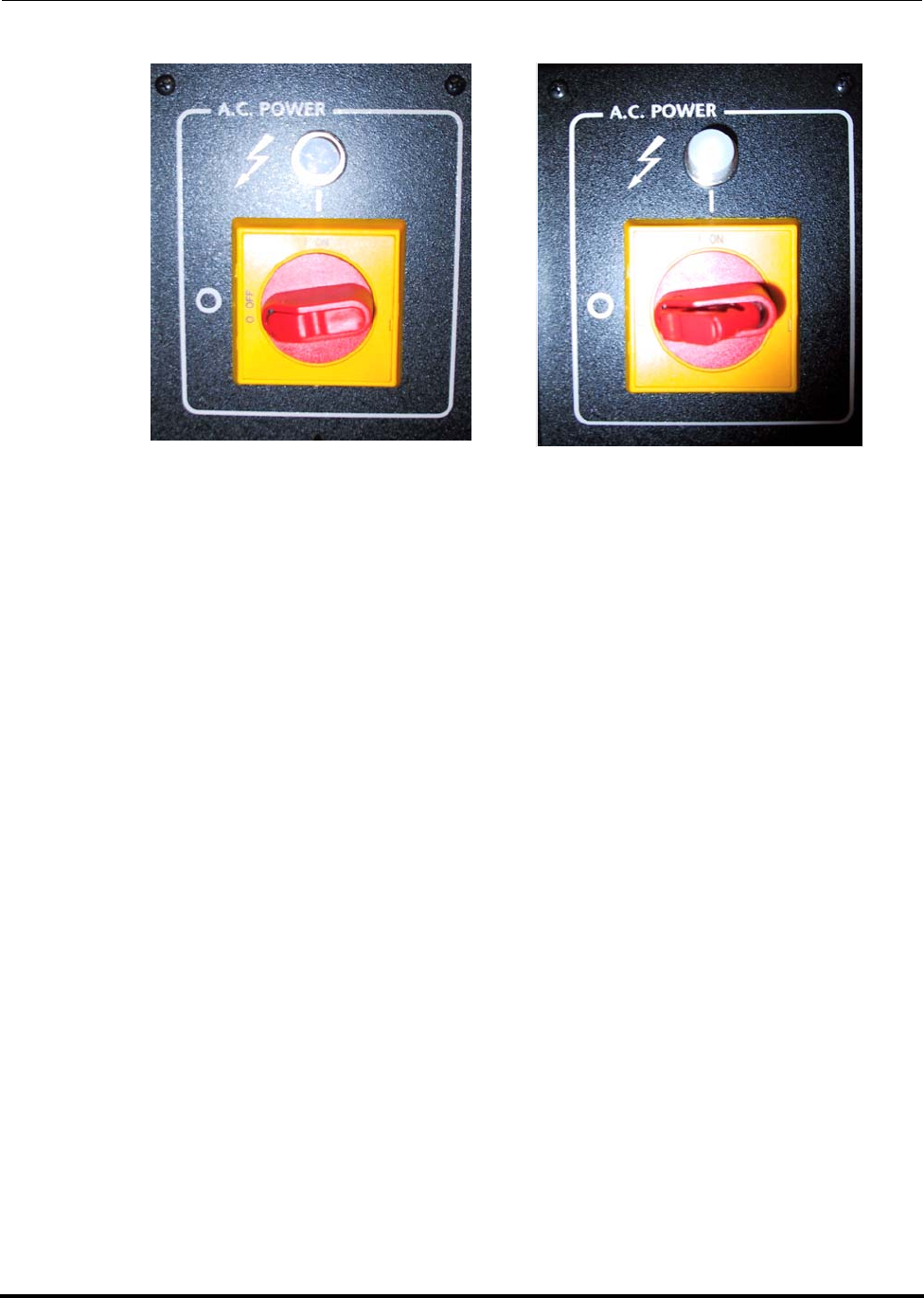
2.5 Lock-Out and Tag-Out Instructions (LOTO)
NOTE: A lock-out refers to disconnecting the power supply from the unit, and reapplying
safe power in order to avoid possible personnel electrocution.
1. Shut down the system as described in section 8.1 How to Shut Down or Ship
the Cryopump.
2. Switch the Power Disconnect switch (refer to figure below) to the OFF position.
3. Pull out the Tag (shown in lower right picture below) on Power Disconnect
Switch and place a pad lock in the opening keep the power off and locked.
4. Using an appropriate test meter, verify no electrical potential exists on second-
ary side of Power Disconnect Switch.
5. It is now safe to work in this area, refer to the Type 3 Electrical Work instruc-
tions before proceeding.
WARNING
ELECTRICAL HAZARD
Contact could cause electric shock and result in death or serious
injury. After performing LOTO of the Power Disconnect Switch,
Line Voltage is still present at input terminals of the Power Dis-
connect Switch. To remove electrical power to the input termi-
nals of the Power Disconnect Switch, refer to end-user’s Facility
Power LOTO instructions.
Polycold Fast Cycle Water Vapor Cryopump
Customer Instruction Manual
Brooks Automation 825064-00
Revision 09 2-19
Figure 2-6: Power Disconnect Switch in OFF position –
Unlocked (Left), Locked (Right) (Customer supplied lock out device not shown.)

Polycold Fast Cycle Water Vapor Cryopump
Customer Instruction Manual
Brooks Automation 825064-00
Revision 09 2-20
2.6 Safety Interlocks
The PFC safety interlock circuitry design is a positive logic, hardware based, fault tol-
erant device (approved by an authorized testing agency and NRTL approved for use
as a safety device), providing operator notification, requiring manual reset, and which
places the equipment in a safe standby condition upon activation. An exception to
this is the compressor discharge safety interlock that uses negative logic. The risk
associated with this variance has been deemed to be acceptable since other interlocks
(which use positive logic) are expected to be activated if abnormally high discharge
temperatures occur.

Polycold Fast Cycle Water Vapor Cryopump Safety
Customer Instruction Manual Circuit Breaker and Fuse Protection
Brooks Automation 825064-00
Revision 09 2-21
2.7 Circuit Breaker and Fuse Protection
Table 2-2: PFC Circuit Breaker and Fuse Protection
Reference
Designation Protection
Provided Rated Voltage
and Amperage
*Amperage
Interrupting
Capacity
High Voltage
Box
CB1 Over Current 460V 1A
CB2 Over Current 460V 1A
CB3 Over Current 24VAC 5A
High Voltage
Box- 575V
Compressor
FU1 Over Current 600V 1A Not Applicable
FU2 Over Current 600V 1A Not Applicable
CB1 Over Current 24VAC 5A
System Con-
trol Printed
Circuit Board F1 Over Current 24VAC 1A Not Applicable
NOTE: *Amperage Interrupting Capacity refers to the maximum current that the elec-
trical component is rated for. If the current is too high the contacts will “arc”
exceeding capacity and possibly weld (fuse) together. In some locations this is
also known as “AC breaking capacity.”

Safety Polycold Fast Cycle Water Vapor Cryopump
Circuit Breaker and Fuse Protection Customer Instruction Manual
825064-00 Brooks Automation
2-22 Revision 09
This Page Intentionally Left Blank

Polycold Fast Cycle Water Vapor Cryopump
Customer Instruction Manual
Brooks Automation 825064-00
Revision 09 3-1
3 Installation
Overview
This chapter provides complete installation procedures for the Brooks Automation
Product including: unpacking, assembly, facilities connections, initial setup, and ini-
tial check-out.
Chapter Contents
3.1 How to Install the Cryosurface . . . . . . . . . . . . . . . . . . . . . . . . . . . . . . . . . . . . . . .3-3
3.1.1 If the Cryosurface is a Coil. . . . . . . . . . . . . . . . . . . . . . . . . . . . . . . . . . . .3-3
3.1.2 If the Cryosurface Is a Baffle . . . . . . . . . . . . . . . . . . . . . . . . . . . . . . . . . .3-5
3.2 How to Install the Refrigeration Unit. . . . . . . . . . . . . . . . . . . . . . . . . . . . . . . . . .3-7
3.2.1 Inspect the Unit. . . . . . . . . . . . . . . . . . . . . . . . . . . . . . . . . . . . . . . . . . . . .3-7
3.2.2 Position the Unit . . . . . . . . . . . . . . . . . . . . . . . . . . . . . . . . . . . . . . . . . . . .3-9
3.2.3 Place the Unit. . . . . . . . . . . . . . . . . . . . . . . . . . . . . . . . . . . . . . . . . . . . . . .3-10
3.2.4 Connect the Electrical Power. . . . . . . . . . . . . . . . . . . . . . . . . . . . . . . . . .3-17
3.2.5 Connect the Cooling Water. . . . . . . . . . . . . . . . . . . . . . . . . . . . . . . . . . .3-27
3.2.6 How to Install Refrigeration Unit to Meet ASHRAE Requirements.3-30
3.3 How to Connect the Cryosurface to the Refrigeration Unit . . . . . . . . . . . . . . .3-32
3.3.1 Connect the Refrigerant Line . . . . . . . . . . . . . . . . . . . . . . . . . . . . . . . . .3-32
3.3.2 Position the Refrigerant Line. . . . . . . . . . . . . . . . . . . . . . . . . . . . . . . . . .3-35
3.3.3 Check the Refrigerant Line & Cryosurface for Leaks . . . . . . . . . . . . .3-39
3.3.4 Evacuate the Refrigerant Line and Cryosurface. . . . . . . . . . . . . . . . . .3-44
3.3.5 Connect the COIL IN & COIL OUT Thermocouples. . . . . . . . . . . . . .3-47
3.4 How to Prepare the Cryopump for Operation . . . . . . . . . . . . . . . . . . . . . . . . . .3-52
3.4.1 Open the Isolation Valves . . . . . . . . . . . . . . . . . . . . . . . . . . . . . . . . . . . .3-52
3.4.2 Cycle the Cryopump & Check for Refrigerant Leaks . . . . . . . . . . . . .3-53
3.4.3 Insulate the Exposed Tubes and Couplings . . . . . . . . . . . . . . . . . . . . .3-55
3.4.4 Evaluate the Cryopump. . . . . . . . . . . . . . . . . . . . . . . . . . . . . . . . . . . . . .3-58
3.5 Cryosurface & Cryogenic Feed-through Specification. . . . . . . . . . . . . . . . . . . .3-67
3.5.1 If the Cryosurface is a Coil. . . . . . . . . . . . . . . . . . . . . . . . . . . . . . . . . . . .3-67

Installation Polycold Fast Cycle Water Vapor Cryopump
Customer Instruction Manual
825064-00 Brooks Automation
3-2 Revision 09
3.5.2 If the Cryosurface is a Baffle . . . . . . . . . . . . . . . . . . . . . . . . . . . . . . . . . .3-71
3.6 Refrigerant Line Specification . . . . . . . . . . . . . . . . . . . . . . . . . . . . . . . . . . . . . . . .3-74
3.6.1 How to Build the Feed and Return Lines . . . . . . . . . . . . . . . . . . . . . . .3-75
3.7 Brazing Specification. . . . . . . . . . . . . . . . . . . . . . . . . . . . . . . . . . . . . . . . . . . . . . . .3-78
3.8 How to Install the Remote Control (Optional) . . . . . . . . . . . . . . . . . . . . . . . . . .3-79
3.8.1 Connect the Remote Control to a Remote Connector . . . . . . . . . . . . .3-79
3.8.2 Additional Instructions for Remote Temperature Indication . . . . . .3-87
3.8.3 COLDEST LIQUID (TC #9): . . . . . . . . . . . . . . . . . . . . . . . . . . . . . . . . . .3-88

Polycold Fast Cycle Water Vapor Cryopump Installation
Customer Instruction Manual How to Install the Cryosurface
Brooks Automation 825064-00
Revision 09 3-3
3.1 How to Install the Cryosurface
3.1.1 If the Cryosurface is a Coil
Tools and materials needed
• spanner wrench†
• high vacuum lubricant—must have an appropriate low vapor pressure (for
optional use on the feed-through’s O-ring)
† Shipped with Polycold’s standard 2-inch (50 mm) feed-through.
This section assumes the purchase of a cryocoil and standard 2-inch (50 mm) feed-
through from Brooks Polycold Systems Inc. If not, see section 3.5 Cryosurface &
Cryogenic Feed-through Specification. Then continue with the installation.
3.1.1.1 Ensure that the Feed-through Port is Compatible
Check the feed-through port thickness, hole diameter, and sealing surface. Ensure
that the feed-through port is compatible with the feed-through. (See Figure 3-1
below.)
NOTE: Polycold’s 2-inch (50 mm) feed-through is designed to be installed from inside the
vacuum chamber. This allows removal of the cryocoil when cleaning or servicing
the vacuum chamber.
CAUTION
GENERAL HAZARD
Do not connect the unit to an existing cryosurface without first
verifying that the cryosurface meets specification. The cry-
opump’s working pressure may exceed your cryosurface’s work-
ing pressure, which may damage your vacuum system
components and may result in minor or moderate injury. (Reser-
voir type cryosurfaces are not suitable.)
Verify all components meet specifications before connection.
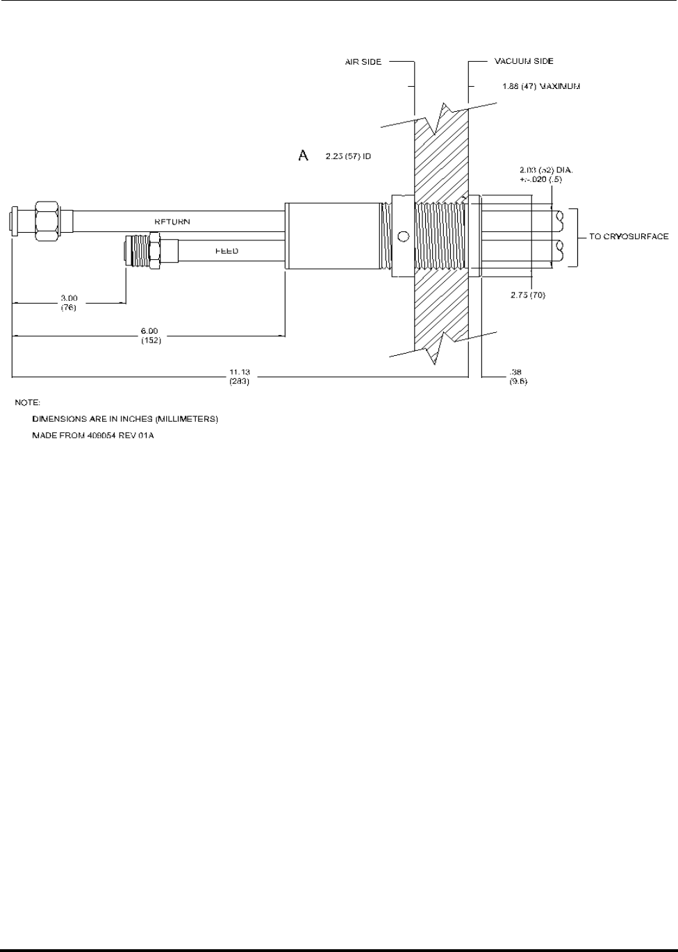
Installation Polycold Fast Cycle Water Vapor Cryopump
How to Install the Cryosurface Customer Instruction Manual
825064-00 Brooks Automation
3-4 Revision 09
Figure 3-1: Polycold’s 2-inch (50 mm) Feed-through with Port Requirements
O-ring number 228: 2.25 inches (57 mm) ID x 0.125 inches (3 mm) section
O-ring material: Buna-nitrile
O-ring surface: 2.60 inches (66 mm) surface roughness not to exceed 32 micro-inch
(32/1000000 inch or 0.81 micron) — must be flat, clean, and free of scratches or depos-
its.
3.1.1.2 Put the Cryocoil into the Vacuum Chamber
1. Insert the feed-through into the feed-through port. Tighten the feed-through
nut finger-tight and position the cryocoil. If the cryocoil has fasteners, secure
them at this time.
2. Verify that no moving parts will hit the cryocoil. Make sure the cryocoil does
not touch the vacuum chamber wall or anything else in the vacuum chamber.
The cryocoil should be at least 5/8 inch (16 mm) away from the vacuum cham-
ber wall.
3. Hold the feed-through in place and tighten the nut with a wrench. Make cer-
tain the nut is tight. If the nut is loose, the O-ring will tend to lift from the vac-
uum chamber wall when under vacuum.
Polycold Fast Cycle Water Vapor Cryopump Installation
Customer Instruction Manual How to Install the Cryosurface
Brooks Automation 825064-00
Revision 09 3-5
4. Install a radiation shield if the cryocoil is in direct view of a source of heat
greater than 50°C. Position the shield between the cryocoil and the heat source.
The shield should be as close as possible to the heat source, and as far away as
possible from the cryocoil. The cryocoil traps molecules best when it has max-
imum view of the vacuum chamber.
3.1.1.3 Check Vacuum Chamber for Leaks
Check the feed-through port and seals used to install the cryocoil to ensure that the
vacuum chamber is free of leaks.
3.1.2 If the Cryosurface Is a Baffle
Tools and materials needed:
high vacuum lubricant—must have an appropriate low vapor pressure (for optional
use on an O-ring seal)
NOTE: Note: This section assumes the purchase of a cryobaffle from Brooks Polycold Sys-
tems Inc. If not, see section 3.5 Cryosurface & Cryogenic Feed-through Specifica-
tion. Then continue with the installation.
3.1.2.1 Inspect All Vacuum Sealing Surfaces
Surfaces must be clean and free from scratches or other imperfections that might
result in vacuum leaks. Protect these surfaces at all times. Remove any contaminants
by wiping it with a clean cloth moistened with alcohol.
CAUTION
GENERAL HAZARD
Do not connect the unit to an existing cryosurface without first
verifying that the cryosurface meets specification. The cry-
opump’s working pressure may exceed your cryosurface’s work-
ing pressure, which may damage your vacuum system
components and may result in minor or moderate injury. (Reser-
voir type cryosurfaces are not suitable.)
Verify all components meet specifications before connection.

Installation Polycold Fast Cycle Water Vapor Cryopump
How to Install the Cryosurface Customer Instruction Manual
825064-00 Brooks Automation
3-6 Revision 09
3.1.2.2 Mount the Cryobaffle
If the cryobaffle is a Polycold “CB” type, carefully center it between the flange bolt
holes to assure a good O-ring seal.
3.1.2.3 Confirm Cryobaffle is Thermally Isolated
1. Shield the cryobaffle from any radiation source greater than 50°C.
2. Ensure that there isn’t any part of the cryobaffle in direct contact with the vac-
uum chamber.
3.1.2.4 Check the Vacuum Chamber for Leaks
Polycold Fast Cycle Water Vapor Cryopump Installation
Customer Instruction Manual How to Install the Refrigeration Unit
Brooks Automation 825064-00
Revision 09 3-7
3.2 How to Install the Refrigeration Unit
3.2.1 Inspect the Unit
3.2.1.1 Check All Items Received
Notify the carrier immediately if there is reason to suspect an item was damaged dur-
ing shipping. Contact Polycold’s local sales representative or Polycold’s shipping
department if there are any questions about what has been received. Spare parts are
normally shipped in the compressor compartment of the unit.
3.2.1.2 Check Unit’s Balance Pressure
Locate the COMPRESSOR PRESSURE gauges on the front of the unit. Record the
pressure of the discharge gauge.
Refrigeration unit’s balance pressure: _______ psig
The unit’s balance pressure should be in the appropriate range. (See Table 3-1.) If not,
contact Polycold’s local sales representative or Brooks Polycold Systems Inc. for assis-
tance.
NOTE: Some refrigeration units cannot be shipped with the refrigerant charge in them. If
the unit does not contain a refrigerant charge, a separate refrigerant charge with
instructions for charging the unit should have been received.
WARNING
HIGH PRESSURE RUPTURE
If a high pressure circuit is ruptured equipment damage could
occur. In addition, cuts and eye injury from flying objects could
result in death or serious injury.
Review this manual before performing any procedure including
routine operation of Polycold’s Cool Solutions ® Fast Cycle Water
Vapor Cryopump. Inspect the refrigerant circuit and entire unit
before continuing.

Installation Polycold Fast Cycle Water Vapor Cryopump
How to Install the Refrigeration Unit Customer Instruction Manual
825064-00 Brooks Automation
3-8 Revision 09
Table 3-1: Acceptable Balance Pressures for Refrigeration Units†
Refrigeration Unit *Balance Pressure psig (bar)
550-HC 110-125 (7.6-8.6)
550-LT 110-130 (7.6-9.0)
551-HC 139-152 (9.6-10.5)
552-HC 135-155 (9.3-10.7)
660-HC 140-175 (9.7-12.1)
661-HC 155-175 (10.7-12.1)
662-HC 160-190 (11.0-13.1)
670-HC 140-175 (9.7-12.1)
672-HC 160-190 (11.0-13.1)
1100-HC 160-200 (11.0-13.8)
1100-LT 155-170 (10.7-11.7)
1101-HC 165-185 (11.4-12.8)
1101-LT 150-170 (10.3-11.7)
1102-HC 175-200 (12.1-13.8)
NOTE:
†These pressures are for the refrigeration units only.
The balance pressure may drop 5-10 psig (35-70 kPa)
after installing the refrigerant line and cryosurface
and opening the isolation valves.
*Balance Pressure refers to the pressure of the unit
when it is turned off and fully warmed up to room
temperature. It is the balance of pressure on both sides
(suction and discharge) of the compressor. Under
operating conditions (when the compressor is run-
ning) the unit creates a pressure difference between
sides of the compressor.
Polycold Fast Cycle Water Vapor Cryopump Installation
Customer Instruction Manual How to Install the Refrigeration Unit
Brooks Automation 825064-00
Revision 09 3-9
3.2.2 Position the Unit
Tools and materials needed:
• Forklift
• Two 9/16-inch wrenches
• Phillips screwdriver
3.2.2.1 PED information for PFC-552, -662, -672 and 1102 systems.
The following is a representative label of the unit label and typical information
provided on the unit nameplate. Due to changes in our manufacturing process
the specific information on your unit may differ.
WARNING
TIP OVER
Failure to properly lift this device could result in death or serious
injury.
Use forklift slots to properly lift this device.
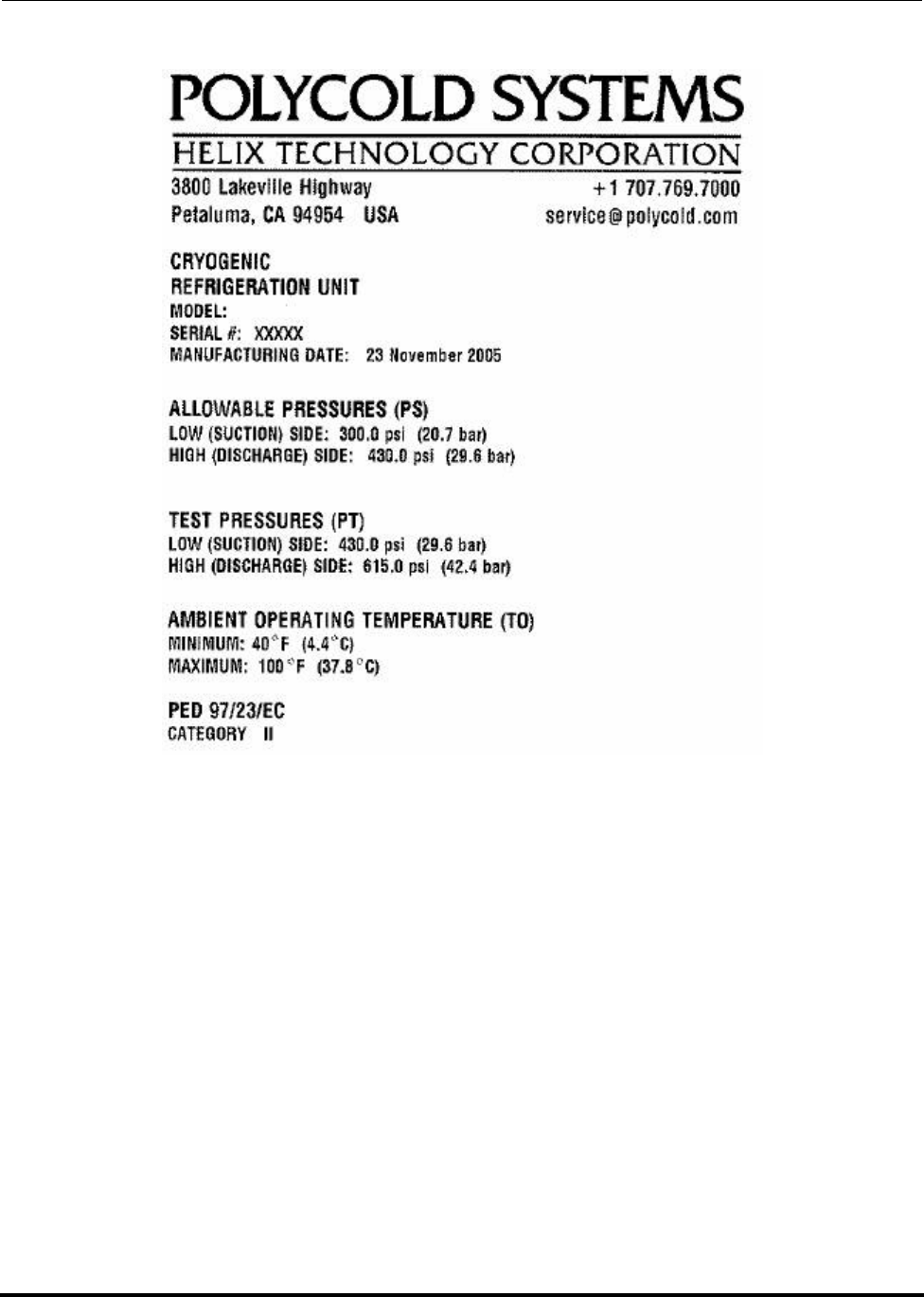
Installation Polycold Fast Cycle Water Vapor Cryopump
How to Install the Refrigeration Unit Customer Instruction Manual
825064-00 Brooks Automation
3-10 Revision 09
Figure 3-2: Typical Unit Label and Nameplate
3.2.3 Place the Unit
(See Figure 3-3.)
1. The refrigeration unit should be installed in an environment that meets the fol-
lowing conditions:
•Indoors
• Above ground
• A well ventilated area
• A room temperature of 40-100° F (4-38 C)
• A relative humidity of 20-80%, no condensation
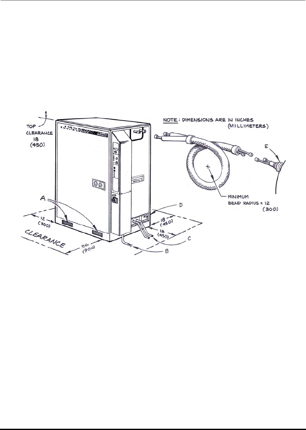
Polycold Fast Cycle Water Vapor Cryopump Installation
Customer Instruction Manual How to Install the Refrigeration Unit
Brooks Automation 825064-00
Revision 09 3-11
2. The refrigeration unit has a PRESSURE RELIEF OUTLET on the utility panel.
This port has a 3/4 inch female NPT fitting. It allows the venting of refrigerant
escaping from a pressure relief valve to another location. To install the unit to
ASHRAE requirements, see section 3.2.6 How to Install Refrigeration Unit to
Meet ASHRAE Requirements.
3. The unit must remain vertical. However, placement of the unit may be at any
elevation relative to the cryosurface. The cryopumping system is not gravity-
sensitive.
Figure 3-3: Unit Placement Considerations
A. Forklift slots
B. Electrical supply port
C. Cooling water connections
D. Pressure relief outlet (not shown)
E. Feed-through port
1. The minimum space requirements for inspection and service are as follows
(see Figure 3-4.):
• 36 inches (900 mm) in the front
• 18 inches (450 mm) on the top, rear, and right side
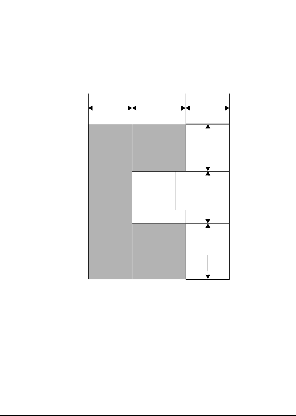
Installation Polycold Fast Cycle Water Vapor Cryopump
How to Install the Refrigeration Unit Customer Instruction Manual
825064-00 Brooks Automation
3-12 Revision 09
• 12 inches (300 mm) on the left side
The couplings, electrical hook-up, and cooling water connections are on the
right side of the unit.
2. The standard refrigerant line is about 8 feet (2.4 m) long. It has a minimum
bend radius of 12 inches (300 mm).
Figure 3-4: PFC Footprint (not to scale)
• The PFC requires 18 inches of clear area at the back of the system and 36 inches
at the front. (See Table 3-2.) This is needed for access to switches, settings, and
for safety reasons.
• Service and maintenance are also slowed if the unit is installed in a confined
area. For this reason we recommend that the unit be installed with as much
clear service access area as the facility will allow.
• Multiple units may be placed side by side as long as the rear of the unit is acces-
sible.
• When units are place facing one another a 36 inch service area is required.
12 37.5 18
SERVICE
ACCESS
AREA
SERVICE
ACCESS
AREA 18
Rear
PFC
Top View 26
Front
SERVICE
ACCESS
AREA 36
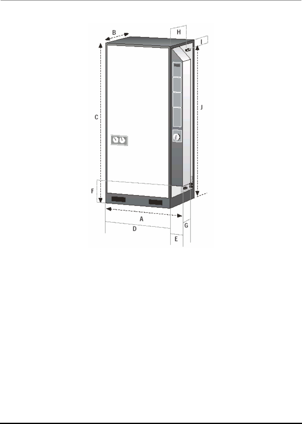
Polycold Fast Cycle Water Vapor Cryopump Installation
Customer Instruction Manual How to Install the Refrigeration Unit
Brooks Automation 825064-00
Revision 09 3-13
Figure 3-5: PFC 550, 551, 552, 660, 661, 662, 670, 672, 1100, 1101, and 1102

Installation Polycold Fast Cycle Water Vapor Cryopump
How to Install the Refrigeration Unit Customer Instruction Manual
825064-00 Brooks Automation
3-14 Revision 09
Table 3-2: PFC Dimensions
Model A
mm /
inches B C D E F G H I J Weight
kg./lb.
Standard
Refriger-
ant Line
550
551
552
953
37.5 660
26 1842
72.5 812
32 140
5.5 254
10 203
8432
17 114
4.5 1727
68 408
900 8 ft.
660
661
670
672
662
953
37.5
953
37.5
660
26
660
26
1842
72.5
1842
72.5
812
32
812
32
140
5.5
140
5.5
254
10
254
10
203
8
203
8
432
17
432
17
114
4.5
114
4.5
1727
68
1727
68
478
1055
476
1050
8 ft.
8 ft.
1100
1101
1102
1054
41.5 711
28 1689
66.5 914
36 140
5.5 102
4203
8457
18 114
4.5 1562
61.5 544
1200 8 ft.
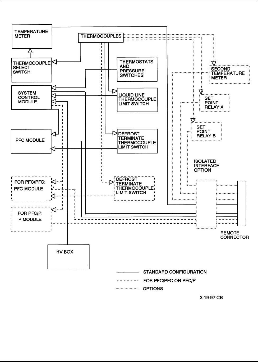
Polycold Fast Cycle Water Vapor Cryopump Installation
Customer Instruction Manual How to Install the Refrigeration Unit
Brooks Automation 825064-00
Revision 09 3-15
Figure 3-6: Electrical Block Diagram
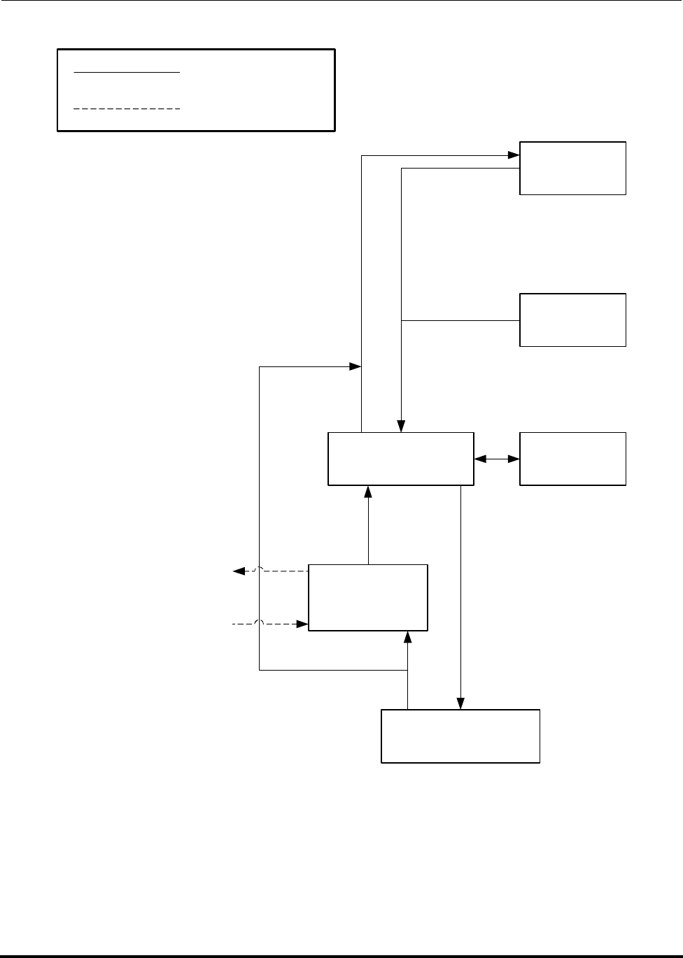
Installation Polycold Fast Cycle Water Vapor Cryopump
How to Install the Refrigeration Unit Customer Instruction Manual
825064-00 Brooks Automation
3-16 Revision 09
Figure 3-7: System Block Diagram
DEFROST GAS SUPPLY
CRYOGENIC
REFRIGERANT
SUPPLY RETURN
REFRIGERANT
CRYOCOIL
EVACUATION
VALVE
EXPANSION
TANK
REFRIGERATION
COOLING STACK
WATER
COOLED
CONDENSER
REFRIGERATION
COMPRESSOR
COOLING WATER
RETURN
COOLING WATER
SUPPLY
REFRIGERANT
COOLING WATER
COOLING STACK
COMPRESSOR
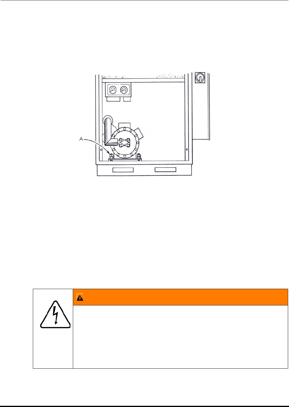
Polycold Fast Cycle Water Vapor Cryopump Installation
Customer Instruction Manual How to Install the Refrigeration Unit
Brooks Automation 825064-00
Revision 09 3-17
3.2.3.1 Remove the Compressor Hold-Down Nuts
Remove the front and lower back panels from the unit. Use two 9/16-inch wrenches
to remove the compressor hold-down nuts. (See Figure 3-8.) Keep these nuts with the
unit they will need to be reinstalled if the unit is moved.
Figure 3-8: Location of Compressor Hold-down Nuts
Compressor hold-down nuts (2 nuts—4 places)
3.2.4 Connect the Electrical Power
Tools and materials needed:
Qualified electrician with tools and materials
WARNING
ELECTRICAL
Hazardous voltages exist. Failure to have a qualified electrician
do all electrical work could result in death or serious injury.
Make sure the power source is off. Do not reach inside the refrig-
eration unit. A qualified electrician must do all electrical work.
Electrical work must be completed according to local codes. Use
copper conductors only.

Installation Polycold Fast Cycle Water Vapor Cryopump
How to Install the Refrigeration Unit Customer Instruction Manual
825064-00 Brooks Automation
3-18 Revision 09
3.2.4.1 Check and Protect the Electrical Supply
Check the nameplate on the Polycold Cool Solutions ® Fast Cycle Water Vapor Cry-
opump unit. If the nominal voltage does not exist, check the control voltage after con-
necting the electrical supply. (See section 3.2.4.2 How to Check the Control Voltage
and Change the Transformer Taps.)
The unit should have its’ own electrical supply. (See section Table 3-3: Electrical Sup-
ply and Protection Requirements.)
3.2.4.2 How to Check the Control Voltage and Change the Transformer Taps
3.2.4.2.1 How to Check the Control Voltage
Tools and materials needed:
Voltmeter that can measure 30 V(ac)
1. Turn off the refrigeration unit. Turn the power disconnect switch to the OFF
position.
2. Loosen the two lower screws on the side of the low voltage box panel. Slide the
panel straight up to remove it. (See Figure 3-22.)
3. Locate the SYSTEM CONTROL printed circuit board that is behind the SYS-
TEM CONTROL panel.
4. Connect the voltmeter. (See Figure 3-9.)
• Connect one lead to a screw holding the heat sink. (The voltage regula-
tor is inside the heat sink.)
• Connect the other lead to a fuse terminal.
5. Make certain the refrigeration unit’s ON/OFF switch is in the OFF position.
Turn the power disconnect switch to the ON position.
6. The acceptable voltage range is 22.5–26.5 V. If the control voltage is not accept-
able, see section 3.2.4.2.2 How to Change the Transformer Taps.
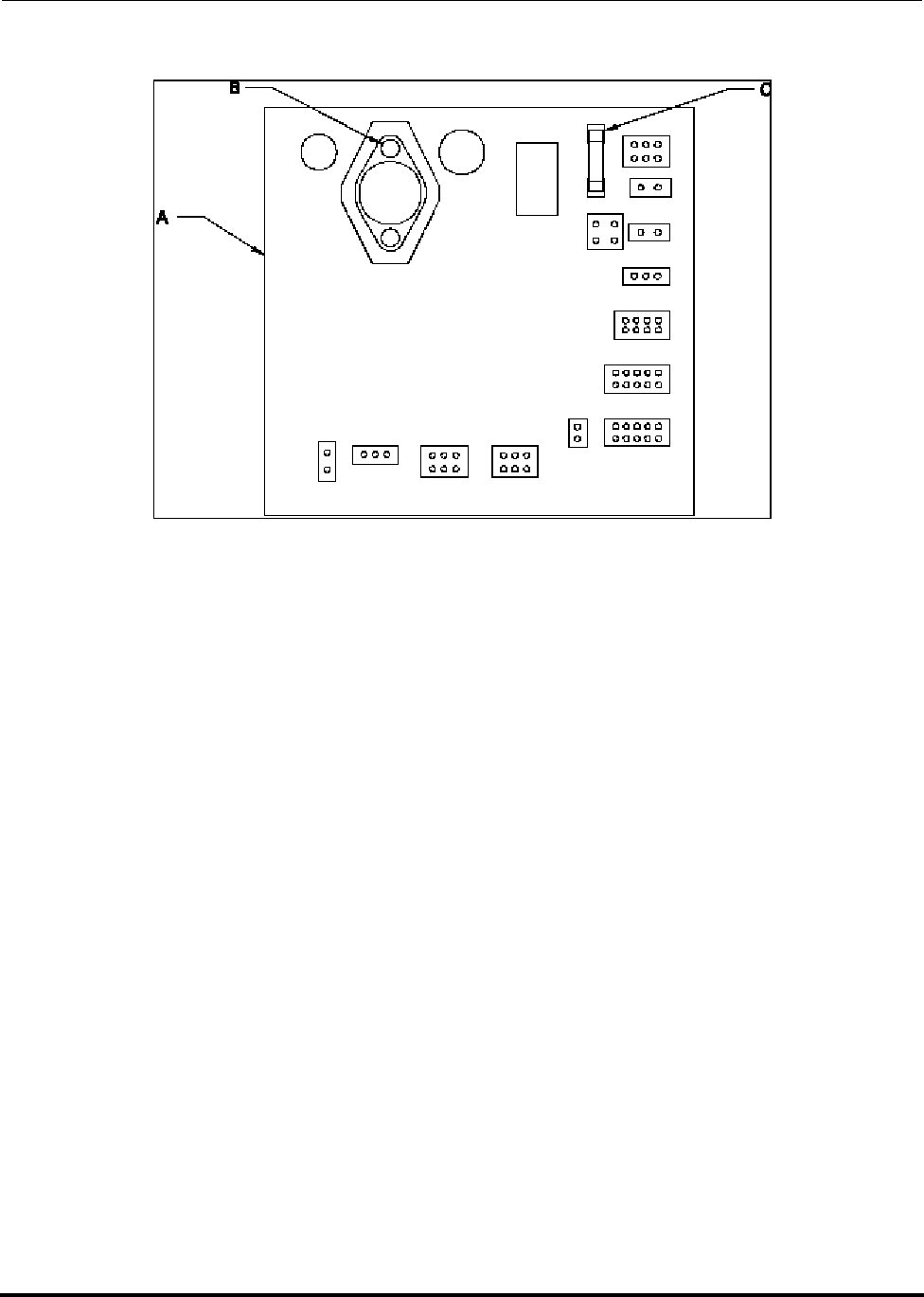
Polycold Fast Cycle Water Vapor Cryopump Installation
Customer Instruction Manual How to Install the Refrigeration Unit
Brooks Automation 825064-00
Revision 09 3-19
Figure 3-9: Control Voltage Check—Voltmeter Connections
A. SYSTEM CONTROL printed circuit board
B. Screw holding the heat sink
C. Fuse terminal
3.2.4.2.2 How to Change the Transformer Taps
1. Make certain the refrigeration unit’s ON / OFF switch is in the OFF position.
2. Turn the power disconnect switch to the OFF position. Remove the high volt-
age box panel.
3. Refer to the “Transformer Connections” table in Figure 10-2.
NOTE: Before changing taps, verify that the transformer connections are set for the proper
line voltage.
• If the control voltage is greater than 26.5 V, move power connection “B”
to the next higher tap. (For example, if “B” is connected to tap 3, move it
to tap 4.)

Installation Polycold Fast Cycle Water Vapor Cryopump
How to Install the Refrigeration Unit Customer Instruction Manual
825064-00 Brooks Automation
3-20 Revision 09
• If the control voltage is less than 22.5 V, move power connection “B” to
the next lower tap, with tap 3 being the lowest selection. (For example,
if “B” is connected to tap 6, move it to tap 5.)
4. Reinstall the high voltage box panel.
5. Check the control voltage with the new transformer setting following the
instructions in section 3.2.4.2.1 How to Check the Control Voltage.
6. If the control voltage is within the acceptable range, record the new trans-
former connections in the manual.
7. If the control voltage is still not within the acceptable range, repeat the proce-
dure above, moving power connection “B” to the next available tap.
8. If none of the available tap settings yield a control voltage within the accept-
able range, contact Polycold Service for assistance.
Table 3-3: Electrical Supply and Protection Requirements
Model Characteristics Electrical Characteristics
Unit Nominal
Compressor
Voltage
Common
Worldwide
Voltage-
Phase-
Frequency
Transformer
Tap Setting
and ID Label
Acceptable
Voltage Range
Low-High
RLA
Amps MCC
Amps LRA
Amps
Fuse
Size
Amps
Power
Input
kVA
550
HC
230V
200-3-50
200-3-60
208/230-3-60 200-3-50/60 180-220@50Hz
187-220@60Hz 21.9
44 160 60 7.6
208/230-3-60
220-3-50
230-3-60 230-3-50/60 207-230@50Hz
207-253@60Hz 19.0
460V
380-3-50 380-3-50 342-418@50Hz 11.0
22 80 25 7.3
400-3-50
415-3-50 400-3-50 360-440@50Hz 10.5
440-3-50
460-3-60 460-3-50/60 414-460@50Hz
414-506@60Hz 9.1
480-3-60 480-3-60 432-528@60Hz 8.7
575V 575-3-60 575-3-60 518-632@60Hz 7.4 17.6 64 20 7.4

Polycold Fast Cycle Water Vapor Cryopump Installation
Customer Instruction Manual How to Install the Refrigeration Unit
Brooks Automation 825064-00
Revision 09 3-21
550
LT
230V
200-3-50
200-3-60
208/230-3-60 200-3-50/60 180-220@50Hz
187-220@60Hz 23.7
44 160 60 8.2
208/230-3-60
220-3-50
230-3-60 230-3-50/60 207-230@50Hz
207-253@60Hz 20.6
460V
380-3-50 380-3-50 342-418@50Hz 14.6
22 80 25 9.6
400-3-50
415-3-50 400-3-50 360-440@50Hz 13.9
440-3-50
460-3-60 460-3-50/60 414-460@50Hz
414-506@60Hz 12.1
480-3-60 480-3-60 432-528@60Hz 11.6
575V 575-3-60 575-3-60 518-632@60Hz 9.4 17.6 64 20 9.4
660
HC
670
HC
230V
200-3-50
200-3-60
208/230-3-60 200-3-50/60 180-220@50Hz
187-220@60Hz 29.0
44 160 60 10.0
208/230-3-60
220-3-50
230-3-60 230-3-50/60 207-230@50Hz
207-253@60Hz 25.2
460V
380-3-50 380-3-50 342-418@50Hz 14.3
22 80 25 9.4
400-3-50
415-3-50 400-3-50 360-440@50Hz 13.6
440-3-50
460-3-60 460-3-50/60 414-460@50Hz
414-506@60Hz 11.8
480-3-60 480-3-60 432-528@60Hz 11.3
575V 575-3-60 575-3-60 518-632@60Hz 9.8 17.6 64 20 9.8
Table 3-3: Electrical Supply and Protection Requirements
Model Characteristics Electrical Characteristics
Unit Nominal
Compressor
Voltage
Common
Worldwide
Voltage-
Phase-
Frequency
Transformer
Tap Setting
and ID Label
Acceptable
Voltage Range
Low-High
RLA
Amps MCC
Amps LRA
Amps
Fuse
Size
Amps
Power
Input
kVA

Installation Polycold Fast Cycle Water Vapor Cryopump
How to Install the Refrigeration Unit Customer Instruction Manual
825064-00 Brooks Automation
3-22 Revision 09
1100
HC
230V
200-3-50
200-3-60
208/230-3-60 200-3-50/60 180-220@50Hz
187-220@60Hz 60.0
62 228 80 20.8
208/230-3-60
220-3-50
230-3-60 230-3-50/60 207-230@50Hz
207-253@60Hz 52.2
460V
380-3-50 380-3-50 342-418@50Hz 28.1
31 114 35 18.5
400-3-50
415-3-50 400-3-50 360-440@50Hz 26.7
440-3-50
460-3-60 460-3-50/60 414-460@50Hz
414-506@60Hz 23.2
480-3-60 480-3-60 432-528@60Hz 22.2
575V 575-3-60 575-3-60 518-632@60Hz 15.4 25 90 30 15.3
1100
LT
230V
200-3-50
200-3-60
208/230-3-60 200-3-50/60 180-220@50Hz
187-220@60Hz 50.7
62 228 80 17.6
208/230-3-60
220-3-50
230-3-60 230-3-50/60 207-230@50Hz
207-253@60Hz 44.1
460V
380-3-50 380-3-50 342-418@50Hz 22.9
31 114 35 15.1
400-3-50
415-3-50 400-3-50 360-440@50Hz 21.7
440-3-50
460-3-60 460-3-50/60 414-460@50Hz
414-506@60Hz 18.9
480-3-60 480-3-60 432-528@60Hz 18.1
575V 575-3-60 575-3-60 518-632@60Hz 16.4 25 90 30 16.3
Table 3-3: Electrical Supply and Protection Requirements
Model Characteristics Electrical Characteristics
Unit Nominal
Compressor
Voltage
Common
Worldwide
Voltage-
Phase-
Frequency
Transformer
Tap Setting
and ID Label
Acceptable
Voltage Range
Low-High
RLA
Amps MCC
Amps LRA
Amps
Fuse
Size
Amps
Power
Input
kVA

Polycold Fast Cycle Water Vapor Cryopump Installation
Customer Instruction Manual How to Install the Refrigeration Unit
Brooks Automation 825064-00
Revision 09 3-23
551
HC
552
HC
230V
200-3-50
200-3-60
208/230-3-60 200-3-50/60 180-220@50Hz
187-220@60Hz 22.3
44 160 60
7.7
208/230-3-60
220-3-50
230-3-60 230-3-50/60 207-230@50Hz
207-253@60Hz 20.4 8.1
460V
380-3-50 380-3-50 342-418@50Hz 11.9
22 80 25 7.8
400-3-50
415-3-50 400-3-50 360-440@50Hz 11.3
440-3-50
460-3-60 460-3-50/60 414-460@50Hz
414-506@60Hz 9.8
480-3-60 480-3-60 432-528@60Hz 9.4
575V 575-3-60 575-3-60 518-632@60Hz 7.8 17.6 64 20 7.8
661
HC
662
HC
672
HC
460V
380-3-50 380-3-50 342-418@50Hz 14.5
22 80 25 9.6
400-3-50
415-3-50 400-3-50 360-440@50Hz 13.8
440-3-50
460-3-60 460-3-50/60 414-460@50Hz
414-506@60Hz 12.0
480-3-60 480-3-60 432-528@60Hz 11.5
575V 575-3-60 575-3-60 518-632@60Hz 9.6 17.6 64 20 9.6
1101
HC
1102
HC
460V
380-3-50 380-3-50 342-418@50Hz 25.8
31 114 35 17.0
400-3-50
415-3-50 400-3-50 360-440@50Hz 24.5
440-3-50
460-3-60 460-3-50/60 414-460@50Hz
414-506@60Hz 21.3
480-3-60 480-3-60 432-528@60Hz 20.4
575V 575-3-60 575-3-60 518-632@60Hz 14.1 25 90 30 14.0
Table 3-3: Electrical Supply and Protection Requirements
Model Characteristics Electrical Characteristics
Unit Nominal
Compressor
Voltage
Common
Worldwide
Voltage-
Phase-
Frequency
Transformer
Tap Setting
and ID Label
Acceptable
Voltage Range
Low-High
RLA
Amps MCC
Amps LRA
Amps
Fuse
Size
Amps
Power
Input
kVA

Installation Polycold Fast Cycle Water Vapor Cryopump
How to Install the Refrigeration Unit Customer Instruction Manual
825064-00 Brooks Automation
3-24 Revision 09
Leg to Leg voltages must be balanced to within 2% of each other.
NOTE: RLA is the current drawn by the compressor at rated load. It may also be referred
to as the maximum full load amps. Maximum recommended fuse size. A Bussman
FRS-R dual element, current limiting fuse or equivalent is recommended to protect
the branch circuit. Actual protection must comply with local codes. “Worse Case
low Volts” refers to the lowest amount of voltage available. Typically power fluctu-
ates by 10% within a given area, so the lowest voltage amount would be 90% of the
nominal voltage.
Gould TRS, Littlefuse FLSR.
MCA=minimum Circuit Ampacity = should be at least 125% RLA
NOTE: This value is to assist the customer electrician to determine the dimensions of the
electrical system.
LRA=Locked Rotor Amps. This refers to the current that the compressor motor
uses when the compressor is not able to rotate because the rotors are locked.
NOTE: Compressors are provided with over current and over temperature protection
which comply with UL and NEC definitions of inherent thermal protection.
kVA = Test Volts*RLA*1.732/1000
kW = kVA*Power Factor (Power Factor is 90% in this case.)
1101L
T460V
380-3-50 380-3-50 342-418@50Hz
31 114 35
400-3-50
415-3-50 400-3-50 360-440@50Hz
440-3-50
460-3-60 460-3-50/60 414-460@50Hz
414-506@60Hz
480-3-60 480-3-60 432-528@60Hz
575V 575-3-60 575-3-60 518-632@60Hz 25 90 30
Table 3-3: Electrical Supply and Protection Requirements
Model Characteristics Electrical Characteristics
Unit Nominal
Compressor
Voltage
Common
Worldwide
Voltage-
Phase-
Frequency
Transformer
Tap Setting
and ID Label
Acceptable
Voltage Range
Low-High
RLA
Amps MCC
Amps LRA
Amps
Fuse
Size
Amps
Power
Input
kVA
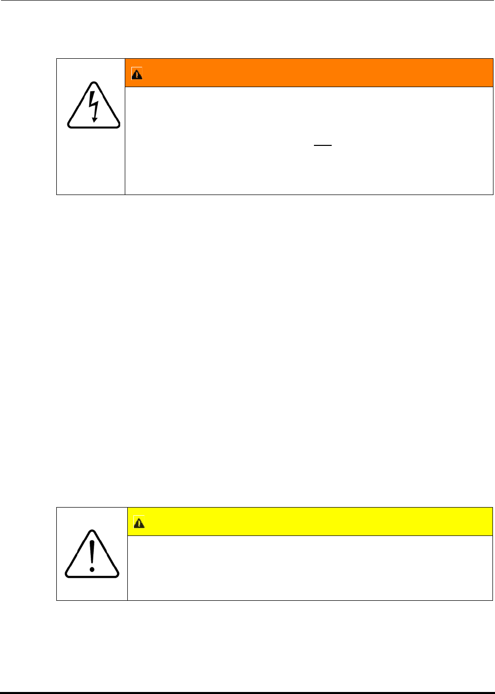
Polycold Fast Cycle Water Vapor Cryopump Installation
Customer Instruction Manual How to Install the Refrigeration Unit
Brooks Automation 825064-00
Revision 09 3-25
3.2.4.3 Connect the Unit to the Electrical Supply
(See Figure 3-10 and Figure 3-11.)
1. Turn the power disconnect switch to the OFF position. Unscrew the fasteners
and remove the high voltage box panel.
2. Refer to Table 3-3 and all local codes to determine the proper type and size
wires. Four wires will be needed—one for each phase and one for the ground.
A neutral wire is not needed.
3. Remove the plug from one of the holes in the bottom of the high voltage box.
Attach wire fittings as required. Feed customer installed wires through this
hole.
4. Ground the unit according to local codes. Polycold has provided two ground
studs. The internal ground stud is inside the high voltage box. For 1100s, the
external ground stud is on the frame to the right of the utility panel. For all
550s, 660s, and 670s the external ground stud is on the frame to the left of the
utility panel.
5. Route your other three wires along the wire guides. Secure a wire in terminals
L1, L2, and L3 of the power disconnect switch. It does not matter which wire
goes to which terminal; the compressor is not phase sensitive. Press the wire
guides down to hold the wires in place.
WARNING
ELECTRICAL
Hazardous voltages exist. Failure to have a qualified electrician
do all electrical work could result in death or serious injury.
Make sure the electrical supply is not energized. Do not reach
inside the refrigeration unit. A qualified electrician must do all
electrical work. Electrical work must be completed according to
local codes.
CAUTION
GENERAL HAZARD
If the internal ground stud is not used damage to the equipment
can result.
Verify that the nut holding the washers and terminal lugs is tight.
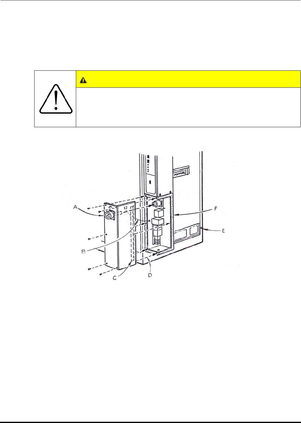
Installation Polycold Fast Cycle Water Vapor Cryopump
How to Install the Refrigeration Unit Customer Instruction Manual
825064-00 Brooks Automation
3-26 Revision 09
NOTE: For additional information, refer to Section 11.
6. Reinstall the high voltage box panel. Make sure its ground and lamp wires and
its tab fit inside the seal.
Figure 3-10: High Voltage Box Panel Removal; External Ground Stud Locations
A. Power disconnect switch
B. Ground and lamp wires (attached to panel)
C. Tab
D. External ground stud for all 550s, 660s, and 670s (not shown)
E. External ground stud for all 1100s
F. High voltage box
CAUTION
GENERAL HAZARD
Do not turn on the unit at this time; damage to the equipment can
result.
Cooling water must be connected before the unit is turned on.
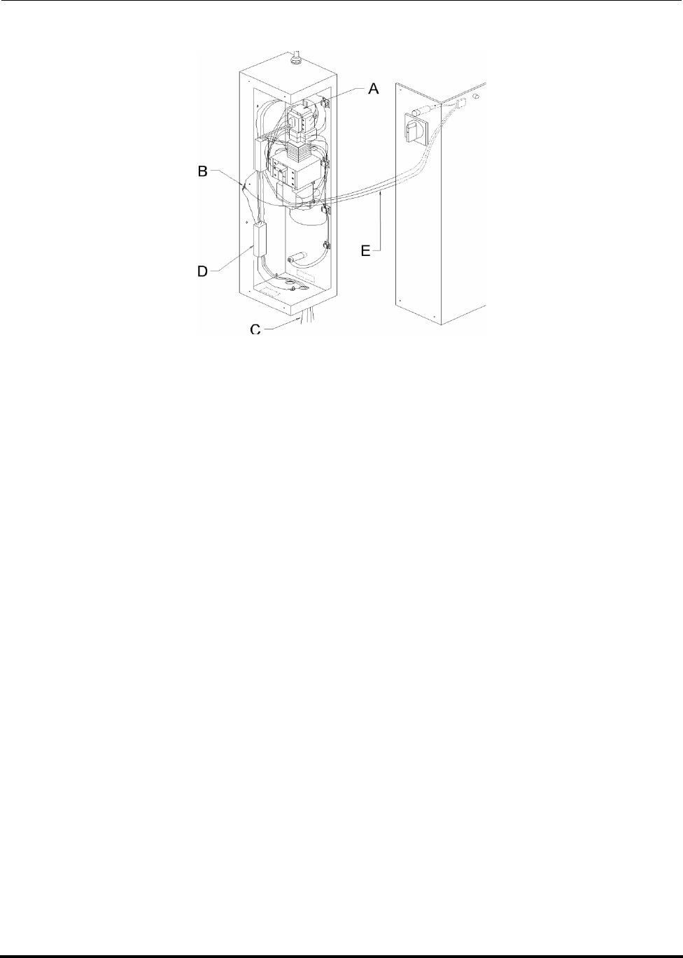
Polycold Fast Cycle Water Vapor Cryopump Installation
Customer Instruction Manual How to Install the Refrigeration Unit
Brooks Automation 825064-00
Revision 09 3-27
Figure 3-11: High Voltage Box Component Locations
A. Power disconnect switch
B. Internal ground stud
C. Customer installed wires
D. Wire guides
E. Ground and lamp wires
3.2.5 Connect the Cooling Water
Tools and materials needed:
For 550, 551, 552, 660, 661, 662, 670, and 672: 1/2-inch (15 mm) standard pipe
size
For 1100, 1101, and 1102: 3/4-inch (20 mm) standard pipe size
Installation Polycold Fast Cycle Water Vapor Cryopump
How to Install the Refrigeration Unit Customer Instruction Manual
825064-00 Brooks Automation
3-28 Revision 09
3.2.5.1 Ensure Cooling Water is Adequate
Measure the inlet water temperature. It must be 55-85°F (13-29°C). Make sure the
minimum flow rate for the water’s temperature is adequate. See Table 3-4.
NOTE: Cooling water may be warmer in the summer than in the winter.
Cooling water should be clean. Polycold recommends filtering cooling water if it is
very dirty or has abrasives in it. Any chemical impurities in the cooling water must
be compatible with copper.
CAUTION
GENERAL HAZARD
If cooling water has not been connected damage to the equipment
can result.
Verify that cooling water has been connected before turning on
the unit.
Table 3-4: Cooling Water Flow Requirements
Refrigeration
Unit
Water Inlet
Temperature
°F (°C)
Minimum
Flow Rate
gpm
(L/min)
Pressure
Drop Inside
the Unit psi
(kPa)
Pressure Drop
in Supply
Line†
psi/ft (kPa/m)
Heat
Rejection
Btu/Hour
(kW)
550, 551, 552
55 (13) (Min) 1.3 (4.9) 0.3 (2.1) no data 23,900 (7.0)
65 (18) 1.7 (6.4) 0.6 (4.1) no data 23,900 (7.0)
75 (24) 2.6 (9.8) 1.3 (9.0) no data 23,900 (7.0)
85 (29) (Max.) 5.2 (19.7) 5.3 (36.6) 0.06 (1.4) 23,900 (7.0)
660, 661, 662,
670, 672
55 (13) (Min) 1.8 (6.8) 0.5 (3.4) no data 33,400 (9.8)
65 (18) 2.4 (9.1) 0.8 (5.5) no data 33,400 (9.8)
75 (24) 3.6 (13.6) 1.8 (12.4) no data 33,400 (9.8)
85 (29) (Max.) 7.3 (27.6) 7.6 (52.4) 0.11 (2.5) 33,400 (9.8)

Polycold Fast Cycle Water Vapor Cryopump Installation
Customer Instruction Manual How to Install the Refrigeration Unit
Brooks Automation 825064-00
Revision 09 3-29
3.2.5.2 Connect a Supply Line and a Drain Line to Refrigeration Unit
Use the correct size pipe, see “Tools and Materials Needed” at the beginning of this
section. For 550, 551, 552, 660, 661, 662, 670, and 672 the COOLING WATER connec-
tions have 1/2-inch female NPT fittings. For 1100, 1101, and 1102 the COOLING
WATER connections have 3/4-inch female NPT fittings.
Connect the supply line to the port marked IN. Connect the drain line to the port
marked OUT. The cooling water must flow in this direction to properly cool the unit.
(See Figure 3-12.)
3.2.5.3 Estimate the Correct Flow Rate
Ensure that the minimum flow rate is achieved. (See Table 3-4.)
To determine the correct flow rate, check both the liquid line temperature and the
water outlet temperature when the unit is in COOL. (This will be checked in section
3.4.4 Evaluate the Cryopump.)
Optional: Install pressure gauges to the cooling water supply and drain lines at the
unit. Measure the cooling water pressures. Make sure pressure drops correspond to
the flow rate needed for the cooling water temperature.
1100, 1101,
1102
55 (13) (Min) 3.6 (13.6) 1.6 (11.0) no data 65,500
(19.2)
65 (18) 4.8 (18.2) 2.8 (19.3) no data 65,500
(19.2)
75 (24) 7.2 (27.3) 6.3 (43.4) no data 65,500
(19.2)
85 (29) (Max.) 14.3 (54.1) 24.8 (171) 0.15 (3.4) 65,500
(19.2)
NOTE: †For 550s, 660s, and 670s these numbers assume a 1/2-inch (15 mm) standard pipe size. For 1100s,
these numbers assume a 3/4-inch (20 mm) standard pipe size.
The maximum working pressure of the unit’s cooling water circuit is 200 psig (1380 kPa).
Table 3-4: Cooling Water Flow Requirements
Refrigeration
Unit
Water Inlet
Temperature
°F (°C)
Minimum
Flow Rate
gpm
(L/min)
Pressure
Drop Inside
the Unit psi
(kPa)
Pressure Drop
in Supply
Line†
psi/ft (kPa/m)
Heat
Rejection
Btu/Hour
(kW)

Installation Polycold Fast Cycle Water Vapor Cryopump
How to Install the Refrigeration Unit Customer Instruction Manual
825064-00 Brooks Automation
3-30 Revision 09
NOTE: If using a rotameter type flow meter, its inherent restriction may reduce the actual
flow rate attainable while it is attached.
Figure 3-12: Cooling Water Supply and Drain Lines Location
A. Supply line
B. Drain line
3.2.6 How to Install Refrigeration Unit to Meet ASHRAE Requirements
The following information helps to comply with ANSI / ASHRAE 15-1994 “Safety
Code for Mechanical Refrigeration”. ANSI is the acronym for the American National
Standards Institute. ASHRAE is the acronym for the American Society of Heating,
Refrigeration, and Air-Conditioning Engineers.
Normally, the manufacturer provides the type and amount of refrigerant used in the
refrigeration unit. However, Polycold considers their mixtures of refrigerants to be
proprietary. Therefore, the following information complies with the above standards.
• The amount of refrigerant mixture, the minimum room size and the refrigerant
safety group classification are included next to the refrigeration unit’s name-
plate. The nameplate is located on the back of the low voltage box.
NOTE: Polycold determined the refrigerant safety group classification of the refrigerant
mixture by evaluating the safety group classifications of the individual compo-
nents. This evaluation used ANSI / ASHRAE-34 as a guide.

Polycold Fast Cycle Water Vapor Cryopump Installation
Customer Instruction Manual How to Install the Refrigeration Unit
Brooks Automation 825064-00
Revision 09 3-31
• The cryopump is a “direct (refrigeration) system”. It is only intended to be
installed above ground in an industrial environment.
• If the minimum room size indicated on the nameplate is not obtainable, the
refrigeration unit must be installed in a “refrigerating machinery room”. Con-
sult local or national building codes for machinery room requirements.
• Some models have a PRESSURE RELIEF OUTLET with a 3/4-inch female NPT
fitting. This port allows the direct refrigerant escaping from a pressure relief
valve to be moved to another location. See section 9.7.8 of ANSI / ASHRAE 15-
1994 for location requirements. See Table 3-5 for piping requirements.
• All models have this PRESSURE RELIEF OUTLET, except models PFC- 552,
672, and 1102 manufactured after March 2003. These models use a refrigerant
that does not require pressure relief outlet plumbing.
Table 3-5: Pressure Relief Piping Requirements to Comply with ANSI/ASHRAE 15-1994
Refrigeration
Unit
Recommended
Discharge Capacity 1
(lb air / min)
Maximum Length of
1/2 inch Diameter
Pipe 2 (feet)
Maximum Length of
3/4 inch Diameter
Pipe 3 (feet)
550, 551, 4.75 113 458
660, 661, 670 4.75 113 458
1100, 1101 7.7 42 174
NOTE:
1 The discharge capacity is recommended by Polycold based on actual relief
requirements from the refrigeration system. The pressure relief devices on
the refrigeration unit are oversized. Discharge capacities based on the pres-
sure relief devices are 23.9 pounds of air per minute for 550s, 660s, and
670s; 30.3 pounds of air per minute for 1100s.
2 Maximum length of piping is based on the recommended discharge capac-
ity using standard wall steel pipe and pressure relief devices set at 300 psig
(2070 kPa).
3 Not required on models PFC- 552, 662, 672, and 1102.

Installation Polycold Fast Cycle Water Vapor Cryopump
How to Connect the Cryosurface to the Refrigeration Unit Customer Instruction Manual
825064-00 Brooks Automation
3-32 Revision 09
3.3 How to Connect the Cryosurface to the Refrigeration Unit
3.3.1 Connect the Refrigerant Line
Tools and materials needed:
• Step ladder
• Torque wrench (optional)
For Parker CPI UltraSeal couplings (standard fitting):
• Silver-plated stainless steel O-rings†
• 1 inch open end wrench
• 15/16 inch open end wrench
For Cajon VCR couplings (optional fitting):
• Silver-plated stainless steel gaskets or unplated nickel gaskets†
• 1-3/16 inch open end wrench
• 1-1/16 inch open end wrench
†Shipped with the unit.
NOTE: This section assumes the purchase of a refrigerant line from Brooks Polycold Sys-
tems Inc. If not, see section 3.6 Refrigerant Line Specification before continuing.
For PFC/PFC or PFC/P: This section assumes that both refrigerant circuits will be
connected at the same time. At times, only one refrigerant circuit may be connected.
Thus, when ready to connect the second refrigerant circuit, the refrigerant mixture
must be drawn back into the unit. (This is because both refrigerant circuits are con-
nected inside the unit.) See Step 1 and Step 2 in section 8.2 How to Disconnect the
Refrigerant Line for instructions.
Attention
Information in this section is for trained technicians familiar with
installing Polycold Fast Cycle Water Vapor Cryopumps. If you
are not trained on these procedures, contact the Polycold factory
or your nearest service representative. Failure to properly install
this product may result in refrigerant leaks or other problems that
are not covered by our warranty.
Polycold Fast Cycle Water Vapor Cryopump Installation
Customer Instruction Manual How to Connect the Cryosurface to the Refrigeration Unit
Brooks Automation 825064-00
Revision 09 3-33
3.3.1.1 Inspect the Couplings
Remove any dirt or foreign materials from the sealing surfaces. Make certain there
are no scratches (particularly radial scratches) or dents in the sealing surfaces. (See
Figure 3-13 and Figure 3-14.) Contact a Polycold sales representative or the Polycold
service department if a sealing surface is damaged.
NOTE: Parker CPI UltraSeal couplings are standard on a 550, 660, 670, or PFC/PFC-
1100. Cajon VCR couplings are standard on a PFC-1100.
CAUTION
GENERAL HAZARD
A common source for leaks is improper connection of the cou-
plings. Internal leaks can result in damage to the equipment.
Use a new O-ring or gasket each time the coupling is assembled.
Do not use grease when assembling the couplings. Grease can
contaminate the cryopump. It can also mask a leak during the
leak-checking procedures. The coupling will leak when the
grease gets brittle at cryogenic temperatures.
Do not scratch or dent the sealing surfaces of the couplings.
Always use the O-ring removal tool to remove an O-ring from the
Parker CPI UltraSeal couplings. See Step 4 in section 8.2 How to
Disconnect the Refrigerant Line for instructions.
WARNING
Use of unauthorized, non-standard couplings will void your war-
ranty. Improper use of, incorrect installation of, over-tightening of,
or use of damaged o-rings in couplings will void your warranty.
(See CAUTION on page 3-33 for installation guidelines.)
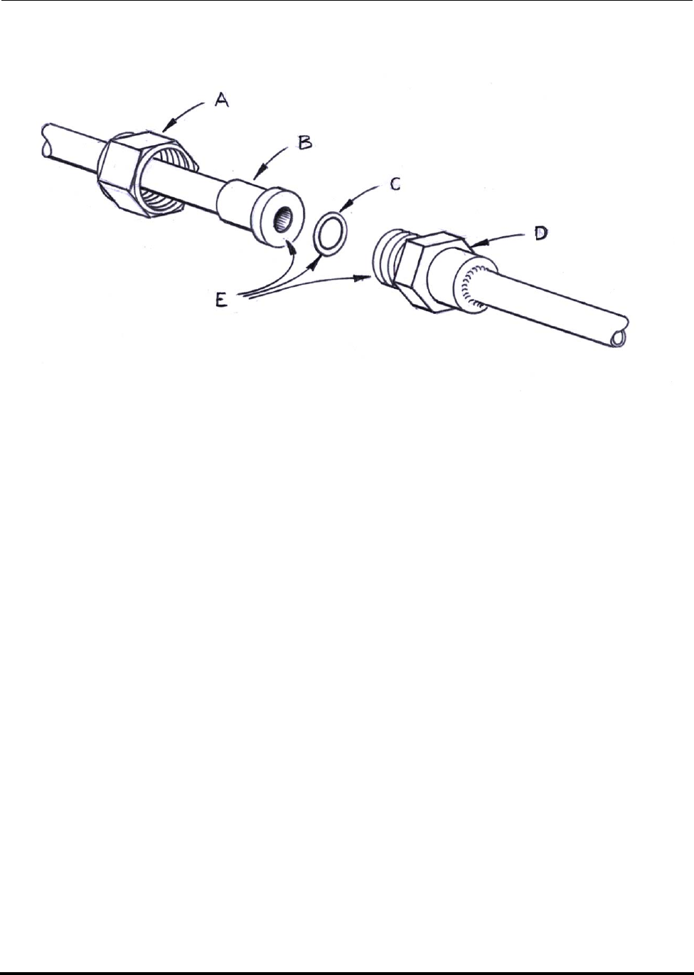
Installation Polycold Fast Cycle Water Vapor Cryopump
How to Connect the Cryosurface to the Refrigeration Unit Customer Instruction Manual
825064-00 Brooks Automation
3-34 Revision 09
Figure 3-13: Parker CPI UltraSeal coupling (standard fitting)
A. Nut
B. Gland
C. Silver-plated stainless steel O-ring
D. Male coupling
E. Sealing surfaces
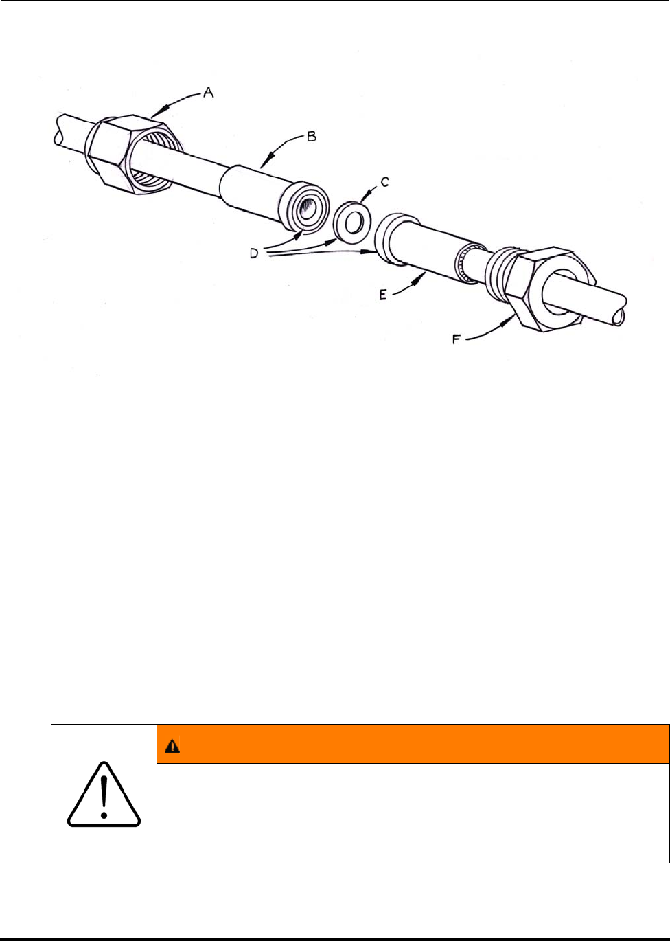
Polycold Fast Cycle Water Vapor Cryopump Installation
Customer Instruction Manual How to Connect the Cryosurface to the Refrigeration Unit
Brooks Automation 825064-00
Revision 09 3-35
Figure 3-14: Cajon VCR Coupling (optional fitting)
A. Female Nut
B. Gland
C. Silver-plated stainless steel gasket or unplated nickel gasket
D. Sealing surfaces
E. Gland
F. Male nut
3.3.2 Position the Refrigerant Line
(See Figure 3-15.)
WARNING
Prevent leaks due to line vibration. See 3.3.2.4 Support the Refriger-
ant Line and Prevent Line Vibrations on page 3-38.
Installation Polycold Fast Cycle Water Vapor Cryopump
How to Connect the Cryosurface to the Refrigeration Unit Customer Instruction Manual
825064-00 Brooks Automation
3-36 Revision 09
NOTE: The refrigerant line is made of soft refrigeration copper and has a minimum bend
radius of 12 inches (300 mm). It is suitable for being bent once to fit the existing
layout.
1. Bend the refrigerant line so that the couplings are even when they get to the
unit (For example, the feed and return lines should have the same bend
radius.)
2. It may be helpful to connect the refrigerant line to the cryosurface first. If so,
tighten the couplings only finger-tight until finishing the positioning of the
refrigerant line. (See section 3.2.1.2 Check Unit’s Balance Pressure.)
NOTE: For PFC/PFC or PFC/P: The upper set of couplings is for the first refrigerant cir-
cuit. The lower set of couplings is for the second refrigerant circuit.
3.3.2.1 Attach the Refrigerant Line to the Cryosurface
For Parker CPI UltraSeal couplings (standard fitting): Insert an O-ring into the male
coupling’s groove. Place the gland against the O-ring and male coupling. Make cer-
tain the O-ring does not drop out of the groove. Slide the nut forward and finger-
tighten the coupling. While keeping the male coupling stationary with the 15/16-inch
wrench, tighten the nut with the 1-inch wrench. Each wrench must have a length of at
least 12 inches (300 mm). Tighten until resistance increases sharply and no further
tightening occurs. During the tightening procedure, the metal o-ring will be crushed
into the o-ring groove. Tighten each coupling to 40-60 foot-pounds (54-80 Nm).
For Cajon VCR couplings (optional fitting): Place a gasket into the female nut.
Assemble the components and finger-tighten the coupling. Use both wrenches to
tighten each coupling to 40-60 foot-pounds (54-80 Nm).
NOTE: These fittings are coupled and sealed based on mechanical displacement of the
threaded parts, which results in compression at the sealing surface. Torque values
are provided for customers requiring a measurable value.
CAUTION
GENERAL HAZARD
Do not repeatedly bend the refrigerant line. Do not twist the
refrigerant line. Do not bend the refrigerant line within 6 inches
(150 mm) of the couplings. Improper handling can result in dam-
age to the line or equipment.
Handle the refrigerant line carefully.
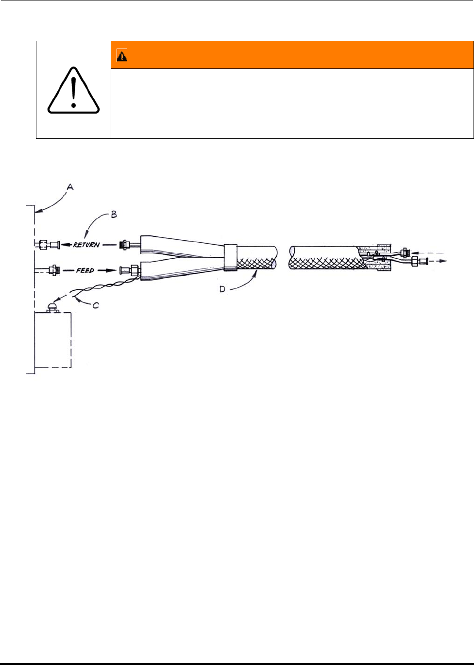
Polycold Fast Cycle Water Vapor Cryopump Installation
Customer Instruction Manual How to Connect the Cryosurface to the Refrigeration Unit
Brooks Automation 825064-00
Revision 09 3-37
Figure 3-15: Refrigerant line connection
A. Refrigeration unit (top view)
B. Direction of refrigerant flow
C. Thermocouple wires (2)
D. Refrigerant line
3.3.2.2 Verify that the Isolation Valves are Closed, and Remove the Blank-off Fit-
tings
1. Remove the top panel of the unit. The isolation valves are in the box closest to
the couplings. Loosen the screws to open the valve box lid. Locate the red
hand valves labeled COLD GAS FEED, COMMON RETURN, and HOT GAS
WARNING
Use of unauthorized, non-standard couplings will void your war-
ranty. Improper use of, incorrect installation of, over-tightening of,
or use of damaged o-rings in couplings will void your warranty.
(See CAUTION on page 3-33 for installation guidelines.)

Installation Polycold Fast Cycle Water Vapor Cryopump
How to Connect the Cryosurface to the Refrigeration Unit Customer Instruction Manual
825064-00 Brooks Automation
3-38 Revision 09
FEED. Turn each hand valve clockwise to make certain it is closed. (See Figure
3-16.)
2. Slowly remove the blank-off fittings from the couplings on the unit. A brief
hiss may be heard. However, if refrigerant continues to escape from the unit,
quickly reinstall the blank-off fittings and make certain the isolation valves are
closed.
3. Keep the blank-off fittings with the unit. They will need to be reinstalled after
the refrigerant line is disconnected.
NOTE: The isolation valves are used to hold the refrigerant mixture in the unit during
shipping or whenever the cryosurface or refrigerant line is disconnected. These
valves cannot be operated when they are at cryogenic temperatures.
3.3.2.3 Attach the Refrigerant Line to the Unit
Remove the rubber O-rings from the couplings. Assemble the couplings following
the instructions in section 3.2.1.2 Check Unit’s Balance Pressure above.
3.3.2.4 Support the Refrigerant Line and Prevent Line Vibrations
Support the refrigerant line at midlength. If a longer refrigerant line is installed, sup-
port it every 3 feet (1 m). Make sure the insulation is not crushed with the support.
Use supports that are at least 4 inches (100 mm) wide such as tape, hangers, clamps,
or cradles.
NOTE: The brand or type of tape, hangers, clamps, or cradles depends on what is available
and acceptable at the installation site. Do not use supports that make direct contact
with the exposed tubes or couplings. Do not allow the lines to be vibrated by the
application.
Polycold recommends using a continuous line length from unit to cryocoil feed thru.
Brooks Automation does not recommend or warranty use of intermediate fittings. If
your line design has an intermediate set of fittings between the unit and chamber feed
thru we recommend eliminating this and brazing the tubes together. However, if this
cannot be done use only approved fittings. In addition the lines must be supported on
each side of the intermediate fitting within 12 inches (300mm) of the fitting.
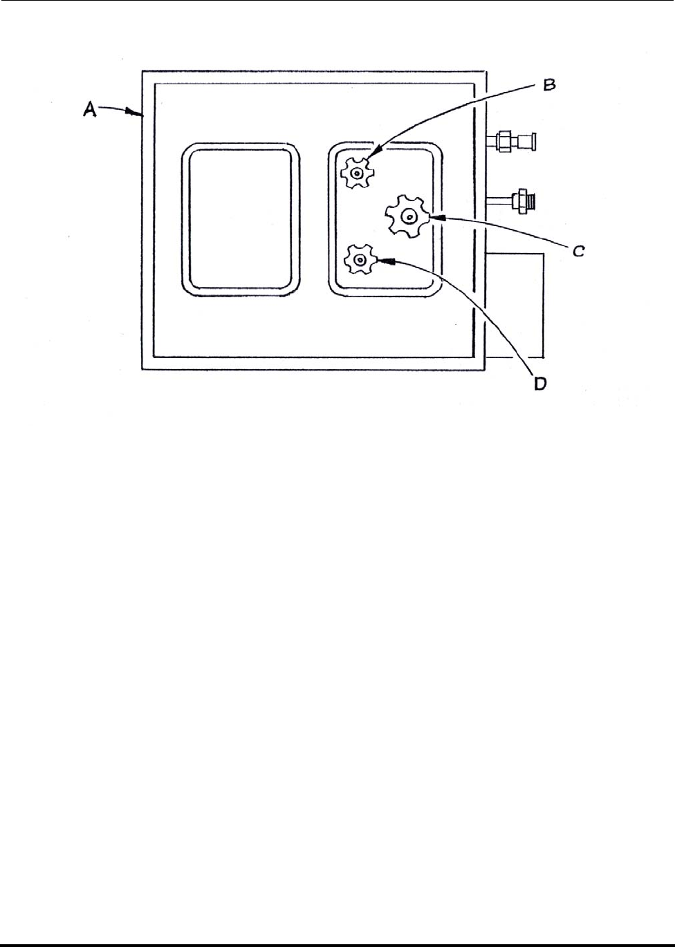
Polycold Fast Cycle Water Vapor Cryopump Installation
Customer Instruction Manual How to Connect the Cryosurface to the Refrigeration Unit
Brooks Automation 825064-00
Revision 09 3-39
Figure 3-16: Isolation Valves Location
NOTE: Two valve boxes shown in the previous figure. Some units have a single box.
A. Refrigeration unit (top view with panel removed)
B. Cold gas feed isolation valve
C. Common return isolation valve
D. Hot gas feed isolation valve
3.3.3 Check the Refrigerant Line & Cryosurface for Leaks
Tools and materials needed:
• Cylinder of refrigerant gas R-22 or R-134a (mandatory for installations in
Europe)
• Cylinder of dry nitrogen gas (dry referring to a very low dew point of –80 C)
with a regulator
• Service manifold gauge set with three hoses (manifold)
Installation Polycold Fast Cycle Water Vapor Cryopump
How to Connect the Cryosurface to the Refrigeration Unit Customer Instruction Manual
825064-00 Brooks Automation
3-40 Revision 09
• Electronic halogen leak detector with a leak sensitivity of at least 0.40 ounces
(11 g) per year
• Leak detector soap
• Inspection mirror
• 5/8 inch end wrench
• 15/16 inch end wrench
• 1/4 inch ratchet valve wrench
NOTE: If these materials are not obtainable, contact the Polycold service department for an
alternate method to check for leaks.
3.3.3.1 Pressurize the Refrigerant Line and Cryosurface
(See Figure 3-17 and Figure 3-18)
1. Make certain the manifold’s valves are closed. Connect the manifold’s suction
(low pressure) hose to the EVACUATION VALVE on the unit. Midseat the
EVACUATION VALVE to open it. (Midseat the EVACUATION VALVE by
turning the valve stem three complete rotations in the counter-clockwise direc-
tion.)
2. Connect the refrigerant cylinder to the manifold’s center port. Pressurize the
refrigerant line and cryosurface to 10-20 psig (70-140 kPa). Once pressurized,
close the valve and disconnect refrigerant cylinder.
3. Connect the nitrogen cylinder to the manifold’s center port. Increase the pres-
sure in the refrigerant line and cryosurface to 150 psig (1030 kPa).
NOTE: For PFC/PFC or PFC/P: section 3.3.3.1 Pressurize the Refrigerant Line and
Cryosurface will pressurize both refrigerant circuits.
CAUTION
GENERAL HAZARD
Do not pressurize the refrigerant line and cryosurface above 335
psig (2310 kPa). The pressure relief valve may leak if it is acti-
vated. Improper pressurization can result in damage to the line
or equipment.
Make sure the procedure in this section, section 3.3.3.1 Pressurize
the Refrigerant Line and Cryosurface, is followed carefully.
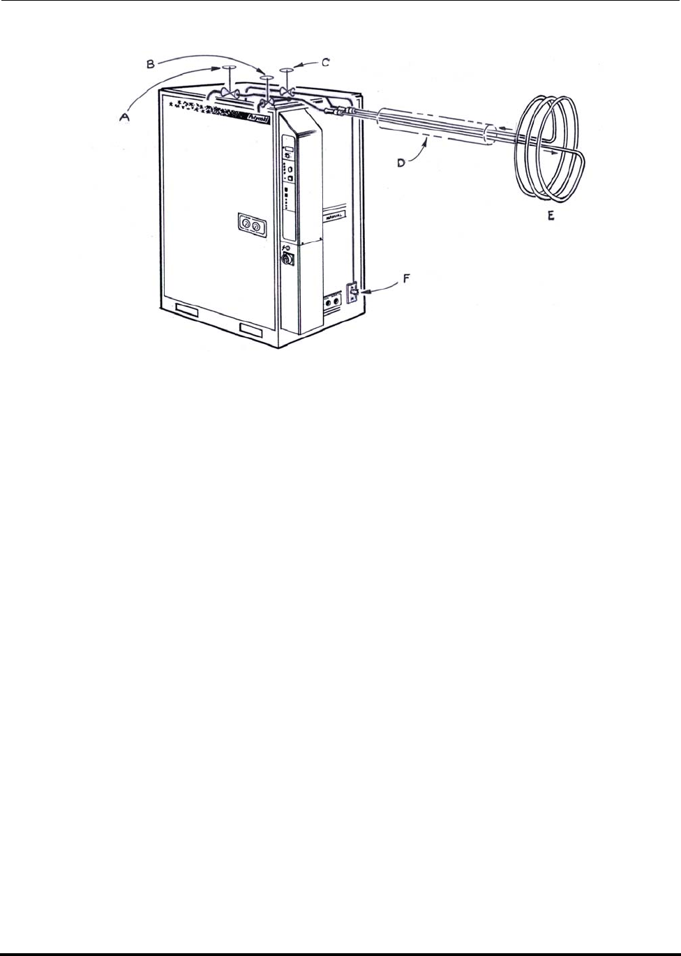
Polycold Fast Cycle Water Vapor Cryopump Installation
Customer Instruction Manual How to Connect the Cryosurface to the Refrigeration Unit
Brooks Automation 825064-00
Revision 09 3-41
Figure 3-17: Evacuation Valve, Refrigerant Line & Cryosurface Relationship
(Schematic only—actual valve locations not shown)
A. Cold gas feed isolation valve (closed)
B. Hot gas feed isolation valve (closed)
C. Common return isolation valve (closed)
D. Refrigerant line
E. Cryosurface
F. Evacuation valve

Installation Polycold Fast Cycle Water Vapor Cryopump
How to Connect the Cryosurface to the Refrigeration Unit Customer Instruction Manual
825064-00 Brooks Automation
3-42 Revision 09
Figure 3-18: Refrigerant Line & Cryosurface—Leak-check Charging Set-up
A. Evacuation valve; pressure relief outlet (not shown)
B. Manifold suction valve
C. Manifold discharge valve (closed)
D. Cylinder of R-22 or R-134a
E. Cylinder of dry nitrogen gas
3.3.3.2 Check for Refrigerant Leaks
1. With the halogen leak detector, carefully check each connection that was made.
This includes the Parker CPI UltraSeal or Cajon VCR couplings, the EVACUA-
TION VALVE, and any brazed joint that may have been made. The Parker and
Cajon couplings have two small access holes on each nut to help find leaks.
With a finger cover one hole and put the sensor at the other hole. (See Figure
3-19.)
2. If no leaks are found, check the pressure on the manifold to verify that it is still
at 150 psig (1030 kPa). If the pressure has not changed, go on to section 3.3.4
Evacuate the Refrigerant Line and Cryosurface.
NOTE: If there is a large leak and the source cannot be gotten close to without activating
the leak detector, open the manifold’s suction valve until the pressure drops to
about 50 psig (345 kPa). This should allow detection of the source of the leak.

Polycold Fast Cycle Water Vapor Cryopump Installation
Customer Instruction Manual How to Connect the Cryosurface to the Refrigeration Unit
Brooks Automation 825064-00
Revision 09 3-43
3.3.3.3 Pinpoint and Repair Any Leaks
If a leak is found with the halogen leak detector, pinpoint its location with leak detec-
tor soap. A bubble that forms in about 2 minutes represents a leak equivalent to 1.5
ounces (43 grams) per year.
NOTE: Note: Avoid making bubbles when applying the leak detector soap.
If a leak is found on the Parker CPI UltraSeal or Cajon VCR couplings
• With a finger cover the lower access hole and apply leak detector soap to the
higher access hole. Observe the higher access hole for at least 2 minutes. If a
bubble forms, verify that the coupling is tightened to within specification.
• If the coupling still leaks, it must be reassembled. Open the manifold’s suction
valve to release the gas in the refrigerant line and cryosurface. Then disassem-
ble the coupling following the instructions in Step 4 in section 8.2 How to Dis-
connect the Refrigerant Line. Make certain the coupling’s sealing surfaces are
not scratched or damaged. Re-assemble the coupling following the instruc-
tions in section 3.3.1 Connect the Refrigerant Line.
If a leak is found on a brazed joint
• Apply leak detector soap to the joint. Use an inspection mirror to view all sides
of the joint. Observe the joint for at least 2 minutes. If the joint has a leak, it
must be repaired. Open the manifold’s suction valve to release the gas in the
refrigerant line and cryosurface. Repair the leak following the instructions in
section 3.7 Brazing Specification.
If a leak is found on the EVACUATION VALVE
• Apply leak detector soap to the packing. Observe the packing for at least 2
minutes. Tighten the valve packing if it is the source of the leak. If the packing
is not the source of the leak, the valve must be replaced.
WARNING
Never add refrigerant to a unit with a leak. Always pinpoint and
repair any leaks prior to adding refrigerant or re-charging.
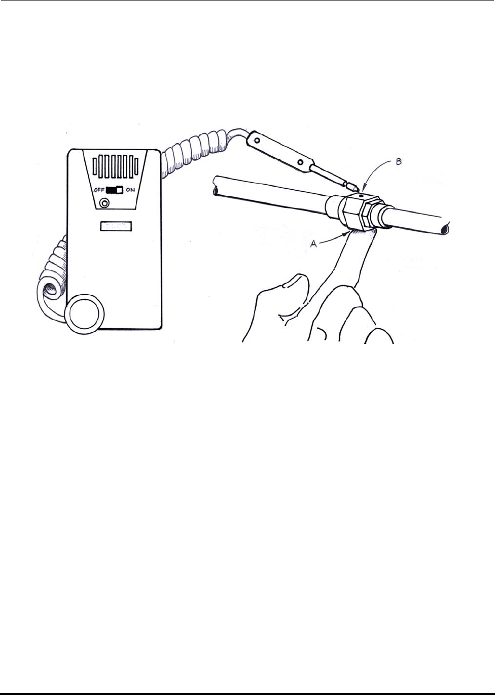
Installation Polycold Fast Cycle Water Vapor Cryopump
How to Connect the Cryosurface to the Refrigeration Unit Customer Instruction Manual
825064-00 Brooks Automation
3-44 Revision 09
3.3.3.4 Confirm that the Refrigerant Line and Cryosurface are Leak-free
Use the halogen leak detector to check any repair that was made. (See section 3.3.3.1
Pressurize the Refrigerant Line and Cryosurface and section 3.3.3.2 Check for Refrig-
erant Leaks.) Repeat this procedure until all leaks have been repaired.
Figure 3-19: Couplings—Leak-checking Method
A. Cover one hole with finger
B. Put sensor at other hole
3.3.4 Evacuate the Refrigerant Line and Cryosurface
Tools and materials needed:
• Vacuum pump with a 1/4-inch SAE male flare connection that is capable of
pumping down to at least 0.05 torr (6.5 Pa)
• Thermistor or thermocouple type vacuum gauge
• Cylinder of dry nitrogen gas with a regulator
• Service manifold gauge set with hoses (manifold)
• 1/4 inch ratchet valve wrench
• 5/8 inch end wrench
• 15/16 inch end wrench

Polycold Fast Cycle Water Vapor Cryopump Installation
Customer Instruction Manual How to Connect the Cryosurface to the Refrigeration Unit
Brooks Automation 825064-00
Revision 09 3-45
3.3.4.1 Evacuate the Refrigerant Line and Cryosurface
1. Evacuate the refrigerant line and cryosurface to 0.1 torr (13 Pa). (See Figure
3-20.)
2. Allow the vacuum pump to continue pumping for 30 minutes.
3. Close the manifold’s suction valve and turn off the vacuum pump.
NOTE: The vacuum pump should evacuate the refrigerant line & cryosurface to 0.1 torr
(13 Pa) within 30 minutes. If not, there may be a leak.
3.3.4.2 Evacuate the Refrigerant Line and Cryosurface a Second Time
1. Connect the nitrogen cylinder to the manifold’s center hose. (See Figure 3-20.)
Pressurize the refrigerant line and cryosurface to 10-20 psig (70-140 kPa).
2. Evacuate the refrigerant line and cryosurface to 0.1 torr (13 Pa). Allow the vac-
uum pump to continue pumping for 30 minutes. Close the unit’s EVACUA-
TION VALVE while the vacuum pump is still pumping. Turn off the vacuum
pump. Slowly remove the hose from the EVACUATION VALVE.
3. Reinstall the protective cap and the flare nut with bonnet onto the EVACUA-
TION VALVE. (See Figure 3-21).
WARNING
GENERAL HAZARD
Failure to have a qualified refrigeration technician do all refrigera-
tion work could result in death or serious injury.
Do not attempt evacuation. Contact a qualified refrigeration tech-
nician.
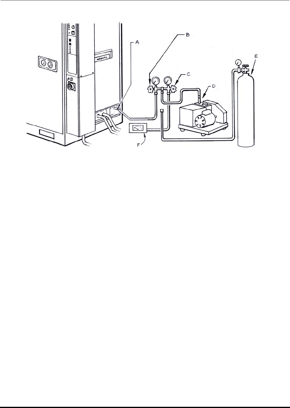
Installation Polycold Fast Cycle Water Vapor Cryopump
How to Connect the Cryosurface to the Refrigeration Unit Customer Instruction Manual
825064-00 Brooks Automation
3-46 Revision 09
Figure 3-20: Refrigerant Line & Cryosurface—Evacuation Set-up
A. Evacuation valve
B. Manifold suction valve
C. Manifold discharge valve
D. Vacuum pump
E. Cylinder of dry nitrogen gas
F. Vacuum gauge
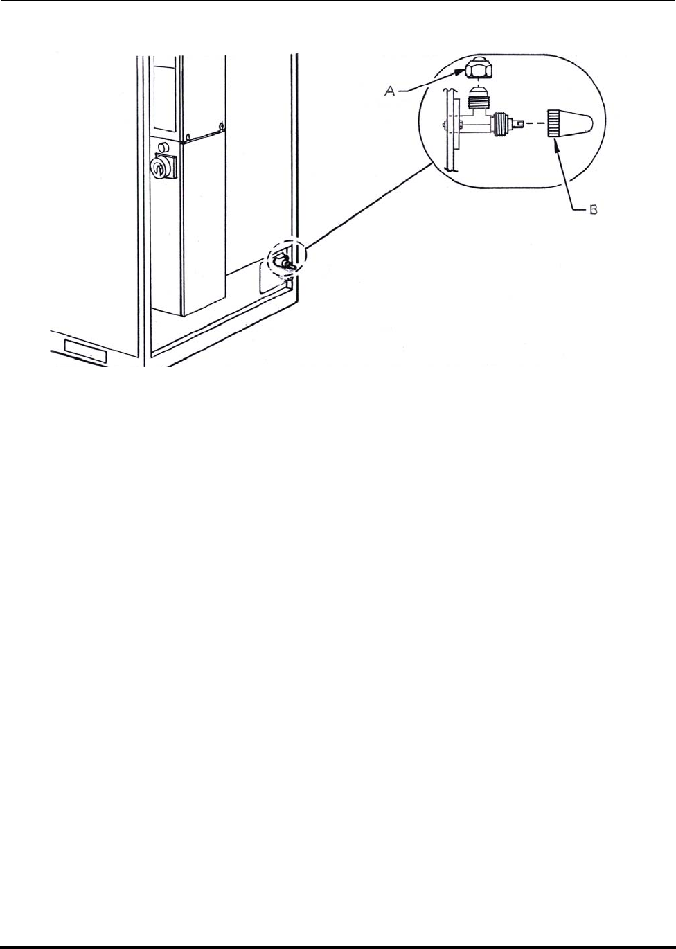
Polycold Fast Cycle Water Vapor Cryopump Installation
Customer Instruction Manual How to Connect the Cryosurface to the Refrigeration Unit
Brooks Automation 825064-00
Revision 09 3-47
Figure 3-21: Evacuation Valve Closure
A. Bonnet with flare nut
B. Cap
3.3.5 Connect the COIL IN & COIL OUT Thermocouples
Tools and materials needed:
• Phillips screwdriver
• small straight blade screwdriver
• wire stripper, a thermal wire stripper is preferred
For PFC/PFC or PFC/P:
• four small labels or tape
• Armaflex tape, about 1x2 inches (25x50 mm)
If someone other than Polycold made the refrigerant line on this system, make sure
that the thermocouples were properly installed. Please refer to section 3.6 Refrigerant
Line Specification.

Installation Polycold Fast Cycle Water Vapor Cryopump
How to Connect the Cryosurface to the Refrigeration Unit Customer Instruction Manual
825064-00 Brooks Automation
3-48 Revision 09
3.3.5.1 Remove the Low Voltage Box Panel
Loosen the two lower screws on the side of the low voltage box. Slide the panel
straight up to remove it. (See Figure 3-22.)
3.3.5.2 Put the COIL IN and COIL OUT Thermocouples in the Low Voltage Box
1. Locate the thermocouple wires labeled COIL IN and COIL OUT on the refrig-
erant line. Locate the EXTERNAL TC fitting on the back of the low voltage box.
2. Unscrew the cap and remove the rubber seal from the EXTERNAL TC fitting.
3. Slide the cap over the thermocouple wires.
4. Slip the thermocouple wires into the slit in the rubber seal. Insert the rubber
seal into the fitting and screw on the cap.
NOTE: For PFC/PFC or PFC/P
• Fold a small piece of tape around each thermocouple wire next to its label.
• Label the tape “#1” on the COIL IN and COIL OUT thermocouple wires com-
ing from the first refrigerant circuit.
5. Label the tape “#2” on the COIL IN and COIL OUT thermocouple wires com-
ing from the second refrigerant circuit.
6. Instead of using the rubber seal, wrap the Armaflex tape around the thermo-
couple wires so that the wires fit tightly in the EXTERNAL TC fitting.
WARNING
ELECTRICAL HAZARD
Contact could cause electric shock and result in death or serious
injury.
Make certain the ON/OFF switch and the power disconnect
switch are in the OFF position.
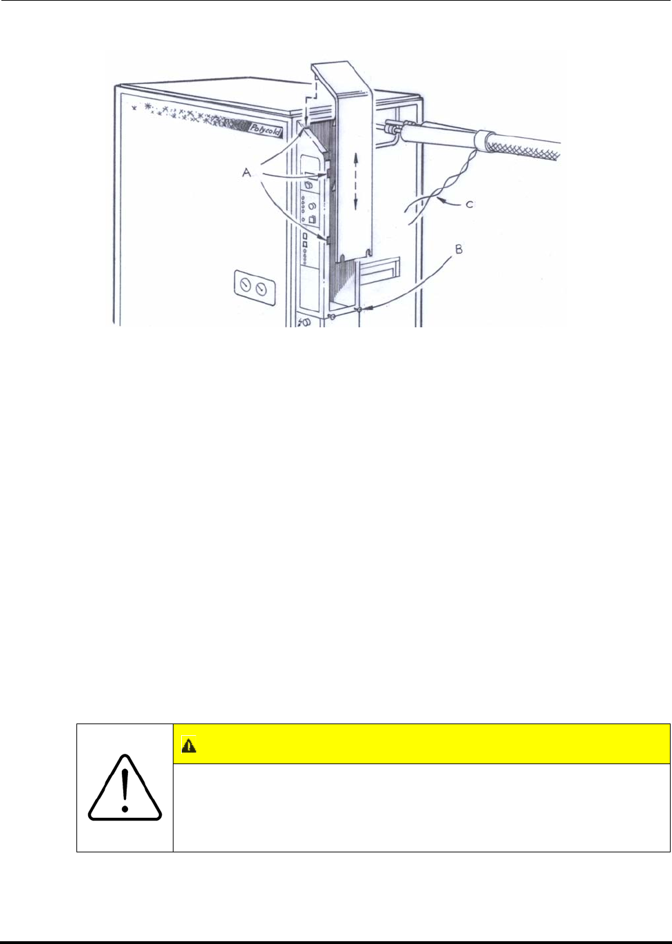
Polycold Fast Cycle Water Vapor Cryopump Installation
Customer Instruction Manual How to Connect the Cryosurface to the Refrigeration Unit
Brooks Automation 825064-00
Revision 09 3-49
Figure 3-22: Low Voltage Box Panel Removal
A. Notches
B. Loosen screws
C. Thermocouple wires
3.3.5.3 Connect the Thermocouple Wires to the Terminal Boards
NOTE: The terminal blocks are located on a printed circuit board directly below the temper-
ature meter.
1. Strip about 1/4 inch (6 mm) of insulation from the end of each thermocouple
wire.
CAUTION
GENERAL HAZARD
Make sure not to nick the conductor. The wire may break with
future vibration and can result in damage to the equipment.
Do not nick the conductor.

Installation Polycold Fast Cycle Water Vapor Cryopump
How to Connect the Cryosurface to the Refrigeration Unit Customer Instruction Manual
825064-00 Brooks Automation
3-50 Revision 09
2. Attach the thermocouple wires to their designated locations. The blue-insu-
lated copper wire must be attached to the positive (+) terminal. The red-insu-
lated constantan wire must be attached to the negative (–) terminal. (See
Figure 3-23.)
• Position #3: COIL IN
• Position #4: COIL OUT
For PFC/PFC or PFC/P:
• Position #3: #1 COIL IN
• Position #4: #1 COIL OUT
• Position #5: #2 COIL IN
• Position #6: #2 COIL OUT
3.3.5.4 Reinstall the Low Voltage Box Panel
1. Slide the panel straight down onto the low voltage box so that the two side tabs
go into their notches.
2. Push the top of the panel towards the unit and at the same time push down so
that the top tab goes into its notch.
3. Tighten the two screws.
NOTE: The temperature from a single thermocouple in Figure 3-20 can be displayed at a
remote location through the remote connector. To accomplish this see section 3.8.2
Additional Instructions for Remote Temperature Indication.
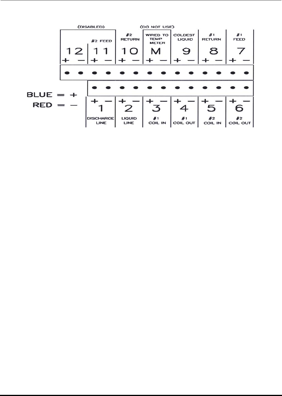
Polycold Fast Cycle Water Vapor Cryopump Installation
Customer Instruction Manual How to Connect the Cryosurface to the Refrigeration Unit
Brooks Automation 825064-00
Revision 09 3-51
Figure 3-23: Thermocouple (TC) positions identification
1. TC #1 = DISCHARGE LINE
2. TC #2 = LIQUID LINE
3. TC #3 = #1 COIL IN
4. TC #4 = #1 COIL OUT
5. TC #5 = #2 COIL IN
6. TC #6 = #2 COIL OUT
7. TC #7 = #1 FEED
8. TC #8 = #1 RETURN
9. TC #9 = COLDEST LIQUID
M. Wired to temperature meter—do not use.
10. TC #10 = #2 RETURN
11. #2 FEED—disabled
12. Disabled
Installation Polycold Fast Cycle Water Vapor Cryopump
How to Prepare the Cryopump for Operation Customer Instruction Manual
825064-00 Brooks Automation
3-52 Revision 09
3.4 How to Prepare the Cryopump for Operation
3.4.1 Open the Isolation Valves
3.4.1.1 Open the Isolation Valves
1. Locate the red hand valves underneath the top panel of the unit. They are
labeled COLD GAS FEED, COMMON RETURN, and HOT GAS FEED. (See
Figure 3-24.)
2. Turn each hand valve counter-clockwise until it is all the way open.
3. Turn each hand valve back (clockwise) 1/4 turn.
3.4.1.2 Record the Balance Pressure of the Cryopump
1. Wait 10 minutes for the pressure to equalize in the system. The pressure may
drop 5-10 psig (35-70 kPa) as the refrigerant mixture enters the refrigerant line
and cryosurface.
2. Record the pressure of the discharge gauge below. Also transfer this pressure
to the “Inspection Log” in section 5 Periodic Inspection and Maintenance. This
measurement will be used as a baseline reference for future inspections.
Cryopump’s balance pressure: _______ psig
3.4.1.3 Reinstall the Valve Box Lid and the Top Panel
Make certain the valve box gasket is in its groove. Screw the valve box lid completely
shut. The gasket should form a seal to keep out water vapor.
CAUTION
GENERAL HAZARD
Do not open the isolation valves doing so can result in damage to
the equipment.
Make sure to follow the instructions in section 3.3.3 Check the
Refrigerant Line & Cryosurface for Leaks and section 3.3.4 Evacu-
ate the Refrigerant Line and Cryosurface before opening the isola-
tion valves.
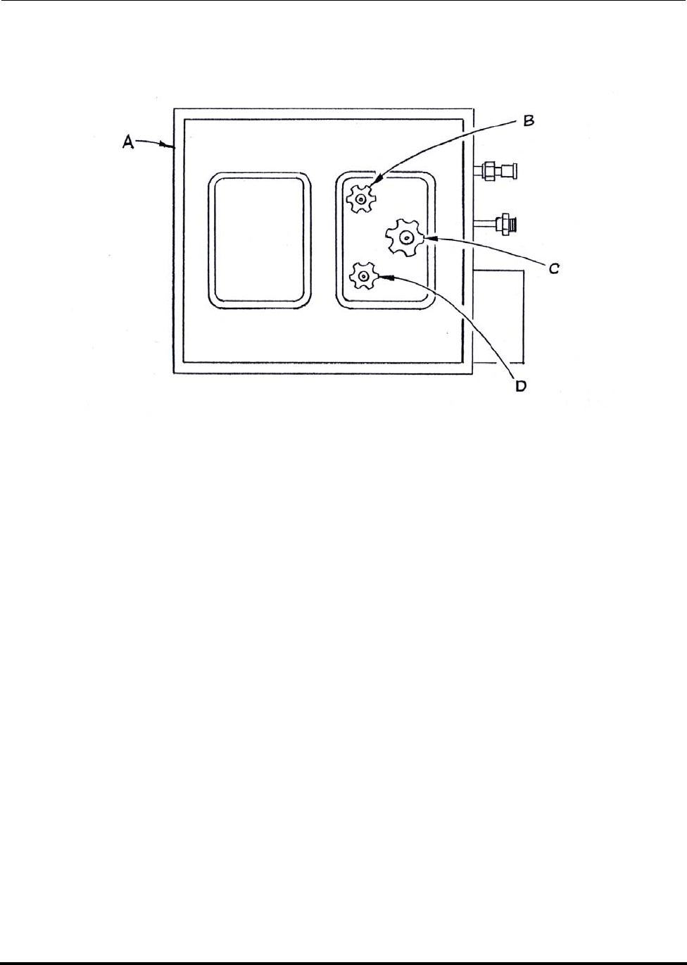
Polycold Fast Cycle Water Vapor Cryopump Installation
Customer Instruction Manual How to Prepare the Cryopump for Operation
Brooks Automation 825064-00
Revision 09 3-53
3.4.1.4 Reinstall the Top Panel
Figure 3-24: Location of Isolation Valves
NOTE: Two valve boxes are shown. Some units have a single valve box.
A. Refrigeration unit (top view with panel removed)
B. Cold gas feed isolation valve
C. Common return isolation valve
D. Hot gas feed isolation valve
3.4.2 Cycle the Cryopump & Check for Refrigerant Leaks
Tools and materials needed:
• electronic halogen leak detector
• clean rag

Installation Polycold Fast Cycle Water Vapor Cryopump
How to Prepare the Cryopump for Operation Customer Instruction Manual
825064-00 Brooks Automation
3-54 Revision 09
3.4.2.1 Cycle the Cryopump
1. Start the cooling water. Verify the power disconnect switch is in the ON posi-
tion. Select LOCAL and STANDBY. Turn on the unit.
2. Wait at least 30 minutes for the “Polycold stack” (heat exchangers and other
components that are encased in insulating foam) to reach operating tempera-
ture.
3. Evacuate the location of your cryosurface to at least 0.01 torr (1.33 Pa).
4. Select COOL and wait 5-10 minutes (10 minutes if the refrigerant line is longer
than 20 feet (6 m)).
5. Select DEFROST. The unit will automatically go into STANDBY when
DEFROST is complete. Remain in STANDBY for 15 minutes.
6. Repeat this COOL, DEFROST, and STANDBY cycle two or three times.
NOTE: For PFC/PFC: Select LOCAL and STANDBY for both refrigerant circuits. Cycle
both refrigerant circuits at the same time.
NOTE: For PFC/P: Select LOCAL and STANDBY for both refrigerant circuits. Cycle the
first refrigerant circuit only.
7. For the second refrigerant circuit, select COOL and wait 10 minutes.
8. Then select STANDBY and wait 10 minutes.
9. Turn off the unit, and dry the exposed tubes of the refrigerant line with a clean
rag.
3.4.2.2 Check for Refrigerant Leaks
With the halogen leak detector carefully check each connection that was made. This
includes the Parker CPI UltraSeal or Cajon VCR couplings, the EVACUATION
VALVE, and any brazed joint that was made.
Optionally, check the refrigeration unit’s compressor compartment. Check the com-
pressor’s suction and discharge valves, and the valves on the tanks.
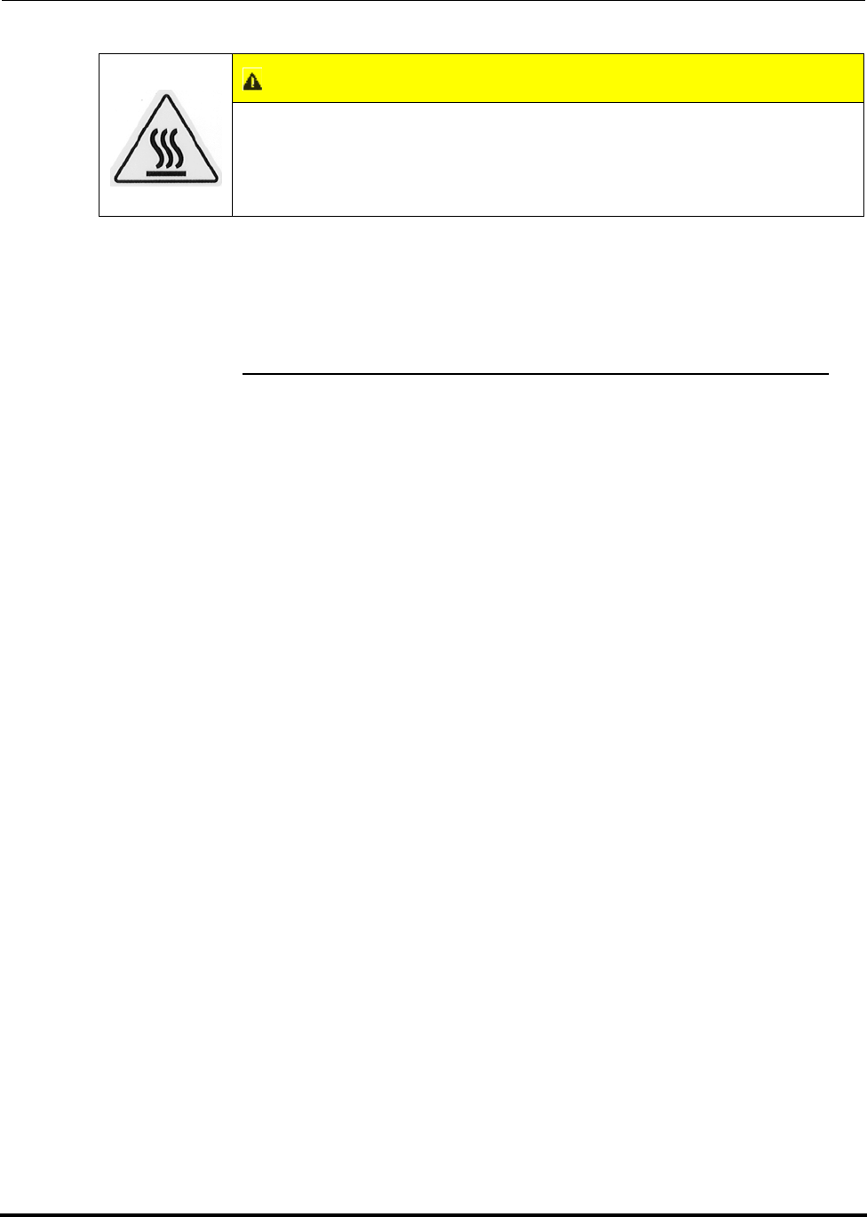
Polycold Fast Cycle Water Vapor Cryopump Installation
Customer Instruction Manual How to Prepare the Cryopump for Operation
Brooks Automation 825064-00
Revision 09 3-55
3.4.2.3 Pinpoint and Repair Any Leaks
To pinpoint the location of a leak, follow the instructions in section 3.3.3 Check the
Refrigerant Line & Cryosurface for Leaks. If reassembly of a coupling is needed (or to
fix a brazed joint), the refrigerant mixture must first be drawn back into the unit. To
do this, follow the Step 1and Step 2 in section 8.2 How to Disconnect the Refrigerant
Line.
With the leak detector, check the repairs following the instructions in section 3.3.3
Check the Refrigerant Line & Cryosurface for Leaks.
3.4.3 Insulate the Exposed Tubes and Couplings
Tools and materials needed:
• tubes of closed-cell pipe insulation †
• sheet of closed-cell pipe insulation †
• Armaflex tape †
• Armstrong 520 adhesive †
• large pair of scissors or knife
† Shipped with the unit if purchased with a refrigerant line.
Properly insulating the exposed tubes and couplings will keep them dry. Penetrating
moisture will add heat load to the cryopump and can cause corrosion or leaks.
CAUTION
EXTREME TEMPERATURES EXIST
The compressor’s heads and discharge line may be hot; contact
with the hot surface may result in minor or moderate injury.
Do not touch the compressor’s heads or discharge line.

Installation Polycold Fast Cycle Water Vapor Cryopump
How to Prepare the Cryopump for Operation Customer Instruction Manual
825064-00 Brooks Automation
3-56 Revision 09
3.4.3.1 Insulate the Exposed Tubes between the Unit and the Refrigerant Line
Insulation.
(See Cross-section A-A in Figure 3-25.)
1. Cut the tubes of insulation so that they will fit snugly between the unit and the
refrigerant line’s insulation. Cut each tube of insulation lengthwise.
2. Fit a smaller diameter tube of insulation around each exposed tube. Apply
adhesive to the lengthwise slits in the insulation. Close the lengthwise slits to
form an air-tight seal.
3. Fit the larger diameter tubes of insulation around the smaller diameter tubes of
insulation. Seal each lengthwise slit shut with adhesive. (It is best to stagger
the lengthwise seams.)
4. Cut the sheet of insulation the same length as the tubes of insulation. Wrap the
sheet once around the tubes of insulation, allowing the sheet to overlap 2-3
inches (50-75 mm). Put adhesive on the last 1-1.5 inches (25-40 mm) of the
overlapping sheet to secure it in place.
5. Seal both ends of the sheet with tape. Secure the sheet to the refrigerant line’s
insulation and to the unit’s panel. Flare the tape so that it connects the sheet to
the panel.
WARNING
FLAMMABLE MATERIAL (1101, 1100, 670, 661, 660, 551, and 550
ONLY) AND CHEMICAL HAZARD
Fumes are a source of ignition and suffocation. Make sure there
is adequate ventilation and no ignition source when using the
Armstrong 520 adhesive. Failure to do so could result in death or
serious injury.
Read the label on the container.
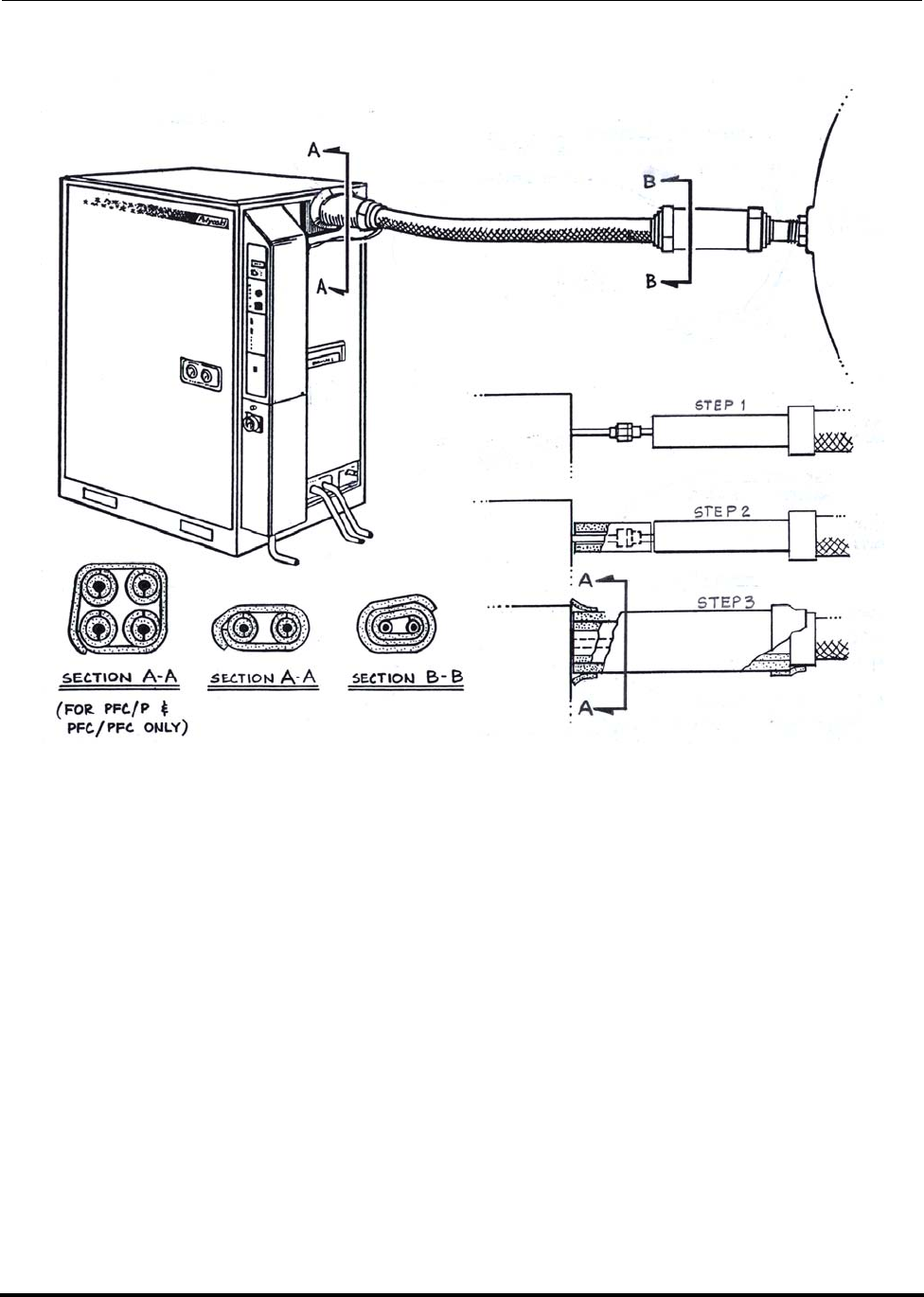
Polycold Fast Cycle Water Vapor Cryopump Installation
Customer Instruction Manual How to Prepare the Cryopump for Operation
Brooks Automation 825064-00
Revision 09 3-57
Figure 3-25: Insulating Exposed Tubes and Couplings Method
3.4.3.2 Insulate the Exposed Tubes between the Refrigerant Line Insulation and
the Feed-through.
(See Cross-section B-B in Figure 3-25.)

Installation Polycold Fast Cycle Water Vapor Cryopump
How to Prepare the Cryopump for Operation Customer Instruction Manual
825064-00 Brooks Automation
3-58 Revision 09
1. Fit the sheet of insulation between the pre-insulated refrigerant line and the
feed-through. Wrap the insulation around the exposed tubes three times. Put
adhesive on the last 1-1.5 inches (25-40 mm) of the overlapping sheet to secure
it in place.
2. Seal both ends of the sheet with tape. Secure the sheet to the refrigerant line’s
insulation and to the feed-through. Do not put the tape closer than 1-2 inches
(25-50 mm) to the threads on the feed-through.
3.4.4 Evaluate the Cryopump
3.4.4.1 Evaluate the Cryopump in STANDBY
1. Start the cooling water. Make sure the minimum flow rate for the water’s tem-
perature is adequate; see section 3.2.5 Connect the Cooling Water.
2. Select LOCAL and STANDBY.
3. Turn on the unit and wait 30 minutes for the stack to cool down.
NOTE: For PFC/PFC or PFC/P: Select LOCAL and STANDBY for both refrigerant cir-
cuits.
CAUTION
GENERAL HAZARD
Armaflex tape or Armstrong 520 adhesive in the threads of the
feed-through is extremely difficult to remove. It makes the feed-
through nut bind when unscrewed and may result in damage to
the equipment.
Do not put Armaflex tape or Armstrong 520 adhesive into the
threads on the feed-through.
Polycold Fast Cycle Water Vapor Cryopump Installation
Customer Instruction Manual How to Prepare the Cryopump for Operation
Brooks Automation 825064-00
Revision 09 3-59
4. Listen to the compressor. It should run continuously without cycling or turn-
ing off.
5. Remove the unit’s left panel. Locate the oil sightglass on the compressor. (Fig-
ure 3-26.) It should be 1/8 to 1/2 full (1/8 full is preferred) while the compres-
sor is running for at least 60 minutes.
6. Record the compressor oil level while the compressor is running for at least 60
minutes:
7. Check the direction of the cooling water’s flow. The drain line (OUT) should be
warmer than the supply line (IN). (See Figure 3-27). If not, turn off the unit
and connect the supply and drain lines to the proper ports.
8. Record the following pressures and temperatures:
CAUTION
EXTREME TEMPERATURES EXIST
Do not reach inside the compressor compartment when the unit
is operating. The compressor’s heads and discharge line may be
hot; contact with the hot surface may result in minor or moder-
ate injury.
Do not touch the compressor’s heads or discharge line. See Fig-
ure 3-26.
DANGER
ELECTRICAL
Do not reach inside the compressor compartment when the unit is
operating. The compressor electrical box contains hazardous volt-
ages. Failure to have a qualified electrician do all electrical work
could result in death or serious injury.
Do not reach inside the unit. A qualified electrician must do all
electrical work.

Installation Polycold Fast Cycle Water Vapor Cryopump
How to Prepare the Cryopump for Operation Customer Instruction Manual
825064-00 Brooks Automation
3-60 Revision 09
Table 3-6: Pressures and Temperatures in Standby
Acceptable Range For Your Measurements For
550
660
670
1100
551
661
1101
552
662
672
1102
550
660
670
1100
551
661
1101
552
662
672
1102
SUCTION
Pressure 3-12 psig
(.2-.8 bar) 3-25 psig
(.2-1.7 bar) 10-25 psig
(.7-1.7 bar) ____ psig 1
____ bar 1 ____ psig 1
____ bar 1 ____ psig 1
____ bar 1
DISCHARGE
Pressure
90-160
psig
(6.2-11
bar)
90-235
psig
(6.2-16.2
bar)
150-230
psig
(10.3-15.8
bar)
____ psig 1
____ bar 1 ____ psig 1
____ bar 1 ____ psig 1
____ bar 1
DISCHARGE
LINE
(TC #1) 80-120°C 80-120°C 80-120°C ____°C 1 ____°C 1 ____°C 1
LIQUID LINE
(TC #2) 13-32°C 13-32°C 13-32°C ____°C 1 ____°C 1 ____°C 1
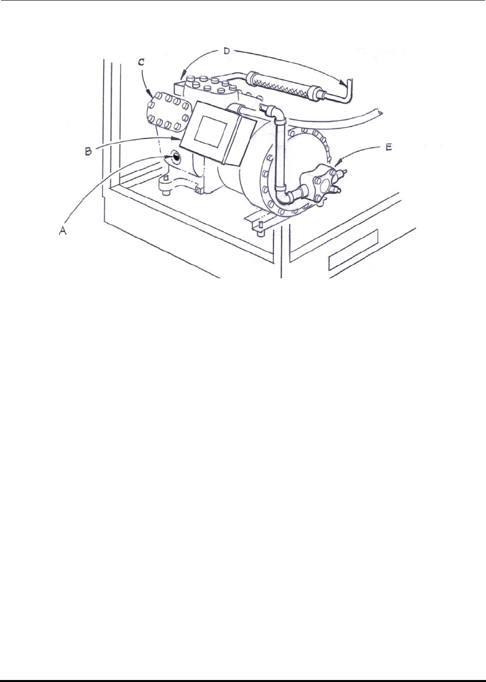
Polycold Fast Cycle Water Vapor Cryopump Installation
Customer Instruction Manual How to Prepare the Cryopump for Operation
Brooks Automation 825064-00
Revision 09 3-61
Figure 3-26: Compressor parts location
A. Oil sightglass
B. Electrical box—high voltage
C. Heads—hot
D. Discharge valve and line—hot
E. Suction valve—may be cold
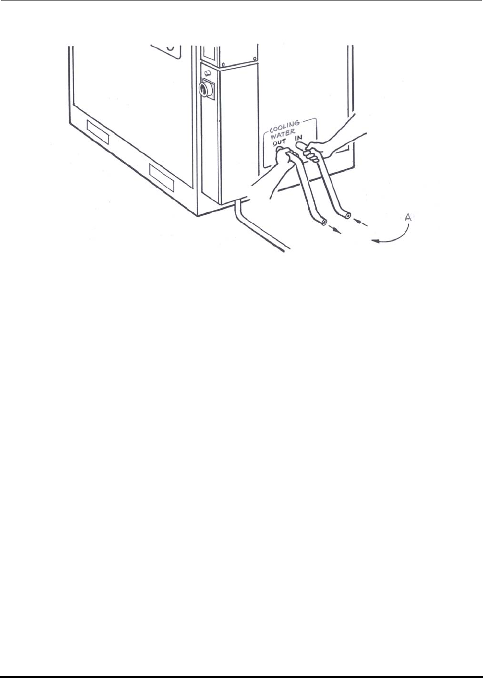
Installation Polycold Fast Cycle Water Vapor Cryopump
How to Prepare the Cryopump for Operation Customer Instruction Manual
825064-00 Brooks Automation
3-62 Revision 09
Figure 3-27: Cooling water flow direction check
A. The water coming out should be warmer than the water going in
3.4.4.2 Evaluate the Cryopump in COOL
1. Evacuate the location of the cryosurface to at least 0.01 torr (1.33 Pa).
2. Select COOL and wait 30 minutes.
NOTE: For PFC/PFC or PFC/P: Select COOL for both refrigerant circuits.
3. Check the outlet temperature of the cooling water. The drain line (OUT)
should be 72-95°F (22-35°C). If not, adjust the water flow to attain a water out-
let temperature in this range.
4. If there is any ice or water on the refrigerant line, turn off the unit and remove
the ice or water. Apply another layer of insulation following the instructions
in section 3.4.3 Insulate the Exposed Tubes and Couplings. Re-evaluate the
cryopump starting at the beginning of Step 1.
5. Record the following pressures and temperatures:

Polycold Fast Cycle Water Vapor Cryopump Installation
Customer Instruction Manual How to Prepare the Cryopump for Operation
Brooks Automation 825064-00
Revision 09 3-63
NOTE: For PFC/PFC or PFC/P: Also record the following temperatures.
Table 3-7: Pressures and Temperatures in Cool
Acceptable Range For Your Measurements For
550
660
670
1100
551
661
1101
552
662
672
1102
550
660
670
1100
551
661
1101
552
662
672
1102
SUCTION
Pressure
4-30 psig
(2.8-20.6
bar)
4-45 psig
(2.8-31
bar)
10-50 psig
(6.8-34
bar)
_____ psig
_____ bar _____ psig
_____ bar _____ psig
_____ bar
DISCHARGE
Pressure
100-380
psig
(6.9-26.2
bar)
100-380
psig
(6.9-26.2
bar)
150-390
psig
10.34-26.9
bar)
_____ psig
_____ bar _____ psig
_____ bar _____ psig
_____ bar
DISCHARGE
LINE
(TC #1) 80-125°C 80-125°C 90-125°C _____°C _____°C _____°C
LIQUID LINE
(TC #2) 13-32°C 13-32°C 13-32°C _____°C _____°C _____°C
COIL IN
(TC #3) See Table
3-8 See Table
3-8 See Table
3-8 _____°C 1_____°C 1_____°C 1
COIL IN
(TC #4) See Table
3-8 See Table
3-8 See Table
3-8 _____°C 1_____°C 1_____°C 1
#2 COIL IN (TC #5): See Table 3-8 _______°C 1
#2 COIL OUT (TC#6): See Table 3-8 _______°C 1

Installation Polycold Fast Cycle Water Vapor Cryopump
How to Prepare the Cryopump for Operation Customer Instruction Manual
825064-00 Brooks Automation
3-64 Revision 09
Table 3-8: Cryosurface Temperature Needed for Desired Water Vapor Partial Pressure
Desired Water Vapor Partial Pressure Average Cryosurface
Temperature Needed †
torr Pascal mbar °C
5 x 1007 x 1027 x 100–25.4
2 x 1003 x 1023 x 100–34.4
1 x 1001 x 1021 x 100–40.8
5 x 10⁻¹ 7 x 1017 x 10–1 –46.8
2 x 10⁻¹ 3 x 1013 x 10–1 –54.3
1 x 10⁻¹ 1 x 1011 x 10–1 –59.7
5 x 10⁻² 7 x 1007 x 10–2 –64.8
2 x 10⁻² 3 x 1003 x 10–2 –71.2
1 x 10⁻² 1 x 1001 x 10–2 –75.8
5 x 10⁻³ 7 x 10⁻¹ 7 x 10⁻³ –80.1
2 x 10⁻³ 3 x 10⁻¹ 3 x 10⁻³ –85.6
1 x 10⁻³ 1 x 10⁻¹ 1 x 10⁻³ –89.6
5 x 10⁻⁴ 7 x 10⁻² 7 x 10⁻⁴ –93.4
2 x 10⁻⁴ 3 x 10⁻² 3 x 10⁻⁴ –98.2
1 x 10⁻⁴ 1 x 10⁻² 1 x 10⁻⁴ –101.6
5 x 10⁻⁵ 7 x 10⁻³ 7 x 10⁻⁵ –104.9
2 x 10⁻⁵ 3 x 10⁻³ 3 x 10⁻⁵ –109.1
1 x 10⁻⁵ 1 x 10⁻³ 1 x 10⁻⁵ –112.2
5 x 10⁻⁶ 7 x 10⁻⁴ 7 x 10⁻⁶ –115.1
2 x 10⁻⁶ 3 x 10⁻⁴ 3 x 10⁻⁶ –118.1
1 x 10⁻⁶ 1 x 10⁻⁴ 1 x 10⁻⁶ –121.5

Polycold Fast Cycle Water Vapor Cryopump Installation
Customer Instruction Manual How to Prepare the Cryopump for Operation
Brooks Automation 825064-00
Revision 09 3-65
3.4.4.3 Evaluate the Cryopump in DEFROST
1. Select DEFROST.
NOTE: For a PFC/PFC: Select DEFROST for both refrigerant circuits.
NOTE: For a PFC/P: Select DEFROST for the first refrigerant circuit. Select STANDBY
for the second refrigerant circuit.
5 x 10⁻⁷ 7 x 10⁻⁵ 7 x 10⁻⁷ –124.1
2 x 10⁻⁷ 3 x 10⁻⁵ 3 x 10⁻⁷ –127.5
1 x 10⁻⁷ 1 x 10⁻⁵ 1 x 10⁻⁷ –129.9
5 x 10⁻⁸ 7 x 10⁻⁶ 7 x 10⁻⁸ –132.2
2 x 10⁻⁸ 3 x 10⁻⁶ 3 x 10⁻⁸ –135.2
1 x 10⁻⁸ 1 x 10⁻⁶ 1 x 10⁻⁸ –137.3
5 x 10⁻⁹ 7 x 10⁻⁷ 7 x 10⁻⁹ –139.5
2 x 10⁻⁹ 3 x 10⁻⁷ 3 x 10⁻⁹ –142.1
1 x 10⁻⁹ 1 x 10⁻⁷ 1 x 10⁻⁹ –144.1
NOTE:
† This is the average of your COIL IN (TC #3) and COIL OUT
(TC #4) measurements.
The COIL OUT temperature must be within 10°C of the aver-
age temperature.
For PFC/PFC or PFC/P: Also average your #2 COIL IN (TC
#5) and #2 COIL OUT (TC #6) measurements.
Table 3-8: Cryosurface Temperature Needed for Desired Water Vapor Partial Pressure
Desired Water Vapor Partial Pressure Average Cryosurface
Temperature Needed †
torr Pascal mbar °C

Installation Polycold Fast Cycle Water Vapor Cryopump
How to Prepare the Cryopump for Operation Customer Instruction Manual
825064-00 Brooks Automation
3-66 Revision 09
2. Record the time it takes for the cryosurface to defrost. When DEFROST s com-
plete, the DEFROST COMPLETE lamp will light and the unit will automati-
cally switch to STANDBY.
Actual Defrost Time: _______ minutes (should be less than 4 minutes)
3. Open the vacuum chamber. The cryosurface should be dry and at room tem-
perature or warmer.
3.4.4.4 Ensure that the Cryopump is Operating Properly
Recheck all measurements to verify the cryopump is operating within specification.
Transfer all measurements marked with a “l” to “Inspection Log” in section 5 Periodic
Inspection and Maintenance. These measurements will be used as a baseline refer-
ence for future inspections.
3.4.4.5 Reinstall the Unit Panels
CAUTION
EXTREME TEMPERATURES EXIST
Parts of the cryosurface may be hot; contact with the hot surface
may result in minor or moderate injury.
Do not touch the cryosurface.

Polycold Fast Cycle Water Vapor Cryopump Installation
Customer Instruction Manual Cryosurface & Cryogenic Feed-through Specification
Brooks Automation 825064-00
Revision 09 3-67
3.5 Cryosurface & Cryogenic Feed-through Specification
3.5.1 If the Cryosurface is a Coil
NOTE: This section assumes that a refrigerant circuit will be used to capture water vapor
in a vacuum chamber.
3.5.1.1 Choose a Good Location
The cryocoil must be located so that:
• Evaporant (deposition source material) is not deposited on its surface.
• It has the best possible (unimpeded) view of the surfaces most likely to emit
water vapor.
• It is facing away (or can be shielded) from sources of heat greater than 50°C.
• It is not subject to damage from moving objects.
• It can be supported without significant thermal conductance from the vacuum
chamber.
If vacuum isolated feed-through is used, it must be located so that water will not col-
lect in it when the cryocoil is defrosted. Subsequent freezing of this water may dam-
age the cryocoil and/or cause vacuum or refrigerant leaks.
CAUTION
GENERAL HAZARD
The tubing, cryosurfaces, and feed-through must be free of oil
and moisture before connecting it to the refrigeration unit. Fail-
ure to comply with the former specification can result in damage
to the equipment.
Make sure the tubing, cryosurfaces, and feed-through are free of
oil and moisture before connecting it to the refrigeration unit.

Installation Polycold Fast Cycle Water Vapor Cryopump
Cryosurface & Cryogenic Feed-through Specification Customer Instruction Manual
825064-00 Brooks Automation
3-68 Revision 09
Table 3-9: Cryocoil Size Specification
Refrigeration Unit Total Surface
Area ft² (m²) Tube Diameter
in (mm) Tube Length
ft (m)
PFC-550-LT 2.7 (0.25) 3/8 (10) 27 (8.0)
PFC-550-HC 5.4 (0.50) 1/2 (12) 41 (13)
PFC-551-HC (CE) 5.4 (0.50) 1/2 (12) 41 (13)
PFC-552-HC (CE) 5.4 (0.50) 1/2 (12) 41.1 (13.3
PFC-660-HC 7.5 (0.70) 5/8 (16) 46 (14)
PFC-661-HC (CE) 7.5 (0.70) 5/8 (16) 46 (14)
PFC-662-HC (CE) 7.5 (0.70) 5/8 (16) 46 (14)
PFC-670-HC 7.5 (0.70) 5/8 (16) 46 (14)
PFC-672-HC (CE) 7.5 (0.70) 5/8 (16) 46 (14)
PFC-1100-LT 5.4 (0.50) 1/2 (12) 41 (13)
PFC-1100-HC 21.6 (2.0) 5/8 (16) 132 (40)
PFC-1101-LT (CE) 5.4 (0.50) 1/2 (12) 41 (13)
PFC-1101-HC (CE) 21.6 (2.0) 5/8 (16) 132 (40)
PFC-1102-HC (CE) 21.6 (2.0) 5/8 (16) 132 (40)
NOTE:
For PFC/PFC: The total surface area must be divided between the
two cryocoils.
Larger cryocoils may give faster pumping speeds, and can be used
in some applications. However, if the heat load is too great, the
cryopump will become less efficient and may be shut off by a pro-
tective device.
Polycold Fast Cycle Water Vapor Cryopump Installation
Customer Instruction Manual Cryosurface & Cryogenic Feed-through Specification
Brooks Automation 825064-00
Revision 09 3-69
3.5.1.2 Design the Cryocoil and Feed-through to the Following Requirements:
1. The cryocoil must be a single continuous circuit (tube).
• Do not put branches in the circuit. It causes uneven distribution of the
refrigerant mixture that degrades the performance of the cryopump.
• Do not add fins or panels to the circuit. The increased mass takes longer
to cool and defrost the cryocoil and raises the cryocoil temperature.
2. The cryocoil must be either stainless steel or refrigeration grade copper tubing.
• Stainless steel tubing is more durable and less chemically reactive. Min-
imum wall thickness is 0.020 inches (0.5 mm).
• Refrigeration grade copper tubing is easier to work with. Minimum
wall thickness is 0.030 inches (0.76 mm).
3. The cryocoil must have the proper surface area based on the diameter and
length of the tubing. See Table 3-9.
4. The cryogenic feed-through must be thermally isolated; a vacuum isolated
feed-through is preferred.
5. If customer is providing feed-through, mating couplings are shipped with the
unit. The couplings must be offset 3 inches (76 mm) to be connected to the
refrigerant line. (See Figure 3-1.)
CAUTION
GENERAL HAZARD
The cryocoil and feed-through must be designed to sustain a
working pressure of 450 psig (3100 kPa). The cryocoil and feed-
through are part of the refrigerant circuit of the cryopump. Fail-
ure to comply with the former specifications can result in damage
to the equipment.
Do not use reservoir-type or large volume cryocoils. Do not use
large diameter tubing.

Installation Polycold Fast Cycle Water Vapor Cryopump
Cryosurface & Cryogenic Feed-through Specification Customer Instruction Manual
825064-00 Brooks Automation
3-70 Revision 09
6. It is preferable to weld or braze all connections inside the vacuum chamber. If
this is not practical, use one of the couplings listed below. These couplings
have been tested and found to be satisfactory. Other types of couplings may
leak.
• Parker CPI Ultra Seal couplings with silver-plated stainless steel
O-rings.
• Cajon VCR couplings with silver-plated stainless steel gaskets or
unplated nickel gaskets.
7. The supports for the cryocoil must allow for thermal contraction and expan-
sion as the coil is cooled and defrosted. Also the supports must not add a sig-
nificant heat load to the cryopump. Suitable supports can be made of thin
stainless steel rods or tubing. Some plastics may be suitable for certain applica-
tions.
3.5.1.3 Carefully Build the CryoCoil (and Feed-through)
Use a tubing bender or mandrel so that the tubing is smooth and wrinkle-free. Follow
the instructions in section 3.7 Brazing Specification. Make certain the tubing is clean
and free of corrosion, flux, and particle residue (inside and out).
3.5.1.4 Pressure-test the CryoCoil to 615 psig 4240 kPa (gauge) (i.e., 6.895 X psig)
This test must be done before you connect the cryocoil to the refrigeration unit. The
pressure relief valve for the refrigerant line and cryosurface may leak if it is pressur-
ized above 335 psig (2310 kPa).
NOTE: 615 psig = 1.43 x 430 psig.
3.5.1.5 Check the Cryocoil for Leaks
Use a helium mass spectrometer if one is available.
WARNING
Use of unauthorized, non-standard couplings will void your war-
ranty. Improper use of, incorrect installation of, over-tightening of,
or use of damaged o-rings in couplings will void your warranty.
(See CAUTION on page 3-33 for installation guidelines.)
Polycold Fast Cycle Water Vapor Cryopump Installation
Customer Instruction Manual Cryosurface & Cryogenic Feed-through Specification
Brooks Automation 825064-00
Revision 09 3-71
3.5.2 If the Cryosurface is a Baffle
NOTE: This section assumes the use of a refrigerant circuit to control back streaming. Back
streaming will contaminate the system because it is the process of hot vapor migrat-
ing and condensing on cold surfaces. When the vacuum pump is used, the pump
oil heats up and travels opposite of the pumping direction and condenses the system
resulting in system contamination.
3.5.2.1 Choose a Good Location
• The cryobaffle must be shielded from sources of heat greater than 50°C.
• The cryobaffle must not come in direct contact with the vacuum chamber.
3.5.2.2 Design the Cryobaffle (and Feed-through) to the Following Requirements
1. The cryobaffle should have a single continuous circuit (tube). Braze the fins of
a baffle to this tube.
• Contact a local Polycold sales representative or Brooks Polycold Sys-
tems Inc. for instructions on sizing the cryobaffle and other information.
CAUTION
GENERAL HAZARD
The tubing must be free of oil and moisture before connecting it to
the refrigeration unit. Failure to comply with the former specifi-
cation can result in damage to the equipment.
Make sure the tubing is free of oil and moisture before connecting
it to the refrigeration unit.
CAUTION
GENERAL HAZARD
The cryocoil, cryobaffle and feed-through must be designed to
sustain a working pressure of 450 psig (3100 kPa). The cryocoil,
cryobaffle and feed-through are part of the refrigerant circuit of
the cryopump. Failure to comply with the former specifications
can result in damage to the equipment.
Do not use reservoir-type or large volume cryobaffles. Do not use
large diameter tubing.

Installation Polycold Fast Cycle Water Vapor Cryopump
Cryosurface & Cryogenic Feed-through Specification Customer Instruction Manual
825064-00 Brooks Automation
3-72 Revision 09
• Do not put branches in the circuit. It causes uneven distribution of the
refrigerant mixture that degrades the performance of the cryopump.
2. The cryobaffle should be made with refrigeration grade copper tubing and
with OFHC (oxygen free, high capacity) copper fins.
• The refrigeration grade copper tubing must have a minimum wall thick-
ness of 0.030 inches (0.76 mm).
• The cryobaffle may be nickel-plated.
3. The cryogenic feed-through must be thermally isolated; a vacuum isolated
feed-through is preferred.
NOTE: Some multi-coolant baffles do not have appropriate feed-throughs and should not be
used. If the feed-through is not sufficiently insulated:
• The additional heat load at the feed-through can significantly degrade
the performance of the cryopump.
• The elastomeric seal (O-ring) may become too cold and cause a vacuum
leak.
• Ice may form on the outside surfaces of the vacuum chamber.
NOTE: If customer is providing feed-through, mating couplings are shipped with the unit.
The couplings must be offset 3 inches (76 mm) to be connected to the refrigerant
line. (See Figure 3-1.)
3.5.2.3 Carefully Build the Cryobaffle (and Feed-through)
• Use a tubing bender or mandrel so that the tubing is smooth and wrinkle-free.
• Follow the instructions in section 3.7 Brazing Specification.
• Make certain the tubing is clean and free of corrosion, flux, and particle residue
inside and out.
3.5.2.4 Pressure-test the Cryobaffle to 615 psig 4240 kPa (gauge) (i.e., 6.895 X psig)
This test must be done before connecting the cryobaffle to the refrigeration unit. The
pressure relief valve for the refrigerant line and cryosurface may leak if it is pressur-
ized above 335 psig (2310 kPa).
NOTE: 615 psig = 1.43 x 430 psig
Polycold Fast Cycle Water Vapor Cryopump Installation
Customer Instruction Manual Cryosurface & Cryogenic Feed-through Specification
Brooks Automation 825064-00
Revision 09 3-73
3.5.2.5 Check the Cryobaffle for Leaks
Use a helium mass spectrometer if one is available
CAUTION
GENERAL HAZARD
The tubing must be free of oil and moisture before connecting it to
the refrigeration unit. Failure to comply with the former specifica-
tion can result in damage to the equipment.
Make sure the tubing is free of oil and moisture before connecting
it to the refrigeration unit.

Installation Polycold Fast Cycle Water Vapor Cryopump
Refrigerant Line Specification Customer Instruction Manual
825064-00 Brooks Automation
3-74 Revision 09
3.6 Refrigerant Line Specification
Tools and materials needed:
• closed-cell pipe insulation rated for cryogenic temperatures
• type T (copper-constantan) thermocouple wire
• wire stripper, a thermal wire stripper is preferred
• soft drawn refrigeration grade copper tubing with a minimum wall thickness
of 0.030 inches (0.76 mm)
For 550, 551, 552, 660, 661, 662, 670, 672, and PFC/PFC-1100, 1101, and 1102
feed line: 5/16 inch (8 mm) OD tube brazed to a short 1/2 inch (12 mm) OD tube
return line: 1/2 inch (12 mm) OD tube
For PFC-1100, 1101, and 1102
feed line: 3/8 inch (10 mm) OD tube brazed to a short 5/8 inch (16 mm) OD tube
return line: 5/8 inch (16 mm) OD tube
Parker CPI UltraSeal or Cajon VCR couplings (Mating couplings are provided to con-
nect the refrigerant line to the unit).
For 550, 551, 552, 660, 661, 662, 670, 672, and PFC/PFC-1100, 1101, and 1102
1/2-inch Parker CPI UltraSeal couplings with silver-plated stainless steel O-
rings
For PFC-1100, 1101, and 1102
5/8-inch Cajon VCR couplings with silver-plated stainless steel gaskets or
unplated nickel gaskets
For brazing:
See section 3.7 Brazing Specification.
Polycold Fast Cycle Water Vapor Cryopump Installation
Customer Instruction Manual Refrigerant Line Specification
Brooks Automation 825064-00
Revision 09 3-75
For soldering:
• sand paper
•propane torch
• 60/40 tin-lead rosin core solder
•rosin flux
3.6.1 How to Build the Feed and Return Lines
NOTE: Position the unit as close as possible to the cryosurface. The longer the refrigerant
line, the warmer the refrigerant gets before it reaches the cryosurface.
NOTE: Braze the refrigerant line to the cryosurface unless the cryosurface will be remov-
able. If so, use Parker CPI UltraSeal or Cajon VCR couplings. These couplings
have been tested and found to be satisfactory. Other types of couplings may leak.
3.6.1.1 Carefully Build the Feed and Return Lines
• Follow the instructions in section 3.7 Brazing Specification.
• Make certain the tubes are clean and free of corrosion, flux, and particle residue
inside and out.
CAUTION
GENERAL HAZARD
The refrigerant line must be designed to sustain a working pres-
sure of 450 psig (3100 kPa). The refrigerant line is part of the
refrigerant circuit of the cryopump. Improper design and / or
handling can result in damage to the line or equipment.
Design and handle the refrigerant line carefully.
WARNING
Use of unauthorized, non-standard couplings will void your war-
ranty. Improper use of, incorrect installation of, over-tightening of,
or use of damaged o-rings in couplings will void your warranty.
(See CAUTION on page 3-33 for installation guidelines.)
Installation Polycold Fast Cycle Water Vapor Cryopump
Refrigerant Line Specification Customer Instruction Manual
825064-00 Brooks Automation
3-76 Revision 09
3.6.1.2 Attach Thermocouples to the Feed and Return Lines near the Feed-through
Port
Remove 1/2 inch (13 mm) of insulation from one end of the thermocouple wire.
• Twist the two wires together. Apply flux and pre-tin the twisted wires.
Remove the flux residue with a wet rag while it is still hot.
• Use sand paper to remove oxidation from the copper tube. Apply flux to the
tube. Position the thermocouple wire so that the first twist of wire (nearest the
insulation) is against the tube. Solder the wire twist to the copper tube.
Remove the flux residue with a wet rag while the joint is still hot.
NOTE: Make certain the wire twist closest to the insulation is in contact with the copper
tube. It is the first twist of wire closest to the insulation that senses and determines
the temperature reading.
• Wrap the thermocouple wire tightly around the tube 3-4 times. Allow enough
thermocouple wire to run along the refrigerant line to the unit, plus an addi-
tional 4 feet (1.2 m) to reach the terminal blocks inside the low voltage box.
3.6.1.3 Pressure Test the Refrigerant Line to 615 psig (4237 kPa)
This test must be done before connecting the cryosurface to the refrigeration unit. The
pressure relief valve for the refrigerant line and cryosurface may leak if it is pressur-
ized above 335 psig (2310 kPa).
NOTE: 615 psig = 1.43 x 450 psig
CAUTION
GENERAL HAZARD
Make sure not to nick the conductor. The wire may break with
future vibration and can result in damage to the equipment.
Do not nick the conductor.
CAUTION
GENERAL HAZARD
Do not overheat the flux. Do not melt or cut the plastic insulation on
the thermocouple wire. It may create false readings and can result in
damage to the equipment.
Be careful when attaching thermocouples to the feed and return lines.
Polycold Fast Cycle Water Vapor Cryopump Installation
Customer Instruction Manual Refrigerant Line Specification
Brooks Automation 825064-00
Revision 09 3-77
3.6.1.4 Check the Feed and Return Lines for Leaks
Use a helium mass spectrometer if one is available.
3.6.1.5 Insulate the Feed and Return Lines
Provide at least 1-1/4 inches (32 mm) wall thickness of insulation around the feed and
return lines. The insulation must be airtight or the refrigerant line will cryopump
water. If the system is not completely sealed and airtight, water vapor from the air
will accumulate on some of the surfaces.
CAUTION
GENERAL HAZARD
The tubing must be free of oil and moisture before connecting it to the
refrigeration unit. Failure to comply with the former specification can
result in damage to the equipment.
Make sure the tubing is free of oil and moisture before connecting it to
the refrigeration unit.

Installation Polycold Fast Cycle Water Vapor Cryopump
Brazing Specification Customer Instruction Manual
825064-00 Brooks Automation
3-78 Revision 09
3.7 Brazing Specification
Tools and materials needed:
• Sand paper or wire brush or steel wool
• Pressure or flow regulated dry nitrogen gas
• Oxy-acetylene torch or air-acetylene torch (propane is not hot enough)
For copper-to-copper joints:
• Harris Dynaflow or Handy & Harman Sil-Fos 6M or equivalent alloy
For copper-to-stainless steel or copper-to-brass joints:
• Harris Safety-Silv 56 or Handy & Harman Braze 560 or equivalent alloy
• Harris Stay-Silv black flux or Handy Flux Type B-1 or equivalent flux
1. Thoroughly clean all mating surfaces to bare metal.
2. Purge the tubes with dry nitrogen gas while brazing and until the tubes and
joints have cooled to at least 374-392°F (190-200°C).
• This prevents internal scale formation or oxidation.
3. Remove all excess flux from the brazed joints with a wet or damp rag while the
brazed joint is still hot.
4. Carefully inspect each joint for the proper flow of the brazing alloy. Both sur-
faces should be “wetted” by the alloy.
5. Carefully check all joints for leaks.

Polycold Fast Cycle Water Vapor Cryopump Installation
Customer Instruction Manual How to Install the Remote Control (Optional)
Brooks Automation 825064-00
Revision 09 3-79
3.8 How to Install the Remote Control (Optional)
This is the Polycold standard remote control.
Electrical signals are transferred to and from the refrigeration unit via remote connec-
tor.
3.8.1 Connect the Remote Control to a Remote Connector
Tools and materials needed:
• Connector plug (shipped with the unit)
• Remote connector pins (shipped with the unit)
• Heat shrinkable insulating tubes (shipped with the unit)
• Multi-strand cable with 18 AWG (0.75 mm2 cross-sectional area) wires
• Wire stripper
• 60/40 tin-lead rosin core solder
• soldering iron
• switches with a minimum capacity of 1A
• 24 V indicator lamps (optional1)
1 If function indicator lamps are wanted at a remote location
3.8.1.1 Review the Remote Control Schematic
Determine if a unit ON/OFF switch or function indicator lamps are wanted at a
remote location. All circuits connected to the remote connector are 24 V(ac). (See Fig-
ure , Figure 10-7, or Figure 10-8.)
NOTE: A temperature from the TC SELECT switch can also be displayed at a remote loca-
tion through the remote connector. To do this, see section 3.8.2 Additional Instruc-
tions for Remote Temperature Indication.
Installation Polycold Fast Cycle Water Vapor Cryopump
How to Install the Remote Control (Optional) Customer Instruction Manual
825064-00 Brooks Automation
3-80 Revision 09
3.8.1.2 Assemble the Connector Plug
(See Figure 3-28.)
1. Remove no more than 1/2 inch (13 mm) of the cable jacket. The cable jacket is
the outer most coving of the insulated cable. Once the cable jacket has been
removed, strip 5/32 inch (4 mm) of inner insulation from the 18 AWG wires.
Pre-tin each wire. Solder a pre-tinned wire to the back of each pin—do not
insert the wire into the hole on the back of each pin.
2. Cut the heat shrinkable insulating tubes into 1/2-inch (13 mm) lengths. Slide a
1/2-inch long insulating tube onto each wire. Slide the cable clamp over the
jacket. (Item D in Figure 3-28.)
3. Insert each pin into the back of the connector until it clicks into place.
4. Slide the 1/2-inch long insulating tubes over the uninsulated wire and solder
joint. Use a heat gun to shrink them in place. Firmly attach (thread, turn or
screw) the cable clamp onto the connector. Tighten the cable clamp over the
cable jacket.
3.8.1.3 Connect the Wires to the Remote Control
See Figure 3-28; Figure 3-29; and Table 3-10 in this section.
WARNING
ELECTRICAL HAZARD
Contact could cause electric shock and result in death or serious injury.
Make certain the ON/OFF switch and the power disconnect switch are
in the OFF position.
CAUTION
GENERAL HAZARD
Make sure the wiring configuration does not operate the unit in
COOL & DEFROST at the same time; damage to the equipment
can result.
Polycold recommends the use of a three-position switch.
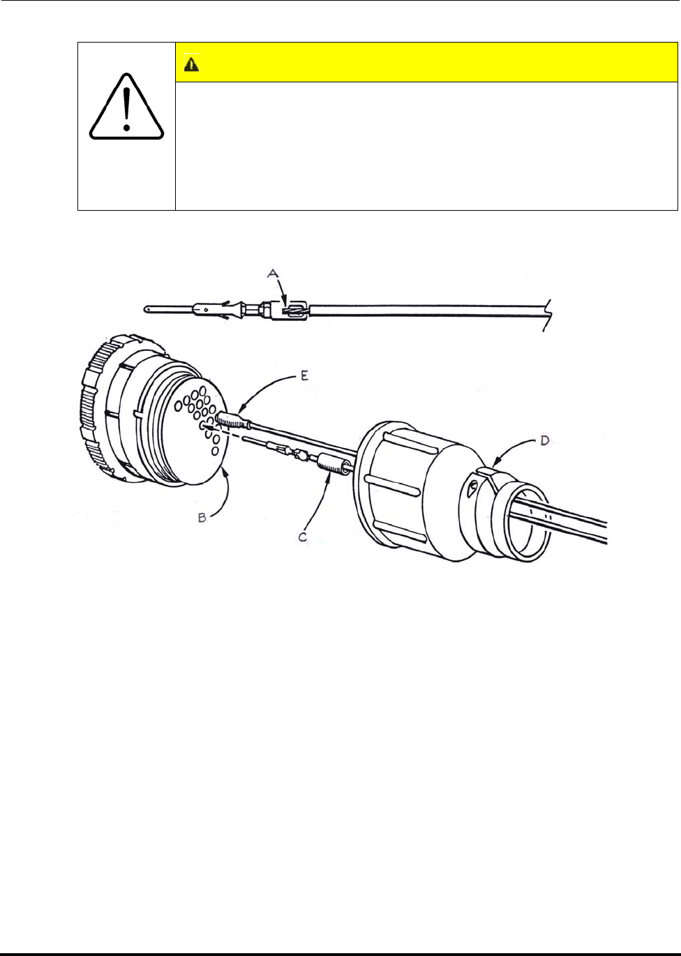
Polycold Fast Cycle Water Vapor Cryopump Installation
Customer Instruction Manual How to Install the Remote Control (Optional)
Brooks Automation 825064-00
Revision 09 3-81
Figure 3-28: Remote Connector Assembly
A. Wire soldered to pin
B. Wire side of connector
C. Heat shrinkable insulating tube
D. Cable clamp
E. Pin inserted with insulating tube shrunk in place
CAUTION
GENERAL HAZARD
Make sure the wiring configuration does not start the unit in
COOL or DEFROST; damage to the equipment can result.
The three-position switch should be in the neutral position so that
the unit will start in STANDBY. (When REMOTE is selected local
functions will be disabled.)
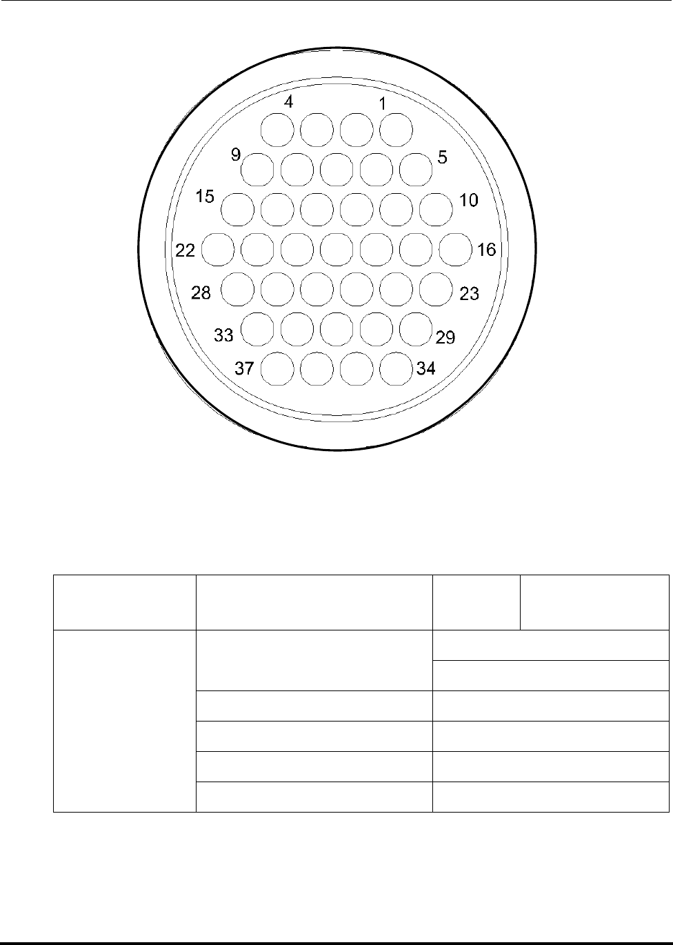
Installation Polycold Fast Cycle Water Vapor Cryopump
How to Install the Remote Control (Optional) Customer Instruction Manual
825064-00 Brooks Automation
3-82 Revision 09
Figure 3-29: Wire Side of Remote Connector Plug
Table 3-10: Remote Connector Wiring Worksheet
Group Wire Function Pin
Number Customer’s Wire
Color
System Control
Operate Unit 1
2
Indicate Unit OK 3
Indicate Power 4
Common 5
Ground 6

Polycold Fast Cycle Water Vapor Cryopump Installation
Customer Instruction Manual How to Install the Remote Control (Optional)
Brooks Automation 825064-00
Revision 09 3-83
3.8.1.4 Program the Remote Control if a Controller is Present
(See section 4 Operation.)
Refrigerant
Circuit 1 (PFC)
Indicate REMOTE 10
Operate COOL 11
Operate DEFROST 12
Indicate DEFROST COM-
PLETE 13
Indicate DEFROST ACTIVE 14
Refrigerant
Circuit 2 (PFC or
P)
Indicate REMOTE 18
Operate COOL 19
Operate DEFROST
(PFC only) 20
Indicate DEFROST COM-
PLETE (PFC only) 21
Indicate DEFROST ACTIVE
(PFC only) 22
Option Indicate Setpoint Relay A 26
27
Temperature
Meter 1
Analog #1 - Out 28
Analog #1 - Return 29
Analog #1 - Shield 30
Option Indicate Setpoint Relay B 31
32
Option—
Temperature
Meter 2
Analog #2 - Out 33
Analog #2 - Return 34
Analog #2 - Shield 35
Table 3-10: Remote Connector Wiring Worksheet
Group Wire Function Pin
Number Customer’s Wire
Color

Installation Polycold Fast Cycle Water Vapor Cryopump
How to Install the Remote Control (Optional) Customer Instruction Manual
825064-00 Brooks Automation
3-84 Revision 09
3.8.1.5 If a remote ON / OFF Switch has been Installed, Unplug Jumper J11 from
the SYSTEM CONTROL Printed Circuit Board
1. Loosen the two lower screws on the side of the low voltage box. Slide the panel
straight up to remove it. (See Figure 3-30 Low voltage box panel removal and
Figure 3-31 Jumper J11 Location.)
2. Locate JMPR J11 on the SYSTEM CONTROL printed circuit board in the low
voltage box. Squeeze the jumper’s latch to unplug it.
3. Reinstall the low voltage box panel. Slide it straight down onto the low voltage
box so that the two tabs go into their notches. Push the top of the panel
towards the unit and at the same time push down so that the top tab goes into
its notch. Tighten the two screws.
3.8.1.6 Connect the Remote Plug to the Unit’s Remote Receptacle and Select
REMOTE
NOTE: Loosen the two lower screws on the side of the low voltage box. Slide the panel
straight up to remove it.
NOTE: When a refrigerant circuit is in LOCAL, its remote functions are disabled (includ-
ing the unit’s ON /OFF switch).
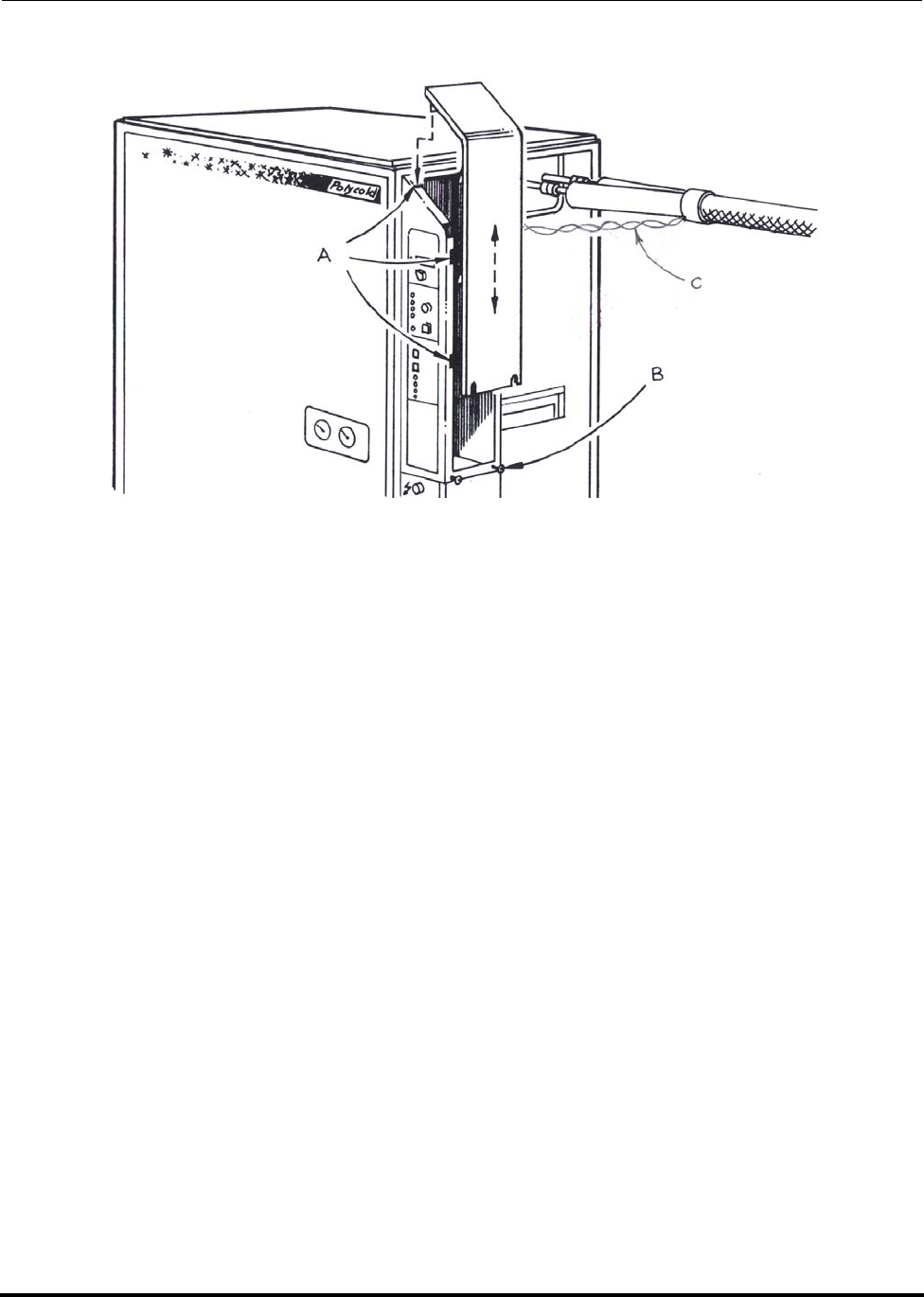
Polycold Fast Cycle Water Vapor Cryopump Installation
Customer Instruction Manual How to Install the Remote Control (Optional)
Brooks Automation 825064-00
Revision 09 3-85
Figure 3-30: Low Voltage Box Panel Removal
A. Notches
B. Loosen screws
C. Thermocouple wires
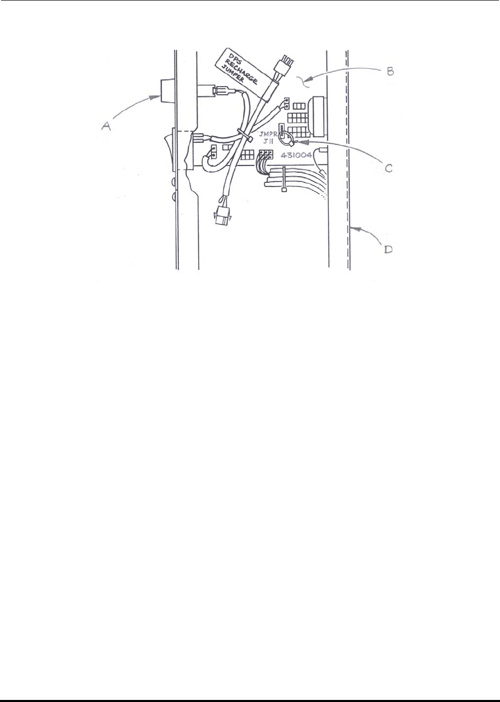
Installation Polycold Fast Cycle Water Vapor Cryopump
How to Install the Remote Control (Optional) Customer Instruction Manual
825064-00 Brooks Automation
3-86 Revision 09
Figure 3-31: Jumper J11 location
NOTE: DPS = Dual Pressure Switch
A. Reset button
B. System control printed circuit board
C. Jumper J11
D. Low voltage box with panel removed
3.8.1.7 Ensure that the Remote Control Operates the Unit Properly
Use the remote control to do the following test:
1. Select STANDBY and turn on the refrigeration unit. The unit’s compressor
should be running. The unit’s STANDBY indicator lamp should be lighted. The
COLDEST LIQUID (TC #9) temperature should start getting colder. Wait 30
minutes.
2. Evacuate location of the cryosurface to at least 0.01 torr (1.33 Pa).
Polycold Fast Cycle Water Vapor Cryopump Installation
Customer Instruction Manual How to Install the Remote Control (Optional)
Brooks Automation 825064-00
Revision 09 3-87
3. Switch to COOL.
• The unit’s COOL indicator lamp should be lighted.
• The COIL OUT (TC #4) temperature should start getting colder.
4. Switch to DEFROST.
• The unit’s DEFROST ACTIVE indicator lamp should be lighted.
• When DEFROST is complete, the unit’s DEFROST COMPLETE and
STANDBY indicator lamps should be lighted.
5. Open your vacuum chamber. The cryosurface should be dry and at room tem-
perature or warmer.
NOTE: For PFC/PFC: Also test the second refrigerant circuit (#2 COIL OUT temperature
= TC #6).
NOTE: For PFC/P: For the second refrigerant circuit, select COOL with your remote con-
trol. The #2 COIL OUT (TC #6) temperature should start getting colder.
3.8.2 Additional Instructions for Remote Temperature Indication
3.8.2.1 About the Thermocouples
DISCHARGE LINE (TC #1):
The thermocouple is located in the refrigeration unit’s compressor compartment. It is
on the compressor discharge line near the compressor. It can be used to monitor com-
pressor performance.
LIQUID LINE (TC #2):
The thermocouple is located in the refrigeration unit’s compressor compartment. It is
on the refrigerant circuit near the exit of the condenser. It can be used to monitor the
effectiveness of the system’s cooling water.
CAUTION
EXTREME TEMPERATURES EXIST
Parts of the cryosurface may be hot; contact with the hot surface
may result in minor or moderate injury.
Do not touch the cryosurface.

Installation Polycold Fast Cycle Water Vapor Cryopump
How to Install the Remote Control (Optional) Customer Instruction Manual
825064-00 Brooks Automation
3-88 Revision 09
#1 COIL IN (TC #3):
The thermocouple is located on the feed line near the cryosurface. It can be used for
troubleshooting if cryopumping is inadequate.
#1 COIL OUT (TC #4):
The thermocouple is located on the return line near the cryosurface. It can be used to
monitor the warmest cryosurface temperature.
#1 FEED (TC #7):
The thermocouple is in the refrigeration unit’s foamed compartment. It is on the
refrigerant circuit near the feed line. It can be used for troubleshooting if cryopump-
ing is inadequate.
#1 RETURN (TC #8):
The thermocouple is in the refrigeration unit’s foamed compartment. It is on the
refrigerant circuit near the return line. It can be used for troubleshooting if cry-
opumping is inadequate.
3.8.3 COLDEST LIQUID (TC #9):
The thermocouple is in the refrigeration unit’s foamed compartment. It is on the final
strainer in the “Polycold stack”. It can be used to determine when to switch from
STANDBY to COOL.
NOTE: For PFC/PFC or PFC/P—additional thermocouples for the second refrigerant cir-
cuit:
#2 COIL IN (TC #5): See #1 COIL IN
#2 COIL OUT (TC #6): See #1 COIL OUT
#2 FEED (tied back): See #1 FEED
#2 RETURN (TC #10): See #1 RETURN
NOTE: The COIL IN, COIL OUT, FEED and RETURN thermocouples only provide
meaningful information when refrigerant is flowing through the cryosurface (i.e.,
when the unit is in COOL or DEFROST).

Polycold Fast Cycle Water Vapor Cryopump Installation
Customer Instruction Manual How to Install the Remote Control (Optional)
Brooks Automation 825064-00
Revision 09 3-89
3.8.3.1 About the Temperature Meter
The display range is –199.9 to +199.9°C and has an accuracy of ±3°C. The temperature
meter accepts a type T (copper-constantan) thermocouple input and is powered by
the unit’s 24 V(ac) control transformer.
The temperature meter provides an analog output from –1.999 to +1.999 V(dc). The
output is 0 V(dc) for 0°C. It provides positive voltage for positive temperatures and
negative voltage for negative temperatures at a rate of 10 mV/°C.
3.8.3.2 Using the Analog Output
The output is taken directly from the analog stages immediately preceding the ana-
log-to-digital conversion for the meter’s display. This circuit is sensitive to currents
introduced into the output from external noise sources and ground loop situations.
Therefore, the following precautions must be observed.
• The connecting cable must be less than 100 feet (30.5 m).
• The connecting cable must be shielded with only one end of the shield con-
nected to ground. This grounding is done at the refrigeration unit. Use the
designated pins in the remote connector for cable shield connections.
• The shielded connecting cable must be separate from the remote cable bundle.
However, it may be routed next to the remote cable bundle.
•Do not ground either side of the analog output of the meter. The external
device must have a differential input to isolate the connections.

Installation Polycold Fast Cycle Water Vapor Cryopump
How to Install the Remote Control (Optional) Customer Instruction Manual
825064-00 Brooks Automation
3-90 Revision 09
This Page Intentionally Left Blank

Polycold Fast Cycle Water Vapor Cryopump
Customer Instruction Manual
Brooks Automation 825064-00
Revision 09 4-1
4 Operation
Overview
This chapter provides complete operation directions for the Brooks Automation Prod-
uct.
Chapter Contents
4.1 What the Cryopump Does in STANDBY, COOL, and DEFROST . . . . . . . . . .4-2
4.1.1 Special notes for PFC/PFC or PFC/P . . . . . . . . . . . . . . . . . . . . . . . . . .4-2
4.2 How to Use the Cryopump . . . . . . . . . . . . . . . . . . . . . . . . . . . . . . . . . . . . . . . . . .4-4
4.2.1 If the Cryosurface is a Coil. . . . . . . . . . . . . . . . . . . . . . . . . . . . . . . . . . . .4-4
4.2.2 If the Cryosurface is a Baffle . . . . . . . . . . . . . . . . . . . . . . . . . . . . . . . . . .4-5

Operation Polycold Fast Cycle Water Vapor Cryopump
What the Cryopump Does in STANDBY, COOL, and DEFROST Customer Instruction
825064-00 Brooks Automation
4-2 Revision 09
4.1 What the Cryopump Does in STANDBY, COOL, and DEFROST
The cryopump operates in three different modes: STANDBY, COOL, and DEFROST.
What the cryopump does in STANDBY
When the unit is in STANDBY, the COOL and DEFROST solenoid valves are closed.
The unit circulates (and cools) the mixture of refrigerants in the “Polycold stack.” The
refrigerant is coldest when the unit is operating in this mode because it has the least
heat load.
What the cryopump does in COOL
When the unit is in COOL, the COOL solenoid valve is open and the DEFROST sole-
noid valve is closed. Cold refrigerant is pumped into the feed line. The cold refriger-
ant cools the cryosurface and comes back through the return line. The refrigerant then
goes through the “Polycold stack” to the suction side of the compressor.
What the cryopump does in DEFROST
When the unit is in DEFROST, the COOL solenoid valve is closed and the DEFROST
solenoid valve is open. Hot refrigerant is pumped from the “Polycold stack” into the
feed line. The hot refrigerant warms the cryosurface and comes back through the
return line. The unit will automatically switch to STANDBY when the cryosurface is
defrosted.
4.1.1 Special notes for PFC/PFC or PFC/P
The PFC/PFC and PFC/P function in the same way as the PFC. However, the refrig-
erant is split into two separate feed and return lines so that it services two cryosur-
faces. Also, the second circuit of a PFC/P cannot be defrosted rapidly. (It does not
have a DEFROST mode.)
When one circuit is defrosted while the other circuit is in cool, the circuit in cool will
warm up by up to 20°C. Therefore, the timing of defrost must be coordinated so as to
maintain your process requirements. If the second circuit is a baffle for a diffusion
pump, this is normally not a problem. However, when both circuits cool cryocoils,
you must evaluate the impact on your process when you defrost one circuit while the
other circuit is in cool during your deposition process.
If the refrigerant circuits are operated in different modes, the following will happen.

Polycold Fast Cycle Water Vapor Cryopump Operation
Customer Instruction Manual What the Cryopump Does in STANDBY, COOL, and DE-
Brooks Automation 825064-00
Revision 09 4-3
STANDBY versus COOL
The cryosurface being cooled will get several degrees colder than when both
cryosurfaces are cooled simultaneously. This is because there is less total heat
load on the system. It is not possible, however, to get 100% of the cooling
capacity into one circuit simply by not using the other circuit.
DEFROST versus COOL
The cryosurface being cooled will warm up by up to 20° C while the other cry-
osurface is defrosted. This is because refrigerant from both cryosurfaces is
combined in the common return line. Contact the Polycold service department
for an evaluation if this warm up will cause a problem.
DEFROST versus STANDBY (PFC/PFC only).
The cryosurface being defrosted will defrost slightly faster than when both cry-
osurfaces are defrosted simultaneously.

Operation Polycold Fast Cycle Water Vapor Cryopump
How to Use the Cryopump Customer Instruction Manual
825064-00 Brooks Automation
4-4 Revision 09
4.2 How to Use the Cryopump
4.2.1 If the Cryosurface is a Coil
Select STANDBY to precool the unit.
When the refrigeration unit is in STANDBY, it cools the refrigerant mixture and
“Polycold stack.” Complete precooling may take 60 minutes if the unit was off for
more than 12 hours.
The COLDEST LIQUID (TC #9) temperature may be used to monitor the internal tem-
perature of the unit. For quick cooling when switching to COOL, this temperature
should be 5-10°C colder than your desired cryocoil temperature. See Table 3-8.
NOTE: The unit may be operated indefinitely in STANDBY.
Select COOL to capture water on the cryocoil.
Once the unit is precooled, the unit may be switched to COOL any time after the vac-
uum chamber is under vacuum. Most users switch to COOL at crossover (when
opening the high vacuum valve). The cryocoil will start capturing water within 60
seconds.
Experimentation can be done with the cryopump to determine the shortest pump-
down time for a particular application. The sooner the unit is switched to COOL, the
faster the vacuum chamber’s pumpdown time. However, if the cryocoil captures too
much water, the cryocoil’s apparent surface temperature will rise and limit the ulti-
mate attainable base pressure.
Select DEFROST to remove the captured water from the cryocoil.
DEFROST allows the “regeneration” of a cryocoil in preparation for the next vacuum
cycle. Start DEFROST so that the cryocoil is warm before the vacuum chamber
reaches atmospheric pressure. A typical DEFROST takes 4 minutes or less. The unit
will terminate DEFROST when the return temperature of the refrigerant reaches 20°C.
This assures that no additional moisture will condense on the cryocoil from the atmo-
sphere.
The unit will automatically go into STANDBY when DEFROST is complete. Allow
the unit to remain in STANDBY for at least 5 minutes before selecting COOL.
NOTE: To shorten the DEFROST cycle, terminate DEFROST early by putting the unit in
STANDBY.
Polycold Fast Cycle Water Vapor Cryopump Operation
Customer Instruction Manual How to Use the Cryopump
Brooks Automation 825064-00
Revision 09 4-5
4.2.2 If the Cryosurface is a Baffle
To cool the cryobaffle
1. Evacuate the location of the cryobaffle to at least 0.01 torr (1.33 Pa).
2. Turn on the refrigeration unit and select COOL. A typical cryobaffle may take
more than 60 minutes to cool down.
3. Turn on the high vacuum pump. It is not necessary to wait until the cryobaffle
has cooled down.
To defrost the cryobaffle
If the cryobaffle captures too much water, the cryobaffle’s apparent surface tempera-
ture will rise and limit the ultimate attainable base pressure. Regular defrosting is
suggested to “regenerate” the cryobaffle. Complete defrosting can take 8 hours or
more depending upon the amount of moisture captured, the mass of the cold surface,
and the vacuum level.
CAUTION
GENERAL HAZARD
If large amounts of water are collected during the vacuum cycle,
liquid or ice may drop from the cryocoil during DEFROST. This
could cause minor or moderate injury.
You may need to provide a drip pan or similar device to prevent
liquid water from accumulating in an undesirable location.
CAUTION
GENERAL HAZARD
For PFC/PFC and PFC/P users:
Be aware that when defrosting one circuit while the other circuit is in
cool, the temperature of the coil being cooled will increase by up to 20°
C. Review the required temperatures for the affected process to make
sure this warming will not affect your process. If such a temperature is
not acceptable, wait until the completion of this process before per-
forming defrost. Both circuits may be defrosted at once.

Operation Polycold Fast Cycle Water Vapor Cryopump
How to Use the Cryopump Customer Instruction Manual
825064-00 Brooks Automation
4-6 Revision 09
1. Turn off your high vacuum pump.
2. Turn off the refrigeration unit or select STANDBY.
NOTE: Backstreaming will contaminate the system because it is the process of hot vapor
migrating and condensing on cold surfaces. When the vacuum pump is used, the
pump oil heats up and travels opposite of the pumping direction and condenses the
system resulting in system contamination.
CAUTION
GENERAL HAZARD
Selecting DEFROST when the cryobaffle is being used to prevent back-
streaming can damage the equipment.
Do not select DEFROST if the cryobaffle is being used to prevent back-
streaming.

Polycold Fast Cycle Water Vapor Cryopump
Customer Instruction Manual
Brooks Automation 825064-00
Revision 09 5-1
5 Periodic Inspection and Maintenance
Overview
This chapter provides maintenance schedules and procedures for the Brooks Automa-
tion Product.
Chapter Contents
5.1 Record Temperatures and Pressures Every Month . . . . . . . . . . . . . . . . . . . . . .5-2
5.2 Check the Cryopump Every Six Months . . . . . . . . . . . . . . . . . . . . . . . . . . . . . . .5-4

Periodic Inspection and Maintenance Polycold Fast Cycle Water Vapor Cryopump
Record Temperatures and Pressures Every Month Customer Instruction Manual
825064-00 Brooks Automation
5-2 Revision 09
5.1 Record Temperatures and Pressures Every Month
Record all measurements in Table 5-1. If all measurements are not within specifica-
tion, see section 7 Troubleshooting and Repair.
In STANDBY
Select LOCAL and STANDBY. Turn on the unit and wait 30 minutes. Record the
SUCTION & DISCHARGE pressures, the DISCHARGE LINE (TC #1) temperature,
and the LIQUID LINE (TC #2) temperature.
NOTE: For PFC/PFC or PFC/P: Select LOCAL and STANDBY for both refrigerant cir-
cuits.
In COOL
Evacuate the location of your cryosurface to at least 0.01 torr (1.33 Pa). Select COOL
and wait 30 minutes. Record the COIL IN (TC #3) and COIL OUT (TC #4) tempera-
tures.
NOTE: For PFC/PFC or PFC/P: Select COOL for both refrigerant circuits. Also record the
#2 COIL IN (TC #5) and #2 COIL OUT (TC #6) temperatures.
Check the outlet temperature of the cooling water. The drain line (OUT) should be
72–95°F (22–35°C). If not, adjust the water flow to attain a water outlet temperature in
this range.

Polycold Fast Cycle Water Vapor Cryopump Periodic Inspection and Maintenance
Customer Instruction Manual Record Temperatures and Pressures Every Month
Brooks Automation 825064-00
Revision 09 5-3
Table 5-1: Inspection Log
Refrigeration Unit’s Serial Number:
________________________________ Baseline
Reference
Acceptable Variance
From the Baseline
Reference Inspections
Date
After 30
Minures
STANDBY
SUCTION psig1, bar1Can vary ±5 psig (±0.34 bar) if
it remains between 3 - 30 psig
(0.2 - 2.1 bar).
DISCHARGE psig1, bar1Can vary ±10%.
DISCHARDE LINE (TC
#1) °C1Can vary ±10%, if it remains
125°C.
LIQUID LINE (TC #2) °C1Can vary ±10%, if it is within
15°C - 33°C.
After 30
Minures
COOL
#1 COIL IN (TC #3)
#2 COIL IN (TC #5) °C Remains stable (depend-
ing on load). See Table
3-8.
#1 COIL OUT (TC #4)
#2 COIL OUT (TC #6) °C
End of
COOL cycle
Additional noise? No None
Ice or water on refriger-
ant line? No None
Off 12 hours Water in valve boxes? No None
Off 48 hours Balance pressure psig2, bar2Can drop 15 psig (1 bar).
NOTE: 1See section 3.4.4 Evaluate the Cryopump.
2See section 3.4.1 Open the Isolation Valves.
Record your baseline reference measurements and make copies of this sheet. If, in the future, you recharge (or
“top off”) your cryopump, you will need to establish a new baseline reference.
≥

Periodic Inspection and Maintenance Polycold Fast Cycle Water Vapor Cryopump
Check the Cryopump Every Six Months Customer Instruction Manual
825064-00 Brooks Automation
5-4 Revision 09
5.2 Check the Cryopump Every Six Months
Record all measurements in Table 5-1. If all measurements are not within specifica-
tion, see section 7 Troubleshooting and Repair.
Noise Level or New Type of Sound
Listen to the unit. Locate the source of any new noise. If the noise is caused by a tube
vibrating against something, move the tube slightly to avoid unnecessary wear.
If the noise is in the compressor, check the compressor oil level—see section 3.4.4
Evaluate the Cryopump. Contact a local sales representative or the Polycold service
department for advice.
Refrigerant Line
Near the end of a typical COOL cycle, check the refrigerant line for ice or water. If
there is ice or water, remove it. Apply another layer of insulation following the
instructions in section 3.4.3 Insulate the Exposed Tubes and Couplings.
Valve Boxes
Turn off the unit and wait 12 hours. Remove the top panel of the unit. Unscrew the
lids to the valve boxes. If there is water in the valve boxes, remove the water.
Make certain each gasket is in its groove. Screw the valve box lids completely shut.
The gaskets should form a seal to keep out water vapor.
Reinstall the top panel of the unit.
Balance Pressure
Wait until the unit is off for 48 hours. Locate the compressor’s pressure gauges on the
front of the unit. Record the pressure of the discharge gauge. If the pressure has
dropped more than 15 psig, the cryopump may have a leak.
WARNING
GENERAL HAZARD
Failure to have a qualified refrigeration technician do all refriger-
ation work could result in death or serious injury.
Contact a qualified refrigeration technician if the cryopump needs
to be repaired.

Polycold Fast Cycle Water Vapor Cryopump Periodic Inspection and Maintenance
Customer Instruction Manual Check the Cryopump Every Six Months
Brooks Automation 825064-00
Revision 09 5-5

Periodic Inspection and Maintenance Polycold Fast Cycle Water Vapor Cryopump
Customer Instruction Manual
825064-00 Brooks Automation
5-6 Revision 09
This Page Intentionally Left Blank

Polycold Fast Cycle Water Vapor Cryopump
Customer Instruction Manual
Brooks Automation 825064-00
Revision 09 6-1
6 Model History
Overview
This chapter provides the configurations and the manufacturing history of specifc
Brooks Automation Product models.
Chapter Contents
6.1 Review of Configurations. . . . . . . . . . . . . . . . . . . . . . . . . . . . . . . . . . . . . . . . . . . .6-2
6.1.1 PFC 1101. . . . . . . . . . . . . . . . . . . . . . . . . . . . . . . . . . . . . . . . . . . . . . . . . . .6-2
6.1.2 PFC 1102. . . . . . . . . . . . . . . . . . . . . . . . . . . . . . . . . . . . . . . . . . . . . . . . . . .6-2
6.1.3 PFC 661. . . . . . . . . . . . . . . . . . . . . . . . . . . . . . . . . . . . . . . . . . . . . . . . . . . .6-4
6.1.4 PFC 662 and 672 . . . . . . . . . . . . . . . . . . . . . . . . . . . . . . . . . . . . . . . . . . . .6-4
6.1.5 PFC 670. . . . . . . . . . . . . . . . . . . . . . . . . . . . . . . . . . . . . . . . . . . . . . . . . . . .6-5
6.1.6 PFC 551. . . . . . . . . . . . . . . . . . . . . . . . . . . . . . . . . . . . . . . . . . . . . . . . . . . .6-5
6.1.7 PFC 552. . . . . . . . . . . . . . . . . . . . . . . . . . . . . . . . . . . . . . . . . . . . . . . . . . . .6-5
6.2 Revision Histories . . . . . . . . . . . . . . . . . . . . . . . . . . . . . . . . . . . . . . . . . . . . . . . . . .6-7
6.2.1 PFC-550 HC . . . . . . . . . . . . . . . . . . . . . . . . . . . . . . . . . . . . . . . . . . . . . . . .6-7
6.2.2 PFC-550 LT. . . . . . . . . . . . . . . . . . . . . . . . . . . . . . . . . . . . . . . . . . . . . . . . .6-7
6.2.3 PFC-660 HC . . . . . . . . . . . . . . . . . . . . . . . . . . . . . . . . . . . . . . . . . . . . . . . .6-7
6.2.4 PFC-670 HC . . . . . . . . . . . . . . . . . . . . . . . . . . . . . . . . . . . . . . . . . . . . . . . .6-7
6.2.5 PFC-1100 HC . . . . . . . . . . . . . . . . . . . . . . . . . . . . . . . . . . . . . . . . . . . . . . .6-7
6.2.6 PFC-1100 LT. . . . . . . . . . . . . . . . . . . . . . . . . . . . . . . . . . . . . . . . . . . . . . . .6-7
6.2.7 PFC-552 HC . . . . . . . . . . . . . . . . . . . . . . . . . . . . . . . . . . . . . . . . . . . . . . . .6-7
6.2.8 PFC-662 HC . . . . . . . . . . . . . . . . . . . . . . . . . . . . . . . . . . . . . . . . . . . . . . . .6-8
6.2.9 PFC-672 HC . . . . . . . . . . . . . . . . . . . . . . . . . . . . . . . . . . . . . . . . . . . . . . . .6-8
6.2.10 PFC-1102 HC . . . . . . . . . . . . . . . . . . . . . . . . . . . . . . . . . . . . . . . . . . . . . .6-8

Model History Polycold Fast Cycle Water Vapor Cryopump
Review of Configurations Customer Instruction Manual
825064-00 Brooks Automation
6-2 Revision 09
6.1 Review of Configurations
Various configurations have been developed to comply with evolving legislation con-
cerning refrigerants. The hardware, electrical, and refrigerant changes for each new
configuration are reviewed briefly in this section.
6.1.1 PFC 1101
The PFC 1101 differs from the PFC 1100 as follows: The PFC 1101 utilizes new oil sep-
arators, a new pressure switch arrangement, and a new pressure fault Printed Circuit
Board (PCB). Refer to troubleshooting section for pressure switch arrangement
details. The pressure switch PCB is shown in Figure 6-2. The PFC 1101 uses a differ-
ent HCFC blend than used in the PFC 1100. The P&ID and Electrical Schematics for
the PFC 1101 are available in document 825118-00.
6.1.2 PFC 1102
The PFC 1102 differs from the PFC 1101 as follows: In addition to the oil separators,
pressure switch arrangement, and pressure fault PCB introduced on the PFC 1101, the
PFC 1102 had a moisture indicator for manufacture dates through 2004. (See Figure
6-1.) Additionally, units manufactured after September of 2002, have a buffer
unloader feature. (See Figure 6-2.) The PFC 1102 uses an HCFC-Free refrigerant
blend. The Process and Instrumentation Diagram (P&ID) and Electrical Schematics
for the PFC 1102 are available in document 825119-00.
NOTE: The Buffer Unloader is a circuit that controls the buffer pressure switch which acti-
vates the buffer valve when excess discharge pressure develops. The discharged
pressure (gas) is removed from circulation and stored in the expansion tank.
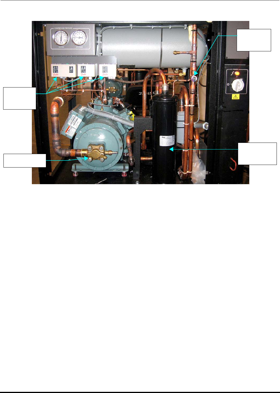
Polycold Fast Cycle Water Vapor Cryopump Model History
Customer Instruction Manual Review of Configurations
Brooks Automation 825064-00
Revision 09 6-3
Figure 6-1: PFC Model 1102 Hardware
NOTE: Read individual model sections to determine if electrical features shown below
apply to a particular model.
Pressure
Switches
Moisture
Indicator
Compressor
Oil
Separato
r
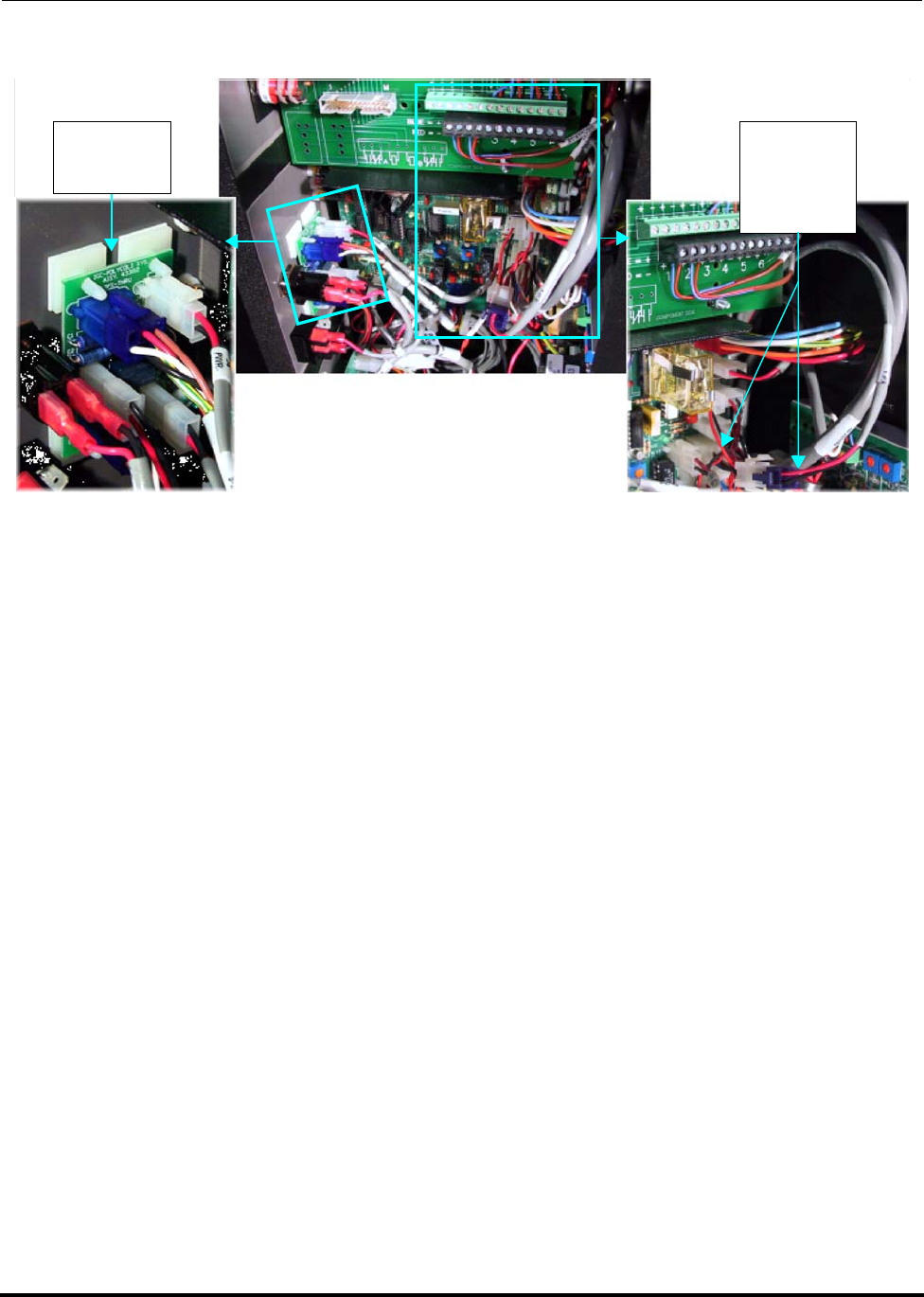
Model History Polycold Fast Cycle Water Vapor Cryopump
Review of Configurations Customer Instruction Manual
825064-00 Brooks Automation
6-4 Revision 09
Figure 6-2: Electrical Changes to PFC Models with CE Mark
6.1.3 PFC 661
The PFC 661 differs from the PFC 660 as follows: The PFC 661 utilizes new oil sepa-
rators, a new pressure switch arrangement, and a new pressure fault PCB. Refer to
the troubleshooting section for pressure switch arrangement details. (The pressure
switch PCB is shown in Figure 6-2.) The PFC 661 uses a different HCFC blend than
used in the PFC 660. The P&ID and Electrical Schematics for the PFC 661 are available
in document 825115-00.
6.1.4 PFC 662 and 672
The PFC 662 and 672 differ from the PFC 661 as follows. In addition to the oil separa-
tors, pressure switch arrangement, and pressure fault PCB introduced on the PFC 661,
the PFC 662 and 672 were equipped with moisture indicators for manufacture dates
through 2004. In addition, the 662 and 672 have Evaporator Pressure Regulating
Valves (EPR Valves), and use HCFC-Free refrigerant blends. (See Figure 6-3.) Units
manufactured after September of 2002, have a buffer unloader feature. (See Figure
6-2.) Additionally, the PFC 672 has a different compressor than the PFC 662. The
P&ID and Electrical Schematics for the PFC 662 & 672 are available in documents
825116-00 & 825117-00 respectively.
Pressure
Fault PCB
Buffer
Unloader
Cable
Interior Low Voltage Box
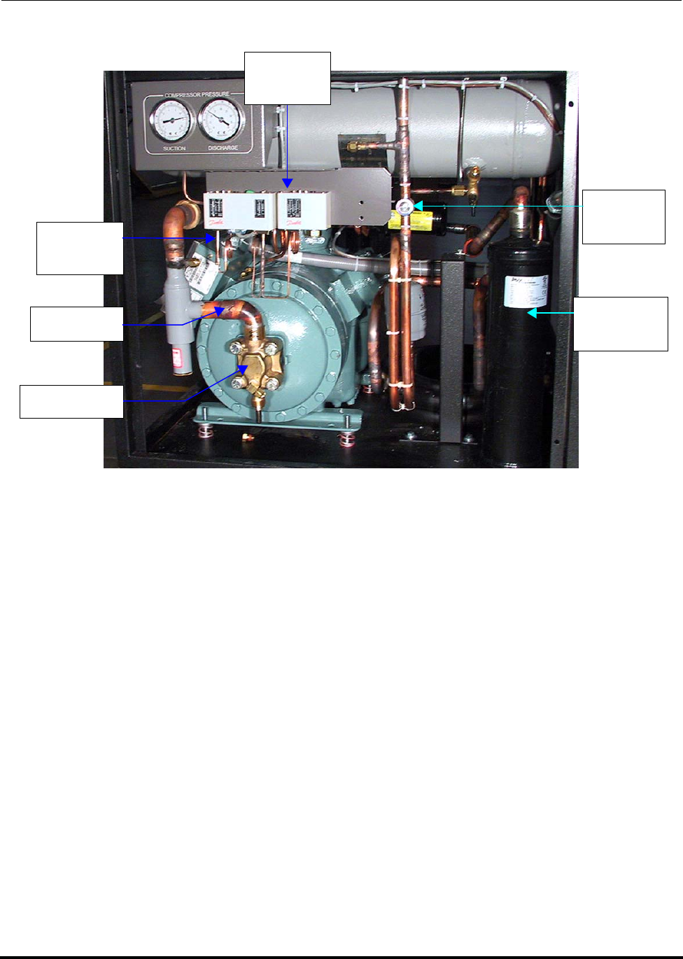
Polycold Fast Cycle Water Vapor Cryopump Model History
Customer Instruction Manual Review of Configurations
Brooks Automation 825064-00
Revision 09 6-5
Figure 6-3: PFC Model 672 Hardware
6.1.5 PFC 670
The PFC 670 differs from the PFC 660 as follows: It utilizes a different compressor
model.
6.1.6 PFC 551
The PFC 551 differs from the PFC 550 as follows: The PFC 551 utilizes new oil sepa-
rators, a new pressure switch arrangement, and a new pressure fault PCB. (See Figure
6-2.) Refer to the troubleshooting section for pressure switch arrangement details.
The PFC 551 uses a different HCFC blend than used in the PFC 550. The P&ID and
Electrical Schematics for the PFC 551 are available in document 825113-00.
6.1.7 PFC 552
The PFC 552 differs from the PFC 551 as follows: In addition to the oil separators,
pressure switch arrangement, and pressure fault PCB introduced on the PFC 551, the
PFC 552 had a moisture indicator for manufacture dates through 2004. In addition, the
Pressure
Switches
Moisture
Indicator
Compressor
Oil
Separator
EPR Valve
Comp.
Inlet Line
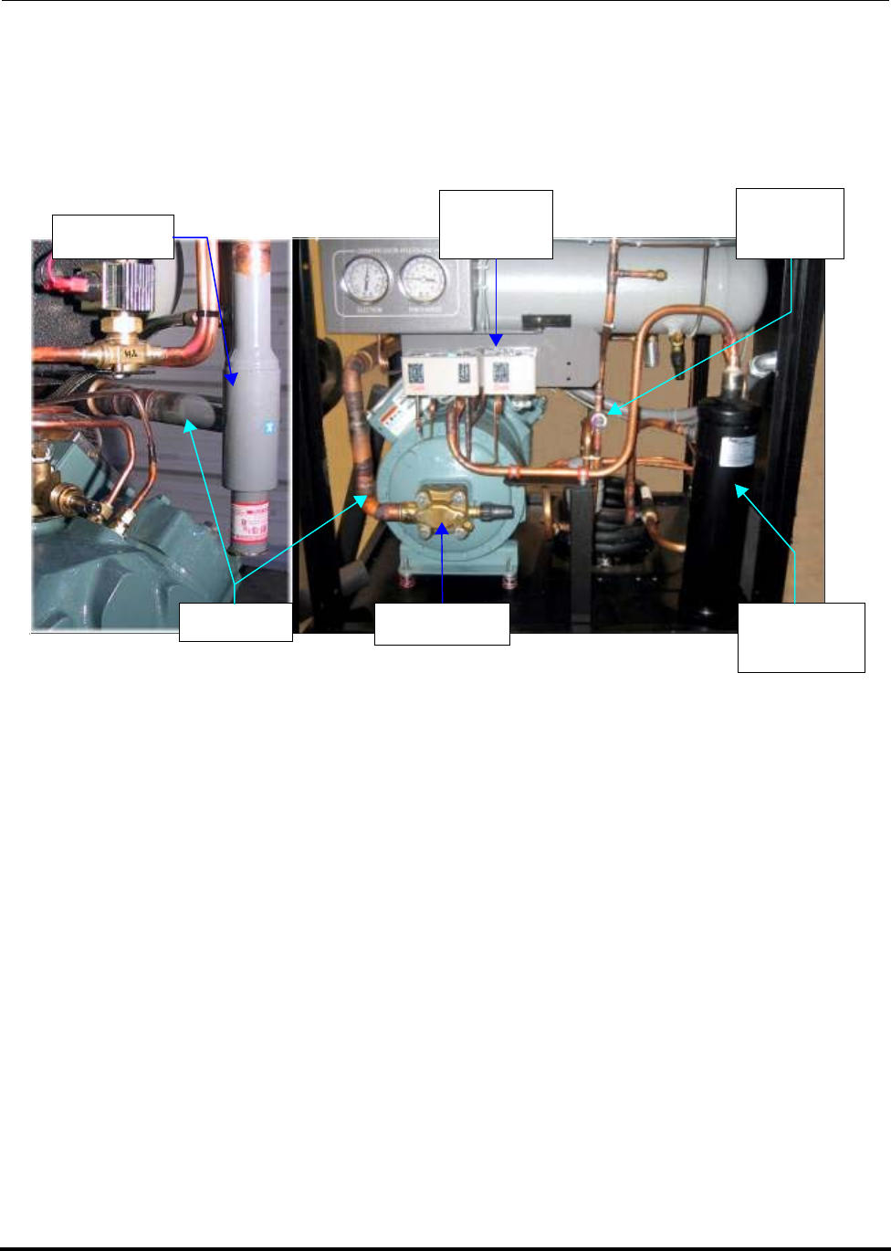
Model History Polycold Fast Cycle Water Vapor Cryopump
Review of Configurations Customer Instruction Manual
825064-00 Brooks Automation
6-6 Revision 09
552 has an Evaporator Pressure Regulating Valve (EPR Valve), and uses an HCFC-
Free refrigerant blend. (See Figure 6-4.) Also, units manufactured after September of
2002, have a buffer unloader feature. (See Figure 6-2.) The P&ID and Electrical Sche-
matics for the PFC 552 are available in document 825114-00.
Figure 6-4: PFC Model 552 Hardware
NOTE: The PFC 552s EPR Valve is located on the compressor inlet line near the rear of the
compressor.
Pressure
Switches
Moisture
Indicator
Compressor
Oil
Separator
EPR Valve
Inlet Line

Polycold Fast Cycle Water Vapor Cryopump Model History
Customer Instruction Manual Revision Histories
Brooks Automation 825064-00
Revision 09 6-7
6.2 Revision Histories
6.2.1 PFC-550 HC
2004: In the Fall of 2004, the pressure switch setting was changed to 400 psi (2760 kPa)
from 375 psi (2590 kPa).
6.2.2 PFC-550 LT
2004: In the Fall of 2004, the pressure switch setting was changed to 400 psi (2760 kPa)
from 375 psi (2590 kPa).
6.2.3 PFC-660 HC
2003: The model was discontinued as a result of a compressor change by the manufac-
turer.
6.2.4 PFC-670 HC
2003: PFC-670 HC replaces PFC-660 HC
2004: In the Fall of 2004, the pressure switch setting was changed to 400 psi (2760 kPa)
from 375 psi (2590 kPa).
6.2.5 PFC-1100 HC
2005: August: The two valve box design was replaced with a one valve box design.
6.2.6 PFC-1100 LT
2004: In the Fall of 2004, the pressure switch setting was changed to 400 psi (2760 kPa)
from 375 psi (2590 kPa).
2005: August: The two valve box design was replaced with a one valve box design.
6.2.7 PFC-552 HC
2001: PED compliant materials and processes were implemented.
2002: The buffer unloader was made standard on all 552s.
2003: The exhaust plumbing for the PRV and rupture discs was eliminated.

Model History Polycold Fast Cycle Water Vapor Cryopump
Revision Histories Customer Instruction Manual
825064-00 Brooks Automation
6-8 Revision 09
6.2.8 PFC-662 HC
2001: PED compliant materials and processes were implemented.
2002: The buffer unloader was made standard on all 662s. The model was discontin-
ued as a result of a compressor change by the manufacturer.
6.2.9 PFC-672 HC
2003: PFC-672 HC replaces the PFC-662 HC The exhaust plumbing for the PRV and
rupture discs was eliminated.
6.2.10 PFC-1102 HC
2001: PED compliant materials and processes were implemented.
2002: The buffer unloader was made standard on all 1102s.
2003: The exhaust plumbing for the PRV and rupture discs was eliminated.
2005: August: The two valve box design was replaced with a one valve box design.

Polycold Fast Cycle Water Vapor Cryopump
Customer Instruction Manual
Brooks Automation 825064-00
Revision 09 7-1
7 Troubleshooting and Repair
Overview
Only trained, qualified persons should attempt to troublehsoot the product. Brooks
Automation provides training in the troubleshooting and repair of the product.
Contents
7.1 If Unit Has A Leak. . . . . . . . . . . . . . . . . . . . . . . . . . . . . . . . . . . . . . . . . . . . . . . . . .7-2
7.2 If Unit Has Lost Performance. . . . . . . . . . . . . . . . . . . . . . . . . . . . . . . . . . . . . . . . .7-3
7.3 What to Do If the Cryopump Stops Running . . . . . . . . . . . . . . . . . . . . . . . . . . .7-5
7.3.1 Low (Suction) Pressure Lamp is Lighted . . . . . . . . . . . . . . . . . . . . . . .7-7
7.3.2 High (Discharge) Pressure Lamp is Lighted. . . . . . . . . . . . . . . . . . . . .7-9
7.3.3 High Discharge Temperature Lamp Is Lighted . . . . . . . . . . . . . . . . . .7-15
7.3.4 High Liquid (Line) Temperature Lamp is Lighted . . . . . . . . . . . . . . .7-17
7.3.5 “Unit OK” Lamp & Compressor Cycle Off & On . . . . . . . . . . . . . . . .7-19
7.3.6 System Control, Temperature Display, and High Voltage Box. . . . .7-20
7.3.7 SYSTEM CONTROL Printed Circuit Board Indicator Lamps . . . . . .7-23
7.4 What to Do If the Cryosurface is Not Cryopumping Adequately . . . . . . . . . .7-25
7.4.1 Check Coil Temperatures . . . . . . . . . . . . . . . . . . . . . . . . . . . . . . . . . . . .7-25
7.4.2 COIL IN Temperature OK, COIL OUT Temperature Not OK. . . . . .7-26
7.4.3 COIL IN and COIL OUT Temperatures are Not OK. . . . . . . . . . . . . .7-29
7.4.4 What to Do If the Cryosurface is Not Defrosting Adequately. . . . . .7-30
7.5 How to Calculate Voltage Unbalance. . . . . . . . . . . . . . . . . . . . . . . . . . . . . . . . . .7-33
Troubleshooting and Repair Polycold Fast Cycle Water Vapor Cryopump
If Unit Has A Leak Customer Instruction Manual
825064-00 Brooks Automation
7-2 Revision 09
7.1 If Unit Has A Leak
1. Locate the leak.
2. Determine why the leak occurred.
If you are authorized:
3. Do not remove the refrigerant until the unit has been off at least 24 hours.
4. Remove and recover the refrigerant charge using environmentally responsible
practices and in accordance with local regulations.
5. Repair the leak.
6. Leak check your work.
7. Evacuate the unit for at least 12 hours with heat lamps on the oil separator(s)
and filter drier to remove moisture. (Heat the filter drier to about 110°C maxi-
mum to avoid internal damage.)
8. Recharge using a genuine Polycold service replacement refrigerant charge
acquired from Brooks Automation Polycold Systems or an authorized service
representative. (See www.brooks.com for a complete list of authorized service
representatives.) Use of unauthorized refrigerants will void your warranty
and may damage your unit.
WARNING
If this is a repeat leak or if you are not trained, stop and contact the
factory or an authorized service representative to repair the leak.

Polycold Fast Cycle Water Vapor Cryopump Troubleshooting and Repair
Customer Instruction Manual If Unit Has Lost Performance
Brooks Automation 825064-00
Revision 09 7-3
7.2 If Unit Has Lost Performance
1. Check the balance pressure.
2. Check for a seeping buffer valve.
With the unit running under steady state operation for at least 60 minutes
locate the buffer valve line. Do you observe any frost on the line or valve? If
so you probably have a buffer valve that is not seating properly. Also, connect
a pressure gauge to the expansion tank. Its pressure should be no higher than
5 psi (0.3 bar) over the compressor suction pressure. If the pressure exceeds
this limit your buffer valve is not seating properly.
3. Perform a compressor pumpdown check.
With the unit running under steady state operation for at least 60 minutes in
standby, front seat the compressor suction valve. Observe the compressor suc-
tion gauge on the unit gauge panel. It should reach at least 10 inches mercury
(0.3 bar ) vacuum. Turn off the compressor. This pressure may rise slowly but
should stay in a vacuum state for at least one minute. If it does not, apply
more torque to the suction service valve to assure it has properly seated and
repeat the pumpdown test then turn off the compressor and check the suction
pressure rate of rise again. If the pressure continues to rise, check with the fac-
tory for additional guidance. A replacement of the compressor valve plate or a
replacement of the compressor may be required.
4. Check for a crimped line or cryocoil.
Check the refrigerant lines and the cryocoil to make sure none of the tubes are
dented or kinked.
5. Check for proper insulation.
Examine the refrigerant line. Make sure the line insulation is still intact. If vac-
uum jacketed lines are used, check for signs of frost on these lines. External
frost is an indication of a kinked line or a loss of the vacuum insulation.
6. Check the voltage at the cool solenoid valve.
Place the unit in the cool mode. Listen for a click to indicate activation of the
valve solenoid. Measure the voltage at the solenoid. It should be within the
limits identified in the electrical installation section.

Troubleshooting and Repair Polycold Fast Cycle Water Vapor Cryopump
If Unit Has Lost Performance Customer Instruction Manual
825064-00 Brooks Automation
7-4 Revision 09
7. Check that the cooling water has adequate flow and is at the correct tempera-
ture.
(Refer to section 3.2.5 Connect the Cooling Water.)
8. For 552 and 672 models only: If the thermocouple #9 is less than -155°C, adjust
the evaporator pressure regulating valve higher.
Operate the unit in standby for 60 minutes. Locate the EPR valve (see Model
History section for your specific model). Remove the large brass cap at the end
of the valve. Connect a test gauge to the service port on the EPR valve. Locate
the label on the EPR valve that shows the direction needed to increase pres-
sure. Using an appropriate size Allen key wrench, insert the long end of the
wrench into the valve and turn the wrench in the indicated direction to
increase pressure. Monitor the coldest liquid temperature (#9) and the test
gauge and the compressor suction. As the test gauge pressure increases the
coldest liquid temperature should increase. Continue to increase the EPR
valve pressure until the coldest liquid temperature is raised by 5 degrees C.
However, if the test gauge pressure increases by 5 psig without effect an on the
coldest liquid temperature stop. Turn off the compressor. Once the coldest liq-
uid temperature has warmed to -130 C or warmer turn the compressor. Once
the coldest liquid temperature reaches -150 C continue adjusting the EPR valve
to maintain this temperature.
9. Check for acid in the compressor oil. If the oil indicates the presence of acid
contact the factory for guidance on possible rework.
10. Check for signs of excessive oil in the cool valve.
To check for oil in the cool valve, remove the cool solenoid valve stem, open the
cool feed hand valve for 15 seconds and look for oil. If you do find signs of
excessive oil contact the factory.
11. If items 1 thru 10 have been checked and are within specification then remove
the refrigerant charge and evacuate the unit for at least 36 hours with heat
lamps on the oil separator(s) and filter drier to remove moisture. (Heat the fil-
ter drier to about 110°C maximum to avoid internal damage.)

Polycold Fast Cycle Water Vapor Cryopump Troubleshooting and Repair
Customer Instruction Manual What to Do If the Cryopump Stops Running
Brooks Automation 825064-00
Revision 09 7-5
7.3 What to Do If the Cryopump Stops Running
Use the unit’s indicator lamps to help find the problem. Note which lamps on the
refrigeration unit are lit. See Figure 7-1. Then find the appropriate troubleshooting
section below. See section 7.3.7 SYSTEM CONTROL Printed Circuit Board Indicator
Lamps.
•section 7.3.1 Low (Suction) Pressure Lamp is Lighted
•section 7.3.2 High (Discharge) Pressure Lamp is Lighted
•section 7.3.3 High Discharge Temperature Lamp Is Lighted
•section 7.3.4 High Liquid (Line) Temperature Lamp is Lighted
•section 7.3.5 “Unit OK” Lamp & Compressor Cycle Off & On
•section 7.3.6 System Control, Temperature Display, and High Voltage Box
•section 7.3.7 SYSTEM CONTROL Printed Circuit Board Indicator Lamps
Attention
After Investigating the cause of the fault and correcting the prob-
lem, the system must be reset in order to be restarted.
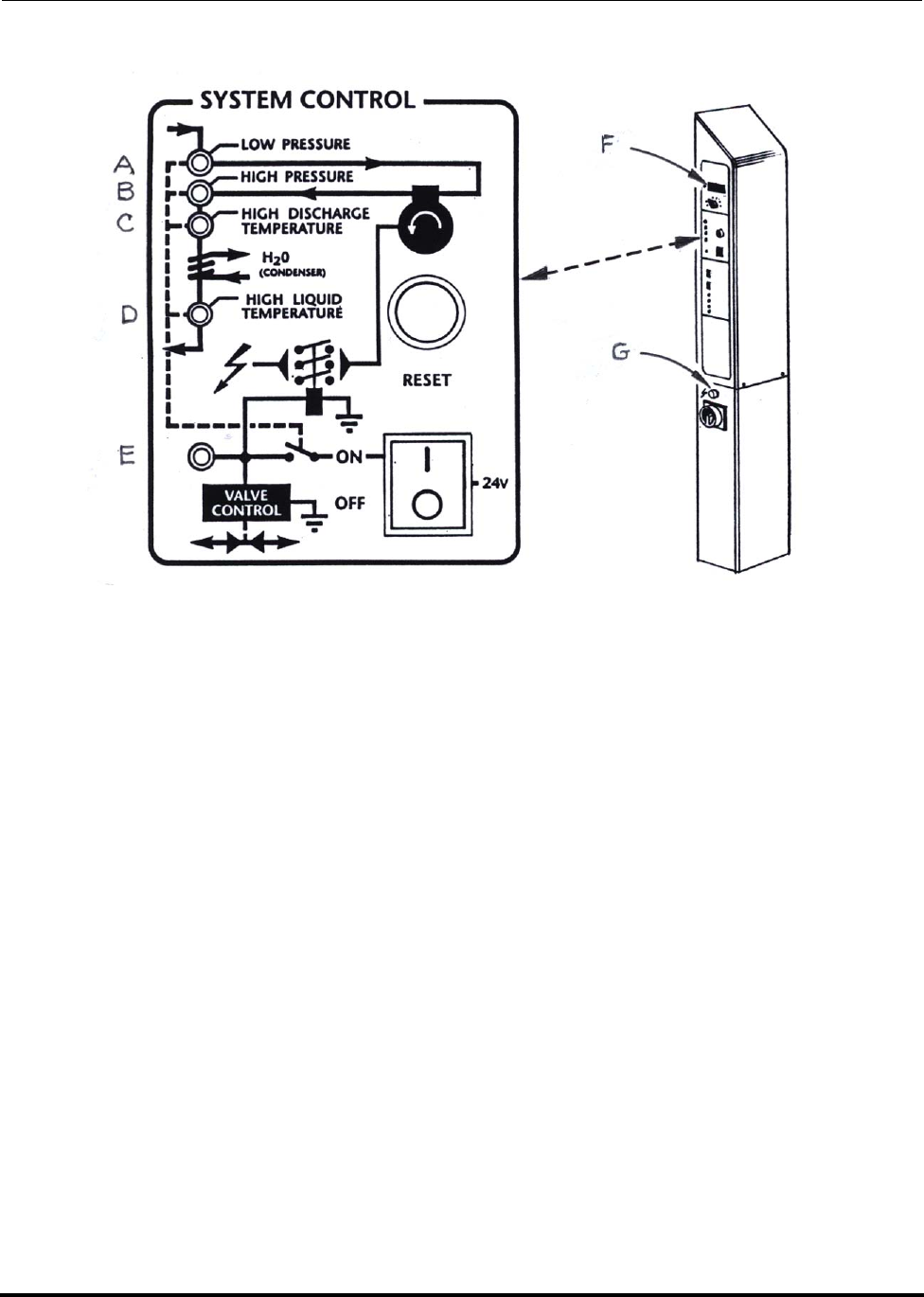
Troubleshooting and Repair Polycold Fast Cycle Water Vapor Cryopump
What to Do If the Cryopump Stops Running Customer Instruction Manual
825064-00 Brooks Automation
7-6 Revision 09
Figure 7-1: Unit indicator lamps
A. LOW PRESSURE lamp
B. HIGH PRESSURE lamp
C. HIGH DISCHARGE TEMPERATURE lamp
D. HIGH LIQUID TEMPERATURE lamp
E. “Unit OK” lamp
F. Temperature display
G. High voltage box lamp
H. Reset button (See note)

Polycold Fast Cycle Water Vapor Cryopump Troubleshooting and Repair
Customer Instruction Manual What to Do If the Cryopump Stops Running
Brooks Automation 825064-00
Revision 09 7-7
7.3.1 Low (Suction) Pressure Lamp is Lighted
Before starting
A dual pressure switch controls the LOW PRESSURE and HIGH PRESSURE lamps.
The LOW PRESSURE side is set at 2 psig (14 kPa). This setting ensures that a positive
pressure is maintained on the suction side of the compressor. If the cryopump has a
leak, the unit will be shutoff before it draws in moist air and contaminates the refrig-
erant circuit.
NOTE: If the cryopump has previously been inspected, see Step 5-1 for more accurate spec-
ifications.
Attention
Attention
For 551, 552, 661, 662, 672, 1101, 1102 a discharge pressure fault
requires resetting pressure switch inside unit. See section 7.1.2.1
WARNING
GENERAL HAZARD
Failure to have a qualified refrigeration technician do all refriger-
ation work could result in death or serious injury.
Contact a qualified refrigeration technician if the cryopump needs
to be repaired.

Troubleshooting and Repair Polycold Fast Cycle Water Vapor Cryopump
What to Do If the Cryopump Stops Running Customer Instruction Manual
825064-00 Brooks Automation
7-8 Revision 09
PROBLEM POSSIBLE CAUSE CORRECTIVE ACTION
Cryopump
stops running.
Cooling water
overcooling the
unit.
Note the LIQUID LINE (TC #2) temperature. Turn
off the unit and press the RESET button. Select
STANDBY and LOCAL. Turn on the unit. Moni-
tor the LIQUID LINE temperature in STANDBY
for 30 minutes. It should be 15-33°C. If not, make
sure the cooling water meets the requirements in
section 3.2.5 Connect the Cooling Water.
Refrigeration unit
shuts off:
•Within a few
minutes of
switching from
COOL to
STANDBY.
• When the unit is
experiencing a
light load.**
• When the LIQ-
UID LINE tem-
perature is
below 20°C.
Raise the LIQUID LINE temperature a few degrees
by decreasing the flow or increasing the tempera-
ture of the cooling water.
NOTE: **No Load means that no external heat load or rather no thermal energy (Watts) are
being removed. Maximum Rated Load can be defined as the unit being rated for light
heat load (light compared to the maximum which is less than ½ or 1/3)

Polycold Fast Cycle Water Vapor Cryopump Troubleshooting and Repair
Customer Instruction Manual What to Do If the Cryopump Stops Running
Brooks Automation 825064-00
Revision 09 7-9
7.3.2 High (Discharge) Pressure Lamp is Lighted
Before starting
A dual pressure switch controls the LOW PRESSURE and HIGH PRESSURE lamps.
These settings ensure that the discharge side of the compressor (and other compo-
nents) operate within their rated working pressures.
7.3.2.1 HIGH PRESSURE Setting: 400 Psig (2760 kPa)
For the 550 HC, 550 LT, 670 HC, 1100 LT models manufactured in Fall 2004 and
beyond and all 1100 HC models, the HIGH PRESSURE side is set at 400 psig (2760
kPa).
Cryopump
stops running
Cryopump has a
leak. Turn off the cryopump and wait 48 hours. Com-
pare the DISCHARGE pressure to the measure-
ment insection 3.4.1.1 Open the Isolation Valves. If
variance is greater than 20 psi, call your certified
service agent or Polycold for instructions.
The compressor’s
suction valve may
not be fully open.
This valve may have been closed while recharging
the unit. Check the valve and close if necessary.
The suction side of
the dual pressure
switch is set at 2
psig.
This setting may have been temporarily changed
while recharging the unit—Cut In = 31 psig & Dif-
ferential = 29 psig. However, the accuracy of the
switch setting must be checked with the SUCTION
gauge. Call your certified service agent or Poly-
cold for instructions.
Cables not securely
connected or con-
nections show
signs of overheat-
ing.
Visually check all system cables. Tighten as neces-
sary; replace bad cables with qualified Polycold
parts.
The cryopump is
leaking liquid
refrigerant.
Call your certified service agent or Polycold for
instructions.
PROBLEM POSSIBLE CAUSE CORRECTIVE ACTION
NOTE: **No Load means that no external heat load or rather no thermal energy (Watts) are
being removed. Maximum Rated Load can be defined as the unit being rated for light
heat load (light compared to the maximum which is less than ½ or 1/3)
Troubleshooting and Repair Polycold Fast Cycle Water Vapor Cryopump
What to Do If the Cryopump Stops Running Customer Instruction Manual
825064-00 Brooks Automation
7-10 Revision 09
7.3.2.2 HIGH PRESSURE Setting: 375 Psig (2590 kPa)
For the 550 HC, 550 LT, 670 HC, and 1100 LT models manufactured prior to Fall 2004,
the HIGH PRESSURE side is set at 375 psig.
7.3.2.3 HIGH PRESSURE Setting: 415 Psig (2690 kPa)
For the 1102 HC, 672 HC, and 552 HC models, the HIGH PRESSURE side is set at 415
psig (2690 kPa).
NOTE: If the cryopump has previously been inspected, see Step 5-1 for more accurate spec-
ifications.
NOTE: Models 551, 552, 661, 662, 672, 1101, and 1102 use a discharge pressure switch
with a manual reset. In some cases, the pressure switch has an external reset. In
other cases the pressure switch has an internal reset. Seesection 7.3.2.4 Resetting
the Discharge Pressure Switch after a Fault for reset details.
WARNING
GENERAL HAZARD
Failure to have a qualified refrigeration technician do all refrigeration
work could result in death or serious injury.
Contact a qualified refrigeration technician if the cryopump needs to
be repaired.

Polycold Fast Cycle Water Vapor Cryopump Troubleshooting and Repair
Customer Instruction Manual What to Do If the Cryopump Stops Running
Brooks Automation 825064-00
Revision 09 7-11
PROBLEM POSSIBLE CAUSE CORRECTIVE ACTION
Cryopump
stops running.
The cryosurface is
exposed to an
excessive heat load.
Switch to COOL. Monitor the DISCHARGE pres-
sure for 30 minutes. If the unit shuts off due to
high discharge pressure, check the following:
• The cryocoil is at least 5/8 inch (16 mm) from
the vacuum chamber wall.
• The cryosurface is not in direct view of a heat
source greater than 50°C.
• The cryosurface is the correct size for this
application (if this is a new application).
• Water or air is not leaking into the vacuum
chamber.
If the potential heat sources (above) are within
specification, make sure the unit is allowed to
remain in STANDBY at least 5 minutes after
DEFROST (before switching to COOL).
Switching from
STANDBY to
COOL after
defrosting the cryo-
surface.
Allow the unit to remain in STANDBY at least 5
minutes after DEFROST is complete.
Internal error
occurring only dur-
ing DEFROST or
when switching
from DEFROST to
STANDBY.
Switch to STANDBY after the cooling cycle is fin-
ished. Allow the DISCHARGE pressure to drop
below 300 psi before switching to DEFROST.
Defrost termina-
tion system NOT
working correctly.
Switch to DEFROST and monitor the #1 RETURN
(TC #8) temperature until the DEFROST COM-
PLETE lamp lights. The #1 RETURN temperature
should not exceed 25°C and the unit should auto-
matically go into STANDBY. If the #1 RETURN
exceeds 30°C, switch to STANDBY.
NOTE: For PFC/PFC: Also monitor the second
refrigerant circuit (#2 RETURN = TC #10).

Troubleshooting and Repair Polycold Fast Cycle Water Vapor Cryopump
What to Do If the Cryopump Stops Running Customer Instruction Manual
825064-00 Brooks Automation
7-12 Revision 09
7.3.2.4 Resetting the Discharge Pressure Switch after a Fault
NOTE: With the following figures (Figure 7-2 through Figure 7-7), identify the correct
pressure switch for your unit and press the green reset button to reset the switch.
If your unit has a reset switch internal to the switch unit make sure to reset it.
Cryopump
stops running.
The cryopump has
too much refriger-
ant charge in it.
The cryopump was
recharged incor-
rectly.
Turn off the cryopump and wait 48 hours. Com-
pare the DISCHARGE pressure to the measure-
ment insection 3.4.1.1 Open the Isolation Valves.
The compressor
discharge valve is
NOT fully open.
This valve may
have been closed
while recharging
the unit.
Check the valve and open if necessary.
The discharge set-
ting of the dual
pressure switch is
incorrect.
HIGH PRESSURE Switch Settings:
375 psig (2590 kPa): For the 550 HC, 550 LT, 670
HC, and 1100 LT models manufactured prior to
Fall 2004, the switch is set at 375 psig.
400 psig (2760 kPa): For all 1100 HC models, the
switch is set at 400 psig. As of Fall 2004, the HIGH
PRESSURE SWITCH setting for the 550 HC, 550
LT, 670 HC, and 1100 LT models was changed to
400 psig.
415 psig (2690 kPa): For all 1102 HC, 672 HC, and
552 HC models, the switch is set at 415 psig.
Cables not securely
connected or con-
nections show
signs of overheat-
ing.
Visually check all system cables. Tighten as neces-
sary; replace bad cables with qualified Polycold
parts.
PROBLEM POSSIBLE CAUSE CORRECTIVE ACTION

Polycold Fast Cycle Water Vapor Cryopump Troubleshooting and Repair
Customer Instruction Manual What to Do If the Cryopump Stops Running
Brooks Automation 825064-00
Revision 09 7-13
A discharge pressure fault requires a resetting of the manual pressure switch. In
some cases (models 551, 661, 1101, and 1102) the reset switch is internal to the switch
unit as shown in Figure 7-2.
Figure 7-2: Pressure Switch
Figure 7-3: 1102
Top View Bottom View
Remove Screws Press Reset Button
Press Reset Button Remove Screws
(Pressure Switch, Top View) Press Reset Button
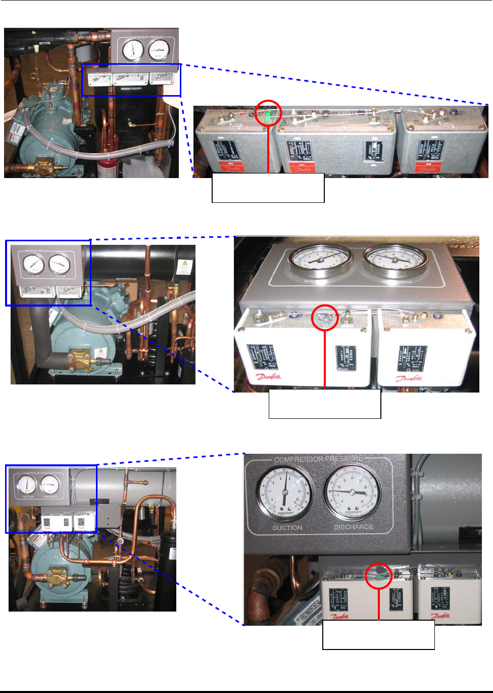
Troubleshooting and Repair Polycold Fast Cycle Water Vapor Cryopump
What to Do If the Cryopump Stops Running Customer Instruction Manual
825064-00 Brooks Automation
7-14 Revision 09
Figure 7-4: 1100
Figure 7-5: 660 and 670
Figure 7-6: 552, 662, and 672
Press Reset Button
Press Reset Button
Press Reset Button
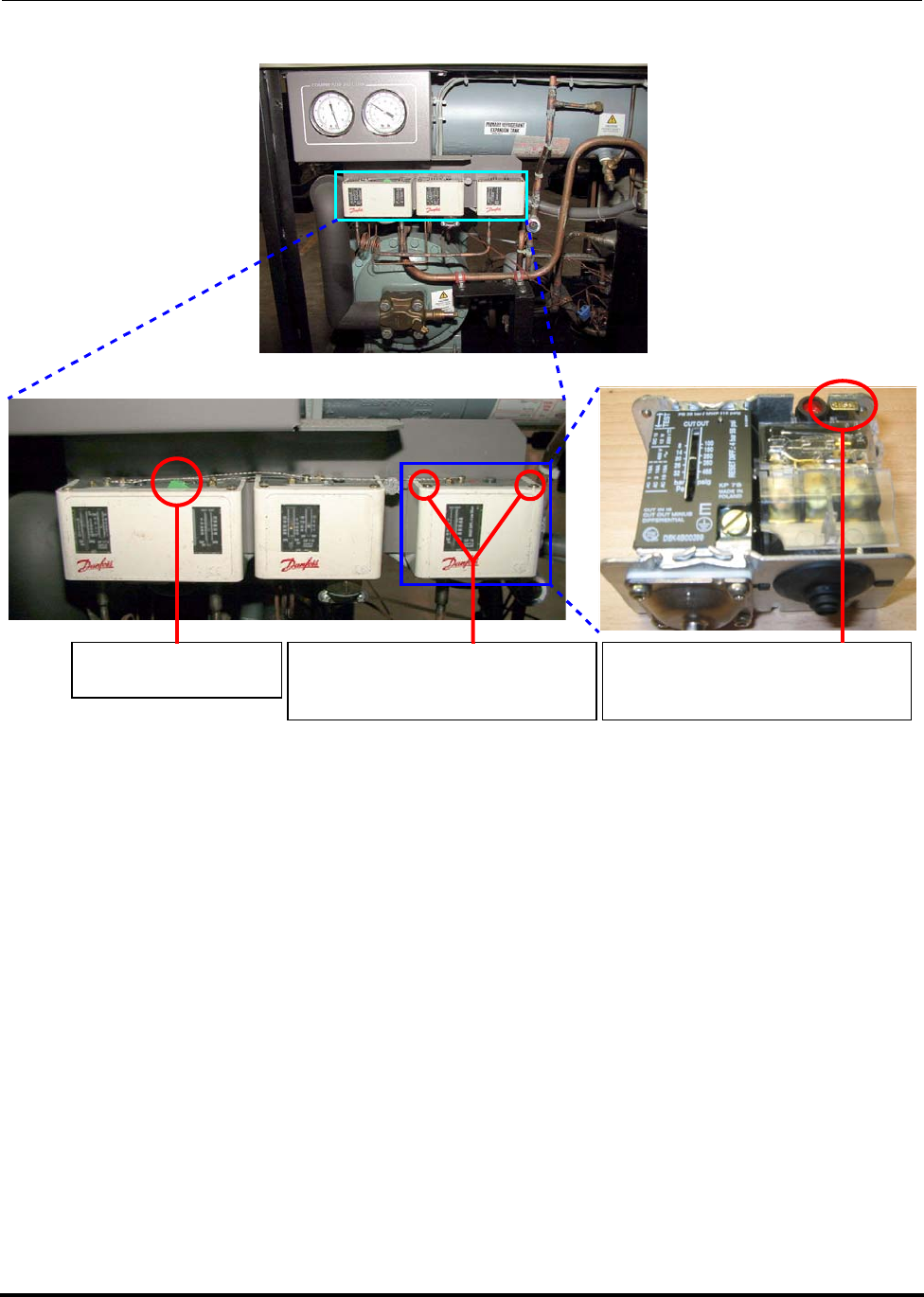
Polycold Fast Cycle Water Vapor Cryopump Troubleshooting and Repair
Customer Instruction Manual What to Do If the Cryopump Stops Running
Brooks Automation 825064-00
Revision 09 7-15
Figure 7-7: 551 and 661
7.3.3 High Discharge Temperature Lamp Is Lighted
Before starting
This lamp is controlled by two thermostat switches located on the compressor’s DIS-
CHARGE LINE. One is set at 275°F (135°C) and the other is set at 300°F (149°C).
• If the DISCHARGE LINE exceeds 149°C, the second thermostat will immedi-
ately shut off the unit. This protects the compressor from overheating.
• If the DISCHARGE LINE exceeds 135°C, the first thermostat is activated which
starts a timer. (The cryopump may need to operate above normal discharge
temperatures for a short time—such as starting the unit after it has been off for
48 hours.) The thermostat switch will shut off the unit if it remains between
135°C and 149°C after 40 minutes. This protects the life of the compressor.
Press Reset Button Remove Screws
(Pressure Switch, Top View) Remove Screws
(Pressure Switch, Top View)

Troubleshooting and Repair Polycold Fast Cycle Water Vapor Cryopump
What to Do If the Cryopump Stops Running Customer Instruction Manual
825064-00 Brooks Automation
7-16 Revision 09
NOTE: If the cryopump has previously been inspected, see Table 5-1 for more accurate
specifications.
WARNING
GENERAL HAZARD
Failure to have a qualified refrigeration technician do all refriger-
ation work could result in death or serious injury.
Contact a qualified refrigeration technician if the cryopump needs
to be repaired.
PROBLEM POSSIBLE CAUSE CORRECTIVE ACTION
Cryopump
stops running.
Cooling water is
inadequate. Turn off the unit and press the RESET button.
Select LOCAL and STANDBY. Turn on the unit.
Monitor the DISCHARGE LINE (TC #1) tempera-
ture and the LIQUID LINE (TC #2) temperature
for 90 minutes.
• The DISCHARGE LINE should not exceed
125°C and should remain stable after 30 min-
utes.
• The LIQUID LINE should be 15-33°C. If the
LIQUID LINE temperature exceeds 33°C, see
section 3.2.5 Connect the Cooling Water. If the
LIQUID LINE temperature exceeds 38°C, turn
off the unit. Either the temperature sensing
system or the protective device’s logic is faulty.
The cryosurface is
exposed to an
excessive heat load.
Switch to COOL. Monitor the DISCHARGE LINE
temperature for 30 minutes. If the unit shuts off
due to high discharge temperature, check the fol-
lowing.
• The cryocoil is at least 5/8 inch (16 mm) from
the vacuum chamber wall.
• The cryosurface is not in direct view of a heat
source greater than 50°C.
• The cryosurface is the correct size for this
application (if this is a new application).
• Water or air is not leaking into the vacuum
chamber.

Polycold Fast Cycle Water Vapor Cryopump Troubleshooting and Repair
Customer Instruction Manual What to Do If the Cryopump Stops Running
Brooks Automation 825064-00
Revision 09 7-17
7.3.4 High Liquid (Line) Temperature Lamp is Lighted
Before starting
This lamp is controlled by a thermocouple limit switch. This switch is set at 92°F
(33°C) to allow reliable operation of the cryopump. Some systems may have an
optional thermocouple limit switch set to 100°F (38°C)
• If the LIQUID LINE exceeds 33°C (38°C for optional TC Limit Switch) while
the unit is operating, this switch will immediately shut off the unit.
• If the LIQUID LINE exceeds 33°C (38°C for optional TC Limit Switch) when
the unit is first started, this switch will shut off the unit after 14 seconds. (The
14 seconds should allow enough time for the water to cool the refrigerant cir-
cuit.)
NOTE: If the cryopump has previously been inspected, see Table 5-1 for more accurate
specifications.
Cryopump
stops running
The cables in the
compressor’s elec-
trical box are not
securely con-
nected. The connec-
tions show signs of
overheating.
Inspect each cable termination and assure that the
connections are tight. Tighten only loose connec-
tions. Replace any parts with signs of heat stress.
Both “high dis-
charge tempera-
ture” thermostats
and cables are not
securely attached
and functioning.
Call your certified service agent or Polycold for
instructions.
The compressor’s
internal valves are
not sealing.
Call your certified service agent or Polycold for
instructions.
PROBLEM POSSIBLE CAUSE CORRECTIVE ACTION

Troubleshooting and Repair Polycold Fast Cycle Water Vapor Cryopump
What to Do If the Cryopump Stops Running Customer Instruction Manual
825064-00 Brooks Automation
7-18 Revision 09
WARNING
GENERAL HAZARD
Failure to have a qualified refrigeration technician do all refriger-
ation work could result in death or serious injury.
Contact a qualified refrigeration technician if the cryopump needs
to be repaired.
PROBLEM POSSIBLE CAUSE CORRECTIVE ACTION
Cryopump
stops running.
Cooling water is
not flowing in the
correct direction.
Turn off the unit and press the RESET button.
Select LOCAL and STANDBY. Turn on the unit.
Grasp the cooling water supply line (IN) with one
hand and the drain line (OUT) with the other
hand. The drain line should be warmer than the
supply line. If not, turn off the unit. Connect the
supply and drain lines to the proper ports.
Cooling water is
not adequately
cooling the unit.
Monitor the LIQUID LINE (TC #2) temperature
for 30 minutes. It should be 15-33°C (15-38°C for
optional TC Limit Switch). If not, seesection 3.2.5
Connect the Cooling Water.
Determine if the unit only shuts off:
• when the cryopump is experiencing a heavy
thermal load, and
• the LIQUID LINE temperature is at the high
end of the acceptable range.
• If so, an increase in the unit’s cooling capacity
may be possible by increasing the flow or low-
ering the temperature of the cooling water.
The liquid line ther-
mocouple wires are
not securely
attached or they are
broken
Tighten or repair thermocouple wiring connec-
tions.
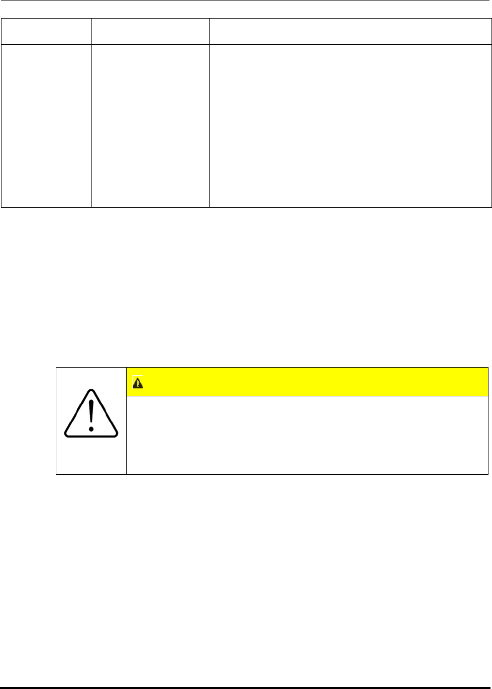
Polycold Fast Cycle Water Vapor Cryopump Troubleshooting and Repair
Customer Instruction Manual What to Do If the Cryopump Stops Running
Brooks Automation 825064-00
Revision 09 7-19
7.3.5 “Unit OK” Lamp & Compressor Cycle Off & On
Before starting
The green “Unit OK” lamp is lighted whenever the compressor is running. The com-
pressor should run continuously when the unit is ON. However, if the compressor
draws too much current, its motor overloads will cycle the compressor (and green
“Unit OK” lamp) off and on.
Cryopump
stops running The cables between
the thermocouple
limit switch and the
SYSTEM CON-
TROL printed cir-
cuit board are not
securely con-
nected. The con-
nections show
signs of overheat-
ing
Tighten thermocouple cable connections or replace
cables as required.
CAUTION
GENERAL HAZARD
Do not operate the cryopump if the compressor is cycling off and
on. Doing this will lower the performance of the cryopump and
shorten the life of the compressor and can damage the equipment.
Call for assistance at this time if you are not a qualified technician.
PROBLEM POSSIBLE CAUSE CORRECTIVE ACTION

Troubleshooting and Repair Polycold Fast Cycle Water Vapor Cryopump
What to Do If the Cryopump Stops Running Customer Instruction Manual
825064-00 Brooks Automation
7-20 Revision 09
7.3.6 System Control, Temperature Display, and High Voltage Box
PROBLEM POSSIBLE CAUSE CORRECTIVE ACTION
Cryopump
stops running.
The electrical sup-
ply is inadequate Requires a qualified electrician.
Control voltage is
inadequate (Requires a qualified electrician.) Seesection
3.2.4.2 How to Check the Control Voltage and
Change the Transformer Taps.
Cables in the high
voltage box are not
securely con-
nected. The con-
nections show
signs of overheat-
ing
Inspect each cable termination and assure that the
connections are tight. Tighten only loose connec-
tions. Replace any parts with signs of heat stress.
The cables in the
compressor’s elec-
trical box are not
securely con-
nected. They show
signs of overheat-
ing
Inspect each cable termination and assure that the
connections are tight. Tighten only loose connec-
tions. Replace any parts with signs of heat stress.
Cryopump
stops running The compressor’s
overloads are not
functioning prop-
erly
Replace overloads.
CAUTION
GENERAL HAZARD
Do not operate the unit. Doing so can damage the equipment.
Call for assistance at this time if you are not a qualified technician.
Polycold Fast Cycle Water Vapor Cryopump Troubleshooting and Repair
Customer Instruction Manual What to Do If the Cryopump Stops Running
Brooks Automation 825064-00
Revision 09 7-21
Table 7-1: System Control Lamps are Off; Temperature Display & High Voltage Box Lamp are
Lighted
PROBLEM POSSIBLE CAUSE CORRECTIVE ACTION
Cryopump
stops running.
The unit’s ON/OFF
switch in the OFF
position
Move switch to “ON” position.
Will the unit start
in the LOCAL
mode
Select STANDBY and LOCAL. Turn on the unit.
Is jumper J11
plugged into the
SYSTEM CON-
TROL printed cir-
cuit board
(This step does not apply if a remote ON/OFF
switch is installed. See section 3.8 “How to Install
the GVE Remote Control Option.”)
The fuse on the
SYSTEM CON-
TROL printed cir-
cuit board is blown
(Requires a qualified electrician.)
Cryopump
stops running The expansion tank
pressure switch has
been triggered
(units with the CE
Mark option and
1100s only)
Call your certified service agent or Polycold for
instructions.
CAUTION
GENERAL HAZARD
Do not operate the unit. Doing so can damage the equipment.
Call for assistance at this time if you are not a qualified technician.

Troubleshooting and Repair Polycold Fast Cycle Water Vapor Cryopump
What to Do If the Cryopump Stops Running Customer Instruction Manual
825064-00 Brooks Automation
7-22 Revision 09
Figure 7-8: Control voltage circuit breaker
Table 7-2: ystem Control Lamps, Temperature Display & High Voltage Box Lamps are Off
PROBLEM POSSIBLE CAUSE CORRECTIVE ACTION
Cryopump
stops running.
The power discon-
nect switch is in the
OFF position
Move switch to “ON” position.
Control voltage is
inadequate (Requires a qualified electrician.) See “How to
Check the Control Voltage & Change the Trans-
former Taps” in section 3.2.3
Is the electrical sup-
ply adequate (Requires a qualified electrician.)
The control voltage
circuit breaker for
the transformer has
been triggered
A small plunger being fully extended within the
transparent protective seal boot of the circuit
breaker indicates a tripped condition. If so, check
electrical components and connections for signs of
overheating. If the problem began following
installation of remote control wiring, check for
proper connections or shorted wires. Pushing the
plunger will reset the circuit breaker. See Figure
7-8.
Back panel of
High Voltage Box Push center of protective cover until
you completely push down plunger.
Protective Cove
r
Plunger
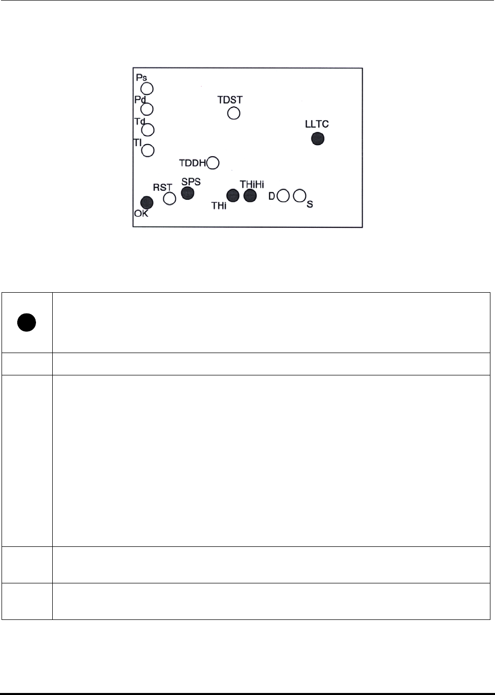
Polycold Fast Cycle Water Vapor Cryopump Troubleshooting and Repair
Customer Instruction Manual What to Do If the Cryopump Stops Running
Brooks Automation 825064-00
Revision 09 7-23
7.3.7 SYSTEM CONTROL Printed Circuit Board Indicator Lamps
Figure 7-9: SYSTEM CONTROL printed circuit board indicator lamps
GREEN LEDs
OK This lamp is lighted when the contactor is closed.
SPS • For models without a buffer unloader cable (550, 660, 670, 1100, 551, 661,
and 1101): Upon initial start-up*, the SPS LED is off, the buffer valve is
open, and the TDST LED is on. After 14 seconds, the TDST times-out. The
SPS LED illuminates once the single pressure switch (SPS) on the discharge
line reaches 350 psig (2410 kPa).
NOTE: *The SPS LED will stay on if the system is turned off and on again before
allowing pressure to drop below 350 psig.
• For models with a buffer unloader cable (552, 662, 672, and 1102): The SPS
LED is on and the buffer valve is open whenever discharge pressure
exceeds 400 psig (2760 kPa).
THi This lamp is lighted when the first discharge thermostat is below 275°F (135°C).
When THi turns off, TDDH comes on.
THiHi This lamp is lighted when the second discharge thermostat is below 300°F
(149°C). When THi turns off, Td comes on.

Troubleshooting and Repair Polycold Fast Cycle Water Vapor Cryopump
What to Do If the Cryopump Stops Running Customer Instruction Manual
825064-00 Brooks Automation
7-24 Revision 09
YELLOW LEDs
Ps This is the LOW PRESSURE indicator lamp on the SYSTEM CONTROL panel.
It is on when the unit has been shut off due to low suction pressure. When Ps
comes on, OK turns off.
Pd This is the HIGH PRESSURE indicator lamp on the SYSTEM CONTROL panel.
It is on when the unit has been shut off due to high discharge pressure. When
Pd comes on, OK turns off.
Td This is the HIGH DISCHARGE TEMPERATURE indicator lamp on the SYS-
TEM CONTROL panel. It is on when the unit has been shut off due to high dis-
charge temperature. When Td comes on, OK turns off.
Tl This is the HIGH LIQUID TEMPERATURE indicator lamp on the SYSTEM
CONTROL panel. It is on when the unit has been shut off due to high LIQUID
LINE temperature. When Tl comes on, OK turns off.
RST This lamp lights while the reset switch on the SYSTEM CONTROL panel is
being pressed.
TDDH This lamp lights and times 40 minutes when the THi lamp turns off. If after 40
minutes THi is still off, TDDH will turn off and Td will turn on.
TDST This lamp lights when the unit is started and times 14 seconds.
DThis lamp lights when the discharge side of the dual switch is set above the
model’s specifications (see the following specifications for each model). When
D comes on, it triggers Pd to come on.
• For the 550 HC, 550 LT, 670 HC, and 1100 LT models manufactured prior to
Fall 2004: 375 psig (2590 kPa)
• For the models (listed above) manufactured from Fall 2005 on and all 1100
HC models: 400 psig (2760 kPa)
• For all 1102 HC, 672 HC, and 552 HC models: 415 psig (2790 kPa)
SThis lamp lights when the suction side of the dual pressure switch is below 2
psig (14 kPa). When S comes on, it triggers Ps to come on.

Polycold Fast Cycle Water Vapor Cryopump Troubleshooting and Repair
Customer Instruction Manual What to Do If the Cryosurface is Not Cryopumping Ade-
Brooks Automation 825064-00
Revision 09 7-25
7.4 What to Do If the Cryosurface is Not Cryopumping Adequately
7.4.1 Check Coil Temperatures
PROBLEM POSSIBLE CAUSE CORRECTIVE ACTION
Cryosurface is
not cry-
opumping
adequately
COIL IN and COIL
OUT temperatures
are out of specifica-
tion
Select LOCAL and STANDBY. Turn on the unit
and wait 30 minutes. Select COOL and wait 30
minutes.
Record the COIL IN (TC #3) temperature and the
COIL OUT (TC #4) temperature.
NOTE: For PFC/PFC or PFC/P: Also record the #2
COIL IN (TC #5) and #2 COIL OUT (TC
#6) temperatures.
Cryosurface is not
being adequately
cooled
Use the above measurements to determine if the
cryosurface is adequately being cooled
The average of COIL IN and COIL OUT tempera-
tures must be colder than the temperature
required for the desired water vapor partial pres-
sure in the vacuum chamber. See Table 3.8 in Sec-
tion 3.4.4 “Evaluate the Cryopump.”
The COIL OUT temperature must be within 10°C
of the average temperature.
NOTE: If the cryopump has previously been
inspected, see Table 5-1 for more accurate
specifications.

Troubleshooting and Repair Polycold Fast Cycle Water Vapor Cryopump
What to Do If the Cryosurface is Not Cryopumping Adequately Customer Instruction
825064-00 Brooks Automation
7-26 Revision 09
Troubleshooting Sections to Consider
(These sections assume that the thermocouple readings and the pressure gauges are
accurate.)
7.4.2 COIL IN Temperature OK, COIL OUT Temperature Not OK
Is the COIL IN
temperature OK? Is the COIL OUT
temperature OK? Then…
Yes Yes Check your vacuum pump.
Yes No Seesection 7.4.2 COIL IN Temperature OK,
COIL OUT Temperature Not OK.
No No See section 7.4.2 COIL IN Temperature OK,
COIL OUT Temperature Not OK.
CAUTION
GENERAL HAZARD
Do not operate the unit. Doing so can damage the equipment.
Call for assistance at this time if you are not a qualified technician.

Polycold Fast Cycle Water Vapor Cryopump Troubleshooting and Repair
Customer Instruction Manual What to Do If the Cryosurface is Not Cryopumping Ade-
Brooks Automation 825064-00
Revision 09 7-27
PROBLEM POSSIBLE CAUSE CORRECTIVE ACTION
Cryosurface is
not cry-
opumping
adequately
The temperature
indication of the
COIL OUT thermo-
couple is incorrect.
Select LOCAL and STANDBY. Turn on the unit
and wait 30 minutes. Select COOL and wait 30
minutes.
Compare the COIL OUT (TC #4) temperature to
the #1 RETURN (TC #8) temperature. They
should be within 10°C of each other.
NOTE: For PFC/PFC or PFC/P: The #2 COIL OUT
(TC #6) temperature should be within 10°C
of the #2 RETURN (TC #10) temperature.
The refrigerant line
has ice or water on
it.
Check the refrigerant line at the end of a typical
COOL cycle. If there is ice or water, remove it.
Apply another layer of insulation following the
instructions insection 3.4.3 Insulate the Exposed
Tubes and Couplings.
Cryosurface is
exposed to an
excessive heat load.
Make sure the cryosurface is:
• at least 5/8 inch (16 mm) from the vacuum
chamber wall (cryocoil only);
• not in direct view of a heat source greater than
50°C;
• the correct size for this application (if this is a
new application).
Make certain the vacuum chamber does not have
an air or water leak.
Cryosurface has
large dents or kinks
in it.
Call your certified service agent or Polycold Sys-
tems for instructions.
Isolation valves are
not fully open. (The isolation valves are closed when the unit is
shipped from the factory and when following the
instructions for disconnecting the refrigerant line.)
Refrigerant line has
a large dent or kink
in it.
Call your certified service agent or Polycold Sys-
tems for instructions.

Troubleshooting and Repair Polycold Fast Cycle Water Vapor Cryopump
What to Do If the Cryosurface is Not Cryopumping Adequately Customer Instruction
825064-00 Brooks Automation
7-28 Revision 09
Cryosurface is
not cry-
opumping
adequately
The DEFROST sole-
noid valve keeps
closing.
Call your certified service agent or Polycold Sys-
tems for instructions.
The buffer bypass
valve is sticking
open (All units
except the 550).
Call your certified service agent or Polycold Sys-
tems for instructions.
The cryopump has
improper refriger-
ant charge in it.
Call your certified service agent or Polycold Sys-
tems for instructions.
Cryopump has a
leak. Call your certified service agent or Polycold Sys-
tems for instructions.
Refrigerant Leak See If Unit Has A Leak on page 7-2.
Loss of cooling,
cause unknown See If Unit Has Lost Performance on page 7-3.
PROBLEM POSSIBLE CAUSE CORRECTIVE ACTION

Polycold Fast Cycle Water Vapor Cryopump Troubleshooting and Repair
Customer Instruction Manual What to Do If the Cryosurface is Not Cryopumping Ade-
Brooks Automation 825064-00
Revision 09 7-29
7.4.3 COIL IN and COIL OUT Temperatures are Not OK
PROBLEM POSSIBLE CAUSE CORRECTIVE ACTION
Cryosurface is
not cry-
opumping
adequately
Is the temperature
indication of the
COIL IN and COIL
OUT thermocou-
ples correct
Select LOCAL and STANDBY. Turn on the unit
and wait 30 minutes. Select COOL and wait 30
minutes.
Compare the following temperatures:
• COIL IN (TC #3) should be within 10°C of #1
FEED (TC #7); and
• COIL OUT (TC #4) should be within 10°C of #1
RETURN (TC #8).
NOTE: For PFC/PFC or PFC/P: Select COOL for
both refrigerant circuits.
• #2 COIL IN (TC #5) should be within 10°C of
#1 FEED (TC #7); and
• #2 COIL OUT (TC #6) should be within 10°C of
#2 RETURN (TC #10).
Isolation valves are
not fully open (The isolation valves are closed when the unit is
shipped from the factory and when following the
instructions for disconnecting the refrigerant line.)
Troubleshooting and Repair Polycold Fast Cycle Water Vapor Cryopump
What to Do If the Cryosurface is Not Cryopumping Adequately Customer Instruction
825064-00 Brooks Automation
7-30 Revision 09
7.4.4 What to Do If the Cryosurface is Not Defrosting Adequately
NOTE: This section is for a PFC refrigerant circuit whose cryosurface is a coil.
Cryosurface is
not cry-
opumping
adequately
Is the COOL sole-
noid valve opening Call your certified service agent or Polycold Sys-
tems for instructions.
The DEFROST sole-
noid valve keeps
closing
Call your certified service agent or Polycold Sys-
tems for instructions.
Does the refriger-
ant line have a kink
in it
Replace kinked section.
The cryopump has
improper refriger-
ant charge in it
Call your certified service agent or Polycold Sys-
tems for instructions.
Cryopump has a
leak Call your certified service agent or Polycold Sys-
tems for instructions.
PFC/PFC or PFC/
P units with one
circuit in cool while
the other circuit is
in defrost.
• If temperature increase is less than 20°C,
review your process sequence and do not
defrost one ciruit while the other circuit is in
cool.
• If temperature increase is greater than 20°C,
call your sertified agent of Polucold Systems
for instructions.
Refrigerant Leak See If Unit Has A Leak on page 7-2.
Loss of cooling,
cause unknown See If Unit Has Lost Performance on page 7-3.
CAUTION
GENERAL HAZARD
Do not operate the unit. Doing so can damage the equipment.
Call for assistance at this time if you are not a qualified technician.
PROBLEM POSSIBLE CAUSE CORRECTIVE ACTION

Polycold Fast Cycle Water Vapor Cryopump Troubleshooting and Repair
Customer Instruction Manual What to Do If the Cryosurface is Not Cryopumping Ade-
Brooks Automation 825064-00
Revision 09 7-31
PROBLEM POSSIBLE CAUSE CORRECTIVE ACTION
Cryosurface is
not defrosting
adequately
Size of the cryosur-
face is not within
specification
(See section 3.5 Cryosurface & Cryogenic Feed-
through Specification.)
Vacuum chamber is
being vented before
the cryosurface is
defrosted
Complete defrost prior to venting the chamber.
The DEFROST
cycle is being termi-
nated early
The unit will automatically terminate the
DEFROST cycle when the #1 RETURN (TC #8)
temperature reaches 20°C. This should take less
than 4 minutes.
If terminating the DEFROST cycle earlier with a
timer or some other method, check to see if enough
time has passed for the cryosurface to be com-
pletely defrosted.
NOTE: For PFC/PFC: If the second refrigerant cir-
cuit is not defrosting adequately, do this step
with the #2 RETURN (TC #10) tempera-
ture.
The defrost termi-
nation system is
NOT working cor-
rectly.
Switch to DEFROST. Monitor the #1 RETURN (TC
#8) temperature until the DEFROST COMPLETE
lamp lights. The #1 RETURN temperature should
not exceed 25°C, and the unit should automatically
switch to STANDBY. Select STANDBY if the
return line temperature exceeds 30°C.
NOTE: For PFC/PFC: Also monitor the second
refrigerant circuit (#2 RETURN = TC #10).
The cryosurface has
a large dent or kink
in it
Call your certified service agent or Polycold Sys-
tems for instructions
The isolation valves
are not fully open (The isolation valves are closed when the unit is
shipped from the factory and when following the
instructions for disconnecting the refrigerant line.)

Troubleshooting and Repair Polycold Fast Cycle Water Vapor Cryopump
What to Do If the Cryosurface is Not Cryopumping Adequately Customer Instruction
825064-00 Brooks Automation
7-32 Revision 09
Cryosurface is
not defrosting
adequately
The DEFROST sole-
noid valve is not
opening
Call your certified service agent or Polycold Sys-
tems for instructions.
The COOL sole-
noid valve keeps
closing
Call your certified service agent or Polycold Sys-
tems for instructions.
The refrigerant line
has a large dent or
kink in it
Call your certified service agent or Polycold Sys-
tems for instructions.
PFC/PFC or PFC/
P units with one
circuit in cool while
the other circuit is
in defrost.
• If temperature increase is less than 20°C,
review your process sequence and do not
defrost one ciruit while the other circuit is in
cool.
• If temperature increase is greater than 20°C,
call your sertified agent of Polucold Systems
for instructions.
PROBLEM POSSIBLE CAUSE CORRECTIVE ACTION
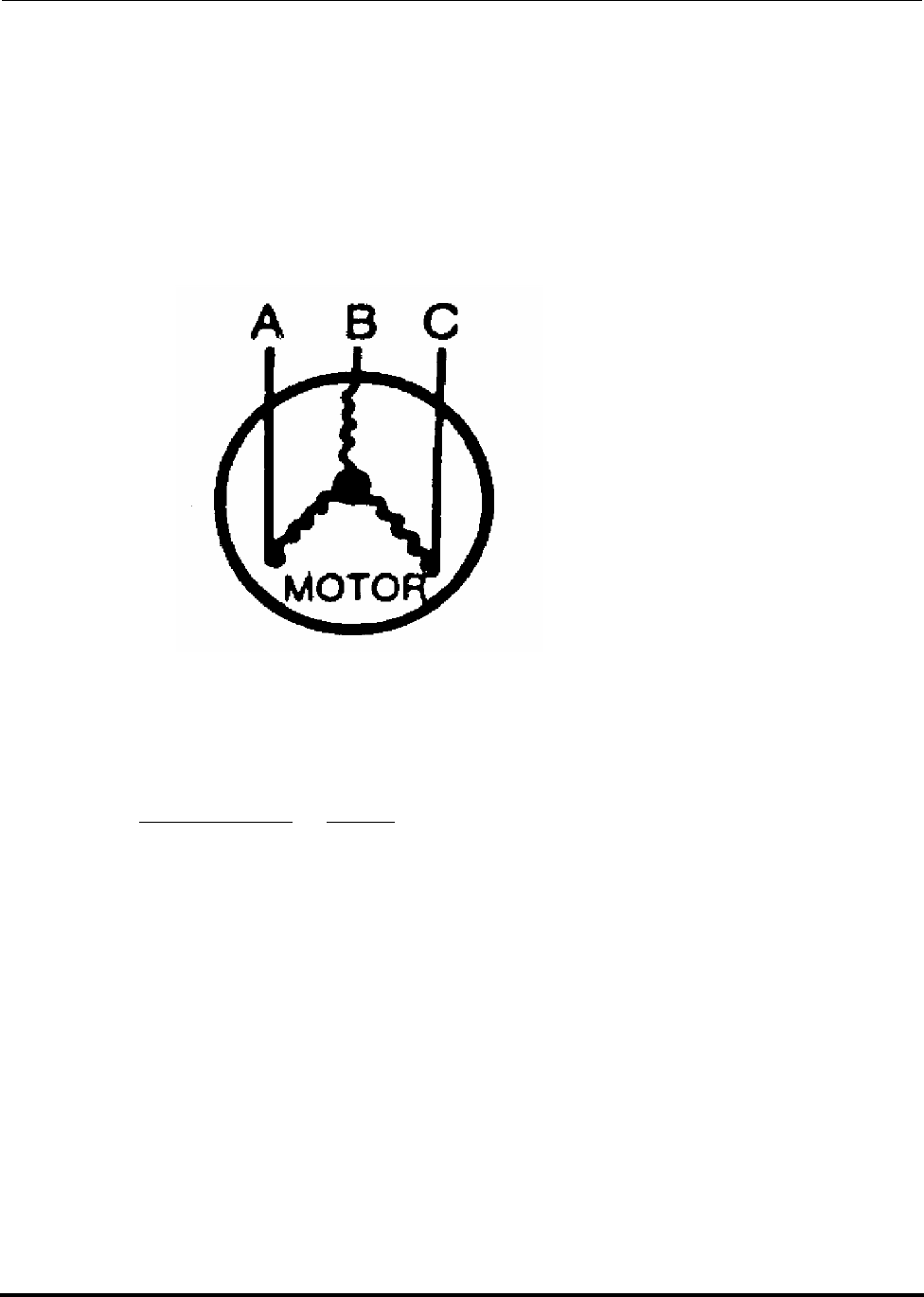
Polycold Fast Cycle Water Vapor Cryopump Troubleshooting and Repair
Customer Instruction Manual How to Calculate Voltage Unbalance
Brooks Automation 825064-00
Revision 09 7-33
7.5 How to Calculate Voltage Unbalance
Voltage unbalance can cause motors to overheat and fail. The following example is
the recommended method for determining voltage unbalance. This example was
taken from the Carlyle Corporation Service Guide Manual.
Example: Supply voltage is 240-3-60
1. Determine the average voltage:
2. Determine maximum deviation from average voltage:
(AB) 243—239= 4 V
(BC) 239—236= 3 V
(AC) 239—238= 1 V
Maximum deviation is 4 V.
243+236+238 =717 = 239V
33
AB = 243V
BC = 236V
AC = 238V

Troubleshooting and Repair Polycold Fast Cycle Water Vapor Cryopump
How to Calculate Voltage Unbalance Customer Instruction Manual
825064-00 Brooks Automation
7-34 Revision 09
3. Determine % voltage unbalance:
This amount of phase unbalance is satisfactory as it is below the maximum allowable
2%.
Important: If the supply voltage phase unbalance is more than 2%, contact the local
electric utility company immediately.
100 x 4= 1.7%
239

Polycold Fast Cycle Water Vapor Cryopump Troubleshooting and Repair
Customer Instruction Manual How to Calculate Voltage Unbalance
Brooks Automation 825064-00
Revision 09 7-35
This Page Intentionally Left Blank

Troubleshooting and Repair Polycold Fast Cycle Water Vapor Cryopump
How to Calculate Voltage Unbalance Customer Instruction Manual
825064-00 Brooks Automation
7-36 Revision 09

Polycold Fast Cycle Water Vapor Cryopump
Customer Instruction Manual
Brooks Automation 825064-00
Revision 09 8-1
8 Disconnection, Storage, and
Reshipment
Overview
Only trained, qualified persons should attempt to troublehsoot the product. Brooks
Automation provides training in the troubleshooting and repair of the product.
Contents
8.1 How to Shut Down or Ship the Cryopump. . . . . . . . . . . . . . . . . . . . . . . . . . . . .8-2
8.2 How to Disconnect the Refrigerant Line . . . . . . . . . . . . . . . . . . . . . . . . . . . . . . .8-3
8.3 How to Replace the Refrigerant. . . . . . . . . . . . . . . . . . . . . . . . . . . . . . . . . . . . . . .8-7

Disconnection, Storage, and Reshipment Polycold Fast Cycle Water Vapor Cryopump
How to Shut Down or Ship the Cryopump Customer Instruction Manual
825064-00 Brooks Automation
8-2 Revision 09
8.1 How to Shut Down or Ship the Cryopump
How to shut down the cryopump:
1. Defrost the cryosurface following the instructions in section 4.2 How to Use the
Cryopump.
2. Turn off the unit.
3. Turn off the POWER DISCONNECT switch (on the high voltage box).
4. Turn off the cooling water.
How to prepare the cryopump for storage or shipment:
1. Follow the instructions in section 8.1 How to Shut Down or Ship the
Cryopump above.
2. Disconnect the refrigerant line following the instructions in section 8.2 How to
Disconnect the Refrigerant Line.
3. Disconnect the cooling water.
4. Blow water from the condenser. (This step protects the unit from freeze dam-
age during storage or a high altitude flight.)
5. Disconnect the electrical supply.
6. Reinstall the compressor hold-down nuts. (These were removed in section
3.2.2 Position the Unit and should have been stored with the unit.)

Polycold Fast Cycle Water Vapor Cryopump Disconnection, Storage, and Reshipment
Customer Instruction Manual How to Disconnect the Refrigerant Line
Brooks Automation 825064-00
Revision 09 8-3
8.2 How to Disconnect the Refrigerant Line
Tools and materials needed:
• stepladder
• Phillips screwdriver
• small straight blade screwdriver
• 1/4 inch ratchet valve wrench
• 15/16 inch end wrench
• 5/8 inch end wrench
• blank-off fittings (These were removed in section 3.3.2.2 Verify that the Isola-
tion Valves are Closed, and Remove the Blank-off Fittings and should have
been stored with the unit.)
For Parker CPI UltraSeal couplings (standard fitting):
• 1 inch open end wrench
• 15/16 inch open end wrench
• O-ring removal tool
For Cajon VCR couplings (optional fitting):
• 1-3/16 inch open end wrench
• 1-1/16 inch open end wrench
1. Draw the refrigerant mixture back into the unit.
Defrost the cryosurface following the instructions in section 4.2 How to Use the
Cryopump. Turn off the unit.
Remove the top panel of the unit. The isolation valves are in the box closest to the cou-
plings. Loosen the screws to open the valve box lid.
Disconnection, Storage, and Reshipment Polycold Fast Cycle Water Vapor Cryopump
How to Disconnect the Refrigerant Line Customer Instruction Manual
825064-00 Brooks Automation
8-4 Revision 09
Allow the isolation valves to warm up to room temperature before attempting to use
them. This takes 2-3 hours without intervention, or about 10 minutes if gently
warmed with a heat gun.
Close the COLD GAS FEED and HOT GAS FEED isolation valves by turning them
clockwise. Turn on the unit and wait 30-45 seconds. (The SUCTION pressure should
be 15-25 psig.) Close the COMMON RETURN isolation valve while the unit is still
running. Turn off the unit.
2. Allow the remaining refrigerant to escape.
Locate the EVACUATION VALVE on the right side of the unit. Unscrew the protec-
tive cap. Remove the flare nut and bonnet.
Note the SUCTION pressure. Slowly midseat the EVACUATION VALVE to release
the remaining refrigerant in the refrigerant line and cryosurface. (Midseat the EVAC-
UATION VALVE by turning the valve stem three complete rotations in the counter-
clockwise direction.) Verify the unit’s SUCTION pressure is not dropping. If it is,
close the valve stem and make certain the isolation valves are fully closed.
Close the valve stem by turning it clockwise. Put on the bonnet and flare nut. Put on
the protective cap.
NOTE: For PFC/PFC or PFC/P: This releases the refrigerant from both refrigerant lines
and cryosurfaces.
3. Disconnect the thermocouples.
See Figure 3-22 and Figure 3-23.
CAUTION
EXTREME TEMPERATURES EXIST
Frostbite danger. The isolation valves may be very cold; contact
with the cold surface may result in minor or moderate injury.
Do not touch the isolation valves. Make certain the cryosurface
is fully defrosted before closing the isolation valves, especially if
the cryopump is being used to cool a baffle. Otherwise, danger-
ous pressures could develop in the refrigerant line and cryosur-
face.
Polycold Fast Cycle Water Vapor Cryopump Disconnection, Storage, and Reshipment
Customer Instruction Manual How to Disconnect the Refrigerant Line
Brooks Automation 825064-00
Revision 09 8-5
Loosen the two lower screws on the side of the low voltage box. Slide the panel
straight up to remove it. Disconnect the COIL IN (TC #3) and COIL OUT (TC #4)
thermocouples from the terminal block.
Unscrew the cap from the EXTERNAL TC fitting on the back of the low voltage box.
Remove the rubber seal from the fitting and remove the thermocouples from the low
voltage box. Put the rubber seal back in the EXTERNAL TC fitting and screw its cap
back on. Secure the thermocouple wires to the refrigerant line to keep them from
being damaged.
NOTE: For PFC/PFC or PFC/P: If you are removing the lower refrigerant line, then dis-
connect the #2 COIL IN (TC #5) and #2 COIL OUT (TC #6) thermocouples.
4. Disconnect the couplings and install blank-off fittings.
Remove the insulation from around the couplings on the refrigerant line. Make cer-
tain the couplings are at room temperature before disassembling them.
For Parker CPI UltraSeal couplings (standard fitting):
Keep the male coupling stationary with the 15/16-inch wrench and loosen the nut
with a 1-inch wrench. Unscrew the nut on each coupling.
Screw the O-ring removal tool onto the male coupling and tighten it to between 10
and 20 foot-pounds (14-27 Nm). Unscrew the O-ring removal tool. The O-ring should
be bent enough to remove it easily with two fingers. See Figure 8-1
Install the rubber O-rings and metal blank-off fittings. (This step ensures that no
additional refrigerant will be lost.) Protect the other half of the couplings with plastic
caps.
CAUTION
GENERAL HAZARD
Over tightening the O-ring removal tool will damage the sealing
surface of the coupling. Under tightening the O-ring removal tool
will not dimple the O-ring enough to remove it easily. Attempt-
ing to pry the O-ring from the groove may damage the sealing
surface and can damage the equipment.
Be careful when screwing the O-ring removal tool onto the male
coupling.
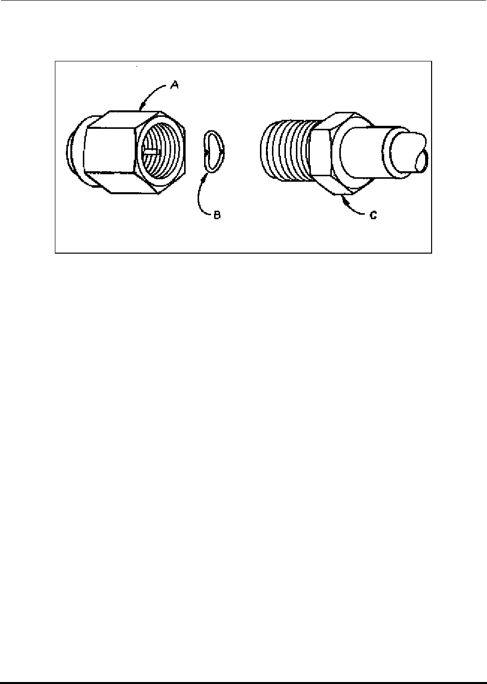
Disconnection, Storage, and Reshipment Polycold Fast Cycle Water Vapor Cryopump
How to Disconnect the Refrigerant Line Customer Instruction Manual
825064-00 Brooks Automation
8-6 Revision 09
Figure 8-1: Parker CPI UltraSeal coupling—O-ring removal tool usage (standard fitting)
A. O-ring removal tool
B. Silver plated stainless steel O-ring
C. Male coupling
For Cajon VCR couplings (optional fitting, not shown):
Hold one nut stationary with a backup wrench, and loosen the other nut with a sec-
ond wrench. Unscrew the two nuts. Remove the gaskets and install the blank-off fit-
tings. (This step ensures that no additional refrigerant will be lost.) Protect the other
half of the couplings with plastic caps.

Polycold Fast Cycle Water Vapor Cryopump Disconnection, Storage, and Reshipment
Customer Instruction Manual How to Replace the Refrigerant
Brooks Automation 825064-00
Revision 09 8-7
8.3 How to Replace the Refrigerant
Refer to Polycold Document 825071, Instructions for Replacing the Refrigerant in
Large Units.

Disconnection, Storage, and Reshipment Polycold Fast Cycle Water Vapor Cryopump
How to Replace the Refrigerant Customer Instruction Manual
825064-00 Brooks Automation
8-8 Revision 09
This Page Intentionally Left Blank

Polycold Fast Cycle Water Vapor Cryopump
Customer Instruction Manual
Brooks Automation 825064-00
Revision 09 9-1
9 Options
Overview
This section describes the options available for this product.
Contents
9.1 CE Mark Units . . . . . . . . . . . . . . . . . . . . . . . . . . . . . . . . . . . . . . . . . . . . . . . . . . . . .9-2
9.2 Isolated Interface Option . . . . . . . . . . . . . . . . . . . . . . . . . . . . . . . . . . . . . . . . . . . .9-5
9.3 Leybold Isolated Interface Option. . . . . . . . . . . . . . . . . . . . . . . . . . . . . . . . . . . . .9-15
9.4 Temperature Module Options. . . . . . . . . . . . . . . . . . . . . . . . . . . . . . . . . . . . . . . .9-20
9.5 High Liquid Line Temperature Alarm Option . . . . . . . . . . . . . . . . . . . . . . . . . .9-26
9.6 How to Install the GVE Remote Control Option. . . . . . . . . . . . . . . . . . . . . . . . .9-28

Options Polycold Fast Cycle Water Vapor Cryopump
CE Mark Units Customer Instruction Manual
825064-00 Brooks Automation
9-2 Revision 09
9.1 CE Mark Units
Introduction
Refrigeration systems with the CE Mark are built to conform to European Community
requirements. The refrigeration unit has the following modifications.
• TÜV approved expansion tanks (pressure vessels)
• Additional pressure relief valve hardware
The EC declaration of conformity and the disclosure that is in compliance with EN
60204-1, Annex B should have been received. The following information is compliant
with prEN378 when installing and servicing the unit.
Additional Information for section 3.2.1 Inspect the Unit and section 5 Periodic
Inspection and Maintenance
The 551, 552, 661, 662, 672, and 1102 have two pressure relief valves that also have a
rupture disc with a pressure gauge. One rupture disc with pressure gauge is for the
suction side of the compressor. The second rupture disc with pressure gauge is for the
refrigerant line and cryosurface. The gauges are located next to each other in the
refrigeration unit.
• For 1101 and 1102s: Remove the front panel from the refrigeration unit. Both
gauges are on the right side of the unit near the front. The gauge for the refrig-
erant line and cryosurface is behind the gauge for the suction side of the com-
pressor.
• For 551s, 552s, 661s, 662s, and 672s: Remove the lower back panel from the
refrigeration unit. When facing the back of the unit:
• Both pressure gauges are in front of the expansion tanks.
• The gauge for the refrigerant line and cryosurface is to the left of the gauge for
the suction side of the compressor.
Additional Information for section 3.2.2 Position the Unit
Normally, the manufacturer provides the type and amount of refrigerant used in the
refrigeration unit. However, Polycold Systems considers their mixtures of refriger-
ants to be proprietary. Therefore, the following information is provided.
• The amount of refrigerant mixture, minimum room size, and refrigerant safety
group classification are included next to the refrigeration unit’s nameplate.
The nameplate is located on the back of the low voltage box.
Polycold Fast Cycle Water Vapor Cryopump Options
Customer Instruction Manual CE Mark Units
Brooks Automation 825064-00
Revision 09 9-3
NOTE: Polycold Systems determined the refrigerant safety group classification of the
refrigerant mixture by evaluating the safety group classifications of the individual
components. This evaluation used ANSI / ASHRAE-34 as a guide.
• The cryopump is a “direct (refrigeration) system.” It is only intended to be
installed above ground in an industrial environment (occupancy category C).
• The refrigeration unit has a PRESSURE RELIEF OUTLET with a 3/4-inch
female NPT fitting. This port allows direct refrigerant escaping from a pres-
sure relief valve to be moved to another location. See section 7.4.9.1 of
prEN378-2 to determine if this is required. See Table 9-1 for piping require-
ments.
Additional Information Regarding Tests
Polycold Systems leak tested and strength pressure tested the refrigeration unit at its
factory. Polycold also checked the refrigeration unit’s protective devices unless the
devices were checked by Polycold’s vendor.
Polycold Systems also leak tested and strength pressure tested the refrigerant line and
cryosurface at its factory (assuming items were bought from Polycold Systems).
CAUTION
GENERAL HAZARD
Strength pressure testing the refrigerant line or cryosurface
while it is attached to the refrigeration unit may cause minor
or moderate injury. The rupture disk may burst if it is pres-
surized above 400 psig (2760 kPa). The pressure relief valve
may leak if it is pressurized above 335 psig (2310 kPa).
Do not strength pressure test the refrigerant line or cryosur-
face while it is attached to the refrigeration unit.

Options Polycold Fast Cycle Water Vapor Cryopump
CE Mark Units Customer Instruction Manual
825064-00 Brooks Automation
9-4 Revision 09
Table 9-1: Pressure Relief Piping Requirements to Comply with EN378
Refrigeration
Unit
Recommended
Discharge
Capacity* (kg/s)
Maximum Length of
1/2 inch or 15 mm
Diameter Pipe** (m)
Maximum Length of
3/4 inch or 20 mm
Diameter Pipe** (m)
552 0.119 34.4 140
662, 672 0.119 34.4 140
1102 0.119 12.8 53
NOTE: *These discharge capacities are recommended by Polycold Systems based on
the actual relief requirements of the refrigeration system.
**Maximum length of piping is based on the recommended discharge
capacity using standard wall steel pipe and pressure relief devices set at 300
psig (2070 kPa).

Polycold Fast Cycle Water Vapor Cryopump Options
Customer Instruction Manual Isolated Interface Option
Brooks Automation 825064-00
Revision 09 9-5
9.2 Isolated Interface Option
Introduction
The isolated interface is a device that maintains electrical isolation between the refrig-
eration unit’s control voltage and a control system’s voltage. This isolation prevents
spurious electrical signals in either system from affecting the other system. It also
allows the refrigeration unit to interface with an incoming voltage different than the
24 V(ac) used internally. Voltage option was specified when the isolated interface
was ordered.
Isolation is provided by relays on a printed circuit board (I/O) board. A signal from
the control system to the refrigeration unit activates the appropriate relay coil, closing
the contact. This contact closure initiates the desired function within the refrigeration
unit.
Status information from the refrigeration unit to the system activates a 24 V(ac) out-
put relay, closing the contact. The control system must provide the appropriate detec-
tion circuit to interpret the contact closure.
NOTE: The analog output signal for remote temperature indication is not isolated.
Additional Instructions for section 3 Installation
1. Verify the voltage option
Loosen the two lower screws on the side of the low voltage box. Slide the low voltage
box panel straight up to remove it.
Locate the isolated interface I/O board in the lower half of the low voltage box. Check
the voltage specification printed on the housings of relays #1, #5, and #7. The voltage
specified on the above relays should indicate the control supply voltage.
NOTE: For 12 V(ac) and 24 V(ac) options: Rectifiers are put before each relay, so the relay
housings will indicate “DC” instead of “AC.”
NOTE: For PFC/PFC: Also check the housings of relays #11 and #13.
NOTE: For PFC/P: Also check the housing of relay #11.

Options Polycold Fast Cycle Water Vapor Cryopump
Isolated Interface Option Customer Instruction Manual
825064-00 Brooks Automation
9-6 Revision 09
2. Verify that the control system meets the electrical requirements.
See Table 9-2.
3. Connect the control system to the isolated I/O connector plug.
The isolated interface provides the same status information and control functions as
the standard remote connector. Follow the instructions in section 3.8 “How to Install
the Remote Control” with the following exceptions:
• Disregard Figure through Figure 10-8. See Figure 9-1 through Figure 9-5 and
Table 9-4.
• The contacts inserted into the back of the isolated I/O connector plug are sock-
ets instead of pins.
Additional Instructions for section 4 Operation
The refrigeration unit cannot operate in COOL and DEFROST at the same time. If the
control system attempts to do this, the refrigeration unit will operate in COOL.
A “remote verification” signal for each refrigerant circuit is provided when the fol-
lowing conditions are met.
Table 9-2: Isolated Interface Option—Electrical Requirements
To Control the Refrigeration Unit To Obtain Status
Information
Specified Voltage
Option
Acceptable
Voltage Range
(V)
Coil
Resistance
(Ω)
Acceptable
Current Range†
(mA)
6 V (ac) 4.8 - 6.6 18.8 100 - 5000
6 V (dc) 4.8 - 6.6 47.0 100 - 5000
12 V (ac or dc) 9.6 - 13.2 188.0 60 - 5000
24 V (ac or dc) 18.2 - 26.4 750.0 30 - 5000
NOTE: † The voltage used to obtain status information must not exceed 24 V.
† Minimum current required to keep relay contacts clean. If this is
not possible, see section 9.1 CE Mark Units, “Additional Instructions
for section 3.2.1 Inspect the Unit and section 5 Periodic Inspection
and Maintenance.”
† Maximum switching current for inductive or resistive loads.

Polycold Fast Cycle Water Vapor Cryopump Options
Customer Instruction Manual Isolated Interface Option
Brooks Automation 825064-00
Revision 09 9-7
• Electrical power is connected to the refrigeration unit and the power discon-
nect switch is in the ON position.
• The ON/OFF switch on the unit’s SYSTEM CONTROL panel is in the ON posi-
tion, and the refrigeration unit (compressor) is running.
• The refrigerant circuit is in REMOTE.
If the refrigeration unit is shut off by one of Polycold’s protective devices, both the
“remote verification” signal and the “unit OK” signal will turn OFF.
Additional Instructions for section 5 Periodic Inspection and Maintenance
Check the operation of each relay every year if running at less than the minimum cur-
rent. See Table 9-2. If it is necessary to replace the relay, refer to the following part
numbers.
Table 9-3: Isolated Interface Option Parts List
Relay Description IDECs (manufacturer)
Part Number Polycold Part Number
6 V(ac) RH1B-U AC 6V Not released
6 V(dc) RH1B-U DC 6V Not released
12 V(dc) RH1B-U DC 12V Not released
24 V(dc) RH1B-U DC 24 333026-01
24 V(ac), 1-pole† RH1B-U AC 24V 333019-01
24 V(ac), 2-pole† RH2B-U AC 24V 333019-02
NOTE: † For relays operated by the refrigeration unit’s control voltage
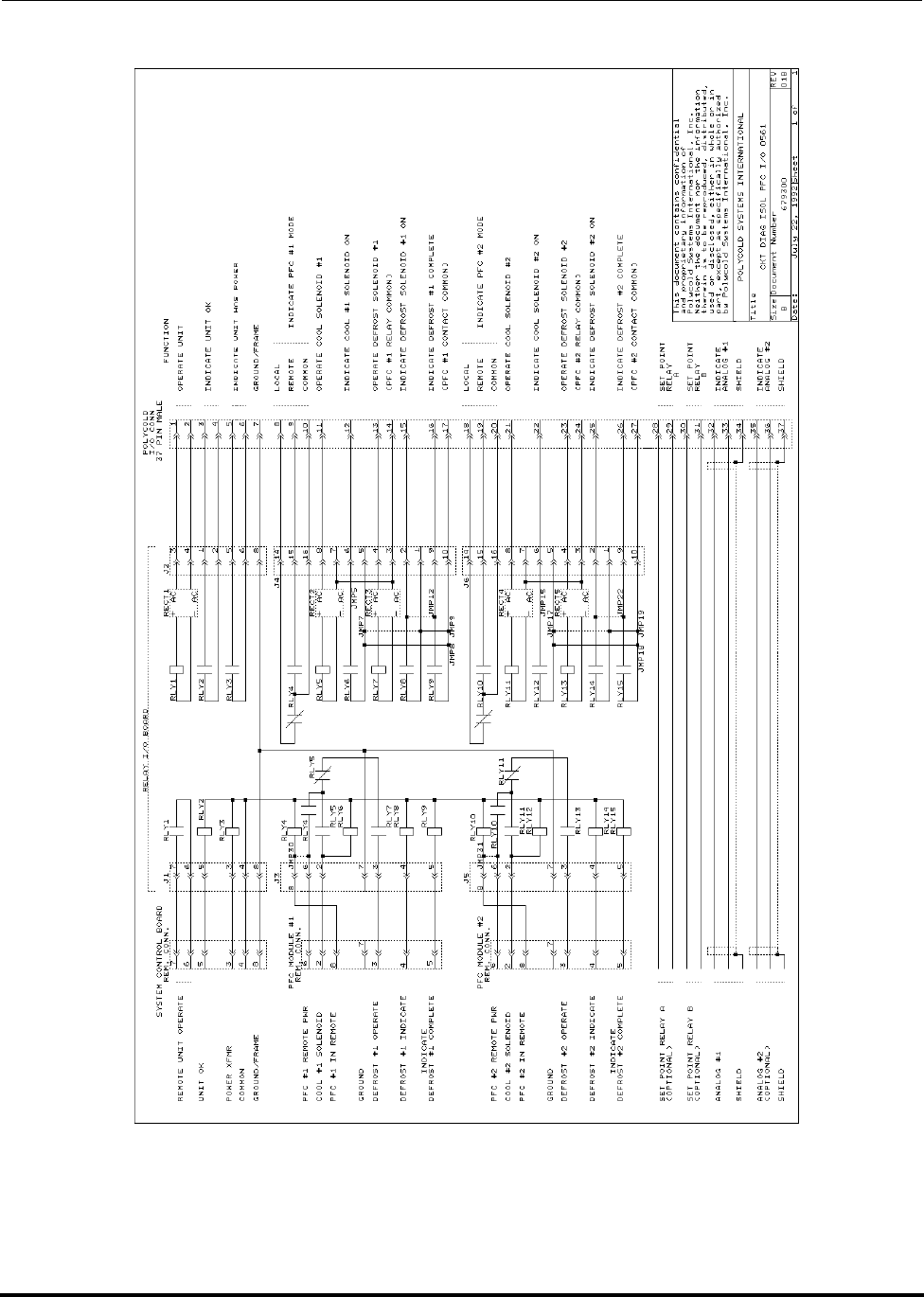
Options Polycold Fast Cycle Water Vapor Cryopump
Isolated Interface Option Customer Instruction Manual
825064-00 Brooks Automation
9-8 Revision 09
Figure 9-1: PFC and PFC/PFC isolated interface option—internal wiring
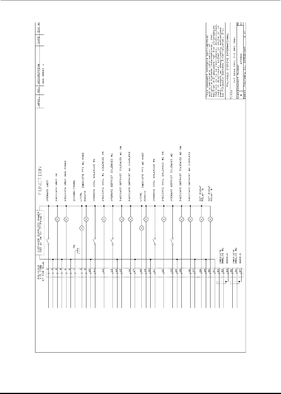
Polycold Fast Cycle Water Vapor Cryopump Options
Customer Instruction Manual Isolated Interface Option
Brooks Automation 825064-00
Revision 09 9-9
Figure 9-2: PFC and PFC/PFC isolated interface option suggested wiring for
customer’s control system
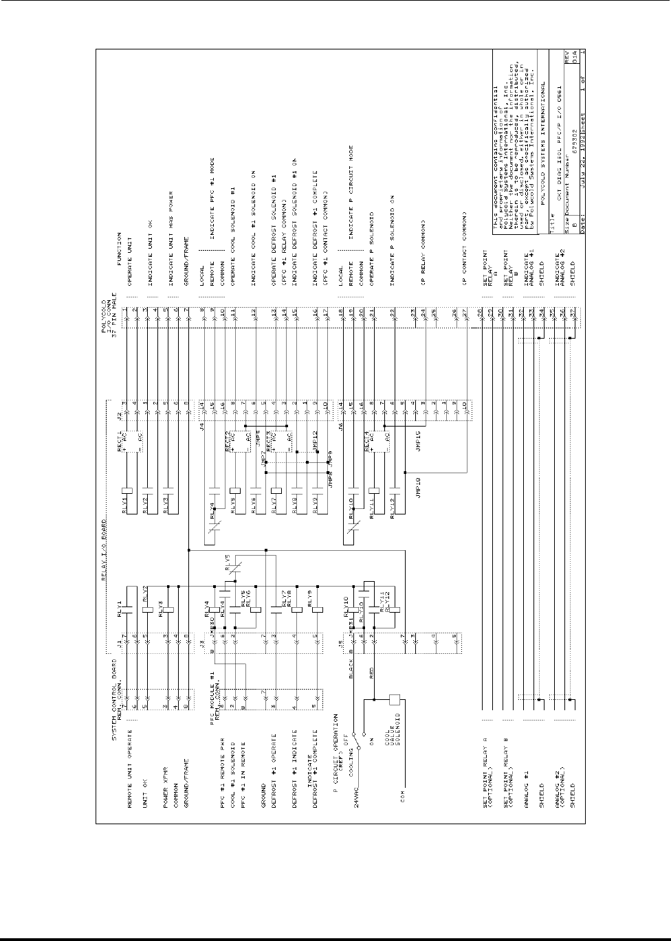
Options Polycold Fast Cycle Water Vapor Cryopump
Isolated Interface Option Customer Instruction Manual
825064-00 Brooks Automation
9-10 Revision 09
Figure 9-3: PFC/P isolated interface option—internal wiring
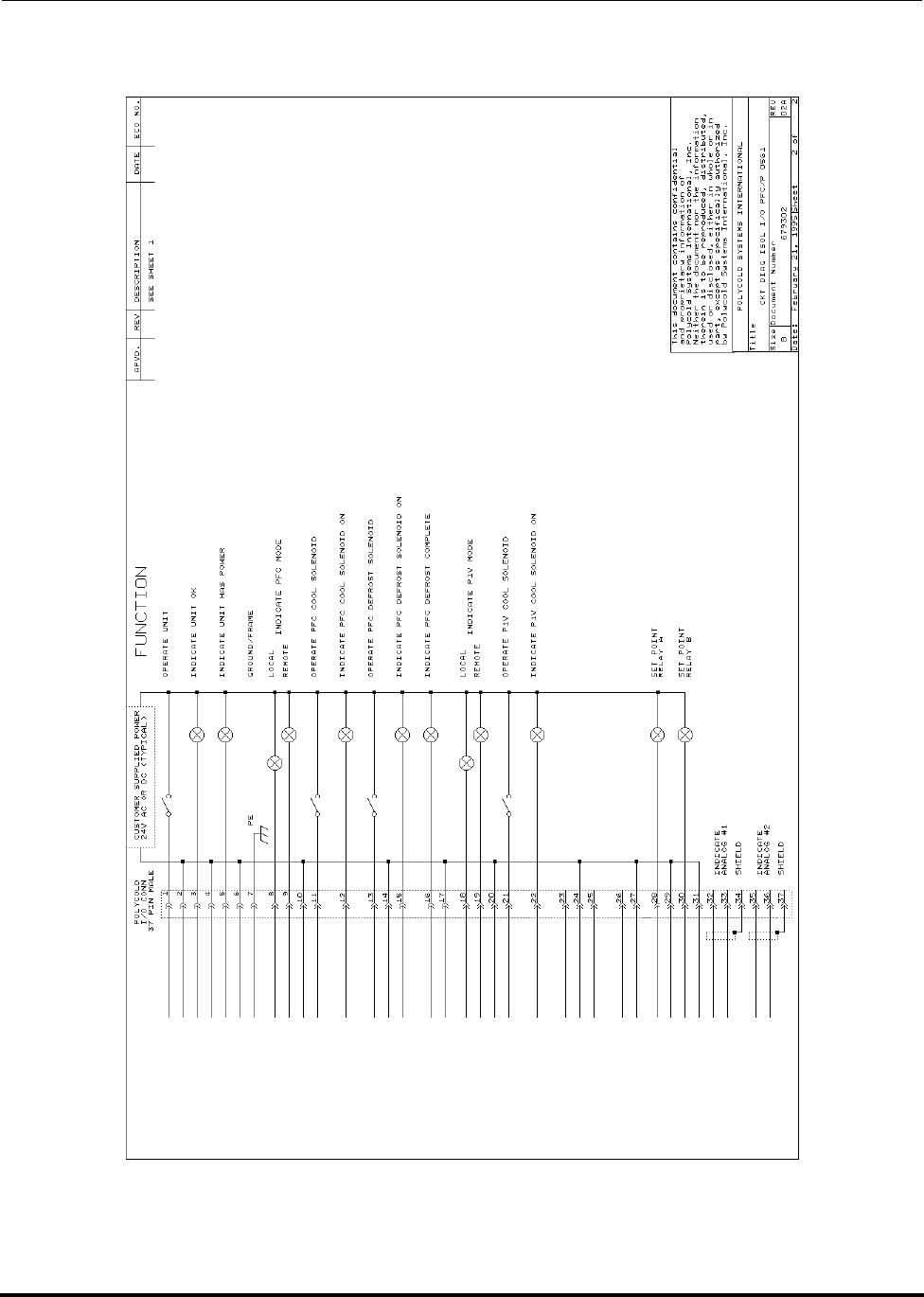
Polycold Fast Cycle Water Vapor Cryopump Options
Customer Instruction Manual Isolated Interface Option
Brooks Automation 825064-00
Revision 09 9-11
Figure 9-4: PFC/P isolated interface option—suggested wiring for customer’s control system
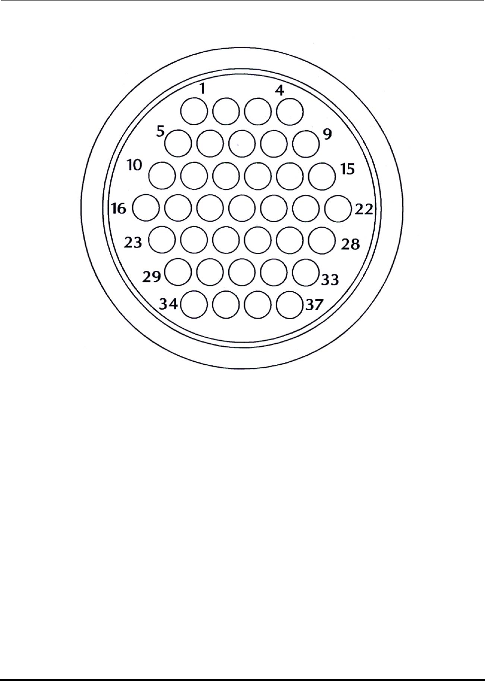
Options Polycold Fast Cycle Water Vapor Cryopump
Isolated Interface Option Customer Instruction Manual
825064-00 Brooks Automation
9-12 Revision 09
Figure 9-5: Isolated interface option—wire side of isolated I/O connector plug
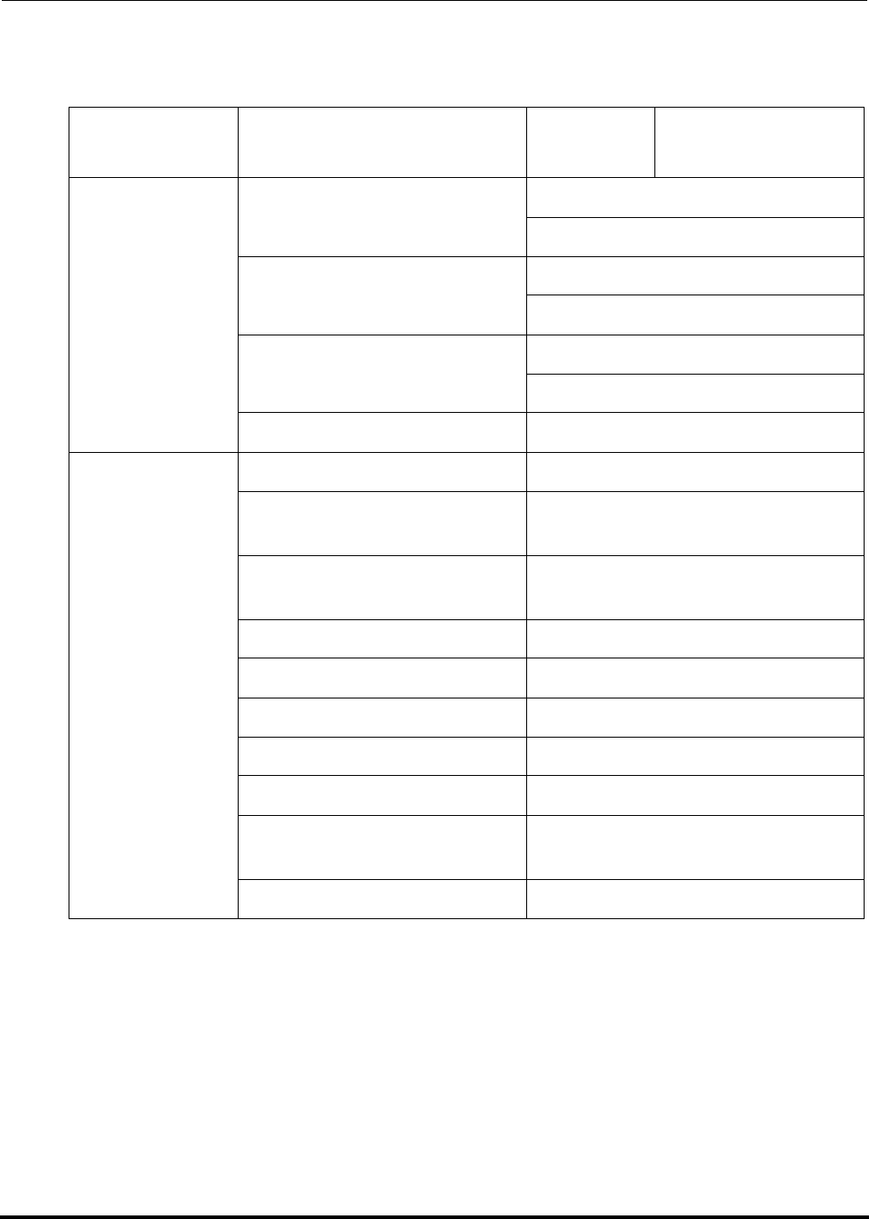
Polycold Fast Cycle Water Vapor Cryopump Options
Customer Instruction Manual Isolated Interface Option
Brooks Automation 825064-00
Revision 09 9-13
Table 9-4: Isolated Interface Option—Isolated I/O Connector Wiring Worksheet
Group Wire Function Pin
Number Customer’s Wire
Color
System
Control
Operate Unit 1
2
Indicate Unit OK 3
4
Indicate Power 5
6
Ground 7
Refrigerant
Circuit 1 (PFC)
Indicate REMOTE- LOCAL 8
Indicate REMOTE –
REMOTE 9
Indicate REMOTE – Com-
mon 10
Operate COOL 11
Indicate COOL 12
Operate DEFROST 13
Operate Common 14
Indicate DEFROST ACTIVE 15
Indicate DEFROST COM-
PLETE 16
Indicate Common 17

Options Polycold Fast Cycle Water Vapor Cryopump
Isolated Interface Option Customer Instruction Manual
825064-00 Brooks Automation
9-14 Revision 09
Refrigerant
Circuit 2
(PFC or P)
Indicate REMOTE- LOCAL 18
Indicate REMOTE –
REMOTE 19
Indicate REMOTE – Com-
mon 20
Operate COOL 21
Indicate COOL 22
Operate DEFROST (PFC
only) 23
Operate Common 24
Indicate DEFROST ACTIVE
(PFC only) 25
Indicate DEFROST COM-
PLETE (PFC only) 26
Indicate Common 27
Option Indicate Setpoint Relay A 28
29
Option Indicate Setpoint Relay B 30
31
Temperature
Meter 1
Analog #1 – Out 32
Analog #1 – Return 33
Analog #1 – Shield 34
Option—
Temperature
Meter 2
Analog #2 – Out 35
Analog #2 – Return 36
Analog #2 – Shield 37
Table 9-4: Isolated Interface Option—Isolated I/O Connector Wiring Worksheet
Group Wire Function Pin
Number Customer’s Wire
Color

Polycold Fast Cycle Water Vapor Cryopump Options
Customer Instruction Manual Leybold Isolated Interface Option
Brooks Automation 825064-00
Revision 09 9-15
9.3 Leybold Isolated Interface Option
The Leybold isolated interface option is the same as Polycold’s standard isolated
interface option with the following exceptions.
• The Leybold isolated interface option is only designed for models PFC and
PFC/PFC.
• The Leybold isolated interface option is only designed for an incoming voltage
of 24V.
• The isolated I/O connector plug has a different pin configuration.
• The Leybold isolated interface does not provide a “remote verification” signal.
Follow the instructions in section 9.2 Isolated Interface Option with the following
exceptions:
•Figure 9-6
•Figure 9-7
• Leybold Isolated Interface Option—Isolated I/O Connector Wiring Worksheet
• Disregard all prior figures and Table 3-10
• Disregard any information with respect to “remote verification” signal
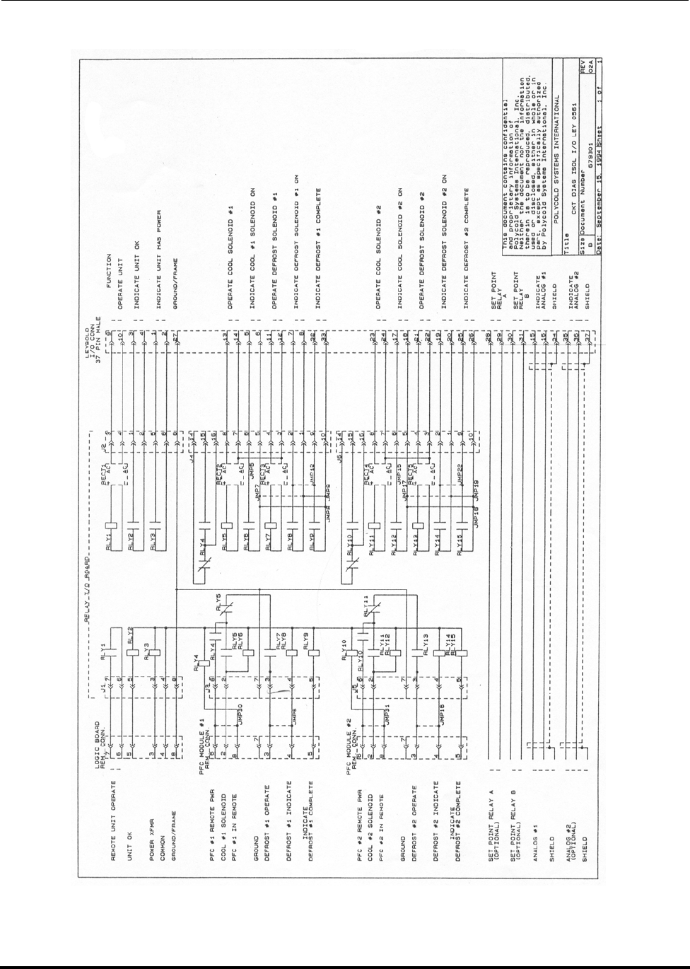
Options Polycold Fast Cycle Water Vapor Cryopump
Leybold Isolated Interface Option Customer Instruction Manual
825064-00 Brooks Automation
9-16 Revision 09
Figure 9-6: Leybold isolated interface option- schematic
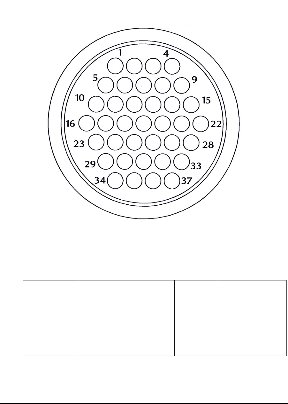
Polycold Fast Cycle Water Vapor Cryopump Options
Customer Instruction Manual Leybold Isolated Interface Option
Brooks Automation 825064-00
Revision 09 9-17
Figure 9-7: Leybold isolated interface option – wiring side of isolated I/O connector plug
Table 9-5: Leybold Isolated Interface Option—Isolated I/O Connector Wiring Worksheet
Group Wire Function Pin
Number Customer’s Wire
Color
System
Control
Indicate Power 1
2
Indicate Unit OK 3
4

Options Polycold Fast Cycle Water Vapor Cryopump
Leybold Isolated Interface Option Customer Instruction Manual
825064-00 Brooks Automation
9-18 Revision 09
Refrigerant
Circuit 1 (PFC)
Indicate COOL 5
6
Indicate DEFROST 7
8
System
Control Operate Unit 9
10
Refrigerant
Circuit 1 (PFC)
Operate DEFROST 11
12
Operate COOL 13
14
Temperature
Meter 1 Analog #1 – Out 15
Analog #1 – Return 16
Refrigerant
Circuit 2 (PFC)
Indicate COOL 17
18
Indicate DEFROST 19
20
Operate DEFROST 21
22
Operate COOL 23
24
Indicate DEFROST COM-
PLETE 25
26
System
Control Ground 27
Option Indicate Setpoint Relay A 28
29
Table 9-5: Leybold Isolated Interface Option—Isolated I/O Connector Wiring Worksheet
Group Wire Function Pin
Number Customer’s Wire
Color
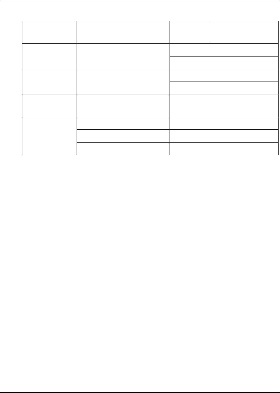
Polycold Fast Cycle Water Vapor Cryopump Options
Customer Instruction Manual Leybold Isolated Interface Option
Brooks Automation 825064-00
Revision 09 9-19
Option Indicate Setpoint Relay B 30
31
Refrigerant
Circuit 1 (PFC) Indicate DEFROST COM-
PLETE 32
33
Temperature
Meter 1 Analog #1 – Shield 34
Option—
Temperature
Meter 2
Analog #2 – Out 35
Analog #2 – Return 36
Analog #2 – Shield 37
Table 9-5: Leybold Isolated Interface Option—Isolated I/O Connector Wiring Worksheet
Group Wire Function Pin
Number Customer’s Wire
Color

Options Polycold Fast Cycle Water Vapor Cryopump
Temperature Module Options Customer Instruction Manual
825064-00 Brooks Automation
9-20 Revision 09
9.4 Temperature Module Options
Introduction
The temperature module options give the user additional information about one or
more temperatures of interest.
• See front of manual for the temperature module option and the thermocouple
numbers selected.
• See Figure 9-9 for identification of options.
• See Figure 3-23 for identification of thermocouple numbers.
Set-point Indication
The setpoint indication provides confirmation that a temperature of interest is below
a pre-determined setpoint. This temperature is transmitted to the thermocouple limit
switch via a type T thermocouple. The setpoint on the thermocouple limit switch is
adjustable from –80°C to –160°C. When the temperature from the input thermocou-
ple drops below the defined setpoint, the thermocouple limit switch:
1. lights a lamp on the temperature panel, and
2. closes a relay contact completing a circuit between two pins in the remote con-
nector.
Second Temperature Meter
The second temperature meter provides continuous indication of a single tempera-
ture between -199°C and +199°C. For more information about the temperature meter
or using the analog output, see section 3.8.2 Additional Instructions for Remote Tem-
perature Indication.
The analog output signal for remote temperature indication is not isolated.
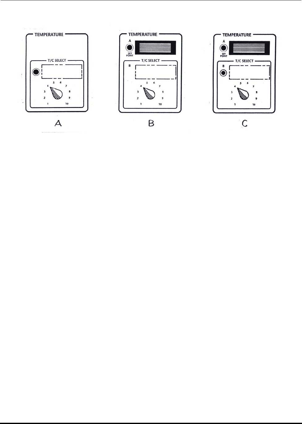
Polycold Fast Cycle Water Vapor Cryopump Options
Customer Instruction Manual Temperature Module Options
Brooks Automation 825064-00
Revision 09 9-21
Figure 9-8: Temperature module options identification
A. Option 600212-02: Setpoint indication, See Figure 9-9.
B. Option 600212-03: Second temperature meter & setpoint indication, see Figure
9-10.
C. Option 600212-04: Second temperature meter & two setpoint indications, see
Figure 9-11.
Additional Instructions for section 3 Installation
1. Connect the thermocouple wires to the appropriate terminal in the terminal
block.
For TCs #1, #2, #7, #8, #9, & #10
These thermocouples were connected at the factory. Skip this step and go to Step 2 in
this section.
NOTE: The COLDEST LIQUID (TC #9) temperature may rise above the setpoint when
the refrigeration unit is switched from STANDBY to COOL. This is due to
increased heat load while cooling the cryosurface.
For TCs #3, #4, #5, & #6
Connect the thermocouple wire to the appropriate terminal inside the low voltage
box. Follow the instructions in section 3.3.5 Connect the COIL IN & COIL OUT Ther-
mocouples.

Options Polycold Fast Cycle Water Vapor Cryopump
Temperature Module Options Customer Instruction Manual
825064-00 Brooks Automation
9-22 Revision 09
2. Set the temperature on the thermocouple limit switch.
Turn the knob to adjust the thermocouple limit switch to a desired temperature. The
accuracy of the setpoint dial is ±5°C.
3. Connect the refrigeration unit to the remote control system (if a remote con-
nector was installed).
Verify the remote control system provides an appropriate detection circuit to inter-
pret the setpoint relay contact closure.
• The maximum control voltage is 24V.
• The minimum current is 30 mA. (This is required to keep the relay contacts
clean. If this is not possible, see “Additional Instructions for section 5 Periodic
Inspection and Maintenance” in this section.)
• The maximum current is 5A (for inductive or resistive loads).
Connect the remote control system to the remote connector.
• For a standard remote connector, follow the instructions in section 3.8 How to
Install the Remote Control (Optional)
• For an isolated I/O connector, see section 9.2 Isolated Interface Option
Additional Instructions for section 5 Periodic Inspection and Maintenance
Check the operation of the setpoint relay(s) every year if running at less than the rec-
ommended minimum current. See Figure 9-9 through Figure 9-11. If it is necessary
to replace a relay, refer to the following part numbers.
Relay Description IDEC’s (manufacturer) Part
Number Polycold’s Part
Number
24 V(ac), 1-pole RH1B-U AC 24V 333019-01
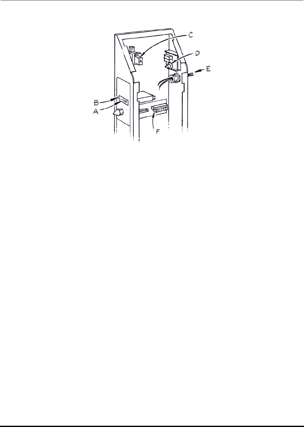
Polycold Fast Cycle Water Vapor Cryopump Options
Customer Instruction Manual Temperature Module Options
Brooks Automation 825064-00
Revision 09 9-23
Figure 9-9: Temperature module options—parts identification for option 600212-02
A. Standard temperature meter
B. Lamp for setpoint A
C. Relay for setpoint A
D. Thermocouple limit switch knob for setpoint A
E. External thermocouple entrance
F. Terminal blocks for thermocouple connections
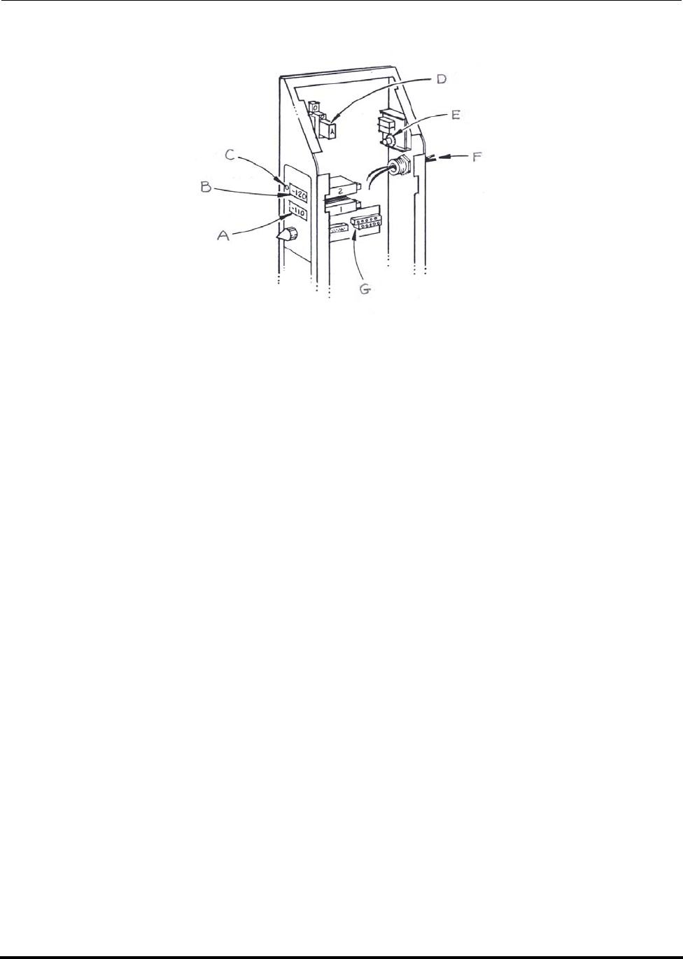
Options Polycold Fast Cycle Water Vapor Cryopump
Temperature Module Options Customer Instruction Manual
825064-00 Brooks Automation
9-24 Revision 09
Figure 9-10: Temperature module options—parts identification for option 600212-03
A. Standard temperature meter
B. Second temperature meter
C. Lamp for setpoint A
D. Relay for setpoint A
E. Thermocouple limit switch knob for setpoint A
F. External thermocouple entrance
G. Terminal blocks for thermocouple connections
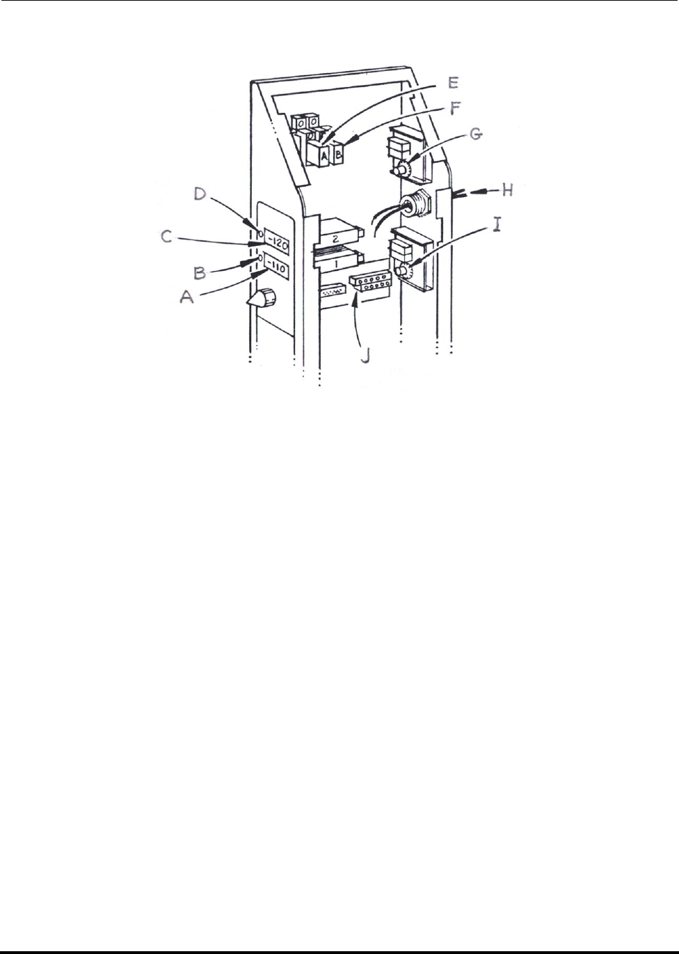
Polycold Fast Cycle Water Vapor Cryopump Options
Customer Instruction Manual Temperature Module Options
Brooks Automation 825064-00
Revision 09 9-25
Figure 9-11: Temperature module options—parts identification for option 600212-04
A. Standard temperature meter
B. Lamp for setpoint B
C. Second temperature meter
D. Lamp for setpoint A
E. Relay for setpoint A
F. Relay for setpoint B
G. Thermocouple limit switch knob for setpoint A
H. External thermocouple entrance
I. Thermocouple limit switch knob for setpoint B
J. Terminal blocks for thermocouple connections

Options Polycold Fast Cycle Water Vapor Cryopump
High Liquid Line Temperature Alarm Option Customer Instruction Manual
825064-00 Brooks Automation
9-26 Revision 09
9.5 High Liquid Line Temperature Alarm Option
Introduction
This option is a modification of Polycold’s standard liquid line protection and the
temperature module options. It is used in locations where the temperature of the
cooling water is marginally warm 86-93°F (30-34°C).
Normally the refrigeration unit is shut off if the LIQUID LINE (TC #2) temperature
exceeds 33°C. The High Liquid Line Temperature Alarm Option does the following.
If the LIQUID LINE (TC #2) temperature rises above 33°C, a thermocouple limit
switch:
• lights the lamp next to the temperature display, and
• closes a relay contact completing a circuit between two pins in the remote con-
nector.
If the LIQUID LINE (TC #2) temperature rises above 38°C, a second thermocouple
limit switch:
• shuts off the refrigeration unit,
• lights the HIGH LIQUID TEMPERATURE lamp on the SYSTEM CONTROL
panel, and
• opens a contact which terminates the “unit OK” signal to the remote connector.
NOTE: If the LIQUID LINE is too hot when the unit is started, a bypass timer allows 14
seconds for it to cool down before the unit is shut off.
Additional Instructions for section 3 Installation (if a remote connector was
installed)
Verify the remote control system provides an appropriate detection circuit to inter-
pret the setpoint relay contact closure.
• The maximum control voltage is 24V.
• The minimum current is 30 mA. (This is required to keep relay contacts clean.
If this is not possible, see “Additional Instructions for section 5 Periodic Inspec-
tion and Maintenance” in this section.)
• The maximum current is 5A (for inductive or resistive loads).
• Connect the remote control system to the remote connector.
• If the remote connector is standard, see section 3.8 How to Install the Remote
Control (Optional).

Polycold Fast Cycle Water Vapor Cryopump Options
Customer Instruction Manual High Liquid Line Temperature Alarm Option
Brooks Automation 825064-00
Revision 09 9-27
• If you have an isolated I/O connector, see section 9.2 Isolated Interface Option.
NOTE: If no other Temperature Module options were purchased, the high liquid line tem-
perature alarm will be designated “Setpoint A.” If the second temperature meter
was purchased with setpoint relay, the high liquid line temperature alarm will be
designated “Setpoint B.” See section 9.4 Temperature Module Options
Additional Instructions for section 5 Periodic Inspection and Maintenance
Check the operation of the relay every year if running at less than the recommended
minimum current. The relay is located above the temperature meter(s) on a rail
mount inside the low voltage box. If it is necessary to replace the relay, refer to the fol-
lowing part numbers.
Relay Description IDECs (manufacturer) Part
Number Polycold Part
Number
24V(ac), 1-pole RH1B-U AC 24V 333019-01

Options Polycold Fast Cycle Water Vapor Cryopump
How to Install the GVE Remote Control Option Customer Instruction Manual
825064-00 Brooks Automation
9-28 Revision 09
9.6 How to Install the GVE Remote Control Option
The GVE Remote Control Option is Polycold’s standard remote control option:
• The GVE Remote Control Option is designed for models PFC-550s, PFC-660s,
PFC-670s, and PFC-1100s.
• Electrical signals are transferred to and from the refrigeration unit via a termi-
nal strip (instead of a remote connector).
9.6.1 Connect the GVE Remote Control Option
Tools and materials needed:
• Phillips screwdriver
• 5/16 inch nut driver
• Drill or punch (as required)
• Liquid tight fitting (for drilled or punched hole)
• Straight blade screwdriver
• 18 AWG (0.75 mm2 cross-sectional area) wire / cable
• Wire strippers
• Terminal crimping tool
• Crimp ring terminals for #6 screws
• Switches with a minimum capacity of 1A
• 24V indicator lamps (optional1)
• Shielded cable (optional2)
1 If function indicator lamps are wanted at a remote location
2 If remote temperature indication is wanted
9.6.1.1 Review the remote control schematic
See Figure . The remote connector pin numbers are the terminal numbers for the GVE
Remote Control Option.
Determine if a unit ON/OFF switch or function indicator lamps are wanted at a
remote location. All circuits connected to the terminal strip are 24V(ac).
Polycold Fast Cycle Water Vapor Cryopump Options
Customer Instruction Manual How to Install the GVE Remote Control Option
Brooks Automation 825064-00
Revision 09 9-29
NOTE: A temperature from the TC SELECT switch can also be displayed at a remote loca-
tion through the remote connector. To do this, see section 3.8.2 Additional Instruc-
tions for Remote Temperature Indication.
9.6.1.2 Connect the control system to the terminal strip
Loosen the two lower screws on the side of the low voltage box. Slide the panel
straight up to remove it. See Figure 3-22.
Remove the plate marked REMOTE from the back of the low voltage box. Drill or
punch a hole in the plate and install the liquid tight fitting. Reinstall the plate.
Feed the cable through the liquid tight fitting. Strip the insulation from the end of
each wire. Crimp each wire to a terminal. Screw each terminal to the appropriate
location on the terminal strip.
Tighten the liquid tight fitting around the cable.
9.6.1.3 Connect the wires to the control system
See Table 9-6 in this section. The remote connector pin numbers are the terminal num-
bers for the GVE Remote Control Option.
WARNING
ELECTRICAL HAZARD
Contact could cause electric shock and result in death or serious
injury.
Make certain the ON/OFF switch and the power disconnect
switch are in the OFF position.
CAUTION
GENERAL HAZARD
Make sure the wiring configuration does not operate the unit in COOL
& DEFROST at the same time; damage to the equipment can result.
Polycold recommends the use of a three-position switch.

Options Polycold Fast Cycle Water Vapor Cryopump
How to Install the GVE Remote Control Option Customer Instruction Manual
825064-00 Brooks Automation
9-30 Revision 09
Figure 9-12: Wire side of remote connector plug
CAUTION
GENERAL HAZARD
Make sure the wiring configuration does not start the unit in COOL or
DEFROST; damage to the equipment can result.
The three-position switch should be in the neutral position so that the
unit will start in STANDBY. (When REMOTE is selected local func-
tions will be disabled.)

Polycold Fast Cycle Water Vapor Cryopump Options
Customer Instruction Manual How to Install the GVE Remote Control Option
Brooks Automation 825064-00
Revision 09 9-31
Table 9-6: Remote Connector Wiring Worksheet
Group Wire Function Pin
Number Customer’s Wire
Color
System
Control
Operate Unit 1
2
Indicate Unit OK 3
Indicate Power 4
Common 5
Ground 6
Refrigerant
Circuit 1 (PFC)
Indicate REMOTE 10
Operate COOL 11
Operate DEFROST 12
Indicate DEFROST COM-
PLETE 13
Indicate DEFROST ACTIVE 14
Refrigerant
Circuit 2
(PFC or P)
Indicate REMOTE 18
Operate COOL 19
Operate DEFROST (PFC
only) 20
Indicate DEFROST COM-
PLETE (PFC only) 21
Indicate DEFROST ACTIVE
(PFC only) 22
Option Indicate Setpoint Relay A 26
27
Temperature
Meter 1
Analog #1 - Out 28
Analog #1 - Return 29
Analog #1 - Shield 30
Option Indicate Setpoint Relay B 31
32

Options Polycold Fast Cycle Water Vapor Cryopump
How to Install the GVE Remote Control Option Customer Instruction Manual
825064-00 Brooks Automation
9-32 Revision 09
9.6.1.4 Program the remote control if a controller is present
See section 4 Operation for operation modes.
9.6.1.5 If a remote ON / OFF switch has been installed, unplug jumper J11 from
the SYSTEM CONTROL printed circuit board
Locate JMPR J11 on the SYSTEM CONTROL printed circuit board in the low voltage
box. See Figure 3-30 and Figure 3-31. Squeeze the jumper’s latch to unplug it.
Reinstall the low voltage box panel. Slide it straight down onto the low voltage box
so that the two tabs go into their notches. Push the top of the panel towards the unit
and at the same time push down so that the top tab goes into its notch. Tighten the
two screws.
9.6.1.6 Select REMOTE
NOTE: When a refrigerant circuit is in LOCAL, its remote functions are disabled (includ-
ing the unit’s ON /OFF switch).
9.6.1.7 Make sure the remote control operates the unit properly
Use the remote control to do the following test.
Select STANDBY and turn on the refrigeration unit.
• The unit’s compressor should be running.
• The unit’s STANDBY indicator lamp should be lighted.
• The COLDEST LIQUID (TC #9) temperature should start getting colder.
Wait 30 minutes. Evacuate location of the cryosurface to at least 0.01 torr (1.33 Pa).
Switch to COOL.
Option—
Temperature
Meter 2
Analog #2 - Out 33
Analog #2 - Return 34
Analog #2 - Shield 35
Table 9-6: Remote Connector Wiring Worksheet
Group Wire Function Pin
Number Customer’s Wire
Color
Polycold Fast Cycle Water Vapor Cryopump Options
Customer Instruction Manual How to Install the GVE Remote Control Option
Brooks Automation 825064-00
Revision 09 9-33
• The unit’s COOL indicator lamp should be lighted.
• The COIL OUT (TC #4) temperature should start getting colder.
Switch to DEFROST.
• The unit’s DEFROST ACTIVE indicator lamp should be lighted.
• When DEFROST is complete, the unit’s DEFROST COMPLETE and STANDBY
indicator lamps should be lighted.
Open your vacuum chamber. The cryosurface should be dry and at room tempera-
ture or warmer.
CAUTION
EXTREME TEMPERATURES EXIST
Parts of the cryosurface may be hot; contact with the hot surface
may result in minor or moderate injury.
Do not touch the cryosurface.

Options Polycold Fast Cycle Water Vapor Cryopump
Customer Instruction Manual
825064-00 Brooks Automation
9-34 Revision 09
This Page Intentionally Left Blank

Polycold Fast Cycle Water Vapor Cryopump
Customer Instruction Manual
Brooks Automation 825064-00
Revision 09 10-1
10 Drawings
Overview
The Process & Instrumentation Diagrams and the Electrical Schematics on the follow-
ing pages pertain to Models 550, 660, 670, and 1100 only.
Contents
Figure 10-1: Cryopump Simplified Controls Diagram (6-2) . . . . . . . . . . . . . . . . .10-3
Figure 10-2: High Voltage Box (6-3) . . . . . . . . . . . . . . . . . . . . . . . . . . . . . . . . . . . . .10-4
Figure 10-3: High Voltage Box—575 V Compressor Only (6-4) . . . . . . . . . . . . . .10-5
Figure 10-4: SYSTEM CONTROL Printed Circuit Board (6-5) . . . . . . . . . . . . . . .10-6
Figure 10-5: PFC Refrigerant Circuit Controls. . . . . . . . . . . . . . . . . . . . . . . . . . . . .10-7
Figure 10-6: PFC Remote Connector Functions. . . . . . . . . . . . . . . . . . . . . . . . . . . .10-8
Figure 10-7: PFC/PFC Remote Connector Functions. . . . . . . . . . . . . . . . . . . . . . .10-9
Figure 10-8: PFC/P Remote Connector Functions . . . . . . . . . . . . . . . . . . . . . . . . .10-10

Drawings Polycold Fast Cycle Water Vapor Cryopump
Customer Instruction Manual
825064-00 Brooks Automation
10-2 Revision 09
The Process & Instrumentation Diagrams and the Electrical Schematics on the follow-
ing pages pertain to Models 550, 660, 670, and 1100 only.
Process & Instrumentation Diagrams and Electrical Schematics for additional Models
are available in separate documents as listed in the table below.
Table 10-1: Additional P & IDs and Electrical Schematics
Model Document #
PFC 551 825113-00
PFC 552 825114-00
PFC 661 825115-00
PFC 662 825116-00
PFC 672 825117-00
PFC 1101 825118-00
PFC 1102 825119-00
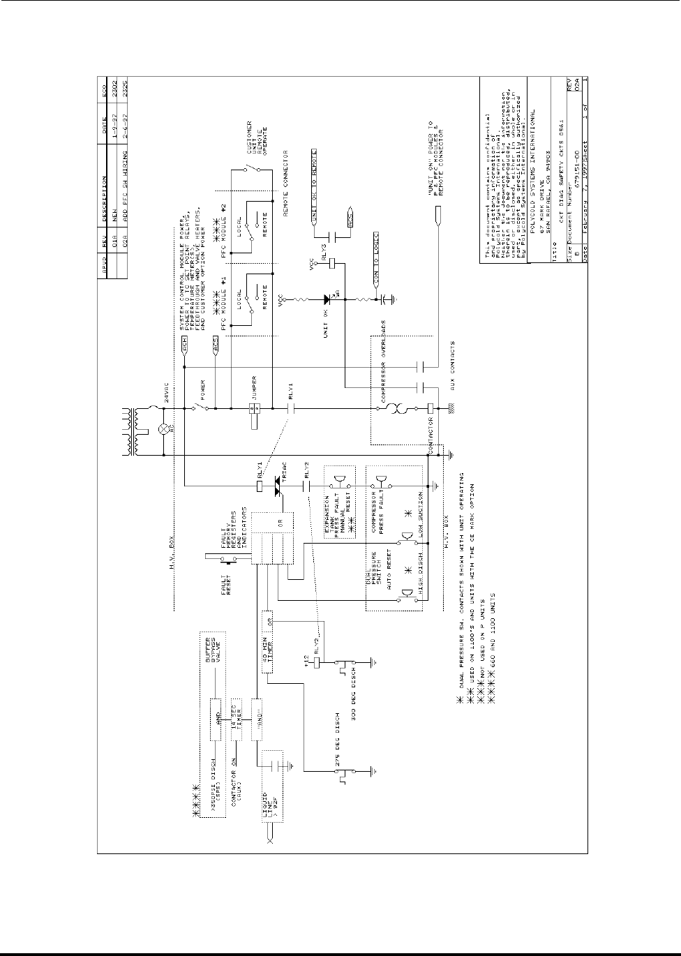
Polycold Fast Cycle Water Vapor Cryopump Drawings
Customer Instruction Manual
Brooks Automation 825064-00
Revision 09 10-3
Figure 10-1: Cryopump Simplified Controls Diagram (6-2)

Drawings Polycold Fast Cycle Water Vapor Cryopump
Customer Instruction Manual
825064-00 Brooks Automation
10-4 Revision 09
Figure 10-2: High Voltage Box (6-3)
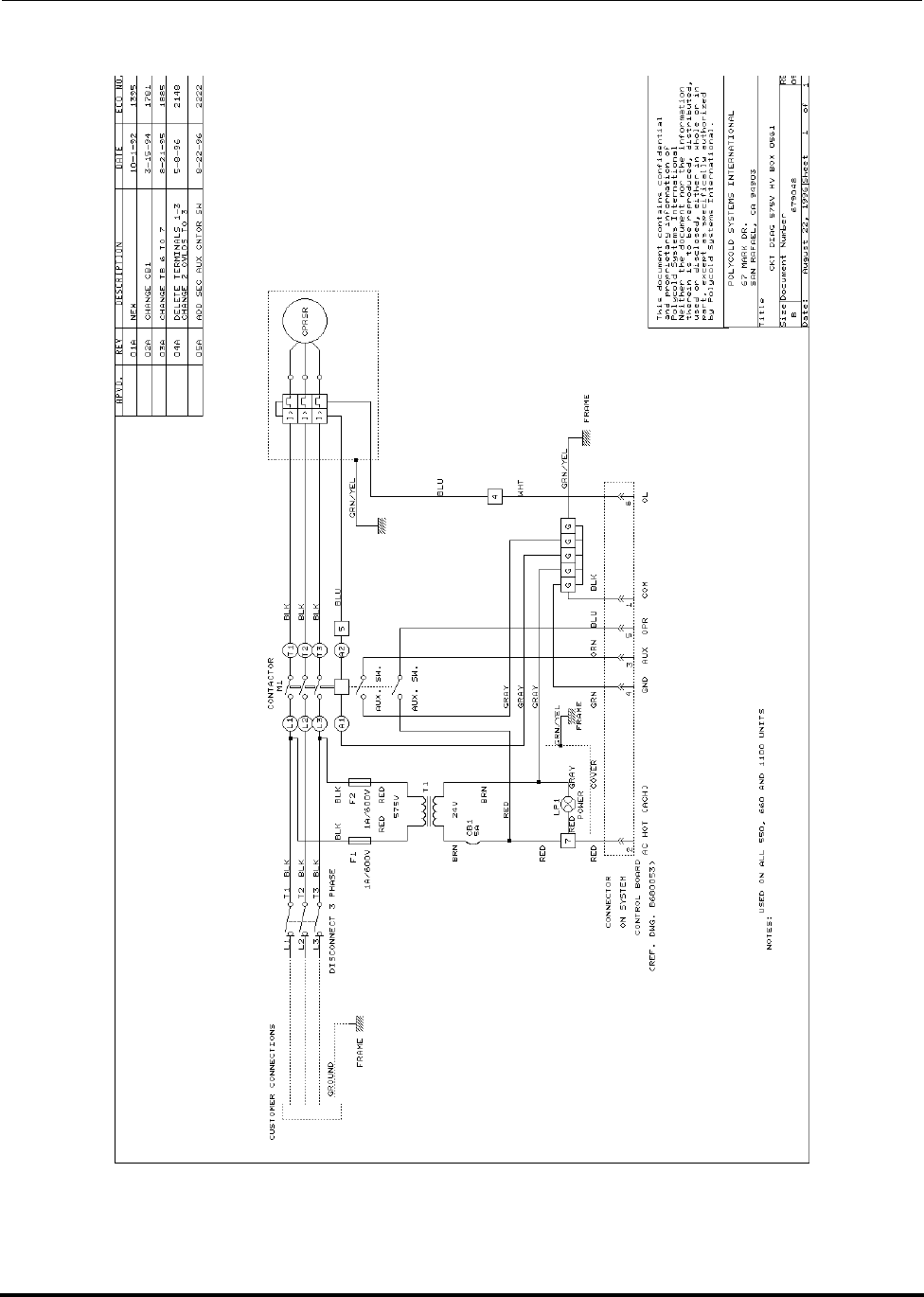
Polycold Fast Cycle Water Vapor Cryopump Drawings
Customer Instruction Manual
Brooks Automation 825064-00
Revision 09 10-5
Figure 10-3: High Voltage Box—575 V Compressor Only (6-4)
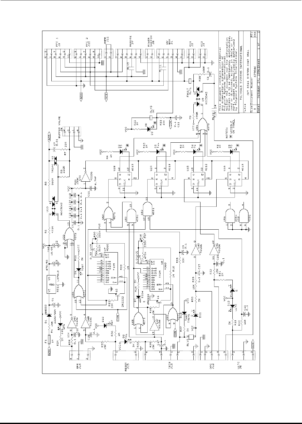
Drawings Polycold Fast Cycle Water Vapor Cryopump
Customer Instruction Manual
825064-00 Brooks Automation
10-6 Revision 09
Figure 10-4: SYSTEM CONTROL Printed Circuit Board (6-5)
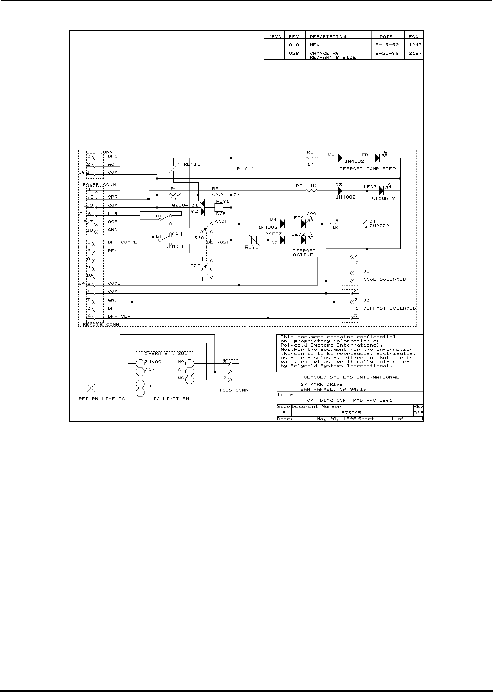
Polycold Fast Cycle Water Vapor Cryopump Drawings
Customer Instruction Manual
Brooks Automation 825064-00
Revision 09 10-7
Figure 10-5: PFC Refrigerant Circuit Controls
- Printed Circuit Board with Panel (6-7)

Drawings Polycold Fast Cycle Water Vapor Cryopump
Customer Instruction Manual
825064-00 Brooks Automation
10-8 Revision 09
Figure 10-6: PFC Remote Connector Functions
with Suggested Wiring (6-8)
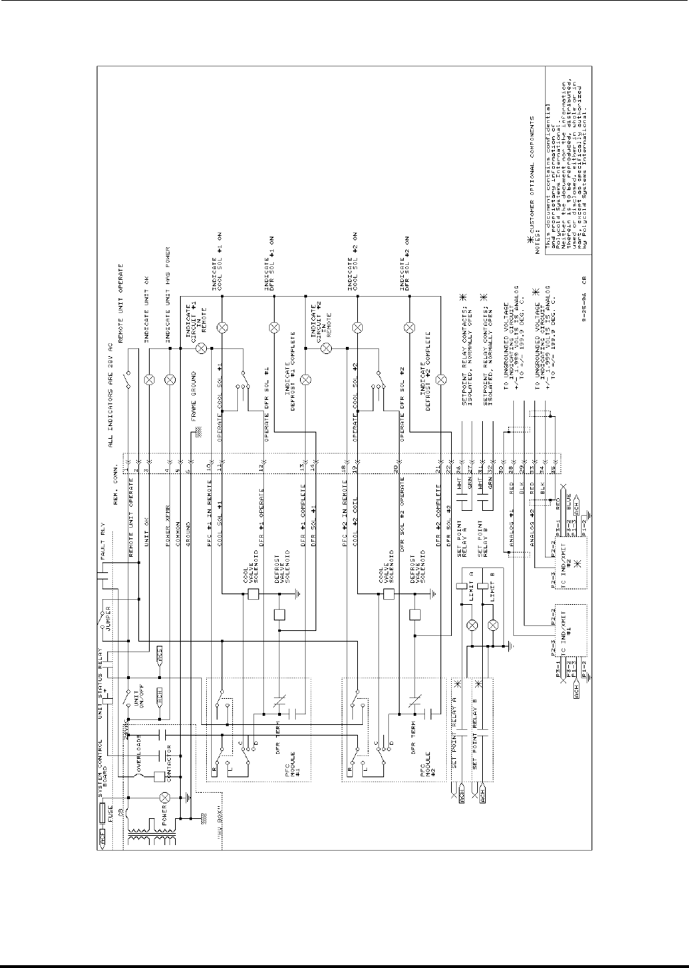
Polycold Fast Cycle Water Vapor Cryopump Drawings
Customer Instruction Manual
Brooks Automation 825064-00
Revision 09 10-9
Figure 10-7: PFC/PFC Remote Connector Functions
with Suggested Wiring (6-9)
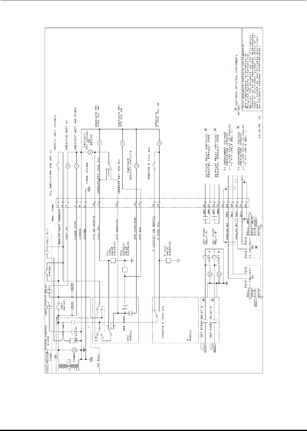
Drawings Polycold Fast Cycle Water Vapor Cryopump
Customer Instruction Manual
825064-00 Brooks Automation
10-10 Revision 09
Figure 10-8: PFC/P Remote Connector Functions
with Suggested Wiring (6-10)

Polycold Fast Cycle Water Vapor Cryopump
Customer Instruction Manual
Brooks Automation 825064-00
Revision 09 G-1
Glossary
This Glossary provides a list of common terms and acronyms used in this document
and their definitions.
3U: U is a unit of height in electronic packaging of 1.75 in. 3U is three times
that height (5.25 in.).
Z Axis: The axis of vertical motion. For a robot it is the “up and down” of the
robot’s arms. For an elevator it is the “up and down” of the platform.
ANSI: American National Standards Institute.
ASHRAE: American Society of Heating, Refrigerating, and Air-Conditioning Engi-
neers.
AWG: American wire gauge.
Balance pressure: The pressure in the refrigeration unit (or cryopump) when the suction
and discharge sides of the compressor are equal. For 550s, 660s, and
1100s, the refrigeration unit must be off for 48 hours to obtain the bal-
ance pressure.
CE: European conformity.
Coldest liquid: A portion of the refrigerant circuit that obtains the lowest temperature
prior to evaporation.
Compressor: A component in the refrigeration unit that raises the refrigerant pres-
sure and causes the refrigerant to move through the circuit.
Compressor compartment: The lower portion of the refrigeration unit that contains the
compressor and condenser.
Condenser: A component in the refrigeration unit that removes heat from the refrig-
erant vapor after it exits the compressor.

Glossary Polycold Fast Cycle Water Vapor Cryopump
Customer Instruction Manual
825064-00 Brooks Automation
G-2 Revision 09
Cryopump: The Polycold cryogenic refrigeration system that captures water mole-
cules in a vacuum chamber. It consists of a refrigeration unit, a refriger-
ant line, and a cryosurface (with cryogenic feed-through).
Cryosurface: The coil or baffle in the vacuum chamber that captures water molecules
by freezing them to its surface.
Discharge line: A portion of the refrigerant circuit containing high temperature, high
pressure refrigerant just after it has exited the compressor.
EC: European Community.
EEC: European Economic Community.
EMC: Electromagnetic compatibility.
EN: European norm (or standard).
Feed line: The copper tube in the refrigerant line that carries refrigerant from the
refrigeration unit to the cryosurface.
Field replacement charge: A refrigerant mixture that replaces the refrigerant in the
cryopump.
IEC: International Electro-technical Commission.
I/O: Input / output.
Liquid line: A portion of the refrigerant circuit containing high pressure refrigerant
just after it has been cooled by the water-cooled condenser.
Lower shelf: See “compressor compartment.”
Manifold: The service manifold gauge set.
NEC: National electrical code.
NPT: National pipe thread.
OFHC: Oxygen-free, high-capacity.
Polycold stack: The upper portion of the refrigeration unit that is insulated with foam.
Recharge: A procedure for replacing the refrigerant in a cryopump.

Polycold Fast Cycle Water Vapor Cryopump Glossary
Customer Instruction Manual
Brooks Automation 825064-00
Revision 09 G-3
Refrigerant: A proprietary mixture of refrigerants made by Brooks Polycold Systems
Inc.
Refrigerant circuit: The path of the refrigerant that goes from the refrigeration unit,
through the feed line, through the cryosurface, through the return line,
and back to the refrigeration unit.
Refrigerant expansion tank: A tank inside the refrigeration unit that maintains the gaseous
refrigerant at a safe pressure when the unit is not at operating tempera-
ture.
Refrigerant line: The insulated feed and return lines that carry refrigerant to and from the
cryosurface.
Refrigeration unit: The machine containing the compressor, condenser, and Polycold stack
that cools the refrigerant mixture to cryogenic temperatures.
Return line: The copper tube in the refrigerant line that carries refrigerant from the
cryosurface to the refrigeration unit.
SAE: Society of Automotive Engineers.
TC: Thermocouple.
TC #___: The position number of the TC SELECT switch that is located on the
front of the refrigeration unit.
Top-off charge: A refrigerant mixture that can be added to the refrigerant in the cry-
opump.
TÜV: Technical Supervision Society; the organization responsible for verify-
ing compliance with EN and IEC standards.
UL: Underwriters Laboratories; the organization responsible for verifying
compliance with NEC standards.

Glossary Polycold Fast Cycle Water Vapor Cryopump
Customer Instruction Manual
825064-00 Brooks Automation
G-4 Revision 09
This Page Intentionally Left Blank
