Pf60 Pfdata
User Manual: pf60
Open the PDF directly: View PDF ![]() .
.
Page Count: 44
PF™
PEM® CAPTIVE
PANEL SCREWS
PEM® access hardware for enclosures
where the screw must remain with the
door or panel.
Bulletin PF-617
Rev 1217
PF-2 PennEngineering • www.pemnet.com
PEM® brand captive panel screws are designed to help keep parts to a minimum and eliminate risks associated with loose
hardware that could fall out and damage internal components. These panel fastener assemblies are ideal to attach metal
panels or other thin material components in applications where subsequent access will be necessary.
PEM® CAPTIVE PANEL SCREWS
PFC2™/PFS2™ screw head, spring-loaded
captive panel screws - PAGE 16
PTL2™/PSL2™ locating pin, spring-loaded
plunger assemblies - PAGE 17
SCBR™ tool only, spinning clinch bolt with
spring - PAGE 18
SCB™/SCBJ™ tool only, spinning clinch bolts,
no spring - PAGE 19
HSCB™, HSR™, and HSL™ heat sink mounting
fastener system - PAGES 20 - 21
PF10™ tool only, flush-mounted captive panel
screws, no spring - PAGES 22 - 23
REELFAST® SMTPFLSM™ surface mount
spring-loaded captive panel screws -
PAGE 24
REELFAST® SMTPF™ surface mount, panel
screw components and assembly data -
PAGE 25
PFK™ screw head, spring-loaded broaching
captive panel screws - PAGE 26
Value-added capabilities - PAGE 27
Captive panel screw installation - PAGES 28 - 36
Captive panel screw performance data - PAGES 37 - 41
Captive panel screw capabilities - PAGE 42
PF11™/PF12™/PF11M™/PF12M™ large knob,
spring-loaded self-clinching panel screws -
PAGE 5
PF11MF™ large knob, spring-loaded flare-
mounted captive panel screws - PAGE 6
PF11MW™ large knob, spring-loaded flare-
mounted, floating captive panel screws -
PAGE 7
PF11PM™ large knob, spring-loaded plastic
PEM® C.A.P.S.® captive panel screws -
PAGE 8
PFHV™ screw head, no spring captive panel
screws - PAGE 9
PF7M™ screw head, spring-loaded self-
clinching captive panel screws - PAGE 10
PF7MF™ flare-mounted captive panel screws
for installing into stainless steel - PAGE 11
PF30™ low-profile knob, spring-loaded captive
panel screws - PAGE 12
PF50™ and PF60™ low-profile knob, spring-
loaded captive panel screws - PAGE 13
PFC4™ recessed-head captive panel screws
for installing into stainless steel - PAGE 14
PFC2P™ tool only, non flush, spring-loaded
captive panel screws - PAGE 15
HEIGHT COMPARISON GUIDE AND STANDARD DRIVER RECESS
PFC4
PF11/PF12
PF11M/PF12M
PFC2/PFS2
PFK
PFC2P
PF50/PF51/PF52
PF60/PF61/PF62 PF30/31/32
PF7M/PF7MF
Installed and fastened height above sheet for M3 Thread size.
PennEngineering • www.pemnet.com PF-3
PF11 5 • • • • •
PF11M 5 • • • • • •
PF12 5 • • • •
PF12M 5 • • • • •
PF11MF 6 • • • • • • • • •
PF12MF 6 • • • • • • • •
PF11MW 7 • • • • • • • • • • •
PF12MW 7 • • • • • • • • • •
PEM
C . A .P. S.
8 • • • • •(1) • •
PFHV 9 • • •
PF7M 10 • • • • •
PF7MF 11 • • • • • • • •
PF30
PF31 12 • • • •
PF32
PF50
PF51 13 • • • • •
PF52
PF60
PF61 13 • • • •
PF62
PFC4 14 • • • • •
PFC2P 15 • • • • •
PFC2 16 • • • • • •
PFS2 16 • • • • •
SCBR 18 • •
SCB/SCBJ 19 • •
HSCB 20-21 • •
PF10 22-23 • • • •
SMTPFLSM 24 • • • • • •
SMTPF 25 • • • • •(1) •
PFK 26 • • • • • • •
(1) Standard color is black.
CAPTIVE PANEL SCREW SELECTOR GUIDE
Application Requires:
PEM®
Panel
Fastener Page
Type No.
Actuation Installs into Includes
Painted Available anti Mating
High Printed Stainless panels Multiple Flush Available in cross- hole
UL corrosion Spring Tool Hand Thinner circuit steel and/or any screw mounted in custom threading misa-
Approved resistance loaded sheets boards sheet hardness lengths top side black colors feature lignment
PF11MF PF11MW PFHV SCB/SCBJ PF10PEM C.A.P.S.® SCBRHSCB
PF-4 PennEngineering • www.pemnet.com
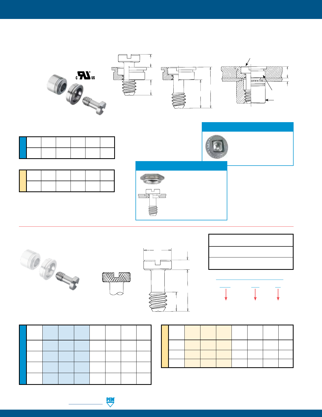
PEM® PF11™/PF12™ CAPTIVE PANEL SCREWS
PEM® PF11/PF12 panel fasteners provide design flexibility by oering three styles of installation types, each having the same profile
or look above the sheet or panel into which it is installed. The various mounting types include self-clinching, flare-mounted, and
floating styles. Each oers a distinct advantage depending on your application. The standard selection of knobs include knurled
or smooth metal caps and plastic PEM C.A.P.S.® (colored access panel screws).
• Installs flush on back side of panel.
• Available in three screw
lengths.
Self-clinching Flare-mounted, Floating
• Compensates for mating hole misalignment.
• Installs into any panel hardness.
Key features include:
1) Universal Phillips/slot drive (except for plastic cap).
2) Shoulder on retainer to provide positive stop during installation.
3) Anti cross-threading feature (designated with an “M” in the
part number). Eases assembly, aligns components, improves
assembly line productivity, prevents jamming, and slides
through clogged internal threads.
Self-clinching Flare-mounted Floating
Black Metal Cap
DuraBlack™ finish is scratch resistant.
Finish is on both metal cap and screw.
(finish code “BL”)
Metal Cap Un-knurled
All metal cap available
without knurls.
Plastic Cap
Available with custom
color plastic cap.
(See page 8 for colors)
-1-
MISALIGNED AXIS
-2-
THREADS CAM
-3-
THREADS DRIVE NORMALLY
ANTI CROSSTHREAD TECHNOLOGY HOW IT WORKS
PennEngineering is a licensee for MAThread® technology, a registered trademark of MAThread Inc.
3
Universal
Phillips/
slot
drive*
1
2Shoulder
on
retainer
Available Drive Configurations:
PF11P
Phillips
(Optional)
PF11LS
Torx®/Slot
Combination
(Optional)
PF11L
To r x ®
(Optional)
PF11S
Slotted
(Optional)
Standard Mounting Styles:
Standard Cap Selection:
Metal Cap knurled
All metal cap available with
knurls.
• Appropriate for close centerline-to-edge
applications.
• Doesn’t require high installation
force.
• Installs into any panel hardness.
• Installs flush on back side of panel.
• Can be installed into most any thin
material.
• Appropriate for painted panels.
Flare-mounted
* Plastic cap version has Phillips drive only.
PF11
Phillips/slot
(Standard -
except for plastic cap)
PennEngineering is a licensee for Acument Global Technologies (Torx®).
© 2017 PennEngineering.
PennEngineering • www.pemnet.com PF-5
METRIC UNIFIED
Type Screw Hole Size Min. Dist.
Thread Thread Length A Min. In Sheet C E G P T1 T2 Driver Hole
Size Knurled Smooth Code Code Max. Sheet + .003 Max. ± .010 ± .025 ± .025 Nom. Nom. Size C/LTo
Cap Cap Thickness - .000 Edge
.112-40 PF11 PF12 0 .170 .000
(#4-40) PF11M PF12M 440 1 .036 .036 .219 .218 .417 .230 .060 .310 .450 #1 .28
2 .290 .120
.138-32 PF11 PF12 0 .230 .000
(#6-32) PF11M PF12M 632 1 .036 .036 .250 .249 .450 .290 .060 .450 .640 #2 .29
2 .350 .120
.164-32 PF11 PF12 0 .230 .000
(#8-32) PF11M PF12M 832 1 .036 .036 .312 .311 .514 .290 .060 .450 .640 #2 .33
2 .350 .120
.190-32 PF11 PF12 0 .230 .000
(#10-32) PF11M PF12M 032 1 .036 .036 .312 .311 .514 .290 .060 .450 .640 #2 .33
2 .350 .120
.250-20 PF11 PF12 0 .290 .000
(1/4-20) PF11M PF12M 0420 1 .036 .036 .375 .374 .575 .350 .060 .530 .790 #3 .46
2 .410 .120
All dimensions are in inches.
All dimensions are in millimeters.
Type Screw Hole Size Min. Dist.
Thread Thread Length A Min. In Sheet C E G P T1 T2 Driver Hole
Size x Knurled Smooth Code Code Max. Sheet + 0.08 Max. ± 0.25 ± 0.64 ± 0.64 Nom. Nom. Size C/LTo
Pitch Cap Cap Thickness Edge
PF11 PF12 0 4.32 0
M3 x 0.5 PF11M PF12M M3 1 0.92 0.92 5.56 5.54 10.59 5.84 1.52 7.87 11.43 #1 7.11
2 7.37 3.05
PF11 PF12 0 5.84 0
M3.5 x 0.6 PF11M PF12M M3.5 1 0.92 0.92 6.35 6.33 11.43 7.37 1.52 11.43 16.26 #2 7.37
2 8.89 3.05
PF11 PF12 0 5.84 0
M4 x 0.7 PF11M PF12M M4 1 0.92 0.92 7.92 7.9 13.06 7.37 1.52 11.43 16.26 #2 8.38
2 8.89 3.05
PF11 PF12 0 5.84 0
M5 x 0.8 PF11M PF12M M5 1 0.92 0.92 7.92 7.9 13.06 7.37 1.52 11.43 16.26 #2 8.38
2 8.89 3.05
PF11 PF12 0 7.37 0
M6 x 1 PF11M PF12M M6 1 0.92 0.92 9.53 9.5 14.61 8.89 1.52 13.46 20.07 #3 11.68
2 10.41 3.05
PEM® PF11™/PF12™/PF11M™/PF12M™ CAPTIVE PANEL SCREWS
Installation Data page 28. Performance Data page 36.
PF11
Knurled Cap
PF12
Smooth Cap
(1) As with all Class 2A/6g external threads with an additive finish, the maximum major and pitch, after plating, may equal basic sizes and be gauged to
Class 3A/4h, per ANSI B1.1, Section 8, Table 3A and ANSI B1.13M, Section 8, Paragraph 8.2.
(2) “BL” suffix will be added to part number to designate DuraBlack™ finish.
(3) See PEM Technical Support section of our website (www.pemnet.com) for related plating standards and specifications.
PF11 M – 632 – 1 BL
PART NUMBER DESIGNATION
Type Optional
Anti-cross thread
feature
Thread
Code
Screw
Length
Code
Optional
DuraBlack
finish
Threads:
External, ASME B1.1, 2A / ASME B1.13M, 6g
Material:
Knob: Aluminum
Retainer: Hardened Carbon Steel
Screw (PF11/PF12): 400 Series Stainless Steel
Screw (PF11M/PF12M): Hardened Carbon Steel (1)
Spring: 300 Series Stainless Steel
Finish: Optional Finish (BL):
Knob: Natural Finish Knob: Black anodize (2)
Retainer: Bright nickel over copper flash Screw: Black nitride,
per ASTM B689 AMS2753, Section 3 (2)
Screw (PF11/PF12): Passivated and/or tested per ASTM A380
Screw: (PF11M/PF12M): Zinc plated, 5m, colorless (3)
Spring: Natural Finish
For use in sheet hardness:
HRB 80 or less (Hardness Rockwell “B” Scale) / HB 150 or less (Hardness Brinell)
Float .010”/0.25mm minimum, in all directions from center, .020”/0.5mm total.
G
E
A
C
T2
T1
Dimples on head
designate metric thread.
P
Phillips
driver size.
(See chart)
Shoulder
provides
positive
stop during
installation.
Clinching profile may vary.
PF-6 PennEngineering • www.pemnet.com
METRIC UNIFIED
PEM® PF11MF™ FLARE-MOUNTED CAPTIVE PANEL SCREWS
Type Screw Hole Size
Thread Thread Length A Min. In Sheet C E G P T1 T2 Driver
Size Knurled Smooth Code Code Max. Sheet + .005 Max. ± .010 ± .025 ± .025 Nom. Nom. Size
Cap Cap Thickness - .000
.112-40 0 .170 .000
(#4-40) PF11MF PF12MF 440 1 .041 .031 .187 .186 .417 .230 .055 .310 .450 #1
2 .290 .115
.138-32 0 .230 .000
(#6-32) PF11MF PF12MF 632 1 .072 .060 .213 .212 .450 .290 .024 .450 .640 #2
2 .350 .084
.164-32 0 .230 .000
(#8-32) PF11MF PF12MF 832 1 .072 .060 .266 .265 .514 .290 .024 .450 .640 #2
2 .350 .084
.190-32 0 .230 .000
(#10-32) PF11MF PF12MF 032 1 .072 .060 .266 .265 .514 .290 .024 .450 .640 #2
2 .350 .084
.250-20 0 .290 .000
(1/4-20) PF11MF PF12MF 0420 1 .072 .060 .323 .322 .575 .350 .024 .530 .790 #3
2 .410 .084
Type Screw Hole Size
Thread Thread Length A Min. In Sheet C E G P T1 T2 Driver
Size x Knurled Smooth Code Code Max. Sheet + 0.1 Max. ± 0.25 ± 0.64 ± 0.64 Nom. Nom. Size
Pitch Cap Cap Thickness
0 4.32 0
M3 x 0.5 PF11MF PF12MF M3 1 1.05 0.79 4.75 4.73 10.59 5.84 1.4 7.87 11.43 #1
2 7.37 2.92
0 5.84 0
M4 x 0.7 PF11MF PF12MF M4 1 1.83 1.52 6.76 6.74 13.06 7.37 0.61 11.43 16.26 #2
2 8.89 2.13
0 5.84 0
M5 x 0.8 PF11MF PF12MF M5 1 1.83 1.52 6.76 6.74 13.06 7.37 0.61 11.43 16.26 #2
2 8.89 2.13
0 7.37 0
M6 x 1 PF11MF PF12MF M6 1 1.83 1.52 8.2 8.18 14.61 8.89 0.61 13.46 20.07 #3
2 10.41 2.13
All dimensions are in inches.
All dimensions are in millimeters.
PF11MF
Knurled Cap
PF12MF
Smooth Cap
(1) As with all Class 2A/6g external threads with an additive finish, the maximum major and pitch, after plating, may equal basic sizes and be gauged to
Class 3A/4h, per ANSI B1.1, Section 8, Table 3A and ANSI B1.13M, Section 8, Paragraph 8.2.
(2) “BL” suffix will be added to part number to designate DuraBlack™ finish.
(3) See PEM Technical Support section of our website (www.pemnet.com) for related plating standards and specifications.
PF11 M F – 632 – 1 BL
PF12 M F – 632 – 1
PART NUMBER DESIGNATION
Type Anti-cross
Thread
Feature
Thread
Code
Screw
Length
Code
Optional
DuraBlack
finish
Flare-
mounted
Style
Threads:
External, ASME B1.1, 2A / ASME B1.13M, 6g (1)
Material:
Knob: Aluminum
Retainer: Aluminum
Screw: Hardened Carbon Steel
Spring: 300 Series Stainless Steel
Finish: Optional Finish (BL):
Knob: Natural Finish Knob: Black anodize (2)
Retainer: Natural Finish Screw: Black nitride
Screw: Zinc plated, 5m, colorless (3) AMS2753,
Spring: Natural Finish Section 3 (2)
Installation Data page 28. Performance Data page 36.
Float .010”/0.25mm minimum, in all directions from center, .020”/0.5mm total.
CA
T2
G
T1
E
P
Dimples on head
designate metric thread.
Phillips
driver size.
(See chart)
Shoulder
provides
positive
stop during
installation.
PennEngineering • www.pemnet.com PF-7
METRIC UNIFIED
PEM® PF11MW™ FLARE-MOUNTED, FLOATING CAPTIVE PANEL SCREW
Type Screw A D Hole Size
Thread Thread Shank Length Max. B In Sheet E G H L1 L2 T1 T2 Driver Min. W
Size Knurled Smooth Code Code Code Sheet Min. +.003 ±.010 Nom. Min. Nom. Max. Nom. Nom. Size Total Nom.
Cap Cap (4) (4) Thickness –.001 Float
.112-40 1 .230
(#4-40) PF11MW PF12MW 440 1 2 .063 .111 .250 .417
.290 .375 .137 .127 .310 .450 #1 .073 .312
.138-32 1 .290
(#6-32) PF11MW PF12MW 632 1 2 .063 .115 .283 .450
.350 .413 .149 .127 .450 .640 #2 .076 .344
.164-32 1 .290
(#8-32) PF11MW PF12MW 832 1 2 .063 .121 .346 .514
.350 .469 .157 .140 .450 .640 #2 .076 .407
.190-32 1 .290
(#10-32) PF11MW PF12MW 032 1 2 .063 .121 .346 .514
.350 .469 .157 .140 .450 .640 #2 .076 .407
.250-20 1 .350
(1/4-20) PF11MW PF12MW 0420 1 2 .063 .128 .413 .575
.410 .531 .157 .140 .530 .790 #3 .081 .468
Type Screw A D Hole Size
Thread Thread Shank Length Max. B In Sheet E G H L1 L2 T1 T2 Driver Min. W
Size x Knurled Smooth Code Code Code Sheet Min. +0.08 ±0.25 Nom. Min. Nom. Max. Nom. Nom. Size Total Nom.
Pitch Cap Cap (4) (4) Thickness –0.03 Float
M3 x 0.5 PF11MW PF12MW M3 1 1 1.6 2.82 6.35 10.59
5.84 9.52 3.48 3.23 7.87 11.43 #1 1.85 7.92
2 7. 3 7
M3.5 x 0.6 PF11MW PF12MW M3.5 1 1 1.6 2.92 7.19 11.43
7. 3 7 10.49 3.78 3.23 11.43 16.26 #2 1.93 8.74
2 8.89
M4 x 0.7 PF11MW PF12MW M4 1 1 1.6 3.07 8.79 13.06
7. 3 7 11.91 3.99 3.56 11.43 16.26 #2 1.93 10.34
2 8.89
M5 x 0.8 PF11MW PF12MW M5 1 1 1.6 3.07 8.79 13.06
7. 3 7 11.91 3.99 3.56 11.43 16.26 #2 1.93 10.34
2 8.89
M6 x 1 PF11MW PF12MW M6 1 1 1.6 3.25 10.49 14.61
8.89 13.48 3.99 3.56 13.46 20.07 #3 2.06 11.89
2 10.41
All dimensions are in inches.
All dimensions are in millimeters.
PF11MW panel fasteners are shipped with mating washers.
PF11MW
Knurled Cap
PF12MW
Smooth Cap
(1) As with all Class 2A/6g external threads with an additive finish, the maximum major and pitch, after plating, may equal basic sizes and be gauged to
Class 3A/4h, per ANSI B1.1, Section 8, Table 3A and ANSI B1.13M, Section 8, Paragraph 8.2.
(2) “BL” suffix will be added to part number to designate DuraBlack™ finish.
(3) See PEM Technical Support section of our website (www.pemnet.com) for related plating standards and specifications.
(4) Other shank and screw lengths available.
PF11 M W – 632 – 1 1 BL
PF12 M W – 632 – 1 1
PART NUMBER DESIGNATION
Type Thread
Code
Shank
Code (4)
Screw
Length
Code (4)
Anti-
cross
Thread Feature
Optional
DuraBlack
finish
Floating
style
Threads:
External, ASME B1.1, 2A / ASME B1.13M, 6g (1)
Material:
Knob: Aluminum
Retainer: Aluminum
Screw: Hardened Carbon Steel
Spring: 300 Series Stainless Steel
Washer: 300 Series Stainless Steel
Finish: Optional Finish (BL):
Knob: Natural Finish Knob: Black anodize (2)
Retainer: Natural Finish Screw: Black nitride,
Screw: Zinc plated, 5m, colorless (3) AMS2753,
Spring: Natural Finish Section 3 (2)
Washer: Natural Finish
PANEL CONFIGURATION 2
For applications where a space between
mating panels is not acceptable.
D
H
A
B
PANEL CONFIGURATION 1
For applications where a space
between mating panels is acceptable.
DA
Installation Data page 29. Performance Data page 36.
L1
.025” / 0.64mm Nom.
T2
G
T1
E
W
Dimples on head
designate metric thread.
Phillips
driver size.
(See chart)
Shoulder
provides
positive
stop during
installation.
L2
PF-8 PennEngineering • www.pemnet.com
METRIC UNIFIED
Type Screw A Hole Size Min. Dist.
Thread Thread Length (Shank) Min. In Sheet C E G P T1 T2 Driver Hole
Size Knurled Code Code Max. Sheet + .003 Max. ± .010 ± .025 ± .025 Nom. Nom. Size C/LTo
Cap Thickness - .000 Edge
.112-40 0 .170 .000
(#4-40) PF11PM 440 1 .036 .036 .219 .218 .417 .230 .060 .310 .450 #2 .28
2 .290 .120
.138-32 0 .230 .000
(#6-32) PF11PM 632 1 .036 .036 .250 .249 .450 .290 .060 .450 .640 #2 .29
2 .350 .120
.164-32 0 .230 .000
(#8-32) PF11PM 832 1 .036 .036 .312 .311 .514 .290 .060 .450 .640 #2 .33
2 .350 .120
.190-32 0 .230 .000
(#10-32) PF11PM 032 1 .036 .036 .312 .311 .514 .290 .060 .450 .640 #2 .33
2 .350 .120
All dimensions are in inches.
All dimensions are in millimeters.
Thread Type
Screw A
Hole Size Min. Dist.
Size x Thread
Length (Shank) Min. In Sheet C E G P T1 T2 Driver Hole
Pitch Knurled Code Code Max. Sheet + 0.08 Max. ± 0.25 ± 0.64 ± 0.64 Nom. Nom. Size C/LTo
Cap Thickness Edge
0 4.32 0
M3 x 0.5 PF11PM M3 1 0.92 0.92 5.56 5.54 10.59 5.84 1.52 7.87 11.43 #2 7.11
2 7.37 3.05
0 5.84 0
M4 x 0.7 PF11PM M4 1 0.92 0.92 7.92 7.9 13.06 7.37 1.52 11.43 16.26 #2 8.38
2 8.89 3.05
0 5.84 0
M5 x 0.8 PF11PM M5 1 0.92 0.92 7.92 7.9 13.06 7.37 1.52 11.43 16.26 #2 8.38
2 8.89 3.05
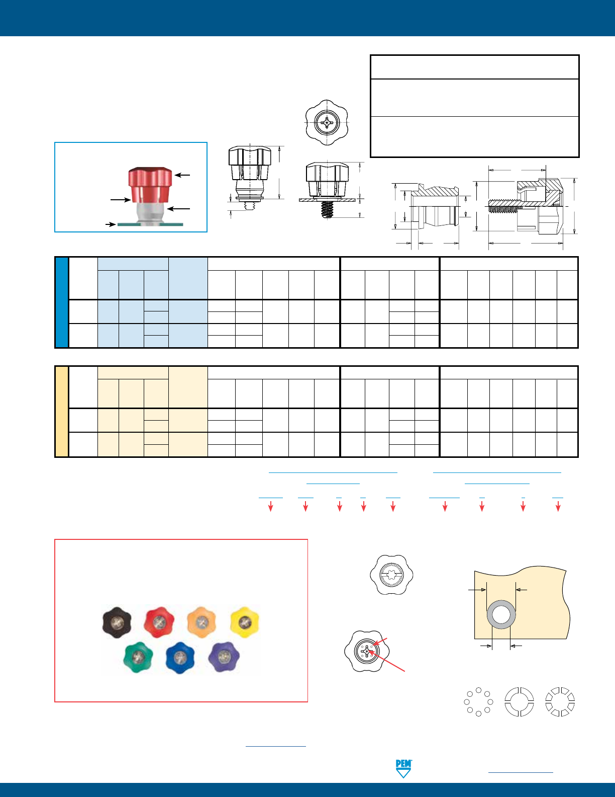
(1) The colors shown (except for black) are non-stocked standards and available on special order. Since actual color knob may vary slightly from those
represented, we recommend that you request samples for color verification. If you require a custom color or you need a “color matched” knob, please
contact us.
(2) As with all Class 2A/6g external threads with an additive finish, the maximum major and pitch, after plating, may equal basic sizes and be gauged to
Class 3A/4h, per ANSI B1.1, Section 8, Table 3A and ANSI B1.13M, Section 8, Paragraph 8.2.
(3) Temperature limit is 210˚ F / 99˚ C.
(4) See PEM Technical Support section of our website (www.pemnet.com) for related plating standards and specifications.
Also available with
flare-mounted
retainer as PF11PMF
or with floating style
retainer as PF11PMW.
Threads:
External, ASME B1.1, 2A /
ASME B1.13M, 6g (2)
Material:
Knob: PC/ABS (UL 94V-0, halogen-free) (3)
Retainer: Hardened Carbon Steel
Screw: Hardened Carbon Steel
Spring: 300 Series Stainless Steel
Finish:
Retainer: CN - Bright nickel over
copper flash per ASTM B689
Screw: Zinc plated, 5m, colorless (4)
Spring: Natural Finish
For use in sheet hardness:
HRB 80 or less (Hardness Rockwell “B” Scale)
HB 150 or less (Hardness Brinell)
PEM® C.A.P.S.® CAPTIVE PANEL SCREWS
Installation Data page 28. Performance Data page 37.
Black = B
(Standard)
Patented.
PF11 P M – 632 – 0 B
PART NUMBER DESIGNATION
Type Thread
Code
Screw
Length
Code
Color
Code
(Standard
Black)
Phillips
Drive
Anti-
cross
Thread
Feature
Red = R Orange = N Yellow = Y Green = G Blue = U Violet = V Metallic = M
Color Capabilities (1)
Choose a knob color code and add it to the end of the base part number.
Float .010”/0.25mm minimum, in all directions from center, .020”/0.5mm total.
G
E
A
C
T2
T1
P
PEM® C.A.P.S.® dot
pattern (Registered
trademark)
Dimples on head
designate metric thread.
Phillips
driver size.
(See chart)
Shoulder
provides
positive
stop during
installation.
Clinching profile may vary.
PennEngineering • www.pemnet.com PF-9
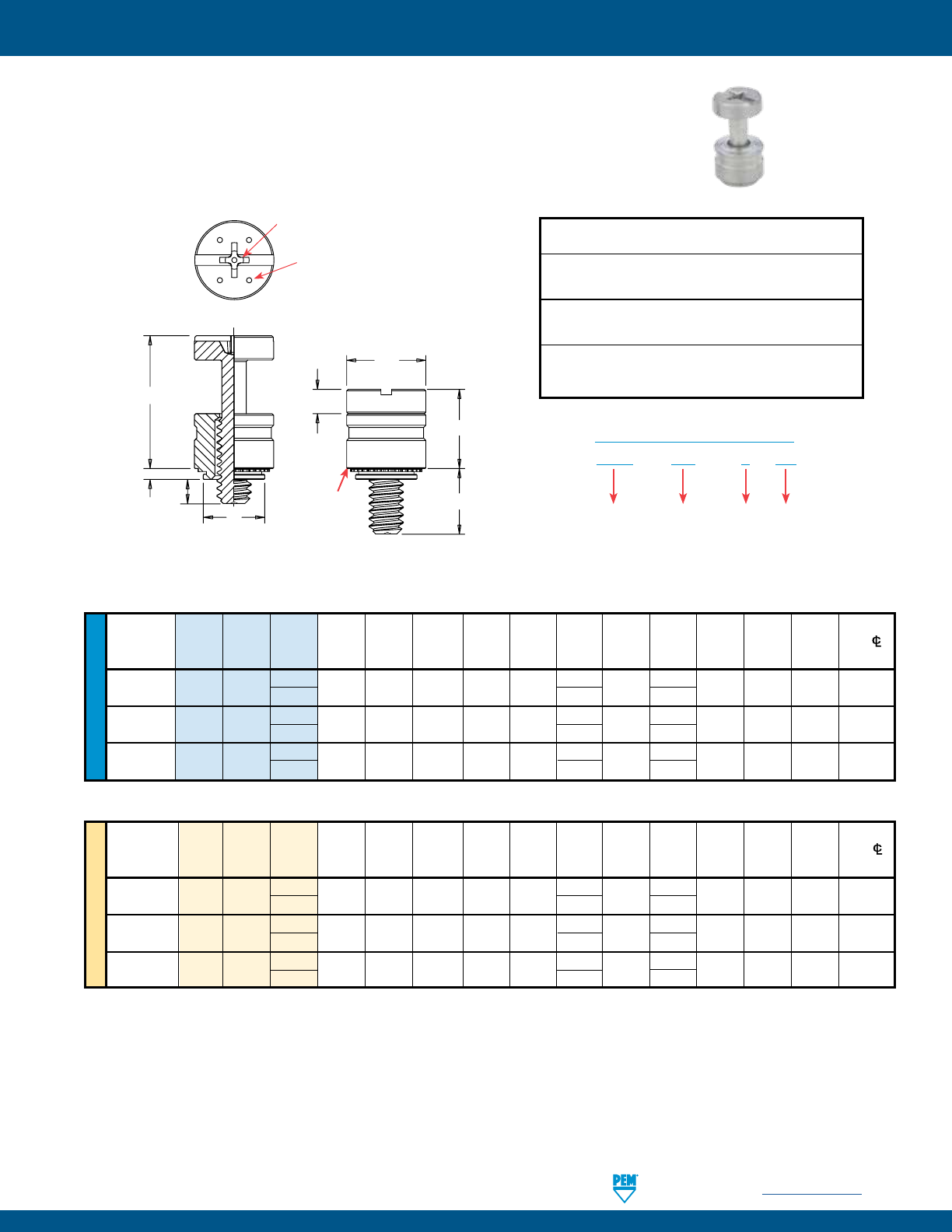
PEM® PFHV™ CAPTIVE PANEL SCREWS
METRIC UNIFIED
Screw A Min. Hole Size
Min. Dist.
Thread Type Thread
Length (Shank) Sheet In Sheet C E G H P T1 T2 Driver HoleC/L
Size Code Code Max. Thickness + .003 Max. ± .010 ± .025 ± .005 ±.025 Nom. Nom. Size To Edge
- .000
.112-40 PFHV 440 0 .036 .036 .203 .202 .260 .216
.080 .000 .260 .436 #1 .21
(#4-40) 1 .316 .095
.138-32 PFHV 632 0 .036 .036 .219 .218 .276 .234
.092 .000 .290 .484 #2 .23
(#6-32) 1 .359 .120
.164-32 PFHV 832 0 .036 .036 .252 .251 .309 .259 .111 .000 .335 .555 #2 .26
(#8-32) 1 .371 .106
All dimensions are in inches.
All dimensions are in millimeters.
Thread
Screw A Min. Hole Size
Min. Dist.
Size x Type Thread
Length (Shank) Sheet In Sheet C E G H P T1 T2 Driver HoleC/L
Pitch Code
Code Max. Thickness + 0.08 Max. ± 0.25 ± 0.64 ± 0.13 ±0.64 Nom. Nom. Size
To Edge
M3 x 0.5 PFHV M3 0 0.92 0.92 5.5 5.49 6.95 5.55 2.03 0 6.69 11.25 #1 5.8
1 7.56 1.9
M3.5 x 0.6 PFHV M3.5 0 0.92 0.92 6 5.98 7.45 6.01 2.34 0 7.45 12.47 #2 6.3
1 8.42 2.3
M4 x 0.7 PFHV M4 0 0.92 0.92 6.4 6.38 7.85 6.59 2.79 0 8.5 14.1 #2 6.7
1
9.39 2.7
PFHV – 632 – 0 CN
PART NUMBER DESIGNATION
Type Thread Size
Code
Screw
Length
Code
Finish
Code
(1) As with all Class 2A/6g external threads with an additive finish, the maximum major and pitch, after plating, may equal basic sizes and be gauged to
Class 3A/4h, per ANSI B1.1, Section 8, Table 3A and ANSI B1.13M, Section 8, Paragraph 8.2.
Threads:
External, ASME B1.1, 2A / ASME B1.13M, 6g (1)
Material:
Retainer: Carbon Steel
Screw: Hardened Carbon Steel
Finish:
Retainer: CN - Bright nickel over copper flash per ASTM B689
Screw: CN - Bright nickel over copper flash per ASTM B689 (1)
For use in sheet hardness:
HRB 60 or less (Hardness Rockwell “B” Scale)
HB 107 or less (Hardness Brinell)
• Low cost captive screw design to replace loose hardware.
Small, compact and low profile design for limited access areas.
• Two screw lengths.
• Universal slot/Phillips recess standard.
• Available with MAThread® anti cross-thread technology. (See page 4 for more information).
• Available with Torx® recess.
Installation Data page 29. Performance Data page 37.
G
H
E
P
C
A
T1
T2
Dimples on head
designate metric
thread.
Phillips
driver size.
(See chart)
For available drive
configurations, see page 4.
Shoulder
provides
positive
stop during
installation.
Clinching profile may vary.
PF-10 PennEngineering • www.pemnet.com
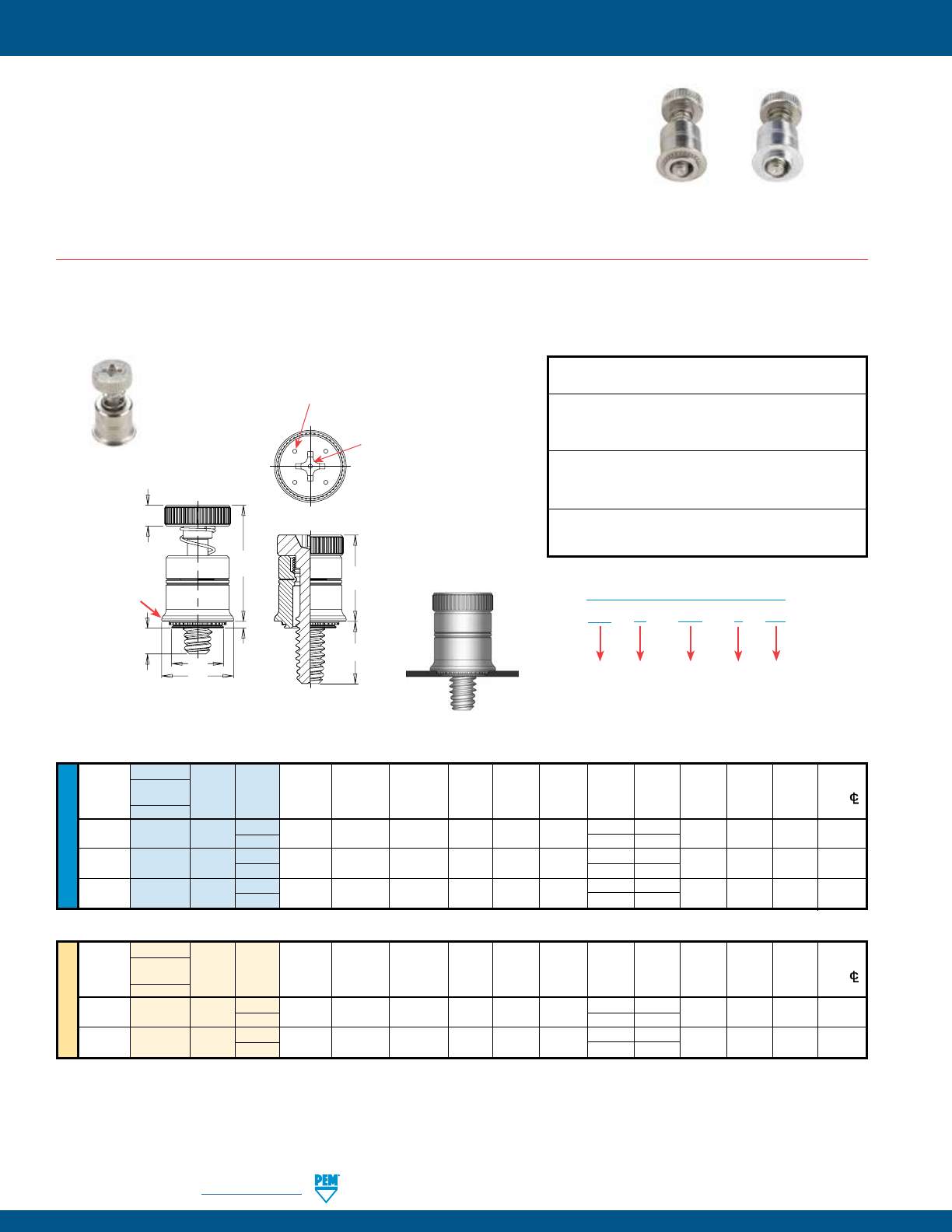
• Smallest footprint, spring-loaded panel fastener for limited access areas.
• MAThread® anti cross-thread technology. (See page 4 for more information).
• Installs flush on back side of panel.
• PF7M Self-clinching mounting design provides high pushout resistance.
• PF7M does not require special hole preparation.
• PF7MF is appropriate for close centerline-to-edge applications.
• PF7MF does not require high installation force.
• PF7MF installs into any panel hardness.
• Available with Torx® recess.
PEM® PF7M™/PF7MF™ CAPTIVE PANEL SCREWS
UNIFIED
Type Hole Size Min.
Fastener
Screw A Min. In Sheet Dist.
Thread Material Thread Length (Shank) Sheet +.003 C E H G P T1 T2 Driver HoleC/L
Size Steel Code Code Max. Thickness –.000 Max. ±.010 ±.010 ±.025 ±.025 Nom. Nom. Size To Edge
. PF
M . . . . . . . . . . # .
#
. .
. PF
M . . . . . . . . . . # .
# . .
. PF
M . . . . . . . . . . # .
# . .
METRIC
Type Min.
Thread Fastener
Screw A Min. Hole Size Dist.
Size x Material Thread Length (Shank) Sheet In Sheet C E H G P T1 T2 Driver HoleC/L
Pitch Steel Code Code Max. Thickness +0.08 Max. ±0.25 ±0.25 ±0.64 ±0.64 Nom. Nom. Size To Edge
M3 x 0.5 PF
7
M M3 0 0.92 0.92 5.56 5.54 7.87 2.5 5.33 0 9.65 13.97 #2 7.11
1
6.86 1.65
M4 x 0.7 PF
7
M M4 0 0.92 0.92 7.92 7.9 10.29 3 6.1 0 10.92 16 #2 8.38
1 7.62 1.65
(1) As with all Class 2A/6g external threads with an additive finish, the maximum major and pitch, after plating, may equal basic sizes and be gauged to
Class 3A/4h, per ANSI B1.1, Section 8, Table 3A and ANSI B1.13M, Section 8, Paragraph 8.2.
All dimensions are in inches.
All dimensions are in millimeters.
Patented.
PF
7
M – 632 – 0 CN
PART NUMBER DESIGNATION
Type Anti
Cross-thread
Feature
Thread
Size
Code
Length
Code
Finish
Threads:
External, ASME B1.1, 2A / ASME B1.13M, 6g (1)
Material:
Retainer: Carbon Steel
Screw: Hardened Carbon Steel
Spring: 300 Series Stainless Steel
Finish:
Retainer: CN - Bright nickel over copper flash per ASTM B689
Screw: CN - Bright nickel over copper flash per ASTM B689
Spring: Natural Finish
For use in sheet hardness:
HRB 60 or less (Hardness Rockwell “B” Scale)
HB 107 or less (Hardness Brinell)
PF7M™ SELF-CLINCHING CAPTIVE PANEL SCREWS
PF7MFPF7M
Installation Data page 30. Performance Data page 37.
H
E
T1
T2
G
A
C
P
Dimples on head
designate metric thread.
Phillips
driver size.
(See chart)
Shoulder
provides
positive
stop during
installation.
Clinching profile may vary.
PennEngineering • www.pemnet.com PF-11
PEM® PF7M™/PF7MF™ CAPTIVE PANEL SCREWS
UNIFIED
Type Hole Size
Fastener
Screw A Min. In Sheet
Thread Material Thread Length (Shank) Sheet +.005 C E H G1 G2 T1 T2 Driver
Size Steel Code Code Max. Thickness –.000 Max. ±.010 ±.010 ±.025 ±.025 Nom. Nom. Size
. PFMF . . . . . . . . . . #
#
. .
. PFMF . . . . . . . . . . #
# . .
. PFMF . . . . . . . . . . #
# . .
METRIC
Type
Thread Fastener
Screw A Min. Hole Size
Size x Material Thread Length (Shank) Sheet In Sheet C E H G1 G2 T1 T2 Driver
Pitch Steel Code Code Max. Thickness +0.13 Max. ±0.25 ±0.25 ±0.64 ±0.64 Nom. Nom. Size
M3 x 0.5 PF7MF M3 0 1.05 0.79 4.75 4.73 7.87 2.5 1.02 5.33 9.65 13.97 #2
1
2.54 6.86
M4 x 0.7 PF7MF M4 0 1.83 1.52 6.76 6.74 10.29 3 1.02 6.1 10.92 16 #2
1 2.54 7.62
(1) As with all Class 2A/6g external threads with an additive finish, the maximum major and pitch, after plating, may equal basic sizes and be gauged to
Class 3A/4h, per ANSI B1.1, Section 8, Table 3A and ANSI B1.13M, Section 8, Paragraph 8.2.
All dimensions are in inches.
All dimensions are in millimeters.
Patented.
PF
7
M F – 632 – 0
PART NUMBER DESIGNATION
Type Anti
Cross-thread
Feature
Flaring Thread
Size
Code
Length
Code
Threads:
External, ASME B1.1, 2A / ASME B1.13M, 6g (1)
Material:
Retainer: Aluminum
Screw: Hardened Carbon Steel
Spring: 300 Series Stainless Steel
Spring: Natural Finish
Finish:
Retainer: Natural finish
Screw: CN - Bright nickel over copper flash per ASTM B689
PF7MF™ FLARE-MOUNTED CAPTIVE PANEL SCREWS
Installation Data page 30. Performance Data page 37.
Dimples on head
designate metric thread.
H
E
T1
T2
A
CG2
G1
Shoulder
provides
positive
stop during
installation.
Phillips
driver size.
(See chart)
PF-12 PennEngineering • www.pemnet.com
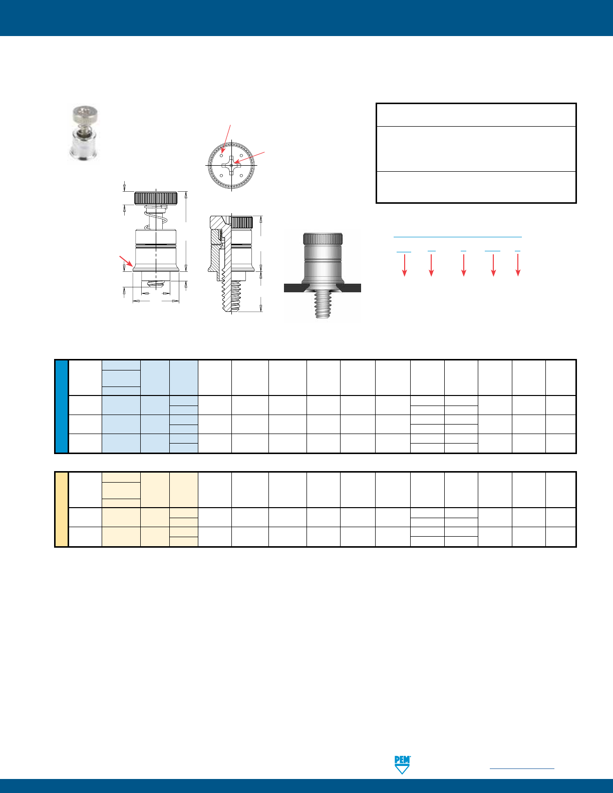
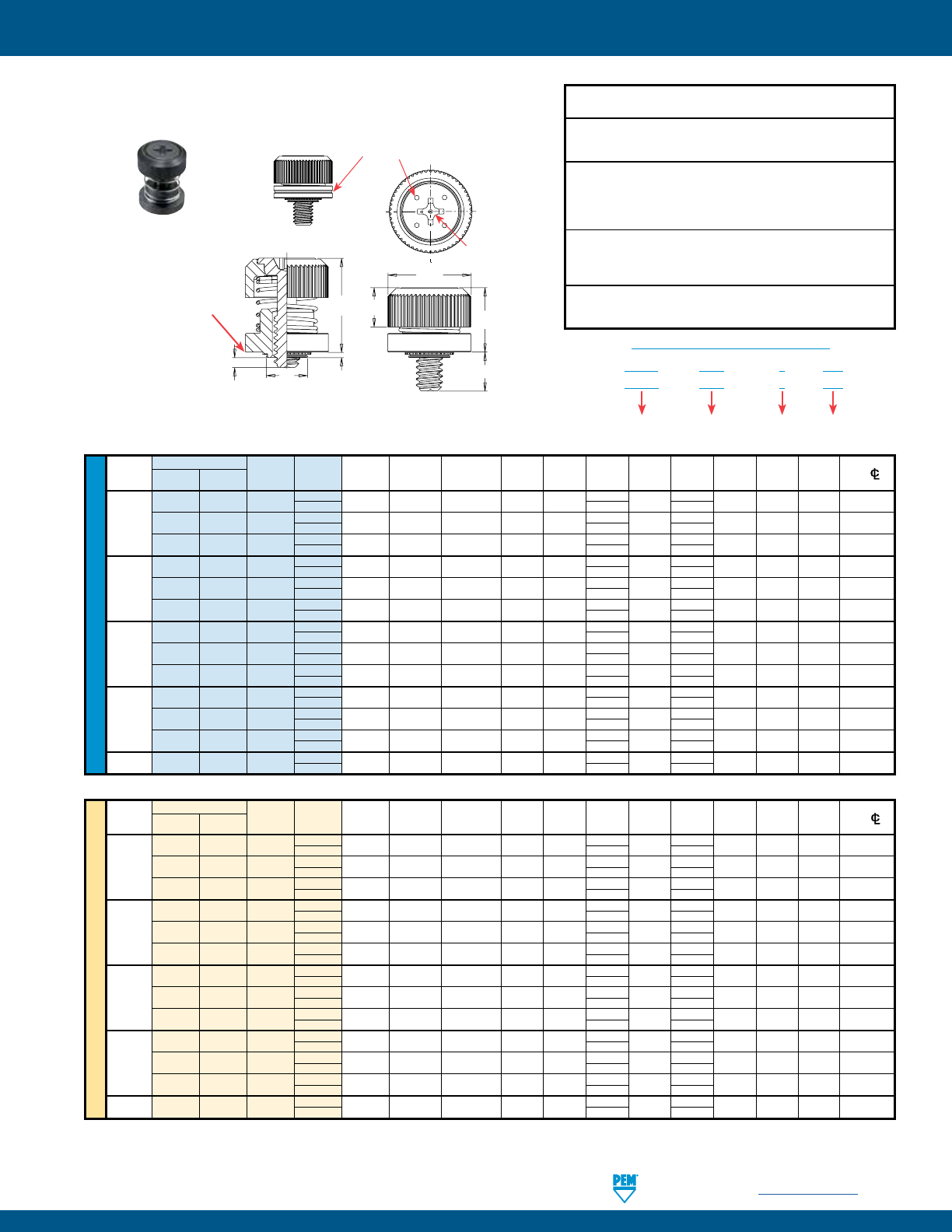
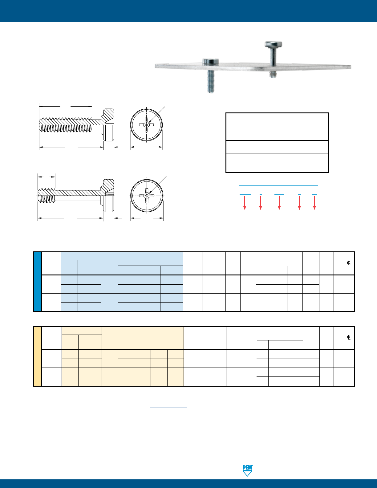
PEM® PF30™/PF50™/PF60™ CAPTIVE PANEL SCREWS
METRIC UNIFIED
Screw A Min. Hole Size
E
Min. Dist.
Thread Thread
Length (Shank) Sheet In Sheet C
±.010
G H T1 T2 HoleC/L
Size Type Code Code Max. Thickness + .003 Max. ± .015 ± .005 Max. Nom. To Edge
- .000
PF30 .030 .030
.112-40 PF31 440 30 .038 .040 .203 .202 .406 .300 .202 .325 .595 .26
(#4-40) PF32 .058 .060
PF30 .030 .030
.138-32 PF31 632 30 .038 .040 .219 .218 .438 .300 .202 .325 .595 .28
(#6-32) PF32 .058 .060
PF30 .030 .030
.164-32 PF31 832 30 .038 .040 .250 .249 .468 .300 .207 .330 .600 .29
(#8-32) PF32 .058 .060
PF30 .030 .030
.190-32 PF31 032 30 .038 .040 .312 .311 .530 .300 .220 .335 .605 .33
(#10-32) PF32 .058 .060
.250-20 PF32 0420 35 .058 .060 .375 .374 .625 .350 .242 .385 .675 .38
(1/4-20)
All dimensions are in inches.
All dimensions are in millimeters.
Thread Screw A Min. Hole Size E Min. Dist.
Size x Type Thread Length (Shank) Sheet In Sheet C G H T1 T2 HoleC/L
Pitch Code Code Max. Thickness + 0.08 Max. ±0.25 ± 0.4 ± 0.13 Max. Nom. To Edge
M3 x 0.5 PF31 M3 30 0.97 1 5.5 5.48 10.31 7.62 5.13 8.26 15.11 6.6
PF32 1.48 1.5
M4 x 0.7 PF31 M4 30 0.97 1 6.4 6.38 11.89 7.62 5.26 8.38 15.24 7.37
PF32 1.48 1.5
M5 x 0.8 PF31 M5 30 0.97 1 8 7.98 13.46 7.62 5.59 8.51 15.37 8.38
PF32 1.48 1.5
M6 x 1 PF32 M6 35 1.48 1.5 9.5 9.48 15.88 8.89 6.12 9.78 17.15 9.65
Available with
DuraBlackTM finish
(Finish Code “BN”)
PF30 – 832 – 30 CN
PART NUMBER DESIGNATION
Type and
Shank Code
Thread Size
Code
Screw
Length Code
Finish
Code
(1) As with all Class 2A/6g external threads with an additive finish, the maximum major and pitch, after plating, may equal basic sizes and be gauged to
Class 3A/4h, per ANSI B1.1, Section 8, Table 3A and ANSI B1.13M, Section 8, Paragraph 8.2.
Threads:
External, ASME B1.1, 2A / ASME B1.13M, 6g (1)
Material:
Retainer: Carbon Steel
Screw: Hardened Carbon Steel (#4-40 and M3 sizes only)
Carbon Steel (all other sizes)
Spring: 300 Series Stainless Steel
Finish:
Retainer: CN - Bright nickel over copper flash per ASTM B689
Screw: CN - Bright nickel over copper flash per ASTM B689
Spring: Natural Finish
Optional Finish:
Retainer: BN - Black nitride, AMS2753, Section 3
Screw: BN - Black nitride, AMS2753, Section 3
For use in sheet hardness:
HRB 60 or less (Hardness Rockwell “B” Scale)
HB 107 or less (Hardness Brinell)
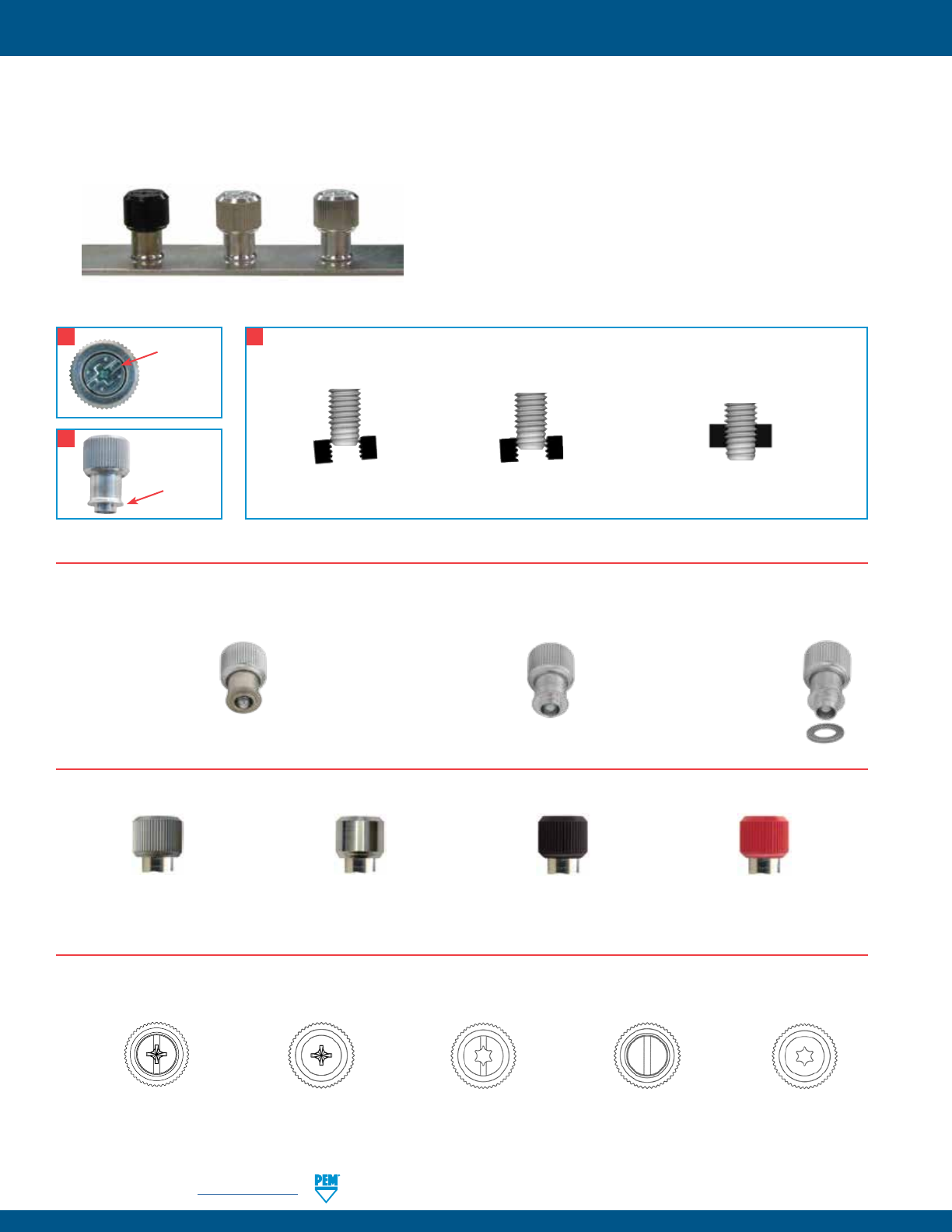
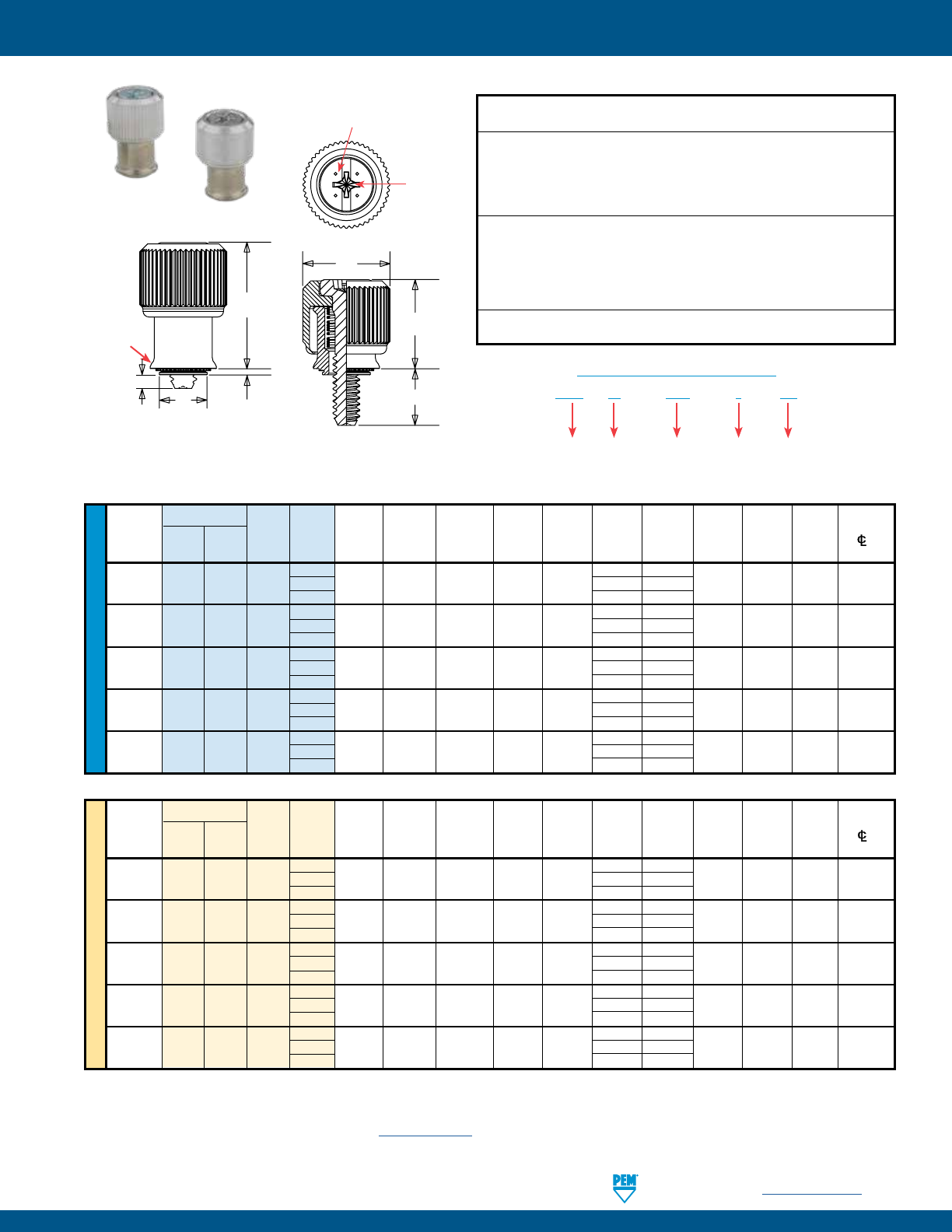
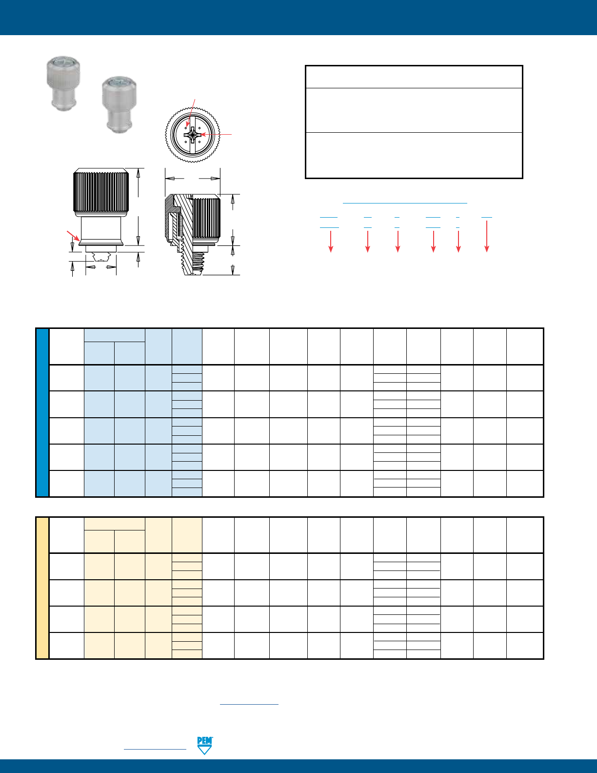
• Low-profile design satisfies many functional and cosmetic requirements.
• Convenient large head for tool or finger operation.
• PF50/PF60 are available with Torx® recess.
• PF50/PF60 are available with MAThread® anti cross-thread
technology. (See page 4 for more information). PF50
Knurled Cap
PF60
Smooth Cap
PF30
Knurled Cap
PF30™ LOW-PROFILE CAPTIVE PANEL SCREWS
Installation Data page 31. Performance Data page 38.
Diagonal knurl and
groove on retainer
identifies metric
thread sizes.
H
E
CG
A
T2T1
Shoulder
provides
positive
stop during
installation.
Clinching profile may vary.
PennEngineering • www.pemnet.com PF-13
PEM® PF30™/PF50™/PF60™ CAPTIVE PANEL SCREWS
UNIFIED
All dimensions are in inches.
Type Screw A Min. Hole Size E Min. Dist
Thread Knurled Smooth Thread Length (Shank) Sheet In Sheet C +.015 G H P T1 T2 Driver HoleC/L
Size Cap Cap Code Code Max. Thickness + .003 -.000 Max. –.005 ±.025 ±.008 ±.025 Max. Nom. Size To Edge
PF50 PF60 440 0
.030 .030 .203 .202 .406 .230
.207 .000 .340 .520 #1 .26
1 .290 .060
.112-40 PF51 PF61 440 0
.038 .040 .203 .202 .406 .230 .207 .000 .340 .520 #1 .26
(#4-40) 1 .290 .052
PF52 PF62 440 0
.058 .060 .203 .202 .406 .230 .207 .000 .340 .520 #1 .26
1 .290 .032
PF50 PF60 632 0
.030 .030 .219 .218 .438 .230
.207 .000 .340 .520 #2 .28
1 .290 .060
.138-32 PF51 PF61 632 0
.038 .040 .219 .218 .438 .230 .207 .000 .340 .520 #2 .28
(#6-32) 1 .290 .052
PF52 PF62 632 0
.058 .060 .219 .218 .438 .230 .207 .000 .340 .520 #2 .28
1 .290 .032
PF50 PF60 832 0
.030 .030 .250 .249 .468 .230 .217 .000
.340 .520 #2 .29
1 .290 .060
.164-32 PF51 PF61 832 0
.038 .040 .250 .249 .468 .230 .217 .000 .340 .520 #2 .29
(#8-32) 1 .290 .052
PF52 PF62 832 0
.058 .060 .250 .249 .468 .230 .217 .000 .340 .520 #2 .29
1 .290 .032
PF50 PF60 032 0
.030 .030 .312 .311 .530 .230
.225 .000 .340 .530 #2 .33
1 .290 .060
.190-32 PF51 PF61 032 0
.038 .040 .312 .311 .530 .230 .225 .000 .340 .530 #2 .33
(#10-32) 1 .290 .052
PF52 PF62 032 0
.058 .060 .312 .311 .530 .230 .225 .000 .340 .530 #2 .33
1 .290 .032
.250-20 PF52 PF62 0420 0 .058 .060 .375 .374 .625 .280
.246 .000 .395 .600 #2 .38
(1/4-20) 1 .340 .060
Available with
DuraBlackTM finish
(Finish Code “BN”)
(1) As with all Class 2A/6g external threads with an additive finish, the maximum major and pitch, after plating, may equal basic sizes and be gauged to
Class 3A/4h, per ANSI B1.1, Section 8, Table 3A and ANSI B1.13M, Section 8, Paragraph 8.2.
METRIC
All dimensions are in millimeters.
Thread Type Screw A Min. Hole Size E Min. Dist
Size x Knurled Smooth Thread Length (Shank) Sheet In Sheet C +0.4 G H P T1 T2 Driver HoleC/L
Pitch Cap Cap Code Code Max. Thickness + 0.08 Max. –0.13 ±0.64 ±0.2 ±0.64 Max. Nom. Size To Edge
PF50 PF60 M3 0
0.77 0.8 5.5 5.48 10.3 5.84
5.26 0 8.64 13.21 #1 6.6
1 7.37 1.52
M3 x 0.5 PF51 PF61 M3 0
0.97 1 5.5 5.48 10.3 5.84 5.26 0 8.64 13.21 #1 6.6
1 7.37 1.32
PF52 PF62 M3 0
1.48 1.5 5.5 5.48 10.3 5.84 5.26 0 8.64 13.21 #1 6.6
1 7.37 0.81
PF50 PF60 M3.5 0 0.77 0.8 5.56 5.54 11.1 5.84
5.26 0 8.64 13.21 #2 7.1
1 7.37 1.52
M3.5 x 0.6
PF51 PF61 M3.5 0 0.97 1 5.56 5.54 11.1 5.84 5.26 0 8.64 13.21 #2 7.1
1 7.37 1.32
PF52 PF62 M3.5 0 1.48 1.5 5.56 5.54 11.1 5.84 5.26 0 8.64 13.21 #2 7.1
1 7.37 0.81
PF50 PF60 M4 0
0.77 0.8 6.4 6.38 11.9 5.84
5.51 0 8.64 13.46 #2 7.4
1 7.37 1.52
M4 x 0.7 PF51 PF61 M4 0
0.97 1 6.4 6.38 11.9 5.84 5.51 0 8.64 13.46 #2 7.4
1 7.37 1.32
PF52 PF62 M4 0
1.48 1.5 6.4 6.38 11.9 5.84 5.51 0 8.64 13.46 #2 7.4
1 7.37 0.81
PF50 PF60 M5 0
0.77 0.8 8 7.98 13.5 5.84
5.72 0 8.64 13.46 #2 8.4
1 7.37 1.52
M5 x 0.8 PF51 PF61 M5 0
0.97 1 8 7.98 13.5 5.84 5.72 0 8.64 13.46 #2 8.4
1 7.37 1.32
PF52 PF62 M5 0
1.48 1.5 8 7.98 13.5 5.84 5.72 0 8.64 13.46 #2 8.4
1 7.37 0.81
M6 x 1 PF52 PF62 M6 0
1.48 1.5 9.5 9.48 15.9 7.11
6.25 0
10.04 15.24 #2 9.7
1 8.64 1.52
PF50 – 440 – 1 CN
PF60 – 440 – 1 CN
PART NUMBER DESIGNATION
Type and
Shank Code
Thread Size
Code
Screw
Length Code
Finish
Code
Threads:
External, ASME B1.1, 2A / ASME B1.13M, 6g (1)
Material:
Knob: Carbon Steel Retainer: Carbon Steel
Screw: Carbon Steel Spring: 300 Series Stainless Steel
Finish:
Knob: CN - Bright nickel over copper flash per ASTM B689
Retainer: CN - Bright nickel over copper flash per ASTM B689
Screw: CN - Bright nickel over copper flash per ASTM B689
Spring: Natural Finish
Optional Finish:
Knob: BN - Black Nitride, AMS2753, Section 3
Retainer: BN - Black Nitride, AMS2753, Section 3
Screw: BN - Black Nitride, AMS2753, Section 3
For use in sheet hardness:
HRB 60 or less (Hardness Rockwell “B” Scale)
HB 107 or less (Hardness Brinell)
PF50™ AND PF60™ LOW-PROFILE CAPTIVE PANEL
SCREWS
Installation Data page 31. Performance Data page 39.
Groove on retainer and dimples on
head designate metric thread.
E
T1
G
A
P
T2
C
H
Phillips
driver size.
(See chart)
Shoulder
provides
positive
stop during
installation.
Clinching profile may vary.
PF-14 PennEngineering • www.pemnet.com
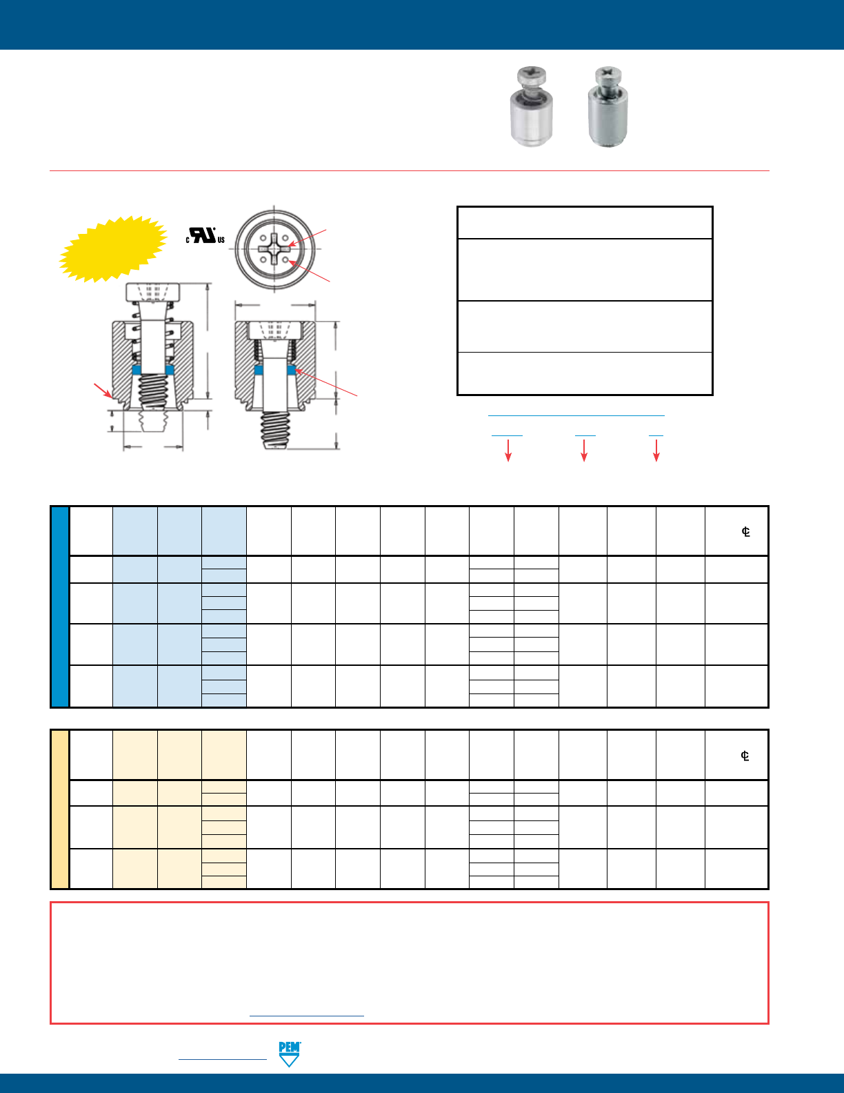
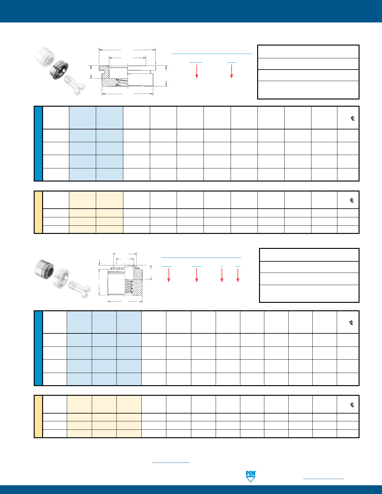
PEM® PFC4™/PFC2P™ CAPTIVE PANEL SCREWS
METRIC UNIFIED
Screw A Min. Hole Size
Min. Dist.
Thread Thread Length (Shank) Sheet In Sheet C E G P T1 T2 Driver HoleC/L
Size Type Code Code Max. Thickness + .003 Max. ± .010 ± .016 ±.025 Max. Nom. Size To Edge
- .000
.112-40 PFC4 440 40 .060 .060 .265 .264 .344 .250 .000 .370 .540 #1 .25
(#4-40) 62
.375 .125
40 .250 .000
.138-32 PFC4 632 62 .060 .060 .281 .280 .375 .375 .125 .380 .540 #2 .28
(#6-32) 84 .500 .250
50 .312 .000
.164-32 PFC4 832 72 .060 .060 .312 .311 .406 .437 .125 .480 .705 #2 .31
(#8-32) 94 .562 .250
50 .312 .000
.190-32 PFC4 032 72 .060 .060 .344 .343 .437 .437 .125 .490 .705 #2 .34
(#10-32) 94
.562 .250
All dimensions are in inches.
All dimensions are in millimeters.
Screw A Min. Hole Size
Min. Dist
Thread Thread
Length (Shank) Sheet In Sheet C E G P T1 T2 Driver HoleC/L
Size Type Code Code Max. Thickness + 0.08 Max. ± 0.25 ± 0.4 ±0.64 Max. Nom. Size To Edge
x Pitch
M3 x 0.5 PFC4 M3 40 1.53 1.53 6.73 6.71 8.74 6.4 0 9.4 13.72 #1 6.35
62
9.5 3.2
50 7.9 0
M4 x 0.7 PFC4 M4 72 1.53 1.53 7.92 7.9 10.31 11.1 3.2 12.19 17.91 #2 7.87
94 14.3 6.4
50 7.9 0
M5 x 0.8 PFC4 M5 72 1.53 1.53 8.74 8.72 11.1 11.1 3.2 12.45 17.91 #2 8.63
94 14.3 6.4
PFC4 – 832 – 50
PART NUMBER DESIGNATION
Type and
Material
Thread Size
Code
Screw Length
Code
PFC4™ RECESSED-HEAD CAPTIVE PANEL SCREWS
Threads:
External, ASME B1.1, 2A / ASME B1.13M, 6g
Material:
Retainer: 400 Series Stainless Steel
Screw: 400 Series Stainless Steel
Spring: 300 Series Stainless Steel
Retaining Ring: Nylon, temperature limit 200˚ F / 93˚ C
Finish:
Retainer: Passivated and/or tested per ASTM A380
Screw: Passivated and/or tested per ASTM A380
Spring: Natural Finish
For use in sheet hardness:
HRB 88 or less (Hardness Rockwell “B” Scale)
HB 183 or less (Hardness Brinell)
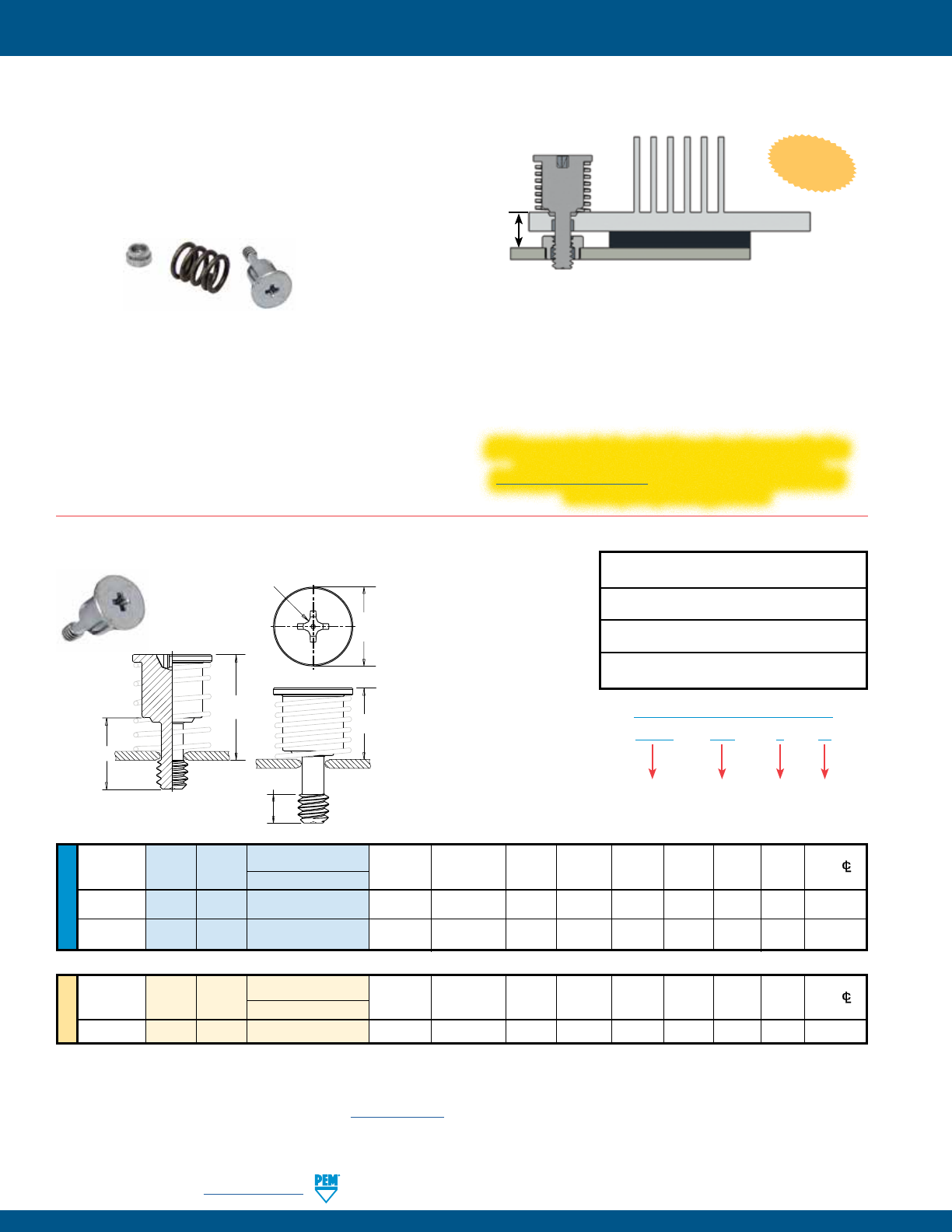
• PFC4/PFC2P have fully concealed-head for tool only access.
• PFC4/PFC2P comply with UL 60950 standards.
• PFC4 installs into stainless steel sheets HRB 88 or less.
• PFC4/PFC2P are available with MAThread® anti cross-thread technology.
(See page 4 for more information).
• PFC4/PFC2P available with Torx® recess. PFC4 PFC2P
Installation Data page 32. Performance Data page 39.
Dimples on head
designates metric
thread.
T2
T1
E
CA
G
Phillips
driver size.
(See chart)
PEM
Trademark
Blue plastic
retaining ring.
P
Shoulder
provides
positive
stop during
installation.
Clinching profile may vary.
INSTALLS INTO
STAINLESS STEEL
A NOTE ABOUT FASTENERS FOR STAINLESS STEEL PANELS
In order for self-clinching fasteners to work properly, the fastener must be harder than the sheet into which it is being installed. In the case of stainless steel panels,
fasteners made from 300 Series Stainless Steel do not meet this hardness criteria. It is for this reason that 400 series fasteners are oered (PFC4). However, while
these 400 Series fasteners install and perform well in 300 Series stainless sheets they should not be used if the end product:
• Will be exposed to any appreciable corrosive presence.
• Requires non-magnetic fasteners.
• Will be exposed to any temperatures above 300˚F (149˚C)
If any of the these are issues, please contact techsupport@pemnet.com for other options.
PennEngineering • www.pemnet.com PF-15
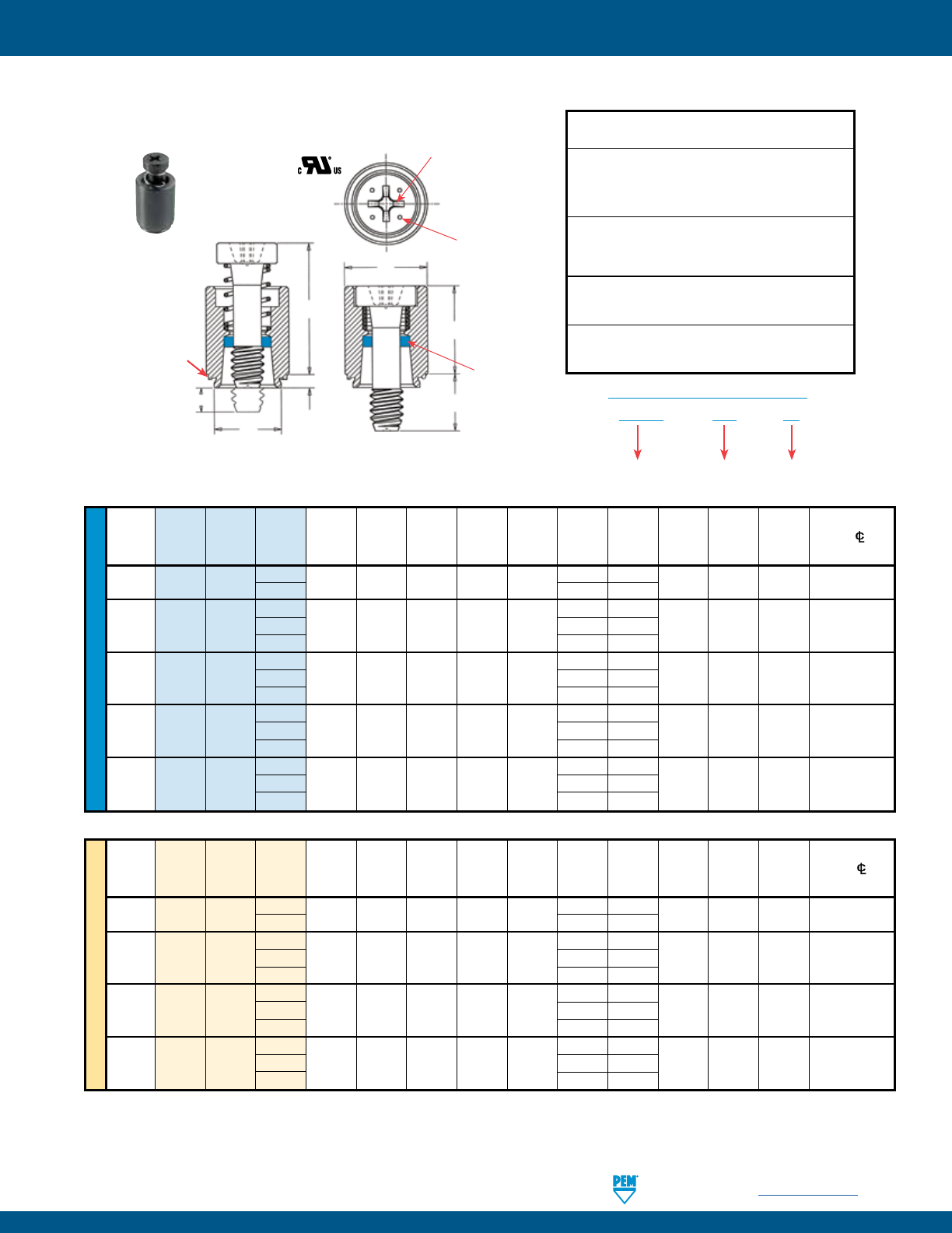
PEM® PFC4™/PFC2P™ CAPTIVE PANEL SCREWS
METRIC UNIFIED
Screw A Min. Hole Size Min. Dist.
Thread Thread Length (Shank) Sheet In Sheet C E G P T1 T2 Driver HoleC/L
Size Type Code Code Max. Thickness + .003 Max. ± .010 ± .016 ±.025 Max. Nom. Size To Edge
- .000
.112-40 PFC2P 440 40 .060 .060 .265 .264 .312 .250 .000 .370 .540 #1 .25
(#4-40) 62 .375 .125
40 .250 .000
.138-32 PFC2P 632 62 .060 .060 .281 .280 .344 .375 .125 .380 .540 #2 .28
(#6-32) 84 .500 .250
50 .312 .000
.164-32 PFC2P 832 72 .060 .060 .312 .311 .375 .437 .125 .480 .705 #2 .31
(#8-32) 94 .562 .250
50 .312 .000
.190-32 PFC2P 032 72 .060 .060 .344 .343 .406 .437 .125 .490 .705 #2 .34
(#10-32) 94 .562 .250
60 .375 .000
.250-20 PFC2P 0420 82 .060 .060 .413 .412 .468 .500 .125 .620 .905 #3 .38
(1/4-20) 04 .625 .250
Screw A Min. Hole Size Min. Dist
Thread Thread
Length (Shank) Sheet In Sheet C E G P T1 T2 Driver HoleC/L
Size x Type Code Code Max. Thickness + 0.08 Max. ± 0.25 ± 0.4 ±0.64 Max. Nom. Size To Edge
Pitch
M3 x 0.5 PFC2P M3 40 1.53 1.53 6.73 6.71 7.92 6.4 0 9.4 13.72 #1 6.35
62 9.5 3.2
50 7.9 0
M4 x 0.7 PFC2P M4 72 1.53 1.53 7.92 7.9 9.53 11.1 3.2 12.19 17.91 #2 7.87
94 14.3 6.4
50 7.9 0
M5 x 0.8 PFC2P M5 72 1.53 1.53 8.74 8.72 10.31 11.1 3.2 12.45 17.91 #2 8.63
94 14.3 6.4
60 9.5 0
M6 x 1 PFC2P M6 82 1.53 1.53 10.49 10.47 11.89 12.7 3.2 15.75 22.99 #3 9.65
04 15.9 6.4
PFC2P – 832 – 50
PART NUMBER DESIGNATION
Type and
Material
Thread Size
Code
Screw
Length Code
All dimensions are in inches.
All dimensions are in millimeters.
Threads:
External, ASME B1.1, 2A / ASME B1.13M, 6g
Material:
Retainer: 300 Series Stainless Steel
Screw: 400 Series Stainless Steel
Spring: 300 Series Stainless Steel
Retaining Ring: Nylon, temperature limit 200˚ F / 93˚ C
Finish:
Retainer: Passivated and/or tested per ASTM A380
Screw: Passivated and/or tested per ASTM A380
Spring: Natural Finish
Optional Finish:
Retainer: BN - Black nitride, AMS2753, Section 3
Screw: BN - Black nitride, AMS2753, Section 3
For use in sheet hardness:
HRB 70 or less (Hardness Rockwell “B” Scale)
HB 125 or less (Hardness Brinell)
PFC2P™ RECESSED-HEAD CAPTIVE PANEL SCREWS
Installation Data page 32. Performance Data page 39.
T2
T1
E
P
CA
G
Dimples on head
designates metric
thread.
PEM
Trademark
Blue plastic
retaining ring.
Phillips
driver size.
(See chart)
Shoulder
provides
positive
stop during
installation.
Available with
DuraBlackTM finish
(Finish Code “BN”)
Clinching profile may vary.
PF-16 PennEngineering • www.pemnet.com
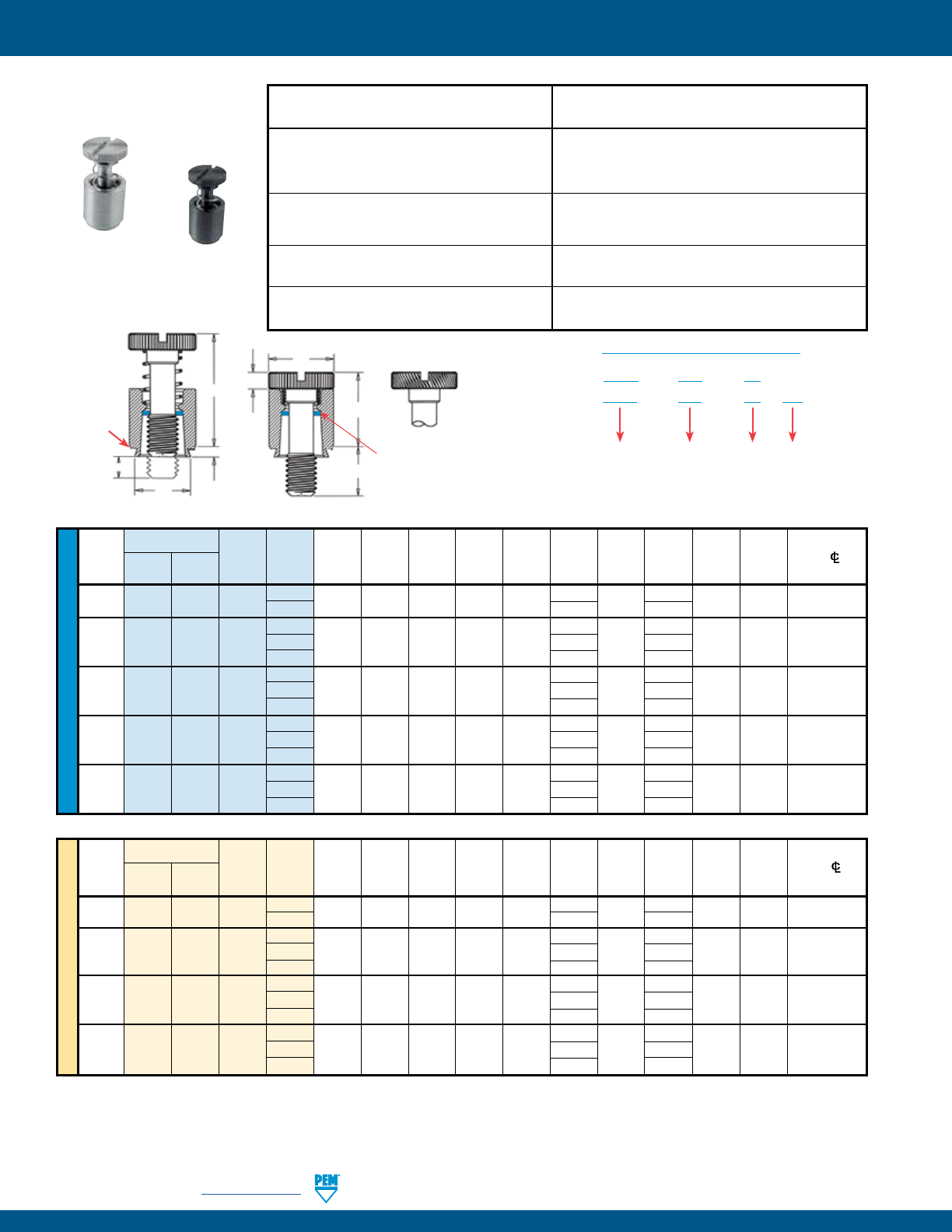
PEM Trademark
Blue plastic
retaining ring
T2
T1
CA
G
H
E
Diagonal knurl identifies
metric thread sizes.
P
Shoulder
provides
positive
stop during
installation.
Clinching profile may vary.
PEM® PFC2™/PFS2™ CAPTIVE PANEL SCREWS
METRIC UNIFIED
Type
Screw A Min. Hole Size
E
Min. Dist.
Thread Thread
Length (Shank) Sheet In Sheet C G H P T1 T2 HoleC/L
Size x Stainless Code Code Max. Thickness + 0.08 Max. ±.25 ± 0.4 ± 0.13 ±0.64 Max. Nom. To Edge
Pitch Steel Steel
M3 x 0.5 PFC2 PFS2 M3 40 1.53 1.53 6.73 6.71 7.92 6.4 1.83 0 9.14 13.72 6.35
62 9.5 3.2
50 7.9 0
M4 x 0.7 PFC2 PFS2 M4 72 1.53 1.53 7.92 7.9 9.53 11.1 2.08 3.2 11.43 17.53 7.87
94 14.3 6.4
50 7.9 0
M5 x 0.8 PFC2 PFS2 M5 72 1.53 1.53 8.74 8.72 10.31 11.1 2.08 3.2 11.47 17.53 8.63
94 14.3 6.4
60 9.5 0
M6 x 1 PFC2 PFS2 M6 82 1.53 1.53 10.49 10.47 11.89 12.7 2.46 3.2 14.73 22.35 9.65
04 15.9 6.4
Type
Screw A Min. Hole Size Min. Dist.
Thread Thread Length (Shank) Sheet In Sheet C E G H P T1 T2 HoleC/L
Size Stainless Code Code Max. Thickness + .003 Max. ± .010 ±.016 ±.005 ±.025 Max. Nom. To Edge
Steel Steel - .000
.112-40 PFC2 PFS2 440 40 .060 .060 .265 .264 .312 .250
.072 .000 .360 .540 .25
(#4-40) 62 .375 .125
40 .250 .000
.138-32 PFC2 PFS2 632 62 .060 .060 .281 .280 .344 .375 .072 .125 .360 .540 .28
(#6-32) 84 .500 .250
50 .312 .000
.164-32 PFC2 PFS2 832 72 .060 .060 .312 .311 .375 .437 .082 .125 .450 .690 .31
(#8-32) 94 .562 .250
50 .312 .000
.190-32 PFC2 PFS2 032 72 .060 .060 .344 .343 .406 .437 .082 .125 .450 .690 .34
(#10-32) 94 .562 .250
60 .375 .000
.250-20 PFC2 PFS2 0420 82 .060 .060 .413 .412 .468 .500 .097 .125 .580 .880 .38
(1/4-20) 04 .625 .250
All dimensions are in inches.
All dimensions are in millimeters.
PFS2 is available with
DuraBlackTM finish
(Finish Code “BN”)
(1) As with all Class 2A/6g external threads with an additive finish, the maximum major and pitch, after plating, may equal basic sizes and be gauged to
Class 3A/4h, per ANSI B1.1, Section 8, Table 3A and ANSI B1.13M, Section 8, Paragraph 8.2.
(2) The blue plastic retaining rings are a PEM trademark. The temperature limit is 200° F / 93° C.
PFS2
Threads:
External, ASME B1.1, 2A / ASME B1.13M, 6g (1)
Material:
Retainer: Hardened Carbon Steel (2)
Screw: Carbon Steel
Spring: 300 Series Stainless Steel
Retaining Ring: Nylon, temperature limit 200˚ F / 93˚ C
Finish:
Retainer: CN - Bright nickel over copper flash per ASTM B689
Screw: CN - Bright nickel over copper flash per ASTM B689
Spring: Natural Finish
Optional Finish:
Retainer: BN - Black nitride, AMS2753, Section 3
Screw: BN - Black nitride, AMS2753, Section 3
For use in sheet hardness:
HRB 80 or less (Hardness Rockwell “B” Scale)
HB 150 or less (Hardness Brinell)
PFC2
Threads:
External, ASME B1.1, 2A / ASME B1.13M, 6g
Material:
Retainer: 300 Series Stainless Steel (2)
Screw: 300 Series Stainless Steel
Spring: 300 Series Stainless Steel
Retaining Ring: Nylon, temperature limit 200˚ F / 93˚ C
Finish:
Retainer: Passivated and/or tested per ASTM A380
Screw: Passivated and/or tested per ASTM A380
Spring: Natural Finish
Optional Finish:
Retainer: BN - Black nitride, AMS2753, Section 3
Screw: BN - Black nitride, AMS2753, Section 3
For use in sheet hardness:
HRB 70 or less (Hardness Rockwell “B” Scale)
HB 125 or less (Hardness Brinell)
PFC2/PFS2
PFS2 – 832 – 50 CN
PART NUMBER DESIGNATION
Type and
Material
Thread Size
Code
Screw
Length
Code
Finish
Code
PFC2 – 832 – 50
Installation Data page 33. Performance Data page 39.
PennEngineering • www.pemnet.com PF-17
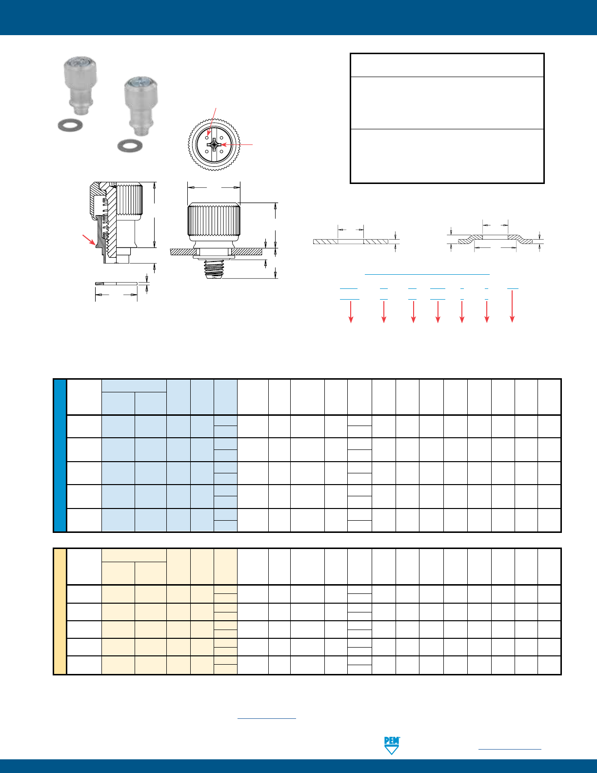
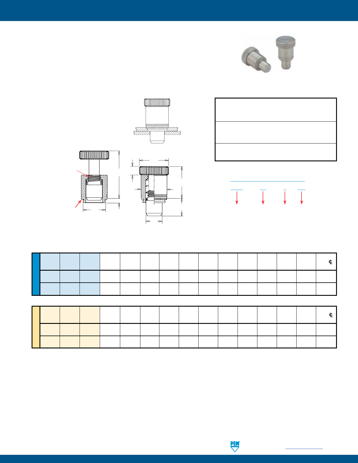
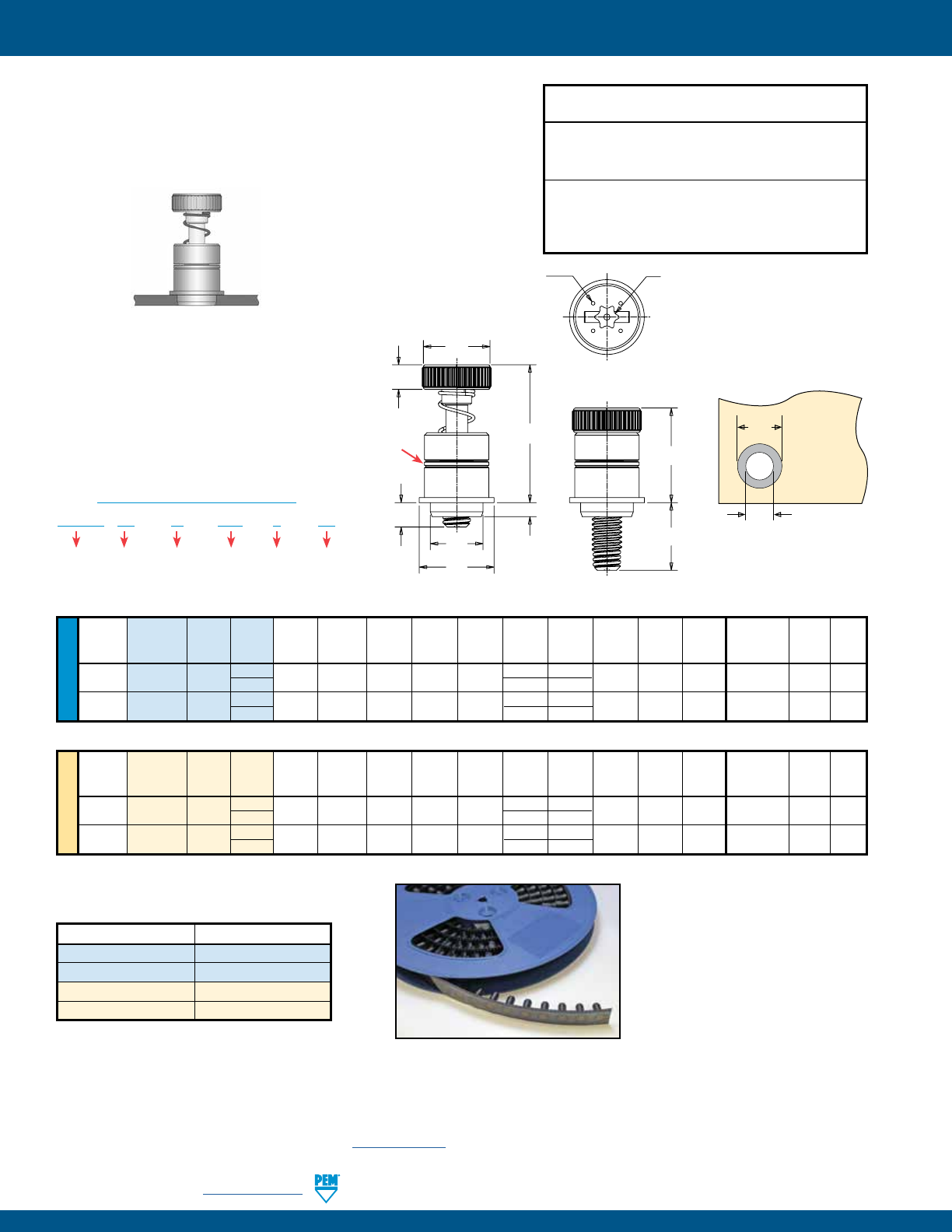
• Used as positioning pins for sliding components such as drawer slides and equipment consoles.
• Fast installation and removal of components.
• Reverse side of sheet is flush when plunger is retracted.
• PTL2 has quick lockout feature to hold plunger in fully retracted position.
• For use in sheets of HRB 80 or less.
• Available as PSL2 without lockout feature on special order.
PEM® PTL2™/PSL2™ SPRING-LOADED PLUNGER ASSEMBLIES
METRIC UNIFIED
Plunger Plunger A Min. Hole Size D Min. Dist.
Type Diameter Length (Shank) Sheet In Sheet C + .000 E1 E2 G H
T1 T2 HoleC/L
Code Code Max. Thickness +.003 -.000 Max. - .005 ± .010 ± .010 ± .010 ± .010 ± .010 Nom. To Edge
PTL2 04 4 .058 .060 .328 .327 .250 .50 .406 .310 .17 .595 .895 .34
PSL2
(1) 04 4 .058 .060 .328 .327 .250 .50 .406 .310 .17 .510 .780 .34
Plunger Plunger A Min. Hole Size Min. Dist.
Type Diameter Length (Shank) Sheet In Sheet C D E1 E2 G H T1 T2 HoleC/L
Code Code Max. Thickness + 0.08 Max. - 0.13 ± 0.25 ± 0.25 ± 0.25 ± 0.25 ± 0.25 Nom. To Edge
PTL2 04 4 1.47 1.53 8.33 8.31 6.35 12.7 10.3 7.87 4.32 15.11 22.73 8.64
PSL2
(1) 04 4 1.47 1.53 8.33 8.31 6.35 12.7 10.3 7.87 4.32 12.95 19.81 8.64
All dimensions are in inches.
All dimensions are in millimeters.
PTL2 – 04 – 4 CN
PART NUMBER DESIGNATION
Type Plunger
Diameter
Code
Plunger
Length
Code
Finish
Code
(1) Without lockout feature. Available on special order.
PTL2/PSL2 installed and with
mating panel. Minimum mating
hole diameter .251” / 6.38 mm.
Material:
Plunger: Hardened Carbon Steel
Retainer: Hardened Carbon Steel
Spring: 300 Series Stainless Steel
Finish:
Plunger: CN - Bright nickel over copper flash per ASTM B689
Retainer: CN - Bright nickel over copper flash per ASTM B689
Spring: Natural Finish
For use in sheet hardness:
HRB 80 or less (Hardness Rockwell “B” Scale)
HB 150 or less (Hardness Brinell)
Installation Data page 33. Performance Data page 39.
E1
E2
T2
T1
C
D
G
H
A
Lockout feature holds
plunger in retracted
position. Simply
retract and twist
to engage lockout
feature.
Shoulder
provides
positive
stop during
installation. Clinching profile may vary.
PF-18 PennEngineering • www.pemnet.com
PEM® SCBR™/SCB™/SCBJ™ CAPTIVE PANEL SCREWS
UNIFIED
NOTE: SCBR screws are shipped with mating springs.
For designs requiring a specific spring rate, contact our PEM Technical Support group at techsupport@pemnet.com.
All dimensions are in inches.
Length Code “L” ±.015 Min. Hole Size E Min. Dist
Thread Thread
(Length Code in 16ths of an inch) Sheet in Sheet +.005 H1 H2 T Driver Hole C/L
Size Type Code .500 Thickness +.003 –.000 –.010 ±.005 Ref. Nom. Size To Edge
. SCBR . . . . . . # .
#
. SCBR . . . . . . # .
#
. SCBR . . . . . . # .
#
All dimensions are in millimeters.
METRIC
Thread Min. Hole Size E Min. Dist
Size x Thread Length Code “L” ±0.4 Sheet in Sheet +0.13 H1 H2 T Driver Hole C/L
Pitch Type Code (Length Code in millimeters) Thickness +0.08 –0.25 ±0.13 Ref. Nom. Size To Edge
M3 x 0.5 SCBR M3 12 1.02 3 9.1 4.2 11.8 3.3 #1 4.5
M4 x 0.7 SCBR M4 12 1.02 4 10.7 4.5 12.1 3.3 #2 5.4
SCBR – 632 – 8 ZI
PART NUMBER DESIGNATION
Type Thread
Size
Code
Length
Code
Finish
(1) As with all Class 2A/6g external threads with an additive finish, the maximum major and pitch, after plating, may equal basic sizes and be gauged to
Class 3A/4h, per ANSI B1.1, Section 8, Table 3A and ANSI B1.13M, Section 8, Paragraph 8.2.
(2) See PEM Technical Support section of our website (www.pemnet.com) for related plating standards and specifications.
SCBR engagedSCBR retracted
SCBR™ SPINNING CLINCH BOLT WITH SELF-RETRACTING FEATURE
Threads:
External, ASME B1.1, 2A / ASME B1.13M, 6g (1)
Material:
Screw - Hardened Carbon Steel
Spring - 300 series stainless steel
Finish:
Screw - ZI - Zinc plated, 5m, colorless (standard) (2)
Spring: Natural Finish
For use in sheet hardness:
HRB 80 or less (Hardness Rockwell “B” Scale)
HB 150 or less (Hardness Brinell)
• Permanently captivates into sheets as thin as .040” / 1.02 mm and greater.
• Lowest cost captive screw design to replace loose hardware.
• Available with self-retracting (SCBR), axial float (SCB), or jacking feature (SCBJ).
• Appropriate for close centerline-to-edge applications.
SCBR SCB SCBJ
Installation Data page 34. Performance Data page 40.
H2
H1
L
T
E
Phillips
driver size.
(See chart)
PennEngineering • www.pemnet.com PF-19
PEM® SCBR™/SCB™/SCBJ™ CAPTIVE PANEL SCREWS
METRIC UNIFIED
SCB J – 632 – 6 ZI
PART NUMBER DESIGNATION
Type Jacking
(If applicable)
Thread
Size
Code
Length
Code
Finish
Type Min. Hole Size T Nom. Min. Dist.
Thread Thread Sheet in Sheet E H Nom. Axial Driver HoleC/L
Size Jacking Non-jacking Code .250 .375 .500
Thickness +.003 –.000 ±.010 Nom. –
4 –
6 –
8 Float Size To Edge
.112-40 SCBJ — 440 4 6 8 .040 .112 .250 .080 .160 .285 .410 — #1 .13
(#4-40) — SCB — — 8 — — .130 .330
.138-32 SCBJ — 632 4 6 8 .040 .138 .291 .080 .160 .285 .410 — #2 .15
(#6-32) — SCB — — 8 — — .130 .330
Length Code “L” ±.015
(Length Code in 16ths of an inch)
Thread Type Min. Hole Size T Nom. Min. Dist.
Size x Thread
Sheet in Sheet E H Nom. Axial Driver HoleC/L
Pitch Jacking Non-jacking Code
Thickness +0.08 ±0.25 Nom. –
6 –10 –12 -14 Float Size To Edge
M3 x 0.5 SCBJ — M3 6 10 12 14 1.02 3 6.6 2.03
3.7 7.7 9.7 11.7 — #1 3.3
— SCB — — 12 14 — — 3.3 5.3 7.67
M4 x 0.7 SCBJ — M4 6 10 12 14 1.02 4 8.28 2.03
3.7 7.7 9.7 11.7 — #2 5
— SCB — — 12 14 — — 3.3 5.3 7.67
Length Code “L” ±0.4
(Length Code in millimeters)
All dimensions are in inches.
All dimensions are in millimeters.
(1) As with all Class 2A/6g external threads with an additive finish, the maximum major and pitch, after plating, may equal basic sizes and be gauged to
Class 3A/4h, per ANSI B1.1, Section 8, Table 3A and ANSI B1.13M, Section 8, Paragraph 8.2.
(2) See PEM Technical Support section of our website (www.pemnet.com) for related plating standards and specifications.
SCB with
axial float.
SCBJ with
jacking feature.
Threads:
External, ASME B1.1, 2A / ASME B1.13M, 6g (1)
Material:
Hardened Carbon Steel
Finish:
ZI - Zinc plated, 5m, colorless (standard) (2)
For use in sheet hardness:
HRB 80 or less (Hardness Rockwell “B” Scale)
HB 150 or less (Hardness Brinell)
SCB™/SCBJ™ SPINNING CLINCH BOLTS
Installation Data page 34. Performance Data page 40.
SCB
L H
T
E
Phillips
driver size.
(See chart)
SCBJ
E
T
LH
Phillips
driver size.
(See chart)
PF-20 PennEngineering • www.pemnet.com
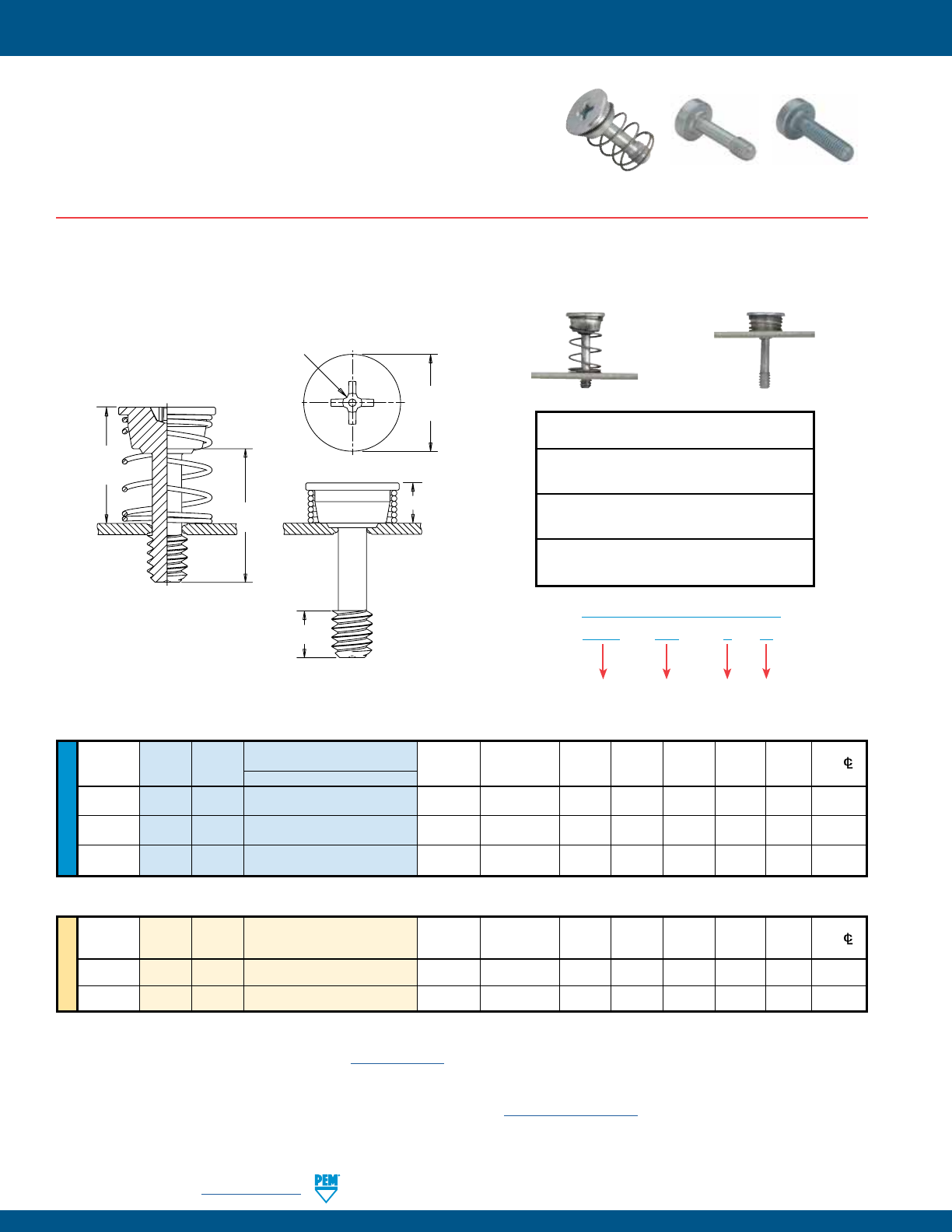
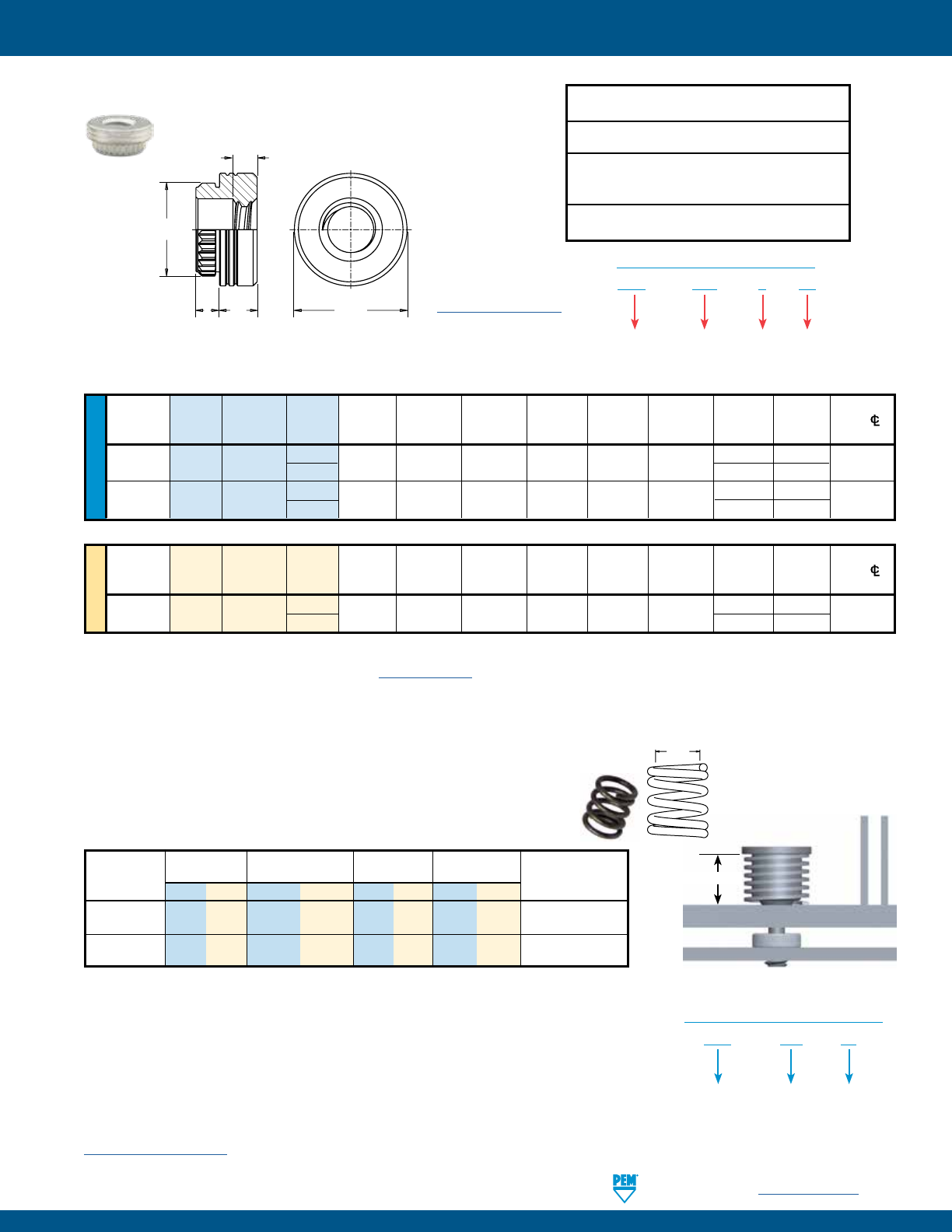
PEM® HSCB™ HEAT SINK MOUNTING SYSTEM
• Screw can not be overtightened. Audible “click” when fully
engaged.
• Screw and spring mount together permanently into the heat
sink.
• Spring determines clamp force.
• Receptacle nut mounts permanently to the PC board.
• Provides even, constant contact of heat sink to chip
component.
• Allows removal of heat sink if desired.
UNIFIED
All dimensions are in inches.
Length Code “L” ±.015 Min. Hole Size Screw Min. Dist
Thread Thread Sheet in Sheet ES H1 H2 TS Factor Driver HoleC/L
Size Type Code .320 Thickness +.003 –.000 ±.010 Ref. Ref. Min. (SF) Size To Edge
. HSCB . . . . . . . # .
#
. HSCB . . . . . . . # .
#
All dimensions are in millimeters.
METRIC
Thread
Length Code “L” ±0.4 Min. Hole Size Screw Min. Dist
Size x Thread Sheet in Sheet ES H1 H2 TS Factor Driver HoleC/L
Pitch Type Code 8.13 Thickness +0.08 ±0.25 Ref. Ref. Min. (SF) Size To Edge
M3 x 0.5 HSCB M3 3 1 3 8.18 7.67 12 3.3 4.32 #1 4.13
HSCB™ SELF-CAPTIVATING SCREW
NOTE: HSCB screws, HSR nuts and HSL springs are sold separately.
(1) As with all Class 2A/6g external threads with an additive finish, the maximum major and pitch, after plating, may equal basic sizes and be gauged to
Class 3A/4h, per ANSI B1.1, Section 8, Table 3A and ANSI B1.13M, Section 8, Paragraph 8.2.
(2) See PEM Technical Support section of our website (www.pemnet.com) for related plating standards and specifications.
(3) HRB - Hardness Rockwell “B” Scale. HB - Hardness Brinell.
To select proper length code of nut/standoff:
1) Determine “G”, the distance from the top surface of the heat sink to
the top of the P.C. Board.
2) Find the combination of Screw (HSCB) and Nut (HSR) whose sum of
Screw Factor (SF) plus Nut Factor (NF) are closest to G.
3) Find D = G – SF – NF. The D value must be a negative number
between zero and 1mm or 1/32” (1 dash length of HSR nut).
4) The actual working load is equal to the Spring (HSL) Working Load
+ (D x spring rate k). Lower D value results in lower force.
The new HSCB™ engineered mounting system provides secure attachment of a heat sink to the circuit board while providing firm
contact to the chip component allowing optimum heat dissipation. The three-piece fastening system, sold individually, includes the
screw, spring and receptacle nut. The clamp load created is determined
by the spring rate and the amount of deflection that is designed into
the joint of the hardware. The system also allows for slight expansion
and contraction of the joint components without stress to the delicate
circuitry. The unique “click” feature lets the user know when the
fastener is completely installed.
Patented
If this or any standard product does not meet your application
needs, contact our PEM Technical Support group at
techsupport@pemnet.com to develop a special product that
matches your specific application.
HSCB – 440 – 4 ZI
PART NUMBER DESIGNATION
Type Thread
Size
Code
Length
Code
Finish
HSCB
HSR
HSL
G
NEW!
Installation Data page 35.
Performance Data page 40.
L
TS
ES
Phillips
driver size.
(See chart)
H1
H2
Threads:
External, ASME B1.1, 2A / ASME B1.13M, 6g (1)
Material:
Hardened carbon steel
Finish:
Screw - ZI - Zinc plated, 5m, colorless (2)
For use in sheet hardness:
HRB 80 / HB150 or less (3)
PennEngineering • www.pemnet.com PF-21
PEM® HSCB™ HEAT SINK MOUNTING SYSTEM
UNIFIED
A Min. Hole Size Nut Min. Dist.
Thread Thread Length (Shank) Sheet In Sheet C EN F TN Factor HoleC/L
Size Type Code Code Max. Thickness +.003 –.000 ±.003 ±.005 ±.010 ±.005 (NF) To Edge
. HSR
. . . . . . . . .
# . .
. HSR
. . . . . . . . .
# . .
All dimensions are in inches.
HSR™ BROACHING NUT/STANDOFF
METRIC
Thread A Min. Hole Size Nut Min. Dist.
Size x Thread Length (Shank) Sheet In Sheet C EN F TN Factor HoleC/L
Pitch Type Code Code Max. Thickness +0.08 ±0.08 ±0.13 ±0.25 ±0.13 (NF) To Edge
M3 x 0.5 HSR M3 2
1.53 1.53 4.22 4.68 5.56 1.3 2 .75 4.4
3 3 1.75
All dimensions are in millimeters.
NOTE: HSCB screws, HSR nuts and HSL springs are sold separately.
(1) See PEM Technical Support section of our website (www.pemnet.com) for related plating standards and specifications.
(2) HRB - Hardness Rockwell “B” Scale. HB - Hardness Brinell.
HSR – 440 – 2 ET
PART NUMBER DESIGNATION
Type Thread
Size
Code
Length
Code
Finish
HSL™ SPRINGS
HSL springs are engineered to provide a reliable and repeatable spring rate when
assembled with mating PEM hardware. The spring rate is critical to the successful
assembly of your heat sink. Clamp load will be determined by the spring rate and
deflection that is designed into the joint.
Working Height
Minimum Load at Working Spring Rate
Part Inside Dia. Working Height ±10% Height Ref. k Spring
Number (in.) (mm) (lbs.) (N) (in.) (mm) (lb/in) (N/mm) Material
HSL-574-35 .226 5.74 7.87 35 .270 6.86 74 12.96 17-7 Stainless Steel,
Natural Finish
HSL-701-35 .276 7.01 7.87 35 .270 6.86 39 6.84 17-7 Stainless Steel,
Natural Finish
The HSL Inside Diameter Code is expressed in hundredths of millimeters.
Example “574” indicates a minimum inside diameter of 5.74mm or .226”.
The HSL Load Code is expressed in Newtons developed at the working height of the spring
once the joint is assembled.
Example “35” indicates working load of 35 Newtons, or approximately 8 lbs.
For designs requiring a specific spring rate, contact our PEM Technical Support group at
techsupport@pemnet.com
Spring I.D.
Min.
NOTE: HSCB screws, HSR nuts and HSL springs are sold separately. HSL-574-35 spring fits screw
thread sizes #4-40 and M3 and HSL-701-35 spring fits screw thread size #6-32.
HSL – 574 – 35
PART NUMBER DESIGNATION
Type Inside
Diameter
Code
Load
Code
Installation Data page 35. Performance Data page 40.
A TNEN
C
F
Threads:
Internal, ASME B1.1, 2B / ASME B1.13M, 6H
Material:
Carbon steel
Finish:
ET - Electro-plated tin ASTM B 545, class B
with clear preservative coating, annealed (1)
For use in sheet hardness:
HRB 60 / HB 107 or less (2)
HSR nuts are available for
surface mounting. Contact our
PEM technical support group at
techsupport@pemnet.com.
PF-22 PennEngineering • www.pemnet.com
PEM® PF10™ FLUSH-MOUNTED CAPTIVE PANEL SCREWS
METRIC
UNIFIED METRIC UNIFIED
Thread Thread Screw E H L T
Size Type
Code Length Nom. + .002 ± .010 Nom.
Code - .006
.112-40 PS10 440 40 .18 .075 .33 .13
(#4-40)
.138-32 PS10 632 40 .21 .075 .33 .13
(#6-32)
.164-32 PS10 832 40 .25 .075 .33 .13
(#8-32)
.190-32 PS10 032 40 .28 .075 .33 .13
(#10-32)
All dimensions are in inches.
PS10™ FLUSH MOUNTED SCREWS
A B G M P T
Min. Nom. ± .010 Nom.
.04 .125 .40 .16 .28 .13
All dimensions are in inches.
A B G M P T
Min. Nom. ± 0.25 Nom.
1 3.18 10.16 4.06 7.11 3.3
All dimensions are in millimeters.
PS10 Screw
Thread Thread Screw E H L T
Size x Type Code Length Nom. + 0.05 ± 0.25 Nom.
Pitch Code - 0.15
M3 x 0.5
PS10 M3 40 4.7 1.91 8.38 3.3
M4 x 0.7
PS10 M4 40 6.3 1.91 8.38 3.3
M5 x 0.8
PS10 M5 40 7.1 1.91 8.38 3.3
All dimensions are in millimeters.
E
H
L
T
Diagonal knurl
identifies metric
thread sizes.
Manually
Retracted
Position
M
T
P
G
N10 Receptacle Nut
PR10 Retainer
PS10 Screw
A
B
PS10 Screw
N10
Receptacle
Nut
PR10
Retainer
PS10 – 832 – 40
PART NUMBER DESIGNATION
Type and
Material
Thread Size
Code
Screw
Length
Code
Threads:
External, ASME B1.1, 2A / ASME B1.13M, 6g
Material:
300 Series Stainless Steel
Finish:
Passivated and/or tested per ASTM A380
• PF10 assembly sits flush in sheets as thin as .050” / 1.27 mm or flush on both sides in .125” / 3.2 mm sheets.
• PS10 screw remains captive in retainer when disengaged.
• PR10 retainer and F10 receptacle nut is for use in sheets of HRB 70 or less.
• N10 nut is for use in sheets of HRB 80 or less.
• Complies with UL 60950 standards.
Floating Receptacle Nuts
Available on special order
F10 self-clinching floating
receptacle nuts permit a
minimum of .015”/0.38mm
adjustment for mating hole
misalignment.
Installation Data page 36. Performance Data page 41.
Flush Fasteners as retainers
For applications where the
screw head may project
above the sheet surface,
PS10 screws may be used
with PEMSERT® F fasteners
as retainers. For dimensions
and engineering data on F
fasteners, see PEM Bulletin F.
PennEngineering • www.pemnet.com PF-23
PEM® PF10™ FLUSH-MOUNTED CAPTIVE PANEL SCREWS
METRIC UNIFIED
A Min. Sheet Min. Sheet Hole Size
Min. Dist.
Thread Type Thread
(Shank) for Self- for Flush in Sheet B C E H HoleC/L
Size Code Max. Clinching Installation + .003 Nom. Max. Nom. Nom. to Edge
- .000
.112-40 PR10 440 .125 .050 .125 .281 .195 .280 .31 .075 .31
(#4-40)
.138-32 PR10 632 .125 .050 .125 .312 .225 .311 .34 .075 .33
(#6-32)
.164-32 PR10 832 .125 .050 .125 .344 .255 .343 .37 .075 .34
(#8-32)
.190-32 PR10 032 .125 .050 .125 .375 .290 .374 .41 .075 .36
(#10-32)
Thread A Min. Sheet Min. Sheet Hole Size Min. Dist.
Size x Type Thread (Shank) for Self- for Flush in Sheet B C E H HoleC/L
Pitch Code Max. Clinching Installation + 0.08 Nom. Max. Nom. Nom. to Edge
M3 x 0.5 PR10 M3 3.18 1.27 3.18 7.14 4.75 7.12 7.87 1.91 7.87
M4 x 0.7 PR10 M4 3.18 1.27 3.18 8.74 6.48 8.72 9.53 1.91 8.64
M5 x 0.8 PR10 M5 3.18 1.27 3.18 9.53 7.37 9.5 10.41 1.91 9.14
E
B
HA
C
(1) The purpose of the thread is for component screw retention only, thread may not accept 2B/6H Go threaded plug gage, but class 3A/4h screw must
pass with finger torque, may not reject NoGo threaded plug gage and minor diameter may exceed 2B/6H maximum.
(2) 2B (unified) and 6H (metric) go gauge may stop at pilot end but class 3A (unified) and 4h (metric) screws will pass through with finger torque.
(3) See PEM Technical Support section of our website (www.pemnet.com) for related plating standards and specifications.
(4) Also available on special order F10 self-clinching floating receptacle nuts.
PR10
Retainer
PR10™ SELF-CLINCHING FLUSH-MOUNTED RETAINERS
PR10 – 832
PART NUMBER DESIGNATION
Type Thread Size
Code
All dimensions are in inches.
All dimensions are in millimeters.
METRIC UNIFIED
All dimensions are in inches.
All dimensions are in millimeters.
A Min. Hole Size
Min. Dist.
Thread Type Thread Shank
(Shank) Sheet In Sheet C E F H T HoleC/L
Size Code Code Max. Thickness + .003 Max. Nom. ± .010 Nom. ± .005 To Edge
- .000
.112-40 N10 440 1 .038 .040 .187 .186 .28 .130 .126 .24 .22
(#4-40)
.138-32 N10 632 1 .038 .040 .213 .212 .31 .130 .156 .24 .27
(#6-32)
.164-32 N10 832 1 .038 .040 .250 .249 .34 .130 .187 .24 .28
(#8-32)
.190-32 N10 032 1 .038 .040 .277 .276 .37 .130 .213 .24 .31
(#10-32)
Thread A Min. Hole Size Min. Dist.
Size x Type Thread Shank
(Shank) Sheet In Sheet C E F H T HoleC/L
Pitch Code Code
Max. Thickness + 0.08 Max. Nom. ± 0.25 Nom. ± 0.13 To Edge
M3 x 0.5 N10 M3 1 0.97 1 4.75 4.73 7.11 3.3 3.2 6 5.59
M4 x 0.7 N10 M4 1 0.97 1 6.35 6.33 8.64 3.3 4.75 6 7.11
M5 x 0.8 N10 M5 1 0.97 1 7.04 7.01 9.53 3.3 5.41 6 7.87
E
T
F
H
C
A
N10
Receptacle Nut
N10™ SELF-CLINCHING RECEPTACLE NUTS(4)
N10 – 832 – 1 ZI
PART NUMBER DESIGNATION
Type Thread Size
Code
Shank
Code
Finish
Threads:
Internal, ASME B1.1, 2B / ASME B1.13M, 6H (1)
Material:
300 Series Stainless Steel
Finish:
Passivated and/or tested per ASTM A380
For use in sheet hardness:
HRB 70 or less (Hardness Rockwell “B” Scale)
HB 125 or less (Hardness Brinell)
Threads:
Internal, ASME B1.1, 2B / ASME B1.13M, 6H (2)
Material:
Hardened Carbon Steel
Finish:
ZI - Zinc plated, 5m, colorless (standard) (3)
For use in sheet hardness:
HRB 80 or less (Hardness Rockwell “B” Scale)
HB 150 or less (Hardness Brinell)
Clinching profile may vary.
Clinching profile may vary.
PF-24 PennEngineering • www.pemnet.com
REELFAST® SMTPFLSM™ SURFACE MOUNT CAPTIVE PANEL SCREWS
All dimensions are in inches.
UNIFIED
Screw A Min. ØK Hole Size ØD Min.
Thread Thread Length (Shank) Sheet C E1 E2 G1 G2 H T1 T2 in Sheet Solder Driver
Size Type Code Code Max. Thickness Max. ±.010 Nom ±.025 ±.025 ±.010 Nom. Nom. +.003 -.000 Pad Size
.112-40 SMTPFLSM 440 0 .063 .063 .215 .280 .300 .040 .210 .100 .38 .55 .220 .340 T15
(#4-40) 1 .100 .270
.138-32 SMTPFLSM 632 0 .063 .063 .247 .310 .320 .040 .240 .100 .42 .62 .252 .400 T15
(#6-32) 1 .100 .300
All dimensions are in millimeters.
METRIC
Screw A Min. ØK Hole Size ØD Min.
Thread Thread Length (Shank) Sheet C E1 E2 G1 G2 H T1 T2 in Sheet Solder Driver
Size Type Code Code Max. Thickness Max. ±0.25 Nom ±0.64 ±0.64 ±0.25 Nom. Nom. +0.08 Pad Size
M3 x 0.5 SMTPFLSM M3 0 1.6 1.6 5.46 7 7.6 1 5.3 2.5 9.6 14 5.6 8.6 T15
1 2.5 6.8
M3.5 x 0.6 SMTPFLSM M3.5 0 1.6 1.6 6.27 7.9 8.13 1 6.1 2.5 10.7 15.7 6.4 10.2 T15
1 2.5 7.62
ØH
ØD
Solder
Pad
Plated through hole
not required.
SMTPF LS M – 440 – 0 ET
Type
PART NUMBER DESIGNATION
Thread
Code
Driver Anti-cross
Thread
Feature
Length
Code
Finish
NUMBER OF PARTS PER REEL
Thread Size Parts Per Reel
440 200
632 150
M3 200
M3.5 150
Packaged on 330 mm recyclable reels. Tape width is 24 mm.
Supplied with polyimide patch for vacuum pick up. Reels conform to EIA-481.
• All metal captive screw assembly installs in one piece
utilizing pick and place method.
• Combination drive, Torx®/slot.
• Solderable finish.
Threads:
External, ASME B1.1, 2A / ASME B1.13M, 6g (1)
Material:
Retainer: Carbon Steel
Screw: Hardened Carbon Steel
Spring: 300 Series Stainless Steel
Finish:
Retainer: ET - Electro-plated tin ASTM B545, Class B
with preservative coating, annealed (2)
Screw: ZI - Zinc plated, 5m, colorless (3)
Spring: Natural Finish
(1) As with all Class 2A/6g external threads with an additive finish, the maximum major and pitch, after plating, may equal basic sizes and be gauged to
Class 3A/4h, per ANSI B1.1, Section 8, Table 3A and ANSI B1.13M, Section 8, Paragraph 8.2
(2) Optimal solderability life noted on packaging.
(3) See PEM Technical Support section of our website (www.pemnet.com) for related plating standards and specifications.
Installation Data page 36. Performance Data page 41.
E1
H
CA
E2
T2
T1
G1
G2
Dimples on head
designate metric thread.
Torx®/slot driver size.
(See chart)
Two Groove
(Registered
Trademark)
PennEngineering • www.pemnet.com PF-25
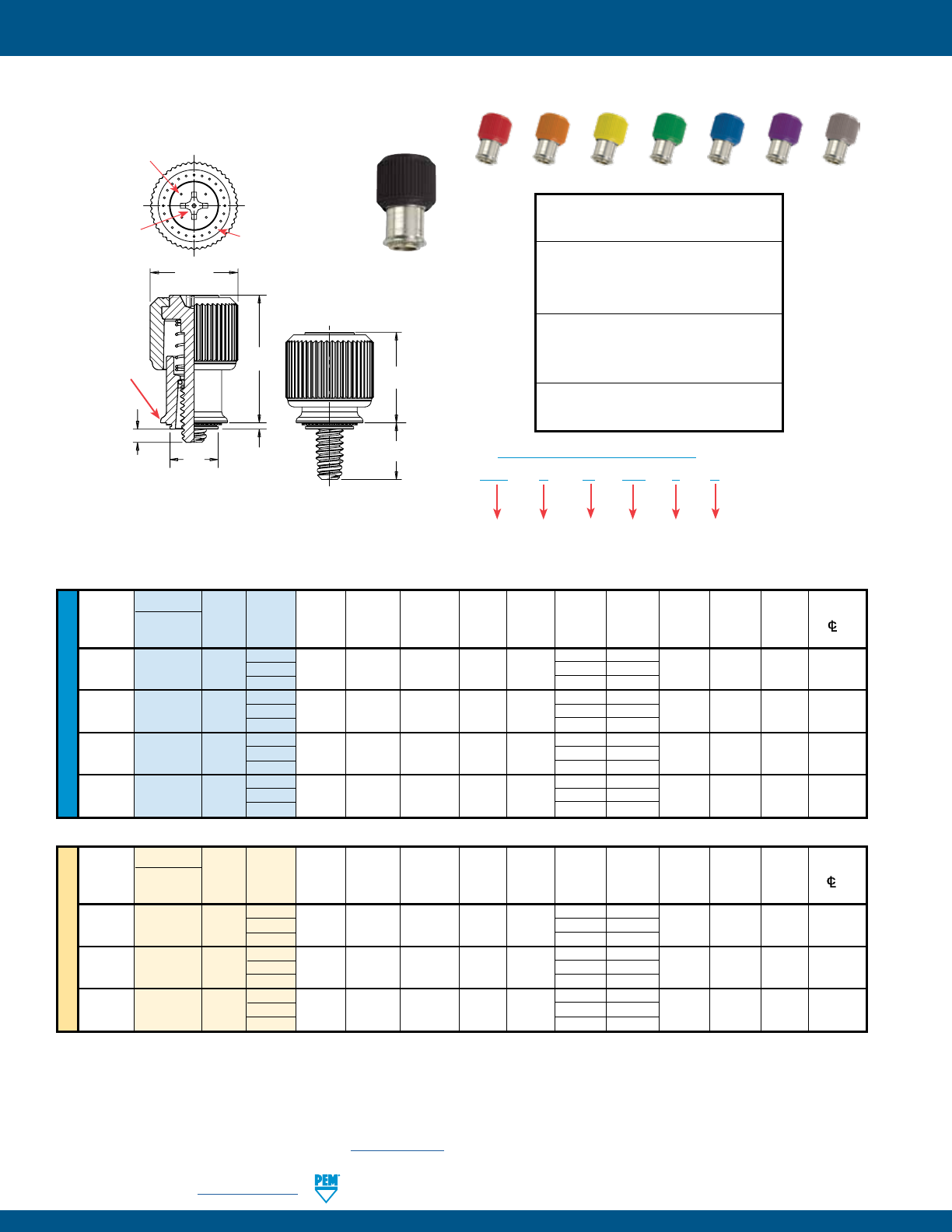
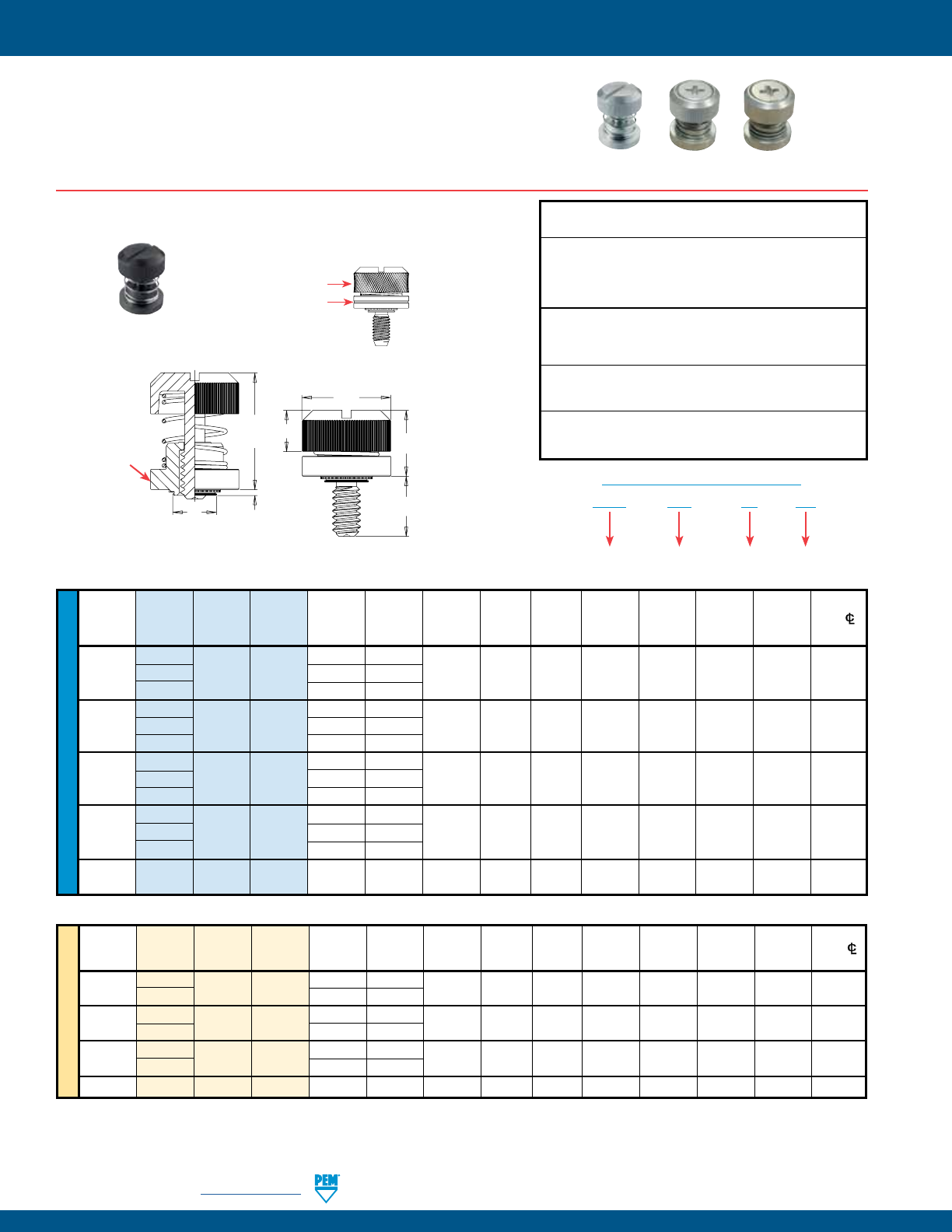
REELFAST® SMTPF™ SURFACE MOUNT CAPTIVE PANEL SCREWS
Threads:
External, ASME B1.1, 2A / ASME B1.13M, 6g (1)
Material:
Knob: ABS (2)
Retainer: Carbon Steel
Screw: Carbon Steel
Finish:
Retainer: ET - Electro-plated tin ASTM B545, Class B
with preservative coating, annealed
Screw: CN - Bright nickel over copper flash per ASTM B689
Retainer installed using conventional surface mount
techniques.
• Simply snap screw into retainer to complete assembly.
• Black ABS knob standard.
• Optional molded-through colors available.
• Available with Torx® recess.
UNIFIED
Available with Torx®
recess on special order.
Stencil Masking Examples
SMTPR – 6 – 1 ET
Type
PART NUMBER DESIGNATION
FOR RETAINER
Finish
Retainer
Size
Shank
Code
PSHP – 632 – 0 L 001
Type
PART NUMBER DESIGNATION
FOR SCREW
Cap
Style
(Lobed)
Thread
Code
Length
Code
Color
Code
(Standard
Black)
Screw Part Number Assembly Dimensions Screw Dimensions Retainer Dimensions
Screw Retainer Total A Min.
Thread Thread Length Part G P T1 T2 Radial C1 E1 L T (Shank) Sheet B C E R
Size Type Code Code Number ± .025 ± .025 Nom. Nom. Float ±.010 ±.010 ±.015 Nom. Max. Thick. ±.003 Max. Nom. ±.005
.112-40 PSHP 440 0
SMTPR-6-1 .188 .000 .478 .646 .015 .440 .542 .510 .663 .060 .060 .167 .249 .375 .325
(#4-40) 1 .248 .026 .570 .723
.138-32 PSHP 632 0
SMTPR-6-1 .188 .000 .478 .646 .020 .440 .542 .510 .663 .060 .060 .167 .249 .375 .325
(#6-32) 1 .248 .026 .570 .723
All dimensions are in inches.
All dimensions are in millimeters.
METRIC
Screw Part Number Assembly Dimensions Screw Dimensions Retainer Dimensions
Thread Screw Retainer Total A Min.
Size x Thread Length Part G P T1 T2 Radial C1 E1 L T (Shank) Sheet B C E R
Pitch Type Code Code Number ± 0.64 ± 0.64 Nom. Nom. Float ±0.25 ±0.25 ±0.38 Nom. Max. Thick. ±0.08 Max. Nom. ±0.13
M3 x 0.5 PSHP M3 0
SMTPR-6-1 4.78 0 12.14 16.41 .38 11.18 13.77 12.95 16.84 1.53 1.53 4.24 6.33 9.53 8.26
1 6.3 .66 14.48 18.36
M3.5 x 0.6
PSHP M3.5 0 SMTPR-6-1 4.78 0 12.14 16.41 .51 11.18 13.77 12.95 16.84 1.53 1.53 4.24 6.33 9.53 8.26
1 6.3 .66 14.48 18.36
RETAINER - Packaged on 330 mm recyclable reels of 465
pieces. Tape width is 24 mm. Supplied with Kapton® patch for
vacuum pick up. Reels conform to EIA-481.
SCREW - Packaged in bags. Retainers and screws are sold
separately.
.396”/
10.06 mm
Min.
Solder
Pad
Plated through hole
not required.
.250” +.003 –.000
6.35 mm +0.08
Four dimples on
head designate
metric thread.
Metal Phillips Recess
#4-40 & M3 = #1
#6-32 & M3.5 = #2
When Assembled
Spring action of
plastic “fingers”
holds screw
in retracted
position.
PSHP
SMTPR
PC Board
R
E
A
CBE
1
L
T
C
1
T
2
T
1
G
PPatented.
The colors shown here (codes #002 thru #007) are non-stocked standards and
available on special order. Since actual cap colors may vary slightly from those
shown here, we recommend that you request samples for color verification. If you
require a custom color or you need a “color matched” cap, please contact us.
Std. Black #001 Red #002 Orange #003 Yellow #004
Green #005 Blue #006 Violet #007
Non-flammable UL 94-V0 plastic caps are available on special order.
COLOR CAPABILITIES FOR PSHP SCREW
(1) As with all Class 2A/6g external threads with an additive finish, the maximum major
and pitch, after plating, may equal basic sizes and be gauged to Class 3A/4h, per ANSI
B1.1, Section 8, Table 3A and ANSI B1.13M, Section 8, Paragraph 8.2.
(2) See PEM Technical Support section of our website (www.pemnet.com) for related
plating standards and specifications.
Installation Data page 36.
Performance Data page 41.
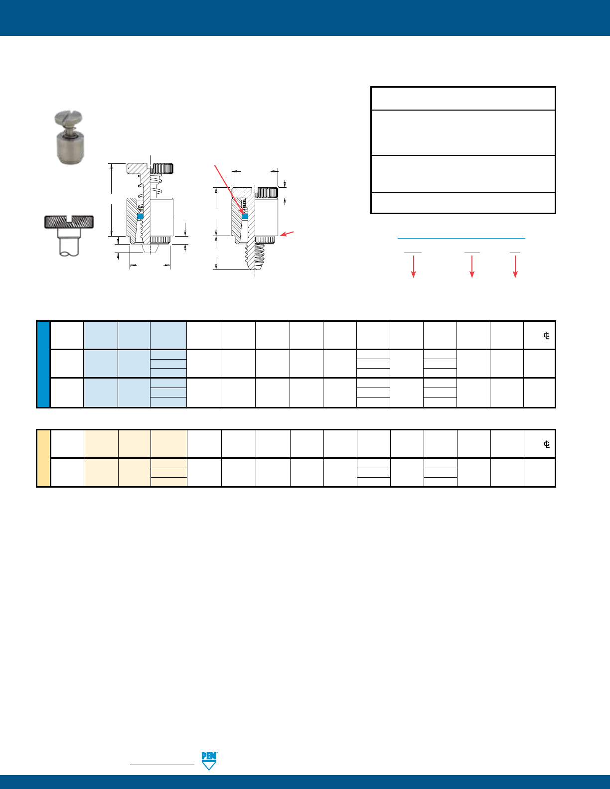
PF-26 PennEngineering • www.pemnet.com
PFK™ BROACHING CAPTIVE PANEL SCREWS
METRIC UNIFIED
Thread Thread Screw A Min. Hole Size C E G H P T1 T2
Min. Dist.
Size Type
Code Length (Shank) Sheet In Sheet ± .003 ±.010 ± .016 ± .005 ± .025 Max. Nom. HoleC/L
Code Max. Thickness +.003 -.000 To Edge
.112-40 40 .250 .000
(#4-40) PFK 440 62 .060 .060 .265 .283 .312 .375 .072 .125 .36 .54 .20
84 .500 .250
.138-32 40 .250 .000
(#6-32) PFK 632 62 .060 .060 .281 .299 .344 .375 .072 .125 .36 .54 .26
84 .500 .250
Thread Thread Screw A Min. Hole Size C E G H P T1 T2
Min. Dist.
Size x Type Code Length (Shank) Sheet In Sheet ± 0.08 ±.25 ± 0.4 ± 0.13 ± 0.64 Max. Nom. HoleC/L
Pitch Code Max. Thickness +0.08 To Edge
40 6.4 0
M3 x 0.5 PFK M3 62 1.53 1.53 6.73 7.19 7.92 9.5 1.83 3.2 9.14 13.72 5.08
84 12.7 6.4
PFK – 632 – 40
PART NUMBER DESIGNATION
Type Thread Size
Code
Screw
Length
Code
All dimensions are in inches.
All dimensions are in millimeters.
Threads:
External, ASME B1.1, 2A / ASME B1.13M, 6g
Material:
Retainer: 300 Series Stainless Steel
Screw: 300 Series Stainless Steel
Spring: 300 Series Stainless Steel
Retaining Ring: Nylon, temperature limit 200˚ F / 93˚ C
Finish:
Retainer: Passivated and/or tested per ASTM A380
Screw: Passivated and/or tested per ASTM A380
Spring: Natural Finish
For use in:
PC Boards
• For permanent and reliable installation in PC boards.
• Screw assemblies remain captive for easy mounting and removal.
Installation Data page 33. Performance Data page 41.
Diagonal knurl
identifies metric
thread sizes
T2
T1
PC
AG
H
E
Shoulder
provides
positive
stop during
installation.
Blue plastic retaining ring*
(Trademark)
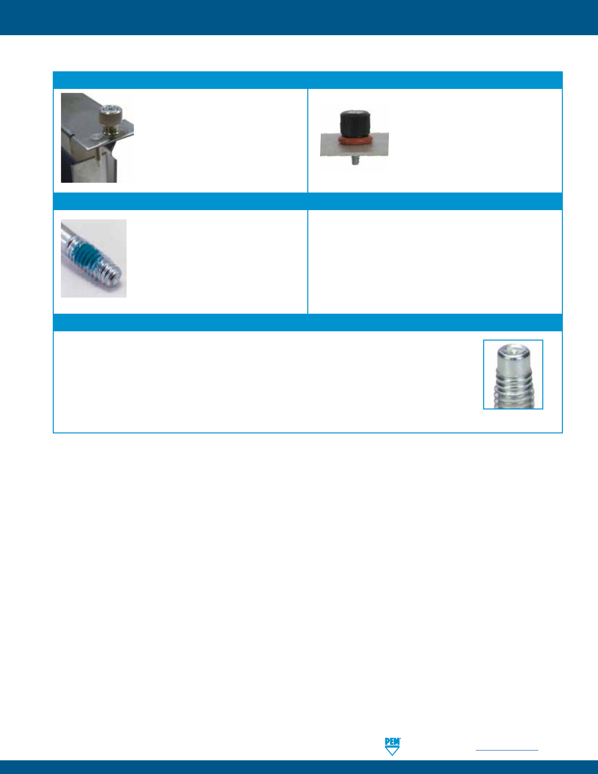
PennEngineering • www.pemnet.com PF-27
VALUE-ADDED CAPABILITIES
VALUE-ADDED CAPABILITIES
ATCA Solutions
Use PF11PM captive panel screw and
TPXS pin in conjunction to satisfy the
requirements of the PICMG 3.0 of the
Advanced TCA®.
Consider adding an o-ring to our PEM
C.A.P.S.® captive panel screw. When
fastened, it provides a tight seal above
the panel.
Tight Seal Solutions
Nylon Locking Patch Thread-forming Opportunity
Nylon locking patch is available to be added
to any of PEM captive panel screws for
applications requiring a locking element.
PennEngineering is official licensee for REMFORM®, TAPTITE®, PT®,
and DELTA PT® fastener products.
REMFORM® and TAPTITE® are trademarks of REMINC®.
PT® and DELTA PT® are trademarks of EJOT®.
MAThread® Anti Cross-thread Technology
PennEngineering is a licensee of MAThread® Anti Cross-Threading Technology. This unique design allows the threads
to self-align and drive easily with reduced effort. This helps speed assembly, reduce or eliminate failures, repairs,
scrap, downtime, and warranty service associated with thread damage. This option is available on most types of
PEM captive panel screws.
MAThread® is a registered trademark of MAThread inc.
Anti Cross-Thread Feature
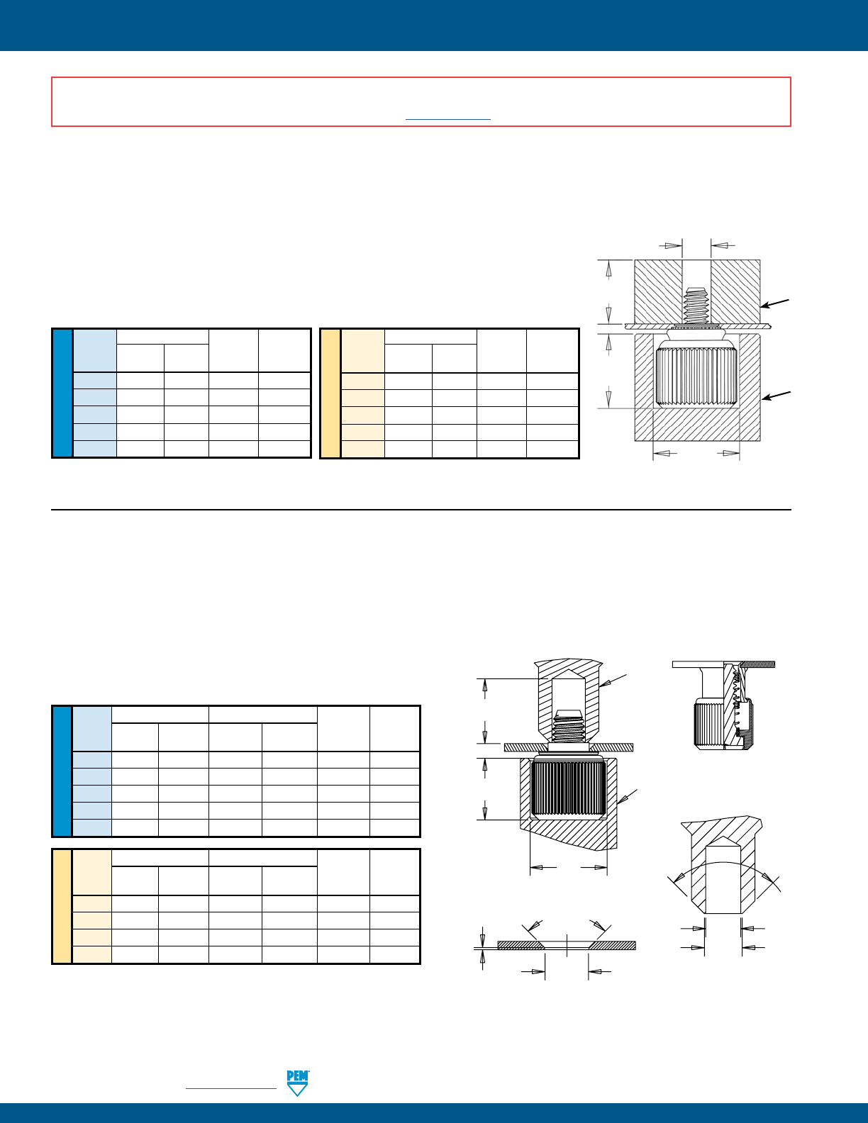
PF-28 PennEngineering • www.pemnet.com
CAPTIVE PANEL SCREW INSTALLATION
METRIC
UNIFIED
Anvil Dimensions (in.)
Thread A C Anvil Part Punch Part
Code ±.002 ±.002 Number Number
440 .260 .437 8003521 8003518
632 .390 .468 8003522 8003519
832 .390 .531 8003523 8003520
032 .390 .531 8003523 8004350
0420 .480 .598 8004351 8004352
Anvil Dimensions (mm)
Thread A C Anvil Part Punch Part
Code ±0.05 ±0.05 Number Number
M3 6.6 11.1 8003521 8003518
M3.5 9.91 11.89 8003522 8003519
M4 9.91 13.49 8003523 8003520
M5 9.91 13.49 8003523 8004350
M6 12.19 15.19 8004351 8004352
PEMSERTER® Installation Tooling(1)
Max. Screw
Extension PUNCH
ANVIL
A
C
Thread Dia. +.080” / +2 mm
PF11™/PF12™/PF11M™/PF12M™/PEM C.A.P.S.® FASTENERS
1. Prepare properly sized mounting hole in sheet. Do not perform any secondary
operations such as deburring.
2. Place fastener into recessed anvil, and place workpiece (preferably the punch
side) over shank of fastener.
3. With installation punch and anvil surfaces parallel, apply squeezing force until the
shoulder of the retainer comes in contact with the sheet material.
(1) Punches and anvils should be hardened.
UNIFIED
PF11MF™/PF12MF™ FASTENERS (flare-mount installation)
1. Prepare properly sized mounting hole in sheet with countersink.
2. Place fastener into recessed anvil, and place workpiece over shank
of fastener.
3. With installation punch and anvil surfaces parallel, apply
squeezing force to flare the retainer of the fastener.
Anvil Dimensions (in.) Punch Dimensions (in.)
Thread A C E F Anvil Punch
Code ±.002 ±.002 +.003 –.000 ±.002 Part No. Part No.
440 .260 .437 .123 .133 8003521 8013670
632 .390 .468 .143 .156 8003522 8013671
832 .390 .531 .202 .210 8003523 8013672
032 .390 .531 .202 .210 8003523 8013672
0420 .480 .598 .255 .264 8004351 8013674
PEMSERTER® Installation Tooling(1)
METRIC
Anvil Dimensions (mm) Punch Dimensions (mm)
Thread A C E F Anvil Punch
Code ±0.05 ±0.05 +0.08 ±0.05 Part No. Part No.
M3 6.6 11.1 3.12 3.38 8003521 8013670
M4 9.91 13.49 5.13 5.33 8003523 8013672
M5 9.91 13.49 5.13 5.33 8003523 8013672
M6 12.19 15.19 6.48 6.71 8004351 8013674
E
F
.015” ±.005”
0.38mm ±0.1mm 90˚
Nom.
C
A
90˚
Nom.
.500” / 12.7mm
Min.
PUNCH
ANVIL
PUNCH DETAIL
COUNTERSINK DETAIL
AFTER INSTALLATIONBEFORE INSTALLATION
Mounting Hole Dia.
(see page 6)
(1) Punches and anvils should be hardened.
INSTALLATION NOTES
• For best results we recommend using a PEMSERTER® press for installation of PEM self-clinching fasteners. Please check our website for more information.
• Visit the Animation Library on our website to view the installation process for select products.
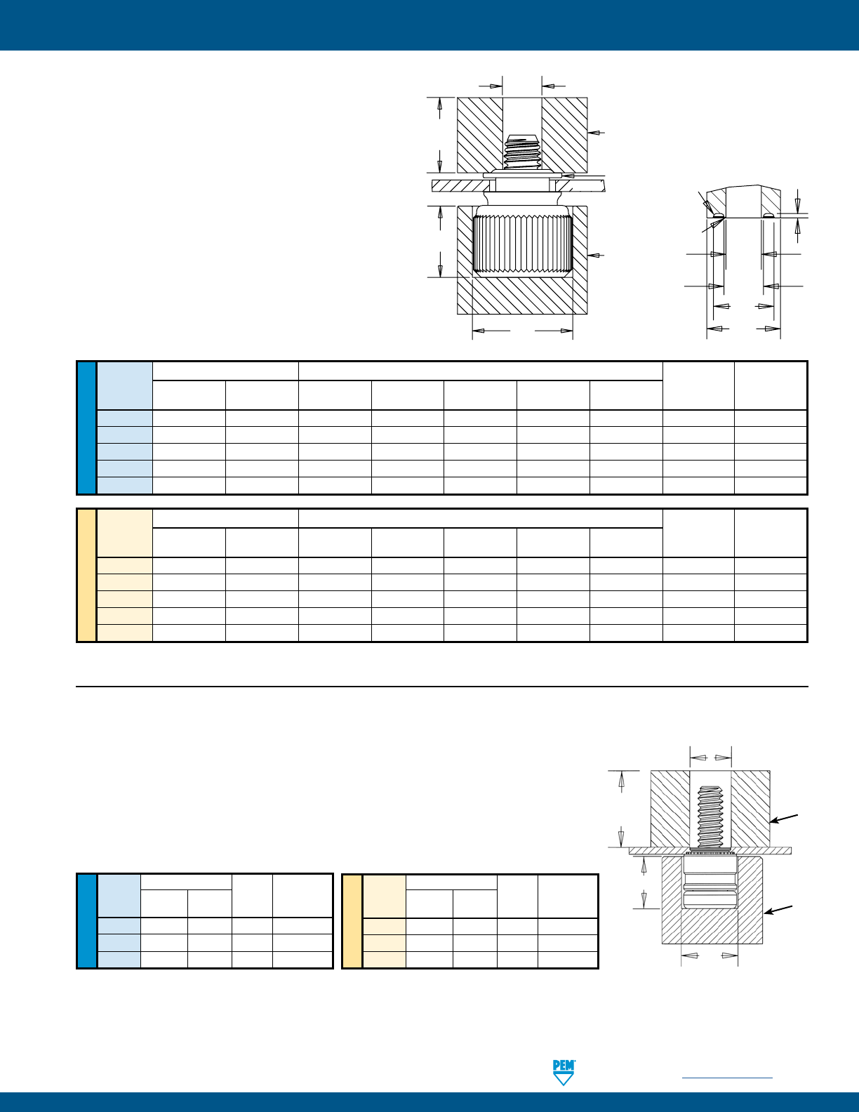
PennEngineering • www.pemnet.com PF-29
CAPTIVE PANEL SCREW INSTALLATION
PF11MW™/PF12MW™ FASTENERS
1. Prepare properly sized mounting hole in sheet.
2. Place fastener into recessed anvil, place
workpiece over shank of fastener, then place the
washer over the shank of the fastener.
3. With installation punch and anvil surfaces
parallel, apply squeezing force with flaring punch.
PEMSERTER® Installation Tooling(1)
UNIFIED
Anvil Dimensions (in.) Punch Dimensions (in.)
Thread A C E F G H I Anvil Punch
Code ±.002 ±.001 +.003 –.000 ±.001 ±.003 Min. ±.004 Part No. Part No.
440 .260 .437 .120 .135 .204 .250 .015 8003521 8014304
632 .390 .468 .140 .159 .249 .300 .015 8003522 8014305
832 .390 .531 .201 .217 .340 .400 .028 8003523 8014306
032 .390 .531 .201 .217 .340 .400 .028 8003523 8014306
0420 .480 .598 .252 .271 .430 .500 .028 8004351 8014307
METRIC
Anvil Dimensions (mm) Punch Dimensions (mm)
Thread A C E F G H I Anvil Punch
Code ±0.05 ±0.03 +0.08 ±0.03 ±0.08 Min. ±0.1 Part No. Part No.
M3 6.6 11.1 3.05 3.43 5.18 6.35 .381 8003521 8014304
M3.5 9.9 11.9 3.56 4.04 6.32 7.62 .381 8003522 8014305
M4 9.9 13.5 5.11 5.51 8.64 10.16 .711 8003523 8014306
M5 9.9 13.5 5.11 5.51 8.64 10.16 .711 8003523 8014306
M6 12.2 15.2 6.4 6.88 10.92 12.7 .711 8004351 8014307
H
E
F
FLARING PUNCH DETAIL
G
I
.010” R /
0.254mm R
Max.
.003” R /
0.08mm R
Max.
C
A
WASHER
E
ANVIL
PUNCH
PANEL
Max. Screw
Extension
METRIC
UNIFIED
Anvil Dimensions (in.)
Thread A C Anvil Part Punch Part
Code ±.002 ±.002 Number Number
440 .220 .285 8004688 970200009400
632 .250 .301 8004689 8015656
832 .285 .332 8005439 970200230400
Anvil Dimensions (mm)
Thread A C Anvil Part Punch Part
Code ±0.05 ±0.05 Number Number
M3 5.59 7.24 8004688 970200020400
M3.5 6.35 7.65 8004689 8015656
M4 7.24 8.43 8005439 970200230400
PFHV™ FASTENERS
1. Prepare properly sized mounting hole in sheet. Do not perform any secondary
operations such as deburring.
2. Place fastener into recessed anvil, and place workpiece (preferably the punch
side) over shank of fastener.
3. With installation punch and anvil surfaces parallel, apply squeezing force until
the shoulder of the retainer comes in contact with the sheet material.
PEMSERTER® Installation Tooling(1)
PUNCH
ANVIL
A
C
Thread Dia. +.080” / +2 mm
Max. Screw
Extension
(1) Punches and anvils should be hardened.
(1) Punches and anvils should be hardened.
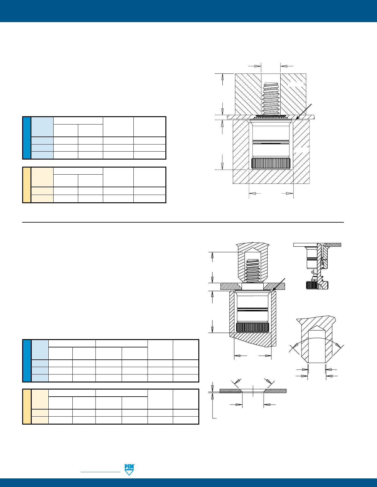
PF-30 PennEngineering • www.pemnet.com
CAPTIVE PANEL SCREW INSTALLATION
UNIFIED
PF7M™ FASTENERS
1. Prepare properly sized mounting hole in sheet. Do not
perform any secondary operations such as deburring.
2. Place fastener into recessed anvil, and place workpiece
(preferably the punch side) over the shank of fastener.
3. With installation punch and anvil surfaces parallel, apply
squeezing force until the shoulder of the retainer comes in
contact with the sheet material.
Thread Anvil Dimensions (in.) Anvil Punch
Code A C Part Part
±.002 ±.002 Number Number
440 .319 .290 8016175 8003518
632 .333 .330 8016176 8003519
832 .353 .385 8016177 8003520
METRIC
Thread Anvil Dimensions (mm) Anvil Punch
Code A C Part Part
±0.05 ±0.05 Number Number
M3 8.1 7.34 8016175 8003518
M4 8.9 9.8 8016177 8003520
A
C
Thread Dia.
+.080” / +2mm
.020” / .51 mm x
45˚ Nom.
Max. Screw
Extension
PUNCH
ANVIL
PF7MF™ FASTENERS (flare-mount installation)
1. Prepare properly sized mounting hole in sheet with
countersink. Do not perform any secondary operations
such as deburring.
2. Place fastener into recessed anvil, and place workpiece
over the shank of fastener.
3. With installation punch and anvil surfaces parallel, apply
squeezing force to flare the retainer of the fastener.
UNIFIED
Anvil Dimensions (in.) Punch Dimensions (in.)
Thread A C E F Anvil Punch
Code ±.002 ±.002 +.003 –.000 ±.002 Part No. Part No.
440 .319 .290 .123 .133 8016175 8013670
632 .333 .330 .143 .156 8016176 8013671
832 .353 .385 .202 .210 8016177 8013672
METRIC
Anvil Dimensions (mm) Punch Dimensions (mm)
Thread A C E F Anvil Punch
Code ±0.05 ±0.05 +0.08 ±0.05 Part No. Part No.
M3 8.1 7.34 3.12 3.38 8016175 8013670
M4 8.9 9.8 5.13 5.33 8016177 8013672
90˚ Nom.
ANVIL
A
C
E
PUNCH
.020” / .51mm x
45˚ Nom.
Max. Screw
Extension
90˚ Nom.
COUNTERSINK DETAIL
.015” ±.005”
0.38 mm ±0.1mm
F
PUNCH DETAIL
Mounting Hole Dia.
(see page 11)
AFTER INSTALLATION
BEFORE INSTALLATION
PEMSERTER® Installation Tooling(1)
PEMSERTER® Installation Tooling(1)
(1) Punches and anvils should be hardened.
(1) Punches and anvils should be hardened.
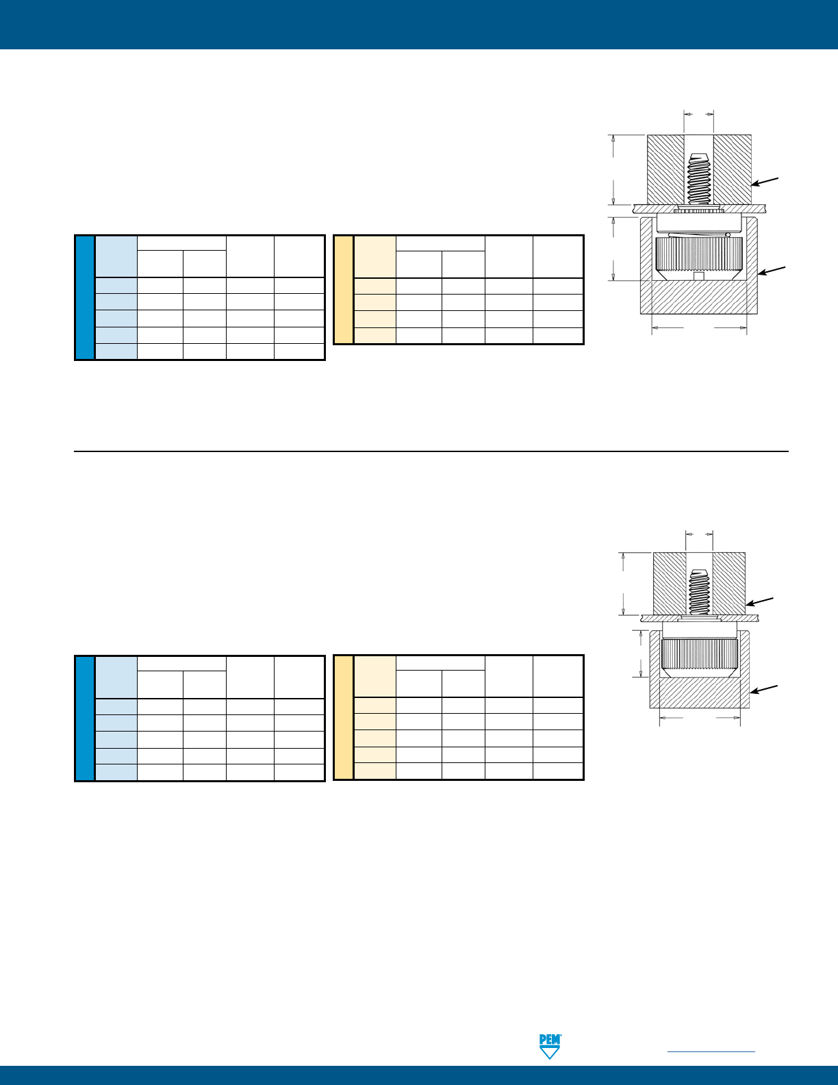
PennEngineering • www.pemnet.com PF-31
CAPTIVE PANEL SCREW INSTALLATION
METRIC
UNIFIED
Anvil Dimensions (in.)
Thread A C Anvil Part Punch Part
Code ±.002 ±.002 Number Number
440 .295 .421 975201060 975200060
632 .295 .453 975201061 975200061
832 .310 .484 975201062 975200062
032 .310 .546 975201063 975200063
0420 .365 .640 975201064 975200064
Anvil Dimensions (mm)
Thread A C Anvil Part Punch Part
Code ±0.05 ±0.05 Number Number
M3 7.49 10.69 975201060 975200060
M3.5 7.49 11.51 975201061 975200061
M4 7.87 12.29 975201062 975200062
M5 7.87 13.87 975201063 975200063
M6 9.27 16.26 975201064 975200064
PF50™/PF51™/PF52™/PF60™/PF61™/PF62™ FASTENERS
1. Prepare properly sized mounting hole in sheet. Do not perform any secondary
operations such as deburring.
2. Place fastener into recessed anvil, and place workpiece (preferably the punch side)
over shank of fastener.
3. With installation punch and anvil surfaces parallel, apply squeezing force until the
shoulder of the retainer comes in contact with the sheet material.
PEMSERTER® Installation Tooling(1)
PUNCH
ANVIL
A
C
Thread Dia. +.080” / +2mm
Max. Screw
Extension
METRIC
UNIFIED
Anvil Dimensions (in.)
Thread A C Anvil Part Punch Part
Code ±.002 ±.002 Number Number
440 .295 .421 975201060 975200060
632 .295 .453 975201061 975200061
832 .310 .484 975201062 975200062
032 .310 .546 975201063 975200063
0420 .365 .640 975201064 975200064
Anvil Dimensions (mm)
Thread A C Anvil Part Punch Part
Code ±0.05 ±0.05 Number Number
M3 7.49 10.69 975201060 975200060
M4 7.87 12.29 975201062 975200062
M5 7.87 13.87 975201063 975200063
M6 9.27 16.26 975201064 975200064
PEMSERTER® Installation Tooling(1)
PF30™/PF31™/PF32™ FASTENERS
1. Prepare properly sized mounting hole in sheet. Do not perform any secondary
operations such as deburring.
2. Place fastener into recessed anvil, and place workpiece (preferably the punch side)
over shank of fastener.
3. With installation punch and anvil surfaces parallel, apply squeezing force until the
shoulder of the retainer comes in contact with the sheet material.
PUNCH
ANVIL
A
C
Thread Dia. +.080” / +2mm
Max. Screw
Extension
(1) Punches and anvils should be hardened.
(1) Punches and anvils should be hardened.
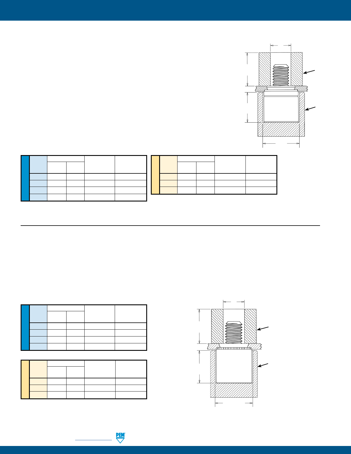
PF-32 PennEngineering • www.pemnet.com
CAPTIVE PANEL SCREW INSTALLATION
METRIC UNIFIED
Anvil Dimensions (in.)
Thread A C Anvil Part Punch Part
Code ±.002 ±.002 Number Number
440 .345 .323 975200026 975200060
632 .345 .358 975200027 975200061
832 .435 .386 975200028 975200062
032 .435 .421 975200029 975200063
Anvil Dimensions (mm)
Thread A C Anvil Part Punch Part
Code ±0.05 ±0.05 Number Number
M3 8.76 8.2 975200026 975200060
M4 11.05 9.8 975200028 975200062
M5 11.05 10.69 975200029 975200063
PFC2P™ FASTENERS
1. Prepare properly sized mounting hole in sheet. Do not perform any secondary operations such as deburring.
2. Place fastener into recessed anvil, and place workpiece (preferably the punch side) over shank of fastener.
3. With installation punch and anvil surfaces parallel, apply squeezing force until the shoulder of the retainer comes in
contact with the sheet material.
PEMSERTER® Installation Tooling(1)
METRIC
UNIFIED
Anvil Dimensions (in.)
Thread A C Anvil Part Punch Part
Code ±.002 ±.002 Number Number
440 .345 .358 975200027 975200060
632 .345 .390 975201243 975200061
832 .435 .421 975200029 975200062
032 .435 .452 975201244 975200063
Anvil Dimensions (mm)
Thread A C Anvil Part Punch Part
Code ±0.05 ±0.05 Number Number
M3 8.76 9.09 975200027 975200060
M4 11.05 10.69 975200029 975200062
M5 11.05 11.48 975201244 975200063
PFC4™ FASTENERS
1. Prepare properly sized mounting hole in sheet. Do not perform any secondary
operations such as deburring.
2. Place fastener into recessed anvil, and place workpiece (preferably the punch side)
over shank of fastener.
3. With installation punch and anvil surfaces parallel, apply squeezing force until the
shoulder of the retainer comes in contact with the sheet material.
Installation Requirements
1. Sheet hardness must be less than 88 on the Rockwell “B” scale.
2. Hole punch should be kept sharp to minimize work hardening around hole.
3. Fastener should be installed in punch side of hole.
4. Fastener should not be installed near bends or other highly cold worked areas
where sheet hardness may be greater than 88 on the Rockwell “B” scale.
PEMSERTER® Installation Tooling(1)
PUNCH
ANVIL
A
C
Thread Dia. +.080” / +2mm
Max. Screw
Extension
PUNCH
ANVIL
A
C
Thread Dia. +.080” / +2mm
Max. Screw
Extension
(1) Punches and anvils should be hardened.
(1) Punches and anvils should be hardened.
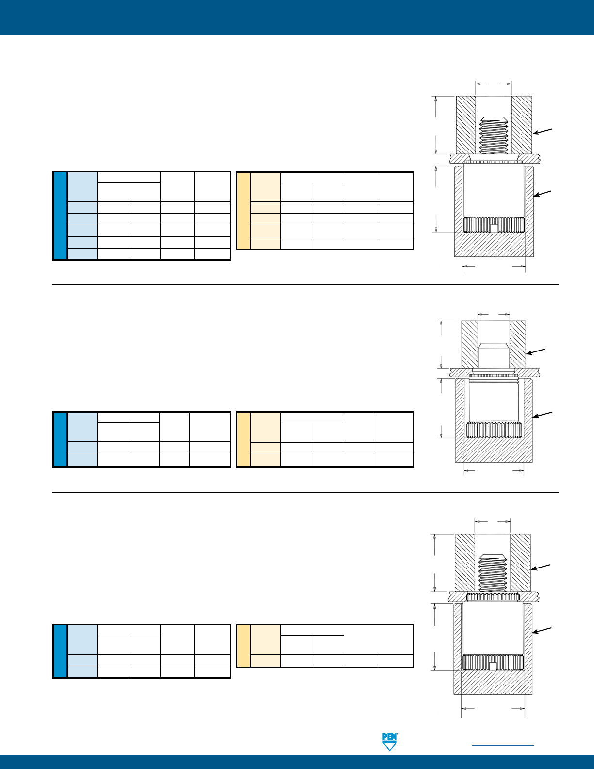
PennEngineering • www.pemnet.com PF-33
CAPTIVE PANEL SCREW INSTALLATION
METRIC
UNIFIED
Anvil Dimensions (in.)
Thread A C Anvil Part Punch Part
Code ±.002 ±.002 Number Number
440 .345 .323 975200026 975200060
632 .345 .358 975200027 975200061
832 .435 .386 975200028 975200062
032 .435 .421 975200029 975200063
0420 .565 .484 975200030 975200064
Anvil Dimensions (mm)
Thread A C Anvil Part Punch Part
Code ±0.05 ±0.05 Number Number
M3 8.76 8.2 975200026 975200060
M4 11.05 9.8 975200028 975200062
M5 11.05 10.69 975200029 975200063
M6 14.35 12.29 975200030 975200064
PEMSERTER® Installation Tooling(1)
PFC2™/PFS2™ FASTENERS
1. Prepare properly sized mounting hole in sheet. Do not perform any secondary
operations such as deburring.
2. Place fastener into recessed anvil, and place workpiece (preferably the punch
side) over shank of fastener.
3. With installation punch and anvil surfaces parallel, apply squeezing force until
the shoulder of the retainer comes in contact with the sheet material.
PUNCH
ANVIL
A
C
Thread Dia. +.080” / +2mm
Max. Screw
Extension
METRIC
UNIFIED
Anvil Dimensions (in.)
Type A C Anvil Part Punch Part
±.002 ±.002 Number Number
PTL2 .580 .520 975201245 970200013300
PSL2 .490 .520 8021146 970200013300
Anvil Dimensions (mm)
Type A C Anvil Part Punch Part
±0.05 ±0.05 Number Number
PTL2 14.86 13.21 975201245 970200013300
PSL2 12.47 13.21 8021146 970200013300
PEMSERTER® Installation Tooling(1)
PTL2™/PSL2™ FASTENERS
1. Prepare properly sized mounting hole in sheet. Do not perform any secondary
operations such as deburring.
2. Place fastener into recessed anvil, and place workpiece (preferably the punch side)
over shank of fastener.
3. With installation punch and anvil surfaces parallel, apply squeezing force until the
shoulder of the retainer comes in contact with the sheet material.
PUNCH
ANVIL
A
C
Pin Dia. +.080” / +2mm
Max. Pin
Extension
METRIC
UNIFIED
Anvil Dimensions (in.)
Thread A C Anvil Part Punch Part
Code ±.002 ±.002 Number Number
440 .320 .323 975200026 975200060
632 .320 .358 975200027 975200061
Anvil Dimensions (mm)
Thread A C Anvil Part Punch Part
Code ±0.05 ±0.05 Number Number
M3 8.13 8.2 975200026 975200060
PFK™ FASTENERS
1. Prepare properly sized mounting hole in board.
2. Place fastener into recessed anvil, and place workpiece over shank of fastener.
3. With installation punch and anvil surfaces parallel, apply squeezing force until
the shoulder of the retainer comes in contact with the board.
PEMSERTER® Installation Tooling(1)
PUNCH
ANVIL
A
C
Thread Dia. +.080” / +2mm
Max. Screw
Extension
(1) Punches and anvils should be hardened.
(1) Punches and anvils should be hardened.
(1) Punches and anvils should be hardened.
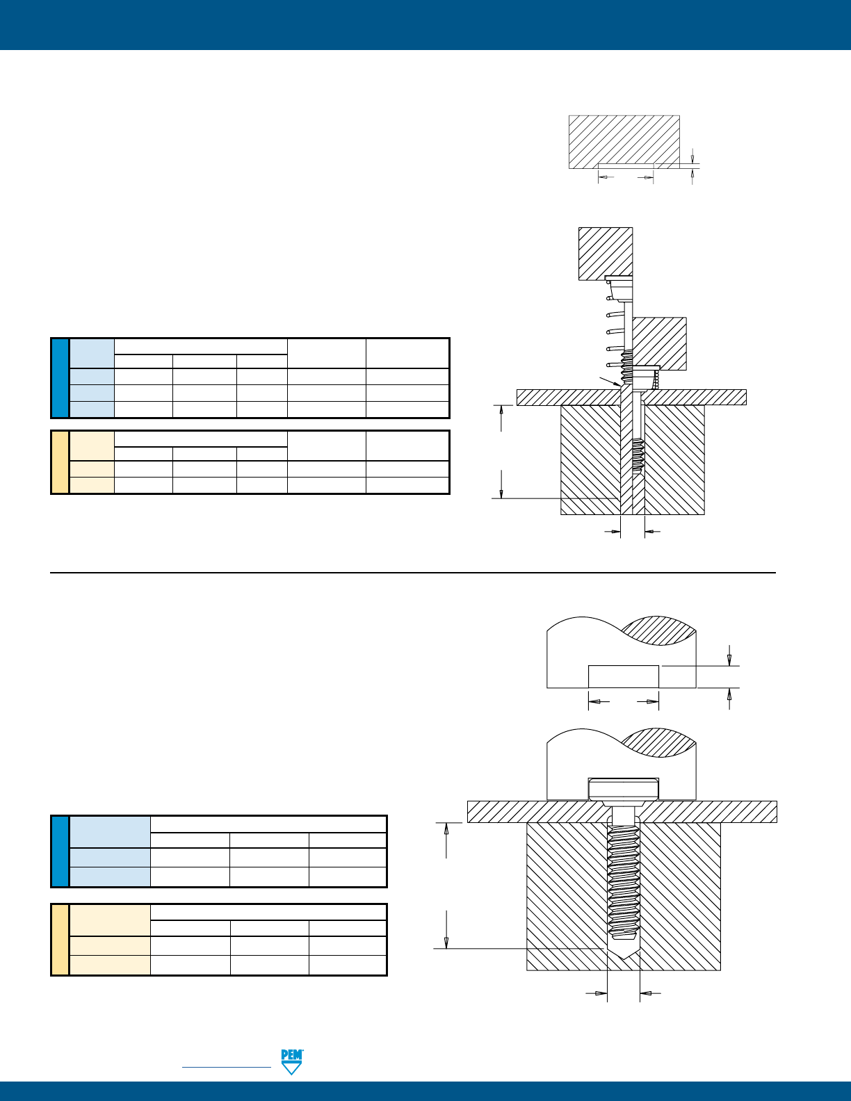
PF-34 PennEngineering • www.pemnet.com
CAPTIVE PANEL SCREW INSTALLATION
METRIC UNIFIED
SCB™/SCBJ™ FASTENERS
1. Prepare properly sized mounting hole in sheet.
2. Place the fastener through mounting hole and into anvil. A flat or
recessed punch can be used.
3. With installation punch and anvil surfaces parallel, apply squeezing
force to the top of the screw head and the underside of the sheet
material. The squeezing action forces the shoulder of the screw
into the sheet, displacing sheet material, causing it to fill the void
under the head and shoulder of the screw.
Thread Installation Tooling Dimensions (in.)
Code C E H
440 .113 - .116 .270 - .280 .073 - .074
632 .139 - .142 .308 - .318 .073 - .074
Thread Installation Tooling Dimensions (mm)
Code C E H
M3 3.03 - 3.11 6.86 - 7.11 1.85 - 1.88
M4 4.03 - 4.11 8.53 - 8.79 1.85 - 1.88
E
H
L*
+.125” / 3.18mm
Min.
C
PEMSERTER® Installation Tooling(1)
UNIFIED
Thread
Installation Tooling Dimensions (in.)
Anvil Magnetic Punch
Code C J K
Part Number Part Number (2)
440 .113 - .116 .354 – .357 .035 970200048300 8016210
632 .139 - .142 .387 – .390 .035 970200052300 8016211
832 .165 - .168 .416 – .419 .035 970200054300 8016212
METRIC
Thread
Installation Tooling Dimensions (mm)
Anvil Magnetic Punch
Code C J K
Part Number Part Number (2)
M3 3.03 - 3.11 9.25 – 9.32 0.89 970200049300 8016213
M4 4.03 - 4.11 10.8 – 10.9 0.89 970200053300 8016214
(1) Punches and anvils should be hardened.
(2) Pneumatic punch may also be used. Please contact our PEMSERTER tooling
division for punch part numbers.
SCBR™ FASTENERS
1. Prepare properly sized mounting hole in sheet. Do not perform any
secondary operations such as deburring. If the hole is punched, be
sure to install fastener into punched side of hole.
2. Assemble spring on screw by rotating spring counter clockwise
and position assembly into recessed magnetic punch.
3. Position hole in workpiece over retractable anvil pin.
4. With installation punch and anvil surfaces parallel, apply squeezing
force on top of the screw head and the underside of the sheet
material. The squeezing action forces the displacer of the screw
into the sheet, causing it to reduce the mounting hole diameter and
captivate the screw.
K
J
Magnetic
Punch (1)
BEFORE
AFTER
SHEET
ANVIL
ANVIL PIN
L*
+.125” / 3.18mm
Min.
C
Magnetic
Punch (1)
Magnetic
Punch (1)
PEMSERTER® Installation Tooling(1)
* For “L”,
see page 18.
* For “L”,
see page 19.
(1) Punches and anvils should be hardened.
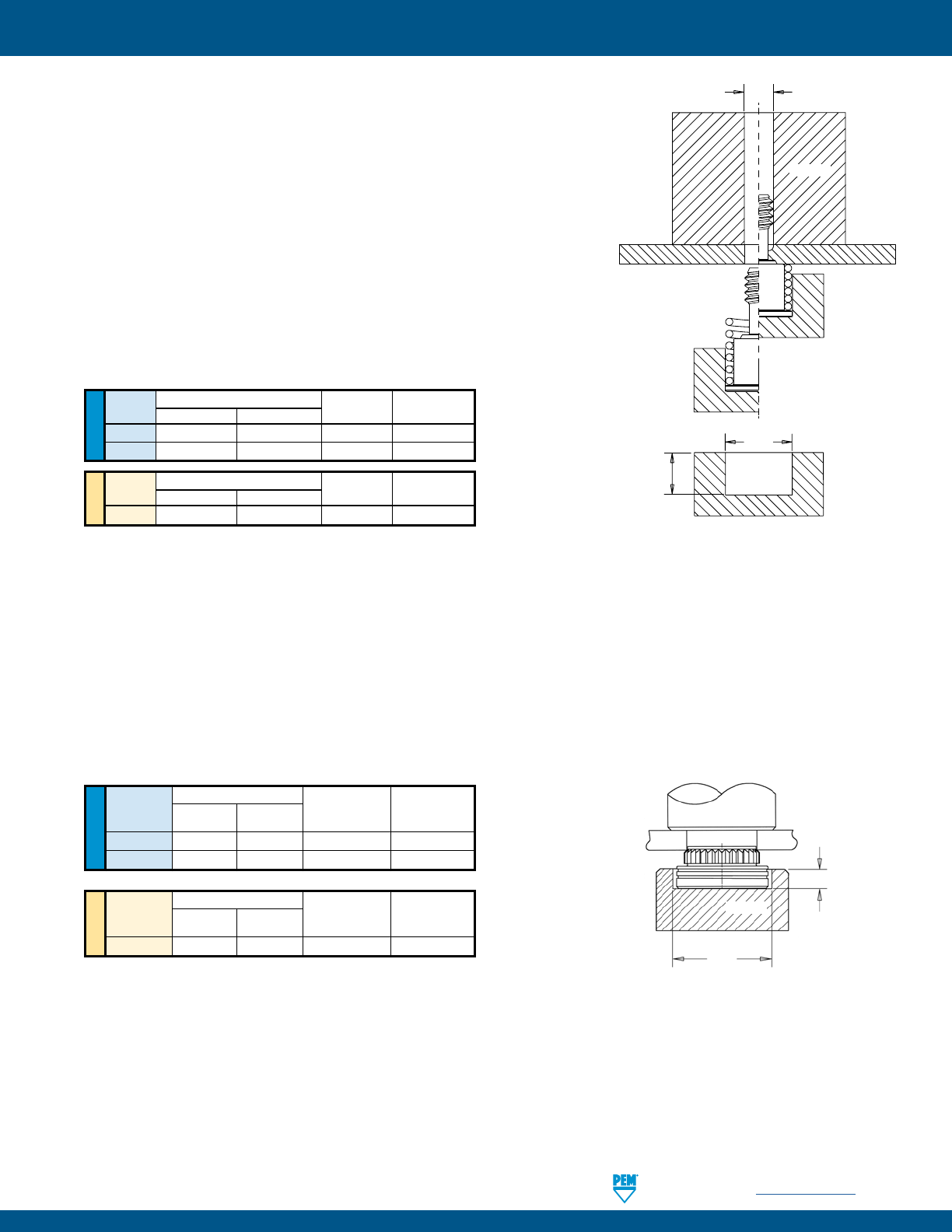
PennEngineering • www.pemnet.com PF-35
CAPTIVE PANEL SCREW INSTALLATION
UNIFIEDMETRIC
HSCB™ FASTENER INTO HEAT SINK
1. Prepare properly sized mounting hole in heat sink. Do not perform any
secondary operations such as deburring. If the hole is punched, be sure to
install the fastener into the punch side of the hole.
2. Place the head of the screw into the recess of the installation anvil
and position assembly into recessed magnetic punch.
3. Place the spring over the shoulder of the screw, maintaining concentricity.
4. Position the heat sink mounting hole over the screw.
5. Bring the heat sink down over the screw and onto the shoulder of the screw.
6. With installation punch and anvil surfaces parallel, apply a squeezing force
to the heat sink and the head of the screw. The squeezing action forces the
displacer of the screw into the heat sink, causing it to reduce the mounting
hole diameter and captivate the screw and spring.
PEMSERTER® Installation Tooling(1)
PEMSERTER® Installation Tooling(1)
Anvil Dimensions (in.)
Thread P Anvil Part Punch Part
Code A ±.005 Number Number
HSR-440 .228 - .231 .115 8023699 975200048
HSR-632 .290 - .293 .115 8023701 975200048
Anvil Dimensions (mm)
Thread P Anvil Part Punch Part
Code A ±0.13 Number Number
HSR-M3 5.8 - 5.86 2.92 8023700 975200048
FINAL ASSEMBLY
Once the screw and spring are captivated, assemble the heat sink to the circuit board by tightening the screw into the
receptacle nut or stando until the audible “click” is heard. The screw will continue to rotate, but will no longer be engaged
in the threads or continue to actively tighten.
C
BEFORE
AFTER
PUNCH
ANVIL
A
P
PUNCH
ANVIL
J
.250” ±.005/
6.35mm ±0.13 ANVIL
HSR™ NUT/STANDOFF
1. Prepare properly sized mounting hole in board.
2. Place fastener into the anvil hole and place the mounting hole over the shank of the fastener as shown in drawing.
3. With installation punch and anvil surfaces parallel, apply squeezing force until shoulder contacts the board.
(1) Punches and anvils should be hardened.
(1) Punches and anvils should be hardened.
UNIFIED
Thread
Installation Tooling Dimensions (in.)
Anvil Punch
Code C J
Part Number Part Number
440 .113 - .116 .322 - .324 8018043 970200006300
632 .139 - .142 .362 - .364 8018044 970200007300
METRIC
Thread
Installation Tooling Dimensions (mm)
Anvil Punch
Code C J
Part Number Part Number
M3 3.03 - 3.11 8.43 - 8.48 8018045 970200229300
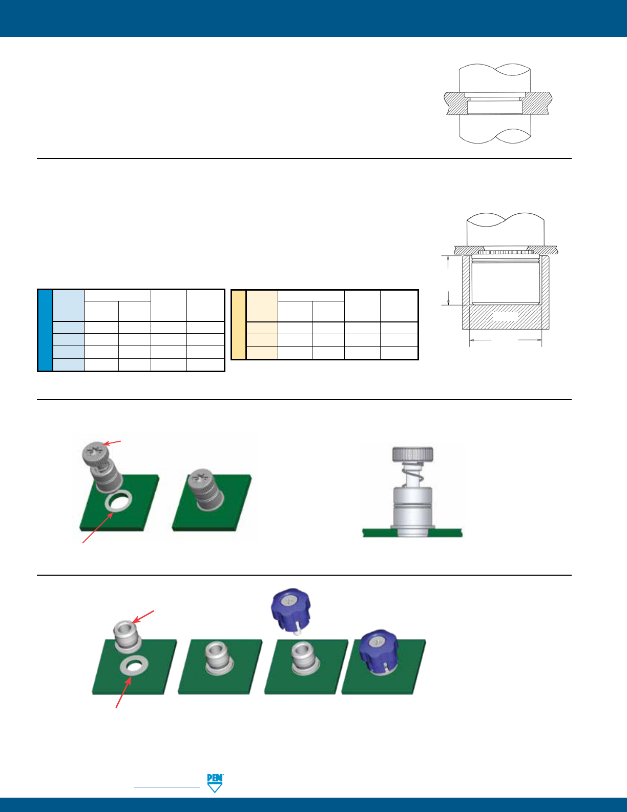
PF-36 PennEngineering • www.pemnet.com
CAPTIVE PANEL SCREW INSTALLATION
METRIC
UNIFIED
Anvil Dimensions (in.)
Thread A C Anvil Part Punch Part
Code ±.002 ±.002 Number Number
440 .225 .298 8006124 975200048
632 .225 .329 8006735 975200048
832 .225 .361 8006736 975200048
032 .225 .392 8006174 975200048
Anvil Dimensions (mm)
Thread A C Anvil Part Punch Part
Code ±0.05 ±0.05 Number Number
M3 5.72 7.57 8006124 975200048
M4 5.72 9.17 8006736 975200048
M5 5.72 9.6 8006174 975200048
PUNCH
ANVIL
A
C
N10™ FASTENERS
1. Prepare properly sized mounting hole in sheet. Do not perform any secondary
operations such as deburring.
2. Place fastener into recessed anvil, and place workpiece (preferably the punch side)
over shank of fastener.
3. With installation punch and anvil surfaces parallel, apply squeezing force until the
shoulder of the nut comes in contact with the sheet material.
PEMSERTER® Installation Tooling(1)
PUNCH
ANVIL
PR10™ FASTENERS
1. Prepare properly sized mounting hole in sheet. Do not perform any
secondary operations such as deburring.
2. Place fastener into the mounting hole.
3. With installation punch and anvil surfaces parallel, apply squeezing force
until the retainer is flush in the sheet.
Solder paste applied
to pad on PCB.
Solder fastener in place
using standard surface
mount techniques.
Screw snapped in place.
Polyimide patch applied
here for vacuum pick up.
Installs in retracted/unfastened position
SMTPF™ RETAINER
SMTPFLSM™ CAPTIVE PANEL SCREWS
Solder paste applied
to pad on PCB.
Solder fastener in place
using standard surface
mount techniques.
Polyimide patch applied
here for vacuum pick up.
(1) Punches and anvils should be hardened.
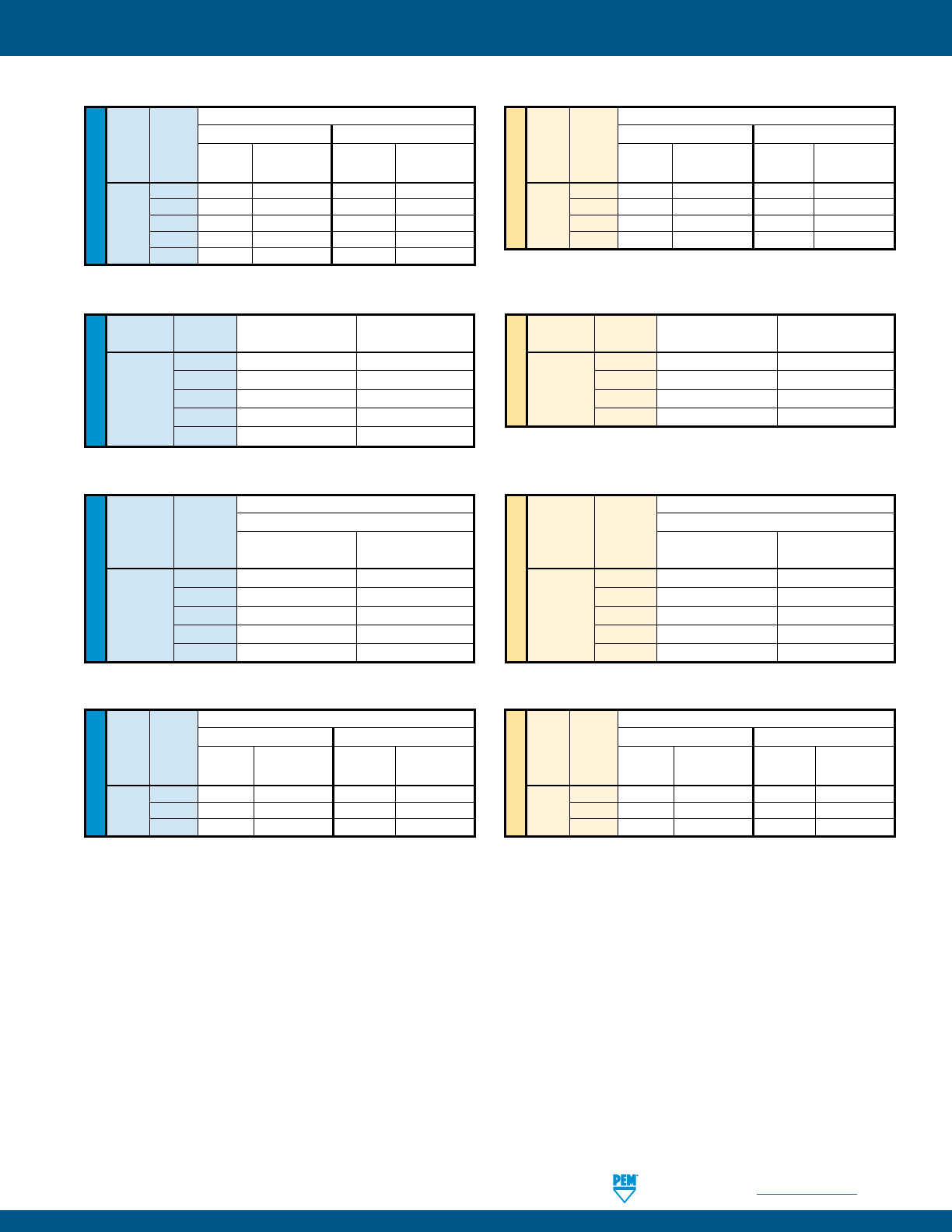
PennEngineering • www.pemnet.com PF-37
CAPTIVE PANEL SCREW PERFORMANCE DATA(1)
(1) Published installation forces are for general reference. Actual set-up and confirmation of complete installation should be made by observing
proper seating of fastener as described in the installation steps. Other performance values reported are averages when all proper
installation parameters and procedures are followed. Variations in mounting hole size, sheet material, and installation procedure may aect
performance. Performance testing this product in your application is recommended. We will be happy to provide technical assistance and/
or samples for this purpose.
UNIFIED
Test Sheet Material
Type Thread Aluminum Cold-Rolled Steel
Code Installation Retainer Pushout Installation Retainer Pushout
(lbs.) (lbs.) (lbs.) (lbs.)
440 1500 80 2500 145
PF11 632 2000 95 3500 150
PF12 832 3000 100 4500 160
032 3000 100 4500 160
0420 3500 105 5000 195
METRIC
Test Sheet Material
Type Thread Aluminum Cold-Rolled Steel
Code Installation Retainer Pushout Installation Retainer Pushout
(kN) (N) (kN) (N)
M3 6.7 355 11.1 645
PF11 M4 13.3 445 20 710
PF12 M5 13.3 445 20 710
M6 15.6 465 22.2 865
PF11™/PF12™/PF11M™/PF12M™/PEM C.A.P.S.® FASTENERS
UNIFIED
Type Thread Installation Retainer Pullout
Code (lbs.) (lbs.)
440 250 81
632 300 175
PF11MF 832 350 180
032 350 180
0420 400 200
METRIC
Type Thread Installation Retainer Pullout
Code (kN) (N)
M3 1.1 360
PF11MF M4 1.5 800
M5 1.5 800
M6 2 890
PF11MF™ FASTENERS
UNIFIED
Test Sheet Material
Type Thread .060” Cold-rolled Steel
Code Swaging Force Retainer Pullout
(lbs.) (lbs.)
440 350 112
632 400 138
PF11MW 832 700 202
032 700 202
0420 900 212
METRIC
Test Sheet Material
Type Thread 1.52mm Cold-rolled Steel
Code Swaging Force Retainer Pullout
(N) (N)
M3 1557 499
M3.5 1779 612
PF11MW M4 3114 897
M5 3114 897
M6 4003 945
PF11MW™ FASTENERS
UNIFIED
Test Sheet Material
Type Thread Aluminum Cold-Rolled Steel
Code Installation Retainer Pushout Installation Retainer Pushout
(lbs.) (lbs.) (lbs.) (lbs.)
440 1700 108 2200 118
PFHV 632 1850 117 2400 128
832 2100 134 2700 147
METRIC
Test Sheet Material
Type Thread Aluminum Cold-Rolled Steel
Code Installation Retainer Pushout Installation Retainer Pushout
(kN) (N) (kN) (N)
M3 8.1 516 10.5 564
PFHV M3.5 8.8 561 11.4 614
M4 9.4 599 12.1 656
PFHV™ FASTENERS
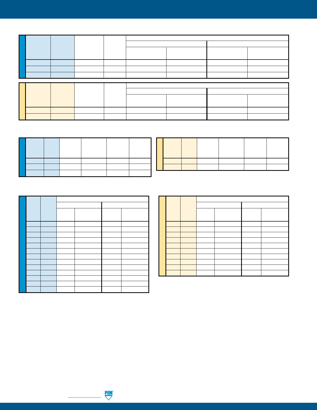
PF-38 PennEngineering • www.pemnet.com
CAPTIVE PANEL SCREW PERFORMANCE DATA(1)
PF
7
M™ FASTENERS
UNIFIED
Rec. Min. Test Sheet Material
Tightening Screw Aluminum Cold-rolled Steel
Type Thread Torque Tensile
Code (in. lbs.) (2) (lbs.) Installation Retainer Pushout Installation Retainer Pushout
(lbs.) (lbs.) (lbs.) (lbs.)
PF
M .
PF
M .
PF
M .
METRIC
Rec. Min. Test Sheet Material
Tightening Screw 5052-H34 Aluminum Cold-rolled Steel
Type Thread Torque Tensile
Code (N • m) (2) (N) Installation Retainer Pushout Installation Retainer Pushout
(kN) (N) (kN) (N)
PF
M M . . .
PF
M M . .
PF
7
MF™ FASTENERS
UNIFIED
Rec.
Tightening Min. Screw Retainer
Type Thread Torque Tensile Installation Pullout
Code (in. lbs.) (2) (lbs.) (lbs.) (lbs.)
PF
MF .
PF
MF .
PF
MF .
METRIC
Rec.
Tightening Min. Screw Retainer
Type Thread Torque Tensile Installation Pullout
Code (N•m) (2) (N) (kN) (N)
PF
MF M . .
PF
MF M . .
(1) Published installation forces are for general reference. Actual set-up and confirmation of complete installation should be made by observing
proper seating of fastener as described in the installation steps. Other performance values reported are averages when all proper
installation parameters and procedures are followed. Variations in mounting hole size, sheet material, and installation procedure may aect
performance. Performance testing this product in your application is recommended. We will be happy to provide technical assistance and/
or samples for this purpose.
(2) Torque values shown will produce a preload of 70% minimum tensile with nut factor “k” equal to .1
UNIFIED
Test Sheet Material
Type Thread Aluminum Cold-Rolled Steel
Code Installation Retainer Pushout Installation Retainer Pushout
(lbs.) (lbs.) (lbs.) (lbs.)
PF30 440 2200 64 5000 90
PF31 440 2200 105 5000 110
PF32 440 2200 185 5000 300
PF30 632 2400 66 5500 90
PF31 632 2400 105 5500 130
PF32 632 2400 190 5500 300
PF30 832 2800 68 6000 90
PF31 832 2800 110 6000 130
PF32 832 2800 200 6000 300
PF30 032 3500 72 8000 95
PF31 032 3500 150 8000 160
PF32 032 3500 260 8000 425
PF32 0420 4300 320 12000 450
METRIC
Test Sheet Material
Type Thread Aluminum Cold-Rolled Steel
Code Installation Retainer Pushout Installation Retainer Pushout
(kN) (N) (kN) (N)
PF30 M3 9.8 285 22.2 400
PF31 M3 9.8 465 22.2 489
PF32 M3 9.8 823 22.2 1334
PF30 M4 12.5 302 26.7 400
PF31 M4 12.5 489 26.7 578
PF32 M4 12.5 890 26.7 1334
PF30 M5 15.6 320 35.6 423
PF31 M5 15.6 667 35.6 712
PF32 M5 15.6 1156 35.6 1890
PF32 M6 19.1 1423 53.4 2002
PF30™/PF31™/PF32™ FASTENERS
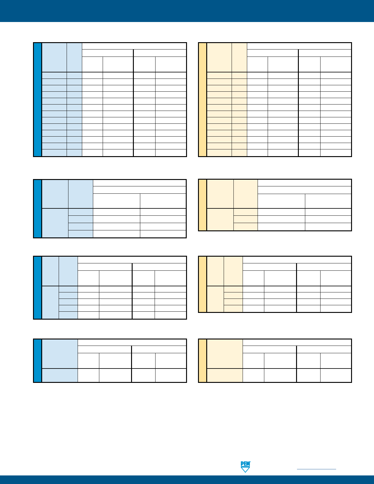
PennEngineering • www.pemnet.com PF-39
CAPTIVE PANEL SCREW PERFORMANCE DATA(1)
(1) Published installation forces are for general reference. Actual set-up and confirmation of complete installation should be made by observing
proper seating of fastener as described in the installation steps. Other performance values reported are averages when all proper installation
parameters and procedures are followed. Variations in mounting hole size, sheet material, and installation procedure may aect performance.
Performance testing this product in your application is recommended. We will be happy to provide technical assistance and/or samples for
this purpose.
PF50™/PF51™/PF52™/PF60™/PF61™/PF62™ FASTENERS
UNIFIED
Test Sheet Material
Type Thread Aluminum Cold-Rolled Steel
Code
Installation Retainer Pushout Installation Retainer Pushout
(lbs.) (lbs.) (lbs.) (lbs.)
PF50/PF60 440 2200 64 5000 90
PF51/PF61 440 2200 105 5000 110
PF52/PF62 440 2200 185 5000 300
PF50/PF60 632 2400 66 5500 90
PF51/PF61 632 2400 105 5500 130
PF52/PF62 632 2400 190 5500 300
PF50/PF60 832 2800 68 6000 90
PF51/PF61 832 2800 110 6000 130
PF52/PF62 832 2800 200 6000 300
PF50/PF60 032 3500 72 8000 95
PF51/PF61 032 3500 150 8000 160
PF52/PF62 032 3500 260 8000 425
PF52/PF62 0420 4300 320 12000 450
METRIC
Test Sheet Material
Type Thread Aluminum Cold-Rolled Steel
Code
Installation Retainer Pushout Installation Retainer Pushout
(kN) (N) (kN) (N)
PF50/PF60 M3 9.8 285 22.2 400
PF51/PF61 M3 9.8 465 22.2 489
PF52/PF62 M3 9.8 823 22.2 1334
PF50/PF60 M3.5 10.7 294 24.4 400
PF51/PF61 M3.5 10.7 465 24.4 578
PF52/PF62 M3.5 10.7 845 24.4 1334
PF50/PF60 M4 12.5 302 26.7 400
PF51/PF61 M4 12.5 489 26.7 578
PF52/PF62 M4 12.5 890 26.7 1334
PF50/PF60 M5 15.6 320 35.6 423
PF51/PF61 M5 15.6 667 35.6 712
PF52/PF62 M5 15.6 1156 35.6 1890
PF52/PF62 M6 19.1 1423 53.4 2002
UNIFIED
Test Sheet Material
Type Thread Aluminum Cold-Rolled Steel
Code Installation Retainer Pushout Installation Retainer Pushout
(lbs.) (lbs.) (lbs.) (lbs.)
440 2400 240 3000 300
PFC2 632 2700 275 3500 350
PFS2 832 2900 300 3800 400
PFC2P 032 3000 400 4000 500
0420 3500 400 5000 600
METRIC
Test Sheet Material
Type Thread Aluminum Cold-Rolled Steel
Code Installation Retainer Pushout Installation Retainer Pushout
(kN) (N) (kN) (N)
M3 10.7 1068 13.3 1334
PFC2 M4 12.9 1334 16.9 1779
PFS2 M5 13.3 1779 17.8 2224
PFC2P M6 15.6 1779 22.2 2669
PFC2™/PFS2™/PFC2P™ FASTENERS
METRIC
UNIFIED
Test Sheet Material
Type Thread 304 Stainless Steel
Code Installation Retainer Pushout
(lbs.) (lbs.)
440 9100 350
PFC4 632 10300 400
832 10800 450
032 11800 550
Test Sheet Material
Type Thread 304 Stainless Steel
Code Installation Retainer Pushout
(kN) (N)
M3 40.5 1557
PFC4 M4 48 2002
M5 52.5 2447
PFC4™ FASTENERS
UNIFIED
Test Sheet Material
Type Aluminum Cold-Rolled Steel
Installation Retainer Pushout Installation Retainer Pushout
(lbs.) (lbs.) (lbs.) (lbs.)
PTL2 3000 400 4000 500
PSL2
METRIC
Test Sheet Material
Type Aluminum Cold-Rolled Steel
Installation Retainer Pushout Installation Retainer Pushout
(kN) (N) (kN) (N)
PTL2 13.3 1779 17.8 2224
PSL2
PTL2™/PSL2™ FASTENERS
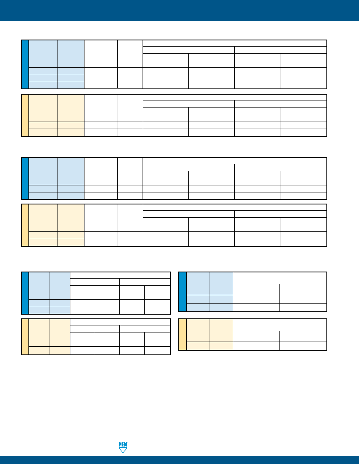
PF-40 PennEngineering • www.pemnet.com
CAPTIVE PANEL SCREW PERFORMANCE DATA(1)
SCB™/SCBJ™ FASTENERS
SCBR™ FASTENERS
(1) Published installation forces are for general reference. Actual set-up and confirmation of complete installation should be made by observing
proper seating of fastener as described in the installation steps. Other performance values reported are averages when all proper
installation parameters and procedures are followed. Variations in mounting hole size, sheet material, and installation procedure may aect
performance. Performance testing this product in your application is recommended. We will be happy to provide technical assistance and/
or samples for this purpose.
(2) Torque values shown will produce a preload of 70% minimum tensile (125 ksi / 935 MPa) with nut factor “k” equal to .1
UNIFIED
Rec. Min. Test Sheet Material
Tightening Screw 5052-H34 Aluminum Cold-rolled Steel
Type Thread Torque Tensile
Code (in. lbs.) (2) (lbs.) Installation Pushout Installation Pushout
(lbs.) (lbs.) (lbs.) (lbs.)
SCBR
SCBR
SCBR
METRIC
Rec. Min. Test Sheet Material
Tightening Screw 5052-H34 Aluminum Cold-rolled Steel
Type Thread Torque Tensile
Code (N • m) (2) (N) Installation Pushout Installation Pushout
(kN) (N) (kN) (N)
SCBR M .
SCBR M .
UNIFIED
Rec. Min. Test Sheet Material
Tightening Screw 5052-H34 Aluminum Cold-rolled Steel
Type Thread Torque Tensile
Code (in. lbs.) (2) (lbs.) Installation Pushout Installation Pushout
(lbs.) (lbs.) (lbs.) (lbs.)
SCB / SCBJ
SCB / SCBJ
METRIC
Rec. Min. Test Sheet Material
Tightening Screw 5052-H34 Aluminum Cold-rolled Steel
Type Thread Torque Tensile
Code (N • m) (2) (N) Installation Pushout Installation Pushout
(kN) (N) (kN) (N)
SCB / SCBJ M .
SCB / SCBJ M .
UNIFIED
Type Thread
Code Installation Pushout Installation Pushout
(lbs.) (lbs.) (lbs.) (lbs.)
HSCB
HSCB
UNIFIED
Test Sheet Material
Type Thread .060” FR-4 Panel
Code
Installation Pushout
(lbs.) (lbs.)
HSR 440 400 65
HSR 632 500 80
METRIC
Test Sheet Material
Type Thread 1.5mm FR-4 Panel
Code
Installation Pushout
(kN) (N)
HSR M3 2.2 290
Test Sheet Material
Aluminum Cold-rolled Steel
METRIC
Type Thread
Code Installation Pushout Installation Pushout
(kN) (N) (kN) (N)
HSCB M
Test Sheet Material
Aluminum Cold-rolled Steel
HSCB™ FASTENERS HSR™ FASTENERS
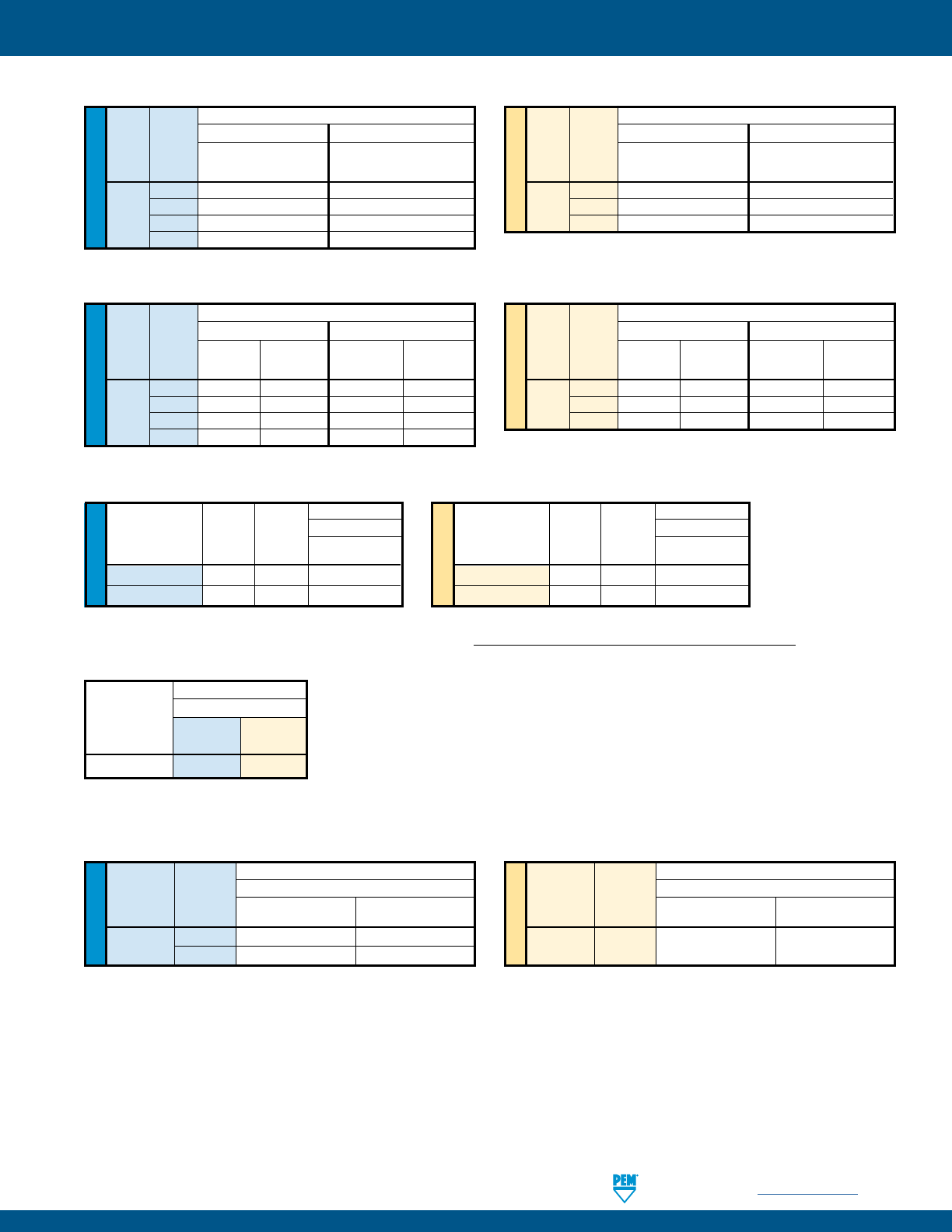
PennEngineering • www.pemnet.com PF-41
CAPTIVE PANEL SCREW PERFORMANCE DATA(1)
REELFAST® SMTPR™ RETAINER(2)
METRIC
UNIFIED
Test Sheet Material
Type Thread FR-4 Fiberglass
Code Installation Pushout
(lbs.) (lbs.)
440 250 55
PFK 632 400 60
Test Sheet Material
Type Thread FR-4 Fiberglass
Code Installation Pushout
(kN) (N)
PFK M3 1.1 245
PFK™ FASTENERS
Test Sheet Material
Part .062” Single Layer RF-4
Number Pushout Pushout
(lbs.) (N)
SMTPR-6-1ET 161.4 718
UNIFIED
Test Sheet Material
Type Thread Aluminum Cold-Rolled Steel
Code Installation Pushout Installation Pushout
(lbs.) (lbs.) (lbs.) (lbs.)
440 2500 95 3600 130
N10 632 2500 105 4000 145
832 3000 110 5000 180
032 3500 120 6300 200
METRIC
Test Sheet Material
Type Thread Aluminum Cold-Rolled Steel
Code Installation Pushout Installation Pushout
(kN) (N) (kN) (N)
M3 11.1 423 16 578
N10 M4 13.3 489 22.2 800
M5 15.6 534 28 890
N10™ FASTENERS
(1) Published installation forces are for general reference. Actual set-up and confirmation of complete installation should be made by observing
proper seating of fastener as described in the installation steps. Other performance values reported are averages when all proper installation
parameters and procedures are followed. Variations in mounting hole size, sheet material, and installation procedure may aect performance.
Performance testing this product in your application is recommended. We will be happy to provide technical assistance and/or samples for
this purpose.
(2) With lead-free paste. Average values of 30 test points. The data presented here is for general comparison purposes only. Actual performance is
dependent upon application variables. We will be happy to provide samples for you to install. If required, we can also test your installed hardware and
provide you with the performance data specific to your application.
(3) Torque values shown will produce a preload of 70% minimum tensile with a nut factor “k” equal to .1.
(4) Failure occurred at the solder joint. Screw retention strength is greater than the retainer.
UNIFIED
Test Sheet Material
Type Thread Aluminum Cold-Rolled Steel
Code Installation Installation
(lbs.) (lbs.)
440 2100 3000
PR10 632 2100 3000
832 2100 3600
032 2400 4200
METRIC
Test Sheet Material
Type Thread Aluminum Cold-Rolled Steel
Code Installation Installation
(kN) (kN)
M3 9.3 13.3
PR10 M4 9.3 16
M5 10.7 18.7
PR10™ FASTENERS
METRIC
UNIFIED
REELFAST® SMTPFLSM™ FASTENERS(2)
Min. Rec.
Test Sheet Material
Type and Tensile Tightening .060” P.C. Board
Thread Size Strength Torque Pull-off
(lbs.) (in. lbs.) (3) (lbs.)
SMTPFLSM-440 556 4.4 100
SMTPFLSM-632 724 7.0 105
Min. Rec.
Test Sheet Material
Type and Tensile Tightening 1.5 mm P.C. Board
Thread Size Strength Torque Pull-off
(N) (N•m)
(3) (N)
SMTPFLSM-M3 2900 0.61 445
SMTPFLSM-M3.5 3269 0.8 465
(4) (4)
TESTING CONDITIONS FOR SMTPFLSM FASTENERS AND SMTPR RETAINER
Oven Quad ZCR convection oven
High Temp 473˚F / 245˚C
Spokes 2 Spoke Pattern
Board Finish 62% Sn, 38% Pb
Screen Printer Ragin Manual Printer
Vias None
Paste
Amtech NC559LF Sn96.5/3.0Ag/0.5Cu (SAC305) (SMTPR)
Alpha CVP-390 Sn96.5/3.0Ag/0.5Cu (SAC305) (SMTPFLSM)
Stencil .0067” / 0.17 mm thick (SMTPR)
.005” / 0.13 mm thick (SMTPFLSM)
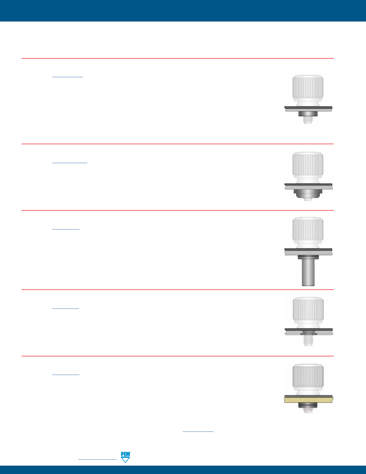
PF-42 PennEngineering • www.pemnet.com
CAPTIVE PANEL SCREW CAPABILITIES
MOST COMMONLY USED AND RECOMMENDED CAPTIVE MATING HARDWARE
FOR USE WITH CAPTIVE PANEL SCREWS
For the best mating hardware for your application please contact our Tech Support line or your local representative.
SELF-CLINCHING NUTS MATED WITH CAPTIVE PANEL SCREW
(See PEM® Bulletin CL)
• S/CLS/SS/CLSS provide load-bearing threads in thin sheets with high pushout and torque-out resistance.
• SP nuts provide load-bearing threads in stainless steel sheets with a hardness of HRB 90 (Rockwell “B”
scale) / HB 192 (Hardness Brinell) or less.
• CLA aluminum nuts are recommended for aluminum sheets with a hardness of HRB 50 (Rockwell “B”
scale) / HB 89 (Hardness Brinell) or less.
• SMPS nuts are for installation into ultra-thin sheets and can be mounted closer to the edge of a sheet than
other self-clinching nuts.
• SL nuts have a unique TRI-DENT® locking feature which meets demanding locking performance requirements.
AS/AC/A4 FLOATING NUTS MATED WITH CAPTIVE PANEL SCREW
(See PEM® Bulletin ALA)
• AS (carbon steel) and AC (300 series stainless steel) floating nuts install into sheets with hardness up to HRB
70 / HB 125 on the Rockwell “B” scale.
• A4 (400 series stainless steel) floating nuts install into sheets with hardness up to HRB 88 / HB 183 on the
Rockwell “B” scale.
• Thread locking versions also available.
B/BS BLIND NUTS MATED WITH CAPTIVE PANEL SCREW
(See PEM® Bulletin B)
• B/BS nuts are used in applications requiring closed thread ends.
• Provides barrier to protect threads against foreign matter.
• Protects internal components from intrusion of screws.
F FLUSH NUTS MATED WITH CAPTIVE PANEL SCREW
(See PEM® Bulletin F)
• Designed to be completely flush in sheets as thin as .060”/1.5mm.
• Ideal for applications where a thin sheet requires load-bearing threads but still must remain smooth, with no
protrusions on either surface.
• The hexagonal head ensures high axial and torsional strength.
• F nuts can be ordered to conform to US NASM45938/4 specifications.
PC BOARD NUTS MATED WITH CAPTIVE PANEL SCREW
(See PEM® Bulletin K)
• KF2/KFS2 broaching nuts utilize specially formed axially groves that can be mounted into a hole to provide a
permanent, strong, threaded attachment point in PC boards.
• SMTSO surface mount nuts also available.
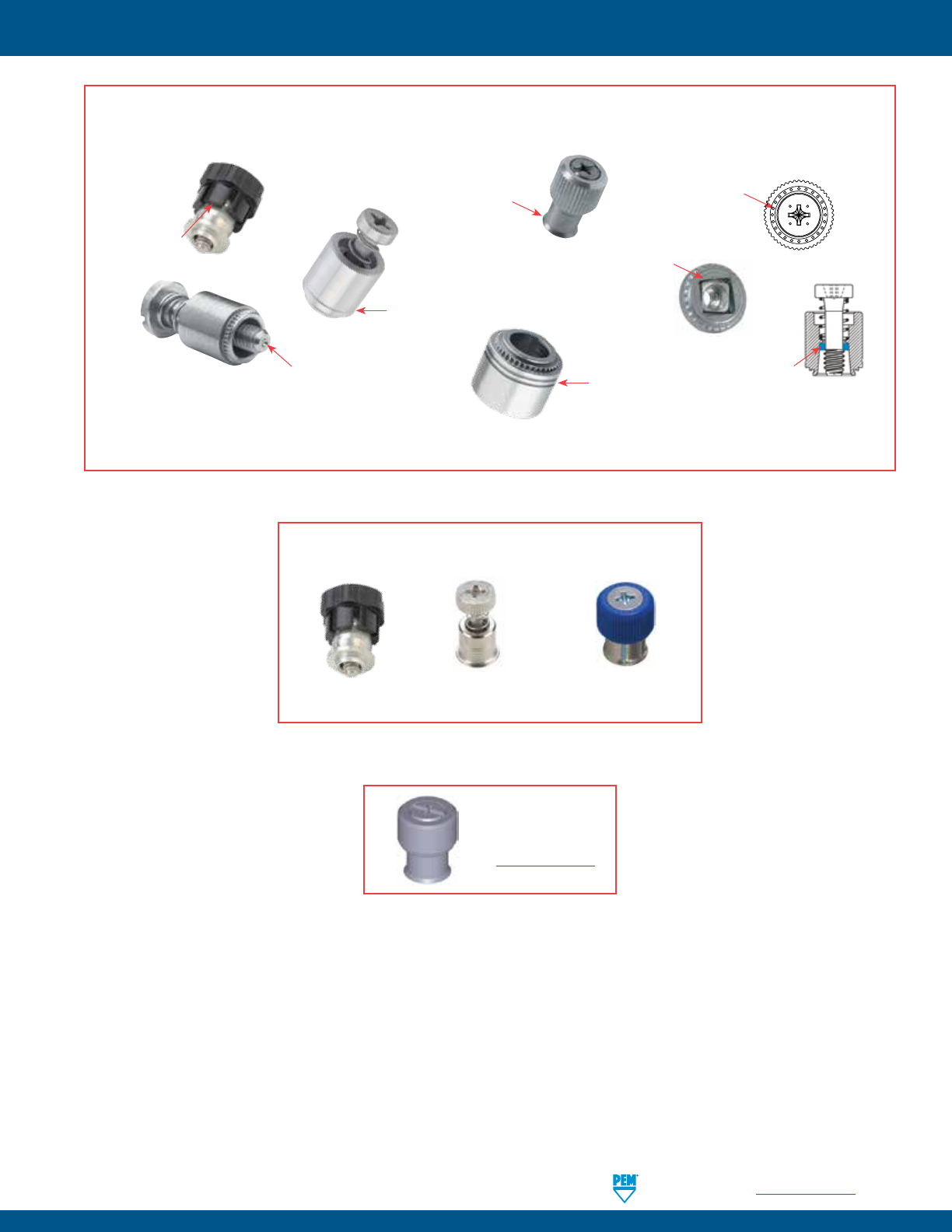
PennEngineering • www.pemnet.com PF-43
PEM® FASTENER IDENTIFICATION AND TRADEMARKS
To be sure that you are getting genuine PEM® brand fasteners, look for the unique PEM product markings and identifiers.
Dimple
(Registered Trademark)
PF10, PF30, PF31, PF32, PF50, PF51, PF52, PF60, PF61, PF62,
PF11, PF11M, PF11MF, PF11MW, PF11PM, PF12, PF12M, PF12MF,
PF12MW, PF7M, PF7MF, PFC2, PFC2P, PFC4, PFHV, PFK, PFS2,
PSHP, SCB, SCBJ, SCBR
Single
Groove
(Registered Trademark)
PFC4
Skirted Shoulder
Identifier
(Registered Trademark)
PF11, PF11M, PF11MF,
PF11MW, PF11PM, PF12,
PF12M, PF12MF,
PF12MW, PF7M, PF7MF
Double
Squares
(Registered
Trademark)
F10
Two Groove
(Registered Trademark)
PF7M, PF7MF, N10, HSR
“PEM” Stamp
(Registered
Trademark)
PSHP
PEM C.A.P.S.
Dot Pattern
(Trademark)
PF11PM
Blue Retaining
Ring
(Trademark)
PFC4, PFC2P, PFC2,
PFS2, PFK
These panel fastener styles are protected by U.S. patents:
No. 6,814,530 No. D656,392S No. D603,693S
Fastener drawings
and models are
available at
www.pemnet.com

PF-44
All PEM® products meet our stringent quality standards. If you require additional industry or other specific quality certifications, special procedures and/or part
numbers are required. Please contact your local sales oice or representative for further information.
Regulatory compliance information is available in Technical Support section of our website. Specifications subject to change without notice. See our website for the
most current version of this bulletin.
North America: Danboro, Pennsylvania USA • E-mail: info@pemnet.com • Tel: +1-215-766-8853 • 800-237-4736 (USA)
Europe: Galway, Ireland • E-mail: europe@pemnet.com • Tel: +353-91-751714
Asia/Pacific: Singapore • E-mail: singapore@pemnet.com • Tel: +65-6-745-0660
Shanghai, China • E-mail: china@pemnet.com • Tel: +86-21-5868-3688
Visit our PEMNET™ Resource Center at www.pemnet.com • Technical support e-mail: techsupport@pemnet.com
