Philips Chassis L01.1E AB Service Manual. Www.s Manuals.com. Tv Ch Manual
User Manual: TV Philips L01.1E AB Chassis - Service manuals and Schematics. Free.
Open the PDF directly: View PDF ![]() .
.
Page Count: 28
- Front Page
- 1. Technical Specifications, Connections and Chassis Overview
- 2. Safety & Maintenance Instructions, Warnings, and Notes
- 3. Directions for Use
- 4. Mechanical Instructions
- 5. Service Modes, Error Codes and Fault Finding
- 5.1 Test Points
- 5.2 Service Modes
- 5.3 Problems and Solving Tips (Related To CSM)
- 5.3.1 Picture Problems
- No colours / noise in picture
- Colours not correct / unstable picture
- TV switches ‘off’ (or ‘on’) or changes the channel without any user action
- Picture too dark or too bright
- White line around picture elements and text
- Snowy picture
- Snowy picture and/or unstable picture
- Black and white picture
- Menu text not sharp enough
- 5.3.2 Sound Problems
- 5.3.1 Picture Problems
- 5.4 ComPair
- 5.5 Error Buffer
- 5.6 The Blinking LED Procedure
- 5.7 Protections
- 5.8 Repair Tips
- 6. Block Diagram, Testpoints, I
- 7. Schematics and PWB’s
- Mono Carrier: Power supply
- Mono Carrier: Power supply Diversity Tables
- Mono Carrier: Line Deflection
- Mono Carrier: Line Deflection Diversity Tables
- Mono Carrier: Line Deflection Diversity Tables
- Mono Carrier: Frame Deflection
- Mono Carrier: Tuner IF
- Mono Carrier: Video IF + Sound IF
- Mono Carrier: Synchronisation
- Mono Carrier: Control
- Mono Carrier: Audio Amplifier
- Mono Carrier: Audio Amplifier Diversity Tables
- Mono Carrier: NICAM + 2CS + BTSC (Stereo / SAP) Decoder
- Mono Carrier: Audio / Video Source Switching
- Mono Carrier: Front I/O + Front Control + Headphone
- Mono Carrier: Front Control Diversity Tables
- Mono Carrier: Rear I/O SCART Diversity Table
- Mono Carrier: Rear I/O SCART
- Mono Carrier: Tilt and Rotation
- Layout Mono Carrier (Top Side)
- Layout Mono Carrier (Mapping Top Side)
- Layout Mono Carrier (Mapping Bottom Side)
- Layout Mono Carrier (Overview Bottom Side)
- Layout Mono Carrier (Part 1 Bottom Side)
- Layout Mono Carrier (Part 2 Bottom Side)
- Layout Mono Carrier (Part 3 Bottom Side)
- Layout Mono Carrier (Part 4 Bottom Side)
- CRT Panel
- SCAVEM Panel
- Layout CRT and SCAVEM Panel (Top Side)
- Layout CRT and SCAVEM (Bottom Side)
- Side AV + HP Panel
- Layout Side AV + HP Panel (Top Side)
- Side AV Panel + Headphone
- Layout Side AV Panel + Headphone (Top Side)
- Front Interface Panel
- Layout Front Interface Panel (Top Side)
- Top Control Panel (RF)
- Layout Top Control Panel (RF) (Top Side)
- Top Control Panel (FSQ)
- Layout Top Control Panel (FSQ) (Top Side)
- 8. Alignments
- 9. Circuit Description
- 10. Spare Parts List
Published by RB 0266 Service PaCE Printed in the Netherlands Subject to modification EN 3122 785 12860
©
Copyright 2002 Philips Consumer Electronics B.V. Eindhoven, The Netherlands.
All rights reserved. No part of this publication may be reproduced, stored in a
retrieval system or transmitted, in any form or by any means, electronic,
mechanical, photocopying, or otherwise without the prior permission of Philips.
Colour Television Chassis
L01.1E
AB
(LARGE SCREEN)
CL26532063_000.eps
140602
Contents Page Contents Page
1. Technical Specifications, Connections and
Chassis Overview 2
2. Safety & Maintenance Instructions, Warnings and
Notes 5
3. Directions for Use 6
4. Mechanical Instructions 11
5. Service Modes, Error Codes and Faultfinding 13
6. Block Diagram, Testpoints, I2C And Supply
Voltage Overview
Block Diagram 21
Testpoint Overview 22
I2C And Supply Voltage Overview 23
7. Electrical Diagrams and PWB’s Diagram PWB
Power Supply (Diagram A1) 24 42-48
Diversity Tables A1 25
Line Deflection (Diagram A2) 26 42-48
Diversity Tables A2 27
Frame Deflection (Diagram A3) 29 42-48
Tuner IF (Diagram A4) 30 42-48
Video IF and Sound IF (Diagram A5) 31 42-48
Synchronization (Diagram A6) 32 42-48
Control (Diagram A7) 33 42-48
Audio Amplifier (Diagram A8) 34 42-48
Diversity Tables A8 35
NICAM (Stereo/SAP) Decoder (Diagram A9) 36 42-48
Audio/Video Source Switching (Diagram A10) 37 42-48
Front I/O + Control, Headphone(Diagram A12) 38 42-48
Diversity Tables A12, A14 39
Rear I/O SCART (Diagram A14) 40 42-48
Tilt and Rotation (Diagram A15) 41 42-48
CRT (Diagram B1) 49 51
SCAVEM (Diagram B2) 50 51
Side AV and Headphone (Diagram C) 52 52
Side AV and Headphone (Diagram E1) 53 53
Front Interface Panel (Diagr. Q1) 54 54
Top Control (RF) (Diagram T) 55 55
Top Control (FSQ) (Diagram T1) 56 56
8. Alignments 57
9. Circuit Description 64
List of Abbreviations 73
10 Spare Parts List 75
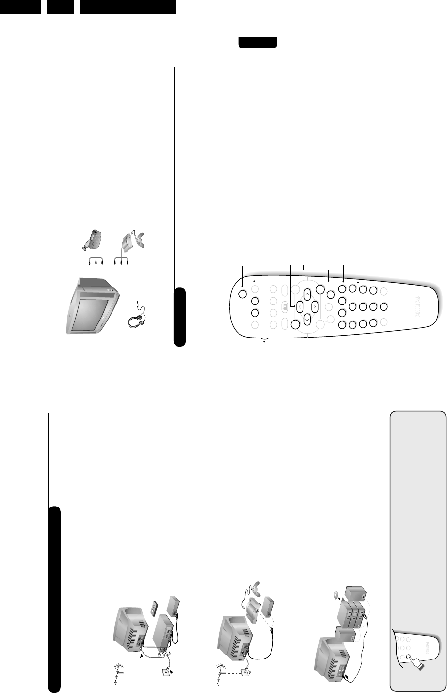
Directions for Use
EN 6 L01.1E AB3.
3. Directions for Use
3
Remote control keys
To display / clear the program
number, name (if it exists), time,
audio mode and time remaining for
the sleep feature. Press the key for
5 seconds to activate permanent
display of the number.This key is
also used to exit from the menu.
Screen information/ permanent no.
VCR key (p.11)
Incredible Surround
(only available on certain versions)
To activate / disable the
Incredible Surround feature. In
stereo, the speakers appear
further apart. In mono, a pseudo-
spatial stereo effect is obtained.
Pre-set sound
Used to access a series of stored
settings: Speech,Music,Theatre
and return to Personal.
Menu
To call up or exit the menus.
Volume
To adjust the sound level
Cursor
These 4 keys are used to move
around the menus or provide
direct access to the different 16:9
formats (p.9).
Number keys
Direct access to the programmes.
For a 2 digit program,enter the
2nd digit before the dash
disappears.
Selection of EXT socket
Press several times to select
EXT1, EXT2, S-VHS and AV.
Radio / TV mode
To switch the TV set to radio or
TV mode (for versions equipped
with radio).
Standby
Lets you place the TV set on
standby.To turn on the TV, press
P@@,b,0to 9(or Â).
Teletext keys (p. 8), VCR keys
(p.11) and list of radio stations ı
(p. 5)
Sleep
To select an automatic standby after a
preset time (from 0 to 240 minutes).
16:9 modes (p. 9)
Pre-set image
Used to access a series of stored
settings: Bright,Natural,Soft,
Multimedia and return to Personal.
Mute
To mute or restore the sound.
Program selection
To access the next or previous
programme.The number, (name)
and sound mode are displayed for
a few moments.
For some programs, the title of the
program will be displayed at the
bottom of the screen.
Sound mode
Used to force programmes in
Stereo to Mono or, for bilingual
programs, to choose between Dual
Ior Dual II. For TV sets equipped
for Nicam reception, depending on
the programmes, you can force the
Stereo Nicam sound to Mono or
select between Nicam Dual I,
Nicam Dual II and Mono.
The Mono indication is red when in
forced position.
Teletext (p. 8)
Teletext keys (p.8)
or VCR keys (p.11)
2
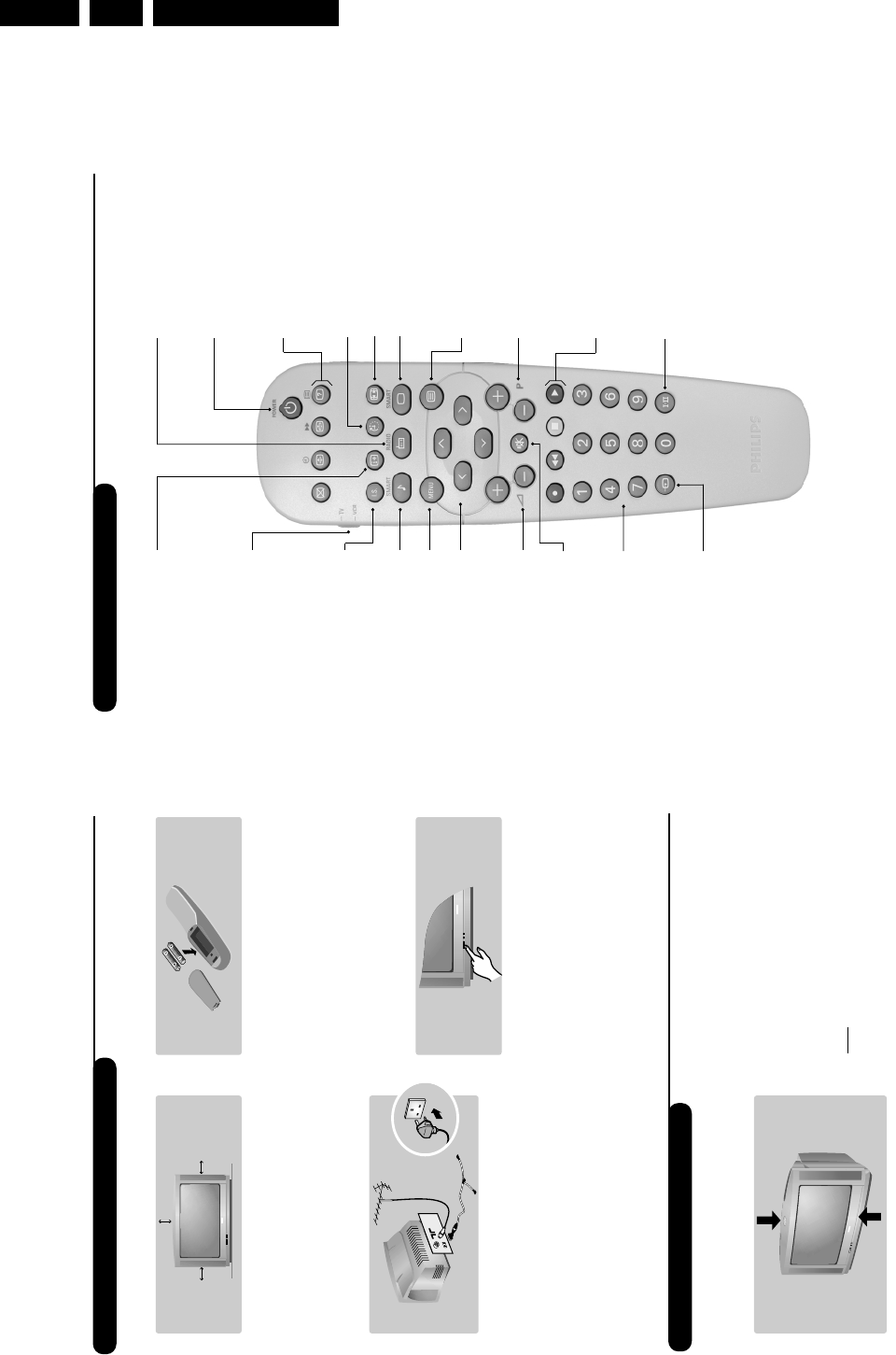
The television set has 4 keys which are located
on the front or the top of the set depending
on the model.
The VOLUME - + (-
”
+) keys are used to
adjust sound levels.The PROGRAM - + (- P+)
keys are used to select the required programmes.
To access the menus, simultaneously hold down
the
”
- and
”
+ keys.The PROGRAM - +
keys may then be used to select an adjustment
and the -
”
+ keys to make that adjustment.
To exit from the menus, hold down the 2
”
-
and
”
+ keys.
Note: when the Child Lock function is activated,
these keys are unavailable (refer to Features
menu on page 7).
&Positioning the television set
Place your TV on a solid, stable surface, leaving
a space of at least 5 cm around the appliance.
To avoid accidents, do not put anything on the
set such as a cloth or cover, a container full of
liquid (vase) or a heat source (lamp).The set
must not be exposed to water.
éConnections
• Insert the aerial plug into the :socket at
the rear of the set.
• For the versions equipped with a radio:
insert the radio aerial socket into the FM
ANT socket using the adapter supplied.
If you are using an indoor aerial, reception may be
difficult in certain conditions.You can improve
reception by rotating the aerial. If the reception
remains poor, you will need to use an external aerial.
• Insert the mains plug into a wall socket (220-
240 V / 50 Hz).
“Remote control
Insert the two R6-type batteries (supplied)
making sure that they are the right way round.
Check that the mode selector is set to TV.
The batteries supplied with this appliance do
not contain mercury or nickel cadmium. If you
have access to a recycling facility, please do not
discard your used batteries (if in doubt,
consult your dealer).When the batteries are
replaced, use the same type.
‘Switching on
To switch on the set, press the on/off key.
A red indicator comes on and the screen
lights up. Go straight to the chapter Quick
installation on page 4.
If the television remains in standby mode,
press P#on the remote control.
The indicator will flash when you use the
remote control.
5 cm
5 cm 5 cm
FM.
ANT.
Installing your television set
The keys on the TV set
Directions for Use EN 7L01.1E AB 3.
5
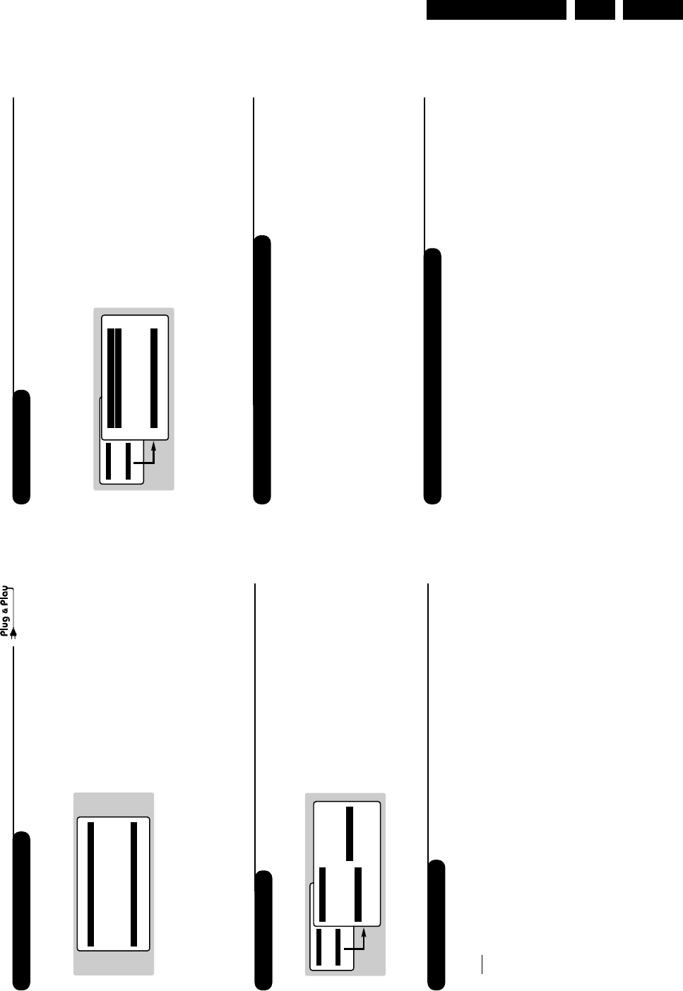
Manual store
Other settings in the Install menu
This menu is used to store the programmes
one at a time.
&Press the Hkey.
éWith the cursor, select the Install menu then
Manual store:
“System: select Europe (automatic detection*)
or Western Europe (BG standard), Eastern
Europe (DK standard), United Kingdom (I
standard) or France (LL’ standard).
* Except for France (LL’ standard), you must select
choice France.
‘Search: press ¬.The search starts. Once a
programme is found, the scanning stops and its
name is displayed (when available). Go to the
next step. If you know the frequency of the
required programme, this can be entered
directly using the 0to 9keys.
If no picture is found, consult the possible solutions (p. 12).
(Program No.: enter the required number
with the Ȭ or 0to 9keys.
§Fine Tune: if the reception is not satisfactory,
adjust using the Ȭ keys.
èStore: press ¬.The program is stored.
!Repeat steps ‘to !for each programme to
store.
çTo quit the menus, press d.
&Press the Hkey and select the Install menu:
éLanguage: to change the display language for
the menus.
“Country: to select your country (GB for
Great Britain).
This setting is used for the search, automatic
programme sort and teletext display. If your
country does not appear in the list, select “. . .”
‘Auto Store: to start automatic search for all
programmes available in your region. If the
transmitter or cable network sends the
automatic sort signal, the programmes will be
numbered correctly. If this is not the case, you
need to use the Sort menu to renumber the
programmes (see p. 4).
Some transmitters or cable networks broadcast
their own sort parameters (region, language, etc.).
In this case, indicate your choice using the îÏ
keys and validate with ¬.To quit or interrupt the
search, press H. If no picture is found, consult the
possible solutions (p. 12).
(To quit the menus, press d.
Using the radio (only available on certain versions)
Choice of TV or radio mode
Press the Âkey on the remote control to
switch the TV set to either TV or radio mode.
In radio mode, the number, station name
(if available), frequency and sound mode are
displayed on the screen.To enter the station
names, use the Name menu (p. 4)
Program selection
Use the 09or @P#keys to select the
FM stations (from 1 to 40).
List of radio stations
Press the ıkey to display the list of radio
stations radio. Use the îÏ keys to change
station and the dkey to exit.
Using the radio menus
Use the Hkey to access the specific radio
setting.
Search for radio stations
If you used the quick installation, all available
FM stations have already been stored.To start
a new search, use the Install :Auto Store
menu (for a complete search) or Manual
Store (for a station by station search).The
Sort and Name menus let you sort or name
the radio stations. Operation of these menus is
the same as for the TV menus.
Mainge
• Picture
• Sound
• Features
$Install
Manual Store
$
System Europe Æ
• Search
• Program No.
• Fine Tune
• Store
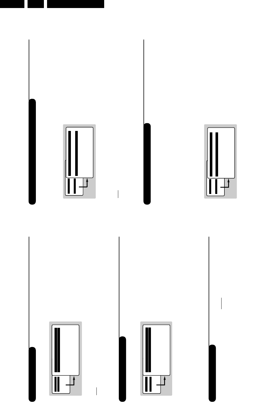
4
Quick installation
Program sort
Program name
The first time you switch on the television, a
menu appears on the screen and the tuning
starts automatically.
If the menu is not displayed, press and hold down
the ”- and ”+ keys on the TV set for 5
seconds to start the tuning.
All the available TV programs and radio stations
*will be stored. This operation takes a few
minutes.The display shows the progress of the
search and the number of programs found.
At the end of the search, the menu disappears.
To exit or interrupt the search, press
H
.
If no program is found, consult the possible solutions
p. 12.
&If the transmitter or cable network sends the
automatic sort signal, the programs will be
numbered correctly. In this case, the
installation is complete.
éIf this is not the case, you need to use the
Sort menu to number the programs correctly.
Some transmitters or cable networks broadcast
their own sort parameters (region, language, etc.).
In this case, indicate your choice using the îÏ
keys and validate with ¬.
* Only on versions equipped with a radio.
&Press key H.The Main menu is displayed on
the screen.
éWith the cursor, select the Install menu
followed by the Sort menu.
“Select the programme you want to move using
the îÏ keys and press ¬.
‘Then use the îÏ keys to select the new
number and validate with È.
(Repeat steps “and ‘for each program you
wish to renumber.
§To quit the menus, press d.
If required, you can give a name to the
programmes and external connectors.
Note: on installation, the programs are named
automatically when an identification signal is sent.
&Press the Hkey.
éWith the cursor, select the Install menu, then
Name
“Use the îÏ keys to select the programme
to name or rename.
‘Use the Ȭ keys to move around the
name display area (5 characters) and the
îÏ keys to select the characters.
(When the name has been entered, use the
Èkey to exit.The name is stored.
§Repeat steps “to (for each programme
you wish to name.
èTo quit the menus, press d.
Auto Store
• Program 2
• TV 470 MHz
• ••••••••••••••••••••••••••••••••
Mainge
• Picture
• Sound
• Features
$Install
Install
• Language
• Country
• Auto Store
• Manual Store
$
Sort
Æ
• Name
00
01 TF1
02 FR2
03
Æ
FR3
04 C +
05 ARTE
Directions for Use
EN 8 L01.1E AB3.
7
Timer function (only available on certain versions)
TV lock (only available on certain versions)
This menu lets you use the TV set as an alarm.
&Press the Hkey.
éWith the cursor, select the Options menu then
Timer :
“Sleep: to select an automatic standby period.
This setting is also available via the `key on the
remote control.
‘Time: enter the current time.
Note: the time is updated automatically each time
the TV set is switched on via the teletext
information on program no. 1. If this program does
not have teletext, the update will not take place.
(Start Time: enter the start time.
§Stop Time: enter the standby time.
èProgram No.: enter the number of the
programme for the wake-up alarm. For models
equipped with a radio, you can select an FM
station by using the Ȭ keys (the 09
keys are only used to select TV programs).
!Activate: the settings include:
• Once for a single alarm,
• Daily for each day,
• Stop to cancel.
çPress
b
to put the TV set in standby. It will
automatically come on at the time programmed.
If you leave the TV set on, it will just change
programmes at the time entered (and will go to
standby mode at the Stop Time).
By combining the TV lock and Timer functions,
you can restrict the period during which the TV set
is used, for example by your children.
You can block certain programs or inhibit use
of the TV set completely by locking the keys.
Child lock
&Press H.
éWith the cursor, select the Options menu and
position Child Lock to On.
“Turn off the TV set and hide the remote
control.The TV set cannot be used (except via
the remote control).
‘To cancel: position Child Lock to Off.
Parental control
&Press the Hkey, select the Features menu
then Parental Cont.:
éYou must enter your secret access code.
The first time you enter this, enter code 0711
twice and then enter your new code choice.
The menu is displayed.
“Parental Cont.: Use the îÏ keys to
select the TV programme required and validate
with ¬.The +symbol will be displayed
opposite the programmes or sockets that are
locked. From now on, to view a locked
programme, you must enter your secret code,
otherwise the screen will stay blank.
The access to the Install menu is also locked.
Caution, for encrypted programs using an external
decoder, you must lock the corresponding EXT socket.
‘Change code: this allows you to enter a new
4 digit code. Confirm your new code by
entering it a second time.
If you have forgotten your secret code, enter the
universal code 0711 twice.
(Unlock all: this is used to unlock all locked
programmes.
§Lock All: this is used to lock all the TV
programmes and EXT connectors.
èPress the dkey to quit.
Mainge
• Picture
• Sound
$Features
• Install
Timer
• Sleep
$
Time 10:56
• Start Time
• Stop Time
• Program No.
• Activate
Mainge
• Picture
• Sound
$Features
• Install
Features
• Timer
• Child Lock Arrêt
• Parental Cont.
• Rotation
• Contrast +
• NR
6
Picture settings
Sound adjustments
&Press Hthen ¬.The Picture menu is
displayed:
éUse the îÏ keys to select a setting and
the Ȭ keys to adjust.
Note: during the picture adjustment, only the
selected line remains displayed. Press îÏ to
display the menu again.
“Once the adjustments have been made, select
Store and press ¬to store them. Press d
to exit.
Description of the adjustments:
• Brightness: this changes picture brilliance.
• Colour: this changes the intensity of the colour.
• Contrast: this changes the difference
between the light and dark tones.
•
Sharpness: this changes the picture definition.
• Colour Temp.: this changes the colour
rendering: Cold (bluer), Normal (balanced)
or Warm (redder).
• Store: to store the picture adjustments and
settings (as well as the settings for Contrast +
and NR in the Features menu).
&Press H, select Sound (Ï) and press ¬.
The Sound menu is displayed:
éUse the îÏ keys to select a setting and
the Ȭ keys to adjust.
“Once the adjustments have been made, select
Store and press ¬to store these changes.
‘To quit the menus, press d.
Description of the settings:
• Treb le: this alters the high frequency sounds.
• Bass: this alters the low frequency sounds.
• Balance: this balances the sound on the left
and right speakers.
• Delta Volume*: this is used to compensate
any volume discrepancies between the
different programs or EXT sockets.This
setting is available for programs 0 to 40 and
the EXT sockets.
• AVL* (Automatic Volume Leveller): this is
used to limit increases in sound, especially on
program change or advertising slots.
• Store: this is used to store the sound settings.
*Only available on certain versions.
Feature settings
&Press H, select Features (Ï) and press ¬.
You can adjust:
éTimer,Child Lock and Parental Cont.: see
next page
“Contrast +: automatic adjustment of the
picture contrast which permanently sets the
darkest part of the picture to black.
‘NR: attenuates picture noise (snow) in difficult
reception conditions.
Caution: to store the Contrast + and NR
settings, use the Store choice in the Picture
menu.
(Rotation (only available on very large screen
sets): large screen sets are sensitive to
terrestrial magnetic field variations.This setting
is used to compensate for this by adjusting the
picture rotation.
§To quit the menus, press d.
Mainge
$Picture
• Sound
• Features
• Install
Picture
$
Brightness --I------ 39
• Colour
• Contrast
• Sharpness
• Colour Temp.
• Store
Mainge
• Picture
$Sound
• Features
• Install
Sound
• Treble -----I--- 56
• Bass
• Balance
• Delta Volume
• AVL
• Store
Directions for Use EN 9L01.1E AB 3.
9
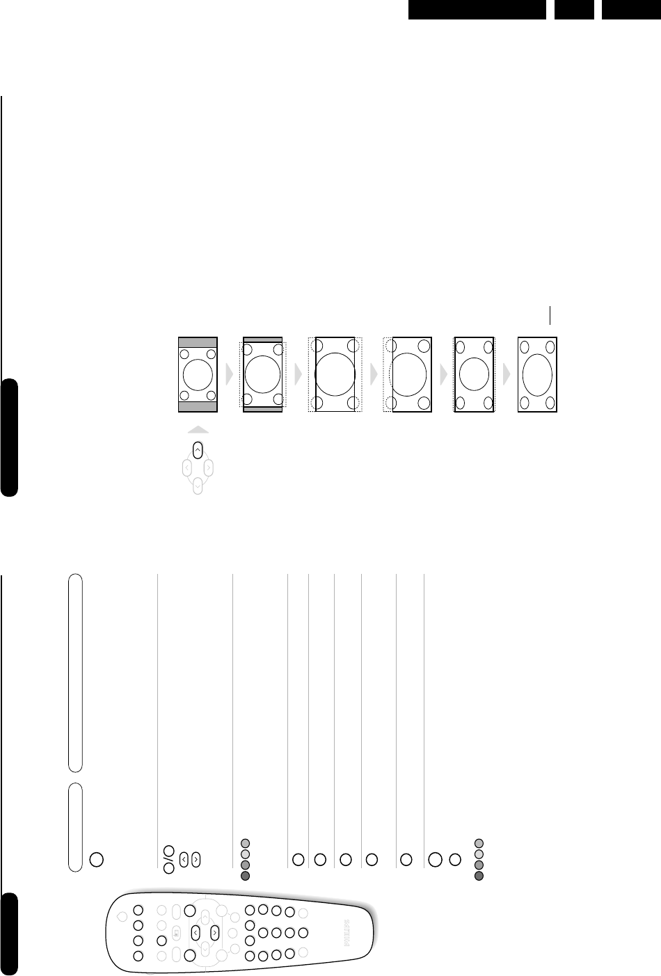
16:9 Formats
The pictures you receive may be transmitted in 16:9 format (wide screen) or 4:3 format
(conventional screen). 4:3 pictures sometimes have a black band at the top and bottom of the screen
(letterbox format).This function allows you to optimise the picture display on screen.
Automatic switching
This TV set is also equipped with automatic switching which will select the correct-screen format,
provided the specific signals are transmitted with the programmes.
This automatic format can olso be modified manually.
Using the different screen formats
Press the ¬key (or È) to select the different modes:
4:3,Zoom 14:9,Zoom 16:9,Subtitle Zoom,Super Wide and Widescreen.
You can also access these settings with key p.
4:3 Mode
The picture is reproduced in 4:3 format and a black band is
displayed on either side of the picture.The picture may be
progressively enlarged using the îÏ keys.
Zoom 14:9 Mode
The picture is enlarged to 14:9 format, a thin black band
remains on both sides of the picture.The îÏ keys allow
you to compress and move the image vertically to view the
top or bottom of the picture (subtitles).
Zoom 16:9 Mode
The picture is enlarged to 16:9 format.This mode is
recommended when displaying pictures which have black
bands at the top and bottom (letterbox format).
Use the îÏ keys if you wish to compress and move the
image vertically to view the top or bottom of the picture.
Subtitle Zoom Mode
This mode is used to display 4:3 pictures using the full
surface of the screen leaving the sub-titles visible.
Use the îÏ keys to increase or decrease the
compression at the bottom of the screen.
Super Wide Mode
This mode is used to display 4:3 pictures using the full
surface of the screen by enlarging the sides of the picture.
The îÏ keys allow you to scroll the image up or down
the screen.
Widescreen Mode
This mode restores the correct proportions of pictures
transmitted in 16:9 using full screen display.
Note: If you display a 4:3 picture in thid mode, it will be enlarged
horizontally.
8
Teletext
Press : You will obtain:
Teletext is an information system broadcast by certain channels which can be consulted like a
newspaper. It also offers access to subtitles for viewers with hearing problems or who are not familiar
with the transmission language (cable networks, satellite channels, etc.).
12
POWER
RADIOSMART
- TV
- VCR
I.S.
SMART
MENU
564
879
0ù
·¢Ê Æ
∫
ı
ŸÓ›
Ë
`
∏
™
%
Y
3
P
--
++
”
¤
.
ª-
[
¤
0 9
Ë
Ë
Ÿ
Ó
›
™
MENU
Teletext call
Selecting a
page
This is used to call teletext, change to transparent mode
and then exit.The summary appears with a list of items
that can be accessed. Each item has a corresponding 3
digit page number.
If the channel selected does not broadcast teletext, the
indication 100 will be displayed and the screen will remain
blank (in this case, exit teletext and select another channel).
Enter the number of the page required using the 0to 9
or @P#keys, îÏ. Example: page 120, enter 12
0.The number is displayed top left, the counter turns and
then the page is displayed. Repeat this operation to view
another page.
If the counter continues to search, this means that the page is
not transmitted. Select another number.
Direct access
to the items
Coloured areas are displayed at the bottom of the screen.
The 4 coloured keys are used to access the items or
corresponding pages.
The coloured areas flash when the item or the page is not yet
available.
Contents This returns you to the contents page (usually page 100).
Temporary
stop This is used to temporarily disable or activate the teletext
display.
Enlarge a page
Stop sub-page
acquisition
This allows you to display the top or bottom part of the
page and then return to normal size.
Certain pages contain sub-pages which are automatically
displayed successively.This key is used to stop or resume
sub-page acquisition.The indication _appears top left.
Hidden
information
Favourite
pages
To display or hide the concealed information (games
solutions).
For teletext programs 0 to 40,you can store 4 favourite
pages which can then be accessed directly using the
coloured keys (red,green, yellow, blue).
&Press the Hkey to change to favourite pages mode.
éDisplay the teletext page that you want to store.
“Press the coloured key of your choice for 3 seconds.
The page is now stored.
‘Repeat the operation with the other coloured keys.
(You can now consult teletext and your favourite
pages will appear in colour at the bottom of the
screen.To retrieve the standard items,press H.
To clear everything, press dfor 5 seconds.
Directions for Use
EN 10 L01.1E AB3.
11
Make the connections as shown opposite.
With the nkey, select AV.
For a monophonic device, connect the audio signal to the
AUDIO L input. Use the ekey to reproduce the sound
on the left and right speakers of the TV set.
Headphones
When headphones are connected, the sound on the
TV set will be cut.The @P#keys are used to
adjust the volume level.
The headphone impedance must be between 32 and
600 Ohms.
Side connections
VCR key
The remote control lets you control the main functions of the VCR.
Press and hold down the VCR key located on the side of the remote
control, then press one of the keys to access the VCR functions:
bstandby
%programming*,
∫fast forward,
Hmenu call *
îÏ select *
Ȭ adjust *
P@# program selection,
·record,
¢fast rewind,
Êstop,
Æplay,
09 enter a number
* Some functions are not available on all VCRs.
The remote control is compatible with all VCRs using the RC5 standard.
12
POWER
RADIOSMART
- TV
- VCR
I.S.
SMART
MENU
564
879
0
ù
·¢Ê Æ
∫
ı
ŸÓ›
Ë
`
∏
™
%
Y
3
P
--
++
”
¤
.
ª-
[
10
Connecting peripheral equipment
The television has 2 external sockets situated at the back of the set (EXT1 and EXT2).
The EXT1 socket has audio, CVBS/RGB inputs and audio, CVBS outputs.
The EXT2 socket has audio, CVBS/S-VHS inputs and audio, CVBS outputs.
Carry out the connections shown opposite, using a good
quality euroconnector cable.
If your video recorder does not have a euroconnector socket, the
only connection possible is via the aerial cable.You will therefore
need to tune in your video recorder's test signal and assign it
programme number 0 (refer to manual store, p. 6).
To reproduce the video recorder picture, press 0.
Video recorder with decoder
Connect the decoder to the second euroconnector socket
of the video recorder.You will then be able to record
scrambled transmissions.
Video recorder
Satellite receiver, decoder, CDV, games, etc.
Carry out the connections shown opposite.
To optimise picture quality, connect the equipment which
produces the RGB signals (digital decoder, games, etc.) to
EXT1, and the equipment which produces the S-VHS
signals (S-VHS and Hi-8 video recorders, certain DVD
drives) to EXT2 and all other equipment to either EXT1
or EXT2.
To connect to a hi-fi system, use an audio connection cable
and connect the “L” and “R” outputs on the TV set to the
“AUDIO IN” “L” and “R” input on your hi-fi amplifier.
Other equipment
Amplifier (only available on certain versions)
VCR
EXT 2
EXT 1
564
879
0
ù
Y
To select connected equipment
Press the nkey to select EXT1,EXT2,S-VHS2 (S-VHS signals
from the EXT2 socket) and AV for connections on the front panel.
Most equipment (decoder, video recorder) carries out the switching itself.
Service Modes, Error Codes and Fault Finding EN 13L01.1E AB 5.
5. Service Modes, Error Codes and Fault Finding
Index of this chapter:
1. Test points.
2. Service Modes.
3. Problems and Solving Tips (related to CSM).
4. ComPair.
5. Error Codes.
6. The Blinking LED Procedure.
7. Protections.
8. Repair Tips.
5.1 Test Points
The chassis is equipped with test points printed on the circuit
board assemblies. These test points refer to the functional
blocks:
Figure 5-1
The numbering is in a logical sequence for diagnostics. Always
start diagnosing within a functional block in the sequence of the
relevant test points for that block.
Perform measurements under the following conditions:
•Service Default Mode.
•Video: colour bar signal.
•Audio: 3 kHz left, 1 kHz right.
5.2 Service Modes
Service Default Mode (SDM) and Service Alignment Mode
(SAM) offer several features for the service technician, while
the Customer Service Menu (CSM) is used for communication
between dealer and customer.
There is also the option of using ComPair, a hardware interface
between a computer (see requirements) and the TV chassis. It
offers the ability of structured trouble shooting, error code
reading and software version readout for all L01 chassis.
Minimum requirements: a 486 processor, Windows 3.1 and a
CD-ROM drive. A Pentium Processor and Windows 95/98 are
also acceptable (see also paragraph 5.4).
Figure 5-2
5.2.1 Service Default Mode (SDM)
Purpose
•To create a predefined setting to get the same
measurement results as given in this manual.
•To override SW protections.
•To start the blinking LED procedure.
Specifications
•Tuning frequency:
–475.25 MHz for PAL/SECAM (Europe and AP-PAL).
–61.25 MHz (channel 3) for NTSC-sets (NAFTA,
LATAM and AP-NTSC).
•Colour system:
–PAL-M for LATAM BI/TRI/FOUR-NORMA.
–SECAM L for France.
–NTSC for NAFTA and AP-NTSC.
–PAL-BG for Europe and AP-PAL.
•All picture settings at 50 % (brightness, colour contrast,
hue).
•Bass, treble and balance at 50 %; volume at 25 %.
•All service-unfriendly modes (if present) are disabled, like:
–(sleep) timer,
–child/parental lock,
–blue mute,
–hotel/hospitality mode
–auto switch-off (when no ‘IDENT’ video signal is
received for 15 minutes),
–skip / blank of non-favorite presets / channels,
–auto store of personal presets,
–auto user menu time-out.
How to enter SDM
Use one of the following methods:
•Use a standard customer RC-transmitter and key in the
code ‘062596’ directly followed by the MENU button or
•Short wires 9631 and 9641 on the mono carrier (see Fig. 8-
1) and apply Mains power. Then press the power button
(remove the short after start-up). Caution: Entering SDM
by shorten wires 9631 and 9641 will override the +8V-
protection. Do this only for a short period. When doing this,
the service-technician must know exactly what he is doing,
as it could lead to damaging the set.
•Or via ComPair.
After entering SDM, the following screen is visible, with SDM at
the upper right side for recognition.
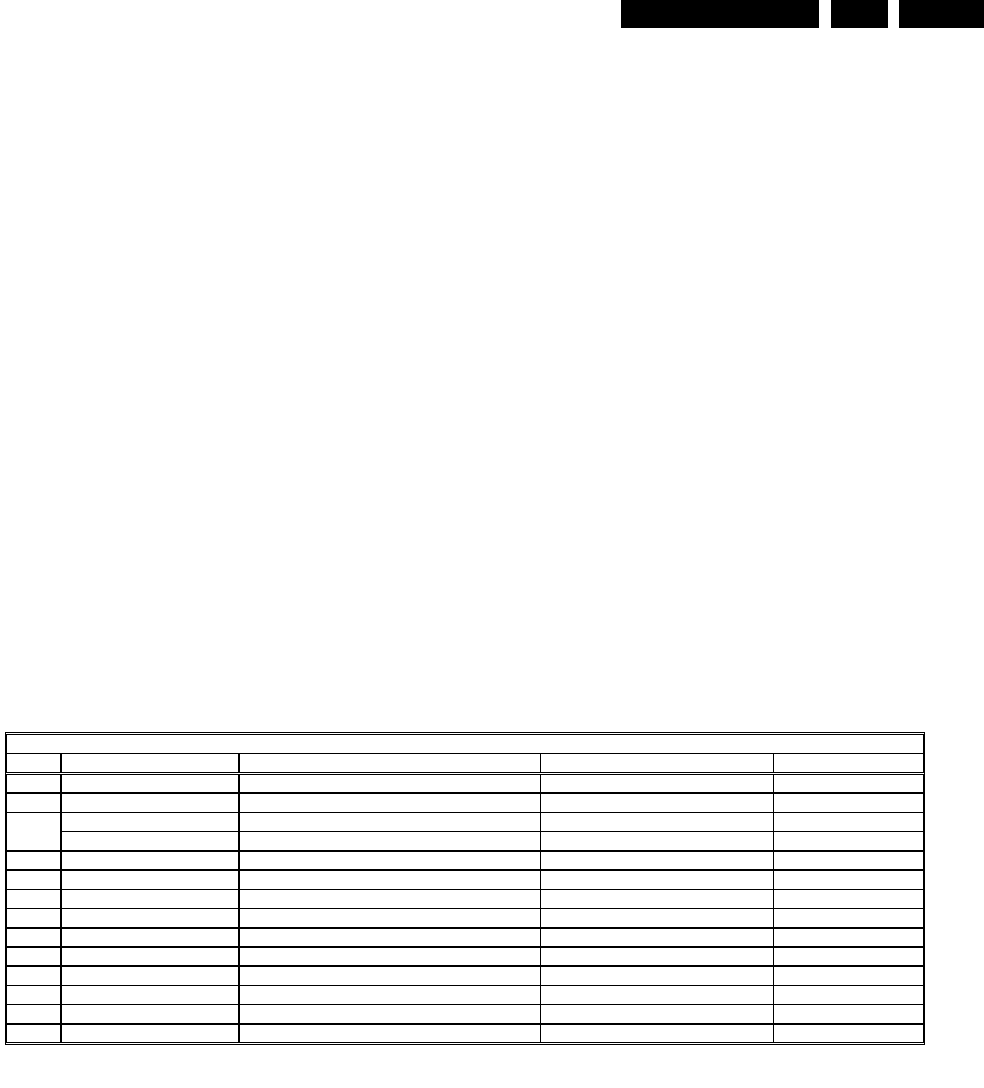
TEST POINT OVERVIEW L01
Test point Circuit Diagram
A1-A2-A3-….. Audio processing A8, A9 / A11
C1-C2-C3-….. Control A7
F1-F2-F3-….. Frame drive A3
I1-I2-I3-….. Tuner & IF A4
L1-L2-L3-…. Line drive A2
P1-P2-P3-….. Power supply A1
S1-S2-S3-….. Synchronisation A6
V1-V2-V3-….. Video processing A5, B1
CL 16532008_044.eps
210501
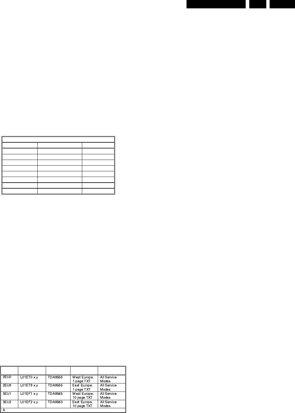
SW
cluster SW name UOC-type Diversity Remark
bbreviations: E= Europe, F= Full TXT, M= mono, T= 1 page TXT
CL 16532008_045.eps
210501
Service Modes, Error Codes and Fault Finding
EN 14 L01.1E AB5.
Figure 5-3
How to navigate
Use one of the following methods:
•When you press the MENU button on the remote control,
the set will switch between the SDM and the normal user
menu (with the SDM mode still active in the background).
Return to the SDM screen with the OSD / STATUS button.
•When you press the OSD / STATUS button on the remote
control, the menu will show or hide the error buffer. This
feature is available to prevent interference during
waveform measurements.
•On the TV, press and hold the 'VOLUME down' and press
the 'CHANNEL down' for a few seconds, to switch from
SDM to SAM and reverse.
How to exit
Switch the set to STANDBY by pressing the power button on
the remote control transmitter (if you switch the set 'off' by
removing the Mains power, the set will return in SDM when
Mains power is re-applied). The error buffer is cleared.
5.2.2 Service Alignment Mode (SAM)
Purpose
•To perform alignments.
•To change option settings.
•To display / clear the error code buffer.
Specifications
•Operation hours counter.
•Software version.
•Option settings.
•Error buffer reading and erasing.
•Software alignments.
How to enter
Use one of the following methods:
•Use a standard customer RC-transmitter and key in the
code ‘062596’ directly followed by the OSD / STATUS
button or
•Via ComPair.
The following screen is visible, with SAM at the upper right side
for recognition.
Figure 5-4
1. LLLL This is the operation hours counter. It counts the
normal operation hours, not the standby hours.
2. AAABCD-X.Y This is the software identification of the main
micro controller:
•A = the project name (L01).
•B = the region: E = Europe, A = Asia Pacific, U =
NAFTA, L = LATAM.
•C = the software diversity: D= DVD, F= full TXT, M=
mono, T= 1 page TXT.
•D = the language cluster number.
•X = the main software version number.
•Y = the sub software version number.
3. SAM Indication of the actual mode.
4. Error buffer Five errors possible.
5. Option bytes Seven codes possible.
6. Clear Erase the contents of the error buffer. Select the
CLEAR menu item and press the CURSOR RIGHT key.
The content of the error buffer is cleared.
7. Options To set the Option Bytes. See chapter 8.3.1 for a
detailed description.
8. AKB Disable (0) or enable (1) the ‘black current loop’ (AKB
= Auto Kine Bias).
9. Tuner To align the Tuner. See chapter 8.3.2 for a detailed
description.
10. White Tone To align the White Tone. See chapter 8.3.3 for
a detailed description.
11. Geometry To align the Geometry. See chapter 8.3.4 for a
detailed description.
12. Audio To align the Audio. See chapter 8.3.5 for a detailed
description.
How to navigate
Use one of the following methods:
•In SAM, select menu items with the CURSOR UP/DOWN
key on the remote control transmitter. The selected item
will be highlighted. When not all menu items fit on the
screen, move the CURSOR UP/DOWN key to display the
next / previous menu items.
•With the CURSOR LEFT/RIGHT keys, it is possible to:
–(De)activate the selected menu item.
–Change the value of the selected menu item.
AAABCDEE X . Y SDM
ERRXXXXXXXXXX
MENU
SDM
Ma i n ^
• Picture > Br ightness
• Sound Co l our
• Features Cont ras t
• Instal l Sharpness
Co l ou r Temp
Store
v
OSD / ST
A
TUS
SDM
CL 16532020_060.pdf
220501
LLLL AAABCD X . Y SAM
ERR XX XX XX XX XX
XXX XXX XXX XXX XXX XXX XXX
CLEAR CLEAR ?
OPT I ONS >
AKB 0 / 1
TUNER >
WH I T E T ONE >
GEOMETRY >
AUD I O >
CL 16532020_061.eps
150401

Service Modes, Error Codes and Fault Finding EN 15L01.1E AB 5.
–Activate the selected submenu.
•When you press the MENU button twice, the set will switch
to the normal user menus (with the SAM mode still active
in the background). To return to the SAM menu press the
OSD / STATUS button [ i+ ].
•When you press the MENU key in a submenu, you will
return to the previous menu.
How to exit
Switch the set to STANDBY by pressing the power button on
the remote control (if you switch the set 'off' by removing the
Mains power, the set will return in SAM when Mains power is
re-applied). The error buffer is not cleared.
5.2.3 Customer Service Mode (CSM)
Purpose
When a customer is having problems with his TV-set, he can
call his dealer. The service technician can than ask the
customer to activate the CSM, in order to identify the status of
the set. Now, the service technician can judge the severness of
the complaint. In a lot of cases he can advise the customer how
to solve the problem, or he can decide if it is necessary to visit
the customer.
The CSM is a read only mode, therefore modifications in this
mode are not possible.
How to enter
The CSM will be turned on after pressing the MUTE key on the
remote control transmitter and any of the control buttons on the
TV for at least 4 seconds simultaneously. This activation only
works if there is no menu on the screen.
After switching ON the Customer Service Mode, the following
screen will appear:
Figure 5-5
1. Software identification of the main micro controller (see
paragraph 5.2.2 for an explanation).
2. Error code buffer (see paragraph 5.5 for more details).
Displays the last seven errors of the error code buffer.
3. In this line, the Option Bytes (OB) are visible. Each Option
Byte is displayed as a decimal number between 0 and 255.
The set may not work correctly when an incorrect option
code is set. See chapter 8.3.1 for more information on the
option settings.
4. Indicates which color and sound system is installed for the
selected pre-set.
5. Indicates if the set is not receiving an ‘IDENT’ signal on the
selected source. It will display ‘Not Tuned’.
6. Indicates if the sleep timer is enabled.
7. Indicates if the V-chip feature is enabled.
8. Value indicates parameter levels at CSM entry. CO=
CONTRAST, CL= COLOR, BR= BRIGHTNESS, HU=
HUE, SH= SHARPNESS
9. Value indicates parameter levels at CSM entry. VL=
VOLUME LEVEL, BL= BALANCE LEVEL, AVL= AUTO
VOLUME LEVEL LIMITER, DV= DELTA VOLUME
10. Value indicates parameter levels at CSM entry (only for
stereo sets). TR= TREBLE, BS= BASS
How to exit
Use one of the following methods:
•After you press ‘any’ key of the remote control transmitter
with exception of the CHANNEL and VOLUME keys.
•After you switch-off the TV set with the Mains power switch.
5.3 Problems and Solving Tips (Related To CSM)
5.3.1 Picture Problems
Note: Below described problems are all related to the TV
settings. The procedures to change the value (or status) of the
different settings are described.
No colours / noise in picture
Check CSM line 4. Wrong colour system installed. To change
the setting:
1. Press the MENU button on the remote control.
2. Select the INSTALL sub menu.
3. Select the MANUAL STORE sub menu.
4. Select and change the SYSTEM setting until picture and
sound are correct.
5. Select the STORE menu item.
Colours not correct / unstable picture
Check CSM line 4. Wrong colour system installed. To change
the setting:
1. Press the MENU button on the remote control.
2. Select the INSTALL sub menu.
3. Select the MANUAL STORE sub menu.
4. Select and change the SYSTEM setting until picture and
sound are correct.
5. Select the STORE menu item.
TV switches ‘off’ (or ‘on’) or changes the channel without
any user action
(Sleep)timer switched the set ‘off’ or changed channel. To
change the setting:
1. Press the MENU button on the remote control.
2. Select the FEATURES sub menu.
3. Select the TIMER sub menu.
4. Select and change the SLEEP or TIME setting.
Picture too dark or too bright
Increase / decrease the BRIGHTNESS and / or the
CONTRAST value when:
•The picture improves after you have pressed the ‘Smart
Picture’ button on the remote control.
•The picture improves after you have switched on the
Customer Service Mode
The new ‘Personal’ preference value is automatically stored.
White line around picture elements and text
Decrease the SHARPNESS value when:
•The picture improves after you have pressed the ‘Smart
Picture’ button on the remote control.
•The picture improves after you have switched on the
Customer Service Mode
The new ‘Personal’ preference value is automatically stored.
Snowy picture
Check CSM line 5. If this line indicates ‘Not Tuned’, check the
following:
•No or bad antenna signal. Connect a proper antenna
signal.
•Antenna not connected. Connect the antenna.
•No channel / pre-set is stored at this program number. Go
to the INSTALL menu and store a proper channel at this
program number.
1AAABCD X.Y CSM
2 CODES XX XX XX XX XX
3 OP XXX XXX XXX XXX XXX XXX XXX
4 DETECTED SYSTEM DETECTED SOUND
5 NOT TUNED SK I PPED
6TIMER
7
8 CO XX CL XX BR XX HU XX SH XX
9VLXX BL XX AVL DVXX
10 TR XX BS XX
CL 16532008_046.eps
220501
Service Modes, Error Codes and Fault Finding EN 17L01.1E AB 5.
•Starter kit ComPair + SearchMan software + ComPair
interface (excluding transformer): 4822 727 21629
•ComPair interface (excluding transformer): 4822 727
21631
•Starter kit ComPair software (registration version): 4822
727 21634
•Starter kit SearchMan software: 4822 727 21635
•ComPair CD (update): 4822 727 21637
•SearchMan CD (update): 4822 727 21638
•ComPair interface cable: 3122 785 90004
5.5 Error Buffer
The error code buffer contains all detected errors since the last
time the buffer was erased. The buffer is written from left to
right. When an error occurs that is not yet in the error code
buffer, it is written at the left side and all other errors shift one
position to the right.
5.5.1 How to Read the Error Buffer
Use one of the following methods:
•On screen via the SAM (only if you have a picture).
Examples:
–ERROR: 0 0 0 0 0 : No errors detected
–ERROR: 6 0 0 0 0 : Error code 6 is the last and only
detected error
–ERROR: 9 6 0 0 0 : Error code 6 was first detected and
error code 9 is the last detected (newest) error
•Via the blinking LED procedure (when you have no
picture). See next paragraph.
•Via ComPair.
5.5.2 How to Clear the Error Buffer
The error code buffer is cleared in the following cases:
•By activation of the CLEAR command in the SAM menu:
•When you exit SDM / SAM with the STANDBY command
on the remote control (when leaving SDM / SAM, by
disconnecting the set from Mains power, the error buffer is
not reset).
•When you transmit the command DIAGNOSE-99-OK with
ComPair.
•If the content of the error buffer has not changed for 50
hours, it resets automatically.
5.5.3 Error Codes
In case of non-intermittent faults, clear the error buffer before
you begin the repair. These to ensure that old error codes are
no longer present.
If possible, check the entire contents of the error buffer. In
some situations, an error code is only the result of another error
code and not the actual cause (e.g., a fault in the protection
detection circuitry can also lead to a protection).
Figure 5-7
!
"
#
$
CL 16532008_047.pdf
210501

Service Modes, Error Codes and Fault Finding
EN 18 L01.1E AB5.
5.6 The Blinking LED Procedure
Via this procedure, you can make the contents of the error
buffer visible via the front LED. This is especially useful when
there is no picture.
When the SDM is entered, the LED will blink the contents of the
error-buffer.
Error-codes ≥ 10 are shown as follows:
–a long blink of 750 ms (which is an indication of the decimal
digit),
–a pause of 1.5 s,
–n short blinks (n = 1 - 9),
–when all the error-codes are displayed, the sequence
finishes with a LED blink of 3 s,
–the sequence starts again.
Example of error buffer: 12 9 6 0 0
After entering SDM:
–1 long blink of 750 ms followed by a pause of 1.5 s,
–2 short blinks followed by a pause of 3 s,
–9 short blinks followed by a pause of 3 s,
–6 short blinks followed by a pause of 3 s,
–1 long blink of 3 s to finish the sequence,
–the sequence starts again.
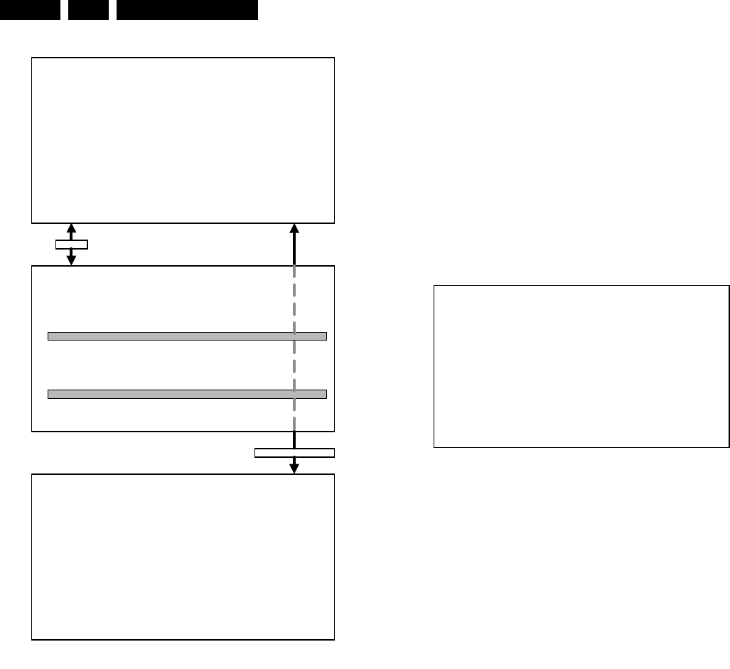
5.7 Protections
If a fault situation is detected an error code will be generated
and if necessary, the set will be put in the protection mode.
Blinking of the red LED at a frequency of 3 Hz indicates the
protection mode. In some error cases, the microprocessor
does not put the set in the protection mode. The error codes of
the error buffer can be read via the service menu (SAM), the
blinking LED procedure or via ComPair. The DST diagnose
functionality will force the set into the Service-standby, which is
similar to the usual standby mode, however the microprocessor
has to remain in normal operation completely.
To get a quick diagnosis the chassis has three service modes
implemented:
•The Customer Service Mode (CSM).
•The Service Default Mode (SDM). Start-up of the set in a
predefined way.
•The Service Alignment Mode (SAM). Adjustment of the set
via a menu and with the help of test patterns.
See for a detailed description Chapter 9 paragraphs Deflection
and Power Supply.
5.8 Repair Tips
Below some failure symptoms are given, followed by a repair
tip.
•Set is dead and makes hiccuping sound
‘MainSupply’ is available. Hiccuping stops when de-
soldering L5561, meaning that problem is in the
‘MainSupply’ load. No output voltages at LOT, no
horizontal deflection. Reason: line transistor 7460 is
defective.
•Set is dead, and makes no sound
Check power supply IC7520. Result: voltage at pins 1, 3, 4,
5 and 6 are about 180 V and pin 8 is 0 V. The reason why
the voltage on these pins is so high is because the output
driver (pin 6) has an open load. That is why MOSFET
TS7521 is not able to switch. Reason: feedback resistor
3523 is defective.
Caution: be careful measuring on the gate of TS7521;
circuitry is very high ohmic and can easily be damaged!
(first connect ground to measuring equipment, than the
gate).
•Set is in hiccup mode and shuts down after 8 s.
Blinking LED (set in SDM mode) indicates error 5. As it is
unlikely that µP ‘POR’ and ‘+8V protection’ happen at the
same time, measure the ‘+8V’. If this voltage is missing,
check transistor TS7480.
•Set is non-stop in hiccup mode
Set is in over current mode; check the secondary sensing
(opto coupler 7515) and the ‘MainSupply’ voltage. Signal
‘Stdby_con’ must be logic low under normal operation
conditions and goes to high (3.3 V) under standby and fault
conditions.
•Set turns on, but without picture and sound
The screen shows snow, but OSD and other menus are
okay. Blinking LED procedure indicates error 10, so
problem is expected in the tuner (pos. 1000). Check
presence of supply voltages. As ‘Vlotaux+5V’ at pin 6 and
7 are okay, ‘VT_supply’ at pin 9 is missing. Conclusion:
resistor 3460 or 3488 is defective.
•Set turns on, but with a half screen at the bottom.
Sound is okay
Blinking LED (set in SDM mode) indicates error 2. Check
‘Vlotaux+13V’ and ‘+50V’. If they are okay, problem is
expected in the vertical amplifier IC7471. Measure with a
scope the waveform on pin 17 of the UOC. Measure also
at pin 1 of IC7471. If here the signal is missing, a defective
resistor R3244 causes the problem.
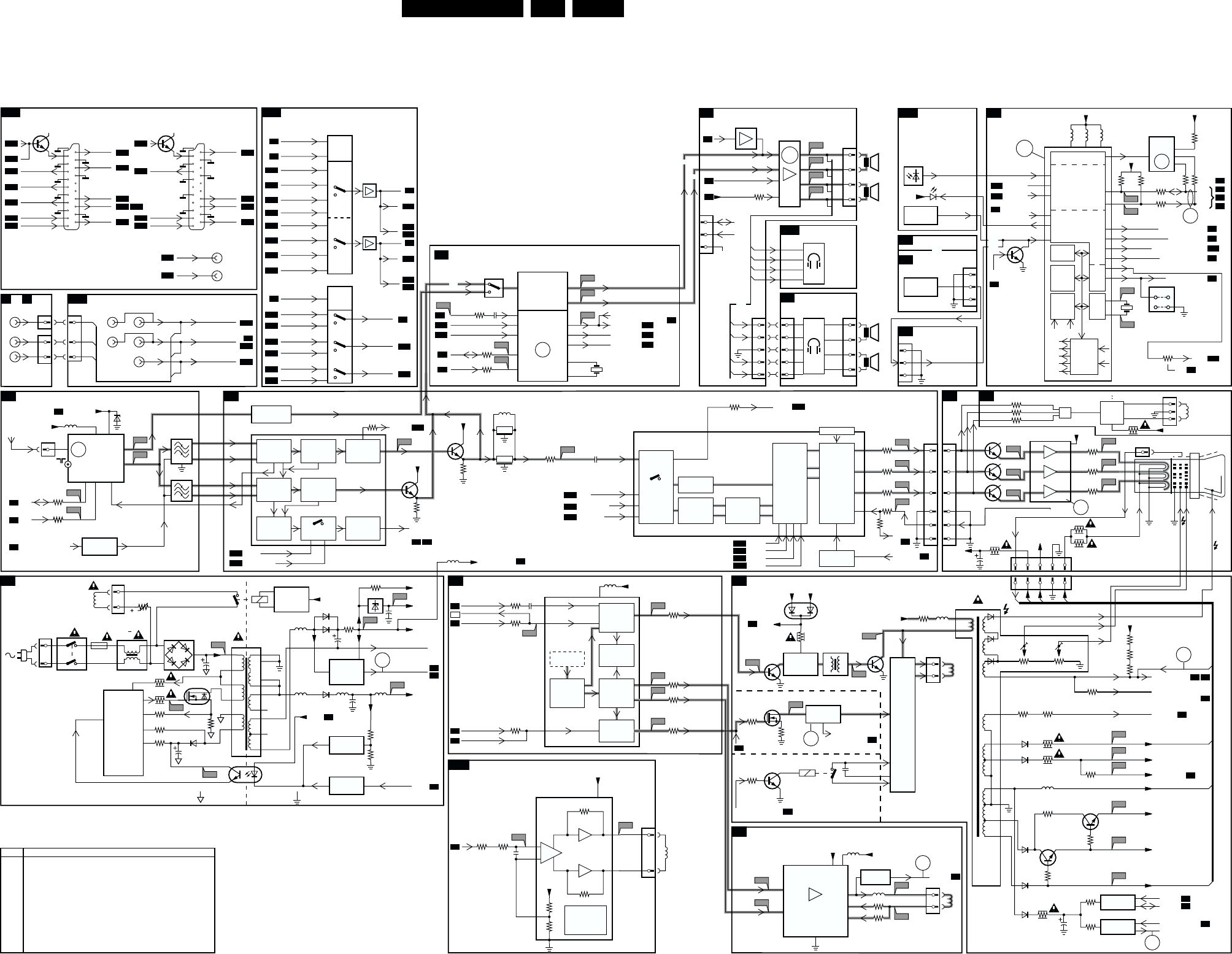
Block Diagram, Testpoints, I2C and Supply Voltage Overview EN 21L01.1E AB 6.
6. Block Diagram, Testpoints, I2C and Supply Voltage Overview
Block Diagram
POWER SUPPLY 0212
43
2
2
3
4
18
17
16
15
14
13
5
38
9
1
3504
CL 16532008_031.eps
050601
P1
L13
I1
I2
P2
P3
P5
V10
I3
I4
P4
V9
C4
C5
C2
A1
C1
0265
SDA
SCL
0211
150 - 250V
SINGLE RANGE
90 - 276V
FULL RANGE
5201
5001
FM-RADIO
TUNER
+
TV TUNER
3543
5562
3001
3000
3564
2564
3213
3251
3404
7400
STP3NC60FP
3405
7444
3259
EHT INFO
SANDCASTLE
H FLYBK
2254
3242
N.C.
3247
5604 3611
36033604
3625
3624
3172
56035602
2203
3544
3558
7560
2567
7561, 7562
7564
6001
BZX79-C33
6520
2521
A1
SYNCHRONISATION
A6
TILT & ROTATION
A15
LINE DEFLECTION
A2
FRAME DEFLECTION
A3
TUNER IF
A4
SIDE AV
E or C
FRONT I/O
A12
REAR I/O SCART
A14
A7
A7
VIDEO IF, SOUND IF
A5
A5
CRT
B1
SCAVEM
B2
A8
A14
A8
A9
A2
A7
A2
A2
Degaussing
Coil
t
1515
5520
7580
7520
TEA1507
DRAIN
DRIVER
SENSE
DEMAG
VCC
CONTROL
IC
CTRL
ENERGIZING
CIRCUIT
AC
DC
6500
GBU6J
5500 :
5502
0231
MAINS
SWITCH
1000 6, 7 9
1
2
11
FM
VIF_1
VIF_2
SIF1
SIF2
RF_AGC
1
12
11
N.C.
N.C.
10
1
2
3
4
1500
T4E
2503
6561
6562
AUDIO SUPPLY GND
MAIN AUX
POWER DOWN
V
LOTAUX
+13V
V
LOTAUX
+5V
VT_SUPPLY
VA
B
C
P6
5560 5564 5561
6560 140V
MAIN SUPPLY
2561
POWER
DOWN
CIRCUIT
12V
+3.3V
+3.9V
MAIN AUX_FB
+8V
+8V
V
DEFL
A7
STDBY_CON
HOT GROUND COLD GROUND
7540, 6540
REFERENCE
CIRCUIT
7541, 7542
STANDBY
CIRCUIT
7515
TCET1103
3532
3525
3523
3526
7521
STP7NB60FP
8
6
5
3522
3528
4
1
D
S
G
VT
AGC
5
SEL-IF-LL-M-TRAP
A7
A2
A6
A5 A6
A2
A2
4
IF
FM
0253
3
10
18
38
49
3214
7206
3230
3208
7201
MONO/AM_
MONO_SOUND
33
48
19
22
23
24
L1-IN
LFRONT-IN
28 29
7001
7002
FILTER
SELECTION
FMR QSS_AM_DEM_OUT
AUDIO CARRIER
FILTERS
7200-A
TDA95XX
1002
1003
1004
VIDEO
IF
AGC
VIDEO
PLL
DEMOD.
VIDEO
AMPLIFIER
V1-OUT
SOUND
FM-DEMOD.
DE-EMPH. AUDIO
SWITCH
SOUND
AMPL.
+ AVL
QSS
SOUND
IF + AGC
QSS MIXER
AM DEMOD.
S2
L1
F1
F2
L4
F3
L6
L7
L5
V5
L8
L10
L9
S1
11
30 H DRIVE
V DRIVE+
V DRIVE-
V DRIVE+
V DRIVE-
H
V
9
17
31
34
7200-D
TDA95XX
H-DRIVE
2nd LOOP
H-SHIFT
TXT/OSD
DISPLAY
16
H/V SYNC
SEPARATOR
H-OSC
+PLL
40
47
1200
5.5MHz
1201
6MHz
A13
A14
A14
C-IN 45
A10
SY-CVBS-IN 44
A13
A10
A10
A10
CVBS1-IN 42
EW
+
GEOMETRY
SHORT
CIRCUIT AND
TEMPERATURE
PROTECTION
VIDEO IDENT
7200-C
TDA95XX
I/O
SWITCHING
Y-DELAY
EHT INFO
PROC. EHT INFO
R-Y
B-Y
U
V
R
G
B
R
G
B
56
57
58
55
Y
VIDEO
FILTERS
RGB
MATRIX
RGB
INSERT
BLACK
STRETCH
WHITE
STRETCH
RGB
CONTROL
OSD TEXT
INSERT
BLUE
STRETCH
WHITE-P.
ADJ
VIDEO
IDENT
L
0251
3
V
L
R1
0219
6
3
1
MONO
V
L
R
CVBS-FRONT-IN
L-FRONT-IN
R-FRONT-IN
A
B
C
STEREO
A14
A2
A1
A14 A4
A4
A7
A8
A9
A14
A12
AUDIO AMPLIFIER
A8
HEADPHONE
A12
FRONT CONTROL
A12
TOP CONTROL (RF)
T
NICAM, 2CS, DECODER
A9
TOP CONTROL (FSQ)
T1
CONTROL
A7
+3.3V
36063607
+3.9V
+3.3V
A10
A9
A8
A7
A11
A6
3833
3834 2847
A14
A10
NICAM, 2CS, BTSL (STEREO DECODER)
A9
7831
MSP34X5G
QSS-AM-DEM-OUT
FMR 47
A5
MONO/AM-MONO-SOUND
7834
7835
6692
TSOP1836
MAIN-OUT-L
44
A10
SC1-L IN 41
A10
SC1-R IN 42
A7
SDA 8
A7
SCL 7
25
4SC2-CTRL
A14
30 R OUT
L OUT
A5
A5
A7
MONO/AM-MONO-SOUND
31
MAIN-OUT-R
24
51
52
DEMODULATOR
NICAM, 2CS,
BTSC, AM, FM
3832
ERR
10
ERR
7
1831
18M432
63
1660
12MHz
H
V
64
7901 AN7522N (STEREO)
7902 AN7523N (MONO)
62 L+
L
8
9
MONO/
AM-MONO-
SOUND
VOLUME MUTE
A5
1
MAINAUX_FB
ERR
7
7209, 7210
FM RADIO
PRE-AMPL.
0280
A2
4L-
A3
10 R-
A4
12 R+
R
L
R
4
3
2
1
0278
3
2
1
0255
4
3
2
1
L+
L-
R-
R+
L+
L-
R-
R+
HEADPHONE
E1
L+
L-
R-
R+
L+
L-
R-
R+
0254
1
2
3
4
0209
1
2
3
5
0267
0246
1
2
3
4
5
OR
SDA
SCL
COMPAIR
CONNECTION
(FOR SERVICE)
IR IR
STATUS1
STATUS2
LED
3.3V
LOCAL
KEYBOARD
KEYBOARD-
PROTN
KEYBOARD-
_PROTN
EW-
PROTECTION
KEYBOARD
_PROTN
0209
7606
1
2
3
LOCAL
KEYBOARD
OR
7200-B
TDA95XX
I/O
VST
PWM-
DAC
ROM
RAM
CPU
OSD
TELETEXT
DISPLAY
IIC
BUS
TRANSCEIVER
I/O
PORTS
67
68
72
71
3
8
76
5
66 61 59
1
2
POWER DOWN 69
LED 5
80
3908
7602
M24C08
EEPROM
(NVM)
SDA
SCL
TILT
SEL-IF-LL-M-TRAP
A10
A15
70 SEL-MAIN-FRONT-RR
A1
6STANDBY-CON
A2
78 BASS PANORAMA
77 TREBLE-BUZZER-HOSP-APP
A8
73 VOLUME/MUTE
A8
ON
SDA
SCL
5241 +8V V
LOTAUX
+13V
V
LOTAUX
+50V
V
DEFL
MAIN AUX
R-V-IN
02450243
1
R
G
B
2
3
5
6
OR
OR
9641
9631
SDM
1/10
PAGES
MEMORY
TELE
TEXT
CVBS SYNC
SCAVEM
PROC
SCAVEM
COIL
+
R
G
B
BL
COR
PAL/NTSC
SECAM
DECODER
BASE
BAND
DELAY
EHT INFO
A2
A7
A2
A2
A7
A1
EHT o
A2
A7
V-DRIVE
+
GEOMETRY
3244
S3 L2
3249
S4
EW DRIVE/
EWD-DYN
BASS_PANORAMA
15 3250
OUT-
IN-
5
3
6
7
2
48
1
IN+ OUT+
S5
L14
V
LOTAUX
+13V V
LOTAUX
+50V
MAIN SUPPLY
140V
6467
BAV70
7462
7460
BU4508DX
3493
3481
3482
3484
7461
7463
DRIVER
STAGE
7471
TDA8359J
FRAME
OUTPUT
5461
LINE
OUTPUT
CIRCUIT
only for sets with E/W correction
only for sets with panorama
EW drive/EWD_dyn
L3
D
S
G
3487
3222
3201
3334
3332
3336
3202
3203
3204
3235
3466
3489
7331
3371 7360 - 7367
3379
3386
7332
1400 2454
1
43
2
7
9
4
E/W
CIRCUIT
E/W PROTECTION
0221
1
2
HOR.
DEFL.
COIL
0222
1
2
VERT.
DEFL.
COIL
F4
1
3
5
6
2
V1+
VP
VOA
VM
VOB
V1-
5472
5471
3479
3471
V
GUARD
CIRCUIT V
GUARD
6470
0268
1
3
ROTATION
COIL
5451
5445
3
1
FOCUS VG2
EHT
0220
0244
12345
ABC D
10
6
EHT INFO
A4
A2
EW DRIVE/EWD_DYN
34693480
H FLYBK
VIDEO SUPPLY
A3
V
GUARD
A5
BLK-IN
A1
POWER-DOWN
EHT o
200V
VT_SUPPLY
FILAMENT
A
B
D
C
5
11
6485
7
12
8
9
6488
6487
3494
3362
V
LOTAUX
+50V
V
LOTAUX
+13V
V
LOTAUX
+5V
+8V
3488
3451
3460
3455
3446 7441
7443, 7450
3452
5480
6486
6447
2444
PROT
CIRCUIT
PROT
CIRCUIT
3447
7480
3450
7482
A2
BLK-IN
BLK BLK
V-OUT 2X
A14
G-Y-IN
A14
A14
B-U-IN
FBL-1
51 52 53 50 54
7204
V6
V7
V9
V12
V11
V13
V14
V15
V16
1
2
3
44
5
6
7333
7330
TDA6107Q
2
1
3
8
5
9
7
R
G
B
EHT-INFO
Filament
+200VA +13V
+200VA
+13V
3340
2340 12345
3341
3342
OSD
R
G
B
CRT
25kV
FOCUS
EHT
VG2
8
6
11
10 9 5 7 1
OR
OR
OR
INPUT
SWITCHING
ERR
4
TV
FM
7943
FOR MONO SETS
0165 AQUADAG
ERR
9
ERR
6
ERR
11
ERR
3
ERR
2
ERR
8
5205
Error Description
0 No error
1 X-Ray / over voltage protection (USA only)
2 High beam (BCI) protection
3 Vertical guard protection
4 I2C error while communicating with the sound processor
5 Power ON reset (POR bit) 3.3V protection / +8V protection
6 General I2C error
7 Power Down (over current) protection
8 EW protection (Large Screen only)
9 I2C error EEPROM error
10 I2C error PLL tuner
11 Black current loop instability protection
ERROR CODE LIST
ERR
5
ERR
2
AUDIO/VIDEO
SOURCE SWITCHING
A10
7801
HEF4052BT
A10
A10
A10
A5
A5
A10
A7
A10
MONITOR OUTPUT
SCART 2
7131
A7
A10
AUDIO R
Y-CVBS-IN
V - OUT
C - IN
L2 - OUT
R2 - OUT
STATU S 2
L2-IN
R2-IN
R-OUT
A10
AUDIO L
L-OUT
SEL_MAIN_FRNT_RR
SEL_MAIN_FRNT_RR
9
A9
A7
A9
A14
SC2-CTRL 10
A12
L-FRONT-IN
SC1-LIN
SC1-R IN
L1-OUT
1
A14
L1-IN 7803
7804
5
A14
L2-IN 2
A9
SC1-LOUT 4
A12
R-FRONT-IN 12
A14
R1-IN 14
3
13
A14
R2-IN 15
A9
SC1-R-OUT 11
SWITCH
LOGIC
7802
HEF4053BT
9
A5
CVBS-FRONT-IN 5
A14
Y-CVBS-IN
SY-CVBS-IN
3
4
SWITCH
LOGIC
A9
A12
A14
R-OUT 2
A9
SC1-R-OUT
R2-OUT
1
15
A10
A14
L-OUT 12
A9
SC1-1-OUT
L2-OUT
13
14
A10
A14
A10
L-OUT
R1-OUT
A14
A10
R-OUT
A13
12
20
21
A10
A10
A10
A5
A5
A10 A5
A7
A5
SCART 1
7101
CVBS1-IN
V1-OUT
V-OUT
R-Y-IN
A5
L1 - OUT
A5
B-U-IN
A5
G-Y-IN
R1 - OUT
STATU S 1
A5
FBL-1
L1-IN
R1-IN
12
20
21
VLOT AUX +13V
VCC
7171
TDA8941P
TILT
VCC
3173 3174
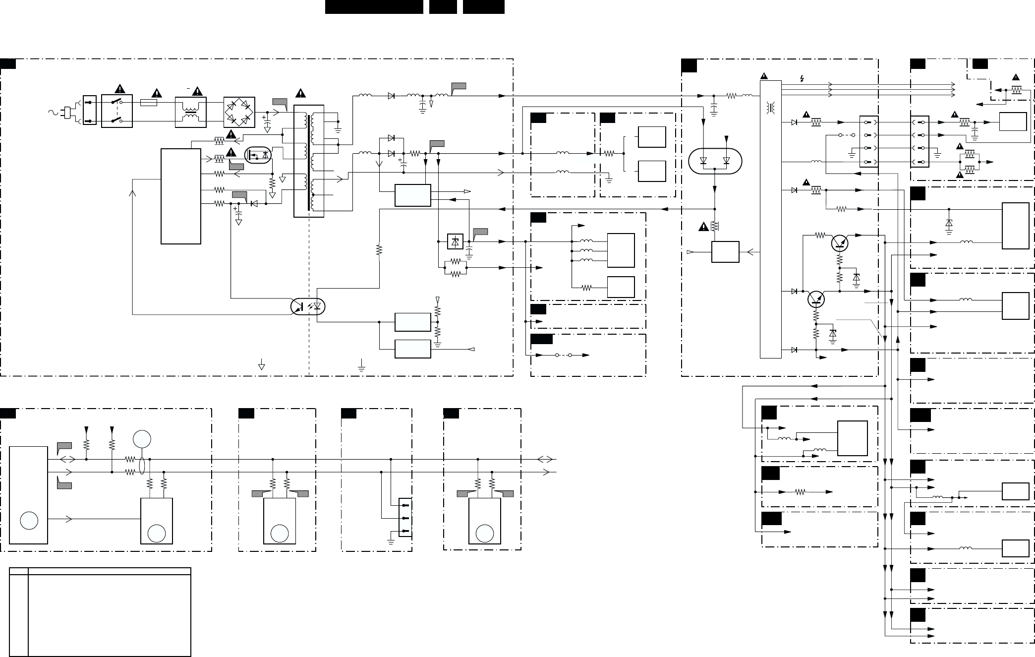
Block Diagram, Testpoints, I2C and Supply Voltage Overview EN 23L01.1E AB 6.
I2C and Supply Voltage Diagram
POWER SUPPLY
2
3
4
A
A
18
17
16
15
14
10
13
12 N.C.
11 N.C.
5
38
9
CL 16532008_029.eps
050601
C4
C5
I1 I2
P1
P2
P3
P5
P6
P4
0211
170 - 250V SINGLE RANGE
90 - 276V FULL RANGE
5205
5602
5603
5604
4693
7901
1000
7902
7200-B
5560 5564
3564
2564
5561
3543
5562
3549
3544
3557
3558
7560
2567
7561, 7562
7564
6520
2521
A1
CONTROL
A7
TUNER IF
A4
VIDEO IF
A5
CONTROL
A7
5520
7520
TEA1507
DRAIN
DRIVE R
SENSE
DEMAG
VCC
CONTROL
IC
CTRL
AC
DC
6500
GBU6J
5500 :
5502
0231
1
1
66
61
59
8
1
2
3
4
1500
T4E
2503
6561
6562
6560
AUDIO SUPPLY GND
POWER DOWN
140V MAIN SUPPLY
12V MAIN AUX
2561
POWER
DOWN
CIRCUIT
AUDIO SUPPLY
GND-FB
+3.3V
+3.3V
+3.3V (TO 3256)
+3.9V +3.9V
(TO 3606
3607,3633)
STBY_CON
HOT GROUND COLD GROUND
7540, 6540
REFERENCE
CIRCUIT
7541, 7542
STANDBY
CIRCUIT
7515
TCET1103
3532
3525
3523
3528
3526
7521
STP7NB60FP
8
6
5
3522
4
1
D
S
G
5204
AUDIO AMPL.
SYNCHRONISATION
A6
+3.3V +3V3A
FRONT CONTROL
A12
AUDIO
OUTPUT
STEREO
AUDIO
OUTPUT
MONO
TUNER
uC
7602
EEPROM
(NVM)
OR
OR
LINE
OUTPUT
3611
LOT
+200VA
+13Va
+13Va
6
+13V
TO CRT
FILAMENT
LINE DEFLECTION
A2
CRT
B1
SCAVEM
B2
TUNER IF
A4
POWER SUPPLY
A1
FRAME DEFLECTION
A3
5451
2450
MAIN SUPPLY
VIDEO SUPPLY
200V +200V
+13V
5445
3
EHT
2340
3487
6001BZX79
-/C33
FOCUS
VG2
EHT
FOCUS
VG2
52
5
9
6
7
7FILAMENT FILAMENT
3494
5480
0220 3340
3341
6485
5
9
8
VT_SUPPLY 33V
VT_SUPPLY
2
3
5
4
0244
3
4
ANODE CRT
FOCUS CRT
VG2 CRT
3342
+5V (TO 6470)
+8V (TO 3008)
5202
VIDEO IF
A5
VLOT AUX +50V
VLOT AUX +13V
VLOT AUX +5V
VLOT AUX +5V
VLOT AUX +5V
VLOT AUX +5V
VLOT AUX +13V
VLOT AUX
TO DEGAUSSING CIRCUIT
VLOT AUX +13V
CONTROL
A7
+8V (TO 4-0217) NOT USED
+5V (TO 2234)
VLOT AUX
VLOT AUX +5V (TO 3619)
+8V
AUDIO AMPLIFIER
A8
+8V (TO 3948, 3950)
VLOT AUX +5V (TO 9904)
+8VA
MAIN AUX_FB
3460
9420
7471
FRAME
OUTPUT
7330
RGB
DRIVER
6
3
5001
5472
SYNCHRONISATION
A6
7200-D
SYNC
PROC.
5241
+8V
+13V
VLOT AUX +50V
+8V
+8V
+8V
+8V
+8VA (TO 3248)
7200-A
VIDEO
IF
9
5832
BTSC DECODER
NICAM 2CS
A9
VLOT AUX +5V
REAR I/O SCART
A14
A15
+8V
AUDIO VIDEO
SOURCE SWITCHING
A10
7831
AUDIO
DECODER
5833 +5VA
+8V +6V8
46
33
3455
34473446
3488
6467
6488
7482
7480
6486
6482
34503449
6481
3801
3625
7602
M24C08
EEPROM
(NVM)
3624
3607 3606
3604
3603
65
72
71
68 7
ERR
9
ERR
5
7200-B
SET
PROCESSOR
PART OF
VIDEO-
PROCESSOR
ERR
6
SDA
SCL
SDA
SCL
SCL
SDA
+3.9V +3.9V
1000
TUNER
3001
3000
45
ERR
10
1
2
0267
3
AUDIO AMPL.
A8
SCL
SDA
A7 A8
NICAM, 2CS,
BTSC DECODER
A9
7831
MSP34X5G
AUDIO
DECODER
3833
3832
78
ERR
4
SCL
SDA
FOR
COMPAIR
ONLY
3493
VLOT AUX +13V
MAIN AUX
H-DRIVE
V DEFL.
V DEFL.
I2C BUS INTERCONNECTION DIAGRAM
3908
39
(TO 6452,6468,3400,
3442,3453)
3362
A8
6467
A9
Error Description
0 No error
1 X-Ray / over voltage protection
2 High beam (BCI) protection
3 Vertical guard protection
4 I2C error while communicating with the sound processor
5 Power ON reset (POR bit) 3.3V protection / +8V protection
6 General I2C error
7 Power Good (over current) protection
8 EW protection (Large Screen only)
9 I2C error EEPROM error
10 I2C error PLL tuner
11 Black current loop instability protection
ERROR CODE LIST
MAIN
SWITCH
TILT & ROTATION
VLOT AUX +13V
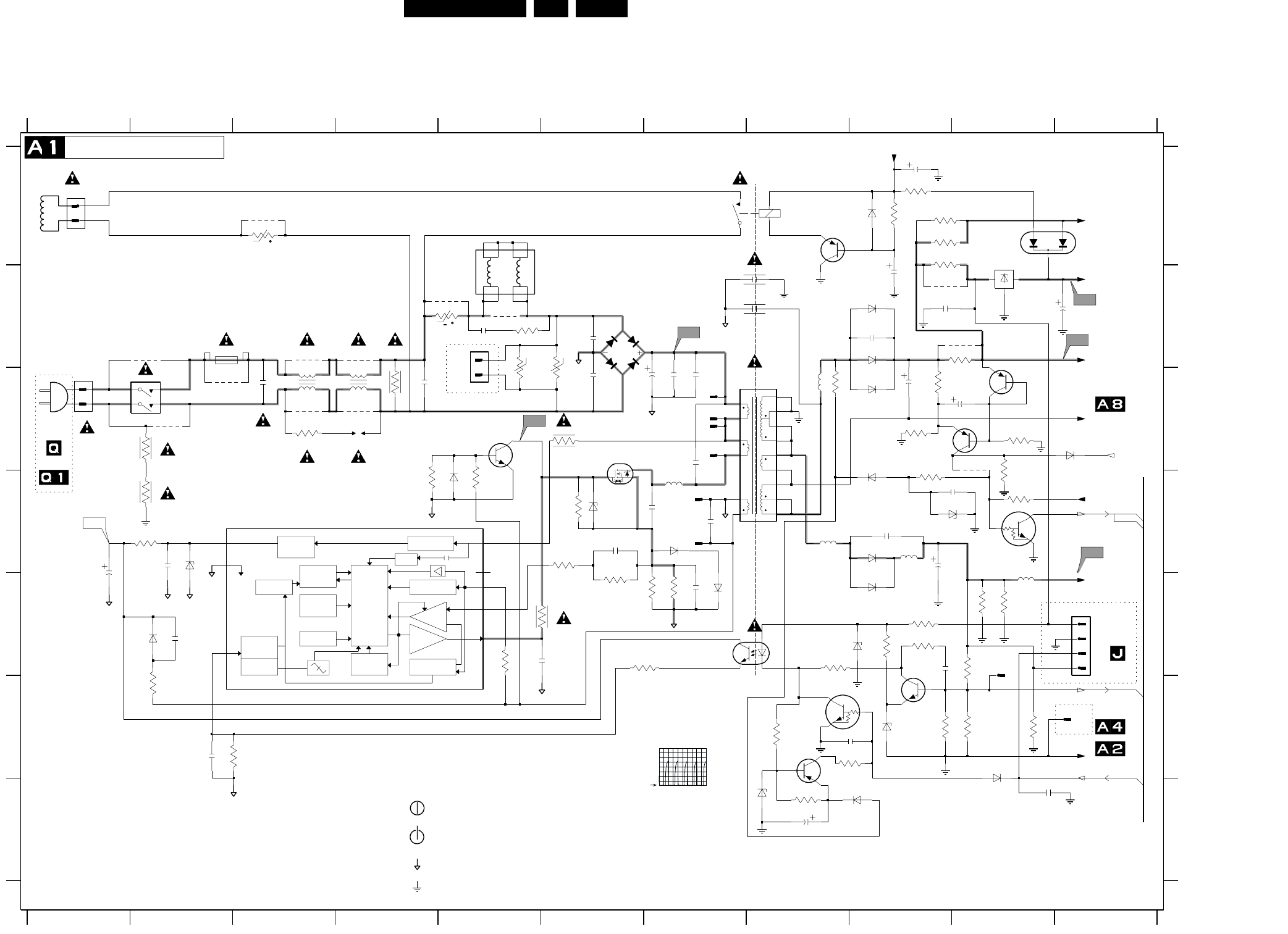
EN 24L01.1E AB 7.
Schematics and PWB’s
7. Schematics and PWB’s
Mono Carrier: Power supply
V
OVER
POWER
LOGIC
CONTROL
CIRCUIT
MAXIMUM
ON-TIME
PROTECTION
VOLTAGE
CONTRLLED
OSCILLATOR
OVER
TEMPERATURE
PROTECTIOM
POWER-ON
RESET
SUPPLY
MANAGEMENT
FREQUENCY
PROTECTION
CONTROL
INPUT
CONTROL
CIRCUIT
BURST
DETECTOR
Drain
HVS
Sense
Demag
Driver
Vcc
Gnd
Ctrl
START-UP
CURRENT SOURCE
VALLEY
START-UP
CURRENT SOURCE
CURRENT
SENSING
OUTPUT
DRIVER
V
t
+t
8V8
6V8
6V8
E
F
G
A
B
C
D
E
F
G
0211 C1
0212 A1
0213 B5
0231 C1
0251 E11
1234567891011
12345678
2525
91011
A
B
C
D
DEGAUSSING COIL
0V
*
0V
-3V2
*
TO 0251
COLD GROUND
RES
RES
3V2
0282 F11
1500 B2
1515 A8
1540 E10
2500 C3
2501 C6
2502 B6
2503 C7
2504 C7
2505 C7
2506 B5
2507 D7
2508 C7
2509 C4
2515 B8
2516 B8
2520 F2
2521 E1
2522 D6
2523 D7
2525 E5
4
TO
*
3
2V8
**
*
150 - 276 V SINGLE RANGE
*
OF
OF
*
2526 D2
2527 E7
2528 E2
2540 E9
2541 F9
2560 D9
2561 D9
2562 B9
2563 D10
2564 C9
2566 C10
2567 B10
2568 G8
2569 G10
2580 B9
2581 A9
2590 B9
3500 C2
3501 D2
1n5
2V
12V
S
BZX79-B6V2
82K
*
11V5
ONLY
MAINS
"$"
*
3503 B5
3504 A3
3506 C4
3507 C4
3508 C3
3509 B5
3510 B5
3511 B6
3519 E7
3520 F2
3521 F2
3522 E5
3523 E5
3524 E6
3525 D6
3526 E7
3527 E7
3528 D2
3529 D4
3530 D6
HOT GROUND
1N5062
(13V8)
2
*
*
BYV29X-500
220V AC 309V (317V)
*
1V8
0V
1V3
(12V)
12V4
*
3531 D5
3532 C6
3541 E8
3542 E9
3543 E10
3544 F10
3545 F9
3548 E9
3550 F10
3552 F9
3557 A9
3558 A9
3560 C9
3561 C8
3562 D9
3563 D10
3564 B10
*
OF
TO 0283
2n2
*
(-V) STANDBY OPERATION
1V7
4
3565 A9
3566 G8
3567 C9
3568 C10
3569 F8
3570 C10
3580 A9
3590 A9
3594 E9
3595 E10
3596 E10
4500 C10
5500 C4
5501 C3
5502 A5
5520 C7
5521 D7
5560 D8
5561 E10
5562 C8
5564 D9
6500 B6
6520 E2
6522 D2
LE33CZ
9V
90 - 276 V FULL RANGE
FOR ITV ONLY
A7-5
*
6523 D5
6524 D7
6525 E7
6526 D6
6540 F9
6541 E9
6560 D9
6561 B9
6562 C9
6563 D9
6564 C11
6565 A11
6566 F10
6567 D10
6568 E9
6569 G9
6570 G8
6580 A9
6582 B9
7515 E7
7520 D3
7521 C6
7522 C5
7540 F9
7541 F8
7542 F8
*
0R1
FOR MAINS 120V AC 170V (177V)
11V8
PDTC114ET
1
A2-11
3V
12V
0V
17V
0V
-3V2
POWER SUPPLY
*
*
*
(6V7)
OR
0V
16V8
*
OF
7560 A10
7561 D10
7562 C9
7564 C10
7580 A8
9500 B2
9501 C2
9502 C2
9503 B5
5521
9504 B5
9505 A3
9506 B4
9507 C4
9508 B3
9509 C3
9510 B9
9511 B10
D
0V4
Jumper
0V
*
(7V7)
RES
"$"
*
3V3
680p
*
12V
11V5
140V
USA
T4E.250V
100u
TO
*
11V8
SDW
For AV Video
1n5
0V
2u2
"$"
0V
10V
0V
FOR ITV ONLY
OR
MAINS SWITCH
9V
G
*
OF
For ITV only
*
TO 0283
"$"
1u
2
*
*
-V NORMAL OPERATION
0V
A7-11
1
0V
for ITV only
*
3
0V
*
3528
2m2
2564
1K2
3520
100n
2522
6570
1M5
3506
5561
27u
DSP
3507
6520
3M3
1540
8
4500
9509
10K
3552
1
2
2561
1
2
3
0251
BAS316
3510
B57237
P2
6522
BC857B
7542
2503
16
17
18
2
3
4
5
8
9
470p
2508
5562
9510
STPS10L60D
6582
7541
BC857B
7562
3568
2509
2563
100n
22u
2581
2580
47u
2507
470p
3561
3500
3M3
0213
1
P6
ZPB
3504
2n2
2501
3570
15K
6524
470R
3594
9503
2523
2K2
3566
3524
56K
9508
3508
BAS216
6569
7561
PDTC143ZT
15K
3548
3
4
3557
1K
7520
TEA1507
1
2
470u
2566
BC547B
7540
1n
2528
BYD33D
9502
3580
47K
5560
6568
BYW76
6500
9504
3541
470R
2506
2516
0211
P4
3523
470p
9505
3545
39K
3563
8K2
3503
2541
1n
9506
2569
6541
PDZ-10B
P5
BAV70
6565
220R
4K7
3531
3544
4K7
6540
3543
3532
2K2
6580
1K
3525
2515
3522
4
3562
12K
SB340
6561
0282
2520
100n
3567
6525
DMF-2820
5500
14
23
2K2
6567
9500
3519
270R
EGP20DL
6562
2590
2568
3509
3530 10K
6566
1N4148
47u
2567
9507
3511
6563
BAS316
1n
2562
5
6
7
8
3521
6560
3527
3550
1K5
3542
0212
1
2
2
3526
2526
3560
47R
1500
9501
470n
2500
0231
13
24
56
330R
3565
2521
22u
3501
5564
2527
3596
220K
3595
220K
5502
1
2
3
45
6
7
2502
2n2
1N4148
6523
TCET1104G
7515
6526
BZX284-C22
5520
10
11
12
13
14
15
7560
GND
2
IN
1
OUT
3
P3
2504
1515
G5PA
23
14
BC857B
7580
14
23
BAS216
6564
DMF-2405
5501
10n
2540
3564
7521
BC847B
7522
3558
330R
5K6
3569
2560
P1
2n2
2505
BC857B
7564
3590
150R
47K
3529
EW_protection
+3.9V
MainAux
VlotAux+13V
+3.3V
MainSupply
MainSupplyGnd
Vcontrol
9511
AudioSupplyGnd
POWER_DOWN
+3.3V
EAR
MainSupplyGnd
Stdby_con
CL 26532063_001.eps
140602
P1 = "$"
P3 = 16V8 (13V8)
P4 = 3V3
P5 = 12V
P6 = 140V
P2
2V / div DC
5us / div
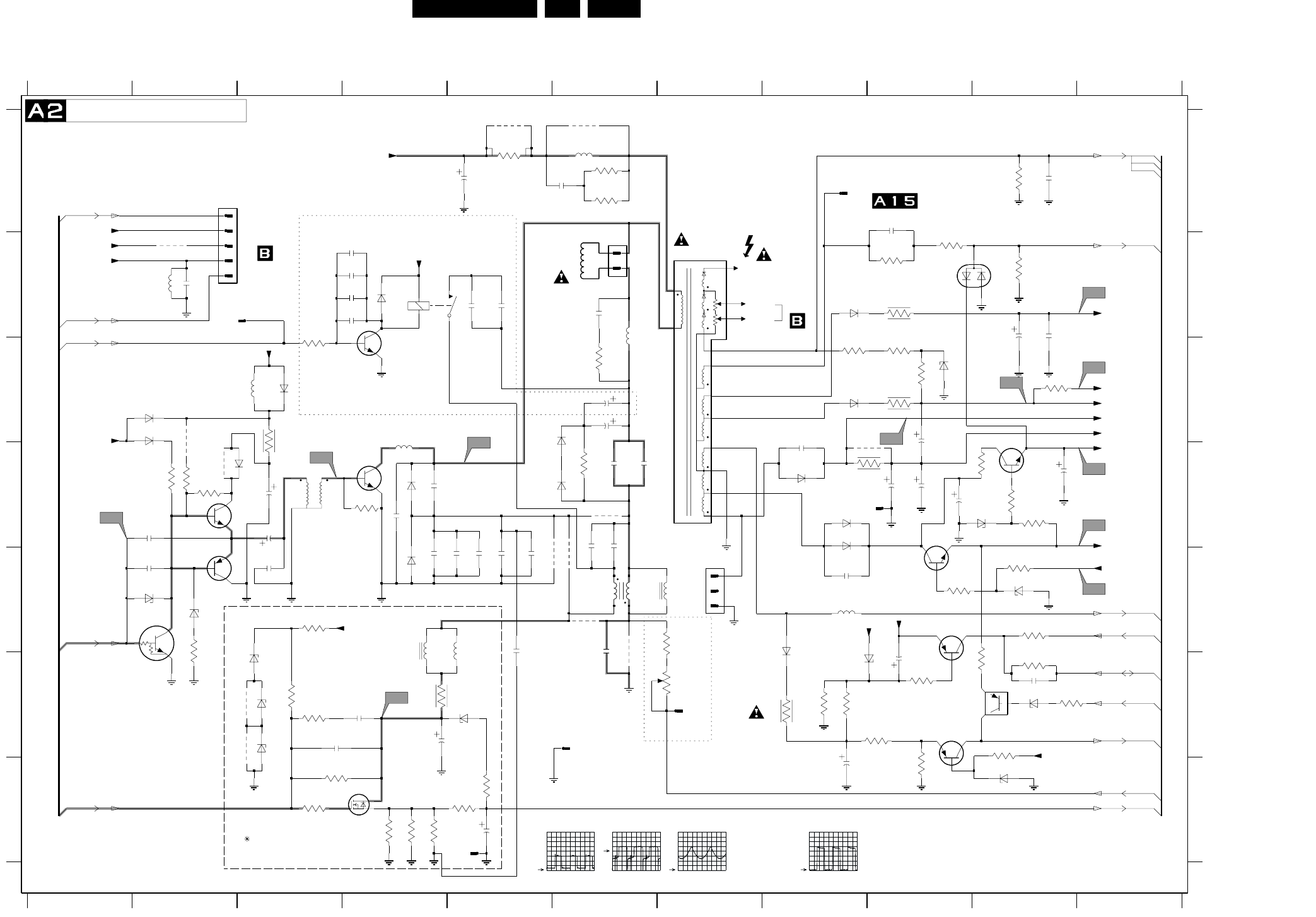
EN 26L01.1E AB 7.
Schematics and PWB’s
Mono Carrier: Line Deflection
FOCUS
VG2
EHT
9424
91011
A
B
C
D
E
F
G
A
B
C
D
E
F
G
0220 A2
1234567891011
12345678
0221 B6
0288 F6
0289 A9
0319 B2
0321 D8
0322 G5
1400 B4
1402 E7
1410 F7
2400 F4
2401 F4
2402 F3
2404 G5
3K9
3460
2491
2405 D3
2415 E3
2420 B4
2421 B4
43
21
2422 B4
2423 B4
2441 F9
2443 F10
2444 G8
2448 A9
2450 A5
2451 A6
2452 B2
2453 B5
2454 B5
2455 D3
2456 D6
2457 D6
2458 C6
2459 B6
2460 D2
2461 E2
2462 E4
2463 D4
2464 E6
2465 D4
2466 E5
2467 E5
2468 E5
2469 D6
2470 E5
2480 D9
2481 D8
2482 A10
2484 D6
2485 B10
2486 D9
2487 D9
2488 D9
2489 D10
6461
9423
2490 C6
2491 E8
2492 B10
2493 E5
3400 E3
3401 F3
3402 F3
3403 G3
3404 G3
3405 G4
3406 G4
3407 G4
3408 G5
3410 G5
3411 F4
3430 E7
3431 F7
L5
3441 E10
3442 F9
3443 F10
3445 F8
3446 F8
3447 E9
3448 E10
3449 D10
3450 D10
3451 F8
3452 F9
3453 F10
3454 G9
3455 D10
3456 F10
3457 F10
3458 C6
3459 D6
3460 C10
3463 D4
3464 D9
3465 A10
3468 E2
3469 B9
3481 C8
3482 C9
3483 B10
3484 C9
3485 A6
3486 A6
3487 A5
3488 C9
3489 C3
3490 B9
3491 D2
3492 D2
3493 C3
3494 B9
3431
3499 D2
4430 C2
5400 E4
5401 E5
5445 B7
5450 B2
5451 A6
5452 D4
5453 C3
5457 B6
5461 D3
5463 E7
3430
5464 E6
5465 E6
5480 E8
6400 F3
6401 F5
6402 F3
6403 F3
6445 F8
6447 E8
6448 G10
6449 B9
6452 B4
6453 F10
6460 D4
6461 E4
6462 E2
6463 E2
6465 D6
6466 C6
6467 C2
6468 C2
6469 C3
6481 D10
6482 E10
6483 C9
6485 B8
6486 D8
6487 C8
6488 D8
6489 D8
6490 D2
7400 G4
7441 E9
7443 G9
7444 C4
7450 F10
7460 D3
7461 D2
7462 F1
BC557B
7443
7463 E2
7480 E9
7482 D10
9420 B2
9422 D9
9423 D2
9424 F3
9426 F3
9451 A6
9453 A5
9460 D6
9461 E5
9462 E6
9463 E6
9464 E6
2484
3443 1M
L1
3464
4R7
6401
7461
BC337-25
L2
2450
47u
5450
2461
1u
2441
9420
3408
2460
1m
3459
15K
6402
L11
9422
3404
6460
7400
470u
3406
3499
0322
6453
BZX384-C6V8
3458
1K
3449
100R
3482
L3
1410
3405
4430
G5PA
1400
23
14
1
2
3
4
5
9451
3401
0288
100MHZ
5452
2420
6448
2463
3457
3463
33R
3403
9464
3494
4R7
CI-15
3K9
3484
2468
3453
1K
4R7
3487
3493
3486
100R
3450
6485
BYD33J
1N4148
6447
RGP30J
5453
22u
RES
8V9
*
*
*
0R
TO 0244
220u
A1-11
A2-16
1V5
*
ONLY FOR SETS WITH
S
0V
*
*
*
*
*
*
E/W CORRECTION
2V
C5V6
*
HORIZONTAL
*
5V2
RES
*
*
For Picture
*
0V5
*
*
A6-16
*
A2-16
PANEL
8V
*
*
*
*
*
*
A6-18
*
*
*
*
9V
*
*
13V3
5V7
A7-7
0V
13V3
0V
A6-23
*
*
0V
*
A2-69
*
*
*
*
*
126V
0R
0V
0V
*
*
A2-69
*
*
*
*
*
*
11V6
*
0V
A7-9
A5-16
*
*
*
5V5
*
BZX79-B6V2
6V3
PANORAMA
*
5V2
5V
*
*
TO 0290
*
137V
OF
PANEL
*
OF CRT
*
UDZS-10B
*
*
DEFLECTION
COIL
RES
A3-65
1.9V
*
*
5V
*
*
5V
*
5V2
*
*
TO PICTURE TUBE
LINE DEFLECTION
*
200V
A6-21
5V2
BZX79
*
D
CCT.
*
*
Width Control
L.LIN
CU15
0V
BAV21
6465
*
A2-22
9V
*
*
*
G
*
*
0V
*
*
*
*
*
TO DAF
*
*
5V6
13V3
A5-36
3492 1K
2415
2469
2400
BAS216
6467
2421
7444
2470
0319
3454
2464
6486
EGP20DL
9461
2402
3448
BD135
7482
2466
L4
9460
L6
3451
BZX79-C9V1
6482
1402
1
2
3
5K6
3446
3491
5461
1
36
4u7
2485
2454
L10
L7
3407
2493
9462
2467
2456
6487
BYD33D
2404
9426
3489
3441
100R
7
8
9
3456
3452
5445
1
10
11
12
3
5
6
6490
BYD33M
2405
5480
47u
2455
9463
5451
27u
BAS216
6468
5464
CU20d
12
34
2490
L9
3465
3400
6463
2489
470u
5463
470p
2481
3483
10K
3410
3485
BAV21
6466
6483
BZX79-C33
2488
3n3
2492
2444
1u
3455
6R8
3402
7450
PDTA114ET
2448
2451
3447
3481
7462
PDTC143ZT
47u
2487
680p
2459
3490
8K2
0321
5457
7441
BC857B
5401
47n2443
3K3
3469
3442
1K
2486
2453
15K
3445
2458
2480
47u
6403
6481
6452
2422
9453
2482
7460
BU4508DX
2462
BC327-25
7463
3468
6488
EGP20DL
2465
2457
6449
BAV99
2423
2401
0220
6445
BZX284-C10
5465
CU15
0221
1
4
5400
VH
7480
BD135
0289
L8
6489
BYD33D
3488
4R7
6462 2452
180p
BYD33M
6469
3411
VlotAux+13V
EHTinfo
VlotAux+13V
VideoSupply
VlotAux+13V
+13V
Bass_panorama
Vcontrol
MainAux
6400
VlotAux+13V
Hdrive
VT_Supply
Filament
Vguard
Hflybk
VlotAux+13V
EW_protection
VlotAux+50V
BLK-IN
VlotAux+5VA
+8VB
VideoSupply
VlotAux+13V
MainSupplyGnd
EHTinfo
Filament
MainSupply
+13V
EHTo
POWER_DOWN
EWdrive|EWD_dyn
VlotAux+5VA
VlotAux+13V
CL 26532063_003.eps
130602
L5 = +200V
L6 = +50V
L7 = +50V
L8 = +13V
L9 = +5V
L10 = +8V
L11 = +13V
L1
1V / div DC
20us / div
L2
1V / div DC
20us / div
L4
5V / div DC
5ms / div
L12
2V / div DC
20us / div
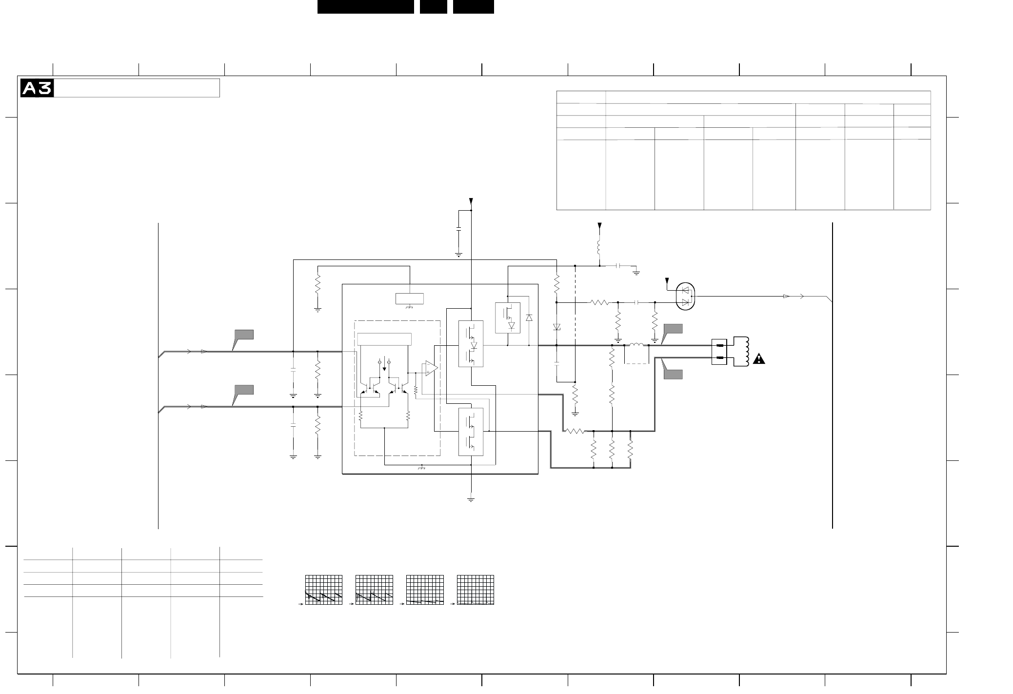
Schematics and PWB’s EN 29L01.1E AB 7.
Mono Carrier: Frame Deflection
25uA
RR
R
A
INPUT/FEEDBACK
B
GUARD
1:1
12K
3498
8910
A
B
C
D
E
F
A
B
C
D
E
F
0222 C8
2471 B5
4470
7471
12345678910
1234567
REGION NAFTA/LATAM
LG PHILIPS SMGK
ITEM
2472 10N
PHILIPS
21RF 27V/29"
2472 C6
2473 B7
2474 C3
2475 D3
2476 C7
3470 B6
3471 D7
3472 D7
3473 D7
3474 C4
3475 D4
3477 C7
3478 D7
3479 D7
3480 D6
3495 C7
3496 C7
3497 C7
3498 B4
4470 B7
5471 C7
5472 B7
6470 B8
6476 C6
7471 B4
9471 C7
9472 C7
9472
5472
3470
BAV99
6470
2K7
3479
3478
150R
3472
2472
47n
F3
22K
3495
F2
3497
100K
2476
2n7
*
A2-65
A6-20
A6-19
COIL
*
150N 150N
3470 SM 270K SM270K SM 330K
3471
1R5
1R5
-
SM JUMPER
COIL
*
4470
6R8 3R9 3R3
3472 6R8 6R8 3R3
3473 3R9 6R8 3R3
3480 -
DEFLECTION
FRAME DEFLECTION
0V
PHILIPS
-
-0V3
5V
1V
13V
5V
6V
6V
*
1V
24WR
VERTICAL
29RF
28WR 21RF
SMGK(SF)
GL
3R9
---
1R5
---
3U3
3MUH3
---
100V 10N
470K
3R9
3R9
---
---
SMD_JUMPER
6U8
6MUH8
JUMPER
32WR 29RF 21RF
LG.PH
---
6R8
4R7
48V
*
330K
3R3
3R3
3R3
1R5
---
3U3
6MUH8
---
63V 150N
470K
2R2
3R3
3R9
1R5
---
3U3
3MUH3
---
100V 10N
270K
3R9
-
5471 3U3 6U8 3U3
TYPE OF TUBE
TUBE
NAFTA/LATAM NAFTA/LATAM
*
0V
7V
-
NAFTA/LATAM
21RF 27RF
150N
SM 470K
3R9
3R9
2R2
1R5
-
6U8
9472 YES
-
-
100K
3496
3R9
1R5
---
6U8
3MUH3
---
63V 150N
SET
2472 63V 150N
3470 470K
3471 2R2
3472 3R3
3473
SMD_JUMPER
6U8
3MUH3
JUMPER
63V 150N
470K
3R9
3R9
3480 1R5
4470 ---
5471 6U8
TUBE
REGION
MODEL
EU
LG.PH
PHCO LG.PH
5472 3MUH3
L2K2
CH/IN
AP
9472 ---
63V 150N
270K
3R9
3R3
2n2
2475
2K2
3475
4R7
3480
F1
3473
BZX79-C12
6476
TDA8359J
GND
5
VFLB
6
VI+1
VI-2
VM 9
VOA
7
VOB 4
VOG
8
VP
3
9471
2473
100n
1
2
2471
100n
5471 0222
3474
2K2
150R
3477
3471
Vdrive-
Vdrive+
VlotAux+5VA
Vguard
+13V
VlotAux+50V
F4
2474
2n2
CL 26532063_004.eps
130602
F1
500mV / div DC
5ms / div
F2
500mV / div DC
5ms / div
F3
10V / div DC
5ms / div
F4
5V / div DC
5ms / div
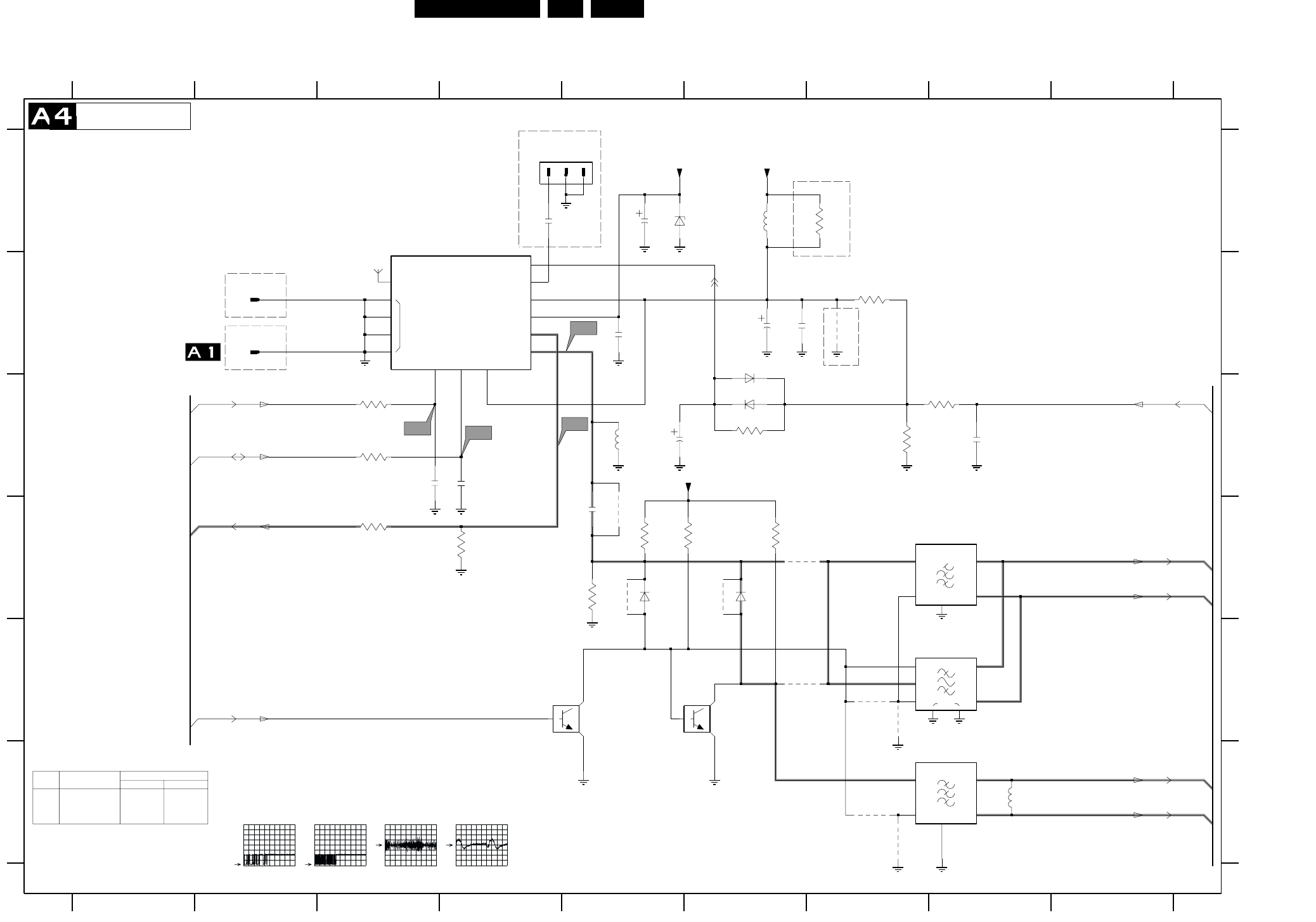
EN 30L01.1E AB 7.
Schematics and PWB’s
Mono Carrier: Tuner IF
+5V ADC
IF
FM
AGC
TUNER
MT
AS SCL SDA
FM-ANT
+5V
VT
GND
SIF_2
89
A
B
C
D
E
F
A
B
C
D
E
F
0265 A4
0283 B2
0285 B2
1000 A3
1002 D7
1003 E7
SIF_1
123456789
1234567
1004 F7
2001 C3
2002 C4
2003 D5
2004 B5
2005 A5
2006 B6
2007 B6
2008 C5
2009 C8
2010 A4
3000 C3
3001 C3
3002 C6
3003 B7
3004 C7
3005 C8
3006 D5
3007 D5
3008 D5
3009 D6
3010 D3
0285
3011 D4
3012 A7
4001 D5
4002 E7
4003 E6
4004 E7
4005 D6
4006 D5
4002
3010
4007 B7
4011 F7
4012 F7
5001 A6
5002 C5
5003 F8
6001 A5
6002 B6
6003 C6
6004 D5
6005 D6
7001 E5
7002 E6
9001 D6
1000
1
10
3006
4012
100R
3000
+8V
6002
BAS216
10K
3002
10
6001
BZX79-C33
2005
10u
SDA
SCL RF_AGC
SEL-IF-LL_M-TRAP
FM
VIF_2
VIF_1
VlotAux+5V
VT_Supply
RES
ITEM Non-FM Radio FM Radio
Stereo Mono
1000
3010
3011
UV1317
---
---
UR1316R UR1316R
330R
--- JMP
330R
Diversity Table
*
RES
RES
A5-25
RES
A7-14
FOR EMC ONLY
FOR ITV ONLY
RES
K3953M
TUNER IF
ISS356
FM-RADIO ANTENNA
4.9V
A5-29
OF
(EUROPE)
5V
RES
K9656M
A5-28
A5-26
1n8
TO 0282
4.3V
*
390n
FOR ITV ONLY
RES
4.3V
A7-13
A7-3
RES
FOR ITV ONLY
0V
3007
6K8
0283
A5-24
RES
0V
RES
34V5
*
RES
A5-27
1002
I3
I4
4001
3005
100R
0265
22p
2002
1
2
3
4
5
4003
5
SWI
1003
38
IN
1
ING
2
O1 4
O2
22n
2009
4007
3009
7002
11
12
13
14
15
2
345
6
78
9
3001
100R
2007
100n
2K2
6004
4006
2006
470u
2001
22p
1004
1
2
3
4
5
I1
I2
6003
1
2
3
3004
6005
5002
5001
5u6
3011
1K5
3003
100u
2008
2003
2K2
3008
PDTC124ET
4011
7001
2010
1n
33R
3012
4005
9001
4004
5003
47n
2004
CL 26532063_008.eps
130602
I1
2V / div DC
200us / div
I2
2V / div DC
200us / div
I3
500mV / div DC
10us / div
I4
20mV / div DC
10us / div
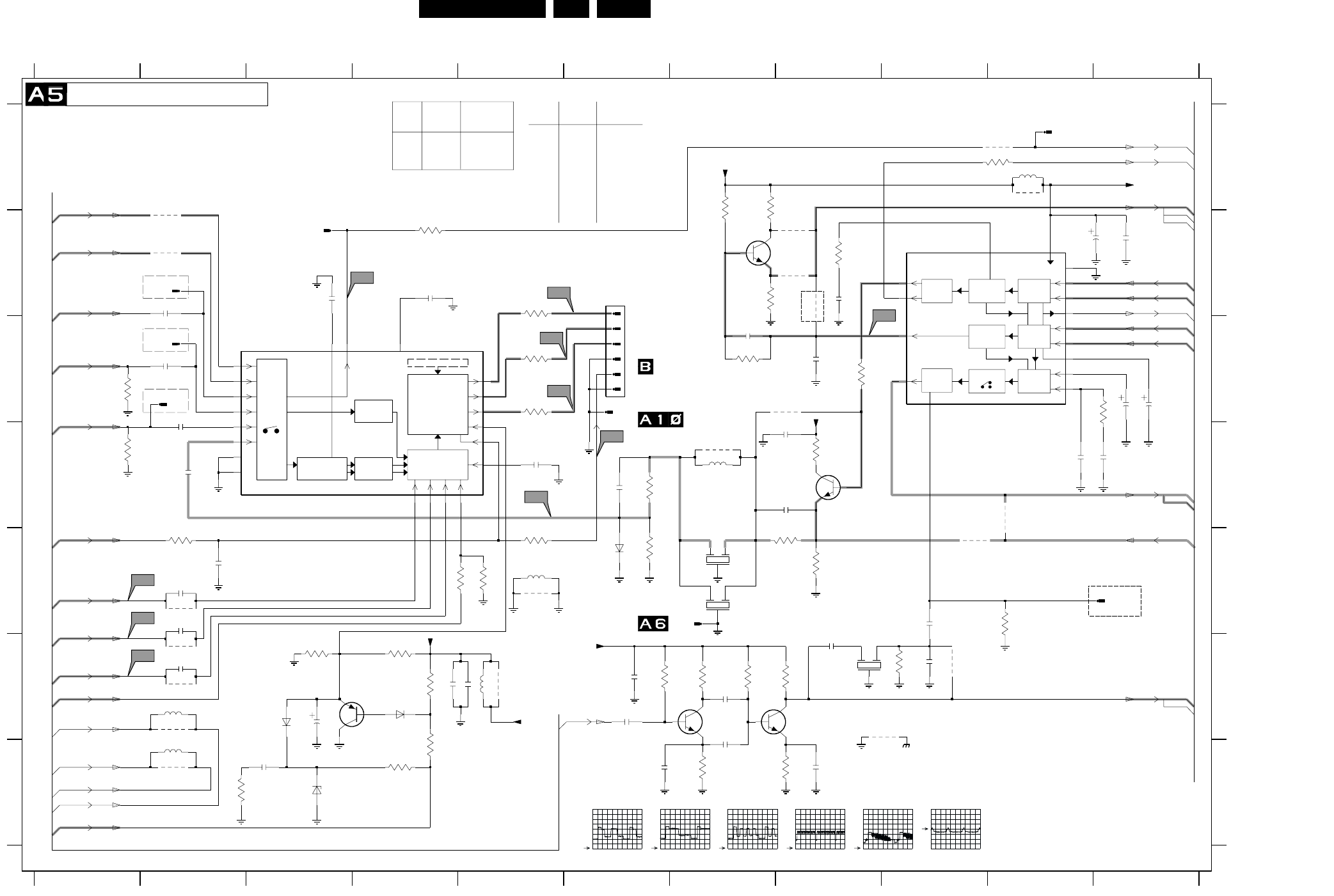
Schematics and PWB’s EN 31L01.1E AB 7.
Mono Carrier: Video IF + Sound IF
AMPL
SOUND
AMPL. + AVL
IF
VISION IF
AGC/AFC
QSS SOUND
AGC
SOUND PLL
DEEMPHASIS
VIDEO
PLL DEMOD.
QSS MIXER AM
DEMODULTOR
AUDIO SWITCH
VIDEO
PAL/SECAM/NTSC
DECODER
VIDEO
FILTERS
VIDEO
IDENT
I/O
SWITCHING
OSD
Y
U
V
OSD/TEXT INSERT
BLUE STRETCH
WHITE-P. ADJ.
RGB/YUV INSERT
BLACK STRETCH
WHITE STRETCH
BASE-BAND
DELAY LINE
LUMA DELAY
PEAKING
F
G
0243 B6
0248 C2
0249 B2
0266 E11
0276 C2
0294 E7
0297 C6
1200 E7
1201 E7
1203 F8
1204 B3
1205 A10
2201 D2
2202 C2
2203 D2
1234567891011
1234567891011
4218
A
B
C
D
E
F
G
A
B
C
D
E
4212
2204 D5
2205 B3
2206 D6
2207 D8
2208 B8
2209 F3
2210 G3
2211 D8
2213 E2
2214 E2
2215 F2
2216 B10
2217 B11
2219 B4
2220 F4
2221 B2
2222 F8
2223 F9
2225 C7
2226 C8
2227 D11
2228 D10
2229 C11
2230 C11
2233 E2
2234 F6
2235 E9
2236 F7
2237 G8
2238 F6
2239 G6
2240 F7
2260 F5
3200 B8
3201 B5
3202 C5
1K
3229
3203 C5
3204 E5
3206 F4
3207 C8
3208 E8
3209 E8
3212 E6
3213 D6
3214 A10
3217 G4
3218 G4
3219 G2
3220 B4
3223 E4
3224 F3
3225 F4
3226 E5
3228 A7
3229 C7
3230 B7
3231 A7
3232 C11
3233 F7
3234 E10
3235 E2
3236 F7
3237 F8
3238 G7
3239 G8
3240 F6
3261 F9
3270 D8
3637 C1
3638 D1
4203 B8
4204 C8
4205 F2
4206 F2
4206
4207 E2
4209 E9
4210 B8
4211 B8
4212 B2
4213 A2
4214 D10
4218 F9
4219 F9
5201 D7
5202 A10
5204 F2
5205 G2
5206 E5
5672 F5
6201 F3
6202 F4
6206 G3
6207 E6
7200-A B9
7200-C C3
7201 D8
7204 F4
7206 B7
7209 F7
7210 F8
9200 D7
9206 E5
9207 A10
9618 A10
9653 F2
9672 F5
9673 G2
100R
3235
2226
3n3
4u7
2230
560R
3226
3200
390R
32
7200-A
18
19
22
23
24
25
26
27
V7
RES
2V5
2V5
5V6
3V5
2V5
2V5
2V5
0V
3V2
2V6
3V5
2V9
2V5
3V3
1V2
A1-XX
TO 0296
2u7
04B
ZTE2
RES
JMP
RES
0V
RES
RES
SGP
A14-40
A14-41
A14-39
A14-38
A10-37
A2-36
A14-35
A14-34
A14-33
A14-32
A14-30
A12-31
A2-16
0V7
5V
2V9
A8-XX
A1-XX
1V4
A8-XX
220R
RES
RES
BAS316
RES
100MHz
V3
3V8
3V3
3V3
RES
2V3
2V9
5V
(EUROPE)
0V
0V
RES
(EUROPE)
OF
8V1
0V
0V8
2V5
2V5
TO 0295
FOR ITV ONLY
RES
RES
FOR ITV ONLY
FOR ITV ONLY
TO 0245
OF
CRT
PANEL
VIDEO IF + SOUND IF
for M’nas only
FOR ITV ONLY
OF
---
ITEM SINGLE
1V9
1V9
5V
A9-42
A5-42
(EUROPE)
A7-44
A9-44
A5-42
A8-43
A9-43
A4-26
A4-27
A4-25
A4-28
A4-29
A10-42
1V5
0V
1V9
1V9
---
---
3233 820R ---
3236 150K ---
3237 1K2 ---
3238 560R ---
3239 270R ---
3240 100K ---
7209
7210
BAS316
820P
RES
RES
3V7
3V7
A4-24
1V5
RES
TDA95XX
TDA95XX
DUAL
SCART IN
5206
5272
JUMPER
SPT0508
F.BEAD
1000MHz80R
DVD
5672 ---
SCART IN
DVD
SPT0508
---
2V5
0V
1V7
2V
2V6
7V8
*
*
*
*
ITEM
---
BFS20
RES
2V5
3V1
4V
FM RADIO NON-FM
RADIO
2234
2238
2222
22n
100uF
1nF ---
---
BFS20
2239
2240
1nF
1nF
9653
9673
5206
5204 100MHZ
5205 100MHZ
V10
9618
2206
V1
V2
4214
2207
9207
5672
27u
9672
AudioSupplyGnd_FB
4219
1204
MainSupplyGnd
1205
2260 470n
3270
6207
9206
330R
3261
2223
10p
0294
0297
75R
3638 3637
1203
G
2
I
1
O
3
V5
6201
V8
V9
0276
4210
4211
3233
2K2
4213
6206
BZX384-C6V8
2239
1n
1n
2240
2K2
3237
2235
1n
2238
1n
4209
V6
100n
2234
V4
100K
3236
3240
220K
BFS20
7209
2236
1n
1K
3238
4203
4204
2204
100n
2210
470n
6202
2233
0249
0248
0266
BC857B
7204
BC847B
7201
4207
4205
3231
680R
2221
22n
3223
100R
220n
2219
1m
2216
7210
BFS20
330K
3239
1n
2237
22n
2217
2225
22n
3228
390K
2227
4n7
3232
2K2
2228
820p
10u
5202
270R
7206
BC847B
3230
680R
3234
100R
3214
G
2
I
1
O
3
9200
2
G
1
I
3
O
1200
1201
3213
560R470R
3212
3207
1K
3208
2211
470n
5201
100n
2203
100R
3209
2220 470n
2205
220n
3220
2208
100n
3218
82K
2K2
3219
2202
100n
2201 100n
3203
100R
3204
10K
3224 3225
2209
3206
33K
2213
22n
4u7
6
0243
1
2
3
4
5
3201
100R
53
54
55
56
57
58
8
3202
100R
7200-C
10
28
29
40
41
42
43
44
45
46
47
5051 52
22n
2215
33
35
36
38
39
48
49
2214
22n
3217
330K
+8V
+8V
+8VA
+8V
+8VB
4u7
2229
SIF_1
SIF_2
RF_AGC
VIF_2
VIF_1
C-IN
EHTinfo
B_U-IN
R_V-IN
G_Y-IN
BLK-IN
FM
VlotAux+5V
QSS_AM_DEM_OUT
L1-IN
LFRONT-IN
FBL-1
AudioSupplyGnd
MainAux
MainAux_FB
AudioSupplyGnd_FB
SY_CVBS-IN
CVBS1-IN
V1-OUT
FMR
V_OUT
MONO|AM_MONO_SOUND
QSS_AM_DEM_OUT
CL 26532063_009.eps
140602
V5
1V / div DC
10us / div
V6
1V / div DC
10us / div
V7
1V / div DC
10us / div
V8
2V / div DC
5ms / div
V9
500mV / div DC
10us / div
V10
200mV / div DC
20us / div
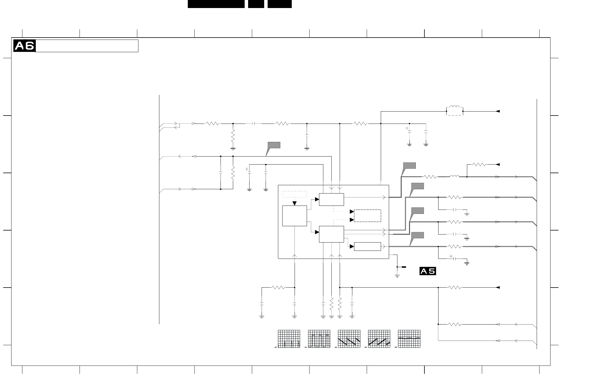
EN 32L01.1E AB 7.
Schematics and PWB’s
Mono Carrier: Synchronisation
+
H
V
H-DRIVE
2nd LOOP
H-SHIFT
VIDEO IDENT
H/V SYNC SEP.
H-OSC. + PLL
V-DRIVE
GEOMETRY
EW
GEOMATRY
TELETEXT/ODS
DISPLAY
456789
A
B
C
D
E
A
B
C
D
E
0295 D7
2241 E5
2242 E5
2243 B5
2244 E6
2245 E6
2246 D8
2247 B7
2248 B7
123456789
123
*
*
0V
A6-16
3V8
2249 B5
2250 B4
2252 C8
2253 C8
2254 B5
2255 B4
3241 D5
3242 B4
3244 C8
3245 E6
3246 E6
3247 E8
3248 D8
3249 C8
3250 D8
3251 C8
3254 B6
3256 B8
3257 B5
3258 B4
3259 B4
5241 A8
5242 C8
7200-D C5
9241 B8
7V9
1V2
3V9
TDA95XX
**
TO 0294
A2-16
A2-18
A3-19
SYNCHRONISATION
4V
1V2
0V
A3-20
1V3
2V1
A2-23
A7-17
(EUROPE)
560K
3V9
0V9
OF
2V9
*
A6-16
A2-22
RES
A2-21
1000u
12K
S2
21
30
31
34
9
5241
2u2
2250
10K
3246
1M
3254
2253
1n
2244
100n
S4
22n
2248
22K
3241
100R
3250
7200-D 11
12
13
14
15
16
17
20
1K
3256
3249
820R
15p
2255
39K3245
3258
100K
9241
2254
3247
0295
3259
470K
820R
3244
1n5
2241
S5
3242
S1
2249
22n
33K
3248
10n
2243
2246
4u7
10u
5242
2247
220n
2245
3251
100R
3257
10M
1u
2242
S3
1n
2252
Vdrive+
+8VA
EWdrive|EWD_dyn
EHTo
Hdrive
+3.3V
EHTinfo
Vdrive-
EHTinfo
Hflybk
SANDCASTLE
+8V
CL 26532063_010.eps
130602
S1
2V / div DC
20us / div
S2
500mV / div DC
20us / div
S3
500mV / div DC
5ms / div
S4
500mV / div DC
5ms / div
S5
1V / div DC
5ms / div
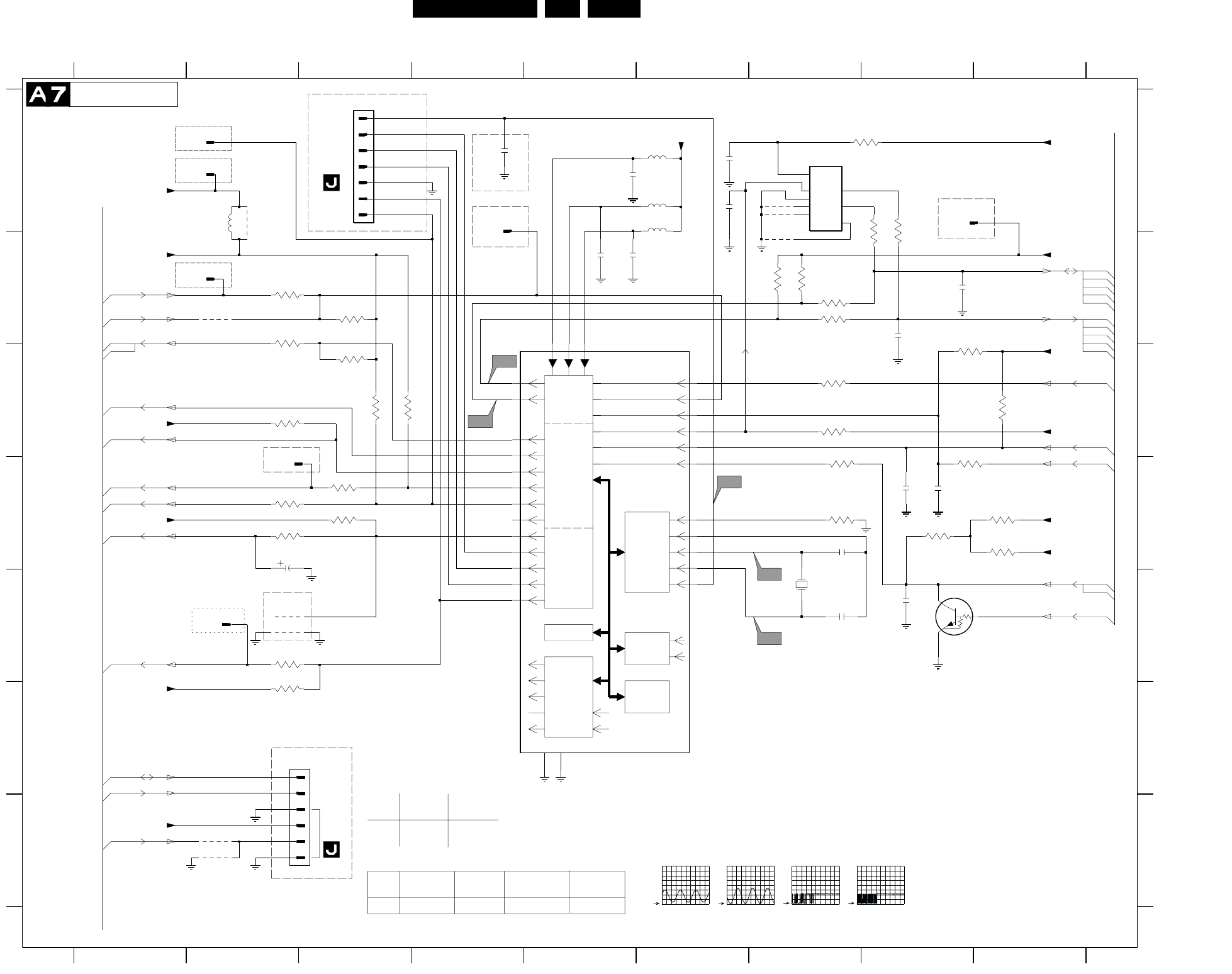
Schematics and PWB’s EN 33L01.1E AB 7.
Mono Carrier: Control
SDA
I/O
PORTS
VST PWM-DAC
ENHANCED
80C51
CPU
ROM/RAM
TELETEXT
ACQUISITION
1/10 PAGES
MEMORY
R
G
B
BL
COR
CVBS
SYNC
H
V
OSD
TELETEXT
DISPLAY
IIC-BUS
TRANSCEIVER
SCL
3605
4K7
4601
D
E
F
G
0217 F2
0240 A3
C4
EU
SNDAMP-
2x10W-VD-
ST-EU
ITEM SNDAMP-
2x10W-ST-
EU
SNDAMP-
2x5W-ST-
EU/AP
SNDAMP-
2x5w-VD-ST
123456789
123456789
A
B
C
D
E
F
G
A
B
C
1n
0250 A1
0261 D2
0273 B4
0274 A8
0279 A1
0287 B2
0318 E2
1660 E7
2601 A6
2602 D8
2604 D2
2606 E8
2607 D7
2608 A5
2609 E7
2611 B5
2612 B8
2618
1u
2613 B8
2615 A6
2616 A4
2618 B5
2619 D8
3601 B3
3603 A8
3604 A8
3605 C2
3606 B7
3607 B7
3608 D8
3609 D3
3610 C3
3611 A8
3612 C3
3614 F2
3615 E2
3617 D2
3618 D2
3619 C3
3622 D7
3623 D3
3624 B7
3625 B7
3626 C7
3627 C9
3628 D7
3629 C8
3630 D8
3632 D9
3633 D9
3634 C7
3635 B2
3636 B2
4601 A7
4602 A7
4603 B7
4604 G2
3607
2K2
4618 G2
5602 A6
5603 A6
5604 A6
5678 A2
7200-B B4
7602 A7
7606 E8
9631 E2
9641 E2
9647 B2
9678 A2
3614
4K7
2611
1u
3619
8K2
7606
PDTC143ZT
9641
220n
2601
4K7
3626
VlotAux+5VA
3615
10K
C5
VlotAux+5V
SANDCASTLE
+3.9V
C1
2615
3633
9631
4602
4603
KEYBOARD_protn
1n
2606
2602
100p
Bass_panorama
IR
Volume|Mute
SDA
SCL
Stdby_con
LED
+3.3V
EW_protection
+3.3V
+3.3V
+3.9V
STATUS1
+3.3V
SEL-IF-LL_M-TRAP
SCL
SDA
+3.3V
+3.3V
+8V
+3.3V
SEL-MAIN-FRNT-RR
Treble_Buzzer_Hosp-app
+3.3V
ITV_MSG
STATUS2
POWER_DOWN
2K2
3630
5u6
5603
A8-15
3V2
FOR ITV ONLY
A7-14
SDM
0V
0V
0V
CONTROL
A14-75
RES
(EUROPE)
*
FOR ITV ONLY
TDA95XX
0V
0V3
A7-13
0V
DATA-IN
*
0V
*
RES
A4-14
3V7
0V
A1-5
A5-3
TO
#
A10-12
FOR ITV ONLY
DATA-OUT
*
3V2
*
*
A6-17
3V2
0V
FOR ITV ONLY
A9-14
0V
RES
0240
FOR ITV ONLY
0V
3V3
A1-11
EEPROM
0V
A4-13
1V5
OF
5V
0V
FOR ITV ONLY
0V
3V7
A2-9
A14-1
3V3
0V
A8-14
0217
A14-2
0R
RES
3V3
A9-8
RES
RES
FOR ITV ONLY
0V
0V
RES
3V7
A7-13
0V
Bass_panorama
3V3
A9-13
M24C08
TREBLE-BUZZ
FOR ITV ONLY
OF
A8-6
0V
A2-7
3V7
0V
TO
CLOCK
0V
POR
FOR ITV ONLY
A4-3
A8-13
A12-8
A12-10
3V2
3V3
FOR ITV ONLY
2604 10uF --- --- 10uF
ITEM SINGLE
SCART IN-
DVD
DUAL
SCART IN
3609 1K 10K
3638 --- 75R
*
*
A12-4
GND
3V3
A7-14
0V
3V3
100R
3622
0240
1
2
3
4
5
6
7
10K
3628
2K2
3606
7
8
100R
3604
7602
1
2
3
45
6
3611
100R
1u
2619
3635
100R
4K7
3627
100R
3624
33p
2609
4
5
6
2608
1u
0217
1
2
3
4618
C3
363210K
3618
1660
12MHZ
0261
0273
47n
2616
33p
2607
4K7
3617
2604
100R
3608
5602
5u6
5604
5u6
3603
100R
2613
68p
3601
0250
0318
C2
100R3625
0287
4K7
3623
3636
100R
1
9647
3612
8K2
0274
1K
3609
9678
0279
8K2
27u
5678
3629
3610
78
79
80
4604
1
2
3
4
5
59
6
60
61
62
63
64
65
66
67
68
69
7
70
71
72
73
74
75
76
77
3634
100R
7200-B
2612
68p
CL 26532063_011.eps
060602
C1
1V / div DC
500us / div
C2
1V / div DC
500us / div
C4
2V / div DC
200us / div
C5
2V / div DC
200us / div
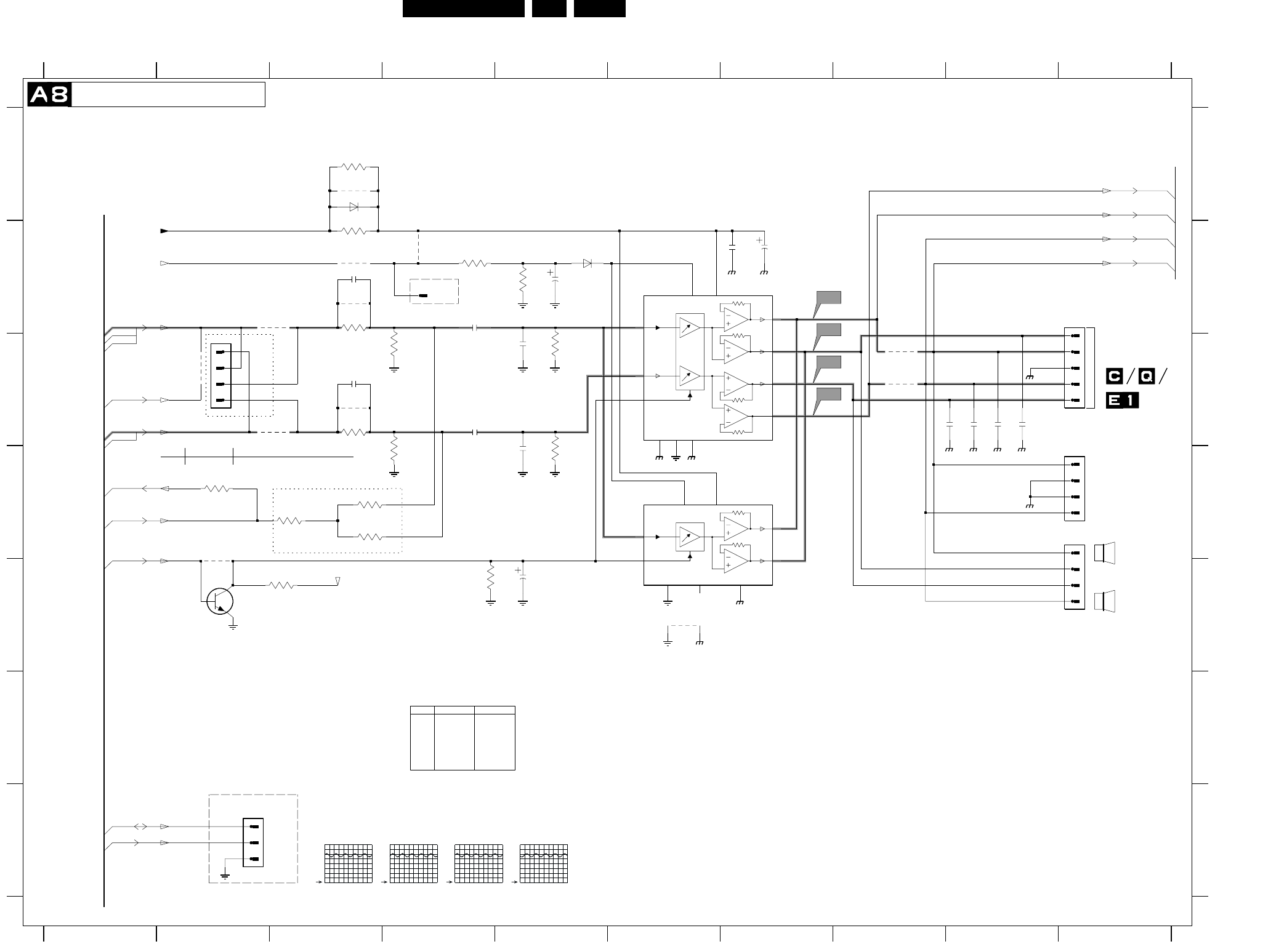
EN 34L01.1E AB 7.
Schematics and PWB’s
Mono Carrier: Audio Amplifier
0246 B10
0267 G2
0271 C2
0275 B4
0280 D10
0281 C10
2901 B7
RES
1V4
3K3 6K8
9905
7903
Yes No
*
*
**
*
*
*
2BY10W
3902
3912
7901
-
AN7522N
12345678910
1
5V2
FOR ITV ONLY
5V2
**
A11-45
A7-13
*
FOR COMPAIR ONLY
VOICE
A7-15
2345678910
A
B
C
D
E
F
G
A
B
C
D
E
F
G
2908
10u
*
*
5V2
*
FOR ITV
CONTROL
A11-46
*
A12-73
*
*
TO 0254
2902 B7
2903 B5
2904 B4
2905 C5
2906 C4
2907 D5
2908 E5
2910 C3
2911 B3
2947 C8
TO
*
A5-43
A12-71
RES
2948 C9
2949 C9
2950 C9
3172 D2
3901 B4
3902 B5
3903 B3
3904 C4
3905 C3
3906 D4
3907 E4
3908 B3
3909 C5
3910 D5
3911 A3
3912 E3
3921 D3
3922 D3
3923 D3
4901 B3
4902 B3
4903 C3
4904 C3
4905 C2
4906 E6
4921 B4
6901 B5
A9-45
RES
5V2
*
*
6K8
Tilt Rotation 29RF-CH/32WS-EU
3172
OF
1V4
A15-74
*
A8-45
PIP Interface
AUDIO_AMPLIFIER
6903 A3
7901 B6
7902 D6
7903 E2
9901 C8
9902 C8
9903 A3
9904 B3
9905 D2
AN7580
Yes No
Yes No
FOR ITV ONLY
ITEM
RES
3V7
*
A12-72
*
RES
0V3
11V8
A7-6
*
3901 1K
68K
A7-14
A12-70
RES
A9-46
*
ONLY
COMMON
*
A1
3923
330K
AudioSupplyGnd_FB
3903
3
4
4904
2902
2R2
3908
0267
4903
4905
AudioSupplyGnd_FB
1n
2905
A2
AN7523N
7902
1
2
3
3172
68K
3911
4R7
4921
A3
9902
2947
2950
0275
9904
4902
3921
330K
2910
2911
6903
AudioSupplyGnd_FB
3904
9901
2903
1u
470n
2904
3909
10K10K
3910
AudioSupplyGnd_FB
3907
3902
AudioSupplyGnd_FB
2906
9 VOL
BC847B
7903
2901
2
CH1+
4
CH1-
6 CH1-IN
3
GNDCH1
7
GNDINP NC
8
5
STB
1
VCC
3905
AudioSupplyGnd_FB
3901
4906
3906
A4
4901
4
1
2
3
4
0281
1
2
3
3922
330K
0271
2949
2907
2948
6901
0246
1
2
3
4
5
4
CH1-IN6
CH2+ 12
CH2- 10
CH2-IN8
GNDCH1
3
GNDCH2
11
GNDINP
7
STB
5
VCC
1
VOL9
9905
7901
CH1+
2
CH1-
2K2
3912
0280
1
2
AmpOutR_Pos
AmpOutR_Pos
AmpOutR+
MainAux_FB
VlotAux+5V
Volume|Mute
MONO|AM_MONO_SOUND
Main_OutL
9903
Main_OutR
VlotAux+5V
SDA
SCL
AmpOutL_Pos
AmpOutL_Pos
Tilt
Treble_Buzzer_Hosp-app
AmpOutL_Neg
AmpOutR_Neg
AmpOutL+
CL 26532063_012.eps
130602
A1
1V / div DC
500us / div
A2
1V / div DC
500us / div
A3
1V / div DC
500us / div
A4
1V / div DC
500us / div
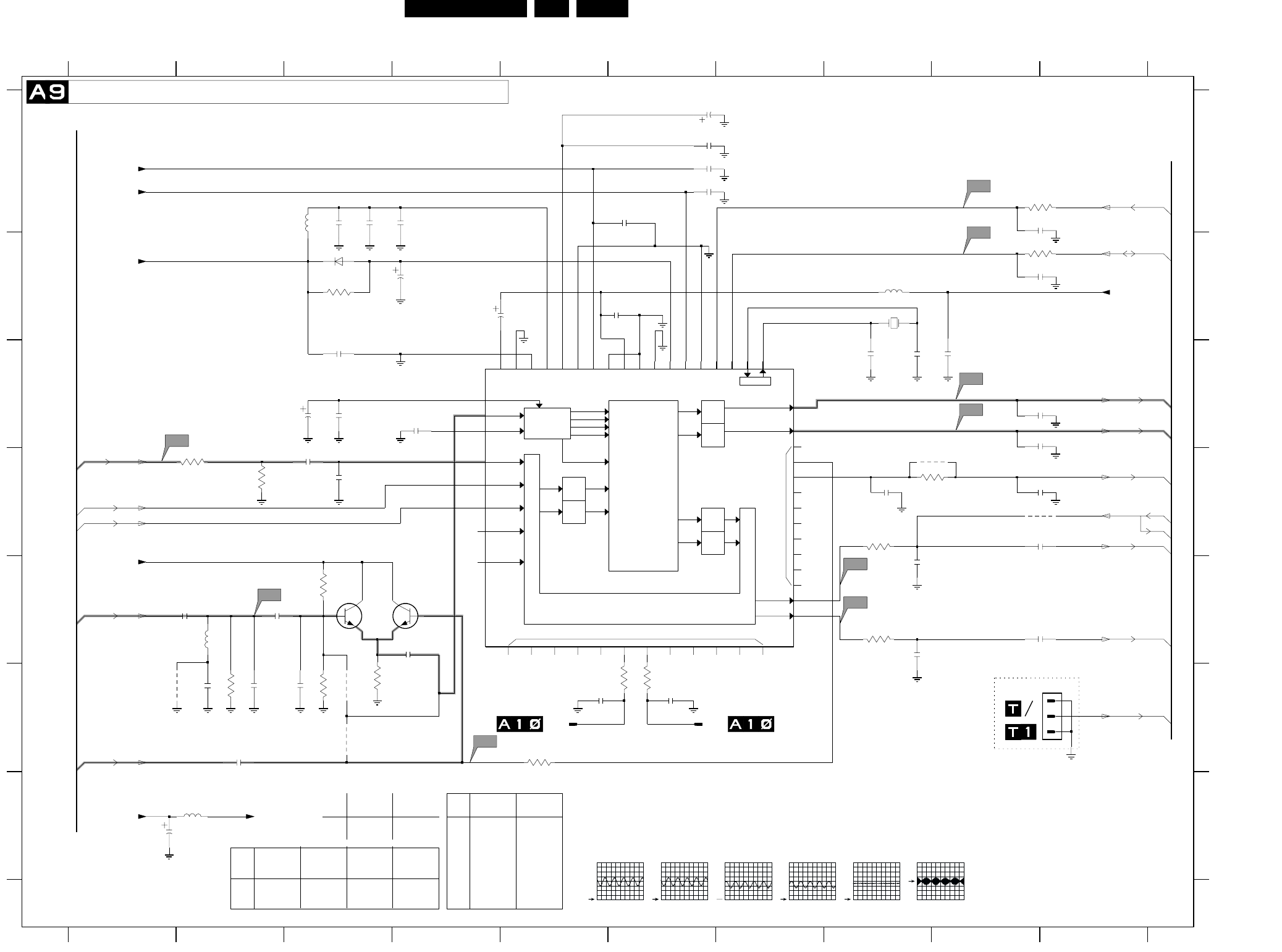
EN 36L01.1E AB 7.
Schematics and PWB’s
Mono Carrier: NICAM + 2CS + BTSC (Stereo / SAP) Decoder
SCART
LOUDSPEAKER
TP
NC
VREFTOP
SOUND IF
ANA_IN1+
ANA_IN1-
SCART-L
IDENT
A/D
A/D SCART-R
MONO-IN
D/A
D/A
D/A
D/A
SCART-L
SCART-R
LOUDSPEAKER L
LOUDSPEAKER R
DSP
SC1-IN-L
SC1-IN-R
SC2-IN-L
SC2-IN-R
MONO
SCART 1
SCART 2
SCART
Switching Facilities SC1-OUT-R
SC1-OUT-L
DACM-L
DACM-R
AUDIO PLL
CAPL_M
TESTEN
DVSS
DVS UP
AGNDC
AVS S
AVS UP
AHVS S
AHVS UP
VREF1
VREF2
RESETQ
STANDBYQ
ADR_SEL
I2C_CL
I2C_DA
DEMODULATOR
& NICAM
DECODER
FM1/AM
FM2
NICAM A
NICAM B
5678910
A
B
C
D
E
F
G
A
B
C
D
E
F
G
0239 F10
1812 F5
43
44
45 46
47
48
49
550 51 52678
9
12345678910
1234
0V
6V2
RES
A10-49
1813 F7
1831 B8
2831 C8
2832 C8
2833 C4
2834 A3
2835 A3
2836 A4
2837 B3
2838 A10
2839 B10
2840 B6
2841 B4
2842 A6
2843 A6
2844 C3
2845 C3
2846 G1
2847 D3
2848 D3
2849 C10
2850 C10
2851 D10
3V8
A5-44
*
A9-43
*
0V
1V5
RES
1V5
A9-43
*
2852 E8
2853 E10
2854 E8
2855 E2
2856 E2
2857 F2
2858 E4
2859 F2
2860 F2
2861 D8
2862 D10
2870 F5
2871 F6
2887 C9
2894 A6
2895 A6
2896 F3
2897 C3
2898 A6
3831 B3
3832 A10
A5-42
A10-50
(EUROPE)
0V
A8-45
2V5
A10-48
RES
3V8
3V
5V
RES
0V
A8-46
1V8
5V
3V7
TO 1811
OF
3833 B10
3834 D2
3835 D2
3837 D8
3839 E8
3840 E3
3841 F3
3842 F5
3843 F2
3844 F6
3845 F6
3849 F3
3861 D9
RES
2V4
2V6
*
0215
0V
4u7
MSP34X5G
3V
0V
A10-51
4u7
RES
4832 D10
4834 F1
4835 F3
4836 F3
4861 D9
5831 A3
5832 B8
5833 G2
5835 E2
6831 B3
7831 C7
7834 E4
7835 E3
RES
1V8
RES
OF
*
3V
*
*
*
TO 1810
4u7
5V
NICAM + 2CS + BTSC (STEREO/SAP) DECODER
RES
RES
(EUROPE)
A5-43
3V7
A7-13
2V5
3V8
A7-14
A10-47
TO
0V
0V
0V
5V
2V4
]
*
0V
7V8
RES
OF
RES
(EUROPE)
SNDSYS-
ITEM
MSP3415B8MSP3415
CL-EU
3V8
A7-8
5V
0V
VD-EU
---
---
BC847B
SNDSYS
NI/GS/RD/
100R
10K
7832
7833 BC847B
2581
2853 JUMPER
JUMPER 4u7
4u7
56p
2860
2851
2833
47p
100n
2845
A11a
2854
1n
2837
7834
3835
1n
2850
MONO|AM_MONO_SOUND
SC1_LOUT
+5VA
+8V
SC2_CTRL
15p
2856
2898
10n
2858
3840
3841
18M432
1831
HC-49/U
3845
100R
220p
2894
2841
10u
A6
---
3839
3844 100R
--- ---
100R
3845
3861 ---
---
NI/GS/RD/
7831 MSP3411G MSP3415
EU
SNDSYS
NI/GS/RL- FM/AM-EU
SNDSYS
NI/GS/RD/
FM
ITEM WITH MON.
OUT WITHOUT
MON. OUT ITEM WITH MON.
OUT WITHOUT
MON. OUT
2862
3836 ---
1K
4u7
---
3837
3838 100R
1K
---
4861
2871
1u
2870
1813
A11
1u
2848
1812
A5
4836
1p
2832
10K
3861
1p
2831
220p
2835
3834
1n
2849
150p
2857
4u72862
2855
27p
100n
2840
3839
100R
100R
3844
3831
47K 6u8
5832
10u
2844
560p
2895
10u
2843
6u8
5831
A9
A10
28
29
3
30
31
32
3334 3536
37 38
39
4
40
41
42
13
14
15
1617
18 19
2
20
21 22
23
24
25
26
27
7831
1
10
11
12
2846
100u
100R
3837
3842
4835
2834
470p
3849
2838
2859
2887
1n
4832
2842
100n
2852
A8a
3843
5835
12u
2853
2861
10n
100R
3833
A7
100R
3832
4834
2896
0239
1
2
3
2847
1n5
2836
2839
1N4148
6831
7835
A8
5833
6u8
2897
390p
SC1_RIN
SCL
SDA
Main_OutR
MONO|AM_MONO_SOUND
VlotAux+5V +5VA
QSS_AM_DEM_OUT
SC1_LIN
+5VA
FMR
VlotAux+5V
VlotAux+5V
KEYBOARD_protn
SC1_ROUT
Main_OutL
CL 26532063_014.eps
140602
A8
1V / div DC
500us / div
A9
500mV / div DC
500us / div
A10
500mV / div DC
500us / div
A11
1V / div DC
200us / div
A8a
1V / div DC
500us / div
A11a
500mV / div DC
2us / div
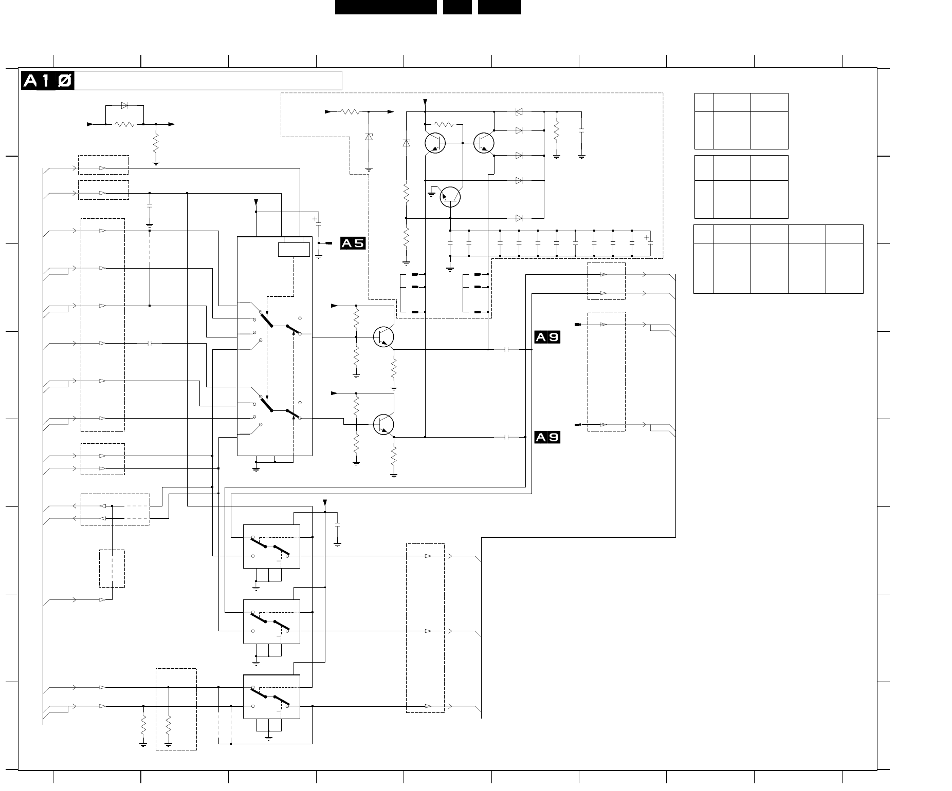
Schematics and PWB’s EN 37L01.1E AB 7.
Mono Carrier: Audio / Video Source Switching
L
H
L
H
LOGIC
LSBMSB
LL
LH
HL
HH
LL
LH
HL
HH
A13-52
1V6
0V
A14-61
*
*
RES
A13-54
*
A9-49
A13-61
Only With CL Out
*
6V
1V8
A9-51
**
A12-53
E
F
G
H
A
B
C
D
E
F
G
H
0296 B4
0298 C5
0299 C5
0300 C5
0301 C5
1810 C6
1811 E6
3801
123456789
123456789
A
B
C
D
2818
1814 C5
1815 C5
2801 B3
2802 F4
2803 D2
2804 D6
2805 E6
*
5V8
2V3
A14-52
*
A12-31
*
AUDIO/VIDEO SOURCE SWITCHING
*
*
*
*
A14-54
6V
Only Europe
*
1V6
2V4
2811 A6
2813 B5
2814 B5
2815 B6
2816 B6
2817 B6
2818 B6
2819 B6
2820 B7
2821 B7
2822 B7
2823 C7
2824 B2
3801 A1
*
A13-59
FRONT/SIDE AV
(RF Mode always)
3802 A2
3803 C4
3804 D4
3805 D4
3806 D4
3807 E4
3808 E4
3809 H1
3810 H2
3811 A6
3812 B4
3813 B4
3814 A5
3815 A4
4805 E1
4806 F1
4807 H2
4808 H3
4809 C2
6801 A6
6802 A6
6803 B6
6804 B6
6805 A4
6806 A4
6807 A6
6808 A1
7801 C3
(EUROPE)
TO 0297
5V
2V4
5V8
*
A9-50
2V5
*
(Scart2 Out)
*
1V6
To Micronas/BTSC/UOC
*
7802-A F3
7802-B G3
7802-C G3
7803 C4
7804 D4
7805 B5
7806 B5
7807 B5
9801 F1
Monitor Out/AV Out
1V7
2V4
*
A5-37
*
A14-59
*
*
A9-47
From Front/Rear I/O
A14-62
1V8
*
*
1V8
A12-58
(EUROPE)
TO 1812
RESERVE
(EUROPE)
A13-60
TO 1813
5V8
A14-56
RES
3V8
From Micronas
SET WITH
A13-32
*
OF
*
5V
*
0V
A7-12
*
*
0V
3V8
*
A14-60
*
A14-63
A5-42
A13-55
ZTE2
A9-48
From MicroP
A14-57
*
*
*
Mono Scart1 out
*
Stereo Scart1 Out (RF Mode always)
*
*
*
*
5V
2V4
1V6
*
*
8V
5V8
(EUROPE)
2817
2804
4808
2815
4805
7802-B
E
6
S10
Vdd
16
Vee
7
Vss
8
Y0
2
Y1
1Z15
3806
6808
0299
0299
OUT WITHOUT
MON.OUT
4809
0300
6801
4u7
2824
2814
3807
6807
6806
3808
1K
OF
RESERVE
OF
220R
1K
---
220R
VD-ST-EU
100K
82K
82K
220K
1K 220R
82K 220K
--- ZTE2
ST-EU SC2-S/CN-
*
0V
A14-55
0V
0V
*
*
0V
From Micronas
A14-32
*
0V
---
*
JMP
9835 --- JMP
ITEM SC1-DVD SC2-MON
OUT-S/CN-
3801
3802
---
220R ---
220R
ST-EU
3803
3804
82K
220K 120K
220K
3806 82K 120K
3807 220K 220K
6808 ZTE2
0298
SC2-S/CN-
---
---
YES
YES
ITEM
1810
1811
---
---
YES
YES
2823 ---100uF/25V
ITEM SINGLE
SCART IN- DUAL
SCART IN
2824
4815 ---
---
4u7
JMP
DVD
4820
4837 ---
WITH MON.
JMP
0296
2802
1815
3812
1814
14
15
23
4
5
6
9
VDD
16
VEE
7
VSS
8
7801
1
10
11
12
13
2823
7803
1811
3815
2821
7807
6802
2819
3805
1K
2803
4806
2811
2822
1810
4807
3802
3804
7802-A
E
6
S11
Vdd
16
Vee
7
Vss
8
Y0
12
Y1
13 Z14
6803
Vdd
16
Vee
7
Vss
8
Y0
5
Y1
3Z4
3811
7802-C
E
6
S9
2801
22u
0298
3814
75R
3809
6804
0301
7805
2820
7806
3813
2805
75R
3810
7804
6805
2813
3803
9801
+6V8
SC1_LIN
R-OUT
L-OUT
2816
R2-IN
SEL-MAIN-FRNT-RR
SC2_CTRL
L1-OUT
R1-OUT
QSS_AM_DEM_OUT
SY_CVBS-INY_CVBS-IN
L2-OUT
R2-OUT
R1-IN
L1-IN
+6V8
+6V8
RFRONT-IN
L2-IN
LFRONT-IN
CVBSFRONT-IN
+8V2
VlotAux+13V +8V2
+6V8
+8V +6V8
SC1_RIN
SC1_ROUT
SC1_LOUT
CL 26532063_015.eps
210502
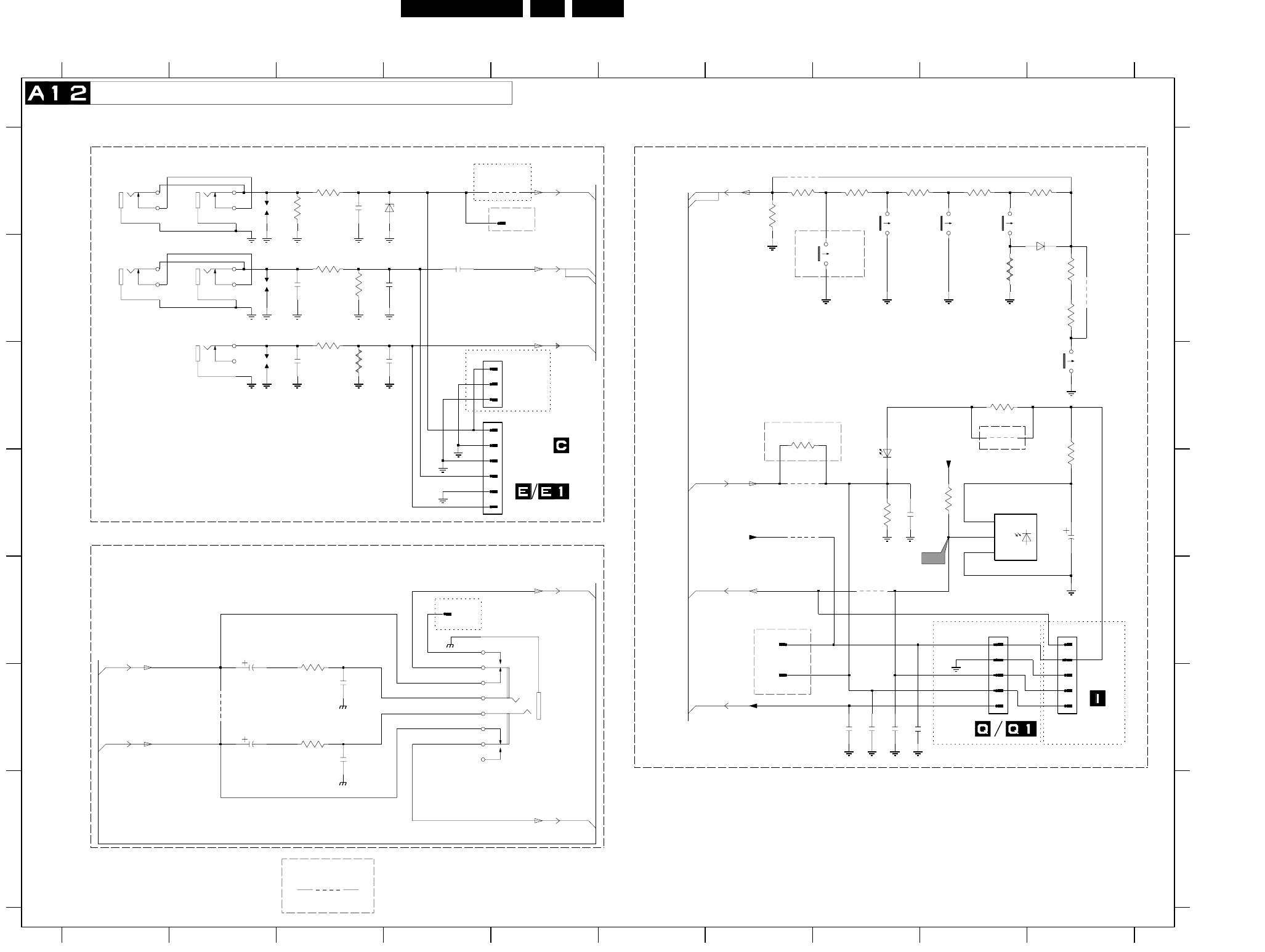
EN 38L01.1E AB 7.
Schematics and PWB’s
Mono Carrier: Front I/O + Front Control + Headphone
9982 F2
3689 A7
3691 C9
3692 D8
3693 D10
3694 D9
3695 C7
3981 E3
3982 F3
4691 E8
4692 D7
4693 D7
4694 G3
4695 C9
4696 B10
6181 A4
6681 B10
6691 D8
6692 D9
9181 A5
9184 A7
&
*
*
*
0R
RES
*
*
V
RES
POWER
A7-10
FOR ITV ONLY
USA
R
L
RES
1183
F
G
A
B
C
D
E
F
G
0214 E9
0215 C4
0218-A C2
0218-B B2
0218-C B2
0219 C4
0232 E5
0259 E10
0270 A5
0277-A B1
0277-B B1
0286 F7
4691
12345678910
12345678910
A
B
C
D
E
0292 E4
0293 E7
1181 A2
1182 B2
1183 C2
1600 C10
1601 A9
1602 A9
1603 A8
1606 B8
2181 A3
2182 B3
2183 C3
2184 B4
*
A10-31
A8-70
2185 B3
2186 C3
2691 D10
2692 D8
(EUROPE)
TO 0214 OF
For Engg Purpose Only
VOICE CONTROL
FOR ITV ONLY
HEADPHONE
BZX384-C6V8
channel-
A8-72
*
2693 F8
2694 F8
2695 F8
2696 F8
2981 E2
2982 F3
2983 F2
2984 F3
3181 A3
3182 A3
3183 B3
3184 B3
3185 B3
3186 C3
3681 A9
3682 A10
3683 A8
3684 A8
3685 A7
3686 B9
3687 B10
3688 B10
ITV ONLY
TS
*
volume+
*
A10-58
FRONT CINCH
TO 0251 & 0253 OF
FOR ITV ONLY
FOR ITV ONLY
MONO SET
A7-4
A7-8
FRONT IO + FRONT CONTROL + HEADPHONE
SIDE/FRONT AV.
A8-71
*
*
*
*
*
*
TO 0251 OF
A12-8
A5-31
FRONT CONTROL
*
A10-53
channel+
RES
RES
*
*
A12-8
volume-
*
*
OR
*
*
RES
*
*
TO 0259 OF
FOR ITV
SET WITH
A8-73
FOR ITV ONLY
*
*
FOR
2696
1606
1
2
3
0219
470p
2982
120R
4692
3981
1
2
3
4
5
6
4K7
3694
3682
2K7
3689
68R
470p
2984
9181
4696
0277-A
2184 BAT85
6681
1
VS
3
3684
1182
3183
3693
220R
4693
3688
3185
3681
AudioSupplyGnd_FB
1181
6181
0293
0286
3685
3692
1K
0215
0218-A 7
8
9
2185
3184
2983
10u
0292
75R
3687
2694
9184
AudioSupplyGnd_FB
1602
2186
6692
TSOP1836
GND
2
OUT
10u
2691
3683
2693
1600
3182
120R
10u
2981
3982
1601
0270
2181
22p
3695
100R
9982
AudioSupplyGnd_FB
1
2
3
4
5
6
7
8
9
1603
0232
LTL-10224WHCR
6691
3
2695
0218-C
1
2
2
3
4
5
4694
1
2
3
4
5
0259
1
0277-B
0214
2182
0218-B
4
5
6
3181
C6
4695
3686
3186
2183
330R
3691
2692
+3.3VA
LED
CVBSFRONT-IN
RFRONT-IN
LFRONT-IN
+3.3V
KEYBOARD_protn
IR
AmpOutR_Pos
AmpOutR+
AmpOutL_Pos
AmpOutL+
KEYBOARD_protn
+3.3VA
CL 26532063_016.eps
060602
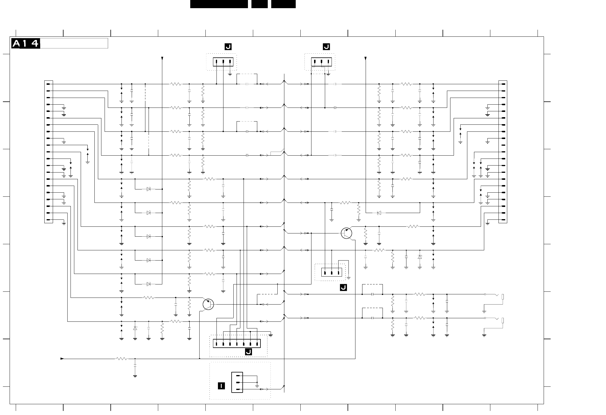
EN 40L01.1E AB 7.
Schematics and PWB’s
Mono Carrier: Rear I/O SCART
91011
A
B
C
D
E
F
G
A
B
C
D
E
F
G
0224-A F11
330p
2143
1234567891011
12345678
A10-60
3V5
0R
A5-41
*
RES
*
FOR ITV ONLY
OF
RES
*
Audio-R_out
RES
0224-B F11
0227 A7
0229 E7
0235-A A1
0235-B A11
0236 A5
0242 F6
0262 G5
1101 A3
1102 B3
1103 B3
1104 C3
1105 C3
1106 D3
1107 C2
1108 D3
1109 C2
1110 E3
1111 E3
7V6
TO 0262
Audio-L_in
A10-59
A7-2
YC-C_in
RGB-G_in
RES
Audio-R_out
SCART 1
*
RES
1112 F3
1113 F3
1131 A9
1132 B9
1133 B9
1134 C9
1135 B10
1136 C9
1137 C10
1138 C10
1139 D9
1140 C10
1141 D9
1142 E9
1151 F9
1152 F9
2101 A3
2102 A4
2103 A5
2104 B3
3V5
RES
OF
A5-39
A5-40
A5-33
A5-38
2105 B4
2106 B5
2107 B3
2108 B4
2109 B5
2110 C3
2111 C4
2112 C5
2113 C5
2114 D5
2115 D5
2116 E5
2117 E5
2118 F4
2119 F3
2120 F4
2131 A9
2132 A8
2133 A7
2134 B9
2135 B8
2136 B7
2137 B9
2138 B8
2139 B7
A5-34
A5-30
RES
A5-35
2V9
2140 C9
2141 C8
2142 C7
2143 C8
2144 D7
2145 D8
2146 E9
2147 E8
2151 F9
2152 F8
2153 F9
2154 F8
2155 F10
2156 F10
2161 G3
3101 A4
3102 A4
3103 B4
3104 B4
3105 B4
3106 B4
3107 C4
3108 C4
3109 C4
3110 C5
3111 D4
3112 D4
BZX384-C6V8
Audio-LEFT
0R
RES
RES
RES
BZX384-C8V2
BZX384-C8V2
BZX384-C8V2
3113 D4
3114 D5
3115 E4
3116 E5
3117 E4
3118 E5
3119 F3
3120 F4
3121 F4
3122 F4
3131 A9
3132 A8
3133 B9
3134 B8
3135 B9
3136 B8
3137 C9
3138 C8
3139 C9
3140 C8
3141 D8
3142 D7
3143 D9
*
RES
RGB-B_in
TO 0227 0F
A10-62
A10-56
Audio-L_in
Video/YC-Y_in
REAR I/O SCART
A10-63
RES
3144 D8
3145 E8
3146 E8
3151 E9
3152 F8
3153 F9
3154 F8
3155 G3
4101 A3
4102 B3
4103 A5
4104 B5
4105 F6
4106 A7
4151 E8
4152 F8
6101 C3
6102 D3
6103 D3
6104 E3
6105 E3
4101
6106 F3
6131 D8
6132 E9
7101 E5
7131 D7
3142
Audio-R_in
RES
7V6
TO 0242 OF
MONITOR OUTPUT
Audio-L_out
A10-32
Audio-R_in
2V9
A7-1
FOR ITV ONLY
Audio-L_out
Terr_CVBS_out
A7-75
Audio-RIGHT
A10-55
Function_Sw
*
BZX384-C8V2
A5-32
Video_in
RES
RES
FOR ITV ONLY
RGB-BL_in
A10-54
A10-52
CVBS_out
TO 0242
RES
*
*
FOR ITV ONLY
A10-61
RES
*
FOR ITV ONLY
*
RGB-R_in
TO 0227 0F
Function_Sw
A10-57
RES
SCART 2
1152
100n
2106
1140
4152
6101
68R
3119
2144
330p
1139
100n
2154
150R
3151
4
1
0224-A
2135
330p
3144
2104
2116
22p
2118
22p
2153
330p
6102
1111
3121
2107
1105
2137
0227
1
100R
3116
100R
4103
3146
220K
3136
4106
2119
1104
0236
1
2
3
6104
1112
5
2
100n
2109
0224-B
6132
6106
330p
2138
3106
220K
2108
330p
2132
3155
47R
2113
22p
330p
27K
3111
3134
47K
4151
1107
3120
1K
1141
100n
2112
67
89 1
2
3
0262
1
2
3
4
5
6
7
1103
0242
3115
75R
330p
2114
330p
2151
6131
27K
3139
3109
75R
6K8
3140
7A
8A
9A
3102
220K
13A
14A
15A
16A
17A
18A
19A
2A
20A
21A
3A
4A
5A
6A
0235-A 1A
10A
11A
12A
1131
220K
3132
100n
2136
BC847B
7101
1
3
2
1102
2161
47u
0229
1
2
3
1132
2146
6103
1137
75R
3113
100R
3118
100R
3114
2110
100R
3141
75R
2152
100n
2140
330p
2111
3101
150R
1133
1109
4104
3137
150R
150R
3103
18B
19B
2B
20B
21B
3B
4B
5B
6B
7B
8B
9B
0235-B
1B
10B
11B
12B
13B
14B
15B
16B
17B
1108
1138
2
3
150R
3107
3133
150R
2133
100n
1113
3138
47K
2139
100n
1142
4105
3110
2156
1151
3145
3122
1106
330p
2105
47K
3104
22p
2145
330p
4102
2141
22p
2117
1134
220K
3154
1110
1K
100n
2142
2134
6105
1101
22p
2115
2101
150R
3135
6K8
3112
2131
1135
3143
68R
3152
220K
2103
100n 150R
3131
BC847B
7131 13
2
47K
3108
22p
2120
2147
22p
1136
75R
3117 2102
330p
3153
150R
2155
3105
150R
ITV_MSG
R1-OUT
CVBS1-IN
V1-OUT
Y_CVBS-IN
V_OUT
R2-IN
L2-IN
R-OUT
L-OUT
L2-OUT
STATUS2
+8V
STATUS1
R2-OUT
+8V
R1-IN
L1-IN
+8V
G_Y-IN
B_U-IN
FBL-1
R_V-IN
L1-OUT
C-IN
CL 26532063_018.eps
210502
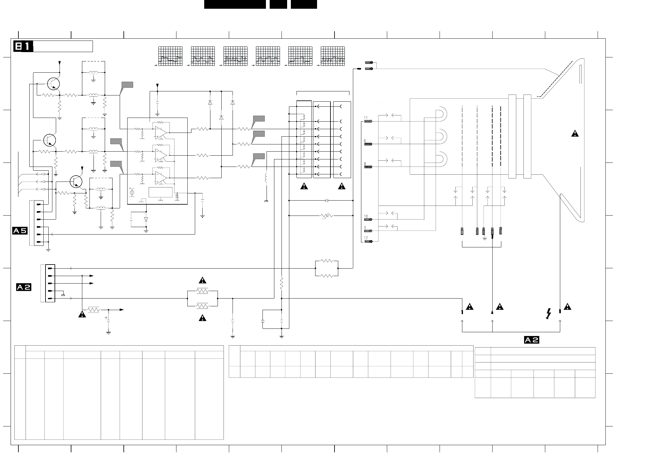
Schematics and PWB’s EN 49L01.1E AB 7.
CRT Panel
3k75
188k7
3k77
3k75
188k7
3k77
3k75
188k7
Vref
7V
PROTECTION
THERMAL
BC1
A1
Vref
Vdd
2.5V
3k77
A2
Vref
Vdd
BC2
A3
Vref
Vdd
BC3
Blue
Green
Red
V
TO
B
1K
1K
1K
GNDLS
GNDSS
1
5
B
C
D
E
F
G
VG2 E9
0165 A7
0244 D1
0245 C1
0254-A A7
0255 A6
0256-A A6
2330 A3
2340 F2
2341 F4
2342 C4
2343 F5
2344 D3
2345 C6
2346 F5
1234567891011
1234567891011
A
3357
B
C
D
E
F
G
A
1K5
---
29" RF
EU
PH
EW
32" WS BLS
EU
PH
*
*
Diversity Table
*
7
*
EU
MATJ
3331 C4
3332 C5
3333 B4
3334 B5
3335 B4
3336 B5
3340 E2
3341 E4
3342 E4
3343 E5
3344 D6
3345 C6
3346 E6
3347 A2
3348 A1
CRT Sockets
EHT
100MHZ 50R
1R5
1R5
JMP
1R5
1R5
JMP
FROM LOT, MAIN CHASSIS
R
0243
T0 CRT SOCKET
(EUROPE)
G
3349 A2
3350 B2
3351 B1
3352 B2
3353 C2
3354 C2
3355 C2
3356 A1
3357 B1
3358 C1
5342 C5
5343 A2
5344 B2
5345 C2
5346 A2
5347 B2
5348 C2
---
*
SDL-4893
TO
1K
1K
1K
CRT PANEL
*
*
*
*
*
SDL-4893
1K 1K
JMP
JMP
1K
6331 B4
6332 D3
6333 A4
6335 A4
7330 B3
7331 A1
7332 B1
7333 C1
9341 A2
9342 B2
9343 C2
TDA6107
FOCUS
---
---
AQUADAG
B2-69
*
*
B2-68
140V
6V
T0 CRT SOCKET
0220
NOT USED
OF
B2-67
*
140V
1R
1R
15u
1R
1R
22u
1R
2V5
2V5
FROM RGB PROCESSING
WIRE
1R
18u
2V5
1K
B
22u
REGION TUBE
PH
EW
28"BLS
EU
PH
EW
25BLD
1R
15u
1R
1R
22u
1R
EW
25BLS 1R
1R
22u
1R
140V
1R
3u9
1R8
18u
1R5
---
---
RES
Diversity Table
RES
RES
JMP
---
BAS316
BC847B
TDA6108
---
---
R
G
OF
1K
*
---
*
*
**
*
*
*
---
BAS316
TDA6107
---
---
---
---
JMP
JMP
JMP
1KJMP
---
JMP
1K
---
------
---
SDL-4893
SDL-4893
*
BC847B
*
100n
---
--- JMP
JMP
BC847B
---
JMP
---
JMP
---
JMP
1K
FROM LINE DEFLECTION
---
SDL-4893
SDL-4893
SDL-4893---
BAS316
TDA6107
SGMK
EW
EU
PH
1R
EW
28" WS BLD
EU
SGMK
EW
25" RF
RES
RES
RES
EW
32WS
EU
EW
21" RF
EU
THCF
1R
*
*
THCF
EW
28WS
5348
3356
3357
---
JMP
---
JMP
JMP
JMP
---
5345
6332
7330
7331
7332
7333 ---
JMP
28WR
3358
2KV 470P
33R
33R
LAL04 22U
32WR
33R
33R
LAL04 22U
32WR
--- ---
---
5346
3354
3352
+13V
B
R
G
5345
3n3
2341
12
3334
8
9
1
3358
5342
BAV21
6335
4
5
0244
1
2
3
CG
6
CR
8
3345
V15 5
G1
3353
+13Va
1
G2
3341
100R
3333
L2K2
29RF
2KV 3N3
---
22R
22R
LAL04 22U
21RF
2KV 2N2
---
33R
33R
LAL04 22U
5343
5344
TDA6107
---
---
---
JMP
JMP
JMP
JMP
--- ---
JMP
ITEM 21/25RF 29SF 28BLD/BLS/32WS(O)
2343
2346
3344
3346
5342
--
2KV 1N2
22R
22R
LAL04 3U9
SET
TUBE
REGION
MODEL
EU
---BAS316
BC847B
BC847B
BC847B
---
---
---
JMP100n
JMP
---
JMP
---
JMP
---
---
28/32WS(TH)(I)
---
---
100n
JMP
---
NO SVM SETS
REGION TUBE (EUROPE)
2344
3347
3348
3350
3351
3353
3354
JMPJMP
JMP
---
JMP
JMP
JMP
---
------
---
BAS316
TDA6107
---
---
JMP
JMP
9341
9342
9343
100n
JMP
JMP
JMP
---
1K
---
---
---
--- SDL-4893
SDL-4893
TDA6108TDA6108
BC847B
BC847B
---
---
---
100n
JMP1K
1K
1K
1K
1K
1K
JMP
JMP
JMP
JMP
---
---
29RF(I) 28/32WS(I) 32W(TH)(O)
---
BC847B
---JMP
JMP
JMP
JMP
--- 3341
3342
5342
ITEM EU
PH
NO EW
21FSQ
EU
PH
EW
28" BLD
EU EU
PH
EW
29SF
1R
3u9
1R8
EU
PH
EW
1R5
22u
1R
24" WS BLD
EU
0165
H2
10
100n
2330
3n3
2343
3346
22R
3331
100R
0255
10
11
12
4
5
6
7
5344
BAV21
6331
0245
1
2
3
4
5
6
GND
H1
9
1n
2342
3342
3349
3336
2344
9
V16
CB
11
+200VA
7
V14
H1
0254-A
1
0256-A
G3
+13Va
G3
12
10u
2340
GND
22R
3344
1K5
3343
5347
3356 3347
3355
V12
+200VA
3332
6333
BAV21
7332
3335
100R
7330
5BCI
GND
4
1 IN1
2 IN2
3 IN3
9OUT1
8OUT2
7OUT3
6
Vdd
5343
CB
11
VG2
3351
G1
5
V13
9342
10
V11
6332
G2
7
H2
3348
9341
2345
1n
2346
680p
7333
CR
8
10R
3340
3350
7331
9343
CG
6
EHT_INFO
FF
+200V
BC_INFO
CL 26532063_020.eps
060602
V11
1V / div DC
10us / div
V12
1V / div DC
10us / div
V13
1V / div DC
10us / div
V14
50V / div DC
10us / div
V15
50V / div DC
10us / div
V16
50V / div DC
10us / div
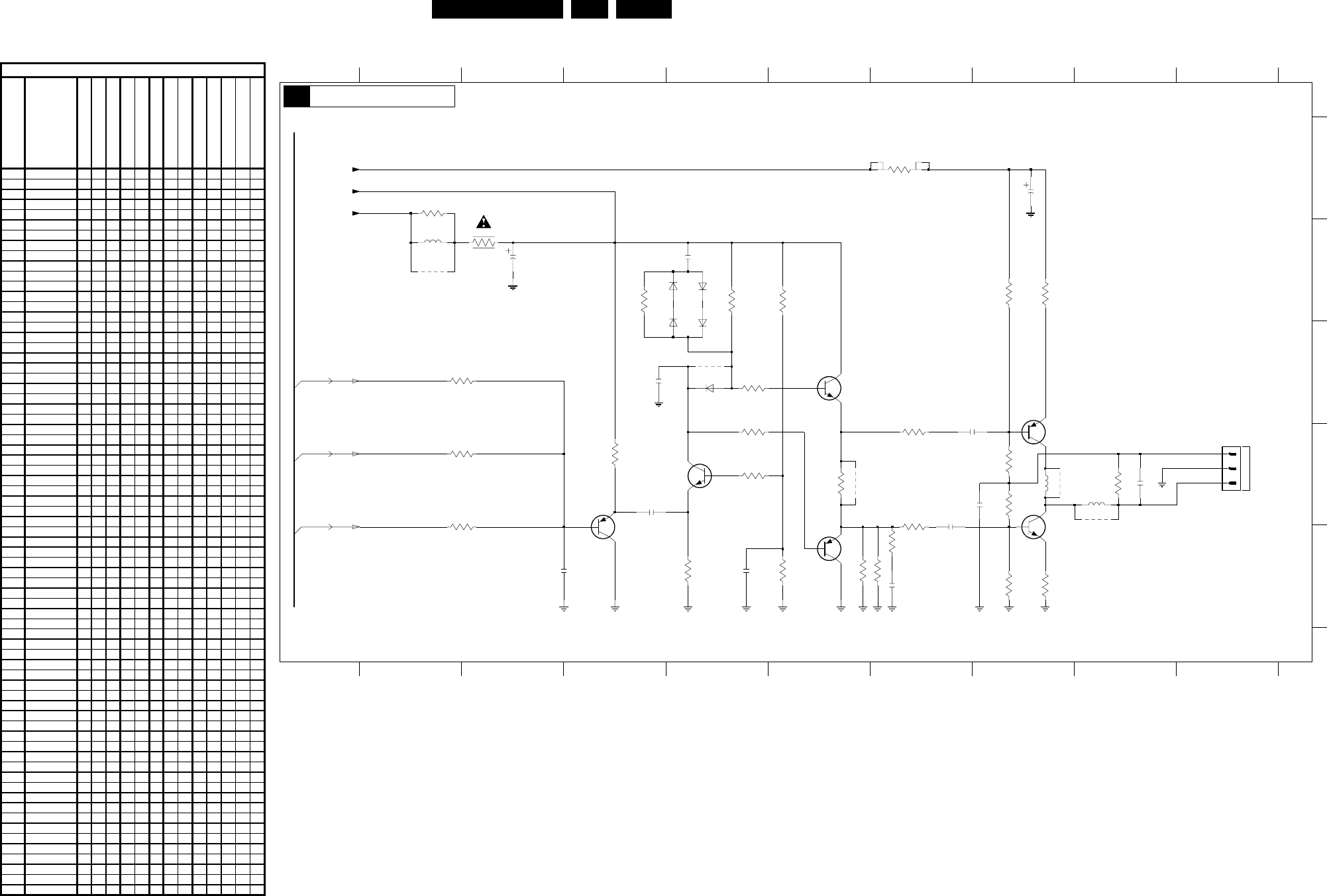
EN 50L01.1E AB 7.
Schematics and PWB’s
SCAVEM Panel
TO
SCAVEM COIL
7V3
1V8
1V1
14V
7V6
7V9
7V6
92V4
0V6
0V
48V8
93V7
8K2
4n7
BD140
BD139
3R33R3
0R
B1-67
B1-68
B1-69
*
*
*
** *
*
3385 E8
3386 D3
3387 D4
3388 E6
3389 E7
3390 D7
3391 D7
3392 E7
3393 B4
5360 B2
5361 D8
5362 D9
6360 C5
6361 B5
6362 C5
6364 B5
6365 C5
7360 C6
7362 C8
7363 D5
7365 D8
7366 E6
7367 D4
9361 B2
9363 D8
9364 D9
9365 C5
9366 D6
0278 D10
2360 A8
2361 B3
2365 D8
2366 D7
2367 D4
2368 D7
2372 C4
2373 E3
2374 E5
2375 D9
2376 E7
2377 B5
3360 A7
3361 A2
3362 B3
3363 B8
3364 B8
3368 B5
3369 B6
3370 C5
3371 C3
3373 D5
3374 D8
3375 D9
3376 D5
3377 D6
3378 D8
3379 D3
3382 E6
3383 E5
3384 E8
12345678910
12345678910
A
B
C
D
E
100n
2376
4K7
3393
220R
3392
6365
BAS216
6364
BAS216
6362
BAS216
100n
2377
6361
BAS216
3373
33R
3391
2375
150p
3390
33R
2374
1n
2373
1n
220R3388
220R3389
9366
5p6
2372
470R
3387
9365
BC557B
7367
470R
3375
150p
2367
2K2
3386
3379
2K2
3360
3361
680R
9361
9363
9364
3364
3385
5362
5361
7366
BF423
2K2
3371 6360
1N4148
3376
7362
BC548B
7365
2360
22u
7360
2361
5360
5u6
1
2
3
100u
0278
2366
4n7
2368
100n
3384
820R
3374
56K
3378
56K
3363
820R
2365
7363
BC548B
3382
1K5
3377
10R
3369
3383
220R
330R
3370
10K
10R
3362
1K2
3368
+13V
G
B
+200V
+13Va
R
CL 16532020_089.eps
050601
Item Description
21" Real flat
25" Real flat
29" Super flat
28" Blackline, FM radio
32" Wide screen, No FM radio
29" Real flat
28" Wide screen, FM radio
32" Wide screen, FM radio
21" Blackline
24" Wide screen
25" Blackline
28" Blackline, No FM radio
28" Wide screen, No FM radio
2365 22N 250V XXXXXXXX
2366 100N 100V XXXXXXXX
2367 47P 50V X X X
2367 56P 50V X X
2367 150P 50V X
2367 180P 50V X X
2368 22N 50v XXXXXXXX
2372 5P6 50V X X X X X
2373 56P 50V X X
2375 100P 50V X X X X X
2375 330P 50V X X
2376 100N 25V X X X
2377 100N 25V X X X
3360 8K2 5W XXXXXXXX
3361 680R
3362 Fuse 10R XXXXXXXX
3363 820R XXXXXXXX
3364 1R8 X X X
3364 3R3 X X X X X
3368 2K7 XXXXXXXX
3369 10K XXXXXXXX
3370 220R X X X
3370 330R X X X X X
3371 10K X X X X X
3371 4K7 X X X
3373 220R X X X
3374 56K XXXXXXXX
3375 150R X X
3375 220R X
3375 470R X X X X X
3376 Jumper XXXXXXXX
3377 10R X
3377 4R7 X X
3378 56K XXXXXXXX
3379 10K X X X X X
3379 4K7 X X X
3382 1K5 XXXXXXXX
3383 470R XXXXXXXX
3384 820R XXXXXXXX
3385 1R8 X X X
3385 3R3 X X X X X
3386 10K X X X X X
3386 4K7 X X X
3387 470R XXXXXXXX
3388 220R X X X X X
3389 220R X X X X X
3390 10R X X
3390 33R X X X X X X
3391 10R X X
3391 33R X X X X X X
3392 220R X X X
3393 4K7 X X X
5360 5.6uH 10% XXXXXXXX
5361 COIL
5362 COIL
6360 1N4148 X X X
6361 BAS316 X X X
6362 BAS316 X X X
6364 BAS316 X X X
6365 BAS316 X X X
7360 BC547B XXXXXXXX
7362 2SA1358 XXXXXXXX
7363 BC547B XXXXXXXX
7365 2SC3421 XXXXXXXX
7366 BF423 X X X
7367 BC557B XXXXXXXX
9361 Wire
9363 Wire XXXXXXXX
9364 Wire XXXXXXXX
9365 Wire X X X X X
9366 Wire X X X X X
Diversit
y
Table B2
SCAVEM PANEL
B2